PMC Services for Kochi-Coimbatore-Erode-Salem LPG ...
307
PMC Services for Kochi-Coimbatore-Erode-Salem LPG Pipeline Project ENQUIRY DOCUMENT (Document No : A538-010-LS-MR-4510-1039-RFQ) Page 1 of 307
-
Upload
khangminh22 -
Category
Documents
-
view
2 -
download
0
Transcript of PMC Services for Kochi-Coimbatore-Erode-Salem LPG ...

PMC Services for Kochi-Coimbatore-Erode-Salem LPG Pipeline
Project
ENQUIRY DOCUMENT
(Document No : A538-010-LS-MR-4510-1039-RFQ)
Page 1 of 307

Click on the Document Title to go to that section of the document
Table of ContentsDocument Number Rev. Document Title Page
NumberA538-010-LS-MR-4510-1039-RFQ
0 ENQUIRY DOCUMENT 3
A538-010-LS-MR-4510
B Mobile Flare System 122
A538-010-80-43-SI-4510
A SPECIAL INSTRUCTION TO BIDDERS 126
A538-010-80-43-LD-4510
A DEVIATION TO TECHNICAL SPECIFICATIONS 129
A538-010-80-43-TCL-4510
A TECHNICAL COMPLIANCE STATEMENT 131
A538-010-80-43-SP-4510
B JOB SPECIFICATION (MOBILE FLARE SYSTEM) 132
A538-010-02-DS-1801
0 PROCESS DATASHEET 148
A538-04-41-010-1111
0 SCOPE MARKED P&ID 151
A538-010-80-43-CL-4510
A CHECKLIST-SCOPE OF SUPPLY DG SET 152
A538-010-80-43-DS-4510
B DATASHEET (MOBILE FLARE SYSTEM0 155
A538-010-80-43-DS-4511
A DATASHEET (TYPICAL) DIESEL GENERATOR 160
A538-010-80-43-VDR-4510
A VENDOR DATA REQUIREMENT (MOBILE FLARE SYSTEM) 164
A538-010-80-43-SU-4510
B SITE AND UTILITY DATA 168
A538-010-16-50-SP-4510
A JOB SPECIFICATION 170
A538-010-16-50-DS-4510
A DATA SHEET 182
A538-010-16-50-DS-4511
A DATA SHEET 188
A538-010-16-50-VR-4510
A VENDOR DATA REQUIREMENTS 190
A538- 503-83-41-VL-0001
0 Vendor List for KSPPL Project 193
6-51-0051 7 Specification for medium and high voltage cables & accessories. 1976-51-0061 5 Specification for hazardous area light fixtures and junction boxes 2076-51-0083 5 Specification for lighting installation. 2146-79-0020 0 Standard specification for surface preparation and protective
coating (new construction)227
6-78-0001 1 Specification for quality management system requirements frombidders
286
6-78-0003 1 Specification for documentation requirement from suppliers 2936-81-1061 3 ITP for hazardous area lighting fixture & junction boxes 302
Page 2 of 307

GLOBAL COMPETITIVE BIDDING
KOCHI-SALEM LPG PIPELINE PROJECT
Engineers India Limited (EIL) on behalf of M/s Kochi Salem Pipeline Pvt. Ltd. (KSPPL) invites e-bids from eligible bidders for supply of the following item:
DESCRIPTION BIDDING DOCUMENT ON
WEBSITE
PRE BID DATE, PLACE & TIME
BID DUE DATE & TIME
MOBILE FLARE SYSTEM (Bidding Document No. :AK/A538-010-LS-MR-4510/1039)
From 08.12.2016
to 06.01.2017
22.12.2016 Engineers India Bhawan,
New Delhi at
1030 Hrs (IST)
Up to 1200 Hrs. (IST) on 06.01.2017
The complete Bidding Document with contact details & detailed IFB along with Qualification Criteria can be viewed / downloaded from Central Public Procurement Portal (CPPP) website: http://eprocure.gov.in/eprocure/app. Link of the same can also be viewed from EIL website: http://tenders.eil.co.in. Bids can only be uploaded on CPP Portal. All amendments, time extension, clarifications, etc. will be uploaded in the websites only and will not be published in newspapers. Bidders should regularly visit the EIL & CPPP websites to keep themselves updated.
D.G.M. (C&P)
Page 3 of 307

Page 1 of 5
INVITATION FOR BIDS (IFB) FOR
MOBILE FLARE SYSTEM FOR KOCHI-SALEM LPG PIPELINE PROJECT OF
M/s KOCHI SALEM PIPELINE PVT. LIMITED BIDDING DOC. NO.: AK/A538-010-LS-MR-4510/1039
(GLOBAL COMPETITIVE BIDDING) E-Tendering
1.0 INTRODUCTION:
1.1 M/s Kochi Salem Pipeline Private Limited (KSPPL) proposes to lay an onshore LPG pipeline of 12 inch NB, approximately 200 km long, from Kochi Refinery (BPCL) to Udayamperoor Bottling Plant of IOCL & Kochi Refinery (BPCL) to Palakkad in the state of Kerala.
1.2 Engineers India Limited (EIL) has been engaged for EPCM services for the above pipeline project. EIL on behalf of Client, invites bids through e-tendering under single stage two bid system from eligible bidders meeting the Qualification Criteria as per clause 5.0 below, for supply of Mobile Flare System.
2.0 BRIEF SCOPE OF SUPPLY:
2.1 The Scope of Work shall consist of Design, engineering, manufacture, procurement of materials, assembly, inspection, painting, supply, supervision of installation, testing and commissioning of complete Mobile Flare System with following major design parameters:
Tag No. : 010-ME-0001 & 010-ME-0002
Service /Location : Hydrocarbon (LPG)
Peak Flare Load (kg/hr) : 10000
Diameter of Flare Stack : 8 inches
Height (upto Tip) : 13 meters
Allowable Pressure drop for Flare tip and Flare Seal (combined together)
: 1000 mm WC
Design Pressure (kg/cm2g) (Flare Stack) : 3.5
Design Temperature (0C) (Flare Stack) : 65
Mobile Flare system broadly consists of : Flare Stack, Flare Seal, Pilot burner, Flare tip, FFG/ HEI, LPG Manifold, LPG Cylinder and DG Set.
For Complete details refer bid document.
3.0 DELIVERY PERIOD :
3.1 FOR INDIAN BIDDERS: 07 (Seven) Months on FOT Site Basis from the date of Fax of Acceptance. The Date of receipt of all materials at site shall be considered as date of delivery.
3.2 FOR FOREIGN BIDDERS: 06 (Six) Months on FOB Port of Exit basis from the date of Fax of
Acceptance. The date of clean bill of lading shall be considered as the date of delivery.
4.0 SALIENT DETAILS:
a) Bidding Document on Website : From 08.12.2016 to 06.01.2017
b) Last date of Receipt of Bidder’s Queries for Pre-Bid Meeting
: On 20.12.2016
c) Date of Pre Bid Meeting : at 1030 Hrs. (IST) on 22.12.2016
d) Last Date and time of Online submission of Bids (Bid Due Date)
: Up to 1200 Hrs. (IST) on 06.01.2017
Page 4 of 307

Page 2 of 5
e) Online Opening of Techno-commercial Unpriced Bid
: 1400 Hrs. (IST) on 06.01.2017
f) Earnest Money Deposit / Bid Security
: As per Clause no. 8.1 below.
g) Cost of Bidding Document : Not Applicable
h) Opening of Priced Bids : On date & time to be intimated later
If any of the dates indicated at Sl. No. c) & e) happens to be a declared holiday in EIL New Delhi, the next working day shall be considered.
The complete Bidding Document is available Central Public Procurement Portal (CPPP) website: https://eprocure.gov.in/eprocure/app and link to download Bidding Document is available on EIL website: http://tenders.eil.co.in; and Bidders can view / download the document from website mentioned above.
All amendments, time extension, clarifications, etc. will be uploaded in the websites only and will not be published in Newspapers. Bidders should regularly visit the above website(s) to keep themselves updated.
Request for extension or any queries received from any bidder with less than four working days prior to bid due date shall generally be ignored, since there will not be adequate time for proper communication with Client and other Bidders. Bidders shall submit the bid directly and in their own name without involving any intermediaries.
5.0 BIDDERôSQUALIFICATION CRITERIA: Bidder shall fulfil the following qualification criteria:
5.1 TECHNICAL CRITERIA:
5.1.1 The Bidder shall be a supplier of Mobile Flare System and shall be the single point responsibility vendor (SPRV) for the complete Mobile Flare System.
5.1.2 Bidder shall have designed, engineered and supplied at least 1 (One) no. Mobile Flare System with a capacity of at least 6000kg/hr (flare load) for any Hydrocarbon gas service in the last ten (10) years, which shall have been in operation for a minimum period of One (1) year as on bid due date.
5.1.3 For qualification of Mobile Flare system, above clauses shall be read in conjunction.
5.2 FINANCIAL CRITERIA
5.2.1 The minimum Annual Turnover of the Bidder as per audited financial results in at least one of the immediate preceding three financial years shall not be less than the amount indicated in the below table:
Sl No Bidder Annual Turnover
1 Indian Bidders INR 1,75,00,000.00 (Rupees One Crore Seventy Five Lakh Only)
2 Foreign Bidders USD 2,60,000.00 ( USD Two Hundred Sixty Thousand Only)
5.2.2 The minimum Net Worth of the Bidder as per audited financial results of immediate preceding financial year shall not be less than the amount indicated in the below table:
Sl No Bidder Net Worth
1 Indian Bidders INR 17,50,000.00 (Rupees Seventeen Lakh Fifty Thousand Only)
2 Foreign Bidders USD 26,000.00 ( USD Twenty Six Thousand Only)
5.2.3 The minimum Working Capital of the Bidder as per audited financial results of immediate preceding financial year shall not be less than the amount indicated in the below table:
Page 5 of 307

Page 3 of 5
Sl No Bidder Working Capital
1 Indian Bidders INR 17,50,000.00 (Rupees Seventeen Lakh Fifty Thousand Only)
2 Foreign Bidders
USD 26,000.00 ( USD Twenty Six Thousand Only)
5.2.4 In case of Foreign Bidders, if the Annual Turnover is in currency other than US$, the same shall be converted into equivalent US$ considering the exchange rate indicated in Bidder’s Audited Financial Report. In case the same is not indicated, the conversion rate of US$ as on last date of Bidder’s financial year shall be considered based on SBI bill selling rate.
5.2.5 Financial year / previous periods as above shall be reckoned from the due date of submission of bids.
5.2.6 In case audited balance sheets and profit and loss account for the immediate preceding financial year is not available for bid closing date up to 30th September, the Bidder has an option to submit the audited balance sheets and profit & loss account of the three previous years immediately prior to the last financial year. However, for bid closing date after 30th September, the bidder has to compulsorily submit the audited balance sheets and profit and loss account for the immediately preceding three financial years only. In any case the date (i.e. the financial period closing date) of the immediate previous year’s audited annual accounts should not be older than eighteen (18) months from the bid due date.
5.3 DOCUMENTS REQUIRED WITH BID:
5.3.1 Bidder shall complete and submit the Proven Track Record Proforma enclosed with the bid document (Annexure- I) to establish that the bidder meets the Bidder Qualification Criteria as per clause no. 5.1 of this document.
5.3.2 Bidder shall furnish documentary evidence in the form of Annual Report/ Financial Statements- Balance sheets and Profit and Loss Accounts statements etc. of the preceding 3 (Three) financial years along with the Bid to establish Bidder’s conformance to Financial Criteria mentioned in Clause 5.2 above.
5.3.3 All documents furnished by the bidder in support of meeting the Technical and Financial criteria of BQC shall be:
Either
Duly certified by Statutory Auditors of the bidder or practicing Chartered Accountant (not being an employee or a Director or not having any interest in the bidder’s company/firm) where audited accounts are not mandatory as per law.
Or
Duly notarized by any Notary Public in the Bidder’s Country. In case of Notarization, Bidder shall also submit an Affidavit duly notarized in the Format attached as Annexure ïII with this IFB, signed by the Authorized Signatory of the Bidder.
5.3.4 With regards to financial documents, in case Bidder submits bound published and audited annual financial statements including balance sheet, profit & loss accounts and all other schedules for the preceding three financial years, the same shall be considered without certification of Statutory Auditor/ Notarization of Notary Public. However, in case the bidder submits either a photocopy of published statement or a translated copy of the published financial statements, the same shall be certified either by statutory auditor or Notary Public, in original as per clause no. 5.3.3 above.
5.3.5 In case of Foreign Bidders, if the documents in support of meeting the Technical and Financial criteria are not in English Language, then the English translation copy of the same shall be furnished duly certified, stamped and signed by Local Chamber of Commerce of Bidder’s country/ Indian Embassy in addition to the requirement mentioned at clause no. 5.3.3 above with the Bid.
5.3.6 All documents furnished by the bidder in support of meeting the Technical and Financial criteria (5.1 and 5.2 above) of BQC as per IFB shall be submitted in a separate section/booklet along with their offer. This section/booklet shall be titled as ñDocumentation against Bidder Qualification Criteria (Technical and Financial)ò with proper index and page numbering. Refer Instructions to Bidders (ITB) for details.
5.3.7 Any additional documents if deemed necessary to establish the qualifying requirements may be submitted by the Bidder.
Page 6 of 307

Page 4 of 5
5.3.8 Submission of authentic documents is the prime responsibility of the Bidder. However, Owner/EIL reserves the right of getting the document cross verified, at their discretion from the document issuing authority.
5.3.9 Owner /EIL reserves the right to complete the evaluation based on the details furnished (without seeking any additional information) and / or in-house data, survey or otherwise.
5.3.10 Failure to meet the above Qualification Criteria will render the Bid to be summarily rejected. Therefore, the bidder shall in his own interest furnish complete documentary evidence in the first instance itself along with their bids, in support of their fulfilling the Qualification Criteria as given above.
6.0 PRE-BID MEETING
6.1 Bidders are requested to attend a pre-bid meeting at Business Centre, Engineers India Bhawan, 1, Bhikaiji Cama Place, New Delhi-110 066 as per the date mentioned in Cl. 4.0 above.
6.2 The bidder may send their queries, if any, on Bidding Document by e-mail/courier to reach EIL within the date indicated at Cl. No. 4.0 above. These queries shall be replied during the Pre-bid meeting.
6.3 The queries raised (without identifying the sources of the query) and the responses will be uploaded on website.
7.0 SUBMISSION OF BID & VALIDITY
7.1 Bids are required to be submitted only through Govt. of India CPP Portal at https://eprocure.gov.in/eprocure/app on or before the Bid submission date and time. Bidders are required to enroll on the e-Procurement module of the Central Public Procurement Portal (URL: https://eprocure.gov.in/eprocure). No enrolment fee would be charged from the bidders. It may also be noted that the price details are required to be filled & submitted only on the Schedule of Price format downloaded from above e-Tendering website.
7.2 Bidders in their own interest are requested to enroll on Govt. of India CPP portal and upload/submit their bid well in time. In the event of failure in bidder’s connectivity with EIL/CPP Portal during the last few hours, bidder is likely to miss the deadline for bid submission. Due date extension request due to above reason may not be entertained.
7.3 Physical Bids / Offers or Bids through any other mode shall not be accepted. The Offers submitted through e-tendering system, as above shall only be considered for evaluation and ordering.
7.4 Bidders to refer Instruction to Bidders for E-Tendering Methodology as attached in the Bidding Document. Bidders are requested to get acquainted with the E-Tendering System in advance and obtain/seek clarifications, if any from EIL and/or CPP Portal Helpdesk, whose contact information is provided in the E-Tendering Methodology.
7.5 Validity of bid shall be 4 (four) months from the final Bid Due Date.
8.0 EARNEST MONEY DEPOSIT (EMD)
8.1 EMD amount shall be as follows :
Sl No Bidder Applicable EMD
1 Indian Bidders INR 2,00,000.00 (Rupees Two Lakh Only)
2 Foreign Bidders USD 3,000.00 (USD Three Thousand Only)
8.2 Bid Security/EMD shall be in favour of M/s “Kochi Salem Pipeline Private Limited” and shall be acceptable in the form of Crossed Demand Draft (Payable at Ernakulam) or Bank Guarantees in the prescribed pro-forma from Scheduled Commercial banks in India/ Indian Branch of Foreign Bank. The B.G. shall be valid for a period of 6 months from the due date of submission of Bid. The Bid Security/ EMD from foreign bidders shall be either in the form of Crossed Demand Draft (DD) (Payable at Ernakulam as the case may be) or Bank Guarantees (BG) from any Indian scheduled bank which includes Indian branch of foreign bank recognized as scheduled bank by RBI. Foreign Bidders may also submit BG from an international bank of repute having a branch in India or having correspondent banking relationship with an Indian scheduled bank, in which case the BG shall be countersigned by their Indian Branch or by any Scheduled Indian Bank. Standard Bank Guarantee format of OWNER shall be used.
Page 7 of 307
Page 5 of 5
8.3 Bidders are required to submit the EMD (in the prescribed format) in original at the time of bid submission in sealed envelope and are required to upload the scanned copy of EMD on CPP Portal along with e-Bid. EMD in original shall be submitted in a sealed envelope titled “Earnest Money Deposit for Bidding Document No. AK/A538-010-LS-MR-4510/1039ò. Bidder must upload the scanned copy of EMD (in the prescribed format) on CPP Portal along with the e-bid. Swift message/Cheque/Cash shall not be acceptable. In case bidder fails to upload scanned copy of EMD on CPP Portal by the bid due date & time, such bids shall not be considered for evaluation.
8.4 If the Bidder is unable to submit original EMD within the due date and time of Bid submission, he may submit the same within 7 calendar days from the date of unpriced bid opening, provided scanned copy of the same have been uploaded on CPP Portal. In case the Bidder fails to submit the EMD in original within 7 calendar days, his bid shall be rejected, irrespective of their status / ranking in tender and notwithstanding the fact that a copy of EMD were uploaded earlier by the Bidder.
8.5 Public sector undertakings of Central Government will be exempted from submission of EMD against Press Enquiries.
8.6 EMD exemption will also be applicable for Micro or Small Enterprises registered with District Industries Centers or Khadi and Village Industries Commission or Khadi and Village Industries Board or Coir Board or National Small Industries Corporation or Directorate of Handicrafts and Handloom or any other body specified by Ministry of Micro, Small and Medium Enterprises.
9.0 GENERAL
9.1 Owner/EIL reserves the right to carry out capacity & capability assessment of the bidder using in-house information and past performance.
9.2 The bidders who are on Holiday/Negative list of OWNER or EIL as on due date of submission of bid/ during the process of evaluation of the bids, the offers of such bidders shall not be considered for bid opening/evaluation/Award. If the bidding document were issued inadvertently/ downloaded from website, offers submitted by such bidders shall also be not considered for bid opening/evaluation/Award.
9.3 Owner/EIL will not be responsible or liable for cost incurred in preparation, submission & delivery of bids, regardless of the conduct or outcome of the bidding process.
9.4 In case any Bidder is found to be involved in cartel formation, his Bid will not be considered for evaluation / placement of order. Such Bidder will also be debarred from bidding in future.
9.5 Canvassing in any form by the Bidder or by any other agency on their behalf may lead to disqualification of their Bid.
9.6 Evaluation/ Ordering shall be done on bottom line basis for this RFQ.
9.7 Unsolicited clarifications to the offer and / or change in the prices during the validity period would render the bid liable for rejection.
9.8 Bidder shall not be under liquidation, court receivership or similar proceeding.
9.9 Bidders may view the Bid opening through Govt. of India CPP Portal i.e. https://eprocure.gov.in/eprocure or may witness the bid opening in EIL Office, Delhi.
9.10 Owner/EIL reserves the right to reject any or all the bids received or annul the bidding process at any time.
9.11 Bids submitted on Consortium or unincorporated Joint-Venture basis shall not be accepted.
9.12 Owner reserves its right to allow Public Sector Enterprises (Central/State), purchase preference as admissible/applicable from time to time under the existing Govt. of India policy. Owner shall also follow the Public Procurement Policy on Procurement of Goods and Services from Micro and Small Enterprises (MSEs) Order 2012.
9.13 For detailed specifications, terms and conditions and other details, refer complete Bidding Document.
9.14 Clarification, if any, can be obtained from Ms. Sunita Mitra, DGM (C&P), Mr. D. Chatterjee, Sr. Manager (C&P), Mr. Arnav Ranjan, Sr. Engineer (C&P) through following number. Telephone No. 011-2676 3113/2824; E-mail: [email protected] /[email protected]/ [email protected].
Dy. General Manager(C&P)
Engineers India Limited.
Page 8 of 307

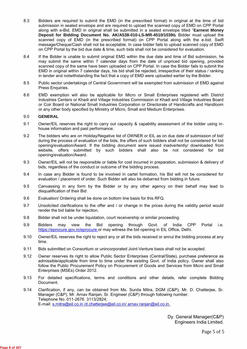
PROVEN TRACK RECORD PROFORMA (FOR BIDDER QUALIFICATION) FOR SIMILAR SUPPLY OF GOODS/WORKS/SERVICES (ANNEXURE-I) PROJECT- Kochi Salem LPG Pipeline Project CLIENT- M/s KSSPL
EIL JOB NO- A538 VENDOR- ITEM/ PACKAGE- MOBILE FLARE SYSTEM ITEM/ PACKAGE TAG NO.- 010-ME-0001 & 010-ME-0002
Place: [Signature of Authorized Signatory]* Date: Name: Designation: Seal:
* Note-9 Page 1 of 2
SL.
NO.
PARAMETER INFORMATION ON
PROPOSED EQUIPMENT
(FOR THIS PROJECT)
INFORMATION ON REFERRED EXISTING
INSTALLATIONS
Reference.- 1 Reference- 2
1.0 Is the Bidder, a supplier of Mobile Flare system? - Yes/No
2.0 Is the Bidder, a Single Point Responsibility Vendor (SPRV) for the complete Mobile Flare system? -Yes/No
3.0 Has the Bidder, designed, engineered and supplied at least ONE (1) no. Mobile Flare system with a capacity of at least 6000kg/hr (flare load) for any Hydrocarbon gas service in the last ten (10) years as on bid due date? – Yes/No
Further to authenticate the above statement, Details furnished are as under:
3.1 Service Hydrocarbon (LPG)
3.2 Date of Delivery of complete Mobile Flare system
-----
3.3 Date of commissioning of Mobile Flare system -----
3.4 Has the Mobile Flare system completed ONE Year of operation, as on bid
due date? - Yes/No
-----
3.5
Purchaser's / End User’s Name and Address
3.6 Name (Company / Organization)
3.7 Name of Contact Person
3.8 Address Including Telephone No/ Fax No/ Email-ID
3.9 Are duly endorsed supporting documents attached as specified in RFQ/IFB?
– Yes/No
Page 9 of 307
PROVEN TRACK RECORD PROFORMA (FOR BIDDER QUALIFICATION) FOR SIMILAR SUPPLY OF GOODS/WORKS/SERVICES (ANNEXURE-I) PROJECT- Kochi Salem LPG Pipeline Project CLIENT- M/s KSSPL
EIL JOB NO- A538 VENDOR- ITEM/ PACKAGE- MOBILE FLARE SYSTEM ITEM/ PACKAGE TAG NO.- 010-ME-0001 & 010-ME-0002
Place: [Signature of Authorized Signatory]* Date: Name: Designation: Seal:
* Note-9 Page 2 of 2
INSTRUCTIONS TO BIDDERS:
1. This proforma duly filled-in, stamped and signed shall be submitted along with the Bid.
2. To establish, bidder meeting qualification criteria, following documents are to be submitted along with bid.
i. Copies of Letter of Awards or Purchase Order or Work Orders ii. IRN/Proof of delivery. iii. Other technical documents e.g. data sheet, drawing etc. to establish that the Bidder meets BQC requirements.
3. The Supply/Work/Services completed beyond 10 years need not be indicated here. 4. The list of Supply/Work/Services, not of similar nature shall not be indicated here. Failing to comply aforementioned instructions may
lead to rejection of bid.
5. Since the information requested in this proforma shall be utilized to assess the Bidder’s capability, it is in the interest of the Bidder to pick those cases out of total list of references which most closely match with the Bid requirement. The Bidder shall also ensure that all information asked for is furnished and the same is correct and complete in all respects. Incomplete information could lead the bid being considered ineligible for further evaluation.
6. Incorrect information furnished in this proforma shall render the bid/order liable for rejection at any stage of evaluation/ work
execution, at the risk and cost of the bidder and the bidder shall be blacklisted. 7. For the referred installations, the bidder shall indicate the name of the Purchaser/ End User’s contact person (along with his address,
telephone no., fax no., e-mail id etc.) who may be contacted by the Purchaser/End User, if felt necessary. 8. Bidder shall submit standard reference list for Mobile Flare System. 9. For certification and other requirements, refer commercial part.
Page 10 of 307
Page 1 of 1
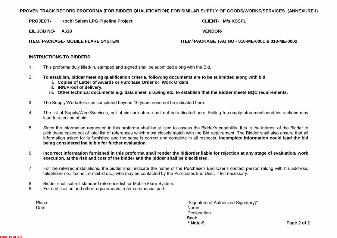
ANNEXURE ï II
FORMAT FOR FURNISHING AFFIDAVIT
AFFIDAVIT AFFIDAVIT OF ………………………….., S/o D/o , resident of EMPLOYED AS ……………….WITH ………………………………………………….. …………………………………HAVING OFFICE AT ………………………………………PIN…………. I, the above named deponent do hereby solemnly affirm and state as under :-
1. That I am the authorized representative and signatory of M/s……….
2. That the document(s) submitted as mentioned here under by M/s…….alongwith the Bid Document
submitted under covering letter no…. Dated …..towards Tender No……for…………………(Project)
has/have been submitted under my knowledge.
Sr. No. Document Reference
no. &date
Document subject Issuing Authority
3. That the document(s) submitted as mentioned above, by M/s…….along with the Bid Document for
meeting the Bid Qualification Criteria there under, vide covering letter no….dated…..towards Tender
No…… for…………………are authentic, genuine, copy of their originals and have been issued by the
issuing authority mentioned above and no part of the document(s) is false, forged or fabricated.
4. That no part of this affidavit is false and that this affidavit and the above declaration in respect of
genuineness of the documents has been made having full knowledge of (i) the provisions of the Indian
Penal Code in respect of offences including, but not limited to those pertaining to criminal breach of
trust, cheating and fraud and (ii) provisions of bidding conditions which entitle the Owner/EIL to initiate
action in the event of such declaration turning out to be a misrepresentation or false representation.
5. I depose accordingly.
DEPONENT
VERIFICATION
I, ……………………….the deponent above named do hereby verify that the factual contents of this affidavit
are true and correct. No part of it is false and nothing material has been concealed there from.
Verified at …………….on this…………..day of……………………….20…
DEPONENT
Page 11 of 307
Page 1 of 4
ENGINEERS INDIA BHAWAN, 1, BHIKAJI CAMA PLACE, DELHI ï 110066, INDIA
REQUEST FOR QUOTATION (RFQ) *RFQ No.: AK/A538-010-LS-MR-4510/1039 Date: 08.12.2016 To, M/s
Client :Kochi Salem Pipeline Private Limited (KSPPL)
Project: Kochi Coimbatore Erode Salem LPG Pipeline Project
MR No.: A538-010-LS-MR-4510 REV. B
Item: MOBILE FLARE SYSTEM
Due Date & Time:06.01.2017 & Up to 1200 Hrs. (IST)
PRE BID MEETING: A Pre-bid Meeting will be held on 22.12.2016 at 10:30 Hrs. (IST) at EIL Office, New Delhi.
UNPRICED BID OPENING: At 1400 Hours (IST) on 06.01.2017 (**) at Engineers India Bhawan,1-Bhikaji Cama Place, Delhi- 110066
PRICED BID OPENING: TIME & VENUE SHALL BE INTIMATED LATER.
(**)If the particular day against is happened to be a declared holiday in EIL, Delhi, the next working day shall be considered.
GENTLEMEN, 1. Online Bids are requested under competitive bidding on e-procurement basis for the captioned subject
item in complete accordance with the documents attached.
1.1 Bidders can download the complete enquiry document from the or http://eprocure.gov.in/eprocure/app. Downloading link shall be available on web address http://tenders.eil.co.in.
1.2 E-Bids are required to be submitted only through Central Public Procurement Portal (CPPP) of Government of India, on or before the bid submission date and time. Bidders are required to register themselves at http://eprocure.gov.in/eprocure/app. No registration fee would be charged from the bidders.
1.3 Bidders are required to upload the bid along with all supporting documents & priced part on the e-tendering website (http://eprocure.gov.in/eprocure/app) only.
1.4 Bidders to refer E-Tendering methodology attached with the RFQ. Various links such as “Help for Contractor”, “Information about DSC”, “FAQ”, “Resources
Required”, “Bidders Manual Kit” etc. are available on home page of http://eprocure.gov.in/eprocure/app facilitating vendors to participate in the bidding process. Bidder are advised to download & utilize the available information/documents under these links for activities like Registration in CPPP, obtaining User ID & Password, uploading & submission of e-bids etc. Bidders are advised in their own interest to carefully go through Instructions for E-tendering and other related document available against various help links so as to ensure that bids are uploaded in E-tendering website well before the closing date and time of bid submission.
1.5 The bid has to be necessarily submitted on the NIC Portal.
2. The vendor registration on NIC Portal is a very user friendly process. However, in case of any doubt, the vendor may also contact the undersigned.
Page 12 of 307
Page 2 of 4
3. In the event of failure in bidder’s connectivity with EIL/CPPP website during the last few hours on account of problem on bidders account, they are likely to miss the deadline for bid submission. Due date extension request due to this reason will not be entertained. In view of the same, bidders are advised to upload their bid in advance.
4. Commercial requirements are specified in the attached General Purchase Conditions, Special Purchase Conditions, Instructions to Bidders, Terms & Conditions for Site Work (applicable if MR calls for Scope of Site Work), Terms & Conditions for Supervision of Erection, Testing & Commissioning (applicable if MR calls for supervision), Agreed Terms & Conditions (ATC) questionnaire etc. The ATC should be duly filled in, signed & stamped, scanned and uploaded with your bid.
5. Bidders are advised to submit quotations based on strictly on the specifications, terms & conditions contained in the RFQ documents and not to stipulate any deviation.
6. Addendum / corrigendum to the RFQ documents if issued must be signed and submitted along with the bid.
7. The order, if any, will be issued by our above-mentioned client.
8. Please submit your Acknowledgement against the RFQ on EIL’s website http://tenders.eil.co.in\newtenders within the due date & time, with reasons(s) of not participating in the RFQ in case of regret/negative acknowledgment.
9. As Purchaser intends to contract directly with suppliers of the goods for which bids are invited, the bids should be prepared by the suppliers and submitted directly. Purchaser reserves the right to reject offers made by intermediates.
10. Online Bids/ Offer through CPP Portal only shall be accepted. Bids/ Offer through Email or fax/ Telex/Telegraphic or received through any other mode shall not be accepted and rejected.
11. Delivery Period: Delivery period shall be as clause 3.0 of IFB.
12. Validity of Offer: The offer should be valid for Four (4) months from final bid due date.
13. The bidder shall bear all costs associated with the preparation and submission of its bid, and the Purchaser/Consultant shall in no case be responsible or liable for these costs regardless of the conduct or outcome of the bidding process.
14. Canvassing in any form by the Bidder or by any other agency on their behalf may lead to disqualification of their bid.
15. E-bids received online shall be opened at EIL office on due date and time as specified above. Bids shall be opened in presence of representatives of bidders who choose to attend the same. Such representative shall submit Bid Acknowledgement Number generated by the Portal/System after successfully Bid Submission online. Time and Date of opening of Price Bids of technically and commercially acceptable bidders shall be notified to the qualified and acceptable bidders at a later date. However, bidder can also view unpriced / priced Bid Opening online in their office/remote end itself. The bidder’s representatives, who are present, shall sign a register evidencing their attendance.
16. Bidders to note that price changes against Technical / commercial clarifications, in line with terms & conditions of enquiry documents are not allowed. In case any bidder gives revised prices / price implications against such clarifications, their bid shall be liable for rejection.
17. Payment Terms: 17.1 For Indian Bidder: As per clause No.13.1.2, 13.1.5, 13.1.6 & “Notes” of Special Purchase Conditions
(SPC). 17.2 For Foreign Bidder: As per clause No. 13.2.1, 13.2.3, 13.2.4 &”Notes” of Special Purchase Conditions
Page 13 of 307

Page 3 of 4
(SPC).
18. EIL reserves the right to use in-house information for assessment of bidder’s capability for consideration of bid.
19. If any of quoted rates/prices/charges are repeated in the bid, then higher of them shall be considered for evaluation and lower for ordering.
20. In case any bidder is found to be involved in cartel formation, his bid will not be considered for evaluation / placement of order. Such bidder will also be debarred from bidding in future.
21. We reserve the right to make any changes in the terms and conditions of purchase and to reject any or all the bids.
22. PRE-BID MEETING
22.1 The bidder(s) or his official representative are invited to attend a pre-bid meeting which will take place at
Business Centre, Engineers India Bhawan, 1, Bhikaiji Cama Place, New Delhi-110066 on above mentioned
date and time. 22.2 The bidder is requested to submit any questions by courier/fax/e-mail to reach EIL on or before
20.12.2016. These questions shall be replied during the pre-bid meeting. Pre-bid queries after pre-bid meeting shall not be entertained.
22.3 Record Notes including the text of the questions raised (without identifying the sources of the query) and the responses given will be transmitted to all bidders.
23. Non-attendance of the pre-bid meeting will not be a cause for disqualification of bidder.
24. Where any provisions of Instructions to Bidders, Special Purchase Conditions and General Purchase Conditions is in conflict or at variance with any provisions of RFQ Cover Letter, RFQ Cover Letter shall over-ride such provision(s) of Instructions to Bidders, Special Purchase Conditions and General Purchase Conditions only to the extent of such repugnancy or variation.
25. The name of the Owner/Client appearing as ñBPCL/IOCL/Consortium of BPCL & IOCLò in the ITB, SPC, GPC, ATC (Indian & Foreign) or elsewhere in the RFQ document stands replaced by ñM/s Kochi Salem Pipeline Private Limited (KSPPL)ò in the entire bidding document.
26. Contact Persons for this RFQ are:
Ms. Sunita Mitra, DGM (C&P), Mr. D. Chatterjee, Sr. Manager (C&P), email: [email protected] or
Mr. Arnav Ranjan, Sr. Engineer (C&P), Tel No.011-2676 2824 & email: [email protected] *Please specify RFQ No.: AK/A538-010-LS-MR-4510/1039 in all Correspondence. THIS IS NOT AN ORDER
Very truly yours, For & on Behalf of Kochi Salem Pipeline Private Limited
DGM(C&P) ENGINEERS INDIA LIMITED Enclosure: As per List Attached
Page 14 of 307

Page 4 of 4
LIST OF ENCLOSURES DOCUMENT
A) Request For Quotation (RFQ).
B) Invitation For Bids.
C) Commercial document:
i) Price Schedule Format (For Indian / Foreign Bidders).
ii) Instruction to Bidder (ITB).
iii) Proposal Forms.
iv) Format for Bank Guarantee.
v) General Purchase Conditions including Addendum to GPC.
vi) Special Purchase Conditions (SPC).
vii) Agreed Terms & Conditions (For Indian Bidders).
viii) Agreed Terms & Conditions (For Foreign Bidders).
ix) Terms & Condition for Supervision (For Indian/ Foreign Bidders).
x) E-tendering Methodology.
xi) Instructions for Foreign bidders for DSC.
xii) Micro and Small Enterprises (MSEs) order 2012 .
xiii) Format for Pre Bid Queries.
D) Technical document:
Material Requisition (MR) No. : A538-010-LS-MR-4510 REV. B
Page 15 of 307

1
2
3
4
5
6
7
8
9
10
11
12
13
BIDDER : M/S ____________________
Page1
ITEM : MOBILE FLARE SYSTEM
Bidder to note that Technical loading, if any, shall be as per loading criteria if specified in the MR and the same shall be
considered for comparison and evaluation.
BIDDING DOCUMENT NO.: AK/A538-010-LS-MR-4510/1039
Note: Bidders must submit this preamble to price schedule duly signed and stamped with both unpriced & priced offer.
Prices for spares for 2 years normal operation and maintenance must be furnished on FOT Despatch Point basis and Freight
from Bidders' works upto Delivery Destination, as per enclosed format shall be quoted separtely in the Price Schedule. Prices
for 2 years normal operation & maintenance spares should be valid upto the time as specified in the Bidding Document. Same
shall not be considered for evaluation.
Bidders shall quote per diem supervision charges as per Material Requisition in the format enclosed in accordance with Terms
& Conditions for Supervision of erection, testing and commissioning.
All the items including 2 years Spares , per diem supervision charges etc as per enclosed price schedule format must be
quoted.
PREAMBLE TO PRICE SCHEDULE (INDIAN BIDDERS)
Bidder must quote the prices in enclosed Price Schedule formats only. The formats shall not be changed and/or retyped. For
any deviation to the formats, offer may be rejected.
Scope of supply including Testing, Inspection, documentation etc., shall be strictly as per Material Requisition and RFQ
Document.
Bidders shall quote per diem charges for On Call Service to Client after one year of Commissioning of Mobile Flare Systes as
per Material Requisition.
Bidder shall furnish built-in CIF value if any, against each item, giving details of description of goods, qty. rate of Custom Duty
etc. in attached Format-"CIF/CD".
Bidder to clearly indicate 'Quoted' / 'Not Quoted' against each Sr. No. in the price column in the unpriced Price Schedule.
Bidders must submit Price part of above Price schedule in their Priced Bid and Unpriced part with the Unpriced Bid. Bidders
must also submit this Preamble duly signed and stamped with both unpriced & priced offer.
Quoted prices are firm and fixed till complete execution of the entire order. Also price variation on account of variation in
Foreign Exchange rate is not allowed .
Commissioning spares and Special Tools & Tackels as per Material Requisition are included in the quoted basic prices.
Bidders to furnish the itemwise list & quantity of commissioning spares & Special tools & Tackles.
Bidder confirm that he has noted the contents of the preamble to the price schedule format , price schedule, Bidding
Document, Material Requisition and quoted his prices accordingly without any deviation.
Inspection of items supplied by Indian bidders shall be in the scope of EIL. In case Indian party sourcing materials from abroad,
the bidder shall arrange inspection through EIL, if required.
Page 16 of 307
BIDDING DOCUMENT NO.: AK/A538-010-LS-MR-4510/1039 BIDDER: M/S _____________________
1 2 3 4 5 6
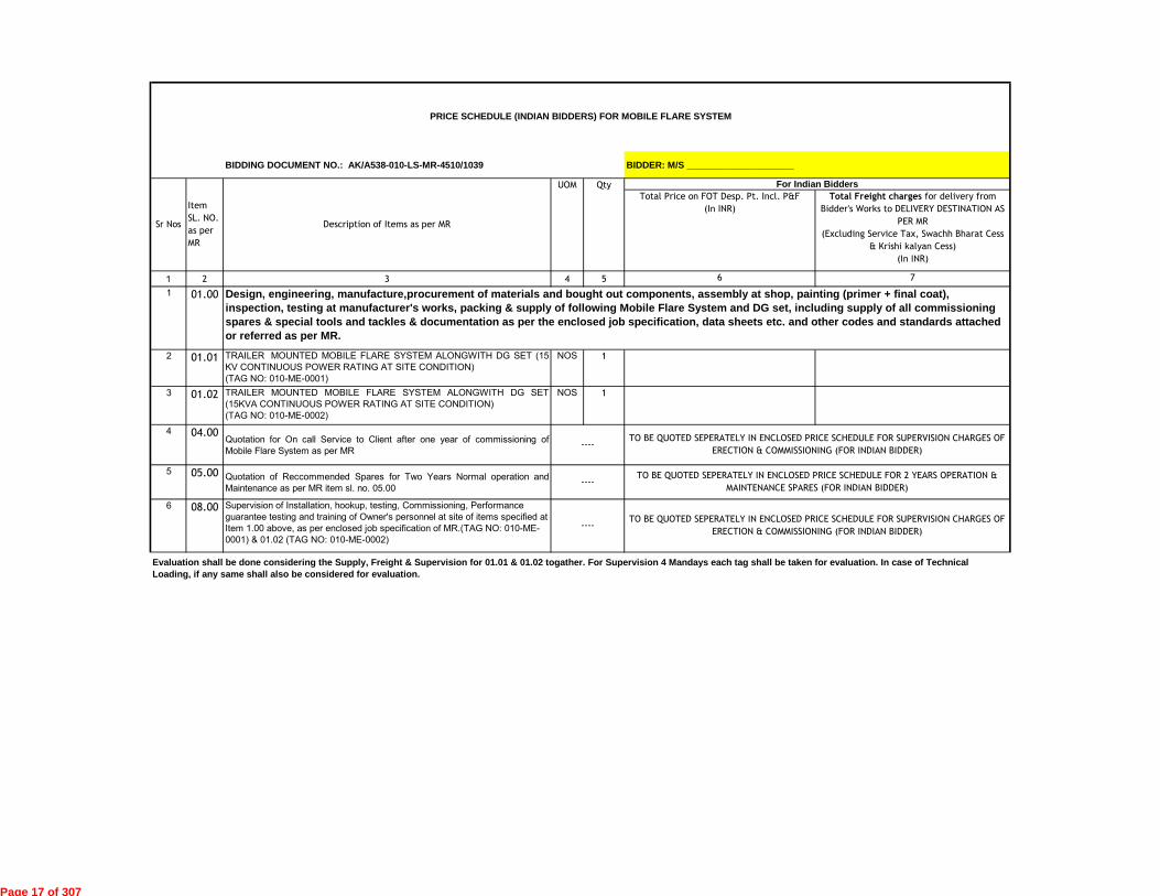
1 01.00
2 01.01 TRAILER MOUNTED MOBILE FLARE SYSTEM ALONGWITH DG SET (15
KV CONTINUOUS POWER RATING AT SITE CONDITION)
(TAG NO: 010-ME-0001)
NOS 1
3 01.02 TRAILER MOUNTED MOBILE FLARE SYSTEM ALONGWITH DG SET
(15KVA CONTINUOUS POWER RATING AT SITE CONDITION)
(TAG NO: 010-ME-0002)
NOS 1
4 04.00Quotation for On call Service to Client after one year of commissioning of
Mobile Flare System as per MR
5 05.00 Quotation of Reccommended Spares for Two Years Normal operation and
Maintenance as per MR item sl. no. 05.00
6 08.00 Supervision of Installation, hookup, testing, Commissioning, Performance
guarantee testing and training of Owner's personnel at site of items specified at
Item 1.00 above, as per enclosed job specification of MR.(TAG NO: 010-ME-
0001) & 01.02 (TAG NO: 010-ME-0002)
Evaluation shall be done considering the Supply, Freight & Supervision for 01.01 & 01.02 togather. For Supervision 4 Mandays each tag shall be taken for evaluation. In case of Technical Loading, if any same shall also be considered for evaluation.
Item
SL. NO.
as per
MR
Description of Items as per MR
Total Freight charges for delivery from
Bidder's Works to DELIVERY DESTINATION AS
PER MR
(Excluding Service Tax, Swachh Bharat Cess
& Krishi kalyan Cess)
(In INR)
----
Qty
TO BE QUOTED SEPERATELY IN ENCLOSED PRICE SCHEDULE FOR 2 YEARS OPERATION &
MAINTENANCE SPARES (FOR INDIAN BIDDER)
Design, engineering, manufacture,procurement of materials and bought out components, assembly at shop, painting (primer + final coat), inspection, testing at manufacturer's works, packing & supply of following Mobile Flare System and DG set, including supply of all commissioning spares & special tools and tackles & documentation as per the enclosed job specification, data sheets etc. and other codes and standards attached or referred as per MR.
7
TO BE QUOTED SEPERATELY IN ENCLOSED PRICE SCHEDULE FOR SUPERVISION CHARGES OF
ERECTION & COMMISSIONING (FOR INDIAN BIDDER)
Total Price on FOT Desp. Pt. Incl. P&F
(In INR)
PRICE SCHEDULE (INDIAN BIDDERS) FOR MOBILE FLARE SYSTEM
For Indian Bidders
TO BE QUOTED SEPERATELY IN ENCLOSED PRICE SCHEDULE FOR SUPERVISION CHARGES OF
ERECTION & COMMISSIONING (FOR INDIAN BIDDER)----
----
UOM
Sr Nos
Page 17 of 307
BIDDING DOCUMENT NO.: AK/A538-010-LS-MR-4510/1039
ITEM : MOBILE FLARE SYSTEM
NAME OF BIDDER: M/S __________________________
1 2 2a 4 5 6
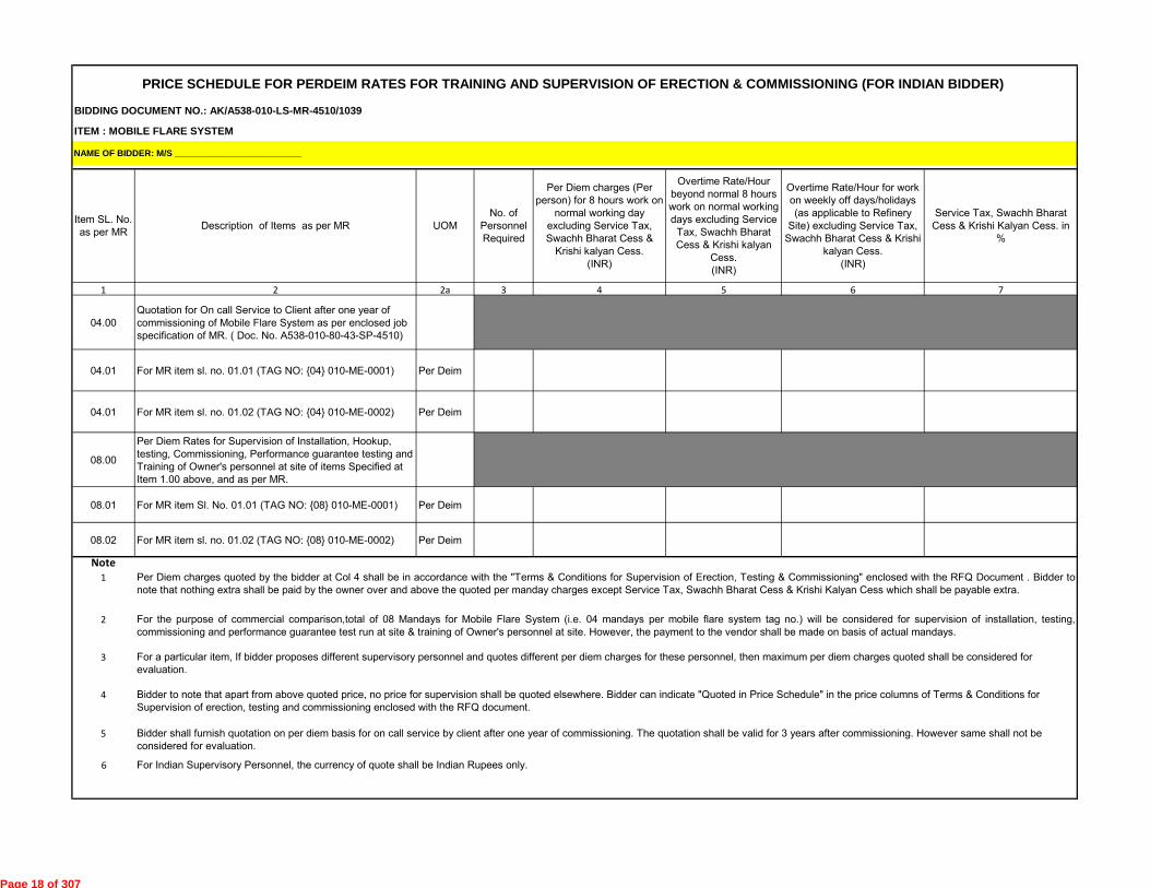
04.00
Quotation for On call Service to Client after one year of
commissioning of Mobile Flare System as per enclosed job
specification of MR. ( Doc. No. A538-010-80-43-SP-4510)
04.01 For MR item sl. no. 01.01 (TAG NO: {04} 010-ME-0001) Per Deim
04.01 For MR item sl. no. 01.02 (TAG NO: {04} 010-ME-0002) Per Deim
08.00
Per Diem Rates for Supervision of Installation, Hookup,
testing, Commissioning, Performance guarantee testing and
Training of Owner's personnel at site of items Specified at
Item 1.00 above, and as per MR.
08.01 For MR item Sl. No. 01.01 (TAG NO: {08} 010-ME-0001) Per Deim
08.02 For MR item sl. no. 01.02 (TAG NO: {08} 010-ME-0002) Per Deim
Note1
2
3
4
5
6 For Indian Supervisory Personnel, the currency of quote shall be Indian Rupees only.
Bidder to note that apart from above quoted price, no price for supervision shall be quoted elsewhere. Bidder can indicate "Quoted in Price Schedule" in the price columns of Terms & Conditions for
Supervision of erection, testing and commissioning enclosed with the RFQ document.
For a particular item, If bidder proposes different supervisory personnel and quotes different per diem charges for these personnel, then maximum per diem charges quoted shall be considered for
evaluation.
Per Diem charges quoted by the bidder at Col 4 shall be in accordance with the "Terms & Conditions for Supervision of Erection, Testing & Commissioning" enclosed with the RFQ Document . Bidder to
note that nothing extra shall be paid by the owner over and above the quoted per manday charges except Service Tax, Swachh Bharat Cess & Krishi Kalyan Cess which shall be payable extra.
For the purpose of commercial comparison,total of 08 Mandays for Mobile Flare System (i.e. 04 mandays per mobile flare system tag no.) will be considered for supervision of installation, testing,
commissioning and performance guarantee test run at site & training of Owner's personnel at site. However, the payment to the vendor shall be made on basis of actual mandays.
Bidder shall furnish quotation on per diem basis for on call service by client after one year of commissioning. The quotation shall be valid for 3 years after commissioning. However same shall not be
considered for evaluation.
PRICE SCHEDULE FOR PERDEIM RATES FOR TRAINING AND SUPERVISION OF ERECTION & COMMISSIONING (FOR INDIAN BIDDER)
Item SL. No.
as per MRDescription of Items as per MR
No. of
Personnel
Required
Per Diem charges (Per
person) for 8 hours work on
normal working day
excluding Service Tax,
Swachh Bharat Cess &
Krishi kalyan Cess.
(INR)
Overtime Rate/Hour
beyond normal 8 hours
work on normal working
days excluding Service
Tax, Swachh Bharat
Cess & Krishi kalyan
Cess.
(INR)
Overtime Rate/Hour for work
on weekly off days/holidays
(as applicable to Refinery
Site) excluding Service Tax,
Swachh Bharat Cess & Krishi
kalyan Cess.
(INR)
Service Tax, Swachh Bharat
Cess & Krishi Kalyan Cess. in
%
UOM
3 7
Page 18 of 307

BIDDING DOCUMENT NO.: AK/A538-010-LS-MR-4510/1039
ITEM : MOBILE FLARE SYSTEM
S. NO. Item Tag Nos. Description of spare parts
Qty (Unit_____)*
1 2 3 4
1
2
3
4
5
6
7
8
9
10
11
12
*UNIT TO BE SPECIFIED BY BIDDER
5 6 7
Note : 1. Quantity of 2 years Operation & Maintenance Spares shall be decided by Client
For MR Item SL. No 01.01 & 01.02
PRICE SCHEDULE FOR 2 YEARS OPERATION & MAINTENANCE SPARES (FOR INDIAN BIDDER)
NAME OF BIDDER: M/S __________________________
Unit Price on FOT Despatch Point including P&F
(INR)
Total Price on FOT Despatch Point including P&F
(INR)
Freight Charges from FOT Despatch Point to Site
in %(percentage) -applicable extra on Column No.6
Page 1 of 1
Page 19 of 307

BIDDING DOCUMENT NO.: AK/A538-010-LS-MR-4510/1039
ITEM : MOBILE FLARE SYSTEM
For Item Sl .
No. as per
MR
Description of
Imported Items
Qty.
(Unit____) *
CUSTOM
TARRIF NO.
BASIC
CUSTOMS DUTY
(%)
CVD + EDU.
CESS ON CVD
(%)
EDU. CESS
ON CUSTOM
DUTY (%)
SAD (%) TOTAL CUSTOM
DUTY (%)
Price in Figures Price in Words
1 2 4 5 6 7 8 9
i)_____
ii)_____
iii)______
i)_____
ii)_____
iii)______
*UNIT TO BE SPECIFIED BY BIDDER
ENCLOSURE TO PRICE SCHEDULE FOR SUPPLY (INDIAN BIDDERS) FORMAT - "CIF/CD"
NAME OF BIDDER: M/S __________________________
DETAILS OF BUILT-IN-CIF VALUE OF IMPORT CONTENT CONSIDERED AND INCLUDED IN QUOTED FOT DESPATCH POINT PRICES UNDER PRICE SCHEDULE
DESCRIPTION CIF value of Import Content
included in quoted supply prices for
column (2) Qty.
(In Rs)
RATE OF IMPORT DUTY INCLUDED IN QUOTED SUPPLY PRICES
3
For MR
Item SL.
No 01.01
TOTAL CIF VALUE
For MR
Item SL.
No 01.02
Page 20 of 307

1
2
3
4
5
6
7
8
9
10
11
12
13
14
15
1
BIDDER : M/S _________________
Foreign Bidder shall quote in USD / Euro / INR only. Bids of such Bidder(s) who quote in any other Currency shall not be considered for further evaluation & summarily rejected.
NOTE:
Bidder to confirm that he has noted the contents of the Preamble to the Price Schedule, Price Schedule, RFQ , Material Requisition etc. and quoted his prices accordingly without
any deviation.
Bidders shall quote per diem supervision charges as per Material Requisition in the format enclosed in accordance with Terms & Conditions for Supervision of erection, testing and
commissioning.
Bidder to note that Technical loading, if any, shall be as per loading criteria if specified in the MR and the same shall be considered for evaluation.
PREAMBLE TO PRICE SCHEDULE (FOREIGN BIDDER)BIDDING DOCUMENT NO.: AK/A538-010-LS-MR-4510/1039ITEM: MOBILE FLARE SYSTEM
Bidder shall furnish prices/details as above, in accordance with Instructions To Bidders (ITB)
Bidders shall quote per diem supervision charges as per Material Requisition in the format enclosed in accordance with Terms & Conditions for Supervision of erection, testing and
commissioning.
Bidder's quoted prices are inclusive of Commissioning spares and Special Tools and Tackles. Bidder to furnish itemised list of such commissioing spares and Special Tools and
Tackles included in the lumpsum price for main equipment in Unpriced Bid.
The quoted Basic Prices are inclusive of charges for Inspection & Testing as per MR. Inspection of Imported Items against orders on Foreign Suppliers shall be carried out by EIL.
No additional charges shall be payable to seller on account of the same. In the case of a foreign supplier sourcing items from India, the inspection shall be carried out by EIL, no
additional charges shall be payable to seller on account of the same.
Bidders must upload this document duly signed and stamped with both unpriced & priced offer.
Bidder must quote Ocean Freight charges in the space provided in the price schedule.
Scope of supply including testing, inspection, documentation etc., shall be strictly as per Material Requisition and other documents which are part of RFQ.
Bidder to clearly indicate 'Quoted'/'Not Quoted' against each Sr. No. in the price column in the unpriced Price Schedule. Bidders to submit Price Part of above Price Schedule in their
Priced Bid and Unpriced Part with the Unpriced Bid.
Bidder must quote the price in enclosed Price Schedule formats only. The formats shall not be changed and/or retyped.
Itemised Prices for 2 years normal operation & maintenance spares shall be furnished as per enclosed price schedule format and shall not be included in the quoted supply prices.
Prices for 2 years operation & maintenance spares should be valid up to the time as specified in the Bidding Document. Same shall not be considered for evaluation.
Quoted prices are firm and fixed till complete execution of the entire order.
Bidders shall quote per diem charges for On Call Service to Client after one year of Commissioning of Mobile Flare System as per Material Requisition.
Page 21 of 307
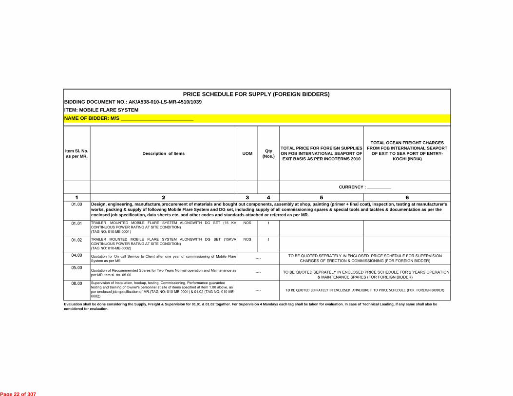
BIDDING DOCUMENT NO.: AK/A538-010-LS-MR-4510/1039
Item Sl. No. as per MR. Description of Items UOM Qty
(Nos.)
TOTAL PRICE FOR FOREIGN SUPPLIES ON FOB INTERNATIONAL SEAPORT OF EXIT BASIS AS PER INCOTERMS 2010
TOTAL OCEAN FREIGHT CHARGES FROM FOB INTERNATIONAL SEAPORT OF EXIT TO SEA PORT OF ENTRY-
KOCHI (INDIA)
1 2 3 4 5 6
01.00
01.01 TRAILER MOUNTED MOBILE FLARE SYSTEM ALONGWITH DG SET (15 KV
CONTINUOUS POWER RATING AT SITE CONDITION)
(TAG NO: 010-ME-0001)
NOS 1
01.02 TRAILER MOUNTED MOBILE FLARE SYSTEM ALONGWITH DG SET (15KVA
CONTINUOUS POWER RATING AT SITE CONDITION)
(TAG NO: 010-ME-0002)
NOS 1
04.00 Quotation for On call Service to Client after one year of commissioning of Mobile Flare
System as per MR
05.00Quotation of Reccommended Spares for Two Years Normal operation and Maintenance as
per MR item sl. no. 05.00
08.00 Supervision of Installation, hookup, testing, Commissioning, Performance guarantee
testing and training of Owner's personnel at site of items specified at Item 1.00 above, as
per enclosed job specification of MR.(TAG NO: 010-ME-0001) & 01.02 (TAG NO: 010-ME-
0002)
----
Evaluation shall be done considering the Supply, Freight & Supervision for 01.01 & 01.02 togather. For Supervision 4 Mandays each tag shall be taken for evaluation. In case of Technical Loading, if any same shall also be considered for evaluation.
----TO BE QUOTED SEPRATELY IN ENCLOSED PRICE SCHEDULE FOR SUPERVISION
CHARGES OF ERECTION & COMMISSIONING (FOR FOREIGN BIDDER)
TO BE QUOTED SEPRATELY IN ENCLOSED PRICE SCHEDULE FOR 2 YEARS OPERATION
& MAINTENANCE SPARES (FOR FOREIGN BIDDER)
TO BE QUOTED SEPRATELY IN ENCLOSED ANNEXURE F TO PRICE SCHEDULE (FOR FOREIGN BIDDER)
CURRENCY : __________
Design, engineering, manufacture,procurement of materials and bought out components, assembly at shop, painting (primer + final coat), inspection, testing at manufacturer's works, packing & supply of following Mobile Flare System and DG set, including supply of all commissioning spares & special tools and tackles & documentation as per the enclosed job specification, data sheets etc. and other codes and standards attached or referred as per MR.
PRICE SCHEDULE FOR SUPPLY (FOREIGN BIDDERS)
ITEM: MOBILE FLARE SYSTEMNAME OF BIDDER: M/S __________________________
----
Page 22 of 307

BIDDING DOCUMENT NO.: AK/A538-010-LS-MR-4510/1039 ANNEXURE-F
ITEM : MOBILE FLARE SYSTEM
NAME OF BIDDER: M/S __________________________
Indian / Foreign discipline wise
1 2 3 4 5 7 8 9
Note
1
2
3
4
5
6
PER DEIM
PER DEIM
04.01
For MR item sl. no. 01.02 (TAG NO: {04} 010-
ME-0002)04.02
Per Diem Rates for Supervision of Installation,
Hookup, testing, Commissioning, Performance
guarantee testing and Training of Owner's
personnel at site of items Specified at Item 1.00
above, and as per MR.
08.00
PER DEIM
08.02 For MR item sl. no. 01.02 (TAG NO: {08} 010-ME-0002)
Per Diem charges quoted by the bidder at Col 7 shall be in accordance with the "Terms & Conditions for Supervision of Erection, Testing & Commissioning" enclosed with the RFQ Document . Bidder to note that nothing extra
shall be paid by the owner over and above the quoted per manday charges except Service Tax which shall be payable extra.
For the purpose of commercial comparison,total of 08 Mandays for Mobile Flare System (i.e. 04 mandays per mobile flare system tag no.) will be considered for supervision of installation, testing, commissioning and
performance guarantee test run at site & training of Owner's personnel at site. However, the payment to the vendor shall be made on basis of actual mandays.
For a particular item, If bidder proposes different supervisory personnel and quotes different per diem charges for these personnel, then maximum per diem charges quoted shall be considered for evaluation as per Note 2
above.
Bidder to note that apart from above quoted price, no price for supervision shall be quoted elsewhere. Bidder can indicate "Quoted in Price Schedule" in the price columns of Terms & Conditions for Supervision of erection,
testing and commissioning enclosed with the RFQ document.
Bidder shall furnish quotation on per diem basis for on call service by client after one year of commissioning. The quotation shall be valid for 3 years after commissioning. However same shall not be considered for evaluation.
For Indian Supervisory Personnel, the currency of quote shall be Indian Rupees only
6
04.00
Quotation for On call Service to Client after one
year of commissioning of Mobile Flare System as
per enclosed job specification of MR. ( Doc. No.
A538-010-80-43-SP-4510)
For MR item Sl. No. 01.01 (TAG NO: {08} 010-ME-0001)08.01
For MR item sl. no. 01.01 (TAG NO: {04} 010-
ME-0001)
PER DEIM
PRICE SCHEDULE FOR PERDEIM RATES FOR TRAINING AND SUPERVISION OF ERECTION & COMMISSIONING (FOR FOREIGN BIDDER)
Item SL. No.
as per MRDescription of Items as per MR
Type of specialist
(Refer Note 2 below)
CURRENCYNo. of
Personnel
Required
Per Diem charges (Per
person) for 8 hours work on
normal working day
excluding Service Tax,
Swachh Bharat Cess &
Krishi Kalyan Cess.
Overtime Rate/Hour
beyond normal 8 hours
work on normal working
days excluding Service
Tax, Swachh Bharat
Cess & Krishi Kalyan
Cess.
Overtime Rate/Hour for work
on weekly off days/holidays
(as applicable to Refinery
Site) excluding Service Tax,
Swachh Bharat Cess & Krishi
Kalyan Cess.
UOM
Page 23 of 307

BIDDING DOCUMENT NO.: AK/A538-010-LS-MR-4510/1039
ITEM : MOBILE FLARE SYSTEM
S. NO. Item Tag Nos. Description of spare parts
Qty (Unit_____)*
1 2 3 4
1
2
3
4
5
6
7
8
9
10
11
12
*UNIT TO BE SPECIFIED BY BIDDER
Note : 1. Quantity of 2 years Operation & Maintenance Spares shall be decided by Client
CURRENCY : _____________________________
For MR Item SL. No 01.01 & 01.02
PRICE SCHEDULE FOR 2 YEARS NORMAL OPERATION & MAINTENANCE SPARES (FOR FOREIGN BIDDER)
5 6 7
Unit Price on FOB International Port of Exit Prices as per INCOTERMS 2010
NAME OF BIDDER: M/S __________________________
Ocean Freight Charges from International Sea Port of Exit to Sea Port of entry-Kochi
(India)in %(percentage) -applicable extra on
Column No.5
Total Price on FOB International Port of Exit Prices as per INCOTERMS 2010
Col (4 x 5 )
Page 24 of 307

Page 1 of 14
KOCHI SALEM LPG PIPELINE PROJECT
OF
M/S KOCHI SALEM PIPELINE PRIVATE LIMITED
INSTRUCTIONS TO BIDDERS (ITB)
Page 25 of 307

Page 2 of 14
INDEX
1. SCOPE OF BID .......................................................................................................... 3 2. ELIGIBLE BIDDERS ................................................................................................... 3 3. ONE BID PER BIDDER .............................................................................................. 3 4. COST OF BIDDING .................................................................................................... 3 5. SITE VISIT .................................................................................................................. 4 6. CONTENTS OF BIDDING DOCUMENT ..................................................................... 4 7. CLARIFICATION ON BIDDING DOCUMENTS ........................................................... 4 8. AMENDMENT OF BIDDING DOCUMENTS ............................................................... 4 9. LANGUAGE OF BID ................................................................................................... 5 10. DOCUMENTS COMPRISING THE BID ...................................................................... 5 11. BID PRICES ............................................................................................................... 7 12. BID CURRENCY AND PAYMENT .............................................................................. 8 13. BID VALIDITY ............................................................................................................. 9 14. OFFER WITHOUT ANY DEVIATION .......................................................................... 9 15. AGENTS/CONSULTANTS/REPRESENTATIVES/RETAINERS/ASSOCIATES .......... 9 16. SUBMISSION OF BIDS .............................................................................................. 9 17. DEADLINE FOR SUBMISSION OF BID ..................................................................... 9 18. LATE BIDS / UNSOLICITED BIDS / BID SUBMISSION AT OTHER PLACE .............. 9 19. MODIFICATION AND WITHDRAWAL OF BIDS ......................................................... 9 20. UN-PRICED BID OPENING ...................................................................................... 10 21. PROCESS TO BE CONFIDENTIAL .......................................................................... 10 22. CONTACTING THE OWNER/ OWNER REPRESENTATIVE ................................... 10 23. EXAMINATION OF BIDS AND DETERMINATION OF RESPONSIVENESS ............ 10 24. PRICE CHANGES / IMPLICATIONS AFTER OPENING OF TECHNICAL BIDS ...... 11 25. PRICE BID OPENING .............................................................................................. 11 26. ARITHMETIC CORRECTIONS ................................................................................. 11 27. CONVERSION TO SINGLE CURRENCY ................................................................. 11 28. BID REJECTION CRITERIA ..................................................................................... 12 29. PRICE EVALUATION & COMPARISON AND LOADING CRITERIA ........................ 12 30. OTHER CRITICAL POINTS FOR EVALUATION OF OFFER ARE AS UNDER ........ 12 31. PRICE CHANGES / IMPLICATIONS AFTER OPENING OF PRICE BIDS ................ 12 32. AWARD OF WORK .................................................................................................. 12 33. QUANTITY VARIATION............................................................................................ 12 34. OWNER'S RIGHT TO ACCEPT ANY BID AND TO REJECT ANY BID..................... 13 35. NOTIFICATION OF AWARD .................................................................................... 13 36. WAIVER OR TRANSFER OF THE AGREEMENT .................................................... 13 37. CARTEL FORMATION ............................................................................................. 13 38. INFORMATION TO BE FURNISHED BY FOREIGN SUPPLIERS/
CONTRACTORS / CONSULTANTS ....................................................................... 13 39. ORDER OF PRECEDENCE ..................................................................................... 14
Page 26 of 307

Page 3 of 14
A. GENERAL:
1. SCOPE OF BID 1.1. EIL hereinafter "the Consultant" on behalf of the Purchaser/Owner/BPCL as defined in the
General Purchase Conditions, hereinafter "the Owner" wishes to receive bids as described in
the Bidding Documents hereinafter shall also mean RFQ documents.
1.2. SCOPE OF WORK: The scope of work shall be as defined in the MR included in the RFQ.
1.3. The successful bidder will be expected to complete the Scope of work within the period stated
in Bidding Document.
1.4. Throughout this Bidding Documents, the term "bid" and "tender" and their derivatives
("bidder/tenderer", "Bid/tendered/tender", "bidding/tendering", etc.) are synonymous,
and day means calendar day. Singular also means plural.
2. ELIGIBLE BIDDERS 2.1 Documents Establishing Bidder's Qualification.
2.1.1 Pursuant to qualification criteria specified in IFB/NIT, the bidder shall furnish all necessary supporting documentary evidence to establish the bidders claim of meeting qualification criteria.
2.1.2 The bidder shall furnish, as part of his bid, documents establishing the bidder's eligibility to bid and his qualifications to perform the contract if his bid is accepted.
2.1.3 The documentary evidence of the bidder's qualifications to perform the contract if their bid are accepted, shall establish to the OWNER'S/CONSULTANT'S satisfaction that, the bidder has the financial, technical and productions capacity necessary to perform the contract.
2.1.4 A bidder shall not be affiliated with a firm or entity:
(i.) that has provided consulting services related to the work to the OWNER during the preparatory stages of the works or of the project of which the works form a part, or
(ii.) that has been hired by the OWNER as engineer/consultant for the contract.
2.1.5 The bidder shall not be under a declaration of ineligibility by OWNER for corrupt or fraudulent practices as defined at clause no.21 of SPC.
3 ONE BID PER BIDDER 3.1 A bidder (i.e. the bidding entity) shall, on no account submit more than one bid either directly
(as a single bidder or as a member of consortium) or indirectly (as a sub-contractor) failing
which following actions shall be initiated:
(i) All bids submitted by such bidder (say „A‟) directly & indirectly, shall stand rejected and EMD,
if any, in case of direct bid submitted by bidder „A‟ shall be forfeited.
(ii) If another bidder (say „B‟) has proposed bidder „A‟ as a sub-contractor then bidder „B‟‟s bid
shall also be rejected. However, in case the bidder „B‟ has also proposed an alternative sub-
contractor who is other than the bidder „A‟, then bidder „B”s bid shall be evaluated with the
proposed alternative sub-contractor only. Hence, every bidder shall ensure in his own interest
that his proposed sub-contractor is not submitting alternative/ multiple
4 COST OF BIDDING 4.1 The bidder shall bear all costs associated with the preparation and submission of the bid, and
OWNER / CONSULTANT, will in no case be responsible or liable for this cost, regardless of
the conduct or outcome of the bidding process.
Page 27 of 307

Page 4 of 14
5 SITE VISIT 5.1 The bidder is advised to visit and examine the site or / locations of warehouse and its
surroundings and obtain for itself, at its own responsibility, all the information that may be
necessary for preparing the bid and entering into the Contract. The cost of visiting the site shall
be at the bidder's own expense.
5.2 The bidder or any of its personnel or agents will be granted permission by the Owner to enter
upon its premises and land for the purpose of such visits, but only upon the express condition
that the bidder, its personnel, and agents will indemnify the Owner and its personnel and
agents from and against all liabilities in respect thereof, and will be responsible for death or
personal injury, loss of or damage to property, and any other loss, damage, costs, and
expenses incurred as a result of the inspection.
B. BIDDING DOCUMENT. CLARIFICATION AND AMENDMENT
6 CONTENTS OF BIDDING DOCUMENT 6.1 The Bidding Documents has been hosted on EIL Website http://tenders.eil.co.in/newtenders/,
other websites mentioned in the RFQ covering letter/Notice Inviting Bid/ Letter Inviting Bid and in https://eprocure.gov.in/eprocure/app.
6.2 The bidder is expected to examine Bidding Documents, bidding guidelines received from EIL or
available on EIL website, all instructions, formats, terms, specifications and drawings etc., enclosed in the Bidding Documents. The invitation for bid (bidding) together with all its attachment thereto, shall be considered to be read, understood and accepted by the bidder. Failure to furnish all information required by the Bidding Documents or submission of a bid not substantially responsive to the bidding documents in every respect will be at bidder's risk and may result in the rejection of the Bid.
7 CLARIFICATION ON BIDDING DOCUMENTS 7.1 A prospective bidder requiring any information or clarificat ion of the Bidding Documents,
may notify the Consultant in writing by e-mail/post at Consultant's mailing address indicated in the bidding document Dy. General Manager (C&P), Engineers India Ltd., EIB, 1, Bhikaiji Cama Place, New Delhi – 110066 (India) E-mail: [email protected] / [email protected] / [email protected]. All question/ queries should be referred to EIL as specified in the IFB document. Reply to Pre-Bid Queries shall be hosted on http://tenders.eil.co.in & https://eprocure.gov.in/eprocure/app. The response to pre-bid queries shall not form part of the bidding document unless issued as an amendment.
8 AMENDMENT OF BIDDING DOCUMENTS 8.1 At any time prior to the deadline for submission of bids, the Owner/Consultant may, for any
reason, whether on its own requirement or in response to a clarification requested by prospective bidders, modify the Bidding Documents by issuing addenda.
8.2 Any addendum thus issued shall be part of the Bidding Documents. The addendum will be hosted on the EIL's website http://tenders.eil.co.in & https://eprocure.gov.in/eprocure/app. All the bidders who have raised the queries in pre-bid meeting, shall be informed by e-mail about the addendum for their reference. Bidders have to take into consideration of all the addendum(s) / corrigendum (s) issued/ web hosted, before submitting the bid.
8.3 The Owner/Consultant may, at its discretion, extend the date of submission of Bids in order to allow the bidders a reasonable time to furnish their most competitive bid taking into account the amendments issued.
Page 28 of 307

Page 5 of 14
C. PREPARATION OF BIDS
9 LANGUAGE OF BID 9.1. The Bid prepared by the bidder, all correspondence/drawings and documents relating to the
bid exchanged by the bidder with the Owner/Consultant shall be in English Language alone
provided that any printed literature furnished by the bidder may be written in another language
so long as accompanied by an English translation, in which case, for the purpose of
interpretation of the bid, the English translation shall govern.
9.2. In the event of submission of any document/ certificate by the Bidder in a language other than
English, the English translation of the same duly authenticated by Chamber of Commerce of
Bidder's country shall be submitted by the Bidder.
10 DOCUMENTS COMPRISING THE BID 10.1 No Physical Bids / Offers shall be permitted. The offers/bids submitted online through Central
Public Procurement Portal (CPPP) of Government of India
(http://eprocure.gov.in/eprocure/app) shall only be considered for evaluation and ordering.
Bidders are required to upload the Bid/offer along with all supporting documents including
Priced bid on the E-Tendering website (http://eprocure.gov.in/eprocure/app) only. However,
bidder are required to submit the following documents in original in the manner prescribed in
the Bidding Document in sealed envelope titled “Original Documents for respective
RFQ/Bidding Document No“ and shall be send to Dy. General Manager (C&P), Engineers India
Ltd., Engineers India Bhawan, M Floor, 1, Bhikaiji Cama Place, New Delhi – 110066 (India)
Tel: 011 –2676 2309 / 3113 within 7 days from the Unpriced bid opening date. However,
bidders are required to upload the scanned copies of all relevant documents on E-tendering
website along with the e-bid.
1. EMD/Bid Security as applicable as per clause no.10.3 below / MSME Certificate as mentioned in the Bidding Document. 2. Documentation against Bidder Qualification Criteria (Technical &Financial). 3. Power of Attorney. 4. Any other document to be submitted in original as per Bidding Document/RFQ.
10.2 The bid shall be submitted by uploading relevant document in respective covers provided in the
e-tendering website.
10.2.5 BID SECURITY/EARNEST MONEY DEPOSIT:EMD/Bid Security as applicable
10.2.6 TECHNO-COMMERCIAL/UNPRICED BID: Unpriced Bids shall contain followings;
a. Covering letter of Bid on bidder‟s letter head.
b. Master Index / List of enclosures of RFQ and copies of all technical and commercial amendments/addendums/corrigendum issued (if any), duly signed and stamped on each page as a token of having received and read all parts of the bidding document and having accepted and considered the same in preparing their bid.
c. Power of attorney in favour of signatory (ies) of the bid.
d. Price Schedule with prices blanked out mentioning “Quoted / Not Quoted” against each item.
e. Qualification Documents duly authenticated against Bidder Qualification Criteria (Technical& Financial) as per of IFB.
f. Details of Annual Turnover, net worth and working capital as per Proposal Form F1
g. Compliance to Bid requirement as per Proposal Form F2.
Page 29 of 307
Page 6 of 14
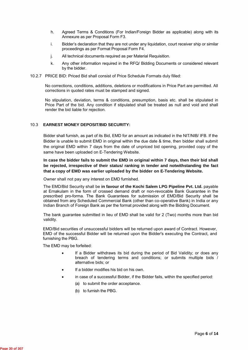
h. Agreed Terms & Conditions (For Indian/Foreign Bidder as applicable) along with its Annexure as per Proposal Form F3.
i. Bidder‟s declaration that they are not under any liquidation, court receiver ship or similar proceedings as per Format Proposal Form F4.
j. All technical documents required as per Material Requisition.
k. Any other information required in the RFQ/ Bidding Documents or considered relevant by the bidder.
10.2.7 PRICE BID: Priced Bid shall consist of Price Schedule Formats duly filled:
No corrections, conditions, additions, deletions or modifications in Price Part are permitted. All corrections in quoted rates must be stamped and signed.
No stipulation, deviation, terms & conditions, presumption, basis etc. shall be stipulated in Price Part of the bid. Any condition if stipulated shall be treated as null and void and shall render the bid liable for rejection.
10.3 EARNEST MONEY DEPOSIT/BID SECURITY:
Bidder shall furnish, as part of its Bid, EMD for an amount as indicated in the NIT/NIB/ IFB. If the
Bidder is unable to submit EMD in original within the due date & time, then bidder shall submit
the original EMD within 7 days from the date of unpriced bid opening, provided copy of the
same have been uploaded on E-Tendering Website.
In case the bidder fails to submit the EMD in original within 7 days, then their bid shall be rejected, irrespective of their status/ ranking in tender and notwithstanding the fact that a copy of EMD was earlier uploaded by the bidder on E-Tendering Website.
Owner shall not pay any interest on EMD furnished.
The EMD/Bid Security shall be in favour of the Kochi Salem LPG Pipeline Pvt. Ltd. payable at Ernakulam in the form of crossed demand draft or non-revocable Bank Guarantee in the prescribed pro-forma. The Bank Guarantees for submission of EMD/Bid Security shall be obtained from any Scheduled Commercial Bank (other than co-operative Bank) in India or any Indian Branch of Foreign Bank as per the format provided along with the Bidding Document. The bank guarantee submitted in lieu of EMD shall be valid for 2 (Two) months more than bid validity. EMD/Bid securities of unsuccessful bidders will be returned upon award of Contract. However, EMD of the successful Bidder will be returned upon the Bidder's executing the Contract, and furnishing the PBG.
The EMD may be forfeited:
If a Bidder withdraws its bid during the period of Bid Validity; or does any breach of tendering terms and conditions; or submits multiple bids / alternative bids; or
If a bidder modifies his bid on his own.
in case of a successful Bidder, if the Bidder fails, within the specified period:
(a) to submit the order acceptance.
(b) to furnish the PBG.
Page 30 of 307

Page 7 of 14
11 BID PRICES 11.1. Prices shall be furnished strictly in the appropriate Price Schedule format(s) enclosed with the
bidding document. Quoted prices shall be net of discount, if any. Conditional discounts, if offered by a bidder, shall not be considered for evaluation.
11.2. Price quoted by the bidder, shall remain firm & fixed until completion of the contract and will not be subject to any variation, except statutory variation in taxes, duties &levies pursuant to relevant provisions of Special Purchase Conditions.
11.3. The bidder shall quote the price for item in the Price Schedule after careful analysis of cost involved for the performance of complete work considering all parts of the RFQ/Bidding Documents. In case, any activity though specifically not covered but is required to complete the work as per scope of work, scope of supply, specifications, standards, drawings, GPC, SPC or any other part of RFQ Document, the prices quoted shall deemed to be inclusive of cost incurred for such activity.
11.4. Domestic bidder to consider Merit rate of custom duty for their import content. Bidder shall ascertain the applicable merit rate of customs duty and shall be solely responsible towards applicability and correctness of such rates. The evaluation and ordering shall be carried out based on the merit rates of customs duty considered by the bidder. The bidder(s) must indicate quantity, CIF value & rate of custom duty considered in the Price Schedule.
11.5. Owner will not issue concessional Form 'C‟ for CST. No concessional form shall be issued for VAT also.
11.6. Indian Bidders shall indicate the following in their offer:
11.6.1 FOT despatch Point price of item including packing & forwarding, (such price to include fabrication /manufacturing of item, all costs as well as duties and taxes paid or payable on components and raw materials incorporated or to be incorporated in the goods, inspection testing etc.) but excluding applicable taxes and duties on finished goods. Bidder‟s prices shall be firm and fixed on account of Foreign Exchange variation due to incorporation of import content, if any.
11.6.2 FOT despatch Point price shall be exclusive of CENVATABLE Excise Duty (including Cess)
and CST (without concessional form) or VAT (without concessional form) which will be applicable on the finished goods.
11.6.3 Transportation Charges upto respective project site exclusive of Service Tax and Ed Cess thereon. Transit Insurance and Road permit shall be arranged by Owner for the materials directly consigned to the Owner.
11.6.4 Site work Prices, if applicable as per MR for the scope of work mentioned in MR / RFQ Documents, exclusive of Service Tax but inclusive of VAT on Work Contracts. All necessary taxes& duties and registration, if required for carrying out the site activities shall be done by the bidder and cost towards the same shall be included in quoted site work prices.
11.6.5 Training , Post Warranty/Annual Maintenance and Per-diem Supervision Charges shall be exclusive of Service tax, if applicable as per MR.
11.6.6 Bidder shall indicate the following separately:
11.6.6.1 CIF value (in Indian Rupees) of import for raw material and components incorporated or to be incorporated in the goods and included in quoted price. The bidder shall provide description of such material, quantity, rate, value etc.
11.6.6.2 Merit rate of Import Duties (rate) considered on above CIF value of import for raw material and components and included in the quoted prices.
11.6.6.3 If a bidder does not furnish built-in CIF value and confirmed that quoted prices are firm and
Page 31 of 307

Page 8 of 14
fixed, in that case bidder will not be entitled to claim any variation in the Import Duties even if bidder has quoted their prices considering Import Duties.
11.6.6.4 Variation in price due to customs duty rate will be dealt with separately after receipt of materials at site against documentary evidence.
11.7. Foreign Bidders shall indicate the following in their offer: 11.7.1 Bidders shall submit their prices on FOB -International Port of Exit basis and also quote for
Ocean Freight charges upto the port of entry- Kochi (India) as detailed out in the price schedule.
11.7.2 The request for separate FOB Price and Ocean Freight is merely to facilitate the comparison of bids and will not in any way limit Owner's right to order on different terms.
11.7.3 In case of award, initially the purchase order (PO) shall be placed on FOB basis and Owner reserves the right to convert the same to CFR basis before Contractual Delivery Date based on shipping details of consignment (complete in all respect) indicated in the bid/post award. Therefore, the quoted Ocean Freight Charges should be valid up to Contractual Delivery Date.
11.7.4 FOB Prices quoted shall be inclusive of all applicable taxes, packing & forwarding etc.
applicable upto FOB - International Port of Exit.
11.7.5 Site work Prices, if applicable as per MR for the scope of work mentioned in MR / RFQ Documents exclusive of cenvatable Service Tax but inclusive of VAT on Work Contracts. All necessary taxes & duties registration, if required for carrying out the site activities shall be done by the bidder and cost towards the same shall be included in quoted site work prices.
11.7.6 Training, Post Warranty/Annual Maintenance and Per-diem Supervision Charges, if applicable
as per MR, shall be exclusive of cenvatable Service Tax.
11.7.7 Indian Income Tax applicable rate & concession if any (under Double Taxation Avoidance Agreement (DTAA) etc.). Bidder to provide PAN No. along with offer.
11.7.8 Concessional rate of Custom Duty:
a) The bidder must ascertain and confirm along with supporting documents in the bid, if any Customs Duty exemption / waiver is applicable to the products being supplied by him under any multi-lateral / bi-lateral trade agreement between India and bidder's country.
b) The bidder shall be liable to provide all documentation to ensure availment of the exemption /waiver. In case the bidder defaults on this due to any reason, whatsoever, he shall be liable to bear the incremental Customs Duty applicable, if any.
c) Any Customs Duty applicability on account of any change in the bi-lateral / multi-lateral
agreement shall be to bidder's account.
d) Documentation to be furnished for availing the exemption / waiver of Customs Duty shall be specifically listed in the Letter of Credit also as the pre-requisite for release of payment against shipping documents and this documentation shall necessarily form a part of shipping documents.
12 BID CURRENCY AND PAYMENT 12.1 Bidding currency shall be Indian Rupees for Indian bidders and US Dollars / EUROs /
Japanese Yen/ Indian Rupees for foreign bidders in accordance with RBI guidelines.
12.2 A foreign bidder expecting to incur a portion of his expenditure in the performance of Order in more than one currency (limited to maximum two currencies) (In case foreign bidder supply
Page 32 of 307

Page 9 of 14
some minor components of supply from their Indian subsidiary/Branch Office then the same shall be quoted in INR only) and wishing to be paid accordingly shall indicate the same in the bid. In such a case, the bid shall be expressed indifferent currencies with the respective amounts in each currency together making up the total price.
12.3 Currency once quoted will not be allowed to be changed. Owner/EIL shall not be compensating for any exchange rate fluctuation.
12.4 Payment shall be released to the supplier in the currency of quote.
13 BID VALIDITY 13.1 The bid shall remain valid for acceptance for period mentioned in RFQ/IFB/Notice Inviting
Bid (NIB) from the final bid due date. Owner/EIL shall reject a bid valid for a shorter period being non-responsive.
13.2 In exceptional circumstances, prior to expiry of the original bid validity period, the Owner/EIL may request that the bidder extend the period of validity for a specified additional period. The requests and the responses thereto shall be made in writing (by fax/post/e-mail).
14 OFFER WITHOUT ANY DEVIATION Owner/EIL will appreciate submission of offer based on the terms and conditions in the enclosed SPC, GPC, ITB, Scope of Work, and Technical Specification etc. to avoid wastage of time and money in seeking clarifications on technical/ commercial aspect of the offer.
15 AGENTS/CONSULTANTS/REPRESENTATIVES/RETAINERS/ASSOCIATES Owner would prefer to deal directly with the manufacturers/ principals abroad without involving any Indian agent. Agents/consultants/representatives/retainers/associates bids found at any stage of evaluation i.e. from un-priced bid opening till priced bid opening shall be liable for rejection.
16 SUBMISSION OF BIDS 16.1 No Physical bids / offers shall be permitted. The offers submitted through Central Public
Procurement Portal (CPPP) of Government of India shall only be considered for evaluation & ordering. Bidders are required to upload the bid along with all supporting documents including priced bid on the e-tendering website (http://eprocure.gov.in/eprocure/app.) only.
17 DEADLINE FOR SUBMISSION OF BID 17.1 The E-Bids must be submitted on or before the last date and time mentioned in the RFQ.
17.2 The Owner / EIL may, in exceptional circumstances and at its discretion, on giving reasonable
notice to all prospective bidders, extend the deadline for the submission of e-bids in which case all rights and obligations of the Owner /EIL and bidders, previously subject to the original deadline will thereafter be subject to deadline as extended.
18 LATE BIDS / UNSOLICITED BIDS / BID SUBMISSION AT OTHER PLACE 18.1 No bid will be received after the deadline of submission of bid.
18.2 Unsolicited bids or bids being submitted to address other than one specifically stipulated in the
bid documents will not be considered for opening / evaluation / award.
19 MODIFICATION AND WITHDRAWAL OF BIDS 19.1 The Bidder may modify or withdraw its Bid after the Bid's submission but prior to the due date
prescribed for submission of Bids by selecting the “Re-Submission” option available in the e-tender portal.
19.2 No bid shall be modified subsequent to the deadline for submission of bids.
19.3 No bid shall be allowed to be withdrawn in the interval between the deadline for submission of
Page 33 of 307

Page 10 of 14
bids and the expiration of the period of bid validity specified by the bidder. Withdrawal of a bid during this interval shall result in the forfeiture of bidder's EMD/Bid security.
19.4 There are two specific features in CPPP viz, “Withdraw” and “Re-Submission”. Bidders should not use the feature “withdraw” unless they have decided to withdraw their bids. It is to be noted that once “withdraw” feature is used they will not be allowed to re-submit their bid against this RFQ. In case a Bidder desires to change his bid for any reason before bid due date, Bidder shall use “Re-Submission” feature.
20 UN-PRICED BID OPENING 20.1 The un-priced Bids shall be opened online through e-tender portal, at the specified date and
time given in the RFQ document or extended otherwise. The Bidders who have submitted their Bid will be able to view online the name & status of all the Bidders at their respective windows, after un-priced Bid opening by Owner/Consultant.
20.2 Only those bidders, whose bids meet the qualification criteria and are technically and commercially acceptable, will be informed the date, time and venue for price bid opening.
D. E-BID OPENING AND EVALUATION
21 PROCESS TO BE CONFIDENTIAL Information relating to the examination, clarifications, evaluation and comparison of bids, and recommendations for the award of Order shall not be disclosed to bidders or any other person officially concerned with such process.
22 CONTACTING THE OWNER/ OWNER REPRESENTATIVE 22.1 From the time of the bid opening to the time of the award, if any bidder wishes to contact the
Owner for any matter relating to the bid, it should done in writing.
22.2 Any effort by a bidder to influence the Owner/EIL in any manner in respect of bid evaluation or award will result in the rejection of that bid.
23 EXAMINATION OF BIDS AND DETERMINATION OF RESPONSIVENESS 23.1 The Owner/EIL will examine the bids to determine whether they are complete, whether any
computational errors have been made, whether the documents have been properly signed, and whether the bids are generally in order.
23.2 Prior to the detailed evaluation, the Owner/EIL will determine whether each bid is of acceptable quality, is generally complete and is responsive to the RFQ/Bidding Documents. For the purposes of this determination, a responsive bid is one that conforms to all the terms, conditions and specifications of the RFQ/Bidding Documents without deviations, objections, conditionality or reservations.
23.3 Bidder shall not be allowed to submit any Price Implication or Revised Price after submission of Bid, unless there is change in the stipulations of the RFQ/ Bidding Document and such changes are incorporated through an Amendment. In case Exceptions and Deviations submitted by Bidder along with Bid are not considered as acceptable and no Amendment is issued, then in such a case the Bidders would be required to withdraw such Exceptions/Deviations in favour of stipulations of the RFQ/ Bidding document and Bidders would not be eligible for submission of Price Implication/Revised Price, failing which such Bid(s) shall be considered as non responsive and rejected.
23.4 The Owner/EIL determination of a bid's responsiveness is to be based on the contents of the bid itself without recourse to extrinsic evidence. If a bid is not responsive, it will be rejected by the Owner/EIL, and may not subsequently be made responsive by the bidder by correction of the nonconformity.
Page 34 of 307
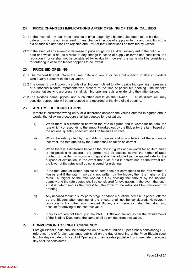
Page 11 of 14
24 PRICE CHANGES / IMPLICATIONS AFTER OPENING OF TECHNICAL BIDS 24.1 In the event of any suo- moto increase in price sought by a bidder subsequent to the bid due
date and which is not as a result of any change in scope of supply or terms and conditions, the bid of such a bidder shall be rejected and EMD of that Bidder shall be forfeited by Owner.
24.2 In the event of any suo-moto decrease in price sought by a Bidder subsequent to the bid due
date and which is not as a result of any change in scope of supply or terms and conditions, the reduction in price shall not be considered for evaluation however the same shall be considered for ordering in case the bidder happens to be lowest.
25 PRICE BID OPENING 25.1 The Owner/EIL shall inform the time, date and venue for price bid opening to all such bidders
who qualify pursuant to bid evaluation.
25.2 The Owner/EIL will open price bids of all bidders notified to attend price bid opening in presence of authorised bidders' representatives present at the time of priced bid opening. The bidder's representatives who are present shall sign bid-opening register evidencing their attendance.
25.3 The bidder's name, prices, and such other details as the Owner/EIL, at its discretion, may consider appropriate will be announced and recorded at the time of bid opening.
26 ARITHMETIC CORRECTIONS If there is correction/wrong entry or a difference between the values entered in figures and in words, the following procedure shall be adopted for evaluation: i) When there is a difference between the rate in figures and in words for an item, the
rate which corresponds to the amount worked out by the Bidder for the item based on the notional quantity specified, shall be taken as correct.
ii) When the rate quoted by the Bidder in figures and words tallies but the amount is incorrect, the rate quoted by the Bidder shall be taken as correct
iii) When there is a difference between the rate in figures and in words for an item and it
is not possible to ascertain the correct rate as detailed above, the higher of rates quoted for the item in words and figure shall be adopted as the quoted rate for the purpose of evaluation. In the event that such a bid is determined as the lowest bid, the lower of the rates shall be considered for ordering.
iv) If the total amount written against an item does not correspond to the rate written in
figures and if the rate in words is not written by the bidder, then the higher of the rates, i.e. higher of the rate worked out by dividing the amount by the notional quantity and the rate quoted shall be considered for evaluation. In the event that such a bid is determined as the lowest bid, the lower of the rates shall be considered for ordering.
v) Any uncalled for lump sum/ percentage or adhoc reduction/ increase in prices, offered
by the Bidders after opening of the prices, shall not be considered. However, if reduction is from the recommended Bidder, such reduction shall be taken into account for arriving at the contract value.
vi) If prices etc. are not filled up in the PRICED BID and are not as per the requirements
of the Bidding Document, the same shall be omitted from evaluation.
27 CONVERSION TO SINGLE CURRENCY Foreign Bidder‟s bids shall be compared on equivalent Indian Rupees basis considering RBI reference rate of foreign exchange published on the day of opening of the Price Bids.In case RBI holiday on date of Priced Bid Opening, exchange rates published on immediate preceding day shall be considered.
Page 35 of 307

Page 12 of 14
28 BID REJECTION CRITERIA The bidders shall adhere to the following provisions of the Bidding Document without taking any deviations, failing which the Bid shall be considered to be non-responsive and may be rejected.
i) Defects liability period/ Guarantee Period. ii) Delivery schedule/ Time Period of Completion iii) Bids with Price Variation Clause (PVC) without variation formula and ceiling. iv) Insufficient validity period. v) Advance payment vi) Non submission of EMD vii) Non submission, lesser value/validity of CPBG viii) Any other points mentioned in the Bidding document.
29 PRICE EVALUATION & COMPARISONAND LOADING CRITERIA 29.1 Evaluation criteria for comparison of bids shall be as per Annexure-II of Special Purchase
Conditions (SPC).
29.2 Commercial loading of offers in case of deviations specified by the Bidder against RFQ terms & conditions shall be as per Annexure-III of Special Purchase Conditions (SPC).
29.3 Price Bid evaluation & comparison shall be done as mentioned in the Bidding document.
30 OTHER CRITICAL POINTS FOR EVALUATION OF OFFER ARE AS UNDER 30.1 The prices quoted in the price bid is to be considered for evaluation and no cognizance will
be given to the supplementary/supporting document attached to the price bid, break -up of
prices, etc.
30.2 In case bidder intend not to quote for certain item/tags/groups as applicable, then the bidder shall
mention "Not Quoted (NQ)" in respective cells of price schedule. Wherever cell is found blank in
the price schedule, then it shall be treated as "Not Quoted (NQ)" and evaluation of bids shall be
carried out accordingly.
30.3 Purchase Preferences as applicable shall be considered as per clause no.33 of GPC.
31 PRICE CHANGES / IMPLICATIONS AFTER OPENING OF PRICE BIDS 31.1 After opening of price bid, if the party increases the price, though within the validity period and
even though the offer remains lowest, the bid should be rejected. Such bidders shall be debarred
for future enquiries for such action of bidders as a penal measure and EMD of such bidder shall
be forfeited by Owner.
31.2 Suo-moto Price reduction after price bid opening are to be ignored for evaluation. However, if the
same party happens to be the lowest based on original price bids, the benefit of such reduction
may be availed of.
E. AWARD OF CONTRACT
32 AWARD OF WORK 32.1 The Owner/EIL will award the order to the successful bidder (s) whose bid has been
determined to be lowest.
33 QUANTITY VARIATION 33.1 The Owner/EIL reserves the right to vary the quantity of goods, if specified in MR, without any
change in quoted unit price or other terms and conditions.
Page 36 of 307

Page 13 of 14
33.2 Owner/EIL reserves the right to delete the requirement of any one or more items of MR without
assigning any reason.
34 OWNER'S RIGHT TO ACCEPT ANY BID AND TO REJECT ANY BID The Owner/EIL reserves the right to accept or reject any bid, and to annul the bidding process and reject all bids at any time prior to award of the order without thereby incurring any liability to the affected bidder or bidders or any obligations to inform the affected bidder or bidders of the ground for Owner/EIL's action.
35 NOTIFICATION OF AWARD 35.1 Prior to the expiration of period of bid validity Owner /EIL will notify the successful bidder
in writing by fax/e-mail to be confirmed in writing, that his bid has been accepted. The
notification of award / Fax of Acceptance will constitute the formation of the Order.
35.2 The Delivery Schedule shall commence from the date of notification of award / Fax of
Acceptance (FOA).
35.3 Award of Contract/Order will be by issuing Fax of Acceptance (FOA) of your bid. FOA will
contain price, delivery and other salient terms of bid and RFQ Document.
Bidder will be required to confirm receipt of the same by returning "Copy of the FOA" duly signed and stamped by the bidder as a token of acknowledgement to Owner and EIL. On receipt of acknowledgement without any deviation / condition, detail Purchase Order / Contract will be issued in quadruplicate. Three copies of the same without any condition / deviation will be returned duly signed and stamped by the bidder as a token of acknowledgement to Owner and EIL.
36 WAIVER OR TRANSFER OF THE AGREEMENT 36.1 The successful bidder shall not waive the Agreement or transfer it to third parties, whether
in part or in whole, nor waive any interest that is included in the Agreement without the prior written permission of the Owner.
37 CARTEL FORMATION 37.1 In case any bidder is found to be involved in cartel formation, his bid will not be considered
for evaluation /placement of order. Such bidder will also be debarred from bidding in future.
38 INFORMATION TO BE FURNISHED BY FOREIGN SUPPLIERS/ CONTRACTORS /CONSULTANTS It is mandatory for the foreign supplier/contractor/consultant to furnish the following information in case his receipts are subject to tax deduction at source in India:
i) PAN No. as per the Indian Income Tax requirements failing which the
Supplier/Contractor/Consultant shall be responsible for any additional tax deduction at source as per the provisions of the Indian Income Tax Act/Rules and the same shall be deducted from the payment made to supplier/contractor/consultant.
ii) Tax Residency Certificate (TRC) containing prescribed particulars as per the enclosed
Appendix-A from the Government of foreign country in order to claim the benefits of DTAA as per the Indian Income Tax requirements failing which the relief under DTAA will not be available and consequently the higher rate of withholding tax @25% will be applicable and deducted from the payment made to supplier/contractor/consultant (i.e., non-resident taxpayer). The TRC shall be duly verified by the Government of the country of which the assess claims to be a resident for the purposes of tax.
iii) In additional to TRC, bidder in order to claim the benefits of DTAA shall also submit
additional information in form no. 10F (enclosed as Appendix-B). Form 10F has to be signed & verified by the assesses himself.
Page 37 of 307

Page 14 of 14
If some information is already contained in TRC, the bidder shall not be required to provide that information in Form no. 10F but even then Form no. 10F is required to be provided by the bidder. However, the bidder may write Not Applicable in the relevant column in case that information is already contained in TRC.
The above shall be furnished before release of any payment or within one month of the release of Order, whichever is earlier failing submission of the above information, any additional tax liability on purchaser, will be deducted from the payment due to the bidder.
39 ORDER OF PRECEDENCE The Instructions to Bidders (ITB) shall supplement to the Special Purchase Conditions (SPC) and General Purchase Conditions (GPC). Where any portion of Special Purchase Conditions (SPC) and/or General Purchase Conditions (GPC) is in conflict with or at variance with any provisions of Instructions to Bidders, the provisions of Instructions to Bidders shall over-ride such provision(s) of Special Purchase Conditions (SPC) and /or General Purchase Conditions (GPC), only to the extent of such repugnancy or variation.
Page 38 of 307

Client: M/s Kochi Salem Pipeline Private Limited Proposal Form Kochi Salem LPG Pipeline Project Job Number: A538 Sheet 1 of 5 Sub: MOBILE FLARE SYSTEM Bidding Doc. No.: AK/A538-030-LS-MR-4510/1039
PROPOSAL FORM F-1
ANNUAL TURNOVER STATEMENT
The Bidder shall indicate herein his annual turnover during immediately preceding 3 financial years based on the audited balance sheet/profit & loss account statement.
FINANCIAL YEAR
ANNUAL TURNOVER
(Indicate Currency)
NET WORTH
(Indicate Currency)
WORKING CAPITAL
(Indicate Currency)
NOTE: 1. Authenticated copies of audited financial statement for immediately preceding 3
financial years are to be enclosed along with the Bid. SIGNATURE OF BIDDER : _______________________ NAME OF BIDDER : _______________________ COMPANY SEAL : _______________________
FO
Page 39 of 307

Client: M/s Kochi Salem Pipeline Private Limited Proposal Form Kochi Salem LPG Pipeline Project Job Number: A538 Sheet 2 of 5 Sub: MOBILE FLARE SYSTEM Bidding Doc. No.: AK/A538-030-LS-MR-4510/1039
RM-D
PROPOSAL FORM F-2
COMPLIANCE TO BID REQUIREMENT
ITEM: ________________________________________________ BIDDING DOCUMENT NO.: ___________________________________ We M/s ___________________________________hereby agree to fully comply with, abide by and accept without variation, deviation or reservation all technical, commercial and other conditions whatsoever of the Bidding Documents and Addendum/Amendment/ Corrigendum to the Bidding Documents, if any, for subject work issued by Engineers India Limited.
We hereby further confirm that any terms and conditions if mentioned in our bid (Un-priced as well as Priced Part), shall not be recognised and shall be treated as null and void. SIGNATURE OF BIDDER : _______________________ NAME OF BIDDER : _______________________ COMPANY SEAL : _______________________
Page 40 of 307

Page 3 of 5
Client: M/s Kochi Salem Pipeline Private Limited Proposal Form Kochi Salem LPG Pipeline Project Job Number: A538 Sheet 3 of 5 Sub: MOBILE FLARE SYSTEM Bidding Doc. No.: AK/A538-030-LS-MR-4510/1039
PROPOSAL FORM F-3
AGREED TERMS & CONDITIONS (ATC) (FOR INDIGENOUS BIDDERS)
(ENCLOSED SEPARATELY)
Page 41 of 307

Page 4 of 5
Client: M/s Kochi Salem Pipeline Private Limited Proposal Form Kochi Salem LPG Pipeline Project Job Number: A538 Sheet 4 of 5 Sub: MOBILE FLARE SYSTEM Bidding Doc. No.: AK/A538-030-LS-MR-4510/1039
AGREED TERMS & CONDITIONS (ATC) (FOR FOREIGN BIDDERS)
(ENCLOSED SEPARATELY)
Page 42 of 307
Page 5 of 5
Client: M/s Kochi Salem Pipeline Private Limited Proposal Form Kochi Salem LPG Pipeline Project Job Number: A538 Sheet 5 of 5 Sub: MOBILE FLARE SYSTEM Bidding Doc. No.: AK/A538-030-LS-MR-4510/1039
PROPOSAL FORM F-4
We confirm that we are not under any liquidation, court receivership or similar proceedings. We also confirm that the content of the Bidding Document including price schedule and Amendment/ Addendum /Corrigendum/ (if any) have not been altered or modified. (_____________________________)
Signatures of the authorised Person) NAME: ________________________ DESIGNATION: __________________ STAMP OF THE BIDDER:
Page 43 of 307
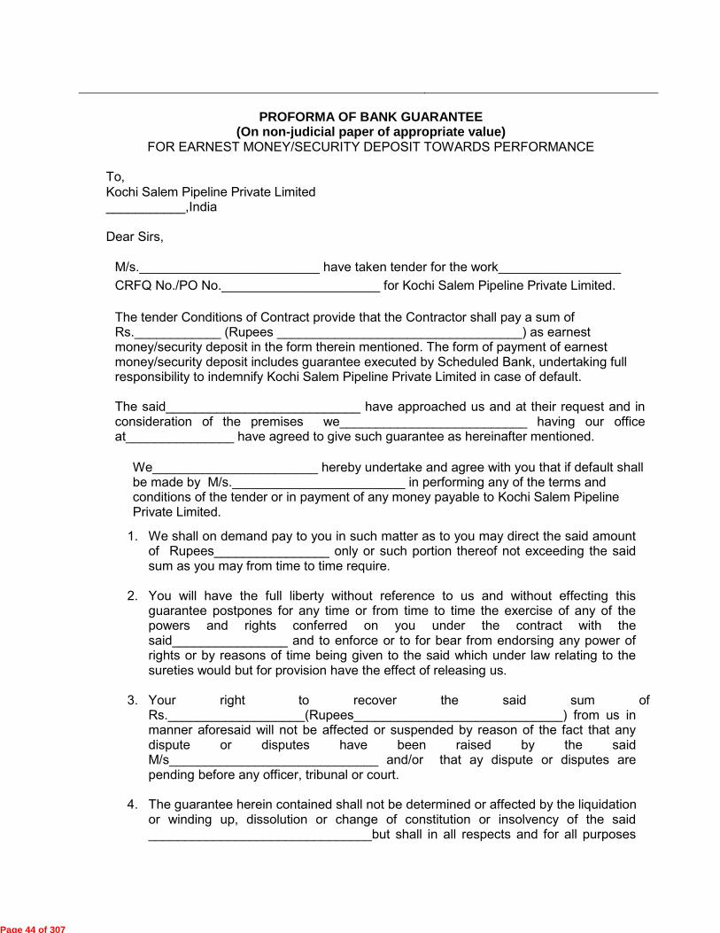
Sub: UPS SYSTEM Bidding Doc. No.: AS/A538-010-XI-MR-0441/1022
PROFORMA OF BANK GUARANTEE (On non-judicial paper of appropriate value)
FOR EARNEST MONEY/SECURITY DEPOSIT TOWARDS PERFORMANCE To, Kochi Salem Pipeline Private Limited ___________,India Dear Sirs,
M/s._________________________ have taken tender for the work_________________ CRFQ No./PO No.______________________ for Kochi Salem Pipeline Private Limited.
The tender Conditions of Contract provide that the Contractor shall pay a sum of Rs.____________ (Rupees __________________________________) as earnest money/security deposit in the form therein mentioned. The form of payment of earnest money/security deposit includes guarantee executed by Scheduled Bank, undertaking full responsibility to indemnify Kochi Salem Pipeline Private Limited in case of default. The said___________________________ have approached us and at their request and in consideration of the premises we__________________________ having our office at_______________ have agreed to give such guarantee as hereinafter mentioned.
We_______________________ hereby undertake and agree with you that if default shall be made by M/s.________________________ in performing any of the terms and conditions of the tender or in payment of any money payable to Kochi Salem Pipeline Private Limited.
1. We shall on demand pay to you in such matter as to you may direct the said amount of Rupees________________ only or such portion thereof not exceeding the said sum as you may from time to time require.
2. You will have the full liberty without reference to us and without effecting this guarantee postpones for any time or from time to time the exercise of any of the powers and rights conferred on you under the contract with the said________________ and to enforce or to for bear from endorsing any power of rights or by reasons of time being given to the said which under law relating to the sureties would but for provision have the effect of releasing us.
3. Your right to recover the said sum of Rs.___________________(Rupees_____________________________) from us in manner aforesaid will not be affected or suspended by reason of the fact that any dispute or disputes have been raised by the said M/s_____________________________ and/or that ay dispute or disputes are pending before any officer, tribunal or court.
4. The guarantee herein contained shall not be determined or affected by the liquidation or winding up, dissolution or change of constitution or insolvency of the said _______________________________but shall in all respects and for all purposes
Page 44 of 307

Sub: UPS SYSTEM Bidding Doc. No.: AS/A538-010-XI-MR-0441/1022
be binding operative units payments of all money due to you in respect of such liabilities is paid.
5. Our liability under this guarantee is restricted to Rupees__________________________________ Our guarantees shall remain in force until______________________________ unless a suit or action to enforce a claim under___________________________ Guarantee is filed against us within six months from ______________________________ (which is date of expiry of guarantee) all our rights under the said guarantee shall be forfeited and shall be relieved and discharged from all libilities thereunder.
6. We have power to issue this guarantee in your favour under Memorandum and Articles of Association and the undersigned has full power to do under the Power of Attorney dated___________________ granted to him by the Bank.
Yours faithfully ______________________Bank by its Constituted Attorney Signature of a person duly authorized to sign on behalf of the bank.
Page 45 of 307

Page 1 of 24
Bharat Petroleum Corporation Limited General Purchase Conditions The following conditions shall be applicable for all procurement unless specifically mentioned in the Special Purchase Conditions. INDEX 1. DEFINITIONS 2. REFERENCE FOR DOCUMENTATION 3. RIGHT OF OWNER TO ACCEPT OR REJECT TENDER 4. LANGUAGE OF BID 5. PRICE 6. TAXES AND DUTIES 7. INSPECTION 8. SHIPPING 9. INDIAN AGENT COMMISSION 10. ORDER AWARD / EVALUATION CRITERIA 11. CONFIRMATION OF ORDER 12. PAYMENT TERMS 13. GUARANTEE/WARRANTY 14. PERFORMANCE BANK GUARANTEE 15. PACKING & MARKING 16. DELIVERY 17. UNLOADING AND STACKING 18. TRANSIT INSURANCE 19. VALIDITY OF OFFER 20. DELIVERY DATES AND PRICE REDUCTION SCHEDULE 21. RISK PURCHASE CLAUSE 22. FORCE MAJEURE CLAUSE 23. ARBITRATION CLAUSE 24. INTEGRITY PACT (IP) 25. RECOVERY OF SUMS DUE 26. CONFIDENTIALITY OF TECHNICAL INFORMATION 27. PATENTS & ROYALTIES 28. LIABILITY CLAUSE 29. COMPLIANCE OF REGULATIONS 30. REJECTION, REMOVAL OF REJECTED GOODS AND REPLACEMENT 31. NON-WAIVER 32. NEW & UNUSED MATERIAL 33. PURCHASE PREFERENCE CLAUSE 34. CANCELLATION 35. ANTI –COMPETITIVE AGREEMENTS/ABUSE OF DOMINANT POSITION 36. ASSIGNMENT 37. GOVERNING LAW 38. AMENDMENT 39. SPECIAL PURCHASE CONDITIONS 40. Expediting 41. Spare Part 42. Part order & Repeat Order 43. Oils & Lubricants 44. Jurisdiction 45. Address 46. Notices
Page 46 of 307

Page 2 of 24
Bharat Petroleum Corporation Limited General Purchase Conditions 1. DEFINITIONS:
The following expressions used in these terms and conditions and in the purchase order shall have the meaning indicated against each of these:
1.1. OWNER: Owner means Bharat Petroleum Corporation Limited (a Government of India
enterprise), a Company incorporated in India having its registered office at Bharat Bhavan, 4 & 6 Currimbhoy Road, Ballard Estate, Mumbai 400038 and shall include its successors and assigns (hereafter called BPCL as a short form).
1.2. VENDOR: Vendor means the person, firm or the Company / Corporation to whom this
Request for quotation (RFQ)/purchase order is issued and shall include its successors and assigns.
1.3. INSPECTOR: Person/agency deputed by BPCL for carrying out inspection,
checking/testing of items ordered and for certifying the items conforming to the purchase order specifications..
1.4. GOODS / MATERIALS: means any of the articles, materials, machinery, equipments,
supplies, drawing, data and other property and all services including but not limited to design, delivery, installation, inspection, testing and commissioning specified or required to complete the order.
1.5. SITE / LOCATION: means any Site where BHARAT PETROLEUM CORPORATION
LTD. desires to receive materials any where in India as mentioned in RFQ. 1.6. “RATE CONTRACT” means the agreement for supply of goods/ materials between
Owner and Vendor, for a fixed period of time (i.e till validity of Rate Contract, with no commitment of contractual quantity) on mutually agreed terms and conditions. The actual supply of goods/ materials shall take place only on issue of separate purchase orders for required quantity as and when required by Owner.
1.7. “FIRM PROCUREMENT” means the agreement between the parties for mutually
agreed terms and conditions with commitment of Quantity Ordered. 2. REFERENCE FOR DOCUMENTATION: 2.1. The number and date of Collective Request for Quotation (CRFQ) must appear on all
correspondence before finalization of Rate Contract / Purchase Order. 2.2. After finalization of Contract / Purchase Order: The number and date of Rate Contract /
Purchase Order must appear on all correspondence, drawings, invoices, dispatch advices, (including shipping documents if applicable) packing list and on any documents or papers connected with this order.
2.3. In the case of imports, the relevant particulars of the import Licence shall be duly indicated in the invoice and shipping documents as well as on the packages or consignments.
Page 47 of 307

Page 3 of 24
3. RIGHT OF OWNER TO ACCEPT OR REJECT TENDER :
The right to accept the tender will rest with the Owner.
4. LANGUAGE:
The Bid and all supporting documentation and all correspondence whatsoever exchanged by Vendor and Owner, shall be in English language only.
5. Price :
Unless otherwise agreed to the terms of the RFQ, price shall be :
Firm and no escalation will be entertained on any ground, except on the ground of statutory levies applicable on the tendered items.
6. TAXES AND DUTIES:
All vendors shall have VAT / CST/GST/Service tax registration in the concerned State and vendor shall quote their TIN number in the quotation.
6.1. EXCISE DUTY: 6.1.1. Excise duty extra as applicable at the time of delivery within scheduled delivery period
will be payable by BPCL against documentary evidence. Vendor shall mention in their offer, the percentage of excise duty applicable at present. Any upward variation in excise duty rates, beyond the contractual delivery period, shall be to vendor’s account.
6.1.2. In case Excise Duty is not applicable at present : Excise duty due to change in turn over is
not payable. If applicable in future, the same will be borne by vendor. 6.1.3. Owner may shall take CENVAT Credit on the material supplied for both excise duty and
cess component and accordingly Excise duty / Cess should be quoted separately wherever applicable.
Vendor shall ask the transporter of the goods to hand over the copy of excise invoice (transporter’s copy) at the time of delivery of goods at owner’s site.
6.2. SALES TAX / VAT/GST : 6.2.1. Sales Tax as applicable at the time of delivery within scheduled delivery period will be
payable by BPCL. Vendor shall give details of local sales tax and/oror central sales tax currently applicable in their offer. The rates applicable for “CST without form C”, “CST with form C" and “VAT” shall be clearly indicated.
6.2.2. Input VAT Credit may be claimed by BPCL, wherever applicable. Vendor shall submit
the TAX invoice. 6.3 Service tax :
Page 48 of 307

Page 4 of 24
All vendors shall have service tax registration wherever applicable. BPCL may also claim CENVAT Credit on service tax. The vendor should quote service tax separately, if applicable. Vendor shall submit the TAX invoice. Vendor is required to furnish serially numbered and signed invoice / bill / challan containing the following details:
a) Name, address and registration number of the service provider b) Name and address of person receiving taxable service c) Description, classification and value of taxable service provided d) Service Tax Payable
6.4 FREIGHT AND OCTROI : 6.4.1 Freight: Firm freight charges to be quoted as indicated in the Tender documents. Freight
shall be payable after receipt of the Material(s) at the site, unless otherwise specified. 6.4.2. Octroi and entry taxes, if any, shall be invoiced separately and shall be re-imbursed by
BPCL at actuals after receipt of the Material(s) at the Site against the submission of original documentary evidence for proof of payment of the related octroi and entry taxes, as the case may be.
6.5. NEW STATUTORY LEVIES :
All new statutory levies leviable on sale of finished goods to owner , if applicable are payable extra by BPCL against documentary proof, within the contractual delivery period.
6.6 Variation in Taxes/Duties
Any increase/decrease in all the above mentioned statutory levies on the date of delivery during the scheduled delivery period on finished materials will be on BPCL's account. Any upward variation in statutory levies after contractual delivery date shall be to vendor’s account.
7. INSPECTION : 7.1. Materials shall be inspected by EIL / BPCL approved third party inspection agency if
applicable before dispatch of materials. However, arranging and providing inspection facilities is entirely vendor’s responsibility and in no way shall affect the delivery schedule.
7.2. Scope of Inspection shall be as per RFQ. Our registered third party inspection agencies
are /LRIS/CEIL/DNV///EIL/ as amended time to time unless otherwise specified in the Special Purchase Conditions.
7.3. Unless otherwise specified, the inspection shall be carried out as per the relevant
standards/scope of inspection provided alongwith the Tender Enquiry/Purchase Order. 7.4. BPCL may, at its own expense, have its representative(s) witness any test or inspection.
In order to enable BPCL’s representative(s) to witness the tests/inspections. BPCL will advise the Vendor in advance whether it intends to have its representative(s) be present at any of the inspections.
Page 49 of 307

Page 5 of 24
7.5. Even if the inspection and tests are fully carried out, the Vendor shall not be absolved
from its responsibilities to ensure that the Material(s), raw materials, components and other inputs are supplied strictly to conform and comply with all the requirements of the Contract at all stages, whether during manufacture and fabrication, or at the time of Delivery as on arrival at site and after its erection or start up or consumption, and during the defect liability period. The inspections and tests are merely intended to prima-facie satisfy BPCL that the Material(s) and the parts and components comply with the requirements of the Contract. The Vendor’s responsibility shall also not be anywise reduced or discharged because BPCL or BPCL’s representative(s) or Inspector(s) shall have examined, commented on the Vendor’s drawings or specifications or shall have witnessed the tests or required any chemical or physical or other tests or shall have stamped or approved or certified any Material(s).
7.6. Although material approved by the Inspector(s), if on testing and inspection after receipt
of the Material(s) at the location, any Material(s) are found not to be in strict conformity with the contractual requirements or specifications, BPCL shall have the right to reject the same and hold the Vendor liable for non-performance of the Contract.
8. SHIPPING : 8.1 SEA SHIPMENT : All shipment of materials shall be made by first class direct vessels, through the
chartering wing, Ministry of Surface Transport as per procedure detailed hereunder. The Foreign Supplier shall arrange with Vessels Owners or Forwarding Agents for proper storage of the entire Cargo intended for the project in a specific manner so as to faciliate and to avoid any over carriage at the port of discharge. All shipment shall be under deck unless carriage on deck is unavoidable.
The bills of lading should be made out in favour of `Bharat Petroleum Corporation Ltd..
or order'. All columns in the body of the Bill of Lading namely marks and nos., material description, weight particulars etc., should be uniform and accurate and such statements should be uniform in all the shipping documents. The freight particulars should mention the basis of freight tonnage, heavy lift charges, if any, surcharge, discount etc. clearly and separately. The net total freight payable shall be shown at the bottom.
SHIPPING DOCUMENTS : All documents viz. Bill of Lading, invoices, packing list, freight memos, country of
origin certificates, test certificate, drawings and catalogues should be in English language.
In addition of the bill of lading which should be obtained in three stamped original plus
as many copies as required, invoices, packing list, freight memos,(if the freight particulars are not shown in the bills of lading), country of origin certificate, test / composition certificate, shall be made out against each shipment in as many number of copies as shown below.
Page 50 of 307
Page 6 of 24
The bill of lading, invoice and packing list specifically shall show uniformly the mark and numbers, contents case wise, country of origin, consignees name, port of destination and all other particulars as indicated under clause 2. The invoice shall show the unit rates and net total F.O.B. prices. Items packed separately should also be invoiced and the value shown accordingly. Packing list must show apart from other particulars actual contents in each case, net and gross weights and dimensions, and the total number of packages. All documents should be duly signed by the Vendor's authorised representatives.
In the case of FOB orders, Shipping arrangements shall be made by the Chartering Wing Of the Ministry of Surface Transport, New Delhi through their respective forwarding
agents. The names and addresses of forwarding agents shall be as per Special Purchase Conditions. Supplier shall furnish to the respective agents the full details of consignments such as outside dimension, weights (both gross and net) No of packages, technical description and drawings, name of supplier, ports of loading, etc. 6 weeks notice shall be given by the supplier to enable the concerned agency to arrange shipping space.
The bill of lading shall indicate the following : Shipper : Goverment of India Consignee : Bharat Petroleum Corporation Ltd. In case of supplies from USA, Export Licences, if any required from the American
Authorities shall be Obtained by the U.S. Suppliers. If need be assistance for obtaining such export licences would be available from India Supply Mission at Washington.
8.2 AIRSHIPMENT : In case of Airshipment, the materials shall be shipped through freight consolidator
(approved by us). The airway bill shall be made out in favour of BHARAT PETROLEUM CORPORATION LTD.
TRANSMISSION OF SHIPPING DOCUMENTS : Foreign Supplier shall obtain the shipping documents in seven complete sets including
three original stamped copies of the Bill of Lading as quickly as possible after the shipment is made, and airmail as shown below so that they are received at least three weeks before the Vessels arrival. Foreign Supplier shall be fully responsible or any delay and / or demurrage in clearance of the consignment at the port due to delay in transmittal of the shipping documents.
If in terms of letter or otherwise, the complete original set of documents are required to
be sent to BPCL through Bank the distribution indicated below will confine to copies of documents only minus originals. Documents BPCL (Mumbai) Bill of Lading 4 (including 1 original) Invoice 4
Page 51 of 307

Page 7 of 24
Packing List 4 Freight Memo 4 Country of Origin Certificate 4 Third party inspection certificate 4 Drawing 4 Catalogue 4 Invoice of Third Party 4 for inspection charges whenever applicable. 9. INDIAN AGENT COMMISSION : Any offer through Indian agents will be considered only after authorization mentioning
them as Indian agents, is received from Vendor. Indian agents commission if applicable will be payable only in Indian currency. Indian agents should be registered with Directorate General of Supplies and Disposals, Government of India and agency commission will be payable only after registration with DGS&D, New Delhi.
10. ORDER AWARD / EVALUATION CRITERIA :
Unless otherwise specified, Order award criteria will be on lowest quote landed price basis. Landed price will be summation of Basic Price, Packing & Forwarding Charges, Excise Duty, Sales Tax, Freight, Inspection, Octroi, Supervision of Installation & Commissioning and other taxes & levies, loading etc, if any, reduced by cenvat/vat credit as applicable.
11. CONFIRMATION OF ORDER :
The vendor shall acknowledge the receipt of the purchase order within 10 days of mailing the same. The vendor shall sign, stamp the acknowledgement copy of the purchase order and return the same to BPCL.
12. PAYMENT TERMS : 12.1. Unless otherwise specified, 100% payment shall be made within 30 days from date of
receipt and acceptance of materials at Site against submission of Peformance Bank Guarantee (PBG) for 10% of basic order value if PBG is applicable for the tender.
12.2. In the case of imports, payment will be made on submission of original documents
directly to Owner (Telegraphic Transfer-TT) or through Bank (Cash against documents-CAD) or through irrevocable Letter of Credit.
12.3. Unless otherwise mentioned, the specified documents (All documents listed below (one
original and two copies)) should be submitted to originator of P.O. (the name and contact details of whom are given in PO) and payments for despatches will be made by the originator of Purchase Order :
a) Invoice b) Excise invoice c) The Lorry Receipt of the consignment d) Packing list for the consignment
Page 52 of 307

Page 8 of 24
e) Third Party Inspector’s Certificate covering the invoiced Material(s)/ Release Note, wherever applicable
f) Manufacturers Test/Composition Certificate, wherever applicable g) Drawing(s)/Catalogue(s) covering the Material(s) , wherever applicable h) Guarantee/Warranty Certificate(s), wherever applicable. i) Original Receipt for Octroi/other statutory levies as applicable. j) Performance Bank Guarantee as applicable.
13. GUARANTEE/WARRANTY : 13.1. Materials shall be guaranteed against manufacturing defects, materials, workmanship and
design for a period of 18 months from the date of commissioning or 24 months from the date of dispatch whichever is earlier. Warranty for replacement of material / accessories should be provided free of charges at our premises. The above guarantee/warranty will be without prejudice to the certificate of inspection or material receipt note issued by us in respect of the materials.
13.2. All the materials including components and sub contracted items should be guaranteed by
the vendor within the warranty period mentioned above. In the event of any defect in the material, the vendor will replace / repair the material at BPCL’s concerned location at vendor’s risk and cost on due notice.
13.3. In case, vendor does not replace / repair the material on due notice, rejected material will
be sent to the vendor on “Freight to pay” basis for free replacement. Material after rectification of defects shall be dispatched by the vendor on “Freight Paid” basis. Alternatively, BPCL reserves the right to have the material repaired / replaced at the locations concerned, at the vendor’s risk, cost and responsibility.
13.4. The Vendor shall provide similar warrantee on the parts, components, fittings,
accessories etc. so repaired and / or replaced. 14. PERFORMANCE BANK GUARANTEE : 14.1. Vendor will have to provide Performance Bank Guarantee for 10% of the basic value of
purchase order unless otherwise specified. This bank guarantee shall be valid (shall remain in force) for guarantee period (as mentioned in the guarantee clause), with an invocation period of six months thereafter. In the case of Indigenous vendors, the Performance Bank Guarantee shall be given on a non-judicial stamp paper of appropriate value (currently Rs 100). PBG format is as per Annexure I.
In case, PBG is not provided by the Vendor, 10% of the basic value shall be retained in lieu of PBG, till the expiry of guarantee and claim period. In the case of imports, the Supplier shall furnish the Performance Bank Guarantee (as per Annexure I) through the following : a) Branches of Indian scheduled banks operating in their Country. b) Foreign bank operating in their Country which is counter guaranteed by branches of
Indian scheduled banks operating in their Country/India. c) Indian branches of foreign banks. d) Foreign bank operating in their Country counter guaranteed by their Indian branch
Page 53 of 307

Page 9 of 24
However, in respect of c) and d) above, the Indian branch of foreign banks should be recognized as scheduled bank by Reserve Bank of India.
14.2. If Vendor wants to submit the PBG at Contract level to avoid multiple number of PBG
(i.e. PBG issued against every purchase/call off order) then the validity of PBG will be calculated as mentioned below :
14.2.1. Validity of PBG = Rate Contract Issue Date (Start Date of Rate Contract) + Rate
Contract Period (validity of Rate Contract) + Contractual Delivery Period of material + Contractual Guarantee period + 6 month (for invocation / Claim).
15. PACKING & MARKING : 15.1 PACKING : 15.1.1 Packing shall withstand the hazards normally encountered with the means of transport
for the goods of this purchase order including loading and unloading operation both by crane and by pushing off.
In the case of imports, all equipments / materials shall be suitably packed in weather
proof, seaworthy packing for ocean transport under tropical conditions and for rail or road or other appropriate transport in India. The packing shall be strong and efficient enough to ensure safe preservance upto the final point of destination.
Raw/Solid wood packaging material of imported items has to be appropriately treated &
marked as per International Standard of Phytosanitary Measures (ISPM-15") for material originating from the contracting countries to the International Plant Protection Convention or the members of Food & Agriculture Organization. Material from non-contracting parties would have to be accompanied by a phytosanitary certificate of the treatment endorsed. The Custom Officer at Indian Port shall not release the material without appropriate compliance of the above provisions w.e.f. 01.11.2004.
15.1.2 The packing specification incorporated herein are supplementary to the internal and
external packing methods and standards as per current general rules of J.R.A. Good Tariff Part-I. All packaging shall be done in such a manner as to reduce volume as much as possible.
15.1.3 Fragile articles should be packed with special packing materials depending on the type of
Materials and the packing shall bear the words "HANDLE WITH CARE GLASS FRAGILE, DON'T ROLL THIS END UP. THIS END DOWN," to be indicated by arrow.
15.1.4 Chemicals in powder form, catalyst, refractories and like materials etc. shall be packed in
drums, cans and tins only. However, Catalyst may be supplied in Jumbo bags. 15.1.5 The hazardous materials shall be packed in accordance with the applicable rules,
regulations and tariff of all cognizant Government Authorities and other Governing bodies. It shall be the responsibility of the seller of hazardous materials to designate the material as hazardous and to identify each material by its proper commodity name and its hazardous material class code.
Page 54 of 307

Page 10 of 24
15.1.6 All package requiring handling by crane should have sufficient space at appropriate place
to put sling of suitable dia (strength). Iron/Steel angle should be provided at the place where sling marking are made to avoid damage to package/ equipment while lifting.
15.1.7 Item shipped in bundles must be securely tied with steel wire or strapping. Steel
reinforcing rods, bars, pipes, structural members etc. shall be bundled in uniform lengths and the weight shall be within the breaking strength of the securing wire or strapping.
In the case of imports, for bundles the shipping marks shall be embossed on metal or
similar tag and wired securely on each end. 15.1.8 All delicate surface on equipment/materials should be carefully protected and printed
with protective paint/compound and wrapped to prevent rusting and damage. 15.1.9 All mechanical and electrical equipment and other heavy articles shall be securely
fastened to the case bottom and shall be blocked and braced to avoid any displacement/shifting during transit.
15.1.10 Attachments and spare parts of equipment and all small pieces shall be packed separately
in wooden cases with adequate protection inside the case and wherever possible should be sent along with the main equipment. Each item shall be suitably tagged with identification of main equipment, item denomination and reference number of respective assembly drawing. Each item of steel structure and furnaces shall be identified with two erection markings with minimum lettering height of 15mm. Such markings will be followed by the collection numbers in indelible ink/paint. A copy of the packing list shall accompany the materials in each package.
15.1.11 All protrusions shall be suitably protected by providing a cover comprising of tightly
bolted wooden disc on the flanges. All nozzles, holes and openings and also all delicate surfaces shall be carefully protected against damage and bad weather. All manufactured surfaces shall be painted with rust proof paint.
In the case of imports, for bulk uniform material when packed in several cases,
progressive serial numbers shall be indicated on each case. 15.1.12 Wherever required, equipment/materials instruments shall be enveloped in polythene
bags containing silicagel or similar dehydrating compound. 15.1.13 Pipes shall be packed as under:
a. Upto 50mm NB in wooden cases/crates.
b. Above 50mm NB and upto 100mm NB in bundles and should be strapped at minimum three places.
c. Above 100mm NB in loose.
15.1.14 Pipes and tubes of stainless steel, copper etc. shall be packed in wooden cases
irrespective of their sizes.
Page 55 of 307

Page 11 of 24
15.1.15 Pipes with threaded or flanged ends shall be protected with suitable caps covers, before packing.
In the case of imports, all pipes and sheets shall be marked with strips bearing progressive no.
15.1.16 Detailed packing list in waterproof envelope shall be inserted in the package together
with equipment/materials. One copy of the detailed packing list shall be fastened outside of the package in waterproof envelope and covered by metal cover.
15.1.17 The supplier shall be held liable for all damages or breakages to the goods due to the
defective or insufficient packing as well as for corrosion due to insufficient protection. 15.1.18 Packaged equipment or materials showing damage defects or shortages resulting from
improper packaging materials or packing procedures or having concealed damages or shortages, at the time of unpacking shall be to the supplier’s account.
All packages which require special handling and transport should have their Centres of Gravity and the points at which they may be slung or gripped clearly indicated and marked “ATTENTION SPECIAL LOAD HANDLE WITH CARE” both in English/Hindi Languages.
In the case of imports, a distinct colour splash in say red black around each package crate
/ bundle shall be given for identification. 15.1.19 Along with the packed material, supplier should attach material list, manuals/instructions
and also the Inspection certificate/release note, wherever applicable. 15.2. MARKING :
The following details to be written on the side face of packing:
a) Purchase Order Number b) Vendor Name c) Batch no with Manufacturing date d) Procedure (in brief) for handling e) Date of dispatch etc.
15.3 Imported items :
On three sides of the packages, the following marks shall appear, clearly visible, with indelible paint and on Vendor's care and expenses. BHARAT PETROLEUM CORPORATION LIMITED
Page 56 of 307

Page 12 of 24
(With detailed address as given in Special Purchase Conditions) From : To : Bharat Petroleum Corpn.Ltd. (With detailed address as given in Special Purchase Conditions) Order no. Rev. no. Item : Equipment Nomenclature : Net weight : Kgs. Gross weight : Kgs. Case No. of Total cases : Dimensions : Import Licence No. NOTE :
Marking shall be bold - minimum letter height 5 cm. For every order and every shipment, packages must be marked with serial progressive numbering.
Top heavy containers shall be so marked either Top Heavy or Heavy Ends. When packing material is clean and light coloured, a dark black stencil paint shall be acceptable. However, where packaging material is soiled or dark, a coat of flat zinc white paint shall be applied and allowed to dry before applying the specific markings. In case of large equipments like vessels, heat exchangers, etc. the envelope containing the documents shall be fastened inside a shell connection, with an identifying arrow sign "documents" using indelible paint.
16. DELIVERY : 16.1. Unless otherwise mentioned, Vendor is requested to quote their best delivery schedule from the date of receipt of Purchase order. 16.2. Time being the essence of this contract, the delivery mentioned in the purchase order
shall be strictly adhered to and no variation shall be permitted except with prior authorization in writing from the Owner. Goods should be delivered, securely packed and in good order and condition, at the place of delivery and within the time specified in the purchase order for their delivery.
16.3. The contractual delivery period is inclusive of all the lead time for engineering /
procurement of raw material, the manufacturing, inspection / testing, packing, transportation or any other activity whatsoever required to be accomplished for effecting the delivery at the required delivery point.
16.4. Unless otherwise specified, Material(s) shall not be despatched without prior inspection
and/or testing and Release Order/Material(s) Acceptance Certificate issued by the Inspector(s).
Page 57 of 307

Page 13 of 24
16.5. BPCL shall have the right to advise any change in despatch point or destination in respect of any Material(s). Any extra expenditure incurred by the Vendor on this account supported by satisfactory documentary evidence, will be reimbursed to the Vendor by BPCL.
17. UNLOADING AND STACKING :
Unloading and stacking will be arranged by BPCL. The Vendor shall send BPCL information of the proposed consignment well in advance by telegram/fax/e-mail/courier to enable BPCL to take necessary action.
18. TRANSIT INSURANCE :
Unless otherwise mentioned, 18.1. Transit Insurance shall be covered by BPCL against its Mega Package Policy. 18.2 In the case of imports, insurance against all marine and transit risk shall be covered under
the Owner's marine policy. However, the Vendor shall ensure that in effecting shipments clear bill of lading are obtained and the carrier's responsibility is fully retained on the Carriers so that the consignee's interests are fully secured and are in no way jeopardized.
18.2. The Vendor shall send BPCL information of the proposed consignment well in advance
by telegram/fax/e-mail/courier to enable BPCL to take necessary action for the transit insurance of the consignment. Any failure by the Vendor to do so shall place the consignment at the Vendor’s risk.
18.3. In the case of imports, as soon as any shipment is made, the Foreign Supplier shall send
advance information by way of Telex message to Bharat Petroleum Corporation Ltd., (with detailed address as given in Special Purchase Conditions) giving particulars of the shipments, vessels name, port of shipment, bill of lading number and date, total FOB and freight value.
19 VALIDITY OF OFFER:
The rates quoted against this tender shall be valid for a period of 90 Days from the date of opening of the tender unless otherwise specified in the Special Purchase Conditions.
20. DELIVERY DATES AND PRICE REDUCTION SCHEDULE : 20.1. The time and date of Delivery of Material(s) as stipulated in the Contract shall be adhered
to on the clear understanding that the Price(s) of the Material(s) has/have been fixed with reference to the said Delivery date(s).
20.2. If any delay is anticipated by the Vendor in the delivery of the Material(s) or any of them
beyond the stipulated date(s) of Delivery, the Vendor shall forthwith inform BPCL in writing of such anticipated delay and of the steps being taken by the Vendor to remove or reduce the anticipated delay, and shall promptly keep BPCL informed of all subsequent developments.
Page 58 of 307

Page 14 of 24
20.3. The delivery period quoted must be realistic & specific. The inability of successful Vendors to execute orders in accordance with the agreed delivery schedule will entitle BPCL, at its options, to :
20.3.1. Accept delayed delivery at prices reduced by a sum equivalent to one percent ( 1%) of
the basic value of any goods not delivered for every week of delay or part thereof, limited to a maximum of 10% of the total basic order value. LR date will be considered as delivery completion date for calculation of price reduction in the case of ex works contract. Date of receipt of materials at owners premises shall be considered for calculation of price reduction for F.O.R destination contract.
In the case of imports, the contractual delivery date shall be considered from the date of Letter of Credit (L/C) or the date of L/C amendment because of Buyer’s fault plus one week (to take care of transit time for receipt of L/c) plus the delivery schedule as indicated by the vendors.
In case of the shipment taking place on “Cash against documents”, the contractual delivery shall be taken from the date of purchase order plus one week (to take care of transit time for receipt of order) plus delivery period.
Further the date of B/L or House airway bill shall be considered to find out the delay with respect to contractual delivery date. In case of FOB shipments if the vessel is not available then the intimation by vendors regarding readiness of the goods for the shipment shall be considered for calculating the delay if any. So vendor shall inform the readiness of material for shipment on FOB (Free on Board)basis / FCA (Free on Carrier) basis.
20.3.2. Cancel the order in part or full and purchase such cancelled quantities from elsewhere on account at the risk and cost of the vendor, without prejudice to its right under 20.3.1 above in respect of goods delivered.
21. RISK PURCHASE CLAUSE :
BPCL reserves the right to curtail or cancel the order either in full or part thereof if the vendor fails to comply with the delivery schedule and other terms & conditions of the order. BPCL also reserves the right to procure the same or similar materials/equipment through other sources at vendor's entire risk, cost and consequences. Further, the vendor agrees that in case of procurement by the owner from other sources the differential amount paid by the owner shall be on account of the vendor together with any interest and other costs accrued thereon for such procurement.
22. FORCE MAJEURE CLAUSE :
(A) Definition: The term “Force Majeure” means any event or circumstance or combination of events or circumstances that affects the performance by the vendor of its obligations pursuant to the terms of this Agreement (including by preventing, hindering or delaying such performance), but only if and to the extent that such events and circumstances are not within the vendor’s reasonable control and were not reasonably foreseeable and the effects of which the vendor could not have prevented or overcome by acting as a Reasonable and Prudent person or, by the exercise of reasonable skill and care. Force Majeure events and circumstances
Page 59 of 307

Page 15 of 24
shall in any event include the following events and circumstances to the extent they or their consequences satisfy the requirements set forth above in this Clause:
(i) the effect of any element or other act of God, including any storm, flood, drought, lightning, earthquake, tidal wave, tsunami, cyclone or other natural disaster;
(ii) fire, accident, loss or breakage of facilities or equipment, structural collapse or explosion;
(iii) epidemic, plague or quarantine;
(iv) air crash, shipwreck, or train wreck;
(v) acts of war (whether declared or undeclared), sabotage, terrorism or act of public enemy (including the acts of any independent unit or individual engaged in activities in furtherance of a programme of irregular warfare), acts of belligerence of foreign enemies (whether declared or undeclared), blockades, embargoes, civil disturbance, revolution, rebellion or insurrection, exercise of military or usurped power, or any attempt at usurpation of power;
(vi) radioactive contamination or ionizing radiation;
( B) Notice and Reporting:
( i ) The Vendor shall as soon as reasonably practicable after the date of commencement of the event of Force Majeure, but in any event no later than two (7) days after such commencement date, notify the BPCL in writing of such event of Force Majeure and provide the following information:
(a) reasonably full particulars of the event or circumstance of Force Majeure and the extent to which any obligation will be prevented or delayed;
(b) such date of commencement and an estimate of the period of time required to enable the vendor to resume full performance of its obligations; and
(c) all relevant information relating to the Force Majeure and full details of the measures the vendor is taking to overcome or circumvent such Force Majeure.
(ii) The Vendor shall, throughout the period during which it is prevented from performing, or delayed in the performance of, its obligations under this Agreement, upon request, give or procure access to examine the scene of the Force Majeure including such information, facilities and sites as the other Party may
Page 60 of 307

Page 16 of 24
reasonably request in connection with such event. Access to any facilities or sites shall be at the risk and cost of the Party requesting such information and access.
(C) Mitigation Responsibility:
(i) The Vendor shall use all reasonable endeavours, acting as a Reasonable and Prudent Person, to circumvent or overcome any event or circumstance of Force Majeure as expeditiously as possible, and relief under this Clause shall cease to be available to the Vendor claiming Force Majeure if it fails to use such reasonable endeavours during or following any such event of Force Majeure.
(ii) The Vendor shall have the burden of proving that the circumstances constitute valid grounds of Force Majeure under this Clause and that it has exercised reasonable diligence efforts to remedy the cause of any alleged Force Majeure.
(iii) The Vendor shall notify BPCL when the Force Majeure has terminated or abated to an extent which permits resumption of performance to occur and shall resume performance as expeditiously as possible after such termination or abatement.
(D) Consequences of Force Majeure. Provided that the Vendor has complied and continues to comply with the obligations of this Clause and subject to the further provisions:
(i) the obligations of the Parties under this Agreement to the extent performance thereof is prevented or impeded by the event of Force Majeure shall be suspended and the Parties shall not be liable for the non-performance thereof for the duration of the period of Force Majeure; and
(ii) the time period(s) for the performance of the obligations of the Parties under this Agreement to the extent performance thereof is prevented or impeded by the event of Force Majeure shall be extended for the duration of the relevant period of Force Majeure except as provided herein.
(E) Force Majeure Events Exceeding 60 Days
(i) If an event or series of events (alone or in combination) of Force Majeure occur, and continue for a period in excess of 60 consecutive days, then BPCL shall have the right to terminate this agreement, whereupon the Parties shall meet to mitigate the impediments caused by the Force Majeure event.
Page 61 of 307

Page 17 of 24
23. ARBITRATION CLAUSE : 23.1 Any dispute or difference of any nature whatsoever, any claim, cross-claim, counter-claim or set off of BPCL/Vendor against omission or on account of any of the parties hereto arising out of or in relation to this Contract shall be referred to the Sole Arbitration of Director (Marketing) / of BPCL as the case may be or to some officer of BPCL who may be nominated by them. 23.2. In the event the Arbitrator being unable or refusing to act for any reason whatsoever, the
said Directors of BPCL shall designate another person to act as an Arbitrator in accordance with the terms of the said Contract/Agreement. The Arbitrator newly appointed shall be entitled to proceed with the reference from the point at which it was left by his predecessor.
23.3. It is known to the parties herein that the Arbitrator appointed hereunder is an employee of
the Corporation and may be Share holder of the Corporation. 23.4. The award of the Arbitrator so appointed shall be final, conclusive and binding on all the
parties to the contract and the law applicable to arbitration proceedings will be the Arbitration and Conciliation Act, 1996 or any other enactment in replacement thereof.
23.5. The language of the proceedings will be in English and the place of proceedings will be
Mumbai. 23.6. The parties hereby agree that the Courts in the city of Mumbai alone shall have
jurisdiction to entertain any application or other proceedings in respect of anything arising under this Agreement and any Award or Awards made by the Sole Arbitrator hereunder shall be filed, if required, in the concerned Courts in the City of Mumbai alone. (Legal)
24. INTEGRITY PACT (IP) :
Vendors are requested to sign & return our pre-signed IP document , if applicable. This document is essential & binding. Vendor's failure to return the IP document duly signed along with Bid Document may result in the bid not being considered for further evaluation.
25. RECOVERY OF SUMS DUE :
Whenever, any claim against vendor for payment of a sum of money arises out of or under the contract, the owner shall be entitled to recover such sums from any sum then due or when at any time thereafter may become due from the vendor under this or any other contract with the owner and should this sum be not sufficient to cover the recoverable amount of claim(s), the vendor shall pay to BPCL on demand the balance remaining due.
26. CONFIDENTIALITY OF TECHNICAL INFORMATION :
Page 62 of 307

Page 18 of 24
Drawing, specifications and details shall be the property of the BPCL and shall be returned by the Vendor on demand. The Vendor shall not make use of drawing and specifications for any purpose at any time save and except for the purpose of BPCL. The Vendor shall not disclose the technical information furnished to or organized by the Vendor under or by virtue of or as a result of the implementation of the Purchase Order to any person, firm or body or corporate authority and shall make all endeavors to ensure that the technical information is kept CONFIDENTIAL. The technical information imparted and supplied to the vendor by BPCL shall at all time remain the absolute property of BPCL. Imparting of any confidential information by the Vendor will be breach of contract.
27. PATENTS & ROYALTIES :
The vendor shall fully indemnify BPCL and users of materials specified herein/supplied at all times, against any action, claim or demand, costs and expenses, arising from or incurred by reasons of any infringement or alleged infringement of any patent, registered design, trademark or name, copy right or any other protected rights in respect of any materials supplied or any arrangement, system or method of using, fixing or working used by the vendor. In the event of any claim or demand being made or action sought against BPCL in respect of any of the aforesaid matter, the vendor shall be notified thereof immediately and the vendor shall at his/its own expense with (if necessary) the assistance of BPCL (whose all expense shall be reimbursed by the vendor) conduct all negotiations for the settlement of the same and/or litigation which may arise thereof.
28. LIABILITY CLAUSE :
In case where it is necessary for employees or representatives of the Vendor to go upon the premises of owner, vendor agrees to assume the responsibility for the proper conduct of such employees/representatives while on said premises and to comply with all applicable Workmen's Compensation Law and other applicable Government Regulations and Ordinances and all plant rules and regulations particularly in regard to safety precautions and fire hazards. If this order requires vendor to furnish labour at site, such vendor's workmen or employees shall under no circumstances be deemed to be in owner's employment and vendor shall hold himself responsible for any claim or claims which they or their heirs, dependent or personal representatives, may have or make, for damages or compensation for anything done or committed to be done, in the course of carrying out the work covered by the purchase order, whether arising at owner's premises or elsewhere and agrees to indemnify the owner against any such claims, if made against the owner and all costs of proceedings, suit or actions which owner may incur or sustain in respect of the same.
29. COMPLIANCE OF REGULATIONS :
Vendor warrants that all goods/Materials covered by this order have been produced, sold, dispatched, delivered and furnished in strict compliance with all applicable laws, regulations, labour agreement, working condition and technical codes and statutory requirements as applicable from time to time. The vendor shall ensure compliance with the above and shall indemnify owner against any actions, damages, costs and expenses of any failure to comply as aforesaid.
30. REJECTION, REMOVAL OF REJECTED GOODS AND REPLACEMENT:
Page 63 of 307

Page 19 of 24
In case the testing and inspection at any stage by inspectors reveal that the equipment, materials and workmanship do not comply with specification and requirements, the same shall be removed by the vendor at his/its own expense and risk, within the time allowed by the owner. The owner shall be at liberty to dispose off such rejected goods in such manner as he may think appropriate. In the event the vendor fails to remove the rejected goods within the period as aforesaid, all expenses incurred by the owner for such disposal shall be to the account of the vendor. The freight paid by the owner, if any, on the inward journey of the rejected materials shall be reimbursed by the vendor to the owner before the rejected materials are removed by the vendor. The vendor will have to proceed with the replacement of the equipment or part of equipment without claiming any extra payment if so required by the owner. The time taken for replacement in such event will not be added to the contractual delivery period.
31. NON-WAIVER :
Failure of the Owner to insist upon any of the terms or conditions incorporated in the Purchase Order or failure or delay to exercise any rights or remedies herein, or by law or failure to properly notify Vendor in the event of breach, or the acceptance of or payment of any goods hereunder or approval of design shall not release the Vendor and shall not be deemed a waiver of any right of the Owner to insist upon the strict performance thereof or of any of its or their rights or remedies as to any such goods regardless of when such goods are shipped, received or accepted nor shall any purported oral modification or revision of the order by BPCL act as waiver of the terms hereof. Any waiver to be effective must be in writing. Any lone incident of waiver of any condition of this agreement by BPCL shall not be considered as a continuous waiver or waiver for other condition by BPCL.
32. NEW & UNUSED MATERIAL :
All the material supplied by the vendor shall be branded new, unused and of recent manufacture.
33. PURCHASE PREFERENCE CLAUSE :
Owner reserves its right to allow Public Sector Enterprises (Central/State), purchase preference as admissible/applicable from time to time under the existing Govt. policy. Purchase preference to a PSE shall be decided based on the price quoted by PSE as compared to L1 Vendor at the time of evaluation of the price bid. Owner reserves its right to allow Micro and Small Enterprises (MSEs) and MSEs owned by Scheduled Caste (SC) or the Scheduled tribe (ST) entrepreneurs, purchase preference as admissible/applicable from time to time under the existing Govt. policy. Purchase preference to a MSE and a MSE owned by SC/ST entrepreneurs shall be decided based on the price quoted by the said MSEs as compared to L1 Vendor at the time of evaluation of the price bid.
34. CANCELLATION :
Page 64 of 307
Page 20 of 24
34.1. BPCL reserves the right to cancel the contract/purchase order or any part thereof through a written notice to the vendor if.
34.1.1. The vendor fails to comply with the terms of this purchase order/contract. 34.1.2. The vendor becomes bankrupt or goes into liquidation. 34.1.3. The vendor fails to deliver the goods on time and/or replace the rejected goods promptly. 34.1.4. The vendor makes a general assignment for the benefit of creditors. 34.1.5. A receiver is appointed for any of the property owned by the vendor. 34.2. Upon receipt of the said cancellation notice, the vendor shall discontinue all work on the
purchase order matters connected with it. BPCL in that event will be entitled to procure the requirement in the open market and recover excess payment over the vendor's agreed price if any, from the vendor and also reserving to itself the right to forfeit the security deposit if any, made by the vendor against the contract. The vendor is aware that the said goods are required by BPCL for the ultimate purpose of materials production and that non-delivery may cause lossof production and consequently loss of profit to the BPCL. In this-event of BPCL exercising the option to claim damages for non delivery other than by way of difference between the market price and the contract price, the vendor shall pay to BPCL, fair compensation to be agreed upon between BPCL and the vendor. The provision of this clause shall not prejudice the right of BPCL from invoking the provisions of price reduction clause mentioned in 20.3.1 as aforesaid.
35. ANTI –COMPETITIVE AGREEMENTS/ABUSE OF DOMINANT POSITION :
The Competition Act, 2002 as amended by the Competition (Amendment) Act, 2007 (the Act), prohibits anti- competitive practices and aims at fostering competition and at protecting Indian markets against anti- competitive practices by enterprises. The Act prohibits anti- competitive agreements, abuse of dominant position by enterprises, and regulates combinations (consisting of acquisition, acquiring of control and M&A) wherever such agreements, abuse or combination causes, or is likely to cause, appreciable adverse effect on competition in markets in India. BPCL reserves the right to approach the Competition Commission established under the Act of Parliament and file information relating to anti-competitive agreements and abuse of dominant position. If such a situation arises, then Vendors are bound by the decision of the Competitive Commission and also subject to penalty and other provisions of the Competition Act.
36. ASSIGNMENT The Vendor can / does not have any right to assign his rights and obligations under these general purchase conditions without the prior written approval of BPCL. 37. GOVERNING LAW These General Purchase Conditions shall be governed by the Laws of India. 38. AMENDMENT
Page 65 of 307

Page 21 of 24
Any amendment to these General Purchase Conditions can be made only in writing and with the mutual consent of the parties to these conditions. 39. SPECIAL PURCHASE CONDITIONS In case of a conflict between the clauses, terms and conditions of General Purchase Conditions and Special Purchase condition, the clauses, terms and conditions of Special Purchase Condition will have an overriding effect over General Purchase Conditions and the same shall be applicable. 40. EXPEDITING
Engineers India Limited have been assigned to expedite both manufacture and shipment of equipment and testing materials covered by the Purchase Order. BPCL/CONSULTANT shall have the free access to Vendor’s shop and/or sub-supplier’s shop at any time and they shall be provided all necessary assistance and information to help them perform their job. In order to facilitate overall execution of the order within the contractual delivery date, Vendor shall furnish to CONSULTANT within 4 weeks of receipt of Purchase Order the required number of copies of documents such as but not limited to schedules/PERT charts, unpriced copies of sub-orders/sub-contracts, phased programme of itemwise manufacturing, testing and delivery and any other information/documentation as may be called for by BPCL/CONSULTANT. Vendor shall furnish Progress Report at the end of each month to CONSULTANT/BPCL
41. OILS & LUBRICANTS
The first filling of oils and lubricants, if any required for every equipment shall be included in the price and appropriate products manufactured by Bharat Petroleum Corporation shall be used. In case, the particular oils and lubricants are not manufactured by BPCL, same of other Government Oil Company can be used. The Vendor shall also recommend the quality/quantity of oils and lubricants required for one year continuous operation.
42. SPARE PARTS
The Vendor must furnish itemised and priced list of mandatory spare parts required for two years operation of the main equipment and prime movers also. The Vendor shall provide the necessary cross sectional drawing to identify the spare parts numbers and their location as well as an interchange ability chart.
43. PART ORDER/REPEAT ORDER
Vendor hereby agrees to accept part order against tender enquiry at Owner’s option without any limitation whatsoever and also accept repeat order during a period of Twelve months after placement of purchase order at the same unit prices, terms and conditions. All lumpsum charges, if any, shall be pro-rata on value basis on acceptance of part order
44. JURISDICTION
The contract shall be governed by and constructed according to the laws in force in INDIA. The contractor hereby submits to the jurisdiction of the Courts situated at New Delhi for the purpose of actions and proceedings arising out of the contract and the courts at New Delhi only will have the jurisdiction to hear and decide such actions and proceedings.
Page 66 of 307

Page 22 of 24
45. ADDRESS
Ch. Manager (Pipeline Projects) Bharat Petroleum Corporation Ltd Plot A 5 & 6, Sector 1 Noida UP – 201301 Fax – 0120-2474368
Note : Performance banK guarantee shall be mailed to the address given in clause no. 41 above. 46. NOTICES
Any notices to be given hereunder by a Party to the other shall be in English and delivered by hand or sent by courier or facsimile to the other Party at the address or facsimile number stated below or such other address or number as may be notified by the relevant Party from time to time: BPCL _______________________ _______________________ _______________________
Vendor _______________________ _______________________ _______________________
Please sign & return all the pages of GPC as a token of your acceptance of all the terms & conditions as mentioned above.
Page 67 of 307

Page 23 of 24
Annexure I
PERFORMANCE BANK GUARANTEE (On Non-judicial paper for appropriate value)
To, Bharat Petroleum Corporation Limited --------------------------------- -------------------------------- Dear Sir, In consideration of the Bharat Petroleum Corporation Limited, (hereinafter called ‘the Company’ which expression shall include its successors and assigns) having awarded to M/s. (Name) ………. (Constitution)………….. (address) ……….(hereinafter referred to as “The vendor” which expression shall wherever the subject or context so permits include its successors and assigns) a supply contract in terms interalia, of the Company’s Purchase order No…….. dated ………. and the General and Special Purchase Conditions of the Company and upon the condition of vendor’s furnishing security for the performance of the vendor’s obligations and/or discharge of the vendor’s liability under and / or in connection with the said supply contract upto a sum of Rs.(in figures)…………..Rs(in words)…………………………only amounting to 10% (ten percent)of the total contract value. We, (Name)…………..(constitution) ……………(hereinafter called “the Bank” which expression shall include its successors and assigns) hereby jointly and severally undertake and guarantee to pay to the Company in -----(Currency) forthwith on demand in writing and without protest or demur of any and all moneys any wise payable by the Vendor to the Company under in respect of or in connection with the said supply contract inclusive of all the Company’s losses and expenses and other moneys anywise payable in respect to the above as specified in any notice of demand made by the Company to the Bank with reference to this Guarantee upto an aggregate limit of Rs(in figures)…………Rs(in words)……………………….only. AND the Bank hereby agrees with the Company that i. This Guarantee/undertaking shall be a continuing guarantee and shall remain valid and
irrevocable for all claims of the Company and liabilities of the vendor arising upto and until midnight of …………………………………..
This date shall be 6 months from the last date of guarantee period.
ii. This Guarantee / Undertaking shall be in addition to any other guarantee or security of
whatsoever that the Company may now or at any time otherwise have in relation to the vendor’s obligation/liabilities under and /or connection with the said supply contract, and the Company shall have full authority to take recourse to or reinforce this security in preference to the other security(ies) at its sole discretion, and no failure on the part of the Company in enforcing or requiring enforcement of any other security shall have the effect of releasing the Bank from its liability hereunder.
iii. The Company shall be at liability without reference to the Bank and without effecting the
full liability of the Bank hereunder to take any other security in respect of the vendor’s obligations and /or liabilities under or in connection with the said supply contract and to
Page 68 of 307
Page 24 of 24
vary the terms vis a vis the vendor of the said supply contract or to grant time and / or indulgence to the vendor or to reduce or to increase or otherwise vary the prices of the total contract value or to release or to forbear from enforcement all or any of the obligations of the vendor under the said supply contract and / or the remedies of the Company under any other security(ies) now or hereafter held by the Company and no such dealing(s), variation(s), reduction(s), increase(s) or the indulgence(s) or arrangement(s) with the vendor or release or forbearance whatsoever shall have the effect of releasing the Bank from its full liability to the Company hereunder or of prejudicing rights of the Company against the Bank.
iv. This Guarantee /Undertaking shall not be determined by the liquidation or winding up
ordissolution or change of constitution or insolvency of the vendor but shall in all respects and for all purposes be binding and operative until payment of all moneys payable to the Company in terms hereof.
v. The Bank hereby waives all rights at any time inconsistent with the terms of the
Guarantee /Undertaking and the obligations of the Bank in terms hereof shall not be anywise affected or suspended by reason of any dispute or disputes having been raised by the vendor (whether or not pending before any Arbitrator, officer, Tribunal or Court) or any denial of liability by the vendor or any other order of communication whatsoever by the vendor stopping or preventing or purporting to stop or prevent any payment by the Bank to the Company in terms hereof.
vi. The amount stated in any notice of demand addressed by the Company to the Guarantor
as liable to be paid to the Company by the vendor or as suffered or incurred by the Company on account of any losses or damages of costs, charges and or expenses shall as between the Bank and the Company be conclusive of the amount so liable to be paid to the Company or suffered or incurred by the Company, as the case may be and payable by the Guarantor to Company in terms hereof.
Yours faithfully, (Signature) NAME & DESIGNATION NAME OF THE BANK NOTES:
Page 69 of 307
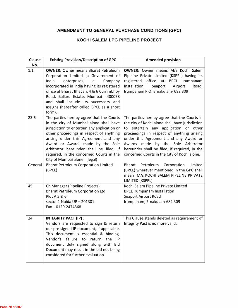
AMENDMENT TO GENERAL PURCHASE CONDITIONS (GPC)
KOCHI SALEM LPG PIPELINE PROJECT
Clause No.
Existing Provision/Description of GPC Amended provision
1.1 OWNER: Owner means Bharat Petroleum Corporation Limited (a Government of India enterprise), a Company incorporated in India having its registered office at Bharat Bhavan, 4 & 6 Currimbhoy Road, Ballard Estate, Mumbai 400038 and shall include its successors and assigns (hereafter called BPCL as a short form).
OWNER: Owner means M/s Kochi Salem Pipeline Private Limited (KSPPL) having its registered office at BPCL Irumpanam Installation, Seaport Airport Road, Irumpanam P O, Ernakulam- 682 309
23.6 The parties hereby agree that the Courts in the city of Mumbai alone shall have jurisdiction to entertain any application or other proceedings in respect of anything arising under this Agreement and any Award or Awards made by the Sole Arbitrator hereunder shall be filed, if required, in the concerned Courts in the City of Mumbai alone. (legal)
The parties hereby agree that the Courts in the city of Kochi alone shall have jurisdiction to entertain any application or other proceedings in respect of anything arising under this Agreement and any Award or Awards made by the Sole Arbitrator hereunder shall be filed, if required, in the concerned Courts in the City of Kochi alone.
General Bharat Petroleum Corporation Limited (BPCL)
Bharat Petroleum Corporation Limited (BPCL) wherever mentioned in the GPC shall mean M/s KOCHI SALEM PIPELINE PRIVATE LIMITED (KSPPL)
45 Ch Manager (Pipeline Projects) Bharat Petroleum Corporation Ltd Plot A 5 & 6, sector 1 Noida UP – 201301 Fax – 0120-2474368
Kochi Salem Pipeline Private Limited BPCL Irumpanam Installation Seaport Airport Road Irumpanam, Ernakulam-682 309
24 INTEGRITY PACT (IP) : Vendors are requested to sign & return our pre-signed IP document, if applicable. This document is essential & binding. Vendor's failure to return the IP document duly signed along with Bid Document may result in the bid not being considered for further evaluation.
This Clause stands deleted as requirement of Integrity Pact is no more valid.
Page 70 of 307

EIL-A538 Page 1 of 17
KOCHI - SALEM LPG PIPELINE PROJECTS
OF
M/S KOCHI SALEM PIPELINE PRIVATE LIMITED
SPECIAL PURCHASE CONDITIONS (SPC)
Page 71 of 307

EIL-A538 Page 2 of 17
INDEX 1.0 DEFINITIONS .................................................................................................... 3
2.0 BIDDER’S SCOPE ............................................................................................ 3
3.0 BID VAILIDTY .................................................................................................... 3
4.0 DELIVERY SCHEDULE / COMPLETION PERIOD ........................................... 4
5.0 DESPATCH INSTRUCTIONS ............................................................................ 4
6.0 PACKING, MARKING AND SHIPMENT .......................................................... 4
7.0 INSURANCE ...................................................................................................... 4
8.0 INSPECTION ..................................................................................................... 5
9.0 INDEPENDENT BIDDER ................................................................................... 5
10.0 TAXES & DUITES ............................................................................................. 5
11.0 RECOVERY OF CUSTOM DUTY, EXCISE DUTY AND SALES TAX .............. 7
12.0 PERFORMANCE BANK GUARANTEE (PBG)/CONTRACT PERFORMANCE BANK GUARANTEE (CPBG): .......................................................................... 7
13.0 PAYMENT TERMS ............................................................................................ 7
14.0 DEDUCTION AT SOURCE .............................................................................. 11
15.0 LIMITATION OF LIABILITY ............................................................................. 11
16.0 STATUTORY APPROVAL .............................................................................. 11
17.0 FINANCIAL DETERRENT FOR VIOLATION OF HSE .................................... 11
18.0 LIEN ................................................................................................................. 11
19.0 SETTLEMENT OF DISPUTE BETWEEN GOVT. DEPT./ PUBLIC SECTOR UNDERTAKINGS ............................................................................................ 11
20.0 INTEGRITY PACT / INDEPENDENT EXTERNAL MONITORS ...................... 11
21.0 FRAUDULENT PRACTICES ........................................................................... 12
22.0 EVALUATION CRITERIA FOR COMPARISON OF BIDS .............................. 12
23.0 COMMERCIAL LOADING OF OFFERS IN CASE OF DEVIATIONS ............. 12
EVALUATION CRITERIA FOR COMPARISON OF BIDS............................................. 13
COMMERCIAL LOADING OF OFFERS IN CASE OF DEVIATIONS .......................... 15
Page 72 of 307

EIL-A538 Page 3 of 17
SPECIAL PURCHASE CONDITIONS (SPC)
1.0 DEFINITIONS 1.1. In addition to meaning ascribed to certain capitalised terms in “General Purchase Conditions
(GPC)”, following initial capitalised terms shall have the meaning as ascribed to such term hereunder. In case any term defined hereunder is also defined in “GPC”, the meaning ascribed to such term hereunder shall prevail:
1.1.1. Definitions
RFQ Documents shall mean documents issued to the bidder
Effective Date shall mean the date on which Bidder’s obligations will commence and that will be date of Fax of Acceptance (FOA).
1.2. Interpretations
1.2.1. Where any portion of the GPC is repugnant to or at variance with any provisions of the SPC then, unless a different intention appears, the provisions of the SPC shall be deemed to govern the provisions of the GPC, and SPC provisions shall prevail to the extent of such repugnancy or variations exist.
1.2.2. In RFQ Documents unless otherwise stated specifically, the singular shall include the plural and vice versa wherever the context so requires.
1.2.3. Notwithstanding the sub-division of the RFQ Documents into separate sections and volumes every part of each shall be deemed to be supplementary to and complementary of every other part and shall be read with and into the Agreement so far as it may be practicable to do so.
1.2.4. All headings, subtitles and marginal notes to the clauses of the GPC, SPC or to the Specifications or to any other part of RFQ Document are solely for the purpose of giving a concise indication and not a summary of the contents thereof, and they shall never be deemed to be part thereof or be used in the interpretation or construction thereof.
1.2.5. The terms fully capitalized and/or initial capitalized shall be interchangeable and shall have the meaning as assigned to fully capitalized term or initial capitalised term.
1.2.6. Except the obligation of payment to Seller, Consultant may discharge all other Purchaser’s obligations. In RFQ documents at all such places where obligations are confined to Purchaser alone such provision to read as ‘Purchaser/Consultant’s’ obligation to the extent the context so means/ requires.
1.2.7. Throughout RFQ Document terms “Letter of Acceptance”, “Letter of Intent”, “Letter of Award”, “Fax of Acceptance” are synonymous.
2.0 BIDDER’S SCOPE Bidder’s scope shall include (a) manufacturing of Items as per Material Requisition including Technical Specifications; (b) preparation of Quality Assurance / Quality control programme; (c) obtaining Consultant’s approval; (d) Inspection by Purchaser’s/Consultant/Agency Designated by Purchaser and obtaining Inspection Release Note; (e) obtaining despatch clearance; (f) Packing; and (g) Loading on truck/trailer and transportation upto site for Indian Bidder/ loading on ship at FOB/FCA port of exit including stowing as applicable for foreign bidder.
3.0 BID VAILIDTY 3.1 The bid shall remain valid for acceptance for period mentioned in RFQ from the final bid due
date. Owner/EIL shall reject a bid valid for a shorter period being non-responsive.
3.2 In exceptional circumstances, prior to expiry of the original bid validity period, the Owner/EIL may request that the bidder extend the period of validity for a specified additional period. The requests and the responses thereto shall be made in writing (by fax/post/e-mail).
3.3 The validity of recommended spares (If applicable as per MR) for 2 years normal operation and maintenance will be 12 months beyond the validity of bid.
Page 73 of 307

EIL-A538 Page 4 of 17
4.0 DELIVERY SCHEDULE / COMPLETION PERIOD 4.1 All goods under the scope of the Bidder shall be delivered as per delivery schedule / completion
period specified in Request for Quotation (RFQ) and no variation shall be permitted.
4.2 Failing to meet the delivery schedule / completion period will be subject to Price Reduction and/or other remedies available to the Purchaser in RFQ Documents.
4.3 Price Reduction Schedule (PRS) shall be applicable as per Clause 20 of GPC subject to condition that the contractual delivery/completion date shall be reckoned from the date of Fax of Acceptance in all cases.
4.4 Where erection/testing/commissioning supervision, commissioning assistance is required as per RFQ Documents / Material requisition, penalty for non mobilization/delay in mobilization as per order shall be applicable. The penalty shall generally be 1.5 times the per diem rate for each day of delay of reporting to site and shall be in addition to price reduction for delayed delivery.
4.5 For Indian Bidder, date of LR/GR shall be considered as date of delivery or date of receipt of material at site shall be the date of delivery as specified in RFQ Cover Letter /Fax of acceptance/Purchase Order. For Foreign Bidder, date of clean Bill of Lading /Airway Bill shall be considered as date of Delivery.
5.0 DESPATCH INSTRUCTIONS 5.1 Bidder shall obtain despatch clearance from the purchaser prior to despatch.
5.2 Following despatch documents are required to be submitted by the Bidder immediately after shipment is made.
Commercial Invoice Dispatch instructions/ clearance by Purchaser/Consultant. Inspection Release Note by Purchaser / Consultant. LR/ GR / Clean Bill of Lading/Airway Bill. Packing List Test Certificates (NDT reports, MTC, etc. as per MR) Certificate of Measurement and Weight List of documents as specified in Bidder Data Requirement in Material Requisition &
counter signed & stamped by Purchaser / Consultant. In addition to above documents in case of Foreign Bidder following documents are also required to be submitted ETA Kochi Seaport /Airport (In case of CFR/CPT Contract) Documents pertaining to ocean/air freight (In case of CFR/CPT Contract) Country of origin certificate
6.0 PACKING, MARKING AND SHIPMENT 6.1 The Bidder wherever applicable shall after proper painting, pack and crate all goods for
sea/road/rail transportation in such a manner so as to protect it from damage and deterioration. The Bidder shall be held responsible for all damages due to improper packing. The Bidder shall ensure sizing or packing of all oversized consignments in such a way that availability of carrier and/or road/rail route is properly taken into consideration.
6.2 Bidder shall comply with the Packing, Marking and Shipping Instructions as in respective documents given as part of RFQ Document.
7.0 INSURANCE 7.1 For cases where only supply is involved and where divisible scope of supply and site work with
separate delivery /completion period for respective scope of work is specified, Transit insurance , marine insurance and comprehensive (transit cum marine, storage, erection, till handing over of equipment) insurance, as applicable shall be excluded from the bidder’s scope and, the same shall be arranged by the owner.
Page 74 of 307

EIL-A538 Page 5 of 17
7.2 For purchases involving indivisible/turnkey works where single time schedule of completion is specified, the comprehensive (transit cum marine, storage, erection, till handing over of equipment) insurance shall be in the scope of bidder/contractor.
8.0 INSPECTION 8.1 Inspection of Imported Items against orders on Foreign Bidders shall be carried out by EIL. No
additional charges shall be payable to seller on account of the same. In the case of a foreign bidder sourcing items from India, the inspection shall be carried out by EIL, no additional charges shall be payable to seller on account of the same.
8.2 Inspection of items supplied by Indian bidders shall be in the scope of EIL. In case Indian party sourcing materials from abroad, the bidder shall arrange inspection through EIL, if required.
8.3 Travel, Living and Personnel expenses of EIL’s Representative shall be borne by the Owner.
9.0 INDEPENDENT BIDDER It is expressly understood and agreed that Bidder is an independent party and that neither the Bidder/ its personnel are servants, agents or employees of Purchaser/ Consultant nor the Bidder has any kind of interest in other Bidders.
10.0 TAXES & DUITES 10.1 EXCISE DUTY (Applicable only for Indian Bidder / Indigenous Supplies):
Quoted Price should be exclusive of Excise Duty including Ed Cess applicable on Finished Goods. Applicable rate of Excise Duty including Ed Cess should be indicated by the bidder in Price Schedule / Annexure-1 to Agreed Terms and Conditions.
10.2 CENTRAL SALES TAX (CST) / VAT (Applicable only for Indian Bidder / Indigenous Supplies):
Quoted Price should be exclusive of CST (without concessional form) or VAT (without concessional form) applicable on the finished goods. Applicable rate should be indicated by the bidder in Price Schedule / Annexure-1 to Agreed Terms and Conditions.
Owner shall not issue concessional form “C” for Central Sales Tax. No concessional form shall be issued for VAT.
10.3 IMPORT DUTIES (Applicable only for Indian Bidder):
Quoted Price shall be inclusive of Import Duties on the import content if any in the supply. Bidder to indicate CIF value of the import content and applicable merit rate of Import Duties on the import content in the Price Schedule / Annexure-1 to Agreed Terms and Condition. Statutory variation on Import Duties within the 2/3rd of contractual delivery period shall be to Owner’s account against submission of the documentary evidence and shall be given as per CIF value and applicable merit rate of import duties indicated by the bidder in their offer. Any increase in the rate of Import Duties on CIF value beyond the 2/3rd of contractual completion period shall be to bidder’s account. Any decrease in the rate of Import Duties on CIF shall be passed on to the Owner.
Owner shall not issue Project Authority Certificate (PAC) / Import License to the Bidders.
10.4 SERVICE TAX:
10.4.1 TRANSPORTATION CHARGES (Applicable only for Indian Bidders):
Quoted Transportation charges shall be exclusive of applicable Service Tax including Ed Cess. Applicable rate of Service Tax including Ed Cess should be indicated by the bidder in Price Schedule / Annexure-1 to Agreed Terms and Conditions.
10.4.2 SUPERVISION / TRAINING CHARGES:
Quoted Supervision / Training Charges shall be exclusive of applicable Service Tax including Ed Cess. Indian Bidder to indicate applicable rate of Service Tax including Ed Cess on Supervision / Training Charges in Price Schedule.
Page 75 of 307

EIL-A538 Page 6 of 17
For Foreign Bidder Service Tax on Supervision / Training Charges shall be paid by the Owner directly.
10.4.3 SITE WORK:
Quoted Site Work Prices shall be exclusive of applicable Service Tax. Bidder to indicate applicable rate of Service Tax including Ed Cess on Site Work Charges in Price Schedule.
For cases where only supply is involved and where divisible scope of supply and site work with separate delivery /completion period for respective scope of work is specified, Bidder to quote their rates exclusive of Service tax at full rate.
10.4.4 VAT ON WORK CONTRACTS:
Quoted Site Work Prices shall be inclusive of applicable VAT on Work Contracts.
VAT on Work Contracts as applicable shall be deducted at source and TDS certificate shall be issued to the Bidder.
The bidder has to be a registered dealer under the State VAT Act before getting payment for his works contract. The contractor has to produce an authenticated copy of the certificate of registration under State VAT Act or furnish an undertaking for getting so registered.
10.5 OCTROI / ENTRY TAX:
10.5.1 For cases where only supply is involved and where divisible scope of supply and site work with separate delivery /completion period for respective scope of work is specified: Entry Tax / Octroi on supply component shall be reimbursed by purchaser against documentary evidence.
10.5.2 For purchases involving indivisible/turnkey works where single time schedule of completion is specified: Entry Tax / Octroi on material brought by the Seller to site for execution of work at site shall be borne by the Seller and quoted prices should be inclusive of such Entry Tax / Octroi. No variation on any account (including Statutory) on such entry tax/octroi shall be paid by the Owner.
10.6 ADDITIONAL TAXES & DUTIES (Applicable for Indian Bidder)
Within the contractual delivery period, if any new taxes and/or duties come into force the same will be reimbursed to bidder against documentary evidence. However any new or additional taxes/ duties imposed after contractual delivery shall be to Bidder’s account.
10.7 Owner may claim Cenvat /input tax credit on CVD/ Additional CVD / service tax / VAT / Excise Duty and education cess as per the relevant statutes in force. Excise/customs duty, CVD, Service Tax, education cess and VAT / CST as applicable shall be payable against proper invoice as per statutes enabling Owner to claim Cenvat /input tax credit.
10.8 In case of Foreign Bidder quoted FOB Prices shall be inclusive of all charges inclusive of all applicable taxes & duties, applicable upto FOB International Port of Exit.
10.9 All necessary taxes & duties registration, if required for carrying out the site activities shall be done by the supplier and cost towards the same shall be included in quoted prices.
10.10 Any Statutory variation in Excise Duty, Sales Tax and Service Tax , within the contractual delivery date, shall be on owner’s account, against submission of documentary evidence. However, in case of delay in delivery beyond the contractual date, for reasons attributable to seller, any increase in these rates shall be borne by seller, whereas any decrease shall be passed on to the owner. Owner shall take input credit as applicable. No variation on any account (including Statutory) on VAT on Works Contract shall be paid by the Owner.
10.11 Further, in case of delay in delivery, due to reasons attributable to seller, any new or additional taxes, duties or levies imposed after the contractual delivery date shall be on seller’s account.
10.12 For the purpose of applicability of statutory variations on taxes and duties (including imposition of any new taxes/duties/levies, etc.) under above terms, each staggered delivery of lots (due in a specific month as per delivery schedule for bulk items) shall be considered as delivery date for the respective lot(s).
Page 76 of 307

EIL-A538 Page 7 of 17
11.0 RECOVERY OF CUSTOM DUTY, EXCISE DUTY AND SALES TAX In case of Indian Bidders, if the Statutory Variation entitles the employer to recover the amount (irrespective of contractual delivery) such amount will be recovered from any bill of the Bidder immediately on enforcement of such variation under intimation to the Bidder.
12.0 PERFORMANCE BANK GUARANTEE (PBG)/CONTRACT PERFORMANCE BANK GUARANTEE (CPBG):
12.1 Performance Bank Guarantee for 10% of total order value shall be furnished by successful bidders in Owner’s format for orders of all values. However orders placed against Press/Open Enquiries and orders placed on Foreign bidders, Contract Performance Bank Guarantee (CPBG) shall be furnished by successful bidder Within 15 days from the date of Fax of Acceptance.
13.0 PAYMENT TERMS In partial modification of the payment terms as mentioned in the General Purchase Conditions, the following payment terms shall be applicable.
13.1 PAYMENT TERMS (INDIAN BIDDERS):
13.1.1 Where the Material Requisition is only for supply of materials and there is no Bidder Data Requirement specified in MR e.g., bulk piping items etc.
100% alongwith transportation charges within 30 days after receipt and acceptance of materials at site *[and on submission of a performance bank guarantee for 10% of total
order value, valid till the full guarantee period plus six months' claim period].
13.1.2 Where the Material Requisition calls for Bidder drawings/Technical Documentation.
13.1.2.1 Supply:
13.1.2.1.1 85% payment alongwith transportation charges within 30 days of receipt and acceptance of materials at site upon satisfactory completion of order including receipt of relevant technical documentation as specified in MR.
13.1.2.1.2 15% payment after receipt of final technical documentation as per Purchase Requisition against EIL's certification *[and on submission of performance bank guarantee for 10% of total order value, valid till full guarantee period plus six months claim period ].
13.1.2.2 Transportation charges:
100% within 30 days after receipt of materials at site.
13.1.3 Where supply of materials and erection or site work are in the scope of bidder and package items.
13.1.3.1 Supply:
13.1.3.1.1 85 % within 30 days after receipt of equipment /materials at BPCL's site. Billing schedule to be furnished by the Bidder in case pro-rata payments are required and EILs certification.
13.1.3.1.2 15% within 30 days after handing over of the successfully commissioned equipment to BPCL, on submission of final technical documents as required in the Purchase Requisition against EIL’s certification *[and on submission of performance bank guarantee for 10% of total order value (Supply plus Site Work), valid till full guarantee period plus six months claim period.] Wherever commissioning is not in Bidder’s scope the payment will be released after erection and handing over of equipment.
13.1.3.1.3 For cases where divisible scope of supply and site work with separate delivery /completion period for respective scope of work is specified following;
In case owner intimation regarding availability of work front at site is not given upto 6 (Six) months after receipt of all supplies at site, then last 15% payment shall be released against submission of a Bank Guarantee of equivalent amount valid for 1 (One) year in addition to
Page 77 of 307

EIL-A538 Page 8 of 17
submission of performance bank guarantee for 10% of total order value (Supply plus Site Work), valid till full guarantee period plus six months claim period.
13.1.3.2 Transportation charges:
100% within 30 days after receipt of materials at site.
13.1.3.3 Erection/ Site work:
13.1.3.3.1 90% against monthly running bills (based on agreed billing schedule), duly certified by EIL.
13.1.3.3.2 10% within 30 days after final handing over of equipment package to BPCL at site.
13.1.4 Other items (Pumps, Compressors, Switch gears etc.)
13.1.4.1 Supply:
13.1.4.1.1 85% payment against receipt of material at site along with duly certified bill from EIL. Billing schedule to be furnished by the Bidder in case pro-rata payments are required.
13.1.4.1.2 15 % payment after receipt of final documents as required in Purchase Requisition against EIL's certification *[and on submission of performance bank guarantee for 10% of total order value, valid till full guarantee period plus six months claim period]
Or
Where Scope of Work involves Erection, Testing & Commissioning / Demonstration of Performance Guarantee:
15% payment after commissioning /demonstration of Performance Guarantee (if applicable) and on receipt of final documents as required in Purchase Requisition along with *[ performance bank guarantee for 10% of total order value, valid till full guarantee period plus six months claim period].
In case Erection, Testing & Commissioning / Demonstration of Performance Guarantee is delayed beyond 6 months from the date of receipt of material at site ,for the reasons attributable to Owner, last 15% payment shall be released against submission of additional BG of equivalent amount valid for 1 year, and on receipt of final documents as required in Purchase Requisition along with *[ performance bank guarantee for 10% of total order value, valid till full guarantee period plus six months claim period] . However in the event of delay in conducting the performance guarantee run, the bidder is not relieved of his responsibility to carry out the performance run. No additional payment shall be made for visit of bidder to site for demonstrating the performance, if the same is included in the scope of bidder. Bill shall be certified by EIL.
Note : * In case of Press Enquiries Bidders are required to submit Contract Performance Bank Guarantee after receipt of Fax of Acceptance, hence the words “[and on submission of performance bank guarantee for 10% of total order value (Supply plus Site Work), valid till full guarantee period plus six months claim period.]” shall not be applicable.
13.1.4.2 Transportation charges:
100% within 30 days after receipt of materials at site.
13.1.5 Payment of per diem charges for supervision of Erection and Commissioning
100% of invoice amount shall be paid on completion of services against submission of Invoice after the time sheet duly certified by EIL/BPCL Site In Charge. Payment shall be made after deducting income tax at applicable rates. Service tax, if any, shall be paid on submission of service Tax invoice.
13.1.6 General:
a) Excise duty, Service Tax and VAT shall be released only on receipt of Cenvatable / Vatable copy of corresponding Invoice.
Page 78 of 307

EIL-A538 Page 9 of 17
b) No initial advance payment shall be made by the Owner against supplies as well as services (i.e., transportation, erection, site work etc.). If a bidder insists on the same, the offer shall be rejected.
c) Bank Guarantee(s) shall be issued through Scheduled commercial bank in India/ Indian Branch of foreign Bank, directly to the Owner as per pro-forma enclosed and Bidder shall enclose copy of the same along with invoice.
d) All payments shall be released within 30 days of receipt of invoice and all requisite documents, complete in all respects.
e) Billing schedule shall be submitted to EIL & BPCL by the bidder for approval within 30 days from the date of Purchase order wherever specified in the purchase order. No payment against pro-rata dispatch shall be made without approval of billing schedule.
13.2 PAYMENT TERMS (FOREIGN BIDDERS):
13.2.1 Where the Material Requisition is only for supply of materials
13.2.1.1 100% of FOB order value shall be paid through an irrevocable letter of credit against submission of Shipping Documents. The letter of credit shall be established only on receipt of unconditional acceptance of BPCL’s Fax of acceptance/Order along with submission of Bank Guarantee of 10% towards performance valid till full guarantee period plus six months claim period.
13.2.1.2 Transportation:
In case of Purchase order placed on FOB Port of Exit basis, ocean transportation from FOB Port of Exit to Designated Indian Port shall be arranged by Owner through their nominated freight forwarder. Bidder shall arrange handing over of the material to Owner’s nominated freight forwarder at the designated port of exit.
In cases Purchase order placed on CFR basis, Owner reserves the right to ask the bidder to arrange shipment through the bidder’s own freight forwarder at the quoted freight rates & full Ocean Freight charges shall be released on receipt of despatch/ shipping documents along with Documents pertaining to Ocean Freight.
In case of award, initially the purchase order (PO) shall be placed on FOB basis and Owner reserves the right to convert the same to CFR basis within Contractual Delivery Date based on shipping details of consignment (complete in all respect) indicated in the bid. Therefore, the quoted Ocean Freight Charges should be valid till Contractual Delivery Date.
13.2.2 Where the Material Requisition calls for supply of material and erection or site work
in the scope of bidder and package items.
13.2.2.1 Supply:
13.2.2.1.1 90% of FOB Supply value payment through an irrevocable letter of credit against submission of Shipping Documents.
13.2.2.1.2 10% of FOB Supply value through direct wire transfer through banking channels on completion of erection or site work as per purchase order against submission of final documents of certificate for completion of activity by BPCL site.
The letter of credit shall be established only on receipt of acceptance of BPCL’s Fax of acceptance/Order along with submission of Bank Guarantee for 10% of total order value (Supply plus Site work) Towards Performance valid till full guarantee period plus six months claim period.
13.2.2.2 Site Work:
13.2.2.2.1 100% of amount for erection or site work shall be paid through direct wire transfer as per normal banking channels on completion of erection or site work as per purchase order against submission of certificate for completion of work by EIL.
13.2.2.3 Transportation:
Page 79 of 307
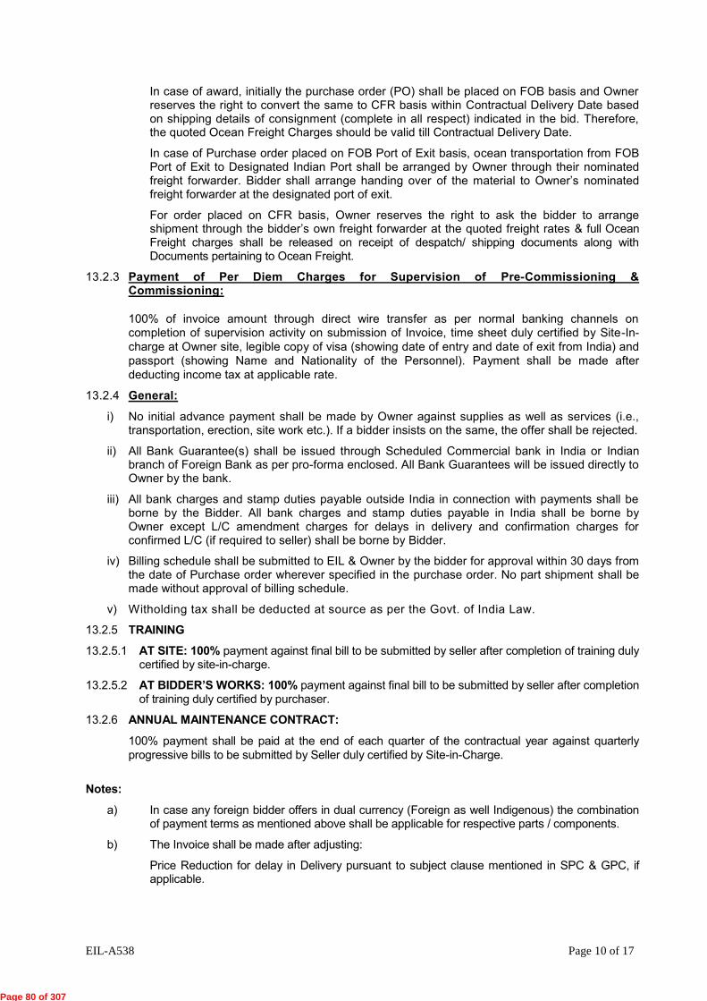
EIL-A538 Page 10 of 17
In case of award, initially the purchase order (PO) shall be placed on FOB basis and Owner reserves the right to convert the same to CFR basis within Contractual Delivery Date based on shipping details of consignment (complete in all respect) indicated in the bid. Therefore, the quoted Ocean Freight Charges should be valid till Contractual Delivery Date.
In case of Purchase order placed on FOB Port of Exit basis, ocean transportation from FOB Port of Exit to Designated Indian Port shall be arranged by Owner through their nominated freight forwarder. Bidder shall arrange handing over of the material to Owner’s nominated freight forwarder at the designated port of exit.
For order placed on CFR basis, Owner reserves the right to ask the bidder to arrange shipment through the bidder’s own freight forwarder at the quoted freight rates & full Ocean Freight charges shall be released on receipt of despatch/ shipping documents along with Documents pertaining to Ocean Freight.
13.2.3 Payment of Per Diem Charges for Supervision of Pre-Commissioning & Commissioning:
100% of invoice amount through direct wire transfer as per normal banking channels on completion of supervision activity on submission of Invoice, time sheet duly certified by Site-In-charge at Owner site, legible copy of visa (showing date of entry and date of exit from India) and passport (showing Name and Nationality of the Personnel). Payment shall be made after deducting income tax at applicable rate.
13.2.4 General:
i) No initial advance payment shall be made by Owner against supplies as well as services (i.e., transportation, erection, site work etc.). If a bidder insists on the same, the offer shall be rejected.
ii) All Bank Guarantee(s) shall be issued through Scheduled Commercial bank in India or Indian branch of Foreign Bank as per pro-forma enclosed. All Bank Guarantees will be issued directly to Owner by the bank.
iii) All bank charges and stamp duties payable outside India in connection with payments shall be borne by the Bidder. All bank charges and stamp duties payable in India shall be borne by Owner except L/C amendment charges for delays in delivery and confirmation charges for confirmed L/C (if required to seller) shall be borne by Bidder.
iv) Billing schedule shall be submitted to EIL & Owner by the bidder for approval within 30 days from the date of Purchase order wherever specified in the purchase order. No part shipment shall be made without approval of billing schedule.
v) Witholding tax shall be deducted at source as per the Govt. of India Law.
13.2.5 TRAINING
13.2.5.1 AT SITE: 100% payment against final bill to be submitted by seller after completion of training duly certified by site-in-charge.
13.2.5.2 AT BIDDER’S WORKS: 100% payment against final bill to be submitted by seller after completion of training duly certified by purchaser.
13.2.6 ANNUAL MAINTENANCE CONTRACT:
100% payment shall be paid at the end of each quarter of the contractual year against quarterly progressive bills to be submitted by Seller duly certified by Site-in-Charge.
Notes:
a) In case any foreign bidder offers in dual currency (Foreign as well Indigenous) the combination of payment terms as mentioned above shall be applicable for respective parts / components.
b) The Invoice shall be made after adjusting:
Price Reduction for delay in Delivery pursuant to subject clause mentioned in SPC & GPC, if applicable.
Page 80 of 307
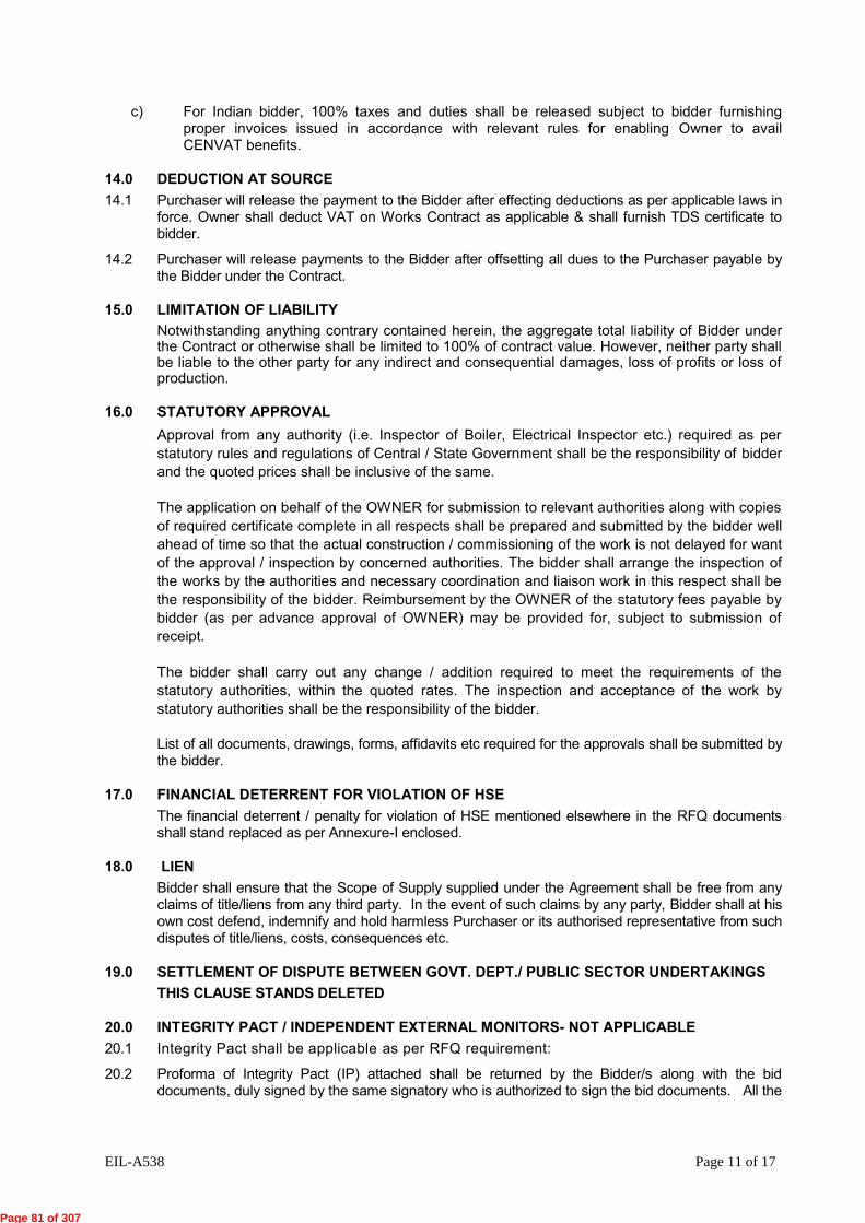
EIL-A538 Page 11 of 17
c) For Indian bidder, 100% taxes and duties shall be released subject to bidder furnishing proper invoices issued in accordance with relevant rules for enabling Owner to avail CENVAT benefits.
14.0 DEDUCTION AT SOURCE 14.1 Purchaser will release the payment to the Bidder after effecting deductions as per applicable laws in
force. Owner shall deduct VAT on Works Contract as applicable & shall furnish TDS certificate to bidder.
14.2 Purchaser will release payments to the Bidder after offsetting all dues to the Purchaser payable by the Bidder under the Contract.
15.0 LIMITATION OF LIABILITY Notwithstanding anything contrary contained herein, the aggregate total liability of Bidder under the Contract or otherwise shall be limited to 100% of contract value. However, neither party shall be liable to the other party for any indirect and consequential damages, loss of profits or loss of production.
16.0 STATUTORY APPROVAL Approval from any authority (i.e. Inspector of Boiler, Electrical Inspector etc.) required as per statutory rules and regulations of Central / State Government shall be the responsibility of bidder and the quoted prices shall be inclusive of the same.
The application on behalf of the OWNER for submission to relevant authorities along with copies of required certificate complete in all respects shall be prepared and submitted by the bidder well ahead of time so that the actual construction / commissioning of the work is not delayed for want of the approval / inspection by concerned authorities. The bidder shall arrange the inspection of the works by the authorities and necessary coordination and liaison work in this respect shall be the responsibility of the bidder. Reimbursement by the OWNER of the statutory fees payable by bidder (as per advance approval of OWNER) may be provided for, subject to submission of receipt.
The bidder shall carry out any change / addition required to meet the requirements of the statutory authorities, within the quoted rates. The inspection and acceptance of the work by statutory authorities shall be the responsibility of the bidder. List of all documents, drawings, forms, affidavits etc required for the approvals shall be submitted by the bidder.
17.0 FINANCIAL DETERRENT FOR VIOLATION OF HSE The financial deterrent / penalty for violation of HSE mentioned elsewhere in the RFQ documents shall stand replaced as per Annexure-I enclosed.
18.0 LIEN Bidder shall ensure that the Scope of Supply supplied under the Agreement shall be free from any
claims of title/liens from any third party. In the event of such claims by any party, Bidder shall at his own cost defend, indemnify and hold harmless Purchaser or its authorised representative from such disputes of title/liens, costs, consequences etc.
19.0 SETTLEMENT OF DISPUTE BETWEEN GOVT. DEPT./ PUBLIC SECTOR UNDERTAKINGS THIS CLAUSE STANDS DELETED
20.0 INTEGRITY PACT / INDEPENDENT EXTERNAL MONITORS- NOT APPLICABLE20.1 Integrity Pact shall be applicable as per RFQ requirement:
20.2 Proforma of Integrity Pact (IP) attached shall be returned by the Bidder/s along with the bid documents, duly signed by the same signatory who is authorized to sign the bid documents. All the
Page 81 of 307

EIL-A538 Page 12 of 17
pages of the Integrity Pact shall be duly signed. Bidder's failure to submit the IP duly signed shall result in the bid not being considered for further evaluation.
20.3 Bidders may raise disputes/complaints, if any, with the nominated Independent External Monitor, mentioned below:
T.S.KRISHNAMURTHY Flat NO.9, Gokul Tower
Next to Mookambika Complex No.7, C P Ramaswamy Road Alwarpet Chennai-600 018
044-24993077 044-24993079 Mobile- 9444999555
SHRI JANKI BALLABH
Flat No. 605, Varsova Vainayak CO-OP. HSG. SOC. HSG Plot No. 8, Near Versova Telephone Exchange, Versova, Andheri (West), Mumbai -400 053
022 - 2635 3456 (RES) Mobile 9833363066
21.0 FRAUDULENT PRACTICES 21.1 The OWNER requires that Bidders/Bidders/Contractors observe the highest standard of ethics
during the award/execution of Contract. “Fraudulent Practice” means a misrepresentation of facts in order to influence the award of a Contract to the detriment of the OWNER, and includes collusive practice among bidders ( prior to or after bid submission ) designed to establish bid prices at artificial non-competitive levels and to deprive the OWNER of the benefits of free and open competition.
21.2 The OWNER will reject a bid for award if it determines that the bidder recommended for award has engaged in fraudulent practices in competing for the Contract in question.
Bidder is required to furnish the complete and correct information/ documents required for evaluation of their bids, if the information/ documents forming basis of evaluation is found to be false/ forged, the same shall be considered adequate ground for rejection of bids and forfeiture of Earnest Money Deposit.
21.3 In case, the information/ document furnished by the Bidder/bidder/Contractor forming basis of evaluation of his bid is found to be false/ forged after the award of the contract, OWNER shall have full right to terminate the contract and get the remaining job executed at the risk & cost of such Bidder/Bidder/ Contractor without any prejudice to other rights available to OWNER under the contract such as forfeiture of PBG/CPBG, withholding of payment etc.
21.4 In case, this issue of submission of false document comes to the notice after execution of work, OWNER shall have full right to forfeit any amount due to the Bidder/Bidder/Contractor along with forfeiture of PBG/Security Deposit furnished by the Bidder/Bidder/Contractor.
21.5 Further, such Bidder/Bidder/ Contractor shall be put on Blacklist/ Holiday/Negative List of OWNER debarring them from future business with OWNER and EIL for a time period, as per the prevailing policy of OWNER and EIL.
22.0 EVALUATION CRITERIA FOR COMPARISON OF BIDS Evaluation criteria for comparison of bids shall be as per Annexure-II enclosed.
23.0 COMMERCIAL LOADING OF OFFERS IN CASE OF DEVIATIONS Commercial loading of offers in case of deviations specified by the Bidder against RFQ terms & conditions shall be as per Annexure-III enclosed.
Page 82 of 307

EIL-A538 Page 15 of 17
ANNEXURE-II
EVALUATION CRITERIA FOR COMPARISON OF BIDS
1.1. Where only Indian Bids are under comparison
• Bids shall be evaluated on the basis of landed cost at Site inclusive of freight, taxes & duties as applicable except octroi/entry tax MINUS Cenvatable Excise Duty.
• Commercial loading, if applicable, shall be done on FOT dispatch point price exclusive of freight, taxes & duties.
1.2. Where only Foreign Bids are under comparison
• Bids shall be evaluated on CFR/CPT basis considering firm Ocean/Airfreight as quoted by bidders
• In case of pipes. wherever the supplier has not indicated/included stowage charges, the FOB price shall be loaded @ 10% of the bidder's quoted ocean freight. The seller shall not be allowed to change port of shipment after quoting unless the bidder absorbs any additional cost on account of the change.
• Comparison shall be done on equivalent Indian Rupees considering RBI reference rate of foreign exchange published on the day of opening of the Price Bids. In case RBI holiday on date of Priced Bid Opening, exchange rates published on immediate preceding day shall be considered.
• Commercial loading, if applicable, shall be done on FOB price.
• In case bidder ascertain and confirm, along with supporting documents, if custom duty exemption/waiver is applicable under any multilateral/bilateral trade agreement as per Cl. No. 11.7.8 of ITB, then evaluation shall be done as per Evaluation Procedure defined under “Foreign Bidder” against Cl. No. 1.3, instead of evaluation on CFR/CPT basis as mentioned above.
1.3. Where Indian as well as Foreign Bids are under comparison
Domestic Bidders:
• Bids shall be evaluated on the basis of landed cost at Site inclusive of freight, taxes & duties as applicable except octroi/entry tax MINUS Cenvatable Excise Duty.
• Commercial loading, if applicable, shall be done on FOT dispatch point price exclusive of freight, taxes & duties.
Foreign Bidders:
Bids shall be evaluated on the basis of landed cost at Site including all duties, taxes and transportation charges as under except octroi/entry tax.
Sr. No. Head Basis 1. F.O.B./FCA Price Basis As quoted by the bidder (including stowage
charges in case of pipes*)
*Stowage charges, if not included in the quoted FOB Price, the same shall be loaded @ 10% of ocean freight quoted by the bidder.
Page 83 of 307

EIL-A538 Page 16 of 17
Sr. No. Head Basis 2. Add Ocean/ Air Freight: Firm freight as quoted by bidders up to
designated Seaport/Airport of Entry in India.
3. Add Marine insurance @1% of FOB price
4. Add Customs Duty Prevailing rate of Customs Duty based on Merit rate or Concessional Rate as per Cl. No. 11.7.8 of ITB (CIF value plus Landing Charges @ 1% of CIF Value) MINUS Cenvatable CVD.
5. Add Port Handling & CHA charges
@ 3% of CIF value
6. Add Inland freight charges from Port of Entry in India to project site(s)
1% of landed cost, i.e., S. No. 1 to 5
7. Add L/c Charges @ 0.75 % of FOB/FCA Price
8. Commercial Loadings, If any.
On FOB value
9. FOT SITE PRICE Sum (1 to 8)
• Comparison shall be done on equivalent Indian Rupees considering RBI reference rate of foreign exchange published on the day of opening of the Price Bids. In case RBI holiday on date of Priced Bid Opening, exchange rates published on immediate preceding day shall be considered.
1.4. Cost of Mandatory (Insurance) spares if identified in the Material Requisition, commissioning spares and special tools and tackles will be included for price evaluation of bids, but costs of Spares for two years normal operation and maintenance shall be excluded.
1.5. Cost of loading towards Technical Parameters (Utilities etc.) wherever applicable shall be carried out.
1.6. CENVAT benefits on account of Excise Duty and CVD shall only be considered for evaluation and comparison of bids. Cenvat benefits on account of Service Tax and VAT shall not be considered for evaluation and comparison of Bids.
1.7. Service Tax is non-cenvatable for this Project. Same shall be loaded while evaluation
1.8. Wherever site work, AMC/PWMC, training, supervision etc. are required as per MR/RFQ, the same shall be considered for evaluation
Page 84 of 307

EIL-A538 Page 15 of 17
ANNEXURE-III
COMMERCIAL LOADING OF OFFERS IN CASE OF DEVIATIONS 1.1 Basis of Loading
The Foreign Bids shall be loaded on FOB Port of Exit prices and the Indian Bids shall be loaded on FOT Dispatch Point prices.
1.2 Payment Terms
1.2.1. Any differential payment terms offered by an Indian bidder as against the terms specified in the RFQ/ GPC shall be loaded at 15% (simple interest) for the applicable period as under:
Final payment against dispatch document - one month
1.2.2. Foreign bidders shall not be permitted to offer differential payment terms as against the terms specified in the RFQ/ GPC and in case they insist, their offer shall be rejected.
1.2.3. Any payment before dispatch of material shall be considered as Advance Payment. If a bidder insists for Advance Payment, his offer shall be rejected.
1.3 Performance Bank Guarantee (PBG)
1.3.1. Performance Bank Guarantee shall be required in all cases of supplies of all values. In case a bidder offers to give a PBG for less than 10% of order value, or for a lesser period than what is provided in GPC, loading shall be done for the differential amount and/ or the differential period. For differential period / amount loading, the following example will amplify the methodology (if GPC specifies 10% PBG for 24 months + 6 months claim period = Total 30 months)
For differential period:
Period offered by bidder Loading 10% for 30 months - No loading
10% for 21 months - 10% x 9/30 = 3%
10% for 18 months - 10% x 12/30 =4%
10% for 12 months - 10% x 18/30 = 6%
10% for 6 months - 10% x 24/30 = 8%
For differential Amount:
Other than 10%: To be loaded by percentage by which PBG is short of 10%.
1.3.2. In case, bidder does not agree to submit the PBG, 10% payment shall be deducted and withheld till the guarantee period.
1.3.3. In case, bidder does not agree to submit the PBG or agree for deduction as per 1.3.2 above, the offer shall be liable for rejection.
1.4 Delayed Deliveries (considering GPC clause of 1% un-delivered order value (UDOV) ~ 10% total order value (TOV)
In case a Bidder does not accept the delayed delivery clause and/or takes any deviation (indicates penalty clause/Liquidated Damages in place of Price Reduction Clause) or takes
Page 85 of 307

EIL-A538 Page 16 of 17
exception to the percentage rate mentioned in GPC, the offer of such bidder(s) shall be loaded as under:
1% UDOV to 10%TOV No loading
1% UDOV to 10% UDOV 5%
1% UDOV to less than10% TOV Differential between the Offered % and 10%
Any other deviation/Liquidated damages/ penalty or non acceptance of price reduction schedule
10%
In case of Package/Turnkey enquiry :
1% TOV to 10%TOV No Loading
1% TOV to less than 10% TOV Differential between the Offered % and 10%
Any other deviation/Liquidated damages/ penalty or non acceptance of price reduction schedule
10%
1.5 Price variation :
Bidders must quote firm & fixed prices unless price variation is specified in the RFQ. Where price variation is permitted as per RFQ, the loading there to shall be as follows
a) Firm Price No loading b) In case of Price Variation formula with
ceiling Loading by ceiling percentage offered.
c) No formula or no ceiling specified by Bidder (This shall be resorted to only after putting efforts with Bidder and obtaining BPCL's approval)
Offer shall be rejected.
1.6 Freight charges:
If a bidder does not quote freight charges, his offer shall be loaded with maximum freight charges as quoted by the other bidders. If bidder happens to be L1 even after loading the freight charges shall be absorbed by bidder.
1.7 Indian taxes / duties :
In case a bidder states that taxes/duties are not applicable at present and will be charged as applicable at the time of delivery, then his bid shall be loaded by the maximum rate of taxes/duties applicable.
1.8 Supervision Charges :
Supervision Charges quoted by the Bidder on pre-diem basis shall be loaded for the number of supervision mandays to be considered for evaluation as specified in the Material Requisition/Enquiry document
Page 86 of 307

EIL-A538 Page 17 of 17
If a bidder does not quote Supervision charges, his offer shall be loaded with maximum Supervision charges as quoted by the other bidders. In the event of award, Supervision charges shall be absorbed by bidder for estimated man days. Any extra mandays beyond estimated mandays shall be payable extra at actuals subject to maximum Supervision charges by which prices have been loaded.
1.9 Delivery
The required delivery period will be stipulated in the RFQ and the bids with longer than required delivery shall be liable for rejection.
1.10 Utilities
Cost loading in respect of utilities etc. will be considered as per rates specified in respective MRs.
Where ever standard baseline can be established for the power and utility consumptions, the same shall be incorporated in the tender document and suitable acceptance criteria shall be specified in the SPC.
Page 87 of 307

EIL-ATC (I)-A538 Page 1 of 8
CONSORTIUM OF BHARAT PETROLEUM CORPORATION LTD. (BPCL) AND INDIAN OIL CORPORATION LTD. (IOCL)
KOCHI COIMBATORE ERODE SALEM LPG PIPELINE PROJECT (Job No. A538)
AGREED TERM & CONDITIONS (ATC) (FOR INDIAN BIDDERS/INDIGENOUS ITEMS/WORK)
Vendor Name: M/s ______________________________________________________________ RFQ No. : __________________________________________________________________ Vendor’s Offer Ref No. : ___________________________________________________________ Tel. No. ___________________Mob. No. ______________________ Fax No. ________________ Contact Person: ___________________________ E-mail _________________________________ 1. ALL CORRESPONDENCE MUST BE IN ENGLISH LANGUAGE ONLY. 2. DULY SIGNED & STAMPED COPIES OF THIS “QUESTIONNAIRE”, WITH ALL THE
CLAUSES DULY CONFIRMED/ PRECISELY REPLIED TO BY THE VENDOR, SHALL BE ENCLOSED.
3. ALL COMMERCIAL TERMS ARE GIVEN/CONFIRMED IN THE QUESTIONNAIRE ITSELF
AND NOT ELSEWHERE IN THE QUOTATION. IN CASE OF CONTRADICTION, THE SAME GIVEN HEREIN SHALL PREVAIL.
4. FAILURE ON THE PART OF VENDOR IN SUBMITTING THIS DULY FILLED-UP
"QUESTIONNAIRE WITH UNPRICED BID AND/OR UPLOADING / SUBMITTING INCOMPLETE REPLIES MAY LEAD TO REJECTION OF VENDOR'S QUOTATION”.
5. YOUR OFFER SHALL BE IN TOTAL COMPLIANCE WITH RFQ DOCUMENTS
CONTAINING COMMERCIAL AND TECHNICAL SPECIFICATIONS INCLUDING GENERAL / TECHNICAL NOTES AND SCOPE OF SUPPLY INCLUDING DOCUMENTATION AS PER MATERIAL REQUISITION (MR) AND SUBSEQUENT TECHNICAL/COMMERCIAL AMENDMENT AND TECHNICAL/COMMERCIAL CORRIGENDUM, IF ANY.
SL. NO.
DESCRIPTION VENDOR’S CONFIRMATION
1 Quoted supply prices are on FOT despatch point basis inclusive of Packing & Forwarding.
Confirmed
2 Specify Despatch Point
Refer Annexure-1 to ATC
3 a) b) c)
Confirm firm transportation charges exclusive of Service Tax and Ed Cess, upto project site, has been quoted separately by you in Price Schedule.
Percentage of Service Tax as applicable extra on Freight Statutory Variation on Service Tax on Transportation Charges shall be paid by the owner against documentary evidence within completion period.
a. Confirmed , Quoted in Price
Schedule
b. Refer Annexure-1 to ATC
c. Confirmed
4 Transit Insurance shall be taken by the Owner & charges of the same shall be borne by Owner.
Confirmed
Page 88 of 307

EIL-ATC (I)-A538 Page 2 of 8
SL. NO.
DESCRIPTION VENDOR’S CONFIRMATION
5. a. b.
c.
Excise Duty applicable extra in percentage. Any variations in ED at the time of supplies for any reasons including variation due to turn-over shall be borne by the seller. Only statutory variations within Contractual Deliver Date shall be borne by Purchaser. If Excise Duty is not applicable at present due to any reason, the same shall be borne by vendor if it becomes applicable later.
a. Refer Annexure-1 to ATC
b. Confirmed
c. Confirmed
6. a. b.
Confirm Excise Duty will not be applicable on transportation charges. If Excise Duty is not applicable on transportation charges presently, and if it becomes applicable at the time of delivery due to any reasons other than statutory, the same will be borne by the Vendor. Confirm acceptance.
a. Confirmed
b. Confirmed
7. a. b. c. d. e.
Central Sales Tax applicable extra in percentage without Form ‘C’ VAT applicable extra: If CST / VAT is not applicable at present due to any reason, the same shall be borne by vendor if it becomes applicable later. Confirm CST/ VAT will not be applicable on transportation charges. If CST / VAT is not applicable on transportation charges presently, and if it becomes applicable at the time of delivery due to any reasons other than statutory, the same will be borne by the Vendor. Confirm acceptance.
a. Refer Annexure-1 to ATC
b. Refer Annexure-1 to ATC
c. Confirmed
d. Confirmed
e. Confirmed
8. Any new or additional taxes/ duties and any increase in the existing taxes/duties imposed after Contractual Delivery/Completion Date shall be to Vendor’s account whereas any corresponding decrease in the existing taxes/ duties shall be passed on to the Owner.
Confirmed
9.
Spares Parts: Confirm item wise unit price (FOT Despatch Point) of following spare parts as required in Material Requisition (MR) have been included indicating itemised quantity. i) Mandatory Spares are included quoted as per MR. ii) Commissioning spares as specified in MR are included in
the quoted Price. iii)Special Tools & Tackles as specified in the MR are
included in the quoted prices. iv) Confirm spares wherever required as per MR have been
included in the quoted price and list of spares is also furnished.
Confirmed
Confirmed (if Applicable as per MR)
Confirmed (if Applicable as per MR)
Confirmed (if Applicable as per MR)
Confirmed (if Applicable as per MR)
Page 89 of 307

EIL-ATC (I)-A538 Page 3 of 8
SL. NO.
DESCRIPTION VENDOR’S CONFIRMATION
10. a. b. c. d.
e.
Site Work: For Site Work, if in the scope of the Bidder as per MR, please confirm the following: Confirm that quoted site work prices are exclusive of Service Tax & inclusive of all other applicable taxes & duties including VAT on Work Contract Tax. Percentage of Service Tax as applicable extra on Site Work.
No variation in VAT on Work Contracts on any account (Including statutory variation) shall be paid by the owner. Statutory Variation within contractual completion dtae/period on Service Tax on Site work shall be paid by the owner against documentary evidence. If Service tax is not applicable at present on site work due to any reason, the same shall be borne by vendor if it becomes applicable later.
a. Confirmed
b. Refer Annexure-1 to ATC
c. Confirmed
d. Confirmed
e. Confirmed
11 a.
b. c. d.
Supervision / Training Charges: Charges for Supervision / Training / Annual Maintenance Contract, if in the scope of the Bidder as per MR have been indicated by bidder separately in the Price Schedule. Percentage of Service Tax as applicable extra on Supervision / Training / Annual Maintenance Contract
Per-diem rate for supervision has been quoted in accordance with the Terms & Conditions for Supervision enclosed with the RFQ Documents. Where erection/testing/ commissioning supervision, commissioning assistance is required as per RFQ Documents / Material requisition, penalty for non mobilization/delay in mobilization as per order shall be applicable. The penalty shall generally be 1.5 times the per diem rate for each day of delay of reporting to site and shall be in addition to price reduction for delayed delivery.
a. Confirmed, Quoted in Price
Schedule
b. Refer Annexure-1 to ATC
c. Confirmed
d. Noted & Confirmed
12. Confirm documentation charges as per MR are included in quoted prices.
Confirmed
13. Price Reduction for delay in completion/ delivery: a) Confirm acceptance of price reduction schedule for delay in
deliveries / completion as specified in GPC / RFQ Cover sheet. Liquidated damages or penalty are not acceptable.
b) In case of delay, vendor will reduce the invoice amount by
applicable reduction.
a. Confirmed
b. Confirmed
14. Delivery Schedule/ Completion Period: Please confirm delivery schedule/completion period as specified in the RFQ document
Confirmed
15.
Payment Term: Confirm acceptance of “Terms and Mode of Payment” as per respective clause given in RFQ covering letter & SPC.
Confirmed
Page 90 of 307

EIL-ATC (I)-A538 Page 4 of 8
SL. NO.
DESCRIPTION VENDOR’S CONFIRMATION
16. a. b.
Part Order: Confirmed acceptance to Part Order (As per MR / RFQ Requirement). The quantities against a particular item will not be split. Any charges quoted extra as lumpsum shall be applicable prorata on value basis in the event of part order.
a. Confirmed.
b. Confirmed
17. Repeat Order: Confirm Acceptance to Repeat Order as per RFQ Covering Letter /ITB / SPC / GPC (Indian).
Confirmed
18.
Performance Bank Guarantee: a) In the event of award of order, submission of Performance
Bank Guarantee/ Contract Performance Bank Guarantee (for Press Enquiries) for 10% of total contract value valid till full guarantee period plus 6 months. Contract Performance Bank Guarantee (in case of Press Enquiries shall be submitted within fifteen days from the Date of FOA.
b) The Performance Bank Guarantee shall be strictly as per
enclosed proforma and shall be from any Indian Scheduled Bank or branch of an International Bank situated in India and registered with Reserve Bank of India as scheduled foreign Bank.
a. Confirmed
b. Confirmed
19. Guarantee / Warranty
a) Materials shall be guaranteed against manufacturing defects, materials, workmanship and design for a period of 18 months from the date of commissioning or 24 months from the date of dispatch whichever is earlier. Warranty for replacement of material / accessories should be provided free of charges at our premises. The above guarantee/warranty will be without prejudice to the certificate of inspection or material receipt note issued by us in respect of the materials.
b) All the materials including components and sub contracted items should be guaranteed by the vendor within the warranty period mentioned above. In the event of any defect in the material, the vendor will replace / repair the material at BPCL’s concerned location at vendor’s risk and cost on due notice.
c) In case, vendor does not replace / repair the material on due notice, rejected material will be sent to the vendor on “Freight to pay” basis for free replacement. Material after rectification of defects shall be dispatched by the vendor on “Freight Paid” basis. Alternatively, BPCL reserves the right to have the material repaired / replaced at the locations concerned, at the vendor’s risk, cost and responsibility.
d) The Vendor shall provide similar warrantee on the parts, components, fittings, accessories etc. so repaired and / or replaced.
a. Confirmed
b. Confirmed
c. Confirmed
d. Confirmed
Page 91 of 307

EIL-ATC (I)-A538 Page 5 of 8
SL. NO.
DESCRIPTION VENDOR’S CONFIRMATION
e)
20. Firmness of prices: Confirm quoted prices shall remain firm and fixed till complete execution of order. Price Variation shall not be considered on any account.
Confirmed
21. a.
b. c.
Testing and Inspection charges: Goods supplied including built in imported contents (if any which require inspection in the country of origin) shall be subjected to stage wise and final inspection as specified in MR by EIL and no extra charges shall be payable by owner towards the same. Travel, Living and Personnel expenses of EIL’s Representative shall be borne by Owner. Quoted prices are:
i) Inclusive of all testing and inspection charges (if applicable) as per MR.
ii) Inclusive of all IBR/IGC/NACE charges (if applicable) as
required in the Material Requisition. iii) Inclusive of all statutory certification charges PESO/CCOE
etc. (if applicable) as required in the Material Requisition Is your shop approved by IBR/CCE authority, if yes, indicate validity. i. IBR ii. CCE
a. Confirmed
b. Confirmed
i) Confirmed
ii) Confirmed
iii) Confirmed
c. IBR Approved
22. a. b. c. d. e. f. g. h.
Import Content: If your offer is based on certain imported raw materials required for equipments/ materials offered, please specify the following : Confirm that quoted prices are based on Merit rate of Customs duty, CVD, Educational Cess and SAD as applicable. Indicate rate of Import Duties considered and included in the quoted prices. Indicate brief description/ specification with itemised CIF value and country of origin of imported material. Indicate classification with tariff no. under which Vendor intends to import. Confirm prices shall be firm on account of variation in foreign exchange rate. Owner shall not provide any import license. Quoted prices are after considering the benefit of CENVAT on CVD including Edu. Cess. In case material is directly dispatched from port, CVD amount shall be reimbursed subject to submission of bill of entry documents along with CVD invoice. Any upward variation due to change in Customs Duty
a. Confirmed
b. Refer Annexure-1 to ATC
c. Refer Annexure-1 to ATC
d. Refer Annexure-1 to ATC
e. Confirmed
f. Noted
g. Confirmed
h. Confirmed i. Confirmed
Page 92 of 307
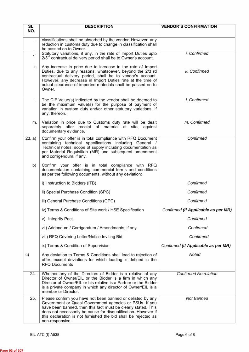
EIL-ATC (I)-A538 Page 6 of 8
SL. NO.
DESCRIPTION VENDOR’S CONFIRMATION
i. classifications shall be absorbed by the vendor. However, any reduction in customs duty due to change in classification shall be passed on to Owner.
j. k.
Statutory variations, if any, in the rate of Import Duties upto 2/3rd contractual delivery period shall be to Owner’s account. Any increase in price due to increase in the rate of Import Duties, due to any reasons, whatsoever, beyond the 2/3 rd contractual delivery period, shall be to vendor's account. However, any decrease in Import Duties rate at the time of actual clearance of imported materials shall be passed on to Owner.
i. Confirmed
k. Confirmed
l. m.
The CIF Value(s) indicated by the vendor shall be deemed to be the maximum value(s) for the purpose of payment of variation in custom duty and/or other statutory variations, if any, thereon. Variation in price due to Customs duty rate will be dealt separately after receipt of material at site, against documentary evidence.
l. Confirmed
m. Confirmed
23. a) b) c)
Confirm your offer is in total compliance with RFQ Document containing technical specifications including General / Technical notes, scope of supply including documentation as per Material Requisition (MR) and subsequent amendment and corrigendum, if any. Confirm your offer is in total compliance with RFQ documentation containing commercial terms and conditions as per the following documents, without any deviation: i) Instruction to Bidders (ITB) ii) Special Purchase Condition (SPC) iii) General Purchase Conditions (GPC) iv) Terms & Conditions of Site work / HSE Specification
v) Integrity Pact. vii) Addendum / Corrigendum / Amendments, if any viii) RFQ Covering Letter/Notice Inviting Bid ix) Terms & Condition of Supervision Any deviation to Terms & Conditions shall lead to rejection of offer, except deviations for which loading is defined in the RFQ Documents
Confirmed
Confirmed
Confirmed
Confirmed
Confirmed (if Applicable as per MR)
Confirmed
Confirmed Confirmed Confirmed (if Applicable as per MR) Noted
24. Whether any of the Directors of Bidder is a relative of any Director of Owner/EIL or the Bidder is a firm in which any Director of Owner/EIL or his relative is a Partner or the Bidder is a private company in which any director of Owner/EIL is a member or Director.
Confirmed No relation
25. Please confirm you have not been banned or delisted by any Government or Quasi Government agencies or PSUs. If you have been banned, then this fact must be clearly stated. This does not necessarily be cause for disqualification. However if this declaration is not furnished the bid shall be rejected as non-responsive.
Not Banned
Page 93 of 307

EIL-ATC (I)-A538 Page 7 of 8
SL. NO.
DESCRIPTION VENDOR’S CONFIRMATION
26. 26.1 26.2
Please confirm you have uploaded the following in the E-Tendering Portal: UNPRICED OFFER- without any Deviations & ATC in Unpriced Cover PRICED OFFER Duly filled Price Schedule in PRICE COVER
Confirmed
Confirmed
27 Please confirm that you have quoted strictly for items based on your registration/approval with EIL as on date of issue of RFQ.
Confirmed
28 Any claim arising out of order shall be sent to Owner in writing with a copy to EIL within 3 months from the date of last despatch. In case the claim is received after 3 months, the same shall not be entertained by Consultant/ Owner.
Confirmed
29 Printed terms and conditions, if any, appearing in quotation, shall not be applicable in the event of order. In case of contradiction between the confirmations given above and terms & conditions mentioned elsewhere in the offer, the confirmation given/confirmed herein above shall prevail.
Confirmed
30 Confirm that Net worth of the bidder’ company is positive as per the immediate preceding year’s audited financial results & Immediate preceding year’s audited annual financial results submitted along with unpriced bid.
Confirmed
VENDOR’S NAME:
SIGNATURE & SEAL:
Page 94 of 307

EIL-ATC (I)-A538 Page 8 of 8
ANNEXURE – I TO AGREED TERMS & CONDITIONS (FOR INDIAN BIDDERS/INDIGENOUS ITEMS/WORK)
NAME OF BIDDER: _________________________________ OFFER REF. _______________________________________ Dated _____________ RFQ/BIDDING DOC NO.: __________ ITEM: __________ Client: Consortium / Joint Venture of Bharat Petroleum Corporation Ltd. (BPCL) and Indian Oil
Corporation Ltd. (IOCL) Project: Kochi Coimbatore LPG Pipeline Project The salient features of the offer are as below:
1. Despatch Point
_____________
2. Present applicable rate of Excise Duty + Education Cess
______ % EXTRA
3. Excise duty: tarrif sub heading no.
____________
4. Present applicable of Central Sales Tax without Form ‘C’
(Applicable for interstate sales)
______ % EXTRA
5. Present applicable rate of VAT
(applicable for sales within same state)
______ % EXTRA
6. Packing & Forwarding Charges
INCLUDED
7. Freight charges extra upto project site
(Excluding Service Tax)
QUOTED IN PRICE
SCHEDULE
8. Service Tax payable extra on freight charges, if any (not to be
included in the freight charges)
______ % EXTRA ON
________% OF FREIGHT CHARGES.
9. Service Tax on the following (other than Service Tax on
freight charges), if any : Site work portion (if applicable as per MR) Supervision of Erection, Testing & Commissioning (if
applicable as per MR)
Training (if applicable as per MR)
Annual Maintenance Contract(if applicable as per MR)
______ % EXTRA
______ % EXTRA
______ % EXTRA
______ % EXTRA
BIDDER’S SIGNATURE & DATE: _______________________________ WITH SEAL/STAMP:
Page 95 of 307

EIL-ATC (F)- A538 Page 1 of 6
CONSORTIUM / JOINT VENTURE OF BHARAT PETROLEUM CORPORATION LTD. (BPCL) AND INDIAN OIL CORPORATION LTD. (IOCL)
KOCHI COIMBATORE ERODE SALEM LPG PIPELINE PROJECT (Job No. A538)
AGREED TERMS & CONDITIONS (ATC) (FOR FOREIGN BIDDERS)
Vendor Name: M/s __________________________________________________________
RFQ No. : ______________________________________________________________
Vendor’s Offer Ref No. : ______________________________________________________
Tel. No. ________________Mob. No.____________________ Fax No. _________________
Contact Person: ___________________________ E-mail __________________________
1. ALL CORRESPONDENCE MUST BE IN ENGLISH LANGUAGE ONLY. 2. DULY SIGNED & STAMPED COPIES OF THIS “QUESTIONNAIRE”, WITH ALL THE CLAUSES
DULY CONFIRMED/ PRECISELY REPLIED TO BY THE VENDOR, SHALL BE ENCLOSED. 3. ALL COMMERCIAL TERMS ARE GIVEN/CONFIRMED IN THE QUESTIONNAIRE ITSELF AND
NOT ELSEWHERE IN THE QUOTATION. IN CASE OF CONTRADICTION, THE SAME GIVEN HEREIN SHALL PREVAIL.
4. FAILURE ON THE PART OF VENDOR IN SUBMITTING THIS DULY FILLED-UP
"QUESTIONNAIRE WITH ALL SETS OF UNPRICED BID AND/OR SUBMITTING INCOMPLETE REPLIES MAY LEAD TO REJECTION OF VENDOR'S QUOTATIONò.
5. YOUR OFFER SHALL BE IN TOTAL COMPLIANCE WITH RFQ DOCUMENTS CONTAINING
COMMERCIAL AND TECHNICAL SPECIFICATIONS INCLUDING GENERAL / TECHNICAL NOTES AND SCOPE OF SUPPLY INCLUDING DOCUMENTATION AS PER MATERIAL REQUISITION (MR) AND SUBSEQUENT TECHNICAL/COMMERCIAL AMENDMENT AND CORRIGENDUM, IF ANY.
SL. NO.
DESCRIPTION VENDORôS CONFIRMATION WITH DETAILS
1. a) Confirm that the offer contains firm prices on F.O.B. International Seaport of Exit Basis
b) Indicate International Seaport of Exit c) Confirm that ocean freight charges upto port of entry,
India (Kochi) has been quoted separately by you in the price schedule.
a. Confirmed , Quoted in Price Schedule
b. ____________________
c. Confirmed , Quoted in Price Schedule
2 Marine Insurance: Price quoted must exclude Marine insurance charges from FOB International Sea Port of Exit, as same shall be arranged by the Owner. However all insurance charges for inland transit upto FOB International Sea Port of Exit must be included by you in your prices.
Confirmed
3 Owner reserves the option to place order either on FOB or CFR basis. Quoted ocean freight charges shall be valid till the Contract Period
Confirmed
Page 96 of 307

EIL-ATC (F)- A538 Page 2 of 6
SL. NO.
DESCRIPTION VENDORôS CONFIRMATION WITH DETAILS
4 Delivery / Completion Period:
a) Delivery / Completion period shall be as mentioned in the RFQ document on FOB International Sea Port of Exit basis.
b) Confirm delivery period shall be reckoned from the date of Fax of Acceptance.
c) Confirm date of clean Bill of Lading shall be considered as date of delivery. (In case order is placed on FOB port of Exit basis or on CFR basis)
a. Confirmed
b. Confirmed
c. Confirmed
5 a. b.
Taxes & Duties: All taxes, duties and levies of any kind payable upto FOB International Sea Port of Exit shall be borne by Bidder. Export permit/licence if required shall be vendor’s responsibility & any expenditure towards same will be borne by Bidder.
a. Confirmed
b. Confirmed
6
a. b. c.
Supervision / Training Charges: Charges for Supervision / Training / Annual Maintenance Contract, if in the scope of the Bidder as per MR have been indicated by bidder separately in the Price Schedule. Per-diem rate for supervision has been quoted in accordance with the Terms & Conditions for Supervision enclosed with the RFQ Documents. Bidder to indicate Permanent Account Number (PAN) to avoid any additional Tax deduction at source as per the prevailing Indian Income tax Acts Rule.
a. Confirmed, Quoted in Price
Schedule
b. Confirmed
c. ____________________
7
Validity: a. Confirm that the offer shall be valid upto period as
mentioned in the RFQ document.
b. Confirm validity of recommended spares (If applicable as per MR) for 2 years operation and maintenance will be 12 months over and above the validity of offer.
a. Confirmed
b. Confirmed( if Applicable)
8 Manufacturer’s name and address _____________________________
9 a. b.
Inspection Charges: Goods supplied are subject to stage wise and final inspection as specified in MR by EIL in the country of origin and no extra charges shall be payable by owner towards the same. Travel, Living and Personnel expenses of EIL’s Representative shall be borne by Owner. Quoted prices are: i) Inclusive of all testing and inspection charges (if
a. Confirmed
b. i)Confirmed
Page 97 of 307
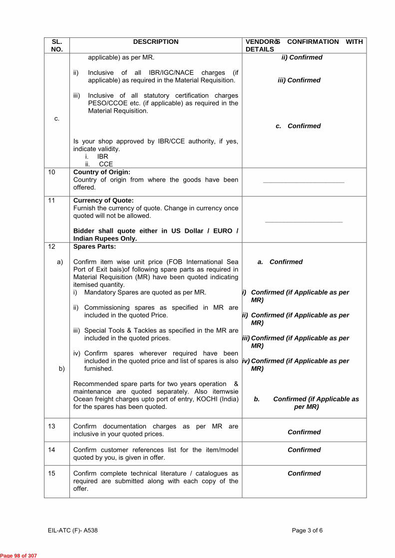
EIL-ATC (F)- A538 Page 3 of 6
SL. NO.
DESCRIPTION VENDORôS CONFIRMATION WITH DETAILS
c.
applicable) as per MR.
ii) Inclusive of all IBR/IGC/NACE charges (if applicable) as required in the Material Requisition.
iii) Inclusive of all statutory certification charges PESO/CCOE etc. (if applicable) as required in the Material Requisition.
Is your shop approved by IBR/CCE authority, if yes, indicate validity.
i. IBR ii. CCE
ii) Confirmed iii) Confirmed
c. Confirmed
10 Country of Origin: Country of origin from where the goods have been offered.
______________________
11 Currency of Quote: Furnish the currency of quote. Change in currency once quoted will not be allowed. Bidder shall quote either in US Dollar / EURO / Indian Rupees Only.
_____________________
12 a) b)
Spares Parts: Confirm item wise unit price (FOB International Sea Port of Exit bais)of following spare parts as required in Material Requisition (MR) have been quoted indicating itemised quantity. i) Mandatory Spares are quoted as per MR.
ii) Commissioning spares as specified in MR are
included in the quoted Price.
iii) Special Tools & Tackles as specified in the MR are included in the quoted prices.
iv) Confirm spares wherever required have been
included in the quoted price and list of spares is also furnished.
Recommended spare parts for two years operation & maintenance are quoted separately. Also itemwsie Ocean freight charges upto port of entry, KOCHI (India) for the spares has been quoted.
a. Confirmed
i) Confirmed (if Applicable as per
MR) ii) Confirmed (if Applicable as per
MR) iii) Confirmed (if Applicable as per
MR) iv) Confirmed (if Applicable as per
MR)
b. Confirmed (if Applicable as
per MR)
13 Confirm documentation charges as per MR are inclusive in your quoted prices. Confirmed
14 Confirm customer references list for the item/model quoted by you, is given in offer.
Confirmed
15 Confirm complete technical literature / catalogues as required are submitted along with each copy of the offer.
Confirmed
Page 98 of 307

EIL-ATC (F)- A538 Page 4 of 6
SL. NO.
DESCRIPTION VENDORôS CONFIRMATION WITH DETAILS
16 Indicate shipping weight (net and gross) and volume of the consignment.
_______________________
17 a.
Contract Performance Bank Guarantee:
Confirm goods to be supplied by you shall be guaranteed for performance as per the General Purchase Conditions (GPC) and valid till full guarantee period plus 6 (Six) Months.
a. Confirmed
b. The Performance Bank Guarantee shall be strictly as per proforma enclosed with the GPC document and shall be issued through Scheduled commercial bank in India/ Indian Branch of foreign Bank, directly to BPCL as per pro-forma enclosed and Vendor shall enclose copy of the same along with invoice.
b. Confirmed
18. Guarantee / Warranty
a) Materials shall be guaranteed against manufacturing
defects, materials, workmanship and design for a
period of 18 months from the date of commissioning
or 24 months from the date of dispatch whichever is
earlier. Warranty for replacement of material /
accessories should be provided free of charges at
our premises. The above guarantee/warranty will be
without prejudice to the certificate of inspection or
material receipt note issued by us in respect of the
materials.
b) All the materials including components and sub
contracted items should be guaranteed by the
vendor within the warranty period mentioned above.
In the event of any defect in the material, the vendor
will replace / repair the material at BPCL’s concerned
location at vendor’s risk and cost on due notice.
c) In case, vendor does not replace / repair the material
on due notice, rejected material will be sent to the
vendor on “Freight to pay” basis for free
replacement. Material after rectification of defects
shall be dispatched by the vendor on “Freight Paid”
basis. Alternatively, BPCL reserves the right to have
the material repaired / replaced at the locations
concerned, at the vendor’s risk, cost and
responsibility.
d) The Vendor shall provide similar warrantee on the
parts, components, fittings, accessories etc. so
repaired and / or replaced.
a. Confirmed
b. Confirmed
c. Confirmed
d. Confirmed
Page 99 of 307

EIL-ATC (F)- A538 Page 5 of 6
SL. NO.
DESCRIPTION VENDORôS CONFIRMATION WITH DETAILS
19. Firmness of prices: Confirm quoted prices shall remain firm and fixed till complete execution of order. Price Variation shall not be considered on any account.
Confirmed
20. Part Order: a) Confirm acceptance to part order. b) The quantities against a particular item will not be
split. Any charges quoted extra as lumpsum shall be applicable prorata on value basis in the event of part order.
a. Confirmed
b. Confirmed
21 Repeat Order: Confirm Acceptance to Repeat Order as per RFQ Covering Letter/ITB/SPC/GPC
Confirmed
22 Price Reduction on delay in delivery: a) Confirm acceptance of price reduction schedule for
delay in deliveries specified in General Purchase Conditions (GPC) enclosed with the RFQ Document. Liquidated damages or penalty are not acceptable.
b) In case of delay, vendor will reduce the invoice amount by applicable reduction.
a. Confirmed
b. Confirmed
23 Payment Term: Confirm acceptance of payment terms as per “Payment Terms and Mode of Payment” specified in Special Purchase Conditions and RFQ covering letter.
Confirmed
24 a) Letter of Credit shall be opened after receipt of
unconditional order acknowledgement along with 10% performance bank guarantee valid till expiry of Material/Equipment Guarantee period as per General Purchase Conditions and Special Purchase Conditions plus 6 (Six) months claim period.
b) Letter of Credit shall be opened through a Govt. of India Nationalised/ Scheduled Bank and hence need not be confirmed.
OR c) However, if you still insist for confirmed L/C,
confirmation charges shall be borne by you. Please confirm.
a. Confirmed
b. Confirmed L/C not required
c. Noted
25 All Bank charges and stamp duties payable outside India in connection with payments to be made under Purchase Order for the item, if placed, shall be borne by you. All bank charges and stamp duties payable in India shall be borne by the Purchaser.
Confirmed
26 Please indicate name and address of your Bankers for L/C opening, telephone/E-mail address.
______________________
27 a)
Confirm your offer is in total compliance with RFQ Document containing technical specifications including General / Technical notes, scope of supply including documentation as per Material Requisition (MR) and
a. Confirmed
Page 100 of 307

EIL-ATC (F)- A538 Page 6 of 6
SL. NO.
DESCRIPTION VENDORôS CONFIRMATION WITH DETAILS
b)
c)
subsequent amendment and corrigendum, if any, without any deviation. Confirm your offer is in total compliance with RFQ documents containing commercial terms and conditions as per the following documents, without any deviation:
i. Instructions to Bidder (ITB) (If applicable)
ii. Special Purchase Conditions
iii. General Purchase Conditions
iv. Terms & Conditions for supervision
v. vi)Terms & Conditions for site work & HSE
vi. Integrity Pact
vii. RFQ Covering Letter/Notice Inviting Bid
viii. Addendum / Corrigendum / Amendments, if any, if any
Any deviation to Terms & Conditions shall lead to rejection of offer, except deviations for which loading is defined in the RFQ Documents
b. Confirmed
i. Confirmed
ii. Confirmed
iii. Confirmed
iv. Confirmed (if Applicable as per MR)
v. Confirmed (if Site Work is Applicable as per MR)
vi. Confirmed
vii. Confirmed
viii. Confirmed
c. Noted
28 Direct offer without the intermediary of an Indian Agent will only be considered. Noted & Confirmed.
29 Please confirm you have not been banned or delisted by any Government or Quasi Government agencies or PSUs. If you have been banned, then this fact must be clearly stated. This does not necessarily be cause for disqualification. However if this declaration is not furnished the bid shall be rejected as non-responsive.
Not Banned
30 30.1 30.2
Please confirm your offer contains the following: Unpriced offer- without any deviations Priced Offer Price Schedule only.
Confirmed
Confirmed
31 Any claim arising out of order shall be sent to Owner in writing with a copy to EIL within 3 months from the date of last despatch. In case the claim is received after 3 months, the same shall not be entertained by consultant / Owner.
Confirmed
32 Indicate whether Custom duty exemption / waiver under multi-lateral/bi-lateral agreement between Indian and bidder's country as per Cl. no 11.7.8 of ITB is applicable. .
Not Applicable OR
Applicable:_________%
(Relevant Documents Enclosed)
33 Printed terms and conditions, if any, appearing in quotation, shall not be applicable in the event of order. In case of contradiction between the confirmations given above and terms & conditions mentioned elsewhere in the offer, the confirmation given/confirmed herein above shall prevail.
Confirmed
VENDOR’S NAME: SIGNATURE & SEAL:
Page 101 of 307

Page 1 of 1
Client: Consortium of BPCL & IOCL Terms & Conditions For Supervision KCESPL Project Job Number: A538 Sheet 1 of 1
TERMS & CONDITIONS FOR SUPERVISION OF ERECTION, TESTING AND COMMISSIONING
FOR INDIGENOUS PERSONNEL
1) Bidder shall quote per diem charges which shall include to & fro fare ,lodging, boarding, medical , local transport, all insurances including Bidder’s personnel and third party insurance , all taxes
including income tax etc. & all other incidental charges but excluding Service Tax which will be paid extra .
2) Per Diem rates shall apply from the day the supervisory personnel reach site and upto the day they
leave site. No per Diem payment will be made for travel days / period. 3) Working hours as those prevailing at site – normally eight hours a day, Monday through Saturday
and holidays as applicable to site personnel shall apply. 4) Supplier’s supervisory personnel to observe/abide by site working conditions prevailing in the
existing refinery, safety codes & Indian laws. 5) A notice period of 15 days will be given for supervision of erection / testing / commissioning.
NOTES: In case bidder recommends more than one category level of supervisory personnel the
information desired at S. No. (i) to (vi) shall be furnished separately for each category of supervisory
personnel in the Price Schedule.
RFQ NO:__________________ VENDOR’S SIGNATURE & DATE:_______
ITEM:____________________ NAME:____________________________ OFFER NO:_______________ DESIGNATION : ____________________
SEAL / STAMP : ___________________
Sl.
No.
Description Vendor’s Reply /
information
i.
ii.
iii.
iv.
v.
vi.
Number of supervisory personnel required.
Per diem charges (per person) for 8 hours work
on normal working days.
Overtime rate/ hour beyond normal 8 hours
work on normal working days.
Overtime rate/ hour for work on weekly off
days/ holidays (as applicable to Refinery site).
Maximum estimated time (number of days) for job completion.
Service Tax excluded in the above rates &
payable extra.
(Vendor shall provide invoices in accordance with service tax rules)
i. (Refer Priced Schedule)
ii. (Refer Priced Schedule)
iii. (Refer Priced Schedule)
iv. (Refer Priced Schedule)
v. (Refer Priced Schedule)
vi. Confirmed (Refer Priced Schedule)
Page 102 of 307

A546_T&C-SUP (FOREIGN) Rev.0 Page 1 of 2
Client: Consortium of BPCL & IOCL Terms & Conditions For Supervision KCESPL Project Job Number: A538 Sheet 1 of 2
TERMS & CONDITIONS FOR SUPERVISION OF ERECTION, TESTING AND COMMISSIONING FOR FOREIGN PERSONNEL
1) Bidder shall quote all inclusive per diem charges which shall also include lodging, boarding, medical, To & Fro air traveling including local transportation, all insurances including Bidder’s personnel and third party insurance, income tax (withholding tax), corporate tax (as may be applicable), etc. and all other incidental charges, but excluding Service tax which will be paid extra by owner.
2) No additional cost shall be payable towards travel, lodging & boarding, etc. by Client. 3) Per Diem rates shall apply from the day the supervisory personnel reach site and upto the day they
leave site. No per Diem payment will be made for travel days / period. 4) Working hours as those prevailing at site – normally eight hours a day, Monday through Saturday
and holidays as applicable to site personnel shall apply. 5) Supplier’s supervisory personnel to observe/abide by site working conditions prevailing in the
existing refinery, safety codes & Indian laws.
6) A notice period of 15 days will be given for supervision of erection / testing / commissioning. 7) Bidder will be responsible for all liabilities towards corporate tax, personal income tax (Withholding
Tax) etc. (except Service Tax for their personnel deputed for the supervision job). Tax(s) as per Government policy shall be deducted at source by Purchaser while making payments against each
invoice.
8) Requirement of Employment Visa for Foreign Nationals
All foreign nationals coming to India for execution of Projects / Orders will have to apply for
Employment Visa only and that grant of Employment Visa would be subject to strict adherence of
following norms: a) Employment Visa is granted only for the skilled and qualified professional or to a person who is
being engaged or appointed by a company, organisation, Industry or undertaking etc. in India on contract or employment basis at a senior level, skilled position such as technical expert, senior
executive or in managerial position etc.
b) Request for employment Visa for jobs for which large number of qualified Indian are available, is not considered.
c) Under no circumstances an Employment Visa is granted for routine, ordinary secretarial / clerical jobs.
Bidders are advised in their own interest to check latest Visa rules from Indian Embassy/ High Commission in their country in case foreign nationals are required to be deputed to Indian during execution of the Order.
Sl. No. Description Vendor’s Reply / information
i.
ii.
iii.
iv.
v.
Number of supervisory personnel required.
Per diem charges (per person) for 8 hours
work on normal working days.
Overtime rate/ hour beyond normal 8 hours work on normal working days.
Overtime rate/ hour for work on weekly off days/ holidays (as applicable to Refinery site).
Maximum estimated time (number of days) for job completion.
i. (Refer Priced Schedule)
ii. (Refer Priced Schedule)
iii. (Refer Priced Schedule)
iv. (Refer Priced Schedule)
v. (Refer Priced Schedule)
Page 103 of 307

A546_T&C-SUP (FOREIGN) Rev.0 Page 2 of 2
Client: Consortium of BPCL & IOCL Terms & Conditions For Supervision KCESPL Project Job Number: A538 Sheet 2 of 2
(* ) The per diem charges shall be exclusive of service tax & education cess applicable
thereupon , which shall be paid extra by Owner . Evaluation shall be done based on prevailing rate of Service tax.
NOTES: In case bidder recommends more than one category level of supervisory personnel the
information desired at Sl. No. (i) to (v) shall be furnished separately for each category of supervisory
personnel.
RFQ NO:__________________ VENDOR’S SIGNATURE & DATE:_______
ITEM:____________________ NAME:____________________________
OFFER NO:_______________ DESIGNATION : ____________________ SEAL / STAMP: ___________________
Page 104 of 307

Template No. 5-0000-0001-T2 Rev. 1 Copyrights EIL – All rights reserved Dated -02-July-2014
E-TENDERING METHODOLOGY
Instructions for Online Bid Submission: The bidders are required to submit soft copies of their bids electronically on the CPP Portal (URL: http://eprocure.gov.in) only, using valid Digital Signature Certificates. The instructions given below are meant to assist the bidders in registering on the CPP Portal, prepare their bids in accordance with the requirements and submitting their bids online on the CPP Portal.
More detailed information useful for submitting online bids on the CPP Portal may be obtained at:
http://eprocure.gov.in/eprocure/app .
REGISTRATION
1) Bidders are required to enroll on the e-Procurement module of the Central Public Procurement Portal (URL: http://eprocure.gov.in/eprocure/app) by clicking on the link “Click here to Enroll” on the CPP Portal is free of charge.
2) As part of the enrolment process, the bidders will be required to choose a unique username and assign a password for their accounts.
3) Bidders are advised to register their valid email address and mobile numbers as part of the registration process and submit in EIL tender portal for updation of records (http://tenders.eil.co.in) . These details would be used for any communication from the CPP Portal.
4) Upon enrolment, the bidders will be required to register their valid Digital Signature Certificate (DSC) (Class II or Class III Certificates with signing key usage) issued by any Certifying Authority recognized by CCA India (e.g. Sify / TCS / nCode / eMudhra etc.), with their profile.
5) Foreign Bidders have to refer “DSC details for foreign Bidders” for Digital signature Certificates requirements which comes under Download Tab at http://eprocure.gov.in/eprocure/app and the remaining part is same as above and below.
6) Only one valid DSC should be registered by a bidder. Please note that the bidders are responsible to ensure that they do not lend their DSC’s to others which may lead to misuse.
7) Bidder then logs in to the site through the secured log-in by entering their user ID / password and the password of the DSC / e-Token.
SEARCHING FOR TENDER DOCUMENTS
1) There are various search options built in the CPP Portal, to facilitate bidders to search active tenders by several parameters. These parameters could include Tender ID, organization name, location, date, value, etc. There is also an option of advanced search for tenders, wherein the bidders may combine a number of search parameters such as organization name, form of contract, location, date, other keywords etc. to search for a tender published on the CPP Portal.
2) Once the bidders have selected the tenders they are interested in, the same can be moved to the respective ‘My Tenders’ folder. This would enable the CPP Portal to intimate the bidders through SMS / e-mail in case there is any corrigendum issued to the tender document.
Page 105 of 307

Template No. 5-0000-0001-T2 Rev. 1 Copyrights EIL – All rights reserved Dated -02-July-2014
3) The bidder should make a note of the unique Tender ID assigned to each tender, in case they want to obtain any clarification / help from the Helpdesk.
PREPARATION OF BIDS
1) Bidder should take into account any corrigendum published on the tender document before submitting their bids.
2) Please go through the tender advertisement and the tender document carefully to understand the documents required to be submitted as part of the bid. Please note the number of covers in which the bid documents have to be submitted, the number of documents - including the names and content of each of the document that need to be submitted. Any deviations from these may lead to rejection of the bid.
3) To avoid Network congestion, Bidder is recommended to upload file size of up to Maximum 35 MB per part. However, in case file size exceeds 35 MB, bidder may compress the files by scanning with 75 dpi setting as per s.no 4 below and can use additional 25 MB space (“My Documents”) provided to the bidder as per s.no 5 below.
4) Bidder, in advance, should get ready the bid documents to be submitted as indicated in the tender document and generally, they can be in PDF / XLS / RAR / DWF formats. Bid documents may be scanned with 75 dpi with black and white option. However, Price Schedule / SOR shall be strictly in RAR format without altering any contents of the formats uploaded by EIL in their Bidding Document.
5) To avoid the time and effort required in uploading the same set of standard documents which are required to be submitted as a part of every bid, a provision of uploading such standard documents (e.g. PAN card copy, annual reports, auditor certificates etc.) has been provided to the bidders. Bidders can use “My Documents” area available to them to upload such documents. These documents may be directly submitted from the “My Documents” area while submitting a bid, and need not be uploaded again and again. This will lead to a reduction in the time required for bid submission process.
SUBMISSION OF BIDS
1) Bidder should log into the site well in advance for bid submission so that he/she upload the bid in time i.e. on or before the bid submission time. Bidder will be responsible for any delay due to other issues.
2) The bidder has to digitally sign and upload the required bid documents one by one as indicated in the tender document.
3) Bidder has to select the payment option as “offline” to pay the tender fee / EMD as applicable and enter details of the instrument.
4) Bidder should prepare the EMD as per the instructions specified in the tender document. The original should be posted/couriered/given in person to the Tender Processing Section, with in 7 calendar days of the date of Unpriced bid opening. The details of the DD/any other accepted instrument, physically sent, should tally with the details available in the scanned copy and the data entered during bid submission time. Otherwise the uploaded bid will be rejected.
5) A Price Bid format has been provided with the tender document to be filled by all the bidders. Bidders are requested to note that they should necessarily submit their financial bids in the format provided and no other format is acceptable. Bidders are required to download the
Page 106 of 307

Template No. 5-0000-0001-T2 Rev. 1 Copyrights EIL – All rights reserved Dated -02-July-2014
Price Bid file, open it and complete the cells with their respective financial quotes and other details (such as name of the bidder). No other cells should be changed. Once the details have been completed, the bidder should save it and submit it online, without changing the filename. If the Price Bid file is found to be modified by the bidder, the bid will be rejected.
6) The server time (which is displayed on the bidders’ dashboard) will be considered as the standard time for referencing the deadlines for submission of the bids by the bidders, opening of bids etc. The bidders should follow this time during bid submission.
7) All the documents being submitted by the bidders would be encrypted using PKI encryption techniques to ensure the secrecy of the data. The data entered cannot be viewed by unauthorized persons until the time of bid opening. The confidentiality of the bids is maintained using the secured Socket Layer 128 bit encryption technology. Data storage encryption of sensitive fields is done.
8) The uploaded tender documents become readable only after the tender opening by the authorized bid openers.
9) Upon the successful and timely submission of bids, the portal will give a successful bid submission message & a bid summary will be displayed with the bid no. and the date & time of submission of the bid with all other relevant details.
10) The bid summary has to be printed and kept as an acknowledgement of the submission of the bid. This acknowledgement may be used as an entry pass for any bid opening meetings.
RETENDER
Please note that if Tender has been retendered, than it is mandatory for the bidder to submit their offer again on CPP Portal.
WITHDRAWAL OF BID
It may please be noted that bidders now have an additional feature of withdrawing their bids before due date and time. After submitting the bid on the CPP Portal, if the bidder wishes to withdraw his bid, he can do so. However, if the bidder withdraws his bid, he will be exempted from further participation in the tender and won’t be able to submit his bid again for that particular tender.
ASSISTANCE TO BIDDERS
1) Any queries relating to the tender document and the terms and conditions contained therein should be addressed to the Tender Inviting Authority for a tender or the relevant contact person indicated in the tender.
2) Any queries relating to the process of online bid submission or queries relating to CPP Portal in general may be directed to the 24 x 7 CPP Portal Helpdesk. The contact number for the helpdesk is 1800-3070-2232 and Mobile Nos +91-7878007972, +91-7878007973.
Page 107 of 307

Government eProcurement System
D S C f o r F o r e i g n N a t i o n a l s Version 1.0
Procedure for obtaining Digital Signature by Foreign Vendors
This document gives the procedure to be followed by bidders who are resident of countries other than India for participating in Online Tendering Activity. As per the IT ACT 2000, all bidders who participate in the online bidding process in this site should possess a valid Digital Signature issued by any of the Digital Signature Certificate (DSC) vendors approved by CCA, India (https://cca.gov.in). The following document gives the procedure that is generally followed by various vendors. Generally, the documents that are required to be submitted by Foreign Nationals are as follows:
1. Identity Proof (ID Proof) of the person in whose name DSC has to be issued (E.g. Passport copy)
2. Bank account statement in country of residence, duly attested by Indian Embassy / High Commission / Consulate / Apostille in the country where the applicant is currently located. (At least 6 months of Bank transactions) with the proof indicating the account is owned by the Individual.
3. Copy of the Trade license attested by any one of the authorities as specified in Point 2 above.
4. As the Individual is representing the company, an Authorization on company’s letter head as given in the form
5. Copy of the Authorization letter or invitation letter from department for the participation in the tender by any one of the tender inviting authority.
As of now, it is learnt that GNFC, TCS, eMudhra issue DSCs with the above procedure. The copy of the nCodes, TCS and eMudhra Format is enclosed as Annexure; the Copies of other vendors will be made available on receipt of information from these vendors.
Note: The Information given by the vendors is attached for facilitating the Foreign Nationals to procure DSCs from the Indian CA authorized vendors for information purpose only as shared by the respective CA's. Please find below the details of various vendors and procedure for obtaining DSC: GNFC
Tata Consultancy Services
eMudhra
Page 108 of 307

Page 109 of 307

Page 110 of 307

Page 111 of 307

Page 112 of 307

Page 113 of 307

Page 114 of 307

Page 115 of 307
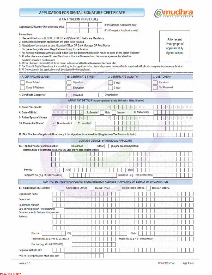
Page 116 of 307

Page 117 of 307

Page 118 of 307

Page 119 of 307

Page 117 of 202
Page 120 of 307

FORMAT FOR PRE BID QUERIES
SL No.
BIDDING DOCUMENT SUBJECT BIDDER’S QUERY
OWNER’S REPLY
PART/ VOL.
PAGE NO. CLAUSE NO.
NOTE: 1. Bidder’s queries may be sent by e-mail to [email protected] / [email protected] 2. Technical & commercial queries, if any, must be submitted separately in editable format as per this format. SIGNATURE OF BIDDER : ______________________ NAME OF BIDDER : ______________________ COMPANY SEAL : ______________________
Page 121 of 307

ENGINEERS INDIA LIMITED
NEW DELHI Client: KOCHI-SALEM PIPELINE PVT. LTD.
Project: KOCHI-COIMBATORE- SALEM LPG PIPELINE
File Name: F:\A538-010-LS-MR-4510 released.pdf
Thi
s dr
awin
g, d
esig
n an
d de
tails
giv
en o
n th
is f
orm
at a
re th
e pr
oper
ty o
f E
NG
INE
ER
S IN
DIA
LIM
ITE
D. T
hey
are
mer
ely
loan
ed o
n th
e bo
rrow
er's
exp
ress
agr
eem
ent t
hat t
hey
will
not
be
repr
oduc
ed, c
opie
d, e
xhib
ited
or u
sed,
exc
ept i
n th
e lim
ited
way
per
mitt
ed b
y a
wri
tten
cons
ent g
iven
by
the
lend
er to
the
borr
ower
for
the
inte
nded
use
. EIL
-164
1-51
5 R
ev.1
A4-
210x
297.
Sheet 1 of 4
ITEM DESCRIPTION: MOBILE FLARE SYSTEM
GROUP ITEM CODE: 06GB DESTINATION: As per Commercial Documents
MR CATEGORY: II DELIVERY PERIOD: As per Commercial Documents
DOCUMENT NUMBER( Always quote the Document Number given below as reference )
28/09/2016 80
JOB NO. UNIT/ AREA
MAINCOST
CENTRE
DOC.CODE
SR. NO. REV. DATE
43
DIVN. DEPT.
ORIGINATOR
NOTES :12
3
This page is a record of all the Revisions of this Requisition.The nature of the Revision is briefly stated in the "Details" column below, theRequisition in its entirety shall be considered for contractual purposes.Vendor shall note the MR category and shall submit his offer in line with therequirements included in attached 'Instructions to Bidders'.
REV. DATE BY CHK. APPD. DETAILS
A
B
01/09/2016
28/09/2016
ISSUED FOR BIDS
REVISED AS PER CLIENT COMMENTS ANDREISSUED
SASWATA
SASWATA
PD
PD
SM
SM
MATERIAL REQUISITION (TOP SHEET)
010 LS MR 4510 BA538
This is a system generated approved document and does not require signature.
Page 122 of 307

ENGINEERS INDIA LIMITED
NEW DELHI Client: KOCHI-SALEM PIPELINE PVT. LTD.
Project: KOCHI-COIMBATORE- SALEM LPG PIPELINE
File Name: F:\A538-010-LS-MR-4510 released.pdf
Thi
s dr
awin
g, d
esig
n an
d de
tails
giv
en o
n th
is f
orm
at a
re th
e pr
oper
ty o
f E
NG
INE
ER
S IN
DIA
LIM
ITE
D. T
hey
are
mer
ely
loan
ed o
n th
e bo
rrow
er's
exp
ress
agr
eem
ent t
hat t
hey
will
not
be
repr
oduc
ed, c
opie
d, e
xhib
ited
or u
sed,
exc
ept i
n th
e lim
ited
way
per
mitt
ed b
y a
wri
tten
cons
ent g
iven
by
the
lend
er to
the
borr
ower
for
the
inte
nded
use
. EIL
-164
1-51
5 R
ev.1
A4-
210x
297.
Sheet 2 of 4
REQUISITION NO. REV.
BA538-010-LS-MR-4510
SR. NO.TAG NO/
ITEM CODE/ [ ID. NO. ] DESCRIPTION QUANTITY
01.00
02.00
03.00
04.00
05.00
06.00
07.00
08.00
09.00
Design, engineering, manufacture,procurement of materials and bought outcomponents, assembly at shop, painting(primer + final coat), inspection,testing at manufacturer's works, packingand supply of following mobile flaresystem and DG set, including supply ofall commissioning spares & special toolsand tackles & documentation as per theenclosed job specification, data sheetsetc. and other codes and standardsattached or referred.
<< DELETED >>
<< DELETED >>
Quotation for On call Service to Clientafter one year of commissioning of Mobileflare system as per enclosed jobSpecification (doc.no. A538-010-80-43-SP-4510).
Quotation for recommended spares for TwoYears of normal operation andmaintenance, as per enclosed jobspecification.(doc. no. A538-010-80-43-SP-4510).<< DELETED >>
<< DELETED >>
Supervision of installation, hookup,testing, commissioning, performanceguarantee testing and training of Owner'spersonnel at site of items specified atitem 1.00 above, as per enclosed jobSpecification. (Note - 2)
Drawings and documents as per attachedVendor Data requirement for all suppliesand services covered above in Sr.Nos.1.00to Sr.No.8.00
Lot
Lot
Vendors shall quote prices in EIL Price Schedule except for Sr.No.9.00. Price fordocumentation is implied to be included in the prices quoted against Sr.No.1.00 toSr.No.8.00
Vendor to note that the numbers given in square '[]' and curly '{}' brackets arenot for their use and meant for store purpose only. Items shall be tagged as permain equipment Tag No. only.
01.01
01.02
04.01
04.02
08.01
08.02
010-ME-0001
010-ME-0002
{04}010-ME-0001
{04}010-ME-0002
{08}010-ME-0001
{08}010-ME-0002
Trailer mounted Mobile Flare Systemalongwith DG set(15KVA Continuous Powerrating at sitecondition)
Trailer mounted Mobile Flare Systemalongwith DG set(15KVA Continuous Powerrating at sitecondition)
For Sr. No. 01.01
For Sr. No. 01.02
For Sr. No. 01.01
For Sr. No. 01.02
1 Nos
1 Nos
1 Lot
1 Lot
1 /diem rate
1 /diem rate
D1
D1
D1
D1
D1
D1
Note:Bidder to note that,one fixed price is to be quoted for grouped items. The groupsof items are identified by D1 where D1 indicates one group and so on.
Page 123 of 307
ENGINEERS INDIA LIMITED
NEW DELHI Client: KOCHI-SALEM PIPELINE PVT. LTD.
Project: KOCHI-COIMBATORE- SALEM LPG PIPELINE
File Name: F:\A538-010-LS-MR-4510 released.pdf
Thi
s dr
awin
g, d
esig
n an
d de
tails
giv
en o
n th
is f
orm
at a
re th
e pr
oper
ty o
f E
NG
INE
ER
S IN
DIA
LIM
ITE
D. T
hey
are
mer
ely
loan
ed o
n th
e bo
rrow
er's
exp
ress
agr
eem
ent t
hat t
hey
will
not
be
repr
oduc
ed, c
opie
d, e
xhib
ited
or u
sed,
exc
ept i
n th
e lim
ited
way
per
mitt
ed b
y a
wri
tten
cons
ent g
iven
by
the
lend
er to
the
borr
ower
for
the
inte
nded
use
. EIL
-164
1-51
5 R
ev.1
A4-
210x
297.
Sheet 3 of 4
REQUISITION NO. REV.
BA538-010-LS-MR-4510
SR. NO.TAG NO/
ITEM CODE/ [ ID. NO. ] DESCRIPTION QUANTITY
Grouped items shall not be split ordered.
Page 124 of 307

ENGINEERS INDIA LIMITED
NEW DELHI Client: KOCHI-SALEM PIPELINE PVT. LTD.
Project: KOCHI-COIMBATORE- SALEM LPG PIPELINE
Sheet 4 of 4
File Name: F:\A538-010-LS-MR-4510 released.pdf
Thi
s dr
awin
g, d
esig
n an
d de
tails
giv
en o
n th
is f
orm
at a
re th
e pr
oper
ty o
f E
NG
INE
ER
S IN
DIA
LIM
ITE
D. T
hey
are
mer
ely
loan
ed o
n th
e bo
rrow
er's
exp
ress
agr
eem
ent t
hat t
hey
will
not
be
repr
oduc
ed, c
opie
d, e
xhib
ited
or u
sed,
exc
ept i
n th
e lim
ited
way
per
mitt
ed b
y a
wri
tten
cons
ent g
iven
by
the
lend
er to
the
borr
ower
for
the
inte
nded
use
. EIL
-164
1-51
5 R
ev.1
A4-
210x
297.
REQUISITION NO. REV.
BA538-010-LS-MR-4510
LIST OF ATTACHMENTS
SL.No. DOCUMENT TITLE DOCUMENT NO.
REVISION
REV. REV. REV. REV.DATE DATE DATE DATE
In case of any subsequent revision of MR or PR, only revised sheets of theattachments listed above shall be issued alongwith the revision.
GENERAL NOTES:1) For list of attachments, refer "Table of Contents".2) For price comparision purpose, total of 8 Mandays for Mobile Flare Systems (i.e.4Mandays per Mobile Flare System Tag no.) will be considered for supervision ofinstallation, hookup, testing, commissioning and performance guarantee test run atsite &training of Owner's personnel at site. However, for payment, actual no. of daysconsumed at site shall be applicable.
1
Page 125 of 307

SPECIAL INSTRUCTIONS
TO BIDDERS
DOCUMENT No.
A538-010-80-43-SI-4510 Rev.A
Page 1 of 3
A 10.08.2016 ISSUED WITH MR SASWATA PD SM
Rev. No.
Date Purpose Prepared
by Checked
by Approved
by
Format No. EIL 1641-1924 Rev. 1 Copyright EIL – All rights reserved
SPECIAL INSTRUCTIONS
TO
BIDDERS
PROJECT : KOCHI- SALEM LPG PIPELINE PROJECT
OWNER : KOCHI- SALEM PIPELINE PVT. LTD
(KSPPL)
CONSULTANT : ENGINEERS INDIA LTD
JOB NO. : A538
Page 126 of 307

SPECIAL INSTRUCTIONS
TO BIDDERS
DOCUMENT No.
A538-010-80-43-SI-4510 Rev.A
Page 2 of 3
Format No. EIL 1641-1924 Rev. 1 Copyright EIL – All rights reserved
1.0 SCOPE
This document is intended to outline the procedures envisaged for execution of this enquiry including pre-bid & in-bid requirements.
2.0 SPECIAL REQUIREMENTS This bid is intended for “ZERO DEVIATION BIDDING" i.e. No POST-BID CORRESPONDENCE” is envisaged. Following guidelines shall be strictly followed by all Bidders to achieve the same.
2.1 Bidder shall quote only for those items for which the bidder is approved / enlisted by EIL.
2.2 PRE-BID STAGE:
i) Bidders shall be invited for an extensive pre-bid meeting after floating of enquiry. Participation in pre-bid meeting is MANDATORY for all the bidders. The Pre-bid meeting shall be attended by competent representative(s) of bidder who is competent enough to discuss and conclude all the technical and commercial issues in Pre-bid meeting only.
ii) In case, any of the bidder is not attending the PRE- BID meeting, it shall be understood that the bidder does not have any comments/ deviations to RFQ requirements. In case, any deviations/clarifications are furnished by such bidder in his Bid or the Bid is incomplete, the complete bid is likely to be rejected.
iii) During pre-bid meeting, Bidder shall submit their duly filled up clarifications/deviations format (doc. no. A538-010-80-43-LD-4510) with respect to RFQ requirements. (Note – A copy of such deviations shall be forwarded by the bidder to Owner/Consultant before the pre-bid scheduled date)
In case, clarifications/deviations (if any) are forwarded by bidders after pre-bid meeting, Owner/Consultant reserves the right not to entertain any clarifications/deviations by bidders.
iv) Bidder to note, only those deviations which are technically infeasible shall be
discussed during PRE- BID meeting alongwith suitable justification. Owner/Consultant decision on such deviations shall be treated as FINAL. Deviations, which can be complied either with extra cost and or with time implications, shall not be permitted. It is in Bidder’s interest to ensure that all technical deviations are sorted out in the pre-bid meeting only.
v) Conflicts, if any, between various documents attached in the material requisition shall be highlighted by the bidder during pre-bid meeting and Owner/Consultant decision shall be treated as FINAL. Any conflict brought to Owner/Consultant notice during pre-bid stage shall be subject to Owner/Consultant’s clarification / decision during that stage and the same shall be complied by the bidder without any commercial implications.
Page 127 of 307

SPECIAL INSTRUCTIONS
TO BIDDERS
DOCUMENT No.
A538-010-80-43-SI-4510 Rev.A
Page 3 of 3
Format No. EIL 1641-1924 Rev. 1 Copyright EIL – All rights reserved
vi) Conclusion agreed in PRE- BID meeting shall be issued as “Record Notes of Pre-bid Meeting / Reply to Pre-bid Queries” to the bidders present in the pre-bid meeting and the same shall be considered as part of enquiry document.
vii) In case the parameters and/or scope of certain item(s) included in the MR get revised due to revision in Owner/Consultant’s requirements or discussion during pre-bid meeting and/or any other reasons, an amendment (clearly identifying the changes) shall be issued.
viii) Individual meeting shall also be arranged with each bidder separately to discuss and finalise the offered model, data sheets, performance curves etc. Bidder shall necessarily bring & discuss/ finalize the following documents during the pre-bid meeting: (a) Completely filled in equipment datasheets and machine configuration details. (b) Deviations/ exceptions/ clarifications/ conflicts between various documents
duly filled in the enclosed deviation format “A538-010-80-43-LD-4510”. (c) In case, there are NIL deviations from Bidder, duly signed & stamped copy of
deviation format stating “NIL DEVIATIONS” shall be provided by the bidders during pre-bid meeting.
(d) Duly filled & signed/stamped Technical Compliance Statements. (e) Tentative Utility Consumption data including electrical load data
ix) Minute of Pre-bid meeting signed with individual bidder, shall be considered as part of bid and binding on bidder, even if bidder has not enclosed the Minutes of pre-bid meeting along with the bid. The information contained therein shall be incorporated into the Purchase Requisition also.
2.3 Bidder’s Scope of supply & services shall be as per Process Data Sheet (Doc. No. A538-010-04-DS-1801), P & ID (Doc No: A538-04-41-010-1111) and job specification for Mobile Flare system (doc. no. A538-010-80-43-SP-4510).
2.4 For information related to spare parts, refer cl. no. 2.2.1.18 of job specification for Mobile Flare System (doc. no. A538-010-80-43-SP-4510).
Page 128 of 307

LIST OF DEVIATIONS TO TECHNICAL SPECIFICATIONS
(PRE-BID MEETING PURPOSE ONLY)
DOCUMENT No.
A538-010-80-43-LD-4510 REV. A
Page 1 of 2
Format No. EIL 1645-DF-351 Rev. 1 Copyright EIL – All rights reserved
DEVIATIONS
TO TECHNICAL SPECIFICATIONS
(PRE-BID MEETING PURPOSE ONLY)
PROJECT : KOCHI- SALEM LPG PIPELINE PROJECT
OWNER : KOCHI- SALEM PIPELINE PVT. LTD (KSPPL)
CONSULTANT : ENGINEERS INDIA LTD
JOB NO. : A538
NOTES: 1. Bidder shall note that only those deviations to RFQ requirements (if any), which are technically infeasible shall be permitted, provided with suitable
justification for the same. Deviations, which can be complied with extra cost and or time implication, shall not be permitted. 2. Any deviations/deletions/corrections made elsewhere in the body of the vendor’s proposal will not be taken cognisance of and all such deviations shall be
deemed to have been withdrawn by the vendor.
3. Deviations (if any) shall be submitted prior to pre-bid meeting.
Page 129 of 307
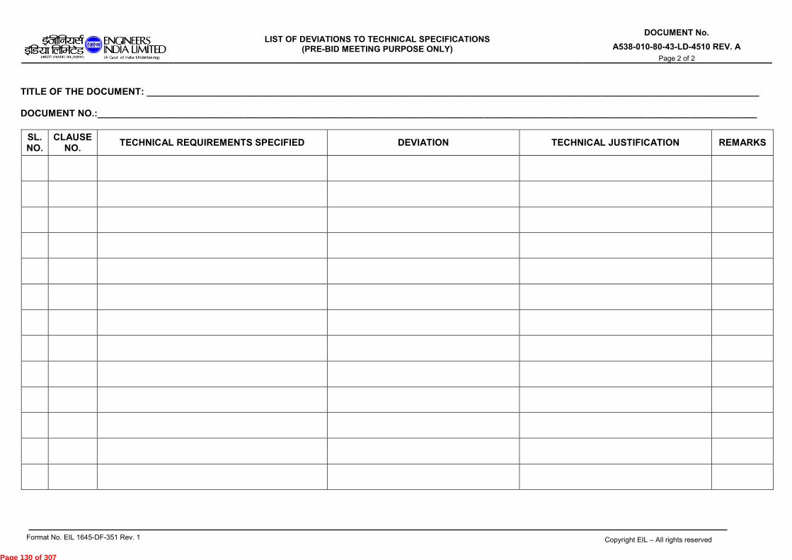
LIST OF DEVIATIONS TO TECHNICAL SPECIFICATIONS
(PRE-BID MEETING PURPOSE ONLY)
DOCUMENT No.
A538-010-80-43-LD-4510 REV. A
Page 2 of 2
Format No. EIL 1645-DF-351 Rev. 1 Copyright EIL – All rights reserved
TITLE OF THE DOCUMENT: _____________________________________________________________________________________________________________________
DOCUMENT NO.:______________________________________________________________________________________________________________________________
SL. NO.
CLAUSE NO.
TECHNICAL REQUIREMENTS SPECIFIED DEVIATION TECHNICAL JUSTIFICATION REMARKS
Page 130 of 307

Doc. No. A538-010-80-43-TCL-4510
TECHNICAL COMPLIANCE STATEMENT
(TO BE SIGNED BY VENDOR'S PRINCIPAL CORPORATE LEVEL SIGNATORY ON COMPANY LETTERHEAD)
I, ON BEHALF OF M/s CONFIRM THAT THE PROPOSAL OF ------
----------------------------------------------QUOTED BY M/s FOR NRL
DHT PROJECT AGAINST MATERIAL REQUISITION /TENDER/PACKAGE No. ---------
----------------------------------------- IS IN TOTAL COMPLIANCE TO THE SCOPE AS
WELL AS ALL THE TECHNICAL SPECIFICATION AND NO DEVIATION, VARIATION
OR RESERVATION WHATSOEVER HAS BEEN MENTIONED IN THE BID. IT IS
AGREED THAT ANY TECHNICAL DETAILS FINALISED DURING PRE-BID
MEETING SHALL BE CONSIDERED PART OF BID AND BINDING ON US. IT IS
FURTHER AGREED THAT DURING DETAILED ENGINEERING STAGE ANY
CHANGE REQUIRED TO MEET THE REQUIREMENTS OF ENQUIRY
SPECIFICATION INCLUDING AMENDMENT(S) (IF ANY) WILL BE INCORPORATED
BY US WITHOUT ANY PRICE AND TIME IMPLICATION.
(SIGNATURE WITH SEAL)
Page 131 of 307

JOB SPECIFICATION (STATIC & MACHINERY
EQUIPMENT DIVISION - 2) MOBILE FLARE SYSTEM
KSPPL
DOCUMENT No.
A538-010-80-43-SP-4510 Rev B
Page 1 of 16
B 28.09.2016 REVISED AS PER CLIENT’S COMMENT AND
REISSUED WITH MR SASWATA PD SM
A 22.08.2016 ISSUED WITH MR SASWATA PD SM
Rev. No
Date Purpose Prepared by Checked
by Approved
by
Format No. EIL 1641-1924 Rev. 1 Copyright EIL – All rights reserved
JOB SPECIFICATION
FOR MOBILE FLARE SYSTEM
PROJECT : KOCHI- SALEM LPG PIPELINE PROJECT OWNER : KOCHI- SALEM PIPELINE PVT. LTD (KSPPL) JOB NO. : A538
Page 132 of 307

JOB SPECIFICATION (STATIC & MACHINERY
EQUIPMENT DIVISION - 2) MOBILE FLARE SYSTEM
KSPPL
DOCUMENT No.
A538-010-80-43-SP-4510 Rev B
Page 2 of 16
Format No. EIL 1641-1924 Rev. 1 Copyright EIL – All rights reserved
CONTENTS
1. GENERAL
2. SCOPE OF SUPPLY & SERVICES
3. EXCLUSIONS
4. SPECIAL TECHNICAL REQUIREMENT
5. INSPECTION AND TESTING
6. SHOP AND FIELD PAINTING
7. SPARES
8. ORDER OF PRECEDENCE
9. AMENDMENT TO PROCESS DATA SHEET
ANNEXURE 1 (D.G. SET)
Page 133 of 307
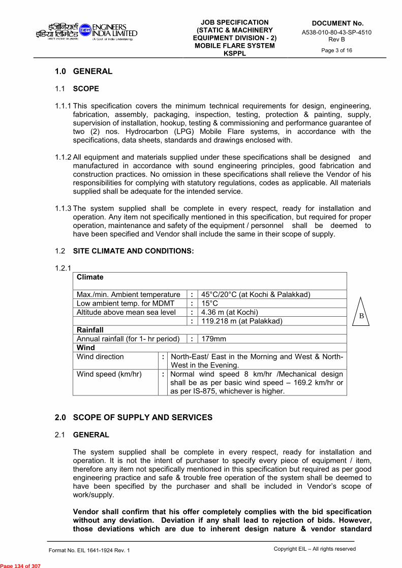
JOB SPECIFICATION (STATIC & MACHINERY
EQUIPMENT DIVISION - 2) MOBILE FLARE SYSTEM
KSPPL
DOCUMENT No.
A538-010-80-43-SP-4510 Rev B
Page 3 of 16
Format No. EIL 1641-1924 Rev. 1 Copyright EIL – All rights reserved
1.0 GENERAL
1.1 SCOPE
1.1.1 This specification covers the minimum technical requirements for design, engineering, fabrication, assembly, packaging, inspection, testing, protection & painting, supply, supervision of installation, hookup, testing & commissioning and performance guarantee of two (2) nos. Hydrocarbon (LPG) Mobile Flare systems, in accordance with the specifications, data sheets, standards and drawings enclosed with.
1.1.2 All equipment and materials supplied under these specifications shall be designed and
manufactured in accordance with sound engineering principles, good fabrication and construction practices. No omission in these specifications shall relieve the Vendor of his responsibilities for complying with statutory regulations, codes as applicable. All materials supplied shall be adequate for the intended service.
1.1.3 The system supplied shall be complete in every respect, ready for installation and
operation. Any item not specifically mentioned in this specification, but required for proper operation, maintenance and safety of the equipment / personnel shall be deemed to have been specified and Vendor shall include the same in their scope of supply.
1.2 SITE CLIMATE AND CONDITIONS:
1.2.1
Climate
Max./min. Ambient temperature : 45°C/20°C (at Kochi & Palakkad)
Low ambient temp. for MDMT : 15°C
Altitude above mean sea level : 4.36 m (at Kochi)
: 119.218 m (at Palakkad)
Rainfall
Annual rainfall (for 1- hr period) : 179mm
Wind
Wind direction : North-East/ East in the Morning and West & North-West in the Evening.
Wind speed (km/hr) : Normal wind speed 8 km/hr /Mechanical design shall be as per basic wind speed – 169.2 km/hr or as per IS-875, whichever is higher.
2.0 SCOPE OF SUPPLY AND SERVICES
2.1 GENERAL The system supplied shall be complete in every respect, ready for installation and operation. It is not the intent of purchaser to specify every piece of equipment / item, therefore any item not specifically mentioned in this specification but required as per good engineering practice and safe & trouble free operation of the system shall be deemed to have been specified by the purchaser and shall be included in Vendor’s scope of work/supply. Vendor shall confirm that his offer completely complies with the bid specification without any deviation. Deviation if any shall lead to rejection of bids. However, those deviations which are due to inherent design nature & vendor standard
B
Page 134 of 307

JOB SPECIFICATION (STATIC & MACHINERY
EQUIPMENT DIVISION - 2) MOBILE FLARE SYSTEM
KSPPL
DOCUMENT No.
A538-010-80-43-SP-4510 Rev B
Page 4 of 16
Format No. EIL 1641-1924 Rev. 1 Copyright EIL – All rights reserved
manufacturing process having field-proven past supply references and cannot be complied with additional time and cost, shall be considered subject to mutual discussion/ justification during pre-bid meeting. Vendor to note that Technical deviations/clarifications, if any shall be submitted during pre-bid meeting and will be mutually discussed and agreed during pre-bid meeting. No further technical deviation will be entertained in the offer and the same shall lead to rejection of Vendor’s offer.
2.2 SCOPE OF SUPPLY The scope of supply shall include all materials and supplies as specified in the Process Data Sheet (Doc. No. A538-010-04-DS-1801), P & ID (Doc No: A538-04-41-010-1111), this specification and drawings/documents enclosed/referred with this requisition. Each Mobile Flare System (010-ME-0001/010-ME-0002) shall have two vehicles for accommodating the flare and power unit separately. Scope Matrix for each Mobile Flare System shall be as per table below:
Vehicle Details
Item Description Vendor Scope of Supply
KSPPL Scope of Supply
Remarks
1st Vehicle (Flare Skid)
Prime Mover (Note 1)
---- ▲ Trailer shall house Flare stack, hydraulic winch, nitrogen cylinder bank and other accessories.
Trailer ▲ ------
2nd Vehicle (Power Unit)
Prime Mover cum chassis (Note 1 & Note 2)
------ ▲
This vehicle shall house DG set, LPG manifold, Flame Front Generator or High Energy Ignitor system as detailed below.
Note 1 Prime mover for 1st vehicle & Prime mover cum chasis for 2nd vehicle shall be procured by M/s KSPPL.
Note 2 2nd Vehicle shall always be located outside the sterile radius of flare stack. (Minimum distance to be considered – 30 meters).
Vendor shall be single point responsible vendor (SPRV) for the complete Mobile Flare skid and Power Unit. Vendor’s supply shall be complete in all respects within the Battery Limit for safe and efficient operation and easy maintenance of the system. The Vendor’s scope of supply shall include but not limited to the following major items as listed below:-
2.2.1 Each Mobile Flare System (010-ME-0001/0002) shall be trailer mounted system with components detailed in this job specification, Data Sheet (Doc. No. A538-010-04-DS-1801), P & ID (Doc No: A538-04-41-010-1111). This system shall comprise of but not limited to the following:
2.2.1.1 Flare Tip of length 3m (minimum) with accessories like pilot gas burner, windshield, pilot
lines, ignitor lines, flame retention lugs for stable flame, etc. as detailed in Note 1 of PDS (doc. no. A538-010-04-DS-1801). Material of construction (MOC) of pilot gas line, ignition gas line along the flare tip section shall be same MOC of Flare tip.
B
Page 135 of 307

JOB SPECIFICATION (STATIC & MACHINERY
EQUIPMENT DIVISION - 2) MOBILE FLARE SYSTEM
KSPPL
DOCUMENT No.
A538-010-80-43-SP-4510 Rev B
Page 5 of 16
Format No. EIL 1641-1924 Rev. 1 Copyright EIL – All rights reserved
2.2.1.2 Integral Gas Seal to minimize purge flow requirement & ingress of air.
2.2.1.3 2nd vehicle chassis mounted with Flame Front Generator(FFG) Panel: Flare Gas Natural
Draught type Flame Front Generator Panel System suitable for lighting one pilot using battery operated ignition device and with non-electric type ignitor. Details of pipes and flanges between flare stack and flame front generator to be specified by Vendor. FFG Panel shall have following as minimum:
2.2.1.3.1 Fuel Gas Pressure regulating Valve 2.2.1.3.2 Fuel Gas Needle Valve 2.2.1.3.3 Fuel Gas strainer 2.2.1.3.4 Pressure Gauge for Fuel gas 2.2.1.3.5 2 Way Gauge Manifold Valve for Pressure Gauges 2.2.1.3.6 Natural Draught Air Aspirator 2.2.1.3.7 Mixing Cum Ignition Chamber 2.2.1.3.8 Battery operated Ignitor as well as triboliter non electric ignitor 2.2.1.3.9 Necessary Piping Panel and canopy 2.2.1.3.10 Pilot Monitoring box with indicator lamp for pilot ON/OFF indicator 2.2.1.3.11 Flame Failure Alarm 2.2.1.3.12 Low pressure Alarm 2.2.1.3.13 Thermocouple/ Temperature Element for Flare Tip ignition 2.2.1.3.14 Alternatively to Flame front generator panel (Cl. no. 2.2.1.3.6, 2.2.1.3.7, 2.2.1.3.8)
vendor can supply High Energy Ignition system (HEI) for lighting one pilot using high energy ignition probe with spark tip and wiring. Electronics for High Energy Ignition system shall be mounted on 2nd vehicle chasis away from sterile radius of flare system. Minimum 50 meters wiring between HEI panel and flare stack base shall be considered in addition to HEI cable requirement for Flame stack height. Cable reeling/un-reeling drum shall also be provided in 1st vehicle and 2nd vehicle for ease of handling during transportation.
2.2.1.4 Flare Stack riser with supporting & detachable arrangement. Flare stack riser shall be designed suitable for the overall flare height of minimum 13m from trailer top. This shall include flare tip height of minimum 3m. Flare stack shall have inlet flange of 8” NB 150# as per ANSI B16.5. The outlet flange connecting with flare tip shall be designed by Vendor. The detail of outlet flange to be specified by Vendor.
2.2.1.5 Stack Supporting Arrangement Supporting arrangement with base plate and simple fixing arrangement (preferably hold down pegs) and guyed support with guy rope pegs as necessary for erecting the same on trailer so as to suit the prevailing site conditions (wind speed etc.) Vendor shall provide a reliable supporting arrangement and stand guarantee for the same. Stack supporting arrangement for the flare shall be designed suitable for an overall height of flare.
2.2.1.6 Knockout drum of adequate size, (if required) to collect the liquid droplets because of pressure reduction.
2.2.1.7 Flame arrestor on mainline and pilot ignitor lines, if required. 2.2.1.8 LPG manifold system & supply of 6 nos. commercial LPG cylinders
LPG manifold system shall comprise of 2 Nos. of isolation valves and fittings for 0.5” SS Impulse Tubing /Piping. LPG manifold system shall be suitable to connect with minimum 6 nos. of cylinders with isolation valves and flexible hose connections.
B
Page 136 of 307

JOB SPECIFICATION (STATIC & MACHINERY
EQUIPMENT DIVISION - 2) MOBILE FLARE SYSTEM
KSPPL
DOCUMENT No.
A538-010-80-43-SP-4510 Rev B
Page 6 of 16
Format No. EIL 1641-1924 Rev. 1 Copyright EIL – All rights reserved
Flexible hose shall have union connections to connect with standard commercial LPG cylinders. LPG manifold system shall have piping connection to connect with FFG Panel inlet piping. Vendor shall supply 6 nos. of commercial LPG cylinders. However, LPG cylinders shall be registered in the name and address of KSPPL as mentioned below and registration documents shall be handed over to Client post order: Kochi Salem Pipeline Private Limited Bharat Petroleum Corporation Limit, Irimpanam Installation, PO- Irimpanam, Kochi-682039, Kerala, India.
2.2.1.9 Required number (min 2 nos.) of Inert gas cylinders with pressure regulators, manifold, piping, valves, etc. for purging of the flare stack. Vendor shall supply N2 cylinder along with N2 gas.
2.2.1.10 Hydraulic type winch with associated hydraulic power unit (HPU) shall be provided for erecting the flare system. Vendor shall also supply hydraulic hand pump as a standby for erecting flare stack during hydraulic pump failure. Hydraulic oil tank and hydraulic pipes shall be Stainless steel. Hydraulic oil shall be supplied by Vendor. Equivalent grade of oil shall be specified. Hydraulic type winch shall be designed for handling 1.5 times of the total weight to be handled.
2.2.1.11 Power supply source for Mobile Flare System shall be from DG set located on chassis
of 2nd vehicle. DG set shall be procured from one of EIL enlisted vendor as per attached vendor list. DG set (15KVA) shall be supplied by Mobile flare vendor as per attached Annexure 1 to this specification, datasheet (doc.no. A538-010-80-43-DS-4511) and checklist for Scope of Supply (doc.no. A538-010-80-43-CL-4510).
Power required for ignition in FFG/HEI system, flare stack skid illumination light, hydraulic pump and instruments in FFG shall be derived from DG set. Wiring between DG set and flare stack skid (minimum 50 meters) shall be supplied by vendor. Further, Cable reeling/un-reeling drums shall be provided with both 1st vehicle and 2nd vehicle of mobile flare system for ease of operation. Electrical Lighting Fixture for illumination of Mobile flare skid & FFG/HEI skid. Also refer Electrical specification (doc. no.A538-010-16-50-SP-4510) and datasheet (doc. no. A538-010-16-50-DS-4510 & A538-010-16-50-DS-4511) for details.
2.2.1.12 Temperature Element
Single pair mineral insulated and SS 321 sheathed temperature element “K” type from flare tip pilot to FFG Panel.
2.2.1.13 Utility Piping Utility Piping Supply should include piping for flame front line and Pilot gas line.
2.2.1.13.1 Pilot Gas Line Suitable Pipe line shall be designed from FFG Panel to Flare tip bottom (1 No X 0.5”NB SCH 80- SA106 GB B). Length: To be decided by Vendor.
2.2.1.13.2 Ignition Line in case of FFG Suitable pipe line shall be designed from FFG Panel to Flare tip bottom (1 No X 2” NB SCH 40- SA 106 Gr B). Length: To be decided by Vendor.
B
B
Page 137 of 307

JOB SPECIFICATION (STATIC & MACHINERY
EQUIPMENT DIVISION - 2) MOBILE FLARE SYSTEM
KSPPL
DOCUMENT No.
A538-010-80-43-SP-4510 Rev B
Page 7 of 16
Format No. EIL 1641-1924 Rev. 1 Copyright EIL – All rights reserved
2.2.1.14 All accessories required including flanges, orifice plates, regulators, valves, CS pipe spool for pilot gas and ignitor gas line, SS 304 flexible hoses, straps etc.
2.2.1.15 Prime mover cum chasis of 2nd vehicle of adequate capacity shall be procured by KSPPL and shall be made available at vendor’s work within India. Foreign vendor may nominate a designated workshop within India for delivering the vehicle at the workshop. Vendor shall fabricate the structural skid on the chasis of the 2nd vehicle, supply, mount and carry out Factory Acceptance Test (FAT) of LPG manifold, LPG cylinder cage & cylinders, DG set and FFG/HEI system, flow meters,etc. at vendor works before despatch.
2.2.1.16 Trailer with pipe rack mounted flare tip, seal, stack risers, supporting arrangement and
all other related equipment of the Mobile flare system in the folded and compact condition so that minimum size trailer is required without compromising on the quickness of erecting the system. If jib crane is required for assembling/erecting stack riser pieces, same shall be included/ mounted on the trailer. Trailer mounted flare system must comply with the standard requirement of Indian Road Congress(IRC).
2.2.1.17 Storage locker/ Tool box on trailer for guy ropes, earthing lead, tools and hose guides, electrical cable etc.
2.2.1.18 Commissioning spares as per vendor’s recommendation for all electrical,
instrumentation and mechanical items. As a minimum, Vendor shall supply following spares listed below for each mobile flare system. Commissioning spares shall be supplied individually for each flare system. a. 2 sets of studs & nuts of each type and size and 200% gasket for Tip (Hydrocarbon
flare tip). b. 1 set of gasket, bolts and nuts for ignition system. Price of all commissioning spares shall be included in the base price of the equipment.
2.2.1.19 Vendor shall supply new & unused special tools and tackles for the offered mobile flare system. Price towards special tools & tackles shall be included in the base price of the equipment. Vendor shall supply individual special tools and tackles for each mobile flare system.
2.2.1.20 Vendor shall furnish itemized price list of recommended two years spares for smooth and trouble-free operation of complete system including electrical and instrumentation spare. Owner shall order these spares separately.
2.3 SCOPE OF SERVICES
2.3.1 Design, engineering and selection of equipment
2.3.2 Procurement of raw materials and bought out components.
2.3.3 Manufacture, assembly and packaging
2.3.4 Shop inspection, testing, Factory Acceptance Test.
2.3.5 Surface preparation and painting. Complete painting (primer and finish) shall be done in vendor’s shop only.
2.3.6 Packing and supply
B
B
Page 138 of 307

JOB SPECIFICATION (STATIC & MACHINERY
EQUIPMENT DIVISION - 2) MOBILE FLARE SYSTEM
KSPPL
DOCUMENT No.
A538-010-80-43-SP-4510 Rev B
Page 8 of 16
Format No. EIL 1641-1924 Rev. 1 Copyright EIL – All rights reserved
2.3.7 Supervision of installation (i.e. erection, dismantling, folding and mounting of the
equipment on trailer), hookup, testing, commissioning and performance guarantee test run at site & training of Owner’s personnel at site of mobile flare systems on per diem rate basis.
For commercial comparison of offers, total of eight (8) mandays for mobile flare system (i.e. Four (4) mandays per tag of mobile flare system) will be considered for supervision installation, testing, commissioning and performance guarantee test run at site and training of Owner’s personnel by Vendor’s representatives. However, for payment, actual no. of days consumed during installation, testing, commissioning and performance guarantee test run at site and training of Owner’s personnel shall be applicable. The quoted per diem rate is applicable for both the places where mobile flare system will be installed. Training of Owner’s personnel at site:
The training programme will comprise of classroom training and explanation of details of equipment at site. The group to be trained will comprise of persons from all disciplines of maintenance, operation and other associated departments (mechanical, electrical, instrumentation). All required facilities for class room training at site shall be provided by owner. However all training materials shall be provided by Vendor.
2.3.8 Preparation and submission of drawings and documents online through V-Portal/eDMS as specified under Vendor Data requirement.
2.3.9 Client shall arrange for registration of 2 vehicles (prime movers) however vendor shall
provide necessary assistance including preparation of technical documents & drawings inline with statutory requirements of RTO.
2.3.10 Vendor shall assist Client in getting all statutory clearances, permits from local, statutory
and other bodies. Vendor’s assistance shall include preparation of documents in line with statutory requirements, preparation of technical answers in the event of queries from statutory body, attending technical meeting with statutory body along with Client. All fees related to Statutory Approval shall be borne by Client.
2.3.11 Vendor shall provide all necessary assistance to client regarding finalizing prime mover
for 1st vehicle and 2nd vehicle during detail engineering. However, prime movers shall be procured by client.
2.3.12 Vendor shall furnish quotation on per diem basis for on call service by client after one
year of commissioning. The quotation shall be valid for 3 years after commissioning. However, same shall not be considered for evaluation.
3.0 EXCLUSION
3.1 Installation of mobile flare system at site. 3.2 Civil work (if any)
4.0 SPECIAL TECHNICAL REQUIREMENT
B
B
Page 139 of 307

JOB SPECIFICATION (STATIC & MACHINERY
EQUIPMENT DIVISION - 2) MOBILE FLARE SYSTEM
KSPPL
DOCUMENT No.
A538-010-80-43-SP-4510 Rev B
Page 9 of 16
Format No. EIL 1641-1924 Rev. 1 Copyright EIL – All rights reserved
4.1 Vendor shall supply equipment as per the technical requirements specified in Process Data Sheet (Doc. No. A538-010-04-DS-1801), P & ID (Doc No: A538-04-41-010-1111), this specification and drawings/documents enclosed/referred with this requisition.
4.2 The equipment shall be complete in all respect and any item/feature not mentioned
hereinafter but essential for proper operation and intended utilization of the unit shall be included by the Vendor.
4.3 The design and construction of the flare stack components shall be in accordance with
ASME Section VIII Div. 1(latest addition), API-RP-521 wherever applicable, and other relevant international codes. Test certificate shall be furnished to that effect.
4.4 Provision for draining of material condensed in the flare seal shall be provided. Collection
pot for material condensed shall be provided in the flare stack skid for draining at later stage.
4.5 Allowable pressure drop for Flare tip and Flare seal (combined together) is to be
considered as 1000 mmWC. However, vendor to indicate the calculated pressure drop separately for flare tip and flare seal.
4.6 Flare tip size(diameter) shall not be lower than the estimated minimum size specified in
the process data sheet no. A538-010-04-DS-1801. 4.7 Acceptable noise level at design flare load shall not exceed 90 dBA at the base. 4.8 Ignition of pilot burners shall be through Flame front Generator/ High energy ignitor. 4.9 The flame front generator panel shall be battery operated electric type suitable for
outdoor location. Suitable weather hood shall be provided. The flame front generator shall be suitable for manual ignition, unless otherwise specified.
4.10 Gas seal shall be provided to ensure safe flare operation by preventing ingress of air into
the stack. Flare tip shall have integral gas seal. 4.11 Material of Construction (MOC) of flare tip and seal shall be as per Process Data
Sheet.
5.0 INSPECTION AND TESTING
5.1 Equipment shall be subjected to stage wise expediting, inspection and testing at vendor’s/ sub vendor’s works by purchaser/its authorized inspection agency. Vendor shall submit Quality Assurance (QA) procedures before commencement of fabrication. Approved QA procedures shall form the basis of equipment inspection.
5.2 Third party inspection shall be as per commercial part of bid document.
5.3 Shop tests for the equipment & piping items shall be carried out in accordance with applicable codes, as per the procedures laid out by the Inspector & as per requirements mentioned in the applicable specifications. As a minimum 100% for “T” joints and 10% for all butt welds on flare tip shall be radiographed.
5.4.1 The winch and complete stack & tip hoisting system shall be performance tested for the
intended duty by the vendor at Vendor works.
B
Page 140 of 307

JOB SPECIFICATION (STATIC & MACHINERY
EQUIPMENT DIVISION - 2) MOBILE FLARE SYSTEM
KSPPL
DOCUMENT No.
A538-010-80-43-SP-4510 Rev B
Page 10 of 16
Format No. EIL 1641-1924 Rev. 1 Copyright EIL – All rights reserved
5.4.2 Vendor shall carry out Factory Acceptance Test (FAT) of LPG manifold, LPG cylinder cage & cylinders, DG set and FFG/HEI system, flow meters, etc. at vendor works before dispatch.
5.5 Any or all the tests, at purchaser’s option, shall be witnessed by purchaser/ its authorized
inspection agency. However, such inspection shall be regarded as checkup and in no way absolve the vendor of his responsibility.
5.6 Performance Testing and Guarantees
5.6.1. All materials & equipments shall be guaranteed against defects of design, material &
workmanship. Any deficiency in operating performance & any defect in material or workmanship found during the guarantee period shall be corrected by the vendor at his own cost.
5.6.2. All instruments & accessories (duly calibrated) necessary for site performance testing shall be arranged by the vendor. However Vendor shall take back all such instruments after completion of Process guarantee test run (PGTR).
5.6.3. Mobile Flare system & associated accessories shall be guaranteed for a service life of 3 years minimum.
5.6.4. Vendor shall furnish Performance Guarantee procedure for Client/EIL approval during detail engineering. Performance guarantee testing shall be carried out based on approved procedure. Performance guarantee testing shall be carried out for 24 hrs continuously. However, as a minimum Vendor shall guarantee & demonstrate the following guarantee parameters at site:
a) Radiation level at operating conditions at the time of testing. Vendor shall furnish the Graph between flow rate vs Radiation level at sterile radius and at stack base and provide the same along with PGTR procedure document. Acceptable radiation for mobile flare system is 1500 BTU/ft2/hr including solar radiation (300 BTU/ft2/hr).
b) Noise level at operating conditions at the time of testing. Vendor shall furnish the Graph
between flow rate vs Noise level at sterile radius and provide the same along with PGTR procedure document. Acceptable noise level at design flare load shall not exceed 90 dBA at the base.
6.0 SHOP AND FIELD PAINTING
6.1 For all the equipment including all vessels, piping, valves and structural items external surface, preparation, primer and finish painting shall be carried out as per the attached Standard Specification for Surface Preparation and Protective Coating (doc. no. 6-79-0020) as per Cl. no. 10.3 of Table 10, and wherever field paint is specified in the attached specification it shall mean shop painting.
7.0 SPARES
7.1 Commissioning Spares Vendor shall supply adequate quantity of commissioning spares for each mobile flare system so as to ensure that commissioning of the system is not hampered for shortage of commissioning spares. Vendor shall include the cost of the commissioning spares in the lump sum quoted price of each flare system. If any spare, over and above the supplied commissioning spares is required during commissioning, the same shall be supplied by Vendor without any price or time implication. In case during commissioning any spare is
Page 141 of 307

JOB SPECIFICATION (STATIC & MACHINERY
EQUIPMENT DIVISION - 2) MOBILE FLARE SYSTEM
KSPPL
DOCUMENT No.
A538-010-80-43-SP-4510 Rev B
Page 11 of 16
Format No. EIL 1641-1924 Rev. 1 Copyright EIL – All rights reserved
used from recommended spares for 2 years operation and maintenance, the same shall be replaced free of cost within a reasonable period of time. All spares parts shall be wrapped and packaged so that they are preserved in original as-new condition, under normal conditions of storage to be anticipated in India, and shall be properly tagged and coded so that later identification for intended equipment usage will be facilitated. The two years’ “recommended spares” and “commissioning spares” shall be packaged separately and clearly marked as “Spare Parts” and “Commissioning Spares” respectively.
7.2 Recommended Spares
Vendor shall furnish list of recommended spares (Mechanical, electrical, instrumentation,
piping) for two (2) years normal operation and maintenance of the equipment with itemized
price list along with the Bid.
7.3 All spares parts shall be wrapped and packaged so that they are preserved in original as-new condition, under normal conditions of storage to be anticipated in India, and shall be properly tagged and coded so that later identification for intended equipment usage will be facilitated. The two years’ “recommended spares” and “commissioning spares” shall be packaged separately and clearly marked as “Spare Parts” and “Commissioning Spares” respectively.
8.0 ORDER OF PRECEDENCE In the event of conflict between this specification and other attached documents, the
following order of precedence will govern:
o This Specification o Process Data Sheet (Doc. No. A538-010-04-DS-1801), P & ID (Doc No: A538-04-
41-010-1111), o Other job specifications and standards. o Codes and Standards
NOTE: “Vendor” shall be read as “Bidder” till placement of order.
9.0 AMENDMENT TO PROCESS DATA SHEET(PDS) (doc. no. A538-010-02-DS-1801)
The terms, conditions and specifications of PDS stand modified to the extent indicated under column “MODIFICATIONS/ADDITION”. All other terms & conditions, stipulations and specifications of MR document shall remain unaltered.
Legend: A:Addition D:Delete M:Modify C:Clarification
S. No.
Clause No. A/D/M/C
Description of Amendment
1. Note 2, Sr. no. (N)
M Note – “Battery” shall be modified as “DG set”.
2. Note 2, D Sentence “The ignition system shall be loose supplied as spool piece with flanged ends.” shall be deleted.
Page 142 of 307

JOB SPECIFICATION (STATIC & MACHINERY
EQUIPMENT DIVISION - 2) MOBILE FLARE SYSTEM
KSPPL
DOCUMENT No.
A538-010-80-43-SP-4510 Rev B
Page 12 of 16
Format No. EIL 1641-1924 Rev. 1 Copyright EIL – All rights reserved
ANNEXURE 1 (D.G. SET)
SECTION 1 - GENERAL
1.1 SCOPE
1.1.1 This specification together with the attendant Data Sheets and other specifications/
attachments to inquiry / order defines the minimum requirements for the DG sets and
their accessories/ auxiliaries for general industrial purposes.
1.1.2 Vendor shall make all possible efforts to comply strictly to the requirements of this
specification and other specifications/attachments to inquiry/order.
No deviation or exception shall be permitted without the written approval of the
purchaser.
1.1.3 Compliance with this specification shall not relieve the vendor of the responsibility of
furnishing equipment and accessories/auxiliaries of proper design, materials and
workmanship to meet the specified operating conditions.
1.2 CONFLICTING REQUIREMENTS
1.2.1 In case of conflict between this specification and the attendant data sheets and other
attached specification the following order of precedence shall govern:
1. Equipment Data Sheets
2. This specification
3. Other referred codes and standards
1.3 DEFINITION OF TERMS
1.3.1 All the definitions as indicated in ISO:3046 shall apply for Reciprocating Internal
Combustion Engines.
1.3.2 All the definitions as indicated in ISO:8528 shall apply for Reciprocating Internal
combustion engine driven alternating current generating sets.
1.4 EQUIPMENT QUALIFICATION CRITERIA (EQC)
1.4.2 Unless otherwise specified elsewhere in the inquiry document, following EQC shall be
applied for acceptance of the offered Engine model:
The Engine offered shall be from a regular and established manufacturer of
reciprocating I.C. Engines having requisite design, engineering, manufacturing and
testing facilities.
The Engine model offered shall be from the regular manufacturing range of the
manufacturer (for power generation application) and already type tested at either
manufacturer's works or outside.
Bidder to furnish the general reference list of the offered Diesel Engine or DG set
during detail engineering stage.
Since this reference list will be used for establishing provenness of proposed model for
operating under specified operating conditions, it is in vendor's own interest to select
Page 143 of 307

JOB SPECIFICATION (STATIC & MACHINERY
EQUIPMENT DIVISION - 2) MOBILE FLARE SYSTEM
KSPPL
DOCUMENT No.
A538-010-80-43-SP-4510 Rev B
Page 13 of 16
Format No. EIL 1641-1924 Rev. 1 Copyright EIL – All rights reserved
such references, where the proposed model is supplied and operating at conditions
similar to those specified for item against which the proposed model is offered. In
addition, manufacturer's catalogue and general reference list for the Engine shall also be
furnished.
1.4.2 EQC for DG set
The proposed equipment shall be from the regular manufacturing range of the vendor
and shall have sufficient proven track record without any problems. The proposed equipment shall not be a prototype machine or a scaled version of existing equipment.
Equipment is not considered to be prototype if at least 3 units of similar type and size
have each accumulated an operating experience of at least 1 year in a similar duty.
SECTION 2 - BASIC DESIGN
2.1 GENERAL
2.1.1 The Engine selected shall be vendor’s standard model after taking into consideration the
requirement of the driven equipment, transmission losses, site de-ration and power
requirements of auxiliaries and other parasitic loads.
Engine Manufacturer’s de-ration calculations for the specified site conditions shall be
furnished during detail engineering. As a minimum, the vendor shall consider the de-
ration due to ambient temperature, altitude, relative humidity, cooling water temperature,
inlet and exhaust losses etc. De-ration factor shall be worked out as per ISO: 3046. In
case there is no de-ration for the specified site conditions, the Engine Manufacturer’s
statement along with justification shall be furnished.
2.1.2 Standard reference conditions shall be as defined in ISO: 3046-1.
2.2 RATED POWER OUTPUT AND SPECIFIC FUEL CONSUMPTION
2.2.1 Diesel Engine
2.2.1.1 The engine rating is the net shaft output in Kilowatts which the engine is capable of
delivering unlimited no of hours, between the normal maintenance intervals stated by the
manufacturer, at a variable power sequence and under stated ambient conditions
assuming that the maintenance prescribed by the manufacturer being carried out. Diesel
Engine Rating indicated by the manufacturer in the Equipment data sheet shall be with
no negative tolerance.
2.2.1.2 The engine shall be capable of providing 10% over load power for a period of one hour in
every 12 hours of operation.
2.2.1.3 Specific fuel consumption shall be indicated at the rating as defined in clause 2.2.1.1
above. Specific fuel consumption shall also be indicated at other loads as specified by
purchaser in the Engine data sheet. The tolerances shall be as per ISO:3046-1.
2.2.2 Diesel Engine Generating Set
Page 144 of 307

JOB SPECIFICATION (STATIC & MACHINERY
EQUIPMENT DIVISION - 2) MOBILE FLARE SYSTEM
KSPPL
DOCUMENT No.
A538-010-80-43-SP-4510 Rev B
Page 14 of 16
Format No. EIL 1641-1924 Rev. 1 Copyright EIL – All rights reserved
2.2.2.1 The power of the DG Set is the power output available at the generating set terminals
excluding the electrical power absorbed by the essential independent auxiliaries.
2.2.2.2 Power rating of the DG Set is the power output expressed in kilowatts at rated frequency
and a power factor of 0.8 lagging unless otherwise stated. The DG set rating indicated by
the manufacturer in the Equipment Data Sheet shall be with no negative tolerance.
2.2.2.3 The vendor shall furnish, a list of engine auxiliaries, which require electrical power during
detail engineering stage. All such auxiliaries shall be further categorized on the basis of:
- If these are required to run continuously / intermittently.
- If these are required to run before engine starting, during starting or required to run
after start-up.
- If the above are required to be fed from engine developed power (In such a case,
feeding arrangement shall be in vendor’s scope).
The vendor shall clearly identify those auxiliaries, which will be required to be fed by the
Purchaser.
2.3 ENGINE STARTING SYSTEM
2.3.1 Unless otherwise specified, the type of starting arrangement shall be battery starting.
2.3.2 Engines shall be capable of starting without the use of cold starting aids for ambient
temperatures of 4°C and above.
The Vendor shall provide suitable cold starting aids with engines for quick starting at
ambient temperatures below 4°C and such aids shall be clearly detailed out in the offer.
Lubricating oil heaters shall not be used as a cold starting aid.
2.4 ENGINE JACKET COOLING SYSTEM
2.4.1 The engine shall be provided with a radiator mounted on the common base plate with
engine driven radiator fan, temperature control valve, expansion tank, radiator guard and
other necessary piping and valves.
2.5 COMBUSTION AIR INTAKE & ENGINE EXHAUST SYSTEM
2.5.1 The vendor shall prepare a layout drawing showing the layout and routing of air intake
and engine exhaust piping/ducting, and include in his scope complete piping/ducting,
nozzles, expansion joints and supports as required as per his layout and routing.
2.5.2 The type and location of air intake filter shall be vendor's standard and shall be suitable
for the climatic/environmental conditions applicable to the site of installation of the
engine.
2.5.3 The filter shall be suitably located to prevent exhaust gases getting into the intake air.
2.5.4 Exhaust gas discharge shall be located away from ventilation air intakes to prevent
reentry of offensive fumes and also should not cause discomfort to personnel or hazards
to building or equipment.
2.5.4 Unless otherwise specified or required as per applicable statutory regulation, the height
of the engine stack from the base of the engine room /height of the acoustic enclosure
box shall be as under
Page 145 of 307

JOB SPECIFICATION (STATIC & MACHINERY
EQUIPMENT DIVISION - 2) MOBILE FLARE SYSTEM
KSPPL
DOCUMENT No.
A538-010-80-43-SP-4510 Rev B
Page 15 of 16
Format No. EIL 1641-1924 Rev. 1 Copyright EIL – All rights reserved
H = h + 0.2 * kVA
where
H = minimum height of the exhaust from base, meter
h = height of engine room eves level from the base / height of engine acoustic
enclosure from the base, meter
kVA = kW site rating of the engine, kVA.
2.6 GOVERNING
2.6.1 Unless otherwise specified in the equipment data sheets, the engine shall be provided
with Class M2 governing as per ISO: 3046.
2.6.2 In case engines are required to drive generators in parallel, the governor - fuel injection
pumps provided shall have identical characteristics.
2.7 ENVIRONMENTAL COMPLIANCE ON NOISE AND EXHAUST GAS EMISSION
2.7.1 Unless otherwise specified, any applicable legislation/ statutory requirements relating to
the protection of environment and to the health and safety of personnel, with regard to
noise and exhaust gas emission, as applicable to the place of installation shall be fully
complied with by the Engine manufacturer.
2.7.2 In case of Diesel Engine Generating sets, the DG set vendor shall also be responsible
for complying to the requirements specified in any applicable official Gazette Notifications
issued by Ministry of Environment and Forests, Govt. of India, for all installations
intended to be located in India.
2.8 NAME PLATE
A name plate of 18Cr-8Ni stainless steel or Monel shall be attached by pins of a similar
material to the Engine and to any other piece of major auxiliary equipment, in a location
permitting easy visibility. The purchaser's item number, the vendor's name, serial
number, rating and testing data appropriate to the unit shall appear on all name plates.
SECTION 3 - ACCESSORIES
3.1 BASE PLATE
3.1.1 Unless otherwise specified, a common baseplate for the complete unit (engine and the
driven equipment) shall be supplied by the vendor. A baseplate shall be a single
fabricated steel unit.
3.1.2 The base plate shall be provided with lifting lugs for a four point lift. Lifting the baseplate
complete with all equipment mounted shall not permanently distort or otherwise damage
the base plate or the machinery mounted on it.
3.2 MAINTENANCE TOOL KIT
Normal Maintenance tool kit as per manufacturer standard shall be provided for the each
DG set.
3.3 INSTRUMENTATION
Page 146 of 307

JOB SPECIFICATION (STATIC & MACHINERY
EQUIPMENT DIVISION - 2) MOBILE FLARE SYSTEM
KSPPL
DOCUMENT No.
A538-010-80-43-SP-4510 Rev B
Page 16 of 16
Format No. EIL 1641-1924 Rev. 1 Copyright EIL – All rights reserved
Manufacturer standard instrumentation and controls shall be provided. If in the opinion of the vendor, additional instruments, controls and safety devices are required, the vendor shall include the same in his scope of supply and provide the same.
SECTION 4 - INSPECTION, TESTING AND PREPARATION FOR SHIPMENT
4.1 GENERAL
4.1.1 Vendor to refer equipment data sheet for the applicable inspection and test
requirements.
4.2 PREPARATION FOR SHIPMENT
4.2.1 Immediately upon completion of all tests and inspections, all exposed machined surfaces
shall be cleaned and coated with a suitable rust preventive by the Vendor and the
unmachined surfaces shall be painted by at least two coats of red oxide primer.
4.2.2 Diesel engines alongwith its auxiliaries/ accessories shall be transported in assembled
condition as far as possible.
4.2.3 All untapped openings shall be provided with 4 mm thick metal closures with full rubber
gaskets and bolted by not less than 4 bolts. All connections including those for
instruments, instrument leads, lubricating oil and the like shall be identified with securely
attached tags indicating the type of connection, the instrument or the line description as
applicable.
4.2.4 The equipment shall be crated for domestic/export shipment as specified in the data
sheets considering for storage at job site for atleast 12 months. If any extra precaution is
to be taken by the Purchaser for storage beyond 12 months the same shall be explicitly
indicated in the operation and maintenance manuals. Lifting load-cut, and handling
instructions shall be securely attached to the exterior of the largest packing in a well
marked weather proof container. Upright position lifting points, weight (including
packing) and dimensions shall be clearly identified with item nos., serial nos., package
nos., and the names of the equipment.
4.2.5 Two copies of the manufacturer's installation and instruction manual shall be packed and
shipped with the equipment.
SECTION 5 - VENDOR'S DATA
5.1 Preparation and submission of drawings and documents online through V-Portal/eDMS
as specified under Vendor Data requirement.
Page 147 of 307

Document No.
Rev. No. 1Page 1 of
FLARED GASFLARE LOAD, KG/HR MINIMUM
PEAKSMOKE LESS
AVERAGE MOLECULAR WEIGHTGAS TEMPERATURE DEG CFLARE LOADS FOR ALL THE CASES PROVIDED (NOTE-1)FLARE STACK YES
ITEM NO. NOTYPEDIAMETER INCHESHEIGHT MDESIGN PRESSURE KG/CM2GDESIGN TEMPERATURE DEG CMATERIAL OF CONSTRUCTIONCORROSION ALLOWANCE MM
FLARE SEALITEM NO.TYPEALLOWABLE PRESSURE DROP MM WCMATERIAL OF CONSTRUCTIONCORROSION ALLOWANCE MM
FLARE TIPITEM NO.ALLOWABLE PRESSURE DROP MM WCMATERIAL OF CONSTRUCTION
FLAME FRONT GENERATORITEM NO.
FLARE VENDOR SCOPEFLARE STACKFLARE SEAL NO NOPILOT BURNERSFLARE TIPFLAME FRONT GENERATORASSOCIATED ACCESSORIESOTHERS
REFERENCE P&ID NO.
UTILITIES AVAILABLE MINIMUM NORMAL MAXIMUM DESIGNMP STEAM
PRESSURE KG/CM2GTEMPERATURE DEG C
INSTRUMENT AIRPRESSURE KG/CM2GTEMPERATURE DEG CDEW POINT @ ATM DEG C
NOTE-2
BY VENDOR
NOTE-8
3NOTE-1
NOTE-8
NOTE-5
INTEGRAL SEAL
FLUIDIC
3
ELEVATED813 (NOTE-3) 3.5 65
20-25
NSASMS
YESMAIN FLARE STACK
Format No,3-0441-1035 Rev. 0 Copyrights EIL - all rights reserved
AS ASPrepared
ByReviewed
ByApproved
By
ISSUED FOR ENGINEERING
Purpose
PROJECTUNIT
CLIENTJOB NO. UNIT NO.
KOCHI-SALEM LPG PIPELINE PROJECT
HYDROCARBON (LPG)
10000
FLARE SYSTEMPROCESS DATA SHEET
3
MOBILE FLARE SYSTEM (010-ME-0001/2)KSPPLA538 010
REVISED AS PER ENGINEERING COMMENTS /INPUTS AS
A538-010-02-DS-1801
Rev. No.
01
Date
29.07.201509.12.2015
NOTE-4
1
1
1
Page 148 of 307

Document No.
Rev. No. 1Page 2 of
UTILITIES AVAILABLE (CONTD.)NITROGEN
PRESSURE KG/CM2GTEMPERATURE DEG C
FUEL GASPRESSURE KG/CM2GTEMPERATURE DEG C
RECIRCULATING COOLING WATER SUPPLY PRESSURE KG/CM2GSUPPLY TEMPERATURE DEG CRETURN PRESSURE KG/CM2GRETURN TEMPERATURE DEG C
NOTES:
1 FLARE TIP WITH FOLLOWING SHALL BE PROVIDED BY VENDOR:(A) ONE PILOT GAS BURNER PROVIDED WITH AIR ASPIRATOR & FLAME FRONT IGNITION TUBE AND THERMOCOUPLE(B) FLAME RETENTION LUGS(C) SLATTED WIND SHIELD(D) INTEGRAL GAS SEAL(E) 8''NB 150# FLARE GAS INLET FLANGE AS PER ANSI B 16.5(F) 0.5" TUBING/PIPING FOR LPG SUPPLY CONNECTION TO PILOT/IGNITION BURNER.(G) 20 METRES 8'' SS WIRE BRAIDED FLEXIBLE HOSE TO CONNECT WITH 4'' NB FLARE HEADER USING EXPANDER OF 4''NB X 8"NB(H) SUITABLE FLANGE FOR PILOT GAS INLET AND FLAME FRONT LINE INLET AS PER ANSI B16.5(I) FLARE TIP LENGTH: MIN 3000MM OR VENDOR TO SPECIFY(J) MOC OF MAIN SHIELD : TOP 1.5 METRES OF SS 310 AND 3.5 METRES BOTTOM OF SS310 OR VENDOR TO SPECIFY(K) MOC OF WIND SHIELD : SS 310 OR VENDOR TO SPECIFY(L) MOC OF FLAME RETENTION LUGS : SS 310 OR VENDOR TO SPECIFY(M) MOC OF INTEGRAL GAS SEAL : VENDOR TO SPECIFY(N) MOC OF PILOT GAS LINE AND IGNITION LINE ALONG FLARE TIP SECTION SHALL BE OF SS310
2 FLAME FRONT GENERATOR PANEL: FLARE GAS NATURAL DRAUGHT TYPE FLAME FRONT GENERATOR PANEL SYSTEM SUITABLE FOR LIGHTING ONE PILOT USING BATTERY OPERATED IGNITION DEVICE AND WITH NON ELECTRIC TYPE IGNITOR. THE IGNITION SYSTEM SHALL BE LOOSE SUPPLIED AS A SPOOL PIECE WITH FLANGED ENDS. SUTIABLE FLANGESSHALL BE DESIGNED BY VENDOR. DETAILS OF PIPES AND FLANGES TO BE SPECIFIED BY VENDOR. MIN PRESSURE OF FUEL GAS SHALLBE GIVEN BY VENDOR IN KG/CM2G. THE FFG PANEL SHALL HAVE FOLLOWING AS A MINIMUM:(A) FUEL GAS PRESSURE REGUALTING VALVE(B) FUEL GAS NEEDLE VALVE(C) FUEL GAS STRAINER(D) PRESSURE GAUGE FOR FUEL GAS(E) 2 WAY GAUGE MANIFOLD VALVES FOR PRESSURE GAUGES(F) NATURAL DRAUGHT AIR ASPIRATOR(G) MIXING CUM IGNITION CHAMBER(H) BATTERY OPERATED IGNITOR AS WELL AS TRIBOLITER NON ELECTRIC IGNITOR(I) NECESSARY PIPING PANEL AND CANOPY(J) PILOT MOTORING BAR WITH INDICATOR LAMP FOR PILOT ON /OFF INDICATOR.(K) FLAME FAILURE ALARM(L) LOW PRESSURE ALARM(M) THERMOCOUPLE / TEMPERATURE ELEMENT FOR FLARE TIP IGNITION(N) BATTERY
AS ASAS AS
PROJECT KOCHI-SALEM LPG PIPELINE PROJECT CLIENT KSPPLUNIT A538
BY VENDOR
MINIMUM DESIGN
FLARE SYSTEM
UNIT NO.MOBILE FLARE SYSTEM (010-ME-0001/2) JOB NO.
A538-010-02-DS-1801PROCESS DATA SHEET
3
010
1 09.12.2015 REVISED AS PER ENGINEERING COMMENTS /INPUTS
Format No,3-0241-1035 Rev. 0 Copyrights EIL - all rights reserved
ISSUED FOR ENGINEERING
Rev. No. Date Purpose
0 29.07.2015 NSPrepared
ByReviewed
ByApproved
By
MS
NORMAL MAXIMUM
11
1
1
Page 149 of 307

Document No.
Rev. No. 1Page 3 of
3 THE ELEVATION IS UPTO THE TOP OF THE TIP.
4. FUEL GAS COMPOSITION (LPG) FOR FLAME FRONT GENERATOR IS GIVEN AS BELOW:
COMPOSITION (MOL%)
ETHYLENE 0ETHANE 0.29PROPYLENE 10.85PROPANE 19.49ISO BUTANE 7.85BUTENES 31.64N-BUTANE 29.2C5 0.7
AVG MOL WT: 50-53
5. FLARE STACK RISER SHALL BE BE DESIGNED SUITABLY FOR THE OVERALL FLARE HEIGHT OF MINIMUM OF 13 METRES AND SHALL BE 8"NB 150# AS PER ANSI B16.5. THE OUTLET FLANGE SHALL BE SUITABLY DESIGNED BY VENDOR AND DETAILSOF THE OUTLET FLANGE SHALL BE GIVEN BY VENDOR. STACK SUPPORTING STRUCTURE SHALL BE DESIGNED SUITABLE FOR AN OVERAL HEIGHT OF THE FLARE. MOC OF FLARE RISER SHALL BE CS TO A106 GR. B
6. PROVISION FOR DRAINING OF MATERIAL CONDENSED IN THE FLARE SEAL SHALL BE PROVIDED.
7. MOBILE FLARE SYSTEM INCLUDING FLARE TIP, FLARE RISER, FFG PANEL, LPG MANIFOLD SHALL BE MOUNTED ON TRAILER CHASSIS.
8. ALLOWABLE PRESSURE DROP FOR FLARE TIP AND FLARE SEAL (COMBINED TOGETHER) IS TO BE CONSIDERED AS 1000 MMWC. HOWEVER, VENDOR TO INDICATE THE CALCULATED PRESSURE DROP SEPARATELY FOR FLARE TIP AND FLARE SEAL.
9. LPG MANIFOLD SYSTEM SHALL COMPRISE OF 2 ISOLATION VALVES AND FITTINGS FOR 0.5'' SS IMPULSE TUBING / PIPING..LPG MANIFOLD SYSTEM SHALL COMPRISE OF MINIMUM 6 NUMBER OF CYLINDER CONNECTION WITH ISOLATION VALVE & FLEXIBLEHOSE CONNECTION. FLEXIBLE HOSE SHALL HAVE UNION CONNECTION TO CONNECT WITH STANDARD COMMERCIAL LPG CYLINDERS.LPG MANIFOLD SYSTEM SHALL HAVE PIPING CONNECTION TO CONNECT WITH FFG PANEL INLET PIPING.
10. SINGLE PAIR MINERAL INSULATED AND SS 321 SHEATHED TEMPERATURE ELEMENT "K" TYPE FROM FLARE TIP PILOT TO FFG PANEL. TOTAL LENGTH OF TEMPERATURE ELEMENT SHALL BE DECIDED BY VENDOR.
11. UTILITY PIPING: SUPPLY SHOULD PIPING FOR FLAME FRONT LINE AND PILOT GAS LINE:(A) PILOT GAS LINE SHALL BE DESIGNED FROM FFG PANEL TO FLARE TIP BOTTOM (1 NO. X 0.5”NB SCH 80- A106 GR B).
LENGTH : VENDOR TO SPECIFY(B) IGNITION LINE SHALL BE DESIGNED FROM FFG PANEL TO FLARE TIP BOTTOM. (1 NO. X 2” NB SCH 40- A106 GR B).
LENGTH : VENDOR TO SPECIFY
12 MOBILE FLARE SYSTEM HAS TO BE DESIGNED FOR OPERATION AT ALL THE STATIONS ENVISAGED IN THIS PIPELINE. MAXIMUM OPERATING PRESSURE OF PIPELINE SHALL BE 90 KG/CM2G.
13 THROTTLING PLUG VALVE FOR PRESSURE CONTROL & ISOLATION VALVE HAS ALREADY BEEN PROVIDED AT IPS, DTS & RTS BLOW DOWN LINE. HOWEVER, KNOCKOUT DRUM OF ADEQUATE SIZE, IF REQUIRED SHALL BE PROVIDED BY VENDOR TO COLLECT THE LIQUID DROPLETS BECAUSE OF PRESSURE REDUCTION.
Approved By
AS0 29.07.2015 ISSUED FOR ENGINEERING NS AS AS1 09.12.2015
Format No,3-0241-1035 Rev. 0 Copyrights EIL - all rights reserved
Rev. No. Date Purpose Prepared By
Reviewed By
REVISED AS PER ENGINEERING COMMENTS /INPUTS MS AS
PROJECT KOCHI-SALEM LPG PIPELINE PROJECTUNIT MOBILE FLARE SYSTEM (010-ME-0001/2) JOB NO. A538 010
FLARE SYSTEM A538-010-02-DS-1801PROCESS DATA SHEET
3CLIENT KSPPL
UNIT NO.
1
1
1
1
1
Page 150 of 307

Pag
e 15
1 o
f 30
7

Checklist - Scope of Supply
DG SET
DOCUMENT No.
A538-010-80-43-CL-4510 Rev.A
Page 1 of 3
A 22/08/2016 ISSUED WITH MR SASWATA PD SM
Rev. No
Date Purpose Prepared
by Checked
by Approved
by
Format No. EIL 1641-1924 Rev. 1 Copyright EIL – All rights reserved
CHECKLIST - SCOPE OF SUPPLY DG SET
PROJECT : KOCHI-COIMBATORE-ERODE-SALEM LPG PIPELINE
CLIENT : KSPPL EIL JOB NO. : A538
Page 152 of 307

Checklist Scope of Supply
DG SET
DOCUMENT No.
A538-010-80-43-CL-4510 Rev.A
Page 2 of 3
Format No. EIL 1641-1924 Rev. 1 Copyright EIL – All rights reserved
CHECKLIST : SCOPE OF SUPPLY of DG SET VENDOR
Notes : (i) Vendor shall furnish all equipment, drivers, auxiliary systems, instruments and controls and
safety devices as per Annexure 1 to Job Specification (doc. no. A538-010-80-43-SP-4510). Anything required over and above what is specified, for safe and satisfactory operation of the equipment package shall be included by the vendor in his scope.
(ii) Each DG set is envisaged to be Power Unit for each Mobile Flare System (010-ME-0001 / 010-ME-0002) and shall be of portable type. Refer Job Specification (doc. no. A538-010-80-43-SP-4510), datasheet (doc.no. A538-010-80-43-DS-4511) for detail. Also refer Electrical Specification for Emergency Generator (doc. no. A538-010-16-50-SP-4510), electrical datasheet for DG set (doc. no. A538-010-16-50-DS-4510).
(ii) Vendor's scope of supply shall include but not be limited to the following (For each DG Set):
Sr. No.
Description Included in Vendor’s
scope Remarks
1) Diesel Engine (Refer equipment data sheets & related specs. for full details)
a) Diesel Engine & Alternator duly mounted on common base plate, and with the following major auxiliary systems :
Yes
- Air Intake System Yes
- Exhaust System (i.e. exhaust silencer, support/hanger, exhaust pipe , exhaust pipe insulation & cladding, etc.)
Yes
- Fuel System, fuel piping etc. Yes
- Cooling System (Radiator Cooled) Yes
- Starting System (Battery Start) Yes
- Guards for Moving Parts Yes
- Instruments & Controls (Mfr. Std.) Yes
- Coupling for Engine and driven equipment Yes
- Acoustic enclosure for the complete DG set with necessary enclosure ventilation system.
Yes
- Foundation/Anchor bolts/Anti vibration pads (as required). Yes
2) Electrical Equipment (Refer also electrical data sheet & related specs. for full details)
a) Alternator Yes
b) Battery and battery charger Yes
c) DG control panel Yes
d) All other items as specified as per electrical data sheet & Specs. Yes
3) SPARES & TOOLS/TACKLES
a) Commissioning Spares for the complete package including Mechanical, Electrical, Instrumentation etc. (Base price)
Yes
b) Standard normal maintenance kit and Special tools & tackles (if required) for erection, site assembly and maintenance of DG Set package as recommended by the equipment manufacturer.
Yes (Remark-1)
c) Quotation for vendor recommended spares for 2 year normal operation.
Yes
4) Inspection and Testing:
a) As specified on the Engine/Alternator Datasheet and specifications etc.
Yes
5) Vendor Data & Drawings
a) All data & drawings as required per Vendor data requirements, data Yes
Page 153 of 307

Checklist Scope of Supply
DG SET
DOCUMENT No.
A538-010-80-43-CL-4510 Rev.A
Page 3 of 3
Format No. EIL 1641-1924 Rev. 1 Copyright EIL – All rights reserved
Sr. No.
Description Included in Vendor’s
scope Remarks
sheets, specifications and referenced codes and standards.
6) Miscellaneous
a) All other items as specified in the bid document Yes
b) Additional items (including mechanical, electrical and instrumentation & controls) not specified by Purchaser but recommended by bidder for safe, smooth and efficient operation of complete package.
Yes
c) Noise level as per Relevant central/ state pollution board. Yes
d) Emission level as per Relevant central/ state pollution board. Yes
e) Obtaining clearance certificate from the Relevant central/ state pollution board on behalf of purchaser for emission/noise requirements is included in bidder’s scope of work.
Yes
REMARKS- (1) Bidders are required to submit a list of commissioning spares (as recommended by them) along with the
offer which shall be supplied with the DG set. Any spare consumed over and above the spares supplied along with the DG set, shall be furnished by the bidder during commissioning without any extra time/cost implications to the purchaser.
(2) One set of standard normal maintenance kit and special tools & tackles, if required, shall be provided for
each item. (3) Bidder shall note that consumables, lubricants etc. including diesel required during commissioning and
performance guarantee run such as first fill of lubricants etc. shall be in bidder’s scope. A consolidated list for all rotating equipment shall be provided indicating type of lubricant, grease, oil etc. giving specifications, quantities, brand name and their Indian equivalent.
(4) Site PGTR shall be conducted at available load.
Page 154 of 307

DATA SHEET (STATIC & MACHINERY
EQUIPMENT DIVISION-2) MOBILE FLARE SYSTEM
KSPPL
DOCUMENT No.
A538-010-80-43-DS-4510 Rev B
Page 1 of 5
B 23.09.201
6 ISSUED WITH MR SASWATA PD SM
A 10.08.201
6 ISSUED WITH MR SASWATA PD SM
Rev.
No Date Purpose
Prepared by
Checked by
Approved by
Format No. EIL-1641-1924 Rev.1
Copyright EIL – All rights reserved
DATA SHEET
FOR MOBILE FLARE SYSTEM
PROJECT : KOCHI- SALEM LPG PIPELINE PROJECT OWNER : KOCHI- SALEM PIPELINE PVT. LTD (KSPPL) JOB NO. : A538
Page 155 of 307
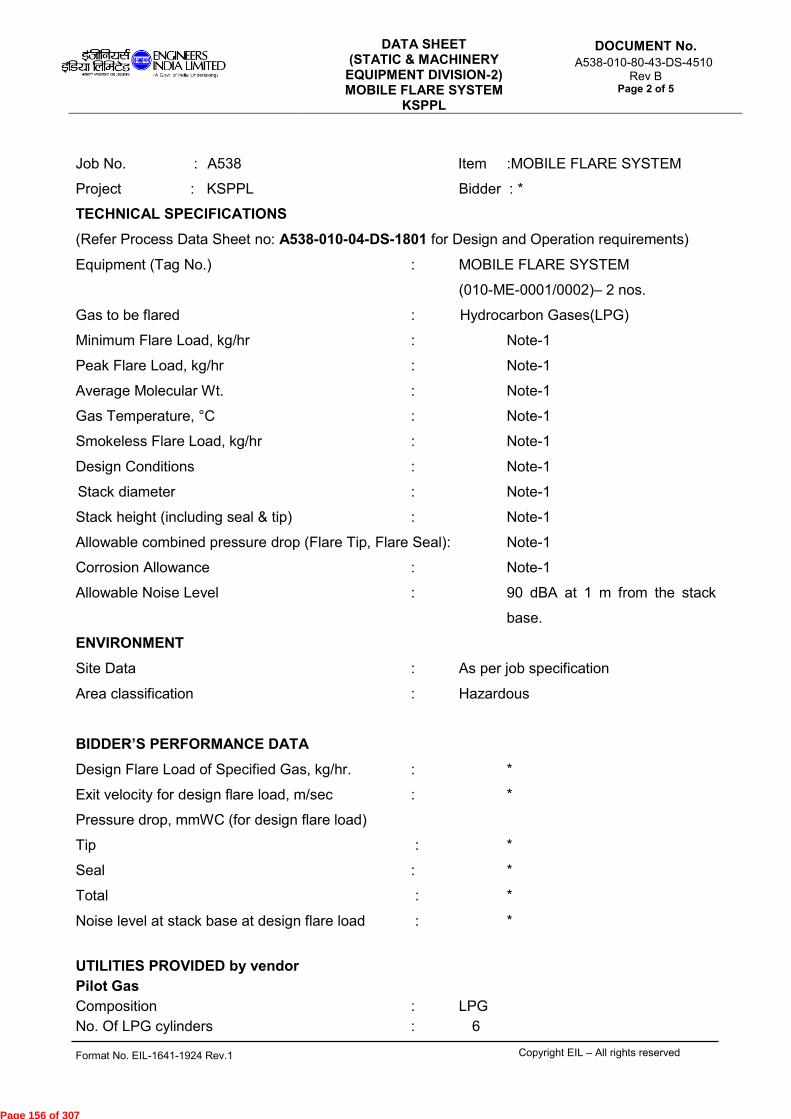
DATA SHEET (STATIC & MACHINERY
EQUIPMENT DIVISION-2) MOBILE FLARE SYSTEM
KSPPL
DOCUMENT No.
A538-010-80-43-DS-4510 Rev B
Page 2 of 5
Format No. EIL-1641-1924 Rev.1 Copyright EIL – All rights reserved
Job No. : A538 Item :MOBILE FLARE SYSTEM
Project : KSPPL Bidder : *
TECHNICAL SPECIFICATIONS
(Refer Process Data Sheet no: A538-010-04-DS-1801 for Design and Operation requirements)
Equipment (Tag No.) : MOBILE FLARE SYSTEM
(010-ME-0001/0002)– 2 nos.
Gas to be flared : Hydrocarbon Gases(LPG)
Minimum Flare Load, kg/hr : Note-1
Peak Flare Load, kg/hr : Note-1
Average Molecular Wt. : Note-1
Gas Temperature, °C : Note-1
Smokeless Flare Load, kg/hr : Note-1
Design Conditions : Note-1
Stack diameter : Note-1
Stack height (including seal & tip) : Note-1
Allowable combined pressure drop (Flare Tip, Flare Seal): Note-1
Corrosion Allowance : Note-1
Allowable Noise Level : 90 dBA at 1 m from the stack
base.
ENVIRONMENT
Site Data : As per job specification
Area classification : Hazardous
BIDDER’S PERFORMANCE DATA
Design Flare Load of Specified Gas, kg/hr. : *
Exit velocity for design flare load, m/sec : *
Pressure drop, mmWC (for design flare load)
Tip : *
Seal : *
Total : *
Noise level at stack base at design flare load : *
UTILITIES PROVIDED by vendor
Pilot Gas
Composition : LPG
No. Of LPG cylinders : 6
Page 156 of 307
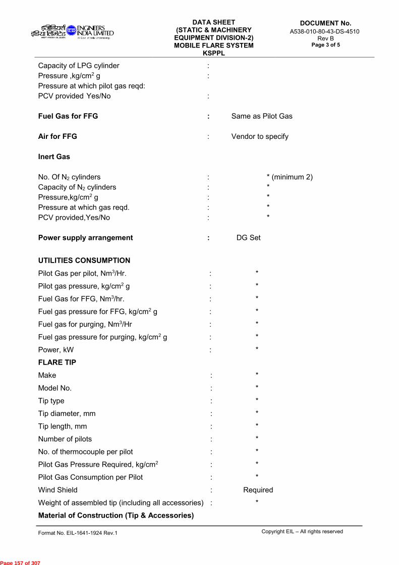
DATA SHEET (STATIC & MACHINERY
EQUIPMENT DIVISION-2) MOBILE FLARE SYSTEM
KSPPL
DOCUMENT No.
A538-010-80-43-DS-4510 Rev B
Page 3 of 5
Format No. EIL-1641-1924 Rev.1 Copyright EIL – All rights reserved
Capacity of LPG cylinder :
Pressure ,kg/cm2 g :
Pressure at which pilot gas reqd:
PCV provided Yes/No :
Fuel Gas for FFG : Same as Pilot Gas
Air for FFG : Vendor to specify
Inert Gas
No. Of N2 cylinders : * (minimum 2)
Capacity of N2 cylinders : *
Pressure,kg/cm2 g : *
Pressure at which gas reqd. : *
PCV provided,Yes/No : *
Power supply arrangement : DG Set
UTILITIES CONSUMPTION
Pilot Gas per pilot, Nm3/Hr. : *
Pilot gas pressure, kg/cm2 g : *
Fuel Gas for FFG, Nm3/hr. : *
Fuel gas pressure for FFG, kg/cm2 g : *
Fuel gas for purging, Nm3/Hr : *
Fuel gas pressure for purging, kg/cm2 g : *
Power, kW : *
FLARE TIP
Make : *
Model No. : *
Tip type : *
Tip diameter, mm : *
Tip length, mm : *
Number of pilots : *
No. of thermocouple per pilot : *
Pilot Gas Pressure Required, kg/cm2 : *
Pilot Gas Consumption per Pilot : *
Wind Shield : Required
Weight of assembled tip (including all accessories) : *
Material of Construction (Tip & Accessories)
Page 157 of 307

DATA SHEET (STATIC & MACHINERY
EQUIPMENT DIVISION-2) MOBILE FLARE SYSTEM
KSPPL
DOCUMENT No.
A538-010-80-43-DS-4510 Rev B
Page 4 of 5
Format No. EIL-1641-1924 Rev.1 Copyright EIL – All rights reserved
Main Shield : Note-1
Top shell section : Note-1
Bottom shell section : Note-1
Tip bottom flange : Note-1
Wind Shield : Note-1
Flame retention lug : Note-1
Lifting lugs : SS 321
Pilot tube : Note-1
Pilot nozzle : Note-1
Ignitor Pipes : Note-1
Connection details (Tip & accessories) (Bidder to indicate size, type and rating)
(All flanges shall be WNRF as per ANSI)
Pilot gas line flange at Tip bottom level : * (to match with piping)
Flame Propagation line at Tip bottom level : * (to match with piping)
FLAME FRONT GENERATOR (FFG)/ HEI SYSTEM: As Applicable
Make : *
Model No : *
Area classification : *
Fuel Gas line connection size : *
Power supply required : *
Power consumption : *
Number of Flame propagation line : *
Size of flame propagation line : *
Pressure (Operating and design), kg/cm2 g : *
Temperature (Operating and design) °C : *
Strainer of 100 mesh size at inlet fuel : Required gas line
Auto Ignition : Not Applicable
Manual ignition : Required
Overall dimensions of FFG : *
Approximate weight of FFG : *
HEI SYSTEM
HEI Cable Specification : *
HEI Power requirement : *
HEI Voltage : *
Electrode MOC : *
Electrode Gap : *
Page 158 of 307

DATA SHEET (STATIC & MACHINERY
EQUIPMENT DIVISION-2) MOBILE FLARE SYSTEM
KSPPL
DOCUMENT No.
A538-010-80-43-DS-4510 Rev B
Page 5 of 5
Format No. EIL-1641-1924 Rev.1 Copyright EIL – All rights reserved
Spark frequency : *
Cable Conduit provision along flare stack : Required
FLARE STACK
Diameter,mm : *
Thickness,mm : *
Length,mm : *
Material of Construction : Note 1
Design code : ASME SEC VIII Div 1
Nozzles : *
TRAILER FOR MOBILE FLARE SKID
Capacity,Tonnes : *
Size,mm x mm x mm : *
Make : *
No. Of tyres/Rating : *
Other features : *
WINCH FOR ERECTING SYSTEM
Lifting Capacity,Tonnes : *
Type : Hydraulic
HPU Pump (Make/ Model) : *
Pump discharge pressure : *
HPU Pump Motor (KW) : *
HPU Oil Reservoir capacity (litres) : *
HPU Oil Grade : *
Hydraulic Piston model : *
Notes:
1. As per Process data sheet no: A538-010-04-DS-1801 attached with the requisition
* Bidder to indicate and submit along with bid.
Page 159 of 307

Format No. 1645-DS-411 Rev. 0 Copyrights EIL – All rights reserved
Document No. A538-010-80-43-DS-4511
Rev. No. A
Page 1 of 4
DIESEL ENGINE
(Typical)
1
GENERAL
2
Project: Kochi-Salem LPG Pipeline Project Job No.: A538
3
Owner: M/s KOCHI SALEM PIPELINE PVT LTD (KSPPL) Site:
4
Purchaser: Unit: Unit No.:
5
Item No.: Service: DG SET
6
No. Reqd.: 1 Working: Standby: Driven Equipment Item no.:
7
Applicable to: Proposals Purchase As built
8
Note: Scope option / information specified by Purchaser information required from / options left to vendor. Vendor to cross the selected option.
9
SITE / INSTALLATION DATA
10
Site Conditions(Refer Site & Utility Data, Doc. No. A538-000-80-43-SU-4510) Location:
11
Barom. Pressure (mbar): Highest: Lowest: Avg.: Indoors Outdoor (Note- 7) Grade
12
Height above Mean Sea Level (m): Heated Unheated
13
Ambient Air Temp.(°C): Max.: Min.: Under-roof Partial Sides
14
Ambt. Air Temp. around the Engine(°C): Highest Lowest Closed Room With Air Ventilation System.
15
Relative Air Humidity at the Max. Ambient Air Temp.(%): Electrical Area classification : SAFE AREA
16
Water Vapour Pressure at the Max. Ambient Air Temp.(kg/cm2A): Class Group Division
17
Wet Bulb Temp. (°C): Dry Bulb Temp. (°C):
18
Cooling Water Supply Temp. (°C):
19
APPLICABLE CODES & STANDARDS
20 EIL Standard spec. no. (Refer Job Spec. Doc.no. A538-010-80-43-SP-4510) ISO 3046/ BS 5514 ISO 8528
21
Noise specification: 75 dBA @ 1 m with acoustic enclosure.
22 Acoustic Housing: Yes No Certificate of conformity
23
Exhaust Gas Emission - Statutory requirement: Yes No Certificate of conformity
24 Shell and Tube type Exchangers: Manufacturer's Std. Auxiliary Pumps: Manufacturer's Std.
25 Air Cooled Heat Exchangers/Radiator: Manufacturer's Std. Other Tanks and Vessels: Manufacturer's Std.
26
DRIVEN EQUIPMENT
27
Driven Equipment: Elect. Generator Emergency
28 For DG set application:Continuous Power Rating(COP) i.e. Net Power available at Alternator Terminals is ___KVA @ ___V with rated
29
P.F. of 0.8 after accounting for Engine Deration for Site conditions & Alternator Efficiency with Engine Driving its all Auxiliaries. (Note- 1&2)
30
Direction of Rotation of driven equipment viewed from Coupling End: CW CCW
31
Method of Drive: Thru universal joint Direct thru Flexible Coupling V-Belts Gear Drive
32
CONSTRUCTION FEATURES
33
Manufacturer: Engine Model:
34
Type of Engine: Two-Stroke Four-Stroke Engine Cooling: Air Cooled Water Cooled (CCCW)
35 Mech. Pressure-charged Turbo-Charged: With Charge Air Cooler Normally Aspirated
36 No. of Cylinders: Cylinder Arrangement:
37 Bore/Stroke(mm/mm): Compression Ratio:
38 Speed (rpm): ≤ 1500 rpm Mean Piston Speed (m/sec.): BMEP (Kg/cm2g):
39
PERFORMANCE
40 Rated Engine Power at Standard operating conditions as per ISO 3046/ BS 5514 (ISO Std. Power): kW @ RPM
41
(Using only the essential dependent Auxiliaries and with 10% Overload provision for One Hour within a period of 12 Hours of Operation).
42 Rated engine Power at Site conditions (Service Std. Power) (Guaranteed, No Negative Tolerance): kW @ RPM
43
(Using only the essential dependent Auxiliaries and with 10% Overload provision for One Hour within a period of 12 Hours of Operation).
44
Note: Refer Annexure-A to Datasheet
45 Min. Engine site power at which Engine can be Operated Continuously. kW @ RPM
46 Min. Engine Speed & corresponding site Power at which Engine can be Operated Continuously RPM @ kW
47 Starting time required for full load operation (Seconds)
48 Direction of Rotation of Engine viewed from Coupling End CW CCW
49
Air Flow Required for Operation of the Engine for: Combustion & Scavenging Cooling & Ventilation
50
Essential dependent Auxiliaries are:
51 Engine Shaft Driven Radiator Fan kW Engine Shaft Main LO Pump kW
52 Engine Shaft Driven CW Pump kW Engine Shaft Driven Fuel Oil Pump kW
53
Independent Auxiliaries are:
54
Specific Fuel Consumption:
55
Description
Fuel Consumption, gm/kW-hr @ reference conditions
56
ISO 3046 Manufr's. Std. Site Manfr's. shop
57
(a) Guaranteed Engine Rated Power
58
(100 % Rating)
59
(b) 75 % of (a)
60
(c) 50 % of (a)
61
(d) 110 % of (a)
62
Standard Reference Conditions:
63
-- Total Barometric Pressure, pr, kg/cm2A (100 kPa)
Page 160 of 307

Format No. 1645-DS-411 Rev. 0 Copyrights EIL – All rights reserved
Document No. A538-010-80-43-DS-4511
Rev. No. A
Page 2 of 4
DIESEL ENGINE
(Typical)
64
-- Atmospheric Temp. ,tr, OC 25 (298°K)
65
-- Relative Humidity ,φr, % 30
66
-- Charge Air Coolant Temp.,tcr, OC 25 (298°K)
67
SPEED GOVERNING SYSTEM
68
Type: Single Speed Multiple Speed All Speed (Variable Speed)
69
Class of Accuracy: A0 A1 A2 B1 B2 Shall be suitable for frequency & voltage variation specified in Electrical Specs
70
Governor Type: Electronic Electro Hydraulic Mechanical
71
Make: Model:
72
Governor Control Mechanism: Manual Remote
73
STARTING SYSTEM
74
Method of Starting Manual (key switch) Automatic (through AMF)
75
Method of Stopping Manual (Push button) Automatic
76
Type of Cold Starting Aid: Based on site min Temp
77
Type of Starting System: Battery Starting
78
Battery Starting System: (Refer Electrical Specification)
79
Battery Bank: Number: Voltage AH Capacity Make:
80
Cells per Bank Number Voltage AH Capacity
81 Starter Make/Rating: Dynamo Make/Rating: Regulator and Cut-out:
82 Battery charging equipment including transformer, Static Rectifier, D.C. Ammeter , D.C. Voltmeter, Charge Rate selector switch
83
and Charging Meter.
84 Inter connecting cable leads between battery charger & battery Inter connecting cable leads between battery & engine Starter
85
Note: Battery Bank shall be sized to provide minimum 3+3 consecutive starts without recharging with cold engine under
86
full compression.
87
COOLING SYSTEM (As per Manufacturer’s standard)
88 Radiator Cooling including Interconnecting Piping and:
89 Radiator with Temp. Control Valve Expansion/Make-Up water Tank
90 Fan Driven By: Engine Engine Driven Water circulating Pump
91 Engine Water Inlet/Outlet Temp(C):
92 FRAME LUBRICATION SYSTEM (As per Manufacturer’s Standard)
93 Force Feed Lubrication including Valves, oil Pump, Piping &:
94 Oil cooler type: (As per manufacturer standards)
95 Oil Filters Self Cleaning Duplex Paper Cartridge Simplex Filter self cleaning type (As per manufacturer standards)
96 Pre-lube Oil Pump driven by:
97 Pre-lubrication Manual Automatic at intervals of hours. (Vendor to recommend)
98 Type/Grade of Lube Oil: Auto pre-lubrication pump shall be powered from mains.
99 Oil Sump capacity (litres): Oil consumption (Lph):
100
FUEL SYSTEM
101
Type: Gravity Feed System Fuel Lift Pump including
102 Fuel Filters Paper cartridge Duplex
103 Fuel Injection Pump Make: Model:
104 Daily Service Fuel Tank: Engine Mounted Wall Mounted Ground Mounted (located outside DG room)
105 Capacity of Daily Service Tank(litres): 990 liters For 8_ hrs of continuous operation @ full load, as a minimum
106 For 12 hrs continuous operation @ full load For 24 hrs continuous operation @ full load
107 Fuel Float Tank Ground Mounting with Base Plate
108 Motor Driven Fuel Transfer Pump
109 Fuel Piping and Fittings:
110 Fuel Piping from Transfer Pumps to Daily Tank Fuel Piping from Daily Tank to Engine
111 Overflow Pipes Vent Connection for Fuel Tank with Flame Arrester + Breather Valve
112 Drain Valve for Fuel Tank Inspection and cleaning Hole for Fuel Tank (min 150 mm dia.)
113 Fill connection for Fuel Tank Level Switch in Fuel tank ( For Low Alarm)
114 Shielded Level Gauge for fuel tank Float valve in fill connection Strainers
115
AIR INLET SYSTEM
116 Suction Air Filter Air Inlet Ducting / Piping / Manifolds Inlet Silencer
117 Expansion Bellows All supports / Hangers
118
ENGINE EXHAUST SYSTEM
119 Exhaust Manifolds / Ducting / Piping (refer Job Spec A538-010-80-43-SP-4510) Exhaust Silencer (Residential Type)
120 Expansion Bellows All supports / Hangers
121 Thermal Insulation for complete Exhaust Piping (horizontal portion and vertical portion up to 3.0 m Height)
122 Fuel Tank:
123 INSPECTION AND TESTING
124 Witness Observe
125 Stage Inspection during Manufacture 126 Engine Mfr. Routine shop test & test certificates
127 Fuel consumption & Governing Test at Engine Manufacturer's Shop
Page 161 of 307

Format No. 1645-DS-411 Rev. 0 Copyrights EIL – All rights reserved
Document No. A538-010-80-43-DS-4511
Rev. No. A
Page 3 of 4
DIESEL ENGINE
(Typical)
128 Full Load Test for 4 hours of Engine Generator Set at Packager’s/ Engine Manufacturer’s shop 129 No load Mechanical Run test at Packager's/Driven Eqpt. Mfr. Shop 130 Inspection/Testing Witnessed By: Others Purchaser/Representative
131 WEIGHTS
132 Net Weight of Engine with Mounted Ancillaries (kg):
133 Heaviest part to be handled during erection and its weight (kg):
134 Heaviest part to be handled during normal maintenance and its weight (kg):
135 Recommended Crane capacity (Tons): Crane Hook Height (m):
136 MAINTENANCE DATA
137 Expected Period of Running Between Top Overhauls: Hours
138 Expected Period of Running Between Main Overhauls: Hours
139 The Type and Grade of Lubricating Oil Recommended
140 Lube Oil Consumption (kg/hr)/ (Litres/hr)
141 Change of Lubricating Oil After: Hours
142
143 NOTES
144 (1)One no. 15 KVA Continuous Power Rating (COP) DG set is required for each Mobile Flare system (010-ME-0001/ 010-ME-0002).
145 (2)DG Set power rating category shall be Continuous Power Rating (COP) as per ISO 8528-1. The genset shall be offered to have their published COP rating equal or higher than the required rating. In case the COP rating is not published, the genset shall be offered to meet the required rating with 70% of the published PRP Rating.
146 (3) Instrumentation & controls shall be as per engine/ alternator manufacturer’s standard.
147 (4) All accessories of the DG set including engine, alternator, coupling, local control panel/local gauge board etc. shall be mounted on a
148 common base plate.
149 (5) The DG set shall be designed for black start condition. The battery bank shall be sized for six (6) consecutive starts and shall
150 be supplied with all the necessary cabling and battery stand. 151 (6) The utilities required for DG such as electrical power, fuel oil and water shall be as described below:
152 (a) Vendor to note Battery Charging shall be self power charging as no electrical power is available at site.
153 (b) Vendor to note that Cooling water shall not be available at site. Closed circuit cooling water system (radiator cooling) has been envisaged. 154 Radiator for engine cooling/lube oil cooler shall be skid mounted. All interconnecting piping, valves, instruments etc shall be in bidder’s
155 scope. Only potable water shall be available for make-up purpose.
156 (c) Bidder shall terminate the drains at skid edge.
157 (7)DG set with acoustic enclosure shall be installed on chassis of 2nd vehicle of each Mobile Flare system.
158 (8)During detailed engineering, the bidder shall furnish filled in diesel engine datasheet & performance/sizing related details as listed in Annexure-A, for purchaser's approval.
159
Annexure-A
Date Rev Job Engineer Rev. & Approved By
Page 162 of 307

Format No. 1645-DS-411 Rev. 0 Copyrights EIL – All rights reserved
Document No. A538-010-80-43-DS-4511
Rev. No. A
Page 4 of 4
DIESEL ENGINE
(Typical)
1. ISO Standard Power (as per ISO 3046-1) of the engine, (obtained after
deducting power loss due to essential dependent auxiliaries) (Continuous Power) (Note-1)
Piso : kW 2. Deration on account of site conditions (refer Table 1.2 in Site & Utility Data, Doc.
No. A538-010-80-43-SU-4510) as per ISO 3046-1 Temperature (around the engine and alternator) : kW Altitude (d1) : kW Humidity (d2) : kW CW temp (d3) : kW Inlet losses (d4) : kW Exhaust back press (d5) : kW Total Deration (Pderation = d1+d2+d3+d4+d5) : kW 3. Service Standard Power (as per ISO 3046-1) of the Engine (i.e. at stated
conditions) Pservice = Piso - Pderation : KW
4. Power Loss in the Alternator under stated conditions (Palt) : kW 5. Power consumed by essential independent auxiliaries (Paux) : kW 6. Transmission losses (P Trans) : kW 7. Any other Power Loss applicable to the offered DG set (Pmisc) : kW 8. Net output for electrical consumption (Poutput) (Poutput = _______ kW (minimum)) : kW 9. Actual Power Required from Engine (Pactual) Pactual = Poutput + Palt + Paux + Ptrans+ Pmisc : kW Bidder shall ensure that Pservice ≥ Pactual and shall furnish calculations / supporting
documents during detailed engineering. NOTES: (1) DG Set power rating category shall be Continuous Power Rating (COP) as per
ISO 8528-1. The genset shall be offered to have their published COP rating equal or higher than the required rating. In case the COP rating is not published, the genset shall be offered to meet the required rating with 70% of the published PRP Rating.
Page 163 of 307
VENDOR DATA REQUIREMENTS
FOR
MOBILE FLARE SYSTEM
A 24-AUG-2016 ISSUED WITH MR SAS PD SM
Rev.No.
Date Purpose Prepared by Checked by Approved by
VENDOR DATA REQUIREMENTSFOR
MOBILE FLARE SYSTEM of 4
Document No.A538-010-80-43-VDR-4510
Rev. A
Page 1
Format No. EIL-1642-1924 Rev.1 Copyright EIL - All rights reserved
Page 164 of 307
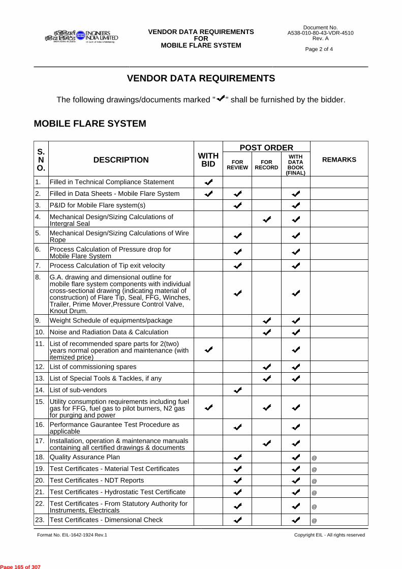
VENDOR DATA REQUIREMENTS
The following drawings/documents marked " " shall be furnished by the bidder.
MOBILE FLARE SYSTEM
S.NO.
DESCRIPTION WITHBID
POST ORDERREMARKSFOR
REVIEWFOR
RECORD
WITHDATABOOK
(FINAL)
1. Filled in Technical Compliance Statement
2. Filled in Data Sheets - Mobile Flare System
3. P&ID for Mobile Flare system(s)
4. Mechanical Design/Sizing Calculations ofIntergral Seal
5. Mechanical Design/Sizing Calculations of WireRope
6. Process Calculation of Pressure drop forMobile Flare System
7. Process Calculation of Tip exit velocity
8. G.A. drawing and dimensional outline formobile flare system components with individualcross-sectional drawing (indicating material ofconstruction) of Flare Tip, Seal, FFG, Winches,Trailer, Prime Mover,Pressure Control Valve,Knout Drum.
9. Weight Schedule of equipments/package
10. Noise and Radiation Data & Calculation
11. List of recommended spare parts for 2(two)years normal operation and maintenance (withitemized price)
12. List of commissioning spares
13. List of Special Tools & Tackles, if any
14. List of sub-vendors
15. Utility consumption requirements including fuelgas for FFG, fuel gas to pilot burners, N2 gasfor purging and power
16. Performance Gaurantee Test Procedure asapplicable
17. Installation, operation & maintenance manualscontaining all certified drawings & documents
18. Quality Assurance Plan @
19. Test Certificates - Material Test Certificates @
20. Test Certificates - NDT Reports @
21. Test Certificates - Hydrostatic Test Certificate @
22. Test Certificates - From Statutory Authority forInstruments, Electricals
@
23. Test Certificates - Dimensional Check @
VENDOR DATA REQUIREMENTSFOR
MOBILE FLARE SYSTEM of 4
Document No.A538-010-80-43-VDR-4510
Rev. A
Page 2
Format No. EIL-1642-1924 Rev.1 Copyright EIL - All rights reserved
Page 165 of 307

DIESEL ENGINE GENERATOR PACKAGE
S.NO.
DESCRIPTION WITHBID
POST ORDERREMARKSFOR
REVIEWFOR
RECORD
WITHDATABOOK
(FINAL)
24. Test Certificates - Any Other Test Report @
25. As Built Drawings
26. Other Electrical documents
27. Catalogues for flare tip, integral seal, flamefront generator, instruments and electrical
28. Document Control Index (DCI) or Supplier /Vendor Drawing & Documentation Schedule(This shall be the first document to besubmitted by vendor immediately after FOI)
S.NO.
DESCRIPTION WITHBID
POST ORDERREMARKSFOR
REVIEWFOR
RECORD
WITHDATABOOK
(FINAL)
1. Document Control Index (DCI) or Supplier /Vendor Drawing & Documentation Schedule(This shall be the first document to besubmitted by vendor immediately after FOI)
2. Quotation for recommended spare parts for twoyears of normal operation (indicating exactname of the part, part no. and material ofconstruction)
3. List of recommended erection & commissioningspares(indicating exact name of the part, part no. andmaterial of construction)
4. List of recommended Special Tools & Tacklesand Standard Maintenance Tool Kit, asrequired(indicating exact name of the part and part no.)
5. Equpment Layout drawing showing acousticallyenclosed DG Set including all assosciatedaccessories & auxiliaries like Air Intake System,Exhaust System, Cooling System, FuelSystem, Electrical/ Instrumentation Panels/Gauge Boards (LCP, MCC, Breaker Panel,Local Gauge Board etc, as applicable) alongwith interface connections/ terminal pointdetails including their location co-ordinates,trench details, maintenance space forfrequently maintaned parts etc., erection &maintenance weights, capacity & hook heightof maintenance equipment (HOT/ EOT Crane/Monorail with CP Block, as applicable) etc
6. Utility consumption data including electric loaddata.
7. Schedule of lubricants, chemicals &consumables with their specifications.
8. Data Sheets for Diesel Engine along withDeration calculations (As per ISO 3046)
VENDOR DATA REQUIREMENTSFOR
MOBILE FLARE SYSTEM of 4
Document No.A538-010-80-43-VDR-4510
Rev. A
Page 3
Format No. EIL-1642-1924 Rev.1 Copyright EIL - All rights reserved
Page 166 of 307

Notes :
1. "TICK" denotes applicability.
2. Post order, drawing / document review shall commence only after approval of Document Control Index (DCI).
3. All post order documents shall be submitted / approved through EIL eDMS portal.
4. Final documentation shall be submitted in hard copy (Six prints) and soft ( two CDs/DVDs ) in addition to
submission through EIL eDMS.
5. Refer - 6-78-0001: Specification for quality management system from Bidders.
6. Refer - 6-78-0002: Specification for documentation requirements from Contractors.
7. Refer - 6-78-0003: Specification for documentation requirement from Suppliers.
8. All drawings & documents shall be submitted in A4 or A3 paper sizes. Documents in higher paper size shall
be submitted in exceptional circumstances or as indicated in the MR/Tender.
9. Post order- The schedule of drawing / data submission shall be mutually agreed between EIL & the bidder /
contractor / supplier during finalization of Document Control Index (DCI).
10. "@" indicates submission of documents to Inspection Agency.
11. Bill of Material shall form part of the respective drawing.
12. Also refer other department's VDR :-
13. Electrical
S.NO.
DESCRIPTION WITHBID
POST ORDERREMARKSFOR
REVIEWFOR
RECORD
WITHDATABOOK
(FINAL)
9. General Arrangement drawing of DG skidshowing Diesel Engine, drive transmissionsystem (as applicable) & Alternator/ Generatorplaced in acoustic enclosure, as required,including all assosciated accessories &auxiliaries on DG skid
10. P&ID of Diesel Engine icluding all the auxiliarysyestems like Air intake/ exhaust gas system,starting system, lubrication system, coolingsystem, fuel system
11. Installation, Operation & Maintenance manualsfor complete DG Package
VENDOR DATA REQUIREMENTSFOR
MOBILE FLARE SYSTEM of 4
Document No.A538-010-80-43-VDR-4510
Rev. A
Page 4
Format No. EIL-1642-1924 Rev.1 Copyright EIL - All rights reserved
Page 167 of 307

SITE AND UTILITY DATA
Document No.
A538-010-80-43-SU-4510 Rev. B
Page 1 of 2
Format No. EIL-1641-1924 Rev.1 Copyright EIL – All rights reserved
SITE AND UTILITY DATA
B 23/09/16 REVISED AS PER CLIENT COMMENT AND REISSUED
WITH MR SASWATA PD SM
A 10/08/16 ISSUED WITH MR SASWATA PD SM
Rev. No
Date Purpose Prepared by Checked
by Approved
by
PROJECT : KOCHI- SALEM LPG PIPELINE
CLIENT : M/s KOCHI SALEM PIPELINE PVT LTD (KSPPL)
JOB NO. : A538
Page 168 of 307

SITE AND UTILITY DATA
Document No.
A538-010-80-43-SU-4510 Rev. B
Page 2 of 2
Format No. EIL-1641-1924 Rev.1 Copyright EIL – All rights reserved
1.0 SITE DATA INFORMATION
1.1 METEOROLOGICAL DATA OF VARIOUS SITE LOCATIONS
1.2 DATA FOR DIESEL GENERATOR (DG) DESIGN
S.No. Parameter Value
1. Ambient Temperature to be considered for
calculation of Engine deration
450 C
2. Relative Humidity to be considered for calculating
Engine deration
95%
3. Ambient Pressure to be considered for calculating
Engine deration
746 mm Hg
Location Ambient temp. Deg C Altitude ,M above MSL
Min. Max.
Kochi 20 38 4.36
Palakkad 20 45 119.218 B
B
Page 169 of 307

JOB SPECIFICATION FOR
EMERGENCY GENERATOR
DOCUMENT No.
A538-010-16-50-SP-4510, Rev. A
Page 1 of 12
A 9.8.2016 ISSUED WITH MR AD MKS MKS
Rev. No
Date Purpose Prepared by Checked by Approved by
JOB SPECIFICATION
FOR
EMERGENCY GENERATOR
Page 170 of 307
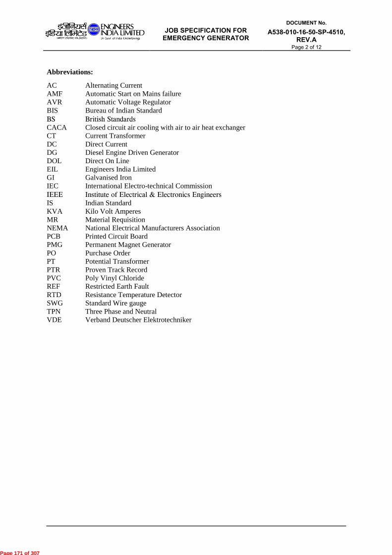
JOB SPECIFICATION FOR
EMERGENCY GENERATOR
DOCUMENT No.
A538-010-16-50-SP-4510, REV.A
Page 2 of 12
Abbreviations:
AC Alternating Current
AMF Automatic Start on Mains failure
AVR Automatic Voltage Regulator
BIS
BS
CACA
Bureau of Indian Standard
British Standards
Closed circuit air cooling with air to air heat exchanger
CT Current Transformer
DC Direct Current
DG Diesel Engine Driven Generator
DOL Direct On Line
EIL
GI
Engineers India Limited
Galvanised Iron
IEC
IEEE
IS
International Electro-technical Commission
Institute of Electrical & Electronics Engineers
Indian Standard
KVA Kilo Volt Amperes
MR Material Requisition
NEMA
PCB
National Electrical Manufacturers Association
Printed Circuit Board
PMG Permanent Magnet Generator
PO
PT
Purchase Order
Potential Transformer
PTR
PVC
Proven Track Record
Poly Vinyl Chloride
REF Restricted Earth Fault
RTD Resistance Temperature Detector
SWG Standard Wire gauge
TPN
VDE
Three Phase and Neutral
Verband Deutscher Elektrotechniker
Page 171 of 307

JOB SPECIFICATION FOR
EMERGENCY GENERATOR
DOCUMENT No.
A538-010-16-50-SP-4510, REV.A
Page 3 of 12
CONTENTS
1.0 SCOPE
2.0 CODES AND STANDARDS
3.0 SITE CONDITIONS
4.0 GENERAL REQUIREMENTS
5.0 PERFORMANCE REQUIREMENTS
6.0 DESIGN AND CONSTRUCTION
7.0 EXCITATION SYSTEM
8.0 SYSTEM OPERATION
9.0 GENERATOR CONTROL PANEL
10.0 INSPECTION TESTING AND ACCEPTANCE
11.0 PACKING AND DESPATCH
Page 172 of 307

JOB SPECIFICATION FOR
EMERGENCY GENERATOR
DOCUMENT No.
A538-010-16-50-SP-4510, REV.A
Page 4 of 12
1.0 SCOPE
This specification defines the minimum requirements for the supply of self-excited Internal
Combustion Engine driven Emergency Generator and associated electrics suitable for
installation in Unclassified / Safe area.
Unless otherwise specified in the Material Requisition (MR) / data sheet, the emergency
generator and associated electrics shall be complete with
a. Alternator with brushless excitation system complete with AVR.
b. Generator Control Panel to include AMF system, Auto / Manual control, auxiliary
devices, battery and charger. This panel shall also include generator MCCB.
c. Any other part / accessories not specifically mentioned above but considered necessary
for safe and reliable operation.
2.0 CODES AND STANDARDS
2.1. The equipment shall comply with the requirements of latest revision of following standards
issued by BIS (Bureau of Indian standards) unless otherwise specified.
IS: 5 Colours for ready mix paints and enamels
IS : 2253 Designation for type of construction and mounting arrangement of rotating
electrical machines.
IS : 4691 Degree of protection provided by enclosures of Rotating Electrical
Machinery.
IS : 4722 Rotating electrical machines.
IS : 4728 Terminal marking and direction of rotation for rotating electrical
machinery.
IS : 4889 Methods of determination of efficiency of rotating electrical machines.
IS : 6362 Designation of Methods of Cooling of Rotating Electrical Machines.
IS : 7132 Guide for testing synchronous machines.
IS : 7306 Methods of determining synchronous machines quantities from tests.
IS : 7372 Lead acid storage battery for motor vehicle.
IS : 7816 Guide for testing of insulation resistance of rotating machines.
IS : 12065 Permissible limits of noise level for rotating electrical machines.
IS : 12075 Mechanical vibration of rotating electrical machines with shaft heights 56
mm and higher - measurements, evaluation and limits of vibration severity
IS : 12802 Temperature rise measurement of rotating electrical machines.
IS : 13364
Part-I
AC Generators up to 20 KVA driven by reciprocating internal combustion
engine.
IS : 13364
Part-II
AC Generators above 20 and up to 1250 KVA driven by reciprocating
internal combustion engine.
IS : 13947 Low voltage Switchgear and Control gear: General Rules.
2.2. In case of imported equipments, standards of the country of origin shall be applicable if these
standards are equivalent or stringent than the applicable Indian standards.
2.3. The equipment shall also conform to the provisions of CEA regulations and other statutory
regulations currently in force in the country.
2.4. In case Indian standards are not available for any equipment, standards issued by
IEC/BS/VDE/IEEE/NEMA or equivalent agency shall be applicable.
Page 173 of 307

JOB SPECIFICATION FOR
EMERGENCY GENERATOR
DOCUMENT No.
A538-010-16-50-SP-4510, REV.A
Page 5 of 12
2.5. In case of any conflict between requirements specified in various applicable documents, the
most stringent one shall prevail. However, owner’s decision in this regard shall be final and
binding.
3.0 SITE CONDITIONS
Generator shall be suitable for operating satisfactorily in humid and corrosive atmospheres
found in refineries, petrochemical and other industrial plants. Ambient conditions shall be as
specified in the Data Sheet.
The specified maximum ambient temperature shall be considered outside the enclosure for
machines having acoustic enclosure. The temperature inside the acoustic enclosure shall be
suitably considered by manufacturer taking care of temperature rise inside the acoustic
enclosure during full load conditions, for the machines having acoustic enclosure.
4.0 GENERAL REQUIREMENTS
4.1 The offered equipment shall be brand new with state of art technology and proven field track
record. No prototype equipment shall be offered.
4.2 Vendor shall ensure availability of spare parts and maintenance support services for the
offered equipment at least for 15 years from the date of supply.
4.3 Vendor shall give a notice of at least one year to the end user of equipment and EIL before
phasing out the product/spares to enable the end user for placement of order for spares and
services.
5.0 PERFORMANCE REQUIREMENTS
5.1 Name Plate Rating and Duty
Generator nameplate rating indicated in the data sheet shall be the continuous apparent
power output (KVA) of the set at the maximum ambient temperature conditions specified for
the site.
For machines having acoustic enclosure, vendor shall account for temperature rise inside the
enclosure during full load operation. The enclosure ventilation system shall be designed
along with the proposed alternator model so as to generate the rated power while operating
inside enclosure and with the specified maximum ambient temperature to be considered
outside the enclosure.
5.2 Transient voltage performance
5.2.1 Transient voltage behavior of machine shall conform to the VG3 grade specified in
IS:13364.
5.2.2 The generator shall operate satisfactorily under sudden load rejection up to full load.
5.3 Voltage Regulation
The voltage regulation of the machine shall be within + 2 % of the nominal voltage under
following conditions:
Between no load and nominal load with p. f. of 0.8 lag to unity, with the machine cold or
warm and at a speed drop of approximately 3 % of the nominal speed.
Page 174 of 307

JOB SPECIFICATION FOR
EMERGENCY GENERATOR
DOCUMENT No.
A538-010-16-50-SP-4510, REV.A
Page 6 of 12
5.4 Voltage setting range
The generator terminal voltage shall be adjustable with a continuously variable
potentiometer. The adjustment range shall be + 10% of the nominal voltage. Manual remote
voltage trimmer/ Motorized potentiometer shall be provided where remote control of voltage
is envisaged as per data sheet.
5.5 Unbalanced Load
The generator shall be capable of withstanding without injury the effects of a continuous
current unbalance corresponding to a negative-phase sequence current of 8% of the rated
current for cylindrical rotor machines and 10% for salient pole machines provided none of
the phase current exceeds rated current.
5.6 Waveform Distortion
Harmonic distortion factor shall not exceed the values given in the IS:13364 – part-2.
5.7 Frequency limits
The generator shall be suitable for continuous operation at rated load for a frequency
variation of ±3 % of rated value.
5.8 Over current requirement
Generator shall be capable of withstanding momentary excess current as per IS:13364.
5.9 Short circuit conditions
The generator shall be capable of withstanding without damage, 3 times full load current for
a duration of 3 seconds when operating at rated speed and rated load and with an excitation
corresponding to 5 % over voltage.
5.10 Excitation support system
Excitation system shall be provided with short-circuit support equipment to maintain three
times the rated current for three seconds in case of short circuit to ensure proper fault
clearance in outgoing feeders.
5.11 Noise
Statutory noise control requirements as applicable and as stipulated in the Mechanical
Specifications shall be adhered to.
6.0 DESIGN AND CONSTRUCTION
6.1 The generator design shall meet the requirement specified in data sheet and shall be suitable
for the site conditions specified therein.
6.2 The generator shall be mounted on a common base frame together with prime mover unless
otherwise agreed. The generator shall be provided with necessary lifting hooks and two
earth terminals on opposite sides for connection to main earth grid.
6.3 Various generator windings (stator, rotor of Main Generator, Exciter) shall be designed
having insulation class: -
Either class 'F' with temperature limitation for class 'B'
Or
class 'H' with temperature limitation for class 'F'.
The windings and overhangs shall be braced to withstand the short circuit forces.
The stator winding shall be star connected and ‘all windings shall be brought out to (3+3)
insulated terminals in a terminal box’ OR ‘windings shall be brought out to (3+1) insulated
terminal in a terminal box’ with provision of CTs as per details given in the data sheet.
Page 175 of 307

JOB SPECIFICATION FOR
EMERGENCY GENERATOR
DOCUMENT No.
A538-010-16-50-SP-4510, REV.A
Page 7 of 12
6.4 Where terminal box does not have sufficient space for accommodating CTs for protection, a
separate cubicle shall be provided by vendor, irrespective of the machine rating .In such case
all connections shall be brought to the cubicle, using cable / bus duct connection of sufficient
rating. Apart from accommodating CTs, formation of star point and neutral tee off point
shall be achieved in this cubicle. Outgoing power cable connection to owner’s power
distribution board shall also be done in this cubicle.
6.5 The terminal box and cubicles shall have sufficient space for the termination of quantity of
cable or bus duct as specified in data sheet.
6.6 All terminals shall be stud/ link type. The terminal boxes / cubicles shall be complete with
tinned copper lugs and single compression nickel plated brass cable glands for the quantity
and type of power cables as specified in the data sheet. Where single core cables are
specified, gland plates shall be of non magnetic material (Stainless steel or Aluminum)
6.7 All parts and accessories shall be suitable to withstand stresses due to over speed / over load/
short circuit conditions specified.
6.8 Bearings
6.8.1 Bearings shall be grease lubricated ball or roller bearing or of the manufacturers standard
type. In all cases the bearings shall be chosen to give a minimum L-10 rating of 5 years
(40,000hrs) at rated operating conditions.
6.8.2 Grease lubricated bearings shall be capable of grease injection from outside without removal
of covers. The bearing boxes shall be provided with labyrinth seals to prevent loss of grease
or entry of dust or moisture. When grease nipples are provided those shall be associated,
where necessary, with appropriately located relief devices which ensure passage of excess
grease through the bearings.
6.8.3 Sleeve type bearing shall either be ring lubricated or forced-oil lubricated, depending on the
loading. Sleeve bearing shall be of proven track record (PTR). While offering sleeve
bearings, list of past supplies shall be furnished.
6.9 Generator enclosure protection class shall be as specified in data sheet.
6.10 The direction of rotation of the rotor of the machine shall be compatible with that of the
prime mover. A clear indication of the direction of rotation shall be given on either end of
the machine.
6.11 Space heaters shall be installed within the enclosure. Location and maximum surface
temperature of the heaters shall be such that no damage can be caused to any insulation.
Heaters shall be suitable for operation on a single-phase 240 V AC supply unless otherwise
specified.
6.12 Field winding shall have insulation class and temperature limitations as per para 6.3 above.
The field winding shall be capable of operating at 125 % of rated field voltage for at least
one minute starting from hot initial condition, i.e. stabilized temperatures at rated load
conditions. (Rated field voltage is the voltage applied at the field winding for producing rated
terminal voltage at rated load and speed).
6.13 Auxiliary Terminal Boxes
Separate Terminal boxes of sturdy construction shall be provided for Space Heater and other
devices (as applicable like RTDs), with sufficient space for connecting the cables as
indicated in the requisition.
6.14 A rating plate of stainless steel shall be fixed on the generator frame and shall give the
information as per IS: 4722.
6.15 Battery Bank
6.15.1 The battery shall be lead acid, high discharge automotive type suitable for engine starting
duty and conforming to IS: 7372. The battery shall be placed on battery stands made of steel
Page 176 of 307

JOB SPECIFICATION FOR
EMERGENCY GENERATOR
DOCUMENT No.
A538-010-16-50-SP-4510, REV.A
Page 8 of 12
with suitable PVC coating. One no. each of the accessories viz. hydrometer, thermometer,
cell testing voltmeter, pair of rubber gloves, spanner, acid resistant jug and funnel, teak wood
holder for the hydrometer etc. shall be supplied with each battery set.
6.15.2 The battery capacity shall be adequate for six (3+3) consecutive starts of the engine under
cold engine condition, without recharging, with additional 10% spare capacity. The auto
starting system shall successively carry out 3 (three) automatic start attempts but if diesel
engine fails to start even after three attempts then an alarm shall be annunciated on this
account and remaining 3 (three) start attempts can be carried out manually as per operator’s
decision.
6.15.3 Battery bank shall be charged while DG is running. No external supply for battery charging
will be available.
6.16 Auxiliary Motors
All auxiliary motors shall have IP - 55 enclosures and shall conform to relevant Indian
Standards. No external power supply shall be made available; it shall be derived from the
running generator itself. Any equipment required for creating the power supply for the
auxiliary drives is in the scope of the vendor.
7.0 EXCITATION SYSTEM
7.1 The generator shall be self-exciting or with PMG, i.e. it shall generate its nominal voltage
without the use of external power sources, even after long idle periods or after a short circuit
.The generator shall be provided with brushless type solid state self-excitation system with
automatic voltage regulator. The excitation system shall include the automatic voltage
regulator, AC exciter and rotary rectifier.
7.2 The field of the exciter shall be fed from the stator winding and AVR. AC voltage generated
in the AC exciter shall be rectified by the rotary rectifier assembly and fed to the main field
circuits. The rotor winding of the AC exciter, the rectifier assembly, main field winding of
the generator and other accessories on rotor parts shall be rigidly fastened to the shaft and the
connection with different items shall be anti-loosening type. The exciter capacity shall be at
least 20 % more than the maximum requirement at any time. The exciter winding shall be
insulated as per para 6.3 above.
7.3 The rotary rectifier set shall consist of rectifiers, zener diodes, fuses, field discharge resistors,
condensers, etc. Rotor circuit shall be designed to take care of rectification of AC voltage
and for proper field suppression through discharge resistors. The rating of the Diode Bridge
and armature shall be such that the full load rated current can be supplied with one branch in
operation.
7.4 All components shall be mounted considering the effects of the centrifugal forces.
7.5 Automatic solid-state voltage regulator (AVR) shall be provided with the following features
as a minimum:
Short circuit protection
Manual voltage control is optional and provision of the same shall be as per
manufacturer’s standard.
Voltage build up circuitry
Over voltage protection
7.6 The AVR can be installed either in the generator control panel or at the generator. In later
case, the AVR shall be located in a separate housing or in a clearly segregated section of the
main terminal box.
Page 177 of 307

JOB SPECIFICATION FOR
EMERGENCY GENERATOR
DOCUMENT No.
A538-010-16-50-SP-4510, REV.A
Page 9 of 12
8.0 SYSTEM OPERATION
8.1 Modes of Operation
The emergency generator and associated electrics shall normally be in an unattended area.
The control system shall be suitable for unattended operation. The control system shall
operate in fail-safe mode and shall include all controls and protection necessary for the safe
operation of the DG set. The generator and associated electrics shall function as per the
following schemes:
Manual start in Service/Test mode
Manual stop upon supply restoration
8.1.1 Manual start
8.1.1.1 In Service Mode
This shall be effective in manual position of Auto/Manual switch and service position of
service / test selector switch located in control panel. The scheme of operation shall be same
as of auto mode as per clause 8. 1.1 above except that starting command shall be extended
manually using the push button (instead of command from AMF sequence) from the local
control panel. Provision shall also be kept for manual start from owner's remote control
panel.
8.1.1.2 In Test Mode
This shall be effective in test position of service / test selector switch. The scheme of
operation shall be same as that of manual start in service mode as per clause 8.1.2.1 above
except that the closing command for generator MCCB/contactor shall not be extended
automatically.
If periodic load test-run of generator is envisaged as per data sheet, the generator MCCB
shall be closed manually after synchronization with grid.
8.2 Shut-down
It shall be possible to manually stop the generator in all operational cases including
emergency case by means of the push button provided in either generator control panel or
Owner's remote panel.
8.3 Starting time
Unless specified otherwise, the total time from the receipt of the starting impulse for the
generator till the set reaches rated speed and generator reaches rated voltage shall not be
more than 30 seconds. If this time is exceeded, an annunciation in the local control panel
shall be provided with a facility for repeat annunciation in Owner's panel.
8.4 Black start facility
The generating unit shall be provided with all necessary 'black start' facilities.
9.0 GENERATOR CONTROL PANEL
9.1 The local generator control panel for the generator shall include all interlock and controls for
the generator and its auxiliaries and comprise of the following unless otherwise specified in
the attached data sheet:
a. Local MCCB.
b. Line Cubicle, as applicable.
c. Metering CTs and CT/PTs for AVR
d. Metering equipments
e. Indicating instruments
f. Synchronizing equipment, if specified
Page 178 of 307

JOB SPECIFICATION FOR
EMERGENCY GENERATOR
DOCUMENT No.
A538-010-16-50-SP-4510, REV.A
Page 10 of 12
g. Motor control gear section for generator auxiliaries
h. Battery charger
i. Any other accessory necessary for generator operation.
9.2 The generator control panel shall preferably be split into various functional sections viz. Line
and Neutral Power Section, Battery Charger section, Auxiliary Motor Control Gear Section,,
Metering & Control section and AVR section etc.
9.3 In case, a generator MCCB is required to be supplied, it shall form part of the line cubicle.
The MCCB rating shall be as specified in the data sheet. This MCCB shall serve the purpose
of local isolation. The MCCB shall be in draw out execution. In case of 415 V generators,
MCCB shall have four poles for isolation of phases and neutral.
9.4 All motor starters for DG set auxiliaries if required shall be ‘direct-on-line’ type in fixed
execution.
9.5 Single Phase Charger
Chargers for DC power out put up to 1000 W shall be conforming to the following
specifications:
9.5.1 The battery charger shall have 1-phase full wave controlled Rectifier Bridge with their
protective devices. The charger shall be of solid state design, constant voltage type with
current limiting feature suitable for automatic and manual, normal (float charging) and quick
(boost) charging of batteries. The output voltage shall be stabilized to + 1 % for mains
variation of + 10 % and load variation of 0 to 100%. The maximum ripple content in the
charger output voltage shall be lower than the safe value recommended by battery
manufacturer and in any case shall not exceed 5% with battery disconnected. The charger
shall be sized for boost charging the battery within 10-14 hours.
9.5.2 The charger shall have auto as well as manual control facility. In auto mode, the charger
shall automatically control the battery charging current/voltage to ensure optimum boost
charging of the battery. After completion of boost charging, the charger shall switch to float
charging mode without any manual intervention.
9.5.3 In the manual mode, it shall be possible to charge the battery at any desired current that is
safe for the battery. A backup timer of 0-24 hours range shall be provided for switching the
charger from boost to float mode after the set time, under any mode of operation.
9.5.4 Auto/manual selector switch, ON/OFF switch for incoming power supply, float/boost
selector switch, potentiometer for control of output voltage and backup timer shall be
provided on the front of the panel in addition to AC incoming voltmeter and ammeter with
selector switch and DC output voltmeter and ammeter. Indication lamps for AC power on,
charger in float, charger in boost, charger failure shall also be provided.
9.6 Generator Control Panel Construction
9.6.1 The generator control panel shall be free standing, metal enclosed fabricated with cold rolled
sheet steel of 2mm thickness, dust and vermin proof type with a hinged door and having a
degree of protection IP 41 unless otherwise specified. Power and control equipment shall be
segregated inside the panel as far as practicable.
9.6.2 The maximum height of the operating handle / switches shall not exceed 1800 mm and the
minimum height shall not be below 300 mm.
9.6.3 All hardware shall be corrosion resistant and bolts; nuts and washers shall be made of
galvanized, zinc passivated or cadmium plated high quality steel.
9.6.4 Unless otherwise specified, the panel shall be suitable for bottom cable entry. Necessary
removable type undrilled gland plate; single compression cable glands and cable lugs shall
be provided with the panel.
Page 179 of 307

JOB SPECIFICATION FOR
EMERGENCY GENERATOR
DOCUMENT No.
A538-010-16-50-SP-4510, REV.A
Page 11 of 12
9.6.5 All auxiliary devices for control, indication, measurement and alarm such as push button,
control / selector switches, indicating lamps, metering instruments, annunciations etc. shall
be mounted on the front door of the panel. Adequate number of potential free contacts shall
be provided in the control panel for any remote control, monitoring of the generator.
9.6.6 All switches shall be load-break, heavy-duty type. All fuses shall be non-deteriorating HRC
cartridge pressure fitted, link type. The contactors for auxiliary motor starters shall be of air-
break type having AC-3 duty rating. Thermal overload relays shall be three element, positive
acting, ambient temperature compensated type with adjustable setting range and built in
protection feature against single phasing.
9.6.7 All indicating instruments shall be moving iron, flush mounting type and of 72 mm. x 72
mm. square pattern. As an option, vendor may offer digital meters.
9.6.8 All control/ selector switches shall be rotary back-connected type having a cam-operated
contact mechanism with knob type handle. 'Stop' push buttons shall be stay-put type.
9.6.9 Wiring for power, control and signaling circuits shall be done with 660 V grade PVC
insulated, BIS approved, flame retardant type, copper conductors. Minimum size of control
wires shall be 1.5 mm2. Clamp type terminals shall be acceptable for wires up to 10 mm2
size and for conductors larger than 10 mm2 bolted type terminals with crimping lugs shall be
provided. A minimum of 10 % spare terminals shall be provided on each terminal block.
9.6.10 50 x 6-mm2 Aluminum or equivalent copper earth bus shall be provided in the panel for
connection to the main earth grid. All non-current carrying metallic parts of the mounted
equipments shall be earthed. Doors and movable parts shall be earthed using flexible copper
connections.
9.6.11 Engraved nameplates shall be provided for all devices mounted on the front of the panel.
Nameplate or polyester adhesive stickers shall be provided for ach equipment mounted
inside the panel.
9.6.12 All metal surfaces shall be thoroughly cleaned of scale, rust, and grease etc. prior to painting.
Cleaned surfaces shall be given two coats of primer and prepared for final painting. Final
finish shall be free from all sorts of blemishes.
10.0 INSPECTION TESTING AND ACCEPTANCE
10.1 The Owner or his authorized Representative may visit the works during manufacture of
equipment to assess the progress of work as well as to ascertain that only quality raw
materials are used for the same. He shall be given all assistance to carry out the inspection.
10.2 Owner's representative shall be given minimum four weeks advance notice for witnessing
the final testing. Type test certificates for all type tests as specified in the applicable IS / IEC
shall also be submitted to the inspector for machine of identical type / design /rating.
10.3 Generator with all auxiliaries and control panel shall be tested to conform to the applicable
IS standards and the following acceptance tests shall be conducted in the presence of Owner
or his authorised Inspector unless otherwise agreed:
i. Functional tests.
ii. Power frequency voltage test
iii. Mechanical / electrical operational check.
iv. Routine tests for alternator as per IS: 4722.
v. Waveform test for alternator as per IS: 4722.
vi. Vibration test for alternator as per limits of IS: 12075
11.0 PACKING AND DESPATCH
11.1 All the equipment shall be divided into several sections for protection and ease of handling
during transportation. The equipment shall be properly packed for selected mode of
Page 180 of 307

JOB SPECIFICATION FOR
EMERGENCY GENERATOR
DOCUMENT No.
A538-010-16-50-SP-4510, REV.A
Page 12 of 12
transportation i.e. by ship/rail or trailer. The equipment shall be wrapped in polythene sheets
before being placed in crates/cases to prevent damage to finish. Crates/cases shall have skid
bottom for handling. Suitable lifting lugs etc. shall also be provided and lifting points shall
be clearly marked on the package. Special notations such as `Fragile', `This side up', `Center
of gravity', `Weight, Owner’s particulars (PO nos.) etc., shall be clearly marked on the
package together with other details as per purchase order.
11.2 The equipment may be stored outdoors for long periods before installation. The packing
shall be completely suitable for outdoor storage in areas with heavy rains/high ambient
temperature unless otherwise agreed.
Page 181 of 307

Datasheet for DG SET
(ELECTRICAL) Project : Kochi Salem LPG
Pipeline Project
DOCUMENT No.
A538-010-16-50-DS-4510 Rev.A
Page 1 of 6
A 9.8.2016 ISSUED WITH MR AD MKS MKS
Rev. No
Date Purpose Prepared
by Checked
by Approved
by
Format No. EIL 1650-2016 Rev. 2 Copyright EIL – All rights reserved
DATA SHEET-EMERGENCY GENERATOR PACKAGE
Part-1 : Scope of work (Electrical) A. Vendor's scope: for DG
Sl.no. Description Supply Installation
Testing & Commissioning
1 Emergency generator complete with brushless excitation and AVR system, frame earthing connections & lubrication system.
Yes (Refer Note-3) (Refer Note-3)
2 Generator control panel with AMF system and control, protection & metering and auxiliary equipments.
Yes -do- -do-
3 Line Cubicle for CT /PT Yes (Refer Note-2)
-do- -do-
4 Neutral Cubicle for CTs Yes (Refer Note-2)
-do- -do-
5 Line side MCCB in cubicle Yes (Refer Note-2)
-do- -do-
6 Battery & battery charger for control power requirement of the complete DG set.
Yes (Refer Note-2)
-do- -do-
7 Power and Control cabling in between the package equipment
Yes
-do- -do-
8 Earthing within the battery limits and connection to main earthing grid
Yes
-do- -do-
9 Fabricated steel cable trays and racks as required for cabling in the battery limits
Yes -do- -do-
10 Spares for commissioning. Yes - -
11 Unit Rates for spares for two years trouble free operation
Yes - -
Notes:
1.0 ‘Yes’ indicates activity in Vendor’s scope.
2.0 Items listed at 3, 4, 5 and 6 can also form part of Generator Control panel listed at 2 above.
3.0 Scope of 'Installation /Testing/Commissioning' shall be as defined elsewhere in the MR.
Page 182 of 307

Datasheet for DG SET (ELECTRICAL)
Project :
DOCUMENT No.
A538-010-16-50-DS-4510 Rev.A
Page 2 of 6
Format No. EIL 1650-2016 Rev. 2 Copyright EIL – All rights reserved
Data Sheet-Part-2 (Data furnished by Purchaser)
1.0 Site Conditions 1.1 Maximum ambient temp : 45 °C 1.2 Minimum ambient temp : 1 °C 1.3 Design temp : 45 °C 1.4 Altitude above MSL : < 1000M 1.5 Location : 1.6 Atmosphere : Highly corrosive and dusty as applicable for
refineries Note : For machines with acoustic enclosure, this temperature is applicable for the ambience outside the acoustic enclosure.
2.0 Equipment location : Outdoor/Indoor/DG room (Indoor) /Trolley Mounted
3.0 Ventilation : Adequate/Inadequate
4.0 Fault Level :
5.0 Neutral Earthing :
6.0 List of Attachments: 6.1 Data Sheets
S.No. Title Document No. Rev.
1. Data Sheet for DG Set (Electrical) A538-010-16-50-DS-4510 A
2. Lighting fixture schedule A538-010-16-50-DS-4511 A
6.2 Specifications
S No. Title Document No. Rev
1. Job Specification for Emergency
Generator
A538-010-16-50-SP-4510 A
6.3 Vendor Data Requirement
S No. Title Document No. Rev.
1. Vendor Data Requirements for
Emergency Generator Package.
A538-010-16-50-VR-4510 A
6.4 Standard Specifications
S No. Title Document No. Rev
1. Standard Specification for HV & MV Cables 6-51-0051 7
2. Specification for hazardous area light fixtures and junctions boxes
6-51-0061 5
3. Specification for lighting installation
6-51-0083 5
4. Inspection & test plan for hazardous area lighting fixture & junction boxes
6-81-1061 3
7.0 Rating & Job Requirements 7.1 Alternator Data 7.1.1 Item No. : 7.1.2 Duty : Continuous
Page 183 of 307

Datasheet for DG SET (ELECTRICAL)
Project :
DOCUMENT No.
A538-010-16-50-DS-4510 Rev.A
Page 3 of 6
Format No. EIL 1650-2016 Rev. 2 Copyright EIL – All rights reserved
7.1.3 No. Of units : 7.1.4 Type of driver : Diesel Engine 7.1.5 Painting : Epoxy Based 7.1.6 Color shade : Vendor Standard 7.1.7 Rated output : 15 KVA 7.1.8 Rated Terminal voltage : 240V 7.1.9 Rated P.F. : 0.8 lag 7.1.10 Rated Frequency : 50Hz ± 3% 7.1.11 System neutral earthing : Solid 7.1.12 System fault level (kA) : 7.1.13 Degree of protection : Minimum IP-23 7.1.14 Insulation class : F or H 7.1.15 Temp Rise limited to : B for insulation class F and F for insulation class H
7.1.16 Maximum Transient Reactance (Xd’) : . 7.2 Technical Particulars 7.2.1 Type of excitation system. : Brushless 7.2.2 Excitation support by PMG : Vendor to decide 7.2.3 Type of cooling. : Alternator to be air cooled 7.2.4 Short time parallel operation with grid: Not Required 7.2.5 Continuous parallel operation with grid: Not Required 7.2.6 Permissible voltage drop : 15 % 7.2.7 Black Start Facility : Required 7.2.8 Generator start-up time : < 30 seconds
7.3 Termination Details 7.3.1 Generator line side : Cable 7.3.2 Line side cable – Type/size : By Vendor 7.3.3 Neutral side cable- Type/size : By Vendor
7.4 Generator breaker : Required 7.4.1 Generator Breaker Rating : 240V 7.4.2 Breaking Capacity : kA 7.4.3 Making Capacity (Peak) : kA 7.4.4 Type of Circuit Breaker :
7.5 C.T.s /P.T.s: : Required
7.6 Protection Relays : Vendor standard protection shall be provided for DG set.
7.7 Metering
S.No. Metering Type Requirement
1 Ammeter with selector switch Yes
2 Voltmeter with selector switch Yes
3 KWH meter Yes
4 KW meter Yes
5 P.F. meter Yes
6 Frequency meter Yes
7 Hour run counter Yes
Page 184 of 307

Datasheet for DG SET (ELECTRICAL)
Project :
DOCUMENT No.
A538-010-16-50-DS-4510 Rev.A
Page 4 of 6
Format No. EIL 1650-2016 Rev. 2 Copyright EIL – All rights reserved
7.8 Control requirements
S.No. Control Function / Element Generator Control Panel
1 Gen Start/stop P.B. Yes
2 Freq increase/decrease Yes *
3 Voltage increase/decrease Yes *
4 Auto/Man sel. sw. Under Normal Mode
Yes
5 Auto/Man sel. sw. for regulation Yes
6 Annunciation windows Yes
7 Annunciation accept/reset P.B Yes
* this requirement is there in Auto only.
7.9 Indications & Alarms
S. No.
Function Generator Control Panel
1 Load on mains/generator Yes
2 Control supply failure Yes
3 Start Failure Yes
4 Earth fault Yes
5 Over current Yes
6 DG ready to start (#) Yes
‘Yes’ indicates facility to be provided by Vendor, as applicable
# DG ready to start indication shall be active only after all auxiliaries of DG set (i.e. lube oil pump, other auxiliary motors, etc.) are in ready/healthy condition.
8.0 TESTING AT WORKS : As per Job Specification for Emergency Generator (A538-010-
16-50-SP-4510).
Page 185 of 307

Datasheet for DG SET (ELECTRICAL)
Project :
DOCUMENT No.
A538-010-16-50-DS-4510 Rev.A
Page 5 of 6
Format No. EIL 1650-2016 Rev. 2 Copyright EIL – All rights reserved
Part-3 Technical Data from Alternator Manufacturer
1.0 Rating & performance details:
a. Make :
b. Temp. inside acoustic enclosure : C higher than design ambient
c. Frame designation :
d. Rated output : KVA
e. Terminal voltage : KV
f. Enclosure :
g. Rated P.F. : Lag
h. Phase/connection/no.of terminals :
i. Full load current :
j. Speed : RPM
k. Rated frequency :
l. Cooling system :
m. Max permissible inductive loading :
n. Steady state 3-phase S.C. currents :
o. 3-phase S.C. withstand time :
p. Type of voltage regulator :
q. Insulation class :
r. Max. permissible impact load :
s. Temperature rise at full load
Efficiency % 25% Load 50% Load 75% Load 100% Load
Rated P.F.
Unity P.F.
2.0 Reactances (Mfr. to indicate tolerances)
Sl.no. Parameter Abbr. Tolerance % Value(pu)
a Direct axis transient reactance Xd’ ±
b Direct axis subtransient reactance Xd” ±
c Synchronous reactance Xd ±
d Zero sequence reactance X0 ±
e Negative sequence reactance X2 ±
3.0 Resistances and time constants
a. Armature resistance (25 c) : Ohm/phase
b. Armature resistance (100 c) : Ohm/phase
c. Transient time constant Td’ : Sec
d. Sub-transient time constant Td” : Sec
Page 186 of 307

Datasheet for DG SET (ELECTRICAL)
Project :
DOCUMENT No.
A538-010-16-50-DS-4510 Rev.A
Page 6 of 6
Format No. EIL 1650-2016 Rev. 2 Copyright EIL – All rights reserved
4.0 Generator control panel
a. Make :
b. Dimension :
c. Type :
d. Degree of protection : IP-
e. Weight :
f. Colour shade : Vendor Standard
5.0 Miscellaneous data
a. Alternator dimension (LxWxH) :
b. Stator weight :
c. Rotor weight :
d. Total weight :
e. Coupling : Direct / Through gear Box
Page 187 of 307
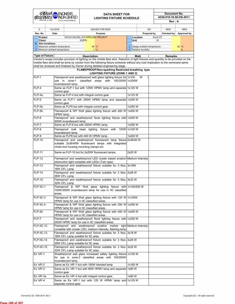
Project KOCHI SALEM LPG PIPELINE PROJECT Location Kochi DT
Client KSPPL Unit 20
A Site Conditions
1 Maximum ambient temperature: 45 °C 3 Design ambient temperature: 45 °C
2 Minimum ambient temperature: 1 °C 4 Relative humidity: %
FLP-IIC-13
FLP-IIC-14 Flameproof and weatherproof fixture suitable for 3 Nos.
26W CFL Lamp suitable for IIC area
3x26 W
FLP-7 Flameproof and weatherproof flood lighting fixture with
250W HPMV lamp for use in IIC classified areas.
1x250 W
FLP-IIC-15 Flameproof and weatherproof fixture suitable for 3 Nos.
32W CFL Lamp suitable for IIC area
3x32 W
FLP-IIC-12 Flameproof and weatherproof aviation marker light
complete with cluster LED, medium intensity, flashing lamp
FLP IIC-1
FLP IIC-4
Flameproof and weatherproof fixture suitable for 3 Nos.
18W CFL Lamp suitable for IIC area
3x18 W
FLP-5b Flameproof & WP Well glass lighting fixture with 400 W
HPMV lamp for use in IIC classified areas.
1x400 W
FLP-12
FLP IIC-3 Flameproof & WP Well glass lighting fixture with 125 W
HPMV lamp for use in IIC classified areas.
1x125W
Flameproof & WP Well glass lighting fixture with 250 W
HPMV lamp for use in IIC classified areas.
1x250 W
Same as FLP5 but with integral control gear.
Document No.
A538-010-16-50-DS-4511
Rev : A
FLAMEPROOF/Non-sparking Restricted breathing type
LIGHTING FIXTURE (ZONE-1 AND 2)
1x100 W
1x250 W
Flameproof and weatherproof LED cluster based aviation
obstruction light complete with LEDs (Twin type)
Medium Intensity
Flameproof bulk head lighting fixture with 100W
incandescent lamp.
1x100 W
1x250 W
Medium Intensity
Ex 'nR'-2 Same as Ex 'nR'-1 but with 160W blended lamp. 1x160 W
Ex 'nR'-3 Same as Ex 'nR'-1 but with 80W HPMV lamp and separate
control gear.
Ex 'nR'-3a Same as Ex 'nR'-3 but with integral control gear. 1x80 W
1x80 W
Ex 'nR'-4 Same as Ex 'nR'-1 but with 125 W HPMV lamp and
separate control gear.
1x125 W
Ex 'nR'-1 Weatherproof well glass increased safety lighting fixture
for use in zone-2 classified areas with 100/200W
incandescent lamp.
FLP-13 Flameproof and weatherproof fixture suitable for 3 Nos.
18W CFL Lamp
3x18W
FLP-14 Flameproof and weatherproof fixture suitable for 3 Nos.
26W CFL Lamp
3x26 W
FLP-10 Flameproof and weatherproof fluorescent lamp fixture
suitable 2x36/40W fluorescent lamps with integrated
choke box housing mounting clamps etc.
2x36/40 W
1x400 W
FLP-11 Same as FLP-10 but for 2x20W fluorescent lamps. 2x20 W
FLP-9 Same as FLP6 but with 400 W HPMV lamp.
FLP-6 Flameproof and weatherproof flood lighting fixture with
500W incandescent lamp.
1x500 W
FLP-7 Same as FLP-6 but with 250W HPMV lamp.
FLP-8
1x400 W
1x125 W
FLP-5 Same as FLP-1 with 250W HPMV lamp and separate
control gear
1x250 W
FLP-4a Same as FLP-4 but with integral control gear.
FLP-5a
Flameproof and weatherproof fixture suitable for 3 Nos.
32W CFL Lamp
3x32 W
FLP-4 Same as FLP-1 but with 125W HPMV lamp and separate
control gear.
1x125 W
FLP-5b Flameproof & WP Well glass lighting fixture with 400 W
HPMV lamp.
MKS MKS
Rev. No
Flameproof & WP Well glass lighting fixture with
100W/200W incandescent lamp for use in IIC classified
areas.
1x100/200 W
FLP-1 Flameproof and weatherproof well glass lighting fixture for
use in zone-1 classified areas with 100/200W
incandescent lamp.
1x100 W /
1x200W
FLP-15
A 9.8.2016 ISSUED FOR BIDS
DATA SHEET FOR
LIGHTING FIXTURE SCHEDULE
RemarksWattType of Fixture Description
AD
Date Purpose Prepared by Checked by Approved by
Vendor's scope includes provision of lighting on the mobile flare skid. Selection of light fixtures and quantity to be provided on the
mobile flare skid shall be done by vendor from the following fixture schedule without any cost implication to the ownerand same
shall be reviewed and finalised by Owner during detailed engineering stage.
Format No: EIL 1650-3010 Rev.1 Copyrights EIL - All rights reserved
Page 188 of 307

Document No.
A538-010-16-50-DS-4511
Rev : A
DATA SHEET FOR
LIGHTING FIXTURE SCHEDULE
NOTES:
8. Manufacturers type designation for fixtures indicated are for guidance purpose based on present catalogue nos, However contractor shall
select equivalent fixture from approved vendor list.
3. All fluorescent fixtures shall be fitted with low loss type electronic ballast and shall be cool white.
4. All 36 W fluorescent lamp can be replaced by 40W with the consultation of site Engineer-in-Charge.
5. All mirror optics luminaries should be epoxy powder coated.
6. Make of fixtures shall be embossed on the body.
7. All hazardous well glass fixtures shall be supplied with stainless steel external reflectors
1. All fixtures shall be complete with lamps.
2. All fluorescent/Mercury vapour/ Sodium Vapour /metal halide / LED fixtures shall be high power factor (Min. 0.9) type.
Ex 'nR'-13 Increased safety & WP lighting fixture suitable for use in
zone-2 classified areas with 3x26W CFL lamp.
3X26W
Ex 'nR'-5a Same as Ex 'nR'-5 but with integral control gear. 1x150 W
Ex 'nR'-6 Increased safety & WP Well glass lighting fixture for use in
zone-2 classified areas with 400 W HPMV lamp.
1x400 W
Same as Ex 'nR'-4 but with integral control gear. 1x125 W
Ex 'nR'-5 Same as Ex 'nR'-1 but with 250 W HPMV lamp and
separate control gear.
1x250 W
Ex 'nR'-4a
Format No: EIL 1650-3010 Rev.1 Copyrights EIL - All rights reserved
Page 189 of 307

VENDOR DATA REQUIREMENTS
FOR
EMERGENCY GENERATOR PACKAGE
A 10-AUG-2016 ISSUED WITH MR AD MKS MKS
Rev.No.
Date Purpose Prepared by Checked by Approved by
VENDOR DATA REQUIREMENTSFOR
EMERGENCY GENERATOR PACKAGE of 3
Document No.A538-010-16-50-VR-4510
Rev. A
Page 1
Format No. EIL-1642-1924 Rev.1 Copyright EIL - All rights reserved
Page 190 of 307
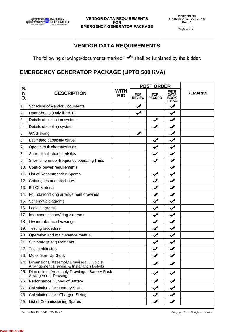
VENDOR DATA REQUIREMENTS
The following drawings/documents marked " " shall be furnished by the bidder.
EMERGENCY GENERATOR PACKAGE (UPTO 500 KVA)
S.NO.
DESCRIPTION WITHBID
POST ORDERREMARKSFOR
REVIEWFOR
RECORD
WITHDATABOOK
(FINAL)
1. Schedule of Vendor Documents
2. Data Sheets (Duly filled-in)
3. Details of excitation system
4. Details of cooling system
5. GA drawing
6. Estimated capability curve
7. Open circuit characteristics
8. Short circuit characteristics
9. Short time under frequency operating limits
10. Control power requirements
11. List of Recommended Spares
12. Catalogues and brochures
13. Bill Of Material
14. Foundation/fixing arrangement drawings
15. Schematic diagrams
16. Logic diagrams
17. Interconnection/Wiring diagrams
18. Owner Interface Drawings
19. Testing procedure
20. Operation and maintenance manual
21. Site storage requirements
22. Test certificates
23. Motor Start Up Study
24. Dimensional/Assembly Drawings : CubicleArrangement Drawing & Installation Details
25. Dimensional/Assembly Drawings : Battery RackArrangement Drawing
26. Performance Curves of Battery
27. Calculations for : Battery Sizing
28. Calculations for : Charger Sizing
29. List of Commissioning Spares
VENDOR DATA REQUIREMENTSFOR
EMERGENCY GENERATOR PACKAGE of 3
Document No.A538-010-16-50-VR-4510
Rev. A
Page 2
Format No. EIL-1642-1924 Rev.1 Copyright EIL - All rights reserved
Page 191 of 307

Notes :
1. "TICK" denotes applicability.
2. Post order, drawing / document review shall commence only after approval of Document Control Index (DCI).
3. All post order documents shall be submitted / approved through EIL eDMS portal.
4. Final documentation shall be submitted in hard copy (Six prints) and soft ( two CDs/DVDs ) in addition to
submission through EIL eDMS.
5. Refer - 6-78-0001: Specification for quality management system from Bidders.
6. Refer - 6-78-0002: Specification for documentation requirements from Contractors.
7. Refer - 6-78-0003: Specification for documentation requirement from Suppliers.
8. All drawings & documents shall be submitted in A4 or A3 paper sizes. Documents in higher paper size shall
be submitted in exceptional circumstances or as indicated in the MR/Tender.
9. Post order- The schedule of drawing / data submission shall be mutually agreed between EIL & the bidder /
contractor / supplier during finalization of Document Control Index (DCI).
10. "@" indicates submission of documents to Inspection Agency.
11. Bill of Material shall form part of the respective drawing.
12. '*' indicates the following:
a. Equipments whose ITP is attached with Contract -ITP for respective equipment shall be followed. Therefore,
no ITP is to be furnished for review for those equipments.
b. Equipments whose ITP is not attached with Contract-Manufacturer's ITP shall be submitted by Packager/
Vendor/Contractor to respective Regional Procurement Office (RPO) near to manufacturer's works for approval
by EIL Inspection.
13. All technical details and documents furnished with bids shall be treated as data for engineering. These shall
however be subject to Purchasers review after order placement and bidder shall comply to MR/Tender
requirements without any cost & time implication to EIL/Owner.
S.NO.
DESCRIPTION WITHBID
POST ORDERREMARKSFOR
REVIEWFOR
RECORD
WITHDATABOOK
(FINAL)
30. Data Books/ Manuals : Installation Manual/Catalogues/ Brochures
31. Inspection & Test Plan (ITP) -For review byInspection Dept.
Refer Note-'*'
32. Confirmation to Job Specification & Datasheet
VENDOR DATA REQUIREMENTSFOR
EMERGENCY GENERATOR PACKAGE of 3
Document No.A538-010-16-50-VR-4510
Rev. A
Page 3
Format No. EIL-1642-1924 Rev.1 Copyright EIL - All rights reserved
Page 192 of 307

-----------------------------------------------------------------------------------------------------------------------------------------------------------------------------------Format No. EIL -1641-1924 Rev. 1 Copyright EIL – Right reserved
VENDOR LIST FOR
KSPPL PROJECT
Document No.
A538-503-83-41-VL-0001 Rev.0
Page 1 of 4
VENDOR LIST FOR
KSPPL PROJECT
0 19.08.2016 ISSUED FOR TENDER AK NSV SK
Rev. No. Date Purpose Prepared by Checked by Approved by
Page 193 of 307

-----------------------------------------------------------------------------------------------------------------------------------------------------------------------------------Format No. EIL -1641-1924 Rev. 1 Copyright EIL – Right reserved
VENDOR LIST FOR
KSPPL PROJECT
Document No.
A538-503-83-41-VL-0001 Rev.0
Page 2 of 4
VENDOR LIST
1) CONTRACTOR/ VENDOR shall necessarily procure all the material / equipment forming
Permanent part of the unit / plant from vendors as per enclosed vendor list. This shall
include sub-ordered items / components also. The “Approved Vendors” shall be item
specific.
2) Current validity and range of approval as per EIL enlistment letter, work load, stability and
solvency need to be verified by the CONTRACTOR/ VENDOR before placement of order.
3) CONTRACTOR/ VENDOR are also required to ensure that equipment qualification
criteria if any, specified elsewhere in the bid document, is also simultaneously met.
4) Vendors on KSPPL/ EIL holiday list shall not be considered for ordering. CONTRACTOR/
VENDOR to note that during the Implementation Stages should a Vendor listed in the ITB
vendor list be put on holiday, KSPPL/ EIL reserves the right to inform CONTRACTOR/
VENDOR to ensure that no subsequent orders, from the time of issuance of the message
from KSPPL/ EIL, shall be placed on such vendors. However it shall remain an exclusive
responsibility of the contractor to ensure that the vendor, to whom the enquiries are being
issued/order, is being placed by the contractor, is not on EIL Holiday list. This
requirement has to be followed by the contractor without any time and cost implication to
the OWNER.
5) During the Implementation Stages should the contractor discover that there are additional
vendors for a particular item which have been additionally enlisted with EIL, the same
may be brought to the attention of KSPPL/ EIL for seeking approval for issuance of
enquiry. This approval will not be withheld without justifiable reason.
6) In an eventuality that CONTRACTOR/ VENDOR encounters the state of no response
from the vendors enlisted in the Bidding Documents, upon written documentary evidence
of the regret from the ITB enlisted vendors, contractor may consider, alternate vendors,
with prior approval of KSPPL/ EIL. Requisite documentation supplementing the
credentials of the proposed additional vendors in such an eventuality shall be provided to
KSPPL/ EIL for approval. CONTRACTOR/ VENDOR to note that it shall be the
CONTRACTOR/ VENDOR’s exclusive responsibility to meet the quality, schedule
considerations from the proposed alternate Vendor. KSPPL/ EIL shall, in no way, be
responsible for delays on this account.
7) Compliance to procurement of material from Approved Vendors is mandatory and shall
be fully complied with. No deviation to Approved Vendor list shall generally be
acceptable.
8) For items not covered in the above list, the Vendors list shall be approved by KSPPL/ EIL
prior to placement of order by CONTRACTOR/ VENDOR. CONTRACTOR/ VENDOR
shall list down the proposed suppliers / vendors for such items and submit the same for
Page 194 of 307
-----------------------------------------------------------------------------------------------------------------------------------------------------------------------------------Format No. EIL -1641-1924 Rev. 1 Copyright EIL – Right reserved
VENDOR LIST FOR
KSPPL PROJECT
Document No.
A538-503-83-41-VL-0001 Rev.0
Page 3 of 4
KSPPL/ EIL review / approval along with necessary documents / credentials. Non-
acceptance of a particular proposed vendor due to any reasons whatsoever shall not be a
cause of schedule and cost implication.
9) CONTRACTOR/ VENDOR shall make an independent assessment of capability of all the
vendors for timely deliveries of material / equipment. Any delays in deliveries by Vendor
(s) shall not be entertained as a cause of schedule and cost implication.
10) At any stage of the project, if it comes to the notice of KSPPL/ EIL that CONTRACTOR/
VENDOR has procured material / equipment, intentionally or unintentionally whatsoever,
from an Unapproved Vendor and/or items not falling in approved range of vendor(s), the
same shall be rejected forthwith and CONTRACTOR/ VENDOR shall be liable to replace
such material / plant / machinery without any schedule and cost implication to KSPPL.
11) List of vendors appearing anywhere else in the contract document in case of duplication
of the items at two or more places (except for the vendors list provided by process
Licensor, if applicable) shall not be considered by CONTRACTOR/ VENDOR and shall
be superseded by the vendor list enclosed herewith.
12) It is understood that should the name of Vendor be changed due to change in their
Company or Corporate shareholding, KSPPL/ EIL will accept such Vendors under its new
name with prior approval and submission of the requisite documentation by the
CONTRACTOR/ VENDOR.
13) Any such approval shall however, not release the CONTRACTOR/ VENDOR from any of
his obligations under the contract; neither shall any such approval signify nominations or
instruction to use such a vendor. All Approved Vendors are deemed to have been freely
chosen by the CONTRACTOR/ VENDOR at his own risk.
14) For approved vendors list for fabricated equipment (Vessels, Column, Heat Exchangers
and Ejectors etc.) bidder shall approach KSPPL/ EIL for approved vendor list. EIL vendor
list is for fabrication alone. Where mechanical design of the equipment is included in
CONTRACTOR’S/ VENDOR’S scope, CONTRACTOR/ VENDOR shall either himself or
through his Detailed Engineering sub-contractor is responsible for designing and
obtaining approval / review of Mechanical design calculations as per codes/specifications
specified elsewhere in the Bid/Contract document from KSPPL/ EIL.
Page 195 of 307

-----------------------------------------------------------------------------------------------------------------------------------------------------------------------------------Format No. EIL -1641-1924 Rev. 1 Copyright EIL – Right reserved
VENDOR LIST FOR
KSPPL PROJECT
Document No.
A538-503-83-41-VL-0001 Rev.0
Page 4 of 4
VENDORS FOR ELECTRICAL ITEMS
1. BAJAJ ELECTRCIAS LTD
2. BALIGA LIGHTING EQUIPMENTS (P) LTD
3. CROMPTON GREAVES LTD
4. FLEXPRO ELECTRICALS PVT LTD
5. FLAMEPROOF EQUIPMENTS PVT LTD
6. FCG POWER INDUSTRIES PVT LTD
7. FCG FLAMPROOF CONTROL GEARS P. LTD
8. PETROLEUM SAFETY PRODUCTS IND. PVT.
LTD
9. KAYSONS TECHNO EQUIPMENT P LTD.
10. SUDHIR SWITCHGEARS PVT LTD
VENDORS FOR ELECTRICAL ITEMS (ALTERNATOR)
1. CROMPTON GREAVES LTD INDIA
2. CUMMINS GENREATOR TECHNOLGIES I LTD U.S.A.
3. LEROY SOMAR & CONTROLS INDIA PVT LTD BELGIUM
VENDORS FOR DG SET
1. BHEL BHOPAL
2. GREAVES COTTON LTD
3. KIRLOSKAR OIL ENGINES LTD
4. POWERICA LTD
5. STERLING GENERATORS PVT LTD
6. SUDHIR POWER LTD
7. TIL LIMITED
8. TRADING ENGINEERS (INTERNATIONAL) LTD
9. WARTSILA INDIA LTD
Page 196 of 307

largt-Qie? laelaileg}
ENGINEERS INDIA LIMITED IA Geri al Inds Undeddlunpl
SPECIFICATION FOR
MEDIUM AND HIGH VOLTAGE CABLES AND ACCESSORIES
STANDARD SPECIFICATION No.
6-51-0051 Rev. 7
Page 1 of 10
TRAIT id s q A
c;iski 3ikkurk-A.
1-ff‘ 1-4ffkr
SPECIFICATION FOR
MEDIUM AND HIGH VOLTAGE CABLES & ACCESSORIES
7 01/04/16
6 11/04/11
5 20/04/09
4 15/03/04
3 30/07/98
REVISED AND ISSUED AS STANDARD SPECIFICATION
REVISED AND ISSUED AS STANDARD SPECIFICATION
REVISED AND ISSUED AS STANDARD SPECIFICATION
REVISED AND ISSUED AS STANDARD SPECIFICATION
REVISED AND ISSUED AS STANDARD SPECIFICATION
Rev. No Date Purpose
PS ANPS UAP DM
PB UAP JMS ND
RKM AAN VPS SKG
SKG RKM VPS AS
Prepared by
Checked by
StandardsCommitteeC onvenor
Standards Bureau
Chairman
Approved by
Copyright EIL — All rights reserved Format No. 8-00-0001-F1 Rev. 0
Page 197 of 307

SPECIFICATION FOR
MEDIUM AND HIGH VOLTAGE CABLES AND ACCESSORIES
ISKUtzleft ENGINEERS aZ:11 fagegW INDIA LIMITED
IA GcM a/ Inds Undertaking)
STANDARD SPECIFICATION No .
6-51-0051 Rev. 7
Page 2 of 10
Abbreviations:
ASTM American Society for Testing and Materials
BIS Bureau of Indian Standards
BS British Standard
CEA Central Electricity Authority
DGMS Director General of Mines and Safety
EPR Ethylene Propylene Rubber
FR Flame Retardant
FRLS Flame Retardant Low Smoke
FS Fire Survival
HR PVC Heat Resistant Polyvinyl Chloride
ICEA Insulated Cable Engineers Association
IEC International Electro technical Commission
IS Indian Standards
NEMA National Electrical Manufacturers Association
PVC Polyvinyl Chloride
UV Ultra Violet
XLPE Cross linked Polyethylene
Electrical Standards Committee
Convener: Mr. B.R. Bhogal Members: Ms. S. Anand
Mr. Parag Gupta Mr. M. K. Sahu
Ms. N S Bhattacharya Mr. Saeed Akhtar (Inspection) Ms. N.P. Guha (Projects)
Format No. 8-00-0001-F1 Rev. 0 Copyright EIL -All rights reserved
Page 198 of 307

Olazie?e, ENGINEERS 51:gzrr tagreg W INDIA LIMITED
cos d India UndeplaMirgi
SPECIFICATION FOR
MEDIUM AND HIGH VOLTAGE CABLES AND ACCESSORIES
STANDARD SPECIFICATION No .
6-51-0051 Rev. 7 Page 3 of 10
CONTENTS
1.0 SCOPE 4
2.0 CODES AND STANDARDS 4
3.0 GENERAL CONSTRUCTION 5
4.0 CABLE ACCESSORIES 7
5.0 INSPECTION, TESTING AND ACCEPTANCE 8
6.0 PACKING AND DESPATCH 10
Format No. 8-00-0001-F1 Rev. 0 Copyright EIL —All rights reserved
Page 199 of 307

SVIZIei#SENGINEERS les W INDIA LIMITED
SPECIFICATION FOR
MEDIUM AND HIGH VOLTAGE CABLES AND ACCESSORIES
STANDARD SPECIFICATION No.
6-51-0051 Rev. 7
Page 4 of 10
1.0 SCOPE
This specification along with data sheets covers requirements for design, manufacture, testing at works and supply of Fire survival Medium voltage cables and Flame Retardant Low Smoke Medium & High Voltage cables and cable jointing / terminating accessories for medium and high voltage systems.
2.0 CODES AND STANDARDS
2.1 The cables and cables jointing & terminating accessories shall comply with the latest edition of the following standards as applicable:
IS: 209 Specification for zinc. IS: 1554 • PVC insulated (heavy duty) electric cables. IS: 3961(Pt-2) : Recommended current ratings for cables: Part - 2 PVC Insulated and
PVC sheathed heavy-duty cables. IS: 3975 Mild steel wires, strips and tapes for armouring of cables. IS: 5831 PVC insulation and sheath of electric cables. IS: 6380 Specification for elastomeric insulation and sheath of electric cables. IS: 7098 Cross-linked polyethylene insulated PVC sheathed cables. IS: 8130 Conductors for insulated electric cables and flexible cords. IS: 10418 Drums for electric cables. IS: 10462 (Pt-1): Fictitious calculation method for determination of dimensions of
protective coverings of cables: Part - I Electrometric and thermo-plastic insulated cables.
IS: 10810 Methods of test for cables: Part 41: Mass of zinc coating on steel armour Part 58: Oxygen index test Part-61: Flame retardant test Part-62:Fire resistance test for bunched cables. Part-63: Measurement of Smoke density of Electric cables under fire conditions
IS: 13573 Joints and terminations for polymeric cables for working voltages from 6.6kV up to and including 33kV.
IEC: 60331-21: Tests for electric cables under fire conditions circuit integrity — Procedures and requirements — Cables of rated voltage up and including 0.6/1.0kV.
IEC: 60332-1 : Test of the fire behaviour on single core or single cable (flame retardancy)
IEC: 60332-3 : Tests of the fire behaviour on bunched cables (reduced flame propagation)
IEC: 61034 : Measurement of smoke density of cables burning under defined condition
NEMA-WC70 : Standard for non shielded power cables rated 2000V or less for the distribution of electrical energy.
NEMA-WC53 : Standard test methods for extruded dielectric power, control, instrumentation and portable cables for test.
ASTM-G-154 : Standard practice for operating fluorescent light apparatus for UV exposure of non-metallic materials.
ASTM-D-2863 : Measurement of minimum oxygen concentration to support candle like combustion of plastics
BS: 7846 Electric cables- 600/1000V armoured fire resistant cables having thermosetting insulation and low emission of smoke and corrosive gases when affected by fire.
Format No. 13-00-0001-F1 Rev. 0
Copyright EIL — All rights reserved
Page 200 of 307

SPECIFICATION FOR
MEDIUM AND HIGH VOLTAGE CABLES AND ACCESSORIES
Sanaa&te, ENGINEERS • fsr.7f EVIeG W INDIA UMITED
STANDARD SPECIFICATION No.
6-51-0051 Rev. 7
Page 5 of 10
2.2 The cables and accessories shall also conform to the provisions of CEA Regulations and other statutory regulations, as applicable.
2.3 In case of any conflict between requirements specified in various applicable documents for the project, the most stringent one shall prevail. However, Owner's decision in this regard will be final and binding.
3.0 GENERAL CONSTRUCTION
3.1 The cables shall be suitable for laying in trays, trenches, ducts, and conduits and for underground-buried installation with uncontrolled backfill and possibility of flooding by water and chemicals.
3.2 Outer sheath of all cables shall be black in colour and the minimum value of oxygen index shall be 29% at 27 ± 2 ° C. In addition suitable chemicals shall be added into the PVC compound of the outer sheath to protect the cable against rodent and termite attack. However, for earthing cables; colour of outer sheath shall be green.
3.3 All cables covered in this specification shall be Flame Retardant Low Smoke (FRLS) or Fire Survival (FS). The outer sheath of FRLS cables shall possess flame propagation properties meeting requirements as per IS-10810 (Part-62) category AF. FRLS cable shall be identified by indenting, embossing or printing the appropriate legend i.e. 'FRLS, Category — C2' throughout the cable length. FRLS properties shall be as per IS:10810 Part 61 & 62, IEC-60332 Part 1 & Part 3, IEEE-383, IEC-61034, IEC-60754 Part 1, ASTM-D-2863.
3.4 Sequential marking of the length of the cable in metres shall be provided on the outer sheath at every one metre. The embossing/engraving shall be legible and indelible.
3.5 The overall diameter of the cables shall be strictly as per the values declared by the manufacturer in the technical information subject to a maximum tolerance of ±2 mm up to overall diameter of 60mm and ±3mm for beyond 60mm.
3.6 PVC/ Rubber end caps shall be supplied free of cost for each drum with a minimum of eight per thousand metre length. In addition, ends of the cables shall be properly sealed with caps to avoid ingress of water during transportation and storage.
3.7 The joints in armour wire/strips shall be made by brazing or welding and any surface irregularities shall be removed. A joint in any wire/strip shall be at least 300mm. from the nearest joint in any wire/strip in the complete cable.
3.8 The cables meant to be used in mining area under the jurisdiction of DGMS shall satisfy the following
(a) "DGMS CERTIFIED" to be embossed at outer sheath at regular interval.
(b) Cables to be used in Mines shall have copper conductor only.
(c) The resistance of armour shall not exceed that of the conductor as specified in IS-8130 by more than 33%. To satisfy this, substitution of galvanised steel wire/strip in armouring by the required number of tinned copper wires/strips is permissible.
(d) For mining cables, the size and type of armour shall be such that the combined conductance of armour shall be equivalent to 75 percent of the conductance of the largest conductor of the cable.
Copyright EIL — All rights reserved Format No. 8-00-0001-F1 Rev. 0
Page 201 of 307

SPECIFICATION FOR
MEDIUM AND HIGH VOLTAGE CABLES AND ACCESSORIES
lataae ENGINEERS laileGWP INDIA LIMITED
ereew? niTIR (A Govt al !oda Undettakprw
STANDARD SPECIFICATION No.
6-51-0051 Rev. 7
Page 6 of 10
3.9 Medium Voltage Cables
3.9.1 All power/control cables for use on medium voltage systems shall be heavy-duty type, 650/1100V grade with aluminium/ copper conductor, PVC/XLPE (as mentioned in datasheet / Material requisition) insulated, inner-sheathed, armoured/ unarmoured and overall PVC sheathed. XLPE insulated cables shall meet the requirement specified in IS-7098 (Part-1).
3.9.2 The conductors shall be solid for conductor of nominal area up to and including 6mm2 and stranded beyond 6mm2 . Conductors of nominal area less than 16 mm 2 shall be circular only. Conductors of nominal area 16 mm 2 and above may be circular or shaped as per IS 8130. Cables with reduced neutral conductor shall have sizes as per Table 1 of IS 1554 (Part-1).
3.9.3 The core insulation shall be with PVC/XLPE compound applied over the conductor by extrusion. PVC compound shall conform to the requirements of type 'C' compound as per IS: 5831. The thickness of insulation and the tolerance on thickness of insulation shall be as per Table 2 of IS: 1554 (Part-1). Control cables having 6 cores and above shall be identified with prominent and indelible Arabic numerals on the outer surface of the insulation. Colour of the numbers shall contrast with the colour of insulation with a spacing of maximum 50 mm between two consecutive numbers. Colour coding for cables up to 5 cores shall be as per Indian standard.
3.9.4 The inner sheath shall be applied over the laid-up cores by extrusion and shall be of PVC conforming to the requirements of Type ST-2 PVC compound as per IS: 5831. The minimum thickness of inner sheath shall be as per Table-4 of IS: 1554 (Part-1). Single core cables shall have no inner sheath.
3.9.5 All cables shall be provided with armour except those specifically specified as unarmoured. For single core cables intended for use on AC system, the armouring shall be of non-magnetic material. For multicore cables, the armour shall be by single round galvanised steel wires where the calculated diameter below armouring does not exceed 13 mm and by galvanised steel strips where this dimension is greater than 13 mm. Requirement and methods of tests for armour material and uniformity of galvanisation shall be considered as per IS - 3975 and IS - 10810 (Part 41). The dimensions of armour shall be considered as per method (b) of IS - 1554 (Part -1).
3.9.6 The outer sheath for the cables shall be applied by extrusion and shall be formulated for lower smoke and shall be of PVC compound conforming to the requirements of type ST-2 compound as per IS: 5831. The minimum and average thickness of outer sheath for unarmoured cables and minimum thickness of outer sheath for armoured cables shall be as per Table-7 of IS: 1554 (Part -I).
3.9.7 If heat resisting PVC cables are specified in the data sheet„ it shall be possible to continuously operate the cable at a maximum conductor temperature of 85°C under full load condition and 160°C under short-circuit condition.
3.9.8 For XLPE insulated cables, it shall be possible to continuously operate the cable at a maximum conductor temperature of 90°C under full load condition and 250°C under short-circuit condition.
3.9.9 The fire survival cables shall meet the following additional requirements : i) The insulation shall be of EPR or equivalent material with glass mica tape below or
above insulation. ii) The cables shall meet requirement of circuit integrity test for a minimum period of 3
hours at maximum temperature of 950° C. iii) Vendor shall have the test certificate for circuit integrity test as per IEC: 60331-21.
Copyright EIL —All rights reserved Format No. 8-00-0001-F1 Rev. 0
Page 202 of 307

SPECIFICATION FOR
MEDIUM AND HIGH VOLTAGE CABLES AND ACCESSORIES
lardzie ENGINEERS s'g7 fataiegw INDIA LIMITED (A
can a Inds Uneertakpng)
STANDARD SPECIFICATION No.
6-51-0051 Rev. 7
Page 7 of 10
3.10 High Voltage Cables
3.10.1 Power cables from 3.3kV and up to and including 33kV systems shall be Aluminium/ Copper conductor, XLPE insulated, sheathed, armoured/ unarmoured and overall PVC sheathed.
3.10.2 The conductors shall be stranded and compacted circular for all cables.
3.10.3 All cables rated 3.8/ 6.6kV and above shall be provided with both conductor screening and insulation screening. The conductors shall be provided with non-metallic extruded semi conducting screen.
3.10.4 The core insulation shall be with cross linked polyethylene insulating compound dry cured, applied by extrusion. It shall be free from voids and shall withstand all mechanical and thermal stresses under steady state and transient operating conditions. It shall conform to the properties given in Table-I of IS: 7098 (Part -2).
3.10.5 The insulation screen shall consist of non-metallic extruded semi-conducting compound in combination with a non-magnetic metallic copper screen. The copper screen for all the three cores together shall be capable of carrying the single line to ground fault current value and the duration specified in the data sheet. For single core cable, non-magentic armour shall constitute the copper screen which shall be capable of carrying the single line to ground fault current value and the duration specified in the data sheet.
3.10.6 The conductor screen, XLPE insulation and insulation screen shall all be extruded in one operation by 'Triple Extrusion' process to ensure perfect bonding between the layers. The core identification shall be by coloured strips or by printed numerals.
3.10.7 The inner sheath shall be applied over the laid up cores by extrusion and shall conform to the requirements of type ST 2 compound of IS: 5831. The extruded inner sheath shall be of uniform thickness. In case of single core cables, there shall be extruded inner sheath between insulation metallic screen and armouring.
3.10.8 All cables shall be provided with armour except those specifically specified as unarmoured. For single core cables intended for use on AC system, the armouring shall be of non-magnetic material. For multicore cables, the armour shall be by galvanised steel strips. Requirement and methods of tests for armour material and uniformity of galvanisation shall be as per IS - 3975 and IS -10810 (Part 41). The dimensions of armour shall be as per method (b) of IS - 7098 (Part -2).
3.10.9 The outer sheath of the cables shall be applied by extrusion over the armouring and PVC compound conforming to the requirements of Type ST 2 compound of IS: minimum and average thickness of outer sheath for unarmoured cables and thickness of outer sheath for armoured cables shall be as per IS: 7098 (Part-2).
shall be of 5831. The minimum
3.10.10 The thickness of the insulation, inner sheath shall be governed by values given in Table-4 and Table-5 of IS: 7098 (Part -2).
4.0 CABLE ACCESSORIES
4.1 The termination and straight through jointing kits for use on the systems shall be suitable for the type of cables offered as per this specification and shall meet requirements of IS 13573.
4.2 The accessories shall be supplied in kit form. Each component of the kit shall carry the manufacturer's mark of origin.
Format No. 8-00-0001-F1 Rev. 0 Copyright EIL — AU rights reserved
Page 203 of 307

aazieLlida ENGINEERS a tifiIegW WA LIMITED lawn eia5,40r.povail (A Gal 0/ Inas Undellakingl
SPECIFICATION FOR
MEDIUM AND HIGH VOLTAGE CABLES AND ACCESSORIES
STANDARD SPECIFICATION No.
6-51-0051 Rev. 7 Page 8 of 10
4.3 The kit shall include all stress grading, insulating and sealing materials apart from conductor fittings and consumable items. An installation instruction sheet shall also be included in each kit.
4.4 The contents of the accessories kit including all consumable shall be suitable for storage without deterioration at a temperature of 45° C, with shelf life extending to more than 5 years.
4.5 Terminating Kits
The terminating kits shall be suitable for termination of the cables to an indoor switchgear or to a weatherproof cable box of an outdoor mounted transformer/ motor. For outdoor terminations, weather shields/ sealing ends and any other accessories required shall also form part of the kit. The terminating kits shall be from one of the makes/ types mentioned in the data sheet.
4.6 Jointing Kits
The straight through jointing kits shall be suitable for installation on overhead trays, concrete lined trenches, and ducts and for underground burial with uncontrolled backfill and possibility of flooding by water and chemicals. These shall have protection against any mechanical damage and suitably designed to be protected against rodent and termite attack. The inner sheath similar to that provided for cables shall be provided as part of straight through joint. The jointing kits shall be from one of the makes/ types mentioned in the data sheet.
5.0 INSPECTION, TESTING AND ACCEPTANCE
The cables shall be tested and inspected at the manufacturer's works. Manufacturer shall furnish all necessary information concerning the raw material supply to EIL/ Owner's inspectors. The inspector shall have free access to the manufacturer's works for the purpose of inspecting the process of manufacture in all its stages and will have the power to reject any material, which appears to be of unsuitable description or of unsatisfactory quality. For HV cables, the vendor shall give at least 2 weeks advance notice to the purchaser, regarding the date of testing to enable purchaser's representative to witness the tests.
5.1 Cables
5.1.1 After completion of manufacture of cables and prior to despatch, the cables shall be subjected to type, routine, acceptance and special tests as detailed below. The test reports for all cables shall be got approved from the Engineer before despatch of the cables.
5.1.2 All routine tests, acceptance tests, type tests and additional type tests for improved fire performance shall be carried out as listed in IS: 1554 (Part-1) and IS: 7098 (Part-2) on PVC and XLPE insulated cables respectively.
5.1.3 The test requirements for PVC insulation and sheath of cables shall be as per latest revision of IS: 5831.
5.1.4 Test for Resistance to Ultra Violet Radiation: This test shall be carried out as per ASTM-G-53 or ASTM-G-I54 on outer sheath. The retention value of tensile strength and ultimate elongation after the test shall be minimum 60 % of tensile strength and ultimate elongation before the test. Test certificates with respect to this test (not older than one year) from recognised testing laboratory to be furnished for review by EIL before despatch clearance of cables. In case test certificates are not available, test is to be conducted by vendor at his own cost in any recognised test laboratory or in house testing laboratory, before despatch clearance
Format No. 8-00-0001-F1 Rev. 0
Copyright EIL — All rights reserved
Page 204 of 307

18ilfrkie? la{a 051.agi
ENGINEERS WA LIMITED A Gaol al Inds Undeplaltingi,
SPECIFICATION FOR
MEDIUM AND HIGH VOLTAGE CABLES AND ACCESSORIES
STANDARD SPECIFICATION No .
6-51-0051 Rev. 7
Page 9 of 10
of cables. Sampling for this test is to be done randomly once for each order, provided outer sheath remains same.
5.1.5 Acceptance tests as per IS-1554 (Part-1) and IS-7098 (Part-2) and the following special tests to be performed on the cables as per sampling plan for all cables. However these tests are required to be witnessed by EIL/ Owner for HV cables.
a. Accelerated water absorption test for insulation as per NEMA-WC-70. (For PVC insulated cables) and as per NEMA-WC-53 (for XLPE/ EPR insulated cables). Test certificates with respect to this test (not older than one year) from recognised testing laboratory to be furnished for review by EIL before despatch clearance of cables. In case test certificates are not available, test is to be conducted by vendor at his own cost in any recognized test laboratory or in house testing laboratory, before despatch clearance of cables. Sampling for this test is to be done randomly once for each order, provided type of insulation remains same.
b. Dielectric Retention Test: The dielectric strength of the cable insulation tested in accordance with NEMA-WC-70 at 75 ± 1° C shall not be less than 50 % of the original dielectric strength. (For PVC insulated cables). Test certificates with respect to this test (not older than one year) from recognised testing laboratory to be furnished for review by EIL before despatch clearance of cables. In case test certificates are not available, test is to be conducted by vendor at his own cost in any recognized test laboratory or in house testing laboratory, before despatch clearance of cables. Sampling for this test is to be done randomly and once for each order.
c. Oxygen Index Test: The test shall be carried out as per IS-10810 (Part 58). Sampling to be done for every offered lot/size as per sampling plan.
d. Flammability Test: The test shall be carried out on finished cable as per IS-10810 (Part 61 & 62). Sampling for these tests is to be done randomly once for each order, provided outer sheath remains same. The acceptance criteria for tests conducted shall be as under:
Part-61-The cable meets the requirement if there is no visible damage on the test specimen within 300 mm from its upper end
Part-62-The maximum extent of the charred portion measured on the test sample should not have reached a height exceeding 2.5 m above the bottom edge of the burner at the front of the ladder.
e. Test for rodent and termite repulsion property shall be done by analysing the property by chemical method.
5.1.6 Following tests shall be carried out to prove FRLS property of the cable.
a. Critical oxygen index as per ASTM-D-2863 i.e. Determination of % of oxygen required for combustion at room temperature of FRLS sheath which shall remain as 29%(min.)
b. Temperature index as per ASTM-D-2863 i.e. To determine at what temperature normal oxygen content of 29% in air will support combustion of FRLS sheath which shall remain as 250°C.
c. Halogen acid gas emission as per IEC-60754 Part 1 i.e. To determine the % of release of hydrochloric acid gas from the FRLS sheath under fire which shall be 20% (max.)
Format No. 8-00-0001-F1 Rev. 0
Copyright EIL —AU rights reserved
Page 205 of 307

SPECIFICATION FOR
MEDIUM AND HIGH VOLTAGE CABLES AND ACCESSORIES
15ilfazle? ENGINEERS sal laiRegCW t■DIA LIMfTED
IA Gal Olinda UneerVATVI
STANDARD SPECIFICATION No.
6-51-0051 Rev. 7
Page 10 of 10
d. Smoke Density Test shall be as per ASTM D - 2843 and Smoke Density Rating of FRLS Sheath shall be 60% (max.).
5.1.7 The test for circuit integrity for fire survival cables shall be carried out as per IEC-60331 (Part-21).
5.2 Cable Accessories
Type tests should have been carried out to prove the general qualities and design of a given type of termination/ jointing system as per IS-13573. The type test certificates from independent testing laboratory shall be submitted before despatch.
6.0 PACKING AND DESPATCH
6.1 Cables shall be despatched in non-returnable steel drums of suitable barrel diameter, securely packed, with the take-off end fully protected against mechanical damage. Ferrous parts used shall be treated with a suitable rust preventive finish or coating to avoid rusting during transit or storage.
6.2 On the flange of the drum, necessary information such as project title, manufacturer's name, type, size, voltage grade of cable, length of cable in metres, drum no., cable code, BIS certification mark, gross weight etc. shall be printed. An arrow shall be printed on the drum with suitable instructions to show the direction of rotation of the drum.
6.3 Cables shall be supplied in drum lengths as follows:
MV Cables Multicore Power cables upto 6 mm 2 1000 m Multicore Power cables from 10 mm 2 up to 500 mm2 500 m Single Core Power cables upto 630 mm 2 1000 m Control cables upto 61 cores 1000 m
HV Power Cables Upto 11kV Grade
Three Core cables upto 400 mm 2 500 m Single Core cables upto 400 mm 2 1000 m Single Core cables above 400 mm 2 and upto 1000 mm2 750 m
HV Power Cables Above 11kV Grade and upto 33kV Grade
Three Core cables upto 300 mm 2 grade 350 m Single Core cables upto 400 mm 2 1000 m Single Core cables above 400 mm 2 and upto 1000 mm 2 500 m
However exact drum lengths shall be finalised during order execution. A tolerance of ± 3 % shall be permissible for each drum. However overall tolerance on each size of cable shall be limited to ±2%.
6.3.1
6.3.2
6.3.3
Copyright EIL — All rights reserved Format No. 8-00-0001-F1 Rev. 0
Page 206 of 307

411 5 24.02.16
REVISED AND ISSUED AS STANDARD SPECIFICATION NNB/AK NP
ft
4 11.04.11 REVISED AND ISSUED AS STANDARD SPECIFICATION
PS ANPS
3 27.08.07 REVISED AND ISSUED AS STANDARD SPECIFICATION ANPS UAP
2 30.01.02 REVISED AND ISSUED AS STANDARD
SPECIFICATION UAP AAN
1 23.12.96 REVISED AND ISSUED AS STANDARD SPECIFICATION RKM VPS
Rev. No Date Purpose
Prepared by
Checked by
BRB
SC
UAP DM
JMS VC
VPS GRR
SG
AS
Standards Standards Committee
Bureau Convenor
Chairman
Approved by
ENGINEERSOgell 215reg INDIA LIMITED
1.11 262,1R2 ,751.3.10.1) I A GoN of India UndertalonM
SPECIFICATION FOR
HAZARDOUS AREA LIGHT FIXTURES AND JUNCTION
BOXES
STANDARD SPECIFICATION No.
6-51-0061 Rev. 5
Page 1 of 7
FZR (11rd.4 1 ritIct*PcR1
■Ticrkll tsictki
faF~T
SPECIFICATION FOR
HAZARDOUS AREA LIGHT FIXTURES AND JUNCTION BOXES
Format No. 8-00-0001-F1 Rev. 0 Copyright EIL — All rights reserved
Page 207 of 307

ENGINEERS effidfaregVIOP INDIA LIMITED Wien (A Govf Of India Undertaking)
SPECIFICATION FOR
HAZARDOUS AREA LIGHT FIXTURES AND JUNCTION
BOXES
STANDARD SPECIFICATION No.
6-51-0061 Rev. 5
Page 2 of 7
Abbreviations:
BIS Bureau of Indian Standards BS British Standard CEA Central Electricity Authority CIMFR Central Institute of Mines and Fuel Research (formerly CMRI) DGMS Directorate General of Mines Safety ERTL Electronics Regional Test Laboratory ES Edison Screw FM Factory Mutual Research Corporation GI Galvanised Iron HRC High Rupturing Capacity ICAO International Civil Aviation Organisation IEC International Electrotechnical Commission IEEE Institute of Electrical & Electronics Engineers IP Ingress Protection IS Indian Standard LCIE Laboratoire Central des Industries Electriques LED Light Emitting Diode LV Low Voltage NEMA National Electrical Manufacturers Association PESO Petroleum and Explosives Safety Organisation PVC Poly Vinyl Chloride SPN Single Phase Neutral TPN Three Phase Neutral UL Underwriters Laboratories VDE Verband der Elektrotechnik, Elektronik and Information stechnik
Electrical Standards Committee
Convenor: Mr. B. R. Bhogal
Members: Ms. Sumita Anand Mr. Parag Gupta Mr. M. K. Sahu Ms. N. S. Bhattacharya Mr. Saeed Akhtar (Inspection) Ms. N. P. Guha (Projects)
Format No. 8-00-0001-F1 Rev. 0
Copyright EIL — All rights reserved
Page 208 of 307

101 eJ ENGINEERS $'1g7 0151eg INDIA LIMITED
(A Govt of Ind. Undertaking)
SPECIFICATION FOR
HAZARDOUS AREA LIGHT FIXTURES AND JUNCTION
BOXES
STANDARD SPECIFICATION No.
6-51-0061 Rev. 5
Page 3 of 7
CONTENTS
1.0 SCOPE 4
2.0 CODES AND STANDARDS .4
3.0 GENERAL REQUIREMENTS 4
4.0 SITE CONDITIONS 4
5.0 POWER SUPPLY 4
6.0 CERTIFICATION 5
7.0 TECHNICAL REQUIREMENTS 5
8.0 INSPECTION, TESTING AND ACCEPTANCE 7
9.0 PACKING AND DESPATCH 7
Format No. 8-00-0001-F1 Rev. 0
Copyright EIL — All rights reserved
Page 209 of 307

.311 ENGINEERS
$1geZiEifiteg INDIA LIMITED
WWI ?IMRE 4,4,10.1) (A Govt of India Undertaking)
SPECIFICATION FOR
HAZARDOUS AREA LIGHT FIXTURES AND JUNCTION
BOXES
STANDARD SPECIFICATION No.
6-51-0061 Rev. 5
Page 4 of 7
1.0 SCOPE
This specification covers the requirements of design, manufacture, testing, packing and supply of lighting fixtures, control gearboxes, junction boxes and accessories suitable for installation in locations handling flammable liquids and gases / vapours.
2.0 CODES AND STANDARDS
2.1 The equipment shall comply with the requirements of latest revision of the following standards issued by BIS: IS-5
Colours for ready mixed paints and enamels. IS / IEC 60079-0
Electrical apparatus for explosive gas atmospheres (General requirements).
IS / IEC 60079-1 : Electrical apparatus for explosive gas atmospheres (Equipment Protection by Flameproof Enclosures "d").
IS / IEC 60079-7
: Electrical apparatus for explosive gas atmospheres (Equipment Protection by Increased Safety "e").
IS / IEC 60079-15
: Electrical apparatus for explosive gas atmospheres Construction, test & marking of type of protection "n"
IS / IEC 60529 : Degrees of protection provided by enclosures (IP Code). IEC 61347-2-13 : Lamp Controlgear — Part 2 -13: Particular Requirement for
D.C. and A.C. supplied electronic control gear for LED models
2.2
In case of imported equipment, standards of the country of origin shall be applicable if these standards are equivalent or more stringent than the applicable Indian standards.
2.3
The equipment shall also confirm to the provisions of CEA Regulations with latest amendments and statutory regulations currently in force in the country.
2.4
In case Indian standards are not available for any equipment, standards issued by IEC/ BS/ VDE/ IEEE/ NEMA or equivalent agency shall be applicable.
2.5
In case of any conflict between requirements specified in various applicable documents for the project, the most stringent requirement shall govern. However, Owner's / EIL's decision in this regard will be final and binding.
3.0 GENERAL REQUIREMENTS
3.1 The offered equipment shall be brand new with state of art technology and having proven field track record. No prototype equipment shall be offered.
3.2 Vendor shall ensure availability of spare parts and maintenance support services for the offered equipment for at least 10 years from the date of supply.
4.0 SITE CONDITIONS
The equipment shall be suitable for installation and satisfactory operation in classified hazardous locations in tropical, humid and corrosive atmosphere as prevalent in refineries, petrochemical and fertilizer plants. Unless otherwise specified, a design ambient temperature of 40° C and an altitude not exceeding 1000 m above mean sea level shall be considered.
5.0 POWER SUPPLY
All AC lighting fixtures/ control gear boxes/ junction boxes shall be suitable for 220 — 250V, SPN, 50Hz ± 3% power supply and all DC lighting fixtures/ junction boxes shall be suitable for 110/ 220 ±10% V power supply.
Format No. 8-00-0001-F1 Rev. 0
Copyright EIL — All rights reserved
Page 210 of 307

SPECIFICATION FOR
HAZARDOUS AREA LIGHT FIXTURES AND JUNCTION
BOXES
STANDARD SPECIFICATION No.
6-51-0061 Rev. 5
Page 5 of 7
eiENGINEERS ogel, fame-, INDIA LIMITED
IvoRvt eiRoor?OvJOinvit
IA Govt of India Undertaking)
6.0 CERTIFICATION
The equipment shall have test certificates issued by recognised independent test house (CIMFR/ ERTL/ Baseefa/ LCIE/ UL/ FM or equivalent). All equipment (indigenous & imported) shall also have valid statutory approvals as applicable for the specified location. All indigenous flameproof equipment shall have valid BIS license and marking as required by statutory authorities.
7.0 TECHNICAL REQUIREMENTS
7.1 Construction
7.1.1 The enclosures of the lighting fixtures, control gear box and junction boxes shall be of cast light metal alloy.
7.1.2 All equipment shall be suitable for use in outdoor open locations and shall have IP-55 degree of protection.
7.1.3 The enclosures shall be provided with gaskets made of non-inflammable and self-extinguishing material.
7.1.4 All metal surfaces shall undergo manufacturer's standard cleaning/ painting cycle. After preparation of under surface, the equipment shall be painted with two coats of epoxy based final paint with colour shade as below:
- Flame proof (Gas group IIA/IIB) and AC supply : Dark admiralty grey shade 632 of IS-5/ RAL 7031
- Flame proof (Gas group IIC) and AC Supply : Light yellow shade 355 of IS-5 / RAL 1012
- Zone-2/ Increased safety and AC Supply
: Dark admiralty grey shade 632 of IS-5/ RAL 7031
- DC lighting fixtures
: Bright red shade 538 of IS-5 / RAL 3003
All unpainted steel parts shall be suitably treated to prevent rust formation. If these parts are moving elements then these shall be greased.
7.1.5 A warning inscription "DO NOT OPEN WHEN ENERGIZED" shall be provided on each enclosure. The warning inscription shall be embossed on the enclosure or a separate warning plate with above inscription shall be fixed to the enclosure with screws. The warning plate shall be of nickel plated brass or stainless steel.
7.1.6 All accessories like nuts, bolts, washers etc. shall be made of stainless steel SS-304.
7.1.7 All equipments on single phase supply shall be provided with an independent earth terminal with lug inside the enclosure for terminating the third (earth) core of the cable and shall have facility for looping.
7.1.8 A nameplate shall be provided to indicate the details of testing agency (CIMFR or equivalent), test certificate reference, statutory approval agency (PESO/ DGMS) and reference, BIS license number, applicable gas group etc. The nameplates shall be engraved type and permanently fixed on the equipment. In case the standard details given above are embossed on the enclosures, the same need not be repeated on the nameplate.
7.2 Lighting Fixtures
7.2.1 Glass used for lighting fixture shall be clear and suitable for use under conditions involving exceptional risk of mechanical damage.
7.2.2 All well glass fixtures shall be provided with either galvanised steel or epoxy powder coated mild steel protective wire cage using minimum 5mm welded steel construction and having mesh dimension not exceeding 50mm x 70mm. The mounting bolts of mild steel required for
Format No. 8-00-0001-F1 Rev. 0
Copyright EIL — All rights reserved
Page 211 of 307
e_ ENGINEERS
tfiWieg INDIA LIMITED
1.1Eq, 212M? MR OgleFI)
(A Govt of India undertaking)
SPECIFICATION FOR
HAZARDOUS AREA LIGHT FIXTURES AND JUNCTION
BOXES
STANDARD SPECIFICATION No.
6-51-0061 Rev. 5
Page 6 of 7
physically connecting the hazardous area well glass lighting fixtures (bracket / ceiling mounted type) to the respective mounting bracket shall be supplied by Vendor along with the fixtures.
7.2.3 The fixing parts of the enclosure, which are to be opened for replacement of bulb, shall be so fastened that they can be unfastened only with special tools.
7.2.4 The lighting fixtures in Zone-2 area shall be Ex nR type. Lamp holder shall be Edison screw type.
7.2.5 The lighting fixtures having integral control gear box / driver or to be used with incandescent lamps shall be provided with 2 nos. threaded entries and 2 nos. double compression nickel plated brass cable glands. All other lighting fixtures shall be provided with 1 no. threaded entry and 1 no. double compression nickel plated brass cable gland. The glands shall be suitable for the specified cable size. 20% of the fixtures having double cable entry shall be supplied with 1 no. nickel plated brass plug for sealing the unused entry.
7.2.6 The top of all well glass lighting fixtures shall be identically drilled/ threaded to facilitate installation on pole/ column or ceiling.
7.2.7 The flood lighting fixtures shall be supplied with adjustable mounting arrangement both in horizontal and vertical plane.
7.2.8 The lighting fixtures for aviation purpose shall have cluster LED lamps of medium intensity (as per ICAO regulations) and of red colour, with toughened glass.
7.2.9 All lighting fixtures shall be provided with suitable mirror-polished aluminum internal reflector of suitable thickness to ensure adequate mechanical strength. Additionally, all well glass fixtures except LED type shall be provided with an anodized mirror-polished aluminum external reflector of minimum thickness 1.2mm and parabolic in design.
7.2.10 External reflectors, for use with well glass fixtures with lamps rated up to 150W, shall have a height not less than 60% of the length of the well glass in use. Height of the external reflectors, for use with well glass fixtures with lamps rated above 150W, shall extend at least 10mm below the full length of the well glass in use.
7.2.11 For LED type fixture, all fixture shall be supplied complete with associated lamp and driver. LED driver shall be suitable for surge protection of minimum 2 kV surge. LED driver shall comply with the requirement of IEC 61347-2-13. Fixture lifetime (L70) shall be greater than 50000 hours at ambient temperature of 40°C. Warranty period of LED fixture and driver shall be as specified elsewhere in the MR.
7.3 Control Gear Box
7.3.1 Lighting fixtures suitable for discharge lamps shall be provided with power factor correction capacitor, choke starter etc., housed in separate control gear box. The choke shall be copper wound. The complete control gear shall have power factor not less than 0.9.
7.3.2 The control gear boxes shall be provided with 3 nos. entries and 3 nos. double compression nickel plated brass cable glands. The glands shall be suitable for the specified cable size. 20% of the control gear boxes shall be supplied with 1 no. nickel plated brass plug for sealing the unused entry.
7.3.3 Control gear box for flame proof fixtures shall be flameproof type and for Ex nR type fixtures shall be increased safety type, except that the control gear boxes having a fuse inside the enclosure shall be necessarily of flameproof type. The fuses shall be HRC type. Requirement of fuse shall be as specified in data sheet/ job specification.
7.4 Junction Boxes The junction boxes shall be of flameproof or non-sparking type construction as mentioned in the MR / Datasheet. All junction boxes for looping of single phase lighting circuits using cables up to 6mm2 shall be minimum 125mm diameter in size. Each junction box shall be
Format No. 8-00-0001-F1 Rev. 0
Copyright EIL — All rights reserved
Page 212 of 307

tll~ieiENGINEERS 51g-zir Ofieg INDIA LIMITED
Govt of India find. "ng tallE71 eirant, an Oraff.if
SPECIFICATION FOR
HAZARDOUS AREA LIGHT FIXTURES AND JUNCTION
BOXES
STANDARD SPECIFICATION No.
6-51-0061 Rev. 5
Page 7 of 7
complete with requisite number of cable entries and double compression flameproof nickel plated brass cable glands to suit the specified cable size.
7.5 Terminals & Wiring 7.5.1 The fixtures and junction boxes shall be provided with sufficient number of terminals. More
than 2 wires per terminal shall not be permitted. If required, additional terminal with shorting link may be used. The terminals for external cable termination shall be suitable for 2.5mm' solid copper conductor. Tinned copper lugs shall be provided for cable termination wherever applicable.
7.5.2 All internal wiring shall employ 1.5mm2, 660 V grade, FR type, PVC insulated copper conductor wires, colour coded for phase, neutral and earth.
7.5.3 For flameproof equipments, terminal box can be provided in 'Exe' or 'Exd' execution.
8.0 INSPECTION, TESTING AND ACCEPTANCE
8.1 During fabrication, the equipment shall be subjected to inspection by EIL/ Owner or by an agency authorised by the Owner, if specified/ agreed in Inspection Test Plan. Manufacturer shall furnish all necessary information concerning the supply to EIL/ Owner's inspector. All routine/ acceptance tests shall be carried out at manufacturer's works under his care and expense.
8.2 Type test certificates from CIMFR or equivalent test house, applicable PESO/ DGMS approval certificates, BIS license and original drawings referred in type test certificates shall be shown to the inspection agency on demand during inspection. The certificates and BIS license must be valid at the time of despatch.
8.3 Test certificates of bought out components shall be shown to the inspection agency on demand during inspection.
8.4 All equipments shall be subjected to various acceptance tests as per Inspection and Test Plan no. 6-81-1061.
9.0 PACKING AND DESPATCH
All the equipment shall be divided into several sections for protection and ease of handling during transportation. The equipment shall be properly packed for the selected mode of transportation, i.e. by ship/ rail or trailer, and shall be wrapped in polythene sheets before being placed in crates/ cases to prevent damage to finish. The crates/ cases shall have skid bottom for handling. Special notations such as 'Fragile', 'This side up', 'Center of gravity', `Weight',' Owner's particulars', 'PO nos.' etc., shall be clearly marked on the packages together with other details as per purchase order.
The equipment may be stored outdoors for long periods before installation. The packing should be suitable for outdoor storage in areas with heavy rains and high ambient temperature unless otherwise agreed. A set of instruction manuals for installation, testing and commissioning, a set of operation & maintenance manuals and a set of final drawing shall be enclosed in a waterproof cover along with the shipment.
Format No. 8-00-0001-F1 Rev. 0
Copyright EIL — All rights reserved
Page 213 of 307

tt~iei ENGINEERS
$igar taf4eg INDIA LIMITED
0177 er,er,.,try, IA Gosn of India UndeFlakinqi
SPECIFICATION FOR
LIGHTING INSTALLATION
STANDARD SPECIFICATION No.
6-51-0083 Rev. 5 Page 1 of 13
WIRT FzraTlIT 3-entrR-
fe4-4-tr
SPECIFICATION FOR
LIGHTING INSTALLATION
j/s .jr) twV 5 10.03.15 REVISED AND ISSUED AS SPECIFICATION AKG SA BR /' SC
4 15.01.14 REVISED AND ISSUED AS SPECIFICATION FA SA UAP SC
3 25.04.08 REVISED AND ISSUED AS SPECIFICATION RKS SSM JMS VC
2 28.02.03 REVISED and ISSUED AS SPECIFICATION HKM RSG VPS SKG
1 01.09.97 REVISED and ISSUED AS STANDARD SPECIFICATION
RR VPS SG AS
0 31.03.82 ISSUED AS STANDARD SPECIFICATION RR VPS
Rev. No
Date Purpose Prepared
by Checked
Standards Committee Convenor
Standards Bureau
Chairman by Approved by
Format No. 8-00-0001-F1 Rev. 0 Copyright EIL — All rights reserved
Page 214 of 307

tJ1 e.1 ENGINEERS ligar faWeg INDIA LIMITED
1.727 er,o,,fojoin-,0 (A GoN of India Undertalongf
SPECIFICATION FOR
LIGHTING INSTALLATION
STANDARD SPECIFICATION No.
6-51-0083 Rev. 5 Page 2 of 13
Abbreviations:
AC Alternating Current BIS Bureau of Indian Standards CCoE Chief Controller of Explosives CD Compact Disc CEA Central Electricity Authority CFL Compact Fluorescent Lamps CIMFR Central Institute of Mining and Fuel Research DC Direct Current DG Diesel Generator DGMS Director General Mines and Safety ELCB Earth Leakage Circuit Breaker FFL Finished Floor Level FRP Fibre Reinforced Plastic GI Galvanised Iron HPMV High Pressure Mercury Vapour HPSV High Pressure Sodium Vapour HRC High Rupturing Capacity IP Ingress Protection IS Indian Standards JB Junction Box LED Light Emitting Diode MCB Miniature Circuit Breaker MCCB Moulded Case Circuit Breaker MDB Main Distribution Board MS Mild Steel PE Polyethelene PVC Polyvinyl Chloride TPN Three Phase and Neutral
Electrical Standards Committee
Convenor: Mr. BR Bhogal
Members: Ms. S. Anand Mr. Parag Gupta Mr. M.K. Sahu Mr. A.K. Chaudhary (Inspection) Ms. N.P. Guha (Projects)
Format No. 8-00-0001-F1 Rev. 0
Copyright EIL — All rights reserved
Page 215 of 307

■J̀itfaelel ENGINEERS SPECIFICATION FOR
LIGHTING INSTALLATION
STANDARD SPECIFICATION No.
6-51-0083 Rev. 5 Page 3 of 13
51g-ar tif54-g 1.771,Teeure omFirrm,
INDIA LIMITED IA Go, of India Undertaking)
CONTENTS
1.0 SCOPE 4
2.0 CODES AND STANDARDS 4
3.0 EQUIPMENT SPECIFICATIONS 4
4.0 LIGHTING INSTALLATION 7
5.0 TESTING AND COMMISSIONING 12
Format No. 8-00-0001-F1 Rev. 0
Copyright EIL — All rights reserved
Page 216 of 307

t_71 el ENGINEERS
$fgar faft-eg INDIA LIMITED
oNr77-1,3-7.77 ■74,1-cry.
IA GAN Of indo UndertakIng,
SPECIFICATION FOR
LIGHTING INSTALLATION
STANDARD SPECIFICATION No.
6-51-0083 Rev. 5 Page 4 of 13
1.0 SCOPE
This specification defines the requirements for the supply of equipment, materials, installation, testing and commissioning of the lighting system (lighting fixtures, lighting power distribution, telephone wiring etc.).
2.0 CODES AND STANDARDS
2.1 The work shall be carried out in the best workman like manner in conformity with this specification, EIL installation standards, layout drawings, the latest edition of relevant specifications, codes of practice of Bureau of Indian Standards and OISD standards listed below : SP:30 (BIS) Special Publication - National Electrical Code.
IS:5 Colours for ready mixed paints and enamels.
IS:3854 Switch for domestic & similar purpose
IS/IEC 60947 L.V. Switch gear and control gear
IS: 1293 Plugs & socket outlets of rated voltage upto and including 250V & rated current upto 16A.
IS:9537 Conduits for electrical installations
IS 694
Polyvinyl Chloride insulated unsheathed & sheathed cables/cords upto & including 450/750V
OISD RP- 147
Inspection and safe practice during electrical installation
OISD 173
Fire prevention and protection system for electrical installation
2.2 In addition to the above it shall be ensured that the installation conforms to the requirements of the following as applicable:
a. CEA Regulations b. Regulations laid down by CEA/Electrical Inspectorate. c. Regulations laid down by CCoE/DGMS (as applicable). d. The petroleum rules (Ministry of Industry Government of India). e. Any other regulations laid down by central/state/local authorities and Insurance
agencies.
3.0 EQUIPMENT SPECIFICATIONS
All materials, fittings and appliances to be supplied by the contractor shall be new, unused and of the best quality and shall conform to the specifications given hereunder. These shall be manufactured in accordance with the latest revision of the specifications of Bureau of Indian Standards/International standards. In the absence of any specifications for a particular item, contractor shall bring material samples along with proven track record to site and get the same approved by Engineer-in-Charge/Owner before installation.
3.1 Lighting and Power Panels
3.1.1 Lighting and Power panels (general purpose panels for safe area) shall be made of 1.6mm thick sheet steel or polycarbonate material as specified and shall be dust and vermin proof. All metal surfaces shall be cleaned free of rust, given a coat of red-oxide primer and finished with two coats of epoxy based paint of shade 632 of IS 5. Panels shall be indoor/outdoor type as specified. Indoor type panels shall have IP42 degree of protection and shall be suitable for surface or flush mounting on wall surface as specified. Lighting and power panels located outdoor shall be IP55 weather protected and shall also preferably have integral canopy for
Format No. 8-00-0001-F1 Rev. 0
Copyright EIL — All rights reserved
Page 217 of 307

■_11 el ENGINEERS 12--a faWs d INDIA LIMITED
isirerr A26,7 711,17/TA)
IA Govt of incto Undettakingt
SPECIFICATION FOR
LIGHTING INSTALLATION
STANDARD SPECIFICATION No.
6-51-0083 Rev. 5 Page 5 of 13
additional weather protection. The canopy shall be made of 2mm thick galvanized sheet steel or FRP where these are separate from the equipment.
3.1.2 Lighting and Power panels shall have TPN incoming feeder and single phase outgoing feeders. Lighting circuit feeders shall be rated for 10 amps and power circuit feeders shall have current rating of 16Amps.In power panels for window Air conditioning units, power circuit feeder shall be rated for 20 amps. Panels shall be equipped with phase and neutral bus bars of required current carrying capacity. The outgoing feeders shall be provided with single pole miniature circuit breakers (MCBs) for safe areas and double pole MCBs for hazardous areas. The incomer shall be with MCB and ELCB unit unless otherwise specified. In case of panel for Green Buildings incomer shall also be provided with Energy Meter as per GRIHA requirements. Accordingly, CTs shall be provided in all the three phases for current measurement and voltage shall be tapped directly from phases through control fuses. Miniature circuit breakers shall be mounted in such a way that the operating levers project outside the front Bakelite cover plates for ease of operation. A hinged door to cover the operating knobs shall be provided. In addition, a circuit diagram indicating incomer details and outgoing details viz. Circuit number, circuit rating, and load connected and details of the load shall be pasted inside the panel. Also a laminated copy of the diagram shall be provided inside the panel in a suitably designed pocket. Two external earthing studs for connection to the plant earthing grid shall be provided on the panel. Further, the panel shall be provided with an earth bus bar with terminal studs for connection to the third core of each outgoing circuit. Each circuit phase and neutral shall be given ferrule numbers. Complete wiring inside the panel, shall be neatly bunched with PVC tape and button. Sufficient terminals shall be provided in the terminal block so as to ensure that not more than one wire (core) is connected to a terminal. The panel shall have knock out holes or removable gland plate for the entry of incoming and outgoing conduits or cables. The panels shall be complete with requisite number of cable glands as specified.
3.1.3 The Main distribution board (MDB) where used, shall be made of 2mm thick sheet steel panel, dust and vermin proof similar in construction to Lighting and Power panels but with TPN MCCB or switch fuse incoming and TPN outgoings ( MCB with ELCB units and MCB without ELCB unit as applicable) of required numbers as specified.
3.1.4 All MCBs shall be of M9 category as per IS 8828 and sensitivity of ELCBs shall be 100 mA-300 mA unless otherwise specified.
3.1.5 Wherever the size of incoming cable to lighting, power panels/MDB is more than 35 sq.mm a suitable cable adapter box shall be provided and attached to the panel. The incoming cable leads shall be connected to terminal block (bolted type terminals) of required size. This terminal block shall be connected to TPN incomer unit through separate PVC insulated copper conductor wires/bus bars. Sufficient space shall be provided (minimum 300mm) between gland plate and the bottom of terminal block for easy termination.
3.2 Lighting Fixtures
The types, makes and catalogue numbers of various types of lighting fixtures shall be as given in Fixture schedule job data sheet. HPMV/HPSV/fluoroscent lighting fixtures shall be complete with ballast, starters and capacitor, as required. Control gears for these fixtures shall be integral or non-integral as specified in lighting layout drawings. Unless otherwise specified, all fixtures shall be supplied complete with lamps. Ballast for fixture shall be copper wound or electronic type. The fixtures shall be of high power factor type i.e. at least 0.9 or more.
3.3 Switches
Switches, manufactured in accordance with IS:3854 shall be used for non hazardous areas. Switches in areas where concealed wiring has been adopted, shall be flush mounting piano
Format No. 8-00-0001-F1 Rev. 0 Copyright EIL — All rights reserved
Page 218 of 307

k.it et ENGINEERS
51g-a054-'eg INDIA LIMITED
I.77 elec.', ,,,foral, IA Govl of India UncleItai,Ing,
SPECIFICATION FOR
LIGHTING INSTALLATION
STANDARD SPECIFICATION No.
6-51-0083 Rev. 5 Page 6 of 13
type unless otherwise specified. For surface conduit wiring, piano type switches in surface mounted box shall be provided. Industrial Type switches (Weather protected) shall be used for outdoor areas. Modular switches along with required boxes shall be provided for indoor application in case shown in the layout.
3.4 Receptacles
Three pin type 5A/15A receptacles manufactured in accordance with IS: 1293 shall be used for non hazardous areas. The receptacles and the controlling ON/OFF switch shall be mounted in the same enclosure box but these shall be in separate units to facilitate replacement by parts. Flush mounting type receptacles shall be used in areas where concealed wiring has been adopted and surface type shall be used in other areas. For exhaust fans and wall mounted air circulators, socket and switch enclosures shall be separate. In buildings such as sub-station, DG. Shed, Workshop, maintenance shop etc. industrial type metal clad socket outlets and plugs shall be provided. These sockets shall be supplied complete with plugs. Modular type receptacles along with required boxes shall be provided for indoor application in case shown in the layout
3.5 Outlet Boxes
The outlet boxes used as point outlets shall be prefabricated type 65mm deep junction boxes. Outlet boxes custom fabricated for sockets, switches, fixtures and fan regulators etc. shall be made of MS sheet having minimum thickness of 1.6mm.Outlet boxes shall be galvanized/ nickel plated after fabrication. These shall be complete with terminal block suitable for connection of wires up to 4 sq. mm Front cover plate shall be of 3mm thick Bakelite / PE sheet. The colour shall suit the shade of the walls or shall be white if the shade of the walls is not finalised. The sheet shall extend at least 2 cm on all sides of outlet box. Cover plate shall be fixed by cadmium plated brass screws and cup washers. Outlet boxes shall be provided with adequate number of knock outs on all the sides for ease of wiring either with conduits or without conduits.
3.6 Conduit and Accessories
Conduits for Electrical installations shall conform to IS: 9537. The type of conduit (steel / GI/ PVC) shall be as specified on drawing. Black enameled steel or GI conduit shall be of 1.6mm thick and the minimum wall thickness of PVC conduit shall be 1.6mm. Generally PVC conduits shall be used in concealed wiring and for surface wiring GI conduit (in plant buildings) and black enameled steel conduit (in non plant buildings) shall be used.
3.7 Lighting Poles
Lighting poles shall be fabricated as per EIL installation standards enclosed with the specification from ERW steel tubular pipes of specified section, with joints, swaged together when hot and beveled on outside edges or hexagonal shape. Poles shall be coated with bituminous preservative solution on the ground portion of the outside surface. Remainder of the outside surface shall be given one coat of redoxide primer and finished with two coats of aluminium paint. The pole shall have a marshalling box near the bottom to contain HRC fuses, a neutral link, an earth stud and terminal block. FRP type lighting poles shall be provided in case shown in the layout.
3.8 Lighting Mast
3.8.1 Lighting masts (Lattice tower) where used, shall be fabricated as per EIL Standard Drawing enclosed with the tender/specification. They shall be complete with 2 nos. MS flats provided at the base plate for connection to the plant earthing grid. A ladder, platform, handrail, a weather protected TPN switch (at 1500mm from ground level) and a weather protected distribution board fabricated out of sheet steel shall be provided at the top of mast. The TPN
Format No. 8-00-0001-F1 Rev. 0
Copyright EIL — All rights reserved
Page 219 of 307
k31 el ENGINEERS
lfgar 204-g INDIA LIMITED
170271 21-,a2 ,2,1,111,711 t A Go4 ut maw Undellalkini
SPECIFICATION FOR
LIGHTING INSTALLATION
STANDARD SPECIFICATION No.
6-51-0083 Rev. 5 Page 7 of 13
Switch and the distribution board shall also have a canopy for additional weather protection. The TPN switch shall be suitable for looping one more lighting mast from the same incoming power supply. The distribution board shall have TPN bus bars of 30 Amps. rating and 12 Nos. outgoing circuits each with a 6A single pole MCB. The distribution board shall have cable entries from bottom. Necessary space provision and suitable mounting arrangement shall be made on top of the tower for mounting of ballast (choke) and condensers for all the circuits and the lighting fixtures. The masts shall be given one coat of red oxide primer and two coats of aluminium paint. Distribution board shall be fabricated out of 2mm thick sheet steel and shall be painted with two coats of enamel over a base coat of red oxide.
3.8.2 Unless otherwise specified the flood lighting high masts shall be telescopic type conforming to EIL specification and data sheet.
3.9 Wires
Wires shall be PVC insulated and shall be of 660 Volts grade as per IS694. Conductor shall be of stranded copper and size shall be minimum 1.5 Sq. mm for lighting, 2.5 Sq. mm for 15A power socket circuits and 4 sq. mm for split A/C power socket circuits. Red/Yellow/blue wires for phases, black wire for neutral and green wire for earth shall be used (size of earth wire shall be same as for phase and neutral size). Wire size for air conditioning circuit feeders shall be as indicated in the panel schedule.
3.10 Ceiling fan/Exhaust fan
Ceiling fans shall be of 1200mm sweep with BEE (Bureau of energy efficiency) rating of minimum 3 star, unless otherwise specified with double ball bearing and regulator. The suspension down rod shall be sturdy mild steel rod of adequate diameter and of minimum length of 300mm with shackles suspension arrangement as per IS. For exhaust fans, the sweep dia. and air CFM shall be as specified in job specification. Exhaust fans for battery room shall be with anticorrosive blades suitable for use in acidic fumes. Exhaust fans shall be with BEE rating of minimum 3 star.
3.11 Decorative switches and sockets
Decorative lighting switches and sockets where specified, shall be modular in design. All these items shall fit into the same frame with overall standard dimensions. Frames shall be suitable for surface and flush mounting in brick / concrete wall. The frames shall be suitable for conduit entry from all the sides. Switches and sockets shall match colors of the frame and cover plates to obtain a combination which shall match decor of the interiors of Control Room, Administrative buildings, offices rooms etc.
4.0 LIGHTING INSTALLATION
4.1 General
4.1.1 The lighting fixtures in the plant shall be fed from lighting panel. All outdoor lighting shall be group controlled manually or through synchronous timer or photocell. Lighting wiring between panel and lighting fixtures shall be done with PVC insulated 3-core (phase, neutral and earth) copper conductor armoured cable for hazardous areas. Wiring in the building shall be done by means of 3-core copper, conductor PVC insulated, un-armoured cables, or PVC insulated copper conductor wires in conduit/Metsec channel as specified. All joints of conductors in Switch boards/JBs Fittings shall be made only by means of approved mechanical connectors (nylon/PVC connectors). Bare twisted joints shall not be permitted any where in the wiring system.
4.1.2 The lighting layouts furnished by owner will indicate approximate locations of lighting fixtures. The electrical contractor shall determine, with approval of Engineer-in-Charge, the
Format No. 8-00-0001-F1 Rev. 0
Copyright EIL — All rights reserved
Page 220 of 307

-artil ENGINEERS
51g ttijit‘g .7,77 051 ..717.0
SPECIFICATION FOR
LIGHTING INSTALLATION
STANDARD SPECIFICATION No.
6-51-0083 Rev. 5 Page 8 of 13
INDIA LIMITED IA Gov't of Indo Undeltakingt
exact locations of each fixture in order to avoid interference with piping or other mechanical equipment and also with a view to obtain as much uniform illumination as practicable, and to avoid objectionable shadows. Conduits shall be laid out by the contractor to suit field conditions and as per directions of the Engineer-in-Charge.
4.1.3 On walkways, platforms and other outdoor area, lighting fixtures shall be located nearer to landing of stairs or ladders, gauges, flow meters, panel boards and other equipment to provide proper illumination.
4.1.4 The minimum height of any lighting fixture shall be preferably not less than 2.5 meters above the floor level.
4.1.5 All outdoor cable terminations to outdoor junction boxes, panels, socket outlets etc. shall be through bottom or from side. Top entries for cables shall be avoided to avoid water entry. All cable glands for outdoor terminations shall be double compression type and the gland shall be covered with PVC or rubber boot shroud. All unused cable entries shall be plugged with suitable blanking plugs.
4.1.6 Mounting height of equipment shall be as under:-
Top of Switch Box
1200 mm from FFL (Finished floor level)
Top of Lighting/Power Panel
1800mm from FFL
5/15 Amp. receptacle
300mm from FFL unless otherwise specified (1200 mm for process areas and industrial sheds)
Lighting fixture
As indicated in layout drawing
Exhaust fan
In the cutout provided / as indicated in Layout drawings.
4.1.7 Fixtures shall be firmly supported from the structures. Support clamps etc. may be bolted or welded to the existing steel work or metal inserts. In case of concrete structures, where metal inserts are not available, fixtures shall be suspended from concrete surfaces with the help of anchor fasteners. In such cases special care shall be taken to see that anchoring is firm. In places where ceiling fans are provided, lighting fixtures shall be suspended below the level of fan to avoid shadow effect.
4.1.8 The lighting fixtures on various circuits shall be suitably interlaced so that failure of any one circuit does not result in complete darkness.
4.1.9 Circuit cables in a group shall be cleated to structure by using galvanised strip clamps or cable run in cable trays wherever trays are available. Spacers and cleats shall be of required size to accommodate the cables. All hardware shall be galvanised or zinc passivated. Underground lighting cables (in paved areas) shall be taken in suitable GI sleeves buried at a minimum depth of 300mm from FFL. GI pipe sleeves shall be extended to 300mm above FFL. Exact termination/layout of GI pipes (for protection of cables) shall be decided at site as per site convenience in consultation with Engineer-in-charge.
4.1.10 Wiring for all outlet sockets shall be done with 3 cores of equal sizes for phase, neutral and earth. The terminals of switch sockets shall be suitable to receive the size of wire specified.
4.1.11 All lighting fixtures shall be provided with terminal block with required terminals suitable for connection of wire up to 2.5 sq. mm copper conductor.
4.1.12 The cable shall be straightened after unwinding it from the drum. All cables are clamped/laid in straight run without any sag and kink.
Format No. 8-00-0001-F1 Rev. 0
Copyright EIL — All rights reserved
Page 221 of 307

t_71 el ENGINEERS
$1gar tV1-g INDIA LIMITED
I 44-171 ett47,77 011 J7,37.9, IA GM of India Unaellaiong)
SPECIFICATION FOR
LIGHTING INSTALLATION
STANDARD SPECIFICATION No.
6-51-0083 Rev. 5 Page 9 of 13
4.1.13 For location where fan points are shown, fan hooks with junction box shall be provided during concreting.
Where fan hooks and JBs. are provided separately JB shall be located within a distance of 300mm from hook for mounting of ceiling rose.
4.1.14 Industrial type plug sockets with 20A MCB or rating as per job specification shall be provided at a height of 500mm from FFL for window AC units.
Socket outlets and plugs for installation in Sub-station building, DG shed, workshop, and maintenance shop etc. shall be of industrial metal clad type.
4.1.15 Wiring for exhaust fans shall be terminated in receptacles as specified in layout drawing and the connection from receptacle to the exhaust fan shall be by means of a flexible cord equivalent in size to the main run of wires. Switch for exhaust fan shall be located in a separate switch board along with other switches.
4.2 Conduit System
4.2.1 Surface or concealed conduit system of wiring shall be adopted, as specified in the drawings. Required number of pull boxes shall be used at intervals to facilitate easy drawing of wires. Separate conduit shall be run for lighting and power circuits. Further, conduits for Normal lighting/Emergency lighting/DC critical lighting shall be separate. Conduit layout shall be decided at site as per site conditions. Drop conduits for switch boards shall be decided by contractor as per wall locations shown in Architectural drawings. All exposed run of conduits on surface, shall be vertical or horizontal.
4.2.2 Only threaded type conduit fittings shall be used for metallic conduit system. Pin grip type or clamp type fittings are not acceptable. Conduit ends shall be free from sharp edges or burrs. The ends of all conduits shall be reamed and neatly bushed.
Conduit shall be of minimum 25mm dia. Maximum number of wires permissible in a conduit shall be seven/nine for wire size of 2.5 sqmm/1.5 sq.mm. respectively.
4.2.3 The exposed outer surface of the conduit pipes, including all accessories forming part of the conduit system, shall be adequately protected against rusting. In all cases, bare threaded portion of conduit pipe shall not be exposed unless such bare threaded portion is treated with anti corrosive preservative or covered with approved plastic compound.
4.2.4 Conduit connection to outlet boxes shall be by means of screwed hubs or check nuts on either side. Where concealed wiring is done, junction boxes (65mm deep) shall be used so as to rest on shuttering properly. Conduits shall be laid above reinforcement. All conduit connections shall be properly screwed and Junction box covers shall be properly fitted so as to avoid entry of concrete slurry.
4.2.5 Conduit pipes shall be fixed by 1.6mm thick GI saddles on 3mm thick Gl. saddle bars of required width in an approved manner at intervals of not more than 50cms for straight run. At places near junction boxes, bends, or similar fittings, saddle and bars shall be provided on either side.
4.2.6 Where concealed wiring is to be adopted, conduits shall be laid in time before concreting of the slab. Pull wire (GI or steel) shall be provided inside conduit for the ease of wire pulling. The contractor shall coordinate his work with other agencies involved in the civil works in such a way, that the work of the other agencies is not hampered or delayed. Vertical conduit runs shall be made in wall before plastering is done so as to avoid chasing. Where chases are made for conduit run contractor shall fill these chases or any other openings made by them after completing the work and patch the surface. During installation, care shall be taken to see
Format No. 8-00-0001-F1 Rev. 0 Copyright EIL - All rights reserved
Page 222 of 307

tll ENGINEERS SPECIFICATION FOR
LIGHTING INSTALLATION
STANDARD SPECIFICATION No.
6-51-0083 Rev. 5 Page 10 of 13
5g-ar We's- 2T7377 TI
INDIA LIMITED IA CAM or Inclo Unde)taking,
that proper covers are provided to prevent rusting of conduits. Locations of all point outlets, junction boxes shall be marked with brick powder or sand so that these are easily identified after shuttering removal. As built conduit layout drawing shall be submitted by contractor after completion of the work.
4.2.7 All junction boxes, bends and other accessories shall be of the same material as that of conduit and shall have the same protective coatings.
4.2.8 After erection, the entire conduit system shall be tested, for mechanical and electrical continuity and shall be permanently connected to earth by means of approved type of earthing clamps.
4.3 Hazardous Area Installation
4.3.1 Wiring in hazardous area shall be done by using minimum 2.5mm2 copper conductor armoured cable.3' core of the cable shall be used as earth conductor for earthing of lighting fixture. Circuit wiring feeding hazardous areas shall be controlled by two pole switches/MCBs (for phase as well as neutral isolation).Switches for lighting panels installed in hazardous area shall have a pole to break the neutral in addition to poles for phases.
4.3.2 Correct type of lighting equipment (fixtures and JBs) with regard to hazardous protection as specified in the drawing shall be installed for the areas classified as Zone 1, Zone 2 etc.
4.3.3 The terminations in the junction boxes and the lighting fittings shall be done avoiding possibility of loose connections due to vibrations. After the terminations are made the cover of the junction boxes and the lighting fittings shall be closed properly with all bolts and hard wares in correct position, retaining its explosion and weather protections. In fixtures having double cable entries, both the entries shall be used for looping in and looping out connection, thus minimising the use of a separate junction box. Wherever separate control gear boxes (CG box) are provided looping in and looping out connections shall be through CG box, thus avoiding the use of an additional junction box. All unused cable entries shall be sealed with suitable plugs.
4.3.4 Circuit cables shall be firmly cleated in a group along columns/ beam/ladders/side channels/platform using 1.6mm thick GI saddles on 25x3 mm GI saddle bar at intervals of 400mm to 500mm for straight run and on either side close to bending and at both termination ends as per the directions of Engineer-in-charge. Where required 3 or more of cables shall be taken in perforated150mm wide slotted channel cable tray after getting the approval of Engineer-in-charge. Minimum straight run shall be 3000mm.Cables shall not be routed along hand rails.
Where fire proofing column/structures are encountered, all cabling shall be taken in GI pipes of required size and both ends shall be sealed, well before fire proofing is done. Similarly equipment such as lighting fixture, control gear box, lighting/ power panels, field call stations, junction boxes etc. shall be installed on suitable steel mounting frame/distance bracket, thereby avoiding direct contact with the concrete used for fire proofing.
4.3.5 Cable glands for terminating cable on flameproof equipment shall be of double compression FLP type. Any material/equipment specified to be supplied by contractor for installation in hazardous areas, shall be tested by CIMFR and duly approved by CCoE or DGMS or any other applicable statutory authority. All indigenous FLP equipment shall also have valid BIS license as required by statutory authorities.
4.4 Building Lighting
4.4.1 The type of wiring system shall comprise surface/concealed conduit system or cable wiring as specified on layout drawings.
Format No. 8-00-0001-F1 Rev. 0 Copyright EIL — All rights reserved
Page 223 of 307

til~fzt ENGINEERS SPECIFICATION FOR
LIGHTING INSTALLATION
STANDARD SPECIFICATION No.
6-51-0083 Rev. 5 Page 11 of 13
Oar s& 1.1-2a. eren,,rajtgraa,
INDIA LIMITED IA Gov't of India Uncle'flung)
4.4.2 Mounting details of fixtures shall be indicated on the drawings. If specified on the drawings, a group of fluorescent lighting fixtures which are to be mounted end to end shall be fixed to mild steel cold rolled sections of 50mm x 50mm and of I .2mm thick (Metsec channel). The entire assembly shall be fixed to the ceiling with necessary number of supports which may be by means of steel conduit or chromium plated chain link as required. The 'Metsec' Channel shall run continuous in suitable sections from one end to other end of wall. The complete channel shall be spray painted, with approved colour as per the directions of Engineer-in-Charge. All wires inside channel shall be neatly bunched by nylon tape and buttons.
4.4.3 Wiring in areas above false ceiling shall be done in Surface Conduit (25mm dia GI conduit) suitably clamped to the true ceiling. Vertical drops from true ceiling for panels, switches, receptacles etc. shall be taken in 25mm dia PVC conduit concealed in walls upto switchboards/panels. Lighting fixtures shall be supported from true ceiling. Exact location of fixtures shall be finalised in co-ordination with air-conditioning duct diffuser layout, panel's layout and false ceiling grid layout. To facilitate easy maintenance 'Looping back system' of wiring shall be followed throughout. Accordingly supply tapping's and other interconnections including for earthing are made only at fixture connector blocks or at switch boards. Required number of junction boxes shall be used at intervals for wire pulling and inspection.
4.4.4 All wires in conduit shall be colour coded as specified. Each circuit shall have independent phase neutral and earth wire. However when group of circuits are run in a single conduit the earth wire can be common.
4.4.5 Building conduit lighting system of wiring where measurement is done on point wiring basis generally consists of two parts. The first part is the circuit wiring which includes the work necessary from lighting panel up to switch box and from switch box to another switch box. The second part is the point wiring which shall include the work necessary from tapping point in the switch box upto various fixtures or fan outlets/ceiling roses.
4.4.6 Switches for light fixtures/exhaust fans in battery room shall be provided outside the Battery room.
4.4.7 Lighting layouts for non-plant buildings (such as ware house, cement godown, gate house, workshop, service building, rest room, etc.) shall be prepared by installation contractor as defined in the scope of work.
The following basic data/document for preparation of layouts will be provided to the contractor. i) Architectural drawings
ii) Illumination level required
iii) Type of lighting fixture
iv) Type of wiring (concealed/surface conduit/cable wiring etc.)
Based on the above input, contractor shall prepare and submit lighting layout drawings, panel schedules, conduit layout drawings for concealed wiring, design calculations wherever required, for review by purchaser before erection work is started. The lighting layout drawing shall show the location, type and mounting details of lighting fixtures, receptacles, junction boxes, layout of circuit indicating number of wires etc. The number of points in a circuit shall not exceed ten and the load in each circuit shall be less than 1000 Watts.
The panel schedule shall include rating of incoming and outgoing feeders, number of outlets, load for each outgoing circuit, etc.
Format No. 8-00-0001-F1 Rev. 0
Copyright EIL — All rights reserved
Page 224 of 307

ENGINEERS sIgar faaL d INDIA LIMITED
iqerme )9511 IA Gov! of India UncleIlaking)
SPECIFICATION FOR
LIGHTING INSTALLATION
STANDARD SPECIFICATION No.
6-51-0083 Rev. 5 Page 12 of 13
All drawings shall be prepared preferably in AO and Al size. Panel schedules shall be in A4 size drawings. Final submission of drawings shall be in soft copies (CD form) and in bound volumes.
4.5 Street Lighting
4.5.1 Street lighting poles to be located on road side shall be installed at a minimum distance of 300mm from the edge of the walkway of the road (road berm). Size of wires from marshalling box upto fixture shall be 1.5mm2/2.5mm2, copper conductor PVC insulated.
4.5.2 Each pole shall be earthed at two points by connecting to the plant earth grid as shown on Installation standards.
4.5.3 Street lighting fixture shall be mounted on steel tubular poles as per standard drawings. The foundation for the street lighting poles will be made by electrical contractor. Street lighting poles shall be supplied with a base plate.
4.5.4 The poles shall be numbered as per the drawings/ directions of Engineer Incharge.
4.6 Mast Lighting
4.6.1 The lattice structure masts shall be installed on concrete foundations with the base plate bolted on to the anchor bolts. The lattice structure shall be painted with a coat of primer and two coats of aluminium paint, the second coat to be given just before handing over to the owner. The masts shall be numbered as per drawings. The masts shall be connected to the plant earth grid at two points
4.6.2 The main feeder upto the distribution board of lighting mast shall be through PVC insulated armoured cable of size as specified in the respective drawing. Wiring from Distribution Board to each flood-light fixture shall be by means of a 3-core 2.5sqmm, copper conductor PVC insulated armoured cable. All the cables shall be neatly clamped to the structure at intervals not exceeding 25 cms.
4.6.3 Exact orientation of flood lighting fixtures shall be decided at site to achieve optimum utility of these fixtures.
4.7 Telephone Wiring
Conduits for telephone wiring in buildings shall be of 1.6mm thickness. 25mm dia black enameled steel conduit/PVC as per IS 9537, installed on wall surface or concealed or as specified in job specification.
Conduit installation system shall comply with the requirements given in clause 4.2 'conduit system'. Required number of pull boxes shall be provided at interval for easy drawing of wires. The telephone wiring shall be done with 0.63mm dia annealed copper conductor PVC insulated 660V grade, twin flat wire, unless otherwise specified in job specification. One telephone socket outlet shall be provided for connection to telephone instrument.
5.0 TESTING AND COMMISSIONING
5.1 Lighting installation shall be tested and commissioned by installation contractor as per EIL specifications. Precommissioning checks and tests shall include but not be limited to the following:
(i)
The insulation resistance of each circuit without the lamps (load) being in place shall be measured and it should not be less than 500,000 ohms. (Between phases, phases to neutral, phase/neutral to Earth).
Format No. 8-00-0001-F1 Rev. 0
Copyright EIL — All rights reserved
Page 225 of 307

■JI el ENGINEERS 2fWeg INDIA LIMITED
larr, i"-RU, J.70,
iA Govt of now undeFtakingi
SPECIFICATION FOR
LIGHTING INSTALLATION
STANDARD SPECIFICATION No.
6-51-0083 Rev. 5 Page 13 of 13
(ii) Current and voltage of all the phases shall be measured at the lighting panel bus bars with all the circuits switched on with lamps. If required load shall be balanced on the three phases.
(iii) The earth continuity for all socket outlets shall be checked. A fixed relative position of the phase and neutral connections inside the socket shall be established for all sockets.
(iv) After inserting all the lamps and switching on all the circuits, minimum and maximum illumination level shall be measured in the area and recorded.
(v) It shall be ensured that switch provided for ON/OFF control of point (light/fan/socket) is only on LIVE side.
(vi) Operation of ELCB's shall be checked.
Contractor shall duly fill in all the above test results and submit the test reports to Engineer-in-Charge in triplicate.
5.2 All lighting layout drawings shall be marked by contractor for 'AS BUILT STATUS' and two sets of hard copies plus 1 set of soft copy in CD, shall be submitted to EIL.
Format No. 8-00-0001-F1 Rev. 0
Copyright EIL — All rights reserved
Page 226 of 307

siitaet5Keg
RI AQFIV CA ,
ENGINEERSSTANDARD SPECIFICATION
INDIA LIMITED FOR SURFACE PREPARATIONIA GOO Of N. Undeflangl AND PROTECTIVE COATING
STANDARD SPECIFICATIONNO. 6-79-0020
Rev. 0PAGE 1 OF 59
(Cr)
tin a K4
1-49-br
(7q. Wu! tg)
STANDARD SPECIFICATION
FOR
SURFACE PREPARATION
AND PROTECTIVE COATING
(NEW CONSTRUCTION)
6-44-0004 REV. 3 REVISED, RE-0 30.08.12 NUMBERED 8 ISSUED AS STANDARD A.SRIDHAR R.CHAUDHURY P.P.LAHIRI D.MALHOTRA
SPECIFICATION
Rev.No Date Purpose Prepared
by Checked byStandards StandardsCommittee BureauConvenor Chairman
Approved by
Format No. 8-00-0001-F1 Rev. 0 Copyright EIL — All rights reserved
Page 227 of 307

02-zieLa ENGINEERS STANDARD SPECIFICATION$1?-eir la Me ear INDIA LIMITED FOR SURFACE PREPARATION
HIM eknillcIAJAA.M IA GNI al India LInderlaIm9/ AND PROTECTIVE COATING
STANDARD SPECIFICATIONNO. 6-79-0020
Rev. 0PAGE 2 OF 59
Abbreviations:
AS Alloy SteelCS Carbon SteelDFT : Dry Film ThicknessDM De-mineralizedGI Galvanized IronID Internal DiameterIRN Inspection Release NoteLTCS : Low Temperature Carbon SteelMS Mild SteelNB Nominal BoreOD Outside DiameterRCC : Reinforced Cement ConcreteSS Stainless SteelTSAC : Thermally Sprayed Aluminium CoatingWFT : Wet Film Thickness
SMMS Standards Committee
Convener : Mr. P.P. Lahiri
Members : Mr. A. Amin (SMMS)Mr. R. Chaudhury (SMMS)Mr. S. Ghosal (SMMS)Mr. G.S. Hegde (SMMS)Mr. P. Saha (SMMS)Mr. R Nanda (Piping)Mr. Raj Kishore (Pipeline)Mr. A.K. Gupta (HMTD)Mr. S. Mukharjee (Construction)Mr. A.R. Purushottam (POSD)Mr. R. Muthulingam (Inspection)Mr. M.P. Jain (Projects)
Format No. 8-00-0001-F1 Rev. 0 Copyright EIL —All rights reserved
Page 228 of 307

OfteituvaNEERs STANDARD SPECIFICATIONlaiReedi INDIA LIMITED FOR SURFACE PREPARATION
PIM FRW ZIRJR140 IA Go.4 ei India unden.lono AND PROTECTIVE COATING
STANDARD SPECIFICATIONNO. 6-79-0020
Rev. 0PAGE 3 OF 59
CONTENTS
SL. DESCRIPTION PAGENO NO.
1.0 General 42.0 Scope 43.0 Reference Codes & Standards 64.0 Equipment 75.0 Surface Preparation, Shop Primer,Coating Application & Repair and Documentation 76.0 Paint Materials 167.0 Coating Systems 218.0 Coating System for Gratings, Rolling & Stationery Ladders, Spiral Stairways and
Hand Rails in All Location 239.0 Coating System for Offsite Area (Inland Plants) 2410.0 Coating System For Unit Areas as well as DM, CPP, Cooling Tower of Inland Plants
and for All Areas (Unit, Offsite, DM, CPP, etc.) of Coastal Plants 2511.0 Coating System for Effluent Treatment Plant (ETP) 2712.0 External Coating Systems for Uninsulated Carbon Steel and Low Alloy Steel Storage
Tanks (For All Plant Locations, Coastal or Inland) - All Process Units & Off-Sites 2813.0 Internal Coating Systems for Carbon Steel and Low Alloy Storage Tanks - All
Process Units & Off-Sites 3014.0 Coating Systems for External Side of Underground Carbon Steel Plant Piping and
Underground Vessels 3215.0 Coating Under Insulation (Coastal Or Inland Plants) All Units Areas & Off-Sites 3316.0 Coating System for Carbon Steel Components of Coolers / Condensers (Internal
Protection) for Fresh Water Service 3417.0 Coating System (Internal Protection) for Galvanized or Non Ferrous or Stainless
Steel/ Duplex Stainless Steel Components of Coolers/ Condensers for Fresh WaterService 35
18.0 Storage 3519.0 Colour Code 3520.0 Identification of Vessels, Piping etc 4221.0 Painting for Civil Defence Requirements 4222.0 Quality Control, Inspection and Testing 4223.0 Guarantee 4624.0 Qualification Criteria of Painting Contractor/Sub-Contractor 4625.0 Qualification/Acceptance Criteria for Paint Coating System 4626.0 Method of Sampling & Dispatch for Laboratory Testing 48
Annexure-I Specification For TSAC 50
Format No. 8-00-0001-F1 Rev. 0 Copyright EIL — All rights reserved
Page 229 of 307

StilMziet- ENONEERS STANDARD SPECIFICATIONOar iiiRtg Ter INDIA LIMITED FOR SURFACE PREPARATION
own ARAW/INJOSA) /A Govt a htha Unden•ingi AND PROTECTIVE COATING
STANDARD SPECIFICATIONNO. 6-79-0020
Rev. 0PAGE 4 OF 59
1.0 GENERAL
1.1
This technical specifications shall be applicable for the work covered by the contract, andwithout prejudice to the provisions of various international codes of practice, standardspecifications etc. It is understood that contractor shall carry out the work in all respects withthe best quality of materials and workmanship and in accordance with the best engineeringpractice and instructions of Engineer-In-Charge.
1.2 Wherever it is stated in the specification that a specific material is to be supplied or a specificwork is to be done, it shall be deemed that the same shall be supplied or carried out by thecontractor.
Any deviation from this standard without written deviation permit from appropriateauthority will result in rejection of job.
1.3 This specification coven the requirement for protective coating for new construction.
2.0 SCOPE
2.1 Scope of work covered in the specification shall include, without being limited to thefollowing.
2.1.1 This specification defines the requirements for surface preparation, selection and applicationof primers and paints on external surfaces of equipment, vessels, machinery, piping, ducts,steel structures, external & internal protection of storage tanks for all services and chimneysif any. The items listed in the heading of tables of paint systems is indicative only, however,the contractor is fully responsible for carrying out all the necessary painting, coating andlining on external and internal surfaces as per the tender requirement.
2.2 Extent of Work
2.2.1 The following surfaces and materials shall require shop, pre-erection and field painting:
All uninsulated Carbon Steel & Alloy Steel equipments like vessels, Columns, storageTanks, Exchangers if any, parts of boilers etc.
All uninsulated carbon steel and low alloy plant and related piping, fittings and valves(including painting of identification marks), furnace ducts and stacks.
All insulated parts of vessels, boilers, chimneys, stacks, piping and steam piping and ifany other insulated items present.
All items contained in a package unit as necessary.
All structural steel work, pipe, structural steel supports, walkways, handrails, ladders,platforms etc.
Flare lines, external surfaces of MS chimney with or without refractory lining andinternal surfaces of MS chimney without refractory lining. (If present)
Format No. 8-00-0001-F1 Rev. 0 Copyright EIL — All rights reserved
Page 230 of 307
0a-zetaENGINEERS STANDARD SPECIFICATION51gar fatilegW INDIA WIRD FOR SURFACE PREPARATION
laiRrIMENVOIMBIll (A GoN ot India undertaiongi AND PROTECTIVE COATING
STANDARD SPECIFICATIONNO. 6-79-0020
Rev. 0PAGE 5 OF 59
Identification of colour bands on all piping as required including insulated aluminiumclad, galvanized, SS and nonferrous piping.
Identification lettering/ numbering on all painted surfaces of equipment/piping insulatedaluminium clad, galvanized, SS and non-ferrous piping.
Marking / identification signs on painted surfaces of equipment/piping includinghazardous service.
Supply of all primers, paints and all other materials required for painting (other thanOwner supplied materials)
Over insulation surface of equipments and pipes wherever required.
Painting under insulation for carbon steel, alloy steel and stainless steel as specified.
Painting of pre-erection/fabrication and Shop primer.
Repair work of damaged pre-erection/ fabrication and shop primer and weld joints in thefield/site before and after erection as required.
All CS Piping, equipments, storage tanks and internal surfaces of RCC tanks in ETPplant.
Quality control, testing and inspection during all stages of work (surface preparation,application of coating and testing of furnished coating).
2.2.2 The following surfaces and materials shall not require painting in general. However, if thereis any specific requirement by the owner, the same shall be painted as per the relevantspecifications:
Uninsulated austenitic stainless steel.
Plastic and/or plastic coated materials
c. Non-ferrous materials like aluminum, Cu-Ni alloy, galvanized steel.
2.3 Documents
2.3.1 The contractor shall perform the work in accordance with the following documents issued tohim for execution of work.
Bill of quantities for piping, equipment, machinery and structures etc.
Piping Line List.
c. Painting specifications including special civil defence requirements.
2.4 Unless otherwise instructed, final paint coating (i.e., application of field primer,wherever required, intermediate and top coats) on pre-erection/ shop primed
Format No. 8-00-0901-F1 Rev. 0 Copyright EIL —All rights reserved
Page 231 of 307

151fraeLA ENGINEERS STANDARD SPECIFICATIONItgar 'Matt INDIA umnB) FOR SURFACE PREPARATION
(NM Fletifie Maga,/ IA Gobi al India uncienaton9/ AND PROTECTIVE COATING
STANDARD SPECIFICATIONNO. 6-79-0020
Rev. 0PAGE 6 OF 59
equipments shall be applied at site, only after all welding, testing on systems arecompleted as well as after completion of steam purging wherever required .
2.5 Changes and deviations required for any specific job due to clients requirement or otherwiseshall be referred to E1L for deviation permit.
3.0 REFERENCE CODES & STANDARDS
3.1 Without prejudice to the provision of Clause 1.1 above and the detailed specifications of thecontract, latest editions of the following codes and standards are applicable for the workcovered by this contract.
IS-5 : Colour codingRAL DUTCH : International Standard for colour shade (Dutch Standard)IS-101 : Methods of test for ready mixed paints and enamelsIS-2379 : Indian Standard for Pipe line identification-colour codeISO-12944 : Corrosion Protection of steel Structures by Protective Paint
SystemASTM-Vol 6.01&6.03 : American standard test methods for Paints and Coatings.ANSI A 13.1 : Scheme for identification of piping systems: American
National Standards InstitutionSSPC : Steel Structures Painting Council
3.2 Surface Preparation Standards
The latest editions of any of the following standards shall be followed for surfacepreparation:
3.2.1 ISO 8501-1 / SIS-05 59 00: ISO standard for Preparation of steel substrates beforeapplication of paints and related products. This standard contains photographs of the variousstandards on four different degrees of rusted steel and as such is preferable for inspectionpurpose by the Engineer-In-Charge.
3.2.2 Steel Structures Painting Council, U.S.A. (Surface Preparation Specifications (SSPC-SP).
3.2.3 National Association of Corrosion Engineers, U.S.A., (NACE).
3.2.4 Various International Standards equivalent to Swedish Standard for surface preparations aregiven in Table-I.
3.3 The contractor shall arrange, at his own cost, to keep a set of latest edition of above standardsand codes at site.
3.4 The paint manufacturer's instructions shall be followed as far as practicable at all times forbest results. Particular attention shall be paid to the following:
Instructions for storage to avoid exposure as well as extremes of temperature.
Surface preparation prior to painting shall be followed as per Table 8.0 to 16.0 ofthis standard shall be followed.
Format No. 8-00-0001-F1 Rev. 0 Copyright EIL —All rights reserved
Page 232 of 307

1511teTa ENONEERS STANDARD SPECIFICATIONoga naleuw INDIA umn-ED FOR SURFACE PREPARATION
Men KROP7m3R6311 IA GOY/ India Undatalang/ AND PROTECTIVE COATING
STANDARD SPECIFICATIONNO. 6-79-0020
Rev. 0PAGE 7 OF 59
Mixing and thinning.
Application of paints and recommended limit on time intervals in between coats.
4.0 EQUIPMENT
4.1 All tools, brushes, rollers, spray guns, blast material, hand power tools for cleaning and allequipments, scaffolding materials, shot & grit blasting equipments & air compressors etc.required to be used shall be suitable for the work and all in good order and shall be arrangedby the contractor at site and in sufficient quantity. The manufacturer's test certificates / datasheets for all the above items shall be reviewed by Engineer-in-charge at site before start ofwork.
4.2 Mechanical mixer shall be used for paint mixing operations in case of two pack systemsexcept that the Engineer-In-Charge may allow the hand mixing of small quantities at hisdiscretion in case of specific requirement for touch up work only.
5.0 SURFACE PREPARATION, SHOP PRIMER COATING APPLICATION & REPAIRAND DOCUMENTATION
5.1 General
5.1.1 In order to achieve the maximum durability, one or more of following methods of surfacepreparation shall be followed, depending on condition of surface to be painted and asinstructed by Engineer-In-Charge. Adhesion of the paint film to surface depends largely onthe degree of cleanliness of the metal surface. Proper surface preparation contributes more tothe success of the paint protective system.
Abrasive blast cleaning
Mechanical or power tool cleaning
5.1.2 Mill scale, rust, rust scale and foreign matter shall be removed fully to ensure that a clean anddry surface is obtained. Unless otherwise specified, surface preparation shall be done as perprovisions of relevant tables given elsewhere in this specification. The minimum acceptablestandard, in case of thermally sprayed metal coatings, in case of mechanical or power toolcleaning it shall be St. 3 or equivalent. In case of blast cleaning it shall be Sa 2-1/2 as perSwedish Standard SIS-055900 (latest edition) or SSPC-SP or ISO 8501-01.Blast cleaningshall be Sa 3 as per Swedish Standard in case thermally sprayed metal coatings.
Before surface preparation by blast cleaning, the surface shall be degreased by aromaticsolvent to remove all grease, oil etc.
5.1.3 Irrespective of whether external or internal surface to be coated, blast cleaning shall not beperformed where dust can contaminate surfaces undergoing such cleaning or during humidweather conditions having humidity exceed 85%. In case of internal coating of storage tanks,dehumidifier shall be used, to control humidity level below 60%. Dehumidifier shoulddepress the dew point of air in the enclosed space, sufficient enough so as to maintain it 3°C
Format No. 8-00-0001-F1 Rev. 0 Copyright EIL —All rights reserved
Page 233 of 307

Oa ft ENGINEERS STANDARD SPECIFICATIONOg a 'Meg INDIA LIMITED FOR SURFACE PREPARATION
MON FIXOW COIORFM /A Govt kW Undertaking) AND PROTECTIVE COATING
STANDARD SPECIFICATIONNO. 6-79-0020
Rev. 0PAGE 8 OF 59
below the metal substrate temperature during centre period of blasting and coatingapplication. During the interval time between application of primer coat and subsequentintermediate and top coats or between blast cleaning completion and start of application ofprimer coat, dehumidifier unit should be in continuous operation to ensure that nocondensation occurs on substrate.
Dehumidifier should be able to maintain grain drop (moisture removal) at the rate of 25grains per pound of air per hour. Dehumidifier should have capacity of at least 2 air changesper hour of the enclosed space. All necessary psychometric data should be collected bycontractor for the given site conditions before starting operation of dehumidifier to ensurethat desired values of dew point, moisture content in enclosed scope is achieved.
Dehumidification to be maintained round the clock for surface preparation and painting tillthe total coating application is over.
Dehumidifier shall not be stopped under any condition till the entire blasted surface is primedto the satisfaction of the technical representative of the paint manufacturer interested withquality assurance for the work. In case the dehumidifier breaks down in middle of the job, thesame shall be replaced at the risk and the cost of the contractor and the entire unfinishedwork shall be repeated.
5.1.4 The Engineer in-charge shall have the right to disallow usage of dehumidifier if theperformance is not meeting the specified requirements. Under such circumstances thecontractor shall remove the equipment and replace the same with another equipment toprovide satisfactory results without any additional cost to the owner.
5.1.5 Irrespective of the method of surface preparation, the first coat of primer must be applied byairless spray/ air assisted conventional spray if recommended by the paint manufacturer ondry surface. This should be done immediately and in any case within 4 hours of cleaning ofsurface. However, at times of unfavorable weather conditions, the Engineer-In-Charge shallhave the liberty to control the time period, at his sole discretion and/or to insist on re-cleaning, as may be required, before primer application is taken up. In general, duringunfavorable weather conditions, blasting and painting shall be avoided as far as practicable.
5.1.6 The external surface of R.C.C. chimney to be painted shall be dry and clean. Any looseparticle of sand, cement, aggregate etc. shall be removed by scrubbing with soft wire brush.Acid etching with 10-15% HCL solution for about 15 minutes shall be carried and surfacemust be thoroughly washed with water to remove acid & loose particles and then driedcompletely before application of paint.
5.2 Procedure for Surface Preparation
5.2.1 Air Blast Cleaning with abrasives
The surfaces shall be blast cleaned using one of the abrasives like angular chilled cast iron orsteel grit, copper slag or Nickel slag, Al 203 particles at pressure of 7kg/cm 2 at an appropriatedistance and angle depending of nozzle size maintaining constant velocity and pressure.Chilled cast iron or steel shall be in the form of shot or grit of size in the range of G16 — G42conforming to SSPC AB I and 5250 grade size of steel shots (maximum) to obtain a desiredsurface profile of 35-50 microns trough to peak. For all other abrasives, size shall be in the
Format No. 8-00-0001-F1 Rev. 0 Copyright EIL — All rights reserved
Page 234 of 307

aielMENGINEERS STANDARD SPECIFICATIONIguemegwir INDIA LIMITED FOR SURFACE PREPARATION
Men AMR =MOM (A GS of India UndedaIngl AND PROTECTIVE COATING
STANDARD SPECIFICATION
NO. 6-79-0020Rev. 0
PAGE 9 OF 59
range of G16 — G24. The combination of steel grits and shots shall be normally in the ratio of3:1. The quality of abrasives shall be free from contaminants and impurities and shall meetthe requirements of SSPC AB I . Compressed air shall be free from moisture and oil. Theblasting nozzles should be venturi style with tungsten carbide or boron carbide as thematerials for liners. Nozzles orifice may vary from 3/16" to %". On completion of blastingoperation, the blasted surface shall be clean and free from any scale or rust and must show agrey white metallic luster. Primer/first coat of paint shall be applied within 4 hours of surfacepreparation. Blast cleaning shall not be done outdoors in bad weather without adequateprotection or when there is dew on the metal, which is to be cleaned. Surface profile shall beuniform to provide good key to the paint adhesion (i.e. 35 to 50 microns). If possiblevacuum collector shall be installed for collecting the abrasives and recycling.
5.2.2 Mechanical or Power Tool Cleaning
Power tool cleaning shall be done by mechanical striking tools, chipping hammers, grindingwheels or rotating steel wire- brushes. Excessive burnish of surface shall be avoided as it canreduce paint adhesion. On completion of cleaning, the detached rust mill scale etc. shall beremoved by clean rags and /or washed by water or steam and thoroughly dried withcompressed air jet before application of paint.
5.3 Non-Compatible Shop Coat Primer
For equipments on which application of total protective coating (Primer + Intermediate + topcoat) is carried out at shop, compatibility of finish coat with primer should be checked withpaint manufacturer. If the shop coat is in satisfactory condition showing no major defect uponarrival at site, the shop coat shall not be removed.
5.4 Shop coated equipments (coated with Primer & Finishing coat) should not be repainted unlesspaint is damaged. Repair shall be carried out as per Table 7.2 of paint systems dependingupon compatibility of paint.
5.5 Shop primed equipment and surfaces will only be 'spot cleaned' in damaged areas by meansof power tool brush cleaning or hand tool cleaning and.then spot primed before applying onecoat of field primer unless otherwise specified. If shop primer is not compatible with fieldprimer then shop coated primer should be completely removed before application of selectedpaint system for particular environment.
5.6 For Package units/equipment, shop primer should be as per the paint system given in thisspecification. However, manufacturer's standard can be followed after review.
As mentioned in section 2.4, all coating application at field (field primer, intermediate andtop coat) on equipments, structures, piping, etc, shall be carried out only after its erection andall welding, testing, steam purging (wherever carried out) have been completed.
5.7 Coating Procedure and Application
All paint coatings shall be applied by airless spray excepting at the following specialcases where application can be carried out by brush subject to suitability of theapplication of the paint product by brush.
Spot repairStripe coating on edges
Format No. 8-00-0001-F1 Rev. 0
Copyright EIL — MI rights reserved
Page 235 of 307

samzEift. ENGINEERS STANDARD SPECIFICATION51?eg faitegW: INDIA LIMITED FOR SURFACE PREPARATION
MUT fIRIVOIMIPM (A Ga.( al Oda undenakm AND PROTECTIVE COATING
STANDARD SPECIFICATIONNO. 6-79-0020
Rev. 0PAGE 10 OF 59
- Small bore parts not suitable for spray application.
Irregular surfaces such as sharp edges, welds, small brackets, and interstices may stripecoated to ensure specified DFT is achieved. Paint manufacturer recommendationshould be followed before deciding for brush application.
5.7.1 Surface shall not be coated in rain, wind or in environment where injurious airborne elementsexists, when the steel surface temperature is less than 5°F above dew point when the relativehumidity is greater than 85% or when the temperature is below 40°F and when theambient/substrate temp is below the paint manufacturer's recommended temperature ofapplication and curing. De-humidifier equipment shall be used to control RH and Dew point.The paint application shall not be done when the wind speed exceeds 20km per hour.
5.7.2 Blast cleaned surface shall be coated with one complete application of primer as soon aspracticable but in no case later than 4 hrs the same day.
5.7.3 To the maximum extent practicable, each coat of material shall be applied as a continuousfilm uniform thickness free of probes. Any spots or areas missed in application shall berecoated and permitted to dry before the next coat is applied. Applied paint should have thedesired wet film thickness.
5.7.4 Each coat shall be in proper state of cure or dryness before the application of succeedingcoat. Material shall be considered dry for recoating when an additional coat can be appliedwithout the development of any detrimental film irregularities, such as lifting or loss ofadhesion of the under coat. Manufacturer instruction shall be followed for inter coat interval.
5.7.5 When the successive coat of the same colour have been specified, alternate coat shall betinted, when practical, sufficiently to produce enough contrast to indicate complete coverageof the surface. The tinting material shall be compatible with the material and not detrimentalto its service life and shall be recommended by the original paint manufacturer.
5.7.6 Airless spray application shall be in accordance with the following procedure: as per steelstructure paint Manual Vol.1 & Vol.2 by SSPC, USA, Air less spray relies on hydraulicpressure rather than air atomization to produce the desired spray. An air compressor orelectric motor is sued to operate a pump to produce pressures of 1000 to 6000 psi. paint isdelivered to the spray gun at this pressure through a single hose within the gun, a single paintstream is divided into separate streams, which are forced through a small orifice resulting inatomization of paint without the use of air. This results in more rapid coverage with less overspray. Airless spray usually is faster, cleaner, more economical and easier to use thanconventional air spray.
Airless spray equipment is mounted on wheels, and paint is aspirated in a hose that suckspaint from any container, including drums. The unit shall have in built agitator that keep thepaint uniformly mixed during the spraying. The unit shall consist of in built strainer. Usuallyvery small quantity of thinning is required before spray. In case of high build epoxy coating(two pack). 30:1 pump ratio and 0.020-0.023" tip size will provide a good spray pattern.Ideally fluid hoses should not be less than 3/8" ID and not longer than 50 ft to obtainoptimum results.
In case of gun choking, de-choking steps shall be followed immediately.
Format No. 8-00-0001-F1 Rev. 0 Copyright EIL —AI rights reserved
Page 236 of 307
1512-ada INGINEERS STANDARD SPECIFICATION#arepeow INDIA umirED FOR SURFACE PREPARATION
OfferleIRPRIM3aqi/ IA Gov1 a/ India UnclettSagl AND PROTECTIVE COATING
STANDARD SPECIFICATIONNO. 6-79-0020
Rev. 0PAGE 11 OF 59
5.7.7 Brush application of paint shall be in accordance with the following:
Brushes shall be of a style and quality that will enable proper application of paint.
Round or oval brushes are most suitable for rivets, bolts, irregular surface, andrough or pitted steel. Wide flat brushes are suitable for large flat areas, but theyshall not have width over five inches.
Paint shall be applied into all corners.
Any runs or sags shall be brushed out.
There shall be a minimum of brush marks left in the applied paint.
Surfaces not accessible to brushes shall be painted by spray, doubers, or sheepkin.
5.7.8 For each coat the painter should know the WFT corresponding to the specified DFT andstandardize the paint application technique to achieve the desired WFT. This has to beensured in the qualification trial.
5.8 Drying of Coated Surfaces
5.8.1 No coat shall be applied until the preceding coat has dried. The material shall be considereddry for re-coating when another coat can be applied without the development of any filmirregularities such as lifting or loss of adhesion of undercoats. Drying time of the applied coatshould not exceed maximum specified for it as a first coat; if it exceeds the paint material haspossibly deteriorated or maxing is faulty.
5.8.2 No paint shall be force dried under conditions which will cause chalking, wrinkling,blistering formation of pores, or detrimentally affect the conditions of the paint.
5.8.3 No drier shall be added to paint on the job unless specifically called for in the manufacturer'sspecification for the paint.
5.8.4 Paint shall be protected from rain, condensation, contamination, snow and freezing until dryto the fullest extent practicable.
5.9 Spot Repair of Damaged Primer
5.9.1 Where pre erection shop primer has been damaged at isolated localized spots during handlingand transportation, or after erection / welding, the repair of damaged coating of pre-erection /pre-fabrication or shop primer shall be done as given below and as per the Table 7.2 of thisspecification.
5.9.2 Repair of damaged inorganic zinc silicate pre-erection / pre-fabrication or shop primer(F9) after erection / welding in the design temperature of -90°C to 400°C and damagedsilicone aluminium (F-12) pre-erection / pre-fabrication or shop primer after erection /welding for design temperature range of 401 — 550 °C.
Surface Preparation: Quickly remove the primer from damaged area by mechanical scrapingand emery paper conforming to SSPC-SP-3 to expose the white metal. Blast clean the
Format No. 8-00-0001-F1 Rev. 0 Copyright EIL —All rights reserved
Page 237 of 307
0R-4:Aft ENGINEERS STANDARD SPECIFICATIONSiga tilaiegel INDIA LIMITED FOR SURFACE PREPARATION
11412712013Valgarff / IA Gott of Ha undertaking) AND PROTECTIVE COATING
STANDARD SPECIFICATIONNO. 6-79-0020
Rev. 0PAGE 12 OF 59
surface, if possible. Feather the primed surface over the intact adjacent surface surroundingthe damaged area by emery paper.
Primer coating: One coat of F-9 shall be applied wherever damage was observed on pre-erection / pre fabrication or shop primer of inorganic zinc silicate coating (F-9). Similarlyone coat of F-12 shall be applied wherever damage observed on pre-erection / pre-fabrication shop primer of silicone aluminium (F-12).
5.9.3 Wherever if damaged areas are found extensive and spread over large areas, then entire pre-erection / pre-fabrication or shop primer shall be removed by blasting to achieve SSPC-SP-10 then entire blasted surface shall be primed again with F-9 or F-12 as applicable for theintended design temp. (See note under table 7.2).
5.10 Paint Application
5.10.1 Shop priming/pre-erection priming with F9 or F12 shall be done only on blasted surface(SSPC-SP-10)
5.10.2 Shop priming / pre-erection priming with F9 or F 12 shall be done only with airless spray.
5.10.3 Assessment of Painting Requirement
The paint system to be applied for a specific job shall be arrived at sequentially as givenbelow:
- Identify the environment from area classification details and chose the appropriate table.
- Identify the design temperature from the technical documents
- Identify the specific field paint system and surface preparation requirement from the aboveidentified table and temperature range.
- Identify the shop priming requirement from Table 7.1 based on compatibility of the abovepaint system.
- Identify the need of repair of shop primer and execute as per Table 7.2.
5.11 Documentation / Records
5.11.1 A written quality plan with procedure for qualification trials and for the actual workincluding test and inspection plan & procedure for approval before start of work.
5.11.2 Daily progress report with details of weather conditions, particular of applications, no ofcoats and type of materials applied, anomalies, progress of work versus program.
5.11.3 Results of measurement of temperatures relative humidity, surface profile, film thickness,holiday detection, adhesion tests with signature of appropriate authority.
5.11.4 Particulars of surface preparation and paint application during trials and during the work.
Format No. 8-00-0001-F1 Rev. 0 Copyright EIL — All rights reserved
Page 238 of 307

02zielt. ENGINEERSSTANDARD SPECIFICATION
I@Tif WeVITIV INDIA LIMITED FOR SURFACE PREPARATIONINIPPIFIRINVMMICID (A Gov of Inda Underliong) AND PROTECTIVE COATING
STANDARD SPECIFICATIONNO. 6-79-0020
Rev. 0PAGE 13 OF 59
5.11.5 Details of non-compliance, rejects and repairs.
5.11.6 Type of testing equipments and calibration.
5.11.7 Code and batch numbers of paint materials used.
The coating applicator must maintain a job record consisting of all the information as per5.11.2 -5.11.7 above as well as the approved procedure of work (5.11.1 above). The jobrecord consisting of information as required in accordance to 5.11.2 — 5.11.7 shall be enteredon daily basis and should be daily signed by Engineer-in-charge.
Format No. 8-00-0001-F1 Rev. 0 Copyright EIL —All rights reserved
Page 239 of 307

1515036a ENGINEERS STANDARD SPECIFICATIONKiegW WA LIMITED FOR SURFACE PREPARATION
l aildleRzer7013Rdill Cdd d India Underldm9) AND PROTECTIVE COATING
STANDARD SPECIFICATIONNO. 6-79-0020
Rev. 0PAGE 14 OF 59
TABLE-1 (FOR CLAUSE 5.0)
SURFACE PREPARATION STANDARDS
SI.No. DESCRIPTION
VARIOUS INTERNATIONALSTANDARDS (EQUIVALENT) REMARKSISO 8501-1/
SIS-05 59 00SSPC-SP,
USANACE,
USA
1
Manual or hand toolcleaning
Removal of loose rust, loosemill scale and loose paint,chipping, scrapping,standing and wire brushing.Surface should have a faintmetallic sheen
ST.2 SSPC-SP-2 --
This method isapplied when thesurface is exposed tonormal atmosphericconditions whenother methods cannotbe adopted and alsofor spot cleaningduring maintenancepainting.2
Mechanical or power toolcleaning
Removal of loose rust loosemill scale and loose paint todegree specified by powertool chipping, de-scaling,sanding, wire brushing andgrinding, after removal ofdust, surface should have apronounced metallic sheen.
ST.3 SSPC-SP-3 --
3
Dry abrasive Blast cleaning
There are four commongrades of blast cleaning
3.1
White metal
Blast cleaning to white metalcleanliness. Removal of all.visible rust. Mill scale, paint& foreign matter 100%cleanliness with desiredsurface profile.
SA 3 SSPC-SP-5 NACE#1
Where extremelyclean surface can beexpected for prolonglife of paint system.
3.2
Near white metal
Blast cleaning to near whitemetal cleanliness, until atleast 95% of each element ofsurface area is free of allvisible residues with desiredsurface profile. SA 21/4 SSPC-SP-10 NACE#2
The minimumrequirement forchemically resistantpaint systems such asepoxy, vinyl,polyurethane basedand inorganic zinc.silicatelicate paints, alsofor conventional paintsystems used underfairly corrosiveconditions to obtaindesired life of paintsystem.
Copyright EIL — All rights reservedFormat No. 8-00-0001-F1 Rev. 0
Page 240 of 307

Isdozesk-r ENGINEERS STANDARD SPECIFICATIONfatalegwv INDIA mem FOR SURFACE PREPARATION
laiRn FRaW !NW) GoA a/ India Undenaly.91 AND PROTECTIVE COATING
STANDARD SPECIFICATIONNO. 6-79-0020
Rev. 0PAGE 15 OF 59
SI.No. DESCRIPTION
VARIOUS INTERNATIONALSTANDARDS (EQUIVALENT) REMARKS
ISO 8501-1/SIS-05 59 00
SSPC-SP,USA
NACE,USA
3.3
Commercial Blast
Blast cleaning until at leasttwo-third of each element ofsurface area is free of allvisible residues with desiredsurface profile.
SA 2 SSPC-SP-6 NO.3
For steel required tobe painted withconventional paintsfor exposure tomildly corrosiveatmosphere for longerlife of the paintsystems.
3.4
Brush-off Blast
Blast cleaning to white metalcleanliness, removal of allvisible rust, mill scale, paint& foreign matter. Surfaceprofile is not so important
SA 1 SSPC-SP-7 NO.4
Format No. 8-00-0001-F1 Rev. 0 Copyright EIL —All rights reserved
Page 241 of 307

15illtea ENGINEERS STANDARD SPECIFICATIONItgai Bakst INDIA map FOR SURFACE PREPARATION
Men eiMEORMCFM (A Govt of India Undertalung) AND PROTECTIVE COATING
STANDARD SPECIFICATIONNO. 6-79-0020
Rev. 0PAGE 16 OF 59
6.0 PAINT MATERIALS
Paint manufacturers shall furnish the characteristics of all paints materials on original printedliterature, alongwith the test certificate for all specified characteristics given in thisspecification. All the paint materials shall be of first quality and conform to the followinggeneral characteristics as per the tables 6.1, 6.2, 6.3 and 6.4.
PAINT MATERIALS
TABLE No. 6.1 PRIMERS
SI.No.
DESCRIPTION P-2 P-4 P-6 P-7
1 Technical name
Chlorinatedrubber ZincPhosphate primer.
Etchprimer/washprimer
Epoxy zincphosphate primer
ZINGA,LOCKTITE orZRCcold galvanizing
2 Type and composition
Single pack, airdrying chlorinatedrubber basedmediumplasticised withunsaponifiableplasticizer,pigmented withzinc phosphate.
Two packpolyvinyl butyralresin mediumcured withphosphoric acidsolutionpigmented withzinc tetroxychromate.
Two componentpolyamine curedepoxy resinmedium,pigmented withzinc phosphate.
One packSynthetic Resinbased zincgalvanizingcontaining min92% of electrolyticzinc dust of99.95% purity.
3 Volume Solids % 40±3 10±1 50±1 37%
4DFT (Thy Filmthickness) per coat inmicrons
40-45 8-10 40-50 40-50p
5 Theoritical coveringcapacity in M2/coat/ litre 8-10 8-10 8-10 4m2/kg
6 Weight per litre inkgs/litre 1.3±0.05 1.2±0.05 1.4±0.05 2.67 kg at 15°C
7 Touch dry at 30°C(minimum) 30 minutes 2 hrs. After 30 min. 10 minutes
8 Hard dry at 30°C(maximum.) 8 hrs. 24 hrs. 8 hrs 24 hrs.
9 Overcoating interval Min.: 8 hrs Min: 4-6 hrs. Min.:Shrs. Min.:4 hrs
10 Pot life at 30°C for twocomponent paints
NotApplicable Not applicable 6 - 8 hrs. Unlimited
11 Temperature (Resistance(minimum)
60 °CDry service
NADry service
80°CDry service
50°CDry service
Format No. 8-00-0001-F1 Rev. 0 Copyright EIL — All rights reserved
Page 242 of 307

15ifiziEgftENIONEERS STANDARD SPECIFICATIONstar taRegWINDIA LIMITED FOR SURFACE PREPARATION
011iTIF01112451W1, (A GM al Se Undertab19) AND PROTECTIVE COATING
STANDARD SPECIFICATIONNO. 6-79-0020
Rev. 0PAGE 17 OF 59
PAINT MATERIALS
TABLE No. 6.2 FINISH PAINTS
SI.No
DESCRIPTION F-2 F-3 F-6A/I3 F-6C F-7
1 Technical nameAcrylicPolyurethanefinish paint
Chlorinatedrubber basedfinish paint
Epoxy-High Build.coati ngSolvent lessepox coating
High build coaltar epoxycoating.
2 Type andcomposition
Two-packaliphaticisocynatecured acrylicfinish paint.
Single packplasticisedchlorinatedrubber basedmedium withchemical andweatherresistantpigments.
F-6A Two-packAromatic aminecured epoxy resinmedium suitablypigmented.F-6B: polyamidecured epoxy resinmedium suitablypigmented
Two pack,cured withAmineAdduct;catalyzedepoxy resinsuitably.pigmented
Two packpolyamidecured epoxyresin blendedwith coaltarmedium,suitablypigmented
3 Volume Solids % 40 ± 3 38±2 60±3 99+1 65±3
4DFT (Dry Filmthickness) per coat inmicrons
30-40g 30-40 100-125g 200-500 100-125g
5Theoritical coveringcapacity inM2/coat/litre
11-15 11-15 5-6 2-3 5.2-6.5
6 Weight per liter inkgs/litre 1.15±0.03 1.150.03 1.41+0.03 1.40+0.03 1.40±0.03
7 Touch dry at 30°C 30 minutes 30 minutes. 3 hrs. 3 hrs. 4 hrs.
8
Hard dry at 30°C(max)Full cure at 30°C (forimmersion/ hightemperature service)
8 hrs 8 hrs16 hrs
5 days 16 hrs48 hrs
5 days
9 Over-coating intervalat 30°C
Min.12 hrs. Min.:Overnight
Min.: OvernightMax.: 5 days
Min.: 8 hrs.Max.: 48 hrs.
Min.: 24 hrsMax.: 5 days.
10Pot life (approx.) at30°C for twocomponent paints
6-8 hrs. otapplicable 4-6 hrs 30 minutes 4-6 hrs.
11
TemperatureResistance(minimum)
80 °CDry service
min
60 °CImmersion
service80°C
Dry service
120°C(Diyservice),
50°C(Immersion
service)
125°CImmersion
service
Format No. 8-00-0001-F1 Rev. 0 Copyright EIL — NI rights reserved
Page 243 of 307

Owes ENGINERS STANDARD SPECIFICATIONoges kveg INDIA Limo) FOR SURFACE PREPARATION
Wien diereer eagatale deort d India Undertaking) AND PROTECTIVE COATING
STANDARD SPECIFICATIONNO. 6-79-0020
Rev. 0PAGE 18 OF 59
PAINT MATERIALS
TABLE No. 6.3 FINISH PAINTS
SI.No DESCRIPTION F-8 F-9 F-11 F-12
1 Technical name
Self priming typesurface tolerant
high build epoxycoating (complete
rust controlcoating).
Inorganic zincsilicate coating
Heat resistantsynthetic mediumbased two pack
Aluminium paintsuitable upto
250°C dry temp.
Heat resistantsilicone
Aluminium paintsu table upto
500 °i C dry temp.
2 Type & composition
Two pack epoxyresin based
suitablepigmented and
capable ofadhering tomanually
prepared surfaceand old coating.
A two pack airdrying self curing
solvent basedinorganic zinc
silicate coating withminimum 80% zinccontent on dry film.
The final cure ofthe dry film shallpass the MEK rub
test.
Heat resistantsynthetic mediumbased two pack
Aluminium paintsuitable upto
250°C.
Single packsilicone resinbased medium
with Aluminiumflakes.
3 Volume Solids % 7813 60±3 3810.03 2012
4DFT (Dry Filmthickness) per coat inmicrons
100-125 65-75p 15-20g 15-20g
5Theoritical coveringcapacity in M2/coat/litre
6.0-7.2 8-9 10-12 8-10
6 Weight per liter inkgs/litre 1.4110.03 2.310.03 0.95±0.03 1.0010.03
7 Touch dry at 30°C(maximum) 3 hrs. 30 minutes. 3 hrs. 30 minutes.
8
Hard dry at 30°C(maximum)Full cure 30°C (forimmersion thightemperature service)
24 hrs
5days
12
NA
12 hrs
NA
24 hrs
NA
9 Over-coating interval Min.: 10 hrs Mm.: 12 hrsMb. . at 20°C& 50 % RH 24 lin Mb.: 24 hrs
10 Pot life at 30°C for twocomponent paints 90 minutes. 4-6 hrs. Not applicable Not applicable
11 TemperatureResistance (minimum)
80 °CDry service
400 °CDry service
250°CDry service
500°CDry service
Format No. 8-00-0001-F1 Rev. 0 Copyright EIL — All rights reserved
Page 244 of 307

ate ENGINEERSazir Wear INDIA LIMITED
NOM MN ?AMMO (A GS of kola tAlerlicing)
STANDARD SPECIFICATIONFOR SURFACE PREPARATIONAND PROTECTIVE COATING
STANDARD SPECIFICATIONNO. 6-79-0020
Rev. 0PAGE 19 OF 59
PAINT MATERIALS
TABLE No. 6.4 FINISH PAINTS
SI.No
DESCRIPTION F-14 F-15 F-16 F-17
1 Technical name Polyamine curedcoal tar epoxy
Two-componentEpoxy phenoliccoating cured withPolyamine adducthardner system(primer +intermediate coat+ finish paint)
Ambient temperaturecuring Poly Siloxanecoating/High buildcold aapplied inorganiccopolymer basedaluminium coatingsuitable for under.Insulation coating ofCS and SS piping forhigh temperatureservice.
Two componentsolvent free typehigh build epoxyphenolic/novalacepoxy phenoliccoating cured withPolyamine adducthardner system
2 Type & composition
Speciallyformulatedpolyamine curedcoal tar epoxysuitable forapplication underinsulation
Two pack ambienttemperature curingepoxy phenoliccoating systemsuitable forapplication underinsulation ofCS/SS piping
Amercoat 738 fromPPG Protective &Marine Coatings orIntertherm 751 CSA ofInternational (AkzoNobel). Note: 6
Two componentsolvent free typehigh build epoxyphenolic/novalacepoxy phenoliccoating cured withPolyamine adducthardner system
3 Volume Solids % 70±3 70±3 60±2 98-100
4DFT (Dry Filmthickness) per coat inmicrons
100-125 75-100 75-100 125- 150
5Theoritical coveringcapacity in M2/coat/litre
5-8 4-5 7.0- 9.0 6.5 - 8
6 Weight per liter inkgs/litre (mix paint) 1.4540.03 1.650.03 1.3 1.7
7 Touch dry at 30°C(maximum) 4 hrs 3 hrs 1 hr 2 hrs
8
Hard dry at 30°C(maximum)Full cure 30°C (forimmersion Thightemp. service)
24 hrs
168 hrs (7 days)
24 hrs
168 hrs (7 days)
16 hrs
-
24 hrs
168 hrs (7 days)
9 Over-coating interval Min. 6 hrsMax.S days
Min. 36 hrsMax.21 days
Min.16 hrsMax. Not applicable
Min. 16 hrsMax.21 days
10Pot life at 30°C fortwo componentpaints
4 hrs 4-6 hrs 1 hr 1 hr
11
TemperatureResistance
-45°C to 125°Cunder insulationAnd immersion
-45°C to 150°Cunder insulation &
immersion(Note: 5)
upto 400 °C for C.Steel & S. Steel forIntertherm 751 CSAupto 480 °C for C.
Steel & upto 600 °Cfor S. Steel forAmercoat 738
-45°C to 150°C forimmersion service
Format No. 8-00-0001-F1 Rev. 0 Copyright Ell. —All rights reserved
Page 245 of 307

0151-43-eta ENGINEERSSTANDARD SPECIFICATION
Igtlf Emegw INDIA LIMIIID FOR SURFACE PREPARATIONIMWIFIRMFMWD IA Gobi of Incl. Unded*V AND PROTECTIVE COATING
STANDARD SPECIFICATIONNO. 6-79-0020
Rev. 0PAGE 20 OF 59
NOTES (for tables 6.1 to 6.4):
Covering capacity and DFT depends on method of application. Covering capacityspecified above are theoretical. Allowing the losses during application, min specifiedDFT should be maintained.
All primers and finish coats should be cold cured and air drying unless otherwisespecified.
All paints shall be applied in accordance with manufacturer's instructions for surfacepreparation, intervals, curing and application. The surface preparation, quality andworkmanship should be ensured. In case of conflict between this specification andmanufacturer's recommendation, the same shall be clarified through EIL SMMSdepartment.
Technical data sheets for all paints shall be supplied at the time of submission ofquotations.
F-15: Two-component Epoxy phenolic coating cured with Polyamine adduct hardnersystem (primer + intermediate coat + finish paint) suitable upto 225°C (Intertherm 228from M/s Akzo Nobel Coatings India Pvt Ltd. Bangalore). For all other companies, thetemperature resistance shall be a maximum of 150°C.
F-16: Ambient temperature curing epoxy poly siloxane Coating or high build coldapplied inorganic co-polymer based aluminium coating.
Amercoat 738 from PPG Protective & Marine coatings. Mumbai, is suitable up to480°C for CS surfaces and 600°C for SS surfaces.
Intertherm 751 from Akzo Nobel Coatings India Pvt Ltd. Bangalore, Inorganic co-polymer cold applied Aluminium spray coating is suitable upto 400°C of CS & SSsurfaces.
Format No. 8-00-0001-F1 Rev. 0 Copyright EIL — All rights reserved
Page 246 of 307

fit ENGINEERS STANDARD SPECIFICATIONligar ta2eg ie INDIA LIMITED FOR SURFACE PREPARATION
1 11101.124112=3WRI■ IA Gen a/ Ind4a Undertalng) AND PROTECTIVE COATING
STANDARD SPECIFICATIONNO. 6-79-0020
Rev. 0PAGE 21 OF 59
7.0 COATING SYSTEMS
The coating system should be selected based on the Plant location as given below:
Classification based on Plant Location:
a) Plant located in Inland area (more than 50 km from coast);Environment Classification — Industrial
For offsite areas: Table 9.0 to be followed
For all unit areas including DM,CPP and Cooling Tower: Table 10.0 to befollowed
b) Plant located on sea coast or within 50 km from sea coast;Environment classification- Industrial marine
-
For offsite area, as well as all unit area including DM, CPP, Cooling Tower:Table 10.0 to be followed
c) For external surface of above ground tanks, table 12.0 to be followed for alllocations (Inland or coastal)
Notes:
Coating systems (Primers, Finish Paints etc.) based on Areaclassification/environments/Applications are tabulated in Table 8.0 to Table 17.0
Primers & Finish paints covered in Tables 8.0 to 17.0 are listed in Table 7.1.
3. Repair of Pre-Erection/Pre-Fabrication & Shop priming after erection/ welding shall bedone as per Table 7.2.
Format No. 8-00-0001-F1 Rev. 0 Copyright EIL — All rights reserved
Page 247 of 307

el ENGINEERS STANDARD SPECIFICATION
lita Raft INDIA LIMITED FOR SURFACE PREPARATION
imeneRanuoim IA GNI d Undertakng) AND PROTECTIVE COATING
STANDARD SPECIFICATIONNO. 6-79-0020
Rev. 0PAGE 22 OF 59
TABLE 7.1: LIST OF PRIMERS & FINISH COATS COVERED IN TABLE NOS. 8 to 18.0
PRIMERS
P-2 Chlorinated rubber zinc Phosphate Primer
P-4 Etch Primer/Wash Primer
P-6 Two component Epoxy Zinc Phosphate Primer cured with polyamine hardener
P-7Single pack, cold galvanizing compounds containing minimum 92% electrolytic zinc in dry film.
make ZINGA, LOCKTITE (of HENKEL) or ZRC
FINISH COATS / PAINTS
F-2 Two component Acrylic — Polyurethane finish paint
F-3 Chlorinated Rubber finish paint
F-6A High Build Epoxy finish coating cured with polyamine hardener
F-6B High Build Epoxy finish coating cured with polyamide hardener
F-6C Solvent less Epoxy Coating cured with poly amine hardener
F-7 High. build Coal Tar epoxy coating cured with polyamine hardener
F-8 Self priming surface Tolerant High Build epoxy coating. cured with polyamine hardener
F-9 Two component Inorganic Zinc Silicate coating
F-11 Heat resistant synthetic medium based Aluminium paint
F-12 Two component Heat resistant Silicone Aluminium paint.
F-14 Specially formulated coal tar epoxy coating. cured with polyamine hardener
F-15 Two component Epoxy phenolic coating cured with Polyamine adduct hardener system
F-16Engineered Epoxy poly Siloxane Coating or high build cold applied inorganic co-polymer based
aluminium coating
F-17Two component solvent free type high build epoxy phenolic/novalac epoxy phenolic coating cured
with Polyamine adduct hardener system
Format No. 8-00-0001-F1 Rev. 0 Copyright EIL — NI rights reserved
Page 248 of 307

latrazieLre ENGINEERS STANDARD SPECIFICATIONlgaf Efieg NDIA LIMITED FOR SURFACE PREPARATION
lageR21201701JMAI (A Govt Lea Undertakin) AND PROTECTIVE COATING
STANDARD SPECIFICATIONNO. 6-79-0020
Rev. 0PAGE 23 OF 59
TABLE 7.2 REPAIR OF PRE-ERECTION/PRE-FABRICATION OR SHOP PRIMERAFTER ERECTION/WELDINGFor all un-insulated CS, LTCS & low allow steel items in all Environments
SI.No. Design Temp. in °C Surface
Preparation Coating SystemTotal DFTin Microns
(min.)Remarks
7.2.1 -90 to 400 SSPC-SP-3 1 coat of F-9 65-75 See notebelow and
7.2.2 401 to 550 SSPC-SP-3 1 coat of F-12 20 clause 5.9.3
NOTES
1 The application and repair of pre-erection/pre-fabrication or Shop Primer given in above tablesshall be done for all the items to be painted. In case the damages of primer are severe and spreadover large area, entire primer shall be removed by blasting to achieve SSPC-SP-10 and surfacesto be primed again with F-9 or F-12 as applicable.
TABLE 8.0 COATING SYSTEM FOR GRATINGS, ROLLING & STATIONERYLADDERS, SPIRAL STAIRWAYS AND HAND RAILS IN ALL LOCATION
SI.No.
DesignTemp. in
°CCoating System Total DFT
in Microns (min.)
8.1 Up to 60
Hot Dip Galvanizing to 80-85 microns (600-610gm/m2)as per IS 4759, 2629, 4736, 2633 +
1 coat of P-6 @ 40u DFT/coat + 1 coat of F-2 @ 40microns DFT/coat
80 microns of finish coat(excluding the thickness of(excluding
)
NOTES:
1 No galvanized specimen shall have thickness less than 80 microns.
2 Repair of the damaged area of galvanized coatings due to welding during erection shall becarried out as per recommended practice IS 11759 using cold galvanizing spray process.Organic Paint systems are not acceptable for repair.
3 After repair of damaged galvanized coating by Cold Galvanized, the repaired area shall be topcoated with paint system as given in Table 8.0 above (i.e., 1 coat of P-6 @ 40g DFT/coat + 1coat of F-2 @ 40g DFT/coat).
4 Approved Cold Galvanizing manufacturers are ZINGA, LOCKTITE or Z.R.C.
Format No. 8-00-0001-F1 Rev. 0 Copyright EIL — All rights reserved
Page 249 of 307

PlitiegaENONIEERS STANDARD SPECIFICATIONOga ft W INDIA UMITED FOR SURFACE PREPARATION
AND PROTECTIVE COATING
STANDARD SPECIFICATIONNO. 6-79-0020
Rev. 0PAGE 24 OF 59
lam mewl:limn.) IA Gal of w. undmanno
TABLE 9.0 COATING SYSTEM FOR OFFSITE AREA (INLAND PLANTS)For external surfaces of Un-insulated & aboveground (atmospheric exposure)Structures, Piping, Vessels, Equipments, Pumps, etc. (Note-1); (For Carbon Steel,LTCS & Low Alloy Steel). See Note Below*
SI.No.
DesignTemp. in
° C
SurfacePreparation &
Pre-erection/ShopPrimer
Coating System(Post-erection / Field)
Total FinalDFT
in Microns(min.)
RemarksPrimer Finish Coat
9.1 -90 to -15SSPC-SP-10;
lcoat of F-9 @65-75p DFT/coat
None None 65-75No over-coating to bedone on
lead to mudcracking.
F-12 shall beambienttemperaturecuring type
9.2 -14 to 60SSPC-SP-10;
1 coat of F-9 @65-75p DFT/coat
None I coat of F-2 @40p DFT/coat
F-9 as it will105-115
9.3 61 to 80SSPC-SP-10;
lcoat of F-9 @65-75g OFT/coat
None 1 coat of F-2 @40g DFT/coat 105-115
9.4 81 to 250SSPC-SP-10;
I coat of F-9 @65-75p DFT/coat
None
2 coats of F-1120p
DFT@/coat;(2x20=40)
105
9.5 251 to 400SSPC-SP-10;
1 coat of F-9 @65-75p DFT/coat
None
2 coats of F-12@ 20p
DFT/coat(2x20=40)
105-115
9.6 401 to 550SSPC-SP-10;
lcoat of F-12 @20g DFT/coat
None2 coats of F-12@20g DFT/coat
(2x20=40)60
* Flare line within unit or offsite areas shall be coated as per Clause 10.3 of Table 10.0, buthaving finish coat of 2 coats of F-12.
NOTES:
1 The list of items given in the heading of the above table is not exhaustive. There may be moreitems for a particular contract where these specifications are used. The Contractor is fullyresponsible for completing painting including prefabrication primer for all the items suppliedand fabricated through his scope of work as per tender document.
2 If the Pre-erection/Pre-fabrication & Shop Primer has already been completed, the same shall notbe repeated again in the field. In case the damages of primer are severe and spread over largeareas, the engineer-in-charge may decide & advise re-blasting and priming again. Repair of pre-fabrication/pre-erection primer, if required, shall be done as per Table 7.2.
3 In case of Paint systems as per SI. Nos. 9.5 and 9.6, the color bands shall be applied over theAluminum paint as per the Color coding requirement for specific service of piping given inClause 19.0.
4 All coating system including surface preparation, primer, and finish coat for piping shall be doneat field only.
Format No. 8-00-0001-F1 Rev. 0 Copyright EIL —NI rights reserved
Page 250 of 307
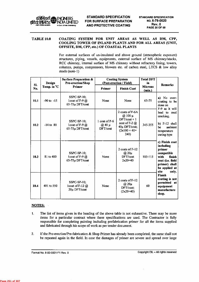
15Naega- ENGNEERSSTANDARD SPECIFICATION
5litaf talateltli INDIA LMTED FOR SURFACE PREPARATIONeRternorni IA God al Indo Undenalogl AND PROTECTIVE COATING
STANDARD SPECIFICATIONNO. 6-79-0020
Rev. 0PAGE 25 OF 59
TABLE 10.0 COATING SYSTEM FOR UNIT AREAS AS WELL AS DM, CPP,COOLING TOWER OF INLAND PLANTS AND FOR ALL AREAS (UNIT,OFFSITE, DM, CPP, etc.) OF COASTAL PLANTS
For external surfaces of un-insulated and above ground (atmospheric exposure)structures, piping, vessels, equipments, external surface of MS chimney/stacks,RCC chimney, internal surface of MS chimney without refractory lining, towers,columns, pumps, compressors, blowers etc. of carbon steel, LTCS & low alloysteels (note-1)
SI.No.
DesignTemp. in °C
Surface Preparation &Pre-erection/Shop
Primer
Coating System(Post-erection / Field)
Total DFTin
Microns(min.)
RemarksPrimer Finish Coat
10.1 -90 to -15SSPC-SP-10;
lcoat of F-9 @65-75g DFT/coat
None None 65-75No over-
coating to bedone onF 9 as it willlead to mudcracking.
temperaturecuring type
c) Finish coatincludingprimercompatiblewith finishcoat (i.e. fieldprimer) shallbe applied atsite only.Finishcoating is notpermitted atequipmentmanufactureshop.
10.2 -14 to 80SSPC-SP-I 0;
lcoat of F-9 @65-75p DFT/coat
1 coat of P-6@ 40 p
DFT/coat
2 coats of F-6A@ 100 g
DFT/coat + 1coat of F-2 @4 0p DFT/coat;(2x100 + 40=
240)
F-12 shallbe ambient
345_355
10.3 81 to 400SSPC-SP-10;
lcoat of F-9 @65-75p DFT/coat
None
2 coats of F-12@ 20p
DFT/coat2x20=40
105-115
10.4 401 to 550SSPC-SP-10;
lcoat of F-12 @20p DFT/coat
None
2 coats of F-12@ 20p
DFT/coat;(2x20=40)
60
NOTES:
The list of items given in the heading of the above table is not exhaustive. There may be moreitems for a particular contract where these specifications are used. The Contractor is fullyresponsible for completing painting including prefabrication primer for all the items suppliedand fabricated through his scope of work as per tender document.
If the Pre-erection/Pre-fabrication & Shop Primer has already been completed, the same shall notbe repeated again in the field. In case the damages of primer are severe and spread over large
Format No. 8-00-0001-F1 Rev. 0 Copyright EIL — All rights reserved
Page 251 of 307
ail-ileaENGINEERS STANDARD SPECIFICATION Eififtw INDIA LIMITED FOR SURFACE PREPARATION
imprriWREM3001411 (A GS of In& Undertalargl AND PROTECTIVE COATING
STANDARD SPECIFICATIONNO. 6-79-0020
Rev. 0PAGE 26 OF 59
areas, the engineer-in-charge may decide & advise re-blasting and priming again. Repair of pre-fabrication/pre-erection primer, if required, shall be done as per Table 7.2.
For external surface of MS chimney with or without refractory lining and for internal surfacewithout refractory lining, paint system as per 10.3 above shall be followed.
For external surface of RCC Chimney, 2 coats of F-6 @ 10012 DFT/coat to obtain total DFT of200 p. shall be applied after proper surface preparation as per guidelines in 5.1.6.
In case of paint systems as per SI. Nos. 10.3 and 10.4, the colour bands shall be applied over theAluminum paint as per the Color coding requirement for specific service of piping given inClause 19.0.
All coating system including surface preparation, primer, finish coat for piping shall be done atsite/field only.
Format No. 8-00-0001-F1 Rev. 0 Copyright EIL — All rights reserved
Page 252 of 307

OWIETte. ENONEERS STANDARD SPECIFICATION1ga fa2e3 WV INDIA LIMITED FOR SURFACE PREPARATION
Olen eiROIMMICR)A GM a/ Incia Undertalong) AND PROTECTIVE COATING
STANDARD SPECIFICATIONNO. 6-79-0020
Rev. 0PAGE 27 OF 59
TABLE 11.0 COATING SYSTEM FOR EFFLUENT TREATMENT PLANT (ETP)
SI.No.
Design Temp.in °C Surface Preparation
Coating System TotalDFT inMicrons(min.)
RemarksPrimer Finish Coat
11.1For Extemal Surfaces of C.S./M.S. items: Screens, Walk way bridges, Baffles, Dual media filters,Vertical pumps, piping in treated effluent sump, bio sludge pump, Screw pump and pump house, CStanks, sumps and vessels.
-14 to 80 SSPS-SP-101 coat of F-9@ 65-75gDFT/coat
2 coats ofF-6A @100gDFT/coat + 1
of F-2 @coat40g
DFT/coat;(2x100+40=2
40)
305-315 -
11.2 For Internal Surfaces of CS/MS Items: Bio-sludge sump, Fil er feed sump, Process sump, Sanitarysump, Transfer ump, Sludge, Slop oil tank, scrapping mechanism in Clarifier
-14 to 80 SSPS-SP-101 coat of F-9@ 65-75gDFT/coat.
3 coats ofF-6A @100g
DFT/coat(3x100=300)
365-375 Note:1
11.3 All R.C.C./concrete surfaces exposed to effluent water / liquid such as tanks, structures, drains etc. inProcess sump, TPI separator (Process and Oil), Aeration Tank and Transfer sump etc.
-14 to 80
Blast cleaning to SSPC-SPguide lines and Acidetching with 10-15% HCIacid followed by thoroughwater washing.
Epoxy Screed lining
applied as per
3mm
Epoxy screedlining shall be
specificmanufacturerand Engineer-in-Chargeinstructions
11.4 C.S/M.S Dual media filters (Internal), Chemical dosing tanks(intemal such as Di-AmmoniumPhosphate (DAP) and Urea
Up to 60 SSPC-SP-10Natural Rubber Lining(As per IS 4682, Part 1) 4.5mm
NaturalRubber lining
shall beapplied as per
specificmanufacturerand Engineer-
in-Chargeinstructions
NOTES
1. The paint /coating manufacturers shall provide their Quality control test certificate of coatingmaterials (F-6A) for immersion service of the exposed effluent given in 11.2.
Format No. 8-00-0001-F1 Rev. 0 Copyright EIL —All rights reserved
Page 253 of 307

azdZICS ENGNEERS STANDARD SPECIFICATIONOa' 111e W INDIA LIMITED FOR SURFACE PREPARATION
(02,121POIRCOMWM (A Sort el In& Undeftmg ) AND PROTECTIVE COATING
STANDARD SPECIFICATIONNO. 6-79-0020
Rev. 0PAGE 28 OF 59
TABLE 12.0 EXTERNAL COATING SYSTEMS FOR UNINSULATED CARBON STEELAND LOW ALLOY STEEL STORAGE TANKS (For all plant locations, coastalor inland)
All Process Units & Off-sites
SI.No.
Design Temp.in °C
SurfacePreparation
(Field)
Coating system (Field)(see note 1 below)
TotalDFT
inMicrons(min.)
Remarks
Primer Finish Coat
12 1'All external surfaces of shell, wind girders, appurtenances, roof tops of all above ground tank including top
.side of external and internal floating roof and associated external structural works.
12.1.1 -14 to 80 SSPC-SP-10lcoat of F-9 @ 65-75pDFT/coat + lcoat of P-6@ 40p DFT/ coat ;
2 coats of F-6A @100p DFT /coat + 1coat of F-2 @ 40pDFT/ coat;
345-355
F-6 shouldbe suitable
foroccasional
waterimmersion
12.1.2 81 to 150 SSPC-SP-101 coat of F-15 primer @80p DFT/ coat + 1 coatof F-15 intermediatecoat @ 80p DFT/coat ;
1 coat of F-15 finishcoat @80p DFT/ coat +lcoat of F-2 @ 40pDFT/ coat;
280 -
12.1.3 151 to 500 SSPC-SP-10 lcoat of F-9 @ 65-75pDFT/coat
2 coats of F-12 @20 pDFT/ coator
1 coat of F-16 @ 50 pDFT / coat
105or
115 -
12.2 External surfaces of bottom pla e (soil side) for all storage tanks.
12.2.1 -14 to 80 SSPC-SP-10 1 coat of F-9 @65-75p DFT/ coat
3 coats of F-7@ 100pDFT/coat (3x100=300)
365_375
F-7 shouldbe suitable
forimmersionservice of
theproducts
given
12.2.2 81 to 150 SSPC-SP-10
1 coat of F-15 primer @80p DFT/ coat + 1 coatof F-15 intermediatecoat @ 80p DFT/coat ;(80+80=160)
1 coat of F-15 finishcoat @ 80p DFT/ coat 240 -
12.2.3 151 to 550 SSPC-SP-10 1 coat of F-16 @ 125 pDFT /coat
1 coat of F-16 @ 125 pDFT /coat 250 -
12.3 For underside of the bottom plate (in case tank is not lifted during PWHT) (see Note 2c)
Format No. 8-00-0001-F1 Rev. 0 Copyright EIL — All rights reserved
Page 254 of 307

5Rizth ft ENGINEERS
1@U Elffleg NDIA LIMITED
leiarr FIROIMIWII IA Gut d India Undedalung)
STANDARD SPECIFICATIONFOR SURFACE PREPARATIONAND PROTECTIVE COATING
STANDARD SPECIFICATIONNO. 6-79-0020
Rev. 0PAGE 29 OF 59
For CSSSPC SP-6Commercial
Productsfrom
JOTUN or
12.3.1 -180 to 650 Blast 1 coat of inert polymericmatrix coating @ 125 u
2 coats of inertpolymeric matrixcoating @ 125 Ft
350-400
HI-TEMPcoatings or
SKFORMULA TIONS are
recommended.
For SSSSPC SP-1with non-chlochloridesolvent
NOTES
All paint coating application including primer for tankage shall be carried out at field aftererection and completion of all welding.
For underside of bottom plate :Painting shall be carried out before laying of bottom plate for tanks with Non-Post WeldHeat Treatment (PWHT).For tanks with PWHT, painting shall be carried out after PWHT.
c) In case tank is not lifted during PWHT then painting shall be applied before laying of bottomplate, clause no. 12.3.1 shall be followed.
Caution: PWHT temperature shall not exceed 650°C.
Format No. 8-00-0001-F1 Rev. 0 Copyright EIL — All rights reserved
Page 255 of 307

151fizieta ENCINEERS STANDARD SPECIFICATION
Oga tiRegs INDIA LMTED FOR SURFACE PREPARATIONINF 212(INVINMER) (A Gout of kb Undettiong) AND PROTECTIVE COATING
STANDARD SPECIFICATIONNO. 6-79-0020
Rev. 0PAGE 30 OF 59
TABLE 13.0 INTERNAL COATING SYSTEMS FOR CARBON STEEL AND LOW ALLOYSTORAGE TANKS
All Process Units & Off-sites
SI.No.
DesignTemp. in °C
SurfacePreparation
(Field)
Coating system (Field)(see note 1 below)
TotalDFT
inMicrons(min.)
Remarks
Primer Finish Coat
CRUDE OIL, ATF, TURPENTINE OIL, LUBRICAT NG OIL AND VEGETABLE OILUnderside of floating roof, internal surface of cone roof, inside of bottom plate, Internal surfaces of Shell
13.1 - including wetted and free board height, oil side surfaces of deck plates, oil side surfaces of pon oons,roof structures, structural steel, ladders and other CS internals
1 coat of F-15intermediate coat @
13.1.1 -14 to 90 SSPC-SP-10 1 coat of F-15 primer a—800 DFT/ coat 800 DFT/coat + 1 coat
of F-15 finish coat @240-300 -
80p DFT/ coat,
PETROLEUM PRODUCTS & INTERMEDIATES like LDO, HSD , GAS OIL, FEEDS ofFCC-PC, FCC-LCO, VGO-HDT, ISOM, DHDT, REFORMATE, DCU, NHT & GASOLINE,
13.2 NAPHTHA, ISOMERATE AND KEROSENE.Underside of Floating roofs, internal surface of cone roof, inside of bottom plate, internal surfaces ofBare shell for full height, underside of floating roof, oil side surfaces of deck plates, oil side surfaces ofpontoons, support structures and ladders etc.
13.2.I -14 to 45 SSPC-SP-10 I coat of F-9 @
75 0 DFT/coat - 75 Note 2
1 coat of F-15
13.2.2 46 to 90 SSPC-SP-10 1 coat of F-15 primer @
80p DFT/ coat
intermediate coat @80p DFT/coat + 1 coatof F-15 finish coat @
240-300 -
800 DFT/ coat;
13.3 POTABLE AND FIRE WATERAll internal surfaces, accessories and roof structures of Cone and Dome roof tanks
13.3.1 -14 to 60 SSPC-SP-10 1 Coats of P-6 @
100 0 DFT/coat;
2 Coats of F-6A @1000 DFT/ Coat;
(2x100=200)300-350 Note-4
13.4 DE-MINERALIZED (DM) WATERAll internal surfaces, accessories and roof structures of Cone and Dome roof tanks
13.4.1 -14 to 60 SSPC-SP-i0 1 Coats of P-6 @
1000 DFT/coat;
2 coats of F-6C @200p DFT/ coat;
(2x200=400)400-450 -
1 coat of F-15intermediate coat @
13.4.2 61 to150 SSPC-SP-10 1 coat of F-15 primer @
800 DFT/ coat800 DFT/coat + 1 coatof F-15 finish coat @ 240-300
800 DFT/ coat;(80+80=160)
13.5 HYDROCHLORIC ACID (HCI) 10 %All internal surfaces, accessories and roof structures of Cone and Dome roof tanks
13.5.1 -14 to 60 SSPC-SP-10 None Natural Rubber Lining 4.5 mm -
Format No. 8-00-0001-F1 Rev. 0 Copyright EIL - All rights reserved
Page 256 of 307

ofteiftENGINEERS STANDARD SPECIFICATIONogaiEgRegewr INDIA um-rED FOR SURFACE PREPARATION
114M MK,'"UMR0 IA GS of Undertaiong) AND PROTECTIVE COATING
STANDARD SPECIFICATIONNO. 6-79-0020
Rev. 0PAGE 31 OF 59
13.6AGGRESSWE SOLVENTS LIKE HEXANE, HEXENE, BENZENE, XYLENE AND TOLUENEAll internal surfaces, accessories and roof structures of Cone and Dome roof tanks
13.6.1 -14 to 65 SSPC-SP-10 1 coat of F-9 @ 75p
DFT/ coat --- 75
13.7 ETHYLENE GLYCOL (EG) TANKSInternal shell-full height, bottom plate, underside of roof and all accessories
13.7.1 All SSPC-SP-10 None
3 coats of vinylchloride co-polymerAMERCOAT 23 @
75p /Coat;(3x75=225)
225 -
13.8 Inside pontoon and inside of double deck of all floatingroofs13.8.
1 - 14 to 80 SSPC-SP-3 1 coat of F-8 @ 100p 1 coat of F-8 @ 100pDFT/coat DFT/coat 200
13.9 WET SLOPS, AMINE soluCons, SOUR WATER , WATER DRAW OFFAll internal surfaces, accessories and roof structures of Cone and Dome roof tanks
13.9.1 -14 to 90 SSPC-SP-]0 1 coat of F-15 primer @
80p DFT/ coat
1 coat of F-15intermediate coat @
80p DFT/coat + 1 coatof F-15 finish coat @
80p DFT/ coat;(80+80=160)
240
13.10
VACUUM RESIDUE, FUEL OIL , DRY SLOP, BITUMEN AND OTHER HIGH TEMPERATUREHYDROCARBON LIQUIDSUnderside of floating roof, internal surface of cone roof, bottom plate, inside of bare shell — includingwetted and non wetted surfaces, oil side surfaces of deck plates, oil side surfaces of pontoons, roofstructures, structural steel and ladders
13.10.1 Up to 150°C SSPC-SP-10 1 coat of F-17 primer
@ 125p DFT/ coat
1 coat of F-17intermediate coat @
125p DFT/coat + 1 coatof F-17 finish coat@125p DFT/ coat.
(125+125=250)
375 _.. N..ote:3
13.11 ALKALIS UP TO 50 % CONCENTRATIONAll internal surfaces, accessories and roof structures of Cone and Dome roof tanks
13.111 Up to 60°C SSPC-SP-10 1 coat of F-15 primer
80p DFT/ coatmer @ 2 Coats of F-6 A @
100p DFT/coat;(2x100=200)
280-100 -
NOTESI. All paint coating application including primer shall be carried out after erection and completion
of all welding work at site.
F-6A should be suitable and resistant for immersion service for the respective Hydrocarbons.
This system can be used where maximum operating temperature is below 150°C and designtemperature is upto 200°C. Cases of operating temperature > 150°C are not covered in this spec,such cases shall be covered in the job specifications.
4 F-6 A shall be suitable for drinking water service and should have competent authoritycertification.
Format No. 8-00-0001-F1 Rev. 0 Copyright EIL —All rights reserved
Page 257 of 307

ateaftINGINEERSSTANDARD SPECIFICATION
Igar fitileuW WA LIMITED FOR SURFACE PREPARATIONIiik717421191PONAZIPI) IA GM al Ma Undslasn91 AND PROTECTIVE COATING
STANDARD SPECIFICATIONNO. 6-79-0020
Rev. 0PAGE 32 OF 59
TABLE 14.0 COATING SYSTEMS FOR EXTERNAL SIDE OF UNDERGROUNDCARBON STEEL PLANT PIPING AND UNDERGROUND VESSELS
SI.No.
DesignTemp. in
°C
SurfacePreparation
&Shop Primer
Coating system (Field) Total FinalDFT
in Microns(min.)
RemarksSurfacePreparation &
min.)Finish Coat
14.1 Underground carbon steel plant piping
14.1.1 25 to 65 ---
SSPC-SP-10;
1 coat of syntheticfast drying primer25 @it DFT/ coat
I layer of coaltar tapecoating @ 2mm +1
coat of synthetic fastdrying primer 25 @u
OFT/ coat + 1 layer ofcoal tar tape coating @
2mm /layer as perEIL Standard
Specification No6-79-0011
4 mm
The primerDFT is notmeasurable.
Reconciliationprimer shallbe done bycoverage of
maximum 10sq.m/litre
14.2.1 66 to 150 ---
SSPC-SP-10;
1 coat of F-17primer @ 125u
DFT/ coat
1 coat of F-17intermediate coat @125u DFT/coat + Icoat of F-17 finish
coat @125u DFT/ coat
375 -
14.2.2 151 to 400 ---
SSPC-SP-10;
1 coat of F-I6primer @l25µ
DFT/ coat
1 coat of F-16 finishcoat @125u DFT/ coat 250 -
14.3 External side of un-insulated underground storage vessels
14.3.1 -40 to 80
SSPC-SP-10;
I coat of F-9@
65-75u DFT/coat
-- 3 coats of F-7 @ 100uDFT/coat 365-375 -
14.3.2 81 to 150
SSPC-SP-10;
1 coat of F-17primer @
125u DFT/coat
---
I coat of F-17intermediate coat @125u DFT/coat + 1coat of F-17 finishcoat @12512 DFT/ coat
375 -
143.3 151 to 400
SSPC-SP-10;
I coat of F-16primer @
125u DFT/coat
--- 1 coat of F-16 finishcoat @125u DFT/ coat 250 -
Format No. 8-00-0001-F1 Rev. 0 Copyright EIL—All rights reserved
Page 258 of 307

sfillteifitENONEERS STANDARD SPECIFICATIONazo eies INDIA utsiTED FOR SURFACE PREPARATION
IMIPWd3,0111 IA GOA d loan Undeglaan9) AND PROTECTIVE COATING
STANDARD SPECIFICATIONNO. 6-79-0020
Rev. 0PAGE 33 OF 59
TABLE 15.0
COATING UNDER INSULATION (COASTAL OR INLAND PLANTS). ALLUNITS AREAS & OFF-SITESFor insulated Piping, Equipments, Storage vessels, tanks, Columns etc of CarbonSteel, LTCS, Low Alloy Steel & Stainless Steels
SI.No.
DesignTemp. in °C
SurfacePreparation &
Pre-erection/Shop
Primer
Coating System(Post-erection / Field)
TotalFinalDFT
inMicrons(min.)
RemarksPrimer/
Intermediate Finish Coat
15.1 Carbon steel, LTCS and low Alloy steel Piping
15.1.1 -45 to 120SSPC-SP-10;
'coat of F-15 @75p DFT/coat
1 coat of F-15 @75p DFT/coat
2 coats of F-15 @75p DFT/coat;
(2x75= 150)225- 250 -
15.1.2 121-540SSPC-SP-10;
'coat of F-12 @20p DFT/coat
None2coat of F-I2 @20p DFT/coat;
(2x20=40)60 -
15.2 Carbon steel, LTCS and low Alloy steel - Storage vessels, Reactors, Columns & Equipments
15.2.1 -45 to 120SSPC-SP-10;
'coat of F-15 @75p DFT/coat
1 coat of F-15 @75p DFT/coat
2 coats of F-15 @75p DFT/coat;
(2x75= 150)225- 250 -
15.2.2 121 to 540
Temporary oilbased varnishcoating to beprovided fortransport and
storage
Thermally Sprayed Aluminium coating(TSAC)
Refer ANNEXURE-I - -
153 Stainless Stee (SS) including Alloy-20 piping (Note:2)
15.3.1 -180 to Zero
For CSSSPC SP-6
Commercial Blast 1 coat of inertpolymeric matrixcoating @ 125 p
2 coats of inertpolymeric matrixcoating @ 125 p
350-400
Products fromJOTUN or HI-
TEMP coatings orSK
FORMULATIONSare recommended.
For SSSSPC SP-1 with
non-chloridesolvent
15.3.2 0 to 125
SSPC-SP-10(15-25p surface
profile)1 coat of F-15@80 p DFT/coat
1 coat of F-15intermediate coat
@80 p DFT/coat
1 coat of F-15finish coat@ 80
p DFT/coat;240
If the piping &equipments arealready erected
then surface shallbe prepared bycleaning with
emery paper and wash/flush with
chloride free DMwater followed by
wiping withorganic solvent
15.3.3 126 to 400SSPC-SP-10
1 coat of F-16 @125 g DFT/coat
None 1 coat of F-16 @125 0 DFT/coat 250
Not recommendedfor operatingtemperature
Format No. 8-00-0001-F1 Rev. 0 Copyright EIL — All rights reserved
Page 259 of 307

laizEtha ENGINEERS STANDARD SPECIFICATIONGlga tiOtegmv INDIA UNITED FOR SURFACE PREPARATION
1011PFT 21R077 ttUatf 0 IA Govl of Yea Undetlicingi AND PROTECTIVE COATING
STANDARD SPECIFICATIONNO. 6-79-0020
Rev. 0PAGE 34 OF 59
15.3.4 401 to 600
SSPC SP-10;1 coat of
Amercoat 738@125 it DFT/coat
NoneI coat of
Amercoat 738@125 g DFT/coat
250
between60 - 120 °C
15.4 Coating system for Cyclic Service of Carbon Steel, LTCS, Low Alloy Steel & Stainless Steel
15.4.1 - 40 to 150
SSPC-SP-10(15-25g surface
profile)1 coat of F-15 @80 p DFT/coat
1 coat of F-15intermediate coat@ 80g DFT/coat
1 coat of F-15finish coat @
80m DFT/coat;240
Apcothem EPN200 of M/s Asian
Paints LtdOR
Equivalent
15.4.2 -180 to 650
For CSSSPC SP-6
Commercial Blast 1 coat of inertpolymeric matrixcoating @ 125 g
2 coats of inertpolymeric matrixcoating @ 125 g
350-400
Products fromJOTUN or HI-
TEMP coatings orSK
FORMULATIONSare recommended.
For SSSSPC SP-1 with
non-chloridesolvent
15.5 No painting is required for insulated Monel, Incoloy and Nickel lines.
NOTES
"Cyclic Service" is characterized by rapid temperature fluctuation.The blast cleaning abrasives for SS and Alloy steel surfaces shall be Aluminium oxidegrits/shots or garnet.
3. In case of overlapping of temperature ranges as mentioned in 15.4.1 and 15.4.2, clause 15.4.1shall be followed.
TABLE 16.0 COATING SYSTEM FOR CARBON STEEL COMPONENTS OF COOLERS /CONDENSERS (INTERNAL PROTECTION) FOR FRESH WATER SERVICEFresh Water boxes, channels, partition plates, end covers and tube sheets etc.
SI.No.
DesignTemp. in .C
Surface Preparation& Pre-erection/Shop
Primer
Coating System(Post-erection / Field)
TotalFinal DFTin Microns
(min.)
RemarksPrimer Finish paint
16.1 Up to 80 °C SSPC-SP-10 1 coat of F-15@ 80 microns
2 coats of F-15 @80p DFT/coat; 240
16.2 80 to 140 SSPC-SP-10
1 coat of GlassFibre ReinforcedNovolac epoxy of
1.5 mm DFT
1500 -
Format No. 8-00-0001-Fl Rev. 0 Copyright EIL - All rights reserved
Page 260 of 307

laitairiENONEERS STANDARD SPECIFICATION5fgaitameni, INDIA umiTED FOR SURFACE PREPARATION
MR" eleanSFM (A Gm 0/ India Undertiongi AND PROTECTIVE COATING
STANDARD SPECIFICATIONNO. 6-79-0020
Rev. 0PAGE 35 OF 59
TABLE 17.0 COATING SYSTEM (INTERNAL PROTECTION) FOR GALVANIZED ORNON FERROUS OR STAINLESS STEEL/ DUPLEX STAINLESS STEELCOMPONENTS OF COOLERS/ CONDENSERS FOR FRESH WATERSERVICE
SI.No.
DesignTemp. in °C
Surface Preparation& Pre-erection/Shop
Primer
Coating System(Post-erection / Field)
Total FinalDFT
in Microns(min.)
RemarksPrimer Finish paint
17.1 Up to 80 Sweep Blasting 1 coat of F-15 @80g DFT/coat;
1 coat of F-15 @80g DFT/coat; 160 -
17.2 80 to 140 Sweep Blasting ---
I coat of GlassFibre ReinforcedNovolac epoxy of
1.5 mm DFT
1500 -
18.0 STORAGE
18.1 All paints and painting materials shall be stored only in rooms to be arranged by contractorand approved by Engineer-in-charge for the purpose. All necessary precautions shall betaken to prevent fire. The storage building shall preferably be separate from adjacentbuilding. A signboard bearing the word "PAINT STORAGE - NO NAKED LIGHT -HIGHLY INFLAMABLE" shall be clearly displayed outside. Manufacturer'srecommendation shall be followed for storage of paint materials.
19.0 COLOUR CODE
The following colour coding system shall be followed. However alternate colour coding mayalso be followed as per Owner's colour coding practice/scheme.
19.1 IDENTIFICATION
The system of colour coding consists of a ground colour and secondary colour bandssuperimposed over the ground colour. The ground colour identifies the basic nature of theservice and secondary colour band over the ground colour distinguishes the particular service.The ground colour shall be applied over the entire length of the un-insulated pipes. Forinsulated lines ground colour shall be provided as per specified length and interval to identifythe basic nature of service and secondary colour bands to be painted on these specified lengthto identify the particular service. Above colour code is applicable for both unit and offsitepipelines.
Format No. 8-00-0001-F1 Rev. 0 Copyright EIL — All rights reserved
Page 261 of 307

,S RS STANDARD SPECIFICATION0?atitatuvoy INDIA LIMITED FOR SURFACE PREPARATION
Sifflirel3qtall IA Govt d Irda Undenkr9) AND PROTECTIVE COATING
STANDARD SPECIFICATIONNO. 6-79-0020
Rev. 0PAGE 36 OF 59
COLOUR CODING
SR.No.
SERVICE RECOMMNDED COLOUR FORPAINT SYSTEM
RAL COLOUR CODE
BASECOLOUR
BANDCOLOUR
HYDROCARBON LINES (UNINSULATED)
1 CRUDE SOUR Dark Admiralty grey with 1 orange band 7012 20112 CRUDE SWEET Dark Admiralty grey with I red band 7012 30013 LUBE OILS Dark Admiralty grey with 1 green band 7012 60104 FLARE LINES Heat Resistant Aluminium 90065 LPG Orange with 1 oxide red band 2011 30096 PROPYLENE Orange with 2 blue bands 2011 50137 NAPTHA Orange with 1 green band 2011 60108 M.S. Orange with 1 dark admiralty grey band 2011 70129 AV.GASOLINE (96 RON) Orange with 1 band each of green, white
and red bands2011 6010 9010 3001
10 GASOLINE (regular, leaded) Orange with 1 black band 2011 900511 GASOLINE (premium,
leaded)Orange with 1 blue band 2011 5013
12 GASOLINE (white) Orange with 1 white band 2011 901013 GASOLINE (Aviation
100/130)Orange with 1 red band 2011 3001
14 GASOLINE (Aviation115/145)
Orange with 1 purple band 2011 4006
15 N-PENTANE Orange with 2 blue bands 2011 501316 DIESEL OIL (White) Oxide red with 1 white band 3009 901017 DIESEL OIL (Black) Oxide red with 1 yellow band 3009 102318 KEROSENE Oxide red with 1 green band 3009 601019 HY.KEROSENE Oxide red with 2 green bands 3009 601020 DISUFIDE OIL (EX-
MEROX)Oxide red with 1 black band 3009 9005
21 M.T.0 Oxide red with 3 green bands 3009 601022 DHPPA Oxide red with 2 white bands 3009 901023 FLUSHING OIL Oxide red with 2 black bands 3009 900524 LAB FS Oxide red with 2 dark admiralty grey
bands3009 7012
25 LAB RS Oxide red with 3 dark admiralty greybands
3009 7012
26 LAB (Off. Spec) Oxide red with 1 light grey band 3009 703527 N-PARAFFIN Oxide red with 1-blue band 3009 501328 HEAVY ALKYLATE Oxide red with red band 3009 300129 BLOW DOWN, VAPOR
LINEOff white / Aluminum with 1-Brownband
9006 8004
30 SLOWDOWN Off white / Aluminum with 2 brownbands
9006 8004
31 A.T.F. Leaf brown with 1 white band 8003 901032 TOULENE Leaf brown with 1 yellow band 8003 102333 BENZENE Leaf brown with 1 green band 8003 601034 LAB PRODUCT Leaf brown with 1 blue band 8003 501335 FUEL OIL Black with 1 yellow band 9005 1023
Format No. 8-00-0001-F1 Rev. 0 Copyright EIL — All rights reserved
Page 262 of 307
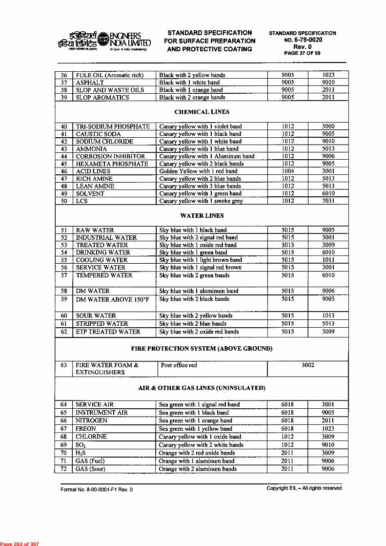
OfraeliftENGINEERS STANDARD SPECIFICATIONogeg gaituw INDIA umn-ED FOR SURFACE PREPARATION
INIMMER1101MOR0 IA GOA d India Undedakingl AND PROTECTIVE COATING
STANDARD SPECIFICATIONNO. 6-79-0020
Rev. 0PAGE 37 OF 59
36 FULE OIL (Aromatic rich) Black with 2 yellow bands 9005 102337 ASPHALT Black with 1 white band 9005 901038 SLOP AND WASTE OILS Black with 1 orange band 9005 201139 SLOP AROMATICS Black with 2 orange bands 9005 2011
CHEMICAL LINES
40 TRI-SODIUM PHOSPHATE Canary yellow with 1 violet band 1012 500041 CAUSTIC SODA Canary yellow with 1 black band 1012 900542 SODIUM CHLORIDE Canary yellow with 1 white band 1012 901043 AMMONIA Canary yellow with 1 blue band 1012 501344 CORROSION INHIBITOR Canary yellow with 1 Aluminum band 1012 900645 HEXAMETA PHOSPHATE Canary yellow with 2 black bands 1012 900546 ACID LINES Golden Yellow with 1 red band 1004 300147 RICH AMINE Canary yellow with 2 blue bands 1012 501348 LEAN AMINE Canary yellow with 3 blue bands 1012 501349 SOLVENT Canary yellow with 1 green band 1012 601050 LCS Canary yellow with 1 smoke grey 1012 7031
WATER LINES
51 RAW WATER Sky blue with 1 black band 5015 900552 INDUSTRIAL WATER Sky blue with 2 signal red band 5015 300153 TREATED WATER Sky blue with 1 oxide red band 5015 300954 DRINKING WATER Sky blue with 1 green band 5015 601055 COOLING WATER Sky blue with 1 light brown band 5015 101156 SERVICE WATER Sky blue with 1 signal red brown 5015 300157 TEMPERED WATER Sky blue with 2 green bands 5015 6010
58 DM WATER Sky blue with 1 aluminum band 5015 900659 DM WATER ABOVE 150°F Sky blue with 2 black bands 5015 9005
60 SOUR WATER Sky blue with 2 yellow bands 5015 101361 STRIPPED WATER Sky blue with 2 blue bands 5015 501362 ETP TREATED WATER Sky blue with 2 oxide red bands 5015 3009
FIRE PROTECTION SYSTEM (ABOVE GROUND)
63 FIRE WATER FOAM &EXTINGUISHERS
Post office red 3002
AIR & OTHER GAS LINES (UNINSULATED)
64 SERVICE MR Sea green with 1 signal red band 6018 300165 INSTRUMENT AIR Sea green with 1 black band 6018 900566 NITROGEN Sea green with 1 orange band 6018 201167 FREON Sea green with 1 yellow band 6018 102368 CHLORINE Canary yellow with 1 oxide band 1012 300969 SO2 Canary yellow with 2 white bands 1012 901070 H2S Orange with 2 red oxide bands 2011 300971 GAS (Fuel) Orange with 1 aluminum band 2011 900672 GAS (Sour) Orange with 2 aluminum bands 2011 9006
Format No. 8-00-0001-F1 Rev. 0 Copyright EIL —All rights reserved
Page 263 of 307

olgra14 ENGINEERS STANDARD SPECIFICATIONogatimever NA UNITED FOR SURFACE PREPARATION
1 4*Vi MeRnm agara) (AGutsneauncleilaking) AND PROTECTIVE COATING
STANDARD SPECIFICATIONNO. 6-79-0020
Rev. 0PAGE 38 OF 59
73 GAS (Sweet) Orange with 2 signal red band 2011 300174 HYDROGEN Orange with 1 light green band 2011 6021
STEAM AND CONDENSATE LINES (UNINSULATED)
75 HP STEAM Off white / Aluminum with 1 yellow band 9006 102376 MP STEAM Off white / Aluminum with 1 red band 9006 300177 MLP STEAM Off white / Aluminum with 1 orange band 9006 201178 LP STEAM Off white / Aluminum with 1 light green
band9006 6021
79 CONDENSATE Sky blue with 1 white band 5015 901080 CONDENSATE ABOVE
150°FSky blue with 3 oxide red band 5015 3009
81 BFW Sky blue with 2 red bands . 5015 3001Note: For all insulated steam lines, the colour coding shall be follow as given for un insulated lines with thespecified length of color bands.
INSULATED HYDROCARBON PIPING
82 IFO SUPPLY 1Black ground colour with 1 yellow bandin centre 102390059
83 IFO RETURN Black ground colour with 1 green band incentre
9005 6010
84 HPS Black ground colour with 1 red band incentre
9005 3001
85 BITUMEN Black ground colour with 2 red bands incentre
9005 3001
86 CLO Black ground colour with 1 brown bandin centre
9005 8004
87 VB TAR Black ground colour with 2 brown bandsin centre
9005 8004
88 VR AM (BITUMEN / VBUFEED)
1 Black ground colour with 1 blue bandin centre
9005 5013
89 VR BH 1 Black ground colour with 2 blue bandsin centre
9005 5013
90 VAC. SLOP 1 Black ground colour with 1 white bandin centre
9005 9010
91 SLOP 1 Black ground colour with 1 orange bandin centre
9005 2011
92 CRUDE SWEET 1 Dark admiralty grey ground colour with1 red band in centre
7012 3001
93 CRUDE OUR 1 Dark admiralty grey ground colour with1 orange band in centre
7012 2011
94 VGO / HCU 1 Oxide red ground colour with 2 steelgrey bands in centre
3009 7011
95 OHCU BOTOM / FCCUFEED
1 Oxide red ground colour with 2 steelgrey bands in centre
3009 7011
UNINSULATED EQUIPMENTS, TANKS AND STRUCTURES
96 HEATER STRUCTURE Steel grey 701197 HEATER CASING Heat resistant aluminium 900698 VESSELS & COLUMNS Aluminium 9006
Format No. 8-00-0001-F1 Rev. 0 Copyright EIL — All rights reserved
Page 264 of 307

15ilfraqt ENGINEERSSTANDARD SPECIFICATION
igeg Eveglief INDIA umiTED FOR SURFACE PREPARATIONINA/ 2ROWMACNI) IA Cal el India Undertaking) AND PROTECTIVE COATING
STANDARD SPECIFICATIONNO. 6-79-0020
Rev. 0PAGE 39 OF 59
99 HYDROGEN BULLETS Pink 3014100 LPG VESSELS Oxide red 3009101 SO2 VESSEL Canary yellow 1012102 HEAT EXCHANGER Heat resistant aluminium 9006103 FO TANK AND HOT
TANKSBlack 9005
104 ALL OTHER TANKS Aluminum / Off white 9006105 CAUSTIC / AMINE / ACID
TANKSGolden yellow 1004
106 SOUR WATER Sky Blue 5015107 OUTER SURFACE IN
BOILER HOUSEHeat resistant aluminum 9006
108 COMPRESSORS ANDBLOWERS
Dark admiralty grey 7012
109 PUMPS Navy blue 5014110 MOTORS & SWITCH GEAR Bluish green 5024111 HAND RAILING Signal red 3001112 STAIRCASE, LADDER
AND WALKWAYSBlack 9005
113 LOAD LIFTINGEQUIPMENT ANDMONORAILS ETC
Leaf brown 8003
114 GENERAL STRUCTURE Black 9005
PIPES AND FITTINGS OF ALLOY STEEL AND SS MATERIAL IN STORE
115 IBR Signal red 3001116 9Cr-lMo Verdigris green 6021117 5Cr-0.5Mo Satin blue 5012118 2 1 ,4Cr-1 Mo Aircraft yellow 1026119 1,,4Cr- 1/2 Mo Traffic Yellow 1023120 SS-304 Dark blue grey 5008121 SS-316 Dark violet 4005122 SS-321 Navy blue 5014
SAFETY COLOUR SCHEMES
123 DANGEROUSOBSTRUCTION
Black and alert orange band 9005 2008
124 DANGEROUS OREXPOSED PARTS OFMACHINERY
Alert orange 2008
Note: All LPG service PSVs shall be painted Deep Blue.
All drains & Vents shall be painted in Main line colour.The colour code scheme is for identification of piping service group, It consists of a groundcolour and 1 / 2 colour bands.
19.2 Ground ColourOn uninsulated pipes, the entire pipe has to be painted in ground colour., and on metal claddedinsulated lines, minimum 2M long portion should be painted.
Format No. 8-00-0001-F1 Rev. 0 Copyright EIL — All rights reserved
Page 265 of 307

el ENGNERS STANDARD SPECIFICATIONlazir faiatowNDIAumn-ED FOR SURFACE PREPARATION
7ROW ,a MOM IA God d Ada Undertaking / AND PROTECTIVE COATING
STANDARD SPECIFICATIONNO. 6-79-0020
Rev. 0PAGE 40 OF 59
19.3 Colour BandsLocation of colour bands:
At Battery LimitsIntersection points & change of direction points in pipingMidway of piping section, near valves, across culvertsAt 50 M interval on long stretch pipesAt starting and termination points.
Minimum width:
NB Width75 mmNB X 25 MMNB X 18 MMNB X 15 MM
3" and belowAbove 3" to 6"Above 6" to 12"Above 12"
II! Note:For insulated pipes, NB indicatesOD of the insulation
Sequence :Colour bands shall be arranged in sequence showing Table above and the sequence follows thedirection of flow. The width of the l st Band to 2nd band is 4:1,
!!! Note : Wherever deemed required by Process Department or Safety, pipes handling hazardoussubstances will be given hazard marking of 30 mm wide diagonal stripes of Black and Golden Yellowas per IS : 2379.
19.4 Special Camouflage Painting for Uninsulated Crude and Product Storage Tanks.
Paint specification shall be as per standards.
Camouflage painting scheme for Defense requirement in irregular patches will be applied with3 colours
Dark Green Light green Medium Brown5
3 2
The patches shall be irregular and asymmetrical and inclined at 30 to 60 Degrees.
Patches should be continuous at surface meeting lines / points.
Slits / holes shall be painted in dark green shade.
Width of patches shall be 1 to 2 meters.
19.5 Identification Markings on Equipment / Piping
Equipment tag Numbers shall be Stenciled / neatly painted using normal 'Arial' LetteringStyle on all equipment and piping (Both insulated & uninsulated) after completion of all paintworks. Lettering colour shall be either BLACK or WHITE, depending upon the background,so as to obtain good contrast.
Format No. 8-00-0001-F1 Rev. 0 Copyright EIL — All rights reserved
Page 266 of 307

02-zieLft ENGINEERS STANDARD SPECIFICATIONIgZIT gate* WA LIMITED FOR SURFACE PREPARATION
IMEAMIIInM 3AIFAI IA GoN d India Undeoliongl AND PROTECTIVE COATING
STANDARD SPECIFICATIONNO. 6-79-0020
Rev. 0PAGE 41 OF 59
Operations Group shall specify location.
Sizes shall be:Columns, Vessels, Heaters: 150 mmPumps and other M/c 50 mmPiping OD / 2 with Maximum 100 MM.Storage Tanks (As per Drawings)
19.6. Colour Coding for Control Valve
Carbon steel body - Light grey
Alloy steel body - Canary yellow
Stainless steel body - Natural
The actuator of the Control valve shall be painted as :
Direct action (open on air failure) valves - Green
Reverse acting (close on air failure 1 valves - Red
The painting Status shall be comprehensively updated every 6 months for compliance
19.7 Colour Coding for Structural & Others
SINo
Item Color
1 Pipe rack structurals Dark Admiraltry Grey2 Chequered Plate ( Both faces) Black3 Grating Black4 Ladder Rungs & Railing Vertical Posts Black5 Hand Rail, Middle rail, Toe Plate Signal Red6 Ladder Verital Posts Signal Red7 Building Structurals, Steel Columns; brackets,
beams, bracings, roof trusses, purlings, sidegirts, louvers, stringers
Dark Admiratry Grey
8 OverHead Monorail Signal Red9 Gantry Girder & Monorail Dark Green10 Monorail Stopper Plates Signal Red.11 Coke Cutting System Signal red12 EOT / HOT Cranes Canary Yellow13 Transformers, & Battery room structurals Dark Admiraltry Grey
14 Electrical Motors Dark Blue
Indicative
Copyright EIL —All rights reservedFormat No. 8-00-0001-F1 Rev. 0
Page 267 of 307

OWES ENGINEERS STANDARD SPECIFICATIONSaga €10e3W INDIA LIMITED FOR SURFACE PREPARATION
PRA panne an) IA Govt Crl hda Undertakng ) AND PROTECTIVE COATING
STANDARD SPECIFICATION
NO. 6-79-0020Rev. 0
PAGE 42 OF 59
20.0 IDENTIFICATION OF VESSELS, PIPING ETC
20.1 Equipment number shall be stencilled in black or white on each vessel, column, equipment &machinery (insulated or uninsulated) after painting. Line number in black or white shall bestencilled on all the pipe lines of more than one location as directed by Engineer-In-Charge;Size of letter printed shall be as below:
Column & Vessels 150mm (high)Pump, compressor & other machinery 50mm (high)Piping 40-150 mm
20.2 Identification of Storage Tanks
The storage tanks shall be marked as detailed in the drawing.
21.0 PAINTING FOR CIVIL DEFENCE REQUIREMENTS
21.1 Following items shall be painted for camouflaging if required by the client.All ColumnsAll tanks in OffsitesLarge VesselsSpheres
21.2 Two coats of selected finishing paint as per defense requirement shall be applied in aparticular pattern as per 20.3 and as per the instructions of Engineer-In-Charge.
21.3 Method of Camouflaging
21.3.1 Disruptive painting for camouflaging shall be done in three colours in the ratio of 5:3:2 (allmatte finish).
Dark Green Light Green Dark Medium Brown5
3 2
21.3.2 The patches should be asymmetrical and irregular.
21.3.3 The patches should be inclined at 30° to 60° to the horizontal.
21.3.4 The patches should be continuous where two surfaces meet at an angle.
21.3.5 The patches should not coincide with corners.
21.3.6 Slits and holes shall be painted in dark shades.
21.3.7 Width of patches should be 1 to 2 meters.
22.0 QUALITY CONTROL, INSPECTION AND TESTING
22.1 All painting materials including primers and thinners brought to site by contractor forapplication shall be procured directly from manufactures as per specifications and shall be
Format No. 8-00-0001-F1 Rev. 0
Copyright EIL —All rights reserved
Page 268 of 307

OPzEtt, ENGINEERS STANDARD SPECIFICATION laatuilir INDIA UMITED FOR SURFACE PREPARATION
1142710IROW WWI/ IA Gait pi India Uadettiong) AND PROTECTIVE COATING
STANDARD SPECIFICATIONNO. 6-79-0020
Rev. 0PAGE 43 OF 59
accompanied by manufacturer's test certificates. Paint formulations without certificates arenot acceptable (see section 24.0).
22.2 The contractor must produce Test Certificate from Pre Qualified Paint Manufacturer forvarious tests as detailed out in section 25.1 of this document, for each batch & for eachcategory of product. The Engineer-in-Charge shall have the right to test wet samples of paintfrom each batch at random for verifying quality of paint supplied. Contractor shall arrange tohave such tests, when called for by Engineer-in-Charge, performed at his cost any one of theindependent laboratories listed in the 25.1 of this document.
Samples for the test will be drawn at random in presence Engineer-in-Charge or hisrepresentations. Following tests to be carried out if called for by Engineer-in-Charge:
Specific Gravity- % solids by weight (% zinc content in case of inorganic or organic zinc primer)
Drying time (touch dry & full curing)- Adhesion
Flexibility- Hardness
Storage stability (pot life)
Test methods for above tests shall be as per relevant ASTM or ISO Standard.
22.3 The painting work shall be subject to inspection by Engineer-In-Charge at all times. Inparticular, following stage-wise inspection will be performed and contractor shall offer thework for inspection and approval of every stage before proceeding with the next stage. Therecord of inspection shall be maintained in the registers. Stages of inspection are as follows:
Surface preparationPrimer application
(c) Each coat of paint
During surface preparation, following tests are to be carried out:
Test for absence oil & grease after degreasing before blasting as per procedure given insec 6.7 of Annexure-I of this specification (specification for thermally sprayedAluminium Coating).Tests for surface finish of blasted surface shall be done by visual inspection using SSPC-VISI. Clear cellophane tape test as per ISO 8502-3 shall be used to confirm absence ofdust on blasted surface. Checks shall be done on each component atleast once per 200 m2of blasted surface and minimum of 3 checks per shift.Test for presence of soluble salt as per method ISO 8502-9. Maximum allowable saltcontent shall be considered 20 mg/m 2 (2 mg/cm 2). Checks shall be done on eachcomponent atleast once per 200 m2 of blasted surface and minimum of 3 checks per shift.In case salt exceeds specified limit, the contaminated surface shall be cleaned by methodas per Annexure-C of IS 12944-4 (water cleaning). After cleaning surface shall beretested for salt after drying.Blast profile measurement — This shall be done as described in sec 6.2 of Annexure-I ofthis specification (Specification for thermally sprayed Aluminium).Test for blasting Media and Blasting air- this shall be done as described in sec 6.6 ofAnnexure-I of this specification (Specification for thermally sprayed Aluminium).
Format No. 8-00-0001-F1 Rev. 0 Copyright EIL — All rights reserved
Page 269 of 307

161daelela, ENGINEERS STANDARD SPECIFICATIONOgzir tapeg w NDR
LIDFOR SURFACE PREPARATION
Mien FIRM WWI) IA Gad of Nu Uncle/01V AND PROTECTIVE COATING
STANDARD SPECIFICATIONNO. 6-79-0020
Rev. 0PAGE 44 OF 59
In addition to above, record should include type of shop primer already applied on equipmente.g. zinc silicate, or zinc rich epoxy, or zinc phosphate.
Any defect noticed during the various stages of inspection shall be rectified by the contractorto the entire satisfaction of Engineer-In-Charge before proceeding further. Irrespective of theinspection, repair and approval at intermediate stages of work, contractor shall be responsiblefor making good any defects found during final inspection/guarantee period/defect liabilityperiod as defined in general condition of contract. Dry film thickness (DFT) shall be checkedand recorded after application of each coat and extra coat of paint should be applied to make-up the DFT specified without any extra cost to owner, the extra coat should have priorapproval of Engineer-in-charge.
22.4 Primer Application
After surface preparation, the primer should be applied to cover the crevices, corners, sharpedges etc. in the presence of inspector nominated by Engineer-In-Charge.
22.5 The shades of successive coats should be slightly different in colour in order to ensureapplication of individual coats, the thickness of each coat and complete coverage should bechecked as per provision of this specification. This should be approved by Engineer-In-Charge before application of successive coats.
22.6 The contractor shall provide standard thickness measurement instrument with appropriaterange(s) for measuring.
Dry film thickness of each coat, surface profile gauge for checking of surface profile in caseof sand blasting. Holiday detectors and pinhole detector and protector whenever required forchecking in case of immersion conditions.
22.7 Prior to application of paints on surfaces of chimneys, the thickness of the individual coatshall be checked by application of each coat of same paint on M.S.test panel. The thickness ofpaint on test panels shall be determined by using gauge such as 'Elkometer'. The thickness ofeach coat shall be checked as per provision of this specification. This shall be approved byEngineer-In-Charge before application of paints on surface of chimney.
22.8 At the discretion of Engineer-In-Charge, the paint manufacturer must provide the experttechnical service at site as and when required. This service should be free of cost and withoutany obligation to the owner, as it would be in the interest of the manufacturer to ensure thatboth surface preparation and application are carried out as per their recommendations. Thecontractor is responsible to arrange the same.
22.9 Final inspection of finished coating shall consist of measurement of:Paint dry film thickness (DFT),Adhesion, and,
3) Holiday detection check as well as for finish and workmanship.
1) Coating DFT measurement shall be as per ISO 2808. Type II electromagnetic gaugesshould be used for ferrous substrates. DFT gauge calibration, number of measurement
Format No. 8-00-0001-F1 Rev. 0 Copyright EIL — M rights reserved
Page 270 of 307
agraes ENGINEERS STANDARD SPECIFICATIONazit ta5tegWV INDIA LIMITED FOR SURFACE PREPARATION
ilMwegawo (A GM of Inda Undertalcmg) AND PROTECTIVE COATING
STANDARD SPECIFICATIONNO. 6-79-0020
Rev. 0PAGE 45 OF 59
shall be as per SSPC-DA 2. Measured DFT shall be within + 10% of the dry filmthickness, specified in the specifications.
Adhesion of the primer to the steel substrate and intercoat adhesion of the subsequentcoat(s) after curing for at least a week after application of the topcoat shall be examined bya knife test in accordance with ASTM D 6677. For the knife test, if the rating is better than8, the adhesion is considered acceptable. The adhesion is destructive and tested areas shallbe repaired afterward using the spot repair procedure. Alternatively, the applicator mayperform the adhesion test on a steel coupon coated using the same surface preparation andcoating application procedure as the work piece. Adhesion testing shall be carried out foreach component at least once per 200 m2 (2000 ft2) of coated surface.
Holiday testing shall be conducted in accordance with NACE SP 0188. For immersionservices, 100% of coated area shall be inspected for holidays. For atmospheric exposure,10% of coated area which must include weld seams, corners and edges to be holidaytested. Voltage at which test is to be carried out will depend upon DFT of coating beingtested and shall be as per NACE SP 0188. Any holiday is unacceptable and should bemarked and repaired immediately.
22.10 The contractor shall arrange for spot checking of paint materials for Specific gravity, glowtime (ford cup) and spreading rate.
22.11 Final Inspection of coating system
A final inspection shall be conducted prior to the acceptance of the work. The coatingcontractor and the facility owner shall both be present and they shall sign an agreed inspectionreport. Such reports shall include:General
Names of the coating contractor and the responsible personnelDates when work was performed
Coating Materials- Information on coating materials being applied- Condition of coating materials received
Environmental Conditions- Weather and ambient conditions- Coating periods
Surface PreparationCondition of surface before preparationTools and methods used to prepare surfaceCondition of surface after preparation
Coating Application- Equipment used- Mixing procedure prior to application- Coating application techniques used
Format No. 8-00-0001-F1 Rev. 0 Copyright EIL —All rights reserved
Page 271 of 307

15i1frita ENGINEERS STANDARD SPECIFICATION
V_IF INDIA UNITED FOR SURFACE PREPARATIONle FROWCPWO (A Gpi of Irda usertakm9) AND PROTECTIVE COATING
STANDARD SPECIFICATIONNO. 6-79-0020
Rev. 0PAGE 46 OF 59
TestingType and calibration of inspection instruments usedType of quality control tests performed, and results
23.0 GUARANTEE
23.1 The contractor shall guarantee that the chemical and physical properties of paint materials usedare in accordance with the specifications contained herein/to be provided during execution ofwork.
24.0 QUALIFICATION CRITERIA OF PAINTING CONTRACTOR/SUB-CONTRACTOR
Painting contractor who is awarded any job for EL, Projects under this standard must havenecessary equipments, machinery, tools and tackles for surface preparation, paint applicationand inspection. The contractor mush have qualified, trained and experienced surfacepreparator, paint applicator, inspector and supervisors. The contractor supervisor, inspector,surface preparator and paint applicator must be conversant with the standards referred in thisspecification.
25.0 QUALIFICATION/ACCEPTANCE CRITERIA FOR PAINT COATING SYSTEM
25.1 Pre-Qualification of Paint Coating Manufacturer and his Products
Paint Coating manufacture meeting the following requirements shall be considered for supplyof their products. Contractor is advised to select coating manufacturer. Only after obtainingprequalification from EL for the manufacturer based on following requirements. Even thosemanufacturers, whose names are appearing elsewhere in the tender document, under the list of"EIL's Recommended or Approved Vendors", will also be required to meet the followingprequalification requirements.
Manufacturer should have been in continuous business of paint coating formulation andmanufacturer for at least past 5 years.
Manufacturer should posses past experience of supplying his products to hydrocarbonprocessing industry or offshore platforms in the past 5 years.
- Coating manufacturer should have supplied at least 10000 litre of an individual productto hydrocarbon processing industry or offshore platform.
The manufacturer's manufacturing procedure & QA/QC system shall meet ISO 9001requirements and preferably should posses ISO 14000 certificate.
The Quality control set up should be manned by qualified paint technologists whose biodata should be sent along with quality control organization chart.
Pre-Qualification Testing:Manufacturer should have got his products tested at least one time in last 3 years at areputed independent laboratory for the following test items. Test certificates which aremore than 3 years old will not be considered.
Format No. 8-00-0001-F1 Rev. 0 Copyright EIL — All rights reserved
Page 272 of 307

OFEET ENONEERS STANDARD SPECIFICATIONIariaffleg41, INDIA UNITED FOR SURFACE PREPARATION
iwnewa.mgarm IA Gart Inda Undertaar0 AND PROTECTIVE COATING
STANDARD SPECIFICATIONNO. 6-79-0020
Rev. 0PAGE 47 OF 59
Test Test MethodSpecific gravity ASTM D 1475Dipping properties ASTM D 823Film characteristics -Solids content by weight ASTM D 2369Drying time ASTM D 1640Flexibility ASTM D 1737/ D 522Hardness ASTM D 3363Adhesion ASTM D 2197Abrasion resistance ASTM D 968/ D 1044DFT/coat As per SSPC guidelinesStorage Stability ASTM D 1849Resistance to moisture vapour permeability for 2000 hrs ASTM D 2247Cyclic Test for the duration of 4200 h (25 cycles a 168hours)
ISO 7253, ASTM G53
% Zn in Dry film for Inorganic ZincSilicate primer
-
Chemical Resistance test- 10% & 40% NaOH (applicable only for F-6 & F-15)- 10% H2SO4 (applicable only for F-6 & F-15)- 10 % Nitric Acid test (applicable only for F-6 & F-15)- Benzene / Toluene (applicable only for F-6 & F-15)- Kerosene (applicable only for F-6 & F-15)- Sea water (applicable only for F-6 & F-15)- MIBK test (applicable only for F-6 & F-15)
ASTM D 543
Resistance to water using water immersion (applicableonly for F6-, F-7, F-8, F-14 & F-15)
ASTM D 870
Dry Heat Resistance test(applicable only for F-9, F-6A/B, F-2, F-15, F-16,polysiloxane, heat resistance Al silicone)Thermal shock resistance test(only for F-9, F-6, polysiloxane)
ASTM D2485 - 91
Each coating product to be qualified shall be identified by the following
An infrared scan (fingerprint), for Part A and B, each component as per ASTMD 2621
Specific gravity of Base and curing agent (Ref. ISO 2811)3) Ash content (ASTM D1650), volatile and non-volatile matters (ISO 3251) of each
component
The identification shall be carried out on the batch, which is used for the Pre-qualification testing. Pre-qualification of the products shall be carried out at anindependent laboratory.
Test shall be carried out at any one of the following laboratories and tests to be witnessed &certified by third party inspection agency (TUV, BV, DNV).
Format No. 8-00-0001-F1 Rev. 0 Copyright EIL —All rights reserved
Page 273 of 307

000:eftENGINEERS STANDARD SPECIFICATIONsiges eg W: WA LIMITED FOR SURFACE PREPARATION
men eeteRtel3AARI (A God d( Undell/A1A) AND PROTECTIVE COATING
STANDARD SPECIFICATIONNO. 6-79-0020
Rev. 0PAGE 48 OF 59
IICT, HyderabadHBTI, KanpurDMSRDE, KanpurBIS LaboratoriesUICT, Matunga, MumbaiRITES, KolkataPDIL, SindriNTH, Kolkata
Contractor shall furnish to EIL for approval/ acceptance of all necessarydocuments/information including test certificates to prove that the paint manufacturers, fromwhom he intends to procure paint products, meet the various requirements for fulfilling thepre-qualification criteria as given under section 25.1 above. The paint manufacturer shall bequalified and approved for supply after review/assessment of the submission made by thecontractor.
25.2 Information to be furnished during delivery of coating system:
Contractor along with delivery of paint material has to furnish following information frompaint manufacturer to EIL for acceptance/approval of products.
Batch test certificates (Batch Testing)
Along with delivery to site of the paint products from pre-qualified coating manufacturer.Contractor has to produce test certificate from paint manufacturer for each batch and foreach category of product for the following test items. Test to be witnessed & certifiedby third party inspection agency. All test results must mention clearly the batch no. andcategory of product tested. Tests to be conducted for following properties:
Infrared scan for Part A and B, each component- Specific Gravity- % solids by weight (% zinc content in case of inorganic or organic zinc primer)
Product information sheet/ technical data sheet for each category of product.
26.0 METHOD OF SAMPLING & DISPATCH FOR LABORATORY TESTING(Pre-Qualification tests (sec. 25.1), Batch testing (sec. 25.2) and Inspection testing (sec.22.0))
26.1 Samples of coating materials should be submitted to the Govt. laboratory in sealed containerswith batch no. and test certificate on regular format of manufacturer's testing laboratory. Thesampling shall be certified and sealed by a certifying agency.
26.2 All test panels should be prepared by Govt. testing agency coloured photographs of testpanels should be taken before and after the test and should be enclosed along with test report.
Sample batch no. and manufacturer's test certificate should be enclosed along with thereport. Test report must contain details of observation and rusting if any, as per the testingcode.
Format No. 8-00-0001-F1 Rev. 0 Copyright EIL — All rights reserved
Page 274 of 307
Oftieta ENGINEERS STANDARD SPECIFICATIONTif Ell5leg4TV WA LIMITED FOR SURFACE PREPARATIONMien a21017 ./L7RIM IA GM of India Undeddimal AND PROTECTIVE COATING
STANDARD SPECIFICATION
NO. 6-79-0020Rev. 0
PAGE 49 OF 59
26.3 Manufacturers should intimate the company, details of sample submitted for testing, name ofGovt. testing agency, date, contact personnel of the govt. testing agency. At the end of thetest the manufacturer should submit the test reports to the company for approval.
26.4 Coating systems for panel test shall be decided after discussion with EIL
Format No. 8-00-0001-F1 Rev. 0
Copyright EIL — All rights reserved
Page 275 of 307

151Rat ENGINEERS STANDARD SPECIFICATION11;471E1071ft%, INDIA LIMITED FOR SURFACE PREPARATION
MM.'MOWS° IA GM India Underlimg ) AND PROTECTIVE COATING
STANDARD SPECIFICATIONNO. 6-79-0020
Rev. 0PAGE 50 OF 59
ANNEXURE-I
SPECIFICATION FOR THERMALLY SPRAYED ALUMINIUM (TSA) COATING
1.0 SCOPE
The following sections outlines the requirement of supply, application and testing of thermallysprayed aluminum coatings (TSAC) for corrosion protection of insulated carbon steel pipingand equipments with design temperature not exceeding 540 ° C.
2.0 ITEMS TO BE THERMALLY SPRAYED
Steel Structures/equipments to be protected by TSAC shall be as per Tables 15.0 of thisstandard specification. Structures, components thermally sprayed shall not have any uncoatedarea or shall not be in mechanically connected by flanges etc to any uncoated bare steel work.Such adjacent areas to TSA coated areas, if not coated by TSA shall have suitable paintcoating system as per the standard specification.
3.0 TSAC REQUIREMENTS
3.1 Surface Preparation
All the parts to be sprayed shall be degreased according to SSPC-SP 1. The absence of oil andgrease after degreasing shall be tested by method given elsewhere in the specification (ReferSec. 6.7). Thereafter the surface to be abrasive blasted to white metal finish as per NACE1/SSPC-SP 5 for marine and immersion service. Using SSPC VIS 1, it is to be visuallyassessed that the blast cleaned surface meets requirement of SSPC-SP 5. Thereafter clearcellophane tape test as per ISO 8502-3 shall be used to confirm absence of dust on the blastedsurface Finally blasted surface shall be tested for presence of soluble salts as per method ISO8502-9. Maximum allowable salt content shall be considered 50mg/m 2 . (5 micrograms/cm2).In case salt content exceeds specified limit. The contaminated surface shall be cleaned bymethod as per Annex C of IS 12944-4 (Water Cleaning). After cleaning the surface shall beretested for salt content after drying. Testing shall be carried out at least on each component,once per 200 m2 and a min of 3 times per shift during progress of work.
The blasting media shall be either chilled iron or angular steel grit as per SSPC-AB-3 of meshsize G-16 to G-40. Copper, Nickel slag, Garnet or Aluminum Oxide as abrasives will also besuitable having mesh size in the range of G16 to G24 (10-30 mesh), conforming to SSPC-AB-1. Mesh size shall be required as appropriate to the anchor tooth depth profile requirement andblasting equipment used. The blasted surface should be having angular profile depth not lessthan 65 microns with sharp angular shape but shall not exceed 85 microns. The profile depthshall be measured according to NACE standard RP 0287 (Replica Tape) or ASTM D 4417method B (Profile depth gauge).
For manual blasting one profile depth measurement shall be taken every 10-20 m 2 of blastedsurface.
Surface preparation shall be completed in one abrasive blast cleaning operation whereverpossible.
Format No. 8-00-0001-F1 Rev. 0 Copyright EIL — All rights reserved
Page 276 of 307

agraift ENGINEERS STANDARD SPECIFICATION$1g a fifReall INDIA UNITED FOR SURFACE PREPARATION
(NMI MIRMIARI/ (A Gout al lita Underlakin3) AND PROTECTIVE COATING
STANDARD SPECIFICATIONNO. 6-79-0020
Rev. 0PAGE 51 OF 59
If rust bloom (visual appearance of rust) appears on the blast cleaned surface before thermalspraying, the affected area shall be reblasted to achieve specified degree of cleanliness afterwhich only thermal spraying shall commence.
Air blasting pressure at nozzle shall be normally maintained at 100 psi. Air pressure andmedia size should be reduced and adjusted to preclude damage/distortion to thin gaugematerials. Blasting time on work piece should be adjusted to only clean the surface and cutrequired anchor tooth with minimum loss of metal. Blast angle should be as close toperpendicular as possible but in no case greater than ± 30 ° from perpendicular to worksurface. Blasting media must be free of debris, excessive fines, and contaminants such asNaCI and sulfur salts (Ref. SEC 6.0 of this Spec). Blast cleaning shall not be performed whenthe surfaces to be blasted are wet or less than 5°C above dew point temperature or when therelative humidity in the vicnicity of the work is greater than 90%.
3.1.1 Blasting Equipment
The TSAC applicator shall use mechanical (centrifugal wheel) or pressure pot blast cleaningequipment and procedures. Suction blasting equipment shall not be used. Sec 6.6.2 shall beused to validate clean and dry air.
3.1.2 Feed Stock
The feed stock shall be in the form of wire. The feed stock shall be 99.5% aluminum ofcommercial purity grade, its composition shall be in accordance with requirement of BS 1475or ASTM B833 or ISO 209-1 type Al (wrought aluminum and aluminum alloys, wire). Wireshall be supplied in protective wrapping indicating batch number and other details.
3.1.3 Thickness Requirement
The nominal thickness of finished TSAC shall be 250 microns having minimum value of 225microns at low thickness areas (valleys) and not more than 275 microns at peak areas.
The finished thickness shall be measured using SSPC-PA 2 type 2 fixed probe gauge(Magnetic Gauge).
3.1.4 Coating Bond Strength Requirement
The TSAC coating shall have a minimum individual tensile-bond strength value of 1000 psifor flame sprayed and 1500 psi for arc sprayed coating with an average of 2000 psi for arcsprayed coatings. Minimum tensile bond strength should be achieved by proper anchor toothprofile of blasted surface, laying down the TSA thickness in multiple passes and carrying outTSA application under controlled environment
3.1.5 Porosity
All thermally sprayed metallic coatings will have porosity. For thermally sprayed aluminumcoatings porosity shall not exceed 15% of total surface area for flame sprayed coating and 8%for arc spray coating.
Format No. 8-00-0001-F1 Rev. 0 Copyright EIL — All rights reserved
Page 277 of 307

lafteleENIONEERS STANDARD SPECIFICATIONes iiptew INDIA umn-ED FOR SURFACE PREPARATION(MRPI FRaRVINJWMil IA GO. Dna Wean) AND PROTECTIVE COATING
STANDARD SPECIFICATIONNO. 6-79-0020
Rev. 0PAGE 52 OF 59
4.0 THERMAL SPRAY APPLICATION PROCEDURE
Items in the atmospheric zone to be coated by TSA shall be applied by either Flamespray or Arc spray method only. For coating under insulation, application shall be byarc wire method.
4.1 Equipment Set Up
4.1.1 Thermal spray equipment shall be set up calibrated, operated (1) according to manufacturerinstructions/technical manuals and also TSAC applicators refinement thereto and (2) asvalidated by Procedure Qualification (Sec 7.0 of this specification).
4.1.2 Spray Parameters
Spray parameters (see 4.1.3 below) and thickness of each crossing pass shall be set and shallbe validated with bend test (See 6.5 of this Spec).
4.1.3 Spray Parameters
Spray Parameters Method of Application
Arc voltageArc wire Spray Flame Wire Spray
27 V -Air pressure 80 psi 80 psi
Steel surface cleanliness NACE-1 white metal NACE-1 white metal /or Near white metal
Steel surface profile 75 microns (minimum) 75 microns (min.)Arc current 250-280A -
Coating thickness 225 microns (nominal) 225 microns(Nominal)Coating adhesion > 1500 psi (Total coating),see 3.1.4 >1000 psiCoating porosity Less than 8% Less than 15%.
Spray distance (spray Gunwork piece) 6-8" 5-7"
Spray Pass width 40mm 20 mm
The above parameters to be validated with a bend test by the contractor before start of work(for details of bend test see Sec 6.5 of this Spec).
4.2 Post Blasting Substrate Condition and Thermal Spraying Period.
4.2.1 The steel surface temperature shall be at least 5°C above dew point of ambient air temperature.
Steel substrate surface temperature shall be recorded by with a contact pyrometer.Thermal spraying should commence within 15 minutes from the time of completion of blasting
4.2.2 Holding Period
Time between the completion of final anchor tooth blasting and completion of thermalspraying of blasted surface should be no more than four hours. If within this period rust bloomappears Sec 4.4.1of this specification will apply.
Format No. 8-00.0001-F1 Rev. 0 Copyright EIL — All rights reserved
Page 278 of 307

azdzieft ENGINEERS STANDARD SPECIFICATION1&11€151erilV INDIA LIMITED FOR SURFACE PREPARATION
imerreRaRtitM11711 IA Gat al InCia UNIeltaking) AND PROTECTIVE COATING
STANDARD SPECIFICATIONNO. 6-79-0020
Rev. 0PAGE 53 OF 59
4.3 Pre-Heating
For flame spraying, the initial starting area of 1-2 square feet to be preheated to approx.120°Cto prevent condensation of moisture in the flame on the substrate. For arc spraying thepreheating is not required.
4.4 Thermal Spraying
Spraying should commence only after validation of equipment set up by procedurequalification test and spray parameter validation tests described in Sec 7.0 and 6.5respectively. Thermal spraying must commence within 15 minutes from the time ofcompletion of blast cleaning
The specified coating thickness shall be applied in several crossing passes. The coating bondstrength is greater when the spray passes are kept thin. Laying down an excessively thick spraypass increases the internal stresses in TSAC and decreases the bond strength of total TSAC.The suitable thickness for crossing passes shall be determined by procedure qualification testdescribed in Sec 7.0 of this specification.
For manual spraying, spraying to be done in perpendicular crossing passes to minimize thinspots in coating. Approx. 75-100 microns of TSAC shall be laid down in each pass.
The surface geometry of the item or area to be sprayed should be inspected before application.The spraying pass and sequence shall be planned according to following.
Maintain Gun as close to perpendicular as possible and within ± 30° from perpendicular tothe substrate.Maintain nominal standoff distance and spray pass width as given below:
Spray method Standoff (Inches) Spray pass width(Inches)
Arc Wire 6-8 1 'A( 40mm )Flame wire 5-7 %( 20mm )
4.4.1 Rust Bloom (Visual appearance of rust or Discoloration)
If Rust bloom appears on the blasted surface before thermal spraying, the affected area shall bereblasted to achieve the specified level of cleanliness.
If Rust bloom in form of discoloration, or any blistering or a degraded coating appears at anytime during application of TSAC, then spraying shall be stopped and acceptable sprayed areashall be marked off. The unsatisfactory areas shall be repaired to the required degree of surfacecleanliness and profile.
Blast the edges of the TSAC to provide for 2-3" feathered area overlap of the new work intoexisting TSAC.
Then apply TSAC to the newly prepared surfaces and overlap the existing TSAC to the extentof feathered edge so that overlap is a consistent thickness.
Format No. 8-00-0001-F1 Rev. 0 Copyright Ell. —AI rights reserved
Page 279 of 307

latazidie ENGINEERS STANDARD SPECIFICATIONsigtaReW INDIA LIMITED FOR SURFACE PREPARATION
2174WZAJWIRD (A Go..4 Inda Undedalungl AND PROTECTIVE COATING
STANDARD SPECIFICATIONNO. 6-79-0020
Rev. 0PAGE 54 OF 59
4.4.2 Masking
Masking all those parts and surfaces which are not required to be thermally sprayed asinstructed by purchaser should be inspected by applicator to ensure that they are properlymarked and covered by purchaser.
Complex geometries (flanges, valve manifolds, intersections) shall be masked by applicator tominimize overspray i.e. TSAC applied outside spray parameters (primarily gun to substratedistance and spray angle).
4.4.3 TSAC Finish
The deposited TSAC shall be uniform without blisters, cracks, loose particles, or exposed steelas examined with 10 X magnification.
5.0 SEALER
Sealant shall be applied after satisfactory application of TSAC and completion of all testingand measurements of the finished TSAC as per Sec 6.0 of this specification.
For shop workSealer shall be applied immediately after thermal spraying and for field worksealer shall be applied within 8 hours. The sealcoat shall be thin enough to penetrate into thebody of TSAC.
The sealant shall be Silicone Alkyd Aluminium paint having DFT not more than 35-40 micron.Typically seal coat shall be applied at a spreading rate resulting in theoretical 38 microns DFT.The seal coat shall be applied in accordance with SSPC-PA 1 and the paint manufacturerinstruction for sealing.
6.0 TESTING AND MEASUREMENT SCHEDULE
6.1 Surface Finish
That the blasted cleaned surface meets the required criteria (NACE 1/SSPC-SP 5) shall bevisually inspected using SSPC-VIS 1. The clear cellophane-tape test as per ISO 8502-3 shallbe used to confirm absence of dust or foreign debris on the cleaned surface. Checks shall bedone on each component at least once per 200 m2 of blasted surface and minimum of 3 checksper shift.
6.2 Blast Profile Measurement: (In-Process testing during actual production before applicationof TSA coating)
The angular profile depth measurement shall be done by profile tape as per method NACEStandard RP 0287 or ASTM D 4417 method B (Profile depth gauge micrometer). Spotmeasurement shall be carried out every 15m2 of blasted surface. At each spot threemeasurements shall be taken over an area of 10 cm 2 and average of measurements to berecorded and reported.If profile is <65 microns blasting shall continue till grater than 65 microns depth profile isachieved.
Format No. 8-00-0001-F1 Rev. 0 Copyright EIL —All rights reserved
Page 280 of 307

Oftela ENGINEERS STANDARD SPECIFICATIONfelliteCe INDIA LIMITED FOR SURFACE PREPARATION
awn maw nem) (A Gem al inda Underlikog AND PROTECTIVE COATING
STANDARD SPECIFICATIONNO. 6-79-0020
Rev. 0PAGE 55 OF 59
6.3 TSAC Thickness (In-Process Testing For finished coating during regular production)
6.3.1 TSAC finished thickness shall be measured using SSPC-PA 2 type 2 fixed probe gauge.
6.3.2 For flat surfaces, measurements shall be taken along a straight measurement line, onemeasurement line for every 15 m2 of applied TSAC shall be selected along which 5measurements to be taken at 25 mm internal and average to be reported.
6.3.3 For curved surface or complex geometry, 5 measurements shall be taken at a spot measuring10 cm2 in area. One spot to be taken for every 15 m2 of applied TSAC area.
6.3.4 The TSAC thickness in surface changes or contour changes, welds and attachments shall bealso measured and reported.
6.3.5 If TSAC is less than specified minimum thickness, apply additional TSAC until specifiedthickness range is achieved.
6.3.6 All locations and values of TSAC thickness measurements shall be recorded in Job Record(JR).
6.4 Tensile Bond Testing (In-Process testing for finished coating during regular production)
Tensile Bond strength of the TSAC finish coat shall be determined according toASTM D 4541 using a self-aligning adhesion tester.
One measurement shall be made every 50 m2. If tensile bond at any individual spotis less than 1000 psi for flame sprayed coating and 1500 psi for arc sprayed coatingthe degraded TSAC shall completely removed and reapplied.
The tensile bond portable test instrument to be calibrated according to ASTM C 633
6.5 Bend Tests
Bend test shall be carried out at beginning of each work shift. Bend tests shall also beconducted on sample coupons before start of thermal spraying work to qualify the following asmentioned earlier in this specification.
To qualify spray parameters and thickness of each crossing pass.
6.5.1 Test Procedure
Five corrosion control steel coupons each of dimension 50 mm x 150 mm x 1.3 mmthk. to be prepared.
Surface shall be prepared by dry abrasive blast cleaning as per this specification.
TSAC shall be applied as per specified thickness range. TSAC should be sprayed incrossing passes laying down approx. 75-100 microns in each pass.
TSAC applied coupons shall be bent 180 ° around a 13 mm diameter mandrel.
Format No. 8-00-0001-F1 Rev. 0 Copyright EIL —All rights reserved
Page 281 of 307

g,,ENGINEERS(gale tiregw INDIA LMTED
STANDARDSTANDARD SPECIFICATIONFOR SURFACE PREPARATION
STANDARD SPECIFICATIONNO. 6-79-0020
Rev. 01411MeRePWW) IA Govt al India Undertiong) AND PROTECTIVE COATINGPAGE 56 OF 59
e) Bend test shall be considered passed if on bend radius there is
- No cracking or spalling or lifting by a knife blade from the substrate- Only minor cracking that cannot be lifted from substrate with a knife blade.
Bend test fails if coating cracks with lifting from substrate.
6.6 Tests for blasting media, blasting air
6.6.1 Blasting Media (For every fresh batch of media and one random test during blasting)
Blasting Media shall be visually inspected for absence of contamination and debris using 10 Xmagnification.
Inspection for the absence of oil contamination shall be conducted using followingprocedure :
Fill a small clean 200 ml bottle half full of abrasive.
Fill the bottle with potable water, cap and shake the bottle.
Inspect water for oil film/slick. If present, the blasting media is not to be used.
Soluble salt contamination if suspected shall be verified by method ASTM D 4940. Ifpresent, media to be replaced.
c) Clean blasting equipment, especially pot and hoses, and then replace blasting mediaand retest.
6.6.2 Test for Blasting Air (Once Daily before start of blasting and once at random during blasting)
The air for blasting shall be free from moisture and oil. The compressor air shall be checkedfor oil and water contamination per ASTM D 4285.
6.7 Test for presence of oil/grease and contamination
The steel substrate after degreasing as per SSPC-SP 1 shall be tested as per followingprocedure to validate absence of oil and grease contamination.
Visual inspection - Continue degreasing until all visible signs of contamination are removed.Conduct a solvent evaporation test by applying several drops or a small splash of residue-freetrichloromethane on the suspect area especially pitting, crevice corrosion areas or depressedareas. An evaporation ring formation is indicative of oil and grease contamination.Continue degreasing and inspection till test is passed.
7.0 TSAC APPLICATOR QUALIFICATION
Following tests to be carried out as part of procedure qualification test for the applicator.Thickness measurementCoating bond strengthPorosity test
Format No. 8-00-0001-F1 Rev. 0 Copyright EIL —All rights reserved
Page 282 of 307

loirif&JelitENIGINERS STANDARD SPECIFICATIONgtIf WegNEW INDIA LIMITED FOR SURFACE PREPARATION
MDR [111,3M11/ IA Gael d hdia Underlain)) AND PROTECTIVE COATING
STANDARD SPECIFICATIONNO. 6-79-0020
Rev. 0PAGE 57 OF 59
Bend strength
TSAC applicator's surface finishing and application process and equipment set up, calibrationand operation shall be qualified by application of TSA on a reference sample which shall beused as a comparator to evaluate the suitability of application process. Only that applicator willbe permitted to carry out the work when test specimens coated by the applicator meets thedesired requirements as cited below.
The sample shall be made of a steel plate measuring approx. 18"x 18" x Vo" thick. If the actualwork is less than 1/4" thick then the sample to be made from material of representativethickness.
The surface preparation, TSAC application shall be made with actual field equipments andprocess/spray parameters and procedures as per the specification. The depth profile of blastedsurface, TSAC coating thickness for each cross pass and total thickness range shall be as perspecification.
The surface preparation and thermal spraying shall be carried out in representativeenvironmental conditions spraying with makeshift enclosure.
7.1 After application of coating, thickness and tensile bond measurements shall be made infollowing manner.
Divide the sample piece into four quadrants.
Measure thickness along the diagonal line of each quadrant.
Four each quadrant five in-line thickness measurements at 1" interval shall be doneusing SSPC -PA 2 type 2 fixed probe gauge. Thus a total of four "five in line"thickness measurements to be done for the whole sample.
One tensile bond measurement using ASTM D 4541 type III or IV portable selfaligning test instrument to be done at centre of each quadrant. Total of 4 measurementsfor the sample.
One porosity evaluation test by Metallographic examination shall be conducted todemonstrate the achievement of porosity within the limits specified. Sample shall beprepared for Metallographic examination as per ASTM E — 3.
The procedure shall be considered qualified if thickness and tensile-bond strength andporosity values meet the specification requirement.
7.2 Bend test: Bend test shall be carried out as detailed at sec. 6.5 of this specification.
Applicators thermal spray equipment set-up, operation and procedure of application includingin-process QC checkpoints adopted during procedure qualification as described above shouldbe always subsequently followed during entire duration of work.
8.0 DOCUMENTATION
The following information shall be provided by TSAC applicator before award of work.
Format No. 8-00-0001-F1 Rev. 0 Copyright EIL — All rights reserved
Page 283 of 307

SfilOze ift ENONEERS STANDARD SPECIFICATIONligaf 215leg ire INDIA WAITED FOR SURFACE PREPARATION
1411PMFIRFROMPI) IA &vet Incha Undertaang/ AND PROTECTIVE COATING
STANDARD SPECIFICATIONNO. 6-79-0020
Rev. 0PAGE 58 OF 59
TSAC application process consisting of equipment capabilities and their technicalparameters, feed stock material and source of procurement.
Detailed application procedure and in-process quality control check points for (a)surface preparation (b) thermal spraying (c) seal coats.
Type and specification of instruments to be deployed for measurement of blast profiledepth, TSAC thickness and tensile bond.
Paint manufacturer data sheet for the selected sealing coat to be applied.
9.0 RECORDS
The TSAC applicator shall maintain job record to record production and QCinformation. All the results of the tests and quality control checks shall be entered inthe record for each component/part thermally sprayed. All the result of tests(thickness, tensile bond, bend tests) and other validation tests (e.g. procedurequalification test, test for surface cleanliness after abrasive blasting, test forcleanliness of abrasives and air) shall also be recorded and duly signed by owner.
All the information mentioned in Sec 8.0 above should also form part of the Jobrecord.
Any modification affected after procedure qualification in the procedure, QC, sprayparameter, equipment spec to the original information (submitted before award of thework) must also form part of Job record.
10.0 WARRANTY
The TSAC applicator shall warrant the quality of material used by providing the purchaserwith a certificate of materials used to include
Spray feed stock: Alloy type/designation, Lot Number, wire diameter, chemicalanalysis, name of supplier, manufacturer.
Sealant: Name of manufacturer, application data sheet.
11.0 SAFETY
The TSAC applicator shall follow all safety procedures required by the purchaser/owner.Owner shall also give compliance requirement to be followed by applicator. The applicatorshall follow all appropriate regulatory requirements.
12.0 CODES AND STANDARDS
This specification shall apply in case of conflict between specification and followingapplicable standards:
Format No. 8-00-0001-F1 Rev. 0 Copyright EIL — All rights reserved
Page 284 of 307

(3ti1tael4t ENGINEERS STANDARD SPECIFICATION5gaia2egwiNDIA umn-ED FOR SURFACE PREPARATION
Wen FRa W ',AMER) IA Govi al India Undeltalangl AND PROTECTIVE COATING
STANDARD SPECIFICATIONNO. 6-79-0020
Rev. 0PAGE 59 OF 59
AWS C. 2.17 Recommended Practice for Electric arc Spray.ASTM C 633 Test Method for Adhesive/Cohesive Strength of Flame Sprayed Coatings.
ASTM D 4285 Method for indicating Oil or Water in Compressed Air.ASTM D 4417 Test Method for Field Measurement of Surface Profile of Blasted Steel.
BS 2569 Specification for Sprayed Metal Coating.NACE Standard RP
0287Field Measurement of Surface Profile of Abrasive Blast Cleaned SteelSurfaces Using a Replica Tape.
ASTM D 4541Test method for Pull-Off Strength of Coating Using Portable AdhesionTesters.
ANSI/AWS C2.18Guide for the Protection of Steel with Thermal Spray Coatings ofAluminum, Zinc and Their Alloys and Composites.
NACE No. 12/AWSC2.23M/SSPC-CS
23.00
Specification for the application of thermal spray coatings (Metallizing) ofaluminum, zinc, and their alloys and composites for the corrosionprotection of steel.
SSPC Publication The inspection of coatings and linings: A Handbook of Basic practice forInspectors, Owners, and Specifiers.
SSPC-AB 1 Mineral and Slag Abrasives.SSPC-AB 3 Ferrous Metallic Abrasives.SSPC-PA 1 Shop, Field, and Maintenance Painting of Steel.SSPC-PA 2 Measurement of Dry Coating Thickness with Magnetic Gages.
NACE No. 1/SSPC-SP 5
White Metal Blast Cleaning.
NACE No. 2/SSPC-SP 10
Near —White Metal Blast Cleaning.
SSPC-VIS 1Guide and Reference Photographs for Steel Surfaces Prepared by DryAbrasive Blast Cleaning.
Copyright EIL —All rights reservedFormat No. 8-00-0001-F1 Rev. 0
Page 285 of 307
QMSStandardsCommittee
1 12.03.15 General Revision
QMS
QMS0 04.06.09 Issued as Standard Specification
Standards
Standards SCT
NDCommittee
Committee
Rev.No Date Purpose Prepared by Checked
by
StandardsCommitteeConvener
StandardsBureau
Chairman
QMSStandardsCommittee
MPJ
SC
ENGINEERSlakgINDIA LIMITED
(A Gavt at India Undertaking)
SPECIFICATION FOR QUALITYMANAGEMENT SYSTEMREQUIREMENTS FROM
BIDDERS
STANDARD SPECIFICATION No.
6-78-0001 Rev. 1Page 1 of 7
mren ewaire mjvam)
64)(11 Chrlf qu i ciall -51-04ffu tea aliikrrat t ?drift'
SPECIFICATION FOR QUALITYMANAGEMENT SYSTEM
REQUIREMENTS FROM BIDDERS
Approved by
Format No. 8-00-0001-F1 Rev. 0
Copyright EIL — All rights reserved
Page 286 of 307

ENGINEERS SPECIFICATION FOR QUALITY STANDARD SPECIFICATION No.
INDIA LIMITED SYSTEM 6-78-0001 Rev. 1lft2 (AG'"ind'Undelt6ung) REQUIREMENTS FROM BIDDERS Page 2 of 7
Abbreviations:
CV Curriculum Vitae
ISO International Organization for Standardization
MR Material Requisition
PO Purchase Order
PR Purchase Requisition
QA Quality Assurance
QMS Quality Management System
QMS Standards Committee
Convener: Mr. M.P. Jain
Members: Mr. A.K. Chaudhary (Insp.)Mr. S.K. Kaul (C&P)Mr. R.K. Trivedi (Engg.)Mr. Ravindra Kumar (Const.)Mr. Tilak Raj (Projects)Mr. Vinod Kumar (CQA)
Format No. 8-00-0001-F1 Rev. 0 Copyright EIL — All rights reserved
Page 287 of 307

ENGINEERS SPECIFICATION FOR QUALITY STANDARD SPECIFICATION No.
INDIA LIMITED SYSTEM 6-78-0001 Rev.'A
Govt At ' nth' Und"k"V) REQUIREMENTS FROM BIDDERS Page 3 of 7Igar llks
Oiren
CONTENTS
Clause Title Page
No.
1.0 SCOPE 4
2.0 DEFINITIONS 4
3.0 REFERENCE DOCUMENTS 4
4.0 QUALITY MANAGEMENT SYSTEM — GENERAL 4
5.0 QUALITY SYSTEM REQUIREMENTS 4
6.0 AUDITS 7
7.0 DOCUMENTATION REQUIREMENTS 7
Copyright EIL — All rights reservedFormat No. 8-00-0001-F1 Rev. 0
Page 288 of 307

el ENGINEERS SPECIFICATION FOR QUALITY STANDARD SPECIFICATION No.
$1g-zg faReg INDIA LIMITED MANAGEMENT SYSTEM 6-78-0001 Rev. 1
own 120.2 .I J40.9) IA GOVt of India Undertaking) REQUIREMENTS FROM BIDDERS Page 4 of 7
1.0 SCOPE
This specification establishes the Quality Management System requirements to bemet by BIDDER for following purpose:
• QMS requirements to be met by suppliers/contractors after award of work/during contract execution.
2.0 DEFINITIONS
2.1 Bidder
For the purpose of this specification, the word "BIDDER" means the person(s), firm,company or organization who is under the process of being contracted by EIL /Owner for delivery of some products (including service). The word is consideredsynonymous to supplier, contractor or vendor.
2.2 Project Quality Plan
Document tailored from Standard Quality Management System Manual of BIDDER,specifying how the quality requirements of the project will be met.
2.3 Owner
Owner means the owner of the project for which services / products are beingpurchased and includes their representatives, successors and assignees.
3.0 REFERENCE DOCUMENTS
6-78-0002
Specification for Documentation Requirements fromContractors
6-78-0003
Specification for Documentation Requirements from Suppliers
4.0 QUALITY MANAGEMENT SYSTEM — GENERAL
Unless otherwise agreed with EIL / Owner, the BIDDER proposed quality systemshall fully satisfy all relevant requirements of ISO 9001 "Quality ManagementSystems — Requirements." Evidence of compliance shall be current certificate ofquality system registration to ISO 9001 or a recent compliance audit recommendingregistration from a certification agency. The quality system shall provide theplanned and systematic control of all quality related activities for execution ofcontract. Implementation of the system shall be in accordance with BIDDER'SQuality Manual and PROJECT specific Quality Plan.
5.0 QUALITY SYSTEM REQUIREMENTS
5.1 BIDDER shall prepare and submit for review / record, Project Quality Plan / QualityAssurance Plan for contracted scope / job. The BIDDER'S Quality Plan shalladdress all of the applicable elements of ISO 9001, identify responsible partieswithin BIDDER'S organization, for the implementation / control of each area,reference the applicable procedures used to control / assure each area, and verifythe documents produced for each area. The Project Quality Plan shall necessarilydefine control or make reference to the relevant procedures, for design andengineering, purchase, documentation, record control, bid evaluation, inspection,production/manufacturing, preservation, packaging and storage, quality control at
Format No. 8-00-0001-F1 Rev. 0
Copyright EIL — All rights reserved
Page 289 of 307

ENGINEERS SPECIFICATION FOR QUALITY STANDARD SPECIFICATION No.
INDIA LIMITED MANAGEMENT SYSTEM 6-78-0001 Rev. 1(A Gavt of India undertaking' REQUIREMENTS FROM BIDDERS Page 5 of 7
construction site, pre-commissioning, commissioning and handing over (asapplicable) in line with contract requirement and scope of work.
5.2 BIDDER shall identify all specified or implied statutory and regulatory requirementsand communicate the same to all concerned in his organization and his subcontractor's organization for compliance.
5.3 BIDDER shall deploy competent and trained personnel for various activities forfulfillment of PO / contract. BIDDER shall arrange adequate infrastructure and workenvironment to ensure that the specification and quality of the deliverable aremaintained.
5.4 BIDDER shall do the quality planning for all activities involved in delivery of order.The quality planning shall cover as minimum the following:
ResourcesProduct / deliverable characteristics to be controlled.Process characteristics to ensure the identified product characteristics are
realizedIdentification of any measurement requirements, acceptance criteriaRecords to be generatedNeed for any documented procedure
The quality planning shall result into the quality assurance plan, inspection and testplans (ITPs) and job procedures for the project activities in the scope of bidder.These documents shall be submitted to EIL/Owner for review/approval, beforecommencement of work.
5.5 Requirements for sub-contracting / purchasing of services specified in contract /tender shall be adhered to. In general all outsourced items will be from approvedvendors of EIL. Wherever requirements are not specified, or approved sub vendorsdo not exist, the sub-contractor shall establish and maintain a system for purchasing/ sub-contracting to ensure that purchased product / service conforms to specifiedrequirements. Criteria for selection of sub-contractor, evaluation, re-evaluation,maintenance of purchasing data and verification of purchased product (sub-contractor services), constitute important components of this requirement.
5.6 BIDDER shall plan and carry production and service provision under controlledconditions. Controlled conditions shall include, as applicable
the availability of information that describes the characteristics of the productthe availability of work instructionsthe use of suitable equipmentthe availability and use of monitoring and measuring devicesthe implementation of monitoring and measurementthe implementation of release, delivery and post-delivery activities
5.7 BIDDER shall validate any processes for production and service provision whereresulting output cannot be verified by subsequent monitoring and measurement.This includes any process where deficiencies become apparent only after theproduct is in use or service has been delivered.
5.8 BIDDER shall establish a system for identification and traceability of product /deliverable throughout product realization. Product status with respect to inspectionand testing requirements shall be identified.
Format No. 8-00-0001-F1 Rev. 0 Copyright EIL — All rights reserved
Page 290 of 307

ei ENGINEERS SPECIFICATION FOR QUALITY STANDARD SPECIFICATION No.
lge.ji id5fez INDIA LIMITED MANAGEMENT SYSTEM 6-78-0001 Rev. 1IA Govt of India undettaking) REQUIREMENTS FROM BIDDERS Page 6 of 7
Oren erRRIZ .71.1.113,70
5.9 BIDDER shall identify, verify, protect and safeguard EIL / Owner property (material /document) provided for use or incorporation into the product. If any Owner / EILproperty is lost, damaged or otherwise found to be unsuitable for use, this shall bereported to the EIL / Owner.
5.10 BIDDER shall ensure the conformity of product / deliverable during internalprocessing and delivery to the intended destination. Requirements mentioned in thetender shall be adhered to.
5.11 BIDDER shall establish system to ensure that inspection and testing activities arecarried out in line with requirements. Where necessary, measuring equipmentsshall be calibrated at specified frequency, against national or internationalmeasurement standards; where no such standard exists, the basis used forcalibration shall be recorded. The measuring equipments shall be protected fromdamage during handling, maintenance and storage.
5.12 BIDDER shall ensure effective monitoring, using suitable methods, of the processesinvolved in production and other related processes for delivery of the scope ofcontract.
5.13 BIDDER shall monitor and measure the characteristics of the product/deliverable toverify that product requirement has been met. The inspection (stage as well asfinal) by BIDDER and EIL / Owner personnel shall be carried out strictly as per theITPs forming part of the contract. Product release or service delivery shall notproceed until the planned arrangements have been satisfactorily completed, unlessotherwise approved by relevant authority and where applicable by Owner / EIL.
5.14 BIDDER shall establish and maintain a documented procedure to ensure that theproduct which does not conform to requirements is identified and controlled toprevent its unintended use or delivery
5.15 All non-conformities (NCs) / deficiencies found by the BIDDER'S inspection /surveillance staff shall be duly recorded, including their disposal action shall berecorded and resolved suitably. Effective corrective and preventive action shall beimplemented by the BIDDER so that similar NCs including deficiencies do not recur.
5.16 All deficiencies noticed and reported by EIL / Owner shall be analyzed by theBIDDER and appropriate corrective and preventive actions shall be implemented.BIDDER shall intimate EIL / Owner of all such corrective and preventive actionimplemented by him.
5.17 BIDDER should follow the standards, specifications and approved drawings.Concessions/Deviations shall be allowed only in case of unavoidable circumstances.In such situations Concession/deviation request must be made by the BIDDERthrough online system of EIL eDMS. URL of EIL eDMS ishttp://edocx.eil . co . in/vportal.
5.18 BIDDER shall have documented procedure for control of documents.
5.19 All project records shall be carefully kept, maintained and protected for any damageor loss until the project completion, then handed over to EIL / Owner as per contractrequirement (Refer Specification Nos. 6-78-0002 - Specification for DocumentationRequirements from Contractors and 6-78-0003 - Specification for DocumentationRequirements from Suppliers), or disposed as per relevant project procedure.
Copyright EIL—All rights reservedFormat No. 8-00-0001-F1 Rev. 0
Page 291 of 307

ENGINEERS SPECIFICATION FOR QUALITY STANDARD SPECIFICATION No.
INDIA LIMITED MANAGEMENT SYSTEM 6-78-0001 Rev. 1(A Goof of India UndertakIngi REQUIREMENTS FROM BIDDERS Page 7 of 7
eiJrIft kif51ft.wirer riraxem3Tmil
6.0 AUDITS
BIDDER shall plan and carry out the QMS audit for the job. Quality audit programmeshall cover design, procurement, construction management and commissioning asapplicable including activities carried out by sub-vendors and sub-contractors. Thisshall be additional to the certification body surveillance audits carried out underBIDDER'S own ISO 9001 certification scheme.
The audit programmes and audit reports shall be available with bidder for scrutinyby EIL / Owner. EIL or Owner's representative reserves the right to attend, as awitness, any audit conducted during the execution of the WORKS.
In addition to above EIL, Owner and third party appointed by EIL/Owner may alsoperform Quality and Technical compliance audits. BIDDER shall provide assistanceand access to their systems and sub-contractor / vendor systems as required for thispurpose. Any deficiencies noted shall be immediately rectified by BIDDER.
7.0 DOCUMENTATION REQUIREMENTS
BIDDER shall submit following QMS documents immediately after award of work(Within one week) for record / review by EIL / Owner.
Organization chart (for complete organization structure and for the project)Project Quality Plan/Quality Assurance PlanJob specific Inspection Test Plans, if not attached with PRJob ProceduresInspection/Test Formats
In addition to above QMS documents, following documentation shall be maintainedby the BIDDER for submission to EIL / Owner on demand at any point of time duringexecution of the project.
Quality ManualCertificate of approval for compliance to ISO: 9001 standardProcedure for Control of Non-conforming ProductProcedure for Control of DocumentsSample audit report of the QMS internal and external audits conducted duringlast one yearCustomer satisfaction reports from at least 2 customers, during the last oneyearProject QMS audit reportTechnical audit reports for the projectCorrective action report on the audits
Documents as specified above are minimum requirements. BIDDER shall submitany other document/data required for completion of the job as per EIL/Ownerinstructions.
Copyright EIL—All rights reservedFormat No. 8-00-0001-F1 Rev. 0
Page 292 of 307

1 12.03.15 General Revision
C)(415----2QMS QMS
Standards StandardsCommittee Committee
SC
∎31 ENGINEERSligar lafgesW INDIA LIMITED
(411W1 292,51V MIJ‘10571) Govt o India Undertalongj
SPECIFICATION FORDOCUMENTATION
REQUIREMENTS FROMSUPPLIERS
STANDARD SPECIFICATION No.
6-78-0003 Rev. 1Page 1 of 8
affrirewufat 74ER
*mat t feituSPECIFICATION FOR
DOCUMENTATION REQUIREMENTSFROM SUPPLIERS
QMS QMS0 04.06.09 Issued as Standard Specification
Standards Standards SCT NDCommittee Committee
Rev.No Date Purpose Prepared Checked
by by
Standards StandardsComm ifte BureauConvener Chairman
Approved by
Format No. 8-00-0001-F1 Rev. 0 Copyright EIL — All rights reserved
Page 293 of 307

STANDARD SPECIFICATIONNo.
6-78-0003 Rev. 1Page 2 of 8
(t,ft. ENGINEERS1i laWGNIIY INDIA LIMITEDogire, efiTIWAnowAl (A Govt of Into Undertaking(
SPECIFICATION FORDOCUMENTATION
REQUIREMENTS FROMSUPPLIERS
Abbreviations:
DCI - Document Control Index
eDMS - Electronic Document Management System
FOA Fax of Acceptance
HOD Head of Division / Department
IC Inspection Certificate
IRN Inspection Release Note
ITP Inspection and Test Plan
LOA Letter of Acceptance
MOU Memorandum of Understanding
MR Material Requisition
PO Purchase Order
PR Purchase Requisition
PVC Polyvinyl Chloride
QMS Quality Management System
TPIA Third Party Inspection Agency
URL Universal Resource Locator
QMS Standards Committee
Convener: Mr. M.P. Jain
Members: Mr. A.K. Chaudhary (Insp.)Mr. S.K. Kaul (C&P)Mr. R.K. Trivedi (Engg.)Mr. Ravindra Kumar (Const.)Mr. Tilak Raj (Projects)Mr. Vinod Kumar (CQA)
Copyright EIL — All rights reservedFormat No. 8-00-0001-F1 Rev. 0
Page 294 of 307
SPECIFICATION FORDOCUMENTATION
REQUIREMENTS FROMSUPPLIERS
STANDARD SPECIFICATIONNo.
6-78-0003 Rev. 1Page 3 of 8
ei ENGINEERSOaez idiWIeg INDIA LIMITED
011E71 ewaxedaagem) (A Govt of India Undertaking)
CONTENTS
Clause Title PageNo.
1.0 SCOPE 42.0 DEFINITIONS 43.0 REFERENCE DOCUMENTS 44.0 DOCUMENTATION REQUIREMENTS 4
Attachments
Format for completeness of Final Documentation Format No. 3-78-0004
Format No. 8-00-0001-F1 Rev. 0
Copyright EIL — All rights reserved
Page 295 of 307

ENGINEERSINDIA LIMITED(A Govt of Intha Undertakongt
SPECIFICATION FORDOCUMENTATION
REQUIREMENTS FROM
STANDARD SPECIFICATIONNo.
6-78-0003 Rev. 1dol
5'gzir tlf5ltuI.VOM
SUPPLIERS Page 4 of 8
1.0 SCOPE
This specification establishes the Documentation Requirements from Suppliers.
All documents/data against the PO / PR / MR shall be developed and submitted toEIL/Owner by the suppliers for review / records, in line with this specification.
2.0 DEFINITIONS
2.1 Supplier
For the purpose of this specification, the word "SUPPLIER" means the person(s),firm, company or organization who is under the process of being contracted by EIL /Owner for delivery of some products (including service). The word is consideredsynonymous to bidder, contractor or vendor.
2.2 Owner
Owner means the owner of the project for which services / products are beingpurchased and includes their representatives, successors and assignees.
3.0 REFERENCE DOCUMENTS
6-78-0001 Specification for Quality Management System Requirementsfrom Bidders
4.0 DOCUMENTATION REQUIREMENTS
4.1 Documents/Data to be Submitted by the Supplier
4.1.1 The Supplier shall submit the documents and data against the PO/PR/MR as per thelist given in respective PO/PR/MR.
4.1.2 Review of the supplier drawings by EIL would be only to review the compatibility withbasic designs and concepts and in no way absolve the supplier of hisresponsibility/contractual obligation to comply with PR requirements, applicablecodes, specifications and statutory rules/regulations. Any error/deficiency noticedduring any stage of manufacturing/execution/installation shall be promptly correctedby the supplier without any time and cost implications, irrespective of comments onthe same were received from EIL during the drawing review stage or not.
4.1.3 Unless otherwise specified, submission of documents for Review/Records shallcommence as follows from the date of Fax of Intent / Letter of Intent/ Fax ofAcceptance (FOA)/ Letter of Acceptance (LOA):
QMS - 1 weekDrawing/Document Control Index - 2 weeksOther Documents/Drawings - As per approved Drawing/Document Control
Index/Schedule
4.1.4 Documents as specified in PO/PR/MR are minimum requirements. Supplier shallsubmit any other document/data required for completion of the job as per EIL/Ownerinstructions.
Format No. 8-00-0001-F1 Rev. 0
Copyright EIL — All rights reserved
Page 296 of 307

'7f 11I OfiTt cYeawlnn
ENGINEERSINDIA LIMITED(A Govt of India UndenakIngi
SPECIFICATION FORDOCUMENTATION
REQUIREMENTS FROMSUPPLIERS
STANDARD SPECIFICATIONNo.
6-78-0003 Rev. 1Page 5 of 8
4.2 Style and Formatting
4.2.1 All Documents shall be in ENGLISH language and in M.K.S System of units.
4.2.2 Before forwarding the drawings and documents, contractor shall ensure that thefollowing information are properly mentioned in each drawing:
Purchase Requisition NumberName of Equipment / PackageEquipment / Package Tag No.Name of ProjectClientDrawing / Document TitleDrawing / Document No.Drawing / Document Revision No. and Date
43 Review and Approval of Documents by Supplier
4.3.1 The Drawing/Documents shall be reviewed, checked, approved and dulysigned/stamped by supplier before submission. Revision number shall be changedduring submission of the revised supplier documents and all revisions shall behighlighted by clouds. Whenever the supplier require any sub-supplier drawings to bereviewed by EIL, the same shall be submitted by the supplier after duly reviewed,approved and stamped by the supplier. Direct submission of sub-supplier's drawingswithout contractor's approval shall not be entertained.
4.4 Document Category
4.4.1 Review Category
Following review codes shall be used for review of supplier Drawings/Documents:
Review Code 1 No comments. Proceed with manufacture/fabrication as per the document.
Review Code 2 Proceed with manufacture/fabrication as percommented document. Revised documentrequired.
Review Code 3 Document does not conform to basicrequirements as marked. Resubmit for review
R Document is retained for Records. Proceedwith manufacture/fabrication.
V Void
4.5 Methodology for Submission of Documents to EIL/Owner
4.5.1 Document Control Index (DCI)
Supplier shall create and submit Document Control Index (DCI) for review based onPO/PR/MR along with schedule date of submission of each drawing/document on EILeDMS. The DCI shall be specific with regard to drawing/document no. and the exacttitle. Proper sequencing of the drawings/documents should be ensured in scheduledate of submission.
Format No. 8-00-0001-F1 Rev. 0 Copyright EIL — All rights reserved
Page 297 of 307

r1.7-14 ENGINEERS51g-a feff5leg INDIA LIMITED
1.17,124ifflsrefloJOORI1 IA GUN. of India Undertaking,
SPECIFICATION FORDOCUMENTATION
REQUIREMENTS FROMSUPPLIERS
STANDARD SPECIFICATIONNo.
6-78-0003 Rev. 1Page 6 of 8
4.5.2 Submission of Drawings/Documents
Drawings/documents and data shall be uploaded on the EIL eDMS Portal as per DCI.The detail guidelines for uploading documents on EIL eDMS Portal are available onfollowing URL
http://edocx.eil.co.in/vportal
4.5.3 Statutory Approvals
Wherever approval by any statutory body is required to be taken by Supplier, theSupplier shall submit copy of approval by the authority to EIL.
4.5.4 Details of Contact Persons of Supplier
After placement of order supplier shall assign a Project Manager for that order. Thedetails are to be filled online through the portal. The details include e-mail address,mailing address, telephone nos., fax nos. and name of Project Manager. All the systemgenerated emails pertaining to that order shall be sent to the assigned ProjectManager.
4.5.5 Schedule and Progress Reporting
Supplier shall submit monthly progress report and updated procurement, engineeringand manufacturing status (schedule vs. actual) every month, beginning within 2 weeksfrom FOA/LOA. In case of exigencies, EIL/Owner can ask for report submission asrequired on weekly/fortnightly/adhoc basis depending upon supply status and suppliershall furnish such reports promptly without any price implication. Format for progressreport shall be submitted by the Supplier during kick off meeting or within one week ofreceiving FOA/LOA, whichever is earlier.
4.5.6 Quality Assurance Plan/Inspection and Test Plan
Inspection and test plans (ITP) attached if any, to the MR/PR are to be followed.However for cases wherein ITPs have not been attached with MR/PR, Supplier shallsubmit within one week of receiving FOA/LOA, the Quality Assurance Plan formanufacturing, covering quality control of critical bought out items/materials,inspection & testing at various stages of production, quality control records and siteassembly & testing as may be applicable to the specific order and obtain approvalfrom concerned Regional procurement Office of EIL/third party inspection agency, asapplicable.
For Package equipment contracts, the supplier shall prepare a list of items/equipments and their inspection categorization plan for all items included in the scopeof supply immediately after receipt of order and obtains approval for the same fromEIL. The items shall be categorized into different categories depending upon theircriticality for the scope of inspection of TPIA and/or EIL.
4.5.7 Inspection Release Note (IRN)/ Inspection Certificate (IC)
IRN/ IC shall be issued by EIL Inspector/ third party inspection agency on the basis ofsuccessful inspection, review of certificates as per specifications & agreed quality plan(as applicable) and only after all the drawings/documents as per DCI are submittedand are accepted under review code-1 or code R. Supplier shall ensure that necessarydocuments/manufacturing and test certificates are made available to EIL/TPIA as andwhen desired.
Format No. 8-00-0001-F1 Rev. 0 Copyright EIL — All rights reserved
Page 298 of 307

ENGINEERSOgell 0151jeg INDIA LIMITED
IA Govt of India Unclettalong)1.127, owtore o43frosso
SPECIFICATION FORDOCUMENTATION
REQUIREMENTS FROMSUPPLIERS
STANDARD SPECIFICATIONNo.
6-78-0003 Rev. 1Page 7 of 8
Note: Non fulfilling above requirement shall result into appropriate penalty or with-holding of payment as per conditions of PO/PR/MR.
4.5.8 Transportation Plan
Transportation Plan for Over Dimensional Consignments (ODC), if any, shall besubmitted within 2 weeks of receiving FOA/LOA, for approval. Consignment withparameters greater than following shall be considered as over dimensional.
Dimensions: 4 meters width x 4 meters height x 20 meters length
Weight : 32 MT
4.6 Final Documentation
4.6.1 As Built Drawings
Shop changes made by Supplier after approval of drawings under `Code 1' by EIL anddeviations granted through online system , if any, shall be marked in hard copies ofdrawings which shall then be stamped 'As-built' by the supplier. These 'As-built'drawings shall be reviewed and stamped by EIL Inspector/ TPIA also. Supplier shallprepare scanned images files of all marked — up 'As — built' drawings. SimultaneouslySupplier shall incorporate the shop changes in the native soft files of the drawingsalso.
4.6.2 As Built Final Documents
As built final documents shall be submitted as listed in PO/PR/MR.
4.6.3 Packing/Presentation of Final Documents
Final Documents shall be legible photocopies in A4, A3 size only. Drawings will beinserted in plastic pockets (both sides transparent, sheet thickness minimum 0.1 mm)with an extra strip of 12 mm wide for punching so that drawings are well placed.
Final Documentation shall be bound in Hard board Plastic folder(s) of size 265 mm x315 mm (10 1 /2 inch x 12 1 /2 inch) and shall not be more that 75 mm thick. It may be ofseveral volumes and each volume shall have a volume number, index of volumes andindex of contents of that particular volume. Where number of volumes are more,90mm thickness can be used. Each volume shall have top PVC sheet of minimum0.15 mm thick duly fixed and pressed on folder cover and will have 2 lever clip. Incase of imported items documents, 4 lever clip shall also be accepted. All four cornersof folders shall be properly metal clamped. Indexing of contents with page numberingmust be incorporated by supplier. Spiral/Spico bound documents shall not beacceptable. As mentioned above, books should be in hard board plastic folders withsheets punched and having 2/4 lever clips arrangement.
Each volume shall contain on cover a Title Block indicating package Equipment TagNo. & Name, PO/Purchase Requisition No., Name of Project and Name of Customer.Each volume will have hard front cover and a reinforced spine to fit thickness of book.These spines will also have the title printed on them. Title shall include also volumenumber (say 11 of 15) etc.
4.6.4 Submission of Soft Copies
Supplier shall submit to EIL, the scanned images files as well as the native files ofdrawings/documents, along with proper index.
Format No. 8-00-0001-F1 Rev. 0 Copyright EIL—AIL rights reserved
Page 299 of 307

SPECIFICATION FORDOCUMENTATION
REQUIREMENTS FROMSUPPLIERS
STANDARD SPECIFICATIONNo.
6-78-0003 Rev. 1Page 8 of 8
C,'(L:ED'D ENGINEERSINDIA UMITEDIA Govt of India Undertaking)
ligar idf5lesI MT riernfO7IJOCFAI
In addition to hard copies, Supplier shall submit electronic file (CD-ROM) covering softcopies of all the final drawings and documents, all text documents prepared oncomputer, scanned images of all important documents (not available as soft files), allrelevant catalogues, manuals available as soft files (editable copies of drawings/textdocuments, while for catalogues/manuals/proprietary information and data, PDF filescan be furnished).
All the above documents shall also be uploaded on the EIL eDMS portal.
4.6.5 Completeness of Final Documentation
Supplier shall get the completeness of final documentation verified by EIUTPIA andattach the Format for Completeness of Final Documentation (Format No. 3-78-0004)duly signed by EIL Inspector or TPIA as applicable to the document folder.
Format No. 8-00-0001-F1 Rev. 0 Copyright EIL — All rights reserved
Page 300 of 307

$afg7:11 tel5legMen eRali• 4,30.0
ENGINEERS COMPLETENESS OF FINAL
INDIA LIMITED DOCUMENTATION(A Gort of hula Undertakog)
fEr)
COMPLETENESS OF FINAL DOCUMENTATION
Name of Supplier/Contractor
Customer
Project
EIL's Job No.
Purchase Order No./Contract No.
Purchase Requisition No./Tender No. Rev. No. :
Name of the Work/Equipment
Tag. No.
Supplier's/ Contractor'sWorks Order No.
Certified that the Engineering Documents/ Manufacturing & Test Certificates submitted by thesupplier are complete in accordance with the Vendor Data Requirements of PurchaseRequisition.
Signature
Date
Name
Designation
Department
Signature
Date
Name
Designation
Department
Supplier/Contractor EIL/TPIA
arTilittl/APPROVED
gTffTeR/ Sig eilegiltktvi .
4/ Name: ......... .. . ......................
f4-41--/ Date: ..... ••••••• .... ........................
Copyright EIL — All rights reservedFormat No. 3-78-0004, Rev. 1/ 12.03.2015
Page 301 of 307
G)
Aq penoiddy
o ZOOZ•90•Z uoge;ueweidw! .10j penssi
G)
G) pensshed pue pes!nad LOOZ*60'9Z
w penss!ed pue pes!nad Z tOZ'90'6Z
STANDARD SPECIFICATION NO. z
o fD 0
.°4
c
0 •Aed Ld-1000-00-9 "oN lewiod
Copyright EIL —All rights reserved
Pag
e 30
2 o
f 30
7
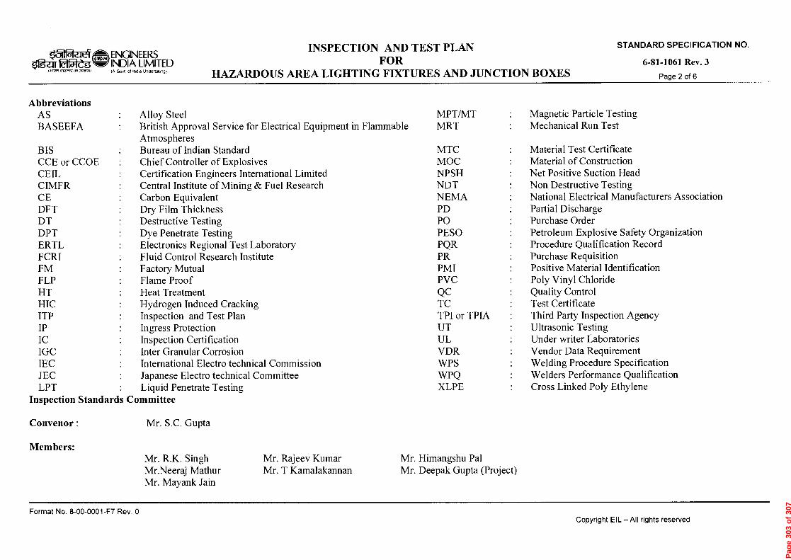
suo!mitaiciqy
'ON NOIIV313133dS adVONVIS
0 Aad Ld-1000-00-8 '0N leauod pamasai s;LIBIJ IIV —113 46!JAdoo
n rD
o
»61
•;' r'7
1‹ 5 -c
=)' 'F
)' --9
'z3'
'-ri -
1 tii
lz
-)n
nn
to
czi>
5 =
c
,..,:j ,
?-..)
3 t"
" 4
(Th ,-
o ,---
3 '-r
1 rr
l '-''
tri (
-) 7)
>
cA
or
CD
', H
(")
n (
")
~d
■-3 ,-
-3 H
t
4 rn
CD
Z
.:
1,•.
,~ r-
I '.1
1
CA
tri
>
x o
ol.
t-ri
r.
•-s
ICOH
e.)
o
4 4
4
_. g
. ,.,
. o: 5
" 5"
5-'
.., cn
cfc?
ci)
`-‹
.
. .
E .=
-cs
-.
s,› -,.
.
CD
,..,
;.-.;
CD
co
CD
‘< '-
t •
' ro o
rii o
'--t
- v)
CD
CD
■-• ri
l "
Zt.
E),
, st =
- co
0
CD
n .
.._.,
-• 8
c)
o
o
CD
-t -
: c)
t,)
o
o
cn
(-
cp
-..
•
:,'•
,-,"
,..,•
= $:,.,
...
4 4
o-
= $.-
cc
: :
, o
,__. g.
. eD
o
cp ,....-
A.
n)
cn .
()
cn
A) ,
x.
(5 •
')."')
7-'
AD 0 A
,) 0
~t
0
'-r1 s-
r1 'rl
trl
C".7
uic
-)c
-)nnto
>ti
i>
■-cj .,
'7
1
,--,
. ■--
1-,
0
o' "C . , -' •
, _ tt. .
. a.
.5. '
,,,,,,,,
,,,,, .
„.8r
CD
cn
r) 6
co
'.<:5
~ .
Z
C)
(-) ,
c4
0
.-4
i
v
CD ,
co
H (,
. 0
6
'
o
E
,-..
r o
<
7:1 c
m H
c4
.1"-
co
co
ro -
- o
CD
cfc
l "
("1)
0 ,-. • 0
AD
cn
0
:"1-
. Cir'
Z C
C2
CD
CA
C
I)
..1
,.,
CH D(4 ''C
S
"' ()
.
rà) co
5"
(4,-
5" 8
)
cyq ,i.
(,)
0..
o..4.,
Y-r) r
"'
0
Z-. AD
go
.(29) .
«
-
o
cr
o
CD
til
F' D+ .9
,
8.-
c17'
A)
CD
O
0
,-t
v) r
"'
>ri"
1:0
n)
..c)
" F
.t,
0..
.6- .
CD
...
•11
r).
crAD
Ii
< C
H ■C
) 'tJ
4
7cie
rrio
eir
rie
,-o0
H
rri
H
- n,>
- -• a ,o
f_L .,
■ c— ,
H HC
(,D),
cr
o
D
'.-o •
c , "
o C g.o
Ao D z z o
4
4 --+ g .
4 g.
4
( 4=
4A
n
C CC
"
r
69+
) C
CA (Q -D
°
- n
O.
0. C
"
CL,
'--
0
r
- cD
g =
- = D
.- • c
n G
1Q ,-
-, AD
(...)
er)
- •
CD
CA
C/2
CD
..1
.—e
CD
(,)
,--,
•
,..,
...
'-1
:1-, •
'(-
)..
- ... ,...,
›:, co
Zrf
• •-
4 ,—
,- C
D S
H
C)
•-• c
o -
, P
'-''
s.< ■
••-t- s.
_,
'' -'
. ,...
,,
riz)
'''n.,
CD
1."-'
AD
...
t ‘•-
■.°
(1) (
-) (
4,-)
7.
CL,
■-n
"
,.,_,
0 c
or'
.,- C
D .-
c)
><
0-
,,,-
.- •
C/)
,-,
.- - '•
C3
' - •
0 'A
7) "
c7, "
..' ', .
,a,
CD
c)
= i
r)
., -
,--,
- •
H (
7 O
n -
. -s
t-t-
o.
, ■-
■ -,
• (,-)
,- •
n f
:L, 0
lz,
) CD
C)
,--h
" .
CD
H
trl c
) t t
),)
'".
• ,/, C
D
,--t
- cp
C.4
CD
,-,
- ,-
■.- e-
t- l /
C+
Cip
"
Zi
0
,
0
cA
5 x
'8' 9
4 ..-,-
V,LD , E
4.i
c4
CfQ
r)
n
G1Q
AD co
,.-
r),) C
D .-
' •
C'D
.-t-
(,-) r)
r) -•
-• ̀
-<
o
-t
O
.-I
r+
CrQ
CD
cn
ts7
AD
(/)
e-r-
CA ■-.
. 0
0
C)
..-..
AD .--
O
Pag
e 30
3 o
f 30
7

0 Al G L3-1000-00-8 'oN 4eLtuo3 pamasai sp.161.1 IIV —113 4146pAclo3
siNawaffinÒau amv MOIIDadSKI O'£
PO/PR/ Standards referred there in/Job specifications/Approved documents.
This Inspection and Test Plan covers the minimum testing requirements of Lighting fixtures, control gearboxes, junction boxes and accessories
adODS
'ON NOIIV01d103cIS aavaNvis
4.
0
(...)
iNJ
(....)
. ■—■
t..4
. C5
t.)
.—
ts.>
c:
, 0
z w
) 0 r
•
Final Inspection
Control gear boxes and junction Boxes
CD
=
cfa ES-
cn
cn
CD
C4
In process Inspection
Incoming materials like castings, terminals, Glass, Rubber gaskets, reflectors, Guards, Chokes, Capacitors, etc.
Material Inspection
Procedures
STAGE/ ACTIVITY
Routine Pressure test
Static Hydraulic test
Physical & Chemical Properties, Dimensions, Surface finish, Light transmission thro' glass, tests on glass, Material Certificate, Make, IR for chokes, etc.
, ril ,- ,—, c.)
100% by supplier and
sample basis by EIL
100% by supplier and
sample basis by EIL
Samples as per relevant standard/ supplier's standard
QUANTUM OF CHECK
Supplier's Test Records
Supplier's Test Records
Supplier's Test Records
, r) o g
z
SUB SUPPLIER
SCOPE OF INSPECTION
z z
z
SUPPLIER
xJ . .
EIL/TPIA
Pag
e 30
4 o
f 30
7

0 'Aed L3-1000-00-9 'oN pamesai sp.16P IIV —113 41160do3
•
Aall 1901-18-9
1\1VrId LSI.L (INV momaasm 'ON NOILVD1d133dS aavaNvis
i..) —
,,..,
4 ...,
k
Type tests:-
'"Il
,-
-..
P,
'CZ
(i
) r) o,-
-.
STAGE/ ACTIVITY
• Temperature rise test
•
Test for suspension for Div 2 fittings
•
Test for enclosed Break lamp holder for Div 2 fittings.
•
Pressure Test (As Applicable)
Acceptance Tests:-
•
Physical, Dimensional and BOM Verification
•
Flame paths, Clearances
•
Marking on each piece for suitability to area classification, Tag no. and other details as per relevant IS/IEC.
•
Marking on glass for type and other details as per IS/IEC
•
Test for restricted breathing enclosure for Div-2
•
Impact test (on samples)
•
Thermal shock test (on samples)
•
Electrical operation check
•
Power factor test on choke
•
HV test
• IR test before & after HV
CHARACTERISTICS
Samples
,---
CD
C
D
‘:
QUANTUM OF CHECK
Certificates from test agencies
-,..1 ■
-• • r
-, c'-
' '-'•
v)
cp
(I)
o
(-)
cp
(=1..
,-.1 -
• u)
o
CD
,-4- -
(n
0
SUB SUPPLIER
SCOPE OF INSPECTION
SUPPLIER EIL/TPIA
Pag
e 30
5 o
f 30
7
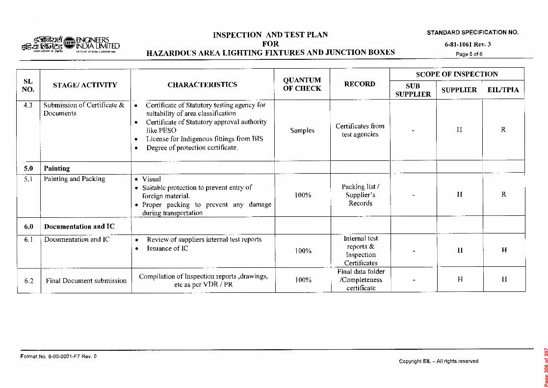
0 ykod Ld-L000-00-9 '0N 4euilod pemesei sP-16P liv -113 1.16pAclo3
so rg
> 2
r=1-
71 M
.nau 1901-18-9
'ON NOI1V313103dS CIWONVIS
CT t)
Cl'■
»,---.
01
P
L
/1
;.-.
(J1
7:::,
.4,
L-)
V)
0
.
Final Document submission
Documentation and IC
Documentation and IC
Painting and Packing
.0
0 ..
•4-
....
Cr:
Submission of Certificate & Documents
STAGE/ ACTIVITY
Compilation of Inspection reports ,drawings, etc as per VDR / PR
• Review of suppliers internal test reports
• Issuance of IC •
Visual
•
Suitable protection to prevent entry of foreign material.
•
Proper packing to prevent any damage during transportation
•
Certificate of Statutory testing agency for suitability of area classification
•
Certificate of Statutory approval authority like PESO
•
License for Indigenous fittings from BIS
•
Degree of protection certificate.
CHARACTERISTICS
,..-
0
0
■-,
0
0
.-,
0
0
Samples
QUANTUM OF CHECK
Final data folder /Completeness
certificate
Internal test reports & Inspection Certificates
Packing list / Supplier's Records
Certificates from test agencies
o g SUB
SUPPLIER
SCOPE OF INSPECTION
z
z
z z
SUPPLIER
z
z
EIL/TPIA
Pag
e 30
6 o
f 30
7

0 •A92:1 LJ-1000-00-8 'oN }eWJOJ pemesai s}116P IIV —113 4460do3
•
Aall 1901-18-9
'ON NOLLVOld103dS aavaNvis
> H
o
C
) c)•
CD
1:
t • •
C-)
CO7
eD
CD
CFA
cp
O C
D (7)
CL.
CD
rij
C/)
• o
'a-
• a)
• Cf
c7
• -
cn
cn
• CD
CD
s),)
cn
"Ct
CD
»-t
~C
•
o.
,-t-
•
• 0
cn
■-b
o
ct)
CD
" O
Zi
■-s
- cn
o
o
'c;
cr
ci)
'11=1
c)
co
,•••■•
— •
s=1.,
v)
E •
CD
o
c->
(
•
?D
CD
cn(4
A.)
o
r))
cr'
CD
Pag
e 30
7 o
f 30
7


![national university of advanced legal studies - [nuals], kochi](https://static.fdokumen.com/doc/165x107/6324ac0acedd78c2b50c392d/national-university-of-advanced-legal-studies-nuals-kochi.jpg)