Platform Support for Development and Deployment of ... - Eurecom
284
Platform Support for Development and Deployment of Multipoint Multimedia Applications PRÉSENTÉE À LA SECTION DE SYSTÈMES DE COMMUNICATION ÉCOLE POLYTECHNIQUE FÉDÉRALE DE LAUSANNE POUR L’OBTENTION DU GRADE DE DOCTEUR ÈS SCIENCES TECHNIQUES PAR CHRISTIAN BLUM Ingénieur électricien diplômé Université de Stuttgart de nationalité allemande Composition du jury: Prof. J.Y. Le Boudec, président du jury Prof. R. Molva, directeur de thèse Dr. G. Coulson, corapporteur Prof. J.-P. Hubaux, corapporteur Prof. B. Merialdo, corapporteur Prof. M. Mühlhäuser, corapporteur Sophia-Antipolis, Eurécom 1997
-
Upload
khangminh22 -
Category
Documents
-
view
3 -
download
0
Transcript of Platform Support for Development and Deployment of ... - Eurecom

Platform Support for Developmentand Deployment of Multipoint
Multimedia Applications
PRÉSENTÉE À LA SECTION DE SYSTÈMES DE COMMUNICATION
ÉCOLE POLYTECHNIQUE FÉDÉRALE DE LAUSANNE
POUR L’OBTENTION DU GRADE DE DOCTEUR ÈS SCIENCES TECHNIQUES
PAR
CHRISTIAN BLUM
Ingénieur électricien diplômé Université de Stuttgart denationalité allemande
Composition du jury:
Prof. J.Y. Le Boudec, président du juryProf. R. Molva, directeur de thèse
Dr. G. Coulson, corapporteurProf. J.-P. Hubaux, corapporteurProf. B. Merialdo, corapporteur
Prof. M. Mühlhäuser, corapporteur
Sophia-Antipolis, Eurécom1997

Acknowledgements
This thesis is the result of research performed in the Corporate Communications Departmentof Eurécom, a subsidiary of the École Nationale Supérieure des Télécommunications (ENST)Paris and the École Polytechnique Fédérale de Lausanne (EPFL). I would like to thank ClaudeGueguen, the director of Eurécom, for having received me at this fine institute that may wellserve as a model for other pan-european efforts in research and education. I equally would liketo thank Jacques Labetoulle, the head of the Corporate Communications Department, whomade my research possible, and who was a constant source of advice and help throughout mythesis. I owe special thanks to Refik Molva, my thesis advisor, for his support and his criticalobservations in many discussions that helped me advance in my work. I am indebted to himand to Erich Rütsche for having had the initial idea for APMT, the multimedia platform archi-tecture that is now at the core of this thesis. I then need to thank Ernst Biersack for the initialcontact with Eurécom, and his constant interest in the progress of my thesis.
Many people merit credit for having contributed to the APMT architecture and prototype.Laurent Gautier and Henning Schröder implemented a first version of the prototype. MarcusSchmid developed the connection management framework of the prototype, and here mostnotably the Conference Configuration and Connection Manager. Robert Haas and BernhardSuter developed a first version of the audio transmission framework. Based on that, FrankGerischer developed the audio components of the APMT prototype. Antonio Suarez, RodolpheKraftsik, Nicolas Durville and Christophe Stegmann implemented the APMT video on-demand application.
This thesis has profited to quite some extent from the experience that I have gained in theteleconferencing project BETEUS. I need to thank Philippe Dubois, Olivier Schaller, DidierLoisel and Refik Molva for more than one year of exciting team-work. I owe special thanks toOlivier Schaller, with whom I designed the BETEUS API that is described in this thesis.
This thesis would not have been possible without the countless discussions I had with myoffice mates Christoph Bernhardt, Alaa Dakroub, Mahmoud Nazeman, Erich Rütsche and RaulOliveira, and more recently, Jamel Gafsi and Lassaad Gannoun. The same needs to be said forthe lunch-time discussions with Christian Bonnet, Stéphane Decrauzat, Alain Enout, RaymondKnopp, Karim Maouche, Constantinos Papadias, Didier Samfat and Nicolas Tavier, and thecoffee-time discussions with Jakob Hummes about Java-RMI and CORBA.
For their warm welcome and constant support I would further like to thank the people work-ing in the administration of Eurécom, among them Catherine Betrancourt, Lina Chrin, Jean-Christophe Delaye, Nathalie Richardin and Agnès Rougiers. Many thanks to Remy Giacconefor the organization of the thesis defense.
I am grateful to Karim Maouche, Jörg Nonnenmacher, Jamel Gafsi and Jakob Hummes forthe organization of numerous unforgettable festivities that indirectly contributed to this thesis.
I need to thank Sylvie Géra for her love, her support, and her patience.


Abstract
Multipoint multimedia applications are often developed as standalone applications without thesupport of a development and deployment platform. Such applications have to implement basicfunctionality like the transmission and processing of digital audio and video from scratch.They do not profit from a deployment platform for their dissemination, and tend to requireskilled personnel for installation and operation. Standalone applications are typically found inresearch environments where new application features need to be evaluated with prototypes.However, applications that need to be deployed as services on large networks to a large numberof users must be built on top of a platform. Such a platform must not only support the deploy-ment of applications, it must also offer means that facilitate their development. A platform isan investment that can only be justified if it satisfies the interests of many users. It must there-fore foster application diversity, which it does best by supporting application development on ahigh level.
The investment a development and deployment platform represents also requires it to belong-lived, with the key to longevity being extensibility. Early platforms like Bellcore’s Tour-ing Machine feature a monolithic application programming interface that is hard to extend,because every extension requires considerable modifications to the infrastructure. Such mono-lithic platforms must be replaced by platforms based on the component framework paradigmwhich allows the platform to be extended by third-parties. The high-level abstractions exhib-ited by the application programming interfaces of monolithic platforms remain neverthelessvaluable, and can be reimplemented as toolkits on top of low-level components.
A platform for multipoint applications is necessarily distributed, and should therefore beconstructed on top of an existing platform for distributed processing. The most adequate plat-form for this purpose is the Common Object Request Broker Architecture (CORBA) of theObject Management Group (OMG). CORBA is language-independent, object-oriented andopen, which makes it superior to alternatives like Java RMI, OSF DCE and Microsoft DCOM.
This thesis proposes an extensible platform for multipoint multimedia applications based onCORBA that supports application development with high and low-level component frame-works, and that supports application deployment with mobile code techniques. Applicationsreside in so-called application pools from where they download applets into static multimediaterminals. A multimedia terminal consists of a terminal control and an extensible set of high-level components called terminal servers. A special kind of terminal server is the applet han-dler which houses the applets sent by the application. The multimedia middleware of the termi-nal is also encapsulated in a terminal server. It consists of low-level components called devicesthat can be plugged together to form device graphs. Device graphs can be controlled over thenetwork by the application, or locally by downloaded applets. Many applications require ahigher level of programming support than devices or terminal servers. These applications profitfrom high-level components in the application pool called application pool utilities. Applica-tion pool utilities relieve applications from dealing with multiple terminals. An example appli-cation pool utility is a connection manager that allows an application to create and connectcomplex device graphs in multiple terminals with a few programming instructions.
The platform proposed by this thesis is tailored to IP networks. It uses the Internet Inter-ORB Protocol (IIOP) for control communication, and the transport protocols TCP/IP, UDP/IPand UDP/IP multicast for the transport of multimedia data. The platform does not require anychanges to the existing IP network infrastructure, which makes it possible to deploy it today onthe Internet, or on corporate intranets. This is in contrast to the Telecommunications Informa-tion Networking Architecture (TINA), which has to be considered as the major effort in thearea of telecommunications to provide platform support for distributed multimedia applica-tions. TINA is rooted in the network, and its introduction will require considerable investmentsby network operators.
A first version of the platform has been implemented in a prototype in order to evaluate itsfeasibility. The platform, as it is presented in this thesis, builds on the experience gained withthis prototype. The thesis discusses the platform in general, its application management archi-tecture, its multimedia middleware, and the prototype. The thesis also develops a set ofrequirements that platforms should fulfill, and evaluates a certain number of platforms withrespect to these requirements. The platforms that are evaluated are Bellcore’s TouringMachine, Eurécom’s Beteus platform, IBM’s Lakes platform, Olivetti’s Medusa, the Multime-dia System Services (MSS) of the Interactive Multimedia Association (IMA), and TINA.

Résumé
La plupart des applications multipoints multimédia sont développées sans le support d’uneplate-forme de développement et de déploiement. Par conséquent ces applications doiventimplémenter beaucoup de fonctions de base, comme par exemple la transmission et le traite-ment du son et de la vidéo. Elles ne peuvent pas être déployées automatiquement, et ellesnécessitent un personnel expérimenté pour leur installation et exploitation. Souvent on trouvece type d’application dans les environnements de recherche où la faisabilité d’une applicationnouvelle doit être validée par un prototype. Cependant, des applications qui vont êtredéployées comme services dans un réseau publique avec un grand nombre d’utilisateurs nepeuvent pas renoncer au support d’une plate-forme. Une telle plate-forme doit non seulementrendre possible le déploiement d’applications, mais doit aussi faciliter leur développement.Une plate-forme est un investissement qui ne peut être justifié que si celle-ci satisfait les inté-rêts d’un grand nombre d’utilisateurs. Par conséquent elle doit promouvoir la diversité desapplications, ce qui demande un support à haut niveau pour le développement d’applications.
L’investissement que représente une plate-forme se justifie aussi par une durée de vie éten-due de celle-ci. La clé de la longévité de la plate-forme est son extensibilité. Les premièresplate-formes, comme la Touring Machine de Bellcore, implémentent une interface de program-mation monolithique dont chaque extension nécessite des modifications importantes dansl’infrastructure. Les plate-formes monolithiques doivent être remplacées par des plate-formesqui sont basées sur des composants configurables, ce qui permet une extension de la plate-forme par des tiers. Les abstractions à haut niveau des plates-formes monolithiques restentcependant valable, et peuvent être réimplémentées sous forme de toolkit au-dessus de compo-sants à bas niveau.
Une plate-forme pour des applications multipoints est nécessairement distribuée, et a elle-même besoin du support d’une plate-forme pour des applications réparties. La plate-forme quiest la plus adéquate pour cela est la Common Object Request Broker Architecture (CORBA)de l’Object Management Group (OMG). CORBA ne dépend pas d’un langage de programma-tion, est orienté-objet et ouvert, ce qui le rend supérieur à des alternatives comme Java RMI,OSF DCE et Microsoft DCOM.
Cette thèse propose une plate-forme pour des applications multipoints multimédia qui estbasée sur CORBA. Cette plate-forme facilite le développement d’applications avec des compo-sants configurables de bas et de haut niveau, et le déploiement d’applications avec des techni-ques de code mobile. Les applications résident dans des serveurs centraux appelés applicationpools d’où elles téléchargent du code sous forme d’applets dans des terminaux multimédia. Unterminal multimédia consiste en une entité de contrôle et en un nombre extensible de compo-sants de haut niveau appelés terminal servers. L’exemple d’un terminal server est le applethandler qui héberge les applets téléchargées. L’infrastructure multimédia du terminal est aussiencapsulée par un terminal server. Elle consiste en composants à bas niveau appelés devicesqui peuvent être inter-connectés à volonté pour former des graphes. Un device peut être con-trôlé par l’application à travers le réseau, ou en local par une applet téléchargée. Beaucoupd’applications demandent un support de programmation plus élevé que celui fourni par lesdevices et les terminal servers. Ces applications peuvent se servir de composants de haut

niveau appelés application pool utilitities. Les application pool utilities facilitent pour l’appli-cation le contrôle de plusieurs terminaux. L’exemple d’une application pool utility est le mana-ger de connexions qui permet à l’application de créer et de connecter des graphes de devicesdans plusieurs terminaux avec seulement quelques lignes de code.
La plate-forme proposée par cette thèse est adaptée aux réseaux IP. Elle utilise l’InternetInter-ORB Protocol (IIOP) pour la communication de contrôle, et les protocoles de transportTCP/IP, UDP/IP et UDP/IP multicast pour le transport des données multimédia. Elle nerequière pas des modifications dans l’infrastructure existante d’un réseau IP, ce qui permet dela déployer aujourd’hui sur Internet, ou sur un réseau d’entreprise. Cette propriété la distinguede la Telecommunication Information Networking Infrastructure (TINA), qui doit être consi-dérée comme l’effort principal dans le domaine de télécommunications de créer une plate-forme pour des services multimédia. TINA est ancrée dans le réseau, et son introduction vanécessiter des investissements importants par les opérateurs.
Un premier prototype a été développé afin de vérifier la faisabilité de la platforme. La thèsedécrit la plate-forme en général, son architecture pour l’administration des applications, soninfrastructure multimédia, ainsi que le prototype. La description de la plate-forme est précédéepar la discussion des conditions qu’elle doit remplir, et l’évaluation d’un certain nombre deplate-formes qui sont considérées comme des réferences importantes: la Touring Machine deBellcore, la plate-forme Beteus d’Eurécom, la plate-forme Lakes d’IBM, la plate-formeMedusa d’Olivetti, les Multimedia System Services (MSS) de l’Interactive Multimedia Asso-ciation (IMA), et TINA.
ix
Table of Contents
Chapter 1: Introduction 1
1.1 Multipoint Multimedia Applications 1
1.2 Platforms for Multipoint Multimedia Applications 1
1.3 Component Frameworks 3
1.4 CORBA 3
1.5 Objectives of this Thesis 3
1.6 Structure of the Document 4
Chapter 2: Platform Requirements 5
2.1 Introduction 5
2.2 Major Aims 5
2.3 Required Platform Properties 7Open 7Extensible 8Programmable 8Scalable 9Deployable 9Simple 10
2.4 Required Platform Functionality 10User Session Management 10Connection Management 11Multimedia Data Processing 12Multipoint Control Communication 13Resource Management 13Synchronization 14Mobile Code 15Presentation Environment 16Federation of Applications 17Security 17Mobility 17Directory Service 18Platform Management 18Accounting 18
2.5 Distributed Processing Environment 18
2.6 Platform Evaluation Criteria 20
2.7 Conclusion 21
Chapter 3: Distributed Processing Environment 23
3.1 Introduction 23
3.2 CORBA for the DPE 24

Table of Contents
x
3.3 OMA, CORBA, CORBAservices and CORBAfacilities 25Object Management Architecture 26Common Object Request Broker Architecture 27CORBA Interoperability 31CORBAservices 34CORBAfacilities 37Stream Support in CORBA 38CORBA and RM-ODP 39Problems and Tendencies 41Assessment 43
3.4 Other Platforms 43Distributed Computing Environment 43Distributed Component Object Model 45Distributed Object Computing in Java 46
3.5 Conclusion 47
Chapter 4: Monolithic MMC Platforms 49
4.1 Introduction 49
4.2 Touring Machine 50Assessment 52
4.3 The Beteus Platform 53The Beteus ATM Network 54Platform Architecture 55Site Architecture 57Major Connection Abstractions 58Application Programming Interface 60Example Application Scenario 63Implementation 64Assessment 66
4.4 IBM Lakes 68Assessment 69
4.5 Other Platforms 71
4.6 Conclusion 71
Chapter 5: MMC Component Frameworks 73
5.1 Introduction 73
5.2 Medusa 74Assessment 76
5.3 IMA Multimedia System Services 77Properties and Capabilities 79Connection Establishment 80Synchronization 81Resource Management 81Interface Hierarchy 82Assessment 83
5.4 TINA 84Business Model 85Computing Architecture 86Service Architecture 87Connection Management Architecture 88

xi
Table of Contents
Assessment 89
5.5 Other Frameworks 91Frameworks Based on a Standard Object Model 91Frameworks Based on a Proprietary Object Model 92Frameworks Based on Rudimentary Object Models 93
5.6 Component Framework Design Considerations 95
5.7 Conclusion 99
Chapter 6: APMT Overview 101
6.1 Introduction 101
6.2 Application Pools and Multimedia Terminals 102Architecture Overview 102Overview of the Multimedia Terminal 106Overview of the Application Pool 107Overview of Additional Components 109
6.3 Session Model 110
6.4 APMT Specification 111
6.5 Multimedia Terminal Interfaces 111Terminal Control 111Applet Handler 113Stream Agent 114
6.6 Application Pool Interfaces 115Application Pool Control 115Applications and Utilities 116
6.7 User Agent Pool Interfaces 117
6.8 Application Model and Major Application Scenarios 118
6.9 Deployment Scenarios 120
6.10 APMT and TINA 121
6.11 Conclusion 122
Chapter 7: APMT Platform Architecture 123
7.1 Introduction 123
7.2 Usage of CORBA in APMT Definitions 123
7.3 Overview of APMT Modules 125
7.4 Major Types 126Basic Types 126Advanced Types 127
7.5 Terminal Control Interfaces 129Interface Tc::Terminal 130Interface Tc::PanelTerminalControl 130Interface Tc::ApplicationControl 132Interface Tc::UserSession 133Interface Tc::TerminalControl 134
7.6 Terminal Server and Applet Handler Interfaces 136Interface Ts::TerminalServer 137The Tcl/Tk Applet Handler 137
Table of Contents
xii
The Java Applet Handler 140
7.7 Application Pool Control Interfaces 141Interface Pc::Pool 141Interface Pc::SessionControl 142Interface Pc::PoolControl 144
7.8 Application Interfaces 145Interface Pc::ApplicationControl 145Interface App::Application 146
7.9 Utilities and the Participation Control 146Interface Put::Utility 146Participation Control Interfaces 147Interfaces Pac::SessionAccess and ParticipationRequest 147Interfaces Pac::SessionControl and Application 148Interfaces Pac::Participant and ParticipationControl 150Interface Pac::SessionInformation 150
7.10 Scenarios 151Application Startup Scenario 151Session Join Scenario 152Session Invitation Scenario 154Child Application Startup Scenario 155
7.11 Conclusion 155
Chapter 8: APMT Multimedia Middleware 157
8.1 Introduction 157
8.2 Overview of the Multimedia Middleware 158
8.3 Graph Objects 161
8.4 Devices 163Formats and Ports 164Device Interfaces 171Device Introspection 173Device Granularity 175Device Interface Hierarchy 175
8.5 Transport Devices 176
8.6 Device Connectors 179
8.7 Graph and Stream Agent 183Graphs 183Stream Agent 187Graph Creation Scenario 187
8.8 A Connection Manager 189Connection Management Session, Graph Models and Terminal Sets 189Bridges 192
8.9 Open Issues 194
8.10 Conclusion 194
Chapter 9: APMT Evaluation 197
9.1 Introduction 197
9.2 APMT Prototype 197
xiii
Table of Contents
Multimedia Middleware Interfaces 199Implementation of the Multimedia Middleware 201CCCM 202Devices 202The Videoconferencing Test Application 205The Video On-Demand Application 206
9.3 Evaluation of APMT 209Platform Properties 209Platform Functionality 210
9.4 Conclusion 214
Chapter 10: Conclusions 215
10.1 MMC Platforms 215
10.2 APMT 216
10.3 Further Work 218
References 221
List of Acronyms and Abbreviations 233
Appendix A: APMT Platform Interface Definintions A1
A.1 Remarks A1A.2 Module Typ A1A.3 Module Ftyp A2A.4 Module Ex A3A.5 Module Atyp A3A.6 Module Tc A5A.7 Module Ts A8A.8 Module TclTk A8A.9 Module Java A9A.10 Module Pc A9A.11 Module Put A11A.12 Module App A12A.13 Module Pac A12
Appendix B: APMT Multimedia Middleware Interface Definitions B1
B.1 Remarks B1B.2 Module Bas B1B.3 Module DevMan B4B.4 Module Trans B5B.5 Module Port B7B.6 Module Cont B8B.7 Module Tgraph B9B.8 Module Strag B11B.9 Module Cccm B11

Table of Contents
xiv
xv
List of Figures
Figure 2.1. Possible relationships between application, MMC platform and DPE. 20Figure 3.1. The Object Management Architecture. 26Figure 3.2. Structure of the Object Request Broker. 29Figure 3.3. OMG stream architecture proposal. 39Figure 3.4. An example for OMG-ODL usage. 40Figure 4.1. The Touring Machine software architecture. 50Figure 4.2. The Beteus ATM network. 54Figure 4.3. Node mapping example. 55Figure 4.4. The Beteus application model. 56Figure 4.5. The Beteus site architecture. 57Figure 4.6. API procedure calls during a session with two participants. 61Figure 4.7. Lakes architecture. 68Figure 5.1. The Medusa architecture. 75Figure 5.2. Interaction between MSS objects. 78Figure 5.3. MSS interface inheritance diagram. 82Figure 5.4. An example for TINA-ODL usage. 86Figure 5.5. Overview of the TINA service and connection management architecture. 88Figure 5.6. The computational environment of a device. 96Figure 6.1. APMT example scenario. 103Figure 6.2. Terminal components. 106Figure 6.3. Application pool components. 107Figure 6.4. Layered view of the APMT architecture. 108Figure 6.5. Terminal control interfaces. 112Figure 6.6. Applet handler interfaces. 113Figure 6.7. Selected multimedia middleware interfaces. 114Figure 6.8. Application pool control interfaces. 115Figure 6.9. Application and application pool utility interfaces. 116Figure 6.10. Interfaces of the user agent pool. 117Figure 6.11. Interactive presentation scenario. 118Figure 6.12. Centralized and distributed variants of the conference scenario. 119Figure 6.13. Broadcast application scenario. 120Figure 7.1. Interfaces of the child and parent session. 143Figure 7.2. Interfaces of the participation control utility. 147Figure 7.3. Event trace of the application startup scenario. 151Figure 7.4. Event trace of the session join scenario. 153Figure 7.5. Event trace of the session invitation scenario. 154Figure 7.6. Event trace for the child application startup scenario. 155
List of Figures
xvi
Figure 8.1. Example for a device graph. 159Figure 8.2. Graph object interface inheritance diagram. 160Figure 8.3. Components of the APMT multimedia middleware. 161Figure 8.4. The computational environment of a device. 163Figure 8.5. Port interfaces. 169Figure 8.6. Device interface template. 171Figure 8.7. Transport device interface hierarchy. 177Figure 8.8. The RTP header and header extension. 178Figure 8.9. Two device connection configurations. 181Figure 8.10. Ternary relationship between two devices and a device connector. 182Figure 8.11. Graph creation and control scenario. 188Figure 8.12. CCCM interfaces. 191Figure 9.1. Interface hierarchy of the APMT prototype. 200Figure 9.2. Distribution of objects over processes. 201Figure 9.3. Video device interface hierarchy and graphs. 204Figure 9.4. Three example audio device graphs. 205Figure 9.5. The graphical user interface of the videoconferencing application, 206Figure 9.6. Components and control flows of the video on-demand application. 207Figure 9.7. Sender and receiver graphs of the video on-demand application. 208

xvii
List of Tables
Table 2.1. The platform evaluation table. 21Table 3.1. Standardized CORBAservices. 34Table 4.1. Evaluation of the Touring Machine. 53Table 4.2. The API call for bridge definition. 62Table 4.3. Example bridge definitions. 63Table 4.4. Evaluation of the Beteus platform. 67Table 4.5. IBM Lakes platform evaluation. 70Table 5.1. Evaluation of Medusa. 77Table 5.2. Evaluation of IMA-MSS. 83Table 5.3. Evaluation of TINA. 90Table 7.1. APMT platform architecture modules. 126Table 8.1. APMT multimedia middleware modules. 158Table 9.1. Implemented devices. 203Table 9.2. APMT evaluation. 213

List of Tables
xviii

1
1 Introduction
1.1 Multipoint Multimedia Applications
Multimedia applications reach people today mainly via CD-ROM. The enormous amount ofdata that can be stored on optical disks together with the ever-increasing computation power ofpersonal computers allows to build highly interactive applications with synchronized audio,video, text, graphics and animation as principal building blocks. CD-ROM’s are ideally suitedfor applications that give immediate access to large amounts of stored data, but they are not aneconomical vehicle for the delivery of timely information of any kind. Here it is the WorldWide Web (Web) that is dominating the scene. The Web allows to access dynamically chang-ing hyperlinked multimedia content on a global scale. The share of network bandwidth avail-able to a user of the Web is still by far lower than what he has on the backplane bus of hispersonal computer, but this is a minor problem considering that the main attraction of the Webis the immediate access it offers to specific pieces of timely information. While the Web, sincethe advent of Java, is catching up on the CD-ROM with respect to interactivity, it is only slowlystarting to integrate digital audio and video. An interesting development in the Web is theadvent of groupware applications written in Java that use the Web as deployment platform.Such applications can, as soon as the network permits this, evolve to full-fledged multimediaapplications accessible by anyone who has a Web browser installed on his desktop computer.
One of the most interesting properties of the Web is that content development and dissemi-nation is easy. Even computer illiterate people are able to create their own Web pages, with theresult that the amount of content available on the Web is growing explosively. A similar devel-opment, although certainly to a lesser extent, and not for the immediate future, can be foreseenfor multipoint multimedia applications. Such applications are characterized by the exchange ofmultimedia data among a set of cooperating application endpoints, with examples being videoconferences, tele-teaching applications, computer-supported collaborative work (CSCW), ordistributed games. If development and deployment of multipoint multimedia applications iseasy they will appear in large numbers on the network. People will be able to tailor such appli-cations with limited effort to very specific requirements. Just like it is no problem today to adda photograph to a personal Web page it will be no problem to add multipoint digital video to agroupware application. In order to reach this stage there has to be a standard infrastructure formultipoint multimedia applications that is in scope well beyond the current Web infrastructure.
1.2 Platforms for Multipoint Multimedia Applications
Most of the multipoint multimedia applications described in literature are developed as standa-lone applications without the support of a development and deployment platform. Such appli-cations have to implement basic functionality like the transmission and processing of digitalaudio and video from scratch. They do not profit from a deployment platform for their dissem-ination, and they tend to require skilled personnel for installation and operation. Standalone
Introduction
2
applications are typically found in research environments where new application features needto be evaluated with prototypes. However, applications that need to be deployed as services onlarge networks to a large number of users cannot renounce on the support of a platform. Such aplatform must not only support the deployment of applications, it must also offer means thatfacilitate their development. A platform is an investment that can only be justified if it satisfiesthe interests of many users. It must therefore foster application diversity, which it does best bysupporting application development on a high level.
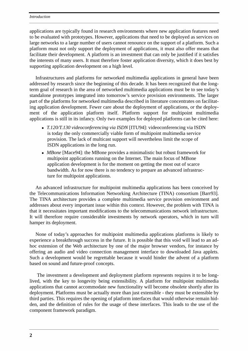
Infrastructures and platforms for networked multimedia applications in general have beenaddressed by research since the beginning of this decade. It has been recognized that the long-term goal of research in the area of networked multimedia applications must be to see today’sstandalone prototypes integrated into tomorrow’s service provision environments. The largerpart of the platforms for networked multimedia described in literature concentrates on facilitat-ing application development. Fewer care about the deployment of applications, or the deploy-ment of the application platform itself. Platform support for multipoint multimediaapplications is still in its infancy. Only two examples for deployed platforms can be cited here:
• T.120/T.130 videoconferencing via ISDN [ITU94]: videoconferencing via ISDNis today the only commercially viable form of multipoint multimedia serviceprovision. The lack of multicast support will nevertheless limit the scope ofISDN applications in the long run.
• MBone [Mace94]: the MBone provides a minimalistic but robust framework formultipoint applications running on the Internet. The main focus of MBoneapplication development is for the moment on getting the most out of scarcebandwidth. As for now there is no tendency to prepare an advanced infrastruc-ture for multipoint applications.
An advanced infrastructure for multipoint multimedia applications has been conceived bythe Telecommunications Information Networking Architecture (TINA) consortium [Barr93].The TINA architecture provides a complete multimedia service provision environment andaddresses about every important issue within this context. However, the problem with TINA isthat it necessitates important modifications to the telecommunications network infrastructure.It will therefore require considerable investments by network operators, which in turn willhamper its deployment.
None of today’s approaches for multipoint multimedia applications platforms is likely toexperience a breakthrough success in the future. It is possible that this void will lead to an ad-hoc extension of the Web architecture by one of the major browser vendors, for instance byoffering an audio and video connection management interface to downloaded Java applets.Such a development would be regrettable because it would hinder the advent of a platformbased on sound and future-proof concepts.
The investment a development and deployment platform represents requires it to be long-lived, with the key to longevity being extensibility. A platform for multipoint multimediaapplications that cannot accommodate new functionality will become obsolete shortly after itsdeployment. Platforms must be actually more than just extensible - they must be extensible bythird parties. This requires the opening of platform interfaces that would otherwise remain hid-den, and the definition of rules for the usage of these interfaces. This leads to the use of thecomponent framework paradigm.
3
Component Frameworks
1.3 Component Frameworks
A component framework consists of a set of interfaces that a component can access, or that ithas to implement itself, and a set of rules to which the component has to conform in order to beusable within applications. Platforms based on component frameworks are extended with everycomponent that is developed for them. Applications do not program components, they custom-ize them and plug them together with other components to a larger whole. Example componentframeworks are toolkits for graphical user interfaces (GUI) where applications use a scriptinglanguage to build a graphical user interface from generic widgets. The functionality of a GUItoolkit is augmented with every widget that is developed for it. Other examples are compounddocument frameworks like Microsoft’s OLE/COM [Micr95], the plug-ins that can be devel-oped for the Netscape browser [Nets97], and the Java component framework JavaBeans[Sun96a]. Platforms for multipoint multimedia applications are very broad in scope andrequire the use of components at multiple places. The most straightforward example are multi-media data processing devices, but components are also required at a higher level. An examplefor a high-level component is the application itself that can become part of a composite appli-cation. The components used by multipoint multimedia applications must be able to communi-cate with each other across address spaces and networks. This requires the use of acommunication platform that makes address spaces and networks transparent. A communica-tion platform that is adequate for this is the Common Object Request Broker Architecture(CORBA) of the Object Management Group (OMG).
1.4 CORBA
A communication platform is needed by the platform infrastructure, by platform components,and by applications. Among all communication platforms that exist today, CORBA is the mostadequate for the use in a platform for multipoint multimedia applications. CORBA is lan-guage-independent, object-oriented and open, which makes it superior to alternatives like JavaRMI [Sun96d], OSF DCE [Bran95] and Microsoft DCOM [Brow96]. A platform formultipoint multimedia applications that is based on CORBA will not only profit from transpar-ent distributed object computing, but it will be augmented with whatever functionality is addedby OMG to CORBA and the Object Management Architecture (OMA), OMG’s ambitiousframework for future component-based applications. On the network, CORBA relies on a sin-gle protocol that may experience in the future a success comparable to the Hyper-Text TransferProtocol (HTTP) of the Web: the Internet Inter-ORB Protocol (IIOP) [OMG95c]. There aretendencies in the World Wide Web Consortium (W3C) to build the next generation of HTTP(HTTPng) on top of IIOP.
1.5 Objectives of this Thesis
The objective of this thesis is to invent a platform architecture based on CORBA and the com-ponent framework paradigm that fosters the development and deployment of multipoint multi-media applications. The thesis targets applications that in one way or another serve humancommunication purposes and that can be accessed via a user terminal, not considering thosethat treat multimedia data in a non-interactive and fully automated way. The platform mustaccommodate multipoint applications, with asymmetric client-server applications or evencompletely local applications as special cases. The data that are exchanged between the distrib-uted components of a multipoint application can be of any format. The thesis denominates

Introduction
4
these data as multimedia data without imposing any restrictions on them. The thesis concen-trates nevertheless on providing platform support for the exchange of high-volume and time-critical data which are the most difficult to handle.
The platform proposed by this thesis must not only provide high-level support for thedeployment of multipoint multimedia applications, it must itself be deployable. This meansthat the architecture of the platform must not contain features that make its deployment eco-nomically or technically difficult. A platform must be deployed as a simple kernel that can beextended as user demand crystallizes. The success of such a proceeding has been demonstratedby the Web which started as a simple hypertext document platform and is now a client-serverapplication platform.
The thesis shall set forth the reasoning that leads from standalone applications to applica-tion platforms, and from non-extensible platforms with a proprietary control middleware toextensible platforms with standard middleware. Considerable space will therefore be dedicatedto the discussion of existing approaches that will then be used to demonstrate the advantages ofthe CORBA-based platform that is in the center of this thesis.
For the purpose of this thesis, the acronym MMC for Multipoint Multimedia Communica-tion is introduced. The thesis denominates multipoint multimedia applications for human com-munication and interaction as MMC applications. It also denominates platforms for MMCapplications as MMC platforms.
1.6 Structure of the Document
Chapter 2 develops a set of requirements for MMC platforms. Requirements are on one handproperties the platform must exhibit, and on the other hand functionality that it has to imple-ment. One of these requirements is the use of a communication platform. Chapter 3 presentsCORBA, Java RMI, OSF DCE and Microsoft DCOM as possible candidates for the communi-cation platform, and justifies the choice of CORBA. Chapter 4 starts the discussion of MMCplatforms with monolithic platforms. Monolithic platforms exhibit a single application pro-gramming interface, and are hard to extend. They remain interesting because they define high-level abstractions that can be recycled in toolkits for component-based platforms. The plat-forms that are discussed in Chapter 4 are Bellcore’s Touring Machine, Eurécom’s Beteus plat-form, and the IBM Lakes platform. The description of the Beteus platform is part of thecontribution of this thesis. Chapter 5 is dedicated to component-based platforms. The plat-forms that are discussed are Olivetti’s Medusa, the Multimedia System Services (MSS) of theInteractive Multimedia Association (IMA), and TINA. Chapter 6 starts a series of chapters thatdescribe the component-based platform proposed by this thesis. Chapter 6 presents the archi-tecture in general and the reasoning behind it. A basic characteristic of this architecture is thatapplications are logically and perhaps geographically separated from the terminals that theycontrol. Applications reside in application pools (AP), from where they download applets intomultimedia terminals (MT). The thesis refers to this architecture as APMT (AP+MT). Chapter7 discusses the application management architecture of APMT. Chapter 8 presents the multi-media middleware of APMT, and an example connection manager. Chapter 9 is dedicated tothe evaluation of APMT. It describes the APMT prototype, and evaluates APMT with respectto the requirements that were developed in Chapter 2. Chapter 10 contains the final conclu-sions.
5
2 Platform Requirements
2.1 Introduction
The previous chapter introduced the notion of multipoint multimedia applications for humancommunication (MMC applications) that is going to be used throughout this thesis. It also gavethe motivation for developing platforms and infrastructures for MMC applications. Platformsfacilitate and foster the development of MMC applications and are a necessary condition fortheir wide-scale deployment. This chapter continues with some general reflections about therequirements a platform for MMC applications has to fulfill. It starts off by defining four majoraims that are considered to be of utmost importance for the design of the platform. These aimsare at the basis of a set of properties the platform must exhibit. Platform properties do notdescribe any specific functionality. They are defined as adjectives that must be applicable to thedescription of the platform as a whole. Following that comes a comprehensive discussion ofthe functionality that has to be provided by the platform. It is reasoned that this functionalitycannot be provided by a single design effort, and that the overall MMC platform should best beprovided by an existing platform for distributed applications that is augmented with MMC spe-cific functionality. At this point it is possible to develop the criteria that are used in the follow-ing chapters to assess existing MMC platforms and to evaluate the platform that is proposed bythis thesis.
2.2 Major Aims
Before stepping on to a discussion of specific requirements it seems adequate to formally statethe major aims to be attained by the MMC platform. Four aims are identified that underly therequirements developed later in the text. The platform shall
• foster the development of MMC applications
• facilitate the deployment of MMC applications
• be ubiquitous
• be long-lived
The first two aims define the basic functionality that is to be provided by the platform. Theuse of the verbs foster and facilitate instead of for instance supports indicates that the platformhas to not only enable development and deployment, but also to provide considerable comfortfor this. A user experiences a platform mostly via the applications that are running on top of it.It is therefore the developer rather than the user that has to deal with the platform itself. Offer-ing a comfortable and attractive development environment has the benefit that it is easier fordevelopers to respond to user demands or to solicit new user demands by proposing new appli-cation features. The degree of development comfort provided by a platform has therefore adirect impact on the quality and diversity of the applications running on top of it, which isimportant to keep in mind considering that the success of the platform is intimately linked with

Platform Requirements
6
the success of its applications. Once developed an application has to be made available to pro-spective users as fast as possible. Fast deployment is just as important as fast development as itpermits the rapid reaction of service providers to user demands. Application deployment con-stitutes a considerable problem in case the number of users and applications is high, as isenvisaged for the MMC platform. One of the reasons that lead to the introduction of IntelligentNetwork (IN) platforms into telecommunication networks was to reduce the enormous effortthat had to be spend on the deployment of new services [Thoe94]. IN platforms allow to con-trol services on network level, making instantaneous and network-wide installation andremoval of a service a feasible task. The standard user terminal in telecommunication net-works, which is the telephone handset, is static and is not affected by the installation of a newservice. This is different in the case of MMC applications where terminals are similar in com-plexity to network equipment and where it is likely that application specific code has to be exe-cuted on them. Since manual installation of application software on user terminals is not areasonable solution to this problem there have to be mechanisms provided by the MMC plat-form that allow transparent downloading and installation of application-specific terminal soft-ware via the network. Ease of application deployment is therefore synonymous with supportfor mobile code.
As third aim the MMC platform has to strive after ubiquity. The platform should not be tai-lored to the needs of specific user groups, but should instead be useful for as many domainsand user groups as possible. Most importantly, the platform should be as interesting for enter-prises as it should be for private users. The design, implementation, deployment and continu-ous extension and revision of an MMC platform architecture is such an enormous task that it isagainst everybody’s interest to have more than one such platform on a global scale. Havingmultiple platforms for different user communities or different platforms competing againsteach other within the same user community is clearly an undesirable situation. As user com-munities usually do not exist in isolation there will be immediately the need for gateways thatallow users belonging to different communities to communicate with each other. Gateways arealready quite complex when they have to mediate between administrational domains. Gate-ways that have to mediate in addition between complex platform technologies are probably notfeasible. A single ubiquitous platform avoids the interworking problem, but raises the problemof consensus. If no consensus can be found on a single platform and if multiple platforms arecompeting against each other it can be expected that the platform reaching the largest numberof user communities and users will prevail. An MMC platform must therefore try to be as ubiq-uitous and universal as possible, otherwise it is bound to disappear. The key to ubiquity isadaptability - the platform must be adaptable to different environments.
The lifetime of a platform may also turn out to be short if it is not explicitly designed forlongevity. The platform must be able to rapidly incorporate new developments in multimediaand networking or even ride on the wave and be the target of new developments. If the platformis not able to keep pace with the times it will soon be replaced, resulting in a considerablewaste of investment. The key to longevity is extensibility - the platform has to be deployed as akernel that is then gradually extended as user demand crystallizes.
Fostering application development, facilitating deployment, ubiquity and longevity must bethe major aims underlying the design of an MMC platform. These aims are finally a conse-quence of the enormous dynamics the field of multimedia communication and computationexhibits. Standardization efforts that do not take these dynamics into account risk to be out-dated even before they are finished. The four aims defined in this section are the basis of a

7
Required Platform Properties
more elaborate, but still qualitative set of platform properties which in turn shall dominate thedesign of the platform.
2.3 Required Platform Properties
The qualitative requirements imposed on the platform architecture are defined as a set of prop-erties. The platform must be
• open
• extensible
• programmable
• scalable
• deployable
• simple
These properties have all a very concrete impact on the shape the platform has to take. Thefollowing provides a discussion of the required platform properties along with their implica-tions.
2.3.1 Open
An MMC platform architecture has to be open, meaning that its interfaces and computationalbehavior are well-defined and published in form of a standard. Clients that conform to the stan-dardized mode of interaction with the platform can access its services. The three principaltypes of platform clients that can be identified are the user, the platform provider and the ser-vice provider that develops and deploys applications. The MMC platform must have openinterfaces wherever client interests meet, most importantly between the user terminal and theplatform, between the platform and the application, and between parts of the distributed plat-form that are under different administration. In addition to that, platform extension must beopen, requiring that internal platform interfaces have to be standardized.
Openness is directly linked with standardization. The standardization of an MMC platformhas to be in the hand of a single organism upon which all interested parties agree. The stan-dardization must come up with a globally accepted architectural framework that, while defin-ing all important interfaces, leaves considerable room for competition. Important areas ofcompetition are applications and platform extensions. The MMC platform architecture mustmake maximum use of existing standards and concentrate on architectural issues. Relevantstandards are for instance multimedia data encoding and transmission standards, or controlmiddleware standards, but it can also be envisaged that the platform encapsulates existing sys-tems similar to the way the Web provided access to Gopher [Liu94].
As the computational interactions among platform components are likely to be complexthere is a need for formal methods in the definition of the interfaces that reduce the ambiguityplain text often exhibits. The application of formal specification methods should neverthelessbe done with moderation, and care should be taken to keep interaction complexity at a levelthat can be handled with a limited amount of specification.
Openness fosters application development and is a necessary condition for ubiquity.
Platform Requirements
8
2.3.2 Extensible
An MMC platform has to be extensible if it is to be long-lived. Extension should be possibleon architecture level and on component level. New components that are built on top of plat-form extension interfaces may become part of the platform following a light-weight standard-ization process. It can also be envisaged that new components are introduced without anystandardization, with their integration into the platform being linked with the success of appli-cations that are using them. Apart from extension on component level it must also be possibleto extend the architecture itself as new developments in MMC demand this. The key to thissecond kind of extensibility is modularity. Low-level platform components have to be groupedinto modules that can be added to and removed from the platform without affecting the plat-form as a whole. This allows to adapt the platform to the needs of new application classes, or tosimply improve existing modules. Different versions of the same module may coexist, witholder versions being removed as the applications that are using them become obsolete or areported to the new versions. The advantage of this is that the size of the platform may remainmanageable over time. The phenomenon that will be observed after the platform has been inuse for some years is that the platform is mutating rather than growing. It is clearly more desir-able to have a platform that is mutable than a new platform every once in a while. An examplefor platforms that are not mutable are today’s monolithic operating systems. Considerationssimilar to the ones presented here led to the development of modular micro-kernel operatingsystems like Chorus [Rozi91] that are able to go with the times.
2.3.3 Programmable
Programming on top of the platform, be it for applications or platform extensions, must becomfortable. Most importantly, the platform must help the application developer in dealingwith the problems that arise out of distribution, providing for instance solutions for locationtransparency, partial failure and concurrency. The platform must also provide an applicationmodel, i.e., an explicit programming paradigm that guides application design and develop-ment. An application model allows the development of a standard proceeding for applicationdesign, and helps structuring application code. A good application model may further lay theground for a compiler that generates application skeletons based on formal application descrip-tions. Tools like an application compiler help automatizing the application development pro-cess and hide the complexities of low level application programming interfaces. A platformshould provide the possibility to program on toolkit level while leaving the door open for low-level programming. This allows application developers to rapidly include standard functional-ity and to concentrate on the features that distinguish their application from others. Standardfunctionality may for instance be included in the form of active components that are orches-trated rather than programmed by the application.
MMC applications are hard to test and to debug because it is difficult to emulate the condi-tions under which they are deployed. An MMC application may for instance be exposed to thestatistically combined input of a large number of users, something that is difficult to check on atest-bed. Another problem is high-speed data transfer and processing where conceptual mis-takes or programming errors are hard to trace down, especially when they are timing-related,resulting in programs that seem to work correctly when checked with a debugger, but that mis-behave when running at normal speed. An MMC platform must provide solutions for testingand debugging. A good application model already helps to structure an application, allowing todebug different application parts separately. The separate debugging of application parts isonly possible if the platform services that are used by an application part can be run indepen-
9
Required Platform Properties
dently from the rest of the platform. If this is not the case the complete platform software has tobe run whenever a newly coded feature needs to be tested. There is a clear need for develop-ment platforms that allow to streamline the process of designing, implementing and testing anMMC application. Besides that an MMC platform must be deployable on small test-beds thatallow to run applications with reasonable effort in a real-world environment.
2.3.4 Scalable
A platform is scalable if it can grow without running into performance problems. The MMCplatform has to scale well on several levels:
• number of platform nodes: the platform shall perform equally well whendeployed on a small private network or on a large public network like the Inter-net.
• number of applications: the platform should not put any restriction on the num-ber of installed applications.
• number of platform extensions: the platform should accommodate a large num-ber of extensions. Not all extensions need to be installed on all platform nodes.
• number of platform users: the platform should be able to serve large numbers ofusers.
• number of concurrent platform users: the platform should allow large numbersof users to use the platform and its applications in parallel.
• number of application users: the platform should support applications having alarge number of users.
• number of concurrently active applications: the platform should allow to run alarge number of applications in parallel.
Scalability is a prerequisite for ubiquity. If an MMC platform cannot scale with the numberof users or the number of concurrently running applications, its availability will suffer, result-ing in frustrated users. Scalability is a property that mostly concerns the platform architecture,and not so much its implementation. It is naturally desirable that a given implementation scaleson many levels, but it is not required that it scales on all the levels mentioned above. There isno single implementation of the platform that can fit all possible deployment scenarios.
2.3.5 Deployable
An MMC platform must be deployable in the sense that its introduction into a network is eco-nomically feasible. An MMC platform that requires drastic changes in the network infrastruc-ture even before its initial deployment is bound to disappear in favor of a platform that makesthe best out of the existing infrastructure. Once deployed such a platform may justify infra-structure changes and other investments with the appeal and usefulness of its applications. Thearchitecture of the MMC platform must support this kind of deployment scenario by defining asmall and easily deployable platform kernel that can then be extended following the lines of apartly predefined migration path. A good migration path is necessary to keep ad-hoc exten-sions from leading the platform architecture into an early dead end. Designing a platform to bedeployable is a constraint that is hard to impose on a team of enthusiastic designers because itimplies that technically elegant solutions cannot be considered if they are economically doubt-ful.

Platform Requirements
10
2.3.6 Simple
The architecture of the MMC platform must be simple in the sense that it provides a lot offunctionality with a small number of concepts. Economy of concepts reduces platform com-plexity and increases usability. The platform must be simple to use, to program, to install andto maintain. People using the platform in one way or another should at no time have theimpression of dealing with a complex and clumsy system.
2.4 Required Platform Functionality
The properties open, extensible, programmable, scalable, deployable and simple constitute aset of qualitative requirements on the platform architecture that shall influence all design deci-sions. An important decision concerns the range of functionality that is to be integrated into theplatform. The integration of a certain function into the platform makes sense only if it will beused by a considerable number of applications. In general it is more difficult to integrate func-tionality into the platform than to implement it within an application. One reason for this is thatplatform functionality must be wider in scope than the functionality needed by a single appli-cation, requiring a sound design rather than an ad-hoc solution to a specific problem. Function-ality implemented by the platform must also be significantly more reliable than a singleapplication given that possibly many applications will depend on it. The decision whether tointegrate a given function into the platform or to leave its implementation to applications willoften be difficult. Opting in favor of platform integration whenever there is a doubt about theusefulness of a function is the wrong way to go - too much functionality increases complexityand is just as undesirable as lack of functionality.
The following subsections give a list of functions an MMC platform may implement. Thedescription of a function is accompanied by pointers towards related research or existing sys-tems that may be relevant for the MMC platform. From the list of functions only three are con-sidered to be mandatory: session management, connection management, and multimedia dataprocessing. Session management provides standard support for the establishment, modificationand release of user sessions. Connection management supports the exchange of multimediadata between the application endpoints that form the session. Multimedia data processing isrequired to mediate between a representation of multimedia data that is meaningful to a user,and a representation that is adequate for transmission over the network. Together these threefunctions represent a platform on top of which an already wide range of MMC applications canbe implemented. They are nevertheless not sufficient for the kind of large scale MMC plat-forms that are targeted by this thesis. A platform that satisfies the major aims discussed in Sec-tion 2.2, namely ubiquity, longevity and ease of programming and deployment, has toimplement all of the functions that are discussed in the following.
2.4.1 User Session Management
An MMC platform must provide a user session management function, i.e., a standard way forusers to start, join, leave and terminate an application. This relieves applications from havingto implement the procedures that are associated with session membership changes, and hasalso the advantage that users are not confronted with a myriad of ways to access an application.The user session management function can be seen as an antechamber where the user has topass through when entering or leaving an application. Standard procedures implemented or ini-tiated by the user session management function are for instance authentication of users, access

11
Required Platform Functionality
control, compatibility check, invitation of users, and accounting. The session managementfunction keeps also state about session membership, but it can be expected that applicationsthat have to keep context specific user state will have to double this function. User sessionmanagement may provide advanced session types such as asynchronous sessions, persistentsessions and subsessions, or advanced features like merging, splitting, moving and copying ofuser sessions [Rang91] [Raja95]. It is not necessary and probably not desirable that the usersession management offers all of this advanced functionality, but care has to be taken that itdoes not prevent applications from implementing it.
User session management is often directly linked with connection management, resulting inapplications or platforms that define multimedia connection endpoints in terms of human usersrather than in terms of computational objects. This provides advantages for the development ofcertain conferencing applications, but is not adequate for general multipoint applicationswhere an implicated network node does not need to have a user attached to it. A multimediadata server is a simple example for a node that may be implicated in an application as an inde-pendent entity. Trying to force multimedia servers into a session participant abstraction inorder to be able to establish connections among servers and normal user terminals is not a via-ble solution. What is needed is a clear distinction between the user session and other possiblesessions, as for instance connection management sessions. The user session takes a special rolesimply because MMC applications are user centric, i.e., there will always be a user terminalsomewhere in the application. It should nevertheless be kept in mind that an MMC applicationis above all a distributed application, and as such a collection of cooperating computationalobjects. A session models a relationship among a subset of the computational objects that con-stitute the application. Since there are different kinds of relationships among computationalobjects there are also different kinds of sessions. The concept of a user session is justifiedbecause the association of a user to an application has a significant computational impact onthe application. Other session types should be decoupled from the user session, and theyshould be based on computational abstractions rather than the abstraction user.
2.4.2 Connection Management
Connection management deals with the establishment, control and release of connections forthe transfer of multimedia data among computational objects. The connection managementfunction must be able to establish connections among objects regardless of their location, i.e.,it should be able to connect objects that are in the same address space, on the same machine, orscattered over an internet. Up to now the focus of connection management architectures hasbeen on the establishment of network connections. The reason for this is that the transmissionof high-volume and time-critical data over the network is problematic, firstly because band-width is still a scarce resource, and secondly because the necessary network technologies andtransport protocols are still immature. Once this situation has improved the focus of connectionmanagement will shift from network connections to end-to-end connections, and connectionmanagement will deal with the complete transmission chain from multimedia data acquisition,transmission and processing to presentation. It cannot be expected that connection manage-ment can make data transmission over a network as transparent and as save as a local memorycopy, but it can become much more transparent than it is today.
The connection management function must be organized into at least two sublayers, onethat is network independent and that provides a standard connection management interfacetowards applications, and another that interfaces to the network and that maps standard con-nection management requests onto network specific functionality. The establishment of con-
Platform Requirements
12
nections over different provider domains requires the federation of connection managers. Thissuggests a further structuring of the upper connection management layer into a possibly cen-tralized high-level connection manager that communicates with low-level connection manag-ers in different domains. A centralized high-level connection manager allows to optimizecommunication over the network. Having a single access point for connection management isalso likely to ease application development.
The connection management function must provide extensive support for multipoint com-munication. It will interface to multicast protocols like IP Multicast [Deer91] for the transmis-sion of high-volume isochronous data and to reliable multicast protocols like RMP [Mont95]and Scalable Reliable Multicast (SRM) [Floy96] for the transmission of data with integrity andsequencing requirements.
2.4.3 Multimedia Data Processing
The MMC platform must provide standard functionality for the processing of multimedia data.This covers for instance the acquisition of multimedia data by analog devices, conversion fromthe analog to the digital domain, coding and transcoding, storage and replay, filtering and mix-ing, conversion back to the analog domain, and presentation again via an analog device. Theimplementation of multimedia data processing functionality tends to be an enormous task andshould not be imposed on application developers. Applications use existing functionality andconfigure it for their purposes.
Multimedia data are typed. Two computational objects that want to exchange multimediadata have to agree on a common medium format. A format is given by a format identifier plusa set of format specific parameters. The following media types can be identified [Gibb94]:
• text: although still the most important medium, text tends to be neglected in thecontext of multimedia. Example formats are ASCII, PostScript [Ado90] andHTML [Grah96].
• image: the digital representation of a real-world object, for instance of a photo.Example formats are the Graphics Interchange Format (GIF) [Kay92], the TagImage File Format (TIFF) [TIF88], and the Joint Photographic Experts Group(JPEG) format [Wall91].
• graphics: graphics data represent a computer generated artifact that can be madevisible with a rendering operation. Example formats are the Computer GraphicsMetafile (CGM) [ISO87], and again PostScript.
• video: based on the image data type. Video can be analog or digital. An exampledigital video format is MPEG [Gall91]. An example analog format is PAL[Jack93].
• audio: the digital representation of real-world sound. Example formats areCCITT G.721 that is known from digital telephony, and MPEG audio [Pan95].
• music: similar to graphics, music data represent a computer artifact that can bemade audible with a rendering operation. An example format is the MusicalInstrument Digital Interface (MIDI) [Rona87].
• animation: a temporal media type that is based on graphics.
These are the most widely used media types today. Other media types exist, but are not asimportant as the ones mentioned above. Most of the media types allow transcoding from one
13
Required Platform Functionality
format into another within the same media type category. Many media types can also betranscoded to a medium type belonging to another category. It is for instance possible totranscode text into audio, graphics into image, and animation into video.
2.4.4 Multipoint Control Communication
The MMC platform has to offer multipoint control communication services to the applicationsthat run on top of it. MMC applications can be centralized, for instance when user terminals donot run application-specific code, but in general they are distributed. The distributed parts of anapplication need to communicate with each other for control purposes. Control communicationmay be complex in the case of multipoint applications, requiring for instance the ordered andreliable delivery of a control message to multiple recipients. The design and implementation ofcontrol communication cannot be imposed on application developers. Instead of that, the plat-form must provide a rich palette of control communication services that covers all possibleapplication needs. This prevents application programmers from resorting to control communi-cation protocols the platform wants to hide from the application because they compromiseapplication portability.
The MMC platform is itself distributed and needs a multipoint communication function forits own control purposes. It makes sense to provide a single multipoint control communicationservice that is used for all control communication within the platform, within the distributedapplication, and between application and platform. A multipoint control communication ser-vice together with a standard connection management service for multimedia data helps isolateapplication and platform against the network. Both services can eventually be provided by acommon infrastructure that offers various kinds of communication among computationalobjects, ranging from remote procedure calls to isochronous multimedia streams.
2.4.5 Resource Management
MMC applications consume a considerable amount of network and endsystem resources. Theyrequire a lot of bandwidth and CPU time and they impose stringent upper bounds on transmis-sion delay for multimedia data and on remote method invocation delay for control communica-tion. Since multiple MMC applications are competing for limited resources there has to be amanagement function that allows applications to reserve resources and to protect reservedresources against misbehaving applications. Resource management has to be end-to-endbecause a multimedia stream has to be protected not only on the network, but also within theendsystem. What is therefore needed is a resource management or Quality of Service (QoS)architecture that integrates network and endsystem resource management [Camp93][Camp96].
Older network technologies like Ethernet and network protocols like IP do not provide anyQoS support. Newer technologies, and here mainly ATM [Pryc93], are designed for the trans-mission of multimedia streams and provide adequate resource management functionality. Theaccess point to ATM resource management is the UNI signalling protocol [AF93] that allowsto specify QoS on connection setup. However, as it cannot be assumed that network connec-tions are end-to-end ATM, there is a need for a resource reservation protocol that is indepen-dent from any specific network technology. The Resource ReSerVation Protocol (RSVP)defined by the IETF is such a protocol [Brad96].

Platform Requirements
14
Endsystem resource management is not possible if the operating system does not support ascheduling algorithm that is adequate for the processing of isochronous data [Stei95]. There isa lot of research in the area of end-system QoS architectures, but few of these architectureshave actually been implemented in prototypes, and there is no commercial operating systemthat can claim that it implements a full-fledged QoS architecture. Promising research is beingdone at Lancaster University where the Chorus micro-kernel operating system has beenextended with QoS support [Coul95].
MMC applications must have access to a resource management interface that is independentfrom operating system or network peculiarities. Resource management is a platform functionthat is accessed via the connection management service. Research in resource managementfocuses for the moment on multimedia data stream support, with resource management forcontrol communication being a research topic that is gaining momentum [IWQ96].
2.4.6 Synchronization
The timing properties of multimedia objects that are stored or transmitted have to be reestab-lished when these objects are presented to the user. The process of reestablishing timing rela-tionships among multimedia objects is called multimedia synchronization. Early work in thearea of multimedia synchronization was based on the experience gained with thread synchroni-zation in operating systems and parallel programming languages [Stei90]. This work is stillrelevant given that multimedia synchronization in a computer system is likely to be imple-mented on top of a threads package. Three kinds of synchronization can be identified [Sree92]:
• intra-stream synchronization: the reestablishment of timing relationships amongthe samples of a stream. An example is the regeneration of the frame rate of avideo stream.
• inter-stream synchronization: the reestablishment of timing relationships amongdifferent continuous streams. An example is the synchronization of a videostream with a related audio stream, also referred to as lip-synchronization.
• event-based synchronization: events trigger the presentation of samples or otheractivity. Example events are timer events, user interactivity events, or mediastream related events, like start or stop of presentation.
The final target of all synchronization activity is the timely presentation of multimedia datato the user. Before multimedia data can be presented they have to be acquired, computed orretrieved from storage, and they may have to be transmitted over a network. Since all of theseactivities consume time they have to be coordinated with respect to data presentation, requiringsynchronization during all processing steps. The synchronization of multiple streams over thewhole processing chain is so complex that its implementation cannot be imposed on an appli-cation programmer without providing platform support for it. An MMC platform must offersupport for all three kinds of synchronization. Intra-stream synchronization must be imple-mented with elastic playout buffers that smooth jitter. The size of these buffers and the maxi-mum playout jitter are parameters that can be controlled by the application. Inter-streamsynchronization requires a standard protocol for the fine-grained orchestration of computa-tional objects in related streams [Camp92]. Since the timing relationships between continuousstreams are natural there are few degrees of freedom for an application developer. The applica-tion starts and stops the presentation of synchronized streams, and may control playout speed ifthe streams are stored, but apart from that it controls mostly what is to be synchronized, andnot how this is done. Inter-stream synchronization is therefore, although difficult to implement,
15
Required Platform Functionality
of limited visibility at the interface of the platform towards the application. Event-based syn-chronization on the other hand allows to create artificial timing relationships among all mediatypes, including discrete media types like text and graphics as well as continuous media typeslike audio and video that may already be synchronized with each other. The best support forevent-based synchronization the MMC platform can offer is a presentation engine similar tothe one of MHEG [MB95]. The presentation engine interprets scripts written in a language thatallows to describe temporal relationships1 among media objects. Developers using this lan-guage may concentrate on the temporal layout of their application, with the presentationengine taking care of all retrieval, processing and transmission issues. The advantage of ascripting language is that it supports the rapid prototyping and testing of a presentation sched-ule. The scripting language may be based on one of the flavors of the well-established timedpetri-net model [Litt90] [Woo94].
2.4.7 Mobile Code
The user terminal must be able to access a multitude of MMC applications without that theuser is obliged to install application specific software. The French Minitel [Luca95] and theearly Web2 have shown that static terminals can be constructed that access a broad range ofapplications. This range can be significantly extended by adding support for mobile code to theuser terminal. Mobile code can make use of the computational power of the user terminal,transforming it from a dumb sensor into an intelligent peer node. It increases the amount offunctionality offered to users and off-loads computational load from servers to terminals. Serv-ers will mostly download code and data, process transactions and provide access to databasesthat are too large to be downloaded.
One of the driving forces for the development of languages that enable the shipping of codeis mobile agent technology [Wool96] [Wayn95]. Mobile agents are scripts that are sent overthe network to interact locally with servers, for instance to lookup specific information in adatabase. They are mobile in the sense that they can move themselves from one host machineto another. Mobile agents help reducing network load in applications where the size of theagent code is considerably smaller than the size of the information that needs to be examined.There are possibilities for the deployment of mobile agent technology in MMC platforms, forinstance for the discovery of sessions, applications and users in the network, but it has to benoted that in an MMC platform mobile code techniques will be mainly used for the transfer ofintelligence from the network into the terminals, and not vice-versa as is the case with mobileagent technology.
There are quite a number of languages that enable the shipping of code. All of these lan-guages are platform independent and interpretable, and they are all augmented with standardlibraries that can be accessed by downloaded scripts. A big problem with mobile code is that itrepresents a security hazard for the host system and the user that executes it. Security is there-fore a prime issue in the design of both the language and its interpreter. Example languagesare:
• Java: a modern object-oriented language developed at Sun Microsystems, fea-turing among other things byte compilation, a secure interpreter, extensive net-working support and a class library for graphical user interfaces [Sun95].
1. Such a script must also be able to express spatial relationships and reaction to user input.
2. The Web before the integration of Java.
Platform Requirements
16
• Safe-Tcl: a secure version of Tcl [Oust94] developed by Nathaniel Borensteinand Marshall Rose to add interactivity to electronic mail [Bore94] [Oust96].Safe-Tcl is supplemented by Safe-Tk which allows to create graphical userinterfaces at remote locations.
• Telescript: a language developed by General Magic for the programming ofmobile agents. The language contains a go instruction that moves the agentfrom one place to another, and a meet instruction that allows agents to commu-nicate with each other [Magi96]. Telescript targets electronic commerce.
• ScriptX: a language for the development and distribution of multimedia titlesthat is similar in spirit to Java. The ScriptX platform, originally developed atKaleida Labs, has been abandoned, but its major concepts and its class librariesare now leveraged on Java as part of Apple’s Biscotti project [Engi96].
ScriptX was not conceived for being shipped over the network, but its integration into Javashows that there are no significant problems in doing so. There are quite a number of other lan-guages that are adequate for remote execution, with examples being Python [Watt96], LISP, orUNIX shell scripts. Given the dynamics of the field an MMC platform should not depend onthe features of a single language for mobile code. It may support multiple languages at a time,and it must be possible to add support for a new language or to remove support for a languagethat has become obsolete.
2.4.8 Presentation Environment
An MMC platform must offer a standard presentation environment. The final target of all activ-ity in platform and applications is the human user in front of the terminal. This suggests thatextra care has to be taken on the design of user interfaces and the way multimedia objects arepresented to the user. Multimedia objects do not exist in isolation - they have timing, spatialand other relationships among each other that have to be established when they are presentedto the user. The presentation of multimedia objects will also need to be integrated into applica-tion-specific graphical user interfaces, and the user must be able to interactively control presen-tation. All this must be done by a standard presentation environment that mediates between theuser, the application, and the media processing functionality of the platform.
There is an upcoming ISO standard for such a presentation environment, which is the Pre-sentation Environment for Multimedia Objects (PREMO) [Herm94] [ISO96a]. PREMOdefines an object model that is compatible with the one of OMG, and includes the MultimediaSystem Services (MSS) of the Interactive Media Association (IMA) that will be discussed inChapter 5. It is strongly influenced by earlier standards for computer graphics that came fromthe same ISO subcommittee. It remains to be seen if PREMO can be used as the presentationenvironment of an MMC platform. Other presentation related standards that are interesting forMMC platforms are MHEG [Kret92], ScriptX [Engi96] and document component standardslike OpenDoc1.
1. OpenDoc has been abandoned by the companies that developed it. It nevertheless remains interesting as anexample for a CORBA-based component framework. See [Orfa96] for an overview of OpenDoc.
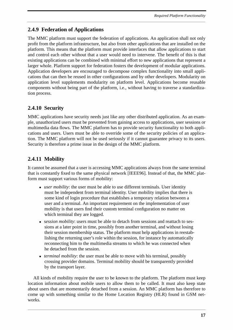
17
Required Platform Functionality
2.4.9 Federation of Applications
The MMC platform must support the federation of applications. An application shall not onlyprofit from the platform infrastructure, but also from other applications that are installed on theplatform. This means that the platform must provide interfaces that allow applications to startand control each other without that a user would need to intervene. The benefit of this is thatexisting applications can be combined with minimal effort to new applications that represent alarger whole. Platform support for federation fosters the development of modular applications.Application developers are encouraged to decompose complex functionality into small appli-cations that can then be reused in other configurations and by other developers. Modularity onapplication level supplements modularity on platform level. Applications become reusablecomponents without being part of the platform, i.e., without having to traverse a standardiza-tion process.
2.4.10 Security
MMC applications have security needs just like any other distributed application. As an exam-ple, unauthorized users must be prevented from gaining access to applications, user sessions ormultimedia data flows. The MMC platform has to provide security functionality to both appli-cations and users. Users must be able to override some of the security policies of an applica-tion. The MMC platform will not be used seriously if it cannot guarantee privacy to its users.Security is therefore a prime issue in the design of the MMC platform.
2.4.11 Mobility
It cannot be assumed that a user is accessing MMC applications always from the same terminalthat is constantly fixed to the same physical network [IEEE96]. Instead of that, the MMC plat-form must support various forms of mobility:
• user mobility: the user must be able to use different terminals. User identitymust be independent from terminal identity. User mobility implies that there issome kind of login procedure that establishes a temporary relation between auser and a terminal. An important requirement on the implementation of usermobility is that users find their custom terminal configuration no matter onwhich terminal they are logged.
• session mobility: users must be able to detach from sessions and reattach to ses-sions at a later point in time, possibly from another terminal, and without losingtheir session membership status. The platform must help applications in reestab-lishing the returning user’s role within the session, for instance by automaticallyreconnecting him to the multimedia streams to which he was connected whenhe detached from the session.
• terminal mobility: the user must be able to move with his terminal, possiblycrossing provider domains. Terminal mobility should be transparently providedby the transport layer.
All kinds of mobility require the user to be known to the platform. The platform must keeplocation information about mobile users to allow them to be called. It must also keep stateabout users that are momentarily detached from a session. An MMC platform has therefore tocome up with something similar to the Home Location Registry (HLR) found in GSM net-works.

Platform Requirements
18
2.4.12 Directory Service
The MMC platform must provide access to a ubiquitous directory service that allows to regis-ter and distribute information about users, terminals, applications, ongoing sessions and ses-sion announcements. This information is accessed by both users and applications. Users maysearch the directory service via special browsers for interesting applications or ongoing ses-sions. MMC applications use the directory service for instance to find users that are to beinvited to the session, and other applications they want to start or contact. The platform mustdefine standard interfaces that hide the actual kind of directory service being used, otherwise itwill be impossible to introduce a new directory service into the platform. Also, the platformshould make use of existing directory services rather than inventing its own.
A directory service of global scale is the Internet’s Domain Name System (DNS) [Mock87].The DNS is theoretically able to distribute other hierarchically structured information thanname-to-address mappings, but it was not conceived to provide a general white pages servicewith potentially huge numbers of users and with a high percentage of short-lived informationrecords. The Access, Searching and Indexing of Directories (ASID) working group of theIETF is now working on a general directory service for the Internet, providing access to infor-mation about people, organizations and services. The ASID working group is looking at differ-ent directory services for this purpose, among them WHOIS++ [Deut95] and X.500 [CCIT88].The results produced by the ASID working group are likely to be directly usable by an MMCplatform.
2.4.13 Platform Management
The MMC platform must provide standard interfaces for its management, for instance in formof Management Information Bases (MIB) that can be accessed via a standard network manage-ment protocol. This allows the development of management tools that are independent of theplatform implementation itself. Platform management becomes a complex task as the numberof users, applications and platform nodes increases.
2.4.14 Accounting
Many of the MMC applications installed on the platform will represent services for whichusers must pay. In addition to that, users may have to pay in one way or another for the networkbandwidth they are consuming. Accounting for MMC applications will be more complex thanin normal telephone networks. As an example, in the case of multipoint applications it is likelythat users want to share the costs of the session, rather than imposing them on the user thatstarted the session. The MMC platform must support this and other accounting scenarios in astandard way. The accounting functionality of the platform must interwork with the platform’ssecurity functionality to protect both users and service providers against fraud.
2.5 Distributed Processing Environment
The range of functionality that is required from the MMC platform is too broad to be providedby a single design effort. It would be an enormous task to conceive a platform from scratch thatoffers all the functionality listed in the previous section, and even more so to implement it. TheMMC platform has to be built on another platform that relieves it from issues that are not par-ticular to MMC, most notably from issues related to distribution. MMC applications are dis-

19
Distributed Processing Environment
tributed applications, and must therefore overcome problems that arise from distribution.Distributed applications profit from communication platforms that make the network transpar-ent and that allow programmers to implement distributed applications similar to monolithicapplications. The communication platform may offer a variety of services to applications,ranging from synchronous remote procedure calls with a single destination to asynchronousmessage passing with multiple destinations. Future communication platforms may also pro-vide transparent multipoint communication of multimedia stream data, with the result thatapplications will be completely isolated from the network.
A communication platform can mitigate negative effects of distribution, but it would be anillusion to think that application programmers do not have to worry about distribution any-more. There are four major differences between local computing and distributed computingthat a communication platform cannot hide [Wald94]:
• latency: a remote procedure call will always take orders of magnitude longer tocomplete than a procedure call within a single address space.
• memory access: remote memory access is inherently different from local mem-ory access. A platform that hides this difference prevents programmers fromoptimizing their applications.
• partial failure: parts of the distributed application may fail due to system crashesor failing network links, leaving remaining application parts without knowledgeabout what happened. In the case of local computing, failures are either com-plete or detectable.
• concurrency: the parts of a distributed application are truly concurrent, and thereis no central entity for the synchronization of application parts.
A good communication platform does not try to hide these differences between local anddistributed computing. It will even emphasize them to make application programmers moreconscious about the problematic aspects of distribution. This does not mean that the applica-tion programmer is let alone with his distributed application - he is just told where the platformcannot decide for him and where he must intervene.
For the purposes of this thesis we refer to the communication platform as the DistributedProcessing Environment (DPE), a term that is promoted by the TINA initiative and that corre-sponds more accurately to the kind of functionality needed by the MMC platform. It is statedthat an MMC platform must be built on top of a DPE to fulfill the functional requirements thatare listed in the previous section. A DPE will provide multipoint control communication andpossibly multimedia stream communication, and it will also deal with issues like security, ter-minal mobility, and possibly mobile code. Figure 2.1 shows different possibilities for the rela-tion between application, MMC platform and DPE. Relationship A is included forcompleteness and shows an unstructured MMC platform that interfaces to the applicationabove it and to the network below it. Relationship B shows a scenario where the MMC plat-form hides the underlying DPE from the applications. This has the advantage that the DPE canbe exchanged or modified without that application code would break, but requires the MMCplatform to bridge multipoint control communication between the application and the DPE.Note also that both the MMC platform and the DPE interface to the network, the MMC plat-form for multimedia data transmission, and the DPE for control communication. RelationshipC interfaces the application directly to the DPE, resulting in a DPE that provides services toboth the MMC platform and the application. Relationship D finally extends the DPE to provideall network communication.
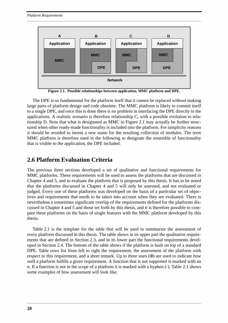
Platform Requirements
20
The DPE is so fundamental for the platform itself that it cannot be replaced without makinglarge parts of platform design and code obsolete. The MMC platform is likely to commit itselfto a single DPE, and once this is done there is no problem in interfacing the DPE directly to theapplications. A realistic scenario is therefore relationship C, with a possible evolution to rela-tionship D. Note that what is designated as MMC in Figure 2.1 may actually be further struc-tured when other ready-made functionality is included into the platform. For simplicity reasonsit should be avoided to invent a new name for the resulting collection of modules. The termMMC platform is therefore used in the following to designate the ensemble of functionalitythat is visible to the application, the DPE included.
2.6 Platform Evaluation Criteria
The previous three sections developed a set of qualitative and functional requirements forMMC platforms. These requirements will be used to assess the platforms that are discussed inChapter 4 and 5, and to evaluate the platform that is proposed by this thesis. It has to be notedthat the platforms discussed in Chapter 4 and 5 will only be assessed, and not evaluated orjudged. Every one of these platforms was developed on the basis of a particular set of objec-tives and requirements that needs to be taken into account when they are evaluated. There isnevertheless a sometimes significant overlap of the requirements defined for the platforms dis-cussed in Chapter 4 and 5 and those set forth by this thesis, and it is therefore possible to com-pare these platforms on the basis of single features with the MMC platform developed by thisthesis.
Table 2.1 is the template for the table that will be used to summarize the assessment ofevery platform discussed in this thesis. The table shows in its upper part the qualitative require-ments that are defined in Section 2.3, and in its lower part the functional requirements devel-oped in Section 2.4. The bottom of the table shows if the platform is built on top of a standardDPE. Table rows list from left to right the requirement, the assessment of the platform withrespect to this requirement, and a short remark. Up to three stars (❄ ) are used to indicate howwell a platform fulfills a given requirement. A function that is not supported is marked with ann. If a function is not in the scope of a platform it is marked with a hyphen (-). Table 2.1 showssome examples of how assessment will look like.
Figure 2.1. Possible relationships between application, MMC platform and DPE.
A B C D
Application
MMCMMC
Application Application Application
MMC MMC
DPE DPE DPE
Network
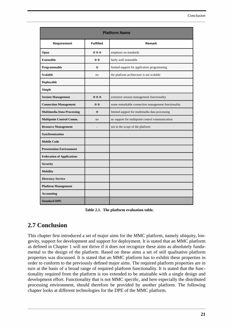
21
Conclusion
2.7 Conclusion
This chapter first introduced a set of major aims for the MMC platform, namely ubiquity, lon-gevity, support for development and support for deployment. It is stated that an MMC platformas defined in Chapter 1 will not thrive if it does not recognize these aims as absolutely funda-mental to the design of the platform. Based on these aims a set of still qualitative platformproperties was discussed. It is stated that an MMC platform has to exhibit these properties inorder to conform to the previously defined major aims. The required platform properties are inturn at the basis of a broad range of required platform functionality. It is stated that the func-tionality required from the platform is too extended to be attainable with a single design anddevelopment effort. Functionality that is not MMC specific, and here especially the distributedprocessing environment, should therefore be provided by another platform. The followingchapter looks at different technologies for the DPE of the MMC platform.
Platform Name
Requirement Fulfilled Remark
Open ❄ ❄ ❄ emphasis on standards
Extensible ❄ ❄ fairly well extensible
Programmable ❄ limited support for application programming
Scalable no the platform architecture is not scalable
Deployable
Simple
Session Management ❄ ❄ ❄ extensive session management functionality
Connection Management ❄ ❄ some remarkable connection management functionality
Multimedia Data Processing ❄ limited support for multimedia data processing
Multipoint Control Comm. no no support for multipoint control communication
Resource Management - not in the scope of the platform
Synchronization
Mobile Code
Presentation Environment
Federation of Applications
Security
Mobility
Directory Service
Platform Management
Accounting
Standard DPE
Table 2.1. The platform evaluation table.

Platform Requirements
22
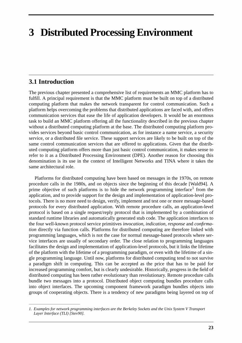
23
3 Distributed Processing Environment
3.1 Introduction
The previous chapter presented a comprehensive list of requirements an MMC platform has tofulfill. A principal requirement is that the MMC platform must be built on top of a distributedcomputing platform that makes the network transparent for control communication. Such aplatform helps overcoming the problems that distributed applications are faced with, and offerscommunication services that ease the life of application developers. It would be an enormoustask to build an MMC platform offering all the functionality described in the previous chapterwithout a distributed computing platform at the base. The distributed computing platform pro-vides services beyond basic control communication, as for instance a name service, a securityservice, or a distributed file service. These support services are likely to be built on top of thesame control communication services that are offered to applications. Given that the distrib-uted computing platform offers more than just basic control communication, it makes sense torefer to it as a Distributed Processing Environment (DPE). Another reason for choosing thisdenomination is its use in the context of Intelligent Networks and TINA where it takes thesame architectural role.
Platforms for distributed computing have been based on messages in the 1970s, on remoteprocedure calls in the 1980s, and on objects since the beginning of this decade [Wald94]. Aprime objective of such platforms is to hide the network programming interface1 from theapplication, and to provide support for the design and implementation of application-level pro-tocols. There is no more need to design, verify, implement and test one or more message-basedprotocols for every distributed application. With remote procedure calls, an application-levelprotocol is based on a single request/reply protocol that is implemented by a combination ofstandard runtime libraries and automatically generated stub code. The application interfaces tothe four well-known protocol service primitives invocation, indication, response and confirma-tion directly via function calls. Platforms for distributed computing are therefore linked withprogramming languages, which is not the case for normal message-based protocols where ser-vice interfaces are usually of secondary order. The close relation to programming languagesfacilitates the design and implementation of application-level protocols, but it links the lifetimeof the platform with the lifetime of a programming paradigm, or even with the lifetime of a sin-gle programming language. Until now, platforms for distributed computing tend to not survivea paradigm shift in computing. This can be accepted as the price that has to be paid forincreased programming comfort, but is clearly undesirable. Historically, progress in the field ofdistributed computing has been rather evolutionary than revolutionary. Remote procedure callsbundle two messages into a protocol. Distributed object computing bundles procedure callsinto object interfaces. The upcoming component framework paradigm bundles objects intogroups of cooperating objects. There is a tendency of new paradigms being layered on top of
1. Examples for network programming interfaces are the Berkeley Sockets and the Unix System V TransportLayer Interface (TLI) [Stev90].
Distributed Processing Environment
24
older ones. This suggests that platforms that are organized in a modular way and that are flexi-ble enough to form an intermediate layer will have the chance to survive paradigm shifts, withthe advantage that legacy applications may run on the same distributed computing platform asmodern applications.
The previous chapter introduced longevity as one of the major aims for the MMC platform.Since the DPE will be at the heart of the MMC platform it has to be just as future-proof as theMMC platform is required to be. The trend at the time of writing is clearly towards distributedobject computing (DOC) [Orfa96]. It is difficult if not impossible to predict the lifetime of thisparadigm, but since it is the most modern, and since it offers the most in terms of programma-bility, it is the natural choice for the DPE. The following section shows that at the momentthere is only a single DOC platform that satisfies the requirements developed in the previouschapter - this is CORBA. The choice of CORBA is justified with a first quick look at possiblealternatives. Following that comes a comprehensive description of CORBA with an emphasison those features that are used by the MMC platform proposed in this thesis. It is then possibleto have a closer look onto alternative distributed computing platforms and to discuss them withrespect to CORBA.
3.2 CORBA for the DPE
The distributed computing platform that is chosen to be the spine of the MMC platform has toexhibit the properties that were developed in the last chapter; just like the MMC platform as awhole it must be open, extensible, programmable, scalable, deployable and simple. It isrequired to offer services beyond basic control communication, and since it must be future-proof to a certain extent it is required to be language-independent and object-oriented. Theplatforms that are taken into account are:
• CORBA: the Common Object Request Broker Architecture1 is a DOC platformthat is being standardized by the Object Management Group (OMG) [OMG95c].CORBA is language-independent and offers a rich set of services in horizontaland vertical domains.
• DCE: the Distributed Computing Environment [Lock94] is a platform based onremote procedure calls that has been standardized by the Open Software Foun-dation (OSF), now part of the Open Group. DCE offers a rich set of services andhas been in use for a couple of years in large enterprises.
• DCOM: the Distributed Component Object Model is defined by Microsoft toextend the reach of its Object Linking and Embedding (OLE), ComponentObject Model (COM) and ActiveX architectures over the network [Brow96].The evolution and standardization of ActiveX has recently been given into thehands of the Open Group. DCOM has been submitted to the IETF.
• Java RMI: Java Remote Method Invocation is a DOC platform that is tailored toSun Microsystems’ Java language [Sun96d]. Together with the componentframework Java Beans [Sun96a] it is sure to become an interesting platform fordistributed applications.
The four platforms are chosen because they all play a significant role in distributed comput-
1. It is more correct to refer to OMG’s overall architecture as the Object Management Architecture (OMA), butthe acronym CORBA is widely used as a synonym for OMA, although it is actually a part of it.

25
OMA, CORBA, CORBAservices and CORBAfacilities
ing and they are all intended to be deployed on a global scale. It would have been possible toadd more RPC platforms to this list, most notably Sun Microsystems’ Open Network Comput-ing (ONC) [Sun88], but since these platforms are not based on the DOC paradigm they are notconsidered here. The exception to this is DCE which is included on one hand because it pro-vides interesting services, and on the other hand because it is the foundation for Microsoft’sDCOM.
The selection of CORBA for the DPE of the MMC platform is quickly justified. CORBA iseligible because it is open, object-oriented and language-independent. It is actually not neces-sary to get much deeper into platform properties at this point because these properties alreadyexclude the other candidates. DCE is excluded because it does not support distributed objectcomputing, and because it is too closely linked with the C programming language. This doesnot prevent DCE from being used as the RPC layer of a DOC platform, as can be seen withDCOM and some CORBA implementations. Java RMI is excluded because it is completelylanguage specific, and also because it is proprietary. However, Java RMI may become a defacto standard, or may even be standardized along with Java itself. DCOM finally is excludedbecause it is still proprietary, although steps have been undertaken by Microsoft to transformDCOM into an open standard. The strength of Microsoft architectures like OLE and COM isclearly the endsystem. As for now, DCOM appears to be a patch that allows OLE/COM tobecome accessible via the network. It is clear that DCOM will become a strong competitor toCORBA once it is standardized, and once it has become as mature as CORBA is now. Thechoice for one or the other must then be based on arguments that are more technical than thoseused here.
Right now CORBA is the only viable solution for the DPE. This picture may change as timegoes by, but for the moment there is no alternative DOC platform that is as open, mature andwidely accepted as CORBA. The following section provides an overview of CORBA that justi-fies its choice on a technical level. It is subsequently compared to DCE, DCOM and Java RMI.
3.3 OMA, CORBA, CORBAservices and CORBAfacilities
A general discussion of CORBA has to comprise the Object Management Architecture(OMA), which is the overall architectural framework, the Object Request Broker (ORB) itself,the common CORBAservices1 and the common CORBAfacilities2. CORBA is standardized bythe OMG3, an international organization founded in 1989 with the objective to establish objectmanagement specifications and a common framework for object-oriented application develop-ment. At the time of writing, OMG has about 700 members, including most of the major play-ers in information technology. The OMG standardization process is initiated with a Request forInformation (RFI) issued by an OMG Task Force that produces some ideas about the require-ments the future standard has to fulfill. A Request for Proposal (RFP) is then issued that con-tains the requirements imposed on standards proposals, and a deadline for submission. Whatfollows is an adoption process during which companies that submitted individual proposals tryto merge their submissions into a single proposal that is then considered by the Task Force forstandardization. Companies that submit proposals commit themselves to provide a commer-cially available implementation of their proposal within one year of adoption. The OMG stan-
1. Formerly known as Common Object Services (COS).
2. Formerly known as Common Facilities (CF).
3. See http://www.omg.org for substantial information about OMG, its members, activities and specifications.
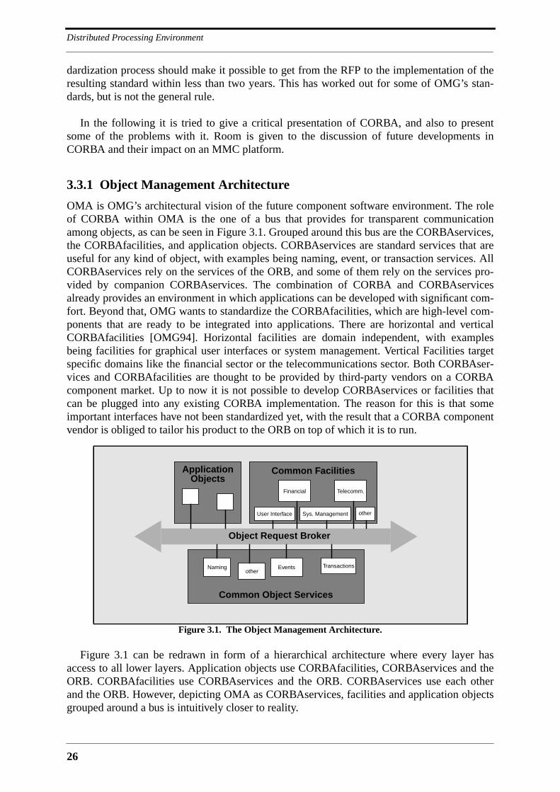
Distributed Processing Environment
26
dardization process should make it possible to get from the RFP to the implementation of theresulting standard within less than two years. This has worked out for some of OMG’s stan-dards, but is not the general rule.
In the following it is tried to give a critical presentation of CORBA, and also to presentsome of the problems with it. Room is given to the discussion of future developments inCORBA and their impact on an MMC platform.
3.3.1 Object Management Architecture
OMA is OMG’s architectural vision of the future component software environment. The roleof CORBA within OMA is the one of a bus that provides for transparent communicationamong objects, as can be seen in Figure 3.1. Grouped around this bus are the CORBAservices,the CORBAfacilities, and application objects. CORBAservices are standard services that areuseful for any kind of object, with examples being naming, event, or transaction services. AllCORBAservices rely on the services of the ORB, and some of them rely on the services pro-vided by companion CORBAservices. The combination of CORBA and CORBAservicesalready provides an environment in which applications can be developed with significant com-fort. Beyond that, OMG wants to standardize the CORBAfacilities, which are high-level com-ponents that are ready to be integrated into applications. There are horizontal and verticalCORBAfacilities [OMG94]. Horizontal facilities are domain independent, with examplesbeing facilities for graphical user interfaces or system management. Vertical Facilities targetspecific domains like the financial sector or the telecommunications sector. Both CORBAser-vices and CORBAfacilities are thought to be provided by third-party vendors on a CORBAcomponent market. Up to now it is not possible to develop CORBAservices or facilities thatcan be plugged into any existing CORBA implementation. The reason for this is that someimportant interfaces have not been standardized yet, with the result that a CORBA componentvendor is obliged to tailor his product to the ORB on top of which it is to run.
Figure 3.1 can be redrawn in form of a hierarchical architecture where every layer hasaccess to all lower layers. Application objects use CORBAfacilities, CORBAservices and theORB. CORBAfacilities use CORBAservices and the ORB. CORBAservices use each otherand the ORB. However, depicting OMA as CORBAservices, facilities and application objectsgrouped around a bus is intuitively closer to reality.
Figure 3.1. The Object Management Architecture.
Object Request Broker
Common Facilities
Common Object Services
ApplicationObjects
User Interface Sys. Management other
Telecomm.Financial
Events TransactionsNamingother
27
OMA, CORBA, CORBAservices and CORBAfacilities
OMA is an architecture that is based on the component framework paradigm. Applicationscan readily integrate an extensive set of CORBAservices and facilities, allowing applicationdevelopers to concentrate on application specific issues. However, the integration of COR-BAservices and facilities happens on a low computational level; application developers mustinteract with the objects they integrate via the ORB, which is serious programming. It can beimagined that the integration of applications happens at a higher level where independent com-ponents, each possibly with its own graphical user interface, cooperate after having beenplugged together. These so-called business objects are developed independently from eachother, but they have the capability to find out about the environment in which they are running,and they can cooperate with other business objects to reach the common goal for which theyare configured by the user that plugged them together. At the beginning of 1996, OMG issuedthe RFP Common Business Objects and Business Object Facility in a move to standardize abusiness object architecture on top of OMA [OMG96a]. Revised submissions to this RFP aredue in November 1997. Related to the business objects RFP is the CORBA Component ModelRFP that OMG issued in June 1997 [OMG97a]. This RFP asks for the development of inter-faces and mechanisms for a CORBA component model similar in spirit to Java Beans andActiveX. Interestingly, OMG requires the CORBA component model to be compatible withJava Beans. Initial submissions to the RFP are due in November 1997.
3.3.2 Common Object Request Broker Architecture
The CORBA ORB manages all communication between object clients and implementations.CORBA defines a relatively simple object model with the main constituents being the objectinterface and an identifier for the object, the object reference. The object interface is describedwith the programming-language neutral Interface Definition Language (IDL). Up to now, IDLis the predominant formalism for specification in OMA, if not the only one. The following dis-cusses the object model, the IDL, and the ORB architecture [OMG95c].
Object Model
The services an object can provide are isolated from object clients by well-defined encapsulat-ing interfaces. An object client refers to a certain object by means of a unique identifier, whichis the object reference. A given object may be identified by more than one such object refer-ence. An object client interacts with the object via requests. A request carries parameters andpossibly a context to the object where the respective service is invoked, and returns a resultback to the client in case the request could be served as expected, or an exception in case anerror occurred. A request parameter is of type in, out or inout. In-parameters are passed fromthe client to the object, out-parameters are filled in by the object and returned to the client, andinout-parameters are passed from the client to the object where they are modified and returnedto the client. Parameters represent values of one of the basic or constructed CORBA types.Basic CORBA types are signed, unsigned, short or long integers, short or long floating pointnumbers, characters, booleans, opaque 8-bit numbers, enumerations, strings and the type any.Constructed CORBA types are records, discriminated unions, sequences, arrays and interfaces.Most of these types are well-known from programming languages like C, with the exception ofthe types any and interface. The type interface allows to pass a typed object reference asparameter of a request. The type any is used as a container for an arbitrary basic or constructedtype.
The execution semantics defined so far in CORBA are twoway1 and oneway. A twowayrequest consists of the actual request and a reply that is sent back to the requester. It blocks the
Distributed Processing Environment
28
requester until either a result or an exception is returned. The default semantics of twowayrequests are exactly once if the request is successful, and at most once if an exception isreturned. A oneway operation does not return a result to the requester, but may generate anexception. The semantics of oneway operations are best-effort, meaning that the delivery of therequest to the object is not guaranteed and that the request will be serviced at most once. Thisreduces the utility of oneway operations because they cannot be used for reliable asynchronousmessaging1.
An object interface declares the requests an object can service in form of operations. Inaddition to that it exposes a part of the object’s state to the outside in form of attributes. Thevalue of an attribute can in general be read and modified, but CORBA also supports read-onlyattributes. The utility of attributes is controversial given that from a computational point-of-view an attribute can be substituted with a set and a get operation. Attributes in CORBA seemto have their origin in object-oriented analysis. Their existence in CORBA facilitates the movefrom analysis to design, but they are a potential risk for unexperienced CORBA designers thattend to use them as a surrogate for operations. Since it is not possible to define exceptions forattributes it should be avoided to use an attribute if there is the slightest chance that the set orget operation on the attribute fails.
Interface Definition Language
The interface of a CORBA object is defined in IDL. Interface definitions can be compiled intoprogramming-language specific client stubs and server skeletons that mediate between a dataformat adequate for transmission over the network and the programming languages in whichthe object client and the object itself are implemented. IDL is object-oriented, making it some-what awkward to map it on a language that is not, like for instance C. IDL language mappingsexist for C, C++, Ada, Cobol and Smalltalk. The language mapping for Java is about to befinalized at the time of writing. The IDL language mapping to Java is of strategic importancefor OMG as it promotes the use of CORBA for Internet applications, namely the Web.
IDL supports multiple interface inheritance. This allows to base architectures defined inIDL on polymorphism and to design interface hierarchies that can be close to implementationhierarchies if the programming language supports multiple implementation inheritance. C++ isan example for a programming language that maps naturally to IDL due to its support for mul-tiple inheritance. A well-designed IDL interface hierarchy may be reflected one-to-one in aC++ class hierarchy, laying the ground for code reuse. This does not work out as nicely forJava which only supports single implementation inheritance. However, Java supports multipleinterface inheritance2, making it straightforward to map IDL interfaces directly onto Java inter-faces. All IDL interfaces inherit implicitly from the interface Object which contains basicfunctionality that is accessible to both the object client and the object implementation.
IDL supports the definition of contexts for operation invocations. A context is a set ofstring-value mappings that is passed along with the operation invocation from the client to theobject implementation. This allows to supply information to an operation invocation thatwould be inconvenient to pass in the parameter list. A context may contain information that is
1. Twoway operations are the default in IDL operation definitions. There is no special keyword for them.
1. Oneway operations are implemented in different ways. Some ORB’s block the requester until the request isdelivered, others transmit the request asynchronously. The standard is not very clear about the semantics ofoneway requests.
2. Java refers to interface inheritance as interface extension.
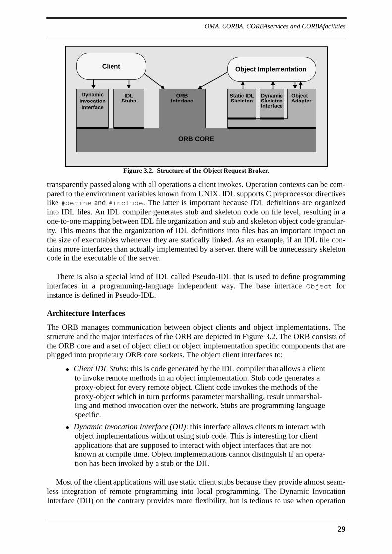
29
OMA, CORBA, CORBAservices and CORBAfacilities
transparently passed along with all operations a client invokes. Operation contexts can be com-pared to the environment variables known from UNIX. IDL supports C preprocessor directiveslike #define and #include. The latter is important because IDL definitions are organizedinto IDL files. An IDL compiler generates stub and skeleton code on file level, resulting in aone-to-one mapping between IDL file organization and stub and skeleton object code granular-ity. This means that the organization of IDL definitions into files has an important impact onthe size of executables whenever they are statically linked. As an example, if an IDL file con-tains more interfaces than actually implemented by a server, there will be unnecessary skeletoncode in the executable of the server.
There is also a special kind of IDL called Pseudo-IDL that is used to define programminginterfaces in a programming-language independent way. The base interface Object forinstance is defined in Pseudo-IDL.
Architecture Interfaces
The ORB manages communication between object clients and object implementations. Thestructure and the major interfaces of the ORB are depicted in Figure 3.2. The ORB consists ofthe ORB core and a set of object client or object implementation specific components that areplugged into proprietary ORB core sockets. The object client interfaces to:
• Client IDL Stubs: this is code generated by the IDL compiler that allows a clientto invoke remote methods in an object implementation. Stub code generates aproxy-object for every remote object. Client code invokes the methods of theproxy-object which in turn performs parameter marshalling, result unmarshal-ling and method invocation over the network. Stubs are programming languagespecific.
• Dynamic Invocation Interface (DII): this interface allows clients to interact withobject implementations without using stub code. This is interesting for clientapplications that are supposed to interact with object interfaces that are notknown at compile time. Object implementations cannot distinguish if an opera-tion has been invoked by a stub or the DII.
Most of the client applications will use static client stubs because they provide almost seam-less integration of remote programming into local programming. The Dynamic InvocationInterface (DII) on the contrary provides more flexibility, but is tedious to use when operation
Figure 3.2. Structure of the Object Request Broker.
Client Object Implementation
DynamicInvocationInterface
IDLStubs
ORBInterface
Static IDLSkeleton
DynamicSkeleton
ObjectAdapter
ORB CORE
Interface
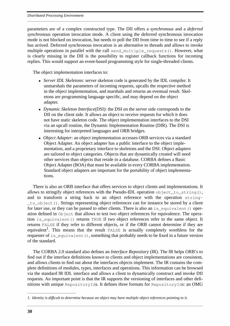
Distributed Processing Environment
30
parameters are of a complex constructed type. The DII offers a synchronous and a deferredsynchronous operation invocation mode. A client using the deferred synchronous invocationmode is not blocked on invocation, but needs to poll the DII from time to time to see if a replyhas arrived. Deferred synchronous invocation is an alternative to threads and allows to invokemultiple operations in parallel with the call send_multiple_requests(). However, whatis clearly missing in the DII is the possibility to register callback functions for incomingreplies. This would support an event-based programming style for single-threaded clients.
The object implementation interfaces to:
• Server IDL Skeletons: server skeleton code is generated by the IDL compiler. Itunmarshals the parameters of incoming requests, upcalls the respective methodin the object implementation, and marshals and returns an eventual result. Skel-etons are programming language specific, and may depend on the objectadapter.
• Dynamic Skeleton Interface(DSI): the DSI on the server side corresponds to theDII on the client side. It allows an object to receive requests for which it doesnot have static skeleton code. The object implementation interfaces to the DSIvia an upcall routine, the Dynamic Implementation Routine (DIR). The DSI isinteresting for interpreted languages and ORB bridges.
• Object Adapter: an object implementation accesses ORB services via a standardObject Adapter. An object adapter has a public interface to the object imple-mentation, and a proprietary interface to skeletons and the DSI. Object adaptersare tailored to object categories. Objects that are dynamically created will needother services than objects that reside in a database. CORBA defines a BasicObject Adapter (BOA) that must be available in every CORBA implementation.Standard object adapters are important for the portability of object implementa-tions.
There is also an ORB interface that offers services to object clients and implementations. Itallows to stringify object references with the Pseudo-IDL operation object_to_string(),and to transform a string back to an object reference with the operation string-_to_object(). Strings representing object references can for instance be stored by a clientfor later use, or they can be passed to other clients. There is also an is_equivalent() oper-ation defined in Object that allows to test two object references for equivalence. The opera-tion is_equivalent() returns TRUE if two object references refer to the same object. Itreturns FALSE if they refer to different objects, or if the ORB cannot determine if they areequivalent1. This means that the result FALSE is actually completely worthless for therequester of is_equivalent(), something that probably needs to be fixed in a future versionof the standard.
The CORBA 2.0 standard also defines an Interface Repository (IR). The IR helps ORB’s tofind out if the interface definitions known to clients and object implementations are consistent,and allows clients to find out about the interfaces objects implement. The IR contains the com-plete definitions of modules, types, interfaces and operations. This information can be browsedvia the standard IR IDL interface and allows a client to dynamically construct and invoke DIIrequests. An important point is that the IR supports the versioning of interfaces and other defi-nitions with unique RepositoryIds. It defines three formats for RepositoryIds: an OMG
1. Identity is difficult to determine because an object may have multiple object references pointing to it.
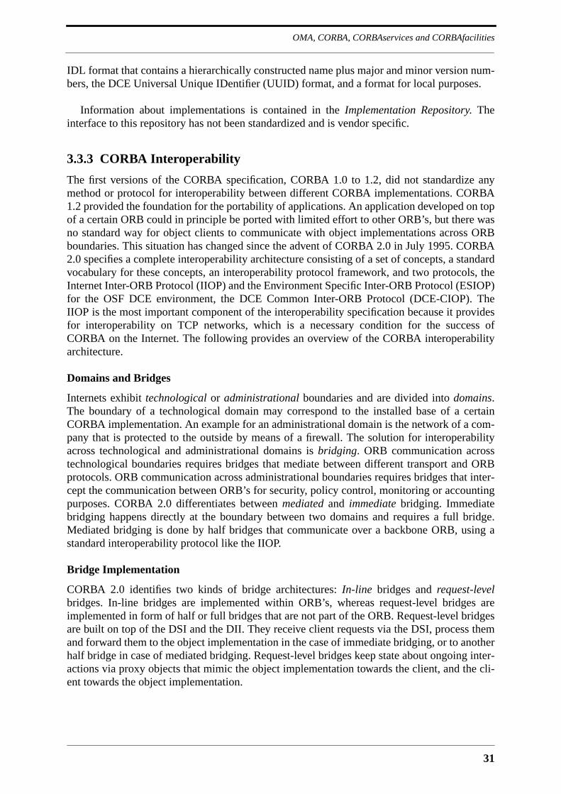
31
OMA, CORBA, CORBAservices and CORBAfacilities
IDL format that contains a hierarchically constructed name plus major and minor version num-bers, the DCE Universal Unique IDentifier (UUID) format, and a format for local purposes.
Information about implementations is contained in the Implementation Repository. Theinterface to this repository has not been standardized and is vendor specific.
3.3.3 CORBA Interoperability
The first versions of the CORBA specification, CORBA 1.0 to 1.2, did not standardize anymethod or protocol for interoperability between different CORBA implementations. CORBA1.2 provided the foundation for the portability of applications. An application developed on topof a certain ORB could in principle be ported with limited effort to other ORB’s, but there wasno standard way for object clients to communicate with object implementations across ORBboundaries. This situation has changed since the advent of CORBA 2.0 in July 1995. CORBA2.0 specifies a complete interoperability architecture consisting of a set of concepts, a standardvocabulary for these concepts, an interoperability protocol framework, and two protocols, theInternet Inter-ORB Protocol (IIOP) and the Environment Specific Inter-ORB Protocol (ESIOP)for the OSF DCE environment, the DCE Common Inter-ORB Protocol (DCE-CIOP). TheIIOP is the most important component of the interoperability specification because it providesfor interoperability on TCP networks, which is a necessary condition for the success ofCORBA on the Internet. The following provides an overview of the CORBA interoperabilityarchitecture.
Domains and Bridges
Internets exhibit technological or administrational boundaries and are divided into domains.The boundary of a technological domain may correspond to the installed base of a certainCORBA implementation. An example for an administrational domain is the network of a com-pany that is protected to the outside by means of a firewall. The solution for interoperabilityacross technological and administrational domains is bridging. ORB communication acrosstechnological boundaries requires bridges that mediate between different transport and ORBprotocols. ORB communication across administrational boundaries requires bridges that inter-cept the communication between ORB’s for security, policy control, monitoring or accountingpurposes. CORBA 2.0 differentiates between mediated and immediate bridging. Immediatebridging happens directly at the boundary between two domains and requires a full bridge.Mediated bridging is done by half bridges that communicate over a backbone ORB, using astandard interoperability protocol like the IIOP.
Bridge Implementation
CORBA 2.0 identifies two kinds of bridge architectures: In-line bridges and request-levelbridges. In-line bridges are implemented within ORB’s, whereas request-level bridges areimplemented in form of half or full bridges that are not part of the ORB. Request-level bridgesare built on top of the DSI and the DII. They receive client requests via the DSI, process themand forward them to the object implementation in the case of immediate bridging, or to anotherhalf bridge in case of mediated bridging. Request-level bridges keep state about ongoing inter-actions via proxy objects that mimic the object implementation towards the client, and the cli-ent towards the object implementation.

Distributed Processing Environment
32
Interoperable Object References
Different ORB’s use different formats for the object references that identify object implemen-tations. A bridge must mediate between the object reference formats of the domains that itinterconnects. The proxy object in a request-level bridge is addressed by the client with anobject reference having the format of the client’s ORB, and maps this object reference to theformat that is understood by the ORB of the hidden object implementation. CORBA 2.0defines a standard format for object references in interoperability protocols, which is the Inter-operable Object Reference (IOR). IOR’s consist of a type identifier and a list of so calledtagged profiles that identify the object implementation in various formats. The type identifier isin fact the supposedly unique RepositoryId of the object’s interface in the Interface Reposi-tory. It gives ORB’s the possibility to dynamically check type consistency between operationinvocations and object implementations. A tagged profile consists of the basic information nec-essary to identify a certain object within the scope of a certain ORB protocol. It contains a pro-file identifier (the tag) and a sequence of octets (the profile data). Every interoperabilityprotocol defines a tagged profile to be used in IOR’s.
General Inter-ORB Protocol and Internet Inter-ORB Protocol
CORBA 2.0 defines the General Inter-ORB Protocol (GIOP) that can be mapped onto varioustransport protocols. The GIOP specification consists of the Common Data Representation(CDR), the GIOP message format, and some assumptions about transport.
The CDR provides a complete network-level representation for IDL and Pseudo-IDL types,including primitive types, constructed types, the any type, type codes, exceptions, and IOR’s.The encoding of type codes is the most complex because of their recursive nature. Byte order-ing in CDR may be big-endian or little-endian and is chosen by the message originator. Thisimproves performance whenever message originator and receiver share the same internal datarepresentation.
The GIOP allows to locate objects, invoke operations in object implementations, and man-age transport connections. It defines a common message header and seven messages, alldefined in Pseudo-IDL. The message header contains the protocol version, the byte order, themessage type and the message size. The messages are:
• Request: sent by a client to invoke an operation in an object implementation.The header of this message contains among other things the object identifierthat is derived from the IOR, the name of the operation, a value identifying therequesting principal, and a request identifier. The body contains the in and inoutparameters and the context of the operation.
• Reply: sent in response to Request messages. The header of this message con-tains the request identifier of the respective Request message, and a reply statustelling if the body of the Reply message contains out and inout parameters, anexception, or an IOR. The latter case signifies that the client ORB must reissuethe request to the object identified by the received IOR.
• CancelRequest: allows a client to cancel a request. This message may be sent incase a client is not willing to keep on waiting for a Reply message.
• LocateRequest: allows a client to find out if a server is capable of receivingrequests to the given object identifier. The LocateRequest message contains arequest identifier and the respective object identifier.

33
OMA, CORBA, CORBAservices and CORBAfacilities
• LocateReply: sent by a server in response to a LocateRequest message. TheLocateReply message header contains a locate status telling if the object isunknown, supported locally, or supported elsewhere. In the latter case the Loca-teRequest message body contains the IOR of the new location.
• CloseConnection: sent by servers to indicate to clients that the connection isgoing to be shut down.
• MessageError: sent in response to erroneous messages.
Clients open initial connections with agents that may not necessarily be able to respond torequests directed to a certain object. A client may therefore choose to send a LocateRequest asfirst message on a newly established connection. The LocateReply of the agent may then con-tain a new IOR which in turn allows the client to open a connection to a server that implementsthe object. Clients may also adopt an optimistic approach and immediately send a Requestmessage on the connection. An agent that is not capable of serving the request will send aReply containing the IOR, and the client is obliged to repeat the request. This proceeding mayhave a negative performance impact if the request contains voluminous parameters. Clientsmust be prepared to receive IOR replies at any time. This supports the transparent migration ofobjects.
An important restriction of GIOP is that connections between clients and servers are asym-metrical, meaning that a server may never send a Request, LocateRequest or CancelRequestmessage on a connection. This restriction has the advantage that it keeps the protocol simple,and that it avoids race conditions, but it appears to be rather awkward at a time where distrib-uted computing is evolving from client-server to peer-to-peer communication. A server havingevents to communicate to a client is obliged to open a second connection, which is a seriousdrawback considering that transport connections consume considerable operating systemresources.
IIOP finally is a mapping of GIOP onto TCP. CORBA 2.0 defines IIOP on two pages, withthe most important definition being a tagged profile for the IIOP IOR. The profile contains theIIOP version number, an Internet host address in dotted decimal format, a port number, and theobject identifier. IIOP is the most widely used CORBA protocol today. It is already supportedby a couple of firewall vendors, and will also be part of the next generation of Web browsers,where it will be used by downloaded Java applets to access CORBA servers. IIOP is likely tobecome one of the most important Internet protocols.
Environment Specific Inter-ORB Protocol
CORBA 2.0 foresees interoperability protocols other than the GIOP that are based on existingprotocols. Such Environment Specific Inter-ORB Protocols (ESIOP) provide the advantagethat ORB’s may leverage existing functionality that is possibly outside the scope of CORBA.The DCE-CIOP is an ESIOP that has been defined on top of DCE. There is a single DCE-IDLinterface containing the operations invoke() and locate() that are accessed via DCE RPC.The DCE-CIOP is the only ESIOP defined until now. Another candidate for standardizationmight be the ONC+ RPC. It must nevertheless be said that ESIOP’s are a solution for the inte-gration of ORB’s into legacy systems. OMG is targeting functionality for standardization thatis way beyond what DCE offers today. This includes a security service, which until now hasbeen one of the strong points of DCE. Once this functionality is available it is likely that net-work administrators that are now favoring DCE-CIOP will switch to IIOP, which is anywayimplemented by all CORBA vendors.
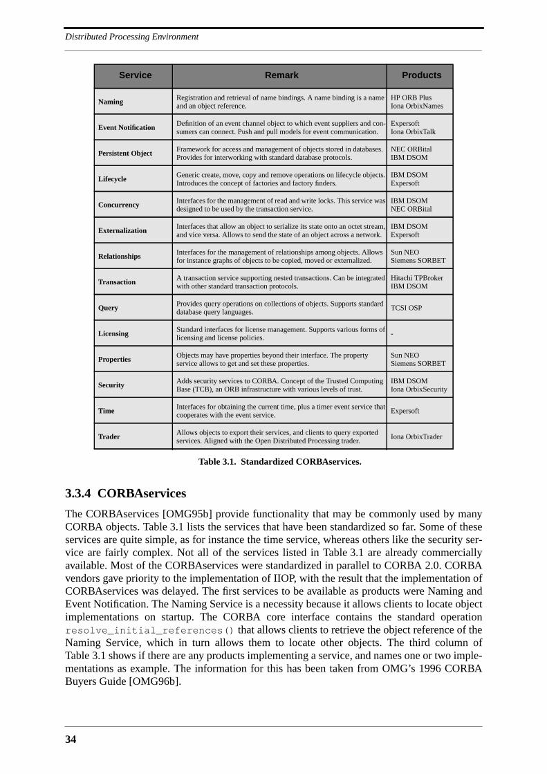
Distributed Processing Environment
34
3.3.4 CORBAservices
The CORBAservices [OMG95b] provide functionality that may be commonly used by manyCORBA objects. Table 3.1 lists the services that have been standardized so far. Some of theseservices are quite simple, as for instance the time service, whereas others like the security ser-vice are fairly complex. Not all of the services listed in Table 3.1 are already commerciallyavailable. Most of the CORBAservices were standardized in parallel to CORBA 2.0. CORBAvendors gave priority to the implementation of IIOP, with the result that the implementation ofCORBAservices was delayed. The first services to be available as products were Naming andEvent Notification. The Naming Service is a necessity because it allows clients to locate objectimplementations on startup. The CORBA core interface contains the standard operationresolve_initial_references() that allows clients to retrieve the object reference of theNaming Service, which in turn allows them to locate other objects. The third column ofTable 3.1 shows if there are any products implementing a service, and names one or two imple-mentations as example. The information for this has been taken from OMG’s 1996 CORBABuyers Guide [OMG96b].
Service Remark Products
Naming Registration and retrieval of name bindings. A name binding is a nameand an object reference.
HP ORB PlusIona OrbixNames
Event Notification Definition of an event channel object to which event suppliers and con-sumers can connect. Push and pull models for event communication.
ExpersoftIona OrbixTalk
Persistent Object Framework for access and management of objects stored in databases.Provides for interworking with standard database protocols.
NEC ORBitalIBM DSOM
Lifecycle Generic create, move, copy and remove operations on lifecycle objects.Introduces the concept of factories and factory finders.
IBM DSOMExpersoft
Concurrency Interfaces for the management of read and write locks. This service wasdesigned to be used by the transaction service.
IBM DSOMNEC ORBital
Externalization Interfaces that allow an object to serialize its state onto an octet stream,and vice versa. Allows to send the state of an object across a network.
IBM DSOMExpersoft
Relationships Interfaces for the management of relationships among objects. Allowsfor instance graphs of objects to be copied, moved or externalized.
Sun NEOSiemens SORBET
Transaction A transaction service supporting nested transactions. Can be integratedwith other standard transaction protocols.
Hitachi TPBrokerIBM DSOM
Query Provides query operations on collections of objects. Supports standarddatabase query languages.
TCSI OSP
Licensing Standard interfaces for license management. Supports various forms oflicensing and license policies.
-
Properties Objects may have properties beyond their interface. The propertyservice allows to get and set these properties.
Sun NEOSiemens SORBET
Security Adds security services to CORBA. Concept of the Trusted ComputingBase (TCB), an ORB infrastructure with various levels of trust.
IBM DSOMIona OrbixSecurity
Time Interfaces for obtaining the current time, plus a timer event service thatcooperates with the event service.
Expersoft
Trader Allows objects to export their services, and clients to query exportedservices. Aligned with the Open Distributed Processing trader.
Iona OrbixTrader
Table 3.1. Standardized CORBAservices.
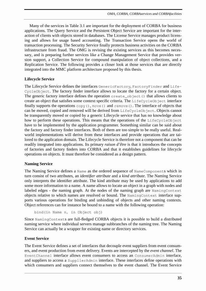
35
OMA, CORBA, CORBAservices and CORBAfacilities
Many of the services in Table 3.1 are important for the deployment of CORBA for businessapplications. The Query Service and the Persistent Object Service are important for the inter-action of clients with objects stored in databases. The License Service manages product licens-ing and allows for usage based accounting. The Transaction Service opens the world oftransaction processing. The Security Service finally protects business activities on the CORBAinfrastructure from fraud. The OMG is revising the existing services as this becomes neces-sary, and is preparing further services like a Change Management Service that provides ver-sion support, a Collection Service for compound manipulation of object collections, and aReplication Service. The following provides a closer look at those services that are directlyintegrated into the MMC platform architecture proposed by this thesis.
Lifecycle Service
The Lifecycle Service defines the interfaces GenericFactory, FactoryFinder and Life-CycleObject. The factory finder interface allows to locate the factory for a certain object.The generic factory interface defines the operation create_object() that allows clients tocreate an object that satisfies some context specific criteria. The LifeCycleObject interfacefinally supports the operations copy(), move() and remove(). The interface of objects thatcan be moved, copied and removed will be derived from LifeCycleObject. Objects cannotbe transparently moved or copied by a generic Lifecycle service that has no knowledge abouthow to perform these operations. This means that the operations of the LifeCycleObjecthave to be implemented by the application programmer. Something similar can be said aboutthe factory and factory finder interfaces. Both of them are too simple to be really useful. Real-world implementations will derive from these interfaces and provide operations that are tai-lored to the application domain. The Lifecycle Service is therefore not a component that can bereadily integrated into applications. Its primary raison d’être is that it introduces the conceptsof factories and factory finders into CORBA and that it establishes guidelines for lifecycleoperations on objects. It must therefore be considered as a design pattern.
Naming Service
The Naming Service defines a Name as the ordered sequence of NameComponents which inturn consist of two attributes, an identifier attribute and a kind attribute. The Naming Serviceonly interprets the identifier attribute. The kind attribute may be used by applications to addsome more information to a name. A name allows to locate an object in a graph with nodes andlabeled edges - the naming graph. At the nodes of the naming graph are NamingContextobjects relative to which names are resolved or bound. The NamingContext interface sup-ports various operations for binding and unbinding of objects and other naming contexts.Object references can for instance be bound to a name with the following operation:
bind(in Name n, in Object obj)
Since NamingContexts are full-fledged CORBA objects it is possible to build a distributednaming service where individual servers manage subbranches of the naming tree. The NamingService can actually be a wrapper for existing name or directory services.
Event Service
The Event Service defines a set of interfaces that decouple event suppliers from event consum-ers, and event production from event delivery. Events are intercepted by the event channel. TheEventChannel interface allows event consumers to access an ConsumerAdmin interface,and suppliers to access a SupplierAdmin interface. These interfaces define operations withwhich consumers and suppliers connect themselves to the event channel. The Event Service
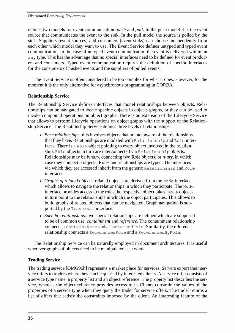
Distributed Processing Environment
36
defines two models for event communication: push and pull. In the push model it is the eventsource that communicates the event to the sink. In the pull model the source is polled by thesink. Suppliers (event sources) and consumers (event sinks) can choose independently fromeach other which model they want to use. The Event Service defines untyped and typed eventcommunication. In the case of untyped event communication the event is delivered within anany type. This has the advantage that no special interfaces need to be defined for event produc-ers and consumers. Typed event communication requires the definition of specific interfacesfor the consumers of pushed events and the suppliers of pulled events.
The Event Service is often considered to be too complex for what it does. However, for themoment it is the only alternative for asynchronous programming in CORBA.
Relationship Service
The Relationship Service defines interfaces that model relationships between objects. Rela-tionships can be navigated to locate specific objects in objects graphs, or they can be used toinvoke compound operations on object graphs. There is an extension of the Lifecycle Servicethat allows to perform lifecycle operations on object graphs with the support of the Relation-ship Service. The Relationship Service defines three levels of relationships:
• Base relationships: this involves objects that are not aware of the relationshipsthat they have. Relationships are modeled with Relationship and Role inter-faces. There is a Role object pointing to every object involved in the relation-ship. Role objects in turn are interconnected via Relationship objects.Relationships may be binary, connecting two Role objects, or n-ary, in whichcase they connect n objects. Roles and relationships are typed. The interfacesvia which they are accessed inherit from the generic Relationship and Roleinterfaces.
• Graphs of related objects: related objects are derived from the Node interfacewhich allows to navigate the relationships in which they participate. The Nodeinterface provides access to the roles the respective object takes. Role objectsin turn point to the relationships in which the object participates. This allows tobuild graphs of related objects that can be navigated. Graph navigation is sup-ported by the Traversal interface.
• Specific relationships: two special relationships are defined which are supposedto be of common use: containment and reference. The containment relationshipconnects a ContainsRole and a ContainedRole. Similarily, the referencerelationship connects a ReferencesRole and a ReferencedByRole.
The Relationship Service can be naturally employed in document architectures. It is usefulwherever graphs of objects need to be manipulated as a whole.
Trading Service
The trading service [OMG96h] represents a market place for services. Servers export their ser-vice offers to traders where they can be queried by interested clients. A service offer consists ofa service type name, a property list and an object reference. The property list describes the ser-vice, whereas the object reference provides access to it. Clients constrain the values of theproperties of a service type when they query the trader for service offers. The trader returns alist of offers that satisfy the constraints imposed by the client. An interesting feature of the

37
OMA, CORBA, CORBAservices and CORBAfacilities
trading service is federation. A trader can have links to other traders and forward client queriesto them. A client can therefore consult with a single query the offers of multiple federated trad-ers.
3.3.5 CORBAfacilities
The CORBAfacilities [OMG95a] are application specific services layered on top of the ORBand the CORBAservices. OMG distinguishes between horizontal and vertical facilities. Hori-zontal facilities target a broad range of applications and markets, whereas vertical facilities aretailored to a single market. Horizontal facilities are classified into the following categories[Sieg96]:
• User interface: rendering management, compound presentation management,user support, desktop management, scripting. OpenDoc has been submitted ascompound presentation management facility.
• Information management: information modeling, information storage andretrieval, compound interchange, et cetera.
• Systems management: a standard for systems management has been proposed byX/Open (now the Open Group).
• Task management: workflow, agents, rule management, automation.
At the time of writing the RFP’s for the horizontal facilities have been issued, and submis-sions have been received, but the only facility that is standardized is the System ManagementFacility.
Various OMG Task forces have been formed to work on vertical CORBAfacilities. The tar-geted vertical markets and respective RFP’s are:
• Healthcare: there is a Patient Identification Services RFP and a Healthcare Lex-icon Service RFP.
• Telecommunications: there are three RFP’s - the RFP for Control and Manage-ment of A/V Streams, the Topology RFP and the Notification Service RFP.
• Financial Services: there is the Financial Domain Task Force Currency RFP.
• Electronic Commerce: there is an Electronic Payment Facility RFP.
• Manufacturing: there is the Product Data Management Enablers RFP.
• Business Objects: the Business Object Domain Task Force has issued an RFPfor common business objects and a business object facility [OMG96a]. Thebusiness object facility is the environment in which common business objectsare active. It has to be noted that business objects appear to be an extension ofOMA rather than a CORBAfacility. The RFP depicts the business object facilityas being layered on top of OMA.
As can be seen, the OMG is getting active on diverse markets. Given this it can be imaginedthat an MMC platform is standardized as a CORBAfacility. The CORBAfacility standardiza-tion process is lightweight compared to the one of the CORBAservices. An OMG Task Forcecould rapidly standardize a basic MMC platform, and take care of extensions in the following.The existence of a Telecommunications Task Force shows that OMG is starting to account forthe interest of the telecommunications industry in CORBA. Until now the TelecommunicationsTask Force has issued three RFP’s and one RFI. The RFI Issues for Intelligent Networking with

Distributed Processing Environment
38
CORBA is the first step towards an introduction of CORBA into IN. The Topology RFP asksfor an alternative to the Relationship Service that accommodates relationships betweenCORBA and non-CORBA objects. Such a service allows to integrate the CORBA objectmodel and existing network management object models into a single framework. The Notifica-tion RFP asks for an event notification service that allows event consumers to filter incomingevents. This RFP is again motivated by network management requirements. The third RFP,Control and Management of A/V Streams, is interesting for MMC platforms and is discussed inthe following.
3.3.6 Stream Support in CORBA
The Telecommunications Task Force proposes in its RFP [OMG96g] and a companion whitepaper [Raym95] a model for an architecture that supports audio and video streams. Althoughsubmissions are not required to adopt this model it is very likely that the final standard willcorrespond to it. Figure 3.3 depicts the synthesis of the architecture description in the whitepaper and the RFP. The white paper proposes a stream extension of CORBA along the lines ofthe existing architecture. Streams are composed of data flows which in turn consist of individ-ual frames. A stream may therefore bundle multiple flows, with an example being an audio anda correlated video flow. Stream sources and sinks interface to a stream like a client and anobject implementation interface to an operation. The stream source interfaces to a stream stubthat marshals data into frames. Similarly, the stream sink interfaces to a stream skeleton thatunmarshals frames and forwards data. Stub and skeleton code is generated by a compiler thattakes a stream interface definition as input. Communication protocols are either encapsulatedby the stream object adapter, or integrated into the ORB core. Stream sources and sinks cancontrol stream QoS via the stream object adapter interface. Since different communication pro-tocols have different QoS parameters, there is the risk that every stream object adapter definesits own interface to QoS management, with the result that application code must be tailored toa communications protocol. This can be avoided by defining a standard QoS interface for thestream object adapter that is independent from any communication protocol.
The RFP addresses the control and management of audio and video streams. This is indi-cated with the control interfaces in the source and sink objects in Figure 3.3. The outcome ofthis RFP will therefore be a set of normal IDL interfaces for the setup and control of audio andvideo stream bindings. The RFP requires submissions to address among other things the fol-lowing issues:
• Various topologies: one-to-one, one-to-many, many-to-one, many-to-many.
• Multiple flows: a stream is a container for multiple flows. Operations on streamsare compound operations on the flows streams contain.
• Stream control: this covers stream setup, release and modification.
• Stream interface reference: the endpoints of stream must be identified with astream interface reference. This corresponds to the object reference.
• Quality of Service: framework for the expression and monitoring of QoS.
The interfaces between stream source and sink and the stream object adapters are explicitlyexcluded from the scope of this RFP. It can be assumed that they will be addressed by a futureRFP. The Telecommunications Task Force foresees to standardize a selected submission inSeptember 1997.
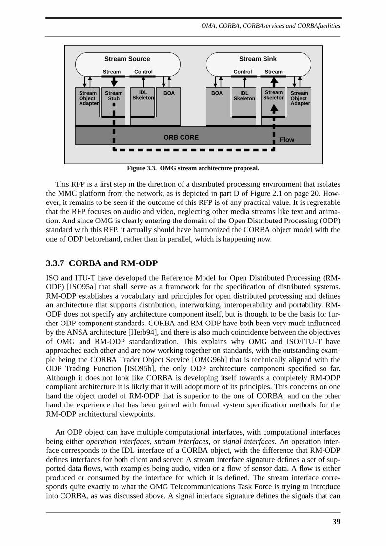
39
OMA, CORBA, CORBAservices and CORBAfacilities
This RFP is a first step in the direction of a distributed processing environment that isolatesthe MMC platform from the network, as is depicted in part D of Figure 2.1 on page 20. How-ever, it remains to be seen if the outcome of this RFP is of any practical value. It is regrettablethat the RFP focuses on audio and video, neglecting other media streams like text and anima-tion. And since OMG is clearly entering the domain of the Open Distributed Processing (ODP)standard with this RFP, it actually should have harmonized the CORBA object model with theone of ODP beforehand, rather than in parallel, which is happening now.
3.3.7 CORBA and RM-ODP
ISO and ITU-T have developed the Reference Model for Open Distributed Processing (RM-ODP) [ISO95a] that shall serve as a framework for the specification of distributed systems.RM-ODP establishes a vocabulary and principles for open distributed processing and definesan architecture that supports distribution, interworking, interoperability and portability. RM-ODP does not specify any architecture component itself, but is thought to be the basis for fur-ther ODP component standards. CORBA and RM-ODP have both been very much influencedby the ANSA architecture [Herb94], and there is also much coincidence between the objectivesof OMG and RM-ODP standardization. This explains why OMG and ISO/ITU-T haveapproached each other and are now working together on standards, with the outstanding exam-ple being the CORBA Trader Object Service [OMG96h] that is technically aligned with theODP Trading Function [ISO95b], the only ODP architecture component specified so far.Although it does not look like CORBA is developing itself towards a completely RM-ODPcompliant architecture it is likely that it will adopt more of its principles. This concerns on onehand the object model of RM-ODP that is superior to the one of CORBA, and on the otherhand the experience that has been gained with formal system specification methods for theRM-ODP architectural viewpoints.
An ODP object can have multiple computational interfaces, with computational interfacesbeing either operation interfaces, stream interfaces, or signal interfaces. An operation inter-face corresponds to the IDL interface of a CORBA object, with the difference that RM-ODPdefines interfaces for both client and server. A stream interface signature defines a set of sup-ported data flows, with examples being audio, video or a flow of sensor data. A flow is eitherproduced or consumed by the interface for which it is defined. The stream interface corre-sponds quite exactly to what the OMG Telecommunications Task Force is trying to introduceinto CORBA, as was discussed above. A signal interface signature defines the signals that can
Figure 3.3. OMG stream architecture proposal.
Stream Sink
IDLSkeleton
Stream
ORB CORE
SkeletonStreamObjectAdapter
BOA
StreamControl
Stream Source
StreamStub
IDLSkeleton
BOAStream
ControlStream
ObjectAdapter
Flow
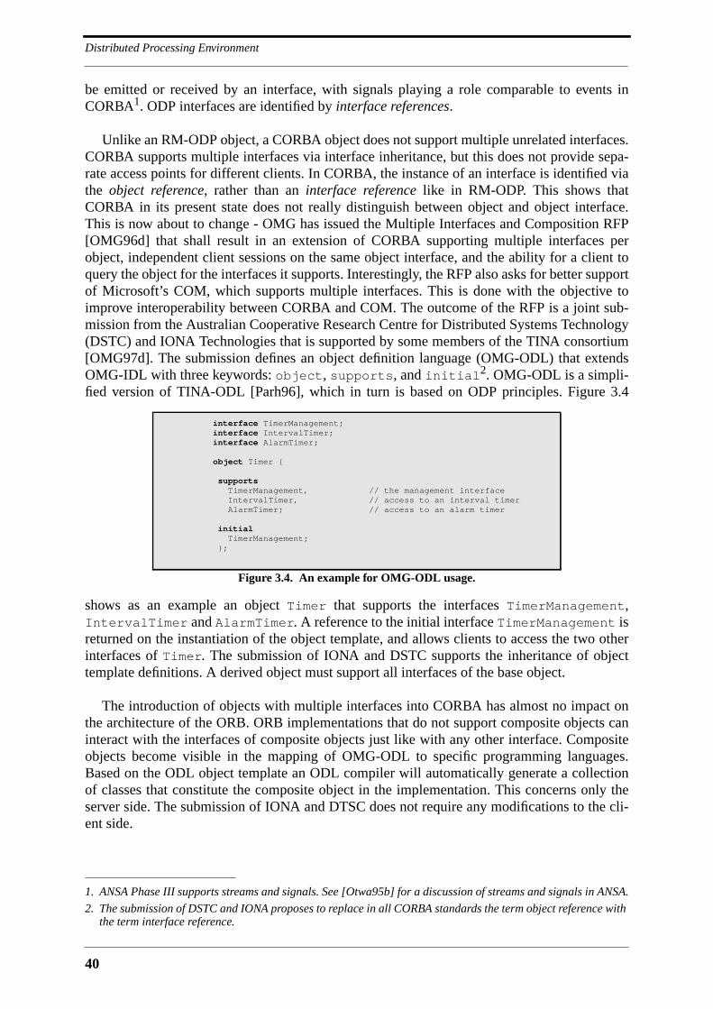
Distributed Processing Environment
40
be emitted or received by an interface, with signals playing a role comparable to events inCORBA1. ODP interfaces are identified by interface references.
Unlike an RM-ODP object, a CORBA object does not support multiple unrelated interfaces.CORBA supports multiple interfaces via interface inheritance, but this does not provide sepa-rate access points for different clients. In CORBA, the instance of an interface is identified viathe object reference, rather than an interface reference like in RM-ODP. This shows thatCORBA in its present state does not really distinguish between object and object interface.This is now about to change - OMG has issued the Multiple Interfaces and Composition RFP[OMG96d] that shall result in an extension of CORBA supporting multiple interfaces perobject, independent client sessions on the same object interface, and the ability for a client toquery the object for the interfaces it supports. Interestingly, the RFP also asks for better supportof Microsoft’s COM, which supports multiple interfaces. This is done with the objective toimprove interoperability between CORBA and COM. The outcome of the RFP is a joint sub-mission from the Australian Cooperative Research Centre for Distributed Systems Technology(DSTC) and IONA Technologies that is supported by some members of the TINA consortium[OMG97d]. The submission defines an object definition language (OMG-ODL) that extendsOMG-IDL with three keywords: object, supports, and initial2. OMG-ODL is a simpli-fied version of TINA-ODL [Parh96], which in turn is based on ODP principles. Figure 3.4
shows as an example an object Timer that supports the interfaces TimerManagement,IntervalTimer and AlarmTimer. A reference to the initial interface TimerManagement isreturned on the instantiation of the object template, and allows clients to access the two otherinterfaces of Timer. The submission of IONA and DSTC supports the inheritance of objecttemplate definitions. A derived object must support all interfaces of the base object.
The introduction of objects with multiple interfaces into CORBA has almost no impact onthe architecture of the ORB. ORB implementations that do not support composite objects caninteract with the interfaces of composite objects just like with any other interface. Compositeobjects become visible in the mapping of OMG-ODL to specific programming languages.Based on the ODL object template an ODL compiler will automatically generate a collectionof classes that constitute the composite object in the implementation. This concerns only theserver side. The submission of IONA and DTSC does not require any modifications to the cli-ent side.
1. ANSA Phase III supports streams and signals. See [Otwa95b] for a discussion of streams and signals in ANSA.
2. The submission of DSTC and IONA proposes to replace in all CORBA standards the term object reference withthe term interface reference.
interface TimerManagement;interface IntervalTimer;interface AlarmTimer;
object Timer {
supports TimerManagement, // the management interface IntervalTimer, // access to an interval timer AlarmTimer; // access to an alarm timer
initial TimerManagement; };
Figure 3.4. An example for OMG-ODL usage.

41
OMA, CORBA, CORBAservices and CORBAfacilities
A CORBA object model similar to the one of ODP has two benefits. On one hand it sup-ports the implementation of objects with multiple interfaces, which until now requires tediousworkarounds. On the other hand it is a starting point for the introduction of formal methodsinto the design of CORBA applications, for which a sound object model is a prerequisite.
3.3.8 Problems and Tendencies
Although CORBA is an already quite mature technology, there are some problems the OMGstill needs to solve. The following is a list of now apparent problems1 with the CORBA stan-dards, of which some have already been addressed by RFP’s:
• server code portability: every CORBA implementation has extended the BOAwith proprietary functionality, with the effect that server code is not completelyportable from one ORB to another. Equally, every CORBA implementation hasits own way of dealing with server threads. The new Portable Object Adapter(POA) replaces the BOA with an extensive programming interface that is sup-posed to improve server code portability [OMG97e].
• object identity: the ORB does not provide functionality that allows to determineif two object references refer to the same object. This is clearly missing giventhat identity is one of the major properties of an object.
• unclear semantics for oneway calls: the semantics of oneway calls are best-effort, leaving the determination of the exact semantics to the implementation.
• problematic object model: it is stated in the CORBA 2.0 standard that ‘Interfaceinheritance provides the composition mechanism for permitting an object tosupport multiple interfaces’2. CORBA 2.0 does not clearly differentiatebetween object and interface.
• asymmetric GIOP connections: bidirectional communication with GIOPrequires the establishment of two transport connections, which is a waste ofoperating system resources. OMG will have to revise this GIOP peculiarity oncecommunication between two peers has become more symmetric than in currentclient/server applications.
• lack of formal methods: up to now the only formalism for application analysisand design in CORBA is IDL. The Object Analysis and Design RFP [OMG96e]solicits the development of formal methods that are tailored to CORBA. Sub-missions must define structural models, behavioral models, use-case modelsand architectural models and provide a notation for every defined model. Inresponse to this RFP, Rational Software has submitted its Unified ModelingLanguage (UML) [OMG97f] for standardization.
CORBA lacks some of the functionality that is commonly expected from a DOC platform.The following is a list of additional functions for which RFP’s have already been issued:
• change management: up to now there is only limited support for interface ver-sioning in CORBA. Interface versions are integrated into the Interface Reposi-tory, but it is not clear what kind of changes in an interface a client should beable to overlook. There will at some point be a change management service.
1. Some of the listed problems have already been mentioned previously in the text.
2. See the OMG CORBA 2.0 specification [OMG95c], Subsection 1.2.5.

Distributed Processing Environment
42
• objects by value: until now objects can only be passed by reference. TheObjects-By-Value RFP [OMG96f] solicits proposals for CORBA extensionsthat allow objects to be passed by value. Due to performance considerations anapplication may prefer to transfer objects from servers to clients, rather thanhaving these objects be accessed by clients over the network.
• asynchronous messaging: as for now, communication with CORBA is mostlysynchronous. The Messaging Service RFP [OMG96c] solicits CORBA exten-sions that allow clients to asynchronously transmit requests and register call-backs for replies, or to send so-called persistent requests for which the replymay not arrive during the lifetime of the client, in which case it must be storedor processed by another entity. The Messaging Service RFP is a move towards amessage-oriented middleware (MOM).
• quality of service: the Messaging Service RFP asks for interfaces that allowapplications to control the quality of service with which the ORB services aninvocation. Example QoS properties are acknowledgment level, time-to-live,priority, reliability and client request ordering.
• realtime support: OMG has issued an RFI that shall help in assembling a list ofrequirements to be imposed on proposals for a realtime ORB. Realtime exten-sions shall help extending the scope of CORBA to systems for which it nowappears to be too heavy. There are already a couple of ORB’s that have realtimeextensions, with an example being ANSAware [Li95].
Although the CORBA standard and CORBA implementations have been around for a cou-ple of years, interest in CORBA has only recently reached the dimensions that are envisagedby OMG. CORBA implementations are now being deployed for a wide range of sometimesmission-critical applications, which effectively puts them onto a test stand. The following listssome of the problems that have become apparent:
• proliferation of transport connections: current CORBA implementations estab-lish at least one transport connection between every pair of communicating pro-cesses. Client processes that communicate with many server processes, orservers that serve many client processes, will not be able to have as many trans-port connections active in parallel as is required, simply because there are oper-ating system limits on this. What is needed is ORB support for the concept ofdormant bindings where the lifetime of a binding is not linked with the lifetimeof the underlying connection. This allows clients or servers to release transportconnections of a momentarily inactive binding without releasing the binding.
• DII and IIOP performance problems: early implementations of the DII and theIIOP had performance problems due to presentation layer, memory manage-ment and data copying overhead [Schm96b]. The focus of the first IIOP imple-mentations has been on interoperability rather than performance. ORBimplementers are now spending more effort on optimizing performance.CORBA performance is an active research area at Washington University, St.Louis [Gokh96].
• large footprints: current CORBA implementations tend to be gourmand withrespect to system resources. The size of the stub and skeleton code generated byan IDL compiler is often enormous, resulting in excessive compilation times
43
Other Platforms
and inflated executables. There are ways to minimize stub and skeleton codesize, for instance by avoiding duplicate code generation in the case of identicaltypes.
One shall not be mistaken by this list of problems to believe that CORBA is an immaturetechnology. Given the enormous scope of the CORBA standardization effort it is clear that itcannot be completely errorfree. However, it should be noted that up to now no major flaw hasbeen identified within the standard1.
3.3.9 Assessment
CORBA is a mature platform for distributed object computing. It qualifies for the DPE of theMMC platform because it satisfies the requirements that were developed in the previous chap-ter - it is open, extensible, programmable, scalable, deployable and simple. It is open since itsupports portability and interoperability, and extensible because new language mappings, ser-vices and facilities can be added to it. It is programmable because it makes the network trans-parent, and deployable because it can be implemented as a daemon process and a library anddoes not need to be integrated into the operating system. It is simple because it is based on alimited number of well-devised concepts. Domain-specific complexity is encapsulated byCORBAservices and CORBAfacilities. It is scalable because none of its features prevents animplementation to be scalable.
What is missing at the moment is support for multipoint communication. The only supportavailable is the event service, which is of limited utility, firstly because there is no multipointsupport in IIOP from which it could profit, and secondly because it does not guarantee thedelivery of events. One of the reasons for the limited support of multipoint communication inCORBA is certainly the lack of standard protocols for reliable multicast.
3.4 Other Platforms
The four platforms that Section 3.2 identified as possible candidates for the DPE of the MMCplatform are CORBA, DCOM, DCE and Java RMI. Following the introduction into CORBA inthe preceding section it is now possible to have a closer look on alternatives to CORBA and tojustify the decision for CORBA with more technical arguments than those used in Section 3.2.
3.4.1 Distributed Computing Environment
The Distributed Computing Environment (DCE) [Lock94] is a distributed computing platformthat has originally been standardized by the Open Software Foundation (OSF)2. DCE standard-ization is now in the hands of the Open Group, which is a recent merger of OSF and X/Open.DCE is based on a procedural programming model; it defines a basic RPC mechanism for theC programming language and a set of services that run on top of it. Related remote proceduresare grouped into interfaces that are described with the DCE Interface Definition Language
1. Defenders of Microsoft’s COM claim that CORBA’s interface inheritance is a dangerous feature. They refer tothe "fragile base class problem", meaning that modifications in a base class tend to break subclass code. Whilethere is a some truth behind this, it appears strange that the principle of inheritance should be abandoned alto-gether just because of a potential pitfall for unexperienced designers.
2. Version 1.0 of DCE appeared in 1992. The actual version of DCE is 1.2.2.

Distributed Processing Environment
44
(DCE-IDL). Interface definitions are compiled into client and server stubs that are linked withapplication code written in C or C++. A client can dynamically bind to a server and call remoteprocedures without being aware of the location of this server. A remote procedure is automati-cally executed in a thread, forcing the application programmer to make sure that the remoteprocedure is thread-safe. An important concept in DCE is the Universal Unique Identifier(UUID) that is generated based on the current time and the hardware address of the networkadapter. Every DCE interface is identified with a UUID and a version number, insuring typecompatibility between clients and servers. In addition to that, UUID’s are used to identify ser-vices, making it possible to distinguish between services that are accessed via identical inter-faces. Besides the basic RPC, DCE provides the following platform services:
• directory service: in DCE, administrational domains are called cells. A CellDirectory Service (CDS) provides for name resolution and resource location oncell level. Global name resolution is provided by a Global Directory Agent(GDA) in collaboration with a Global Directory Service (GDS) based on X.500.
• security service: DCE supports authentication, authorization, message integrity,and message encryption. The security service is the most acclaimed feature ofDCE.
• distributed time service: synchronizes the hardware clocks on all hosts in a DCEcell and across cell boundaries. Synchronized clocks are required by every dis-tributed application that bases decisions on absolute time. An important exam-ple is DCE’s security service.
• distributed file service: provides, besides the basic distributed file system, globalnaming, data replication and caching at the client. File access is secured withthe DCE security service.
The specifications for the RPC service, the threads service and the platform services arecomplete and mature. They have all been implemented by multiple vendors and are in daily usewithin a large number of corporations. OSF enforces interoperability between different imple-mentations of DCE by distributing a reference implementation. Vendors are obliged to licenseDCE from OSF if they want to label their implementation OSF DCE.
Assessment1
DCE is based on a procedural programming model that is now being superseded by distributedobject computing. DCE has limited support for objects via its server interfaces, but it does notsupport interface inheritance like CORBA. It also offers way less platform services thanCORBA, and does not reach as far up into vertical domains as CORBA. It is intertwined withthe C programming language, which is the main argument against using it as the basis for theMMC DPE. The main arguments for DCE are the completeness of its specifications, its matu-rity, and its security service, which is currently unrivaled. DCE is a standardized CORBAESIOP, as was already mentioned in Section 3.3.3. There is also an RFP for the interworkingbetween CORBA and DCE [OMG97b], with initial submissions being due in November 1997.An interworking standard will provide a smooth migration path from DCE to CORBA. This isalso how DCE is now perceived by the DCE community itself: a temporary solution thatbridges the gap until CORBA is ready to take over. DCE is therefore no valid alternative toCORBA for a MMC DPE that needs to be future-proof.
1. See [Bran95] for a detailed comparison between DCE and CORBA.

45
Other Platforms
3.4.2 Distributed Component Object Model
Microsoft introduced its Object Linking and Embedding Technology (OLE) in 1990 to providea cut-and-paste utility for the Windows operating system. This utility was later extended toprovide general communication among objects in different applications on a machine. To thispurpose, OLE was split into a low-level communication architecture, which is the ComponentObject Model (COM) [Micr95], and a high-level component architecture called OLE2. Com-ponents based on OLE and COM are called OLE controls (OCX). The component architectureconsisting of OLE and COM has recently been streamlined by Microsoft with the goal todeploy it on the Internet. The streamlined version of OLE and COM is called ActiveX and ispushed by Microsoft to become the dominant component technology of the Internet. Thedeployment of OLE and COM on the Internet is made possible by COM extensions that allowclients to reach server objects over the network. Microsoft refers to this new version of COMas Distributed COM (DCOM) [Brow96].
COM Objects have multiple interfaces. Interfaces are defined in an IDL that is based onDCE-IDL. COM relies on globally unique identifiers (GUID) for the identification of classes(CLSID) and interfaces (IID). Every COM object implements the interface IUnknown, whichcontains the functions QueryInterface(), AddRef() and Release(). A COM client callsQueryInterface() to retrieve pointers to the other interfaces of an object. The remainingfunctions are used to manage the life-cycle of an object. COM does not support interface inher-itance, but it provides two mechanisms for code reuse, namely containment and aggregation.In the containment mechanism, an inner object that is to be reused is simply encapsulated byan outer object. The outer object forwards invocations on functions in externally visible inter-faces to the interfaces of the inner object. In the aggregation mechanism, the interfaces of theinner object are directly exposed to the outside along with the interfaces of the outer object.
It has to be noted that COM is a language-neutral binary standard. The functions imple-mented by a server are accessed via a table of pointers that is similar to the vtable generatedby C++ compilers. COM clients and servers may therefore be implemented in different lan-guages. The most important languages that are supported are C, C++, Java and VisualBasic.
DCOM extends COM over the network. A COM interface that is to be accessed over thenetwork is compiled with the Microsoft IDL compiler (MIDL), with the result being proxycode for the client side and stub code for the server side. DCOM uses DCE RPC for the com-munication between clients and servers, and the Network Data Representation (NDR) for themarshalling of the data types that are supported by Microsoft IDL.
Assessment
OLE, COM, DCOM and ActiveX are still proprietary technologies. Microsoft has submittedparts of the DCOM specification to the IETF, and it is cooperating with the Open Group on thetransformation of ActiveX into an industry standard. However, this does not mean thatMicrosoft is willing to loosen its grip on DCOM and ActiveX. First of all it is hard to imaginethat the IETF starts a standardization process for DCOM. And then it is already clear thatActiveX will be standardized as is, i.e., without taking input external to Microsoft into account.The only benefit of the standardization of ActiveX will therefore be a good documentation ofits features. Another problem with DCOM is that it is currently only available on Microsoftoperating systems. UNIX and Apple Macintosh versions are being implemented, but they willnot be released before the end of 1997.
Distributed Processing Environment
46
Programming with DCOM is more tedious than programming with CORBA, which ismostly due to a lack of standard language mappings. However, Microsoft supplies a consider-able number of tools that hide the low-level details of DCOM, and that make distributed pro-gramming comfortable. A major drawback of DCOM is the lack of object identifiers similar tothe object references to CORBA. The relation between a client and a server object is alwaystemporary, meaning that once this relation is released there is no way for a client to reconnectto the same object instance. OLE and DCOM provide workarounds for this problem, but nosound solution. Other drawbacks of DCOM that can be cited are lack of interface inheritance,lack of exceptions, an inflexible version control, and most importantly, lack of object services.All these disadvantages are outweighed by Microsoft’s market position and a large base ofOLE component developers for which DCOM is the natural choice.
It is possible to build an MMC platform based on ActiveX components that communicatevia DCOM. Such a platform could use both Java and ActiveX for mobile code, with Java beinggiven preference wherever security is important, and ActiveX given preference whereveradvanced functionality has to be provided. However, the immaturity of DCOM and its propri-etary nature dissuade from using it in an architecture that is required to be stable, long-livedand ubiquitous, and it is therefore not a real alternative to CORBA for the MMC platformenvisaged by this thesis1.
3.4.3 Distributed Object Computing in Java
Sun Microsystems has added a native DOC facility to Java called Java Remote Method Invoca-tion (Java RMI) [Sun96d]. Java RMI supports seamless invocation of methods in objects resid-ing in different virtual machines. Java RMI servers implement so-called remote interfaces thatmust extend the (empty) interface Remote. In Java RMI 1.0, the implementation class mustextend the class java.rmi.server.UnicastRemoteObject which provides basic func-tionality for singleton servers. Future versions of Java RMI will provide other server baseclasses, for instance one that supports replicated servers. A remote interface must be compiledwith the rmic interface compiler, which generates client stub and server skeleton code. Theclient stub contains the definition of a proxy class with a name identical to the one of theremote interface. Java RMI clients create proxy objects and bind them via a name service toremote implementations before accessing their methods. The methods of the proxy object for-ward invocations to the respective implementation of the remote interface. Clients may passboth local and remote objects as parameters in remote invocations. Passing a local object asparameter results in a copy of the object from the virtual machine of the client to the one of theserver. This is only possible if the local object is serializable, i.e., if it implements the (empty)java.io.Serializable interface or the java.io.Externalizable interface2. It is pos-sible that the class code for the copied object is not available at the server side. In this case theserver may dynamically load this code from the client via the so-called RMIClassLoader. Pass-ing a remote object as a parameter results in a copy of the client stub and the creation of aproxy at the remote side. The automatic transfer of client stub code and class code is one of thestrong points of Java RMI. Given this possibility there is no need in Java RMI to define some-thing like CORBA’s Dynamic Invocation Interface.
1. This does not preclude the use of OLE and COM. OMG is about to issue a standard for the interworkingbetween COM and CORBA, which allows to access OLE controls via the CORBA object bus. Major CORBAvendors already offer proprietary gateways to COM.
2. These interfaces are defined in the Java Object Serialization Specification [Sun96c].

47
Conclusion
Java RMI may play an important role in Java Beans [Sun96a], Sun Microsystems’ compo-nent framework for Java. Java Beans defines a set of interfaces that allow the Java classes thatimplement them to be integrated into visual application builder tools. These interfaces providesupport for introspection, customization, events, properties and persistence. The most impor-tant features of a Java Bean are the methods it provides, the events it generates, and the proper-ties it allows to set. Every Java Bean may be accompanied by a BeanInfo class that allows tointrospect the Bean, and a customizer class that can provide substantial comfort for the cus-tomization of the Bean. The upcoming Java Media API [Sun96b], which will provide standardprogramming interfaces for 2D and 3D graphics, audio and video, collaboration, telephony,speech and animation, will probably be based on Java Beans. Future versions of the JavaAbstract Window Toolkit (AWT) will be compatible with Java Beans.
Assessment
Java RMI 1.0 does not provide much more than remote method invocation, object passing anddynamic class loading. Additional features that need to be mentioned are distributed garbagecollection, and the definition of a basic name service for client bootstrapping. Java RMI istherefore far from providing a distributed computing environment similar in scope to CORBA.However, what really keeps it from being the DPE of choice for the MMC platform is itsdependency on a single programming language. This relieves it from a lot of ballast and makesprogramming with it easy, but it has to be realized that it can only be used for distributed appli-cations that are entirely written in Java. It can nevertheless be imagined that Java RMI is usedin a MMC platform for communication on application level, i.e., in addition to CORBA. AnMMC platform that integrates mobile code written in Java will profit from the Java Beans com-ponent framework, and may therefore also support Java RMI for communication among Beansin Java applets and applications.
OMG has issued an RFP for the transparent use of IIOP in Java applets and applications thatwant to access CORBA servers, or that want to make objects available to CORBA clients[OMG97c]. The basic idea behind this is to take a Java interface definition and to compile itinto an OMG IDL definition, from which stub and skeleton code can be generated in a secondstep. The result of this is that it will be as easy for a programmer to use CORBA as it is to useJava RMI. Proposals to the RFP are required to provide the same amount of functionality asJava RMI. Initial submissions are due in September 1997, with the adoption of a standardbeing scheduled for the beginning of 1998.
3.5 Conclusion
This chapter introduced CORBA, and justified the choice of CORBA as the DPE of the MMCplatform proposed by this thesis. CORBA is not perfect, but it is unrivaled at the time of writ-ing, and with its integration into the Web it may well become as ubiquitous as HTTP is today.In the MMC platform it will be used for all control communication among platform compo-nents. Interfaces defined in IDL and a single network level protocol, IIOP, provide the func-tionality that in the past would have required a multitude of message-based application-levelprotocols. In the long run, CORBA may also provide for the transparent streaming of multime-dia data over the network.

Distributed Processing Environment
48
49
4 Monolithic MMC Platforms
4.1 Introduction
In Chapter 2 it was stated that an MMC platform must be built on top of a general distributedprocessing environment (DPE) so that platform design and implementation may concentrateon MMC specific problems. Chapter 3 presented OMG’s CORBA as the distributed computingplatform of choice for the DPE. CORBA is object-oriented and language independent andoffers a wide and ever growing range of distributed processing functionality that can be readilyintegrated into applications. Object-orientation is the key to component frameworks, which arein turn the key to extensible application platforms. The suitability of CORBA for componentframeworks has been demonstrated with the OpenDoc component model that is based onIBM’s System Object Model (SOM), a CORBA-compliant ORB. An application platformbased on a component framework has the advantage that it is extended with every componentthat is developed for it. Applications developed on top of such a platform communicate with amultitude of objects that behave according to some predefined rules, rather than with a singleentity that implements an extensive programming interface. This thesis distinguishes betweenMMC platforms that are based on a component framework, and others that export a monolithicprogramming interface. The internal structure of platforms that export a monolithic program-ming interface is usually static, which means that the objects of which it is composed are putinto a static relationship, making it difficult if not impossible to plug in new functionality.Component frameworks on the contrary promote dynamic binding and have to be regarded as ameeting place for objects that are able to discover themselves and to collaborate. In the follow-ing, MMC platforms with monolithic programming interfaces are simply referred to as mono-lithic MMC platforms, alluding to both the monolithic API and the static internal structure ofsuch platforms. Monolithic MMC platforms are being superseded by platforms based on com-ponent frameworks, but they are still relevant given that the platform approach for MMC appli-cations has not yet prevailed over the stand-alone application approach. Platforms in general,and therefore also monolithic MMC platforms, have to be considered as a substantial progresswith respect to the stand-alone application.
This chapter presents examples for monolithic MMC platforms, and exposes some of theproblems with them for which component frameworks are a natural solution. This chapter isthus a motivation for the remainder of this thesis, which is dedicated to component frame-works. The platforms that are discussed here are Bellcore’s Touring Machine, Eurecom’sBeteus platform, and IBM’s Lakes platform. The Touring Machine was the first platform withan API that was deployed on a large scale. The Beteus platform is the contribution of this thesisin the area of monolithic platforms. It features a high-level connection management API thatsignificantly facilitates application development. The Lakes platform finally offers some fea-tures that place it at the border between monolithic MMC platforms and component frame-works.
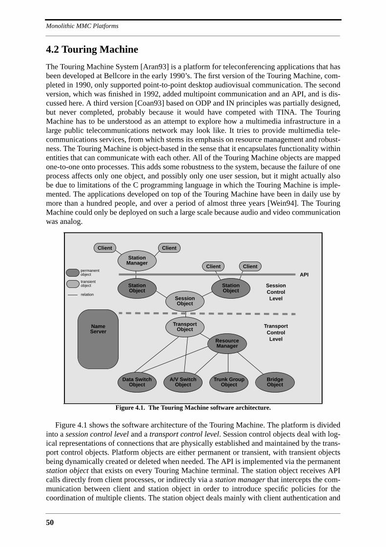
Monolithic MMC Platforms
50
4.2 Touring Machine
The Touring Machine System [Aran93] is a platform for teleconferencing applications that hasbeen developed at Bellcore in the early 1990’s. The first version of the Touring Machine, com-pleted in 1990, only supported point-to-point desktop audiovisual communication. The secondversion, which was finished in 1992, added multipoint communication and an API, and is dis-cussed here. A third version [Coan93] based on ODP and IN principles was partially designed,but never completed, probably because it would have competed with TINA. The TouringMachine has to be understood as an attempt to explore how a multimedia infrastructure in alarge public telecommunications network may look like. It tries to provide multimedia tele-communications services, from which stems its emphasis on resource management and robust-ness. The Touring Machine is object-based in the sense that it encapsulates functionality withinentities that can communicate with each other. All of the Touring Machine objects are mappedone-to-one onto processes. This adds some robustness to the system, because the failure of oneprocess affects only one object, and possibly only one user session, but it might actually alsobe due to limitations of the C programming language in which the Touring Machine is imple-mented. The applications developed on top of the Touring Machine have been in daily use bymore than a hundred people, and over a period of almost three years [Wein94]. The TouringMachine could only be deployed on such a large scale because audio and video communicationwas analog.
Figure 4.1 shows the software architecture of the Touring Machine. The platform is dividedinto a session control level and a transport control level. Session control objects deal with log-ical representations of connections that are physically established and maintained by the trans-port control objects. Platform objects are either permanent or transient, with transient objectsbeing dynamically created or deleted when needed. The API is implemented via the permanentstation object that exists on every Touring Machine terminal. The station object receives APIcalls directly from client processes, or indirectly via a station manager that intercepts the com-munication between client and station object in order to introduce specific policies for thecoordination of multiple clients. The station object deals mainly with client authentication and
Figure 4.1. The Touring Machine software architecture.
StationObject
StationManager
SessionObject
A/V SwitchObject
Trunk GroupObject
BridgeObject
ResourceManager
TransportObject
StationObject
Data SwitchObject
Client Client
ClientClient
NameServer
SessionControlLevel
TransportControlLevel
APIpermanentobject
transientobject
relation

51
Touring Machine
registration, and inter-client communication. It creates a transient session object when askedby a client, and forwards all connection and session related requests to it. The session objectkeeps state about session membership, session policies and existing connections. It establishesconnections with the help of a transient transport object that maintains a mapping betweenlogical and physical connections. The transport object requests end-to-end connections fromthe resource manager which establishes them in collaboration with low-level resource objects.The Touring Machine includes four types of resource objects. The A/V switch object estab-lishes analog audio and video connections. The data switch object establishes digital connec-tions for inter-client communication. The trunk group object establishes trunks betweendifferent A/V switches. The bridge object finally allocates audio and video bridges for multi-way communication. The transport object talks directly to the data switch object and the A/Vswitch object when it needs to act on local connection endpoints. Figure 4.1 also shows a nameserver that can be browsed by every platform object. The name server is a repository for staticand dynamic information about the system, like for instance authorized users, registered cli-ents, ongoing sessions, or Touring Machine stations.
The Touring Machine defines the connection related abstractions connector, endpoint andport. A connector is a medium specific bridge that can be of type audio, video or data and thathas source and sink endpoints from participating clients attached to it. Connectors can repre-sent point-to-point as well as multipoint connections. Clients access connector endpoints viaports that are typed with medium and flow direction. The port abstraction allows clients toswitch locally between different sources or sinks for the same connector endpoint. Audio andvideo ports exist statically, whereas data ports can be created dynamically. A multipoint dataconnector is realized with a data switch object that establishes TCP connections with everyattached client.
The API of the Touring Machine [Mak93] is message-based. An API message consists of alength field and a set of message fields, which are either integers, strings enclosed by doublequotes, or API keywords. The format of a message is described by means of a simple propri-etary syntax. Messages that require a reply contain a token that allows to match a reply withthe original request. The functionality provided by the API can be divided into six categories:
• client registration: a client process registers with its name and the configurationof the station, and receives a client ID to be used in all consequent messages.
• session establishment and modification: a session is created with an initial set ofparticipants and connections that can later be modified. Session establishmentand modification requires prior negotiation with all concerned clients.
• network access control: the mapping between ports and endpoints can be con-trolled, and data ports can be dynamically created or deleted.
• name server query: the name server may be queried for users, clients, stations,ports, sessions, connectors and endpoints. Queries may contain wildcards. Cli-ents may register triggers in order to be notified when certain events occur.
• inter-client message forwarding: a client can send a string to one or more otherregistered clients.
• error notification: an error notification is returned to a client if the message pre-viously sent by the client contains syntax errors.
The API defines all in all 46 messages. The number of real procedures is smaller becausethe Touring Machine defines for every procedure a request, an accepted and a denied message.

Monolithic MMC Platforms
52
Two applications have been developed on top of the Touring Machine: the Cruiser telecon-ferencing application, and the Rendezvous shared workspace application. Both applicationscan be run on top of the same session. This is possible because there can be more than one cli-ent per station within the same session1. This is a powerful feature because it allows to createnew applications by combining existing applications that were developed independently fromeach other2.
4.2.1 Assessment
The use of analog audio and video cannot be considered as a limitation of the TouringMachine, for it is this feature that made a large-scale deployment of the platform possible. Aconsequence of the analog media transmission is that the platform does not need to supportinter-stream synchronization. A drawback is maybe that an application cannot control mediapresentation, which would be possible with digital audio and video.
The API of the Touring Machine is monolithic. Any addition of functionality to the APIrequires modification of the station object, and probably other platform objects. The platformitself is closed in the sense that internal interfaces are hidden, making it impossible for thirdparties to develop platform extensions. The Touring Machine would have greatly profited froma distributed object computing platform like CORBA. The six categories into which the APIfunctionality is split would immediately be represented by six major CORBA interfaces. Everyinterface would be implemented by the object that provides the respective functionality, withthe advantage that requests do not need to be routed through unconcerned platform objects. Asan example, the name service would be accessed directly, possibly via the CORBA name orquery services, and name service requests would not need to pass through the station object, asis happening in the Touring Machine. A problem with the API is that it is based on a propri-etary protocol. It defines a PDU format and message exchange rules that are rather complexwhenever negotiation among multiple parties is involved. The message-based API could easilybe reformulated in terms of RPC’s. None of the publications about the Touring Machineexplains why this was not done, and it can only be assumed that the hardware infrastructurewas too heterogeneous for this, meaning that there was no single RPC available on all of theinvolved hardware architectures. Application developers must consequently code the marshal-ling and unmarshalling of parameters by hand, which is not only additional work, but also asource of programming mistakes. Since internal communication is also based on messages it islikely that a considerable part of the 125K lines of C code that make up the Touring Machinecould be generated automatically by a CORBA IDL compiler or ONC’s rpcgen.
Inter-client communication in the Touring Machine is completely provided by the platform.Clients are not supposed to open direct TCP connections with any peer. They use multipointdata connectors for the communication of application data, and the inter-client messaging fea-ture of the API for the construction of application-level control protocols. Both kinds of inter-client communication could be readily provided by the CORBA event service, or the futuremessaging service. Table 4.1 provides a summary of the features of the Touring Machine withrespect to the requirements on MMC platforms developed in Chapter 2.
1. Note that a Touring Machine client is not the user. A user may have multiple clients on his station running onhis behalf.
2. This feature bears some resemblance to the component framework paradigm. It would have been possible toformalize this feature, which requires inter-application signalling, but this was not done.

53
The Beteus Platform
4.3 The Beteus Platform
The platform described in the following was developed at Eurécom in the course of the Euro-pean teleconferencing project Beteus (Broadband Exchange for Trans-European USage)[Blum97c]. The project definition of Beteus focused on network communication aspects ratherthan applications. It required the development of at least two applications, with one of thembeing a tele-teaching application, but apart from that it only said that Beteus applications mustmake the best use of the high bandwidth available on the ATM network that interconnected theproject partners in France (Eurécom in Sophia-Antipolis), Switzerland (CERN in Geneva,EPFL in Lausanne, ETHZ in Zürich) and Germany (TUB Berlin). Two applications werevaguely envisaged, a tele-meeting application for informal group meetings, and a distributedclassroom application that would allow to give a lecture at one site to a virtual classroom that isthe combination of classrooms at several Beteus sites. Since there was no clear vision for theapplications at the beginning of the project, it was decided to build an application platformrather than stand-alone applications for everyone of the envisaged application scenarios. The
Touring Machine
Requirement Fulfilled Remark
Open no uses proprietary protocols for API and internal communication
Extensible no every extension requires platform modifications
Programmable ❄ tedious due to message-based API
Scalable ❄❄❄ was deployed on a large enterprise network with many users
Deployable ❄ needs to be embedded into the network
Simple ❄❄ clearly structured platform, relatively simple API
Session Management ❄❄ sessions support multiple clients per user; session policies
Connection Management ❄❄ powerful abstractions (connector, endpoint, port)
Multimedia Data Processing ❄❄ analog audio mixers and video bridges
Multipoint Control Comm. ❄❄ provided by the API (inter-client message forwarding)
Resource Management ❄❄ resource management for analog audio and video connections
Synchronization no not necessary because audio and video are analog
Mobile Code no client code is installed on the endsystem
Presentation Environment no no audio or video presentation control
Federation of Applications ❄❄ possible due to sharable session object. No formalization.
Security ❄ user authentication and rudimentary access control
Mobility ❄❄ supports user mobility via the name server
Directory Service ❄❄ information about users, stations, clients, sessions, et cetera
Platform Management no -
Accounting no -
Standard DPE no -
Table 4.1. Evaluation of the Touring Machine.

Monolithic MMC Platforms
54
platform should constitute the highest common denominator between the envisaged applica-tion scenarios and should allow to implement and to incrementally improve an application sce-nario with significantly reduced effort as compared to an approach based on stand-aloneprototypes.
The Beteus platform and the initial application scenarios were designed and developed inthe period from August 1994 to April 1995. In May 1995, the Beteus field trials started on theEuropean ATM pilot network. Two application scenarios were demonstrated to a commissionof the European Union in July 1995. The field trials continued until the beginning of December1995, with the second major event being the coorganization of a distributed conference onNovember 16 and 17 between a main site in Madeira and attached sites in Madrid, Brusselsand Sophia-Antipolis (IDC‘95).
4.3.1 The Beteus ATM Network
At the beginning of the project there was not only uncertainty about the applications, but it wasalso not clear how exactly the project partners would be interconnected with each other. It wasassumed that the majority of project partners would have access to the European ATM pilotnetwork [Geib96], but at least in the case of Eurécom it looked a long time as if access wouldbe Switched Multi-Megabit Data Service (SMDS). It was a clear objective to have ATM accessfor all project partners since such an access was supposed to be favorable for multipoint com-munication. The network configuration that was finally reached is qualitatively depicted in Fig-ure 4.2. All Beteus project partners had ATM LAN’s. The ATM LAN’s of all partners butETHZ connected to the ATM pilot via 34 Mbit/s E3 interfaces. ETHZ is the only project part-ner that had a 155 Mbit/s STM 1 link to the ATM pilot. The ATM pilot itself was a collectionof ATM cross-connects in various European countries. Beteus ran over cross-connects in Paris,Cologne, Geneva and Zürich as far as can be judged from the scarce information provided bythe network operators. Although the resulting network was a pure ATM network, it was neverseriously considered to use any network protocol for the application platform other than theInternet Protocol (IP over ATM), and any network programming interface other than the Ber-keley sockets. The use of proprietary ATM programming interfaces was not considered, firstbecause this would have defeated platform portability, and then because of the performanceproblems that implementations of such interfaces still exhibit.
Figure 4.2. The Beteus ATM network.
CCParis
CC
Cologne
ATM Pilot Network
34 Mbit/s34 Mbit/s
34 Mbit/s
34 Mbit/s
155 Mbit/s
ATM LAN
ETHZ (CH)
ATM LAN
EPFL (CH)
ATM LAN
CERN (CH)
ATM LAN
EURECOM (F)
CC
Zürich
ATM LAN
TUB (D)
CC
Geneva?
CC = Cross-Connect
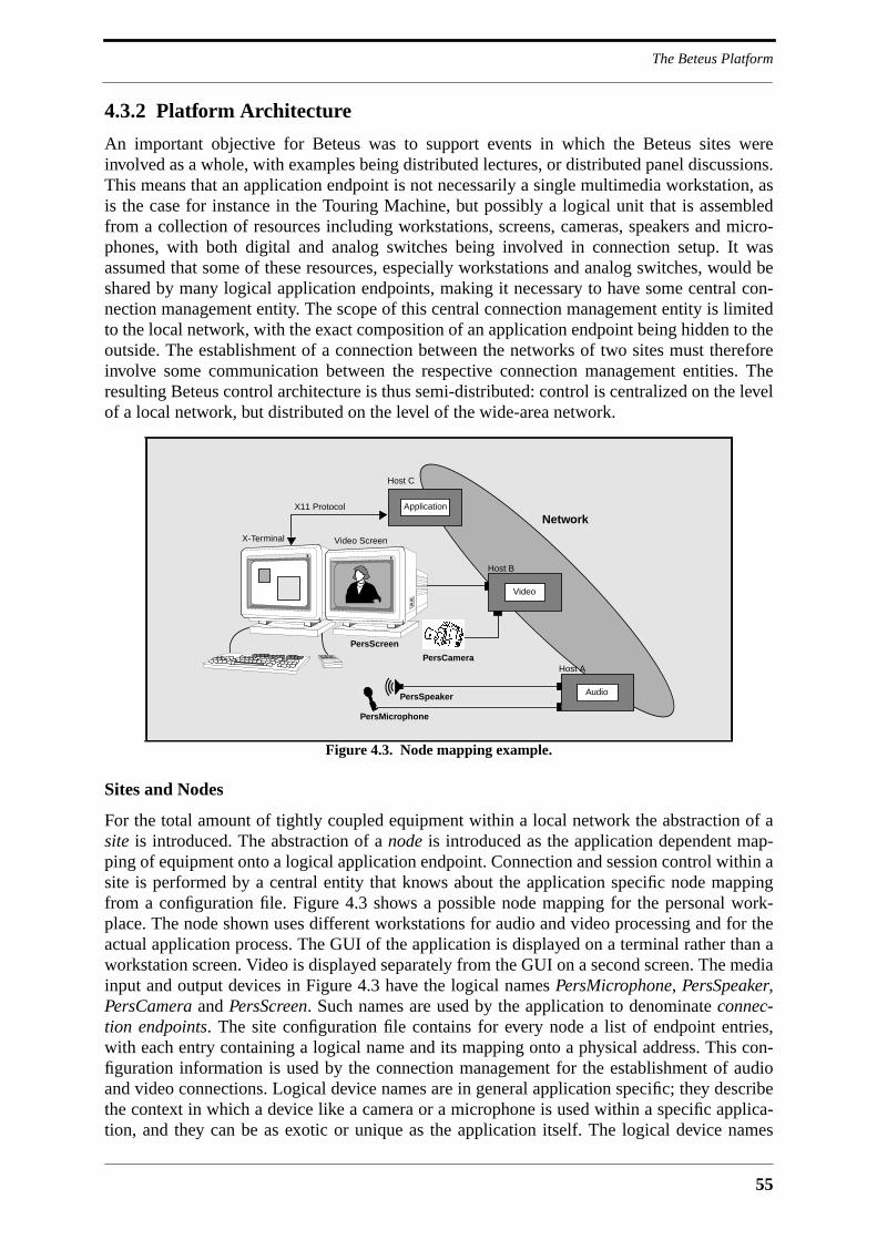
55
The Beteus Platform
4.3.2 Platform Architecture
An important objective for Beteus was to support events in which the Beteus sites wereinvolved as a whole, with examples being distributed lectures, or distributed panel discussions.This means that an application endpoint is not necessarily a single multimedia workstation, asis the case for instance in the Touring Machine, but possibly a logical unit that is assembledfrom a collection of resources including workstations, screens, cameras, speakers and micro-phones, with both digital and analog switches being involved in connection setup. It wasassumed that some of these resources, especially workstations and analog switches, would beshared by many logical application endpoints, making it necessary to have some central con-nection management entity. The scope of this central connection management entity is limitedto the local network, with the exact composition of an application endpoint being hidden to theoutside. The establishment of a connection between the networks of two sites must thereforeinvolve some communication between the respective connection management entities. Theresulting Beteus control architecture is thus semi-distributed: control is centralized on the levelof a local network, but distributed on the level of the wide-area network.
Sites and Nodes
For the total amount of tightly coupled equipment within a local network the abstraction of asite is introduced. The abstraction of a node is introduced as the application dependent map-ping of equipment onto a logical application endpoint. Connection and session control within asite is performed by a central entity that knows about the application specific node mappingfrom a configuration file. Figure 4.3 shows a possible node mapping for the personal work-place. The node shown uses different workstations for audio and video processing and for theactual application process. The GUI of the application is displayed on a terminal rather than aworkstation screen. Video is displayed separately from the GUI on a second screen. The mediainput and output devices in Figure 4.3 have the logical names PersMicrophone, PersSpeaker,PersCamera and PersScreen. Such names are used by the application to denominate connec-tion endpoints. The site configuration file contains for every node a list of endpoint entries,with each entry containing a logical name and its mapping onto a physical address. This con-figuration information is used by the connection management for the establishment of audioand video connections. Logical device names are in general application specific; they describethe context in which a device like a camera or a microphone is used within a specific applica-tion, and they can be as exotic or unique as the application itself. The logical device names
Figure 4.3. Node mapping example.
Host A
Audio
X-Terminal Video Screen
Host B
Video
Host C
ApplicationX11 Protocol
PersMicrophone
PersSpeaker
PersCamera
PersScreen
Network
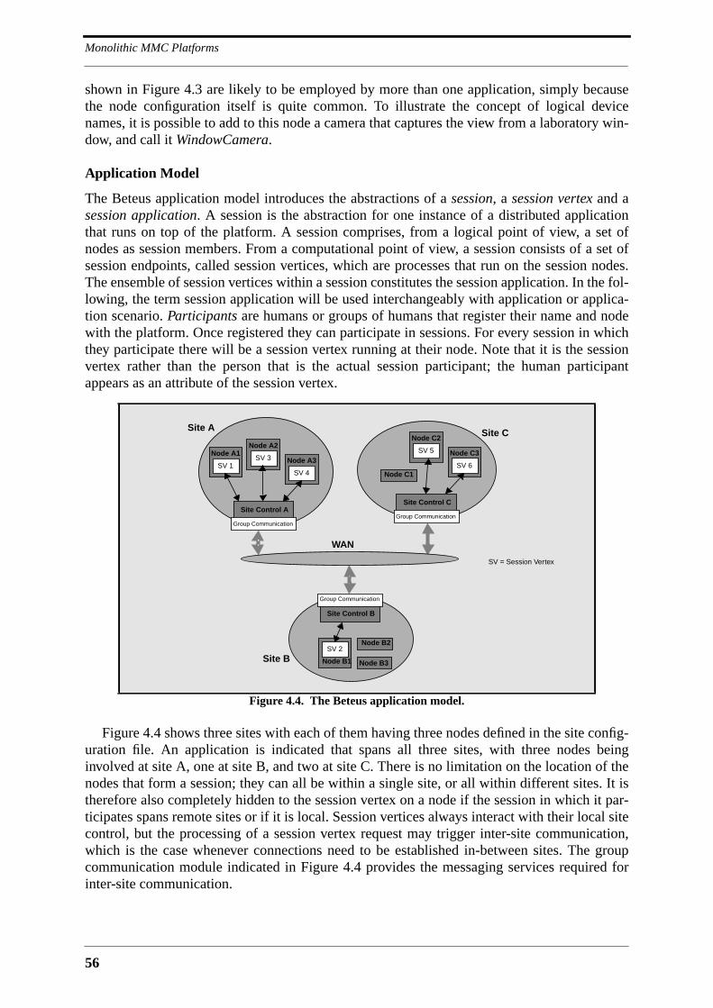
Monolithic MMC Platforms
56
shown in Figure 4.3 are likely to be employed by more than one application, simply becausethe node configuration itself is quite common. To illustrate the concept of logical devicenames, it is possible to add to this node a camera that captures the view from a laboratory win-dow, and call it WindowCamera.
Application Model
The Beteus application model introduces the abstractions of a session, a session vertex and asession application. A session is the abstraction for one instance of a distributed applicationthat runs on top of the platform. A session comprises, from a logical point of view, a set ofnodes as session members. From a computational point of view, a session consists of a set ofsession endpoints, called session vertices, which are processes that run on the session nodes.The ensemble of session vertices within a session constitutes the session application. In the fol-lowing, the term session application will be used interchangeably with application or applica-tion scenario. Participants are humans or groups of humans that register their name and nodewith the platform. Once registered they can participate in sessions. For every session in whichthey participate there will be a session vertex running at their node. Note that it is the sessionvertex rather than the person that is the actual session participant; the human participantappears as an attribute of the session vertex.
Figure 4.4 shows three sites with each of them having three nodes defined in the site config-uration file. An application is indicated that spans all three sites, with three nodes beinginvolved at site A, one at site B, and two at site C. There is no limitation on the location of thenodes that form a session; they can all be within a single site, or all within different sites. It istherefore also completely hidden to the session vertex on a node if the session in which it par-ticipates spans remote sites or if it is local. Session vertices always interact with their local sitecontrol, but the processing of a session vertex request may trigger inter-site communication,which is the case whenever connections need to be established in-between sites. The groupcommunication module indicated in Figure 4.4 provides the messaging services required forinter-site communication.
Figure 4.4. The Beteus application model.
Site Control A
Group Communication
Site A
SV 4
Node A3SV 3
Node A2
SV 1
Node A1
Site Control B
Group Communication
Site B
Node B2SV 2
Node B1
Site Control C
Group Communication
Site C
SV 6
Node C3SV 5
Node C2
Node C1
Node B3
SV = Session Vertex
WAN
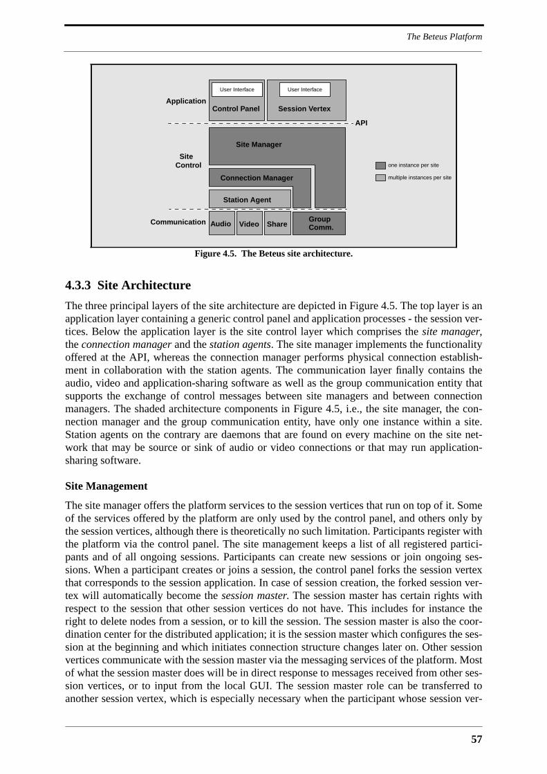
57
The Beteus Platform
4.3.3 Site Architecture
The three principal layers of the site architecture are depicted in Figure 4.5. The top layer is anapplication layer containing a generic control panel and application processes - the session ver-tices. Below the application layer is the site control layer which comprises the site manager,the connection manager and the station agents. The site manager implements the functionalityoffered at the API, whereas the connection manager performs physical connection establish-ment in collaboration with the station agents. The communication layer finally contains theaudio, video and application-sharing software as well as the group communication entity thatsupports the exchange of control messages between site managers and between connectionmanagers. The shaded architecture components in Figure 4.5, i.e., the site manager, the con-nection manager and the group communication entity, have only one instance within a site.Station agents on the contrary are daemons that are found on every machine on the site net-work that may be source or sink of audio or video connections or that may run application-sharing software.
Site Management
The site manager offers the platform services to the session vertices that run on top of it. Someof the services offered by the platform are only used by the control panel, and others only bythe session vertices, although there is theoretically no such limitation. Participants register withthe platform via the control panel. The site management keeps a list of all registered partici-pants and of all ongoing sessions. Participants can create new sessions or join ongoing ses-sions. When a participant creates or joins a session, the control panel forks the session vertexthat corresponds to the session application. In case of session creation, the forked session ver-tex will automatically become the session master. The session master has certain rights withrespect to the session that other session vertices do not have. This includes for instance theright to delete nodes from a session, or to kill the session. The session master is also the coor-dination center for the distributed application; it is the session master which configures the ses-sion at the beginning and which initiates connection structure changes later on. Other sessionvertices communicate with the session master via the messaging services of the platform. Mostof what the session master does will be in direct response to messages received from other ses-sion vertices, or to input from the local GUI. The session master role can be transferred toanother session vertex, which is especially necessary when the participant whose session ver-
Figure 4.5. The Beteus site architecture.
Site Manager
Connection Manager
Station Agent
Audio Video ShareGroup
Session Vertex
User Interface
Control Panel
Comm.
API
SiteControl
Application
Communication
User Interface
one instance per site
multiple instances per site
Monolithic MMC Platforms
58
tex bears this role wants to leave the session. Note that the session master functionality is notnecessarily visible at the GUI of the respective session vertex - this is an application designchoice.
Connection Management
The connection manager receives connection control and endpoint control requests from thesite manager. Connection control comprises connect and disconnect requests and is only per-formed by the connection control of the session master; endpoint control stands for the settingof device parameters like audio volume and video saturation. The connection manager mapsthe logical endpoint names in site manager requests to physical addresses. Endpoint controlrequests can then be forwarded to the corresponding audio or video processes. Connectrequests result in immediate connection establishment if all of the connection endpoints arelocal. If an endpoint is remote, the connection manager of the session master asks the remoteconnection manager to establish the respective endpoint. The site manager requests only point-to-point connections from the connection manager, but every connect request is accompaniedby a hint as to whether the respective connection is part of a multipoint connection structure, inwhich case the connection manager may use IP multicast [Deer91] if available.
Inter-Site Communication
Both the site manager and the connection manager communicate with remote peer entities, asis indicated in Figure 4.5. Site managers need to communicate as part of the directory service,the messaging service and the session management service. The communication between sitemanagers consists of the reliable transfer of a message from one site manager to one or moreother site managers. Connection managers need to communicate in order to establish inter-siteconnections. Connection endpoints are established sequentially: the connection manager sendsfor every connection endpoint an establishment request and receives an acknowledgment oncethe remote connection manager has established the endpoint.
The communication requirements of the site manager and the connection manager are opti-mally addressed by the Reliable Multicast Protocol (RMP) [Mont95]. RMP supports the reli-able delivery of messages to all members of a group with different levels of service rangingfrom unreliable delivery to totally resilient delivery. It runs efficiently on IP multicast, butallows group members that are not multicast capable to be reached via UDP.
4.3.4 Major Connection Abstractions
A major requirement for the Beteus platform was ease of application development. The con-nection management part of the Beteus API is based on powerful abstractions that allow toestablish and to modify complex audio, video and application-sharing connection structureswith a single call. The major connection abstractions are role, bridge and bridge set.
Roles
An application scenario is implemented within a single executable. The session vertices of anapplication are therefore identical in terms of code, but they behave according to dynamicallytaken or assigned roles. The already introduced master role and a general participant role arethe only roles which exist by default - all other roles are defined by the application itself. Anapplication may define as many roles as it wishes, and session vertices may also hold multipleroles at the same time. A session vertex will adapt the GUI that it produces to the role or roles
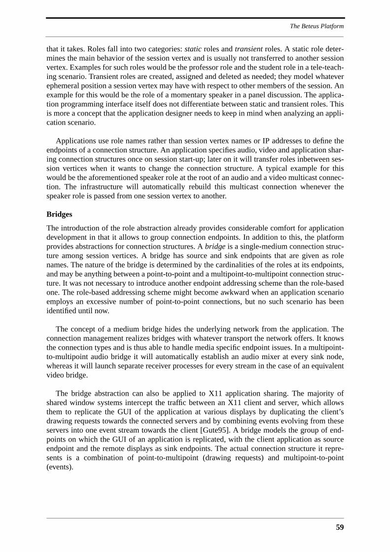
59
The Beteus Platform
that it takes. Roles fall into two categories: static roles and transient roles. A static role deter-mines the main behavior of the session vertex and is usually not transferred to another sessionvertex. Examples for such roles would be the professor role and the student role in a tele-teach-ing scenario. Transient roles are created, assigned and deleted as needed; they model whateverephemeral position a session vertex may have with respect to other members of the session. Anexample for this would be the role of a momentary speaker in a panel discussion. The applica-tion programming interface itself does not differentiate between static and transient roles. Thisis more a concept that the application designer needs to keep in mind when analyzing an appli-cation scenario.
Applications use role names rather than session vertex names or IP addresses to define theendpoints of a connection structure. An application specifies audio, video and application shar-ing connection structures once on session start-up; later on it will transfer roles inbetween ses-sion vertices when it wants to change the connection structure. A typical example for thiswould be the aforementioned speaker role at the root of an audio and a video multicast connec-tion. The infrastructure will automatically rebuild this multicast connection whenever thespeaker role is passed from one session vertex to another.
Bridges
The introduction of the role abstraction already provides considerable comfort for applicationdevelopment in that it allows to group connection endpoints. In addition to this, the platformprovides abstractions for connection structures. A bridge is a single-medium connection struc-ture among session vertices. A bridge has source and sink endpoints that are given as rolenames. The nature of the bridge is determined by the cardinalities of the roles at its endpoints,and may be anything between a point-to-point and a multipoint-to-multipoint connection struc-ture. It was not necessary to introduce another endpoint addressing scheme than the role-basedone. The role-based addressing scheme might become awkward when an application scenarioemploys an excessive number of point-to-point connections, but no such scenario has beenidentified until now.
The concept of a medium bridge hides the underlying network from the application. Theconnection management realizes bridges with whatever transport the network offers. It knowsthe connection types and is thus able to handle media specific endpoint issues. In a multipoint-to-multipoint audio bridge it will automatically establish an audio mixer at every sink node,whereas it will launch separate receiver processes for every stream in the case of an equivalentvideo bridge.
The bridge abstraction can also be applied to X11 application sharing. The majority ofshared window systems intercept the traffic between an X11 client and server, which allowsthem to replicate the GUI of the application at various displays by duplicating the client’sdrawing requests towards the connected servers and by combining events evolving from theseservers into one event stream towards the client [Gute95]. A bridge models the group of end-points on which the GUI of an application is replicated, with the client application as sourceendpoint and the remote displays as sink endpoints. The actual connection structure it repre-sents is a combination of point-to-multipoint (drawing requests) and multipoint-to-point(events).

Monolithic MMC Platforms
60
Bridge Sets
A number of bridges, typically an audio and a related video bridge, can be assembled to form abridge set. An application configures the platform on session start-up with a description of thebridge sets that it uses. During the session, only one bridge set can be active at a time. If anapplication changes the active bridge set, the infrastructure will tear down any connection ofthe old bridge set that is not included in the new one, and establish the connections that aremissing. The number of bridge sets an application defines corresponds to the number of funda-mental application states, which in turn corresponds to different temporal phases a sessiontraverses during its lifetime. The programming interface does not directly support the notion ofapplication state, but application state is, like static and transient roles, a concept that the appli-cation designer has to be aware of.
4.3.5 Application Programming Interface
The API is based on synchronous RPC and asynchronous event notifications. The RPC pack-age chosen for the communication between session vertices and the site manager is Tcl-DP[Rowe93], the distributed programming package for Tcl/Tk [Oust90]. Since simple applica-tions will mainly deal with GUI issues, it is possible to implement them completely in Tcl/Tk.More complex applications may have C or C++ code in addition to the Tcl/Tk GUI script; theywill use the C library of Tcl-DP to call site manager procedures or to register callback func-tions for event notification.
The API procedure calls are grouped into the following categories:
• registration: user registration and deregistration.
• endpoint handling: audio and video device control.
• session directory: directory service related calls.
• session information: convenience calls.
• session control: session membership and lifetime control.
• bridge set handling: changing the active bridge set.
• messaging: communication among session vertices.
• role handling: role assignment and removal.
• application sharing: X11 application sharing.
The convenience calls allow session vertices to query the session configuration. Session ver-tices do not maintain records about actual role assignment, actual bridge set or session partici-pants; they retrieve this information from the site manager as they need it.
The main event notifications are:
• Receive: a message from another session vertex
• Join: there is a new session vertex in the session
• Left: a session vertex left the session
• Kill: the session got killed or disrupted
• RoleAdd: a role is assigned to the session vertex
• RoleDel: a role is removed from the session vertex
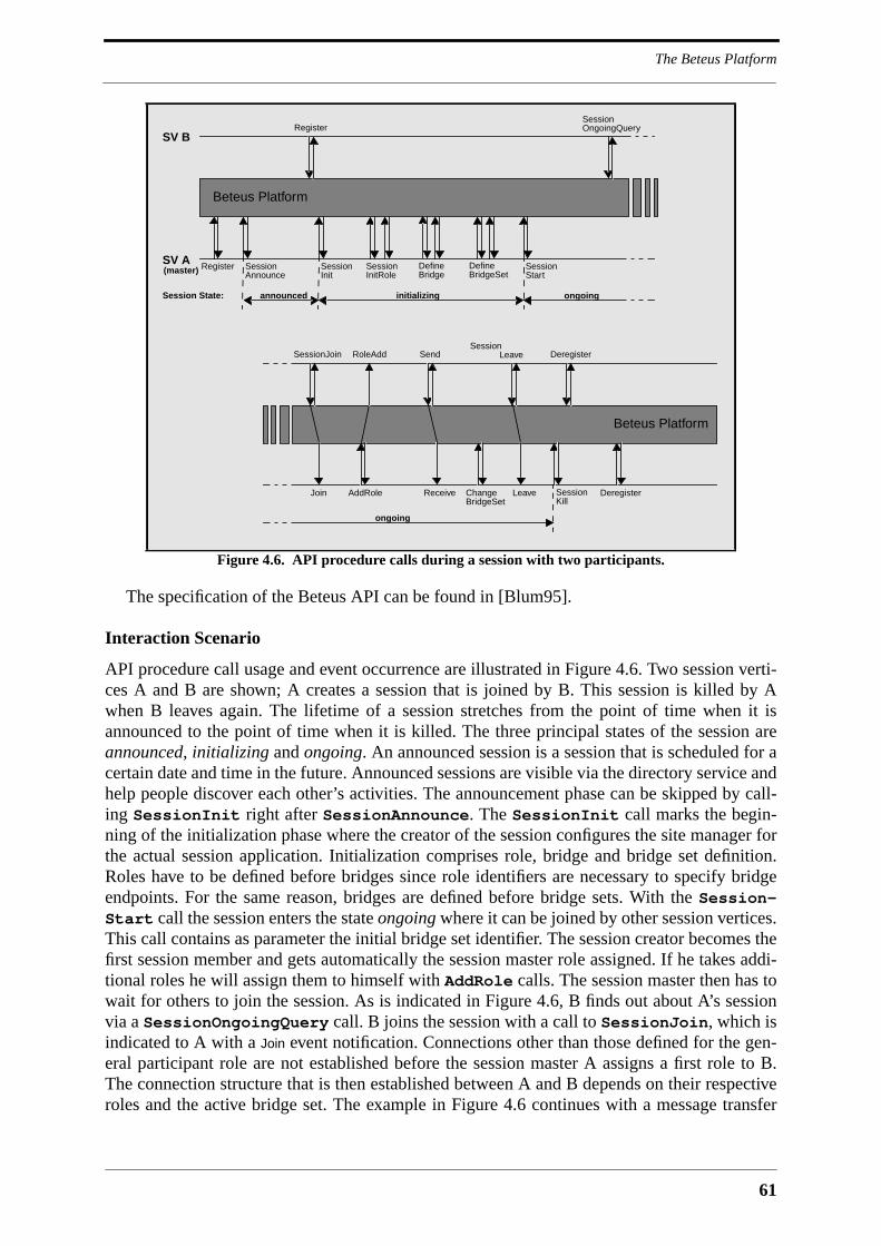
61
The Beteus Platform
The specification of the Beteus API can be found in [Blum95].
Interaction Scenario
API procedure call usage and event occurrence are illustrated in Figure 4.6. Two session verti-ces A and B are shown; A creates a session that is joined by B. This session is killed by Awhen B leaves again. The lifetime of a session stretches from the point of time when it isannounced to the point of time when it is killed. The three principal states of the session areannounced, initializing and ongoing. An announced session is a session that is scheduled for acertain date and time in the future. Announced sessions are visible via the directory service andhelp people discover each other’s activities. The announcement phase can be skipped by call-ing SessionInit right after SessionAnnounce. The SessionInit call marks the begin-ning of the initialization phase where the creator of the session configures the site manager forthe actual session application. Initialization comprises role, bridge and bridge set definition.Roles have to be defined before bridges since role identifiers are necessary to specify bridgeendpoints. For the same reason, bridges are defined before bridge sets. With the Session-Start call the session enters the state ongoing where it can be joined by other session vertices.This call contains as parameter the initial bridge set identifier. The session creator becomes thefirst session member and gets automatically the session master role assigned. If he takes addi-tional roles he will assign them to himself with AddRole calls. The session master then has towait for others to join the session. As is indicated in Figure 4.6, B finds out about A’s sessionvia a SessionOngoingQuery call. B joins the session with a call to SessionJoin, which isindicated to A with a Join event notification. Connections other than those defined for the gen-eral participant role are not established before the session master A assigns a first role to B.The connection structure that is then established between A and B depends on their respectiveroles and the active bridge set. The example in Figure 4.6 continues with a message transfer
Figure 4.6. API procedure calls during a session with two participants.
Register SessionAnnounce
SessionInit
SessionInitRole
Define Define SessionBridgeSetBridge Start
SV A
announced initializingSession State:
(master)
Beteus Platform
RegisterSV B
ongoing
SessionOngoingQuery
Beteus Platform
SessionJoin
Join AddRole
RoleAdd
Change
Send
ReceiveBridgeSet
SessionLeave
Leave
Deregister
SessionKill
Deregister
ongoing

Monolithic MMC Platforms
62
from B to A that prompts A to change the active bridge set. When B leaves the session, the sitemanagement tears down all connections between A and B. The session is formally finishedwith A’s call to SessionKill.
API Call Example
Table 4.2 shows as example for an API call the parameter fields of DefineBridge. The firsttwo parameter fields identify participant and session. The type field marks the bridge as audio,video or shared application bridge. Information granularity is interpreted as window size in thecase of video and as sample encoding in the case of audio. Similarly, time granularity is inter-preted as frame rate in the case of video and sample rate in the case of audio. Source and sinkendpoint names define the logical devices that terminate the connections of the bridge. The callfurther allows to define a list of role identifiers for sources and one for sinks. The connectiontype is determined by the cardinality of source and sink roles within the session:
• no connection: no session vertex holds any of the source roles, or no session ver-tex holds any of the sink roles.
• point-to-point connection: one session vertex holds one of the source roles, andone session vertex holds one of the sink roles.
• point-to-multipoint connection: one session vertex holds one of the source roles,and multiple session vertices hold one of the sink roles.
• bidirectional connection: two roles are given as source and sink roles and areheld by two session vertices.
• multipoint-to-multipoint connection: source and sink roles are held by multiplesession vertices.
• multipoint-to-point connection: only one session vertex holds one of the sinkroles, and multiple session vertices hold one of the source roles.
The DefineBridge call returns an identifier that can consequently be used to include thebridge in one or more bridge sets.
DefineBridge pid sid type ginfo gtime srcepname rslist sinkepname rrlist
pid Integer participant identifier
sid Integer session identifier
type Enum{1,2,3} 1=audio,2=video,3=sharedXapp
ginfo Integer information granularity [0..100]
gtime Integer time granularity [0..100]
srcepname String source endpoint name
rslist Integer list of source role identifiers
sinkepname String sink endpoint name
rrlist IntegerList list of sink role identifiers
returns: bid Integer bridge identifier
Table 4.2. The API call for bridge definition.

63
The Beteus Platform
4.3.6 Example Application Scenario
An example shall serve to illustrate how application scenarios are translated into role, bridgeand bridge set definitions. A distributed school has to be imagined with professors and studentsall geographically dispersed. Professors have application scenarios for all kinds of teachingpurposes at hand, among them a scenario that supports translation work on stage-plays writtenin a foreign language. The scenario has four states or phases. In a first phase, the professorgives an introduction into the translation assignment that was previously distributed by E-mail.Students see and hear the professor, and they hear each other, which allows them to listen toquestions asked to the professor by fellow students. In a second phase, the students start towork on the translation of the stage-play. The professor goes from student to student andanswers their questions. The editor of the currently visited student is automatically shared withthe professor. The professor may return to phase one if a question is of general interest. Oncestudents have finished the translation, phase three begins where individual students presenttheir results. The professor and the momentarily presenting student are visible to all other stu-dents and to each other. The editor of the student is automatically shared with all others, andaudio is like in phase one. In phase four, multiple students take roles in the stage-play andrecite them. Their image and voice is distributed to the professor and to the other students. Theprofessor finishes the course with some remarks, with the application being again in phase one.During the whole session the professor has as the replacement of a classroom-view an icon-sized video image with low frame rate from every student.
The roles that can be identified in this scenario are:
• professor: static professor role
• student: static student role
• studentSpeaker: visible students in phase two, three, four
• master: held by the professor
• participant: professor and students
The transient role studentSpeaker is assigned to the visited student in phase two, to the pre-senting student of phase three, and to the acting students in phase four. The bridges that need tobe defined are shown in Table 4.3 . The first audio bridge is the all-to-all audio bridge of phaseone and three. Audio bridge 2 and video bridge 6 form a bidirectional audiovisual connectionfor phase two. Audio bridge 3 and video bridge 7 form the virtual stage of phase 4. The
No. Medium Source Roles Sink Roles
1 audio participant participant
2 audio professor,studentSpeaker professor,studentSpeaker
3 audio studentSpeaker participant
4 video professor student
5 video student professor
6 video professor,studentSpeaker professor,studentSpeaker
7 video studentSpeaker participant
8 sharedX studentSpeaker professor
9 sharedX studentSpeaker participant
Table 4.3. Example bridge definitions.

Monolithic MMC Platforms
64
multipoint-to-point bridge 5 represents the icon-sized classroom view. Four bridge sets aredefined according to the four phases of the application scenario:
• bridge set one (introduction): audio bridge 1, video bridges 4+5. In the introduc-tory phase, all participants hear each other (1). The professor is visible to all stu-dents (4), and can see all students (5).
• bridge set two (question): audio bridge 2, video bridge 5+6, sharedX bridge 8.The professor has bidirectional audio and video connections and a sharedX con-nection with an asking student (2,6,8), and can see all students (5).
• bridge set three (presentation of results): audio bridge 1, video bridges 5+7,sharedX bridge 9. During result presentation, all participants hear each other(1), the student that presents his results is visible to all participants (7), and theprofessor can see all students (5).
• bridge set four (recitation): audio bridge 3, video bridge 5+7. During recitation,the reciting students can be heard and seen by all participants (3,7), and theprofessor can see all students (5).
Connection control during the session consists of changing between bridge sets and assign-ing the transient role studentSpeaker.
The example scenario illustrates some aspects of application development on top of theBeteus API. Starting point is the invention of an application scenario. Then comes a problemanalysis phase during which the roles, bridges and bridge sets within the application scenarioare identified. This is an iterative process because the analysis of the scenario will likely influ-ence the scenario itself. The following design phase comprises the dimensioning of bridgeparameters, the specification of the messages that are exchanged between session vertices, andthe specification of the functionality to be put into GUI’s. The final implementation phase ismainly concerned with the development of GUI’s. The tight match between scenario analysismethodology and API functionality greatly reduces the effort needed to implement the connec-tion management part of a teleconferencing application.
4.3.7 Implementation
The Beteus platform is implemented in C++ and Tcl/Tk and runs on Sun workstations underSunOs 4.1.3. Communication between applications and site control is based on Tcl-DP. Allother platform components within the site communicate by means of a proprietary RPC-likeprotocol that is closely integrated with C++. Three applications have been developed on top ofthe platform. The following discusses implementation issues concerning the various platformcomponents.
Audio and Video Transmission
Audio and video is transmitted via UDP or, if available, via IP multicast. The audio and videosender components implement simple UDP stream duplication that allows to deploy the plat-form on networks like the European ATM pilot that do not support IP multicast. Video trans-mission is built around the XVideo board from Parallax. The compression of the Parallax boardfollows the JPEG standard for the compression of still images [Wall91]. On connection setup,the video sender allows to specify a target data rate that is consequently enforced by means ofa control loop in which maximum and measured data rate are constantly compared, with theJPEG compression factor being modified according to the result of this comparison. Such a
65
The Beteus Platform
mechanism was necessary in the case of Beteus where there are data rate restrictions per videostream and traffic policing within the network. The audio component is implemented as a sin-gle process that contains both sender and receiver. The sender performs silence detection andtransmits audio in the form of talk spurts. The receiving side supports both mixing and streamselection.
Application Sharing
The application sharing component of the platform is Xwedge from project partner ETHZürich [Gute95]. Xwedge is a distributed shared window system that has agents running at allimplicated client and server sites. X11 clients connect to the local Xwedge agent which in turncommunicates via TCP with remote agents and the local X11 server. The Beteus API offersthree calls for application sharing control: a session vertex can get a list of sharable applica-tions, which are the clients that are momentarily connected to the Xwedge agent, and it canshare and unshare an application. Sharing means that the interface of the chosen application isreplicated at the sink endpoints of the currently active X11 bridge. The platform does notimplement the rich set of floor control mechanisms that Xwedge offers. The platform uses thedefault floor control mode where the floor follows mouse clicks and keyboard input.
Site Control
It was planned to implement the site control in two steps. A first version should only supportsessions within a single site, which is effectively a completely centralized platform. A secondversion should extend the centralized platform to the semi-distributed platform described inSection 4.3.2. The first version was finished on time and was presented in July 1995 to a com-mission of the European Union. In order to be able to operate this first version of the platformon the Beteus network depicted in Figure 4.2, all Beteus sites had to be configured as a singlelogical site. This worked without any problem, but was clearly against the design philosophy ofthe Beteus platform. The second version of the platform was almost finished when the first waspresented, but was never made to run, for the problems that were encountered with the ATMpilot network moved the focus of the project away from the applications to basic audio andvideo transmission [Blum96]. However, the existing first version of the site manager imple-ments the complete API as described in Section 4.3.5. In addition to this runtime version of thesite manager there is a development version that forks a dummy connection manager whichreads the site configuration file and returns positive responses to site management connect anddisconnect requests. This allows to test session vertices in emulated sessions on a single screenand without establishing audio, video or application-sharing connections.
Applications
The applications that have been developed are the generic control panel, a tele-meeting appli-cation, a tele-tutoring application, and a test application that allows to dynamically establisharbitrary connection structures. The originally intended distributed-classroom application wasnot implemented because the distributed summer school for which it was intended did not takeplace.
The tele-meeting scenario is a simple framework for work meetings that can be used withinmany environments. The audio and video connection structure is all-to-all, i.e., everybody seesand hears everybody else. There are simple GUI’s for a chairman and a normal participant,with the chairman being able to assign the role of a presenter to one of the session participants.The presenting person can share one of its X11 applications with the other participants. Thechairman interface allows to transfer the chairman role to another participant, in which case
Monolithic MMC Platforms
66
this participant gets his interface exchanged for a chairman interface. The tele-meeting sce-nario is implemented with a single bridge set containing an all-to-all audio bridge, an all-to-allvideo bridge and a one-to-all application-sharing bridge with the presenter role as source. Con-nection management only gets active when the presenter role is assigned, or when participantsjoin or leave the session, in which case their connection endpoints are automatically added orremoved from the audio and video bridges.
The tele-tutoring application features a professor and students that are all geographicallydispersed. The application can be in the states global and talk. In the state global, the professorhas a video window for every student, and can himself be seen and heard by all students. In thetalk state, the professor talks to a single student, but audio and video of both professor and stu-dent are distributed to all other students so that everybody can follow their discussion. The stu-dent can also share an X11 application to show his work. The roles, bridges and bridge setsdefined for this scenario resemble the ones described in the example scenario of Section 4.3.6.The tele-tutoring application is still a simple application, but it already has much more connec-tion structure dynamics than the tele-meeting scenario.
4.3.8 Assessment
The Beteus platform supports conference-style communication among a small number of sitesthat have a static relationship with each other. Examples for such groups of sites are universi-ties with a common tele-teaching program, or laboratories working on a common project. Theplatform is not designed for ad-hoc communication on a network with a large number of siteslike the MBone. Such a deployment is imaginable, but would require a redesign of at least thedirectory service.
The principal contributions of the Beteus platform are its connection abstractions (role,bridge and bridge set) and the API that supports the rapid development and incrementalimprovement of collaborative teleconferencing applications. The use of Tcl-DP for the API hasthe advantage that applications can be entirely developed in Tcl/Tk, which makes sense giventhat GUI code represents the most significant part of the application1. The ease with whichapplications can be developed on top of the Beteus platform was proven with the tele-tutoringapplication, which was implemented by two Eurécom students as part of a small 1st semesterproject. None of the two was familiar with Tcl/Tk at the beginning of the project, and most ofthe work was done within a period of a couple of days at the end of the semester. In addition ithas to be noted that the tele-tutoring application is a remake of the Betel application [Pusz94]that was jointly developed by Eurécom and the EPFL as part of a 1 year European project. TheBeteus platform made it possible to implement the Betel application with significantly reducedeffort and in very short time.
Concerning the drawbacks of the API, the same can be said as in the case of the TouringMachine. The API is monolithic, and it is not possible to extend it without modifying the sitemanager. The now procedure-based API would profit from being reformulated with CORBAIDL. A Beteus API based on CORBA would for instance have an interface for bridge set con-trol, a session vertex interface for role assignment, various interfaces for audio and video end-point control, and interfaces for audio, video and application-sharing bridges that inherit froma generic bridge interface. A good part of the API call parameters are right now identifiers for
1. Tcl is a controversial language. For arguments against the use of Tcl see Richard Stallman’s 1994 mail to theUsenet newsgroup comp.lang.tcl ‘Why you should not use Tcl’ [Stal94].

67
The Beteus Platform
what would be objects with CORBA. It can therefore be expected that an API based onCORBA would be much easier to use. Besides that, CORBA is also likely to simplify the sitemanager which is already implemented in C++, and which now contains code that dispatchesTcl-DP procedure calls onto object methods. CORBA would also improve the internal commu-nication of the platform. As an example, the modification of the audio volume is now an APIcall that traverses the site manager, the connection manager and the station agent before arriv-ing at the audio process. In the case of CORBA there would be a direct TCP connectionbetween the Beteus control panel and the audio process, and audio endpoint control would beimplemented directly by the audio process, making it possible to add audio control functional-ity without modifying the site control. During the Beteus field tests it turned out that peoplehad difficulties in identifying the video window of the current speaker in a set of video receiverwindows depicting conference participants. A straightforward solution to this problem wouldbe to visually mark the video window that shows the current speaker. There was no way to dothis in the Beteus platform. In a CORBA-based platform, the video receiver would simply reg-ister for activity events with the audio process, and receive them directly without any otherplatform component being involved.
Beteus Platform
Requirement Fulfilled Remark
Open ❄ uses the de-facto standard Tcl-DP RPC for the API
Extensible no every extension requires platform modifications
Programmable ❄❄❄ API contains high-level connection management support
Scalable no limited number of sites and nodes
Deployable ❄❄ runs on TCP/IP; deployment = editing site configuration file
Simple ❄❄ clearly structured platform; simple API
Session Management ❄❄ users can create or join a session; concept of roles
Connection Management ❄❄❄ powerful abstractions (roles, bridges, bridge sets, nodes,...)
Multimedia Data Processing ❄❄ highly configurable digital audio and video transmission
Multipoint Control Comm. ❄❄ communication between session vertices provided by the API
Resource Management no -
Synchronization no would be necessary
Mobile Code no session vertex code is installed on the endsystem
Presentation Environment ❄ A/V presentation controllable, but not integrated with the GUI
Federation of Applications no -
Security no -
Mobility no -
Directory Service ❄❄ information about users, announced sessions, ongoing sessions
Platform Management ❄ performance monitoring of audio and video [Bess95]
Accounting no -
Standard DPE no -
Table 4.4. Evaluation of the Beteus platform.
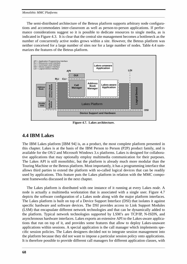
Monolithic MMC Platforms
68
The semi-distributed architecture of the Beteus platform supports arbitrary node configura-tions and accommodates inter-classroom as well as person-to-person applications. If perfor-mance considerations suggest so it is possible to dedicate resources to single media, as isindicated in Figure 4.3. It is clear that the central site management becomes a bottleneck as thenumber of concurrently active nodes grows within a site. However, the Beteus platform wasneither conceived for a large number of sites nor for a large number of nodes. Table 4.4 sum-marizes the features of the Beteus platform.
4.4 IBM Lakes
The IBM Lakes platform [IBM 94] is, as a product, the most complete platform presented inthis chapter. Lakes is at the basis of the IBM Person to Person (P2P) product family, and isavailable for the OS/2 and Microsoft Windows 3.x platforms. Lakes is designed for collabora-tive applications that may optionally employ multimedia communication for their purposes.The Lakes API is still monolithic, but the platform is already much more modular than theTouring Machine or the Beteus platform. Most importantly, it has a programming interface thatallows third parties to extend the platform with so-called logical devices that can be readilyused by applications. This feature puts the Lakes platform in relation with the MMC compo-nent frameworks discussed in the next chapter.
The Lakes platform is distributed with one instance of it running at every Lakes node. Anode is actually a multimedia workstation that is associated with a single user. Figure 4.7depicts the software configuration of a Lakes node along with the major platform interfaces.The Lakes platform is built on top of a Device Support Interface (DSI) that isolates it againstspecific hardware and software devices. The DSI provides access to Link Support Modules(LSM) that encapsulate different network technologies and that can be dynamically added tothe platform. Typical network technologies supported by LSM’s are TCP/IP, N-ISDN, andasynchronous hardware interfaces. Lakes exports an extensive API to the Lakes-aware applica-tions that run on top of it, and provides some features that allow to deploy Lakes-unawareapplications within sessions. A special application is the call manager which implements spe-cific session policies. The Lakes designers decided not to integrate session management intothe platform because they did not want to impose a particular session policy onto applications.It is therefore possible to provide different call managers for different application classes, with
Figure 4.7. Lakes architecture.
RLI
DSI
API
Lakes Platform
Device Support and Hardware
CallManager
AddressBook
ManagerLakes-awareApplication
Lakes-unawareApplication
Lo
gic
al D
evic
e
LDI
Ad
dre
ss B
oo
k
ProfileData
AddressBook
Pro
file
IFM
od
ule
Acc
ess
Mo
du
le
CLIGUI
API = Application Programming InterfaceRLI = Resources Level InterfaceCLI = Command Level InterfaceDSI = Device Support InterfaceLDI = Logical Device Interface
69
IBM Lakes
the limitation that only one call manager can be active at a time. It was nevertheless realizedthat few developers will want to develop their own call managers, which is why there is a Com-mand Level Interface (CLI) that allows to reuse the call management engine of the default IBMcall manager. Another replaceable utility application is the address book manager that providesaccess to information about Lakes nodes. The address book access module shown in Figure 4.7is a directory service that can be supplied by third-party developers. The address book can con-sequently be as simple as a file or as complex as a distributed database. The address bookaccess module is accessed via the resources level interface (RLI). Another module accessed viathe RLI is the profile interface module which can be queried for customization data concerningthe node and the networks to which the node is attached.
Applications running at different Lakes nodes may temporarily come together in sharingsets. Applications within the same sharing set may establish channels among each other, withchannels being unidirectional point-to-point connections among application ports with explicitQoS attributes. The establishment of a channel may be preceded by QoS negotiation with thetarget node, in which case the call manager takes the role of a resource manager. Channels canbe combined to channel sets of type standard, merged, serialized or synchronized. Mergedchannels multicast data coming from all incoming channels of the channel set to all outgoingchannels. Serialized channels serialize data from different sources, so that every sink sees thesame ordered sequence of data packets. Synchronized channels finally deliver packets with thesame timing relationship with which they received them. Channels are terminated by applica-tion ports or logical device ports. Applications realize audio or video connections with chan-nels between audio and video logical devices. The Lakes platform can be extended with logicaldevices that are programmed on top of the logical device interface (LDI). Logical devices arecontrolled via their ports, for which the Lakes API provides the call LakSignalPort. Theprincipal parameter of this call is a command string that is interpreted by the logical device.This means that logical devices can be added to the platform without any modification of theAPI. However, it is clear that command strings are not very comfortable to program with.
Lakes offers multiple mechanisms for applications to exchange data. Applications may addcommand strings to many API calls that are transparently forwarded to peer applications. Theymay explicitly use the calls LakSignalApp or LakSignalWithReply to send a commandstring to arbitrary Lakes applications. They may further use the port signalling facility tobroadcast messages to all applications connected to a channel set. These three mechanisms arenot foreseen for the transmission of volume data, which must be done with normal channels.
Applications communicate with the Lakes platform via a proprietary request-reply protocolthat is hidden behind the API calls. Lakes API calls may either be synchronous or asynchro-nous. Calls that require negotiation with remote entities are usually asynchronous. They returnimmediately, with the outcome of the call being returned as an event.
4.4.1 Assessment
Table 4.5 provides an overview of the functionality provided by the Lakes platform. The func-tionality provided by Lakes is comparatively low-level because the designers of the platformwanted to support a broad range of applications. The API is still monolithic, and would alsoprofit from a reformulation in CORBA IDL, but it is not affected of platform extensions in theform of logical devices. The comparatively large number of replaceable modules and openplatform interfaces in Lakes indicates the direction that the design of MMC platforms is tak-ing: towards components with interfaces that can be accessed via an ORB.

Monolithic MMC Platforms
70
One of the major benefits of the Lakes platform is the substantial support it provides for col-laborative applications. This support goes well beyond what is offered by the Touring Machineor the Beteus platform. Platform support for collaborative applications is essential because atone point it will be more important to collaborate over the net than just to communicate. Theattention that digital audio and video transmission receive today is mainly due to the resourceproblems they provoke. Once a high-quality multipoint video transmission over the Internethas become a matter of course there will be more attention on application logic in general, andtherefore also more attention on platform support for collaboration over the network.
IBM Lakes
Requirement Fulfilled Remark
Open ❄ some standards support on transport level (X/Open XTI)
Extensible ❄❄ allows to add logical devices and to replace certain modules
Programmable ❄❄ powerful, but low-level API
Scalable ❄❄ no bottlenecks but the number of applications in a sharing set
Deployable ❄ platform may require considerable customization
Simple ❄ API is complex
Session Management ❄❄ call managers can be supplied by third parties
Connection Management ❄❄❄ merged/serialized/synchronized channels
Multimedia Data Processing ❄❄ logical devices
Multipoint Control Comm. ❄❄❄ API supports point-to-point and multipoint signalling
Resource Management ❄❄ channels have QoS attributes
Synchronization ❄ only delivery of data is synchronized (not presentation)
Mobile Code no application code is installed on the endsystem
Presentation Environment ❄ A/V presentation controllable, but not integrated with the GUI
Federation of Applications ❄❄❄ multiple applications/sharing sets within a call
Security no -
Mobility no user mobility can be added via a special call manager
Directory Service ❄❄ can be provided by third parties
Platform Management no -
Accounting no -
Standard DPE no -
Table 4.5. Evaluation of the IBM Lakes platform.

71
Other Platforms
4.5 Other Platforms
There are much more MMC applications described in literature than MMC platforms. One rea-son for this is that the development of platforms requires much more effort in terms of design,programming and testing than stand-alone applications. A new application concept can be val-idated with the implementation of a prototype that embodies this concept. However, the valida-tion of a new platform concept requires not only the implementation of the platform, but alsothe development of a considerable number of applications on top of it. Applications developedon top of platforms tend to be less revolutionary and less appealing than stand-alone researchprototypes. The reason for this is that platform functionality is necessarily based on establishedconcepts, and that platforms are tuned to support application classes rather than special appli-cations. Research in platforms is therefore not only more costly, but it may also be less reward-ing than research in application concepts. This may serve to explain why the number ofapplications developed on the Touring Machine, the Beteus platform and IBM Lakes is small.
There is other work that can be mentioned in the context of monolithic MMC platforms.Examples are the Betel platform and the Platinum platform. The Betel project [Pusz94] is apredecessor of the Beteus project at Eurécom. The outcome of the Betel project is a stand-alone tele-tutoring application that supports different interaction scenarios [Gros94]. Differentinteraction scenarios are defined as entries in an interaction policy database and can be dynam-ically accessed and interpreted by a central session agent. An interaction scenario is defined interms of user roles and simple rules that map user interactivity onto connection establishmentcommands. The connection structures established by the Betel application, as well as itsbehavior, can therefore be easily modified and adapted to different situations, which wasimportant in the Betel project. Similar to Beteus, Betel was confronted with many uncertaintiesconcerning the network and the application scenario. The role abstraction in Beteus was moti-vated by Betel’s user roles.
The objective of the Platinum platform [Klap96] was to bring advanced ATM features likemulti-party and multi-connection calls to the desktop. In the course of the project a signallingprotocol was implemented that would be B-ISDN signaling release 3 in ITU-T terms. Thefunctionality of this protocol is accessed via a message-based programming interface thatallows applications to participate in multi-party calls and to establish multipoint connections.The Platinum platform is an example for a platform that facilitates the development of B-ISDNtelecommunications services.
4.6 Conclusion
This chapter presented three monolithic MMC platforms, namely the Touring Machine, theBeteus platform, and IBM Lakes. These platforms have to be considered as first generationplatforms, built to explore how a future MMC infrastructure may look like. All three of themhave become obsolete, which is partly due to a lack of extensibility and an inflexible softwarearchitecture. For all three platforms it was shown that they would greatly profit from CORBA.CORBA allows to considerably improve the structure of a platform and of the API that itexposes to applications. It shortens communication paths and fosters modularity and extensi-bility. However, although the software architecture of the presented platforms is outdated itwould be a mistake to forget about them. Monolithic platforms are still revolutionary given thatmost of today’s MMC applications are built without platform support.

Monolithic MMC Platforms
72
The API’s of at least the Touring Machine and Beteus remain valuable, but need to be refor-mulated in OMG IDL. The API of IBM Lakes is situated at a lower level than the ones of theTouring Machine and Beteus. It is consequently more flexible, but also more complex, andapplication development is not as straightforward as on the other platforms. The followingchapter will postulate that an MMC platform must provide various levels of programming sup-port, allowing developers to develop on a low level wherever they need flexibility, and on ahigh level wherever they want to reuse existing functionality. The API’s of the TouringMachine and Beteus can therefore be reimplemented as toolkits on a low-level API similar inspirit to the one of IBM Lakes.

73
5 MMC Component Frameworks
5.1 Introduction
The previous chapter discussed the first generation of MMC platforms, which is mainly char-acterized by a large monolithic API and an opaque internal architecture. The support for appli-cation development in first generation MMC platforms is already quite good, making itpossible to develop MMC applications in a couple of days, rather than in a couple of months,as is the case with stand-alone applications. However, the principal problem with monolithicplatforms is that they are not designed to be extended by third parties. At the very most theyhave internal interfaces that facilitate extension for those that originally implemented the plat-form. These interfaces are normally hidden, and even if they were published they would not beusable by third parties because their usage tends to have side-effects that are hard to document.This means that third parties can extend such a platform only if the platform code is providedalong with the specification of internal interfaces. The lack of extensibility that monolithicplatforms exhibit goes hand in hand with a lack of openness. Monolithic platforms have moreof a product than of an open platform, with the effect that third parties are not only unable toextend the platform, but also unable to implement it. Lack of extensibility and openness is tan-tamount to reduced lifetime. Monolithic platforms are not able to adapt themselves to tenden-cies in the rapidly moving field of multimedia, and they are consequently bound to disappear.
This chapter looks at MMC platforms that are based on the component framework para-digm. Component frameworks decompose functionality into self-contained building blocksthat can be customized and plugged together. These building blocks, or components, behaveaccording to some predefined rules that manage the way they interact with each other. Applica-tion development on top of a component framework consists of customizing components,establishing relationships among them, and associating program code with events generated bythem. Components are smart in that they are able to find out about the environment in whichthey are running. This allows them to react to many events without that the programmer wouldneed to intervene. One of the benefits of component frameworks is therefore a certain simplic-ity in application development. In the case of MMC applications this was already achievedwith the monolithic platforms presented in the previous chapter. The real benefit of a compo-nent framework in the case of MMC applications is therefore extensibility. Components can bedeveloped by third-parties and added to a platform without that any modification or recompila-tion of the platform would be necessary. An MMC platform based on the component frame-work paradigm is extended with every component that is developed for it.
Components need to interact with each other, and they must also be controllable by applica-tion code. CORBA comes into the game as the bus that carries all component control commu-nication. This chapter discusses two MMC platforms that are based on CORBA, and one that isbased on a proprietary communication mechanism. The two CORBA-based platforms are theMultimedia System Services of the Interactive Multimedia Association (IMA-MSS), and theTelecommunication Information Networking Architecture (TINA) of the TINA Consortium
MMC Component Frameworks
74
(TINA-C). The platform with the proprietary communication mechanism is Medusa, whichwas developed at the Olivetti Research Laboratory (ORL) in Cambridge. Medusa is includedin order to illustrate how an MMC platform based on components can profit from a standardORB architecture like CORBA. A remarkable feature of Medusa is that it provides high-levelprogramming support on top of its low-level components. Medusa can be seen as a linkbetween the IBM Lakes architecture that has limited support for components, and architectureslike IMA-MSS that define a component framework on top of CORBA. The discussion ofexample platforms in this chapter is followed by some general remarks about how a futurestandard MMC component framework may look like. This leads over to the next chapter,which presents, as the main contribution of this thesis, a platform that is based on CORBA andthe component framework paradigm.
5.2 Medusa
Medusa [Wray94] was developed at ORL to address some of the limitations experienced withPandora [Jone93], which was a joint project between Olivetti and the Cambridge UniversityComputer Laboratory. Multimedia data transmission and processing in Pandora was done by aperipheral, Pandora’s Box, that was directly attached to an ATM network. This means thatapplications running on the workstation associated with Pandora’s Box were not able to accessmultimedia streams and to do any application-specific processing on multimedia data. Theconcept of ATM direct peripherals was retained in Medusa, but one of the requirements wasthat there should be no more limitations as to where multimedia streams are generated andconsumed. Applications should still be able to delegate multimedia processing to components(the hands-off approach), but they should also be able to process data on their way from sourceto sink (the hands-on approach). Additional objectives for Medusa were support for security,support for application reuse, and support for a heterogeneous computing environment consist-ing of systems running UNIX, Windows NT and ATMOS, ORL’s in-house operating systemfor direct ATM peripherals.
A Medusa terminal consists of a standard workstation plus multimedia devices that aregrouped around a small ATM switch which is itself connected to an ATM backbone. This so-called desk area network (DAN) architecture allows to add an arbitrary number of ATM directperipherals to the workstation switch without affecting the performance of the workstation.The software architecture of Medusa hides the existence of peripherals behind the moduleabstraction. Modules are objects that encapsulate multimedia processing functionality. Everyactive object in Medusa, including the application itself, is a module. Modules usually repre-sent some clearly defined function like video compression or audio source and are intended tobe chained together to form pipelines from source to sink. Every module defines attributes thatmodel its behavior. Applications can set or get the value of an attribute, and they can ask to benotified via an event whenever the value of the attribute changes. Existing modules are identi-fied by unique capabilities. A capability contains the information that is necessary to localize amodule. Modules have ports, and the ports of different modules can be linked via oneway con-nections. Connections are untyped, but carry messages which in turn contain data segmentsthat can be of type audio, video, command, reply and event. Connections are thus used for bothcontrol and media data. As can be seen in Figure 5.1, an application needs to establish two con-nections for a complete control association with a module, one on which commands are sent tothe module, and another on which the module returns replies and events to the application.Since connections are used for control they have to be reliable. Unreliable connections over anetwork are represented as special modules.
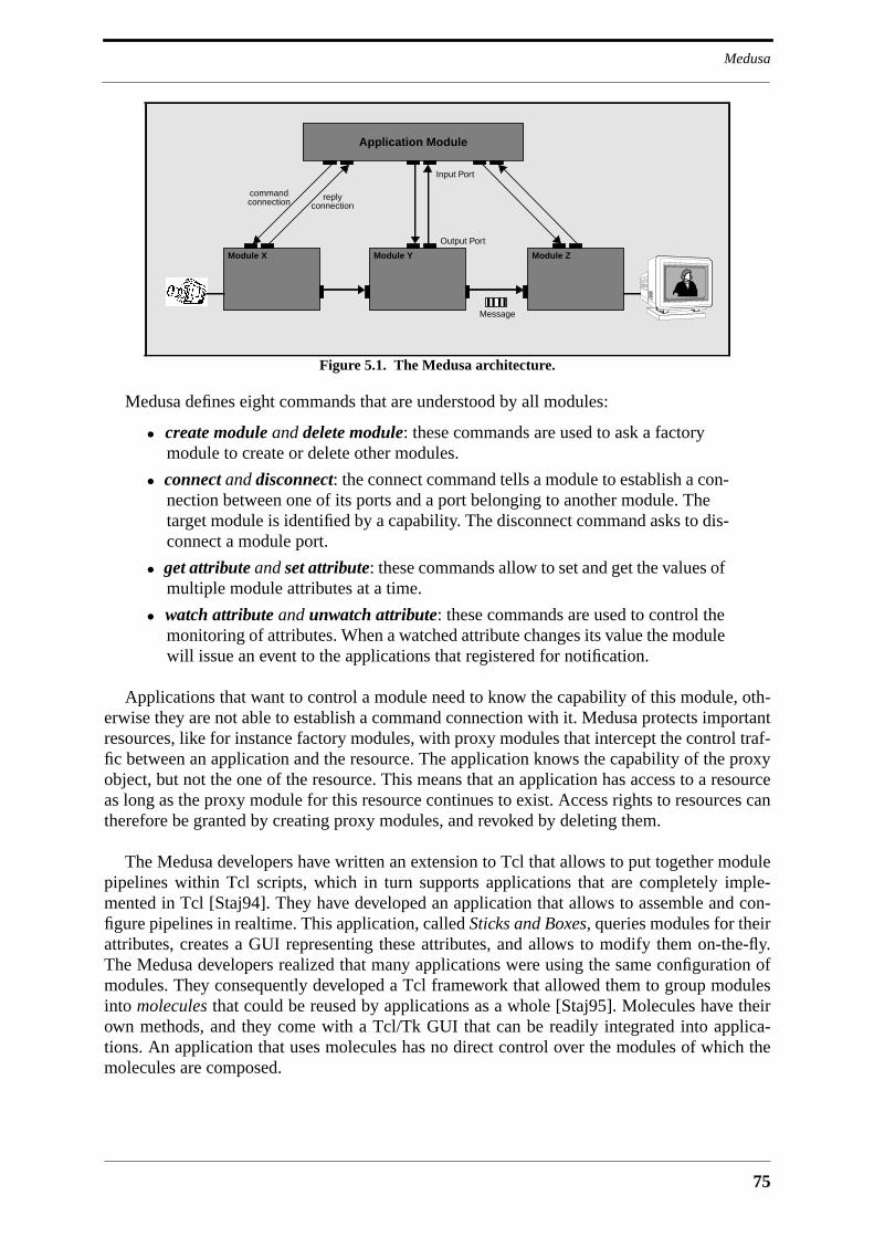
75
Medusa
Medusa defines eight commands that are understood by all modules:
• create module and delete module: these commands are used to ask a factorymodule to create or delete other modules.
• connect and disconnect: the connect command tells a module to establish a con-nection between one of its ports and a port belonging to another module. Thetarget module is identified by a capability. The disconnect command asks to dis-connect a module port.
• get attribute and set attribute: these commands allow to set and get the values ofmultiple module attributes at a time.
• watch attribute and unwatch attribute: these commands are used to control themonitoring of attributes. When a watched attribute changes its value the modulewill issue an event to the applications that registered for notification.
Applications that want to control a module need to know the capability of this module, oth-erwise they are not able to establish a command connection with it. Medusa protects importantresources, like for instance factory modules, with proxy modules that intercept the control traf-fic between an application and the resource. The application knows the capability of the proxyobject, but not the one of the resource. This means that an application has access to a resourceas long as the proxy module for this resource continues to exist. Access rights to resources cantherefore be granted by creating proxy modules, and revoked by deleting them.
The Medusa developers have written an extension to Tcl that allows to put together modulepipelines within Tcl scripts, which in turn supports applications that are completely imple-mented in Tcl [Staj94]. They have developed an application that allows to assemble and con-figure pipelines in realtime. This application, called Sticks and Boxes, queries modules for theirattributes, creates a GUI representing these attributes, and allows to modify them on-the-fly.The Medusa developers realized that many applications were using the same configuration ofmodules. They consequently developed a Tcl framework that allowed them to group modulesinto molecules that could be reused by applications as a whole [Staj95]. Molecules have theirown methods, and they come with a Tcl/Tk GUI that can be readily integrated into applica-tions. An application that uses molecules has no direct control over the modules of which themolecules are composed.
Figure 5.1. The Medusa architecture.
Module X Module Y Module Z
Application Module
commandconnection reply
connection
Output Port
Input Port
Message
MMC Component Frameworks
76
5.2.1 Assessment
Medusa is the first platform presented in this thesis that is explicitly designed for extensibility.Simple Medusa modules can be implemented with a few lines of C++ code. Every applicationdeveloped for Medusa will enrich the platform by increasing the number of modules availableto factories. Second generation applications will then have access to a rich library of modulesthat they can assemble in many different ways. The Medusa architecture is a component frame-work, with the restriction that it does not support the development of platform components bythird parties. This was never an objective for Medusa - Medusa was exclusively designed forthe ATM network at ORL, and it was consequently not necessary to provide open interfaces forcomponent development. Unlike the platforms presented until now, Medusa does not offer anysupport for session management, and it does not have a clear application model. Medusa is infact a multimedia middleware on top of which different application frameworks and policiescan be developed.
The way control is handled in Medusa appears to be weird at first, but can be explained withthe ATM direct peripherals. These peripherals run a small operating system that did not sup-port RPC by the time Medusa was developed, which is why a message-based control protocolcould not be avoided. Meanwhile, an in-house ORB has been implemented for the peripheralsin a move to build a platform similar to Medusa on top of CORBA [Murp96]. CORBA wouldsimplify the Medusa architecture to a big extent. First of all, the interface of a module can bedefined in CORBA-IDL rather than as a set of attributes. Medusa capabilities can be replacedby CORBA object references, and command and reply messages by CORBA operations. Mod-ule interfaces can inherit from a base interface that offers functionality that is uniformly pro-vided by all modules, like for instance connection establishment. Medusa events can beprovided by the CORBA event service, and the module query feature that is needed by theSticks and Boxes application can be provided by the CORBA interface repository.
The perhaps most interesting feature of Medusa for this thesis is its support for modulegrouping. The decomposition of functionality into fine-grained components has the benefit thatit allows to build applications simply by interconnecting components, but it also creates theproblem that applications then have to deal with interfaces of multiple components, whereasbefore they only dealt with a single API. As an example, in Medusa it does not make sense tochange the size of the video window produced by video converter module if it is not alsochanged in the video window module at the receiving side. This is not a problem with mono-lithic API’s like those presented in the previous chapter. Monolithic API’s control the compo-nents of an end-to-end connection in a consistent way, and do not require the programmer tofigure out how a video sink must be configured so that it can meaningfully process the streamproduced by a video source. In the case of component frameworks for MMC applications thereis a need to provide further layers of abstractions on top of components in order to achieve thesame ease of programming as with monolithic API’s. There must be higher-level objects thatoffer operations for the compound control of component networks. These objects may com-pletely hide the components from the application, in which case they are typed, or they mayrepresent a single access point for compound operations that need to be uniformly applied toevery object in the component network, in which case they are generic. Typed higher-levelobjects deploying the same component configurations may offer different degrees of program-mability. As an example, one can imagine an audio object with two operations: add participantand remove participant. This object would interconnect session participants with an audiocomponent network containing audio coders, decoders and mixers. There are applications thatdo not need more than that. For applications that want to have more control there could be

77
IMA Multimedia System Services
audio objects offering considerably more functionality, for instance choice of audio coding,control over the number of streams mixed at receiving sides, et cetera.
5.3 IMA Multimedia System Services
The Multimedia System Services (MSS) of the Interactive Multimedia Association (IMA) isan architecture that shall facilitate cross-platform compatibility of multimedia applications[IMA94a][IMA94b]. The IMA-MSS standard, or Recommended Practice (RP) in IMA’s ter-minology, is based on a submission jointly proposed by Hewlett-Packard, SunSoft and IBM[Picc94]. MSS was never finalized by IMA1, but instead handed over to ISO where it will now
1. IMA worked on MSS until well into 1995. Work on MSS then stopped because "over time industry focus shiftedto other things", as was stated by Steven Mitchell, Director of Systems and Information Management at IMA,in a mail to the author of this thesis.
Medusa
Requirement Fulfilled Remark
Open no all protocols and interfaces are proprietary
Extensible ❄❄❄ component framework
Programmable ❄❄❄ grouping of modules into high-level reusable molecules
Scalable ❄❄❄ no inherent scalability limitations
Deployable no tailored to the hard- and software environment at ORL
Simple ❄❄ small number of powerful concepts
Session Management - not in the scope of the architecture
Connection Management ❄❄ support for simultaneous module creation and interconnection
Multimedia Data Processing ❄❄❄ flexibility due to component framework
Multipoint Control Comm. ❄ control communication is low-level and point-to-point
Resource Management no -
Synchronization no -
Mobile Code no can be added (Medusa applications are written in Tcl)
Presentation Environment ❄ allows to integrate video into application windows
Federation of Applications - -
Security ❄ some support for access control
Mobility - -
Directory Service - -
Platform Management no -
Accounting - -
Standard DPE no no standard DPE
Table 5.1. Evaluation of Medusa.

MMC Component Frameworks
78
become part of PREMO [ISO96b]. However, the version of MSS discussed here is the last RPdraft published by IMA. This is justified by the fact that until now the ISO committee workingon PREMO has not significantly modified MSS.
MSS should provide abstractions that make it possible for applications to deal with the dis-tributed processing of multimedia data. Applications should be able to use MSS without beingconcerned with particular software or hardware environments, i.e., they should be able to runon top of heterogeneous software and hardware platforms. MSS should provide support forresource management, synchronization, and both live and stored multimedia data. MSS wasnot supposed to address security, scripting, graphical user interfaces, data sharing or billing.MSS defines abstractions for time, data flows, processing nodes, connections among process-ing nodes, and the grouping of processing nodes and connections. MSS is the first architecturediscussed in this thesis that is based on CORBA. MSS defines IDL interfaces within a basicinheritance tree that can be extended by third parties.
Figure 5.2 shows the major concepts of the MSS architecture. MSS decomposes data pro-cessing functionality into virtual devices. A virtual device consists of a processing element andone or more ports through which data are communicated. A virtual device exports the follow-ing interfaces:
• device-specific interface: a single interface that allows to control device-specificprocessing characteristics. This interface inherits from the generic Virtu-alDevice interface.
• stream control: there is one stream control interface per port, and one on device-level for compound stream control. Typical stream control operations arepause(), resume(), prime(), drain() or mute(). The base interface forstream control is Stream.
• format control: a device port supports one or more media stream formats. Theformat of a port is set via an operation in the VirtualDevice interface. For-mat parameters are then set via operations in an interface that inherits from thegeneric Format interface.
Figure 5.2. Interaction between MSS objects.
Stream
Stream
Format
VirtualDevice
Stream
Stream
Format
VirtualDevice
Media Stream Protocol
Stream
Stream
VirtualConnection
Group
EventChannel
PushConsumerClient
ProcessingElementPortPortProcessing
Element
ContainingCORBA Object
ContainedCORBA Object
Internal Object
Client Interaction
Internal Interaction

79
IMA Multimedia System Services
Device ports themselves are internal objects for which no IDL interface is defined. Applica-tions refer to ports with opaque port handles. The ports of different devices are connected via avirtual connection that can be unicast, in which case it connects a source port with a sink port,or multicast, in which case it connects one source port with multiple sink ports. The mostimportant operation of the VirtualConnection interface is connect(). This operationtakes as parameters a source endpoint and a sink endpoint, with an endpoint being given as theobject reference of a virtual device plus a port handle. The VirtualConnectionMulticastinterface inherits from VirtualConnection and adds the operation attach() with whichan endpoint can be added to a virtual connection. A virtual connection contains a Streaminterface that allows to control the connection as a whole. Operation invocations on this inter-face are propagated to the Stream interfaces of the connected device ports.
The interfaces VirtualConnection and VirtualDevice inherit both from the interfaceVirtualResource, as can be seen in the interface inheritance diagram in Figure 5.3. A vir-tual resource is an object that requires endsystem or network resources for operation. Theresources that are held by a virtual resource are obtained with the call acquire_re-source(), which takes a QoS value as parameter, and released with the call release_re-source(). Virtual resources also contain a Stream interface that can be accessed with theoperation get_stream().
MSS supports compound operations on device networks via Group objects. Operations oninterfaces exported by the Group object are propagated to all group members. The Groupinterface contains the membership control operation add_resource() that allows to add avirtual resource to the group. Since Group is itself a virtual resource it is possible to establishgroup hierarchies containing virtual devices and connections at the bottom and multiple levelsof group objects further up. As a virtual resource a group object must also implement the oper-ation acquire_resource(). The QoS requested with this call is end-to-end, meaning that ithas to be provided as a common effort of all group members. Applications will typically addall virtual devices and virtual connections of a device graph to a group, as is indicated in Figure5.2, reserve resources for the graph as a whole with a call to acquire_resource(), and con-trol this graph via operation invocations to the Stream interface of the group.
The first versions of MSS defined a proprietary event service, which was at last replacedwith the standard CORBA event service, as can be seen in Figure 5.2. MSS object clients havethe choice of receiving events via the push or the pull mechanism, whereas MSS objects them-selves deliver an event to the event channel via the push mechanism. It seems that event chan-nels can be associated with a client, like in Figure 5.2, with an MSS object, or with a particularevent generated by an MSS object. The MSS RP is not very clear about this.
The following subsections discuss some important features of MSS, namely its use of theCORBA property service, the way connections are established, and further how it handles syn-chronization and resource management.
5.3.1 Properties and Capabilities
An important concept in MSS are properties and capabilities. An MSS object may have prop-erties beyond the operations that it implements, with an example being its location. A propertyis defined as a string constant in the interface of the object with which the property is associ-ated. Clients can read or modify the values of a property via the standard CORBA property ser-vice. Since the value of a CORBA property is of type any, it is necessary to define for every

MMC Component Frameworks
80
property the type of the value it can take. Capabilities are special properties that describe therange of values a property can take. MSS renounces on the use of CORBA attributes and takesinstead of that the use of properties and capabilities to the extreme. Capabilities allow clients toimpose constraints on properties. Clients may for instance impose a constraint on the locationof an object that is created by a factory. They may also impose constraints on the QoS to beallocated by a virtual resource, or on certain parameters of a stream format. The idea behindthis constraint mechanism is that clients will only need to give values for properties they areinterested in, leaving the choice of remaining property values to MSS objects.
Properties and capabilities add a lot of flexibility to MSS, but it is tedious to program withthem, which is why it can be assumed that much of the flexibility gained with properties andcapabilities will remain unused by applications.
5.3.2 Connection Establishment
To arrive at the configuration depicted in Figure 5.2, the application first needs to access aFactoryFinder object in order to find the factories that are able to create the two virtualdevices, the virtual connection and the group. Once it has the object references of the factoriesit will create the virtual devices with calls to GenericFactory::MSS_create_object().Following that it will create format interfaces at the ports it wants to connect, and possibly con-strain some of the format parameters via calls to the Format interfaces. It will then create avirtual connection and have it connect the two ports. The primary task of the virtual connectionobject is to establish a physical path between the two ports. The way this is done is hidden tothe client, and consequently not in the scope of MSS. The virtual connection object must alsomatch the formats of source and sink port. It first retrieves the list of constraints imposed on theformat object of the media master, which is the first of the two endpoints mentioned in theVirtualConnection::connect() call, and compares these constraints with the capabili-ties of the other format object. This is done with a call to Format::compare(). This callreturns the intersection of the given constraints and the capabilities that are supported by theformat object on this port. The virtual connection continues to iterate between the formatobjects of the two ports until all format parameters are fixed. Following that, the applicationcreates a group object and adds the two virtual devices and the virtual connection to it. It thencalls the acquire_resource() operation of the group, and once the resources are acquiredit retrieves the object reference of the stream object of the group, and calls resume()to starttransmission.
As can be seen, the establishment of a connection between two virtual devices requires alarge number of operation invocations. Many of these operation invocations will cross the net-work, especially those coming from the virtual connection object which needs to call the for-mat objects multiple times in order to match format parameters. Operation invocations over thenetwork take multiple milliseconds to complete, which is several orders of magnitude morethan it takes for a method invocation within a single address space. With this in mind it can beexpected that it takes several seconds to establish a multipoint-to-multipoint connection amonga set of terminals, especially if there are multiple virtual devices to be chained together onevery terminal. Another problematic feature of MSS is the way format parameters arematched. The scheme described above works fine for the case that only two ports need to beconnected, but it is not clear how the virtual connection object can match all port formats in agraph that contains more than two devices. The source and sink port formats of a virtual devicewill usually be interdependent, meaning that the choice of a format at a sink port is likely toconstrain the format choices at the source ports of the same virtual device. A first consequence
81
IMA Multimedia System Services
of this is that format matching cannot be done in parallel in a graph because it would be subjectto race conditions. Serial format matching of port pairs will not produce inconsistencies, but itis likely to fail because it does not take format interdependencies into account. This means thatapplications cannot rely on automatic format matching if they establish graphs containing mul-tiple virtual devices.
5.3.3 Synchronization
The Stream interface contains the operation get_position() that allows to retrieve the cur-rent time or stream position, and the operation set_position_reporting() that causes thestream to periodically generate position events. These two operations allow other streams tosynchronize themselves with a master stream by comparing the stream position of the masterstream with the local stream position. MSS defines the VirtualClock interface for use as anindependent source of time. The VirtualClock interface inherits from VirtualResource,and implements consequently the Stream interface. Applications have therefore the choice tosynchronize data streams with respect to each other by designating a master stream, or to syn-chronize multiple streams with a virtual clock. A virtual device that is able to synchronize itsstreams with an external stream implements the SyncStream interface. This interface con-tains the operation attach_master() that takes as parameter the object reference of a streamto which the object implementing the SyncStream interface shall synchronize itself.
MSS also supports the insertion of application-defined markers into streams that causeevents for which applications can register. This together with the possibility to synchronizestreams represents a decent synchronization framework which will suffice for many applica-tions.
5.3.4 Resource Management
The resources allocated by an MSS virtual resource are described by five QoS characteristics:
• guaranteed level: defines to which extent the requested QoS is maintained byMSS once it is allocated. Possible values are guaranteed, best effort, or no guar-antee.
• reliable: defines if the delivery of data on connections is reliable or not.
• delay bounds: minimum and maximum delay experienced by data in a virtualresource (virtual connection, virtual device, group).
• jitter bounds: minimum and maximum delay variance experienced by data in avirtual resource (virtual connection, virtual device, group).
• bandwidth bounds: minimum and maximum bandwidth of a stream.
The MSS RP defines the type QoS as a list of capabilities describing value ranges for thefive QoS characteristics above. This allows applications to specify only those QoS characteris-tics in a resource reservation in which they are interested. Applications are actually not thoughtto set the QoS of every virtual device or connection, although they have the possibility to do so.Applications will rather add all virtual resources of a graph to a group, and set the QoS of thegroup. The MSS RP states that "the group does the work of allocating the QoS to individualobjects to meet the overall QoS objective"1. This can be expected to work for the simple case
1. See Section 6.3.5.1 of the MSS RP [IMA94a].

MMC Component Frameworks
82
of bandwidth bounds, but it is not clear how the generic group object can decide about how todistribute a maximum end-to-end delay over a chain of virtual devices and connections ofwhich it does not have any knowledge. The same is true for jitter bounds. Another problemwith resource management in MSS is that QoS is requested for virtual resources rather than forstreams, which would make more sense. There is no problem with this in the case of virtualconnections where there is a one-to-one mapping between stream and virtual resource, but it isnot correct in the case of virtual devices, which have to deal with multiple streams wheneverthey have more than two ports. A virtual device supporting multiple streams will therefore notknow to which stream it has to apply given bandwidth or delay bounds.
The MSS RP also outlines a resource management architecture consisting of resource man-agers for individual resources that are accessed by virtual devices, but since the mechanisms ofresource management are hidden from the client it does not define any resource managementinterfaces under the hood.
5.3.5 Interface Hierarchy
All MSS objects inherit from the base interface MSSObject, which in turn inherits from theCORBA property service interface PropertySet. The PropertySet interface contains allthe functionality that is necessary to set or get the values of properties. The most importantcomponent of the MSSObject interface is the definition of the location property. Three inter-faces inherit from MSSObject: VirtualResource, Format and Stream. The most interest-ing aspects of the Stream interface and its descendants have already been discussed. TheFormat interface is further refined with digital audio and video formats and analog connectorformats. All MSS devices inherit from VirtualDevice, which in turn inherits from Virtu-alResource. The MSS RP defines virtual video devices for different windowing technologiesand basic microphone and speaker devices for audio. Not shown in Figure 5.3 are the filedevice and a compact disk player device.
The design of the interface inheritance tree is sound with the exception of the VirtualDe-vice hierarchy. The existence of the virtual devices VideoDevice, AVDevice andAudioDevice appears to be a result of taxomania [Meye96]. The IDL definition of these vir-tual devices contains only properties and capabilities, i.e., string constants, and no real func-tionality. The only recognizable function of these interfaces is that they protect the names of
Figure 5.3. MSS interface inheritance diagram.
MSSObject
VirtualResource
Format
Stream
ConnectorFormat
DigitalVideoFormat
DigitalAudioFormat
CATVFormat
VideoConnectorFormatAudioConnectorFormat
MPEGVideoFormatJPEGVideoFormatPseudoColorVideoFormat
DynamicDigitalAudioFormat
ControlledStream
FileStream
SyncStream
VirtualDevice
VirtualClock
Group
VirtualConnection
VideoDevice
AVDevice
AudioDevice MicrophoneDeviceSpeakerDeviceAudio
VideoMSWindowVideoDeviceAVMSWindowDeviceSyncXWindowVideoDeviceXWindowVideoDeviceAVXWindowDevice
PropertySet

83
IMA Multimedia System Services
the defined audio or video properties and capabilities. This however should be rather done by aCORBA module definition than by an interface definition. Note that MSS does not useCORBA modules at all, with the result that all MSS interfaces are defined on global scope.
5.3.6 Assessment
MSS is the most important CORBA-based multimedia middleware defined until now. It definesa complete framework for multimedia processing and transmission and is based on set ofsound abstractions, most notably the virtual device, stream and format abstractions. The mostimportant problem with it is maybe that it was never finished by the people that originally con-ceived it. The last MSS RP draft is incomplete and contains many inconsistencies, which iswhy it is certainly not easy to recycle it for PREMO. Some important details of the architecturedo not work as they are supposed to, with examples being automatic format matching andcompound resource allocation, and nobody has ever built a prototype for MSS. Maybe MSS
IMA-MSS
Requirement Fulfilled Remark
Open ❄❄ client interfaces open, internal device interfaces hidden
Extensible ❄❄ extensible design, but no implementation framework
Programmable ❄❄ programming with capabilities is flexible, but tedious
Scalable ❄ graphs may only contain a small number of devices
Deployable no no strategy for deployment
Simple ❄❄ small number of powerful concepts
Session Management - not in the scope of the architecture
Connection Management ❄❄ a lot of flexibility at a low level
Multimedia Data Processing ❄❄❄ flexibility due to virtual device and format abstractions
Multipoint Control Comm. ❄❄❄ use of CORBA and the CORBA event service
Resource Management ❄ resource management architecture outlined
Synchronization ❄❄ inter-stream and event-based synchronization
Mobile Code - -
Presentation Environment no does not address integration of objects into GUI’s
Federation of Applications - -
Security no -
Mobility - -
Directory Service - -
Platform Management no -
Accounting - -
Standard DPE ❄❄❄ CORBA
Table 5.2. Evaluation of IMA-MSS.

MMC Component Frameworks
84
came too early with respect to CORBA. The first version of MSS could not use any CORBAservice, and by the time work on MSS stopped the CORBA property service had not even beenfinalized yet.
MSS is a framework for the support of application compatibility. As such it is not at all con-cerned with internal interfaces, and most notably not with the internal interfaces that have to beimplemented by a virtual device or that are accessed by it. It is therefore not possible for thirdparties to develop virtual devices. Support for third-party device development requires at leastthe definition of the port and resource manager interfaces. It would also be necessary to addsome GUI abstractions to MSS. The technology-prone video devices to be seen in Figure 5.3would need to be replaced with widgets that can be readily integrated into GUI’s.
5.4 TINA
The Telecommunication Information Networking Architecture (TINA) is a platform for MMCservice provision that is being developed by the TINA Consortium (TINA-C). The TINA con-sortium was founded at the beginning of 1993 following an initiative of Bellcore in the UnitedStates, British Telecom in the United Kingdom, and NTT Japan [Barr93], and has at the timeof writing 45 members, including 26 telecommunications operators, 11 telecommunicationsmanufacturers, and eight computer manufacturers and software companies1. TINA is the pre-dominant effort in the area of telecommunications to come up with an open, next-generationarchitecture for the provision of MMC services. It is mainly motivated by the fact that cus-tomer premises equipment has become more intelligent than network equipment, with the con-sequence that it will play an important role in future telecommunications systemsarchitectures. Other factors that lead to the foundation of the TINA consortium were markettrends like the globalization of services and the increasing demand for service diversity. Cur-rent network and service architectures are complex and difficult to manage. They do not sup-port the rapid development and introduction of new services, and they are overwhelmed byservice interaction problems. TINA is supposed to solve these and other problems of currentnetworks by defining a radically new and future-proof architecture along with a viable migra-tion path to it.
TINA is required to provide architecture support for administrational domains, businessroles and stakeholders. Transport mechanisms shall be transparent to TINA, making it possibleto deploy TINA on top of all kinds of networks including ISDN, B-ISDN, WAN’s, LAN’s andmobile networks. TINA shall be useful at all stages of the service life cycle, and the range ofservices supported by TINA shall be open-ended. The following objectives are defined forTINA [Brow95]:
• interoperability: platform and application software of different vendors shall beable to interoperate.
• reusability of application software: support for the reuse of application design,and the run-time reuse of application software.
• distributed execution of applications: support for the transparent distribution ofapplication and platform software onto physical nodes.
1. See the Web site of the TINA Consortium (http://www.tinac.com/) for up-to-date information regarding mem-bers.

85
TINA
• support of new types of service: support for MMC services, mobility, servicecustomization and the handling of service interaction.
• support for management: support for the management of software and networkresources, version management, replication management, accounting, etc.
• independence from computing environment and hardware: the architecture shallnot rely on specific hardware and software environments.
• support for quality of services: the architecture shall provide QoS managementfunctionality on multiple levels (network connections, service execution, etc.)
• scalability: implementations of the architecture shall work efficiently in the faceof large numbers of users, nodes, administrational domains, etc.
• security: the platform architecture must address all possible security concerns.
• compatibility with existing telecommunication systems: the architecture mustsupport interworking with existing telecommunication systems.
• flexibility against regulation: the architecture must be flexible with respect tospecific regulatory environments.
• conformance testing: the architecture must define rules and guidelines for con-formance testing.
In its present state, TINA does not respond to all of these objectives. Service interaction andsecurity are examples for important issues that are not sufficiently addressed by the current setof TINA specifications. However, the scope of TINA is so wide and the number of problemsconsequently so large that it would be astonishing if TINA could reach all of its objectives.
The following sections discuss the most important features of TINA, namely the businessmodel, the service architecture, the connection management architecture, and the computingarchitecture on which all processing is based. Figure 5.5 sketches the service and connectionmanagement architecture of TINA, as well as some aspects of the business model.
5.4.1 Business Model
The global TINA system is partitioned into a multitude of administrational domains thatbelong to various kinds of stakeholders. Stakeholders take one or more business roles, with abusiness role being linked with a certain kind of commercial activity. The business rolesdefined so far by TINA are [Jans96]:
• consumer: the consumer is the target of all commercial activity in a TINA sys-tem, and is therefore the economical basis of a TINA system.
• service retailer: the service retailer offers telecommunications services to con-sumers, and can be regarded as a supermarket for services.
• broker: a broker helps stakeholders in finding other stakeholders. A prominentexample is the consumer that looks for a service retailer offering a specific ser-vice.
• third-party provider: third party providers build services or provide content thatis commercialized via retailers.
• connectivity provider: connectivity providers establish transport connectionsbetween computational objects of other stakeholders.
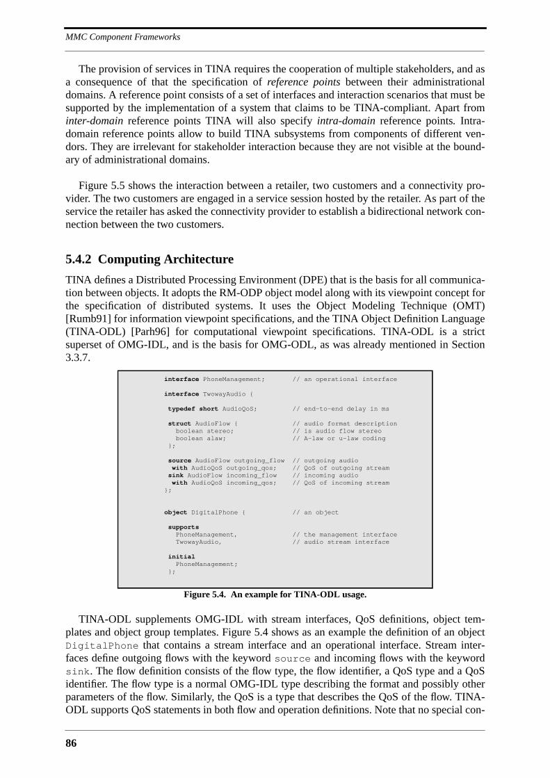
MMC Component Frameworks
86
The provision of services in TINA requires the cooperation of multiple stakeholders, and asa consequence of that the specification of reference points between their administrationaldomains. A reference point consists of a set of interfaces and interaction scenarios that must besupported by the implementation of a system that claims to be TINA-compliant. Apart frominter-domain reference points TINA will also specify intra-domain reference points. Intra-domain reference points allow to build TINA subsystems from components of different ven-dors. They are irrelevant for stakeholder interaction because they are not visible at the bound-ary of administrational domains.
Figure 5.5 shows the interaction between a retailer, two customers and a connectivity pro-vider. The two customers are engaged in a service session hosted by the retailer. As part of theservice the retailer has asked the connectivity provider to establish a bidirectional network con-nection between the two customers.
5.4.2 Computing Architecture
TINA defines a Distributed Processing Environment (DPE) that is the basis for all communica-tion between objects. It adopts the RM-ODP object model along with its viewpoint concept forthe specification of distributed systems. It uses the Object Modeling Technique (OMT)[Rumb91] for information viewpoint specifications, and the TINA Object Definition Language(TINA-ODL) [Parh96] for computational viewpoint specifications. TINA-ODL is a strictsuperset of OMG-IDL, and is the basis for OMG-ODL, as was already mentioned in Section3.3.7.
TINA-ODL supplements OMG-IDL with stream interfaces, QoS definitions, object tem-plates and object group templates. Figure 5.4 shows as an example the definition of an objectDigitalPhone that contains a stream interface and an operational interface. Stream inter-faces define outgoing flows with the keyword source and incoming flows with the keywordsink. The flow definition consists of the flow type, the flow identifier, a QoS type and a QoSidentifier. The flow type is a normal OMG-IDL type describing the format and possibly otherparameters of the flow. Similarly, the QoS is a type that describes the QoS of the flow. TINA-ODL supports QoS statements in both flow and operation definitions. Note that no special con-
interface PhoneManagement; // an operational interface
interface TwowayAudio {
typedef short AudioQoS; // end-to-end delay in ms
struct AudioFlow { // audio format description boolean stereo; // is audio flow stereo boolean alaw; // A-law or u-law coding };
source AudioFlow outgoing_flow // outgoing audiowith AudioQoS outgoing_qos; // QoS of outgoing streamsink AudioFlow incoming_flow // incoming audiowith AudioQoS incoming_qos; // QoS of incoming stream
};
object DigitalPhone { // an object
supports PhoneManagement, // the management interface TwowayAudio, // audio stream interface
initial PhoneManagement; };
Figure 5.4. An example for TINA-ODL usage.
87
TINA
struct for the definition of stream interfaces is introduced in TINA-ODL. It is therefore possi-ble to mix flow and operation definitions within a single interface. Objects are composed ofmultiple interfaces, with one of them being the initial interface that is available after object cre-ation. Similarly, object groups are composed of multiple objects with one of them being themanager object, i.e., the object that is available after object group creation. Object group tem-plates define the component objects, the manager object and the interfaces that the objectgroup exports to the outside.
Up to now there is no way to define synchronization relationships between flows. TheTINA-ODL specification proposes the introduction of the keyword synch for the definition ofsynchronization relationships between flows within a stream interface, but this would certainlybe an ad-hoc solution.
The TINA consortium has been rather reluctant in adopting CORBA specifications. WithTINA-ODL it has integrated the basic CORBA ORB into TINA, but it does not use any of theCORBAservices, nor does it seem to plan on doing so.
5.4.3 Service Architecture
At the foundation of the TINA service architecture [Abar96] is the user/provider paradigm,which is a qualification of the relationship between two interacting stakeholders. The businessroles taken by stakeholders that interact as user and provider are most of the times differentfrom each other, with examples being the interaction between customer and retailer or betweencustomer and broker, but they can also be identical, with an example being the interactionbetween two retailers. TINA distinguishes three kinds of users, namely end-users, subscribersand anonymous users. Subscribers have a contract with the provider. End-users have no con-tract with the provider, but they are known to the provider and can consequently be invited toservices. Anonymous users are unknown to the provider, which is why they can only requestservices, but not be invited to them. Interaction between users and providers in TINA is linkedwith a session. TINA defines four kinds of sessions:
• access session: established between user and provider prior to any service request.
• service session: the instance of an active service.
• user service session: the user’s view of a service session.
• communication session: the collection of network resources used by a service.
The computational objects that are defined by the TINA service architecture are shown inthe upper half of Figure 5.5. Users are represented in the provider domain via a User Agent(UA). Similarly, providers are represented in the user domain via Provider Agents (PA). TheInitial Agent (IA) allows User Applications (UAP) to establish an access session, which corre-sponds to a binding between the PA in the user domain and the UA in the provider domain.Once the access session exists, a UAP can start a session. For this it needs to contact the PA,which in turn asks the UA to create the session via the Service Factory (SF). The SF creates aService Session Manager (SSM) representing the service session and a User Service SessionManager (USM) representing the user service session. The UAP receives object references ofthe USM and the SSM and can directly interact with them. Note that both the USM and theSSM are service specific objects. They implement service specific interfaces in addition to thegeneric USM and SSM interfaces defined by the service architecture. Service sessions can bejoined by other users, and users that are already part of the service session may ask their USMto invite others. The SSM has a single access point for connection management, which is the
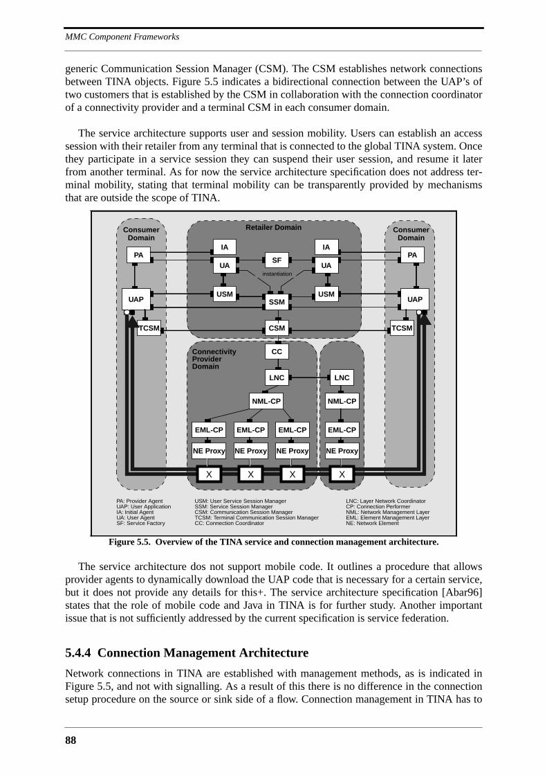
MMC Component Frameworks
88
generic Communication Session Manager (CSM). The CSM establishes network connectionsbetween TINA objects. Figure 5.5 indicates a bidirectional connection between the UAP’s oftwo customers that is established by the CSM in collaboration with the connection coordinatorof a connectivity provider and a terminal CSM in each consumer domain.
The service architecture supports user and session mobility. Users can establish an accesssession with their retailer from any terminal that is connected to the global TINA system. Oncethey participate in a service session they can suspend their user session, and resume it laterfrom another terminal. As for now the service architecture specification does not address ter-minal mobility, stating that terminal mobility can be transparently provided by mechanismsthat are outside the scope of TINA.
The service architecture dos not support mobile code. It outlines a procedure that allowsprovider agents to dynamically download the UAP code that is necessary for a certain service,but it does not provide any details for this+. The service architecture specification [Abar96]states that the role of mobile code and Java in TINA is for further study. Another importantissue that is not sufficiently addressed by the current specification is service federation.
5.4.4 Connection Management Architecture
Network connections in TINA are established with management methods, as is indicated inFigure 5.5, and not with signalling. As a result of this there is no difference in the connectionsetup procedure on the source or sink side of a flow. Connection management in TINA has to
Figure 5.5. Overview of the TINA service and connection management architecture.
ConsumerDomain
Retailer Domain
PA
CC
USM
UA
IA
CSM
SSM
ConsumerDomain
PA
USMUAP
UA
IA
TCSMTCSM
SF
instantiation
UAP
ConnectivityProviderDomain
LNC
NML-CP
EML-CP
NE Proxy
X
EML-CP
NE Proxy
X
EML-CP
NE Proxy
X
LNC
NML-CP
EML-CP
NE Proxy
X
PA: Provider AgentUAP: User ApplicationIA: Initial AgentUA: User AgentSF: Service Factory
USM: User Service Session ManagerSSM: Service Session ManagerCSM: Communication Session ManagerTCSM: Terminal Communication Session ManagerCC: Connection Coordinator
LNC: Layer Network CoordinatorCP: Connection PerformerNML: Network Management LayerEML: Element Management LayerNE: Network Element
89
TINA
deal with administrational and technological boundaries. It must support the establishment ofend-to-end connections that span the domains of multiple connectivity providers and that crossmultiple technological boundaries. A set of contiguous subnetworks that is based on the samenetworking technology is called a layer network. In general, the boundaries of layer networksand administrational domains do not coincide. Connection establishment across layer networksis controlled by Layer Network Coordinators (LNC). If a layer network crosses administra-tional domains, LNC’s of all involved domains have to cooperate in setting up a connection, asis indicated in Figure 5.5. The actual establishment of connections is done by Connection Per-formers (CP). A Network Management Layer CP (NML-CP) is responsible for the establish-ment of a connection across the part of the layer network that belongs to its administrationaldomain. To this purpose, an NML-CP orchestrates multiple Element Management Layer CP’s(EML-CP). EML-CP’s are responsible for the management of single network elements, likefor instance switches.
An SSM that wants to establish a connection between the stream interfaces of a set ofUAP’s creates a CSM via a CSM factory and asks it to establish the respective logical connec-tion graph. Connection graphs can be point-to-point or point-to-multipoint and are unidirec-tional. The CSM informs the Terminal CSM (TCSM) within every concerned terminal aboutthe imminent connection setup. The TCSM receives a token that allows it to match incomingconnection setup requests with stream interfaces. The CSM then creates a Connection Coordi-nator (CC) which establishes the end-to-end connection in cooperation with one or moreLNC’s. It has to be noted that there is one CC for every active connection, or connectivity ses-sion, but only one CSM per service session.
Figure 5.5 only shows the most important connection management objects. The TINA con-nection management architecture defines significantly more objects, and is much more com-plex than it appears here. The setup of a simple unidirectional point-to-point connectionrequires a multitude of operation invocations, of which a significant part has to be conveyedover the network. It can therefore be expected that the setup of a multipoint-to-multipoint con-nection takes a couple of seconds to complete. Most of the complexity of the TINA connectionmanagement architecture stems from the fact that it is tailored to switched networks. The con-nection management specification states that the integration of connectionless networks, andhere namely the Internet, is an open issue.
5.4.5 Assessment
Table 5.3 shows the overall evaluation of TINA. The ultimate goal of TINA is to provide abusiness environment for the provision of advanced telecommunications services. It conse-quently defines a business model and an elaborate service architecture that allows stakeholderswith different business roles to interact on a computational level. More than half of the mem-bers of the TINA consortium are telecommunications operators for which the sale of connec-tivity is a core business. It is therefore clear that their requirements will have a significantimpact on the TINA architecture in general, and most importantly on the connection manage-ment architecture. The TINA connection management architecture cannot build on a networklayer that hides the heterogeneity of network hardware and protocols, simply because such anetwork layer does not exist in the realm of telecommunications. The connection managementarchitecture must therefore work out details all the way down to the network elements.
The TINA architecture is a framework for the provision of MMC services in the sense that itdefines a service architecture and that it allows services to establish flow connections between

MMC Component Frameworks
90
the stream interfaces of computational objects. It does not provide explicit support for thedevelopment of services, and most notably it does not provide any support for the structuringof the service session beyond SSM and USM. The SSM appears as a monolithic applicationwith which the developer of a service is let alone. Architecture support for service federationwill be a big step towards application reuse, but this is not sufficient. What is needed are stan-dard service building blocks that help assembling a service without being exposed to TINAdetails. The only building block defined so far that points in this direction is the CSM.
The TINA architecture does not define any multimedia abstractions beyond the stream andflow abstractions of RM-ODP. It does not address synchronization and presentation, whichsuggests that a multimedia middleware like IMA-MSS would need to be layered on top ofTINA in order to provide an acceptable programming environment.
TINA
Requirement Fulfilled Remark
Open ❄❄❄ Inter-domain and intra-domain reference points in OMG-IDL
Extensible ❄❄ RM-ODP object model, but no explicit provisions for extension
Programmable ❄ would need to be augmented with toolkits
Scalable ❄❄❄ no inherent scalability limitations
Deployable ❄ requires modification to the network infrastructure
Simple no complex connection management architecture
Session Management ❄❄❄ refined session concept
Connection Management ❄❄ CSM offers unicast and multicast connection establishment
Multimedia Data Processing ❄❄ RM-ODP object model, but no special multimedia abstractions
Multipoint Control Comm. ❄❄ point-to-point control communication with CORBA
Resource Management ❄❄ the notion of QoS is omnipresent
Synchronization no mentioned in the specifications, but not addressed
Mobile Code no for further study
Presentation Environment - outside the scope of the architecture
Federation of Applications no foreseen, but not yet provided
Security no no solutions for security provided
Mobility ❄❄❄ addresses user, session and terminal mobility
Directory Service ❄❄❄ information services via the broker business role
Platform Management ❄❄❄ platform consists of various management architectures
Accounting ❄❄❄ defines an accounting management architecture
Standard DPE ❄❄❄ defines a standard DPE based on RM-ODP and CORBA
Table 5.3. Evaluation of TINA.
91
Other Frameworks
5.5 Other Frameworks
TINA is the predominant standardization effort in the area of MMC service provision. It is atthe same time the most important multimedia RM-ODP system architecture, which makes itthe ideal target for all RM-ODP related multimedia research. IMA-MSS is a first standardiza-tion effort for multimedia middleware. It adds multimedia-specific functionality to the basicCORBA object model and defines interfaces that facilitate the programming of distributedmultimedia applications. The IMA-MSS virtual device could be expressed in TINA-ODL witha stream interface for every port, and with separate operational interfaces for device controland device-level stream control. The IMA-MSS virtual device can therefore be regarded as aspecialization of the RM-ODP object, which can be a basis for the integration of IMA-MSS inthe larger TINA framework. Medusa finally is an MMC framework like it is typically found inresearch. The main target of platforms like Medusa is the programming of MMC applications,and not the openness of platform interfaces, or standardization. This relieves such platformsfrom a lot of ballast, and explains the fact that it is much easier to program an exciting MMCapplication on the Medusa platform than on IMA-MSS or TINA. Another way to express therelation between TINA, IMA-MSS and Medusa is to say that an ideal MMC platform could becomposed of these three architectures, with TINA providing the service environment, IMA-MSS a standard low-level component framework, and Medusa a comfortable programmingenvironment.
TINA, IMA-MSS and Medusa were chosen here because they exemplify different develop-ment directions in the area of MMC platforms. The following sections provide a short over-view of other frameworks, of which most are similar in spirit to the three that were alreadypresented. They are classified into three categories depending on their object model. The firstsection presents frameworks that are based on a standard object model, which is either the oneof RM-ODP or the one of CORBA. The second section presents frameworks that define a pro-prietary object model, and the third section presents frameworks that only exhibit a rudimen-tary object model.
5.5.1 Frameworks Based on a Standard Object Model
One of the first researchers to work on multimedia extensions to ODP was Geoffrey Coulsonfrom Lancaster University, who proposed a stream interface with QoS functionality and a syn-chronization service framework in his Ph.D. thesis [Coul93]. The distributed multimedia plat-form proposed by Coulson was implemented on top of APM’s ANSAware [vdL93], which ismore or less an implementation of ODP. APM itself continues to work on multimedia exten-sions to the ANSAware as part of the Distributed Interactive MultiMedia Architecture(DIMMA) project [Otwa95a]. APM is engaged in RM-ODP, CORBA and TINA standardiza-tion.
Various research groups have started to implement aspects of TINA. An example for this isfor instance the TANGRAM project at DeTeBerkom [Ecke96] in the course of which a TINA-C compliant DPE has been implemented that integrates various commercially availableCORBA 2.0 implementations. Another example is the European ReTINA project [Bosc96] inwhich an industry-quality realtime DPE is going to be developed. APM and Chorus Systèmesare among the participants of the ReTINA project.
MMC Component Frameworks
92
Xbind
The COMET group at Columbia University is working on a project called Xbind that is moti-vated by both IMA-MSS and TINA [Laza95]. Xbind recycles some of the abstractions ofIMA-MSS, namely the concept of a virtual resource and a virtual device, and establishes net-work connections via switch management operations, as is done in TINA. Xbind focuses onresource management in ATM networks, for which it defines a whole set of new abstractions.As for now, ATM features like virtual channel or path identifiers are directly visible in the vir-tual device interface [Laza96]. This would need to be changed in order to make the underlyingATM network transparent.
5.5.2 Frameworks Based on a Proprietary Object Model
Frameworks that do not build on a standard object model tend to be more interesting from thepoint of view of programming. Frameworks based on a standard object model are mostly foundin the area of telecommunications, where the primary concern is to bring large volume mediastreams safely from a source object to a sink object. The frameworks presented in this sectiondo no neglect QoS, but their focus is more on multimedia abstractions and on support for rapidapplication development.
Gibbs’ Multimedia Component Kit
The first framework that has to be mentioned here is the C++ multimedia component kit devel-oped by Simon Gibbs and others at the University of Geneva [dM93]. The media objectsdefined by Gibbs are active in the sense that they process multimedia streams in the absence ofmethod invocations. Gibbs defines three kinds of media objects, namely producer, transformerand consumer, which are derived from the common base class component. Components haveports, with ports of different components being linked with connectors. Associated with portsare formats that describe the kind of media formats a component accepts on a port. Compo-nents, ports, connectors and formats are abstractions that are similarly found in most of theframeworks that have been discussed until now. What distinguishes Gibbs’ component kit fromframeworks like Medusa or IMA-MSS is the definition of abstractions for media objects.Gibbs defines a hierarchy for media classes consisting of a class Media at the root, the classesText, Graphic, Image and TemporalMedia derived from Media, and the classes Audio,Video, Music and Animation derived from TemporalMedia. The primary interest of hav-ing a media class hierarchy is to bridge the gap between authoring and playback of stored mul-timedia presentations. The class Media contains the basic methods cut(), copy() andpaste() which are applicable to all media objects. These methods are supplemented by morespecific operations on media values further down the media class hierarchy that all togetherprovide significant comfort in the authoring of multimedia content. Media classes and compo-nents share the format abstraction, making it possible to transmit and process media objectswithin a network of components, and to present them to users via consumer components. Themultimedia component kit is described in detail in a book by Simon Gibbs and DionysiosTsichritzis about multimedia programming [Gibb94]. In this book, Gibbs and Tsichritzispresent many examples for advanced applications based on the component kit. The originalityof these applications is that they deploy components not only for audio and video, but also forother media types like graphics and animation. This is a proof of concept that most otherframeworks described in literature fail to deliver.
93
Other Frameworks
CINEMA
Another interesting framework is the Configurable INtEgrated Multimedia Architecture (CIN-EMA) that was developed at the University of Stuttgart [Roth94]. CINEMA defines abstrac-tions for components and ports similar to those of Gibbs. In addition to that it allows to buildcompound components from existing components that resemble the molecules known fromMedusa. CINEMA supports stream synchronization via the clock hierarchy abstraction withwhich multiple streams can be synchronized to the same clock. An application editor has beenimplemented on top of CINEMA that allows to visually configure component networks in real-time.
Other Work
Other work that needs to be mentioned is the component-based authoring and presentationplatform described by John Bates and Jean Bacon from the University of Cambridge [Bate94].Their platform offers a configuration service that supports a simple scripting language for thesetup and control of component networks. Robert Mines and others from the Sandia NationalLaboratories describe the Distributed Audio and Video Environment (DAVE) [Mine94]. DAVEfeatures a connection management API in addition to a simple component model. J. ChristianFritsche from the University of Frankfurt defines a component model featuring a managementinterface in addition to the stream interface and the component control interface [Frit96].David Tennenhouse and others from the Massachusetts Institute of Technology have realizedthe VuNet and VuSystem, a multimedia platform that is like Medusa based on the desk areanetwork paradigm [Houh95]. All multimedia processing in the ViewStation is done in soft-ware, which is an optimal environment for component frameworks. The VuSystem definessimple module, port and payload abstractions, and uses an extended Tcl interpreter for thecomposition of module pipelines. Lawrence A. Rowe and Ketan Mayer-Patel describe the Ber-keley Continuous Media Toolkit (CMT), which is also using Tcl for the composition of appli-cations from components [MP97]. CMT supports the remote control of components via Tcl-DP RPC.
5.5.3 Frameworks Based on Rudimentary Object Models
None of the MMC platforms that are already deployed on a large scale is explicitly based onobject-oriented principles. Wide-scale deployment, especially in commercial environments,requires standardization, and standard or pseudo-standard DOC platforms like CORBA,DCOM or Java RMI have not yet found a level of maturity that would make them acceptablefor usage in strategically important ITU or ISO standards. There are also no real DOC tenden-cies to be seen in the various MMC standardization activities of the IETF, let aside the Web.One reason for this is that the emphasis of MMC application development for the Internet is onrobustness rather than software reuse. It can be expected that interest in DOC for MMC appli-cations on the Internet will grow along with the available bandwidth.
MBone
The network platform for MMC applications on the Internet is the Multicast Backbone(MBone) [Mace94]. The applications that are deployed on the MBone correspond in granular-ity roughly to components found in frameworks like Medusa or IMA-MSS. There is the VisualAudio Tool (vat) that handles audio, the WhiteBoard (wb) that supports shared drawing andslide distribution, the VIdeo Conferencing tool (vic), and a number of alternative audio orvideo tools. Although these tools are not based on an object model they must be considered as

MMC Component Frameworks
94
components, simply because they can be composed to form different applications. The gluethat holds these tools together for the moment is the session directory (sdr). Session announce-ments contain a description of the tools that are used for a conference, and when a user joins anannounced conference the respective tools are automatically launched. Once implemented, theRTP Control Protocol (RTCP) [Schu96b] will allow standard control communication amongthe tools that participate in a session. Steve McCanne and Van Jacobson propose in their paperabout vic [McCa95] a lightweight protocol for the coordination of the MBone tools running ata node. This so-called conference bus defines a small set of standard messages that areexchanged between the tools participating in a session via IP multicast sockets bound to theloopback interface. The voice-switched video windows of vic rely on activity messages sent byvat on the conference bus. Other functionality that can be provided by the conference bus isfloor control, synchronization and hardware device access. Note that the internal structure ofvic is based on module pipelines that are controlled via Tcl.
T.120/T.130 Conferencing
The T.120 and T.130 standards suites are today the dominant framework for multimedia con-ferencing on telecommunications networks [ITU94][ITU97]. The T.120 standards define thegeneral conferencing and data exchange framework, to which the T.130 standards add audiovi-sual capabilities. An inherent assumption in T.120 is that all communication over the networkis point-to-point. All multipoint capabilities of the architecture must therefore be provided bymultipoint bridges, or Multipoint Control Units (MCU) in the terminology of T.120. The T.120standards define an MMC application platform that supports the development of applicationswith features like the Generic Conference Control (GCC) and a Multipoint CommunicationsService (MCS). An interesting aspect of T.120 is that it standardizes application protocols.This shows that the focus of T.120 is more on interoperability than on application portability.The application protocols standardized until now are whiteboard and file transfer. Also sup-ported are non-standard application protocols, but T.120 does not specify a standard program-ming interface that would allow applications developed by third parties to be uniformlydeployed on the terminal infrastructure of different vendors. The Generic Application Tem-plate (GAT) defined by T.121 might appear as something like a programming interface, but it isactually only a conceptual model for application protocols [ITU95]. It can nevertheless beexpected that it provides a certain level of application portability between the T.120 toolkits ofdifferent vendors. Application protocols are implemented by Application Service Elements(ASE). T.120 allows a one-to-one mapping between ASE and applications, with the result thathigh-level applications can be constructed from low-level ASE. T.120 may therefore be consid-ered as a component framework.
InSoft OpenDVE
Insoft’s Communique!TM teleconferencing product is based on the company’s Open DigitalVideo Everywhere (OpenDVE) architecture [InSo94]. OpenDVE features an API that allowsthird parties to develop plug-ins on top of a generic conference engine. Available plug-ins canbe orchestrated via a toolkit API.
Netscape Plug-Ins
Netscape plug-ins [Nets97] are components that extend the Netscape Web browser with inter-active multimedia capabilities. Plug-ins make it possible to use the Netscape browser for vide-oconferencing or other MMC applications. They may expose a control interface towards Javaapplets and scripts that are being executed by the browser.
95
Component Framework Design Considerations
5.6 Component Framework Design Considerations
All the constituent parts of an MMC platform have to be extensible. A first mechanism thatsupports extension is object and interface inheritance. Object inheritance allows to add newinterfaces to an existing platform object, and interface inheritance allows to add new function-ality to an existing interface. Inheritance is a way to improve and refine the functionality pro-vided by platform objects without breaking existing application code. However, inheritancealone does not support the introduction of a completely new feature into the platform. Sinceplatform objects do not exist in isolation, it is not possible to add a new object to the platformwithout having a framework into which it can be plugged. Such component frameworks do notcome for free. They first require an intensive study of the problem domain, and based on thisthe definition of templates for all component interfaces, and a definition of component behav-ior. A component framework makes sense wherever it can be reasonably expected that anapplication would want to orchestrate a set of objects rather than control their behavior individ-ually via their operational interfaces. In the case of an MMC platform there are multiple placeswhere a component framework should be defined:
• multimedia data transmission and processing: multimedia data processing func-tionality can be decomposed into devices that can be plugged together by appli-cations. Examples for such multimedia middleware are Medusa and IMA-MSS.An MMC platform must provide a framework that supports third-party develop-ment of devices.
• graphical user interfaces: MMC applications will build their GUI’s from wid-gets. An MMC platform has to provide widgets that interface to the multimediamiddleware in order to integrate multimedia data presentation into the GUI.
• tools: there must be a framework that allows applications to be composed ofhigh-level tools. Example tools are whiteboards, shared editors, or file transferutilities. This approach is found in the MBone, in T.120, and in OpenDVE.
• applications: it must be possible to compose new applications from existingapplications. In the terminology of TINA this is called service federation.
A component framework can also be imagined for the session management or service archi-tecture, where it would allow applications to configure the platform environment on top ofwhich they are running. Session and service management functionality is nevertheless likely tobe much more static in nature than for instance multimedia data processing, which suggests toimplement it as a set of objects with hardwired interrelationships, as is done in TINA.
The component framework for multimedia data transmission and processing is the mostcomplex among the ones that can be imagined for an MMC platform. The platforms that havebeen described in this chapter show that there is some consensus on a basic object model forthe multimedia device, which is more or less the one put forth by RM-ODP. However, this isonly a starting point, and apart from that there is no consensus at all on how a multimedia mid-dleware has to look like. The following presents the major issues that the design of a multime-dia middleware must address.
Design Considerations for a Multimedia Middleware
A component framework for multimedia middleware must allow what is commonly referred toas plug-and-play. Applications must be able to assemble device networks from single multime-dia devices, and third parties must be able to add devices to the set of those that applications
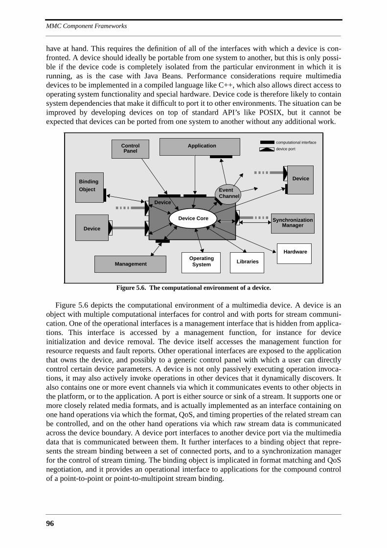
MMC Component Frameworks
96
have at hand. This requires the definition of all of the interfaces with which a device is con-fronted. A device should ideally be portable from one system to another, but this is only possi-ble if the device code is completely isolated from the particular environment in which it isrunning, as is the case with Java Beans. Performance considerations require multimediadevices to be implemented in a compiled language like C++, which also allows direct access tooperating system functionality and special hardware. Device code is therefore likely to containsystem dependencies that make it difficult to port it to other environments. The situation can beimproved by developing devices on top of standard API’s like POSIX, but it cannot beexpected that devices can be ported from one system to another without any additional work.
Figure 5.6 depicts the computational environment of a multimedia device. A device is anobject with multiple computational interfaces for control and with ports for stream communi-cation. One of the operational interfaces is a management interface that is hidden from applica-tions. This interface is accessed by a management function, for instance for deviceinitialization and device removal. The device itself accesses the management function forresource requests and fault reports. Other operational interfaces are exposed to the applicationthat owns the device, and possibly to a generic control panel with which a user can directlycontrol certain device parameters. A device is not only passively executing operation invoca-tions, it may also actively invoke operations in other devices that it dynamically discovers. Italso contains one or more event channels via which it communicates events to other objects inthe platform, or to the application. A port is either source or sink of a stream. It supports one ormore closely related media formats, and is actually implemented as an interface containing onone hand operations via which the format, QoS, and timing properties of the related stream canbe controlled, and on the other hand operations via which raw stream data is communicatedacross the device boundary. A device port interfaces to another device port via the multimediadata that is communicated between them. It further interfaces to a binding object that repre-sents the stream binding between a set of connected ports, and to a synchronization managerfor the control of stream timing. The binding object is implicated in format matching and QoSnegotiation, and it provides an operational interface to applications for the compound controlof a point-to-point or point-to-multipoint stream binding.
Figure 5.6. The computational environment of a device.
Device
Device
EventChannel
Application
Device Core
OperatingSystem
Hardware
Management Libraries
SynchronizationManager
DeviceBinding
Object
ControlPanel
computational interface
device port
97
Component Framework Design Considerations
The design considerations are listed in the following. This list is not claimed to be complete,but it contains all the design considerations that underlie the multimedia middleware presentedlater in this thesis:
• independence from reference application topologies: A frequent assumption isthat DOC makes the network completely transparent. The result is an architec-ture like IMA-MSS that neglects the cost of an RPC. There must be referencecontrol scenarios that underlie the design of the multimedia middleware, i.e., themultimedia middleware must be optimized for certain application topologies.
• device granularity: The functionality implemented by devices can have differentlevels of granularity. Frameworks like IMA-MSS, TINA or Xbind tend to definedevices with coarse granularity, whereas the devices of Medusa have a very finegranularity. The advantage of fine granularity is more flexibility in device com-position, but this flexibility does not come for free. Wherever functionality isseparated into two different devices, formats must be matched and QoS negoti-ated when these devices are plugged together again. Excessive granularity istherefore just as problematic as the process-level granularity found in TINA. Arule of thumb is to separate functionality only if it can be reasonably expectedthat the resulting devices will be used independently from each other.
• reuse levels: devices are the lowest level of code reuse. This level may be toolow for many applications, which makes it necessary to provide higher-levelcomponents. Two more levels should be supported by the multimedia middle-ware. There should be the possibility to compose devices into molecules, whichare in fact coarse-grained devices, and the possibility to assemble molecules ordevices into end-to-end device networks that can be readily reused. Thesedevice networks will present themselves to the application like a tool, with pro-gramming interfaces similar in spirit to the one of Beteus. Components are notvisible to applications at this level. Max Mühlhäuser and Jan Gecsei discuss theuse of low-level multimedia component frameworks within high-level program-ming paradigms [Mühl96].
• compound operations: the multimedia middleware must support the grouping ofdevices at runtime. This should not be confounded with molecules that areassembled off-line. Device grouping enables compound operations.
• implicit or explicit binding: explicit binding refers to the case where the bindingbetween object interfaces is represented by a binding object. Such an object isnot present in the case of implicit binding. The binding between client andserver of an operational interface is implicit, whereas the binding between twodevice ports needs to be explicit. The binding object relieves the applicationfrom directly dealing with format matching and QoS negotiation. There must bea hierarchy of binding objects in the case of device pipelines with more than twodevices in order to prevent the situation that the application has to deal with alarge number of binding objects.
• resource management: both devices and stream bindings require resources.Devices take CPU time or need exclusive access to hardware. Stream bindingsbetween devices that are both on the same station may take inter-process com-munication resources, or CPU time for memory copies. Stream bindingsbetween devices that are scattered over the network take network resources.
MMC Component Frameworks
98
Standard resource management interfaces must therefore be defined via whichdevices and binding objects can request resources. A node-level resource archi-tecture for device pipelines is proposed by Geoffrey Coulson [Coul96].
• format matching: the media formats of ports engaged in a binding must bematched. Format matching is linked with resource management, given that theformat of a stream has an impact on the associated data rate. One approach is tohave source ports add format information to the streams that they produce, withsink ports automatically adapting to these formats. Another approach is to com-pletely match the format of two ports, in which case no format information hasto be conveyed within the stream. This tends to be difficult whenever multipledevices are linked together. Still another approach is to just fix major formatparameters on all ports, and use dynamic adaptation for minor parameters. Aformal method for type matching of ODP streams is proposed by Frank Eliassen[Elia96].
• stream identity: streams have a clear identity between a source port and a sinkport. They keep their identity between the source port and the sink port of adevice if they are only transformed into another format. Streams loose theiridentity when they are mixed with other streams into a new stream, as is indi-cated in Figure 5.6. Stream identity is important for synchronization, but it alsoplays a role in format matching because it may correlate the formats of thesource and sink ports of a device.
• synchronization: synchronization in a component-based multimedia middlewarecan be done like in IMA-MSS with the CORBA event service. Also useful forsynchronization is the CORBA time service. It is important that synchronizationis based on end-to-end delays. This requires devices that source or sink a streamto be involved in synchronization activities related to this stream. Applicationswill want to define synchronization relationships on stream level, and not ondevice level. This means that the infrastructure has to locate the devices that arecapable of synchronizing a given stream.
• device categories: the categories commonly found are source, sink and filter.This modeling is wrong because it has no computational consequence, i.e., thedefinition of source, sink and filter IDL interfaces would likely be empty. Thegeneral device can be source, sink and filter at the same time by having a sourceand a sink port and using the incoming stream together with other parametersfor the calculation of a completely different outgoing stream. What is moreimportant is the concept of an addressable device. This can be used to associatedevices with identifiable items like cameras, screens, files, widgets, etc. Theaddress of a device would correspond to a device property, and would not be aninterface on its own. There could be a special kind of device modeling applica-tions that source or sink a stream.
• device interface hierarchy: it has to be avoided to define interfaces in the devicehierarchy that only serve to categorize devices. Typical examples are VideoDe-vice or AudioDevice, which are interfaces that can be found in nearly allpublished frameworks that are based on DOC. Too many levels in an interfacehierarchy indicate a design flaw.

99
Conclusion
• analog and digital links: some frameworks, like for instance IMA-MSS, distin-guish between analog and digital links. There is no need to make such a distinc-tion visible to the application. Since analog data are just as much associatedwith a format as digital data it is not possible to accidentally connect a digitalport to an analog port.
• graphical user interface: the integration of devices into GUI toolkits is impor-tant because the final goal of all multimedia data processing is the creation ofaudiovisual effects. No proposal for a multimedia middleware should neglectthe GUI, or the presentation environment in general.
• hardware: the device abstraction is challenged whenever special multimediaprocessing hardware is involved. The functionality provided by hardware of agiven category varies, making it impossible to adapt the device abstractions toit. Some video boards are just frame grabbers, whereas others do MPEG com-pression and more. The control of hardware must be transparently assured bythe devices that are concerned, meaning that these devices have to conspirerather than exchange stream data between their ports.
• data formats: the physical layout of data exchanged between device ports mustbe standardized on platform level and on network level. For transmission it isnecessary to specify a standard PDU format.
Most of the component frameworks that have been presented in this chapter are tailored tolive and stored continuous media, mainly audio and video. It has not been sufficiently shownthat it is possible to construct a framework for the interactive presentation of multimedia con-tent similar in spirit to MHEG on top of such a component framework.
5.7 Conclusion
MMC platforms must be based on low and high-level component frameworks in order to beextensible. Low-level component frameworks like IMA-MSS help to construct high-level com-ponent frameworks that are tailored to different application domains and that provide program-ming comfort comparable to the one of monolithic platforms. Applications may then be builtfrom both low and high-level components. An application uses high-level components wher-ever it needs standard functionary, and low-level components wherever it has special require-ments. Until now, research has mostly concentrated on low-level component frameworks.Examples for high-level components are the molecules of Medusa and the CommunicationSession Manager (CSM) of TINA.
The platform that is presented in the following chapters can be considered as a fusion ofMedusa, IMA-MSS and TINA. It defines an MMC application management architecture thatcan be compared with the service management architecture of TINA, a multimedia middlewarethat can be compared with IMA-MSS, and high-level utilities similar in spirit to the moleculesof Medusa.

MMC Component Frameworks
100
101
6 APMT Overview
6.1 Introduction
Chapter 2 developed a list of requirements for MMC platforms. One of these requirements wasthat the MMC platform must be based on a standard DPE. Chapter 3 presented the distributedcomputing platforms that come into question, and designated CORBA as the DPE of choicefor the MMC platform of this thesis. Chapter 4 started the discussion of existing MMC plat-forms with a description of three monolithic platforms, namely the Touring Machine, Beteusand IBM Lakes. These platforms are characterized by a high-level API that facilitates thedevelopment of MMC applications. The primary problem with monolithic platforms is thatthey are not extensible. Extensibility is optimally supported by the component framework par-adigm, with examples being the Medusa and IMA-MSS platforms presented in Chapter 5. Plat-forms based on the component framework paradigm decompose multimedia processingfunctionality into building blocks that can be plugged together by applications. A lot of flexi-bility is gained with this approach, but since there will be many applications that do not want tobe exposed to components there is still a need for high-level API’s as found in monolithic plat-forms. These API’s must then be provided by layers above the component framework. Alsopresented in Chapter 5 was TINA, which is a platform for the provision of MMC telecommuni-cation services. TINA defines a service architecture and a connection management architec-ture, but it does not provide a component-based multimedia middleware or API’s that wouldease application development. TINA must therefore be augmented with a component frame-work similar in spirit to IMA-MSS if it is to foster application development. However, it is notpossible to layer IMA-MSS on top of the TINA connection management architecture withoutat least adapting its object model to the one of RM-ODP. But even then it remains questionableif IMA-MSS could really fit on TINA, or if it would not be better to define an entirely newmultimedia middleware that is tailored to TINA. The example of TINA and IMA-MSS makesthe concept of a general purpose multimedia middleware dubious. It is likely that such a multi-media middleware has features that conflict with some of the requirements of the MMC plat-form in which it is to be integrated, or, in other words, it is difficult if not impossible to developa multimedia middleware that is completely orthogonal to the policies imposed by differentapplication models. This means that either the MMC platform has to be tailored to an existingmultimedia middleware, or vice versa the middleware to the MMC platform. The latterapproach is chosen for the MMC platform that is presented in the rest of this thesis.
The most important objective for this MMC platform is to have a static terminal. The aver-age user will not be able to, or will not want to manually install code for every MMC applica-tion that he uses. It may also happen that the number of available MMC applications becomesso large that it is simply not possible to install all of them, or even only the most popularamong them, on a single endsystem. The solution to this problem is a static terminal that canrun a multitude of different MMC applications. This can either be a rather dumb terminal withgraphics capabilities like the French Minitel [Luca95] or the X11 terminal, or it can be a moreintelligent terminal that is able to execute mobile code imported from the network. A fiercely

APMT Overview
102
discussed example for the latter category is the network computer (NC) that is promoted by theJava community [Appl96]. Such an intelligent terminal is also at the basis of the MMC plat-form that is proposed by this thesis. The applications that are installed on this platform residein so called application pools (AP) from where they control a set of participating multimediaterminals (MT). A multimedia terminal has a clearly defined and extensible interface that sup-ports a wide range of applications. Applications download applets into the multimedia terminalto handle all issues that are local to the terminal. This architecture is discussed in the rest ofthis thesis, and will be referred to as APMT (AP+MT).
This chapter provides an overview of APMT. It discusses its major features and motivatessome of the design decisions, but it does not go into any architectural detail. It starts with anoverview of the architecture building blocks that make up APMT, and a discussion of majorAPMT characteristics. Following that comes a closer description of the most important archi-tecture building blocks. The description of an architecture building block is given in terms ofthe interfaces that it exposes. The chapter continues with a discussion of the APMT applicationmodel and the major application scenarios, and closes with some remarks about platformdeployment and a comparison between APMT and TINA. IDL interfaces, control scenariosand other architectural details are given in the following two chapters. Chapter 7 discusses thebasic APMT platform architecture. The APMT multimedia middleware, which must be seen asan extension of the basic APMT platform architecture, is presented in Chapter 8. Chapter 9 isdedicated to an evaluation of APMT.
6.2 Application Pools and Multimedia Terminals
APMT provides a complete framework for the deployment of MMC applications in networksof any scale. This framework is a synthesis of a multimedia middleware with a general applica-tion management architecture. It can therefore be compared with both IMA-MSS and the ser-vice architecture of TINA. A fundamental difference between APMT and TINA is that APMTis not integrated into the network. APMT is an overlay architecture, and an APMT platform isa normal user of the transport services of the underlying network. Another fundamental differ-ence between TINA and APMT is the target network, which is a B-ISDN telecommunicationnetwork in the case of TINA, and an IP network in the case of APMT. It is not the ambition ofAPMT to redesign the way connections are established across the network. APMT relies onstandard Internet protocols for the communication among platform components, with the ben-efit that its deployment is possible today. Figure 6.1 depicts an example APMT scenario withan application in an application pool controlling three multimedia terminals. The followingsubsections provide an overview of APMT and its major components and describe the entitiesindicated in Figure 6.1. A description of the APMT session model and a summary of the tech-niques used for the specification of APMT finishes this first overview, and leads over to a moreprofound look at the various architecture components.
6.2.1 Architecture Overview
In APMT, application intelligence is distributed between central application pools and termi-nals in the periphery. An application residing on an application pool will download applets intothe terminals that serve as intelligent sensors and that deal with every issue that is local to theterminal. Applications access low-level terminal objects as well as high-level application poolutilities. One such utility is the connection manager that establishes connections among the ter-minals that participate in a multipoint application. The application pool must be considered as
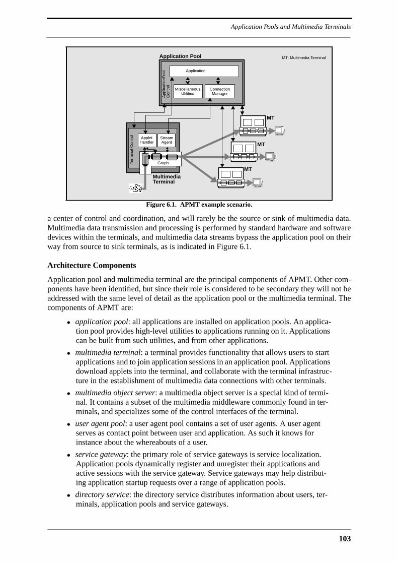
103
Application Pools and Multimedia Terminals
a center of control and coordination, and will rarely be the source or sink of multimedia data.Multimedia data transmission and processing is performed by standard hardware and softwaredevices within the terminals, and multimedia data streams bypass the application pool on theirway from source to sink terminals, as is indicated in Figure 6.1.
Architecture Components
Application pool and multimedia terminal are the principal components of APMT. Other com-ponents have been identified, but since their role is considered to be secondary they will not beaddressed with the same level of detail as the application pool or the multimedia terminal. Thecomponents of APMT are:
• application pool: all applications are installed on application pools. An applica-tion pool provides high-level utilities to applications running on it. Applicationscan be built from such utilities, and from other applications.
• multimedia terminal: a terminal provides functionality that allows users to startapplications and to join application sessions in an application pool. Applicationsdownload applets into the terminal, and collaborate with the terminal infrastruc-ture in the establishment of multimedia data connections with other terminals.
• multimedia object server: a multimedia object server is a special kind of termi-nal. It contains a subset of the multimedia middleware commonly found in ter-minals, and specializes some of the control interfaces of the terminal.
• user agent pool: a user agent pool contains a set of user agents. A user agentserves as contact point between user and application. As such it knows forinstance about the whereabouts of a user.
• service gateway: the primary role of service gateways is service localization.Application pools dynamically register and unregister their applications andactive sessions with the service gateway. Service gateways may help distribut-ing application startup requests over a range of application pools.
• directory service: the directory service distributes information about users, ter-minals, application pools and service gateways.
Figure 6.1. APMT example scenario.
Application
Application Pool
ConnectionManager
MiscellaneousUtilities
App
licat
ionP
ool
Con
trol
Term
inal
Con
trol Stream
AgentApplet
Handler
Graph
MultimediaTerminal
MT
MT
MT
MT: Multimedia Terminal
APMT Overview
104
APMT components can be internally distributed. As an example, a multimedia terminalmay consist of a single machine as well as of a cluster of cooperating machines. It is neverthe-less likely that APMT components are not internally scattered over different administrationaldomains. As an example, an application pool will not run applications on machines outside thenetwork of its owner.
Applications versus Services
The word service is used with care in the specifications of APMT. APMT is first and foremostan architecture for the development, deployment and execution of MMC applications. It ispossible to commercialize these applications as telecommunication services, but the way thiscan be done exactly is outside the scope of this thesis. The name service gateway for the archi-tecture component that mediates between application pools and users was chosen on purposein order to indicate that the APMT application platform can be tuned into a service platform.This requires most notably support for service subscription and accounting. In its current form,APMT does not provide any support for service subscription, which means that users areunknown to the application pools on which they run their applications. Also not supported byAPMT is accounting. It is likely that users will want to pay the majority of services providedby application pools with electronic money [Neum95], making it maybe more important toprovide support for electronic payment than for classical accounting. However, service sub-scription and accounting can be added to APMT without any difficulties. The APMT compo-nent that handles the participation of terminals and users in application sessions is extensibleand may be supplemented by more sophisticated ones. This makes it possible to add new ses-sion management components to the platform that are tailored to business requirements, andthat interface to an accounting framework.
APMT and Internet Technology
APMT builds on existing Internet protocols for all control and data communication. The trans-port protocols that are relevant for APMT are TCP for reliable point-to-point transmission,UDP for unreliable unicast datagrams, and IP multicast in combination with UDP for the unre-liable delivery of datagrams to multiple receivers. What is still missing is a standard reliablemulticast protocol as a multipoint counterpart to TCP. Applications have widely differingrequirements on multipoint transmission, which makes it impossible to define a single genericreliable multicast protocol that fits all applications. It may therefore happen that multiple pro-tocols are standardized by the IETF, or that one generic protocol is standardized on top ofwhich additional functionality can be layered. There is a special interest group in the IETFworking on the standardization of reliable multicast protocols [Mank96]. The scalable reliablemulticast (SRM) protocol proposed by Van Jacobson and others [Floy96] is a promising candi-date for standardization.
The Internet in its current form offers a single transport service, which is the best-effortdelivery of an IP datagram. The network does not allow to specify QoS parameters for thedelivery of packets, it does not allow to reserve resources for packet streams, and it does notsupport admission control. IP networks are based on the assumption that most of the traffic ispoint-to-point and connection-oriented. This allows to implement congestion avoidance andcontrol in the transport protocol, rather than in the network. Connectionless multimedia trafficon the other hand poses a problem for the Internet. The source of a high-volume stream ofUDP packets is not aware of the congestion that its packets may cause in network nodes, and istherefore unable to adapt the data rate it generates to the actual network load. There are threesolutions to this problem, which are congestion control on application level, resource reserva-
105
Application Pools and Multimedia Terminals
tion together with admission control, and overprovisioning of network resources. Congestioncontrol on application level can be done by more centralized applications that have controlover both senders and receivers. Such an application monitors the transmission characteristicsof its streams and throttles senders when it realizes that the network is congested. However,congestion control on application level is not a viable solution because it cannot be enforcedthat every application implements it. As to resource reservation, the IETF is working on RSVP,which is a resource reservation protocol for the Internet [Zhan93]. It will still take a couple ofyears until RSVP is widely deployed on the Internet, making overprovisioning the only solu-tion that is at hand today. However, overprovisioning becomes expensive as the number ofusers grows, as is for instance shown by Scott Shenker [Shen95]. It is therefore impossible torenounce on reserve reservation in the long run.
APMT can be deployed on the Internet or on enterprise networks that are based on IP. TheMMC applications running on top of APMT do not necessarily require high-speed networksfor data transmission among terminals. The APMT platform may for instance support modernlow-bitrate audio and video codecs that make it possible to transmit a bidirectional audio andvideo stream over a 28.8 kbit/s modem line. What is more likely to be a problem is controlcommunication, which may suffer from the high roundtrip times commonly experienced on theInternet. APMT takes this into account, and tries for instance to reduce control communicationover the network as much as possible.
Deploying an MMC platform on the Internet has many advantages. The most importantones are listed in the following:
• low deployment costs: the infrastructure exists, and there is no need for any fun-damental modifications to it.
• low communication costs: the usage of the Internet is basically free, making it pos-sible to develop and deploy applications free from any commercial constraints.
• large user base: a large number of users and potential programmers can bereached via the Internet.
• joint development: the development of platform and application software can bea joint effort of many volunteers that require only little central coordination1.
It can also be imagined that the success of an MMC platform on the Internet may justify theinvestments to be made for a similar platform on a telecommunications network, i.e., it maypave the way for TINA.
APMT and CORBA
APMT deploys CORBA as DPE, and tries to profit as much as possible from existing andfuture CORBA specifications. The approach of APMT is therefore to make the best out ofCORBA, rather than developing proprietary solutions for problems whenever the respectiveCORBA standard is not completely satisfying. As an example, APMT adopts the object modelof CORBA rather than defining its own. Once the RM-ODP object model is adopted byCORBA it will also be adopted by APMT. APMT is therefore following CORBA standardiza-tion, rather than preceding it, as does TINA. The benefit of this is again ease of deployment.APMT can be readily implemented on today’s object request brokers, whereas TINA takes the
1. See the article "Leveraging Cyberspace" by Thomas A. Kalil for examples of problems that were solved by alarge number of networked users [Kali96].

APMT Overview
106
position that CORBA is not completely acceptable in its present state. CORBA profits fromTINA input, but TINA does not profit from CORBA as much as it could if it were ready toadopt other CORBA standards than just the basic object request broker.
6.2.2 Overview of the Multimedia Terminal
The top-level components of the terminal are depicted in Figure 6.2. The brain of the multime-dia terminal is the terminal control. The terminal control manages the application life-cycle onthe terminal side: it starts and joins applications in the application pool on behalf of the user, oron behalf of applications that are already running on the terminal, and processes invitations toapplications. It grants applications access to the major terminal servers and supervises theactivities of applications within the terminal. Every major object created by an application hasan interface to the terminal control which allows it to be queried, monitored, and removed. Theoperations defined for the terminal control interface constitute together with related operationsin application pool interfaces an application control protocol. Since this protocol is applicationindependent it can be expected to remain stable over an extended period of time. Protocolextensions, and the eventual development of additional protocols for different terminal types,can be handled via interface inheritance.
Two important terminal servers are the applet handler and the stream agent. An applet han-dler executes an applet downloaded from the application. This applet generates the graphicaluser interface of the application and controls the locally generated device graphs. As a result ofuser action it will call operations in callback interfaces implemented by the application. Anadequate programming language for simple applets is Tcl/Tk. If the downloaded applet is toperform more advanced tasks than to generate a graphical user interface, a strongly typed lan-guage like Java can be used. The major requirement on the programming language to be usedfor applets is the existence of a respective CORBA language mapping. The multimedia termi-nal has separate applet handlers for every applet programming language that it supports.
A stream agent assembles, controls and modifies stream graphs. A stream graph is an arbi-trarily structured network of media processing devices similar to the module pipelines ofMedusa or the virtual device graphs of IMA. The procedure of creating a graph consists ofthree operation invocations of which the last returns an object reference for every device con-
Figure 6.2. Terminal components.
Terminal ApplicationsTerminal Applications
StreamAgent
AppletHandler
NamingService
TerminalServer
TerminalControl
GenericControlPanel
Control Panelin
Application and Application Pool Utilities
Terminal Boundary
Terminal ApplicationsApplet Handler
TerminalMgr.

107
Application Pools and Multimedia Terminals
tained in the graph. The applet handler can use these object references for local control, as isindicated in Figure 6.1. The applet handler may get them for instance via the CORBA nameserver shown in Figure 6.2, which helps the different objects in a terminal to locate each other.
The applet handler and the stream agent are not the only terminal servers. Every applicationrunning on a terminal as part of an MMC application falls under the terminal server abstrac-tion. This concerns CSCW applications like shared whiteboards, but also complete frameworkslike MHEG. It is also possible to introduce a new multimedia middleware encapsulated in aterminal server other than the stream agent.
A terminal may also contain so called terminal applications. These are applications that runlocally on the terminal and that access terminal services in the same way as applications run-ning in application pools. Terminal applications are a reminiscence of the standalone applica-tion that is common today. They profit from the APMT terminal infrastructure, but do notenjoy any platform support beyond the terminal boundary.
A user accesses the terminal control either via a generic control panel that is installed on theterminal, or via his own control panel application running in an applet handler. The latterallows users to import their personal control environment into any terminal they are logged on.The control panel application is downloaded from an application pool in the home domain ofthe user.
Also indicated in Figure 6.2 is the terminal management. The terminal management allowsfor instance to add new components to the multimedia terminal, and to remove obsolete ones.
6.2.3 Overview of the Application Pool
Figure 6.3 depicts the top-level components of an application pool. The counterpart to the ter-minal control in the application pool is the application pool control. The application pool con-trol launches applications on behalf of terminals, grants them access to the application poolutilities and to other applications, and monitors their activities. Applications can access the ter-minal interfaces directly or via application pool utilities that reduce the complexity of multi-user scenarios. One such utility is the participation control that helps applications manage ses-sion membership. This functionality is provided by a utility rather than the application pool
Figure 6.3. Application pool components.
OtherUtilitiesOther
Utilities
ApplicationApplication
ApplicationPool
ApplicationPool
Management
Terminals
Application Pool Boundary
Control
ServiceBroker
ParticipationControl
ConnectionManager
Application
AppletLoader
OtherUtilities

APMT Overview
108
control because it is assumed that session membership is a private matter of the application.The application pool control is mostly concerned with applications and utilities, and not somuch with terminals or users.
Another important utility is the connection manager. The connection manager provides sup-port for the establishment of complex connection structures among groups of terminals andconfigures the device graphs within these terminals. An application will usually prefer to dealwith one connection manager rather than with many stream agents. Multiple connection man-agers can be imagined, providing support for different categories of applications.
The applet loader indicated in Figure 6.3 is a server that is accessed by applet handlers interminals to retrieve applet code. The way this is done exactly depends on the programminglanguage. It is therefore necessary to provide an applet loader for every programming languagethat is used by applications in the application pool.
Also indicated in Figure 6.3 is the application pool management. The application pool man-agement accesses the management interface of the application pool control and performs stan-dard tasks like installation of new applications and application pool utilities or monitoring ofrunning applications.
The service broker allows users to find out about the applications that are supported by theapplication pool, and the public sessions that are currently running on it or that are announced.The service broker of the application pool advertises a part of its offer to service gateways. It isbased on the CORBA trading service.
Figure 6.4 depicts a layered view of APMT as seen by applications. Applications and appli-cation pool utilities reside both on top of the services provided by terminal objects. Applica-tions use in addition the services of the application pool utilities, and they may also be builtfrom other applications. The ensemble of accessible terminal IDL interfaces represents theview that the developer of an application or an application pool utility has of a terminal. Simi-larly, the ensemble of application pool interfaces that are accessible to applications representsthe view that the application has of an application pool.
Figure 6.4. Layered view of the APMT architecture.
Application
ApplicationPool
Services
TerminalServices
Terminal Interfaces
Application Pool Interfaces
Composite Application
Application Interfaces

109
Application Pools and Multimedia Terminals
6.2.4 Overview of Additional Components
Application pool and multimedia terminal are the most important components of the APMTplatform, but they are not sufficient for the kind of MMC platform that is envisaged by this the-sis. They need to be supplemented with the components that are presented in the following.
Multimedia Object Server
Multimedia terminals are also thought to be consumers and providers of stored multimediapresentations, with the necessary software being part of the multimedia middleware. Everymultimedia terminal can therefore serve multimedia content to other terminals. Pure multime-dia object servers consequently reveal themselves as a special kind of terminal. They offer thesame set of multimedia middleware interfaces to the outside, although it can be expected thatthe underlying software is different from the one installed on user terminals. The benefit forapplication development is that the control interfaces of multimedia object servers and termi-nals are identical. Multimedia object servers are likely to be combined with an applicationpool. The multimedia content stored on a server is then managed by a set of applications thatcan be accessed by user terminals. Multimedia object servers may also exist in isolation, inwhich case it is necessary to define access control interfaces for them. This can be done by spe-cializing some of the terminal control interfaces. Multimedia object servers are not coveredany further in this thesis.
User Agent Pool
Terminal mobility is supported by user agents. A user agent represents the user towards appli-cations and other users. When a user logs onto a terminal he may choose to inform his useragent about his current location, which in turn allows him to be invited to application sessions,or to be contacted by other users. A user agent is managed by a user agent pool that is locatedin the home domain of the user. The user agent pool is covered in more detail in Section 6.7.
Service Gateway
Application pools may advertise applications and sessions to external service gateways. A useraccesses a service gateway to retrieve a reference to an application pool that supports a certainkind of application, or that houses a certain public session. Service gateways cooperate withservice brokers in application pools. Both of them are based on the CORBA trading service.The service gateway is a high-level trader that repeats the offers of multiple service brokers inapplication pools. The CORBA trading service supports such configurations with a linkingmechanism. The use of the trading service in APMT requires the definition of APMT-specificproperties like participant list, application name or title name that are used by applicationpools to advertise service offers, and by interested clients in query operations. APMT serviceoffers are installed applications and announced or active application sessions that are public.The service gateway makes use of the dynamic properties feature of the CORBA trading ser-vice. As an example, the property participant list could be a dynamic property, for which theservice gateway retrieves the value directly from the application pool whenever it is required.A service gateway that receives multiple service offers of the same type will perform some sortof load balancing among the concerned application pools. An application pool that hits acapacity limitation may dynamically revoke its service offerings, and reregister them once thesituation has improved. Service gateways and service brokers are not covered any further inthis thesis.
APMT Overview
110
Directory Service
The service gateway distributes dynamically changing information about available applica-tions and active sessions. In addition to that, a directory service is necessary to distribute staticinformation about APMT resources to users and applications. User agent pools, applicationpools and service gateways are named after the Internet host that runs their public access inter-face. The IP address of this host can be retrieved via the Internet DNS, and transformed into anIIOP IOR. Once this is done the respective entity can be accessed via IIOP. Users are uniquelyidentified by their name together with the hostname of the user agent pool that runs their useragent. User identifiers in APMT are therefore similar to normal E-mail addresses, which sug-gests to use the same notation for them. Since the hostname of the user agent pool is part of theuser identifier, it is easy to locate and access a certain user agent.
The Internet DNS solves the basic localization problem, but it requires a user to know theexact name of the application pool, service gateway or user that he is searching. A directoryservice like X.500 offers much more functionality than that, and can be used to performsearches based on a combination of attributes, with a completely or partially given name beingone of them. A directory service other than the DNS is therefore desirable, although not abso-lutely necessary. Directory service client functionality can be provided by utilities in the appli-cation pool or by terminal applications in the terminal. In the case of application pool utilities itis necessary to hide the used directory service protocol behind a uniform IDL interface in orderto avoid the situation that application code relies on a specific directory service.
6.3 Session Model
A session is an abstraction for a temporary activity that brings together a set of resources inorder to attain a given target. In the case of an MMC platform, some of these resources mayrepresent human users, while others represent the functionality dedicated by the platform to thetemporary interaction between a set of users, or between users and platform components. AnMMC session is therefore not only defined in terms of the users that are participating in it, butalso in terms of the resources that are activated by the platform for the purpose of this session.Five major session types can be identified in APMT:
• Terminal Session: a user must explicitly log onto a terminal before he can startapplications. This establishes a temporary relationship between the user and aterminal.
• User Session: every application in which the terminal participates is modeled bya user session. A user session is the view that the terminal has of its role withinan application instance.
• Application Session: an application session models the totality of resources thatare allocated in terminals and application pools for an application instance.
• Participant Session: a participant session represents the set of terminals that par-ticipate in an application session. The participant session is handled by the par-ticipation control in the application pool.
• Composite Application Session: a composite application session consists of mul-tiple federated application instances, and can be described in terms of a set ofapplication sessions.
111
APMT Specification
A terminal cannot distinguish if the application in which it is participating is a compositeapplication or not. There is consequently no need to model a composite application session onthe terminal side with a session abstraction other than the user session.
APMT does not have a counterpart to the access session known from TINA. The only rela-tion a user may have with an application pool is participation in an application, which is mod-eled by the application session. There is no computational object in the application poolinfrastructure representing a user in another way than as participant in an application. Mostnotably, there is no object representing a subscribed user.
6.4 APMT Specification
Before embarking on a closer tour of APMT it is necessary to outline the way it is specified.The major means of specification is CORBA-IDL. All interfaces are defined in CORBA-IDL,with the exception of language-specific API’s in applet handlers. CORBA-IDL is used for bothlocal and remote interfaces. Local interfaces are API’s that can be mapped to different pro-gramming languages. They are defined in a variant of CORBA-IDL called Pseudo-IDL whichmay contain pointers. CORBA-IDL definitions are supplemented with OMT object diagramsand event traces [Rumb91].
APMT is based on the CORBA object model, with the effect that more importance is givento the definition of interfaces than to the identification of objects. The APMT architecture com-ponents shown in Figure 6.2 and Figure 6.3 can be regarded as coarse-grained objects. Theyencapsulate fine-grained objects that cannot exist in isolation. APMT identifies objects when-ever they represent components in a component framework. This is for instance the case in themultimedia middleware. Objects are also defined whenever it is necessary to indicate that a setof interfaces has a common life-cycle. This is the case with interfaces that are related to thevarious session types of APMT.
All APMT definitions are contained in modules in order to avoid name clashes. Modulenames themselves can be protected with a leading Apmt, but this is not necessary for the pur-poses of this thesis. All APMT IDL definitions have been compiled with idldoc, a tool for theautomatic generation of hyperlinked IDL documentation [Whit96]. The APMT documentationgenerated by idldoc is available online on the Internet [Blum97a].
6.5 Multimedia Terminal Interfaces
The anatomy of the multimedia terminal can be described in terms of its interfaces. The fol-lowing introduces the major interfaces of the multimedia terminal, namely the interfaces of theterminal control, the applet handler and the stream agent. The complete set of interfaces, alongwith the most important operations and types, will be presented in the following two chapters.
6.5.1 Terminal Control
Figure 6.5 shows the interfaces of the terminal control. The terminal control interacts withremote applications and application pool utilities, and with local terminal servers, control pan-els and terminal applications. The public terminal interface to the outside is Tc::Terminal.This interface allows applications to invite the currently logged user to participate in an appli-
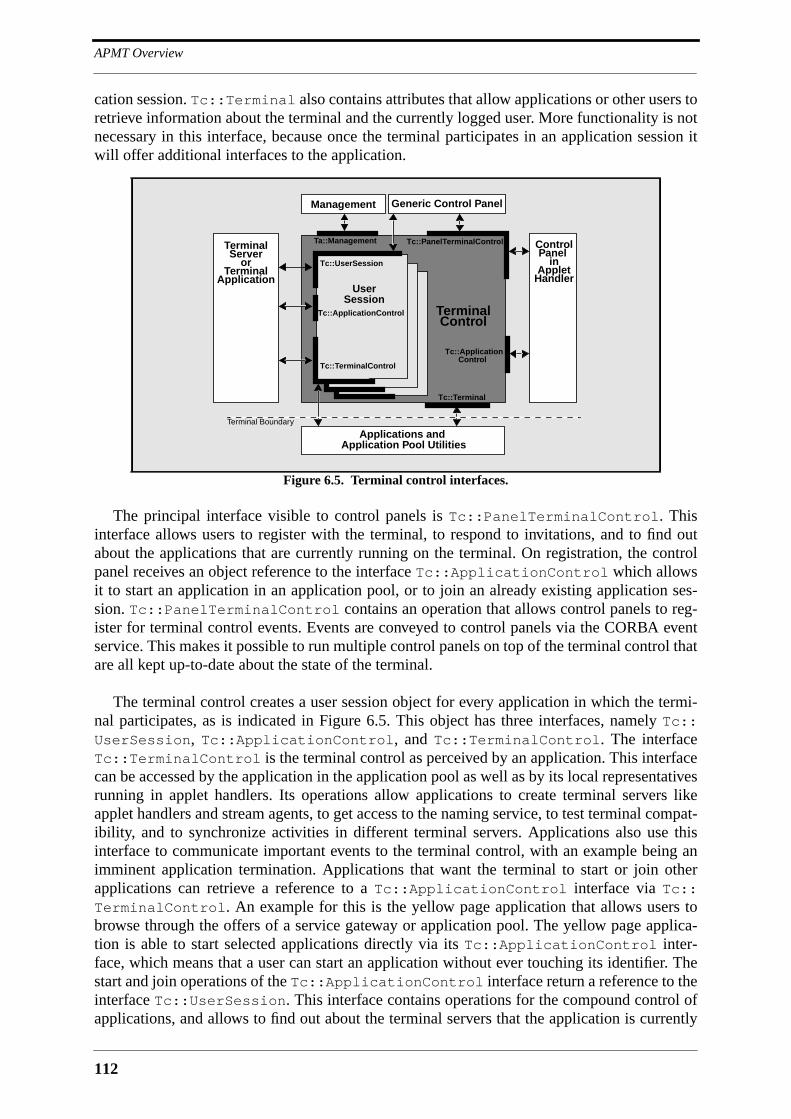
APMT Overview
112
cation session. Tc::Terminal also contains attributes that allow applications or other users toretrieve information about the terminal and the currently logged user. More functionality is notnecessary in this interface, because once the terminal participates in an application session itwill offer additional interfaces to the application.
The principal interface visible to control panels is Tc::PanelTerminalControl. Thisinterface allows users to register with the terminal, to respond to invitations, and to find outabout the applications that are currently running on the terminal. On registration, the controlpanel receives an object reference to the interface Tc::ApplicationControl which allowsit to start an application in an application pool, or to join an already existing application ses-sion. Tc::PanelTerminalControl contains an operation that allows control panels to reg-ister for terminal control events. Events are conveyed to control panels via the CORBA eventservice. This makes it possible to run multiple control panels on top of the terminal control thatare all kept up-to-date about the state of the terminal.
The terminal control creates a user session object for every application in which the termi-nal participates, as is indicated in Figure 6.5. This object has three interfaces, namely Tc::UserSession, Tc::ApplicationControl, and Tc::TerminalControl. The interfaceTc::TerminalControl is the terminal control as perceived by an application. This interfacecan be accessed by the application in the application pool as well as by its local representativesrunning in applet handlers. Its operations allow applications to create terminal servers likeapplet handlers and stream agents, to get access to the naming service, to test terminal compat-ibility, and to synchronize activities in different terminal servers. Applications also use thisinterface to communicate important events to the terminal control, with an example being animminent application termination. Applications that want the terminal to start or join otherapplications can retrieve a reference to a Tc::ApplicationControl interface via Tc::TerminalControl. An example for this is the yellow page application that allows users tobrowse through the offers of a service gateway or application pool. The yellow page applica-tion is able to start selected applications directly via its Tc::ApplicationControl inter-face, which means that a user can start an application without ever touching its identifier. Thestart and join operations of the Tc::ApplicationControl interface return a reference to theinterface Tc::UserSession. This interface contains operations for the compound control ofapplications, and allows to find out about the terminal servers that the application is currently
Figure 6.5. Terminal control interfaces.
TerminalServer
User
Tc::TerminalControl
Tc::ApplicationControl
Tc::UserSession
Tc::PanelTerminalControl
Tc::Terminal
TerminalControl
Applications and
Generic Control Panel
ControlPanel
inApplet
Handler
Terminal Boundary
Tc::Application
orTerminal
Application
Application Pool Utilities
Session
Control
Management
Ta::Management

113
Multimedia Terminal Interfaces
running on the terminal. The Tc::UserSession interface of a session object is hidden fromall applications with the exception of the eventual parent application. It is visible to controlpanels, which allows them to monitor the activities of an application, and to control them.
Also shown in Figure 6.5 is the Ta::Management interface of the terminal control that isaccessed by the terminal management. This interface is considered to be an integral part ofAPMT, but it has not been defined yet.
6.5.2 Applet Handler
Figure 6.6 shows the interfaces of an applet handler. An applet handler is a shell for the appletsthat the application executes on the terminal. It is created via the Tc::TerminalControlinterface, and exposes an interface derived from the general Ts::TerminalServer interface,which contains operations for the compound control of terminal servers. This interface isaccessed by both the terminal control and the application, as is indicated in Figure 6.6. Anapplet handler can receive an applet as parameter to an operation in its interface, or it may loadit from a server in the application pool for which the application supplies an object reference.The exact mechanism depends on the language in which the applet is implemented. Appletsare executed on top of a secure system services API that hides the operating system of the ter-minal. This API provides ways for the applet to find out about the environment in which it isrunning. It allows to retrieve the object reference to Tc::TerminalControl, and may alsoallow to retrieve references to objects in the application. Once activated the applet may instan-tiate objects that it advertises via the naming service to other terminal servers. It creates agraphical user interface and forwards user input that it cannot process locally to the parentapplication in the application pool.
An applet may have a very tight relationship with its parent application, in which case it isjust a sensor, or it may be completely decoupled from its parent application, in which case it isan application in its own right.
Figure 6.6. Applet handler interfaces.
TerminalServer
Ts::TerminalServer
AppletHandler
Applications and
Naming Service
TerminalControl
Terminal Boundary
Applet
Secure System Services API
Application Pool Utilities
ApplicationSpecificObject
ApplicationSpecificObject

APMT Overview
114
6.5.3 Stream Agent
Figure 6.7 shows the stream agent and some of the multimedia middleware objects that it con-trols. The interface of the stream agent, Strag::StreamAgent, inherits from Ts::Termi-nalServer and is accessed by both the terminal control and the application, as is the casewith all terminal servers.
The unit of multimedia processing functionality in APMT is the device. Devices have portsthat are interconnected by untyped device connectors. Devices and device connectors have apublic interface towards applications and control panels, and a hidden management interfacetowards a graph that controls them. Devices, device connectors and graphs inherit from inter-faces defined by the CORBA relationship service. This allows applications, control panels, anddevices to navigate the relationships within the graph and to discover its topology. All devicesinherit from the abstract interface Bas::Device. Two different kinds of device connectors aredefined which offer different levels of control. Both of them inherit from the abstract interfaceBas::DeviceConnector. Control over a graph is provided via the interface Tgraph::Graph. This interface contains operations for the compound control of graphs and for graphmodification. A graph can be created with a call to the create_graph() operation in theStrag::StreamAgent interface. Devices and device connectors are added to it with calls tothe add_objects() and commit() operations in Tgraph::Graph.
Device connectors can only connect the ports of devices that are situated inside the sameterminal. Their IDL interface does not provide much more functionality to the application thanthe possibility to choose the device ports that are to be connected. The way this is done is com-pletely hidden from applications, and may for instance involve the establishment of networkconnections if the terminal consists of more than one network node. The application on theother hand is responsible for connecting the network ports of devices located in different termi-nals. This is a task that it will usually delegate to special connection managers in the applica-tion pool.
Figure 6.7. Selected multimedia middleware interfaces.
AppletHandler
Strag::StreamAgent
StreamAgent
Application and Application Pool Utilities
Control Panel
TerminalControl
Terminal Boundary
Graph
Device
Device
Dev
ice
Bas::Device
Tgraph::Graph
Dev
ice
Cxt
or
DeviceCxtor
Bas::DeviceConnector
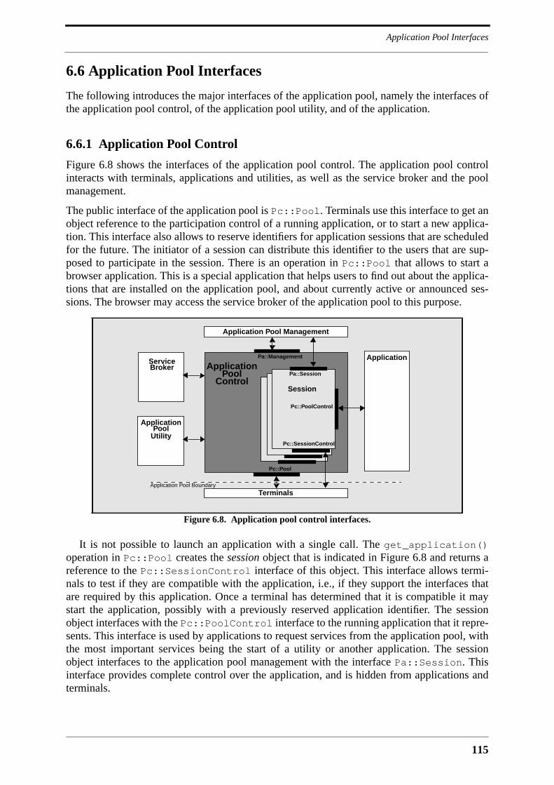
115
Application Pool Interfaces
6.6 Application Pool Interfaces
The following introduces the major interfaces of the application pool, namely the interfaces ofthe application pool control, of the application pool utility, and of the application.
6.6.1 Application Pool Control
Figure 6.8 shows the interfaces of the application pool control. The application pool controlinteracts with terminals, applications and utilities, as well as the service broker and the poolmanagement.
The public interface of the application pool is Pc::Pool. Terminals use this interface to get anobject reference to the participation control of a running application, or to start a new applica-tion. This interface also allows to reserve identifiers for application sessions that are scheduledfor the future. The initiator of a session can distribute this identifier to the users that are sup-posed to participate in the session. There is an operation in Pc::Pool that allows to start abrowser application. This is a special application that helps users to find out about the applica-tions that are installed on the application pool, and about currently active or announced ses-sions. The browser may access the service broker of the application pool to this purpose.
It is not possible to launch an application with a single call. The get_application()operation in Pc::Pool creates the session object that is indicated in Figure 6.8 and returns areference to the Pc::SessionControl interface of this object. This interface allows termi-nals to test if they are compatible with the application, i.e., if they support the interfaces thatare required by this application. Once a terminal has determined that it is compatible it maystart the application, possibly with a previously reserved application identifier. The sessionobject interfaces with the Pc::PoolControl interface to the running application that it repre-sents. This interface is used by applications to request services from the application pool, withthe most important services being the start of a utility or another application. The sessionobject interfaces to the application pool management with the interface Pa::Session. Thisinterface provides complete control over the application, and is hidden from applications andterminals.
Figure 6.8. Application pool control interfaces.
ServiceBroker
Pc::Pool
Pa::Management
ApplicationPool
Terminals
Application Pool Management
Application
Application Pool Boundary
Control
Session
Pc::PoolControl
Pa::Application
Session
Pc::PoolControl
Pa::Application
Session
Pc::SessionControl
Pc::PoolControl
Pa::Session
ApplicationPool
Utility
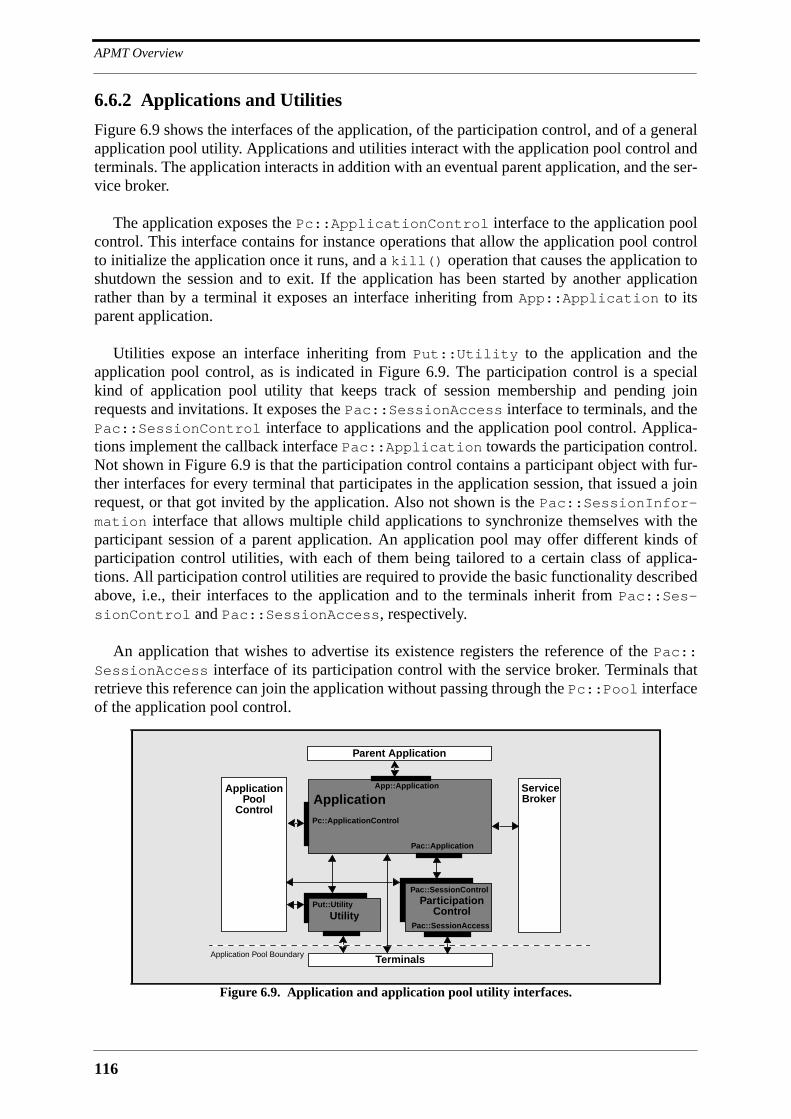
APMT Overview
116
6.6.2 Applications and Utilities
Figure 6.9 shows the interfaces of the application, of the participation control, and of a generalapplication pool utility. Applications and utilities interact with the application pool control andterminals. The application interacts in addition with an eventual parent application, and the ser-vice broker.
The application exposes the Pc::ApplicationControl interface to the application poolcontrol. This interface contains for instance operations that allow the application pool controlto initialize the application once it runs, and a kill() operation that causes the application toshutdown the session and to exit. If the application has been started by another applicationrather than by a terminal it exposes an interface inheriting from App::Application to itsparent application.
Utilities expose an interface inheriting from Put::Utility to the application and theapplication pool control, as is indicated in Figure 6.9. The participation control is a specialkind of application pool utility that keeps track of session membership and pending joinrequests and invitations. It exposes the Pac::SessionAccess interface to terminals, and thePac::SessionControl interface to applications and the application pool control. Applica-tions implement the callback interface Pac::Application towards the participation control.Not shown in Figure 6.9 is that the participation control contains a participant object with fur-ther interfaces for every terminal that participates in the application session, that issued a joinrequest, or that got invited by the application. Also not shown is the Pac::SessionInfor-mation interface that allows multiple child applications to synchronize themselves with theparticipant session of a parent application. An application pool may offer different kinds ofparticipation control utilities, with each of them being tailored to a certain class of applica-tions. All participation control utilities are required to provide the basic functionality describedabove, i.e., their interfaces to the application and to the terminals inherit from Pac::Ses-sionControl and Pac::SessionAccess, respectively.
An application that wishes to advertise its existence registers the reference of the Pac::SessionAccess interface of its participation control with the service broker. Terminals thatretrieve this reference can join the application without passing through the Pc::Pool interfaceof the application pool control.
Figure 6.9. Application and application pool utility interfaces.
Application App::Application
Application
Terminals
Parent Application
Service
Application Pool Boundary
Pc::ApplicationControl
UtilityPut::Utility Participation
Control
Pac::SessionControl
Pac::SessionAccess
Pac::Application
PoolControl
Broker
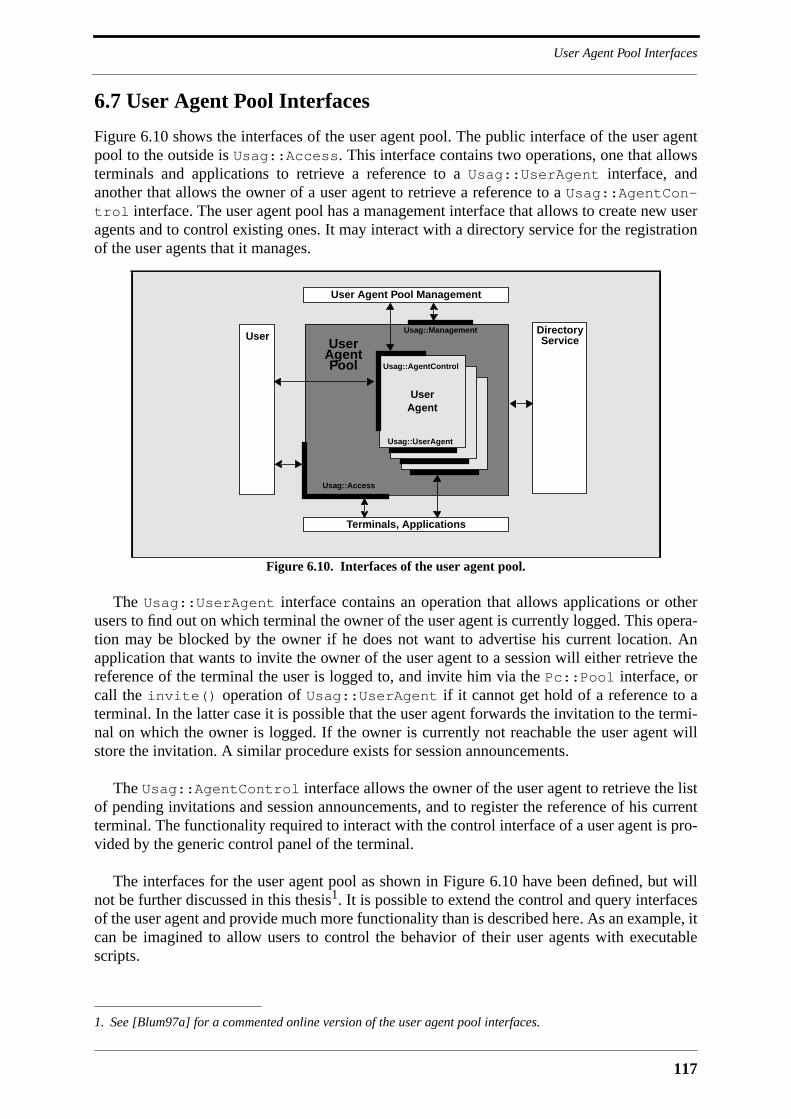
117
User Agent Pool Interfaces
6.7 User Agent Pool Interfaces
Figure 6.10 shows the interfaces of the user agent pool. The public interface of the user agentpool to the outside is Usag::Access. This interface contains two operations, one that allowsterminals and applications to retrieve a reference to a Usag::UserAgent interface, andanother that allows the owner of a user agent to retrieve a reference to a Usag::AgentCon-trol interface. The user agent pool has a management interface that allows to create new useragents and to control existing ones. It may interact with a directory service for the registrationof the user agents that it manages.
The Usag::UserAgent interface contains an operation that allows applications or otherusers to find out on which terminal the owner of the user agent is currently logged. This opera-tion may be blocked by the owner if he does not want to advertise his current location. Anapplication that wants to invite the owner of the user agent to a session will either retrieve thereference of the terminal the user is logged to, and invite him via the Pc::Pool interface, orcall the invite() operation of Usag::UserAgent if it cannot get hold of a reference to aterminal. In the latter case it is possible that the user agent forwards the invitation to the termi-nal on which the owner is logged. If the owner is currently not reachable the user agent willstore the invitation. A similar procedure exists for session announcements.
The Usag::AgentControl interface allows the owner of the user agent to retrieve the listof pending invitations and session announcements, and to register the reference of his currentterminal. The functionality required to interact with the control interface of a user agent is pro-vided by the generic control panel of the terminal.
The interfaces for the user agent pool as shown in Figure 6.10 have been defined, but willnot be further discussed in this thesis1. It is possible to extend the control and query interfacesof the user agent and provide much more functionality than is described here. As an example, itcan be imagined to allow users to control the behavior of their user agents with executablescripts.
1. See [Blum97a] for a commented online version of the user agent pool interfaces.
Figure 6.10. Interfaces of the user agent pool.
UserAgent
User
Usag::Access
Usag::Management
UserAgent
Terminals, Applications
User Agent Pool Management
Directory
Pool
Service
UserAgent
UserAgent
Usag::AgentControl
Usag::UserAgent

APMT Overview
118
6.8 Application Model and Major Application Scenarios
The application model of APMT consists of a central application that orchestrates a set ofapplets in the periphery. Applets run in applet handlers on multimedia terminals. Applet codeis either downloaded from the application pool, or retrieved from a local cache. Applets takecare of issues that are local to the terminal on which they are running. Events that are of globalimportance are communicated back to the application in the application pool. The applicationprocesses incoming events, and emits directives to its applets that are a function o these events.The application may also directly interact with the terminal infrastructure, which it does whenit establishes multipoint connections among terminals. Since both the applet and the applica-tion are interacting with the terminal infrastructure it is necessary to provide a mechanism thatallows them to synchronize their activities. One such mechanism is event notification based onthe CORBA event service.
The application model of APMT is flexible enough to accommodate a wide range of appli-cations and application scenarios. The three major application scenarios that are supported are:
• interactive presentation: a user accesses multimedia content via a presentationapplication in an application pool that controls a multimedia object server.Example applications are games, video on-demand and multimedia kiosks.
• conference: multiple users interact with each other and the application. Thenumber of users participating in the conference is limited. Example applicationsare video-conferences, CSCW, and distributed games.
• broadcast: multimedia content is broadcast to a possibly large number of users.There is only limited feedback from the terminals that consume content to thosethat produce it. An example application is network radio.
These scenarios can be combined together to form mixed scenarios. As an example, theconference and broadcast scenarios can be combined to form a panel scenario where a largenumber of spectators participates passively in the interaction between a small number of panel-ists. In the following it is shown how these scenarios are realized by APMT.
Interactive Presentation
Figure 6.11 shows the simple interactive presentation scenario. A user starts an application inan application pool which in turn controls a multimedia object server. It is likely that there is adirect control communication path between the applet on the multimedia terminal and the one
Figure 6.11. Interactive presentation scenario.
AP
Application
MT
Applet
MOS
Applet
MOS: Multimedia Object Server
control
stream

119
Application Model and Major Application Scenarios
on the multimedia object server. Simple applications will not require any intelligence on themultimedia object server. The applet on the multimedia terminal will then directly control themultimedia devices on the multimedia object server.
Conference
Two variants of the conference scenario are depicted in Figure 6.12. They are distinguished bythe way intelligence is distributed between applet and application. The left side of Figure 6.12shows a centralized scenario where the bulk of intelligence resides in the central application,with the applets being sensors and actuators that mediate between the user and the application.The right side of Figure 6.12 shows a distributed scenario where most of the application intelli-gence resides in applets. In this case the role of the application is limited to session and con-nection management, and to some sort of arbitration between conflicting user requests. Appletsin the distributed scenario are likely to communicate directly with each other, as is indicated inFigure 6.12. A conference application can be anything from completely centralized to com-pletely distributed. The centralized scenario is adequate for very small conferences, whereasthe distributed scenario is adopted by applications that need to accommodate larger numbers ofusers.
Broadcast
The broadcast scenario is depicted in Figure 6.13. The number of user terminals participatingin a broadcast application may overwhelm a single application pool, which makes it necessaryto distribute broadcast applications over multiple application pools. The source terminal runsthe master application, which controls the broadcast, on an arbitrary application pool andadvertises the identifier of this application, the set of used multicast addresses and a sessiondescription via the service gateway to other application pools. Those application pools thathave the necessary code installed will offer participation in the broadband application sessionvia the service gateway to users. A terminal may therefore participate in the broadcast sessionby joining a slave application on an application pool other than the one that houses the masterapplication. It is able to connect to the stream emitted by the source terminal because it knowsthe respective multicast addresses. The slave application may communicate with the masterapplication, as is indicated in Figure 6.13, for instance to inform it about local session member-ship, or the result of a vote. Multiple hierarchies of slave applications can be imagined thatreduce the communication load on the master application, but this is not supported by theactual APMT specifications. Also shown in Figure 6.13 is the case where a terminal partici-
Figure 6.12. Centralized and distributed variants of the conference scenario.
AP
Application
MT
Applet
MT
Applet
MT
Applet
AP
Appl.
MT
Applet
MT
Applet
MT
Applet
centralized distributed
control
stream

APMT Overview
120
pates in a broadcast session without being connected to a slave application in an applicationpool. This is possible by running a terminal application and configuring it with informationabout the broadcast session. This kind of scenario resembles broadcasting as known from theMBone.
6.9 Deployment Scenarios
Whoever owns a host that is connected to the Internet, or to a network based on Internet proto-cols, may run an application pool. An application pool can run on a single personal computerjust as it can run on a cluster of workstations or a mainframe. Three example deployment sce-narios will be discussed in the following:
• private application pool: a user runs application pool software together with ter-minal software on the same machine.
• intranet application pool: an enterprise runs one or more application pools forinternal communication.
• public application pool: a service provider runs an application pool to offer ser-vices to a large public.
This is only a small selection of possible scenarios that shall serve to illustrate the flexibilityof the APMT architecture.
Private Application Pool
A user may deploy a private application pool in order to disseminate an application that hedeveloped, or to host private meetings on it. In case it is deployed to disseminate an applicationits address will be advertised to other users via service gateways. In case it is used for privatemeetings its address will be kept secret, and it is possible that the user runs it only during themeetings that take place on it. In this case it is used just like any other conferencing software,with the only difference being that there is a central component running at the site of one con-ference participant. In the case of a more distributed application, corresponding to the scenarioindicated on the right side of Figure 6.12, the performance impact on the machine hosting theapplication pool is rather small. The number of sessions that can be concurrently run on a sin-
Figure 6.13. Broadcast application scenario.
AP
Slave
MT
MT
Applet
Applet
MT
Applet
AP
MT AP
MT
MT
control
stream
MT
Appl.Master
Appl.
Terminal runninga terminal application
121
APMT and TINA
gle machine will then be limited by the maximum number of concurrently running processes,or the maximum number of concurrently active TCP connections, but not by the power of itsCPU.
Intranet Application Pool
An intranet application pool is deployed on the network of an enterprise. Since it may have toserve a larger number of users in parallel it will be distributed over multiple workstations. Oneof these workstations runs the application pool control which distributes applications andapplication pool utilities over the other workstations that are at disposal. The software used forthe intranet scenario may be identical to the one used for private application pools. This flexi-bility is largely due to the use of CORBA.
Public Application Pool
A public application pool serves a large community with application logic and multimediacontent. It is based on a possibly considerable number of workstations, or alternatively on asmall number of high-end application servers. One or more file servers are dedicated to thedownloading of application code into terminals. Multimedia object servers are collocated withthe application pool. The application pool control is transparently replicated on multiplemachines in order to achieve high availability. The application pool has a high-speed access tothe Internet, and is itself built on top of a high-speed network that minimizes end-to-end delayof internal communication.
The three deployment scenarios given here show how application pools may look like. Theway the other platform components are deployed is rather straightforward. The multimedia ter-minal is deployed on a personal computer, or on a couple of workstations in case it represents alarger conference room. The user agent pool is a single server running on a machine in thehome domain of the user. The user agent of a private user will be managed by the user agentpool of his Internet service provider. The user agent of a business user will be managed by theuser agent pool of his company, which may be collocated with an intranet application pool.Service gateways can be housed by large public application pools.
6.10 APMT and TINA
APMT can be considered as a service provision platform, and may therefore be compared withTINA. The principal similarity between APMT and TINA is the partition of functionalitybetween components in the network and components in the terminal. However, the philoso-phies that lead to this partition of functionality differ from each other. TINA is a full-fledgedservice provision architecture for telecommunications networks. Service logic in telecommu-nications networks resides traditionally within the network, and is accessed via dumb terminalslike telephone handsets. TINA must be considered as a move to make use of the increasedintelligence of terminals. This is different for APMT, for which the starting point is the intelli-gent terminal, and which discovers servers in the network as code repositories and applicationsrunning in them as central coordination points for multiple terminals. APMT distinguishesitself from TINA also in its emphasis on extensibility, programmability, and mobile code. Boththe multimedia terminal and application pool are based on a high-level component frameworkthat allows them to be extended by third parties. The high-level components in the applicationpool, the application pool utilities, are meant to provide additional layers of functionality to theterminal interfaces, and to support the rapid development of applications. Terminals are static
APMT Overview
122
in the sense that no application code needs to be installed on them. Application code is down-loaded into the terminals at runtime. Extensibility, programmability and mobile code are notsufficiently addressed by TINA.
6.11 Conclusion
This chapter introduced the CORBA-based APMT platform. APMT is an overlay platform thatcan be deployed on an IP network without requiring any modifications to the existing networkinfrastructure. The APMT platform features a static terminal that can execute applets down-loaded from applications in application pools. MMC applications developed on top of APMTcan be either completely centralized, completely decentralized or somewhere inbetween thesetwo extremes. APMT supports single-user applications, multi-user applications, and broadcastapplications. The APMT platform is highly extensible. The infrastructure of the terminal canbe extended with new terminal servers supporting new interpreted languages, CSCW tools andwhatever functionality may be needed in the terminal. The stream agent terminal server encap-sulates a low-level component framework for multimedia processing devices that can beextended by third-parties. The infrastructure of the application pool can be extended with newapplication pool utilities that help applications manage terminals servers and low-level objectsin terminals. Every application implementing the App::Application interface extends theplatform because it can be reused by composite applications.
The following two chapters present the core architecture of APMT and the APMT multime-dia middleware. A third chapter discusses the APMT prototype and evaluates the APMT plat-form with respect to the criteria that were developed in Chapter 2.

123
7 APMT Platform Architecture
7.1 Introduction
The previous chapter introduced the APMT platform along with its major features and a set ofpossible deployment scenarios. This chapter continues the description of APMT with adetailed presentation of the platform architecture. It starts with some remarks about howCORBA is used in APMT, and an overview of the modules that represent the core architecture.It then discusses the major application-level interfaces of the multimedia terminal and theapplication pool, and illustrates with a set of reference scenarios the way platform componentsinteract within an application session. The APMT multimedia middleware is not presented inthis chapter because it is already considered to be an extension of the architecture. What is pre-sented are the interfaces that allow to manage applications on terminals and in applicationpools. These are the interfaces that represent the core of the APMT architecture. They are keptsimple in order to have a solid basis for eventual extensions via interface inheritance or newinterface versions. It is supposed that the lifetime of the APMT platform as presented in thisthesis is linked with the one of these interfaces, meaning that they may be extended andimproved, but not substituted by a completely new set of interfaces.
7.2 Usage of CORBA in APMT Definitions
OMG-IDL interface definitions are at the border of design and implementation. Consideringthem as a pure design construct may have a negative impact on the interface implementation. Itis therefore necessary to be aware of the implications of the use of OMG-IDL features likemodules, attributes, and oneway operations, and to take them into account during the design ofa system. This is done best by establishing a set of rules for the use of CORBA and OMG-IDLwith which all interface definitions of a system must comply. The following subsections out-line the rules that were applied to the usage of CORBA in APMT definitions.
CORBAservices
APMT uses not only the basic object request broker, but also some of those CORBA servicesthat are widely approved by the CORBA community, namely the naming service, the event ser-vice, the relationship service, and the trading service. Beyond that it can be assumed thatAPMT applications make use of the transaction service, the query service and the persistentobject service. The usage of CORBA services is not always clearly visible in the APMT IDLspecifications. The usage of the relationship service for instance manifests itself only via inter-face inheritance. The APMT objects that need to navigate the relationships in which they areinvolved, or that need to be found by other APMT objects, inherit from the CosGraphs::Node interface defined by the relationship service.

APMT Platform Architecture
124
Modules
All APMT definitions are enclosed in modules, first of all to protect the name space, and thenalso to be able to group logically related interfaces, which helps in gaining an overview of thearchitecture. No attention is given to the file level, although it is the file rather than the modulethat is the smallest unit of IDL compilation. The IDL standard allows to close and reopen mod-ule definitions within the same scope1, making it in principle possible to distribute the contentof a module over multiple files and compile them separately. The reality however is that this isnot supported by commercially available IDL compilers. It is therefore a good strategy todefine small modules and to group them into files in a way that a client or server is likely to useall, and not just a part of the definitions within a file. If this is not the case it may happen thatclient or server processes incorporate superfluous stub or skeleton code2. APMT defines ratherlarge modules which usually correspond to architecture building blocks. This supports thecomprehension of the definitions, but it is noted that implementation constraints may require tosplit some of these modules into smaller ones.
Attributes
APMT interfaces contain readonly attributes rather than get operations whenever it seems ade-quate to indicate that a certain piece of information that is available through an interface isdirectly maintained by the object that implements this interface. This implies that an object thatis queried for the value of an attribute is able to return a response without being obliged to con-tact other objects. An attribute should hold valid values throughout the lifetime of the object,so that it can be queried at any time. However, there are certain attributes in the APMT defini-tions that cannot hold a valid value right after object creation, i.e., before a first initializationoperation has been called. When queried for the value of an attribute that has not been initial-ized yet, the object raises the standard CORBA system exception BAD_INV_ORDER. TheAPMT definitions mostly use readonly attributes. As was already pointed out in Section 3.3.2,changing the value of an attribute may have a significant impact on the state of an object, andmay consequently fail without that the object is able to throw a meaningful exception. It istherefore preferable to explicitly define a set operation for an attribute whenever there is theslightest chance that the direct setting of the attribute value may fail.
Oneway Operations
Because of their unclear semantics, oneway operations are rarely used in APMT definitions.They are used for non-critical notifications over the network, and for message-style communi-cation among peer objects that are physically collocated, which helps to avoid deadlocks and tosave on threads in an environment where communication errors are unlikely. In both cases it isassumed that the client does not block on the delivery or execution of the operation invocation.
Nested Callbacks
APMT definitions try to avoid nested callbacks, i.e., situations where a server executing a cli-ent request calls an operation in an interface implemented by the client. This can be handled bymulti-threaded CORBA implementations, but results in a deadlock in most of the single-threaded CORBA implementations that are available today. APMT servers that need to call cli-
1. This is stated in the CORBA 2.0 specification in Section 3.13 [OMG95c].
2. In C++, IDL modules are mapped to C++ namespaces, but since namespaces are supported by few C++ com-pilers they are normally mapped to C++ classes. Since C++ class definitions cannot be reopened it is not pos-sible to scatter the definitions of a module over multiple IDL files.
125
Overview of APMT Modules
ent interfaces do this asynchronously, i.e., after completion of the initial client request. It has tobe noted that this kind of handshake is tedious to program if it is not supported by the CORBAimplementation1.
Long-lasting Operations
Comments are used in the IDL definitions of APMT to indicate operations that may take a longtime to complete. Such long-lasting operations are in general avoided with the same mecha-nism that is used to avoid nested callbacks, i.e., asynchronous execution followed by a call-back. Long-lasting operations have the disadvantage that they block threads in client processes.
Passing Object References
A CORBA server that receives an object reference as parameter in an operation call will auto-matically create a proxy object that allows it to call operations in the interface denoted by theobject reference. Since proxy objects take ORB resources it should be avoided to directly passobject references to a server that does not use them. The approach taken by APMT is to passobject references as strings whenever it is unclear if the recipient will use them. A stringifiedobject reference can easily be transformed into a proxy object with the standard CORBA oper-ation string_to_object().
7.3 Overview of APMT Modules
Table 7.1 shows the modules that contain the definitions of the APMT platform architecture.The modules Typ, Atyp, Ftyp and Ex define basic types that are relevant for all other APMTdefinitions. The modules Typ, Ftyp and Ex define types and exceptions that are not necessar-ily specific for the APMT architecture. The module Atyp on the other side defines types thatexpress certain APMT concepts, like user names, application pool addresses and the like.
All terminal control interfaces that are visible to applications and control panels are definedin the module Tc. The module Ts contains the terminal server base interface. The modulesTclTk and Java contain the definitions of applet handlers. The module Ta is foreseen for def-initions related to terminal management.
All application pool control interfaces that are visible to terminals and applications aredefined in the module Pc. The module Pa is foreseen for the definition of application pool con-trol interfaces that are visible to management tools. The module App contains interfaces thatare implemented by applications. The module Put contains the base interface of applicationpool utilities. The module Pac contains all interfaces of the participation control utility. Themodule Uap finally contains the definitions for the user agent pool and the user agent.
1. A CORBA implementation that supports this is OrbixTM from Iona Technologies with its filter mechanism[Ion96a]. A filter in Orbix is server code that can be executed before operation invocation or after operationexecution.
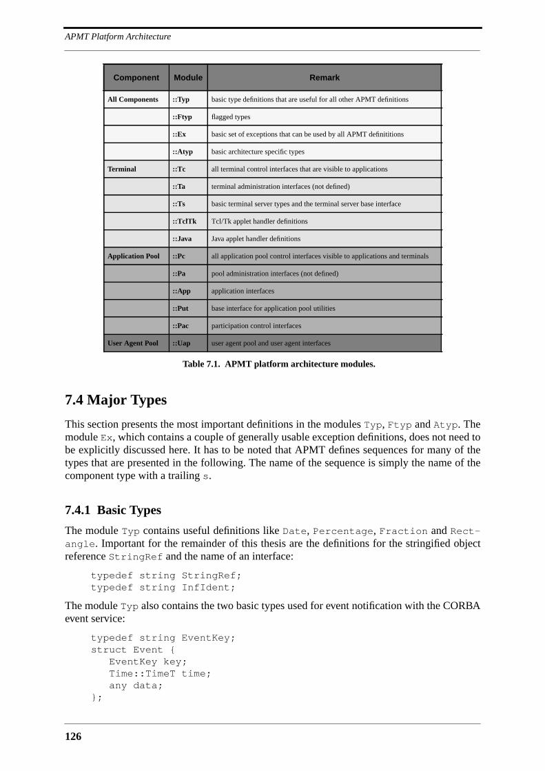
APMT Platform Architecture
126
7.4 Major Types
This section presents the most important definitions in the modules Typ, Ftyp and Atyp. Themodule Ex, which contains a couple of generally usable exception definitions, does not need tobe explicitly discussed here. It has to be noted that APMT defines sequences for many of thetypes that are presented in the following. The name of the sequence is simply the name of thecomponent type with a trailing s.
7.4.1 Basic Types
The module Typ contains useful definitions like Date, Percentage, Fraction and Rect-angle. Important for the remainder of this thesis are the definitions for the stringified objectreference StringRef and the name of an interface:
typedef string StringRef;typedef string InfIdent;
The module Typ also contains the two basic types used for event notification with the CORBAevent service:
typedef string EventKey;struct Event { EventKey key; Time::TimeT time; any data;};
Component Module Remark
All Components ::Typ basic type definitions that are useful for all other APMT definitions
::Ftyp flagged types
::Ex basic set of exceptions that can be used by all APMT definititions
::Atyp basic architecture specific types
Terminal ::Tc all terminal control interfaces that are visible to applications
::Ta terminal administration interfaces (not defined)
::Ts basic terminal server types and the terminal server base interface
::TclTk Tcl/Tk applet handler definitions
::Java Java applet handler definitions
Application Pool ::Pc all application pool control interfaces visible to applications and terminals
::Pa pool administration interfaces (not defined)
::App application interfaces
::Put base interface for application pool utilities
::Pac participation control interfaces
User Agent Pool ::Uap user agent pool and user agent interfaces
Table 7.1. APMT platform architecture modules.
127
Major Types
The event key is a string that uniquely identifies an event within the APMT definitions. Anevent key is defined as a string constant in the interface to which the event is related:
const string EventNameEventK = "module:interface:EventName";
An event key is used by event consumers to register for the generation and reception of specificevents, and by the event producer to mark the events that it generates, as can be seen in theevent data structure. Besides the event key, the event data structure contains a time stamp andevent specific data in form of an any type. The actual type used for event specific data isdefined in the same interface as the event key, and is often a structure or a typedef:
struct EventNameEventD { .... };typedef type EventNameEventD;
For the moment, APMT uses only untyped event communication, which means that the eventdata structure is communicated in form of an any type to event consumers. Event consumersneed to be able to associate the events that they receive with the objects that created them. InAPMT, event channels are always owned by event producers, which allows event consumers toassociate a separate CosEventComm::PushConsumer or CosEventComm::PullCon-sumer interface instance with every event producer, and consequently identify the producer ofan event via the interface through which the event was communicated.
The module Ftyp contains definitions of flagged types, i.e., structures that contain a valueand a boolean flag that tells if the value is valid. Flagged types are used to pass optional param-eters in operations. The following definition shows for instance a flagged string:
struct StringF { boolean flag; string value;};
Flagged types are denoted by a trailing F in the type name. Not only basic CORBA types, butalso many APMT types have a flagged counterpart.
7.4.2 Advanced Types
The module Atyp contains definitions that express architecture concepts. Internet hostnamesare defined as strings, and the major architecture components terminal, application pool anduser agent server are defined as hostnames:
typedef string HostName;typedef HostName TerminalName;typedef HostName PoolName;typedef HostName UapName;
The terminal name identifies the host on which an object implementing the Tc::Terminalinterfaces is instantiated. The same is true for the application pool name, which identifies thehost on which an implementation of the Pc::Pool interface can be accessed, and the useragent pool name, which identifies the host on which an implementation of the Uap::Accessinterface can be accessed. The hostname alone is not sufficient to construct an IIOP IOR. Whatis needed in addition is a port number and an object key that are reserved for APMT. As fornow the IIOP standard does not address the issue of standard object keys. Object keys are con-sidered to be opaque values that an ORB may format as it wishes, with the consequence thatORB’s tend to encapsulate their proprietary object reference within the object key of an IIOPIOR. However, there is a clear need for standard object keys that allow clients to construct

APMT Platform Architecture
128
IIOP IOR’s for certain objects from a hostname and a port number, and it is assumed thatfuture versions of the CORBA standard support this by allowing implementations to choosestandard values for the object key of their IIOP IOR reference. If it should turn out thatCORBA will not support this there is the less elegant alternative to design a bootstrapping ser-vice on top of TCP similar to the Internet finger service [Zimm91] that allows clients of termi-nals, application pools and user agent pools to retrieve an initial object reference. The need toconstruct IIOP IOR’s from hostnames and port numbers disappears as soon as they can beretrieved via a global directory service.
A user name is simply a string. User names do not need to be unique. They become uniquein combination with the name of the user agent pool that houses the agent of the user:
typedef string UserName;
struct User { UapName home; UserName name;};
Users that do not have access to a public user agent pool may run a private one on their multi-media terminal. The UapName in their identifier will then be identical to the name of the termi-nal that they are normally using. The user identifier may be written as a string similar to an E-mail address:
UserName@UapName
This form will for instance be used in graphical user interfaces, or in general whenever theidentifier of a user is communicated via other means than CORBA operations.
The module Atyp defines two identifiers that are used to identify applications and contenton application pools:
typedef string ApplicationName;typedef string TitleName;
The application name is a preferably unique identifier for a certain application. Users startapplications with an application name whenever they are interested in application logic. Theyuse title names whenever they are interested in some content rather than in the applicationlogic that mediates this content. They use both an application and a title name whenever theywant to view some content with a specific application. In this case it may happen that a givencombination of application and content is invalid. Since title names associate application logicwith data they are more important than application names that can only identify functionality.
An application pool assigns a locally unique session identifier to every running application.This session identifier together with the name of the application pool represents a unique ses-sion address:
typedef unsigned long SessionId;
struct SessionAddress { PoolName paddr; SessionId id;};

129
Terminal Control Interfaces
The initiator of a session may reserve a session identifier prior to application startup and dis-tribute it together with the application pool name to other interested users. These users can thenjoin the session once it is active.
An application session can be in the states IDLE, ACTIVE and EXITING. It is IDLE until theapplication pool control has initialized the application. Once it is initialized it is in stateACTIVE. It enters state EXITING when it is asked to release its resources and to terminate:
enum SessionState {IDLE,ACTIVE,EXITING};
The module Atyp further contains the definition of the three important information structuresUserRecord, ParticipantRecord and SessionDescription. The user record containsthe user identifier, his E-mail address, the address of his Web page, and a general informationfield:
struct UserRecord{ UapName home; UserName name; Url homepage; Email mailaddr; string<1000> info;};
The participant record consists of a participant identifier, a user record, a terminal name and atimestamp taken at the moment when the user joined the session. The session descriptionfinally consists of the session address, the application name, the optional title name, the sessionstate, the session start time and a list of participant records:
struct SessionDescription{ PoolName pn; SessionId id; ApplicationName an; TitleNameF tn; SessionState state; ParticipantRecords prs; Typ::Date start;};
The session description is available to every session participant, i.e., it can be accessed inde-pendently from the application via the control panel. Applications are likely to supplement theAPMT session description with application and session specific information that can only beaccessed via the application itself.
7.5 Terminal Control Interfaces
This section presents the various interfaces of the terminal control. It starts with a descriptionof the principal interfaces visible to control panels and application pools, and continues with adescription of the interfaces of the user session object. The interfaces of the terminal controlare depicted in Figure 6.5 on page 112.
APMT Platform Architecture
130
7.5.1 Interface Tc::Terminal
Tc::Terminal is the public interface of the terminal. It contains attributes that describe ter-minal characteristics, the operation finger() that allows other users to find out about who iscurrently logged, and the operation knock() via which a textual message can be communi-cated to the currently logged user. The most important operation it defines is the operationinvite() that allows an application to invite a user to its session:
void invite(in Atyp::User user, in Pac::Participant sc, in Typ::InfIdents termobjects, in Atyp::InvitationInfo info)
raises (NobodyThere,Ex::NotCompatible,
Ex::NoSuchUser);
The parameter user is the identifier of the invited user. The terminal control checks this iden-tifier against the one of the user that is currently logged. If there is a mismatch, it will raise theexception Ex::NoSuchUser. If there is currently nobody logged it will raise the exceptionNobodyThere. The parameter termobjects is the minimal list of interfaces that the termi-nal needs to implement in order to be able to participate in the application. If the terminal doesnot support all of the interfaces mentioned in the list it will raise the exception Ex::NotCom-patible. The parameter info contains a session description that helps the user in his deci-sion whether to accept the invitation or not. The parameter sc is a reference to an interface ofthe participation control that the terminal control will use to asynchronously respond to theinvitation. The response to an invitation is asynchronous because it is assumed that the caller ofthe invite() operation does not want to block for the time it takes the user to decide upon aninvitation. The caller of the invite() operation will typically release the binding to the Tc::Terminal interface right after the call completes.
7.5.2 Interface Tc::PanelTerminalControl
Tc::PanelTerminalControl is the interface of the terminal control towards a controlpanel. Every terminal has a generic control panel, and allows users to import a private controlpanel from an application pool. A user that wants to log to a terminal first starts the genericcontrol panel. The generic control panel contacts his user agent in order to retrieve the userrecord, and registers him with the terminal control:
void register(in Atyp::UserRecord user) raises (RegistrationError);
If the user does not have a user agent he is asked by the control panel to provide the informa-tion that is contained in the user record. Once a user is registered he can access the services ofthe terminal control. A user terminates a terminal session by deregistering from the terminalcontrol with a call to deregister(). Deregistration causes the termination of all applicationsstarted by the user. The terminal will also quit all application sessions in which the terminalparticipates.
After successful registration of the user the control panel may retrieve a stringified referenceto the Tc::Terminal interface and send it to the user agent. This allows the user agent to for-ward invitations to the terminal. Applications will normally send invitations to user agents, andnot directly to terminals. The control panel may also retrieve a reference to an application con-trol interface via which applications can be started:

131
Terminal Control Interfaces
ApplicationControl get_application_control();
This interface allows for instance to import control panels. An imported control panel gets areference to the Tc::PanelTerminalControl interface from the terminal control. It doesnot need to register with the terminal control, and has immediately the same access rights tothe terminal control as the generic control panel. Once the imported control panel is runningthe user will stop to use the generic control panel. However, he will be able to resort to it at anytime if the imported control panel does not work satisfactory.
The terminal control communicates with its control panels via events. Control panels regis-ter for terminal control events with the following operation:
CosEventChannelAdmin::ConsumerAdmin register_terminal_events();
The CosEventChannelAdmin::ConsumerAdmin interface allows a control panel to con-nect a CosEventComm::PushConsumer or CosEventComm::PullConsumer interface tothe event channel. The terminal control maintains a single event channel for control panels,which means that all control panels see exactly the same events. The terminal control generatesfor instance events when applications are started by other applications, when applications areready, and when a message arrived via the knock() operation in the interface Tc::Termi-nal. An important event is the invitation event:
const string InvitationEventK = "Tc:PanelTerminalControl:Invitation";
struct InvitationEventD {Atyp::InvitationInfo info;InvitationKey key;
boolean rejected;};
The event data contains the invitation information that was communicated to the terminal con-trol via the invite() operation in the Tc::Terminal interface, a flag indicating if the termi-nal control already rejected the invitation due to compatibility problems, and an invitation keythat the control panel uses in its response to identify the previous invitation:
UserSession invite_accept(in InvitationKey key) raises (Ex::NoSuchKey,
Ex::ResourceProblem,Atyp::SessionAccessDenied);
oneway void invite_reject(in InvitationKey key);
If the user accepts the invitation, the terminal control contacts the participation control of theapplication, which may actually reject the terminal, for instance due to resource problems thatdid not exist at the time the invitation was sent, or because the invitation was cancelled by theapplication. The invite_accept() operation blocks until the remote participation controlaccepts or rejects the terminal. In case the terminal is accepted, a reference to a new instance ofa Tc::UserSession interface is returned to the control panel.
The control panel may get references to all user session objects, including those that werestarted by yellow page applications. The Tc::UserSession interface allows the controlpanel to discover and access all objects that the respective application has created on the termi-nal, and to call compound operations on all terminal servers owned by an application.
APMT Platform Architecture
132
7.5.3 Interface Tc::ApplicationControl
Tc::ApplicationControl is the interface via which a control panel or an application maystart an application or join a session on an application pool. The most important operation inthis interface is start():
UserSession start(in Atyp::PoolName pool, in Atyp::ApplicationNameF application,
in Atyp::TitleNameF title,in Atyp::SessionId reserved)
raises (PoolNameError,Atyp::NoSuchApplication,
Atyp::NoSuchTitle, Atyp::ApplicationStartupDenied, Atyp::ApplicationStartupFailed, Ex::NotCompatible, Ex::ResourceProblem);
This operation starts an application in an application pool. The application pool is identified bythe pool parameter, and the application by the combination of an application and a title name.The caller may either give a title name, an application name, or both. The parameterreserved indicates with a non-zero value a previously reserved session identifier that is to beused for the session. The call blocks until the application runs and is initialized, i.e., until thereis a certain level of confidence that the application will successfully run on the terminal. A ref-erence to a Tc::UserSession interface is returned to the caller via which the application canbe monitored and controlled.
The start() operation may already fail locally, for instance if the terminal is unable toconstruct an IIOP IOR for the Pc::Pool interface of the given application pool, or if the ter-minal does not have enough resources to support a new application. It may then fail in an earlyphase if the contacted application pool does not support the given application or title, or if theuser is not authorized to start it. It may further fail because the terminal finds out by itself thatit is not compatible with the application. The application pool control allows terminals to testtheir compatibility before they actually start an application. Application startup may then failbecause the application crashes right after startup, or because it cannot serve the requested titleto the user. The exceptions that the start() operation may raise take account of all the men-tioned failure scenarios.
The second important operation in Tc::ApplicationControl is join() which allowsto join an ongoing application session:
UserSession join(in Atyp::SessionAddress aaddr)raises (Atyp::SessionAccessDenied,....);
The only information needed to join a session is the session address consisting of the applica-tion pool name and a local session identifier. The terminal control first accesses the Pc::Poolinterface of the application pool where it can get a reference to the Pac::SessionAccessinterface of the respective participation control. It then issues a join request to the participationcontrol. This join request returns immediately because it is processed asynchronously. The ter-minal control receives a callback from the participation control once the application or one ofthe session participants has decided about the request. In case the terminal and its user areaccepted, the operation join() returns a reference to the Tc::UserSession interface of theuser session object. It raises the exception Atyp::SessionAccessDenied if the applicationdenied session access.

133
Terminal Control Interfaces
The interface Tc::ApplicationControl further contains a couple of operations thatallow to start special applications. The control panel of a user is started with the followingoperation:
UserSession start_panel(in Atyp::PoolName pool, in Atyp::TitleName paneluser)
raises (....);
A special operation is necessary for this because the control panel has, unlike other applica-tions, the right to retrieve a reference to the Tc::PanelTerminalControl interface. Thecontrol panel is identified by a title name, which may for instance be identical with the username.
Terminal applications are also started via the Tc::ApplicationControl interface. Theonly argument needed for this is an application name:
UserSession start_term_app(in Atyp::ApplicationName application)raises (....);
It can also be imagined to provide a special interface for already running terminal applicationsthat allows them to directly access the terminal control services.
7.5.4 Interface Tc::UserSession
Every application running on the terminal is represented by a user session object in the termi-nal control. The Tc::UserSession interface of the user session object allows a control panelto control an application. Terminal applications and remote applications are handled via differ-ent interfaces that both inherit from Tc::UserSession:
module Tc { .... interface UserSession {...}; interface RemoteUserSession : UserSession {...}; interface LocalUserSession : UserSession {...};};
Every running application has a user session identifier that is unique within the terminal:
typedef unsigned long UserSessionId;
A user session is associated with a state:
enum UserSessionState{RUNNING,PAUSED,HIDDEN, HIDDEN_PAUSED,EXITING};
A user may locally pause an application, which means that the terminal servers of the applica-tion stop processing. This does not concern applet handlers, and it also does not concern theprocessing of control operation requests. A user may further hide an application, in which caseit unmaps its graphical user interface and stops all output. An application may also be pausedand hidden at the same time, in which case it does not consume any resources and is invisibleto the user. The operations in Tc::UserSession that influence the user session state are:
void hide();void show();void pause();void continue();

APMT Platform Architecture
134
These operations can also be found in the interface Ts::TerminalServer. The user sessionobject may therefore simply repeat their invocation on every terminal server owned by theapplication. Since these operations only have a limited effect on the application it is assumedthat they do not fail under normal conditions. An eventual failure indicates a major problemthat is fatal to the user session as a whole.
A user may also kill the applications that he started, quit the applications that he joined, andremove the user session object:
void kill();void quit();void remove();
The kill() operation blocks until the application has terminated. Similarly, the quit()operation blocks until the application has removed all of its terminal servers. Applications willnormally provide proprietary ways to quit or kill the application session. It can therefore beassumed that users will rarely need to resort to kill() or quit().
The module Tc defines the type RemoteSessionDescription for the description of anapplication running in an application pool:
struct RemoteSessionDescription { UserSessionId id; UserSessionState state; Atyp::SessionDescription globdesc; Ts::TermServDescriptions terservs;};
The member terservs is a list of terminal server descriptions. A terminal server descriptioncontains a reference to a Ts::TerminalServer interface that allows a control panel to con-tact the respective terminal server and to find out about the objects that it instantiated. The ses-sion description can be retrieved via an operation in the Tc::RemoteUserSession interface:
RemoteSessionDescription get_description();
An operation has been chosen rather than an attribute because the terminal control may need tocontact the participation control in the application pool in order to get an up-to-date sessionmembership list.
7.5.5 Interface Tc::TerminalControl
Tc::TerminalControl is the interface of running applications to the terminal control. Itoffers more functionality than any other terminal control interface. The terminal control givesthe reference to the Tc::TerminalControl interface not only to terminal applications andremote applications, but also to every terminal server that is activated by an application. Beforean application activates a terminal server it may find out what kinds of terminal servers areavailable:
readonly attribute Typ::InfIdents termservers;
It may also find out what interfaces are supported by the terminal:
Typ::InfIdents challenge(in Typ::InfIdents termobjects);
The parameter termobjects is the list of interfaces in which the application is interested.The terminal control compares this with the list of available interfaces, and returns the subset
135
Terminal Control Interfaces
of interfaces that is not supported by the terminal. The challenge() operation is a conve-nient way for applications to find out if a terminal supports certain sets of interfaces. It is notthought to be a compatibility test. The compatibility of the terminal with respect to the applica-tion is tested as part of the startup procedure, i.e., before the application even sees a referenceto the Tc::TerminalControl interface.
The application may activate terminal servers with the following operation:
Ts::TerminalServer get_terminal_server(in Ftyp::NameF name, in Typ::InfIdent server)
raises (....);
The parameter server is the name of the terminal server that is to be activated. The parametername allows the application to assign a name to the newly created instance of the terminalserver. The terminal control will then register this name and the object reference of the termi-nal server with the local naming service.
Yellow page applications or application pool browsers may want to start other applicationson behalf of the user. They may retrieve a reference to the Tc::ApplicationControlinterface via the following operation:
ApplicationControl get_application_control();
Imported control panels need to get access to the Tc::PanelTerminalControl interface ofthe terminal control:
PanelTerminalControl get_terminal_control();
This operation will raise the standard security exception NO_PERMISSION if it is called by anapplication that was not started as a control panel.
The application may retrieve a reference to a branch in the naming tree of the local nameservice that it may freely use for its purposes:
CosNaming::NamingContext get_name_service();
This branch is deleted when the application terminates. It would also be possible to provide abranch in the naming tree that is shared among applications on the terminal and that allowsthem to discover each other.
Many of the objects that an application owns on a terminal are in fact created by one of itsapplication pool utilities. This means that the application and its applets on the terminal do notautomatically have object references to them. An application may get the object references it isinterested in from the utilities that created the respective objects, and communicate these refer-ences to its applets, but this is awkward and should be avoided because it puts an unnecessaryload on the application. It makes more sense to communicate object references locally to theapplets that are interested in them. The application and its utilities may assign a name to everyobject that they create, as could be seen in the case of terminal servers. If an object is createdwith a name, the terminal control will advertise its object reference via an entry in the namingtree branch of the application. Most applications will need in addition to that a real handshakeprocedure that allows them to synchronize with the life-cycle of an object. The interface Tc::TerminalControl supports this with four operations and two events. The following twooperations are called by factories within terminal servers to indicate the creation or deletion ofa named object:
APMT Platform Architecture
136
oneway void create_indication(in CosNaming::Name obj_name, in Typ::StringRef obj_ref);oneway void delete_indication(in CosNaming::Name obj_name);
Applets that want to synchronize with the creation or deletion of named objects call the follow-ing two operations:
boolean create_event(in CosNaming::Name objname, out Typ::StringRef obj_ref);boolean delete_event(in CosNaming::Name objname);
The operation create_event() returns TRUE if the object exists already, in which case itreturns the object reference in the obj_ref parameter. The operation delete_event()returns TRUE if the object has already been deleted. The following events are issued by the ter-minal control when a named object is created or deleted:
const string CreationEvent = "Tc:TerminalControl:Creation";struct CreateEventD { CosNaming::Name obj_name; Typ::StringRef obj_ref;};
const string DeleteEventK = "Tc:TerminalControl:Deletion";typedef CosNaming::Name DeleteEventD;
Applets must separately register for the events in which they are interested:
CosEventChannelAdmin::ConsumerAdmin register_event(in Typ::EventKey key) raises (Ex::NoSuchEvent);
The user session object maintains one event channel per event. This means that an applet mustfilter the create and delete events that it receives. This is acceptable because it can be assumedthat there will be rarely more than one applet per application on the terminal. If this assumptionshould turn out to be wrong it would be necessary to add functionality to Tc::TerminalCon-trol that allows applets to maintain their own event channels, in which case the user sessionobject needs to keep track about the requester of every registered event.
An application that is about to terminate, or that dismisses the terminal from the applicationsession, deletes all terminal servers. Once this is done it calls the terminal control to indicatethat the terminal is no longer part of the application session:
void terminated();
This operation may actually be called by the application in the application pool, or by an appletin an applet handler shortly before it terminates. The operation is also called if the terminationof the application was initiated by the user via the quit() or kill() operation in the Tc::UserSession interface, or by the terminal control itself.
7.6 Terminal Server and Applet Handler Interfaces
This section presents the terminal server base interface and as special cases of terminal serversthe interfaces of applet handlers for Tcl/Tk and Java.
137
Terminal Server and Applet Handler Interfaces
7.6.1 Interface Ts::TerminalServer
The module Ts contains the definitions of the terminal server base interface Ts::Termi-nalServer and some types that are related to it. Two of the types defined in Ts shall be pre-sented here:
enum TerminalServerState {NORMAL,HIDDEN,PAUSED, HIDDEN_PAUSED,EXITING};
struct TermServDescription { Typ::InfIdent type; Typ::Date started; Typ::StringRef termservref; TerminalServerState state;};
The definition of the terminal server state is identical to the one of the user session state. Theterminal server description contains the interface name of the terminal server, the time it wasstarted, a stringified reference to it, and its state. It can be retrieved via an attribute in the inter-face of the terminal server:
readonly attribute TermServDescription description;
Terminal servers are always started by the terminal control. The terminal control initializes aterminal server with the following operation:
void set_terminal_control(in Typ::StringRef termcont);
The parameter termcont is a stringified reference to the Tc::TerminalControl interfaceof the application that started the terminal server. The terminal server may consequently accessthis interface and find out about the context in which it is running.
The remaining operations of the Ts::TerminalServer interface are already known fromthe Tc::UserSession interface:
void hide();void show();void pause();void continue();void remove();
They can be called by the control panel, by the application, or by the user session object, forinstance following a call in the Tc::UserSession interface. It is possible to register for achange event which allows all interested clients to be kept up-to-date about the state of a termi-nal server. As for now it does not seem necessary to define a separate terminal server interfacetowards the terminal control that is hidden from the application and the control panel.
7.6.2 The Tcl/Tk Applet Handler
There is no standard language mapping for OMG-IDL to Tcl, but it is possible to design a sim-ple mapping for the purposes of APMT. This mapping may for instance build on the one pro-posed by the Web* project [Alma95]. Tcl/Tk is fine for the development of graphical userinterfaces that can be downloaded into the terminal. It is therefore an option for the develop-ment of centralized applications as shown in Figure 6.12 on page 119. Since it is weakly typedit should not be used for complex applets as found in completely distributed applications.
APMT Platform Architecture
138
Another limitation of Tcl is the bad performance of the Tcl interpreter. However, starting withversion 8.0 the Tcl interpreter contains an on-the-fly bytecode compiler with which the execu-tion speed of a Tcl script can be considerably improved. An appealing feature of Tcl is theSafe-Tcl interpreter [Oust96] which isolates a Tcl script from the system that is housing it,making it the natural choice for the interpreter in the Tcl/Tk applet handler.
An APMT applet handler is defined by an IDL interface and a secure system services API,as was explained in Section 6.5.2. This section only presents the IDL interface of the Tcl/Tkapplet handler. The internal API is left open here, but it is stated that its specification is neces-sary, for applets need a standard environment within the applet handler. The module TclTkcontains all definitions that are relevant for the Tcl/Tk applet handler. This includes the defini-tion of an applet handler interface, and the definition of a code and media object loader for theapplication pool:
module TclTk { .... interface TclTkLoader {...}; interface TclTkApplethan : Ts::TerminalServer {...};};
The application itself does not need to download Tcl/Tk scripts into an applet handler. Tcl/Tkapplet handlers maintain a cache of downloaded scripts and media objects, and access the Tcl/Tk loader in the application pool if they need scripts or media objects that are not in the cache.The module TclTk defines a unique identifier for scripts and media objects:
struct Downloadable { Atyp::ApplicationName appname; Typ::Name objname; string version;};
A downloadable object can either be a script or a medium object like a digital image that is partof the graphical user interface generated by a Tcl/Tk script. The globally unique applicationname and the object name in the Downloadable structure form together with the versionnumber a unique identifier for a downloadable object. It allows Tcl/Tk applet handlers to findout if they hold the exactly required version of an object in their cache, and if not, to retrieve itfrom a loader.
The module TclTk also defines two types that represent a script and a binary mediumobject:
typedef string TclTkScript;typedef sequence<octet> MediumObject;
Scripts and media objects are both downloaded via IIOP. This simplifies the architecture of theapplet handler and the loader, but is slower than a transmission directly on top of TCP1. It canbe envisaged to compress Tcl/Tk scripts for the purpose of downloading. This reduces the loadon the network and the code loader, but results in additional delay on the client side wherereceived applet code must be decompressed before it can be executed.
1. [Pyar96] reports a considerable performance loss when using CORBA/IIOP for the transfer of binary largeobjects (BLOB) rather than TCP via Berkeley sockets. On an ATM link, the CORBA/IIOP transfer of a BLOBonly reached 66% of the throughput measured for Berkeley sockets.
139
Terminal Server and Applet Handler Interfaces
Applet Handler Interface
TclTk::TclTkApplethan inherits from the Ts::TerminalServer interface. An applica-tion launches a Tcl/Tk applet handler with a call to the get_terminal_server() operationof the Tc::TerminalControl interface. It initializes the applet handler with the followingoperation:
void init(in Downloadable script, in Downloadables libraries, in Downloadables media_objects, in Typ::StringRef loader, in Typ::StringRef application);
The parameter script is the identifier for the script that is to be executed. The libraries thatare used by this script are communicated via the second parameter. The parameter media_objects identifies the media objects that are used. The applet handler must have the men-tioned libraries and media objects at hand when it starts to evaluate the script. The parameterloader is a reference to the loader in the application pool where the applet handler canretrieve scripts and media objects that it does not have in the cache. The parameter applica-tion finally is a stringified reference to a callback interface in the application that can beaccessed by the script once it is running. The init() operation returns immediately becausethe applet handler is searching asynchronously for scripts, script libraries and media objects.The next operation the application calls is start():
void start() raises (TclNok, NoScript);
This causes the script handler to evaluate the script. Start() blocks until the script has beenfound and evaluated by the interpreter. Once the Tcl/Tk script in the applet handler is running itmay access the terminal control, retrieve object references to other objects of the application inthe terminal, and communicate user input back to the application in the application pool. Theapplication controls the applet with the following two operations:
Result eval_script(in TclTkScript script) raises (TclNok);
void as_eval_script(in TclTkScript script);
The script parameter is a small Tcl script, typically not more than the name of a Tcl proce-dure that is to be executed, and some string arguments to it. The Result is the string resultthat is returned by the Tcl interpreter. The first operation blocks until the script is evaluated,whereas the second operation evaluates the script asynchronously. These two operations are asurrogate for a server side IDL language mapping, which means that the Tcl/Tk applet handleronly needs to implement a client side mapping1. A Tcl/Tk script in the applet handler cantherefore access CORBA objects without any problems, but it cannot implement CORBAinterfaces. Its services are accessed directly in Tcl with the two evaluation operations of theapplet handler. These operations are supplemented with two further operations that allow to getor set the value of a variable in the applet:
Result get_variable(in string variable) raises (TclNok);
1. It is assumed that a Tcl client uses the Dynamic Invocation Interface for requests. The advantage of this is thatno stub code needs to be shipped over the network. A server-side language mapping could be implemented ontop of the Dynamic Skeleton Interface.
APMT Platform Architecture
140
void set_variable(in string variable, in string value) raises (TclNok);
These two operations can be considered as a replacement for CORBA attributes.
Loader Interface
The interface TclTk::TclTkLoader contains two operations that allow applet handlers toretrieve scripts and media objects. A complete script or script library is retrieved with the get_script() operation:
TclTkScript get_script(in Downloadable script) raises (NoSuchObject);
Media objects can be downloaded with the following operation:
MediumObject get_medium_object(in Downloadable obj)raises (NoSuchObject);
It is assumed that digital images and other objects in the graphical user interface are medium-sized, and that it is not necessary to stream them from the application pool to the terminal.
The Tcl interpreter calls the unknown command whenever it stumbles over a command thatit does not know. The applet handler code may intercept calls to unknown, retrieve the missingprocedure from a cached library, and make it available to the script without that an error is gen-erated. This procedure can be extended to allow the dynamic downloading of procedure codefrom the loader. A similar procedure can be added for the dynamic downloading of mediaobjects.
7.6.3 The Java Applet Handler
The integration of Java into APMT is straightforward, first of all because of the existence of astandard Java language mapping in CORBA, and then because Java is designed to be shippedacross the network and to be executed remotely. Java can be used in APMT the same way as inthe Web. This means that APMT Java applets are classes that extend the standard classjava.applet.Applet. What is different with respect to the Web is the bootstrapping proce-dure, the class loader, and the security policies. APMT uses IIOP rather than HTTP to down-load applet code into the terminal. This requires the definition of a Java code loader interface inaddition to an applet handler interface, and the development of an APMT class loader thatextends the default class loader java.lang.ClassLoader. The Java applet handler mustaccess CORBA interfaces on the terminal, in the application pool, and possibly in remote ter-minals. This requires a relaxation of the current security policies for Java applets.
The Java code loader and applet handler interfaces are defined in the module Java. TheJava applet handler inherits from the general terminal server interface:
module Java { typedef string ClassName; typedef string PackageName; typedef sequence<octet> Package; .... interface JavaLoader {...}; interface JavaApplethan : Ts::TerminalServer {...};};

141
Application Pool Control Interfaces
The Java applet handler interface contains the two operations init() and start(). Theapplication calls the init() operation in order to communicate the applet name to the applethandler:
void init(in ClassName applet, in Typ::StringRef loader,
in Typ::StringRef application);
The parameter applet is a globally unique Java class name. The parameter loader is astringified reference to the Java code loader in the application pool. The parameter applica-tion is a stringified reference to an interface implemented by the application. The applet han-dler looks asynchronously for the Java packages that are necessary to run the applet, anddownloads them from the code loader in the application pool. This includes not only the pack-age of the applet itself, but also packages containing stub code for the application-specificinterfaces that the applet accesses, and skeleton code for the application-specific interfaces thatit implements. The following operation defined in Java::JavaLoader is used for download-ing packages:
Package get_package(in PackageName name)raises (NoSuchPackage);
At some point the application starts the execution of the applet by calling start(). This oper-ation blocks until the applet handler is ready to execute the applet, and returns just before thestart() method of java.applet.Applet is called. There are two possiblities how thecontact between the applet and the application can be established. One possibility is to have theapplet call an operation in the application interface to which it holds a reference. The otherpossiblity is to have the application call an operation in the applet right after start() returns.
Due to the existence of a Java server-side mapping there is no need for special evaluationoperations like the ones implemented by the Tcl/Tk applet handler. Once the applet is running,the application can directly communicate with it, and does not need to pass through the inter-face Java::JavaApplethan. The only interface that remains to be defined is the internalAPMT system services interface of the applet handler that allows applets to find out about theenvironment in which they are running.
7.7 Application Pool Control Interfaces
This section presents the interfaces of the application pool control, as depicted in Figure 6.8 onpage 115 in the previous chapter. It starts with a description of the public interface of the appli-cation pool, which is the interface Pc::Pool, followed by a discussion of the interfaces of thesession object that represents a running application.
7.7.1 Interface Pc::Pool
Pc::Pool is the public interface of the application pool. Terminals access it to start applica-tions, or to join application sessions. A terminal control that wants to start an application callsthe following operation:
ParentSessionControl get_application(in Atyp::UserRecord user, in Atyp::ApplicationNameF application, in Atyp::TitleNameF title) raises (Atyp::NoSuchApplication,

APMT Platform Architecture
142
Atyp::NoSuchTitle,Atyp::ApplicationStartupDenied,Ex::ResourceProblem);
This operation does not yet start the application. It returns a reference to the session controlinterface of a session object. This session object represents the application that the terminalcontrol addresses with the combination of title and application name in the parameter list of theoperation. The session control interface allows the terminal control to find out if it is compati-ble before it actually starts the application. It is a parent session control because all applica-tions started by a terminal are automatically parent applications. The operation get_application() fails if the application pool does not contain the combination of applicationand title requested by the terminal control, if the user denoted by the parameter user is notauthorized to start the application, or if the application pool does not have enough resourcesleft to start this application.
A terminal control that holds an identifier for a session on an application pool may retrieve areference to the session access interface of the respective participation control:
Pac::SessionAccess get_access(in Atyp::SessionId sid) raises (....);
The operation fails if the given session identifier is invalid, if the session cannot be joined, or ifthere is a resource problem. This operation is also used by terminals that want to join a slaveapplication of a broadcast application. The slave application is transparently launched by thefirst terminal that wants to join it, and terminates when the last terminal quits the applicationsession.
The interface Pc::Pool also contains an operation with which a user may reserve a sessionidentifier for a future application session on this application pool:
Atyp::SessionId reserve_identifier(in Atyp::UserRecord user in Typ::Date expires);
A user accesses this operation for instance via his control panel. The parameter expires indi-cates the expiration date of the session. If the session has not taken place until the date indi-cated by expires, the reservation is automatically cancelled. The reservation of sessionidentifiers is the most simple form of reservation that can be imagined. A future version of thePc::Pool interface may provide access to more refined reservation interfaces.
7.7.2 Interface Pc::SessionControl
Applications started by terminals are parent applications and are represented by a parent ses-sion object in the application pool control. Parent applications may start child applicationswhich are represented by a child session object. Similarly, child applications may start theirown child applications, which results in a hierarchy of application sessions that are all part ofthe same composite session. A composite session is controlled by the application that was orig-inally launched by a terminal. Figure 7.1 depicts the interfaces of the child and parent sessionobject, and the interaction between these objects with the terminal control and the child andparent applications. Child session objects differ from parent session objects in the controlinterface that is exposed to the owner of the application:
module Pc { .... interface SessionControl;

143
Application Pool Control Interfaces
interface ParentSessionControl : SessionControl {...}; interface ChildSessionControl : SessionControl {...};};
The common base interface Pc::SessionControl allows applications and terminals toretrieve a list of terminal interfaces required by the application:
Typ::InfIdents required_interfaces();
Terminals may compare this list with the list of interfaces that they implement in order todetermine if they are compatible with the application. Applications may check this list againstthe list of interfaces implemented by every terminal in the application session. The terminal orparent application that started an application may also kill it:
void kill();
It is assumed that there is normally no need to call this operation.
The interface Pc::ParentSessionControl contains two operations that allow to startan application:
Atyp::SessionId start(in Typ::StringRef tc)raises (....);
void start_with_id(in Typ::StringRef tc, in Atyp::SessionId id)
raises (....);
The operation start() returns a session identifier if the application could be started success-fully. The operation start_with_id() allows to start the application with a previouslyreserved session identifier. Both operations block until the application runs. The parameter tcis a stringified reference to a Tc::TerminalControl interface in the terminal that wants tostart the application. The application control initializes the application with this reference.
The interface Pc::ChildSessionControl contains an operation that allows an applica-tion to start a child application:
App::Application start()raises (....);
Figure 7.1. Interfaces of the child and parent session.
Application Pool Management
Terminal Control
Parent
Pc::ParentSessionControl
Pc::PoolControl
Pa::SessionParent
ApplicationChild
Pc::ChildSession
Pc::PoolControl
Pa::Session
Control
Session Session
ChildApplication
Composite SessionApplication Pool Boundary

APMT Platform Architecture
144
The operation returns a reference to the control interface of the child application.
7.7.3 Interface Pc::PoolControl
Pc::PoolControl is the interface of the application pool control towards a running applica-tion. It allows to start application pool utilities and other applications. Similar to the interfacePc::Pool it provides information about installed utilities, applications and titles:
readonly attribute Typ::InfIdents installed_uts;readonly attribute Atyp::ApplicationNames installed_apps;readonly attribute Atyp::TitleNames installed_titles;
Applications may first consult these lists before they choose to start a child application or autility. They may also access the service broker of the application pool to get more informationabout installed applications and titles. Two further attributes inform the application about theutilities and child applications it has currently running:
readonly attribute Put::UtilityDescriptions running_uts;readonly attribute ChildSessionControls child_sessions;
The attribute child_sessions is a list of references to Pc::ChildSessionControl inter-faces. The attribute running_uts is a list of utility descriptions, with a utility descriptioncontaining some basic information about the utility and a reference to a Put::Utility inter-face. Utilities are started with a call to the following operation:
Put::Utility get_utility(in Typ::InfIdent utility)raises (....);
The call returns a reference to a Put::Utility interface once the utility is up and running.The application may then narrow this reference to the type of interface it actually instantiated,and start to issue operation requests to this interface.
The procedure for starting a child application is similar to the one for starting a parent appli-cation. The application that wants to start a child application must first get hold of a referenceto a session control interface:
ChildSessionControl get_application(in Atyp::ApplicationNameF application, in Atyp::TitleNameF title) raises (....);
The application specifies a combination of application and title name, and receives a referenceto a Pc::ChildSessionControl interface if the application pool can satisfy the request.This interface allows the application to test if the terminals that are currently participating inthe application session are compatible with the child application. Once compatibility is testedthe application may start the child application:
App::Application start()raises (....);
The exceptions raised by this operation correspond to those of the get_application() callin the interface Pc::Pool.
An application that terminates indicates this to the application pool control with a call to thefollowing operation:

145
Application Interfaces
void terminated();
Before calling this operation, the application must have disconnected from all terminals andremoved all application pool utilities and child applications that it owns. It will exit right afterthe call to terminated() returns.
7.8 Application Interfaces
An application implements at least a Pc::ApplicationControl interface towards theapplication pool control. If it can act as a child application it will also implement an App::Application interface towards its parent application. Apart from that an application will alsoimplement interfaces towards the application pool utilities it uses, and the applets it downloadsinto terminals.
7.8.1 Interface Pc::ApplicationControl
This interface contains operations that allow the application pool control to initialize an appli-cation and to kill it. Parent applications are initialized with a call to the following operation:
void init_parent(in PoolControl cb, in Typ::StringRef termcont, in Atyp::UserRecord ur, in Atyp::TitleNameF title, in Atyp::SessionId aid);
The parameter cb is a reference to the Pc::PoolControl interface of the parent sessionobject. The parameter termcont is the stringified reference to the terminal control of the ter-minal that launched the application. The parameter ur is the user record of the user thatrequested the application, title is the name of the possibly requested title, and aid is theidentifier assigned to the parent application session. The application needs to know this identi-fier if it wants to invite terminals to participate in the session.
The initialization of a child application is slightly different. In this case, no informationabout terminals is passed to the application. It is assumed that the parent application will shareits participation control utility with its child applications, which allows the child application toretrieve all information it needs about participating terminals. A child application is initializedwith a call to the following operation:
App::Application init_child(in PoolControl cb, in Atyp::TitleNameF title, in Atyp::SessionId aid)
raises (NoChildMode);
The operation returns a reference to the App::Application interface of the application incase it may run in child mode, and the exception NoChildMode in case it can only run as aparent application.
The application also implements a kill() operation that is called by the application poolcontrol when the owner of the application or the application pool management wants to termi-nate the application. This call returns immediately since it is processed asynchronously by theapplication. The application enters state EXITING and calls terminated() in the Pc::PoolControl interface of its session object when it is ready to exit. An application that does
APMT Platform Architecture
146
not respond to kill() may still be killed via the ORB, or directly via an operating systemcall.
7.8.2 Interface App::Application
App::Application is the interface from which all child application interfaces inherit. Itcontains operations that allow the parent application to synchronize the child application withthe parent application session. If the parent application is a single-user application, it will fur-nish a reference to a terminal control interface:
void set_terminal_control(in Typ::StringRef termcont)raises (SessionRequired);
If the child application requires a participation control utility it will raise the SessionRe-quired exception. Multi-user child applications are initialized with a stringified reference tothe Pac::SessionInformation interface of the participation control utility:
void synchronize_to_session(in Typ::StringRef sessioninfo) raises (NoSessionSupport);
The Pac::SessionInformation interface allows a child application to find out which ter-minals participate in the session, and to register for events that indicate session changes.
A parent application may cause a child application to exit:
void remove();
This call is as handled asynchronously by the child application. It enters state EXITING andcalls terminated() in the Pc::PoolControl interface of its session object when it hasreleased all the terminal and application pool resources that it uses. It does not terminate theuser session with a call to terminated() in the Tc::TerminalControl interface. This callis reserved to parent applications.
7.9 Utilities and the Participation Control
This section presents the base interface of application pool utilities and the interfaces of theparticipation control. The participation control is a utility that helps the application to managethe participant session. The participation control interfaces presented here are meant to be baseinterfaces that can be extended to provide more services to terminals and applications.
7.9.1 Interface Put::Utility
The module Put contains the definitions of the type UtilityDescription and the interfacePut::Utility. This interface contains an operation allowing to remove the utility, andanother operation that allows the application pool control and the applications to register forevents generated by the utility. The remove operation in Put::Utility returns immediatelywhen called. It causes the utility to release all the terminal and application pool resources thatit holds. Once this is done it will generate a last state change event which allows applications tosynchronize with the termination of their utilities. The interface Put::Utility itself definesonly this state change event, but it can be expected that the interfaces which inherit from Put::Utility will define more events. An application pool utility maintains one event channelper event type.

147
Utilities and the Participation Control
7.9.2 Participation Control Interfaces
The previous chapter already gave a rough overview of the participation control. Figure 7.2depicts all interfaces of the participation control utility and associated callback interfaces in theapplication and the terminal control. These interfaces are all defined in the module Pac. Theparticipation control has a public Pac::SessionAccess interface towards terminals, a Pac::SessionControl interface towards the application that controls the participant session, anda Pac::SessionInformation interface towards child applications that need to synchronizewith the participant session of a parent application. Every terminal that participates in the ses-sion, that has been invited to the session, or that issued a join request, is represented by a par-ticipant object in the participation control utility. This object has a Pac::Participantinterface towards the parent application, and a Pac::ParticipationControl interfacetowards the represented terminal. The parent application implements a Pac::Applicationinterface via which the participation control communicates events like join requests andresponses to invitations. A terminal that wants to join a session provides a reference to a Pac::ParticipationRequest interface to the participation control. The join request is pro-cessed asynchronously by the participation control and the application, with the outcome beingcommunicated as callback to the Pac::ParticipationRequest interface of the requestingterminal.
7.9.3 Interfaces Pac::SessionAccess and ParticipationRequest
Pac::SessionAccess is the interface that terminals use to join an application session. A ter-minal can retrieve a reference to this interface via a call to the operation get_access() inPc::Pool if it knows the identifier of the application session, or it may also retrieve it via aservice gateway or the service broker of the application pool. The interface Pac::Session-Access contains an attribute describing the application session:
readonly attribute Atyp::SessionDescription description;
Figure 7.2. Interfaces of the participation control utility.
Participation
Pac::SessionAccess
Pac::Participant
Pac::Participation Control
Participant
Pac::SessionControlPac::SessionInformation
ParentChildApplications
Pac::Application
Application
Joining Terminal
Invitedor
Pac::ParticipationRequest
Application Pool Boundary
ParticipatingTerminal
ApplicationPool
Control
ControlUtility
APMT Platform Architecture
148
It further contains an operation that allows a terminal to test if it is compatible with the applica-tion:
Typ::InfIdents required_interfaces();
The kind of compatibility test provided by this operation is very simple. As was already said inthe discussion of the Pc::SessionAccess interface, a future version of APMT may containmore advanced compatibility negotiation support. Once a terminal has tested its compatibilityit may issue a join request with a call to the following operation:
ParticipationControl join(in ParticipationRequest pr,in Atyp::UserRecord us)
raises (....);
The terminal furnishes a user record and a reference to a Pac::ParticipationRequestinterface to which the response of the application is delivered. The application or the participa-tion control may immediately reject the join request, for instance in case the user is not autho-rized to join the session, or in case there are not enough resources to accommodate a newparticipant. If the application accepts to process the join request, the call to join() returns areference to a Pac::ParticipationControl interface, which is the interface of the termi-nal to the participant object by which it is represented in the participation control. The applica-tion may need a considerable amount of time to process a join request, for instance because itneeds the approval of a user. If the application accepts the join request of the terminal, the par-ticipation control will call the following operation in the Pac::ParticipationRequestinterface of the terminal:
Typ::StringRef join_accept()raises(JoinRequestCanceled);
The operation returns a stringified reference to a Tc::TerminalControl interface that theparticipation control forwards to the application. If the user of the terminal has cancelled thejoin request in the meantime, the operation raises a JoinRequestCanceled exception. Oncejoin_accept() has returned successfully, the terminal is member of the application session.If the application does not accept the join request of the terminal, the following operation iscalled:
void join_reject(in string description);
The parameter description contains an informal description of the reason why the terminalis not allowed to join the application session. This description is meant to be displayed to theuser via the control panel.
7.9.4 Interfaces Pac::SessionControl and Application
Pac::SessionControl is the interface that the application controlling the participant ses-sion has to the participation control. It inherits from Put::Utility and is therefore also visi-ble to the application pool control. The application initializes the participation control with acall to the following operation:
SessionInformation init(in Application cb in Atyp::SessionDescription session);
The parameter cb is a reference to the Pac::Application callback interface implementedby the application. The parameter session is the initial session description. The operationreturns a reference to the Pac::SessionInformation interface of the participation control

149
Utilities and the Participation Control
that the application may forward to its child applications. The application must further provideinformation about the terminal by which it was started:
Participant init_participant(in Atyp::ParticipantRecord part, in Typ::StringRef termcont);
The application furnishes a participant record and a stringified reference to a Tc::Terminal-Control interface, and retrieves a reference to a Pac::Participant interface, which is theinterface that the application has to a participant object. Once the application has initialized theparticipation control it may invite users:
Participant invite_user(in Atyp::User user);
The application furnishes a user identifier, and retrieves a reference to a Pac::Participantinterface. The participation control processes the invitation request asynchronously. It contactsthe user agent of the user and places the invitation. If the application knows on which terminala user is logged it may also cause the participation control to contact a terminal rather than auser agent:
Participant invite_terminal(in Atyp::User user, in Atyp::TerminalName terminal);
In this case the participation control calls the invite() operation in the Tc::Terminalinterface. Once the participation control has successfully placed an invitation it will notify theapplication of this with a call to the following operation in the Pac::Application interfaceof the application:
oneway void invitation_placed(in Atyp::ParticipantId pid, in boolean success);
The participation control indicates for which participant it placed an invitation, and it also indi-cates if the invitation was placed successfully. If the latter is not the case the invitation proce-dure has failed and is finished, causing the participant object of the invited user to be deleted.
The Pac::Application interface contains further operations related to join requests andinvitations. A join request is indicated to the application with a call to the following operation:
void join(in Atyp::UserRecord user,in Participant part)
raises (....);
The application may immediately reject the join request, in which case the newly created par-ticipant object is deleted, or it may start to asynchronously process the request, which it indi-cates by not raising an exception. Terminals may cancel join requests. The participation controlindicates a cancelled join request with a call to the following operation:
oneway void cancel_join(in Atyp::ParticipantId id, in string description);
The join procedure may fail even after the application has accepted the terminal:
oneway void join_reject(in Atyp::ParticipantId pid);
It may also happen that a terminal rejects an invitation:
oneway void invite_reject(in Atyp::ParticipantId pid, in string description);
APMT Platform Architecture
150
The participation control indicates the successful outcome of an invitation or join procedurewith a call to the following operation:
oneway void new_participant(in Atyp::ParticipantId pid, in Typ::StringRef tc);
The parameter tc is a stringifed reference to a Tc::TerminalControl interface in the ter-minal that joined the application session. The counterpart to new_participant() is theoperation with which the participation control indicates to the application that a terminal wantsto leave the session:
oneway void quit(in Atyp::ParticipantId pid, in string description);
Terminals will rarely quit an application session via the participation control. It is supposedthat every application offers the possibility to quit the session in the graphical user interfacethat it generates on a terminal. It is therefore normally the application that informs the partici-pation control that a terminal has left the session.
7.9.5 Interfaces Pac::Participant and ParticipationControl
Pac::Participant is the interface of the application towards a participant object. Thisinterface contains operations that allow the application to accept or reject a join request, to can-cel an invitation, and to remove the participant object in case the respective terminal has leftthe application session.
Pac::ParticipationControl is the interface of a terminal to a participant object. Itallows terminals to accept or to reject invitations, to cancel a pending join request, and to quitthe application session. A terminal accepts an invitation by calling the following operation:
void invite_accept(in Typ::StringRef tc, in Atyp::UserRecord us) raises (InvitationCancelled);
It furnishes a stringified reference to a Tc::TerminalControl interface and a user record.The terminal is member of the application session if the operation returns normally. An appli-cation may cancel a previously issued invitation. If the terminal tries to accept an invitation thathas been cancelled, the exception InvitationCancelled is returned to it.
7.9.6 Interface Pac::SessionInformation
The interface Pac::SessionInformation allows child applications to synchronize with theparticipant session of their parent application. It contains an attribute listing the actual sessionparticipants along with all information that child applications need to know about a participant.The most important information child applications need to know is the reference to the termi-nal control interface of a participating terminal. Pac::SessionInformation further con-tains an operation that allows applications to register for events, and the definition of the eventsNewParticipantEventK and GoneParticipantEventK. Child applications do not haveaccess to other participation control interfaces than Pac::SessionInformation. Sessionmembership is exclusively controlled by the parent application. Child applications may syn-chronize with the session controlled by the parent application, but they cannot modify it.

151
Scenarios
7.10 Scenarios
This section discusses a selection of scenarios in order to illustrate the usage of the APMTplatform interfaces. The scenarios are application startup, session invitation, session join, andchild application startup. Session termination scenarios are less complex and are therefore notshown here. It is assumed that the previous sections conveyed a good idea of how user sessionsand application sessions are terminated.
7.10.1 Application Startup Scenario
Figure 7.3 depicts the event trace of the application startup scenario. The figure shows how thecontrol panel, the terminal control and the application pool control interact during applicationstartup. The application startup scenario begins with the control panel issuing a start()request to the Tc::ApplicationControl interface of the terminal control. The terminalcontrol contacts the respective application pool and issues a get_application() request inthe interface Pc::Pool. This causes the application pool control to create an application ses-sion object with a Pc::ParentSessionControl interface towards the terminal. The termi-nal control accesses this interface to retrieve the list of objects that are required by theapplication, and compares it with its list of installed objects. If it sees that all objects requiredby the application are installed on the terminal it creates a user session object and requests thestart of the application with a call to start()in the Pc::ParentSessionControl inter-face. The argument to start() is a stringified reference to the Tc::TerminalControlinterface of the newly created user session object. The application session object launches theapplication and initializes it by calling init_parent() in the interface Pc::Application-Control. The arguments to this operation inform the application about the circumstancesunder which it was created. It receives a user record identifying the user that started the appli-cation, the name of the possibly requested title, and the stringified reference to the terminalcontrol interface of the user session object. If the application decides to serve the user, itreturns from the call to init_parent() without raising an exception. This causes the appli-cation session object to return a session identifier to the terminal control, which returns a refer-
Figure 7.3. Event trace of the application startup scenario.
TerminalControl
Use
r S
essi
on
Ap
plic
atio
n
Tc::ApplicationControlstart()
ControlPanel
ApplicationPool
Control
Ap
plic
atio
n S
essi
on
Pc::Poolget_application()
Pc::ParentSessionControlrequired_interfaces()
Pc::ParentSessionControlstart() [launch application]
Pc::ApplicationControlinit_parent()
Tc::TerminalControlget_terminal_server()
Ap
ple
t H
and
ler
[launch
Ts::TerminalServerset_terminal_control()
applet handler]
time
APMT Platform Architecture
152
ence to the Tc::RemoteUserSession interface of the user session object to the controlpanel. Figure 7.3 then shows how the application starts an applet handler with a call to theget_terminal_server() operation in the Tc::TerminalControl interface. The usersession object initializes the applet handler with a reference to the Tc::TerminalControlinterface that the eventually downloaded applet may retrieve via the internal system servicesAPI of the applet handler.
The ORB in the terminal control must establish a TCP connection with the application poolcontrol before it can issue the first IIOP invocation. It is assumed that the application pool con-trol closes this connection once the application runs in order to save network communicationresources. If the terminal control wants to terminate the application with a call to kill() inthe Pc::ParentSessionControl interface it must therefore first reestablish the TCP con-nection with the application pool control1.
It takes the terminal control three IIOP operation invocations to start the application. Thedelay introduced by these invocations is insignificant compared to the time it takes the ORB toestablish the TCP connection and the application pool control to launch the application.
If the application can accommodate multiple terminals it may at some point ask the applica-tion pool control for a participation control utility and initialize it with the participant record ofthe original terminal. Other terminals may then join the application session.
7.10.2 Session Join Scenario
Figure 7.4 depicts the event trace of the session join scenario. The panel control calls thejoin() operation in the interface Tc::ApplicationControl which blocks until the termi-nal has joined the application, or has been rejected by it. The argument to join() is a sessionaddress consisting of an application pool name and a session identifier. The terminal controlcontacts the application pool and calls get_access() with the session identifier as argumentin order to retrieve a reference to the Pac::SessionAccess interface of the participationcontrol. From there it can get the list of objects that the application requires, which allows it totest its compatibility before it joins the application. As soon as it has determined that it is com-patible it instantiates an object implementing the Pac::ParticipationRequest interfaceand forwards a reference to this interface with a call to join() to the participation control.This causes the participation control to create a participant object, and to call the join() oper-ation in the Pac::Application callback interface implemented by the application. If theapplication refuses to process the join request it raises an exception. Otherwise it returns fromthe call and starts to asynchronously process the join request, for instance by consulting a uservia one of its applets. Once it has decided to accept the user it calls join_accept() in thePac::Participant interface of the participant object. The participant object forwards theacceptance notification to the terminal control by calling join_accept() in the Pac::Par-ticipationRequest interface. Since it may take an application a considerable amount oftime to decide if it wants to accept a join request it may happen that the terminal cancels itsrequest in the meantime, which in turn causes the join_accept() call to fail. If the joinrequest has not been cancelled, the terminal control creates a user session object and returnsthe stringified reference of the Tc::TerminalControl interface to the participation control.
1. This means that it is not possible to hook garbage collection to the TCP connection between terminal controland application pool control. A TCP connection that is more adequate for this is the one between applicationand applet handler.
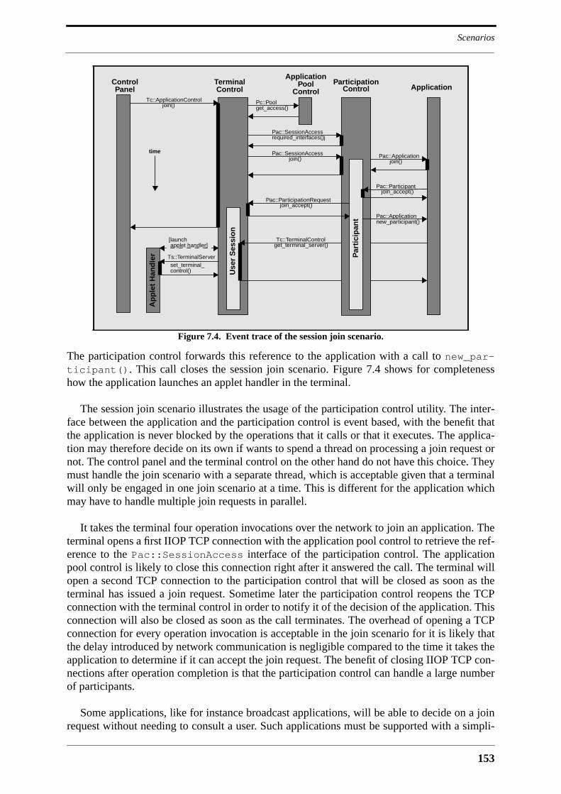
153
Scenarios
The participation control forwards this reference to the application with a call to new_par-ticipant(). This call closes the session join scenario. Figure 7.4 shows for completenesshow the application launches an applet handler in the terminal.
The session join scenario illustrates the usage of the participation control utility. The inter-face between the application and the participation control is event based, with the benefit thatthe application is never blocked by the operations that it calls or that it executes. The applica-tion may therefore decide on its own if wants to spend a thread on processing a join request ornot. The control panel and the terminal control on the other hand do not have this choice. Theymust handle the join scenario with a separate thread, which is acceptable given that a terminalwill only be engaged in one join scenario at a time. This is different for the application whichmay have to handle multiple join requests in parallel.
It takes the terminal four operation invocations over the network to join an application. Theterminal opens a first IIOP TCP connection with the application pool control to retrieve the ref-erence to the Pac::SessionAccess interface of the participation control. The applicationpool control is likely to close this connection right after it answered the call. The terminal willopen a second TCP connection to the participation control that will be closed as soon as theterminal has issued a join request. Sometime later the participation control reopens the TCPconnection with the terminal control in order to notify it of the decision of the application. Thisconnection will also be closed as soon as the call terminates. The overhead of opening a TCPconnection for every operation invocation is acceptable in the join scenario for it is likely thatthe delay introduced by network communication is negligible compared to the time it takes theapplication to determine if it can accept the join request. The benefit of closing IIOP TCP con-nections after operation completion is that the participation control can handle a large numberof participants.
Some applications, like for instance broadcast applications, will be able to decide on a joinrequest without needing to consult a user. Such applications must be supported with a simpli-
Figure 7.4. Event trace of the session join scenario.
TerminalControl
Use
r S
essi
on
Application
Tc::ApplicationControljoin()
ControlPanel
Pac::SessionAccessjoin()
time
Pac::ParticipationRequestjoin_accept()
Pac::Applicationjoin()
Tc::TerminalControlget_terminal_server()
Ap
ple
t H
and
ler
[launch
Ts::TerminalServerset_terminal_control()
applet handler]
ParticipationControl
Par
tici
pan
t
Pac::SessionAccessrequired_interfaces()j
Pac::Participantjoin_accept()
Pac::Applicationnew_participant()
ApplicationPool
ControlPc::Poolget_access()

APMT Platform Architecture
154
fied session join scenario in which a terminal may become a session participant with a singlejoin operation. This can be done with a slight modification of the join operations in the Pac::SessionAccess and Pac::Application interfaces.
7.10.3 Session Invitation Scenario
Figure 7.5 shows the event trace of the session invitation scenario. The scenario starts with theapplication calling invite_user() in the Pac::SessionControl interface of the partici-pation control. This causes the participation control to create a participant object, and to con-tact the user agent of the invited user. The participation control retrieves a reference to theUsag::UserAgent interface via a call to get_agent() in the interface Usag::Access. Itthen calls the operation invite() of the user agent. One of the arguments of this operation isthe stringified reference to the Pac::ParticipationControl interface of the participantobject. As soon as invite() returns, the participant object notifies the application of the suc-cessful placement of the invitation with a call to invitation_placed() in the interfacePac::Application. The user agent forwards the invitation to the terminal where the user islogged. It does so by calling the invite() operation in the Tc::Terminal interface. Boththe invite operation of the user agent and the invite operation of the terminal have an argumentcontaining the list of required terminal objects. The terminal can therefore immediately findout if it is compatible with the application or not. If it is not compatible, it may immediatelyreject the invitation with a call to invite_reject() in the Pac::ParticipationCon-trol interface. It will do this only if it is authorized by the user to react to invitations. It will inany case notify the control panel of the invitation by means of an invitation event. Once theuser has decided to accept the invitation, the control panel calls the invite_accept() oper-ation in the Tc::PanelTerminalControl interface. This causes the terminal control to cre-ate a user session object1, and to call invite_accept() in the Pac::Participation-
1. The user session object may be created earlier, for instance during the processing of the invite() operation.The user session object must be created at the latest before invite_accept() is called. This operation for-wards the reference to the Tc::TerminalControl interface to the participation control.
Figure 7.5. Event trace of the session invitation scenario.
TerminalControl
Use
r S
essi
on
Application
ControlPanel
time Pac::SessionControlinvite_user()
Ap
ple
t H
and
ler
[launch
Ts::TerminalServerset_terminal_control()
applet handler]
UserAgent
Use
r A
gen
t
PoolParticipation
Control
Par
tici
pan
t
Usag::Accessget_agent()
Usag::UserAgent invite()
Tc::Terminalinvite()
Pac::Applicationinvitation_placed()Tc::PanelTerminalControl
[Invitation Event]
Tc::PanelTerminalControlinvite_accept() Pac::ParticipationControl
invite_accept() Pac::Applicationnew_participant()
Tc::TerminalControlget_terminal_server()
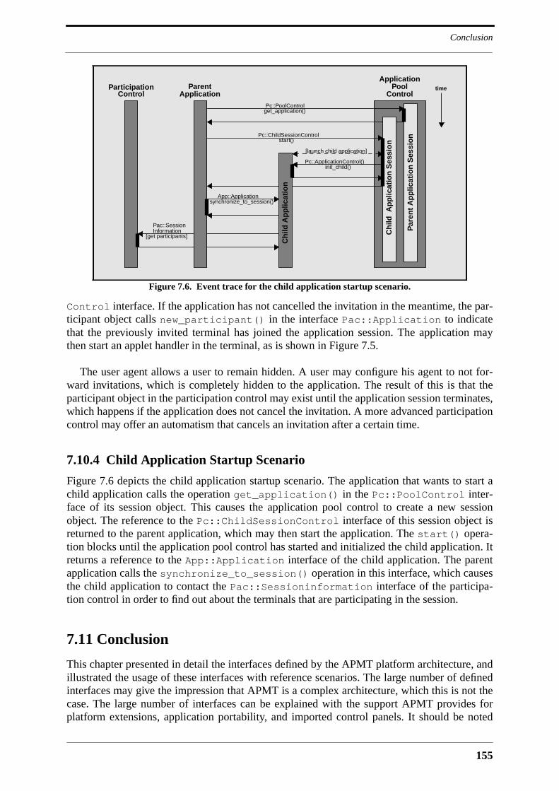
155
Conclusion
Control interface. If the application has not cancelled the invitation in the meantime, the par-ticipant object calls new_participant() in the interface Pac::Application to indicatethat the previously invited terminal has joined the application session. The application maythen start an applet handler in the terminal, as is shown in Figure 7.5.
The user agent allows a user to remain hidden. A user may configure his agent to not for-ward invitations, which is completely hidden to the application. The result of this is that theparticipant object in the participation control may exist until the application session terminates,which happens if the application does not cancel the invitation. A more advanced participationcontrol may offer an automatism that cancels an invitation after a certain time.
7.10.4 Child Application Startup Scenario
Figure 7.6 depicts the child application startup scenario. The application that wants to start achild application calls the operation get_application() in the Pc::PoolControl inter-face of its session object. This causes the application pool control to create a new sessionobject. The reference to the Pc::ChildSessionControl interface of this session object isreturned to the parent application, which may then start the application. The start() opera-tion blocks until the application pool control has started and initialized the child application. Itreturns a reference to the App::Application interface of the child application. The parentapplication calls the synchronize_to_session() operation in this interface, which causesthe child application to contact the Pac::Sessioninformation interface of the participa-tion control in order to find out about the terminals that are participating in the session.
7.11 Conclusion
This chapter presented in detail the interfaces defined by the APMT platform architecture, andillustrated the usage of these interfaces with reference scenarios. The large number of definedinterfaces may give the impression that APMT is a complex architecture, which this is not thecase. The large number of interfaces can be explained with the support APMT provides forplatform extensions, application portability, and imported control panels. It should be noted
Figure 7.6. Event trace for the child application startup scenario.
ApplicationPool timeParticipation
ControlParent
Application Control
Par
ent
Ap
plic
atio
n S
essi
onPc::ChildSessionControl
Pc::PoolControlget_application()
start()
[launch child application]
Pc::ApplicationControl()init_child()
App::Applicationsynchronize_to_session()
Pac::SessionInformation
[get participants]
Ch
ild A
pp
licat
ion
Ch
ild A
pp
licat
ion
Ses
sio
n
APMT Platform Architecture
156
that no developer will be confronted with all platform interfaces at once. Terminal serverdevelopers only deal with the Ts::TerminalServer and Tc::TerminalControl inter-faces. Application pool utility developers only deal with the Put::Utility interface. Appli-cation developers deal with more interfaces, but they do not need to care about details ofapplication startup and participation control. The only components that are likely to be difficultto implement are the core components terminal control and application pool control.

157
8 APMT Multimedia Middleware
8.1 Introduction
The previous chapter introduced the APMT platform architecture and its center pieces, the ter-minal control, the applet handler, the application pool control and the participation control.The APMT platform architecture is based on coarse-grained components, which are the termi-nal servers on the multimedia terminal and the application pool utilities in the application pool.Terminal servers allow to introduce new functionality into the terminal without that any modi-fication of the basic terminal architecture would be necessary. New terminal servers may causethe invention of new application pool utilities that add another layer of abstractions to them,and that help to orchestrate them in multipoint configurations. Terminal servers and applicationpool utilities provide for platform extensibility on a high, possibly conceptual level. This chap-ter describes how this high-level extensibility is supplemented with low-level extensibility inform of a component framework for multimedia data processing and communication. The pri-mary abstractions of this component framework are devices and device connectors. Devicesencapsulate multimedia processing functionality and can be plugged together by means ofdevice connectors, with the result being a device graph. Device graphs are created via thestream agent, which is the terminal server that encapsulates the low-level multimedia compo-nent framework. Stream agent, graph, devices and device connectors constitute a multimediamiddleware that assures terminal interoperability and application portability. However, formany applications programming on component-level is not acceptable. They require toolkitssimilar in spirit to the API of Beteus that allow to establish complex component networks witha few programming instructions. This chapter proposes as an example for such a toolkit anapplication pool utility for the management of connections in teleconferences. This illustrateshow an application pool utility may simplify application development by providing a singlepoint of control for the management of multiple terminals.
The multimedia middleware described in this chapter is not yet complete. It does not sup-port inter-stream synchronization, and it needs to be supplemented with a resource manage-ment architecture. As for synchronization, it is stated that the synchronization architecture ofIMA-MSS can be readily integrated into APMT. Resource management is mirrored in theinterfaces of the APMT device, but the interface between the device and a resource managerstill needs to be defined. Also missing are mappings of the APMT component framework ontospecific operating systems. Such mappings address issues like component installation and acti-vation, and are necessary in order to provide a standard programming environment for compo-nents on every operating system. Since all interfaces of a component are defined it can beexpected that the program code of a component can be ported from one operating system toanother with a limited amount of effort.
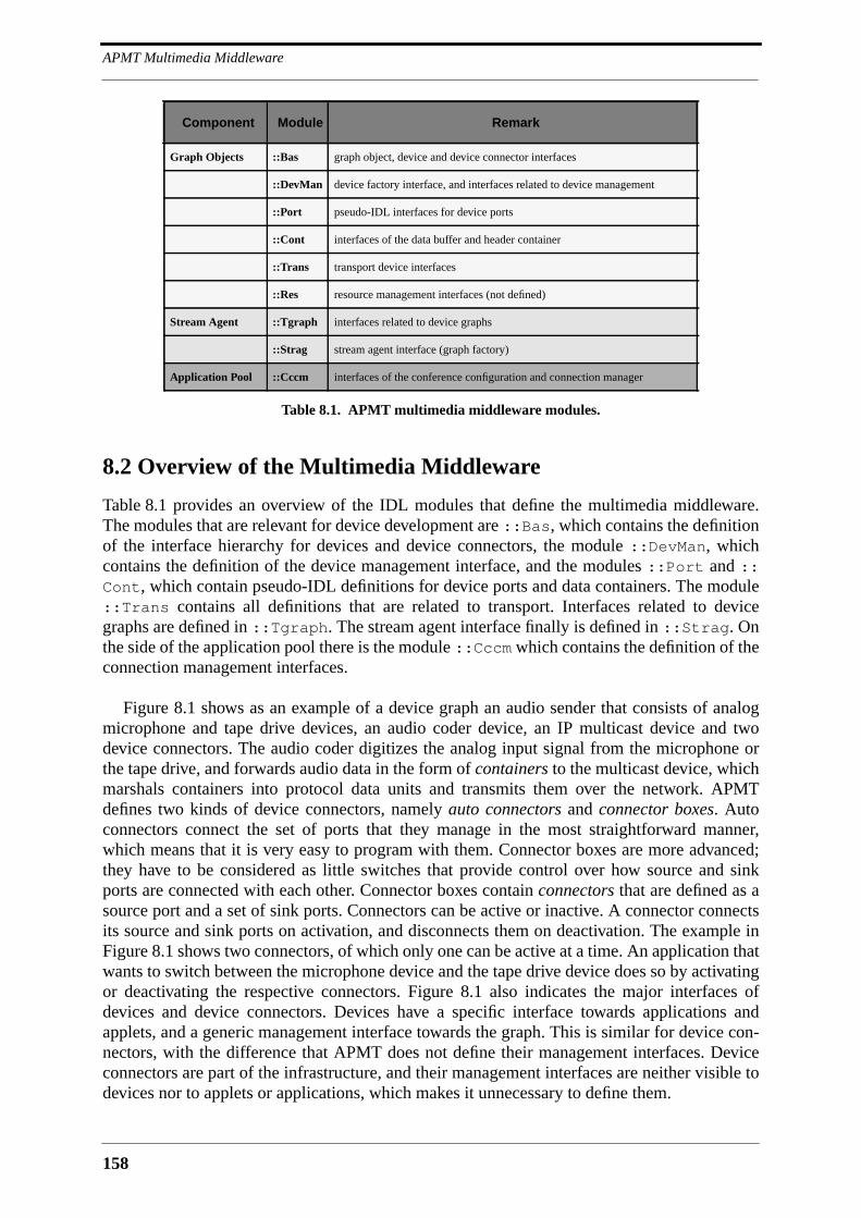
APMT Multimedia Middleware
158
8.2 Overview of the Multimedia Middleware
Table 8.1 provides an overview of the IDL modules that define the multimedia middleware.The modules that are relevant for device development are ::Bas, which contains the definitionof the interface hierarchy for devices and device connectors, the module ::DevMan, whichcontains the definition of the device management interface, and the modules ::Port and ::Cont, which contain pseudo-IDL definitions for device ports and data containers. The module::Trans contains all definitions that are related to transport. Interfaces related to devicegraphs are defined in ::Tgraph. The stream agent interface finally is defined in ::Strag. Onthe side of the application pool there is the module ::Cccm which contains the definition of theconnection management interfaces.
Figure 8.1 shows as an example of a device graph an audio sender that consists of analogmicrophone and tape drive devices, an audio coder device, an IP multicast device and twodevice connectors. The audio coder digitizes the analog input signal from the microphone orthe tape drive, and forwards audio data in the form of containers to the multicast device, whichmarshals containers into protocol data units and transmits them over the network. APMTdefines two kinds of device connectors, namely auto connectors and connector boxes. Autoconnectors connect the set of ports that they manage in the most straightforward manner,which means that it is very easy to program with them. Connector boxes are more advanced;they have to be considered as little switches that provide control over how source and sinkports are connected with each other. Connector boxes contain connectors that are defined as asource port and a set of sink ports. Connectors can be active or inactive. A connector connectsits source and sink ports on activation, and disconnects them on deactivation. The example inFigure 8.1 shows two connectors, of which only one can be active at a time. An application thatwants to switch between the microphone device and the tape drive device does so by activatingor deactivating the respective connectors. Figure 8.1 also indicates the major interfaces ofdevices and device connectors. Devices have a specific interface towards applications andapplets, and a generic management interface towards the graph. This is similar for device con-nectors, with the difference that APMT does not define their management interfaces. Deviceconnectors are part of the infrastructure, and their management interfaces are neither visible todevices nor to applets or applications, which makes it unnecessary to define them.
Component Module Remark
Graph Objects ::Bas graph object, device and device connector interfaces
::DevMan device factory interface, and interfaces related to device management
::Port pseudo-IDL interfaces for device ports
::Cont interfaces of the data buffer and header container
::Trans transport device interfaces
::Res resource management interfaces (not defined)
Stream Agent ::Tgraph interfaces related to device graphs
::Strag stream agent interface (graph factory)
Application Pool ::Cccm interfaces of the conference configuration and connection manager
Table 8.1. APMT multimedia middleware modules.
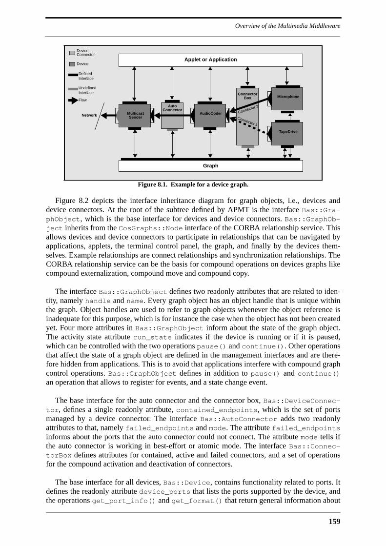
159
Overview of the Multimedia Middleware
Figure 8.2 depicts the interface inheritance diagram for graph objects, i.e., devices anddevice connectors. At the root of the subtree defined by APMT is the interface Bas::Gra-phObject, which is the base interface for devices and device connectors. Bas::GraphOb-ject inherits from the CosGraphs::Node interface of the CORBA relationship service. Thisallows devices and device connectors to participate in relationships that can be navigated byapplications, applets, the terminal control panel, the graph, and finally by the devices them-selves. Example relationships are connect relationships and synchronization relationships. TheCORBA relationship service can be the basis for compound operations on devices graphs likecompound externalization, compound move and compound copy.
The interface Bas::GraphObject defines two readonly attributes that are related to iden-tity, namely handle and name. Every graph object has an object handle that is unique withinthe graph. Object handles are used to refer to graph objects whenever the object reference isinadequate for this purpose, which is for instance the case when the object has not been createdyet. Four more attributes in Bas::GraphObject inform about the state of the graph object.The activity state attribute run_state indicates if the device is running or if it is paused,which can be controlled with the two operations pause() and continue(). Other operationsthat affect the state of a graph object are defined in the management interfaces and are there-fore hidden from applications. This is to avoid that applications interfere with compound graphcontrol operations. Bas::GraphObject defines in addition to pause() and continue()an operation that allows to register for events, and a state change event.
The base interface for the auto connector and the connector box, Bas::DeviceConnec-tor, defines a single readonly attribute, contained_endpoints, which is the set of portsmanaged by a device connector. The interface Bas::AutoConnector adds two readonlyattributes to that, namely failed_endpoints and mode. The attribute failed_endpointsinforms about the ports that the auto connector could not connect. The attribute mode tells ifthe auto connector is working in best-effort or atomic mode. The interface Bas::Connec-torBox defines attributes for contained, active and failed connectors, and a set of operationsfor the compound activation and deactivation of connectors.
The base interface for all devices, Bas::Device, contains functionality related to ports. Itdefines the readonly attribute device_ports that lists the ports supported by the device, andthe operations get_port_info() and get_format() that return general information about
Figure 8.1. Example for a device graph.
ConnectorBox Microphone
AudioCoder
TapeDrive
Multicast
AutoConnector
Network
Graph
Applet or Application
DefinedInterface
Flow
Sender
DeviceConnector
Device
Connector 1
Connector 2
UndefinedInterface
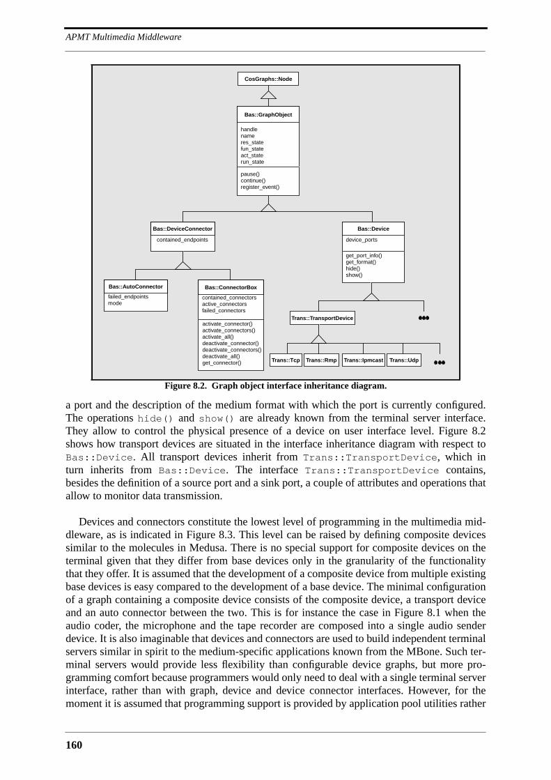
APMT Multimedia Middleware
160
a port and the description of the medium format with which the port is currently configured.The operations hide() and show() are already known from the terminal server interface.They allow to control the physical presence of a device on user interface level. Figure 8.2shows how transport devices are situated in the interface inheritance diagram with respect toBas::Device. All transport devices inherit from Trans::TransportDevice, which inturn inherits from Bas::Device. The interface Trans::TransportDevice contains,besides the definition of a source port and a sink port, a couple of attributes and operations thatallow to monitor data transmission.
Devices and connectors constitute the lowest level of programming in the multimedia mid-dleware, as is indicated in Figure 8.3. This level can be raised by defining composite devicessimilar to the molecules in Medusa. There is no special support for composite devices on theterminal given that they differ from base devices only in the granularity of the functionalitythat they offer. It is assumed that the development of a composite device from multiple existingbase devices is easy compared to the development of a base device. The minimal configurationof a graph containing a composite device consists of the composite device, a transport deviceand an auto connector between the two. This is for instance the case in Figure 8.1 when theaudio coder, the microphone and the tape recorder are composed into a single audio senderdevice. It is also imaginable that devices and connectors are used to build independent terminalservers similar in spirit to the medium-specific applications known from the MBone. Such ter-minal servers would provide less flexibility than configurable device graphs, but more pro-gramming comfort because programmers would only need to deal with a single terminal serverinterface, rather than with graph, device and device connector interfaces. However, for themoment it is assumed that programming support is provided by application pool utilities rather
Figure 8.2. Graph object interface inheritance diagram.
get_port_info()get_format()hide()show()
device_ports
Bas::Device
pause()continue()register_event()
handlenameres_statefun_stateact_staterun_state
Bas::GraphObject
CosGraphs::Node
contained_endpoints
Bas::DeviceConnector
failed_endpointsmode
Bas::AutoConnector
activate_connector()activate_connectors()activate_all()deactivate_connector()deactivate_connectors()deactivate_all()get_connector()
contained_connectorsactive_connectorsfailed_connectors
Bas::ConnectorBox
Trans::TransportDevice
Trans::UdpTrans::Tcp Trans::IpmcastTrans::Rmp
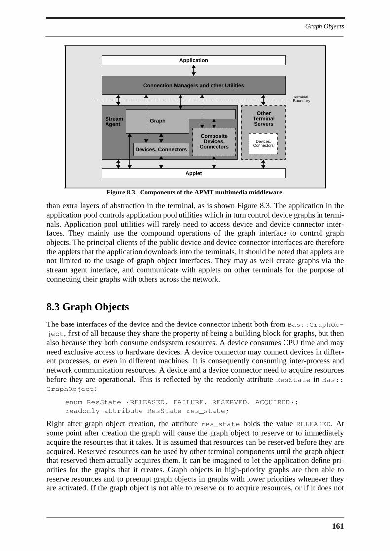
161
Graph Objects
than extra layers of abstraction in the terminal, as is shown Figure 8.3. The application in theapplication pool controls application pool utilities which in turn control device graphs in termi-nals. Application pool utilities will rarely need to access device and device connector inter-faces. They mainly use the compound operations of the graph interface to control graphobjects. The principal clients of the public device and device connector interfaces are thereforethe applets that the application downloads into the terminals. It should be noted that applets arenot limited to the usage of graph object interfaces. They may as well create graphs via thestream agent interface, and communicate with applets on other terminals for the purpose ofconnecting their graphs with others across the network.
8.3 Graph Objects
The base interfaces of the device and the device connector inherit both from Bas::GraphOb-ject, first of all because they share the property of being a building block for graphs, but thenalso because they both consume endsystem resources. A device consumes CPU time and mayneed exclusive access to hardware devices. A device connector may connect devices in differ-ent processes, or even in different machines. It is consequently consuming inter-process andnetwork communication resources. A device and a device connector need to acquire resourcesbefore they are operational. This is reflected by the readonly attribute ResState in Bas::GraphObject:
enum ResState {RELEASED, FAILURE, RESERVED, ACQUIRED};readonly attribute ResState res_state;
Right after graph object creation, the attribute res_state holds the value RELEASED. Atsome point after creation the graph will cause the graph object to reserve or to immediatelyacquire the resources that it takes. It is assumed that resources can be reserved before they areacquired. Reserved resources can be used by other terminal components until the graph objectthat reserved them actually acquires them. It can be imagined to let the application define pri-orities for the graphs that it creates. Graph objects in high-priority graphs are then able toreserve resources and to preempt graph objects in graphs with lower priorities whenever theyare activated. If the graph object is not able to reserve or to acquire resources, or if it does not
Figure 8.3. Components of the APMT multimedia middleware.
StreamAgent
Graph
Devices, Connectors
CompositeDevices,
Connectors
Connection Managers and other Utilities
Application
OtherTerminalServers
Applet
TerminalBoundary
Devices,Connectors
APMT Multimedia Middleware
162
get the resources that it needs during operation, it will indicate this with a res_state value ofFAILURE.
Three more attributes reflect the state of a graph object. The attribute FunState tells if thegraph object operates normally, or if it encountered partial or complete failure. The attributeActState tells if the graph object is idle, activated or deactivated. The attribute RunStatefinally tells if the graph object is hidden, paused or both hidden and paused:
enum FunState {OK, PARTIAL_FAILURE, COMPLETE_FAILURE};enum ActState {IDLE,ACTIVATED,DEACTIVATED};enum RunState {NORMAL,HIDDEN,PAUSED,HIDDEN_PAUSED};
readonly attribute FunState fun_state;readonly attribute ActState act_state;readonly attribute RunState res_state;
RunState and ActState are orthogonal to each other. The RunState is typically influencedby user interaction, whereas the ActState is controlled by the owner of the graph, like forinstance a connection manager in the application pool.
The interface Bas::GraphObject further contains two attributes for the identification ofthe graph object:
readonly attribute Typ::ObjectHandle handle;readonly attribute Ftyp::NameF name;
The object handle is defined in ::Typ as an unsigned long integer. The handle is an identifierthat the creator of a graph assigns to graph objects. It must be unique within a graph because itis used to define device ports and connectors. The name is the name that the application mayoptionally assign to the graph object. The object references and names of named graph objectsare registered with the naming service of the terminal, and their creation and removal causesthe terminal control to emit events, as was shown in the previous chapter.
The graph object interface defines three operations. The operations pause() and con-tinue() cause the graph object to pause or restart operation, respectively. A paused deviceconnector halts data transmission among the ports that it manages. However, the most impor-tant operation in the graph object interface is event registration:
CosEventChannelAdmin::ConsumerAdmin register_event (in Typ::EventKey key) raises (Ex::NoSuchEvent);
This operation allows an applet to retrieve a reference to the consumer administration interfaceof an event channel, where it can register for the reception of events via the push or pull mech-anism. A graph object maintains one event channel per event. For some events it may alreadybe solicited to create events when it executes the event registration operation. Other eventsrequire the applet interested in an event to explicitly call an operation to this purpose. Theparameters of this operation determine the characteristics of event creation. Since the graphobject maintains one event channel per event it is not possible for different event consumers toindividually control the creation characteristics of an event. This would require one event chan-nel per event per consumer, which puts an additional management burden on device program-mers and takes significantly more event communication resources. In order to save resources,device designers are supposed to keep the number of events created by a device as small aspossible. The way this is done is demonstrated by the graph object interface, which communi-
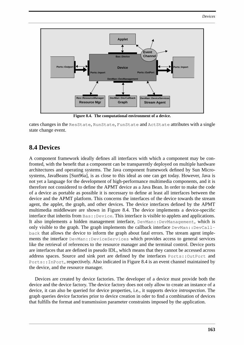
163
Devices
cates changes in the ResState, RunState, FunState and ActState attributes with a singlestate change event.
8.4 Devices
A component framework ideally defines all interfaces with which a component may be con-fronted, with the benefit that a component can be transparently deployed on multiple hardwarearchitectures and operating systems. The Java component framework defined by Sun Micro-systems, JavaBeans [Sun96a], is as close to this ideal as one can get today. However, Java isnot yet a language for the development of high-performance multimedia components, and it istherefore not considered to define the APMT device as a Java Bean. In order to make the codeof a device as portable as possible it is necessary to define at least all interfaces between thedevice and the APMT platform. This concerns the interfaces of the device towards the streamagent, the applet, the graph, and other devices. The device interfaces defined by the APMTmultimedia middleware are shown in Figure 8.4. The device implements a device-specificinterface that inherits from Bas::Device. This interface is visible to applets and applications.It also implements a hidden management interface, DevMan::DevManagement, which isonly visible to the graph. The graph implements the callback interface DevMan::DevCall-back that allows the device to inform the graph about fatal errors. The stream agent imple-ments the interface DevMan::DeviceServices which provides access to general serviceslike the retrieval of references to the resource manager and the terminal control. Device portsare interfaces that are defined in pseudo IDL, which means that they cannot be accessed acrossaddress spaces. Source and sink port are defined by the interfaces Ports::OutPort andPorts::InPort, respectively. Also indicated in Figure 8.4 is an event channel maintained bythe device, and the resource manager.
Devices are created by device factories. The developer of a device must provide both thedevice and the device factory. The device factory does not only allow to create an instance of adevice, it can also be queried for device properties, i.e., it supports device introspection. Thegraph queries device factories prior to device creation in oder to find a combination of devicesthat fulfills the format and transmission parameter constraints imposed by the application.
Figure 8.4. The computational environment of a device.
Stream Agent
Ports::Inport Ports::OutPort
Bas::Device
DevMan::DevManagement
DevMan::DeviceServices
Device
Applet
Ports::InportPorts::Outport
EventChannel
GraphDevMan::DevCallback
Resource MgrRes::ResourceManager

APMT Multimedia Middleware
164
It is transparent to an application if a device is implemented in software, or if it provides itsfunctionality via special hardware. It is also transparent to the application how media data arecommunicated from one device to another. If two connected devices are both implemented insoftware, data will be communicated via the device connector. If two connected devices areboth built on top of the same hardware device, data will be communicated under the hood. Thisis for instance the case with the audio coder, the microphone and the tape drive in Figure 8.1.These three devices have to conspire to fulfill their functionality. The microphone device willforward some of the operation invocations that it receives to the audio coder, or to a hiddenobject that serves as the central point of control for the audio hardware of the terminal. Thedevice interface supports conspiracy via the CORBA relationship service, which allows adevice to explore its neighborhood in the graph.
The concept of device conspiracy has the benefit that application developers are not con-fronted with different abstractions for hardware devices, software devices or analog devices,and different kinds of device connectors like digital or analog connectors. Application develop-ers see uniform device and device connector abstractions, and they do not need to care abouthow devices are implemented, and how data are forwarded inbetween them. It is clear that thisalready high level of abstraction does not come for free. Device development is more complexthan it would be if the abstractions were closer to the hard- and software environment in a ter-minal. However, it is assumed that the level of reuse of a device in applications is sufficientlyhigh to justify the additional burden imposed on device development.
The following subsections explore all aspects of a device. The first subsection discusses theformat and port abstractions. Following that, the interface Bas::Device is presented. Oncethis is done it is possible to discuss device introspection, creation and management. A finalsubsection presents some assumptions about how the device interface hierarchy will look like.
8.4.1 Formats and Ports
This subsection presents the format and port abstractions of APMT. It further explains howtyped multimedia data are moved from source ports to sink ports.
Formats
Media data are associated with a format just like the parameters of a CORBA operation areassociated with a type. Media data are communicated via the source and sink ports of devices.A port reflects the processing limitations of a device by constraining the format of the mediadata that can enter or leave the device through it. The formats that are associated with con-nected source and sink ports must be matched, which means that a source port and a sink portmust have a common understanding of the format of the media data that are exchangedbetween them. Three different ways of format matching can be imagined:
• dynamic matching: media data are accompanied by complete format informa-tion, which allows a sink port to dynamically adapt to incoming data.
• semi-dynamic matching: only the format type is matched prior to connectionestablishment. Media data are accompanied by complete format information,which allows a sink port to dynamically adapt to format parameters.
• static matching: format type and parameters are matched prior to connectionestablishment. Media data do not need to be accompanied by format informa-tion.

165
Devices
Dynamic matching is not a viable solution because it will lead to runtime errors. Staticmatching may become very complex, if not infeasible, when the formats of many chaineddevices have to be matched, as can be seen in IMA-MSS. The approach taken by APMT istherefore semi-dynamic matching. Only the format type of source and sink ports is matched.Format parameters are then chosen by source devices, with sink devices being forced todynamically adapt to the format parameters of the received media data. Semi-dynamic match-ing is feasible if it can be reasonably assumed that all devices that are dealing with a given for-mat are able to handle all variations of this format. In order to make semi-dynamic matchingwork it is therefore necessary to restrict the parameter spaces of formats, and maybe even todefine different APMT formats based on different parameter spaces for one physical format.Another possible pitfall of semi-dynamic matching is that in some cases the size of the formatinformation that accompanies media data is of the same order of magnitude than the size of themedia data. This is no problem within the endsystem, but may present itself as a waste of band-width on the network. This can be remedied by transmitting format information only everyonce in a while over the network.
APMT does not define media data formats from scratch. Instead of that it recycles existingformat standards for its purposes. An important source of format standards is the Audio-VideoTransport Working Group of the IETF which develops the Realtime Transport Protocol (RTP)[Schu96b] and RTP payload formats. RTP payload formats are designed for dynamic match-ing, which is necessary given that the loosely coupled MBone applications do not implementapplication-level protocols that would allow for static format matching. RTP payload formatscan therefore be readily used by APMT where sink devices must adapt to the format of themedia data emitted by source devices. Some video formats defined so far are H.261 [Turl96],MPEG [Hoff96] and Motion JPEG [Berc96]. A large number of video and audio formats fore-seen for standardization is listed in [Schu96a].
APMT uses hierarchically structured strings to identify a format type. Format identifiers arecommunicated via the type FormatKey which is defined in ::Bas:
typedef string FormatKey;
The module ::Bas further defines the basic format categories:
const string AnyFormatK = "any";const string AudioFormatK = "audio";const string VideoFormatK = "video";const string ImageFormatK = "image";...
Actual formats are defined as follows:
const string MJPEGFormatK = "video:mjpeg"; // Motion JPEGconst string MPEG1FormatK = "video:mpeg:mpeg1"; // MPEG1const string PCMAudioFormatK = "audio:pcm:8kHz"; // PCM audio
A format description consists of a format key and a structure with format parameters:
struct Format { FormatKey key; any parameters;};
APMT Multimedia Middleware
166
Every format key, except for those identifying format categories, is therefore accompanied bythe definition of a structure containing format parameters. The format structure definition oflogarithmically scaled 8kHz pulscode modulated (PCM) audio may therefore look as follows:
struct AudioPcm8kHzFormatD { unsigned short channels; // number of channels boolean mu_law; // 1=mu-law,0=A-law};
Format matching would be simplified if the formats a device supports were fixed. This wouldmake it possible to automatically check for format mismatches at application developmenttime. However, fixing the formats a device can handle is restrictive because it hinders the evo-lution of a device towards the support of new formats. An APMT device may therefore supportmultiple formats per port with the only restriction that they must belong to the same formatcategory, and that they do not need to be separately reflected in the main interface of thedevice. It is therefore not possible to introduce a format into a device that requires additionalfunctionality in the main device interface. Such a format can be accommodated by a newdevice that extends the main interface of the existing device.
Buffers, Attribute Headers and Header Containers
Within the terminal, media data are forwarded by means of buffer objects. The format informa-tion belonging to a data buffer is forwarded in a header container. Also forwarded in the headercontainer are so-called attribute headers, which contain device-specific information that islinked with the media data in the associated buffer. Attribute headers do not contain formatinformation, and are consequently irrelevant for the decoding of media data. They may forinstance describe where media data originated, what they contain, and how they were pro-cessed. An audio mixer for instance may add an attribute header to the mixed audio data whichtells what flows have been mixed together. This information may be displayed by a down-stream device in a graphical user interface. Attribute headers are a convenient alternative toCORBA operations and events for the transmission of control data within a terminal and inbe-tween terminals. Transport devices transmit attribute headers together with the format headerand the media data. The transmitted headers are recreated on the receiving side and put into aheader container.
All data buffer and header container related pseudo-IDL interfaces are defined in the mod-ule ::Cont. This module contains the definitions of the interfaces Buffer, BufferFactory,AttrHeader and HeaderContainer. The interface Cont::Buffer contains a size and afill-level attribute and the two operations remove() and copy(). The Cont::BufferFac-tory interface defines the single operation allocate() which allocates a buffer of a certainsize and returns a reference to it. Both the Cont::Buffer and the Cont::BufferFactoryinterface are meant to be extended with functionality specific to implementation languages.Buffers must be implemented in a way that device developers do not have to deal with memorymanagement. Device implementations create buffers via the buffer factory when they needthem. They forward them to other devices, which may remove them once they are done withthem. A device may not override the data in a buffer that it received. If it transforms the mediadata in the buffer from one coding into another it has to use a new buffer for the result. Thisallows to forward the reference to a media data buffer to all sink ports of a multicast connector,i.e., unnecessary copies of possibly voluminous media data are avoided. The buffer must main-tain a reference count that allows to find out when it is no longer referenced, in which case itcan be released. The buffer and the buffer factory must implement an intelligent memory man-

167
Devices
agement scheme that avoids the overhead that would be associated with the use of the nativememory allocation and deallocation mechanism of the implementation language.
The module ::Cont defines a general header interface, and derived from that interfaces forattribute headers and format headers. The interface Cont::Header contains the followingattributes and operations:
readonly attribute any header_data;void set_data(in any header_data) raises (InvalidHeader);void remove();
The format header interface Cont::FormatHeader adds an attribute via which the formatkey can be set and read:
attribute Bas::FormatKey key;
The header_data in Cont::Header is a format description in the case of a format header.The attribute header interface Cont::AttrHeader adds the following two attributes toCont::Header:
attribute AttrHeaderKey key;attribute boolean transmit;
The attribute header key is defined as a string. The attribute transmit tells the transportdevices if the attribute header shall be transmitted over the network or not. The device that addsthe attribute header to the media data uses this attribute to control the network bandwidth con-sumed by the attribute header. Attribute header keys and data are defined as illustrated by thefollowing fictive example:
const unsigned long SpeakerHeaderK = "speaker";struct SpeakerHeaderD { string name; string e-mail;};
This header may for instance accompany video data and inform about a depicted person.Attribute and format header encoding is discussed in the subsection describing transportdevices.
The header container is defined with the interface Cont::HeaderContainer. A headercontainer contains one format header and an arbitrary number of attribute headers, with therestriction that an attribute header of a given type may only appear once in the header con-tainer. Format headers and attribute headers are set as follows:
void set_format_header(in FormatHeader format)raises (InvalidHeader);
void set_attr_header(in AttrHeader header)raises (InvalidHeader);
The attribute header in set_attr_header() may overwrite an already contained header ofthe same type. Headers are retrieved as follows:
FormatHeader get_format_header()raises (NoSuchHeader);
AttrHeader get_attr_headerk(in HeaderKey key)raises (NoSuchHeader);
AttrHeader get_attr_headern(in unsigned short index)

APMT Multimedia Middleware
168
raises (NoSuchHeader);
The operation get_attr_headern() allows to search the header container for attributeheaders. The interface Cont::HeaderContainer further defines a copy() and a remove()operation as well as attributes for the sequence number of the container, the source identifier,and the creation timestamp:
readonly attribute Typ::TimeStamp creation_time;attribute unsigned long contnum;attribute unsigned long sourceid;
The source identifier is important for mixers that receive multiple flows via a single sink port.It is set by receiving transport devices.
Header containers and data buffers are treated differently when they are moved from onedevice to another, which is the reason why they are defined separately. Unlike data buffers,header containers are copied by multicast connectors, for it is assumed that downstreamdevices will want to modify the content of the header container. Since the size of header con-tainers is small it is not necessary to devise a special memory management scheme for them.
Ports
The ports of a device are defined as integer constants in the main device interface. As an exam-ple, the following two ports may be defined by a device that decodes a Motion JPEG videostream:
const short JpegInPort = 1;const short VideoOutPort = 2;
Source ports are marked with the ending OutPort, and sink ports with the ending InPort.Port identifiers are communicated via the type PortKey:
typedef short PortKey;
Applications use the following type to set the format of a port:
struct PortSetting { PortKey port; FormatKey format;};
The format of a port has a direct influence on the characteristics of the flow that it emits. Theflow characteristics defined in APMT are reflected by the following type:
struct FlowParameter { unsigned long data_rate; // in bytes per second};
The definition of this type is preliminary and is meant to be replaced by a more refined defini-tion once a resource management framework has been defined for the multimedia middleware.The structure member data_rate expresses the data rate of a flow leaving or entering adevice. Applications use the flow parameter structure to set the QoS of a flow that leaves thenetwork port of a transport device. Based on the network flow parameters the graph calculatesthe flow parameters for every connected source port within the graph, as will be shown later inthe text. The graph will then set both the format and the flow parameters of a source port. Thefollowing type is used for this:
struct PortFlowSetting {

169
Devices
PortKey port; FormatKey format; FlowParameter flowparm;};
Figure 8.5 shows excerpts from the port definitions. The module ::Ports contains the defini-tion of a Ports::Port base interface from which the interfaces Ports::InPort andPorts::OutPort inherit. The interface Ports::Port contains a set of transmission statis-tics and port status attributes that are thought to be used by the device itself and by graphs thatmonitor the state of their devices. The transmission statistics attributes in the Ports::Portinterface can be implemented by a library. All other attributes and operations must be imple-mented by the device developer. Care must therefore be taken to define only attributes andoperations that are really needed.
The Ports::Port interface contains attributes informing about the type of the port, itskey, and its state:
readonly attribute Bas::PortType type; // source or sink portreadonly attribute Bas::PortKey key;readonly attribute Bas::PortState connect_state;readonly attribute Typ::State activity_state;
The attribute connect_state tells if the port is currently connected or not. The attributeactivity_state tells if data are transmitted or not. A connected source port does not neces-sarily transmit data all the time. Ports::Port further defines attributes informing about theamount of time a port exists and is connected, the number of bytes that have passed through it,and the current data rate. Two operations are defined in Ports::Port, the operation dis-connect() that disconnects the port, and the operation remove() that deletes it.
The interface Ports::InPort defines the operations connect(), push() and stop().The connect() operation sets the format of the port and tells the sink port to which sourceport it is connected:
void connect(in Outport out_port, in Bas::FormatKey format) raises (InvalidPortSetting);
Figure 8.5. Port interfaces.
connect()adjust_flow()
Ports::OutPort
disconnect()remove()
typekeyconnect_stateactivity_stateup_timebytes_since_up
Ports::Port
connect()stop()push()
Ports::InPort
APMT Multimedia Middleware
170
The connect() operation raises the exception InvalidPortSetting if it does not supportthe requested format. The sink port uses the reference out_port when it wants to throttle thesource port with a call to the adjust_flow() operation.
The push() operation is called by a source port to forward media data to a sink port. TheAPMT prototype that is described in the following chapter supports a pull mechanism in addi-tion to the push mechanism. It turned out that this adds an extra level of complexity to devicedevelopment that can be avoided with an intelligent garbage collection scheme. It is thereforeassumed that a device pushes a data unit to the next device in the chain as soon as it is finishedwith it. Data units will then be buffered by the devices that finally consume them, which isdesirable given that these devices are also responsible for intra-stream synchronization. Thepush() operation is defined as follows:
void push(in Cont::HeaderContainer cont, in Cont::Buffer buff);
The parameter buff contains the media data buffer. The parameter cont is the header con-tainer that is associated with the data buffer.
A source device may temporarily halt the transmission of data, with an example being thesilence detector device that cuts silence periods from an audio stream. A source port that haltstransmission may indicate this with a call to the stop() operation. The respective sink devicemay forward this call to other devices for which it acts as source device. Data transmission isconsidered to be resumed next time the source port calls push().
The interface Ports::OutPort defines the operations connect() and adjust_flow(). The operation connect() sets the format and the flow parameters of the sourceport, and hands a reference to a sink port to the source port:
void connect(in Inport in_port, in Bas::FormatKey format, in Bas::FlowParameter parms) raises (InvalidPortSetting,BadParameters);
The parameter in_port may denote the sink port of the device to which the source port isconnected, or a proxy sink port inserted by the device connector, which is for instance the casewhen the source port is connected to multiple sink ports via a multicast connector.
The operation adjust_flow() allows the graph and downstream devices to throttle theflow that a source port generates:
void adjust_flow(in Bas::FlowParameter parms)raises (BadParameters,NoInfluence);
A device that receives a call to this operation on one of its source ports may propagate it via itssink ports to upstream devices if it has no or only limited influence on the parameters of theemitted flow. The operation raises the exception NoInfluence if the device has no influenceon flow parameters, and cannot forward the call to other devices. Network receiver devices forinstance have no influence on the characteristics of the flows that they receive. The same is truefor devices that generate constant bitrate flows.
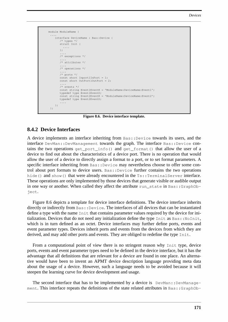
171
Devices
8.4.2 Device Interfaces
A device implements an interface inheriting from Bas::Device towards its users, and theinterface DevMan::DevManagement towards the graph. The interface Bas::Device con-tains the two operations get_port_info() and get_format() that allow the user of adevice to find out about the characteristics of a device port. There is no operation that wouldallow the user of a device to directly assign a format to a port, or to set format parameters. Aspecific interface inheriting from Bas::Device may nevertheless choose to offer some con-trol about port formats to device users. Bas::Device further contains the two operationshide() and show() that were already encountered in the Ts::TerminalServer interface.These operations are only implemented by those devices that generate visible or audible outputin one way or another. When called they affect the attribute run_state in Bas::GraphOb-ject.
Figure 8.6 depicts a template for device interface definitions. The device interface inheritsdirectly or indirectly from Bas::Device. The interfaces of all devices that can be instantiateddefine a type with the name Init that contains parameter values required by the device for ini-tialization. Devices that do not need any initialization define the type Init as Bas::NoInit,which is in turn defined as an octet. Device interfaces may further define ports, events andevent parameter types. Devices inherit ports and events from the devices from which they arederived, and may add other ports and events. They are obliged to redefine the type Init.
From a computational point of view there is no stringent reason why Init type, deviceports, events and event parameter types need to be defined in the device interface, but it has theadvantage that all definitions that are relevant for a device are found in one place. An alterna-tive would have been to invent an APMT device description language providing meta dataabout the usage of a device. However, such a language needs to be avoided because it willsteepen the learning curve for device development and usage.
The second interface that has to be implemented by a device is DevMan::DevManage-ment. This interface repeats the definitions of the state related attributes in Bas::GraphOb-
module ModuleName { .... interface DeviceName : Bas::Device { /* types */ struct Init { .... }; .... /* exceptions */ .... /* attributes */ .... /* operations */ .... /* ports */ const short Inport1InPort = 1; const short OutPort1OutPort = 2; .... /* events */ const string Event1EventK = "ModuleName:DeviceName:Event1"; typedef type Event1EventD; const string Event2EventK = "ModuleName:DeviceName:Event2"; typedef type Event2EventD; .... }; };
Figure 8.6. Device interface template.

APMT Multimedia Middleware
172
ject. It further defines a set of operations for lifecycle and device management. Right aftercreation a device is initialized with a call to the init() operation:
void init(in DevCallback cb,in any initdata,in Ftyp::NameF name,in DeviceServices devser,in Typ::ObjectHandle handle)
raises (InitProblem);
The parameter list of this operation contains references to the device callback interface Dev-Man::DevCallBack that is implemented by the graph, and the device service interface Dev-Man::DeviceServices that may for instance be implemented by the stream agent. Theparameter handle is the object handle that is assigned to the device, and the parameter nameis the name that is possibly assigned to it. The parameter initdata finally carries the initial-ization data for the device. The CORBA type code that comes along with the initialization datain initdata must identify an Init type defined by the device itself, or by one of the devicesfrom which it inherits.
Following the instantiation of all devices, the graph will instantiate device connectors. Adevice connector has a reference to the DevMan::DevManagement interface, and calls thefollowing operation to cause the device to create a port:
Ports::Port create_port(in Bas::PortKey key) raises (NoSuchPort,TooManyInstantiations);
The exception NoSuchPort is returned if the device does not implement a port with the iden-tifier key. Some devices allow to instantiate a port more than once. Devices that do not supportthis, or that already have a maximum number of ports of the given type, will raise the exceptionTooManyInstantiations when asked to instantiate another port of this type. After a deviceconnector has created all the ports that it manages, it connects them.
Once the complete graph is created, and all devices are initialized, the graph may call thefollowing operation that causes a device to prepare operation:
void prepare() raises (MissingInterface, Ex::GeneralProblem);
Devices that rely on other objects for proper operation, like for instance conspiring devices, areprompted by this call to search for them. A device may access the CORBA relationship servicefor this purpose, the device services interface, the naming service of the terminal, or an appli-cation-level interface for which it got the reference via the initialization data. The exceptionMissingInterfaces is raised if the device cannot locate one or more of the objects that itrequires. The graph repeats the operation prepare() whenever devices are added or removedfrom it.
Two operations in DevMan::DevManagement control resource reservation. The operationreserve() causes the device to reserve resources, the operation free() to free them. Thedevice starts operation and acquires resources as result of a call to activate(), and it stopsoperation and releases resources when deactivate() is called. The deactivate() opera-tion does not cancel any previous resource reservations, which means that the device will getback any reserved resources when it is reactivated. On deactivation, the device removes all ofthe buffers that it holds, but it does not reinitialize its state. The device will therefore manifestitself after reactivation exactly like before it was deactivated. DevMan::DevManagement fur-
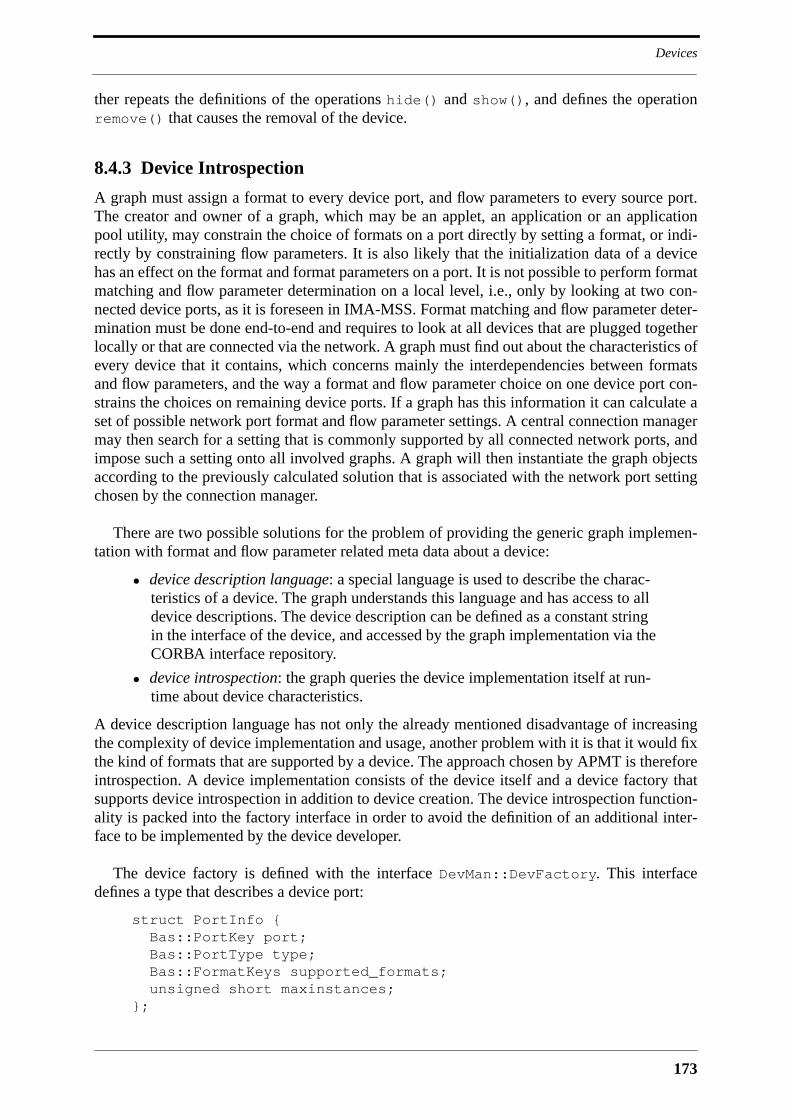
173
Devices
ther repeats the definitions of the operations hide() and show(), and defines the operationremove() that causes the removal of the device.
8.4.3 Device Introspection
A graph must assign a format to every device port, and flow parameters to every source port.The creator and owner of a graph, which may be an applet, an application or an applicationpool utility, may constrain the choice of formats on a port directly by setting a format, or indi-rectly by constraining flow parameters. It is also likely that the initialization data of a devicehas an effect on the format and format parameters on a port. It is not possible to perform formatmatching and flow parameter determination on a local level, i.e., only by looking at two con-nected device ports, as it is foreseen in IMA-MSS. Format matching and flow parameter deter-mination must be done end-to-end and requires to look at all devices that are plugged togetherlocally or that are connected via the network. A graph must find out about the characteristics ofevery device that it contains, which concerns mainly the interdependencies between formatsand flow parameters, and the way a format and flow parameter choice on one device port con-strains the choices on remaining device ports. If a graph has this information it can calculate aset of possible network port format and flow parameter settings. A central connection managermay then search for a setting that is commonly supported by all connected network ports, andimpose such a setting onto all involved graphs. A graph will then instantiate the graph objectsaccording to the previously calculated solution that is associated with the network port settingchosen by the connection manager.
There are two possible solutions for the problem of providing the generic graph implemen-tation with format and flow parameter related meta data about a device:
• device description language: a special language is used to describe the charac-teristics of a device. The graph understands this language and has access to alldevice descriptions. The device description can be defined as a constant stringin the interface of the device, and accessed by the graph implementation via theCORBA interface repository.
• device introspection: the graph queries the device implementation itself at run-time about device characteristics.
A device description language has not only the already mentioned disadvantage of increasingthe complexity of device implementation and usage, another problem with it is that it would fixthe kind of formats that are supported by a device. The approach chosen by APMT is thereforeintrospection. A device implementation consists of the device itself and a device factory thatsupports device introspection in addition to device creation. The device introspection function-ality is packed into the factory interface in order to avoid the definition of an additional inter-face to be implemented by the device developer.
The device factory is defined with the interface DevMan::DevFactory. This interfacedefines a type that describes a device port:
struct PortInfo { Bas::PortKey port;
Bas::PortType type; Bas::FormatKeys supported_formats;unsigned short maxinstances;
};

APMT Multimedia Middleware
174
The member type tells if the port is a source or a sink port. The member maxinstances tellshow many times this port can be instantiated. This will most of the times be a single instance.An attribute allows the graph to retrieve a list of port descriptions:
readonly attribute PortInfos ports;
Three query operations allow the graph implementation to test device characteristics. The firstquery operation allows a graph to test if a device supports the initialization data that will begiven to it after instantiation:
void query_init_parameters(in any initparms)raises (InvalidParameters);
The second operation allows to find out about the formats a port supports when all other portformats are set:
Bas::FormatKeys query_format(in Bas::PortKey port, in Bas::PortSettings settings, in any initparms)
raises (InvalidSettings,InvalidParameters,NoSuchPort);
Since the initialization data may constrain format choices they are also presented to the devicefactory. The operation query_format() allows the graph implementation to calculate possi-ble format settings independently from any flow parameter constraints. Given that the applica-tion may itself constrain format settings, and that APMT devices are unlikely to support manyformats on a port, it will often happen that there is only a single possible combination of formatsettings for all devices in the graph. Once the graph has found the set of theoretically possibleformat settings it will try to find a setting that fulfills the flow parameter constraints imposedby the creator of the graph. The following operation is used for this:
Bas::PortFlowSettings query_flow_parameters(in Bas::PortSettings sink_settings,
in Bas::PortFlowSettings source_settings,in any initparms)
raises (InvalidSettings,InvalidParameters,NoSuchPort);
The caller of the operation must provide flow parameter and format settings for all sourceports, and format settings of all sink ports of the device. It then receives the flow parameter set-tings that the device expects on its sink ports. The owner of a graph imposes flow parameterconstraints on the network ports of sending transport devices. The graph will therefore start toquery the device connected to the transport device, and work itself towards source devices. Itwill thereby use the flow parameters returned for sink ports as flow parameter constraints forconnected source ports. Many devices will not be able to exactly predict the parameters of theflow that they are producing, which means that the result of the flow parameter matching pro-cedure can only be approximative. There is therefore a need for a runtime mechanism for flowparameter enforcement. This mechanism uses the adjust_flow() operation of the Ports::OutPort interface. Sending transport devices call this operation in the source port that is con-nected to their input port when they realize that their flow parameter constraints are violated.The operation invocation propagates upstream until a device is hit that may influence the flowparameters, like for instance a video coder that can reduce the frame rate.

175
Devices
Once the graph has found a viable combination of devices, formats and flow parameter set-tings it will instantiate devices with calls to the following operation:
void create(out Typ::StringRef devref, out DevManagement devman);
The operation returns a reference to the management interface of the device, and a stringifiedreference to the main device interface that the graph will forward to the graph owner.
8.4.4 Device Granularity
APMT devices are not supposed to support large numbers of formats on a port, and the formatsof a port should also belong to a single format family. As an example, a video coder output portshould not support MPEG and Motion JPEG at the same time. The approach of APMT is todefine an MPEG and a Motion JPEG device that may be connected to the output port of avideo coder device. Formats like MPEG and Motion JPEG offer many degrees of freedom onthe coding side, which need to be reflected by an interface. APMT avoids format interfaces inorder to keep the usage of a device simple. Format control must therefore be provided by themain device interface, which becomes awkward if it has to provide control over more than onecomplex format per device port. The result of this is that APMT defines in some cases deviceswhere IMA-MSS defines formats. The approach taken by APMT has multiple benefits. Appli-cations only need to deal with device interfaces, and not with format interfaces in addition. Theoperations of a device interface will often have a side effect on port formats, and vice versa, thedirect modification of a format via a format interface will have a side effect on the operationmode of a device. This means that a device developer would have to spend extra care on pre-venting side effects, and the application developer extra time to find out how to use format anddevice interfaces without producing side effects. All this is avoided if a device offers a singleconsistent interface to applications.
The lack of format interfaces causes APMT to define fine-grained devices that are dedicatedto format manipulations. The granularity of APMT devices is therefore lower than the one ofIMA-MSS virtual devices or TINA objects, and corresponds approximately to the one ofMedusa modules. This does not prevent the definition of coarse-grained APMT devices thatare possibly composed from fine-grained devices. APMT graphs may consequently contain aconsiderable number of fine-grained devices, or just a coarse-grained device connected to oneor more transport devices. The following chapter, which presents the APMT prototype, willprovide examples for APMT device definitions.
8.4.5 Device Interface Hierarchy
There are no limitations on the design of the device interface hierarchy. It is possible to addabstract devices inbetween the base interface Bas::Device and real devices, but it is alsopossible to derive real devices directly from Bas::Device. Abstract devices have the advan-tage that they leave some degrees of freedom for the format setting procedure when used ingraph creation requests. An application that is not interested in the format of the video flowsthat are transmitted inbetween terminals may use for instance generic VideoCompressionand VideoDecompression devices in its sender and receiver graph creation requests, withwhich it indicates that it wants video to be compressed. The connection manager may thenhave the choice among Motion JPEG, MPEG and H.261 devices that inherit from VideoCom-pression or VideoDecompression.

APMT Multimedia Middleware
176
8.5 Transport Devices
An APMT transport device is a special kind of device that is able to transmit and receive mediadata buffers and header containers. Transport devices are considered to be part of the terminalinfrastructure, which means that it is not possible to transparently add a transport device to aterminal, as can be done with all other devices. The reason for this is that transport devicesneed to be known to the graph implementation. Support for transport device developmentcould nevertheless be added to the APMT middleware if this should turn out to be necessary,and requires the definition of transport-specific extensions to the basic device managementinterface DevMan::DevManagement.
Transport devices have one input port and one output port to other devices within the samegraph, and one network port for the transmission and reception of containers. There is noexplicit definition for a network port identifier in the transport device interface. Network portsare identified by a port number and a network interface address, rather than by an integer as isthe case with normal device ports. The formats set for the input and output port of the transportdevice must be identical. APMT transport devices are tailored to IP, and it is not possible toadd a transport device to the multimedia middleware that is not based on IP. APMT transportdevices are supposed to implement Internet standards for the transport of multimedia data,with examples being RTP [Schu96b] for the transport of streams and RSVP [Brad96] forresource reservation in the network.
All transport related definitions are contained in the module ::Trans. This module definestypes for an IP address, a transport protocol port, and a transport service access point consist-ing of an address and a port:
typedef string IpAddress;typedef unsigned short IpPort;struct IpTsap { IpAddress addr; IpPort port;};
The string format of an IP address is dotted decimal. The module ::Trans further containsthe definition of a flow identifier:
struct FlowIdentifier { IpAddress srcterm; FlowHandle handle;};
The member handle is an unsigned long integer that the application assigns to a flow. Themember srcterm is the IP address of the terminal control of the terminal that emits the flow.Flow identifiers are transported within special attribute headers across the network.
The transport device interface hierarchy defined in ::Trans is depicted in Figure 8.7. Thegeneric Trans::TransportDevice interface inherits from Bas::Device. It contains thedefinitions for the two transport device ports:
const short TpInPort = 1;const short TpOutPort = 2;
It further contains the attribute mytsap that informs about the local interface and port to whichthe transport device is bound, the attribute device_mode that tells if the device is operating as
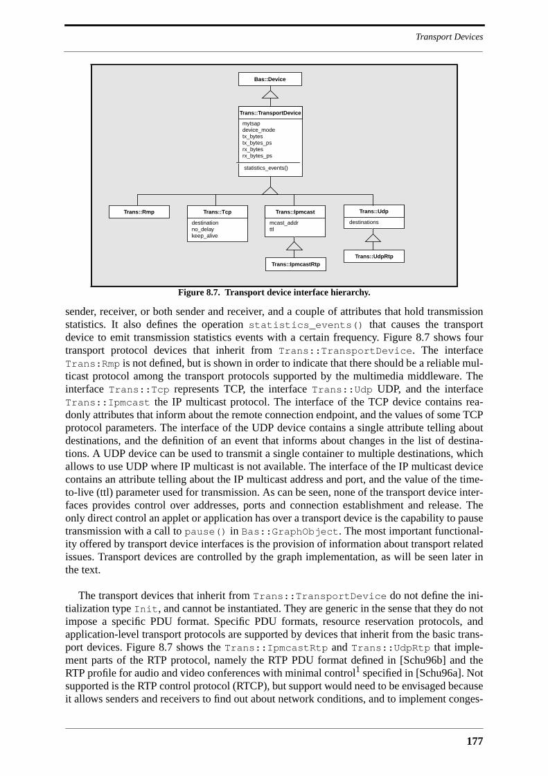
177
Transport Devices
sender, receiver, or both sender and receiver, and a couple of attributes that hold transmissionstatistics. It also defines the operation statistics_events() that causes the transportdevice to emit transmission statistics events with a certain frequency. Figure 8.7 shows fourtransport protocol devices that inherit from Trans::TransportDevice. The interfaceTrans:Rmp is not defined, but is shown in order to indicate that there should be a reliable mul-ticast protocol among the transport protocols supported by the multimedia middleware. Theinterface Trans::Tcp represents TCP, the interface Trans::Udp UDP, and the interfaceTrans::Ipmcast the IP multicast protocol. The interface of the TCP device contains rea-donly attributes that inform about the remote connection endpoint, and the values of some TCPprotocol parameters. The interface of the UDP device contains a single attribute telling aboutdestinations, and the definition of an event that informs about changes in the list of destina-tions. A UDP device can be used to transmit a single container to multiple destinations, whichallows to use UDP where IP multicast is not available. The interface of the IP multicast devicecontains an attribute telling about the IP multicast address and port, and the value of the time-to-live (ttl) parameter used for transmission. As can be seen, none of the transport device inter-faces provides control over addresses, ports and connection establishment and release. Theonly direct control an applet or application has over a transport device is the capability to pausetransmission with a call to pause() in Bas::GraphObject. The most important functional-ity offered by transport device interfaces is the provision of information about transport relatedissues. Transport devices are controlled by the graph implementation, as will be seen later inthe text.
The transport devices that inherit from Trans::TransportDevice do not define the ini-tialization type Init, and cannot be instantiated. They are generic in the sense that they do notimpose a specific PDU format. Specific PDU formats, resource reservation protocols, andapplication-level transport protocols are supported by devices that inherit from the basic trans-port devices. Figure 8.7 shows the Trans::IpmcastRtp and Trans::UdpRtp that imple-ment parts of the RTP protocol, namely the RTP PDU format defined in [Schu96b] and theRTP profile for audio and video conferences with minimal control1 specified in [Schu96a]. Notsupported is the RTP control protocol (RTCP), but support would need to be envisaged becauseit allows senders and receivers to find out about network conditions, and to implement conges-
Figure 8.7. Transport device interface hierarchy.
destinations
Trans::Udp
statistics_events()
mytsapdevice_modetx_bytestx_bytes_psrx_bytesrx_bytes_ps
Trans::TransportDevice
Bas::Device
Trans::UdpRtp
mcast_addrttl
Trans::Ipmcast
Trans::IpmcastRtp
destinationno_delaykeep_alive
Trans::TcpTrans::Rmp
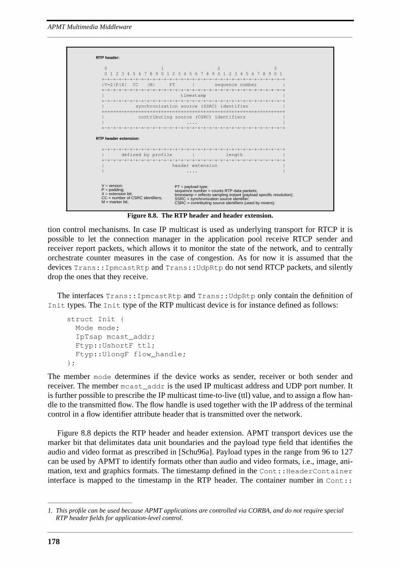
APMT Multimedia Middleware
178
tion control mechanisms. In case IP multicast is used as underlying transport for RTCP it ispossible to let the connection manager in the application pool receive RTCP sender andreceiver report packets, which allows it to monitor the state of the network, and to centrallyorchestrate counter measures in the case of congestion. As for now it is assumed that thedevices Trans::IpmcastRtp and Trans::UdpRtp do not send RTCP packets, and silentlydrop the ones that they receive.
The interfaces Trans::IpmcastRtp and Trans::UdpRtp only contain the definition ofInit types. The Init type of the RTP multicast device is for instance defined as follows:
struct Init { Mode mode;
IpTsap mcast_addr; Ftyp::UshortF ttl; Ftyp::UlongF flow_handle;};
The member mode determines if the device works as sender, receiver or both sender andreceiver. The member mcast_addr is the used IP multicast address and UDP port number. Itis further possible to prescribe the IP multicast time-to-live (ttl) value, and to assign a flow han-dle to the transmitted flow. The flow handle is used together with the IP address of the terminalcontrol in a flow identifier attribute header that is transmitted over the network.
Figure 8.8 depicts the RTP header and header extension. APMT transport devices use themarker bit that delimitates data unit boundaries and the payload type field that identifies theaudio and video format as prescribed in [Schu96a]. Payload types in the range from 96 to 127can be used by APMT to identify formats other than audio and video formats, i.e., image, ani-mation, text and graphics formats. The timestamp defined in the Cont::HeaderContainerinterface is mapped to the timestamp in the RTP header. The container number in Cont::
1. This profile can be used because APMT applications are controlled via CORBA, and do not require specialRTP header fields for application-level control.
Figure 8.8. The RTP header and header extension.
RTP header:
0 1 2 3 0 1 2 3 4 5 6 7 8 9 0 1 2 3 4 5 6 7 8 9 0 1 2 3 4 5 6 7 8 9 0 1 +-+-+-+-+-+-+-+-+-+-+-+-+-+-+-+-+-+-+-+-+-+-+-+-+-+-+-+-+-+-+-+-+ |V=2|P|X| CC |M| PT | sequence number | +-+-+-+-+-+-+-+-+-+-+-+-+-+-+-+-+-+-+-+-+-+-+-+-+-+-+-+-+-+-+-+-+ | timestamp | +-+-+-+-+-+-+-+-+-+-+-+-+-+-+-+-+-+-+-+-+-+-+-+-+-+-+-+-+-+-+-+-+ | synchronization source (SSRC) identifier | +=+=+=+=+=+=+=+=+=+=+=+=+=+=+=+=+=+=+=+=+=+=+=+=+=+=+=+=+=+=+=+=+ | contributing source (CSRC) identifiers | | .... | +-+-+-+-+-+-+-+-+-+-+-+-+-+-+-+-+-+-+-+-+-+-+-+-+-+-+-+-+-+-+-+-+
RTP header extension:
+-+-+-+-+-+-+-+-+-+-+-+-+-+-+-+-+-+-+-+-+-+-+-+-+-+-+-+-+-+-+-+-+ | defined by profile | length | +-+-+-+-+-+-+-+-+-+-+-+-+-+-+-+-+-+-+-+-+-+-+-+-+-+-+-+-+-+-+-+-+ | header extension | | .... |
V = version;P = padding;X = extension bit;CC = number of CSRC identifiers;M = marker bit;
PT = payload type;sequence number = counts RTP data packets;timestamp = reflects sampling instant (payload specific resolution);SSRC = synchronization source identifier;CSRC = contributing source identifiers (used by mixers);

179
Device Connectors
HeaderContainer is mapped to the RTP sequence number. The synchronization sourceidentifier (SSRC) is randomly generated as prescribed by RTP, and mapped to the source iden-tifier in Cont::HeaderContainer. The contributing sources field (CSRC) is not used,because its function will be provided by APMT attribute headers. Attribute headers are com-municated via the RTP header extension, which can be ignored by RTP receivers outside theAPMT platform. APMT format keys and headers are mapped onto RTP payload types and for-mat headers. An APMT audio or video stream can therefore be received and decoded by non-APMT receivers that implement the RTP profile for audio and video conferences, like forinstance the existing MBone tools. This kind of interoperability can be desirable in the case ofbroadcast applications.
The content of attribute headers must be marshalled into the header extension by senders,and unmarshalled by receivers. Since attribute headers are defined in IDL it seems adequate touse the Common Data Representation (CDR) of GIOP for this purpose. Marshalling codecould then be automatically generated by modified IDL compilers. However, the problem withCDR is that it will waste a lot of bandwidth when used in streams. It encodes for instance anIDL boolean as an octet, and a string as a four octet length field followed by the individualcharacters. It is therefore more adequate to define an optimized network representation forevery attribute header and to provide marshalling code for it. In order to facilitate this task itwould be possible to constrain the kinds of CORBA types that can be used in attribute headerdefinitions.
An implementation of the APMT multimedia middleware must define internal interfacesthat allow to transparently add and remove RTP transport support for format and attributeheaders. The way this is done is outside the scope of the APMT definitions.
8.6 Device Connectors
Device connectors connect the source and sink ports of devices. Device connectors are notresponsible for matching the formats or flow parameters of device ports, and are therefore con-siderably simpler than the virtual connection objects of IMA-MSS that take a similar role.They are instructed by the graph implementation about what formats and flow parameters touse for every port they manage. Device connectors have a public interface that allows appletsand applications to control the connections between devices. They access the CORBA relation-ship service to establish relationships between devices and themselves that allow to navigatethe graph starting from a device or device connector. Two types of device connectors aredefined, as can be seen in Figure 8.2. The auto connector is a simple device connector thatautomatically connects all the source ports that it manages to all sink ports. This connector istypically used for unicast and multicast connections among device ports. The connector boxoffers more degrees of freedom than that and allows to switch between predefined connectionstructures, called connectors, as was indicated in Figure 8.1. The connector box is more diffi-cult to use than the auto connector, which is not more than a plug.
A graph is defined in terms of devices and device endpoints connected by device connec-tors. The module ::Bas defines a device endpoint as follows:
struct Endpoint { Typ::ObjectHandle device; PortKey port;};
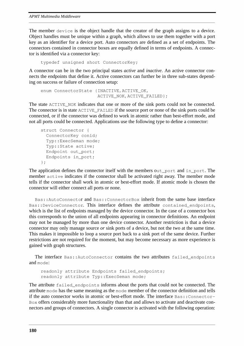
APMT Multimedia Middleware
180
The member device is the object handle that the creator of the graph assigns to a device.Object handles must be unique within a graph, which allows to use them together with a portkey as an identifier for a device port. Auto connectors are defined as a set of endpoints. Theconnectors contained in connector boxes are equally defined in terms of endpoints. A connec-tor is identified via a connector key:
typedef unsigned short ConnectorKey;
A connector can be in the two principal states active and inactive. An active connector con-nects the endpoints that define it. Active connectors can further be in three sub-states depend-ing on success or failure of connection setup:
enum ConnectorState {INACTIVE,ACTIVE_OK, ACTIVE_NOK,ACTIVE_FAILED};
The state ACTIVE_NOK indicates that one or more of the sink ports could not be connected.The connector is in state ACTIVE_FAILED if the source port or none of the sink ports could beconnected, or if the connector was defined to work in atomic rather than best-effort mode, andnot all ports could be connected. Applications use the following type to define a connector:
struct Connector { ConnectorKey conid; Typ::ExecSeman mode; Typ::State active; Endpoint out_port; Endpoints in_port;};
The application defines the connector itself with the members out_port and in_port. Themember active indicates if the connector shall be activated right away. The member modetells if the connector shall work in atomic or best-effort mode. If atomic mode is chosen theconnector will either connect all ports or none.
Bas::AutoConnector and Bas::ConnectorBox inherit from the same base interfaceBas::DeviceConnector. This interface defines the attribute contained_endpoints,which is the list of endpoints managed by the device connector. In the case of a connector boxthis corresponds to the union of all endpoints appearing in connector definitions. An endpointmay not be managed by more than one device connector. Another restriction is that a deviceconnector may only manage source or sink ports of a device, but not the two at the same time.This makes it impossible to loop a source port back to a sink port of the same device. Furtherrestrictions are not required for the moment, but may become necessary as more experience isgained with graph structures.
The interface Bas::AutoConnector contains the two attributes failed_endpointsand mode:
readonly attribute Endpoints failed_endpoints;readonly attribute Typ::ExecSeman mode;
The attribute failed_endpoints informs about the ports that could not be connected. Theattribute mode has the same meaning as the mode member of the connector definition and tellsif the auto connector works in atomic or best-effort mode. The interface Bas::Connector-Box offers considerably more functionality than that and allows to activate and deactivate con-nectors and groups of connectors. A single connector is activated with the following operation:
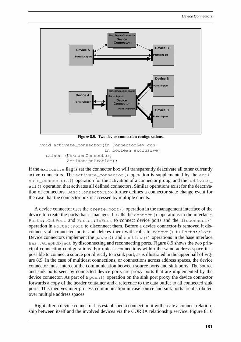
181
Device Connectors
void activate_connector(in ConnectorKey con, in boolean exclusive) raises (UnknownConnector, ActivationProblem);
If the exclusive flag is set the connector box will transparently deactivate all other currentlyactive connectors. The activate_connector() operation is supplemented by the acti-vate_connectors() operation for the activation of a connector group, and the activate_all() operation that activates all defined connectors. Similar operations exist for the deactiva-tion of connectors. Bas::ConnectorBox further defines a connector state change event forthe case that the connector box is accessed by multiple clients.
A device connector uses the create_port() operation in the management interface of thedevice to create the ports that it manages. It calls the connect() operations in the interfacesPorts::OutPort and Ports::InPort to connect device ports and the disconnect()operation in Ports::Port to disconnect them. Before a device connector is removed it dis-connects all connected ports and deletes them with calls to remove() in Ports::Port.Device connectors implement the pause() and continue() operations in the base interfaceBas::GraphObject by disconnecting and reconnecting ports. Figure 8.9 shows the two prin-cipal connection configurations. For unicast connections within the same address space it ispossible to connect a source port directly to a sink port, as is illustrated in the upper half of Fig-ure 8.9. In the case of multicast connections, or connections across address spaces, the deviceconnector must intercept the communication between source ports and sink ports. The sourceand sink ports seen by connected device ports are proxy ports that are implemented by thedevice connector. As part of a push() operation on the sink port proxy the device connectorforwards a copy of the header container and a reference to the data buffer to all connected sinkports. This involves inter-process communication in case source and sink ports are distributedover multiple address spaces.
Right after a device connector has established a connection it will create a connect relation-ship between itself and the involved devices via the CORBA relationship service. Figure 8.10
Figure 8.9. Two device connection configurations.
Ports::Inport
Ports::OutPort
Bas::DeviceConnector
Device
Ports::Inport
Ports::OutportConnector
Ports::Inport
Device A
Device B
Device C
Bas::DeviceConnector
DeviceConnector
Ports::Outport
Device APorts::Inport
Device B

APMT Multimedia Middleware
182
shows that a connection between two device ports is modeled as a ternary relationship betweena source device, a sink device and the device connector that connects them. The source devicetakes the source role, the sink device the sink role, and the device connector the connects role.These roles are defined as empty interfaces in ::Bas:
interface SourceRole : CosGraphs::Role;interface SinkRole : CosGraphs::Role;interface ConnectsRole : CosGraphs::Role;
The interface CosGraphs::Role is the role interface defined by the relationship service. Theconnect relationship is also represented by an interface:
interface ConnectRelation : CosRelationships::Relationship { readonly attribute Endpoint source; readonly attribute Endpoint sink;};
The source and sink attributes identify the device endpoints that are involved in the connec-tion. A device connector that wants to create a connect relationship first queries the roles_of_node attribute of the CosGraphs::Node interfaces of the involved devices to see if theyalready contain the necessary source and sink roles. If not, the device connector creates therequired roles via a role factory and adds them to the devices. Following that it creates the con-nect relationship via a relationship factory, which establishes relationship links to the sourceand sink roles of the devices and the connects role of the device connector. The device connec-tor can then set the source and sink attributes of the new connect relationship. Once all con-nect relationships have been created within a graph it is possible to navigate the graph. Thestarting point for navigation can be an object reference to a device, a device connector, or aconnect relationship. The relationship service defines the CosGraphs::Traversal interfacethat provides significant comfort for the navigation of graphs.
The connect relationships will be used by conspiring devices that need to locate each other,and by applets that need to retrieve object references for devices and device connectors withinthe graph. The control panel may use the connect relationships to query the structure of agraph, which allows it to offer the user direct control over devices and device connectors.Debugging tools may use the connect relationships for realtime exploration of establishedgraphs. In the future, connect relationships may provide support for compound life cycle con-trol and compound externalization of graphs. This in turn may be the basis for user sessionmobility support in APMT. It may also be possible to establish connect relationships that spanthe network, i.e., that model connections among the network ports of transport devices. As fornow, connect relationships are local to a terminal.
Figure 8.10. Ternary relationship between two devices and a device connector.
Device
ConnectRelation
sourcesink
source
sink
Device Connectorconnects
183
Graph and Stream Agent
8.7 Graph and Stream Agent
Graphs provide compound control over device and device connector networks within a termi-nal. To the outside, graphs appear as device factories. They are themselves created via thestream agent interface, which effectively makes the stream agent a graph factory.
8.7.1 Graphs
Graphs are controlled by the stream agent via a management interface that is outside the scopeof the APMT definitions, for graphs are, like device connectors and transport devices, part ofthe terminal infrastructure. The graph and its devices and device connectors are optimally col-located within the same address space. The management of graph objects requires a multitudeof operation invocations, which has the consequence that the performance of graph manage-ment procedures is directly linked with the performance of an operation invocation on the man-agement interface of a device or device connector. The performance of an operation invocationis optimal in the case of collocation within the same address space. It already suffers if graphand graph objects are located in different address spaces on the same machine, and it is bad incase a graph needs to control graph objects across a network. Just like the communicationbetween graph and graph objects is assumed to be local, the communication between the graphand a graph owner is assumed to be remote. Most operations defined in the graph interface arecompound control operations. The invocation of a compound control operation will generallyresult in a multitude of operation invocations on graph objects. Graphs optimize the perfor-mance of device management, because they relieve the application or application pool utilityfrom an individual access of all devices and device connectors across the network. They per-form the following functions:
• device and device connector life-cycle management: graphs create and removedevices and device connectors.
• format matching: the graph matches the formats of all connected device ports.This must be done in combination with flow parameter translation.
• flow parameter translation: the application imposes flow parameters at sendingnetwork ports that the graph translates into flow parameter constraints for everyconnected source port.
• compound resource management: the graph supports compound operations forreservation, acquisition and release of resources.
• compound graph object control: the graph supports operations that start, pause,restart and stop all contained devices and device connectors.
Graphs manage connections between devices. Connection managers in the application poolmanage network connections between graphs. Graphs perform format matching and flowparameter setting on terminal level, whereas connection managers perform this task on net-work level. This partition of functionality facilitates the establishment and control of devicenetworks involving device graphs in multiple terminals.
The module ::Tgraph defines the interfaces Graph and GraphCallBack, with the latterbeing implemented by the owner of a graph. The module ::Tgraph further defines a couple oftypes that are used in device and device connector creation requests. The following type is usedin device creation requests:
APMT Multimedia Middleware
184
struct DeviceRequest { Typ::InfIdent dev_name; Ftyp::NameF name; Typ::ObjectHandle dev_handle; any dev_settings; Bas::PortSettings port_settings;};
The member dev_name identifies the device that is to be created. The member name is theoptional name assigned by the application to the device, the member dev_handle the uniqueobject handle used in connector definitions. Initialization data is passed via dev_settings tothe graph, which will transparently forward them to the device. The member port_settingscan be used to set port formats. The creator of a device is not obliged to set port formats, butmay do so if the application requires a specific format on a port. The graph will set all unsetport formats as part of the format matching procedure.
The creation request types for auto connectors and connector boxes resemble the one fordevices. Auto connectors are requested as follows:
struct AutocxtorRequest { Ftyp::StringF name; Typ::ObjectHandle cxtor_handle; Bas::Endpoints dev_ports;};
The member dev_ports is the list of device ports that are to be connected by the auto connec-tor. This member is replaced by a list of connectors in the case of the connector box:
struct CoboxRequest { Ftyp::StringF name; Typ::ObjectHandle cobox_handle; Bas::Connectors cxtors;};
The module ::Tgraph also defines types related to network ports. The following type is usedto relate network ports to a transport device:
struct NetPortAddress { Typ::ObjectHandle transdev; Trans::IpTsaps addr;};
The flow parameters of a network port are set with the following type:
struct NetPortParameter { Typ::ObjectHandle transdev; Bas::FlowParameter flowparm;};
The format set on the network port of a transport device is described as follows:
struct NetPortFormat { Typ::ObjectHandle transdev; Bas::FormatKey format;};
Possible combinations of network port format settings are given as follows:
185
Graph and Stream Agent
typedef sequence<NetPortFormat> NetPortFormats;typedef sequence<NetPortFormats> NetPortFormatCombs;
The interface Tgraph::Graph defines attributes informing about the name of the graph, itsstate, and the flows that it currently receives via one of its transport devices. The state of agraph is reflected by four attributes that are identical to the state attributes of the graph objectas described on page 162. Graphs are created via the stream agent interface. Once they exist,the following operation is used to add devices and device connectors to them:
NetPortFormatCombs add_objects(in DeviceRequests devs,in AutocxtorRequests cxtors,in CoboxRequests coboxes,
in NetPortParameters tx_parms) raises (....);
The first three parameters describe the devices, auto connectors and connector boxes that shallbe instantiated1. The parameter tx_parms is a list of constraints on network flows emitted bytransport devices. The graph returns a list of possible network port format combinations that iscalculated by means of device introspection. The graph must find a format setting for everyconnected device port, with constraints being the port formats already set in the device requestsand the flow parameters imposed on sending transport devices. The graph not only introspectsa device given in devs, but also all devices installed on the terminal that inherit from it,because it is assumed that devices further down the device hierarchy support additional for-mats. The outcome of device introspection is a probably small number of solutions to the portformat and flow parameter setting problem for the graph described by the parameters devs,cxtors and coboxes. Solutions differ not only in port format and flow parameter settings,but also in the choice of devices within the device hierarchy. It is therefore not possible toinstantiate devices until one of the solutions is chosen. The graph presents a found solution as alist of network port format settings. This list contains a setting for every transport device givenin the parameter devs. The owner of the graph must choose one of the proposed solutions withthe following operation:
void commit(in NetPortFormats port_formats, out NetPortAddresses rx_addrs, out Typ::RefHandles objs)
raises (....);
The parameter port_formats is the chosen format setting combination. The graph choosesone of the precalculated solutions that corresponds to this combination of network port for-mats, and instantiates and initializes the necessary devices and device connectors. It returns thestringified object references of all instantiated graph objects in the parameter objs, and a listof network port addresses for receiving transport devices in rx_addrs. If the owner of a graphrealizes that it is impossible to match the network port formats of the graphs that are to beinterconnected, he will cancel the graph modification procedure with a call to cancel().
The graph does not have to be constructed in one move. First of all it is possible to calladd_objects() multiple times before commit() is called. It is further possible to addobjects to free device ports of an existing and possibly active graph. This is subject to the con-dition that the formats and flow parameters of existing network ports remain unchanged. Graphobjects can also be removed from the graph:
1. The client of the graph transmits an empty request list for the graph object categories in which he is not inter-ested.
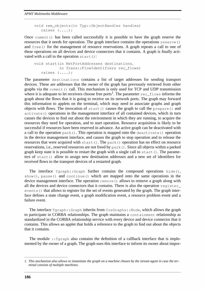
APMT Multimedia Middleware
186
void rem_objects(in Typ::ObjectHandles handles) raises (....);
Once commit() has been called successfully it is possible to have the graph reserve theresources that it needs for operation. The graph interface contains the operations reserve()and free() for the management of resource reservations. A graph repeats a call to one ofthese operations on all devices and device connectors that it contains. A graph is finally acti-vated with a call to the operation start():
void start(in NetPortAddresses destinations, in Trans::FlowIdentifiers rec_flows)
raises (....);
The parameter destinations contains a list of target addresses for sending transportdevices. These are addresses that the owner of the graph has previously retrieved from othergraphs via the commit() call. This mechanism is only used for TCP and UDP transmissionwhere it is adequate to let receivers choose free ports1. The parameter rec_flows informs thegraph about the flows that it is going to receive on its network ports. The graph may forwardthis information to applets on the terminal, which may need to associate graphs and graphobjects with flows. The invocation of start() causes the graph to call the prepare() andactivate() operations in the management interface of all contained devices, which in turncauses the devices to find out about the environment in which they are running, to acquire theresources they need for operation, and to start operation. Resource acquisition is likely to besuccessful if resources have been reserved in advance. An active graph can be deactivated witha call to the operation park(). This operation is mapped onto the deactivate() operationin the device management interface, and causes the graph to stop operation and to release theresources that were acquired with start(). The park() operation has no effect on resourcereservations, i.e., reserved resources are not freed by park(). Since all objects within a parkedgraph keep state it is possible to restart the graph with a single call to start(). The parame-ters of start() allow to assign new destination addresses and a new set of identifiers forreceived flows to the transport devices of a restarted graph.
The interface Tgraph::Graph further contains the compound operations hide(),show(), pause() and continue() which are mapped onto the same operations in thedevice management interface. The operation remove() allows to remove a graph along withall the devices and device connectors that it contains. There is also the operation register_events() that allows to register for the set of events generated by the graph. The graph inter-face defines a state change event, a graph modification event, a resource problem event and afailure event.
The interface Tgraph::Graph inherits from CosGraphs::Node, which allows the graphto participate in CORBA relationships. The graph maintains a containment relationship asstandardized in the CORBA relationship service with every device and device connector that itcontains. This allows an applet that holds a reference to the graph to find out about the objectsthat it contains.
The module ::Tgraph also contains the definition of a callback interface that is imple-mented by the owner of a graph. The graph uses this interface to inform its owner about impor-
1. This mechanism also allows to instantiate the graph on a machine chosen by the stream agent in case the ter-minal consists of multiple machines.

187
Graph and Stream Agent
tant events. The owner of a graph, which is assumed to be remote, will therefore not explicitlyneed to register for events.
8.7.2 Stream Agent
The stream agent is the terminal entity that is responsible for the creation and management ofdevice graphs. Applications, including composite applications, run one instance of the streamagent on a terminal. The stream agent is a terminal server, and supports therefore the com-pound operations defined in Ts::TerminalServer. The stream agent interface Strag::StreamAgent also inherits from CosGraphs::Node, which allows it to participate in rela-tionships. The stream agent maintains standard containment relationships with its graphs,which allows applets to find out about currently existing graphs. Graphs are created with thefollowing operation:
void create_graph(in Ftyp::NameF name, in Tgraph::GraphCallback mgr);
The parameter name is the optional name of the graph, the parameter mgr the callback inter-face implemented by the owner of the graph. The stream agent further supports an operationthat informs about installed devices:
Typ::InfIdents challenge(in Typ::InfIdents devices);
This operation is similar to the challenge() operation defined in the Tc::TerminalCon-trol interface. The caller presents a list of required devices, and the operation returns thosedevices in that list that are not supported by the terminal. An application or application poolutility that is only interested in devices, and not in terminal objects in general, will use thechallenge() operation of the stream agent rather than the one of the terminal control. Bothoperations will return the same result, but the challenge() operation of the stream agent willperform better because the database it has to browse is smaller.
Still missing in the stream agent interface are attributes and operations that allow connec-tion managers to find out about the network access capabilities of the terminal. The flowparameters that the connection manager imposes on sending network ports must be chosenunder consideration of the network access capabilities of sending and receiving terminals. Anexample network access capability is maximum available bandwidth, which depends on boththe physical bandwidth of the network interface and the bandwidth limitations on the networkroutes to the terminal. Attributes and operations related to network access capabilities must bedefined as part of a larger resource management framework for APMT.
8.7.3 Graph Creation Scenario
Figure 8.11 shows as a summary of the discussion in this section an example graph creationscenario. The graph owner depicted on the right side can be an applet, an application, or anapplication pool utility like the connection manager. The graph is created with a call to thecreate_graph() operation in the stream agent interface. Next the operation add_objects() is called, which causes the graph to load the device factories for all requesteddevices and all the devices that inherit from them. The graph finds out about the ports of everydevice by querying the ports attribute of the device factory interface. It then calls possiblymultiple times the operation query_format() in order to test format combinations. At theend the graph has found all possible combinations of device port settings. It then tests everyformat setting combination against the flow parameter constraints on sending network ports.
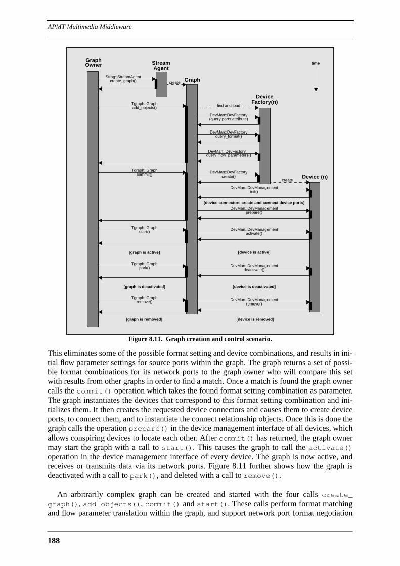
APMT Multimedia Middleware
188
This eliminates some of the possible format setting and device combinations, and results in ini-tial flow parameter settings for source ports within the graph. The graph returns a set of possi-ble format combinations for its network ports to the graph owner who will compare this setwith results from other graphs in order to find a match. Once a match is found the graph ownercalls the commit() operation which takes the found format setting combination as parameter.The graph instantiates the devices that correspond to this format setting combination and ini-tializes them. It then creates the requested device connectors and causes them to create deviceports, to connect them, and to instantiate the connect relationship objects. Once this is done thegraph calls the operation prepare() in the device management interface of all devices, whichallows conspiring devices to locate each other. After commit() has returned, the graph ownermay start the graph with a call to start(). This causes the graph to call the activate()operation in the device management interface of every device. The graph is now active, andreceives or transmits data via its network ports. Figure 8.11 further shows how the graph isdeactivated with a call to park(), and deleted with a call to remove().
An arbitrarily complex graph can be created and started with the four calls create_graph(), add_objects(), commit() and start(). These calls perform format matchingand flow parameter translation within the graph, and support network port format negotiation
Figure 8.11. Graph creation and control scenario.
timeGraphOwner Stream
Agent
GraphcreateStrag::StreamAgent
create_graph()
Tgraph::Graphadd_objects()
DeviceFactory(n)
find and load
DevMan::DevFactoryquery_format()
DevMan::DevFactoryquery_flow_parameters()
DevMan::DevFactory(query ports attribute)
DevMan::DevFactorycreate() Device (n)
create
Tgraph::Graphcommit()
Tgraph::Graphstart()
DevMan::DevManagementinit()
[device connectors create and connect device ports]DevMan::DevManagement
prepare()
DevMan::DevManagementactivate()
[device is active][graph is active]
Tgraph::Graphpark() DevMan::DevManagement
deactivate()
[device is deactivated][graph is deactivated]
Tgraph::Graphremove() DevMan::DevManagement
remove()
[graph is removed] [device is removed]
189
A Connection Manager
and transport address exchange between sending and receiving network ports in differentgraphs. A connection manager that wants to create and connect graphs in different terminalsmay call the create_graph(), add_objects(), commit() and start() operations inparallel in all terminals.
8.8 A Connection Manager
This section presents an example connection manager, the conference configuration and con-nection manager (CCCM) [Schm96a]. The CCCM is tailored to the management of audio andvideo connection structures among the participants of a conference. It relieves applicationsfrom the establishment and modification of complex connection structures and hides their dis-tributed nature behind a monolithic API. The connection management abstractions of theCCCM are motivated by the ones of the Beteus API, and bear some similarities with them.Emphasis has been put on the support for dynamic connection structure changes as required byapplications similar to the teleteaching scenario described in Section 4.3.6 on page 63. It alsohas been tried to keep the CCCM as generic as possible, i.e., to keep it free from any devicedependencies.
The main abstractions exhibited by the CCCM interfaces are graph model, bridge and ter-minal set. A graph model is simply a device graph that does not contain any transport devices.Instead of that it leaves one device port open to which the CCCM can then attach the necessarytransport devices. A sender graph model has a source port to which sending transport devicescan be attached. This is similar for receiver graph models which have a sink port to which areceiving transport device can be attached. A given sender graph model can be instantiatedonly once on a terminal. This is different for receiver graph models, which may need to beinstantiated more than once in case they do not contain any mixing devices. A bridge is amultipoint connection structure among instantiated graph models. It is defined in terms of asender graph model, a receiver graph model, and a connection structure type. Possible connec-tion structure types are simplex, duplex, all-to-one, one-to-all, some-to-all, and all-to-all.Bridges interconnect the terminals of a terminal set. A terminal set is a subset of the terminalsthat are in the connection management session. A terminal can be member of multiple terminalsets, which allows the construction of arbitrarily complex connection structures among the par-ticipants of a conference. The CCCM connection management session is decoupled from theapplication session, which means that the application must explicitly add or remove terminalsfrom it. Other connection managers could register for the session membership events of theparticipation control, and establish connections with new session participants without that theapplication would need to intervene.
8.8.1 Connection Management Session, Graph Models and Terminal Sets
Figure 8.12 shows an OMT object diagram of the CCCM interfaces. The principal interface ofthe CCCM is Cccm::Session, which inherits from the application pool utility interface Put::Utility. Cccm::Session is a factory for terminal objects and terminal set objects, andallows to register sender and receiver graph models. Terminal objects are created with the fol-lowing operation:
Terminal create_terminal(in Tc::TerminalControl tc)raises (....);
APMT Multimedia Middleware
190
The CCCM uses the reference to the terminal control interface to start a stream agent in theterminal, or to get a reference to it if it is already running. Once create_terminal() hasreturned successfully, the terminal identified by tc is part of the connection management ses-sion. Terminals in the connection management session can be grouped into terminal sets:
TerminalSet create_terminal_set(in Terminals terminals);
It is also possible to create global terminal sets which automatically contain all terminals in theconnection management session:
TerminalSet create_global_terminal_set();
Cccm::Session contains two operations for the registration of sender and receiver graphmodels. Graph models are identified by a handle that is defined in ::Cccm:
typedef unsigned short ModelHandle;
A sender graph model consists of devices and device connectors and some additional informa-tion concerning network transport. Sender graphs are registered as follows:
void register_sender_model( in ModelHandle handle, in Tgraph::DeviceRequests devices, in Tgraph::AutocxtorRequests autocxtors, in Tgraph::CoboxRequests coboxes, in Bas::Endpoint network_port,
in Bas::FlowParameter flow_parms, in Trans::FlowHandle flow_handle)
raises (....);
The parameter handle is the graph model handle assigned by the application to this graphmodel. The parameters devices, autocxtors and coboxes contain the graph objects thatare part of the graph model. The parameter network_port is the device port to which theCCCM may attach transport devices. This port is a an unconnected source port of one of thedevices listed in the parameter devices. The parameter flow_parms is a flow parameterspecification for the sending transport devices that the CCCM attaches to the graph model. Theparameter flow_handle finally is the flow handle assigned to the flows that are transmittedover the network.
A receiver graph model does not contain flow parameters and flow handles. The questionthat is important in the case of receiver graph models is multiplicity of instantiations. In thecase of a video receiver graph model for instance it may be necessary to instantiate onereceiver graph for every received video flow, i.e., for every video sender graph. This is differentin the case of audio, where one receiver graph with an audio mixer or flow selector may handleall incoming audio flows. The mixer parameter in the register_receiver_model()operation indicates if the receiver graph model is able to handle multiple incoming flows:
void register_receiver_model( in ModelHandle handle, in Tgraph::DeviceRequests devices, in Tgraph::AutocxtorRequests autocxtors, in Tgraph::CoboxRequests coboxes, in Bas::Endpoint network_port, in boolean mixer)raises (....);

191
A Connection Manager
Network flows carry unique source identifiers and flow identifiers consisting of the terminalcontrol address of the sending terminal and the flow handle assigned to sending network portsin the register_sender_model() operation. Mixing devices use source identifiers todemultiplex the flows contained in the stream of containers they receive from a transportdevice. They use flow identifiers to correlate flows with source terminals on application level.An applet on a terminal has prior knowledge about the significance of certain flow handles, forthey are assigned by the application and known beforehand. The additional information of thesource terminal contained in a flow identifier allows an applet to tailor the functionality itoffers to the flows that it receives. As an example, it may allow to individually control the vol-ume of incoming audio flows in a mixed audio signal. It would use volume sliders in the graph-ical user interface that indicate the name of the person whose audio volume can be controlled.The interface of a mixer must define events via which information about currently receivedflows can be communicated to applets. Applets can register for such events once they have areference to the mixer. There are multiple ways an applet may receive references to graphobjects that were not created by itself, which is the case here where graphs are instantiated bythe CCCM. It may receive references via the application, which gets them from CCCM, or itmay receive them via the trigger mechanism of the terminal control in case the device wasassigned a name in the respective graph model request. It may also get them by navigatinggraphs with the help of the CORBA relationship service.
The interface Cccm::Terminal is the place for compound operations on terminals. This isillustrated with two operations, pause() and continue(), which pause and restart all graphsmanaged by the CCCM on a terminal. The operation remove() removes the terminal from theconnection management session and from all terminal sets, and as a result of that from allbridges. It also causes the CCCM to delete all graphs that it owns on the terminal.
Figure 8.12. CCCM interfaces.
start()park()remove()get_object()
typestatesemanticsfailed_graphs
Bridge
connect()set_sender()set_receiver()
senderreceiver
SimplexBridge
connect()
terminals
DuplexBridge
set_sender()
sender
OneToAllBridge
set_senders()add_senders()rem_senders()
senders
SomeToAllBridge AllToAllBridge
add_terminals()remove_terminals()create_bridge()remove()
typebridgesterminals
TerminalSet
pause()continue()remove()
statetermcont
Terminal
create_terminal()create_terminal_set()create_global_terminal_set()register_sender_model()register_receiver_model()reset()remove()
terminal_setsterminals
Session
2+ Endpoint-of
Membership
member
set_receiver()
receiver
AllToOneBridge

APMT Multimedia Middleware
192
A terminal set corresponds to the subconference abstraction found in other session and con-nection management architectures. Terminals can be member of multiple terminal sets at atime. A terminal set defines the endpoints of a bridge. Adding a terminal to a terminal set istherefore likely to have side effects on all bridges that are created on the terminal set. As can beseen in Figure 8.12, the terminal set interface Cccm::TerminalSet contains the threeattributes type, bridges and terminals which tell if the terminal set is global or not, whatbridges are created on it, and which terminals it contains. The operations add_terminals()and remove_terminals() allow to control terminal set membership. The operationremove() removes the terminal set along with all of its bridges. Bridges are created with thefollowing operation:
enum BridgeType {SIMPLEX,DUPLEX,ALL_TO_ONE, ONE_TO_ALL,SOME_TO_ALL,ALL_TO_ALL};
Bridge create_bridge(in BridgeType type, in ModelHandle sender, in ModelHandle receiver, in Typ::ExecSeman semantics)raises (....);
The parameter type identifies the type of the bridge that is to be created. The parameterssender and receiver determine the sender and receiver graph models that are to be used forthis bridge. The parameter semantics tells if the bridge shall create network connections inatomic or best-effort mode.
8.8.2 Bridges
Figure 8.12 shows the base interface Cccm::Bridge and derived from it interfaces for allbridge types that are supported by the CCCM. A bridge can be in state IDLE, ACTIVATED,ACTIVE and PARKED. It is in state IDLE when it is created, in state ACTIVATED once the oper-ation start() has been called, and in state ACTIVE if connections are established. Connec-tions will not be established until the terminal set holds at least two terminals. Some bridgetypes also require further calls after start() in order to establish connections. An activated oractive bridge can be deactivated with a call to park(), which is mapped on the park() oper-ation in Tgraph::Graph. Once the bridge is in state ACTIVE, the application can retrieveobject references from the CCCM:
Typ::StringRefs get_object(in Typ::ObjectHandle handle, in ModelType graph_type, in Terminal terminal)
raises (....);
The parameter handle identifies the object the application is interested in. The parametergraph_type determines if this object is in the sender or receiver graph. The parameter ter-minal finally identifies the terminal on which the graph model is instantiated. The operationreturns a list of stringified object references in the case of a receiver graph without a mixingdevice that has been instantiated multiple times on the terminal. Otherwise it returns a singleobject reference. Applications that name devices in graph models will normally not need toretrieve object references with get_object(), because their applets may retrieve referencesto named objects without any further help from the application.
The interfaces for the various bridge types that inherit from Cccm::Bridge are kept sim-ple. The interface for a simplex bridge, Cccm::SimplexBridge, contains the attributes

193
A Connection Manager
sender and receiver that identify the current endpoints of the simplex connection. Theoperation connect() is used to connect a sender graph with a receiver graph. The operationsset_sender() and set_receiver() allow to dynamically change one of the endpoints ofthe simplex connection. This functionality is not provided in the interface Cccm::Duplex-Bridge where a duplex connection is controlled via a single connect() operation taking twoterminals as argument. The interface Cccm::OneToAllBridge is the multicast counterpart toCccm::SimplexBridge. It defines the attribute sender, which is the current multicast root,and the operation set_sender() that allows to reassign the sender role to a new terminal.The interface Cccm::AllToOneBridge is the inverse of Cccm::OneToAllBridge. Itdefines the attribute receiver for the current receiver, and the operation set_receiver()to reassign the receiver role. The interface Cccm::SomeToAllBridge is inbetween Cccm::OneToAllBridge and Cccm::AllToAllBridge and allows to define a group of sendingterminals within the terminal set that transmit streams to all other terminals, including othersending terminals. Group membership is controlled via the operations set_sender(), add_senders() and remove_senders() and reflected by the attribute senders. The last bridgesupported by the CCCM is the all-to-all bridge which is represented by the empty interfaceCccm::AllToAllBridge. Other bridge types can be imagined, and may be added to futureversions of the CCCM if they turn out to be important.
The CCCM instantiates graph models in terminals as they are needed. In the case of a mul-ticast bridge for instance it will not instantiate any graph until the application has called theset_sender() operation for the first time. Once the sender is set, the CCCM will instantiatethe receiver graph model once on all terminals in the terminal set except for the sending termi-nal on which it instantiates the sender graph model. When the application chooses a newsender, the CCCM will park the sender graph on the sending terminal and create a receivergraph on it, and it will park the receiver graph on the terminal that becomes the new sender andcreate a sender graph on it. If the application switches back to the previous sender at somepoint the CCCM will park the current sender graph and reactivate the receiver graph on thesame terminal, and it will park the receiver graph on the previously sending terminal and reac-tivate its sender graph. Reactivating existing graphs is supposed to take considerably less timethan the creation of new ones, for it requires less operation invocations across the network, andno format matching procedure. The CCCM may implement a strategy for the recycling ofinstantiated graphs. It will therefore not necessarily remove an instantiated graph model on aterminal if the bridge in which it is used is removed by the application. It will keep it forinstance in case the graph can be recycled in another bridge which uses the same model.
The CCCM must also implement a strategy for the use of transport devices. The CCCM willfor instance establish the point-to-point connection of a simplex bridge via UDP if the sendergraph on the sending terminal is not active in any other bridge. Since sender graphs and mixingreceiver graphs can be used by multiple bridges in parallel it is possible that the sender graphof the simplex bridge is already transmitting via IP multicast within another bridge. In this casethe CCCM may choose to realize the simplex connection with IP multicast and create thereceiver graph on the receiving terminal of the simplex bridge with an IP multicast device.Alternatively it may choose to still use UDP for the simplex connection and add a UDP deviceto the existing IP multicast device in the sender graph. The complexity of network connectionsincreases with the number of concurrently active bridges. The CCCM may realize complexbridge combinations by having graphs transmit or receive on multiple UDP and IP multicastaddresses.

APMT Multimedia Middleware
194
8.9 Open Issues
The multimedia middleware presented in this chapter still lacks some important functionality,namely resource management, synchronization and support for graphical user interfaces. Someof the operations in the device management interface reflect the existence of a resource man-agement framework for the terminal, but the interface between the device and resource man-agement has not been designed. However, it is assumed that the definition of terminal resourcemanagement interfaces does not require any modifications to existing device, device connectorand graph interfaces. The multimedia middleware also needs to be augmented with resourcemanagement functionality for communication over the network. This requires the integrationof RSVP, which is the mainstream approach for resource management in the Internet. RSVPcan be added to the APMT multimedia middleware in the form of special transport devices, asis done with RTP. Since resource reservation in RSVP is initiated by receivers it is necessary tocommunicate flow parameters to both sending and receiving transport devices. Sending trans-port devices try to enforce flow parameters via the adjust_flow() operation of the devicesource port to which they are connected. Receiving transport devices use the flow parametersin RSVP resource reservations. The structure Bas::FlowParameter, which now only con-tains the definition of a maximum data rate, must be refined, and possibly tailored to RSVPrequirements.
Intra-stream synchronization is transparently supported by playout devices that maintain abuffer in order to recreate the internal timing of a flow. Event-based synchronization can besupported with special attribute headers that cause certain devices to generate events for whichorchestrating applets can register. Inter-stream synchronization requires the introduction ofabstractions for time into the multimedia middleware, possibly based on the CORBA time ser-vice. The CORBA relationship service can be used to model synchronization relationshipsbetween devices in different graphs. A starting point for the design of an APMT inter-streamsynchronization framework can be the one of IMA-MSS. The APMT multimedia middlewarefurther lacks abstractions for stored media and their interactive presentation over the network.Here again it may be possible to recycle IMA-MSS concepts, namely the Stream interfacehierarchy that is depicted in Figure 5.3.
Also missing is support for the integration of media data playout with the graphical userinterface generated by downloaded applets. One possibility to support this would be to haveapplets reserve windows within the graphical user interface for media data playout, and com-municate their native window identifiers to playout devices. It is also possible to devise playoutdevices as widgets that can be readily integrated into a graphical user interface.
8.10 Conclusion
This chapter introduced a multimedia middleware that is based on a low-level componentframework, and that is tailored to APMT1. A connection manager was described that illustrateshow toolkits can be built on top of the low-level component framework that are similar in pro-gramming comfort to the monolithic platforms presented in Chapter 4. The APMT multimediamiddleware was influenced by IMA-MSS, and bears some similarities with it. However, the
1. The fact that the presented multimedia middleware is tailored to APMT somehow compromises the use of theterm ‘multimedia middleware’, given that a multimedia middleware is actually generic, and independent froman application framework. However, the term ‘multimedia middleware’ was retained because it seems to be thebest compromise for the denomination of the low-level APMT multimedia component framework.
195
Conclusion
scope of the APMT multimedia middleware is wider than the one of IMA-MSS. The APMTmultimedia middleware is a full-fledged component framework because it defines all interfacesof a device, including port interfaces and management interfaces, and not just the ones that arevisible to applications. Other differences are listed in the following:
• format interfaces: APMT does not define format interfaces. A device has a sin-gle consistent control interface towards applets and applications. APMT devicesare, as a consequence of this, more fine-grained than IMA-MSS virtual devices.
• format matching: IMA-MSS matches formats between device pairs. APMT hasa two-level format matching framework: formats of device ports within a termi-nal are matched by graphs, whereas network port formats are matched by cen-tral connection managers.
• relation between formats and flow parameters: format matching in APMT takesflow parameter constraints into account. In IMA-MSS, there is no evident rela-tion between the format matching procedure and QoS negotiation.
• compound graph creation: in APMT, four operation invocations suffice to per-form format matching, to instantiate all graph objects, and to start operation.IMA-MSS requires considerably more operation invocations, and the number ofoperation invocations grows with the number of devices.
• device introspection: APMT uses introspection to provide access to device metadata. This approach was not envisaged by IMA-MSS.
• relationship service: APMT uses the CORBA relationship service to relate thedevices within a graph to each other. This allows for instance the conspiracy ofdevices.
IMA-MSS has some features that do not have an APMT counterpart. IMA-MSS may there-fore still be a source of inspiration for APMT. It is for instance possible that the IMA-MSSsynchronization and stored media framework can be recycled in APMT.

APMT Multimedia Middleware
196
197
9 APMT Evaluation
9.1 Introduction
Chapter 6 introduced the APMT architecture and discussed all of its components. Chapter 7discussed the APMT application management architecture and showed how applications arestarted and controlled by terminals or by other applications. Chapter 8 presented the APMTmultimedia middleware consisting of the device, the device connector, the graph, and thestream agent. Also presented in Chapter 8 was an example connection manager, the Confer-ence Configuration and Connection Manager (CCCM), which assists conferencing applica-tions in the management of complex connection structures. This chapter discusses the APMTprototype which was built to test the feasibility of APMT, and evaluates the APMT architec-ture with respect to the requirements on MMC platforms that were developed in Chapter 2.
9.2 APMT Prototype
The principal aspects of APMT that are evaluated with the prototype are the APMT applicationmodel consisting of a central application and downloaded applets, the adequacy of CORBA ascontrol bus for fine- and coarse-grained APMT objects, and the usefulness of the componentmodel on which the APMT multimedia middleware is based. Neither the multimedia terminalnor the application pool have been implemented entirely. Important architecture componentsthat still need to be implemented are the terminal control and the application pool control. Pri-ority was given to the implementation of an applet handler, the multimedia middleware, andthe CCCM because it was assumed that these architecture building blocks are more challeng-ing. The APMT prototype consists of the following architecture building blocks:
• Tcl/Tk applet handler: the Tcl/Tk applet handler implements the interface dis-cussed in Section 7.6.2.
• Multimedia middleware: the prototype implements the stream agent, graph,device, and connector box interfaces.
• Devices: 25 audio, video and text devices have been developed for the multime-dia middleware.
• CCCM: the CCCM of the prototype implements an important subset of theinterfaces discussed in Section 8.8.
• Title manager: the title manager is a video on-demand connection manager thatcan be used by applications that want to integrate stored video clips or movies.
• Demo application: a videoconferencing demo application has been developedthat illustrates all aspects of the prototype.
• Video on-demand application: the video on-demand application illustrates theuse of the title manager.
APMT Evaluation
198
The IDL interfaces that were presented in Chapter 6, 7 and 8 are founded on the ones of theprototype, but may differ significantly from them. This is on one hand due to the experiencegained with CORBA during the implementation of the prototype, and on the other hand due tothe revision of some features of APMT that were found to be problematic once they wereimplemented and used. An online documentation of the interfaces of the APMT prototype canbe found at [Blum97b].
The CORBA implementation that has been used for the implementation of the APMT pro-totype is Orbix from Iona Technologies [Ion96a]. The first version of the prototype used Orbix1.3, which implemented a proprietary C++ language mapping. The software was subsequentlyported to Orbix 2.0, which was the first version of Orbix to implement the standard C++ lan-guage mapping. The first version of the prototype ran on top of SunOs 4.1.3 and could there-fore not use multi-threading, which turned out to be a serious limitation. The actual version ofthe prototype runs on Solaris 2.5 and uses the multi-threading features of Orbix 2.1 MT. Multi-threading is mainly required in the application pool where it allows applications and connec-tion managers to perform multiple control operations in parallel. The audio devices of theprototype use OrbixTalk [Ion96b], Iona’s implementation of the CORBA event service, for thecommunication of events to applets and applications. OrbixTalk is based on IP multicast anduses a proprietary reliable multicast protocol for the communication between event producersand consumers.
The Tcl/Tk applet handler uses the TclDii package that was developed at West Virginia Uni-versity [Alma95]. TclDii is basically an extension of the Tcl interpreter that allows Tcl scriptsto invoke CORBA operations via the Dynamic Invocation Interface (DII). The use of the DIIrequires operation invocations to be accompanied by type information, as is illustrated by thefollowing fictive example:
long get(in short n, in short m); //OMG-IDL
set result [orb_call $objref get l s 13 s 20] //Tcl
The operation get() takes two short integers as parameters and returns a long integer. In Tcl-Dii the operation is called with the procedure orb_call that takes a stringified object refer-ence and a description of the invoked operation as parameters. The operation descriptionconsists of the operation name (get), the return type (l), and a list of parameter type descrip-tions along with values (s 13 and s 20). The TclDii Tcl language mapping is simple to use aslong as operation types are simple. Except for any, TclDii supports all CORBA types, but con-structed types like unions and structures are tedious to use. This precludes the Tcl/Tk applethandler from being used for applets that access a large number of complex interfaces. The lan-guage of choice for these kinds of applets is Java. A Java applet handler has not been imple-mented because of the late arrival of a server-side mapping in OrbixWeb, Iona’s Javaimplementation of CORBA. The only other product that could have been used is Visigenic’sVisibroker, which would have required the use of IIOP, for which support was still in itsinfancy at the time the prototype was implemented.
The prototype runs on Sun Sparc stations that are connected via 100 Mbit/s TAXI interfacesto a Fore ASX-200 ATM switch [Biag93]. The video devices use the Motion JPEG XVideoboard from Parallax. The audio devices use the standard audio features of Sun stations.

199
APMT Prototype
9.2.1 Multimedia Middleware Interfaces
Figure 9.1 depicts the basic interfaces of the multimedia middleware implemented by theAPMT prototype. At the root of the graph object interface hierarchy is the interface APMTOb-ject, which contains operations for event registration. This interface was intended to be abase interface for all interfaces defined by APMT, but finally it turned out that there is no rea-son to have such an interface, which is why it was abandoned in the new set of interfaces thatwere presented in Chapter 7 and 8. The interface TerminalResource, which is the onlyinterface inheriting from APMTObject, is the base interface of CoBox and Device. It containsthe two operations activate() and deactivate() which are among the most importantoperations defined by the prototype. These operations are thought to be used by the graph, butnothing prevents an applet or application to invoke them. This has been changed in the new setof interfaces, where the activate() and deactivate() operations are defined in the devicemanagement interface that can only be accessed by the graph. The interface CoBox also con-tains operations that are reserved for usage by the graph, with an example being the operationdevice_removal() which is used by the graph to tell the connector box that a device hasbeen removed. The new version of the interface CoBox, Bas::ConnectorBox, does not con-tain any management operations, and a management interface for connector boxes is notdefined because connector boxes are considered to be part of the infrastructure. Programmingwith connector boxes turned out to be tedious in cases where only two ports needed to be con-nected. This is the reason why the new version of the interfaces contains the simple auto con-nector Bas::AutoConnector. The definition of an auto connector with the typeTgraph::AutocxtorRequest requires significantly less lines of code than with the typeTgraph::CoBoxRequest. Figure 9.1 also shows the transport device interface hierarchy.The transport devices of the prototype are unidirectional, which explains the existence of theinterfaces TRANS::Sender and TRANS::Receiver that inherit from the base interfaceTRANS::TransportDevice. Transport devices are further divided into unicast and multicastsenders and receivers. Multicast senders are able to send to multiple UDP or IP multicastaddresses at a time. Similarly, multicast receivers can receive from multiple UDP sources or onmultiple IP multicast addresses. Their interfaces have been defined, but not implemented,which is the reason why they are not shown in Figure 9.1. The IP multicast transport devices ofthe prototype are derived from corresponding UDP devices, which makes sense given thatUDP is commonly layered on top of IP multicast. However, the five transport device hierarchylevels introduced by the prototype are not really needed, and they were reduced to three in thenew version of the interfaces (see Figure 8.7). Also abandoned were the interfacesVIDEO::VideoDevice and AUDIO::AudioDevice which were inspired by IMA-MSS, butturned out to be useless in APMT.
Figure 9.1 also shows the interfaces Graph and StrAgent which correspond toTgraph::Graph and Strag::StreamAgent in the new set of interfaces. Graph creationand startup in the prototype requires only two operation invocations as compared to four in thenew set of the interfaces. This is because the prototype does not support format matching. Thecreate_graph() operation in the interface StrAgent already takes a graph description asparameter. This graph is instantiated immediately, and can be activated with the start()operation in the interface Graph. In the new version of the interfaces, an empty graph is cre-ated with create_graph(), to which objects are added with add_objects(). Graphobjects are not instantiated until the graph client chooses a format combination with com-mit(). Only then it is possible to start the graph. The interface StrAgent contains the opera-tion get_terminal_capabilities() which is used by connection managers to find outabout the network access capabilities of a terminal. This operation currently returns networkinterface descriptions containing information about IP addresses and interface types.

APMT Evaluation
200
The port and header container interfaces are defined as C++ classes, and not as Pseudo-IDLinterfaces like in the new version. The prototype offers pull in addition to push-style communi-cation among device ports. Pull-style communication was introduced because it facilitatedmemory management. However, the existence of two mechanisms and the rather complexdetails of the pull mechanism turned out to be confusing for device developers, which is why itwas omitted in the new set of interfaces. Devices within a graph recycle header containers anddata buffers in order to avoid the overhead of the frequent allocation of large blocks of mem-ory. This complicated device development, and introduced interdependencies between devicesthat compromised their usage as pluggable components. The new version of the port, headercontainer and data buffer interfaces assumes the existence of a smart memory management
Figure 9.1. Interface hierarchy of the APMT prototype.
Device
register_all_events()register_event()
APMTObject
activate_connector()add_connector()deactivate_connector()device_removal()get_connector_list()remove_connector()
CoBox
activate()deactivate()
object_state
TerminalResource
byte_counterbytes_secondbytes_secondavgmax_bytes_secondmax_packetmin_bytes_secondmin_packet
TRANS::TransportDevice
interface_addressreceive_buffer_sz
TRANS::Receiver
sender_address
TRANS::UnicastReceiver
TRANS::UDPreceiver
mcast_address
TRANS::IPmcastReceiver
TRANS::Sender
dest_address
TRANS::UnicastSender
TRANS::UDPsender
interface_addresstime_to_live
TRANS::IPmcastSender
AUDIO::AudioDeviceVIDEO::VideoDevice
graph_state
Graph
add_term_resource ()modify_graph()park()start()get_receiver_addresses()get_tr_refs()remove_term_resource()remove_sub_graph()
StrAgent
create_graph()get_terminal_capabilities()remove_graph()exit()
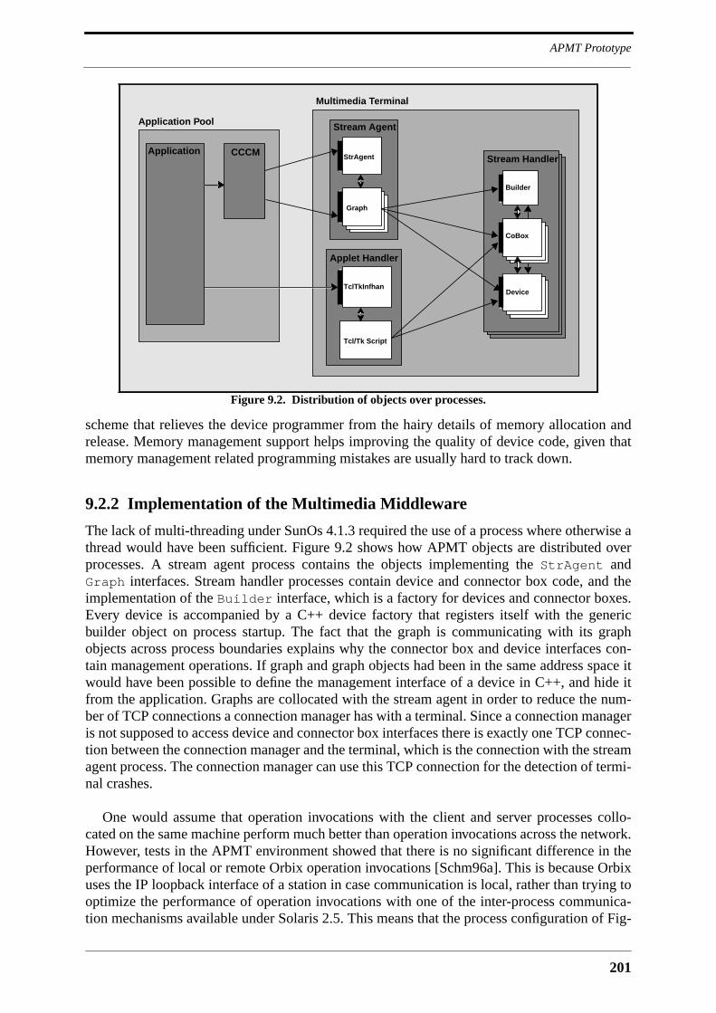
201
APMT Prototype
scheme that relieves the device programmer from the hairy details of memory allocation andrelease. Memory management support helps improving the quality of device code, given thatmemory management related programming mistakes are usually hard to track down.
9.2.2 Implementation of the Multimedia Middleware
The lack of multi-threading under SunOs 4.1.3 required the use of a process where otherwise athread would have been sufficient. Figure 9.2 shows how APMT objects are distributed overprocesses. A stream agent process contains the objects implementing the StrAgent andGraph interfaces. Stream handler processes contain device and connector box code, and theimplementation of the Builder interface, which is a factory for devices and connector boxes.Every device is accompanied by a C++ device factory that registers itself with the genericbuilder object on process startup. The fact that the graph is communicating with its graphobjects across process boundaries explains why the connector box and device interfaces con-tain management operations. If graph and graph objects had been in the same address space itwould have been possible to define the management interface of a device in C++, and hide itfrom the application. Graphs are collocated with the stream agent in order to reduce the num-ber of TCP connections a connection manager has with a terminal. Since a connection manageris not supposed to access device and connector box interfaces there is exactly one TCP connec-tion between the connection manager and the terminal, which is the connection with the streamagent process. The connection manager can use this TCP connection for the detection of termi-nal crashes.
One would assume that operation invocations with the client and server processes collo-cated on the same machine perform much better than operation invocations across the network.However, tests in the APMT environment showed that there is no significant difference in theperformance of local or remote Orbix operation invocations [Schm96a]. This is because Orbixuses the IP loopback interface of a station in case communication is local, rather than trying tooptimize the performance of operation invocations with one of the inter-process communica-tion mechanisms available under Solaris 2.5. This means that the process configuration of Fig-
Figure 9.2. Distribution of objects over processes.
StrAgent
Graph
Stream Agent
Stream Handler
Builder
CoBox
DeviceTclTkInfhan
Tcl/Tk Script
Applet Handler
Multimedia Terminal
CCCMApplication
Application Pool
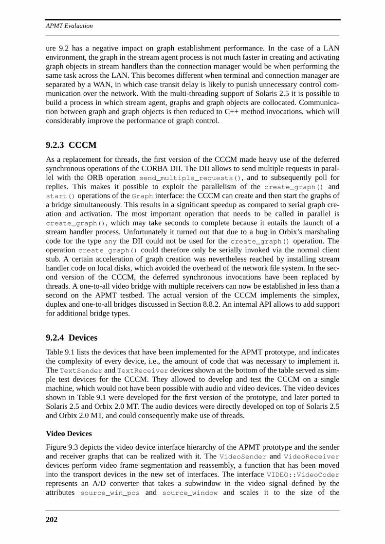
APMT Evaluation
202
ure 9.2 has a negative impact on graph establishment performance. In the case of a LANenvironment, the graph in the stream agent process is not much faster in creating and activatinggraph objects in stream handlers than the connection manager would be when performing thesame task across the LAN. This becomes different when terminal and connection manager areseparated by a WAN, in which case transit delay is likely to punish unnecessary control com-munication over the network. With the multi-threading support of Solaris 2.5 it is possible tobuild a process in which stream agent, graphs and graph objects are collocated. Communica-tion between graph and graph objects is then reduced to C++ method invocations, which willconsiderably improve the performance of graph control.
9.2.3 CCCM
As a replacement for threads, the first version of the CCCM made heavy use of the deferredsynchronous operations of the CORBA DII. The DII allows to send multiple requests in paral-lel with the ORB operation send_multiple_requests(), and to subsequently poll forreplies. This makes it possible to exploit the parallelism of the create_graph() andstart() operations of the Graph interface: the CCCM can create and then start the graphs ofa bridge simultaneously. This results in a significant speedup as compared to serial graph cre-ation and activation. The most important operation that needs to be called in parallel iscreate_graph(), which may take seconds to complete because it entails the launch of astream handler process. Unfortunately it turned out that due to a bug in Orbix’s marshalingcode for the type any the DII could not be used for the create_graph() operation. Theoperation create_graph() could therefore only be serially invoked via the normal clientstub. A certain acceleration of graph creation was nevertheless reached by installing streamhandler code on local disks, which avoided the overhead of the network file system. In the sec-ond version of the CCCM, the deferred synchronous invocations have been replaced bythreads. A one-to-all video bridge with multiple receivers can now be established in less than asecond on the APMT testbed. The actual version of the CCCM implements the simplex,duplex and one-to-all bridges discussed in Section 8.8.2. An internal API allows to add supportfor additional bridge types.
9.2.4 Devices
Table 9.1 lists the devices that have been implemented for the APMT prototype, and indicatesthe complexity of every device, i.e., the amount of code that was necessary to implement it.The TextSender and TextReceiver devices shown at the bottom of the table served as sim-ple test devices for the CCCM. They allowed to develop and test the CCCM on a singlemachine, which would not have been possible with audio and video devices. The video devicesshown in Table 9.1 were developed for the first version of the prototype, and later ported toSolaris 2.5 and Orbix 2.0 MT. The audio devices were directly developed on top of Solaris 2.5and Orbix 2.0 MT, and could consequently make use of threads.
Video Devices
Figure 9.3 depicts the video device interface hierarchy of the APMT prototype and the senderand receiver graphs that can be realized with it. The VideoSender and VideoReceiverdevices perform video frame segmentation and reassembly, a function that has been movedinto the transport devices in the new set of interfaces. The interface VIDEO::VideoCoderrepresents an A/D converter that takes a subwindow in the video signal defined by theattributes source_win_pos and source_window and scales it to the size of the
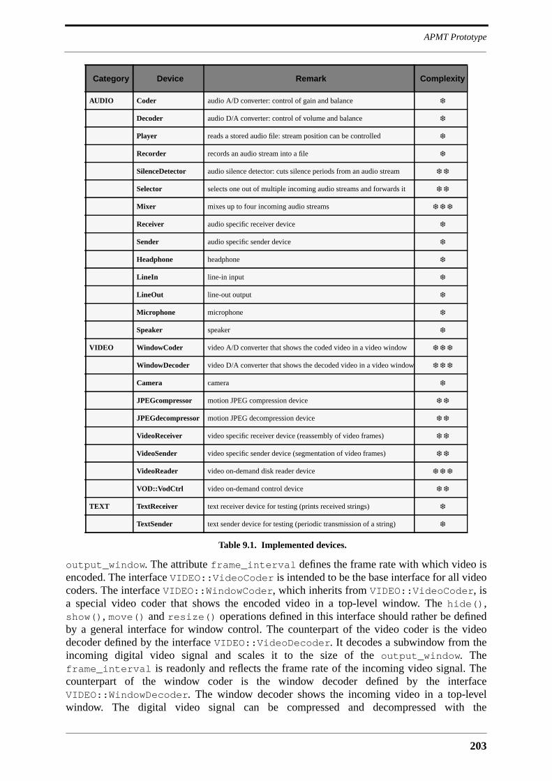
203
APMT Prototype
output_window. The attribute frame_interval defines the frame rate with which video isencoded. The interface VIDEO::VideoCoder is intended to be the base interface for all videocoders. The interface VIDEO::WindowCoder, which inherits from VIDEO::VideoCoder, isa special video coder that shows the encoded video in a top-level window. The hide(),show(), move() and resize() operations defined in this interface should rather be definedby a general interface for window control. The counterpart of the video coder is the videodecoder defined by the interface VIDEO::VideoDecoder. It decodes a subwindow from theincoming digital video signal and scales it to the size of the output_window. Theframe_interval is readonly and reflects the frame rate of the incoming video signal. Thecounterpart of the window coder is the window decoder defined by the interfaceVIDEO::WindowDecoder. The window decoder shows the incoming video in a top-levelwindow. The digital video signal can be compressed and decompressed with the
Category Device Remark Complexity
AUDIO Coder audio A/D converter: control of gain and balance ❄
Decoder audio D/A converter: control of volume and balance ❄
Player reads a stored audio file: stream position can be controlled ❄
Recorder records an audio stream into a file ❄
SilenceDetector audio silence detector: cuts silence periods from an audio stream ❄ ❄
Selector selects one out of multiple incoming audio streams and forwards it ❄ ❄
Mixer mixes up to four incoming audio streams ❄ ❄ ❄
Receiver audio specific receiver device ❄
Sender audio specific sender device ❄
Headphone headphone ❄
LineIn line-in input ❄
LineOut line-out output ❄
Microphone microphone ❄
Speaker speaker ❄
VIDEO WindowCoder video A/D converter that shows the coded video in a video window ❄ ❄ ❄
WindowDecoder video D/A converter that shows the decoded video in a video window ❄ ❄ ❄
Camera camera ❄
JPEGcompressor motion JPEG compression device ❄ ❄
JPEGdecompressor motion JPEG decompression device ❄ ❄
VideoReceiver video specific receiver device (reassembly of video frames) ❄ ❄
VideoSender video specific sender device (segmentation of video frames) ❄ ❄
VideoReader video on-demand disk reader device ❄ ❄ ❄
VOD::VodCtrl video on-demand control device ❄ ❄
TEXT TextReceiver text receiver device for testing (prints received strings) ❄
TextSender text sender device for testing (periodic transmission of a string) ❄
Table 9.1. Implemented devices.
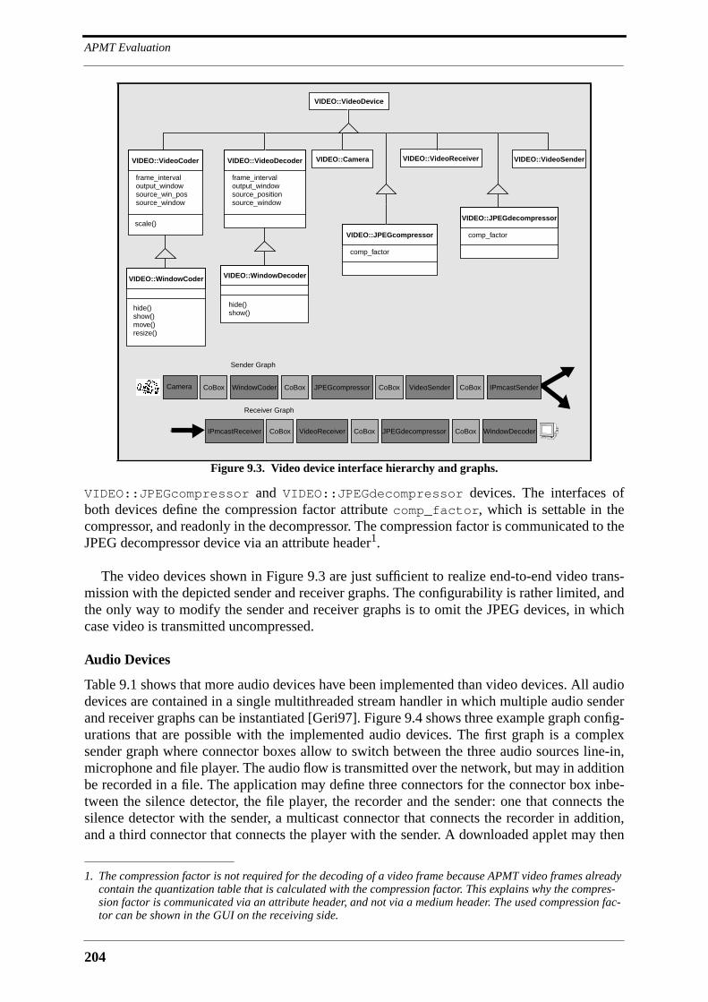
APMT Evaluation
204
VIDEO::JPEGcompressor and VIDEO::JPEGdecompressor devices. The interfaces ofboth devices define the compression factor attribute comp_factor, which is settable in thecompressor, and readonly in the decompressor. The compression factor is communicated to theJPEG decompressor device via an attribute header1.
The video devices shown in Figure 9.3 are just sufficient to realize end-to-end video trans-mission with the depicted sender and receiver graphs. The configurability is rather limited, andthe only way to modify the sender and receiver graphs is to omit the JPEG devices, in whichcase video is transmitted uncompressed.
Audio Devices
Table 9.1 shows that more audio devices have been implemented than video devices. All audiodevices are contained in a single multithreaded stream handler in which multiple audio senderand receiver graphs can be instantiated [Geri97]. Figure 9.4 shows three example graph config-urations that are possible with the implemented audio devices. The first graph is a complexsender graph where connector boxes allow to switch between the three audio sources line-in,microphone and file player. The audio flow is transmitted over the network, but may in additionbe recorded in a file. The application may define three connectors for the connector box inbe-tween the silence detector, the file player, the recorder and the sender: one that connects thesilence detector with the sender, a multicast connector that connects the recorder in addition,and a third connector that connects the player with the sender. A downloaded applet may then
1. The compression factor is not required for the decoding of a video frame because APMT video frames alreadycontain the quantization table that is calculated with the compression factor. This explains why the compres-sion factor is communicated via an attribute header, and not via a medium header. The used compression fac-tor can be shown in the GUI on the receiving side.
Figure 9.3. Video device interface hierarchy and graphs.
VIDEO::VideoDevice
frame_intervaloutput_windowsource_win_possource_window
VIDEO::VideoCoder VIDEO::Camera VIDEO::VideoSenderVIDEO::VideoReceiver
scale()
frame_intervaloutput_windowsource_positionsource_window
VIDEO::VideoDecoder
VIDEO::WindowCoder
hide()show()move()resize()
hide()show()
VIDEO::WindowDecoder
comp_factor
VIDEO::JPEGcompressor comp_factor
VIDEO::JPEGdecompressor
Camera CoBox WindowCoder CoBox JPEGcompressor CoBox VideoSender CoBox
WindowDecoderCoBoxJPEGdecompressorCoBoxVideoReceiverCoBoxIPmcastReceiver
Sender Graph
Receiver Graph
IPmcastSender

205
APMT Prototype
switch between these connectors. The second graph shown in Figure 9.4 is a receiver graphwith a mixer of which the output is sent to a speaker, a headphone and a recorder, or to a com-bination thereof. The mixer in this graph can be replaced with a selector if flow selection is suf-ficient for the application. The third graph in Figure 9.4 mixes multiple incoming audio flowsthat are sent to it via UDP, and transmits the mixed signal again on an IP multicast address.
9.2.5 The Videoconferencing Test Application
The videoconferencing application is a toy application that was developed in order to test allfeatures of the first version of the prototype, namely the multimedia middleware with the videodevices, the CCCM, and the Tcl/Tk applet handler. The videoconferencing application canaccommodate two or three terminals. When started it first downloads the Tcl/Tk script into theapplet handlers of the terminals. It then creates a high-quality video one-to-all bridge amongthe terminals, and causes the sender role to rotate a predetermined amount of times around theterminals in the terminal set. During the first round, the reassignment of the sender role takes afew seconds to complete because multiple processes need to be launched in the concerned ter-minals. Starting with the second round, the reassignment takes less than a second, because theCCCM only needs to park and restart graphs, and no graph needs to be created. The followingpiece of code implements the sender rotation:
for (i=0; i<ROUND_NUMBER; i++) for (int j=0; j<termnum; j++) { try { mcast_bridge->set_sender(terminal[j]); } catch (...) { cerr << endl << "could not change sender..." << endl; } sleep(10); }
This illustrates the high level of programming comfort that the CCCM provides. Once senderrotation is finished, the application establishes additional low-quality video bridges with asmaller frame rate and window size in a way that a momentary speaker emits a high-qualityvideo image and receives low-quality video images from the other terminals. The other termi-
Figure 9.4. Three example audio device graphs.
Microphone CoBox
Coder CoBox SilenceDetectorCoBox Sender CoBox
Speaker
CoBoxMixerCoBoxReceiverCoBoxIPmcastReceiver
IPmcastSender
Player Recorder
LineIn
Recorder
HeadPhone
MixerCoBoxReceiverCoBoxUDPreceiver Sender CoBox IPmcastSenderCoBox

APMT Evaluation
206
nals receive and show the high-quality video image of the momentary speaker, and the low-quality video images of each other. Once the video bridges are established, the applicationfeeds its applets with the object references of the created window coder and decoder objects,and causes them to activate the buttons of the GUI depicted in Figure 9.5. The GUI contains aphoto and a moving teddy icon that illustrate how media objects can be downloaded into theterminals along with the Tcl/Tk scripts. When the user presses the ShowMe button, the appletcalls the application, which in turn rebuilds the connection structure so that the requesting userbecomes the momentary speaker. The Hide button is a toggle button that causes the applet tocall the hide() or show() operations in the interfaces of all low quality video decoders,which then unmap or map their X11 video windows. This illustrates how the downloadedapplet controls other objects on the terminal that were not created by itself. The Exit buttonfinally causes the applet to indicate its termination to the application in the application pool.The application then removes all video bridges and applet handlers.
9.2.6 The Video On-Demand Application
The video-on demand application is a reimplementation of a video server architecture previ-ously developed at Eurécom [Bern95]. The principal characteristic of this video server archi-tecture is that it is based on a server array rather than multiple independent server nodes.Videos are striped over the nodes of the server array, with the striping blocks being for instancesingle video frames. Clients receive the frames of a video from multiple synchronized servernodes, and reassemble them to a continuous video stream. The advantage of this architecture is
Figure 9.5. The graphical user interface of the videoconferencing application,
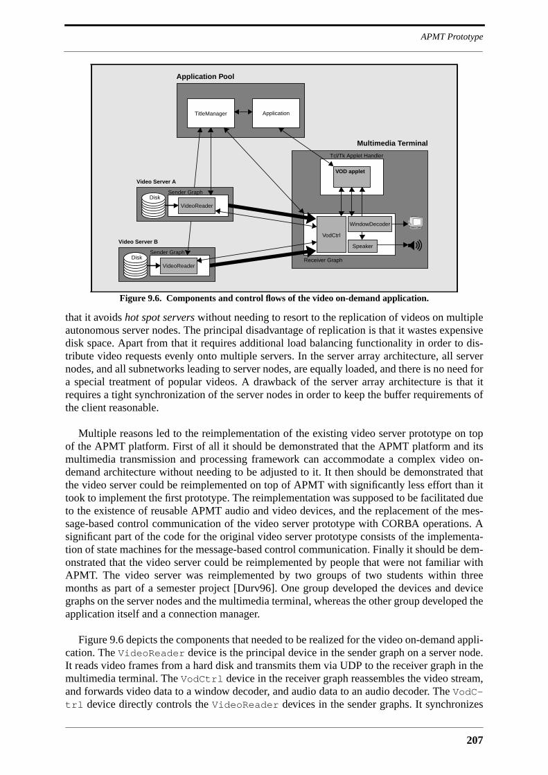
207
APMT Prototype
that it avoids hot spot servers without needing to resort to the replication of videos on multipleautonomous server nodes. The principal disadvantage of replication is that it wastes expensivedisk space. Apart from that it requires additional load balancing functionality in order to dis-tribute video requests evenly onto multiple servers. In the server array architecture, all servernodes, and all subnetworks leading to server nodes, are equally loaded, and there is no need fora special treatment of popular videos. A drawback of the server array architecture is that itrequires a tight synchronization of the server nodes in order to keep the buffer requirements ofthe client reasonable.
Multiple reasons led to the reimplementation of the existing video server prototype on topof the APMT platform. First of all it should be demonstrated that the APMT platform and itsmultimedia transmission and processing framework can accommodate a complex video on-demand architecture without needing to be adjusted to it. It then should be demonstrated thatthe video server could be reimplemented on top of APMT with significantly less effort than ittook to implement the first prototype. The reimplementation was supposed to be facilitated dueto the existence of reusable APMT audio and video devices, and the replacement of the mes-sage-based control communication of the video server prototype with CORBA operations. Asignificant part of the code for the original video server prototype consists of the implementa-tion of state machines for the message-based control communication. Finally it should be dem-onstrated that the video server could be reimplemented by people that were not familiar withAPMT. The video server was reimplemented by two groups of two students within threemonths as part of a semester project [Durv96]. One group developed the devices and devicegraphs on the server nodes and the multimedia terminal, whereas the other group developed theapplication itself and a connection manager.
Figure 9.6 depicts the components that needed to be realized for the video on-demand appli-cation. The VideoReader device is the principal device in the sender graph on a server node.It reads video frames from a hard disk and transmits them via UDP to the receiver graph in themultimedia terminal. The VodCtrl device in the receiver graph reassembles the video stream,and forwards video data to a window decoder, and audio data to an audio decoder. The VodC-trl device directly controls the VideoReader devices in the sender graphs. It synchronizes
Figure 9.6. Components and control flows of the video on-demand application.
VideoReader
Disk
Video Server A
Sender Graph
VideoReader
Disk
Video Server B
Sender Graph
VodCtrl
Receiver Graph
Speaker
Tcl/Tk Applet Handler
WindowDecoder
VOD applet
Multimedia Terminal
TitleManager Application
Application Pool
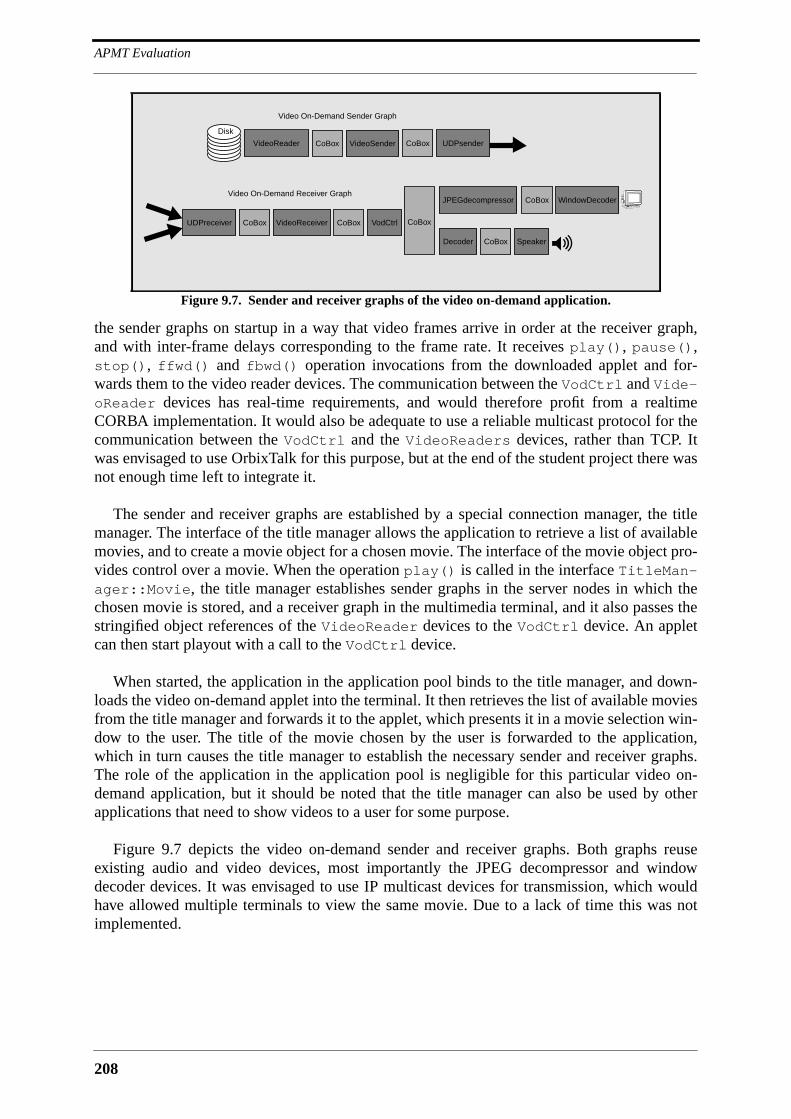
APMT Evaluation
208
the sender graphs on startup in a way that video frames arrive in order at the receiver graph,and with inter-frame delays corresponding to the frame rate. It receives play(), pause(),stop(), ffwd() and fbwd() operation invocations from the downloaded applet and for-wards them to the video reader devices. The communication between the VodCtrl and Vide-oReader devices has real-time requirements, and would therefore profit from a realtimeCORBA implementation. It would also be adequate to use a reliable multicast protocol for thecommunication between the VodCtrl and the VideoReaders devices, rather than TCP. Itwas envisaged to use OrbixTalk for this purpose, but at the end of the student project there wasnot enough time left to integrate it.
The sender and receiver graphs are established by a special connection manager, the titlemanager. The interface of the title manager allows the application to retrieve a list of availablemovies, and to create a movie object for a chosen movie. The interface of the movie object pro-vides control over a movie. When the operation play() is called in the interface TitleMan-ager::Movie, the title manager establishes sender graphs in the server nodes in which thechosen movie is stored, and a receiver graph in the multimedia terminal, and it also passes thestringified object references of the VideoReader devices to the VodCtrl device. An appletcan then start playout with a call to the VodCtrl device.
When started, the application in the application pool binds to the title manager, and down-loads the video on-demand applet into the terminal. It then retrieves the list of available moviesfrom the title manager and forwards it to the applet, which presents it in a movie selection win-dow to the user. The title of the movie chosen by the user is forwarded to the application,which in turn causes the title manager to establish the necessary sender and receiver graphs.The role of the application in the application pool is negligible for this particular video on-demand application, but it should be noted that the title manager can also be used by otherapplications that need to show videos to a user for some purpose.
Figure 9.7 depicts the video on-demand sender and receiver graphs. Both graphs reuseexisting audio and video devices, most importantly the JPEG decompressor and windowdecoder devices. It was envisaged to use IP multicast devices for transmission, which wouldhave allowed multiple terminals to view the same movie. Due to a lack of time this was notimplemented.
Figure 9.7. Sender and receiver graphs of the video on-demand application.
VideoReader CoBox VideoSender
JPEGdecompressor
CoBoxVodCtrlCoBoxVideoReceiverCoBoxUDPreceiver
Decoder CoBox Speaker
CoBox WindowDecoderVideo On-Demand Receiver Graph
CoBox UDPsender
Video On-Demand Sender Graph
Disk
209
Evaluation of APMT
9.3 Evaluation of APMT
The prototype is a proof for the feasibility of the APMT architecture, and it demonstrates theadvantage of having a low-level component framework in the terminal and multiple specializedhigh-level connection managers in the application pool. However, the prototype is not a fullimplementation of the APMT architecture, and the modifications that have been made in thenew set of interfaces still need to be evaluated with a prototype. The actual prototype is there-fore only a partial evaluation of the APMT architecture. It also has to be stated that someaspects of the architecture, like for instance scalability, can only be evaluated by simulation orby deployment of the platform on a large network.
This section evaluates the APMT architecture with respect to the requirements for MMCplatforms that were developed in Chapter 2. It lists the features of APMT, and points out werefunctionality is still missing. Table 9.2 contains a summary of the evaluation of APMT.
9.3.1 Platform Properties
This subsection evaluates APMT with respect to the required platform properties open, exten-sible, programmable, scalable, deployable and simple.
Open
APMT supports terminal interoperability, application portability and platform extensibilitywith open interfaces. Openness is largely due to the use of CORBA and IIOP. CORBA guaran-tees the openness of control communication. The openness of multimedia data communicationis provided by the use of Internet standards like RTP. The application pool and terminal infra-structures can be developed independently from each other, and there is no need for referenceimplementations against which individual application pool and terminal implementations mustbe tested.
Extensible
APMT features open interfaces for platform extension. The APMT platform is based on thecomponent framework paradigm and can be extended with both fine and coarse-grained func-tionality. Coarse-grained functionality is added via terminal servers in the terminal and appli-cation pool utilities in the application pool. Since APMT supports the federation ofapplications, an application that is capable of acting as a child application must also be consid-ered as a platform extension. Fine-grained functionality is added via low-level componentframeworks that are encapsulated by terminal servers. An example for such a componentframework is the multimedia middleware of the terminal that is encapsulated in the streamagent. Another low-level component framework would be for instance the abstract windowtoolkit implemented in a Java applet handler. It is still necessary to define operating-systemspecific mappings for the multimedia middleware that solve issues like the installation anddynamic loading of devices and device factories.
Programmable
APMT is highly programmable. Applications may directly access low-level terminal compo-nents, or they may profit from the services of high-level application pool utilities. The applica-tion model of APMT based on a central application and applets in the periphery reflects thefundamental structure of distributed software. The central application manages all issues that

APMT Evaluation
210
require arbitration among multiple applets, whereas applets take care of all issues that are localto a terminal. APMT is independent from any specific programming language. Applicationsand applets can both be implemented in Java, which allows to use all features of Java inAPMT. Computation intensive applications, or applications that need to interface to legacysoftware, can be implemented in C++, and download graphical user interfaces written in Tcl/Tk into the terminals.
Scalable
An application pool may run many applications simultaneously, because applications dis-charge processing via applets into terminals. Additional machines can be added to an applica-tion pool if it needs to run more applications, or serve more terminals. CORBA makes itpossible that application pools with different hardware configurations use the same software,which in turn allows to transparently upgrade the hardware of an application pool. Large com-munities of users can be served by multiple application pools, with a service gateway takingcare of load balancing. The number of applications supported by an application pool is onlylimited by the available disk space. The number of terminals that participate in an applicationmay vary from one to thousands. Applications with a large number of participants require thefederation of a master application and multiple slave applications.
Deployable
APMT is an overlay architecture and does not require any modifications of the network infra-structure. In its simplest form it also does not require user agent pools and service gateways.An application pool is as simple to deploy as a Web server. It consists of a daemon that imple-ments the Pc::Pool interface to the outside and that launches applications and applicationpool utilities. A factor that facilitates the deployment of APMT is its target network, the Inter-net, through which a large number of potential users and programmers can be reached. A factorthat could hinder the deployment of APMT is the commercial nature of existing CORBAimplementations. Public-domain implementations exist, but they are not as robust as the com-mercial implementations, and they do not offer the same amount of functionality. It can never-theless be expected that CORBA implementations become free for non-commercial use, as isthe case with Web browsers.
Simple
The implementation of the APMT platform is likely to cause some difficulties. Critical featuresare for example format matching, for which efficient algorithms need to be developed, andmulticast address management in connection managers. Care has to be taken to avoid dead-locks, although the APMT interfaces are designed to reduce this risk. Many APMT compo-nents, like for instance the terminal control, have to serve multiple clients in parallel. Thisrequires the use of threads, which in turn complicates implementation. It was tried to shift asmuch complexity as possibly away from components into the infrastructure. A connectionmanager for instance, which is a high-level component, does not need to perform formatmatching between devices within a terminal. The development of devices, terminal servers,application pool utilities and applications is therefore considerably simpler than the implemen-tation of the APMT infrastructure.
9.3.2 Platform Functionality
This subsection evaluates APMT with respect to the requirements on platform functionality.
211
Evaluation of APMT
Session Management
APMT models the relationships between users, terminals and applications with multiple ses-sion types, namely the terminal session, the user session, the application session, the partici-pant session, and the composite application session. Terminals may start applications, joinparticipant sessions, be invited to participant sessions, leave participant sessions, and kill appli-cations. The participant session is managed by an application pool utility, the participationcontrol, rather than the application pool control. This allows the development of multiple par-ticipation controls with differing levels of functionality. Applications are then able to choose aparticipation control that fits their needs.
Connection Management
Connection management is provided by connection managers in the application pool in collab-oration with the stream agents and graphs in the terminals. Connection managers are applica-tion pool utilities and are tailored to specific tasks. The APMT prototype contains two suchconnection managers, namely the CCCM and the video on-demand title manager. The central-ized connection management of APMT offers total control over connection establishmentwithin an application session. Connection structures can be dynamically created, modified anddeleted. Dynamic connection structure changes are difficult to achieve in a purely distributedconnection management architecture like the one originally planned for Beteus.
Multimedia Data Processing
Multimedia data processing is provided by the devices of the multimedia middleware. Multi-media data processing is highly configurable since devices can be plugged together in variousways.
Multipoint Control Communication
The most important vehicle for control communication in APMT is CORBA. The onlymultipoint communication feature CORBA offers at the time of writing is the event service. InAPMT, the event service is exclusively used for event communication within the terminal orwithin the application pool. This allows the use of a proprietary reliable multicast protocolunder the hood if only one ORB is used for internal communication, which is considered to bethe case. The shape of APMT would be different if CORBA offered more multipoint commu-nication functionality. There would be more emphasis on multipoint communication betweenapplets, which is now neglected in favor of the point-to-point communication between theapplet and its application. Another vehicle for the communication of control information arethe attribute headers of the multimedia middleware. Attribute headers allow for the unreliableoneway communication of control information from devices in sender graphs to devices inreceiver graphs, and from upstream devices to downstream devices within the same graph.
Resource Management
Resource management is reflected in the device and graph interfaces, but the interface of aresource manager still needs to be defined. For network communication the integration ofRSVP and RTCP is foreseen, which is considered to be rather straightforward, given that acentral connection management has complete control over sender and receiver transport ports.The stream agent interface needs to be extended with functionality that provides connectionmanagers with information about the network interfaces of the terminal and the available band-width.

APMT Evaluation
212
Synchronization
APMT supports event-based synchronization via attribute headers, and intra-stream synchroni-zation via devices. Inter-stream synchronization still needs to be integrated into the multimediamiddleware. Inter-stream synchronization is more an implementation than an interface designproblem, and its integration into the multimedia middleware interfaces should not providemore problems than its integration into IMA-MSS.
Mobile Code
APMT is based on mobile code techniques, but does not depend on a particular interpretedprogramming language for this. Tcl/Tk and Java applet handlers have been described. Tcl/Tk isa scripting language and may be used for the rapid development of downloadable graphicaluser interfaces, which may be sufficient for many applications. More advanced functionalityrequires the use of a strongly typed language like Java.
Presentation Environment
The integration of the multimedia middleware and the graphical user interfaces generated bydownloaded applets has not been addressed yet.
Federation of Applications
APMT supports the federation of applications with the concept of parent and child applicationsin an application pool. Applications that can be used by other applications implement the inter-face App::Application. In the current version of the interfaces, child applications have toreside on the same application pool as parent applications. This could be extended to allowparent applications to run child applications on other application pools. Another form of feder-ation of applications are the master and slave applications in broadcast scenarios.
Security
Security has not been explicitly addressed yet. Secure interpreters for Tcl and Java keepapplets from accessing the operating system in the terminal. Applets have access to the securesystem services provided by the applet handler, and to all objects on the terminal for whichthey can get an object reference. This may be critical in the case of objects that communicatethe content of files, like for instance the audio player device of the prototype. APMT must beanalyzed with respect to security flaws. The use of the CORBA security service must be envis-aged to protect control communication and resource access. Multimedia data communicationcan be protected with devices that encrypt data flows before they are transmitted over the net-work.
Mobility
APMT supports user mobility with user agents. Users may access their personal terminal con-trol environment via remote control panel applications. APMT does not address terminalmobility and session mobility, which are considered to be advanced concepts that should notbe part of the first version of the APMT platform.
Directory Service
Terminals, application pools, user agent pools and service gateways have a normal IP hostname. Their IP address can consequently be retrieved from DNS name servers, which in turnallows to construct an IIOP IOR for their principal public interface. Information about users is
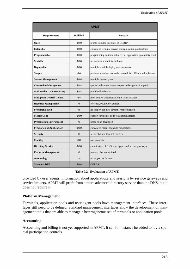
213
Evaluation of APMT
provided by user agents, information about applications and sessions by service gateways andservice brokers. APMT will profit from a more advanced directory service than the DNS, but itdoes not require it.
Platform Management
Terminals, application pools and user agent pools have management interfaces. These inter-faces still need to be defined. Standard management interfaces allow the development of man-agement tools that are able to manage a heterogeneous set of terminals or application pools.
Accounting
Accounting and billing is not yet supported in APMT. It can for instance be added to it via spe-cial participation controls.
APMT
Requirement Fulfilled Remark
Open ❄❄❄ profits from the openness of CORBA
Extensible ❄❄❄ concept of terminal servers and application pool utilities
Programmable ❄❄❄ programming on terminal server or application pool utility level
Scalable ❄❄❄ no inherent scalability problems
Deployable ❄❄❄ multiple possible deployment scenarios
Simple ❄❄ platform simple to use and to extend, but difficult to implement
Session Management ❄❄❄ multiple session types
Connection Management ❄❄❄ specialized connection managers in the application pool
Multimedia Data Processing ❄❄❄ provided by devices
Multipoint Control Comm. ❄❄ most control communication is point-to-point
Resource Management ❄ foreseen, but not yet defined
Synchronization no no support for inter-stream synchronization
Mobile Code ❄❄❄ support for mobile code via applet handlers
Presentation Environment no needs to be developed
Federation of Applications ❄❄❄ concept of parent and child applications
Security ❄ secure Tcl and Java interpreters
Mobility ❄❄ user mobility
Directory Service ❄❄❄ combination of DNS, user agents and service gateways
Platform Management ❄ foreseen, but not defined
Accounting no no support as for now
Standard DPE ❄❄❄ CORBA
Table 9.2. Evaluation of APMT.
APMT Evaluation
214
9.4 Conclusion
The prototype demonstrates the feasibility of the APMT platform. The evaluation of APMTshows that it addresses most of the requirements on MMC platforms that were developed inChapter 2. The most important issues among those that still need to be addressed is security.The APMT platform cannot be deployed if it represents a risk for the owners of applicationpools and terminals. Other issues to be addressed are synchronization, resource management,platform management and accounting. The APMT platform also lacks an integrated presenta-tion environment within the terminal that allows to combine multiple standalone graphical userinterfaces of terminal servers into a single one.
215
10 Conclusions
10.1 MMC Platforms
The development and deployment of applications for multipoint multimedia communication(MMC) requires the support of a platform. It is stated that such a platform must be open, exten-sible, programmable, scalable, deployable and simple in order to attract application developersand users. The functionality such a platform must provide is enormous and requires theemployment of existing technologies wherever this is possible. It must be built on top of a dis-tributed processing environment that makes the network transparent for control communica-tion. The most mature distributed processing technology that is at hand today is CORBA.CORBA is open, language-independent and object-oriented, and provides in addition to thebasic object request broker an extensive set of services of which most are interesting for theapplication platform targeted by this thesis.
First generation platforms like the Touring Machine, Beteus and Lakes provide considerablesupport for application development. However, they provide only limited support for applica-tion deployment because they require applications to be installed on endsystems. The thesisrefers to them as monolithic platforms because of their monolithic application programminginterface and their static internal structure that makes it difficult to extend them. The key toextensibility is the definition of component frameworks that are embedded in the platform andthat allow third parties to augment the functionality of the platform by adding new componentsto it. The way this can be done is illustrated by Medusa and IMA-MSS, two low-level compo-nent frameworks for multimedia processing and communication. Medusa is a complete com-ponent framework in the sense that it defines all interfaces of a component, including streaminterfaces, but it uses a proprietary protocol for the control of components. IMA-MSS usesCORBA for this purpose, but defines only those interfaces of a component that are visible toapplications. Low-level component frameworks like Medusa and IMA-MSS must be supple-mented by high-level component frameworks in order to increase the programmability of theplatform. High-level components can be built from low-level components, with an example forthis being the molecules of Medusa.
Medusa and IMA-MSS are meant to be generic component frameworks that can be inte-grated into larger application platforms. One problem with this is that application platformsmay be based on principles that conflict with the ones of generic component frameworks, withan example being TINA’s object model that is not compatible with the one of IMA-MSS.Another problem is that a generic component framework may be inadequate or sub-optimal forthe application model and the target network of the platform in which it is to be integrated. It istherefore stated that a component framework for multimedia data processing and transmissionmust be harmonized with the platform in which it is embedded, or even better, be tailored to it.
Conclusions
216
10.2 APMT
The APMT platform proposed by this thesis is a platform for multipoint applications that sup-ports multimedia data processing and communication with a low-level component frameworkthat is tailored to it. This component framework must already be considered as a platformextension. APMT responds to most of the requirements that the thesis imposes on multipointmultimedia application platforms. APMT is open due to the use of CORBA for the definitionof all interfaces, extensible due to the definition of low and high-level component frameworks,and programmable due to the application pool utilities that are layered on top of low-level ter-minal components, and its support for mobile code. APMT is scalable with respect to the num-ber of users, terminals, applications and application sessions. It is deployable because it isbased on an overlay architecture that is tailored to IP networks and that does not require anymodifications of the network infrastructure. APMT is meant to be deployed as a platform ker-nel that is extended with functionality as user demand crystallizes.
The major architecture building blocks are the application pool and the multimedia termi-nal, which are supplemented by the user agent pool and the service gateway that is based onthe CORBA trading service. The following list summarizes the major features of APMT:
• Static terminal: application code is installed in the application pool, not in theterminal. Applications download applets into terminals.
• Extensibility: the multimedia terminal can be extended with terminal servers, theapplication pool with application pool utilities.
• Application model: the APMT application model is tailored to multipoint appli-cations. Central applications arbitrate among applets in the periphery that takecare of whatever is local to a terminal.
• Application scenarios: APMT supports applications ranging from single-userinteractive presentations to broadcast applications with a large number of users.
• Maximum use of CORBA: in its current form, APMT uses the event service, thenaming service, the relationship service, and the trading service. APMT willprofit from other services like the security and transaction services, and facili-ties like electronic payment and A/V stream control.
• Internet: APMT uses IIOP for control communication. It further uses Internethostnames for the identification of terminals, application pools, user agent poolsand service gateways.
• Support for multiple interpreted languages: support for new interpreted lan-guages can be added via applet handlers in the terminal.
• Support for the import of control panels: users can import their own control pan-els into the terminals that they are using.
• Support for yellow page applications: applications can be started by other appli-cations in the terminal
• Support for terminal applications: applications installed on the terminal canaccess the APMT infrastructure.
• Compatibility testing: the compatibility of a terminal with a certain applicationcan be tested before the terminal starts or joins the application.
• Exchangeable participation control: participation control is not part of the corearchitecture. A basic participation control utility is defined that serves as a basisfor more advanced ones.
217
APMT
• Support for composite applications: applications can be built from other appli-cations.
Multimedia data communication is supported with a low-level component framework basedon devices that is adapted to the APMT application model. Device networks in the terminal arecontrolled by graphs that provide compound operations to connection managers or other utili-ties in the application pool. Compound operations reduce network communication andincrease the speed with which connection structures can be established among terminals. Thefollowing list summarizes the major features of the multimedia component framework:
• Devices: devices have a single consistent interface towards the application, amanagement interface towards the infrastructure, and one or more ports formedia data flows.
• Device connectors: device ports are connected by simple auto connectors orcontrollable connector boxes.
• Transport devices: transport devices encapsulate transport protocols and areused for the communication of multimedia data among terminals.
• Graphs: graphs provide for compound operations. Graphs containing an arbi-trary number of devices and device connectors can be created and activated withfour operation invocations.
• Device introspection: meta data about devices is provided via introspection,rather than via a device description language.
• Format matching: format matching within the terminal is performed by graphs.Format matching inbetween terminals is performed by central connection man-agers. APMT pleads the cause of semi-dynamic format matching where onlythe format type of source and sink ports is matched. Sink ports adapt dynami-cally to the format parameters of incoming multimedia data.
• Attribute headers: attribute headers are a means to add media-format indepen-dent control information to a data flow.
• Relationship service: the CORBA relationship service is used to allow for thenavigation of device graphs.
• Internet: APMT uses TCP/IP, UDP/IP, UDP/IP multicast, RTP and RTP payloadformats for network communication. The use of RSVP and RTCP is envisaged.
Applications may directly access devices and device connectors, or they may delegate con-trol over them to application pool utilities, like for instance connection managers. The thesispresented two connection managers, namely the Conference Configuration and ConnectionManager (CCCM) and the Title Manager used by the video on-demand application.
The core architecture of APMT can be compared with the service management architectureof TINA which is based on a similar application model. APMT distinguishes itself from TINAmainly with its emphasis on mobile code, on extensibility and on programmability. APMT isan overlay architecture for IP networks that can be deployed today, whereas TINA is, at least inits current form, an architecture for telecommunications networks that requires considerableinvestments prior to its deployment.
Conclusions
218
10.3 Further Work
The present thesis concentrated on the application management architecture and the multime-dia middleware of APMT. Few words were said about actual applications, and this is the pointwhere additional work is required. APMT must be evaluated with respect to its capability toaccommodate existing networked multimedia applications. The multimedia middleware pro-vides ways to exchange and to process multimedia data, but many applications require moreinfrastructure support than that. In order to demonstrate the aptitude of APMT as a generalapplication platform it is necessary to identify additional functionality that can be integratedinto the platform.
The Internet has become the realm of the Web, with the result that it is impossible to intro-duce a new application platform into the Internet that does not interface to the Web in one wayor another. It its therefore necessary to relate APMT with the Web and to find ways for howAPMT can be reached via the Web and vice-versa. It is possible to define a new type of Uni-form Resource Locator (URL) that denotes an APMT application or application session andthat can be used for hyper-links in HTML. Web browsers may then be integrated into APMT asterminal applications with access to the terminal control, which in turn allows users to start orjoin APMT applications by following hyper-links.
Application platforms like APMT are best divulged via freely available prototype imple-mentations that demonstrate their capabilities better than any theoretical description. The exist-ing prototype is only a first step in this direction since it is not a complete implementation ofAPMT. A first publicly available prototype should only integrate a subset of the functionalitypresented in this thesis in order to be simple to use and robust.
10.4 Contribution of this Thesis
The contribution of this thesis is in the area of multipoint applications for human communica-tion and interaction, and consists of the following main parts:
• Motivation for platforms: the thesis motivates the use of platforms for the devel-opment and deployment of multipoint multimedia applications. Developmentand deployment support will lead to a large number and variety of applications,which in turn is a prerequisite for the (commercial) success of multipoint appli-cations in general. A large number of available applications and the resultinguser demand will justify investments into the network infrastructure.
• Requirements on platforms: the thesis develops a set of requirements that arecrucial for the design of a platform for multipoint multimedia applications. It isshown that none of the existing approaches for platforms responds to all of theserequirements. There are few platforms that address multipoint applicationdevelopment and deployment at all. The emphasis of platforms like TINA is onterminal compatibility and application portability.
• Beteus platform: the thesis describes the Beteus platform, which is an examplefor a platform that provides high-level support for multipoint multimedia appli-cation development.
219
Contribution of this Thesis
• APMT platform architecture: the APMT platform responds to all importantrequirements identified by this thesis. It supports application development withhigh and low-level component frameworks, and application deployment withmobile code techniques.
• APMT multimedia middleware: the thesis describes a multimedia middlewarebased on low-level components, and a connection manager as an example for ahigh-level component. The connection manager builds on the multimedia mid-dleware and provides advanced support for application development.
The only platform known to the author that addresses the problem of platform design formultipoint multimedia applications in a way comparable to APMT is TINA. It is stated thatAPMT may provide many ideas for the future development of TINA.

Conclusions
220
221
References
References
[Abar96] Chelo Abarca et al. Service Architecture Version 5.0. TINA-C Baseline DocumentNo. TB_RM.001_4.0_96, December 1996.
[Ado90] Adobe Corporation. Postscript Language Reference Manual, Addison-WesleyPublishing Company, Inc., 1990.
[AF93] ATM-Forum. ATM User-Network Interface Specification Version 3.0. Prentice-Hall, Englewood Cliffs, 1993.
[Alma95] George Almasi et al. TclDii: A TCL Interface to the Orbix Dynamic InvocationInterface. Technical report, West Virginia University, 1995. Online version at http://www.cerc.wvu.edu/dice/iss/TclDii/TclDii.html.
[Appl96] Apple, IBM, Oracle, Netscape, and Sun. Network Computer Reference ProfileIntroduction. http://www.nc.ihost.com/nc_ref_profile.html, May 1996.
[Aran93] M. Arango et al. The Touring Machine System. Communications of the ACM,36(1):63–77, January 1993.
[Barr93] William J. Barr, Trevor Boyd, and Yuji Inoue. The TINA Initiative. IEEE Commu-nications Magazine, 33(3):70–76, March 1993.
[Bate94] John Bates and Jean Bacon. A Development Platform for Multimedia Applicationsin a Distributed, ATM Network Environment. In Proceedings of the InternationalConference on Multimedia Computing and Systems, Boston MA, May 1994.
[Berc96] L. Berc, W. Fenner, B. Frederick, and S. McCanne. RTP Payload Format forJPEG-compressed Video. Internet Engineering Task Force RFC 2035, October1996.
[Bern95] Christoph Bernhardt and Ernst Biersack. A Scalable Video Server: Architecture,Design and Implementation. In Proceedings of the Realtime Systems Conference,pages 220–227, Paris, France, January 1995.
[Bess95] Michel Besson, Karim Traore, and Philippe Dubois. Control and Performance-Monitoring of a Multimedia Platform over the ATM Pilot. In Proceedings of theFirst International Distributed Conference IDC’95, Madeira, November 1995.
[Biag93] Edoardo Biagionie, Eric Cooper, and Robert Sansom. Designing a Practical ATMLAN. IEEE Network, March 1993.
[Blum95] Christian Blum and Olivier Schaller. The Beteus Application Programming Inter-face. Technical Report RR-96-020, Institut Eurécom, December 1995. Online ver-sion at http://www.eurecom.fr/ blum/pub/pub.html.

References
222
[Blum96] Christian Blum, Didier Loisel, and Refik Molva. BETEUS: Multipoint Teleconfer-encing over the European ATM Pilot. In Proceedings of the European Conferenceon Networks and Optical Communication NOC ’96, Heidelberg, June 1996.
[Blum97a] Christian Blum. APMT IDL Documentation. http://www.eurecom.fr/ blum/phd/apmtdoc.html, April 1997.
[Blum97b] Christian Blum. APMT Prototype. http://www.eurecom.fr/ blum/proto/proto.html,May 1997.
[Blum97c] Christian Blum, Philippe Dubois, Refik Molva, and Olivier Schaller. A Develop-ment and Runtime Platform for Teleconferencing Applications. Journal onSelected Areas in Communications, special issue on Network Support forMultipoint Communication, 15(3), April 1997.
[Bore94] Nathaniel S. Borenstein. EMail with a Mind of Its Own: The Safe-Tcl Languagefor Enabled Mail. In Proceedings of the IFIP WG 6.5 Conference, Barcelona, May1994.
[Bosc96] Pier Giorgio Bosco, Eirik Dahle, Michel Gien, Andrew Grace, Nicolas Mer-couroff, Nathalie Perdigues, and Jean-Bernard Stefani. The ReTINA Project: AnOverview. Technical Report RT/TR-96-15.1, Chorus Systèmes, May 1996.
[Brad96] R. Braden, L. Zhang, S. Berson, S. Herzog, and S. Jamin. Resource ReSerVation-Protocol (RSVP) - Version 1 Functional Specification. IETF Internet Draft, Octo-ber 1996.
[Bran95] Thomas J. Brando. Comparing DCE and CORBA. Technical Report DocumentMP 95B-93, MITRE, March 1995.
[Brow95] Dave Brown and Stefano Montesi. Requirements upon TINA-C Architecture.TINA-C Document No. TB_MH.002_2.0_94, February 1995.
[Brow96] Nat Brown and Charlie Kindel. Distributed Component Object Model Protocol:DCOM 1.0. Internet Engineering Task Force, Internet Draft, November 1996.Online version at ftp://ftp.ietf.org/internet-drafts/draft-brown-dcom-v1-spec-01.txt.
[Camp92] Andrew Campbell, Geoff Coulson, Francisco Garcia, and David Hutchison. AContinuous Media Transport and Orchestration Service. In Proceedings of ACMSIGCOMM’92, Maryland, Baltimore USA, August 1992.
[Camp93] Andrew Campbell, Geoff Coulson, Francesco Garcia, David Hutchison, and Hel-mut Leopold. Integrated Quality of Service for Multimedia Communications. InProceedings of IEEE Infocom, San Francisco, March 1993.
[Camp96] Andrew Campbell, Cristina Aurrecoechea, and Linda Hauw. A Review of QoSArchitectures. In Proceedings of the 4th IFIP International Workshop on Qualityof Service, IWQS’96, Paris, France, March 1996.
223
References
[CCIT88] CCITT/ISO. Recommendation X.500: The Directory - Overview of Concepts,Models and Services. ITU and ISO, Geneva, March 1988. ISO 9594 is technicallyaligned with X.500.
[Coan93] Brian A. Coan et al. The Touring Machine System (Ver. 3): An Open DistributedPlatform for Information Networking Applications. In Proceedings of TINA ’93,September 1993.
[Coul93] Geoffrey Coulson. Multimedia Application Support in Open Distributed Systems.PhD thesis, Computing Department at Lancaster University, April 1993.
[Coul95] Geoffrey Coulson, Andrew Campbell, Philippe Robin, Gordon Blair, Michael Pap-athomas, and Doug Sheperd. The Design of a QoS-Controlled ATM-Based Com-munications System in Chorus. IEEE Journal on Selected Areas inCommunications, 13(4):686–699, May 1995.
[Coul96] Geoffrey Coulson and Daniel G. Waddington. A CORBA Compliant Real-TimeMultimedia Platform for Broadband Networks. In Otto Spaniol et al, editor, Pro-ceedings of the International Workshop TreDS’96 on Trends in Distributed Sys-tems: CORBA and Beyond, Springer Lecture Notes in Computer Science 1161,Aachen, October 1996.
[Deer91] Stephen Deering. Multicast Routing in a Datagram Internetwork. Technical ReportSTAN-CS-92-1415, Stanford University, December 1991.
[Deut95] P. Deutsch, R. Schoultz, P. Faltstrom, and C. Weider. Architecture of theWHOIS++ Service. Internet Engineering Task Force RFC 1835, August 1995.
[dM93] Vicki de Mey and Simon Gibbs. A Multimedia Component Kit. In Proceedings ofthe ACM Multimedia ’93, Annaheim, CA, August 4-6 1993.
[Durv96] Nicolas Durville, Rodolphe Kraftsik, Christophe Stegmann, and Antonio Suarez.Une Application Vidéo On-Demand. Semester project report, Institut Eurécom,December 1996.
[Ecke96] Klaus-P. Eckert, M. Khayrat Durmosch, Klaus D. Engel, and Peter Schoo. ACORBA 2 Based Distributed Processing Environment for TelecommunicationApplications. In Proceedings of the Distributed Object Computing for TelecomConference at ObjectWorld’96, Frankfurt am Main, Germany, October 1996.
[Elia96] Frank Eliassen and John R. Nicol. A Flexible Type Checking Model for StreamInterface Typing. In Proceedings of the IEEE International Workshop on Multime-dia Software Development, Berlin, March 1996.
[Engi96] Apple ScriptX/Java Engineering. Biscotti - A Treat for Java Lovers. http://dev-world.apple.com, November 1996.
[Floy96] S. Floyd, V. Jacobson, C. Liu, S. McCanne, and L. Zhang. A Reliable MulticastFramework for Light-weight Sessions and Application Level Framing. To appearin IEEE/ACM Transactions on Networking, November 1996.
References
224
[Frit96] J. Christian Fritsche. Multimedia Building Blocks for Distributed Applications. InProceedings of the IEEE International Workshop on Multimedia Software Devel-opment, pages 41–48, Berlin, March 1996.
[Gall91] Didier Le Gall. MPEG: A Video Compression Standard for Multimedia Applica-tions. Communications of the ACM, 34(4):46–58, April 1991.
[Geib96] Rüdiger Geib. Operating the European ATM Pilot. In Proceedings of the EuropeanConference on Networks and Optical Communication NOC’96, Heidelberg, June1996.
[Geri97] Frank Gerischer. Design and Implementation of Audio Components for a CORBA-Based Multimedia Application Platform. Master’s thesis, University of Stuttgart,May 1997.
[Gibb94] Simon J. Gibbs and Dionysios C. Tsichritzis. Multimedia Programming: Objects,Environments and Frameworks. Addison-Wesley, 1994.
[Gokh96] Aniruddha Gokhale, Douglas C. Schmidt, Tim Harrison, and Guru Parulkar. Oper-ating System Support for High-Performance, Real-Time CORBA. In Proceedingsof the 5th International Workshop on Object-Orientation in Operating SystemsIWOOOS’96, Seattle, Washington, October 1996.
[Grah96] Ian S. Graham. HTML Sourcebook: A Complete Guide to HTML 3.0. John Wileyand Sons, Inc., 2nd edition, 1996.
[Gros94] Pascal Gros, Toni Vaquer-Mestre, and Philippe Dubois. Intelligent Session Man-agement for Multimedia Shared Workspaces. Technical report, Institut Eurecom,1994.
[Gute95] Thomas Gutekunst, Daniel Bauer, Germano Caronni, Hasan, and Bernhard Platt-ner. A Distributed and Policy-Free General-Purpose Shared Window System.IEEE/ACM Transactions on Networking, 3(1):51–62, February 1995.
[Herb94] Andrew Herbert. An ANSA Overview. IEEE Network, 8(1):18–23, January/Febru-ary 1994.
[Herm94] I. Herman et al. PREMO: An ISO Standard for a Presentation Environment forMultimedia Objects. In Proceedings of ACM Multimedia’94, pages 111–117, SanFrancisco, October 1994.
[Hoff96] D. Hoffman and G. Fernando. RTP Payload format for MPEG1/MPEG2 Video.Internet Engineering Task Force RFC 2038, October 1996.
[Houh95] Henry H. Houh, Joel F. Adam, Michael Ismert, Christopher J. Lindblad, andDavid L. Tennenhouse. The VuNet Desk Area Network: Architecture, Implemen-tation and Experience. IEEE Journal on Selected Areas in Communications,13(4):710–721, May 1995.

225
References
[IBM 94] IBM Lakes Team. IBM Lakes: An Architecture for Collaborative Networking. R.Morgan Publishing, Chislehurst, 1994.
[IEEE96] IEEE Communications Society. Special Issue: Multimedia Networked Terminals.IEEE Personal Communications, 3(2), April 1996.
[IMA94a] Interactive Multimedia Association. Multimedia System Services Part 1: Func-tional Specifications, IMA Recommended Practice, September 1994.
[IMA94b] Interactive Multimedia Association. Multimedia System Services Part 2: Multime-dia Devices and Formats, IMA Recommended Practice, September 1994.
[InSo94] InSoft. OpenDVE Architecural Overview. Technical report, InSoft Inc., 1994.
[Ion96a] Iona Technologies Ltd. Orbix 2 Programming Guide, October 1996.
[Ion96b] Iona Technologies Ltd. OrbixTalk 1.0 Programming Guide, July 1996.
[ISO87] International Organization for Standardization. Information Processing Systems -Computer Graphics - Metafile for the Storage and Transfer of Picture DescriptionInformation, ISO IS 8632, 1987.
[ISO95a] ISO/IEC and ITU-T. Open Distributed Processing: - Basic Reference Model - Part1: Overview, Draft Standard 10746-1, Draft Recommendation X.901, 1995.
[ISO95b] ISO/IEC and ITU-T. Open Distributed Processing: - ODP Trading Function, DraftInternational Standard 13235, 1995.
[ISO96a] International Organization for Standardization. Information Processing Systems -Computer Graphics and Image Processing - Presentation Environments for Multi-media Objects (PREMO)- Part 1: Fundamentals of PREMO, ISO/IEC standardscommittee ISO/IEC JTC1/SC24 draft 1996-05-15, May 1996.
[ISO96b] International Organization for Standardization. Information Processing Systems -Computer Graphics and Image Processing - Presentation Environments for Multi-media Objects (PREMO)- Part 3: Multimedia System Services, ISO/IEC standardscommittee ISO/IEC JTC1/SC24 draft 1996-05-15, May 1996.
[ITU94] International Telecommunication Union. Recommendation T.120: Data Protocolsfor Multimedia Conferencing, March 1994.
[ITU95] International Telecommunication Union. Draft Recommendation T.121: GenericApplication Template, March 1995.
[ITU97] International Telecommunication Union. Draft Recommendation T.130: Real TimeAudio-Visual Control for Multimedia Conferencing, January 1997.
[IWQ96] IFIP Fifth International Workshop on Quality of Service (IWQOS ’97) . http://www.ctr.columbia.edu/iwqos/, 1996. Workshop announcement.
References
226
[Jack93] Keith Jack. Video Demystified: A Handbook for the Digital Engineer. BrooktreeCorporation, 1993.
[Jans96] Rickard Janson and Laurence Demounem. TINA Reference Points Version 3.1.TINA-C Baseline Document No. EN_RC_J.030_3.1_96, December 1996.
[Jone93] Alan Jones and Andrew Hopper. Handling Audio and Video Data Streams in a Dis-tributed Environment. In Proceedings of the 14th ACM Symposium on OperatingSystem Principles, pages 231–243, December 1993.
[Kali96] Thomas A. Kalil. Leveraging Cyberspace. IEEE Communications Magazine,34(7):82–86, July 1996.
[Kay92] David C. Kay and John P. Levine. Graphics File Formats. Windcrest/McGraw-Hill, 1992.
[Klap96] A. J. Klapwijk and U. Behnke. PLATINUM: A Platform for Users of Multimedia.In Proceedings of the European Conference on Networks and Optical Communica-tion NOC’96, Heidelberg, June 1996.
[Kret92] Francis Kretz and Francoise Colaitis. Standardizing Hypermedia InformationObjects. IEEE Communications Magazine, pages 60–70, May 1992.
[Laza95] Aurel A. Lazar, Shailendra K. Bhonsle, and Koon-Seng Lim. A Binding Architec-ture for Multimedia Networks. Journal of Parallel and Distributed Computing,30(2):204–216, November 1995.
[Laza96] Aurel A. Lazar, Koon-Seng Lim, and Franco Marconcini. The Binding InterfaceBase. Technical Report CTR 412-95-18, COMET Group at Columbia University,February 1996.
[Li95] Guanxing Li. ANSA Phase III: An Overview of Realtime ANSAware 1.0. Techni-cal Report APM.1285.01, Architecture Projects Management APM, March 1995.Online version at ftp://ftp.ansa.co.uk/.
[Litt90] Thomas D. C. Little and Arif Ghafoor. Synchronization and Storage Models forMultimedia Objects. IEEE Journal on Selected Areas in Communications,8(3):413–427, April 1990.
[Liu94] Cricket Liu, Jerry Peck, Russ Jones, Bryan Buus, and Adran Nye. Managing Inter-net Information Services. O’Reilley and Associates, Inc., December 1994.
[Lock94] Harold W. Jr. Lockhart. OSF DCE: Guide to Developing Distributed Applications.McGraw-Hill, Inc, 1994.
[Luca95] Henry C. Lucas, Hugues Levecq, Robert Kraut, and Lynn Streeter. France’s Grass-Roots Data Net. IEEE Spectrum, pages 71–77, November 1995.
[Mace94] Michael R. Macedonia and Donald P. Brutzman. MBone Provides Audio andVideo Across the Internet. IEEE Computer, 27(4):30–36, April 1994.
227
References
[Magi96] General Magic. Telescript Technology: An Introduction to the Language. http://www.genmagic.com/Telescript/index.html, 1996.
[Mak93] Viktor Mak, Mauricio Arango, and Takako Hickey. The Application ProgrammingInterface to the Touring Machine. Bellcore Technical Report, February 1993.
[Mank96] Allison Mankin and Allyn Romanow. IETF Criteria For Evaluating Reliable Mul-ticast Transport and Application Protocols. Internet Engineering Task Force, Inter-net Draft, November 1996.
[MB95] Thomas Meyer-Boudnik and Wolfgang Effelsberg. MHEG Explained. IEEE Multi-media, 2(1):26–38, Spring 1995.
[McCa95] Steven McCanne and Van Jacobson. vic: A Flexible Framework for Packet Video.In Proceedings of ACM Multimedia’94, pages 511–521, San Francisco, October1995.
[Meye96] Bertrand Meyer. The many faces of inheritance: A taxonomy of taxonomy. IEEEComputer, 29(5):105–108, May 1996.
[Micr95] Microsoft. The Component Object Model Specification, Draft Version 0.9. Techni-cal report, Microsoft Corporation and Digital Equipment Corporation, October1995.
[Mine94] Robert F. Mines, Jerrold A. Friesen, and Christine L. Yang. DAVE: A Plug andPlay Model for Distributed Multimedia Application Development. In Proceedingsof ACM Multimedia’94, pages 59–66, San Francisco, October 1994.
[Mock87] P. Mockapetris. Domain Names: Implementation and Specification. Internet Engi-neering Task Force RFC 1035, November 1987.
[Mont95] Todd Montgomery. Design, Implementation and Verification of the Reliable Multi-cast Protocol. Master’s thesis, West Virginia University, December 1995.
[MP97] Ketan Mayer-Patel and Lawrence A. Rowe. Design and Performance of the Berke-ley Continuous Media Toolkit. In Proceedings of Multimedia Computing and Net-working MMCN’97, San Jose, CA, February 1997.
[Mühl96] Max Mühlhäuser and Jan Gecsei. Services, Frameworks, and Paradigms for Dis-tributed Multimedia Applications. IEEE Multimedia, 3(3):48–61, Fall 1996.
[Murp96] Brendan Murphy and Glenford Mapp. Integrating Multimedia Streams into a Dis-tributed Computing System. In Proceedings of Multimedia Computing and Net-working, San Jose, CA, USA, January 1996.
[Nets97] Netscape, Inc. Netscape Navigator Inline Plug-Ins. http://home.netscape.com/inf/comprod/products/navigator/version_2.0/plugins/% index.html, May 1997.
[Neum95] B. Clifford Neuman. Security, Payment and Privacy for Network Commerce. IEEEJournal on Selected Areas in Communications, 13(8):1523–1531, October 1995.
References
228
[OMG94] Object Management Group. Common Facilities Architecture: Revision 4.0, OMGDocument 95-1-2, January 1994.
[OMG95a] Object Management Group. Common Facilities Architecture, OMG Document 95-1-2, January 1995.
[OMG95b] Object Management Group. CORBAservices: Common Object Services Specifica-tion, Revised Edition, OMG Document 94-1-1, March 1995. Online version athttp://www.omg.org/library/corbserv.htm.
[OMG95c] Object Management Group. The Common Object Request Broker Architecture andSpecification: Revision 2.0, Object Management Group, Inc., Framingham, MA.,July 1995.
[OMG96a] Object Management Group. Common Facilities RFP-4: Common Business Objectsand Business Objects Facility, OMG Document CF/96-01-04, January 1996.
[OMG96b] Object Management Group. The Fall 1996 CORBA Buyers Guide. Object Manage-ment Group, Inc., Framingham, MA., 1996. Online version at http://www.omg.org/news/cbg.htm.
[OMG96c] Object Management Group. Messaging Service RFP, OMG Document orbos/96-03-16, March 1996.
[OMG96d] Object Management Group. Multiple Interfaces and Composition RFP, OMG Doc-ument orb/96-01-04, January 1996.
[OMG96e] Object Management Group. Object Analysis and Design RFP, OMG Document ad/96-05-01, May 1996.
[OMG96f] Object Management Group. Objects-by-value RFP, OMG Document orbos/96-06-14, June 1996.
[OMG96g] Object Management Group. Telecommunications Task Force RFP: Control andManagement of A/V Streams, OMG Document telecom/96-08-01, August 1996.
[OMG96h] Object Management Group. Trading Object Service, OMG Document orbos/96-05-06, October 1996.
[OMG97a] Object Management Group. CORBA Component Model RFP, OMG Documentorbos/97-06-12, June 1997.
[OMG97b] Object Management Group. DCE/CORBA Interworking RFP, OMG Documentorbos/97-03-19, March 1997.
[OMG97c] Object Management Group. Java to IDL RFP, OMG Document orbos/97-03-08,March 1997.

229
References
[OMG97d] Object Management Group. Multiple Interfaces and Composition, Joint Submis-sion to Object Management Group by Iona Technologies and others, OMG Docu-ment orbos/97-01-02, January 1997.
[OMG97e] Object Management Group. ORB Portability Enhancement - Portable ObjectAdapter (POA), OMG Document orbos/97-04-14, April 1997.
[OMG97f] Object Management Group. Proposal to the OMG’s Analysis and Design TaskForce, Joint Submission to Object Management Group by Rational Software Cor-poration and others, OMG Document orbos/97-01-14, January 1997.
[Orfa96] Robert Orfali, Dan Harkey, and Jeri Edwards. The Essential Distributed ObjectsSurvival Guide. John Wiley and Sons, Inc., 1996.
[Otwa95a] Dave Otway. ANSA Phase III: DIMMA Overview. Technical ReportAPM.1439.02, Architecture Projects Management APM, April 1995. Online ver-sion at ftp://ftp.ansa.co.uk/.
[Otwa95b] Dave Otway. ANSA Phase III: Streams and Signals. Technical ReportAPM.1393.02, Architecture Projects Management APM, January 1995. Onlineversion at ftp://ftp.ansa.co.uk/.
[Oust90] John K. Ousterhout. Tcl: An Embeddable Command Language. In Proceedings ofthe Winter 1990 USENIX Conference, 1990.
[Oust94] John K. Ousterhout. Tcl and the Tk Toolkit. Addison-Wesley, Reading, Massachu-setts, 1994.
[Oust96] John K. Ousterhout, Jacob Y. Levy, and Brent B. Welch. The Safe-Tcl SecurityModel. Technical report, Sun Microsystems, November 1996. Online version athttp://www.smli.com/research/tcl/.
[Pan95] Davis Pan. A Tutorial on MPEG/Audio Compression. IEEE Multimedia, 2(2):60–74, Summer 1995.
[Parh96] A. Parhar. TINA Object Definition Language Manual Version 2.3. TINA-C Base-line Document No. TR_NM.002_2.2_96, July 1996.
[Picc94] Marty Picco, Glenn Stewart, Wayne Blackard, Greg Flurry, William K. Pratt, andJim Van Loo. Multimedia Systems, chapter Middleware System Services Architec-ture, pages 221–244. ACM Press SIGGRAPH Series. Addison-Wesley PublishingCompany, New York, 1994.
[Pryc93] Martin De Prycker. Asynchronous Transfer Mode: Solution for Broadband-ISDN.Ellis-Horwood, 1993.
[Pusz94] Yu-Hong Pusztaszeri et al. Multimedia Teletutoring over a Trans-European ATMNetwork. In Proceedings of the IWACA ’94, pages 32–39, September 1994.

References
230
[Pyar96] Irfan Pyarali, Timothy H. Harrison, and Douglas C. Schmidt. Design and Perfor-mance of an Object-Oriented Framework for High-Speed Electronic MedicalImaging. USENIX Computing Systems Journal, 9(3), November/December 1996.
[Raja95] Sreeranga Rajan, P. Venkat Rangan, and Harrick M. Vin. A Formal Basis for Struc-tured Multimedia Collaborations. In Proceedings of the 2nd IEEE InternationalConference on Multimedia Computing and Systems, Washington, D.C., May 1995.
[Rang91] P. Venkat Rangan and Harrick M. Vin. Multimedia Conferencing as a UniversalParadigm for Colaboration. In Lars Kjelldahl, editor, Multimedia - Principles, Sys-tems, and Applications, chapter 14. Springer-Verlag, April 1991. (Proceedings ofEurographics Workshop on Multimedia Systems, Applications, and Interaction,Stockholm, Sweden).
[Raym95] Kerry Raymond. Streams and QoS: A White Paper. Technical report, OMG Tele-communications SIG, 1995.
[Rona87] J. Rona. MIDI: The Ins, Outs & Thrus. Hal Leonard, Milwaukee, 1987.
[Roth94] Kurt Rothermel, Ingo Barth, and Tobias Helbig. CINEMA - An Architecture forDistributed Multimedia Applications. In O. Spaniol, A. Danthine, andW. Effelsberg, editors, Architecture and Protocols for High-Speed Networks, pages253–271. Kluwer Academic Publishers, 1994.
[Rowe93] L. A. Rowe, B. Smith, and S. Yenftp. Tcl Distributed Programming (Tcl-DP).Technical report, University of Berkeley, Computer Science Division, March 1993.
[Rozi91] M. Rozier et al. Overview of the CHORUS Distributed Operating System. Techni-cal Report CS/TR-90-25.1, Chorus Systèmes, February 1991.
[Rumb91] James Rumbaugh, Michael Blaha, William Premerlani, Frederick Eddy, and Will-iam Lorensen. Object-Oriented Modeling and Design. Prentice Hall International,Inc., Englewood Cliffs, New Jersey, 1991.
[Schm96a] Marcus Schmid. Design and Implementation of a Connection Management Plat-form for Networked Multimedia Applications. Master’s thesis, University of Stut-tgart, May 1996.
[Schm96b] Douglas C. Schmidt and Aniruddha Gokhale. Performance of the CORBADynamic Invocation Interface and Internet Inter-ORB Protocol over High-SpeedATM Networks. In Proceedings of IEEE GLOBECOM’96, London, November1996.
[Schu96a] Henning Schulzrinne. RTP Profile for Audio and Video Conferences with MinimalControl. Internet Engineering Task Force RFC 1890, May 1996.
[Schu96b] Henning Schulzrinne, Van Jacobson, Stephen L. Casner, and Ron Frederick. RTP:A Transport Protocol for Real-Time Applications. Internet Engineering Task ForceRFC 1889, February 1996.
231
References
[Shen95] Scott Shenker. Fundamental Design Issues for the Future Internet. IEEE Journalon Selected Areas in Communications, 13(7):1176–1188, September 1995.
[Sieg96] Jon Siegel et al. CORBA: Fundamentals and Programming. John Wiley and Sons,Inc., 1996.
[Sree92] Cormac John Sreenan. Synchronization Services for Digital Continuous Media.PhD thesis, Christ’s College University of Cambridge, October 1992.
[Staj94] Frank Stajano. Writing Tcl Programs in the Medusa Applications Environment. InProceedings of the Tcl/Tk Workshop, New Orleans, June 1994.
[Staj95] Frank Stajano and Robert Walker. Taming the Complexity of Distributed Multime-dia Applications. In Proceedings of the 1995 Usenix Tcl/Tk Workshop,, Toronto,July 1995.
[Stal94] Richard Stallman. Why you should not use Tcl. USENET article on comp.lang.tcl,September 1994.
[Stei90] Ralf Steinmetz. Synchronization Properties in Multimedia Systems. IEEE Journalon Selected Areas in Communications, 8(3):401–412, April 1990.
[Stei95] Ralf Steinmetz. Analyzing the Multimedia Operating System. IEEE Multimedia,2(1):68–84, Spring 1995.
[Stev90] Richard W. Stevens. UNIX Network Programming. Prentice Hall, Inc., EnglewoodCliffs, New Jersey, 1990.
[Sun88] Sun Microsystems. RPC: Remote Procedure Call Specification Version 2. InternetEngineering Task Force, RFC 1050, June 1988. Online version at ftp://ds.inter-nic.net/rfc/rfc1057.txt.
[Sun95] Sun Microsystems. The Java Language Specification, October 1995. Online ver-sion at http://www.javasoft.com/doc/programmer.html.
[Sun96a] Sun Microsystems. Java Beans 1.0 API Specification, December 1996. Online ver-sion at http://splash.javasoft.com/beans/spec.html.
[Sun96b] Sun Microsystems. Java Media API, 1996. Online version at http://www.java-soft.com/products/api-overview.html.
[Sun96c] Sun Microsystems. Java Object Serialization Specification, December 1996.Online version at http://chatsubo.javasoft.com/current/serial/index.html.
[Sun96d] Sun Microsystems. Remote Method Invocation Specification, 1996. Online versionat http://java.sun.com/products/JDK/1.1/docs/guide/rmi/.
[Thoe94] Jan Thoerner. Intelligent Networks. Artech House, 1994.

References
232
[TIF88] Aldus Corporation Developer Desk and Microsoft Corporation Windows Market-ing Group. TIFF 5.0. An Aldus/Microsoft Technical Memorandum, 1988.
[Turl96] Thierry Turletti and Christian Huitema. RTP Payload format for H.261 VideoStreams. Internet Engineering Task Force RFC 2032, October 1996.
[vdL93] Rob van der Linden. ANSA Phase III: An Overview of ANSA. Technical ReportAPM.1000.01, Architecture Projects Management APM, July 1993. Online ver-sion at ftp://ftp.ansa.co.uk/.
[Wald94] Jim Waldo, Geoff Wyant, Ann Wollrath, and Sam Kendall. A Note on DistributedComputing. Technical Report SMLI TR-94-29, Sun Microsystems Laboratories,November 1994.
[Wall91] G. K. Wallace. The JPEG Still Compression Standard. Communications of theACM, 34(4):31–45, April 1991.
[Watt96] Aaron R. Watters. The What, Why, Who, and Where of Python. http://www.wcmh.com/uworld/archives/95/tutorial/005.html, November 1996.
[Wayn95] Peter Wayner. Agents Unleashed: A Public Domain Look at Agent Technology.Academic Press Professional, Chestnut Hill, Massachusetts, 1995.
[Wein94] Abel Weinrib. The Need for a Software Infrastructure to Support Community Net-working Applications. In Proceedings of the 1st International Workshop on Com-munity Networking, San Francisco, July 1994.
[Whit96] Robert A. Whiteside and Ernest J. Friedman-Hill. Idldoc: The IDL DocumentationGenerator. http://herzberg.ca.sandia.gov/idldoc/, April 1996.
[Woo94] Miae Woo, Naveed U. Qazi, and Arif Ghafor. A Synchronization Framework forCommunication of Pre-orchestrated Information. IEEE Network, pages 52–61,January/February 1994.
[Wool96] Michael Woolridge. Intelligent Agents and Multi-Agent Systems. In Proceedingsof the EUNICE’96 Summer School on Telecommunications Services, Lausanne,September 1996.
[Wray94] Stuart Wray, Tim Glauert, and Andy Hopper. Networked Multimedia: The MedusaEnvironment. IEEE Multimedia, 1(4):54–63, Winter 1994.
[Zhan93] Lixia Zhang, Steve Deering, Deborah Estrin, Scott Shenker, and Daniel Zappala.RSVP:A New Resource ReSerVation Protocol. IEEE Network Magazine, Septem-ber 1993.
[Zimm91] D. Zimmerman. The Finger User Information Protocol. Internet Engineering TaskForce RFC 1288, December 1991.

233
List of Acronyms and Abbreviations
ANSA Advanced Networked Systems ArchitectureAP Application PoolAPI Application Programming InterfaceAPM Architecture Projects ManagementAPMT Application Pool and Multimedia Terminal architectureATM Asynchronous Transfer ModeASE Application Service ElementASID Access, Searching and Indexing of DirectoriesA/V Audio and VideoAWT Abstract Window ToolkitBETEUS Broadband Exchange for Trans-European USageB-ISDN Broadband-ISDNBLOB Binary Large ObjectBOA Basic Object AdapterCC Cross-ConnectCC Connection CoordinatorCCCM Conference Configuration and Connection ManagerCCITT Comité Consultatif International Télégraphique et TéléphoniqueCD Compact DiskCDR Common Data RepresentationCDS Cell Directory ServiceCINEMA Configurable INtEgrated Multimedia ArchitectureCLSID CLaSs IDentifierCF Common FacilitiesCGM Computer Graphics MetafileCIOP Common Inter-ORB ProtocolCLI Command-Level InterfaceCMT Continuous Media ToolkitCOM Component Object ModelCORBA Common Object Request Broker ArchitectureCOS Common Object ServicesCP Connection PerformerCPU Central Processing UnitCSCW Computer-Supported Collaborative WorkCSM Communication Session ManagerCSRC Contributing SouRCeDAN Desk Area NetworkDAVE Distributed Audio and Video Environment
List of Acronyms and Abbreviations
234
DCOM Distributed Component Object ModelDCE Distributed Computing EnvironmentDII Dynamic Invocation InterfaceDIMMA Distributed Interactive MultiMedia ArchitectureDIR Dynamic Implementation RoutineDNS Domain Name SystemDOC Distributed Object ComputingDPE Distributed Processing EnvironmentDSI Dynamic Skeleton Interface (CORBA)DSI Device Support Interface (IBM Lakes)DSTC Cooperative Research Centre for Distributed Systems TechnologyEML Element Management LayerESIOP Environment Specific Inter-ORB ProtocolGAT Generic Application TemplateGCC Generic Conference ControlGDA Global Directory AgentGDS Global Directory ServiceGIF Graphics Interchange FormatGIOP General Inter-ORB ProtocolGSM Global System for Mobile CommunicationGUI Graphical User InterfaceGUID Globally Unique IDentiferHLR Home Location RegistryHTML Hyper-Text Markup LanguageHTTP Hyper-Text Transfer ProtocolIA Initial AgentID IdentifierIDL Interface Definition LanguageIETF Internet Engineering Task ForceIID Interface IDentifierIIOP Internet Inter-ORB ProtocolIMA Interactive Multimedia AssociationIN Intelligent NetworkIOR Interoperable Object ReferenceIP Internet ProtocolIR Interface RepositoryISDN Integrated Services Digital NetworkISO International Organization for StandardizationITU International Telecommunications UnionJPEG Joint Photographic Experts GroupLAN Local Area NetworkLDI Logical Device InterfaceLNC Layer Network CoordinatorLSM Link Support Module
235
List of Acronyms and Abbreviations
MBone Multicast BackboneMCS Multipoint Communications ServiceMCU Multipoint Control UnitMHEG Multimedia and Hypermedia Coding Experts GroupMIB Management Information BaseMIDI Musical Instrument Digital InterfaceMIDL Microsoft IDLMMC Multipoint Multimedia CommunicationMOM Message-Oriented MiddlewareMPEG Motion Pictures Expert GroupMSS Multimedia System ServicesMT Multimedia TerminalNC Network ComputerNDR Network Data RepresentationOCX OLE ControlsODL Object Definition LanguageODP Open Distributed ProcessingOLE Object Linking and EmbeddingOMA Object Management ArchitectureOMG Object Management GroupOMT Object Modeling TechniqueONC Open Network ComputingORB Object Request BrokerORL Olivetti Research LaboratoriesOS Operating SystemOSF Open Software FoundationP2P Person-To-PersonPA Provider AgentPAL Phase Alternation LinePDU Protocol Data UnitPREMO Presentation Environment for Multimedia ObjectsQoS Quality of ServiceRFI Request For InformationRFP Request For ProposalRLI Resource-Level InterfaceRMI Remote Method InvocationRM-ODP Reference Model for ODPRMP Reliable Multicast ProtocolROM Read-Only MemoryRP Recommended PracticeRPC Remote Procedure CallRSVP Resource ReSerVation ProtocolRTP Realtime Transport ProtocolRTCP Realtime Transport Control Protocol

List of Acronyms and Abbreviations
236
SDR Session DirectorySF Service FactorySMDS Switched Multi-Megabit Data ServiceSOM System Object ModelSRM Scalable Reliable MulticastSSM Service Session ManagerSSRC Synchronization SouRCeTCL Tool Command LanguageTCL-DP TCL Distributed ProcessingTCP Transmission Control ProtocolTCSM Terminal CSMTK ToolkitTLI Transport Layer InterfaceTIFF Tag Image File FormatTINA Telecommunications Information Networking ArchitectureTINA-C TINA ConsortiumTTL Time-To-LiveUA User AgentUAP User APplicationUDP User Datagram ProtocolUML Unified Modeling LanguageURL Uniform Resource LocatorUSM User Service Session ManagerUUID Universal Unique IDentifierVAT Visual Audio ToolVIC VIdeo Conferencing toolWAN Wide Area NetworkWB WhiteBoardWeb World Wide Web
A1
Appendix A APMT Platform InterfaceDefinintions
A.1 Remarks
This appendix contains a reference of the APMT platform definitions discussed in Chapter 7.An online version of these interfaces can be found under [Blum97a]. Note that the online ver-sion is commented.
A.2 Module Typ
module Typ{ typedef string StringRef; typedef sequence<StringRef> StringRefs; enum State {ACTIVE,INACTIVE}; enum ProbSign {FATAL,NONFATAL}; enum ExecSeman {ATOMIC,BEST_EFFORT}; typedef string Name; typedef string InfIdent; typedef sequence<InfIdent> InfIdents; typedef unsigned long ObjectHandle; typedef sequence<ObjectHandle> ObjectHandles; struct RefHandle { ObjectHandle handle; StringRef ref; }; typedef sequence<RefHandle> RefHandles; typedef unsigned short Percentage; struct Date { unsigned short year; unsigned short month; unsigned short day; unsigned short hour; unsigned short minute; unsigned short second; }; typedef unsigned long TimeStamp; typedef unsigned long MilliSeconds; struct Fraction { long numerator; long denominator; }; struct IntRange { long min; long max; }; struct Rectangle { long width; long height; };

APMT Platform Interface Definintions
A2
struct D2Position { long xpos; long ypos; }; struct D3Position { long xpos; long ypos; long zpos; }; typedef string EventKey; struct Event { EventKey key; Time::TimeT time; any data; };};
A.3 Module Ftyp
module Ftyp{ struct BooleanF { boolean flag; boolean value; }; struct ShortF { boolean flag; short value; }; struct UshortF { boolean flag; unsigned short value; }; struct OctetF { boolean flag; octet value; }; struct LongF { boolean flag; long value; }; struct UlongF { boolean flag; unsigned long value; }; struct FloatF { boolean flag; float value; }; struct StringF { boolean flag; string value; }; struct NameF { boolean flag; CosNaming::Name name; }; struct IntRangeF { boolean flag; Typ::IntRange value; };

A3
Module Ex
struct FractionF { boolean flag; Typ::Fraction value; }; struct RectangleF { boolean flag; Typ::Rectangle value; }; struct D2PositionF { boolean flag; Typ::D2Position value; }; struct D3PositionF { boolean flag; Typ::D3Position value; };};
A.4 Module Ex
module Ex{ exception GeneralProblem { Typ::ProbSign significance; string description; }; exception RangeProblem { string description; }; exception ResourceProblem { Typ::ProbSign significance; string description; }; exception NoSuchUser {}; exception NoSuchEvent {}; exception NoSuchApplication {}; exception NoSuchKey {}; exception NotCompatible {};};
A.5 Module Atyp
module Atyp{ typedef string Url; typedef string Email; typedef string IpAddress; typedef string HostName; typedef IpAddress TerminalAddress; typedef HostName TerminalName; typedef IpAddress PoolAddress; typedef HostName PoolName; typedef IpAddress UapAddress; typedef HostName UapName; typedef string UserName; typedef sequence<UserName> UserNames; struct User { UapName home; UserName name;
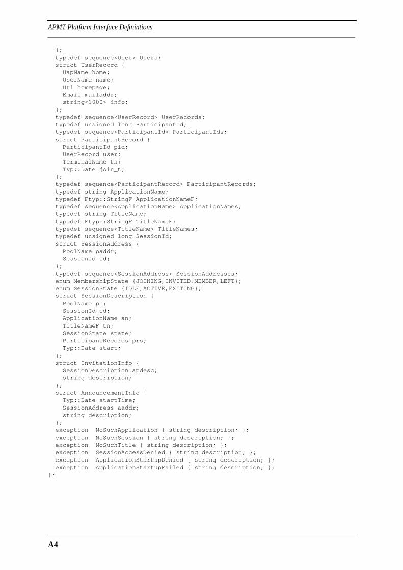
APMT Platform Interface Definintions
A4
}; typedef sequence<User> Users; struct UserRecord { UapName home; UserName name; Url homepage; Email mailaddr; string<1000> info; }; typedef sequence<UserRecord> UserRecords; typedef unsigned long ParticipantId; typedef sequence<ParticipantId> ParticipantIds; struct ParticipantRecord { ParticipantId pid; UserRecord user; TerminalName tn; Typ::Date join_t; }; typedef sequence<ParticipantRecord> ParticipantRecords; typedef string ApplicationName; typedef Ftyp::StringF ApplicationNameF; typedef sequence<ApplicationName> ApplicationNames; typedef string TitleName; typedef Ftyp::StringF TitleNameF; typedef sequence<TitleName> TitleNames; typedef unsigned long SessionId; struct SessionAddress { PoolName paddr; SessionId id; }; typedef sequence<SessionAddress> SessionAddresses; enum MembershipState {JOINING,INVITED,MEMBER,LEFT}; enum SessionState {IDLE,ACTIVE,EXITING}; struct SessionDescription { PoolName pn; SessionId id; ApplicationName an; TitleNameF tn; SessionState state; ParticipantRecords prs; Typ::Date start; }; struct InvitationInfo { SessionDescription apdesc; string description; }; struct AnnouncementInfo { Typ::Date startTime; SessionAddress aaddr; string description; }; exception NoSuchApplication { string description; }; exception NoSuchSession { string description; }; exception NoSuchTitle { string description; }; exception SessionAccessDenied { string description; }; exception ApplicationStartupDenied { string description; }; exception ApplicationStartupFailed { string description; };};

A5
Module Tc
A.6 Module Tc
module Tc{ interface UserSession; interface TerminalControl; interface PanelTerminalControl; typedef sequence<UserSession> UserSessions; typedef unsigned long UserSessionId; typedef sequence<UserSessionId> UserSessionIds; enum TerminationCause {LEFT, KILLED, FAILURE}; enum UserSessionState {RUNNING,PAUSED,HIDDEN,HIDDEN_PAUSED,EXITING}; struct RemoteSessionDescription { UserSessionId id; UserSessionState state; Atyp::SessionDescription globdesc; Ts::TermServDescriptions terservs; }; struct LocalSessionDescription { UserSessionId id; UserSessionState state; Atyp::ApplicationName an; Ts::TermServDescriptions terservs; Typ::Date start; };
interface Terminal { struct FingerInfo { Atyp::UserRecord ur; Atyp::SessionAddresses inapps; Typ::Date since; boolean present; }; readonly attribute Atyp::Email administrator; readonly attribute Atyp::TerminalName name; readonly attribute Atyp::TerminalAddress address; exception NobodyThere {}; void invite(in Atyp::User user, in Pac::Participant sc, in Typ::InfIdents termobjects, in Atyp::InvitationInfo info) raises (NobodyThere, Ex::NotCompatible, Ex::NoSuchUser); oneway void knock(in string text); FingerInfo finger() raises (NobodyThere); };
interface UserSession { readonly attribute boolean local; readonly attribute Atyp::ApplicationName name; readonly attribute UserSessionId localid; readonly attribute UserSessionState state; void hide(); void show(); void pause(); void continue(); void kill(); void quit(); void remove();

APMT Platform Interface Definintions
A6
CosEventChannelAdmin::ConsumerAdmin register_event(in Typ::EventKey key) raises (Ex::NoSuchEvent); const string StateEventK = "Tc:UserSession:State"; typedef UserSessionState StateEventD; };
interface RemoteUserSession : UserSession { RemoteSessionDescription get_description(); const string ChangeEventK = "Tc:RemoteUserSession:Change"; typedef RemoteSessionDescription ChangeEventD; };
interface LocalUserSession : UserSession { readonly attribute LocalSessionDescription description; };
interface ApplicationControl { exception PoolNameError { string description; }; UserSession start(in Atyp::PoolName pool,
in Atyp::ApplicationName application, in Atyp::TitleNameF title, in Atyp::SessionId reserved) raises (PoolNameError, Atyp::NoSuchApplication, Atyp::NoSuchTitle,
Atyp::ApplicationStartupDenied, Atyp::ApplicationStartupFailed, Ex::NotCompatible, Ex::ResourceProblem); UserSession start_browser(in Atyp::PoolName pool) raises (PoolNameError, Atyp::NoSuchApplication, Atyp::ApplicationStartupDenied,
Atyp::ApplicationStartupFailed, Ex::NotCompatible, Ex::ResourceProblem); UserSession start_panel(in Atyp::PoolName pool, in Atyp::TitleName paneluser)
raises (PoolNameError, Atyp::NoSuchTitle, Atyp::ApplicationStartupDenied, Atyp::ApplicationStartupFailed, Ex::NotCompatible,
Ex::ResourceProblem); UserSession start_term_app(in Atyp::ApplicationName application) raises (Atyp::NoSuchApplication, Ex::ResourceProblem); UserSession join(in Atyp::SessionAddress aaddr)
raises (Atyp::NoSuchSession, Atyp::SessionAccessDenied, Atyp::ApplicationStartupFailed, Ex::NotCompatible, Ex::ResourceProblem); };
interface TerminalControl { readonly attribute Atyp::UserRecord terminal_user; readonly attribute Atyp::TerminalName name; readonly attribute Atyp::TerminalAddress address; readonly attribute Typ::InfIdents termservers;

A7
Module Tc
exception TooManyInstances { short maxinst; }; exception NoSuchServer {}; CosNaming::NamingContext get_name_service(); CosEventChannelAdmin::EventChannel get_event_channel(); Ts::TerminalServer get_terminal_server(in Ftyp::NameF name, in Typ::InfIdent server)
raises (NoSuchServer, TooManyInstances); PanelTerminalControl get_terminal_control(); oneway void create_indication(in CosNaming::Name obj_name, in Typ::StringRef obj_ref); oneway void delete_indication(in CosNaming::Name obj_name); boolean create_event(in CosNaming::Name objname, out Typ::StringRef obj_ref); boolean delete_event(in CosNaming::Name objname); CosEventChannelAdmin::ConsumerAdmin
register_event (in Typ::EventKey key) raises (Ex::NoSuchEvent); void terminated(); void session_change(in Atyp::SessionDescription des); Typ::InfIdents challenge(in Typ::InfIdents termobjects); const string CreationEventK = "Tc:TerminalControl:Creation"; struct CreationEventD { CosNaming::Name obj_name; Typ::StringRef obj_ref; }; const string DeleteEventK = "Tc:TerminalControl:Deletion"; typedef CosNaming::Name DeleteEventD; };
interface PanelTerminalControl { typedef unsigned long InvitationKey; readonly attribute UserSessions sessions; exception RegistrationError { string description; }; void register(in Atyp::UserRecord user) raises (RegistrationError); ApplicationControl get_application_control(); Typ::StringRef get_terminal(); void deregister(); UserSession invite_accept(in InvitationKey key) raises (Ex::NoSuchKey, Ex::ResourceProblem, Atyp::SessionAccessDenied); oneway void invite_reject(in InvitationKey key); void quit_all(); CosEventChannelAdmin::ConsumerAdmin register_terminal_events(); const string ReadyEventK = "Tc:PanelTerminalControl:Ready"; typedef UserSession ReadyEventD; const string InvitationEventK = "Tc:PanelTerminalControl:Invitation"; struct InvitationEventD { Atyp::InvitationInfo info;
InvitationKey key; boolean rejected; }; const string TerminationEventK = "Tc:PanelTerminalControl:Termination"; typedef UserSessionId TerminationEventD; const string DeregistrationEventK =
"Tc:PanelTerminalControl:Deregistration"; const string KnockEventK = "Tc:PanelTerminalControl:Knock"; typedef string KnockEventD; };};
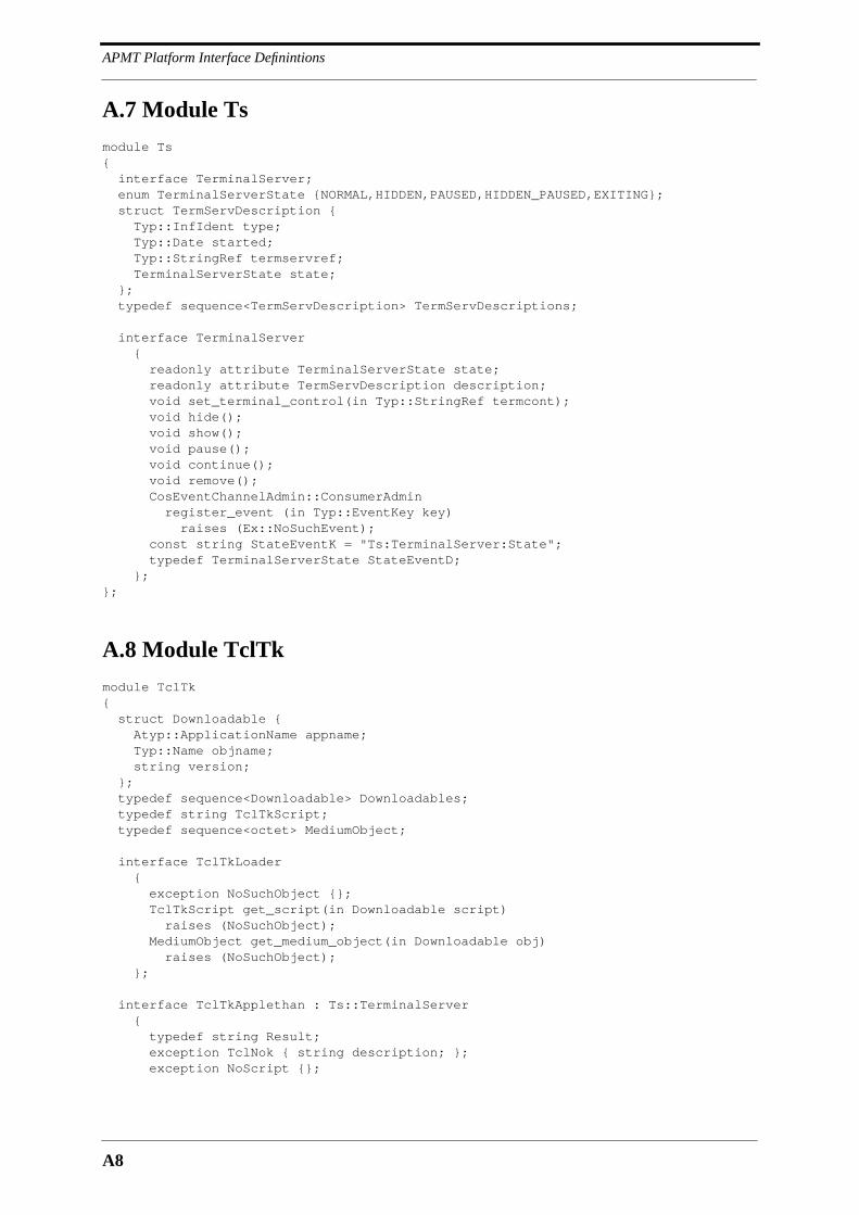
APMT Platform Interface Definintions
A8
A.7 Module Ts
module Ts{ interface TerminalServer; enum TerminalServerState {NORMAL,HIDDEN,PAUSED,HIDDEN_PAUSED,EXITING}; struct TermServDescription { Typ::InfIdent type; Typ::Date started; Typ::StringRef termservref; TerminalServerState state; }; typedef sequence<TermServDescription> TermServDescriptions;
interface TerminalServer { readonly attribute TerminalServerState state; readonly attribute TermServDescription description; void set_terminal_control(in Typ::StringRef termcont); void hide(); void show(); void pause(); void continue(); void remove(); CosEventChannelAdmin::ConsumerAdmin register_event (in Typ::EventKey key)
raises (Ex::NoSuchEvent); const string StateEventK = "Ts:TerminalServer:State"; typedef TerminalServerState StateEventD; };};
A.8 Module TclTk
module TclTk{ struct Downloadable { Atyp::ApplicationName appname; Typ::Name objname; string version; }; typedef sequence<Downloadable> Downloadables; typedef string TclTkScript; typedef sequence<octet> MediumObject;
interface TclTkLoader { exception NoSuchObject {}; TclTkScript get_script(in Downloadable script)
raises (NoSuchObject); MediumObject get_medium_object(in Downloadable obj) raises (NoSuchObject); };
interface TclTkApplethan : Ts::TerminalServer { typedef string Result; exception TclNok { string description; }; exception NoScript {};
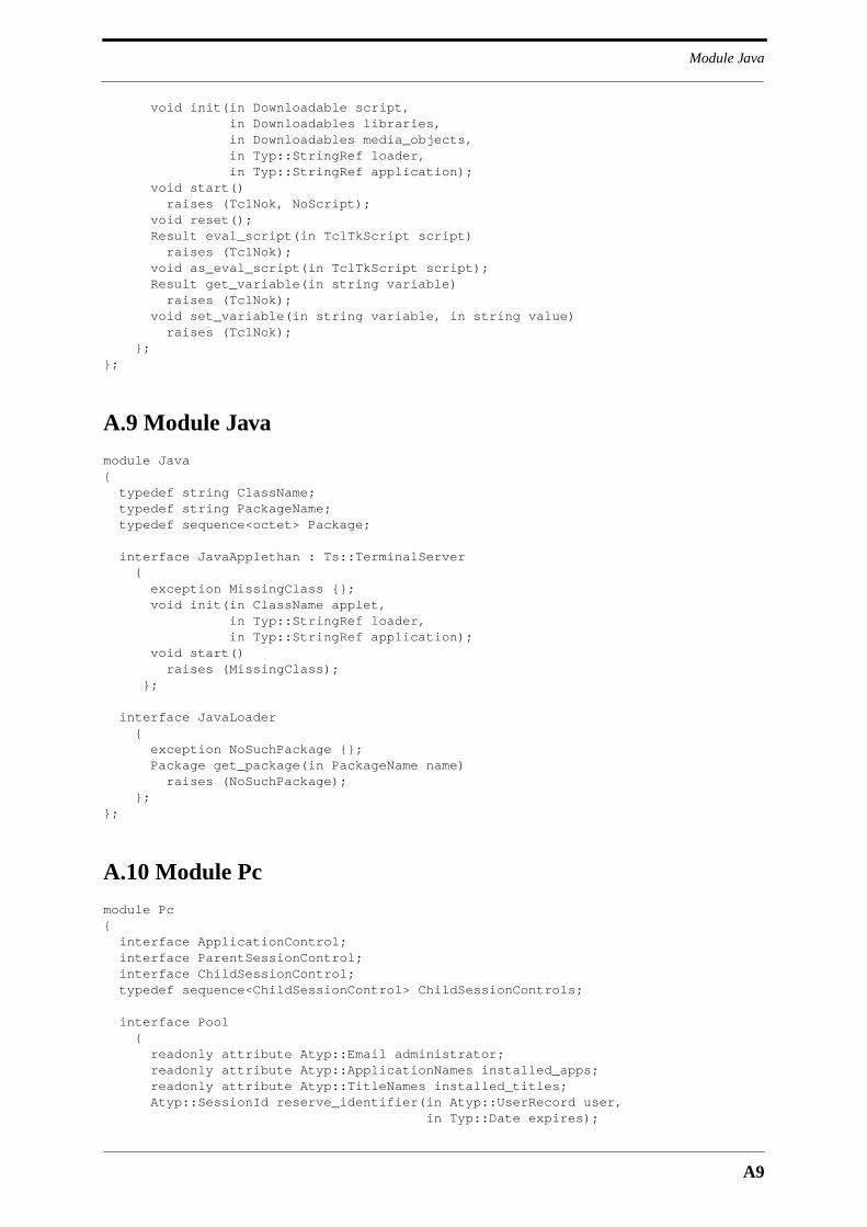
A9
Module Java
void init(in Downloadable script, in Downloadables libraries, in Downloadables media_objects, in Typ::StringRef loader, in Typ::StringRef application); void start() raises (TclNok, NoScript); void reset(); Result eval_script(in TclTkScript script)
raises (TclNok); void as_eval_script(in TclTkScript script); Result get_variable(in string variable) raises (TclNok); void set_variable(in string variable, in string value)
raises (TclNok); };};
A.9 Module Java
module Java{ typedef string ClassName; typedef string PackageName; typedef sequence<octet> Package;
interface JavaApplethan : Ts::TerminalServer { exception MissingClass {}; void init(in ClassName applet,
in Typ::StringRef loader, in Typ::StringRef application); void start()
raises (MissingClass); };
interface JavaLoader { exception NoSuchPackage {}; Package get_package(in PackageName name) raises (NoSuchPackage); };};
A.10 Module Pc
module Pc{ interface ApplicationControl; interface ParentSessionControl; interface ChildSessionControl; typedef sequence<ChildSessionControl> ChildSessionControls;
interface Pool { readonly attribute Atyp::Email administrator; readonly attribute Atyp::ApplicationNames installed_apps; readonly attribute Atyp::TitleNames installed_titles; Atyp::SessionId reserve_identifier(in Atyp::UserRecord user, in Typ::Date expires);

APMT Platform Interface Definintions
A10
ParentSessionControl get_application(in Atyp::UserRecord user, in Atyp::ApplicationNameF application, in Atyp::TitleNameF title)
raises (Atyp::NoSuchApplication, Atyp::NoSuchTitle, Atyp::ApplicationStartupDenied, Ex::ResourceProblem); Pac::SessionAccess get_access(in Atyp::SessionId sid) raises (Atyp::NoSuchSession, Atyp::SessionAccessDenied, Ex::ResourceProblem); ParentSessionControl get_browser() raises (Atyp::ApplicationStartupDenied, Atyp::NoSuchApplication, Ex::ResourceProblem); };
interface SessionControl { readonly attribute Atyp::ApplicationName name; readonly attribute Atyp::SessionId sid; readonly attribute Atyp::SessionState state; exception NoSuchSessionId {}; exception AlreadyStarted {}; Atyp::SessionDescription get_description(); void kill(); Typ::InfIdents required_interfaces(); };
interface ParentSessionControl : SessionControl { Atyp::SessionId start(in Typ::StringRef tc) raises (AlreadyStarted, Atyp::ApplicationStartupFailed, Ex::ResourceProblem); void start_with_id(in Typ::StringRef tc, in Atyp::SessionId id) raises (Ex::ResourceProblem, NoSuchSessionId, Atyp::ApplicationStartupFailed, Atyp::ApplicationStartupDenied); };
interface ChildSessionControl : SessionControl { App::Application start() raises (AlreadyStarted, Atyp::ApplicationStartupFailed, Ex::ResourceProblem); };
interface PoolControl { readonly attribute Typ::InfIdents installed_uts; readonly attribute Atyp::ApplicationNames installed_apps; readonly attribute Atyp::TitleNames installed_titles; readonly attribute Put::UtilityDescriptions running_uts; readonly attribute ChildSessionControls child_sessions; exception NoSuchUtility {}; exception UtilityStartupFailed { string description; };
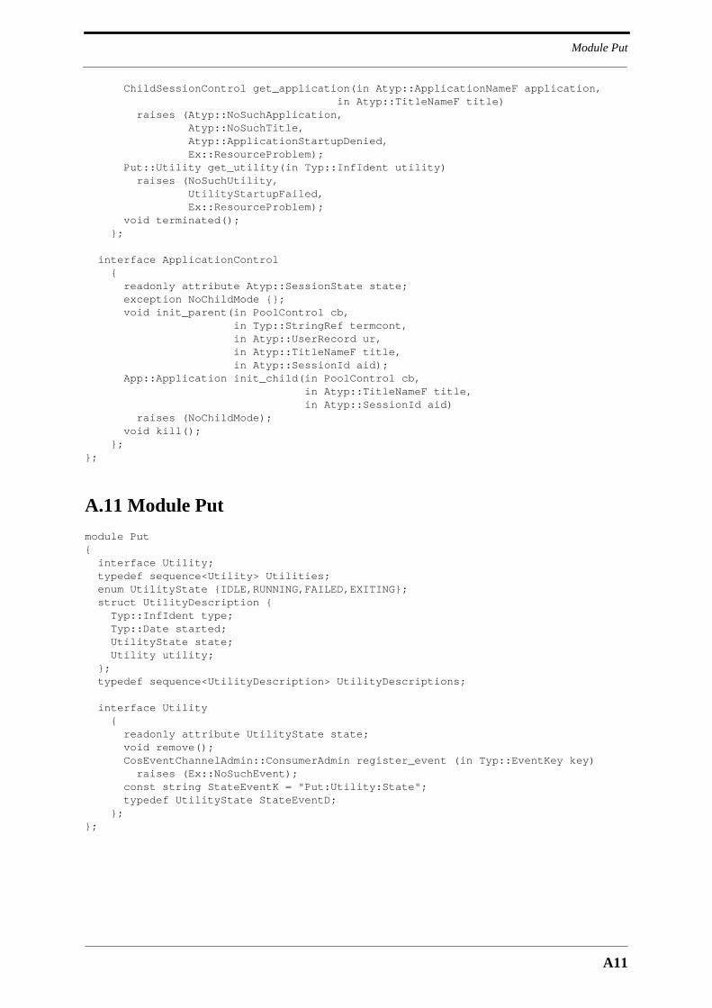
A11
Module Put
ChildSessionControl get_application(in Atyp::ApplicationNameF application, in Atyp::TitleNameF title) raises (Atyp::NoSuchApplication, Atyp::NoSuchTitle, Atyp::ApplicationStartupDenied, Ex::ResourceProblem); Put::Utility get_utility(in Typ::InfIdent utility)
raises (NoSuchUtility, UtilityStartupFailed, Ex::ResourceProblem); void terminated(); };
interface ApplicationControl { readonly attribute Atyp::SessionState state; exception NoChildMode {}; void init_parent(in PoolControl cb, in Typ::StringRef termcont, in Atyp::UserRecord ur, in Atyp::TitleNameF title, in Atyp::SessionId aid); App::Application init_child(in PoolControl cb, in Atyp::TitleNameF title, in Atyp::SessionId aid)
raises (NoChildMode); void kill(); };};
A.11 Module Put
module Put{ interface Utility; typedef sequence<Utility> Utilities; enum UtilityState {IDLE,RUNNING,FAILED,EXITING}; struct UtilityDescription { Typ::InfIdent type; Typ::Date started; UtilityState state; Utility utility; }; typedef sequence<UtilityDescription> UtilityDescriptions;
interface Utility { readonly attribute UtilityState state; void remove(); CosEventChannelAdmin::ConsumerAdmin register_event (in Typ::EventKey key) raises (Ex::NoSuchEvent); const string StateEventK = "Put:Utility:State"; typedef UtilityState StateEventD; };};

APMT Platform Interface Definintions
A12
A.12 Module App
module App{ interface Application { readonly attribute Atyp::SessionState state; exception NoSessionSupport {}; exception SessionRequired {}; void remove(); void synchronize_to_session(in Typ::StringRef sessioninfo)
raises (NoSessionSupport); void set_terminal_control(in Typ::StringRef termcont) raises (SessionRequired); CosEventChannelAdmin::ConsumerAdmin register_events () raises (Ex::NoSuchEvent); const string StateEventK = "App:Application:State"; typedef Atyp::SessionState StateEventD; };};
A.13 Module Pac
module Pac{ interface Participant; interface ParticipationRequest; interface ParticipationControl; interface Application; interface SessionControl; interface SessionInformation; struct Invitation { Atyp::User user; Typ::Date invitation_time; }; typedef sequence<Invitation> Invitations; struct JoinRequest { Atyp::User user; Typ::Date join_time; }; typedef sequence<JoinRequest> JoinRequests;
interface SessionAccess { readonly attribute Atyp::SessionDescription description; Typ::InfIdents required_interfaces(); ParticipationControl join(in ParticipationRequest pr, in Atyp::UserRecord us) raises (Atyp::SessionAccessDenied, Ex::ResourceProblem); };
interface ParticipationRequest { exception JoinRequestCancelled {}; void join_reject(in string description); Typ::StringRef join_accept() raises(JoinRequestCancelled); };
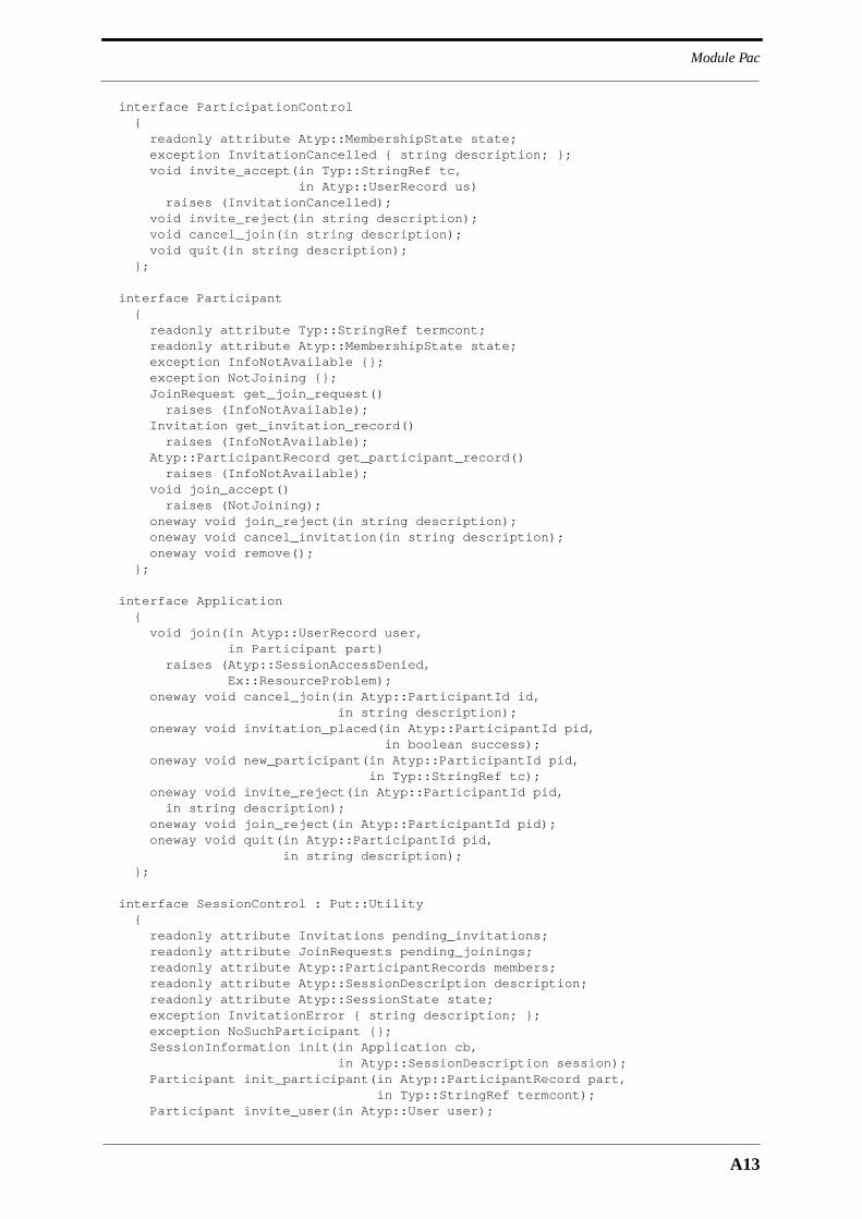
A13
Module Pac
interface ParticipationControl { readonly attribute Atyp::MembershipState state; exception InvitationCancelled { string description; }; void invite_accept(in Typ::StringRef tc, in Atyp::UserRecord us) raises (InvitationCancelled); void invite_reject(in string description); void cancel_join(in string description); void quit(in string description); };
interface Participant { readonly attribute Typ::StringRef termcont; readonly attribute Atyp::MembershipState state; exception InfoNotAvailable {}; exception NotJoining {}; JoinRequest get_join_request() raises (InfoNotAvailable); Invitation get_invitation_record() raises (InfoNotAvailable); Atyp::ParticipantRecord get_participant_record() raises (InfoNotAvailable); void join_accept() raises (NotJoining); oneway void join_reject(in string description); oneway void cancel_invitation(in string description); oneway void remove(); };
interface Application { void join(in Atyp::UserRecord user, in Participant part) raises (Atyp::SessionAccessDenied, Ex::ResourceProblem); oneway void cancel_join(in Atyp::ParticipantId id, in string description); oneway void invitation_placed(in Atyp::ParticipantId pid, in boolean success); oneway void new_participant(in Atyp::ParticipantId pid, in Typ::StringRef tc); oneway void invite_reject(in Atyp::ParticipantId pid, in string description); oneway void join_reject(in Atyp::ParticipantId pid); oneway void quit(in Atyp::ParticipantId pid, in string description); };
interface SessionControl : Put::Utility { readonly attribute Invitations pending_invitations; readonly attribute JoinRequests pending_joinings; readonly attribute Atyp::ParticipantRecords members; readonly attribute Atyp::SessionDescription description; readonly attribute Atyp::SessionState state; exception InvitationError { string description; }; exception NoSuchParticipant {}; SessionInformation init(in Application cb, in Atyp::SessionDescription session); Participant init_participant(in Atyp::ParticipantRecord part, in Typ::StringRef termcont); Participant invite_user(in Atyp::User user);

APMT Platform Interface Definintions
A14
Participant invite_terminal(in Atyp::User user, in Atyp::TerminalName terminal); Participant get_participant(in Atyp::ParticipantId pid) raises (NoSuchParticipant); };
interface SessionInformation { struct ParticipantInfo { Atyp::ParticipantRecord part; Typ::StringRef termcont; }; typedef sequence<ParticipantInfo> ParticipantInfos; readonly attribute ParticipantInfos participants; CosEventChannelAdmin::ConsumerAdmin register_events()
raises (Ex::NoSuchEvent); const string StateEventK = "Pac:SessionInformation:State"; typedef Atyp::SessionState StateEventD; const string NewParticipantEventK = "Pac:SessionInformation:NewParticipant"; typedef ParticipantInfo NewParticipantEventD; const string GoneParticipantEventK = "Pac:SessionInformation:GoneParticipant"; typedef Atyp::ParticipantId GoneParticipantEventD; };};
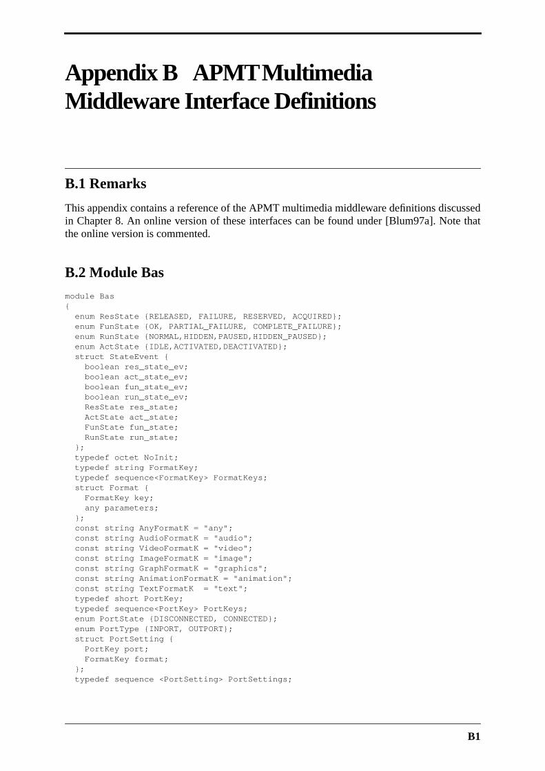
B1
Appendix B APMT MultimediaMiddleware Interface Definitions
B.1 Remarks
This appendix contains a reference of the APMT multimedia middleware definitions discussedin Chapter 8. An online version of these interfaces can be found under [Blum97a]. Note thatthe online version is commented.
B.2 Module Bas
module Bas{ enum ResState {RELEASED, FAILURE, RESERVED, ACQUIRED}; enum FunState {OK, PARTIAL_FAILURE, COMPLETE_FAILURE}; enum RunState {NORMAL,HIDDEN,PAUSED,HIDDEN_PAUSED}; enum ActState {IDLE,ACTIVATED,DEACTIVATED}; struct StateEvent { boolean res_state_ev; boolean act_state_ev; boolean fun_state_ev; boolean run_state_ev; ResState res_state; ActState act_state; FunState fun_state; RunState run_state; }; typedef octet NoInit; typedef string FormatKey; typedef sequence<FormatKey> FormatKeys; struct Format { FormatKey key; any parameters; }; const string AnyFormatK = "any"; const string AudioFormatK = "audio"; const string VideoFormatK = "video"; const string ImageFormatK = "image"; const string GraphFormatK = "graphics"; const string AnimationFormatK = "animation"; const string TextFormatK = "text"; typedef short PortKey; typedef sequence<PortKey> PortKeys; enum PortState {DISCONNECTED, CONNECTED}; enum PortType {INPORT, OUTPORT}; struct PortSetting { PortKey port; FormatKey format; }; typedef sequence <PortSetting> PortSettings;
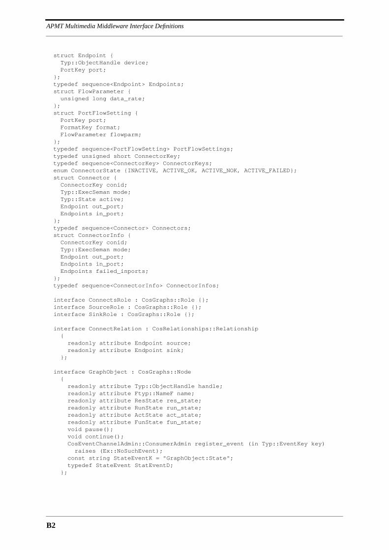
APMT Multimedia Middleware Interface Definitions
B2
struct Endpoint { Typ::ObjectHandle device; PortKey port; }; typedef sequence<Endpoint> Endpoints; struct FlowParameter { unsigned long data_rate; }; struct PortFlowSetting { PortKey port; FormatKey format; FlowParameter flowparm; }; typedef sequence<PortFlowSetting> PortFlowSettings; typedef unsigned short ConnectorKey; typedef sequence<ConnectorKey> ConnectorKeys; enum ConnectorState {INACTIVE, ACTIVE_OK, ACTIVE_NOK, ACTIVE_FAILED}; struct Connector { ConnectorKey conid; Typ::ExecSeman mode; Typ::State active; Endpoint out_port; Endpoints in_port; }; typedef sequence<Connector> Connectors; struct ConnectorInfo { ConnectorKey conid; Typ::ExecSeman mode; Endpoint out_port; Endpoints in_port; Endpoints failed_inports; }; typedef sequence<ConnectorInfo> ConnectorInfos;
interface ConnectsRole : CosGraphs::Role {}; interface SourceRole : CosGraphs::Role {}; interface SinkRole : CosGraphs::Role {};
interface ConnectRelation : CosRelationships::Relationship { readonly attribute Endpoint source; readonly attribute Endpoint sink; };
interface GraphObject : CosGraphs::Node { readonly attribute Typ::ObjectHandle handle; readonly attribute Ftyp::NameF name; readonly attribute ResState res_state; readonly attribute RunState run_state; readonly attribute ActState act_state; readonly attribute FunState fun_state; void pause(); void continue(); CosEventChannelAdmin::ConsumerAdmin register_event (in Typ::EventKey key)
raises (Ex::NoSuchEvent); const string StateEventK = "GraphObject:State"; typedef StateEvent StatEventD; };
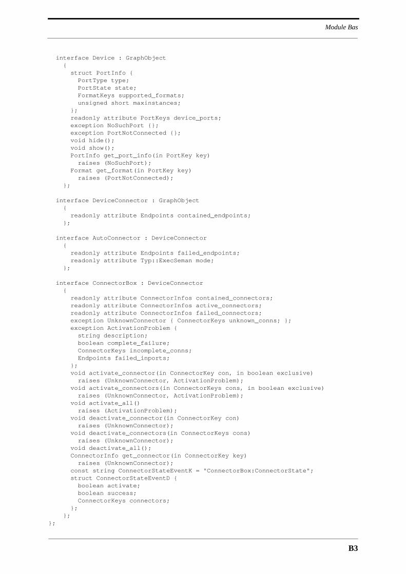
B3
Module Bas
interface Device : GraphObject { struct PortInfo { PortType type; PortState state; FormatKeys supported_formats; unsigned short maxinstances; }; readonly attribute PortKeys device_ports; exception NoSuchPort {}; exception PortNotConnected {}; void hide(); void show(); PortInfo get_port_info(in PortKey key) raises (NoSuchPort); Format get_format(in PortKey key)
raises (PortNotConnected); };
interface DeviceConnector : GraphObject { readonly attribute Endpoints contained_endpoints; };
interface AutoConnector : DeviceConnector { readonly attribute Endpoints failed_endpoints; readonly attribute Typ::ExecSeman mode; };
interface ConnectorBox : DeviceConnector { readonly attribute ConnectorInfos contained_connectors; readonly attribute ConnectorInfos active_connectors; readonly attribute ConnectorInfos failed_connectors; exception UnknownConnector { ConnectorKeys unknown_conns; }; exception ActivationProblem {
string description; boolean complete_failure;
ConnectorKeys incomplete_conns; Endpoints failed_inports;
}; void activate_connector(in ConnectorKey con, in boolean exclusive) raises (UnknownConnector, ActivationProblem); void activate_connectors(in ConnectorKeys cons, in boolean exclusive) raises (UnknownConnector, ActivationProblem); void activate_all()
raises (ActivationProblem); void deactivate_connector(in ConnectorKey con) raises (UnknownConnector); void deactivate_connectors(in ConnectorKeys cons)
raises (UnknownConnector); void deactivate_all(); ConnectorInfo get_connector(in ConnectorKey key) raises (UnknownConnector); const string ConnectorStateEventK = "ConnectorBox:ConnectorState"; struct ConnectorStateEventD {
boolean activate;boolean success;ConnectorKeys connectors;
}; };};
APMT Multimedia Middleware Interface Definitions
B4
B.3 Module DevMan
module DevMan{ interface DevManagement; interface Graph;
interface DevFactory { struct PortInfo { Bas::PortKey port; Bas::PortType type; Bas::FormatKeys supported_formats; unsigned short maxinstances; }; typedef sequence<PortInfo> PortInfos; exception NoSuchDevice {}; exception InvalidSettings {}; exception InvalidParameters {}; exception NoSuchPort {}; readonly attribute PortInfos ports; void query_init_parameters(in any initparms) raises (InvalidParameters); Bas::FormatKeys query_format(in Bas::PortKey port, in Bas::PortSettings settings, in any initparms) raises (InvalidSettings, InvalidParameters, NoSuchPort); Bas::PortFlowSettings query_flow_parameters( in Bas::PortSettings sink_settings, in Bas::PortFlowSettings source_settings, in any initparms)
raises (InvalidSettings, InvalidParameters, NoSuchPort); void create(out Typ::StringRef devref, out DevManagement devman); };
interface DevFactoryFinder { typedef sequence<DevFactory> DevFactories; exception NoSuchFactory {}; exception AlreadyRegistered { Typ::InfIdents devices; }; DevFactories find_factory(in Typ::InfIdent device) raises (NoSuchFactory); void register_factory(in DevFactory factory, in Typ::InfIdent device) raises (AlreadyRegistered); };
interface DeviceServices { readonly attribute Typ::StringRef termcont; readonly attribute Res::ResourceManager resmgr; readonly attribute Cont::BufferFactory buff_fact; };

B5
Module Trans
interface DevCallback { oneway void problem (in Typ::ObjectHandle error_source, in Typ::ProbSign significance, in string description); };
interface DevManagement { readonly attribute Typ::ObjectHandle object_handle; readonly attribute Bas::GraphObject object_interface; readonly attribute Bas::ResState res_state; readonly attribute Bas::RunState run_state; readonly attribute Bas::ActState act_state; readonly attribute Bas::FunState fun_state; exception InitProblem { boolean inittype_error; boolean paramrange_error; boolean paramsupport_error;
string description; }; exception NoSuchPort {}; exception TooManyInstantiations {}; exception RoleNotSupported {}; exception MissingInterface { Typ::InfIdents missing_interfaces; }; void init(in DevCallback cb,
in any initdata, in Ftyp::NameF name, in DeviceServices devser, in Typ::ObjectHandle handle) raises (InitProblem); void prepare()
raises (MissingInterface,Ex::GeneralProblem);
void reserve() raises (Ex::ResourceProblem); void free(); void activate() raises (Ex::GeneralProblem, Ex::ResourceProblem); void deactivate(); void hide(); void show(); void remove(); Ports::Port create_port(in Bas::PortKey key)
raises (NoSuchPort,TooManyInstantiations); };};
B.4 Module Trans
module Trans{ typedef string IpAddress; typedef sequence<IpAddress> IpAddresses; typedef unsigned short IpPort; struct IpTsap { IpAddress addr; IpPort port; };
APMT Multimedia Middleware Interface Definitions
B6
typedef sequence <IpTsap> IpTsaps; struct IpAddressF { boolean flag; IpAddress address; }; struct IpTsapF { boolean flag; IpTsap tsap; }; enum Mode {TX, RX, TX_AND_RX}; typedef unsigned long FlowHandle; struct FlowIdentifier { IpAddress srcterm; FlowHandle handle; }; typedef sequence<FlowIdentifier> FlowIdentifiers;
interface TransportDevice : Bas::Device { readonly attribute IpTsap mytsap; readonly attribute Mode device_mode; readonly attribute unsigned long tx_bytes; readonly attribute unsigned long tx_bytes_ps; readonly attribute unsigned long rx_bytes; readonly attribute unsigned long rx_bytes_ps; void statistics_events(in unsigned long ival) raises (Ex::RangeProblem); const short TpInPort = 1; const short TpOutPort = 2; const string StatisticsEventK = "Trans:TransportDevice:Statistics"; struct StatisticsEventD { unsigned long tx_bytes; unsigned long tx_bytes_ps; unsigned long rx_bytes; unsigned long rx_bytes_ps; }; };
interface Udp : TransportDevice { readonly attribute IpTsaps destinations; const string AddressEventK = "Trans:Udp:Address"; struct AddressEventD { IpTsaps destinations; IpAddressF if_addr; }; };
interface UdpRtp : Udp { struct Init { Mode device_mode; IpTsaps destinations; Ftyp::UshortF port; Ftyp::UlongF flow_handle; }; };
interface Ipmcast : TransportDevice { readonly attribute IpTsap mcast_addr; readonly attribute unsigned short ttl; };
B7
Module Port
interface IpmcastRtp : Ipmcast { struct Init { Mode mode; IpTsap mcast_addr; Ftyp::UshortF ttl; Ftyp::UlongF flow_handle; }; };
interface Tcp : TransportDevice { readonly attribute IpTsap destination; readonly attribute boolean no_delay; readonly attribute boolean keep_alive; const string ConnectEventK = "Trans:Tcp:Connect"; struct ConnectEventD { boolean connect; IpTsap destination; IpTsap if; }; };};
B.5 Module Port
module Ports{ interface Outport; interface Inport;
interface Port { readonly attribute Bas::PortType type; readonly attribute Bas::PortKey key; readonly attribute Bas::PortState connect_state; readonly attribute Typ::State activity_state; readonly attribute Typ::MilliSeconds up_time; readonly attribute Typ::MilliSeconds conn_time; readonly attribute Typ::MilliSeconds active_time; readonly attribute unsigned long cont_num_since_up; readonly attribute unsigned long bytes_since_up; readonly attribute unsigned long cont_num_since_conn; readonly attribute unsigned long bytes_since_conn; exception InvalidPortSetting {}; void disconnect(); void remove(); };
interface Inport : Port { void connect(in Outport out_port, in Bas::FormatKey format) raises (InvalidPortSetting); void stop(); void push(in Cont::HeaderContainer cont, in Cont::Buffer buff); };

APMT Multimedia Middleware Interface Definitions
B8
interface Outport : Port { exception BadParameters { Typ::ObjectHandle originator; Bas::FlowParameter minparm; };
exception NoInfluence {}; void connect(in Inport in_port, in Bas::FormatKey format, in Bas::FlowParameter parms)
raises (InvalidPortSetting,BadParameters); void adjust_flow(in Bas::FlowParameter parms)
raises (BadParameters,NoInfluence); };};
B.6 Module Cont
module Cont{ interface BufferFactory; interface HeaderContainer; typedef string AttrHeaderKey; exception InvalidHeader { string description; };
interface Buffer { readonly attribute unsigned long size; readonly attribute unsigned long fill_level; void remove(); Buffer copy(); };
interface BufferFactory { Buffer allocate(in unsigned long size); };
interface Header { readonly attribute any header_data; void set_data(in any header_data) raises (InvalidHeader); void remove(); };
interface FormatHeader : Header { attribute Bas::FormatKey key; };
interface AttrHeader : Header { attribute AttrHeaderKey key; attribute boolean transmit; };
interface HeaderContainer { readonly attribute Typ::TimeStamp creation_time; attribute unsigned long contnum;
B9
Module Tgraph
readonly attribute unsigned long sourceid; readonly attribute unsigned short headnum; void set_format_header(in FormatHeader format) raises (InvalidHeader); void set_attr_header(in AttrHeader header)
raises (InvalidHeader); FormatHeader get_format_header() raises (NoSuchHeader); AttrHeader get_attr_headerk(in AttrHeaderKey key) raises (NoSuchHeader); AttrHeader get_attr_headern(in unsigned short index) raises (NoSuchHeader); HeaderContainer copy(); void remove(); };};
B.7 Module Tgraph
module Tgraph{ interface Graph; interface GraphCallback; struct ObjectProblem { Typ::ObjectHandle handle; string problem; }; typedef sequence<ObjectProblem> ObjectProblems; struct NetPortAddress { Typ::ObjectHandle transdev; Trans::IpTsaps addr; }; typedef sequence<NetPortAddress> NetPortAddresses; struct NetPortParameter { Typ::ObjectHandle transdev; Bas::FlowParameter flowparm; }; typedef sequence<NetPortParameter> NetPortParameters; struct NetPortFormat { Typ::ObjectHandle transdev; Bas::FormatKey format; }; typedef sequence<NetPortFormat> NetPortFormats; typedef sequence<NetPortFormats> NetPortFormatCombs; struct DeviceRequest { Typ::InfIdent dev_name; Ftyp::NameF name; Typ::ObjectHandle dev_handle; any dev_settings; Bas::PortSettings port_settings; }; typedef sequence<DeviceRequest> DeviceRequests; struct AutocxtorRequest { Ftyp::StringF name; Typ::ObjectHandle cxtor_handle; Bas::Endpoints dev_ports; }; typedef sequence<AutocxtorRequest> AutocxtorRequests;

APMT Multimedia Middleware Interface Definitions
B10
struct CoboxRequest { Ftyp::StringF name; Typ::ObjectHandle cobox_handle; Bas::Connectors cxtors; }; typedef sequence<CoboxRequest> CoboxRequests; exception NoSuchObject { Typ::ObjectHandles miss_handles; }; exception BadRequests { ObjectProblems bad_requests; }; exception BadEndpoints { Bas::Endpoints bad_endpoints; }; exception BadObjectHandles { Typ::ObjectHandles bad_handles; }; exception ObjectsWithProblems { ObjectProblems objprobs; }; exception GraphIncomplete { string description; };
interface Graph : CosGraphs::Node { readonly attribute Ftyp::NameF name; readonly attribute Bas::ResState res_state; readonly attribute Bas::RunState run_state; readonly attribute Bas::ActState act_state; readonly attribute Bas::FunState fun_state; readonly attribute boolean error_state; readonly attribute Trans::FlowIdentifiers rec_flows; exception FormatMismatch { Typ::ObjectHandles bad_objects; }; exception NoFormatMatch {}; NetPortFormatCombs add_objects (in DeviceRequests devs, in AutocxtorRequests cxtors, in CoboxRequests coboxes, in NetPortParameters tx_parms) raises (NoSuchObject,BadRequests, BadEndpoints,BadObjectHandles, FormatMismatch, NoFormatMatch, Ex::ResourceProblem); void commit(in NetPortFormats port_formats, out NetPortAddresses rx_addrs, out Typ::RefHandles objs) raises (ObjectsWithProblems, FormatMismatch); void cancel(); void rem_objects(in Typ::ObjectHandles handles)
raises (NoSuchObject); void reserve() raises (ObjectsWithProblems); void free(); void start(in NetPortAddresses destinations, in Trans::FlowIdentifiers rec_flows) raises (ObjectsWithProblems,GraphIncomplete); void park(); void pause(); void continue(); void remove(); CosEventChannelAdmin::ConsumerAdmin register_events (); const string StateEventK = "Tgraph:Graph:State"; struct StateEventD { Bas::StateEvent state; Trans::FlowIdentifiers rec_flows; }; const string ResourceEventK = "Tgraph:Graph:Resource"; typedef ObjectProblems ResourceEventD; const string ModificationEventK = "Tgraph:Graph:Modification"; const string FailureEventK = "Tgraph:Graph:Failure"; typedef string FailureEventD; };
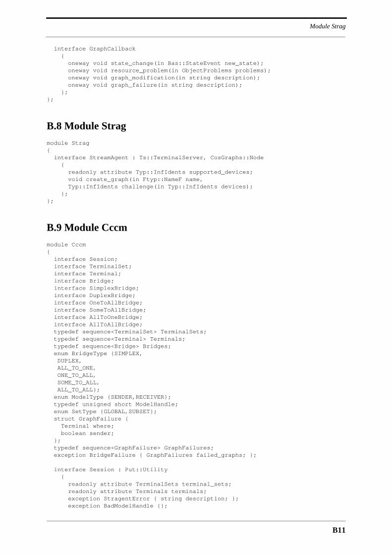
B11
Module Strag
interface GraphCallback { oneway void state_change(in Bas::StateEvent new_state); oneway void resource_problem(in ObjectProblems problems); oneway void graph_modification(in string description); oneway void graph_failure(in string description); };};
B.8 Module Strag
module Strag{ interface StreamAgent : Ts::TerminalServer, CosGraphs::Node { readonly attribute Typ::InfIdents supported_devices; void create_graph(in Ftyp::NameF name, Typ::InfIdents challenge(in Typ::InfIdents devices); };};
B.9 Module Cccm
module Cccm{ interface Session; interface TerminalSet; interface Terminal; interface Bridge; interface SimplexBridge; interface DuplexBridge; interface OneToAllBridge; interface SomeToAllBridge; interface AllToOneBridge; interface AllToAllBridge; typedef sequence<TerminalSet> TerminalSets; typedef sequence<Terminal> Terminals; typedef sequence<Bridge> Bridges; enum BridgeType {SIMPLEX, DUPLEX, ALL_TO_ONE, ONE_TO_ALL, SOME_TO_ALL, ALL_TO_ALL}; enum ModelType {SENDER,RECEIVER}; typedef unsigned short ModelHandle; enum SetType {GLOBAL,SUBSET}; struct GraphFailure { Terminal where; boolean sender; }; typedef sequence<GraphFailure> GraphFailures; exception BridgeFailure { GraphFailures failed_graphs; };
interface Session : Put::Utility { readonly attribute TerminalSets terminal_sets; readonly attribute Terminals terminals; exception StragentError { string description; }; exception BadModelHandle {};

APMT Multimedia Middleware Interface Definitions
B12
Terminal create_terminal(in Tc::TerminalControl tc) raises (StragentError); TerminalSet create_terminal_set(in Terminals terminals); TerminalSet create_global_terminal_set(); void register_sender_model(in ModelHandle handle, in Tgraph::DeviceRequests devices, in Tgraph::AutocxtorRequests autocxtors, in Tgraph::CoboxRequests coboxes, in Bas::Endpoint network_port, in Bas::FlowParameter flow_parms, in Trans::FlowHandle flow_handle) raises (Tgraph::BadRequests, Tgraph::BadEndpoints,
Tgraph::BadObjectHandles, BadModelHandle);
void register_receiver_model(in ModelHandle handle, in Tgraph::DeviceRequests devices, in Tgraph::AutocxtorRequests autocxtors, in Tgraph::CoboxRequests coboxes, in Bas::Endpoint network_port, in boolean mixer) raises (Tgraph::BadRequests, Tgraph::BadEndpoints, Tgraph::BadObjectHandles, BadModelHandle); void reset(); void remove(); };
interface Terminal { enum State {IDLE,CONNECTED,STOPPED,DEFUNCT}; readonly attribute State state; readonly attribute Tc::TerminalControl termcont; readonly attribute TerminalSets terminal_sets; void pause(); void continue(); void remove(); };
interface TerminalSet { readonly attribute SetType type; readonly attribute Bridges bridges; readonly attribute Terminals terminals; exception InvalidModel { string description; }; void add_terminals(in Terminals terminals); void remove_terminals(in Terminals terminals); Bridge create_bridge(in BridgeType type, in ModelHandle sender, in ModelHandle receiver, in Typ::ExecSeman semantics) raises (InvalidModel); void remove(); };
interface Bridge { enum State {IDLE,ACTIVATED,ACTIVE,PARKED}; readonly attribute BridgeType type; readonly attribute State state; readonly attribute TerminalSet my_terminal_set; readonly attribute Typ::ExecSeman semantics;
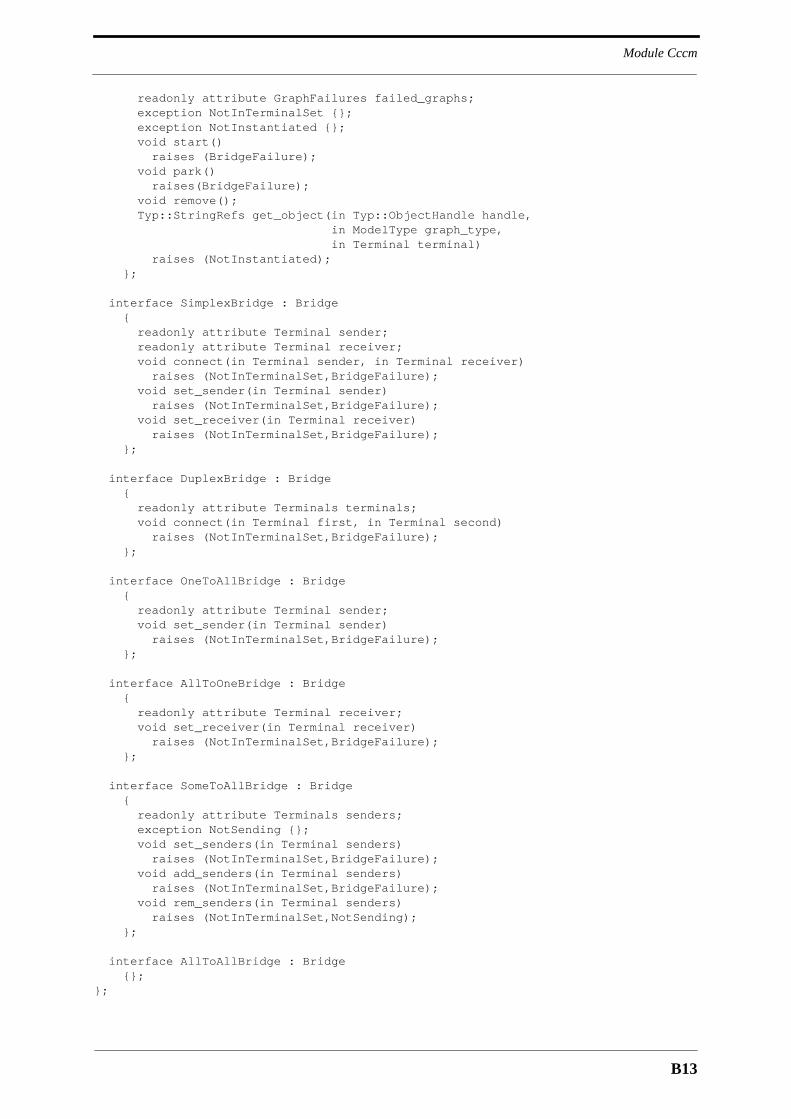
B13
Module Cccm
readonly attribute GraphFailures failed_graphs; exception NotInTerminalSet {}; exception NotInstantiated {}; void start() raises (BridgeFailure); void park() raises(BridgeFailure); void remove(); Typ::StringRefs get_object(in Typ::ObjectHandle handle, in ModelType graph_type, in Terminal terminal) raises (NotInstantiated); };
interface SimplexBridge : Bridge { readonly attribute Terminal sender; readonly attribute Terminal receiver; void connect(in Terminal sender, in Terminal receiver) raises (NotInTerminalSet,BridgeFailure); void set_sender(in Terminal sender) raises (NotInTerminalSet,BridgeFailure); void set_receiver(in Terminal receiver) raises (NotInTerminalSet,BridgeFailure); };
interface DuplexBridge : Bridge { readonly attribute Terminals terminals; void connect(in Terminal first, in Terminal second) raises (NotInTerminalSet,BridgeFailure); };
interface OneToAllBridge : Bridge { readonly attribute Terminal sender; void set_sender(in Terminal sender) raises (NotInTerminalSet,BridgeFailure); };
interface AllToOneBridge : Bridge { readonly attribute Terminal receiver; void set_receiver(in Terminal receiver) raises (NotInTerminalSet,BridgeFailure); };
interface SomeToAllBridge : Bridge { readonly attribute Terminals senders; exception NotSending {}; void set_senders(in Terminal senders) raises (NotInTerminalSet,BridgeFailure); void add_senders(in Terminal senders) raises (NotInTerminalSet,BridgeFailure); void rem_senders(in Terminal senders) raises (NotInTerminalSet,NotSending); };
interface AllToAllBridge : Bridge {};};

APMT Multimedia Middleware Interface Definitions
B14
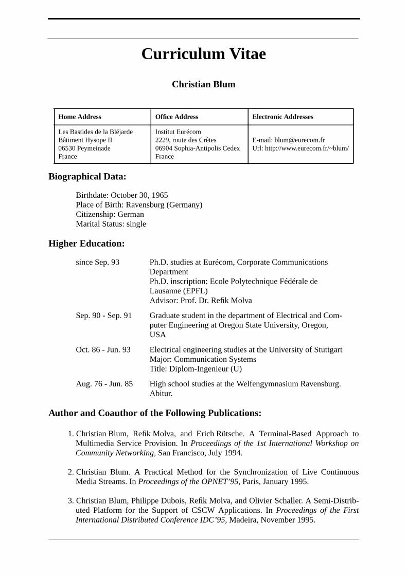
Curriculum Vitae
Christian Blum
Biographical Data:
Higher Education:
Author and Coauthor of the Following Publications:
1. Christian Blum, Refik Molva, and Erich Rütsche. A Terminal-Based Approach toMultimedia Service Provision. In Proceedings of the 1st International Workshop onCommunity Networking, San Francisco, July 1994.
2. Christian Blum. A Practical Method for the Synchronization of Live ContinuousMedia Streams. In Proceedings of the OPNET’95, Paris, January 1995.
3. Christian Blum, Philippe Dubois, Refik Molva, and Olivier Schaller. A Semi-Distrib-uted Platform for the Support of CSCW Applications. In Proceedings of the FirstInternational Distributed Conference IDC’95, Madeira, November 1995.
Home Address Office Address Electronic Addresses
Les Bastides de la BléjardeBâtiment Hysope II06530 PeymeinadeFrance
Institut Eurécom2229, route des Crêtes06904 Sophia-Antipolis CedexFrance
E-mail: [email protected]: http://www.eurecom.fr/~blum/
Birthdate: October 30, 1965Place of Birth: Ravensburg (Germany)Citizenship: GermanMarital Status: single
since Sep. 93 Ph.D. studies at Eurécom, Corporate CommunicationsDepartmentPh.D. inscription: Ecole Polytechnique Fédérale deLausanne (EPFL)Advisor: Prof. Dr. Refik Molva
Sep. 90 - Sep. 91 Graduate student in the department of Electrical and Com-puter Engineering at Oregon State University, Oregon,USA
Oct. 86 - Jun. 93 Electrical engineering studies at the University of StuttgartMajor: Communication SystemsTitle: Diplom-Ingenieur (U)
Aug. 76 - Jun. 85 High school studies at the Welfengymnasium Ravensburg.Abitur.

4. Christian Blum and Olivier Schaller. The Beteus Application Programming Interface.Technical Report RR-96-020, Institut Eurecom, December 1995. Available at http://www.eurecom.fr/~blum/pub/pub.html.
5. Christian Blum, Didier Loisel, and Refik Molva. BETEUS: Multipoint Teleconferenc-ing over the European ATM Pilot. In Proceedings of the European Conference on Net-works and Optical Communication NOC ’96, Heidelberg, June 1996.
6. Christian Blum and Refik Molva. A Software Platform for Distributed MultimediaApplications. In Proceedings of the IEEE International Workshop on Multimedia Soft-ware Development, Berlin, March 1996.
7. Christian Blum, Philippe Dubois, Refik Molva, and Olivier Schaller. A Developmentand Runtime Platform for Teleconferencing Applications. Journal on Selected Areasin Communications, special issue on Network Support for Multipoint Communication,15(3), April 1997.
8. Christian Blum and Refik Molva. A CORBA-Based Platform for Distributed Multime-dia Applications. In Proceedings of Multimedia Computing and NetworkingMMCN’97, San José, CA, February 1997.
9. Marcus Schmid and Christian Blum. A CORBA-Based Connection ManagementScheme for a Multimedia Platform with Stream Configuration Support. In Proceed-ings of the 5th Open Workshop on High-Speed Networks, Paris, March 1996.