
Plasma technology – a novel solution for CO2 conversion?
60
Registered charity number: 207890 rsc.li/chem-soc-rev Featuring work from Dr Ramses Snoeckx and Prof. Dr Annemie Bogaerts from the research group PLASMANT, University of Antwerp, Belgium. Plasma technology – a novel solution for CO 2 conversion? Plasma technology could provide a viable solution for the conversion of CO 2 into value-added chemicals while the fate of the world hangs in the balance. The future of the Earth rests in our hands. Cover art credit: “The Bigger Picture II” Dimitri De Waele, digitally altered watercolour on paper © 2017. As featured in: See Ramses Snoeckx and Annemie Bogaerts, Chem. Soc. Rev., 2017, 46, 5805.
-
Upload
khangminh22 -
Category
Documents
-
view
5 -
download
0
Transcript of Plasma technology – a novel solution for CO2 conversion?

Registered charity number: 207890
rsc.li/chem-soc-rev
Featuring work from Dr Ramses Snoeckx and
Prof. Dr Annemie Bogaerts from the research group
PLASMANT, University of Antwerp, Belgium.
Plasma technology – a novel solution for CO2 conversion?
Plasma technology could provide a viable solution for the
conversion of CO2 into value-added chemicals while the fate
of the world hangs in the balance. The future of the Earth
rests in our hands.
Cover art credit: “The Bigger Picture II” Dimitri De Waele,
digitally altered watercolour on paper © 2017.
As featured in:
See Ramses Snoeckx and Annemie Bogaerts,Chem. Soc. Rev., 2017, 46, 5805.

This journal is©The Royal Society of Chemistry 2017 Chem. Soc. Rev., 2017, 46, 5805--5863 | 5805
Cite this: Chem. Soc. Rev., 2017,
46, 5805
Plasma technology – a novel solution for CO2
conversion?
Ramses Snoeckx * and Annemie Bogaerts *
CO2 conversion into value-added chemicals and fuels is considered as one of the great challenges of the 21st
century. Due to the limitations of the traditional thermal approaches, several novel technologies are being
developed. One promising approach in this field, which has received little attention to date, is plasma
technology. Its advantages include mild operating conditions, easy upscaling, and gas activation by energetic
electrons instead of heat. This allows thermodynamically difficult reactions, such as CO2 splitting and the dry
reformation of methane, to occur with reasonable energy cost. In this review, after exploring the traditional
thermal approaches, we have provided a brief overview of the fierce competition between various novel
approaches in a quest to find the most effective and efficient CO2 conversion technology. This is needed to
critically assess whether plasma technology can be successful in an already crowded arena. The following
questions need to be answered in this regard: are there key advantages to using plasma technology over
other novel approaches, and if so, what is the flip side to the use of this technology? Can plasma technology
be successful on its own, or can synergies be achieved by combining it with other technologies? To answer
these specific questions and to evaluate the potentials and limitations of plasma technology in general, this
review presents the current state-of-the-art and a critical assessment of plasma-based CO2 conversion, as
well as the future challenges for its practical implementation.
1. Introduction
Environmental and energy applications of low temperatureplasmas are gaining increasing interest worldwide. The centralresearch question is whether plasma-based solutions can yield
Research group PLASMANT, Department of Chemistry, University of Antwerp,
Universiteitsplein 1, BE-2610 Antwerp, Belgium.
E-mail: [email protected], [email protected]
Ramses Snoeckx
Ramses Snoeckx, born in 1988,obtained his Master’s degree inboth Environmental Science andChemistry. Combining these back-grounds, he successfully obtainedhis PhD in Chemistry (2017) forhis research on the plasma-basedconversion of greenhouse gasesinto value-added chemicals andfuels. He actively collaborated withseveral (inter)national researchinstitutions, for example duringresearch visits at the InstitutoSuperior Tecnico (Portugal), the
King Abdullah University of Science and Technology (Saudi Arabia)and the Drexel Plasma Institute (USA). The coming year he willcontinue his research in this area as post-doctoral fellow at theKing Abdullah University of Science and Technology.
Annemie Bogaerts
Annemie Bogaerts, born in 1971,obtained her PhD in Chemistry in1996, from the University ofAntwerp in Belgium. She becameprofessor of physical chemistry in2003, at this university, and hasnow been full professor since 2012.She is head of the interdisciplinaryresearch group PLASMANT. Theresearch activities of her groupinclude the modelling of plasmachemistry, plasma reactor designand plasma–surface interactions,as well as carrying out plasma
experiments for various applications, including environmental andmedical applications (mainly cancer treatment), as well as nanotech-nology and analytical chemistry. In recent years, special attention hasalso been given to CO2 conversion by plasma and plasma catalysis.
Received 25th January 2016
DOI: 10.1039/c6cs00066e
rsc.li/chem-soc-rev
Chem Soc Rev
REVIEW ARTICLE
Ope
n A
cces
s A
rtic
le. P
ublis
hed
on 2
1 A
ugus
t 201
7. D
ownl
oade
d on
7/2
1/20
22 4
:15:
11 P
M.
Thi
s ar
ticle
is li
cens
ed u
nder
a C
reat
ive
Com
mon
s A
ttrib
utio
n 3.
0 U
npor
ted
Lic
ence
.
View Article OnlineView Journal | View Issue
5806 | Chem. Soc. Rev., 2017, 46, 5805--5863 This journal is©The Royal Society of Chemistry 2017
a valuable alternative to existing thermal processes and whetherthey can compete with other novel gas conversion technologies.Nowadays, the conversion of CO2 into chemicals and fuels is ahot topic. The worldwide transition to renewable energy givesplasma processes a clean electricity source, and due to their highoperation flexibility, plasmas are very suitable for storing thisintermittent renewable energy in a chemical form, i.e. as fuelsand chemicals.
1.1. CO2 mitigation and valorisation
Throughout history, the use of natural resources has played amajor role in the rapid development of the human race. Amongthese resources, fossil fuels in particular have contributed to afast and unprecedented development in human society. Still,this comes with a great cost, since burning fossil fuels leads tothe emission of large amounts of the greenhouse gas CO2.Because these anthropogenic CO2 emissions outpace the naturalcarbon cycle, atmospheric CO2 concentrations have beenincreasing from 280 ppm since the beginning of the industrialrevolution to 400 ppm in 2014.1 With high certainty, it can besaid that it is this increase that has led to the current adverseglobal environmental climate changes,1 which have a growingdetrimental effect on our climate and environment, and thatrepresent a severe threat to our current society and futuregenerations in general.2–5
Therefore, the conversion of this main greenhouse gas intovalue-added chemicals and liquid fuels is considered as one ofthe main challenges for the 21st century.1,2 The aim is not onlyto tackle climate change, but also to provide an answer to ourdependence on fossil fuels. As stated by Goeppert et al.,6
‘‘Whether humankind uses up most of the fossil fuel resources(combined with carbon capture) or uses increasingly alternativeenergies, the need for transportation fuels and materials that wecurrently obtain from petroleum and natural gas will remain. Withincreasing population, products based on carbon from plastics tomedicines will also be required in increasing quantities. In orderto fulfil the demand for carbon-based products, CO2 will have tobe recycled in an anthropogenic version of nature’s own carboncycle. Carbon capture and recycling (CCR) will capture CO2 fromany source, and eventually mainly from the atmosphere, andrecycle it to new materials and fuels using any alternative energysource.’’
Utilization of this waste and converting it into a new feed-stock not only complies with the framework of sustainable andgreen chemistry7,8 but also fits within the ‘cradle-to-cradle’concept.9 By generating useful products out of CO2 we create thepossibility to effectively close the carbon loop. This has alreadyresulted in a booming interest in technologies that can convert CO2
into value-added products,10–12 since they can effectively convertwaste into new feedstocks following the cradle-to-cradle principle.9
Besides chemical conversion, which is the principle focus of thisreview, CO2 also has other applications in the field of carbondioxide capture, storage and utilization, such as its fixation andtechnological utilization, for these and other processes, as well as incarbon capture, for which we refer to several existing reviews in theliterature.12–19
Besides the traditional thermal CO2 conversion, severalalternative technologies are being investigated, such as electro-chemical, solar thermochemical, photochemical and biochemicalpathways, either with or without catalysts, as well as all theirpossible combinations. Their advantages and disadvantages arebriefly discussed herein, as they form the context for a novelapproach considered to have great potential in recent years, whichis the approach based on (non-thermal) plasma.20,21 Several optionsare being investigated in this regard, including both pure CO2
splitting into CO and O2, as well as the reaction with other gases,like CH4 (dry reforming of methane), H2 (hydrogenation of CO2) orH2O (artificial photosynthesis), aiming for the production of syngasand valuable oxygenates, such as methanol, formaldehyde andformic acid.
1.2. Solar fuels
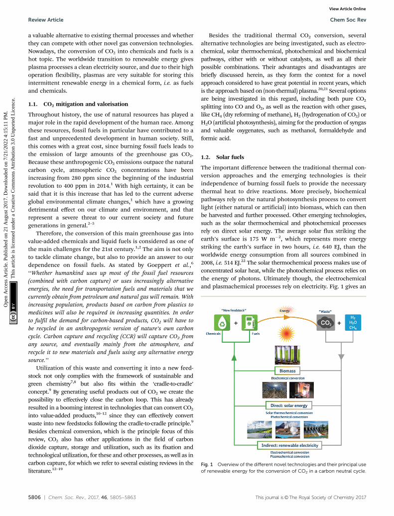
The important difference between the traditional thermal con-version approaches and the emerging technologies is theirindependence of burning fossil fuels to provide the necessarythermal heat to drive reactions. More precisely, biochemicalpathways rely on the natural photosynthesis process to convertlight (either natural or artificial) into biomass, which can thenbe harvested and further processed. Other emerging technologies,such as the solar thermochemical and photochemical processesrely on direct solar energy. The average solar flux striking theearth’s surface is 175 W m�2, which represents more energystriking the earth’s surface in two hours, i.e. 640 EJ, than theworldwide energy consumption from all sources combined in2008, i.e. 514 EJ.22 The solar thermochemical process makes use ofconcentrated solar heat, while the photochemical process relies onthe energy of photons. Ultimately though, the electrochemicaland plasmachemical processes rely on electricity. Fig. 1 gives an
Fig. 1 Overview of the different novel technologies and their principal useof renewable energy for the conversion of CO2 in a carbon neutral cycle.
Review Article Chem Soc Rev
Ope
n A
cces
s A
rtic
le. P
ublis
hed
on 2
1 A
ugus
t 201
7. D
ownl
oade
d on
7/2
1/20
22 4
:15:
11 P
M.
Thi
s ar
ticle
is li
cens
ed u
nder
a C
reat
ive
Com
mon
s A
ttrib
utio
n 3.
0 U
npor
ted
Lic
ence
.View Article Online
This journal is©The Royal Society of Chemistry 2017 Chem. Soc. Rev., 2017, 46, 5805--5863 | 5807
overview of the different novel technologies and their principaluse of renewable energy for the conversion of CO2 in a carbonneutral cycle.
The reliance of electrochemical and plasmachemical conversionson electricity at first seems to limit their use as a greenhouse gasmitigation technology, since currently, producing electricity generallyresults in CO2 emissions. This idea though could not be further fromthe truth due to the worldwide transition to renewable energysources, such as solar and wind energy. In 2014, the estimatedrenewable energy share of the global final energy consumption wasalready 19.2%, while by the end of 2015, the estimated renewableenergy share of global electricity production was 23.7%.23 It is even atsuch a stage that the large-scale adoption of these renewable energysources poses a challenge for the efficient storage and easy transportof the electricity produced, i.e. not only regarding the need for peakshaving, but more importantly the need for technologies to followthe irregular and at times intermittent supply of renewable electricityin a flexible way. While storage in batteries is possible, it is lessefficient than chemical storage in fuels.24 Such fuels, often referredto as carbon neutral fuels or solar fuels, offer a much highergravimetric and volumetric energy storage capacity, have muchhigher energy densities than electrical storage techniques and theymatch the existing worldwide liquid fuel infrastructure.12,24
In the first instance, the reactions in which CO2 is involvedcan be divided into two categories: the production of chemicalsand the production of fuels. The latter is considered as themost suitable target for the conversion of large volumes of CO2
since its market size is 12–14 times larger than the former. Oneof the most interesting compounds is methanol, which ispositioned exactly in the middle of these two categories, beingat the same time a raw chemical and a fuel, used in bothcombustion engines and fuel cells.25
To achieve the transformation of CO2 into value-addedchemicals or fuels, the reactions that are of greatest interestinvolve the conversion of CO2 with a co-reactant that acts as ahydrogen source (like CH4, H2 or H2O). Due to the existinginfrastructure, liquid products are preferable to gases, for mostapplications at least. Two approaches can be considered toachieve this: the indirect oxidative pathway and the directoxidative pathway. The main product of the former is syngas,a mixture of H2 and CO, which can be converted to almost anycommercial bulk chemical or fuel in a second – albeit veryenergy intensively – step through methanol and/or Fischer–Tropsch synthesis.10 In this case, it is of great importance to have ahigh degree of control over the H2/CO ratio to be able to steer thesynthesis towards the desired products.26 The direct oxidativepathway, on the other hand, tries to eliminate the energy-intensive middle man by converting the reactants immediately intohydrocarbons, short-chain olefins (e.g. ethylene and propylene) andoxygenated products (e.g. methanol, formaldehyde, dimethyl etherand formic acid).
Liquid products are more attractive over gaseous hydrogen,since – while in theory a ‘Hydrogen Economy’27 would be veryattractive – the latter has a number of serious drawbacks due toits physico-chemical properties.28 Furthermore, the infrastructureneeded to safely transport, store and dispense hydrogen would be
very expensive to roll out, while liquid chemicals match the alreadyexisting worldwide fuel infrastructure.12,24 Hence, especially in thetransportation sector, a transition from liquid–fossil-fuel-derivedproducts (e.g. gasoline, diesel fuel, kerosene) to a renewable andsustainable liquid fuel is highly desirable. Again, methanol is oneof the most interesting possible candidates to fulfil these require-ments. It is the simplest liquid chemical containing only onecarbon. Although to date it is almost exclusively produced fromnatural gas (and shale gas) for economic reasons, it can easily beobtained from several (future) carbon sources, incl. CO2, biomass,biogas and landfill gas. Therefore, it has been proposed as a keysolar fuel for the above-mentioned anthropogenic carbon cycleunder the framework of a ‘Methanol Economy’.6
To be economically competitive with the existing structures,the efficient production of these solar fuels is critical during thequest to find an effective CO2 conversion technology with thepotential to be commercialized on a large scale.
2. Traditional thermal CO2 conversionapproaches
We first briefly discuss the existing traditional (mainly thermo-catalytic) approaches used on an industrial scale. As such, thissection will act as a comparison for the novel technologiesunder development. This section is subdivided into: (1) pureCO2 splitting and (2) CO2 conversion in combination with aco-reactant, i.e. CH4, H2 or H2O.
2.1. Pure CO2 splitting
Thermal CO2 splitting has not been very effective to date. Thisis not surprising from a thermodynamic point of view; thecarbon–oxygen bonds are relatively strong (783 kJ mol�1)29 andthe Gibbs free energy of formation (DG1 = �394 kJ mol�1)24
clearly shows that CO2 is a highly stable molecule, requiring asubstantial energy input, optimized reaction conditions andactive catalysts for any chemical conversion to take place.Neither the entropy (TDS1) nor the enthalpy (DH1) term seemfavourable for its conversion.2 The overall reaction is written as:
CO2(g) - CO(g) + 1/2O2(g) DH1 = +283 kJ mol�1 (R1)
Of course, the high value of DH1 does not mean that itsconversion is not feasible. Indeed, strongly endothermicchemical reactions can be found in a large number of industrialprocesses used worldwide, a classic example being the steamreforming of methane (SMR):24,31
CH4(g) + H2O(g) - CO(g) + 3H2(g) DH1 = +206 kJ mol�1 (R2)
This highly endothermic reaction has found worldwide use. Inthe fertilizer industry, the H2 is used for the production ofammonia, while in the gas industry, this reaction is responsiblefor 95% of the worldwide H2 production. This shows that thereis no reason to dismiss CO2 splitting just because it is highlyendothermic. Hence, a fair amount of research towards thisreaction has already been conducted, of which an overview canbe found in the work of Rayne.29
Chem Soc Rev Review Article
Ope
n A
cces
s A
rtic
le. P
ublis
hed
on 2
1 A
ugus
t 201
7. D
ownl
oade
d on
7/2
1/20
22 4
:15:
11 P
M.
Thi
s ar
ticle
is li
cens
ed u
nder
a C
reat
ive
Com
mon
s A
ttrib
utio
n 3.
0 U
npor
ted
Lic
ence
.View Article Online

5808 | Chem. Soc. Rev., 2017, 46, 5805--5863 This journal is©The Royal Society of Chemistry 2017
It is, however, clear that, without actively removing one ofthe products (i.e. CO or O2), the equilibrium of this reaction liesstrongly to the left. Thus, thermal CO2 splitting is thermo-dynamically and energetically only favourable at very hightemperatures, as can be seen in Fig. 2. At 2000 K for instance,the reaction is not very efficient: we can easily estimate that ca.92 kJ mol�1 would be needed to heat 1 mole of CO2 from300 to 2000 K. Furthermore, the reaction enthalpy is equalto 245 kJ mol�1 at 2000 K. Based on a conversion of 1.5% atthis temperature, the energy cost for the total conversion isB7.9 MJ mol�1, yielding an energy efficiency of only 4.4% withrespect to the reaction enthalpy of 283 kJ mol�1 at 300 K. On theother hand, ca. 184 kJ mol�1 would be needed to heat 1 mole ofCO2 to 3500 K, and at this temperature the reaction enthalpy isequal to 206 kJ mol�1. Hence, based on a conversion of 80% atthis temperature, the energy cost of the total conversion is thenonly B602 kJ mol�1, yielding an energy efficiency of 47% withrespect to the reaction enthalpy of 283 kJ mol�1 at 300 K. Whilethe conversion continuing to increase, above 3500 K the energyefficiency starts to decrease. At 5000 K, the conversion is 100%but the energy efficiency is only 35%, as can be deduced fromFig. 2.
Thus, it is clear that the equilibrium production of CO andO2 varies from less than 1% at temperatures below 2000 K up to45–80% at the temperature range 3000–3500 K.29,30 Therefore,the most pertinent studies regarding thermal CO2 splittinginvolve membrane reactor systems. Nigara and Cales32 used acalcia-stabilized zirconia membrane and CO as the sweep gas.At a temperature of 1954 K, they were able to reach a conversionof 21.5%, whereas the equilibrium production was a mere 1.2%at the same temperature.32 The overall conversion, however,was much lower due to the permeation of O2 through themembrane, whereby it recombined with the CO sweep gas toform CO2. Itoh et al.33 employed an oxygen permeable yttria-stabilized zirconia membrane and used argon as the sweep gas.Unfortunately, despite the removal of oxygen through themembrane, conversions of only up to 0.5% were obtained fora maximum temperature of 1782 K. Fan et al.34 used a solid
oxide (SrCo0.5FeO3) membrane reactor and methane as thesweep gas. Conversions of up to 10% were found at a tempera-ture of 1213 K, which are one to two orders of magnitude higherthan what could be expected to be attained conventionally.Nonetheless, the feed gas was diluted with four parts of heliumper one part of CO2, and when this is taken into account, aneffective conversion of only 2% was actually reached.
To summarize, these studies have demonstrated the possi-bility of producing CO and O2 by the direct thermal splitting ofCO2 – at lower temperatures than the equilibrium predictions –by means of the use of semipermeable membranes to extractoxygen. Nevertheless, the attained overall effective conversionsof 0.5–2% are too low to be considered practical for successfulapplication on an industrial scale.
Because to date none of the above-mentioned alternativeapproaches to split CO2 at lower temperatures have yet realizedacceptable conversions and energy efficiencies, thermocatalyticCO2 splitting is currently not applied on an industrial scale.The reason for this is the high energy consumption and, inaddition, the lack of effective techniques for separating CO andO2 at high temperatures to avoid ending up with an explosivemixture. Nevertheless, we presented this brief summary of theinitial efforts regarding thermal CO2 splitting to support acomplete understanding of the matter, and because this work haslaid the foundations for one of the novel technologies, i.e. solarthermochemical CO2 splitting, discussed later (see Section 3.2).
2.2. Conversion of CO2 with a co-reactant
Due to the inherent high energy consumption and derived lowenergy efficiency of thermocatalytic CO2 splitting, the onlypractical way to reform CO2 consists of using a co-reactant.Thermodynamically speaking, it is significantly easier to con-vert CO2 when it is paired with a co-reactant that has a higher,i.e. less negative, Gibbs free energy.24 Some suitable candidatesare CH4 (DG1 = �50.7 kJ mol�1) and H2 (DG1 = 0 kJ mol�1). Inessence, these hydrogen-bearing energy carriers give up theirintrinsic chemical energy to promote the conversion of CO2.
As such, it is no surprise that the most widely investigatedtraditional processes to convert CO2 involve the reaction witheither CH4 or H2. The former is one of the best knowntraditional processes for reforming CO2 into synthesis gas orsyngas, which is a mixture of H2 and CO. The reaction with H2
is known as the Sabatier reaction, which is a well-knownprocess to generate CH4 (and H2O). Additionally, the combi-nation of CO2 and H2 can also be used to produce methanolthrough the methanol synthesis process. A final process ofinterest to mention is the combined conversion of CO2 andH2O, a technique for which there is no real traditionalapproach. Nevertheless, we briefly mention it here becausewater is an interesting co-reactant to pursue for the growingarray of novel techniques. After all, H2O is not only the mostubiquitous and cheapest hydrogen source, compared to CH4
and H2, but converting CO2 in combination with H2O toproduce value-added products using renewable energy wouldsuccessfully mimic natural photosynthesis.35,36 It is interestingto note that besides CH4, H2 and H2O, other possible hydrogen
Fig. 2 Calculated theoretical thermal conversion (left axis) and corres-ponding energy efficiency (right axis) as a function of temperature for thepure splitting of CO2 into CO and O2.
Review Article Chem Soc Rev
Ope
n A
cces
s A
rtic
le. P
ublis
hed
on 2
1 A
ugus
t 201
7. D
ownl
oade
d on
7/2
1/20
22 4
:15:
11 P
M.
Thi
s ar
ticle
is li
cens
ed u
nder
a C
reat
ive
Com
mon
s A
ttrib
utio
n 3.
0 U
npor
ted
Lic
ence
.View Article Online

This journal is©The Royal Society of Chemistry 2017 Chem. Soc. Rev., 2017, 46, 5805--5863 | 5809
sources could also be considered, such as glycerol. The use ofglycerol as a hydrogen donor has already been suggested andsuccessfully implemented for different technologies, such as itsuse as a hydrogen donor (and green solvent) in catalytic transferhydrogenation–dehydrogenation reactions of various unsaturatedorganic compounds;37 its use as a hydrogen donor for the produc-tion of CH3OH from CO2 in a hybrid enzymatic/photocatalyticapproach38 and its use in the plasma-based reforming of glyceroltowards syngas,39 which also led to the suggestion of using glycerolas a hydrogen donor for the possible in situ trapping of oxygenduring the plasmachemical splitting of CO2.40 However, in thisreview, the focus lies on the above-mentioned three most commonlyused hydrogen sources CH4, H2 and H2O.
2.2.1. CO2 + CH4: dry reforming of methane. The combinedconversion of CO2 and CH4, known as the dry reforming ofmethane (DRM), is named analogous to its sibling conversion,namely the steam reforming of methane (SMR; reaction (2)above) – indicating the replacement of water by carbon dioxide:
CH4(g) + CO2(g) - 2CO(g) + 2H2(g) DH1 = +247 kJ mol�1
(R3)
This process is, however, not as straightforward as the steamreforming of methane, because CO2 is a highly oxidized,thermodynamically stable molecule, while its reaction partner,CH4, is chemically inert. Hence, the process needs to be carriedout at high temperatures (900–1200 K) in the presence of acatalyst, typically containing Ni, Co, precious metals or Mo2C asthe active phase.41,42 Fig. 3 illustrates the theoretical thermalconversion and energy efficiency as a function of temperature.At 1500 K, complete conversion is achieved, with an energyefficiency of 60%. However, the maximum energy efficiency of70% is obtained before this at 1000 K, reaching a conversion ofmaximum of 83%, but this then decreases with increasing thetemperature.
The dry reforming of methane (DRM) has quite a history. Itwas first studied by Fischer and Tropsch in 1928,42 and hasbeen a challenge for chemical engineering ever since.41 Sincethat time, the rationale for investigating this process has
adapted itself several times to the spirit of the age. In its origin,it arose from a desire for alternative ways to produce fuels andchemicals (in combination with the Fischer–Tropsch synthesis)due to the limited supply of fossil fuels during the SecondWorld War.43 A renewed interest was found in the 1970s in theaftermath of the oil crisis,43 again to circumvent the need forfossil fuels and with the idea of utilizing cheaper and moreabundant natural gas. With the beginning of a new millenniumand the increasing concern regarding climate change, DRM wasseen as a way to convert the major greenhouse gas CO2 intouseful products with the aid of natural gas.31,44 To date, a trueamalgam of environmental and economical motivations exist,such as the conversion of the greenhouse gas CO2, the capabilityof using biogas as a feedstock, the search for a convenient way toliquefy CH4 for easier transport, and the availability of cheapCH4 through shale gas.12,18,31,41,42,44–46
Alas, despite all the bright outlooks, there is one majorpitfall, namely the process’ inherent susceptibility for sootdeposition and the detrimental effect this has on the processthrough deactivation of the catalyst. Due to this drawback,DRM is to date not yet (widely) used on an industrial scale.Of course, a lot of research is still ongoing towards modifiedcatalysts to circumvent this coking issue, which was originallyalso a big problem for the currently widely adopted steamreforming of methane. Nevertheless, the inability to transformthe alluring promises of DRM into reality through the tradi-tional thermal methods – among other reasons– has sparkedand fuelled the growing interest for alternative reformingtechnologies, as is discussed in Sections 3 and 4.
2.2.2. CO2 + H2: hydrogenation of CO2. Both the completehydrogenation of CO2 to CH4, known as the Sabatier reaction orthe methanation of CO2, and the selective hydrogenation ofCO2 to methanol are well-known commercially interestingprocesses.47 The catalytic hydrogenation of CO2 to methane isa thermodynamically very favourable process:48
CO2(g) + 4H2(g) - CH4(g) + 2H2O(g) DH1 = �165.3 kJ mol�1
(R4)
However, due to the high oxidation of the carbon, its reductionconsists of an eight-electron process, significantly limiting thereaction kinetics and requiring a catalyst with high rates andselectivities.48 The process has been extensively studied usingvarious supported nickel catalysts.48,49 CO2 conversions of495%, with the methane selectivity going up to 100% attemperatures of 700 K, have already been achieved.49 However,for industrial commercialization, this process is only viablewhen the H2 is produced from renewable energy and the CO2
comes from cheap accessible waste streams.10,49 As mentionedabove, 95% of the worldwide H2 production, however, comesfrom steam methane reforming, leading to a problematicflawed loop. Furthermore, the current cost for CO2 capture,separation and purification from waste streams is too high.Both reasons make this process economically unfeasible.49
The selective hydrogenation of CO2 to methanol, on theother hand, is a process that is currently operated on anindustrial scale. The annual worldwide production of methanol
Fig. 3 Calculated theoretical thermal conversion (left axis) and corres-ponding energy efficiency (right axis) as a function of temperature for thedry reforming of methane.
Chem Soc Rev Review Article
Ope
n A
cces
s A
rtic
le. P
ublis
hed
on 2
1 A
ugus
t 201
7. D
ownl
oade
d on
7/2
1/20
22 4
:15:
11 P
M.
Thi
s ar
ticle
is li
cens
ed u
nder
a C
reat
ive
Com
mon
s A
ttrib
utio
n 3.
0 U
npor
ted
Lic
ence
.View Article Online

5810 | Chem. Soc. Rev., 2017, 46, 5805--5863 This journal is©The Royal Society of Chemistry 2017
is estimated to be around 70 M metric tonnes (2015). The mostcommon commercial catalyst is copper supported on highsurface area alumina (often promoted with zinc oxide).47 Therelevant reactions for the selective hydrogenation of CO2 are:50
CO2(g) + H2(g) - CO(g) + H2O(g) DH1 = +40.9 kJ mol�1 (R5)
CO(g) + 2H2(g) - CH3OH(g) DH1 = �90.8 kJ mol�1 (R6)
CO2(g) + 3H2(g) - CH3OH(g) + H2O(g) DH1 = �49.9 kJ mol�1
(R7)
While the overall reaction (reaction (7)) of CO2 hydrogenationto methanol is exothermic (DH1 = �49.9 kJ mol�1), the ratedetermining step is the activation of CO2 in the reverse water–gas shift (RWGS) reaction, i.e. reaction (5). Obviously, dopingmetals that function as catalysts in the RWGS reaction willpromote CO2 hydrogenation.50 As a result, much effort is stillfocused on investigating the efficacy of Cu-based catalystspromoted with Pd and Ga,51 with the fundamental materialchallenge centring on the fact that, generally, CO2 and H2 willonly react at high temperatures with multicomponent hetero-geneous catalysts.24
One of the main drawbacks of the selective hydrogenation ofCO2 to methanol in the above case is the production of water asa by-product (see reaction (7)). A third of the H2 is thusconverted to water compared to the complete conversion tomethanol when starting from syngas (see reaction (6)). Further-more, the thermodynamics for methanol production from H2
and CO2 are not as favourable as those for the production fromsyngas (cf. reactions (6) and (7)).51 Therefore, on an industrialscale, methanol production usually relies on syngas in a 3 to 1ratio from SMR (reaction (2)), while CO2 is added to deal withthe excess H2 in the feed (compared to reaction (6)), and finallythe produced water (reaction (7)) is recycled via the water–gasshift reaction (the reverse reaction of reaction (5)).
Nevertheless, to conclude, we can state that, currently theselective hydrogenation of CO2 with H2 into methanol is themost – if not to say only – industrially successful traditionalprocess for the direct reforming of CO2 into chemicals and fuels.
2.2.3. CO2 + H2O: artificial photosynthesis. Although thereis no real traditional approach for the combined conversion ofCO2 and H2O, we present here the main overall reactions ofinterest for the combined conversion of CO2 and H2O, mostlyfor the sake of completeness and because of their interest to thediscussion of novel technologies (see Sections 3 and 4):
CO2(g) + H2O(g) - CO(g) + H2(g) + 1/2O2(g) DH1 = +525 kJ mol�1
(R8)
CO2(g) + 2H2O(g) - CH3OH(g) + 3/2O2(g) DH1 = +676 kJ mol�1
(R9)
These are clearly the most endothermic overall reactionsdescribed in this section, partially explaining the absence of atraditional (thermocatalytic) reforming approach. Fig. 4 illustratesthat the same high temperatures are needed for this reaction asfor the pure CO2 splitting, while obtaining somewhat lowerenergy efficiencies. The highest energy efficiency (40%) is
obtained at 3300 K together with a conversion of 60%. Athigher temperatures, the energy efficiency decreases to 25%at 5000 K for a total conversion.
Nevertheless, a process involving the reaction of CO2, H2O,O2 and CH4, called tri-reforming, is gaining quite someinterest.24 The concept, proposed by Song et al.,31 involves asynergetic combination of dry reforming, steam reforming andthe partial oxidation of methane in a single reactor, which canproduce syngas in desired ratios (1.5–2.0), while eliminatingcarbon formation, as demonstrated for a fixed bed flow reactorat 1123 K over supported nickel catalysts.31
3. Novel CO2 conversion approaches
It stands without doubt that the efficient conversion of CO2 touseful molecules presents an important challenge and a greatopportunity for chemists today. Due to the inability of thetraditional thermal approaches to address the worldwide CO2
and energy challenge, several promising novel technologies areunder development. Plasma technology is one such technology,but before elaborating on this specific technology in moredetail, first, a summary of its main ‘frenemies’ in this domainis given. For each technology, first a brief explanation of theworking principles and current achievements is given, followedby the major advantages and challenges. From this section, itwill become clear that there is, indeed, fierce competition in thequest to find the most effective and efficient CO2 conversiontechnology with the potential to be used on an industrial scale.It should be noted that only technologies for CO2 conversionare described here. For other (in)direct applications and fixa-tion technologies, we refer to other reviews.12–19
3.1. Electrochemical conversion
We kick off our discussions with one of the closest competitorsto plasma technology, i.e. the electrochemical conversion orreduction of CO2. This closeness derives from the fact that bothtechnologies rely on the use of (renewable) electrical energy,whereas most of the other novel technologies only take direct
Fig. 4 Calculated theoretical thermal conversion (left axis) and corres-ponding energy efficiency (right axis) as a function of temperature for theconversion of CO2 and H2O into H2, CO and O2.
Review Article Chem Soc Rev
Ope
n A
cces
s A
rtic
le. P
ublis
hed
on 2
1 A
ugus
t 201
7. D
ownl
oade
d on
7/2
1/20
22 4
:15:
11 P
M.
Thi
s ar
ticle
is li
cens
ed u
nder
a C
reat
ive
Com
mon
s A
ttrib
utio
n 3.
0 U
npor
ted
Lic
ence
.View Article Online

This journal is©The Royal Society of Chemistry 2017 Chem. Soc. Rev., 2017, 46, 5805--5863 | 5811
advantage of renewable energy, i.e. the sun, either based on itsfocused radiation heat or its emitted photons. Although sig-nificant technical and catalytic advances are still required forits large-scale use, electrochemical conversion is becoming amature technology for H2O splitting. For CO2 reduction, on theother hand, several important challenges remain.7,45,52–55
The electrochemical valorization of CO2 is an innovativetechnology, in which electrical energy is supplied to establish apotential between two electrodes, allowing CO2 to be trans-formed into value-added chemicals under mild conditions.7,55
This transformation can occur through a wide variety of path-ways, which are typically strongly affected by the experimentalconditions. The electrochemical reduction of CO2 can proceedthrough two-, four-, six- and eight-electron reduction pathwaysin gaseous, aqueous and non-aqueous phases in different celland electrode configurations.7,53 Fig. 5 shows the three maincell types. Fig. 5(a) and (b) illustrate the principle of a solidproton conducting electrolysis cell (SPCEC) for the combinedconversion of CO2 and H2O, and of a solid oxide electrolysis cell(SOEC) that could be used for either the pure or combinedconversion of CO2 and H2O, respectively, while a typical alkalineelectrolysis cell for water splitting is shown in Fig. 5(c).The catalyst and/or electrode materials, the reaction medium,electrolyte solution, buffer strength, pH, CO2 concentration andpressure as well as the reaction temperature all influence anddetermine the wide variety of products that can be obtained.53
The major reduction products obtained include carbon mon-oxide (CO), formic acid (HCOOH) or formate (HCOO�) in basicsolution, formaldehyde (CH2O), methanol (CH3OH), oxalic acid(H2C2O4) or oxalate (C2O4
2�) in basic solution, methane (CH4),ethylene (C2H4) and ethanol (C2H5OH).7,45,53
There are a number of reasons why the electrochemicalreduction process stands out from the crowd; for instance,the process is controllable by several reaction parameters,including the electrode potential and temperature.7,45,52–54
Furthermore, a wide variety of valuable products can be made,either in mixtures or more importantly in their pure form. Forexample, besides the direct electrochemical reduction of CO2 tomethanol, it is also possible to produce CO and H2 at thecathode in a H2/CO ratio close to 2, while at the anode, a
valuable pure oxygen stream is generated (see Fig. 1–5(b)).45
Another advantage is that electrochemical conversion can makeuse of a wide variety of (intermittent) renewable electricity sources,i.e. more than just solar energy.53 Finally, the electrochemicalreaction systems are compact, modular, on-demand and thus easyto utilize for small or large scale-up applications.53
The accomplishments to date in the electrochemicalreduction of CO2 have been encouraging, and the potentialrewards are enormous.7 Nevertheless, several challengesremain, such as the high overpotential, which is the differencein electrode voltage between the theoretical thermodynamicand actual real-world values to drive a reaction;52,54 the lowsolubility of CO2 in aqueous solutions;52 the formation ofproduct mixtures, thus requiring expensive separation steps;52
fouling and catalytic deactivation of the electrodes by impurities,reaction intermediates and by-products;7,52,54 the instability ofthe electrode material;7 the low Faradaic efficiencies, currentdensities and high energy consumption;52,53 the kinetic barriersleading to low efficiencies;53,54 and the non-optimized electrode/reactor and system design for practical applications.53 In gen-eral, it is recognized that the single biggest challenge is the lowperformance of the electrocatalysts, due to low activity, lowselectivity and most importantly insufficient stability. Thereported stability tests in the literature are only in the order of,or below, 100 hours, while long-term tests are non-existent todate.53 This makes the development of stable electrocatalystmaterials with high activity and selectivity the main priority forthis technology.7,53,56
It seems that despite many advances and successful proof-of-concepts being reported, the maturity of electrochemicalCO2 reduction technology is still far from reaching the require-ments for commercialization, due to the several remainingmajor technological challenges, as listed above.7,52,53 Particu-larly for industrial-scale implementation, the low catalyst sta-bility seems to be the major limitation.53 As a result, noelectrocatalysts developed to date for the reduction of CO2
would be deemed useful for a large-scale system.54 As statedby Qiao et al.,53 ‘‘With continued and extensive efforts focused ondeveloping innovative composite and nanostructured catalystmaterials to overcome the challenges of insufficient catalyticactivity, product selectivity, and catalytic stability, the technologyof CO2 electroreduction will become practical in the near future’’.Hence, to successfully achieve the transformation of CO2 toliquid fuels and useful chemicals, new methods and approachesfor activating the CO2 molecule at lower overpotentials arerequired.7 In the first instance, novel electrodes enabling opera-tion at current densities close to commercially available H2Oelectrolyzers have to be developed, for which solid oxide electro-des appear to be suitable candidates.52 Furthermore, a betterunderstanding of the mechanistic role of metal and metal oxidesin the reduction process is needed to open the possibility todesign electrodes with certain compositions.52 To conclude,efforts to optimize system designs and at the same time todevelop durable catalysts still need to be carried out.53 However,the final grand question remains: can all of this be done withinexpensive earth-abundant metals?54
Fig. 5 Principles of a solid proton conducting electrolysis cell (SPCEC) (a),solid oxide electrolysis cell (SOEC) (b) and an alkaline electrolysis cell (c) forthe conversion of CO2 and/or H2O.
Chem Soc Rev Review Article
Ope
n A
cces
s A
rtic
le. P
ublis
hed
on 2
1 A
ugus
t 201
7. D
ownl
oade
d on
7/2
1/20
22 4
:15:
11 P
M.
Thi
s ar
ticle
is li
cens
ed u
nder
a C
reat
ive
Com
mon
s A
ttrib
utio
n 3.
0 U
npor
ted
Lic
ence
.View Article Online

5812 | Chem. Soc. Rev., 2017, 46, 5805--5863 This journal is©The Royal Society of Chemistry 2017
3.2. Solar thermochemical conversion
Another technology, which has recently made several hugeleaps forward, is the solar thermochemical conversion of CO2.There are several ways to reduce CO2 with the assistance ofrenewable solar energy, with those using direct solar lightirradiation probably the most effective methods because thereis no additional extra energy required and no negative influence onthe environment.57 Two forms of direct solar energy conversion canbe distinguished: (i) thermal conversion – described here – wherework can be extracted after sunlight is absorbed as thermal energyand (ii) quantum conversion – described in the next section – wherethe work output can be taken directly from the light absorber(e.g. a semiconductor, molecule or organic compound).58 For solarthermochemical conversion, concentrated solar radiation is used –in the form of high-temperature heat – as an energy source to drivethe highly endothermic reactions.
The single step thermal dissociation of CO2 (or H2O) isimpeded by the need to operate at high temperatures (42500 K),as demonstrated in Fig. 2 above, and the need for effectiveseparation techniques to avoid ending up with an explosive mixtureof CO/O2 (or H2/O2).58,59 Multi-step thermochemical cycles usingmetal oxide redox reactions bypass the separation problem and, inaddition, they allow operation at relatively moderate temperatures.More specifically, as shown in Fig. 6, solar processes involvingheat at Z1500 K enable a two-step thermochemical cycle usingmetal oxide redox reactions for CO2/H2O-splitting.58,59 The first –endothermic – step is the solar thermal reduction of the metal
oxide MOox (where M is e.g. Ce, Zn, or Fe)60 to the metal or to thelower-valence metal oxide MOred. The second – nonsolar –exothermic step is the oxidation of the reduced metal oxide withCO2 and/or H2O to form CO and/or H2, allowing the (re)oxidizedmetal oxide to be reused/recycled for the first step.58,59 Ingeneral, two cycle categories can be considered: volatile andnon-volatile. Non-volatile cycles utilize metal oxides, whichremain in the solid state during reduction, while volatile redoxcycles consist of metal oxides, which undergo gas–solid phasetransitions. The volatile reactions appear more favourable, butthe volatile products must be quenched rapidly to avoid recom-bination, and to date this issue has not been solved in anenergetically efficient fashion.59 For the non-volatile cycles,cerium oxide (ceria, CeO2) has emerged as a highly attractiveredox active material choice for two-step thermochemicalcycling.60,61 Another promising pathway, which operates at lowertemperatures than ceria, is the exploration of doped perovskiteoxides.62
The main advantage of the solar thermochemical conversionof CO2 is obviously the direct use of solar energy. Concentratingsolar technologies, which are currently applied commerciallyfor large-scale (megawatt) power generation, can be coupled tohigh-temperature thermochemical reactors with the potentialto achieve high solar-to-fuel energy conversion efficiencies and,consequently, the potential to produce solar fuels on a largescale and at a competitive cost.58 To date, solar flux concen-tration ratios exceeding 2 MW m�2 are attainable with large-scale solar tower and dish systems. Solar thermochemicalapplications, although not as far developed as solar thermalelectricity generation, employ the same solar concentratinginfrastructure, with the solar reactor positioned at the focusof the solar tower (for megawatt centralized applications) orsolar dish (for kilowatt decentralized applications).58 A recentcomprehensive review of solar concentrating technologies forthermal power and thermochemical fuel production was givenby Romero et al.63 Consequently, these cycles inherently havethe potential to realize a greater theoretical efficiency thanmethods using energy vectors or a small part of the solarspectrum and are, in addition, conceptually simpler.62,64 Thispotential to achieve high solar-to-fuel energy conversion effi-ciencies is primarily related to the fact that solar thermalprocesses inherently operate at high temperatures and utilizethe entire solar spectrum, and, as such, provide a thermodyna-mically favourable path to the production of solar fuels.58,59 Athermodynamic analysis based solely on the material proper-ties of e.g. CeO2 indicated that efficiency values in the range of16–19% could be attainable, even in the absence of sensibleheat recovery. These values are close to the 20% efficiency thatis likely to be needed for solar fuels to be considered costcompetitive,65 as will be discussed in more detail in Section 6.3.
Although significant advances have been made in the fieldof solar thermochemical CO2 conversion technologies usingmetal oxides, a lack of fundamental research into the behaviourof the metal oxides under the high-temperature conditionspresent in these cycles has hampered the development ofmaterials. Basic questions relating to oxygen transport, surface
Fig. 6 Schematic of the two-step solar thermochemical cycle for CO2
and H2O splitting based on metal oxide redox reactions.
Review Article Chem Soc Rev
Ope
n A
cces
s A
rtic
le. P
ublis
hed
on 2
1 A
ugus
t 201
7. D
ownl
oade
d on
7/2
1/20
22 4
:15:
11 P
M.
Thi
s ar
ticle
is li
cens
ed u
nder
a C
reat
ive
Com
mon
s A
ttrib
utio
n 3.
0 U
npor
ted
Lic
ence
.View Article Online

This journal is©The Royal Society of Chemistry 2017 Chem. Soc. Rev., 2017, 46, 5805--5863 | 5813
chemistry, structural changes vs. redox reactions, materials’synthesis methods, the effects of thermochemical cycling on thematerial and the role of supports still have to be addressed.66
Furthermore, despite its favourable thermodynamics, both theefficiency and the cycling rates in the reactor can be largelylimited by thermal losses, resulting from poor conductive andradiative heat transfer across the porous metal oxide structure.58
Finally, the thermochemical conversion rates are higher than,for example, the photocatalytic rates, but although conceptuallysimple, focusing lenses for sunlight and high-temperaturereactors incur high initial investment costs.60
Solar thermochemistry has clearly emerged as a viable pathto utilize concentrated solar technology – currently appliedcommercially for large-scale power generation – for the conver-sion of CO2 (and H2O) into CO (and H2). Also, solar thermo-chemical cycles for the conversion of CO2 and H2O via themetal oxide redox reaction have favourable thermodynamics,but the ultimate factor dictating commercial viability is a highsolar-to-fuel energy conversion efficiency, and to date efficien-cies above 10% are still pending experimental demonstrationwith robust and scalable solar reactors.58,59,62 The discoveryof new materials with large oxygen exchange capabilities atmoderate temperatures and their implementation in efficientsolar reactors are thus essential. Additionally, rapid chemicalkinetics and material stability over thousands of cycles must bedemonstrated for each material considered.59,67 This is thesecond key to achieving market viability, because materialsmust remain active for many thousands of redox cycles in orderto avoid the high costs that would be associated with frequentreplacement. As such, commercial success is again predicatedupon finding appropriate materials composed of earth-abundantelements that can operate at lower reduction temperatures thancurrent systems, together with sufficient activity to achieve highprocess efficiency.62
3.3. Photochemical conversion
The photochemistry for the photochemical conversion differsfrom (solar) thermochemistry in the way the solar energy isused: the former uses the energy of a photon in the chemicalreactions,60 while the latter uses the absorbed thermal energyto overcome the activation barriers and to affect the chemicalequilibria.58
The photoreduction of CO2 to formaldehyde and methanolin purified water was already reported back in 1979, using thesemiconductors TiO2, ZnO, CdS, GaP, SiC and WO3.60 Based ona correlation between the conduction band energy potentialand the yield of methanol, it was suggested that the photo-reduction of CO2 proceeds by the photoexcited electrons in theconduction band moving to CO2. This principle mechanism ofselective photocatalysts under light irradiation is shown inFig. 7. Here, the conduction band energy minimum is higherthan that for CO2 photoreduction.60 Again the efficiency of thephotocatalytic materials in their use of sunlight for the conver-sion of CO2 to fuel is of critical importance.68 This efficiency isinfluenced by several factors, such as catalyst dosage, reactantratio, reaction temperature, time, system pressure, pH, light
intensity and wavelength.57 A wide variety of reduction pro-ducts can be obtained, just like with the electrochemicaltechnique, including carbon monoxide (CO), formic acid(HCOOH), formaldehyde (CH2O), methanol (CH3OH), methane(CH4), ethylene (C2H4), ethane (C2H6) and ethanol (C2H5OH).68
From a sustainable point of view, solar light is the idealenergy source. In combination with photocatalytic H2O split-ting, the solar-driven reduction of CO2 to fuels is a veryattractive approach.52 The advantages of photochemical systemsinclude the assertion that they are composed of only a few partsand are therefore theoretically less likely to fail, providing theremaining parts are reliable.58 The most extensively investigatedcatalyst for the photoreduction of CO2 is TiO2.60 Several attemptshave already been made to enhance the photocatalytic activity ofTiO2, including by the addition of a metal, Rh/TiO2 or Rh/WO3–TiO2,60 the use of highly dispersed active Ti ion species,60
through atomically dispersing TiO2 on zeolites or ordered meso-porous SiO2 or by doping with Pt, Cu, N, I, CdSe or PbS.60 Themost significant breakthrough was achieved using nitrogen-doped TiO2 nanotube arrays co-catalyzed with Cu and/or Ptnanoparticles, in which water-vapour-saturated CO2 was reducedto methane and other hydrocarbons without the application ofan electrical bias.60,68
It should be noted, however, that for many oxide semicon-ductors (incl. TiO2) this electrical bias is necessary, because theconduction band is located below the acceptor level. This is onefactor that limits the efficiency of metal oxide materials.58
Furthermore, most work is performed using artificial (UV) lightsources,57,68 because the large band gap of metal oxides resultsin a poor photo-responsiveness to visible light.52,57,58 Theorydictates that a band gap between 2 and 2.4 eV is optimal, whichlimits the maximum attainable efficiency to about 17%.68
However, solar energy conversion efficiencies obtained to dateare much lower (at present, at o2%),58 mainly as a result of theenergy associated with this electrical bias.58 Furthermore, aremaining challenge lies in the separation and collection of the
Fig. 7 Principle of the photochemical reduction of CO2 by water on aphotocatalyst.
Chem Soc Rev Review Article
Ope
n A
cces
s A
rtic
le. P
ublis
hed
on 2
1 A
ugus
t 201
7. D
ownl
oade
d on
7/2
1/20
22 4
:15:
11 P
M.
Thi
s ar
ticle
is li
cens
ed u
nder
a C
reat
ive
Com
mon
s A
ttrib
utio
n 3.
0 U
npor
ted
Lic
ence
.View Article Online

5814 | Chem. Soc. Rev., 2017, 46, 5805--5863 This journal is©The Royal Society of Chemistry 2017
hydrogen and oxygen gas produced (often produced in closeproximity).58 Finally, many of the photocatalysts presently beingstudied are metal complexes employing rare and expensive transi-tion metals, hence efforts must be made using earth-abundantelements that could support large-scale undertakings.54
From the literature, it is clear that encouraging progress hasbeen made towards the photocatalytic conversion of CO2 usingsunlight, but nevertheless, the existing techniques are insuffi-cient to date and further efforts are required to increase thesolar-to-fuel conversion efficiencies.54,55,57,58,68 This appears tobe a general remark for photochemistry: very few examples existof chemical processes operating effectively on the basis ofphotocatalysis technology. Not only do the photon efficiencyof materials and the resulting achievable rates remain insuffi-cient, also sub-optimal photocatalytic reactors often induceinefficiencies in operation, which limit their practicalapplication.52 The immediate requirement in this technologyis to develop visible-light-sensitive photocatalysts, which areprominent in CO2 recycling.57 What we ultimately seek is ameans for achieving the high-rate photocatalytic reduction ofCO2, using solar radiation as the only input energy source.Since visible light comprises the majority of the solar spectrumenergy, it behoves us to consider photocatalysts sensitive tosunlight.68 Immediate research opportunities include uniformco-catalyst sensitization of the entire nanotube array surface forenhanced conversion rates, and the design of co-catalysts toimprove and control the product selectivity.68 Although thephotocatalytic reduction of CO2 may become an importantstepping stone to solar fuel production, much progress remainsto be achieved before it could be considered practical as anindustrial process.54 Based on the highest reported activities,one can conclude that game-changing rates have not yet beenachieved. Reported turnover frequencies are far from thoserequired for an efficient catalytic process, and an efficiencyimprovement of at least 3 orders of magnitude is needed.52 It isthus clear that photochemical systems have a long way to go toachieve their full potential and to be able to successfullycompete with the alternative approaches to producing fuelsfrom sunlight.58
3.4. Biochemical conversion
Another pathway converting solar energy into chemical energyis by ‘natural’ photosynthesis for the production of biofuels.69
The biological conversion of CO2 for producing chemicals orfuels is an attractive route. Nevertheless, the use of first gen-eration biofuels has generated a lot of controversy, mainly dueto their competition with agriculture for arable land use forfood production, thus impacting global food markets and foodsecurity.69,70 The use of microalgae, on the other hand, couldmeet the conditions for technically and economically viablebiofuel production. More specifically, viable biofuel productionshould be competitive or cost less than petroleum fuels, itshould require low to no additional land use, it should enableair quality improvement and should require minimal wateruse.69,70 Microalgae can typically be used to capture CO2 fromthree different sources: atmospheric CO2, CO2 emissions from
power plants and industrial processes, and CO2 from solublecarbonates.70 The pathways for CO2 fixation have evolved overbillions of years and use many diverse mechanisms andenzymes for processing CO2 by forming C–H and C–C bondsand cleaving C–O bonds.47 Furthermore, algae are more photo-synthetically efficient than terrestrial plants, making themwithout doubt very efficient CO2 fixers.71
Microalgae are currently considered to be one of the mostpromising alternative sources for biodiesel; hence, most of thecurrent research and developmental efforts are focused onmicroalgae, in particular due to their high growth rate andhigh oil content (up to 77% of the dry cell mass). Algae containoils, sugars, and functional bioactive compounds that can beused for commercial products. In addition to fuels, the devel-opment of appropriate technologies for high-efficiency algalbiodiesel production is also applicable to biohydrogen, biogas,bioethanol and biomass-to-liquid (BTL) approaches using fastgrowing algae.69,70 Furthermore, valuable co-products, suchas biopolymers, proteins and animal feed, can be producedduring the process.71,72 Other advantages include very shortharvesting cycles (B1–10 days), thus allowing multiple orcontinuous harvests with significantly increased yields.Furthermore, the cultivation can potentially be carried out onmarginal or non-arable land, and even the use of waste waterfor algal cultivation is a viable option.69,70 To obtain the bestperforming microalgae strains for biofuel production, one can:(1) screen a wide range of natural isolates, (2) improve them bymetabolic (genetic) engineering or (3) obtain them by selectionand adaptation. There are algae collections worldwide, whichcontain thousands of different algal strains that can beaccessed.69
It should, however, be emphasized that the significantdrawback in all the biochemical techniques is the big shareof the cost for cultivation. Among others, the harvesting ofalgal biomass accounts for the highest proportion of energyinput during production, but currently, there are no standardharvesting techniques.69–71 Therefore, currently algal biomassis not suitable to be cultivated solely for bioenergy applicationsand instead it must be integrated with the production of othervalue-added products, e.g. pharmaceutics, cosmetics and food.Unfortunately, processes for the recovery of complex moleculesfrom algal biomass are expensive and significant technologicalprogress is still required before commercial deployment.73
Algae can be grown in many ways, such as in freshwater,saltwater or wastewater, in closed photobioreactors or in openponds.69 One key advantage of algae is that its cultivation doesnot require cropland, although, on the other hand, otherresources are needed.72 Other inorganic nutrients requiredfor algae production include nitrogen and phosphorus,70
resulting in the need for unsustainable inputs of nitrogenousfertilizers, which are produced from fossil fuels and thatrequire huge inputs of energy for production.72 Furthermore,it has been reported that between 3.15 and 3650 litres offreshwater are needed to produce algal biofuel equivalent to1 litre of gasoline using current technologies. Thus, the integra-tion of the upstream production and downstream processing of
Review Article Chem Soc Rev
Ope
n A
cces
s A
rtic
le. P
ublis
hed
on 2
1 A
ugus
t 201
7. D
ownl
oade
d on
7/2
1/20
22 4
:15:
11 P
M.
Thi
s ar
ticle
is li
cens
ed u
nder
a C
reat
ive
Com
mon
s A
ttrib
utio
n 3.
0 U
npor
ted
Lic
ence
.View Article Online

This journal is©The Royal Society of Chemistry 2017 Chem. Soc. Rev., 2017, 46, 5805--5863 | 5815
microalgae, and the framing of these in the context of watersavings and net energy gain is required to build up credibility.72
Fig. 8 shows a schematic overview of the different steps for theapplication of a photobioreactor for CO2 conversion. Finally,optimization of the strain-specific cultivation conditions iscomplex, with many interrelated factors that can each be limitingfactors, including temperature, mixing, fluid dynamics and hydro-dynamic stress, gas bubble size and distribution, gas exchange,mass transfer, light cycle and intensity, water quality, pH, salinity,mineral and carbon regulation/bioavailability, cell fragility, celldensity and growth inhibition.69
Despite its inherent potential as a biofuel resource, manychallenges have impeded the development of algal biofueltechnology as a commercially viable solution that could supportsustainable production and utilization.70 Consequently, thelarge-scale cultivation of algae for biofuel production is still inthe research and development phase. The long-term potentialof this technology can be improved by the following approaches:(1) identifying and developing cost-saving growth technologies ofoil-rich algae;69,72 (2) utilizing integrated bio-refineries to pro-duce biodiesel, animal feed, biogas and electrical power, therebyreducing the overall cost of production;71,72 (3) enhancing thealgal biology by genetic modification and metabolic engineeringto aid the selection and successful outdoor large-scale cultivationof a robust microalgal strain;69,71,72 (4) identifying area-efficienttechniques to capture CO2 from industrial power plants;72
(5) recycling nutrients from municipal sewage and industrialwastewaters to reduce the demand for fertilizers to grow thealgae;69,70,72 (6) improving the economics of microalgae produc-tion by generating additional revenues from wastewater treat-ment and greenhouse gas emissions abatement;72 (7) mostimportantly, by developing cost-effective and energy-efficientharvesting methods to make the whole biofuels productionprocess economical;71 in this respect, strain selection is animportant consideration since certain species are much easierto harvest than others.69
3.5. Catalytic conversion
In Section 2, we already covered the main traditional thermo-catalytic approaches used. Of course, there is still a lot of researchongoing towards finding new improved (thermo-)catalytic pathways
for the different processes involved in CO2 conversion. There aretwo main catalysis types that can be applied for this process:homogeneous and heterogeneous catalysts. The former (e.g.Ru-, Rh- and Ir-based catalysts) are efficient for the formation offormic acid and formates, but are more challenging to be usedin commercial applications, while the latter (e.g. Fe-, Cu- andNi-based catalysts) are more practical for industrial applica-tions, but they frequently suffer from low yields and poorselectivity. As a result, significant improvements in new catalyticsystems are necessary to make thermocatalytic CO2 reductioneconomically feasible.48
Nonetheless, the catalytic conversion is briefly discussedhere; especially since it is clear from the sections above thatcatalytic materials can play an important role in the develop-ment and further advancement of most of the novel techno-logies under study.25 These scientific advances give rise tointriguing new combinations, and corresponding names, suchas electrocatalytic, photocatalytic, biocatalytic, as well as theireven more advanced hybrids forms, e.g. photoelectrocatalyticand bioelectrocatalytic processes.12,14,53 Kumar et al.54 statedquite frankly that virtually every approach under considerationfor the conversion of CO2 requires catalysts to facilitate theformation and cleavage of chemical bonds, as illustrated byFig. 9. In general, these required catalysts fall into threeclassifications: (1) they already exist and show good perfor-mance but are too rare/costly to be scaled up; (2) they alreadyexist but in forms that are not optimal or practical for adapta-tion to an integrated solar fuels system; (3) they do not exist yetand await discovery.54
From a scientific point of view, the development of catalystswith inexpensive metals, such as iron and copper compounds,which can also be active under mild conditions, is a bigchallenge.48 Still, it is evident that due to their reliance onthermal heat – as currently derived from burning fossil feed-stocks – the current pure thermocatalytic routes can only makea limited net contribution to CO2 conversion. Hence, techniquesbased on the use of (in)direct solar energy and other renewableenergy sources are needed to contribute to avoiding largevolumes of CO2.25 One exciting thermocatalytic advancementto circumvent this reliance on fossil fuels – besides the solarthermochemical conversion discussed in Section 3.2 above – isthe use of microwaves.74 Here, microwave-assisted CO2 conver-sion over carbon-based catalysts combines the catalytic anddielectric properties of carbonaceous materials with the advan-tages of microwave heating, which favours catalytic heteroge-neous reactions due to, among other reasons, the generation ofhot spots.
Microwave radiation has been shown to have beneficial effectson the reaction rate of heterogeneous (catalytic) reactions.75,76 Thecombination of microwave heating and a carbon material acting asboth a catalyst and microwave receptor gives rise to enhancedconversions compared to conventional heating, both in the case ofCO2 gasification and in the dry reforming of methane.75,76 Fidalgoet al.76 observed conversions that were a factor of 1.6 to 1.9 higherfor MW-heating compared to conventional heating. Unlike inconventional heating, the applied microwave energy is transferred
Fig. 8 Schematic of photo-bioreactor application for CO2 conversion.
Chem Soc Rev Review Article
Ope
n A
cces
s A
rtic
le. P
ublis
hed
on 2
1 A
ugus
t 201
7. D
ownl
oade
d on
7/2
1/20
22 4
:15:
11 P
M.
Thi
s ar
ticle
is li
cens
ed u
nder
a C
reat
ive
Com
mon
s A
ttrib
utio
n 3.
0 U
npor
ted
Lic
ence
.View Article Online

5816 | Chem. Soc. Rev., 2017, 46, 5805--5863 This journal is©The Royal Society of Chemistry 2017
directly to the catalyst without any heat flux. As a result, thetemperature inside the material is usually higher than the tem-perature of the surrounding atmosphere near the surface, and theuniformity of heat distribution is improved with respect to conven-tional heating, as shown in Fig. 10.76 Furthermore, the formation ofhot spots, possibly due to the generation of microplasma within thecatalyst bed, which may be at higher temperatures compared tothe bulk catalyst, have been reported to be responsible for anenhancement in the reaction rate, higher yields and the improvedselectivities of heterogeneous (catalytic) reactions.75,76
3.6. Summary
It should be of no surprise that the field of CO2 conversion israpidly evolving. As such, it is not the purpose of this section tocover all the (recent) work performed for these novel technologies,such as CO2 mineralization and utilization, which converts thechemical energy of CO2 mineralization into electricity, whileproducing valuable mineralization products,77 or the hybridenzymatic/photocatalytic approach for the production ofCH3OH from CO2 with the use of water–glycerol, as mentioned
in Section 2.38 Clearly, giving a complete comprehensive over-view of all the carbon capture, utilization, and storage (CCUS)technologies is outside the scope of this review. Nevertheless, bydiscussing the main novel technologies for CO2 conversion, wewere able to roughly sketch out the current landscape, one inwhich we want to orient another emerging technology with thepotential for CO2 conversion, i.e. plasmachemical conversion. Itis evident that, for all technologies discussed above, there areseveral distinctive up- and downsides. This will not be differentfor plasma technology – as will become evident from the followingsection. In the final benchmarking section (Section 6) of thisreview, we make a visual comparison between all the emergingtechnologies, based on their versatility, the mentioned distinctiveadvantages and limitations and – in what appears to be mostimportant from an economical point of view – their solar-to-fuelconversion efficiency.
4. Plasma technology for CO2
conversion
From the previous section, it is clear that several alternative(non-conventional) CO2 conversion technologies are, more orless, successfully being investigated. In recent years, anothernovel technology has started to be considered, but has notspent much time in the spotlight yet: plasma technology.Herein, we first give a brief introduction to plasma technology,and highlight its general advantages and unique features forCO2 conversion. Next, we describe the different kinds of plasmareactors used for CO2 conversion, focusing on their advantagesand disadvantages. Subsequently, we discuss the possibly fruit-ful combination of plasma with catalysts, in so-called plasma-catalysis. Finally, in the next section (Section 5), we present acritical assessment of plasma-based CO2 conversion for thesedifferent set-ups, for both pure CO2 splitting and CO2 conver-sion, together with the specified co-reactants.
4.1. Properties of plasma and its unique features for CO2
conversion
The term ‘plasma’ was first introduced by Irving Langmuir(1928). Plasma is an ionized gas, which means that at least oneelectron is unbound, creating positively charged ions. In prac-tice, the ionization degree in plasma can vary from fully ionizedgases (100%) to partially ionized gases (e.g. 10�4–10�6). Besidesthe various types of ions (both positive and negative), plasmaalso consists of a large number of neutral species, e.g. differenttypes of atoms, molecules, radicals and excited species. Thelatter can lead, among other things, to the emission of light.More importantly, all these species can interact with eachother, making plasma a highly reactive and complex chemicalcocktail, which is of interest to many potential applications.21,78
Indeed, plasmas can already be found in several applications inmaterials science (e.g. coating deposition, surface modification,nanomaterial fabrication) and in the microelectronics industry(for microchip manufacturing), but also as light sources, lasersand displays (owing to their light emitting characteristics) as
Fig. 9 Reaction coordinate diagram showing the working principle of acatalyst.
Fig. 10 Comparison of the temperature gradients produced by conven-tional (a) and microwave (b) heating.
Review Article Chem Soc Rev
Ope
n A
cces
s A
rtic
le. P
ublis
hed
on 2
1 A
ugus
t 201
7. D
ownl
oade
d on
7/2
1/20
22 4
:15:
11 P
M.
Thi
s ar
ticle
is li
cens
ed u
nder
a C
reat
ive
Com
mon
s A
ttrib
utio
n 3.
0 U
npor
ted
Lic
ence
.View Article Online

This journal is©The Royal Society of Chemistry 2017 Chem. Soc. Rev., 2017, 46, 5805--5863 | 5817
well as for many emerging environmental and even medicalapplications (such as sterilization, wound treatment and evencancer treatment). More details about these applications can befound in the above-cited references, as well as in the referencestherein. In this review, however, we focus only on their applica-tion in CO2 conversion into value-added chemicals and fuels.
Plasma is sometimes referred to as the ‘fourth state ofmatter’, owing to the observation that with increasing tempera-ture matter transforms in the sequence: solid, liquid, (neutral)gas and finally an ionized gas or plasma. Although the conceptof plasma is less known than the other states of matter, morethan 99% of the visible matter in the universe is in the plasmastate, mainly attributed to interstellar matter and the stars.Hence, our own sun is a perfect example of a plasma. Further-more, basically, many – if not to say all – natural occurringweather phenomena emitting light are in fact plasma, e.g. SaintElmo’s fire, lightning, red sprites, auroras (Borealis and Australis),where we must thank the excited species for the emission of thesecolourful lightshows. Other natural plasmas close to home are theearth’s ionosphere, plasma sphere and the outer magnetosphere.
Beside these natural plasmas, we can distinguish betweentwo main groups of man-made plasmas. The first ones are thehigh-temperature or fusion plasmas, which are in generalcompletely ionized plasmas. Applications include tokomaks,stellarators, plasma pinches and focuses. The second groupcomprises the weakly ionized plasmas or so-called gas discharges,which are under study and covered in this review.
A second sub-division can be made based on whether theplasma is in thermal equilibrium or not. The temperature in aplasma is determined by the average energies of the differentspecies (electrons, neutrals, ions) and their relevant degrees offreedom (translational, rotational, vibrational and electronic).Since plasma is a multicomponent system, it can exhibit multipletemperatures. When the temperature of all these species is thesame in a localized area, the plasma is said to be in ‘localthermodynamic equilibrium’ (LTE), and these kinds of plasmasare usually called ‘thermal plasmas’. When the plasma ischaracterized by multiple different temperatures and thus isfar from thermodynamic equilibrium, the plasma is said to bein ‘non-local thermodynamic equilibrium’ (non-LTE) and thesedischarges are usually called ‘non-thermal plasmas’.
4.1.1. Thermal plasmas. Thermal plasmas can be achievedin two ways, either at high temperature, typically ranging from4000 K to 20 000 K, depending on the ease of ionization, or athigh gas pressure. The latter can be explained as follows.Initially, the electrons receive energy from the electric fieldduring their mean free path in between collisions, and they losea small portion of this energy during collisions with so-calledheavy particles (e.g. gas molecules or atoms). Subsequent colli-sions of this nature, also known as ‘Joule heating’, can lead tothe temperatures changing to reach equilibrium between theelectron and heavy particle temperature. At high pressures, themean free path becomes smaller, so more collisions occur;hence, leading to a more efficient energy exchange between theelectrons and the heavy particles. More specifically, it is thesquare of the ratio of the electric field (E) to the pressure (p), i.e.
(E/p)2, which is proportional to the temperature difference ingas discharges.21
Thermal plasmas have numerous advantages, compared totraditional technologies, due to their interesting characteristics,including high temperature, high intensity non-ionizing radiationand high-energy density. The heat source is also directional, withsharp interfaces and steep thermal gradients that can be controlledindependently of the chemistry. Whereas the upper temperaturelimit when burning fossil fuels is 2300 K, thermal plasmas canreach temperatures of 20 000 K or more, as mentioned above. As aresult, this type of plasma is already being used for a wide range ofapplications, such as for coating technology, fine powder synthesis,(extractive) metallurgy (e.g. welding, cutting) and the treatment ofhazardous waste materials.79
On the other hand, the inherent nature of thermal plasmasmakes them unsuitable for the efficient conversion of CO2.More specifically, the ionization and chemical processes inthermal plasmas are determined by the temperature. As aresult, the maximum energy efficiency is limited to the thermo-dynamic equilibrium efficiency and corresponding conversionsof 47% and 80% at 3500 K, respectively (see Fig. 2 above). Thisis in contrast to non-thermal plasmas, where lab-scale efficien-cies of up to 90% have already been reported (see further,Section 5.1).21
4.1.2. Non-thermal plasmas. In its simplest way, a non-thermal plasma is created by applying a potential differencebetween two parallel electrodes, which are inserted in a reactorfilled with gas (or they form the reactor walls). This potentialdifference creates an electric field, which causes so-called gasbreakdown, i.e. the gas ‘breaks up’ (to some extent) intopositive ions and electrons, although the majority of the gasmolecules still remain neutral. The electrons are accelerated bythis electric field towards the positive electrode (anode). Whenthey collide with gas molecules, it can give rise to ionization,excitation and dissociation. The ionization collisions createnew electrons and ions; the ions are accelerated by the electricfield towards the negative electrode (cathode), where they causesecondary electron emission. The new electrons – created byionization or secondary electron emission at the cathode – canthen further give rise to further ionization collisions. Theseprocesses make the plasma self-sustaining. The excitationcollisions create excited molecules, which can decay to theground-state (or another lower level), thereby emitting light,which is one of the characteristic features of plasmas. Finally,the dissociation collisions create radicals, which can easilyform new compounds, and this forms the basis of the gasconversion applications of non-thermal plasmas.
Although this way of plasma creation, i.e. by applyinga potential difference between two electrodes, is only onepossibility to create a plasma, the principle of gas activationby electrons, creating reactive species (ions, excited species,radicals) is equally valid for other types of plasmas as well, andwill be discussed in Section 4.2 below. In general, this gasactivation by electrons is also the reason for the good energyefficiency of CO2 conversion by non-thermal plasmas, as will beexplained below.
Chem Soc Rev Review Article
Ope
n A
cces
s A
rtic
le. P
ublis
hed
on 2
1 A
ugus
t 201
7. D
ownl
oade
d on
7/2
1/20
22 4
:15:
11 P
M.
Thi
s ar
ticle
is li
cens
ed u
nder
a C
reat
ive
Com
mon
s A
ttrib
utio
n 3.
0 U
npor
ted
Lic
ence
.View Article Online

5818 | Chem. Soc. Rev., 2017, 46, 5805--5863 This journal is©The Royal Society of Chemistry 2017
In non-thermal plasmas, the electrons are indeed characterizedby a much higher temperature than the heavy particles, leading tothe non-LTE condition, as mentioned above. As a result of all thedifferent species, the relationship between all their differenttemperatures can become quite complex, but conventionallythe temperature of the electrons (Te) is the highest, followed bythe vibrationally excited molecules (Tv), while the lowest tem-perature is shared by the neutral species (T0, or simply the gastemperature, Tg), the ions (Ti) and the rotational degrees offreedom of the molecules (Tr); hence the temperature order is:Te c Tv 4 Tr E Ti E T0.21 In most cases, the electrontemperature is in the order of 1 eV (B10 000 K), while the gastemperature remains close to room temperature. This highelectron temperature is due to the small mass of the electrons,allowing them to be easily accelerated by the applied electro-magnetic fields, whereas the heavy particles – even the ions –are not easily accelerated. Furthermore, due to the large massdifference, the electrons lose less energy during elastic collisionswith heavy particles, so they can easily keep their high energygained from the electric field.
As mentioned above, the electrons can be considered as theinitiators of the highly reactive chemical mixture. This isobviously one of the key advantages of non-thermal plasmatechnology: it allows gases – even as unreactive as CO2 – to be‘activated’ at room temperature by the highly energetic electrons.Accordingly, there is no need to heat the entire reactor or the gas,because the discharge and the associated reactions are easilyinitiated by applying an electromagnetic field. This results inthe second key advantage of non-thermal plasma technology forCO2 conversion, namely that it is a very flexible, or so-calledturnkey, process, since it can easily and, more importantly,instantaneously be switched on and off, with conversion andproduct yield stabilization times generally lower than 30 minutes.Furthermore, its power consumption can easily be scaled andadjusted. As such, it has the inherent ability to be(come) one ofthe most suitable technologies to utilize excess intermittentrenewable energy (e.g. energy originating from wind turbines orsolar panels) and for storing it in a chemical form. Indeed, thismakes it suitable for both peak shaving and, more importantly,grid stabilization, by being able to adapt to the irregular supply ofrenewable electricity. Hence, in essence the current transition torenewable energy sources not only gives plasma processes a cleanelectricity source, but plasma-based CO2 conversion technologycan also provide a solution for the imbalance between energysupply and demand by enabling the storage of electrical energy ina desirable chemical form according to the market needs.
Additional advantages compared to the other emergingtechnologies for CO2 conversion are the low investment costfor the reactors, as they do not rely on rare earth materials, andlast but not least, their simple scalability from watt to megawattapplications, as already demonstrated by the successful devel-opment of ozone generators.80 Due to their extreme scalability,the applications can vary hugely in both scale and applicationtype, starting from small devices, such as on board vehicles forexhaust treatment or to provide on board fuel cell feeds81 aswell as in household-scale devices for indoor air treatment,82,83
to medium on-demand installations, such as modular containerizedplant concepts84 or in in situ CO production,85 and finally to large-scale industrial plants. This scalability and flexibility in applicationsalso gives plasma technology a high locational flexibility. As such,both production on demand and remote production become possi-ble, which is a critical point for carbon capture and utilization (CCU)techniques.
On the other hand, for the comparison made here with othernovel technologies, the reliance of non-thermal plasma technologyon indirect solar energy in the form of electricity is at the same timea limiting factor for the overall solar-to-fuel conversion efficiency,compared to technologies that can harvest solar energy in a directform. However, when looking at the broader picture, its ability torely on multiple energy sources again gives plasma technology ahuge advantage regarding locational flexibility, not to mention thatit can be operated 24/7, even when the sun is not shining.
Although non-thermal plasma is good at creating a non-equilibrium condition by ‘activating’ stable molecules, it isabsolutely non-selective in the formation of targeted products.More specifically, the reactive species created by the electronsreact according to the laws of chemical kinetics, and as such,they recombine into a (large) number of different products,depending on the reaction conditions, not to mention that theformed products can again be destroyed by new electroncollisions. For pure CO2 splitting, this is not much of an issue,since CO and O2 (together with small amounts of O3) arebasically the only products that can be formed. However, whencombining CO2 with other reactants, such as CH4, H2O or H2, awide variety of products can be formed, including syngas (COand H2) and higher hydrocarbons (C2Hx, C3Hy, C4Hz) as well asseveral oxygenates, e.g. methanol, ethanol, dimethyl ether,formaldehyde, acetaldehyde and carboxylic acids. For thatreason, the combination with catalysis is also highly desirablefor plasma technology when targeting the selective productionof specific compounds (see Section 4.3).
4.1.3. Warm plasmas. Conventional thermal and non-thermal discharges cannot simultaneously provide a high levelof non-equilibrium and a high electron density, whereas mostprospective plasmachemical applications require both, i.e. ahigh power (as translated in a high electron density) forefficient reactor productivity and a high degree of non-equilibrium to selectively populate certain degrees of freedom,such as vibrationally excited states (see Section 4.1.4 below).86
Recent studies have revealed that a transitional type of plasma,so-called warm discharge or warm plasma, which operates atthe boundary – and hence shares properties – of both thermaland non-thermal plasmas, might be very promising for CO2
conversion. These are non-equilibrium discharges, which arenot only able to supply (re)active species, but also offer somecontrolled level of translational temperature. Although thistranslational gas temperature is still much lower than theelectron temperature, it is significantly higher than roomtemperature and can easily reach up to 2000–3000 K. Hence,these warm plasmas are able to create the advantage of a non-equilibrium condition, while at the same time they can influ-ence the chemical kinetics due to this higher gas temperature.
Review Article Chem Soc Rev
Ope
n A
cces
s A
rtic
le. P
ublis
hed
on 2
1 A
ugus
t 201
7. D
ownl
oade
d on
7/2
1/20
22 4
:15:
11 P
M.
Thi
s ar
ticle
is li
cens
ed u
nder
a C
reat
ive
Com
mon
s A
ttrib
utio
n 3.
0 U
npor
ted
Lic
ence
.View Article Online

This journal is©The Royal Society of Chemistry 2017 Chem. Soc. Rev., 2017, 46, 5805--5863 | 5819
For the application of CO2 conversion, however, it is not theincreased temperature that makes these discharges most inter-esting, but rather their characteristic electron energy distribu-tion, which leads to most of the electron energy going into thevibrational excitation of CO2, as will be discussed below. Thelatter is indeed known to provide the most energy efficient andhence most important channel for CO2 dissociation.21,87 Infact, in recent modelling studies, it was suggested that thehigher gas temperature inherent to these warm discharges isactually an unwanted effect.88–90 As such, the development of‘cooler’ warm discharges might be beneficial for furtherincreasing the CO2 conversion and energy efficiency.
4.1.4. CO2 dissociation channels. For a better understanding ofthe difference between non-thermal and warm discharges, andspecifically between the different discharge types described inSection 4.2 below, we provide an overview of the different channelsof energy transferred by electrons to CO2. As mentioned, theelectrons receive their energy from the electric field in non-thermalplasmas, and subsequently, through collisions, this energy is dis-tributed between elastic energy losses and different channels ofexcitation, ionization and dissociation. Fig. 11 illustrates the fractionof the energy transferred to the different channels of the excitation,ionization and dissociation of CO2, as a function of the reducedelectric field (E/n).91 The reduced electric field is the ratio of theelectric field in the plasma over the neutral gas density and hasdistinctive values for different plasma types. For example, a dielectricbarrier discharge (DBD), which is one of the most common types ofnon-thermal plasmas for CO2 conversion (see Section 4.2.1), has areduced electric field in the range above 200 Td (Townsend; 1 Td =10�21 V m2), whereas microwave (MW) and gliding arc (GA) dis-charges (which belong to the category of warm plasmas; see Sections4.2.2 and 4.2.3) typically operate well below this range (about 50 Td).
From Fig. 11, it is clear that the value of the reduced electricfield will have wide implications on the distribution of theelectron energy among the different channels. In the regionabove 200 Td, 70–80% of the electron energy goes into electronicexcitation, about 5% is transferred to dissociation, 5% is used forionization (increasing with E/n), while only 10% goes intovibrational excitation (decreasing with E/n). Around 50 Td,however, only 10% goes into electronic excitation and 90% ofthe energy goes into vibrational excitations. It is important tokeep in mind that the addition of different gases (e.g. Ar, He, N2,H2O, H2, CH4) has an influence on the distribution of thesechannels.92 Hence, even during the pure decomposition of CO2
into CO and O2, there will be an effect on this distribution.The distribution of energy into different modes, and especially
the fraction going into vibrational excitation, is very important,since, as mentioned above, it is known that the vibrational levelsof CO2 can play an important role in the efficient dissociation ofCO2. To achieve direct electron-impact dissociation, an electronneeds to have enough energy (47 eV) to excite CO2 into adissociative (i.e. repulsive) electronic state, which will lead to itsdissociation into CO and O (see Fig. 12). As such, the amount of
Fig. 11 Fraction of electron energy transferred to different channels ofexcitation, as well as to the ionization and dissociation of CO2, as afunction of the reduced electric field (E/n), as calculated from the corres-ponding cross-sections of the electron-impact reactions. The E/n regionscharacteristic for MW and GA plasma and for DBD plasma are indicated.
Fig. 12 Schematic of some CO2 electronic and vibrational levels, illus-trating that much more energy is needed for direct electronic excitation–dissociation than for step-wise vibrational excitation, i.e. the so-calledladder-climbing process (reproduced from ref. 91 with permission fromthe Royal Society of Chemistry).
Chem Soc Rev Review Article
Ope
n A
cces
s A
rtic
le. P
ublis
hed
on 2
1 A
ugus
t 201
7. D
ownl
oade
d on
7/2
1/20
22 4
:15:
11 P
M.
Thi
s ar
ticle
is li
cens
ed u
nder
a C
reat
ive
Com
mon
s A
ttrib
utio
n 3.
0 U
npor
ted
Lic
ence
.View Article Online

5820 | Chem. Soc. Rev., 2017, 46, 5805--5863 This journal is©The Royal Society of Chemistry 2017
energy spent is much higher than the theoretical value necessaryfor CQO bond breaking (5.5 eV). Due to the special nature of theCO2 molecule, a more efficient dissociation pathway is based onits vibrational excitation. This pathway starts with electron-impact–vibrational-excitation of the lowest vibrational levels,followed by vibrational–vibrational (VV) collisions. This so-calledladder-climbing gradually populates the higher vibrational levels,which eventually leads to dissociation of the CO2 molecule (seealso Fig. 12). In this way, it is possible to dissociate CO2 moreefficiently, since only the minimum amount of 5.5 eV for bondbreaking is needed, compared to the overshoot in the case ofelectronic excitation–dissociation.91
4.2. Different types of plasma set-ups used for CO2 conversion
As mentioned above, in recent years, there has been an increasinginterest in the use of plasma technology for CO2 conversion.Experiments have been carried out in several types of plasmas.The most common types reported in the literature are dielectricbarrier discharges (DBDs), microwave (MW) and gliding arc(GA) discharges, although other types have been used as well(e.g. radiofrequency, corona, glow, spark and nanosecond pulsedischarges). A DBD is a typical example of a ‘non-thermalplasma’, where the gas is more or less at room temperature,and the electrons are heated to temperatures of 2–3 eV(B20 000–30 000 K) by the strong electric field in the plasma.The MW and GA discharges are examples of ‘warm plasmas’(see Section 4.1.3 above). The gas can reach temperatures of upto 1000 K and more, and the electron temperature is typicallyup to a few eV. The operating conditions and characteristicfeatures of the three major plasma types for CO2 conversion areexplained here, as well as for some other plasma types that havealso been applied for CO2 conversion.
4.2.1. Dielectric barrier discharge (DBD). Dielectric barrierdischarges (DBDs), also called ‘silent discharges’, have beenknown for more than a century. The first experimental inves-tigations were reported by Siemens in 1857 and were concen-trated on the most well-known industrial application of DBDs,i.e. ozone generation.80 For an extensive overview of the history,discharge physics and industrial applications of DBDs, we referto the review of Kogelschatz et al.80
A DBD consists of two plane-parallel or concentric metalelectrodes and, as its name suggests, it contains at least onedielectric barrier (e.g. glass, quartz, ceramic material or poly-mers) in between the electrodes.78,80,86,93 The purpose of thedielectric barrier is to restrict the electric current and thus toprevent the formation of sparks and/or arcs.93 A gas flow isapplied between the (discharge) gap, which can typically varyfrom 0.1 mm (e.g. in plasma displays), to over 1 mm (e.g. forozone generators) to several cm (e.g. in CO2 lasers).78,86 Sometypical planar (top) and cylindrical (bottom) DBD configura-tions are shown in Fig. 13. In general, DBDs operate atapproximately atmospheric pressure (0.1–10 atm, but usually1 atm), while an alternating voltage with an amplitude of1–100 kV and a frequency of a few Hz to MHz is appliedbetween both electrodes.
To ignite the discharge, or more specifically, to transportcurrent in the discharge gap, an electric field high enough tocause breakdown in the gas needs to be applied. This breakdownvoltage (Vb) can be determined according to Paschen’s Law, andis a function of the pressure (p) and the gap distance (d):
Vb ¼D � pd
lnC � pdln 1=gð Þ
� �
where C, D and g are the gas (or mixture) specific parameters.Upon breakdown of the gas, most often a non-uniform plasma,consisting of a large number of micro-discharges (or filaments),is observed (indicated as purple in the top-left panel of Fig. 13).This mode is called the ‘filamentary mode’, and plasma formation isrestricted to these micro-discharges. The occurrence of a filamentarymode, as opposed to a homogeneous mode, depends on the typeof gas. Most gases, including CO2, give rise to a filamentarymode. It is stated that the volume of the micro-discharges, andhence the plasma volume, comprises about 1–10% of the totalgas volume.94,95 The rest of the gas is not ionized and serves asbackground reservoir to absorb the energy dissipated in themicro-discharges and to collect and transport the long-livedspecies created in the micro-discharges.80 For a more detailedphysical description on the formation of these micro-discharges,we refer to the review of Fridman et al.86
4.2.2. Microwave (MW) discharge. Microwave dischargesoperate according to a different principle and belong to thegroup of warm plasmas. They are electrode-less and as theirname suggests, the electric power is applied as microwaves, i.e.electromagnetic radiation in the frequency range of 300 MHz to10 GHz. There exist several different types of MW plasmas, e.g. cavityinduced plasmas, free expanding atmospheric plasma torches,electron cyclotron resonance plasmas and surface-wave discharges.For more details about the different microwave discharges, we referto several reviews in the literature.21,78,93,96
In the so-called surface-wave discharge, which is mostcommonly used for CO2 conversion research, the gas flowsthrough a quartz tube – which is transparent to microwaveradiation – intersecting with a rectangular wave guide, where
Fig. 13 Basic planar (top) and cylindrical (bottom) dielectric barrier dis-charge configurations.
Review Article Chem Soc Rev
Ope
n A
cces
s A
rtic
le. P
ublis
hed
on 2
1 A
ugus
t 201
7. D
ownl
oade
d on
7/2
1/20
22 4
:15:
11 P
M.
Thi
s ar
ticle
is li
cens
ed u
nder
a C
reat
ive
Com
mon
s A
ttrib
utio
n 3.
0 U
npor
ted
Lic
ence
.View Article Online

This journal is©The Royal Society of Chemistry 2017 Chem. Soc. Rev., 2017, 46, 5805--5863 | 5821
the discharge is initiated, see Fig. 14. This system, also called‘guide-surfatron’, involves surface waves. The microwavespropagate along the interface between the quartz tube andthe plasma column. The wave energy is absorbed by the plasma.Characteristic features are the wavelength (815 MHz or 2.45 GHz),which is comparable to the length of the apparatus, and the shortperiod of the exciting microwave field. Surface-wave dischargescan be created both at reduced and at atmospheric pressure, butin the pressure regime above 0.1 atm they approach a state ofLTE.78
4.2.3. Gliding arc (GA) discharge. A gliding arc (GA) dischargeis also a warm plasma, combining advantages of both thermal andnon-thermal plasma systems.86 It is a transient type of arc dis-charge. At high currents, the periodic discharge typically evolvesduring one cycle from an arc to a strongly non-equilibriumdischarge. The non-equilibrium GA is a very sophisticated physicalphenomenon: this transitional quasi-equilibrium/non-equilibriumdischarge is essentially non-uniform in time and in space, andincludes an internal transition from thermal to non-thermalmechanisms of ionization.86
A classical GA plasma is an auto-oscillating periodic dis-charge, where the gas flows between two diverging flat electro-des. When applying a potential difference between bothelectrodes, an arc plasma is formed at the narrowest gap, whichis then dragged by the gas flow towards a rising interelectrodedistance, until it extinguishes and a new arc is ignited at theshortest interelectrode gap. More specifically, the length of thearc column increases together with the voltage until it exceedsits critical value (lcrit). At this point, heat losses from the plasmacolumn begin to exceed the supplied energy and it is no longerpossible to sustain the plasma in its LTE state, resulting in afast transition into a non-LTE state. The discharge cools rapidlyto gas temperature but the plasma conductivity is maintainedby a high value of the electron temperature (Te B 1 eV, which ismost suitable for efficient vibrational excitation of CO2). Afterthis fast transition, the GA continues its evolution under non-LTE conditions, until the length reaches a new critical value(l B 3�lcrit), leading to decay of the discharge, after which theevolution repeats from the initial breakdown. During this cycle,
up to 75–80% of the energy can be dissipated in the non-LTEzone of the gliding arc. It is this effect that permits thestimulation of chemical reactions in regimes quite differentfrom conventional thermal reaction chemistry. When the GA isoperated under milder conditions, i.e. lower currents and highfrequencies, this transition to the non-LTE phase can occur inthe order of nanoseconds. As a result, the GA operates in thenon-LTE regime starting almost immediately after its ignition,and a higher fraction of the discharge energy can be consumedby the non-LTE phase.97–99
The classical GA plasma, however, also exhibits some dis-advantages. The flat 2D electrode geometry makes it lesscompatible with industrial systems, and also the gas conversionis non-uniform and quite limited, because a considerablefraction of the gas does not pass through the active plasmaregion. Moreover, a high gas flow rate is needed to drag the arc,so the gas residence time is limited, thereby further limitingthe conversion. Therefore, a 3D cylindrical GA plasma reactorwas developed a few years ago, which makes use of vortexflow stabilization.100 The gas flows in the reactor through atangential inlet. An arc is again formed between both electrodes,and is dragged with the tangential gas flow, thereby expandinguntil it extinguishes, followed by a new cycle. Basically, the arc isagain gliding between the anode and cathode, and it is stabilizedin the centre of the reactor. Depending on the diameter of theanode tube, a forward or reverse vortex gas flow is created. If theanode diameter is equal to the cathode diameter, the gas canleave the reactor through the anode outlet, leading only to aforward vortex flow. On the other hand, if the anode diameter issmaller than the cathode diameter, the gas cannot immediatelyleave the reactor, and will first flow upwards close to the walls, ina forward vortex. As this gas is still cold, it creates an isolatingand cooling effect, protecting the reactor walls from the warmplasma arc in the centre. When it reaches the upper end of thereactor, it will have lost some speed due to friction and inertia,and when flowing downwards, it moves in a smaller inner vortex,a so-called reverse vortex, where it mixes with the plasma arc,resulting in a more energy-efficient conversion. The reversevortex flow GA is also called a ‘gliding arc plasmatron’ (GAP).Fig. 15 shows the difference between these two types of GAs.
4.2.4. Other plasma types used for CO2 conversion. Besidesthe above three main discharge types for CO2 conversion, someresearch is also being carried out with other plasma types,which are briefly discussed here. These include radio frequency(RF) discharges, several different atmospheric pressure glowdischarges (APGD), corona discharges, spark discharges andnanosecond pulsed discharges.
RF discharges usually operate in the 1–100 MHz frequencyrange, resulting in a corresponding wavelength (300–3 m) muchlarger than the plasma reactor dimensions. The power couplingcan be done through capacitive or inductive coupling, resultingin capacitively coupled plasma (CCP) and inductively coupledplasma (ICP). These kind of discharges are mainly applied tothin-film deposition, plasma etching, the sputtering of materialsand as an ion source in mass spectrometry,96 but some researchis also being performed for CO2 conversion applications, as is
Fig. 14 Schematic (left) and image (right; courtesy of Dutch Institute ForFundamental Energy Research (DIFFER)) of a MW discharge.
Chem Soc Rev Review Article
Ope
n A
cces
s A
rtic
le. P
ublis
hed
on 2
1 A
ugus
t 201
7. D
ownl
oade
d on
7/2
1/20
22 4
:15:
11 P
M.
Thi
s ar
ticle
is li
cens
ed u
nder
a C
reat
ive
Com
mon
s A
ttrib
utio
n 3.
0 U
npor
ted
Lic
ence
.View Article Online

5822 | Chem. Soc. Rev., 2017, 46, 5805--5863 This journal is©The Royal Society of Chemistry 2017
illustrated in Section 5. An RF source operating at low pressure,both with and without the influence of an external magnetic field,has been used. The advantages for CO2 conversion are its capabilityto allow obtaining high electron densities at low gas temperature.
When a sufficiently large electric field is applied, coronadischarges occur near sharp points, edges or thin wires whenused as an electrode. When a high negative voltage is applied tothe electrode, it acts as a cathode and is considered as a negativecorona discharge. When a positive voltage is applied, it isconsidered as a positive corona discharge. Corona dischargesare always non-uniform, with a strong electric field, ionizationand luminosity close to the wire/sharp electrode, whereas thecharged particles are dragged to the other electrode by weakelectric fields. They are often operated in a pulsed mode, mostlyto increase the power, while inhibiting the transition of thestreamer formation into sparks.21 An advantage of corona dis-charges compared to DBDs is that they are relatively easy toestablish; however, their performance in CO2 conversion pro-cesses is quite similar, as will become clear from Section 5.
When a streamer is able to connect two electrodes, withoutthe presence of a pulsed power supply (see corona discharge above)or the presence of a dielectric (see DBD), a spark discharge can
develop by further growth of the current.21 However, when theamount of power provided is restricted, the discharge cannotdevelop into a stationary (thermal) arc and instead the dis-charge extinguishes within several hundred microseconds.Hence, spark discharges consist of an initiation of streamersthat develop into highly energetic spark channels, which thenextinguish and reignite periodically. Lightning is a typicalexample of a spark discharge.
A wide variety of plasma set-ups fall under APGDs, such asminiaturized direct current (dc) GDs, microhollow cathode dcdischarges and RF discharges as well as DBDs.78 The mainadvantage of APGDs is the absence of vacuum conditionscompared to with regular glow discharges, and also operatingwithout elevated temperatures. Depending on the gas mixtureand electrode configuration, the discharge can operate in astable homogeneous glow or filamentary glow mode. For example, aDBD can operate in APGD mode, and in this case the dischargebenefits from the average power densities of a DBD but operating ina uniform homogeneous glow mode, thus benefiting uniform gastreatment.21 This discharge is interesting for DRM due to its specialcharacteristics of electron density (3 � 1012 cm�3), electron tem-perature (B2 eV, suitable for the vibrational excitation of CO2) and
Fig. 15 Schematic of the classical GA (top left) and the GAP (top right) configuration, and pictures of the classical GA (bottom left; courtesy of theUniversity of Manchester) and GAP (bottom right; courtesy of the University of Antwerp).
Review Article Chem Soc Rev
Ope
n A
cces
s A
rtic
le. P
ublis
hed
on 2
1 A
ugus
t 201
7. D
ownl
oade
d on
7/2
1/20
22 4
:15:
11 P
M.
Thi
s ar
ticle
is li
cens
ed u
nder
a C
reat
ive
Com
mon
s A
ttrib
utio
n 3.
0 U
npor
ted
Lic
ence
.View Article Online

This journal is©The Royal Society of Chemistry 2017 Chem. Soc. Rev., 2017, 46, 5805--5863 | 5823
plasma gas temperature (900 K), which is lower than that of thermalplasma but higher than that of DBDs and corona discharges.
Finally, nanosecond pulsed discharges are basically dischargesthat rely on repetitively pulsed excitation, through a nanosecondscale pulse rise time and duration. This leads to a highly non-LTEstate with very high plasma densities for a relatively low powerconsumption due to the short pulse durations. Whereas (sub)-microsecond pulsed discharges are initiated by Townsend dis-charges, nanosecond pulsed discharges ignite instantaneously, i.e.without the involvement of secondary electrons. Furthermore, thedischarge remains in a glow-like (rather than filamentary) modedespite the high electric field. The interest in shorter pulses is notbecause of the duration of the discharge itself, but rather becausethey offer better control of the electron energy than continuous wavedischarges, depending on the pulse length.101 Thus, more energycan be directed towards the desired dissociation channels.
4.3. Plasma-catalysis
As with most of the technologies described in Section 3, plasmaset-ups can also be combined with a packing material orcatalyst, giving rise to plasma-catalysis. Plasma-catalysis is anemerging branch of plasma processing at the interface of avariety of disciplines, including physical chemistry, materialscience, nanotechnology, catalysis, plasma physics and plasmachemistry. In short, its objective is to enhance plasma reactionsby adding a catalyst to the reaction cycle and vice versa.Theoretically speaking, combining plasma with catalysis offersthe best of both worlds. Inert molecules are activated by theplasma under mild conditions, and subsequently the activatedspecies selectively recombine at the catalyst surface to yield thedesired products. This will be especially important to furtheradvance and optimize the direct oxidative liquefaction pathwayof plasmachemical CO2 conversion, in order to selectivelyproduce the desired liquid products. In this section, we presenta brief overview of the different approaches and possibleinteractions between the plasma and the catalyst. For moreextensive details, we refer to several broad reviews on thisspecific topic that have recently been published.83,102–104
4.3.1. Approaches. Plasmas and catalysts can be combinedin two main configurations, as illustrated in Fig. 16. In the first,the so-called two-stage configuration (Fig. 16(b)), the catalyst isspatially separated from the plasma region, either upstream ordownstream, but the main configuration is downstream. In thesecond, the so-called one-stage configuration (Fig. 16(c)), thecatalyst is placed inside the discharge region. In a traditionalthermal catalysis experiment, molecules are dissociativelyadsorbed onto the catalyst with the energy being supplied inthe form of heat. In plasma-assisted catalysis, species areactivated by the plasma due to excitation, ionization or dissocia-tion by electrons in the gas phase or on the catalyst surface.
The major difference between the one-stage and two-stageconfiguration is the kind of species to which the catalyst isexposed. In the two-stage configuration, the end-products andthe long-lived intermediates will interact with the catalyst,while in the one-stage configuration, the catalyst can alsointeract with all the short-lived species, including excited
species, radicals, photons and electrons. Furthermore, in thisconfiguration the catalyst may also be influenced by the plasmaand vice versa (see below). Besides plasma-catalysis, the pre-paration and modification of catalysts by plasma treatment isgaining increased attention, especially for catalysts with a lowthermal stability.103
The most widely investigated and, for this review, mostinteresting configuration is the one-stage configuration, inwhich the catalyst is placed inside the discharge region, eithercompletely or only partially occupying the discharge zone. Thecatalyst itself can be introduced in the discharge as pellets,(fine) powders, foams, honeycomb monoliths, differentelectrode materials and electrode coatings or as coated quartzwool. The ease of adding a catalyst into the discharge zonegreatly varies depending on the type of plasma reactor used. Ingeneral, due to their simple geometry and operation close toroom temperature, implementation of a catalyst in a DBDreactor is very easy. Although MWs also have a simple geometry,due to the high gas temperature inside the discharge zone(1000–2000 K compared to 300–400 K for DBD) catalysts areoften placed downstream, due to their low thermal stability.Finally, GA discharges have rather complex geometries and thesame higher gas temperatures, thus catalysts are typically intro-duced downstream, although the use of a spouted bed has alsobeen reported.105 If these MW and GA discharges can beoperated at slightly lower temperatures (r1000 K), this wouldyield new possibilities. It would also open up the way for usingsufficiently thermally stable catalysts inside the discharge zone,and at the same time it would allow thermal activation ofcatalysts inside the discharge zone by the plasma.
4.3.2. Synergetic effects. The resulting interactions whencombining a plasma with a catalyst for plasma-based CO2
conversion often yield improved process results in terms ofconversion, selectivity, yield and energy efficiency. This surpluseffect, as shown in Fig. 17, is a complex phenomenon originat-ing from the interplay between the various plasma–catalyst
Fig. 16 Schematic of the different plasma-catalyst configurations: (a)plasma alone without a catalyst, (b) catalyst downstream of the discharge,and (c) catalyst directly inside the discharge zone. These examples mainlyapply to a DBD. For MW and GA discharges, the catalyst is most commonlyplaced in the downstream region.
Chem Soc Rev Review Article
Ope
n A
cces
s A
rtic
le. P
ublis
hed
on 2
1 A
ugus
t 201
7. D
ownl
oade
d on
7/2
1/20
22 4
:15:
11 P
M.
Thi
s ar
ticle
is li
cens
ed u
nder
a C
reat
ive
Com
mon
s A
ttrib
utio
n 3.
0 U
npor
ted
Lic
ence
.View Article Online

5824 | Chem. Soc. Rev., 2017, 46, 5805--5863 This journal is©The Royal Society of Chemistry 2017
interactions and is often termed ‘synergy’, when the combinedeffect is larger than the sum of the two separate effects.102 Notethat most research to date regarding this effect has beenperformed for DBDs.
The complex interactions can be subdivided into twocategories: the effects of the plasma on the catalyst, andvice versa, the effects of the catalyst on the plasma.102,107
Second, it is important to distinguish between the two typesof effects: physical and chemical effects. While the physicaleffects are mainly responsible for gaining a better energyefficiency, the chemical effects can lead to an improved selec-tivity towards the targeted products. In the case of CO2 split-ting, mainly CO and O2 are formed, so the primary added valueof the catalyst is to increase the energy efficiency, although theconversion can also be improved by chemical effects, such asenhanced dissociative chemisorption due to the catalyst acid/basic sites. When adding a co-reactant (e.g. CH4, H2O, H2), thecatalyst allows modifying the selectivity towards the targetedproducts.
An overview of the plasma–catalyst interactions is given inFig. 18. When adding a catalyst, the following effects on theplasma have been reported: (i) an enhancement of the electric fieldthrough the geometric distortion and surface roughness; (ii) theformation of micro-discharges inside the pores of the catalystmaterial, due to the very strong electric field inside the pores,leading to different characteristics compared to the bulk; (iii) achange in the discharge type, because the presence of insulatingsurfaces promotes the development of surface discharges; (iv) theadsorption of species on the catalyst surface, which affects theirconcentration and conversion due to longer retention times. All theeffects of the catalyst on the plasma can thus generally be con-sidered as physical effects. The reported effects of the plasma onthe catalyst, on the other hand, are of both a physical and chemicalnature. They include: (i) changes in its physico-chemical properties,such as a higher adsorption probability at the catalyst surface, ahigher catalyst surface area, a changed catalyst oxidation state, thereduction of metal oxide catalysts to their metallic form, reducedcoke formation on the surface and a change in the catalyst workfunction; (ii) the formation of hot spots on the surface due to theformation of strong micro-discharges; (iii) catalyst activation byphoton irradiation emitted by the excited plasma species (althoughthis effect is probably of only minor importance due to the lowphoton fluxes); (iv) lowered activation barriers due to there beingmore reactive vibrationally excited plasma species and conse-quently a greater possibility for non-adiabatic barrier crossings;(v) changes in the reaction pathways due to the presence of a widevariety of (re)active species.
While the physical effects have been more extensively studied,such as the plasma behaviour in packed-bed DBD reactors108 orinside catalyst pores,109 the chemical effects are less understood,mainly because they are often correlated with the physicaleffects. Indeed, in a DBD, the catalyst is mostly introduced asa packed bed, making it difficult to distinguish between the twoeffects. Hence, more systematic studies on both the physical andchemical effects of the catalyst material are highly needed.102
Furthermore, as summarized in Fig. 19, the plasma and catalystboth have an influence on the gas composition, and at the same
Fig. 17 Demonstration of the synergy of plasma-catalysis for the dryreforming of methane, adapted from Zhang et al.106
Fig. 18 An overview of the possible effects of the catalyst on the plasma and vice versa, possibly leading to synergism in plasma-catalysis.
Review Article Chem Soc Rev
Ope
n A
cces
s A
rtic
le. P
ublis
hed
on 2
1 A
ugus
t 201
7. D
ownl
oade
d on
7/2
1/20
22 4
:15:
11 P
M.
Thi
s ar
ticle
is li
cens
ed u
nder
a C
reat
ive
Com
mon
s A
ttrib
utio
n 3.
0 U
npor
ted
Lic
ence
.View Article Online

This journal is©The Royal Society of Chemistry 2017 Chem. Soc. Rev., 2017, 46, 5805--5863 | 5825
time the plasma influences the catalyst properties and vice versa, asmentioned above. Therefore, both the gas composition and theplasma and catalyst properties continuously influence each other,and at the same time are influenced by the plasma chemistry andsurface chemistry. Thus, it is recommended to develop tailoredcatalysts for plasma-catalysis, rather than simply relying on classicalcatalysts. This is discussed further in Section 5.
Finally, it is worth mentioning that besides CO2 conversion,the combination of plasma with catalysts is also promising fornanomaterial synthesis, such as for the growth of carbonnanotubes, nanofibres, and graphene. To date, research onthis topic has been mainly focused on pure methane plasmas,instead of CO2 plasmas. This is, however, outside the scope ofthe present review, but we refer to another recent review paper,where these applications are discussed in detail.102
4.4. Definitions
In this section, an overview of the different expressions for thespecific energy input (SEI), conversion (w), energy efficiency (Z)and energy cost (EC) are given, which are used for the criticalassessment in Section 5.
4.4.1. Specific energy input (SEI). The specific energy input(expressed in J cm�3 or kJ L�1) is defined as the plasma powerdivided by the gas flow rate, and this is the dominant determin-ing factor for the conversion and energy efficiency in a plasmaprocess, as will also become clear in Section 5:
SEI J cm�3� �
¼ SEI kJ L�1� �
¼ Power ðkWÞFlowrate L min�1ð Þ � 60 s min �1
� � (1)
The SEI is also commonly expressed in electron volts permolecule:
SEI eV per moleculeð Þ ¼ SEI kJ L�1� �
�6:24� 1021 eV kJ�1
� �� 24:5 Lmol�1
� �6:022� 1023 molecule mol�1ð Þ
(2)
Note that the value of 24.5 L mol�1 is only valid for 298 Kand 1 atm.
4.4.2. Absolute and effective conversion. Two types of con-version can be defined. The (absolute) conversion is based onthe molar flow rates of the reactants, e.g. CO2, CH4, H2O or H2.This is the typical expression used for ‘conversion’ throughoutthis review, and also in general in the literature:
wabs;reactanti ¼_nreactanti ;inlet � _nreactanti ;outlet
_nreactanti ;inlet(3)
where :n stands for the molar flow rate of reactant species i.When more than one gas is present in the feed mixture, the
effective conversion takes the dilution into account:
weff;reactanti ¼ wabs;reactanti �_nreactanti ;inletP
i
_nreactanti ;inlet(4)
This alternative definition of conversion is important forcomparing the conversion of a specific reactant in differentmixtures, since it shows how the conversion rate of the reactantis affected, rather than the absolute value of its conversion.
For an easy comparison of DRM mixtures, it is also inter-esting to determine the total conversion, which is the sum ofthe effective conversions:
wTotal ¼Xi
_nreactanti ;inletPi
_nreactanti ;inlet� wabs;reactanti
0@
1A ¼X
i
weff;reactanti
(5)
4.4.3. Energy efficiency and energy cost. The energy effi-ciency and energy cost depend on the process under study. Theenergy efficiency is a measure of how efficiently the processperforms compared to the standard reaction enthalpy, basedon the specific energy input (SEI):
Z¼wTotal�DH�298K kJmol�1
� �SEI kJ mol�1ð Þ ¼
wTotal�DH�298K eVmolecule�1� �
SEI eVmolecule�1ð Þ(6)
As mentioned in Section 2, DH�298K is 283 kJ mol�1
(or 2.93 eV per molecule) for pure CO2 splitting and 247 kJ mol�1
(or 2.56 eV per molecule) for DRM.The energy cost is the amount of energy consumed by the
process (generally expressed as kJ per converted mol or eV perconverted molecule):
EC kJ molconv�1� �¼
SEI kJ L�1� �
� 24:5 L mol�1� �
wTotal(7)
Note that the value of 24.5 L mol�1 is only valid for 298 Kand 1 atm.
EC eV moleculeconv�1� �¼ EC kJ molconv
�1� �
�6:24� 1021 eV kJ�1
� �6:022� 1023 molecule mol�1ð Þ
(8)
Fig. 19 Visualization of the continuous influence of plasma and the catalyston the gas conversion process (EEDF = electron energy distribution function).
Chem Soc Rev Review Article
Ope
n A
cces
s A
rtic
le. P
ublis
hed
on 2
1 A
ugus
t 201
7. D
ownl
oade
d on
7/2
1/20
22 4
:15:
11 P
M.
Thi
s ar
ticle
is li
cens
ed u
nder
a C
reat
ive
Com
mon
s A
ttrib
utio
n 3.
0 U
npor
ted
Lic
ence
.View Article Online

5826 | Chem. Soc. Rev., 2017, 46, 5805--5863 This journal is©The Royal Society of Chemistry 2017
5. Critical assessment of plasma-basedCO2 conversion
In this section, we address the present state-of-the-art withrespect to plasma-based CO2 conversion, focusing on a criticalassessment of the advantages and disadvantages of the variousset-ups described in Section 4.2. The aim is to unveil theirfuture challenges, risks and opportunities for successful imple-mentation. Several options are being investigated, includingboth pure CO2 splitting into CO and O2, as well as the reactionwith other gases, such as CH4 (the dry reforming of methane),H2O (artificial photosynthesis) and H2 (hydrogenation). Byadding a hydrogen source, the main aim is to produce value-added chemicals and/or fuels, e.g. syngas, hydrocarbons andvaluable oxygenates, such as methanol, formaldehyde andformic acid. As mentioned above in Section 4, most researchon plasma-based CO2 conversion is performed with DBDs, MWand GA plasmas, with a main focus on improving the energyefficiency of the conversion, as well as the selectivity towardsvalue-added chemicals, in combination with catalysis.
In order for plasma technology to be competitive withtraditional as well as emerging novel technologies (as describedin Sections 2 and 3) we can define two main goals. First, plasmatechnology will have to be competitive with electrolysis, whichis its main competitor and that also has the same advantage asbeing able to rely on all sorts of renewable electricity. Forelectrochemical water splitting, commercial energy efficienciesof 65–75% have been obtained; hence, the goal of plasmatechnology should be at least to aim for an energy efficiencycomparable to this, and better than the thermal equilibriumenergy efficiency limits of B45–50% (see Section 2). Second,when comparing with other novel technologies that can make useof direct solar energy, such as solar thermochemical conversion, weshould look at the solar-to-fuel conversion efficiency. As such, fornovel technologies, a solar-to-fuel conversion efficiency of approxi-mately 20% is considered industrially competitive, e.g. when look-ing at the production of syngas,110 as will be elaborated inSection 6.3 below. When relying on solar energy, taking a solarpanel efficiency of 25%111 and a plasma-conversion energyefficiency of 60–80% towards the syngas components CO and H2,this would yield a competitive solar-to-fuel efficiency of 15–20%.Hence, in the following critical assessment of plasma-based CO2
conversion technology, we should keep in mind that – from anenergy efficiency point of view – to be considered as a competitiveand worthy alternative, plasma technology should aspire to anenergy efficiency of at least 60%, at least when focusing on theproduction of syngas.
On the other hand, the conversion of syngas into moresuitable fuels and chemicals through the Fischer–Tropschprocess or for methanol synthesis (and subsequently for methanolor ethanol to olefin) is a very energy-intensive process. As a result,the energy efficiency requirements for the direct production ofthese compounds is highly dependent on the formed products.Hence, the target energy cost to be competitive can be significantlylower for a direct one-step process. For example, a solar-to-methanol conversion efficiency of 7.1% is already economically
feasible.110 In this case, a plasma-conversion energy efficiency of30% (instead of the above 60%) would already suffice. This is veryimportant and it shows that, in contrast to the indirect approachthrough syngas, for the direct oxidative pathway – which aims tosynthesize oxygenated liquid products in one step – the energyefficiency target is much lower, depending on the products formed,due to the circumvention of the energy-intensive step of convertingsyngas into the desired liquids. The possibility to proceed throughthis direct oxidative pathway is one of the key benefits of plasmatechnology, and in theory this pathway is the most promising. Fornow, however, a lot of research is still needed to understand theunderlying processes, in order to improve the yield of the desired(oxygenated) liquid products.112 Hence, the analysis in this sectionis based on the production of the syngas components CO and H2
using plasma technology, based on the energy efficiency target of60%. Nevertheless, it is important to keep in mind that this 60%energy efficiency target applies to syngas production, but this targetwould change completely, i.e. it would decrease by a factor two tothree, if a direct oxidative pathway towards liquids could besuccessfully realized using plasma technology.
5.1. CO2 splitting
As outlined in Section 4 above, in the case of pure CO2 splitting,the dominant products are CO and O2 in a 2-to-1 ratio. Hence,this is a simple chemical process and there are no concernsregarding the complexity and the wide variety of products thatcan be formed – such as in the case with an added H-source –and thus one does not have to contemplate how to steer thedifferent selectivities. As such, the research can solely focus onoptimizing the CO2 conversion and the energy efficiencies, andwill be judged on those indicators.
5.1.1. DBD plasmas. Although many papers are alreadypublished on CO2 conversion by DBD, detailed systematicstudies presenting values for both the conversion and energyefficiency in a DBD appear to be very scarce. The most detailedstudies focusing on a wide range of conditions were performedby Aerts et al.,95 Paulussen et al.,113 Yu et al.114 and Ozkan et al.115
We combine the most important observations from these worksand complement them with various other findings in the literature,to sketch a complete image with the data available to date.
The most commonly used geometry to study CO2 conversionuses a coaxial DBD reactor,95,113–115 while parallel plate reactors116
(see Section 4.2.1; Fig. 13) are mainly used to study the system withadvanced optical diagnostics.117 To achieve higher values of CO2
conversion and energy efficiency, several approaches have alreadybeen investigated, including changing the applied frequency,applied power, gas flow rate, discharge length, discharge gap,reactor temperature, dielectric material, electrode material, mixingwith gases, i.e. Ar, He, N2, and by introducing (catalytic) packingmaterials. Furthermore, extensive modelling has also been per-formed to obtain a more fundamental insight into the plasmachemistry in a DBD and in turn to aid in the improvement of futureexperiments. Fig. 20 summarizes most of the data available in theliterature. From this figure, several main trends become clear. Firstof all, the conversion increases with increasing specific energyinput (SEI), while the energy efficiency generally decreases with
Review Article Chem Soc Rev
Ope
n A
cces
s A
rtic
le. P
ublis
hed
on 2
1 A
ugus
t 201
7. D
ownl
oade
d on
7/2
1/20
22 4
:15:
11 P
M.
Thi
s ar
ticle
is li
cens
ed u
nder
a C
reat
ive
Com
mon
s A
ttrib
utio
n 3.
0 U
npor
ted
Lic
ence
.View Article Online

This journal is©The Royal Society of Chemistry 2017 Chem. Soc. Rev., 2017, 46, 5805--5863 | 5827
increasing SEI, especially above an SEI of 10 eV per molecule. Whenplotting the energy efficiency as a function of the conversion, it isclear that most of the results are situated below an energy efficiencyof 15% and a conversion of 40%, with some exceptions. Thehighest conversions of 42% were obtained for packed-bed DBDswhile the highest energy efficiency of 23% was obtained with apulsed power DBD. It is important to note that some of the data in
this figure has been recalculated to represent coherent values forthe conversions and energy efficiencies. For instance, in plasmaresearch, the mixture is sometimes diluted with He, Ar or N2 toobtain an more easily ignitable and more stable discharge, but aswill be mentioned below, this influences the results – an effect thatwas, among others, not always taken into account in the originaldata. A more detailed influence of the different parameters isdiscussed below.
It is well known that the specific energy input (SEI), which isdefined as the plasma power divided by the gas flow rate, is thedominant determining factor for the conversion and energyefficiency.95,114,115,118 It has also been observed that the samevalues of SEI defined by different combinations of plasmapower and gas flow rate can result in different conversions. Itis the gas flow rate, and hence the residence time, which hasthe most important effect, while the effect of the power is lesssignificant. As such, a lower power with a lower gas flow ratewill result in a higher conversion and energy efficiency than ahigher power with a higher gas flow rate for the same SEI.95,115
Some possible geometry modifications are the discharge lengthand discharge gap. Yu et al.114 found that varying the dischargelength for a fixed SEI has no significant effect on the dischargecharacteristics, the conversion and the energy efficiency. On theother hand, the discharge gap appears to affect the dischargebehaviour, and thus also the CO2 conversion. Aerts et al.95 foundthat above a certain gap width (3.3 mm in their case) less streamerformation occurs, leading to a decrease in the effective plasmavolume, and hence lower conversions and efficiencies result.
Furthermore, Aerts et al.95 also reported that the appliedfrequency seems to have a negligible effect on the conversionand energy efficiency. However, the plasma appears morefilamentary at high frequency (75 kHz) compared to at lowfrequency (6 kHz). Ozkan et al.,115 however, found that both theconversion and energy efficiency decrease slightly upon increasingthe frequency from 15 to 30 kHz. This was explained byPaulussen et al.,113 who suggested that the optimum dischargefrequency depends on the power input, and as such it cannot beunambiguously stated that higher or lower frequencies give riseto an increased CO2 conversion and energy efficiency.
In thermochemical reactions, the gas temperature is one ofthe most important parameters governing the reaction rates.For the plasma-based conversion in a DBD, however, the effectof temperature is not so clear. Paulussen et al.113 observed aslight and linear increase in the conversion from 26% to 28.5%when the inlet gas was heated from 303 K to 443 K. Ozkanet al.,115 on the other hand, reported that the wall and gastemperature should remain as low as possible. In addition,Wang et al.118 detected an increase in conversion of 0.5–3%when using an external fan to cool the reactor, and theysuggested that higher flow rates are preferred, since the latterremove large amounts of heat from the reactor. Brehmeret al.117 noted a big effect of the wall temperature on the O3
density and suggested that the recombination of CO and O onthe wall would also increase with rising wall temperatures.
The effect of the dielectric material used in the DBD reactoris another topic of debate. By studying the formation of a
Fig. 20 Experimental data collected from the literature for CO2 splittingin a DBD, showing the conversion (a) and energy efficiency (b) as afunction of the SEI, as well as the energy efficiency as a function of theconversion (c). The open symbols represent the data with a packed bed(PB). Note, some of the data have been recalculated from the originalreferences to take, among others, dilution effects into account.
Chem Soc Rev Review Article
Ope
n A
cces
s A
rtic
le. P
ublis
hed
on 2
1 A
ugus
t 201
7. D
ownl
oade
d on
7/2
1/20
22 4
:15:
11 P
M.
Thi
s ar
ticle
is li
cens
ed u
nder
a C
reat
ive
Com
mon
s A
ttrib
utio
n 3.
0 U
npor
ted
Lic
ence
.View Article Online

5828 | Chem. Soc. Rev., 2017, 46, 5805--5863 This journal is©The Royal Society of Chemistry 2017
conductive coating, Belov et al.119 observed that the conductivityof the dielectric might be the most crucial parameter affectingthe discharge properties. However, Aerts et al.95 reported nosignificant effect between quartz or alumina under a wide rangeof conditions, although it was still concluded that alumina hasseveral advantages in terms of reactor stability. Ozkan et al.115
found that alumina and quartz perform better than mullite andPyrex, and that a thicker dielectric leads to a higher conversionand energy efficiency.115 More sophisticated dielectric materialswere created and tested by Li et al.120,121 and Wang et al.122 Theformer investigated the influence of Ca0.8Sr0.2TiO3 (CST) with0.5 wt% Li2Si2O5 as the dielectric barrier and achieved animprovement in the conversion by a factor 9 of up to 9, comparedto silica glass. Wang et al.122 investigated the performance of CSTceramics with various amounts of CaO–B2O3–SiO2 (CBS) glassaddition (0.5–5 wt%), and found that the addition of 5.0 wt%CBS resulted in an increase in the conversion by a factor of 2.6,while the energy efficiency almost tripled compared to that with0.5 wt% CBS. However, from the calculation of the plasma power inboth studies, it appears that the more sophisticated dielectricsmainly increased the efficiency between the input power andplasma power, and not the effective plasma-conversion energyefficiency. Nevertheless, these dielectrics allowed operation underlower voltages, which could be beneficial for certain processes. Insummary, different dielectrics may allow for easier igniting andstreamer formation, but not necessarily more energy-efficientplasma-conversion chemistry.
Besides the dielectric material, also the electrode materialcan be varied. Wang et al.118 studied the effect of changing – orcoating – the high voltage electrode and obtained an order ofactivity as Cu 4 Au 4 Rh 4 Fe B Pt B Pd. The Cu and Auelectrodes yielded a relative increase in the conversion by afactor 1.5 compared to an Fe electrode. Furthermore, themaximum energy efficiency of the Au electrode was almostthree times higher than the energy efficiency of the Rh elec-trode under the same conditions. However, besides the factthat some of these electrodes or coatings are more expensive,compared to the inert stainless steel electrode, they also aresusceptible to chemical erosion (i.e. oxidation) and plasmasputtering (as observed for Au).
As mentioned above, some researchers have also added inertgases, such as N2, Ar and He, to ignite the plasma more easily.This also has several effects on the discharge characteristics,conversion, energy efficiency and even by-product formation inthe case of N2. The addition of He and Ar leads to an increase inthe CO2 conversion, but the effective conversion decreases,since there is less CO2 present in the mixture and the increasedconversion is not sufficient to counteract this drop in the CO2
fraction. As a result, the energy efficiency decreases aswell.118,123,124 The addition of N2, on the other hand, shows acompletely different behaviour. Snoeckx et al.125 discoveredthat the presence of N2 in the gas mixture of up to 50% barelyinfluences the effective CO2 conversion and the correspondingenergy efficiency. Indeed, N2 enhances the absolute CO2 con-version, due to the dissociation of CO2 upon collision with N2
metastable molecules, and this effect is strong enough to
compensate for the lower CO2 content in the mixture. However,the presence of N2 in the mixture leads to the formation ofunwanted by-products, i.e. N2O and several NOx compounds,with concentrations in the range of several 100 ppm,125 whichcan give rise to severe air pollution problems.
Other modifications being investigated to improve the CO2
conversion in a DBD reactor are the use of micro plasmareactors,126 a hybrid DBD reactor on the surface of anSOEC127 and a pulsed power supply.115 A micro plasma reactorprovides a stronger electric field and a higher concentration ofreactive species, while offering better control of the processingparameters.126 Applying DBD plasma on the surface of an SOECallows the in situ exclusion of O2 during CO2 splitting, resultingin an increase in the conversion by a factor of 4.127 Finally, theuse of a power supply in the pulsed or so-called burst mode,instead of injecting the power in a continuous AC mode, isreported to lead to an increase in conversion and energyefficiency by a factor of 1.5 for a duty cycle of 50%.115
Besides all the experimental work, great advances have alsobeen made in modelling the plasma chemistry for CO2 conver-sion in a DBD.90,95,124,128–131 The main findings are that thesplitting of CO2 is dominated by electron-impact reactions withground-state molecules and, predominantly, by electron-impactexcitation followed by dissociation. Electron-impact ionizationis also important, but is compensated by the fact that a largefraction of the formed ions will eventually recombine, resultingin the formation of CO2. Splitting from the vibrationally excitedstates is found to be of minor importance in a DBD.95,128
A reduced chemistry model consisting of only 9 species and17 reactions was presented by Aerts et al.,95 which allowedidentifying the main dissociation mechanisms. A 1D fluidmodel, with roughly the same chemistry, was developed byPonduri et al.130 Furthermore, recently, a thorough examina-tion of the cross-sectional data was performed,94,132 as well as acareful examination of all the rate coefficients and a compar-ison of the performances of different models.129
Finally, as mentioned in Section 4.3, a packing can be addedto the DBD reactor to enhance the conversion and energyefficiency. In the case of pure CO2 splitting, the addition of apacking will not influence the formation of products, since nohydrogen source is available. Hence, most of research workfocuses on increasing the conversion and energy efficiency byphysical effects. Generally, when tested, the CO2 conversion inpacked-bed DBD reactors is always higher than in the corres-ponding empty reactors, albeit Fig. 20 clearly illustrates that thehighest efficiencies found to date are for regular DBD reactors,achieved by varying the different parameters discussed above.Nevertheless, at high conversions, we see that the packed-bedreactors are generally more efficient. As such, in general, adding apacking seems to allow the system to operate at the same energyefficiency, but significantly increases the conversion. Several mate-rials have already been investigated, more specifically, glasswool,133 glass beads,134 silica gel,114 quartz,114 quartz wool,133,135
quartz sand,135 Al2O3,114,133,135,136 CaTiO3,114 ZrO2,133,137 SiO2,133
BaTiO3,133,134,136 MgO135 and CaO.135 The best results have beenobtained for ZrO2
137 and CaO,135 with conversions in the range of
Review Article Chem Soc Rev
Ope
n A
cces
s A
rtic
le. P
ublis
hed
on 2
1 A
ugus
t 201
7. D
ownl
oade
d on
7/2
1/20
22 4
:15:
11 P
M.
Thi
s ar
ticle
is li
cens
ed u
nder
a C
reat
ive
Com
mon
s A
ttrib
utio
n 3.
0 U
npor
ted
Lic
ence
.View Article Online

This journal is©The Royal Society of Chemistry 2017 Chem. Soc. Rev., 2017, 46, 5805--5863 | 5829
30–45% and energy efficiencies in the range of 5–10% (see Fig. 20).One of the more recent and interesting works is from Butterworthet al.136 The authors stated that the testing of different materialsshould be performed according to a more predefined protocol,since the packing particle size affects the discharge phenomenaand the chemistry within the packed bed. More specifically, theefficacy of CO2 conversion is strongly affected by the particle size,whereby small particle sizes (180–300 mm) can increase the CO2
conversion by up to 70%. However, they also increase the reactorbreakdown voltage and they lead to partial discharging, i.e. a dropin the fraction of the reactor where plasma formation occurs.Comparison with the works of other researchers shows thatquite often, insufficient electric field strengths are applied forcomplete reactor discharging to occur. Hence, packing materialsfor plasma-catalysis should be tested with equivalent reactoroperating conditions. It is therefore important to ensure that either:(a) complete discharging occurs in the reactor, or (b) the partialreactor discharging is quantified.136 A similar message, regardingthe need to compare material performances with similar reactorset-ups, was given in the recent work of Michielsen et al.133
From all these data in the literature, we can conclude that aDBD reactor can provide reasonable conversions of up to 40%,but the energy efficiency is still at least a factor of 3–4 away fromthe necessary 60% mark. DBDs have the advantage of beingvery scalable and easy to operate, but their current energyefficiency makes it doubtful that they will be the most suitabletechnology for pure CO2 splitting.
5.1.2. MW and RF plasmas. The dissociation of CO2 usingMW and RF discharges, was already extensively studied boththeoretically and experimentally in the 1970–1980s,21 butgained renewed interest with the current global challengesregarding CO2 emissions. Already back in the 1970–1980s, it wasconcluded that MW discharges were ideal for obtaining highenergy efficiencies for CO2 conversion, due to a combination oftheir relatively high electron density and low reduced electric field(see Section 4). These conditions favour the excitation of theasymmetric mode vibrational levels of CO2.138 This efficientdissociation channel is a combination of several reaction steps –excitation of the lower vibrational levels by electrons, followed bycollision between vibrational levels, gradually populating thehigher levels, and dissociation of the excited vibrational levelsstimulated by collisions with other molecules – covering a wholespectrum of vibrational levels.87
The main set-ups used for CO2 conversion are the (surfa-guide) MW discharge (2.45 GHz and 915 GHz) and RF dis-charges (13.56 MHz). More details about these set-ups can befound in Section 4. To obtain the best values for the conversionand energy efficiency, several approaches have already beenproposed, including changing the applied power, gas flow rate,flow type, reactor geometry, gas temperature, and admixturegases, or by introducing (catalytic) packing materials, as well asby carrying out extensive plasma chemistry modelling to gain abetter insight into the underlying mechanisms. Fig. 21 sum-marizes all the data available from the literature. The highestenergy efficiencies reported in the 1970–1980s were up to 80%for subsonic flow conditions, and up to 90% for supersonic
flows.21,139,140 Recently, several attempts have been made toreproduce these high energy efficiencies.141–144 To date, max-imum energy efficiencies of 50% have been successfullyachieved, with both MW and RF discharges.141–143 The resultsobtained by Bongers et al.142 were near the thermal dissociationlimit, indicating that the thermal dissociation mechanism ispredominant. The authors concluded that the applied valuesfor a reduced electric field, i.e. 70–80 Td, were too high, andfuture experiments should be directed towards values around20–50 Td, while keeping the temperature in the discharge aslow as possible. It should be noted that all the experimentsreporting such high energy efficiencies were performed atreduced pressures, which might not be beneficial for high-throughput industrial implementation, despite the high flowrates of up to 75 SLPM.142 Indeed, increasing the pressure leadsto a significant decrease in energy efficiency.140 At atmosphericpressure, Spencer et al.144 obtained a maximum energy effi-ciency of 20%, which is nevertheless still a factor two betterthan that obtained for a DBD (see previous section).
Fig. 21 also demonstrates that, in general, surfaguide MWsachieve the highest energy efficiencies (up to 90%). Further-more, just like for the DBD results, the conversion increaseswith increasing the SEI, while the energy efficiency decreasesabove an SEI of 0.1–1 eV per molecule. When plotting theenergy efficiency as a function of the conversion, it is clearthat the more recent results typically have an energy efficiencyof 10–50% in the entire range of conversions up to 95%. Again,like for the DBD results above, it is important to note that someof the data have been recalculated to represent coherent valuesfor the conversions and energy efficiencies. A more detailedinfluence of the different parameters is discussed below.
For the MW discharges, the same trade-off as described forthe DBD between energy efficiency and conversion as a functionof SEI is present.141,142,144–146 Hence, to successfully increasethe energy efficiency, one must be able to increase the conver-sion degree without increasing the specific energy input of thesystem, which essentially requires using techniques other thanincreasing the input power.145 It is also clear that the highestenergy efficiencies are obtained for low SEI values (0.1–1 eV permolecule), while the conversion is low at these conditions,hence conflicting requirements are encountered.143
As already mentioned, pressure has one of the most impor-tant influences on the MW discharge and on its performancefor CO2 conversion, and most studies are carried out at reducedpressure. One of the reasons for this is that at low pressure thethree-body recombination reaction CO + O + M - CO2 + M,which is the most important reaction limiting the effective CO2
conversion in the gas phase, becomes negligible.146 An optimumoperation pressure seems to exist around 150 mbar (at 5 SLPM),but the latter depends on other operating conditions, such as thegas flow rate.141 Furthermore, the pressure plays an importantrole in which mode – contracted, diffuse or combined – theplasma is operating.141
Several more complex flow types and geometries havealready been studied to optimize the MW discharge perfor-mance for CO2 conversion. Supersonic flows in MW discharges
Chem Soc Rev Review Article
Ope
n A
cces
s A
rtic
le. P
ublis
hed
on 2
1 A
ugus
t 201
7. D
ownl
oade
d on
7/2
1/20
22 4
:15:
11 P
M.
Thi
s ar
ticle
is li
cens
ed u
nder
a C
reat
ive
Com
mon
s A
ttrib
utio
n 3.
0 U
npor
ted
Lic
ence
.View Article Online

5830 | Chem. Soc. Rev., 2017, 46, 5805--5863 This journal is©The Royal Society of Chemistry 2017
have proven to reduce the losses of vibrational levels upon collisionwith ground-state molecules (i.e. the so-called VT relaxation), whichoccurs mainly at higher temperature, and has allowed achieving anenergy efficiency of up to 90%,140 in agreement with theoreticalcalculations.139 Bongers et al.142 observed an energy efficiency ofonly 15% for a supersonic flow, but by additionally quenching theplasma, an energy efficiency of up to 47% was observed, aspredicted for plasmas in the thermal regime (see Section 2,Fig. 2). Similarly, the addition of a vortex gas flow, more specificallya reverse vortex, led to a significant improvement in CO2 conversionand energy efficiency compared to a forward vortex flow.142
For MW discharges, the effect of gas temperature is quitecomplicated. A signature of the desired non-equilibrium con-ditions in a MW plasma is a low (or moderate) gas temperature(in the order of 1000–2000 K), while vibrational and electrontemperatures are higher (i.e. 3000 up to 8000 K and 1–5 eV,respectively).89,141 For low pressures and reduced electric fields(E/n), gas temperatures around 2000 K have been observed.However, when increasing pressure at an SEI of about 0.5 eVper molecule, the discharge undergoes a transition from adiffuse to a contracted regime, and the temperature risessteeply to 14 000 K.141 When this transition occurs and thevibrational and rotational gas temperature are in thermalequilibrium, low values of energy efficiency are observed.144
Recent modelling studies suggest that keeping the temperatureunder control is beneficial for the vibrational excitation, and isa key parameter for more efficient CO2 conversion.88–90 Bongerset al.142 noted that the E/n in their MW plasma set-up was toohigh to achieve VT non-equilibrium conditions and that thehigh temperatures in the plasma core could account for theobserved high values of E/n. It is thus clear that the gastemperature should be kept as low as possible to reducevibrational energy losses via VT relaxation.88
Just like for the DBD plasma, some papers have also reportedon the addition of other gases to CO2 in the MW plasma, i.e.Ar,144,147,148 He148 and N2.149 For Ar, Spencer et al.147 observed noeffect on CO production, suggesting it does not affect the collisionalprocesses benefiting dissociation, but, depending on the set-up, itmight be necessary as an electron source to ignite the discharge.144
Tsuji et al.148 observed higher CO2 conversions when diluted in Arcompared to He, and furthermore, the conversion increased butthe energy efficiency decreased when adding more Ar or He. Incontrast, just like for the DBD, N2 can play a very important role inthe CO2 conversion, but the mechanism in the MW plasma isdifferent than in the DBD plasma. Indeed, while in the DBD, themetastable electronically excited N2 molecules give rise to enhancedCO2 conversion (see the previous section),125 while in the MWplasma, the improvement is due to the vibrationally excited N2
molecules.149 The energy difference between the first vibrationallevel of N2 and CO2 is very small, making the fast resonancetransfer of vibrational energy from N2 to CO2 possible.150 As such,N2 can help with the vibrational pumping of the asymmetric modeof CO2 and thus can enhance the CO2 conversion. On the otherhand, the vibrationally excited N2 molecules can also react with Oatoms, leading to the production of NOx in undesirable concentra-tions, as was also observed for a DBD (see previous section).149
Just like for DBDs, big leaps forward have been made in thepast few years regarding modelling the plasma chemistry tobetter understand and improve CO2 conversion in MWdischarges.87–90,94,131,151,152 The added complexity for MW plas-mas compared to the plasma chemistry in DBDs stems from thevery effective excitation to vibrational states, which can lead tothe so-called ladder-climbing effect and eventually very efficientdissociation of the vibrationally excited CO2 molecule (as dis-cussed in Section 4.1.4). This means that all the vibrationallevels up to the dissociation limit need to be taken into accountin accurate models for a CO2 MW plasma, as well as all the
Fig. 21 Experimental data collected from the literature for CO2 splitting inMW and RF discharges, showing the conversion (a) and energy efficiency(b) as a function of the SEI, as well as the energy efficiency as a function ofthe conversion (c). The open symbols represent the data from the 1970–1980s. Note, some of the data have been recalculated from the originalreferences to take, among others, dilution effects into account.
Review Article Chem Soc Rev
Ope
n A
cces
s A
rtic
le. P
ublis
hed
on 2
1 A
ugus
t 201
7. D
ownl
oade
d on
7/2
1/20
22 4
:15:
11 P
M.
Thi
s ar
ticle
is li
cens
ed u
nder
a C
reat
ive
Com
mon
s A
ttrib
utio
n 3.
0 U
npor
ted
Lic
ence
.View Article Online

This journal is©The Royal Society of Chemistry 2017 Chem. Soc. Rev., 2017, 46, 5805--5863 | 5831
reactions with these different vibrationally excited levels. Themodels predict that, besides electron-impact dissociation of thevibrationally excited levels, also collisions with neutrals willbecome important as dissociation mechanisms, as was alsosuggested by one optical characterization study,153 and this isthe key to achieving maximum energy efficiency of the CO2
splitting process.87 It has also been shown that at low E/nvalues,151 and in post-discharge conditions,152 the rates fromthe vibrational-dissociation mechanism overcome the electron-impact dissociation. To be able to perform multidimensionalmodelling investigations for these type of discharges, i.e.where the vibrational levels play an important role, a reducedchemistry set has been developed in which, among others, thevibrational levels are lumped into a limited number of groups,to avoid the need to solve equations for all the individual CO2
vibrational levels.154
Finally, in contrast to the DBD research, no work has beenperformed on adding a (catalyst) packing in the MW dischargezone, and only a few papers have reported on adding a post-discharge (catalytic) packing.144,155 Of course, as mentioned inSection 4.3, this is due to the added complexity of addingpacking materials to a MW discharge. Spencer et al.144 addeda monolith structure with and without a Rh/TiO2 catalyticcoating in the post-discharge zone. For both cases, a slightenergy efficiency loss was observed and the Rh/TiO2 wasdeemed inappropriate due to the possible stimulation of thebackward reaction of CO + O2 - CO2 + O. On the other hand,Chen et al.155 reported that the use of plasma-pretreated-TiO2-supported NiO catalysts in the post-discharge zone led to anenergy efficiency of 17%, which was an increase by a factor 2compared to the plasma-only case. However, this increase wassuggested to arise from the dissociation of CO2 at the catalystsurface with oxygen vacancies through dissociative electronattachment, which is an inherently less efficient dissociationprocess than the step-wise vibrational excitation (as shown inSection 4.1.4; Fig. 12). We believe that the addition of a catalystto a MW discharge for pure CO2 splitting will only be beneficialif it is capable of either effectively lowering the E/n value ofthe discharge due to its physical effects and/or stimulating thedissociation of vibrationally excited CO2 molecules on thesurface. Furthermore, the development of MW dischargesoperating at lower temperatures (r1000 K) would allow theimplementation of thermal catalysts in the discharge zone,rather than use of the current post-discharge packing.
From all these data, it should be clear that MW dischargesare more than capable of surpassing the 60% efficiency markfor pure CO2 splitting. However, the best results of this earlierwork21,139,140 have not yet been reproduced to date, while thebest energy efficiency in the more recent work appears to bearound the thermodynamic equilibrium value of 45–50%. Thisobservation, together with the reported gas temperatures,makes it questionable whether vibrational excitation plays themajor role here. Nonetheless, from modelling insights,88,89 itis evident that when the set-up can be tailored to achieve thecorrect strong non-equilibrium conditions,141 vibrational excitationscan lead to energy efficiencies of up to 90%. The main disadvantage
of MW discharges is, however, their current requirement tooperate at low pressures, in order to reach this strong non-equilibrium, and thus these high energy efficiencies.
5.1.3. GA plasmas. It is evident that both DBD and MWdischarges have their distinctive advantages and disadvantages.DBDs operate at atmospheric pressure, but cannot make use ofthe most energy-efficient dissociation process by vibrationalinteractions, while MW discharges can, but the vibrationalpathways are only fully exploited when they operate at reducedpressure. The GA set-up tries to combine the best of bothworlds, offering the possibility to operate at atmospheric pres-sure and at the same time trying to reach a strong enough non-equilibrium to stimulate the most efficient dissociation processthrough vibrational excitation.100
As explained in Section 4.2.3, there are two main GA reactorgeometries used for CO2 conversion. The first one relies onsimple two-dimensional (2D) electrode blades. However, thisconfiguration has a few disadvantages: the residence time inthe plasma is quite short, flow rates are more limited and, dueto its geometry, only a limited fraction of the gas flow isprocessed by the discharge (e.g. about 20% depending on theactual geometry).97,156,157 As a result, this limits the theoreticalmaximum possible conversion to B20%.97 The GAP configu-ration, on the other hand, is based on cylindrical electrodes,and the gas follows a vortex flow pattern. The gas in the reverse(inner) vortex flow passes exactly through the arc in the long-itudinal direction, which ensures longer residence times in thedischarge zone, even at high flow rates. Based on the gas flowcalculations, about 40% of the gas flow can be processed by thedischarge,158 doubling the theoretical maximum conversioncompared to the classical 2D electrode configuration.
Beside these geometry variations, other work has focusedon changing the applied power, gas flow rate, flow type,interelectrode gap, admixture gases and plasma chemistrymodelling. Again, all the data available in the literature areplotted in Fig. 22. Most experiments report a maximum energyefficiency of around 40–50%,97,100,159 with the highest experi-mentally reported and also calculated energy efficiency being65%.97,160 Most of the conversion results, however, remainbelow 15%, for both the regular GA and the GAP set-ups. Theonly exception is the work of Indarto et al.161 (35% conversion),where the mixture was diluted with N2, but at the expense of theenergy efficiency (o5%). As such, compared to DBDs, whichalso work at atmospheric pressures, GA plasmas deliver aboutthe same conversion, but the energy efficiency is in general 3–4times higher. A more detailed discussion on the influence ofthe different parameters is given below.
It should be no surprise that again a trade-off between theenergy efficiency and conversion as a function of SEI isobserved.97,100,159,161,162 In general, the conversion increasesand the energy efficiency decreases with increasing the SEI, ascan be seen in Fig. 22, and the same optimal SEI range of0.1–1 eV per molecule, in terms of energy efficiency, is observedas for the MW discharges. For a regular GA, the conversionclearly increases and the energy efficiency decreases when morepower is supplied.97 The GAP geometry, on the other hand, can
Chem Soc Rev Review Article
Ope
n A
cces
s A
rtic
le. P
ublis
hed
on 2
1 A
ugus
t 201
7. D
ownl
oade
d on
7/2
1/20
22 4
:15:
11 P
M.
Thi
s ar
ticle
is li
cens
ed u
nder
a C
reat
ive
Com
mon
s A
ttrib
utio
n 3.
0 U
npor
ted
Lic
ence
.View Article Online
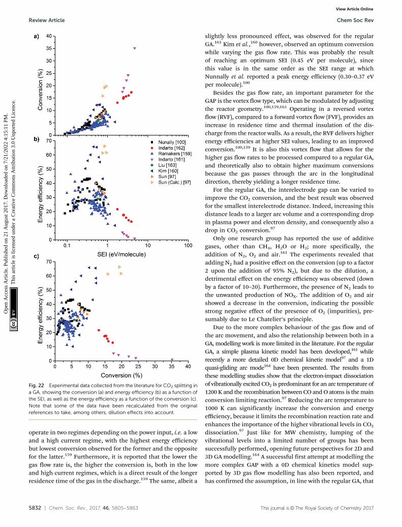
5832 | Chem. Soc. Rev., 2017, 46, 5805--5863 This journal is©The Royal Society of Chemistry 2017
operate in two regimes depending on the power input, i.e. a lowand a high current regime, with the highest energy efficiencybut lowest conversion observed for the former and the oppositefor the latter.159 Furthermore, it is reported that the lower thegas flow rate is, the higher the conversion is, both in the lowand high current regimes, which is a direct result of the longerresidence time of the gas in the discharge.159 The same, albeit a
slightly less pronounced effect, was observed for the regularGA.161 Kim et al.,160 however, observed an optimum conversionwhile varying the gas flow rate. This was probably the resultof reaching an optimum SEI (0.45 eV per molecule), sincethis value is in the same order as the SEI range at whichNunnally et al. reported a peak energy efficiency (0.30–0.37 eVper molecule).100
Besides the gas flow rate, an important parameter for theGAP is the vortex flow type, which can be modulated by adjustingthe reactor geometry.100,159,163 Operating in a reversed vortexflow (RVF), compared to a forward vortex flow (FVF), provides anincrease in residence time and thermal insulation of the dis-charge from the reactor walls. As a result, the RVF delivers higherenergy efficiencies at higher SEI values, leading to an improvedconversion.100,159 It is also this vortex flow that allows for thehigher gas flow rates to be processed compared to a regular GA,and theoretically also to obtain higher maximum conversionsbecause the gas passes through the arc in the longitudinaldirection, thereby yielding a longer residence time.
For the regular GA, the interelectrode gap can be varied toimprove the CO2 conversion, and the best result was observedfor the smallest interelectrode distance. Indeed, increasing thisdistance leads to a larger arc volume and a corresponding dropin plasma power and electron density, and consequently also adrop in CO2 conversion.97
Only one research group has reported the use of additivegases, other than CH4, H2O or H2; more specifically, theaddition of N2, O2 and air.161 The experiments revealed thatadding N2 had a positive effect on the conversion (up to a factor2 upon the addition of 95% N2), but due to the dilution, adetrimental effect on the energy efficiency was observed (downby a factor of 10–20). Furthermore, the presence of N2 leads tothe unwanted production of NOX. The addition of O2 and airshowed a decrease in the conversion, indicating the possiblestrong negative effect of the presence of O2 (impurities), pre-sumably due to Le Chatelier’s principle.
Due to the more complex behaviour of the gas flow and ofthe arc movement, and also the relationship between both in aGA, modelling work is more limited in the literature. For the regularGA, a simple plasma kinetic model has been developed,161 whilerecently a more detailed 0D chemical kinetic model97 and a 1Dquasi-gliding arc mode164 have been presented. The results fromthese modelling studies show that the electron-impact dissociationof vibrationally excited CO2 is predominant for an arc temperature of1200 K and the recombination between CO and O atoms is the mainconversion limiting reaction.97 Reducing the arc temperature to1000 K can significantly increase the conversion and energyefficiency, because it limits the recombination reaction rate andenhances the importance of the higher vibrational levels in CO2
dissociation.97 Just like for MW chemistry, lumping of thevibrational levels into a limited number of groups has beensuccessfully performed, opening future perspectives for 2D and3D GA modelling.164 A successful first attempt at modelling themore complex GAP with a 0D chemical kinetics model sup-ported by 3D gas flow modelling has also been reported, andhas confirmed the assumption, in line with the regular GA, that
Fig. 22 Experimental data collected from the literature for CO2 splitting ina GA, showing the conversion (a) and energy efficiency (b) as a function ofthe SEI, as well as the energy efficiency as a function of the conversion (c).Note that some of the data have been recalculated from the originalreferences to take, among others, dilution effects into account.
Review Article Chem Soc Rev
Ope
n A
cces
s A
rtic
le. P
ublis
hed
on 2
1 A
ugus
t 201
7. D
ownl
oade
d on
7/2
1/20
22 4
:15:
11 P
M.
Thi
s ar
ticle
is li
cens
ed u
nder
a C
reat
ive
Com
mon
s A
ttrib
utio
n 3.
0 U
npor
ted
Lic
ence
.View Article Online

This journal is©The Royal Society of Chemistry 2017 Chem. Soc. Rev., 2017, 46, 5805--5863 | 5833
the vibrational levels play an important role for the energy-efficient conversion of CO2.159
In summary, the data in the literature show that GA dis-charges succeed in exploiting the most energy-efficient CO2
dissociation channel based on vibrational excitation, whileoperating at atmospheric pressure. Energy efficiencies of 45%are no exception and even results above the target value of 60%have already been reported. On the other hand, model calculationsreveal that the non-equilibrium character of the GA – making fullpotential of the vibrational excitation/dissociation pathway – couldbe further exploited to improve the energy efficiency. Just like forMW discharges, operating GA plasmas at lower gas temperaturesmight be the key for achieving this. In addition, the main limitingfactor compared to MW discharges appears to be the conversion,due to the limited fraction of the gas flow that is currently processedby the discharge. Smart reactor design, such as enhancing theprocessed gas fraction, should lead to the necessary advancementsto overcome this limitation in the future.
5.1.4. Other plasma types. Beside the three most commonplasma types discussed above, a number of other non-thermalplasmas have been used for CO2 conversion, including coronadischarges,165–170 glow discharges,171–174 non-self-sustaineddischarges,174 capillary discharges175 and nanosecond pulseddischarges.176 For more details and background regardingthese different discharges, we refer to the respective references.When available, the relevant data have been extracted from theliterature and the results are presented in Fig. 23. In general,the performance of all these different discharges is similar tothat observed for a DBD, with maximum conversions of up to40% and energy efficiencies below 15%. The main exception isthe non-self-sustained discharge investigated by Andreevet al.,174 which reached a conversion of 50% with a corres-ponding energy efficiency of almost 30%. The advantage of thisdischarge type is its ability to control the mean electron energyby changing the E/n. The higher energy efficiency is reachedwhen operating at values around 20 Td, which favours thevibrational excitation mechanism, as shown in Section 4.1.4(Fig. 11 and 12). However, just like for the MW plasmas, thisdischarge operates at reduced pressures (1550 Pa).
5.1.5. Summary. To summarize, in Fig. 24, we plot theenergy efficiency as a function of the CO2 conversion, groupedper discharge type, for all the data discussed above. Further-more, both the thermal equilibrium limit (see Section 2.1;Fig. 2) and the target energy efficiency of 60% (see the begin-ning of this section) are displayed. This figure allows us to drawthe following conclusions.
First of all, it is clear that, although DBDs are among themost extensively studied for CO2 conversion, and indeed arealready successfully applied80 for commercial O3 productionand VOC removal, they appear to be unsuitable for the efficientconversion of CO2. Their energy efficiency remains a factor of 4too low, even when combined with a packing, in order to justifythem as industrially competitive. The same applies to most ofthe other plasma types listed in Section 5.1.4 above.
Second, the best results for GA plasmas are capable ofreaching the set energy efficiency target, namely 60%. Moreover,
almost all of the results obtained are far above the thermalequilibrium limit, which is especially interesting, keeping inmind that the GA plasmas operate at atmospheric pressure. Thisdemonstrates the non-equilibrium character of this type ofplasma, even at atmospheric pressure, and the benefits of beingable to exploit this behaviour through the energy-efficient
Fig. 23 Experimental data collected from the literature for CO2 splitting inother plasmas, besides DBD, MW/RF and GA, showing the conversion (a)and energy efficiency (b) as a function of the SEI, as well as the energyefficiency as a function of the conversion (c). Note that some of the datahave been recalculated from the original references to take, among others,dilution effects into account.
Chem Soc Rev Review Article
Ope
n A
cces
s A
rtic
le. P
ublis
hed
on 2
1 A
ugus
t 201
7. D
ownl
oade
d on
7/2
1/20
22 4
:15:
11 P
M.
Thi
s ar
ticle
is li
cens
ed u
nder
a C
reat
ive
Com
mon
s A
ttrib
utio
n 3.
0 U
npor
ted
Lic
ence
.View Article Online

5834 | Chem. Soc. Rev., 2017, 46, 5805--5863 This journal is©The Royal Society of Chemistry 2017
dissociation of the CO2 vibrational levels. Moreover, modellinghas revealed that this non-equilibrium character could (andshould) be further exploited, to further enhance the energyefficiency. To date, the main challenge is the limited conversion,which remains below 20% because only a limited fraction of thegas passes through the active arc plasma.
Finally, if, for now, we ignore the fact that most MWdischarges used for CO2 conversion operate at reduced pressure,in contrast to the commercially more interesting atmosphericpressure of GA plasmas, it is clear that MW discharges offer awide variety of possibilities. Even up to conversions of 40%, theenergy efficiency target is easily crossed and they clearly operatein a non-equilibrium regime, thus favouring the step-wisevibrational-dissociation mechanism. Conversions in the rangeof 40–90% are also possible, albeit with maximum energyefficiencies of only up to 40%. Under these conditions, theMW discharges most probably operate in the thermal regime.Nevertheless, this shows the wide variety of both conversionsand energy efficiencies achievable with MW discharges for theconversion of pure CO2.
5.2. CO2 + CH4: dry reforming of methane
Contrary to pure CO2 splitting, DRM can yield a wide variety ofproducts. This has several implications for the evaluation andcomparison of the various studies in the literature, mainlybecause it affects the definition of the energy efficiency. Todetermine the true energy efficiency of the process, we wouldneed to take all the formed products into account – bothgaseous and liquids – to determine the theoretical reactionenthalpy. Another possibility would be to determine the thermalenergy efficiency (see Section 6), based on the higher (or lower)
heating value of the output, i.e. the products, relative to that ofthe input, i.e. the reactants and power input. However, typicallyonly the selectivity (or yield) towards the syngas components, COand H2, and light hydrocarbons is given for most studies in theliterature. Thus, at the moment these strategies are impossibleto pursue when presenting an overview of the available literatureresults in the sections below. Therefore, in this section, we usethe energy cost, in units of eV per converted molecule, tocompare the different discharges, together with their total con-version. As an energy efficiency target for syngas production, wetake the same 60% value for the general stoichiometric DRMprocess, which equals an energy cost of 4.27 eV per moleculeconverted. Indeed, 100% energy efficiency would yield an energycost equal to the standard reaction enthalpy of 2.56 eV permolecule (as outlined in Section 2.2.1). In our opinion, this isthe best representation to compare the results in the literature,considering the fact that in most of the studies, the higherhydrocarbons and the valuable liquid fraction containing oxyge-nates (e.g. formaldehyde, methanol, ethanol, formic acid, aceticacid) are neglected. However, as explained at the beginning ofSection 5, this 60% energy efficiency target is only valid for thecomparison towards syngas production. When liquids (such asmethanol) are formed through the direct oxidative pathway,which has already been demonstrated using the plasmachemicalconversion of CO2 with a co-reactant, the energy efficiencyrequirements are drastically lowered by a factor of two to three.This is a direct result of circumventing the energy-intensive stepof further processing the syngas into the desired liquid products.
Plasma-based DRM has received a lot of attention in recentyears. Some overviews can be found in the literature.21,41,177–179
In a recent review on the liquefaction of methane,112 DRM was
Fig. 24 Comparison of all the data collected from the literature for CO2 splitting in the different plasma types, showing the energy efficiency as afunction of the conversion. The thermal equilibrium limit and the 60% efficiency target are also indicated.
Review Article Chem Soc Rev
Ope
n A
cces
s A
rtic
le. P
ublis
hed
on 2
1 A
ugus
t 201
7. D
ownl
oade
d on
7/2
1/20
22 4
:15:
11 P
M.
Thi
s ar
ticle
is li
cens
ed u
nder
a C
reat
ive
Com
mon
s A
ttrib
utio
n 3.
0 U
npor
ted
Lic
ence
.View Article Online

This journal is©The Royal Society of Chemistry 2017 Chem. Soc. Rev., 2017, 46, 5805--5863 | 5835
considered as oxidative plasma-based CH4 liquefaction. It canbe performed in two ways: either as a two-step process, yieldingmainly syngas, which can then be further processed intoFischer–Tropsch liquids or methanol, or as a one-step process,aiming for the direct formation of value-added oxygenatedproducts, such as formaldehyde, methanol, ethanol, dimethylether and formic acid. These two options are therefore called theindirect and direct oxidative plasma liquefaction approaches,respectively. An overview of the progress in the field of plasma-based DRM is given below, starting again with DBD, MW and GAplasmas. However, in contrast to CO2 splitting, a vast amount ofresearch has been performed with some other discharges as wellfor DRM, so these have been given their separate sections below.
First some general trends applicable for all discharges aresummarized. We start off with the SEI, because for all dis-charges studied, it is clear that for DRM – just like for pure CO2
splitting – the SEI is the major determining factor for theconversion and energy cost, as it combines the effects of powerand residence time. Typically, a higher SEI leads to a higherconversion, but also incurs a higher energy cost. The conversionsof CH4 and CO2 increase almost linearly when a higher voltage orinput power is applied, as observed for DBD,106,180–190 MW,191
GA,192–194 corona,195–198 spark,199–205 APGD206,207 and nano-second pulsed discharges.208–212 Generally, this is accompaniedby an increase in energy cost. Regarding product selectivity,some different trends are reported as a function of power forthe different discharge types. In general, in DBDs, higher H2 andCO yields are reported, with the ratio of H2 to CO remainingconstant,184,187,188 as well as a sharp drop in the selectivityof the light hydrocarbons.186,189,190 Furthermore, some studiesobserved no significant changes in the selectivities in a DBD,except for an increase in carbon deposition,184 while other studiesreport an increase in CO and H2 selectivity,186,187,190 or even theopposite trend.188 For corona discharges, the H2 selectivity seems todecrease, while the CO selectivity exhibits the opposite trend,195,196
and as a result, the H2/CO ratio greatly depends on the dischargepower.197 In spark discharges, a more pronounced carbon deposi-tion at higher input power has been reported,202 as well as anincreased selectivity for H2 and CO and a drop in C2H2 selectivity,pointing to an enhancement of the reforming reactions overcoupling reactions.202,203 APGD discharges exhibit a higher COselectivity and coke deposition at higher input voltages and theseconditions favour the production of unsaturated hydrocarbons,such as C2H2.206 On the other hand, for nanosecond pulseddischarges, upon a higher SEI, the mass balance points to a lossof oxygen and carbon, which are converted into water and carbonpowder or are deposited, respectively.208 Finally, for MW and GAplasmas, no specific trends have been reported yet for the effect ofpower on the product selectivities. Thus we can conclude that,albeit with some exceptions, a higher discharge power generallyimproves the conversion, but does not change the reaction path-ways significantly.
A higher total flow rate has the opposite effect to the power,and leads to lower conversions and energy costs forDBD,106,180,183,185,186,188,189,213 GA,194 corona,196–198,214
spark,199,202 APGD206,207 and nanosecond pulsed discharges.209
No results have been reported yet for MW plasmas. On the otherhand, the flow seems to have almost no effect on the selectivitytowards the syngas components CO and H2 and hence also noton the syngas ratio itself, for DBD,183,185,189,213 GA194 andAPGD.206,207 At higher flow rates, some researchers have alsoreported a decrease in H2 and CO selectivity in DBDs,186,188 whilethe selectivity towards hydrocarbons increases.180,183,186,188,213
For corona discharges, a slightly higher H2 and CO selectivity isobserved, but the syngas ratio remains almost unchanged.196–198,214
For spark discharges, it is reported that the H2 selectivity rises andthe CO selectivity drops, at higher flow rates.199 Finally, for MW andnanosecond pulsed discharges, again no specific data have beenreported yet for the effect of flow rate on the product selectivities.Nevertheless, in general we may again conclude that the dissocia-tion and formation mechanisms are, albeit with some exceptions,not significantly influenced by a change in the flow rate, althoughthe selectivities can be altered.
Besides the SEI (or the power and gas flow rate), theCH4/CO2 mixing ratio has a tremendous influence on the CH4
and CO2 conversions, as well as on the product selectivities. Ingeneral, when adding more CH4 to the mixture, the effectiveCH4 conversion rises, while the effective CO2 conversion drops.Note that we talk about the effective conversions (as defined inSection 4.4.2; eqn (4)) and not about the (absolute) conversionitself, in order to take the effect of the change in gas mixtureinto account. At the same time, the selectivity towards (light)hydrocarbons increases, as well as the selectivity towards H2,while the CO selectivity decreases, when more CH4 is present inthe mixture. This inevitably leads to an increase in the syngasratio. Thus, the H2/CO ratio is highly dependent on the inletfeed, which makes the ratio easily adjustable over a wide rangeto fit the Fischer–Tropsch or methanol synthesis requirements.This was found for all discharges, i.e. DBD,182,183,186–190
GA,192–194,215 MW,191 corona,197,214,216–218 spark,200,202,204,205
APGD207,217,219,220 and nanosecond pulsed discharges.209,211,221
The formation of carbon black and its deposition on theelectrode and reactor walls for mixtures seems to occur with ahigh CH4/CO2 ratio (41), and this deposition can highly influencethe discharge operation.119 For lower CH4/CO2 ratios, this is notobserved, neither in DBD,182,189,190 GA,192–194,215 corona,195–197
spark,200,205 APGD207,217,219,220 nor nanosecond pulseddischarges,209 as CO2 prevents carbon formation. For APGDs, ahigher CH4/CO2 ratio is reported to increase the water formation.In contrast, for a DBD187 and spark discharge,202 a higher waterproduction is observed at low CH4/CO2 feed ratios, presumablydue to the occurrence of the reverse water–gas shift reaction.
These trends can be explained by the following reactions:increasing the CH4/CO2 ratio leads to a more pronounced H2
formation and at the same time it reduces the amount of Ospecies in the mixture. Hence, the reaction C + O - CO isreduced, leading to a lower CO selectivity, and increased carbondeposition. On the other hand, the reaction H2 + O - H2Obecomes more important, giving rise to the higher H2O produc-tion, but it is not significant enough to balance the higher H2
production, thus explaining the increased H2 selectivity. Thisalso means that the deposited C is still an active species in the
Chem Soc Rev Review Article
Ope
n A
cces
s A
rtic
le. P
ublis
hed
on 2
1 A
ugus
t 201
7. D
ownl
oade
d on
7/2
1/20
22 4
:15:
11 P
M.
Thi
s ar
ticle
is li
cens
ed u
nder
a C
reat
ive
Com
mon
s A
ttrib
utio
n 3.
0 U
npor
ted
Lic
ence
.View Article Online

5836 | Chem. Soc. Rev., 2017, 46, 5805--5863 This journal is©The Royal Society of Chemistry 2017
reactions, and it is suggested that the addition of O2207 and/or
H2O217 can prevent carbon deposition. Finally, it is reportedthat the rate of CO production is always higher than the rate ofCO2 reduction, proving that CO is formed by both the reductionof CO2 and the oxidation of CH4.214
The effect of the CH4/CO2 mixing ratio on the total conver-sion and hence on the energy cost is less straightforward. Fornanosecond pulsed discharges, depending on the set-up, dif-ferent optimum values have been reported for this mixing ratiofor achieving the lowest energy cost. Ghorbanzadeh et al.209,212
reported a considerable increase in the energy cost whenmethane becomes predominant in the mixture, while Zhanget al.211 reported the energy cost was cut in half when goingfrom a 1 : 3 to a 3 : 1 CH4/CO2 ratio. For a DBD, the effect of themixing ratio on the total conversion also appears to depend on thespecific set-up, since both an increase182,186,222,223 anddecrease106,183,188 are widely reported upon the addition of moreCH4. Snoeckx et al.,181 Zheng et al.213 and Pinhao et al.224 allreported an initial increase in total conversion upon adding CH4
when the CH4/CO2 ratio was o1, and a decrease when the ratiobecame 41. These trends suggest that the CH4 conversion isstrongly affected by the CO2 conversion, especially when the ratiois o1 and when CO2 is thus the main component in the mixture.For the other plasma types, no specific data have yet been reportedin the literature on the effect of the CH4/CO2 mixing ratio on thetotal conversion. Finally, as the energy cost is inversely proportionalto the obtained conversion (cf. Section 4.4.3; eqn (7)), the effect ofthe CH4/CO2 mixing ratio on the energy cost is opposite to theeffects described above for the total conversion.
Besides these general trends for the effect of the SEI and theCH4/CO2 mixing ratio, which are very similar for the variousdischarge types, some specific trends characteristic for eachplasma reactor are reported for DRM. These are summarized inthe next sections, along with a summary of all the values forconversion and energy cost reported in the literature.
5.2.1. DBD plasmas. Due to its simple design and ease ofuse – also in combination with packing materials – again mostof the research to date has been performed with DBDs, with thecoaxial reactor (see Section 4.2.1; Fig. 13) being the maingeometry. To improve the conversion and energy costs, and totune the product distribution, several approaches have beeninvestigated, including changing the SEI, applying pulsedpower, changing the gas flow rate or feed ratio, changing thereaction temperature or pressure, applying multi-electrodeconfigurations or different electrode materials, and mixingwith other gases, i.e. Ar, He, N2, as well as introducing (cataly-tic) packing materials. Some of these effects have already beendescribed above, but the others are explained in more detailbelow. Furthermore, extensive modelling work has also beenperformed to obtain more fundamental insights into theplasma chemistry and in turn to aid in the improvement offuture experiments. For all the experiments reported in theliterature, the syngas components H2 and CO were the majorreaction products, with smaller amounts of C2 and C3 hydro-carbons also detected, in the order: C2H6 d C3H8 4 C2H4 4C2H2. In even lower quantities, hydrocarbons up to C5 have been
detected, where the selectivities of unsaturated hydrocarbons areagain much lower than those of paraffins. The major productsdetected when the condensate was analysed183,222,225,226 wereC4–C10 hydrocarbons and oxygenates, including methanol, ethanol,1-propanol, acetic acid and other e.g. tertiary alcohols, ketones,esters and carboxylic acids.
Fig. 25 summarizes most of the results, in terms of bothconversion and energy cost, available in the literature. Due to
Fig. 25 Experimental data collected from the literature for DRM in a DBD,showing the conversion (a) and energy cost (b) as a function of the SEI, aswell as the energy cost as a function of the conversion (c). Note that someof the data have been recalculated from the original references to take,among others, dilution effects into account.
Review Article Chem Soc Rev
Ope
n A
cces
s A
rtic
le. P
ublis
hed
on 2
1 A
ugus
t 201
7. D
ownl
oade
d on
7/2
1/20
22 4
:15:
11 P
M.
Thi
s ar
ticle
is li
cens
ed u
nder
a C
reat
ive
Com
mon
s A
ttrib
utio
n 3.
0 U
npor
ted
Lic
ence
.View Article Online

This journal is©The Royal Society of Chemistry 2017 Chem. Soc. Rev., 2017, 46, 5805--5863 | 5837
the large amount of data available for packed-bed reactors,those data are discussed and presented further below in Fig. 26.The conversion and energy cost increase again upon a risingSEI. When plotting the energy cost as a function of the conver-sion, it is clear that most of the results are situated above anenergy cost of 20 eV per molecule and below a conversion of60%, albeit with some exceptions. The highest experimentalconversion reported is 66%,186 and the lowest experimentally
observed energy cost is 18 eV per molecule.181 This is more thana factor of 4 higher than the set efficiency target of 4.27 eV permolecule (see the beginning of Section 5.2). Model calculationspredict that higher conversion and lower energy costs shouldbe achievable by a careful selection of the operating conditions,as will be outlined below.181 It is important to note that some ofthe data in this figure have again been recalculated to representcoherent values for the conversions and energy costs. Forinstance, as also explained for pure CO2 splitting, the mixtureis sometimes diluted with He, Ar or N2 to obtain an more easilyignitable and more stable discharge, but this influences theresults – an effect that was not always taken into account in theoriginal data. A more detailed influence of the different para-meters is discussed below.
The effect of the temperature and pressure on DRM in aDBD has been investigated by several authors. Low pressuresseem to favour the reactant conversion, whereas the syngasratio does not show any pressure dependence.187 On the otherhand, the selectivity of both CO and light hydrocarbons isreported to increase with rising pressure.190 For a wall tem-perature range of 353–523 K, Zhou et al.187 observed slightlyhigher conversions and product yields upon increasing thetemperature, with the syngas ratio being independent of thetemperature. Zhang et al.184 and Goujard et al.183 investigated thetemperature effect in the range of 297–773 K and 298–873 K,respectively. Both the conversions and the hydrocarbon selectivitywere reported to increase with temperature, while the H2 and COselectivity decreased. However, Zhang et al.184 found an increasein the syngas ratio, whereas Goujard et al.183 observed theopposite, noting also that when the temperature reached 773 K,the CO2 conversion appeared to increase more rapidly than theCH4 conversion, indicating a shift in the dominant reformingprocesses around 673 K.183 These results indicate that while theelectron-impact dissociation reactions govern the reactant conver-sions, the thermochemistry can be used to control the consecutiveproduct reaction pathways.
Several changes with respect to the electrode configurationand materials have been reported as well. Wang et al.186 foundlittle influence of the discharge gap on the reactions, while Liet al.222 observed higher conversions upon reducing the dis-charge gap. At the same time, Wang et al.186 reported asignificant influence on the conversions using multi-stageionization (i.e. multiple DBD and ‘afterglow’ zones in onereactor by placing several electrodes in series), while only smalleffects were observed by Li et al.222 Both groups, however,found a significant positive influence on the syngas productselectivities when applying multi-stage ionization. Rico et al.185
reported better conversions with porous electrodes, while the(catalytic) effect of different inner electrodes only showed verylittle influence on the conversions,227,228 but a significantincrease in the oxygenate synthesis for nickel and copper,suggesting a catalytic role of the metallic surface.228 Finally,applying a pulsed power also seemed to have a beneficial effecton the conversion.229
As mentioned above, some researchers added inert gases,such as N2, Ar and He, to ignite the plasma more easily.
Fig. 26 Experimental data collected from the literature for DRM in apacked-bed DBD, showing the conversion (a) and energy cost (b) as afunction of the SEI, as well as the energy cost as a function of theconversion (c). Note that some of the data have been recalculated fromthe original references to take, among others, dilution effects into account.
Chem Soc Rev Review Article
Ope
n A
cces
s A
rtic
le. P
ublis
hed
on 2
1 A
ugus
t 201
7. D
ownl
oade
d on
7/2
1/20
22 4
:15:
11 P
M.
Thi
s ar
ticle
is li
cens
ed u
nder
a C
reat
ive
Com
mon
s A
ttrib
utio
n 3.
0 U
npor
ted
Lic
ence
.View Article Online

5838 | Chem. Soc. Rev., 2017, 46, 5805--5863 This journal is©The Royal Society of Chemistry 2017
However, this also has several effects on the discharge char-acteristics, conversion and energy cost. Ozkan et al.182 investi-gated the effect of Ar and He dilution, but did not compare theresults with pure CH4/CO2 mixtures. The CH4 conversion washigher for He than for Ar addition, while the opposite wasfound for CO2 conversion. This could be related to a changefrom filamentary to glow discharge when switching from Ar toHe, which significantly influences the shape of the EEDF andthus the electron-impact reactions. Zhang et al.106 indicatedthat, although the conversion increases when adding Ar, thelatter is not sufficient to counteract the lower CH4/CO2 feedcontent, since the conversion rates are lower compared to amixture without Ar. On the other hand, they observed a positiveeffect towards the syngas component selectivities. Pinhaoet al.224 reported a positive effect on the breakdown voltagewith increasing He content, resulting in a rise in the conversionrates with increasing the He content up to 80%. However, a stillhigher He content showed detrimental effects on both theconversion and selectivity, but again no comparison for themixture without He was made. In a follow-up modelling studyby Janeco et al.,92 a shift in the electron velocity distributionfunction due to the addition of He was observed.
Kolb et al. studied the addition of the molecular gases O2
and H2O on the performance of DRM in a DBD.230,231 Theyfound that O2 aids in the conversion of CH4 but also producesCO2,231 which is not beneficial. H2O, on the other hand, onlyhas a small negative influence on the conversion of CO2, butsignificantly enhances the conversion of CH4 and, more impor-tantly, the production of valuable oxygenates, such as formal-dehyde and methanol.230 This study showed that a tri- or moregeneral multi-reforming process, using a mixture of CO2/CH4/H2O or a combination of different reforming processes inseries, could be a very interesting next step to pursue usingplasma technology.
Due to the historical interest in thermocatalytic DRM andthe ease of implementing a (catalytic) packing in the dischargezone of a DBD, as explained in Section 4.3, a lot of research hasalready been performed towards plasma-catalytic DRM andhybrid reactors. A complete but brief overview is given below,but for more detailed information on the effects and mechan-isms behind plasma-catalysis, we refer to the existing excellentliterature on this topic.102,103,232 Most of the work to date hasbeen performed with packed-bed reactors, but some researchalso exists on fluidized-bed reactors.233,234 Contrary to pure CO2
splitting, for DRM, the addition of packing can greatly influ-ence the formation of products, due to the availability of CH4 asa hydrogen source. Hence, the research work focuses both onincreasing the conversion and lowering the energy cost byphysical effects, as well as on chemical effects to steer theproduct distribution towards more value-added chemicals,such as light hydrocarbons and oxygenates. Packed-bed DBDreactors generally yield similar conversions and energy costs asthe corresponding empty reactors, as can be seen when com-paring Fig. 25 and 26. Nevertheless, the use of a catalyticpacking can drastically alter the chemical pathways and thusthe selectivity and product distributions, which would be
beneficial for exploiting the direct oxidative pathway of DRM,instead of utilizing the indirect process through syngasproduction.
A broad spectrum of materials have already been investigated forthe plasma-catalytic DRM, of which Ni is by far the most commonlyused active phase, such as in Ni/g-Al2O3,106,180,188,213,233,235–240 Ni/SiO2,238,241,242 Ni–Fe/g-Al2O3,237 Ni–Fe/SiO2,237,242 Ni–Cu/g-Al2O3,106
Ni0/La2O3,183 Ni/MgO,238 Ni/TiO2,238 NiFe2O4,237 NiFe2O4#SiO2,237
LaNiO3/SiO2,241 LaNiO3241 and [email protected] Furthermore,
alumina is the most commonly used support, i.e. in Ni/g-Al2O3,106,180,188,213,233,235–240 Ni–Fe/g-Al2O3,237 Mn/g-Al2O3,213
Cu/g-Al2O3,106,213,234 Co/g-Al2O3,213 La2O3/g-Al2O3,243 Ag/g-Al2O3,244 Pd/g-Al2O3,234,244 Fe/g-Al2O3
245 and Cu–Ni/g-Al2O3,106 or even in its pure form.185,188,244,246 Many othercatalytic systems are based on zeolites, e.g. 3A,246 A4,247 NaX,248
NaY245 and Na-ZSM-5.245 Besides, studies have also been conductedusing BaTiO3,185,242 a mixture of BaTiO3 and NiSiO2,242 ceramicfoams (92% Al2O3, 8% SiO2) coated with Rh, Ni or NiCa,249 quartzwool,246 glass beads,189 a stainless steel mesh,242 starch,250 BZT(BaZr0.75T0.25O3) and BFN (BaFe0.5Nb0.5O3).189 For a regular AC-packed DBD, the best result was obtained for the Zeolite Na-ZSM-5,with a total conversion of 37% and an energy cost of 24 eV perconverted molecule (see Fig. 26).245 Just like for pure CO2 splitting,the addition of a catalyst does not seem to make the process moreenergy efficient, but it does yield higher conversions at the sameenergy cost. The best overall results in a packed-bed DBD wereobtained for a quasi-pulsed DBD packed with BFN and BZN, withtotal conversions in the range of 45–60% and an energy cost in therange of 13–16 eV per converted molecule (see Fig. 26),189 which islower than that for a DBD without packing, but this might also bedue to the pulsed operation.
Besides the experimental work, major insights have beenobtained in recent years based on modelling of the DRM processfor a DBD. Different kinds of models and computational techni-ques have been successfully developed, including semi-empiricalkinetic models,187,251,252 zero-dimensional chemical kinetic modelswith both simplified253 and extensive chemistry sets,131,181,254 aone-dimensional fluid model,255 a so-called 3D IncompressibleNavier–Stokes model combined with a convection–diffusionmodel,256 a hybrid artificial neural network-genetic algorithm,257
a model focusing on a more accurate description of the electronkinetics92 and density functional theory (DFT) studies, to investi-gate the reaction mechanisms.226,258 Due to the complex chemistrytaking place in a DRM, the development of accurate multidimen-sional models with extensive chemistry is currently restricted bycomputational limits.
Some key findings of these models are presented here.Snoeckx et al.181 performed an extensive modelling study, withdetailed plasma chemistry, spanning a wide range of experi-mentally accessible conditions. The model predicted thatincreasing the SEI at a constant gas ratio and frequency resultsin a higher total conversion. However, the increase in conver-sion is not entirely proportional to the rise in SEI, resulting insomewhat higher energy costs with increasing the SEI. Thelowest energy cost was predicted to be 16.9 eV per molecule, butthis corresponds to a very low value for the total conversion, i.e.
Review Article Chem Soc Rev
Ope
n A
cces
s A
rtic
le. P
ublis
hed
on 2
1 A
ugus
t 201
7. D
ownl
oade
d on
7/2
1/20
22 4
:15:
11 P
M.
Thi
s ar
ticle
is li
cens
ed u
nder
a C
reat
ive
Com
mon
s A
ttrib
utio
n 3.
0 U
npor
ted
Lic
ence
.View Article Online

This journal is©The Royal Society of Chemistry 2017 Chem. Soc. Rev., 2017, 46, 5805--5863 | 5839
0.015%. On the other hand, the highest total conversion pre-dicted by the model, i.e. 84.2%, corresponded to an energy costof 30.1 eV per molecule. A larger amount of CO2 was observedto lead to a higher total conversion and lower energy cost. Thisis attributed to the O atoms formed by the electron-impactdissociation of CO2, which reacts very effectively with theH atoms originating from the electron-impact dissociation ofCH4. As shown in the kinetics analysis of Snoeckx et al.,254 theconversion of CH4 is normally limited by the fast backwardreaction, i.e. CH3 + H - CH4, but when more O atoms areavailable, this reaction is of minor importance compared to thereaction O + H/OH - OH/H2O. Thus, by limiting the backwardreaction, the conversion of CH4 rises dramatically with increasingCO2 content, leading to a higher total conversion.181 Anotherimportant effect is the total number of micro-discharge filamentsthat the gas molecules experience when passing through the DBDreactor. It seems that for most cases a larger number of filaments,but with lower energy, yields higher values for the conversion andlower energy costs, compared to a smaller number of filaments, butwith more energy deposited per filament.181 In some other modelsby Janeco et al.92 and Goujard et al.,253 the effect of adding He tothe CH4/CO2 mixture was investigated. Both groups reported thatHe, as well as all other species that may result from the electroncollisions in the gas mixture, can significantly change the electronvelocity distribution function, the electron reaction rates and theenergy losses, which can ultimately affect the energy cost whentaken into account in the model.
Summarizing all the data in the literature, we can concludethat a DBD reactor can provide reasonable conversions of up to60% and 80% for empty (i.e. non-packed) and packed-bedDBDs, respectively. However, the energy cost lies in the rangeof 20–100 eV per molecule, which corresponds to an energyefficiency of 12.8–2.6%, assuming that only syngas is formed.This is at least a factor 5 away from the necessary 4.27 eV permolecule benchmark for the energy cost (or the 60% bench-mark for energy efficiency), as defined at the beginning of thissection, with no positive outlook on the horizon. Indeed, evenextensive modelling studies have predicted that the lowestachievable energy cost, obtained after careful selection of theoperating conditions, would be 16.9 eV per molecule (seeabove).181 Hence, despite a simple reactor design for scalability,the ease of implementing a wide variety of packings and itsindustrial success for ozone generation (and possibly VOC abate-ment), at this point, the high energy cost – and hence low energyefficiency – makes it doubtful that DBDs will be the most suitabletechnology for DRM into syngas. Nevertheless, due to its ease ofuse, research with DBDs still can yield valuable insights andknowledge, which may be transferable to other more efficientdischarges. On the other hand, if suitable catalysts could be foundfor the production of valuable oxygenates with high yields throughdirect (plasma-catalytic) oxidative liquefaction,112 the energy effi-ciency target would be significantly lower (by a factor of 2–3 in thecase of methanol), so this could change the analysis drastically.However, many challenges for this pathway remain, such asfinding suitable catalysts, and advances in energy efficiency arealso still required.
5.2.2. MW plasmas. Compared to the extensive work availableon pure CO2 splitting in MW plasmas, almost no work exists forDRM using a MW plasma. This is in great contrast to the extensivework performed for DRM in DBD reactors (see above). We areaware of only one study for a pulsed MW plasma,259 and one for acontinuous MW plasma, where a comparison is made with theintroduction of a Ni catalyst.191 The pulsed set-up achieved CH4
and CO2 conversions of 71% and 69%, respectively, at an energycost of 6.5 eV per molecule for a CH4/CO2 ratio of 1.5. Syngas wasagain the major product, but C2H2 and C2H4 were also detected.259
Furthermore, no coking was observed. The data are presentedtogether with the results for the GA plasma in Fig. 27.
Cho et al.191 obtained conversions in continuous MWplasma in the same range as in the pulsed MW plasma ofZhang et al.,259 but at much high powers, up to 1.5 kWcompared to 120 W, and at low flow rates (100 mL min�1 vs.200 mL min�1), so their energy costs were unacceptably high,i.e. between 93 and 343 eV per molecule. Adding a Ni catalyst tothe discharge was reported to lead to a higher conversion by10% for CH4 and by 15% for CO2. Furthermore, the H2/CO ratiochanged drastically from 1.7 for the plasma-only case to 1.2when combined with the catalyst. As additional products, onlyC2H4 was detected, with increasing selectivity when more CH4
was added to the feed.191
In Section 3.5, we also discussed catalysis based on MW-heating. Fidalgo et al.76 observed the formation of micro-plasmas in their so-called microwave receptor/catalyst set-up.However, the MW source was simply used in that case to heat thegas, with the creation of microplasmas at the catalyst surfaceonly a side effect of the strong electric fields at the sharp edges.
In general, the few studies reported so far in literature forDRM by MW plasmas show high conversions, as well as a highselectivity towards CO and H2. Furthermore, based on the pureCO2 splitting results presented in the previous section, wemight expect that a large treatment capacity is in principlepossible, as well as high energy efficiencies. Nevertheless,experimental evidence to date remains extremely scarce. Oneof the major unanswered questions is related to the role playedby the vibrational levels of CH4 in the CO2 dissociation, andmore specifically in the ladder-climbing effect, which wasexplained in Section 4.1.4 (cf. Fig. 12). In particular, it is notclear whether they will affect (i.e. stimulate or inhibit) thisprocess or not, as well as how the dissociation of CH4 itself willbe influenced.
5.2.3. GA plasmas. Most of the research for DRM with GAplasmas is based upon 2D bladed electrodes,192,194,215,260–263
while only some studies have reported the use of a rotating GAdischarge,193,264–266 and even then, mostly for biogas instead ofa pure CH4/CO2 mixture.264–266 All the data available in theliterature are plotted in Fig. 27. Conversions in the range of30–50% for both CH4 and CO2 have been reached, with energycosts as low as 1–2 eV per converted molecule. The best resultachieved a total conversion of 39%, with an energy cost of only1 eV per molecule.193 The main products formed seem to bethe syngas components, unsaturated C2 hydrocarbons (i.e.C2H2 and C2H4) and solid carbon.192–194,215 Additionally, the
Chem Soc Rev Review Article
Ope
n A
cces
s A
rtic
le. P
ublis
hed
on 2
1 A
ugus
t 201
7. D
ownl
oade
d on
7/2
1/20
22 4
:15:
11 P
M.
Thi
s ar
ticle
is li
cens
ed u
nder
a C
reat
ive
Com
mon
s A
ttrib
utio
n 3.
0 U
npor
ted
Lic
ence
.View Article Online

5840 | Chem. Soc. Rev., 2017, 46, 5805--5863 This journal is©The Royal Society of Chemistry 2017
formation of different carbon materials, including sphericalcarbon nanoparticles, multi-wall carbon nanotubes and amor-phous carbon, have also been reported.194 Hence, compared toa DBD, the distribution of C2 hydrocarbons seems to be shiftedfrom C2H6 to C2H2 and C2H4, and there is no formation of C3
hydrocarbons reported.194 This shift is commonly observed for
discharges where the gas temperature is higher. Furthermore,compared to a DBD, which also operates at atmosphericpressure, GA plasmas deliver about the same conversion, butthe energy cost is, in general, 20 times lower. This followsdirectly from Fig. 27, because the energy input is also an orderof magnitude lower. A more detailed discussion on the influenceof the different parameters is given below.
For GA discharges, the addition of inert gases has not yetbeen studied in the literature for DRM, but some studies havereported mixtures with reactive gases. Rueangjit et al.260,261
investigated the dry reforming of simulated natural gas with a highCO2 content, represented by CH4 : C2H6 : C3H8 : CO2 in a molar ratioof 70 : 5 : 5 : 20. However, only a comparison with mixtures withoutCO2 was made, and it was then concluded that CO2 considerablyenhances the conversion of the hydrocarbons in the feed.260 Inaddition, very high syngas ratios, i.e. around 10–20, could beobtained by adding these small amounts of hydrocarbons in thefeed, due to their lower C–H bond energy.260,261
Furthermore, some research has also been performed on thecombination of dry reforming with O2 and steam using GAplasmas, to mimic biogas feeds as an input source.261,262,264–266
However, in this case, CO2 is not only converted but is alsobeing produced from the reaction of the CH4 dissociationproducts with O atoms,261,264,265 and in the case of H2Oaddition, even a net CO2 formation can be observed.262,266 Itis suggested that when adding O2, the main process becomesthe partial oxidation of methane, while the main involvementof CO2 is in the reverse water–gas shift reaction.264 The mainpositive effect of adding O2 is minimization of the carbondeposit.261 When adding steam, it seems again possible toobtain high syngas ratios, i.e. around 7.262,266
For DRM, the addition of a catalytic bed after the GAdischarge zone has been investigated in two studies.262,263 In bothstudies, a NiO/Al2O3 catalyst was used. It was found that the CO2
and CH4 conversion increased by 24% and 16%, respectively. Theselectivity of the syngas components, on the other hand, was foundto drop slightly and the unsaturated hydrocarbons, C2H2 and C2H4,were formed with selectivities ranging from 16% to 19%. LowerNiO loading and smaller particle sizes appeared to be beneficial.Finally, it was suggested that there is scope for further developmentand optimization using a fluidized bed for maximizing the plasma–catalyst interactions.263
It is clear that the obtained energy costs for DRM using a GAplasma are much lower than those obtained for DBDs, while atthe same time they allow achieving much higher feed proces-sing capacities. Furthermore, the energy costs achieved already,i.e. around 1 eV per molecule, are already a factor of 4 betterthan the required target for syngas production. No data isavailable yet for the DRM of the GAP set-up, but we couldexpect even further improvements, as already demonstrated forpure CO2 splitting (see Section 5.1.3 above). Finally, the use of acatalytic spouted bed might be able to influence the productdistributions, as already reported for pure CH4 reforming.105
5.2.4. Corona discharges. As described in Section 4.2.4,corona discharges can operate in both a negative and positivemode, and both modes can be used to perform DRM, although
Fig. 27 Experimental data collected from the literature for DRM in MW(open symbols) and GA plasma (closed symbols), showing the conversion(a) and energy cost (b) as a function of the SEI, as well as the energy cost asa function of the conversion (c). Note that some of the data have beenrecalculated from the original references to take, among others, dilutioneffects into account.
Review Article Chem Soc Rev
Ope
n A
cces
s A
rtic
le. P
ublis
hed
on 2
1 A
ugus
t 201
7. D
ownl
oade
d on
7/2
1/20
22 4
:15:
11 P
M.
Thi
s ar
ticle
is li
cens
ed u
nder
a C
reat
ive
Com
mon
s A
ttrib
utio
n 3.
0 U
npor
ted
Lic
ence
.View Article Online

This journal is©The Royal Society of Chemistry 2017 Chem. Soc. Rev., 2017, 46, 5805--5863 | 5841
positive coronas seem to exhibit slightly higher conversions,while the H2/CO ratio is slightly higher for negative coronas.197
This effect can be attributed to the different characteristics andgeneration mechanisms between both operation modes. Never-theless, most research on DRM is performed with positivecoronas. Fig. 28 summarizes the available data from the
literature. Both the conversion and energy cost increase withthe SEI. Conversion values in the entire range up to 90% areachieved, with energy costs around 20 eV per molecule. Thebest result comprises a total conversion of 44% with an energycost of 5.2 eV per molecule.196 The main products formed arethe syngas components, as well as C2H2, with some minorproduction of C2H6 and C2H4.216
A pulsed corona was investigated by Yao et al.,216 whoreported that the conversion and CO selectivity increase withrising frequency, while the hydrocarbon selectivities showedthe opposite trend.
Some experiments were also performed by placing catalystsin the corona discharge. Liu et al.267 observed a significantconversion of CH4 and CO2 over a NaOH-treated Y zeoliteplaced in the discharge zone. The selectivity shifted towardshigher hydrocarbons, e.g. propane, n-butane, isobutane, 1-buteneand n-pentane. Aziznia et al.196 investigated the effect of Ni/Al2O3 inthe discharge zone. Upon the addition of Al2O3, the conversionsdecreased slightly; the CO selectivity also decreased, but the H2
selectively increased remarkably. When adding up to 20 wt% Ni,the CH4 and CO2 conversions increased from 18% and 25% to 23%and 36%, respectively. Furthermore, the selectivity towards CO wasfavoured over other carbon-containing compounds, and as a result,the H2/CO ratio decreased, i.e. from 0.7 to 0.6 for Ni 20 wt%. It wassuggested that CO2 molecules are readily chemisorbed and dis-sociated into CO on the surface of Ni-based catalysts, and in a highelectric field the Ni sites become active and affect the conversionand selectivity. Finally, Li et al.195 used both Ni/Al2O3 and theHZSM-5 zeolite (SiO2/Al2O3 = 38) as catalysts. No significant effecton the conversions was observed, but the catalysts did affect theselectivities, whereby a higher CO and lower H2 selectivity wereobserved for Ni/Al2O3, while higher H2 and lower CO selectivitieswere measured for the HZSM-5 zeolite as the catalyst.
It is clear that corona discharges exhibit several similaritieswith DBDs, with an energy cost in the range of 4–100 eV permolecule and conversions of up to 60% (with exceptions evenup to 80%). Thus, much work would still be required to lowerthe energy cost by a factor 2–3, which would be needed beforecorona plasmas could become a competitive alternative. Inaddition, it is difficult to achieve a high treatment capacitydue to a corona’s localized breakdown.177 This leads us tobelieve that, at this point, corona discharges have the samenegative outlook as DBDs.
5.2.5. Spark discharges. Spark discharges are also beingexplored for DRM, but the developments are rather new andlimited to date.199–205,268–272 The available data are presented inFig. 29, showing a pronounced increase in total conversion withthe SEI. Furthermore, the energy cost is between 3 and 10 eVper molecule, with the best results achieving a total conversionof 85% at an energy cost of barely 3.2 eV per molecule.199 Inaddition to H2 and CO, C2H2 is also formed with selectivities ofup to 40% and minor quantities of C2H4 and C2H6.202
A spark discharge with different interelectrode distancesand varying pressure and frequency was investigated by Zhuet al.203 With the interelectrode distance rising from 3 to 9 mm,a higher conversion was observed, followed by a slight decrease
Fig. 28 Experimental data collected from the literature for DRM in acorona discharge, showing the conversion (a) and energy cost (b) as afunction of the SEI, as well as the energy cost as a function of theconversion (c). Note that some of the data have been recalculated fromthe original references to take, among others, dilution effects into account.
Chem Soc Rev Review Article
Ope
n A
cces
s A
rtic
le. P
ublis
hed
on 2
1 A
ugus
t 201
7. D
ownl
oade
d on
7/2
1/20
22 4
:15:
11 P
M.
Thi
s ar
ticle
is li
cens
ed u
nder
a C
reat
ive
Com
mon
s A
ttrib
utio
n 3.
0 U
npor
ted
Lic
ence
.View Article Online

5842 | Chem. Soc. Rev., 2017, 46, 5805--5863 This journal is©The Royal Society of Chemistry 2017
for even larger gap widths, while the selectivities were onlyslight affected. At increased pressures, i.e. up to 2.5 bar, higherconversions were reported for the same SEI.203,268 The selectiv-ities again appeared unaffected. When increasing the frequencyfrom 5 to 80 kHz at the same SEI, an increase in the conversionsof CH4 and CO2 from 67% and 58% to 74% and 63%, respec-tively, was observed. This might be explained by the relatively
higher density of active species at higher frequencies. Theproduct selectivities, on the other hand, showed only a minordependence on the frequency.
Just like aforementioned for the GA discharge, for sparkdischarges, a lot of research has already been performed for theaddition of O2 to the mixture to simulate biogas reforming.204,269–272
The same observations were made regarding a shift from DRM topartial oxidation reactions,204,269–271 with the suggestion that thewater–gas shift reaction is the major or even the only effectivecontributor to the CO2 conversion.270,271
Finally, some experiments were also performed for theimplementation of catalysts in spark discharges. Chung et al.199
used BaZr0.05Ti0.95O3 (BZT), with a perovskite structure and ferro-electric properties, as a packing material inside the spark dischargezone. Compared to the empty reactor, the CH4 and CO2 conversionsincreased from 53% and 49% to 84% and 77%, respectively. Thisindicated that the combination induced synergistic effects to reducethe specific energy cost. Two types of packing were tested: coarse(C-BZT) and fine (F-BZT) particles. C-BZT showed a betterperformance than C-BZT, possibly because the void space waslarger in the former, leading to a higher electron density.
In summary, spark discharges allow a high conversion, i.e.up to 85%, while demonstrating low energy costs, i.e. 3–10 eV permolecule. At the same time, they can achieve high selectivitiestowards syngas, which is interesting for the indirect oxidativeliquefaction. The direct formation of oxygenates has, however,not been observed up to this point.
5.2.6. Atmospheric pressure glow discharges (APGDs). TheAPGD shows quite some similarities with DBD and corona dis-charges. However, to date, the application of this discharge type forDRM is rather limited.206,207,217,219,220 Nevertheless, it has somedistinctive properties, which make it more suitable than its twocompanions, such as its high electron density and proper plasmatemperature for vibrational excitation. The highest obtained conver-sions of CH4 and CO2 are 99% and 90%, while the main productsare H2 and CO, with a ratio that can easily be modulated with theCH4/CO2 ratio.219 Fig. 30 summarizes the data available in theliterature, with the best result achieving a total conversion of 89%at an energy cost of only 1.2 eV per molecule.219 Both the conversionand energy cost show a clear increasing trend with the SEI.
Long et al.220 added N2 to the CH4/CO2 mixture to generate astable discharge, but increasing the N2 flow rate led to adecrease in the CH4 and CO2 conversions from 46% and 34%to 37% and 22%, respectively, while the H2 and CO selectivityonly changed slightly.
Furthermore, Long et al.220 combined the APGD plasma jetwith a post-discharge catalyst bed. A g-Al2O3 carrier and 12 wt%Ni/g-Al2O3 catalyst were used. The performance for the g-Al2O3
was similar to the plasma-only results, while the Ni/g-Al2O3
catalyst significantly enhanced the process. The conversion ofCH4 and CO2 increased by 14% and 6%, respectively, while theyields of H2 and CO increased by 18% and 11%, respectively.The single pass conversion was, however, too low and N2 wasneeded to maintain a stable discharge.220
In summary, the APGD seems to be promising for DRM,based on its proper plasma temperature for vibrational
Fig. 29 Experimental data collected from the literature for DRM in a sparkdischarge, showing the conversion (a) and energy cost (b) as a function ofthe SEI, as well as the energy cost as a function of the conversion (c). Notethat some of the data have been recalculated from the original referencesto take, among others, dilution effects into account.
Review Article Chem Soc Rev
Ope
n A
cces
s A
rtic
le. P
ublis
hed
on 2
1 A
ugus
t 201
7. D
ownl
oade
d on
7/2
1/20
22 4
:15:
11 P
M.
Thi
s ar
ticle
is li
cens
ed u
nder
a C
reat
ive
Com
mon
s A
ttrib
utio
n 3.
0 U
npor
ted
Lic
ence
.View Article Online

This journal is©The Royal Society of Chemistry 2017 Chem. Soc. Rev., 2017, 46, 5805--5863 | 5843
excitation and its high electron density, as it has a higherconversion ability compared to DBD and corona discharges,i.e. conversions up to 90% are reported for energy costs as lowas 1 eV per molecule. Nevertheless, more research will beneeded to fully demonstrate the capabilities. One of the majorchallenges remains a further enlargement of the process totreat large volumes.
5.2.7. Nanosecond pulsed discharges. Nanosecond pulseddischarges are another relatively new alternative used for DRM,for which relatively high energy efficiencies, or low energy costs,have been reported, compared to other discharge types. All thedata available in the literature are plotted in Fig. 31. Totalconversions in the 40–60% range have been achieved, with
Fig. 30 Experimental data collected from the literature for DRM in anAPGD, showing the conversion (a) and energy cost (b) as a function of theSEI, as well as the energy cost as a function of the conversion (c). Note thatsome of the data have been recalculated from the original references totake, among others, dilution effects into account.
Fig. 31 Experimental data collected from the literature for DRM in nano-second pulsed discharges, showing the conversion (a) and energy cost (b)as a function of the SEI, as well as the energy cost as a function of theconversion (c). Note that some of the data have been recalculated fromthe original references to take, among others, dilution effects into account.
Chem Soc Rev Review Article
Ope
n A
cces
s A
rtic
le. P
ublis
hed
on 2
1 A
ugus
t 201
7. D
ownl
oade
d on
7/2
1/20
22 4
:15:
11 P
M.
Thi
s ar
ticle
is li
cens
ed u
nder
a C
reat
ive
Com
mon
s A
ttrib
utio
n 3.
0 U
npor
ted
Lic
ence
.View Article Online

5844 | Chem. Soc. Rev., 2017, 46, 5805--5863 This journal is©The Royal Society of Chemistry 2017
energy costs around 3–10 eV per converted molecule.208,212 Thebest results comprise an energy cost of only 5.3 eV per moleculefor a total conversion of 56%,212 or 47%.208 The most abundanthydrocarbons formed are C2H2 (and C2H4). This is differentfrom the results for DBD where C2H6 is mostly formed. Hence,the product distribution, with a prevalence for unsaturatedhydrocarbons, in nanosecond pulsed discharges seems to bemore similar to GA or spark discharges.208 Work in this area hasbeen performed on pulsed coronas with a pulse width of both100 ns273 and 330 ns,211,221 and on pulsed glow-arc dischargeswith a typical pulse width in the range of 20–70 ns.208–210,212
In this type of discharge, the amount of power dissipated inthe plasma is determined by the pulse voltage and pulsefrequency.209–212 A higher pulse voltage or repetition frequencyleads to a higher power, which hence increases the SEI andconversions. The influence of the pulse voltage seems to bestronger than that of the pulse frequency.211 Regarding productselectivity, increasing the pulse frequency gives rise to a higherC2H4 selectivity and a decrease in C2H2 selectivity.210,211
Zhang et al.221 investigated the effects of adding variouscatalysts to the discharge and observed significant effects. Pureg-Al2O3 significantly increases the CH4 conversion, while boththe CO2 conversion and C2 selectivity decrease. La2O3/g-Al2O3
catalysts, in contrast, give lower CH4 conversions and higher C2
selectivities, i.e. more than 60%. Pd/g-Al2O3 and Pd-La2O3/g-Al2O3 catalysts show the same results as pure g-Al2O3 andLa2O3/g-Al2O3, respectively, but the C2 product distributionshifts from C2H2 to C2H4.221
In summary, these nanosecond pulsed discharges allow ahigh conversion, i.e. of up to 50–60%, while demonstratingrelatively low energy costs, i.e. 3–10 eV per molecule. In previous
sections, pulsed power DBD and corona discharges were men-tioned, operating in the microsecond pulse regime, but it is clearthat the latter did not attain the high conversions and energyefficiencies of nanosecond pulsed discharges. This leads us tobelieve that the nanosecond timescale is essential to create thenecessary strong non-equilibrium,209 as is also the case in thefilaments of a DBD.
5.2.8. Summary. It is clear that DRM has already been exploredmore extensively than pure CO2 splitting, and several promisingresults have already been obtained for various types of plasmas. Onthe other hand, the DRM process is clearly more complex than pureCO2 splitting. The CH4/CO2 ratio plays an extremely important role,not only in the conversion rates and energy cost, but even moreimportantly in the product distributions and syngas ratio. Abalance appears to be required, since at high CH4/CO2 ratioscarbon deposition can cause detrimental effects, while at low ratiosthe H atoms are lost to H2O, and next to H2 formation. Severaldischarges also exhibit high selectivities towards syngas, which isbeneficial for the indirect oxidative pathway, while others might bemore interesting in the long run due to their suitability for a directoxidative pathway, in combination with catalysts.112
To summarize, in Fig. 32 we plot the energy cost as afunction of the total conversion, grouped per discharge type,for all the data discussed above. Furthermore, both the thermalequilibrium limit (see Section 2.2.1; Fig. 3) and the targetenergy cost of 4.27 eV per molecule for the production of syngas(see the beginning of Section 5.2; indicated as ‘‘Efficiencytarget’’) are displayed. Note that the y-axis is reversed, to allowa better comparison with Fig. 24 for pure CO2 splitting, where weplotted the energy efficiency. This figure allows us to draw thefollowing conclusions.
Fig. 32 Comparison of all the data collected from the literature for DRM regarding the different plasma types, showing the energy cost as a function ofthe conversion. The thermal equilibrium limit and the target energy cost of 4.27 eV per molecule for the production of syngas (corresponding to a 60%efficiency target) are also indicated. Note that the y-axis has been reversed for easy comparison with Fig. 24.
Review Article Chem Soc Rev
Ope
n A
cces
s A
rtic
le. P
ublis
hed
on 2
1 A
ugus
t 201
7. D
ownl
oade
d on
7/2
1/20
22 4
:15:
11 P
M.
Thi
s ar
ticle
is li
cens
ed u
nder
a C
reat
ive
Com
mon
s A
ttrib
utio
n 3.
0 U
npor
ted
Lic
ence
.View Article Online

This journal is©The Royal Society of Chemistry 2017 Chem. Soc. Rev., 2017, 46, 5805--5863 | 5845
First of all, it is clear that for DRM – just like for CO2
splitting – although DBDs are by far the most extensivelystudied, they do not allow the energy-efficient conversion ofCO2 and CH4 into syngas. Their energy cost currently remains afactor of 5 too high, even when combined with a packing, andwe do not expect this to be sufficiently improved in the nearfuture for them to become industrially competitive. On theother hand, if suitable catalysts could be found that wouldallow the direct high yield production of valuable oxygenates,this would change the analysis drastically, due to the morefavourable energy requirements for the one-step process, asexplained above. The same conclusion applies to most studieson corona discharges and the several studies on APGDs, withsome exceptions as mentioned below.
Second, there is a significant lack of data with MW plasmason DRM compared to pure CO2. Research in this area is highlyrecommended to evaluate whether the potential of MW dis-charges for DRM is as high as for pure CO2 splitting.
Third, the best results for GA plasmas are easily capable ofsurpassing the energy efficiency (or energy cost) target set forDRM. Even for conversions up to 40%, the energy efficiencytarget is easily crossed and they clearly operate in a strongnon-equilibrium regime, as evidenced when compared to thethermal equilibrium limit. Moreover, further improvementscan still be expected from this discharge type, as the fullcapabilities of the novel type of GAP, which has many advantagescompared to classical GA discharges (see Sections 4.2.3 and 5.1.3above), have not yet been explored for DRM.
Fourth, although the use of spark discharges and nano-second pulsed discharges is relatively new and studies are stillscarce, energy costs in the range of 10 eV per molecule arereported, and even as low as 3 eV per molecule, thus alreadyreaching the efficiency target, even with the limited amountof research performed to date. For the nanosecond pulseddischarges, conversions are currently limited to 40–50% atthese energy costs, while for spark discharges, conversions upto 85–95% have already been achieved. This clearly shows thepotential for this type of discharge, and more research shouldbe performed to further exploit their possibilities.
Finally, as mentioned above, for APGDs, some resultsobtained in the literature seem to be very promising. Indeed,as appears from Fig. 32, the best overall results were clearlyachieved for APGDs, which could reach a high conversion, suchas 88% for the spark discharge, in combination with low energycosts, such as 1.2 eV per molecule for the GA discharges. Thus,at this stage, APGDs together with GA discharges seem to be themost powerful, providing significant conversions at highenergy efficiencies for DRM.
5.3. CO2 + H2O: artificial photosynthesis
As is clear from the sections above, to date a lot of research is basedon both pure CO2 splitting and the dry reforming of methane.There has also been some research on pure H2O splitting withplasmas, i.e. for the production of hydrogen.21,274–278 However,research on the simultaneous conversion of CO2 and H2O – orso-called artificial photosynthesis – into syngas or oxygenated
products by plasma is rather limited. The different plasmaset-ups used to date for combined CO2/H2O conversion are: aregular DBD,279,280 ferroelectric packed-bed DBD,279 DBDpacked with Ni/gAl2O3,281 MW discharge,282–285 GA,100,162 surfacedischarge286 and a negative DC corona discharge.287
5.3.1. DBD plasmas. Futamura et al.279 investigated twodifferent plasma reactor types: a ferroelectric packed-bed reactor(using BaTiO3 pellets) and a silent discharge reactor, a.k.a. aDBD. For both reactors, the CO2/H2O mixture was diluted to0.5–2.5% in N2. For the DBD reactor, a CO2 conversion of only0.5% was obtained, with product yields of 0.7% for H2, 0.5%for CO and 0% for O2, but no oxygenated compounds werementioned. The packed-bed reactor was much more successfuland a CO2 conversion of 12.3% was reached, with product yieldsof 12.4% for H2, 11.8% for CO and 2.8% for O2, but again,nothing was mentioned concerning the formation of oxygenates.
Mahammadunnisa et al.281 investigated the effect of a DBDreactor packed with a Ni/g-Al2O3 catalyst, in both its unreducedand partially reduced forms, on combined CO2/H2O conver-sion. For the measurements without a catalyst, a CO2 conver-sion of 12–25% was obtained, depending on the SEI. The higherthe power or the longer the residence time, the higher theconversion was. The reported selectivities were 18–14% for H2
and 97–99% for CO, leading to a syngas ratio of 0.55–0.18.When adding the catalysts, the conversion and syngas ratioincreased, to 18–28% and 0.95–0.45, respectively, for the unre-duced catalyst (NiO/g-Al2O3), and to 24–36% and 0.66–0.35,respectively, for the partially reduced catalyst (Ni/g-Al2O3). Inthis case, the added catalyst leads to a combination of physicaland chemical effects, since, beside the enhanced conversion,the NiO catalyst is responsible for a further reduction of theproduced CO to CH4 (and CH3OH), as well as the othercompounds that were detected, i.e. C2H2, propadiene andcarbon nanofibres of the partially reduced catalyst. Further-more, it was concluded that higher flow rates lead to a higherH2/CO ratio, and thus to more economical syngas production.
Snoeckx et al.280 recently performed a combined experi-mental and computational study for CO2/H2O conversion in aDBD. CO2 and water vapour were used as the feed gases, withvarying the H2O content in the mixture between 0% and 8% forthree different SEI values. It was demonstrated that adding afew % of water to a CO2 plasma leads to a steep drop in the CO2
conversion, and then both the CO2 and H2O conversion keep ondecreasing slightly when adding more water. The main pro-ducts formed were CO, H2 and O2, as well as H2O2 – up to 2%for high SEI values and water contents. The combination of theexperiments with a computational chemical kinetics studyallowed the researchers to analyse the chemical kinetics andto construct and investigate the different chemical pathways toclarify the experimental results. In general, it was concludedthat for a DBD, the main reactive species created are OH, CO, Oand H, of which the OH radicals will quickly recombine withCO into CO2, thereby limiting the CO2 conversion upon theaddition of water. At the same time, the O and H atoms willundergo subsequent reactions to form H2O again, thus explainingwhy the H2O conversion is also limited. Furthermore, the fast
Chem Soc Rev Review Article
Ope
n A
cces
s A
rtic
le. P
ublis
hed
on 2
1 A
ugus
t 201
7. D
ownl
oade
d on
7/2
1/20
22 4
:15:
11 P
M.
Thi
s ar
ticle
is li
cens
ed u
nder
a C
reat
ive
Com
mon
s A
ttrib
utio
n 3.
0 U
npor
ted
Lic
ence
.View Article Online

5846 | Chem. Soc. Rev., 2017, 46, 5805--5863 This journal is©The Royal Society of Chemistry 2017
reaction between O/OH and H atoms also explains why no oxyge-nated products were formed, because it occurs much faster thanthe possible pathways that might otherwise lead to oxygenates.280
5.3.2. MW plasmas. Ihara et al.282,283 were the first toinvestigate the combined CO2 and H2O conversion. In their firststudy282 a 1 : 1 mixture of CO2/H2O was investigated for a MWplasma. They detected low yields of oxalic acid and H2O2 in thecold trap condensate by reversed-phase chromatography usingUV and conductivity detectors. The H2O2 production was verydependent on the discharge power, and a maximum yield of0.024% was obtained. Furthermore, they assumed that H2 andO2 are generated, although these products were not measured.Interestingly, they also found the deposition of a transparent solidcrystal film on the reactor walls, corresponding to oxalic acid.
In their follow-up study,283 they used the same MW set-up,but alternative detection techniques, i.e. steam chromatographyand gas chromatography–mass spectrometry (GC–MS). TheCO2/H2O gas mixture was varied from a 1 : 4 to a 1 : 1 ratio, butthe full conditions for the presented results were not mentioned.This time, methanol formation, instead of H2O2 and oxalic acid,was reported, albeit in very low concentrations o0.01%, both inthe effluent stream and in a transparent solid crystal film thatwas deposited on the reactor walls. Therefore, the authorsconcluded that two pathways for methanol formation could beconsidered: the direct formation from CO2 and H2O in theplasma and the reformation of deposited polymeric materialon the walls during the plasma reaction with H2O. Most importantly,they observed that the methanol yield increased by a factor of3.5 when increasing the pressure from 240 to 400 Pa, and sothey stated that the system pressure is one of the mostimportant parameters to consider.
Chen et al.284 applied a surface-wave MW discharge for thesimultaneous dissociation of CO2 and H2O. The formation ofsyngas and O2 was observed, but no hydrocarbons or oxyge-nates were detected. The influences of the gas mixing ratio, theSEI and the feed flow rate on the H2 and CO production werestudied. It was found that syngas with a ratio close to 1 can beproduced when the CO2/H2O ratio in the gas mixture is 1 : 1.
In a follow-up study,285 the authors combined their MW set-up with NiO/TiO2 catalysts. In this work, they reported anincrease in CO2 conversion from 23% to 31%, along with alower energy cost from 30.2 to 22.4 eV per molecule, whenadding 10% H2O for the plasma-only conditions. At the sametime, a lower gas temperature was observed, which might bedue to the higher heat capacity of water and the inducedendothermic reactions. In turn, this lower temperature mightbe responsible for the higher conversion, since a lower gastemperature in MW plasmas is beneficial for energy-efficientCO2 conversion, due to there being lower vibrational losses byVT relaxation (see Section 5.1.2 above) and a reduced backwardreaction rate, i.e. the recombination of CO back into CO2.88,89
When adding a NiO/TiO2 catalyst treated with an Ar plasma, theCO2 conversion further increased to 48%, with an energy cost of14.5 eV per molecule. Still though, no oxygenated products weredetected. It was suggested that CO2 is adsorbed at an oxygenvacancy on the catalyst surface, reducing the threshold for the
dissociative electron attachment process to 2 eV, creating CO, anadsorbed O atom at the vacancy and an electron. Subsequently,the adsorbed O atoms interact with OH to form O2 and H as well aswith gas phase O atoms to recombine to O2. As such, this seems tobe some evidence that the reactions and species limiting the CO2
and H2O conversion, as described in the chemical reaction path-ways for a pure DBD plasma280 (see previous section), can indeed,as suggested, be hijacked by the implementation of a catalyst.
5.3.3. GA plasmas. As mentioned in Section 5.1.3 on pureCO2 splitting, Indarto et al.162 and Nunnally et al.100 applied aGA to investigate the conversion and energy efficiency of CO2.The former investigated the addition of water vapour in therange of 5% to 31% for a classical GA. A decrease in CO2
conversion (from 7.1% to 3.0%) and an increase in energy cost(from 89 to 189 eV per molecule) was observed over this rangecompared to 13.4% and 53 eV per molecule for pure CO2. Oneof the suggested reasons for this was the increased instabilityof the GA with the increasing water vapour concentration.Nunnally et al.100 investigated the effect of adding 1% watervapour for a GAP, and showed an increase in the energy cost from9.5 to 14.8 eV per molecule. While Indarto et al.162 attributed thisto arc instabilities, no instabilities were observed for the GAP.Therefore, it was concluded that this higher energy cost is due tovibrational energy losses through VT relaxation. This process isrelatively slow for CO2 molecules,21,100 leading to the high energyefficiency of pure CO2 splitting in a GA and MW plasma. However,for H2O this VT relaxation is much faster,21,100 hence it is believedthat water absorbs part of the vibrational excitation energy of CO2
and subsequently loses this energy quickly through VT relaxation,leading to the observed drop in energy efficiency, or vice versa, therise in energy cost.21,100
5.3.4. Other plasma types. Another discharge type, namelysurface discharge, was applied for both a 1 : 1 mixture of CO2/H2 and CO2/H2O in a comparative study by Hayashi et al.286 TheCO2 conversions achieved were 15% and 5%, respectively. Inboth cases, the major products were the same, i.e. CO, CH4,dimethyl ether (DME) and formic acid, and in the case of H2 asco-reactant, also water formation.
Guo et al.287 reported the use of a negative DC coronadischarge for the reaction between CO2 and H2O, varying thewater vapour content between 10% and 43%, and the pressurebetween 1 and 4 bar. They observed a drop in CO2 conversionwith increasing gas flow rates (hence decreasing SEI) andincreasing water content. The main products formed wereethanol and methanol, in roughly a 3 : 1 ratio, with a totalmolar yield of up to 4.7% and CO2 conversion reaching amaximum of 16% at 1 bar, 50 mL min�1 and 23% water vapour.Other compounds detected were H2 and CO. Increasing thepressure had a beneficial effect on the methanol and ethanolyields. For example, when going from 1 to 4 bar, the ethanolyield increased from 3.2% to 11.9%. Unfortunately, some of thereported results seem to be contradictory/inconsistent, makingit difficult to interpret the obtained results.
5.3.5. Summary. In general, from all the data presented inthe available literature, we may conclude that, for plasma-onlycases, the addition of even small amounts of water (1–2%) leads
Review Article Chem Soc Rev
Ope
n A
cces
s A
rtic
le. P
ublis
hed
on 2
1 A
ugus
t 201
7. D
ownl
oade
d on
7/2
1/20
22 4
:15:
11 P
M.
Thi
s ar
ticle
is li
cens
ed u
nder
a C
reat
ive
Com
mon
s A
ttrib
utio
n 3.
0 U
npor
ted
Lic
ence
.View Article Online

This journal is©The Royal Society of Chemistry 2017 Chem. Soc. Rev., 2017, 46, 5805--5863 | 5847
to a significantly lower CO2 conversion. This declining trendcontinues upon the addition of even more water, albeit lesssevere. As a result, the addition of water also leads to higherenergy costs. For a classical DBD reactor, the energy cost isalready quite limited, thus making it unsuitable for the com-bined CO2/H2O conversion. As shown in Sections 5.1 and 5.2above, MW and GA plasmas are far more efficient. Moreover,they operate at somewhat higher temperatures, i.e. in the orderof 1000 K or more, which enables the addition of more H2Ovapour. Nevertheless, it has been suggested that H2O mightquench the vibrational levels of CO2,100,162 thus reducing themost energy-efficient conversion process, and therefore raisingthe energy cost. Both GA studies reported in the literature,i.e. those by Nunnally et al.100 and Indarto et al.,162 seem toconfirm this hypothesis, while the MW results from Chenet al.285 seem to contradict it. However, the MW set-up of Chenet al. might be less prone to this quenching mechanism, sinceit operates at low pressures (30–60 Torr). Furthermore, thepresence of water in the low pressure MW case also seems tolead to a cooling effect, resulting in a higher energy efficiency.Nevertheless, the low pressure operation is still less ideal forindustrial implementation. Fig. 33 summarizes the energy costper converted CO2 molecule as a function of the conversion, forthose discharges where data were available.
The main products formed are again H2 and CO, like in thecase of DRM (see Section 5.2), as well as O2, but some papers alsoreport the production of hydrogen peroxide (H2O2),280,282 oxalicacid (C2H2O4),282 formic acid (CH2O2),286 methane (CH4),281,286
dimethyl ether (C2H6O, DME),286 methanol (CH3OH),281,283,287
ethanol (C2H5OH),287 acetylene (C2H2),281 propadiene (C3H4)281
and even carbon nanofibres (CNF).281 Unfortunately, most dataon the formation of these products are only qualitative andmainly incomplete, making it impossible to deduce a generaltrend on product yields or selectivities. Although research on
this process is more limited than for DRM – and hence the roadahead is longer – this clearly indicates that, just like for DRMabove, the plasmachemical conversion of CO2 with H2O as aco-reactant allows for the development of the highly desirabledirect oxidative pathway.
It is clear from the results obtained in the literature that CO2
and H2O seem to be unsuitable to create oxygenated hydro-carbons in a one-step process by means of a pure non-thermalplasma, i.e. in the absence of a catalyst, with the exception ofthe negative DC corona discharge. There are too many stepsinvolved in generating these oxygenates, such as CH3OH, in anefficient way, and all of them involve H atoms, which will havethe tendency to quickly recombine with OH into H2O or with O2
into HO2, which also reacts further with O into OH, and henceH2O. The problem at hand is thus that the interactions of Hatoms with oxygen species (either OH, O3, O2 or O atoms) aretoo fast and their tendency to form H2O is too strong.
On the other hand, CO2/H2O plasmas can deliver an easilycontrollable H2/CO ratio with a rich hydrogen content – even upto 8.6 – when sufficient amounts of water can be added to theCO2 plasma, as was demonstrated in the computational studyby Snoeckx et al.280 Hence, they might be suitable to createvalue-added chemicals, such as oxygenates, in a two-step pro-cess, which is good news. However, the interaction betweenH2O and CO2 dissociation products, i.e. the recombinationbetween OH and CO into CO2, and the recombination of Hand OH into H2O, limit the CO2 and H2O conversion, and thusthe formation of useful products. Besides syngas, the directproduction of sufficient amounts of hydrogen peroxide, whichcan be used as a disinfectant or for biomedical purposes, seemspossible. However, the formation rate of H2O2 is also partiallylimited by the destruction reaction of OH + H2O2 towards H2Oand HO2. Therefore, rapid removal of the formed product (i.e.H2O2), e.g. by means of a membrane, would be an importantaspect for further improving this process. Based on thesefindings, and the work by Mahammadunnisa et al.,281 it isevident that a CO2/H2O plasma should be combined with acatalyst in order to produce value-added chemicals.102,107
As such, it appears that, due to the inherent nature of thismixture and the plasma set-ups, the future for the combinedCO2 and H2O conversion by pure plasma technology does notlook so bright at the moment. Nevertheless, we believe that apossible promising way forward is by its combination withspecific tailored catalysts to produce value-added chemicals.
Such catalysts should be able to selectively let the plasma-generated CO and H2 react into oxygenates, such as methanol,and subsequently allow separation of the methanol from themixture. As mentioned in the next section, Eliasson et al.288
applied a CuO/ZnO/Al2O3 catalyst in a CO2/H2 discharge, whichresulted in an increase in methanol yield and selectivity bymore than a factor of 10. Several other reported catalysts usedalready for CO2 conversion with H2 in traditional thermalcatalysis might also be interesting to investigate for theirsuitability in plasma-catalysis in a CO2/H2O mixture, such asNi-zeolite catalysts, for which methanation is reported,289 aRh10/Se catalyst, yielding an ethanol selectivity of up to 83%,11
Fig. 33 Comparison of all the data collected from the literature for theartificial photosynthesis (CO2 + H2O) in the different plasma types, show-ing the energy cost per converted CO2 molecule as a function of theconversion. Note, some of the data have been recalculated from theoriginal references to take, among others, dilution effects into account.
Chem Soc Rev Review Article
Ope
n A
cces
s A
rtic
le. P
ublis
hed
on 2
1 A
ugus
t 201
7. D
ownl
oade
d on
7/2
1/20
22 4
:15:
11 P
M.
Thi
s ar
ticle
is li
cens
ed u
nder
a C
reat
ive
Com
mon
s A
ttrib
utio
n 3.
0 U
npor
ted
Lic
ence
.View Article Online

5848 | Chem. Soc. Rev., 2017, 46, 5805--5863 This journal is©The Royal Society of Chemistry 2017
and a Ni–Ga catalyst for the conversion into methanol.290
Moreover, a lot of research into catalytic CO2 hydrogenation isshowing promising results for CuO/ZnO/ZrO2 and for Cu/ZnO-based catalysts promoted with Pd and Ga, as well as Pd/ZnO andPd/SiO2 with the addition of Ga.51 In general, multicomponentsystems (Cu/ZnO/ZrO2/Al2O3/SiO2) have reported good perfor-mances for the formation of methanol starting from CO/CO2/H2
mixtures,11 making them potentially also very interesting forplasma-catalysis of a CO2/H2O mixture (as well as for DRM),because the CO/CO2/H2 mixture is anyway generated in situduring plasma-based conversion.
Based on the chemical kinetics pathway analysis presentedby Snoeckx et al.280 (see Section 5.3.1 above), two pathwaysmight be interesting and realistic to achieve: (i) promoting therecombination of OH radicals to H2O2 or (ii) promoting thereduction of CO to methanol. In both cases, the thermo-dynamic aspects at the nanoscale will become very important,especially since plasma-catalysis is a far-from-equilibriumprocess.107 The critical point will be the arrival and binding(e.g. physi- or chemisorption) of the reactants to the catalystsurface. To be successful, this process should be faster than therecombination rate of OH with H into H2O. Of course, thesesuggestions are only speculations, and further research will beneeded to investigate these possibilities in practice.
We need to give a final critical note concerning safety. Weneed to be cautious about the explosive mixture that can beformed during this process – which could of course also occurfor some of the other novel technologies discussed in Section 3,when O2 and H2 are not produced separately – due to thepresence of O2, together with CO, H2 and an ignition source in aplasma set-up. At the research level, this will probably never bea problem due to the low volumes and conversions. However,when going to a pilot or industrial scale, i.e. with larger volumesand conversions, the risk will increase significantly. Conse-quently, both the capital and operating costs will increasedrastically to ensure safe operations. One way to circumventthis problem is by diluting this mixture with an inert gas, suchas argon or helium. In this case, however, an additionalseparation (for the products) and recuperation (for the inertgas) step will need to be included, which will also increase thecost. Furthermore, part of the input energy will be lost due tothe electron-impact excitation and ionization of these gases.Therefore, this option will reduce the energy efficiency andincrease the operating cost, but it will ensure safe operation.
5.4. CO2 + H2: hydrogenation of CO2
Research on the plasma-based hydrogenation of CO2 – using H2
as a co-reactant – is as limited as the combined conversion ofCO2 and H2O. Historically, this is in part due to the high cost ofhydrogen. Like for multiple other novel technologies discussedin Section 3, the sustainable and economically viable produc-tion of H2 is indispensable for pathways relying on the use ofH2 as a co-reactant. Although interest into the plasma-basedhydrogenation of CO2 emerged around the same time as theuse of H2O as a co-reactant, most of the work performed isactually very recent. The different plasma set-ups used to date:
are a DBD,288,291 packed-bed DBD,288,292 MW discharge,285,293,294
RF discharge295 and a surface discharge.286
5.4.1. DBD plasmas. Eliasson et al.288 investigated thehydrogenation of CO2 to methanol in a DBD, both with andwithout the presence of a CuO/ZnO/Al2O3 catalyst. The experi-ments were performed at a gas pressure of 8 bar and a H2/COratio of 3 : 1. For the plasma-only case, the major productsfound were CO and H2O, which is not surprising keeping theresults of CO2/H2O in mind (see the previous section). Othercomponents detected were CH4 and methanol, with a selectivityof only 3–4% and 0.4–0.5%, respectively. By adding the catalyst,the methanol yield increased about 10 times and the selectivitywas 10–20 times higher. Furthermore, by optimizing the systemto use low power and high pressure, it became possible tofurther enhance the methanol selectivity over the CH4 selectiv-ity. The results indicate that the discharge shifts the region ofmaximum catalyst activity from 220 1C to 100 1C. Nevertheless,the electric power used is considered to be prohibitive formethanol production on an industrial scale, due to the lowyield, i.e. B1%.
The methanation of CO2 in a DBD packed with Ni/zeolitepellets was investigated by Jwa et al.289 Conventional andplasma-assisted catalytic hydrogenation were compared witha varying nickel loading for a temperature range of 180–360 1Cfor a stoichiometric 4 : 1 ratio of H2/CO2. For the conventionalcatalytic hydrogenation case, a conversion of 96% was observedat 360 1C, while for the plasma-assisted hydrogenation, thesame conversion was already reached at 260 1C. It was assumedthat the reactive species generated in the plasma reactor couldspeed up the rate determining step of the catalytic hydrogena-tion. The hydrogenation of CO2 involves the dissociation ofCO2 to CO and O on the active site of the Ni/zeolite (CO2,ads -
COads + Oads). The rate determining step in the CO2 conversioninto CH4 would be the same as for CO conversion (COads -
Cads + Oads). Subsequently, the dissociated species react withhydrogen to produce CH4. This increased methanation rate isbelieved to arise from an increase in the surface concentrationof carbon. The plasma can help to dissociate the adsorbedmolecules, and hence surface carbon can be produced by boththermal activation and plasma activation, ultimately resultingin a higher methanation rate. Without Ni (bare zeolite), theconversion of CO and CO2 was found to be less than 1%,implying that the zeolite support together with the plasmacannot efficiently convert CO2 into CH4.289
Nizio et al.292 investigated the effect of a packed-bed DBDwith Ni-CexZr1�xO2 catalysts on the hydrogenation of CO2 for astoichiometric H2/CO2 ratio of 4 : 1. At 90 1C without a catalyst,the CO2 conversion was around 5%, without any methanationtaking place. For the same conditions, 78% CO2 conversion andmethanation with a selectivity of 99% and an energy cost o3 eVper molecule CH4 was achieved when adding the catalyst. Thisdemonstrated the activity of plasma-catalytic systems at lowtemperature (Tg o 260 1C) and the possibility of enhancingboth the conversion and selectivity of the process under study,by combining plasma with catalysts. Furthermore, the plasma-catalytic system showed almost no difference in activity for the
Review Article Chem Soc Rev
Ope
n A
cces
s A
rtic
le. P
ublis
hed
on 2
1 A
ugus
t 201
7. D
ownl
oade
d on
7/2
1/20
22 4
:15:
11 P
M.
Thi
s ar
ticle
is li
cens
ed u
nder
a C
reat
ive
Com
mon
s A
ttrib
utio
n 3.
0 U
npor
ted
Lic
ence
.View Article Online

This journal is©The Royal Society of Chemistry 2017 Chem. Soc. Rev., 2017, 46, 5805--5863 | 5849
different ceria-zirconia supports, while in the absence ofplasma this was the case. The latter clearly indicates that it isindeed the plasma that initiates the methanation process bydissociating adsorbed CO2 molecules – a reaction that does nottake place catalytically below 250 1C.
Recently, Zeng et al.291 investigated the performance of CO2
hydrogenation in a DBD at atmospheric pressure and lowtemperature, both with and without a catalyst, i.e. Cu/g-Al2O3,Mn/g-Al2O3 and Cu-Mn/g-Al2O3. Some plasma-only results werealso presented. The CO2 conversion was found to be 7.5%, andthe main products were CO, H2O and CH4. The CO and CH4
selectivity were 46% and 8%, respectively. No methanol produc-tion was reported, although this might have been due to theinability to detect this compound by the GC set-up used.Adding the catalysts enhanced the process: the CO2 conversionincreased to 8–10%, while the CH4 selectivity remained around6.9–8.6%, but the CO selectivity and yield were enhanced to76–80% and 6.4–7.9%, respectively.
Finally, de Bie et al.296 performed an extensive computa-tional study on the hydrogenation of CO2 in a DBD, using a one-dimensional (1D) fluid model. The H2/CO2 mixing ratio wasvaried in the entire range from 1 : 9 to 9 : 1. The most abundantproducts predicted by the model were CO, H2O and CH4, and toa lower extent also formaldehyde, C2H6, O2 and methanol. TheCO2 conversion was found to be rather low (2–7% in all the gasmixing ratios), especially when compared to typical valuesfound for DRM (3–20%) at comparable conditions. This wasthought to be the result of the lack of high enough concentra-tions of CH2 and CH3 radicals, which aid in the CO2 conversion.Moreover, a very similar chemical behaviour as described above forthe CO2/H2O mixture280 was reported. Indeed, the CO2 conversionwas limited due to the formation of CHO (CO + H + M - CHO + M),which reacted back to CO2 (CHO + O - CO2 + H). Furthermore, a lotof subsequent reactions were needed to form the desired hydro-carbons or oxygenates, such as CH4 and methanol, making theiroverall production rates negligible. Hence, it was concluded that aCO2/H2 mixture in a DBD-only set-up is not suitable for the produc-tion of value-added chemicals.
5.4.2. MW and RF plasmas. Maya293 employed a MWdischarge to explore the possibility of obtaining formic acidfrom a H2/CO2 mixture. The pressure in the reactor was,however, very low, i.e. about 1–2 Torr. The main productsobserved were CO and water, with some secondary productswhen the H2/CO2 ratio exceeded 1 : 1, including acetylene,methane, methanol, ethylene, formaldehyde and formic acid.
A so-called RF impulse discharge was used by Kano et al.295
to study the combined H2/CO2 conversion into CH4 and metha-nol at low gas pressures (1–10 Torr). For a H2/CO2 mixing ratioof 4 : 1, the main products detected were CO and H2O, as well asCH4 and to a lesser extent, i.e. one order of magnitude lower,methanol. Formaldehyde and formic acid were not observed.When the repetition frequency was lowered from 60 to 10 kHz,the formation of products decreased as well, while the CH4
production almost disappeared. The maximum CO2 conversionand CH4 selectivity obtained were 26% and 21%, respectively.The most efficient production of CH4 took place for a mixing
ratio of 6 : 1 H2/CO2, which was larger than the stoichiometricratio (4 : 1).
De la Fuente et al.294 recently used a surface-wave MWplasma reactor without a catalyst to study the effect of the gasflow rate, H2/CO2 mixing ratio and SEI on the performance forCO2 hydrogenation. The main products found were CO andH2O as well as 200 ppm C2H4 and 10–20 ppm methanol, butremarkably no CH4 was detected. The best performance wasobtained for a H2/CO2 mixture of 3 : 1, obtaining a CO2 conversionof 82% and an energy cost of 28 eV per converted CO2 molecule,which are the best values reported in the literature for plasma-onlyoperation. The CO2 conversion was even higher than for pure CO2
splitting, which was 65%, with an energy cost of 35 eV permolecule. It was predicted by means of a zero-dimensional (0D)reactor model that the dominant intermediate species are H and O,which was also found by OES measurements. The higher conver-sion of CO2 when adding H2 was thought to be the result of theslightly lower ionization energy of H atoms, resulting in higherelectron densities. Furthermore, as these atoms cannot be excitedvibrationally and/or rotationally, it might lead to higher electrontemperatures.294
Chen et al.285 added a Ni/TiO2 catalyst to a surface-waveMW plasma, to not only investigate a CO2/H2O mixture (seeSection 5.3.2 above), but also a H2/CO2 mixture in a ratio of 1 : 9.For the plasma-only case, a reduction in the CO2 conversionfrom 23% to 14% occurred. When adding the catalyst, theconversion was enhanced by a factor of 2, up to 28%, whichwas, however, still lower than the value for the pure CO2 case(41%), and also no methanol or CH4 formation was observed.
5.4.3. Other plasma types. As also mentioned in Section 5.3above, Hayashi et al.286 investigated both the effects of H2O andH2 as an additive gas for the plasma-based conversion of CO2
using surface discharge. A 1 : 1 mixing ratio was used at atmo-spheric pressure. The products observed were again CO andH2O as the main components and additionally CH4, DME andformic acid. For the highest SEI conditions, the maximum CO2
conversion was approximately 15%. Although higher than forthe CO2/H2O case, these conversions and yields are consideredto be too low.
5.4.4. Summary. It is clear from the above results that theconversions in CO2 hydrogenation are about a factor of 2–3lower (and the energy costs the same factor higher) than forDRM and pure CO2 splitting. Therefore, we may conclude fromthe limited data available in the literature that the hydrogena-tion of CO2 for plasma-only cases is not successful. Fig. 34summarizes the energy cost per converted CO2 molecule as afunction of the conversion for those discharges where data wereavailable.
From all the data presented in the available literature, themain products formed are clearly CO and H2O. Some secondaryproducts are also reported, but always in much smaller, indeedalmost negligible, amounts, with the most important onesbeing CH4
286,288,291,293,295,296 and methanol,288,293–296 although somepapers also report the production of formaldehyde (CH2O),293,296
formic acid (CH2O2),286,293 dimethyl ether (C2H6O, DME),286
acetylene(C2H2),293 ethylene (C2H4)293,294 and ethane (C2H6).296
Chem Soc Rev Review Article
Ope
n A
cces
s A
rtic
le. P
ublis
hed
on 2
1 A
ugus
t 201
7. D
ownl
oade
d on
7/2
1/20
22 4
:15:
11 P
M.
Thi
s ar
ticle
is li
cens
ed u
nder
a C
reat
ive
Com
mon
s A
ttrib
utio
n 3.
0 U
npor
ted
Lic
ence
.View Article Online

5850 | Chem. Soc. Rev., 2017, 46, 5805--5863 This journal is©The Royal Society of Chemistry 2017
In spite of these low amounts, the fact that these products can beformed is an indication that the plasmachemical conversionprocess has the potential for the development of the highlydesirable direct oxidative pathway if suitable catalysts couldbe found.
Thus, CO2 conversion using H2 as an additive, without acatalytic packing, shows a high resemblance to the use of H2O,which is of course not surprising, since the same reactiveintermediate species and hence reactions are responsible forthe plasma chemistry taking place. In accordance with thatobservation, in a pure plasma set-up, the combination of CO2
and H2 also seems to be unsuitable to create methane and/ormethanol (or other oxygenated hydrocarbons) in a one-stepprocess. The same number of steps – still too many – areinvolved in generating these value-added hydrocarbons oroxygenates in an efficient way. All these steps involve H atoms,which will have the same tendency to quickly recombine intoOH and subsequently H2O.
Nevertheless, from the limited studies available, it appearsthat the combination with a catalytic packing is a viable optionto produce value-added chemicals in an efficient way. Wewould like to make the same suggestions as in the previoussection, namely that the catalyst should be able to selectively letthe plasma-generated C (or CO) and H2 react into methane(or oxygenates). Multicomponent systems (Cu/ZnO/ZrO2/Al2O3/SiO2) that show good performance for CO/CO2/H2 mixtures11
are potentially very interesting, since this mixture is anywaygenerated in situ during the plasma-based conversion ofCO2/H2. Additionally, based on the work of Jwa et al.289 andNizio et al.,292 the most effective and efficient pathway seems to bea low-power Ni-based plasma-catalytic set-up, in which the plasmatakes care of the rate determining step, namely dissociating theadsorbed CO into C, allowing for the catalyst to reduce the C with Hto CH4.
6. Benchmarking of plasma-basedCO2 conversion against the other(traditional and novel) technologies
Finally, in this section, we compare plasma technology with thetraditional catalytic approach and with the other novel approachesfor CO2 conversion, based on all aspects explained in the previoussections. Furthermore, we identify the advantages and limitations ofplasma-based CO2 conversion with respect to the other technologies,which will help us to define future priorities for the development ofplasma-based CO2 conversion systems.
6.1. Process versatility
A first comparison is made based on the versatility of thedifferent CO2 conversion technologies. Table 1 shows thedifferent technologies and the four different CO2 conversionapproaches that were discussed. Traditional thermal catalysis,as discussed in Section 2, can be successfully applied for DRM andthe hydrogenation of CO2, but seems unsuccessful at this point forpure CO2 splitting, while data for the combined conversion of CO2
and H2O are unavailable. The novel technologies, discussed in
Fig. 34 Comparison of all the data collected from the literature for CO2
hydrogenation in the different plasma types, showing the energy cost perconverted CO2 molecule as a function of the conversion. Note, some ofthe data have been recalculated from the original references to take,among others, dilution effects into account.
Table 1 Overview of traditional thermal catalysis and the different emerging technologies, indicating their suitability for the four different CO2
conversion processes discussed in the previous section. The colour coding gives an additional visual sense for how efficiently this process could beapplied when it is achievable, as discussed in more detail in the text: inefficient (red), to be proven (orange) or efficient (green)
a CO2 and H2O are not converted at the same time, see discussion in Section 3.2. b H2O is a vital nutrient for the growth of the algae, see discussionin Section 3.4. c When used in combination with catalysts (plasma-catalysis), see Sections 5.3 and 5.4.
Review Article Chem Soc Rev
Ope
n A
cces
s A
rtic
le. P
ublis
hed
on 2
1 A
ugus
t 201
7. D
ownl
oade
d on
7/2
1/20
22 4
:15:
11 P
M.
Thi
s ar
ticle
is li
cens
ed u
nder
a C
reat
ive
Com
mon
s A
ttrib
utio
n 3.
0 U
npor
ted
Lic
ence
.View Article Online

This journal is©The Royal Society of Chemistry 2017 Chem. Soc. Rev., 2017, 46, 5805--5863 | 5851
Section 3, are all applicable to converting CO2 together with H2O.Furthermore, the electrochemical and solar-thermochemical-basedtechnologies are also capable of pure CO2 splitting. The combina-tions with CH4 and H2 are not generally reported in the literature.Plasmachemical conversion, on the other hand, currently is theonly technology reporting successful application for all four pro-cesses, i.e. pure CO2 splitting, DRM, the hydrogenation of CO2 andthe combined conversion of CO2 and H2O. As discussed in detail inSection 5, plasma-based pure CO2 splitting and DRM are obviouslythe two most successful processes today, with some types ofplasmas already surpassing the posed 60% energy efficiency targetfor syngas production and achieving conversions of up to 90–95%,even without the combination with catalysis. Furthermore, theproduction of liquids in a one-step process, through a directoxidative pathway (in combination with catalysts), has alreadyproven successful, with further research in full progress. In thiscase, avoiding the intermediate syngas step, and thus circumventingthe need for an additional Fischer–Tropsch or methanol synthesisand subsequently the methanol/ethanol to olefins synthesis, wouldsignificantly reduce the energy efficiency target and make it morecompetitive (i.e. by at least a factor of 2–3 in the case of methanol).Studies regarding the hydrogenation of CO2 using plasmas incombination with catalysis are very promising as well, but more
research is still required. Although technically possible, the com-bined conversion of CO2 and H2O – the so-called artificial photo-synthesis – with plasma technology seems the least promising fromthe data available to date. Nonetheless, here as well the combinationwith catalysis could prove beneficial, if a suitable catalyst could befound, as discussed in Section 5.3.5 above, but to date, research inthis area is very scarce.
This high process versatility makes the plasmachemicalconversion of CO2 very interesting as a CCU technique. It allowsthe process to be used at a wide variety of locations, independentof the available product feed, and even adjustable to a variableproduct feed at a specific location by the easily adaptableprocess. This process versatility gives the plasmachemical con-version a substantial benefit over the other technologies.
6.2. Advantages/disadvantages
It is clear that, although all the technologies, regardless of theirmaturity, have specific or even unique advantages, there isalways a flip side to the coin. Table 2 provides a visual overviewof the different technologies discussed in Section 3, as well asfor plasmachemical conversion, together with a list of some oftheir key distinctive advantages and disadvantages.
Table 2 Overview of traditional thermal catalysis and the different emerging technologies, indicating their distinctive key advantages and disadvantages.The colour coding gives an additional visual sense for the impact of the feature, as discussed in more detail in the text: negative (red), undesirable/neutral(orange) or positive (green)
a Bio- and photochemical processes can also rely on indirect renewable energy when they are coupled with artificial lighting, see Sections 3.3 and3.4. b Electrochemical cells are turnkey, but generally the cells need to operate at elevated temperatures and the cells are sensitive to on/offfluctuations, see Section 3.1. c The need for post-reaction separation for the electrochemical conversion highly depends on the process and celltype used, see Section 3.1. d Biochemical CO2 conversion requires very energy-intensive post-reaction separation and processing steps, see Section 3.4.e The need for post-reaction separation for plasma technology highly depends on the process, see Section 5.
Chem Soc Rev Review Article
Ope
n A
cces
s A
rtic
le. P
ublis
hed
on 2
1 A
ugus
t 201
7. D
ownl
oade
d on
7/2
1/20
22 4
:15:
11 P
M.
Thi
s ar
ticle
is li
cens
ed u
nder
a C
reat
ive
Com
mon
s A
ttrib
utio
n 3.
0 U
npor
ted
Lic
ence
.View Article Online

5852 | Chem. Soc. Rev., 2017, 46, 5805--5863 This journal is©The Royal Society of Chemistry 2017
From an economical and sustainable point of view, the useof rare earth metals is one of the key disadvantages of mosttechnologies at this point, except for biochemical and plasma-chemical conversion. As mentioned before, the grand challengefor the other emerging technologies to be successful (as well asfor traditional catalysis) is switching to inexpensive earth-abundant metals. It cannot be stressed enough that this is acritical make or break point, but which is not an issue for theplasmachemical conversion.
The discussion regarding the reliance on renewable energyin a direct or indirect manner (see Sections 1, 3 and 4) is morenuanced. The ability of solar thermochemical, photochemicaland biochemical conversion to directly utilize renewable energy,i.e. solar radiation, can be considered to give them an edge overthe other novel technologies, i.e., catalysis by MW-heating,electrochemical and plasmachemical conversion, which rely onelectricity, and hence indirect renewable energy. The formerhave the advantage of skipping an energy conversion step, whichwould otherwise always leads to further energy losses, hence theenergy efficiency of the latter is intrinsically determined by theefficiency of the renewable electricity generation. On the otherhand, this also means that the MW-heating, electrochemicaland plasmachemical processes can rely on other renewableenergy sources as well, e.g. wind, hydro, wave and tidal power,increasing their versatility and employability, since they can beinstalled and operated independent of the availability of solarlight. This significantly increases the application flexibility ofMW-heating and electrochemical as well as plasmachemicalconversion. Note that bio- and photochemical technologiesmay also rely on indirect renewable energy, when used incombination with artificial lighting.
The wide-scale adoption of these renewable energy sources,and their intermittent character, poses a challenge for theefficient storage and easy transport of the electricity produced.Not only is there a need for peak shaving, but more importantlya need for grid stabilization, which requires technologies tofollow the irregular and at times intermittent supply of renew-able electricity in a flexible manner. Technologies that areable to harness this energy and convert it into carbon neutralfuels could play an important role for the future energy infra-structure industry. Due to the intermittent character of renew-able energies, a flexible storage process, which can easily beswitched on and off to follow the supply, i.e. a so-called turnkeyprocess, would be most ideal. Photochemical and plasmachem-ical conversion are the only two processes that truly meet thiscondition. They can be turned on with the flick of a switch,since no pre-heating or long stabilization times (o30 minutes)are required, as is the case for traditional catalysis. Likewise,they can be turned off with the flick of a switch, since nosensitive cool-down times are required and there is no risk ofdamaging the reactors with repeated on–off cycles. The pro-blem with electrochemical cells is that, not only do they operateat elevated temperatures, but they are not designed– indeed,they suffer – for repeatedly being turned on and off, whilebiochemical processes need to be looked after on a continuousbasis, e.g. regarding the nutrients, light, temperature, mixing.
From an industrial point of view, high conversions andyields are required, and most technologies are already capableof delivering on these requirements, with the exception ofthe photo- and biochemical conversion. A closely related keyparameter is the solar-to-fuel conversion efficiency, which isdiscussed separately in the next section (Section 6.3).
Furthermore, when assuming that all or most of the feed isconverted, the question arises as to whether an additional post-reaction separation step is required for the products. Solarthermochemical and electrochemical conversion (dependingon the process and cell type) are the only two technologiescapable of generating separated product streams, i.e. separatedCO and O2 streams in the case of pure CO2 splitting. This is animportant advantage, since the separation of CO and O2 israther energy intensive at this point, although in the future,membranes might bring a convenient solution to this problem.Currently, this is probably the major disadvantage of plasmatechnology, as the products are all in one feed, i.e. for pure CO2
splitting, a mixture of CO and O2 is produced, and for DRM amixture of (mainly) CO and H2, with – highly depending on thedischarge type – some (minor) side-products, like hydrocarbonsand oxygenates. Of course, a mixture of CO and H2 should notbe a big problem, if the mixture will be immediately processedfurther through Fischer–Tropsch or methanol synthesis, sincethe plasmachemical conversion is able to deliver any desiredsyngas ratio, mainly depending on the gas mixing ratio in thefeed. Nevertheless, research on the in situ trapping of species40
or a combination with other technologies297 is highly valuable,and requires more attention.
At the same time, this problem can also become lesssignificant when focusing on the direct conversion of CO2 intovalue-added liquid oxygenated products by means of plasma-catalysis,102,103 including alcohols, aldehydes and acids, whichare easier to separate. In the long run, as already mentionedbefore, this direct oxidative pathway to produce more value-added products is highly preferred rather than the currentindirect method, which involves first producing CO and H2,which are then further processed. At the moment, except forsolar thermochemical conversion, all the technologies arealready able to produce more value-added chemicals in a directfashion, although the yields are still extremely low and mostresearch is still in its early stages.
The investment and operating costs are in general consid-ered to be low for most technologies. The main exceptions aresolar thermochemical conversion, which has a high investmentcost for concentrating the solar energy, and biochemicalconversion, where both investment and operating costs canbe high, depending on the bioreactor type. Furthermore, theplasmachemical conversion is a highly modular technology,which is not dependent on an economy of scale and thus allowsfor local on-demand production capabilities.
Finally, one of the key-features for CCU techniques is theiroverall flexibility. This is actually a combination of many of thefeatures discussed above. The plasmachemical conversion hasa tremendous advantage here, due to its feed flexibility (CO2,CO2/CH4, CO2/H2 and CO2/H2O), its energy source flexibility
Review Article Chem Soc Rev
Ope
n A
cces
s A
rtic
le. P
ublis
hed
on 2
1 A
ugus
t 201
7. D
ownl
oade
d on
7/2
1/20
22 4
:15:
11 P
M.
Thi
s ar
ticle
is li
cens
ed u
nder
a C
reat
ive
Com
mon
s A
ttrib
utio
n 3.
0 U
npor
ted
Lic
ence
.View Article Online

This journal is©The Royal Society of Chemistry 2017 Chem. Soc. Rev., 2017, 46, 5805--5863 | 5853
(solar, wind, hydro, nuclear power), its operation flexibility(instant on/off, power scalability) and its flexibility of scale.None of the other technologies possess this unique combinationof features required for successful worldwide implementation asa CCU technique.
In conclusion, plasma technology fares very well in thiscomparison, with its main disadvantages being: (i) its currentneed for post-reaction separation processes, (ii) the fact that theenergy efficiency is dependent on the reactor type and (iii) theneed for combination with catalysis to steer the product yieldand selectivity.
6.3. Solar-to-fuel efficiency
In our opinion, the most interesting measure to compare thedifferent technologies is based on how well solar energy isconverted into chemical energy, known as the solar-to-fuelconversion efficiency (Zsolar-to-fuel). First, we calculate this valuefor the various plasma-based technologies, based on the datapresented above. Subsequently, we compare these solar-to-fuelefficiencies with the values for the other emerging technologies.
Where possible (see the discussion in Section 6.4 below), wecalculated the solar-to-fuel conversion efficiency for all the pureCO2 splitting data, based upon:
Zsolar-to-fuel ð%Þ ¼Eout
Ein¼
DHc;fuel kJ mol�1� �
SEI kJ mol�1ð Þ � ZPV ð%Þ (9)
where DHc,fuel is the standard enthalpy of combustion of thefuel, based on the high heating value (HHV) of all the products –so basically this is the energy output. Furthermore, the SEI is thespecific energy input based on the plasma power, which is thusthe energy input. Finally, ZPV is the photovoltaic efficiency forelectricity production, which we need to be able to compare thetechnologies relying on direct and indirect solar energy. Ofcourse, as discussed in Section 6.2 above, one of the key benefitsof plasma technology is its energy source flexibility. Hence, when(renewable) electricity from other sources is used, this term canbe removed from the equation (just like for the electrochemicalconversion). As mentioned above, it is added here to allow aneasy comparison of all the different novel technologies. However,in the overall comparison, it is important to keep this notein mind.
For the simple case of CO2 splitting, this means DHc,fuel
equals:
DHc;fuel kJ mol�1� �
¼ wCO2� SC;CO � 283 kJ mol�1
� �� �
þ wCO2� SO;O2
� 0 kJ mol�1� �� �
) DHc;fuel kJ mol�1� �
¼ _nCO;out_nCO2;inlet
� 283 kJ mol�1� �
¼ YC;CO � 283 kJ mol�1� �
(10)
where w stands for the conversion, S and Y are the selectivityand yield, respectively, which are here expressed with respect to
C (for CO) and to O (for O2), and :n stands for the molar
flow rate.Thus, since the C-based selectivity for CO in the case of pure
CO2 splitting in most cases is 100%, the equation for the solar-to-fuel efficiency equals here the definition for energy efficiency(eqn (6); defined in Section 4.4.3) – as well as the thermalenergy efficiency (based on the HHV) – multiplied by thephotovoltaic efficiency:
Zsolar-to-fuelð%Þ ¼DHc;fuel kJ mol�1
� �SEI kJ mol�1ð Þ � ZPVð%Þ
¼wCO2
� 283 kJ mol�1� �
SEI kJ mol�1ð Þ � ZPVð%Þ
¼ Z ð%Þ � ZPV ð%Þ ¼ ZThermal;HHVð%Þ � ZPVð%Þ(11)
For the DRM data, the equation becomes a bit more delicate.First of all we need to take the HHV of the converted CH4 in thefeed into account as part of the denominator, since this countsas an energy input.
Zsolar-to-fuelð%Þ ¼Eout
Ein
¼DHc;fuel kJ mol�1
� �SEI kJ mol�1ð Þ þ DHc;conv CH4
kJ mol�1ð Þ
� ZPVð%Þ(12)
Second, as mentioned in the sections above, a wide variety ofproducts is formed, which all need to be taken into account.Hence, for DRM, the solar-to-fuel efficiency would only equalthe definition for energy efficiency (eqn (6)) multiplied by thephotovoltaic efficiency, when the stoichiometric reaction asdefined in Section 2.2.1 occurs, i.e. CO2 + CH4 - 2CO + 2H2.
Note that since the SEI is based on the plasma power, thisefficiency does not take the energy losses into account, whichoccur at the level of the power supply and power couplingwith the plasma. The data regarding these energy losses aregenerally not reported, since those may vary greatly, dependingon the plasma type and power supply used, but they areindependent from the plasma process under study. Furthermore,a lot of (successful) research progress is still being made inminimizing these electrical losses when going from outlet powerto plasma power.
It should be noted that the solar-to-fuel conversion efficiencycould only be calculated based upon the available data in theliterature. If certain reaction products were not measured, theircontribution to the enthalpy of combustion could not be takeninto account. Due to the scarcity of information regardingCO2/H2O and CO2/H2 mixtures, we only consider CO2 splittingand DRM in the following analysis.
For the following discussions, we consider a PV efficiencyvalue of 25% based on the efficiencies of the current commercialPV systems at the cell level.111 It is important to keep in mindthat advancements in PV efficiency have a direct positive
Chem Soc Rev Review Article
Ope
n A
cces
s A
rtic
le. P
ublis
hed
on 2
1 A
ugus
t 201
7. D
ownl
oade
d on
7/2
1/20
22 4
:15:
11 P
M.
Thi
s ar
ticle
is li
cens
ed u
nder
a C
reat
ive
Com
mon
s A
ttrib
utio
n 3.
0 U
npor
ted
Lic
ence
.View Article Online

5854 | Chem. Soc. Rev., 2017, 46, 5805--5863 This journal is©The Royal Society of Chemistry 2017
influence on the solar-to-fuel efficiency of plasma technology. Forexample, PV efficiencies of up to 45% have already been reportedon a lab scale,298 a value which would almost double the solar-to-fuel efficiency of plasma technology as reported below.
It is reported in the literature that – on a purely economicbasis – for the various novel technologies to be cost competitivewith existing chemical and fuel processes, a solar-to-fuel conver-sion efficiency of 20% is likely to be needed for the production ofsyngas.65,110 Nonetheless, as already indicated above, all of theseemerging technologies have additional advantages compared tothe traditional catalytic technologies currently used. Further-more, when the intermediate syngas step can be circumvented,i.e. due to the production of liquids through a direct oxidativepathway, this solar-to-fuel conversion efficiency target decreasesdrastically, e.g. for methanol, a solar-to-methanol efficiency of7.1% would already be considered feasible.110 This is the greatestadvantage of the plasmachemical conversion (in combinationwith catalysis), namely its already proven capability of producinga wide variety of liquid chemicals in a direct (although currentlyunselective) manner.
Table 3 presents the best data obtained from the literatureon solar-to-fuel efficiencies, together with the obtained conver-sions, for the different plasma types discussed in Section 5. Itshould be no surprise that the plasma set-ups that showed thebest performance also have the highest solar-to-fuel efficiency.For pure CO2 splitting, MW and GA plasmas are the two most
promising discharge types, with maximum achieved solar-to-fuel efficiencies to date of 22.5% and 16.4%, respectively. ForDRM, APGDs and GA plasmas have obtained the highest solar-to-fuel efficiencies up to now of 23.0% and 22.1%, respectively.However, most other discharges, except for DBDs, already reachefficiencies between 11% and 15%. This means that the chemicalsand fuels produced by the plasmachemical conversion of CO2 intosyngas could already be cost competitive, depending on the criticalnotes made above on product separation costs and power supplyefficiencies.
Finally, it is important to realize that this analysis is only ascreenshot of the current production of syngas. When a suc-cessful shift is made towards the direct oxidative production ofliquids, the performance of the different plasma types couldchange drastically. Indeed, certain plasma types (i.e. DBDs)allow for the easier implementation of catalytic materials, andthe latter will play an important role in the selective productionof these value-added compounds through the direct oxidativepathway. Furthermore, by circumventing the energy-intensiveconversion of syngas to the desired liquids through theFischer–Tropsch or methanol and subsequent synthesis pro-cesses, the required solar-to-fuel conversion efficiency neededto be competitive decreases by a factor of two to three.
Finally, in Table 4, we compare the reported solar-to-fuelconversion efficiencies obtained to date, as well as the theo-retical maximum values, of plasmachemical conversion with
Table 3 Overview of the best solar-to-fuel efficiencies, along with the obtained conversions, calculated from the data in the literature for the differentplasma types discussed in Sections 1.1 and 1.2, and presented in Fig. 24 and 32. For some plasma types, two or three ‘best values’ are listed, as someconditions lead to the best conversion, while others lead to the best efficiency; cf. the trade-off between both, as discussed in previous sections.Processes reaching efficiencies below 10% are considered inefficient (red), while those between 10–15% are considered promising (orange), above 15%very promising (green) and values above 20% might already be cost competitive (green, underline, bold). Note that this analysis applies to the productionof the syngas components CO and H2; when considering the direct oxidative pathway to produce liquid fuels, lower values will already be costcompetitive (see text)
a Based on eqn (9) above, using a PV efficiency of 25%. b Based on eqn (12) above, using a PV efficiency of 25%.
Review Article Chem Soc Rev
Ope
n A
cces
s A
rtic
le. P
ublis
hed
on 2
1 A
ugus
t 201
7. D
ownl
oade
d on
7/2
1/20
22 4
:15:
11 P
M.
Thi
s ar
ticle
is li
cens
ed u
nder
a C
reat
ive
Com
mon
s A
ttrib
utio
n 3.
0 U
npor
ted
Lic
ence
.View Article Online

This journal is©The Royal Society of Chemistry 2017 Chem. Soc. Rev., 2017, 46, 5805--5863 | 5855
the other novel technologies. As mentioned in Section 3.1, aswater electrolysis powered by renewable energy is already a moremature technology, we have added it here to the comparison.
Water electrolysis yields efficiencies in the range of 16–19%for a PV efficiency of 25% and an electricity-to-hydrogenefficiency of 65–75%.58 Despite this success, electrochemicalCO2 splitting, on the other hand, faces large efficiency losses due tooverpotentials, and the theoretical efficiency is expected to be below15%.58 For the solar thermochemical approach, theoretical effi-ciencies of 16–19% or 35–50% are assumed,58,61,65 depending onthe heat recovery (see details in the cited references). Nevertheless,efficiencies above 10% are still pending experimental demonstra-tion with robust and scalable solar reactors.59,61,65,110 For thephotochemical conversion, the efficiency is theoretically limitedto a maximum below 5%58 or 17%,68 depending on the band gapenergy of the photocatalysts. However, the actual solar-to-fuelconversion efficiencies obtained to date are generally much lower(o2%),58,68 with some exceptions when coupled with an electrolyticcell (10.9%).68 For the biochemical conversion, a maximum effi-ciency for the conversion of light to stored chemical energy of about4.5% has been calculated.35 However, this value is rarely achieved.Only in exceptional cases will dry matter yield exceed 1% or 2%.35
Finally, it is clear from Table 4 that the highest valueobtained to date on a lab scale for the plasmachemical conver-sion of CO2, i.e. 23% (see Table 3 above), already appears to becompetitive with the current most mature technology (i.e. waterelectrolysis) to transform renewable energy into chemicals andfuels through the intermediate production of the syngas com-ponents CO and H2. Furthermore, the theoretical maximumenergy efficiency is 90–95%, when multiplied by the powersupply efficiency and the PV efficiency. This is based on thetheoretical – and experimentally proven – most energy-efficientCO2 dissociation process through vibrational excitation (seeSection 4.1.4). Hence, the construction, use and matching of
efficient power supplies for generating the plasma is highlycritical. Nonetheless, we should not forget the critical notesmade above on product separation. Additional – and indeedsubstantial – research is needed to provide an answer to theseissues, just like in the case with all the other emergingtechnologies and their specific concerns. Due to its emergingcharacter, interdisciplinary research towards plasma technology,especially in combination with other fields, such as catalysis will,undoubtedly, lead to further advancement and breakthroughs inthis field.
6.4. Research recommendations
To conclude, we would like to provide some research recom-mendations for plasma technology, based on all the collecteddata from the literature, to further advance the field of plasma-based CO2 conversion. The first recommendation is related tothe need for a more standardized framework in reporting data,to allow easier comparison of data within and outside the fieldof plasma technology. The most important criterion here is tobe able to compare the conversions and energy cost/efficiency.Regarding the conversions, this requires a clear reporting onthe presence of diluting agents (i.e. N2, He, Ar) when used, sincethese agents can significantly influence the plasma process, asdiscussed in Section 5. Furthermore, Pinhao et al.299 elabo-rately described the effect of gas expansion during plasmaprocessing, which is to date often neglected, but which canhave a tremendous influence on data accuracy, for example onthe conversions obtained through GC measurements.92,95,125
Concerning the energy cost/efficiency, first of all there should beno room for interpretation about whether the reported power isthe applied input power or the measured plasma power andthrough which electrical techniques, such as Lissajous plots, thispower was obtained. Second, one should aim to identify all theimportant products and their selectivities, to be able to deter-mine the energy efficiency based on the enthalpy of the reaction,as well as the so-called fuel production efficiencies. Third, dataon power supply efficiency and its optimization are urgentlyrequired to report accurate solar-to-fuel conversion efficiencies.In general, as also discussed by Butterworth et al.136 for thetesting of materials for plasma-catalysis, general frameworkson performing experiments and reporting data are becomingessential for the transparent further development of plasmaresearch, both within the plasma community and within thelarger CO2 conversion community.
Finally, we also have some more personal recommenda-tions. From the plots in the sections above, showing the energycost/efficiency as a function of the SEI, it becomes more thanclear that most applied SEIs are far too high, especially for thecombinations with catalysis. An SEI range of 0.1–5 eV perreactant molecule (taking possible dilutions into account)should be the target to achieve energy-efficient conversions,as also recommended by Fridman.21 Furthermore, sinceplasma processes are very susceptible to the effect of impuritiesin the feed, more research and insights are needed towards theeffect of real-life gas compositions on both the physical side
Table 4 Overview of the currently obtained and theoretical maximumsolar-to-fuel conversion efficiencies to give the syngas components COand H2 for the different emerging technologies described in Section 3, aswell as by plasma technology
Solar-to-fuel efficiencyCurrentlyobtained
Theoreticalmaximum
Water electrolysis 16–19%a 65–75%58
(x PV efficiency)Electrochemical conversion NA o15%58
Solar thermochemicalconversion
0.4–0.8%61,65
1.7–3.5%59
7.1%110
NA
16–19%61,65
35–50%58
Photochemical conversion o2%58
0.01–10.9%68o5%58
B17%68
Biochemical conversion NA 4.5%35
x harvestingefficiency
Plasmachemical conversion 23%a,b 90–95%x power supplyefficiency(x PV efficiency)
a Based on a PV efficiency of 25%. b Without taking the power supplyefficiency into account, due to lack of this data in the literature.
Chem Soc Rev Review Article
Ope
n A
cces
s A
rtic
le. P
ublis
hed
on 2
1 A
ugus
t 201
7. D
ownl
oade
d on
7/2
1/20
22 4
:15:
11 P
M.
Thi
s ar
ticle
is li
cens
ed u
nder
a C
reat
ive
Com
mon
s A
ttrib
utio
n 3.
0 U
npor
ted
Lic
ence
.View Article Online

5856 | Chem. Soc. Rev., 2017, 46, 5805--5863 This journal is©The Royal Society of Chemistry 2017
(e.g. discharge stability) and on the chemical side (e.g. productdistributions, harmful by-products).
7. Conclusions and outlook
The conversion of CO2 – preferably into value-added products –is considered one of the great challenges of our century. In thepast decade, substantial progress with several novel technolo-gies has been made. The last section of this review intended toprovide the reader with a state-of-the art and critical assess-ment of an – up till now – rather underexposed emergingtechnology: the plasmachemical conversion of CO2. To achievethis, we provided an introduction to the basic concepts ofplasma, and we demonstrated its viability as a gas conversiontechnology, finally putting it in the broader context of its peers.
From the advances in the area of CO2 conversion discussedin this review, one outcome stands out without doubt. Thequestion is not ‘if’ one of these novel technologies will beindustrially competitive, but rather ‘when’ and ‘which one(s)will play the leading role’. To shine a brighter light on – thefinal burning question – whether plasma technology could bethe answer – or at least be part of the equation – we brieflysummarize here the arising opportunities and challenges forplasma technology in the field of CO2 conversion.
Plasmas possess some important advantages over certainother (novel) technologies: (i) they can operate at room temperatureusing any source of (renewable) electricity, (ii) they have a largeflexibility in terms of the feeds that need to be processed, (iii) theyprovide an extremely flexible ‘turnkey’ process, which allows for theefficient storage of energy, peak shaving and grid stabilization,(iv) the reactors have low investment and operating costs, (v) theyhave a simple scalability both in size and applicability, and (vi) lastbut not least, the technology does not rely on rare earth materials –making it rather unique at this point. This unprecedented combi-nation of features gives plasmachemical conversion a very highoverall flexibility, making it an extremely useful and valuabletechnology for CCU.
The flip side of the coin is that the reliance of plasmatechnology on indirect solar energy in the form of electricityis – at the same time – a limiting factor for the solar-to-fuelconversion efficiency, especially compared to technologies thatcan directly harvest solar energy. Nonetheless, this also allowsplasma technology to rely on other renewable energy sources,and more importantly, it adds to its overall – location andprocess – flexibility, since it is not dependent on the availabilityof sunlight. More urgent, however, is the issue of productseparation. From all the data available in the literature, it isclear that converting CO2 – with or without an additionalhydrogen source – always yields a mixture of products afterreaction. This implies the need for an – often expensive – post-processing separation step.
From the benchmarking discussion, it is clear that plasmatechnology can definitely play an important role in the field ofCO2 conversion, and it is not beyond our grasp to think aboutits eventual commercial implementation, be it on a large or
small scale. Nevertheless, as always, only a few candidates seemsuitable for the specific task at hand, as we outline here.
Two main CO2 conversion strategies were discussed: (i) pureCO2 splitting and (ii) CO2 conversion in combination with aco-reactant serving as the hydrogen source, i.e. CH4, H2 andH2O, yielding processes named the dry reforming of methane(DRM), the hydrogenation of CO2 and artificial photosynthesis,respectively. At this time, the conversion of CO2 through thelatter two processes is – although possible – inefficient in aplasma-only set-up, not to mention industrially undesirable,due to the formation of possibly dangerous mixtures to behandled. In the future, the combination of plasma with othertechnologies, such as catalysis or electrolysis, could solve theseissues. On the contrary, for both pure CO2 splitting and DRM,the proposed energy efficiency target of 60% has already beensurpassed by several types of plasma reactors, resulting in asolar-to-fuel conversion efficiency for the production of syngasabove – the required – 20% mark.
In the short run, pure CO2 splitting using the most energy-efficient set-ups, i.e. MW and GA discharges, appears to have ahigh potential. In this case, pure CO and O2 could be produced,after a separation step, or a pure CO stream when in situtrapping of the O2 can be successfully implemented, e.g. bycombination with other technologies or through the addition ofscavengers.
In the long run, it seems evident that CO2 conversion incombination with a hydrogen containing co-reactant has thehighest potential for the efficient production of value-addedproducts, such as alcohols, aldehydes, esters and acids. Inparticular, the direct oxidative pathway, in which the inter-mediate syngas step is circumvented, has great potential. Fornow, however, a lot of research in this area is still needed toincrease the selectivity towards these valuable bulk chemicalsover the currently produced syngas. This will most probablyneed to be achieved in combination with catalysts. However,even today, APGD and GA discharges already provide an energy-efficient alternative to produce syngas in any desired ratiothrough DRM.
By all means, plasma technology is not just an overlookedunicorn – although its combination of features does make it quiteunique for CCU – but, as mentioned several times throughout thiswork, and just like for all other emerging technologies in this field,several important challenges remain. General challenges comprisethe need for further fundamental research, concerning: (i) theplasmachemical processes taking place in warm discharges, suchas MW and GA, which stimulate vibrational excitation; whereby thelatter, representing the most energy-efficient dissociation pathway,should be further exploited by enhancing the non-equilibriumcharacter of these plasmas to further improve the energy efficiency,(ii) the combination of plasma with catalysis and the possibility oftaking advantage of the synergetic effects and the selective produc-tion of value-added compounds, (iii) in situ O/O2 trapping by usingscavengers, or combinations with other technologies, such ascatalysis or SOEC, to further enhance the conversions and yieldstowards the desired value-added compounds, (iv) the demonstra-tion of successful scale-up for other discharges than DBDs and
Review Article Chem Soc Rev
Ope
n A
cces
s A
rtic
le. P
ublis
hed
on 2
1 A
ugus
t 201
7. D
ownl
oade
d on
7/2
1/20
22 4
:15:
11 P
M.
Thi
s ar
ticle
is li
cens
ed u
nder
a C
reat
ive
Com
mon
s A
ttrib
utio
n 3.
0 U
npor
ted
Lic
ence
.View Article Online

This journal is©The Royal Society of Chemistry 2017 Chem. Soc. Rev., 2017, 46, 5805--5863 | 5857
(v) the production and tuning of efficient power supplies forgenerating and sustaining the plasma.
Moreover, some important discharge-specific research challengescan also be identified. For MW plasmas, the ultimate goal should beto achieve the same energy efficiency at atmospheric pressure ascurrently obtained at reduced pressure for CO2 splitting, while moreresearch towards DRM is essential. For GA plasmas, the limitedamount of gas that passes through the active arc region, and thusthat can be converted by the plasma, is currently limiting the overallCO2 conversion, and more research in this direction is needed, e.g.by improving the reactor design. Furthermore, some other plasmareactors show good performance, but the available data and insightsare still limited, thus requiring more research to explore their fullpotential. Of course, inherent to every review, the above analysisrepresents the current state-of-the-art. Plasma-technology-based CO2
conversion is relatively new and it is clearly a fast advancing fieldwith – just like for any emerging technology – ample room forimprovement and new (interdisciplinary) developments.
It appears that the ultimate plasma for CO2 conversion would be asystem with a high electron density (Ne) and a low electron tempera-ture (Te) – resulting from a low reduced electric field (E/n) – which areessential to stimulate and achieve a high fraction of vibrationalexcitation. At the same time, this system should operate at a lowgas temperature (Tg) to minimize the VT relaxation losses andbackward recombination reactions. Finally, to be industriallyattractive, this should be achieved at atmospheric pressure.
Future research towards the direct oxidative production ofoxygenates, as well as multi-reforming processes with a combi-nation of gases (e.g. CO2, CH4 and H2O or O2) or severalreforming processes in series, using plasma technology appearsvery promising and should be pursued. Furthermore, moreinterdisciplinary research into the combination of plasmas withother novel technologies is highly desirable. For catalysis, thecombination is already proving alluring, and it is our opinionthat combinations with electrolysis, although even more challen-ging, could also lead to synergetic effects. As is the case for manyimportant issues brought forward in the current age, with a highprobability the future will rely on a true amalgam of technologiesand solutions, each for its specific tasks, rather than the ‘onesolution (or technology) fits all’ mentality of the old age.
From the current analysis, it is evident that pure CO2
splitting could reach industrial implementation at a fasterpace. Nevertheless, CO2 conversion using a hydrogen sourceas a co-reactant should certainly be further pursued, since –when successful – in the long run it offers us the possibility ofproducing a wide variety of value-added chemicals and fuels,starting from the same building block and allowing the flex-ibility to tune the output depending on the market’s needs. Onthat account, we believe plasmas could be – at least part of – thebright light that shines on our horizon.
Acknowledgements
We would like to thank W. Wang (University of Antwerp) forproviding the data on the thermal equilibrium conversions.
Furthermore, we acknowledge financial support from the IAP/7(Inter-university Attraction Pole) programme ‘PSI-PhysicalChemistry of Plasma-Surface Interactions’ by the Belgian Fed-eral Office for Science Policy (BELSPO), the Methusalem finan-cing of the University of Antwerp, the Fund for ScientificResearch Flanders (FWO; Grant no. G.0383.16N, G.0254.14Nand G.0217.14N), the TOP research project of the ResearchFund of the University of Antwerp (grant ID. 32249).
References
1 R. K. Pachauri and L. A. Meyer, IPCC, 2014: ClimateChange 2014: Synthesis Report. Contribution of WorkingGroups I, II and III to the Fifth Assessment Report of theIntergovernmental Panel on Climate Change, Geneva,Switzerland, 2014.
2 L. Johnson, J. Grant and P. L. Low, Two degrees of separa-tion: ambition and reality: Low Carbon Economy Index 2014,2014.
3 C. B. Field, V. R. Barros, D. J. Dokken, K. J. Mach, M. D.Mastrandrea, T. E. Bilir, M. Chatterjee, K. L. Ebi, Y. O. Estrada,R. C. Genova, B. Girma, E. S. Kissel, A. N. Levy, S. MacCracken,P. R. Mastrandrea and L. L. White, IPCC, 2014: ClimateChange 2014 Impacts, Adaptation, and Vulnerability. Part A:Global and Sectoral Aspects. Contribution of Working Group IIto the Fifth Assessment Report of the Intergovernmental Panelon Climate Change, Cambridge University Press, 2014.
4 C. Lagarde, Int. Monet. Fund, 2013.5 G. Nichols Roth, G7Climate Change The New Economy,
World News -Climate Change The New Economy Ltd, 2015.6 A. Goeppert, M. Czaun, J.-P. Jones, G. K. Surya Prakash and
G. A. Olah, Chem. Soc. Rev., 2014, 43, 7995–8048.7 J. Albo, M. Alvarez-Guerra, P. Castano and A. Irabien, Green
Chem., 2015, 17, 2304–2324.8 G. Fiorani, W. Guo and A. W. Kleij, Green Chem., 2015, 17,
1375–1389.9 W. McDonough, M. Braungart, P. Anastas and J. Zimmerman,
Environ. Sci. Technol., 2003, 37, 434A–441A.10 G. Centi, E. A. Quadrelli and S. Perathoner, Energy Environ.
Sci., 2013, 6, 1711–1731.11 G. Centi and S. Perathoner, Catal. Today, 2009, 148, 191–205.12 M. Mikkelsen, M. Jørgensen and F. C. Krebs, Energy
Environ. Sci., 2010, 3, 43–81.13 M. Aresta, A. Dibenedetto and A. Angelini, Philos. Trans. R.
Soc., A, 2013, 371, 20120111.14 J. A. Martens, A. Bogaerts, N. De Kimpe, P. A. Jacobs, G. B.
Marin, K. Rabaey, M. Saeys and S. Verhelst, ChemSusChem,2017, 10, 1039–1055.
15 A. Goeppert, M. Czaun, G. K. Surya Prakash and G. A. Olah,Energy Environ. Sci., 2012, 5, 7833.
16 M. E. Boot-Handford, J. C. Abanades, E. J. Anthony, M. J.Blunt, S. Brandani, N. Mac Dowell, J. R. Fernandez,M.-C. Ferrari, R. Gross, J. P. Hallett, R. S. Haszeldine,P. Heptonstall, A. Lyngfelt, Z. Makuch, E. Mangano, R. T. J.Porter, M. Pourkashanian, G. T. Rochelle, N. Shah,
Chem Soc Rev Review Article
Ope
n A
cces
s A
rtic
le. P
ublis
hed
on 2
1 A
ugus
t 201
7. D
ownl
oade
d on
7/2
1/20
22 4
:15:
11 P
M.
Thi
s ar
ticle
is li
cens
ed u
nder
a C
reat
ive
Com
mon
s A
ttrib
utio
n 3.
0 U
npor
ted
Lic
ence
.View Article Online

5858 | Chem. Soc. Rev., 2017, 46, 5805--5863 This journal is©The Royal Society of Chemistry 2017
J. G. Yao and P. S. Fennell, Energy Environ. Sci., 2014, 7,130–189.
17 P. Markewitz, W. Kuckshinrichs, W. Leitner, J. Linssen,P. Zapp, R. Bongartz, A. Schreiber and T. E. Muller, EnergyEnviron. Sci., 2012, 5, 7281.
18 E. A. Quadrelli, G. Centi, J.-L. Duplan and S. Perathoner,ChemSusChem, 2011, 4, 1194–1215.
19 M. Aresta, A. Dibenedetto and A. Angelini, Adv. Inorg.Chem., 2014, pp. 259–288.
20 S. Samukawa, M. Hori, S. Rauf, K. Tachibana, P. Bruggeman,G. Kroesen, J. C. Whitehead, A. B. Murphy, A. F. Gutsol,S. Starikovskaia, U. Kortshagen, J.-P. Boeuf, T. J. Sommerer,M. J. Kushner, U. Czarnetzki and N. Mason, J. Phys. D: Appl.Phys., 2012, 45, 253001.
21 A. Fridman, Plasma chemistry, Cambridge University Press,New York, 2008.
22 Solar FAQs, ed. J. Tsao, N. Lewis and G. Crabtree, workingdraft version 20th April 2006, http://www.sandia.gov/Bjytsao/Solar%20FAQs.pdf.
23 J. L. Sawin, K. Seyboth and F. Sverrisson, Renewables 2016:Global Status Report, 2016.
24 Z. Jiang, T. Xiao, V. L. Kuznetsov and P. P. Edwards, Philos.Trans. R. Soc., A, 2010, 368, 3343–3364.
25 M. Aresta, A. Dibenedetto and A. Angelini, Chem. Rev.,2014, 114, 1709–1742.
26 P. L. Spath and D. C. Dayton, Natl. Renew. Energy Lab.,2003, 1–160.
27 J. Rifkin, The hydrogen economy: the creation of the world-wide energy web and the redistribution of power on earth,Putnam, New York, 2002.
28 U. Bossel, Proc. IEEE, 2006, 94, 1826–1836.29 S. Rayne, Nat. Preced., 2008, 1–17.30 D. D. Wagman, J. E. Kilpatrick, W. J. Taylor, K. S. Pitzer and
F. D. Rossini, J. Res. Natl. Bur. Stand., 1945, 34, 143–161.31 C. Song, Catal. Today, 2006, 115, 2–32.32 Y. Nigara and B. Cales, Bull. Chem. Soc. Jpn., 1986, 59,
1997–2002.33 N. Itoh, M. A. Sanchez, W.-C. Xu, K. Haraya and M. Hongo,
J. Membr. Sci., 1993, 77, 245–253.34 Y. Fan, J. Ren, W. Onstot, J. Pasale, T. T. Tsotsis and F. N.
Egolfopoulos, Ind. Eng. Chem. Res., 2003, 42, 2618–2626.35 J. Barber, Chem. Soc. Rev., 2009, 38, 185–196.36 S. Berardi, S. Drouet, L. Francas, C. Gimbert-Surinach,
M. Guttentag, C. Richmond, T. Stoll and A. Llobet, Chem.Soc. Rev., 2014, 43, 7501–7519.
37 A. Wolfson, C. Dlugy, Y. Shotland and D. Tavor, TetrahedronLett., 2009, 50, 5951–5953.
38 M. Aresta, A. Dibenedetto, T. Baran, A. Angelini, P. Łabuzand W. Macyk, Beilstein J. Org. Chem., 2014, 10, 2556–2565.
39 X. Zhu, T. Hoang, L. L. Lobban and R. G. Mallinson, Chem.Commun., 2009, 2908.
40 R. Aerts, R. Snoeckx and A. Bogaerts, Plasma ProcessesPolym., 2014, 11, 985–992.
41 J.-M. Lavoie, Front. Chem., 2014, 2, 1–17.42 D. Pakhare and J. Spivey, Chem. Soc. Rev., 2014, 43,
7813–7837.
43 D. Leckel, Energy Fuels, 2009, 23, 2342–2358.44 J. R. H. Ross, Catal. Today, 2005, 100, 151–158.45 G. A. Olah, A. Goeppert and G. K. S. Prakash, J. Org. Chem.,
2009, 74, 487–498.46 J. Ma, N. Sun, X. Zhang, N. Zhao, F. Xiao, W. Wei and
Y. Sun, Catal. Today, 2009, 148, 221–231.47 A. M. Appel, J. E. Bercaw, A. B. Bocarsly, H. Dobbek,
D. L. Dubois, M. Dupuis, J. G. Ferry, E. Fujita, R. Hille,P. J. A. Kenis, C. A. Kerfeld, R. H. Morris, C. H. F. Peden,A. R. Portis, S. W. Ragsdale, T. B. Rauchfuss, J. N. H. Reek,L. C. Seefeldt, R. K. Thauer and G. L. Waldrop, Chem. Rev.,2013, 113, 6621–6658.
48 W. Wang, S. Wang, X. Ma and J. Gong, Chem. Soc. Rev.,2011, 40, 3703–3727.
49 M. A. A. Aziz, A. A. Jalil, S. Triwahyono and A. Ahmad,Green Chem., 2015, 17, 2647–2663.
50 B. Hu, C. Guild and S. L. Suib, J. CO2 Util., 2013, 1, 18–27.51 S. G. Jadhav, P. D. Vaidya, B. M. Bhanage and J. B. Joshi,
Chem. Eng. Res. Des., 2014, 92, 2557–2567.52 E. V. Kondratenko, G. Mul, J. Baltrusaitis, G. O. Larrazabal,
J. Perez-Ramirez, G. O. Larrazabal and J. Perez-Ramırez,Energy Environ. Sci., 2013, 6, 3112–3135.
53 J. Qiao, Y. Liu, F. Hong and J. Zhang, Chem. Soc. Rev., 2014,43, 631–675.
54 B. Kumar, M. Llorente, J. Froehlich, T. Dang, A. Sathrumand C. P. Kubiak, Annu. Rev. Phys. Chem., 2012, 63, 541–569.
55 I. Ganesh, Renewable Sustainable Energy Rev., 2014, 31,221–257.
56 S. Verma, B. Kim, H.-R. Molly’ Jhong, S. Ma and P. J. A.Kenis, ChemSusChem, 2016, 9, 1972–1979.
57 S. Das and W. M. A. Wan Daud, RSC Adv., 2014, 4,20856–20893.
58 G. P. Smestad and A. Steinfeld, Ind. Eng. Chem. Res., 2012,51, 11828–11840.
59 J. R. Scheffe and A. Steinfeld, Mater. Today, 2014, 17, 341–348.60 Y. Izumi, Coord. Chem. Rev., 2013, 257, 171–186.61 W. C. Chueh, C. Falter, M. Abbott, D. Scipio, P. Furler,
S. M. Haile and A. Steinfeld, Science, 2010, 330, 1797–1801.62 A. H. McDaniel, E. C. Miller, D. Arifin, A. Ambrosini,
E. N. Coker, R. O’Hayre, W. C. Chueh and J. Tong, EnergyEnviron. Sci., 2013, 6, 2424–2428.
63 M. Romero and A. Steinfeld, Energy Environ. Sci., 2012, 5,9234–9245.
64 D. Arifin, V. J. Aston, X. Liang, A. H. McDaniel andA. W. Weimer, Energy Environ. Sci., 2012, 5, 9438–9443.
65 P. Furler, J. R. Scheffe and A. Steinfeld, Energy Environ. Sci.,2012, 5, 6098–6103.
66 E. N. Coker, A. Ambrosini, M. A. Rodriguez and J. E. Miller,J. Mater. Chem., 2011, 21, 10767–10776.
67 B. Meredig and C. Wolverton, Phys. Rev. B: Condens. MatterMater. Phys., 2009, 80, 245119.
68 S. C. Roy, O. K. Varghese, M. Paulose and C. A. Grimes, ACSNano, 2010, 4, 1259–1278.
69 P. M. Schenk, S. R. Thomas-Hall, E. Stephens, U. C. Marx,J. H. Mussgnug, C. Posten, O. Kruse and B. Hankamer,BioEnergy Res., 2008, 1, 20–43.
Review Article Chem Soc Rev
Ope
n A
cces
s A
rtic
le. P
ublis
hed
on 2
1 A
ugus
t 201
7. D
ownl
oade
d on
7/2
1/20
22 4
:15:
11 P
M.
Thi
s ar
ticle
is li
cens
ed u
nder
a C
reat
ive
Com
mon
s A
ttrib
utio
n 3.
0 U
npor
ted
Lic
ence
.View Article Online

This journal is©The Royal Society of Chemistry 2017 Chem. Soc. Rev., 2017, 46, 5805--5863 | 5859
70 L. Brennan and P. Owende, Renewable Sustainable EnergyRev., 2010, 14, 557–577.
71 R. Halim, M. K. Danquah and P. A. Webley, Biotechnol.Adv., 2012, 30, 709–732.
72 Y. Shen, RSC Adv., 2014, 4, 49672–49722.73 W. M. Budzianowski, Renewable Sustainable Energy Rev.,
2012, 16, 6507–6521.74 A. Navarrete, G. Centi, A. Bogaerts, A. Martın, A. York and
G. D. Stefanidis, Energy Technol., 2017, 5, 796–811.75 X. Zhang, C. S. Lee, D. M. P. Mingos and D. O. Hayward,
Catal. Lett., 2003, 88, 129–139.76 B. Fidalgo, A. Domınguez, J. Pis and J. Menendez, Int.
J. Hydrogen Energy, 2008, 33, 4337–4344.77 H. Xie, W. Jiang, Y. Wang, T. Liu, R. Wang, B. Liang, Y. He,
J. Wang, L. Tang and J. Chen, Environ. Earth Sci., 2015, 74,6481–6488.
78 A. Bogaerts, E. Neyts, R. Gijbels and J. Van der Mullen,Spectrochim. Acta, Part B, 2002, 57, 609–658.
79 E. Gomez, D. A. Rani, C. R. Cheeseman, D. Deegan,M. Wise and A. R. Boccaccini, J. Hazard. Mater., 2009,161, 614–626.
80 U. Kogelschatz, Plasma Chem. Plasma Process., 2003, 23,1–46.
81 X. Guofeng and D. Xinwei, Energy, 2012, 47, 333–339.82 O. Koeta, N. Blin-Simiand, W. Faider, S. Pasquiers, A. Bary
and F. Jorand, Plasma Chem. Plasma Process., 2012, 32,991–1023.
83 H. L. Chen, H. M. Lee, S. H. Chen, M. B. Chang, S. J. Yu andS. N. Li, Environ. Sci. Technol., 2009, 43, 2216–2227.
84 B. S. Patil, N. Cherkasov, J. Lang, A. O. Ibhadon, V. Hesseland Q. Wang, Appl. Catal., B, 2016, 194, 123–133.
85 A. Foote, J. Dedrick, D. O’Connell, M. North and T. Gans,APS Gaseous Electronics Conference, 2016.
86 A. Fridman, A. Chirokov and A. Gutsol, J. Phys. D: Appl.Phys., 2005, 38, R1–R24.
87 T. Kozak and A. Bogaerts, Plasma Sources Sci. Technol.,2014, 23, 45004.
88 T. Kozak and A. Bogaerts, Plasma Sources Sci. Technol.,2015, 24, 15024.
89 A. Berthelot and A. Bogaerts, J. Phys. Chem. C, 2017, 121,8236–8251.
90 A. Bogaerts, A. Berthelot, S. Heijkers, St. Kolev, R. Snoeckx,S. Sun, G. Trenchev, K. Van Laer and W. Wang, PlasmaSources Sci. Technol., 2017, 26, 063001.
91 A. Bogaerts, T. Kozak, K. van Laer and R. Snoeckx, FaradayDiscuss., 2015, 183, 217–232.
92 A. Janeco, N. R. Pinhao and V. Guerra, J. Phys. Chem. C,2015, 119, 109–120.
93 C. Tendero, C. Tixier, P. Tristant, J. Desmaison andP. Leprince, Spectrochim. Acta, Part B, 2006, 61, 2–30.
94 A. Bogaerts, W. Wang, A. Berthelot and V. Guerra, PlasmaSources Sci. Technol., 2016, 25, 55016.
95 R. Aerts, W. Somers and A. Bogaerts, ChemSusChem, 2015,8, 702–716.
96 H. Conrads and M. Schmidt, Plasma Sources Sci. Technol.,2000, 9, 441–454.
97 S. R. Sun, H. X. Wang, D. H. Mei, X. Tu and A. Bogaerts,J. CO2 Util., 2017, 17, 220–234.
98 W. Wang, B. Patil, S. Heijkers, V. Hessel and A. Bogaerts,ChemSusChem, 2017, 10, 2145–2157.
99 X. Tu, H. J. Gallon and J. C. Whitehead, Electrical andoptical diagnostics of atmospheric pressure argon gliding arcplasma jet, 30th ICPIQ August 28-September 2nd 2011,Belfast, Northern Ireland, UK, C10-081, http://mpserver.pst.qub.ac.uk/sites/icpig2011/081_C10_Tu.pdf.
100 T. Nunnally, K. Gutsol, A. Rabinovich, A. Fridman, A. Gutsoland A. Kemoun, J. Phys. D: Appl. Phys., 2011, 44, 274009.
101 F. Iza, J. L. Walsh and M. G. Kong, IEEE Trans. Plasma Sci.,2009, 37, 1289–1296.
102 E. C. Neyts, K. Ostrikov, M. K. Sunkara and A. Bogaerts,Chem. Rev., 2015, 115, 13408–13446.
103 J. C. Whitehead, J. Phys. D: Appl. Phys., 2016, 49, 243001.104 E. C. Neyts and A. Bogaerts, J. Phys. D: Appl. Phys., 2014,
47, 224010.105 H. Lee and H. Sekiguchi, J. Phys. D: Appl. Phys., 2011,
44, 274008.106 A. Zhang, A. Zhu, J. Guo, Y. Xu and C. Shi, Chem. Eng. J.,
2010, 156, 601–606.107 E. C. Neyts and K. Ostrikov, Catal. Today, 2015, 256, 23–28.108 K. Van Laer and A. Bogaerts, Plasma Sources Sci. Technol.,
2016, 25, 15002.109 Y. R. Zhang, K. Van Laer, E. C. Neyts and A. Bogaerts, Appl.
Catal., B, 2016, 185, 56–67.110 J. Kim, C. A. Henao, T. A. Johnson, D. E. Dedrick, J. E.
Miller, E. B. Stechel and C. T. Maravelias, Energy Environ.Sci., 2011, 4, 3122.
111 K. Yoshikawa, H. Kawasaki, W. Yoshida, T. Irie, K. Konishi,K. Nakano, T. Uto, D. Adachi, M. Kanematsu, H. Uzu andK. Yamamoto, Nat, Energy, 2017, 2, 17032.
112 R. Snoeckx, A. Rabinovich, D. Dobrynin, A. Bogaerts andA. Fridman, Plasma Processes Polym., 2017, 14, e1600115.
113 S. Paulussen, B. Verheyde, X. Tu, C. De Bie, T. Martens,D. Petrovic, A. Bogaerts and B. Sels, Plasma Sources Sci.Technol., 2010, 19, 34015.
114 Q. Yu, M. Kong, T. Liu, J. Fei and X. Zheng, Plasma Chem.Plasma Process., 2012, 32, 153–163.
115 A. Ozkan, A. Bogaerts and F. Reniers, J. Phys. D: Appl. Phys.,2017, 50, 84004.
116 M. Schiorlin, R. Klink and R. Brandenburg, Eur. Phys. J.:Appl. Phys., 2016, 75, 1–7.
117 F. Brehmer, S. Welzel, R. M. C. M. Van De Sanden andR. Engeln, J. Appl. Phys., 2014, 116, 123303.
118 J. Wang, G. Xia, A. Huang, S. L. Suib, Y. Hayashi andH. Matsumoto, J. Catal., 1999, 185, 152–159.
119 I. Belov, S. Paulussen and A. Bogaerts, Plasma Sources Sci.Technol., 2016, 25, 15023.
120 R. Li, Q. Tang, S. Yin and T. Sato, Appl. Phys. Lett., 2007, 90,3–5.
121 R. Li, Q. Tang, S. Yin and T. Sato, Fuel Process. Technol.,2006, 87, 617–622.
122 S. Wang, Y. Zhang, X. Liu and X. Wang, Plasma Chem.Plasma Process., 2012, 32, 979–989.
Chem Soc Rev Review Article
Ope
n A
cces
s A
rtic
le. P
ublis
hed
on 2
1 A
ugus
t 201
7. D
ownl
oade
d on
7/2
1/20
22 4
:15:
11 P
M.
Thi
s ar
ticle
is li
cens
ed u
nder
a C
reat
ive
Com
mon
s A
ttrib
utio
n 3.
0 U
npor
ted
Lic
ence
.View Article Online

5860 | Chem. Soc. Rev., 2017, 46, 5805--5863 This journal is©The Royal Society of Chemistry 2017
123 M. Ramakers, I. Michielsen, R. Aerts, V. Meynen andA. Bogaerts, Plasma Processes Polym., 2015, 12, 755–763.
124 M. A. Lindon and E. E. Scime, Front. Phys., 2014, 2, 1–13.125 R. Snoeckx, S. Heijkers, K. Van Wesenbeeck, S. Lenaerts
and A. Bogaerts, Energy Environ. Sci., 2016, 9, 30–39.126 X. Duan, Y. Li, W. Ge and B. Wang, Greenhouse Gases: Sci.
Technol., 2015, 5, 131–140.127 Y. Tagawa, S. Mori, M. Suzuki, I. Yamanaka, T. Obara,
J. Ryu and Y. Kato, Kagaku Kogaku Ronbunshu, 2011, 37,114–119.
128 R. Aerts, T. Martens and A. Bogaerts, J. Phys. Chem. C, 2012,116, 23257–23273.
129 P. Koelman, S. Heijkers, S. T. Mousavi, W. Graef,D. Mihailova, T. Kozak, A. Bogaerts and J. van Dijk, PlasmaProcesses Polym., 2017, 14, 1600155.
130 S. Ponduri, M. M. Becker, S. Welzel, M. C. M. Van DeSanden, D. Loffhagen and R. Engeln, J. Appl. Phys., 2016,119, 093301.
131 A. Bogaerts, C. De Bie, R. Snoeckx and T. Kozak, PlasmaProcesses Polym., 2016, 1–21.
132 M. Grofulovic, L. L. Alves and V. Guerra, J. Phys. D: Appl.Phys., 2016, 49, 395207.
133 I. Michielsen, Y. Uytdenhouwen, J. Pype, B. Michielsen,J. Mertens, F. Reniers, V. Meynen and A. Bogaerts, Chem.Eng. J., 2017, 326, 477–488.
134 D. Mei, X. Zhu, Y.-L. He, J. D. Yan and X. Tu, PlasmaSources Sci. Technol., 2014, 24, 15011.
135 X. Duan, Z. Hu, Y. Li and B. Wang, AIChE J., 2015, 61, 898–903.136 T. Butterworth, R. Elder and R. Allen, Chem. Eng. J., 2016,
293, 55–67.137 K. Van Laer and A. Bogaerts, Energy Technol., 2015, 3,
1038–1044.138 V. D. Rusanov, A. A. Fridman and G. V. Sholin, Usp. Fiz.
Nauk, 1981, 134, 185–235.139 R. I. Asisov, A. A. Fridman, V. K. Givotov, E. G.
Krasheninnikov, B. I. Patrushev, B. V. Potapkin, V. D.Rusanov and M. F. Krotov, 5th International Symposiumon Plasma Chemistry, 1983, vol. 1, p. 52.
140 R. I. Asisov, A. K. Vakar, V. K. Jivotov, M. F. Krotov, O. A.Zinoviev, B. V. Potapkin, A. A. Rusanov, V. D. Rusanov andA. A. Fridman, Proc. Acad. Sci. USSR, Chem. Technol. Sect.,1983, 271, 94–98.
141 G. J. van Rooij, D. C. M. van den Bekerom, N. den Harder,T. Minea, G. Berden, W. A. Bongers, R. Engeln,M. F. Graswinckel, E. Zoethout and M. C. M. van deSanden, Faraday Discuss., 2015, 183, 233–248.
142 W. Bongers, H. Bouwmeester, B. Wolf, F. Peeters,S. Welzel, D. van den Bekerom, N. den Harder, A. Goede,M. Graswinckel, P. W. Groen, J. Kopecki, M. Leins, G. vanRooij, A. Schulz, M. Walker and R. van de Sanden, PlasmaProcesses Polym., 2017, 14, e1600126.
143 A. P. H. Goede, W. A. Bongers, M. F. Graswinckel, R. M. C. M.Van De Sanden, M. Leins, J. Kopecki, A. Schulz and M. Walker,EPJ Web Conf., 2014, 79, 1005.
144 L. F. Spencer and A. D. Gallimore, Plasma Sources Sci.Technol., 2013, 22, 15019.
145 L. F. Spencer and A. D. Gallimore, Plasma Chem. PlasmaProcess., 2010, 31, 79–89.
146 A. Vesel, M. Mozetic, A. Drenik and M. Balat-Pichelin,Chem. Phys., 2011, 382, 127–131.
147 L. F. Spencer, The Study of CO2 Conversion in a MicrowavePlasma/Catalyst System, PhD dissertation, The University ofMichigan, 2012.
148 M. Tsuji, T. Tanoue, K. Nakano and Y. Nishimura, Chem.Lett., 2001, 22–23.
149 S. Heijkers, R. Snoeckx, T. Kozak, T. Silva, T. Godfroid,N. Britun, R. Snyders and A. Bogaerts, J. Phys. Chem. C, 2015,119, 12815–12828.
150 S. Y. Savinov, H. Lee, H. K. Song and B.-K. Na, KoreanJ. Chem. Eng., 2002, 19, 564–566.
151 L. D. Pietanza, G. Colonna, G. D’Ammando, A. Laricchiuta andM. Capitelli, Plasma Sources Sci. Technol., 2015, 24, 42002.
152 L. D. Pietanza, G. Colonna, G. D’Ammando, A. Laricchiutaand M. Capitelli, Chem. Phys., 2016, 468, 44–52.
153 T. Silva, N. Britun, T. Godfroid and R. Snyders, PlasmaSources Sci. Technol., 2014, 23, 25009.
154 A. Berthelot and A. Bogaerts, Plasma Sources Sci. Technol.,2016, 25, 45022.
155 G. Chen, V. Georgieva, T. Godfroid, R. Snyders and M. P.Delplancke-Ogletree, Appl. Catal., B, 2016, 190, 115–124.
156 I. Rusu and J. M. Cormier, Chem. Eng. J., 2003, 91,23–31.
157 F. Ouni, A. Khacef and J. M. Cormier, Chem. Eng. Technol.,2006, 29, 604–609.
158 S. Heijkers and G. Trenchev, 2017, private communication.159 M. Ramakers, G. Trenchev, S. Heijkers, W. Wang and
A. Bogaerts, ChemSusChem, 2017, 1–28, submitted.160 S. C. Kim, M. S. Lim and Y. N. Chun, Plasma Chem. Plasma
Process., 2014, 34, 125–143.161 A. Indarto, J.-W. Choi, H. Lee and H. K. Song, Environ. Eng.
Sci., 2006, 23, 1033–1043.162 A. Indarto, D. R. Yang, J.-W. Choi, H. Lee and H. K. Song,
J. Hazard. Mater., 2007, 146, 309–315.163 J. L. Liu, H. W. Park, W. J. Chung and D. W. Park, Plasma
Chem. Plasma Process., 2016, 36, 437–449.164 W. Wang, A. Berthelot, S. Kolev, X. Tu and A. Bogaerts,
Plasma Sources Sci. Technol., 2016, 25, 65012.165 G. Horvath, J. D. Skalny and N. J. Mason, J. Phys. D: Appl.
Phys., 2008, 41, 225207.166 T. Mikoviny, M. Kocan, S. Matejcik, N. J. Mason and
J. D. Skalny, J. Phys. D: Appl. Phys., 2004, 37, 64–73.167 W. Xu, M.-W. Li, G.-H. Xu and Y.-L. Tian, Jpn. J. Appl. Phys.,
2004, 43, 8310–8311.168 M. Morvova, J. Phys. D: Appl. Phys., 1998, 31, 1865–1874.169 Y. Wen and X. Jiang, Plasma Chem. Plasma Process., 2001,
21, 665–678.170 I. Maezono and J.-S. Chang, IEEE Trans. Ind. Appl., 1990,
26, 651–655.171 S. L. Suib, S. L. Brock, M. Marquez, J. Luo, H. Matsumoto
and Y. Hayashi, J. Phys. Chem. B, 1998, 102, 9661–9666.172 S. L. Brock, M. Marquez, S. L. Suib, Y. Hayashi and
H. Matsumoto, J. Catal., 1998, 180, 225–233.
Review Article Chem Soc Rev
Ope
n A
cces
s A
rtic
le. P
ublis
hed
on 2
1 A
ugus
t 201
7. D
ownl
oade
d on
7/2
1/20
22 4
:15:
11 P
M.
Thi
s ar
ticle
is li
cens
ed u
nder
a C
reat
ive
Com
mon
s A
ttrib
utio
n 3.
0 U
npor
ted
Lic
ence
.View Article Online

This journal is©The Royal Society of Chemistry 2017 Chem. Soc. Rev., 2017, 46, 5805--5863 | 5861
173 S. L. Brock, T. Shimojo, M. Marquez, C. Marun, S. L. Suib,H. Matsumoto and Y. Hayashi, J. Catal., 1999, 184, 123–133.
174 S. N. Andreev, V. V. Zakharov, V. N. Ochkin and S. Y.Savinov, Spectrochim. Acta, Part A, 2004, 60, 3361–3369.
175 S. Mori, A. Yamamoto and M. Suzuki, Plasma Sources Sci.Technol., 2006, 15, 609–613.
176 M. S. Bak, S. K. Im and M. Cappelli, IEEE Trans. PlasmaSci., 2015, 43, 1002–1007.
177 X. Tao, M. Bai, X. Li, H. Long, S. Shang, Y. Yin and X. Dai,Prog. Energy Combust. Sci., 2011, 37, 113–124.
178 A. Lebouvier, S. A. Iwarere, P. D’Argenlieu, D. Ramjugernathand L. Fulcheri, Energy Fuels, 2013, 27, 2712–2722.
179 I. Istadi and N. A. S. Amin, Fuel, 2006, 85, 577–592.180 X. Tu and J. C. Whitehead, Appl. Catal., B, 2012, 125, 439–448.181 R. Snoeckx, Y. X. Zeng, X. Tu and A. Bogaerts, RSC Adv.,
2015, 5, 29799–29808.182 A. Ozkan, T. Dufour, G. Arnoult, P. De Keyzer, A. Bogaerts
and F. Reniers, J. CO2 Util., 2015, 9, 78–81.183 V. Goujard, J.-M. Tatibouet and C. Batiot-Dupeyrat, Appl.
Catal., A, 2009, 353, 228–235.184 X. Zhang and M. S. Cha, J. Phys. D: Appl. Phys., 2013, 46, 415205.185 V. J. Rico, J. L. Hueso, J. Cotrino and A. R. Gonzalez-Elipe,
J. Phys. Chem. A, 2010, 114, 4009–4016.186 Q. Wang, B.-H. Yan, Y. Jin and Y. Cheng, Plasma Chem.
Plasma Process., 2009, 29, 217–228.187 L. M. Zhou, B. Xue, U. Kogelschatz and B. Eliasson, Energy
Fuels, 1998, 12, 1191–1199.188 H. K. Song, J.-W. Choi, S. H. Yue, H. Lee and B.-K. Na,
Catal. Today, 2004, 89, 27–33.189 W. Chung, K. Pan, H. Lee and M. Chang, Energy Fuels,
2014, 28, 7621–7631.190 C. J. Liu, B. Xue, B. Eliasson, F. He, Y. Li and G. H. Xu,
Plasma Chem. Plasma Process., 2001, 21, 301–310.191 W. Cho, W. S. Ju, S. H. Lee, Y. S. Baek and Y. C. Kim,
Proceedings of 7th International Conference on CarbonDioxide Utilization, 2004, pp. 205–208.
192 Z. Bo, J. Yan, X. Li, Y. Chi and K. Cen, Int. J. HydrogenEnergy, 2008, 33, 5545–5553.
193 A. Wu, J. Yan, H. Zhang, M. Zhang, C. Du and X. Li, Int.J. Hydrogen Energy, 2014, 39, 17656–17670.
194 X. Tu and J. C. Whitehead, Int. J. Hydrogen Energy, 2014, 39,9658–9669.
195 M. Li, C. Liu, Y. Tian, G. Xu, F. Zhang and Y. Wang, EnergyFuels, 2006, 20, 1033–1038.
196 A. Aziznia, H. R. Bozorgzadeh, N. Seyed-matin, M. Baghalhaand A. Mohamadalizadeh, J. Nat. Gas Chem., 2012, 21, 466–475.
197 M. Li, G. Xu, Y. Tian, L. Chen and H. Fu, J. Phys. Chem. A,2004, 108, 1687–1693.
198 N. Seyed-Matin, A. H. Jalili, M. H. Jenab, S. M. Zekordi,A. Afzali, C. Rasouli and A. Zamaniyan, Plasma Chem.Plasma Process., 2010, 30, 333–347.
199 W. Chung and M. Chang, Energy Convers. Manage., 2016,124, 305–314.
200 M. M. Moshrefi, F. Rashidi, H. R. Bozorgzadeh andM. Ehtemam Haghighi, Plasma Chem. Plasma Process.,2013, 33, 453–466.
201 V. Shapoval, E. Marotta, C. Ceretta, N. Konjevi, M. Ivkovic,M. Schiorlin and C. Paradisi, Plasma Processes Polym.,2014, 11, 787–797.
202 V. Shapoval and E. Marotta, Plasma Processes Polym., 2015,12, 808–816.
203 B. Zhu, X. Li, J. Liu, X. Zhu and A. Zhu, Chem. Eng. J., 2015,264, 445–452.
204 X.-S. Li, B. Zhu, C. Shi, Y. Xu and A.-M. Zhu, AIChE J., 2011,57, 2854–2860.
205 S. Kado, K. Urasaki, Y. Sekine and K. Fujimoto, Fuel, 2003,82, 1377–1385.
206 A. Huang, G. Xia, J. Wang, S. L. Suib, Y. Hayashi andH. Matsumoto, J. Catal., 2000, 189, 349–359.
207 Q. Chen, W. Dai, X. Tao, H. Yu, X. Dai and Y. Yin, PlasmaSources Sci. Technol., 2006, 8, 181–184.
208 M. Scapinello, L. M. Martini, G. Dilecce and P. Tosi, J. Phys.D: Appl. Phys., 2016, 49, 75602.
209 A. M. Ghorbanzadeh, S. Norouzi and T. Mohammadi,J. Phys. D: Appl. Phys., 2005, 38, 3804–3811.
210 S. L. Yao, F. Ouyang, A. Nakayama, E. Suzuki, M. Okumotoand A. Mizuno, Energy Fuels, 2000, 14, 910–914.
211 B. Dai, X. L. Zhang, W. M. Gong and R. He, Plasma SourcesSci. Technol., 2000, 2, 577–580.
212 A. M. Ghorbanzadeh, R. Lotfalipour and S. Rezaei, Int.J. Hydrogen Energy, 2009, 34, 293–298.
213 Y. Zeng, X. Zhu, D. Mei, B. Ashford and X. Tu, Catal. Today,2015, 256, 80–87.
214 M. a Malik and X. Z. Jiang, Plasma Chem. Plasma Process.,1999, 19, 505–512.
215 A. Indarto, J. Choi, H. Lee and H. Song, Energy, 2006, 31,2986–2995.
216 S. L. Yao, M. Okumoto, A. Nakayama and E. Suzuki, EnergyFuels, 2001, 15, 1295–1299.
217 Y. Yang, Ind. Eng. Chem. Res., 2002, 41, 5918–5926.218 C. Liu, A. Marafee, R. Mallinson and L. Lobban, Appl.
Catal., A, 1997, 164, 21–33.219 D. Li, X. Li, M. Bai, X. Tao, S. Shang, X. Dai and Y. Yin, Int.
J. Hydrogen Energy, 2009, 34, 308–313.220 H. Long, S. Shang, X. Tao, Y. Yin and X. Dai, Int.
J. Hydrogen Energy, 2008, 33, 5510–5515.221 X. Zhang, B. Dai, A. Zhu, W. Gong and C. Liu, Catal. Today,
2002, 72, 223–227.222 Y. Li, C. J. Liu, B. Eliasson and Y. Wang, Energy Fuels, 2002,
16, 864–870.223 Y. Zhang, Y. Li, Y. Wang, C. Liu and B. Eliasson, Fuel
Process. Technol., 2003, 83, 101–109.224 N. R. Pinhao, a Janeco and J. B. Branco, Plasma Chem.
Plasma Process., 2011, 31, 427–439.225 G. Scarduelli, G. Guella, D. Ascenzi and P. Tosi, Plasma
Processes Polym., 2011, 8, 25–31.226 L. M. Martini, G. Dilecce, G. Guella, A. Maranzana,
G. Tonachini and P. Tosi, Chem. Phys. Lett., 2014, 593, 55–60.227 Y. Li, G. Xu, C. Liu, B. Eliasson and B. Xue, Energy Fuels,
2001, 15, 299–302.228 M. Scapinello, L. M. Martini and P. Tosi, Plasma Processes
Polym., 2014, 11, 624–628.
Chem Soc Rev Review Article
Ope
n A
cces
s A
rtic
le. P
ublis
hed
on 2
1 A
ugus
t 201
7. D
ownl
oade
d on
7/2
1/20
22 4
:15:
11 P
M.
Thi
s ar
ticle
is li
cens
ed u
nder
a C
reat
ive
Com
mon
s A
ttrib
utio
n 3.
0 U
npor
ted
Lic
ence
.View Article Online

5862 | Chem. Soc. Rev., 2017, 46, 5805--5863 This journal is©The Royal Society of Chemistry 2017
229 H. Song, H. Lee, J.-W. Choi and B. Na, Plasma Chem.Plasma Process., 2004, 24, 57–72.
230 T. Kolb, T. Kroker, J. H. Voigt and K. H. Gericke, PlasmaChem. Plasma Process., 2012, 32, 1139–1155.
231 T. Kolb, J. H. Voigt and K.-H. Gericke, Plasma Chem. PlasmaProcess., 2013, 33, 631–646.
232 W. C. Chung and M. B. Chang, Renewable SustainableEnergy Rev., 2016, 62, 13–31.
233 Q. Wang, Y. Cheng and Y. Jin, Catal. Today, 2009, 148,275–282.
234 T. Kroker, T. Kolb, A. Schenk, K. Krawczyk, M. Młotek andK.-H. Gericke, Plasma Chem. Plasma Process., 2012, 32,565–582.
235 S. Mahammadunnisa, P. M. K. Reddy, B. Ramaraju andC. Subrahmanyam, 2013.
236 S. Kameshima, K. Tamura, Y. Ishibashi and T. Nozaki,Catal. Today, 2015, 256, 67–75.
237 X. Zheng, S. Tan, L. Dong, S. Li and H. Chen, J. PowerSources, 2015, 274, 286–294.
238 D. Mei, X. Zhu, C. Wu, B. Ashford, P. T. Williams and X. Tu,Appl. Catal., B, 2016, 182, 525–532.
239 Q. Wang, B. H. Yan, Y. Jin and Y. Cheng, Energy Fuels,2009, 23, 4196–4201.
240 X. Tu, H. J. Gallon, M. V. Twigg, P. A. Gorry andJ. C. Whitehead, J. Phys. D: Appl. Phys., 2011, 44, 274007.
241 X. Zheng, S. Tan, L. Dong, S. Li and H. Chen, Int.J. Hydrogen Energy, 2014, 39, 11360–11367.
242 K. Zhang, T. Mukhriza, X. Liu, P. P. Greco and E. Chiremba,Appl. Catal., A, 2015, 502, 138–149.
243 M. H. Pham, V. Goujard, J. M. Tatibouet and C. Batiot-Dupeyrat, Catal. Today, 2011, 171, 67–71.
244 J. Sentek, K. Krawczyk, M. Młotek, M. Kalczewska,T. Kroker, T. Kolb, A. Schenk, K. H. Gericke andK. Schmidt-Szałowski, Appl. Catal., B, 2010, 94, 19–26.
245 K. Krawczyk, M. Młotek and B. Ulejczyk, Fuel, 2014, 117,608–617.
246 H. J. Gallon, X. Tu and J. C. Whitehead, Plasma ProcessesPolym., 2012, 9, 90–97.
247 H. H. Nguyen and K. Kim, Catal. Today, 2015, 256,88–95.
248 B. Eliasson, C. Liu and U. Kogelschatz, Ind. Eng. Chem.Res., 2000, 39, 1221–1227.
249 M. Kraus, B. Eliasson and A. Wokaun, Phys. Chem. Chem.Phys., 2001, 3, 294–300.
250 J. J. Zou, Y. P. Zhang, C. J. Liu, Y. Li and B. Eliasson, PlasmaChem. Plasma Process., 2003, 23, 69–82.
251 M. Kraus, W. Egli, K. Haffner, B. Eliasson, U. Kogelschatzand A. Wokaun, Phys. Chem. Chem. Phys., 2002, 4, 668–675.
252 B. B. Hwang, Y. K. Yeo and B. K. Na, Korean J. Chem. Eng.,2003, 20, 631–634.
253 V. Goujard, J.-M. Tatibouet and C. Batiot-Dupeyrat, PlasmaChem. Plasma Process., 2011, 31, 315–325.
254 R. Snoeckx, R. Aerts, X. Tu and A. Bogaerts, J. Phys. Chem.C, 2013, 117, 4957–4970.
255 C. De Bie, J. van Dijk and A. Bogaerts, J. Phys. Chem. C,2015, 119, 22331–22350.
256 H. Machrafi, S. Cavadias and J. Amouroux, J. Phys.: Conf.Ser., 2011, 275, 12016.
257 I. Istadi and N. A. S. Amin, Chem. Eng. Sci., 2007, 62,6568–6581.
258 J. Wang, C. Liu and B. Eliassion, Energy, 2004, 153, 148–153.259 J. Q. Zhang, Y. J. Yang, J. S. Zhang and Q. Liu, Acta Chim.
Sin., 2002, 60, 1973–1980.260 N. Rueangjitt, C. Akarawitoo, T. Sreethawong and
S. Chavadej, Plasma Chem. Plasma Process., 2007, 27,559–576.
261 N. Rueangjitt, T. Sreethawong and S. Chavadej, PlasmaChem. Plasma Process., 2008, 28, 49–67.
262 Y. N. Chun, Y. C. Yang and K. Yoshikawa, Catal. Today,2009, 148, 283–289.
263 Z. A. Allah and J. C. Whitehead, Catal. Today, 2015, 256,76–79.
264 J. L. Liu, H. W. Park, W. J. Chung, W. S. Ahn andD. W. Park, Chem. Eng. J., 2016, 285, 243–251.
265 K. Li, J. Liu, X. Li, X. Zhu and A. Zhu, Chem. Eng. J., 2016,288, 671–679.
266 Y. N. Chun, H. W. Song, S. C. Kim and M. S. Lim, EnergyFuels, 2008, 22, 123–127.
267 C.-J. Liu, R. G. Mallinson and L. L. Lobban, Appl. Catal., A,1999, 178, 17–27.
268 B. Zhu, X. S. Li, C. Shi, J. L. Liu, T. L. Zhao and A. M. Zhu,Int. J. Hydrogen Energy, 2012, 37, 4945–4954.
269 B. Zhu, X. Li, J. Liu and A. Zhu, Int. J. Hydrogen Energy,2012, 37, 16916–16924.
270 X. Zhu, K. Li, J. Liu and X. Li, Int. J. Hydrogen Energy, 2014,39, 13902–13908.
271 J. Liu, X. Li, X. Zhu, K. Li, C. Shi and A. Zhu, Chem. Eng. J.,2013, 234, 240–246.
272 K. Li, J. Liu, X. Li, X. Zhu and A. Zhu, Catal. Today, 2015,256, 96–101.
273 O. Mutaf-yardimci, A. Saveliev, A. A. Fridman andL. A. Kennedy, Int. J. Hydrogen Energy, 1998, 23, 1109–1111.
274 P. Bruggeman and C. Leys, J. Phys. D: Appl. Phys., 2009,42, 53001.
275 B. R. Locke and K.-Y. Shih, Plasma Sources Sci. Technol.,2011, 20, 34006.
276 M. A. Malik, A. Ghaffar and S. A. Malik, Plasma Sources Sci.Technol., 2001, 10, 82–91.
277 P. Sunka, V. Babicky, M. Clupek, P. Lukes, M. Simek,J. Schmidt and M. Cernak, Plasma Sources Sci. Technol.,1999, 8, 258–265.
278 B. R. Locke and S. M. Thagard, Plasma Chem. PlasmaProcess., 2012, 32, 875–917.
279 S. Futamura and H. Kabashima, Stud. Surf. Sci. Catal.,2004, 153, 119–124.
280 R. Snoeckx, A. Ozkan, F. Reniers and A. Bogaerts, Chem-SusChem, 2017, 10, 409–424.
281 S. Mahammadunnisa, E. L. Reddy, D. Ray, C. Subrahmanyamand J. C. Whitehead, Int. J. Greenhouse Gas Control, 2013, 16,361–363.
282 T. Ihara, M. Kiboku and Y. Iriyama, Bull. Chem. Soc. Jpn.,1994, 67, 312–314.
Review Article Chem Soc Rev
Ope
n A
cces
s A
rtic
le. P
ublis
hed
on 2
1 A
ugus
t 201
7. D
ownl
oade
d on
7/2
1/20
22 4
:15:
11 P
M.
Thi
s ar
ticle
is li
cens
ed u
nder
a C
reat
ive
Com
mon
s A
ttrib
utio
n 3.
0 U
npor
ted
Lic
ence
.View Article Online

This journal is©The Royal Society of Chemistry 2017 Chem. Soc. Rev., 2017, 46, 5805--5863 | 5863
283 T. Ihara, T. Ouro, T. Ochiai, M. Kiboku and Y. Iriyama,Bull. Chem. Soc. Jpn., 1996, 69, 241–244.
284 G. Chen, T. Silva, V. Georgieva, T. Godfroid, N. Britun,R. Snyders and M. P. Delplancke-Ogletree, Int. J. HydrogenEnergy, 2015, 40, 3789–3796.
285 G. Chen, N. Britun, T. Godfroid, V. Georgieva, R. Snydersand M.-P. Delplancke-Ogletree, J. Phys. D: Appl. Phys., 2017,50, 84001.
286 N. Hayashi, T. Yamakawa and S. Baba, Vacuum, 2006, 80,1299–1304.
287 L. Guo, X. Ma, Y. Xia, X. Xiang and X. Wu, Fuel, 2015, 158,843–847.
288 B. Eliasson, U. Kogelschatz, B. Xue and L.-M. Zhou, Ind.Eng. Chem. Res., 1998, 37, 3350–3357.
289 E. Jwa, S. B. Lee, H. W. Lee and Y. S. Mok, Fuel Process.Technol., 2013, 108, 89–93.
290 F. Studt, I. Sharafutdinov, F. Abild-Pedersen, C. F. Elkjær,J. S. Hummelshøj, S. Dahl, I. Chorkendorff andJ. K. Nørskov, Nat. Chem., 2014, 6, 320–324.
291 Y. Zeng and X. Tu, IEEE Trans. Plasma Sci., 2015, 44, 1–7.
292 M. Nizio, A. Albarazi, S. Cavadias, J. Amouroux, M. E.Galvez and P. Da Costa, Int. J. Hydrogen Energy, 2016, 41,11584–11592.
293 L. Maya, J. Vac. Sci. Technol., A, 2000, 18, 285–287.294 J. F. de la Fuente, S. H. Moreno, A. I. Stankiewicz and
G. D. Stefanidis, Int. J. Hydrogen Energy, 2016, 1–11.295 M. Kano, G. Satoh and S. Iizuka, Plasma Chem. Plasma
Process., 2012, 32, 177–185.296 C. De Bie, J. van Dijk and A. Bogaerts, J. Phys. Chem. C,
2016, 120, 25210–25224.297 S. Mori, N. Matsuura, L. L. Tun and M. Suzuki, Plasma
Chem. Plasma Process., 2016, 36, 231–239.298 F. Dimroth, M. Grave, P. Beutel, U. Fiedeler, C. Karcher,
T. N. D. Tibbits, E. Oliva, G. Siefer, M. Schachtner,A. Wekkeli, A. W. Bett, R. Krause, M. Piccin, N. Blanc,C. Drazek, E. Guiot, B. Ghyselen, T. Salvetat, A. Tauzin,T. Signamarcheix, A. Dobrich, T. Hannappel andK. Schwarzburg, Prog. Photovol.: Res. Appl., 2014, 22, 277–282.
299 N. Pinhao, A. Moura, J. B. Branco and J. Neves, Int.J. Hydrogen Energy, 2016, 41, 9245–9255.
Chem Soc Rev Review Article
Ope
n A
cces
s A
rtic
le. P
ublis
hed
on 2
1 A
ugus
t 201
7. D
ownl
oade
d on
7/2
1/20
22 4
:15:
11 P
M.
Thi
s ar
ticle
is li
cens
ed u
nder
a C
reat
ive
Com
mon
s A
ttrib
utio
n 3.
0 U
npor
ted
Lic
ence
.View Article Online