
Plasma-based X-ray laser at 21 nm for multidisciplinary applications
6
Eur. Phys. J. D 54, 439–444 (2009) DOI: 10.1140/epjd/e2009-00021-1 Regular Article T HE EUROPEAN P HYSICAL JOURNAL D Plasma-based X-ray laser at 21 nm for multidisciplinary applications T. Mocek 1, a , B. Rus 1 , M. Kozlov´a 1 , J. Polan 1 , P. Homer 1 , K. Jakubczak 1 , M. Stupka 1 , D. Snopek 1 , J. Nejdl 1 , M.H. Edwards 2 , D.S. Whittaker 2 , G.J. Tallents 2 , P. Mistry 2 , G.J. Pert 2 , N. Booth 2 , Z. Zhai 2 , M. Fajardo 3 , P. Zeitoun 4 , J. Chalupsk´ y 1 , V. H´ ajkov´ a 1 , and L. Juha 1 1 Institute of Physics/PALS Centre, Na Slovance 2, Prague 8, Czech Republic 2 University of York, Heslington, York, UK 3 Instituto Superior T´ ecnico, Lisbon, Portugal 4 Laboratoire d’Optique Appliqu´ ee, ENSTA, Palaiseau, France Received 2 September 2008 / Received in final form 16 December 2008 Published online 6 February 2009 – c EDP Sciences, Societ`a Italiana di Fisica, Springer-Verlag 2009 Abstract. An overview of recent advances in applications of currently the most energetic X-ray laser at 21 nm is given. The unique parameters of this half-cavity based X-ray laser such as record output energy of 10 mJ, highly symmetric beam, robustness and reproducibility, have made it possible to carry out a number of multidisciplinary scientific projects featuring novel applications of intense coherent X-ray radi- ation. Selected results obtained in these experiments are reviewed, including X-ray laser probing of dense plasmas, measurements of transmission of focused soft X-ray radiation at intensities of up to 10 12 W cm -2 , measurements of infrared laser ablation rates of thin foils, and ablative microstructuring of solids. PACS. 42.55.Vc X- and gamma-ray lasers – 52.50.Jm Plasma production and heating by laser beams (laser-foil, laser-cluster, etc.) – 52.38.Mf Laser ablation 1 Introduction Despite tremendous progress [1,2] achieved over the past few years in producing high-repetition rate, tabletop soft X-ray lasers (XRL), there is still an important class of applications requiring large energy delivered in a single pulse. Activities carried out at the Prague Asterix Laser System (PALS) facility [3], using a part of capacity of its iodine infrared laser to produce multi-millijoule pulses at 21.2 nm in Ne-like Zn [4], address predominantly such ap- plications. The main reason for operating Zn laser as a workhorse for this extensive program is its robustness, as well as high reliability and reproducibility of its parame- ters, both shot-to-shot and long-term. Also, the material and optical properties of Zn make this element extremely convenient and cost-effective for use as XRL target. The XRL is generated in a plasma column with length of 30 mm and diameter ∼150 μm, produced on a Zn slab target. The target is irradiated by sequence of a prepulse and a main pulse, with equal duration of ∼300 ps, deliv- ered at the fundamental wavelength of 1.315 μm of the iodine laser. Smoothing optics is used in both beams en- suring uniform irradiation profiles of the corresponding line foci. It was found experimentally that the use of these devices is essential in order to achieve a well reproducible a e-mail: [email protected] and stable XRL in the long term. The PALS’s zinc XRL at 21.2 nm (58.5 eV) delivers up to 10 mJ (∼10 15 pho- tons), 150 ps pulses in a narrowly collimated beam [5] with divergence of about 4 × 6 mrad 2 (full width at half maximum). The XRL is then manipulated in a separate vacuum chamber (devoted solely for application experi- ments) by Mo:Si multilayer optics including flat mirrors, spherical mirrors, and/or off-axis parabolas. 2 High resolution X-ray laser backlighting of dense plasmas In applications where XRL is used to backlight highly emissive hot plasma, there is generally a problem with the plasma self emission. Especially in time-integrated measurements, this plasma emission is usually produced over much longer times than the duration of the XRL pulse, and integrated over significantly larger spectral in- terval than the narrow spectral width of the XRL line. The fact that the XRL emission is very collimated can be utilized in a simple but powerfull experimental technique able to dramatically suppress contribution of the plasma self-emission to the detected signal.
-
Upload
independent -
Category
Documents
-
view
1 -
download
0
Transcript of Plasma-based X-ray laser at 21 nm for multidisciplinary applications
Eur. Phys. J. D 54, 439–444 (2009)DOI: 10.1140/epjd/e2009-00021-1
Regular Article
THE EUROPEANPHYSICAL JOURNAL D
Plasma-based X-ray laser at 21 nm for multidisciplinaryapplications
T. Mocek1,a, B. Rus1, M. Kozlova1, J. Polan1, P. Homer1, K. Jakubczak1, M. Stupka1, D. Snopek1, J. Nejdl1,M.H. Edwards2, D.S. Whittaker2, G.J. Tallents2, P. Mistry2, G.J. Pert2, N. Booth2, Z. Zhai2, M. Fajardo3,P. Zeitoun4, J. Chalupsky1, V. Hajkova1, and L. Juha1
1 Institute of Physics/PALS Centre, Na Slovance 2, Prague 8, Czech Republic2 University of York, Heslington, York, UK3 Instituto Superior Tecnico, Lisbon, Portugal4 Laboratoire d’Optique Appliquee, ENSTA, Palaiseau, France
Received 2 September 2008 / Received in final form 16 December 2008Published online 6 February 2009 – c© EDP Sciences, Societa Italiana di Fisica, Springer-Verlag 2009
Abstract. An overview of recent advances in applications of currently the most energetic X-ray laser at21 nm is given. The unique parameters of this half-cavity based X-ray laser such as record output energyof 10 mJ, highly symmetric beam, robustness and reproducibility, have made it possible to carry out anumber of multidisciplinary scientific projects featuring novel applications of intense coherent X-ray radi-ation. Selected results obtained in these experiments are reviewed, including X-ray laser probing of denseplasmas, measurements of transmission of focused soft X-ray radiation at intensities of up to 1012 Wcm−2,measurements of infrared laser ablation rates of thin foils, and ablative microstructuring of solids.
PACS. 42.55.Vc X- and gamma-ray lasers – 52.50.Jm Plasma production and heating by laser beams(laser-foil, laser-cluster, etc.) – 52.38.Mf Laser ablation
1 Introduction
Despite tremendous progress [1,2] achieved over the pastfew years in producing high-repetition rate, tabletop softX-ray lasers (XRL), there is still an important class ofapplications requiring large energy delivered in a singlepulse. Activities carried out at the Prague Asterix LaserSystem (PALS) facility [3], using a part of capacity of itsiodine infrared laser to produce multi-millijoule pulses at21.2 nm in Ne-like Zn [4], address predominantly such ap-plications. The main reason for operating Zn laser as aworkhorse for this extensive program is its robustness, aswell as high reliability and reproducibility of its parame-ters, both shot-to-shot and long-term. Also, the materialand optical properties of Zn make this element extremelyconvenient and cost-effective for use as XRL target.
The XRL is generated in a plasma column with lengthof 30 mm and diameter ∼150 μm, produced on a Zn slabtarget. The target is irradiated by sequence of a prepulseand a main pulse, with equal duration of ∼300 ps, deliv-ered at the fundamental wavelength of 1.315 μm of theiodine laser. Smoothing optics is used in both beams en-suring uniform irradiation profiles of the correspondingline foci. It was found experimentally that the use of thesedevices is essential in order to achieve a well reproducible
a e-mail: [email protected]
and stable XRL in the long term. The PALS’s zinc XRLat 21.2 nm (58.5 eV) delivers up to 10 mJ (∼1015 pho-tons), 150 ps pulses in a narrowly collimated beam [5]with divergence of about 4 × 6 mrad2 (full width at halfmaximum). The XRL is then manipulated in a separatevacuum chamber (devoted solely for application experi-ments) by Mo:Si multilayer optics including flat mirrors,spherical mirrors, and/or off-axis parabolas.
2 High resolution X-ray laser backlightingof dense plasmas
In applications where XRL is used to backlight highlyemissive hot plasma, there is generally a problem withthe plasma self emission. Especially in time-integratedmeasurements, this plasma emission is usually producedover much longer times than the duration of the XRLpulse, and integrated over significantly larger spectral in-terval than the narrow spectral width of the XRL line.The fact that the XRL emission is very collimated can beutilized in a simple but powerfull experimental techniqueable to dramatically suppress contribution of the plasmaself-emission to the detected signal.
440 The European Physical Journal D
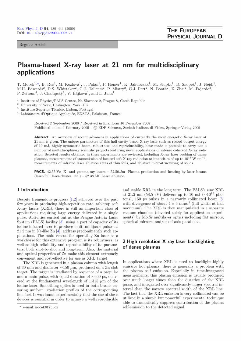
Fig. 1. Principle of the spatial filtering technique.
2.1 Spatial filtering and contrast enhancement
The basic principle of spatial filtering is shown in Figure 1.Rays of a (near) parallel beam pass freely through a smallpinhole located exactly in the focal plane of a lens or mir-ror, while majority of (near) isotropic emission from theprobed object is stopped by the pinhole.
To assess the contrast enhancement due to the pin-hole, let us consider a point on the axis and assume thatthe radiation source is isotropic, yielding intensity Is ona spherical surface with radius a, corresponding to thedistance between the focusing mirror and source object.When the rays reflected by the mirror (focal length f)propagate unobstructed, the intensity Im produced in theimage plane is
Im = IsΩm
4π, (1)
where the spatial angle Ωm is given by
Ωm =πd2
m
4a2, (2)
and dm is the size of mirror. When some part of the raysis stopped by the pinhole, the intensity in the image planeIp is
Ip = IsΩp
4π, (3)
where the spatial angle Ωp depends critically on the sizeof pinhole p projected to the mirror plane
Ωp =πp2
4a2, (4)
where p is defined by
p =dpa
f, (5)
where dp is the pinhole diameter. From equations (1) and(3) it is possible to determine the final contrast enhance-ment in the image plane
Im
Ip=
Ωm
Ωp=
d2m
p2=
d2m
d2p
f2
a2. (6)
For the actual experimental parameters (f = 253 mm,a = 305 mm, dm = 25.4 mm, dp = 0.3 mm) the con-trast enhancement amounts to ∼5000! The effectiveness
(a) (b)
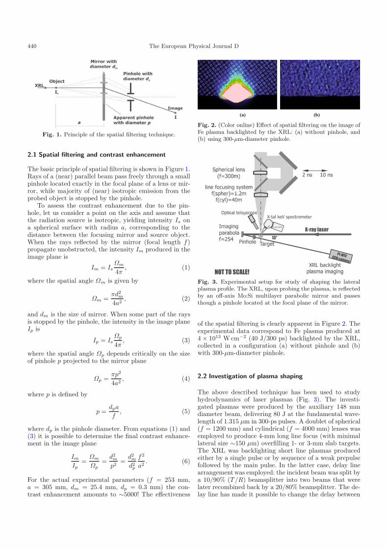
Fig. 2. (Color online) Effect of spatial filtering on the image ofFe plasma backlighted by the XRL: (a) without pinhole, and(b) using 300-µm-diameter pinhole.
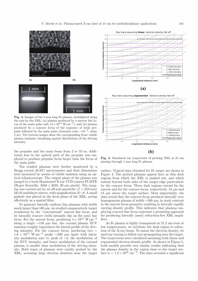
Fig. 3. Experimental setup for study of shaping the lateralplasma profile. The XRL, upon probing the plasma, is reflectedby an off-axis Mo:Si multilayer parabolic mirror and passesthough a pinhole located at the focal plane of the mirror.
of the spatial filtering is clearly apparent in Figure 2. Theexperimental data correspond to Fe plasma produced at4 × 1013 Wcm−2 (40 J/300 ps) backlighted by the XRL,collected in a configuration (a) without pinhole and (b)with 300-μm-diameter pinhole.
2.2 Investigation of plasma shaping
The above described technique has been used to studyhydrodynamics of laser plasmas (Fig. 3). The investi-gated plasmas were produced by the auxiliary 148 mmdiameter beam, delivering 80 J at the fundamental wave-length of 1.315 μm in 300-ps pulses. A doublet of spherical(f = 1200 mm) and cylindrical (f = 4000 mm) lenses wasemployed to produce 4-mm long line focus (with minimallateral size ∼150 μm) overfilling 1- or 3-mm slab targets.The XRL was backlighting short line plasmas producedeither by a single pulse or by sequence of a weak prepulsefollowed by the main pulse. In the latter case, delay linearrangement was employed: the incident beam was split bya 10/90% (T /R) beamsplitter into two beams that werelater recombined back by a 20/80% beamsplitter. The de-lay line has made it possible to change the delay between
T. Mocek et al.: Plasma-based X-ray laser at 21 nm for multidisciplinary applications 441
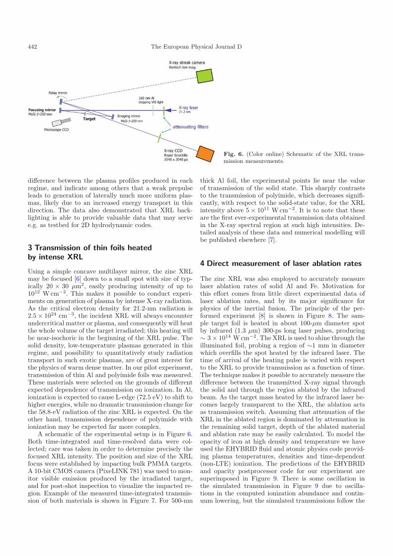
Fig. 4. Images of the 1-mm long Fe plasma, backlighted alongthe axis by the XRL: (a) plasma produced by a narrow line fo-cus of the main pulse only (3× 10¹³ W cm−2), and (b) plasmaproduced by a concave focus of the sequence of weak pre-pulse followed by the main pulse (intensity ratio ∼10−3, delay5 ns). The bottom images show the corresponding front visibleplasma emission visualizing spatial distribution of the drivingintensity.
the prepulse and the main beam from 2 to 10 ns. Addi-tional lens in the optical path of the prepulse was em-ployed to produce prepulse focus larger than the focus ofthe main pulse.
The studied plasmas were further monitored by aBragg crystal (KAP) spectrometer and their dimensionswere measured by means of visible emission using an op-tical telemicroscope. The output plane of the plasma wasimaged to a back-illuminated X-ray CCD camera PI-MTE(Roper Scientific, 2048 × 2048, 20 μm pixels). The imag-ing was carried out by an off-axis parabolic (f = 253 mm)Mo:Si multilayer mirror, with magnification of∼8. A smallpinhole was placed in the focal plane of the XRL, actingeffectively as a spatial filter.
To generate laterally uniform line plasmas with widthmuch larger than 100 μm, we studied comparatively targetirradiation by the “conventional” narrow line focus, andby laterally concave (with intensity dip on the axis) linefocus. For the narrow focus, producing 4 × 10¹³ Wcm−2
along a single ∼150 μm line, the coronal plasma XUVemission roughly reproduces the lateral profile of the driv-ing intensity. For the concave focus, producing two ∼1.6 × 10¹³ Wcm−2 peaks ∼500 μm apart with inten-sity modulation axis vs. peak of ∼3, the modulation ofthe XUV intensity, and hence modulation of the coronalplasma, is smaller than modulation of the driving inten-sity. Both types of plasmas were axially probed by theXRL, accessing large electron densities near the target
Ray trace assuming linear electron density fall-off
0
2
4
6
8
10
12
14
16
18
20
18.06.04.02.00
Longitudinal distance (mm)
Tra
nsv
ers
e d
ista
nce
(m
icro
n)
L=120 micronsL=80 micronsL=100 micronsMeasured value
(a) Ray trace assuming exponential electron density fall-off
0
2
4
6
8
10
12
14
16
18
20
18.06.04.02.00
Longitudinal distance (mm)
Tra
nsv
ers
e d
ista
nce
(m
icro
n)
L=120micronsL=80micronsL=100micronsMeasured value
(b) Fig. 5. Simulated ray trajectories of probing XRL at 21 nmpassing through 1 mm long Fe plasma.
surface. Typical data obtained for Fe target are shown inFigure 4. The probed plasmas appear here as thin darkregions from which the XRL is pushed out, and whichextend beyond both sides of the target edge particularlyby the concave focus. These dark regions extend for thenarrow and for the concave focus, respectively, 18 μm and13 μm above the target surface. Most importantly, thedata reveal that the concave focus produces laterally veryhomogeneous plasma of width ∼500 μm, in stark contrastto the narrow focus geometry resulting in laterally rapidlyvarying density profile. This indicates that plasmas em-ploying concave line focus represent a promising approachfor producing laterally (near) refraction-free XRL ampli-fiers.
As Fe plasma is highly transparent at 21.2 nm even atlow temperatures, we attribute the dark region to refrac-tion of the X-ray beam. To assess the electron density, weused ray tracing to follow rays propagating near the target.The trajectories were calculated assuming both linear andexponential electron density profile. As shown in Figure 5,both models provide very similar results indicating thatthe plasma density in the region close to the target sur-face is ∼ 1.2× 1022 cm−3. The data revealed a significant
442 The European Physical Journal D
Fig. 6. (Color online) Schematic of the XRL trans-mission measurements.
difference between the plasma profiles produced in eachregime, and indicate among others that a weak prepulseleads to generation of laterally much more uniform plas-mas, likely due to an increased energy transport in thisdirection. The data also demonstrated that XRL back-lighting is able to provide valuable data that may servee.g. as testbed for 2D hydrodynamic codes.
3 Transmission of thin foils heatedby intense XRL
Using a simple concave multilayer mirror, the zinc XRLmay be focused [6] down to a small spot with size of typ-ically 20 × 30 μm2, easily producing intensity of up to1012 Wcm−2. This makes it possible to conduct experi-ments on generation of plasma by intense X-ray radiation.As the critical electron density for 21.2-nm radiation is2.5 × 1024 cm−3, the incident XRL will always encounterundercritical matter or plasma, and consequently will heatthe whole volume of the target irradiated; this heating willbe near-isochoric in the beginning of the XRL pulse. Thesolid density, low-temperature plasmas generated in thisregime, and possibility to quantitatively study radiationtransport in such exotic plasmas, are of great interest forthe physics of warm dense matter. In our pilot experiment,transmission of thin Al and polyimide foils was measured.These materials were selected on the grounds of differentexpected dependence of transmission on ionization. In Al,ionization is expected to cause L-edge (72.5 eV) to shift tohigher energies, while no dramatic transmission change forthe 58.8-eV radiation of the zinc XRL is expected. On theother hand, transmission dependence of polyimide withionization may be expected far more complex.
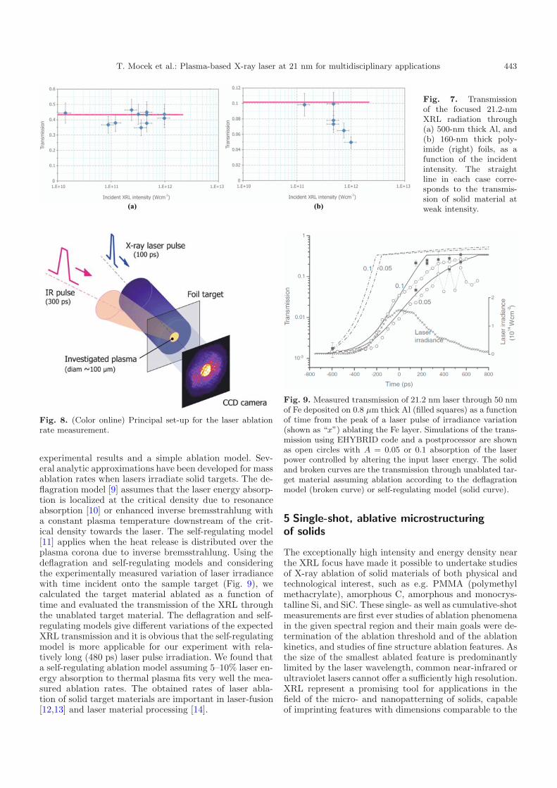
A schematic of the experimental setup is in Figure 6.Both time-integrated and time-resolved data were col-lected; care was taken in order to determine precisely thefocused XRL intensity. The position and size of the XRLfocus were established by impacting bulk PMMA targets.A 10-bit CMOS camera (PixeLINK 781) was used to mon-itor visible emission produced by the irradiated target,and for post-shot inspection to visualize the impacted re-gion. Example of the measured time-integrated transmis-sion of both materials is shown in Figure 7. For 500-nm
thick Al foil, the experimental points lie near the valueof transmission of the solid state. This sharply contraststo the transmission of polyimide, which decreases signifi-cantly, with respect to the solid-state value, for the XRLintensity above 5 × 10¹¹ W cm−2. It is to note that theseare the first ever-experimental transmission data obtainedin the X-ray spectral region at such high intensities. De-tailed analysis of these data and numerical modelling willbe published elsewhere [7].
4 Direct measurement of laser ablation rates
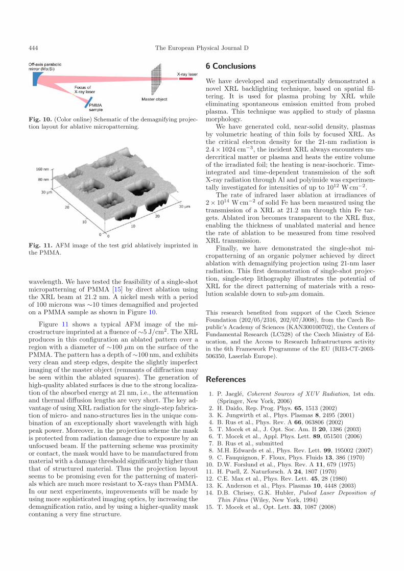
The zinc XRL was also employed to accurately measurelaser ablation rates of solid Al and Fe. Motivation forthis effort comes from little direct experimental data oflaser ablation rates, and by its major significance forphysics of the inertial fusion. The principle of the per-formed experiment [8] is shown in Figure 8. The sam-ple target foil is heated in about 100-μm diameter spotby infrared (1.3 μm) 300-ps long laser pulses, producing∼ 3 × 10¹⁴ Wcm−2. The XRL is used to shine through theilluminated foil, probing a region of ∼1 mm in diameterwhich overfills the spot heated by the infrared laser. Thetime of arrival of the heating pulse is varied with respectto the XRL to provide transmission as a function of time.The technique makes it possible to accurately measure thedifference between the transmitted X-ray signal throughthe solid and through the region ablated by the infraredbeam. As the target mass heated by the infrared laser be-comes largely transparent to the XRL, the ablation actsas transmission switch. Assuming that attenuation of theXRL in the ablated region is dominated by attenuation inthe remaining solid target, depth of the ablated materialand ablation rate may be easily calculated. To model theopacity of iron at high density and temperature we haveused the EHYBRID fluid and atomic physics code provid-ing plasma temperatures, densities and time-dependent(non-LTE) ionization. The predictions of the EHYBRIDand opacity postprocessor code for our experiment aresuperimposed in Figure 9. There is some oscillation inthe simulated transmission in Figure 9 due to oscilla-tions in the computed ionization abundance and contin-uum lowering, but the simulated transmissions follow the
T. Mocek et al.: Plasma-based X-ray laser at 21 nm for multidisciplinary applications 443
Fig. 7. Transmissionof the focused 21.2-nmXRL radiation through(a) 500-nm thick Al, and(b) 160-nm thick poly-imide (right) foils, as afunction of the incidentintensity. The straightline in each case corre-sponds to the transmis-sion of solid material atweak intensity.
Fig. 8. (Color online) Principal set-up for the laser ablationrate measurement.
experimental results and a simple ablation model. Sev-eral analytic approximations have been developed for massablation rates when lasers irradiate solid targets. The de-flagration model [9] assumes that the laser energy absorp-tion is localized at the critical density due to resonanceabsorption [10] or enhanced inverse bremsstrahlung witha constant plasma temperature downstream of the crit-ical density towards the laser. The self-regulating model[11] applies when the heat release is distributed over theplasma corona due to inverse bremsstrahlung. Using thedeflagration and self-regulating models and consideringthe experimentally measured variation of laser irradiancewith time incident onto the sample target (Fig. 9), wecalculated the target material ablated as a function oftime and evaluated the transmission of the XRL throughthe unablated target material. The deflagration and self-regulating models give different variations of the expectedXRL transmission and it is obvious that the self-regulatingmodel is more applicable for our experiment with rela-tively long (480 ps) laser pulse irradiation. We found thata self-regulating ablation model assuming 5–10% laser en-ergy absorption to thermal plasma fits very well the mea-sured ablation rates. The obtained rates of laser abla-tion of solid target materials are important in laser-fusion[12,13] and laser material processing [14].
Fig. 9. Measured transmission of 21.2 nm laser through 50 nmof Fe deposited on 0.8 µm thick Al (filled squares) as a functionof time from the peak of a laser pulse of irradiance variation(shown as “x”) ablating the Fe layer. Simulations of the trans-mission using EHYBRID code and a postprocessor are shownas open circles with A = 0.05 or 0.1 absorption of the laserpower controlled by altering the input laser energy. The solidand broken curves are the transmission through unablated tar-get material assuming ablation according to the deflagrationmodel (broken curve) or self-regulating model (solid curve).
5 Single-shot, ablative microstructuringof solids
The exceptionally high intensity and energy density nearthe XRL focus have made it possible to undertake studiesof X-ray ablation of solid materials of both physical andtechnological interest, such as e.g. PMMA (polymethylmethacrylate), amorphous C, amorphous and monocrys-talline Si, and SiC. These single- as well as cumulative-shotmeasurements are first ever studies of ablation phenomenain the given spectral region and their main goals were de-termination of the ablation threshold and of the ablationkinetics, and studies of fine structure ablation features. Asthe size of the smallest ablated feature is predominantlylimited by the laser wavelength, common near-infrared orultraviolet lasers cannot offer a sufficiently high resolution.XRL represent a promising tool for applications in thefield of the micro- and nanopatterning of solids, capableof imprinting features with dimensions comparable to the
444 The European Physical Journal D
Fig. 10. (Color online) Schematic of the demagnifying projec-tion layout for ablative micropatterning.
Fig. 11. AFM image of the test grid ablatively imprinted inthe PMMA.
wavelength. We have tested the feasibility of a single-shotmicropatterning of PMMA [15] by direct ablation usingthe XRL beam at 21.2 nm. A nickel mesh with a periodof 100 microns was ∼10 times demagnified and projectedon a PMMA sample as shown in Figure 10.
Figure 11 shows a typical AFM image of the mi-crostructure imprinted at a fluence of ∼5 J/cm2. The XRLproduces in this configuration an ablated pattern over aregion with a diameter of ∼100 μm on the surface of thePMMA. The pattern has a depth of ∼100 nm, and exhibitsvery clean and steep edges, despite the slightly imperfectimaging of the master object (remnants of diffraction maybe seen within the ablated squares). The generation ofhigh-quality ablated surfaces is due to the strong localiza-tion of the absorbed energy at 21 nm, i.e., the attenuationand thermal diffusion lengths are very short. The key ad-vantage of using XRL radiation for the single-step fabrica-tion of micro- and nano-structures lies in the unique com-bination of an exceptionally short wavelength with highpeak power. Moreover, in the projection scheme the maskis protected from radiation damage due to exposure by anunfocused beam. If the patterning scheme was proximityor contact, the mask would have to be manufactured frommaterial with a damage threshold significantly higher thanthat of structured material. Thus the projection layoutseems to be promising even for the patterning of materi-als which are much more resistant to X-rays than PMMA.In our next experiments, improvements will be made byusing more sophisticated imaging optics, by increasing thedemagnification ratio, and by using a higher-quality maskcontaning a very fine structure.
6 Conclusions
We have developed and experimentally demonstrated anovel XRL backlighting technique, based on spatial fil-tering. It is used for plasma probing by XRL whileeliminating spontaneous emission emitted from probedplasma. This technique was applied to study of plasmamorphology.
We have generated cold, near-solid density, plasmasby volumetric heating of thin foils by focused XRL. Asthe critical electron density for the 21-nm radiation is2.4× 1024 cm−3, the incident XRL always encounters un-dercritical matter or plasma and heats the entire volumeof the irradiated foil; the heating is near-isochoric. Time-integrated and time-dependent transmission of the softX-ray radiation through Al and polyimide was experimen-tally investigated for intensities of up to 1012 Wcm−2.
The rate of infrared laser ablation at irradiances of2× 1014 Wcm−2 of solid Fe has been measured using thetransmission of a XRL at 21.2 nm through thin Fe tar-gets. Ablated iron becomes transparent to the XRL flux,enabling the thickness of unablated material and hencethe rate of ablation to be measured from time resolvedXRL transmission.
Finally, we have demonstrated the single-shot mi-cropatterning of an organic polymer achieved by directablation with demagnifying projection using 21-nm laserradiation. This first demonstration of single-shot projec-tion, single-step lithography illustrates the potential ofXRL for the direct patterning of materials with a reso-lution scalable down to sub-μm domain.
This research benefited from support of the Czech ScienceFoundation (202/05/2316, 202/07/J008), from the Czech Re-public’s Academy of Sciences (KAN300100702), the Centers ofFundamental Research (LC528) of the Czech Ministry of Ed-ucation, and the Access to Research Infrastructures activityin the 6th Framework Programme of the EU (RII3-CT-2003-506350, Laserlab Europe).
References
1. P. Jaegle, Coherent Sources of XUV Radiation, 1st edn.(Springer, New York, 2006)
2. H. Daido, Rep. Prog. Phys. 65, 1513 (2002)3. K. Jungwirth et al., Phys. Plasmas 8, 2495 (2001)4. B. Rus et al., Phys. Rev. A 66, 063806 (2002)5. T. Mocek et al., J. Opt. Soc. Am. B 20, 1386 (2003)6. T. Mocek et al., Appl. Phys. Lett. 89, 051501 (2006)7. B. Rus et al., submitted8. M.H. Edwards et al., Phys. Rev. Lett. 99, 195002 (2007)9. C. Fauquignon, F. Floux, Phys. Fluids 13, 386 (1970)
10. D.W. Forslund et al., Phys. Rev. A 11, 679 (1975)11. H. Puell, Z. Naturforsch. A 24, 1807 (1970)12. C.E. Max et al., Phys. Rev. Lett. 45, 28 (1980)13. K. Anderson et al., Phys. Plasmas 10, 4448 (2003)14. D.B. Chrisey, G.K. Hubler, Pulsed Laser Deposition of
Thin Films (Wiley, New York, 1994)15. T. Mocek et al., Opt. Lett. 33, 1087 (2008)