
PLANT LA OF F (GIR AYOUT P FISHING RONA). Final D Food ...
160
PLA ANT LA OF F (GIR AYOUT P FISHING RONA). Final D Food PROJEC G INDUS Tu Degree P d Engine CT FOR STRY LO Author: utor: Edu Project eering R THE E OCATED Clara Vin ard Hern Date: 10 NLARG D IN RO ngut Expó ández Yá / July / 2 GEMENT OSES ósito áñez 2015 T
-
Upload
khangminh22 -
Category
Documents
-
view
1 -
download
0
Transcript of PLANT LA OF F (GIR AYOUT P FISHING RONA). Final D Food ...
PLAANT LA
OF F
(GIR
AYOUT P
FISHING
RONA).
Final D
Food
PROJEC
G INDUS
Tu
Degree P
d Engine
CT FOR
STRY LO
Author:
utor: Edu
Project
eering
R THE E
OCATED
Clara Vin
ard Hern
Date: 10
NLARG
D IN RO
ngut Expó
ández Yá
/ July / 2
GEMENT
OSES
ósito
áñez
2015
T
Plant
Title
Aut
Tuto
Abs
proj
mad
Spe
prod
and
praw
So
faci
Fina
calc
The
plan
Key
HAC
t layout proj
e: PLANT
FISHI
tor: Clara
or: Edua
stact: Th
ect of an
de the d
ecifically
duction o
also ha
wn carpa
they ha
lities suc
ally, the
culations
e docume
nes.
y words:
CCP.
ect for the e
T LAYOU
ING INDU
a Vingut E
rd Hernán
is Final D
n industria
design of
it has b
of fish bro
as been e
ccio Rose
ave made
h as light
plans
of the fac
ent consis
industry
enlargement
UT PROJ
USTRY L
Expósito.
ndez Yáñ
Degree P
al plant d
f the new
een rem
oth beca
expandin
es.
e the ne
ting, elec
have be
cilities.
sts of me
y, broth,
t of fishing i
Escola Su
JECT FO
OCATED
ñez.
Project is
dedicated
w plant
modelled
ause has
ng to pro
ecessary
ctricity, ref
een prep
emory, ca
carpaccio
ndustry loca
uperior d’AgricU
OR THE
D IN ROS
a remod
to the fi
layout a
the area
already
oduce a n
y calculat
frigeratio
pared to
alculation
o, distrib
ated in Rose
ultura de BarcUPC ‐ Barcelon
ENLARG
SES (GIRO
delling an
shing ind
and new
a where
increase
new prod
tions for
n and fire
give e
and eigh
ution, ins
es (Girona)
celona aTech
GEMENT
ONA).
nd expan
dustry. I h
installati
there is
ed produc
duct such
r sizing
e.
effect to
ht annex
stallation
1
T OF
nsion
have
ons.
the
ction
h as
new
the
es 8
and
Plant
Títo
D’U
Aut
Tuto
Res
rem
pes
de l
es p
altra
com
Així
nov
frigo
Fina
insta
El d
Par
APP
t layout proj
ol: PROJ
NA INDÚ
tora: Clar
or: Edua
sum: Aq
modelació
quera. S
les noves
produeix
a banda s
m és el ca
í doncs s
es instal
orífica i la
alment s’h
al·lacions
document
raules cla
PCC.
ect for the e
JECTE D
ÚSTRIA P
ra Vingut
rd Hernán
quest Tre
i expans
’ha realitz
s instal·la
el fumet d
s’ha fet u
arpaccio d
s’han real
·lacions
a de contr
han elabo
s.
t consta d
au: indús
enlargement
DE DISSE
PESQUER
Expósito
ndez Yáñ
eball de
sió d’una
zat el dis
acions. Co
de peix ja
una expan
de gambe
litzat els
com la
ra incendi
orat els p
de la mem
stria, fume
t of fishing i
ENY EN
RA A RO
.
ñez.
Final d
planta in
sseny de
oncretam
a que s’h
nsió per t
es de Ros
càlculs n
il·luminac
is.
plànols pe
mòria, 8 a
et, carpac
ndustry loca
PLANTA
SES (GIR
de Grau
dustrial d
la nova
ment s’ha
ha augme
tal de pro
ses.
necessaris
ció, l’elec
er fer efec
nnexos d
ccio, distr
ated in Rose
A PER L
RONA).
és un
dedicada
distribuci
remodela
entat la pr
oduir un n
s per dim
ctricitat, l
ctius els c
de càlcul i
ribució, in
es (Girona)2
L’AMPLIA
projecte
a la indu
ió en pla
at la zona
roducció
nou prod
mensiona
a instal·l
càlculs de
i 8 plànols
nstal·lacio
2
ACIÓ
e de
stria
nta i
a on
i per
ucte
r les
lació
e les
s.
ons i
Plant
Títu
AMP
(GIR
Aut
Tuto
Res
rem
indu
en
rem
ha
exp
gam
Así
las
insta
Fina
cálc
El d
Pala
y AP
t layout proj
ulo: PR
PLIACIÓN
RONA).
tora: Clar
or: Edua
sumen:
modelación
ustria pes
planta y
modelado
aumenta
ansión pa
mbas de R
í pues se
nuevas
alación fr
almente s
culos de la
document
abras cla
PPCC
ect for the e
OYECTO
N DE U
ra Vingut
rd Hernán
Este Tra
n y expa
squera. S
y de las
la zona d
ado la pr
ara produ
Roses.
e han rea
instalacio
rigorífica y
se han e
as instala
to consta
ave: indu
enlargement
O DE
UNA IN
Expósito
ndez Yáñ
abajo de
ansión de
e ha real
nuevas
donde se
roducción
ucir un nu
lizado los
ones com
y la de co
elaborado
aciones.
de la me
stria, fum
t of fishing i
Escola Su
DISEÑO
DUSTRIA
.
ñez.
e Fin de
e una pl
izado el d
instalac
produce
n y por
uevo prod
s cálculos
mo la il
ontra ince
o los pla
emoria, 8
met, carpa
ndustry loca
uperior d’AgricU
EN P
A PESQ
e Grado
lanta ind
diseño de
ciones. C
el caldo d
otro lad
ducto com
s necesa
uminació
endios.
anos para
anexos d
accio dist
ated in Rose
ultura de BarcUPC ‐ Barcelon
PLANTA
QUERA
es un
ustrial de
e la nueva
Concretam
de pesca
o se ha
mo es el
rios para
ón, la ele
a hacer
de cálculo
ribución,
es (Girona)
celona aTech
PARA
EN ROS
proyecto
edicada
a distribu
mente se
ado ya qu
a hecho
carpaccio
a dimensio
ectricidad
efectivos
o y 8 plan
instalacio
3
LA
SES
o de
a la
ución
e ha
e se
una
o de
onar
d, la
s los
os.
ones
Plant
1ST
ANN
t layout proj
DOCUME
REPO
1. O
2. B
3. B
4. P
5. E
6. H
7. B
8. F
NEX
Annex
Annex
Annex
Annex
Annex
Annex
Annex
Annex
ect for the e
ENT: RE
RT
Object
Backgrou
Basis proj
Process e
Engineeri
Health an
Budget
Financial
1. Plan
2. Fire
3. Ligh
4. Ref
5. Elec
6. HAC
7. Hea
8. Fina
enlargement
GEN
PORT AN
nd
ject
engineerin
ng works
d safety
evaluatio
nt layout
e protectio
hting insta
rigeration
ctrical ins
CCP
alth and S
ancial Eco
t of fishing i
NERAL IN
ND ANNE
ng
s and insta
on
on
allation
n installati
stallation
Safety Stu
onomic A
ndustry loca
NDEX
EX
allations
ion
udy
Assessme
ated in Rose
ent
es (Girona)44
Plant
2ND
3RD
t layout proj
DOCUM
1. Loc
2. Cur
3. Plan
4. Sec
5. Mac
6. Ligh
7. Unif
8. Fire
DOCUM
Partial
Genera
ect for the e
ENT: PLA
ation
rrent statu
nt floor
ction
chinery di
hting and
filar sche
e protectio
ENT: BU
budget
al budget
enlargement
ANS
us: plant f
istribution
electrical
me
on distribu
DGET
t
t of fishing i
Escola Su
floor and
n
l distribut
ution plan
ndustry loca
uperior d’AgricU
elevation
tion plant
nt
ated in Rose
ultura de BarcUPC ‐ Barcelon
es (Girona)
celona aTech
5
Plant
t layout project for the eenlargementt of fishing i
Escola Su
ndustry loca
uperior d’AgricU
R
ated in Rose
ultura de BarcUPC ‐ Barcelon
1ST D
REPORT A
es (Girona)
celona aTech
DOCUME
AND ANN
ENT:
NEX
1

2
REP
1.
2.
3.
3.1
3.2
3.3
4.
4.1
4.2
4.3
5.
5.1
5.2
5.3
PORT
OBJECT _
BACKGR
BASIS PR
1. Guideli
3.1.1. Pu
3.1.2. Co
2. Conditio
3.2.1. Cli
3.2.2. Uti
3.2.3. Leg
3. Current
PROCESS
1. Fish bro
4.1.1. Ra
4.1.2. Pro
4.1.3. Pro
4.1.4. Ma
4.1.4.1. Pro
4.1.4.2. Re
2. Prawn
4.2.1. Ra
4.2.2. Pro
4.2.3. Pro
4.2.4. Ma
4.2.4.1. Pro
4.2.4.2. Re
3. HACCP
ENGINEE
1. Exterio
2. Flooring
3. Doors .
__________
OUND ____
ROJECT ___
nes .............
urpose .........
onditions imp
oning projec
matic chara
ilities ...........
gislative inv
t situation ...
S ENGINEE
oth ..............
aw matters ..
oduction pro
ocess diagra
achinery ......
ocess mach
efrigeration
carpaccio ...
aw matters ..
oduction pro
ocess diagra
achinery ......
ocess mach
efrigeration
P .................
ERING WOR
r walls and
g .................
...................
__________
__________
__________
...................
...................
posed by th
ct ................
acterization ..
...................
volvement ....
...................
ERING ____
...................
...................
ocess descr
am ..............
...................
hinery ..........
machinery
...................
...................
ocess descr
am ..............
...................
hinery ..........
machinery
...................
RKS ______
ceilings .......
...................
...................
__________
__________
__________
...................
...................
e developer
...................
...................
...................
...................
...................
__________
...................
...................
ription .........
...................
...................
...................
y .................
...................
...................
ription .........
...................
...................
...................
y .................
...................
__________
...................
...................
...................
__________
__________
__________
...................
...................
r ..................
...................
...................
...................
...................
...................
__________
...................
...................
...................
...................
...................
...................
...................
...................
...................
...................
...................
...................
...................
...................
...................
__________
...................
...................
...................
__________
__________
__________
...................
...................
...................
...................
...................
...................
...................
...................
__________
...................
...................
...................
...................
...................
...................
...................
...................
...................
...................
...................
...................
...................
...................
...................
__________
...................
...................
...................
__________
__________
__________
...................
...................
...................
...................
...................
...................
...................
...................
__________
...................
...................
...................
...................
...................
...................
...................
...................
...................
...................
...................
...................
...................
...................
...................
__________
...................
...................
...................
______ 4
______ 5
______ 6
............ 6
............ 6
............ 6
............ 6
............ 6
............ 6
............ 7
............ 8
_____ 12
......... 12
......... 12
......... 12
......... 15
......... 16
......... 16
......... 16
......... 17
......... 17
......... 17
......... 18
......... 19
......... 19
......... 19
......... 19
_____ 20
......... 20
......... 20
......... 21
Plant
5.4
5.5
6.
6.1
6.2
6.3
7.
8.
9.
t layout proj
4. Ventilat
5. Lighting
INSTALLA
1. Fire pro
2. Refrige
3. Electric
6.3.1. Ele
6.3.2. Pro
HEALTH A
BUDGET _
FINANCIA
ect for the e
tion .............
g .................
ATIONS ___
otection .......
eration instal
cal installatio
ectrical supp
otections ....
AND SAFE
__________
AL EVALUA
enlargement
...................
...................
__________
...................
llation ..........
on ................
plying ..........
...................
TY _______
__________
ATION ____
t of fishing i
Escola Su
...................
...................
__________
...................
...................
...................
...................
...................
__________
__________
__________
ndustry loca
uperior d’AgricU
...................
...................
__________
...................
...................
...................
...................
...................
__________
__________
__________
ated in Rose
ultura de BarcUPC ‐ Barcelon
...................
...................
__________
...................
...................
...................
...................
...................
__________
__________
__________
es (Girona)
celona aTech
...................
...................
__________
...................
...................
...................
...................
...................
__________
__________
__________
......... 21
......... 21
_____ 22
......... 22
......... 22
......... 23
......... 23
......... 24
_____ 25
_____ 26
_____ 27
3
4
1.
The
Rose
involv
The
Rose
The
963,7
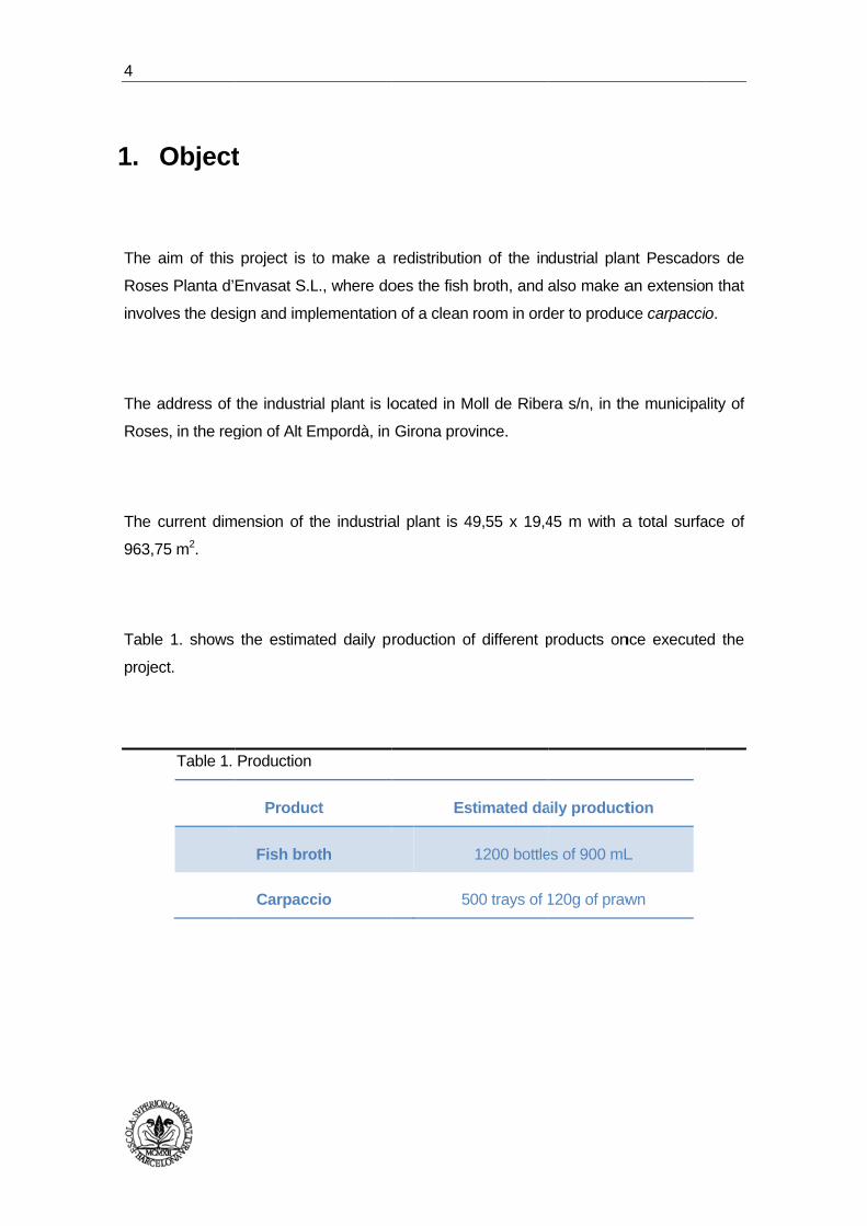
Table
proje
Object
aim of this
es Planta d’
ves the des
address of
es, in the reg
current dim
75 m2.
e 1. shows
ect.
Table 1.
t
project is t
Envasat S.L
sign and imp
the industri
gion of Alt E
mension of t
the estima
Production
Produc
Fish bro
Carpacc
to make a
L., where do
plementation
al plant is lo
Empordà, in
he industria
ated daily p
ct
oth
cio
redistributio
oes the fish
n of a clean
ocated in M
Girona prov
al plant is 4
roduction o
Es
5
on of the in
broth, and
room in ord
Moll de Ribe
vince.
49,55 x 19,4
of different p
stimated da
1200 bottle
00 trays of 1
dustrial plan
also make a
der to produc
ra s/n, in th
45 m with a
products on
aily product
es of 900 mL
120g of praw
nt Pescado
an extensio
ce carpacci
he municipa
a total surfa
nce execute
tion
L
wn
ors de
n that
io.
ality of
ace of
ed the

Plant
2.
Pesc
the F
acce
Gove
Main
Plant
Over
Gota
a 51%
Root
prelim
went
broth
As a
the i
owne
Depu
mollu
Pesc
comp
incre
the m
t layout proj
Backg
cadors de R
Fisherman
ess to the
ernment of
nly its activ
ta d’Envasa
r the years
anegra in or
% the Fishe
t of this soc
minary trea
t on to othe
h.
result of th
installations
er of these
uradora Se
uscs and th
cadors de R
pany the c
ease of the
market in or
ect for the e
ground
Roses Plan
Brotherhoo
box of Ro
Catalonia.
ity was ha
at S.L. base
the Brothe
rder to grow
erman Broth
ciety the ac
atments suc
er activities
he society, t
s with Pes
companies
ervimar. Th
eir distribut
Roses Plan
commerciali
production
rder to diver
enlargement
ta d’Envasa
od of Rose
oses. The
ndling, proc
ed its activity
erhood deci
w economica
herhood of
ctivity of th
ch as clean
including t
the two com
cadors de
s also has a
is company
tion.
nta d’Envas
sation on
. Also wan
rsify risk.
t of fishing i
Escola Su
at S.L. was
es, to take
company w
cessing an
y in the gut
ided to ass
ally. So the
Roses and
he company
ning, classif
the develop
mpanies set
Roses Pla
another com
y is dedica
sat S.L. is
a large sc
ts to broad
ndustry loca
uperior d’AgricU
s founded i
advantage
was create
d freezing
ted, filleted
sociate with
society rem
a 49% Peix
y changed
fication, evi
pment of fis
ttled in the e
anta d’Enva
mpany withi
ated to the
currently n
ale of the
den the sco
ated in Rose
ultura de BarcUPC ‐ Barcelon
n 2001 wit
of all the
ed by a su
fish. Pesca
and frozen
h another c
mained of th
xos Gotane
and stoppe
isceration a
sh-based p
establishme
asat S.L. F
n this estab
e treatment
egotiating w
fish broth,
ope of produ
es (Girona)
celona aTech
h an initiati
fish he ha
ubsidy from
adors de R
n fresh fish.
company, P
he following
egra.
ed to realis
and filleting
products like
ent, thus sh
Furthermore
blishment t
t of live bi
with an ext
this mean
ucts availab
ive of
ad no
m the
Roses
Peixos
g way:
se the
; and
e fish
haring
e the
hat is
ivalve
ternal
ns an
ble in
5
6
3.
3.1.
3.1.1.
Pesc
contr
Furth
cons
For t
invol
equip
3.1.2.
The p
3.2.
3.2.1.
The
temp
3.2.2.
The i
Basis
Guidel
. Purpo
cadors de R
ract that m
hermore the
sumer trend
these reas
ves an exp
pment nece
. Condit
promoter im
The daily
Make mi
Condit
. Climat
cooler tem
peratures oc
. Utilitie
industrial pla
Network
project
ines
se
Roses Plan
akes the d
e company
s making a
ons the pu
pansion, th
essary to re
tions impo
mposes the f
y production
inimal chan
tioning p
tic charact
mperatures
ccur in the s
es
ant is built a
k of drinking
t
ta d’Envasa
emand for
wants to d
new produ
urpose of t
he dimensio
alize the ac
osed by th
following cha
n.
ges possib
project
terization
of winter a
summer sun
and provides
water.
at S.L. is e
fish broth
diversify the
ct such as
his project
oning of el
ctivities.
he develop
aracteristics
le.
are not on
n is not up t
s the followi
expanding d
is much hi
e risk of pro
prawn carp
is to defin
ectrical ins
per
s:
nly down 5
to 28 degre
ng services
due to the s
gher than t
oduction an
accio.
ne a new p
stallations a
degrees a
es.
:
signing of a
the current
nd adapt to
plant layou
and lighting
and the hi
a new
t one.
o new
t that
g and
ghest
Plant
3.2.3.
t layout proj
Network
Network
Public lig
Net telep
Electrica
Access p
Well sea
. Legisl
General
o T
o L
o E
w
o R
re
o F
R
T
Legislati
o R
a
o R
a
o
o R
a
o
c
ect for the e
k drainage o
k sanitation
ghting.
phony.
al network.
paved.
awater itself
ative invo
legislation:
Technical B
Law 21/1992
Electrical lo
which appro
Royal Decr
egulations o
Fire Protect
Royal Decr
Technology.
on in relatio
REGULATIO
and the Cou
REGULATIO
and the Cou
of animal or
REGULATIO
and the Cou
of official co
consumption
enlargement
of rainwater.
sewage.
f to stock up
lvement
uilding Cod
2 of 16 July
w voltage r
oves the Ele
ree 138/20
of plants an
tion Regula
ee 2267/20
.
on on the fo
ON 852/200
uncil relative
ON 853/200
uncil, by wh
igin.
ON 854/200
uncil, by wh
ontrols on p
n.
t of fishing i
Escola Su
.
p
de.
y, of industry
regulation,
ectrotechnic
11 of 4 F
nd refrigerat
ations for th
004 of 3rd
ood product
04, of 29 A
e to the hyg
04, of 29 A
hich establi
04, of 29 A
hich establi
products of
ndustry loca
uperior d’AgricU
y.
Royal Dec
cal Regulati
February, w
tion installa
he Industria
December
s:
April 2004, o
giene of food
April 2004, o
sh specific
April 2004, o
sh specific
f animal orig
ated in Rose
ultura de BarcUPC ‐ Barcelon
ree 842/20
ons for Low
which appro
tions.
l Establishm
r. Ministry
of the Europ
dstuffs.
of the Europ
norms of h
of the Europ
norms for
gin allocate
es (Girona)
celona aTech
002 of 2 Au
w Voltage.
oves the s
ments (RSC
of Science
pean Parlia
pean Parlia
hygiene of f
pean Parlia
the organis
ed to the h
ugust,
safety
CIEI):
e and
ament
ament
foods
ament
sation
uman
7
8
3.3.
The
diver
(refrig
prese
The
week
week
wher
have
prod
Legislati
o R
T
a
o O
s
fo
a
o R
b
1
fi
o R
p
th
o R
fi
Curren
current act
rse; on the o
gerated), b
erves, semi-
most elabo
kly producti
kly product
re there is t
e to do a r
uction.
on in relatio
ROYAL DE
Technical an
and Aquacu
ORDER, of
standards, t
or the de
aquaculture
REGULATIO
by which es
04/200 of
ishery prod
ROYAL DE
parasitism b
hat serve fo
ROYAL DE
ishery prod
nt situati
tivities of th
one hand it
but also de
- products, p
orated prod
ion of 1.050
ion until 6.
the fish brot
restructurin
on to the fis
ECREE 152
nd Health R
lture with d
2nd Augus
he limits of
termination
.
ON (CE) 20
stablish the
the Counc
ucts and aq
ECREE 14
by Anisakis
ood to final c
CREE 121
ucts, aquac
on
he company
devotes to t
evotes to t
precooked a
duct of this
0 bottles of
000 bottles
th remains
g of the p
shing indust
21/1984, of
Regulations
estiny for h
st 1991, by
heavy met
n of heavy
065/2001, of
e disposals
cil relative
quaculture.
420/2006, o
s in fishery
consumers
/2004, of
culture and
y Pescador
the purchas
the transfor
and frozen.
s company
f 900 mL b
s of 900 m
small and a
plant to find
ry:
f 1st Augus
s Establishm
uman cons
y which ap
als content
y metals
f 22 Octobe
of applicat
on the co
of 1st Dec
products s
or commun
23rd Janua
live, fresh s
rs de Rose
se side is en
rmation of
is the fish
but the com
mL. This de
also the ma
d a more s
st, by whic
ments and F
umption.
pproves the
and the an
for fishery
er 2001, of t
tion of the
nsumer inf
cember, on
supplied by
nities.
ry, on the
shellfish, ch
es Planta E
ngaged and
fish (fresh
h broth; at
mpany want
ecision does
achinery. Th
suitable pla
ch approve
Fishery Pro
e microbiolo
nalytical me
y products
the Commis
Regulation
formation in
n preventio
y establishm
identificatio
hilled or coo
Envasat S.L
selling fres
and froze
present ha
ts to expan
s that the
herefore it w
ace for the
s the
ducts
ogical
thods
and
ssion,
(CE)
n the
on of
ments
on of
ked
L. are
sh fish
en) in
ave a
d the
room
would
e new
Plant
It mu
muss
On th
carpa
trays
indus
exten
So it
prod
exten
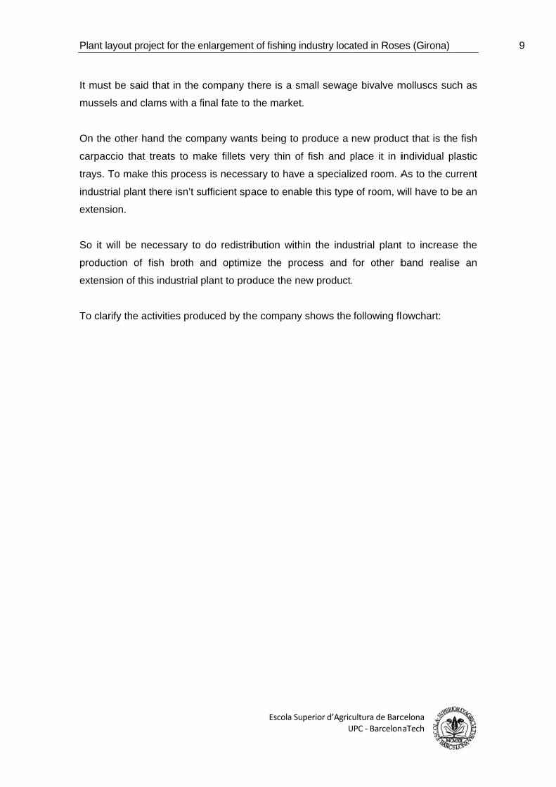
To cl
t layout proj
ust be said
sels and cla
he other ha
accio that t
s. To make
strial plant t
nsion.
t will be ne
uction of f
nsion of this
larify the ac
ect for the e
that in the
ams with a f
and the com
treats to m
this proces
there isn’t s
ecessary to
fish broth a
s industrial
ctivities prod
enlargement
company th
final fate to
mpany want
ake fillets v
ss is necess
ufficient spa
do redistri
and optimiz
plant to pro
duced by th
t of fishing i
Escola Su
here is a sm
the market
ts being to
very thin of
sary to have
ace to enab
ibution with
ze the pro
oduce the ne
e company
ndustry loca
uperior d’AgricU
mall sewag
.
produce a
f fish and p
e a specializ
ble this type
hin the indu
ocess and
ew product.
y shows the
ated in Rose
ultura de BarcUPC ‐ Barcelon
e bivalve m
new produc
place it in i
zed room. A
e of room, w
ustrial plant
for other b
.
following flo
es (Girona)
celona aTech
molluscs su
ct that is th
individual p
As to the cu
will have to b
t to increas
band realis
owchart:
ch as
e fish
plastic
urrent
be an
e the
se an
9
10
Refri
Process
‐
‐
‐
‐
‐
‐
‐
igerated or f
sing industr
Salted prodProducts salt. Smoked prCooked proPreserves.Semi-preseRestructure
Distribution
Final con
Ob
pro
Pr
R
frozen produ
ry:
ducts. dried or d
roducts. oducts. erves. ed products
n and sale
nsumer
btainment o
oducts:
‐ Extrac‐ Aquac
reliminary tr
fish
Refrigeration
and fi
ucts
dry in
s
of the fish
ctive fishingculture.
reatment of
hery product
n or freezing
shery produ
and fisher
.
the fish and
ts.
g of the fish
ucts.
ry
d
Refriger
Distribut
Final
rated produc
tion and sal
l consumer
cts
e
Plant
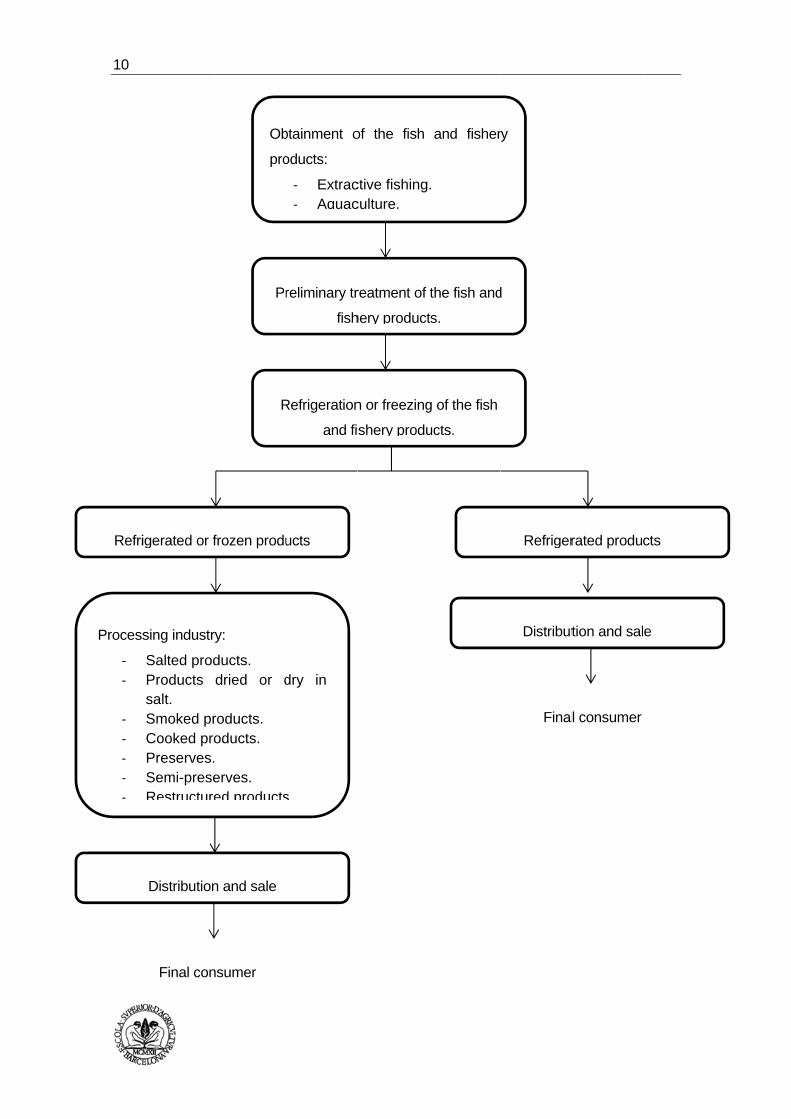
Table
t layout proj
e 2 shows th
Table 2.
Refrige
Refrige
Freezer
Freezer
Room d
Offices
Area cle
Packag
Room m
Men’s w
Women
Broth ro
Autocla
Chambe
Loading
Storage
Kitchen
Laborat
ect for the e
he dimensio
Zone’s dim
rator 1
rator 2
r 1
r 2
debug mus
eaning and
ging room a
maintenanc
wardrobes
n’s wardrob
oom
ave room
er of waste
g and unlo
e container
n
tory
enlargement
ons of each
ensions
Zon
ssels
d packagin
and finish p
ce
bes
e
ading zone
rs
t of fishing i
Escola Su
area of the
ne
g of musse
product sto
e
ndustry loca
uperior d’AgricU
industrial pl
els
orage
ated in Rose
ultura de BarcUPC ‐ Barcelon
ant today.
Are
5
3
4
1
6
2
2
1
3
2
1
6
4
4
5
1
es (Girona)
celona aTech
rea (m²)
59,14
32,50
41,93
16,50
60,62
24,41
245,27
25,75
36,63
20,02
14,88
61,24
44,34
4,00
43,28
56,70
9,94
11,70
11
12
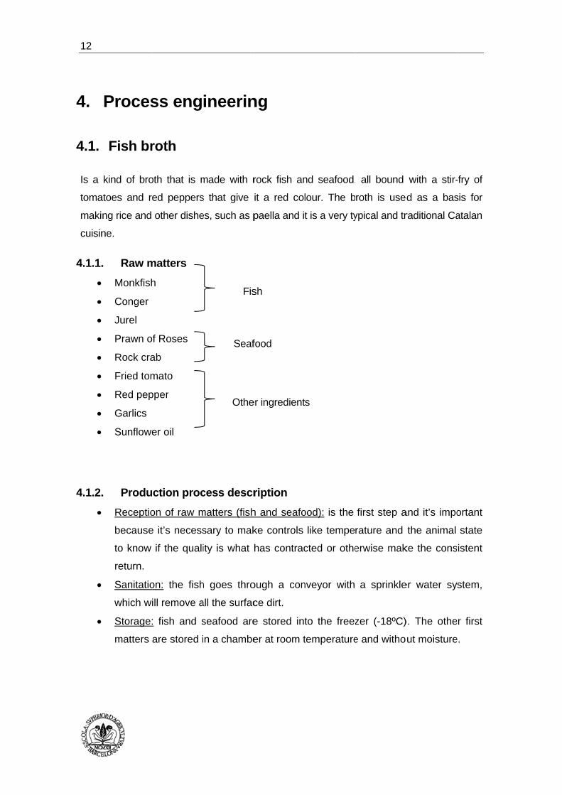
4.
4.1.
Is a
toma
maki
cuisin
4.1.1.
4.1.2.
Proces
Fish br
kind of bro
atoes and re
ng rice and
ne.
. Raw m
Monkfish
Conger
Jurel
Prawn o
Rock cra
Fried tom
Red pep
Garlics
Sunflowe
. Produ
Receptio
because
to know
return.
Sanitatio
which wi
Storage:
matters a
ss eng
roth
oth that is m
ed peppers
other dishe
matters
h
f Roses
ab
mato
pper
er oil
ction proc
on of raw m
e it’s necess
if the quali
on: the fish
ill remove a
: fish and s
are stored i
ineerin
made with r
s that give
es, such as p
cess descr
matters (fish
sary to mak
ity is what h
h goes thro
all the surfac
seafood are
n a chambe
Fis
Seaf
Othe
ng
rock fish an
it a red col
paella and it
ription
h and seafo
ke controls
has contrac
ough a con
ce dirt.
e stored int
er at room t
sh
food
er ingredient
nd seafood,
lour. The b
t is a very ty
ood): is the
like tempe
cted or othe
nveyor with
to the freez
temperature
ts
all bound
roth is used
ypical and tr
first step a
rature and
erwise mak
a sprinkle
zer (-18ºC)
e and witho
with a stir-
d as a bas
raditional Ca
and it’s impo
the animal
ke the cons
er water sy
). The othe
ut moisture
-fry of
sis for
atalan
ortant
state
istent
stem,
r first
e.
Plant
t layout proj
Thawing
and 6ºC
Seafood
Preparat
peeled g
prepare
Cooking
hot wate
cooking:
o F
th
o L
o W
o T
o L
Filtering
liquid pa
parts or
Dosage:
broth pe
Bottle cl
that bot
autoclav
Heat tre
minutes
o W
p
o M
1
o C
c
T
ect for the e
g of fish and
C. The fish
d isn’t thawe
tion of othe
garlics and
the sting th
: before be
er (70ºC) to
Firstly adds
he sting tha
Let stir-fry fo
When stir-fry
Then fills the
Let it being t
: once coo
asses throu
foreign mat
this stage
r container.
osing: once
ttles remai
ving.
eatment: it r
in a cycle t
Warming: th
process has
Maintenance
21ºC and a
Cooling: usi
contact with
This process
enlargement
d seafood:
is placed o
ed in order t
er ingredien
anglerfish
at later it st
eginning wit
o ensure th
to the kettl
at have prep
or 5 minutes
y is done ad
e kettle from
to boil and c
ked, pours
gh another
terials.
is carried o
.
e filled, glas
in totally w
realises a c
hat consist
he temperat
s a duration
e: it’s the st
a pressure o
ing sea wa
the broth).
s cools to 1
t of fishing i
Escola Su
it carries ou
on top of pl
to don’t give
nts: Take th
liver and g
tir-fry with s
th the cook
hat all the
le 5L of oil
pared previo
s and then a
dd all the fis
m water of p
count some
the broth
r filter to en
out using a
ss bottles a
well closed
conventiona
in three sta
ture increas
of 45 minu
tage of ster
of 1,5 atmos
ater to cool
The excha
22ºC to 40º
ndustry loca
uperior d’AgricU
ut in a refrig
astic pallet
e a darker c
he tomato
grind togeth
sunflower oi
king it’s nec
circuit is to
of sunflowe
ously.
add the sea
sh.
public netwo
e 45 minute
until a dru
nsure the re
liquid dosi
are sealed
d and dep
al sterilizatio
ages:
ses form 20
tes.
rilization, m
spheres for
the circuit
nger finds o
ºC and has
ated in Rose
ultura de BarcUPC ‐ Barcelon
gerator that
s because
colour to the
sauce, pee
er with a g
l and seafoo
cessary to d
otally clean.
er, once wa
afood.
ork.
s to 98ºC.
m separato
emoval of la
ng schedul
with a meta
posited in
on to 121-1
ºC to 122ºC
maintaining a
r 10 minutes
t (this wate
out of the au
a duration
es (Girona)
celona aTech
t is between
exudate le
e broth.
eled red pe
grinder blad
od.
do a rinsing
. Then it b
as a bit hot,
or. The res
arge fish b
led of 900 m
al cap, che
the wago
122ºC durin
C gradually
a temperatu
s.
er never go
utoclave.
of 45 minut
n 3ºC
aves.
epper,
des to
g with
egins
adds
ultant
ones,
mL of
ecking
on of
ng 10
. This
ure of
oes in
tes.
13

14
Labelling
label tha
boxes of
Storage:
g and packa
at consist i
f 6 bottles o
: it stores in
aging: once
n the placi
of capacity.
pallet shelv
e glass bott
ng of the t
ves with a c
tles go out o
two product
capacity of
of the autoc
t labels, an
14 pallets a
clave proce
nd then pla
altogether.
eed to
ace in
Plant
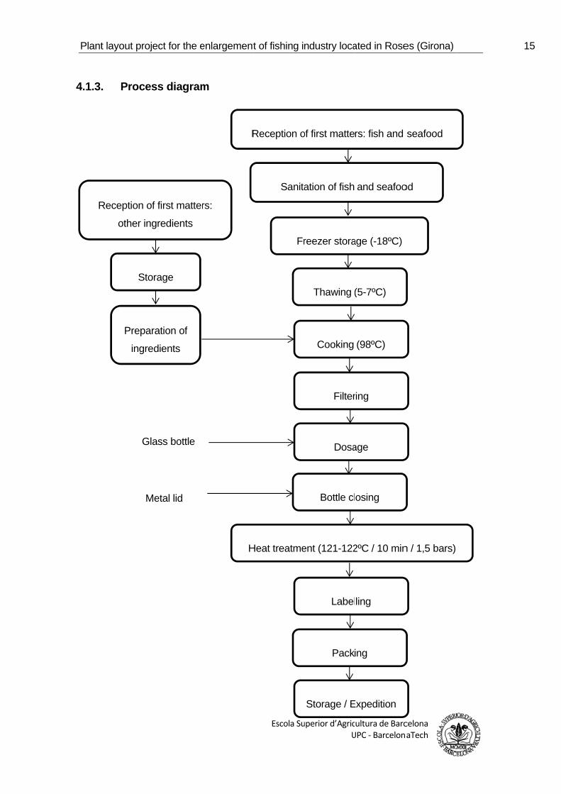
4.1.3.
R
t layout proj
. Proces
Reception of
other ing
Sto
Prepar
ingre
M
Gl
ect for the e
ss diagram
f first matter
gredients
orage
ration of
edients
Metal lid
ass bottle
enlargement
m
rs:
R
H
t of fishing i
Escola Su
Reception o
Sanita
Fr
Heat treatme
ndustry loca
uperior d’AgricU
of first matte
ation of fish
reezer stora
Thawing (
Cooking
Filter
Dosa
Bottle cl
ent (121-122
Label
Pack
Storage / E
ated in Rose
ultura de BarcUPC ‐ Barcelon
rs: fish and
and seafoo
age (-18ºC)
(5-7ºC)
(98ºC)
ring
age
osing
2ºC / 10 min
ling
ing
Expedition
es (Girona)
celona aTech
seafood
od
n / 1,5 bars)
15
16
4.1.4.
4.1.4.
4.1.4
. Machi
.1. Proces
Sanitatio
high pre
and the
Cooking
stainless
sticking
Is also n
cooking
Dosage:
that can
position
power is
Bottle cl
metal lid
maximum
Autoclav
Labelling
the seal
.2. Refrige
All the re
nery
ss machine
on: it uses a
ssure to re
power is 1,8
: it uses a
s steel. The
of products
needed a he
that has a m
it uses an
fill simulta
them below
s 1 kW.
osing: it wil
ds using st
m speed of
ving: is use
g: it will use
guarantee.
eration ma
efrigeration m
ery
a conveyor
move unwa
85 kW.
a cooker w
e inside of
. It has a ca
elical exhau
maximum fl
automatica
aneously be
w each noz
ll use a ma
team press
150 jars pe
ed the autoc
e a machin
Is made of
achinery
machinery is
r roller rotat
anted partic
with agitato
the cookin
apacity of 4
ust system
low of 7560
ally bottle f
etween 2 a
zzle, after
achine that
sure contro
er minute.
clave that th
ne that appl
f stainless s
s described
ting with a s
cles. Dimen
or blades e
ng tank is g
00 L and th
to remove
0 m3/h and t
filling mach
nd 12 bottl
filling the b
closes auto
l. It has a
he company
lies the lab
steel and ha
in Annex IV
sprinkler wa
sions are 3
electric ma
glazed polis
e power is
the gases
he power is
ine made o
es. It move
bottles are
omatically g
power of
y has curren
el and bac
as a power o
V.
ater system
3,5 x 1,5 x 1
nufactured
shed, to pr
22,5 kW.
produced d
s 0,37 kW.
of stainless
es the bottl
evacuated
glass bottles
2,35 kW a
ntly.
ck label and
of 2,6 kW.
m with
1,6 m
from
event
during
steel
les to
. The
s with
and a
d also
Plant
4.2.
Praw
4.2.1.
4.2.2.
t layout proj
Prawn
wn carpaccio
. Raw m
Prawn
. Produ
Receptio
controls.
Sanitatio
system,
Freezer
hours. It
growth o
Thawing
to be ab
overhead
Remova
because
remove t
Filleting:
thinly fille
Adding s
Packagin
are 20 tr
Refrigera
expeditio
ect for the e
carpacc
o is a prepar
matters
n of Roses m
ction proc
on: when pr
. It is import
on of prawn
which will r
storage: th
t is importa
of microorga
g: it will thaw
ble to man
d.
al of rind: i
e there sho
the head an
with the p
eted (2 mm
salt: it adds
ng: trays ar
rays.
ated storag
on.
enlargement
cio
ration on thi
medium-size
cess descr
rawn arrives
tant to know
n: the prawn
remove all t
he prawn fr
ant that the
anisms.
w partially th
ipulate it m
it is a man
ould be no
nd the rind w
prawn’s bod
thick) and
salt in orde
re sealed an
e: finally th
t of fishing i
Escola Su
in slices of p
ed.
ription
s to the ind
w the tempe
n goes thro
he surface
reezes quic
e raw matt
he prawn in
more easily
nual proces
cross cont
with a spec
dy, once wi
then placed
er to preserv
nd placed in
ey bring the
ndustry loca
uperior d’AgricU
prawn of Ro
dustrial plan
erature.
ough a conv
dirt.
ckly to -18º
er freeze q
n a cold roo
and that t
ss. This po
tamination
cial scissors
thout the h
d on trays u
ve the prod
n cardboard
e boxes to a
ated in Rose
ultura de BarcUPC ‐ Barcelon
oses.
nt must pas
veyor with a
C during a
quickly in o
om that us b
the tempera
oint is the
to the prod
.
head and th
up to 120 g
uct.
ds boxes. In
a cold stora
es (Girona)
celona aTech
s several q
a sprinkler w
minimum
order to av
between 5 –
ature was
most impo
duct. It trea
he rind, are
per tray.
n each box
age ready fo
quality
water
of 24
void a
– 7ºC
no to
ortant
ats to
e very
there
or the
17
18
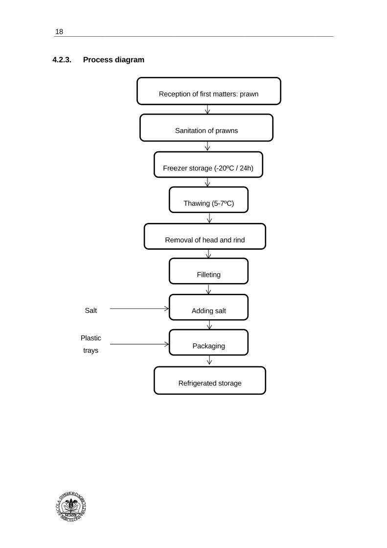
4.2.3.
. Proces
Salt
Plastic
trays
ss diagramm
Rece
Free
Rem
eption of first
Sanitation o
ezer storage
Thawing
Fillet
Packa
Refrigerate
moval of he
Adding
t matters: pr
of prawns
e (-20ºC / 24
(5-7ºC)
ting
aging
ed storage
ead and rind
g salt
rawn
4h)

Plant
4.2.4.
4.2.4.
4.2.4
4.3.
The
treatm
Othe
micro
Anne
HAC
t layout proj
. Machi
.1. Proces
Sanitatio
system w
1,5 x 1,6
Freezer:
steel of 3
Filleting:
These m
product
Packagin
primarily
of 8 kW.
.2. Refrige
All the refr
HACCP
fish broth
ment step, b
erwise the
obiologically
ex VI explain
CCP system
ect for the e
nery
ss machine
on of prawn
with high pr
6 m and the
before free
370 W. It is
it will use
machines c
and it’s mad
ng: for the
y constructe
eration ma
rigeration ma
P
is a very s
but despite t
prawn car
y talking. Th
ned the biol
and finally t
enlargement
ery
n: is used
ressure to r
power is 1
ezer storag
equipped w
a pair of c
consist of a
de of stainle
closing of t
ed in stainle
achinery
achinery is d
safety prod
this, it is imp
rpaccio be
erefore mus
ogical haza
the analysis
t of fishing i
Escola Su
a conveyor
remove unw
,85 kW.
e it will use
with three fa
cutter indus
a conveyor
ess steel.
the trays it
ess steel an
described in
duct becaus
portant to av
ing a raw
st take into a
ards, the hyg
s of raw mat
ndustry loca
uperior d’AgricU
r roller rota
wanted part
e a tunnel o
ans and a p
strial with a
r counts fo
will use a t
nd anodized
n Annex IV.
se in their
void any cro
w product
account the
giene progra
terials used.
ated in Rose
ultura de BarcUPC ‐ Barcelon
ating with a
icles. Dime
f frozen tub
pan for colle
power of
or input an
tray sealer.
d aluminium
production
oss-contamin
is much m
different ris
am of the ind
es (Girona)
celona aTech
a sprinkler w
ensions are
bular of stai
ecting the w
1 kW each
d output o
The Mach
m. It has a p
there is a
nation.
more dang
sks.
dustrial plan
water
3,5 x
inless
aste.
one.
of the
ine is
power
heat
erous
nt, the
19

20
5.
5.1.
5.2.
Engine
Exterio
It is nece
façade w
wall of 3
lacquered
Ceilings:
ceiling is
barrier pa
Furtherm
lacquere
finished w
Walls: th
and conc
lacquere
and 32 k
piece rod
pavemen
Floorin
Continuo
HM-20 c
and sanit
They col
eering
or walls a
essary to fo
will be of se
35 cm of th
d aluminium
the outsid
s plasterbo
aper Kraff.
more there i
d , internal
with anticor
he inside is
crete armed
d internal
kg/m3 of den
d, the same
nt and facilit
ng
ous flooring
oncrete rein
tary accepta
lect water c
works
and ceil
ollow the gu
en concrete
hickness wit
m, placed flu
de of the r
oard ceiling
is a refriger
polisocian
rrosive coat
made of c
d plus a ref
polyisocyan
nsity. All pa
e material a
tate cleanin
of PVC a
nforced with
able not slip
channels AC
ings
uidelines of
e block of w
th seen fini
sh on prefra
roof is wate
with fiber
rator panel
urato PIR i
ting PET.
concrete 20
frigerator pa
nurate PIR
anels will co
as the pan
ng.
dhesive an
h slatted ø
p. With a va
CO concrete
the existen
white colour
shes. The
ames inferio
erproofed w
rglass blank
format of r
nsulation 8
0cm thick re
anel consis
rigid foam
over the bo
el, which w
nd self-leve
5 15x15 typ
apour barrie
e polymer ty
t Building a
r, and a rein
carpentries
orly.
with a kind
ket 80 mm
ribbed stee
0mm thick
einforced ac
ting of 0.5m
insulation
ttom half of
will serve as
lling mortar
pe B500T fo
er.
ype.
and therefor
nforced con
will be of
d DECK. In
m with a va
el sheet 0.5
metal plate
ccording to
mm ribbed
2000 mm
f a prefabri
s delivery t
r. Base is
orming 2%
re the
ncrete
white
nterior
apour
5mm ,
e and
NTE
steel,
thick
cated
to the
20cm
slope

Plant
5.3.
5.4.
5.5.
t layout proj
Doors
Doors w
beating fo
Ventila
The build
system w
Lightin
For more
III. There
ensure su
ect for the e
ill be white
or a vacuum
ation
ding will re
will monitor
ng
detail gene
are lamps I
fficient light
enlargement
lacquered
m force estim
emain heate
the air qual
eral and em
IP45 watert
ting.
t of fishing i
Escola Su
aluminium,
mated 90x21
ed to a tem
lity inside.
ergency lig
tight. There
ndustry loca
uperior d’AgricU
, placed on
15 cm, mad
mperature o
hting install
are fluores
ated in Rose
ultura de BarcUPC ‐ Barcelon
n frame of b
e with profil
of about 15
lation is des
scents of 58
es (Girona)
celona aTech
base with a
les higher p
5ºC, so tha
scribed in A
8 W and 36
a leaf
rice.
at the
Annex
W to
21
22
6.
6.1.
The f
Indus
Scien
This
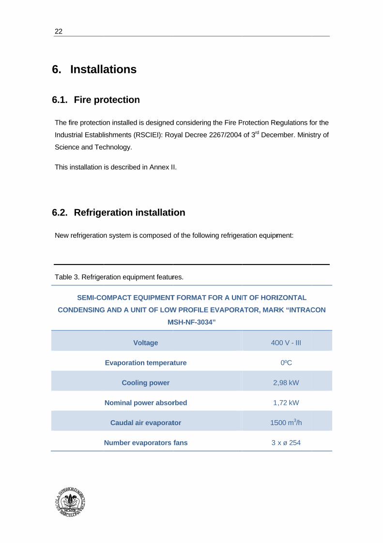
6.2.
New
Table
CON
Installa
Fire pro
fire protectio
strial Establ
nce and Tec
installation
Refrige
refrigeration
e 3. Refrige
SEMI-CO
NDENSING
ations
otection
on installed
ishments (R
chnology.
is described
eration i
n system is
ration equip
OMPACT EQ
G AND A UN
Vo
Evaporatio
Cooli
Nominal po
Caudal a
Number ev
n
is designed
RSCIEI): Ro
d in Annex I
nstallati
composed
pment featur
QUIPMENT
NIT OF LOW
M
oltage
on tempera
ng power
ower absor
air evaporat
vaporators
d considering
oyal Decree
I.
ion
of the follow
res.
T FORMAT
W PROFILE
MSH-NF-303
ature
rbed
tor
fans
g the Fire P
2267/2004
wing refriger
FOR A UNI
E EVAPORA
34”
rotection Re
of 3rd Dece
ration equipm
IT OF HORI
ATOR, MAR
40
2
1
15
3
egulations fo
ember. Minis
ment:
IZONTAL
RK “INTRAC
00 V - III
0ºC
2,98 kW
,72 kW
500 m3/h
x ø 254
or the
stry of
CON
Plant
For m
detai
6.3.
The
insta
The
drop
6.3.1.
The
isolat
t layout proj
Evaporato
Condense
more inform
iled calculat
Electric
company’s
llation acco
installation
may not ex
. Electri
power of th
ted of 1000
ect for the e
Caudal a
or dimensi
er dimensio
Gas r
Ga
mation, see A
tions and ch
cal insta
three-phas
rding to nee
is calculated
xceed 3% fo
ical supply
e industrial
V that goes
enlargement
air condens
ons (length
ons (length
refrigerant
as load
Annex IV of
haracteristics
allation
se power s
eds, with a fr
d tacking in
r light and 5
ying
plant is ma
s to the prote
t of fishing i
Escola Su
ser
h, width, hig
h, width, hig
f the Refrige
s of the equ
supply prov
requency of
nto account
5% for the re
ade using a
ection box a
ndustry loca
uperior d’AgricU
gh)
gh)
eration Insta
ipment to b
vides a vo
f 50 Hz.
that the pe
est of the ins
copper cou
and to the g
ated in Rose
ultura de BarcUPC ‐ Barcelon
15
1650 x 4
925 x 5
R
allation, whe
e used in th
ltage of 23
rcentage of
stallation.
pling with a
eneral distri
es (Girona)
celona aTech
500 m3/h
492 x 200 m
580 x 515 m
R-404A
< 10
ere can see
he installatio
30/400 V to
f the total vo
a voltage no
ibution box.
mm
m
more
on.
o the
oltage
ominal
23
24
6.3.2.
The
switc
differ
and m
The
elem
grou
In An
as th
. Protec
lines have
ches. The
rential switc
machinery.
earth take
ments and th
nded.
nnex V of th
he results.
ctions
protection
installation
hes of sens
es is install
he direct ac
he electrica
against po
also has
sitivity of 30
ed to elim
ction of the
al installatio
ossible surg
protections
mA per ligh
inate the t
differential
n can be fo
ges and sho
s against d
hting and plu
tension tha
protection.
ound all calc
ort circuits
direct and
ugs, and 300
t can pres
Thus, all e
culations pe
by means
indirect co
0 mA for en
sent the me
elements wi
erformed as
MCB
ontact,
ngines
etallic
ll find
s well
Plant
7.
The
occu
of the
There
and a
The
down
The
cove
All te
t layout proj
Health
aim of the
pational risk
e industrial p
e are analys
also the env
legislation u
n the minimu
identified ri
r constructio
erms related
ect for the e
h and S
safety and
ks to be follo
plant.
sed work un
vironment an
used in this
um safety a
isks are the
on and also
d to health a
enlargement
Safety
health stud
owed during
nits, technolo
nd physical
point is the
nd health in
e land mov
the installat
nd safety ar
t of fishing i
Escola Su
dy is to est
g the execut
ogy, work p
conditions.
e Royal De
n constructio
vement and
tion of the e
re explained
ndustry loca
uperior d’AgricU
tablish guid
tion of the re
procedures a
ecree 1627/1
on.
d excavation
electrical and
d in Annex V
ated in Rose
ultura de BarcUPC ‐ Barcelon
delines on t
emodelling a
and organiza
1997 of 24th
ns, the stru
d refrigeratio
VII
es (Girona)
celona aTech
the preventi
and enlarge
ation of the
h October, l
ucture, walls
on systems
ion of
ement
work,
laying
s and
.
25
26
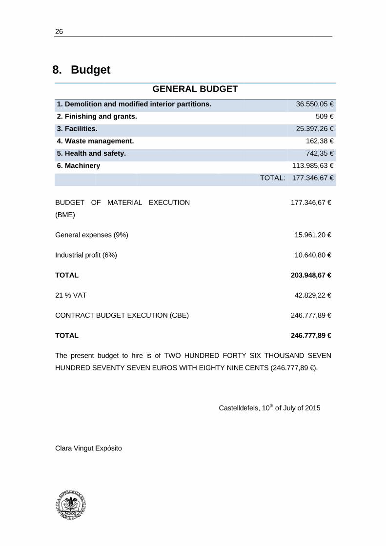
8.
1. D
2. Fi
3. Fa
4. W
5. H
6. M
The
HUN
Clara
BUD
(BME
Gene
Indus
TOTA
21 %
CON
TOTA
Budge
emolition a
inishing an
acilities.
Waste mana
ealth and s
Machinery
present bu
NDRED SEV
a Vingut Exp
DGET OF
E)
eral expense
strial profit (
AL
% VAT
NTRACT BU
AL
et
and modifi
nd grants.
agement.
safety.
udget to hire
VENTY SEV
pósito
MATERIAL
es (9%)
6%)
UDGET EXE
GENE
ed interior
e is of TW
VEN EUROS
L EXECUT
ECUTION (C
ERAL BU
r partitions
WO HUNDR
S WITH EIG
TION
CBE)
UDGET
.
RED FORTY
GHTY NINE
Castellde
TOTA
Y SIX THO
CENTS (24
efels, 10th of
36.55
25.39
16
74
113.98
AL: 177.34
OUSAND SE
46.777,89 €
of July of 201
177.346
15.961
10.640
203.948
42.829
246.777
246.777
0,05 €
509 €
7,26 €
2,38 €
2,35 €
5,63 €
6,67 €
EVEN
).
15
6,67 €
1,20 €
0,80 €
8,67 €
9,22 €
7,89 €
7,89 €

Plant
9.
In
In
IR
s
F
Clara
t layout proj
Financ
n the scena
ndeed, eco
RR is 36%.
some flexibil
For details, g
a Vingut Exp
ect for the e
cial eva
rio of the inv
nomic indic
that means
ity.
go to Annex
pósito
enlargement
aluation
vestment, it
cators are p
that there
x VIII.
t of fishing i
Escola Su
n
is recovere
positive, NP
is a 36% of
ndustry loca
uperior d’AgricU
ed in three ye
PV values o
f readability
Cast
ated in Rose
ultura de BarcUPC ‐ Barcelon
ears.
obtained is 4
y, so it is an
elldefels, 10
es (Girona)
celona aTech
488.267,8 €
n investmen
0th of July of
€ and
nt with
f 2015
27
28
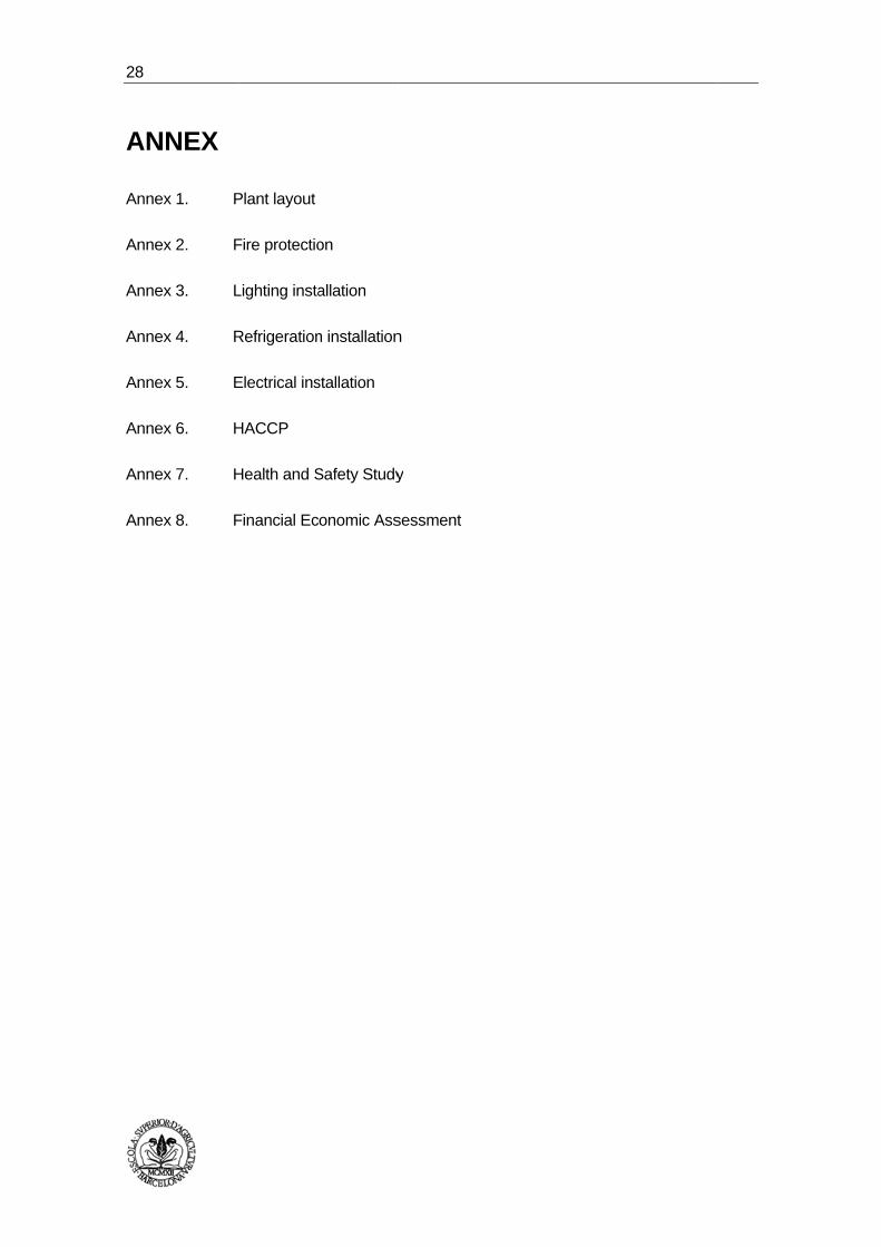
AN
Anne
Anne
Anne
Anne
Anne
Anne
Anne
Anne
NNEX
ex 1. P
ex 2. F
ex 3. L
ex 4. R
ex 5. E
ex 6. H
ex 7. H
ex 8. F
Plant layout
Fire protectio
Lighting insta
Refrigeration
Electrical ins
HACCP
Health and S
Financial Ec
on
allation
n installation
stallation
Safety Study
onomic Ass
n
y
sessment
ANNEX I
Annex I. – Plant Layout
2
ANNEX I. – PLANT LAYOUT
INDEX
1. DESCRIPTION OF AREAS .......................................................................................... 3
2. RELATIONAL TABLE ACTIVITIES ............................................................................. 6
3. RELATIONAL GRAPH ACTIVITIES ............................................................................ 7
4. SURFACE DISTRIBUTION ........................................................................................... 9
Annex I. – Plant Layout
3
1. DESCRIPTION OF AREAS
To do the design of the new plant distribution of this food industry is necessary
analyse operations that may generate risks to consumer health. So have to
identify the zones that are sensitive and the zones that are inert.
Here is shown the different zones of work that also can see schematised in
figures 1 and 2.
Zone 1: Pre-treatment of fish and seafood: in this area is done the
reception of fish and seafood and later becomes the surface cleaning.
Zone 2: Freeze: in this area is done the freezing of fish and seafood in the
freezer at -18ºC.
Zone 3: Defrost: in this area is done the thawing of fish in a cold storage
defrost that has a temperature between 5 – 7ºC.
Zone 4: Production of fish broth / carpaccio: if we talk about fish broth in
this area is done the preparing of the ingredients such as tomato sauce,
red pepper, garlics… but also the cooking at 98ºC, the filtering, the dosing
broth and the closing of glass bottles. On the other hand if we talk about
the carpaccio in this area is done the process of withdrawal of the heat and
rind, the filleting and the salt addition.
Zone 5: Heat treatment: in this area is carried out the heat treatment in
order to sterilize the product.
Zone 6: Packaging: in this area is carried out the labelling of bottles of fish
broth and the packaging of these, along with the packaging trays
carpaccio.
Zone 7: Storage and expedition: in this area is carried out the finished
product storage and the expedition of these.
Zone 8: Reception of other ingredients: in this area is carried out the
reception of other ingredients such as fried tomatoes, red peppers, garlics,
sunflower oil and salt, among others.

Figur
R
8
re 1: fish bro
Reception of
matters: oth
Storage
Preparatio
of
ingredient
4
M
Gla
oth diagram
first
her
on
ts
H5
1
Metal lid
ass bottle
Reception
Sanita
Fr
Heat treatme
S
n of first mat
ation of fish
reezer stora
Thawing (
Cooking
Filter
Dosa
Closu
ent (121-122
Label
Packag
Storage / Ex
tters: fish an
and seafoo
age (-18ºC)
(5-7ºC)
(98ºC)
ring
age
ure
2ºC / 10 min
ling
ging
xpedition
Annex
nd seafood
od
n / 1,5 bars)
6
7
2
3
x I. – Plant LLayout
4
Inert
Sens
zo
zone
sitive
ne
Figurre 2: prawn
S
1
2
4
7
3
Plastic tra
carpaccio d
Re
F
Re
Salt
ays
diagram
eception of f
Sanitatio
Freezer stora
Thawi
Fi
Pac
frigerated st
Removal o
Add
first matters
on of prawns
age (-20ºC /
ing (5-7ºC)
illeting
ckaging
torage / Exp
of head and
ding salt
: prawn
s
/ 24h)
pedition
rind
Annex
6
x I. – Plant LLayout
5
Inert z
Sensit
zone
one
ive
e

1
2
3 4 5
6
7 8
2. RELA
Once
of pr
proxi
That
letter
reaso
In thi
objec
muss
Figure 3.
REAS
Proximity in
Hyg
CoC
Bad sme
Produc
Common usAcces
ATIONAL T
e defined un
roduction, i
imity betwe
is why we
rs are used
ons.
is case, we
ctive of this
sels product
. Relational
SON
n the process
giene
ontrol Cold
lls, noise…
ct safety
se of materiassibility
TABLE ACT
nit operation
t is necess
en them to
make a re
to indicate
have includ
s project su
tion zone.
table activit
s A
E
I OU
X
al
TIVITIES
ns and areas
sary to est
o place them
elational tab
e the import
ded other p
uch as office
ties.
PROXIM
Absolutely
Especially
ImpoLittle imUnimp
Undes
s will be dev
ablish the
m properly o
le of activiti
ance of pro
arts of the p
es, wardrob
MITY
necessary
important
ortant mportant portant
sirable
Annex
veloped, tha
degree of
on the surfa
ies (figure 3
oximity and
plant that ar
bes, laborat
ASSOC
x I. – Plant L
at is direct m
relationship
face of the
3) whereas
numbers to
re not part o
tory, kitchen
CIATE COLO
Red
Yellow
Green Blue Black
Brown
Layout
6
means
p and
plant.
code
o give
of the
n and
OUR

Annex I. – Plant Layout
7
3. RELATIONAL GRAPH ACTIVITIES
Once done the relational table of activities, the activities relational diagram is
created. This diagram will establish a first spatial arrangement of zones
according to the degree of proximity that must exist between them.
First, the areas that have more type A are arranged in the central position of
the scheme, and then put around the other areas depending on the type of
relationship it has with each other. It will start with the type relation A between
the different zones and then continue with the type E, I, O, U and X.
The zones are represented by squares, within which we will put the number
that it represents. The relationships between areas are represented by lines,
so that the more important the relationship is between them, it will have more
lines. In order to make more understandable diagram, we omit to put the lines
in the relations U and X.
In this way, the relationship is represented:
A
E
I
O
U
X
Annex I. – Plant Layout
8
Thus the relationship diagram activities of this industry are as follows image 4:
Image 4. Relational activities graph.
1 8
13
12
11
10
9
2
3
7 6 5 4
Annex I. – Plant Layout
9
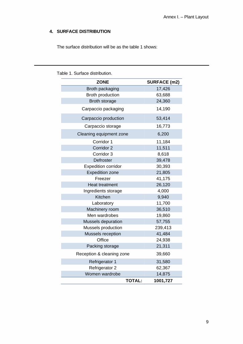
4. SURFACE DISTRIBUTION
The surface distribution will be as the table 1 shows:
Table 1. Surface distribution.
ZONE SURFACE (m2)
Broth packaging 17,426 Broth production 63,688
Broth storage 24,360
Carpaccio packaging 14,190
Carpaccio production 53,414
Carpaccio storage 16,773
Cleaning equipment zone 6,200
Corridor 1 11,184 Corridor 2 11,511 Corridor 3 8,618 Defroster 39,478
Expedition corridor 30,393 Expedition zone 21,805
Freezer 41,175 Heat treatment 26,120
Ingredients storage 4,000 Kitchen 9,940
Laboratory 11,700 Machinery room 36,510 Men wardrobes 19,860
Mussels depuration 57,755 Mussels production 239,413 Mussels reception 41,484
Office 24,938 Packing storage 21,311
Reception & cleaning zone 39,660
Refrigerator 1 31,580 Refrigerator 2 62,367
Women wardrobe 14,875
TOTAL: 1001,727

Imag
To fa
adde
direc
final
for th
Acco
ge 5. Final d
acilitate the
ed two corrid
ction of the
product. Th
he carpaccio
ording to the
istribution.
distribution
dors: one o
dispatch ar
he other cor
o production
ese final dist
of the plan
of them runs
rea making
rridor leads
n area.
tribution plan
nt and contro
s through th
more acce
into the ar
n is as follow
Annex
ol cross con
he middle of
essible the e
ea that has
ws in the im
x I. – Plant L
ntamination
of the plant
expedition o
s been expa
mage 5:
Layout
10
were
in the
of the
anded
ANNEX II
Annex II. – Fire protection installation
2
ANNEX II. – FIRE PROTECTION INSTALLATION
INDEX
1. OBJET ................................................................................................................................. 3
2. REGULATIONS .................................................................................................................. 3
2.1. STATE .............................................................................................................................. 3
2.2. REGIONAL ...................................................................................................................... 3
3. CHARACTERIZATION OF THE ESTABLISHMENT ................................................... 3
4. CALCULATION OF THE FIRE LOAD. DETERMINATION OF THE LEVEL OF THE INTRINSIC RISK. .............................................................................................................. 4
5. PASSIVE MEASURES ...................................................................................................... 6
5.1. MATERIAL .................................................................................................................. 6
5.2. EVACUATION OF THE INDUSTRIAL ESTABLISHMENT ................................ 6
5.3. VENTILATION AND ELIMINATION OF SMOKES AND GASES OF THE COMBUSTION IN THE INDUSTRIAL BUILDINGS ......................................................... 7
5.4. STORAGE ................................................................................................................... 7
6. ACTIVE MEASURES ........................................................................................................ 8
6.1. MANUAL FIRE ALARM SYSTEM .......................................................................... 8
6.2. FIRE EXTINGUISHERS ............................................................................................ 8
6.3. FIXED FIREFIGHTING SYSTEM ............................................................................ 8
6.4. EMERGENCY LIGHTING SYSTEM ....................................................................... 9

Annex II. – Fire protection installation
3
1. OBJET
The purpose of this document is the technical justification of the fire protection
measures taken that affects to a closed industrial plant 1001,72 m2 dedicated to the
marketing and distribution of fresh fish, the production of fish broth and the
production of fish carpaccio.
2. REGULATIONS
2.1. STATE
- Fire Protection Regulations for the Industrial Establishments (RSCIEI):
Royal Decree 2267/2004 of 3rd December. Ministry of Science and
Technology.
- Royal Decree 1942/1993, of 5th November, whereby the Regulations on fire
protection facilities (RIPCI) is approved. Ministry of Industry and
Engineering.
- C.T.E. Basic Safety Document in case of fire.
2.2. REGIONAL
- Law 3/2010 of 18 February about prevention and safety system fires on
establishments and activity, infraestructura and buildings.
- ORDER INT/322/2012, of 11 October for approving the supplementary
technical instructions, Fire Protection Regulations in industrial
establishments (RSCIEI).
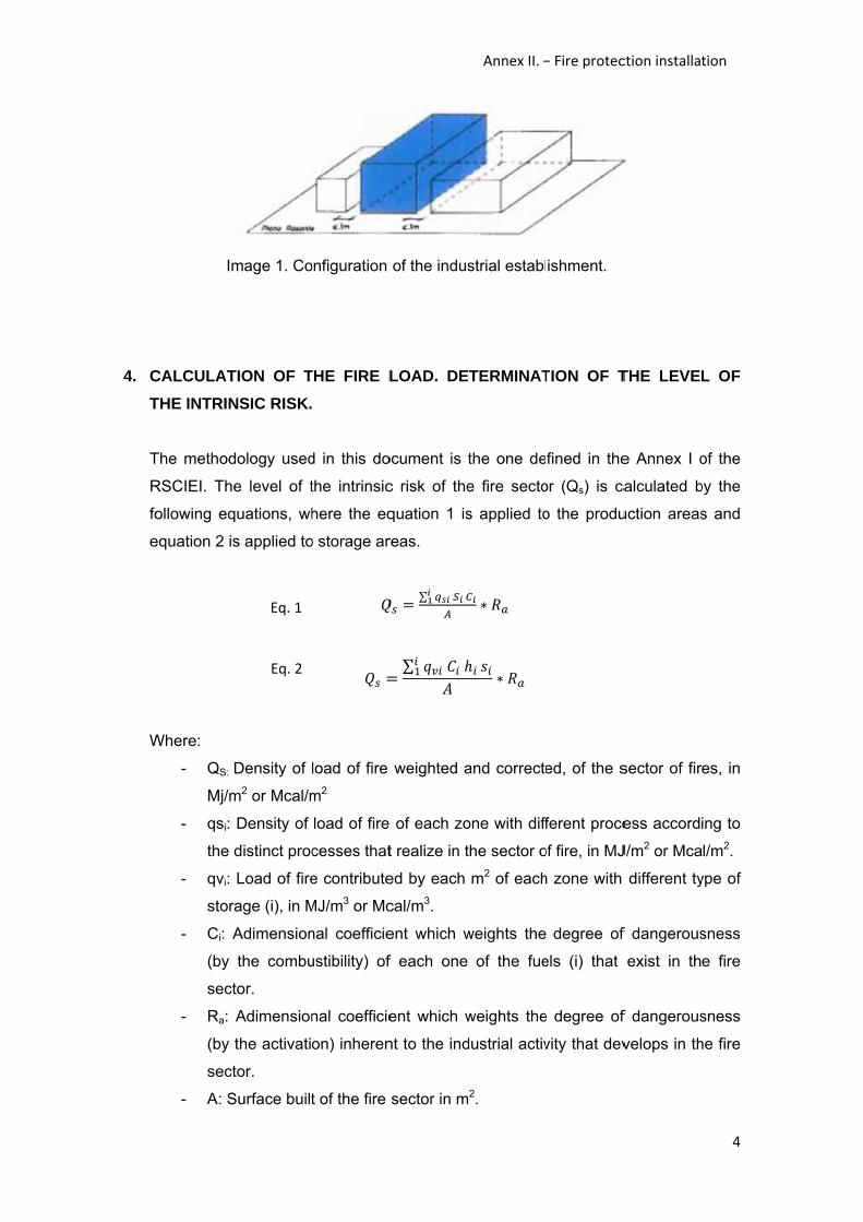
3. CHARACTERIZATION OF THE ESTABLISHMENT
According to the classification of the Annex I of the RSCIEI, the building is an
industrial establishment type B, as shown in picture 1, because the industrial
establishment entirely occupies a building that is attached to another building.
4. C
T
T
R
fo
e
W
Im
CALCULAT
THE INTRIN
The method
RSCIEI. The
ollowing eq
equation 2 is
Where:
- QS:
Mj/m
- qsi:
the
- qvi:
stor
- Ci: A
(by
sect
- Ra:
(by
sect
- A: S
mage 1. Co
TION OF T
NSIC RISK.
dology used
e level of t
quations, wh
s applied to
Density of
m2 or Mcal/m
Density of
distinct proc
Load of fire
age (i), in M
Adimension
the combu
tor.
Adimension
the activati
tor.
Surface built
Eq. 2
Eq. 1
onfiguration
THE FIRE L
d in this do
the intrinsic
here the eq
o storage ar
load of fire
m2
load of fire
cesses that
e contribute
MJ/m3 or Mc
nal coefficie
ustibility) of
nal coefficie
on) inheren
t of the fire
of the indus
LOAD. DE
ocument is
c risk of the
quation 1 is
reas.
∑ ∑
weighted a
of each zo
t realize in t
ed by each
cal/m3.
ent which w
f each one
ent which w
nt to the ind
sector in m
Annex II. –
strial establ
TERMINAT
the one de
e fire secto
s applied to
∗
∗
and correcte
one with diff
the sector o
m2 of each
weights the
of the fue
weights the
dustrial activ
2.
– Fire protec
ishment.
TION OF T
fined in the
or (Qs) is ca
o the produ
ed, of the s
ferent proce
of fire, in MJ
h zone with
degree of
els (i) that
e degree of
vity that dev
ction installat
THE LEVEL
e Annex I o
alculated b
uction areas
sector of fir
ess accordi
J/m2 or Mca
different ty
f dangerous
exist in th
f dangerous
velops in th
tion
4
L OF
of the
by the
s and
es, in
ing to
l/m2.
ype of
sness
e fire
sness
he fire

Annex II. – Fire protection installation
5
- Si: Surface of each zone with different process and density of load of fire, in
m2.
- hi: Height of the storage of each one of the fuels, in m.
- si: Occupied surface in plant by each zone with different type of storage, in
m2.
In accordance with the table 1.3 of the Annex I on the RSCIEI and attending to the
calculations that justify in the table 1, the density of load of fire weighted and
corrected is 1204,9 MJ/m2, which corresponds to a intrinsic risk level MEDIUM-3
because 850 < QS ≤ 1275 (MJ/m2).
Tabla 1: Justification of fire load.
ACTIVITY
PRODUCTION STORAGE
m² qs
MJ Ra Ci MJ m³ qv
MJ Ra Ci MJ MJ/m² (1) MJ/mᵌ (1)
Packing 31,6 800 25294 1,5 1,3 49324 68,2 800 54554 1,5 1,3 106380 Expedition 21,8 1000 21805 2 1,3 56693
Raw materials 90,8 3400 308557 2 1 617114 Production zone 198,2 200 39648 1 1 39648
Offices 24,9 600 14963 1 1 14963Cold stores and
freezer 612,4 300 183715 1 1,3 238830
Toilets, wardrobes and
corridors 96,4 80 7715 1 1 7715
Laboratory 11,7 200 2340 1 1 2340Storage cleaning
products 369,7 200 73948 1 1 73948
(1) Table 1.2 Annex I RSCIEI. Food, technical office, machinery and drug-storage.
TOTAL AREA m²: 1001,72
TOTAL MJ: 1206953,5MJ/m² 1204,9
Annex II. – Fire protection installation
6
5. PASSIVE MEASURES
According to table 2.1 of the Annex II on the RSCIEI and since the intrinsic risk leve
is MEDIUM-3, the maximum surface built for each fire sector is 3500 m2.
5.1. MATERIAL
Materials coating or Surface finishes should be CFL-s1 (M2) or more favourable
and walls and ceilings should be C-s3 d0 (M2) or more favourable. It has been
proven existing coating materials and meets these characteristics.
Knew that the intrinsic risk level of the plant is medium, and the establishment is
type B: the stability of the structural elements in front the fire (pillars and cover)
has to be R 90 as shown in table 2.2 of the Annex II of RSCIEI. It is important to
know that the existing structural elements comply with the condition.
.
The fire resistance of enclosing structural elements without supporting role,
complying with the characteristics explained above will be EI 180.
As it treats of an establishment with a B configuration, exist a constructive
element partitioning the neighbouring establishment that tackles to the cover,
therefore the resistance to the fire of this element will be EI 90 in a strip whose
width is equal to 1 m and it will be fixed to the roof structure.
5.2. EVACUATION OF THE INDUSTRIAL ESTABLISHMENT
For the implementation of the requirements relating to the evacuation of the
industrial establishment, it is necessary to estimate on occupation, P, derived
from the following expression where “p” is the number of employees:
P = 1,10 p when p<100 1,10*40= 44
Knowing that the industrial plant has more than one exit, the length of the
evacuation routes until some exit does not exceed 50 m.
o Dimensioning of the evacuation elements:
The doors shall not be less than 0,80 m wide.
Annex II. – Fire protection installation
7
The corridors and ramps where is foreseen the use of cars to
transport products will have an equal or upper width 1,80 m, but
if it is not foreseen the use of cars to transport products the
width will be 1,40 m.
o Signalling:
The exits of the plant shall have a sign with the entitle “EXIT”
and will have indicatives signals of the direction of the
evacuation routes, visible from all origin of evacuation. In case
that exist alternative routes that can induce to error as they can
be doors that are not exit will be have a signal with the entitle
“No Exit”,
The signals have to be visible even in case of failure in the
lighting subminist, therefore has to be photo luminescent.
Means of fire protection with manual use are signalled by
signals defined in UNE 23003-1 with a size of 595 x 495 mm.
5.3. VENTILATION AND ELIMINATION OF SMOKES AND GASES OF THE
COMBUSTION IN THE INDUSTRIAL BUILDINGS
Fort the evacuation of smokes and gases of the combustion, and with them, the
heat generated in the zone of production, will apply a minimum of aerodynamic
Surface of 0,5 m2/100m2 and for the storage zone will apply a minimum of
aerodynamic Surface of 0,5m2/100m2.
The ventilation will be natural and for this the gap will be in the high part of the
façade, but also in addition to gaps for the entrance of air in the low part of the
sector.
5.4. STORAGE
It will use a system of independent storage, therefore, the materials of the
structure have to be of class A1 steel and painted coating with thicknesses less
than 100μ must be the Bs3d0 class and also must be non-flammable.
Annex II. – Fire protection installation
8
6. ACTIVE MEASURES
6.1. MANUAL FIRE ALARM SYSTEM
Due to the fact that it does not require the installation of automatic systems of
fire detection according to the section 3.1 of the Annex III of the RSCIEI, will
install a manual fire alarm system.
This system will consist by a group of buttons that allow transmitting a signal to
a central control and signalling for the area that has been activated the button.
It will be installed in the fire section in vertical parameters as pillars or walls.
6.2. FIRE EXTINGUISHERS
Considering a load fire of medium will install portable fire extinguishers of CO2
with a minimum efficiency 21A-113B, in accordance with the table 3.1 of the
Annex III of the RSCIEI. We will install fire extinguishers each 15 m, of this way
will be a total of 12. Two of them will be of CO2 and will be placed around
electrical panels and office; the rest will be of multipurpose powder.
It has to be easily visible and accessible, besides have to be situated near of
the points where foresees a greater probability of fire.
6.3. FIXED FIREFIGHTING SYSTEM
As it is a type B building, its intrinsic risk level is medium and the total plant
area is 1001,76 m2, two fixed firefighting of 25 m will be installed next to the
main doors. In this way all the plant is covered.
According to article 9.2 of Annex III, a fixed firefighting system type DN 25 mm
will be installed with simultaneity of 2 and an autonomy time of 60 minutes.
Annex II. – Fire protection installation
9
6.4. EMERGENCY LIGHTING SYSTEM
An emergency lighting system will be installed in compliance with the article 16
of Annex III of RSCIEI.
- Conditions:
o It will be fixed, will be foreseen of own source of energy and will
light automatically when producing a failure of 70% of his nominal
tension of services.
o It will keep the conditions of service during 1 hour, minimum, from
the moment in that it produce the failure.
o It will provide a luminance of 1 lx, minimum, in the level of the floor
in the routes of evacuation.
o The luminance will be 5 lx minimum in the space where are installed
boxes, controls centre or technical installations.
o Uniformity of illumination provided at various points of each zone is
such that the ratio between the maximum and minimum and it has
to be less than 40.
o The levels of illumination establishment should be obtained
considering null the reflection factor of walls and ceiling and
contemplating a factor maintenance that comprise the reduction of
the luminous performance due to aging of lamps and dirt on
luminaries.

ANNEX III
Annex III. – Lighting Installation
2
ANNEX III. – LIGHTING INSTALLATION
1. DESIGN CONDITIONINGS .............................................................................................. 3
2. CALCULATION PROCEDURE ....................................................................................... 3
3. LIGHTING CALCULATION .............................................................................................. 5
3.1. GENERAL LIGHTING ............................................................................................... 5
3.2. EMERGENCY LIGHTING ......................................................................................... 7

Annex III. – Lighting Installation
3
1. DESIGN CONDITIONINGS The intensity of the lighting in the work rooms (reception and cleaning zone, broth production, heat treatment, broth packaging zone, carpaccio production, carpaccio packaging zone and expedition zone) it will be not less than 300 lux,it will have fluorescent with diffusing screen sealed to prevent contamination of food in case of breakage (IP-44minimum). In the other areas (freezer, defroster, broth storage, packaging storage, carpaccio storage, ingredient storage, cleaning equipment zone and corridors) lighting will be 200 lux maximum. (IP-44 minimum). All luminarias will be fluorescent with a power of 58 W except in the corridors, in the cleaning equipment zone and in the ingredient storage that it will be a power of 36 W. Emergency lighting will be situated near of the doors, to facilitate the visualisation of the exits in case of emergency. The lights of emergency are of 5 lux each one with an hour of autonomy and a power of 8 W each one. It has a IP-65 and an illumination of 240 lm.
- Legrand series NT65, IP65 class I, 240 lm and a power of 8 W.
2. CALCULATION PROCEDURE To determinate the number of lamps it is necessary to know the dimensions and the lighting level of each zone. So, for doing we will use the following expressions: Localrate(K):K = ∗ℎ( + ) Localflow(Ф):Ф = ∗∗
Lampsnumber = ФФ
a i b: zone dimensions (m).
h: distance between the light and the work plane (m).
Ф: local flow (lumen).
L: lighting level (lux).
S: Surface.
u: utilization factor.
m: maintenance coefficient.
Ф: local flow (lumen).
ФL: lamp flow (lumen).
Figure.1account
Figure 1
To find tlamps thand floor Walls of
- -
Figure 2.
indicates the photom
. Maintenan
the utilizatiohat are usedr. Figure 2 s
industrial pThe ceiliThe wall
Utilization fa
the apprometric chara
nce factor.
on factor had in each zoshows how
plant shouldng reflectios reflection
actor.
opriate maacteristics of
as to take ione and thethese value
d be light con percentagpercentage
Annex III
intenance f the lamps.
nto accoune reflection pes are.
loured and ge is 75%.e is 50%.
. – Lighting
factor valu.
t the local percentage
rough grou
Installation
ues, taking
index found on walls, c
und; thus:
n
4
g into
d, the ceiling
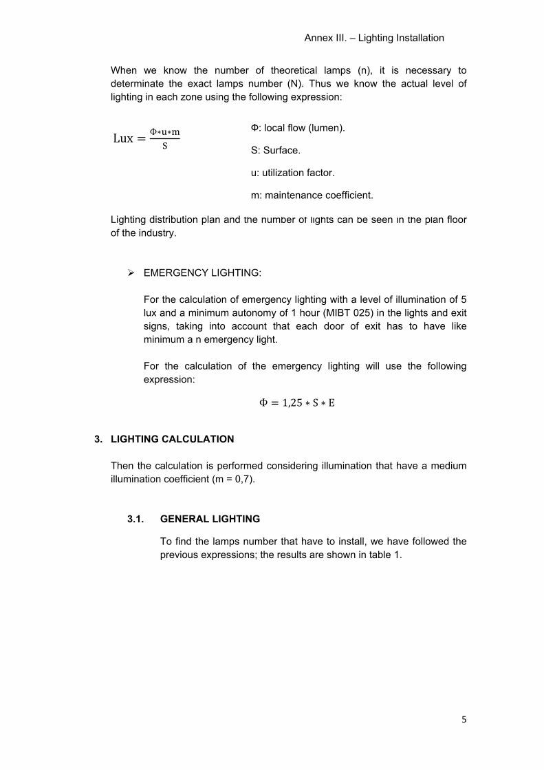
Annex III. – Lighting Installation
5
When we know the number of theoretical lamps (n), it is necessary to determinate the exact lamps number (N). Thus we know the actual level of lighting in each zone using the following expression:
Lux = Ф∗ ∗
Lighting distribution plan and the number of lights can be seen in the plan floor of the industry. EMERGENCY LIGHTING:
For the calculation of emergency lighting with a level of illumination of 5 lux and a minimum autonomy of 1 hour (MIBT 025) in the lights and exit signs, taking into account that each door of exit has to have like minimum a n emergency light. For the calculation of the emergency lighting will use the following expression: Ф = 1,25 ∗ S ∗ E
3. LIGHTING CALCULATION
Then the calculation is performed considering illumination that have a medium illumination coefficient (m = 0,7).
3.1. GENERAL LIGHTING
To find the lamps number that have to install, we have followed the previous expressions; the results are shown in table 1.
Ф: local flow (lumen).
S: Surface.
u: utilization factor.
m: maintenance coefficient.
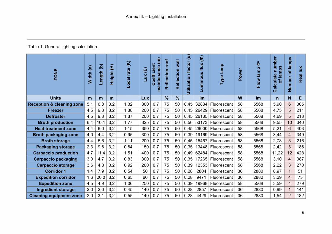
Annex III. – Lighting Installation
6
Table 1. General lighting calculation.
ZO
NE
Wid
th (
a)
Len
gth
(b
)
Hei
gh
t (H
)
Lo
cal r
ate
(K)
Lu
x (E
)
Co
effi
cien
t m
ain
ten
ance
(m
)
Ref
lect
ion
ro
of
Ref
lect
ion
wal
l
Uti
lizat
ion
fac
tor
(u)
Lu
min
ou
s fl
ux
(Ф)
Typ
e la
mp
Po
wer
Flo
w la
mp
Фᶫ
Cal
cula
te n
um
ber
o
f la
mp
s
Nu
mb
er o
f la
mp
s
Rea
l lu
x
Units m m m Lux % % lm W lm n N E
Reception & cleaning zone 5,1 6,8 3,2 1,32 300 0,7 75 50 0,45 32834 Fluorescent 58 5568 5,90 6 305
Freezer 4,5 9,3 3,2 1,38 200 0,7 75 50 0,45 26429 Fluorescent 58 5568 4,75 5 211
Defroster 4,5 9,3 3,2 1,37 200 0,7 75 50 0,45 26135 Fluorescent 58 5568 4,69 5 213
Broth production 6,4 10,1 3,2 1,77 325 0,7 75 50 0,56 53173 Fluorescent 58 5568 9,55 10 340
Heat treatment zone 4,4 6,0 3,2 1,15 350 0,7 75 50 0,45 29000 Fluorescent 58 5568 5,21 6 403
Broth packaging zone 4,0 4,4 3,2 0,95 300 0,7 75 50 0,39 19169 Fluorescent 58 5568 3,44 4 349
Broth storage 4,4 5,6 3,2 1,11 200 0,7 75 50 0,45 15467 Fluorescent 58 5568 2,78 3 216
Packaging storage 2,3 9,6 3,2 0,84 150 0,7 75 50 0,35 13448 Fluorescent 58 5568 2,42 3 186
Carpaccio production 4,7 11,4 3,2 1,51 400 0,7 75 50 0,49 62484 Fluorescent 58 5568 11,22 12 428
Carpaccio packaging 3,0 4,7 3,2 0,83 300 0,7 75 50 0,35 17265 Fluorescent 58 5568 3,10 4 387
Carpaccio storage 3,6 4,8 3,2 0,92 200 0,7 75 50 0,39 12353 Fluorescent 58 5568 2,22 3 270
Corridor 1 1,4 7,9 3,2 0,54 50 0,7 75 50 0,28 2804 Fluorescent 36 2880 0,97 1 51
Expedition corridor 1,6 20,0 3,2 0,65 60 0,7 75 50 0,28 9471 Fluorescent 36 2880 3,29 4 73
Expedition zone 4,5 4,9 3,2 1,06 250 0,7 75 50 0,39 19968 Fluorescent 58 5568 3,59 4 279
Ingredient storage 2,0 2,0 3,2 0,45 140 0,7 75 50 0,28 2857 Fluorescent 36 2880 0,99 1 141
Cleaning equipment zone 2,0 3,1 3,2 0,55 140 0,7 75 50 0,28 4429 Fluorescent 36 2880 1,54 2 182
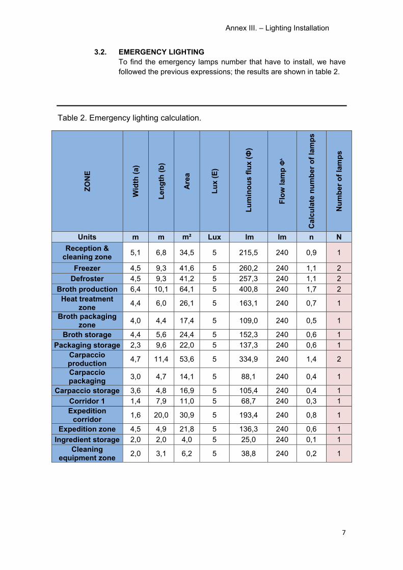
Annex III. – Lighting Installation
7
3.2. EMERGENCY LIGHTING To find the emergency lamps number that have to install, we have followed the previous expressions; the results are shown in table 2.
Table 2. Emergency lighting calculation.
ZO
NE
Wid
th (
a)
Len
gth
(b
)
Are
a
Lu
x (E
)
Lu
min
ou
s fl
ux
(Ф)
Flo
w la
mp
Фᶫ
Cal
cula
te n
um
ber
of
lam
ps
Nu
mb
er o
f la
mp
s
Units m m m² Lux lm lm n N
Reception & cleaning zone
5,1 6,8 34,5 5 215,5 240 0,9 1
Freezer 4,5 9,3 41,6 5 260,2 240 1,1 2
Defroster 4,5 9,3 41,2 5 257,3 240 1,1 2
Broth production 6,4 10,1 64,1 5 400,8 240 1,7 2 Heat treatment
zone 4,4 6,0 26,1 5 163,1 240 0,7 1
Broth packaging zone
4,0 4,4 17,4 5 109,0 240 0,5 1
Broth storage 4,4 5,6 24,4 5 152,3 240 0,6 1
Packaging storage 2,3 9,6 22,0 5 137,3 240 0,6 1 Carpaccio production
4,7 11,4 53,6 5 334,9 240 1,4 2
Carpaccio packaging
3,0 4,7 14,1 5 88,1 240 0,4 1
Carpaccio storage 3,6 4,8 16,9 5 105,4 240 0,4 1
Corridor 1 1,4 7,9 11,0 5 68,7 240 0,3 1 Expedition
corridor 1,6 20,0 30,9 5 193,4 240 0,8 1
Expedition zone 4,5 4,9 21,8 5 136,3 240 0,6 1
Ingredient storage 2,0 2,0 4,0 5 25,0 240 0,1 1 Cleaning
equipment zone 2,0 3,1 6,2 5 38,8 240 0,2 1

ANNEX IV

Annex IV.- Refrigeration Installation
2
ANNEX IV.- REFRIGERATION INSTALLATION
INDEX
1. OBJECT ............................................................................................................................... 3
2. REGULATIONS .................................................................................................................. 3
3. COLD STORAGE FEATURES ........................................................................................ 3
3.1. DIMENSIONS ............................................................................................................. 3
3.2. OPERATION CONDITIONS ..................................................................................... 3
4. COOLANT CLASSIFICATION ........................................................................................ 5
4.1. T.E.W.I. CALCULATION .......................................................................................... 5
5. THERMAL LOAD CALCULATION ................................................................................. 7
5.1. CONDUCTION HEAT GAINS .................................................................................. 7
5.2. INFILTRATION COOLING LOAD ........................................................................... 8
5.3. SENSIBLE COOLING LOADS ................................................................................ 9
5.4. HEAT PERSONS ....................................................................................................... 9
5.5. ANCILLARY COOLING LOADS ............................................................................. 9
5.6. SUMMARY OF ALL POWERS .............................................................................. 10
6. CHECK AND JUSTIFICATION FOR LOSSES BY RSIF. CALCULATION OF THE MAXIMUM LOAD COOLANT ................................................................................................ 11
6.1. JUSTIFICATION OF THE CHAMBER AND TESTING FOR LOSSES RSIF 11
6.2. CALCULATION OF THE MAXIMUM LOAD OF REFRIGERANT ................... 11
7. COLD PARAMETERS CALCULATION ....................................................................... 13
8. PIPES CALCULATION ................................................................................................... 15
9. REFRIGERATION EQUIPMENT ................................................................................... 17
Annex IV.- Refrigeration Installation
3
1. OBJECT
Currently in the area where we are doing the remodelling there are two
freezers. So the aim of this document is to leave a freezer as such but
reduce it in size, that it will be the freezer storage of raw materials. The
other freezer will become in a refrigerator to use for thawing raw materials.
Finally there is going to make a new cold storage to store the final product
carpaccio.
2. REGULATIONS
- Royal Decree 138/2011, of 4 February, approving the Safety
Regulations of Refrigeration Installations and their complementary
technical instruction (RSIF).
3. COLD STORAGE FEATURES
3.1. DIMENSIONS
The dimensions on the cold rooms are:
- Freezer: 9,25 m de long, 4,5 m wide and 3,2 m high; with a volume
of 133,2 m3.
- Defroster: 9,25 m de long, 4,45 m wide and 3,2 m high; with a
volume of 131,72 m3.
- Carpaccio storage: 4,75 m de long, 3,55 m wide and 3,2 m high;
with a volume of 53,96 m3.
3.2. OPERATION CONDITIONS
Then, in tables 1, 2 and 3, that are the conditions and technical data
necessary for the dimensioning of thermal equipment required:
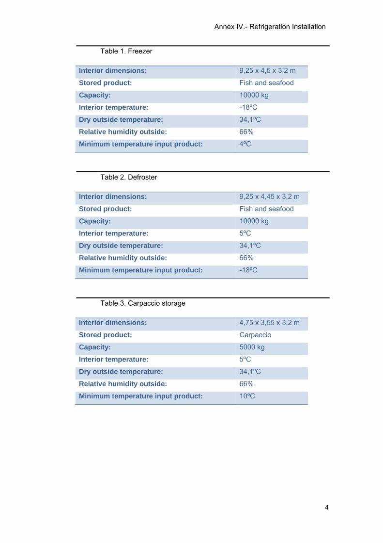
Annex IV.- Refrigeration Installation
4
Table 1. Freezer
Interior dimensions: 9,25 x 4,5 x 3,2 m
Stored product: Fish and seafood
Capacity: 10000 kg
Interior temperature: -18ºC
Dry outside temperature: 34,1ºC
Relative humidity outside: 66%
Minimum temperature input product: 4ºC
Table 2. Defroster
Interior dimensions: 9,25 x 4,45 x 3,2 m
Stored product: Fish and seafood
Capacity: 10000 kg
Interior temperature: 5ºC
Dry outside temperature: 34,1ºC
Relative humidity outside: 66%
Minimum temperature input product: -18ºC
Table 3. Carpaccio storage
Interior dimensions: 4,75 x 3,55 x 3,2 m
Stored product: Carpaccio
Capacity: 5000 kg
Interior temperature: 5ºC
Dry outside temperature: 34,1ºC
Relative humidity outside: 66%
Minimum temperature input product: 10ºC
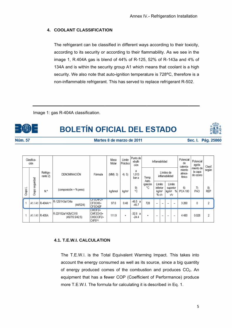
Imag
4. COO
The
acco
imag
134A
secu
non-
ge 1: gas R-
4.1. T
T
a
o
e
m
OLANT CLA
refrigerant
ording to its
ge 1, R.404A
A and is with
rity. We als
inflammable
-404A class
T.E.W.I. CA
The T.E.W.I
account the
of energy p
equipment t
more T.E.W
ASSIFICAT
can be clas
security or
A gas is ble
hin the secu
so note that
e refrigeran
sification.
ALCULATIO
I. is the To
energy con
roduced co
hat has a f
.I. The form
ION
ssified in dif
r according
end of 44%
urity group
t auto-ignitio
nt. This has
ON
otal Equiva
nsumed as
omes of the
fewer COP
mula for calc
Annex IV
fferent ways
to their flam
% of R-125,
A1 which m
on temperat
served to re
lent Warmi
well as its s
e combusti
(Coefficien
culating it is
V.- Refrigera
s according
mmability. A
52% of R-
means that c
ture is 728º
eplace refri
ng Impact.
source, sinc
on and pro
nt of Perform
described
ation Installa
g to their tox
As we see i
-143a and 4
coolant is a
ºC, therefor
gerant R-50
This takes
ce a big qu
oduces CO
mance) pro
in Eq. 1.
ation
5
xicity,
in the
4% of
a high
re is a
02.
s into
antity
O2. An
oduce
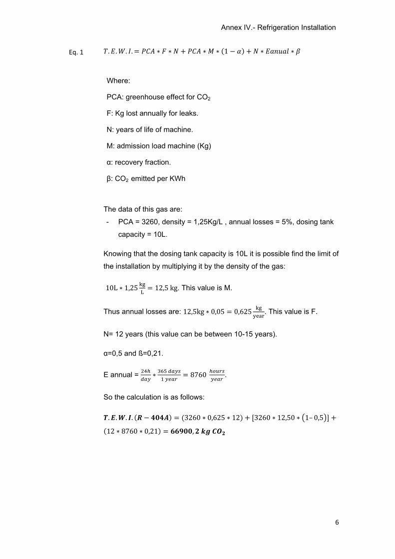
Annex IV.- Refrigeration Installation
6
. . . . = ∗ ∗ + ∗ ∗ (1 − ) + ∗ ∗
The data of this gas are:
- PCA = 3260, density = 1,25Kg/L , annual losses = 5%, dosing tank
capacity = 10L.
Knowing that the dosing tank capacity is 10L it is possible find the limit of
the installation by multiplying it by the density of the gas:
10L ∗ 1,25 = 12,5kg. This value is M.
Thus annual losses are: 12,5kg ∗ 0,05 = 0,625 . This value is F.
N= 12 years (this value can be between 10-15 years).
α=0,5 and ß=0,21.
E annual = ∗ = 8760 .
So the calculation is as follows:
. . . . ( − ) = (3260 ∗ 0,625 ∗ 12) + [3260 ∗ 12,50 ∗ 1– 0,5 ] +(12 ∗ 8760 ∗ 0,21) = ,
Where:
PCA: greenhouse effect for CO2
F: Kg lost annually for leaks.
N: years of life of machine.
M: admission load machine (Kg)
α: recovery fraction.
β: CO2 emitted per KWh
Eq. 1
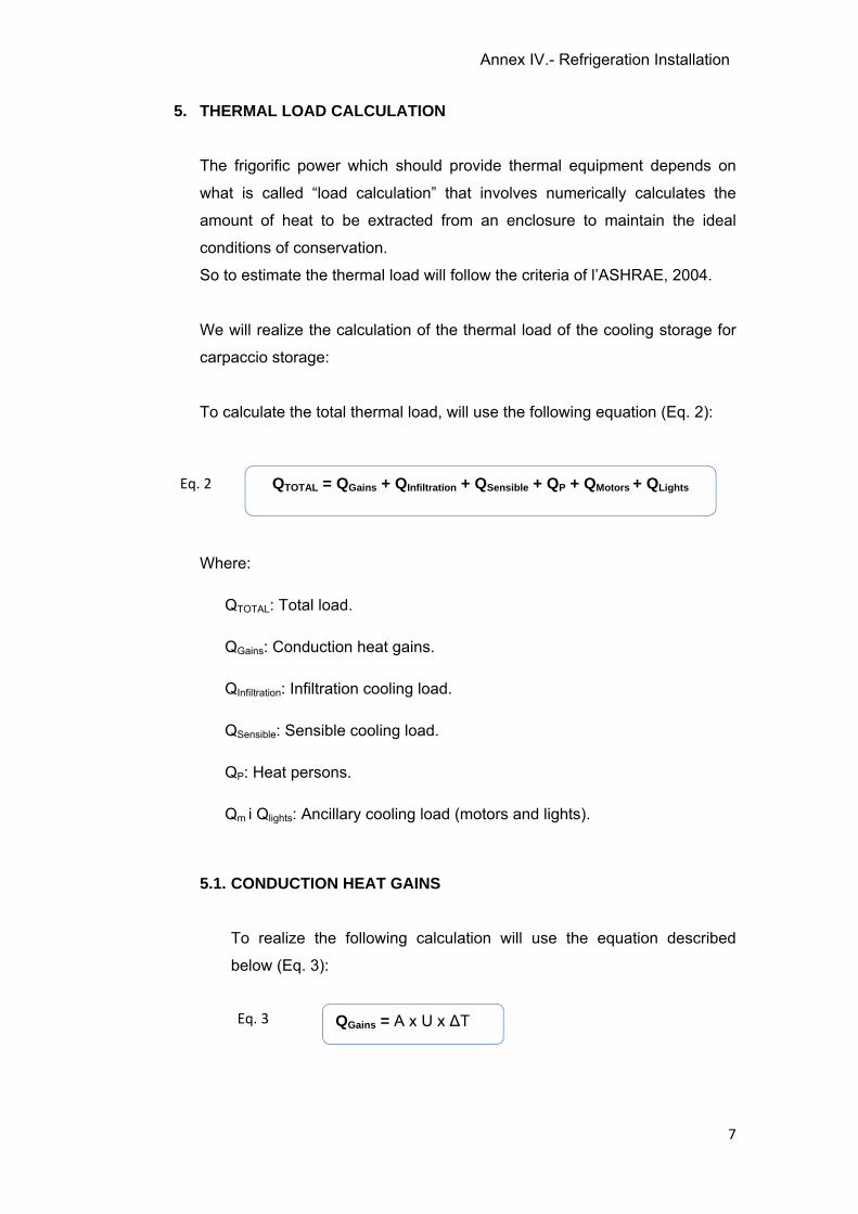
Annex IV.- Refrigeration Installation
7
5. THERMAL LOAD CALCULATION
The frigorific power which should provide thermal equipment depends on
what is called “load calculation” that involves numerically calculates the
amount of heat to be extracted from an enclosure to maintain the ideal
conditions of conservation.
So to estimate the thermal load will follow the criteria of l’ASHRAE, 2004.
We will realize the calculation of the thermal load of the cooling storage for
carpaccio storage:
To calculate the total thermal load, will use the following equation (Eq. 2):
Where:
QTOTAL: Total load.
QGains: Conduction heat gains.
QInfiltration: Infiltration cooling load.
QSensible: Sensible cooling load.
QP: Heat persons.
Qm i Qlights: Ancillary cooling load (motors and lights).
5.1. CONDUCTION HEAT GAINS
To realize the following calculation will use the equation described
below (Eq. 3):
QTOTAL = QGains + QInfiltration + QSensible + QP + QMotors + QLights
QGains = A x U x ∆T Eq. 3
Eq. 2
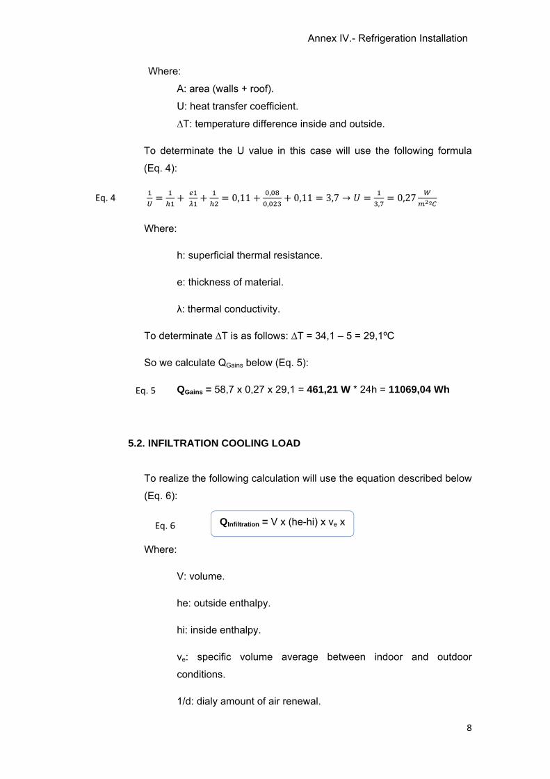
Annex IV.- Refrigeration Installation
8
Where:
A: area (walls + roof).
U: heat transfer coefficient.
∆T: temperature difference inside and outside.
To determinate the U value in this case will use the following formula
(Eq. 4):
= + + = 0,11 + ,, + 0,11 = 3,7 → = , = 0,27 º
Where:
h: superficial thermal resistance.
e: thickness of material.
λ: thermal conductivity.
To determinate ∆T is as follows: ∆T = 34,1 – 5 = 29,1ºC
So we calculate QGains below (Eq. 5):
QGains = 58,7 x 0,27 x 29,1 = 461,21 W * 24h = 11069,04 Wh
5.2. INFILTRATION COOLING LOAD
To realize the following calculation will use the equation described below
(Eq. 6):
Where:
V: volume.
he: outside enthalpy.
hi: inside enthalpy.
ve: specific volume average between indoor and outdoor
conditions.
1/d: dialy amount of air renewal.
Eq. 4
Eq. 5
QInfiltration = V x (he-hi) x ve x Eq. 6
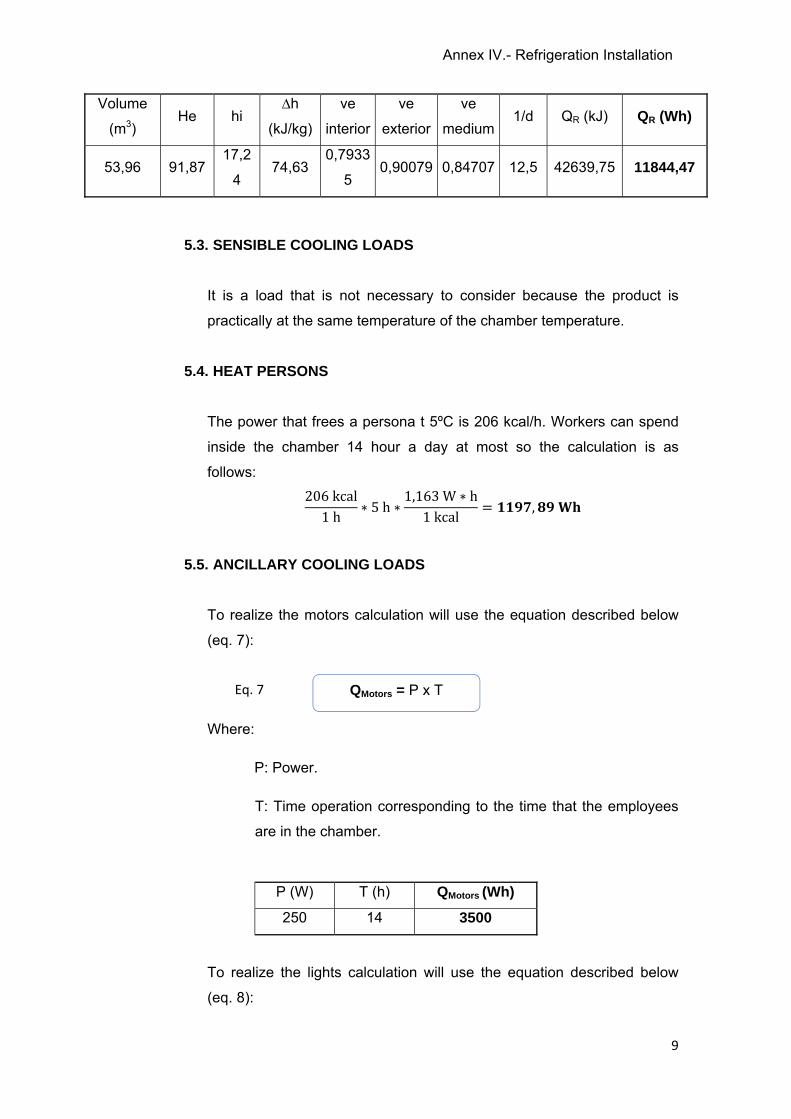
Annex IV.- Refrigeration Installation
9
Volume
(m3) He hi
∆h
(kJ/kg)
ve
interior
ve
exterior
ve
medium1/d QR (kJ) QR (Wh)
53,96 91,87 17,2
4 74,63
0,7933
5 0,90079 0,84707 12,5 42639,75 11844,47
5.3. SENSIBLE COOLING LOADS
It is a load that is not necessary to consider because the product is
practically at the same temperature of the chamber temperature.
5.4. HEAT PERSONS
The power that frees a persona t 5ºC is 206 kcal/h. Workers can spend
inside the chamber 14 hour a day at most so the calculation is as
follows: 206kcal1h ∗ 5h ∗ 1,163W ∗ h1kcal = ,
5.5. ANCILLARY COOLING LOADS
To realize the motors calculation will use the equation described below
(eq. 7):
Where:
P: Power.
T: Time operation corresponding to the time that the employees
are in the chamber.
To realize the lights calculation will use the equation described below
(eq. 8):
P (W) T (h) QMotors (Wh)
250 14 3500
QMotors = P x TEq. 7

Annex IV.- Refrigeration Installation
10
Where:
P: Power.
T: Time operation corresponding to the time that are the
employees in the chamber.
P (W) T (h) Qllums (Wh)
204 14 2856
5.6. SUMMARY OF ALL POWERS
Table 4 shows a summary of all the powers previously calculated along,
with the total power.
Table 4. Summary of powers
Charges Power (Wh)
Conduction heat gains 11069,04 Infiltration cooling load 11844,47
Heat persons 1197,89
Ancillary cooling loads
Motors 3500,00 Lights 2856,00
TOTAL: 30467,4
After knowing the total thermal load should be borne in mind that the
camera will operate 14 hours a day. Moreover must apply a safety
factor that is 1,1.
Thus the total cooling capacity is: 30467,4Wh24h ∗ 24h14h ∗ 1,1 = , = ,
QLights = P x TEq. 8
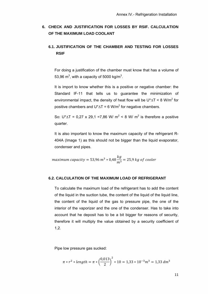
Annex IV.- Refrigeration Installation
11
6. CHECK AND JUSTIFICATION FOR LOSSES BY RSIF. CALCULATION
OF THE MAXIMUM LOAD COOLANT
6.1. JUSTIFICATION OF THE CHAMBER AND TESTING FOR LOSSES
RSIF
For doing a justification of the chamber must know that has a volume of
53,96 m3, with a capacity of 5000 kg/m3.
It is import to know whether this is a positive or negative chamber: the
Standard IF-11 that tells us to guarantee the minimization of
environmental impact, the density of heat flow will be U*∆T < 8 W/m2 for
positive chambers and U*∆T = 6 W/m2 for negative chambers.
So: U*∆T = 0,27 x 29,1 =7,86 W/ m2 < 8 W/ m2 is therefore a positive
quarter.
It is also important to know the maximum capacity of the refrigerant R-
404A (Image 1) as this should not be bigger than the liquid evaporator,
condenser and pipes.
= 53,96 ∗ 0,48 = 25,9
6.2. CALCULATION OF THE MAXIMUM LOAD OF REFRIGERANT
To calculate the maximum load of the refrigerant has to add the content
of the liquid in the suction tube, the content of the liquid of the liquid line,
the content of the liquid of the gas to pressure pipe, the one of the
interior of the vaporizer and the one of the condenser. Has to take into
account that he deposit has to be a bit bigger for reasons of security,
therefore it will multiply the value obtained by a security coefficient of
1,2.
Pipe low pressure gas sucked:
∗ ∗ ℎ = ∗ 0,0132 ∗ 10 = 1,33 ∗ 10 = 1,33
Annex IV.- Refrigeration Installation
12
Pipe line liquid at high pressure:
∗ ∗ ℎ = ∗ 0,0062 ∗ 10 = 2,83 ∗ 10 = 0,283
Pressure gas pipeline:
∗ ∗ ℎ = ∗ 0,0082 ∗ 10 = 5,03 ∗ 10 = 0,503
Evaporator (2 units): 3,7 dm3 * 2 = 7,4 dm3
Capacitor: 4,5 dm3
The total amount of coolants is: 14,02 dm3. To compare this result with
the result of the maximum load of refrigerant it is necessary to express it
in kg, knowing the cooler density: 1048 kg/m3.
14,02 ∗ 11000 ∗ 10481 = 14,69
Comparing this values that is the maximum load of cooling found in the
refrigeration, the value of the previous paragraph is the maximum
cooling that there may be, we can say that is correct because 14,69 kg <
25,9 kg
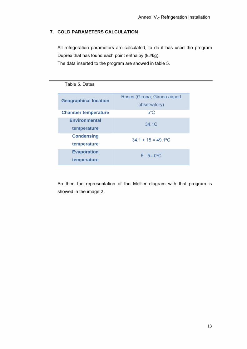
Annex IV.- Refrigeration Installation
13
7. COLD PARAMETERS CALCULATION
All refrigeration parameters are calculated, to do it has used the program
Duprex that has found each point enthalpy (kJ/kg).
The data inserted to the program are showed in table 5.
Table 5. Dates
Geographical location Roses (Girona; Girona airport
observatory)
Chamber temperature 5ºC
Environmental
temperature 34,1C
Condensing
temperature 34,1 + 15 = 49,1ºC
Evaporation
temperature 5 - 5= 0ºC
So then the representation of the Mollier diagram with that program is
showed in the image 2.
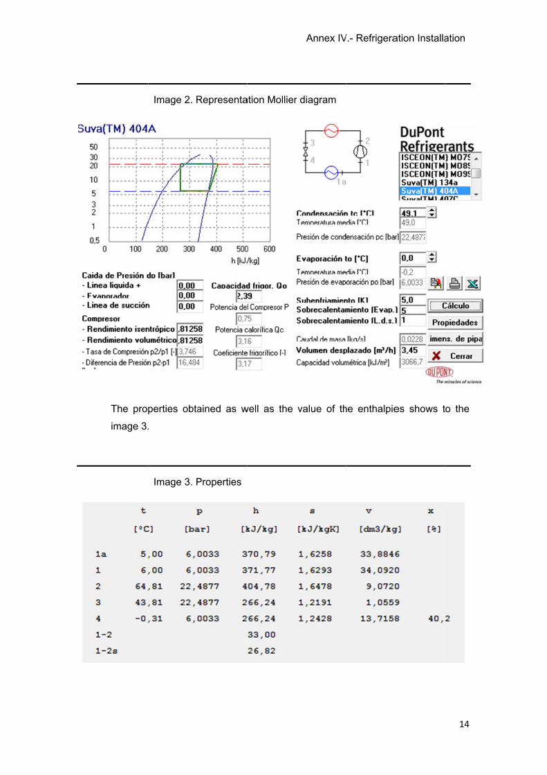
The prop
image 3.
Image 2. R
perties obta
.
Image 3. P
Representa
ained as w
Properties
ation Mollier
well as the
Annex IV
r diagram
value of th
V.- Refrigera
he enthalpie
ation Installa
es shows t
ation
14
to the
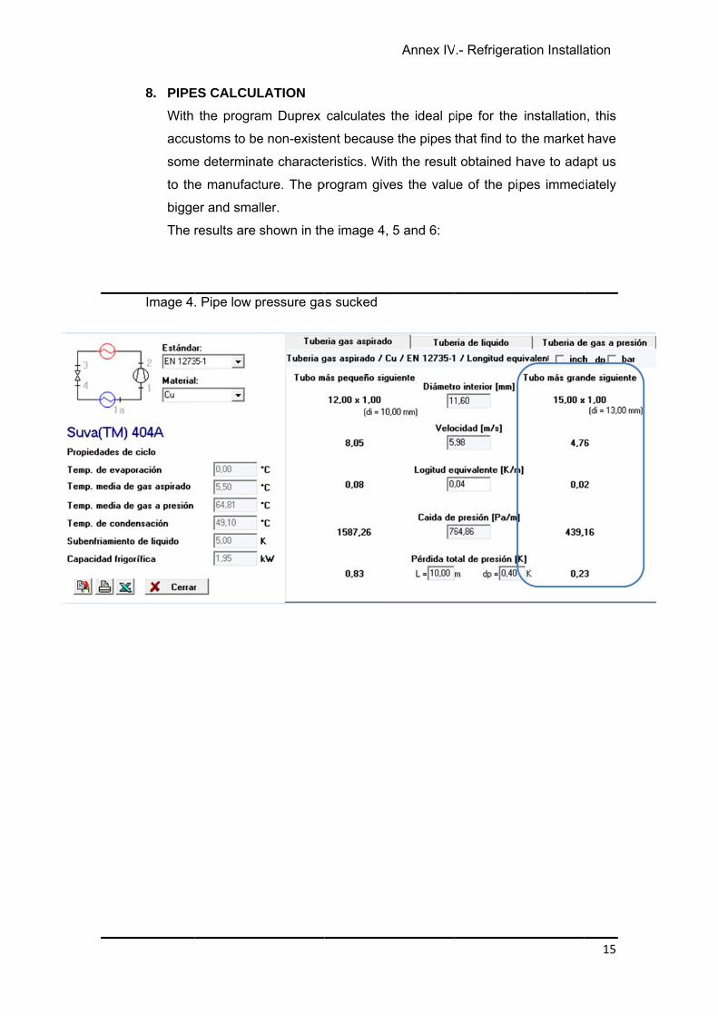
8. PIPE
With
accu
some
to th
bigge
The r
Image 4.
ES CALCUL
the progra
stoms to be
e determina
e manufact
er and smal
results are
. Pipe low p
LATION
am Duprex
e non-existe
ate characte
ture. The p
ller.
shown in th
pressure ga
calculates
ent because
eristics. Wit
program giv
he image 4,
s sucked
Annex IV
the ideal p
e the pipes
th the result
es the valu
5 and 6:
V.- Refrigera
pipe for the
that find to
t obtained h
ue of the pip
ation Installa
installation
the market
have to ada
pes immed
ation
15
n, this
have
apt us
iately

Image 5.
Image 6.
. Pipe line li
. Pressure g
iquid at high
gas pipeline
h pressure
e
Annex IVV.- Refrigeraation Installaation
16
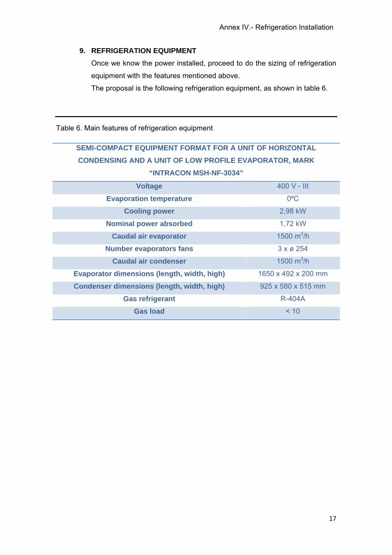
Annex IV.- Refrigeration Installation
17
9. REFRIGERATION EQUIPMENT
Once we know the power installed, proceed to do the sizing of refrigeration
equipment with the features mentioned above.
The proposal is the following refrigeration equipment, as shown in table 6.
Table 6. Main features of refrigeration equipment
SEMI-COMPACT EQUIPMENT FORMAT FOR A UNIT OF HORIZONTAL
CONDENSING AND A UNIT OF LOW PROFILE EVAPORATOR, MARK
“INTRACON MSH-NF-3034”
Voltage 400 V - III
Evaporation temperature 0ºC
Cooling power 2,98 kW
Nominal power absorbed 1,72 kW
Caudal air evaporator 1500 m3/h
Number evaporators fans 3 x ø 254
Caudal air condenser 1500 m3/h
Evaporator dimensions (length, width, high) 1650 x 492 x 200 mm
Condenser dimensions (length, width, high) 925 x 580 x 515 mm
Gas refrigerant R-404A
Gas load < 10

ANNEX V
Annex V.- Electrical Installation
2
ANNEX V.- ELECTRICAL INSTALLATION
INDEX
1. OBJECT ............................................................................................................................... 3
2. REGULATIONS .................................................................................................................. 3
3. IMMOVABLE DESCRIPTION AND CLASSIFICATION .............................................. 3
4. CIRCUIT DESCRIPTION .................................................................................................. 4
5. POWER NEEDED FOR THE ELECTRICAL INSTALLATION ................................... 4
5.1. POWER NEEDED FOR LIGHTING ........................................................................ 4
5.1.1. GENERAL LIGHTING ....................................................................................... 4
5.1.2. EMERGENCY ILLUMINATION ....................................................................... 5
5.2. POWER NEEDED FOR MACHINERY ................................................................... 6
5.3. TOTAL POWER ......................................................................................................... 7
6. PROCEDURE CALCULATION ....................................................................................... 8
6.1. INTENSITY CALCULATION (I) ............................................................................... 8
6.2. PARTIAL VOLTAGE DROP CALCULATION ..................................................... 12
6.3. TOTAL VOLTAGE DROP ...................................................................................... 13
7. CALCULATION OF CIRCUITS ..................................................................................... 13
Annex V.- Electrical Installation
3
1. OBJECT
The aim of this Annex is to calculate and dimension the remodelling and extension
of the electrical installation of the industry. To continuation is detailed the electrical
installation of the general and the emergency illumination, the machinery and the
plugs.
2. REGULATIONS
For writing and doing the calculations of this project has taken into account the
following regulations:
Royal Decree 842/2002, of 2 August, approving the Electrotechnical
Regulations for Low Voltage (REBT-2002).
Technical Building Code (CTE).
UNE 60-260.
3. IMMOVABLE DESCRIPTION AND CLASSIFICATION
The areas involved in the production are classified as humid because
environmental conditions manifest temporally or permanently in shape of
condensation to the ceiling and walls, saline stains or moulds drops although not
appear neither the ceiling or walls are impregnated of water.
The areas dedicated to cold storage premises are classified as wet because the
floors, ceiling and walls are or can be impregnated of humidity and where see
appear, although only was temporally, big drops of water owed to the condensation
or be silverwares with steam during long periods
Annex V.- Electrical Installation
4
4. CIRCUIT DESCRIPTION
In order to does a good distribution, in the general electrical box will install two sub-
boxes, thus circuits are grouped into:
Coupling: the input connection is buried and his installation complies with
the requirements set out in MI BT instructions. This line reaches the general
protection box with insulated conductors.
General distribution box: is located next to the main gate along with
counters. From this general distribution box are controlled the new three-
phase and single-phase sub-boxes.
New sub-boxes: these are located in the reception zone, one next to the
other. From this sub-boxes are controlled all the machinery, the new cooling
equipment, the general lighting of the remodelling zone and the emergency
lighting of the industrial plant.
5. POWER NEEDED FOR THE ELECTRICAL INSTALLATION
The company’s three-phase power supply provides a voltage of 230/400 V to the
installation according to needs, with a frequency of 50 Hz.
5.1. POWER NEEDED FOR LIGHTING
Given that the industry already has a general box, it will be two sub-boxes: one
is for three-phase machines and other is for single-phase machines, lighting
and plugs.
5.1.1. GENERAL LIGHTING
Table 1 shows the power required by the general lighting in each area.
It is important to know that the power is calculated by multiplying the total
number of lamps for power but also used a safety factor: the fluorescents
have been added to the power of 10 W each.
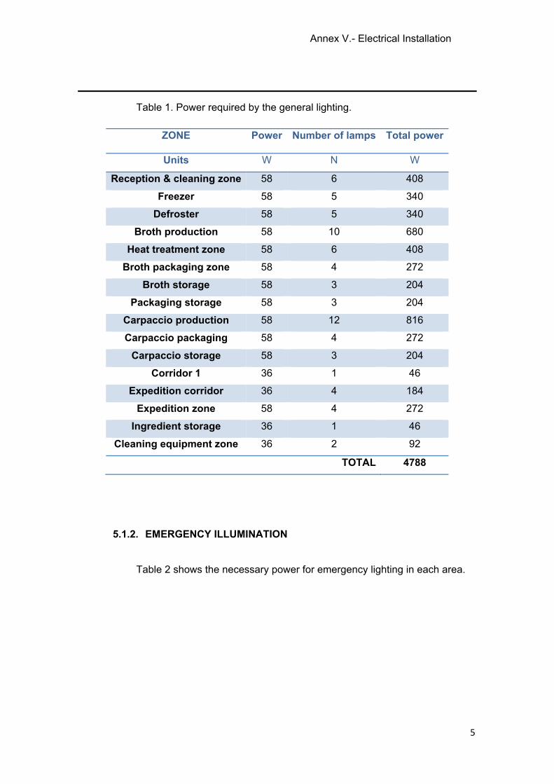
Annex V.- Electrical Installation
5
Table 1. Power required by the general lighting.
ZONE Power Number of lamps Total power
Units W N W
Reception & cleaning zone 58 6 408
Freezer 58 5 340
Defroster 58 5 340
Broth production 58 10 680
Heat treatment zone 58 6 408
Broth packaging zone 58 4 272
Broth storage 58 3 204
Packaging storage 58 3 204
Carpaccio production 58 12 816
Carpaccio packaging 58 4 272
Carpaccio storage 58 3 204
Corridor 1 36 1 46
Expedition corridor 36 4 184
Expedition zone 58 4 272
Ingredient storage 36 1 46
Cleaning equipment zone 36 2 92
TOTAL 4788
5.1.2. EMERGENCY ILLUMINATION
Table 2 shows the necessary power for emergency lighting in each area.
Annex V.- Electrical Installation
6
Table 2. Power required by the emergency lighting.
ZONE Power Number of lamps Total power
Units W N W
Reception & cleaning zone 8 1 8
Freezer 8 2 16
Defroster 8 2 16
Broth production 8 2 16
Heat treatment zone 8 1 8
Broth packaging zone 8 1 8
Broth storage 8 1 8
Packaging storage 8 1 8
Carpaccio production 8 2 16
Carpaccio packaging 8 1 8
Carpaccio storage 8 1 8
Corridor 1 8 1 8
Expedition corridor 8 1 8
Expedition zone 8 1 8
Ingredient storage 8 1 8
Cleaning equipment zone 8 1 8
TOTAL 160
5.2. POWER NEEDED FOR MACHINERY
Table 3 below shows the power required per Machine.

Annex V.- Electrical Installation
7
Table 3. Power required by the machinery.
MACHINERY Quantity Power Real
consumption
Units nº W W
Conveyor roller rotating
with a sprinkler water
system
1 1850 1850
Cooker 1 22500 22500
Exhaust system 1 370 370
Bottle filling machine 1 1000 1000
Bottle closing 1 2350 2350
Autoclaving 1 16000 16000
Labelling 1 2600 2600
Filleting 2 1000 2000
Tray sealer 1 8000 8000
Tunnel frozen 1 370 370
TOTAL 57040
5.3. TOTAL POWER
The total installed power is the sum of the powers of the machinery with the
powers of emergency and general lighting. So is a total power of 62192 W.
Annex V.- Electrical Installation
8
6. PROCEDURE CALCULATION
To realize the calculation of the different conductive section has to take into
account the intensity (I) and the voltage drop (CdT).
Should know that the sections are in REBT 2002 from the intensity calculated.
So to calculate the intensity will use equations 1 and 2 and to calculate the voltage
drop will use equations 3 and 4. Finally to calculate the total voltage drop will use
equations 5 and 6, all described below.
6.1. INTENSITY CALCULATION (I)
Single-phase:
= ∗∗ ∗ Ф
Three-phase:
= ∗∗ √3 ∗ ∗ Ф
Where:
I: Intensity that circulates for the line (IB).
k: coefficient of stared motors = 1,3; fluorescents = 1,8; resistances = 1.
P: power.
V: voltage.
η: motor performance.
cosФ: gap between current and voltage.
For motors are used the performance metrics and cos Ф from table 4.
depending on the power of each motor.
Eq. 1
Eq. 2

Table 4.
Once th
protectio
this at t
explaine
Relation be
e calculatio
on “PIA” (IN)
he same ti
d below – fo
etween pow
on of inten
), from the
ime has to
ollowing the
wer, perform
nsity (IB) ha
image 1, w
o be smalle
e relation:
IB ≤ IN
Annex V.
mance and c
as been m
which must
er than the
≤ IZ
- Electrical
cos Ф.
made, shoul
be smaller
intensity o
Installation
ld be chos
r than the I
of the line
n
9
sen a
B and
(IZ) –
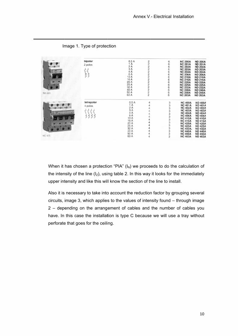
Im
When it
the inten
upper int
Also it is
circuits,
2 – dep
have. In
perforate
mage 1. Typ
has chosen
nsity of the l
tensity and
necessary
image 3, w
ending on
this case t
e that goes
pe of protec
n a protectio
ine (IZ), usi
like this wil
to take into
hich applies
the arrang
the installat
for the ceili
ction
on “PIA” (IN
ng table 2.
l know the s
o account th
s to the val
ement of c
tion is type
ng.
Annex V.
N) we proce
In this way
section of th
he reduction
ues of inten
cables and
C because
- Electrical
eds to do th
it looks for
he line to in
n factor by g
nsity found –
the numbe
e we will us
Installation
he calculat
r the immed
nstall.
grouping se
– through i
er of cables
se a tray w
n
10
ion of
diately
everal
mage
s you
ithout
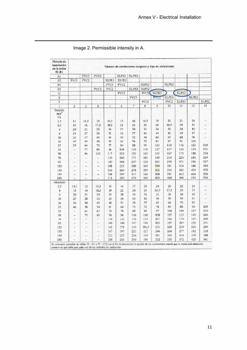
Image 22. Permissibble intensity
Annex V.
in A.
- Electrical Installationn
11
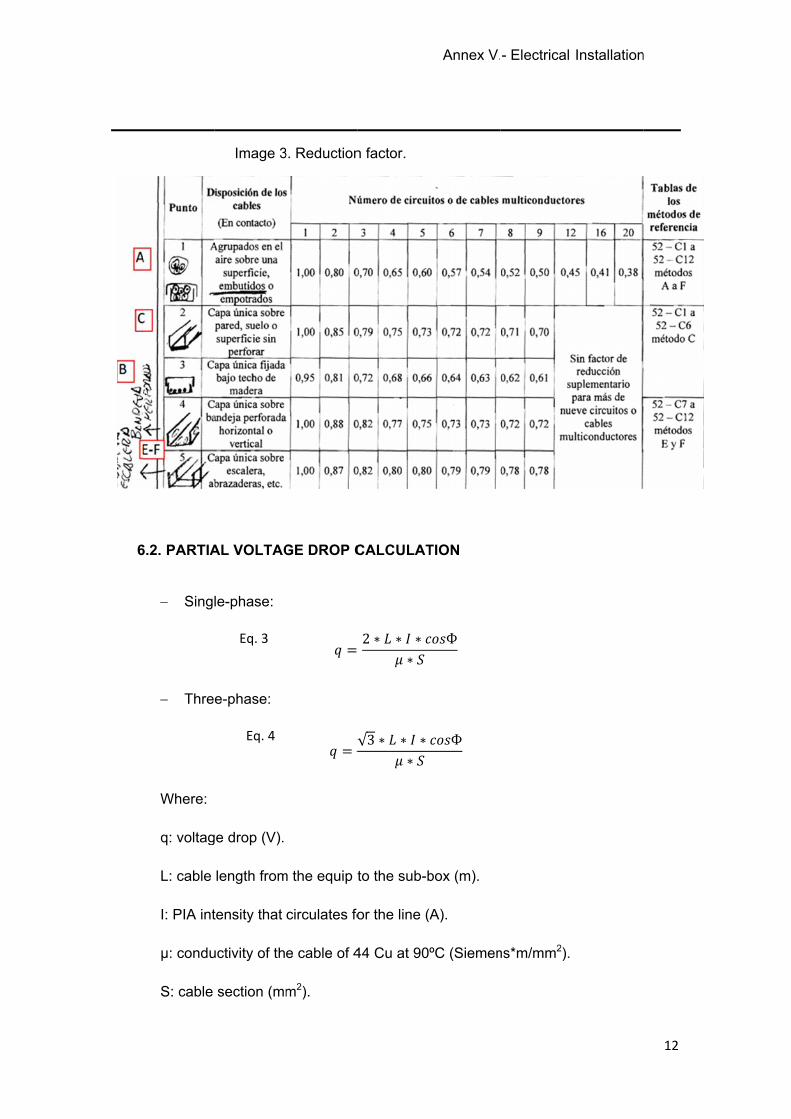
66.2. PARTIA
Singl
Thre
Where:
q: voltag
L: cable
I: PIA int
μ: condu
S: cable
Image 3
AL VOLTAG
le-phase:
e-phase:
ge drop (V).
length from
tensity that
uctivity of th
section (mm
Eq. 3
Eq. 4
3. Reduction
GE DROP C
== √
m the equip t
circulates fo
e cable of 4
m2).
n factor.
CALCULAT
2 ∗ ∗ ∗∗√3 ∗ ∗ ∗∗
to the sub-b
or the line (
44 Cu at 90
Annex V.
TION
Ф
Ф
box (m).
(A).
ºC (Siemen
- Electrical
ns*m/mm2).
Installationn
12
Annex V.- Electrical Installation
13
6.3. TOTAL VOLTAGE DROP
Is the sum of all partial drop voltage of each line.
It is necessary to take into account that as the REBT-2002, the percentage of
the total voltage drop may not exceed 3% for light and 5% for the rest of the
installation. In case there was any lines exceed this limit would increase driver
section and repeat the checks.
Single-phase:
% = ∗ 100400√3
Three-phase:
% = ∗ 100400
7. CALCULATION OF CIRCUITS
Following the methods described in the previous section, we proceed to make the
sizing of powers lines installation. The calculations are showed in table 4 and 5.
Eq. 5
Eq. 6
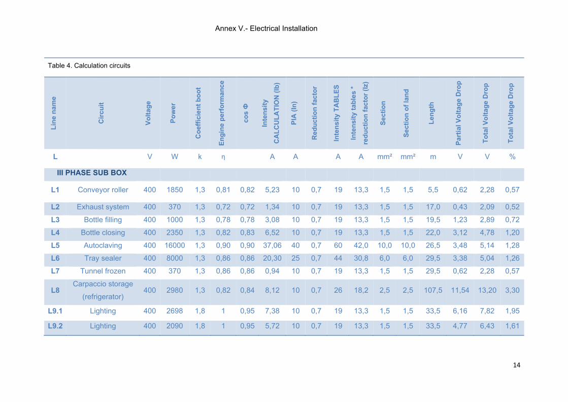
Annex V.- Electrical Installation
14
Table 4. Calculation circuits
Lin
e n
ame
Cir
cuit
Vo
ltag
e
Po
wer
Co
effi
cien
t b
oo
t
En
gin
e p
erfo
rman
ce
cos Ф
Inte
nsi
ty
CA
LC
UL
AT
ION
(Ib
)
PIA
(In
)
Red
uct
ion
fac
tor
Inte
nsi
ty T
AB
LE
S
Inte
nsi
ty t
able
s *
red
uct
ion
fac
tor
(Iz)
Sec
tio
n
Sec
tio
n o
f la
nd
Len
gth
Par
tial
Vo
ltag
e D
rop
To
tal V
olt
age
Dro
p
To
tal V
olt
age
Dro
p
L
V W k η
A A
A A mm² mm² m V V %
III PHASE SUB BOX
L1 Conveyor roller 400 1850 1,3 0,81 0,82 5,23 10 0,7 19 13,3 1,5 1,5 5,5 0,62 2,28 0,57
L2 Exhaust system 400 370 1,3 0,72 0,72 1,34 10 0,7 19 13,3 1,5 1,5 17,0 0,43 2,09 0,52
L3 Bottle filling 400 1000 1,3 0,78 0,78 3,08 10 0,7 19 13,3 1,5 1,5 19,5 1,23 2,89 0,72
L4 Bottle closing 400 2350 1,3 0,82 0,83 6,52 10 0,7 19 13,3 1,5 1,5 22,0 3,12 4,78 1,20
L5 Autoclaving 400 16000 1,3 0,90 0,90 37,06 40 0,7 60 42,0 10,0 10,0 26,5 3,48 5,14 1,28
L6 Tray sealer 400 8000 1,3 0,86 0,86 20,30 25 0,7 44 30,8 6,0 6,0 29,5 3,38 5,04 1,26
L7 Tunnel frozen 400 370 1,3 0,86 0,86 0,94 10 0,7 19 13,3 1,5 1,5 29,5 0,62 2,28 0,57
L8 Carpaccio storage
(refrigerator) 400 2980 1,3 0,82 0,84 8,12 10 0,7 26 18,2 2,5 2,5 107,5 11,54 13,20 3,30
L9.1 Lighting 400 2698 1,8 1 0,95 7,38 10 0,7 19 13,3 1,5 1,5 33,5 6,16 7,82 1,95
L9.2 Lighting 400 2090 1,8 1 0,95 5,72 10 0,7 19 13,3 1,5 1,5 33,5 4,77 6,43 1,61
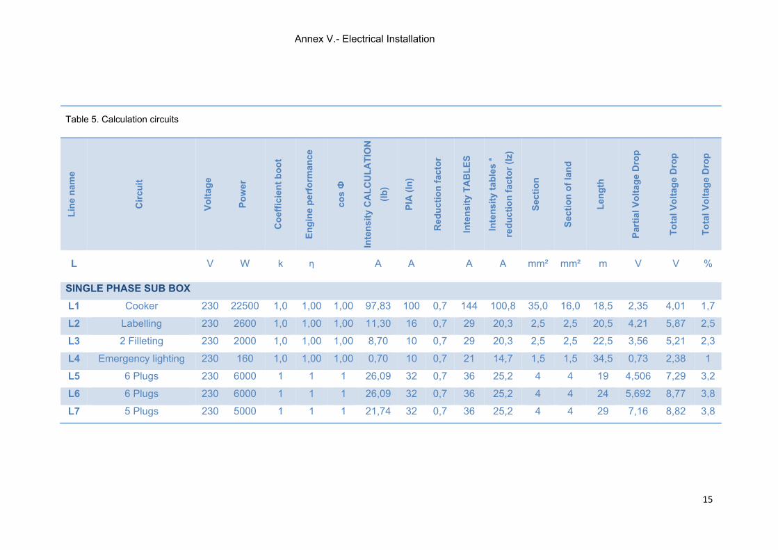
Annex V.- Electrical Installation
15
Table 5. Calculation circuits
Lin
e n
ame
Cir
cuit
Vo
ltag
e
Po
wer
Co
effi
cien
t b
oo
t
En
gin
e p
erfo
rman
ce
cos Ф
Inte
nsi
ty C
AL
CU
LA
TIO
N
(Ib
)
PIA
(In
)
Red
uct
ion
fac
tor
Inte
nsi
ty T
AB
LE
S
Inte
nsi
ty t
able
s *
red
uct
ion
fac
tor
(Iz)
Sec
tio
n
Sec
tio
n o
f la
nd
Len
gth
Par
tial
Vo
ltag
e D
rop
To
tal V
olt
age
Dro
p
To
tal V
olt
age
Dro
p
L
V W k η
A A
A A mm² mm² m V V %
SINGLE PHASE SUB BOX
L1 Cooker 230 22500 1,0 1,00 1,00 97,83 100 0,7 144 100,8 35,0 16,0 18,5 2,35 4,01 1,7
L2 Labelling 230 2600 1,0 1,00 1,00 11,30 16 0,7 29 20,3 2,5 2,5 20,5 4,21 5,87 2,5
L3 2 Filleting 230 2000 1,0 1,00 1,00 8,70 10 0,7 29 20,3 2,5 2,5 22,5 3,56 5,21 2,3
L4 Emergency lighting 230 160 1,0 1,00 1,00 0,70 10 0,7 21 14,7 1,5 1,5 34,5 0,73 2,38 1
L5 6 Plugs 230 6000 1 1 1 26,09 32 0,7 36 25,2 4 4 19 4,506 7,29 3,2
L6 6 Plugs 230 6000 1 1 1 26,09 32 0,7 36 25,2 4 4 24 5,692 8,77 3,8
L7 5 Plugs 230 5000 1 1 1 21,74 32 0,7 36 25,2 4 4 29 7,16 8,82 3,8
ANNEX VI
Annex VI. – Hazard Analysis Critical Control Points
2
ANNEX VI. – HAZARD ANALYSIS CRITICAL CONTROL POINTS
INDEX
1. OBJECT ......................................................................................................................... 3
2. BIOLOGICAL HAZARDS .............................................................................................. 3
2.1. PATHOGENIC BACTERIA ................................................................................... 3
2.1.1. BACTERIA INDIGENOUS TO THE AQUATIC AND GENERAL ENVIRONMENT ............................................................................................................. 4
2.1.2. BACTERIA INDIGENOUS TO THE HUMAN/ANIMAL RESERVOIR ......... 6
2.2. PRODUCTION OF BIOGENIC AMINES .............................................................. 7
2.3. VIRUSES ................................................................................................................ 8
2.4. PARASITES ........................................................................................................... 8
3. HYGIENE ....................................................................................................................... 8
3.1. HYGIENE PROGRAM ........................................................................................... 8
3.1.1. CLEANING PROGRAM ................................................................................. 8
3.1.2. DISINFECTION PROGRAM .......................................................................... 9
3.1.3. MONITORING OF CLEANING AND DISINFECTION ................................ 10
3.2. PREVENTION OF CROSS-CONTAMINATION ................................................. 12
3.3. PEST CONTROL ................................................................................................. 13
4. THE HACCP SYSTEM ................................................................................................ 14
4.1. BASIC SEVEN PRINCIPLES OF HACCP ......................................................... 15
4.2. APPLICATION OF THE HACCP PRINCIPLES ................................................. 15
5. HAZARD ANALYSIS OF RAW MATERIAL .............................................................. 17
5.1. RAW FISH TO BE CONSUMED RAW ............................................................... 18
6. HAZARD ANALYSIS OF FISH BROTH ..................................................................... 20
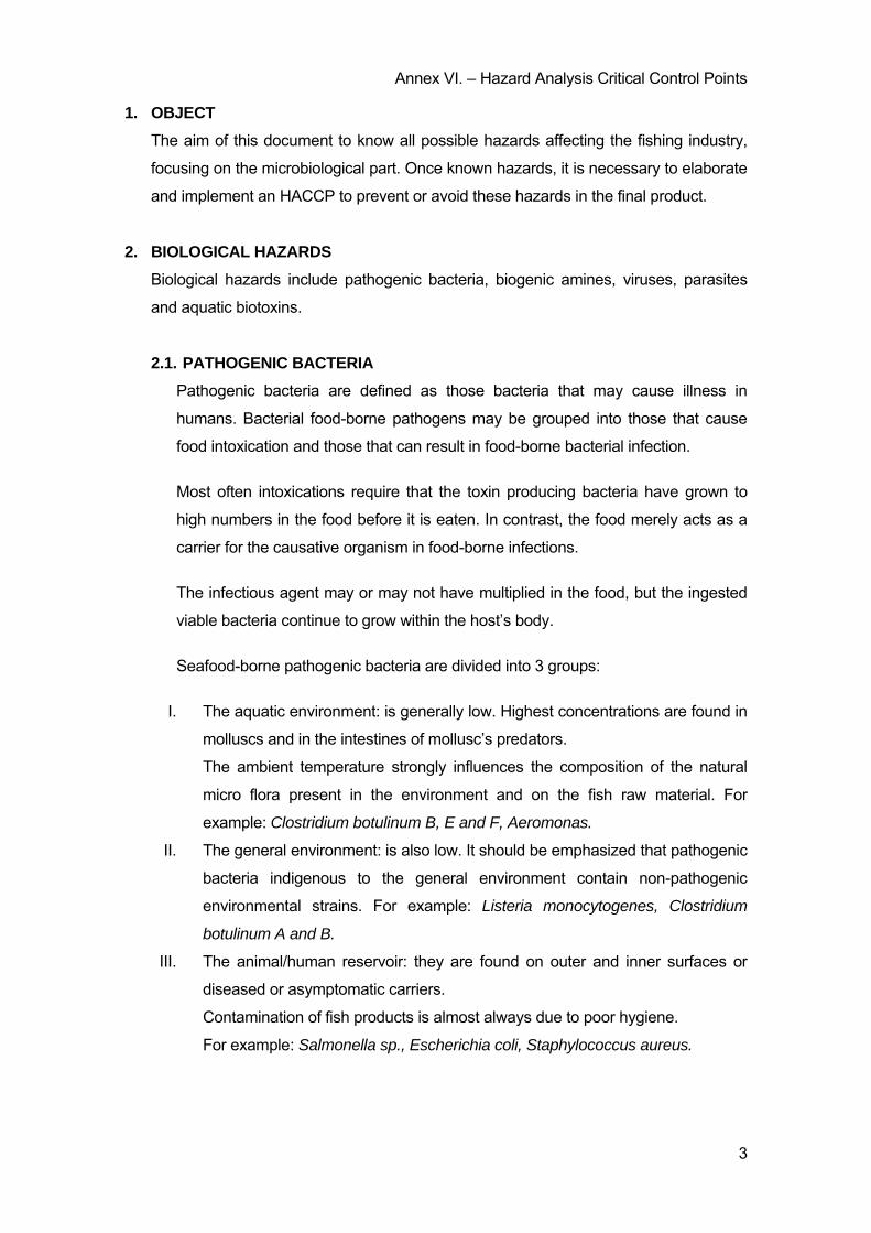
Annex VI. – Hazard Analysis Critical Control Points
3
1. OBJECT
The aim of this document to know all possible hazards affecting the fishing industry,
focusing on the microbiological part. Once known hazards, it is necessary to elaborate
and implement an HACCP to prevent or avoid these hazards in the final product.
2. BIOLOGICAL HAZARDS
Biological hazards include pathogenic bacteria, biogenic amines, viruses, parasites
and aquatic biotoxins.
2.1. PATHOGENIC BACTERIA
Pathogenic bacteria are defined as those bacteria that may cause illness in
humans. Bacterial food-borne pathogens may be grouped into those that cause
food intoxication and those that can result in food-borne bacterial infection.
Most often intoxications require that the toxin producing bacteria have grown to
high numbers in the food before it is eaten. In contrast, the food merely acts as a
carrier for the causative organism in food-borne infections.
The infectious agent may or may not have multiplied in the food, but the ingested
viable bacteria continue to grow within the host’s body.
Seafood-borne pathogenic bacteria are divided into 3 groups:
I. The aquatic environment: is generally low. Highest concentrations are found in
molluscs and in the intestines of mollusc’s predators.
The ambient temperature strongly influences the composition of the natural
micro flora present in the environment and on the fish raw material. For
example: Clostridium botulinum B, E and F, Aeromonas.
II. The general environment: is also low. It should be emphasized that pathogenic
bacteria indigenous to the general environment contain non-pathogenic
environmental strains. For example: Listeria monocytogenes, Clostridium
botulinum A and B.
III. The animal/human reservoir: they are found on outer and inner surfaces or
diseased or asymptomatic carriers.
Contamination of fish products is almost always due to poor hygiene.
For example: Salmonella sp., Escherichia coli, Staphylococcus aureus.
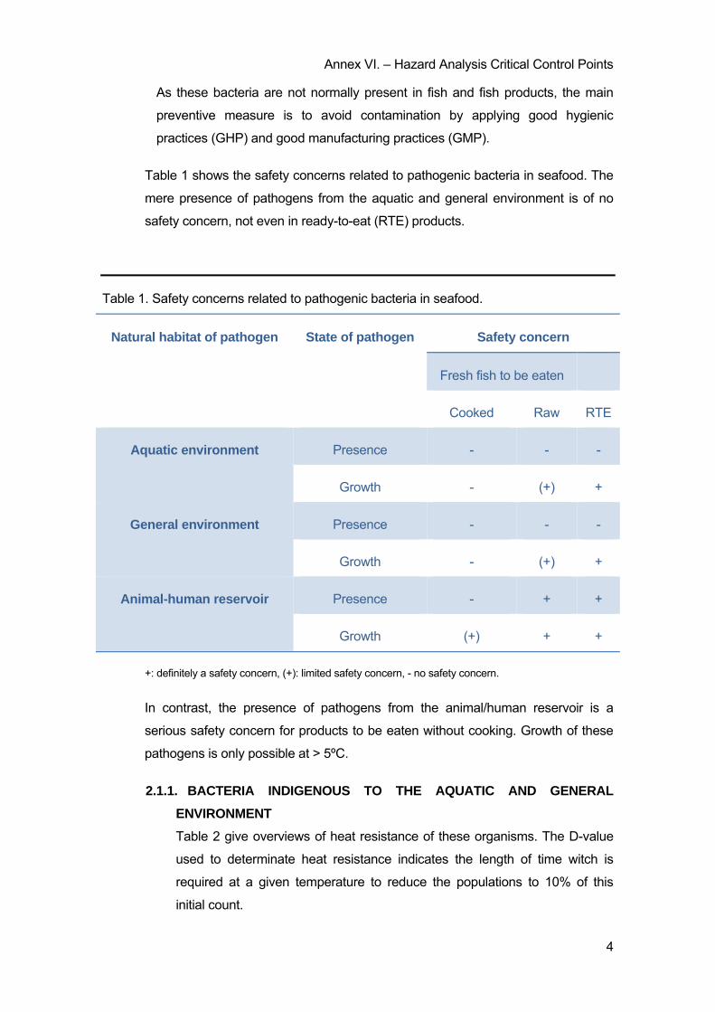
Annex VI. – Hazard Analysis Critical Control Points
4
As these bacteria are not normally present in fish and fish products, the main
preventive measure is to avoid contamination by applying good hygienic
practices (GHP) and good manufacturing practices (GMP).
Table 1 shows the safety concerns related to pathogenic bacteria in seafood. The
mere presence of pathogens from the aquatic and general environment is of no
safety concern, not even in ready-to-eat (RTE) products.
Table 1. Safety concerns related to pathogenic bacteria in seafood.
Natural habitat of pathogen State of pathogen Safety concern
Fresh fish to be eaten
Cooked Raw RTE
Aquatic environment Presence - - -
Growth - (+) +
General environment Presence - - -
Growth - (+) +
Animal-human reservoir Presence - + +
Growth (+) + +
+: definitely a safety concern, (+): limited safety concern, - no safety concern.
In contrast, the presence of pathogens from the animal/human reservoir is a
serious safety concern for products to be eaten without cooking. Growth of these
pathogens is only possible at > 5ºC.
2.1.1. BACTERIA INDIGENOUS TO THE AQUATIC AND GENERAL
ENVIRONMENT
Table 2 give overviews of heat resistance of these organisms. The D-value
used to determinate heat resistance indicates the length of time witch is
required at a given temperature to reduce the populations to 10% of this
initial count.
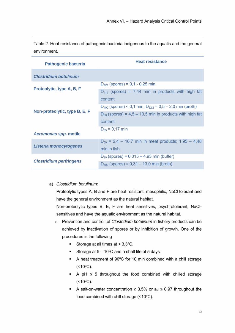
Annex VI. – Hazard Analysis Critical Control Points
5
Table 2. Heat resistance of pathogenic bacteria indigenous to the aquatic and the general
environment.
Pathogenic bacteria Heat resistance
Clostridium botulinum
Proteolytic, type A, B, F D121 (spores) = 0,1 - 0,25 min
D119 (spores) = 7,44 min in products with high fat
content
Non-proteolytic, type B, E, F D100 (spores) < 0,1 min; D82,2 = 0,5 – 2,0 min (broth)
D80 (spores) = 4,5 – 10,5 min in products with high fat
content
Aeromonas spp. motile D55 = 0,17 min
Listeria monocytogenes D60 = 2,4 – 16,7 min in meat products; 1,95 – 4,48
min in fish
Clostridium perfringens D90 (spores) = 0,015 – 4,93 min (buffer)
D100 (spores) = 0,31 – 13,0 min (broth)
a) Clostridium botulinum:
Proteolytic types A, B and F are heat resistant, mesophilic, NaCl tolerant and
have the general environment as the natural habitat.
Non-proteolytic types B, E, F are heat sensitives, psychrotolerant, NaCl-
sensitives and have the aquatic environment as the natural habitat.
o Prevention and control: of Clostridium botulinum in fishery products can be
achieved by inactivation of spores or by inhibition of growth. One of the
procedures is the following
Storage at all times at < 3,3ºC.
Storage at 5 – 10ºC and a shelf life of 5 days.
A heat treatment of 90ºC for 10 min combined with a chill storage
(<10ºC).
A pH ≤ 5 throughout the food combined with chilled storage
(<10ºC).
A salt-on-water concentration ≥ 3,5% or aw ≤ 0,97 throughout the
food combined with chill storage (<10ºC).
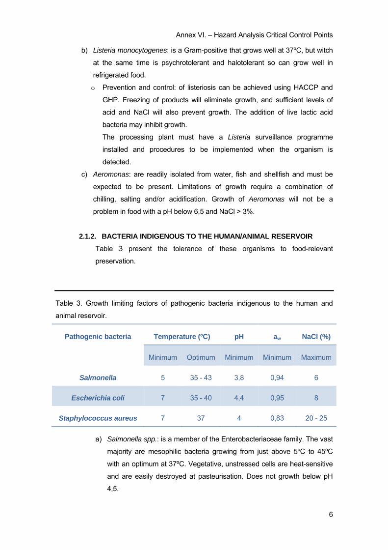
Annex VI. – Hazard Analysis Critical Control Points
6
b) Listeria monocytogenes: is a Gram-positive that grows well at 37ºC, but witch
at the same time is psychrotolerant and halotolerant so can grow well in
refrigerated food.
o Prevention and control: of listeriosis can be achieved using HACCP and
GHP. Freezing of products will eliminate growth, and sufficient levels of
acid and NaCl will also prevent growth. The addition of live lactic acid
bacteria may inhibit growth.
The processing plant must have a Listeria surveillance programme
installed and procedures to be implemented when the organism is
detected.
c) Aeromonas: are readily isolated from water, fish and shellfish and must be
expected to be present. Limitations of growth require a combination of
chilling, salting and/or acidification. Growth of Aeromonas will not be a
problem in food with a pH below 6,5 and NaCl > 3%.
2.1.2. BACTERIA INDIGENOUS TO THE HUMAN/ANIMAL RESERVOIR
Table 3 present the tolerance of these organisms to food-relevant
preservation.
Table 3. Growth limiting factors of pathogenic bacteria indigenous to the human and
animal reservoir.
Pathogenic bacteria Temperature (ºC) pH aw NaCl (%)
Minimum Optimum Minimum Minimum Maximum
Salmonella 5 35 - 43 3,8 0,94 6
Escherichia coli 7 35 - 40 4,4 0,95 8
Staphylococcus aureus 7 37 4 0,83 20 - 25
a) Salmonella spp.: is a member of the Enterobacteriaceae family. The vast
majority are mesophilic bacteria growing from just above 5ºC to 45ºC
with an optimum at 37ºC. Vegetative, unstressed cells are heat-sensitive
and are easily destroyed at pasteurisation. Does not growth below pH
4,5.
Annex VI. – Hazard Analysis Critical Control Points
7
b) Escherichia coli: is a member of the Enterobacteriaceae family and is the
most common aerobic organism in the intestinal tract of man and warm-
blooded animals. All E.coli strains are mesophilic organisms with a
optimum growth at 37ºC.
Prevention and control of mesophilic Enerobacteriaceae: therefore
adherence to GHP with emphasis on clear water and personnel hygiene will
control the organisms. All are sensitive to heating. Growth will be inhibited at
chill temperature and by salting.
c) Staphylococcus aureus: are Gram-positive with their primary habitat in
the skin, glands and mucous membranes.
o Prevention and control: avoidance of cross contamination of heat
treatment products is important. They are resistant to heat and will
resist boiling for some time.
2.2. PRODUCTION OF BIOGENIC AMINES
Histamine poisoning is a food-borne chemical intoxication occurring few minutes
to several hours bellowing the ingestion of foods that contain unusually high
levels of histamine.
Levels for histamine content of fish:
o < 5 mg/100 g safe for consumption.
o 5 - 20 mg/100 g possibly toxic.
o 20 - 100 mg/100 g probably toxic.
o > 100 mg/100 g toxic and unsafe for human consumption.
- Prevention and control: rapid chilling of fish immediately after dead. Generally, fish
should be placed in ice or in refrigerated seawater, in chilled sea water or brine at
4,5ºC or less within 12 hours of dead.
Fish exposed to air or water temperatures above 28ºC, or large tuna that are
eviscerated before on-board chilling, should be placed in ice or refrigerated
seawater or brine at 4,5ºC or less within 6 hours of dead.
Large tuna that are not eviscerated before on-board chilling should be chilled to an
internal temperature of 10ºC or less within 6 hours death.
Annex VI. – Hazard Analysis Critical Control Points
8
2.3. VIRUSES
Viruses are very small microorganisms which consist of genetic material and a
protein cover. Viruses are obligatory intracellular pathogens and cannot multiply
outside host cells.
- Prevention and control: is simple since the source of disease is indirect or direct
faecal contamination. Thus, measures that prevent this contamination control
disease.
2.4. PARASITES
The presence of parasites in fish is very common, but most of them are of little
concern with regard to economics or public health.
o Anisakis species: is a gastrointestinal parasitosis caused by the larval
stage of Anisakis nematodes. Humans acquire the disease by eating raw
or improperly cooked food.
- Prevention and control: all fish and fish products must be subject to a visual
inspection during processing for the purpose of detecting and removing any visible
parasite. Further, all fish that are to be consumed raw or almost raw must be
subjected to a freezing process.
3. HYGIENE
3.1. HYGIENE PROGRAM
All food contact surfaces should be adequately and routinely cleaned and
disinfected. Cleaning and disinfection belong to the most important operation.
3.1.1. CLEANING PROGRAM
In the preparatory phase, the processing area is cleaned of remaining
products, spills… Machines are dismantled so that all locations where
microorganisms can accumulate became accessible for cleaning and
disinfection.
Before use of the cleaning agent, a gross food debris removal procedure
should be carried out by brushing or scraping.
The types of residues to be removed:
o Organic matter, such as protein, fat and carbohydrate. These are most
effectively removed strong alkaline.

Annex VI. – Hazard Analysis Critical Control Points
9
o Inorganic matter, such as salts of calcium. These are most effectively
removed by an acid cleaning agent.
o Biofilm, formed by bacteria, moulds, yeasts and algae can be removed by
cleaning agents that are effective against organic matter.
Cleaning is carried out at 60 – 80ºC because when the water is heated, any
calcium and magnesium salts will precipitate as insoluble salts.
3.1.2. DISINFECTION PROGRAM
It can be effected by physical treatments such as heat, U.V. irradiation, or by
means of chemical compounds. With the use of chemical disinfectants, the
death rate for microorganisms depends, among other things, upon the
agent’s microbiological properties, concentration, temperature and pH.
Different microorganisms show different resistance.
Table 4 describes some types of disinfectants and its advantages and
disadvantages.
Table 4. Types of disinfectants
Disinfectant Description Advantages Disadvantages
Chlorine
Hypochlorite
Chlorite gas
Organic chlorite
Kills most type of microorganisms.
Does not form films.
Effective at low temperature.
Relatively inexpensive.
May corrode metals and weaken
rubber.
Irritating to skin, eyes and throat.
pH sensitive.
Unstable, dissipates quickly.
Iodophors
Iodine dissolved in
surfactant and
acid
Kills most types of
microorganisms.
Less pH sensitive than chlorine.
Solution colour indicates active
sanitiser.
May stain plastics and porous
materials.
Inactive above 50ºC.
May be unsuitable for cleaning in
place due to foaming.

Annex VI. – Hazard Analysis Critical Control Points
10
Acid-Anionic
Combination of
certain surfactants
and acids
Sanitize and acid rinse in one step.
Very stable.
Can be applied at high
temperature.
Effectiveness varies with
microorganisms.
pH sensitive (use below pH 3.0).
Corrode some metals.
May be unsuitable for cleaning in
place due to foaming.
Peroxy
Compounds
Acetic acid and
hydrogen
peroxide
combined to form
peroxyacetic acid
Best against bacteria in biofilms.
Kills most types of
microorganisms.
Relatively stable in use.
Effective at low temperatures.
Suitable for cleaning in place.
Inactivated by some metals.
May corrode some metals.
Not as efficient as some against
yeasts and moulds.
Carboxylic acid
Fatty acids
combined with
other acids
Kills most types of bacteria.
Sanitize and acid rinse in one step.
Suitable for cleaning in place due
to a low foaming.
Inactivated by some detergents.
pH sensitive (use below 3.5).
May damage non-stainless steel
materials.
Less effective than chlorine.
3.1.3. MONITORING OF CLEANING AND DISINFECTION
Effective cleaning is a prerequisite for an efficient disinfection. This indicates
the importance of controlling cleaning. The most important control is sensory
inspection to demonstrate:
o That all cleaned surfaces are visibly clean.
o That all surfaces, be feeling, are free from food residues and by smelling,
free from undesirables odours.
Control of disinfection will be the final control of the complete cycle of cleaning
and disinfection. It will be effective when the following conditions are met:
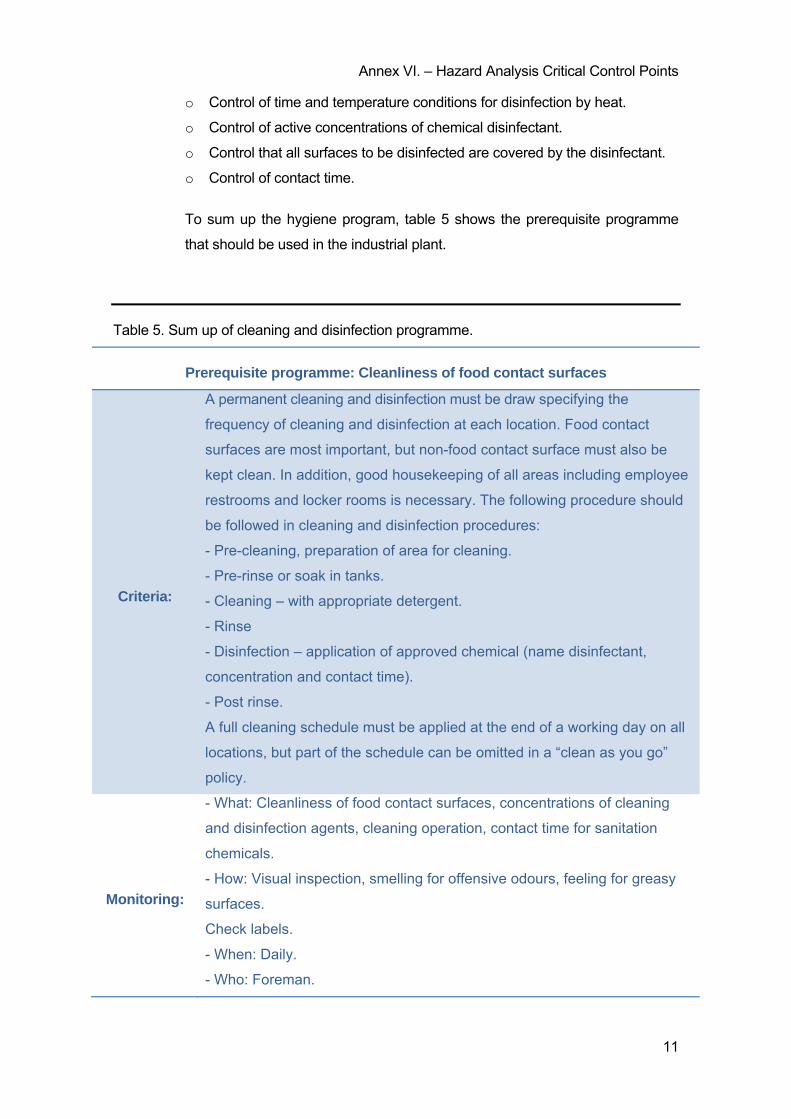
Annex VI. – Hazard Analysis Critical Control Points
11
o Control of time and temperature conditions for disinfection by heat.
o Control of active concentrations of chemical disinfectant.
o Control that all surfaces to be disinfected are covered by the disinfectant.
o Control of contact time.
To sum up the hygiene program, table 5 shows the prerequisite programme
that should be used in the industrial plant.
Table 5. Sum up of cleaning and disinfection programme.
Prerequisite programme: Cleanliness of food contact surfaces
Criteria:
A permanent cleaning and disinfection must be draw specifying the
frequency of cleaning and disinfection at each location. Food contact
surfaces are most important, but non-food contact surface must also be
kept clean. In addition, good housekeeping of all areas including employee
restrooms and locker rooms is necessary. The following procedure should
be followed in cleaning and disinfection procedures:
- Pre-cleaning, preparation of area for cleaning.
- Pre-rinse or soak in tanks.
- Cleaning – with appropriate detergent.
- Rinse
- Disinfection – application of approved chemical (name disinfectant,
concentration and contact time).
- Post rinse.
A full cleaning schedule must be applied at the end of a working day on all
locations, but part of the schedule can be omitted in a “clean as you go”
policy.
Monitoring:
- What: Cleanliness of food contact surfaces, concentrations of cleaning
and disinfection agents, cleaning operation, contact time for sanitation
chemicals.
- How: Visual inspection, smelling for offensive odours, feeling for greasy
surfaces.
Check labels.
- When: Daily.
- Who: Foreman.

Annex VI. – Hazard Analysis Critical Control Points
12
Corrective
action: Repeat the operation.
Records: All observations and actions. Daily sanitation control records.
Verification: Microbiological testing of food contact surfaces, review of records and
procedures.
3.2. PREVENTION OF CROSS-CONTAMINATION
Table 6 shows the prerequisite programme but the main preventive measures
to avoid cross-contamination are:
o A clear and effective separation of raw material and cooked products
during processing, handling and storage.
o Proper employee hygiene, clothing and handling practices.
o Restricted and controlled traffic or movement about the plant
(employees, product, equipment).
o Food handling and processing areas and equipment adequately cleaned
and disinfected.
o Use of potable water.
Table 6. Sum up of prevention of cross-contamination programme.
Prerequisite programme: Prevention of cross-contamination
Criteria:
Cooked products must be physically separated from raw materials during
processing and storage.
Waste must be removed by the most direct route or at least downstream out
of the processing-area. Care must be taken to avoid any possible contact
with food products.
No traffic of employees, products or utensils between clean and less clean
areas is permitted.

Annex VI. – Hazard Analysis Critical Control Points
13
Food handling and processing areas must be clean and orderly at start-up.
Description of dress-code.
Description of hand-washing requirements.
Monitoring:
Adequate separation of raw and cooked or ready-to-eat products and
processing activities.
Cleanliness of food handling areas.
Employee hygiene, handling practices and traffic in the plant.
The monitoring should be carried out continuously by all supervisors in their
areas of responsibility.
Corrective
action:
Stop all activities until areas or utensils are cleaned and disinfected or faulty
procedures are corrected.
Further training of personnel.
If contamination of cooked or ready-to-eat products is likely to have
happened, these products must be identified and segregated until a decision
is made on their safety.
Records:
Daily sanitation records – including specified time for checks on cleaning
and disinfection procedures.
All observations and actions.
3.3. PEST CONTROL
Pets such rodents, birds and insects as well as dogs or cats, can carry a variety
of human disease agents, which can be introduced into the processing
environment. For this reason table 7 shows the prerequisites programme about
pests control. It should be based on:
o Exclusion or preventive access.
o Restriction by avoiding creating an environment conductive to pests.
o Destruction and eradication.
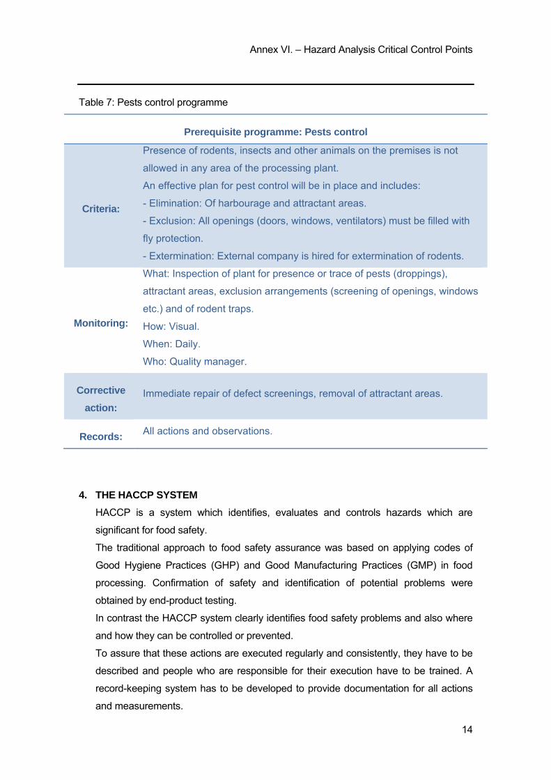
Annex VI. – Hazard Analysis Critical Control Points
14
Table 7: Pests control programme
Prerequisite programme: Pests control
Criteria:
Presence of rodents, insects and other animals on the premises is not
allowed in any area of the processing plant.
An effective plan for pest control will be in place and includes:
- Elimination: Of harbourage and attractant areas.
- Exclusion: All openings (doors, windows, ventilators) must be filled with
fly protection.
- Extermination: External company is hired for extermination of rodents.
Monitoring:
What: Inspection of plant for presence or trace of pests (droppings),
attractant areas, exclusion arrangements (screening of openings, windows
etc.) and of rodent traps.
How: Visual.
When: Daily.
Who: Quality manager.
Corrective
action:
Immediate repair of defect screenings, removal of attractant areas.
Records: All actions and observations.
4. THE HACCP SYSTEM
HACCP is a system which identifies, evaluates and controls hazards which are
significant for food safety.
The traditional approach to food safety assurance was based on applying codes of
Good Hygiene Practices (GHP) and Good Manufacturing Practices (GMP) in food
processing. Confirmation of safety and identification of potential problems were
obtained by end-product testing.
In contrast the HACCP system clearly identifies food safety problems and also where
and how they can be controlled or prevented.
To assure that these actions are executed regularly and consistently, they have to be
described and people who are responsible for their execution have to be trained. A
record-keeping system has to be developed to provide documentation for all actions
and measurements.
Annex VI. – Hazard Analysis Critical Control Points
15
4.1. BASIC SEVEN PRINCIPLES OF HACCP
Principle 1: conduct a hazard analysis.
Principle 2: determine the critical control points (CCPs).
Principle 3: establish critical limits.
Principle 4: establish monitoring procedures.
Principle 5: establish corrective actions.
Principle 6: establish verification procedures.
Principle 7: establish record-keeping and documentation procedures.
4.2. APPLICATION OF THE HACCP PRINCIPLES
The codex guidelines suggest that the introduction and application of the HACCP
principles should follow 12 steps described below:
Step 1. Assemble the HACCP team:
Introduction of HACCP is a complex process and requires a
multidisciplinary approach by a team of specialists. The microbiologist is of
paramount importance, and must advise the team on all matters related to
microbiology safety and risks.
Other important members of the HACCP team are the processing
specialist, food chemist or food engineer.
Step 2. Describe product:
Is a full and detailed description of the final product.
Elements of the product description: product name, raw materials and
ingredients used, aw, pH, % salt, processing, packaging, storage condition
and shelflife.
Step 3. Identify intended use and consumer:
The intended use should be based on expected use by the consumer. The
use and preparation before use greatly influence the safety of the product.
The intended consumer may be the general public or a particular segment
of the population such as infants or eldering.
Step 4. Construct flow diagram:
It provides a clear simple description of all steps involved in the processing.
Step 5. On-site confirmation of flow diagram:
The constructed flow diagram should be verified on-site for accuracy.
Step 6. List all potential hazards:
Associated with each step in the operation, conduct a hazard analysis and
consider any measure to control identified hazards.
Step 7. Determine the critical control points (CCPs):

Annex VI. – Hazard Analysis Critical Control Points
16
To facility this identification, the use of a CCP decision tree can be of a
great help.
It’s important to note, that if an identified hazard is eliminated or reduced at
a later process step or by normal consumer use, the raw material is not a
CCP.
Step 8. Establish critical limits:
Critical limits are a criterion which separates acceptability from
unacceptability. All critical limits should be scientifically based and refer to
factors such as: time/temperature conditions, water activity, pH…
Microbiological limits should normally be avoided. This is because
microbiological data can usually only be produced by a process which may
take several days.
Step 9. Establish monitoring procedures:
To determine if there is a loss of control and a deviation occurs at a CCP.
Appropriate action must then be taken.
Monitoring keeps check on the operation and provides information whether
there is a trend towards loos of control and action can be taken to bring the
process back into control before a deviation occur.
Provides written documentation for use in verification and audit.
Step 10. Establish corrective actions:
A corrective action is any action to be taken when the results of monitoring
at the CCP indicate a loss of control. These actions should include:
Determine and correct the cause of deviation.
Determine the disposition of products that were produced during
the process deviation.
Record the corrective action taken.
Step 11. Establish verification procedures:
Verification is the application of methods, procedures, tests and other
evaluation, in addition to monitoring to determine the compliance with the
HACCP plan.
An essential complement of verification is validation that is obtaining
evidence that the elements of the HACCP plan are effective.
Step 12. Establish record-keeping and documentation procedures:
Record keeping ensure that the information resulting from the HACCP
study and implementation of the resulting HACCP plan is available for
validation, verification, review, auditing and other purposes.

Annex VI. – Hazard Analysis Critical Control Points
17
5. HAZARD ANALYSIS OF RAW MATERIAL
In a general hazard analysis of the pre-harvest conditions for fish and shellfish and the
procedures for handling the raw material before being received at the processing plant
a number of significant hazards can be identified:
- Pathogenic bacteria:
o Pathogenic bacteria from the aquatic or general environment may be
present in low numbers in all fish and shellfish at the time of harvest so this
is not a significant hazard. However, if growth and toxin production of this
organism is taking place as a result of time/temperature abuse, it is
reasonably likely that these pathogens and their toxins could be reach
unsafe levels. For fish to be eaten war or used as raw material in products
that are not heat-treated, this situation is a significant hazard that must be
controlled.
o Pathogenic bacteria from animal/human reservoir may be present in fish
and shellfish harvested in contaminated waters. This is a significant hazard
for fish and shellfish to be eaten raw due to the low Minimum Infective
Dose (MID) from some of these organisms. The preventive measure for
these hazards are control and monitoring of harvest areas for faecal
pollution and placing a limit on the time between harvest and refrigeration
prevent growth and toxin production.
- Viruses: the presence of viruses in the harvest area is of particular concern in
molluscan shellfish.
- Biotoxins: contamination of fish and shellfish with natural toxins from the harvest
area can cause serious consumer illness. The toxins accumulate in fish when they
feed on marine algae, where the toxins are produced. The preventive measures
for the presence of biotoxins are control and classification of harvesting areas. As
a result, fish harvesting is only allowed from “safe” waters.
- Biogenic amines: these amines are produced as a result of time/temperature
abuse of certain fish species and they can cause illness in consumers. The
preventive measure is rapid chilling of fish immediately after capture. Generally,
fish should be packed in ice or chilled sea water in less than 12 hours after catch
or chilled to an internal temperature of 10ºC or less whithin 6 hours after capture.
- Parasites: it is reasonably likely that parasites will be present in significant
numbers of wild caught fish species. Thus, parasites should be considered a
significant hazard and a preventive measure to eliminate parasites must be
identified during the processing of any particular fish products.

Annex VI. – Hazard Analysis Critical Control Points
18
5.1. RAW FISH TO BE CONSUMED RAW
Contamination of raw fish with indigenous pathogenic bacteria is unlikely to be
high enough to provoke disease and therefore not a significant hazard. Growth of
these bacteria and of histamine producing bacteria is a potential hazard, but it is
very unlikely in a product to be eaten raw.
Table 9 shows the hazard analysis of raw fish to be consumed raw.
The significant hazards are:
o Contamination of fish with non-indigenous bacteria, viruses or biotoxins.
o Presence of parasites.
Table 8 shows the two CCPs that are identified in the processing of raw fish to be
eaten raw: the receiving step and the freezing step.
Table 8. Raw fish to be consumed raw programme.
Raw fish to be consumed raw programme
Critical limits:
1. In situations where contamination with non-indigenous
pathogens from the harvest area is a possibility, a source
control or certificate must accompany all lots of fish.
2. Critical limits for the freezing step.
Monitoring
program:
What: time and temperature at freezing step.
How: visual check.
When: all containers. Continuous recording of freezing temperature.
Who: receiving employee.
Corrective
actions:
1. Reject if untagged or from closed areas.
2. Adjust freezer. Refreeze material not properly frozen.
Record
keeping:
1. Receiving record on all fish raw material.
2. Temperature records.
Verification: Daily review of records.

Annex VI. – Hazard Analysis Critical Control Points
19
Table 9. Hazard analysis of raw fish to be consumed raw
Organism/ component of
concern
Potential hazard Analysis of hazard Control
Contamination Growth SeverityLikely
occurrence Significant
Govt. monitoring
programme
Pre-requisite
Programme
Incl. In
HACCP
plan
Pathogenic
bacteria
Indigenous - + High Low -
Non-
indigenous + - High High + + + +
Viruses + - High High + + + +
Biotoxins + - High High/low +/-
(+) - +
Biogenic amines - + Low Low -
Parasites + - Low High + - - +
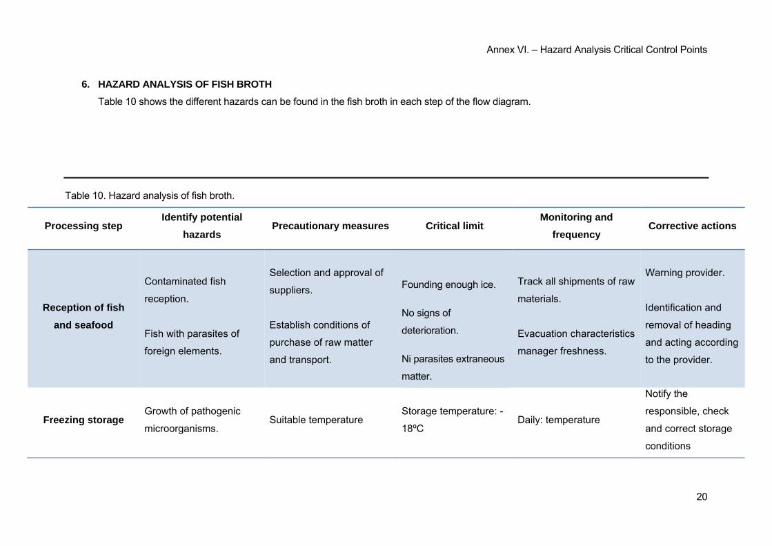
Annex VI. – Hazard Analysis Critical Control Points
20
6. HAZARD ANALYSIS OF FISH BROTH
Table 10 shows the different hazards can be found in the fish broth in each step of the flow diagram.
Table 10. Hazard analysis of fish broth.
Processing step Identify potential
hazards Precautionary measures Critical limit
Monitoring and
frequency Corrective actions
Reception of fish
and seafood
Contaminated fish
reception.
Fish with parasites of
foreign elements.
Selection and approval of
suppliers.
Establish conditions of
purchase of raw matter
and transport.
Founding enough ice.
No signs of
deterioration.
Ni parasites extraneous
matter.
Track all shipments of raw
materials.
Evacuation characteristics
manager freshness.
Warning provider.
Identification and
removal of heading
and acting according
to the provider.
Freezing storage Growth of pathogenic
microorganisms. Suitable temperature
Storage temperature: -
18ºC Daily: temperature
Notify the
responsible, check
and correct storage
conditions
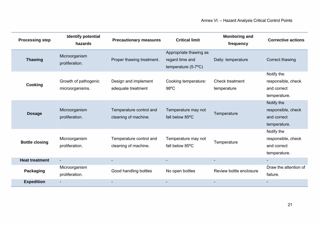
Annex VI. – Hazard Analysis Critical Control Points
21
Processing step Identify potential
hazards Precautionary measures Critical limit
Monitoring and
frequency Corrective actions
Thawing Microorganism
proliferation. Proper thawing treatment.
Appropriate thawing as
regard time and
temperature (5-7ºC)
Daily: temperature Correct thawing
Cooking Growth of pathogenic
microorganisms.
Design and implement
adequate treatment
Cooking temperature:
98ºC
Check treatment
temperature
Notify the
responsible, check
and correct
temperature.
Dosage Microorganism
proliferation.
Temperature control and
cleaning of machine.
Temperature may not
fall below 85ºC Temperature
Notify the
responsible, check
and correct
temperature.
Bottle closing Microorganism
proliferation.
Temperature control and
cleaning of machine.
Temperature may not
fall below 85ºC Temperature
Notify the
responsible, check
and correct
temperature.
Heat treatment - - - - -
Packaging Microorganism
proliferation. Good handling bottles No open bottles Review bottle enclosure
Draw the attention of
failure.
Expedition - - - - -

Annex VI. – Hazard Analysis Critical Control Points
22
The information source to realize this Annex is:
FAO, Fisheries Technical Paper Nº 444. Assessment and Management of Seafood
Safety and Quality. Rome, 2004.
ANNEX VII
ANNEX VII. – SAFETY AND HEALTH STUDY
INDEX
1. THE COMPLIANCE OF 1627/97 of 24 OCTOBER PROVISIONS ON MINIMUM SAFETY AND
HEALTH IN CONSTRUCTION WORKS ..................................................................................................... 3
1.1. INTRODUCTION .......................................................................................................................... 3
2. GENERAL PRINCIPLES APPLICABLE DURING THE EXECUTION OF WORK ............................. 4
3. RISKS IDENTIFICATION .................................................................................................................... 5
3.1. MEANS AND MACHINERY ......................................................................................................... 6
3.2. PREVIOUS WORK ...................................................................................................................... 6
3.3. LAND MOVEMENTS AND EXCAVATIONS ............................................................................... 6
3.4. STRUCTURE ............................................................................................................................... 7
3.5. BOUQUET OF BRICKLAYER ..................................................................................................... 7
3.6. COVER ......................................................................................................................................... 7
3.7. COATINGS AND FINISHES ........................................................................................................ 8
3.8. INSTALLATIONS......................................................................................................................... 8
4. PREVENTION AND PROTECTION MEASURES ............................................................................... 9
4.1. COLLECTIVE PROTECTION MEASURES ................................................................................ 9
4.2. INDIVIDUAL PROTECTION MEASURES .................................................................................. 9
4.3. PROTECTION MEASURES TO THIRD .................................................................................... 10
5. FIRST AID .......................................................................................................................................... 10

3
1. THE COMPLIANCE OF 1627/97 of 24 OCTOBER PROVISIONS ON MINIMUM SAFETY
AND HEALTH IN CONSTRUCTION WORKS
1.1. INTRODUCTION
This study established the Basic Health and Safety, during the execution of this work,
forecasts regarding the prevention of occupational accidents and illnesses, as well as useful
information to carry in his day, proper safety and health, predictable maintenance work later.
Will provide basic guidelines for the construction company to carry out their obligations in
the field of health and safety professionals, facilitating their development, according to Royal
Decree 1627/1997 of 24 October, laying down minimum safety and health in construction.
Based on article 7th, and implementation of the Basic Health and Safety Study, the
contractor shall prepare a Plan for Safety and Health at Work which analyses, study,
develop and complement the provisions contained in this document.
The Health and Safety Plan must be approved before the start of the work by the Health
and Safety Coordinator during the execution of the work, or where there is none, by the
Project Management. In the case of works of public administration must be submitted for the
approval of this administration.
It recalls the obligation that every workplace there is a Book of incidents by monitoring the
Plan. The annotations made to the Book of incidents should get the attention of the
Inspectorate of Labour and Social Security, within 24 hours, when there are repetitions of
the incident.
According to article 15th Royal Decree, contractors and sub-contractors must ensure that
workers receive appropriate information on all measures of safety and health at work.
The communication opening workplace occupational competent authority shall include the
Health and Safety Plan, should be made prior to the start of work and present only those
considered to be entrepreneurs contractors.
The Health and Safety Coordinator during the execution of the work or any member of the
Project Management should see an imminent serious risk to the safety of workers will stop
work completely or partially, communicating it the Inspectorate of Labour and Social
Security, the contractor, sub-contractors and workers' representatives.
4
The responsibility of the coordinators of the Project Management and the developer does
not exempt its responsibilities to contractors and sub-contractors (Art. 11th).
2. GENERAL PRINCIPLES APPLICABLE DURING THE EXECUTION OF WORK
Article 10 of Royal Decree 1627/1997 states that apply the principles of preventive action
contained in Art. 15th of "Labour Risks Prevention Act (Ley 31/1995 of 8 November)" during
the execution of the work and in particular in the following activities:
- The maintenance of the work in good order and cleanliness.
- The choice of the location of places and work areas, taking into account the conditions
of access and determining routes or areas of displacement or movement.
- The manipulation of different materials and the use of auxiliary means.
- The maintenance, control prior to commissioning and periodic control facilities and
devices necessary for the execution of the work, with the object of correcting defects
that could affect the safety and health of worker.
- Delimitation and preparation areas and storage tank of the different materials.
- The collection of hazardous materials used.
- Storage and disposal or removal of waste and debris.
- The adaptation depending on the evolution of work time cash should be spent on
different tasks or phases of the work.
- Cooperation between contractors, sub-contractors and freelancers.
- Interactions and incompatibilities with any other work or activity that is done on site or
near the work
The principles of preventive action laid down in the 15th article of the Law 31/95 are:
The employer implements measures that make up the general duty of prevention, in
accordance with the following general principles:
o Avoid risks.
o Assess the risks cannot be avoided.
o Combating risks at source.
o Adapt the job to the person, particularly with regard to the design of workplaces, the
choice of equipment and methods of work and production, to reduce monotonous and
repetitive work and reduce the effects of same health.
o Taking into account the evolution of technology.
o Replace what is dangerous by what has little or no danger.
5
o Plan prevention, seeking a coherent whole that integrates technology, work
organization, working conditions, social relationships and the influence of
environmental factors at work.
o Adopt measures that put collective protection ahead of the individual.
o Give appropriate instructions to workers.
The employer shall take into consideration the professional skills of workers in safety
and health at the time of the tasks entrusted.
The employer shall take the necessary measures to ensure that only workers who have
received sufficient and appropriate information to access the serious and specific risk
areas.
The effectiveness of preventive measures will provide distractions and reckless
imprudence he could not commit the worker. For its implementation will take into
account the additional risks that may involve certain preventive measures that can be
adopted only when the magnitude of such risks is substantially lower than that of control
and tries safer alternatives do not exist.
May arrange insurance operations whose purpose is to guarantee coverage area as
forecast risks arising from work, the company with respect to its workers, freelancers
respect themselves and respect the cooperatives partners whose activity consists in the
provision of their work.
3. RISKS IDENTIFICATION
Notwithstanding the minimum health and safety applicable to the work set out in Annex IV of
Royal Decree 1627/1997 of 24 October , listed below are the particular risks in different
work force, even considering that some of them may occur during the process of
implementation of the work or be applicable to other jobs .
Should take special care in the most common hazards in the works, such as are falls, cuts,
burns, erosions and blows , having taken each time the position most suitable for the work
to be carried out .
In addition, consider the possible repercussions to the neighbouring building structures and
care at all times to minimize the risk of fire.
6
However, risks related to be taken into account by the foreseeable subsequent work (repair,
maintenance...).
3.1. MEANS AND MACHINERY
- Road accidents, crashes with other vehicles, trapped.
- Interference with supply public facilities (water, electricity, gas…).
- Collapsed and/or fall in construction machinery (silos, cranes…).
- Risks arising from operating cranes.
- Falling cargo.
- Generation excessive dust or toxic gas emanation.
- Falls from high points and/or from temporary elements of access (stairs, platforms).
- Cops and setbacks.
- Falling materials rebounds.
- Excessively noisy environment.
- Direct or indirect electrical contacts.
- Accidents resulting from atmospheric conditions.
3.2. PREVIOUS WORK
- Interference with supply public facilities (water, electricity, gas…).
- Falls from high points and/or from temporary elements of access (stairs, platforms).
- Cops and setbacks.
- Falling materials rebounds.
- About efforts to incorrect postures.
- Overturning cell materials.
- Risks arising from the storage of materials (temperature, humidity, chemical
reactions).
3.3. LAND MOVEMENTS AND EXCAVATIONS
- Interference with supply public facilities (water, electricity, gas…).
- Generation excessive dust or toxic gas emanation.
- Falls from high points and/or from temporary elements of access (stairs, platforms).
- Cops and setbacks.
- Detachment and/or landslide and/or rocks.
- Falling materials rebounds.
- Excessively noisy environment.
- Collapsed and/or collapse of retaining walls, ditches and wells.
- Collapsed and/or collapse of neighbouring buildings.
- Accidents resulting from atmospheric conditions.
7
- About efforts to incorrect postures.
3.4. STRUCTURE
- Interference with supply public facilities (water, electricity, gas…).
- Screening particles during the works.
- Falls from high points and/or from temporary elements of access (stairs, platforms).
- Contacts with aggressive materials.
- Cuts and punctures.
- Cops and setbacks.
- Falling materials rebounds.
- Excessively noisy environment.
- Direct or indirect electrical contacts.
- About efforts to incorrect postures.
- Bankruptcy formwork.
- Generation excessive dust or toxic gas emanation.
- Overturning piles of material.
- Risks arising from the storage of materials (temperature, humidity, chemical
reactions).
- Risks arising from access to plants.
- Risks arising from the rise and receipt of materials.
3.5. BOUQUET OF BRICKLAYER
- Generation excessive dust or toxic gas emanation.
- Screening particles during the works.
- Falls from high points and/or from temporary elements of access (stairs, platforms).
- Contacts with aggressive materials.
- Cuts and punctures.
- Cops and setbacks.
- Falling materials rebounds.
- Excessively noisy environment.
- About efforts to incorrect postures.
- Overturning piles of material.
- Risks arising from the storage of materials (temperature, humidity, chemical
reactions).
3.6. COVER
- Interference with supply public facilities (water, electricity, gas…).
- Screening particles during the works.
8
- Falls from high points and/or from temporary elements of access (stairs, platforms).
- Contacts with aggressive materials.
- Cuts and punctures.
- Cops and setbacks.
- Falling materials rebounds.
- Excessively noisy environment.
- About efforts to incorrect postures.
- Generation excessive dust or toxic gas emanation.
- Falls masts and antennas.
- Overturning piles of material.
- Risks arising from the storage of materials (temperature, humidity, chemical
reactions).
3.7. COATINGS AND FINISHES
- Generation excessive dust or toxic gas emanation.
- Screening particles during the works.
- Falls from high points and/or from temporary elements of access (stairs, platforms).
- Contacts with aggressive materials.
- Cuts and punctures.
- Cops and setbacks.
- Falling materials rebounds.
- About efforts to incorrect postures.
- Overturning piles of material.
- Risks arising from the storage of materials (temperature, humidity, chemical
reactions).
3.8. INSTALLATIONS
- Interference with supply public facilities (water, electricity, gas…).
- Falls from high points and/or from temporary elements of access (stairs, platforms).
- Cuts and punctures.
- Cops and setbacks.
- Falling materials rebounds.
- Emanation of gases in openings cesspools.
- Direct or indirect electrical contacts.
- On - efforts to incorrect postures.
- Falls masts and antennas.
9
4. PREVENTION AND PROTECTION MEASURES
As a general rule take priority protections collective versus individual. In addition, it must be
kept in good condition media auxiliary machinery and work tools. Moreover the means of
protection must be approved according to current regulations.
However, related measures must take into account for the foreseeable subsequent work
(repair, maintenance…).
4.1. COLLECTIVE PROTECTION MEASURES
- Organization and planning work to avoid interference between different jobs and
circulation within the work.
- Signalling danger zones.
- Provide system vehicles and their signalling, both within the work as compared with
the roads outside.
- Let free zone around the area excavated by the passage of machinery.
- Immobilization of trucks using wedges and/or stops during loading and unloading.
- Respect the safety distances with existing facilities.
- The elements of the facilities must be insulated with its protections.
- Foundations correct construction machinery.
- Assembly cranes made by a specialized company, with regular reviews, control of the
maximum load, delimitation of scope, braking, blocking, etc.
- Periodic review and maintenance of machinery and work equipment.
- Irrigation system that prevents the emission of dust in large quantity.
- Checking the appropriateness of implementing solutions to the real state of the
elements (subsoil neighbouring buildings).
- Checking shoring, conditions estrebats protective screens and ditches.
- Use non-slip flooring.
- Installation of guardrail in places with danger of falling.
- Put holes in horizontal networks.
- Protection holes and walls to prevent falling objects (nets, tarpaulins).
- Using pipelines evacuation of debris, properly installed.
- Using ladders, scaffolds and work platforms.
- Placement platform for receiving materials on upper floors.
4.2. INDIVIDUAL PROTECTION MEASURES
- Using masks and goggles approved dust and / or particle projection.
- Use of safety footwear.
- Using helmet.

10
- In all areas where there is high fixed protection systems must be established anchor
points to hold it secure seatbelts approved the use of which is mandatory.
- Use of gloves approved to avoid direct contact with aggressive materials and minimize
the risk of cuts and punctures.
- Use of hearing protectors approved excessively noisy environments.
- Using aprons.
- Fastening systems and permanent monitoring by more than one operator in the work
with danger of poisoning. Use of air supply equipment.
4.3. PROTECTION MEASURES TO THIRD
- Using masks and goggles approved dust and / or particle projection.
- Use of safety footwear.
- Using helmet.
- In all areas where there is high fixed protection systems must be established anchor
points to hold it secure seatbelts approved the use of which is mandatory.
- Use of gloves approved to avoid direct contact with aggressive materials and minimize
the risk of cuts and punctures.
- Use of hearing protectors approved excessively noisy environments.
- Using aprons.
- Fastening systems and permanent monitoring by more than one operator in the work
with danger of poisoning. Use of air supply equipment.
5. FIRST AID
We have a first aid kit with content material specified in the regulations.
Informed at the beginning of the work, the situation of medical centres that must transfer the
victims. It is desirable to have the work and clearly visible from a list of addresses and
phone numbers assigned to emergency centres, ambulances, taxis, etc. to ensure the rapid
transfer of potential victims.

ANNEX VIII
Annex VIII. – Financial Economic Assessment
2
ANNEX VIII. – FINANCIAL ECONOMIC ASSESSMENT
INDEX
1. OBJECT ................................................................................................................................. 3
2. PARAMETERS DEFINING INVESTMENT ........................................................................... 3
2.1. INVESTMENT – INITIAL ............................................................................................... 3
2.2. PROJECT YEARS LIFE ............................................................................................... 3
2.3. REFRESH RATE ........................................................................................................... 3
2.4. CASH FLOW ................................................................................................................. 3
2.4.1. REGULAR PAYMENTS ........................................................................................ 3
2.4.2. EXTRAORDINARY PAYMENTS .......................................................................... 4
2.4.3. ORDINARY CHARGES ........................................................................................ 5
2.4.4. EXTRAORDINARY CHARGES ............................................................................ 6
3. CONCLUSIONS ..................................................................................................................... 6
Annex VIII. – Financial Economic Assessment
3
1. OBJECT
The aim of this Annex is to analyse the feasibility of the project in economic terms
using a dynamic methodology while payments and receipts are projected over the
life of the investment.
Will be evaluated the return on investment using the following economic indicators:
Net Present Value (NPV), Internal Rate of Return (IRR), Payback Period, and
earnings per euro invested (NPV/k).
2. PARAMETERS DEFINING INVESTMENT
2.1. INVESTMENT – INITIAL
The initial investment consists of fixed assets newly acquired reflected in the
document 3: budget that has been granted VAT, totalling the amount of
246.777,89 €.
2.2. PROJECT YEARS LIFE
Life years have been estimated based on the useful life of equipment
installation, so this is reflected in 10 years.
2.3. REFRESH RATE
The refresh rate is initially considered as 5%. It has been estimated by
comparing different investment opportunities in the bond markets the National
Treasury.
2.4. CASH FLOW
2.4.1. REGULAR PAYMENTS
The ordinary payments constitute them all those expenses produced by
the own activity of the investment. In the present project the ordinary
payments are composed by:
- The total annual cost of 4 workers who are in the production of fish
broth and prawn carpaccio. 20.000 € for each worker (public health
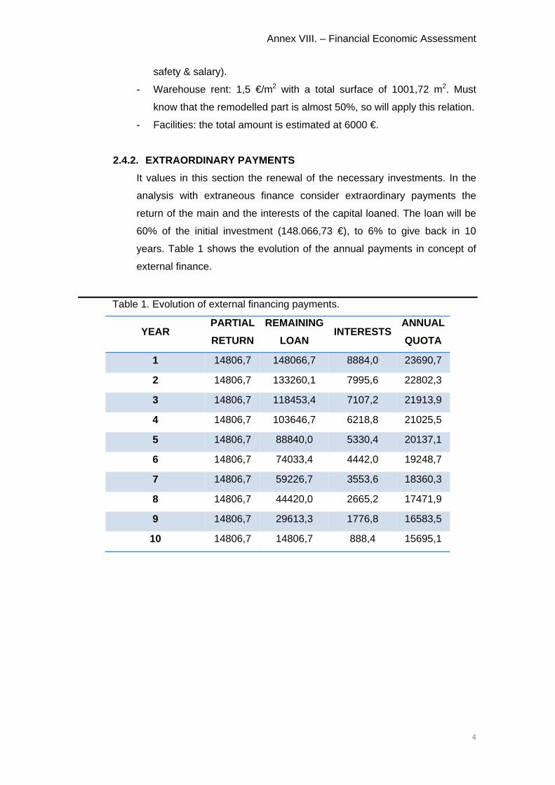
Annex VIII. – Financial Economic Assessment
4
safety & salary).
- Warehouse rent: 1,5 €/m2 with a total surface of 1001,72 m2. Must
know that the remodelled part is almost 50%, so will apply this relation.
- Facilities: the total amount is estimated at 6000 €.
2.4.2. EXTRAORDINARY PAYMENTS
It values in this section the renewal of the necessary investments. In the
analysis with extraneous finance consider extraordinary payments the
return of the main and the interests of the capital loaned. The loan will be
60% of the initial investment (148.066,73 €), to 6% to give back in 10
years. Table 1 shows the evolution of the annual payments in concept of
external finance.
Table 1. Evolution of external financing payments.
YEAR PARTIAL
RETURN
REMAINING
LOAN INTERESTS
ANNUAL
QUOTA
1 14806,7 148066,7 8884,0 23690,7
2 14806,7 133260,1 7995,6 22802,3
3 14806,7 118453,4 7107,2 21913,9
4 14806,7 103646,7 6218,8 21025,5
5 14806,7 88840,0 5330,4 20137,1
6 14806,7 74033,4 4442,0 19248,7
7 14806,7 59226,7 3553,6 18360,3
8 14806,7 44420,0 2665,2 17471,9
9 14806,7 29613,3 1776,8 16583,5
10 14806,7 14806,7 888,4 15695,1

Annex VIII. – Financial Economic Assessment
5
2.4.3. ORDINARY CHARGES
Ordinary charges correspond to the sales of products, knowing the data
shown in table 2:
Table 2. Ordinary charges.
FISH BROTH
Units €
Total
€/L
DAILY SALES 1200 1,5 1800
RAW MATTER
Monkfish 20 12 -240
Conger 30 2 -60
Jurel 30 1,5 -45
Prawn
heads 2 0 0
Crabs 10 0,5 -5
Fried
tomato 10 1 -10
Condiments 4 2 -8
PACKAGING 1200 0,5 -600
GROSS MARGIN 106 832
PRAWN CARPACCIO
Units €
Total
€/120 g
trays
DAILY SALES 500 8 4000
RAW MATTER Prawn 125 25 -3125
Factor
Converting
1 kg prawn
gross = 0,48
kg net prawn
PACKAGING 500 0,5 -250
GROSS MARGIN 125 625
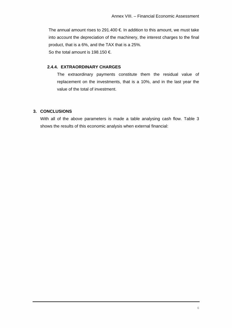
Annex VIII. – Financial Economic Assessment
6
The annual amount rises to 291.400 €. In addition to this amount, we must take
into account the depreciation of the machinery, the interest charges to the final
product, that is a 6%, and the TAX that is a 25%.
So the total amount is 198.150 €.
2.4.4. EXTRAORDINARY CHARGES
The extraordinary payments constitute them the residual value of
replacement on the investments, that is a 10%, and in the last year the
value of the total of investment.
3. CONCLUSIONS
With all of the above parameters is made a table analysing cash flow. Table 3
shows the results of this economic analysis when external financial:
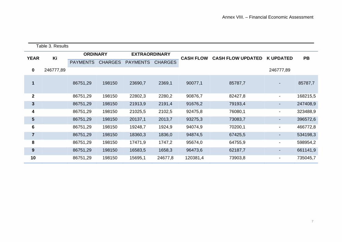
Annex VIII. – Financial Economic Assessment
7
Table 3. Results
YEAR Ki ORDINARY EXTRAORDINARY
CASH FLOW CASH FLOW UPDATED K UPDATED PB PAYMENTS CHARGES PAYMENTS CHARGES
0 246777,89 246777,89
1
86751,29 198150 23690,7 2369,1 90077,1 85787,7 - 85787,7
2 86751,29 198150 22802,3 2280,2 90876,7 82427,8 - 168215,5
3 86751,29 198150 21913,9 2191,4 91676,2 79193,4 - 247408,9
4 86751,29 198150 21025,5 2102,5 92475,8 76080,1 - 323488,9
5 86751,29 198150 20137,1 2013,7 93275,3 73083,7 - 396572,6
6 86751,29 198150 19248,7 1924,9 94074,9 70200,1 - 466772,8
7 86751,29 198150 18360,3 1836,0 94874,5 67425,5 - 534198,3
8 86751,29 198150 17471,9 1747,2 95674,0 64755,9 - 598954,2
9 86751,29 198150 16583,5 1658,3 96473,6 62187,7 - 661141,9
10 86751,29 198150 15695,1 24677,8 120381,4 73903,8 - 735045,7
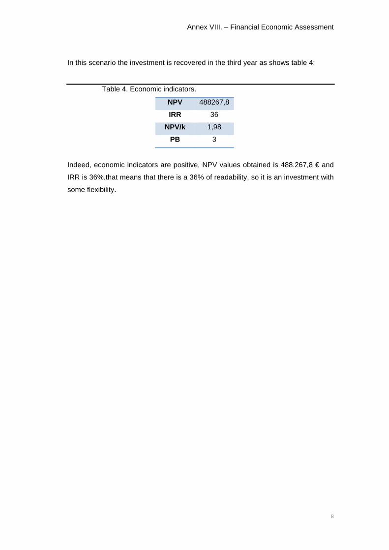
Annex VIII. – Financial Economic Assessment
8
In this scenario the investment is recovered in the third year as shows table 4:
Table 4. Economic indicators.
NPV 488267,8
IRR 36
NPV/k 1,98
PB 3
Indeed, economic indicators are positive, NPV values obtained is 488.267,8 € and
IRR is 36%.that means that there is a 36% of readability, so it is an investment with
some flexibility.

Plant
t layout project for the eenlargementt of fishing i
Escola Su
ndustry loca
uperior d’AgricU
ated in Rose
ultura de BarcUPC ‐ Barcelon
2ND D
es (Girona)
celona aTech
DOCUME
PLA
ENT:
ANS

LOCATION
0,97
1,09
4,674,67
4,93
4,50
4,934,79
4,654,64
3,993,96
4,02
4,05
4,42
1,14
1,01
1,16
1,18
1,19
0.87
0,84
0,850,85
0,88
0,89
0,87
0,840,83
0,850,82
0,85
0,84
0,83
0,86
1,03
0,97
3,90
3,86
4,654,674,84
4,844,51
4,73
4,79
4,66
4,60
4,70
4,74
4,854,55
4,734,74 4,68
4,50
4,82
4,704,71 4,69
4,72
4,90
4,57 4,564,63 4,60
4,90
4,61
4,50
4,58 4,54
4,47
4,55 4,53
4,534,52
4,56
4,53 4,514,47
4,484,42
4,474,40
4,43
4,55
4,39 4,40
4,51
4,37 4,374,31
4,30
4,27
4,19
4,29
4,16
4,24
4,22 4,22
4,28
4,214,24
4,204,20
4,22 4,17
4,124,15
4,07
4,13
4,054,07
4,11
4,14
4,10
1,13
1,30
1,35
1,34
1,28
1,11
1,25
1,00
0,77
1,02
4,02
3,99
3,89
3,93
4,04
4,03
4,18
4,05 4,04
4,02 4,02
3,96
3,97
3,99
4,14
3,85
3,84
4,13
4,01
3,99
4,013,99
4,09 4,06
3,72
3,95
4,034,04
4,03
4,05
3,89
0.94
4,58
4,41
4,59
4,76
4,62
4,49
4,67
4,574,60
4,594,67
4,50
4,74
4,63
4,62
4,68 4,70
4,66
4,62
4,52
4,79
4,66
4,78
4,74
4,73
4,69
4,89
4,794,77
4,83
4,81 4,81
4,70
4,94
4,64
4,94
4,814,82
4,76
4,81 4,80
4,93
4,77 4,76
4,74
4,71
4,634,89
4,75 4,76
1,00
0,71
P-2
P-3
4,76 4,71 4,604,38 4,34 4,28 4,244,514,554,474,614,93 4,83
4,80 4,70 4,46 4,364,39 4,41 4,214,19 4,154,214,264,29
vial de circulació del moll
MOLL DE RIBERA PORT OF ROSES (GIRONA)
DATETUTOR
EDUARD HERNÁNDEZ YAÑEZ 10/JULY/2015
SCALE:
PLANT LAYOUT PROJECT FOR THE ENLARGEMENTOF FISHING INDUSTRY
CLARA VINGUT EXPÓSITO
PLAN TITLE: 01LOCATION
1/08
DIN A2: 1/500
BACHEROL'S DEGREE IN FOOD ENGINEERING
BARCELONA SCHOOLOF AGRICULTURALENGINEERING
N
OE
S
SO
SE
60º
60
º
30
º
21
º 24
º 27º
18
º
α

REMODELLING ZONE
LEGEND
4.94
1.191.03
MOLL DE RIBERA PORT OF ROSES (GIRONA)
DATETUTOR
EDUARD HERNÁNDEZ YAÑEZ 10/JULY/2015
SCALE:
PLANT LAYOUT PROJECT FOR THE ENLARGEMENTOF FISHING INDUSTRY
DIN A2: 1/200
CLARA VINGUT EXPÓSITO
PLAN TITLE: 022/08
BACHEROL'S DEGREE IN FOOD ENGINEERING
BARCELONA SCHOOLOF AGRICULTURALENGINEERINGN
OE
S
SO
SE
60
º60
º
30
º
21
º 24
º 27
º1
8º
α
WEST FACADE
CURRENT STATUS:PLANT FLOOR AND WEST FACADE

r i d e r i d er i d e
POLYISOCYANURATE WALL
LEGEND WALLS
BRICK WALL
TOTAL SURFACETOTAL VOLUME 3205,530 m3
1001,727 m2
MEASURES
470
445
300
1140
785
1996 490
475
435
435
676
470
200
200
1010 21 925
310
635
1043
510
155
600 10 401 10 560 20 355
955
925
144
1022
620
450
2039
520
3044
520
125
30
200
10
510
THE DIMENSIONS ARE EXPRESSED IN CENTIMETERS
NOTE
su: 11.18 m²v : 35.79 m³
CORRIDOR 1
su: 21.31 m²v : 68.20 m³
PACKING STORAGE
su: 39.66 m²v : 126.91 m³
RECEPTION & CLEANING Z
su: 11.51 m²v : 36.84 m³
CORRIDOR 2
su: 8.62 m²v : 27.58 m³
CORRIDOR 3
su: 36.33 m²v : 116.26 m³
MACHINERY ROOM
su: 239.41 m²v : 766.12 m³
MUSSELS PRODUCTION
su: 9.94 m²v : 31.81 m³
KITCHEN
su: 24.94 m²v : 79.80 m³
OFFICE
su: 14.88 m²v : 47.60 m³
WOMEN WARDROBE
su: 19.86 m²v : 63.55 m³
MEN WARDROBES
su: 63.69 m²v : 203.80 m³
BROTH PRODUCTION
su: 41.18 m²v : 131.76 m³
FREEZER
su: 4.00 m²v : 12.80 m³
su: 30.40 m²v : 97.27 m³
EXPEDITION CORRIDOR
su: 39.48 m²v : 126.33 m³
DEFROSTER
su: 14.19 m²v : 45.41 m³
CARPACCIO PACKAGING
su: 21.81 m²v : 69.78 m³
EXPEDITION ZONE
su: 17.43 m²v : 55.77 m³
BROTH PACKAGINGHEAT TREATMENTsu: 26.12 m²v : 83.58 m³
su: 24.36 m²v : 77.95 m³
BROTH STORAGE
su: 41.48 m²v : 132.75 m³
MUSSELS RECEPTION
su: 11.70 m²v : 37.44 m³
LABORATORY
su: 57.76 m²v : 184.82 m³
MUSSELS DEPURATION
su: 31.58 m²v : 101.06 m³
REFRIGERATOR 1su: 62.37 m²v : 199.58 m³
REFRIGERATOR 2
su: 6.20 m²v : 19.84 m³
su: 16.77 m²v : 53.67 m³
su: 53.41 m²v : 170.92 m³
CARPACCIO PRODUCTION
INGREDIENTSSTORAGE
CLEANINGEQUIPMENT ZONE
CARPACCIOSTORAGE
MOLL DE RIBERA PORT OF ROSES (GIRONA)
DATETUTOR
EDUARD HERNÁNDEZ YAÑEZ 10/JULY/2015
SCALE:
PLANT LAYOUT PROJECT FOR THE ENLARGEMENTOF FISHING INDUSTRY
CLARA VINGUT EXPÓSITO
PLAN TITLE: 0303/08
BACHEROL'S DEGREE IN FOOD ENGINEERING
BARCELONA SCHOOLOF AGRICULTURALENGINEERING
DIN A2: 1/100PLANT FLOOR
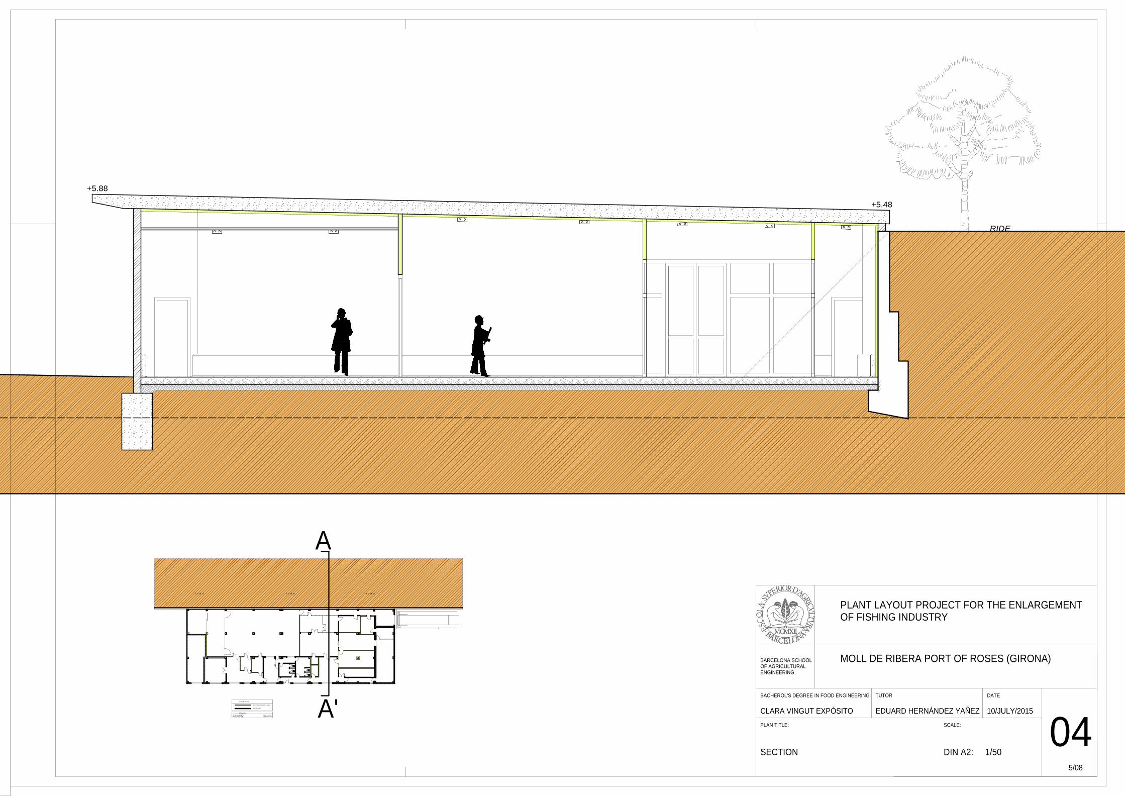
r i d e r i d er i d e
POLYISOCYANURATE WALL
LEGEND WALLS
BRICK WALL
TOTAL SURFACETOTAL VOLUME 3205,530 m3
1001,727 m2
MEASURES
+5.88
+5.48
RIDE
MOLL DE RIBERA PORT OF ROSES (GIRONA)
DATETUTOR
EDUARD HERNÁNDEZ YAÑEZ 10/JULY/2015
SCALE:
PLANT LAYOUT PROJECT FOR THE ENLARGEMENTOF FISHING INDUSTRY
CLARA VINGUT EXPÓSITO
PLAN TITLE:
SECTION
BACHEROL'S DEGREE IN FOOD ENGINEERING
BARCELONA SCHOOLOF AGRICULTURALENGINEERING
DIN A2: 1/50
5/08
04A'
A
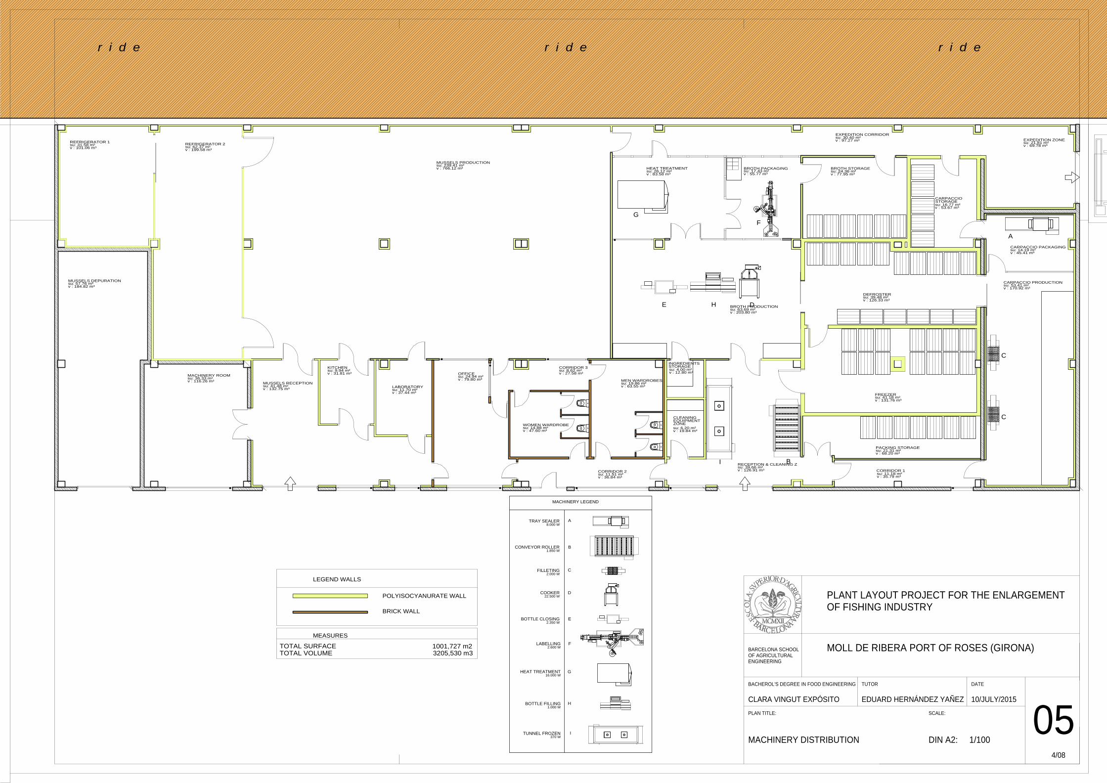
TRAY SEALER8.000 W
A
B
C
D
E
F
G
H
I
FILLETING2.000 W
CONVEYOR ROLLER1.850 W
COOKER22.500 W
BOTTLE CLOSING2.350 W
LABELLING2.600 W
HEAT TREATMENT16.000 W
BOTTLE FILLING1.000 W
TUNNEL FROZEN370 W
MACHINERY LEGEND
r i d e r i d er i d e
POLYISOCYANURATE WALL
LEGEND WALLS
BRICK WALL
TOTAL SURFACETOTAL VOLUME 3205,530 m3
1001,727 m2
MEASURES
su: 11.18 m²v : 35.79 m³
CORRIDOR 1
su: 21.31 m²v : 68.20 m³
PACKING STORAGE
su: 39.66 m²v : 126.91 m³
RECEPTION & CLEANING Z
su: 11.51 m²v : 36.84 m³
CORRIDOR 2
su: 8.62 m²v : 27.58 m³
CORRIDOR 3
su: 36.33 m²v : 116.26 m³
MACHINERY ROOM
su: 239.41 m²v : 766.12 m³
MUSSELS PRODUCTION
su: 9.94 m²v : 31.81 m³
KITCHEN
su: 24.94 m²v : 79.80 m³
OFFICE
su: 14.88 m²v : 47.60 m³
WOMEN WARDROBE
su: 19.86 m²v : 63.55 m³
MEN WARDROBES
su: 63.69 m²v : 203.80 m³
BROTH PRODUCTION
su: 41.18 m²v : 131.76 m³
FREEZER
su: 4.00 m²v : 12.80 m³
su: 30.40 m²v : 97.27 m³
EXPEDITION CORRIDOR
su: 39.48 m²v : 126.33 m³
DEFROSTER
su: 14.19 m²v : 45.41 m³
CARPACCIO PACKAGING
su: 21.81 m²v : 69.78 m³
EXPEDITION ZONE
su: 17.43 m²v : 55.77 m³
BROTH PACKAGINGHEAT TREATMENTsu: 26.12 m²v : 83.58 m³
su: 24.36 m²v : 77.95 m³
BROTH STORAGE
su: 41.48 m²v : 132.75 m³
MUSSELS RECEPTION
su: 11.70 m²v : 37.44 m³
LABORATORY
su: 57.76 m²v : 184.82 m³
MUSSELS DEPURATION
su: 31.58 m²v : 101.06 m³
REFRIGERATOR 1su: 62.37 m²v : 199.58 m³
REFRIGERATOR 2
su: 6.20 m²v : 19.84 m³
su: 16.77 m²v : 53.67 m³
su: 53.41 m²v : 170.92 m³
CARPACCIO PRODUCTION
INGREDIENTSSTORAGE
CLEANINGEQUIPMENT ZONE
CARPACCIOSTORAGE
A
B
C
C
D
F
E
G
H
I
MOLL DE RIBERA PORT OF ROSES (GIRONA)
DATETUTOR
EDUARD HERNÁNDEZ YAÑEZ 10/JULY/2015
SCALE:
PLANT LAYOUT PROJECT FOR THE ENLARGEMENTOF FISHING INDUSTRY
CLARA VINGUT EXPÓSITO
PLAN TITLE:
MACHINERY DISTRIBUTION DIN A2: 1/100
BACHEROL'S DEGREE IN FOOD ENGINEERING
BARCELONA SCHOOLOF AGRICULTURALENGINEERING
4/08
05
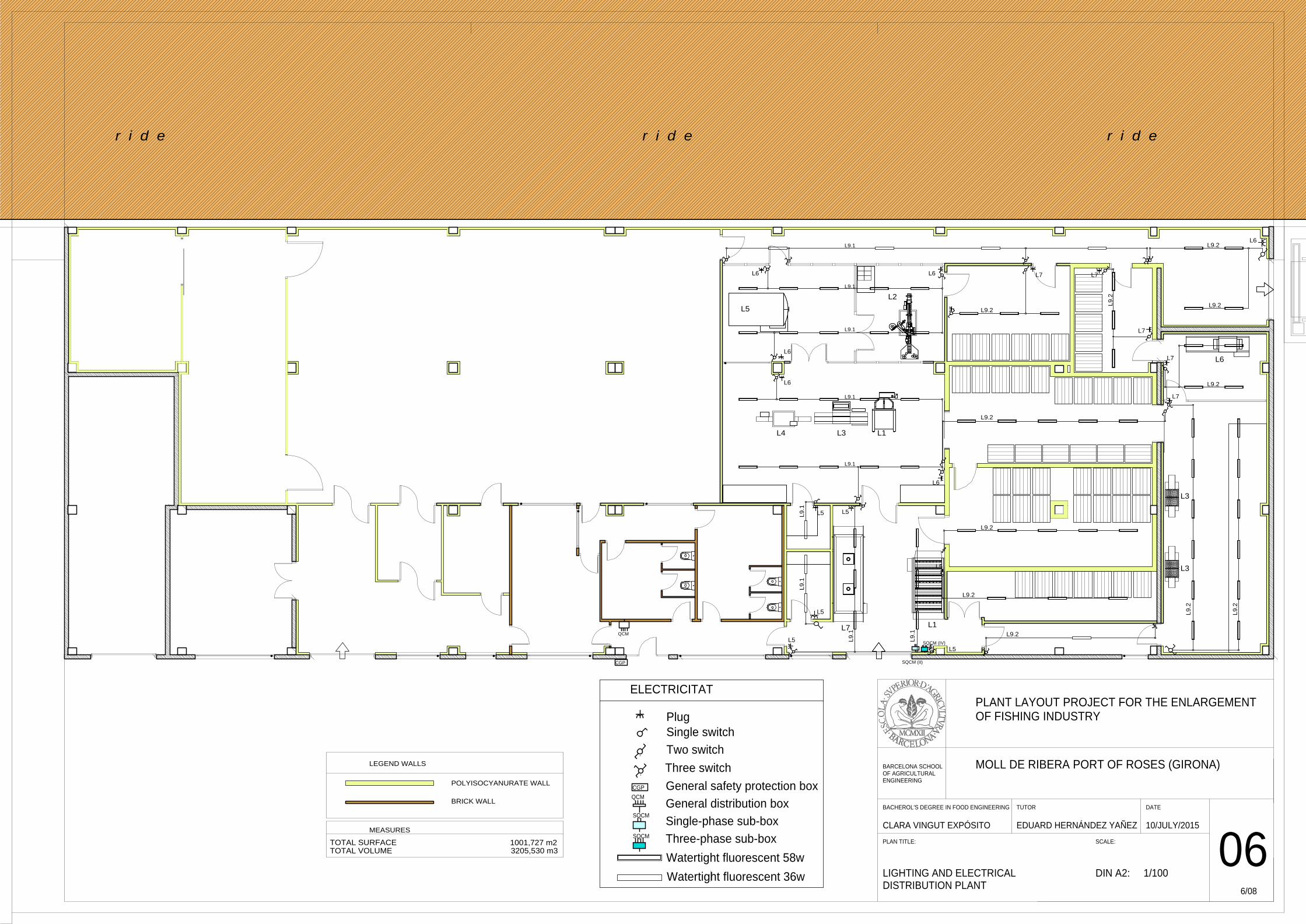
r i d e r i d er i d e
POLYISOCYANURATE WALL
LEGEND WALLS
BRICK WALL
TOTAL SURFACETOTAL VOLUME 3205,530 m3
1001,727 m2
MEASURES
CGP SQCM (II)
SQCM (IV)
QCM
L9
.1
L9.1
L9.1
L9.1
L9.1
L9.1
L9
.1
L9.1
L9
.1
L9.2
L9
.2
L9
.2
L9
.2
L9.2
L9.2
L9.2
L9.2L9.2
L9.2
L9.2
L5
L5
L5 L5
L5
L5
L6
L6
L6
L6 L6
L6
L7 L7
L7
L7
L7
ELECTRICITAT
Plug
General safety protection box
General distribution boxSQCM
Single-phase sub-box
Three-phase sub-box
Watertight fluorescent 36w
Watertight fluorescent 58w
CGP
QCM
Single switch
Two switch
Three switch
SQCM
L2
L6
L4 L3 L1
L3
L3
L7 L1
L5
MOLL DE RIBERA PORT OF ROSES (GIRONA)
DATETUTOR
EDUARD HERNÁNDEZ YAÑEZ 10/JULY/2015
SCALE:
PLANT LAYOUT PROJECT FOR THE ENLARGEMENTOF FISHING INDUSTRY
CLARA VINGUT EXPÓSITO
PLAN TITLE: 066/08
DIN A2: 1/100
BACHEROL'S DEGREE IN FOOD ENGINEERING
BARCELONA SCHOOLOF AGRICULTURALENGINEERING
LIGHTING AND ELECTRICAL DISTRIBUTION PLANT

10A
10A
10ABottle filling
Conveyor rolling
10A
40A
Bottle closing
25A
10A
10A
Tunel frozen
100A
L1 (C 9L)
L2 (C 9L)
L3 (C 9L)
L4 (C 9L)
L5 (C 9L)
L6 (C 9L)
L7 (C 9L)
L8 (C 9L)
Tray sealer
Cooling equipament
Heat treatment
Exhaust system
5.5 m RZ1-K (AS) 0,6/1kV
17.0 m RZ1-K (AS) 0,6/1kV
19.5 m RZ1-K (AS) 0,6/1kV
22.0 m RZ1-K (AS) 0,6/1kV
26.5 m RZ1-K (AS) 0,6/1kV
29.3 m RZ1-K (AS) 0,6/1kV
29.5 m RZ1-K (AS) 0,6/1kV
107.5 m RZ1-K (AS) 0,6/1kV
10A
L2 (C 9L)
L3 (C 9L)
L1 (C 9L) Cooker 2 x 35 T 16
2 x 2,5 T 2,5Labelling16A
Filleting 2 x 2,5 T 2,5
18.3 m RZ1-K (AS) 0,6/1kV
20.5 m RZ1-K (AS) 0,6/1kV
22.3 m RZ1-K (AS) 0,6/1kV
19.0 m RZ1-K (AS) 0,6/1kV
24.0 m RZ1-K (AS) 0,6/1kV
100A
Power PowerCIRCUIT CIRCUIT
125A
40 A
300 mA
63 A
300 mA
63 A
300 mA
CONDUCTOR
mm2
CONDUCTOR
mm2
100 A
300 mA
40 A
300 mA
1.850 W
370 W
1.000 W
2.350 W
16.000 W
8.000 W
370 W
2.980 W
22.500 W
2600 W
2.000 W
10 A /230 V
10 A /230 V6 plugs
6 plugs
10 A /230 V
40 A
300 mA
32A
32A
32A
5 plugsL7 (C 9L)
L6 (C 9L)
L5 (C 9L)
29.0 m RZ1-K (AS) 0,6/1kV
2 x 4.0 T 4.0
2 x 4.0 T 4.0
2 x 4.0 T 4.0
10A
33.3 m RZ1-K (AS) 0,6/1kV
10A 33.5 m RZ1-K (AS) 0,6/1kV
4 x 1,5 T 1,5
4 x 1,5 T 1,5
4 x 1,5 T 1,5
4 x 1,5 T 1,5
4 x 1,5 T 1,5
4 x 10 T 10
4 x 6 T 6
4 x 1,5 T 1,5
4 x 2,5 T 2,5
4 x 1,5 T 1,5
2.698 W
2.090 W
10A
34.5 m RZ1-K (AS) 0,6/1kV
Emergency lighting 2 x 1.5 T 1.5 160 WL4 (C 9L)
20 A
300 mA
L9.1 (C 9L)
L9.2 (C 9L)
Lighting
Lighting
40 A
30 mA
R +
L 2
00 m
IV
IV
IV
II
II
II
II
II
Che
ckpo
int
1 x
35 m
m2
40 k
AU
P 1
.5 k
V
II
LEGEND
I NominalCorve* Class 3* 6 kA Power Cut
R +
L 2
00 m
Che
ckpo
int40
kAU
P 1
.5 k
V
1 x
35 m
m2
IV
II
SURGE PROTECTION
DIFERENTIAL SWITCHConnected to the generalline
THREE PHASE SUB-BOX (SQCM_IV) THREE PHASE SUB-BOX (SQCM_II)
MOLL DE RIBERA PORT OF ROSES (GIRONA)
DATETUTOR
EDUARD HERNÁNDEZ YAÑEZ 10/JULY/2015
SCALE:
PLANT LAYOUT PROJECT FOR THE ENLARGEMENTOF FISHING INDUSTRY
DIN A2: 1/200
CLARA VINGUT EXPÓSITO
PLAN TITLE:
UNIFILAR SCHEME07
7/08
BACHEROL'S DEGREE IN FOOD ENGINEERING
BARCELONA SCHOOLOF AGRICULTURALENGINEERING
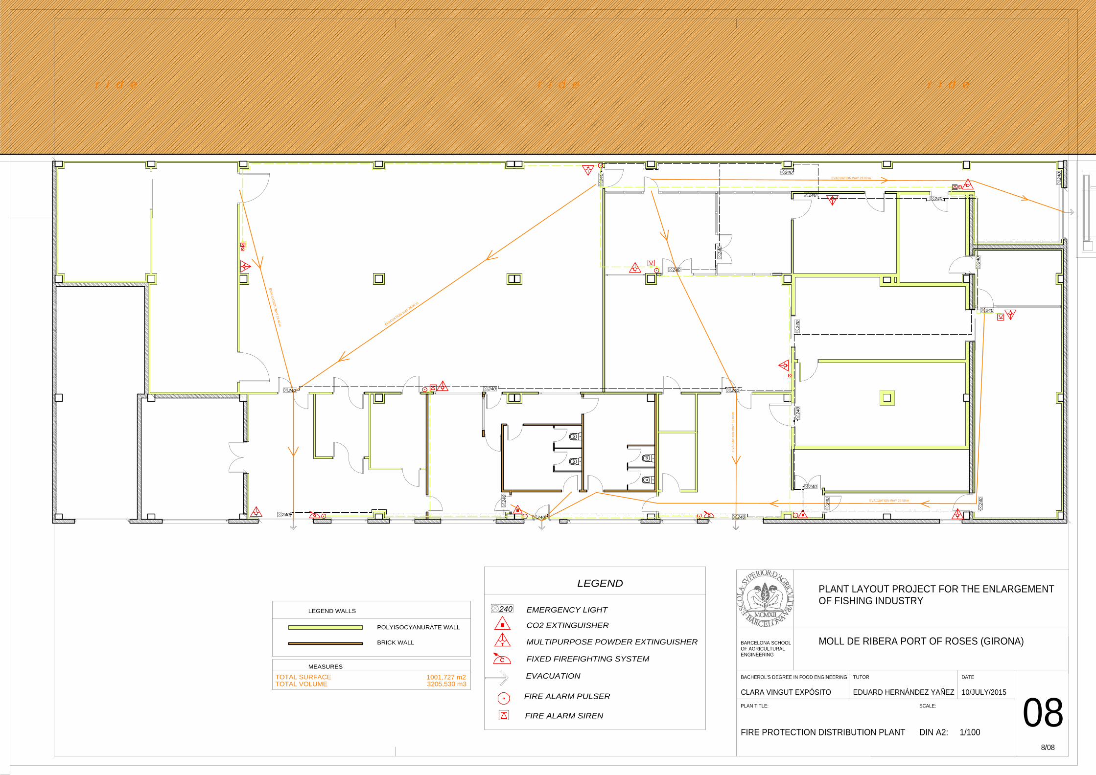
r i d e r i d er i d e
POLYISOCYANURATE WALL
LEGEND WALLS
BRICK WALL
TOTAL SURFACETOTAL VOLUME 3205,530 m3
1001,727 m2
MEASURES
EVACUATION W
AY 25.00 m
EV
AC
UA
TIO
N W
AY
18.40 m
EVACUATION WAY 23.00 m
EVACUATION WAY 22.50 m
EV
AC
UA
TIO
N W
AY
19.
00 m
240
24
0
240
240
240240
24
0
24
0
24
0
240
24
0
24
0
240
240
24
0
240
240
240 240
24
0
240
EMERGENCY LIGHT
CO2 EXTINGUISHER
FIXED FIREFIGHTING SYSTEM
EVACUATION
FIRE ALARM PULSER
FIRE ALARM SIREN
MULTIPURPOSE POWDER EXTINGUISHER
LEGEND
240
MOLL DE RIBERA PORT OF ROSES (GIRONA)
DATETUTOR
EDUARD HERNÁNDEZ YAÑEZ 10/JULY/2015
SCALE:
PLANT LAYOUT PROJECT FOR THE ENLARGEMENTOF FISHING INDUSTRY
CLARA VINGUT EXPÓSITO
PLAN TITLE:
FIRE PROTECTION DISTRIBUTION PLANT08
DIN A2: 1/100
8/08
BACHEROL'S DEGREE IN FOOD ENGINEERING
BARCELONA SCHOOLOF AGRICULTURALENGINEERING

Plant layo
out project ffor the enlarggement of fisshing indust
E
ry located in
Escola Superior
n Roses (Giro
r d’AgriculturaUPC ‐ B
3RD
ona)
a de BarcelonaBarcelonaTech
DOCU
BU
a h
UMENT:
UDGET
:
T
Document 3
INDEX
PARTIAL B
1.1 DISM
1.2 PART
1.3 DOO
PARTIAL B
2.1 FINIS
PARTIAL B
3.1 ELEC
3.2 FIRE
PARTIAL B
4.1 INER
PARTIAL B
5.1 PROT
5.2 TRAI
5.3 PERS
GENERAL
3: Budget
BUDGET nº
MANTLING
TITION WA
ORS ..............
BUDGET nº
SHES ..........
BUDGET nº
CTRICAL ....
E PROTECT
BUDGET nº
RT WASTE
BUDGET nº
TECTION S
NING .........
SONAL PR
BUDGET ..
º 1 MODIFIC
EXISTING
ALLS ...........
....................
º 2 FINISHE
....................
º 3 INSTALL
....................
TION ...........
º 4 WASTE
MANAGEM
º 5 HEALTH
SYSTEM G
....................
ROTECTION
....................
CATION OF
CHAMBER
....................
....................
ES AND AID
....................
LATIONS ...
....................
....................
MANAGEM
MENT ..........
H AND SAF
ROUP ........
....................
N EQUIPME
....................
F INTERIOR
R ..................
....................
....................
D ..................
....................
....................
....................
....................
MENT ..........
....................
ETY ............
....................
....................
ENT .............
....................
R PARTITIO
....................
....................
....................
....................
....................
....................
....................
....................
....................
....................
....................
....................
....................
....................
....................
ONS ............
....................
....................
....................
....................
....................
....................
....................
....................
....................
....................
....................
....................
....................
....................
....................
2
....................
....................
....................
....................
....................
....................
....................
....................
....................
....................
....................
....................
....................
....................
....................
....................
....................
....................
....................
....................
....................
....................
....................
....................
....................
.................. 1
.................. 1
.................. 1
.................. 1
.................. 1
.................. 1
.................. 1
3
3
3
5
6
6
7
7
9
14
14
15
15
15
16
19
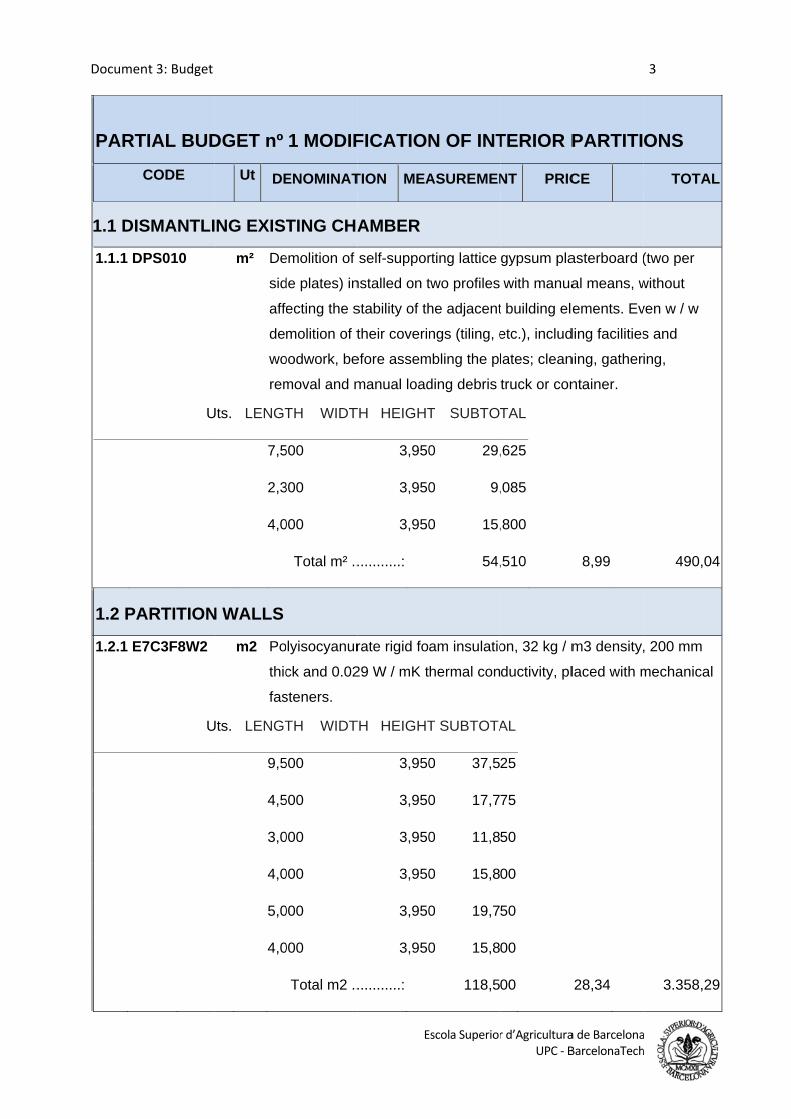
Documen
PART
1.1 DIS
1.1.1 D
1.2 PA
1.2.1 E7
nt 3: Budget
TIAL BUD
CODE
SMANTLI
PS010
U
ARTITION
7C3F8W2
U
DGET nº
Ut DE
ING EXIS
m² De
sid
affe
de
wo
rem
Uts. LENGT
7,5
2,3
4,0
N WALLS
m2 Po
thic
fas
Uts. LENGT
9,5
4,5
3,0
4,0
5,0
4,0
1 MODIF
ENOMINAT
TING CHA
emolition of
de plates) in
ecting the s
molition of t
oodwork, be
moval and m
TH WIDT
500
300
000
Total m² ..
olyisocyanur
ck and 0.02
steners.
TH WIDT
500
500
000
000
000
000
Total m2 ..
E
FICATION
TION MEA
AMBER
self-suppor
nstalled on t
stability of th
their coverin
efore assem
manual load
TH HEIGHT
3,950
3,950
3,950
...........:
rate rigid fo
29 W / mK t
TH HEIGHT
3,950
3,950
3,950
3,950
3,950
3,950
...........:
Escola Superior
N OF INT
ASUREMEN
rting lattice
two profiles
he adjacent
ngs (tiling, e
mbling the pl
ding debris
T SUBTOT
0 29,
0 9,
0 15,
54,
am insulatio
hermal con
T SUBTOTA
0 37,5
0 17,7
0 11,8
0 15,8
0 19,7
0 15,8
118,5
r d’AgriculturaUPC ‐ B
TERIOR P
NT PRIC
gypsum pla
with manua
t building ele
etc.), includ
lates; clean
truck or con
TAL
,625
,085
,800
,510
on, 32 kg / m
ductivity, pl
AL
25
75
50
00
50
00
00
a de BarcelonaBarcelonaTech
PARTITI
CE
asterboard (
al means, w
ements. Ev
ding facilities
ning, gather
ntainer.
8,99
m3 density,
laced with m
28,34
3
a h
ONS
TOTAL
(two per
without
ven w / w
s and
ing,
490,04
, 200 mm
mechanical
3.358,29
L
4
9
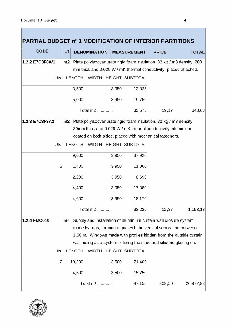
Document 3
PARTIA
CO
1.2.2 E7C3
1.2.3 E7C3
1.2.4 FMC
3: Budget
AL BUDG
ODE
3F8W1
Uts.
3F3A2
Uts.
2
C010
Uts.
2
GET nº 1
Ut DENO
m2 Plate
mm th
LENGTH
3,500
5,000
To
m2 Plate
30mm
coate
LENGTH
9,600
1,400
2,200
4,400
4,600
To
m² Suppl
made
1.60 m
wall, u
LENGTH
10,200
4,500
To
MODIFIC
OMINATIO
polyisocyan
hick and 0.0
WIDTH
otal m2 ......
polyisocyan
m thick and
d on both s
WIDTH
otal m2 ......
ly and insta
e by rugs, fo
m. Window
using as a s
WIDTH
otal m² ......
CATION O
N MEASU
nurate rigid
029 W / mK
HEIGHT S
3,950
3,950
......:
nurate rigid
0.029 W / m
sides, place
HEIGHT S
3,950
3,950
3,950
3,950
3,950
......:
allation of al
orming a gri
ws made wit
system of fix
HEIGHT S
3,500
3,500
......:
OF INTE
UREMENT
foam insul
K thermal co
SUBTOTAL
13,825
19,750
33,575
foam insul
mK thermal
d with mech
SUBTOTAL
37,920
11,060
8,690
17,380
18,170
93,220
uminium cu
d with the v
th profiles h
xing the str
SUBTOTAL
71,400
15,750
87,150
RIOR PA
PRICE
ation, 32 kg
onductivity, p
L
5
0
5 19,
ation, 32 kg
conductivit
hanical fast
L
0
0
0
0
0
0 12,
urtain wall c
vertical sepa
idden from
uctural silic
L
0
0
0 309,
4
ARTITION
g / m3 dens
placed atta
,17
g / m3 dens
ty, aluminiu
teners.
,37
closure syste
aration betw
the outside
cone glazing
,50 2
NS
TOTAL
ity, 200
ched.
643,63
ity,
m
1.153,13
em
ween
e curtain
g on.
26.972,93
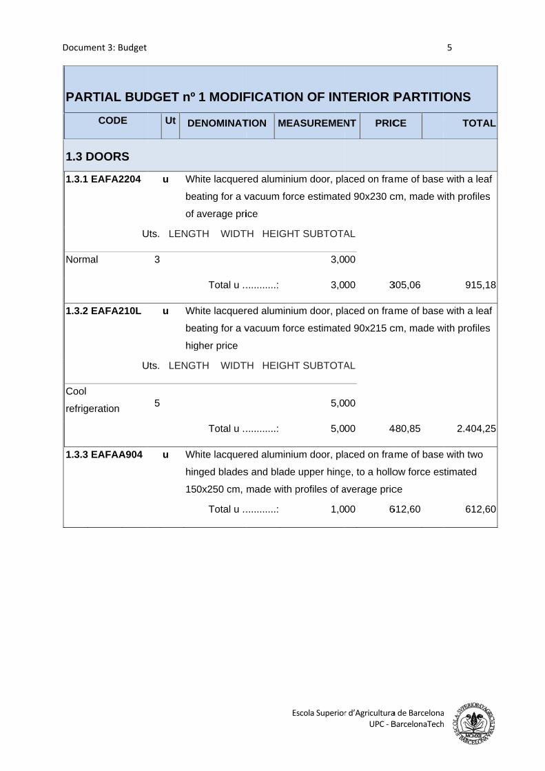
Documen
PART
1.3 DO
1.3.1 EA
Normal
1.3.2 EA
Cool
refrigera
1.3.3 EA
nt 3: Budget
TIAL BUD
CODE
OORS
AFA2204
U
AFA210L
U
ation
AFAA904
DGET nº
Ut DE
u Wh
bea
of a
Uts. LENGT
3
u Wh
bea
hig
Uts. LENGT
5
u Wh
hin
15
1 MODIF
ENOMINAT
hite lacquer
ating for a v
average pri
TH WIDT
Total u ..
hite lacquer
ating for a v
gher price
TH WIDT
Total u ..
hite lacquer
nged blades
0x250 cm,
Total u ..
E
FICATION
TION MEA
red aluminiu
vacuum forc
ice
TH HEIGHT
...........:
red aluminiu
vacuum forc
TH HEIGHT
...........:
red aluminiu
s and blade
made with p
...........:
Escola Superior
N OF INT
ASUREMEN
um door, pla
ce estimate
T SUBTOTA
3,0
3,0
um door, pla
ce estimate
T SUBTOTA
5,0
5,0
um door, pla
upper hing
profiles of a
1,0
r d’AgriculturaUPC ‐ B
TERIOR P
NT PRIC
aced on fra
ed 90x230 c
AL
00
00 3
aced on fra
ed 90x215 c
AL
00
00 4
aced on fra
e, to a hollo
average pric
00 6
a de BarcelonaBarcelonaTech
PARTITI
CE
me of base
cm, made w
305,06
me of base
cm, made w
480,85
me of base
ow force es
ce
612,60
5
a h
ONS
TOTAL
e with a leaf
with profiles
915,18
e with a leaf
with profiles
2.404,25
e with two
stimated
612,60
L
8
5
0
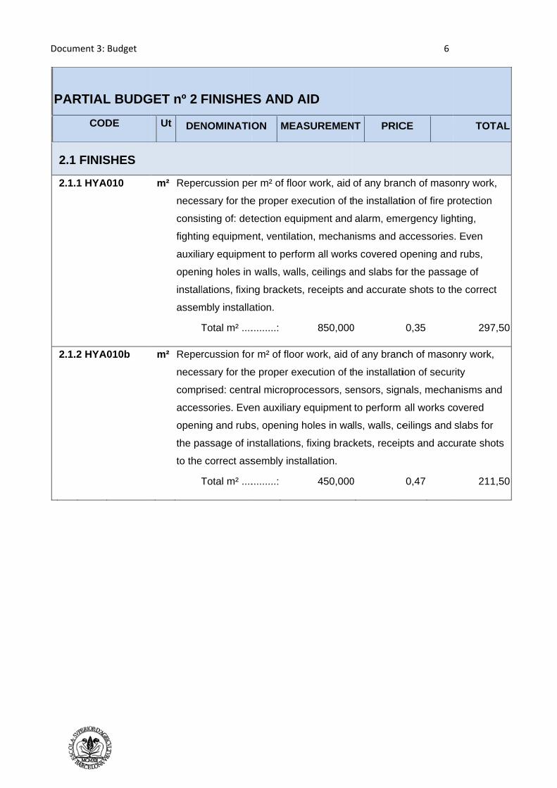
Document 3
PARTIA
CO
2.1 FINI
2.1.1 HYA
2.1.2 HYA
3: Budget
AL BUDG
ODE
ISHES
A010
A010b
GET nº 2
Ut DEN
m² Repe
neces
consis
fightin
auxilia
openi
install
assem
T
m² Repe
neces
comp
acces
openi
the pa
to the
T
FINISHE
NOMINATIO
rcussion pe
ssary for the
sting of: det
ng equipme
ary equipme
ng holes in
lations, fixin
mbly installa
Total m² ....
rcussion for
ssary for the
rised: centr
ssories. Eve
ng and rubs
assage of in
e correct ass
Total m² ....
ES AND A
ON MEA
er m² of floo
e proper ex
tection equ
ent, ventilatio
ent to perfo
walls, walls
ng brackets
ation.
.........:
r m² of floor
e proper ex
ral micropro
en auxiliary
s, opening
nstallations,
sembly inst
.........:
AID
ASUREMEN
or work, aid
ecution of t
ipment and
on, mechan
orm all work
s, ceilings a
, receipts a
850,000
r work, aid o
ecution of t
ocessors, se
equipment
holes in wa
, fixing brac
allation.
450,000
NT PRIC
of any bran
he installati
alarm, eme
nisms and a
s covered o
and slabs fo
nd accurate
0
of any branc
he installati
ensors, sign
to perform
lls, walls, ce
ckets, receip
0
6
CE
nch of maso
ion of fire p
ergency ligh
accessories
opening and
or the passa
e shots to th
0,35
ch of maso
ion of secur
nals, mecha
all works co
eilings and
pts and acc
0,47
TOTA
onry work,
rotection
hting,
s. Even
d rubs,
age of
he correct
297,5
nry work,
rity
anisms and
overed
slabs for
urate shots
211,5
AL
50
s
50
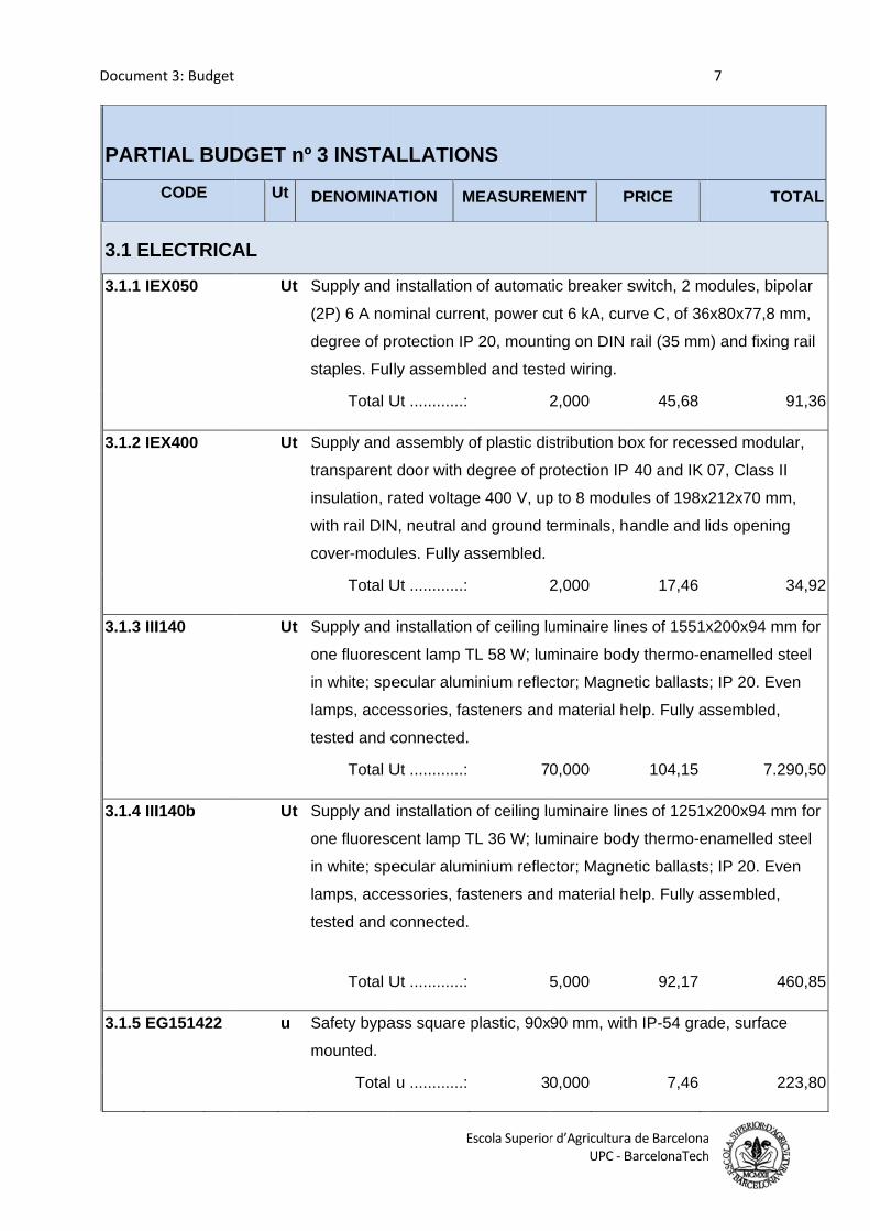
Documen
PART
3.1 EL
3.1.1 IE
3.1.2 IE
3.1.3 III
3.1.4 III
3.1.5 EG
nt 3: Budget
TIAL BUD
CODE
LECTRICA
EX050
EX400
I140
I140b
G151422
DGET nº
Ut D
AL
Ut S
(
d
s
Ut S
t
i
w
c
Ut S
o
i
l
t
Ut S
o
i
l
t
u S
m
3 INSTA
DENOMINA
Supply and
(2P) 6 A nom
degree of pr
staples. Ful
Total U
Supply and
transparent
nsulation, ra
with rail DIN
cover-modu
Total U
Supply and
one fluoresc
n white; spe
amps, acce
tested and c
Total U
Supply and
one fluoresc
n white; spe
amps, acce
tested and c
Total U
Safety bypa
mounted.
Total
E
ALLATION
ATION M
installation
minal curre
rotection IP
ly assemble
Ut ............:
assembly o
door with d
rated voltag
N, neutral an
ules. Fully a
Ut ............:
installation
cent lamp T
ecular alum
essories, fas
connected.
Ut ............:
installation
cent lamp T
ecular alum
essories, fas
connected.
Ut ............:
ass square p
u ............:
Escola Superior
NS
MEASUREM
of automat
nt, power c
P 20, mount
ed and teste
2
of plastic dis
degree of pr
e 400 V, up
nd ground t
assembled.
2
of ceiling lu
TL 58 W; lum
minium reflec
steners and
7
of ceiling lu
TL 36 W; lum
minium reflec
steners and
plastic, 90x
3
r d’AgriculturaUPC ‐ B
MENT P
tic breaker s
ut 6 kA, cur
ing on DIN
ed wiring.
2,000
stribution bo
rotection IP
p to 8 modu
erminals, ha
2,000
uminaire lin
minaire bod
ctor; Magne
d material he
0,000
uminaire lin
minaire bod
ctor; Magne
d material he
5,000
90 mm, with
0,000
a de BarcelonaBarcelonaTech
PRICE
switch, 2 m
rve C, of 36
rail (35 mm
45,68
ox for reces
40 and IK
ules of 198x
andle and l
17,46
nes of 1551x
dy thermo-e
etic ballasts
elp. Fully a
104,15
nes of 1251x
dy thermo-e
etic ballasts
elp. Fully a
92,17
h IP-54 gra
7,46
7
a h
TO
odules, bipo
6x80x77,8 m
m) and fixing
ssed modula
07, Class II
x212x70 mm
ids opening
x200x94 mm
namelled st
s; IP 20. Eve
ssembled,
7.2
x200x94 mm
namelled st
s; IP 20. Eve
ssembled,
46
de, surface
22
OTAL
olar
mm,
g rail
91,36
ar,
m,
g
34,92
m for
teel
en
90,50
m for
teel
en
60,85
e
23,80
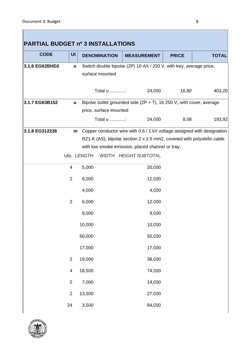
Document 3
PARTIA
CO
3.1.6 EG62
3.1.7 EG63
3.1.8 EG3
3: Budget
AL BUDG
ODE
2BHD2
3B152
12236
U
GET nº 3
Ut DEN
u Swi
surf
u Bipo
pric
m Cop
RZ1
with
Uts. LENGT
4 5,00
2 6,00
4,00
2 6,00
9,00
10,00
50,00
17,00
2 19,00
4 18,50
2 7,00
2 13,50
24 3,50
INSTALL
NOMINATIO
tch double
face mounte
Total u .
olar outlet g
ce, surface m
Total u .
pper conduc
1-K (AS), bi
h low smoke
TH WIDT
00
00
00
00
00
00
00
00
00
00
00
00
00
LATIONS
ON MEA
bipolar (2P
ed
...........:
grounded si
mounted
...........:
ctor wire wi
ipolar sectio
e emission,
TH HEIGHT
S
ASUREMEN
P) 10 AX / 25
24,0
de (2P + T)
24,0
th 0.6 / 1 kV
on 2 x 2.5 m
placed cha
T SUBTOTA
20,0
12,0
4,0
12,0
9,0
10,0
50,0
17,0
38,0
74,0
14,0
27,0
84,0
NT PRI
50 V, with k
00
), 16 250 V,
00
V voltage as
mm2, covere
annel or tray
AL
00
00
00
00
00
00
00
00
00
00
00
00
00
8
CE
key, average
16,80
, with cover
8,08
ssigned wit
ed with poly
y.
TOTA
e price,
403,
r, average
193,
h designatio
yolefin cable
AL
20
92
on
e
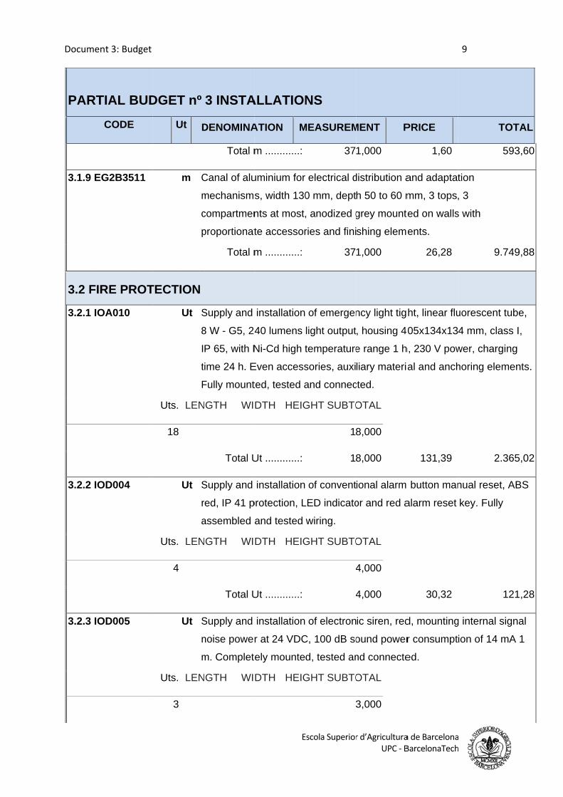
Documen
PART
3.1.9 EG
3.2 FIR
3.2.1 IO
3.2.2 IO
3.2.3 IO
nt 3: Budget
TIAL BUD
CODE
G2B3511
RE PROT
OA010
OD004
OD005
DGET nº
Ut D
m C
m
c
p
TECTION
Ut S
8
I
t
F
Uts. LEN
18
Ut S
r
a
Uts. LEN
4
Ut S
n
m
Uts. LEN
3
3 INSTA
DENOMINA
Total m
Canal of alu
mechanisms
compartmen
proportionat
Total m
Supply and
8 W - G5, 24
P 65, with N
time 24 h. E
Fully mount
NGTH WI
Total U
Supply and
red, IP 41 p
assembled a
NGTH WI
Total U
Supply and
noise power
m. Complete
NGTH WI
E
ALLATION
ATION M
m ............:
uminium for
s, width 130
nts at most,
te accessor
m ............:
installation
40 lumens
Ni-Cd high t
Even access
ted, tested a
DTH HEIG
Ut ............:
installation
protection, L
and tested
DTH HEIG
Ut ............:
installation
r at 24 VDC
ely mounte
DTH HEIG
Escola Superior
NS
MEASUREM
37
electrical d
0 mm, dept
, anodized g
ries and fini
37
of emergen
light output
temperature
sories, auxi
and connec
GHT SUBTO
1
1
of convent
LED indicato
wiring.
GHT SUBTO
4
4
of electron
C, 100 dB so
d, tested an
GHT SUBTO
r d’AgriculturaUPC ‐ B
MENT P
1,000
distribution a
h 50 to 60 m
grey mounte
shing eleme
1,000
ncy light tig
, housing 4
e range 1 h
liary materia
cted.
OTAL
8,000
8,000
ional alarm
or and red a
OTAL
4,000
4,000
ic siren, red
ound power
nd connecte
OTAL
3,000
a de BarcelonaBarcelonaTech
PRICE
1,60
and adaptat
mm, 3 tops
ted on walls
ents.
26,28
ht, linear flu
05x134x13
h, 230 V pow
al and anch
131,39
button man
alarm reset
30,32
d, mounting
r consumpt
ed.
9
a h
TO
5
tion
, 3
s with
9.74
uorescent tu
4 mm, class
wer, chargin
horing elem
2.36
nual reset, A
key. Fully
12
g internal sig
ion of 14 m
OTAL
93,60
49,88
ube,
s I,
ng
ments.
65,02
ABS
21,28
gnal
A 1
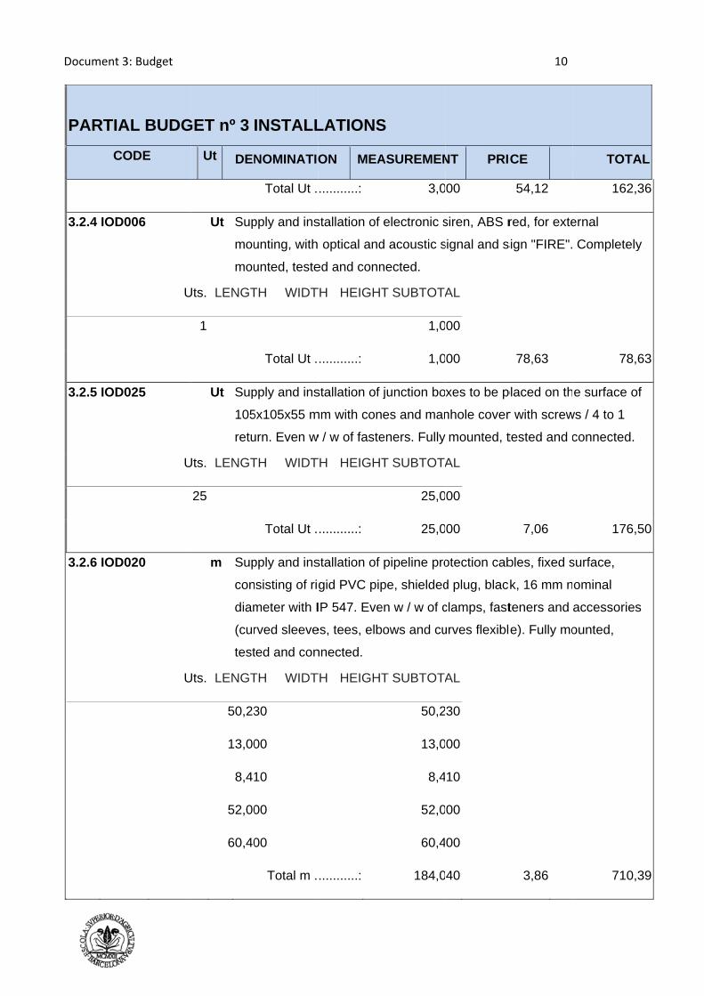
Document 3
PARTIA
CO
3.2.4 IOD0
3.2.5 IOD0
3.2.6 IOD0
3: Budget
AL BUDG
ODE
006
U
025
U
020
U
GET nº 3
Ut DEN
Ut Sup
mou
mou
Uts. LENGT
1
Ut Sup
105
retu
Uts. LENGT
25
m Sup
con
diam
(cur
test
Uts. LENGT
50,23
13,00
8,41
52,00
60,40
INSTALL
NOMINATIO
Total Ut .
pply and ins
unting, with
unted, teste
TH WIDT
Total Ut .
pply and ins
5x105x55 m
urn. Even w
TH WIDT
Total Ut .
pply and ins
sisting of rig
meter with I
rved sleeve
ted and con
TH WIDT
30
00
10
00
00
Total m .
LATIONS
ON MEA
...........:
stallation of
optical and
ed and conn
TH HEIGHT
...........:
stallation of
mm with con
w / w of faste
TH HEIGHT
...........:
stallation of
gid PVC pip
IP 547. Eve
es, tees, elb
nnected.
TH HEIGHT
...........:
S
ASUREMEN
3,0
electronic s
d acoustic s
nected.
T SUBTOTA
1,0
1,0
junction bo
es and man
eners. Fully
T SUBTOTA
25,0
25,0
pipeline pro
pe, shielded
en w / w of c
bows and cu
T SUBTOTA
50,2
13,0
8,4
52,0
60,4
184,0
NT PRI
00
siren, ABS r
signal and s
AL
00
00
xes to be p
nhole cover
mounted, t
AL
00
00
otection cab
d plug, blac
clamps, fast
urves flexibl
AL
30
00
10
00
00
40
10
CE
54,12
red, for exte
sign "FIRE".
78,63
placed on th
r with screw
tested and c
7,06
bles, fixed s
ck, 16 mm n
teners and
e). Fully mo
3,86
TOTA
162,
ernal
Completely
78,
e surface o
ws / 4 to 1
connected.
176,
surface,
ominal
accessories
ounted,
710,
AL
36
y
63
of
50
s
39

Documen
PART
3.2.7 IO
3.2.8 IO
nt 3: Budget
TIAL BUD
CODE
OD030
OX010
DGET nº
Ut D
m S
+
c
p
a
d
c
c
c
a
Uts. LEN
50
13
8
52
60
Ut S
d
k
s
Uts. LEN
7
3 INSTA
DENOMINA
Supply and
+), no flame
class 5 (-K)
polymer-bas
and corrosiv
driver draina
composite fo
corrosive ga
connection
assembled a
NGTH WI
0,230
3,000
8,410
2,000
0,400
Total m
Supply and
dry chemica
kg extinguis
support and
NGTH WI
Total U
E
ALLATION
ATION M
installation
e and fire re
and section
sed elastom
ve gases (S
age pond co
force polyole
ases (Z1), b
and few acc
and tested
DTH HEIG
m ............:
installation
al against re
sher with pre
d mounting a
DTH HEIG
Ut ............:
Escola Superior
NS
MEASUREM
of cable wi
esistant, mu
n 2x1,5 mm
mer vulcaniz
S) screen an
opper outer
efin haloge
being alloca
cessories n
wiring.
GHT SUBTO
5
1
52
6
184
of portable
e-ignition, p
essure gau
accessories
GHT SUBTO
r d’AgriculturaUPC ‐ B
MENT P
iring formed
ltithreaded
m², with insu
zed halogen
nd aluminiu
r covering o
n free low s
ated tension
necessary fo
OTAL
0,230
3,000
8,410
2,000
0,400
4,040
e fire extingu
ressure bui
ge and hos
s. Fully asse
OTAL
7,000
7,000
1
a de BarcelonaBarcelonaTech
PRICE
d by bipolar
copper con
ulation of co
n-free low s
m polyeste
of a thermop
smoke emis
n 300/500 V
or proper in
4,68
uisher ABC
ilt-efficiency
se with nozz
embled.
42,99
11
a h
TO
r SO2Z1-K (
nductor with
ompound
smoke emis
r tape (O2)
plastic
ssion and
V. Even strip
stallation. F
86
multipurpo
y 21A-144B
zle diffuser.
3
OTAL
(AS
h
sion
with
ps of
Fully
61,31
ose
-C, 6
Even
00,93
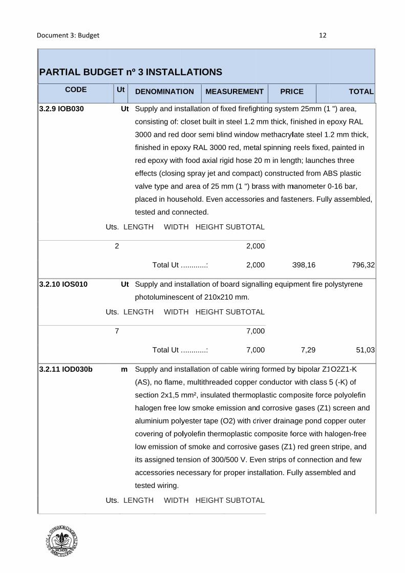
Document 3
PARTIA
CO
3.2.9 IOB0
3.2.10 IOS
3.2.11 IOD
3: Budget
AL BUDG
ODE
030
U
S010
U
D030b
U
GET nº 3
Ut DEN
Ut Sup
con
300
finis
red
effe
valv
plac
test
Uts. LENGT
2
Ut Sup
pho
Uts. LENGT
7
m Sup
(AS
sec
halo
alum
cov
low
its a
acc
test
Uts. LENGT
INSTALL
NOMINATIO
pply and ins
sisting of: c
00 and red d
shed in epo
epoxy with
ects (closing
ve type and
ced in hous
ted and con
TH WIDT
Total Ut .
pply and ins
otoluminesc
TH WIDT
Total Ut .
pply and ins
S), no flame
tion 2x1,5 m
ogen free lo
minium poly
ering of pol
emission o
assigned te
essories ne
ted wiring.
TH WIDT
LATIONS
ON MEA
stallation of
closet built i
door semi b
oxy RAL 300
food axial
g spray jet a
area of 25
sehold. Even
nnected.
TH HEIGHT
...........:
stallation of
cent of 210x
TH HEIGHT
...........:
stallation of
, multithrea
mm², insula
ow smoke e
yester tape
lyolefin ther
of smoke an
nsion of 30
ecessary fo
TH HEIGHT
S
ASUREMEN
fixed firefig
n steel 1.2
blind window
00 red, meta
rigid hose 2
and compac
mm (1 ") b
n accessori
T SUBTOTA
2,0
2,0
board signa
x210 mm.
T SUBTOTA
7,0
7,0
cable wiring
ded copper
ted thermop
emission an
(O2) with d
rmoplastic c
nd corrosive
0/500 V. Ev
r proper ins
T SUBTOTA
NT PRI
hting system
mm thick, f
w methacryl
al spinning
20 m in leng
ct) construc
rass with m
es and fast
AL
00
00 3
alling equip
AL
00
00
g formed by
r conductor
plastic com
d corrosive
river draina
composite fo
e gases (Z1
ven strips of
stallation. Fu
AL
12
CE
m 25mm (1
finished in e
late steel 1.
reels fixed,
gth; launche
cted from AB
manometer 0
teners. Fully
398,16
pment fire po
7,29
y bipolar Z1
with class
mposite force
gases (Z1)
age pond co
orce with ha
) red green
f connectio
ully assemb
TOTA
") area,
epoxy RAL
.2 mm thick
painted in
es three
BS plastic
0-16 bar,
y assemble
796,
olystyrene
51,
O2Z1-K
5 (-K) of
e polyolefin
) screen and
opper outer
alogen-free
stripe, and
n and few
bled and
AL
k,
d,
32
03
d
e
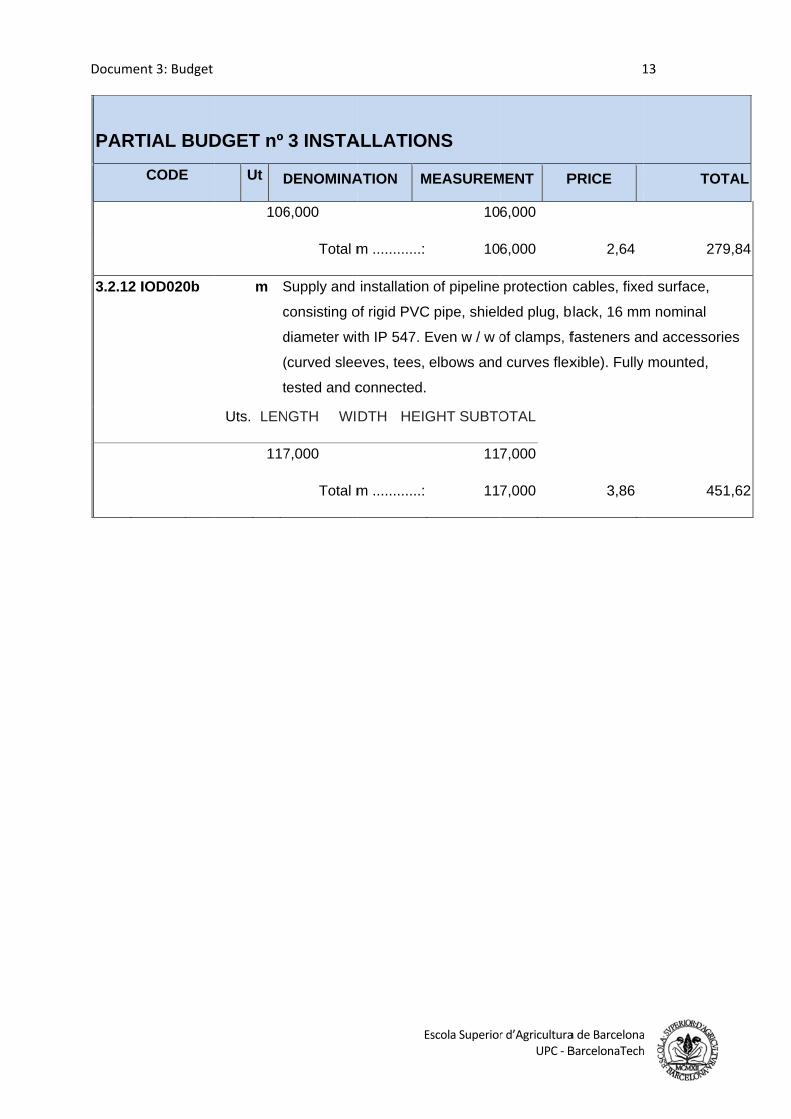
Documen
PART
3.2.12 I
nt 3: Budget
TIAL BUD
CODE
IOD020b
DGET nº
Ut D
106
m S
c
d
(
t
Uts. LEN
117
3 INSTA
DENOMINA
6,000
Total m
Supply and
consisting o
diameter wit
(curved slee
tested and c
NGTH WI
7,000
Total m
E
ALLATION
ATION M
m ............:
installation
of rigid PVC
th IP 547. E
eves, tees,
connected.
DTH HEIG
m ............:
Escola Superior
NS
MEASUREM
10
10
of pipeline
C pipe, shield
Even w / w o
elbows and
GHT SUBTO
11
11
r d’AgriculturaUPC ‐ B
MENT P
6,000
6,000
protection
ded plug, b
of clamps, f
d curves flex
OTAL
7,000
7,000
1
a de BarcelonaBarcelonaTech
PRICE
2,64
cables, fixe
lack, 16 mm
fasteners an
xible). Fully
3,86
13
a h
TO
2
ed surface,
m nominal
nd accesso
mounted,
4
OTAL
79,84
ories
51,62

Document 3
PARTIA
CO
4.1 INER
4.1.1 GRB
3: Budget
AL BUDG
ODE
RT WAST
B020
Uts
1,25
GET nº 4 W
Ut DEN
TE MANA
m³ Canon
produ
treatm
recove
. LENGTH
5 25,500
T
WASTE
NOMINATIO
AGEMENT
n landfill for
ced in cons
ment facility
ery or waste
WIDTH
0 0,800
Total m³ ....
MANAG
ON MEA
T
r inert waste
struction an
constructio
e disposal.
HEIGHT
0,800
.........:
EMENT
ASUREMEN
e Delivery o
d / or demo
on and dem
Excluding t
SUBTOTAL
20,400
20,400
NT PRIC
of bricks, tile
olition landfi
olition work
transportatio
L
0
0
14
CE
es and cera
ll specific w
k or externa
on.
7,96
TOTA
amics,
waste
l centre
162,3
AL
38
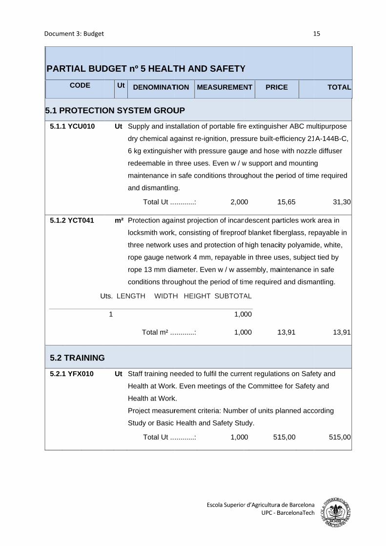
Documen
PART
5.1 PR
5.1.1 Y
5.1.2 Y
5.2 TR
5.2.1 Y
nt 3: Budget
TIAL BUD
CODE
ROTECTIO
YCU010
YCT041
U
RAINING
YFX010
DGET nº
Ut DE
ON SYSTE
Ut Sup
dry
6 kg
rede
mai
and
m² Prot
lock
thre
rope
rope
con
Uts. LENGT
1
Ut Staf
Hea
Hea
Proj
Stud
5 HEALT
ENOMINAT
EM GROU
pply and ins
chemical ag
g extinguish
eemable in
ntenance in
dismantling
Total Ut ..
tection agai
ksmith work
ee network u
e gauge net
e 13 mm dia
ditions thro
TH WIDTH
Total m² ..
ff training ne
alth at Work
alth at Work
ject measur
dy or Basic
Total Ut ..
E
TH AND
TION MEA
UP
stallation of
gainst re-ig
her with pres
three uses.
n safe cond
g.
..........:
inst projecti
k, consisting
uses and pr
twork 4 mm
ameter. Eve
ughout the
H HEIGHT
..........:
eeded to fu
k. Even mee
k.
rement crite
Health and
..........:
Escola Superior
SAFETY
ASUREMEN
portable fire
nition, pres
ssure gaug
. Even w / w
itions throu
2,00
ion of incan
g of fireproo
rotection of
m, repayable
en w / w ass
period of tim
T SUBTOTA
1,0
1,0
lfil the curre
etings of the
eria: Numbe
d Safety Stu
1,00
r d’AgriculturaUPC ‐ B
Y
NT PRIC
e extinguish
sure built-e
e and hose
w support an
ghout the p
0 1
descent pa
f blanket fib
high tenaci
e in three us
sembly, ma
me required
AL
00
00 1
ent regulatio
e Committee
er of units p
udy.
0 51
1
a de BarcelonaBarcelonaTech
CE
her ABC mu
efficiency 21
e with nozzle
nd mountin
period of tim
15,65
articles work
berglass, re
ity polyamid
ses, subject
aintenance i
d and disma
13,91
ons on Safe
e for Safety
planned acc
15,00
15
a h
TOTAL
ultipurpose
A-144B-C,
e diffuser
g
me required
31,30
k area in
epayable in
de, white,
t tied by
in safe
antling.
13,91
ety and
y and
ording
515,00
L
0
1
0
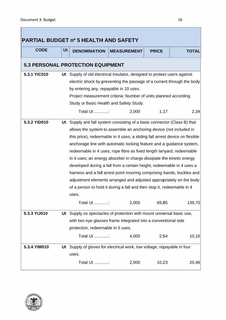
Document 3
PARTIA
CO
5.3 PER
5.3.1 YIC
5.3.2 YID
5.3.3 YIJ0
5.3.4 YIM
3: Budget
AL BUDG
ODE
RSONAL
C010
D010
010
M010
GET nº 5
Ut DENO
PROTECT
Ut Supply
electric
by ente
Project
Study o
To
Ut Supply
allows
this pri
anchor
redeem
in 4 us
develo
harnes
adjustm
of a pe
uses.
To
Ut Supply
with tw
protect
To
Ut Supply
uses.
To
HEALTH
OMINATIO
TION EQU
y of old elec
c shock by p
ering any, re
t measurem
or Basic He
otal Ut .......
y anti fall sys
the system
ce), redeem
rage line wit
mable in 4 u
es; an ener
ped during
ss and a fall
ment eleme
erson to hold
otal Ut .......
y os spectac
wo eye glass
tion, redeem
otal Ut .......
y of gloves f
otal Ut .......
H AND SA
ON MEASU
UIPMENT
ctrical insula
preventing t
epayable in
ment criteria
ealth and Sa
.....:
stem consis
m to assemb
mable in 4 u
th automati
uses; rope f
rgy absorbe
a fall from a
l arrest poin
ents arrange
d it during a
.....:
cles of prote
ses frame in
mable in 5 u
.....:
for electrica
.....:
AFETY
UREMENT
T
ator, design
the passage
n 10 uses.
a: Number o
afety Study
2,000
sting of a ba
ble an ancho
uses; a slidi
c locking fe
fibre as fixed
er in charge
a certain he
nt mooring c
ed and adju
a fall and th
2,000
ection with m
ntegrated in
uses.
4,000
al work, low
2,000
PRICE
ed to protec
e of a curre
of units plan
.
1,1
asic connec
oring device
ng fall arres
eature and a
d length lan
dissipate th
eight, redee
comprising
sted approp
en stop it, r
69,8
mount unive
nto a conven
2,5
voltage, rep
10,2
16
ct users aga
ent through
nned accord
17
ctor (Class
e (not includ
st device on
a guidance
nyard, redee
he kinetic e
emable in 4
bands, buc
priately on t
redeemable
85
ersal basic
ntional side
54
payable in f
23
TOTAL
ainst
the body
ding
2,34
B) that
ded in
n flexible
system,
emable
energy
uses a
kles and
the body
e in 4
139,70
use,
e
10,16
four
20,46
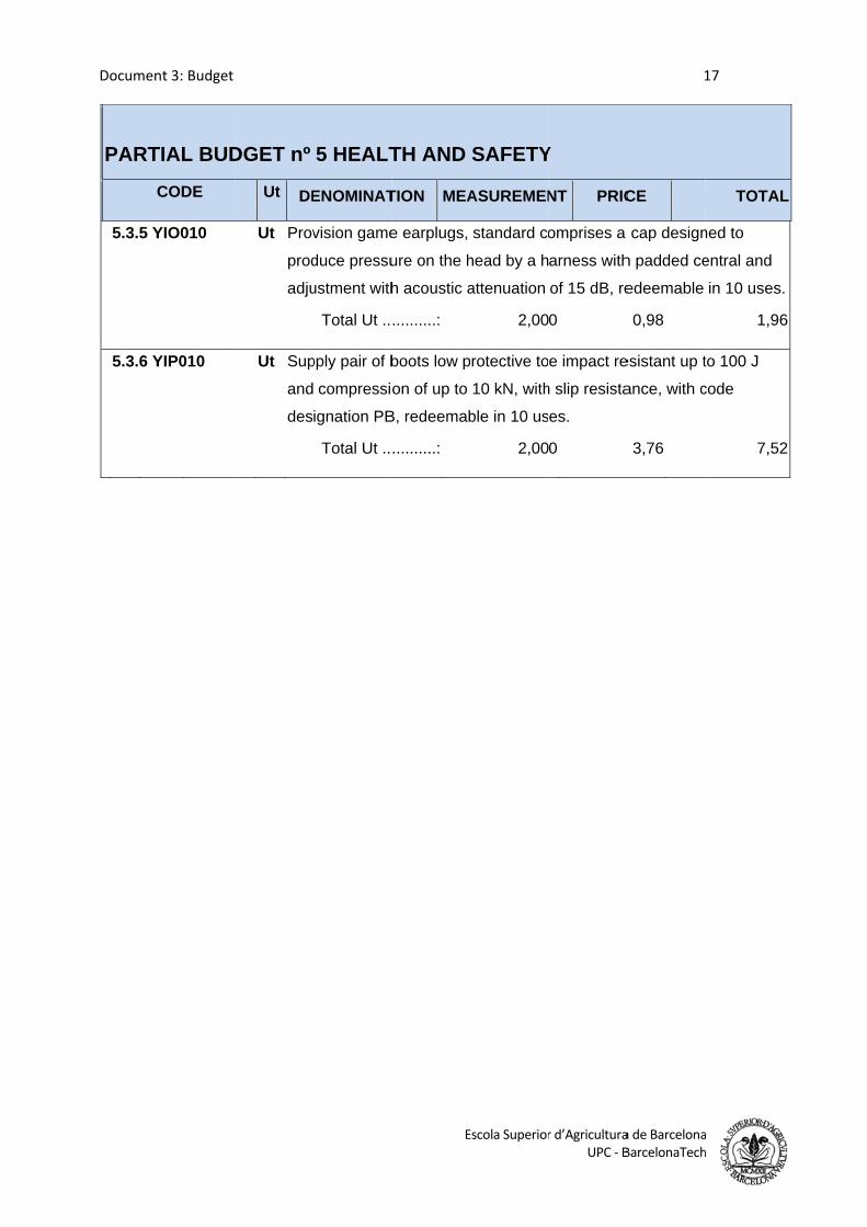
Documen
PART
5.3.5 Y
5.3.6 Y
nt 3: Budget
TIAL BUD
CODE
YIO010
YIP010
DGET nº
Ut DE
Ut Prov
prod
adju
Ut Sup
and
des
5 HEALT
ENOMINAT
vision game
duce pressu
ustment with
Total Ut ..
pply pair of b
compressio
ignation PB
Total Ut ..
E
TH AND
TION MEA
e earplugs,
ure on the h
h acoustic a
..........:
boots low p
on of up to
B, redeemab
..........:
Escola Superior
SAFETY
ASUREMEN
standard co
head by a h
attenuation
2,00
protective to
10 kN, with
ble in 10 us
2,00
r d’AgriculturaUPC ‐ B
Y
NT PRIC
omprises a
arness with
of 15 dB, re
0
e impact re
h slip resista
es.
0
1
a de BarcelonaBarcelonaTech
CE
cap design
h padded ce
edeemable
0,98
esistant up t
ance, with c
3,76
17
a h
TOTAL
ned to
entral and
in 10 uses.
1,96
to 100 J
code
7,52
L
.
6
2

Document 3
PARTIA
CODE
6.1
6.2
6.3
6.4
6.5
6.6
6.7
6.8
6.9
3: Budget
L BUDG
Ut
Ut Con
Ut
Ut
Ut
Ut
Ut
Ut
Ut
Ut
ET nº 6 M
DENOM
nveyor rollesprinkler wa
Coo
Exhaus
Bottle fillin
Bottle
Labe
Fille
Tray s
Tunne
MACHIN
INATION
r rotating water System
oker
t system
ng Machine
closing
elling
eting
sealer
l frozen
ERY
Q
with a m
QUANTITY
1
1
1
1
1
1
2
1
1
PRI
785
2625
358
8468
799
1285
9340
168
1173
18
ICE
50
57,75 2
8,03
8,87
90
54,23 1
0,45 1
895
30,85 1
TOTAL
7850
26257,75
358,03
8468,87
7990
12854,23
18680,90
16895
11730,85
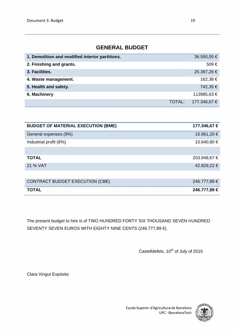
Documen
BUDGE
General
Industria
TOTAL
21 % VA
CONTRA
TOTAL
The pres
SEVENT
Clara Vi
1. Demo
2. Finish
3. Facili
4. Waste
5. Healt
6. Mach
nt 3: Budget
T OF MATE
expenses
al profit (6%
AT
ACT BUDG
sent budget
TY SEVEN
ngut Expós
olition and
hing and g
ities.
e managem
h and safe
hinery
ERIAL EXE
(9%)
%)
GET EXECU
t to hire is o
EUROS W
sito
modified i
rants.
ment.
ety.
ECUTION (B
UTION (CBE
of TWO HUN
WITH EIGHT
GEN
nterior par
E
BME)
E)
NDRED FO
TY NINE CE
NERAL B
rtitions.
Escola Superior
ORTY SIX T
ENTS (246.7
Caste
BUDGET
r d’AgriculturaUPC ‐ B
THOUSAND
777,89 €).
elldefels, 10
T
1
a de BarcelonaBarcelonaTech
D SEVEN H
0th of July of
TOTAL:
19
a h
177.346,67
15.961,20
10.640,80
203.948,67
42.829,22
246.777,89
246.777,89
UNDRED
f 2015
36.550,05
509
25.397,26
162,38
742,35
113985,63
177.346,67
7 €
0 €
0 €
7 €
2 €
9 €
9 €
5 €
9 €
6 €
8 €
5 €
3 €
7 €