FISHING, MILLING AND CLEANING EQUIPMENT FOR OIL ...
112
FISHING, MILLING AND CLEANING EQUIPMENT FOR OIL AND GAS WELLS
-
Upload
khangminh22 -
Category
Documents
-
view
0 -
download
0
Transcript of FISHING, MILLING AND CLEANING EQUIPMENT FOR OIL ...

FISHING, MILLING AND CLEANING EQUIPMENT
FOR OIL AND GAS WELLS

BITTEKHNIKA LLC was established in 1996. Through all these years of successful experience we have developed a sustainable manufacturing system of oilfield equipment. Our products are produced on high professional level and meet re-quirements of international standards. Our geography of products and service supply covers not only territory of the Russian Federation but also Eastern Eu-rope, Middle East and Asia. We work to develop and maintain strong relation-ships with Russian and foreign partners.
BITTEKHNIKA LLC specializes in manufacturing tools for sidetracking, fishing, milling and cleaning equipment: whipstocks, different kinds of mills, reamers, die collars, taper taps, overshots, spears, pipe cutters and other products. The company also produces small-sized equipment for works in wells with coiled tub-ing units.
BITTEKHNIKA LLC has received considerable number of letters of appreciation and awards. We prioritize ongoing innovation and development in production, processing and distribution.
The company provides technical assistance and consulting service. Our experi-enced and highly professional engineering and technical staff can guarantee re-alisation of any kind of complex work. Our knowledge and broad exchange of experience allow to provide the best solution to a specific task.
BITTEKHNIKA LLC aspires to increase the number of business contacts, find new partners and strengthen position on the market of oilfield equipment.
BITTEKHNIKA
All rights reserved. Any copying, reproduction, publication, other usage for commercial purposes is allowed only with preliminary permission of rightholder.

RELEASING OVERSHOT TLN/TLNT . . . . . . . . . . . . . . . . . . . . . . . . . . . . . . . . . . . . . . . . . . . . . . . . . . . . . . . . . . 3SHORT-CATCH RELEASING OVERSHOT TLNK/TLNKT . . . . . . . . . . . . . . . . . . . . . . . . . . . . . . . . . . . . . . . . . . . 5RELEASING ROD OVERSHOT TLNSH . . . . . . . . . . . . . . . . . . . . . . . . . . . . . . . . . . . . . . . . . . . . . . . . . . . . . . . . . 7NON-RELEASING SPEAR TVP . . . . . . . . . . . . . . . . . . . . . . . . . . . . . . . . . . . . . . . . . . . . . . . . . . . . . . . . . . . . . . . 9SLIP RELEASING SPEAR TLVPM . . . . . . . . . . . . . . . . . . . . . . . . . . . . . . . . . . . . . . . . . . . . . . . . . . . . . . . . . . . . . 11RELEASING SPEAR TLV . . . . . . . . . . . . . . . . . . . . . . . . . . . . . . . . . . . . . . . . . . . . . . . . . . . . . . . . . . . . . . . . . . . .13UNIVERSAL FISHING TOOL UL . . . . . . . . . . . . . . . . . . . . . . . . . . . . . . . . . . . . . . . . . . . . . . . . . . . . . . . . . . . . . 15PLAIN DIE COLLAR WITH CUTLIP GUIDE LKGz . . . . . . . . . . . . . . . . . . . . . . . . . . . . . . . . . . . . . . . . . . . . . . . . .17THREADED DIE COLLAR LKz . . . . . . . . . . . . . . . . . . . . . . . . . . . . . . . . . . . . . . . . . . . . . . . . . . . . . . . . . . . . . . 19PLAIN TAPER TAP MLG . . . . . . . . . . . . . . . . . . . . . . . . . . . . . . . . . . . . . . . . . . . . . . . . . . . . . . . . . . . . . . . . . . . .21THREADED TAPER TAP ML . . . . . . . . . . . . . . . . . . . . . . . . . . . . . . . . . . . . . . . . . . . . . . . . . . . . . . . . . . . . . . . . 23SPECIAL OPERATIONAL TAPER TAP MES . . . . . . . . . . . . . . . . . . . . . . . . . . . . . . . . . . . . . . . . . . . . . . . . . . . . 25SPECIAL TAPER TAP FOR JOINTS MSZ . . . . . . . . . . . . . . . . . . . . . . . . . . . . . . . . . . . . . . . . . . . . . . . . . . . . . . . 27INTERNAL WIRELINE SPEAR PIKV . . . . . . . . . . . . . . . . . . . . . . . . . . . . . . . . . . . . . . . . . . . . . . . . . . . . . . . . . . 29EXTERNAI WIRELINE SPEAR PIKN . . . . . . . . . . . . . . . . . . . . . . . . . . . . . . . . . . . . . . . . . . . . . . . . . . . . . . . . . . .31AUGER-TYPE SPEAR PIKSH . . . . . . . . . . . . . . . . . . . . . . . . . . . . . . . . . . . . . . . . . . . . . . . . . . . . . . . . . . . . . . . 33CABLE SPIRAL SPEAR KSU . . . . . . . . . . . . . . . . . . . . . . . . . . . . . . . . . . . . . . . . . . . . . . . . . . . . . . . . . . . . . . . . 35CABLE MULE SHOE PRK . . . . . . . . . . . . . . . . . . . . . . . . . . . . . . . . . . . . . . . . . . . . . . . . . . . . . . . . . . . . . . . . . . 37INTERNAL MECHANICAL CUTTER TRV . . . . . . . . . . . . . . . . . . . . . . . . . . . . . . . . . . . . . . . . . . . . . . . . . . . . . . 39EXTERNAL MECHANICAL CUTTER TRN . . . . . . . . . . . . . . . . . . . . . . . . . . . . . . . . . . . . . . . . . . . . . . . . . . . . . 41INTERNAL HYDRAULIC PIPE CUTTER TVG . . . . . . . . . . . . . . . . . . . . . . . . . . . . . . . . . . . . . . . . . . . . . . . . . . . 43HYDRAULIC TUBING ANCHOR YAGT . . . . . . . . . . . . . . . . . . . . . . . . . . . . . . . . . . . . . . . . . . . . . . . . . . . . . . 45HYDRAULIC PIPE PUNCHER DGT . . . . . . . . . . . . . . . . . . . . . . . . . . . . . . . . . . . . . . . . . . . . . . . . . . . . . . . . . . . 47MECHANICAL JAR YAM . . . . . . . . . . . . . . . . . . . . . . . . . . . . . . . . . . . . . . . . . . . . . . . . . . . . . . . . . . . . . . . . . . 49HYDRAULIC JAR YAG . . . . . . . . . . . . . . . . . . . . . . . . . . . . . . . . . . . . . . . . . . . . . . . . . . . . . . . . . . . . . . . . . . . . 51SAFETY JOINT PB . . . . . . . . . . . . . . . . . . . . . . . . . . . . . . . . . . . . . . . . . . . . . . . . . . . . . . . . . . . . . . . . . . . . . . . . 53HYDRAULIC SAFETY SUB PB-G . . . . . . . . . . . . . . . . . . . . . . . . . . . . . . . . . . . . . . . . . . . . . . . . . . . . . . . . . . . . 55MECHANICAL JUNK BASKET PM . . . . . . . . . . . . . . . . . . . . . . . . . . . . . . . . . . . . . . . . . . . . . . . . . . . . . . . . . . . 57HYDRAULIC JUNK BASKET PG . . . . . . . . . . . . . . . . . . . . . . . . . . . . . . . . . . . . . . . . . . . . . . . . . . . . . . . . . . . . . 59BOTTOM-HOLE JUNK MILL FZ-T . . . . . . . . . . . . . . . . . . . . . . . . . . . . . . . . . . . . . . . . . . . . . . . . . . . . . . . . . . . 61CEMENTED BOTTOM-HOLE MILL FZ-TS . . . . . . . . . . . . . . . . . . . . . . . . . . . . . . . . . . . . . . . . . . . . . . . . . . . . . 63WASHOVER SHOE FK . . . . . . . . . . . . . . . . . . . . . . . . . . . . . . . . . . . . . . . . . . . . . . . . . . . . . . . . . . . . . . . . . . . . 65WAVE-LIKE WASHOVER SHOE FK-V . . . . . . . . . . . . . . . . . . . . . . . . . . . . . . . . . . . . . . . . . . . . . . . . . . . . . . . . 67STRAIGHT-TOOTHED TAPER MILL . . . . . . . . . . . . . . . . . . . . . . . . . . . . . . . . . . . . . . . . . . . . . . . . . . . . . . . . . 69SPECIAL TAPER MILL FKS . . . . . . . . . . . . . . . . . . . . . . . . . . . . . . . . . . . . . . . . . . . . . . . . . . . . . . . . . . . . . . . . . .71PLOT MILL FP . . . . . . . . . . . . . . . . . . . . . . . . . . . . . . . . . . . . . . . . . . . . . . . . . . . . . . . . . . . . . . . . . . . . . . . . . . . 73CONCAVE JUNK MILL FT-V . . . . . . . . . . . . . . . . . . . . . . . . . . . . . . . . . . . . . . . . . . . . . . . . . . . . . . . . . . . . . . . 75JUNK MILL WITH STABILIZING ELEMENTS FT-S . . . . . . . . . . . . . . . . . . . . . . . . . . . . . . . . . . . . . . . . . . . . . . . 77SPECIAL JUNK MILL WITH STABILIZING ELEMENTS FTS X-S . . . . . . . . . . . . . . . . . . . . . . . . . . . . . . . . . . . . . 79JUNK MILL WITH CUTLIP GUIDE FTL . . . . . . . . . . . . . . . . . . . . . . . . . . . . . . . . . . . . . . . . . . . . . . . . . . . . . . . . 81DOWNHOLE WASHOVER SHOE FZK . . . . . . . . . . . . . . . . . . . . . . . . . . . . . . . . . . . . . . . . . . . . . . . . . . . . . . . . 83HARD-ALLOYED STRENGTHENED JUNK MILL FTU-T . . . . . . . . . . . . . . . . . . . . . . . . . . . . . . . . . . . . . . . . . . 85STRAIGHT-TOOTHED TAPER REAMER RKP . . . . . . . . . . . . . . . . . . . . . . . . . . . . . . . . . . . . . . . . . . . . . . . . . . 87WASHOVER PIPE TO . . . . . . . . . . . . . . . . . . . . . . . . . . . . . . . . . . . . . . . . . . . . . . . . . . . . . . . . . . . . . . . . . . . . . 89TOOL FOR PROPPANT PLUGS WASHOVER UPP . . . . . . . . . . . . . . . . . . . . . . . . . . . . . . . . . . . . . . . . . . . . . . . 91JUNK BASKET SHMU . . . . . . . . . . . . . . . . . . . . . . . . . . . . . . . . . . . . . . . . . . . . . . . . . . . . . . . . . . . . . . . . . . . . 93JUNK LEAD SEAL PS-T . . . . . . . . . . . . . . . . . . . . . . . . . . . . . . . . . . . . . . . . . . . . . . . . . . . . . . . . . . . . . . . . . . . 95LEAD CONICAL IMPRESSION BLOCK PS-К . . . . . . . . . . . . . . . . . . . . . . . . . . . . . . . . . . . . . . . . . . . . . . . . . . . 97ROLLER SWAGE OR . . . . . . . . . . . . . . . . . . . . . . . . . . . . . . . . . . . . . . . . . . . . . . . . . . . . . . . . . . . . . . . . . . . . . 99FISHING MAGNET MI . . . . . . . . . . . . . . . . . . . . . . . . . . . . . . . . . . . . . . . . . . . . . . . . . . . . . . . . . . . . . . . . . . . . 101FISHING MAGNET WITH REVERSE CIRCULATION MIP . . . . . . . . . . . . . . . . . . . . . . . . . . . . . . . . . . . . . . . . 103MAGNET FOR CHIPS COLLECTION MSS . . . . . . . . . . . . . . . . . . . . . . . . . . . . . . . . . . . . . . . . . . . . . . . . . . . . 105BOREHOLE FISHING MAGNET MIS . . . . . . . . . . . . . . . . . . . . . . . . . . . . . . . . . . . . . . . . . . . . . . . . . . . . . . . . .107ANNULAR FISHING MAGNET MIK . . . . . . . . . . . . . . . . . . . . . . . . . . . . . . . . . . . . . . . . . . . . . . . . . . . . . . . . 109
CONTENTS

3
RELEASING OVERSHOT TLN/TLNT
Application:
The Releasing Overshot TLN/TLNT is designed to engage and retrieve elements of tubular columns during fishing operations in the well.TLN is used for standard working conditions.TLNT is used for heavy working conditions.
Design:
The Releasing Overshot consists of body, sub, funnel and set of replaceable elements (spiral and basket grapple guide rings).
Releasing overshot can be supplied with:- extensions 500-1000 mm long;- control guides of greater diameter;- limiting sleeve.
To provide hermetic sealing of overshot connection with emergency string it is possible to set packers (it is set in an-nular groove at the upper part of body). Releasing overshot can be produced in left/right hand con-figuration.

Technical data
Code OD, in Load capacity,
lbf
Grapple, inches Connect-ing thread,
API*
Total length, ft
Weight, lbspiral basket
min. max. min. max.
TLN-90 3.57 134 900 2-1/2 2-7/8 1-3/4 2-3/8 NC26 1.97 26.24TLN-114 4.51 215 800 3-5/16 3-5/8 1-7/8 3-1/4 2-7/8 Reg 2.82 48.94TLN-118 4.63 231 600 3-1/2 3-3/4 1-7/8 3-3/8 2-7/8 Reg 2.82 50.04TLN-119 4.7 231 600 3-1/2 3-13/16 1-5/16 3-3/8 2-7/8 Reg 2.82 52.69TLN-122 4.81 272 000 3-1/2 3-7/8 2-1/4 3-1/2 2-7/8 Reg 2.82 55.12TLN-124 4.87 238 300 3-5/8 4.0 2-3/8 3-5/8 2-7/8 Reg 2.82 64.15TLN-130 5.13 249 500 4.0 4-1/4 2-3/4 3-7/8 2-7/8 Reg 2.82 66.36TLN-140 5.51 272 000 4-3/16 4-5/8 1-7/8 4.0 2-7/8 Reg 3.15 67.46TLN-146 5.75 292 300 4-3/8 4-13/16 2-7/8 4-5/16 3-1/2 Reg 3.15 84.44TLN-156 6.14 395 700 4-5/8 5-1/8 2-5/8 4-1/2 3-1/2 Reg 3.15 89.51TLN-168 6.64 476 600 5.0 5-1/2 2-5/8 4-15/16 3-1/2 Reg 3.15 97.44TLN-175 6.89 550 800 5-1/8 5-3/4 3-1/8 4-3/4 NC 50 3.15 101.4TLN-188 7.39 503 600 5-5/8 6-1/4 3-5/8 5-9/16 NC 50 3.15 104.3TLN-194 7.64 562 000 5-7/8 6-1/2 3-5/8 5-3/4 5-1/2FH 3.15 114.6TLN-206 8.13 651 900 6-1/2 7.0 4-1/8 6-7/16 5-1/2FH 3.15 156.5TLN-220 8.65 719 400 7.0 7-1/2 4-3/4 6-7/8 5-1/2FH 3.15 178.6
TLNТ-90 3.57 224 800 2-1/2 2-3/4 1-3/4 2-3/8 NC26 1.97 28.0TLNТ-118 4.63 382 200 3-1/8 3-1/2 1-7/8 3-1/8 2-7/8 Reg 2.54 54.67TLNТ-122 4.81 400 200 3-5/16 3-5/8 1-7/8 3-1/4 2-7/8 Reg 2.55 60.41TLNТ-124 4.89 388 900 3-1/2 3-3/4 2-1/8 3-3/8 2-7/8 Reg 2.55 55.78TLNТ-130 5.13 485 600 3-5/8 4.0 1-7/8 3-5/8 2-7/8 Reg 2.55 73.63TLNТ-140 5.51 442 900 4.0 4-3/8 2-5/8 3-3/4 2-7/8 Reg 2.87 76.72TLNТ-146 5.75 449 600 4.0 4-5/8 2-1/8 3-7/8 3-1/2 Reg 2.87 86.64TLNТ-156 6.14 494 600 4-1/4 4-13/16 2-3/8 4-1/8 3-1/2 Reg 2.85 92.59TLNТ-168 6.64 674 400 4-1/2 5-1/8 2-5/8 4-3/8 3-1/2 Reg 2.85 101.4TLNТ-175 6.89 730 600 4-3/4 5-3/8 2-7/8 4-5/8 NC 50 2.85 105.8TLNТ-188 7.39 813 800 5-1/8 5-3/4 3-1/3 4-3/4 NC 50 2.85 114.6TLNT-194 7.64 854 300 5-3/8 6.0 3-3/8 5-1/4 5-1/2FH 2.85 125.7TLNТ-206 8.13 1 012 000 5-7/8 6-1/2 3-5/8 5-3/4 5-1/2FH 2.85 167.6TLNТ-220 8.65 1 124 000 6-3/8 7.0 4-1/8 6-1/4 5-1/2FH 2.85 189.6
4
TLN/TLNT
RELEASING OVERSHOT
* can be designed and manufactured according to client’s specification

5
Application:
The Short-Catch Releasing Overshot TLNK\TLNKT is used to engage and retrieve elements of tubular columns during fishing operations in the well. TLNK is used for standard working conditions. TLNKT is used for heavy working conditions.
Design:
The Short-Catch Releasing Overshot consists of body, sub and control guide with set of replacement basket grapples of different diameter.
Ring with cutlip guide is welded inside the body in order to avoid fallout of basket. It also operates as guide funnel.
To retrieve short elements of column the basket grapple is placed close to lower part of overshot.
The Short-Catch Releasing Overshot can be produced in left/right hand configuration.
SHORT-CATCH RELEASING OVERSHOT TLNK / TLNKT

Technical data
Code OD, in Load capacity, lbf
Basket grapple, in Connecting thread, API*
Length, ft Weight, lb
TLNK-59 2.31 101 200 1/2 - 1-1/8 NC 16 2.13 22.05
TLNK-92 3.63 168 600 1,0 - 2-3/8 NC 26 1.86 29.32
TLNK-95 3.76 179 800 1,0 - 2-5/8 2-7/8 Reg 1.8 31.09
TLNK-111 4.39 213 600 1-5/8 - 2-7/8 2-7/8 Reg 1.94 39.46
TLNK-118 4.64 314 700 1-5/8 - 3-1/8 2-7/8 Reg 1.94 48.06
TLNK-119 4.71 215 800 1-7/8 - 3-1/2 2-7/8 Reg 1.94 49.6
TLNK-122 4.82 247 300 2-3/8 - 3-1/2 2-7/8 Reg 1.94 53.57
TLNK-124 4.88 224 800 1-11/16 - 3-5/8 2-7/8 Reg 2.0 56.0
TLNK-130 5.14 224 800 2-3/8 - 3-13/16 2-7/8 Reg 2.03 60.19
TLNK-140 5.51 224 800 2-1/8 - 4-1/8 2-7/8 Reg 2.13 60.19
TLNK-146 5.75 247 300 3-1/3 - 4-7/16 2-7/8 Reg 2.15 63.27
TLNK-168 6.64 449 600 2-5/8 - 4-9/10 NC 50 2.2 95.24
TLNK-210 8.27 584 500 4-1/2 - 6-1/2 NC 50 2.2 110.9
TLNKT-59 2.31 146 100 1/2 - 1,0 NC 16 1.8 28.66
TLNKT-92 3.63 213 600 1,0 - 2-1/4 NC 26 1.86 30.64
TLNKT-95 3.76 247 300 1,0 - 2-3/8 NC 26 1.8 31.97
TLNKT-111 4.39 254 000 1-5/8 - 2-7/8 2-7/8 Reg 1.94 39.9
TLNKT-118 4.64 314 700 1-5/8 - 3-1/8 2-7/8 Reg 1.94 48.5
TLNKT-119 4.71 314 700 1-7/8 - 3-1/4 2-7/8 Reg 1.94 48.06
TLNKT-122 4.82 359 700 1-7/8 - 3-3/8 2-7/8 Reg 1.94 55.12
TLNKT-124 4.88 359 700 1-7/8 - 3-3/8 2-7/8 Reg 2.0 58.86
TLNKT-130 5.14 427 100 2-3/8 - 3-3/8 2-7/8 Reg 2.03 62.61
TLNKT-140 5.51 449 600 2-1/8 - 3-3/4 2-7/8 Reg 2.13 65.04
TLNKT-143 5.63 427 100 3-1/8 - 4-3/5 2-7/8 Reg 2.13 80.47
TLNKT-146 5.75 449 600 3-1/8 - 4-1/4 2-7/8 Reg 2.15 82.23
6
TLNK / TLNKT
SHORT-CATCH RELEASING OVERSHOT
* can be designed and manufactured according to client’s specification

7
Application:
The Releasing Rod Overshot TLNSH is used to retrieve elements of pipe strings (mostly pump rods) by catching external cylindrical surface during fishing operations in the well.
Design:
The body of Releasing Rod Overshot has thread for sub con-nection in the upper part. This sub is connected to the fishing string by rod thread or tool-joint thread. Guide funnel with screw cut is fixed by thread to lower part of body. It is used to guide upper end of fished string into releasing rod overshot.
The Releasing Rod Overshot with basket grapple is used at lower diameters of gripping elements of emergency string, and spiral grapple – at bigger diameters, coming to outer di-ameter of overshot.
The process of gripping by Releasing Rod Overshot is real-ized due to presence of cone spiral surfaces made at internal surface of body.
RELEASING ROD OVERSHOTTLNSH

8
TLNSH
RELEASING ROD OVERSHOT
* can be designed and manufactured according to client’s specification
Technical data
Code OD, in Load capacity,
lbf
Connecting thread, API*
Spiral grapple, in
Basket grapple, in
Length, ft
Weight, lb
TLNSH-40 1.56 22 930 Rod 3/4 box 1.0 - 1-1/85/8 - 7/8 1.02 4.41
TLNSH-42 1.66 22 930 Rod 3/4 box 1-1/8 - 1-3/81/2 - 1-1/16 1.02 4.85
TLNSH-45 1.8 22 480 Rod 7/8 box 1-5/16 - 1-7/161/2 - 1-1/8 1.05 6.28
TLNSH-47 1.85 23 160 Rod 7/8 box 1-3/8 - 1-1/21/2 - 1-1/4 1.05 6.5
TLNSH-48 1.93 24 050 Rod 7/8 box 1-5/16 - 1-9/161/2 - 1-5/16 1.08 6.77
TLNSH-54 2.15 23 160 Rod 7/8 box 1-9/16 - 1-3/43/4 - 1-1/2 1.12 7.67
TLNSH-57 2.26 42 710 Rod 7/8 box 1-5/8 - 1-13/163/4 - 1-5/8 1.12 8.07
TLNSH-58 2.28 42 710 Rod 7/8 box 1-11/16 - 1-7/85/8 - 1-11/16 1.17 9.39
TLNSH-60 2.37 46 540 Rod 7/8 box 1-11/16 - 1-7/85/8 - 1-11/16 1.29 11.07
TLNSH-71 2.81 50 810 NC 16 1-15/16 - 2-1/16 1,0 - 1-7/8 1.56 14.66
TLNSH-73 2.88 63 400 NC 16 2-3/16 - 2-3/8 1,0 - 1-1/16 1.56 15.21

9
Application:
The Non-Releasing Spear TVP is used to retrieve tubular items during repair and emergency operations in the well.
Design:
The Non-Releasing Spear consists of body, sub, mandrel, slip and screw.
Sub has collar end with tool-joint thread for connection to fishing string. The other side of sub has special thread for connecting spear body.
Spear body has pup joint form with inclined grooves and slips moving inside.
The Non-Releasing Spear has central watercourse. The tool can be produced in left/right hand configuration.
NON-RELEASING SPEARTVP

10
TVP
NON-RELEASING SPEAR
* can be designed and manufactured according to client’s specification
Technical data
Code ID of caught pipes, in Total length, ft
Connecting thread, API*
Number of slips
Load capacity, lbf
Weight, lb
TVP-60 1-15/16 - 2-3/16 2.63 2-7/8 Reg 3 67 440 36.16
TVP-73 2-5/16 - 2-9/16 2.63 2-7/8 Reg 3 89 920 42.33
TVP-89 2-4/5 - 3-1/8 2.82 2-7/8 Reg 3 112 400 56.44
TVP-102 3-1/4 3.15 2-7/8 Reg 3 134 900 80.25
TVP-114 3-3/4 - 4-5/16 3.22 2-7/8 Reg 6 224 800 99.21
TVP-140 4-1/2 - 5-1/2 3.28 3-1/2 Reg 6 494 600 158.7
TVP-146 4-7/8 - 5-3/4 3.28 3-1/2 Reg 6 494 600 172.0
TVP-168 5-3/8 - 6-1/4 3.28 3-1/2 Reg 6 584 500 183.0

11
Application:
The Slip Releasing Spear TLVPM is used to retrieve tubular items during repair and emergency works in the well.
Design:
The Slip Releasing Spear TLVPM consists of body, slip, head, mandrel, top sub, threaded slip, friction slip and screws.
The Releasing Slip Spear body has pup joint form with milling head at the lower end.
The body has inclined grooves with slips moving inside. Slips have fishing cuts of thrust profile.
The lower end of friction slip has teeth which help to attach it to the top of emergency string during releasing of spear from captured pipes in the well.
The Slip Releasing Spear can be produced in left/right hand configuration.
SLIP RELEASING SPEAR TLVPM

12
TLVPM
SLIP RELEASING SPEAR
* can be designed and manufactured according to client’s specification
Technical data
Code ID of caught pipes, in
Total length,
ft
Connecting thread, API*
Max D of releasing unit,
in
Number of slips
Load capacity,
lbf
Weight, lb
TLVPM-60 1-5/16 - 2-1/16 3.77 NC 26 3-5/8 3 44 960 44.09
TLVPM-73 2-5/16 - 2-9/16 3.58 2-7/8 Reg 3-5/8 6 67 440 78.04
TLVPM-89 2-4/5 - 3-1/8 3.58 2-7/8 Reg 4-1/4 6 112 400 85.98
TLVPM-102 3-3/8 - 3-5/8 3.77 2-3/8 Reg 4-3/4 6 157 400 110.2
TLVPM-114 3-1/2 - 4-1/4 3.77 NC 26 4-3/4 6 179 800 136.7
TLVPM-127 4,0 - 4-9/16 4.27 NC 26 5-1/2 6 179 800 220.5
TLVPM-140 4-7/16 - 5-1/16 4.92 3-1/2 Reg 6-5/16 6 179 800 330.7
TLVPM-146 4-3/4 - 5-7/16 4.92 3-1/2 Reg 6-5/16 6 269 800 440.9
TLVPM-168 5-11/16 - 6-1/4 6.5 3-1/2 IF 5-1/2 6 269 800 551.2

13
Application:
The Releasing Spear TLV is used to retrieve tubular items by catching their internal cylindrical surface during repair and emergency works in the well.
Design:
The Releasing Spear consists of body, basket grapple, mill-ing head, release ring and packer. The original design of basket grapple allows applying big-ger torque during revers without any danger of breaking or damaging the basket.
Milling head provides easier passing of spear into thefished object, removes small foreign objects from the headof emergency string (cable bands, metal pieces, etc.), push-es pieces of cable inside and removes hard sediments.
Packer seals area between spear and fished object, permits to obtain circulation below emergency “head”. It is also used to facilitate retrieval in case of reciprocation with circulation or to pump lubricating agent to seizure area. Increased length of spear permits to avoid usage of exten-sion and to catch the element below damaged area.
Spears can be produced in left/right hand configuration.
RELEASING SPEARTLV

Technical data
Code OD, in Load capacity, lbf
Connecting thread, API*
Grapple, in Length, ft Water course D, in
TLV-34 1.28 56 200 NC 23 1-7/16 - 1-3/4 2.13 3/8 in upper joint
TLV-48 1.43 44 960 NC 10 1-7/16 - 2.0 3.45 3/8 in upper joint
TLV-60 1.87 76 440 NC 13 2-15/16 - 2-7/16 3.94 3/8
TLV-73 2.32 146 100 NC 23 2-3/8 - 3-1/16 3.95 1/2
TLV-89 2.8 224 800 NC 23 2-7/8 - 3-15/16 4.27 1/2
TLV-102 3.31 292 300 NC 26 3-3/8 - 4.0 4.58 11/16
TLV-114 3.74 359 700 2-7/8 Reg 3-7/8 - 4-3/8 4.76 13/16
TLV-127 4.08 449 600 2-7/8 Reg 4-3/16 - 6-1/16 4.76 7/8
TLV-146 4.72 562 000 3-1/2 Reg 4-7/8 - 5-5/16 4.77 7/8
TLV-168 5.1 651 900 3-1/2 Reg 5-1/4 - 6-1/8 4.84 1.0
TLV-178 5.82 651 900 4-1/2 Reg 6-1/8 - 7-15/16 4.84 1-3/16
TLV-219 7.0 1 012 000 5-1/2 FH 7-11/16 - 11.0 5.46 2-3/4
TLV-245 7.87 1 461 000 5-1/2 FH 8-5/8 - 19.0 5.96 2-3/4
TLV-324 10.94 1 461 000 5-1/2 FH 11,89 - 15,09 4.45 4.0
TLV-426 11.42 1 911 000 5-1/2 FH 16 -1/4 - 19.0 4.49 4.0
14
TLV
RELEASING SPEAR
* can be designed and manufactured according to client’s specification

15
Application:
The Universal Fishing Tool UL is used to retrieve parts of pipe strings (mainly pump rods) by catching external cylindrical surface during repair and emergency works in the well.
Design:
The Universal Fishing Tool consists of sub, body, three inserts, set of replaceable slips, replaceable retainer and funnel.Catch gripping unit consists of three inserts fixed in body by retainer with indicators and three slips.
Slips move along guides of inserts with dovetail profile. Slips have toothed cut.
Slips are moved by stretching of fishing string and cut into emergency string with its teeth.
Further stretching of string brings to wedging of slips and grip-ping element as a result fishing tool and emergency string are connected securely.
The Universal Fishing Tool can be designed in left/right hand configuration.
UNIVERSAL FISHING TOOL UL

16
UL
UNIVERSAL FISHING TOOL
* can be designed and manufactured according to client’s specification
To increase range of catch sizes two sets of slips are available:
Code Code of slip sets Range of external diameters for catch-up of restrainer with slips, min-max, in
UL-116Set №1 9/16 - 1-11/16
Set №2 7/8 - 2.0
UL-118Set №1 1/2 - 1-7/8
Set №2 7/8 - 2-1/16
UL-122Set №1 7/8 - 2-1/4
Set №2 9/16 - 1-11/16
UL-136Set №1 15/16 - 2-7/16
Set №2 1/2 - 1-7/8
* can be designed and manufactured according to client’s specification
Technical dataCode Production
casing D, inConnection, API* Tubing string and
tubing parts OD, inLoad
capacity, lbfTotal length,
ft Weight, lb
min max UL-116 5-1/2 Tubing string, 89 9/16 2.0 89 920 2.07 66.14
UL-118 5-1/2 Tubing string, 89 1/2 2-1/16 89 920 2.17 72.75
UL-122 5-3/4 Tubing string, 89 9/16 2-1/4 89 920 2.17 88.18
UL-136 6-5/8 Tubing string, 89 1/2 2-3/8 89 920 2.24 101.4

17
Application:
The Plain Die Collar With Cutlip Guide LKGz is used to retrieve string elements by catching external cylindrical surface during fishing operations in the well.
Design:
The Plain Die Collar is a single piece construction with box joint at the top and internal fishing cone at the bottom.
There is a watercourse for drilling fluid.
The Plain Die Collar can be designed in left/right hand con-figuration depending on the shape of bottom edge of die collar – cutlip guide or plain end.
The Die Collar is released by tensioning with force 25-50% bigger than force applied for fixing the die collar.
PLAIN DIE COLLAR WITH CUTLIP GUIDE LKGz

Technical data
Code Total length, ft Joint OD, in Connecting thread, API* Weight, lbLKGz-90.75x70 1.57 3-9/16 2-3/8 Reg 24.25LKGz-96.81x76 1.57 3-3/4 2-7/8 Reg 26.46LKGz-102.88x83 1.57 4.0 3-1/2 Reg 30.86LKGz-102.91x86 1.85 4.0 3-1/2 Reg 31.09LKGz-110.95x90 1.64 4-5/16 3-1/2 Reg 35.27LKGz-110.97x92 1.64 4-5/16 3-1/2 Reg 35.27LKGz-114.99x94 1.64 4-1/2 3-1/2 Reg 37.48LKGz-114. 104x99 1.64 4-1/2 3-1/2 Reg 33.07LKGz-118.107x101 1.84 4-5/8 3-1/2 Reg 37.48LKGz-122.110x10⁴ 1.84 4-13/16 3-1/2 Reg 39.68LKGz-128.115x10⁹ 1.84 5-1/16 3-1/2 Reg 41.89LKGz-132.117x111 1.84 5-3/16 3-1/2 Reg 44.09LKGz-140.120x114 1.9 5-1/2 3-1/2 Reg 57.32LKGz-140.122x116 1.9 5-1/2 3-1/2 Reg 55.12LKGz-140.123x117 1.9 5-1/2 3-1/2 Reg 55.12LKGz-146.129x123 1.91 5-3/4 3-1/2 Reg 57.32LKGz-146.134x128 1.9 5-3/4 3-1/2 Reg 50.71LKGz-152.135x129 1.91 6.0 3-1/2 Reg 57.32LKGz-152. 142x136 1.9 6.0 3-1/2 Reg 48.5LKGz-156.142x136 1.91 6-1/8 3-1/2 Reg 55.12LKGz-159.148x142 1.9 6-1/4 3-1/2 Reg 52.91LKGz-174.156x150 2.1 6-7/8 NC 50 90.39LKGz-180.157x151 2.1 7-1/16 NC 50 101.4LKGz-194.173x167 2.1 7-5/8 NC 50 103.6LKGz-194.174x168 2.1 7-5/8 NC 50 101.4LKGz-207.180x174 2.17 8-1/8 NC 50 130.1LKGz-207.187x181 2.17 8-1/8 NC 50 119.0LKGz-210.196x190 2.17 8-1/4 NC 50 110.2LKGz-216.199x193 2.17 8-1/2 NC 50 116.8LKGz-219.205x199 2.23 8-5/8 NC 50 125.7LKGz-241.221x215 2.23 9-1/2 NC 50 149.9LKGz-266.247x241 2.23 10-1/2 NC 50 209.4
18
LKGz
PLAIN DIE COLLAR WITH CUTLIP GUIDE
* can be designed and manufactured according to client’s specification

19
Application:
The Threaded Die Collar LKz is used for gripping by screwing over external surface to retrieve tubular parts of strings during fishing operations in the well.
Design:
The Threaded Die Collar is a single piece construction with box joint at the top and internal fishing thread at the bot-tom.
The cone of die collar has special fishing cemented thread with thrust profile.
To help the collar to cut deeply into the fished object and improve conditions for chips removal special profiled grooves are made along the fishing thread.
All die collars are provided with cutlip guide for pipe de-flection from the well wall.
The Threaded Die Collar can be designed in left/right hand configuration. There is a watercourse for drilling fluid.
THREADED DIE COLLAR LKz
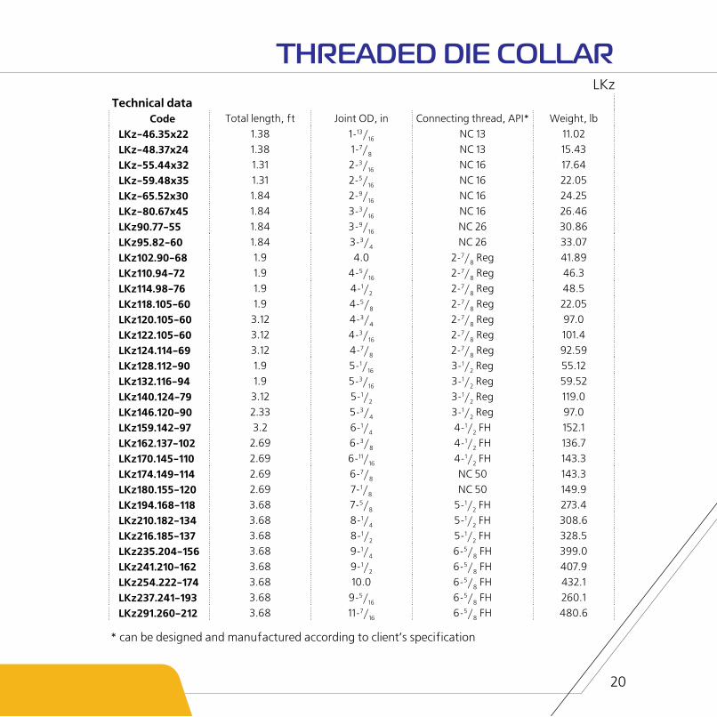
Technical dataCode Total length, ft Joint OD, in Connecting thread, API* Weight, lb
LKz-46.35x22 1.38 1-13/16 NC 13 11.02
LKz-48.37x24 1.38 1-7/8 NC 13 15.43
LKz-55.44x32 1.31 2-3/16 NC 16 17.64
LKz-59.48x35 1.31 2-5/16 NC 16 22.05
LKz-65.52x30 1.84 2-9/16 NC 16 24.25
LKz-80.67x45 1.84 3-3/16 NC 16 26.46
LKz90.77-55 1.84 3-9/16 NC 26 30.86
LKz95.82-60 1.84 3-3/4 NC 26 33.07
LKz102.90-68 1.9 4.0 2-7/8 Reg 41.89
LKz110.94-72 1.9 4-5/16 2-7/8 Reg 46.3
LKz114.98-76 1.9 4-1/2 2-7/8 Reg 48.5
LKz118.105-60 1.9 4-5/8 2-7/8 Reg 22.05
LKz120.105-60 3.12 4-3/4 2-7/8 Reg 97.0
LKz122.105-60 3.12 4-3/16 2-7/8 Reg 101.4
LKz124.114-69 3.12 4-7/8 2-7/8 Reg 92.59
LKz128.112-90 1.9 5-1/16 3-1/2 Reg 55.12
LKz132.116-94 1.9 5-3/16 3-1/2 Reg 59.52
LKz140.124-79 3.12 5-1/2 3-1/2 Reg 119.0
LKz146.120-90 2.33 5-3/4 3-1/2 Reg 97.0
LKz159.142-97 3.2 6-1/4 4-1/2 FH 152.1
LKz162.137-102 2.69 6-3/8 4-1/2 FH 136.7
LKz170.145-110 2.69 6-11/16 4-1/2 FH 143.3
LKz174.149-114 2.69 6-7/8 NC 50 143.3
LKz180.155-120 2.69 7-1/8 NC 50 149.9
LKz194.168-118 3.68 7-5/8 5-1/2 FH 273.4
LKz210.182-134 3.68 8-1/4 5-1/2 FH 308.6
LKz216.185-137 3.68 8-1/2 5-1/2 FH 328.5
LKz235.204-156 3.68 9-1/4 6-5/8 FH 399.0
LKz241.210-162 3.68 9-1/2 6-5/8 FH 407.9
LKz254.222-174 3.68 10.0 6-5/8 FH 432.1
LKz237.241-193 3.68 9-5/16 6-5/8 FH 260.1
LKz291.260-212 3.68 11-7/16 6-5/8 FH 480.6
20
LKz
THREADED DIE COLLAR
* can be designed and manufactured according to client’s specification

21
Application:
The Plain Taper Tap MLG is used to retrieve tubing partsof strings by catching internal surface during fishingoperations in the well.
Design:
The Taper Tap is a single piece construction with fishing cone (0º30’) at one end and tool-joint thread at the other end.
The Taper Tap is put into pipe gripping it by friction force. After that Taper Tap is retrieved with captured pipe. If needed the Plain Taper Tap is released by tensioning with force 25-50% bigger than force applied for fixing the Plain Taper Tap.
The Plain Taper Tap can be designed in left/right hand con-figuration.
There is a watercourse for drilling fluid.
PLAIN TAPER TAP MLG

Technical data
Code Watercourse OD, in
Pressure load, lbf
Load capacity, lbf
Total length, ft Joint OD, in Weight, lb
MLG-18x29 3/16 8 768 6744 2.43 1-3/16 6.28
MLG-24x38 5/16 14 610 11 240 2.95 1-3/16 11.79
MLG-30x44 3/8 17 540 13 490 2.95 1-3/16 15.83
MLG-40x54 1/2 37 990 29 230 3.25 3-3/16 31.09
MLG-46х60 1.0 43 840 33 720 3.15 3-3/16 31.09
MLG-54х68 1.0 62 950 49 460 3.15 3-3/16 41.89
MLG-62х76 1.0 67 440 53 950 3.15 3-3/16 53.35
MLG-76х90 1-1/4 76 440 58 450 3.22 3-3/4 77.6
MLG-84х98 1-1/2 76 440 58 450 3.22 4-1/4 91.05
MLG -90х104 1-1/2 76 440 58 450 3.22 4-1/4 103.6
MLG-96х110 2-5/16 76 440 58 450 3.8 5-1/2 170.2
MLG-104х118 2-5/16 76 440 58 450 3.42 5-1/2 130.1
MLG-108х126 2-5/16 76 440 58 450 4.27 5-1/2 183.0
MLG-118х136 2-5/16 76 440 58 450 4.1 5-1/2 210.5
MLG-126х144 3-3/4 76 440 58 450 4.27 6-1/8 254.6
MLG-140х158 3-3/4 76 440 58 450 4.27 6-1/8 226.0
MLG-148х166 3-3/4 76 440 58 450 4.27 6-1/8 262.4
22
MLG
PLAIN TAPER TAP
23
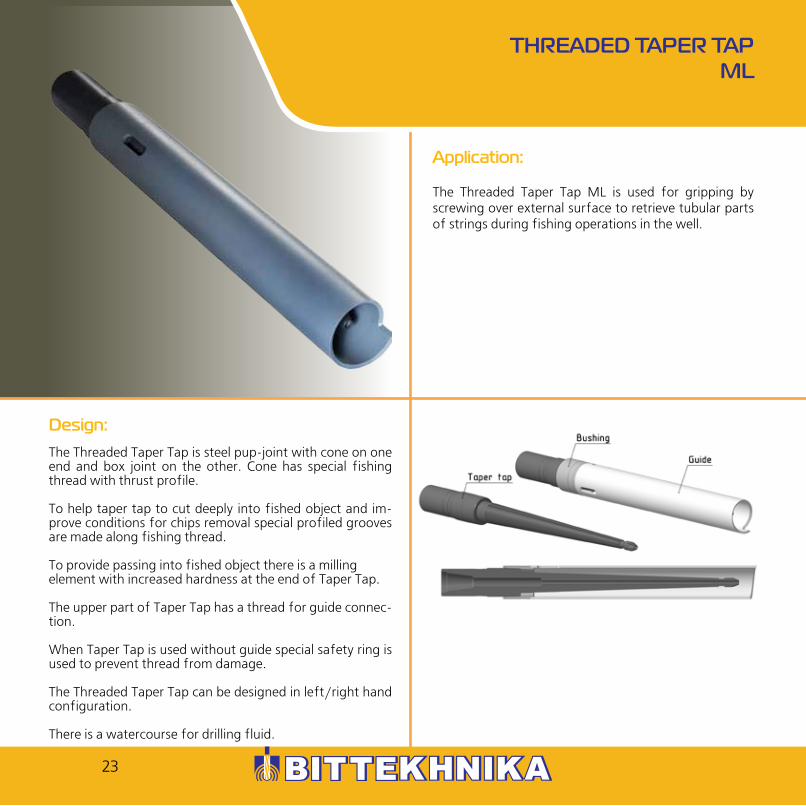
Application:
The Threaded Taper Tap ML is used for gripping by screwing over external surface to retrieve tubular parts of strings during fishing operations in the well.
Design:
The Threaded Taper Tap is steel pup-joint with cone on one end and box joint on the other. Cone has special fishing thread with thrust profile.
To help taper tap to cut deeply into fished object and im-prove conditions for chips removal special profiled grooves are made along fishing thread.
To provide passing into fished object there is a millingelement with increased hardness at the end of Taper Tap.
The upper part of Taper Tap has a thread for guide connec-tion.
When Taper Tap is used without guide special safety ring is used to prevent thread from damage.
The Threaded Taper Tap can be designed in left/right hand configuration.
There is a watercourse for drilling fluid.
THREADED TAPER TAP ML

Technical data
Code Watercourse OD, in
Axial load, lbf
Total length, ft Joint OD, in Connecting thread, API*
Weight, lb
ML-20-45 3/16 54 400 1.84 1-13/16 NC 13 20.06
ML-22-48 3/8 63 620 1.9 2-1/8 NC 16 10.36
ML-22-54 3/8 65 640 2.2 2-1/8 NC 16 13.23
ML-25-65 3/8 99 370 2.69 3-3/16 2-3/8 Reg 27.78
ML-32-72 9/16 134 900 2.72 3-3/16 2-3/8 Reg 38.36
ML-40-80 9/16 144 600 2.72 3-3/8 NC 26 42.33
ML-45x85 7/8 159 600 2.72 3-3/4 2-7/8 Reg 66.36
ML-55-95 7/8 170 900 2.72 4-1/4 3-1/2 Reg 66.36
ML-60-100 1-1/8 196 300 2.84 4-1/4 3-1/2 Reg 74.52
ML-65-109 1-1/4 206 800 3.08 4-5/16 3-1/2 Reg 93.04
ML-70-114 1-7/16 229 300 2.92 4-3/4 NC 38 105.8
ML-75-120 1-1/2 242 800 2.95 5.0 NC 38 110.2
ML-80-125 1-9/16 251 800 2.98 5-1/4 NC 40 141.1
ML-90-135 1-3/4 272 000 3.02 5-1/2 4-1/2 Reg 149.9
ML-100-145 1-15/16 278 800 3.02 6.0 4-1/2 FH 174.2
ML-120-165 2-3/8 296 700 3.05 6-5/8 NC 50 220.5
24
ML
THREADED TAPER TAP
* can be designed and manufactured according to client’s specification

25
Application:
The Special Operational Taper Tap MES is used for gripping by screwing into box thread of tubing pipes and its further retrieval during fishing operations in the well.
Design:
The Taper Tap is a single piece construction made of alloyed forged steel.
It has connection thread at the top and external fishing thread at the bottom.
To make the Taper Tap to cut deeply into fished object spe-cial profiled grooves are made along fishing thread.
The Taper Tap can be designed in left/right hand configura-tion.
There is a watercourse for drilling fluid.
SPECIAL OPERATIONAL TAPER TAP MES

Technical data
Code Fishing thread Watercourse OD, in
Load capacity, lbf
External diameter, in
Total length, ft
MES-48 NKT-48 1/2 80 930 2-9/16 0.59
MES-60 NKT-60 9/16 123 600 3-3/14 0.89
MES-73 NKT-73 1/2 168 600 3-3/14 0.92
MES-89 NKT-89 13/16 224 800 4-1/4 0.92
MES-102 NKT-89 5/8 269 800 4-1/4 0.92
MES-114 NKT-114 9/16 337 200 4-3/4 0.92
MES-V33 NKTV-33 1/4 47 210 2-9/16 0.76
MES-V42 NKTV-42 5/16 62 950 2-9/16 0.76
MES-V48 NKTV-48 1/2 80 930 2-9/16 0.76
MES-V60 NKTV-60 9/16 123 600 3-3/14 0.92
MES-V73 NKTV-73 1/2 168 600 3-3/14 0.92
MES-V89 NKTV-89 13/16 224 800 4-1/4 0.92
MES-V102 NKTV-102 1-1/4 269 800 4-1/4 0.92
MES-V114 NKTV-114 1-9/16 337 200 4-3/4 0.92
26
MES
SPECIAL OPERATIONAL TAPER TAP
* can be designed and manufactured according to client’s specification

27
Application:
The Special Taper Tap for Joints MSZ is used for gripping by cutting into drill pipe joint and its further retrieval during well fishing operations.
Design:
The Special Taper Tap is a single piece construction with connection thread at the top and external fishing thread at the bottom.
The surface of fishing thread is cemented and hardened.
To make the Taper Tap to cut deeply into fished object spe-cial profiled grooves are made along the fishing thread.
There is watercourse for drilling fluid.
SPECIAL TAPER TAP FOR JOINTS MSZ

Technical data
Code Fishing connection,
API*
Water course OD, in
Load capacity,
lbf
Joint OD, in Total length, ft
Connection to fishing
string, API*
Weight, lb
MSZ-66 2-3/8 Reg 9/16 224 800 3-3/16 0.85 2-3/8 Reg 14.55
MSZ-73 NC 26 9/16 337 200 3-3/8 0.92 NC 26 16.98
MSZ-76 2-7/8 Reg 9/16 337 200 3-3/4 0.92 2-7/8 Reg 20.5
MSZ-86 NC 31 13/16 449 600 4-1/8 0.92 NC 31 23.15
MSZ-88 3-1/2 Reg 1.0 449 600 4-1/4 0.92 3-1/2 Reg 25.13
MSZ-102 3-1/2 IF 1-13/16 584 500 4-15/16 1.18 3-1/2 IF 55.12
MSZ-133 NC 50 1-1/2 607 000 6-1/4 1.25 NC 50 74.52
MSZ-147 5-1/2 FH 2-3/8 674 400 7-1/16 1.34 5-1/2 FH 87.52
28
MSZ
SPECIAL TAPER TAP FOR JOINTS
* can be designed and manufactured according to client’s specification

29
Application:
The Internal Wireline Spear PIKV is designed to grip and retrieve electric line, wire line and rope during fishing operations in the well.
Design:
The Internal Wireline Spear has strong construction permit-ting to retrieve wire line or wire rope from the well.
Hooks are placed spirally and have different sizes (increas-ing from down to up), what permits to screw it into solid wire seal.
The head has cone form and penetrates into solid seal from cable or wire.
Top sub operates as stopping ring and has hole for techno-logical flushing.
INTERNAL WIRELINE SPEAR PIKV

30
PIKV
INTERNAL WIRELINE SPEAR
* can be designed and manufactured according to client’s specification
Technical data
Code Body OD, in Total length, ft Joint OD, in Connecting thread, API*.
Load capacity, lbf
Weight, lb
PIKV-20х56 3/16 2.33 2-3/16 NKT-42 33 720 12.13PIKV-40х92 1-9/16 3.42 3-5/8 2-3/8 IF 33 720 37.48PIKV-55х114 2-3/16 4.75 4-1/2 2-3/8 Reg 44 960 61.73PIKV-50х120 2-3/16 4.75 4-3/4 2-7/8 Reg 62 950 92.59PIKV-55х120 2-3/16 5.58 4-3/4 2-7/8 Reg 62 950 99.21PIKV-60х120 2-3/8 5.42 4-3/4 2-7/8 Reg 67 440 125.7PIKV-65х190 2-9/16 7.17 7-1/2 3-1/2 Reg 67 440 160.9
31
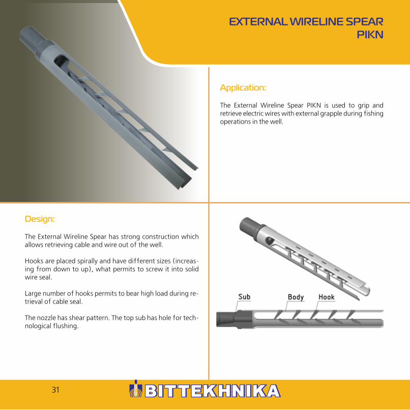
Application:
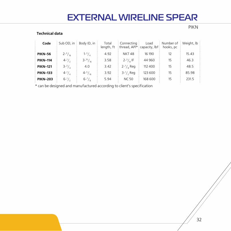
The External Wireline Spear PIKN is used to grip and retrieve electric wires with external grapple during fishing operations in the well.
Design:
The External Wireline Spear has strong construction which allows retrieving cable and wire out of the well.
Hooks are placed spirally and have different sizes (increas-ing from down to up), what permits to screw it into solid wire seal.
Large number of hooks permits to bear high load during re-trieval of cable seal.
The nozzle has shear pattern. The top sub has hole for tech-nological flushing.
EXTERNAL WIRELINE SPEAR PIKN
32
PIKN
EXTERNAL WIRELINE SPEAR
* can be designed and manufactured according to client’s specification
Technical data
Code Sub OD, in Body ID, in Total length, ft
Connecting thread, API*
Load capacity, lbf
Number of hooks, pc
Weight, lb
PIKN-56 2-3/16 1-3/4 4.92 NKT 48 16 190 12 15.43
PIKN-114 4-1/2 3-15/16 3.58 2-3/8 IF 44 960 15 46.3
PIKN-121 3-3/4 4.0 3.42 2-7/8 Reg 112 400 15 48.5
PIKN-133 4-1/4 4-5/16 3.92 3-1/2 Reg 123 600 15 85.98
PIKN-203 6-1/2 6-7/8 5.94 NC 50 168 600 15 231.5

AUGER-TYPE SPEAR PIKSH
Application:
The Auger-type Spear PIKSH is designed to catch, fix and retrieve logging cable, electric cable and wireline during fishing works in the well.
Design:
The Auger-type Spear consists of catching element (au-ger), which looks like helical spiral. It is placed along the full length of body and milling funnel.
Auger and joint are designed as one complete unit. There is connection thread to pipe string at the upper part and tub-ing thread for funnel connection at the lower part. Auger and funnel are made of alloyed steel.
The funnel is used for cable milling and at the same time it is a directing and limiting tool of axial movement of retriev-able cable.
The emergency cable drum is formed in closed space of funnel, which makes the process of retrieval much easier.
The Spear movability allows to loosen it from cable rests and prepare it for further operating.
33

PIKSH
AUGER-TYPE SPEAR PIKSH
Technical data
Code ID, in External D of funnel, in
Min D of auger, in
Max D of auger, in
Total length,
ft
Load capacity,
lbf
Weight, lb
PIKSH-124.60x80 4-5/16 4-7/8 2-3/8 3-3/16 4.17 33 720 79.81
PIKSH-146.70x90 4-5/16 4-7/8 2-3/4 3-9/16 4.17 33 720 94.14
34

CABLE SPIRAL SPEAR KSU
Application:
The Cable Spiral Spear KSU is used to retrieve wireline, electric cable and logging cable from casing during repair works in the well.
Design:
The Cable Spiral Spear is one piece twisted catching element in form of ribbon spiral.
The spiral part is manufactured as part of sub, which has connection thread to tubing string at the top.
The Spear is made of alloyed steel and is heat treated. To prevent cable slippage during retrieving special hooks are placed on turns of Spiral Spear.
35

KSU
CABLE SPIRAL SPEAR
* can be designed and manufactured according to client’s specification
Technical data
Code KSU-122
OD, in 4-13/16
ID, in 2-3/4
Total length, ft 3.92
Length of working part, in 3.08
Connecting thread, API* 2-7/8 IF
Load capacity, lbf 33 720
Weight, lb 78.26
36

37
Application:
The Cable Mule Shoe PRK is used to destroy cable in production string and annular space between wellbore wall and tubing during repair and recovery works in the well.
Design:
The Cable Mule Shoe is connection pipe made of alloyed steel, which has toothed cutter at the bottom. Teeth have hardened surface. The Cable Mule Shoe is made of high-strength cemented steel.
The internal part has screw conveyer form in order to tight-en rests of cable during milling process and provide its fur-ther retrieval.
Screw conveyers are designed with narrow or wide pitch de-pending on size of cable.
There are three types of Cable Mule Shoe depending on the amount of teeth on the lower part of body: – PRK 2 has 2 large cutting elements on the edge. – PRК 4 has 4 large cutting elements on the edge. – PRКz has a variety of small cutting elements on the edge.
It is recommended to set junk basket SHMU above PRK 2-3.
CABLE MULE SHOE PRK

Technical data
Code OD, in ID, in Total length, ft Direction of screw slots *
PRK 2-114х96 4-1/2 3-3/4 1.31 rightPRK 2-120х100 4-3/4 3-15/16 1.31 rightPRK 2-136х117 5-3/8 4-5/8 1.31 right
PRK 4-114х96 4-1/2 3-3/4 1.31 rightPRK 4-120х100 4-3/4 3-15/16 1.31 rightPRK 4-136х117 5-3/8 4-5/8 1.31 rightPRKz-114х96 4-1/2 3-3/4 1.31 right
PRKz-120х100 4-3/4 3-15/16 1.31 rightPRKz-136х117 5-3/8 4-5/8 1.31 right
38
PRK
CABLE MULE SHOE
* can be designed and manufactured according to client’s specification

39
Application:
The Internal Mechanical Cutter TRV is used to cut and retrieve drilling, casing and tubing parts of pipes during emergency and recovery works in the well.
Design:
The Internal Mechanical Cutter consists of body, cuttingblades, retractable device for cutting blades and slip.
Internal cutters can be designed in left/right hand configuration.
INTERNAL MECHANICAL CUTTER TRV

Technical data
Code D of cut pipes, inches Body OD, inches Connecting thread, API*.
TRV-48 1-7/8 1-7/16 NC10
TRV-60 2-3/8 1-7/8 NC10
TRV-73 2-7/8 2-1/4 NC 16
TRV-89 3-1/2 2-5/8 NC 23
TRV-102 4.0 3-1/4 2-3/8 Reg
TRV-114 4-1/2 3-9/16 NC 26
TRV-127 5.0 4.0 2-7/8 Reg
TRV-140 5-1/2 4-5/16 3-1/2 Reg
TRV-146 5-3/4 4-5/8 3-1/2 FH
TRV-168 6-5/8 5-1/4 NC 40
TRV-178 7.0 5-5/8 4-1/2 Reg
TRV-194 7-5/8 6-1/4 4-1/2 Reg
TRV-219 8-5/8 7-3/8 5-1/2 FH
TRV-245 9-5/8 8-1/4 5-1/2 FH
TRV-273 10-3/4 9-1/2 5-1/2 FH
TRV-299 11-3/4 10-1/2 5-1/2 FH
40
TRV
INTERNAL MECHANICAL CUTTER
* can be designed and manufactured according to client’s specification

41
Application:
The External Mechanical Cutter TRN is used to cut and retrieve elements of drilling, casing and tubing pipes during repair, emergency and recovery works in the well.
Design:
The External Mechanical Cutter consists of body, sub, fix-ing element, axial bearing, adjusting sleeve, laying, collar, baffle collar, spring, feeding bush, spear spins, cone, joint pins, screws of joint pints and chisels.
The body is a pipe branch which has box metric thread on lower and upper end. It is used for connection between sub and cone. There are radial cuts at the lower part of body.
Chisels with possibility of radial displacement are set on the axis of cuts. In run-in position feeding bush is fixed in body with the help of brass spear pins.
The lower edge of cone has form of cutlip guide which al-leviates the entry of string “head” to the tool.
EXTERNAL MECHANICAL CUTTER TRN

Technical data
Code Nominal D of cut pipes, in
External diameter of cutter,
in
Internal channel,
in
Maximal tensile
load, lbf
Effort for cutting pin, lbf
Total length, ft
Connecting thread*
Weight, lb
TRN-42 1-5/16 – 1-11/16 3-1/16 2-1/8 8 992 449.6 2.88 NKTV-60 38.14
TRN-50 1-7/8 – 2.0 3-9/16 2-3/4 11 240 562.0 3.25 NKTV-73 55.12
TRN-60 2-3/8 – 2-1/2 4-1/2 3-1/8 13 490 786.8 3.33 NKTV-89 80.25
TRN-73 1-7/8 – 2-7/8 4-11/16 3-13/16 13 490 1 191 3.67 NKTV-102 88.18
TRN-89 2-7/8 – 3-1/2 5-1/2 4-5/16 22 480 1 191 4.0 NKTV-114 91.05
TRN-102 3-1/2 – 4.0 5-15/16 4-7/8 22 480 1 191 4.46 OTTM-140 114.6
TRN-114 4.0 – 4-1/2 7-1/8 5-7/8 24 730 1 349 4.58 OTTM-168 132.3
TRN-127 4-1/2 – 5.0 7-1/2 6-1/4 26 980 1 574 4.92 OTTM-178 154.3
TRN-140 5.0 – 5-1/2 8-1/8 6-7/8 29 230 1 798 5.25 OTTM-194 154.3
TRN-146 5-1/2 – 5-3/4 9-1/8 7-9/16 31 470 1 798 5.25 OTTM-219 176.4
42
TRN
EXTERNAL MECHANICAL CUTTER
* can be designed and manufactured according to client’s specification

43
Application:
The Internal Hydraulic Pipe Cutter TVG is designed to cut elements of drilling strings and oil-well tubings during repair and recovery works in the well.
Design:
The Internal Hydraulic Pipe Cutter is used in assembly with downhole motor. Set the hydraulic tubing anchor above the motor. It fixes body during operation and eliminates axial throw and turn under influence of counter torque.
It is forbidden to provide pressure at the downstream line while lowering the Pipe Cutter. It may lead to premature moving-out of cutters.
When Pipe Cutter reaches required depth, fix the weight of string via weight indicator. Create circulation with required working pressure. At the same time under influence of ex-cess pressure slips of anchor are pressed to well’s wall.
The Pipe Cutter starts its operation. Сirculation of drilling fluid through annular space between casing and tubing signalizes that the pipe was cut.
After finishing operations stop pressure feed in down-stream line. As a result Pipe Cutter and hydraulic anchor come back to transport position.
INTERNAL HYDRAULIC PIPE CUTTER TVG

Technical data
Code Body OD, in Nominal D of cut pipes, in
Working pressure, psi
Connecting thread, API
TVG-73 2.24 2-7/8
74 - 294
NC 16
TVG-89 2.75 3-1/2 NC 16
TVG-102 3.15 4.0 AMMT 1.5
44
TVG
INTERNAL HYDRAULIC PIPE CUTTER

45
Application:
The Hydraulic Tubing Anchor YAGT is designed to fix body of screw downhole motor during its operation. It eliminates axial throw and turn under influence of counter torque. The anchor is used in an assembly with downhole motor and internal hydraulic pipe cutter TVG. It can also be used for other technological operations. The assembly is lowered into the well on small-size pipes or from coiled tubing units.
Design:
The Hydraulic Tubing Anchor consists of body, hold-down slips pressed by springs, which are fixed by planks by means of screws and sealing elements.
The Anchor is set above the downhole motor. Under pres-sure of increasing drilling fluid rate, slips move out of body. After that slips are fixed on the internal pipe wall. When cir-culation goes down, pressure decreases and slips move back into body (transport position).
HYDRAULIC TUBING ANCHOR YAGT

Technical data
Code OD, in Max D of outcome, in Nominal D of pipes, in Length, ft Weight, lb
YAGT-73 2.24 2.52 2.87 1.14 11.46YAGT-89 2.75 3.13 3.5 1.31 20.5YAGT-102 3.15 3.78 4.0 1.73 29.76
46
YAGT
HYDRAULIC TUBING ANCHOR

Application:
The Hydraulic Pipe Puncher DGT-1 is used to punch hole to drain fluid from tubing during repair and emergency works in the well.
Design:
The Hydraulic Pipe Puncher consists of choke, body 1, rod bush, body 2, rod, thrust bush, body3, clutch, isolation joint, puncher, thread bush, ring, valve bush, valve, cup, spring, tail piece, rod hinge pin, set of sealing rings and valve hinge pin.
HYDRAULIC PIPE PUNCHER DGT
47

Technical data
Code DGT-60 DGT-73 DGT-89
Nominal diameter of tubing punched, in
2.36 2.87 3.5
Connecting thread ShN-22 ShN-22 M42x2
Outer diameter of body 1, in 1.57 1.99 2.36
Outer diameter of sleeve, in 0.7 2.23 2.69
Outer diameter of nose piece, in 1.57 1.87 2.36
Outer diameter of prick puncher, in 0.47 0.61 0.61
Outer diameter of shear pin, in 0.17 0.22 or 0.25 0.27
Pressure differential necessary to cut shear pin, psi
- diameter 0.22 in 3 046 +/- 304 3 771 +/- 290 –
- diameter 0.25 in – 4 206 +/- 290 –
- diameter 0.27 in – – 3 553+/-290
Length, ft 3.29 3.66 3.73
Weight, lb 17.64 26.46 41.89
DGT
HYDRAULIC PIPE PUNCHER
* can be designed and manufactured according to client’s specification
48

49
Application:
The Mechanical Jar YAM is used to create load impact (impacts can be directed both up and down) during emergency works because of locking of drilling, casing, tubing strings, string parts, formation testers, calibrators, bits, fishing tools, mills, etc.
Design:
The Mechanical Jar consists of three-section body, stock, stock end, stopping screw and sealing parts.
The body consists of three parts connected with special threads. There is box thread at the top. The Mechanical Jar can be designed in left/right hand configuration depending on connection threads.
It is recommended to set the Mechanical Jar into BHA while using releasing fishing tools (overshot, spear) in order to make releasing process much easier.
MECHANICAL JAR YAM

50
YAM
MECHANICAL JAR
* can be designed and manufactured according to client’s specification
Technical data
Сode D, in Water-course D, in
Free stroke of stock, ft,
not less
Tensile yield, lbf
Yield torque, lbsf.ft
Connec-tion, API*
Average number of
impact
Length, ft
Weight, lb
YAM-95 3.74 1-1/4 1.64 258 530 11 432 2-7/8 Reg 800 4.29 110.2
YAM-103 4.05 1-1/4 1.64 258 530 11 432 2-7/8 Reg 800 4.29 136.6
YAM-122 4.8 1-1/2 1.64 404 660 22 864 3-1/2 Reg 800 4.29 189.6

51
Application:
The Hydraulic Jar YAG is used to create single, upward, repeated load impacts during emergency works in the well.
Design:
The Hydraulic Jar consists of body, rod, sub, piston and set of sealing elements. The sub with special profile connecting box thread is connected to the upper part of rod, rod liner is connected to the bottom part. The piston is set between liner and cylindrical wedge of rod. The body consists of three parts connected by special threads. On the internal surface of upper part of body there are grooves which interact with other grooves on rod used to torque transmission. The surface of middle part which contacts the piston has watercourses. There is pin connection thread at the lower part of body. The shank bore of Hydraulic Jar is filled with special oil. All connections have sealing rings. The filling of Hydraulic Jar is made through holes in body, which are closed with special plugs.
HYDRAULIC JAR YAG

52
YAG
HYDRAULIC JAR
* can be designed and manufactured according to client’s specification
Technical data
Code YaG-95 YaG-103 YaG-122
Outer diameter, in 3.76 4.05 4.81
Internal pass-through channel, in, not less 1.26 1.26 1.5
Free rod movement, in, not less 3.94 3.94 3.94
Full rod movement, in, not less 10.12 10.12 14.57
Maximal stretching load to hydraulic jar for striking, lbf 56 200 56 200 78 680
Maximal stretching load to open hydraulic jar after striking, lbf 269 800 269 800 449 600
Maximal torque passed by hydraulic jar, lbf.ft 11 430 11 430 22 130
Connecting thread, API* 2-7/8 Reg 2-7/8 Reg NC 31
Length, ft 5.24 5.24 6.79
Weight, lb 149.9 165.3 352.7

53
Application:
The Safety Joint PB is used for easy release from stuck tool or pipes during fishing works in the well.
Design:
The Safety Joint is a connection pipe which consists of two parts – sub and body which are connected with trapezoidal thread.There is a stop-ring between them which helps to pre-vent tightening of thread at high torque.
There are two sealing rings which guarantee good hermetic-ity. The sub has watercourse.
The Safety Joint can be designed in left/right hand configura-tion.
SAFETY JOINT PB

Technical data
Code OD, in
Total length, ft
Water course D, in
Connection, API*
Weight, lb
PB-66 3-3/16 2.01 1.0 2-3/8 Reg 52.91
PB-73 3-3/8 2.37 1-1/4 NC 26 55.12
PB-76 3-3/4 2.37 1-1/4 2-7/8 Reg 83.78
PB-86 4-1/4 2.37 2-1/8 NC 31 77.16
PB-88 4-1/4 2.37 1-1/2 3-1/2 Reg 88.18
PB-102 4-3/4 2.37 2-3/4 NC 38 88.18
PB-122 5-3/4 2.63 3-1/4 4 IF 141.1
PB-133 6-1/8 2.63 3-3/4 4-1/2 IF 145.5
PB-147 7.0 2.71 4.0 5-1/2 FH 209.4
54
PB
SAFETY JOINT
* can be designed and manufactured according to client’s specification

55
Application:
The Hydraulic Safety Sub PB-G is designed to provide easy release from stuck tool or pipes during fishing works in the well.
Design:
The Safety Sub is a connection pipe made of alloy steel. The tool consists of upper body, lower body, piston and dies.
Fixation of piston in working position is provided by 3 shear screws. Torque from upper body to lower body transfers connection to grooves which are made on the outer surface.
The hermeticity of tool is provided by sealing rings. The Sub has watercourse for drilling fluid. The tool can be designed in left/right hand configuration.
If there is necessity of detachment from stuck tool or pipes, drive the ball into pipe and provide pressure required for pin cut. When the Sub is disconnected, raise the unconnected part of pipe string.
HYDRAULIC SAFETY SUB PB-G

Technical data
Code OD, in
Total length, ft
Water course D, in
D of ball, in
Actuation pressure, psi
Weight, lb
PB-73G 3-3/8 1.77 1.0 1-1/16
2 057
41.89
PB-76G 3-3/4 1.82 1-1/8 1-3/16 46.3
PB-86G 4-1/8 1.92 1-1/4 1-1/8 61.73
PB-102G 5.0 2.3 1-9/16 1-11/16 110.2
PB-133G 7.0 3.17 2-1/8 2-1/4 286.6
PB-147G 7.0 3.25 2-1/8 2-1/4291.0
56
PB-G
HYDRAULIC SAFETY SUB

57
Application:
The Mechanical Junk Basket PM is designed to retrieve different metal pieces (rolling cones and bearings of drilling bits, cutter arms, cable pieces, metal fragments which have appeared after milling process, etc.) from bottom hole.
Design:
The Mechanical Junk Basket consists of tubular body (made of high-strength alloyed steel), sub, two mechani-cal petal type catchers and washover shoe.
Catchers are set at lower part of body in two levels with possibility of free rotation.
The catcher is equipped with interlaced and extended to the center of tool short and long pins. This tool operates as float valve. The catcher lets core sampler and small metal pieces in one direction (into the tool) by deviation of spring-loaded joint pins upwards. It doesn’t transmit cap-tured pieces in reverse direction (from the tool).
The Mechanical Junk Basket can be designed in left/right configuration depending on direction of connection threads.
MECHANICAL JUNK BASKET PM

Technical data
Code Max torque, ft.lbf
Body OD, in
Milling cone OD, in
Milling cone ID, in
Length, ft
Weight, lb
PM-95 2 213 3-5/8 3-11/16 2-5/16 3.28 44.09
PM-112 2 213 4.0 4-7/16 2-1/2 3.87 66.14
PM-119 2 213 4-1/2 4-1/2 2-15/16 3.87 88.18
PM-136 5 900 5-1/8 5-3/8 3-9/16 4.07 138.5
PM-150 5 900 5-3/4 5-15/16 4-1/4 4.26 154.3
PM-196 8 113 7-1/4 7-15/8 4-15/16 5.24 187.4
PM-206 10 330 7-1/2 8-1/8 5-1/16 4.92 220.5
PM-257 14 750 9-3/4 10-1/8 6-1/2 5.24 264.6
PM-265 14 750 9-15/16 10-7/16 6-11/16 5.9 297.6
PM-286 14 750 9-15/16 11-1/4 7-1/2 6.23 330.7
58
PM
MECHANICAL JUNK BASKET
* can be designed and manufactured according to client’s specification

59
Application:
The Hydraulic Junk Basket PG with reverse circulation is used to retrieve different pieces, cutters of drilling bits, bearings, broken slips, cable fragments, different manual tools, fragments of drilling pipes, milling chips etc.
Design:
The Hydraulic Junk Basket consists of top sub, body with ball valve guide, catcher and washover shoe.
The tool can be made with different type of cutting-and-wearing surface – plain, wave-like, toothed, salient or flushed with body.
The Hydraulic Junk Basket is screwed on drilling pipe with the help of top sub. The Junk Basket is made of manganese bronze and is equipped with interlaced and stretched to the center long and short pins.
The tool can be designed in left/right configuration de-pending on connection guides.
HYDRAULIC JUNK BASKET PG

Technical dataCode Max torque, ft.lbf Body OD, in Max D of caught pieces, in Length, ft Connection, API*
PG-94 2 213 3-5/8 2-5/16 3.92 NC 26
PG-112 2 213 4.0 2-1/2 3.83 2-7/8 Reg
PG-119 2 213 4-1/2 2-5/16 3.83 2-7/8 Reg
PG-130 5 900 5.0 2-5/16 4.0 NC 38
PG-136 5 900 5-1/8 3-9/16 3.83 3-1/2 Reg
PG-146 5 900 5-1/2 4 .0 3.83 2-3/8 IF
PG-150 5 900 5-3/4 4-1/4 3.83 3-1/2 Reg
PG-196 8 113 7-1/4 4-3/4 4.83 NC 50
PG-206 10 330 7-1/2 5-1/16 4.83 NC 50
PG-257 14 750 9-3/4 6-5/8 6.17 NC 50
PG-265 14 750 9-15/16 6-11/16 6.17 4-1/2 IF
PG-286 14 750 10-3/4 7-1/2 6.17 NC 50
PG-340 14 750 13.0 9-5/8 6.25 6-5/8 Reg
60
PG
HYDRAULIC JUNK BASKET
* can be designed and manufactured according to client’s specification

61
Application:
The Bottom-hole Junk Mill is used to destruct cemented stone around all cross-section of well, to drill out sand plugs and casing production tools consisting of soft metals.
Design:
The Bottom-hole Junk Mill consists of body and dressing with tungsten-carbide and carbide inserts.
The lateral surface is strengthened with tungsten-carbide teeth which guarantee high wear resistance.
There is connecting thread at the upper part of body, ports and grooves for effective cooling and intensive washing are placed at the bottom part.
BOTTOM-HOLE JUNK MILL FZ-T

Technical data
Code Outer diameter of mill, in Length, ft Connecting thread, API* Weight, lb
FZ-85T 3.34 1.1 NC 23 22.05
FZ-97T 3.81 1.19 NC 23 26.46
FZ-118T 4.64 1.37 2-7/8 Reg 59.52
FZ-120T 4.72 1.37 2-7/8 Reg 61.73
FZ-122T 4.8 1.5 NC 31 72.75
FZ-124T 4.88 1.5 NC 31 74.96
FZ-130T 5.11 1.64 NC 31 83.78
FZ-133T 5.23 1.64 NC 31 88.18
62
FZ-T
BOTTOM-HOLE JUNK MILL
* can be designed and manufactured according to client’s specification

63
Application:
The Cemented Bottom-hole Mill FZ-TS is designed to destruct cement stones over all section of casing hole, drill out sand plugs, equip casing string and to mill metal objects at bottomhole.
Design:
The Cemented Bottom-hole Mill consists of body and dress-ing with tungsten-carbide and carbide inserts.
The lateral surface of mill is strengthened with tungsten-carbide teeth that guarantee high wear resistance.
There is connecting thread at the upper part of body, ports and grooves for effective cooling and intensive washing are placed at the bottom part.
CEMENTED BOTTOM-HOLE MILL FZ-TS

Technical data
Code Outer diameter of mill, in
Length, ft Rotation speed, rpm
Load capacity, lb
Connecting thread, API*
Weight, lb
FZ-85TS 3-3/8 0.87
30 - 120 4 409 - 6 614
2-3/8 Reg 26.46
FZ-118TS 4-5/8 1.14 2-7/8 Reg 48.55
FZ-120TS 4-3/4 1.14 2-7/8 Reg 52.91
FZ-122TS 4-13/16 1.14 NC 31 55.12
FZ-124TS 4-7/8 1.14 NC 31 57.32
FZ-133TS 5-1/4 1.31 NC 31 66.14
FZ-140TS 5-1/2 1.31 NC 31 70.55
64
FZ-TS
CEMENTED BOTTOMHOLE MILL
* can be designed and manufactured according to client’s specification

65
Application:
The Washover Shoe FK is designed for annular milling (drilling off) of space between milled casing and walls of the well.
Design:
The Washover Shoe is a connection pipe with flat cutting and grinding dressing at the bottom and holes for washing fluid.
The connection type: welded or threaded. The dressing comes with tungsten carbide powder.
WASHOVER SHOE FK

66
FK
WASHOVER SHOE
* can be designed and manufactured according to client’s specification
Technical data
Code Outer diameter, in Internal diameter, in Length, ft
FK-90/61 3.54 2.4
1.31
FK-95/61 3.74 2.4
FK-109/75 4.29 2.95
FK-112/64 4.41 2.52
FK-115/75 4.53 2.95
FK-118/75 4.65 2.95
FK-120/78 4.72 3.07
FK-122/82 4.80 3.23
FK-124/80 4.88 3.15
FK-127/92 5.0 3.62
FK-127/102 5.0 4.02
FK-130/92 5.12 3.62
FK-130/102 5.12 4.02
FK-136/96 5.35 3.78
FK-136/100 5.35 3.78
FK-136/102 5.35 4.02
FK-140/96 5.51 3.78
FK-144/102 5.67 4.02
FK-147/104 5.79 4.09
FK-149/110 5.87 4.33
FK-160/120 6.3 4.72
FK-190/152 7.48 5.98
FK-248/205 9.76 8.07

67
Application:
The Wave-like Washover Shoe FK-V has wave-like tungsten carbide dressing and is used for annular milling (drilling off) of space between the milled casing and walls of the well.
Design:
The Wave-like Washover Shoe is a connection pipe with tungsten carbide dressing at the bottom.
Connection type: threaded or welded.
WAVE-LIKE WASHOVER SHOE FK-V

68
FK-V
WAVE-LIKE WASHOVER SHOE
* can be designed and manufactured according to client’s specification
Technical data
Code Outer diameter, in Internal diameter, in Length, ft
FK-90/61 3.54 2.4
1.31
FK-95/61V 3.74 2.4
FK-109/75V 4.29 2.95
FK-112/64V 4.41 2.52
FK-115/75V 4.53 2.95
FK-118/75V 4.65 2.95
FK-120/78V 4.72 3.07
FK-122/82V 4.80 3.23
FK-124/80V 4.88 3.15
FK-127/92V 5.0 3.62
FK-127/102V 5.0 4.02
FK-130/92V 5.12 3.62
FK-130/102V 5.12 4.02
FK-136/96V 5.35 3.78
FK-136/100V 5.35 3.78
FK-136/102V 5.35 4.02
FK-140/96V 5.51 3.78
FK-144/102V 5.67 4.02
FK-147/104V 5.79 4.09
FK-149/110V 5.87 4.33
FK-160/120V 6.3 4.72
FK-190/152V 7.48 5.98
FK-248/205V 9.76 8.07

69
Application:
The Straight-Toothed Taper Mill FKP is designed to mill collapsed pipes, recover internal diameter of pipes and open boreholes.
Design:
The Straight-Toothed Taper Mill consists of body and cut-ting and grinding dressing with tungsten carbide powder.
Cutting and grinding elements are dressed as stripes.
There is a connection thread at the upper part of body, ports and grooves for effective cooling and intensive washing are placed at the bottom part.
The Mill can be designed in left/right hand configuration.
STRAIGHT-TOOTHED TAPER MILL FKP

Technical data
Code Casing D, in Length, ft Connecting thread, API Weight, lb
FKP-80 4.0 3.54 NC 23 79.37
FKP-95 4-1/2 3.54 NC 23 88.18
FKP-105/110 5.0 3.54 2-7/8 Reg 99.21
FKP-122/125 5-3/4 3.54 2-7/8 Reg 110.2
FKP-142/144 6-5/8 3.54 3-1/2 Reg 143.3
FKP-151/156 7.0 3.54 3-1/2 Reg 149.9
FKP-158/170 7-5/8 3.93 NC 38 198.4
FKP-180/195 8-5/8 3.93 4-1/2 Reg 271.2
FKP-195/215 9-5/8 3.93 4-1/2 Reg 341.7
FKP-220/240 10-3/4 3.93 NC 50 443.1
FKP-240/255 11-13/16 3.93 NC 50 469.6
FKP-260/275 12-3/4 3.93 5-1/2 FH 507.1
70
FKP
STRAIGHT-TOOTHED TAPER MILL
* can be designed and manufactured according to client’s specification

71
Application:
The Special Taper Mill FKS is designed to remove metal pieces and imperfections from internal surface of pipe string; to form chamfer on internal diameter of pipes; to work out pipes having ellipticity (restore internal diameter); to mill collapsed pipes during repair and emergency operations in the well.
Design:
The Special Taper Mill consists of body made of highstrength alloy steel and cutting and grinding dressing with crushed tungsten carbide inserted into matrix of nickel-containingbrass.There is a connection thread at the upper part of body, sta-bilizing elements are placed in the middle part (if needed). Cutting and grinding elements are soldered on the taper as stripes, which are gathered at the top. Circulation of drill-ing fluid is provided through inclined apertures in the middle part of taper and through side channels. Construction of mill: - two variants depending on slope angle: 1) angle 30° 2) angle 60°- two variants depending on connection thread: 1) right 2) left.Construction of the Special Taper Mill allows lower cutting end of small diameter reach the narrow section of pipe string. Expansible wedge-shaped edges mill off-quality part of pipe until it reaches full internal diameter.
SPECIAL TAPER MILL FKS

Technical data
Code Maximal diameter, in Minimal diameter, in Connecting thread, API* Length, ft Weight, lb
FKS-90 3.54 0.98 2-3/8 Reg 1.49 44.1FKS-111 4.37 1.77 2-7/8 Reg 1.71 46.31FKS-114 4.5 1.77 2-7/8 Reg 1.71 48.07FKS-117 4.63 1.77 2-7/8 Reg 1.71 48.51FKS-120 4.72 1.77 2-7/8 Reg 1.71 51.6FKS-125 4.92 1.77 2-7/8 Reg 1.77 55.13FKS-130 5.13 1.85 2-7/8 Reg 1.87 59.54FKS-133 5.25 1.85 2-7/8 Reg 1.87 61.74FKS-136 5.37 1.77 2-7/8 Reg 1.83 63.95FKS-140 5.5 1.85 2-7/8 Reg 1.89 66.37FKS-156 6.13 1.77 3-1/2 Reg 1.98 85.55FKS-159 6.25 1.77 3-1/2 Reg 2.01 88.42FKS-171 6.75 3.15 4-1/2 FH 2.09 111.57FKS-175 6.87 3.15 4-1/2 FH 2.11 115.32FKS-178 7.0 3.15 4-1/2 FH 2.13 119.07FKS-181 7.13 3.15 4-1/2 FH 2.15 122.82FKS-194 7.63 3.15 4-1/2 FH 2.22 138.92FKS-197 7.75 3.15 4-1/2 FH 2.24 143.33FKS-200 7.87 3.15 4-1/2 FH 2.26 147.74FKS-210 8.25 3.15 4-1/2 FH 2.32 162.51FKS-213 8.37 3.98 5-1/2 FH 2.34 177.5FKS-216 8.5 3.98 5-1/2 FH 2.36 182.57FKS-219 8.63 3.98 5-1/2 FH 2.38 188.09FKS-225 8.87 3.98 5-1/2 FH 2.42 198.89FKS-241 9.5 3.98 5-1/2 FH 2.52 229.76
FKS-245 9.63 3.98 5-1/2 FH 2.54 236.38FKS-248 9.75 3.98 5-1/2 FH 2.56 242.77FKS-251 9.87 3.98 5-1/2 FH 2.58 249.39FKS-264 10.37 3.98 5-1/2 FH 2.66 278.05FKS-267 10.5 3.98 5-1/2 FH 2.68 285.77FKS-270 10.63 3.98 5-1/2 FH 2.7 293.49
72
FKS
SPECIAL TAPER MILL
* can be designed and manufactured according to client’s specification

73
Application:
The Pilot Mill FP is used to mill pipe string elements (tubing, drill pipes, sleeves, tails, packers, etc.) during emergency operations in the well.
Design:
The Pilot Mill can be produced in left/right hand configura-tion.
Dressing of mill can be made in two variants:1) Flat 2) Toothed
The pilot part of mill performs centering of the main part relative to emergency object.
PILOT MILL FP

Technical data
Code Connecting thread, API*
Nominal diameter of mill, in
Nominal diameter
of pilot, in
Thickness of cutting
and abrasive welding, in
Diameter of flushing channels,
in
Length, ft
Length of pilot part, ft
Weight, lb
FP-86/38 NC 16 3.40 1.5 0.71 0.47 1.12 0.41 14.77FP-90/38 NC 16 3.56 1.5 0.79 0.63 1.38 0.56 22.93FP-92/47 NC 16 3.62 1.85 0.79 0.63 1.38 0.56 23.59FP-99/47 NC 16 3.91 1.85 0.79 0.63 1.38 0.56 25.8FP-103/47 NC 26 4.06 1.85 0.79 0.63 1.38 0.56 26.9FP-108/47 NC 26 4.24 1.85 0.79 0.63 1.38 0.56 29.33
FP-110/47 NC 26 4.32 1.85 0.79 0.63 1.38 0.56 30.21FP-112/47 2-7/8 Reg 4.40 1.85 0.79 0.63 1.38 0.56 34.4FP-114/47 2-7/8 Reg 4.48 1.85 0.79 0.63 1.38 0.56 35.06FP-116/47 2-7/8 Reg 4.56 1.85 0.79 0.63 1.38 0.56 36.16FP-118/47 2-7/8 Reg 4.65 1.85 0.79 0.63 1.38 0.56 37.93FP-120/57 2-7/8 Reg 4.72 2.24 0.79 0.63 1.38 0.56 39.03FP-130/57 2-7/8 Reg 5.13 2.24 0.79 0.63 1.38 0.56 43.0FP-136/57 2-7/8 Reg 5.37 2.24 0.79 0.63 1.38 0.56 46.31FP-140/57 3-1/2 Reg 5.52 2.24 0.79 0.63 1.38 0.56 50.94FP-146/74 3-1/2 Reg 5.74 2.91 0.79 0.79 1.38 0.56 53.8FP-150/74 3-1/2 Reg 5.9 2.91 0.79 0.79 1.38 0.56 55.57FP-156/74 3-1/2 Reg 6.13 2.91 0.79 0.98 1.38 0.56 57.99FP-164/74 3-1/2 Reg 6.44 2.91 0.79 0.98 1.38 0.56 62.4FP-168/74 3-1/2 Reg 6.6 2.91 0.79 1.26 1.38 0.56 64.83FP-180/85 NC 50 7.11 3.35 1.18 1.97 1.64 0.74 102.09FP-187/85 NC 50 7.11 3.35 1.18 2.20 1.64 0.74 108.27FP-191/85 NC 50 7.52 3.35 1.18 2.64 1.64 0.74 116.42FP-206/85 NC 50 8.13 3.35 1.18 2.64 1.64 0.74 124.14FP-212/85 NC 50 8.37 3.35 1.18 2.64 1.64 0.74 127.23FP-216/85 NC 50 8.52 3.35 1.18 2.76 1.64 0.74 130.98
74
FP
PILOT MILL
* can be designed and manufactured according to client’s specification

75
Application:
The Concave Junk Mill FT-V is used to destruct metal parts and drill out cemented stones during repair and recovery works in the well.
Design:
The Concave Junk Mill consists of body and concave cutting and grinding dressing with tungsten-carbide powder.
There is a connection thread at the upper part of body, ports and grooves for effective cooling and intensive wash-ing are placed at the bottom.
The lateral surface of dressing is flush grinded with external body diameter.
CONCAVE JUNK MILL FT-V

Technical data
Code OD, in Length, ft Rotary frequency,
rpm
Load capacity, lbf
Connecting thread, API
Weight, lb
FT-86V 3-3/8 1.03
60 – 120
1 102 - 6 614 2-3/8 Reg 19.8
FT-112V 4-7/16 1.03 1 102 - 6 614 2-7/8 Reg 34.1
FT-118V 4-5/8 1.03 1 102 - 6 614 2-7/8 Reg 37.4
FT-124V 4-7/8 1.03 1 102 - 6 614 NC 31 46.3
FT-133V 5-1/4 1.03 1 102 - 6 614 NC 31 48.5
FT-140V 5-1/2 1.14 1 102 - 8 818 NC 31 51.8
FT-178V 7.0 1.47 1 102 - 8 818 4-1/2 FH 89.3
FT-220V 8-11/16 1.9 1 102 - 8 818 NC 50 220.5
76
FT-V
CONCAVE JUNK MILL
* can be designed and manufactured according to client’s specification

77
Application:
The Junk Mill with Stabilizing Elements FT-S is used to destruct metal parts in the well.
Design:
The mill consists of body and flat cutting and grinding dress-ing with tungsten-carbide powder.
There is a connection thread at the upper part of body, sta-bilizing element – in the middle, ports and grooves for ef-fective cooling and intensive washing are placed at the bot-tom.
The lateral surface of dressing is flush grinded with external body diameter.
Stabilizing elements protect production casing walls from damage at long-time milling.
JUNK MILL WITH STABILIZING ELEMENTS FT-S

Technical data
Code OD, in Length, ft Rotary frequency, rpm
Load capacity, lbf
Connecting thread, API
Weight, lb
FT-86S 3-3/8 1.08
60 - 120
1 102 - 6 614 2-3/8 Reg 19.8FT-112S 4-7/16 1.48 1 102 - 6 614 2-7/8 Reg 50.7
FT-118S 4-5/8 1.48 1 102 - 6 614 2-7/8 Reg 59.5
FT-120S 4-3/4 1.48 1 102 - 6 614 2-7/8 Reg 61.7
FT-124S 4-7/8 1.82 1 102 - 6 614 NC 31 70.6
FT-133S 5-1/4 1.97 1 102 - 6 614 NC 31 83.8
FT-140S 5-1/2 1.97 1 102 - 8 818 NC 31 94.8
FT-178S 7.0 2.62 1 102 - 8 818 4-1/2 FH 176.4
FT-220S 8-11/16 2.95 1 102 - 8 818 NC 50 277.8
78
FT-S
JUNK MILL WITH STABILIZING ELEMENTS
* can be designed and manufactured according to client’s specification
79
Application:
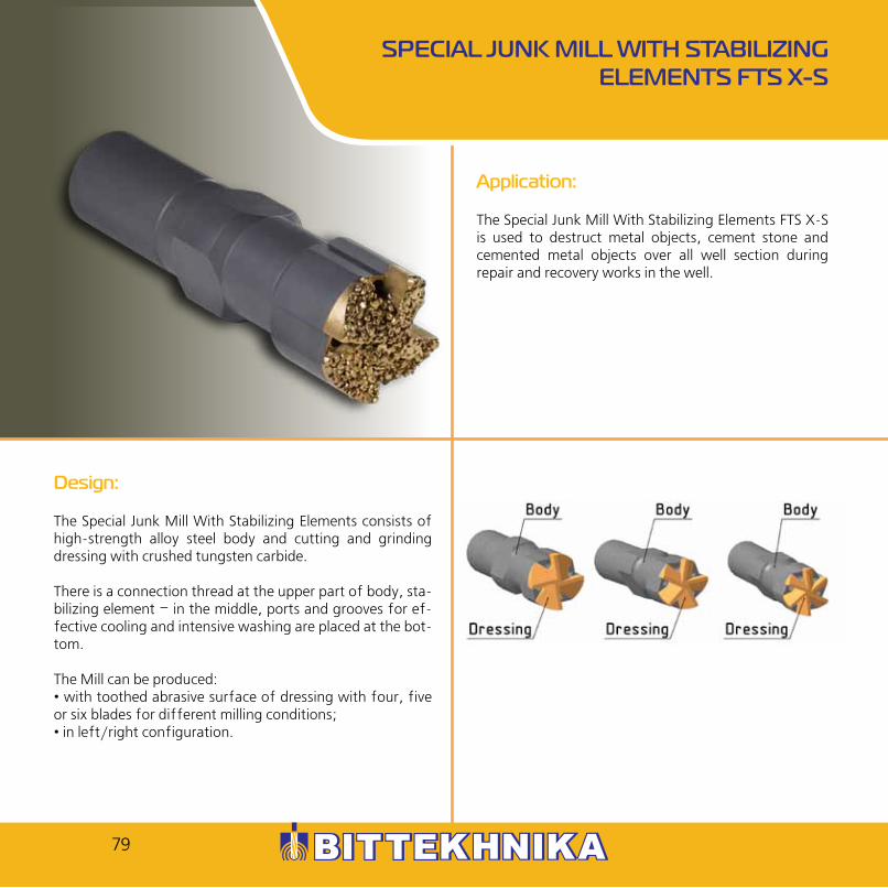
The Special Junk Mill With Stabilizing Elements FTS X-S is used to destruct metal objects, cement stone and cemented metal objects over all well section during repair and recovery works in the well.
Design:
The Special Junk Mill With Stabilizing Elements consists of high-strength alloy steel body and cutting and grinding dressing with crushed tungsten carbide.
There is a connection thread at the upper part of body, sta-bilizing element – in the middle, ports and grooves for ef-fective cooling and intensive washing are placed at the bot-tom.
The Mill can be produced: • with toothed abrasive surface of dressing with four, five or six blades for different milling conditions;• in left/right configuration.
SPECIAL JUNK MILL WITH STABILIZING ELEMENTS FTS X-S
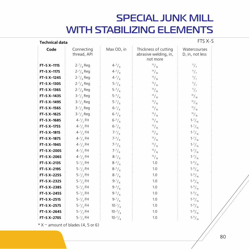
Technical data
Code Connecting thread, API
Max OD, in Thickness of cutting abrasive welding, in,
not more
Watercourses D, in, not less
FT-S X-111S 2-7/8 Reg 4-3/813/16
5/7
FT-S X-117S 2-7/8 Reg 4-5/813/16
5/7
FT-S X-124S 2-7/8 Reg 4-7/813/16
5/7
FT-S X-130S 2-7/8 Reg 5-1/813/16
5/7
FT-S X-136S 2-7/8 Reg 5-3/813/16
5/7
FT-S X-143S 3-1/2 Reg 5-5/813/16
13/16
FT-S X-149S 3-1/2 Reg 5-7/813/16
13/16
FT-S X-156S 3-1/2 Reg 6-1/813/16
13/16
FT-S X-162S 3-1/2 Reg 6-3/813/16
13/16
FT-S X-168S 4-1/2 FH 6-5/813/16 1-7/16
FT-S X-175S 4-1/2 FH 6-7/813/16 1-7/16
FT-S X-181S 4-1/2 FH 7-1/813/16 1-7/16
FT-S X-187S 4-1/2 FH 7-3/813/16 1-7/16
FT-S X-194S 4-1/2 FH 7-5/813/16 1-7/16
FT-S X-200S 4-1/2 FH 7-7/813/16 1-7/16
FT-S X-206S 4-1/2 FH 8-1/813/16 1-7/16
FT-S X-213S 5-1/2 FH 8-3/8 1.0 1-9/16
FT-S X-219S 5-1/2 FH 8-5/8 1.0 1-9/16
FT-S X-225S 5-1/2 FH 8-7/8 1.0 1-9/16
FT-S X-232S 5-1/2 FH 9-1/8 1.0 1-9/16
FT-S X-238S 5-1/2 FH 9-3/8 1.0 1-9/16
FT-S X-245S 5-1/2 FH 9-5/8 1.0 1-9/16
FT-S X-251S 5-1/2 FH 9-7/8 1.0 1-9/16
FT-S X-257S 5-1/2 FH 10-1/8 1.0 1-9/16
FT-S X-264S 5-1/2 FH 10-3/8 1.0 1-9/16
FT-S X-270S 5-1/2 FH 10-5/8 1.0 1-9/16
80
* X – amount of blades (4, 5 or 6)
FTS X-S
SPECIAL JUNK MILL WITH STABILIZING ELEMENTS
81
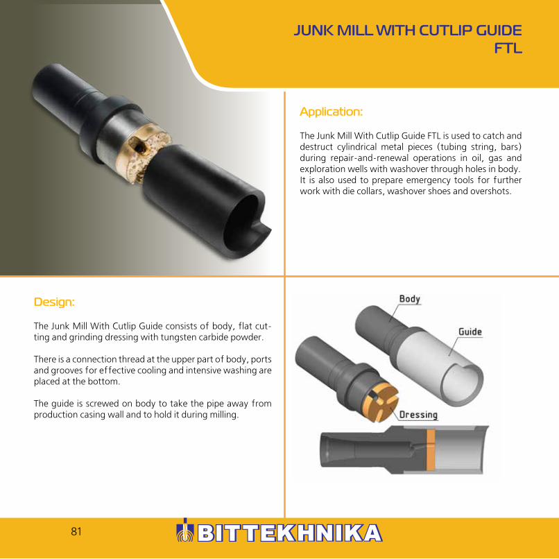
Design:
The Junk Mill With Cutlip Guide consists of body, flat cut-ting and grinding dressing with tungsten carbide powder.
There is a connection thread at the upper part of body, ports and grooves for effective cooling and intensive washing are placed at the bottom.
The guide is screwed on body to take the pipe away from production casing wall and to hold it during milling.
JUNK MILL WITH CUTLIP GUIDE FTL
Application:
The Junk Mill With Cutlip Guide FTL is used to catch and destruct cylindrical metal pieces (tubing string, bars) during repair-and-renewal operations in oil, gas and exploration wells with washover through holes in body.It is also used to prepare emergency tools for further work with die collars, washover shoes and overshots.

Technical data
Code OD, in Length, ft Rotary frequency, rpm
Load capacity, lbf
Connecting thread, API
Weight, lb
FTL-118 4-5/8 1.38 2-3/8 Reg 26.46
FTL-121 4-3/4 1.38 NC 26 30.8
FTL-124 4-7/8 1.38 NC 26 33.0
FTL-130 5-1/8 1.47 2-7/8 Reg 39.6
FTL-133 5-1/4 1.47 45 - 90 1 102 - 6 614 2-7/8 Reg 44.1
FTL-135 5-5/16 1.47 2-7/8 Reg 46.3
FTL-140 5-1/2 1.54 NC 31 55.1
FTL-152 6.0 1.54 NC 31 59.5
FTL-165 6-1/2 1.54 3-1/2 Reg 63.9
82
FTL
JUNK MILL WITH CUTLIP GUIDE
* can be designed and manufactured according to client’s specification

Application:
The Downhole Washover Shoe FZK is used to destroy metal objects, cement stone and cemented metal objects over all cross section of borehole during repair and emergency works in the well.
Design:
The Washover Shoe has plain cutting and grinding dressing and guide funnel in shape of washover shoe.
The Washover Shoe simplifies pretreatment of emergency “head” for catch by overshot TLN providing running in and smoothing of the upper end of damaged pipe.
DOWNHOLE WASHOVER SHOE FZK
83

Technical data
Code Max mill OD, in
Connecting thread, API
Min washover shoe ID, in
Watercourses D, in, not less
Length of washoshover
shoe, ft, not less
Total length of the mill in case of min size,ft, not more
FZK-85/65 3-3/8 2-3/8 Reg 2-9/161/2 0.85 - 2.62 1.16
FZK-102/80 4.0 2-3/8 Reg 3-3/161/2 0.85 - 2.62 1.16
FZK-114/91 4-1/2 2-7/8 Reg 3-9/165/8 0.92 - 2.62 1.29
FZK-117/95 4-5/8 2-7/8 Reg 3-3/45/8 0.92 - 2.62 1.29
FZK-121/99 4-3/4 2-7/8 Reg 3-7/85/8 0.92 - 2.62 1.42
FZK-124/100 4-7/8 2-7/8 Reg 3-15/165/8 0.92 - 2.62 1.29
FZK-127/100 5.0 2-7/8 Reg 3-15/165/8 0.92 - 2.62 1.29
FZK-133/110 5-1/4 2-7/8 Reg 4-5/165/8 0.92 - 2.62 1.42
FZK-140/118 5-1/2 2-7/8 Reg 4-5/85/8 0.92 - 2.62 1.42
FZK-143/118 5-5/8 2-7/8 Reg 4-5/85/8 0.92 - 2.62 1.38
FZK-152/129 6.0 2-7/8 Reg 5-1/165/8 0.92 - 2.62 1.38
FZK-203/176 7-7/8 4-1/2 IF 6-15/161 7/16 1.24 - 2.62 1.92
FZK-206/176 8-1/2 4-1/2 FH 6-15/161 7/16 1.24 - 2.62 1.92
FZK
DOWNHOLE WASHOVER SHOE
* can be designed and manufactured according to client’s specification
84

85
Design:
The Hard-alloyed Strengthened Junk Mill FTU-T consists of body made of high-strength alloy steel, cutting and grind-ing dressing with crushed tungsten carbide introduced into matrix of nickel-containing brass.
There is a connection thread at the upper part of body, stabilizing element – in the middle, ports and grooves for effective cooling and intensive washing are placed at the bottom.
The mill can be designed in left/right hand configuration.
HARD-ALLOYED STRENGTHENED JUNK MILL FTU-T
Application:
The Hard-alloyed Strengthened Junk Mill FTU-T is used to destruct metal objects, cement stone and cemented metal objects over all well section during repair and recovery works in the well.

Technical data
Code Max OD, in Max ID, in Watercourse D, in, not less
Connecting thread, API
FTU-111T 4 3/813/16
5/7 2 7/8 Reg
FTU-117T 4 5/813/16
5/7 2 7/8 Reg
FTU-124T 4 7/813/16
5/7 2 7/8 Reg
FTU-130T 5 1/813/16
5/7 2 7/8 Reg
FTU-136T 5 3/813/16
5/7 2 7/8 Reg
FTU-143T 5 5/813/16 1 3/16 3 1/2 Reg
FTU-149T 5 7/813/16 1 3/16 3 1/2 Reg
FTU-156T 6 1/813/16 1 3/16 3 1/2 Reg
FTU-162T 6 3/813/16 1 3/16 3 1/2 Reg
FTU-168T 6 5/813/16 1 7/16 4 1/2 FH
FTU-175T 6 7/813/16 1 7/16 4 1/2 FH
FTU-181T 7 1/813/16 1 7/16 4 1/2 FH
FTU-187T 7 3/813/16 1 7/16 4 1/2 FH
FTU-194T 7 5/813/16 1 7/16 4 1/2 FH
FTU-200T 7 7/813/16 1 7/16 4 1/2 FH
FTU-206T 8 1/813/16 1 7/16 4 1/2 FH
FTU-213T 8 3/8 1.0 1 9/16 5 1/2 FH
FTU-219T 8 5/8 1.0 1 9/16 5 1/2 FH
FTU-225T 8 7/8 1.0 1 9/16 5 1/2 FH
FTU-232T 9 1/8 1.0 1 9/16 5 1/2 FH
FTU-238T 9 3/8 1.0 1 9/16 5 1/2 FH
FTU-245T 9 5/8 1.0 1 9/16 5 1/2 FH
FTU-251T 9 7/8 1.0 1 9/16 5 1/2 FH
FTU-257T 10 1/8 1.0 1 9/16 5 1/2 FH
FTU-264T 10 3/8 1.0 1 9/16 5 1/2 FH
FTU-270T 10 5/8 1.0 1 9/16 5 1/2 FH
86
HARD-ALLOYED STRENGTHENED JUNK MILL
FTU-T

87
Application:
The Straight-toothed Taper Reamer RKP is used to clean “window” in casing during sidetracking and to restore internal diameter of casing during repair and emergency operations in the well.
Design:
The Straight-toothed Taper Reamer consists of body made of high-strength alloy steel, cutting and grinding dressing with crushed tungsten carbide introduced into matrix of nickel-containing brass.
There is a connection thread at the upper part of body, lower end and side surface are provided with holes and channels for effective cooling and intense flushing for chips removal.
STRAIGHT-TOOTHED TAPER REAMER RKP

Technical data
Code Nominal D of casing
Connecting thread, API
OD, in, not more
Watercourse D, in, not less
Length, ft, not more
Weight, lb
RKP-75 3-1/2 NC 23 2.95 0.79 1.39 16.1
RKP-89 4-1/2 NC 76 3.5 0.79 1.61 31.09
RKP-100 5.0 NC 76 3.94 0.79 1.61 40.13
RKP-120 5-3/4 2-7/8 Reg 4.76 0.79 1.5 44.1
RKP-121 5-3/4 2-7/8 Reg 4.84 0.79 1.5 44.1
RKP-123 5-3/4 2-7/8 Reg 5.12 0.79 1.56 50.72
RKP-130 6-5/8 2-7/8 Reg 2.95 0.79 1.44 57.33
88
RKP
STRAIGHT-TOOTHED TAPER REAMER

89
Application:
The Washover Pipe TO is used for annular milling of space between pipe and wall of the well using mills FK and PRK (for cable).
Design:
The Washover Pipe TO consists of sub, washover pipe and washover shoe.
Equipment of mill is chosen in compliance with material which is going to be drilled (sludge, cement stone or metal).
Special threads are used in order to avoid its damage. It can be designed in left/right hand configuration.
WASHOVER PIPE ТО

Technical data
Code Max OD, in
Wall thickness,
in
ID, in Length, ft, not more
Connection thread
Tensile yield, lbf
Yield torque, ft.lbf
Makeup torque, ft.lbf
TO-102/82x3000 4.0 0.39 3.21
9.84
RDU-102 29 740 2 581 1 844
TO-114/97x3000 4.5 0.34 3.82 RDU-114 31 630 2 876 1 844
TO-127/108x3000 5.0 0.36 4.28 RDU-127 36 820 3 983 2 803
TO-140/121x3000 5.5 0.36 4.78 RDU-140 41 070 4 942 3 393
TO-146/127x3000 5.75 0.37 5.0 RDU-146 45 010 5 679 3 983
TO-168/150x3000 6.63 0.35 5.93 RDU-168 48 330 7 154 5 015
TO-178/160x3000 7.0 0.36 6.28 RDU-178 53 660 8 408 5 900
TO-194/175x3000 7.63 0.37 6.88 RDU-194 61 370 10 550 7 376
TO-203/184x3000 7.99 0.37 7.24 RDU-203 64 830 11 730 8 113
TO-219/199x3000 8.63 0.4 7.82 RDU-219 77 450 15 120 10 620
TO-245/224x3000 9.63 0.39 8.84 RDU-245 84 820 18 730 13 130
TO-273/253x3000 10.75 0.4 9.95 RDU-273 98 020 24 410 16 960
TO-324/302x3000 12.75 0.43 11.89 RDU-324 130 000 38 570 26 990
90
ТО
WASHOVER PIPE

91
Design:
The Tool for Proppant Plugs Washover consists of mill with milled cemented teeth, body, helical rod, screw, backup ring and sealing elements.
After conducting frac job the tool is lowered into well on tubing string. Intensive reverse washover switches on. The rod is extended and mill is placed in the downward most po-sition. When mill leans against hard crust and rod gets load it moves down due to its helical surface and turns the body of tool creating torsion torque on the mill. Hard teeth of mill destruct the crust of proppant and fluid brings it upwards.
By pulling the tubing string at the rod length and creating the load repeat operation until total destruction of solid crust and continue washing of free proppant.
TOOL FOR PROPPANT PLUGS WASHOVER UPP
Application:
The Tool for Proppant Plugs Washover UPP is used to destruct and remove proppant plug after conducting hydraulic fracturing.

Technical data
Сode Diemeter D, in
Watercourse D, in, not less
Free movement along the road,
ft, not less
Tensile yield,
lbf
Yield torque, lbsf.ft
Connection tread, API
Length, ft
Weight, lb
UPP-90 3-9/16 1.0 2.41 89 290 2 213Non-upset tubing 2 1/2
7.61 127.9
UPP-118 4-5/8 2-5/6 2.41 89 290 2 213Non-upset tubing 2 1/2
7.61 174.2
UPP-140 5-1/2 2-5/6 2.41 89 290 2 213Non-upset tubing 2 1/2
7.61 260.1
92
UPP
TOOL FOR PROPPANT PLUGS WASHOVER
* can be designed and manufactured according to client’s specification

93
Application:
The Junk Basket SHMU is used to catch pieces, metal objects and other separate pieces of destroying tool (drill bits, mills, etc.).
Design:
The Junk Basket consists of body having connector ends with tool-joint thread.
There is a passage opening for drilling fluid circulation.
The body has removable cover with holes to discharge drill-ing fluid during lift.
The cover is fixed on body by screws with washer springs and by centralizer which helps to keep the cover centered relative to body.
JUNK BASKET SHMU

Technical data
Сode Max D of the
skirt, in
Body OD, in
Water-course D, in
Annular velocity of
flow, ft/sec, not less
Depth of the
basket, ft, not
less
Length, ft
Connec-tion, API
Weight, lb
SHMU-92 3-5/8 2-1/16 1,0
12.14 2.63
4.59 2-3/8 Reg 83.78
SHMU-94 3-11/16 2-3/16 1,0 4.59 2-3/8 Reg 88.18
SHMU-102 4.0 2-3/16 1-1/4 4.85 2-7/8 Reg 114.6
SHMU-108 4-1/4 2-5/16 1-1/4 4.85 2-7/8 Reg 132.3
SHMU-112 4-7/16 2-5/16 1-1/4 4.85 2-7/8 Reg 138.9
SHMU-114 4-1/2 2-1/2 1-1/4 4.85 2-7/8 IF 145.5
SHMU-127 5.0 2-1/2 1-1/2 4.85 2-7/8 IF 149.9
SHMU-136 5-3/8 2-1/2 1-1/4 4.85 2-7/8 IF 154.3
SHMU-146 5-3/4 2-1/2 1-1/2 4.9 3-1/2 Reg 165.3
SHMU-165 6-1/2 3-15/16 1-1/2 5.15 3-1/2 Reg 169.8
SHMU-168 6-5/8 3-15/16 2-13/16 5.15 4 IF 172.0
SHMU-178 7.0 4-5/16 2-13/16 5.24 4-1/2 IF 180.8
SHMU-195 7-11/16 4-5/16 2-13/16 5.24 4-1/2 IF 191.8
SHMU-203 8.0 4-5/16 2-13/16 5.41 4-1/2 IF 198.4
SHMU-240 9-7/16 5-9/16 4.0 5.58 5-1/2 IF 216.1
SHMU-245 9-5/8 5-9/16 4.0 5.73 6-5/8 Reg 220.5
SHMU-268 10-9/16 5-9/16 4.0 5.73 5-1/2 FH 264.6
SHMU-330 13.0 5-9/16 4.0 5.9 5-1/2 FH 330.7
94
SHMU
JUNK BASKET
* can be designed and manufactured according to client’s specification

95
Application:
The Junk Lead Seal PS-T is used to define dimensional specifications and position of tool or equipment in casing string during repair-and-recovery works in the well.
Design:
The Junk Lead Seal consists of body with connection thread and lead mould which is tightly attached and prevented from being left at bottom hole.
There is a groove for washover.
Lead plasticity allows to get impression of tool in the well.
JUNK LEAD SEAL PS-T

Technical data
Code Max OD, in Watercourse D, in, not less
Lead thickness, in,
not more
Length, ft, not more
Weight, lb Connection, API
PS-41T 1-5/8 - 1-3/16 0.57 0.9 NC 10
PS-45T 1-3/4 - 1-3/16 0.57 1.1 NC 12
PS-54T 2-1/83/16 1-3/8 0.65 5.6 NC 13
PS-57T 2-1/43/16 1-3/8 0.65 6.3 NC 13
PS-70T 2-3/43/16 1-3/8 0.67 8.4 NC 13
PS-85T 3-3/85/8 1-3/4 0.79 19.0 2-7/8 IF
PS-89T 3-1/23/16 1-9/16 0.79 19.8 2-3/8 Reg
PS-95T 3-3/45/8 1-3/4 0.79 19.0 2-7/8 IF
PS-98T 3-7/85/16 2-9/16 0.90 32.4 2-7/8 Reg
PS-105T 4-1/83/8 2-9/16 0.90 35.3 2-7/8 Reg
PS-121T 4-3/45/8 2-9/16 0.92 58.2 2-7/8 Reg
PS-140T 5-1/25/8 2-9/16 0.95 72.8 3-1/2 Reg
PS-203T 8.0 1-1/8 2-9/16 1.76 178.6 4-1/2 Reg
PS-216T 8-1/2 1-1/8 2-9/16 1.76 191.6 4-1/2 Reg
PS-292T 11-1/2 1-3/8- 2-9/16 1.89 327.2 NC 50
PS-299T 11-3/9 1-3/8 2-9/16 1.89 337.4 NC 50
PS-355T 14.0 1-4/5 3-15/16 1.97 579.9 6-5/8 Reg
PS-381T 15.0 3.0 3-15/16 2.64 789.4 6-5/8 Reg
PS-431T 17.0 3-1/7 3-15/16 2.79 1111.3 NC 31
PS-609T 24.0 3-1/7 3-15/16 3.08 2022.0 6-5/8 FH
96
PS-T
JUNK LEAD SEAL
* can be designed and manufactured according to client’s specification

97
Application:
The Lead Conical Impression Block PS-K is used to determine casing string defects during repair and recovery works in the well.
Design:
The Lead Conical Impression Block consists of body filled with lead. The Impression Block has conical form.
There is a connection thread at the upper part. The Impres-sion Block has central washing channel for fluid.
The Impression Block is connected to pipe string and low-ered into the well. The lead plasticity allows to obtain im-print of object located in the well.
LEAD CONICAL IMPRESSION BLOCK PS-K

Technical data
Code Max OD, in
Watercourse D, in, not less
Minimal D of cone, in
Length, ft, not more
Weight, lb Connection, API
PS-41K 1 5/8 - 9/16 0.89 4.63 SH-19
PS-45K 1 3/4 - 5/8 0.92 5.51 SH-19
PS-54K 2 1/8 - 1 1/8 1.07 9.7 NC 13
PS-57K 2 1/43/16
1 3/16 1.07 10.14 NC 13
PS-70K 2 3/43/16
1 3/16 1.15 14.11 NC 13
PS-89K 3 1/23/16 1 13/16 1.39 35.72 2 3/8 Reg
PS-98K 3 7/83/16 2.0 1.48 47.63 2 7/8 Reg
PS-105K 4 1/83/8 2 1/16 1.64 57.77 2 7/8 Reg
PS-121K 4 3/43/8 2 3/16 1.64 69.68 2 7/8 Reg
PS-140K 5 1/23/8 2 1/2 1.64 88.2 3 1/2 Reg
PS-142K 5 5/813/16 4 9/16 1.79 123.48 2 7/8 Reg
PS-146K 5 3/413/16 49/16 1.79 127.89 2 7/8 Reg
PS-203K 8.0 1.0 3 9/16 2.13 241.01 4 1/2Reg
PS-216K 8 1/2 1.0 3 15/16 2.13 266.81 4 1/2Reg
PS-292K 11 1/2 1 1/2 5 1/8 2.62 543.31 NC 50
PS-299K 11 3/9 1 1/2 5 1/8 2.62 560.95 NC 50
98
PS-K
LEAD CONICAL IMPRESSION BLOCK
* can be designed and manufactured according to client’s specification

99
Application:
The Roller Swage OR is designed to restore internal diameter of damaged casing pipes by means of rolling-off during repair-and-renewal operations in the well.
Design:
The Roller Swage OR consists of body made of alloy steel, three rollers and tail piece. There is a box connection tool-joint thread at the top. The middle part has rotating rollers which are set on three eccentric grooves located at 120° angle. Rollers are set on the body by rotary tail piece which is fixed by balls located in grooves of body and tail piece. Balls are fixed in grooves by thread plug.
Sets of rollers have different diameter. They are chosen depending on required diameter of swage and internal diameter of casing pipe.
There are slots on surface of eccentric guide grooves, which are filled with graphite grease.
Construction of the Roller Swage provides usage of same body after changing rollers to straighten casing pipes with same nominal diameter but with different internal diameter (with different well thickness). Each nominal size of the roller fits its own outer diameter of tail piece.
ROLLER SWAGE OR

Technical dataCode Nominal D
of restored casing string,
in
Nominal D of the
swage (along rollers), in
Nominal axial load,
lbf
Yield torque, lbsf.ft
Watercourse D, in, not less
Connection, API
Length, ft
Weight (1 set),
lb
OR-114 4 1/2 3.76 - 4.02 56 200 7 376 1/2 2 3/8 IF 1.97 53.1
OR-127 5.0 4.09 - 4.49 62 950 11 060 5/8 2 7/8 Reg 1.97 67.2
OR-140 5 1/2 4.6 - 5.16 71 490 11 060 11/16 2 7/8 Reg 1.99 117.0
OR-168 5 3/4 5.58 - 5.97 78 680 11 060 15/16 3 1/2 Reg 2.66 177.7
OR-178 7.0 5.83 - 6.09 85 430 11 060 1.0 3 1/2 Reg 3.04 208.8
OR-245 9 5/8 8.37 - 8.72 94 420 11 060 4 3/8 3 1/2 IF 3.79 546.4
100
OR
ROLLER SWAGE

101
Application:
The Fishing Magnet MI is designed to remove small objects having ferromagnetic attraction from oil, gas and exploratory well bores.
Design:
The Fishing Magnet consists of body, sub, magnet element and guide. The sub has tool-joint thread at the end. The removable guide can be designed in three different types: mill guide (Pic. 1), lipped guide (Pic. 2) and flush guide (Pic. 3). The Fishing Magnet has a central water course. The magnet element has direct magnetic action and does not require additional magnification during its service.
FISHING MAGNET MI
Pic.1 Pic.2 Pic.3

Technical dataCode Guide ID, in Load capacity, lbf Total length, ft Connecting thread,
API*
MI-82 3-1/4 474.0 1.52 2-3/8 Reg
MI-89 3-1/2 474.0 1.21 NC 26
MI-102 4,0 771.6 1.28 2-7/8 Reg
MI-114 4-1/2 771.6 1.23 2-7/8 Reg
MI-118 4-5/8 771.6 1.28 2-7/8 Reg
MI-127 5.0 1 213.0 1.31 2-7/8 Reg
MI-135 5-5/16 1 213.0 1.25 2-7/8 Reg
MI-140 5-1/2 1 323.0 1.25 3-1/2 Reg
MI-146 5-3/4 1 323.0 1.26 3-1/2 Reg
MI-152 6.0 1 543.0 1.33 3-1/2 Reg
MI-170 6-11/16 1 543.0 1.38 3-1/2 Reg
MI-188 7-3/8 1 984.0 1.38 4-1/2 Reg
MI-198 7-13/16 1 984.0 1.38 4-1/2 Reg
MI-203 8.0 2 205.0 1.9 NC 50
MI-243 9-9/16 2 205.0 1.82 5-1/2 FH
MI-279 11.0 2 205.0 2.1 NC 50
MI-292 11-1/2 4 806.0 2.01 6-5/8 Reg
MI-295 11-5/8 4 806.0 2.09 5-1/2 FH
MI-315 12-7/16 4 850.0 2.69 6-5/8 FH
MI-355 14.0 4 850.0 3.83 6-5/8 FH
102
MI
FISHING MAGNET
* can be designed and manufactured according to client’s specification

103
Application:
The Fishing Magnet with Reverse Circulation MIP is used to remove such objects as bit cones, bearings, broken slips, various hand tools, fragments of broken drill pipes, mill cuttings, etc. from the well.
Design:
The Fishing Magnet with Reverse Circulation can be designed in left/right hand configuration. It can be equipped with three different types of guide: mill guide (Pic. 1), lipped guide (Pic. 2) and flush guide (Pic. 3). Reverse circulation helps to clear removed object from dirt and press it closer to magnetic surface.
FISHING MAGNET WITH REVERSE CIRCULATION
MIP
Pic. 1 Pic. 2 Pic. 3

Technical data
Code Load capacity, lbf Connecting thread.API*
External diameter of body, in
MIP-94 474.0 NC 26 3-11/16
MIP -112 771.6 2-7/8 Reg 4-7/16
MIP-119 771.6 2-7/8 Reg 4-11/16
MIP-130 1 213.0 NC 38 5-1/8
MIP-150 1 323.0 NC 38 5-7/8
MIP-196 1 984.0 NC 50 7-11/16
MIP-206 2 205.0 NC 50 8-1/8
MIP-257 2 205.0 NC 50 10-1/8
104
MIP
FISHING MAGNET WITH REVERSE CIRCULATION
* can be designed and manufactured according to client’s specification

105
Application:
The Magnet for Chips Collection MSS is used to remove metal chips having ferromagnetic attraction from drilling fluid during milling operation.
Design:
The Magnet consists of two stakes, shaft, alternate brass rings and neodymium magnets.
The shaft with rings and magnets is fixed on stakes by thread connection.
The magnet is set at the bottom of vibrating screen and is fixed by binding wire.
When drilling fluid passes through vibrating screen, metal chips settle on magnets by means of magnetic field. After chips accumulation, the Magnet should be retrieved and cleaned.
MAGNET FOR CHIPS COLLECTION MSS

Technical data
Code Width, in Diameter with magnets, in
Total length, ft Weight, lb
MSS-50 4-3/4 2.0 1.63 17.64
106
MSS
MAGNET FOR CHIPS COLLECTION

Application:
The Borehole Fishing Magnet MIS is used to remove different pieces having ferromagnetic attraction from the well. The Borehole Fishing Magnet can be used: - while cutting the “window”, drilling-out packers to magnetize metal objects; - during washover to clean bottom hole from metal objects; - to remove metal objects from horizontal well;- to remove debris after cutting and milling when flow speed in annular space is poorand when down hole fluid has low capacity for cutting transport.
Design:
The Borehole Fishing Magnet has cylindrical body with central watercourse for drilling fluid. There are connection threads of relevant size on both ends of the tool. There are magnet systems, divided by grooves, along the length and diameter of the tool. Magnet systems can be changed if necessary.
BOREHOLE FISHING MAGNET MIS
107

Technical data
Code Body OD, in Load capacity, lbf
Amount of magnet
systems, items
Total length, ft Weight, lb
MIS-92 3-5/8 220.5 15 4.26 176.4
MIS-165 6-1/2 330.7 24 6.67 407.9
MIS
BOREHOLE FISHING MAGNET
* can be designed and manufactured according to client’s specification
108

Application:
The Annular Fishing Magnet MIK is used to remove small particles having ferromagnetic attraction from oil, gas and geological wells.
Design:
The Annular Fishing Magnet MIK has tubular body. On one side it has double-stage buttress thread for connecting to washover pipe. On the other side there is a magnet system, which consists of permanent magnets. Magnet system magnetizes and retains pieces having ferromagnetic attrac-tion from tubular annulus between pipe, electric submers-ible pump and casing string.
ANNULAR FISHING MAGNET MIK
109

Technical data
Code Load capacity, lbf
OD, in
ID, in
Total length, ft
Connecting thread*
Weight, lb
MIK-123/96 154.3 4-7/8 3-3/16 0.38 RDU-122 2.65
ANNULAR FISHING MAGNET
* can be designed and manufactured according to client’s specification
MIK
110

NOTES