
Pioneer Eclipse Mean Machine Manual.pdf - Performance ...
27
Operator’s Manual Propane Burnisher with Kawasaki Engine Failure to read and understand this manual before operating this machine or performing service on this machine may result in injury to the operator or nearby personnel or result in damage to the machine or nearby property. Each operator must be trained in the operation of this machine before being allowed to use it. Contact Amano Pioneer Eclipse Customer Service at 1-800-367-3550 or 1-336-372-8080 or an authorized Amano Pioneer Eclipse Distributor to inquire about training or to request a replacement manual. La falta de leer y de entender este manual antes de usar esta máquina o de realizar servicio en esta máquina puede dar lugar a lesión al operador o al personal próximo o a resultado en daño a la máquina o propiedad próxima. Cada operador debe ser entrenado en la operación de esta máquina antes de ser permitido utilizarla. Ponerse en contacto con el servicio de Amano Pioneer Eclipse 1-800-367-3550 o 1-336-372-8080 o un distribuidor autorizado por Amano Pioneer Eclipse para investigar sobre el entrenamiento o para solicitar un manual. Manquer de lire et de comprendre ce manuel d'utilisation avant l'utilisation de cette machine ou avant faire de maintenance sur la machine peut être résulter en blessure à l'opérateur ou au personnel proche ou peut endommagé la machine ou la propriété proche. Chaque utilisateur doit être entraîné dans l'opération de cette polisseuse avant l'utilisation. Veuillez contacter le service àpres-vente de Amano Pioneer Eclipse à 1-800-367-3550 ou 1-336-372-8080 et/ou un distributeur de Amano Pioneer Eclipse pour vous renseigner concernant l'en- traînement ou pour obtenir un autre manuel d'utilisation. Models ending in “F”
-
Upload
khangminh22 -
Category
Documents
-
view
6 -
download
0
Transcript of Pioneer Eclipse Mean Machine Manual.pdf - Performance ...

O p e r a t o r ’ s M a n u a l
Propane Burnisher with Kawasaki Engine
Failure to read and understand this manual beforeoperating this machine or performing service on thismachine may result in injury to the operator or nearbypersonnel or result in damage to the machine or nearbyproperty. Each operator must be trained in the operationof this machine before being allowed to use it. ContactAmano Pioneer Eclipse Customer Service at1-800-367-3550 or 1-336-372-8080 or an authorizedAmano Pioneer Eclipse Distributor to inquire abouttraining or to request a replacement manual.
La falta de leer y de entender este manual antes de usaresta máquina o de realizar servicio en esta máquinapuede dar lugar a lesión al operador o al personalpróximo o a resultado en daño a la máquina o propiedadpróxima. Cada operador debe ser entrenado en laoperación de esta máquina antes de ser permitidoutilizarla. Ponerse en contacto con el servicio de AmanoPioneer Eclipse 1-800-367-3550 o 1-336-372-8080 o undistribuidor autorizado por Amano Pioneer Eclipse parainvestigar sobre el entrenamiento o para solicitar unmanual.
Manquer de lire et de comprendre ce manuel d'utilisationavant l'utilisation de cette machine ou avant faire demaintenance sur la machine peut être résulter enblessure à l'opérateur ou au personnel proche ou peutendommagé la machine ou la propriété proche. Chaqueutilisateur doit être entraîné dans l'opération de cettepolisseuse avant l'utilisation. Veuillez contacter le serviceàpres-vente de Amano Pioneer Eclipse à 1-800-367-3550ou 1-336-372-8080 et/ou un distributeur de AmanoPioneer Eclipse pour vous renseigner concernant l'en-traînement ou pour obtenir un autre manuel d'utilisation.
Modelsendingin “F”

In this Operation Manual you will find three statements that you must read and observe to ensuresafe operation of this machine.
DANGER! indicates that the possibility of severe bodily injury or death can occur if DANGER!statements are ignored. Read and observe all DANGER! statements included in the OperationManual and attached to the machine.
WARNING! indicates that the possibility of bodily injury to the operator and other people can occurif WARNING! statements are ignored. Read and observe all WARNING! statements included inthe Operation Manual and attached to the machine.
CAUTION! indicates that the possibility of damage to the machine or other property can occur ifCAUTION! statements are ignored. Read and observe all CAUTION! statements included inthe Operation Manual and attached to the machine.
FOR YOUR SAFETY IF YOU SMELL GAS:1. Open window.2. Don't touch electrical switches.3. Extinguish any open flame.4. Immediately call your gas supplier.
FOR YOUR SAFETYDo not store or use gasoline
or other flammable vapors and liquids in the vicinity of this or any other appliance.
Record This Important Information
Date of Purchase ________________________________________________________Purchased From ________________________________________________________Address ______________________________________________________________City ________________________ State ______________ Zip ______________Phone ______________________ Contact ____________
Machine Model__________________________________________________________Machine Serial Number __________________________________________________Engine Type____________________________________________________________Engine Serial Number ____________________________________________________
Important Phone Numbers
Medical Emergency ______________________________________________________Police ________________________________________________________________Fire Department ________________________________________________________


3
Operator SafetyInstructionsDANGER! Operate this machine only in a
well-ventilated area. It is theresponsibility of the machine operator,machine owner, and site manager toensure that the air exchange systemwhere the machine is to be used is incompliance with local building codes andis operating properly. Failure to operatethis machine in a well-ventilated areacould lead to sickness, injury or deathfrom carbon monoxide (CO) exposure.
DANGER! This machine emits carbonmonoxide (CO) which is a colorless,odorless, non-irritating gas. The firstsymptoms of CO exposure includeheadache, drowsiness, dizziness andnausea. If you should experience any ofthese symptoms while operating thismachine, shut off the machine and gooutside to get fresh air. Have themachine tested for CO emissions by aqualified service technician before using itagain.
DANGER! Prolonged or high exposure toCO may result in vomiting, confusion, andcollapse in addition to loss ofconsciousness and muscle weakness. Ifsuch symptoms occur, call 911 foremergency medical attention. If you haveexperienced these symptoms, do notoperate this machine or any otherpropane machine again until cleared by aphysician. Excessive exposure to COcan result in death.
DANGER! Propane is a highly flammablefuel. If you smell propane, shut off themachine immediately and take it outsidethe building. Do not use the machineagain until the propane leak has beencorrected by a qualified servicetechnician. Do not use or allow anotherperson to use an ignition source such asa cigarette lighter near the propanemachine. Do not smoke near thepropane machine. Do not vent a propanecylinder inside a building. Do not storepropane cylinders inside a building.
DANGER! This machine has parts includingthe pad and pad holder that can causesevere injury if these parts are contactedwhile they are moving. Do not allow anypart of the body or clothing to come incontact with these parts while they aremoving. Do not try to change the padwhile the machine is running. Do notallow other people to come near themachine while it is in operation. Do notallow the machine to run unattended. Donot leave the machine in a place whereunauthorized or untrained personnelcould use the machine. Do not run themachine with the pad off center, damagedor missing. Do not operate the machine ifthe machine has loose parts such as thedrive belt.
WARNING! Modifications or alterations tothis machine can lead to personal injuryor damage to the machine. Do not makeunauthorized modifications or alterationsto this machine. Amano Pioneer Eclipseassumes no liabilities for injury ordamage resulting from an unauthorizedmodification or alteration to the machine.Any unauthorized modification oralteration to this machine voids allwarranties.
WARNING! The muffler and the enginebecome hot enough while the machine isin operation, and for a long time after themachine is shut off, to cause severeburns. Do not touch these parts of themachine until they have cooled.
WARNING! Injury can occur to the eyes andbody while using the machine. Safetygoggles, safety shoes, and safety clothingare recommended while operating themachine.
WARNING! Continuous exposure to highnoise levels can cause hearing loss.Hearing protection is recommended whilethe machine is in operation.
WARNING! Machine vibration may causetingling or numbness in the fingers orhands. Gloves are recommended toreduce machine vibration. If tingling ornumbness persists, shut off the machine.If the vibration is caused by loose partssuch as the drive belt or an off centerpad, adjust or tighten these parts beforeusing the machine again.
CAUTION! Overfilled cylinders can damagefuel regulators. Do not overfill thecylinder. If the regulator freezes, stop theburnisher and carry the propane cylinderoutside the building.
CAUTION! Overheating can be caused by adirty engine filter which is also known asa bonnet or top hat filter.
CAUTION! Overheating can be caused byinsufficient or low oil. Check oil beforeeach use, and fill or change as needed.
CAUTION! Never over-fill with oil. Over-filling could cause irreparable damage tothe engine.
CAUTION! Overheating can be caused bydirty oil. Check oil before each use andchange regularly following recommendedmaintenance schedule.
CAUTION! Do not engage starter for morethan 10 seconds. Allow a 60 second cool-down period for second failed start-upattempt.
CAUTION! Perform all recommendedscheduled maintenance. Regularmaintenance of your propane poweredfloor machine is necessary to keep it insafe working condition.
CAUTION! Do not allow the burnisher tooperate without moving the machine. Itmay burn the floor and damage the floor covering.
This machine is manufactured forcommercial use only.Propane powered floor burnishers aredesigned and manufactured for ultra highspeed commercial floor burnishing only.These machines are designed to burnishmost modern types of floors includingcomposition tile, stone, marble, terrazzo, andresilient floor covering using floor coatingsdesigned for ultra high speed burnishing.Even though NFPA 58 8-4.5 says ...”thesemachines shall be permitted to be used inbuildings frequented by the public, includingthe times when such buildings are occupiedby the public,” Amano Pioneer Eclipsesuggests usage when occupancy of a givenwork area is minimal.
These machines should not be used:in nursing homes, hospitals, day-carecenters, etc.by unqualified or untrained personnel.unless properly maintained and adjusted.on areas with obstructions such asthresholds, floor outlet boxes, etc.in areas where loose tile or other objectsare present. in rooms without proper ventilation.
Refueling and Storage of FuelCylindersAmano Pioneer Eclipse uses the 20 lb.capacity aluminum or steel safe-fill cylinderwhich meets the DOT 4E240 standards.These cylinders are also listed by UL. Fillingshould be done ONLY by a qualified propanedealer. FILL THROUGH THE SERVICEVALVE ONLY. A properly filled cylindershould not exceed 80% of the rated capacity.DO NOT attempt Safe-Fill cylinder repair.Return the cylinder to your propane dealer ifrepair is necessary. Please note that DOTregulations prohibit shipping of cylinders afterthe cylinder has been filled with propane.When not in use, they always should bestored outside in an upright position in asecure, tamper-proof, steel mesh storagecabinet. This cabinet may be located next tothe building but with at least five feet (1.5 m)of space between the cabinet and thenearest building opening (door or window).The National Fire Protection Association(NFPA) Standard for Storage and Handling ofLP Gas is the appropriate authority for safepropane use. A copy of this publication isavailable through the National Fire ProtectionAssociation in Quincy, Massachusetts(1-800-344-3555).

4
Canadian Safety Regulations1. A sign indicating “NO SMOKING” shall be
permanently displayed at the storagearea. The sign shall be in accordancewith the sign required in Clause 10.12.3of CAN/CGA-B149.2-M91, PropaneInstallation Code.
2. When the cylinder is attached to the floor maintenance machine for use, theoperator shall not leave the unitunattended except for short periods oftime such as rest stops, washroom ormeal stops.
3. The requirements of 1.10.1 (e) and (g) donot apply in industrial buildings.
4. A floor maintenance machine shall onlybe used in buildings:
a) provided with continuous mechanicalventilation that removes the products ofcombustion to the outdoors of not lessthan 300 CFM for each 10,000 Btu-hrinput or fraction thereof.
b) provided with natural ventilation of notless than 300 CFM for each 10,000 Btu-hr input or fraction thereof, based on amaximum of one quarter air exchangeper hour for the net building volume.
5. The owner of a floor maintenancemachine shall ensure that the operatorhas participated in a course authorized bythe manufacturer of the unit on the safehandling of propane and the safeoperation of the machine.
6. The owner of a floor maintenancemachine shall ensure that the unit ismaintained in accordance with themanufacturer’s recommendedmaintenance procedures in a safeoperating condition and the owner shallmaintain a record of the maintenance fora period of two years.
7. Before transporting a floor maintenancemachine, the cylinder shall be securelyfastened with the system valve closed,and the cylinder shall be located in a wellventilated space.
Machine PreparationAdding OilWhen the burnisher is shipped by overlandfreight, the correct amount of oil is in theengine. Air freight shipments require themachine to be shipped without oil.When filling a “dry” burnisher or changing oil,for the Kawasaki engine add no more than1.6 quarts (1,5 L) when not changing the oilfilter, or 1.8 US quarts (1,7 L) when the oilfilter is changed, then check the dipstick inthe fill cap. Add oil if necessary but DO NOTOVERFILL! ALWAYS CHECK OIL BEFOREUSING THE MACHINE. Refer to the enginemanual. IMPORTANT: When checking oil onKawasaki models, remove oil filler cap andclean dipstick with clean cloth, then insert
dipstick into tube without screwing in. Thencheck oil level. ALWAYS make sure themachine is sitting level when checking oil.
Connecting the BatteryFor machines with 12 V Start:1. Connect the RED positive battery cable
FIRST.2. Connect the BLACK negative battery
cable LAST.
Adjusting the Handle and RokBakThe burnisher handle adjusts for comfort andoptimum control. Height may be changed tosuit the individual operator. The handle mayalso be adjusted to an full-up (about 45°)position to allow the burnisher to be rockedback for easy pad change. Rock theburnisher to the vertical position from thefront of the unit. The burnisher must be offprior to using the RokBak Tilt System.
Propane Burnisher Daily Start-Up RoutineCHECK CYLINDER: Before bringing a
propane cylinder indoors, always check itfor over-filling.
ATTACH CYLINDER: Connect the fuel hoseto the valve nozzle by turning it to theright. Hand tighten only to avoid leaks.Place the tank on the machine andsecure by buckling the retaining strap.Remove slack by pulling on the loose endof the strap and securing with velcro.Connect the fuel hose coupling to theservice valve by turning clockwise. HANDTIGHTEN ONLY. Make sure coupling isnot cross threaded and check for leakageby noting any propane odors immediatelyafter cylinder is connected. (It issometimes easier to install if theconnection to the service valve is madebefore strapping the cylinder in place.) TO REMOVE THE SAFE-FILLCYLINDER, reverse procedure. Alwaysconnect or change cylinders in a wellventilated area.
ALIGN PIN: Make sure to align the locatingpin with the slot in the top flange of theSafe-Fill cylinder.
ADJUST TOGGLE: Strap the Safe-Fillcylinder in place by clamping the toggleassembly to the cylinder band. Adjust thetoggle assembly by screwing it in or outto keep the cylinder firmly in place.
CLEAN FILTER: The recoil dust filter shouldbe cleaned or replaced after each use ofthe burnisher and after each hour ofcontinuous operation. A dirty filter cancause the engine to overheat and carbonmonoxide emissions could elevate.
CHECK OIL: Make sure the burnisher islevel when checking the oil. Followengine manufacturer’s procedure forchecking the oil as detailed in theoperation manual. The oil level should
always be within the safe levels indicatedon the dip stick. Add oil if necessary, butnever over-fill. Over-filling could causeirreparable damage to the engine.
CHECK PAD: Clean the pad if it is dirty orreplace it if it is torn or worn thin (lessthan 1/8” or 32mm). Having a clean padin good condition is essential toburnishing performance.
CHECK STUDS: Check the velcro studs.Clean if necessary and replace worn orbroken studs.
CHECK PAD HOLDER: Check the padholder for cracks. Replace if necessary.
DEFLECTOR: Check the exhaust deflector.Make sure the deflector is alignedcorrectly and functioning properly toprevent hot motor exhaust from damagingmerchandise.
BELT TENSIONER: Check the tensionerbelt. Replace belt if it is frayed orcracked.
MAINTENANCE LOG: Record the dailymaintenance routine. Fill in the date in theleft hand column, put your initials in thenext column and use check marks in allcolumns which correspond to themaintenance procedures performed.
Optional EcoSenseEmissions MonitoringSystemMachines with model numbers ending in “X”are equipped with the EcoSense EmissionsMonitoring System. EcoSense is anemissions monitoring device that monitorsthe exhaust emissions and will shut theengine down if the emissions levels are toolow or too high.Why will the unit shut down if the levels aretoo low? The monitor must receive a signalfrom the oxygen sensor in order to function. Ifit did not have a minimum readingrequirement it would be possible todisconnect the oxygen sensor and operatethe unit, even if the emissions were out oflimits. In order for the unit work as designed itmust be able to read both low and highsignals, with "not to exceed limits" of both.The oxygen sensor must reach operatingtemperature before it will start to send signalsto EcoSense module. This time is set at forty-five seconds. A unit may shut down at a coldstart up after the forty-five seconds becausethe oxygen sensor did not reach requiredtemperature to start to send signals. If thishappens, turn the key to the off positionseveral seconds to clear the EcoSensemodule and restart the engine. Once theengine has started, advance the throttle tofull throttle position and start the operation.With the engine at full throttle under loan, thesignal from the oxygen sensor should bewithin the normal operating ranges for safeoperation. If the engine's air intake filter
5
needs to be serviced, or an over-filledcylinder has been installed by mistake, orthere is a problem with the fuel system thatcauses the oxygen sensor's signal to be outof range, EcoSense will shut the unit down inforty-five seconds. The unit can be re-startedafter clearing the module by turning off thekey switch. If corrections have not be madeto the unit, EcoSense will continue to shutthe unit down after the forty-five secondwarm-up and forty-five second out of limitperiods or the total of both periods ifrestarting and resuming operation, ninetyseconds.Engines tend to go to lean burn if allowed toidle for even short periods. Even at high idlespeeds most engines will continue to leandownward. It is always best to shut theengine off when it is not being used to dowork. Remember the engine is alwayscreating emissions as long as it is running.The best manner to operate a unit equippedwith EcoSense is as follows.1. With the throttle in the slow position, turn
the key switch to the start position, oncethe engine starts, advance the throttle tofull throttle and start operation.
2. When ready to stop operation, releaseclutch (if equipped) and move throttle tothe slow position. If the unit will not beused within forty-five seconds, turn thekey switch to the off position. If the unitwill not be returned to service within a fewminutes it is best to turn the gas valve onthe tank off first and let the engineconsume all fuel that is in lines. Once theengine dies, turn the key switch to offposition.
3. When ready to restart, open the gas valveon the tank, put the throttle in slowposition and turn key switch to the startposition. Once the engine has started,move throttle to full position and return tooperation.
Operating InstructionsStarting Instructions1. Check oil and fuel levels.2. Check and clean engine air filter. CAUTION! Never run continuously for more
than 1 hour without cleaning or changingengine dust filter.
3. Check carburetor air filter. Change ifnecessary. (See “ScheduledMaintenance”)
4. Turn propane service valvecounterclockwise to open.
CAUTION! Always open service valve slowlyto allow pressure to equalize in hoses.Opening quickly may cause the flowcheck valve to engage, limiting fuel flow.
5. Allow machine to tilt backward (pad offfloor) and move throttle to SLOW position.
6. For models with 110 V Start: Plug electriccord into 110 volt wall receptacle and
onto starter switch. 7. 110 V Start: Engage starter by pushing
the RED starter button. 12 V Start: Engage starter by turning thekey-switch to the starting position for upto 5 seconds. If the machine fails to start, waitapproximately 5 seconds and try again foranother 5 seconds.
CAUTION! Do not engage starter for morethan 10 seconds. Allow a 60 second cool-down period for second failed start-upattempt. Continue cycling through Step 7until engine starts.
OperationAfter engine has started, allow approximately30 seconds for the engine to warm up.Advance the throttle to operating speed.On machines with a clutch, grasp either oneof the handle levers to engage the clutch.When the pad begins to spin, lower theburnishing head to the floor while moving themachine forward slowly.CAUTION! Do not run the burnisher without
moving the machine. If the machine isallowed to run in one spot damage to thefloor may occur.
To stop burnishing, push down on handle toraise the burnishing head off the floor anddisengage the clutch if equipped by releasingthe handle levers.It is recommended to start burnishing on theright side of the aisle, turn and come backdown the aisle in the opposite direction,overlapping the previous path slightly.Continue this pattern until the floor area to beburnished has been covered with the lastpass being on the right side of the machine.The forward speed is generally at normalwalking speed.
Idling and Stopping the MachineOn machines equipped with a clutch, if forany reason the machine needs to idle for ashort period of time, simply raise theburnishing head and disengage the clutch byreleasing the handle levers. DANGER! Allowing the engine to idle
excessively will increase carbonmonoxide emissions!
To stop the engine, close the service valveon the fuel cylinder by turning it clockwise(the engine will stop when the fuel in thelines is used up).
Installing/Changing Burnishing Pad1. With engine OFF, tilt the machine to the
RokBak position. 2. Remove pad centering device and
carefully pull the old pad off the velcropad holding material.
CAUTION! Carefully inspect the pad holderfor cracks or damage. Replace ifnecessary.
WARNING! A damaged pad holder rotating athigh speeds may be an extreme hazard ifit should come apart.
3. Pull center from new pad, center pad onpad holder and secure with centeringdevice.
4. Press pad onto velcro.5. Return machine to upright position.
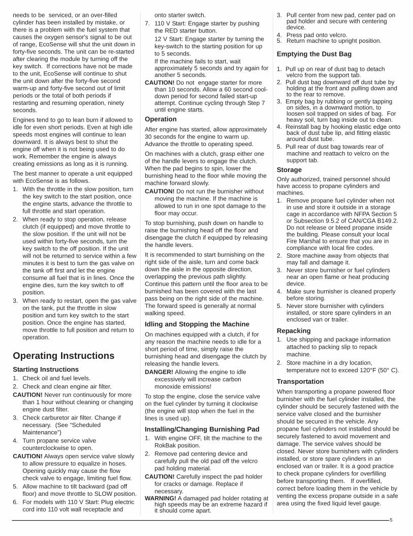
Emptying the Dust Bag
1. Pull up on rear of dust bag to detachvelcro from the support tab.
2. Pull dust bag downward off dust tube byholding at the front and pulling down andto the rear to remove.
3. Empty bag by rubbing or gently tappingon sides, in a downward motion, toloosen soil trapped on sides of bag. Forheavy soil, turn bag inside out to clean.
4. Reinstall bag by hooking elastic edge ontoback of dust tube lip, and fitting elasticaround dust tube.
5. Pull rear of dust bag towards rear ofmachine and reattach to velcro on thesupport tab.
StorageOnly authorized, trained personnel shouldhave access to propane cylinders andmachines.1. Remove propane fuel cylinder when not
in use and store it outside in a storagecage in accordance with NFPA Section 5or Subsection 9.5.2 of CAN/CGA B149.2.Do not release or bleed propane insidethe building. Please consult your localFire Marshal to ensure that you are incompliance with local fire codes.
2. Store machine away from objects thatmay fall and damage it.
3. Never store burnisher or fuel cylindersnear an open flame or heat producingdevice.
4. Make sure burnisher is cleaned properlybefore storing.
5. Never store burnisher with cylindersinstalled, or store spare cylinders in anenclosed van or trailer.
Repacking1. Use shipping and package information
attached to packing slip to repackmachine.
2. Store machine in a dry location,temperature not to exceed 120°F (50° C).
TransportationWhen transporting a propane powered floorburnisher with the fuel cylinder installed, thecylinder should be securely fastened with theservice valve closed and the burnishershould be secured in the vehicle. Anypropane fuel cylinders not installed should besecurely fastened to avoid movement anddamage. The service valves should beclosed. Never store burnishers with cylindersinstalled, or store spare cylinders in anenclosed van or trailer. It is a good practiceto check propane cylinders for overfillingbefore transporting them. If overfilled,correct before loading them in the vehicle byventing the excess propane outside in a safearea using the fixed liquid level gauge.
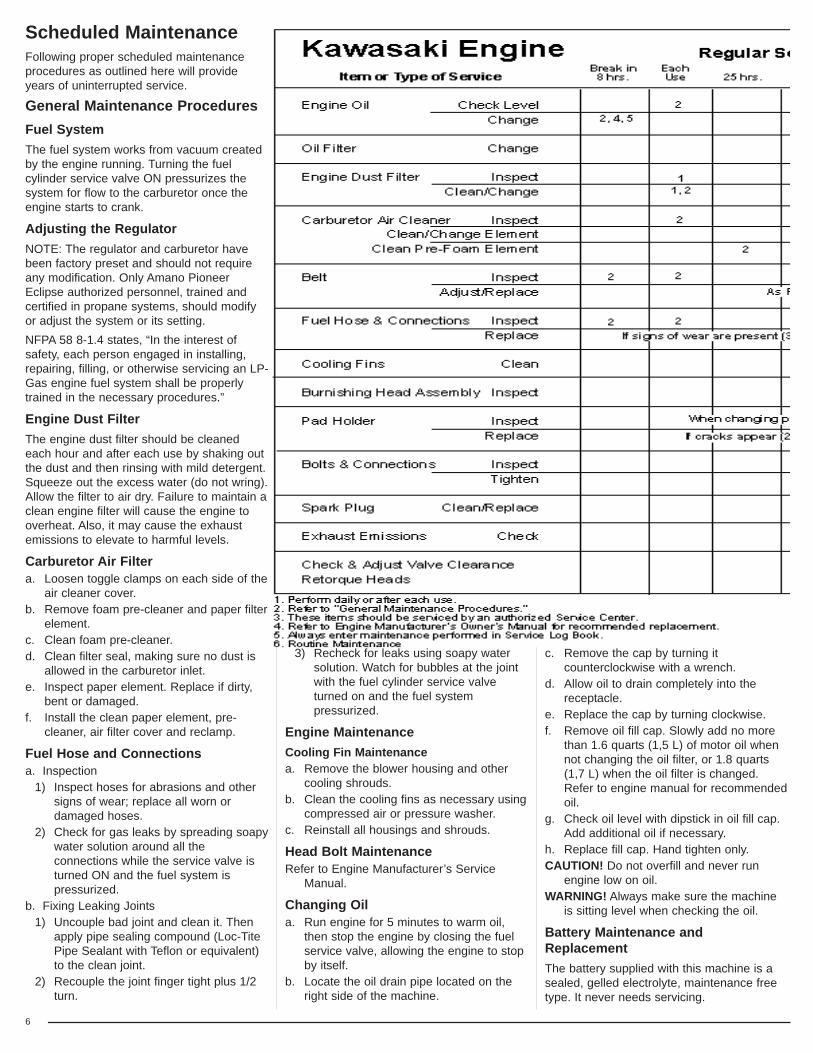
Scheduled MaintenanceFollowing proper scheduled maintenanceprocedures as outlined here will provideyears of uninterrupted service.
General Maintenance ProceduresFuel SystemThe fuel system works from vacuum createdby the engine running. Turning the fuelcylinder service valve ON pressurizes thesystem for flow to the carburetor once theengine starts to crank.
Adjusting the RegulatorNOTE: The regulator and carburetor havebeen factory preset and should not requireany modification. Only Amano PioneerEclipse authorized personnel, trained andcertified in propane systems, should modifyor adjust the system or its setting.NFPA 58 8-1.4 states, “In the interest ofsafety, each person engaged in installing,repairing, filling, or otherwise servicing an LP-Gas engine fuel system shall be properlytrained in the necessary procedures.”
Engine Dust FilterThe engine dust filter should be cleanedeach hour and after each use by shaking outthe dust and then rinsing with mild detergent.Squeeze out the excess water (do not wring).Allow the filter to air dry. Failure to maintain aclean engine filter will cause the engine tooverheat. Also, it may cause the exhaustemissions to elevate to harmful levels.
Carburetor Air Filtera. Loosen toggle clamps on each side of the
air cleaner cover.b. Remove foam pre-cleaner and paper filter
element.c. Clean foam pre-cleaner.d. Clean filter seal, making sure no dust is
allowed in the carburetor inlet.e. Inspect paper element. Replace if dirty,
bent or damaged.f. Install the clean paper element, pre-
cleaner, air filter cover and reclamp.
Fuel Hose and Connectionsa. Inspection
1) Inspect hoses for abrasions and othersigns of wear; replace all worn ordamaged hoses.
2) Check for gas leaks by spreading soapywater solution around all theconnections while the service valve isturned ON and the fuel system ispressurized.
b. Fixing Leaking Joints1) Uncouple bad joint and clean it. Then
apply pipe sealing compound (Loc-TitePipe Sealant with Teflon or equivalent)to the clean joint.
2) Recouple the joint finger tight plus 1/2turn.
3) Recheck for leaks using soapy water solution. Watch for bubbles at the jointwith the fuel cylinder service valveturned on and the fuel systempressurized.
Engine MaintenanceCooling Fin Maintenancea. Remove the blower housing and other
cooling shrouds.b. Clean the cooling fins as necessary using
compressed air or pressure washer.c. Reinstall all housings and shrouds.
Head Bolt MaintenanceRefer to Engine Manufacturer’s Service
Manual.
Changing Oila. Run engine for 5 minutes to warm oil,
then stop the engine by closing the fuelservice valve, allowing the engine to stopby itself.
b. Locate the oil drain pipe located on theright side of the machine.
c. Remove the cap by turning itcounterclockwise with a wrench.
d. Allow oil to drain completely into thereceptacle.
e. Replace the cap by turning clockwise.f. Remove oil fill cap. Slowly add no more
than 1.6 quarts (1,5 L) of motor oil whennot changing the oil filter, or 1.8 quarts(1,7 L) when the oil filter is changed.Refer to engine manual for recommendedoil.
g. Check oil level with dipstick in oil fill cap.Add additional oil if necessary.
h. Replace fill cap. Hand tighten only.CAUTION! Do not overfill and never run
engine low on oil.WARNING! Always make sure the machine
is sitting level when checking the oil.
Battery Maintenance andReplacementThe battery supplied with this machine is asealed, gelled electrolyte, maintenance freetype. It never needs servicing.
6

7
When battery replacement becomesnecessary, the replacement should have thesame specifications as the original. If indoubt, contact Amano Pioneer EclipseCustomer Service at 1-800-367-3550 or1-336-372-8080. To replace:1. Remove the propane fuel cylinder from
the machine.2. Disconnect battery cables from terminals.
Always disconnect the BLACK cable first.3. Remove battery hold-down clamp.4. Lift old battery out and replace with new
battery.5. Reinstall hold-down clamp. 6. Connect the RED positive battery cable
first.Connect the BLACK negative batterycable last.
Dispose of old battery in the proper manner.Most auto parts stores accept used batteriesfor recycling.
Belt Maintenance To inspect the belt it is necessary to turn themachine over. The machine should berocked back to the vertical position. If the beltis badly cracked or worn it should bereplaced.
To check for the proper tightness squeezethe belt together. The belt should depressbetween 1/4” (0,6 cm) and 1/2” (1,3 cm).Always use the recommended belt size.To change belt:1. Remove the pad holder by holding the
end of the shaft on the top of the machinewith a 3/4” wrench and turn the padholder counterclockwise.
2. Use the 3/4” wrench to turn the end of thespindle shaft on top of the machine whileremoving the old belt from the spindlepulley.
3. Finish removing the belt from the enginepulley, if necessary.
4. Check engine pulley for correct alignmentwith the spindle pulley. Check hardwareattaching pulleys for proper tightness.
5. Install the new belt onto the engine pulley.6. Reinstall the new belt onto the spindle
pulley using the 3/4” wrench to turn thespindle clockwise. Make sure the belt iscorrectly placed on the idler pulley.
7. Reinstall the pad holder onto the spindleshaft.
8. Turn the machine upright in theburnishing position.
9. Check belt for correct operation. Checkall hardware for proper tightness.
Adjusting the Handle and RokBak1. With the engine OFF, loosen the handle
adjustment lever on the side of thehandle.
2. Move the handle to the full-up position(about a 45° angle) and retighten handleadjustment lever securely.
3. Lift up on the front of the deck, rockingthe machine back until it rests on thehandle grips.
Adjusting the Wheel BracketsThe burnisher is equipped with wheelbrackets that allow the wheels to be movedforward or backward. To reduce weight onthe pad, the wheels can be moved forward orto add weight, moved to the rear.This feature aids the operator in adjusting themachine for different types of floor finish. Itcan also help in balancing the machine if asteel tank is used in place of an aluminumcylinder. NOTE: Aluminum cylinders with safety
devices for overfill prevention arerecommended.
Troubleshooting
Symptom: Hard to startPossible Causes:
Opening propane cylinder too quickly (OPENSLOWLY)
Low oilInsufficient vacuumCoil, air gap needs adjustingSpark plug or head bolts looseBlown head gasket
Symptom: Will not startPossible Causes:
No fuelLow oilWires broken or disconnectedIncorrect spark plug gap (Gap should be .025)Insufficient vacuum Defective spark plugDefective coilBlown head gasket
Symptom: Engine lacks powerPossible Causes:
Insufficient vacuumDirty air filtersGovernor needs adjustingLeaking head gasketNo compression - worn rings
Symptom: Smell of burned rubberPossible Cause: Belt out of adjustment - check
automatic tensioner
Symptom: Machine vibratesPossible Causes:
Loose nutsPad not centered
Symptom: Machine “Bogs Down” when inuse
Possible Causes: Operator bearing down too hardDirty air filters
Symptom: Machine pulls to one sidePossible Causes:
Bent wheel bracket or worn wheelAdjust wheels forward
Symptom: Engine stops runningPossible Causes:
Out of fuelLow oilDirty air filter
PROPOSITION 65 WARNINGBattery posts, terminals, and relatedaccessories contain lead and leadcompounds, chemicals known to theState of California to cause cancerand reproductive harm. Batteries also contain other chemicalsknown to the State of California tocause cancer.Wash hands after handling.

8
Machine Drawings & Parts ListsSafe Fill Cylinder Head
Machine SpecificationsStarting 110 V Electric or
12 V BatteryDeck Cast AluminumSound Level < 87 dB(A)Engine Kawasaki 13 HP or
Kawasaki 17 HPEngine Speed 3500 rpm
21” MachinesPad Size 21” (53,3 cm)Pad Speed 2000 RPMWidth 24.5” (62,2 cm)Length 56” (142,4 cm)
24” MachinesPad Size 24” (61 cm)Pad Speed 1800 RPMWidth 27.5” (69,9 cm)Length 58.5” (148,6 cm)
28” MachinesPad Size 28” (71,1 cm)Pad Speed 1700 RPMWidth 31.5” (80 cm)Length 61.5” (156,2 cm)
9
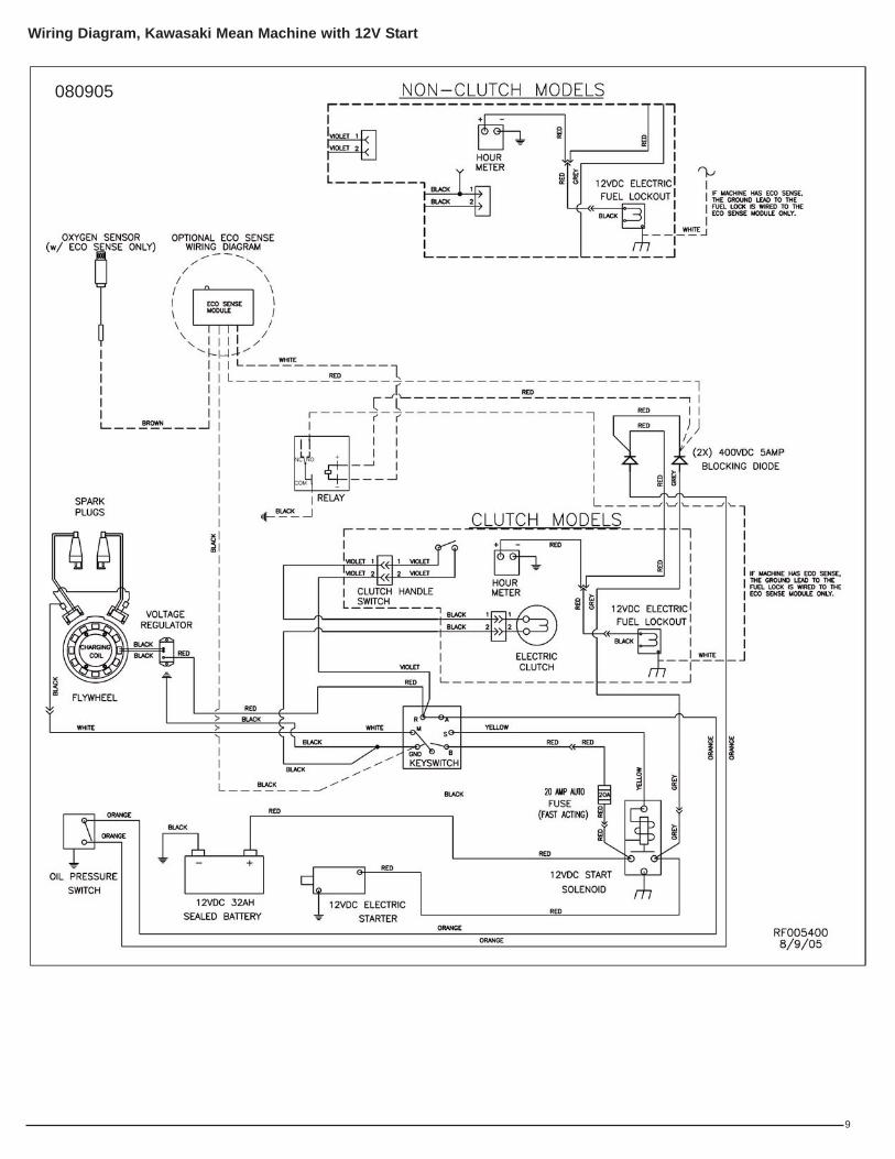
Wiring Diagram, Kawasaki Mean Machine with 12V Start
080905
10
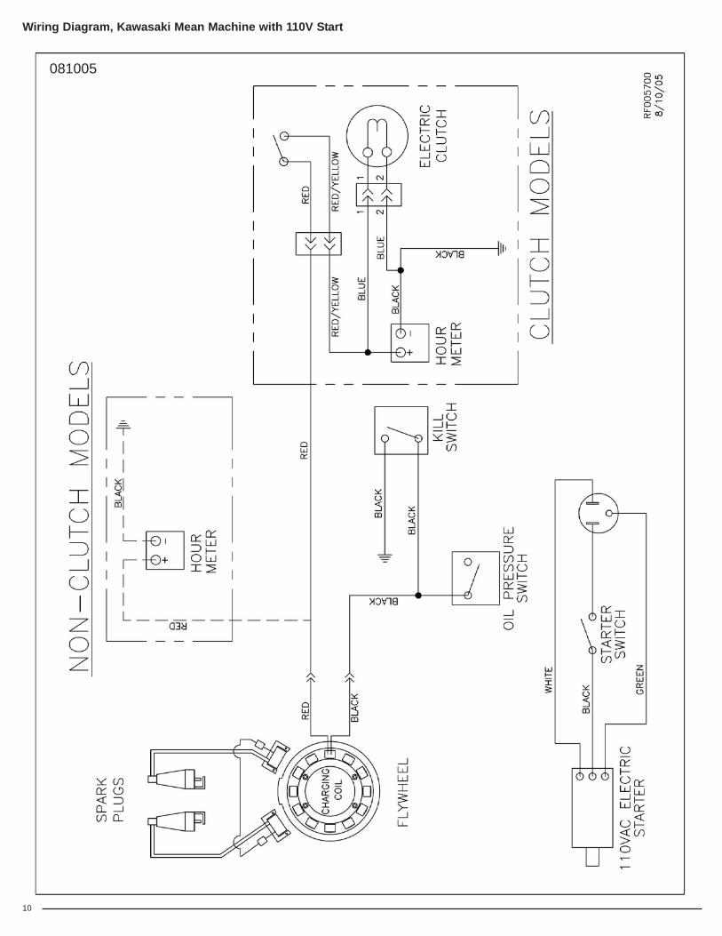
Wiring Diagram, Kawasaki Mean Machine with 110V Start
081005

11
REF PART# DESCRIPTION QTY100 MP114100 Regulator Assy. 17 HP, 12 V, Kaw 1101 MP4340 Hose, Regulator, 12” 1102 MP4330 Fitting, 49 x 6, Reg to Fuelock 1103 MP4500 Coupler, Quick Rego, Female 1104 NB2470 Fuel Line, 3/8” 1.33’105 NB7282 Clamp, Hose, No. 38 2106 MP017900 Fuel, Adjustment Assy. 1107 MP317500 Fuelock, 12 Volt, Asm. 1108 MP4320 Fitting, 48 x 6 1109 NB2460 Hose, Vacuum, 5/32 1.583’110 MP019500 Hose Barb, 1/8 NPT - 1/4 BARB 1111 MP098900 Fitting, 1/8” MPT x 1/8” FPT 90 1
REF PART# DESCRIPTION QTY112 NB6530 Screw, HH Cap, 1/4 - 20 x 1 2113 NB6110 Washer, Lock, 1/4 2114 NB3350 Washer, Flat, 1/4 2115 MP037900 Regulator, Nolff, N5I-A-C 1116 MP106600 Regulator Assy. 17 HP, 110 V, Kaw 1117 MP4325 Fitting, 3325 x 4, Reg to Fuelock 1118 MP4750 Fuelock, Fuel Filter 1119 MP021600 Ballcheck, 1/8 NPT 1120 NB2300 Tee, 3/16 x 3/16 x 3/16, Nylon 1121 MP114400 Regulator Assy. 13 HP, 12 V, Kaw 1122 MP3375 Elbow, Brass, Large 1123 MP114300 Regulator Assy. 13 HP, 110V, Kaw 1
Regulator Sub-Assembly: Kawasaki Mean Machine
051208
103002

12
Engine Sub-Assembly: Kawasaki Mean Machine
031005

13
REF PART# DESCRIPTION QTY400 MP109600 Filter, Recoil (13 HP) 1
MP109700 Filter, Recoil (17 HP) 1401 MP109200 Engine, Kawasaki, 13 HP, 12 V 1
MP102900 Engine, Kawasaki, 13 HP, 110 V 1MP03000 Engine, Kawasaki, 17 HP, 12 V 1MP093200 Engine, Kawasaki, 17 Hp, 110 V 1
402 NB1621 Caplug, K8, Red 1403 MP4515 Tubing, Oil Drain 1404 MP072300 Valve, Oil Drain, Kawasaki 1405 KA590717004 Oil Drain Adapter 1406 MP109500 Seal, Foam (13 HP) 1
MP043100 Engine Air Intake Seal (17 HP) 1407 SA007900 Plate, Throttle, Repl., Bail Style Kit 1408 KA110137016 Element, Air Filter - Foam (13 HP) 1
KA110137001 Element, Air Filter - Foam (17 HP) 1409 NB000100 Screw, HH, 5/16 - 18 x 1 3/4” 4410 MP019200 Oil Pressure Switch 1411 KA490652078 Oil Filter 1412 KA110137017 Element, Air Filter - Main (13 HP) 1
KA110137002 Element, Air Filter - Main (17 HP) 1413 MP121900 Shield, Manifold (13 HP) 1
MP043400 Shield, Manifold (17 HP) 1414 KA110607006 Gasket - Exhaust 2415 MP036200 Switch, Micro, 12 V, 15 A 1416 MP4800 Spacer, Clutch, Top (models w/clutch) 1417 MP107400 Muffler, Catalytic (13 HP) 1
MP107300 Muffler, Catalytic (17 HP) 1418 MP015200 Plug, Oxygen Sensor 1
MP018000 Oxygen Sensor (models w/EcoSense) 1419 MP023500 Pulley, 4”, AB Sheave (models w/out clutch) 1420 MP4787 Clutch Assy. (models w/clutch) 1421 MP4805 Spacer, Clutch Bottom (models w/clutch) 1422 NB005800 Screw, HH, 7/16 - 20 x 1 1/2 1423 NB9267 Washer, Flat, 5/16 4424 MP4790 Tubing (models w/clutch) 1425 NB52816 Screw, BH, 1/4 - 20 x 1/2” 1426 NB3265 Nut, Lock, 5/16 - 18 3427 NB9545 Nut, Spin Lock, 1/4 - 20 1428 NB5282 Bolt, BH, 5/16 - 18 x 1 2429 MP120500 Bracket, Muffler 1430 KA920707003 Plug, Spark, (RCJ8Y) (Not Shown) 2
Engine Sub-Assembly: Kawasaki Mean Machine
032207

14
Deck Sub-Assembly: Kawasaki Mean Machine
050907

15
REF PART# DESCRIPTION QTY301 MP107600 Belt, BX-47 (21” models w/out clutch) 1
MP8070 Belt, BX-46 (21” models w/clutch) 1MP8150 Belt, BX-49 (24” models) 1MP041000 Belt, BX-56 (28” models) 1
302 NB001900 Washer, Fender, 1/2 4303 NB6863 Screw, Hex HD, 1/2 x 1 4304 NB3450 Washer, Flat, 3/8 5305 NB6044 Screw, Cap, 3/8 x 1 1/4 1306 MP9610 Meter, Hour 1307 NB2643 Rivet, Pop 1/8 x 1/4 3308 NB5282 Screw, BH, 5/16 - 18 x 1 4310 NB003100 Nut, Hex, 1/2” - 13, JAM 1311 MP035300 Band, Clamp, Skirt 2312 NB020700 Screw, Phillips, Pan 6 - 32 x 1 4313 MP084700 Molding, Bumper, RokBak 1314 NB020800 Nut, Lock, Nylon, 6 - 32 4315 MP012801 Caster, 2 1/2”, Rear 1316 MP068300 Bracket, Wheel (21” models) 2
MP069000 Bracket, Wheel (24” & 28” models) 2317 MP105300 Wheel, 5”, Performa 2318 MP038100 Pin, Clevis, 3/8 x 2 1/8 2319 NB3265 Nut, Lock, 5/16 6320 LX2105 Clip, Hitch, Pin 2321 MP071800 Tensioner, Belt, w/4” Pulley 1322 MP107700 Spindle, w/6.75” Pulley (21” models) 1
MP7235 Spindle, w/7.25” Pulley (24” models) 1MP7240 Spindle, w/8.75” Pulley (28” models) 1
324 MP081300 Ring, Relief, Stress, Padholder 1325 NB3275 Nut, Lock, 1/4 6326 MP8275D Padholder, 21” 1
MP048300 Padholder, 24” 1SA004000 Padholder, 28” 1
327 NB5700 Washer, 0.755 x 1.005 x 0.060, SS 1328 MP195800 Flexi Disc, w/out Lip, yellow, 80 duro 1329 MP066300 Ring, Spacer, Center Loc II
(24” & 28” models) 1330 MP012700 Retainer, Pad, Center Loc II
(24” & 28” models) 1MP8505 Pad Grab III (21” models) 1
331 NB3350 Washer, Flat, 1/4 6332 NB9319 Screw, BH, 1/4 - 20 x 1 1/4 6333 PD006021 Pad, 21” Blue Blend 1
PD006024 Pad, 24”, Blue Blend 1PD006028 Pad, 28”, Blue Blend 1
334 MP095200 Padholder, 21”, Complete Asm. 1MP047500 Padholder, 24”, Complete Asm. 1MP032500 Padholder, 28”, Complete Asm. 1
335 MP8310 Velcro, Hook, Studs (21” models) 50(24” models) 76(28” models) 68
336 SA003900 Padholder, w/studs, 21” 1SA007800 Padholder, w/studs, 24” 1SA004000 Padholder, w/studs, 28” 1
Deck Sub-Assembly: Kawasaki Mean Machine
050907

16
Deck Sub-Assembly: Machines with Steel Skirt
061008
17
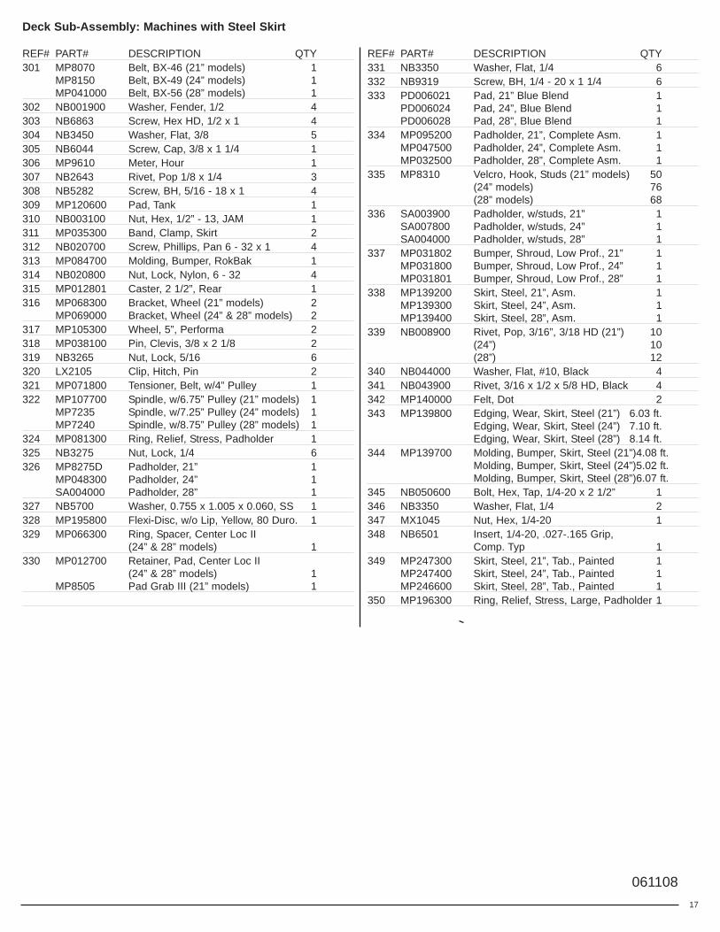
Deck Sub-Assembly: Machines with Steel Skirt
REF# PART# DESCRIPTION QTY301 MP8070 Belt, BX-46 (21” models) 1
MP8150 Belt, BX-49 (24” models) 1MP041000 Belt, BX-56 (28” models) 1
302 NB001900 Washer, Fender, 1/2 4303 NB6863 Screw, Hex HD, 1/2 x 1 4304 NB3450 Washer, Flat, 3/8 5305 NB6044 Screw, Cap, 3/8 x 1 1/4 1306 MP9610 Meter, Hour 1307 NB2643 Rivet, Pop 1/8 x 1/4 3308 NB5282 Screw, BH, 5/16 - 18 x 1 4309 MP120600 Pad, Tank 1310 NB003100 Nut, Hex, 1/2” - 13, JAM 1311 MP035300 Band, Clamp, Skirt 2312 NB020700 Screw, Phillips, Pan 6 - 32 x 1 4313 MP084700 Molding, Bumper, RokBak 1314 NB020800 Nut, Lock, Nylon, 6 - 32 4315 MP012801 Caster, 2 1/2”, Rear 1316 MP068300 Bracket, Wheel (21” models) 2
MP069000 Bracket, Wheel (24” & 28” models) 2317 MP105300 Wheel, 5”, Performa 2318 MP038100 Pin, Clevis, 3/8 x 2 1/8 2319 NB3265 Nut, Lock, 5/16 6320 LX2105 Clip, Hitch, Pin 2321 MP071800 Tensioner, Belt, w/4” Pulley 1322 MP107700 Spindle, w/6.75” Pulley (21” models) 1
MP7235 Spindle, w/7.25” Pulley (24” models) 1MP7240 Spindle, w/8.75” Pulley (28” models) 1
324 MP081300 Ring, Relief, Stress, Padholder 1325 NB3275 Nut, Lock, 1/4 6326 MP8275D Padholder, 21” 1
MP048300 Padholder, 24” 1SA004000 Padholder, 28” 1
327 NB5700 Washer, 0.755 x 1.005 x 0.060, SS 1328 MP195800 Flexi-Disc, w/o Lip, Yellow, 80 Duro. 1329 MP066300 Ring, Spacer, Center Loc II
(24” & 28” models) 1330 MP012700 Retainer, Pad, Center Loc II
(24” & 28” models) 1MP8505 Pad Grab III (21” models) 1
REF# PART# DESCRIPTION QTY331 NB3350 Washer, Flat, 1/4 6332 NB9319 Screw, BH, 1/4 - 20 x 1 1/4 6333 PD006021 Pad, 21” Blue Blend 1
PD006024 Pad, 24”, Blue Blend 1PD006028 Pad, 28”, Blue Blend 1
334 MP095200 Padholder, 21”, Complete Asm. 1MP047500 Padholder, 24”, Complete Asm. 1MP032500 Padholder, 28”, Complete Asm. 1
335 MP8310 Velcro, Hook, Studs (21” models) 50(24” models) 76(28” models) 68
336 SA003900 Padholder, w/studs, 21” 1SA007800 Padholder, w/studs, 24” 1SA004000 Padholder, w/studs, 28” 1
337 MP031802 Bumper, Shroud, Low Prof., 21” 1MP031800 Bumper, Shroud, Low Prof., 24” 1MP031801 Bumper, Shroud, Low Prof., 28” 1
338 MP139200 Skirt, Steel, 21”, Asm. 1MP139300 Skirt, Steel, 24”, Asm. 1MP139400 Skirt, Steel, 28”, Asm. 1
339 NB008900 Rivet, Pop, 3/16”, 3/18 HD (21”) 10(24”) 10(28”) 12
340 NB044000 Washer, Flat, #10, Black 4341 NB043900 Rivet, 3/16 x 1/2 x 5/8 HD, Black 4342 MP140000 Felt, Dot 2343 MP139800 Edging, Wear, Skirt, Steel (21”) 6.03 ft.
Edging, Wear, Skirt, Steel (24”) 7.10 ft. Edging, Wear, Skirt, Steel (28”) 8.14 ft.
344 MP139700 Molding, Bumper, Skirt, Steel (21”)4.08 ft. Molding, Bumper, Skirt, Steel (24”)5.02 ft. Molding, Bumper, Skirt, Steel (28”)6.07 ft.
345 NB050600 Bolt, Hex, Tap, 1/4-20 x 2 1/2” 1346 NB3350 Washer, Flat, 1/4 2347 MX1045 Nut, Hex, 1/4-20 1348 NB6501 Insert, 1/4-20, .027-.165 Grip,
Comp. Typ 1349 MP247300 Skirt, Steel, 21”, Tab., Painted 1
MP247400 Skirt, Steel, 24”, Tab., Painted 1MP246600 Skirt, Steel, 28”, Tab., Painted 1
350 MP196300 Ring, Relief, Stress, Large, Padholder 1
061108
18
Deck Sub-Assembly: Machines with Dust Control
061108

19
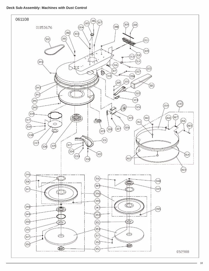
Deck Sub-Assembly: Machines with Dust Control
REF# PART# DESCRIPTION QTY300 MP107600 Belt, BX-47 (21” models w/out clutch) 1
MP8070 Belt, BX-46 (21” models w/clutch) 1MP8150 Belt, BX-49 (24” models) 1MP041000 Belt, BX-56 (28” models) 1
301 NB001900 Washer, Fender, 1/2 4302 NB6863 Screw, Hex HD, 1/2 x 1 4303 NB3450 Washer, Flat, 3/8 5304 NB6044 Screw, Cap, 3/8 x 1 1/4 1305 MP9610 Meter, Hour 1306 NB2643 Rivet, Pop 1/8 x 1/4 3307 NB5282 Screw, BH, 5/16 - 18 x 1 4308 NB003100 Nut, Hex, 1/2” - 13, JAM 1309 MP035300 Band, Clamp, Skirt 2310 NB020700 Screw, Phillips, Pan 6 - 32 x 1 4311 MP084700 Molding, Bumper, RokBak 1312 NB020800 Nut, Lock, Nylon, 6 - 32 4313 MP8310 Velcro, Hook, Stud 1314 MP124800 Bracket, Retainer, Bag, Vacuum 1315 NB9308 Scew, BH, 1/4 - 20 x 1 1316 NB3275 Nut, Lock, 1/4 8317 NB3350 Washer, Flat, 1/4 15318 MP012801 Caster, 2 1/2”, Rear 1319 NB9735 Nut, Lock, 10 - 24, Nylon 3320 NB9645 Washer, flat, #10 6321 MP124700 Bag, Vacuum 1322 MP067600 Tube, Dust 1323 MP065200 Seal, Tube, Dust 1324 MP105300 Wheel, 5”, Performa 2325 MP068300 Bracket, Wheel (21” models) 2
MP069000 Bracket, Wheel (24” & 28” models) 2326 MP038100 Pin, Clevis, 3/8 x 2 1/8 2327 NB3265 Nut, Lock, 5/16 6328 LX2105 Clip, Hitch, Pin 2329 MP071800 Tensioner, Belt, w/4” Pulley 1330 MP139200 Skirt, 21”, Steel, Asm 1
MP139300 Skirt, 24”, Steel, Asm 1MP139400 Skirt, 28”, Steel, Asm 1
331 MP064600 Scoop, Vacuum, 21” 1MP064700 Scoop, Vacuum, 24” 1MP064800 Scoop, Vacuum, 28” 1
332 MX1025 Screw, Pan HD, 10 - 24 x 3/4 3333 NB6530 Screw, Cap, HH, 1/4 - 20 x 1 3334 NB6110 Washer, Lock, 1/4” 7335 MP107700 Spindle, w/6.75” Pulley (21” models) 1
MP034600 Spindle, w/7.25” Pulley (24” models) 1MP7240 Spindle, w/8.75” Pulley (28” models) 1
336 MP065000 Seal, Spindle, 1.01” I.D. x 3.75” O.D. (21” models) 1
MP065100 Seal, Spindle, 2.415” I.D. x 4.5” O.D.(24” & 28” models) 1
337 MP125300 Cover, Pulley (21” models) 1MP073400 Cover, Pulley (24” models) 1MP068600 Cover, Pulley (28” models) 1
338 NB3001 Scew, BH, 1/4 - 20 x 3/4 4339 MP075200 Foam, Skinned, 1/2” x 38” x 1/4” 1340 NB9645 Washer, Flat, #10 4
REF# PART# DESCRIPTION QTY341 MP125200 Liner, Shroud (21” models) 1
MP073300 Liner, Shroud (24” models) 1MP066801 Liner, Shroud (28” models) 1
342 MP8300 Velcro Hook 1” w/ Adhesive -21” 2.1 yd24” 2.3 yd28” 2.8 yd
343 MP139600 Felt, Polyester, 29 oz Black- 21” 6.25 ft24” 7 ft28” 8 ft
345 NB038700 Rivet, Pop, 3/16 x 1/2” x 3/8 HD 4346 MP196300 Ring, Relief, Stress, Large, Padholder 1347 MP8275D Padholder, 21” 1
MP048300 Padholder, 24” 1SA004000 Padholder, 28” 1
348 NB5700 Washer, 0.755 x 1.005 x 0.060, SS 1349 MP195800 Flexi-Disc, w/o Lip, Yellow, 80 Duro. 1350 MP066300 Ring, Spacer, Center Loc II
(24” & 28” models) 1351 MP012700 Retainer, Pad, Center Loc II
(24” & 28” models) 1MP8505 Pad Grab III (21” models) 1
352 NB9319 Screw, BH, 1/4 - 20 x 1 1/4 6353 PD006021 Pad, 21” Blue Blend 1
PD006024 Pad, 24”, Blue Blend 1PD006028 Pad, 28”, Blue Blend 1
354 MP095200 Padholder, 21”, Complete Asm. 1MP047500 Padholder, 24”, Complete Asm. 1MP032500 Padholder, 28”, Complete Asm. 1
355 MP8310 Velcro, Hook, Studs (21” models) 50(24” models) 76(28” models) 68
356 SA003900 Padholder, w/studs, 21” 1SA007800 Padholder, w/studs, 24” 1SA004000 Padholder, w/studs, 28” 1
357 NB038800 Screw, Socket, HD, 1/4 - 20 x 1 1/4 w/Loctite 1
358 MP139900 Bushing, Skirt, Steel 1359 MP247300 Skirt, Steel, 21”, Tab., Painted 1
MP247400 Skirt, Steel, 24”, Tab., Painted 1MP246600 Skirt, Steel, 28”, Tab., Painted 1
360 NB044000 Washer, Flat, 3/16, Black 4361 NB043900 Rivet, 3/16 x 1/2 x 5/8 HD, Black 4362 MP140000 Felt, Dot 2363 MP139800 Bottom, Skirt, Edging - 21” 6.03 ft
24” 7.10 ft28” 8.14 ft
364 MP139700 Top, Skirt, Edging - 21” 4.08 ft24” 5.02 ft28” 6.07 ft
365 NB050600 Bolt, Hex, Tap, 1/4-20 x 2 1/2” 1366 NB3350 Washer, Flat, 1/4 2367 MX1045 Nut, Hex, 1/4-20 1368 NB6501 Insert, 1/4-20, .027-.165 Grip,
Comp. Typ 1369 MP081300 Ring, Relief, Stress, Padholder, 21” 1
061108

20
Handle Sub-Assembly: Kawasaki Mean Machine
020607

21
REF PART# DESCRIPTION QTY
201 NB5366 Screw, Sheet Metal, 8 x 1 1/4 4202 LX2102 Box, Switch, Complete (models w/clutch) 1203 MP013800 Knob, Handle, Tee 1204 MP022500 Handle, Top, 12 V Start 1205 MP6300 Grip, Handle 2206 MP5950 Handle, Adjustable Lever 1207 NB9267 Washer, Flat, 5/16 1208 NB4382 Screw, Drill Kwik, 8 - 18 x 1/2 2209 KC2509904 Switch, Start (12 V models) 1210 NB9460 Bolt, Carriage, 3/8 - 16 x 4 2211 MP114000 Handle, Painted Complete (12 V models) 1
MP105500 Handle, Painted Complete (110 V models) 1212 NB9470 Nut, Acorn, 3/8 - 16 1213 NB3450 Washer, Flat, 3/8 1214 NB5282 Screw, BH, 5/16 - 18 x 1
(110 V models) 2(12 V models) 4
215 KA211637009 Starter Motor & Switch, 110V 1216 MP103900 Bracket, Starter (110 V models) 1217 NB9267 Washer, Flat, 5/16
(110 V models) 2(12 V models) 6
218 NB3265 Nut, Lock, 5/16 - 18 NC (110 V models) 2(12 V models) 4
219 MX1115 Washer, Star Lock, 1/4 2220 MP108800 Bracket, Switch (12 V models) 1221 MP108100 Strap, Tank 1222 NB9510 Nut, Spin Lock, 10 - 24 4223 NB52816 Screw, BH, 1/4 - 20 x 1/2 2224 MP021702 Cylinder, Safety Fill, Aluminum 1
MP106000 Cylinder, Safety Fill, Steel 1225 MP105800 Handle Assy. (110 V models) 1
MP104100 Handle Assy. (110 V models w/clutch) 1MP108400 Handle Assy. (12 V models) 1
226 NB033200 Screw, Socket, 10 - 24 x 3/4 4227 RV009500 Footman Loop 2228 NB5520 Bolt, Carriage, 3/8 - 16 x 1 1/4 5229 NB9267 Washer, Flat, 5/16 5230 NB3267 Nut, Lock, 3/8 NC 5231 MP6600 Velcro, Felt, Black 1232 MP120900 Cable, Battery, Positive, 14” 2233 NB028100 Screw, Machine, 8 - 32 x 2 2234 NB9710 Nut, Keps, 8 - 32 6235 MP113600 Solenoid, 12 V, Side Terminal 1236 NB3275 Nut, Lock, 1/4 2237 MP120800 Battery, 12 V 1238 MP120700 Pad, Battery 1239 IN2012 Cable, Battery, Negative 1240 MP040400 Battery, Retainer, Asm. 1241 MP108300 Tray, Battery, Mean Machine 1242 NB9530 Nut, Lock/Washer, 6 - 32 1243 MP4511 Clip, Oil Drain 1244 NB9200 Screw, Machine 6 - 32 x 5/8 1245 MP044600 Cable, Throttle, 46” 1246 NB007400 Bolt, Phillips, Pan HO #8-32 x 1/2 4247 MP111500 Module, EcoSense, Sub Asm.
(models w/EcoSense) 1248 MP151500 Relay, Board, Circuit, Printed, 12v,
(Model w/ EcoSense) 1249 MP262201 Bracket, Cord Wrap, Black, Formed 1
MP262202 Bracket, Cord Wrap, Hammer-Tone, Formed 1
250 NB4381 Screw, Drill Kwik, 8 x 3/4 2251 MP280900 Pad, Vibration, Box, Battery 1
Handle Sub-Assembly: Kawasaki Mean Machine
042007

22
Optional Padholder: Kawasaki Mean MachineStandard on “QDF” Models
010209
23
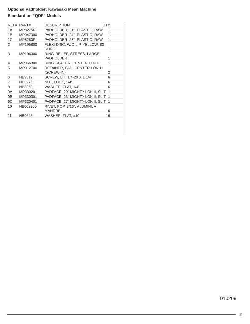
Optional Padholder: Kawasaki Mean MachineStandard on “QDF” Models
REF# PART# DESCRIPTION QTY1A MP8275R PADHOLDER, 21”, PLASTIC, RAW 11B MP047300 PADHOLDER, 24”, PLASTIC, RAW 11C MP8280R PADHOLDER, 28”, PLASTIC, RAW 12 MP195800 FLEXI-DISC, W/O LIP, YELLOW, 80
DURO 13 MP196300 RING, RELIEF, STRESS, LARGE,
PADHOLDER 14 MP066300 RING, SPACER, CENTER LOK II 15 MP012700 RETAINER, PAD, CENTER-LOK 11
(SCREW-IN) 26 NB9319 SCREW, BH, 1/4-20 X 1 1/4” 67 NB3275 NUT, LOCK, 1/4” 68 NB3350 WASHER, FLAT, 1/4” 69A MP330201 PADFACE, 20” MIGHTY-LOK II, SLIT 19B MP330301 PADFACE, 23” MIGHTY-LOK II, SLIT 19C MP330401 PADFACE, 27” MIGHTY-LOK II, SLIT 110 NB002300 RIVET, POP, 3/16”, ALUMINUM
MANDREL 1611 NB9645 WASHER, FLAT, #10 16
010209


To Qualify for this warranty:1) Machine must be registered at the time of purchase on a form
provided by Amano Pioneer Eclipse® Corporation. Your AmanoPioneer Eclipse Distributor is responsible for the registration ofyour machine. Please cooperate with your Distributor in supplyingnecessary information on the card.
2) The machine must have been purchased from Amano PioneerEclipse or an authorized Amano Pioneer Eclipse Distributor.
3) This warranty extends to the original purchaser only and is nottransferable to subsequent owners.
TIME PERIODSONE (1) YEAR WARRANTY - For the models MM and MB.
Warranted to be free from defects in material and workmanshipfor a period of one (1) year from the date of purchase by theoriginal owners. (See Exclusions.)
EXCLUSIONS (Not Covered by Warranty)1) Parts that fail through normal wear by reason of their
characteristics (cords, pads, brushes, belts, bumpers, bodymolding, skirting, squeegees or other consumable parts).
2) This warranty does not extend to parts affected by misuse,neglect, abuse or improper maintenance. All defective parts mustbe returned to the Distributor for credit.
3) Batteries warranted by battery manufacturer for (1) year. 4) Propane Engine warranted by engine manufacturer for *2 years
(*Note: The engine warranty period for Kawasaki engines can beextended to a four (4) years providing the customer uses onlyapproved Kawasaki oil. Contact your Amano Pioneer Eclipsedistributor for more information regarding this optional extendedwarranty program.)
5) Valve train warranted by Amano Pioneer Eclipse for (1) year. 6) Electric motors warranted by motor manufacturer.7) Deck Frame warranted by Amano Pioneer Eclipse for (5) years.
THE OBLIGATION OF AMANO PIONEER ECLIPSECORPORATION
1) The obligation of Amano Pioneer Eclipse under this warranty islimited to repairing or replacing, at its option, any part which isproven to be defective in material or workmanship under normaluse for the applicable period stated above.
2) Warranty repairs will be made by your Amano Pioneer EclipseDistributor without charge for parts and labor.
3) Parts repaired or replaced under this warranty are warranted onlyduring the balance of the original warranty period. All defectiveparts replaced under these warranties become the property ofAmano Pioneer Eclipse.
WARRANTY SERVICETo obtain warranty service, take your machine and proof of purchaseto any authorized Amano Pioneer Eclipse Distributor. Amano PioneerEclipse will not reimburse expenses for service calls or travel. For theDistributor in your area, call Amano Pioneer Eclipse Customer ServiceDepartment at 800-367-3550 or 1-336-372-8080. If you aredissatisfied with the service that you receive, call or write AmanoPioneer Eclipse Customer Service Department for further assistance.
DISCLAIMER OF CONSEQUENTIALAMANO PIONEER ECLIPSE DISCLAIMS ANY RESPONSIBILITYFOR LOSS OF USER TIME OF THE AMANO PIONEER ECLIPSEMACHINE OR ANY OTHER INCIDENTAL OR CONSEQUENTIALDAMAGE EXCEPT AS STATED IN THE WARRANTY APPLICABLETO EACH MACHINE. EXCEPT AS STATED IN SUCHWARRANTIES, THE COMPANY DOES NOT OTHERWISEWARRANT ANY MACHINE AND NO WARRANTY, EXPRESS,IMPLIED OR STATUTORY IS MADE BY THE COMPANY.
Copyright 2007 Amano Pioneer Eclipse Corporation
Limited WarrantyMean Machine Burnishers
LT037300-M; 01022009