Pile Construction Issues and Quality Control of PIT Test
104
Pile Construction Issues and Quality Control of PIT Test Er. Prabhat Kumar Jha Senior Divisional Engineer Senior Divisional Engineer 9841360244 [email protected] https://techwingdor.blogspot.com/ 3
-
Upload
khangminh22 -
Category
Documents
-
view
1 -
download
0
Transcript of Pile Construction Issues and Quality Control of PIT Test

Pile Construction Issues and Quality Control of PIT Test
Er. Prabhat Kumar JhaSenior Divisional EngineerSenior Divisional Engineer
https://techwingdor.blogspot.com/
3

4

5

AugersSB augers are suitable for loosening water-bearing cohesive and non-cohesive soils, whilst SBF augers or progressive augers are suitable for breaking and ripping medium-hard rock.
The augers are available in a wide variety of configurations:With flat teeth or round shank chiselsWear protection on auger flightSingle or double start type
6
Single or double start typeWith or without pilot bitWith or without collar ringDiameter range 520 mm – 2500 mm

Drilling bucketsKB drilling buckets are suitable for drilling in water-bearing cohesive and non-cohesive soils, whilst KBF augers are designed for breaking and ripping dense soils up to medium-hard rock. For emptying the bucket, the hinged revolving bottom gate can be opened automatically. A vent tube prevents the creation of a vacuum as the bucket is withdrawn from the borehole.
The drilling buckets are available in a wide variety of configurations:
7
With flat teeth or round shank chiselsSingle or double start typeDifferent pilot bitsWith or without collar ringDiameter range 520 mm – 2500 mm
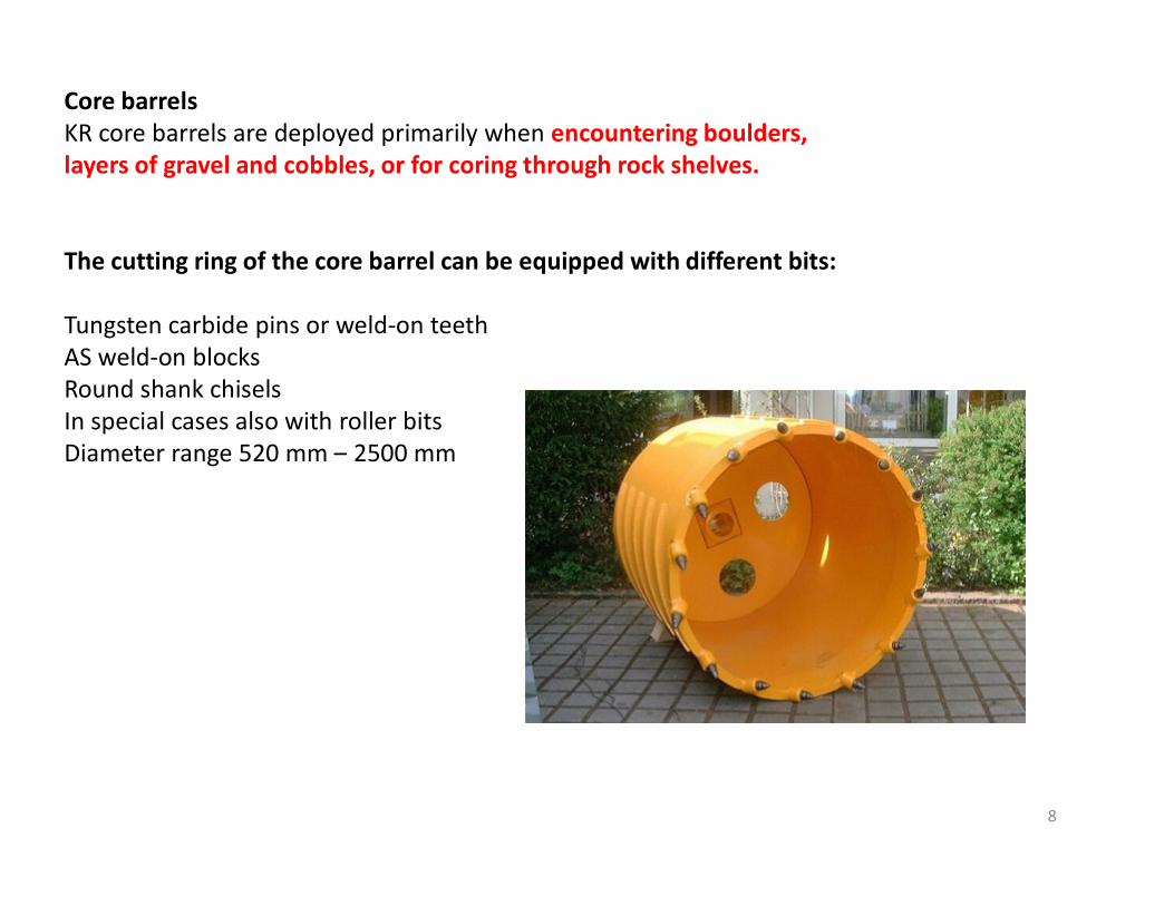
Core barrelsKR core barrels are deployed primarily when encountering boulders, layers of gravel and cobbles, or for coring through rock shelves.
The cutting ring of the core barrel can be equipped with different bits:
Tungsten carbide pins or weld-on teethAS weld-on blocksRound shank chiselsIn special cases also with roller bitsDiameter range 520 mm – 2500 mm
8
Diameter range 520 mm – 2500 mm

Belling bucketIn stable soil formations, the bearing capacity of bored piles can be increased significantly by enlarging the base area of each pile. Belling buckets with retractable cutter arms are used for this purpose.
The toothed cutter arms are extended outwards by the application with the Kelly bar of a vertical crowd force to the scissor mechanism inside the belling bucket.
9

Piling Common Procedures•Piling platform•Setting Out•Installation of Casing•Supply Drilling Mud•Boring•Install the Reinforcement cage•Install tremmie•Start concrete•Cut out tremmie as concrete progresses•Remove casing
10
•Remove casing
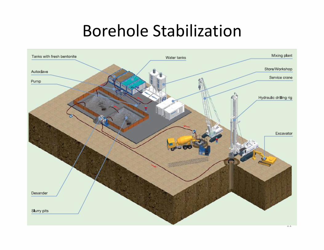
Borehole Stabilization
11


The slurry is normally stored for at least 12 hours before being used
Bentonite : 30-70 kg per 1000 lit. waterPolymer : 0.5-3 Kg per 1000 lit. water
13

Property Units
Stages
Test equipment
Fresh Ready Before
for re-use concreting
Density g/ml < 1.10 < 1.25 < 1.15 Mud balance
Marsh viscosity (946 ml) sec 32 to 50 32 to 60 32 to 50 Marsh funnel
Fluid loss (30 min) ml < 30 < 50 n.a. Filter press
TABLE 1 : CHARACTERISTICS FOR BENTONITE SUSPENSIONS
Fluid loss (30 min) ml < 30 < 50 n.a. Filter press
pH 7 to 11 7 to 12 n.a. pH meter
Sand content % n.a. n.a. < 4 Sand content set
14

Tests and ApparatusMud Balance
For Density Tests
ViscometerViscometer

pH test

Tip Cleaning after Drilling , before concreting
17
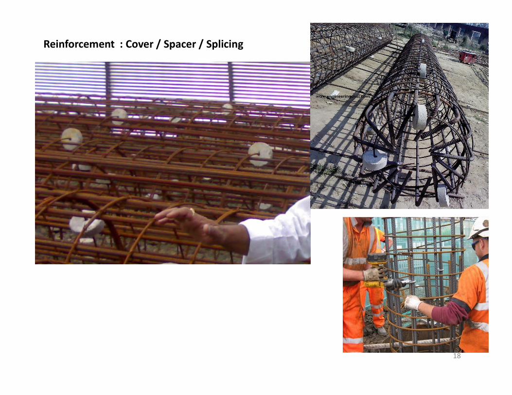
Reinforcement : Cover / Spacer / Splicing
18

Type of tremie pipe :
we have 3 types of tremie : 1m, 2m and 3m Length
Concreting by Trimie The Contractor shall maintain a continuous record of thevolume of concrete used and the level of the concrete in thepipe. Any deviations from the theoretical, or expected,volume/level relationship shall be immediately reported to theEngineer.The volume of concrete : not less than 105% of the nominalvolume of the pile.
3m L
engt
h
1m L
engt
h
2m L
engt
h19

Anti-washout admixtureAnti-washout admixture (also, viscosity improving admixture ) of
concrete for underwater concreting is produced as a viscosity modifyingadmixture to enhance the rheological properties of cement paste. It mainlycomposed of microbial polysaccharides for example gum or polysaccharidederivatives for instance hydroxyethyl cellulose and hydroxypropyl methylcellulose.
20

The slurry is normally stored for at least 12 hours before being used
The time between final excavation includingbottom cleaning and the start of concreting shall bereduced as much as possible and in any case shall
21
Boring and excavation for a pile shall not commence until24 hours after completion of any pile within a radius of 6meters centre to centre.
reduced as much as possible and in any case shallnot exceed 6 hours.

22

23

• Davis and Dunn (1974) report 9.7% defectiveout of a total 717 piles tested on five projects
• Fleming et al (1985) found 1.5% defective outof a total 5,000 piles tested and 1.9%
Frequency of Defective Bored Piles
of a total 5,000 piles tested and 1.9%defective out of a further 4,550 piles tested.
• Ellway (1987) reports 4.2% defective of a total4,400 piles tested
24

• Thasnanipan et al (1988) state 3.3% defectiveof a total 8,689 piles tested
• Low et al (2002) report 7% defective within apopulation of 380 piles tested and 1.5%
Frequency of Defective Bored Piles
population of 380 piles tested and 1.5%defective of a total 5000 piles tested.
• Preiss and Shapiro (1981) suggest thatapproximately 5 % to 10% of the piles onproject could be defective.
25

NO REPORT TO DOR about the defective piles except Bagmati Bridge Tinkune
Frequency of Defective Bored Piles
Bagmati Bridge Tinkuneand One Bridge of
Janakpur????????????????????
26

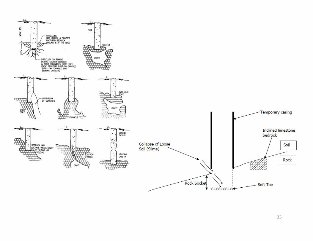
Integrity Problem
27

In Casing Range
Just below casing
Temporary Casing Critical Locations
Any where below casing
Pile Tip
28

Necking Risk within Casing
Length
29

30

31
Defective shaft of bored pile caused by cement being washedout of unset concrete

Soil Intrusion
32

Mis-Aligned Reinforcement
33

Bleeding
34
Cracked Pile
35

Pile Load Test :
Load tests on piles are conducted on completion of 28 days after casting of piles.
Two types of tests namely
initial and routine tests, for each type of loading viz. vertical, horizontal (lateral) pull out, are performed on piles.
36
Pile Load Test :
Load tests on piles are conducted on completion of 28 days after casting of piles.
Two types of tests namely
initial and routine tests, for each type of loading viz. vertical, horizontal (lateral) pull out, are performed on piles.
37

Initial Tests on piles:This test is performed to confirm the design load calculations and to provide guidelines for setting
up the limits of acceptance for routine tests.
It also gives an idea of the suitability of the pilingsystem.system.Initial Test on piles are to be carried out at one or morelocations depending on the number of piles required.Load applied for the initial (cyclic) load test is 2.5 timesthe safe carrying capacity of the pile. Loading for InitialTests is conducted as per Appendix ‘A’ Clause 6.3of IS-2911 Part IV.
38

Routine Tests on piles:Selection of piles for the Routine Test is done basedon number of piles required subject to maximumof 0.5 % of total number of piles required.
The number of tests may be increased to 2%depending on the nature / type of structure.depending on the nature / type of structure.
Recommended : 1 pile on each foundation
The test load applied is 1.5 times the safe carryingcapacity of the pile.The Maintained load method as described in Clause6.2 of IS-2911 (Part IV) – 1985 shall be followed forloading for the Routine Tests. 39

This test will be performed for the following purposes: a) To ensure the safe load capacity of pilesb) Detection of any unusual performance contrary to the findings of the Initial Test.
The tests shall be performed at the cut-off level only. A detailed report for the test result is prepared.Vertical Load Tests on PilesThis test will be carried out as stipulated in IS-2911 (Part IV) 1995.
Fig: Vertical load test on piles
40

Pile Head – The pile head shall be chipped off tillsound concrete is met wherever applicable. Thereinforcement shall be cut and head levelled withPlaster of Paris. A bearing plate with a hole shall beplaced on the head for the jack to rest.
Reaction- Kentledge shall be suitably designed to getReaction- Kentledge shall be suitably designed to getthe desired reaction on the piles. Anchor piles (ifrequired) shall be placed at a centre to centredistance of 3 times the pile diameter subject to aminimum distance of 2 M.
41

42

Settlement- 2 dial gauges for a single pile and 4 dial gaugesfor a group of piles with 0.01 mm sensitivity shall be used.They shall be positioned at equal distance around the piles ondatum bars resting on immovable supports at a distance of 3D(min. of 1.5 m) where D is the diameter of pile orcircumscribing circle for non-circular piles.
Application of load- It shall be applied as specified dependingApplication of load- It shall be applied as specified dependingon the type of test (routine / initial). Each load shall bemaintained till the rate of displacement of the pile top iseither 0.1 mm in the first 30 minutes or 0.2 mm in the firstone hour or 2 hours whichever occurs first. The nextincrement in the load shall be applied on achieving theaforesaid criterion.The test load shall be maintained for 24 hours. 43

Preparation of Pile Head :The pile head should be chipped off to natural
horizontal plane till sound concrete is met.
The projection reinforcement should be cut offor bent suitable and the top finished smoothor bent suitable and the top finished smoothand level with plaster of Paris or similarmaterial
Bearing plate: covering the pile dia.
44

45

46

47

What mistake ?
Pile Safe Capacity for MSL
Pile Capacity Test for No Scour Case
48
MSL
Additional Shaft Resistance considered
Additional End BearingCapacity due to
overburden
Overestimationof pile capacity by pile load test

`
80
100
120
140
Role of Overburden Soil for End BearingEnd Bearing Value, KN
49
0
20
40
60
024681012
Overburden Depth,m
End Bearing Value, KN

50

Safe Load on single pile: least ofa) 75% of Load causing 12mm settlement
b) 50% of Load causing settlement equivalent to 10% of Pile Dia.
c) 1.5 times the working load without causing 12mm settlement.
20% load increment in every 30 min.20% load increment in every 30 min.20% load decrement in every 30 min.
Normally takes 36 hour for complete test
Design Load Test Load
80 ton 120 ton
51

52

53

54

Insufficient loading practice :NO Linear relation between
Load-Displacement
In this case : Upto 50 ton, Settlement =
3mm
55
After 95 ton, Settlement >12mm
But from linear assumption, for 95 ton : only
5.7 mm : Blunder

56

Test Pile
57

Jack to apply load
Steel Beam for Reaction
Bridge Pile used as
Anchor Pile
58

To be checked before any pile test :1. Sure about Test load for No-Scour Case
2. Check the Steel Beam Capacity for Test Load
3. Check for bearing plate size needed according to Pile Dia.
4. Check for Required thickness of Bearing Plate
5. Check the Dial gauges are calibrated or not
6. Check the Hydraulic Jack Load transferring pipe capacity
59

While Pile load test : must check the testing company has anchor beam of
sufficient capacity60

61

Faulty Base Plate
62

300mmFor Test Load =1500KNBase Pressure at Base Plate = 1500*1000/(300*300) = 16.67 N/mm2
Strip Length = 100mm Strip Width,B = 25mm
BM to Strip = 16.67*25*100^2/2= 2.08 KNm
t req. = sqrt (6 * 2.08 * 10^6/ (25*155)) = 56.75 mm
Jack Plate 200mm
63
(25*155)) = 56.75 mm but
used = 20mm
20mm

64

Improper Cover
65

66

Pile Integrity Test # ASTM D5882Low Strain Pile Integrity Testing is a quick and cost effective method to
evaluate the shaft integrity of concrete piles. The testing is able to provide information on: a.) pile continuityb.) consistency of materialc.) location of defectd.) degree of defect
67The cast in situ piles should not normally be tested before 14 days of casting.
68
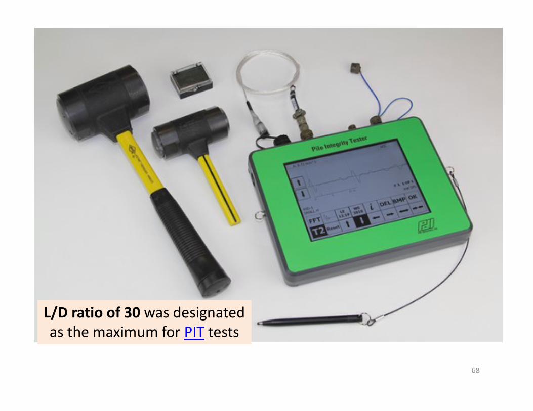
L/D ratio of 30 was designated as the maximum for PIT tests

69
Not Needed
A wavelet is a wave-likeoscillation with an amplitudethat begins at zero, increases,and then decreases back to zero.

Wavelet Representation option 1
Wavelet Representation option 2
Pile Length
300mm
70Continuous wavelet transform method (WTM)
for signal processing technique

71
Result in Wavelet Form needed (1 or 2m)

• Generally, all piles should be tested with threedifferent sized hammers.
• Heavier hammers provide better results forlong piles.
• Lighter hammers provide better resolution,particularly near the pile top. If the piles haveparticularly near the pile top. If the piles havediameters greater than 1 m (36 inches), therecommended hammer masses are 1.5 kg, 3.5kg, and 6 kg (3 lbs., 8 lbs., and 14 lbs.).
• The recommended hammer masses forsmaller size piles are 0.5 kg, 1.5 kg, and 3.5 kg(1 lb., 3 lbs. and 8 lbs.).
72

73
Wave VelocityMagnification DelayMagnificationFilter

74

75

76

77

78

79

80

81

82

A) Magnification Delay (MD)The MD defines the time when exponential
magnification of the signal with time should beapplied to the pile. The default value of 20% ofthe total pile length works well in mostsituations.
This should only be modified when the freestanding length of the pile is more than 20% ofits total length.its total length.
This situation might occur only for marine piles.The change in MD value beyond 20% of pile length
is a most common abuse of data.defect diminishes and the defective pile incorrectly
appears acceptable due to the inappropriatechange in MD value.

84
Refer to Figure 7 which shows the data with proper magnification delay (blue arrow) andwhere a defect is apparent (red arrow) prior to the expected time of reflection from thepile toe (green arrow). However, for the same data, if a later magnification delay (bluearrow in Figure 8) is applied, then the defect diminishes and the defective pile incorrectlyappears acceptable due to the inappropriate change in MD value.
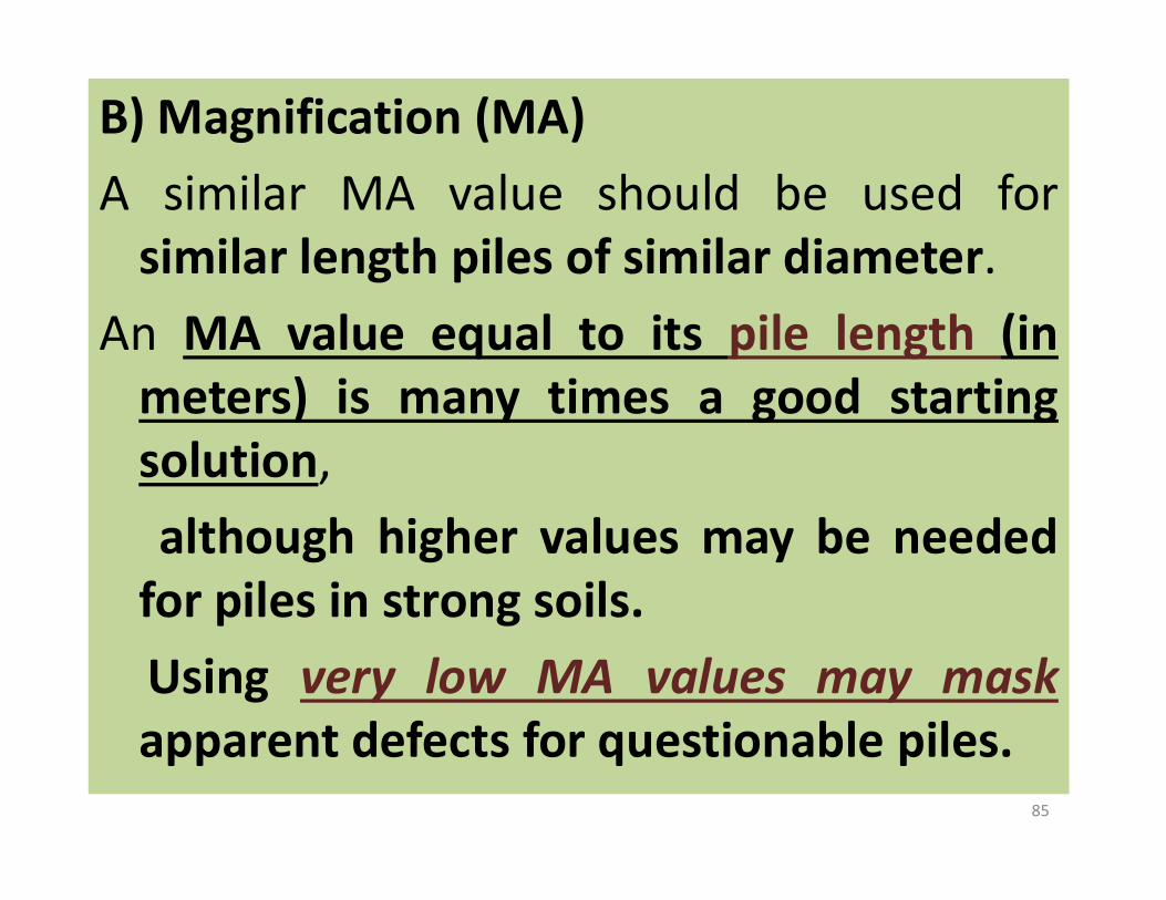
B) Magnification (MA)A similar MA value should be used for
similar length piles of similar diameter.An MA value equal to its pile length (in
meters) is many times a good startingsolution,solution,although higher values may be needed
for piles in strong soils.Using very low MA values may maskapparent defects for questionable piles.
85

B) Magnification (MA)In general, if there is no apparent reflection
from the pile toe,either the pile is defective (as in Figure: 7), orpile preparation has been inadequate, orthe magnification value is too small, orthe magnification value is too small, orthe shaft is relatively long and of a sufficiently
non-uniform character (e.g. generally with arelatively large bulge) and the data should beclassified as “inconclusive”.
86

C) FiltersThe Hi Pass Filter (HI) is used to eliminate low frequency
drifts in the data.
HI is normally either zero (indicating no filter is used) or avalue which is at least 20 times the input pulse width.
Using a very low HI value between 1 to 30 distorts the dataand the interpretation. Use of LO Pass filters is discouraged;
Wavelet (of a value between 1 or 2) is recommended toWavelet (of a value between 1 or 2) is recommended toremove the very high frequency content (generally causedby Raleigh surface waves or short protrudingreinforcement).
Long protruding reinforcement (certainly 3 m or more) oftenresults in a low frequency noise of about the samefrequency as the input pulse width (1 to 2 m) and makesthe data unusable; such long reinforcement should beremoved prior to testing.
87

Foundation length accuracy is dependent on wavespeed accuracy. On low strain tests, like thoseperformed with the PIT and the Acoustic ConcreteTester, wave speeds for good quality concrete varybetween 3500 m/s and 4500 m/s.When using an average wave speed of 4000 m/s, there is a possibility of reaching a maximum variationof +/- 12.5%.
Pile Concrete Strength, Mpa 20 25 30 35
Adopted Wave Velocity, C m/s 3400 3500 3600 3700
88c = Sqrt (E/ ρ)
of +/- 12.5%.

• With what certainty can pile lengths be determined byPIT?
• The accuracy of the determined length is as accurate as theaccuracy of an assumed wave speed. This is because TIMEis being measured. TIME = 2L/c, where L is length and c iswave speed. The TIME equation makes L vary directly withc.
• An engineer can determine the wave speed within anaccuracy of 15%, and likely within 10%, based on concreteaccuracy of 15%, and likely within 10%, based on concretestrength.
• Furthermore, if a pile with known length has a clearreflection from the toe, the wave speed can bedetermined.
• An engineer, with moderate confidence, can use the samewave speed on other piles at the same site if the concrete isconsistent. 89

Wavelet = 1-2 m
MD = 20% of Pile Length
MA = Pile Length, m
Hi Pass Filter = 0
90
Hi Pass Filter = 0
Use of LO Pass filters is discouraged
Soil Data

• Input parameters: – Pulse width – Pulse amplitude – Exponential magnification of displayed
velocity (MA) – Starting point of exponential
magnification (TD) – Cut-off frequency of high-pass filter
(HI), expressed as length (Cutoff frequency=WS/(2*HI))
– Length (LE) – Wave Speed (WS) – Wave Speed (WS) – Top Area (AR) – Cross section area along the pile length -
the pile is divided in elements withlengths of approximately 125 mm (SIunits) or 0.5 ft (English units), and the areaof each element can be changedindividually or in groups. Areas on aselected region can be changed so thatthe region is shaped as arectangle, triangle, trapezoid orcircumference.
91

• Input parameters:– Reference Area - the default value is the
top area (AR); changing this value willchange the percentage area variations.
– Soil resistance along pile shaft and at toe- the soil is divided in the same numberof elements as the pile, plus oneadditional element for the toe. Theresistance of each element can bechanged individually or in groups.Furthermore, a soil layers distribution canbe entered, with different soil types anddensities; the program will automaticallydensities; the program will automaticallyestimate the resistances accordingly.
– Quakes of soil elements along the shaftand at the toe
– Dampings of soil elements along theshaft and at the toe; the value isautomatically changed according to soiltype if a layers distribution is entered
92

Soil Layers
93

Placement of Transducers—The motion sensor should beplaced at or near the pile head using a suitable, ortemporary, thin layer of bonding material (that is, wax,vaseline, putty etc.) so that it is assured that it correctlymeasures the axial pile motion (transducer axis ofsensitivity aligned with the pile axis).The motion sensor is placed generally near the center of
94
The motion sensor is placed generally near the center ofthe pile.Additional locations(min.2) should be considered forpiles with diameters greater than 500 mm.
The low strain impact should be applied to the pile headwithin a distance of 300 mm from the motion sensor.

• Outputs (as a function of time): – Acceleration (ACC) – Velocity only (VEL) – Force and Velocity (F+V -
default) – Displacement (DIS) – Displacement (DIS) – Velocity at top and at
another view location along the pile (V+V)
95

D) Integrity Testing Report Formatsintegrity test report should clearly specify
1. Piles that are acceptable.2. Piles that show major defects and are not
acceptable3. Piles that show minor defects and maybe3. Piles that show minor defects and maybe
acceptable after review of loads, additionaltests etc.
4. Piles that are inconclusive due tobulges, high soil resistances etc.
96

Shafts with no significant reflections from locations above the pile toe and
with a clear pile toe reflection may be accepted.
Where no clear toe reflection is apparent, the experienced test engineer
97
Where no clear toe reflection is apparent, the experienced test engineer
shall state to which shaft depth the test appears to be conclusive.
Where reflections from locations with significant reductions in pile area or
pile material strength or stiffness above the pile toe are observed, the pile has
a serious defect.
If the record is complex, the results may be deemed inconclusive. : GO for
Another Test

β=Z1/Z2 Damage assessment (Rausche & Goble, 1979).
1.0 Uniform
0.8 – 1.0 Slight damage
0.6– 0.8 Damage
The intensity of the defect is quantified in terms of the parameter β definedas Z1/Z2. Following classification of defects could be made based on thevalue of β (Rausche & Goble, 1979).
Z = A √ (E. ρ) or =EA/c
98
0.6– 0.8 Damage0.6< Pile with a major discontinuity
L L L
Local : Small Defect Medium Defect Large DefectL L L
Bulge : Small Medium Large
β: 0.8-1 β: 0.6-0.8 β: >0.6
β: 0.8-1 β: 0.6-0.8 β: >0.6
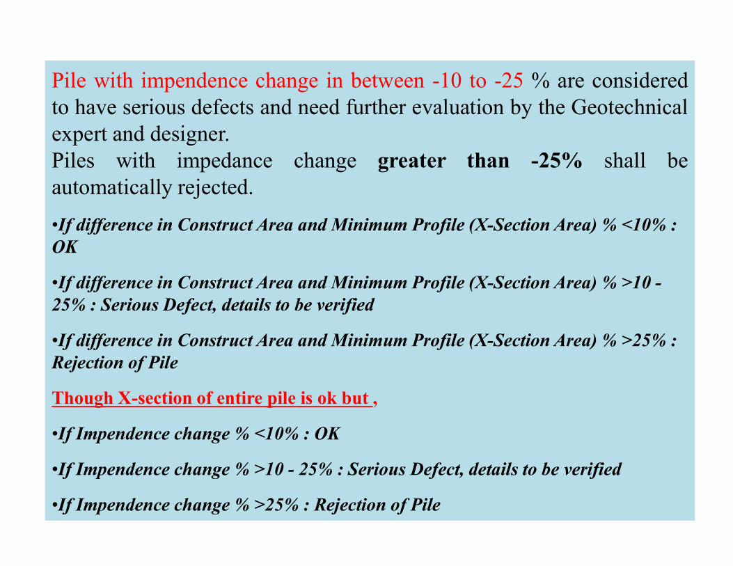
Pile with impendence change in between -10 to -25 % are consideredto have serious defects and need further evaluation by the Geotechnicalexpert and designer.Piles with impedance change greater than -25% shall beautomatically rejected.
•If difference in Construct Area and Minimum Profile (X-Section Area) % <10% : OK
•If difference in Construct Area and Minimum Profile (X-Section Area) % >10 -
99
•If difference in Construct Area and Minimum Profile (X-Section Area) % >10 -25% : Serious Defect, details to be verified
•If difference in Construct Area and Minimum Profile (X-Section Area) % >25% : Rejection of Pile
Though X-section of entire pile is ok but ,
•If Impendence change % <10% : OK
•If Impendence change % >10 - 25% : Serious Defect, details to be verified
•If Impendence change % >25% : Rejection of Pile
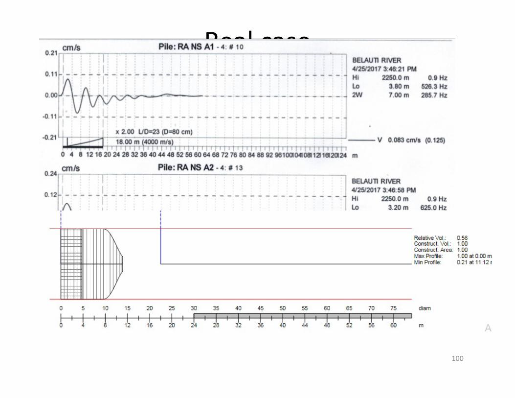
Real case
100

Real case
101

102

103

Be Aware with Such report
104

Limitations of Piles Integrity Tests:i) The present experience of NDT of piles is upto
diameter of 1500 mm.
ii) This is applicable to cast in situ concrete bored anddriven piles. The test cannot be conducted afterprovision / casting of pile cap.
105
iii) This method is not suitable for piles surrounded bywater as it may not give correct results.
iv) It does not provide information regarding verticalityor displacement (in position) of the piles.
v) Local loss of cover, small intrusions or type ofconditions at the base of piles are undetectable.

Thanks
106