Wave Equation Analysis of Pile Driving (WEAP) Program
456
this document downloaded from vulcanhammer.net Since 1997, your complete on- line resource for information geotecnical engineering and deep foundations: The Wave Equation Page for Piling The historical site for Vulcan Iron Works Inc. Online books on all aspects of soil mechanics, founda- tions and marine construc- tion Free general engineering and geotechnical software And much more... All of the information, data and computer software (“information”) presented on this web site is for general information only. While every effort will be made to insure its accuracy, this information should not be used or relied on for any specific applica- tion without independent, competent professional examination and verification of its accuracy, suitability and applicability by a licensed profes- sional. Anyone making use of this information does so at his or her own risk and assumes any and all liability resulting from such use. The entire risk as to quality or usability of the information contained within is with the reader. In no event will this web page or webmaster be held liable, nor does this web page or its webmaster provide insurance against liability, for any damages including lost profits, lost savings or any other incidental or consequential damages arising from the use or inability to use the information contained within. This site is not an official site of Prentice-Hall, Pile Buck, the Univer- sity of Tennessee at Chattanooga, Vulcan Foundation Equipment or Vulcan Iron Works Inc. (Tennessee Corporation). All references to sources of software, equipment, parts, service or repairs do not constitute an endorsement Terms and Conditions of Use: Visit our companion site http://www.vulcanhammer.org
-
Upload
khangminh22 -
Category
Documents
-
view
0 -
download
0
Transcript of Wave Equation Analysis of Pile Driving (WEAP) Program

this document downloaded from
vulcanhammer.netSince 1997, your complete on-line resource for information geotecnical engineering and deep foundations:The Wave Equation Page for Piling
The historical site for Vulcan Iron Works Inc.
Online books on all aspects of soil mechanics, founda-tions and marine construc-tion
Free general engineering and geotechnical software
And much more...
All of the information, data and computer software (“information”) presented on this web site is for
general information only. While every effort will be made to insure its accuracy, this information should
not be used or relied on for any specific applica-tion without independent, competent professional
examination and verification of its accuracy, suitability and applicability by a licensed profes-
sional. Anyone making use of this information does so at his or her own risk and assumes
any and all liability resulting from such use. The entire risk as to quality or usability
of the information contained within is with the reader. In no event will
this web page or webmaster be held liable, nor does this web page or its webmaster provide insurance
against liability, for any damages including lost profits, lost savings or
any other incidental or consequential damages arising from the use or
inability to use the information contained within.
This site is not an official site of Prentice-Hall, Pile Buck, the Univer-
sity of Tennessee at Chattanooga, Vulcan Foundation Equipment or
Vulcan Iron Works Inc. (Tennessee Corporation). All references to
sources of software, equipment, parts, service or repairs do not
constitute an endorsement
Terms and Conditions of Use:
Visit our companion site
http://www.vulcanhammer.org

CATEGORY U
--up-
G. . Goble and 1:ranh RauscRe
The program porfornls wave equation analysis of piles driven by a si.ngle blow of any type of impact hammer. Conventional pile and soil models werc used in addition to both a thermodynanric model for diesels and refined mechanical hammer models. The program can be used to predict impact stresses in piles during driving and to estimate static soil resistance on piles at the time of driving.
'The program development was aimed at providing a simple input and both a flexible and extensive output that include automatic plotting capabilities. The computer language is FORTRAN IV.
The pile and driving systems are represented by a series of discrete masses and springs. The soil is modeled by a spring and a dashpot attached to each mass. The soil resistance so represented are linear elastic plastic. The elastic resistances are linearly proportional to the element velocity for the velocity. By using Newton's Second Law, accelerations and displacements are calculated and tho computation proceeds to the next time increment.
A short input and long or complete input forms are available. Common hammer propcrty data arc stored in a file. Input data is reprinted, options of printed and plotted paramctcrs are available, and time plots are optional.
F. AOOITIOWAL R I U A I K S
Manuals by the Fcderal I-li.ghway Adi~linistration that describe this program and its use are: Vol. I, Background, Report No. FIilVA-IP-76-14.1; Vol. 11, Users Manual, Report No. FIIIVA-11'-76-14.2, Vol. 111, I'rogram Documentation, Report No. 1:1llVA-IP-76-14.3; and Vol. IV, Narrati.ve Presentation, Report No. FI-IWA-IP- 76-14.4.


. . .. 'r~is dac.~~~e:;-, 2 s ~:ss+:c~i:-~$.ed ~ n d c . 7 t h e s3ccsorsh ip of 5 7 %
&nz.z-t>3nt cf Tyen.szr;rt&ior. i n t:;e 'n.kc2rest of ~Lnfarr:-~4,cn "Y "-'"o - . . .ce i,:ritsd Sta;es ;3 ; - e rzen t ESS.:::~S TIC l 5 i S i l i t 3- f o r 2 t s col-.;enis o r use.
Tne contents of this r e p o r t re f l .ec i t h e views o f k b l e 6: Associates i&o Ere respor.s ible f o r t h e f a c t s and t h e accuracy of t h e 6 a t a a r s s e n t s d here in . The contents do n o t r ,ecessar i lv r e f l e c t t h e o i ' f i c i e l mlc% o r po l i cy of t h e Department of T r s n s p o r t a t i ~ n . Tnis r e p o r t does not c o n s t i t u t e a s tandard, s p e c i f i c a t i o n , o r remlat i .on.
'i:ke Ur i t rd 3 e t e s Gcver:.z~c-nt does not endorse products o r . - .en-f~cturers . 'I~a2.e o r m z x f a c b i r s r s ' n m s s a ~ p c a r h e r e i n c r i y Secause they e r e considered e s s ~ n t i a l t o t h e o b j e c t of th5.s document.


Goble G G. , and Raxsche, Prank . O r ~ m i r a l i o n Nua, and A d d r e s s 10. ' N o r i Unir Nu. I T R A I S )
Goble & Associa tes 12434 Cedar Road
~ - ~ 1 e v e 1 _ ~ d ~ F ! ~ h . t . . s ~ ~ i o ~ ~ ~ ~ @ -~-..--.....-06-.06.06.-
12. Spon,.,ing Nome and A d d r a l s
U.S. Departmect of Transpor ta t ion Federa l Highway Administrat ion Of f i ces of Rosenrch and Cevel.opn!ent
- W? s hing~.ilL.-.- 15. Supplsmsnt.ry Notas
~-.J l I . Conire< , 01 Gron, No.
D3T-W-ll.-88~3 . --
F i n a l Report
/ FHWA Contract Nanager: Chien-Tan Chang (!KJV-22) I A computer program was w r i t t e n and t e s t e d t h a t performs a r e a l i s t i c Wave
Equation Analys is of P i l e s d r iven by any t y p e o f impact hammer. Conventional p i l e and s o i l models were used i n add i t ion t o both a therr~odynamic model f o r d i e s e l and r e f i n e d mechacical hammer models.
The program development was aimed a t p rov id ing a simple i n p u t aDd both a f l e x i b l e and e,xtensive output t h a t inc ludes automatic p l o t t i n g c a p a b i l i t i e s . P i l e W i v i n g Hanoner d a t a were prepared and s t o r e d i n a f i l e f o r most of t h e commonly encountered models. The computer l ang lage i s FORTRAN IV.
The program was ex tens ive ly t e s t e d a g a i n s t measured p i l e t o p fo rce and velo- c i t y d a t a and a g a i n s t measured d i e s e l combustion p ressure and s t roke .
Thi.s volume i s t h e f i r s t i n a s e r i e s . The o t h e r s i n t h e s e r i e s a r e :
Vol. No. FWA No. Snor t T i t l e NTIS(PB) N O .
2 IP-76-Ui. 2 User ' s V!~_11ol 3 IP-76-14. 3 Program Doc,mentation 4 IP-76-11;, 4 Narrat ive Presen ta t ion
I ..
COMBUSTION, COW:'TERS, DESLC-FI, No r e s t r i c t i o n s . Copies of t h i s volume DLESiST,, DYNAY-TCS, FOUN-DkTIONS, a r e a.rai.lab1 e from: IMPACT, PILE DRIVI~IG, son ME:CHPJJI:CS, waw EXZIJATION Natior,al Techcical Information Serv ice
- 22161 iol ?h i% rapor*) pages 12. P , , ~ , I
--
L Unclass i f i ed 124
Form DOT F 1700.7 18-72) RepmJuction o f c o n ! p l a t c 4 page ovthar i red

Durj-ng t h e p a s t 15 yea r s wai.- eqA1 ' u n ~ ? . o n computer prograr:.~ have en-
. . . . . . . . . . < , , :,>, 7 . .- , . . - - >' . . ,, . > . . . . . . . . . . . . . . . . . . . . . '-. ." ,.,i +:.. . . . ,
\ , \ -
dr: ,iing. -,; Tie motivat ion %r rLhe p;-epa?at?.on of t h e \+ZAP p r o g r m (Eave
E x a t i o n &nalysi.s of t i l e s ) c a m from p:.ob;ems which were experienced by - - t h e Xew York 3epartri:cint of 'kanspor ta t jor . whsn ihey aattexpted t o implement
rou t ine wave equat ion ana lyses i n t o t h e i r p i l e d r i v i n g p r a c t i c e . They used
a progr.m prepared by t h e Texas Transportat ion I n s t i t u t e . I n s p i t e o f t h e
f a c t t h a t t h i s program i s probably t h e most widely used wave equat ion pro-
gram i n t h e United S ta t e s , s e r ious d i f f i c u l t i e s were encountered i n t h a t un-
r e a l i s t i c s t r e s s e s were sometimes obtained f o r p i l e s d r iven by d i e s e l h ~ ~ m e r s .
The au thor s o f t h i s r e p o r t have performed extens ive r e s e a r c h s t u d i e s on
p i l e d r i v i n g emphasizing t h e measurement of fo rce and a c c e l e r a t i o n dur ing
dr iv ing . These measurements involving p i l e s d r iven by a l l t y p e s of hammers
have been made f o r s e v e r a l s t a t e s inc luding New York. I n o r d e r t o t ake ad-
van-lage of t h e s e measurements t h e Federal Higkway Adminis t ra t ion cont rac ted
with t h e au thor s t o prepare a wave equat ion program which would a c c u r a t e l y
mode!. t h e d i e s e l haiiiiier. Several years have passed s i n c e t h e TTI: Frogrvn
was developed, so it could be expected t h a t o t h e r gene ra l improvements could
be introduced i n t o t h e progri=m f o r a l l types of harmers. F i n a l l y t h e l a r g e

ise:: t o t e s t t i e ~ r 3 g r . a per'formruirice. No clirrer,tl.y ava5.l.able prog-aim has becn
s.,.7<..n+ . c 3 p ~ t o s,ac;i a de:i;z.itdi.ng and tho rouz i t e s t i r . g .
, . :T-" : 7 , . ?. ~ . . ~ ., ,. 5 r : ! o ! . -rn?-ri-.?-, <-i,r.st pr.?;cr:l,s a ger.ira],,
d i scuss ion o f tine u s e of t h e %aye eq~iat-i.oi- n rd ;!ow t:?is part?.cul..zr prosrani
models t h e hemmer-pLle-soil s y s : e n . h.phas;is i.s pl-aced on a d i scuss ion of t h e
ope ra t ion o f d i .ese l h a m e r s and how t h a t ope ra t ion i s nodeled by !,fi;AP. The
second v o l u i e p r o r i d e s a d e s c r i p t i o n of p r o g r m input and output and can se rve
a s a u s e r ' s ~ a . u a l f o r t h e program. It is s t rong ly recorn~ended t'nat a l l u s e r s
read Volume I p r i o r t o t h e Use r ' s Manual s o t h a t t hey w i l l understand t h e
assunpt ions conta ined i n t h e program and how it i s intended t h a t it be used.
The t h i r d volume was prepared t o a i d t h e computer ope ra to r during t h e i n i t i a l
s t a g e s of program and d a t a f i l e loading . It a l s o conta ins a flow c h a r t which
may be of i n t - , r e s t t o those u s e r s who want t o s tudy t h e program i n g r e a t e r
d e t a i l . The f o u r t h volume conta ins t h e t h r e e p a r t s of a l e c t u r e which i s
a l s o a v a i l a b l e i n t h e form o f a t a p e / s l i d e show. The con ten t s of t h i s
n a r r a t i v e r e p o r t d e a l wi th backgrour-d, models and a p p l i c a t i o n s of t h e Wave
Equation.

Eye follow?.ng agencies h v e piven irwa:iLi.:ahle a s s i s t ance t o w r d
. . , . -- . -',a . a n . 2 s . , e n . '::y nruvid:i:!g
coirments and s~ggest.: .ons:
Federal liighway Admini.str;tion, Of f i ce of Oevelcprnent
New York Department o f T r a n s p r t a t i o n , S o i l Mechanics Bureau
New York Department o f Transportat ion, EDP Bureau
The fol lowing firms have con t r ibu ted important da ta :
EXC Corporation - Cedar Rapids, Iowa
Foundation Equipnent Corporat ion - Newcomerstown, Ohio
In te rna t iona l Construct ion Quipment - Elatthews, No. Carolina
L. B. Foster Corporation - Pi t t sburgh, Pennsylvania
14KT Corporation - Dover, N e w j e r sey
S o i l E k ~ l o r a t i o n Company - St . Paul, Mimesota
Vulcan I ron Forks, Inc. - Mest Palm Beach, F lo r ida

NO.
1
2
PAGE
D F S C R I P T I O M O F T E S T DATA 75
COIWARISON OF C0WU'i;ElI WIl 'H OSSFP.'VED Q U A X T I T I E S FOR T E S T E O DATA 77

LIST OF FIGURES
NO. - 2-1
2-2 (A) ?'HE SYSTEM TO BE ANALYZED; (B) 'WE WAVE: FdUATION MODEL .4NE (C) TI33 COWOkENTS OF THE SOIL P-ESISTANCE X0D.E
WDRK1NG PRINCIPLE OF THE OPEN FEE DIES= IicJwm
(A) SCHEUTIC AND (B) MODEL OF OPEN END DDZESm iI!tJQER
( A ) STIFFIZSS VS. COWRESSION FUCLATION ( B ) S T I F r X S S VS. CO~RESSION VELOCITY RELATION; BOTR FOR DRIVING SYSTEM COWONENTS
EXAMPLE OF FORCE VS. DEFORUTION RELATION FOR COMPONENTS OF DRIVING S i S T P i
THE FOUR PHASES OF THE THERMODYNAMIC MODEL
SCHEMI..TICS OF CMSED ENUl DIESEL HkMNERS (A) UNIFGRM (B) NON- UNIFOBN RAM
SCHDMTIC OF A VACUUM CH.mBER DIESEL HAbPEB
DIFrm3U1AL ACTLWG A13/~T224M HidWER ( A ) AE'TER XQACT ( B ) DLIIIING F4.I:L
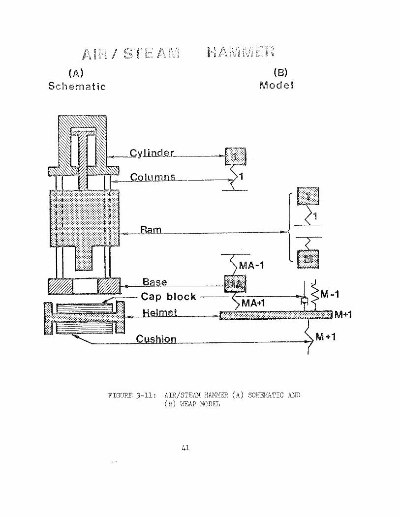
AIR/sTE.L.M II/JJ:.B (A) SCiifltATIC AN51 ( 5 ) k,ZAP MODEL

NO. --
6-1 COppA,SISON O F P I < $ P ~ ~ C ' i ' ~ ~ ' a ,TH X,?:ASL;?Li) P I L E : YfiP FOFC?':
ANE COI"BUSTI0N PmSSW.ES FCP, P I L K NO. 1
CONPARISON O F PREDICTED WITH NE4STJRE P I L E TOP FORCE AND W B C I T Y FOR ( A ) P i Z E NO. 2 AFiD ( B ) P I L E NO. 3
FBRCE AND V X U C I T Y MATCH FOR P I L E KO. 4 (PLIR~~UE)
FORCE AND VELOCITY MATCH FOR P l L E NO. 5 ( ~ 1 4 ~ - DTP 3)
FORCE, VEZOCITY AliTD P R X S S W HATCH ;?'3R P m - NO. 6
FORCE AND VELOCITY MATCH FOR ?Ti NO. 7 ( A ) NORI~IIII, PROGRLY PEFPORMANCE, ( B ) U S I N G P R E I G N I T I O N AND REDUCED FUEL S E T T I N G
FORCE AND VELOCITY MATCH FOR PILE NO. 8 U S I N G P R E I G N I T I O N AND REDUCED FUEL S E T T I N G
FORCE AND VELOCITY MATCH FOR PFLE NO. 9
FORCE AND VELOCITY MATCH FOR PILE NO. 11
FORCE AND VELOCITY MATCH FOR PlLE NO. 1 2 (CUYAHOGA RIVER)
FORCE AND VELOCITY MATCH FOR P U E NO. 13
FORCE AND VELOCITY MATCH FOR PILE NO. 14 (PHILADELPHIA)
FORCE AND VELOCITY MATCH FOR P I L E NO. 16
FORCE i'4ATCH d_nm TH?B> DIM31SIONiLI, 4WRCE PLQT FOR P I L E NO. 17

WAVE 2B.UATION ANALYSIS lQR PII,ES R:; ' . t<SCARCH REPORT
Page No.
PXEFACE ii
ACKNOWL&XlGF>r&YTS
LIST OF TABLES
LIST OF FIGbRES
TABU OF CONTENTS
iv
V
vi
viii
CHAPTER 2 BASIC OP-ERATION AhKJ USE OF THE IE!AAVE EQUP.TION
CHUPTEX 3 !%4'~~EZNIATLCAL MODELS
3 .1 Indroduct ion
3 . 2 Hammer
3 . 2 . 1 Working P r i n c i p l e of t h e Open End Hammer
2 . ' h e hCechanica1 Kodel o f t h e Open End Diese l I izmer
3 .2 .3 l k e Tner~nodynmic t40.iodel of t h e OED Zi,n.mer
3.2.4 Vojorking P r i n c i p l e of t h e Closed &d Diese l ??z~aer

3 . 2 , . 2 Ha.r~~r.er.5 ~ r i t h >$on-~flLiform Rams arzd Conpression T a d c
3.2.5 The Vacuurr. Chi-l.'oer : I m ~ ~ ~ e r
3.2.6 ?he ~ i r / ~ t e ; ~ i ixzer Xode:
3.3 P i l e
3.4 S o i l
3.5 hJw.&rical Treatment
PXOGRA-V INPUT TNFOFL\~I_A.TIObI
4.1 In t roduc t ion
4.2 Open End Diese l Harmer
4.3 Closed h d Diese l Harmers
4.4 A i r Steam Hanmers
4.5 Other Hanmer Related Input I n f o m t i o n
4.6 Driving Accessories
4.7 P i l e
4.8 S o i l
G.9 Other Progra?~ Options
PflSCPJ-X FLOFI
?[<<>G!< -124 p.?kf> (~~<~.~. : , !~~c;
6.1 I n t r o d u c t i o n

CHAPTER 7
APPENDIX A
TABLE OF CONTENTS (Continued)
6.2 Data S e l e c t i o n
6.3 Representa t ion o f R e s u l t s
6.4 F.esuits
CONCLUSIONS A . RXC^vW%WiTIONS
CO?JZUSTION CPIJCULATIONS USING COYBUSTION CHhRTS
A . l General Eemarks
A.2 Sample Ca lcu la t ion
A.3 Discussion
REFERENCES
MFl'RIC CONVERSION FACMRS
Page No.
73
74
76
102
104
104
10 5
108
112
114

and basi.c i d e a s behind a compute; proSr&n c a l l e d hTXP ('&-re Zquzit?on
Ar.alysis o f P i l e s ) which was de:reloperl under c o n t r a c t with t h e Federal
Fiig'r.wsy Pdn!;nist;.atior, l 'h is s tudy was cor,&lcted t o serve t h e follo:,rir!g
purposes:
( a ) To produce a program f o r ana lyz ing a p i l e d r iven by a di .esel harmer us ing a thorough model of both t h e therno- dynamic and mechanical hammer ope r2 t ion .
( b ) To improve and r e f i n e e x i s t l n g techniques f o r wave a n a l y s i s of p i l e s d r iven by a i r - s t e m harmers.
( c ) To s tudy t h e performance o f t h e program by comparing computed va lues o f p i l e t o p f o r c e and v e l o c i t y with those measured p rev ious ly by t h e Case p ro jec t (l)?
(d) To provide a progran t h a t r e q u i r e s minimal e f f o r t f o r t h e p repa ra t ion o f i n p u t d a t a f o r " typ ica l " cases and
. p u t s t h e volume of output informat ion i n t h e con t ro l o f t h e user .
The wave equat ion concept i s n o t new. Smith ( 2 , 3 ) first proposed t h e
u s e o f t h i s d i s c r e t e method f o r modeling t h e hammer-pile-soil system. Among
t h e r e s e a r c h e r s t h a t have f u r t h e r con t r ibu ted t o t h e advancement of t h e a r t
a r e Forehand a ~ d Reese ( 4 ) and Smson e t a 1 ( 5 ) . Probably t h e l a r g e s t r e -
search e f f o r t s were made by t h e Texas Trans?ortatioi! I n s t i t u t e of Texas A&Y
- - --
* Only two o f t h e ~ . a & number of t h e i r r e p o r t s a r e referenced here . - + Numbers i n pa ran thes i s p e r t a i n t o r e 5 r e n c e s l i s t e d a t end o f t e x t .

l i s h e d and made genera l ly a v a i l a b l e i n t h e United S t a t e s .
When t h e TTI program was m i t t e n , air-steam hancer opera t ion was of
pri-nary i n t e r e s t and concern. Therefore, it i s not s u r p r i s i n g t h a t resul - t s
were much l e s s s a t i s f a c t o r y when d i e s e l harmer systems were analyzed. P a r t i -
c u l a r l y t h e p red ic t ion o f d r i v i n g s t r e s s e s f o r these cases has been found t o
be u n s a t i s f a c t o r y by many program u s e r s .
P r i o r t o t i e development of t h e hBkP program t h e performance of wave
equat ion p r o g r m s was t e s t e d e i t h e r by a n a l y s i s of simple cases where c losed
form so lu t ions g iv ing force-time r e l a t i o n s h i p s were a v a i l a b l e , o r f o r r e a l
cases where t h e p red ic t ed capac i ty was compared so t h a t measured i n a s t a t i c
l o a d t e s t . Since only a few cases with overs impl i f ied hammer systems can be
solved i n closed form, t h e primary t e s t i n g was a g a i n s t l oad t e s t r e s u l t s .
Such a comparison involves only one parameter i n a domain where more than
twenty a r e un'm-own and must be found. To make p a t t e r s worse, t h e system i s
non-l inear and s impl i fy ing assumptions, i n t e r p o l a t i o n s and e x t r a p o l a t i o n s do
not always hold. Other problems such a s time - dependent c h a r a c t e r i s t i c s of
t h e s o i l , numerical d e f e c t s o f t h e d i s c r e t e inodel and iriadequate s o i l inodeling
can a l s o y i e l d erroneous r e s u l t s . While l a r g e -volumes of measurements have
been published by t h e Case Research P r o j e c t , appirent1.y t h i s d a t a was not used
t o ang su ' ss tant ia l degree i n checking t h e performance of o t h e r p r o g r a m . One
of t h e t a s k s of t i e p o j ~ c t report.ed here > a s t o sil!:)ject ?.'re nro;r-?.~i . . . ?..r c>:.-
a t t h e p i l e tope f o r a hitie v a r i e t y o f harrier and pi.le types .

a n a l y s i s c a p a b i 1 i t i . e ~ f o r diesel. hamxers. The hTA.1' program d i f f e r s from
t h e TTI propa:?. f o r d i e s e l hahlmers i n t h a t , f i x s t , Td.E~lP i nc ludes t h e de te r -
minat ion o f t h e gas p res su re i n t h e coci'oustiori chalibe;. usi.ng a themioci:ica3ic
a n a l y s i s r a t h e r t h a n a cons tant , s p e c i f i e d p res su re and, secondly, t h e hawner
str*oke i s c a l c u l a t e d i n t h e dynamic a r a l y s i s r a t h e r than be ing spe-,i.fi.ed i n
advance. D i e s e l hammers can opez5ate a t a wide v a r i e t y of s t r o k e s t h a t canrlot
be esti.mated i n advance by i n t u i t i v e means. Moreover, t h e hmLner l s e f f e c t i v e -
nes s i s s t r o n g l y dependent on t h e s t r o k e .
I n Chapter 2 o f t h i s r e p o r t t h e b a s i c use o f t h e wave equat ion i s d i s -
cussed. Rea l hammer performance i s d iscussed i n Chapter 3 and t h e model f o r
hammer o p e r a t i o n i s descr ibed with emphasis placed on d i e s e l hammers. The
s o i l model i s a l s o descr ibed and an a l t e r n a t e approach t o t h a t used by Smith
i s presented . Some f u r t h e r el.aboratj..on on d i e s e l hanuner o p e r a t i o n i s con-
t a i n e d i n Appendix A .
The in fo rma t ion necessary f o r t h e p r e p a r a t i o n o f t h e program i n p u t d a t a
i s desc r ibed i n Chapter L, (and a l s o i n t h e U s e r ' s Manual). Chapter 5 g ives
a general. d e s c r i p t i o n o f t h e program o rgan iza t ion and f low. The extens ive
s tudy of prograxi performance whi.ch conipares cal.cul.ated and measured va lues
o f f o r c e and v e l o c i t y f o r 17 d i f f e r e n t t e s t p i l e s i s r e p o r t e d i n Chapter 6 .
Chapter 7 g i v e s scne conci.usi.or,s and rec3cmer.dati.ons.

CIIAP'I'E? 2
BASIC OI'EIIATION AILTI USE OF THE WAVE K!UATION
For over 100 y e a r s foundation engineers have used dynamic formulas
t o es t imate p i l e bear ing capaci ty ( o r t h e inve r se , t o es t imate t h e re-
qui red blow count f o r a s p e c i f i e d capaci ty) . The use of these formulas has
b e e n s w e r e l y c r i t i c i z e d s ince a l l of them have been proven g r o s s l y inaccura te
and unreliab3.e. Their use p e r s i s t s i n s p i t e of t h e crit5.cism because of t h e i r
s i m p l i c i t y and t h e l a c k of something b e t t e r . Also, sone dyriamic means of cap-
a c i t y p r e d i c t i o n w i l l continue t o be requi red s ince p i l e des ign loads have
tended t o inc rease making s t a t i c load t e s t s inc reas ing ly d i f f i c u l t t o perform.
I n order t o p lace t h e wave equation i n context i t i s appropr i a t e t o re-
view t h e u s e of a dynamic formula. Consider a t y p i c a l example
where R i s t h e des ign load , W i s t h e ram weight, h i s t h e ram s t roke , S i s t h e
permanent s e t o f t h e p i l e pe r hanmer blow and C i s a term which r ep resen t s t h e
e::ergy 1.osses and c z r r i e s t h e smie u ~ i t s a s s e t . Contained i n 'the constant
of equat ion 2 . 1 i s a t'neoretica!. f a c t o r of s a f e t y o f 6 p lus t h e q u a n t i t i e s
r., T.3 P c, <, - . ..~...-. >;.dry t o mike t h e u n i t s c o r r e c t . Tke product 'th u s u a l l y i s used -to re-
present, t h e r a t e d h&mer e n e - g . 'I'h5.s icormdla can be represented by t h e curve
. . , . ,.. . , . . . . ,.~; :,.,, .r! < :! > -.;:.::7<: 2 1.. , :?:.e <::>?> .::: !,j? :: ,., , , .
;,s ,:-.vcc :.s a .: ::.:.ii;n 01, ..:?.;.# - -
. ? c;iint a.rid is KnQiin a s a bearizr ; 5rr;ph. A rmrnbr of ci;.i.:ic&t~::s czn be
v?.sual.ized. '&en 2 prir.ticu3ar blow co.dnt i s observed and t h e r z t z d h?.i:~:!cr
1.;


energy i s known, then w i t h an esti.mate of l o s s t h e p i l e capaci ty can be
deteririned a s shown i n Figare 2.1. O f course, t h e reverse phth i s a l s o
p o s s i b l e . The blow count requi red f o r a s p e c i f i e d capaci ty can be de te r -
mined.
Tne o the r connon problem i s t i e s e l e c t i o n o f equipment. For a p a r t i -
c u l a r job t h e capac i ty i s usua l ly s p e c i f i e d . Then f o r a given d r i v i n g
system ( r a t e d hammer energy and est . inated l o s s e s ) t h e blow count can be
determined. If t h i s blow count i s not judged t o be s a t i s f a c t o r y , t h e equip-
ment can be changed.
The shortcomings of t h e dynamic formulas can be placed i n t h r e e ca te-
g o r i e s . In gene ra l , t hese t h r e e c a t e g o r i e s a r e good f o r evalua t ion o f a l l dy-
namic procedures f o r capaci ty determinat ion:
1. Tne d>namic formulas do a poor job of r ep resen t ing t h e d r iv ing system. Though t h e r a t e d energy i s t h e most important hammer parameter, it i s t h e only one inclilded. Some dynamic formulas inc lude o'ther para- meters such a s ran weight but t h e y have not proven t o be more accura te . An a t tempt i s rrade t o consider t h e d r i v i n g system with t h e 3.oss term, C , but t h i s approach i s g r e a t l y oversimplified. Since only a r a t e d perfor- Kance i s inclcded t h e d~nirr:m.i.c f o r m l a does not at tempt t o d e a l with poor equiprent performance.
2 . A l l e f fec- t s of p i l e f l e x i b i l i t y a r e neglected s in-e i n i t s der ivs t ior . S'ne dy:-1mi.c Zorrnula ass:.uries a r i g i d pi1.e.
P T . 3 . The s o i l r e s i s t i n c e i s asswiied t o be c o r s t a n t . 1r:I.s kind o f s o i l model i s c i - r t a : i ~ l y f a r t o s i a p l e t o even . , - z~;r.(:.x:::::?,;nly . - r.:>re:j~gt a r e a l s o i l .
~. . . . , ~ o!.sw co;?nt ot>scrvc:d p;'.;-n ~s i .v l r :g b ~ g 5 . n ~ on a job. 'Y::. c~2?si. : lcns %?:st
6

cor:L:-,c.'.y ar.i...ti a?,:,: 1:; :;b,$.; b<<,::.:,:,r.<; cp.ij7.:.:t,:j s::;,-.i(::.<>:,.::? )[::.:.',.+ f,.,?-!,:.!.!:.
d r i v i n g produce p i l e damage? Is t h e hanuiier perfornGr:g proper;.y? Is t h e
d r i v i n g sys-tern of t h e correc-t s i z e ?
However, t h e o b s e ~ v a t i o n o f blow count i s a -re?,- csnver,isr.t . n i a ~ t o g z ~ s
t h e q u a l i t y of t h e p i l e i n s t a l l a t i o n . Therefore, the wave e w a t i o n approach
was developed. The one dimensional.wave equat ian can be der ived by applying
Newton's Second Law t o a rod element o f i n f i n i t e s i n z l l eng th . It i s w r i t t e n
whereQ i s t h e m a t e r i a l mass d e n s i t y , E is t h e modulus of e l a s t i c i t y of t h e
m a t e r i a l and u i s t h e a x i a l displacement o f a poin t on t h e rod a t l o c a t i o n
x and t ime t . Thus, at^ i s t h e a c c e l e r a t i o n and Yu/ax2 i s t h e s t r a i n
g r a d i e n t a t x and t .
Using t h i s cont inuous form of t h e wave equat ion f o r p i l e a n a l y s i s i s
u s u a l l y not p r a c t i c a l f o r t h e r e a l boundary condit ions which must be handled.
However, a s i m i l a r equat ion can be de r ived i f elements o f f i n i t e l eng th , a L,
a r e chosen having mass, m =f' A aL and s p r i n g s t i f f n e s s , K = '*/AL. Here
A i s t h e p i l e c r o s s s e c t i o n a l a r e a . New-bon's Second Law l e a d s t o
. . . , ;:.c a,.,, - , ~ . t . : -,. ,-.? A ' ..,..,-,: , ,. .> " _vr,l.... .; ....;. ,- ..... . . 2 . A . . : . A 5.- a.r-: t h e cow.- " t,
presv ion of t h e s p r i n g s a t t h e t o p and bottom, res;?ecti..vel.y, of t h e niass

under considerat ion.
'The Wave Q u a t i o n ( t h e term Wave F ? u a t i o n i s t h e name t h a t has been
a t t ached t o computer programs f o r d i s c r e t e dynamic p i l e a n a l y s i s . I n t h e
remainder of t h i s r e p o r t , t h i s usuage w i l l be adopted) rraltes use o f t h e con-
cept of equat ion 2.3 by r ep resen t ing t'ne p i l e and d r i v i n g system (Figure 2.22.)
by a s e r i e s of masses and sp r ings a s shown i n Figure 2.2b. The s o i l i s
modeled by a spr ing (R , S t a t i c ) and a dashpot (R, ijynamic) a t tached t o each
mass. Tne s o i l r e s i s t a n c e s so represent,ed a r e shown i n Figure 2 . 2 ~ and a r e
].inear e l a s t i c p l a s t i c f o r t h e spri.ng where t h e m a x i m u m f o r c e , %, i s reached
a t a d isp lacenent q, c a l l e d t h e quake, and l i n e a r l y p ropor t iona l t o t h e e l e -
ment v e l o c i t y f o r t h e dashpot (commonly known a s t h e damping f o r c e ) .
The a z a l y s i s proceeds by g ix ing t h e ram an i n i t i a l v e l o c i t y . A t each
element the displacement can be ca lcu la t ed f o r a small t ime increment wi th
element v e l o c i t i e s determined from t h e previous time increment . With t h e s e
displacements and v e l o c i t i e s t h e f o r c e s ac t ing on each mass can be determined.
They a r i s e from t h e p i l e sp r ing deformations, from t h e s o i l spri.ng deformation
and from t h e dashpot fo rce . Using Newton's Second Law i n t h e form repre-
sented i n Equation 2.3 t h e mass a c c e l e r a t i o n s can be ca lcu la t ed and by in -
t e g r a t i o n a l s o t h e v e l o c i t y , !I%e cornputation then proceeds t o t h e next t ime
incremant . Ir. apglica-lion cl s e t of s a i l f o r c e s I?, ??nd <:~~i:,.i.r.g f ~ r c e s z r e asslgnnd
. - 6;. . c ... .- . . . . . - . , . . . ;;!s . , . - ~,~ .,.,*,. 2.. c,::,:;:~':. ;::c:i-, :,:,L? L';:.::, .i.s & : . - ~ ' ~ ! n :." J ,. ..LL.i! :,.:,::;L.~;.L .-;$ !,::;~2:~7~" ;:,;!,A i.,rle
d-,l-. J . ;LJ IL~C . ' co';iput.ation out1ir;ed aSove i s continued through s:.~ccsss!.ve t r i e
8

" 1 p,,,:;:'j'?.,!'<,: ( 1 . $a,-; &,. a:: " bJ . ! .., i . i (Q) [l:,:.:,,ii:>:..;,i.,
DIESEL.
AIR / S T E A M
-ac---- R A M -
-CAPBLOCK ---w
- H E L M E T ---4
(C) SOsb RESITANCE:
V E L O C I T Y
F I W , 2-2: ( A ) TIE SYSTM M BE IWALX!ED; ( b ) I'KE WAVE W.IIATION MODEL A N D ( C ) THE COMF'ONEXTS OF' THE W,SISTANCZ XODn,
9

increments u n t i l a l l s o i l forces a r e l e s s than RU. 1'he t o t a l pernanent
displacement h i l l have then been ca lcula ted and a poin t on t h e bear ing
graph i s known. The capac i ty val.ue i s known a s R and i s equal t o t h e u t
sum of t h e Ru va lues a t each element. The blow count i.s obta ined from t h e
ca lcula ted permanent s e t . I n t h i s procedure t h e perrnzment s e t ( o r blow
count) i s determined f o r a s e t of assigned r e s i s t a n c e s . Rowever, t h e
bearing graph i s p l o t t e d , by t r a d i t i o n , with t h e blow count as t h e inde-
pendent v a r i a b l e . A v a r i e t y of Rut v d u e s can be used t o c a l c u l a t e t h e
t o t a l shape of t h e Sea - ing graph.
I n a d d i t i o n t o t h e bearing graph t h e wave equation a l s o g ives s t r e s s e s
i n t h e p i l e and t h e y can a l s o be shown a s a func t ion of blow count.
I n p r a c t i c e , t h e wave equation bearing graph can be used i n a Icanner
q u i t e s i m i l a r t o t h e dynamic formula bearing graph. I n a d d i t i o n , d r i v i n g
s t r e s s e s can be r a t i o n a l l y l imi ted . While t h e shape o f t h e two curves are
qui.te sinullar t h e d i f f e r e n c e s a r e s u b s t a n t i a l . A p a r t i c u l a r wave equation
bearing graph i s as soc ia t ed with a s i n g l e d r i v i n g system p i l e type, s o i l
profil .e.and a p a r t i c u l a r pi.le penet ra t ion . I f any one of t h e above i tems
a r e changed, t h e bewing graph c h a ~ g e s .
The above 6escr: ipt ion s u m s r i z z s very b r i e f l y t h e ope ra t ion of t r a d i -
, . G ~ O R ~ xave eq.;ation progr?ms such a s t h e TTI program. The system model
.. . w i l l be d e s c ~ l - c a 3.n greaLer d e t a i l i n Chapter 3. The ope ra t ion of t h e
, .:-, , . . . , n . - . . . ; t:!c:;e ,?:::!?c-::j :.;il: :h. i:::." p+..>gi,&;;. .,.;:.,i~~ ?.>so be 6::s?,.--
d i f f e r e n t .

, , . . . . . .. . lile str.o;<i; 0' a ~ ? . e 5 i l S!i:!:..nc si!,2; :.$, :;nU t:': C: :~ZLI :E( : , 2s 211 ir:;?;?,
q u a n t i t y a s was done i n t h e above desc r ip t ion . I n t h e >,TAP program t h e
n~?thec~zti.cn?. model i s cons tn i c t ed l i k e t h a t shc7,rrri i n Fig're 2 . 2 exze:>t,
t h a t a combustion chamber f o r c e is introduced between t h e ran! and t h e
a n v i l . The program ope ra t ion begins by dropping t h e r%?? from some in i . t ia l .
preassigned h e i g h t . The rm v e l o c i t y a t t h e e:x?,ai:st p o r t s can be c a l -
cu la t ed d i r e c t l y from t h e f r e e f a l l d i s t ance . Wnen t h e e L ~ a u s t p o r t s a r e
c losed by t h e ram it continues t o f a l l a g ~ i n s t t"e confined gas i n t h e
comnbustion chamber. I n t h i s s t a g e t h e gas p res su re and rm v e l o c i t y a r e
c a l c u l a t e d inc remen ta l ly . The gas pressure can be determined from t h e
gas law s i n c e t h e volume i s known a s t h e ram f a l l s . When impact occurs ,
and t h e v e l o c i t y a t impact has been ca lcula ted , a dynamic a n a l y s i s o f t h e
general. t y p e descr ibed above i s perforned. Shor t ly a f t e r b p a c t i g n i t i o n
occurs i n t h e combustion chamber and t h e pressure and tempera ture a r e
given an a p p r o p r i a t e inc rease . A t some s t age i n t h e c a l c u l a t i o n s e p a r a t i o n
occurs between t h e ram and t h e a n v i l . The conputat ion now cont inues u n t i l
t h e exhaust p o r t i s passed a t a known v e l o c i t y . From t h i s v e l o c i t y t h e re -
b0ur.d s t r o k e can be ca l cu la t ed . If t h e i n i t i a l s t r o k e i s not t h e saxe a s
t h e rebound t h e computation is repea ted us ing t h e reboi~nd s t r o k e a s t h e
i n i . t i a 1 s t r o k e i n t h e next cyc le . Convergence u s u a l l y occurs i n two o r
t . . . . . . . . Sr;rl e S ,
A beari.ng graph s i m i l a r t o th2.t p r e ~ i o u s l y descrj,.i-ed i s ob ta ined ex-
cept t h a t s t r o k e and p i l e s t r e s s e s a r e a l so inc luded. :4n e x m p l e i s shown
i n F'igurro 6 o f t h e Use r ' s Manual.
11

A v a r i a t i o n of t h i s concept i s necessary f o r hmers which do not
have a d e f i n i t e f u e l s e t t i n g and f o r which t h e combustion pressure i s not
known a p r i o r i . In such cases, t h e s t roke i s u s u a l l y kept a s des i r ed by
a d j u s t i n g t h e f u e l amount. ( I n easy drivi.ng t h e s t r o k e i s probably al.xays
l i m i t e d by t h e maximum combustion energy a v a i l a b l e ) . To model t h i s process
t h e s t r o k e has t o be spec i f i ed and m m u m combustion p ressu re i s adjus ted
u n t i l t h e rebound s t roke equals t h e s p e c i f i e d one.
Now consider t h e t h r e e problems with t h e dynamic formula a s t h e y r e l a t e
, t o t h e wave equation:
1. The d r iv ing system can be r ep resen ted with cons iderable r ea l i sm. The var ious dynamic parameters used t o desc r ibe t h e system must be a v a i l a b l e . Of course, t h e wave equation cannot be expected t o recognize a poor ly performing hammer.
2 . The pi.le i s accura te ly represented .
3 The s o i l model i s a s u b s t a n t i a l improvement over t h a t used i n t h e d P d c formula. However, it i s s t i l l ex- t remely simple and crude. Even f o r t h i s simple model it i s very d i f f i c u l t t o o b t a i n s o i l cons tan t s . Therefore, g r e a t e r complexity ha rd ly seems j u s t i f i e d .
The use of e i t h e r dynamic for;nu?.a o r t h e wave equat ion r e q u i r e s t h e accur-
a t e d e t e r x i n a t i o n of blo-d count. Part ict l l -ar c a r e must be used if t h e d r i v i n g
r e s i s t a n c e i s changing rap id ly . Often when t h e dependent s t r e n g t h changes
occur, it i s d e s i r a b l e t o r e s t r i k e t h e p i l e . Here t h e blow count a t t h e vely
. . teg;.!;r.irig o f ~ e s t r l i e %-st be d e t z r c i n d s!.nce it can be expected t o c:hnnge

c;.,':>,":.;;;:< 3
MATHG*iiZTICAI, NOIOUKt,S
3 . Inkrod!.~cti-on
I n thi .s chas t e r t h e c o n s t r u c t i o n and opera t ion of p i l e d r i v i n g har!uners
w i l l be d iscussed . Af ter t h e hamrer o p e r a t i o n has been descr ibed , t h e mathe-
m a t i c a l model whi.ch has been developed t o represent, it 'trill be presented .
S ince t h e most important c o n t r i b u t i o n o f t h i s r e p o r t i s probably t h e d i e s e l
hammer po r t ion , it w i l l be p resen ted f i r s t .
The model used t o r e p r e s e n t t h e o t h e r p a r t s of t h e d r i v i n g sys ten , t h e
p i l e and t h e s o i l w i l l a l s o be d e s c r i b e d i n cons iderable d e t a i l .
I n genera l , t h e v a r i a b l e s used t o d e s c r i b e t h e system w i l l be t h e same
a s t h o s e used i n t h e program. While t h i s approach i s somewhat unwieldly---
h e r e it has s u b s t a n t i a l advantages f o r t hose r eade r s who need t o become
deeply involved wi th t h e program.
3.2 Hammer
3 . 2 . 1 Working P r i n c i p l e o f t h e Open End Diese l Hammer
The Open b d Diese l hammer (OED) o p e r a t e s on a two s t r o k e d i e s e l c y c l e .
The hammer i s s t a r t e d by r a i s i n g t h e ram wi th a l i f t i n g mechanism. A t t h e
upper end of i t s t r a v e l t h e l i f t i n g mechanism is t r ipped , t h e ran! i s re--
l e a s e d and descends by g r a v i t y . A t t h e t ime t h e ram bottom passes t h e ex-
h a u s t p o r t s a c e r t a i n vol;;we oi' a i r , ViN, i s t ra?ped and is cozpressed
(F igure ? - la ) . Usually before t h e t ime of eha:ist p o r t closi;: '~ a c e r t a i n
amount of f u e l i s s q u i r t e d i n t o t h e c y l i n d e r . Some harmers i n j e c t a n a tmi . zed

OPEN END D L HAMMER
Free Fall lrnpact & &
Fuel Inject ion Ignition Exhaust Air I n t a k e

_Cui:, : : "'. . . . . , , . , cg-"J"d'ln ct;i.::..l.l!d.jicr c~;~~::l:~,. pr.~;:5.,,:.c 2.; :::,:;:-*::,
. . , <. , i * Fiiieri t h e r a n impacts a g a i n s t t h e a n v i l t h e a i r i s coriiprc LO a
f ina l . vollwie ( V F I N ) . The f u e l i s s p l a t t e r e d by t h e impact i.nto th-is f inal .
vol.um;. ( i f f u e l a tont izat ion was not used) and comcustion s t a r t s a t soice
t ime a f t e r jmpact (combustion d e l a y ) . This de l ay i s due t o t h e time t h a t
i s r e q u i r e d f o r t h e f u e l t o mix wi th t h e ( h o t ) a i r and t o i g n i t e . Fore
v o l a t i l e f u e l s might have a s h o r t e r combustion de lay than heavier ones.
Combustiori occurr ing before impact i s c a l l e d p r e i s n i t i o n and can be caused
by t h e wrong f u e l t ype o r an overheated hammer, For Open Znd Diese l FimJ-aer.s
p r e i g n i t i o n i s u s u a l l y considered t o be undes i r ab le .
During impact, a n v i l , capblock and p i l e t o p a r e r a p i d l y d f iven
downward ( F i g ~ r e 3-lb) l e a v i n g t h e cy l inde r wi th no suppor t . Thus, it
s t a r t s t o descend by g r a v i t y .
P i l e rebound and combustion p res su re push t h e ram upwards. Wen t h e
exhaust p o r t s a r e c l e a r e d some o f t h e combustion products a r e exhausted
l e a v i n g i n t h e cy l inde r a volume o f burned gases at ambient p re s su re t h a t
i s e q u a l t o VIN (Figure 3 - l c ) . A s t h e r a n coritinues upward f r e s h a i r , which
is d r a m i n through t h e exhaust p o r t s , mixes wi th t h e r e m a i n i ~ g burned gases
( F i g u r e 3-ld) .
Depending on t h e r e a c t i o n of t h e pj. le and t h e energy provided by com-
L , ~ ~ ~ , c n , ., L 2 ?,he rs:. .N'.Z,1;. r i s e t o sorts i?eL;?t ( s t r o k e ) . It the? ds!;cendj .ax-?tn
by g r a v i t y i d sLari a zew cyc le

3.2.2 The 14echanicl. Model o f t h e Open End Diese l l i m e r
I n order t o proper ly model -the mechanics of t h e O D hmmer t h e followi.ng
c h a r a c t e r i s t i c p r 0 p e r t i . e ~ must be considered i n a d d i t i o n t o those descr ibed
above:
( a ) Tne ram i s r e l a t i v e l y long and f le-hible.
( b ) Ne ta l t o metal inpact occurs between ra , and iinpact bl.ock.
( c ) Energy l o s s e s occur on a l l i n t e r f a c e s of harmer com- ponents which t ransmi t t h e impact.
The capblock, helrnet and, i f present , t h e cushion w i l l be considered
a s a p a r t o f tine hammer. The helmet i s u s u a l l y a r a t h e r heavy s t e e l form
t h a t adapts t o t h e p i l e top . The capbl-ock i s cushioning m a t e r i a l between
a n v i l and helmet while a cushion i s sometimes i n s e r t e d between helmet and
p i l e top .
Figure 3-2 shows both an a c t u a l p i l e d r i v i n g hamiier ( a ) and i t s model (b) .
The ran was d iv ided i n t o M elements t o account f o r i t s f l e x i b i l i t y . Anvil and
cap were r ep resen ted by one mass each. The spr ing s t i f f n e s s above t h e a n v i l
was determined by t h e lowest ram el.emer~t s t i . f fness combined wi th t h a t of t h e
anv i l . Thus, i f &(I) denotes t h e rrass of t h e I - th hammer segment t h e follow-
i n g r e l a t i o n s hold:
b:? ( I ) = -..L- f o r I M .-
%, " g (3-1)

;, fi r-" r. 3 - ! , 7-1 F" p.' "; j::: gq .,, P,; j ; L, , r-,: , $1 i .; I .,I . ... \ ,.,., .; .,.
(A) ( 8 ) Schematic Mode l

S:irnilarly one o b t a i n s
arid
with W and W being t h e weight of t h e a n v i l and capblock, r e spec t ive ly . A c
Thus, t h e hammer model always c o n s i s t s of M+2 elements. M depends on t h e
l eng th of t h e ram. I n i t i a l s t u d i e s showed t h a t ram segments of two t o
t h r e e f e e t i n l eng th y i e l d s u f f i c i e n t accuracy.
The sp r ings com.ecting t h e h m e r masses have t h e fol lowing s t i f f -
nesses ( i f t h e r a n i s uniform):
with AR, LR and E being t h e c ross s e c t i o n a l a r e a , l eng th and e l a s t i c modulus
of t h e rm, respec t ive ly . Furtherinore,
, : ... , . . . 7 ,:.,,d T, :..~::.:~:,rr ---. .--c c. . .,~.. . . - . . . " . .. ., ..A \,.,a ;., .... 6 c:,:L: ..,..:..G,,!i <>: :;><! ;:::Y:KL> i! c,
l y . Note t h a t S:"i(M) i s t h e spr ing aga5nst wtdch t h e ran irlipic-ls.
Sincn ener.gy l o s s e s a r e cs;:aUji associa!;i?d +.th :;uc.h tin j;:.::.lict, tl!e

" ur!%o:!.di n.; stir J . r.e.::i of t h a 2,:ivi.;. i.:; :
where EANV i s t h e c o e f f i c i e n t of r e s t i t u t i o n of t h e a n v i l . S imi lar ly , i f
ECAP i s t h e c o e f f i c i e n t of r e s t i t u t i o n of t h e capblock the ur!loedi.ng s t i f f -
ness of t h e capblock spr ing i s :
STH(M+l) depends s o l e l y on t h e cushion p r o p e r t i e s i n t h e capblock. I f
t h e r e i s a cushion a t t h e p i l e t o p wi th ECUS a s a c o e f f i c i e n t of r e s t i t u t i o n ,
then:
This s t i f f n e s s must be combined wi th t h a t of t h e p i l e top element f o r which
( t h e d e f i n i t i o n of STP(1) - d i l l be given below). I n t h i s ,+ray a combined p i l e
top arrd cushion s t i f f n e s s i s obta ined:

For unloading t h e correspondi.r!g express ions can be found h e n t h e va lues o f
Equations (3-6b) and (3-6c) a r e used.
As a devia t ion from t h e usua l approach t h e loading s t i f f n e s s , say STH
2 was always ca lcula ted a s (EA/L)(e , e being t h e c o e f f i c i e n t of r e s t i t u t i o n .
Ynen t h e unloading slope, becones M/L. I n o t h e r words, i f k = EA/L
is t h e s t i f f n e s s of a segment o r component a s determined i n a compression
t e s t , then k i s used a s t h e unloading s t i f f n e s s i n t h e dynamic appl . ica t ion .
The e f f e c t i s a lower s t i f f n e s s dur ing loading. It i s f e l t t h a t t h i s approach
i s j u s t i f i e d i n l i g h t o f l o c a l p l a s t i f i c a t i o n during t h e rapid conpressj.on
which i s not present dur ing t h e expansion phase of t h e ma te r i a l . The pro-
gram uses t h i s approach f o r a l l s p r i n g s where c o e f f i c i e n t of r e s t i t u t i o n i s
l e s s than 1.
Special cons idera t ion was given t o t h e f a c t t h a t t h e s lope of a s t r e s s -
s t r a i n curve of cushioning r a t e r i a l u s u a l l y i s g radua l ly inc reas ing a i d does
no t - a t zero s t r e s s - start with i t s maximum value. S imi lar ly , t h e f o r c e
deformation c-jrve of two c o l l i d i n g bodies such a s t h e ram impacting a g a i n s t
t h e a n v i l cannot show an j.deal e l a s t i c behavior .
It i s n e i t h e r p o s s i b l e nor necessary t o provide a q u a n t i t a t i v e l y exac t
noc1,el. aua l i ta - t . ive ly , though, t h e c u v e s can be rou::ded and t h e r e s u l t can
be judged by comparison with measurenents.
- For t h i s reason t h r e e di.:i:c!.ace:ren.t va lues , DS, were assumed f o r a?vj.l,
. . ;.l:ld ?.. .. .. .:r-: .. .~ qn .... I.'.. , ..:. ,. -. . ,drii.--.... -...,.........or! .>i-; 1 c::s Lk82 o r t!(ll:al. .!,o ?IS -:.i?c?
.?,
. , . , :;as a-suned .to be l i n e a r l y i n c r e a s i n g wi.th t h e deforination (?ig:,ire 3 - j a ) ,
. . n . , . ' -. . , 3 si:,ffnc-s i s :

Compression
Velocity of Compression

which i s v a l i d f o r DS > DNH(1-1) - DNN(I), with DNH(1) being t h e d i sp lace -
ment of a h a n ~ ~ e r element, I , a t a c e r t a i n t i n e . l4odif icat ions of t h i s fo r -
mula have t o be made where t h e deformation becomes small during unloading.
A load deformation curve obtained by going t h m w h s e v e r a l cyc les o f load-
ing , unloading and s e p a r a t i o n i s shown i n Figiire 3-4.
Another p o i n t o f concern was t h e change of s lope o f t h e load deformation
curve when t h e v e l o c i t y changes s ign . Tnis change was programmed such t h a t
t h e s t i f f n e s s o f hammer sp r ings M, M i 1 and M+2 was changing l i n e a r l y from
t h e low t o t h e h igh v a l u e between 0 and a negat ive compression v e l o c i t y , VS
( s e e Figure 3-3b), which has s e t a t -0.5 f t / s e c (0.15 m/sec).
I n a d d i t i o n t o t h e b i l i n e a r sp r ing a dashpot was added t o model t h e cap-
block. The dashpot cons tan t was s e t a t 2% of t h e ram's c r i t i c a l damping
value (2 d,STH(l)(HM(l))). This damper i s present more t o improve t h e d i s c r e t e
model's accuracy t h a n f o r phys ica l reasons. It was found t h a t agreement wi th
measured d a t a improved when us ing such a dashpot. An a d d i t i o n a l dashpot was
not used with t h e cushion s i n c e t h e p i l e t o p a l ready con ta ins one i n i t ' s
model ( see 3.3).
1.2.3 Thermodynan5c Model of t h e OED Earner
?he therniodynb-c 1ao6el i s divided i n t o four p a r t s : ( a ) compression,
(b) combustion de lay , ( c ) i g n i t i o n and (d ) expansj.on. These four phases a r e
. - . , . . . . ,. .. 3.) .,.c <..;.,::.L:.c> ?.?I i; ::L..rC ; . - -3 . .>
, . Coii:?ri.si;ion ~ , g l , n ~ wk-n tile ran: >I-s i ' a i l u r , to -tile ;ere1 of t h e i .din?ist
po r t s . 'i'he ram v e l o c i t y i s -then:

]n'L<;i l lLl '~ % - L + : l8:XANl'l,l*; Oir' l'TJl<tii'; V; :. I ll':L,l ,I;>,ll\ 'i 'l.~,X libL,+l'P i 5 ,i>d
FOR COWt'ONENTS OF III1lVI>IG 2Y:j;'i.X

PRESSURE

where STXOKE: i s t h e ram f a l l height and DEPIB i s t h e d i s t ance between t h e
e:&s.ust p o r t s and t h e inpac t block ( o r anvil.). The k i t i a ! . volune of a i r
i s VIN = DEPlB (ARAM) + VCHAM (3-10)
where ARAM i s t h e c r o s s s e c t i o n e l a r e a of t h e cyl inder and VCHAM i s t h e
remaining volume a t impact, If dur ing coapression t h e p o s i t i o n of t h e ram
i s DPOS (measured from t h e a n v i l ) t h e n t h e pressure below t h e r a n i s
VIN =. (TDPOS) (ARAM) ) m P (PAW)
Here, EWP i s a parameter depending on t h e s p e c i f i c h e a t s of t h e gas i n t h e
cy l inder and PATM i s t h e atmospheric pressare (U.7 p s i o r 1 .01 ba r ) . For
a d i a b a t i c compression of a i r EXPP i s 1.4. Since t h e process i s not com-
p l e t e l y a d i a b a t i c MPP should be chosen l e s s than 1.4. Resu l t s of a c t u a l
measurements were used t o determine t h e c o r r e c t va lue ( see Appendix A ) .
With regard t o combustion e i t h e r a n a l y t i c a l , e.uperimental o r combined
approaches can be chosen. The t r u l y a n a l y t i c a l approach can only be a s good
a s t h ? ava i l ab le information on many hammer parameters. Actually, t h e r e a r e
limits a s t o t h e accuracy of t h e a n a l y t i c a l approach s ince e f f e c t s of cool ing ,
sca:re!yir:g, f l iel atsri.:;z.ticr, as& o t h e r s c a r only be ezti?a.ted. It si-lould be
added t h a t e l f o r i s jie:.c ;i:Li\al.l.j- :;a!- i o -r.ed:.ct, r com'::'.::::,i.or yi.i::;su.?es.
Appendix A conta ins a sanple ca lcula , t ion and a d iscuss ion o f such r e s u 1 . t ~ .

The t r u l y experjmental approach can on ly be a s good a s t h e meas~u-ements
a r e . I n p a r t i c u l a r i t i s important t o o b t a i n r ep resen ta t ive da ta . On t h e
o t h e r hand, l i m i t a t i o n s on t h e number o f independent v a r i a b l e s considered
w i l l always have t o be imposed. For t h e p resen t program t h e most important
l i m i t a t i o n s on the independent v a r i a b l e s a r e :
( a ) Normal ambient temperature ( a p p r o d a t e l y 680F (20°C)).
(b) Normal atmospheric p res su re (14.7 p s i (1 .01 b a r ) ) .
( c ) Normal hammer performance and condi t ion (compression, temperature, l u b r i c a t i o n , f u e l i n j e c t i o n ) .
( d ) Normal f u e l type .
A hammer t e s t e d under t h e s e cond i t ions , i . e . measurements of p res su re
s t r o k e and p i l e t o p f o r c e and a c c e l e r a t i o n , provides s u f f i c i e n t information.
The parameters t o be exLracted would be t ime of i g n i t i o n and r~agn i tude o f
p res su re . E f f e c t s o f v a r i a b l e s t r o k e on t h e p res su re behavior should be
s tud ied . The records should be obta ined under normal condi t ions .
Since it i s t o o d i f f i c u l t t o o b t a i n pressure-volume d a t a f o r most d i e s e l
hammers t h e p res su re m s t be computed i n t h e program a f t e r i g n i t i o n us ing a n
&ppropr ia te model. An expansion modeled according t o Equation (3-11) was
found t o be s u f f i c i e n t l y accura te . This mode1 can be considered a combined
experimental and analy t ica l . approach.
The v a l i d i t y o f t h e model of F igare 3-5 is shown i n F i g z e 3-6. The
. " f . .\L . , . . ; -)v. ; , ; ; ;,,: & :.:.;,~,;,.,:,L.> : -;GL., ;;<> . - . . , . . " ;.; -; , , , , :,:; !:..j.z
;?s~:ir.or urr(1i.r "no~-rral" co:ldi.ti.o!ls. ' i?~? r k c o r . d exIilii;its E i l - $ t a gradxal 4.ncie:lsa


during precompression; t h e n it s t a y s constant f o r a shor t t ime period which
i s t h e time between impact and combustion and i s ca l l ed t h e combustion de-
l a y ; next, it d i s p l a y s a very rap id inc rease ( i g n i t i o n ) and very high rag-
nitude, high frequency v a r i a t i o n s which gradual ly decay.
'Nhile t h e t iming information on t h i s record i s accura te , it i s very
hard t o determine t h e average o r e f f e c t i v e maximum pressure. For t h i s
reason a low pass , 1 kHz f i l t e r vias employed which produced t h e dashed
curve of Figure 3-6. The r i s e of pressure i s slower i n t h e f i l t e r e d than
i n t h e u n f i l t e r e d curve, t h e m&um pressure value, however, can e a s i l y be
determined.
Further conclusions f o r t h e p ressure record a r e :
( a ) The high frequency components of t h e record a r e caused by p ressure waves i n t h e chamber and a r e of l i t t l e s ig- n i f i c a n c e t o t h e hammer behavior. This pgenomenon has a l s o been repor ted i n measurements made on i n t e r n a l com- bus t ion engines.
( b ) The expansion process can only be judged i n connection wi th a c t u a l pressure-volume da ta . It was found by s imula t ion and comparison with measured d a t a t h a t t h e r ecords represented Otto r a t h e r than Di.ese1 cyc les and t h a t t h e expansion model can be r a t h e r simple.
In sunmry, t h e fol?.owing values a r e used i n t h e model:
( a ) The e q a n s i o n c o e f f i c i e n t , FKP, f o r t h e coii!pression phase was s e t a t 1.35.
(b) The d w a t i o n of t h e coni~ust ion delay can vary but was teken a t 0.002 seconds.
(d ) 'The dura t ion of t h e i g n i t i o n p:qase ~ i ~ l s se.t t,o 0.5 i i l i l i i -
seconds.

. . . , . . . . ( e ) , ; j o ( , f , , : iO?. t: 'i" ., c;<-,.:v,v , , r . . . r L ' ., ... -. p:. ,!<...,> ..
was s e t t o 1.30.
Cer ta in modif ica t ions of t h i s mode!. a r e necessary when a hczmmer using atom-
i z e d f u e l in jec t i -on i s cor.si.dered. In this case the col:'custior: del.ay has
t o be computed from t h e s t a r t of the f u e l i n j e c t i o n and t h e dura t ion of
t h e i g n i t i o n should be increased t o cover t h e dura t ion of t h e in jec t ior l .
For cases where manufacturer 's da ta were not ava i l ab le , both a de lay
and dura t ion of 1 0 mi l l i seconds was used with t h e r e s t r i c t i o n t h a t i g r s t i o n
occurs a t l e a s t a t impact. It shou3.d be mentioned t h a t accura te timing
information f o r atomized i n j e c t i o n may be very important .
3.2.4 Working P r i n c i p l e of t h e Closed End Diese l H m e r
The closed end hammer works very much l i k e t h e open ended one. I n
p r i n c i p l e t h e main change c o n s i s t s o f a closed cy l inder top . Figure 3-7
shows two of t h e s e hammer types . -When t h e ram moves uplard, a i r i s being
compressed a t t h e t o p of t h e ram which causes a s h o r t e r s t r o k e and, there-
f o r e , higher blow r a t e .
The bounce chamber has p o r t s such t h a t atmospheric p ressu re e x i s t s a s
long a s t h e ram t o p i s below t h e s e por t s . A s t h e ram moves toward t h e
cyl inder t o p it c r e a t e s a p ressu re which increases unt i l it i s j u s t i n bal-
ance with t h e weight o f t h e cyl inder i t s e l ~ r . Fur ther corrpression i s not
poss ib le and i f t h e ram s t i l l has an upwards v e l o c i t y u p l i f t of t h e cylinder
.#j.l,.l, r',su:Lt. :rhj.s .dl)l.: < ' - : . . . . . . . , . ,,AbL, i,:.I ctli:fi;; :;:::::.;&,:.:s 2:; ::, 2::;. ,-c;;>.i x:;;. :a
D
unstable d r i v i n g cond i t ion and t o t h e d e s t ~ ~ c t i o n of t h e hanirner. For t h i s
reason t h e f u e l amount and, hence ~ d m u m combustion chamber' pressure , has


to be ri:i..i,:-c; oiie'[; t),:;.!; tl::-:c i s oi:'y ; v e - - s;.i.~!,,i i i f i o f f 01: r.c,r:c 6.t . Y
a l l .
Upl.ift occ;i-.s on1.y when t h e soj.1. re:;ista:lce forces a r e su f f i c i e r i t ly
h igh. For low resi.ster!ce f o r c e s t h e s tmi te w i l l be l e s s than ti.e one f o r
which u p l i f t i s i i ~ e n t .
A ~ o t h e r fea5uz.e of a iew closed esd hamners (Linkbel t ) i s an improved
scavenging sys ten . This design uses both in take and exhaust por t s and an
a i r tank which provides a h o r i z o n t a l a i r flow t h r o u g h t h e cyl inder when
t h e ram. moves do~rinward. It car. be expected t h a t t h e r e l a t i v e amount of un-
scavenged combustion products p resen t during combustion i s smaller t h a n i n
o t h e r ham.ers.
Another c losed end hammer type (BSP) should be d iscussed. This hammer
type employs a vacuum chmber below i t s ram t o inc rease i t s opera t ing speed.
Two phases of t h i s hammer's opera t ion a r e shown i n Figure 3-5. As can be
seen, t h e hammer i s not r e a l l y closed a t t h e top (al though a p ro tec t ive
cover i s u s u a l l y p r e s e n t ) . However, t h e s t roke i s l i m i t e d by t h e vacuum
a c t i o n under t h e upper por t ion of t h e r a m such t h a t it does not become v i s -
i b l e during opera t io i l . I n additAsn t o being f a s t e r than an open end harmer
t h i s type has t h e advantage o f rat l i f t i n g o f f during opera t ion s i n c e t h e
vacuum f o r c e is always l e s s than t h e cy l inder >reight.
2 . 1 . !!ax!?er :j with Liniforci R a m -~ ~. .. --. .~ ~. ~
The des ign of t h e s e hatrfl!er; i s not, very cii.rfer.~::t frolr lb.:: ape? er:d
harmers. The p r i n c i p a l d i f f e r e n c e i s t h a t t h e rm on i t s upward t r a v e l


. . c l o s e s t h e bounce ci-.&oer e;tl!aust p o r t s al?d, s i r c c t h e cjiLl.ri!'2!? i:i ~ 3 . 0 ~ e d
a t t h e top , compresses t h e a i r above t h e ram (Figure 3-7a). Since t h e
bour!ce chmher i s f i l l e d with air, compression occurs a d i a b a t i c a l l y t o a
chember pressure :
DGPBa PB = PATM (=) 1.4
where DEPSB is t h e d i s t ance from exhaust p o r t s and DPOS i s t h e d i s t ance from
t h e ran t o p t o t h e bour.ce chamber top . Of course, f o r DPOS being g r e a t e r
t h a n DEYBB
There e f i s t s a value of DWS at which t h e p ressure becomes so l a r g e t h a t t h e
cy l inder s t a r t s t o l i f t up. I f t h e weight of t h e hanker excluding ram and
d r i v i n g system i s given by RWH, t hen t h i s Limit ing p ressure i s given by
PLIM = - RWH + PAW. AItZM (3-U)
From Equation (3-12) one f i n d s t h e maximum s t r o k e i s
DBCIB i s t h e d i s t ance t h a t t h e ram t r a v e l s upwardbefore it c loses t h e bounce
ck.2..~.ber p o r t s .
3.2.4.2 a r s with nonu.ni.forr;i~~~gj~~~~_"i~ compressi.sn . - t;u:lis
Sometimes t h e top of t h e ram has a l a r g e r c r o s s s e c t i o n (ART) tharn t h e

bottom i n order t o reduce t h e precompression fo rce f o r b e t t e r h a m e r per-
formance i n easy d r iv ing . Also, a compression tank may be a t tached t o t h e
bounce chamber. I n t h i s way t h e bounce chamber volume i s r e l a t i v e l y l a r g e
u n t i l t h e ram c l o s e s t h e p o r t s of t h i s tank. The r m a i n i n g volume i n t h e
cyl inder i s ca l l ed a s a f e t y -rolume. A s t h e ram progresses i n t o it t h e
pressures inc rease very r a p i d l y and hamier l i f t o f f w i l l soon occur.
Because of t h e ex i s t ence of a pressure tank of volume VCT, Equation (3-1.2)
has t o be revised . The bounce chamber pressure i s then:
which i s v a l i d f o r DPOS 2 DSF. (DSF i s t h e d i s t ance from t h e p ressure tank
p o r t t o t h e bounce chanber t o p ) .
The maximum pressure i n t h e compression tank, PCT, i s given by sub-
s t i t u t i n g DSF f o r DPOS i n F ~ u a t i o n (3-16). Defining
and
one obta ins
VBIN + VCT l . 4 j>CT - T: :;?
and f o r DTOS < TISF one can m:*. f:i.r~d

If t h e naxirn.~m s t r o k e occurs f o r DPCS > DSF then
STKINAX = DHCIB + VBIN-kVCT (PATI.1) - 1/1.4 ART PLIM
3.2.5 The Vacuum Chanoer H m e r
This hammer type u t i l i z e s a vacuum r a t h e r t h a r compressed a i r a s f o r
o t h e r c losed end h z x ~ e r s t o reduce i t s s t roke and, t h e r e f o r e , i nc rease i t s
blow r a t e . The e s s e n t i a l components and phases of opera t ion a r e shown i n
Figure 3-8. Since t h e vacuum f o r c e i s l i m i t e d (maximu: atmospheric
p res su re , PATM, t imes t h e d i f f e r e n c e i n a rea between ram t o p and bottorn,
DELA) u p l i f t cannot occur a s long as t h e cyl inder weight exceeds t h i s va lue .
The hammer can t h e r e f o r e be t r e a t e d a s an open ended hammer type as l o n g a s
t h e vacuum f o r c e i s p roper ly considered.
If t h e d i s t a n c e o f t h e ram above t h e a n v i l i s DBC, and t h e p res su re
i n t h e vacuum chaqber starts t o decrease when t h e ram i s a t a d i s t a n c e DSTART
and i f D I N = vIN/DELA (wi th VIN = t h e volume i n t h e chamber a t DBC = DSTAKT)
then t h e ne t f o r c e , F, on t h e r a n i n downward di . rect ion i s
0;' cciir:je, i: ,y;;:; j.:; less :? .s.r, EST>..?? ( ;3,r,., -:,:., .2.< :.:..: ;,::: -1 :! :>+;...,. ;$:.?+) tbs: r,c
vacuum f o r c e e x i s t s . It should be noted t h a t t h e cy l inde r p o s i t i o n , DCYL,
i s considered i n t h e program but not included here f o r t h e sake of c l a r i t y .

In order t o be able t o t r e a t .the hamier Like a n open ended one a for-
mula must be derived f o r the ram veloci ty a t the ports, VFA1.L.
(D, -0.4 - DE -0.4 where D? = PATM ( D m ) 1 , 0.4
DE = DEPiE - DSTART + D I N ,
DB = STROKE - DSTART + DIN
and W and G a r e rani weight and grav i ta t iona l accelerat ion, respectively.
3.2.6 The ~ i r / S t e a m Harmer Model
!he ~ i r / ~ t e a m Hammer i s much simpler t o model than d i e s e l hammers, f i r s t ,
because it has an external power supply and, second, because it has only a
few simple hammer components. The ram usually consis ts of a compact block
with a so-called ram point attached t o i t s bottom. The ram point s t r i k e s
against the capblock. For t h i s reason, t he impact i s cushioned by a s o f t
material . This i n t u rn allows the ram f l e x i b i l i t y t o be neglected.
The ram i s raised by externally produced a i r o r steam pressure (Figure
3-9b) act ing against a piston, housed in the hammer cylinder, which i n t u rn
i s connected t o t h e ran by a rod. Once the ran i s ra'sed a cer ta in distance
a valve i s act ivated and the pressure i n the chamber i s released. A t t h a t
. . . ..> !..^ -..... . ~ , . . Lo "..:,$L "'.C .,;,,. :.,is :jc>:-:,$ . :.,,, ;,.,:;.i,: ..s::L.L,c;:..by. ';;.:::<.:.;~ps fL+, !'c<;:*>"$!: ::,,>;y..
iniurn height ( s t roke) ;ild then fal.1.s :free t o iirip:ict on t h e capbl.ock (?isre
3-9a). Upon irnpact pressure enters again the cylinder. ' h e hamiller described
3 6


above i s known a s t h e s i n g l e a c t i n g a i r / s team harmer.
A double ac t ing h m e r i s one i n which t h e ram i s acce le ra t ed
during i t s f a l l by pressure i n a d d i t i o n t o g r a v i t y . The m r k i n g pr in-
c i p l e of one type of double a c t i n g hmmer, t h e d i f f e r e n t i a l hammer, i s
i l l u s t r a t e d i n Figiire 3-10.
The pressure applied a t t h e t o p of t h e p i s t o n a c t s a g a i n s t t h e t o p
o f t h e cyl inder s x l a r t o t h e bounce chamber p res su re i n a closed end
d i e s e l hammer. O f course, t h e p res su re could l i f t t h e hammer assembly, of
weight WA t o which t h e cyl inder i s connected. Thus, maximum hvnmer ou tpu t
w i l l be achieved when t h e p res su re is kept a t i t s upper limit (PLIX, h e r e
gage p ressu re ) a t which assembly l i f t o f f i s i n c i p i e n t .
The maximum energy of a d i f f e r e n t i a l a c t i n g hammer i s
where W i s t h e weight of t h e ram, A i s t h e e f f e c t i v e cy l inde r a rea , and STRM
i s t h e maximum s t r o k e of t h e hammer. (Note t h a t t h e e f f e c t i v e c y l i n d e r a r e a
i s equal t o t h a t of t h e sinaller ( lower) p i s t o n ) . Since
t h e p o t e n t i a l energy of a hemmer d r iven by an a c t u a l p res su re P S T N i s
i-om thi.s rel .a t ion an e f f e c t i v e skroke, STROKX, i s der ived t h a t a weight W,


with being t h e average mass d e n s i t y of t h e p i l e and zp t h e average
c ross s e c t i o n a l a rea of t h e p i l e . The averages a r e taken over DL.
S imi la r ly t h e segment s t i f f n e s s e s a r e
where %? i s t h e average e l a s t i c modulus over t h e element length . Obvious-
l y , mult i -material p i l e s can be t r e a t e d i n t h i s fashion.
A t h i r d p a r m e t e r , t h e damping va lue can be spec i f i ed f o r t h e
p i l e . Since l i t t l e i s known about t h e c o r r e c t s t r u c t u r a l damping model
and s ince t h i s type o f damping produces r e l a t i v e l y small f o r c e s compared
t o s o i l damping, an e labora te model does not seem j u s t i f i e d . Pius, v iscous
damping was assuned with parameters:
with I R D being t h e danping cons tan t i n percent of c r i t i c a l . Note t h a t Qua.-
t i o n 3-30 i s based on t h e d e f i n i t i o n of c r i t i c a l damping of t h e one degree
of freedom o s c i l l a t o r .
The damping f o r c e between two segments i s then
%here VP(I) i s t h e -ve loc i ty of t h e I- th s::'~ent.

Tile damping const;.ri*,s iLi!) a r c not rel.;.te,i t o pi1.e l e n ~ i h . T?:;.:.::, j.f
f o r a p a r t i c u l a r p i l e a d i f f e r e n t number of elements a r e used with t h e
same dmping parameters, then the t o t a l damping fo rce i s d i f f e r e n t . This
approach is not q u i t e s a t i s f a c t o r y and is o ~ l y t o l e r a t e d i n l i g h t of the
small e f f e c t s of p i l e damping and t h e l imi ted bowledge of m a t e r i a l damping.
Fur ther e f f o r t s i n t h i s a rea a r e encouraged.
3.4 gJ&
The s o i l model used o f f e r s a s an opt ion some differ 'ences from the one
u s u a l l y employed. It b a s i c a l l y c o n s i s t s of a sp r ing and dashpot (Figure 3-12).
The e l a s t i c sp r ing k i e l d s a t a p i l e segment displacement Q ~ ( I ) (quake) such
t h a t t h e r e i s no f u r t h e r inc rease i n s t a t i c r e s i s t a n c e wi th increased d i s -
placement (Rs(I) = %(I), SU being t h e u l t ima te s t a t i c r e s i s t a n c e a t t h a t
element). Unloading, i . e . $nen t h e p i l e segment has an upward veloci ty ,
fol lows a t a sp r ing r a t e t h a t i s i n t h e usua l case equal t o t h a t i n t h e load-
i n g pa th .
An op t ion was b u i l t i n t o t h i s model allowing t h e use of a c o e f f i c i e n t of
r e s t i t u t i o n , ESOIL, which i s employed such t h a t
where S O K ( T ) i n d i c a t e s t h e sc i l ~ t i f f n e s s a t tile I - th p i l e eleoe?.:, and where
t h e barred q u a n t i t y ind ica tes unloading. No-le that L'::X>IL, is t h e s,1-x for a l l
p i l e elements.
I n t h e usua l case where t h e p i l e experiences a n appreciable ne t s e t t h e
45

energy consumption by t h e use of a c o e f f i c i e n t of r e s t i t u t i o n i s n e g l i g i b l e .
Eowever, f o r t h e very hard driving cases (blow count g r e a t e r than 120 blows
per f o o t ) an energy l o s s due t o an ESOIL - value w i l l improve t h e v a l i d i t y
of t h e s o i l model.
The damping model can be chosen according t o Smith
DAM = J ( 1 ) VP(1) RS(1) (3-33
where DAM i s a damping fo rce i n k i p s (N) and J ( I ) , VP(1) and RS(1) a r e t h e
damping f a c t o r i n s e c / f t (sec/m), t h e p i l e v e l o c i t y i n f t / s e c (m/sec) and
t h e s t a t i c r e s i s t a n c e f o r c e i n k i p s (N), r e spec t ive ly ; a l l taken a t t h e
same p i l e segment I.
The second choice i s a non-dimensionalized v iscous damping f o r which
Here JC(I) i s t h e Case ( I n s t i t u t e o f Technology) damping f a c t o r o f u n i t d i -
mension. Note t h a t
( t h i s i s a l s o c a l l e d p i l e hpedance ; Young's modulus, E, t imes c ross s e c t i o n a l
area, A , divided by have speed, c ; a l l i n t h e p i l e ) . The u s e of t h e ex-
.. . ,.. r3 . . . c. , '.,>? - ->.ilc le,<t :,,? ?.-:l:ltic? ?..3,j i s ::r?fi?Tl.?+ -- i t rn?i,*,ch~ +'..- -.--.--.-o . ., . . . . . . , .. .~ - .~.
-, ... , .. - , . . . ... , .,,, , ~ r - t j e s a t an el.s:;r,un-i. i?tcall.ing . that v:i:jcous i;a:i;pifig 1,s , ~ . ~ . ~ , . d ns

while Smith 's dan!ping f a c t o r becomes
The d i s t r i . bu t lon of damping is handled i n t h e following way: For Smith ' s
damping a constant f a c t o r i s used along t h e p i l e sk in and another f a c t o r i s
used a t t h e toe . This a c t u a l l y means t h a t t h e corresponding v iscous damping
f a c t o r v a r i e s p ropor t iona l ly t o t h e s t a t i c r e s i s t a n c e d i s t r i b u t i o n along t h e
skin . In o rde r t o have a s i m i l a r s i t u a t i o n f o r t h e Case damping approach
t h e input c o n s i s t s here a l s o of s k i n and t o e d&,?lping f a c t o r s which, a r e con-
ve r t ed t o v iscous damping f a c t o r s by v i r t u e of Equation 3-37. The s k i n damp-
ing f a c t o r i s then d i s t r i b u t e d t o t h e segments i n proport ion t o t h e s t a t i c
r e s i s t a n c e .
3.5 Numerical Treatment --- There a r e tw a s p e c t s i n t h e numerical t rea tment of t h e anaSysis t h a t
d i f f e r s u b s t a n t i a l l y from t h e T T I o r Smith's approach. First t h e i n t e g r a t i o n
equations involvs a l s o t h e acce le ra t io r . teri:;~, a d seco::d a so-cal led gre-
d ic to r -cor rec to r approach i s used.
The i n t e g r a t i o n equations a r e simply (no te t h a t subsc-ts i n d i c a t i n g
47

element numbers a r e omitted i f not necessary f o r c l a r i t y ) :
mi = -4 (AO + A N ) DT + vo
and
I n t h e s e equations A s tands f o r a c c e l e r a t i o n , V f o r v e l o c i t y , D f o r d is -
placement, 0 ( o l d ) f o r t h e beginning and N (new) f o r t h e end of t h e cu r ren t
t ime increment, DT.
S t a r t i n g with t h e hammer and cont inuing wi th t h e p i l e a p r e d i c t i o n o f
t h e va lues DN and VN i s made by i n t e g r a t i n g according t h e Equat ions ' j -39
and 3-40. Since AN i s not known it i s s e t t o AO. Then t h e top (FO) and
bottom (FV) sp r ing f o r c e s a t t h e I-th element can be computed:
and
( a n N o r P a f t e r DN and ST would i n d i c a t e harmer o r p i l e , r e s p e c t i v e l y ) .
Force con t r ibu t ions due t o p i l e damping a t t h e I - th segment a r e :
and

j ( ) - ( ) . CDP(I-i;). (3-,42b)
S t a t i c r e s i s t a n c e fo rces , RES, a r e computed using t h e s o i l s t i f f n e s s SOK
RESN. =: RESO ,+ (DN-DO) SOK (3-432)
wi th
and f o r t h e t o e
0 L RESN I SU(N+l)
Due t o damping r e s i s t a n c e
f o r Case and
f o r Smi th ' s dampillg.
Including t h e g r a v i t a t i o n a l acce le ra t ion , G, t h e new a c c e l e r a t i o n va lue
can now be found:
(?\>I, I.,?T:, t-(:?,t?~"?.?C! awri.! . t h i s eqilatj-on cor.tei.rs, o f co:Jrse, t'ne gas p r s s s x e
fo rce t o o ) . In teg ra t ion of AN l eads t o new VN and DN -ra:Lues.

Once a l l VN and DN va lues a r e co r rec t ed t h e change from t h e previous
q u a n t i t i e s i s determined and t h e process i s repeated, computing aga in f o r
a l l elements t h e v a r i o u s q u a n t i t i e s s t a r t i n g w i th Equation 3-Wa. This
process i s regea ied until both t h e p i l e t o p f o r c e and bottom v e l o c i t y con-
verge. .4n input d i r e c t e d maximum number of cyc le s (1m) i s observed.

CtiAP'[';:!? 1:
PKOGiLAPI INPUT INFORMATION
4.1 &&roiuc ti_gn
In t h i s chapter t he program input information w i l l be described br ie f ly .
The input s t ruc tu re was designed so as t o minimize the e f f o r t required of
t he engineer i n t he preparation of data. Therefore, as mdch routine com-
putation a s possible i s performed in te rna l ly . However, i n some cases t he
f l e x i b i l i t y of very detaj-led engineer input i s desirable , so options a r e
avai lable which control the form of t he input required by the program.
I n one pa r t i cu l a r case, t he hammer, it i s usual ly unnecessary- f o r t h e
user t o prepare de ta i led data t o describe the hammer since there i s a l imited
number of avai lable hammers. The TTI program has required t h a t each user
obtain t h e hammer d e t a i l s from manufacturers o r dealers . A great danger
ex i s t s t h a t i n c o r r e c t information i s input. In the WEAP program hammer in-
formation has been obtained from t h e manufacturers. Where questions arose
the manufacturer was contacted and c l a r i f i c a t i o n obtained.
2 h e n End Diesel Hammer
To c a l l a hammer the user needs only t o specify the hammer number (IHAW)
from a l is t of hammers i n t he f i l e . There e x i s t s an option (IHilMR = 0 ) tha t
al lows the input of a l l hammer parameters. These par;_n~l;ers i n i.rc',er:
N N . E . . . . . ari alphan>meric s t r i n g of up t o ei.ght c h a ~ a c t e r s .
mf(l) . . .. weight of the I-th ram se@ent i n kips f o r a l l I(I=I,M).
STH(1) ... s t i f f n e s s of t he I-th ram segment i n kips/inch for I = 1, M-I. .
5 1


should f a l l i n order t o provide a kine ti.^ energy equal t o E:
PSTEM WA) STROKE = STRM (I + ------ - PLlM w '
Unfortunately, t h e quant i t i es STRM and PSTEAM are of ten lower than speci-
f i ed since t h e rm. might not r i s e high enough or pressure losses occur
and other l o s se s might occur during the f a l l . For t h i s reason it i s comon
t o multiply t h e e f f ec t ive stroke of both single and double act ing hmners
by an efficiency, EFFIGY, which i s a n~mber l e s s than o r equal t o one.
The ram impact ve loc i ty then becomes:
(G i s the g rav i t a t i ona l acceleration).
The mechanical model of the air/steam hammer (Figure 3-11) includes
M =asses and M-1 s t i f fnes ses t o represent t he ram. Mass M+1 i s the cap mass
(capblock plus helmet) and the s t i f fnes s M i s assigned t o the capblock s t i f f -
ness. I n most cases an air/steam hammer i s modeled with only one ram mass
and no ram s t i f f n e s s ( M = I). Coefficients of r e s t i t u t i o n and tlDS-values"
(see Section 3.2.2) a r e applicable t o t he cap cushion, t he p i l e top cushion
( i f present) and t h e p i l e top.
As an addi t ion t o t h i s act ive h&m~er portion a passive one i s considered
consisting of MA m s s e s and s t i f fnesses t h a t represent t he hammer assembly.
Sl?xs .,lci,..,'n~ y 2.s ' 2ss:jm:~d to ~-:?:jt, ~3 .t,?;3 >z:I..-;?k ?:,<:.f,>r? 5.::::2.2ct z : 2 Lo :<?..LJ. ", - 7
f ree ly a f t e r iinpact u n t i l an impact of assembly with cap occurs.
, ,! ** P " , " 1 c;<: i.,,:' f\, 1.; :i - u $ ? ' a ., u . . L-:. 8.. a i :: a /:.\ i i . f j .i L b
(A) (B) Schemat ic Model
Cap block
F I G W 3-11: .iT"n/STEfiI FT&Wdm. ( A ) SCHDi4TIC AND ( B) T),m2 !?:QD$x,

According to Figure 3-11 the mdel of the assembly will consist of MA masses
and MA stiffnesses. Usually, MA equals two. Then the weights correspond
to cylinder and base weights and the two stiffnesses should be derived from
that of the ram guide bars. Since the impact of the assembly is uncushioned
it is recommended that for both springs in this system the same value be
used, namely, twice that of all assembly columns. In this way the over-
all flex5bility of the assembly is correctly represented without mlch sac-
rifice in accuracy. The flexibilities of both the helmet and lower assembly
mass are extremely small and can hardly be modeled as elastic bodies. A co-
efficient of restitution and a "DS-value" are used in the program to model
this assembly drop as realistically as possible.
3.3 Pile
The pile model consists of springs, masses and dashpots (see Figure 3-12).
The pile is divided in N segments whose lengths are given by
where W T is the total pile length and ALPH(1) is a multiplier which is
normalized (by tne program) such that:

POWSCAV . . D I N J .....
t h e number of ram masses. It can be determined by d iv id ing t h e ram length by 2.5. M should be g r e a t e r than o r equal t o two f o r a l l Diese l hanmers.
weight of a n v i l i n k ips
s t i f f n e s s of l a s t ram element and a n v i l combined i n kips/ inch ( s e e Equation 3-4).
combustion de lay i n seconds (va lues between 0.001 and 0.0025 seconds a r e normal f o r r egu la r i n j e c t i o n ) .
f i n a l volume o r combustion chamber volume i n cubic inches .
d i s t a n c e between exhaust p o r t s and impact block ( a n v i l ) i n inches .
c r o s s s e c t i o n a l a r e a of cyl inder i n square inches .
combustion p ressu res f o r up t o f i v e f u e l s e t t i n g s i n pounds pe r square inch . Note t h a t only P1 must be given. Default of P1 causes t h e use of P1 = 1000 p s i .
a hammer e f f i c i e n c y a s defined f o r t h e &/steam hammer.
maximum s t r o k e i n inches a s s p e c i f i e d by t h e manufacturer. This va lue w i l l be used a s a convergence c r i t e r i o n on t h e s t r o k e . It i s assumed t h a t t h e s t r o k e cannot exceed t h i s va lue .
exponent f o r t h e expanding, combusted gases . A va lue between 1 . 2 and 1.4 i s reasonable.
should be s e t t o 1 i f t h e scavenging i s independent of s t r o k e .
d i s t a n c e between ram l o c a t i o n a t which atomized f u e l i s in - jecLed and a n v i l i n f e e t . D I N J = 0.0 f o r r e g u l a r f u e l i n - j ec t ion .
t h e d i v a t i o n o f atomized f u e l i n j e c t i o n o r t h e d i v a t i o n o f i,.;nit.ion i n gerzral..

4.3 Cl.osr;ci End - - Diesel. Hir~:.er:j -- .
The d a t a needed f o r t h e coinplete desc r ip t ion of a closed end o r a
vacuum chamber (VCH) hammer a r e ( i n add i t ion t o t'nose f o r open end hanuners)
as fo l lows:
ART ...... t h e c r o s s s e c t i o n a l a rea of bounce chamber i n square f e e t .
DWBN . . . . t h e d i s t a n c e between t h e combustion chamber p o r t s ar.d t h e t o p of t h e combustion chamber i n f e e t (not f o r VCH).
DSP ...... t h e d i s t a n c e between t h e pressure tank p o r t s (only i f p resen t ) and t h e t o p of t h e bounce chamber i n f e e t . For VCH t h i s i s t h e d i s t a n c e t h a t t h e ram t r a v e l s upward before t h e vacuum chamber p ressure starts t o decrease.
DBBT . . . . . t h e d i s t a n c e between t h e a n v i l and t h e t o p of t h e combustion chamber minus t h e ram length i n f e e t (not f o r vCII). Note t h a t DBBT - DEPBB = DBCIB a s used i n Equation 3-15.
RWH ...... t h e hammer assembly weight, i . e . t h a t fo rce which cannot be exceeded by t n e bounce chamber (gage) pressure t imes ART (no t f o r VCH).
M P B ..... t h e exponent used f o r c a l c u l a t i o n of t h e bounce chamber p ressure (usua l ly 1 . 4 ) .
VCT ...... t h e volume of t h e compression t ank i n cubic f e e t . For VCH t h i s i s t h e i n i t i a l vacuum chamber volume ( a t t h e t ime when t h e p ressure starts t o decrease) .
Note t h a t ITYPH is t o be given a s 2.001 f o r a l l closed end d i e s e l haimers ex-
c e p t vacuum chaoioer hammers which a r e type IWH -1.001. Note a l s o t'nat
S??N i s dis regarded f o r ITYPH - 2.001.
These hammer types r e q u i r e t h e following input values :

(a) As for diesel hmmers:
NAME
HM(I), I = 1, M
STH(I), I = 1, M-1
M
P1 (Here, raximum (gage) pressure for which uplift just occws in psi; for double acting air-steam hammers only).
EFFICY
STRM which is here the regular working stroke in inches.
RWH (for double acting hmmers only).
ITYPH (here equal to 3.001, i.e. air-steam hammer).
(b) In addition to this data, hammer assembly information is necessary
if its effect is to be studied:
AM(I) . . . . the assembly weights in kips for I = 1, MA.
STA(I) . . . the assembly stiffnesses in kips/inch for I = 1, MA.
MA ....... the number of assembly stiffness values. Note that MA = 0 causes the assembly analysis to be ignored.
4.5 Other Hammer Related In~ut Information .-
This data is required (often at option) even if the program stored
harmer information is used.
IOSTR . . . . (Ignored for air/steam hru7gne:?s).
fied or unspeci.f-!Led) -to be analyzed. Tl-ius, no iteration
54

spec i f i ed i n STROKE ( s e e bel.ow) o r the progra!! assumed
s t roke (5.0 f e e t f o r open end and STR~f.X f o r closed end
hammers) i s anal;yzd and i t e r a t i o n on u&.un f u e l press-
u r e i s performed.
I f 0 ( o r not speci f j -ed) then t h e d m m f u e l pressilre
(P l , , . . , P5 a s s p e c i f i e d by 1I;IJEL) i s kept constant and
i t e r a t i o n on s t r o k e i s performed.
Generally speaking, hammers t h a t a r e operated a t a f ixed
f u e l s e t t i n g should be analyzed with an i t e r a t i o n on
s t roke . There a r e hammers, however, (e .g. BSP) which do
n o t have a f i x e d s e t t i n g and which, therefore , should be
analyzed by assuming a s t r o k e i t e r a t i n g on f u e l s e t t i n g
(combustion p ressures ) .
The engineer must be aware t h a t t h e f ixed s t roke opt ion
may provide unreasonable answers. For example, a s t roke
spec i f i ed r e l a t i v e l y high toge the r with a low s o i l re-
s i s t a n c e may no t be achieved i n t h e f i e l d .
IF'UFX . . . . . (Ignored f o r air /s team h m e r s ) .
I f s e t t o 1, 2, --- , 5 t h e corresponding pressures P i , P2,
, P5 si^l l be used. Thus, IFJXT, ar;scrts t o a f u e l s e t t i n g
I f t h e corre:jpondi.ng pri.zj.~;re i.s zero P!. ,*-L1_!. be used; i f
P l i s zero 1000 p s i i s assumed.
IWEL may o r may not correspond physica l ly t o f u e l s e t t i n g s
55

a t t h e harmer. Measurements of combustion p ressu res a t
reduced f u e l setti .1-g~ a r e only ava i l ab le f o r a DIZBAG
D-30 Iianmer. Using t h e r e s u l t s from t h i s t e s t a s a guide
p ropor t iona l p res su re r educ t ions were determined f o r o t h e r
hmners . Use of t h e II.?IEL value should be r e s t r i c t e d t o
parameter s t u d i e s . I n genera l , it is advisable t o de ter -
mine f i rs t t h e rriaxLmum s t r o k e using IFllEL - 0 o r 1. I f it
i s necessar'y t o l i m i t s t r o k e (e .g . s t r e s s l i m i t a t i o n s ) then
a f ixed s t r o k e (IOSl'R = -1) a n a l y s i s can be made f o r a
s i m i l a r s t roke .
It i s then,when h a m e r s wi th v a r i a b l e f u e l pumps a r e used,
an easy t a s k t o a d j u s t t h e f u e l pressure i n t h e f i e l d such
t h a t t h e analyzed s t r o k e i s a c t u a l l y obtained.
TDEL ..... Is t h e combustion de lay i n seconds. It over r ides t h e va lue
s e t i n t h e d i e s e l h m e r d a t a . If negat ive (hammers with
f u e l i n j e c t i o n have on ly p o s i t i v e time de lays s i n c e he re
T'DEL i s t h e de lay a f t e r i n j e c t i o n ) p r e i g n i t i o n w i l l r e s u l t .
As discussed e a r l i e r 0.001 t o 0.0025 seconds i s reasonable.
STnOXE . . . For d i e s e l h m i e r s : Is a s t a z t i n g value f o r t h e ram s t r o k e
i n f e e t i f IOSTFl - 0. It is t h e s t r o k e analyzed f o r
IOSlT = 1 o r -1.
,mation (both p r o g r m o r u s e r supplied) .
56

E i Y i C Y . . . . Ove~.r;.des the el^iiicie:!cy suppiietl i n t h e h?~r !~cr j.3-
formation (applicab1.e t o a l l hammer t y p e s ) .
PSTEAM . . . . The a c t u a l air /s team pressure used. To be supplied f o r
d i f f e ren t i a l . ac t ing harmers only. If no t given PSTD.i.1
w i l l be s e t t o P1, i . e . t h e mvdmum value.
Rw ....... Overrides t h e hammer assenbly weight suppl ied i n t h e
hammer information. Ignored f o r open end d i e s e l s o r
s i n g l e a c t i n g a i r / s t ean hammers.
4.6 Driving Accessories
The term "Driving Accessories" r e f e r s t o t h e capblock, t h e helmet and
a p o s s i b l e p i l e cushion. There a r e a v a r i e t y of such accessor i e s ava i l ab le
and s t a n d a r d i z a t i o n i s ha rd ly poss ib le . The User ' s Manu6.l conta ins da ta
f o r a few f r e q u e n t l y encountered systems.
In t h e case of no capblock t h e a n v i l s t i f f n e s s w i l l be doubled and an
equal s t i f f n e s s assumed betweenhelmet and a n v i l . This assumption seems
j u s t i f i e d i n l i g h t of t h e u n c e r t a i n t i e s involved i n metal t o metal impact.
The d a t a t o be s p e c i f i e d f o r t h e accessor i e s i s then:
HM(M+2). . . . . ..Weight of cap (helmet p l u s capblock inc luding my p i l e
top adapter ) i n kips.
sTI.I(M+~) . . . S t i f f n e s s of capblock i n k ips per inch.
STE(Xi2) . . . S t i f f n e s s of pi1.e cushion i n k i p s 3e r inch.
I n a d d i t i o n t o Lhe wil-.;ht ard :jti.ffr:csr, va!!~es, coef;'i.cients of r e s t , i tu t ion
should be s p e c i f i e d f o r all non-e las t ic m a t e r i a l s and/or impact i n t e r f a c e s .

Four va lues a r e r equ i red :
EAJdV . . . . . Coeffici.ent of r e s t i t u t i o n (C.O.R.) of a n v i l i n t h e
case o f d i e s e l s o r t h a t of t h e capblock f o r air /s team
h a m e r s . ECAF . . . . . C.O.R. of capblock ( d i e s e l ) o r assembly ( a i r / s t e m ) .
EPT ...... C.O.R. of p i l e top .
ECUS ..... C.O.R. of p i l e cushion.
Default ( i . e . i n p u t not s p e c i f i e d ) r e s u l t s i n a l l c o e f f i c i e n t s t o be s e t t o
0.85 with t h e exception t h a t ECUS would be s e t t o 1 i f no cushion i s present .
The User ' s Manuel con ta ins suggested values. Other r e -
cornendations a r e : f o r t h e a n v i l and f o r s t e e l p i l e t o p s 0.85, f o r p i l e
t o p s o f concre te 0.7 and t imber, 0.5. If a p i l e cushion i s used wi th ECUS < 1
then g r e a t e r EPT values should be chosen. Note: a c t u a l l y , F4SJV i s a hammer
proper ty and should be s t a t e d wi th t h e hammer. However, s i n c e t h i s va lue i s
ha rd ly measurable and can on ly be judged by comparing a n a l y s i s r e s u l t s with
measurements, some f l e x i b i l i t y i s given here by providing t h e oppor tun i ty f o r
change.
4.7
There s r e s e v e r a l op t ions which govern t h e input o f t h e p i . l e p rope r t i e s .
' h e two o p t i o n p a r a m e t e r s t o be considered a r e :
NCRCSS . . . = C means uniform p i l e
. . > , r;or!.-ur:i..?c~l.jn v1.j.e
and
IpExz . . . . . - 0 means automatic generat ion of p i l e s e p e n t parameters
5 8

( i ) . . . . e l a s t i c ciiodu?us i n k ips per sqil:ii-c inch a t XP(1)
1 . . . . s p e c i f i c weight i n pounds per cubi.c f e e t a t XP(T)
A s a l a s t s e t of va lues t h o s e o f t h e p i l e bottom XP(1) =XPT must be given.
The extended i n p u t , i . e . t h e input of STP(1) ( p i l e seginent s t i f f n e s s ) ,
PM(I) ( p i l e segment weight) and ALPH(I) ( r e l a t i v e segment l e n g t h va lues )
i s descr ibed i n t h e U s e r ' s Manual. Csmputation o f s t i f f n e s s e s and weights
should be done according t o Equations 3-28 and 3-29. Note t h a t RP = W/G
2 with G being t h e g r a v i t a t i o n a l a c c e l e r a t i o n (32.2 f t / s e c 2 o r 9 .81 m/sec ) .
Another i n p u t a l lows t h e s p e c i f i c a t i o n o f maximum tensi.on force , SPLICE(I),
i n any one p i l e sp r ing . Note t h a t t h e p i l e t o p has a sp r ing t h a t cannot
t r a n s m i t t e n s i o n . This means t h a t SpLICE(1) i s always s e t t o zero. A l l
o t h e r s p r i n g t e n s i o n f o r c e s a r e s e t t o -5000 k ips . I f at c e r t a i n elements
o t h e r va lues a r e r eques t ed t h e n ISPL should be s e t t o t h e number o f sp r ings
involved and f o r each s p r i n g a p a i r of va lues :
J, SPLICE(J) . . . element number, maximum t e n s i o n f o r c e i n k i p s ( t ens ion
i s nega t ive ) be spec f f i ed .
SPLICE(1) can a l s o be s p e c i f i e d a s a "s lack" va lue i n f e e t . Slack i s
a d i s t a n c e which a s p r i n g can extend writhout e x h i b i t i n g any t e n s i o n f o r c e .
If SPI,ICE(I) i s g i v e n between -0.5 and 0 .0 then it i s assuiied t o i n d i c a t e a
s l a c k . More in fo rma t ion regard ing t h i s i npu t can be found i n t h e Use r ' s
Xarua!. . .>. . >rnal . ly , t h e p i l e ni;iterial. d;.r:p;rg perc;';c;sr. I9l3I?i,! ( J B I I i.? Seckio? 3 .3)
should be s p e c i f i e d a s 1 (1% or' c r i t i c a l ) f o r s t e e l , 3 f o r conc re t e and 5 f o r
t imber . 59

= 1 means automatic genera t ion of p i l e segment para-
meters except t h a t t h e r e l a t i v e element l eng ths
(ALPH(1)) a r e t o be s p e c i f i e d .
= 2 means t h a t a l l parameters a r e s p e c i f i e d a s input in-
cluding t h e r e l a t i v e element l eng ths .
N, t h e number of p i l e elements t o be analyzed must -- be given f o r ZPEL
> 0. (For IPEL = 0, N i s determined f o r a segment l eng th of approximately
5 f e e t ) .
For u f i fo rm p i l e s (NCROSS = 0) t h e fo l lowing d a t a i s s u f f i c i e n t :
XPT ...... t h e t o t a l p i l e l eng th i n f e e t
AP(1) .... t h e p i l e t o p c r o s s s e c t i o n a l a r e a i n square inches
EP(1) . . . . t h e p i l e t o p e l a s t i c modulus i n k i p s pe r square inch
WP(1) . . . . t h e p i l e t o p s p e c i f i c weight i n pounds p e r cubic f e e t .
M a t e r i a l p r o p e r t i e s a r e contained i n t h e U s e r ' s Manual.
For non-uniform p i l e s t h e c r o s s ~ c t i o n and t h e m a t e r i a l va lues must be
completely def ined . A s it i s necessary f o r t h e computer t o i n t e r p o l a t e between
neighboring de f ined c r o s s s e c t i o n va lues t h i s means t h a t d i s c o n t i n u i t i e s
(sudden changes) have t o be defined with - two equal depth v a l u e s t h e f i rst of
which s p e c i f i e s t h e q u a n t i t i e s above t h e change, and t h e second one, those
below t h e change. Exainples =e given i n t h e U s e r ' s Kanual. The program
accep t s up t o n ine teen (19) c ross s e c t i o n a l va lues . These a r e :
:X.P(T) .... c!?pth ;it i.;:.i:!-> -,,a?ies n r e s:?iic;.f+.ed in Teet.
B P ( I ) .... c r o s s s e c t i o n a l ~ r e a .i.n s q u a e inches a t XI?(I)
60

Energy Actually Dissipatsd
Energy Dissipated I n Analysis
G I 4 : B A I , IDAD DEFLECTION CUXVE AhD ITS XGDFL. 18 A CORRFCT AMI;.I,YSIS QUIIKXS Si+I;l,jln TfTjUi 1G.a FjST 3E iTSED..

4.8 S o i l - S o i l d a t a c o n s i s t s o f :
quakes,
damping va lues ,
ultl.r.ate r e s i s t a n c e (op t iona l ) ,
coe f f i c i en t o f r e s t i t u t i o n of s o i l and r e s i s t m c e d i s t r i b u t i o n .
Required va lues a r e :
QS(1) . . . . quake a t sk in i n inches ( d e f a u l t : 0 . 1 inches )
QS(N+~) . . quake a t p i l e bottom ( d e f a u l t : 0 . 1 inches )
Quake va lues were proposed i n t h e l i t e r a t u r e between 0 . 1 and 0.5 inches (7) .
They a r e usua l ly based on s t a t i c load t e s t evalua t ions . Nowever, it should
be not,ed t h a t t h e assumed e l a s t o - p l a s t i c s o i l r e s i s t a n c e law i s only an
approxjaa t ion and should a l low t h e p i l e t o ob ta in a perrranent s e t under a
r e a l i s t i c energy consmiption ( s e e Figure 4-1 f o r an example of a reasonable
approximation). The ques t ions a r i s i n g from t h e s e approxinat ions t o g e t h e r
with those of t h e damping model a r e t h e most se r ious ones with regard t o
wave .equation app1i.cations.
Because of t h e s e ques t ions it seems unreasonable t o use t h e s t a t i c quake
va lues 2s proposed by Coyle e t , a l . ( 7 ) . It i s more l i k e l y t h a t va lues be-
tween 0 . 1 and 0.15 inches g i v e s a t i s f a c t o r y r e s u l t s . Iqote t h a t va lues t h a t
a r e t o o srnal.1 produce a s o i l s t i f f r i e s s tl-iat chn cause numerical. problems.
p,?:: . .... - 4 , - : , - :: ..: ,.... !:L: .. :~;:.:>>ss 2 :.7.:.;.cr, :::::;?.$~:>? --."" ..'- . . . * . : , : . . . : !;..;>)is .., 2, - ,2.'~; ,2s ;-,.<:>;?.:i s e
they a f f e c t t h e blow count r e s u l t t o a much i s r g e r degree. Recnrnendations
02

a r e g iven i n t h e U s e r ' s Manual. Smith 's da;'ipi.ng values were relr;.!.ivel.:i we!.:i.
proven dur ing s e v e r a l years of use , It i s f o r t h i s reason t h a t Smith 's
damping shou1.d be used whenever no experience with Case Dmping e x i s t s .
The requ i red damping values are :
SJ(1) . . .. sk in dm?ing constant i n s / f t f o r Sn i th
(ISMITH = 1 ) damping and dimensi.onless f o r Case
damping.
SJ(N+l) . . t o e damping constant with dimensions a s before.
As for p i l e q u a n t i t i e s , a l l s o i l parameters Qs(I), SJ(1) and SU(1) can be
s p e c i f i e d f o r - each segment i n o rde r t o overr ide t h e automatic condit ions.
The va lues a r e r ead when t h e ITYS value i s negative.
The t o t a l u l t i m a t e s t a t i c r e s i s t a n c e value can be speci-f ied i n t h r e e
ways :
( a ) RULT > 0 i n tons l eads t o t h e a n a l y s i s f o r t h e one RULT
va lue spec i f i ed .
(b) RULT = 0 ( o r blank) causes t h e computer t o determine u l t i -
mate r e s i s t a n c e values based on t h e p i l e impedance (EA/C)
and an assumed fract i-on of impact v e l o c i t y . There w i l l be
a t most t e n (10) analyses performed. I f a blow count has
exceeded 1200 blows/foot (100 blows/inch - 40 blows/cm) then
t h e a n a l y s i s w i l l be ha l ted and t h e r e s u 1 . t ~ p r in ted .
( c ) RGLT < 0 wj.l.1 cause a s e t of ul.ti!i;,?ie re:;i.stic!ce val.ues ( a t
most 10) t o be read and analyzed. These values should be
given i n an increas ing order a s t h e s t a r t i n g vzlues of t h e

s t r o k e a r e based on t h i s assumption. Also, t h e te rminat ion
condi t ion of ( b ) hold, again a s s m i n g an inc reas ing order
of t h e RULT values .
ESOIL ... i s t h e c o e f f i c i e n t o f r e s t i t u t i o n of t h e s o i l ( d e f a u l t 1 . 0 ) .
I f t h e s t r o k e does not converge f o r reason of too l i t t l e energy consumption
by t h e s o i l ( a condi t ion t h a t becomes an unfor tunate r e a l i t y i n some c a s e s )
then a lower va lue might be t r i e d . However, va lues lower t h a n one-half
( O . 5 ) should no t be taken because o f numerical s t a b i l i t y .
The d i s t r i b u t i o n o f r e s i s t a n c e foces , SU(1) can e i t h e r be t aken from
a l i s t of t e n (10) types which a r e b u i l t i n t o t h e program (ITYS) o r , i f
t h i s va lue i s 0 o r blank, it should be spec i f i ed a s . a s e r i e s o f depth and
r e l a t i v e magnitude values:
XP(I), DIS(1) . , . I - th depth i n f e e t and I-th magnitude (non-dimension-
a l ) . A s i n t h e case o f t h e p i l e desc r ip t ion , d i s c o n t i n u i t i e s in t h e d i s -
t r i b u t i o n have t o be described with two i d e n t i c a l W(1) values,. The last
=(I) va lue must be equa l t o t h e p i l e length , t h e f i r s t one equa l t o ze ro .
The propor t ion o f sk in t o t o t a l r e s i s t a n c e has t o be s p e c i f i e d by
IPERCS ... t h e percentage of skin f r i c t i o n of t o t a l RULT. This v a l u e can a l s o
be s p e c i f i e d a s a negat ive number. I n t h i s case t h e skin f r i c t i o n f o r c e w i l l
be deteimined from t h e f i r s t RULT v a l u e (-IPERCS (RULT)) and w i l l be kep t a t
t h e sane ].eve1 f o r f u r t h e r RULT aza1ysi.s. This means th t i t only a ga in of
;,(,? '.,..,-- , ' 5 5 2 i?su:::ed.
4.9 Other Propzam Op.tions - Other i n p u t parameters not y e t described must be s p e c i f i e d i n 01-der t o
hi+

ob ta in t h e des i red
(a ) Output type and q u a n t i t y
( b ) Analysis type
Output type can be obtained i n p r i n t e d and p lo t ted forin. Bas ica l ly , t h e
! higher t h e IOUT ( ca rd 2.000) parameter i s spec i f i ed , t h e more output i s
obtained. The IOUT = 0 op t ion causes minimum output Which i s recornended I
I i f more than one RUL,T va lue i s analyzed ( t y p i c a l production run). I O U T > 9
causes p l o t s t o be produced. The use of these opt ions a s we l l a s t h e more
1 ex tens ive p r i n t i s discussed i n d e t a i l i n t h e User ' s F h u a l . F
It should be noted t h a t t h e program performs severa l analyses f o r one
RULT value. For t h i s reason a l l output q u a n t i t i e s have t o be t empora r i ly
1
s to red until it i s known t h a t t h e s t roke o r maximum combustion pressure has
1 converged. I n o rde r t o keep t h e program small enough f o r implementation on
i a v a r i e t y of computers, t h e output must be l imi ted t o certai .n types ( f o r c e s
o r v e l o c i t i e s e t c . ) and t o a maximum number of va lues (number of p i l e seg- !
ments, number of t ime increments) .
The magnitude of t h e t ime increments has t o be chosen l e s s than c r i t i c a l
This c r i t i c a l t h e increment i s t h e minimum o f :
for z.!.!. T, or. j.t i s t h e t-i!r!e t h s t t h e s t r e s s wave ?.ecCs t o t r a v e l t h o u g h t h e
s h o r t e s t element DI
DTCR = AJ,PH(IM) (XPT)/C (4 -2 )
65

( i f only one material i s considered) and ;he actual time increment e i ther
f o r hammer o r p i l e has t o be
In order t o accomplish t h i s a percentage value IPHI (%) can be specified
which i s defined as
IPHI = (DTCR/DT)~OO (L-4)
This IPHI should be always greater or equal t o 100. Default o r i f IPHI
was accidentally s e t t o l e s s than 100 r e s u l t s i n IPHI = 140 for d i e s e l
and 160 for air/steam hammers. It i s reasonable t o specify IPHI a s la rge
a s 200. It should be mentioned here t h a t t he program involves checks on
DTCR which go beyond Equations 4-1 o r 4-2. These checks include the m g -
nitude of damping and s t a t i c s o i l res is tance.

C . ? 5
PROGRAM FLOW
Only a small part of the program is actually a wave equation program.
It consists of approdnate1.y one-third each input and outpilt coding, one-
sixth dynamic analysis and the other sixth, in the case of diesel hammers,
of "pseudo-dynami.~" and simplified dynamic analyses and general cont,rol.
By pseudo-dynamic analysis is meant that the total system is not
strictly analyzed. This can be done for the rebound portion once the ram
has risen a sufficient distance from the impact block. A simplified dy-
namic analysis is also used for the precompression period.
The following steps are performed by the program for the open end
hammer, standard run,( i.e. fixed fuel, variable stroke).
(a) Read input information
(b) Assemble hamer data
(c) Determine pile segment parameters
(d) Determine soil model parameters
(e) Find stroke (either input or assumed)
(f) Determine ram velocity at exhaust ports
(g) Find initial values just before impact using a simplified
dynamic anal.ysis.
( h ) Perform a wave aralysis until pile rebowds ard r2~. has risen
s~ffi.cierltly.
(i) Find velocity (and therefore stroke) at exhaust ports

(j) For a s t r o k e xhich i s l e s s than 10% d i f f e r e n t from t h e
ass.med one r e p e a t process (h ) using t h e new s t r o k e and
modified i n i t i a l values; f o r g r e a t e r d i f f e r e n c e s go t o ( g ) .
I f t h e s t r o k e was wi th in 5% of t h e assumed value , p r i n t and
p l o t t h e r equ i red output a7d continue wi th ( h ) .
(k) If a new u l t i m a t e r e s i s t a n c e value i s t o be analyzed, de te r -
n i n e new s t r o k e based on previous one and cont inue a t ( f ) .
A s an a l t e r n a t i v e ( f i x e d s t r o k e , v a r i a b l e f u e l ) s t e p (j) i s modified i n t h e
fo l lowing manner: For a rebound s t r o k e t h a t i s more than 5% (3% f o r c losed
end hammer) d i f f e r e n t from t h e assumed s t r o k e t h e maximum combustion press-
u r e value is changed and t h e process i s continued a t s t e p ( h ) . O f course ,
i n s t e p (k ) no new s t r o k e i s assumed. A block diagram i n d i c a t i n g t h e pro-
gram flow i s shown i n Figure 5-1.
The s t eps taken f o r t h e c losed end hammer (s tandard run) d i f f e r some-
what from those j u s t d iscussed . Because o f t h e l i m i t a t i o n s on t h e s t r o k e i n
a c losed end h m n e r and s i n c e t h e t h r o t t l e s e t t i n g i s reduced when u p l i f t
occurs , t h e process i s d i r e c t e d such t h a t , i f no o the r s t r o k e i s s p e c i f i e d ,
t h e maximum s t roke (Equations l j o r 20) i s used f o r a f i r s t a n a l y s i s to -
g e t h e r ~ t h Yne m a x i m u m f u e l s e t t i n g . If t h e s o i l r e s i s t a n c e i s r e l a t i v e l y
smal.1, then a rebound s t r o k e w i l l r e s u l t . I n t h i s case i t e r a t i o n i s per-
formed on s t roke . For h igher rebound s t rokes u p l i f t wsuld occur and, the re -
zc,l.e, ;>;e ,cdi.l s;t>:',ns tc be y;:i;.ti-zd, :;i:-?-e the ;l-ietbic.n of he?. ;:oz-
68

Block Diagram Of Program Flow
I Read Input [ I
S e t Up Hammer-P~le-Soll Model
I
Analyzed
Yes Output Summary End
FIGURE 5-1: BLOCK DIAGRAM OF PROGRAH I . I W

sumption i s not of importance and s ince t h e i n j e c t i o n pumps u s u a l l y empl.oy
continuous r a t h e r than d i s c r e t e s e t t i n g s , an a r b i t r a r y r educ t ion of 10% of
P-UTT~ combustion pressure i s used. This process i s a l s o repeated i t e r -
a t i v e l y .
For c losed end hurters (standard run) t h e program c o n t r o l always causes
a decrease i n h m n e r energy supplied and an inc rease i n blow count. In one
case t h i s occurs due t o a reduced e f f e c t i v e n e s s of t h e hmmer blow (smal ler
impact v e l o c i t y ) and i n t h e o t h e r case due t o a reduced combustion pressure .
A s t h e l a t t e r e f f e c t i s probably r e l a t i v e l y small, t h e s t e p s i z e o f 1@ i n
p ressu re reduct ion seems t o be s u f f i c i e n t l y small.
I n t h e open end program, i t e r a t i n g on s t r o k e , t h e i n i t i a l va lue f o r
s t r o k e i s e i t h e r a s given by t h e use r o r taken as f i v e f e e t . If a second
RULT ( u l t i m a t e r e s i s t a n c e ) va lue i s used (@-eater than t h e previous one),
t hen a s t r o k e 20% higher than t h e previous r e s u l t i s t r i e d . For a t h i r d o r
f u r t h e r RULT value, an extrapol.ation over t h e e a r l i e r s t r o k e s i s employed.
If t h e i t e r a t i o n s a r e done on combustion p ressu re then t h e p res su re from
t h e previous a n a l y s i s i s s t a r t i n g value f o r t h e new RULT value .
A similar process i s used f o r t h e c losed end program except i n a case
where t h e previous r e s u l t was t h e maximum s t r o k e a t a reduced f u e l s e t t i n g .
I n t h i s case t h e r i m s t r o k e i s again assumed t o g e t h e r wi th a t h r o t t l e
s e t t i n g t h a t i s inc rex ied by one s t ep . It should be noted t h a t t h e program
. ,, . thcrsrri't.i-r lo?,^ :lot <r:c-r;:i-e f ) ~ ? ? :ic?tti.iiss. 7 7 ~ ~ 1 3 , l:ll!.,'r ' \ v ~ ~ . u E : s :;y~c~:::.sd i.,n - -- ... -.-
decreas ing o rde r m u l d l e a d t o erroneous r e s u l t s .
70

T h e p r o g r m flow of t h e a i r / s t ee .n hsirLmr a r z l y s ' . . ~ 5.s strc!.ig;!'i. fort;;?-G.
1ni . t i .d va lues need n o t t o be determined and t h e s t roke i s assumed f ixed.
A g r e a t e r energy output f o r higher s o i l r e s i s t a n c e values has been ob-
served, but no at tempt ms nrade here t o include t h e e f f e c t of v a r i a b l e s t roke .

6.1 - In t roduc t ion
130th t h e program and t h e hammer d a t a were ex tens ive ly t e s t e d agains t
measurements. 14ezs~rements cons i s t ed o f p i le - top f o r c e and v e l o c i t y and,
i n twc cases, combustion-chamber p res su re records . I n add i t ion , blow
count and s t r o k e x a s recorded i n many cases . The program t e s t i n g o f t en
proved t o be d i f f i c u l t s i n c e a l l 6 f t h e r e l e v a n t infonilat ion bas not always
a v a i l a b l e . l'he information r equ i red cons i s t ed of t h r e e d i f f e r e n t groups.
(1 ) Driving system d a t a (oap weight, capblock and cushion s t i f f n e s s
p l u s a l l f o u r c o e f f i c i e n t s o f r e s t i t u t i o n ) . While t h e cap weight was u s u a l l y
a c c u r a t e l y known, s t i f f n e s s and c o e f f i c i e n t of r e s t i t u t i o n was e i t h e r guessed
o r chosen from a l a r g e range o f p o s s i b l e va lues .
(2) Thermodynamic d a t a (combustion delay, combustion pressure , ex-
pansion c o e f f i c i e n t ) . The combustion d e l a y was f i x e d a t two mil l i -seconds
f o r a l l hammers with r e g u l a r f u e l i n j e c t i o n . It was determined f o r atomized
i n j e c t i o n by parameter s tud ies . Combustion p ressu res were measured i n some
cases and determined from s t r o k e and/or f o r c e measurements i n o t h e r cases .
I n o rde r t o do t h i s properly, t h e expansion c o e f f i c i e n t bas f ixed at 1.3.
( 3 ) S o i l d a t a ( s k i n and t o e quake, sk in and t o e daxping and t h e d is -
tr-i.b:it,ion of t h e re~!.si .anc.e ?c?r::-c;). ??r2s q.:?.:,cis .,,;::-<; :.;:,z+-.~,~..; ,-: : : .::. :;? C.1
iiiches. iiowever, t h a r c %:<re a i'cvr excsp t iona l cases :<?:ere . l :~ i -~e r va:li:es ]:ad
t o be used t o achieve s a t i z f a c t o r y agreement between co~nput,ed and ~ e a s u r e d
72

velues. Dvriping values' were d i f f i c u l t t o deter;iii.i:e i n tha t they dire , - t ly
affected the stroke and, therefore , t he p i l e top s t r e s s and veloci ty a t
impact and the blow count. The d i s t r i bu t ion of the resistance forces
a f fec ted the shape of force and ve loc i ty curves.
Counting the res is tance d i s t r i bu t ion as only one unknown (although it
involves a l l elements) the above l i s t indicates tha t often a s m y a s 14
d i f f e r en t parameters had t o be determined for each t e s t case.
Parameter s tudies perfomled by the T T I researchers ( 6 ) were bas ica l ly
aimed a t matching t h e predicted with t he observed blow count. In the cur-
r e n t study, however, t h e attempt was a lso made t o match force, veloci ty ,
pressure 'and stroke. The parameters given i n t h e l i t e r a t u r e were of ten
found t o be insuf f ic ien t . The current r e su l t s shed some l i g h t on the qua l i t y
of the predictions of p i l e force a s well as blow count t ha t may be achieved.
Since the information regarding haminer performance i n the f i e l d was of ten
l imited, the' answers obtained give an idea of t h e accuracy which can be ex-
pected when the program i s used. Thus, t he comparisons discussed below can
be regarded as an assessment of expected progran performance. Many of t he
problems which have been reported f o r wave equation programs may be p a r t i a l l y
t h e r e s u l t of excessive expectations.
6.2 Data Select&
A vast amaurit of dynamic and s t a t i c data was gat'r.ere6duri.ng the course
of the Case 'rlestex-n ILeserve Unlvt:sity pi.1i.r.g res?;:-:.? pr.ojects. In adciition,
t he consulting a c t i v i t y of t h e authors and the work of other agezcies which

a l s o use t h e Case Method of p i l e t e s t i n g have c o n t r i b ~ t e d t o t h e d a t a
t h a t was ava i l ab le f o r p i l e t e s t i n g .
The r e s u l t s of 16 d i f f e r e n t p i l e analyses a r e presented i n t h i s r e -
por t . 'The at tempt bas made t o cover a l a r g e number of d i f f e r e n t harmers
and p i l e types. Xmes o f t e s t p i l e s , re ferences and o the r bas ic i n f o r -
mation a r e given i n Table 1.
There a r e a r e l a t i v e l y l a r g e number of DELMAG hammers among t h e h m e r
types t e s t e d . The reason i s t h a t a s u b s t a n t i a l amount of t e s t i n g , inc lud-
ing combustion pressure and s t r o k e measurements, was conducted on t h e s e
hammers. Stroke i s an e s p e c i a l l y important quan t i ty i n t h i s work and i t
must be emphasized i n program t e s t i n g .
Only one c o n c r e t e p i l e i s represented i n t h e da ta . No timber p i l e d a t a
was included. Both concre te and t imber introduce a d d i t i o n a l u n c e r t a i n t i e s
i n t o t h e evaluat ion of t h e program, mainly because of t h e unknown cond i t ions
a t t h e p i l e top ( p i l e cushion of conre te p i l e s and p i l e top q u a l i t y of tim-
ber p i l e s ) .
6.3 Representat ion of R e s u l t s
Figures 6-1 through 6-16 conta in comparisons of computed wi th measured
f o x e s , v e l o c i t i e s and combustion pressures a l l a s a F m c t i o n o f t ime. Velo-
c i t y comparisons of t h i s k ind a r e c e r t a i n l y a f i r s t i n Wave Q u a t i o n t e s t
runs, and t h e l a r g e m o u n t of f o r c e vs. t ime curve comparisons i s uneqcalled.
For , -t:-;c c2r-v-s +,ere :j],"Ftcd in -k;;rie suci.; 4 : ...I . ill, . : 1.1 ..I; ..,' ,..::.,
i n agreement. I n add i t ion , t h e measured f o r c e s were s h i f t e d v e r t i c a l l y such
74

TARt,i;: 1: D1i;SCH:LPl'I:ON OF TEST DATA
P i l e No. Name Source Type Length Hammer f e e t
FEZ 72
FEC 72
FEC 75
Purdue
DTP 3
FEC 71
Biamark
GRTP1
K25 W
Georgia
B-N
CR 4
DTp 33
P h i l a 78
VO8VP
VO8VP
LaVOl6
HBP 40
KBP 75
HBP 40
HBP 50
18x18 PC 60
HBP 70
HBP 160
HBP 60
HBP 30
Pipe 40
HBP 119
Pipe 90
Pipe 41
Pipe 43
trdp 30
m p 30
Pipe 200
Delmag Dl2
Dehg Dl2
D e k g Dl2
Delmag Dl2
Delmag D22
Delmag D3O
Kobe K22
Kobe K22
Kobe K25
MKT CE3O
MKT DA35B
LB Wi.0
LB 660
Vulcan 0 1
Vu1ca.i 08
Vulcan 08
Vulcan 016
L X e c o ~ d s frorn a u t h o r ' s cor!sulti.ng praci;ice. 1 -Numbers i.n parentheses p e r t a i n t o r e fe rences a t end o f text. 3 ~ p e c i a l r eco rds , were ob ta ined from New York Department o f Transpor ta t ion & s p e c i a l r eco rds , were obta ined from Soi l Ekpl.orati.on Conipany.
O D
OED
O D
O D
OED
OED
OED
OED
OED
OED
CED
CED
CED
A/S
A/S
A/S
A/S

t ha t t he computed and measured precompression forces agreed. This s h i f t
was necessary since the precompression force was of ten subtracted from
the measured force curves because of i t s s t a t i c nature.
Almost a l l f igures contain two time scales, milliseconds and L/C un i t s .
The L/c w i t s a r e of ten helpful i n recognizing charac te r i s t ic e f fec t s in
the s t r e s s waves. One f igure (6-16) i s a lso included which shows the auto-
matically p lo t ted t h e e dimensional representation of force vs. p i l e length
and time. These p l o t s a r e ins t ruct ive where wave propagation considerations
are concerned but of l e s s use i n the program t e s t i ng e f f o r t .
The f igures always show t h a t portion of t h e record t h a t was analyzed
by the accurate analysis portion (excluding t h e sim$ified precompression
and expansion phases). This produces p lo t s which a re spread over time such
t h a t t h e higher frequency components of the cwves become apparent.
6.4 Results
Table 2 contains both observed and computed values of t h e program re-
su l t s , RULT ( t o t a l s t a t i c p i l e bearing capacity) i n tons, blow count i n
blows ljer foo t and s t roke (o r an equivalent quant i ty f o r closed end hammers).
In f ac t , RUL.T was determined using e i ther t he Case Method (1)) t he CAse P i le
Wave Analysis Program ( I ) , o r a s t a t i c load t e s t . Urfortunately, the s t a t i c
load - t e s t w 2 s usual ly not performed when stroke measure:nents were taken.
!.jt2.,".: , , 5 , s f e l t t h a t so c;;ny t csL cases irtr-e r;oli.ed t h a t suffi.c;ent con-
fider!ce i n .tile priig13ml i s ebtai.!-ed.

TABL.K 2: C(IbfPAilIS;',M OF' COI~fPUTPX> 'WlTH OI)SF23Vl.;D QUANTITIFS FUR TSSTE3) DATA
P i l e No. Bearing Capaci ty t o n s
16'
7oA
60'
Measured P red ic t ed Blow Count Stroke Blow Count Stroke
b l / f t f t b l / f t f t
R M a d m u m R M a d m u m
43 Normal 411 --
15 sL 6 Normal 7 --
16 260' 184 Normal R -- A
1 7 275 5 5 Nomal 50 --
'using P r e i g n i t i o n and reduced f u e l pressure
'case Xethod
A ~ A P ~ A F Analysis
%ad Test
3+ Refusal . . . no riot,iceable s e t
77

P i l e No. 1
l 'his p i l e was dr iven f o r a hammer performance t e s t . Combustion cham-
b e r p res su res and s t roke were measured i n a d d i t i o n t o both p i l e top accel-
e r a t i o n and fo rce . Using t h e Case Method s t a t i c capaci ty p red ic t ion a s t h e
RULT v a l u e a WEAP run was made. The r e s u l t i n g p i l e t o p f o r c e and combustion
p r e s s u r e a r e shown together with t h e measured q u a n t i t i e s i n Figure 6-1. Max-
imum f ~ r c e i s underpredicted by about @. The curve behavior fol lows t h e
measured curve c losed ly except t h a t it i s somewhat smoother. It should be
mentioned t h a t t h e record p o r t i o n a f t e r t ime 2L/c a f t e r impact i s mainly
governed by t h e s o i l model and i s on ly , to a sma l l e r degree, inf luenced by
t h e hammer model.
The p ressu re curves show b a s i c a l l y t h e same behavior except t h a t t h e
measured one i s somewhat higher in t h e beginning and lower l a t e r on. Note,
however, t h a t t h e p l o t i s a p ressu re vs . t ime p l o t and t h a t minute changes
i n ram p o s i t i o n apprec iably a l t e r t h e p res su re behavior. Since t h e s t r o k e
was determined c o r r e c t l y one can cons ider t h e o v e r a l l p res su re behavior t o
be s u f f i c i e n t l y accura te . The f o r c e e f f e c t on t h e p i l e from pressu re d i f f e r -
ences i s r a t h e r small (100 p s i p res su re correspond t o about 10 k i p s f o r c e ) .
P i l e No ,2
This p i l e was t e s t e d under s h i l a r cond i t ions t o P i l e No. 1. The d i f f e r -
w::e ?,:as t k c z t a )-.ccvy p ? . ~ t e was nd6ed a t :.he t o e . Tc5.s addi . t ior :al . !.i?!ss
accounts f o r t h e t h i r d fo rce peak ( F i p r o 6-2) . This f o r c e curve was very
w e l l p r e d i c t e d by t h e program. ( B e t t e r t h a n 5% agreement f o r t h e &mum).
'79

FIGURE 6-1: COMPARISON OF PREDICTm "rlITH XI$.SdmD P1I.F; TOP FORCES AND COMBUSTiON PRESSrXiSS FOR P1I.F


The ve3.ocj . t~ cxrvo (no ie tiat ve:.oci.ty cur-ves a r e pl.otled a f t e r r;iu!.ti.--
p l i c a t i o n by t h e p r o p o r t i o n a l i t y f a c t o r W(.AP)/C) however, though s i n u l a r
i n cha rac te r , d e v i a t e s before time 21,/c a f t e r impact. This dev ia t ion i s
no t considered c r i t i c a l s i n c e the blow count was det,err~uned r a t h e r accur-
a t e l y . Also, t h e ca lcu la ted s t roke was found t o be i n good agreement
wi th t h e measured one.
P i l e No. 3
This p i l e was an extens ion of P i l e No. 1. Again fo rce , (Figure 6-2b)
s t r o k e and blow count agreement i s very good. It i s i n t e r e s t i n g t o note
t h a t t h e f o r c e shows a r a t h e r smooth behavior while t h e v e l o c i t y d isplays
a peak a t t h e t ime of t h e wave r e t u r n (10 mi l l i seconds) , The maximum force
p red ic ted showed an agreement wi th in 5%.
P i l e . NO. 4
Another wel l -cont ro l led hammer t e s t was performed on t h e campus of
Furdue Unive r s i ty on t h e occasion of t h e ASCE S p e c i a l t y Conference i n 1972
( s e e Reference l o ) . The fo rce and v e l o c i t y match o f Figure 6-3 i s q u i t e
good ( e s p e c i a l l y a t t h e time of wave r e t u r n ) . The mtudmuu f o r c e was over-
p red ic ted by 11% and t h e blow count was underpredicted (36 v s . 40 measured).
It may be t h a t a f o r c e t ransducer reduced t h e fo rce peak t o some degree.
This t rarsd; .~cor w2s i n s e r t e d 5e5-deex hammer a rd p i l e top and u t i l i z e d s t e e l
- ,: A at,<,, a t toy: and kctt,or!i f o r atkickrne~t , . The wci;.;it of t h e s e p:l.aies wa:j ::3~
modeled and t h e additi .onal c o ~ t a c t a rea was not considered i n t h e ar!alysis.


Under t h e s e circumstances t h e resul . t s cannot be eq>ec ted t o be extre!'cl.j
accura te .
P i l e .No:; 5 --- This p i l e was o f concre te and was t e s t ed wi th in a s p e c i a l r e sea rch
p r o j e c t of Case Western Reserve Univers i ty (11) . I n o rde r t o evalua te
Whether o r not t h e "easy d r i v i n g case" can be nmdeled c o r r e c t l y , an e a r l y
record was s e l e c t e d wi th a r e s i s t a n c e approximately equal t h e h-er p l u s
p i l e weight. This case r e p r e s e n t s t h e worst condi t ion regarding t e n s i l e
s t r e s s e s . Figure 6-4 shows a ve ry good agreement f o r t h e f o r c e (@) con-
s i d e r i n g t h e u n c e r t a i n t i e s o f cushion p roper t i e s . The measured v e l o c i t y
shows a h igher peak a t t h e time o f t h e wave r e t u r n which i s , perhaps, due
t o an improper damping assumption. However, f o r s o i l r e s i s t a n c e va lues a s
low a s t h e one used here , a much b e t t e r agreement seems t o be a m t t e r o f
luck.
P i l e No. 6
Another s p e c i a l hammer performance t e s t , t h i s t ime a DFLMAG D-30 ham-
mer, was used f o r comparison. A s car! be seen i n Figure 6-5 a l l q u a n t i t i e s
agree very well , w i th a d - m u m f o r c e d i f f e rence t h a t i s n e g l i g i b l y smal l .
The computed p ressu res a r e somewhat low but f o r t h e reasons given f o r
P i l e No. l. These d i f f e r e z c e s a r e of re la5veely l i t t l e corcern .

Srlm F!! 33caFJ0.3
RL

T IME IN L /c MSEC.
FIGURE 6-5: FORCE, VELOCITY AND PRESSUXE MATCH FOR PILE NO. 6

I'ile No. 7
This case was s e l e c t e d f o r two reasons. First, it was a p i l e d r iven
by a Kobe K22 halimier and second, an exhaust plug was i n s t a l l e d i n t o t h e
lismmer i n order t o i n c r e a s e t h e s t roke . The plug produces slower ex-
haust ing and, t h e r e f o r e , adds t o t h e pressure i n t h e cy l inde r a f t e r t h e
ram has c leared t h e p o r t s .
m e r e s u l t s shown i n .Figure 6-6a were produced by a " regu la r " a n a l y s i s ,
i . e . assuming normal hammer performance. It can be seen t h a t t h e s t r o k e
was s l - ight ly underpredic ted while t h e f o r c e was t o o high by 16%. Also,
t h e blow count was much smal ler than recorded (102 u s . approximately 500).
It can a l s o be observed t h a t t h e measured fo rce increased dur ing impact a t
a much lower r a t e .
It was concluded t h a t t h e hammer both p re ign i t ed and had a reduced
combustion p ressu re due t o poor scavenging. Reanalyzing with a t ime d e l a y
o f -0.001 ( 1 mi l l i second p r e i g n i t i o n ) and reduced f u e l s e t t i n g (IFUEL = 3 )
produced t h e f o r c e match o f Figure 6-6b. This match i s v a s t l y improved and
so i s the blow count. S ince t h e condi t ion of a plug i n t h e p o r t s cannot be
modeled by t h e progran, it i s not s u r p r i s i n g t h a t t h e s t roke was now smal l e r
than observed (5 .5 f e e t ) . It can be argued t h e e f f e c t i v e s t r o k e was in -
deed about 5.5 f e e t which i n d i c a t e s a h m e r eff i .c iency of 79%.
. , T t i s ~.~? .c : ! -es t5 . r .~ t,o no.te that, ;: si-cold p?.!i[; :ir:c'reesc:d ?,?;c L?C?:,I;Z>. !st,.rcke
. . ;;y :;rloL:.or 1. . 3 i':;et.

M E A S U R E D - _ * ." - e - FORCE V E L .
---..---
W E A P
200
F I G m 6-6: FORCE AND VEIOCITY KAnTCF! FCR PIE3 NO. 7 ( A ) NOWAI, PROGRAM PFXFOFU.!?.?iCE, ( I3 ) USING I-'aIGNITION AND Rfi3UCE;D FliT2, SETTING

P i l e No. 8 -
?'he d a t a on t h i s p i l e was used f o r t e s t i n g t o check a second time on
t h e performance of t h e K22 with one exhaust p o r t plugged, lising p r a c t i -
c a l l y t h e same assumptions a s f o r P i l e No, 6 t h e match o f Figure 6-7 was
obtained.
The match shows a 9% overpredic t ion i n fo rce and a dev ia t ion i n be-
hav io r a f t e r t h e wave r e t u r n s . Note t h a t t h e v e l o c i t y d i d c o r r e l a t e very
w e l l at impact. The l a t e r dev ia t ion i n fo rce and v e l o c i t y i s probably due
t o an i n c o r r e c t s o i l qsake ( t h e f u l l r e s i s t a n c e a c t s too ea r ly ) . However,
i n l i g h t of t h e assumptions necessary t o model t h i s hammer, t h e agreement
can be considered s u f f i c i e n t .
P i l e No, 9
Die match o f f o r c e and v e l o c i t y shown i n Figure 6-8 was obta ined f o r
an H p i l e d r iven by a Kobe K25 hammer t o rock. Agreement i s very good con-
s i d e r i n g t h a t y i e l d i n g occurred and the p i l e a c t u a l l y buckled a t t h e p i l e
t o p .
The measured f o r c e s appear t o be higher by 17%. . Iiowever, s ince s t r a i n s
i n t h e p i l e were measured, t h e s e forces were a c t u a l l y lower and should not
have been con~puted by using a constant e l a s t i c modulus throughout t h e , r e c o r d .
The program proper ly determined t h a t y i e ld ing occurred. Elow count and

L / c ' lME IN MSEC.
FIGURE 6-7: FORCE AND VTmCITY MATCH FOR PILE NO. 8 USING PREIGNITION AND REDUCFD RJEL SETTING
89


P i l e . . - No. 1.0 . - This p i l e was d r iven and t e s t e d a s a p a r t o f t h e Case Western Reserve
Unive r s i ty research p r o j e c t (15) . It was s e l e c t e d f o r ana lys i s because it
rep resen ted an open end MKT hammer (DE3O). Although s t r o k e measurements
were no t undertaken, it i s f e l t t h a t t h e r e s u l t s i n d i c a t e a good agreement
(blow count 114 p red ic t ed vs . 130 measured).
F igure 6-9 shows t h e match. The maxAnum f o r c e va lue was detennined
very a c c u r a t e l y . The dev ia t ion of fo rce a f t e r t h e impact peak must be due
t o some r e s i s t e n c e near t h e t o p s ince it does not have an equivalent i n
t h e v e l o c i t y curve.
The v e l o c i t y match is poor a t t h e time of wave r e t u r n i n a manner
s i m i l a r l y observed f o r e a r l i e r p i l e s (e .g . No's 3 and 4 ) . This e f f e c t
i s not f u l l y understood and s t r a n g e l y enough, it on ly occurs i f t h e fo rce
v a l l e y a t time 2L/c a f t e r impact i s proper ly mat,ched (Figure 6-6). The
a u t h o r s b e l i e v e t h a t t h i s high v e l o c i t y r e t u r n i s due t o an improper model
o f t h e s o i l below t h e p i l e t i p . This problem of a proper s o i l model has
no t been so lved and should r e c e i v e a t t e n t i o n i n f u r t h e r research a c t i v i t i e s .
P i l e No. 11
The measurements on thLs p i l e were obtained by t h e New York Department
o f Transpor ta t ion and a r e t h e on ly ones a v a i l a b l e f o r a closed end MKT
,r-. c,. . -. ... .... g.:... 3 . e n;ai;c:l shc* 12 :,[email protected] 6-10 i s good ziitb reg.?rd t,o b t i ! i i ? ~ ~ c t
and t h e t h e of wave r e t u r n . Between these i'do t imes , however, t he pre--
d i c t e d f o r c e and v e l o c i t y a r e both higher than measured. This e r r o r can


be due t o a low combusti.on p r e s s w e . (Perhaps because it was i n e a r l y
d r i v i n g and t h e hammer d id not i g n i t e proper ly) . The f a c t t h a t t h e
blow was a c t u a l l y higher (25) than computed (19) supports t h i s explanat ion .
P i l e No. 1 2 -- This load t e s t p i l e was r e s t ruck , a f t e r a wait ing per iod , by a Link
B e l t 440 hammer. ' f ie hammer l i f t e d o f f and no penetrati .on of t h e p i l e was
achieved. Both observat ions were c o r r e c t l y predic ted by t h e program. The
m a d - ~ u m s t r e s s p r e d i c t i o n was wi th in 5%. The v e l o c i t y match (F igure 6-11]
i s i n thj.5 case somewhat b e t t e r than t h e f o r c e match. Both matches a r e
poor, probably because of inaccura te skin r e s i s t a n c e d i s t r i b u t i o n and ig -
n i t i o n t iming. The l a t t e r event i s no t as w e l l def ined f o r atomized f u e l
i n j e c t i o n a s f o r t h o s e hammers which use t h e impact f o r atomizat ion.
P i l e No. 13
A Link Be l t 660 hammer r ecord i s shown i n Figure 6-12. The match i s
very good. (Maximum f o r c e match wi th in @). A s i n t h e case of P i l e No. 12,
no s e t -was observed and t h e hammer had t o be t h r o t t l e d back i n o rde r t o avoid
l i f t - o f f .
P i l e No. 14
k r a t h e r poor tnatch (21% e r r o r i n mwimum f o r c e p r e d i c t i o n ) i s shown i n
i3,;re 6-13 ?or a !.cad test pii-e frclm the Case resr?.::i-. proi:l'r::r? (1;;). ?tie
. . h&~d:~c:r wa:j a Vulcan No. 1, powersd by compressed a i r . "r:.?*- s A d r t u n a t e l y , capb:iock


and helmet p r o p e r t i e s were not recorded. The bl.ow count was predic ted
very accura te ly .
P i l e s No. 1 5 and 16
Both r e c o r d s (Figures 6-14 and 6-15) were a c t u a l l y recorded on t h e
same p i l e us ing an a i r powered Vulcan 08 harmer. llhe p i l e was dr iven a t
t h e same s i t e a s P i l e No. 9, Reference 12.
Both Figure 6-14 which was recorded i n easy d r i v i n g ( t h e capac i ty o f
t h e p i l e was determined by a p u l l o u t t e s t ) and Figure 6-15 (which was
one of t h e f i r s t r ecords a f t e r t h e p i l e h i t rock) show a ve ry good match.
The blow count was a c c u r a t e l y determined f o r t h e easy d r i v i n g case; r e -
f u s a l was i n d i c a t e d f o r hard d r iv ing . Note t h a t t h e measured blow count
of 104 i s e s s e n t i a l l y r e f u s a l .
P i l e No. 17
This was a r a t h e r long p i l e d r iven by a Vulcan 016 hammer and a n a l y s i s
shows t h a t t h e assembly drop e f f e c t can be p red ic t ed r a t h e r accura te ly .
F i y r e 6-16 con ta ins two p l o t s t h a t were obtained on t h i s WEAP run. The
lower one i s a t h r e e dimensional p l o t of fo rce v s . p i l e l e n g t h and t ime.
Note t h a t t h e assembly drop c r e a t e s a wave s i m i l a r t o t h e impact wave
although of lower magnitude.


CONCLUSIONS NiD RECOMMENDATIONS
The foregoing r e s u l t s and the experience obtained with the program
t o date support t he following conclusions:
(1) The program can be used very eas i ly f o r most of commonly en-
countered dynamic p i l e analyses.
2 Stress predictions w i l l be good ( l e s s than 10% er ror ) i f t he
components of the dr iving system a re well-modeled and i f the hammer per-
forms normally. The extensive study of program performance versus ac tua l
measurements has proven t h i s point. However, it i s only when measurements
a r e available t h a t one can be confident of t h e modeling i f t he system i s
at a l l unusual.
(3) Blow count ( o r bearing capacity) predictions were within 10% for
most of t he cases tes ted . Exceptions were P i l e s No. 7, 9, and 16 which had
blow counts grea te r than 120 blows per foot . Blow counts becoming grea te r
than t h i s value r e s u l t i n a very small increase i n capacity and a re of ten
referred t o a s " a t refusal" .
It should be mentioned t h a t small penetrations, l e s s than 0.1 inch per
blow, may be associated with higher capaci t ies than predicted by the wave
equation. This f a u l t l i e s i n the assumption of an e las to-plas t ic s t a t i c
~3oi.l rssist&!?ce. 'The ult imate res is tance i s not activated but a f i r a ? s e t
i s obtained because of t he nonlinear s o i l behavior.
(li) Stress and blow count a r e both dependent on stroke. The stroke,
102

on t h e o t h e r hand, was well-dcterinined by t h e program f o r a l l thotie cases
i n which t h e hammer performed properly. Improper condi t ions were found
wi th a hammer whose exhaust por t s were p a r t i a l l y plugged. Other problems
t h a t may be encountered a r e p r e i g n i t i o n o r low f u e l t h r o t t l e s e t t i n g s .
S ince low f u e l t h r o t t l e s e t t i n g s produce low s t rokes , t h e i r e f f e c t
i s r e a d i l y recognized i n t h e f i e l d . P re ign i t ion , on t h e o t h e r hand, pro-
duces an i n e f f e c t i v e blow a t a h igh s t r o k e and is, t h e r e f o r e , dangerous.
It can on ly be recognized by t h e examination of f i e l d measurements.
The use of t h e program can he lp i n cons t ruct ion c o n t r o l t o avoid prob-
lems r e s u l t i n g from such abnormal hammer condit ions. The engineer has t o
eva lua te p i l e d r i v i n g performance us ing a l l ana lys i s r e s u l t s ( s t roke o r
! bounce chamber p ressure , blow count and s t r e s s e s ) simultaneously.
1 ( 5 ) The program i s well-sui ted t o so lve t h e d r i v e a b i l i t y problem s ince
it u s e s t h e a c t u a l hammer p o t e n t i a l f o r a given s o i l condi t ion . Of course,
t he program does no t so lve t h e p r i n c i p a l problem of de terminat ion of s o i l
bearing capaci ty .
(6) The program can be used t o e s t a b l i s h d r i v i n g c r i t e r i a i n t h e con-
v e n t i o n a l way except t h a t it w i l l provide a c e r t a i n s t r o k e value together
wi th s t r e s s and blow count. The s t r o k e should be v e r i f i e d i n t h e f i e l d .
I (7) The program can be used i n t h e invest igat j .on of t e n s i o n s t r e s s e s
i n a p i l e . These s t r e s s e s car! be predic ted accura te ly by t h e program I f
1 t h e soj .1 resis!;ar!ct, di:;i;ri.but,ion and t h e d r iv ing systeln p r o p e r t i e s a r e acc~ir- .
a t e i y known. Fur ther work is required t o understand d y n a d c s o i l perfor-

APPENDIX A
COlQ3USTION CALCIJLATIONS USING CONBUSTION CHARTS
A . l - General Remarks
A var ie ty of combustion charts ex is t which simplify combustion cal-
culations. h o n g the charts are those of Hotel, Williams and Satters-
f i e l d ( 8 ) , and Newhall and Starkman (9) . Unfortunately, these char t s
a r e usually devised for four cycle engines or they only consider t h e com-
bustion of isooctane. 'Thus, some er rors a r e made i n using these char ts .
However, the uncer ta in t ies i n basic assumptions usually introduce grea te r
e r rors than those caused by the use of the charts.
One important question i s the degree t o which scavenging occurs.
Suppose, t h a t t h e stroke i s f i v e times the distance from the exhaust por t s
t o t he impact block. Now i f t h e piston has reached the top dead center
t h e gases i n t h e cylinder consis t i n the worst case of 2& burned products
and 80% fresh a i r . Depending on the geometry of t h e exhaust por t s t h e
down stroke of t h e pis ton might e i ther cause a l l f resh a i r , a l l burned pro-
ducts o r a f r ac t ion of a i r and fresh products t o be exhausted. Thus, t h e
r a t i o of burned products to f r e sh a i r , f , might be anywhere between 0 and 100%.
For the following sample calculat ion the char ts of (9) were used.
These char ts were s e t up f o r isooctane combustion but since the H/c r a t i o
. , of th-is .fuel. i s s irr i la Lo t h a t of die:& file?., t,)-!!e ro::u?ts s> :ou ld not b e
affected ser iously.

"The Unburned Compression Chartfr i . e . the charts tha t a r e va l id f o r
t h e compression phase, i n ( 9 ) were prepared ass3uming an air - fuel mixture.
I n t he case of d i e se l hammers, however, pure a i r (o r a mixture of a i r and
combustion products) i s compressed. For t h i s reason the unburned char ts
a r e not used but r a the r t he r e s u l t s from measurements.
The burned product t o f resh a i r r a t i o , f , w i l l be assumed a t 20%
( a very high value compared with t h e usual engine cycles) together with
a constant volume combustion. The l a t t e r assumption i s ju s t i f i ed because
the combustion occurs a t a very high r a t e (as evidenced by Figure 6 ) and
because t h e volume is a t t he minimum during combustion. This i s a l so
apparent from the measurements a s t he precompression force s tays constant
during the combustion delay.
Another e r ro r i s introduced by using t h e chemical enerpj value, Uc,
a s given i n (6). This e f f e c t can be considered negligible, too.
A . 2 Sample Calculation
As an example, consider a D U G D-12 hammer with a compression r a t i o ,
C.R., of 1:13.5, a f u e l charge of 0.00463 lb s . (2.1 per blow and an
i n i t i a l volume of 1308 cubic inches (2.14 cubic decimeters) of a i r . Assum-
ing an i n i t i a l temperature of 537"R ( 2 5 " ~ ) the volume of one pound of a i r
(454 i s 13.53 cubic f e e t (383.1 cubic decimeter). The a i r t o file1
ratio i s , tkcrc'ore

The chemically correct mixture has an air/fuel ratio of 15.0 for
Diesel fuel (based on the combustion of 1 mol C 12 H26
with 18.50 mols
of O2 and (18.5)(3.?73) moles of N~).
Thus the mixture is 100 -lf;-12.1 = 24% fuel. rich. The charts for a 12.i
20% fuel rich mixture will be used.
(a) Compression cycle
The measured pressure at impact was on the average 500 psi
(34.5 bar), Assuming the pressure volume relation to follow
with patm and Vatm being the atmospheric pressure and the corresponding
volume respectively, one obtains for the unknown exponent
P exp = - 1 = 500 1 = 1.36 p d i m C.R. 14.7 13.5
(instead of 1.4 as for the adiabatic and pure air process),
The precompression temperature can then be determined from
The internal energy for this temperature is taken from Chart 6. Thus,
usi~ng the $ = 1.2 curve, one obtains approximately
:LO6

U2 = 185 BTU (195 k i l o Jou1.e)
<
( b ) Combustion
Going t o CharL.3 and using f = 0.2 t h e chemical en'ergy
becomes
Uc = 0 . 8 (-60.88) + 0.2 (-1379) = -324 BTU (-341 k j )
Thus
The volume V i s t h e compressed volume which according t o t h e legend of 3
Chart 5 and using K g = 1 2 = 0.3778 becomes
and from Chart 3, approximately:
p3 = 1800 p s i (124 bar)
T3 = 4750 "R (2639 OK)
S3 = 2.205 BTU/"R (4.19 ~ J / O C )
( c ) m a n s i o n
The f i r !a l . volurrie of e.xp=ls:ion i s

and with S = 2.205 BTU/"R (4.19 k~/'c) 4 one obtains
P4 = 70 psi (4.83 bar)
T = 2420 "R (U44 OK) 4
u = -830 BTU (788 kJ) 4
(d) Work
Expansion: W = U - U. = -l39 - (-830) e 3 4
We = 691 BTU (729 kJ)
Compression: W = U - U = 1 8 5 - 0 C 2 l
Net Work: Wn = 691 - 185 = 506 BTU (534 kJ)
Thermal Efficiency
Wn - - 506 qth = (LW)(Fllel weight) (l9,240j(0.056) = 47%
(Using the weight of diesel fuel per cycle).
A.3 Discussion
'Phe fuel energy per blow converted to work is theoretically
h i - 0./+'7 (1921;0)(0.031~6~) - 41.9 BTU (44 kJ)
Wt = 41.9 (0.778) =. 32.6 k-ft
108

Note t h a t t h i s corresponds t o a s t roke of
St roke = % = 11.9 f t (3.63 rn) 2.75
and t h a t t h e hammer i s r a t e d a t 22.5 k- f t . (30.5 k J ) f o r an 8.2 f t
(2.50 rn) s t r o k e . Such a s t roke i s more than the n v d m u n poss ib le one
of 10.8 f t (3.30 m), e .c .s ince i n general very l i t t l e combustion energy i s
consmed through energy l o s s e s and, the re fo re , a l l of it produces s t r o k e .
It can be s a i d t h a t t h e computed energies a r e approdmate ly 50% too high.
This argument i s confirmed by t h e f a c t t h a t t h e combustion pressure was
computed much h igher than measured.
For t h i s reason it was decided t o use t h e measured combustion p ressure
as a s t a r t i n g va lue f o r t h e expansion process which was then modeled i sen-
t r o p i c a l l y us ing an expansion 'exponent t h a t i s given by t h e combustion
c h a r t . In t h e c u r r e n t case (5-12, 20% f u e l r i c h ) one obtains:
1800 exp = - 1 70
= 1.25 C.R.
i n o rde r t o account f o r some add i t iona l l o s s e s during t h e expansion process,
t h e exponent was chosen a s 1.3. As a f u r t h e r argument aga ins t p ressu re cal-
c u l a t i o n s based on combustion theory it should be mentioned t h a t t h e s t rokes
predi~cted by t h e p resez t wave ana'_:isi.s, u s i n g t h e p.odel 2ust descr!.bed a r e
in ver-y ;Grr;c::::i,:.;+; ry - j th l:,osc mi,_ ser.ve A l j - n i ~ t ~ d I. ,I ,:,.,,re cli.escl. cy(:l.c:
with measured p r e s s a r e s but a t h e o r e t i c a l pressure voliurle r e l a t i o n would

a l s o produce a much l a r g e r n e t work and cannot be considered a s a t i s f a c t o r y
approach ( s e e a l s o Figure A 1 f o r a comparison o f computed with measured
work).
Ca lcu la t ions were a l s o performed i n which t h e combustion product t o
a i r r a t i o , f , was determined assuming a m a x i m u m combustion p ressu re of
1600 p s i . The r e s u l t was f = 0..48.
The reason f o r t h e d i f f e rences between theory and measurement probably
l i e i n t h e i n e f f i c i e n t way f u e l i s mixed with t h e a i r . The atomized in -
j e c t i o n hammers a r e a c t u a l l y us ing much lower f u e l / a i r r a t i o s .

0.1 0.2 0.3 0.4 0.5 0.6 0.7 0.8 0.9 1.0
Volume in Cubic Feet
FIGURE Al: CO.WaRISON OF COMI'UTER WITH MEASURED CObRY.JSTION AND EXPANSION CYCLE.

1. Cfible, G . G. , L ik ins , G. E . , and Rausche, F., "Bearing Capacity o f P i l e s from Dynamic Measururients", F i n a l Report, Department of C i v i l Engineering, Case Western Reserve Univers i ty , Cleveland, Ohio, March 1975.
2. Smith, E. A. L., " P i l e Driving Impact", Proceedings, I n d u s t r i a l Com- pu ta t ion Seminar, September 1950, I n t e r n a t i o n a l Business Machines Corp., New York, N.Y . , 1951, p. 44.
3. Smith, E. A . L., " P i l e Driving Analys is by t h e Wave &uation1' , Proc. ASCE, August 1960.
4. Forehand, P. hr., and Reese, J. L., "P red ic t ion o f P i l e Capacity by t h e Wave Equation", Jou rna l o f t h e S o i l Mechanics and Foundations Divis ion , ASCE, Pa.per 3820, 342, March 1964.
5. Samson, C. H . , Hirsch, T. J., Jr., and Lowery, L. L . , "Computer Study f o r Dynamic Behavior of P i l ing" , J o u r n a l of t h e S t r u c t u r a l Divis ion , ASCE, Vol. 89, No. STk, Proc. Paper 3608, August 1963.
6. Lowery, L. L., Hirsch, T. J . , ~ r . , and Samson, C. H . , " P i l e ~ r i d n ~ Analysis -- S h u l a t i o n of Hmners, Cushions, P i l e s and So i l s " , Research Report 33-9, Texas Transpor ta t ion I n s t i t u t e , August 1967.
7. Coyle, H. M.,'Bartoskewitz, R. E., and Berger, W. J., "Bearing Capac i ty P red ic t ion by Wave Equation Analys is -- S t a t e of t h e A r t " , Texas Trans- p o r t a t i o n I n s t i t u t e , Research Report 125-8, August 1973.
8. I-lottel, A. C . , Williams, G. C . , and S a t t e r f i e l d , C . N., "Thermodynamic Charts f o r Combustion P res su resT1 , New York, N. Y., 3. Wiley, 1949.
9. Newhall, A. K . , and Starionan, E. S., "Thermodynamic P r o p e r t i e s o f Octane and A i r f o r Engine Performance Calcula t ions" , SAE Technical Pro- g r e s s Se r i e s , No. 7, 1963
10. Goble, G. G., Kovacs, W. D. , and Rausche, F., "F ie ld Demonstration: Response of ir.strmen.ted Pi l .es t o Driving and I aad Test ing", Troceedings of t,he Spec ia l ty Conference on Performance of Earth and Earth--Supported Strbcturc::, Volume '!I, Ripdue GI-i.versitg, : ! , a f ~ y e t t e , Ilid?~!:e, h n e 1972.
11. Goble, $. G . , F r icke , I(. I.:., I,Lk:ins, G. E., J r . , "1% S t a t i c arid Dy:;:~riiic P i l e Test i n Dade County, Florida: ' , Department of So l id Mechanics, S t r u c t u r e s and Mechanical Design, Case Western Reserve Unive13sity, Cleveland, (j'hio, March 1974
1~12

12. Case Western Reserve University, Pile Research Project, "H-Piles Driven to Rock", data obtained Smx~er 1975, to be published.
13. Goble, G. G., a!d Rausche, F., "Static and Dynamic Tests in the Cuyahoga River Valley", Interirn Report, Department of Solid Mechanics, Structures and Mechanical Design, Case Western Reserve University, Cleveland, Ohio, June 1973.
U;. Goble, G. G., and Rausche, F., "Static and Dynamic Tests on 'Iko Pipe Piles in Philadelphia, Pennsylvania!', Division of Solid Mechanics, Structures and Mechanical Design, Case Western Reserve University, Cleveland, Ohio, January 1972.
15. Goble, G. G., and Likins, G. E., Jr., "Predicting the Bearing Capacity of a Pile from Dynamic Measurements in Tamer, Georgia", Department of Solid Mechanics, Structures and Mechanical Design, Case Western Reserve University, Cleveland, Ohio, February 1974.

I.';E1'RIC CONIIF31SIOK FACTORS
To Convert --- To -
pounds (lbm) pounds f o r c e ( l b ) k i p s (10001b) inches ( i n . ) f e e t ( f t ) f e e t p e r second ( f p s ) foot-pounds ( f t - l b ) foot-pounds (f t- lb) Poiunds pe r f o o t ( l b / f t ) Accelera t ion of g r a v i t y
( a ) ~ c c e l e r a t i o n o f g r a v i t y
( 9 ) kip-inches (k ip- in . ) degrees Centigrade
kilograms (kg) newtons ( N ) k i l o ~ e w t o n s (kN) centimeters (om) meters (m) meters pe r second (m/sec) newton-meters (N'm) joules ( J ) k i l o & ~ & ~ s pe r meter (kg/m) meters p e r second squared
(m/s2) f e e t per second squared
( f t / s ec2) newton-meters ( N m) degrees Fahrenheit
32.17&05 112.9848
1.8 and add 3 2


. . ,. T t i s d>c..;?~r.: 2 s c~sse::.L~;iteC ~7:3e: the spc?.s3r:.k1~ of t h e j=- - 7- - . . . . .
A . x r ; i r i o r ;r rne &$;irest of i r f o r r a t i a r : . e c' "-;.- T?m ,:-,/ ' exc:?irge. -,,- ;,.._:ed S t 2 t . e ~ Jcserrb~er.i. assli7;;es no i l a ' ? i l i t . y
i.^_ : i _ 2,. . --.. ,er.tc c r .;ce.
,.*I'- .-.I .pe -.;* ?e : ? " re r ,c r : . . . -. . sl:.6- cf .-k':,Le & .. - . , .
. , t : E T~i;::CT,CL* f>: :::e : h " $ ~ 27: ;.-e i C C - d y & C > -
-2- A'.. . . ,- ,..e ci:i pres;ir.;e- r:ereir-.. Z<e ~o:::er,-Ls do no.: ~ ; e e e s s ~ r l ' i , ~ - --r: eCt 4:- r r i -; -- . . - ,..c G : ; , ~ - ~ A i5eh.s o r ~c.L~.c:,. of t h e Lles&~tne:t of %i"s7-n&-+: m . . - u n u ~ b t . 1 1 x 5 r e p o r t does nbt c ~ n s t i t u t e t standhrd, !s?eci'ica-licr., o r r e p i a t i o n .
TPF; &it& S t a t e s Goirerru~znt dzec not enciorse prokacts o r r - m . . A-- --..- i:c..d.er r.i_ e r s . '3aGe o r manxfaci.xrers1 names appear hezeir.
7 .
-,- -.-' . -. seca-se they a r e cc:si.derefi e s s e n t i a l t c t h e o b j e c t 3f t:r.ic doc.;n.er,t.

Ju ly , 1975 .. .~~~ .................. ............-- ~... ... Wave %.~iation h r ~ l . y s i s o f P i l e Drivicg 6 . P c r ; o r n l n g O l g u ,2,io Code J
prograq Vo1. 11: User ' s Manual 1 ..................................... ...-.- 1. 18.
O r g a n l Z m i e n Repor, N o . -.......- .- ..........
Goble, G. G., and Rausche, Frank ~
~ i ..... O r g a n i z o l i o n Name and Address / 10. l o c k Unmt No. lTRAlS1
Goble & Associa tes 12434 Cedar Road II. Confiocl or Grant No.
Cleveland Heights , Ohio 44106 COT-FK-11-8830 - .- 13. T y p e o f Rrpoir and Per iod C o r ~ r . e d
12. sponrorin. A p o n s y N.ms and Add.... I U.S. Department o f Transpor ta t ion +------I F i n a l Report Federa l Highway Adminis t ra t ion
1 FHWA Contract Manager: Chien-Tan Chang (HDV-22) I A computer program was w r i t t e n and t e s t e d t h a t performs a r e a l i s t i c
Wave Equation Analysis of P i l e s d r iven by any type o f impact hminer. Con- v e n t i o n a l p i l e and s o i l models were used i n a d d i t i o n t o both a thermodynamic model. f o r d i e s e l s and r e f i n e d mechanical hammer models.
The program development was aimed a t providing a simple inpu t and bot'n a f l e x i b l e and ex tens ive output t h a t inc ludes automatic p l o t t i n g c a p a b i l i t i e s P i l e Driving Hammer d a t a were prepared and s to red i n a f i l e f o r most of t h e commonly encountered ~ o d e l s . The computer language j.s FORTRAN N.
The program was e x t e ~ s i v e l y t e s t e d aga ins t measured p i l e t o p f o r c e and v e l o c i t y d a t a and a g a i n s t measured d i e s e l combustion p ressure and s t r o k e .
This volume i s t h e second i n a s e r i e s . The o t h e r s i n t h e s e r i e s a r e :
Vol. No. --- mA No. Shor t T i t l e
1 1~-76-1L Sackgrouzd 3 1p-76-li; Program bcumer:tat ion 4 IP-76-L& Narra t ive Presenta t ion
,PJ.7 "." I
.., ..1 ..-.. :- ~: ~a:::s;:+.2 '!l<s:. 7 . i . : ~ .. 2?.-:6;:. .................... .......( C ! a % r i ! . l o ! #h i$ ~ , n y r ' j 21. N e . s ! P o q c % i

SI'ROKES AND COR2ESP3NDING mVIGCE C9A!BDL PRESSURE FOR CLOSED D\TD HPMiCRS
C.4PBU)CK AhD CUSH~ON PROPERTIES AND A F?3h1 HELMEX WEIGHTS
BASIC DATA OF CUSHJOI4 !'L~TEXD.LS
WEIGHTS AND STIF-FNESSES wR FEC DRIVE CAPS
STIFFNESS OF CUSHION USING FOSTE'RIX)N AS SPECIFIED BY L. B. FOSTER CO.
OAK CUSHIONS AS KEC0.NfXND.E FOR KOBE HWMERS
PILE MATERIAL PROPERTIES
RECOM3NDED DPMPING VALUES
PAGE

NO. -
1
2
3
T I T L E
PROGPJX BUILT-IN SOIJ, RE3TSTANCE D I S T H I B G T I O N S
TERMINOLQGY USED M)R D R W F SYSTEM
( A ) W L E 1 ( B ) EXAi"IPIJ3 2 FOR NON-UNIFOKM P Z E DATA I N P U T
( A ) EXAWLE 1 ( B ) EXAMPLE 2 F O R I N P U T O F S K I N F R I C T I O N D I S T R I B U T I O N
MAMPLE COMPUTATION FOR TKE D I S T R I B U T I O N O F S K I N RESISTANCE FORCES
BEARING GRAPH A S OBTAINED FOR EXWLE 7.1
PAGE --
17
19

LIST OF FISRES
. r - , -, M b, .;I
W A V E EQUATION AMA1,YSIS OF P I U S USER'S MLiVJAL
I JST OF TABLES
CHAPTER 1 IW'IRODUC TION
CiU?TE:F, 2 THE BASIC PRDG2LN -FL€hT
2.1 Input
2.2 Analysis Cycle
2.3 Analys is D e t a i l s (Diese l Hammers Oriiy
2.4 Output
CHAPTER 3 SHORT, INPUT
CHAP'IYB 4 COMPLETE INPUT
CHAPTER 5 ADDITIONAL INPUT EXAMPLES
5.1 Speci fy ing a S o i l Plug
5 .2 Specifying a P i l e Po in t
5.3 Speci fy ing a S i n g l e Acting ~ i r / S t e a ? i Hainner
5.4 Speci fy ing an Open End Diese l !;&;:a~er
5 A d d l 2 ., i .. o?ai I ~ I p L ~ ~ - :- . - ,.: *I L L - ~ A C E S .'..A f o r a . . I;ouh:.e Acting A i r / , 5 t e ; a x&r:;;er
PAGE . . li

PAGE - 5.6 Additional. Spec i f i ca t ions f o r
Closed Ehd Diesal Xamers 43
5.7 Speci fy ing Slack o r Sp l i ce 41;
OUTPUT DESCRIPTION 45
6 . 1 Input Check 45
. 6.2 Output 47
6.3 Messages
WAVE ELlUATION EXAMPLES
7 . 1 Oper, End Oiese l Hamer - Determination of Bearing Graph 53
7.2 Closed End Hammer - D r i v e a b i l i t y s tudy 56
7.3 Tension S t r e s s Check 80
7.4 Hypcrthetical Hammer Input 93
7.5 P i l e Segment and Damp7k.g Input 103
M E T R I C CONVERSION FACTORS 116

INTHODUCTION
WEbP i s a computer prograq w r i t t e n ir! FORTRAW 1V code which per-
forms a Wave - - Equation Analysis f o r P i l e s . This program was developed
between Ju ly 1975 and July 1976 under a con t rac t with t h e Federal High-
way Administration, Offices of Research and Development. In add i t ion t o
t h e program code and t h i s User ' s Manual, t h e f o l l o k n g publ ica t ions were
prepared :
1. Wave Equation Analysis of P i l e Driving, Background
2. Wave Equation Analysis of P i l e Driving, Program Documentation
3. Wave Equation Analysis of P i l e Driving, Narrat ive
This User ' s Manual i s intended t o provide f i r s t , a very bas ic o u t l i n e
o f t h e var ious program funct ions ; second, a d e f i n i t i o n of t h e inpu t quan-
t i t i e s ; t h i r d , a desc r tp t ion of t h e output and f i n a l l y , sample problems.
The Manual does not give an in t roduc t ion i n t o t h e wave equation approach
f o r so lv ing p i l e d r iv ing problems. Also, it does not provide, except f o r
examples, inpu t q u a n t i t i e s of p i l e - s o i l parameters. The user who is not
f a m i l i a r with t h e concept of wave equation analyses f o r p i l e s should, t'nere-
f o r e , f m - i l i a r i z e himself with such ideas by readi.ng a t l e a s t Chapter 1
of t h e Back~rourx3 repor t a rd some of t h e pilblicationu r e f e r e w e d t h e r e .
gardi.ng t h e bas ic approach a1 t h e progr:m exi.jt,.
pr.ogi&n; docu:!~entati~r! cor?tainu d c t a ' l s of the Trograri! flow azd
givers recormner.diitions or! t h e program insta!.llatinri i n a con~put,er sys ten . The

311e use of a d i s c r e t e p i l e model, i . e . a s t r i n g of sl)ri,r:ac i - 2nd
K%-ses, t o an&lyzc t h e p i l e dr';.vi.r,g proS;.m ::was f irst p r ~ p c s e d by E, 4. I>.
Smith i n 1955. S d t h htmseif -wrote a progran: t h a t performed the n e c e s s s q
computations on a d i g i t a l c o n ~ ~ t e r . T3e ap?arent adva:::ages of his method-
prompted var ious o t h e r i n i ~ e s t i g a t o r s t o e l ~ a n d t h e concept and t o t e s t t h e
idea . As a r e s u l t , s e v e r a l o t h e r program ve r s ions were wr i t t en . The most
widelg d i s t r ib i l t ed -versior, a s prepared '32' t h e Texas Transportat ion Ln-
The TTI program proved t o be a valuable t o o l both f o r t h e design eng-
i n e e r and f o r cons t ruc t ion c o n t r o l . Eowever, a s it was developed p r imar i ly
f o r a i r / s t e m o r drop hainmers, shortcomings were found when d i e s e l hammer
analyses were at tempted.
The authors o f WEAP in tended t o con t r ibu te t o t h e w t i n t h e fol lowing
ways:
(a) Provide f o r a r e a l i s t i c d i e s e l hammer ana lys i s .
( b ) Improve t h e a i r / s t e m hammer a n a l y s i s by a l s o con- sTdering t h e ve ry heavy assembly of such h m e r s .
( c ) Test t h e wave equati.on a n a l y s i s r e s u l t s by com?ari.son with f o r c e and v e l o c i t y records , measured a t t h e p3.I.e top .
(d ) Make t h e i n p u t a s simple a s p o s s i b l e by t h e e l . i~ninat ion of "computed inpu t " and by t h e provis ion of a 2ata f i l e LI . . md;. conta ins t i e d a t a of co!r:rnorily ~::;nd p i ? c c - : v ? y I . . . . 'C , s ,
( e ) Provide k n r o v e d oiltput by u t l l i z i i i g aui.oniztic piott . ing cap%bi. l . i t ies i n add i t ion t o a very f l e x i b l e pr*:iiniout,

ca?:*';le of qiv;,rie t h e user. n;;v:j j , t';;~ b-.
i n a very i n s t r u c t i v e xp.:!ric:..
The usual. production run t h a t a use r must make i n order t o analyze
an actual . problem i s genera l ly speci f ied with only a few parzmoters de-
s c r i b i n g p i l e and s o i l . Such a run can t h e r e f o r e be coded by using t h e
so-ca l led "Short Input". I n unusual cases, i . e . when t h e user wants t o
s p e c i f y q u a n t i t i e s which cannot be computed by t h e program, o r when a
hammer i s t o be used t h a t i s not contained i n t h e h m e r da ta f i l e , the
"Complete Input" has t o be u t i l i z e d .
Af ter a b r i e f d iscuss ion of t h e program flow (which does not replace
t h e corresponding sec t ion of t h e beckground r e p o r t ) i n Chepter 2, Chapter 3
and 4 d e a l wi th t h e desc r ip t ion of t h e Short and Complete Input, respective-
l y . Chapter 5 g ives examples t h a t r e l a t e t o a few se lec ted , f requent ly
encountered inpu t problems. Chapter 6 desc r ibes t h e c o m p ~ t e r output and
Chapter 7 demonstrates first, t h r e e bas ic examples u t i l i z i n g t h e short in-
put and second, two hypothet ica l cases which r e q u i r e t h e complete input .
Forms f o r both shor t a'nd complete inpu t a r e added i n t h e Appendix.

I n order t o f a c i l i k a t e t h e ilnderst,aridi.ng of t h e fol lowing chap te r s
a few of t h e ideas behind t h e program a r e mestioned. However, t h i s
chapter c&rnot r ep lace t h e more d e t a i l e d d iscuss ions i n t h e r e p o r t .
2.1 zn&
Input was programmed such t h a t t h e a c t u a l known p a r a ~ e t e r such a s
p i l e l e ~ t h , s k i n f r i c t i o n d i s t r i b u t i o n , e t c . can b s used d i r e c t l y .
Since h m n e r s r e q u i r e s p e c i f i c a t i o n of a l a r g e number of da ta , i n p u t h a s
been prepared and s to red on a f i l e f o r most o f t h e commonly encountered
types .
The program conver ts t h e input d a t a t o t h e s tandard Nave Equation
parameters. It i s because o f t h i s automated d a t a prepara t ion t h a t many
o f t h e names kha t appear in t h e Texas Transpor ta t ion I n s t i t u t e (TTI) pro-
gram are not found i n t h i s manual. Also i t was intended t o make a s t andard
computer run simple while providing f o r unusual cases. For t h i s reason
t h e i.nput was divided i n two p a r t s : Short and Complete Input . I n t h e
shor t input terms !mown from t h e TTI work a r e used a s much as p o s s i b l e t o
i d e n t i f y input w a n t i t i e s . Thus, standard cases can be solved us ing hrE.4F
by people used t o t h e TTI program without much prepara t ion .
2.1.1 InuuC of ~ .Soil . % i ~ r i n f ~. .,..
One prz+-r,et?r si!:~al.d be discus;c?d i l i t t l e irurther. It i s t h e sk in
and t o e d;.%ping us:al:Ly r e f e r r e d t o a s :-values. Since t h e s o i l
i2sr:pi.n1 fc,rce i n .%!ith's i;>prcach i s eq1:a.l tc Ckre ~::.od:.i(:t o f J :.i:ni?s

seg:?.snt, veloci.tji ti~ite:; stzkic soil resista-;ct- force, d;-i!csir:g is =:to-
matically distributed like the static skin resistance. In fact, even
though a toe dmping parameter may have been specified the toe dmping
force would be zero if skin friction was 100 percent.
WEAP also allows the use of damping parameters which are independent
of the static soil resistance. This type is referred to as viscous damp-
ing. The viscous damping force is calculated as damping paraineter times
segment velocity (the damping constant, therefore, has dimensions kips per
foot per second).
In order to make the input comparable for the two damping types, skin
and toe damping are again specified. The skin damping parameter for vis-
cous damping is the sum of all segment-skin-damping values. The program
apportions this sum according to the skin friction distribution specified
(and would be present even for zero skin friction).
To further facilitate the input of the viscous damping parameters,
non-dimensionalized skin and toe damping constants are used (so-called Case
damping). Non-dimensionalization is accomplished by division by the pile's
impedance: EA/c == Young's Modulus times cross sectional. area divided by
the wave speed. This impedance has the dimensions of a viscous damping
parameter. Thus, the input values for Case (or viscous damping) are truly
dirni::::ji.:,ni.ess.
f , lo zlarify further the actual. computer program, steps are now listed
for the two dziipi.ng typs:

( b ) Viscous (Case):
Input Set each :segment ' s skin d a ~ p i n g pariirne'ier t o t h e input skin dsinping paranet e e Set t o e segiien;.' s dampifig para- meter t o t h e corresponding i n - put cons tan t .
Analysis Damping f o r c e a t a segment eqlials damping p a r m e t e r t i n e s s t a t i c r e s i s t a n c e f o r c e t imes ve loc i ty , a l l f o r t h e same segrr'ent.
Input Apportion input s k i n daniping para- meter t o a l l seginents according t o t h e i r s t a t i c s k i n f r i c t i o n ( s t i l l non-dimensional) . biul t iply each ski? dmpLng para- meter by t h e EA/C value of t h e corresponding segment. Mult iply inpu t t o e damping para- meter by t h e EA/C va lue of t h e t o e segment.
Analysis Darr.ping f o r c e equals damping para- meter t imes v e l o c i t y f o r t h e same element.
In t h i s context it should be mentioned t h a t t h e corresponding viscous
damping parameters of Smi th ' s approach can become very l a r g e ( e s p e c i a l l y a t
t h e t o e ) . Since t h e corresponding v iscous parameter i s t h e product of
,Smith's cons tant times t h e s t a t i c r e s i s t a n c e it can vary from a n a l y s i s t o
analysis , p ropor t iona l t o t h e s t a t i c r e s i s t a n c e fo rce . . (E.g., 80% t o e r e -
s i s t a n c e , 'toe = 0,15 s/ft, RULT = 50, 100, 150, 200 tons . In t h e f irst
a n a l y s i s t h e corresponding v i scous daii~ping constant i s 2 x 50 x 0.8 x 0.15 =
12 k ips / f t / s ec . In the l r 3 s t . nr?.!?ci.s i t , i s i:? .- ti:'? 4: :I?.-. 2 . i ':-.:. I I.::.:.$
t,he ?n~?eciance o f a twelve inch p i l e .178 inch wall).
WEAT reduces t h e a n a l y s i s t ime increment when t h e d a ~ ~ p i n g cor.st,ant a t
t

Thus, a .Smj.thls damping value t h a t i s l a r g e a t an element which has a l s o
a high s t a t i c res; .s tance fo rce may produce a long ar~d, t h e r e f o r e , c o s t l y
computer run.
Damping parameters a f f e c t t h e blow count r e s u l t t o a cons ide rab le
degree . Therefore, it is advisable t o use the r a t h e r well-documented
Smith-values whenever doubts e d s t a s t o t h e proper Case damping va lues .
2.2 Analxsis Cycle --
2.2.1 Open End Diese l Hammers -- Open end d i e s e l hammers a r e usua l ly s t a r t e d by assuming a f i v e f o o t
s t r o k e ( i f t h e use r d i d not s p e c i f y another one); a dynamic a n a l y s i s i s
then performed and t h e r e t u r n s t r o k e i s determined. I f t h i s r e t u r n s t roke
i s d i f f e r e n t by more than f i v e percent from the f i r s t assWpt ion , then a
new a n a l y s i s i s performed and again a check i s made on t h e convergence of
t h e s t r o k e .
Up t o ?our i t e r a t i o n s a r e u s u a l l y allowed. except f o r cases where the
s t r o k e converges i n an a l t e r n a t i n g mode. Then six t r i a l s a r e per-
mi t ted .
Af te r t h e l a s t s t r o k e i s analyzed, t h e extreme values found a r e pr in ted
t o g e t h e r wi th o t h e r o p t j o n a l ou tpu t .
. . . A 3e.n. u l t i r z i : : rcs<:jtap.ce 1s -,:ie;: ~ a l ~ ~ e : i s t a r t j ~ - . - ... -*-.ith a :.ex s t roke .
oa.sii:i o r p r e K a u s re.s:i? ts asj:ii:iir:g a:: i nc rease i n re- '?his :iew sir::ke i s '

Riis process i s continued u n t i l a l l ul t :~nate r e s i s t m c e valiies a r e
analyzed o r u r l t i l no more ;>emanent s e t occur. Then a s u n n c q of a l l re -
s u l t s i s pr i r tec! and t h e program i s ready t o analyze a completely nek. 6 a t a
s e t .
An exception t o t h i s "standard rill!" i s t h e "cons tant s t roke" a n a l p i s
(IOS'IR = -1). %is op t ion causes t h e change of combustior. pressures u n t i l
t h e r e t u r n s t r o k e equa l s t h e input s t roke . The use of t h i s opt ion is re-
comnended f o r harmers t'nat have a Tar i ab le f u e l pump and/or f o r cases winere
reduced s t rokes a r e t o be used. Pie program does no t check on any f u e l
energy limits when this op t ion i s used. Tnus, s t r o k e s may be a c c i d e n t a l l y
s p e c i f i e d which a r e t o o l a r g e and cannot p o s s i b l y be obtained i n t h e f i e l d
(e .g. when t h e s o i l r e s i s t a n c e i s low).
2.2.2 Closed End Diese l - Hamner
For t h i s hammer type , a s t a r t i s made a t t h e may5mm s t r o k e a t which
u p l i f t i s j u s t imminent, i f t h e user d id not s p e c i f y another value. De-
pending on t h e s o i l r e s i s t a n c e , t h e s t roke w i l l e i t h e r become smal ler o r
f u e l r educ t ions w i l l be necessary t o avoid u p l i f t . Again, t h e program
i t e r a t e s u n t i l t h e proper s t roke o r f u e l s e t t i n g i s found. A ~ ~ u 1 1 1 of
fou r cyc1 .e~ i s allowed.
Fuel s e t t i n g o r s t r o k e &re again used a s a s t a r t i n g p o i n t f o r f u r t h e r
RULT va lues analyzed and a srn1az-y i s p r in ted .
ii.,\ , .. . ; . 3;,>.0*;t . . . .. . CaI.: * C Y C i,e L . L . ~ ? , .-.>, ... r , , ,, ~ . . . e d :;or closed end
t a r s Table 1 was provided t o f a c i l i t a t e t h e s t roke i n p u t f o r a given

MYTOP558 STROKE* 0.C.P.
- . 1.41 -.no . 1.51 .UO
LS . 180 .. Lf! 990 - L9 520 .... S V R O K E , 8.C.P. S T R O K E , 8.C.P. STROKE, L3.t;~.
-69-2.36 1.35.-5r26.-. .92 7 . 8 7 ~
-79 2.82, l e u 5 5.82 1 - 0 2 3.28
L R 660 . S T R O K E , 3.C.P.
TABU 3 : smoms AND CO~SPONDING BOUNCE CHAMBER PRESSURE FOR CLOSED ENI) H ~ . S STROKE IS IN FEET; B.C.P. IS IN PSI, GAUGE PRESSUPS

r,w bounce cl;m.ber p:c:.s.t.re. i n i s tzb!e l i s t s st:ckas m d c c ~ r a s p o n d i r ~ g
bounce ch:iint:er p res su res f o r a l l closed end hamisers which a r e contair-ed
i n t h e han.%er f i l e .
This h ~ m e r type i s s inp ly analyzed f o r t h e s t r o k e and e f f i c i ency
s p e c i f i e d . I n c o n t r a s t t o o ther programs, t h e motion and impact of t h e
assembly i s a l s o modeled; This f e a t u r e does no t in f luence t h e o v e r a l l
program f low and no f u r t h e r d iscxss ion seems necessary.
2.3 - lma lys i s D e t a i l s l D i e s e l I;'ain~ers OnM
For a b e t t e r understanding of t h e program output a few d e t a i l s of t'ne
d i e s e l hammer a n a l y s i s should be known. The a n a l y s i s i s divided i n t o
t h r e e p a r t s :
( a ) Precompression
,(b) Impact Analysis
( c ) Ram Rebound
Whenever t h i s manual r e f e r s t o " t h e analysis ' : p a r t ( b ) i s u s u a l l y meant.
It starts approximately one mil l isecond be fo re e i t h e r impact o r before ig-
n i t i o n and l a s t s u n t i l one of t h e fol lowing two condi t ions i s met:
(a) TENAX a s speci f ied by t h e u s e r i s exceeded.
(b) ((2L/c* have a t l e a s t 'passed (no jmpact)) o r (2 .3 L/C have a t l e a s t passed s ince impact ) ) and ((ram has r i ser . a t l e a s t 20% of d i s t ance t o p o r t s and t o e has ra'bounded a t l e a s t 2%) o r ( r w has r5sen a t leas:. l@ of di$i.nr!ce -in pcr?.s ;!;o t.otr '.:as rc:l,cv;?i:iad a:. :cas: ;20%)),
~ ~
3' %<ce %he time :.hat t h e s<,ress wzve r.ceds t o t r a v e l ~ l o n , r t h e p i l e of l e n g t h L.

va?ljt:s .re cr:]! i:.:':.~;?, 224 e:c';~,s:~;. a r e detern! qe:! a t inter"-e!s be -
tween time jncren~ents wbich deper.d on t h e t o t a l expected a z a l y s i s t ime.
The check f o r s t r e s s minin~z ( t e n s i o n s t r e s s e s ) is lim-ited t o a t ime 3L/c
a f b e r impat t . The n i n h u n s t r e s s i s a t l e a s t zero.
A f u r t h e r d i scuss ion o f t h e a n a l y s i s i s g iven in Chapters 3 , 4 and 5
of t h e research r e p o r t .
2.4 Output
Gutput i s made f o r each RULT a n a l y s i s and a t t h e end o f t h e job.
Var iab les , l i k e fo rces , a s a f u n c t i o n o f t ime have t o be s to red tempor-
a r i l y s i n c e i t i s not known a p r i o r i i f t h e cu r ren t a n a l y s i s i s f o r t h e
c o r r e c t s t r o k e . To keep t h e program s i z e l i m i t e d , output i s r e s t r i c t e d and
i s g iven f o r , a t most, two hundred t ime s t e p s . To cover a s u f f i c i e n t l y
long t ime period, t h e output va lues s t o r e d and l a t e r p r i n t e d a r e u s u a l l y
n o t consecutive ones.
When p l o t s a r e made, t h e t ime curves sometimes appear not w e l l rounded.
This appearance i s caused by t h e sk ipp ing o f in te rmedia te va lues and t h e
p l o t t e r ' s l i n e a r i n t e r p o l a t i o n .

,Kqe shor t input c o - ~ i s t s of t h e fol.lowl.ng infor;:iation: T i t l e , 9pt ions
and Selec t ions , Cap and Ccshion Informati.on, CoeTficients of R e s t i t u t i o n ,
P i l e Cescript.ion and Soi.1 i?escr',pi;ion. !cote t h a t ar. urilLmiteZ niiiirber of
problems cari be solved i n one run by siibrAtting seve ra l input da ta s e t s at
one t ime.
The fo l lowi rg te-minology w i l l he used:
Default : L: value was no t s p e c i f i e d ( l e f t b i m k ) . Usually t h e program i n s e r t s a s tandard va lue automat ica l ly .
Blank o r Unspecified: A d a t a f i e l d i s l e f t without input .
In teger : An i n t e g e r number. Input of i n t e g e r s has t o be always r i g h t j u s t i f i e d %<thin t h e i r f i e l d , i . e . , t hey may have l ead ing but not t r a i l i n g blanks.
Real: A number con ta in ing always a decimal p o i n t ( i n t e g e r p l u s f r a c t i o n ) . Reals can be inpu t a m h e r e i n t h e i r f i e l d . Thus, t h e l o c a t i o n of t h e decknal p o i n t i s not r e s t r i c t e d .
Meld : A n u d e r of consecut ive spaces i n which sev- e r a l cha rac te r s a l l belonging t o one q u a n t i t y cm be f i l l e d .
3.1 .- T i t l e (Card No. 1.000)
P. s t r i n g of up t.? LO alpi,k.?xx)e:ic che rac te r s ide::tifyi.ng t h e problem.
In tege r s i n f i e l d s of fou r spaces, r i g h t j u s t i f i e d .

The fo;.low:r:g opt ions a r e av8?l.?'o: e :
( a ) IOUT Used t o spec i fy which output l e v e l i s chosen. = 0 mininiwn output cons i s t ing of hammer and p i l e mdeL p lus t h e extreme values fol~nd fo r each RUI,T. A sum3ry i s a l so p r i ~ t e d . = 1 i n a d d i t i o n t o t h e output of t h e 0 option two forces i n t h e hammer and a s many a s 13 i n t h e p i l e a r e p r i n t e d a s a funct ion of time f o r each Rml'. = 2 A s f o r 1 but with v e l o c i t i e s ins t ead of forces . = 3 A s f o r 1 but with s t r e s s e s ins tead of fo rces . = L, A s f o r 1 but wi th acce le ra t ions ins tead of forces . = 5 A s f o r 1 but wi th displacements ins tead of forces . = 6 A s f o r 1 but wi th se lec ted p roper t i e s l i k e com- bustion pressure , sum of r e s i s t a n c e forces and force , ve loc i ty and displacement being p r in ted a t t h r e e d i f f e r e n t p i l e l o c a t i o n s . I f 10 i s added t o t h e above opt ion numbers then p l o t s of t h e corresponding p r in tou t s a r e made. The p l o t s obta ined w i l l include one p l o t of t h e speci f ied q u a n t i t i e s vs. t i n e f o r each RULT and a sumnary of r e s i s t a n c e , s t r o k e and both maximum and minimum s t r e s s vs. blow count. I f 20 i s added then i n a d d i t i o n t o t h e +10 opt ion output a three-dimensional p l o t of t h e p r in ted q u a n t i t i e s i s made ( t h i s i s no t t r u e f o r opt ion 26). This p l o t f e a t u r e s q u a n t i t y vs. p i l e length and time. I f IOUT7 9 card No.s 7.000 and 8.000 have t o be supplied (Sect ions 3.8, 4.13, 4.U).
This i s an op t ion which i f equal t o 1 reques ts add i t iona l inpu t on Card No. 9.101 (Section 4 .15) . This input then d e f i n e s t h e element numbers whose q u a n t i t i e s a r e p r i n t e d under output l e v e l 1 through 5 ( o r ll through 1 5 o r 21 through 25) . IJJ = 0 causes these element numbers t o be autoaatical1.y determined.
(b) IJJ
Tkis q u a n t i t y s e l e c t s t h e hmmer t o be used. It ---. is k e y e d t o Ta1-bi.e 2. :lcccrd!r-gl.:~, i kAEiu . czr he any value between I arid 100. If ISA\Iij, :. 0 t'nen input providing va.rj.ous h&m?er proper t i e s has t o be provided. (Card N0.9 5.201 tirroug?, 5.205, Sections 4.4 througt 4 .4) .

TABLE 2: H~~ IDENTIFIER
. . !.;inmer Name Iden t i f i e r -
i!ehag 0-5 26 C e l ~ ~ a g D-12 27 D e h g D-15 28 2eiinag D-22 29 Pelmag D-22-02 30 - E O L ~ ~ D-30 31 neimag D-36-02 32 L c h g i)-36 33 D c h g D-36-02 34 n e h g D-W( 3 5 34mag D-46 7 -
36 ~ ~ e i n a g D-46-02 37 3aLinag D-55 3 8 pr.:T D E ; i O ....,-, 39 i . D.%20 . ..(?. 40 r 1 EE-30 41 i"l:T D%40 L2 :.'JT D S ~ O B 43 :$%T ~ j 3 3 5 0 ~ 4.L i.l<T DF-7013 45 j:YT DA-35E 46 14XT DA-55B b'i i i b e K-13 48 Kobe K-22 49 Kobe K-25 50
Hemmer Name
Kobe KC-25 Kobe K-35 Kobe KC-35 Kobe K-45 Kobe KB-60 Kobe K-150 BSP 1 5 BSP 25 BSP 35 BSP 45 Linkbelt 180 Linkbelt 440 Linkbelt 520 Linkbelt 660
Iden t i f i e r
5 1 52 53 54 55 56 57 58 59 60 6 1 62 63 64 65 66 67 68 69 70 71 72 73 74 75
Hammer Name Iden t i f i e r
Vul.can 2 76 Vulcan 1 7 7 Vu1.can 06 7 8 Vulcan-100 LR 79 Vulcan-106 KR 80 Vulcan 08 81 Vulcan 010-on 82 'Julcan 014-on 83 Vulcan 016-on 84 Vuican 020-03 85 Vulcan 030-on 86 Vulcan 30C $7 Vulcan 50C 88 Vuican 65C 89 Vuican 80C 90 Vulcan 85C 91 Vulcan 1OOC 92 Vulcan 1LOC-on 93 Vulcan 200C-on 94. Vulcan 010-off 95 Vulcan 014-off 96 h l c a n 016-off 97 Vulcan 020-off 98 Vdican 030-off 99 Vuican 340 100
',hlcan 54G Vuican 360 Ti.' *kicar, 560 Vulcan 3163 i'uican 51C'O Vulcan lh0i-off Vulcan 2GOC-off Vdcan 4OOC Vuican 600'3
PXT S-5 W T S-8 Iqi<T S-LO $KT S-14 14KT 5-20 >" 77 ."ILL No. 7 i.i;(T 923
MAT l O B 3 is%T 1183 , r - r " t:ni C-5 HKT C-es6

( e ) INEL
. , , .
. 2 . t o 0, ROI~VI??.~. p?..>gv?.!:! 3$>e?:::~,:-C:!, j..:?.
i t e r a t i o n on s t r o k e ( f ixed fuel . ) . I f equal t o 1, no i t e r a t i o n . I f equal. t o -1, i t e r a t i o n or! Cue?. ( f i x e d s t roke ) . For 10S'i'li -1 a s t r o k e s h o u l i be i ? p l ~ t i n Card No. 6.000. (See a l s o Chapters 4 and 5 of t h e r e sea rch r e p o r t . )
If equal. t o 0 o r 1, normal. ope ra t ion . If equal t o 2 through 5 o t h e r f u e l s e t t i n g s corresponding t o t h e P2 through P5 p res su res i n t h e hammer da ta (Sec t ion 4.6) w i l l be used. For a d i scuss ion of t h i s i n p u t s ee a l s o Chapters 4 and 5 o f t h e re - search r e p o r t .
( f ) IPE;L Defines how one a r r i v e s a t t h e p i l e segment ?ara- meters:
= 0: aut0mati.c de terminat ion o f p i l e s e g i e ~ t s . = 1: automatic de terminat ion b u t w i th t h e re-
l a t i v e segnent l eng ths (ALPH(I)) be ing input Card No,.s 2.101,. . . , Sec t ion 4.3.'
=: 2: p i l e masses and s t i f f n e s s e s a re i n p u t (Card No.$ 2.101, ... and 2.201,. .., Sect ions 4.1, 4 . 2 ) . Correspondirig ALPH(1) va lues a r e a l s o r equ i red (Card No.s 2.301, . . . , Section" 4;3).
( h ) ISPL
( i ) NCR(:SS
Number of pi1.e segments ( m u d m u m 98). If N = 0 o r 1: automatic de t e rmina t ion based on a n element l e n g t h o f approximately 5 f e e t . Note t h a t IPm, # 0 r e q u i r e s t h e i n p u t ' o f N / 1.
The number of s p r i ~ g s which car. t r a n s f e r only l i m i t e d t e n s i o n f o r c e s o r f o r which a s l a c k (ex- t e z s i o n without t e n s i o n f o r c e ) i s t o 3e spec i - f i e d . If ISPI, i s g r e a t e r t h a n ze ro , addi.t ior,al i npu t i s r equ i red (Card No. s 6 . 5 0 , . . . , Sect icn 4 .!.2).
. , I:' s e t t o 0 it .Kill be a s s ~ w d :r:a!, t h e 3-il- A - -. .. i s . .,
-p.-~ ir>r:r arid C;lr: j No. 5.C@C, Jec<;icn 3, 5 st!.>:f! !:<?!; . . , .>.. . . ,;: e ce:,;:r,: ;:i,il.n. ?,,< hJc.l.>[',.:.' '
. . ir,.,r, 1.5 greaL<?? :i:c.q
0 (u:juzlly :- I ) t h e n da ta desc r lS ing both t h e variiiti.on of p i l e c r o s s secticne.2 a r e a ar:i: 2ii.e
. , v.2i -. dt.:...-;l. -.-. ,. vs . depth i s rec>.~iv-c! (car, ' 'i1o.s 5.3!~<:, . . . , ..;<;<:?. : .>n 3 . 5-k' - 1 .

?'he p i l e i n t e r n a l c!smpir@ value i n 9 t r c e n t of
( k ) IIJFi3CS
(m) ITYS
p i l e c:rit i .cal damping. Xei:cii:mznded ve?.ies ;ire f o r s t e e l 1, concre te 3 and 'limber 5 . These val.i:es =e ~ s u a l l y of rrinor in!por-t:,:-ice h:?d si ;T5- cieri: i n fomat ion f o r t h e i r choice i s not y e t a v a i l a b l e . f ie faul t : 1. For 0 p i l e ?:dr,p5.ng s e t I3ED.kV = -1.
- . Percent s k i ? f r i c t i o f i (Setween 0 and 100) . 1 n l . s
va lue can a l s o be inpu t a s a negai4ve r-.mher which c m s e s t h e skin f r i . c t ior . a s dettrroined f o r t h e first a n a l y s i s ( s e e RULT on Card Nc. 6.000, Sec t ion 3 .6) t o be kept co-stant f o r a l l f u r t h e r ar- ,d. l* vses . For e m i p l e : IP-IGS = -60 and IImT ( t h e t o t a l s t a t i c p i l e bear ing capaci ty) = 50, 100, 125 t o n s w i l l produce t h r e e ana lyses w i t h ' t h e s k i n f r i c t i o n always a t 30 t o n s and, t he re fo re , t h e t o e r e s i s t a ~ c e only inc reas ing (20, 70 a ~ d 95 t o n s ) .
=1: The damping parameters a r e assuned t o be o f t h e Smith type, i . e . , djmension sec / f t .
= 0: The damping parameters a r e assumed t o be o f t h e v iscous type bu t non-dimensional- i z e d by divi_sion through EA/C (Sec t ion 3 .6 ) . This type i s a l s o c a l l e d Case damping.
Type o f s k i n f r i c t i o n d i s t r i b u t i o n . If between 1 and 1 0 a corresponding d i s t r i b u t i o n w i l l be chosen from Figure 1. If 0 o r -1 a d e s c r i p t i o n of t h e d i s t r i b u t i o n (on Card N 0 . s 6 ,401, . . . , Sec t ion 3 .7) has t o be i n p u t . If <-1 QS, SJ and SU must he giben f o r a l l elements p l u s t h e p i l e po in t a s a d d i t i o n a l i n p u t (Card No,s 6.101,. . . , 6.201,. . . , 6.301,. . . ). I f equal t o -1 ority t h e damping parameters a r e r ead on Card No.s 6.201,. . . (See Sec t ions 4.9 t,hrough 4 .11) .
( n ) II'III S e t s t h e r a t i o of t ime increment t o c r i t i c a l t ime increment. It i s i.n percent . T?:liis, 100 should be :.he s;rz .:lest vs lue prcvitled. If lei'-, urlspeci- ,.. , l e d i h e ?P'r:I ~,<.ll be s e t t o li+O ( c . t / f . t - I../+) c r f o r d i e s e l snd 160 f o r air/s+,c=: hcl'rmers.
. ,. . Normally t h i s va lue .;.s not spec?.l;ed.


I n a l l o f ' t he fo!lowing i n p u b r e a l nmbers &re requi red conta in ing a di-ci-
ma1 p o i n t - eack i n a f i e l d of e ight spaces.
3 .3 &. rZreight,--La~ For t,he d e f i n i t i o n of "CAP" see Fi.gGe 2. S t i f fnass ,Cush ion Weight of cap i n k ips , s t i f f n e s s of caphlock i n S t i f f n e s s - k i p s per inch and t h e s t i f f n e s s o f t h e p i l e
s ! ! a r d . & ~ ~ ~ ~ ~ cushion i n k ips per inch. If e i t n e r of t h e two cushions i s not p resen t i t s s t i f f n e s . should be 0.0 ( o r blaqk). k l i s t o f t3.pical capb!.ock and cushion p r o p e r t i e s i s given i n Table 3.
3.4 Coef f i c i en t s o f Four c o e f f i c i e n t s of r e s t i t u t i o n have t o be speci- R e s t i t u t i o n f i e 6 f o r Anvil, Cap, P i l e TOD and P i l e C.os?dr, f o r - Tg& d i e s e l hamners o r Cap, AssemQy. Pi.le TOD and E l e T m - Cushion f o r air /s team h m e r s . I f t h e 1 a r e not ICard No. 4.0001 spec i f i ed a va lue o f 0.85 w i l l be a s s m e d except
f o r ECUS when no cushion i s p r e s e n t . m e n EUS w i l l be s e t t o 1 .0 no ma t t e r how it was s p e c i f i e d . It i s recommended t o use 0.85 f o r s t e e l t o s t e e l impact and lower va lues should be used where cushioning ma te r i a l i s p resen t . Table 3 con- ta im some of t h e s e va lues .
TDEL i s t h e combustion de lay a f t e r impact o r atom- i zed f u e l i n j e c t i o n i n seconds. Specifying I'DEL h e r e ove r r ides t h e d a t a f i l e v a l u e o r t h e va lue s p e c i f i e d on Card No. 5.202. It can be s p e c i f i e d as a negat ive value which would cause pre igr l i t ion except f o r atomized f u e l i n j e c t i o n where t h e time delay i s always p o s i t i v e and depends on t h e t ime of i n j e c t i o n . Small p o s i t i v e va lues can a l s o cause p r e i g n i t i o n i n t h e case o f atomized f u e l i n j e c t i o n . Usually TDEL i s l e f t blank.
TEMAX i s t h e r & m m tirne up t o which t n e a n a l y s i s i s t o be c a r r i e d out ( i n mi l l i s econds ) . Note t h a t mMAX i s usua l ly determined by t h e program such t h a t t h e s t roke i s found ~ 5 t h s u f f i c i e n t accuracy. 'I'hus, s p e c i f i c a t i o n of TgvYiX might l e a d to b~or,g r.i?siil.i5.

D I E S E L
IMPACT BLOCK
STRIKER PLATE
NOTE: THE TERY CAP (CARDS NO. 3 .O@O AND 4.000) INCLIJDES STRIKE3 PLATE, CAP BLOCK A N D I I E m T .
?OR STIFFXSSS OF CAP VSlJAL,i,Y ONLY THE CAP BECK VEE;E:jS :rC -- . BE CONSIDEXF, .

l . l . ,~:,~ 3 : AT^.-,: . . ~ I ~ D C K AND Ci!:;HIOIi Pii(j?iYi'I'; ES
11CD .I, YEi' ffF2..MET WXGilTS
!.:aterial Elas t i c Modulus Coefficient of ' E ( k s i ) Rest i tu t ion
e . .. -.. .
Asbestos ( 1 ) 45 0.5
Conbest ( 2 ) 5 60 0.80
Micarta + Aluminum (1) 700 0.80
Cak (L g r a i n ) 40-100 0.50
Oak ( // e r a i n ) 1000-2000 0.50
Plywood 25-100 0.5
TABLE 3 ( B ) : WEIGHTS AND STIPFNESSES FOR DRrVE CAPS
OAK CONBEST !
Size Weight S t i f f n e s s (6 ) ( 7 ) S t i f f n e s s ( 5 ) Weight ( 7 )
kips kips/ in k ips kips/ in i 1

TABLE 3(C): STIFFbIKSS OF CUStIlON USING FOSTXIZION AS SPECIFIkT) BY L.B. FDY)STI;Z CO. ( 8 )
Size Thickness Stlffz:ess (Nominal) i n . kips/in
Kobe 'K13, K22 17" 3 .5 62,000 K25
Kobe K32, K42, K35 a'' 3.5 K45
Vulcan 1, 06, 106 11 .5" d i a . 6.5 50C, 65C
Vulcan 2, 30C 10.5" d i a . 6.5 10,200
Vulcan 0, OR, 08, 14.0'' d i a . 8.5 U,000 010, 8oC
Vulcan Olh, 016, 17.5" d i a . 7.0 26,700 l40C
Vulcan 020, 200C 19.75" d i a . 7.5 31,900
MKT D U O , DA35 -19" d i a . 2.5 88,400
MKT DFAO 23" d i a . 2.5 130,000
TA9Zu4: 3(D): OAK CUSHiSE;S AS RECCN!ENDED %I? KOBE HAwW.S (9)
Thic'mless ( i n ) 4 6 6 6 6 8 9 11.

( 1 ) Taker! from Table A p. 1.L of I4a::ual of TTI, 1971.
(4) FEC . . . Fcundatior: T a j l p x i ~ n t Co., ?Jewcoiiersta-x-., 0:-50. D i s t r i b ~ i o r of F!TANLd.rj- i-,w~:!ers; men<,:fect.jrer of p i l e drli7ir.g 2,ccessorles .
( 5 ) k s e d or. an E = 1000 k s i ( l o a d p a r a l l e l t o phin).
(6) Sased on an E = 560 k s i a s s p e c i f i e d b3. r a n u f a c h r e r ,
( 7 ) Does not inc lude adaptors .
(8) L.B. Fos t e r Corqany, P i t t sbu rgh , Pa., Data t aken from L.B. Foster Brochure.
( 9 ) Td;.~en fron: Spec i f i ca t ions a s suppl ied by t h e L. F. Foster Cc., using E = U+2O k s i .
oak

3.5 ( a ) P i - . . ... . i - . .- . -. . . .. - .. (For p j l e nia.';eri.,i.? d 2 t z si-c- TaXe I,. j t i o n -. i . e . I'ile l eng th , ar.d f o r t h e p i l e top cross-. (Card No. 5.0001 s e c t i o n a l a rea , e l a s t i c modulils and s p e c i f i c L p i l e , A p j - l e t o p weight, r e s p e c t i v e l y . In t h e s h - p l i e s t case -.
E - ~ i l e tonl-W - - vi.le which i s a u ~ L f o r m p i l e tiiese four i p a r t i t i e s ~ O D - a r e s u f f i c i e n t t o desc r ibe t h e +e.
Table 4: P i l e M a t e r i a l P r o p e r t i e s
M a t e r i a l = a s t i c Modulus Spec i f i ed Weight Wave Speed EP k s i RP l b s / f t 3 c ft/msec
S t e e l 29,500-31,000
Concrete 3,000-7,000
Timber 1,300-2,500 Dependent on Ep and Rp
(b) For NCROSS 2 0: i . e . depth , c r o s s s e c t i o n a l area, e l a s t i c modu- Card No.s 5.101, .... l u s and s p e c i f i c weight, t h e l a t t e r t h r e e a t XF' ' ( I ) > AP(L), EP(1). t h e XP(1) depth . The program i n t e r p o l a t e s pro-
*!c%.LL p e r t i e s l i n e a r l y bet.ween consecxtive XP(1) v a l c e s . S t e p ~ s e c h w g e s of z ross sec t ion ( o r charges o f 'mater ial) have t o be i d e n t i f i e d by two ca rds wi th i d e n t i c a l -(I) va lues f i r s t giv'_r.g t h e p i l e pro- p e r t i e s j u s t above t h e char?ge a~.d second j u s t be- !.ow thak s e c t i o n . Any com'oinakion of l i c e a r with strai;i..-t j ec t ions and w i t h any type of m a t e r i a l i s possible. The prograr!! recognizes t h e l a s t s e t of ir?put va!.ues by c o m p a r l ~ g =(I) w i t h L p i l e . It is, t!!ere-
. . Tore, i n p e m . , - - ~ i e . ;' " r i i ~ ' t 3 e l a s t s e t of ;<?(I), . P ( I ) , . ,. . . . . , prl-CLl.i..~.L::C::5 . ( 7 . .?..- c.i.'ie
. , . , , . .. ; . , : . " "' '" . . . - -. . . ,.; -r "<.. :.2 !.:):..*,

i3elow i s added a tapered foot ~ ? ~ p e t h a t de- $5 creases from 10 t o 7.5 i n , l inebr ly . The in-
put mi l ld be as i n F'igu-e 3 (a ) .
p., +dnple . 2: k concrete'pile (El' - 5000 k s i ,
-@ = 15C l b s / f t 3 ) U+ by L!, inches square i s 60 f e e t long and has a s t e e l t i p of 15 f e e t .length and 1 5 . 5 square inch cross sect ion. The d a t a f o r t h i s case i s given in i;.iuWe 3(b) .
3.6 S o i l Ir11orir.3tion 'fie necessary s o i l i ~ x o m t i o n is b a s i c a l l y Harnmer Optional - supplied i n terms of t h e comonly lnowri wave I ~ D u ~ - equation par&eters. The followtng need to ' be (Card No. - 6.0002 -- spec i f i ed ( f o r s o i l dmping vai.ues see Table 5).
Table 5: Recommended Earnping Values
Smith3 Case
Skin Toe Skin Toe
Gravel 0.05 0.05-0.1 0.1-0.2 0 .1
Sand 0.05 0.1-0.2 0.2-0.4 0.1-0.2
S i l t 0.10-0.15-:+ 0.1-0.S+x- 0.5-1.5 0.4-0.8
Clay 0.2 0.01-l ; m ~ ~ 1.0-2.0 0.5-0.8
*These values a re based on the usua l ly employed d i s t r i b u t i o n of s t a t i c r e s i s t a n c e forces .
+"c The TTI recom~endations a r e t h e lower bound values.

o m . . W V ) m y r-.
c ( -

2,igk:. ,%&I?, Q ~ a k e n <lidkes .. a r e t o be speci..fied i ~ n inc!~es (x: ial . ly 0 . 1 ) .
'To ~-~-~~,gf i~~:n&.~.~~~- .__ Dziminr na rans t e r s can be given i n e i t h e r of t,wo 2?~ri.ing Toe 1 Rlll,T r a y s . .If .IS.?<17?? (Card No. 2.030) was chosen a s 1, - / ..C r,s.IL z e a ~ i n g t.hr.t .?iriith d?.zping i s t o be e~iplcyed, t h e
drfiping va!!~es hhve the ~ s : ~ a l s / f t d~.riiensi.on. I f ISNITF: was equal t o zero then t l ; e dap i .ng va lues a r e considered d ixens ionless ( f o r a conversion f r o n SrSth t o viscous damping see t h e r e p o r t ) . RULT -- i s t h e t o t a l s t a t i c c i ? ~ c i t y i n t o c s f o r which arr a c a l y s i s i s t o be performed. i f RULT i s zero ( o r not s p e c i f i e d ) va r ious va lues ( a t most 10 ) w i l l be assumed by t h e computer and a l l analy- s e s w i l l be performed u n l e s s t h e blow count ex- ceeds 1200 blows/ft , I f RUI,T i s giver, as a negat iue va lue (e .g . -1.0) an a d d i t i o n a l c i r d (No. 9.000, Sec t ion 3 . 9 ) wl th up t o 10 RULT vaiues, ( i n t o n s ) , must be su?pi ied.
ESOIT, i s a c o e f f i c i e n t of r e s t i t u t i o n t h a t i s appl ied t o a l l s t a t i c s o i l r e s i s t a n c e c a l c u l a t i o n s . ES3IL l e f t blank w i l l cause t h e computer t o use 1 . 0 (usua l case ) .
Stroke, E f f i c i e n c r -A
S t e m f-pessure and Reaction - Wei@
The Stroke value ( i n f e e t ) i s used a s a star4.' "1%
value i n a d i e s e l hmmer ar ia lys is ( i f IOSTEi = 1 o r = -1 then only t h i s s t r o k e wi.1.l be ana lyzed) . For a i r / s team hammer it r e p l a c e s t h e -usual- s t r o k e va lue e i t h e r program o r u s e r suppl ied .
The L * f i c i e n c ~ can be l e f t blank which causes t,he use of a hammer e f f i c i e n c y of 0.95 f o r d i e s e l hammers o r t h e one spec i f i ed i n t h e hainrner d a t a f o r a i r / s team hamiiers.
Tne - Steam Pressure ( i n p s i ) i s disreg=ded f o r a l l except d i f f e r e n t i a l a c t i n g stetam hammers. I f it i s chosen g r e a t e r than t h e m-hm allowed by t h e rnanu- f a c t u r e r , it i s ignored. I f not suppaied, t h e u d - miun value spec i f i ed by t h e r ~ n u f a c t u r e r i s used.
?he Reac4iion 1Jeteht ( i n Lri.ps) i s on1.y c sed f o r closed . . ::5,./=4- -.-- , en6 r . . o r : ::ct?~r!g ..-., ,.... ?;?.m~jers, - . 1; r.o;'.;i-e:: - 5.f s?ecifi.nd - 2 e y,:lli.:+s r.<:lrli.ed . . by t h e d a t a f i l e o r Gser.

3 .7 Skin ? r i c i i c r L nis-. - -. . . .- . . .. --- . . -. . - . - . . . . . . t r i b u t i o r i .
h d No. s 5. _--) L.01. ... ) --
3 . 8 plo'lt_gr i n f o r - mation -- 1Ca.rd N O . ~ 7,000
3.9 gJi2 -. . .. . Values .
LC_%? .?jo..L-.S,Cil2
For skis f r i . c t5 .0~ d i s t r i b u t i o n s t h j t do not con- .? for:;: t o Table 2, i . e . , .&.:en i?YS =.: 3 , t h e follow-
i n g cards - a t nos t 20 - can be used. These s p e c i f i c a t i o n s cons i s t of p a i r s o f va lues .
= ( I ) i s t h o d e ~ t h i n f e e t ( i n inc reas ing order):. and DIS(1) i s a re la . t ive , d i m e z s i o ~ l e s s q u a n t i t y . 0nl.y t h e sk in f r i c t i o n i s a f f e c t e d by t h e d i s t r i - bu t ion choice. Tne amount o f s k i n f r i c t i o n i s a c e r t s i n percentage of the t o t a l u l t i m a t e r e s i s - t ance RFLT and was spec i f i ed by IPERCS. A s f o r t h e p i l e d a t a on Card No.s 5.101, ..., it i s im- p e r a t i v e t h a t t h e l a s t depth va lue , = ( I ) , be g rea t - e r than o r equal t o Lpi le .
b p l e 1 : The da ta f o r a t r i a n g u l a r d i s t r i b u t i o n over t h e bottom h a l f of a 60 f o o t p i l e i s given i n Figure 4 ( a ) . Note t h a t DIS(3) could have been given a s any o t h e r va lue ( i t i s on ly r e l a t i v e ) . Also, a s i n t h e case of p i l e s p e c i f i c a t i o n s (Card No. 5.101, ...) t h e end of d i s t r i b u t i o n s p e c i f i c a t i o n s i s r e - cognized by t h e appearance o f an X? va lue which is equal t o o r g rea t e r t h a n L p i l e .
Example 2: For t h e p i l e o f Example 1 t h e s o i l re- s i s t a n c e i s o f r ec t angu la r shaoe from 20 t o 30 f e e t and then s t a r t i -ng with one-half o f t h e va lue above i n c r e a s i n g l i n e a r l y t o twice t h a t va lue a t 50 f e e t . It i s t o be zero below t h a t p o i n t . The r e q u i r e d d a t a i s given i n Figure 4 ( b ) . Note t h a t 20 is t h e maximum number of p a i r s o f va lues ( o r c a r d s ) .
.4n a d d i t i o n a l example showing t h e computations per- formed by t h e computer to d e r i v e t h e SU(I) va lues from DIS(1) i s shown i n Figure 5.
n i L ~ O ca rds speci.fying t h e s c d e ar.d t h e quar . t i . t ies
t o be p l o t t e d a r e t o be g iven i f IOUT :- 9. A dis- cuss ion of th i . s da t a i.s given in Sec t ions 4.13 and 4.15. The xos t imy3rtaxt p l o t t e r output i.s pro- vide:3 and a sce1.e s a~to i ia t ' , cs lLy chosen, i f t h e t;w c i i rd ; sre :.eft b1..2?k,
yor ?"I , ,,., 'i' . ./ -., 0 on Card No. 6.00C up t o 10 @SSlT (I) ~ia;~:+?; car.: be sr.;!:5.fi.etc!.


SaWTE33 PILE
- 30 .aoo
-. :RSCT1ON
OF * RULT
(11111 ) S U ( I )
( t o n s )
EX.>-?PL?: FOR TSE CCMT'CTATION OF EI,?~~+~!:XT RESISTANCE XRCES: IPERCS = LC? (%), RULT = 1 2 5 ( t o n s ) >i = 10 X Y = 5 9 ( f e e t j 5eg:: ier ih sar of eqca! ie:-gtk. ( ( 5 feet,)
T o t a l Ski- ! ?es i s t a? , ce = 125 ( 4 0 ) / 1CO = 5 0 ( t o n s ) Total, .$ra:. i r e s i . s t ; i r cc : c : ; y ? t L. ( 0 . j l .c)$(j ; - 10) = 33.0 ( f e e t )
\ :'or $ ~ : ~ l :i:..,:-,;- .- j = (190 - ( 5 0 = ' 5 (tons,
-, .,.-. ~. r . . ( J ' ~ rtc 5 : EX4M!'I,F: C3MPIITA'TlON FOR TIIE: DIi:Tn;titi'iTON OF S K I N RES'ISTANCk: X;RI:ES. ('I'fIIS COE!I":TATLON .- [ , ,,>,> -," A . ; , ;I ]>~p!:,:i-.'<k<!. Lqj' T!{y ~;;K:?J'~K?)

i@;SULT & %;SIJLT ~ hPP!)iliT(I) i s t h e I-- th u l t i r l a t e r e s i s t a n c e (HJLT) ~~~~~ i n tonu. The val.ues should be given i n i.n::reasi.ng orcier. The f irst nccvirrence of a zero ( o r blank f i e l d ) i , e ~ x i n a t e s t,i?e search fo r f.;rtl;er RULT values . j.1~0, no aGdi t ional ana lys i s i s perfc.rned i f t h e mow count o f t h e l a s t RULT value has ex- ceeded 1200 blows/foot.

COMI'LZ'E!: INPUT
The fol lowing d a t a can be s p e c i f i e d i n a d d i t i o n t o t h e shor t i npu t .
The fo l lowing ca rds have t o be i n s e r t e d accordi.ng t o card nwnber sequence -
s e e a l s o complete i n p u t form. A l l va lues a r e r e a l numbers (with decimal
p o i n t s ) i n s e r t e d i n f i e l d s o f 8 spaces except i n Card No.s 6.501, ..., 8.000 and 8.101.
h . l For IPEL = 2: P i l e segment s t i f f n e s s e s i n k ips pe r i nch f o r STP(I ) , I = 1, N a l l N elements. Since 10 values a r e r ead pe r Card No.s 2.101, ... ca rd t h e r e might be up t o 1 0 cards. ( N = 98 =
maxhum) i f t h e I- th value i s t h e same a s t h e (1-1) - t h , it can be l e f t blank. The f i r s t va lue must be g iven .
4.2 For IPEL = 2: P i l e segment weights i n k i p s f o r a l l N e lements . ~ ~ ( 1 1 , . I = 1, N Otherwise a s f o r STP(1). Card No.8 2.201,.,.
4.3 For IPEL # 0: R e l a t i v e segment l e n g t h s (any r e l a t i v e - r e a l - ALPH(I), I = 1, N numbers). Otherwise a s f o r STP(1). (Note, Card No.s 2.301, ... ALPH(1) has t o be provided even though sTP(I)
and PM(I) a r e g iven s i n c e it i s needed t o d e t e r - mine t h e spac ing i n t h e 3-dimensional p l o t ) .
4.4 For I W = O NAME - 8 alphanumeric c h a r a c t e r s descr ib ing t h e hamner. Card No. 5.201
consecut ive p a i r s of hamner weights i n k i p s STH(1) and s t i f f n e s s e s i n k i p s pe r inch.
mIEl(5) I f " bnere a r e l e s s t r ! s ~ . 5 vaal>~es t o be spec i - fie6 t'ner; -the ot,iieru a r e i.er'L Si.arik.
, - 4 . 5 For :HAW = 0 s , , . a r . ~ ~ z ~ : c t i . c r . of rL7, xe-.;:i.g-lts ,3r.l-: 5~i,ffnes:5es. ~ ~ t ~ , car." \A XO. 5.20% '&.(6) A . br~a-, ' thCr.c '& alirzy, .,r? J : . ~ ~ ' ~ ~ O . - less -. ... . U.~ .. - .."a,>
STH(62, thaii .+rei.ght:i, - EiL72.

4.6 For IHAMR = 0 VFIN -- Card No. 5.230
DEPIB
&. 7 For I H 4 X = 0 FLP? .~ .. .-- C;.Jt: KO. 5.234
IiRT
,TX a n,~iir,t,er of ?&I' S E : ~ ~ ~ ~ C ? Z : . C i .~, 'ce ::sed (giver: a s a r e a l nrfiber, e .g . , 3 . 0 ) . 1.!+? f o r Diese ls .
Coinhiiled. anvil n.nd Last, r e 2 sspr<.rg s t i f f n e s s ( d i e s e l on ly ) .
- . hi. .bi?stion de lay i n secones (d;.esel .rimers o r l y ) . For a descr ip t ior . cf t h i s v&liie s ee 3.L.
The dura t ion of f u e l i n j e c t i o n o r i g n i t i o n i n seconds. For atomized i f i j e c t i o n (DINJ > 0 on Card No. 5.204) TS should correspond t o t h e d u r a t i o n of i n j e c t i o n . For r e p l a i n j e c t i o n 0.001 sec . i s a reasonable va lue .
Combustion chamber volume i n cubic i ~ c h e s . ( D i e s e l hammers)
Dis tance between exhaust p o r t s and a n v i l t o p i n inches . (Diese l h a m e r s )
I n s i d e c r o s s s e c t i o n of cy l inde r in squ=e inches . (D iese l hammers)
Up t o f i v e maximum combustior, p ressures a s measured, (Diese l and double a c t i n g a i r / s team hammers), For d i e s e l hammers IFUEL = 1, 2, . . ., 5 w i l l cause t h e s e p res su res t o be user2 as maxima. For Double Acting air /s team h m e r s P1 i s t h e p res su re a t which h m r i s r a t e d .
Fi'ammer e f f i c i e n c y . (4.11 hammers) (Defaul t 0.95). W i l l be overridder, by t h e va lue on Card 6.000.
Nudmum s t r o k e ( d i e s e l ) o r s t r o k e t o be used (air /s tea;n) in inches .
h ~ o n e n t f o r t,he e.qar!sior, process ( d i e s e i i.~;~~fie:.s j
i bance c k a b e r c r o s s s e c t i o r ~ a l cZea i.n s q z z e f e e t ( c losed end d i e s e l h r ~ m e r s ) .

DBDT --
POWSCA
RWH -
EXPB -
VCT -
For IFujPE = 3: ,LM&I-,- - Card Yo. 5.295 - ST1(1) -- .. .-
>4 ;! ....
Di.r.te.nce between compression tar& p o r t s and cyli.nder top ir. f e e t . (Closed end d i e s e l h2v23'ir with coi;~presslon L a r k ) . For vacuum -- chamber harmers DSF i s She d i s t ance between r a n bottom and a n v i l a t which t h e pressure i n t h e vac.;um hamner s t a r t s t o decrease.
Distance between a n v i l and cy l inde r top minus ram l eng th i n f e e t ( c losed er,d d i e s e l hm-ners).
0..0 most cases . 1 .0 where power scavenging is employed (e .g. Link'oelt ) ( d i e s e l hammers).
Reaction weight of c losed end d i e s e l o r a i r / steam hammer i n k ips . W i l l be overr idden by. t h e va lue of Card 6.000.
Exponent f o r bounce chamber exparision - com- p res s ion ( u s u a l l y 1.L) f o r c losed end d i e s e l hammers.
Distance of ram bottom from a n v i l a t which atomized f u e l i s k j e c t e d i n f e e t . Should be -- zero f o r non-atomized f u e l ( d i e s e l ham.ers).
Volume of compression t a n k i n cubic f e e t (closed end d i e s e l hammers). For vaca1un chamber ham-viers it i s t h e volume of t h e chmber ' h e n pressure s t a r t s t o decrease .
- .or vacuvzn chaqi~er h a ~ m e r s only t h e ram weight i?. ;tips (ser;*es 35 i d E n t i * i e r f o p u! AS ' ?B!IL"L~T
+ l y p e ) . --
?.ssemSly segn:er!t wei:>:ts ( k i p s ) and s t i f f c e s s e s (k ips / inch) f o r up t o Chre^; asserbl j . segxer.5~. (.iir/stezm bc-cs--p..-,er.s 3r.l.y).
!>LTt.beT . . . . , , J , . = I . 3 j g:.ve:-.
as 3 r e a l nw!ii?er, e . g . , 2 .!,?. (?.ir/ste?-m :?a?;nrrs cr-;.:; .

4.9 For ITYS < -1: QY,IL - - Card Nc .s I-=-L 6.101,. . . N i l --
4.10 For IWS < 0 : SJiIL C a d iGo. L2.L 6.20i, ... N+l -
4.11 For Ins< -1: SU(1) Card No. 6.301, I, . . . N+l -
4.12 For ISPL>O: J, Card No. SP'J,ICE 6.501,. . .
?&;~;:sr type 1 . 0 i open end d i e s e l kar?z~er 2.01 closed end d i e s e l harmer 3 .01 a i r / s t o m I?;-.z-ier
S o i l qualte i;. inches f o r a l ~ l e'.emeiits p!.i:s p i i e po in t , up t o 99 valxes nlzy be r equ i red . (Otherwise a s for 2,101).
1 i n psri.rne:ers. For T:3<ITE: = l i n s / f t , :.be usual va lses a s give;. ir. Table j can be used. For ISMITH = 0 a s a f r a c t i o n of t h e EA/C va lue o f t h e corresponding segment, Ct2>emise a s f o r 6.101, If a zero va lue i s t o be speci - n. xed and t h e previous va lues were no--zero a 0.0002 should be given. Note t h a t Case dm?- i n g va lues a r e not r e l a t e d t o s t a t i c s o i l r e - s i s t a n c e . Therefore, they can be s p e c i f i e d even though t h e s t a t i c r e s i s t a n c e 4s z e r o . However, t h e va lues recommended i n Table 5 r e p r e s e n t t h e sum of a l l sk in damping parameters. Input on - Card No. 6.201 rep resen t s the cons tan t f o r each i n d i v i d u a l element. For example: For N = 15, a 0.2 Case sk in damping f a c t o r corresponds t o 0.2/15 = 0.0133 f o r each e?.ement i f a uniform damping d i s t r i b u t i o n i s des i red .
R e l a t i v e magnitudes of u l t ima te s t a t i c soi l . r e - s i s t a n c e va lues . Note t h a t t h i s i n p u t o v e r r i d e s IPERCS, i , e . , t h e poin t r e s i s t a n c e i s determined us ing SU(N+l). The program normalizes t h e sU(I) va lues . Therefore, only r e l a t i v e magnitudes need t o be given. A s i n 6.201 a blank f i e l d i n d i c a t e s t h a t t h e previous value i s t o be used. Thus, zero i n p u t should be m d e a s 0.0002. A t l e a s t one va lue should be g r e a t e r than zero.
The number of cards t o be provided i s equa l t o ISPL. On each card t h e elenient number J (a r i g h t j u s t i f i e d i n t e g e r i n a f i e l d of l+ spaces) and t h e corresponding s p l i c e .va?u ( 3 ) ( E r ea?~ . xm- So:. 6 ,>:,&:;e fie;.:; , . \ . . -,
') : r ~ E L r . i .-+..rg.- . ,
O s ~ - ,t,.Jior. -?,‘. for" (;.:e:.aL: -_ v!. s;~i.:lng , car! t rans in i t , i f SPI,ICE(J) = 0.C o r C: -0.5 ( k i p s ) . SPI.TSE(J) s p e c i f i e d between -9.5 and C.0 ( f e e t ) mearis a s l a c k .- val.ue ( 0 tensior . f o r c e w i t h i n an extensi.on of SPT,TCE( J ) :set). See !bxn?le 5.7.

. . The fol.l.ok-i-irg itjio cards a r e always rc,y.lirrc w!;e.n pl.ots a r e des i red; they-
both may be blank.
4.13 For IOUT> 9 -- W A X The mucimm value t o which t h e p o s i t i v e axis Card 80. 7.000 i n t h e p l o t t e r r o u t i n e should be d r a m . For
exa?~p?_e, i f YMAX = 100.0 and i f f o r c e s were p l o t t e d then t h e p o s i t i v e axis would extend t o 100 idps ( o f t e n four 3nches). There would be no problem i f YMAX would be s l i g h t l y smaller- than t h e a c t u a l l y occurr ing &wm value . However, i f YMAX was a c c i d e n t a l l y s e t too small by a f u l l order o f magnitude o r more t h e pro- gram would automat ica l ly change t h i s sca le . Note t h a t YML4.X i s dimensional ar.d should corres- pond t o t h e output v a r i a b l e s s e l e c t e d by IOUT. Thus, t h e dimensions f o r WAX a r e
kips f o r IOUT = 11 o r 21. f t / s f o r IOUT = 1 2 o r 22 k s i f o r IOUT = 13 o r 23 g ' s f o r IOUT = l.4 o r 2.4 inches f o r I O U T = 1 5 o r 25 p s i f o r IOUT = 1 6 or 26 and ISEG(1) = 0 kips f o r IOUT = 16 .o r 26 and ISEG(~) = 1 f t / s f o r I O U T = 16 o r 26 and IsEG(~) = 2 kips f o r IOUT = 16 o r 26 and ISEG(~) = 3
(ISEC(I) i s s p e c i f i e d on t h e next ca rd ) . If YMAX i s no t s p e c i f i e d then t h e s c a l e i s automat ica l ly se lec ted .
4.U For IOUT > 9 : - 1 3 7 , In tege r s i n f i e l d s of 4 spaces. Card No. 8.000 ---2. I - 1 S e l e c t s p i l e segments t o be p l o t t e d a s a func-
1 5 - t i o n of time. I f IsFG(;(I) i s s p e c i f i e d e q x l t o J then t h e
J=1 corresponds t o ram bottom J=2 corresponds t o a n v i l
a id J-3 C'nrough J-15 correspond e i t h e r t o t h e p i l e ses:ezks spec:-r'ier', 5y a~(1) ti..rcu;'? XF
- \ . . (13) (r.ex\ car.::j o r t o -;ne auto1.~255cal';l-< 5E-
.-,.-.i .. . e , ~ - , , : L,,c;u A a , ; i . , . : ) va2:;e:;. e ; t i ~c ! s l~ -c.-.:. 06: g.i~e.? bei.o:x. If,' IC[Ji; =. 1 6 o r 25 -,hen t h e ver-'.+.5ie vs. t h e . . . p l o t .*,cq]? be c~r;,::>:s;?op. presz:-re f o r ~ ? l G ( l ) "
, , 9, p ~ e :JP fo rce 2 ~ a p i l e Sot ic- ?a rcs , f o r

I S l ; ( l ) = 1, pi.le t o p and bottorr. v e l o c i t y f o r ISkG(1) - 2, and p i l e t o p f o r c e p l u s t h e p ropor t io sa l p i l e t o p ve;.ocity (multip!ied by c ) f o r ( 1 = 3 . I f Is!<G(~) .t;-:To\,gh ISbX(4) a re a l s o spec i f i ed all of t h e s e p!.ots can be cbtained.
V i ISlX(1) = 0, 1:SZG(2) = 1, ISM;(?) = 2, JSK-(I+) = 3
p l o t s a l l f m con'zizatiocs. liote C'nat ISEX(5) through ISK(15) a r e ignored i f IOUT = 1 6 o r 26. If all ISa(I) va lues a r e zero then t h e ISM;(3), i . e . , t h e p i l e t o p q u a n t i t y i n t h e u s u a l case wid1 be se l ec t ed f o r p l o t t i n g except f o r IOUT = 16 o r 26 where combdstion pressi i re would be se l ec t ed . Zxunples 141.l be g5.ven below.
4.15 For IJJ = 1 and IOUT 6, 16 o r 26: I n t e g e r s i n f i e l d s of 4 spaces.
INP(I ) , I = 1. 13 A t most 15 v a r i a b l e s can be p r i n t e d due t o t h e Card No. 9.101 width l i m i t a t i o n s of t'ne paper. Since two
hammer v a r i a b l e s a r e u s u a l l y included a se- l e c t i o n of v a r i a b l e s has t o be made i f N > 13. This i s convenient ly done en tomat i ca l ly ( I J J =
0 ) . If t h e u s e r wants t o s p e c i f y c e r t a i n e le - ments, he can do thi.s by spec i fy ing t he 13 p i i e segments f o r which he d e s i r e s output . For ex- ample, i f N = 40 a uniform spac ing would be given us ing t h e fol lowing s t r i n g of numbers:
1, 4, 7, 10, 13, 16, 20, 24, 27, 30, 33, 36, 40 which would inc lude t h e p i l e t o p (1) and bottom (40) .
b n p l e s : ( a ) IOUT = 3, N = 10, IJJ = l
Since no p l o t i s des i r ed , 9U.X and I:iFG(I) would n o t be read . Because of :1JJ = 1 INP(Z) m ~ l d have t o be s p e c i f i e d which would be: 1, 2, 3 , ..., 9, 1.0 and t h r e e blank f i e l d s . The output wsuld be s t r e s s e s i n t h e ram, ar.1rL1 and i n a l l . p i l e e l e:ner.ts. The INP(I) values tk~l;s spe-' - -__- *-' c ' w.xi2.d be the :::.;::: , , :..,. . . . . .. .
( b ) IOU? = 15, i;' - 10, IJ: - 0
l7tA.X may be l e f t blanl; and i:;i%(I) 2 9 ) - 5e chosen a s 3, 1.2, 0, . . . 0 , 0 , 0, 0, 0 , 0 , 0, 0, C, 0, 0, 0, :ir. -*.::lch case 81.1 10 p i l e

disgj&~e::~~.-.ts p?~i:i the two ha?i!xer disglecesezt:! ,would be prl::ted aztl a p lo t vs . time be cons'iructed shch5ry the p i l e top and p i l e bottom displacement as a functi.on of time.
( c ) IOUT = 16, N = 50, I J J = 0
W X and ISFG(1) may be 1ef.Y blank. I n addit ion, ZNP(1) i s not read and IOUT = 16 c a l l s for output of a var ie ty of var iables . The r e s u l t would be a p lo t of combustion pressiire vs. time.
(d) A p i l e i s 120 f e e t long and N i s given t o be 16. A p l o t and p r in t of s t r e s s e s a t p i l e top, middle and bottom a re desi red with the f ixed sca le of 50 k s i = mudmm. Set IJJ = 1, IOUT = 13 ( o r 23 which would also provide a th ree dimensional p lo t o f s t r e s se s ) , YMAX = 50.0 and IsEG(1) = 3, 10, 15, 0, 0 , 0 , 0 , 0 , 0 , 0 , 0 , 0 , 0 , 0 , 0 , 1 = . 1 , 1 5 I N P ( I ) = L , 2, li, 5, 6, 7, 8, 9, 10, 12, U, 15, 16 (1 - 1, 13) . This would produce a p r i n t of s t resses i n ram and anvil in addi t ion t o those i n p i l e springs iden t i f i ed by INP(1). The s t r e s s vs. time p lo t would contain the s t resses in p i l e spring No. 1, 9 and 16.

..,., ' ' 2 j
AIIDI:T19NAL IA'J'UT 12XkNPl..ES
5 .1 S;~-e~.cif~~r&w~- S:;:&.?r$~g
Suppose it i s intended t o desc r ibe a s t e e l p ipe p i l e (AS, Es, hTs)
which was d r iven open ended and viithir! *ich a s o i l p lug has been formed. A
p lug e x i s t s b+en t h e s o i l does not move r e l a t i v e t o $he p i l e . It m y be
assumed t h a t t h e s o i l has a n e g l i g i b l e s t i f f n e s s compared t o t h e p i l e . Thus,
t h e p i l e a r e a and modulus s p e c i f i e d mdst y i e l d t h e p i l e s t i f f n e s s and, t t ,ere-
f o r e , only -dP i s a f f e c t e d . This value can be ca lcu la t ed a s fol lows:
where WP i s t h e unit weight of steel. p l u s s o i l combined, W i s t h e unit s o i l
weight af t h e p lug and A plug
i s t n e c ross s e c t i o n a l a r e a o f t h e plug.
For a 24 inch o u t s i d e diameter p ipe with 60 f e e t length , 1 inch wal l
and 5 foo t plug, one would o b t a i n
E = 30,000 k s i S
W s o i l := 110 #/cu f t (esstmed)
.. - 2Z2 *?lug /4 == 380.1.3 i n 2
and t h e r e f o r e
'W = -1(313~. 1.3 )/72.27 + 1+92 -= 1071 lb/cu f t

Ttie S.nput +roill.d be:
Card # Lpile/XP AP EF WF
5.2 2ecifying 4 Pile Point
2 Suppose the input is to be given for a lOHPit2 (AP = 42/3.&2 = L2.28 in )
pile of 40 feet length with a 75 pound pile point that extends 3 inches be-
low the bottom of the H-pile. Since the effective cross sectional area of
the pile point, A point' is not known it is sufficiently accurate to find
- - WT (in3 /ft3) (lbs)
*point - (Tpoint ) clbs/ft3) (in)
with WTpoint being the total weight, Wpoint the unit weight, T point the
nw&mm thickness of the pile point.
In the given example one obtains:
The input would be
Card # Lpi!.e/XP AF EP WP

This i s the s l n p l e s t h e t o spec5.f~ and, inc:ident,ally, a cirop
As iu. example, cor.sider a haraer with 5.000 kips r a n \.ic:i.ght, e f f i -
ciency 0.8, r i o r d s t roke 35.0 inches. 3 . e asse-nbly i s t o be disreg;rded.
Since t h e air /s te ,m r a i s very cc:r,pact i t s s t . i f fness i s extrene;g
high and can be neglected. Tnus, t h e necessary i r p u t i s a s follows:
Card #
5.201 NAME = P.IRSTEAN, llM(1) = 5.0 5.202 N = 1 .0 5.203 EFFIGY = 0.8, STRN = 36.0 5.204 blank 5.205 IlYPH = 3.001
Should t h e assembly be considered t h e f o l l o w h g must be determined:
Weight of t h e assembly t o p (supported by columns), weight of hmner base,
s t i f f n e s s of a l l columns. Suppose t h e assembly t o p weighs 3.0 k i p s and
t h e base 2.0 kips. There a r e f o u r columns of l+-1/2 inch diameter and 90
inch length. Therefore, t h e assembly s t i f f n e s s i s
21206 STA = 4(4.52) W / 4 (30000)/90 = ' I ? ?
The two assembly springs have twice t h i s s t i f f n e s s . TTus, t h e fol lowing
d a t a i s t o be given on card 5.205.: PM(1) = 3.0, STA(1) = 42212., AM(^) =
2.0, STA(2) = 42212., M!: = 2.0, I T F H - 3.01.
5 ,I4 &xxK;k$~:f; all 2pez 3 : ~ ~ - . ~ ~ . ~ ~ : ~ ~ - . ? & : ; ~ ~
. . In ti1i.s ex'ilrple a i;?zc;er i s concidered :r,hving the foliowing p roper r~ les :

Weight: 2,750 810 l b s Length : 95 19 inch Dianeter : 12.5 12 .5 inch
Compression r a t i o 1 2 : l Chamber voiw.e ' l20 cu i n CombusfAon de lay approx i ra t e ly 2 Msec . Maximum combustion p ressu re on ful l t h r o t t l e 1150 ps i (Values f o r o t h e r t h r o t t l e s e t t i n g s no t known). Maximum s t r o k e 102 inch Expansion exponent not determined, assume 1.3 No power scavenging No atomized f u e l i n j e c t i o n
The ram c ross s e c t i o n a l a r e a i s
The volume d i sp laced by t h e ram i s
The d i s t a n c e between exhaust p o r t s and a n v i l i s t h e r e f o r e (assuming cyl ind-
er a r e a equal ram crogs s e c t i o n ) :
Choosing t h r e e ram elerlrer?ts (equal l eng th ) t h e i r weights a r e
The se2f.ir.i s t j . f fr?csses a r e ( E - 3OC(!O ksi . ) :

The anvi l '% $t,iffr!e:;s i s
Combirring STA with Lhe ran; 'mttom s t i f f n e s s one obtains (K = 3 ) :
The corresponding input i s :
Card i j ;
5.201: %ME = HYPQTXET, : " ~ ( 1 ) = 0.917 = m ( 2 ) = m(3), S T H ( ~ ) = 116000. = m ( 2 ) 5.202: M = 3.0, .W(M+1) = 0.81, STH(M) = 72600., TUEL = 0.002 5.203: VFIN = 120., DWIP = 10.76, ARM4 = 122.72, P1 = 1150.0, STRM =102.0 5.204: EPP = 1.3 5.205: ITYPH = 1.01
A computer run demonstrating the use of t h i s hammer data i s discussed i n Ex-
m p l e 7.4.

5.5 Additi.oria1 - ----- S ~ e c i f i c a t i o n s f o r .- - a Double A.ctini: . , ; ~ . i r / ~ e ? ~ r . I!a~.~.er
I f t h e hammer of Sec t ion 5.3 were double a c t i n g t h e following
a d d i t i o n a l s p e c i f i c a t i o n s would be needed:
P1 (inaxinuoi opera t ing p res su re , i . e . , a t l i f t - o f f ) RWH (hammer r e a c t i o n weight)
Note t h a t t h e s e two va lues a r e r e l a t e d by t h e e f f e c t i v e cy l inder a rea , Ae,
dur ing downstroke (P1 = R N H / A ~ ) . For example, if t h e maximum r a t e d e n e r a -
f o r t h e hammer of Sect ion 5.3 was g iven a s 27,000 f t - l b s then 12,000 ft-
l b s would be from t h e pressure on t h e downward s t r o k e . The r e a c t i o n
weight i s equal t o t n e maximum p r e s s u r e f o r c e ( a t r a t e d
P res su re f o r c e = Ehergy/stroke = 12/3 = 4 k i p s
The equat ion used f o r c a l c u l a t i n g reduced equiva lent s t r o k e s i n t h e program
assumes t h a t u p l i f t occurs a t t h e r a t e d p res su re f o r c e . If Ae = 50 in"
RWH = 4.0 k i p s
P1 = (4.0/50) 1000 = 80 p s i
Note, assembly weights and r e a - t i o n weight need n o t ag ree nuner ica l ly .
5.6 Addi t ional S ~ e ~ i f i ~ c a t i o n s f o r Closed &.d Diese l -- Hanrrr.ers -
Suppose t h a t t h e h a m e r o f Sec t ion 5.4 had a c losed cy l inde r t o p ;ui'Yh
t h e fol.low5ng i ~ . o . c . da t a :
. . R 22,, to:; ; Fres -. ; - : . : : & s . "
moved 5 i r c + e z up from t h e t tcvi i . The r&.t is .mliorm and . . t h e r e is a : l s t a r c c of L-l/i. f e e t t h 2 t t h e ?a? car! nove up- . . ~qard "GI;: t ? ! ~ 5ir:e t!>e Fsu rce ci:~z?.':-,:r ccrnyre5:ii.nn oeg%?s
. . befc r* it :?i.ts ',he t op . !lo co-:~:ressi<:n sa : . r a?:'., .;herefore J
saZe+,y ctank!ar. e x i s t s .

l 'hus t h e fol.2o.w;ing c a : be determir.ed:
l;?T - f:.?:JiAl{ - 1-22.'1%/1-l+,!, = 0 . P522 i't 2
D]'>9A ,. . := I + , 5 f t
DEBT = I)E:i.BB i- 5 inch
:= 4.5 +- 5/12 = k . 9 1 6 ~ f t
(0i course t h e rnm5mm, s t r o k e would be s n a l l e r than in Section 5.4) .
Assming an a d i a b a t i c bounce chamber ~ o m ~ r e s s i c r . / e r ~ ~ ~ i . n s i o n ( m B =
1 .L) a l l of t h e a d d i t i c n a l d a t a t o , b e given on Card 5.20L i s found. On
Card 5.205 t h e hammer type i s t o be changed t o 2.01.
5 .7 S r ~ e c i f y i n a Slack o r S ~ l i c e
Suppose t h a t a 100 f o o t p i l e had two d i f f e r e n t s p l i c e s . F i r s t , 32
feet above t h e p i l e bottom a connection was made which carrnot t r ansmi t
more t'nan 100 k i p s t ens ion f o r c e . 66 f e e t above t h e t o e e second con-
n e c t i o n a l lows a two inch (0.167 f e e t ) extension before it can t r ansmi t
t ens ion .
I n o rde r t o p roper ly a s s i g n JSPLICE values, N should be spec i f i ed ,
s ay N = 20. Tnen t h e s i x t h s p r i n g would c o r r e s p n d t o t h e upper and the
13-th sp r ing t o t h e lower s p l i c e .
The input would be
Card No. Element T " SPLICE( J )
6 ~ y):!. : I. ..c:, 16; 6.502; 13 -100.

cfip,rr:,~:'i* 6 &Ad
OUTPU'P DESCXN":ON
I n t h i s s e c t i o n a d i scuss ion - d i l l be gi-<en i n input check p r i n t er.d
headings used i n t h e p r rn t ed output . Also a d iscuss ion of poss ib l e mess-
age p r i n t o u t w i l l be g iven .
6 . 1 =Check
The first page always contai.ns l i s t i n g s of impor t a r~ t i npu t va lues .
Af t e r t h e job name t h e p i l e d e s c r i p t i o n i s p r i n t e d a s i t was giver1 on
Cards 5.000 and 5.101, ... For a i r / s t eam h m e r s t h e fol lowing i s added: The s t r o k e a c t u a l l y used,
e f f i c i e n c y and de r ived impact v e l o c i t y , f o r double a c t i n g a i r / s team hammers
a l s o t h e ma.ximurll arid a c t u a l p re s su re and ram and r e a c t i o n weights. Next,
t h e hammer model i nc lud ing cap and cushi.on a r e p r i n t e d . The headings a r e
se l f -explanatory .
Under t h e head5ng "PILE: PROPERTIES" fol lows a sw';marized d e s c r f ? t i o n of
t h e p i l e and i t s m a t e r i a l ( p i l e t o p p r o p e r t i e s ) . Then f o r each p i l e seg-
ment t h e f o l l o w i r ~ va lues a r e g iven:
Weight ... t h e weight of t h e segnent i n 'kips
S t i f f r e s s . . . t h e s t i f f n e s s of eat?: s p r i r g :kips/inc:
C 1 ' . . . . . . . . pd.-:: j:. , . . ,,ne a,zlr!:i.g c~r~ri:rl"..:clr saz.-! -.... ~ : . i e c;.:;:?r-os LC
kigs/f';/sec
Splice . . . t h e !nin. i -w~~ fo rce va.:..ze (corures:iii.n i.:: p o s i t < v e ) . , .,,rp:ich c-r :'e trar-;f?rr. ;d k- \$.e ss:-ir;;: 3 . r d i n s .
Soi l -S .. . t h e s t a t i c sci.?.. ?-a-Lst~:!ce :orce acc:.rt: a t ar e l e - ment a s a f r ac t i . cn of t h e toczl. sta5i.c cn;:acity (RUl,'r)

. , Piake . . . t h e c;::ake of each e:?.sr.c-plazti:: so5.l rpr.?ng i n i r ic i~es
L.B.T. . . . t h e 2eret:b below t h e t o p t o w:'ici; t h e bcttom of a s e p e : l t e>rtends
After t h e .-ri P -. .it out, f.jr d l 1; elsr!ents 53s t.:.:.ee s o i l -irc.?ert.: . . es Scil-S,
of r e s t i t u t i o n Soil-D and Q;aaL,e f o r t h e p i l e t o e and t h e s o i l ' s coei 'f lcien'
a r e p r i n t e d . For a negat ive IP-GLCS a aessage i s the?. p r i n t e d i n d i c a t i n g
t h a t t h e ,skin f r i c t i o n i s t o be kept a t a cc5s t an t va lue . Eext f o l . 1 . o ~ ~ a
r ecap o f op t ions and s p e c i f i c a t l ?ens:
PHI ... t h e r a t i o of t h e c r i t i c a l t o t h e t ime increment used
S-Camping ... whether Smith 's o r whether v i scous damping was used
P-Damping ... t h e p i l e damping parameter i n pe rcen t of c r i t i c a l
J SKIN . . . t h e s o i l s k i n damping parameter (dimensions a s i n t h e pi.1.e t a b l e under Soil-D)
J TOE ... t h e s o i l t o e damping parameter (dimensions a s f o r J SKIN)
T W f . . . t h e maximum a n a l y s i s t ime allowed i n u i l l i s e c o n d s ( i n p u t va lue )
1 , i . e . , t h e f u e l s e t t i n g
TOUT, i . e . , t h e output opt ion
i $?' r: 5 : P i s t . lk., :..c,., . L A A X . >
IOSTl., i . e . , s t r o k e op t ion
Ri.PT ( k i p s ) , i . e . , t h e hanuiier re;lc:i.on weight ach:al.ly used

TDFJ, ( s e c ) , i . e . , t h e con;kus-cion delay ( input v a l ) ~ e ) . EFF'TCIFnCY; i . e . , t h e e f f i c i ency used i n t h e case of d i e s e l harmers
TiMF: INCI'L. (MS) the a n a l y s i s t h e increaes t
6.2 output
After t h e inpu t recap a heading i s given ind ica t ing t h e t o t a l s t a t i c s o i l
r e s i s t a n c e analyzed and t h e por t ion a c t i n g a t t h e bottom. For p r i n t opt ions
which a r e not 0, 1 0 o r 20 s e l e c t e d v a r i a b l e s a r e then p r i n t e d vs . t ime. The
s e l e c t i o n of v a r i a b l e s was discussed i n t h e input information. ?he headings
used ind ica te t h e type of v a r i a b l e and i t s dimension (except f o r t h e 6, 16,
26 op t ion) , t h e hammer va r i ab les (RM .I me&?s the r a n bottom), and t h e p i l e
v a r i a b l e s , TOP s t ands f o r t h e f i r s t segrnent while t h e fol1.owing numbers re-
fer t o t h e corresponding p i l e segments.
JP i s a t ime counter and TlME i s in mii l iseconds. TIME i s u s u a l l y
s t a r t e d one mi l l i second before impact.
For t h e 6, 16 , 26 &t ion t h e fol lowing h e a d i ~ g s a r e used:
JP . . . Time counter
TI% . . . T h e i n mil l iseconds
? . . . Combustion pressure f o r d i e s e l ha~~ne l - s
SEA . . . Distazce between assem.Sly and cap f o r a i r / s t e m h?:-.er3

F - . - . . . ..r!dicsting fo rces i n the p:i.cA itr!.th s i i t s c r ip t TOP, MID and 'TOE ( f o r the Lsst , middle hnd l a s t p i l e s p r i q , respect5~ueLy)
. , . , SUN ST . . . Ts :he s;.m of a l l ac t i - ih ted : i~ .&ric s o i l res:.srznce
SUN DP . . . Is t h e sl.un of all rrc-livated d > ? m ~ c s o i l res is t i lnce
RT TOE . . . xs t h e ac t iva ted s+ -." c A-,.. u v l -oc.: A ,r..dL.,nce -A ..
I n a l l cases a t a b l e fol lows with extreme values f o r each pi.le e lenent
2nd t ,h? i r t ime of occurrence. ??me of occurrence i.s giver: ir, t e r n s of J?
(2F t ime t h e ttme Lncrement i s t h e t ime sirice t h e s t a r t of t h e ana lys i s ) .
The headings i n t h i s t a b l e a r e ELB4 f o r element o r segment, MU and
E'I.(IK f o r x ~ n u m and minimurn p i l e f o r c e , r e spec t ive ly ; N l X S ' i 3 and PAXSTI?
f o r miniimm and maxhm p i l e s t r e s s , r e spec t ive ly ; VEUfX AND Dim f o r maxi-
mum p i l e v e l o c i t y and displacement. The t a b l e conta ins t h e extreme values
fol lowed by t h e t ime counter i n parentheses . Appended t o t h e s e t a b l e s i s
t h e maximum energy t r a n s f e r r e d t o t h e p i l e and t h e s t rokes analyzed. Note
t h a t t h e l a s t s t r o k e l i s t e d i s t h e rebound s t roke . Also f o r t h e f ixed s t r o k e
run, t h e t o t a l change o f maximum combustion p ressu re i s given a s n e c e s s i t a t e d
f o r s t r o k e convergence.
I f more than one RULT value i s analyzed Eurther output s t a r t i n g with
t h e new t o t a l and t o e s t a t i c r e s i s t a n c e i s given. Af te r t h e l a s t ana lys i s
and i t s respec t ive ta'wle of extreme va lues a swmriT t a b l e i s then p r i n t e d
ccnt;l!n;nc i!?c enn! . :~?: : No., l?!?,T v ~ l u e , F1c.i~ C?::?;., Y:r??.?c ??+ ::.kc! :?..!~r.!??>,xr
and m a j n r m (of a l l . elements) s t r e s s . For a l l d i e s e l har::~ers t h e blow r a t e
(b:Lms p e r minute) i.s a l s o given. For a l l c lesed en2 k;zzr.ers a n~mber ir.
4E

i ~ a r e n t h e s e s i s appended t o s t r o k e i n d i c a t i n g how many fuel reduct ions had
t o be taken and t h e mxhllin bounce chamber pressure i s given.
6.3 Messages
A nunber of messages may o r may not be p r i n t e d during t h e execution
of t h e program. Four d i f f e r e n t t ypes o f them exist.
P ... Regular output g iv ing c e r t a i n i n d i c a t i o n s about t h e program's performulce.
S ... Stop messages. Program terminat ion message.
I ... I n t e r r u p t message. An unexpected condi t ion causes t h e program t o s'kip t o t h e next RULT o r next da t a s e t .
W ... 'darning. The program's performance i s not a f f e c t e d , however, t h e u s e r i s cauti.oned about t h e r e s u l t s .
Message No. Message Type Message Text ar.d F x p l a a t i o n Subroutine
I - Daaping g r t r . c r i t i c a l , T.I. required* Main . O 1 msec. (m)
The damping parameter became so l a r g e t h a t a n a n a l y s i s would have become i n f e a s i b l e . Damping should e i t h e r be spread over more elements o r reduced.
1
Main ha= was t e m i r a t ed-~s-,~c_.~cr;;~.rect se-k - r e s u l t e d . The condi t ion encountered was no per;r::i?.er s e t ( i n f i n i t e blow couqt) a-.d no ir.cr+asc:
. . i n s t roki . Ir. :-e case 3f d i e s e l ~.~.?L'I:.I-:.s.
Therefore, no a&;<.t: act?.?. ... ':' . i a l u ~ . s 'dsr; , , als,>,,yzed s;s.se -;~e;; 2:-2 z:;s:;-(;d ;a ie - ~ j ; n
l a r s e l . .
-TaL:Jes :ir.e ;s:i ;:.::?, , - ............ ............... M i i X md/or IS!:? we:.- 201; spec i f i ed (C.i.-.!i

numbers 7.000 and 8.000) although IOUT was g r e a t e r than 9 . Zero inpu t was automati- c a l l y assumed.
P Rcw~ner w i l l not run. STMTC For the given parameters no impact occurred
o r t h e ram did not g e t s u f f i c i e n t l y c lose : t o t h e a n v i l f o r a reasonable analys is . The current ava lys i s is, the re fo re , skipped and a higher RULT va lue i s analyzed i f RULT was speci f ied L 0 i n Card No. 6.000. Otherwise t h e n& s e t of d a t a i s read.
P Fuel s e t t i n e reduced by t e n percent . Main Message given f o r closed end hammers t h a t
reach l i f t o f f and, the re fo re , r e q u i r e a reduced f u e l s e t t i n g .
P Main
P Main
P Main
FI Main
No Fuel Conversion. Af ter four f u e l reduct ions l i f t o f f was s t i l l imminent. No new f u e l reduct ion i s a n a l y ~ e d . Resul ts a r e i n genera l acceptable.
No Stroke Conversion. After four analyses t h e rebound s t roke was s t i l l d i f f e r e n t from t h e inpu t s t roke . No new s t roke i s analyzed. Depending on t h e l a s t rebound s t roke it should be decided whether an a d d i t i o n a l a n a l y s i s would be necessary using t h e l a s t s t r o k e value as an inpu t .
Large Damping Requires New Time Increment =
xxx Msec. The damping parameters had become g r e a t e r than c r i t i c a l . To avoid numerical i n s t a b i l i t y time increments were reduced.
% > C a u t i o n am ~ i ~ h t ~l~~ ~~t-:st:i -- For open end d ies& hammers i f t h e s t roke exceeds the m a x i m u m s t roke s p e c i f i e d by t h e rr.afir;sckcrcr. Kate that at rr!ost :::aijzjic strol te will be analyzed.
S Nejiative Volume i n E c Chamber. VACRAM S i m i l a r l y t o message No. 18, t h i s was caused
by improper vacuum harmer s p e c i f i c a t i o n s .

S IPTN
S IPTN
S IPTN
.-
Masses acd St i f f r iesses f o r F i r s t FLemer.ts -- - a r e not Specified.. - M e n d e d input r equ i res a t l e a s t t h e f i r s t segment s p e c i f i c a t i o n s t o be g r e a t e r t h a r zero .
P i l e P roper t i e s a t Bottom of P i l e not Spec i f i ed . During t h e s p e c i f i c a t i o n of AP, EP and RP an X F value had,been encountered t h a t w a s l e s s than e a r l i k r ones. This i s i n t e r p r e t e d a s o u t of range o r a s a l a t e r inpu t card . Thus, p i l e bottom s p e c i f i c a t i o n s were not found . P i l e Masses o r S t i f f n e s s e s Too Small. Check Input Info. A t l e a s t one of t h e p i l e s t i f f n e s s e s o r - masses were l e s s than 100 idps / in o r lo-'/ k ips / f t / sec2 , r e spec t ive ly . E i the r t h e p i l e speci- f i c a t i o n s o r t h e extended input were i n e r r o r .
I n s u f f i c i e n t Hammer Info. IHAMR = xxx. !I%e number of ram segments spec i f i ed was l e s s than one. E i the r t h e hammer d a t a f i l e , o r t h e use r suppl ied da ta cards were i n e r r c r , o r t h e u s e r has spec i f i ed a hammer ider; t i . f ier corresponding t o an empty f i l e .
Negative Veloci ty i n S t a r t . Due t o some abnormal condi t ion t h e ram velo- c i t y was upwards a t t h e exhaust p o r t s . Check hammer da ta .
S Unknown H m e r -Type, Sorry, IPTN I Y N R was spec i f i ed g r e a t e r than t h e ava i i -
a b l e number o f harnmers on f i l e .
S ,, .. ~, .--,-N was not s e t , extended input not possi- -- IPTN ble+:ss:
I f II'Z7.> i s giver. g rea te r thr zero, ?I has t o

S Improper Condition Net When D e t e n n i ~ a V B C I M Ram Veloci.ty a t P o r t 3 VFA'ALL = xxx.
Geometric p r o p e r t i e s were such f o r t h e vacuum chmber hammer t h a t a complex im- pac t v e l o c i t y r e s u l t e d .
s IPTN
s IPTN
Hammer o r P i l e -- T . I . Equal t o Zero, Check Input. C r i t i c a l t im6 increments were not s u f f i c i e n t - l y l a r g e . Probably inpu t e r r o r .
Ram S t i l l Moves Downward a t h d of Blow. Ehd of blow i s here defined a s t h e end of t h e impact a n a l y s i s . Causes m y be in- s u f f i c i e n t combustion pressure, extremely low s o i l r e s i s t a n c e o r i n c o r r e c t hammer o r p i l e da ta . It may a l s o i n d i c a t e t h a t t h e hammer does not run under t h e given conditions.
Data Error . Message was probably caused by improper da ta format,

WAVE DJ.UATION ICCAM'm
7.1 Open End Diesel Hammer - Determination of Bearing'Graph
7.1.1 S i tua t ion
A 45 ton (design) p i l e i s t o be driven through a so f t compressible
layer i n to a dense, coarse sand with gravel. ' The contractor wants t o use
10HP53 p r o f i l e s and a D-12 hammer. He uses a ' s tandard 12xl.2 inch cap with
4-1/2 inches of conbest.
7.1.2. Problem
Determine t h e blow count/bearing capacity r e l a t i on .
7.1.3 Approach
Using a s a fe ty fac tor of two (2) the p i l e has t o be driven t o an u l t i -
mate capacity of 90 tons. A curve can be constructed for the desired range
i f capac i t ies of 30, 60, 90 and 120 tons are analyzed.
7.1.4 Solution I
The shor t input Tom i s su f f i c i en t for solving t h i s problem.
Card No. 1.000 Inser t ing a proper t i t l e
Card NO. 2.000 . IOUT = 10 for a printed and plo t ted sumnary only.
I J J . . . leave it blank (no output vs. time)
THAW-2 . . . f o r DFZK44G Dl2 ( see Tab1.e 2)
IOSTR , . . leave it blank ( s t roke i t e rab ion allowed)
IFUEL ... leave it; b1ar.k ( f u l l combustion p e s s u r e )
IP'SL ,,. leave it Slap& (computer determir.es p i l e element$)

N ... ISPL . . . NCRCSS ...
IPHI ... Card No. 3.000 Weight of
cap . . a
St i f fnes s of
c aP . . . St i f fnes s of Cushion . . .
Card No. 4.000 C.O.R. Cap .. C.O.R. Anvi l .
C.O.R. Pi1.e Top . . . C.0.R. Cushion . ..
leave it blank (automatically determined)
leave it blank (no spl-ices or slacks)
leave it blank (uniform p i l e , neglect t he existence of an endplate)
leave it blank ( s t e e l )
leave it blank (endbearing only)
leave it blank f o r Case damping input.
f o r skin res is tance d i s t r ibu t ion type 6 of Figwe 1. (Note t h a t since toe bearing only was asswed t h i s d i s t r ibu t ion will per ta in t o t h e viscous damping parameters).
leave it blank (normal)
.95 kips (Table 3 B - Conbest)
21,000 kips/inch (Table 3 B - Conbest)
leave it blank (no cushion)
0.80 (Table 3A)
0.80 ( a l i t t l e more conservative than the usual 0.85)
leave it blank (no cushion)
TEMliK . . , leave it blank (normal)
TUl<J2 . . . :i.es.ve it kiank (nor'iral)

Card No. 5.000 L PILE . . . 40.0 f t
A PILE . .. 53 = 1 5 . 5 inch2 49 2
E PILE . . . 30000 k s i (Table 4)
W PILE . . . 492 lbs / f t3 (Table 4)
Card No. 5.101,... Do not use, sipce NCROSS = 0 ,
Card No. 6.000 Quake Skin . . 0 .1 inch (standard)
Quake Toe . .. 0.1 inch (standard)
Damping Skin.. 0.3 (Table 5 - Case Damping, assume sand governs )
Damping Toe.. 0.15 (Table 5 - Case Damping, assume sand governs)
RULT . . . -1.0 (more than one value i s t o be input)
Coeff. of Rest. of Soi l . leave it blank (means 1.0)
Stroke . , . leave it blank (uses 5.0 f e e t a s a start- ing value)
Hammer Efficiency . . leave it blank (noz-mal)
Steam Pressure . .. leave it blank ( for A/S hammers only)
Reaction Weight ... l e a v e it blark ( for closed d i e se l o r double
ac t ing A/s hammers only)
I Card No. 6.401, ... Do r.ot i n s e r t ( I n s - 6 )
1 Card NO. 7.000 F A X . . . leave Fi. b1.ar.k (:lo -'!o-; pa. "a v;. +,;me) ! I I
Card No. 8.000 IS% . . . leave it blank (no plots vs . time) j
Card No. 9.000 U l t i ~ a t e Resistance. , . 30.0, 60.0, 90.0, 120.0

The inpu t form i s shown i n Form 1. The output i s shown i n Figure 6 and
Form 2.
a.
7.1.5 Discussion of Resul ts
It can be concluded t h a t a design load of 45 tons (90 tons with FS = 2)
r e q u i r e s a blow count of 40 blows/ft . The s t r o k e should a t t h i s t ime be
5.7 f e e t . Then t h e maximum compressive s t r e s s would be 23.4 k s i .
7 .2 Closed End Hammer - Driveab i i i ty Study
7.2.1 S i t u a t i o n
A s t e p tapered p ipe p i l e (20.4 f e e t of U+ inch O.D., .203 inch wa l l , , 23 f e e t of U.5 inch OD, .2l9 inch wal l , r e s t 1 0 inch OD, .219 inch wa l l ) i
of 79 f e e t l eng th wi th an add i t iona l 11 inch diameter t o e p l a t e of 1 inch !
t h i ckness i s t o be dr iven t o a depth of 74 f e e t . The s o i l c o n s i s t s of si l t
w i t h some sand.
The s o i l s expert has determined t h a t t h e p i l e would be a b l e t o t r a n s f e r
i as much a s 160 tons load t o t h e s o i l , mainly (70%) i n s k i n f r i c t i o n . However, I ! he expects a l o s s of 25% of t h i s capac i ty during d r i v i n g due t o dynamic
t
e f f e c t s ( t h e " s t a t i c " capaci ty during d r i v i n g would, the re fo re , be only ! i
120 tons ) . He recommends t o use high s o i l d a q i r g parameters a s a r e appro- !
!
p r i a t e f o r c l ays . i
7.2.2 .R-oblem
The con t rac to r who n u s t d r ive t h e p i l e t o pene t ra t ion wants t o use an
LL? 520 h m e r . He i s not sure , however, whether t h i s hammer w i l l do t h e job

I l l / ; r - - r - , - - -- ~ I ;r:i* --


EXRMPLE 7 . i OPEN END D I E S E L HAMMER 30.00 - KSI . COKPRESSIVE STRESS: TENSILE STRESS=*
A
A A
20.00 --
A
10.00 --
1
6 RESISTRNCE-X. STROKE=o
0
0
- ; , , , : , , , T+.-,*t-- 10. 20. a @ . 4G. 50. 6
BLOWS PER FOOT
7. FT.
6.
5.
4.
3.
2.
1.
FICUlU 6: BEARlTG GRAPH AS OBTAINED FOR W . F I X 7.1
59

.- 2 Z w -
W I T J 0 .. u a 0
h... u ur 0 1 0 k r w - "l - 0 - IZ "l a * J J J 4 W 4 K > Z W W 4 0-1
7. W U
0 " WLn I I- X W IT 4 I-+ 4 3 U I 0 z... W O U A
U O W W "7 " l Z
o m W O 4 W U rl.. L E 0,-
a o m .o a o... 0 - 0 .
8 W W Z a 0 Y ) O N J W U * ' + o m a m vr
a o z w 0 t
",a W O n
4 - a Z * O W 00 . 0
W w II . . 0 . I rtu " , O N
E 4 ' L L ..om a: e 0 0 t
0 W n
a _I - a a - I-
"l E C tL
x W 3
b - U a . \ O Z 33 c- II .-. - - . .* J a m 4 W V l Y z a-- r
q X U W C)
Z 0 . ...
u I- LL 3
0 0 O 0
WI- 0 0 0 0
0 " U I-
:::? w rl
W a
2 ." 1 % o o o n o o o w - .. .... . Z Z O O O ~ O
J U - Ln",LnRO W U K N N N ~ O O W L r r r a r l
l - - N N N l O N .A", err( W

PILE PROPERTIES
PILE LENGTH- 40. FT., AREACAT TOPI: 15.5 S-IN E. MODUL(AT TOP)=300001 KS1.r SPEC. WT-(AT TOP): 492. LBS/CU FT
NO.
8 9
TOE
bEIGHT SSIFFN. PDAMP. SPLICE SOIL-S SOIL-D ( K I P S ) (K/INl (KS/FTI (KIPS) (PCT.1 (KS/FT)
- 2 3 5 8719. .55 0. . O O O .516 - 2 3 5 8719, - 5 5 -5000. . O O O .516 .235 8719. .55 -5000. .OOO .516 .235 8719. .55 -5000. . O O O 1.032 .235 8719. ~ 5 5 -5000. ,000 1.032 .235 8719. .55 -5000. . O O O 1.032 - 2 3 5 8719. .55 -5000. . O O O 1.547 .235 8719. a55 -5000. . O O O 1.5117
QUAKE (IN.) . l o o . l o o . l o o ,100 . i o n .100 . loo . l o o ,100 ,100
COEFFIC~ENT OF RLSTITUTION OF SOIL 1.000
OPTIONS AND SPECIFICATIONS PHI 1 0 S-DA+tPIEIG ' VISCOUS RUT (KIPS) .OO 1 0 ~ ~ . 1 0 P-DAMPING 1 SOIL DIST. NO. 6 IFUEL I J SKIN .30 TDEL ISEC.) .0000 IOSTR 0 J TOE .15 TEMAX (MS1 .00
0\ EFFICIENCY .950
P TIME INCR. tns~ .oa7

,& - -------- O K - 4 0 o o m I n * , n -
C", . . . . . . . . a w m x m m m m ~ ~ ~ m ~ 5 X * 3 4 * * 4 - 4 * .. u I- x

_I ---- - ---- - a
~ c ~ 0 0 0 0 0 0 0 0 0 ,- 3 . . . . . . a c v , . . . a t. "7 Y n w
LL Z o r w a u E Z
W l -

ELEM. NO.
I 2 5 4 5
RULT= 90.0, AT TOE= 90.0 TONS .................................
TABLE OF EXTREME VALUES FOR P I L E AND TIME OF OCCURRENCE F M A X FMIN HINSTR MAXSTR VECMX D I SMX K IPS KIPS K S I K S I FT/S INCH 362.3( 32) .O( 0) .O( 0) 23.4( 32) 11.86( 33) .555(1391 361.6( 35) .01 0) -0I 0) 23.31 35) 11073( 361 .537(141) 361.8( 38) .O( 0) .O( 0) 23.3( 38) 11.53( 39) .518(141) 363.2( 41) .O( 01 .O( 0 ) 23.4( 41) 11.25( 42) .490(136) 358.6( 44) .O( 0) .O( 0) 23.1( 44) 10.96( U6) .478(135) 355.5( 48) .O( 0) 0 0 1 22.91 481 10.671 49) ,4581153) 35104( 51) e O ( 0) e O ( 0) 22.7( 51) 10.55t 52) 0439(152) 3Z9.4( 53) .O( 0 ) *O( 0) 21.3( 53) 11.151 56) *419(1U91 291.0( 56) .O( 0) .O( 0) 18.81 56) 12.34( 60) .400(120)
THE MAXIMUM TRANSFERRED ENERGY (ENTHRU) WAS 9.3 K-CT STROKES ANALYZED AND LAST RETURN (FTJ 5.7 5.8 ..
FORM 2: CONTINUED

RULT: 120.0, AT TOE: 120.0 TONS .................................
TABLE OF EXTREME VALUES FOR PILE AND FV,AX FMIN MINSTR K I P S KIPS KSI
TIME OF OCCURRENCE MAXSTR VELMX DISMX
KS1 FT/S INCH 25.31 301 12.52( 31) .509(1181 25.2( 331 12.65( 341 .484(116) 25.2( 36) 12.44( 381 .461(115l 25.3( 40) 12.17( 41) .443(10b) 25.01 431 11.86L 44) .424(1061 24.8( 461 11.50( 47) e400(10b1 24.61 491 11.29( 51) .375(105) 23.3( 5 2 ) 11.56( 541 .349(100) 21.6( 561 11.88( 58) .323( 981
THE MAXIMUM TRANSFERRED ENERGY (ENTHRUI WAS 9.6 K-$1
STROKES ANALYZED AND LAST RETURN (FT) 5.9 6.2 6.2


and i s worried about t he driving s t resses in t h i s re!.e.ti-uely t h in wall.ed
p i l e . He would a l so l i k e t o know i f an interruption would a f f ec t the
d r iveab i l i t y . (The contractor supplied the following data: helmet (cap)
weight = 450 l b s . , s t i f fnes s 10,000 kips/inch.)
First, a sketch of the p i l e geometry i s made on page 1 of t he short
input form. Similarly a sketch i s maae of an assumed skin f r i c t i o n ' d i s -
t r i b u t i o n ( f o r both adhesion and f r i c t i o n ) on page 2 of t he short input
form.
Card No. 2.000 It was decided t o pr in t forces a s a function of time (IOUT = 1); MAMR was found i n Table 2 as 38 and NCROSS was s e t t o 1 (non-uniform p i l e ) . IPERCS was s e t t o 70. No other data were needed on C a r d No. 2.000.
Card No. 3.000
Card No. 4.000
C a d No. 5.000
The cap parameters were inser ted as given by the con- t r a c t o r . No cushion i s present.
Standard coeff ic ients of r e s t i t u t i o n were chosen (blank card).
The p i l e length includes the t oe p l a t e . A p i l e top was computed from wall thickness and diameter E p i l e top (as f o r the r e s t of t he p i l e ) was s e t a t the pipe manufacturers value of 29000 ksi . Stardard s t e e l weight was inserted f o r W P i l e Top.
Card No. 5.101, ... There were three points of discont inui ty which had t o be described a t depths of 20.4, 43.4 and 79.0 f ee t . . Also the cross sect ional area of t he end p la te had t o be given a t t he p i l e bottorn. Thus, seven cards were necessary. Note t h a t E;P and WP were not re-- peated.

card No. 6.000 Of i n t e r e s t on t h i s card a r e only the damping values. Since Case damping parameters were chosen (ISNITH blank) value from the r i g h t par t of Table 5 a r e chosen. Since the recommendatior, was t o use high values ( i n order t o inves t iga te the worst case) values of 2.0 and .8 for skin and toe, re- spectively, were chosen. ( I t i s in te res t ing t o nake a comparison of t he Case damping values with t he corresponding Smith parameters). The average p i l e impedance (EA/c) i s about U kips/ft/sec (using 8 inch2 a s an average s t e e l a rea) . Thus the t o t a l skin viscous damping constant i s 14x2 = 28 kips/ft/sec. The s t a t i c s k i n res i s tance a t 120 tons i s 0 .7~240 =
168 kips. Thus, t h e corresponding Smith damping parameter i s 28/168 = 0.167 (somewhat l e s s than the usual ly recommended 0 .2) . The toe damping constant used here corresponds t o about 0.17. This l a t t e r value seems rather small, however, it i s ac tua l ly a l a rge damping value since 30% end bearing were used more than could usually be expected i n c lay) .
Cards No. 6.401,. . . A trapezoidal d i s t r ibu t ion was chosen assuming t h a t t he p i l e top was 5 f e e t above grade and t h a t t he skin f r i c t i o n would be twice a s high a t t h e bottom as it was a t 10 f e e t below the p i l e top.
Card No. 9.000 The capaci t ies t o be investigated a re 120 and 160 tons.
The two pages of input a r e shown i n Form 3. The output i s reproduced i n
Form 4.
7.2.4 Discussi~n- of Results
The important r e s u l t s can be,found i n t he summary, t he l a s t page of
Form 4. It i s found there t h a t t he blow count f o r RULT - 120 i s 221 more
L!4an 1 8 blows per inch. The stroke (see 2130 E.C .P. -- liounce C!-aiker
rressiu'e) i s a t t he mzximwn and i n order t o avoid l i f t - o f f , the f u e l s e t t i ng

WAVE EQUATeON ANALYSIS for PILES Short input Form, page 1
IOW 1,:: IHM. IOSTR I N 5 N Splice, Unfrorm IBWW IPLRCS 1-th ITYS P H I
Cap and h i sh ion iit. Cao S t i f f . Can S t i f f . Cuahion
(%/in)
3,000 coerr ic ients or Rsotitution r b x Cap (Diesol). 1 TMU TDEL
cap(hi;/sream) ~ . . u n b l ~ ( h / ~ ) ?ils TOP Cushion (maac.) (8ec.I
4.000 ~ i i i ! l l i l l l l l l l ! l l l l r l l l l T l l ~ l l l ~ l l l ~ l ~ l ~ l l l l ~ l ~ ~ l i P i l e A Plls Top E Plls Top U P l l a Top
(in2) (ksi) ( lbs /r t3 1 5.000 ~ ~ & l ~ l . l 4 d I 1 1 M & l d o l . l T l U . ~ . 1 l I ~
IT NSROSS - 1 and I P E )( 2 only
FORM 3: EXAMPLE 7.2


W E A P - WAVE EQUATION ANALYSIS FOR PILES
THIS PROGRAM AS PREPAREO FOR THE FEDERAL HIGHWAY ADMINISTRATION BY GOBLE 8 ASSOCIATES, CLEVELAND* OHIO
EXAMPLE 7.2 DRIVEABILITY CHECK LB 520 PlLE DESCRIPTION
X BEL. TOP IFT) .O 20.0 2004 4 3 4 4 3 4 79.0 79.0 79.1 A (50 . I?<.) 8.8 8.8 8.4 8.4 7.4 7.4 95.0 95.0 E (KS!) 29000. 290001 29000. 29000. .29000. 29000. 29000. 29000. GAMWA !LB/CUFTI 492.0 492.0 492.0 492.0 492.0 492.0 492.0 Q92.0
ELEMENT EiliMSER
A N V I L C A P CUSHION PlLE TOP
HAMMER MODEL LB 520 HEIGHT STIFFNESS COEFF.
KlRN 4: OUTPUT, FXAJIPLE 7.2

m t - a
CO-
- - .- mruul 5 z z 5 Y O - - X
-J J a t u w r
u l l o o w znwI-I- 0 ..

RULTZ 120.09 AT TOE= 36.0 TONS ................................. HAMMER AND PILE FORCESIKIPS)
PILE ELEMENTS TOP 2 3 u 6 7 R
HAMMER - R A Y M ANVIL
96.5 126.5 30.1 133.3
1!+9.5 140.2 100.2 148.1
67.9 158.0 130.6 168.1 164.6 287.7 274.5 459.6 448.7 574.4
FoRM 4 : CONTINUED

id --- . . ,X",Ob4 a,<&.. . 4 z . - N m a C L L < a a a
N N N


I'LL E'LL S'LL L'LL O'BL E'8L 9'8L
L9Zl)ShL' L8h 189'6 ISL IO'OC 10 10' I0 10' ISLlO'hRZ I H~NI 5/13 I SY ISX S~IY SdIY 'ON XWSIO XWl3A 8lSXQW 8lSNIW NIHj XVW? 'W313
33N38M0530 30 3Wll ON1 311d 804 S3fllVA 3W3HlX2 30 318V1
8'OL O'IL E'IL 8'IL h'2L Z'EL I'hL
Z'SE E'SE S'SC L'SE 0'9E h'9E O'LE
Z ' Pt? L'6h 8'6h S'ZS 2'1,s Z'hS Z'LS
8'92 s.92 Z'9Z 0'97 L'SZ h'SZ 7.SZ
582 ZG? 6LZ 9LZ fLZ CLZ LQ?
5-55 8.55 z.95 9.9s I'LS S'LS 0'85 5-85 0'65 9'65 1.09 L'09 E'19
' 0.ZY 9.29 E'C9 O'h9 L'h9 E'S9 6-59 h.99 O'L9 9'L9 2'09 L'89 h'69 I'OL W'OL 9'1L h'ZL CVEL Z'hL Z'SL 0'9L 8'9L h'LL O'8L 6'8L L'6L
9'L9 0'89 h'89 0'69 5-69 I'OL L'OL E.1L b'lL S'ZL 2'CL 6'EL S'hL E'SL 0.9L 6'9L L'LL S'8L C'6L 0.08 L'OW h'l8 2.28 O'F8 W'FB 9.h8 S'S8 h.98 E'L8 E'88 2'68 1'06 1'16 8'16 h'26 2'Cb Z'h6 E'S6 E'96
h'9L 6'LL 9'6L 9'18 8'EB 1'98 S'88 0'16 B'E6 8'96 0'001 Z'COI 5'901 1'011 8'Fll 9'LIT h'IZ1 E'S21 t1.621 9:EFI O'BEI S'ZhT O'Lhl S'IS'I 0'9'31 9'091 E'S91 8'691 E'hLl 9'8LI 8'281 8'981 9'061 E'h61 B'L61 0'102 I'hO2 T'LOZ 8'601
h'2h $.Eh h.hh 9'Sh Z'Lh I'6h C'IS L'CS 2'95. 8'8s 8-19 h'S9 E'69 h'FL 6'LL L'Z8 6'LW 9'E6 8'66 2'901 9'211 0'611 9'SZT h'ZC1 C'6FI 2'9'11 C'EST 2'091 I'L9i 6'ELT 9.091 8'981 8'261 L'861 F'hoZ S'602 F"h12 0'612 I'CZZ
S'WF h'6E *.Oh L'lh I'Ch 8'hh 8'9h 1'6h S'IS O'hS 8-95 2'09 I'h9 E'89 5'2L O'LL Z.28 0.88 B'C6 9-66 1.901 8.211 L'611 8'921 l'hF1 h' I hl 9'8hI 6'SST I'E91 Z'OLI I'LLi 6'E81 h'06T h'961 2.202 L'LOZ L'ZIZ Z'LTZ 9'122
Se0h S'Ih L'Zh I'hh 9'Sh 2.L+7 0'6ti 1.1s S'FS 2-95 1-65 S'ZY 1.99 O.OL S'bL Fa6L C'h8 9'68 2'56 T'TOI *'LOT 6'CII 9'0ZT S'LZI h'hE1 h'Ih1 h'8hI E'SST 1'291 6'89T S'SLT 0'281 C'881 I0h6T 5'661 h.hOZ 0.602 S'ElZ 9'LIZ
6'82 Z'Z9 E.h9 L'E9 h'L9 S'h9 9'89 S'ZL L'hL 9'EL 0'9L b.LL O'8L F'08 L.18 O'l8 8'F8 E'S8 8'hB h.98 0'88 l'L8 1.811 6'68 L'88 6'88 0'16 9'68 1'68 5-16 2.06 6'88 9'16 L'06 9'88 L'16 6'16 S'88 1-16
9'h;l E'hZ O'h? L'C7 h'CZ T'EZ 6'ZZ 9.ZZ E.22 0.ZZ L'1Z h'lZ Z'l? 6'01 9'02 C'OZ O'O? 8'61 S"61 2'61 6'81 9'81 E.81 1.81 8'Ll S'LT Z'LT 6'91 9.91 *'9T 1'91 8'51 sqsl Z"S1 0.51 L.hI hShT 1.hT 8'ET
19Z 852 SSZ Z$? 6b? 91rz EbZ OhZ LC2 hCZ TFZ ezz 5z7 zzz 617 911 FT2 012 LOZ hOZ TOZ 861 561 261 be'. 9R: EWi 081 LLI hLi TL: 691 S9T 29T 6Sl 95 T EST 051 Lhl

THE MAKXMUH TRANSFERRED ENERGY (ENTHRUI WAS 12.2 K-FT ANALYSIS WAS TERMX~ATED AS NO PERWAMENT SET RE5ULTEO

EXAMPLE 7.2 DRIVEABIL~TI CHECK LB 520
SUMMARY
NO R ULT BLOW CT STROKE MIN STR MAX STR BLOWS/ 0.C. PR. TONS l/FT FT KS1 KSI MINUTE PSI

was once reduced ( a computational process t ha t i s not re la ted t o a physical
process).
For RULT = 160 no permanent s e t resulted.
It mst be concluded t h a t even i f dr iving i s not interrupted and
therefore no' s e t up occurs during the driving process, t he blow count i s
already too high t o be economical. Note t h a t it i s
not very easy t o keep the stroke exactly a t maximum thus it can be expected
t h a t driving i s even harder. The m m i m m s t r e s se s were about 31 k s i and
occurred a t tine top (see l is t of maxima f o r individual elements i n Form 4).
Thus, t h e danger of y ie ld , which w t l l be grea tes t a t t he points of cross sec-
t i o n a l change, i s only l imited. A recommendation based on these r e s u l t s i s
t o increase t h e w a l l thickness ra ther than the hammer s ize . ( S t i f f e r p i l e s
dr ive be t t e r ) .
7.3 'Tension S t ress Check
7.3.1 Si tuat ion
Using a Vulcan 80 C hammer a U+xU+ inch prestressed concrete p i l e i s
t o be driven through very so f t na t e r i a l . !Rle p i l e ' l eng th i s 50 f ee t . The
s o i l engineer has estimated t h a t there w i l l be orily 10 tons of skin res i s -
tance (no t i p res is tance) i n t h e ear ly s tages of driving (20 f e e t penetration)
and that, skin dainping ( k i t h ) i s equal t o 0.2.
7.3.2 Problem
It i s expected t h a t tension s t resses w i l l develop i n the p i l e during

t h e e a r l y d r iv ing s t ages . These tens ion s t r e s s e s should a t no point
exceed 1.0 k $ i ( p r e s t r e s s ) . How many sheets of 3/4 inch plywood should
be put on t h e p i l e top t o s u f f i c i e n t l y p ro tec t t h e p i l e ? The plywood
shee t s a r e t o be reused. Capblock proper t ies a r e given a s : weight = 1 .5
k ips , s t i f f n e s s = 10,000 kips/ inch and coef f i c ien t of r e s t i t u t i o n = 0.8.
7.3.3 Solution
The following inpu t was made solving f i r s t the case of a cushion
cons i s t ing o f 2 plywood shee t s .
Card No. 2.000 IOW = 3 f o r a p r i n t of s t r e s s e s IHAMR = 65 from Table 2 IPERCS = 100 no t o e res i s t ance ISMITH = 1 f o r Smith's damping IBEDAM = 3 f o r concrete
Card No. 3.000 W t . Cap = 1 .5 k ips S t i f f . Cap = 10000. kips/inch S t i f f . Cushion = 3360; This value was derived from
AE/L with - 2
A = 196 inch (equal t o t h e p i l e cross sec t iona l a r e a )
E = 30 k s i (estimated f o r plywood)
L = 3 x 0.58 inch ( a s s w i n g t h a t t h e plywood was compressed t o one and three-quarter inches during use)
Card No. 4.000 C.O.R. of Cap'= 0.8, of p i l e top = 1 . 0 , of Cushion =
0.5, of assembly = b1m.k (normal).
Card No. 5.000 L P i l e = 50. f e e t A P i l e Top = 196. s q ~ s r e fr.ch - r, .Pil.e Top = 50CO. ksi. (.ss.:.cd ) W P i l e Top = 150. Ibs. per cu. f t . ( s tandard)
Card No. 6.000 Quakes = 0 . 1 inch S k i n Damping - 0.2 sec/ f t

Toe Damping Not spec i f i ed s ince t h e r e i s no t o e r e s i s t a n c e fo rce .
RU1,T = 10.0 tons A l l o t h e r d a t a a r e l e f t blank f o r s tandard performance.
Card No. 6.401, ... From 0 t o 30 f e e t below t h e p i l e t o p no sk in f r i c t i o n . From 30 t o 50 f e e t uniform sk in f r i c t i o n .
The f i l l e d - i n i n p u t form i s shown i n Form 5. The corresponding o u t p ~ t i s
reproduced i n Form 6.
7.3.4 Discussion of Resu l t s
The output shows t h a t t h e t ens ion s t r e s s e s are g r e a t e r than 1 .0 k s i
a t s e v e r a l segments (no te t h a t t h e output g ives t ens ion as a negat ive
s t r e s s ) . Driving t h e p i l e u,<th only 3 cushion shee t s i s t h e r e f o r e not
advisable .
7.3.5 Addi t ional Computer Analysis
It i s concluded t h a t more cushion s h e e t s should be used and a second
computer r u n i s made f o r six cushion shee t s . Thus t h e cushion s t i f f n e s s
on Card No. 3.000 i s merely divided by 2. The f irst and l a s t page of t h e
out& i s reproduced in Form 7. Obviously t h e maximum tens ion s t r e s s was
reduced such t h a t t ens ion cracks a r e l e s s l i k e l y t o occur. Driving with
reduced p ressu res i n t h e e a r l y phases o f d r i v i n g i s recommended f o r a
b e t t e r and more e f f e c t i v e means.'of g e t t i n g t h e p i l e s a f e l y i n t o t h e ground.
:The Frogram cou1.d have equa l ly we l l been used t o fi.nd PSTXAN which ryould a l s o
1.imit tens ion i n easy d r iv ing .


W E A P - WAVE EQUATION ANALYSIS FOR PILES
THIS PROGRAM WAS PREPARED FOR THE FEDERAL HIGHWAY ADMINISTRATION BY GOBLE 8 ASSOCIATESO CLEVELAND, OHIO
EXAriPLE 7.3 TENSION STRESS CHECK 3-PLY P I L E DESCRIPTION
X %EL. TOP ( F T ) .O 50.0 A (SQ. IN . ) 196.0 196.0 E ( K S I ) 5000. 5004. GAMMA (LB/CU FT) 150.0 150.0 STROKE (EQUIV,) 3.1 F T * EFFICIENCY .8O e IMPACT VELOCITY 12.5 FT/S ACTUAL/ MAX. "RESSURE 120.0/ 120.0 P S I ? REACT./RAM WEIGHT 9.8 / 8.0 K I P S
HAMMER MODEL VULC.8OC ELEMENT WEIGHT STIFFNESS COEFF. NUMSER (K IPS) ( S / I N ) RESTITUTION
1 3.000 ,
CAP 1.500 10000.0 .a00 CUSHION 3360.0 - 5 0 0
P I L E TOP 1,. 000
FORM 6: OUTPUT, EXAMPLE 7.3, 3-PLY

PILE PROPERPIES
PILE LENGTH= 50. FT.r AREACAT TOP)= 196.0 5- IN E , P,ODUL(AT TOPI- 5000. KS1.r SPEC. WT.IAT TOP)= 150. LBS/CU FT
WEIGHT STIFFNO PDaMP. SPLICE SOIL-S SOIL-0 QUAKE L.O.T. NO. (KIPS) (K/IN) IKS/FT) (KIPS) (PCT.) (S/FT) trn.) IFT.)
1 ~ 9 2 8 17967r 4.73 0. .OOO '.200 .lo0 4.5 2 .928 17967. 4.73 -5000. rOOO r200 .I00 9.1
TOE ,000 .OOO . I00
COEFFICIENT OF RESTITUTION OF SOIL 1.000
r OPTIONS AN0 SPECIFICATION< -. - PHI 1.60 "s-O~MP~NG - SMITH RWT (KIPS) 9.78 IOUT 3 P-ObWPING 3 SOIL DIST. NO. 0 IFVEL 1 J SKIN .20 TDEL (SEC.) to000 IOSTR 0 J TOE .OO T E M ~ X (MS) -00 - w TSHE INCR. IHSI *18@
0.
FORM 6 : CONTINUED

AT TOE= -0 TONS .------------------- HAMMER AND PILE STRESSES
TIME !IAMMER (351 RAM M ANVIL 62 .GO .oo .4 .OG .oo
PILE ELEMENTS 3 4 5 6 .06 e 06 .06 005
TOP .06 o 06 -06 -06 .06 ro b 006 e 06 .06 a 06 e 06 so6 -07 .08 .lo 14 .21 a31 .45 .65 .90
1.20 1.52 1.84 2.12 2.34 2.51 2.62 2.66 2.66 2056 2.40 2.19 1.99 1.80 1.65 1.55 1.49 1 .lt8 1.50 1.54 1.60 1.68 1.77 1.86 1.94 2.00 2.05
FORM 6 : CONTINUED

000 .OO .oo .oo .oo .oo 000 .OO so0 .OO r o o .OO .oo .oo .oo r o o - 0 0 .oo .oo .oo .oo 000 .oo .orj .no .oo .oo - 0 0 600 moo + o o . O O *OC .oo 000 000 . O O - 0 0 V O O . oo ' 0 0 .oo .uo .00


- - - - N N N N + + + + W N N N ----
X I a m * n S U N N N N m z * 5 ' 5 Wb.0 - a R R R R
---- x m a m - m 9
W I \ c m N m U J + r . . Z w u - o m ~ W > -4- li:
E E-
li: 3
Z " ---- u m - n m 8 0 N R R R
V) w ---- 3 o m m r - 2 00.0
> ---- Z""I-"
w - a I Z L I m a * W l L Y - P o rc * -4 N
c I l l
W ---- .I X V l R N f O. m a a - - - Q Z . - N * N r ( I... ,L %, %> R, -1 &,
rn m in

5 522.11 37) -215.6( 66) -l,l( 66) 2.7( 37) 10.34( R3) 3.421(272) 6 523.0( 39) -140.6( 66) -.71 66) 2.7( 39) 11.04( 61) 3.418(272) 7 523.1( 41) -54.1( 76) -.3( 76) 2.7( 411 11.13( 61) 3.415(272) 8 508.8( 421 -110.7( 76) -.61 76) 2.6( 42) 10.60( 59) 3.412(272) 9 458.3( 44) -16R.Y( 56) -.9( 56) 2.3( 44) 9.85( 56) 3.408(272) 10 3 5 6 . 0 ( q4) -181.7( 56) -.9( 561 1 . B f 44) 11.40( 51) 3.406(272) 1 ?97.9( 45) -115.3( 56) -.6( 56) 1.0( 45) 12*55( 51) 3.4051272)
THE MAXIMUM TRANSFERRED ENERGY (ENTHRUI WAS 14.2 K-FT
EXAMPLE 7.3 TENSION STRESS CHECK 3-PLY
SUMMARY
NO R ULT 8LOW CT STROKE MIN STR MAX STR TONS 1IF.T FT KSI KS1
1 10.0 4. 3.06 -1 19 2.67

W E A P - WAVE EQUATION ANALYSIS FOR P I L E S
TH IS PROGRAM WAS PREPARED FOR THE FEDERAL HIGHWAY ADMINISTRATION BY GoBLE B ASSOCIATES, CLEVELAND* OHIO
EXAMPLE 7.3 TENSION STRESS CHECK 6-PLY P I L E DESCRIPTION
x BEL. TOP (FTI -0 50.0 A (50. IN.) 196.0 196.0 E L K S I I 5000. 5000. . .~ . ~ ~ . GAMMA iLB/CU F T I 150.0 150.0 STROKE LEQUIV.) 3.1 FTI EFFICIENCY .80 , IMPACT VELOCITY 12.5 FT/S ACiUAL/ M A X . PRESSURE 120.0/ 120.0 P S I * REACTaIRAM WEIGHT 9.W 8.0 K I P S
HAMMER MODEL VULC.&OC ELEMENT WEIGHT--STIFFNESS COEFF. N U M H E ~ .. (K IPS) ( K / I N ) RESTITUTION
1 8.000 CAP 1.500 10000.0 .SO0
CUSHION 1680.0 - 5 0 0 P i L E TOP 1.000
EXAMPLE 7 .3 TENSION STRESS CHECK 6-PLY
SUMMARY
NO R ULT BLOW CT STROKE MIN STR MAX STR TONS 1 /FT FT K S I K S I
1 10.0 U. 3.06 -.62 2.10
FORM 7: OUTPUT, MAMPLE 7.3; 6-PLY ( O ~ Y F ~ S T A P ~ ..LAST PAGE ARE IXCLIJDED)

7.4 Hypothetical Hmier Input
7.4.1 Si tuat ion
A contractor has decided t o build h i s o m hammer. He supplied the data
as used i n Input Sample 5.4. A p i l e with 12.3/lt inch OD pipe with 1/4 inch
wal l thichness has t o be driven t o 90 ton ultimate capacity. The length
of t he p i l e i s 60 f e e t including a one inch toe plate .
7.4.2 Problem
Determine whether this new hammer w i l l drive the p i l e assuming tha t
t h e 90 ton res i s tance wi l l be reached a t a depth of 50 f e e t where t he
otherwise loose sand becomes dense.
7.4.3 Solution
Since the hammer being analyzed i s not contained i n t h e data f i l e t he
Complete Input Form must be used. A sketch i s made of t he assumed skin f r i c -
t i o n d i s t r ibu t ion on Page 3 of t he input form
Card No. 3.000
Card. No. 4.000
Card No. 2.000 IOUT = 0 f o r mi* output IHAMR = 0,harmner data t o be input NCROSS = 1 nonuniform p i l e ( toe p l a t e ) IPERCS = 10 (loose sand on skin, dense sand a t toe)
W t . Cap = .95 kips S t i f f . Cap = 21000 kips/inch S t i f f . Cushion = leave blank ( no cushion)
C.O.R. of .4nvil = 0.8 of Cap - 3.2 of P i l e Top = 0.8

Card No. 5.000 L Pi le = 60.0 f e e t A Pi le Top = 9.82 - (12.75-0.25)%(0.25) inch 2 E P i l e Top = 30000 k s i W P i le Top = 492 l.bs/cu. f t .
Card No. 5.101,.. . The p i l e i s uniform u n t i l the end plate , so only three cards a r e required t o specify t he discontinuity and cross sect ional area of t he end p la te
2 (12.75%/4 = 127.7 inch ).
Card No. 5.201 through 5.205 Since I W was s e t t o 0, the next 5 cards must be
input. The data i s a s i n 5.4
Card No. 6.000 Quakes = 0 .1 Skin Damping = 0.3 Toe Damping = 0.15 RULT = 90 tons Stroke = 6.0 f e e t - assumed stroke i s input a s a s t a r t i ng value.
Card No. 6.401,. .. The skin res i s tance d i s t r i bu t ion was based on SPT values of 2, between grade and 20 f e e t depth, 4 between 30 and 40 f e e t depth, and values increasing t o 6 jus t above the dense sand. Note t h a t these SPT readings could have been inser ted d i r ec t ly in the % Soil Res. column with no difference i n t he resu l t ing res i s tance d i s t r ibu t ion . The input i s l i s t e d in Form 8. The c.orresponding output i s reproduced i n Form 9.
7.4.4 Discussion of Results
The s u m found on the l a s t page of t h e output shows a l l the important
information. With RULT = 90, t he blowcount i s 28, o r 2.3 blows per inch.
The stroke is 6.0 f e e t as assumed. The m a x h u m s t r e s s i s almost 27 ks i .
The hemmer i s running a t a speed of 48 blows per minute, driving the p i l e a t
a r a t e of 1 .7 f e e t per minute. :[i can be coriciuded t h a t t h i s h a ~ n e r would
be a reasonable choice f o r driving the p i l e ,


W E A P - WAVE EQUATION ANALYSIS FOR P I L E S
THIS PROGRAM WAS PREPARED FOR THE FEDERAL HIGHWAY ADMINISTRATION BY GOULE 8 ASSOCIATESP CLEVELAND* OHIO
EXAMPLE 7.4 HYPOTHETICAL HAMMER INPUT P I L E DESCRIPTION
X BEL. TOP CFT) -0. 59.9 59.9 60.0 A (SQ. IN.) 9.8 9.8 127.7 127.7 E ( K S I I 30000. 30000. 30000. 30000. GAMMA (LB/CU F T I 492.0 492.0 492.0 492.0
HAMMER MODEL HYPOTHET ELEWE~IT WEIGHT STIFFNESS COEFF.
ANVIL .b10 ?2700.'0 ~ 8 0 0 CAP a950 ' 21000.0 a800
CUSHION .O 1.000 P i L E TOP .800
FORM 9 : OUTPUT, EXAMPJX 7.4

0 . - O O N , - C + m N m n m ~ N , , l t O o N a Q a O f * m m 4 Q 4
. J u O O N N N N f m m m ~ , - m 0 ) r,.......... ... 0 m N
"'3 m - o O 3 m m m m o O 4 N ~ m O I . 0 0 0 0 0 0 0 4 4 4 4 * * 0 J i - 0 3 0 0 0 0 0 Q 0 0 0 0 0 m n U .............. ,"" ,,,I. . . . .+... . . . . u " l 0 0 0 0 0 ~ 0 0 0 0 0 0 0 ..a o o o o o o o o o o o o J - 4 00000000530 .z , a x m m m m m m m m m m m m m - 1 1 1 1 1 1 1 1 1 1 1 1
- m m m m m m m m m m m m 0 ) a C R n R n R m R R R R m n n IL............. u , 0 m a 5 .-.. ........... z Z m @ m m m m m m m m m P a u-.-.444.444-..4440 L \ n n R R R R n R n R R O f - x L " m m m m m , " m m m m m m . + - "l
W; U II- J [L
2 . - 4 N R f m Q l c Q m o 4 N C ) W W 0
I - W C 4 4 4 - 0 0 - 3 3 0
a w Z t U I O U 0 a-..-

a W w - - - . = r _ I X ~ O J C O v 7 l R C R Z 0 0 3 0 34% +. . . . . . . . . . . . W a c ( Z - C T ri<U.- ICcDC15rr)OO, I + r U Y S ) s l . ' , Q 9 ~ o m o S ) n n * m C m
N N N N N N N N N N N N N

W -1
J 01
a 3: X
C 0
W J V I . 3 2 0 0 @
c ,-

7.5 P i l e Sement ana Damping Input
7.5.1 Si tuat ion
A timber p i l e , (See a lso Figure 7 for de t a i l s ) has t o be driven througfi
a s o i l of s t r a t i f i e d c lay and sand t o a dense gravel l ayer . The timber p i l e
has a length of 36 f e e t and 2 inch. Its cross Gectional area va r i e s from
128.7 a t t he top t o 56.2 (square inches) a t the bottom. It has t o be driven
by a Link Belt U O hammer.
A s o i l s inves t iga t ion resu l ted i n t he following data: A t a depth of 25
f e e t and 8 inches t h e p i l e point w i l l have penetrated i n t o t he gravel such
t h a t a t o t a l ult imate bearing of 75 tons (90% a t t h e t oe ) i s obtained. The
Smith damping f ac to r s a r e 0.15 sec/f t i n the sand and in t h e gravel ( toe) and
0.20 sec / f t i n t he c lay .
7.5.2 Problem
The hammer should be run a t a bounce chamber pressure of 1 5 p s i (gauge)
t o avoid p i l e damage. To what blow count m s t t h e p i l e be driven t o insure
t h e 75 ton bearing capacity?
7.5.3 Solution
TheCompleteInput Form must be used since t h e damping f ac to r s a r e
d i f f e r en t along t!le p i l e skin. For the purpose of denonstration only, the
eleinent masses and s t i f fnesues a r e a l so calculated and input i n t he Complete
Forrii. They can be detemined automatically i n t h i s case.
Foonn 10 l i s t s t h e input parameters. They a re :


C u d No. 1.000
Card No. 2.000 IOUT = 0 for minimum output IH4MR = 37 according t o Table 2 IOSTR = -1 t o e f f ec t a constant stroke analysis IPFL = 2 t o allow the input of element masses and
s t i f fnesses N = 12 Secause of P E L # 0 a choice of the nmber
of elenents had t o be made. N = 12 r e su l t s i n segments of approxirrately 3 f ee t length which i s a length much smaller than necessary
NCROSS = 1 The p i l e i s non-uniform IBEDAN = 5 P i l e Damping f o r Timber IPERCS = 10 According t o t he s o i l invest igat ion ISMITTI = l A s specified i n 7.5.1 ITYS = -1 To allow t h e input of damping parameters.
f o r individual elements.
Cards No. 2.101, 2.102 P i l e Segment s t i f fnesses , STP(I), f o r I = 1, . . . ,12. They a r e computed using the formula
where z ( 1 ) i s t he average p i l e cross sect ional area, EP ( I ) i s t h e average e l a s t i c modulus, both averages a r e t o be taken over t h e element length ALPH(1) (L); ALPH(1) i s t he normalized, r e l a t i v e element length of t h e I-th segment and L i s the t o t a l p i l e length. (See E g u r e 7 f o r a sample calculation).
Cards No. 2.201, 2.202 F i l e Segment Weights, F'M(1) , for I = 1, . . . ,12. They a r e computed using t h e formula
I = I 1 A H ( I ) (L)
-T-
where WP(1) i s t h e average spec i f ic weight of t h e p i l e mater ia l over t he segment length (See Figare 7 f o r i s m p i e cnlculs+.ion).
Cards No. 2.301, 2.302 Relative Length values of p i l e segments, ALPH(I) f o r I = 1, ... ,12. It was convenient t o use t he

f P i L 3 DESCPTPTIOM PILE MODEL SOIL DAWING STATIC DEPTI! A~ STIFF'N. WEIGHT SEXXI'. DEPTH PROFILE J % So i l
i n2 kips/in kips No. I below top sec/ f t Re$.
2000(94.92+88.87) TOE: 1 0.05 1 EXAbfPTLF CALCULATION: STP(6)- = 5100 kips/inch
2 (3 .0) 1 2
PM(6)- 94.92 + 88.87
51 (3.0) = .098 kips 2 (144) 1000
FIGURE 7: DETA~LS OF EXAWLE 7.5

ac tua l element lengths. (Note t h a t the input could have been simplified, since equal and consecutive values need not be repeated).
Card No, 3.000 Weight of Cap = , 7 kips (assumed) S t i f fnes s of Cap - 30000 kips/inch (assumed) Cushion S t i f fness = blank (no cushion)
Card No. 4.000
Card No. 5.000
Coeff ic ients of r e s t i t u t i o n Cap = 0.8 P i l e Top = 0.5 (timber) Other C . O . R . ' s a r e l e f t blank f o r computer determina- t i on .
L P i l e = 36.167 f e e t A P i l e Top = 128.67 inch2 E P i l e Top = 2000 k s i W P i l e Top = 51 l b s / f t 3 Note, these values have t o be provided although the element masses and s t i f fnes se s a r e specif ied. The program u t i l i z e s these values f o r p r in t ing and f o r s t r e s s calculat ions .
Card No. 5.101, and 5;102, ... The p i r e geometry i s input on these cards according
t o Figure 7. The note of card 5.000 i s applicable.
C a r d No; 6.000 Quakes = 0.1 inch Skln and Toe damping values a r e l e f t blank (Damping has t o be specified on cards No. 6.201 and 6.202). RULT = 75 tons Stroke = 2.63 f e e t ( fo r 15.0 p s i bounce chamber pressure, see Table 1 ) .
cards NO. 6.201, and 6.202 N+1 = 13 damping parameters a r e given a s shown i n
f i g u r e 7. The 13th value i s the t oe damping factor .
Card No. 6.401, and 6.402, .. . A uniform skin f r i c t i o n d i s t r ibu t ion i s spec i f ied a s
shown i n Fi.gure 7.
The output i s reproduced i n Form 11.

W E A P - WAVE EQUATION ANALYSIS FOR P I L E S
TH IS PROGRAM WAS PREPARED FOR THE FEDERAL HIGHWAY ADMINISTRATION BY GOBLE 8 ASSOCIATES* CLEVELAND* OHIO
EXAMPLE 7.5 P I L E SEGMENT + OAMPING INPU1 P I L E DESCRIPTION
X BELO TOP I F T ) S O .2 7.0 14.0 21.0 28.0 36.2 A 150. IN.) 128.7 128.7 112.6 97.3 83.1 70.0 56.2 E ( K S I ) 2000. 2000. 2000. 2000. 2000. 2000. 2000. GAMMA[LB /CUFT) 51.0 51.0 5 1 0 51.0 51.0 51.0 51.0
HAMMER MODEL LB W O ELEMENT WEIGHT STIFFNESS COEFF. NUMBER (K IPS) (K/IN) RESTITUTION
1 2.106 2 -987 235000.0 - 3 .943 111000.0
ANVIL 1.160 70000.0 -850 CAP -700 30000.0 e800
CUSHION P I L E TOP
FORM 11: OUTPUT, FXAMT'LE 7.5

PILE PROPERTIES
PILE LENGTH- 36. FT., AREACAT TOP)= 128.7 S-IN E. MODUL(AT TOP)= 2000. KSI.1 SPEC. WT.(AT TOPI- 51. LBS/CU FT
WEIGHT NO. (KIPS1
I -142 2 -126 3 .I18 4 . l i : 5 e l 0 4 6 0098 7 9091 8 a085 9 -079 10 .073 i l .06B 12 so65
TOE
COEFFICIENT
PHI 1.40 - ~
IOUi 0 IFUEL I IOSTR -1
STIFFN. POAMP. SPLICE SOIL-S SOIL-D LK/IN) (KS/FT) (KIPS1 IPCT.1 (S/FT) 6592- 1-87 0. .OOO ,000 6557. 1.76 -5000. .OOO .OOO 6176. 1.65 -5000. ,000 ,000 5800. 1.55 -5000. -006 .050 54450 1.45 -5000.. ,012 ,200 5100. 1.37 -5000. .012 .ZOO 4764. 1.27 -5000. ,012 +050 4440. 1.19 -5000. ,012 ,200 4 1 h 1 0 -5000. .012 .200 3823. 1.02 -5000. -012 ,050 3531r. .95 -5000. en12 -050 3257. .89 -5000. .012 .050
~900 e050
OF RESTIiUiION OF SOIL 1.000
OPTIONS AND SPECIFICATIONS S-DAMPING SMITH RWT (KIPS1 P-DAMPING 5 SOIL DIST. NO. J SKIN .00 TDEL ISEC.) J TOE .15 TEMAX (MS) EFFICIENCY ~950 TIME INCR. (MS) ,075
QUAKE L.8.T. (IN,) (FT.) ,100 3.2 .lo0 6.2 .lo0 9.2
FORM ll: CONTINUED

ELEM. NO.
RULT; 75.0, AT TOE- 67.5 TONS .................................
TABLE OF EXTREME VALUES FOR PILE AND TIME OF OCCURRENCE FMAX FMlN HINSTR MAXSTR VELMX DISMX KIPS KIPS KSI KSI FT/S INCH 153.6(242) .Ol 0) .O( 0) 1.2(242) 6.26i1641 .581(268) 154.8(246) .OI 0) .Oi 01 1.21246) 6.26i1681 .560(270) 155.7(248) .O( 01 .O( 01 1.2(2481 6.26(170) .5381272) 155.9(250) .O( 0) .Oi 0) 1.412501 6.21i172) .513(2741 157.91220) .a( 01 .O( 0 ) 1.4(220) 6.17i176) .487(276) 162.4(216) .O( 0) .O( 0) 1.7(216) 6.09i1781 .459(278) 165.3i214) .01 0) .O( 0) 1.7(214) 6.01(1821 .429(282) 164.9(212) .O( 0 ) .Of 0) 2.0(2121 5.86i184) .398(284) 160.91212) .O: 0) .Oi 0) 1.9(2121 5.581186) .364(288) 158.9(220) o O ( 01 .O( 0) 1,91220) 5.08(188) .328(290) 157.71200) .Oi 01 .O( 0) 2.3(2001 4.20(190) .289(2921 15‘3.4(1981 . 0 ( 0) .O( 0 ) 2.3(198) 3.121200) .248(296)
THE MkXIMUM TRANSFERRED ENERGY (ENTHRU) WAS 4.8 K-FT
RETURNED STROKES AND STROKE ANALYZED, (FT) 3.1 2.7 2.6 2.6 TOTAL PRESSURE CHANGE -22.6 %

2 a I- -
U I-., Ln u m
x \ t- 0 .,

'/. 5.4 Discussion of Resulk
The relatively complicated input should be checked by compari~g
Figure 7 with the pile model table on the second page of the output. The
sitin and toe dampirig parameters in the "Options and Specifications" output
are zero since they werenot specified on Card No. 6.000.
The summary output shows that a blow co&t of 53 blows per foot will
drive the pile to 75 tons capacity if the hammer runs at 15 psi bounce
chamber pressure. The summary lists B.C.P. as 14.2 psi which was the bounce
chamber pressure on the last return stroke. The corresponding stroke was
considered sufficiently accurate and no additional analysis was performed
to obtain better agreement.
The concentrated toe resistance resulted in a relatively high st,ress
of 2.3 ksi. Actually this stress is higher yet however, the area of the
bottom element was only roughly approximated by the area specification just
above the bottom (70.04. inch2). A better 2ob of stress computation is done
by the computer if element masses and stiffnesses are auton!atically deter-
mined. The reader is encouraged to rerun this problem with IPEL = 0 and
correspondingly no input on Cards No. 2.101 to 2.102.

NiTlWIC COIJLriSTON FACTORS
To Convert -- To .-
pounds (1bm) pounds f o r c e ( l b ) k i p s (100010) Inches ( i n . ) f e e t ( f t ) f e e t pe r second ( f p s ) foot-pounds ( f t - l b ) foot-pounds ( f t - l b ) Pounds pe r f o o t ( l b / f t ) hcce;er;tlon o f g r a v i t y
(6 ) kcce le rb i ion o f g r a v i t y
(g ) kip-inches (kip-in. ) degrees Centigrade
k i l o g r a m (kg) neivtons (N) kilonewtons (MQ) cent imeters (om) meters (m) meters pe r second (m/sec) newLon-meters (N'm) jouies ( J ) . kiiograms per meter (kg/m) meters pe r second s q ~ a r e d
(m/s2) f e e t pe r second squared
( f t / s e c 2 ) newton-mezers ( N m) degrees F a h r e ~ e i t
32.17405 112.9848
1 . 8 and aoa 32


T ~ i s document i s disserhnated under t'ne sponsorship of the Department of Transp~rLa t ion i n t h e i n t e r e s t of information excharge. T:?e United S t a t e s Government a s s m e s no l i a b i l i t y f o r i t s contents o r use.
Tqe con ten t s of t h i s r e p o r t r e f l e c t t h e views c f Goble & l . s soc ia tes who a r e respor.si'cle f o r t h e f a c t s and t h e a c c u a c y o f t h e d a t a presented here in . Tne contents do no t n e c e s s a r i l ~ r e f l e c t t h e o f f i c i a l views o r p o l i c y of t h e Department of Transpor ta t ion . This r e p o r t does not c o n s t i t u t e a s tandard, s p e c i f i c a t i o n , o r reppli i t ion.
Tne United S t a t e s Government does no t endorse products o r manufacturers . Trade o r manufacturers ' names appear he re in orAy because they a r e considered e s s e n t i a l t o t h e ob jec t of t h i s document.

Technical Report Docurnentotion Payo .-.-............---p ~.
[T3i;,v,rnm,,,t n,,.,,i,, NO. T?: R e c i p m a n l ' . C Q ~ O I O Q N o . 1 FHWA - IP176-14. 3
-- - 4 . Till. and Subt i f ia t
Wave Equation Ana1ysi.s of P i l e Driving Program 0 1 111: Program Documentation
8. Pa,formlng Ol.lenizo?ion Roped No. I
Goble, G. G., and Rausche, Frank 9. Porlocmin. O<pmi..fi.n Name end Addre.. k- ( 10. Wort U n i f ho. (TRAISI
I FHWA Contract Manager: Chien-Tan Chang (KDV-22) I
Goble & Aseociates l a 3 4 Cedar Road Cleveland Heights, Ohio 44106
12. Sponsoring Agency Nems and Addrass
U.S. Department of Transportation Federal Highway Administration Offices of Research and Development Washineton. D. C., 20590
A computer program was wr i t ten and tes ted tha t performs a r e a l i s t i c Wave Equation Analysis of P i l e s driven by any type of Fmpact hammer. Con- ventional p i l e and s o i l models were used i n addition t o both a thermodynamic model for d iese ls and ref ined mechanical hammer models.
The program development was aimed a t providing a simple input and both a f l ex ib le and extensive output t h a t includes automatic p lo t t ing capabi l i t ies . P i l e Driving Hammer data were prepared and stored i n a f i l e fo r most of t h e commonly encountered models. The computer language i s FORTRAN IT.
The program was extensively tes ted against measured p i l e top force and ve loc i ty data and against measured d i e se l combustion pressure and stroke.
This volume i s the t h i r d i n a s e r i e s . The others i n the s e r i e s a re :
11. c.n,r.cr .r G,.", N o .
DOT-W-11-8830 13. Type 01 Repor t ond Par iod C ~ r a r o d
Final Report
Id. Sponsoring Agency Code
Vol. No. FHWA No. Short T i t l e NTIS (PB) NO.
15. Supplementary Nolss
1 IP-76-1* &ckground 2 IP-76-1* User's Manual 4 IP -76-U Narrative Presenkation
-- - 18. 0 i , t r i bu t i en Stoiamenl
*>,-,<- r , .... > .... ,. n,,>., .,..T>v,,: ~ L , ~ L : > L , .>i .LLJ!V, C U , ~ L liir L , , ~ l>Z::i'LGS, . , . ~ ~ ~ j . ~ ~
DTESGL, DYN;JiTCS, I;OUNnATiONS, a re available froin: IMPACT, PILI: DRIVING, SOIL National Technical Informition Service MECHANICS, WAVE EQUATION 1:- Sprj-r~gfield, .- Virginia 22361
( 01 th i s ropor l l T ~ - ~ ~ ~ l a 5 4 i f . 1-1 #h i s p q g o l ~ ~ ~ ~ K q - 2 2 . Pric*
Unclassified
Form DOT F 1700.7 18-72] R a p r o d u c t i o n o f completed pvgc o u t h o r i z a d

This program documentation i s one of four volumes of t h e
desc r ip t ion of W, Wave Equation Analysis of P i l e s . The
o ther t h r e e v o l ~ e s contain:
1. Background 2. Use r ' s Manual 3 A Narrat ive Report ( t ape / s l ide show).
The WEW program was wr i t t en under cont rac t with t h e Federal
~ i g h w a ~ Administration. It performs a dynamic ana lys i s of impact
driven p i l e s . The r e s u l t s of t h e a n a l y s i s cons is t , among others ,
o f p i l e s t r e s s e s , v e l o c i t i e s and penet ra t ions and a r e provided by
t h e program i n p r in ted and p lo t t ed form. The program i s used i n
foundation design, cons t ruc t ion c o n t r o l and p i l e d r iv ing preparat ion.
P o t e n t i a l u s e r s inc lude s o i l and foundation engineers, cons t ruc t ion
supervisors and p i l e d r iv ing cont rac tors .

WEAP WAVE; QUATION ANN,YSIS FOR TILES
PROGRAM WCWDTATION
TABU OF CONTENTS
FOREWORD
TABLE OF CONTENTS
CIIAPTER 1 GENERAL INSTRUCTIONS
1.1 Program
1 . 2 F i l e
CHAPTER 2 OPERATOR'S F I O W CHART
2.1 Graphic
2.2 Narrat ive
CHAPTEE 3 DESCRIPTION OF SUBROUTINES
CHAPTER 4 FLOW CHARTS
CHAPTER 5 LIST OF COMMON VARIABLES
PAGE 7
ii
iii
1
1
2
3
3
4
6
8
3 5
APPENDIX A PROGRAM LISTING
APPENDIX B LVPUT DATA FORMS

1. G E ~ ~ A L INSTRUCTIONS
1.1 Program
There are a few changes that usually have to be made in the
program before it can be compiled and loaded into a machine. The
changes pertain to the 1/0 device numbers that are referenced in
the program.
The following I/O devices are used:
a) Card Reader
b) Line Printer
c) Sequentially Reading Tape or Disc File
It is easily possible to convert the program for use with a terminal
type 1/0 device having only 80 print columns.
The following program changes have to.be made in any case:
a) In SUBROUTINE IPTN set IW to the card reader's or
terminal's device number.
b) In SUBROUTINE IPTN set IR to the line printer's or
terminal's device number.
c) For terminal use set ICOL = O in IPTN (IcoL = 132
otherwise).
d) 5 1 SUBROUTINE HA.% set IF to the tape or disc file's
device n,~,i!mi;or.
If a plotter is to be used, addi-tional work will have to be
done to adjust the SUBROUTINE OUTPUT to the particular software of

t h e machine tt~ be used. Since p l o t t e r rout ines a r e not standardized
advice cannot be given here. For no p l o t t e r use t h e c a l l s t o OUTPUT
should be removed from t h e main program. Conversion rout ines a r e
ava i l ab le f o r s tandard CALCOMP software.
1.2 File
Two s t e p s a r e involved when loading t h e hammer da ta f i l e .
( i ) Run t h e i n i t i a l i z a t i o n program provided. It i n i t i a l i z e s
t h e f i l e i n t h e proper format. Note t h a t I F has t o be s e t i n t h i s
program t o t h e proper f i l e device number before compilation.
( i i ) Run t h e f i l e update program with t h e da ta provided.
Before compiling it IW, IR and I F have t o be s e t ( a s i n 1.1). Any
change of d a t a can be accomplished by running t h i s program with t h e
new hanuner d a t a sets. The new hammer da ta s e t s have t o be supplied
with t h e i r r e s p e c t i v e i d e n t i f i e r number and i n ascending order of
i d e n t i f i e r nun~ber. Also t h e t o t a l number of hammers t o be loaded
has t o be given as a first inpu t ( a p r i n t opt ion can be s e t on t h i s
card too) . This inpu t da ta i s a l s o explained on the f i l e loading
form.

2. OPHUTOH'S FLOW CHART
2.1 Graphic 2.1.1 Initialize Hammer Data Fi le
2.1.2 Load Hammer Data Fi le
0 NH, IOFT
2.1.3 Perform Wave Analysis
0

2.2 Narrative
2.2.1 INITIALIZE KMlMER FILE
1, I n i t i a l i z e f i l e ( e i t h e r tape, d i sc o r drum1 using program
WITNIT. This program loads zemzsand blanks i n t h e proper
format i n the f i l e .
2.2.2 LOAD HAMMER DATA
1. Obtain hammer da ta cards from engineering department con-
s i s t i n g o f :
First card: NH, IOPT ... number of hamem t o be loaded,
p r i n t opt ion (214 ) . and NH t imes
1 card: IHAMR . . . hammer number (14)
5 data cards: . . . a s per input forms. (To ta l number of
cards 6 (NH) + 1).
2. Process using WDATA program which replaces d a t a on f i l e
with corresponding card data. Input cards from s t e p 1
and hammer f i l e . Gutput t o hammer f i l e and p r i n t e r .
Pr in ted output i s t h e card d a t a and, i f IOPT was g rea te r
than 0, t h e t o t a l f i l e contents (non-zero d a t a ) .
2.1.3 Wki;X /<di;iYSiS
1. Obtain input forms from engineering department.

2. Punch and ve r i fy input cards .with format a s ind ica t ed i n
forms.
3. Process WEAP program.
Input: d a t a cards from s t e p 2 ; hammer fi3.e - o d y
i f IHAMR > 0 (card No. 2.000, cc 9-12).
Output: Pr in ted Resul ts
P l o t t e r Data i f IOUT > 9 (card No. 2.000
cc 1-4).
4. P l o t P l o t t e r Data from Step 3.

3. DESCRIPTION OF SUBROUTINES
Subroutine Subroutine primary funct ion and c a l l s
OUTIN
JJNF
DOWN
FTR
STARTC
VACHAM
DIESEL
SRESN
Read input from cards. Assemble and i n i t i a l i z e data; c a l l s HAFL, P m , SCJILN,
.. OUTIN, JJNP, VACHAM.
Supply hammer information and determine hammer c r i t i c a l time increment.
Determine p i l e segment proper t ies .
Determine d i s t r i b u t i o n of s t a t i c s o i l res is tance; reads from cards.
Determine input information.
Determine output segment numbers.
Determine s t roke and ve loc i ty a t exhaust po r t s f o r closed end d i e s e l hammers; c a l l s FTR.
Determine fo rce on ram top .
Using s t roke determine i n i t i a l values; c a l l s FTR, VACHAM.
Determine ve loc i ty of ram at p o r t s o r vacuum fo rce if vacuum chamber hammer i s analyzed.
Carry out t h e ana lys i s of a d i e s e l hammer; c a l l s PILEAN, F I U , F3LL2, INTEGR, STIFF.
Analyze t h e p i l e f o r a c e r t a i n p i l e increment; c a l l s I N ' m R , SRPISN.
In teg ra te assuming l i n e a r acce le ra t ion t o obtain displacement.
Fjnd s:if*rccs of :i ; , , , ;;;c- def l ec t ion r e l a t i o n .
Find s t a t i c s o i l r e s i s t ance .

OUTPUT
FILL
Find rebound s t roke from pressure and ram velo- c i t y ; c a l l s FTR, VACHAM.
P r i n t segment va r i ab le s a s function of time and extreme va lues f o r each p i l e element.
P lo t segment va r i ab le s vs . time, vs. time and p i l e length and p l o t summary. Cal l s FPLOT, FMOVE, FCHAR, FSCHAR, FSCALE; wr i t e s t o p l o t t e r f i l e . f i l l s up t o output a r rays depending on output opt ion.
F i l l s up output a r rays f o r opt ions 6, 16, 26.
P l o t s t o a po in t .
Moves t o a po in t
P l o t s a cha rac te r o r s t r i n g of charac ters .
P l o t s a s p e c i a l charac ter .
S e t s up o r i g i n and sca le .
9 Only contained i n c e r t a i n program versions; may be conlputer
l i b r m j rou t ines . The F ... r o u t i n e s c a l l s tandard CALCOMP r o u t i n e s l i k e NEWPEN, NUMBER, PUT, PLOTS, &PLOT, SYMROL.

4. F T O W CHARTS
NOTES OU SUBROUTINE GRAPHS:
( i ) The programs and subroutines a r e l i s t e d i n order of occurence i n t h e program flow.
( i i ) The flow c h a r t s conta in th ree d i f f e r e n t symbols.
a. PROCESS c=? A process msy involve s r i t hme t i c . i n n u t ) o u t ~ u t o r an?. o t h e r da t a manipulation.
Decisions l e a d t h e program i n e i t h e r o f two branches. The r u l e used i n t h e following branches was always
YES = downwards NO = sidewise
The t e x t i n t h e dec i s ion diamond may o r may n o t be i d e n t i c a l with t h e corresponding I F s tatement i n t h e program code. I n genera l , it was attempted .to provide a t e x t t h a t explains t h e a c t i o n taken r a t h e r than a copy of t h e a c t u a l code.
OFF - PAGE C.
CONNECTOR
If t h e program flow c h a r t i s in t e r rup ted by an end of page then flow l i n e s a r e terminated and r e s t a r t e d by the off-page corixector using correspondin; nwribers.
( i . i i ) Statement numbers were addec' t o t h e flow c h a r t s whereever poss ib le .
( i v ) The r e fe rence t o t a p e f i l e includes t ape si.m~ilated d i s c s o r t a p e simulated drums.

PROGRAM WINIT
PROGRAM WDATA
A N 3 STORE RbXD NEl4 H m DATA FROM
WRITE DliTA 10 TAPE 7-1 1


SUBROUTINE IPTN
READ TITLE b


SUBROUTINE l PTN
ENOUC1I DATA
STROKE, WALL,
CHECK S3IL
READ EXTENDED SO P A M T O I INPUT
CALL SOILN (DISTRIBUTE
RESISTANCE)

D W I N C u (PRINT RW -
L t
I PR 1 NT ADDITIONAL IN7UT INFO i
t DLTWJtii VFALL (CALL VACIIiM mR VAC~WV HWERS)
ADDITIONAL

SUBROUTINE
SUBROUTINE P l E L


SUBROUTINE AIRSTM
+ INITIALIZATIONS m STATIC m u I L i m n m
JWT - 0 b 803
H W ANALYSIS CALL INTEX CALL STIFF CALL P I W (ANALYSIS OF A I L
PILE m 2 m m S )
hV\m LWP
1

CALL IATTSR OTHW ELWT3TS
*,. . . . . . . .. . . . ..
S R E S N , . ~ , ' , ~ L:L--J
ONR SIT:Hl.XT -7


IIOUT IOUT - 10 FUR 9 C I O U T C 19
459 F n m F'U[ F FOR PILE TOP
I
FMD KIN 7, MIN C
FUR PILE TC?
+ FIN77 !'AX ? FOR PI72
I
FIND MIR F, l4:N d FCR PILE


SUBROUTINE STARTC
I N I T I A L I Z A T I O N S *
IN UPPER i A C W S E H A G ?
I25 I PREDICT tm
H W V A R I A B L E S
C A L L VACIIAX C A L L >TR A - t+fn
(WAVE ANALYSTS)
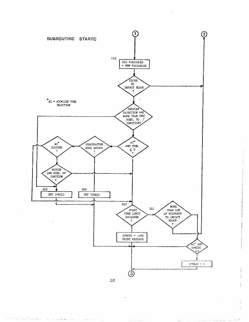
SUBROUTINE STARTC

SUBROUTINE STARTC ,%d-, INITIAL VALVES

S U B R O U T I N E DIESEL
SiT lD INITIAL V A L U S iRO1? STffiTi.
mr=
SET O L m Z W VbP.UBLES JOUT=JOUT+l
MAIN im7P
I!:X-X<:. 1
- w m X A L Y S I S CALL flF (FORCE OK TOP OF Rm) CALL V:.f?M (FDRCE ON TOP OF RAn FOR
VhCUW > > i r n S ) CALL S...? CALL I!,= C W PI=,
P m m m LYALYSIS m R ALL PILE E L ~ N T S
hFST TI!% 8

DIESEL


IIOUT a-,

OUTPUT NOTE RIAT P U T T I N G I!r7/0LVES CALLS 70 SUYROUTINES FPLOT, F%!OVE, FSCHAR, FCHAR AS WJ1. h 5 FSCA1.E. T E E KOUTINFS MY OR WAY b!OT BE AI'ATLIIBLE III THE USER'S FOX3A1: LTPRbRY. m::l?nsIoNs 10 THE STL!IIJ~IID ChLCOI<P SOF7hIIKE hRE IIVAILAB1.E.
I S E C ( I 9 ) I!IIDICATFS CURRDJT 6 4 P T I O N VARIABLE
PLOT AULT VS ==W COUNT
PLOT ST!:UST" \I? i:.:li COl!!iT

5. IJST OF COMNON VARIABLES
Major va r i ab le s used i n WEAF a r e s to red i n COMMON. The
fo l lowing va r i ab le s appear i n order :
I tem No. Name Type Dimension
1 VIM Real 10
D INH
AOH, VOH DOH
ANH, mJH DNH
STH
HM
AM
STA
MA
ESOIL.
AOP, ANP
12 DDP, PNP
Real 10
Real 10
Real 10
Real 10
Real 10
Real 10
Real 10
In t ege r
Real
Real 99
Real 99
35
Descript ion
I n i t i a l ve loc i ty o f hammer components j u s t p r i o r t o impact; loaded i n STARTC, MAIN.
I n i t i a l displacement o f hammer com- ponents; otherwise a s i n VIM.
Acceleration, v e l o c i t y and displace- ment of hammer components a t t h e end of previous t ime increment. Temporarily used i n STARTC, DIESEL, AND AIRS'IPI.
A s i n 3 but f o r cu r ren t time increment.
S t i f f n e s s of hammer segments; loaded i n HAEL and IPTN.
Mass o f hammer segments, otherwise a s i n 5.
Assembly masses; loaded i n HAKL.
Assembly s t i f f n e s s e s ; loaded i n HAEL.
Number of assembly segments.
The s o i l ' s c o e f f i c i e n t of r e s t i t u t i o n , squared; loaded i n IPTN; used in SRESN.
Amelera t ion o f p i l e segments a t end of previozs and a t end of cur rent time
. . iilcreiiien.;, r2 ,,,&L ,... ; .- -,, - .?= d y ; losded 5c
STARTC, PILsAN, DIESFA. and Al?iS'IN.
A s i n 11 but f o r p i l e d i s p l a c e ~ ~ e n t

Itern No. N e Yype Dimension D e s c r i ~ t i o n
13 VOP, VNP Real 99 A s i n 11 but f o r p i l e v e l o c i t i e s .
u STP Real 99 As i n 5 bu t f o r p i l e s t i f f n e s s e s .
1 5 PN Real 99 As i n 6 but f o r p i l e masses.
16 CDP Real 99 P i l e damping parameters; loaded i n IPTN .
17 RES, RESO Real 99 S t a t i c s o i l r e s i s t a n c e f o r end of cu r ren t and end of previous time increment, respec t ive ly . I n i t i a l - i zed i n ASIISTM, DIESEL, SKESN.
18 S J
19 SOK
22 SPLICE
23 DEPIB
211 ARAM
25 ECUS, ECAP, FPT, EANV
26 WALL
Real 99
Real 99
Real 99
Real 99
Real 99
Real
Real
Real
Real
Real
3 6
S o i l damping parameter.
S t a t i c s o i l s t i f f n e s s ; loaded i n IPTN and M A I N .
S o i l quake; loaded i n IPTN.
Ultimate s t a t i c r e s i s t ance . I n i t i a l - i zed i n SOILN: reloaded i n IPTN and MAIN.
Sp l i ce f o r c e o r s lack displacement. Loaded i n IPTN.
Distance between exhaust p o r t s and *
impact block. Loaded in IIAEL.
Cross s e c t i o n a l area of ram (bottom); loaded i n IIAEL.
Coef f i c i en t s of r e s t i t u t i o n (squared) of p i l e cushion, capblock, p i l e t o p and impact block; loaded i n IPTN.
Ram v e l o c i t y a t time o f p o r t c losu re ( d i e s e l ) o r impact ( ~ i r / s t e a m ) . T n a d ~ d i n TJ"!'RI 1 , V"Cl!h!; r"!'.!:.
Volume of comijiisl,ion cl?avber; loaded i n F!Al!X,.

Item No. -- Niinie m e Dimension
28 XPT Real
29 SJJ J Real
30 IBE Real
31 RHO Real
32 DTH, DTP Real
34 JRAT
36 RULT
37 som
38 DSACP
39 FPTO
40 Di
4.1. PCOM
112 TDEZ.
43 IOUT
In tege r
In teger
Real
Real
Real L,
Real
I n t e g e r
Real
Real
I n t e g e r
3 7
Description - Total. p i l e length; loaded i n IPTN.
I g n i t i o n durat ion; loaded i n HAEL o r IPTN.
E l a s t i c modulus a t p i l e top; loaded i n IPTN.
Fass dens i ty a t p i l e t op ; loaded i n IPTN.
Time increments f o r hamner and p i l e , r e spec t ive ly ; loaded i n IPTN.
Number o f p i l e , ram segments, re - spec t ive ly ; loaded i n IPTN and HAEL, r e spec t ive ly .
Rat io o f p i l e t o hammer time incre- ment; loaded i n IPTN.
RULT - ana lys i s counter ; loaded i n IPTN a s t o t a l number of analyses, reloaded i n MAIN as counter.
Ultimate capacity; loaded i n IPTN; re loaded i n MAIN.
S o i l mass; added t o p i l e bottom element; use r e s t r i c t e d .
Rounding displacements f o r impact zones; loaded i n IPTN.
'force a t p i l e t o p a t end of l a s t t ime increment; loaded i n SThRTC, DIESEL, AIRSTM.
Write u n i t number; loaded i n IPTN.
Pressure nu? . t ip l ie r ; 1-oaded i n Ii 'TN.
Combustion delay; loaded i n HAEI,.
Output opt ion; loaded i n IPTN.

Item No. - Name
44 OUT
Type Dimension
Real 3200 Output s torage f o r va r i ab le s vs. time; loaded i n FILL f o r 1 through 5 and FILL2 f o r 6 opt ion; contains va r i ab le s a t increments of 200 loca t ions fo r same time; used i n OUT2 and OUTPUT.
MPP
T r n , TEMO
Real
Real
Combustion exponent; loaded i n XU%.
Gas temperature; i n i t i a l value and value a t end of previous time incre- ment ;. loaded i n STARTC.
In t ege r 13 Contains segment numbers of up t o I3 p i l e segments f o r which output i s des i red ; loaded i n IPTN o r JJNP.
Real Stroke a t beginning of ana lys i s ; loaded i n IPTN and MAIN.
Real
Real
Rebound s t roke; loaded i n UP and MAIN.
Chamber volume a t end of previous time increment; loaded i n STARTC and DIESEL.
PO
DFIN
JDOUT
Real
R e a l
I n t e g e r
A s i n 50 but f o r pressure.
f i n a l s e t ; loaded i n DIESEL, AIRSTM.
Number o f t ime increments which a r e skipped between output va lues minus 1; loaded i n AIRSTM, DIESKL.
J P W
Ex
ICOL
1'' i1b 2.N
I n t e g e r
Real 600
Maximum time counter of va lues s to red in OUT; loaded i n FILL o r FILL2.
S to res extreme va lues obtained i n an a n a l y s i s . Iaaded i n FILL, o r FZLL2.
i n t e g e r P r i n t e r column i n d i c a t o r ( 0 = HO columns, > 0 . . :131 ca:.Lz:J>s). js<><ied f~,.] j.i',it;$*
Real S tores both az.x?&w! i n t e r a c t i o n force and cycle t i n e . h a d e d i n AIXSTM, DIESEL, STARZ'C.

IteinNo. Naxe -- %s...EL~E~&&?
58 TDW[ . Real
59 RESULT Real 100
60 ISMITH
61 ITER
62 ITYPH
63 IPREIG
64 VFALLM
66 DCM.
67 PBAR
AREA
JEX
In teger
In teger
In teger
In teger
Real
Real
Real
Real 20
Real 99
In teger 600
39
E ? u c i m . ~ ~ ~ l ana lys is t ime; loaded i n IPTN.
Contains summary r e s u l t s from a l l analy- s e s ; subscr ip t 1-10 = RULT
11-20 = Blow Count 21-30 = Stroke 31-40 = Min. S t r e s s 41-50 = Max. S t r e s s 51-60 = Blow Rate 61-70 = Fuel Set'ci.ng 71-80 - Bounce Chamber
Pressure 81-100 - Not used;
loaded i n MAIN.
Damping opt ion; Loaded i n IPTN.
I t e r a t i o n counter ; loaded i n IPTN.
Hammer type; loaded i n HAEL.
Pre igni t ion i n d i c a t o r ; loaded i n STARTC.
Veloci ty a t which u p l i f t occurs; loaded i n DOWN.
Stroke a t which u p l i f t occurs; loaded i n DOWN.
Displacement of cy l inde r ; loaded i n DIESEL, UP.
Array containing t h e fol lowing hammer p rope r t i e s i n o rde r : ( f o r va r i ab le descri .pt ion see t h e Use r ' s Manual, Chapter 4 ) ART, DSF, not used, EXPB, VCT, DEPBB, DBBT, RWH, D I N J , STRM, P l , P2, P3 P4, 5 P5, EFFICY, Yass o f ram (k ips sec / f t ) , RWF! ( Air/Stem.), POWSCA, RIIE?; Ioaded i n HAET, and IPTN.
Cross s e c t i o n a l a r e a s of p i l e segrner.ts; loaded i n PIFA.
Time counter va lues corresponding t o EX a r r a y ; loaded i n FILL o r FILL2.


RUN 2 U L L O S 22 JUN 76: .- GOBLE H i134600.8) 14:55:_6_ okEL??&?2N-Z_.
SEQ. XO. 3901649 --- --
AFASG PCF:CFDr1346OO18r -- LENGTH 232. LACWRITTEN 18 JUN 76 AT 14 :02 :2~ - - -
- A CUR CUR OF MARCH 3 , 1976
- TUESOAYt JUNE 22, 1576 AT 1 4 : 5 5 : n
1. L I S T XPTN -. -. .. . ~ .. -. iPTN SYMBOLIC FORTRAN 1 8 JUN 76 14:01:37 7 2 7 6 5 7 2 2 G 5 - 4 6 5 - - - - '
1 -- ~ SUBROUTINE ~- ... .... IPTN (JSELECIISEG~YMAXIALPHITITLEPIOSTR#STRM) . ~. ~. . . ...~ 32 7 6 000004 0 2 COMMON V I N H ~ D I N H ~ A O H ~ V O H ~ D O H ~ A N H , V N H ~ O N H ~ S T H ; H M ~ A R ~ S ~ ~ M A , E S O I L , 1--76---00 0 0 1 h 5 3 1 AOPIP.NPIDOP,DNP,VOP#VNP~STP~PMICDP,RES~RESO~SJ~SOK~QS~SU~ - - -- - - - - - - - - - -. - - - 1 76 000033 0 4
. . . . 2 SPL ICEIDE? IB~ARAMIECUS~ECAPIEPT~EANV,VFALL~ .VCHAM#XPT~SJJJ~ 1 7 6 000046 2
5 ~- 3 E M P ~ R H O ~ D T H r t i T P ~ N , M ~ _ J H A T ! IULTrRULT,SOILM,DSACPr 1 76 00306: 5 6. 3 F P T O P IW r PcOM; TDEL-,'IOUT ~OUTIEXPP~TEMX ; T E M O ~ I N P ; S T ~ ~ ~ K O S S ~ O X N W O , 1 7 6 0 0 0 0 7 3 2- 7 -. 5 ~ D F I N ~ J O O U T ~ J P M A X ~ E X ~ I C O L ~ F I N T M X I TEMAXIRESULT,ISMITHIITER
, I iuPH.;tpdc~t.,."F-A.iiM.;sid~.*icrD22vi~.peAk;~AREi; JE.Xp 1 76 000110 0
8 5 3 7 6 - - - 0 0 0 1 2 3 3- 9 COM~X/SLAK/OPEN(99) 74 76 000134 5
I 0 6 0 0 0
DIMENSION V I N H ~ ~ O ) ~ D I N H ~ ~ O ~ ~ A O H ( ~ O ) ~ V O H ( ~ ~ ~ ~ ~ ~ H ~ ~ ~ ~ ~ A N H ~ ~ ~ ~ ~ 1 11 -. . ~NE_(. ! !?! .DN!!~ LC-! S I H (.10!1!M_!!O_!rV?~!P9?.r..- .. 1 7 6 - 0 ~ 0 1 5 ~ 5 12 2 A O P ( ~ ~ ) : A N P ( ~ ~ ) ~ D O P ( ~ ~ ) , D N P ( ~ ~ ) ~ V O P ~ ~ ~ ) I S T P ~ ~ ~ ) ~ P M I ~ ~ ) I C D P ( ~ ~ ) ~ 1 76 000165 1- 1 3 3 R E S ( ~ ~ ) ~ H E S O ( ~ ~ ) * S ~ ( ~ ~ ) ~ S O K ( ~ ~ ) ~ Q S ~ ~ ~ ) ~ S U ( ~ ~ ) ~ S P L I C E ( ~ ~ ) ~ .... 1 76 000201 -3- 14 i i ~ S A c ~ t 3 ) rOUT(3200), I ~ P 1 1 3 1 rEXibOOY~RESi~TTTaiTTTjER~~O~6) 5 3 ~ 7 6 ~ 0 0 0 2 r r r 5 15 - 1 ~APt~)tXP~20)r~LEllO)~EEI4)~SMITH(2)~VISCOUi2)rDTYP(2) 1 7 6 C O 0 2 27-4- 16 2 ~ A ~ ~ ~ ~ O ~ I S T A ~ ~ ~ ) ~ R P ~ ~ ~ ) ~ E P ~ ~ ~ ) ~ A L P H I ~ ~ ) ~ H N A M E ( ~ ) ~ J S E L E C ( ~ ~ ) ~ 9 7 6 0002'13 0 1 7 3 I S E G ( l S ) ~ P B A O I t A R E A ( 9 9 ) 52 76 000256 4 1 8 C 7 0 7 6 - - 0 0 0 2 6 1 8 -4- 1 9 2 --. INITIALJZE 7 0 7 6 0 0 0 2 6 5 . 5 , 20 C 7 0 76 00027!. 0 2 1 - DATA SMITHeVISCOU /4H SMIt4HTH r 4 K VISt4HCOUS / 1 7 6 000272 1 2 2 1k=6 43 76 ooo9bTC 2 3 ~ ICOL-132 ~. 46 76 000305 3 2 4 IR=5 4 j 7 6 - 0 0 0 3 1 0 ' 0 - - 25 - . .. NHAMR = 100 60 7 6 000311-5- 2 5 pEiE-j;ii- 4 3 7 6 - 0 0 0 3 1 ~ 5 27 N L I M : ~ ~ 43 76 000317 2 28 EL;CYM=IO 4 7 6 0 - 0 - 0 3 2 1 3 - 29 DO 30 I:lv3 43 76 000324 0
- 3 7 3 U - O S A C P ( I T 1 . 0 1 4 3 7 0 0 0 3 2 7 O - 3 1 - . COP(ll=O.O 43 76 000332 4 32 sPi3SETil-=b. E 3 - 7 6 0 0 0 3 3 5 '3- 33 0 0 40 1:2,99 43 7 6 000340 U 34 crnt-rrr== 7 r a FO'3i 3 s - 35 % O CtiP(1):O.O 43 7 6 000547 5
- j 6 - - - -EXPPr ;5 4 3 0 ~ 0 0 0 3 5 3 - 1 - 37 .- TEMIZ25.0 43 76 0 0 0 3 5 5 4 38 SO I LM;O.O l i 3 7 6 6 0 o 360-2- 39 5JJJ:O.O q3 76 000363 0

4 0 DULT-0 .O -~~.--__00_.14b_I=1,19_ 42
" 76 000365 3 1Q6 JSELECIxl=o 27.-.76-000370 0.
-'4 3-- 27 76 000373 2 4q C START TO READ DATA zQ26_000377. 0
~ ~ - ~ E A O - ~ O - P B I N ~ F 70 76 000~00 1 46 C IF NO MORE DATA - QUIT 7o 76__00Oqou~
- Y 7 L - - - 70 76 000411 3 48 1 FORMAT 12014) ~ 0 _ _ 7 6 0 0 0 4 1 6 4 . .
3 9 2 - F - O R M A T - S IOFB.2L____ 1 76 000417 5 50 " FoRMAT (IH1~19X~4'tHW E A P - w ~ v T E ' - ~ C i j - j , ~ ~ ~ y s ~ ~ FOR RLEs// 1 76 000423 4 5 1 - '~~L~&LH_&SOGRAM HAS PREPARED FOR THE FEDERAL HIGHW~Y AOMINISTR
72-76- 000~27 -5- 52 2ATION/22X*38H8y GOflLE 8 ASSOCIATES, CLEVELAND, OHIO//~OX,~OA~J "9 76 OOD_U~_~-~-
-5 3 PEI\D..(. IR?~~ENDE?~Z~,ERR=~O~O) TITcc 71 76 000461 1 5'i GO TO 9877 7076.-000475 1
- 5 2 9 B L 6 - I h..==.l. 0 0 61 76 000504 2 56 RETURN _61.-76-0005~7. 1- 57 -- 9877 C.PN_T-~NUE 61 76 00051~ 4 50 ALPHI1) = 1.0 ~ ~ d 0 0 5 1 0 . 1 -5.9-.~__EDR~lALS 10A41 67 76 000520 1 60 WHITE (IW#41 TITLE 70-76 -000523 3 -61- i- 70 76 0005~7 2 62 C READ OPTIONS AN-ECS. ?0-.76 000533 3 63 C 70 76 00053U 4 64 READ (IR11*END=9876rER~=1020) IOUT*lJJo IHAMRI IOSTR, IFUEL, IpEL,N, 7076__000542 0 65 I 1 S ~ ~ ~ ~ ~ ~ s ~ ~ ~ ~ ~ M * ~ P E R ~ S ~ I ~ ~ ~ ~ ~ r ~ ~ ~ ~ r ~ ~ ~ ~ ~ ~ ~ 1 ~ ~ I ~ I ~ ~ ~ r I D ~ H A 70 76 000543i~- 66 C 70 76 000557 2 67 Cd_HECK_ND./OR CORRECT OPTIONS 70--id- 000573 1
-6s-c 70 76 000574 2 6Y -- II=IAUSIIOUTI '10-76---000602 4 70 ~ ~ ( 9 m . 0 43 76 000603 5 71 IF IIDAHA.EO.01 PM(991 = 2.0 -~ - I F -. .G7-..-..- ~
6nf6bd0b6 ?-'I- 72 -0) PM199) = IDAHA 69 76- 000612 2 73 -. CDPl991 = 0.0 62-76 000620 2 - 7 q- IF (IPERCSeLT.O.01 C D P ~ = 1.0 58 76 000626 4 75 - IPERCS : IADS(1PERCS)
58-76-000632 0
7 6 IF (~EOAM.EQ.O) I8EDAM : 70 76 0006UO 4 77
6476-.~. . . -- IF (1BEDAM.LT.O) IBEDAM = 0 000645 2
iti---- IF iIi.~E.20j-i'i;i1~20- 64 7 6 0 0 0 6 5 3 o 79
IF IF , III.GE.10I Ii;GT,.6)-ibiiT 11-11-10 -b...---- -eo-- 'u3---76 000660 4.- 43 76 000665 3
8: - IF (IFUEL.LT.I.OR.IFUEL,GT.~) IFUELEI 43--?6--0~06~~ -2..~
82 IF (ITEH.EQ.o) IfEkz2 4 l 76 00067h 4
83 8q IF lITER.LT.01 ITER-o - . 60' 7b dbF706-i-
IF-IMAXJRT;LE;O Y ' M A X J R T ~ ~ ~ ~ 60 76 000712 5 85 - IF (IHA~IR.GT NHAMRI WRITE ( 1 ~ 1 3 )
21'---~76~~-000717 3 86- .- . ? ...
IF IIHAMRoLT.01 IHAMR-0 1 76 00072U 5 87 IF (II.EQ.6) IJJ = 0 60-P6-000733 3 88 3 FORMAT l27H UNKNOWN HAMMER TYPE, SORRY)
67 76 000740 3
59 - . . P r : i , K ~ ~ ' ; ~ " ; ? ~ ~ ~ . ~ 2 . ~ t ! ~ ~ ~ ~ ~ ~ ~ 1 76000745-0- 90 '**N WAS N O ~ - S E T ; T X T E R D E ~ ~ U V ~ ~ U T ~ U ~ ~ I E ~ * T ~ 1 76 000755 2 91 -.. IF (N.LE.~.AND.IPEL.GT.O) WRITE ( 1 ~ ~ 1 0 1
25---76--000762' 3
92---- I FTNTLK~XNDXFETG~;U~TOP 67 76 000776 3 93 C
6T--76-001006-2 -'
70 76 Ooloiu 4

94 C EXTENDED PILE INPUT 70 76 001015 5 -. 95 - c 7 0 7 6 0 0 1 0 2 2 3-
95 IF (IPEL.EQ.2) READ (IR,2) (STP(I)*I=l*NI 25 76 001023 4 97 -.~F-.!IPEL~EQ,,?)_FE~~..!I.RI~!-!I'MLL!~~';:!N) 25 76 001033 5- 90 iF (IPEL.GE.1) READ iIRt2) (AiPH(P),I=lrN) 1 76 001043 5 99 - IF (IPELcLT.2) GO TO lQ2 13 76 001054 1 100 9 FORMAT (SOH MASSES AND STIFFNESSES FOR FIRST ELEMENT ARE NOT 21 76 001061 2 1U1 - .. . *?H5PECIUEQ!. 2176_001075. 3- 102 I F (PM(1).LT~lO.E-8.OR.STP(lI.LT.1O.E-8) WR'ITE (IWv91 21 76 001100 5 103 iF-!P!?(1)ILT.lc.E-8.0R.STP(1).LT.10.E-81 STOP 21 76 001113.0- 10" 00 143 I=lrN 13 76 001123 5 105 -. SIP(I)=STPIII*12eO ~- 53 76 001127 0 106 ?M(I)=Pb!(II/32.17 53
~. 76 001133-1-
107 i F_.ISS I . ~ ~ r , L ~ ~ ~ ~ O O ~ ~ . S T p l ~ ) ~ = ~ T P ( 1-1 ) 53 76 001137 1 3 0 8 y - 3 - . i ~ (?M(II.LT.~O.E-8) PM(I)=%4lI=f) 53--76-0011Q6-4- 109 IU2 CONTIN~E_,~-,-, 13 76 001156..2
30 bO0 1:2,99 6 6 7 6 --001161 3~ 111 - 600 ~,F__IFH(11.LT.0.0~1 ALPH(I)=ALPH(I-1) 21 7.6 001164-5- 112 M1=8 1 76 001175 3
2 1 3 "r =?- - 1 76 001177.2- 114 C 7 0 7 6 0 0 1 2 0 1 1 115 ~. c o ~ ! v r ~ ~ _ s x ~ ~ _ ~ r ? t u ~ 70 76 001202 2 116 C 7 0 7 6 0 0 1 2 0 7 1- 117 READ (IRt2) HM(M2l,STH(Ml)*STH(H21 9 76 OQ!2102 115 tiHiMZ)=~MlM2)/~2.17 9 76 001217 2 119 -. . SIH!M?!_=STH!M_L!.?>.? o 1 76001223..4.. 126 STH(M1) = STH(M1:*12. 1 76 001230 2 121 REAq(IRt2) ( E E ( I _ ) - r I = l p 4 ) r T E M A X , B r A t C
7 2 2 5476--001235 0.-
I F , s7Hi M2TXi;I. OT-EE C4T-ri;D 60 76 001244 2 123 ~ DO - 141 1=1,4 1 7!L.-A01?5?-5-
-r2q I ~ E E ( I ~ . L ~ ~ O ~ O O ~ ~ ~ . O R ~ E E ( I ) . G T ~ ~ ~ O ~ El11 = 0.85 .6Y 76 001256 0 125 141.EE.I)=EE(I)**2 1 76001267.4
1 2 6 EANV:EET~T-- 1 76 001273 5 127 ECAPFEL!?) 1 76__001276.~4. 128 EPTZEE(3) 1 76 001301 3 129 - ECUS:EE(4) 1 76 001304 1 -- - . . . .. - .- 13i: C 1 76 001307 0
C NCROSS EQL 0 MEANS UNIFORM A.3i 1 76 001310 1 132 c 7 0 7 6 0 n 1 3 1 6 - 0 - .. -. 1 3 c - SiART PILE INPUT 7 6 0 0 1 3 1 7 _ 1 _ 134 C :&76 001323 2 135 tii4=2 1 76 001324 3
T b X F ' 7 1 ) = 0.0 1 . 7 6 1-326-2- 137 READ (IR.21 X P T ~ A P ( ~ ) ~ E P ( ~ ) ~ R P ( ~ ) ~ S O I L H I T D O R G A I A ~ I B ~ ~ C ~ 69 76 001331 2
7x8- ATE-AP rrr/rvm 3876-00134li-0- 139 T I EP(1) = 29000. 60 76 001350 0 140 .LT.O.l) RP(1) 1492. 66-76-00 1356- *- 141 ENP=EP(L)*144. 13 76 001365 0
- 1 4 2 GO-P(1)./3;170. 13 7 6 0 0 r 3 7 03- 143 IF (NCROSS.LT.~) GO TO 221 - I ; 4 - - 21 76 001374 2 - 1 76~001401-5- 1 5 C . FOR NONUNIFORM P I L E S 7L.6p z-.p ~~
70 76 001403 3 LO R E A D - T ~ R ~ ~ X P ~ I I ~ A P ( I ) P E P ( D ~ R P ( ~ I 1
sG -. - - '0 2

148 IF P I I L T O I EP(.I) = EP(1-11 -1'49 - . IFLSRFII I.tU&LI.RP_LILFR~.U3.~ 60 76 0014220- 150
-- 1 : it1 -6-001'430 5 -
- 1 S l d 2 . . E O R M A L . . ~ 9 8 H B L E - P R R O P E B U E 5 - A . U Q L T 4 ~ OF P-0 WESI 1 76 0014.37 2 152
rIFrtl iF (XP(i-1).LTeXP(I-211 WRITE (IW1121
3??760014Ul..+-
~~L~~XEI.L-UIILL(~U-~ I SOP 37 76 001455 4
154 IF (XP(1-1I.LT.XPTl GO TO 220 37 7 6 2 0 1 1 1 6 5 1
3 5 5 -._GOJO..222 1 76 001473 f 156 221 CONTINUE 1 7 6 0 0 1 5 0 1 . 2 -
-157 1 76 00150s 0
Ap!2].SAf?!lI 158 XP(Z)=XPT 1 7.6__001507_,2- 159 - EP(2)=Em
1 6 7 6 001512 2
160 RP12l=RPIll 1 7 6 0 0 1 5 1 5 A 161 -
1 76 001520 0 ~?CCON_Z/NUE-_
162 C DETERMINE NO. OF ST~TIONS SPECIFIED 1 76-001523.0- -163
70 76 001526 1 o0..21q?_!Fi r?O
16'4 I F \XP1I).GE.XPT-IOE-8l GO TO 2101 1 2 6 0 0 1 5 3 5 U-_ 2 6 5 7IPO QNTINUE
1 76 0015~1 1
166 2101 NN-I 1 76 Q1.5 5
- 16.7 1 76 0015533
. IF_(_I .PELtNE.~ .9 l -GQ~~hQ2 168 Ni=XPT/PELE+i 1 ?6_001556.1- -168 .ILL~~*LEII.!LNENI-
7 7 6 001563 3
170 -
IF (N.GT.NLlM1 NZNLIM 7 76-.Oil1566 5.-
171 C - 1 76 001572 U
172 C DETERMINE PILE SEGMENTS 7 6 0 0 1 5 7 Z 2 173 C : h 6 001600 3 f 74 2107 CALL P I ~ ~ N ~ N ~ X P * A P ~ E P * R P ~ ~ T P ~ M ~ ~ ~ ~ T I ~ ~ 70 76 001605 5
2, e 175
6 0 7 6 0 0 1 6 0 7 - 0 - a- 1 AREA)
176 C 52 76 001622 5 177 c OBTAIN HAMMER DATA 7 0 7 6 0 0 1 6 2 j ~ - i - 178 C 70 70 76 001626 2 179 CALL HAELIIHAMRIOTCRH~OTCRA,HNANEIIRI
7 6 0 0 1 ' 6 3 2 7 -. - - - - . . - - - - 180
40 76 00163'4 0 IF (ABS(TDORGA).GT.IO.E-81 a ~ - T i 6 R ~ A 6 9 7 6 0 0 1 6 4 3 - 5 -
181 -. . STRM = PBAR(101 ie2 c
39 76 001653 3 . . . .-
183 C 70 76 001657-i-
CHECK ON SELF-GENERATED PILE DATA 184 C 70 76 001660 2 185 00 150 I=ltN
70 76 0 0 1 ~ 7 ~
-186 41 76 001670 4
~ F - T s T F ~ T ~ T ; G T . ~ ~ O . ~ ~ A N O . P M ~ ) . G T . W B ~ 3 T ~ b 4 2 7 6 1 0 b 1673-51 187 - ~ .. 7 . FORMAT . - . .- . (5'4H PILE MASSES OR STIFFNESSES TOO SMALLPCHECK INPUT INFO) 41 76 001705 2 A88 W R I T E ~ ~ W ~ ? ) 189
4 1 ~ 6 ~ 0 0 1 ? 2 2 ~ 1 - STOP U1 76 001725 2
190 150 CONTINUE ~ 1 ' 56 o o f l I 7 i 191 C FUEL PRESSURE AND PRESSURE MULTIPLIER FOR DIESELS m 2 70 76 001732 2
PSPEC=P@&R(~O+IFUEL) 7 i i 7 6 a 0 1 7 4 @ - 1 - 193 IF ( P S P E C ~ L T T O D O ~ D A N D D I F U E L ~ ~ T . ~ ~ PSPEC=lOCO.O '41 76 00175@ 4 194 IF (VCHAM.GT.~O.E-B) PCOM~PSPEC/~l4~7*1l~+OEPIB*ARAM/WCHAH~~~l.55) 3 7 7 6 0 0 1 5 6 1 - 4 - 195 NMl-N-1 1 76 0017761 196 Nl=N+l 18 76 197
O o m F - . - IF -- (A.GT.O.1) . - - -.. -. PCOM . = A 17 76 002002 4 195 S O I L M ~ S O I L ~ / ~ ~ . ~ ~ Q ~ 6 0 0 2 0 0 7 - 3 - ' 199 -- I F tAl.GT.1O.E-8) DSACP(lI=AI 41 76 002013 3 200 i F (81.GT.lO.E-81 D ~ P I ~ T z ~ ~ ~ ' 4 1 7 6 0 0 2 0 2 1 3 - 202 IF .(C1.GT.108E-8) DSACP(3)=C1 41 76 002027 5

202 IF (C.GT.O.1) EXPP : C 17 76 002036 0 - 2 03--- A05 C.BLGT,_I/) eE-B)-IDECEE-- 204 C
58-76-002042 5. 70 76 002050 5
R:AU SOIL AND ADDITIONAL HAMMER DATA -?05_ c - 7 0 , 7 6 0 0 2 0 5 2 -0- 236 C 70 76 002061 4 207 RCAD iIR#2~END=9876?ERR=1020) Q ~ ~ I ) , Q S ( N + ~ ) ~ S J ~ ~ ) , S J ( N + ~ ) , R U L T ~ 70 76 002062 ..... 5 208 1 ~SOILISTROKE~EFFICY~PSTEAM,RWT
-- -. 70 76 002076 5
-? 0 S ..SJS=sd!l) 210 SJT=SJ(Ntl)
5576-002105_3_ 55 76 002110 1
- 211 -1 :. iEFF!CY,GI:O:Z)OI)-.PDAR Ll&!~:EFFLCY-.. 49-76-002113.1. 212 i F (RWT.GT.O.O.AND,ITYPH.NE.3) PBARlB)=RWT 50 76 002122 3 - 213 Ii__llTYPH.NE.GO TO 160 49 76 002132 5 214 c 7 T 7 6 ooIi4F1-
FOR A/S HAMMERS OVERRIDE FILE . DATA - 2 1 5 . 2 .. .... .. - 7 0 7 6 0 0 2 1 4 1 . 2 - 2i6 c 70 76 002150 u 217 IF~~jSTROKE~GT!O~OOl)~ PEARI,lUI=STROKE 49 76--002151_5._ 218 1~ ISTHOKE.LT.O.O~) S T R O K E = S T R M " ~ ' - - - - ~ 52-76 002161 1 219 -. if lKkT.GT.O.0) P ~ ~ R _ ! l 8 ~ ~ R W ~ - 50 76 002167'1 220 ic (PSTEAM~GT~PBARII~TT PPTEAM=PBARII~) 4 9-70-n 2 i'7 5 u . - - . . - .
-? 2 I p~- -- l?SlEAM.LT.O. O O l ) ~ ~ P S T E A M = P B A R ~ l ) ~ _ _ ~ - ~ ~ ~ , q9-76--002205 222 C C?Ut?LE ACTING AIR/STEAM STROKE (EQUIVALENT) 70 76 002214 5 223 .i I F r,e,,R(ii,*PBARli7)li (PBAHll11.GT.lO.01 STROKE~PBARl10)*~1~Ot(PSTEAM*PEARll8~l/( ~ 66 76 002225 4
--224 6 6 7 6 0 0 2 2 q l - 3 - 225 - ~~ALL=SQRTISTROKE*64,34*P~AR(16)1 4 9 7 6 2 0 2 2 4 6 . 1 226 hd:iE IIH#l61) STROKE*PBARl16)rVFALL 49 76 002255 0 227 161 - ~ FuR!lAT (~_bH_STF?OK€_(EQUIV.~ tF4.1,QH FT., tllHEFFICIENCY t 49 76 0022642.- 228 1 i5.2t18H , IMPACT VELOCITY vF5.lr5H FT/S 49 76 002300 1
-2 2?--~_~ 49 76 002310 -5-, 230 I i c PEE i n T T ~ i ; i ~ o T w ~ i i P s t ~ ~ ~ R ~ r P B A ~ ( 18 ) , 49 76 002311 4 231 I %'BAR(17) - . ....... - 4 9 7 6 0 5 232 5-1- 232 162 FORMAT (22H A C ~ A L / MAX. PRESSURE tF6.irlH/tF6.lr23H PSI, REACT.& 54 76 002330 2 233 - ~ l ~ b l _ ~ E l ~ ~ T ! . F ~ ~ ~ ~ l ~ / ~ F 6 ~ 1 ~ 5 H KIPS ) $-9 76 0023115_3- 234 00 164 I:21#30 69 76 002354 3 235 - .. 1 6 4 .KFSULI = S T R O K E 69 76 002360 O_ 236 160 C O N T X ~ ~ U E tis-76-002365 o 237 C 70 76 002370 1
7 3 M-T CFTEKV;~~~EULTIMATE C A P A ~ Y 70 BE A N A L ~ E D 70 76 0 0 2 3 i r T 239 ' C -. ....... - 70-76- 002402-0- 240 RULT=E.*RULT 25 76 002403 1 241 .......... . . HMAXzRU'-T. 6 0 7 P - 00211062- 21t2 i F (ESOIL.LT.10.E-4.0RrESOfL.~~O)fSbfi- l .0 50 76 002411 0 243 - ESOIL=ESOIL**2. 7 76 002422 0 244 0 6 - m T 2 t N 64' 7 6 G 0 2 4 2 T F 245 SJ(I)=SJ(l) 1 76 002430 5
- 7 4 6 7 1 4 - 6 5 ( I )=a5 ll)----- 1 7 6 - 0 0 2 4 3 3 5 - 247 C -. 70 76 002437 4 ..
- ~ ~ ~ ~ € - R E A O ~ E X T ~ N D E ~ ~ ~ S D I L ~ ~ ' ~ N P U T ~ 7-6-002440' F 249 C 70 76 002446 2
7 5 0 1 F - ~ T T K ~ . T I T . ' ; T T R E T ~ ~ I R ~ ~ S T ~ , ~ ~ ~ ~ ~ N ~ ~ I 5870-O"6 2VK7-T 251 IF T Y S L T O READ IIK92) , ~ S . J ~ l ~ ~ I ~ l t N l l -25 2..-...-...-.. 25 76 002457 4
. . ( I T ~ ~ ~ ~ T ; > ~ ~ ) ' ~ ~ E A O [ I ~ ~ ~ ~ ~ [ ~ " ~ [ I ) ~ ~ ~ ~ ~ ~ ~ ~ ] ~ ' ~ - - ~ ~ - - - - - 5 6 7 6 ~ 0 0 2 4 b 7 - 5 ' -
2 5 3 ~- IF. (ITE.GE.'?L_GO.TO?!? 58 76 002500 o 254 00 200 1:2#NI 2 S 7 f i o o 2 5 0 5 - 1 - 255 - -. .. IF IOSII).LT.O,OOOl) . Q51i):QS(1-11 25 76 002510 3

h SZIC00 9L 9F (TOOK'HI) 3LIHM 60C -s .TZIFOO.-~L.-.TI o = (1!.235r 2.ro-t-- ~OE
a srrroo 9~ IL ST'T-I ~OOT 00 LOF _T~E1IFOO9LIL 0'0 XVWA.- 99F-
h LOTCOO 9~ 9F cal?Kssi-~~a~rra SOE 2LZLOCOO9L I C %&- l d LN31UjnSNI ti(T51 IVW80i&gT h9.L E L90E00 9L 9C 3flNIlN03 0301 EOF
-ll. h90E009L___9F r@L%Sl~.- OL T E90FOO 9L 9E 11 TO? . . -~-
-~~.~~oEoo-.~LTL ST T=I' ~~s~Qz~Iz~Y~L~o~I~zo~~~IL~~~~~w~~~~sRYI LJI-.--QOC. 0 hEOCOO 9L OL XVWA (0~01=~83~000~=0~3~2~~1~ OY~U (6e19'(l~~~!~8~~) 31 662
~-ocacou~s~ 3nNI~N03 b?~ 862 S 220C00 9L hL (I-I)N3dOt(TlN3dO=(I)N3d0 20F L6Z
-. h LIOSOO9L.-SL N!.Z=!. ZOEOQ 95Z. 2 ITOEOO 9L hL 3nNElN03 OOF 561
_0~000£00 91 hL H! Lo_a_lti--tlbL h 99LZ00 9L 8 1dSI~IzI DOC 00 €62
-L5?LZgoUL 3 262 0 LSLZOO 9L OL 'OjNI b31101d ON1 33IldS OV38 3 162
-5. SSLZOO9L_OL h OSL200 9L ST
062. fCT 01 09 f1'll'ldSI) 31 682
-0LShLZoO9LhL h IhL200 9L 9L
0 '.0?111N3<0.-~-(0=QZ_. 66';-I IOE 00 LUZ
_CSFL?.O.I,dLhL (2'B3Z~hIl~WW11OJ 9 98Z_ S LILZOO 9L 82 (fNlWd*(N)dlS)lHDSr(TN)rS=fKN)PS (I'Ll'HlIWSIl 31 502
_2..PILZOO~L~l< EECE30a=tIlSD (lOOODO'llo~I~S~) 31 S3K K LOLZOO 9L OL '! 8.2-
h FOL2OO 9LOL 3 Fez
s ZOLZOO~~ OL S313%%23H3 3 28;i
3 '182 S 919200 9L 12
TCL9200-9T1Z sns/(11ns=(11ns 082
s L992009L- tlg *zT/( rmm-rn~ 6LT
3flNIlN03 LBT --r-rssaoo 9~ t,9
8LZ ( (I ) wdt (ndlsjr~a-sKi3-rs- r ~.ir~----~-.'-
I 959200 9L hL LLZ
7-9b92009Lh9 3flNIlN03 L8TT 9L2
rns/mffitn )rs=i r )m ( O~;~OTT~$-*~ST-~P--TL~- T 9F9200 9L h9
-77r9ZU'O (N)LVOTJ/(~)~S=(I)~S 101-3.0~~1i~rns) 31 ~LZ
9;! hL LBTT 01 03(0'1i-~sm~ CLZ h 129200 9L h9 - 2-9 T9z 0 0----9L'L i
187 01 09 (TN'Q3'I'H0'0'13'HlIWSI~ 31 th-... ~T=I ...~~ SST~O ~.~
ZLZ f iz-
r ~19200 PL OL - .- 3 OLZ s ~08200 9~ OL 9~ i dw~~a~~T~~~~n81~Tsia~3~9i~ h 909200 9L OL - 3 892 C 209200 9L S2 (TN)nS - SnS : mS C 9LSZOO ?LIZ
L92 - .- 1 TLsZ00--9~ 12
( ~~ns.+~~.=z~'l;ir 992 1N'~:f C81 00 S9T
0 1LSZ00 9L 3 - - '0:snS 0 9SSZ00 9L BS
h92 f~dl~'~f'r1~'ld~'~~i35~ldd1 :5~11) N-IIOS-~~~ ( I-*~$-~~XIIEIT f9z-
s hSS2OO 9L OL s-5200-9~ OL
5 291 33NVl 5r53B 3lOBf8lSIO 3 197
h 965200 9L OL 3 092 -Z-ThSZOO-9L8S 3flNIlN03-OEZ-652-
0 O*SZOO 9L 92 3nNIlNO3 002 -E92SZOO9-'4 esz
~-ITfiSS~TrPON~SA~1117T --iST c LTSZOO 91. sz (T-I~~SZ~II~S (TOOO*O.~.(II~S) 31 9sz

310 1003 CONTINUE 36 76 003131 2 311 C D E ~ E R M I N ~ _PI~,E.QAKP_ING - ~
24-76-003134 -4.. 312 DFAC=FLOATIIBEDAM)/% 24 76 003141 5 31LpRQ-A!iXXZi. tN.-- - ?L76_G30319U... 314 145 CDPLII:DFAC*SORT(PM(I)*5TP(I)) 41 76 003151 5 J L 5 C 70 7 U O 3 1 6 P 2 316 C PRINT IIJPUT INFO 70 76 003162 0 _ 3 1 7 t _ . --- 70 76 003166 1 - 318 CALL O U T ~ N ~ S U ~ S J , Q S ~ ~ T H ~ S T P ~ H M ~ P M ~ I H A M R ~ E E , N ~ M ~ I ~ ~ X P T ~ I S M I T H ~ 1 76 003167 2 319 ~ H ~ A ~ E ~ E S ~ ~ _ L ~ A P ( ~ ) * E M P ~ R H O ~ S P L I C E * C D P ~ A L P H ~ I T Y P H ) 4_B_76-003203 -0.. 320 DO 876 1=1,2 1 76 003214 3 321 -- DTYPII) I VISCOUII) 1 76003217_4- 322 IF (ISMITH.EQ.11 DTYP(X)=SMITH~II 1 76 033224 0
876 CONTINUE -3? 3 . , . . 176--003232-5- 32'4 IF ( I P H I ~ L T ~ ~ O O ~ A N D ~ I T Y P H H L T ~ ~ ) IPHI-140 60 76 003236 1 325 IF-!IPHIpLTo ~OO,?AND.ITYPH.EQ.~) IPHI'60 60- 76 003246 i _
3 2 6 PHI. : FLOAT( IPHI)/IDOF-- 1 76-005256 3 327 PFAC : 1.IPHI 6 0 7 6 0 ? 3 ? 6 3 2 328 8 FORMAT (I~SXI~~HOPTPONS AND SPECIFICATIONS/ 64 76 003266 4 329- i 4H P H I ~ ~ ~ , ~ ~ ~ X , , ~ ~ H _ S - D A M P I N G - ~ ~ , ~ A ~ , U X I ~ ~ R W T (KIPS)#F10.2/ 62 76 003277 4
3 3 0 - ~ - ~ H ~ I O U T ~ ~ ~ ~ ~ X ~ ~ O H P - D A M P I N C ,110t4Xil'iFiSOTL DIST.-NO.,Ib/ 62-76--003313 0-
33k 3 6H IFUEL,I5,4X#6HJ SKIN,F~~.~,~XI~~HTDEL (SEC.),F9.4/ 64 76 003326 1 - J ~ ~ - ~ - ~ H . ~ O S T R ; I ~ ~ ~ x ~ ; F ; H J ~ ' ~ ~ E ' ~ F ~ ~ ; ~ ~ ~ ~ C X ~ I O R T E M A X ~ M S ~ ~ ~ ~ > 64--76003340 5 333 DO 188I:2rN 64 76 003353-1-
-334 IF~SPLICE(I) .GT.O.OI SPLICE(I) = -.SPLICEII) 64 7 6 6 6 3 3 5 6 2 335 IF (A65 (SPL_TFE.!I!.!~CT.~?OIE:B_L.SPU!K!LL~ 1O.E-8 -336p-. 7 3 7 6 0 0 3 3 6 7 . ' 0 -
IF (SPLICEI I I~LT.O.O.AND~SPLICE(I ) .GE~~~) 67 76 003400 2 337 * WRITE (IW~i891 IrSPLICElI) 64 76 003410 4..
- 5 3 8 1 8 9 7 0 i i M A T ( 10H AT-SEGMT ' I .5I 73-76003433 1
339 188 CONTINUE 760034.11?-4_ 390 L ~ V W M A T (?ti SOILMz$F5,2,5H KIPSIBH 05 ~~v=tF5.31 ?'-6 003445 2
34 1 1 8H DS CAPzrF5.3r9H DS PTOP-rF5.3) q3 76 003457 1 . 3112 IS 2 ITYS 67.--76003'*66--2-'
343 IF ~~S..,EQ.lll.-~S = 0 47 76 003471 0 WiiiTE 7 1W;iir P H ~ ; ~ ) ~ W ~ R ( ~ ~ T W ~ E D A ~ ~ ; ~ ~ ~ L ~ S J ~ I B * ~~TTR, 6276--003475.3 - -3qG 1 SJT-TEMAX 62 76 003511 3 345
- ~ ~ ~ ~ ~ H ~ ~ ~ x ~ ~ o H E F F I c I E N C Y I ~ ~ O . ~ J 7 6 7 7 0 b 3 5 i 4 7 - IF I I T Y P H ~ L T , ~ . ; ~ ~ ~ P ~ A ~ ~ ~ ~ ~ _ ) ~ G ~ L O O O O ~ ) WRITE (IWe506) PBAR(16) 76 76 00352U 0 347- --tF'-.15 o~liM*GT
, 0 . .A 1. GT .O.O a o R ~ ; B f ~ T ~ ~ ~ ~ R ~ 1 . 20--76003537 -4- -Ja ~ . ~ T ~ ~ ~ o ! _ ~ ~ ! ! ~ ~ E ~ I W * ~ ~ I SOILM*Alr81*C1 7-'3 76 003551 1.- 349 -- IULT = 0 1 76---003560 5 350 IF 1RULT.GT.lO.E-4) GO TO 502 36 76 003563 2 351
552 IF (AUi;S.LT.O.l GO TO 191 2 T 1 6 0 0 3 5 7 1 - 3 - 70 76 003576 5 353 C
TS~CGEFTERATC~RU~-V~S 7 0 ~ 7 6 0 0 3 6 0 0 ~ 0 --. 70 76 003604 5
3 5 5 2 .~ - RULT : S Q R T T E K P ~ ~ ~ A O ~ ~ * ~ * ~ 38-76-003606 0.-
356 47 76 0036140 357 I : RULTtO.05 + 0.5 -- -- 47 76 003620-2- 358 IF lI.LT.1) I = 1 47 76 003624 -2,- 359 RULT : I * 20:P...
- ~ 6 ~ - ~ - ] ~ ~ ( ~ t ; c p ; i ~ ~ ; 3 6 0 0 b o ( T ; T R i T C I ~ R ~ ~ 6-- 0 0 3630 0 60 76 003637 0 RMAX-RULT*~.~ ..i 76-.003642~.2--- 2 6 L
362 . IULT=lO 21 76 003644 4 363 GO-TO 502

364 191 CONTINUE - 3 b L C -. 1 76 on36~7 2 366 C READ RULT VALUES
----- 70.-76 -.003652 4
-367.-C 70 76 003653 5 368 READ lIHt2) lHESULTlIl~I=1~10)
- 70.--76-..003660 0.
3 6 U a 5 0 D A Z L 14 21 76 003661 1
370 IF (RES1lLT(1liLT.O.001) GO TO 501 2L?6__003667_5_
..371__~59G.-C0NT INUF 70 76 0036i7 5 372 501 COPiTItiUE
70--76 003701%
373-RMAX=PESULTN-11 * G O - . .. 21 76 003705 0
37'4 IULT I 1-1 60-76 003710 1.
375 C 38 76 005714 u 376 C CONVERT FIRST RULT TO KIPS 70760?3717..3- 70 76 003720 u .= 7 7 2 .. - 378 RULT=RESULT(1)*2.0
70-76, -. 003726.3
379 5'4 76 003727 U
- 5 0 2 C O N INK 380 IF .lITYF'H.NE.II GO TO 505
21__76._-.003753 5.
2 81 DEEBCLEIIIIPliErDEeIB '42 76 003737 0 1
382 IF (DFFhLL.GT.O.0011 GO TO 106 Z h 0 0 3 Z q i t l - ~ ~ . ~ . - L ~ ~ O K E . . E P R Y . & C C _ U U N I ~ A W ~
1 76 003750 Y
384 STROKE = 5. 70--16--003757 0 1 76 003764 4
- 3 8 5 _ _ _ _ I F - ~ P B A R . ~ 2 . 0 J . r G J _ r 1 0 . ~ E E r ~ ~ ~ 0 386 DCYL Z0.0
58---76..- 003767 4..
387 -. DFFALL = STROG-DFPU 58 76 003776 4
388 i06 CONTINUE 1 7 6 _ _ @ 0 4 00 1._2,.
e 1 76 OOY006 0
03 - 3 8 ? - ! i L 390 C DETERMIllE RAM VELOCITY AT PORTS 70 76 .00*0ll 2. 391 C
70 76 004012 3
-3 2-- - - - - . - - . . - - -. - IF (OFF ALL~GT. O ~ F ~ ~ K T K K ~ G W F ~ 70 76 004021 2
393 9-16-004022 3 .
- IF (PSAR(ZO)~GT.~O.E-~) CALL VACHAMIPBAR,ARAMPDEPIB~DCYL,STROKE, 58 76 004033 0 394 1 FSUCK,VFALL,IOUTILWI 5 876-0 0 4 0 4 7-1- 295?!?XCONT!EIUE_-__ 396 C
50 76 OoW5U 0 SOIL STIFFNESS 70--~76---004057"1-
397 -. . oo.2 lS -E iLN! . SU(II=SU(I)*RULT
15 76 OOU063 0 398 -1-76-004066 2 ~
399 - SOK(11 SUIII / QSfII 4 U U 1.15 CGXI~UE 1 1 76 00Wi2 1 4Ui C
7 r o r i 4 - 0 773- CHECK .~ TiME INCREMENT INCLUDING SOIL STIFFNESS 70 76 004l02 2
q02 RRhT : H M A X / R U C T - - ~ -%0--?6---004113..3- 403 IF. ( E P ! ~Y?:.GT~OLS_!._R_RP_LL. 1 40q
-61-76-0041117 2- SiCR 2 STP(N)+SOKIN)+SOKIN1)
'405 DTCRP = PM(NlI1STCRfRRAT) 62 76 00U25 2
-- '106 .
62 76 0041332 IF (CUPL99).GT.O.5) D ~ P ~ P M I N ~ / ( S T P L N I + + O K I N ) + ( R M ~ T I / Q S I N ~ ) I 6 1 r G a h Q i 4 T i ' T i
407 . .. NMlZN-1 00-i 0 i O~f =ixi;il
60 76 004155 1 908 6 0 1 6 0 0 4 1 5 7 3-
ST Z STP11+11 +09 60 76 004163 1 410 IF ISTPII).GT.ST) ST=STPIII 6076--004166 '3- 4il - ST=ST+SOK(II*RRAT 60 76 004174 1 "2 DTM=PM(II/ST 6 6 - 7 6 O O G 0 T S -
IF 1DTM.LT.DTCRP) DTCRP-DTM -'?!? 60 76 00~203 2 414 6010 CONTINUE 6076---004211~~0-~ 415 DiCRP=SQRTIDTCRPl 60 76 004214 2 416 C CUSHION DAMPER 70--76--0042202- 417 PMI991 = PMl991*SQRTlSTH(M~*HM(Ml1/50.0 69 76 00422% 1

4 1 8 c DETERMINE TIME INCREMENTS FOR HAMMER AND PILE GTR CRIT ICAL -- 4 i 9 ... DiP=PFACtD.TCRP 1 7 6 004234 0 420 DiH=PFAC*DTCRH
1 7 6 0 0 4 2 4 7 3 _ Y Z L C G Y E F K - I S M E - I N C R E M E N T S
1 7 6 004253 0
4 2 2 I F (DTH.LT.1O.E-6.0R.DTP.LT.lO.E-6) WRITE ( I W t 1 1 9 ) 7 0 7 6 - 0 0 4 2 5 6 - 3 ~ - 4 2 3
5 5 7 6 004263 3 I F (P~<. lO.E-6 .OH.DTP,LT~lO~E-6) STOP
4 2 4 1 1 9 F ~ ~ ~ M A T (47H HAMMER OR P I L E T.1. EQUAL TO ZERO* CHECK INPUT 1 5 5 5 5 7 6 7 6 OOLi_2_/52 004305 1 2 5 l i~DT_CRA: lLLDr_FRH) DTH=PFAC*DTCRA
4 2 6 I F (DTH.GT.DTP) GO TO 3 3 1 76.-004321_2-
4 2 7 o?-1 is_A!?P!5Lfi-- 4 1 7 6 004330 2 4 2 8 IF ( F L O A T ( J R A T + I ) * D T H . G T . D ~ W T O 117 !!-. 7 6 004335 3 4 2 9 1 1 8 CUNTINUE
4 1 76'--004341 2 -
4 3 0 C 4 1 7 6 0 0 4 3 5 1 . 1
4 3 1 C 7 0 7 6 004354 2
GETERMINE TIME INCREMENTS IF HAMMER INCREMENTS SMALLER THAN PILE 4 3 2 C 7 :I:.--
7 0 7 6 0 0 4 3 5 5 3
4 3 3 C ? 0 7 6 0 0 4 3 7 2 -0 - 434 l l ~ 7 ~ ~ ~ . ~ f ~ ~ ~ ~ . L T . 1) MAXJRTEl
7 0 7 6 - 0 0 4 3 7 r 1.- 4 1 7 6 004375 2
4 3 5 IFL.ljRAT.GT.MAXJRT) JRATsMAXJRT 4 3 6
4 1 7 6 004403 3 DTP=DTH*FLOATIJRAT) 4 1 7 6 004412 0
4 3 7 -. . GO TO 2 2 '+36 ~~-DTHZDTP-
4 1 7 6 004416 2 , . 4 1 76--004420 5
4 3 9 -. JRATZl 4 4 0 2 2 CUNTXF~UE 4 I-
7 6 004423 4 4 1 7 6 0 0 4 4 2 5 5 -
4 4 1 2 1 F ~ R M A T ( 1 5 ~ t l S t i T i M E XKCR. (M5)9F5.3) 6 2 7 6 00_0~30-5- 4 4 2 DTPM:DTP*1000. 1 f b 004440 5 4 4 3 C -- 7 0 76-0044442.- 444 C S ~ T - - U P LOADING STIFFNESSES 7 0 7 6 004445 3 4 4 5 C 7 0 7 6 004453 2
7 4 6 iF--lI'TYPH.EQ;3TSTKTMVgATMl I *ECUS 5 C 7 6 - 0 0 4 4 5 4 3- 4 4 7 -. I l = - ! x H r L T . 3 ) STHIMl I=STH(Ml)*ECAP 5 4 7 6 004463 5 4 l i8
- -. . - . . . - - i c ( M A . G ~ . o ) STA(MA)=STA(MA)*ECAP 5 4 7 6 0 0 4 4 7 3 1
4 4 9 -. .~ - sTH'IMZ) : STHIME)*ECUS F ( i ~y-s-iP-li ,*EP- 1 7 6 004502 0 450 1 7 6 0 0 4 5 0 6 ~ ' 5 - 4 5 1 I T H ( M ) I STHIMl*EANV 1 7 6 OOU513 1
7 5 2 4 i < I T E - ' ~ f f W T 2 1 ? - D T P M 62-6111004517 4' 4 5 3 STHOKO : STROKE 1 7 6 004523 5
-454 C s ~ T u F E ( J I m i l ~ t 5 1 I I 1 b o q 5 2 n 4 5 5 I F (IJJ.EQ.1) READ (1R~l,END=1005tERR=1020) ( I N P ( I ) r I = l t l S ) 7 0 7 6 004534 5
- 4 5 6 - -GO' T O - 1 0 0 6 - 56/6--004550-1~~ 457- - 1 0 0 5 I~d:0 mG&... ~ coNT I R.o.i.-- 3 6 7 6 00'4553 0 4 5 8 3 6 7 6 - 0 0 4 5 5 5 - 5 4 5 9 I F I IJJ.NE.11 CALL JJNP (ICOLVNIINPIJMAX) 11 7 6 004561 1 4 6 0 c ... JMAX-NO. OF PILE W R T ~ B C E S THAT IJMAX.L~.NI n. I b o o 4 5 7 n - U 6 1 C NOT USED HERE, RECOMPUTED - I N ANALYSIS 11 7 6 004605 3
7 6 2 RiTURN- 1 1 6 0 0 4 6 1 5 2 - 263.- 1 0 2 0 CSNTINUE
7 0 7 6 004617 3
4 6 4 ~ O Z I ~ ~ F O R M A ~ ~ A T A ~ R R O ~ l 0 7 6 0 0 ~ 2 2 ~ 5- 4 6 5 k x I T E ( IW110211 7 0 7 6 004630 5 4 6 6 STOP m 7 6 T O - 9 5 3 T - T $ 6 7 -~ -. ! hg- 1 7 6 - 0 0 4 6 3 6 . -. 2 . .mo CRU

plEL---..-- ----..-.-----.SIM~OLIC_EPBTRAN-__OZ_JUN~~~-~~~.~_~~_~~-~.~ 24 5 00-12%5~6 522 ,__
1 SUBROUTINE PIEL ~ M P ~ N ~ X P ~ A P * E P ~ R P ~ S T P ~ P M ~ A L P H ~ I O U ~ ~ I W W I C ~ ~ , ~ ~ E L I A E E B L 16 24 00?!0o~o~
3 DIMENSION X P ( ~ ~ ~ * A P ( ~ ~ ) * E P ( ~ ~ ~ ~ R P ~ ~ O ) ~ S T P ~ ~ ~ ~ + P M ( ~ ~ ) ~ A L ~ ~ ( ~ ~ ] 14 24 0 099.171- - L t A r A R E A 1 9 9 ) 1 24 000022 3
5 SALPtI=O. 0 l ~ 2 ~ - 0 0 0 0 3 6 1. -6--.__D0_101_11~11N 1 24 .000046 2
7 101 SALPH=SALPHtALPHlIl) 12U-00005l.O. --B_S 1 24 000051; 2
9 C ELEMENT COUNTER 12, CROSS SECTION INOEX 13 1 8 _ _ 2 4 O C 0 0 6 13-
-A e c 18 21; 000062 11 11 IF lIPEL.EQ.21 GO TO 108 l e ? ~ _ 0 0 0 0 7 3 _ 2 _
- 1 2 _ ? 2 E 1 24 24 000074 3 13 13=2
1 24 000101 4
1 11 - IJ=I~-I i i ~ - - o 00 I 03--3-' 15 XT=O.O I 2".o!?10~~
-16_XU=LX_P'P>ALPH (121 1 /SALPH 1 211 000107 4 17 DX : XB
1 24 OOOlli 5
- A * - - ~ ~ . = ~ P L I I- 22 24 000117-3- 19 RPTZRP 1 I I 1??_000121_11- 20 EPTZEP(1 I 7 24 0001211 1
w 21 GO TO 110 7 24 000126 5 0 - 2 2 2 1 24 000131 3
23 C REPERT RE LOOP FOR EVERY SEGMENT I2 18_2U 00013Q -1- 24 C 18 211-000135 2 25 102 XTZXB 24 000145 0 26
?a_. DX = (XP(MP)*ALPH(I2ll/SALPH 1 24~0001116~1-
2 7 XB = XT + DX - 2 8 - 1_?-SJP!.!?L?l_O:E12
l'? 24
29 PM(I2l:O.O 21 24 000166 3. -3 0- AREAlI2l=O.O 1 2*-000172-5- 31 C
?! 24 ,0001751;
3 C REPEAT 103 LOOP UNTIL NEXT CROSS SECTION DEPTH 15 BELOW SEGMENT -- 18 24 000200~5-
33 C '8 24 O O ~ < O ~ O -
-3Q__. 103-1F-(.XB:.LT~_X_PlI3) I GO TO 107 18 24 000216 2 35 X1:XPl 131-XT
1 24 000217 3
-36__. XT=XP! I31 1 2 4 0 0 0 2 2 6 - - 0 ' -
37 AAO=(ATtAP11311/2. 1 24 000231 1
38 AT=APII3*11 152(i000233--T 1 2% 000240 0


93 If (ICOL.EQ.132) MAX-13 -9 Y _IqZl.-_- 1 24 000615 1
95 ISzMAX 6 2 4 0 0 0 6 2 2 . L
-.96 I F . (15.GT.MP) IS=MP_ 1 24 000624 0
9 7 116 WRITE IIW,112) (XPlIj,X=1@~15) 6-24-000626..1~.
S - I ~ X L T W U A P U I ~ I - - 1-1 1 Z1l 000632 3
99 '*RITE (lW11I4) (EP(I)lI=14rI5) 1 2Y_S00641 3
-1 0 0 .--WRITLIlW c1151L(RPILLLL=&IS 1 24 000647 5 101 IF 1SS.GEoMP) GO TO 117 1 2 Y O 0 0 6 5 6 _ 1 - -
-102 14515f.i- 6 24 000664 3 103 IS=I4+MAX
62'?_000671 3
--lo- i L U _ Z . G U P ) L5-MP - 6 24 000673 5
105 GO TO 116 6 2 4 0 4 0 6 7 6 3 -i0611.CONTXNUE
1 24 000702 5
107 IF (IPEL.NE.2) RETURN !624_000705.~33-
-108-t__ 15 24 000710 5
109 C DETERMINE AVERAGE AREAS FOR THE CASE WHERE NASSES AND 1 8 2 Y 0 0 0 7 1 5 . 3 ~
I - S m - 18 24 000716 4
111 C I R Z L . . - . O ~ O Z J ~
21- DL-=...QILI 18 24 000736 2
113 DO 145 1rltij 1 5 2 4 0 0 0 7 3 7
-lllL . DO..l46 J:2, MI?--- 15 24 000742 0
115 IF LXP(JIeGT.DL) GO TO 147 23-24-000750.3 ~ ! ! L C O n ? U C I V F 15 24 000753 5 117 lq7 AREA(I)=AP(J-1)
~ ~ ~ Q O . O ! 6 1 7
-4.18--?35- 9L .:_GC+ALPHLI.L.?XPLMEr54LLP~ 15 24 000764 4 C i w 119 RETURN 2_"_"24--000776-3--
4 37 000230 2
17 C 1 3 7 0 0 0 2 3 3 -2-
IcilM -., MAX NO9 OF VALUES OF ONE VARIABLE IN OUTPUT, 10 C ULIM*lS=DIM(OUT)
1 37 000236 1 13'f-000250-4-
19 U P T = 1.-l./EXPp 2 0
1 37 000254 5 CDH :: PMlY91
C 30 5 7 0 6 D 2 6 3 7
- 2 4 22 c SET UP OUIPUT VARIABLES
35 37 000264 0 35-37000265-1-
- 23 ~. C - 35 37 000272 3 24 IIOUT = IABS(IOUT1 ~~~~~~~~~~~7 25 IF (IIOUT.GE.20) IIOUT=IIOUT-20 10 37 000303 3

26 IF (IIOUT.GE.10) IIOUT=IIOUT-10 10 37 000312 0 -27 SCS-1.D.rO 34-37-,000320 3-,- _ 28 iAI = 0.0 34 37 000323 1
-29 4WTO 10_57000325 -5- 30 dDOUT = 6.0*XPT/(SQRTlEMP/RHO)*DTP) 1 37 000330 0
J 2 Q L L T > [ L e U _ U I I ) 9 1 37 QOgS 3.7-1- 32 TUD FLOAT(JDOUT)*DTP*lOOO. 1 37 000343 3
- J L ! E - ! . T J D ~ . G I ~ D . S . L J D O U T 3 0 . OMS/DTP) + 0.5 L 3 7 _ 0 0 0 3 5 1 - 3 . ~ 34 IF (JDOUT.LT1l) JU0UT:I 1 37 000361 5
-35 I F_L~TIPUG.EO *$ l-JDQULSdR_OKTLLl 5 _ 3 7 0 0 0 3 6 6 . . 5 ~ 36 C 3MAX ... NUMBER OF OUTPUT TIME TO ANALYSIS PILE TIME INCREMENT 1 37 000375 4 37 J M C 6 1 37 000411 5 38 IF (ICOL.GT.01 JMAX-13 1 37 000414 2 39 - i F__!JklnX~GL,tjl-iMp_Xf N 1 3 7 . - 0 0 0 4 2 1 . 1 ~ 40 C JWAX NUMBER OF PILE VARIABLES PRINTED (DEPENDENT ON FORM 1 37 000425 5 41 C -. s.6' 1 37 0004Ul li 42 C 3 ~ ~ 3 7 0 0 0444 -0- 43 c II~ITIALIZE 35 37 000%45 1 44 C 35 37 000450 2 45 -~ -. FINTMX=O.5 . . . .. . . - - . - 7 37 000451 3.- 46 i s : 0.0005 9 37 000454 2 4 7 IF (PDAR(_9I2~T.OL~LS = SJJJ 33-37000457 2 -- 48 ! F ~ ~ ~ ( P ~ ~ R ~ Y ) . G T . O . O . A N D ~ ~ % L Y . ~ O . E - ~ ) rr = 0 ~ 0 1 33 37 000465 3 49 i4EQ-0.90 8 37 0404/b 3 5 3 IF (EMP.LT.3000000.) RED = 0.0 14 37 000501 0 51 Kl0_ - . . . . 1 37-000507-?- 52 Nl=Ntl 1 37 000511 1 ; 53 - .. ?!Ml=N.-L, 1 37 0005132__ 5 11 FTPO = FPTO 1 37 000515 4 55 . .- FTIT .- = FPTO 1 37 000520 4 5 6 FTPOA ZFTPO 1 37 000523 4 57 -~ r i r M..F-o_,o 31-37-000526..4.~. 58 FANVOA = 0.0 1 37 000531 3 59 - FCUOA ~. = VO 20 37 000534.4- 60 'VNPIT = VOPtNI 1 37 000537 3 6 1 Y,NHIT = VINHIM) 1 37 000543 0 62 vo = VCIIAM + (DINH(M+~)-DINHIM))*ARAM i 37 o oo 5 m- 63 1 lMP_:0._0 3 7 0 0 0 5 5 6 1 64 1T:O.O 7 000561 0 65 -- T1r:O .o_- 7 37 000563 1 66 ' T ~ L O W : -T;O 9-37000565 -2- 67 HeP = 1. 1 37 000570 3 68 RIDEL -1.. 1' 3-00573-1- 69 PCOMR = PCOM 1 37 000576 0 7 0 I F - ( P 6 A R I I 9 ' G G T ~ O X ~ ~ O T ~ O l 7 2 7 7 0 0 0 6 0 1 - r-p 71 . PCOMF = O . ~ * ( , S T R O K O ~ D E P I B ) / O E P I ~ 1 37 000607 3 72 C ~ R E D U C T I O N ~ ~ U E TO POOR SCAVENGING 1 ~ 3 7 0 0 0 6 1 6 I-- 73 - IF (PCOMF.GT.1.0) PCOMF = 1.0 1 37 000625 1 74 IF (PCOMF,LT.O.51 PCOMF = 0.5 5 5-0 0 633-2-
75 - PCOM=~.O+(PCOM-l.O)*PCOMF 22 37 000641 3
76 COT CGNT~NUE i r i 3 7 0 0 0 6 4 d 5 ' - 77 -. PCOM!TC_OM 17-57 000652 0- 78 IF IRSTZO 1 3 7 0 6 0 6 5 q - 5 79 IHEM = 0 1 37 000657 2

6 0 VIPMAX Z 0.0 - 61 DNPMAX. L0.R
9 37 000661 5
82 MMI-M-1 .-d--.37--000655 0 -83 Ml=Mtl._-
1 37 000670 1
8'i 137-000672 .3
M2ZMt2 1 37 000674 4 - 5 L - G G 3 2 d 2 86
1 3uoes76..s- EI4THRU = 0.0 1 37 000701 1
-87 F M A L = . . O . U 88 T2LC = 2000~*XPT*5QRTlRHC/EMP~ 1 3 7 0 0 0 7 0 4 2.
1 37 000707 1 -89 C.____LI_MIL_OF-MAlN.LO0P. 9 0
3%-37000740 0. NT = O,005*TZLC/DTP
4 1 J C X 9 . T - 1 - 37 00074U 3 92
29 37 000750-5- IF (FLOAT(NT)*DTPeLT,O.050) NT : 0.050/DTP 3 5 37 0007h3 4
-93 _IE...(.SEMAX~G.L~~.~.~L~KTKT3.'IEMAX/(.lQ_O.PPt.O9?D5E~ 8 94 C
.--37-00077u C 35 37 001003 5
-85 C . L O P D I N G ~ P F ? ~ : R E D ~ ~ N D ~ ~ I ~ ~ . E ~ S ~ ~ R , PILE TOPIAIIVIL~ AN0 CAPBC~_C_K 95 C 35-57
001005 0. 35 37 001021 3
-91 SIETL3-5 1&\14USIP 11 ) f ( S I l i i M Z L ? S I P ( 1) ) X QO102LL 9a
1 STPT2 = ISTHIM~)/ECUS)*(STP(~)/EPT)/~~STH(M~)/ECU~)+STP(~)/E~T) 1 37 001032 3
-99-STAL ._:_.STHlMI.L 100 SThR = STAL/EANV 137_001046 3-
1 37 001051 5 _ 1 0 1 _ _ _ _ S T C L .=...STH IM11.L 102 STCR ,= STCL/ECAP 1 3 7 . 0 0 1 0 5 5 . 4 _
-~J.UAMEBYAWLE~ TO IUUFS 1 37 001061 1 104 DO 100 121vM2
35 5 7 0 1 0 6 5 _ D - 1 37 001074 2
A.O?VOt!!I.!?VIEiHII! 106 DOHlI)=DINH(I)
1 37 001077.4.-. 18 37 001103 1
. 107__VPA~~.I!.?ViNHL!) 108
1 37 001106 4 DOAHII1:DINH(II
109 . PELAHIII .- = 0.0 137-0011 12-2..
110 AOAHII)=G 1 37 40_?l!h-O- 1 37 001121 3
A ~.?:IO_Q_CONTINUE.- 112 C
1 37 O O l l 2 4 _ 1 ~ ~ CONVERGENCE CRITERIA 3537-001127 3
-i 13____ . E~SV.%O;.P2 Ll*
1 37 001134 .2- EPSF = 1.0
115 DO 97 i:lrNl T i - 0 0 1 1 3 7 2
.- 116 97 AOP(1)-G
1 37 001!42& 1 37 001145 2
-117 DQ. 45!..1~r%oo L i t 3 450 OUTlI)=O.U .
26 37 001150-5-
C 1 37 00115U 3
-!1?-_- . E X T R E M U M _ I R R U 120 DO 460 J:1,6
35 37 001160 0
121 DO 460 I=l,N i57-001163 5. 1 37 001167 0 -
122 IJ=N*(J-1)+1 1 37 ooi.f.j EXIIJ) = 0.0 2 2 3 - .. JEX(IJ~--C 0
1 37 001175 2 12'* ~~-~~--ooLzoo 3 ~ - 125- - ?LCOEITJN_UE ' 29-37 001203 3 126 ACYL = G i9 3 7 ~ 0 0 1 2 0 6 ~ 5 - 127 PtiR = 0.144*14.7*PBAR(l) 19 37 001211 2 126 IF IPBARll).LT.lO.E-8) PER = 2.117*ARAM 27 37 001216131
_li9--~- OELP. = 0.O . . . . 27 37 00122h 2 130 IF (PBAK(~).ET.ARAM) OELP = 2s117*(~B~fTITL&%iR) 2T37--001231-1~- 131 -- IF (PBAR(ZO),GT.O.O) ~~ PER = 0.0 26 37 001242 3 132 C CYLSNDER VARIABLES 35---37-001250 5 - 133 - CYLMZPBAR(8) /G 23 37 001255 2

1 3 4 DCYL = DOHIM11 1 9 3 7 001260 5 1 3 5 v,C!L ..=-~.w(Ml)L-- 1 9 3 7 0 0 1 2 6 4 . 2 - 1 3 6 C I G N I T I O N VARIABLES 3 5 3 7 001267 5
1 3 7 TSLOW ..=.lqO 16-37-001274 2 - 1 3 8 TSA=loO/PCOM 17 3 7 001277 2 1 3 9 ZSil=.!l,O-TSAl/TS 17 3 7 OQ?X._ 1 4 6 C CONiACT AREA VARIABLES 3 5 3 7 001306 2
L A F A = l3.zElNTMXlL2.~- 7 3 7 - 0 0 1 3 1 3 _ 3 - 1 4 2 AFB=li~-FINTMXl/I2~*DSACP(1)) 7 3 7 001317 4 1 4 5 -. . ~ E X ? ~&1,35 5 37__001325.,.5._ 1 4 4 I F (IOUT.LT.01 WRITE (IW,653: 1 3 7 001330 4 1 4 5 C -. 2 9 3 7 - 0 . g j 3 h ~ 1 6 C S % X ~ MAIN LOOP 2 9 3 7 001340 0
1 1 1 7 C .- . . . . . .. .. .- 29 3 7 0013qY-0- 1 4 8 G . 7 0 0 J z l s N T 1 3 7 001345 1 1 4 9 _ _ _ ~ t ( J . G T ~ J C I ( I - _ J C K = ~ I . - - 2 6 3 7 - . 0 0 1 3 5 0 ~ 3_, 1 5 0 I F ( V 1 P M A X . L T ~ V N P l l ) I VlPMAX Z VNPIP) 9 3 7 001355 0 1 5 1 Ii!flE&T.O.Ol) GO TO 1 0 3 9 3 7 0.01364 3 1 5 2 I F ( V P ~ P I L ~ . G T . O ~ ~ * V ~ P M A X X O R R V I P M A X X L T . ~ . O ~ GO TO 1 0 3 1 7 3 7 0 0 1 3 7 2 0 1 5 3 -. . S T f ? i c L Z ~ . R E e 19-37 OOl40Y 0- , . 154 . R t D z 0.0 . 9 . 3 7 - - ~ 0 ~ 1 4 1 0 2 155 -. . - ~O~_CO: ;TENUS .. -- a 3 7 - 0 ~ 1 ~ % 3 0.- 156 DPGS 2 DOHCMI-DCYL 20-37 0 0 1 9 1 6 - 1 1 5 7 C FORCE ON TOP OF RAM FOR REGULAR CLOSED END OR VAC HAMMER 3 5 3 7 O C ! 4 2 3 2 1 5 8 PTH = FTRlDPOS,PBAR,IWTl 19 3 7 001435 3 1 5 9 -~ = :!XH[MI---.- 26-37_001442 -4.- 1 6 0 I F IPUARl20).GT.O.O1 CALL VACHAMIPBAR,ARAM,DEPIB,DCYL,DBC#PTRI 2 6 3 7 001446 0
I
1 6 1 . 1 V F W ! toU!! I!! 2 6 3 7 . 0 0 1 4 6 1 5 - 1 6 2 I F l P t ~ A R ~ 8 ~ ~ G T ~ O . O ~ A C Y L = G ~ ( P ~ R - P ? R ~ / C Y L M 2 3 3 7 001465 4 1 6 3 I ~ , ~ ? ~ A _ H ( 2 0 l ~ G T ~ O ~ 0 1 P T R E P T R ~ A R A M * ~ . ~ ~ ~ 2 7 3 7 0 0 1 4 7 5 5 16Q I F lPL3ARI2O).LT~1O.E-81 PTR = PTR-DELP 2 7 3 7 001505 4 1 6 5 --- ~ ~ ~ ~ . . ; . . o c Y L _ + _ v c Y L . L P T P 19 3 7 001515_2. L 6 6 YCYL = VCYL t ACYL * DTP 1 9 3 7 001522 3 1 6 7 -. . . - I F (DCYL~GT:DOH!M~) lVSYL-=VOH!M1.1. 1 9 3 7 - . 0 0 1 5 2 7 . 4 . 1 6 8 iF (OCYL.GT.OOiiIM1)) DCYL = DOHIM11 1 9 3 7 001536 5 1 6 9 - TT.=T.T+DTP*1000.0 7 3 7 001546 0 1 7 0 C TIME COUNTER IMILLISEC.) 3 5 3 7 001551 5
-1.7 1 . 2 - TI!- iEAFTEH. IMPPFT !TIMPI 3 5 3 7 0 0 1 5 6 1 -0.. 1 7 2 C R l i P : 0.0 MEANS FIRST IMPACT HASS OCCURED 3 5 3 7 001566 3
.l??. .IF ( !??MP.GLO15~TI:<P; ~ D o H ~ M ~ ~ D O H I M ~ I ) / V w l _17-37--PO1577 ..I. 1 7 4 I F IRIMP.LT.0.51 TIMP=TIb?P+DTP 1 7 3 7 001610 0 175 - T_l:'r.itDTP* l l~O-PCOM/PCOM_~~I 1 7 37-00161.6-2 1 7 6 C iGi .11TioN START FOR ATOMIZED FUEL 5 2 7 7 003623 5 1 7 7 I F I P b A R 1 9 ) . G T . 0 e O ~ A N D ~ R I M P ~ L T ~ O ~ 5 ~ RIDEL 0.0 3 2 3 7 001632 5
- r 7 8-- I F 1 T ~ M P ~ C E ~ ~ T O E L ~ A N D ~ I P R E I G . E ~ ~ O ~ T R I D E L I - = T T 1 6 - 3 7 - 0 0 1 6 4 4 ' 0 ~
1 7 9 . iF IJ.GT.O.AND.J.EO.IPREIG1 RIDEL = 0.0 1 6 3 7 001654 5
1 8 0 I F l R I'SE~;~?;~~;S;OR;~COM~L~;~;DIGOTO~~~ 7 3 7 1 0 0 1 6 6 1 i 4 - 1 8 1 TLMO:TEMO*PCOM ~~.. .. - 7 3 7 001675 1
1 6 2 PO:POaPCOM 7 3- 6 T 7 d b V -
1 6 3 EX;'. E r ~ p p 5 3 7 001703-3- 1 8 4 PCaM = 0.0 5 3 7 - 0 0 1 7 0 6 2 185 4 7 L C O ' I T INUE_--.- 5 3 7 0 0 1 7 1 1 I
1 8 6 IF lTT.LT.50.1 GO ~ml 9 3 7 - 0 0 1 7 1 < ~ ' 3 - 187 I F IODC.LT.i2.*DEPIB) GO TO 4 7 1 9 3 7 0 0 1 7 2 1 4


2 4 2 PE : PN*TSLOW ~ * L A E A C . . Z - ~ . . Q-
5 3 7 002300 4 5
2 4 4 I F (DDIS.LT.-DSACP(1)) AFAC=AFA+RFB*DDIS 3 7 _ 9 0 2 3 O L O - - Z * L . i E . _ l DDIS..LIc$.+I1SAtPI& - - 7 3 7 002306 5
2 4 6 FP = PE*ARAM*AFAC ? 0 0 2 3 1 6 _ 5 _ 2 U ,?ANY = Q,0 5 1 3 7 002326 2 2 i i 8
3 7 I F (ODIS.GT.O,O) GO TO 8 1 1
0 0 2232.2-
2 4 9 DVECLYI. IH (Mi 1---VELHM 1 1 3 7 002335 1 2 5 0 5SAC 2 OSACPI I ) 3 1 - 0 0 2 3 i i ; ~ l t
l 5 i . .0D150~~. .DOHiY l ).:DOHIML______ 1 3 7 002347 4 1
2 5 2 DLU : DDIS - DDISO 37-002353-2- 2 5 3 C 4 h V I L SPRING F O R C E A Y S TENSION= + 1 3 7 002360 1 -- . . . - - - - - .. . - 2 5 4 CALL STIFF (DDIS~DVELISTALISTAR,FANVO,FANV,DSAC*DDDI
1 3 7 002364 2
2 5 5 1 3 7 002374 0 - :F (EANV.GT.O,O! . ~ n ~ . v - o . o 2 5 6 ~ ~ ~ - F I N T A C : -FP+FANV J7__00240~-0-
3G~=DDXS.*l2.0 1 5 7 - iT7 002413 4
zse IF I OD IS . GI; 0 3 i-iXFMM=-a 1-3?__002420~3- 259 ! E - ~ ~ ~ * ~ ~ ~ ~ ~ ~ ~ ~ . - 1 3 7 002423 5 260 I F (DDISILT.O.O.AND.IREM.NE.~) I F I R S T = 1
1 3 7 0 0 2 _ 4 3 u
2 6 1 C 1 3 7 002436 5
-. . .- IiIHs!.%L!EPNII1?_P~CLHn10_2CuRED THE F I R S TIME 262
3 5 3 7 002447 0- !F (IFIRST.NE.11 GO TO 6 7 5
-263 -. i 1 MP;O '? ~.. 1 37-00246i-o 26% dCK=O.O015*T2LC/DTP
29 3 7 0 0 2 4 6 6 3
2 6 5 1 1 1 = T T 29-37--0 0247 1-0-
2 6 6 IIIEI.I = 1 1 3 7 002475 2
267 -- Tir?,.: .. TT2..1,1%T:!tC- 1 3 7 002477 5
2 6 8 i F (TLIM.LT.10.1 T L I M = 10. 1 37__002502.2_ i
1 3 7 002507 0 - 2 6 ? 6 1 5 LOI.tTINUE_-_- ... .
u1 2 70 . i l l : G + ( ( D N H ( M M ~ I - D N H ~ * S T H ( # N ~ ) + F I N T A C I / H M I M ) 1 37__00251~."_ V 2 7 1 CALL lNTEGRlDTH,AOH,ANH*VOH1DOH,VNH,DNH,MJ
1 3 7 002520 0 -
2 7 2 C W V I L 1 3 7 0 0 _ 2 5 3 ? 2 1 3 7 002542 4
- ? ? . ? . C j~.!iA_C_.:_:FIKTJC 2 7 4 5!?A = 0.0 1 31__002545-0- 275 -~ 9 G I S = DNH(M21-DNH(M1t
3 0 3 7 002550 5
2 7 6 -- - . . - - . . . - -. - . . . -.
F C U = 0.0 1 3 7 002553 3 277 ii (DDIS.GT~0.01 GO TC 8 1 2
0 0 2 5 6 0 -2- -- 1 3 7 002563 0
278 :>VEL = VtIH(M21-VNHlM1) 1 3 7 0025~0-3- - ??y : ' l i iA = DVELICDI!
280 ;]SAC = DSACP(2) 3 0 - 3 7 0 0 2 5 7 5 _ 2 . _ 1 3 7 002600 5
-281 3G 150-= .DOH.IM~?-DOH(M~) 2 8 2
1 37-00260~..$.. 3b3 = DDIS - DDISO
2 8 3 1 3 7 0 0 2 6 1 1 3 - -- ?,GUO = -FCUO 1 3 7 002615 4 28') CALL S T I F F IDDIS,DVEL~STCLISTCRIFCUO~FCUIDSAC~DDD) 1 ' 3 7 b 0 2 6 2 0 - 5 - 205 I F LFCU.GT.O.01 FCUZO.0 -2 sb----- ..*-..F C~"Q-. - 1 1 3 7 37--002637-3- 002632 3
. . ? G ! - ~ ~ ~ - _ C O N T I & U E . 1 3 7 002642 4 2 8 8 1 = G+ ~FINTAC+FCU+DHA~/HMIM~I Y O - - 3 7 0 0 2 6 4 6 - 0 - 2 8 9 CALL INTEGR(DTHIAOH#ANH,VOH*DOH,VNH#DNHIM~) 1 3 7 002655 1 2 9 0 C CGP 1 3 7 002665 4 2 9 1 -. . ~ 911 _ E . . F _ L Q U ! . r O T L 2 9 2
1 3 7 002667-4- 1 = 1
293 I 37'002674 0
::~P!..EI)Q~Ci!+!Dr!/O_TP)f.(DN_P! l!.-DOP!11!_-- 294 <Pip1 = VOP(1) + (DTl/DTP)*(VNP(l)-VOP(1)) 1 3 7 002676_4-
-.
2 9 5 1 3 7 0 0 2 7 0 5 5
if 1IT.GT.O) GO TO 575 1 3 7 002716 0

296 CALL I N T E G ~ ~ D T ~ ~ A O P ~ A O P ~ V O P ~ D O P ~ V N P ~ O N P , I ) -.297..- . Oi<&?l..Z .ONP(ll
1 37 002722 5
298 VIUP~ = VNPII) 1-37--002733 1- - 2 9 9 - 2 7 5 - CONTINUE..
1 37 002736 3
300 DUIS : ONPI-DNH(142) 127--00271,1..5- 2Ol---YCAP..=-0.L 1 37 002745 1 302 PTD I 0.0 ' I ~ ~ f l 2 ? 5 L 3 _
-3OL...-~ OVEL_;.O.O 30 37 002754 2 30q FTP = 0.0 3Il37.002757..0- -305--- IF. (DUIS.GTeO,O? G0.10-813
1 37 002761 5
306 DVEL : VNP~-VNHIMP) 1 3 7 0 0 2 7 6 q . 3 - -3.37 ..W&-.U!!LM2 ) 1 37 002772 0 308 OSAC = DSACP13) '30 3 7 0 D 2 2 7 L 2 - 2 0 9 .- DuISO..= ooeIl ):DOWM~ 1 37 003001 s 310 DOD 3 DDIS-OD150
1 3 7 0 0 3 0 0 5 . . 3 _
- 3 1 L - - F?PO ... =_.:FTPO 1 37 003012 2
312 CPLL STIFF IDD IS ,DVEL~STPT~ ,STPTZ~FTPO~P,OSAC~ D ~ D ) 137--003016 .1 I ) l u l e - ) FTP - - - 1)
1 37 003021 2
31Q FTPO = -FTPO 1 33 Q11303U -315-813- FCU~;.zFCL
1 37 003043 1
316 AkH(M2J = G+(FCUtFTP+OVEL+CDP(1 )-D%~/HM(M% 1-37-003046 2 . -317. -. CALI-INTEGR IDIXf AOHI ANHflQKrDOHLYNX~NW2L 30 37 003052 0 318 ITH = ITH t l 1 3 7 0 0 3 0 6 2 . 4 . .
AD - - 1 37 003073 1
320 C 1 3Z_90307hZ -321-C___ - IF DTH ~ EQ ~~~ DTP IJRATz~) THE FOLLOWING IS SKIPPED (ONE TIME
35 37 003101 1
322 C INCREMENT) 35 37 003102-2-
- 323 c 35 37 003115 4
324 IF (JRAT,EQ.l) GO TO 650 35 37 003120_5_
2 s ~UWSiLJJ 'cEU_019 650 157-003122 o 326 EKR : ARSiVNHIT-YNH(M1)
1 37 0 0 3 1 2 x 1 37 00313q 1,
2 2 viuHIT.=-VCIH!M) 328 IF IERR.GT.EPSV) GO TO 500
1 37~0031111..~
-.32?-.65L CONrINUE- 1 37 0031~5 1 330 DO 501 I=l,M2
1 37 003152 4
331 i 3 i o 0 3 1 5 6 - - 0 -
- ~ DELA~III) . = AOHIX)*IANHII)-AOH(I))IFLOAT(JRAT) 332 AOHII)=ANH(Il
1 37 005:6=
-333~ VOHII~fVNH!I~ 1 ' 37 003172 1
334 501 DOH(I~=ONH(II 3 7 - 0 0 3 1 7 5 ~ 3. -. 335 - JE~~O:.TEMN i 37 003200 5 336 PO = PN 1 37 003205.-C
337 - - YO = v 1 37 003210 0
338 FANYO = FANY I 37 0_03?!.22 339 -. -~ FTPOf'-FTP
1' 37 003211, 3
340 FCUO = FCU 1 37 003217--4- _39L_60..COI1(UPCUE 1 3 7 0 0 3 2 2 2 3 342 C
1 37__003231_5_
343 C P l L E ANALYSIS 3 5 3 i 003236 2
344 C 35 37 003237.3
345 35 37 00324Ti
- -. QLL PILEAN ~ I P T ~ A O P ~ V O P ~ D O P ~ A N P I V N P ~ D N P ~ S T P ~ P M I S P L I C E ~ ~ J ~ ~ D P , R E ~ , 346 I R E S ~ I S U ~ S O K ~ V N P I T I V C ~ P ~ S ~ I L H ~ ~ C J ~ D ' F P ~ N I ~ ~ ~ I ~ H ~ E P S V ~ I A ~ ~ L ~ 1 37 003246 2 3U7 2 FTP~JRATIITERI
347'1-00327iJ - 348 C
1 37 003311, 0
349 C CHECK FOR CONVERGENCE 3 5 3 7 0 0 3 3 1 7 T 35 37 003321 0

350 C 35 37 003326 0 I L : _ ~ L L + - l _ 352
f 37--003327 -1- IF (1T.GT.ITER) GO TO 850 1 37 003332 1
_ 3 5 L - E R H Y . I . A 8 5 1 \ 1 N P I ? r Y N P I N l l 1_3?__003337 3- 3511 IF IJRAT.EQ.1) VNPIT = VNPIN) 1 37 003344 4 355 - I E _ L L M a U e N D . E H R V . G T + E P S V ) GO TO 800 356
1 3 7 0 0 3 2 5 ERR 2 ABSIFTIT-FTPI 1 37 003363 0
5 . L F 5 I LZJ-TP 358
1 3 7 2 0 3 3 6 7 - 2 - IF (ERR-GT-EPSF) GO TO 800 1 37 003372 1
J59__.95C-.FO8TINUE ..-_-___ 360. C PREPARE OUTPUT FOR CURRENT 137___003377..$_ 361 C
35 37 003403 0 TIME INCREMENT AND 35 37 0034.&.02
362 C SET UP STARTING VALUES 35 37 003415 2 -~ ~ ~ ~ L - F O R . . N E ~ I _ S I L F . - 364 RSUM : 0.0
35 31__003q22_3_ 1 37 003426 1
365 -. ..... - OSUM=SJ(Nl)*VNPINl .......... - - . ...... 366
1 3 7 0 0 3 8 3 1 , 0 . _ IF (ISMITH.EQ.1) DSUMzHES(N1)rDSUM
367 1 37 003935 1 - !F lPSUM.LT~0.0) DSUM = 0.0 1 37 00&+41 368 VMAXP = 0.0 35 37 003451 5
-369 -~ 00 . 401 I=l,NI 370
1 37___003454.~5- RE50111 = RESII) 1 37 003460 1
371 -~ . . AOPIII ............ = ANPII) 1 37 003464.,0- 372 VOP I I I ZVNP ( 1 l ' - ~ 1 37-003467 4 373 - RSUM = RSUM + RES(1) 374 DUAM=SJlIl*VNP(I1
1 3 L 2 0 3 1 ) 7 3 0 1 37 003477 3
37s -. ... IF . (ISMITH.EQ.~) . -. ..... - ...... DDAM=DDAM*RESII) - 1 37__003503~ 3- 376 IF 1I.NE.Nll DSUM = DSUM + DDAM 377
1 37 003512 2 ' -. ~ IF ................. lABSlVOPlIll~GT~VMAXPl VMAXP = ABSIVOP(I1) ", 35 37-003520 5-
iD 378 40: DOP I I )EDNP (1)- 1 37 003531 4 379 !F 1DNPlNl~T.DNPMAX1 DNPMAX = DNPCNI 1 37 00_55325 380 FANVOA Z FANVO 1 37 003545 2 381 -~ ~ FCUOA . = FCUO 1 37-003550..5_. 382 FTPOA Z FTPO 1 37 003554 0 383 - ... - DO ...... 402 - - I . : ~ L M ~ 1 37 003557 1 - 384 AOAHII)=ANH(I) 1 37 003562 3 385 VOAHlIl~VbHlI) 1 37 00356_bL 386 402 DOAH( I l=DNHl I1 1 37 003571 3 387 -~ -.DOP!ttC..=. D O G 1 ).112: 1 37 003575-5- 3~ DtN 2 VOPl1l*OTP*FTP 1 37 003602 1 . 389 . c TRANSFERRED. ENEKGY- 35__37_00360h 4- 390 ENTHRU = ENTHKU + DEN 1 37 003613 1 391 - --- IF 1ENTHRU.GT.EMAX) EMAX = ENTHRU 1 37 003617 5 392 JOUT = JOUT + 1 1' 37-0F36in 393 FTPO = FTP - F. Jo-u .. - 37 37 003632 2
J 9 i i .NE.JD~~) GO TU-699 3 7 - 0 0 3 6 3 5 1. 395 -. ... - JOUT ...... - : 0 1 37 003643 1 396 PT=PTR/PBAR(I) 2 2 ~ 3 7 ~ 0 0 3 6 4 5 ' 4- 397 -- NO2 = N/2 1 37 003653 4 598
jf7b3656'.2- NO21 = N02+1 1
...... 399 ___-._.. -Pg_Ep&L!&L!!4 5 . 37-003661-.3. 400 652 FORMAT l 1 ~ ~ 1 4 ~ 4 I 2 o F 6 . l r F 8 ~ 3 1 2 ~ b ~ l r 2 F 8 . I r 2 F 6 ~ 1 ~ 2 l F 6 . l r F ~ ~ 8 T l ~ 1-37 003664 5 401 ........... 1 F7.3~F6.01 ...... 1 37 0037015, 402 DO 666 I=N02eNMl 31-37111003705 0 4Q3 - 11 = I+l 31 37 00371>2

4 G i COM = ONPIII-0~~11'11 3 1 3 7 003713 2 0 . - F..=..COM*STPLIl)
4 0 6 .- -31-. 3 7 _ - 0 0 3 7 1 7 5 .
i F ( F . L T . S P L i C E I I 1 ) ) F = S P L I C E ( I 1 ) 3 1 3 7 003723 3 -407 . - . I E - ( F . G T . O . O . O R . S P _ L L C L U ~ I A L L ~ L G ~ . ~ ~ ~ ~
408 - 3 1 3 7 .- 003732 4_.
F = 0.0 - - 3 1 3 7 0037U3 2 -4 Q 2 - . - I i l C Q M ~ L T & & I C F Ul I I F - m ) * S T P ( W
410 6 8 5 FOPN :: F 3 1 U O O 3ZVfi 'L 3 1 3 7 003757 3
- ! 1 L -IL..( IIEO.NO~J-EQJ?~-=-L________ 412 686 CONTINUE
31-_ 32.--003762 5 3 1 3 7 003767 4
- 3 l J C D E B U G - 0 U T E Y . L - . 414 6 5 3 FORMAT
35-37---003773.0 - 1 3 7 003776 3
4 1 5 i - ( W U P F T H P TlMF RCW VRU VAN F I N FPT A V1 EEi V5
1 3 7 _ _ O O ! L O 0 1 3 416 F 5 VN FN CP RS DA 1 3 7 0 0 4 0 1 3 4
-4 I?. _8 D T .... L 1--37 OO"23 - 4 1 8 I F (IOUTILT.O) WRITE I IW,6521 1 3 7 004025 5 4 1 9. -. ~ \ . - J ~ I F I R S T * . I T I I T H * I P ~ ~ ~ T I ~ ~ ~ ~ ~ . V F ~ Y L M ! . ~ . V N H ~ M ~ ! . ~ F I N T A C ~ . E T P ~ ~ W ~ ~ J t
420 -1-_.37 - 0 0 ~ 0 3 4 0 . L
1 E N T H R U ~ V O P ~ N O ~ ) ~ F O P ~ ~ V O P ~ N ~ ~ F O P N ~ P Q ~ R S U M ~ D S U M ~ O O P I ~ C ~ P T 2 2 3 7 004050 1 ~ - ~ U * O ~ & h l _ C ~ ~ i u & . L K ~ A X ~ t l , S H # 1
'422 3-90-
~ F I N T A C I F T P ~ I N P ~ D N P ~ S T P ~ S P L I C E I V N H ~ V N P ~ A N H ~ A ~ P ~ J P M A ~ ~ M A X J P ~ E X , A R E A ~ 2 5 3 7 O o U 0 2 3 -! 2 3. 2_JrM,Nt JEXt JCK)_--.-.-. --
424 C 2 6 3 7 - - . 0 0 4 1 1 7 1 _
JPMAX I S THE LATEST J 1 3 7 004123 0 225pC--EILLS .. I N ... THE. OUTPUT..ARRAY~~OUJ_(KLIM*l5.)---
"6 C 1 3 7 . - 004130 0 -
MAXJP I S THE MAXIMUM NUMBER OF VALUES STORED OF ONE VARIA8LE 1 3 7 OO"40 0 A 2 7 _ I _ _ C 1 U J L E Q U A C S 4 P E R O U E M A L ( L & S l l l T 4 2 8
a 37__OOql53-5- I F l I IOUT.EQ.61 CALL F I L L ~ ( N I M I O U T , P Q ~ D N H ~ F T P ~ V N P P O N P I F O P ~ , S J ~ 1 3 7 004162 5
429 l R ~ ~ M ~ . D S U M ~ . R E S ~ . F O P N ! K X I I C O L ~ T T ~ I S M I T H ~ J ~ M A X J P t J P M A X r S T P , A R E A , -. 43U
- 3 7.- 0 0 4 1 7 h 4 - 2 S P L ~ C E ~ E X ~ J E X I J I J C K ) 2 6 3 7 004212 2
4 3 1 C m
CtiECK WHETHER ANALYSIS WAS CARRIED OUT SUFFICIENTLY LONG ~ ~~ ~ 3 5 3 7 004217 1
&32 I F (TEMAX.GT.~.OI GO TO 6 9 9 ~ .-
o 3 1 37poo4z32-i- 4 3 3 I F (VlP~IAX*0.20.1 T.VMAXP) GO TO 6 9 9 -- 3 7 3 7 0 l q 2 4 7 1 _ 434 I F ITT.LT.TLIM1 GO TO 6 9 9 1 3 7 004256 2
-. '+~~_____-.-!I!TLI Li_..T2CCrORLZTAU&)GO 6 9 9 3 7- 3 7 0 0 ~ 0 0 . . 5 - 4 3 6 I F llDNHlH1)-DNH(M)l,GT.~1*DEPIB.*ND.DNP(N)LTDNPMAX*O9 GO TO ' 5 3 , 0 0 4 3 1 0 4 -. 4 3 7 . 2-1 1 3 7 OOU32U 5 4 3 8 I F ( ( D N H ( M ~ ~ - D N H ( M ) ) . G T . ~ ~ + D E P I B . P ~ N D . D N ~ ( N ) . L T . ~ D ~ ~ ~ O 5 3 7 0 0 4 3 2 6 . . S 1 439 - 1 7 0 1 5 3 7 004343 1 440 ~ ~ ? T R s T = 0 1 3 7
7 0 2 CONTINUE 0 m K - i -
_ . . -_ . . . .... . 1 3 7 004.350 5 4q2 7 0 1 CONTINUE 1 3 i 0 0 ~ 3 5 q - i - 4 4 3 - FINTMX-=,.FLOAicJ1?_DP . 2 8 3 7 004357 3 444 DFIN = (DigPMAX-QS(N) ) * I 2 .
i . 3 t b 0 4 3 6 Y . . i -
4 4 5 VNHllOl=VCYL 1 9 3 7 004371 3 4 4 6 DNH(10) I ACYL 2 0 ' 3 7 O d T 3 7 4 7
I F (IOUT.LT.0) WRITE l I W e 6 5 4 ) ENTHRUpEMAX k?____. 3 1 3 7 004400 1 4 4 8 ANP(991 = EMAX 3 1-37-0 0 4 4 1 0-2.- 4 4 9 - 6 S ~ - ~ ~ R M & ~ Q ~ H O T R A N S F E R R E D ENERGY I F I N - MAX=';F~.I,~H -rF6.1,5H K-FTI 9 3 7 0 0 4 4 1 3 5 4 5 0 PCOM = PCOMR
. . -. . . .- . 1 3 7 004431-0-
4 5 1 -. TEMO = TEMN 1 3 7 00W"JlI 4 5 2 RETURN 1 3 7 004437 1 4 5 3 END .... 1 3 7 0 0 4 4 4 1 2
1.1938 CRU --
- ~ l r F 6 m l i N : 2 s!?u - ~ C m m : 5 4 6 0 0 , 8 CARDS: 4 I N OaUr~E5rizCOR~SAE:25;[IRMkX. 2lTJK-AVERAGE

OUT 1 N-' SYMBOLIC FORTRAN 30 APR 76 14:19:32 12 16 5 0015510~-- -' 610 1 SiltlROUTINE OUTlN (SU,SJ,QS~STHISTP,HMIPMIIHAMR~EE~NIM~IWIXPTI 1 2 ~ I S M I T H ~ H N A I ~ E ~ E S O I L ~ A P O ~ E M P ~ R H O ~ S P L I C E ~ C D P ~ A L P H ~ I T Y P H ~ 13 3 IIII~~ENSION HNAME(2)~SUl99)rSJ(99l~QSl99lrSTH(10)~HM~lO)rEE(4)~ 6 4 ~ s T ~ ( ~ ~ ~ ~ P M ~ ~ ~ ~ ~ C R E E ~ ~ ) , ~ R L I C E ~ ~ ~ ) ~ C D P I ~ ~ ~ 6 5 29A~PH(99) ........
--- u FORMAT (15Xtl4H HAMMER MODEL r2A4) 7 5 FOltMAT(6Xt4lH ELEMENT WEIGHT STIFFNESS COEFF. I 8 6 FO~MATlbXt43ti NUMBER (KIPS) (K/IN) RESTITUTION ) 9 7 FOnMAT(6X,9H ANVIL ~F10.3~Fl0.1,F10.31 10 a FOHMAT(~XI~H CAP oF10.3*FlO.l~F10.31 11 9 iOlt;4AT IhXt9tl CUSHION rlOX1FlO.l,F10.3)
-12'-- I0 FOi(MA7 (6Xt9HPILE TOP ,20X,F10.3) 13 12 FOdMAT (2Xt51H WEIGHT STIFFN. POAMP. SPLICE SOIL-S SOIL-D) 14 19 FOf{htAT (IHt,SZX,16H QUAKE L.8.T.) 15 13 FOHMAT (2Xe43HNO. (KIPS) (K/IN) lKS/FT) (KIPS) (PCT.)) 16 20 FOllMAT (1ti+,45Xr23H (IN.) (FT.1) 17 1302 FOirMAT (lHt.'iSX#7HIKS/FTl ? . , - . . . . . . .- ..... -. ... .. . -- 7 8- 1301 FO!(MAT (1~+,46Yr6HlS/fT)) 19 1401 FOi<YAT (9X~I2r4XtF10~3~F10.1t3F10~3~F10.1~ 2 0 14 FOllNAT l I5,F8.3rF8.OrF8.2rF8.Ot3F8.3~F8.1) 21 15 FOlt!4AT (2x1 3tlTOE932X e3F8.3) 22 16 FoKMAT ~ / ~ x * ~ ~ H ~ O E F F I C I E N T OF RESTITUTION OF'SOIL rF8.3) 23 11 FOlIMAT (26X117H PILE PROPERTIES
17 FOltMAT (2x9 12tipILE LENGTH=rFSe0,5H FT., tl4H hREA(A7 TOP):i-~ 25 aF6.lr5H S-IN) . . . . . . . . . . . . . . . . . . . 26 18 FOltMAT (2Xe17HE. MODULIAT TOPI=rF6.0,6H KS1.i; 2 7 ti911 SPEC. WT.IAT TOP)=PFS.O~IOH LBSICU FT//)
16 OUTPUT HAMMER MODEL . . . . . . . . . . . . . . . . . . . . . . . . . . . . . . . . . 16
16

IF (ITYPH.EQ.31 CAPWT=HRlM1)*32.17 IF lITYPH.EQ.31 CAPSTF:STHlMl/12.0 IF (ITYPH.NE.31 WRITE (IWe7) ANVWT.ANVSTFICREE(~) ERCP=CRFF(71 - - -- - IF lITYPHaEQ.31 EREP=CREE(I) WRITE (IWIBI CAPWTtCAPSTFIEREP CSb~STF:STHlM2)/12. IF (ITYPH.EQ.31 CSHSTF=STH(Ml)/IZ.O 1 14 IF (CS~iSTF~GT.10~**9.1 CSHSTFZO. 2 WRITE (IW*91 CSHSTF*CREE(4) IF (CS~1STF.LT~0~000011 CSHSTF=lO.**l2
1 - - (Iwr 101 CREE(Sl . - -. 2
I-'- 67 C 68 C PRINT PILE PROPERTIES AND MODEL
.................. FORMAT IlH11 . . ...... 16 16
WRITE lIWt47131 16 16
. .......... . 16 16 WRITE (IW,lll -. 1 16 -.
WHITE fIWs171 XPTtAPO . . . . . . A1 : EMP/144. , . . . s 16 A2 = RH0+32170. - 16 16
WRITE ( I W I L ~ I ni,aa - .-' . . . . . . . . . . . . . 16 16
WRITE (IW.121 16 16
WRITE 1 1 ~ ~ 1 9 1 -' -.....--....-......-.---._.-.I 1 16
WRITE (IW1131 I 6 -
1 I f .
. . . . . . . . . . . . . . . . . . - - - - - 95 96 .... FOHMAT 145H SKIN FRICTION CONSTANT .. FOR ALL RULT VALUES . . . ) ............ -. -- 15 16
15 16--
WRITE (IWr16) A 1 RETURN


-60' . ..
IF (ICOL.GT.01 GO TO 101 . . . . .. . . . . . . . - . - - . . . -. . . - .. . 61 C TITLE FOR 132 COLUMNS 1 '- ' 18 000653 1 62 IF IIIOUT.EQ.1) WRITE (IW.1) . . . 17 18 000660 2 63 IF lIIOUT.EQ.21 WRITE (IW,21 1 18 000665 2 6q IF IIIOUT.EQ~31 WRITE lXY,3) . 1 18 OOfl673 2 65 IF (IIOUTeEQ.41 WRITE (IWrq) I 18 000701 2
-66----.' ~ -' IF IIIOUT.EQ.5) WRITE'(IW~S)----- -. - . . - -. . .. . . .. . . . . .. .. . - . . . . . .- - -. . . - .- -- -. 1 18 000707 2 67 IF (IIOUT.EO.6) WRITE (IWv32) H1 18 000715 2 68 IF (IIOUT.EQ.6) WRITE (IWv34) H2 . .. 13 18 000723 2 69 IF IIIOUT.EQ.6) GO TO 130 13 18 000732 0 70 WRITE (I~tll) 1 18 000740 4 7 1 WRITE IIW*121 (JNP(Il*I=2rJMAXl 1 18 000746 0
- - - GO TO . . - . . - -~ . ... -~ 1 18 000751 2 73 101 CONTINUE 1 18 ' '- 000757 5 ' -
74 C TITLE FOR DO COLUMNS . .. 1 18 000762 3 75 IF 1IIOUT.EQ.I) WRITE (IWv6) 17 18 000765 5 76 IF (IIOUTeEO.2) WRITE (1Wv7) . . 1 18 000772 Y 77 IF lIiOUT.EQ.3) WRITE lIW,8) 1 18 001000 4 -78---'
IIIOUT.EO.4) WRITE-(iKig)--------.-. - - .- . . -. . . . . . - .. . . - . -- -. . - - . . -. . 1 18 001006 4 79 IF (IIOUT.EO+S) WRITE (IWvlO) 1-- 18 " 001014 4 -
- 8 0 IF (IIOUT.E0,6) wRlfE<IW131)H1' . .. 1 18 001022 4 81 IF (IIOUT.EQ.61 WRITE (IWv33) H2 13 ' 18 001030 5 82 IF lIIOUT.EQ.6) GO TO 130 . . . .. . . .. . - 13 18 001037 1 8 3 WRITE IIWt13) 1 ' 18 001045 5
WRITE f lw, 141 (JNPI IT-,~~~T;IMAXI--- --.- 1 18 001053 1 8 5 102 COiiTINUE 18-'--001056 3 -
86 IF (IIOUT.NE.3) GO TO I07 ... . 1 18 001065 0 87 C 1 18 001070 2 88 C STRESS CONVERSION FROM FORCES . . . . . .. ~. . . 17 18 001075 Y 89 C 17 18 001076 5
-90 CONST1- 1.1144;- . - 17 18 001105 2 91 16---'18 001117 0 - IF (M.GT.11 CONSTI = SQRT(STH(M-~)*HM(M)/(EHMR*RHOHMRH 92 C O I I S T ~ = S Q R T ( S T H ~ M ~ ~ H M ( M ~ ) / ~ E H M R * R H O H M R ) ) . .. . .. . . .. 16 18 001122 5 93 CONSTl=l~O/~CONST1+1V4.~) 1 18 001135 3
-- 94 CONST2=1.O/~CONST2*144~0t . ~. ~ .. .. . . . . . 10 18 001145 3
- 95 DO 103 1-1,JMAX 10 18 001152 5 96--- - - --K = JNPII). .; . .. 1 18 001160 1 -1--18 oo1163 -. 97 103 STSCNVII)=I.O/AREA(K) 98 K = l . - . . . . . . . . . . . . 7 18 001166 V 99 KK = 1 1 18 001174 0 100 ' '
DO 106 I=l,IMAX . . . - . . . . . . ..~. . . . . . . . . . 1 18 001176 0 101 IF (I.GT.KLIM) GO TO 104 1 18 001200 1
-102 -------OUT ( I) -r -OUT( r)tc(~~g~---.-. 1 18 001203 5 103 GO TO 106 -1-18 -~'001211 0 - IOU 104 IF I I.GTIZ*KL~M) GO' TO 105 ' . . . . - 1 18 001215 5 105 OUTfI) = OUT(II*CONSTZ 1 18 001220 3 106 GO TO 106 . . . ... ... . . ~ . . . ... . . 1 18 001226 5 107 105 OUT(1) = OUTII) * STSCNVCKK) 1 18 001233 4 108~- - '.K = K+l -- -- - 1 18 001236 2
109 IF IK.LE.KLIM) GO TO 106 1---18 - 001245 1 -
110 K = 1 ... . ., . - .... . 1 18 001247 3 111 KK = KK 4 1 1 18 001254 4 112 106 COIJTINUE . ..
. .. . . ~ - .. 1 18 001256 Y 119 C 1 ' 18 001261 4
-- . ~ ..~ 17 18 001265 0 - -. . - - -

- - - -- - I
.-119-. I09 00 110 JP = JDOUT:J!?MP_X!!I)OI)T . . .- . -. 120 JJ : JJ*1
18
121 J J K ~ X = IJMAX+I)+KLIM+JJ 1 122 TT = FLOAT(JP)*DTP*IOOO. 123
' I IF ( I I O U T ~ E O ~ I ~ O R ~ I I O U T . E Q ~ ~ ~ O R R I I O U T ~ E O . ~ ) WRITE IIW,15) JPtTT, 7
124 llOuT(I)~I=JJ~JJMAX,KLIM) 7 - lZ5 -. ..... IF (IIOUT.EQ.3) WRITE IIWt211 J P ~ T T ~ ( O U T 1 I l r I : J J ~ J J M A X I K L I M ) 7 126 IF (IIOUT.EQ.51 WRITE -(IU;161JPtTT* (OUT(11 ~I~JJ*JJMAXIKLIM) I?? .~ 110 CONTINUE . - . .. ..... ..... 17s C . . . . . - ....... . . 1 .
FOH 6 OPTION ONLY* FIRST 132 COLUMNS
137 132 WRITE GO TO 135 11~135) ........ JPI(OUTIII ,I:KP,KPMAX#KLIM) . 10 -1 3 e-.-. -1- 139 C . . . . . . . . . . . . ~ . . . . . . 17 140 C 6 OPTION - 80 COLUMNS-. '. . ' 17 141 C 17
. . . . I42 131 KP=O 11 143 DO 13q JP = JDOUT,JPMAX,JOOUT Kp=Kp+l. -- 18 l44-- ~- .-- F O ' - - 145 KPMAX1:200tKP
. . . . . . . . 1 146 KPL : QtKLIMtKP ' ' 16 147 KPMAX2=9*KLIM+KP 9
.- ................ 148 .~~ I34 WRlTE (IWr36) JP, (OUT(!) iI:KP,KPMAXl,KLIM)r (OUT (Il;I=KP2rKPMAX2, - 10 149 1 KLIM) 150 35 COIITIN"E - .-- .- . - 7 - . - ... . ... r-- 151 C ... 152 C FOd ALL OPTIONS EXTREME VALUE TABLES -. 153 C - . 154 17 FOHMAT(13Xt56H TABLE OF EXTREME VALUES FOR PILE AND TIME OF OCCURR 7 155 1ENCE) 7 -156'--~ ~- 18 FOltMAT I & X i 79H'-ECEM.MAX--'--- FMIN---MINSTR-- ' - ' - - - M A X S T - - - 7 - - . 157 1 R VELMX ' DISMX / 7Xe76HNO. KIPS KIPS 7 158 i KSI KSI FT/S INCH) 7 159 19 FOtlMAT l5~~P5~~lF8~lrl~(rI3~1Hl)rF8~2rl~l~I3rlH)rF8t3tlHlrI3r1Hl~ 7 160 20 FOHMAT ( ! t i ) 1 161 DO 115 1 ~ 1 ~ 3 .~ ..-.-..--....-..-..-.-..-.--....--.--p-
I 1 6 2 1 nit ITE (IW,2Ol I..-.

168-- REiURN ~ ~ . .
.- . - . . -. o o o ~ o o 2 . ooonnn- ? b
- O O o l O O -.,; c-- THIS PROGRCM WAS DEVELOPED FOR THE FEDERAL HIGHWAY ADMINISTRATION BY..GOBLE, CONS"LTINC .ENGINEERS---
~ o o o n o o 000iOO 4. C FOR INFORMATION REGARDING THE PROGRAM CODING CONTACT -0O'JCOO '-
O o , ) ~ o ~ - - - - - - ; . . . .. . . . - .- - '. G O B C E ~ -CO~ISULTING-ENGINEERS---------- o o o r ' o o 0DOlOO 6 . C 1 2 4 3 4 CEDAR ROAD 810 - OOOPGD
? i O O j D 0 7 7 C ~ C C E V E L T N F H E I G m F ~ 000000 00OlOO 8. (2161-721-0220 .00000~-
- 0 5 0 i o o - L -- 000000 000000
- ~ o o l o o - - l o : ,: -----Fj6 O O O i O O 11. L c T H A T ' T H ~ S ~ ~ R ~ G ~ ~ A M ~ ~ T I L ~ Z E S ~ & ~ D A ~ A ~ ~ F I L ~ ' ~ ' ~ ~ I C ~ CoNTfiINs------------ . 0 0 0 ~ 0 0 000100 12. PROPRIETORY INFORMATION. THIS DATA, THEREFORE, MAY NOT RE O O O C O O -.
t 5 . c- ooonoo C ~ ~ ~ K I ~ A T E ~ ~ ; ~ A K Y - ~ R M ~ T T Y ~ C ~ E - E X P R E S S E D ~ % ~ T ~ ~7.1-PERMT551D13
000100 14 OF EITHER THE FHWA OR GDBLE CONSULTING ENGINEERS 0 0 3 n 0 0 - -. 5;.-..-.: .- oOol06- L
. . . . . -. . .. -- .- --- - -. - --- -- - - - -. - OODOOO
O O i j l O O 16. C 000000
- oool 000000 CORM6N. V I N H ' ~ D I N H i A O A i V O ~ ~ D O H i A N i i i V N H i D N H i S T H ~ ~ H M i A M i S T n . i M A ~ i E S O I C i - - ~ ~ ~ - - ~ - ~ - - - - - ~ - - - -
O O " ' O 1 10. OOOOGG :A- -. . 1 A O P ~ A N P I D O P ~ D N P ~ V O P ~ V N P ~ S T P ~ P I ~ ~ C D P ~ R E S ~ R E S O ~ S J ~ S O K P Q S ~ S U ~
c. 009131 19. 2 S P L T C E , D E P I R * A R A M ~ E C U S ~ E C A P P E P T ~ E A N V ~ V F A L L ~ V C H A M ~ X P T ~ S J J J ~ -- 000000
C? 000000 _ O00101.--20.-- -3 . E " . P ~ R H O ~ D T H ~ D T P ~ N ~ M , J R A T ~ I L ~ L T ~ R U L T ~ S ~ I L M ~ D S A C P ~ , 000101 21. 4 F P T O ~ I W ~ P C O M ~ T ~ E L ~ I O U T ~ O U T ~ E X P P ~ T E M I ~ T E M O ~ I I ~ P ~ S T R O K O ~ S T ~ O K ~ ~ ~ ~ ~ ~ ~ ...
0 0 0 ~ 0 0 oof inoo
- O D C l 0 1 - . . 2 2 r . 5 r D F I ~ l r J D O U T ~ J P ~ 4 A X * E X * I C O L * F I N T K X t TEMAXrREStIC?.ISMITIIr ITER 0 0 0 i O l 23. 6 rITYPtI~IPREIG~VFALLMrSTRMAX,DCYLrPBARrAREA,JEX 0 0 0 q3 0
~
000nn0 - O O O ~ O ~ _ _ _ _ ~ ~ L _ _ D I M E ~ ~ S I O N . V I ~ J H ( ~ O ~ ~ . ~ I N H ~ ~ ~ ! . . ~ A O H ~ ~ O ~ . L V O H ! ~ . O . ~ . ~ . O ~ ~ ! ~ ~ O ~ ~ ~ ~ ~ Q ~ t
!I00103 25. 1 V N H l l 0 l ~ D ~ H ~ 1 O l ~ S T H l l O ) ~ H M l 1 O l ~ V N P l 9 9 l r O O G ~ O Z ~ . oonooi! _. 000123 .--26e--..- .--2 AOPl991 ~ ~ N ~ ~ Y 9 ~ t D 0 P l 9 9 l ~ D N P ~ 9 Y ~ ~ V 0 P ( 9 9 ~ . ~ S T P ~ 9 9 l r P M ~ 9 9 ~ ~ C D P ( 9 ~ l ~ -
0 0 0 i 0 3 2 7 - .- oo(1002
3 R E S ( ~ ~ ~ ~ R E S ~ ~ ~ ~ ~ ~ S J ~ ~ ~ ) ~ S O K ~ ~ Y ~ ~ R S ~ ~ ~ ) ~ ~ U ~ ~ ~ ~ ~ S P L I C E ~ ~ ~ I ~ 000132 - OOOi03 --.YDSACP(3) rOUTl32001 , I N P I 1 3 1 ,EX l60Ol rRESULT( l00) r J E X I 6 0 0 1
OOOj03 29s . . - -
~ 000n02 5 ~ A M ~ 1 0 l r S T A ~ 1 0 ~ ~ I S E G ~ 1 5 l ~ J S E L E C l 1 3 ~ ~ A L P H ~ 9 9 ~ ~ T I T L E l l O l 00000:! _ . . 0 0 O i 0 > 3 0 . ~ ~ ~ ~ ~ . ~ ~ P ~ ! . ~ ~ ! L ~ L I . N ~ ~ ~ O ~ ~ L S ~ N P I ~ ~ ~ _ ~ ~ *AREA1991 tSTRARl lO1
0 0 0 ~ 0 4 3:. 9877 CONTI~IUE n ~ o n o z - 0 0 0 ~ 0 2 . . o o 0 1 0 s --32! ~ STRI~I\X = 0.0, , , .. . .
COOiO6 IPTN ( JSELEC, 15E-G, yMbX;-iCPH;iiiiE; ibSiR.;SfjiMi----~ ~ ~
33. 090002 ooo'i02
o o o i o 7 3% IF..!IW.GT.-10O)..IWR..:..I~ .- 000111 35. .~ -~ n o 0 0 1 3
I F !IW.LT.-lOO) GO TO 9 8 7 6 -
000n22 OOOl11__36~ O O O ~ ~ I 37 c IPTN READS ALL INPUT INFORMATION AND SETS UP HAMMER-PILE-SOIL- onoo;.z._
MOOEI. 000022
ao0:1: 3 a 0 . - - . ~
0 0 0 l l i 39. c IPTN AUTbH-ijiCiii.iY CACil-I~~R--fli-E-Ri-GFcTT. HhfiMER-.A-g D-...S ETiS-SSi ;i-vvpFc--.--. 000122 000022

-.OOO:l.l--_4o: C _FOR A I R STEAM_HAMMERS>T.R$KE AND VFbLL ARE SET -. 0 0 0 0 2 2 ~ 000111 UI. c 000022 0 0 0 ~ 1 1 2 c INIT-E FOR NEW PROBLEM G00022- 0 0 0 ; l l 43. C 000022
-~ 0 0 0 1 1 5 l ( i ( : - . NI = N+& ooon30 - OOOllY +5. PCOMR I P C O M 000033
- 0 6 0 1 i 5 ~ 6 6 . ITOUT = IOU!. 000035 - 0001?6 47. I F (IOUT.GT.93 I IOUT = I O U ~ ~ 000040 oso ! ro -. . 40. -. I F . (IOUT.GT.19) - - IIOUT : IOUT-20 000050 000122 119. IFUEI = 0 000062- -
50. c93123 .. - ~ .- IwT =~ c ~. - 000963 O d zx%?Y 51. DSTROK = 0.0 0 0 0 0 6 4
-. 006125 -52: INOW f O,,, 000065 : (iOOl2b 53. EPSSTR=O.O~-~-~'- 000066 -
511. C Ci;Ol26 - MACy:UM.-(?VAKE AT BOTTOM ELEMENT 000066 000127 55. Q = o S l N ) Ob0070- - ~.~~ .
. 020130 56. !~s~N1).GT.?)..P.=-QS!N?!.-- 0001173 000:32 57- COLI~(XPT/SORT(EMP/RHO))*~OOOD 000103 --
.. 0 ~ 0 1 3 3 . 58. __ NULTzIULT . . ... -. - -- 000115 000134 590 I F 1NULT.EQ.O) NULT = 1 000117 '-
000:36< -. 60. !!'L1-=L. 000123 060137 61. DULT=RULT*l.25 000!25- OC3140 62. I F (PBAR(1);LT.lO.E-51 PBAR(1) I ARAM - 000130 - ~000142-p- 63. ~ F - - ( I T Y P H . N E ; ~ ~ G O T O - 5 0 2 - 000137-
" > 64. U .Oool!'?p. EpssTR f 0 !03 . . ~- 000143
0001114 6 5 0 C-A FOR CLOSED END HAMMERS, D E T E R M ~ ~ E T ~ F A I I C F ~ ; R ~ ~ ~ P L - ~ F ~ O N D ~ T T O N - 0001113 - 000145 66. CALL D O W N ~ S T R M A X ~ V F A L L M ~ P B A R , H M I D E P I ~ ~ A R A M I I W ~ I O U T ~ D O W N T ) 000145 - .. . . . - - 000146 67. ~~--~fiioKo:ii ;T. 0.1 I GO T n n 3 000160- 000150 6 6 VFALL = YFALLM 000165
- OG0151--~ 69.- -- ---- S T R O K ~ ~ : ~ ~ T R M A X 000167 -- .
- . 0 0 0 1 5 2 7 0 . ~ _ -. GO TO 502 -. 000171 Ob0152 7 1 0 . C 1 F~5iROKE'iS~AS~itN~bbFiN~aCORRE5PONDINGYFACL 000171-- 000153 - 7? * 5 3 3 CALL DOWNISTROKO~VFALL~PBAR~HM~DEPIB,ARAMIIW1IOUT~DOWNT~ 000173 000154 73. 552 CONTINUE 0 I i i i 2 0 6
. o o o 1 5 5 ~ 7 " : - 5!?L.ISTRr0. ... ..... .. 000206- 000155 75. C I N I T I A L I Z E FOR NEW RULT 000206
.-~000156--.76~ IFA = 0 -- 000706 .- 000157 77. RTONS RULT/ZeO 000207
-cqo~ilso_7a. . -. RTOE . - - - = SU(NI)*O.S - - 003212- 000161 790 WRITE (1W.9) RTONStRTOE 000216
-. 000165 50. g . .- FOU~AT_!!<~.!.~~K#>KR_U_L_T=,F~.~~~HI. AT TOE=,F7olvSH TONS/31Xr33(1H-)/ .000225- 000165 8 1 a 1 ) 000225
.. 0 0 0 1 6 6 8 2 ~ NM1ZNzl.- .. 000225- 000167 63 e D i R = 1.0 000236 000170 -. . . . . . . 84. DTRM = 1.0 -. .- -. - . 000240- 000171 85. DO 2n0 l = l , N ~ l 000241
- c 000171 86. . CHECK DAMP!NG....-- 000?41._ 000174 87. SDJ=SJ(I ) 003250
. -- 000175 e8: I F (ISMITH.EQ.1) S D J = S U I I ) * S J ( I ) 000251 000177-. 89. I F - (sDJ.GT.~o.E-13s ~ 7 R - z P M ( V 7 S r - 000256- 000201 90. . - I F (DTR.LT.DTRM) . .. .. - DTRM = DTR 000?66 500203 9 1 0 200 CONTltIUE 600277-
- - 000205 SDJ 2 SJ IN) + S J ( N t 1 ) 000277 93. IF (ISHITH.EO.I~ SDJ=SJINX:SUTNI+SJ~FTP~*SU<NI~ ...... o o n l o 3 . .

0 0 ~ 1 0 .. 9 4 s IF (SDJ.GT.~O+E-~I DTR = PMINl/SDJ - . -- - - . - -. . . . . . - 000212 95. IF (DTR.LT.DTRMI DTRM -
000315 'DTR---------- 000214
000326 ' -
-- . -qG! DTRM = DTRMtO.8 IF in-TRG;GE -..- 006215
000335 97. .DTPI GO TO 711
000217 000346-
... . . y8: . .. IF (0TRM.LT.0.000011 WRITE lIW121) DTRM 000344 000223 99. I F * ( Q T R M . L T ; o . O O O @ ~ T ~ O - ~ T ~ ~ E ~ ~ ~ - - - - 000225 100. DTP = DTRM --000363--
.- 000226 ..--L @
~ . . 3TH 5-DTPIFLOAT(JRAT1
000365 000367 -
000227 122. -. . DTRM . Z DTRM*1000 I i ~ - ~ - - ~ ~ ~ ~ ~ T - 6 T R M 0 0 0 2 3 0 i o j . 000373
000233 104, 711 CONTTHUE 0 0 0 3 7 6
O O 0 ~ 3 4 - - ~ ' 1 0 5 ; ~ ~ OOOQ05
21 ' FORMAT (5IH'ISAMPIFIG-GTR~CRITICInI~~~REBUIALS5~UrMSEGCiE1~- 00623% 106. le5wl~)i
'000405 -- -.
000235- 107;-----i 8 FORMAT I q3KL-ARGE DAMPING~REOUIRES-NE'g-TIME INCREMENT=iFT;47--- - 000405
000235 108. 000u05 -
1 bH 'nSEC. I - 0 0 0 i 3 6 ~ 1 0 4 V 0 C0r~Tit.lUE
000405
000237 110. JMAX = 6 n o 0 4 0 7
0 0 0 4 1 1 ' ' IF (ICOL.GT.O)JMAX :''Iy- 000405
0002'42 112. OOOCO6--
IF (JMAX-GTeNl JMAX : N - ' 0002q~
l13,.----. - - (IT\IPHeLT.3) GO T0~~650-- -- - - - . . . .
OOOUl4
000244 114. C 000423 - - - '
PERFORM AIRlSTM HAMMER ANALYSIS AND GO TO OUTPUT (OUT21 -0002"--115. CALCAIESTM
000423
000247 116. 19LO~y:-I 0001130-
.- 0002 50-.-.1 17. OFIN = ~~DFIN/I;!~OIfQ5~Nl-Ql*l2~~---~~ 000432
000251 118. 000434--'
-000253 1l 9,--... -. IF (P~~S(DFINI.GT.O.O) IDLOW=lZ.O/DFIN+0.5 - 000U43
TO 900 ~
00025s 120. 650 CGI4TIbJUE 000U56---
- 0 0 0 / 5 4 1 2 I . L 'RSGIN-ANALYSTSTUK ALL 000460
000255 122. D-n
V i R = VFALL OOOU60- 03 ..000256----123 -- 000460
0nflUfil- 000257 124.
- - - - - TSTART I FINTMX
- 000260 ---125 ~ ,42=h+y.. ~... 000'463 000465-
-2li!_260 . . - _ 1 _ ? ~ C . . - STORE . . ~ INITIAL VALUES FROM START ANALYSIS (MAY BE REUSED) - 000465 000261 127. S7lEiil(l~lOl=VO 000470 ooo262 128. iT1Y~r(2r101=FPT0. -- - 000472 . . . 000263 129. S T 1 i 4 H ( 3 ~ 1 0 ) = F L O A T l I P R E I G l + O r l Oflo474
_00026U~ 130. STIFlti(4rlOl=PO ...L
000265 131. DO 660 1=1tb\2 --000501.- - 0 0 ~ 2 7 0 , ~ ~ z . STI~.~~I!I!I)=A~H!I!-
000503
000271 133. STINII(2rI):VINH(II 000513- .-
000511( 000272 1341 660 STINH(~~II=C~I.NH!II 00027% 135.
.- .- DO 661 I=l*bll
000516 _- 000525
._000277_-.136.--- _ STINP(l~I)=AOP(II... - -. -- .-. . -. 000500 137. STINP(2~Il=VOP(Il 000525 - 000526
- 0 0 ? 3 0 i . 1 3 @ ~ STINP_(-3!,I J=DOP(j) 000302 139.
000530 661 STIN~(~PI):RESO(I) 000532-
._.QQo304 140. 662 IF (IPREIG.LT.r991 -IELOw=O.. 000306 141. IF (1PREIG.LT.-991 GO TO 700 - -- 000536 _-_-
0005Q7 ..-000310 1 ~ 2 . CALL DIESEL . - ..-..... - 000311 lu3. T D i E s 2 FINTMX .-
000551 000553 - -
-'?OP31 ~ ~ ~ I ) ? L - C _ _ .DE~~E.%!~!J~~_SLRP_KEBYACIAYZING_V_PW~RLM~IIPN 000312 1145.
000553 CALL UP[PBARrDFlHrVNH,DNPrVNPtHMrPM,MrN~DCYL.~OFINrVFALLrVO,POr 000555-
- 000312_..~lqb:_.-_ .~ 1 V F A L L M ~ S T R O K N ~ D E P I R ~ A R ~ M ~ E X P P I I W T ~ I W ~ I O U T ~ P S I ~ T U P I 000555 000312 1 0 . C -~ ?lo PF~IETRATION AND &!O INCREASE-OF-STROKE M E _ ? E I S - ' Q U I T - T S C @ ~ . . 000555 -

'000313-148. . IF . ~ O F I N . L T . O ~ ~ . A N ~ . S T R O K N . L T : ~ I ~ O I ( O ~ ~ ~ ~ ~ ~ ~ . ~ ~ ~ ~ ~ . 000607~~- .. .
IF 1IOSTR.LT-0) GO TO 750 000625 000315 149. REDUCE FUEL FOR UPLIFT 1901) 000315 150. C w"?25- IF I I ~ ~ T ~ E Q ~ I ~ A N O . I ~ Y P H . E Q ~ ~ ~ A N D . I O ~ T ~ N E ~ I ) GO TO 901 000h31 000317 151.
030:17__1521 C _ NO UPLIFT BUT PREVIOUS ~ P L ~ ~ M E A N _ S FUEL SUFFICIENTLY REDUCEDI~OO) 000631- I F ~ ~ ~ F u E L . G T . O ~ A N ~ . ' I O S T R . N E . ~ ) GO To 300--- 000653 -000321 153. IF (ITYPH.EO.~.ANO.STROKN.GT.STRML WRITE (IWt?O) 000667 000323 154: ~. ~
0 0 0 3 2 6 7 5 5 . 2C FoR!~AT-(~~H-*:* CAUTION-RAM MIGHT BLOW OUT ***I 00071i- IF (1TYPH.EO.I.AND.STROKN.GT.SIRM) STROKNZSTRM 000711- 000>27 156. ~ - ti 6, -.
000327 157. c DETERMINE STROKE DIFFERENCEISTORE~EW S~ R O K E DOsTR :I)STROK ..
000730 .. 000331->58* .. .
DSTROK = ABS~STROKN-STROKO~/STROKO 000732- 000332 159. ISTR = ISTR + I 000737 000333__160( . .. - - -- . -
-0003311 161. STRAII i ISTR - STROKO 0007112-
IF (IoSTR.EQ~~.OR.DSTROK.LT.EPSSTR) GO TO 300 000745 000235 ~~ 162. *i_R.0KbT5 ii .R 6 0 0 7 6 1 000337 163.
IF I I S T R . G T . ~ . A N D . D S T R O K ~ G ~ . ( F L ~ A T ~ ~ O - I ~ ) *~O~*DOSTRI GO TO 301 000763 - OO03W0_.16'+~
I F (ISTR-GT.6) GO TO 301 001006- 000342 165. IF IITYPH.GT.l.OR.ISTR.LT.2.0R.pBAR(20).GT.00 GO TO 675 001013
.. 00O344-,166. I F (STRAR (ISTR).~~,STRAR( IS~R-I~'.-AN~;STROKN;GT;STRARI: I5TRln070 00l0~10- 000346 167. O O I O ~ O
168. r 675 0003%6 . - .. -- IF I s T R A R ~ ~ ~ s T ~ R ~ ~ T T s T K A ~ S T R - ~ ~ .ANb.STRmN.LT.ST=R) 1 O TO 0'01054- 003:50 169. 001054
- 000350 170. 4 675 000~50 --l71..-~~--- F O R fi N E W STROKE WHIC~~IS' BETWEEN-PREVIOUSYALOE5 --001054-
STROXN = O.S* iSTRAU(1STR) tSrflosN)- 001072 - 000352172.
VFAL~~'~=-SORTI ~ s T ~ ~ K N - D E P I B ) * ~ ~ ~ ~ ~ ) 001076; 030353 173. STROrO : STRgKN.., OOllOS
00035ir_L??!-~.- ~ -. AT 6 5 0 7 ~ ~ ~ TOMPLETE ANALYSIS STARTS 001105- 000.5s 175. C 001107
_OCO355 176. GO TO 650 0 0 0 ~ 5 5 ~ 1 7 7 7 C - CHANGE FUEL 'SETTING 001107-
750 ISTR = ISTR + 1 001111 003356-178, . I F (I WT.EQ. l)STROKN-.~-STRMAX 001123.- -000357 179. 001127
6 d i i - 3 7 000362 181. IF IABS 10STRFI +GT. .2! DsTRF~~L!OSTRF!ABS!OSJ_RF~.--.- 001142 --
.OfJo364-.182! ~. .. STRfio(1STR) = STROKN 0011511
000366 133. 000367--.la" STROK~I = STRoKo . - - .. . 001 157....
IF I~RS(OSTHF) .LT.E&TRI GO TO 300 OOllhl 000370 105. 001166- - o q o 3 ? 2 i a 6 - ~ - -- IF.. I 1STR:GTtl?!GG_TO66_5
76 FORMQT i2lH FUEL SETTING CHANGEO.F~.~.~H PERCT.) 001173 0003711 187. 000>75-.103? . I F ( I W T . E Q . ~ . A N D . D S T R F ~ T . O ~ ~ . ~ N I _ ~ ~ . L Q . ~ L ~ ~ ~ F ~ S T R F + 0.1 - 001 175.-
PCOM : PCOM*(1.0-DSTRF) 001222 000377 189.
IF iipUT.LT.O? . . ~RITE!_IwL~~)-D_~IRF 001226 , . 0 0 0 ~ 0 0 . ~ ~ 9 0 ? ~ ~ ~ 001240 OOOli04 191. VFALL = VFR 001242
GO TO 761 ,5-. tdNT.yi)"E OOO!ox--!y?~.. ~ 0012'4- 000406 193.
IF IoSTROK.GT.Z. O*EPSSTR!_GO 10,650 001244 .000+07.-19~--. ~~~ ~. .-
INITIAL VALUES ARE REUSED (AT 662) -001244- OOOq07 195. c 001251 OOOq~l 196. 00 666 I=l*M2 , I , 00~414---~197;--~~" 001257- VI~Hll>:STlNtll2
IF 11.LE.M) VINH(I)=(VFALL/VFRI~VINH(I) 001261 000415 198. .ooo,It
;--. -- A o t i ( ~7=STIt~itili~i~~ 001272-
666 DINIilI)=STINHl3[1~ -. 001274 000~20 200. - 001300 - 000422-- 201;--'--- ' ~ . . - GO To 667 ~ .. . -.

-. 00oii2f--io~. 901-IFUEL = IFUEL + 1 - -000~24--20j; VFALL = VFALLF - 00-lF2 -- 000~25 23O. PCOM 2 PCOMR*(l.O-FLoAT(IFUEL)/IO.)
001304-
-0OOGZ62ij5. 11 F O R R h T 7 3 6 R - m ~ 5 e T ~ ~ 001306
000~27 206. IF lIFUEL.GT.41 GO TO 663 0 0 1 3 1 S -000431237-- IF-I'IOUT~LT~OI~RITE-(T~, 111 001315 000431 298. c REINITIALIZE 001321 -
-0001i31i-209 ;-'----.76X-~CONT~E - - 001321 000435 210. DO 664 I=l,M2 001333--
- 0 0 O i j 4 U ~ I 7 ~ AOiililZSTINRn, I ) 001333
-~ 0001,U 212. VINHlIl=STINH(2rIl OD 1'3 '1F O O O ~ ~ ~ ~ ~ ~ ~ ~ ' ~ ~ - - ~ ~ ~ D ~ N H ( I ~ ~ ~ T I N H ~ ~ I ) 001341
- 000~44 214. 667 CONTINUE 001343- OOOir'i5-215Y DO. 665 Irli-Ni 001347
- 000~50 215. AOPII)=STINP(lrI) 001547- 0 0 0 i 3 i 2 1 T . ~ ~ ~ ~ C ~ - ~ ~ S T T N P ~ , 1 001354
-. 000~52 218. DOPlI)=STINP~3~Il 001355- 3 0 0 4 5 3 2 i 9 F - - - 6 6 5 ~ ~ ~ ~ ~ 0 ( 1 1 = ~ ~ 1 ~ ~ l r r ; ~ 001357 000455 220. -. VO:STINHI1,10) OOi361.-
- - ~ 0 @ 0 ~ 5 6 - ~ 2 2 1 ~ - ~ FPTOzSTINH(2;1~ 001364 000057 222. . IPREIG~STIN~i13~101 001366-
7 0 0 4 6 0 2 2 3 . PDZ~Ti3Hi4,lo 001370
-. 000~61 224. GO TO 662 5 0 1 3 7 6 0 0 0 ~ 6 2 2 2 5 ~ ~ T 6 3 - W R I T ~ - l I w i 1 2 ] OOlYoo
- 000q6U 226. GO TO 300 001U02- 0 0 046s-227 ~ - ~ ~ - F 0 R M ~ T T T T [ 2 i l F i F i ~ ~ ~ ~ ~ ~ ~ 1
001406
i 000466 228. - 301 WRITE (IWe8) Ool~ln- 0 0 6 4 ~ 2 5 7 - 8 - F ~ ~ - ~ R - ~ T R O I ( ~ DOES -~J~KG€ OOlUlo
W 000471 230. 300 CONTINUE 001915-
- 0 0 0 4 7 1 2 3 1 ~ . - . - ~ ~ OOlUlS
0D0!471 232. C ONE RULT HAS BEEN ANALYZED 001U15~- 0 0 0471233;---'--7----- 001415
030472 25U. - . - IBLOy=-1 00141F- 000073 235. DFIN = ~ ~ D F I N / ~ ~ . ~ I + Q S ~ N ~ - Q I ~ ~ ~ . O 001415
- 000'474-236! ~ ~ . . . ( A ~ ~ ~ D F I Y I : G ~ . ~ . o ~ ~ ~ ~ L o w ~ ~ ~ . / D F I N 0.5 001416 000476 237. IF 1 IFUEL.EQ.5) IFUEL : 4 001U25-
-0°C500--23~.--30J-CO~~~~~~~ ~ - .. - OOlY40
000500 239. C OUTPUT FOR.ALL HAMMERS 001447- -C 0 !5oL?!+P.: ~ ~ L ~ - ? ~ ? ? ~ ~ ~ ~ L ~ ~ S ~ T H H H M * ~ T P , P M ~ E M P ~ R H O ~ I C O L P M P N , D T P ~ J P M A X , J D O U T , 001~447 000501 201. 1 ~ ~ M ~ ~ ~ ~ ~ N ~ ~ X ~ E X ~ J M A X ~ I W ~ I O U T ~ R E S ~ L T ~ A R E ~ ~ ~ E ~ , I T ~ ~ ~ J 0005022112.
PP 1 u9-L. -~ UPITS..! xW151 L-ANPJ99L- 001447 000505 24.3- 5 1 FORMbT lH0* 13Xv43H~HE MAXIMUM ~ d ~ & ~ ~ d ~ ~ ~ ~ - ~ i j ~ ~ ~ ~ 6 ~ , . 001500-
-.0G"05s02s?% lF6.1~5H K-FT? 001506 000506 2Q5. 1 FORMAT IHO? l3Xe ~~HSTROKES A N A L Y z E ~ A ~ ~ ~ ~ ~ K E T G ~ F ~ T ~ ~ ~ F ~ ~ 001506- - 0 0 P Z i ? 7 < 9 6 - IFLlOSTP.LT.01 GO TO 753
001506
000511 247. IF (IFUEL.LT.~.~ND.ITYPH.LT.~I WRITE IIW-11 ~STRAR(1I,I=lr1~~~), 001506 - 000511248L 2. sTR9K.r 0015iz- 000522 249. 77 FORMAT (1H01 ~ ~ X , ~ Z H R E T U R N E D % ~ ~ ~ T ~ ~ ~ ~ N ~ ~ Z ~ T ~ ) , 001512-
_ 0 0 0 5 2 2 2 5 0 ~ - ~ -1 .?~~..l .?. . . 001547 000523 251. GO TO 754 001547
PPP5?4 252. 753 WRITF (IW1771 ISTRAR(I),I=~~ISTR)~STRDKO 001547- 000~3u-z5j. PCOMC = ~PCOM-PCOMRI/IPCOMR~O.O~) OOISSL
- 0 o 0 5 3 5 - 2 5 U ~ - . . L F ~ R M k 7 : . 7 : ( 14Xp22H TOTAL PRESSURE CHANGEIF~.~~~H %I 001566
0005.36 255. . WRITE (Iw,701 'PCOM~-.---- 001571, 00157U'-

~~ . . . . -- - . -. - - - - - . .. . . . - .- - - ~~. - -. - . .. - . .- .0005Q3 256. 1 5 CONTIbIUE ~ .- . .- -. . 001603 003542 257. I 1 :: -1ULT 001603
C JDOUT NO. OF TIME INCREMENTS BETWEEN OUTPUT VALUES + 1 - o a l ) . 5 L 1 _ ? S L _ 001603- 0005'42 259. C ~ P H A X MAXIMUM J IN OUTPUT- 001603
-. 000542 260,: C MAXJo MAXIMUM V O . OF OUTPUT VALUES OO1h03 0 0 0 5 4 3 2 6 1 - ' - - ~ A ~ J ~ ~ J P M A x / ~ D o ~ ~ T ) ~ ~ 001t.04 000544 262. STPl=STPl l ) /EPT .0005q4-263; . . .. . . OOlh11
0 0 1 h l l PLOT @C05!?rL_264_. C -. O O l h l l
000544 265. C 0 0 1 6 i l - 000545--266. I F IIULT.LT.NULT) CALL oUTPUTIOUT~RESULTI INP~IOUTIDTP~JPMAX~JDOUTI OOlb16
-000545 267. i 11 ;I I~MAXJP~"ALPH;~S~G;J~ELECIYMAX~CO~'I;T~T~E;STP%PMTITI 001616. 000545- 268. C 001616
-000545 ~ ~ ~ . ~ - ~ ~ ~ D E T ~ ~ M I N E ' O V E R A ~ ~ ~ ~ ~ ~ T R E ~ A ~ F O R ~ ~ O M I ; ( A R Y 001616. -c005'+5 270. c - - -. . . - - -. -- OOlh l6
OOOg47 271. SEXMlN = 10.**6 bOlh47- - 0 0 0 5 5 0 - . . 2 7 2 . - . ~ SEX:.IfiX = 0.0 001651
000551 273. IF I cop 199) .~~~0~.5i~'~siiI~iiS~~N~f?RliC~ 001652- 0 0 610 I = l r N c0o553-..27*. 001711 -
000556 275. I F (COP I991 .LT;o.~)"SU(~S=SU(I 'J /RULI 001711 000560 276. I F lSEXMAX.LT.EX(It3*N)) SEXMAX=EX(I+~*N) 001715 - - . . . - . .. 060562 277. ~ ~ ~ ~ ~ F ~ ~ ~ ~ x ~ I ~ ~ G T ~ E X ~ P ~ X N ~ ) ~ ~ ~ + ~ + N ) 001724- 000565 2780 RESULT~IULT)=RULT* .~ 001737
--GO0566 -279;--- ~ ~ R E S I J L T I I U L T ~ ~ O ) = .IRLOW' -001743-
C O O 567- 280: I F (uESULT1IULT+lO).LT.O.O) RESuLT(IULT+lO1 = 9999999. 001746 -
000571 2810 RESULT(IULT+ZO) = STROKO- 001755; R E S U L T I T U L T ~ ~ O ~ = SEXMLN 0 0 ~ 5 7 2 - ~ 8 2 ~ - - ~ ~ ~ ~ . . . . 001760
-0oos73 253. (LT( IULT + 4 o T - 3 E X r A X 001762- 003574-264. -- R E S U L T I I U L T * ~ ~ ) = IFUEL 0017611
d - 000575 295. I F I x05TR.LT;O S-RESVLT ( I U L T T ~ O T I Z ~ S T R - ~ 002767- COO577 286s C-- - I F . --- IITYPH.EQ.3) .- . GO TO 700 002001
- ~ 0 0 0 5 9 7 - - 2 E ! ? ~ 0 0 2 0 0 l r 000577 288. C DETERMINE BLOWS/MINUTE FOR DIESELS 002001 -- - 000577 289. C f l r jzooi-
- I F , ( ? T Y P H ~ E Q ? ~ . A N D ~ P ~ A R I ? ~ ~ G ~ _ . O . ~ ) GO TO 680 - 002005 - ooo60r- .2%___. OOO6O3 291. I F (1TYPH.EQ.2) GO TO 681 352322
0006GS-292.-.- TDOWFl= SQRT( ~ ~ T R O K O - ~ E P . & B ~ ~ I ) ~ O ~ ~ ~ * ~ P O - - OC2026. -.
000606 293. GO To 682 SO2037
FOR CLOSED END HAMMERS FPND CYCIE PiME 002037- - o _ u L ? 6 c t 6 ~ 2 2 4 . c . .. .~ .
681 CALL ' J O W ~ J I S T R O U O , V F ~ L L I P B A R ~ H M ~ ~ E P P B ~ B R I ( M P ~ ~ ~ ? O D > ? 9 1 000607 295. 002355- - o o o 6 1 0 2 9 6 r ~. TDoWNTTDOWN*?~~
000611 297. GO TO 682 002056
0 0 0 6 1 2 2 9 8 . 68?_..DCY.? 0.0 . . . . . . . . . -. . . . - .. . -- 002n60 . - 000612 299. C FOR VACUUM HAM~ERS ONLY - D E T E F ~ ~ ~ ~ N E ~ T I M ~ ~ o F - C Y ~ ~ ~ E 002060
000613 300. CALL V A C H A M ~ P B A R ~ A R A M ~ D E P I B ~ D C Y ~ S T R O K O ~ F S T R ~ V F T ~ I N O U ~ I W ~ C0Z.060 - ~~~ .. ~ .. .~ . ~
000614 301. OD 7 OEPIB-0.001 002073-
CALL V A C H A M I P B A R ~ A R A M ~ D E P I B ~ D C Y ~ D D ~ F S B O ~ V F B I I O U T ~ ~ W ~ 002076 - 000615 3 0 2 ~ - . . ~ 0 0 0 6 1 b 3 0 3 . Ac =.-32.17* 1 ~ ~ O + O . ~ * ' ~ F S T R + F S ~ O ~ ~ P B A R (20)r- 0 0 2 1 1 1 - -
000617 30U. TDOWN 1 SORT~ISTROKO-DEPIB)*~~O/AC)*~.O 002120 - . 0 0 0 6 2 0 3 0 5 ~ -..6B2--. CONtlNUE.. .~ 002133-
-~oo5,2_0_o~06. c TOTAL CYCLE TIME 002133
000621 307. ~ T Y - T ~ O N N ~ T S Y X U ? T T D Y E ~ + T U P 002133-
000622-31)8L RESULT~IULTtSO) : 6 0 . / r ~ . - 002:37
- 0 0 0 ~ 2 2 3 ~ 9 . c-7 - . DETERMINE B O & N C E ~ ~ ~ A M B E R PRESSURF -'OO213?--

.~.. - ~ . 000623 310. IF (PRAR(11 .GT,O.OI RESULT(IULT+~O~=~PBAR(B)/PBAR(~I ) i 0 ; 1 3 i i - - ' ~ - - - - - - . -oo0625--. 311 .---. - - -- -. -- - , 00219'4 IF ' ( IFUEL.EQ.0) RESULT( IULT+7OJ--'cPSr----------- 002155 000627 312. -. . . . 700 IF (IULT.GE~NULT~OR~IBLOW.GT.~~~~.OR.IBLOW.LTO~ GO TO 402 0 0 0 527-3315. r - c - - 002163
000627 314. C 602163.- 002163
~~000627--315;--'C - - S E l - ~ P - F O R ~ N E X I R U C f - A N A I - Y 5 1 5 002163- 000627 316. C
-00063 11317 y.-.-..l-'... il,LT ~ 002163 - -002210 -- OOOb32 318. IF (ITYPH.EQ.3.0R.IOSTR.NEIO) GO TO 904
7Ob63Zp3i9. 002212
C 5 l E i S - s f ROKE7TISSYiMED~FobSEL.S 000634 320. STROKtJ = 1.2*STROKO 002212- 002224 - 000535---321';--'- XF ( IULT.GT. 1) STROKN-Z-kE51R;TrTCILTZUlrT;5"AE50CT5ESU(TUL7flVTIO.~ 002230 ~-
-. 000637 322. IF (STROKN.GT.STRM) STROKNZSTRM no2244 0 0 0 ~ 3 7 - 3 2 3 ~ € - ~ ' - ~ V E L O ~ I T Y AT PORTS---'-- 0022411 -. 0006'4l 322.
-050,43-325. - IF (5TROKN-GTrDEPIB) VFALL=SQRTf64.34*(STROKN-DEPIBH DtYC r-O;d---' On2253
002270- 0 0 0 h Q Q 3 2 6 . IF (PBAR(2Ol.GT.O.Ol CALL VACHAM(PBAR*ARAMIDEPIB,DCYL#STROKNOFSUCK
-000.114--.327 0 rVFALL,IOUT,IWl.... 002271 --- -- 002271
OGOg'46 32R. oo 06c0...-... 329 ..-. ..- '/FALL IF (ITYPH.EQ.11 - VFALCM GO TO 904 002310
-"0023111--- - OOOj51 330. IF (STROKN.LT.STRMAXI 002'516
000 j 5 1 3 J I . - X A I I L - D O ~ ; N C S T R V K N ~ V F ~ C G ~ ~ ~ ~ ~ T R A ~ E P I B + ~ H ~ F I . -m 002516- 000653 332. IF (STROKN.GT.STRWAX1 STROKN = STRMAX 002336
--000&55'---333;----- - TF- (IFUEL.GT.0). IFUEL-r IFUEL---I 002345
- 000657 334. PCO* = PCOMR*(I.O-FLOAT(IFUELI*OOI) (lo0560-.3 55.i-- .9Cb.-CONTTNVE -. 0021511 002354 -~
- 000651 336. IF (IOSTR~E0.01 STROKO = STROKN 002364 C 0 0 & 6 3 3 3 7 . ---IF7ioSTR;NE;orVFnLL = F R G02367- 000653 338.
N - C 002567 000663739;-C- --NEW:3TATIC-SOIL-'RESISTANCE 002367-- 000663 3qO. C 002367
- 0 0 0 & 6 5 7 4 ' 1 7 - ' - ~ ~ TF-TQESULTCT+IT ;G~0017AU~=RESUcTmT7*2 . 092404
~ IF.(RESULT(I+I).GT.O.OOI) GO TO 399 000667 3q2 - 0021112 000671 3u3. RULT : RULT + OULT 002111u
-030672 -.3'4?!___ 399 IULTrIULT+l . _002U20 .- 000673 345. IF (CDP(991 .GT..0.51 GO TO 395 002422
- 0 0 0 6 7 5 3 0 6 . ____._ -DO398 I'lrN1 -0021127 000700 3'47. SU(I1 = SU(I)*R\ILT Ofl2U3U
- 0 0 0 2 0 1 3 , ~ 6 ~ ? ? 8 - . ~ o ~ ~ r . ! ~ ~ . . ~ . ~ ~ ~ 0 _ ~ ( X I OO%u36- 000703 349. GO TO 501 002441 0 0 0 7 0 1 1 3 5 0 ? _ _ _ _ . > 9 5 _ C O N T I N U E . 00070'4 351. C FOR COIISTANT SKIN FRICTION
"02q'43..-.. 002643
-000705-352. SU(NlI=SU(Nll+RULT-RESULS~~IULT-11*2~0 0021143-_ 000706 3530 SOK(N11 = SU(NlI/QS(N11 002U52
- 00070.7__354. GO - . - 10 -. - 501 . Ofl245U- 000710 355. 401 IULT-IULT-1 002li56
-. o007i0 3 5 6 . C-.. . . . . . . . - 002456 -, 000710 357. C NOW ONE PROBLEM IS DONE 002456
- 0007~0-.358.--C.. .- OUTP~lT..SUMM\I!Y.-A!!D 002456_- 000710 359. C FIN4L PLOT 002U55
- ~ ~ ~ ? ~ ? - - 3 b ! ! ~ C ~ . . . 002La56- OOOiii 361. 4 0 2 IF (I)FIN~.O.O) WRITE (IW*231 002461
- 000714--362..2. -,_FORVIIT ~ 1 t l l r 1 2 X ~ l O A 4 / _ l _ H 0 _ . ~ ~ 7 H S U M M A R Y ) 002U71 .000715 363. ~ .. WRITE (IW.4) TITLE 002'471-

- 0 0 0 ~ 2 ~ ~ 6 ~ . ?~_;;R:I~.T.( ; ~ 3 ; ~ ANAL~SI~W.!lTERMINATEO AS NO PERMANENT SET RESULTED ) 002523 - 000725 365. 002523 000~27 356. -~ IF CrTYPH.LT.31 WRITElIWrYOl 002530- C30732. 367. 40 FORM~TI~H+,~~XIBH RLOWS/) 062537 OOOj'33-368. - -- IF (IyPH.EQt2_1_nRITE CIWe30) . . 002537 000736 . 369. WRITE lIWr61 002546-
-000?!!?370. IF "p.=5 iITYPH.EQ.21 .o-.-.......---.-.- WRITE IIW,31l 002553 000743 371. 002562~- 0007b4 - 312. IF (ITYPH.LT.31 . -. IHPI60 002564 000746 373. IF T ~ ~ Y P H . L ~ + ~ ~ ~ R I T E ( I W , ~ ) ~ ) 0.02576 000751 374. - 4~-FORM&T (lH+ *57XL8H MINUTE) 002602 000752-375. D ~ ~ ~ ~ ~ ~ - ~ I = ~ , I u L T -002602-
- 000755 376. ~- WRITE CIW*71 I I I R E S ~ L T I J ) ~ J = I ~ I H P I ~ ~ ~ 002607 0007b5- 377; IFF- :RESULT 160t1) 002623 - 000766 378. a 0 0-7 o-. .. .. IF i~ESULT(I+IOI~LT~0~01 RESULT(I+101=9999999. 002630
379. 8 6 6 1 F - f i f Y P K E 0 7 2 ~ - ~ R f f ~ ~ ~ 1 4 ) I ~ F i T I E ~ + 7 0 1 002636- 000776 380. 14 FORMAT ClH+r35X~lH(~Il~lH)~27XfFlOol) 002653
-000777301 ;-. FORMA FOR MA^ (lH+, 67X;8~iB';~-~'PR~~ 002653 - - 001000 302. 31 FORMAT IlH+r72X*3HPSI) 002653 0 0 1 0 0 1 3 8 3 . ~ - - - ' - - ' 5 FORM~T~~(lHOr55lT~ NO-.- ~ n O % T r ~ O K C 7 T t F 3 R AAX 002653- 001001 384. - 1 STR I 002653 O O l a ~ ; i 3 8 ~ 6 FOririXTrf lX.riqHTOXS irri FT KSI K 5 I I 002653- 001g03 386. 7 FORMRT C I ~ ~ F ~ O . ~ ~ F ~ ~ . O ~ ~ F L O D ~ I F ~ ~ D ~ I 002653
- 0 9 1 0 0 4 5 8 7 IF.. CnUiT;EQ;l J~-IULT~-=-O 002653- - oo100b?88!___- - . CALL OUTPUT ( O U T , R E S U L T I I N P ~ I O U T ~ D T P ~ J P M A X ~ J D O U T ~ I U L T ~ N ~ M A X J P ~ 002660 001006 3d9. 1 nipti; ISEG ; 2 5 E i E c ~ ~ M A S i r C o i F ' f f t ~ ~ P r ; P ~ ~ 002560-- 001007 390. - . - - 400 CONTINUE .. -. . . 002704 001010 391. 10 F o R M A T I H ~ ) 002704- 001010 392.C
W - - ...GO-T .o... RE6d-NEQTRRo .BTtMp 002704 i OOlnlo393. -002704-~ - . o o ~ i r o 16ii+;;; c 002704
G6T0-989T- 002704 - C01012 396. 9875 CONTINUE 002706 001013 397. WRITF (IWR,101 052706- .
Et.9 0127!4 " ..- -
. - . . . - - - . - - . . . . - . . - - . . . - . . . - . . . - . . . 2 1 i ' . P , Sip # SPLICE , : ~ N ~ ~ V ~ , P ; T ~ ~ T ; P ~ ~ P T J F ~ M ~ X ~ ~ M A X J F ~ ~ : ~ ~ ' ~ - A R E R ~ J ; K ~ I ; T J E K ; J ~ ~ - ' 0 C:"?ITT- '
. - . . . .- -. . . . . . . . . 3 . ?IWEf.lS!Oh O , T ~ l l ~ ~ b d ~ l l ~ S T n i 1 l ~ I N P ~ l l ~ D N P l l ) ~ S T P ~ 1 ~ ~ 1 CC3C:'. J + I S P - I C E ~ ~ I ,it.q(l~ ;$f.pill ~ ~ t . ~ ~ ~ l ~ ' i ~ ~ ~ l i ~ ~ ~ X ~ i ~ ~ i ~ ~ K ~ i ) ~ J E x f i ~ ~ ~ ' ~ ~ ~ ~ ~ - -
. -. a o:C'."6 3 5 -. - 3 K . E - -- - -- 1 8 OOfiO61 5 6 MI = M+1 2-d-000064 I KKMAX = (JMAX+li*KLIh! + KK - -- 1 8 000067 2 0 C 7 ~ - - 0 0 G 3 7 4 ~ ' 5 ~ - 9 C CtiECK IF . OUT IS FULL 7 8 000076 0
1 9 c 7- a.----So0102-.S-- - - -- 11 IF (KK.GT.KLIM1 GO TO 459 . . . -- . . .. -- 1 . 8 000104 0
12 K2 = KK + KLIM 1 8 000111'2-- 13 K3 : K2-+EM 1 8 00011'4 5 1 4 K4 = K3 + KLIM 1 B b 0 1 2 0 7 - 15 . _ L~?.~l _ -. -- 1 8 000123 5 16 IF ~ I I O U T . N E . ~ . A N D . I ~ ~ U T ~ N E . ~ ~ ~ ~ T ~ ~ ~ ~ - - - - -1-0----0001255- 17-c- .-- . . -- - 7 8 000135 5 18 C FORCE A S S I G N M E R T - - ~ 7---- 8--~~000157
C 19 7 8 000143 I

~~ ~
-21 ..... IF.. (?'.GT-1) ..?!Ji O(K!.=J.~NH!_MZ_~ )-DNHtbI>L*S?H(M:&)--__. 2 2 OUiiK21 = FINTAC 8 -..a __- 0001~7 1 ~ ,,,
1 I3 OOC170 1 ..23.. ..... .-. OUT(K3) = FTP .................. - - ~__.l 8 . 000t7'4 O 20 L = 2 1 8 OOOi77 2
KK1 Z IliP(2) -25-.- 26
. -- 1 DO 451 I = K4,KKMAXtKLIM 800'?201-2_-
1 8 000204 3 .......... - 2 7 ~ -_-_ 1 = 5 - . . - . 1 --
28 COM Z DlIP(KM1)-DNP(KK1) 8 . - Oon211 " ~ ~ . ~ 6 8 000224 1 -29.- oi i r ! 11 .c?~*s_r~_txy!r.-- 3 0 I F (OUT(ll.LT.SPLICE(KK1)l O ~ f l i m i - X S C i R K i - 6.- 8 000231 t 1 8-----000235
IF (OUTiII.GT.O.O~OR.SPLICElKK1I~LT.-.51 GO TO 686 6 8 000247 0 3 1 .___-_--.. 32 OUT(I1 E 0.0 6 33 IF (COM.Li.SPLlCE(KK1)) OUT(I1 = (COM-~?LICEIKK~))+STPIKK~I -.3~4 - . .... - -- 6
IF ~ U T I ~ T . D O A N D ~ G ~ ~ T I ~ ~ ~ ~ ~ 8 000263 5
35 686 CONTINUE 6- 8'--4300277 1
. ...... ... =, i+l ......... 36
.... -. 6 8 000310 4 - -1--8..-.-. 000314
. ~. 7 7 ,.c. ,,". - ..,-,,,
4 1 ~ ~ . ~ .
i VELOCITY . ASSIGNMENT --&>..- ....... -- -- 7 8 0on3iu --- n-- "**.,..
. - - - - - . - - 7 1 MAXJP = KK 1 8 000506 C
7 2 - - ' 4 5 ~ 7 r i F i T i N C I € --
8 - ' - 0 0 0 5 1 1 3 ~ - ~ 73 C - I 8 000514 5 -

-- 74 C CALCULATE THE EXTREMUM ARRAY EX:N*6)
-- 1 8 000516 0
3 5 C EIIIST..~.EP~cEs.Ji.lQ_STRESSE5 -- 7 8 -__000526 5_. 76 C 7 A 000534 3
-77 - _-SEX1 = 'TP/AREA( 11 4 8 0 0 0 5 3 5 . 4 - 78 IF (FTP.GT.EX(l)I JEZ(1)EJ 3 8 000541 5 79 IFLLEIPdI&~ 11 ) EX ( LI - - 1 8 0 0 0 5 9 . L
80 C 7 8 003555.3 -81-C - _ J ~ . . L E S S . . L . M _ E ~ N L ~ O o M M ~ N I ~ U & ~ O . B ~ O R ~ & ~ M STRESS CHECK 7 00&0556.!-
82 C 7 8 000572 0 - 8 3 _ _ -.IL(JCK,CT:.PI 60.-TO-295 4 8 _ - - 0 0 0 5 7 3 . I-..
84 IF (FTP-LT.EX(N+l)) JEX(N+l)=J 3 8 000600 1 IF (FTP.LT.EX(N+l)) ..... EX(N+1) = FTP. 1
a6 8 000606-3-
IF (SEX~.LT.EX(~*FI+~)) JEX(2*N+I)=J 5 8 000634 3 ... 87 ......... IF (sExl,LT.E~!2*~+L!L.EX!?+.NfllfSEXl 5 8 - 000643. 4- 88 105 CONTINUE 4 8 000653 1
-89 . . IF. (SEX1 rGT.EX(3*N+1!1_JEX.(.3*.N+dl=J - 5 - 8 0 0 0 6 7 5 3-. 9 0 IF (SEXl.GT.EX(3*N+l)) EX(N*3*ll=SEX1 5 8 00n704 4
- 2 i . . 00 461 1=22N 1 8 92
P . O O ? . l ~ . COM = DtI?(I-1)-DNP(1) 6 8 000726 1
-.93 ..... _~ ........ FELP .: CL)M+STP!!! -6 8 . -. .. 000732. 5- 94 IF (FELP.LT.SPLICE(1)) FELP = SPLICE(1) 1 8 000756 5
-95 IF.. (FELP .GT.:Or_O +OR?.SPLIEE(lhLTz>..5_! _GO-T06E 8 0007Y6 4-, 96
-. FELP = 0.0 6 8 000757 4
97 IF(CO-M.LT.SPLJCE11)) FELP = (COM-SPLICE(I)i*STP(I) 6 8 0 0 0 7 6 2 A 98 IF (FELP.LT.O.O.AND.FELP.GT.-.51 FELP = 0.0 6 8 000774 :2
- 9 9 685 .. CONTI'ILJE . --- 6 8 001004 5--- 100 SELP = FELP/AREA(I) I-- 8 0 0 1 0 1 0 1
IF IFELP)GTIE'j!,I.!!EX(I!~ZJ 1 ° L . ........... 3 8 OOlOlY_3_-~ 102 iF (FELP.GT.EX(I)l EX(1) Z FELP 1 8 001022 1 103 IF (JCK.LT.0) GO TO 103 - -- - -. -- -. - - - 4 8 Op1030_>- 104 IF (FELP.LT.EX(N+I)) JEX(N+I)=J 3 8 001035 4
..A05 .- rF.!FEL.P?LSoEX(N+_I.! ? EY!NI!!-2_FELP--. 1 8 001044 .I-_ .... 106 IF (SELP.LT.EX(2*N+II) JEX(2*N+I)=J 3 8 - - 0 0 1 3 5 3 2
-.l!'L_-_- if^. [SEiP:CT?EX!2~jl+Il ) EX(2*N+1) = SELP I-. - ... - 8 001062 3 108 ~O~--CONTINUE 4 8 001072 2-- 109 IF ISEL.?.GT.SX(3*N+I)) JEX(3*N+i)=J 3 8 001075 9 - .
110 461 IF ( s E L P . G T . E x ( ~ * N I I ) T E ~ ~ ~ E L P 1 8 - 7 6 1 i.gz-;-- 1 1 C .... ..?~ ................................... - . -- 7 8 00:ll5 3
VELOCITY AND DISPLACEMENT EXtREKA- 6 0 0 1 1 1 6 4'.-
_..113 .... 2 .............. ' 7 8 001125 5
114 00 462 I=lrN 1- 8~--001127 0- 115 IF (VN?(I).GT.EX(4*EI+Il) JEX(4*N+I)=J - ..... -. .- .... - ...... - .............. - . -. ....... - .. - - - .3 a 001132 1 i 16 IF (vN?(I).GT.EX(Y*N~I)) EX(4*N+I) : VNFri) 8-00 1.1 $i?i- 1-
-I1' 0151 2 ONP(1) * 12:. ,, 1 8 001152 1
118 I F (D1 S.; GT I ) I 3- 8 0 0 1 1 5 6 ' 3 - JEX-'(S-*'N-~I)-~;7---------
119 G62-IF. (!2!SLGT.EX(S*li+ 1!.CL(_5*N+_Z1.E'?1E!!-- 1 8 001165 4 I ?n Q F T I I D N 1- '&-001:76 I--'-
3 ....... .. 2 ! ESOSL! FT4r JRATCTERL . . 2 10 OFCO3'4 4
. . . . . . . ........ 4 DIMENSlON AOP (991 P VOP (99) r DOP(99) vA~iP(951 tDfrlPT99T;PMr95)7STP~(~99')~--- 5-10-000042 -I-' 5 1~5PLICE(9Y)~SJl99)~CDP~99)~RES~99)rRE50(99)~~U~99)rS0K~99~~VNP(99~ 1 10 000056 3

6 C - -1 c . - Tt<iS. SU&PKpGRA~!.PERFOR*S A . WAVE..ANALYSX~S.FOR-A P I L E SUBJECT
0 1 0 7 0 0073-1-
8 C TO ElTtiER OF TliE FOLLOWING THAEE P i L E TOP V&.RIARLES-- 8-- 10 0ono74 2 R 10 O O O l ' O 0
. 7 . - . . I n 1 cQUQL..TO 0.. HA~~MiR.FORCE.USED,. I?J PILEAN 10 C
.. III EQUAL TO I r MEASURED FORCE USED I N PILEAN L o . 2 2 I-.
11 c - . ~ ! - E I ? _ U A C To 2, MEASURED ACCE&ERATION USED I N PILEAN 1 10 000133 1
12 C START TO COWPUTE THE P I L E VARIABLES 1-_!0.0!WY!lr-2- 1 10 000156 Y -13-c- - - . .
14 C SPLICE I S USUALLY AT THE STRUCTURAL L I M I T OF THE P I L E MATERIAL I ? S ~ T ~ % ; - T 1-10.--000166 I.._ .~~
1 5 C tj~.NEG~~l_V!.N.EXCEPT WHERE SPLICES GIVE LOWER VALUE 1 10 000167 2
1 6 C IF eETGEE-N- -dNii-;2i;S- l..T..-I .$..- A .si 7icE- - 1 10--000205 3
1 7 C I T I 5 THE ITERATION COUNTER (ASSIGNED OUTSIDE) 8-10 000217 '3--
1 8 C FU AND FO ARE FORCES AT AN ELEMEKTTOW~~W~~RDS POSITIVELY 0 l(00231-1-
I 9 C 8 10 0002Q2 3
-- . ...~. 2 0 NMlZN-1
.- 8 10 000255 3
2 1 -22
.. ITPZO 1--10-000256 4
I F ' C I i . 6 1 ; O ) € b - ' 1 6 ~ 5 5 ~ - - --- . - - - - - - -- 1 10 000261 0 i1=1
7 1 0 - 0 0 0 2 6 3 0 . ~ 23_ - ~
2L1 C PREDICTION .- 1 10 000267 5
2 5 I F ( IA I .LT .2) CALL INTEGR (DTP~AOP~AOP*VOP.COP,VNP~ONP~II) 8 1 6 - 0 0 5 2 7 1 7 7 -
.- - . - - - . -. -. . . 26
1 10 000274 5 I F - I X A I . E Q ~ ~ ~ ~ ~ C A L ~ - I N T E G R ~ ' ( ~ T ? ~ A O P ~ A N P S V O P ~ D O ~ ~ V N P ~ D N P ~ I ~ T
2 7 ~ ~ 3 2 . 1 7 0 ~ - ~ O - - O O O ~ L O a - ~ - DO 3oU I :2 ,N
1 10 000323 1
2 9 CALL INTEGR(DTP~AOP*AOP,VOPtDOP#Vf . IPtDNPl l ) 1 1 0 - - 005325 4 -
3 7 - 5 6 '-6WiRur- 1 10 000330 5 3 1 550 CONTINUE
1 1 6 - 0 0 0 3 4 1 7 - -. .< . . . - - . . . . . . . - . . . - 1 10 000344 3
3 3 C WAVE ANALYSIS 8-10-000347 5 - - -
-3 4.-- FIRSTPILE- TOP^- 8 10 000351 0
3 5 C 8 - 1 0 - 0 0 0 3 5 4
-36-<0 - -r- IJ U : T e r m F f T T ~ ~ -mJKLFl;?r 8 10 000360 3 4
3 7 FOD z (VCAP-VNP( l> I *CDPl l ) 10 O t l D 3 6 r r
- 5 8 .--IF'-. .~ . LT ;SPCiCE.il ~-J-FODX;D- Y 10 000374 1
3 9 I F I IPI .EQ.11 FOD = 0.0 4 1 0 - - 0 0 0 4 0 1 4.-
,. 4 o IF ( ~ u ; t r . ' - s ~ i f c ~ ( i r r 7ii~mrt~r~j-------------
4 10 0Oi)QlO 5
Q1 I F ~ S P L I C E ~ 2 ) ~ L T ~ - 0 ~ 5 ~ 0 R ~ F U ~ L T ~ O ~ O l GO 70 175 r--10- 000Y15 5.~--
-2 EXT=-oKJp-i D-3rnl) 1 0 10 OOOQU4 5
43 I F (EXT.LT.O.01 GO TO 1 7 5 5 7 6 - o ~ n l i 5 ~ q -
44 FU ' 6 ; 6 5 10 000462 0
-5-10-000467 2.- I F (EXT.LT.-SPLICE(21) GO TO 1 7 5 -45 . .
Li 6 5 10 000471 5
FU = ( E X T * S P L I C E I ~ I ' I ~ S T ~ + ~ V N P T ~ T ; V N P ~ ' ~ I * C ~ ~ F ( Z ~ - - - 47 175 CONTINUE
1 0 - 0 0 0 5 0 0 - 3 . - 5' 10 090512 1
i i8 I;I 4 m 4 9 CALL SRESN ( O N P ~ D O P ~ S U ~ S O K ~ I ~ R E S O ~ R E S ~ E S O I L I
[1005I?FT-
-50----~ - DK 5 V N P ( 1 1 ' % 5 3 i T l - -- 1 - 1 0 T 0 0 5 3 0 ~ 1 - 1 10 000517 3
5 1 I F (ISMITH-EQ.1) 0 1 = DA * RESl1) -52-_- - .-.iF7~I.A~ ;2) -GTt.a-gm------ 1 1 0 000534 1
I 5 3 FTP (ANP(ll-G)*PMI11-FU-FOD+RESI1) + DA 10-OOOSU3-0-
3 4 4 10 000550 0
GOO 2 0 1 I rn 5 5 200 CONTINUE
U D 0 5 6 T F
- 5 7 --.'-'ANP ( I 1 - = - G T F T P T F O F f ~ R I ~ ~ A O "0 000562 5 -
57 CALL INTEGR~DTPIAOP~ANP~VOPIDOPIVNP~DNP~I) 1 0 0 0 0 5 6 6 - 7 3BC - .-------I-- - - 1 1 0 000576 2
59 C B - - 1 U O O O 6 0 6 - V -
ELEMENTS BETWEEN TOP AND TOE 8 1 0 000607 5

.- -- ---. - . -. ... -- -. 6 0 C 8 1 0 000616 1
- 6 1 2 P L ?0.3(!1LI:?rNMl.---.--..--.--- l--.lO.-.OOO617 2 ... 6 2 i l = I + l 1 10 000623 3
... . . . . . . . . . . . . . . . . . . . -.63 I M l z I - 1 -- - - 1-..I0 000625 4 6 4 FO 3 -FU 4 1 0 000630 0 5 N 1 I S + ( V N P l I 1 ) - V N P ( 1 ) )*COP11 1) 4 1 0 _ 0 P ~ b J ? L - 6 6 I F 1FU.GT.-SPLICEI I I ) ) FU I - S P L I C E ( I l ) 1 1 0 0 0 0 6 9 5 2
- 6?---.-~ i F .!SPLICE( I1!tLT.:O.~.5~OR.~.EU~LS:-O~~~G~._LO 1 7 6 .9.-.10 000672 l?..-
6 8 EXT z D N P I I I i - D N P I I ) 5 10 000703 4 -6 9 I F .!EXT.LLePtOl G O LQ .L.75__ -. .. . 5--. 10 000710 1
70 Fil = 0.0 5 10 000715 3 7 1 - 1.E. 1 E . X T i L l r - - S P L I C E ! I l l ) GO TO 1 7 6 7 1 L L ! P 0 7 ? O L 7 2 FU~~EXT+SPLICE111))*STP(II~+~VNPlI1l-VNP~I~~*CDPlI1~ 7 1 0 000747 4 7 3 . . . . ... .- tlb- CONTINUE 6 10 000761 7 4 CALL S R E S I ~ IDNPIDOP~SU~SOKI I .RESO~RES;ESOW 1 1 0 000765 0
-7 5. = V N P ( I ) *..SJ!I.! -- 1 -10.--000775 4 _ 7 6 I F (ISMITH.EO.1) DA = DA * R E S I I ) 1 10 0 0 1 0 0 2 0
7 7 . N P ( I ) = G + lFO+FU-RFS( i ) -QAl /PM( I ) 4 10-0001PlP-5 7 8 CALL INTEGR(DTPIAOP,ANP~VOP+DOP~VNP~DNPII). 1 1 0 001020 1
_ 1 9 . . 3 0 ! ... coc?ITb!UE - - -- l--l~.-001030 3 .... 8 0 C 8 1 0 001033 5 8 1 C START P I L E TOE ANALYSIS -~ ---- ............. ~- 8-. 1 0 0 0 1 0 3 5 0 _ - 8 2 C 8 1 0 0010Y2 2 8 3 N1:Ncl 1 L o - 2 ' ? 1 0 ! ! 3 . A - es DNP(NL)=DI~P(N) 1 10 0 0 1 0 4 5 4 8 5 . . - ~ ~ L L . . S P E ? N . . ! P N P ! P O I ~ ! ~ U L ~ ~ K L " ~ . ~ R E S O ~ R E S ~ E ~ _ ~ I L ) 1 10--0olosr .l 8 6 I F (RES(I.Il).LT.O.O) RES(N1):O.O 1 - 1 0 001062 0-'
U U
8 7 ?a8='!Np!14).?sJ!N!.) 1 1 0 001070 3 8 8 I F I ISMITH.EO.1) D A B = D A B * R E ~ N ~ ~ ~ i i o - - 0 0 1 0 7 ~ ~ 3 - - 8 9 - I F (nAR.LT.0.01 DAB=OeO 1 1°!0%1.2LL.- 9 0 DCURE r: 0. 4 10 001110 1 9 1 ~ . IF..(VMP(N!~.GT~D~O:AN~YS~/JJIEIOILQCUBE. LVNPIN)r.J*SJJJ ~ ~ 0 0 0 1 1 1 3 o - 9 2 CALL SRES1.I (ONP,DOP~SU~SOK~N,RESO~RES,ESOIL) 1 1 0 0 0 1 1 2 5 5 9 3 .. . Q:, = V I ~ P ( N L r - s ? ! ~ ) -- 1 1 0 0 0 1 1 : 1 6 3 9 4 I F (ISMITH.EQ.1) DA = DA*RESlN) 1 1 0 0011q2 5--. 9 5 - FO = -FU -- 4 10 '?_41!51-?- 96 ANP(,El) = G + ( ~ O - D A - R E S . ( N I ~ ~ P M ( N ) + S O I L M ) 4 10 001153 5
-.9 7- CALL I N T E G R _ ! Q T P ~ A ~ P ~ A N P , V O P ~ D O P ~ V N P ~ D N P ~ N ) 1 10 001x67 1 9 8 ITP=ITP+~ i--10--001177~3-~- 9 9 I F -iJHAT.E?! 1 ) G 0 L T 0 2 5 0 .- 1- 10 or11202 1
1 0 0 I F 1ITP.GT.ITER) GO TO 7 5 0 1 10---001207 1 0 1 C CtiCHCC3NVERGENCE (IF DTH NOT EQ DTP) -- 8 10 0012:q 5 1 0 2 E R R - ~~Sx$@?-f;\jmP (N) i 1 l d O O I 2 24-.4-- 1 0 3 VNPlT 2 VEIPIN) -- .. . . . . . . . . . . . .. 1 1 0 001231 4 1 0 4 C FOR NO CONVERGENCE REPEAT A N A L Y R S 8--10--00 1235 1 --
I F 1ERR.GT.EPSVI GO TO Q O O 1 ° 5 l o - 0 0 1 2 4 4 3 - _ - 1 0 6 7 5 0 CO-I~TXNUE 1 1 0 001252 0 1 0 7 RETURbI 1 1 0 001255 2
2 COV,MON VINHrDI I~H~AOH~VOH~DOHrANH~VNHrDNHrSTH, t IMtAMtSTArMArESOIL , 1 4 3 000010 0 3 I AOP,P;NP;~~P ;DNP;~W;Y~;~P;STP;PM;CDP~RE~~~RESO~SJ~SOR~QS~SU~ T - 4 3 - - 0 0 0 0 2 4 ~ 1 - . ii .- 2 S P L I C E ~ D E P I B ~ A R A M , E C U S ~ E C A P ~ E P T ~ E A N V ~ V F A L L ~ V C H A M ~ X P T ~ S J J J ~ 1 113 000037 3

-- - -- .- -- - - .-. . -. 5
-- .- - 3 E M P r K t 1 O r I ) T b l ~ D T P , E I r M ~ J d A r t I U L T ~ Q U L T ~ S O I L M ~ D l ; A C P ~
-- 1 43 000053 0
. 6 . 4 F P T O ~ I R ~ P C O Y I T ~ E L ~ I O U T ~ O U T ~ E X P ~ P T ~ M ~ ~ ~ C M ~ ~ I ~ ~ P ~ S T R O U O ~ S T R O K N ~ V O ~ P O . .-~ .. 1 -. 43 - OOOOb? 3 7 5 .OFIN.JDOUTIJ?MAXIEXI ICOL,FINT!~X~ TEMAX~RESULTVISMITH~ITER 1 43 000101 1 8 -... 6 1 ITYPI-I* IP I IE IG~'JFALLM~STRMAXIDCYL!PBAR!~REA!JEX. ,.
9 CONMnN/SLAK/OPEN(Y91 27._ 43 OC0114 4 42 43 000132 3
-I.0__- D ~ M C ! - ~ S I O ~ ~ V N H U ~ ) L D I N H ! ~ ~ L ! ~ H ~ ~ I O ~ : ~ P _ H ~ ~ ~ I IDOH (10 1 v PNH( lo), 11 1 V N 1 4 I 1 0 ) ~ C I N H ( l O I ~ S T H ( 1 0 ) r t l M l 1 0 ) ~ VNP(9R)r
1 ! + 3 0 0 ? 1 3 7 . 0- 1 43 000152 3
-12-.- 2 Aop (Q91 !k!4P! 99) ~ D P P ! ~ ~ ? . ! D N P . ! ~ ? ~ ~ . V ? P _ ! ~ _ ~ ~ L S I P ( ~ ~ ~ ! . ~ ~ ~ ~ ~ ! C D P (99) t 13 - 1-43.~--.00fl162 5 3 R E S ( ~ ~ ) ~ K E S O ~ ~ ~ ~ ~ S J ~ ~ ~ ~ ~ S O K ~ ~ Y ~ ~ Q S ~ ~ ~ I ~ S U ~ ~ ~ ~ ~ S P L I C E ~ Y ~ ) ~ 1 43 GO0177 1
4 DSACPI~) .OUT(~ZOOI IINP(~~) p~X(600) tRESULT(1001 ~JEX(~OO) ,.-27 U3 000212 3 -14.-. 15 5 ri\:(lo) r5~Ai10) ~ P ~ A R ( ~ O I AREA(^^^"--^^^^-^---^ 26 43 009225 3
>?-. IP_H_E!GI!L- 17 TCCZO .O
10 4 3 0 0 0 2 3 4 4
TEMIKf272.O+TEMI i 07 o o o 2 37.-1.-
-18 - . . . - . .--. - - . .. .. - - - -- EXP=l.35
10 43~--_000241 3 19 2 0 STTII'E = 0.0 -10-43 000245 2 - -
-. EXPT=~ .d-i .c~EXP-- -- 31 43 0on247 5
2 1 22
10.- 43----- 000253 0 PATM=l4.7*.144 -- -. - . - 10 U 3 000256 S
23 TEMPCIO .O 2%
1 0 ~ 3 ~ 0 0 2 6 2 2- -- . - -. .- I F (TDEL.GT.1.01 TEMPCZTDEL IF (VFALll-if .o;dr- wdi.rE.-.(I w75T- 10 43 000265 0 25 10---43---000272 4 . ' ~ ' 26 - 5 FORMAT 127H NEGATIVE VELOCITY IN START 1 - 10 43 000301 0
2 7 - 7 IF I P A A R ~ ~ ~ ~ ' . G T ~ ~ ~ ~ ) Y F A L C ~ V F L U ( P B ~ R ~ ~ J ~ lo-- 43--000311 28 IF (VFALLeLT.Oefll STOP - ~
10 43 000322 3 29 Ml=M+I 30
ib7j-ao0327-2- -- M2=M.t2 31--~~---t41=Q*i- -. 10 43 OGC331 3
'1(1-43-'-- 000333 32 i
-33-- I N 1 Tl f i L I Z E - R A M M E A ~ ~ T C C T ~ m B L X 7 ~ --- 36 43 000335 5 -36--43----000337 0
34 C 36 q3 000346 4 35 OCYL = 0.0 3 6 DELP = 0.0 2 V 7 3 - a 011 31i7-5
--37----~ 30 43 000352 U
I F - I PGAR I I 7 ; m k a M l T E L P - I P B 3 I R . ( T F R R a R T f q .7 30---43-- COP355 3 '- 3 b - -. FSUCK=O.O = , . - -. 30 43 000367 2 39 10--43-000372 0 - ~ - . 40 RAMZO.0 --- - - . . - 10 43 00037U 2 4 1 00 100 IZlrM2 10 ?12 IF lI.LT.Ml) RAM = RAM + HM(1)
ri3-0 0 O'I76-.k- VOH ( I ) - -- 11 43 000402 0
--43--- -- lo--- 43- 000410
~. 56 C - 57 . .- 36 43 000467 5
DETERM IN?? T t~m?7REi4€Rf 36---~43 -0on4710- - 58 C .- -- 36 43 000476 3 -

....... DO 102 I=?,N 3 69 70 3 1 4 3 0 0 0 556-4- - GT~=PM(~I/(STP(I)+~OK(I))
IF II.EQ.N) DT~:PM(N~/(sTP(N~+SOK(N)+SOK(N+~II 31 U 3 000564 0 71 72 10>3.-- 000575 O... 1.02-1F ..(DT~GTID_TL!-PL=PJ.~ 73 NMl 2 N-1 33 43 000602 2
b l I 33- 43-.000605 0- i~ = SJ(N)*SU(NI 4 SJ(Nl)*SU(N1) 33 43 00061: 4 Ui*STP(N)) 33 33 43 4 00!'6?22- 000631 2
- DAM-E. SJ(N)~-SJ.(.EI: -c ?-- -- 75 IF IISMITH.EQ.I) DI 7 6 D A M 1 OAM/SQRT(PM(I 7 7 DO 141 I = 1rN
- O ~ . . ~ J ~ I . ~ L S ~ R Z ~ P _ M ( I , S L P A ~ L IF (ISMITH.EQ.1) DA = DA*SU(I)
33- U 3 . U U 1 J O 5 L . 80 IF ..(pA:GT?DC! _DAE=DA x x 9, 7 n n n ~ s ~ dTINUE y = DAM*&. (nAMaLT.2?) DAM =
- .... ad 7- ,,-,,, 2 si 141 coi 40 43 ~ 0 6 6 1 ~
82 -- .A&! 39 43 000565 0 . . . . . . . . 83 IF - 000672 0 84 -- OT . . -- '= .- SQRT(DTl/DPM-_-_ ......... -. .... 33 Y3 00n676-0-- 3 3 4 3- -.
85 I F (DT.LT.O.OOOO~) DT = 0.00001 1.6-!3- 000704_3_- 85 -. TLIM . L 2.5&DEPiB/VFALL ....... - 16 43 0007LI 2 ..
87 DLIM = 0025*0EPlB 0007!!,<2- IF IDLIM.LT.O.2) DLIM = 0.2 16 43- 88 36 $3 000723 0
89 C PLACER~M AT ~ X H A U S T PORTS In 43-000750 5 90 .-DTOPz:DEPIB_.__ 1$--~3 000733-5- 91 DDH(MI=-DEPIB ... A . Z
0007571- n> ~ ~ ~ 1 0 . - - 4 3 . .


167 DIIPIIll : UOP(N1 + IVNPCNI + VOP(N))*O.S*GT 39 43 001663 4- - 1 6 8 1 2 - CONTINUE - - .... -. -- -12- 43-._001674 0 ._ 169 VlIP(N11 = VNP(N) 35 43 001702 2
-170 .. ONPIN11 = DFiP(N) _ A S - $ 3 . - 0 0 1 7 0 6 -1.- 171 CO 107 I=t4,?.!2 10 43 001721 0
_LIL-..AOH L LL;A!‘IIILL UI w QQ ~7.~9- 173 VOHlI):VNH(Il 10 43 001727 4
-17'tp 10.7 DOH 1 I! =DNH 1 I.! -- L 0 2 3 0 0 1 7 3 3 . . 0 - 175 I F lT2S.LT.lO.E-81 GO TO 113 12 43 001737 0
-176 DO 106 I=lrNL.- 10-43-00171r5 0 . 177 RESO(Il=RESlI) 10 Q3 001750 2
~ 2 3 ;or !IL:-!C?FIPIX 10 43_00!_753-5 179 VOPII)=VNPIII 10 q3 001757 1
-1 8 P . - 198. DOP(1 )=DY(I) ._ . - - -. - - -- 1043--001762 3. 181 113 CGNTINUE 12 43 001766 3
..182-.~. ~ ^;l=DOP(lJ*l2- . . . 10~43--..00l771 5- 183 DCilA~~lDOH~M11-DOHlMl~*122 10 43 001775 1
1 8 4 IF._!IQUTLL.J~Q~A~Q.IK~.~Q-~&~ WRITE (IWr6) .I*FP,FCUrFPTtVOH(M)t 10 4 3 0 0 2 0 ~ . ~ % 185 1'JOHIMl) ,VOP(lI eVOPIN5) ~VOP(N)rDfHAPl,Dl 10 43 002016 2
-186 .: *IiES0!!.11). . 32.-43- 002026 1.- 187 iF IIN.EO.101 IN-0 10 43 002031 1
~~. 188 6 FORMnT 115?11F10.31-~. 3 2 4 3 --002035 2,. 189 C ilnl.; CLOSE ENOUGH AT I M P A C T E ~ O ~ K ~ F O R ~ ~ ~ Z ? ( ~ ~ T ~ O N ~ C H E ~ K - ~ 36 43 032042 1
A.?a- ~F~:DQH!M~+GTIDLIM!-GO TO 109 16 43 OOZOS~-?- 191 i'O = FV/ARAhi 16 43 002062 4
-I?2 TEN0 f TEML_K+(PO/PAIM)*:.E_XPT -.16___ 0 0 2 0 6 5 5- 193 TIMP=l*O 10 43 002073 5
-194~-. I F . !~~~~!:_GZIVQH!M!.~~_LZMP?DO~!C~L~CDOH.!_M_)~!I~IOH(M!-VOH!M~~~ f O--4?- 002076 2~ 195 C 36 43 002112 0 196 C - ~ ~. C_I!ECG!iE_TS_IGNLSE OR IMPACT IS ABOUT TO OCCUR 36 Lt3~.0211J_-L -- - '97 C 36 43 002125 1
-1PK .. I F (-TDEL.GTTIMP-Q.ODI! GP. TO ,203 1 0 4 3 . 0 0 2 1 2 6 2- 159 IF lPAARI9).GT.O.O.AND.TDELiLT.1O.E-8) GO TO 212 24 43 002135 2 . - .. zoo._-.^--^ i F ( TEMPC .GT. 1. 0 AND.TEMO.GT.TEMPC!- GO T O 206 --_10--~43-_-002146 4 201 !F (-DOIilMl~LT.POAHl9).RND.PBAR~9lrGT~O~O) TCC TCC + GT 24 4 3 , 002157 3 202 - i F ~ l T ~ ~ ~ G T ~ T D E L - 0 ~ 0 0 1 ~ A N D ~ P B A R ~ 9 1 ~ G T ~ 0 ~ 0 ) GO TO 203 24 43 0 0 ? 1 7 2 3 203 GO TO 212 10 43 002204 2
... 204 .... 203 iF'!<EIGZ0.001/DTP+0.5 10 43 002207 0 205 c IG!,ITION #ILL OCCUR AFTER ~-MI~LISEC~------- -36-~---43--002214 -1 -
. . 206 . GO To 20.?~..... .~ 10 43 0 0 2 2 2 ~ ~ 0 - 207 206 IPREIG = O.OOO~S~DTP + 0.5 --13- - - ~ 3 0 0 2 2 2 6 4
TEMPERATtlRE IGNITION AFTER I/* MSEC. 208 c .- 36 G3 002235 0 . . 0 6 2 2 4 L i Y 2 0 9 GO TO 202 10 43
21z CONTINUE 2'0 .... IF lj, *DT;iT.;.ii.rk) T.6.i.i .3.---- -~ 16 43 002247 2 21 1 1 6 - 4 3 0 0 2 2 5 2 3 ~
... 2 12 ........ e R I T E ,(Ilryl .~ .- - -.16-. 4 3 0 0 2 2 6 1 3 _ 213 IPKEIG = -loo--- 16 43 002261 4
-2 !? -- GO TO-202 16 43 002270 0 215 213 CONTINUE 1 6 ; i 3 0 0 2 2 7 2 - 4 -
... 216 .. 9 FOHYAT L28H * * * WAM!4ER WILL NOT RUN ***) - 10 43 002275 5 i3 ..-.rc ...-.O 02306..l.. 217 i~ I ~ H H ( M ~ ) - D N ~ ~ I Y I . G T ~ o . ~ ~ * D E P ~ ~ ~ ~ ~ G ~ ~ T ~ ' ~ ~ ~
F F ~ R 0 ??EL. AN0 ATOMIZC?_FVECIN_JS.CT!PII ....... .- 36 43 002316 4 2 1 C (ASSIJME AT IMPACT) 36-~~+3-~-002326 '4.-
220 - IF (TCC.GT.lO.W_PREIG = (TDEL-TCCl/DTP 24 43 002333 1

..-...... - .--.-. ........................... .. .. ..... -- . - . -- .... - .. - . .- -. . - - . -- - .... ..-.- _ -~ -.
. - 221 IF (TCC.GT.~O.E-B.AND.IPREIG . L T ~ IPREIG : 1 - - . -. -. - -. -
29 43 002543 3 -222 20~2.~M"1=M-I.. . 10 _43 . . . 002354 3. 223 FPTO I: -FPT 24 43 002357, 3 .22+--~~. .... = -FC" . 2Q Q3 . . . 002362 3 225 DO 111 IZM,M2 10 43 007365 1 226 DINHII)=OOH(I) .
227 ' 10 43?02_3ZP-Y
111 VINH~I)='VOlilil 10 43 002374 0 ..~e DO 110- !1:1!.~_~1__-- .- - -10. 43-002400 1~ 229 I=M-I1 10 43 002Y03 5 -230 - ....... viN"(!!:VP_H!E(! 231 110 DIN~I(I) DINH(I+~I t FP/sTHTI-T----.---- lo-Q3 Oo:l406 0
13 43 002411-3'. 232 -. .... FIEITMX ..... = STTXME 002U20 .... 4 233 RETURN
3.223- 10 43 002'424 2
1 SULiROUTINE FILL2 IN,MIOUTIPQ,DNW,FTP~VNPPDNP,FNO~OSJ~RSUM~DSUM~ 1 13 000004 0 --2
-" 1 R E S I F T N , I < K ~ I C O L ~ T T ~ I S M ~ T H ~ J , M A X J P P J P M A X ~ ~ T P ~ A R E A , S P L ~ C E ~ E X , J E X ~ ~ - - - - - - - ~ 8--..'13 000020 0'
3 2 JlrJCK) 0 13 00003~ 2 4 DIMENSION OUT(3200J~DNH(10~rVNP~99J~DNP(99)rRES~99l~SJ~99~~ 6 13 000037 0 5 P SPLICEl99)rSTP(99lrAREA~99~~EX~6OOJ~JEX~6OOJ 6 13 000052 2 6 Nl:N+l 2 13 000063 2 7 - -- -. - - - -. - - -.... .. ... .... . 1 13 000065 3
- ~ O J - I---.l3 000067 4 9 KKZKKtl . . . . . . . . . . . . . . . . . . . . . - . . . . . 13 000072 0 10 --. ' KLlM'200 6 13 000074 2 11 C . . 13 13 000076 5 12 i CHECK IF OUT IS FULL - . 13 13 000100 0 13 C 13 13 000104 5 -1 'lP--- -- IF
( KK . GT X L I M J - - G U D I V T Q p . - - - - - - - 2-15 - ' 000106 0 15 KlsKKtKLlM . . . . . . . . . . . . . . . . . . . 3 13 000113 2 16 ........ K2=KI+KLIH 3 13 000116 1 l7 ... K3:K2+KLIM K4=KJ+KLIM . . . . . . . . . . . . . .- . . . . . . . .. . . - . . 3 13 OOOl2l 0 18 3 13 000123 5 19 KS=KI(+KLIM -- 3 13 000126 4
--KbrK5+KLiM~ --J---13'-- 000131 3 2 1 K7:K6+KLIM ..................... . - . . . . . . . . . . . . .
3 13 000134 2 22 K82K7tKLIM 3 ' 13 000137 1 23 K9:K8+KLIM
...... - . . . . . . . . . . . . . . . . . . . . . . . . . . . . 3 13 000142 0 24 . - KlO=K9+KLIM 3 13 OOOlUU 5 25 Kll=KlO+KLIM -. .... .- . - . . - - - . -. . - - - - . . - . . - - - - - - - - - .. - - - 3 13 000187 5 . . . ..-. - -

30 C 13 13 31 C ASSIGN VARIABLES TO OUT . . .- - - . . . . -. . . . . . . . . . . . . - . .. -. . . . . . -. . .. . - -. . . - . . . . . 13 13
5 2 ~ - - C 13 - - 13
~ ~
39 OU1 (K6)=DNP(11*12. 3 13 4 0 OUT(K7)=FI.105 3 13 4 1 OUT(KRI:VNP(NOS) 3 13 42 OUT(K9)=DNP(N05)*12. 3 13 43 Oui(KlO)=HSUM - -.. ... -. - . -. . . -. . - - . . - . . . . .. . . .- . . 3 13
-44- - OUT iK1:):DSUM ' 3'-- 13 '.'
45 RTOE : SJINl)*VNPlN) 13 13 Q6 IF iRTOEeLi-0~00011 RTOE=O. 1 13 la7 IF (ISMITHeEQ.1: RVOE=RTOEIRES(Nl) 1 13 Y 6 OVT(K12)=RLS(N11+RTOE 3 13 '49 OlJTlK13i=FiM . - . . . . - - . . -- - . . . -. .. .. -- . - -. . . . . . . . . . -. -. . . . . . . -- -- - 3 13 -SOe-- - ' ' OUT{Kl4)=VNPINI '
3-..- 13 "-
5 1. OUi(K15I=DNP(Nl*$2e 3 13 52 IF "n . a b O L l t i E ~ O > $3 TB a o i 3 13 53 OVVIKS;~OUT(KPS) S P3 54 OUT(KS>=OJT !#I@) 3 $3 55 DuTIKB):OUT(XIS) - -. - . . . - - - . - . . . .. -. - . - . . . . -. .. . - . . . . . -. . . - . . - - . . . . -. - 3 ZS.
-56-- JFlihx;J. . . 9.3 - .
57 MAXJPZKK . .. 3 13 58 C CALCULATE THE EXTREMUM ARRAY EX(N*6) 4 I3 59 102 CONTINUE .. . 6 13 60 ~EX~=FTP/AREA(~) 8 13 6 1 I F (FTP.GT.EX(1)) JEX(l)=JL 6 13 62--- ' -IF (FTP.GT.EX(I)~EXI~I~TP 6 13.'. 63 C 13 13 6'4 C JCK LESS 0 MEANS NO MINII!UM FORCE AN0 STRESS CHECK 13 13 65 C 13 13 66 IF (JCK.LT.0) GO TO 105 8 13 67 68 .-IF IF iFTP.LT.EX(N+lll (FTP.LT+EXIIJ+lI .)...EXrN+l,=FTP JEX(N+ll=Jl . 6 13
4 - - 13'
69 IF (SEXl.LT.EX(Z*N+l11 JEX(Z*N+I)=JI .. .. . .. 6 13 . . .
7 0 IF (SEX~.LT.EX(~*N+I)) EX(Z*N+l)=SEXl 4 13 7 1 105 COI<TINUE . . 9 13 72 IF (SEXI+GT.EXI3*N+1)) .JEX(3*N41) = J1 10 13 73 DO IF 103 iSEXl.GT.EXi3*N+l)) Ir2,N . . EX(3*N+11 . = SEX1 . 10 13 --- (4-- - - q----- I3 -'
75 COM Z ONPiI-1)-DNP(I) 11 13
76 FELP = COM*STP(Il 11 13 77 IF (FELP.LT.SPLICE(11) FELP=SPLICE(I) 4 13
78 IF ( F E L P . G T ~ O ~ O ~ O R ~ S P L X C E ~ I I ~ L T ~ - ~ ~ I GO TO 685 11 13 79 11 13
-. . . .. . FELP = 0.0 . . . . . . . . . . . . . - - -. - - - - .. . . . . ~ -
jot,-, COP i t 0003~;3 2 000345 5 000355 3 000360 4 000364 3

e0 IF (COM~LT.SPLICE11)) FELP = (COM-SPLICE(Il~*STP(Il -. . .
8 1 IF (FELP.LT~O~O.ANO.FELP.GT.-0.51 FELPZO.0 11 13 000564 0
82 685 CO!*TINUE 11 13 0005755
83 SELP=FELP/AREAIII 11 13 000606 1
8q IF (FELP.GT.EXl1)) JEX(ItrJ1 "3 000630 1
85 IF (FELP.GT.EX(I)l EX(1)rFELP 6 13 000634 1 - 86 '- ' '.
IF (JCK.LT.0) GO T O 106 . . .. ~ . . . . -. - .- . . '4 13 000642 1
87 IF lFELP.LT.EX(N+I)l JEX(N+II=Jl 8 ' 13 000650 2 88 IF IFELP.LT.EXIN+I))EX(N+I):FELP 6 13 000655 2 89 IF lSELP.LT.EXlZ*N+l1I JEX(2*N+lI=J1 q 13 000664 0 90 IF (SELP.LT+EX(Z*N+IIl EXIZ*N+Il=SELP 6 13 000672 U 91 106 , COriTINUE
4 13 000702 0
-92 IF (SELP.GT.EX(~*N+II~-JEX(~*N+I)=J~ . . . . . . . . ~ 8 13 000711 3
93 103 IF lSELP.GT.EXl3*N+Il) EX(J*N+II=SELP 6 ' 13 000714 5 DO 104 IrleN 3 000734 2 IF IVNPIII.GT.EXI4*N+II) JEX(4*N+II=Jl IF (VNP(Il.GT.EX(4*N+Il) EX(U*N+I):VNP(II D1SI~DNPlIl*l2. . -~ - . . ... . - . . -. - .. . .
~
C O I ~ ~ ~ O ~ V I N ~ ~ ~ D I N H ~ A O H r V O H ~ D O H ~ A ~ ~ V N H r D N H ~ S T H r H M r A M r S T A r M A r E S O I L r 000000 000105 3. - ~ ~ - A o P ~ A N F ~ C J O P ~ O N P ~ v0PNNPr S T P ~ P M ~ ~ D P ~ H E S ~ R E S O ~ S J ~ S O K ~ Q S ~ S U I 000n00---~ 00G103 .~ 4. 3--E. 2 SPL I C E I D ~ P I U ~ A R A M I E C U S ~ E R S S , E P T T E A N V V V F A L L ~ V C H A ~ ~ ~ X P T ~ S J J J ~ ..- . - - .- - -- 000000 OOUl03 5. ~ " ~ P , ~ < I ~ O I D T ~ ~ ~ D T P , N ~ M ~ J R A T ~ ~ ~ T ~ H U L T ~ ~ ~ ~ L ~ ; ~ ~ S A ~ P ~ O O O O L R - 000103 6. - 4 F T P O ~ ~ W ~ P C O M ~ ~ D E L ~ I O U T ~ O U T ~ ~ X P P ~ T E M I ~ T E ~ O ~ ~ N P ~ S T R ~ K ~ ~ S T R O K F I , V O ~ P O 000300 000ic,3 7. S-~DFI~I; JOOUT ; ~ P M ~ x ~ E ~ ; ~ C O L ~ F ~ ~ ~ T K K ~ ~ T E R ~ . R Y ; R E S U L T ; ISrjlfTii;TTER--. 000000~-
. . 000iC3._.-..8! 6 r I T Y P t l . I P l ? E I G r V F A L L H I S T R M A ~ ! D C Y L r P B A R ~ A R E A r J E X 000000 000104 9. O~MEN S J O N ~11.1~110) , D I N H ~ ~ O I ~ A o H ~ ~ O I ~ V O H ~ ~ O ) ~ D O H ~ I ~ ~ ~ K I ~ S T ~ 000000-- Oti(ii04 10. . -- . . . ~- 1 V N H l 1 0 l r D ~ l H ~ 1 0 ~ ~ S T H l 1 O ~ ~ H M ~ 1 O l ~ V N P ( 9 9 l ~ A M ~ l O l ~ S T A l 1 O ~ ~ V O A ~ 1 o l ~ . - - 000000 000104 11. 2 L ~ O A ~ ~ ~ ) ~ A O A ~ ~ ~ ~ ~ V N A ~ ~ ~ ~ ~ U N A ~ ~ ~ ) ~ A N A ( ~ ~ ~ E L A A ( ~ O ) ~ 00660n-
. . 000104 12. 3 AOPl99)rANPl99)rDOPl99l~ONPl99l~VOPl991~STP(?9l~PMl99~~CDP~99~~ - 000000 Oooi 04-13; --.iiR E S i 4 9 r ~ r RE30~991 ~55(94T;SOK1~99K85r99 JFSUI 99)';SPLT'CECWJ r 000i)oo-
14. ~DSAC~~3lrOUT~3200l~IWP(~3ltEXl600)rRESULTL100)rJEXl600~ ~ 0001300 - ooOiou 00U104 15, 6 rAOAti(99l~VOAHl99)r~0AH(99l~AREAl99lrDELAHl99) 000000--~ GOOlO~ . , 16. 7 ~ V O A A 1 1 O I ~ A O A A ~ l O ~ ~ D 0 A A ( 1 O ~ ~ P B A R ~ 2 0 1 000000 OOti105 17, KLIM = 200 ODLlO-00- COiiiO6 18, Nl=N+l
i9; - OOOO01
0 0 U 1 0 7 ~ - NM1 = N-1 0000OU~- OOOilO
~ . 20. M1 = Mtl . . - + 000007 • . MAR : MA OOOOIZ-
000112 22. IF IMAR.LT,l) MAR = 1 000014

AIRSTM . ~~ 14 JUL 76 16:06:24 PAGE 3
-- .-- - (001111 23. I;+I = 0,O 0 0 0 0 2 - r i 00115_.-211:. ~. = M A .._---.......--p 0000211-- : 00116 2 5 . C D I ~ : Pt4199) 000026 : 0 0 1 1 ? _ ? 6 : -____-_- Ii- 1V.rl:GT:MLL.ML =.Mi 000~0?3- 100121 27. TLIM : 0.0 000101
_ r ?ol??p~8, 1 ~!?T.LJ!~LLI.~!!~. 00 0102- i.00123 29. T~OLOC=~.O*XPT/SI~RTCEMP/RHO~ 0001011
30. . ! 30124 ~ Tzic ; ?v?LQE*l.!'?O t 0?011h- 1:00125 31. IF (IIOUT.GT.1YI IIOUT : IIOUT - 20 000120
L 0O127JZt - - 11- l l O T l 9 l l I O U T = IIOUT - 10 000130- iOUi31 33. JsOUT = 3.O*TWOLOC/DTP 000140
-. " 0 I 34. J;~~U~I-JDOUT / lCj) 000147 600133 35. TcD = FLOATlJGOUT)*DTP*1000~ 000153 000133 36, C ~. TYD ~ IS TIME INCREMENT OF OUTPUT IN MILISECONDS 000153 00~13c--- 37. I F !TJo.GT;O;~~' JDOUT = ~ O + O O O ~ ~ D T F T ~ ~ ; S 000161- 000136 . 000140.--38L
IF (JDOUT.LT.11 . . .. .. . . JOOUTZ1 000175 39. J l i A X = 6 00020c--
- OOulliO 4 0 C 6 COLUMS OF PILE OUTPUT IF ICOL =O 13 OTHERWISE IF NOT GTR N 0002011 oObi41 lil. I F - ~ T € ~ T ; T G T J M A ~ ( Z ~ ~ 66b2 0 6 - 000143 42. IF (JMAX.GT.N) . . . . . . - . -. JMAX-N - .- - 000214 0 0 i i 1 4 5 - ~ 43; K<:O 000223-- 0001116 1111.
- RtD = 0.9 00022'1 OU61~7---45. 1F . I Ef4P;~T;3bOO%b(T~fED = 0.0 000226.- 000151 . . 46. S g i _ = 0.0 00023U oooi52 47. ~ i : k i 4 : 0.0 000235- 000153 48. _ G = 32:110- 000236 0 0 3 1 5 6 7 9 . Gti '902 1citM 000243- 0GG157' 50. qOP_-ARAM = wRAM + HM(I1.G 0002113 0 0 0 1 6 1 ~ ~ 51. J- . 000247- k;\sc-O o--~------- 000162 -. 52. 03 905 IZlrMAR 000253 0~0i65 n. 9~03-~;,5SIAb~5TAMl I) tG UOC253-
- 000167 54. FA0A:WASS 000257 0 0 0 1 7 0 ~ 55.. 6;s ; G ; i r - 000260- 000171 56. I ItiASS.GT.O.0) GAS = ~~.-SJJJI*G*~I.+WRAM/YASS~ 000263 oo017357;------ 4i , .- - -G----- 000277- OOOi74 58. IL IMA.LT.~~ FAOA = 0.0 000301
- D 3 0 1 7 6 5 9 . i n--=a;o GUO17UT-- 000177 60. FhD : 0.0 000310
- 0O020Op 61. ~ F T P O ~ ~ A S S ~ ~ ~ K ( N ~ T G D0031I- 000201 62. FiIT = FTPO 000316
O(,G~O~.--- 63.- F i I'OA-~FTPO- 000317- GO0203 64 a F:,l.IVOA I 0.0 000320
' - U 0 0 2 0 4 6 5 . v : I P I ~ F V O P W I 00032 T- 030205 66. V:IHIT r: VINHIM) 0003214 -000206--- 67. --T3EF=G;002-- 00032T- 000207 68. VFALLI3:bFALL-G'TBEF . - -~ 000331 .- _ OUbL10 6 9 ; ViWilCNll 2 0.0 -00033[1--
000211 70. D 3 YO3 1:lrMAR 000340 .. ... o o G 2 i L 7 i .
-. DLLtiATn =D.O 000340-
OOGi15 72. VOAA( I1 30.0 0005'10 ~- 000216 7 3 7 0 3 - A 3 A A I IY?OTO- 000391- 000220 74. DXPMAX E 000 000343
. 0 0 0 2 2 i 7 5 ; - % : . * , i ~ = ~ - l - ~ - - 0003q9- OG0222 7 6 . MAM1 ... = MA-l 000347 --

. . -- A I M M - 1 4 J V L _ I h i . G 6 _ : 0 _ 0 _ P A 4 ~ - -
-- OOU223 77. ENTIiRU r 0.0
-. .- 000352
000229 78. . . - EMAX =..0,0 . 000225 79. NT = S.O*TYOLOC/DTP -000353
000354 000226 80. ..~....I...... JCK: 1.5*TWOLOC/DTP_tO~OO3~DIL. . 000227 81. IF (FLOAT(NTl*DTP.LT.O.050) NT = 0.050/DTP 00036Y..
000.177 - - 0 ~ ~ 2 3 L 2 IE_iTEMPX~GT.Lt.OI NT = TFMAX*O~OOl/DTP
000233 83. STPTI = STtiIMl)*STPlll/(STH(Mll+STP(1ll 0.Qok.: 5- -
OOOU31 ~ ~ ~ ~ ~ ~ ~ B ~ . ~ ~ . ~ S . T ~ T Z ~ ~ ~ ! S J H ( M ~ ) E C U S ~ * ( S T P ~ ~ ~ ~ E P T ) ~ ~ ~ S T H ~ M ~ ~ ~ E C U S ~ + S T P ~ ~ I / E ~ T ~ 000235 85. STAL = STHIMI o o o g ~ o -
OOOUU6 003236.!36. sTA8 .=..SrAL/E.ANK OGU237 87. STASL : STAIMAR)
000'451-
88 STASH = STASL/EASS 000153 - ? P 0 2 " ?
OUU2'+l 89. WP:O.O 00056-
0 0 0 2 1 2 9 0 1 _ _ ..DO.51 I=l.N.!l 000'460
0002U5 91. 51 UP=WP+PM(II*G 000U6U_.. OflOUbU
- ... Go02'4Z.?z. .-_DO .pa .l=N!.NL 000252 93. DUP(II:OeO
OOOU70_
9'*. -00u253p.... 000174
LQP(jLE0 9 0 00025Q 95. AOP(1IrG 0 0 943-
- OOOU75
00025S_-96, 98 RE59 (I.!=el.!? 000257 97.
000177- DO 52 1=2rN 000501
0 0 0 2 6 2 . ? ~ . ~ . , ~ ~ Il=lJl-.I 000253 99.
000501- D O P ~ ~ ~ ~ ~ D O P ~ I ~ + ~ ~ + ~ ~ F T P O + W P ~ / S T P ~ I ~ + ~ ~ ~ * F L O A T ~ I ~ / F L O A T ~ N ~
0002b4 100. -- ~ . . vopcLl_L=o. 0 000507
000265 101. AOPlIl)=G O 0 s*-zL. .- 000266__!02: RESOIII!:QLO
000523
OU0267 103. 52 WP~WP-PM(I~)*G 000525- 000271' 10'4- DINHlM11~DOPlll+SQRTlFTPO*DSACP~2l/STPT1l 000526 m-ooo272-. . ........
105. b!Al:MAtl 000533
01 000273 106. IF (HA.LT.11 GO TO 1906
000545-
0 0 O i i 5 ~ 0 7 . 000550
D O A A I M A I ~ D I N H I M ~ ) + S Q R T I W A ~ S * D S A C ~ ~ A I M A ) ) W=W"S.-AM_IMp*
5 0 0 5 5 F -. 0 " 2 7 6 ~ ! 0 8 . ~ _ ~ 000277 109. i F lMA.LT.2) GO TO 1906
000567
000301 110. DO 906 IZ2tMAMl 000575-
- . oo;,o . . l-.....--. 111. 11-MA1-I
000600
00[1305 112. 000605-
-- D O A A I I l ) ~ D O A A ( I 1 + 1 ~ + W / S T ~ ~ I 1 ) OOU306 113. 906 W~W-AMIIII*G
000611
000310 ilu. 1906 CONTINUE OTU6IF;
-ooo31i-115--~- ........... 000621 DO 901 1=1rM
00031!--116. VINHII1:VFALLO 000621i-
-~ OOC657 OOU315 1 ~~';-'~C~~QIFII~ ( i ' i Z z U ; 5 + ? V F ~ ~ L ~ + V F ~ L ~ ) *TBEF+DmmA1 000317 118.
000660- -- .... -- - Do loo I=l?Ml 00U322 119.
000667 VOAHIII~VINHII)
000323 120. DOAtil I1:DINIilIl 5 0 0 6 6 7
.~ ~ o o g 3 2 q ~ - - ~ 2 ~ ; - - " - - ~ ~ ~ ~ j i ' ( ' ~ j ~ ~ ~ 0.0 000670 OOOfi72- AOAH .. ( I1:G -0oo325__122:
000326 123. 000673
100 CONTINUE 000330 129.
000676- EPSV = 0.1
OCU331 125. 000676
EPSF : 1.0 FSU700 LIMOUT=KLIM*16 -OOci3322~Z6. ....
000333 lz7. 000702
DO 450 I=l,LIMOUT 00G705 000336 128. - ~ L(50 OU_III):U .O o o 0 34'opi297
000711 DO 460 J-1.6
000343 130. 000715-
DO 460 I:l,N 006724

~
IiZTtiO lrrrs-)+3r3 (S.1'13'XVWdlA) 31 'h81 SShflOO _.902TOO .......... ~~~. Tzl
~ . ~. 1 . hShOC0 1OZIOO 3nNIlN03 00s '781 CShOl?
. ... .ti9IIOO-~ ~~~IIHN~.!HNA~H00~HOA~HN.Y!.HOV.~Hl0lU93lNI llW3 TO1 '191 ISC?nO h91100 IW'TII I01 00 '091 9hh000
L!xiiOO '6LLhbhC?L L~~Y~>J~.Y~O'VM'W'UVLUOL~!~~!U.~~Y 3L9.QSp- SC'.IOO HVW'IrI 985 OG 'RLl 1hh%03
. .......... . ...... -.SEI~OO ~ 3n*!Ijti03 Sss .LLI LChoOO 1EIIOO IIIVOV = (IIVhlW '9LI 9Ch000
.... ...... -0ci100~- LIlIlOl. 5 (I 1HLIV ___'SLI ..SEbOCO
OF1100 3flNIlF103 606 I.? '1Ch000
9ZLLO 0 SRS_OlOL.-.~ELIEEbO00. ZZIIOO (I)VVl3OtlH~llVOl~+~I1VOV = (IIY~~W I ZFhOOO
..... ......... -E111OO. ~1~1~~~3~*..~l-lrll~.0~1~.?~1 1~0~. =.(I 1lit.l~ ~-:1~1 IC~"CO 211100 606 01 09 l0'03'111 $1 'OLT LZhCOo
. ........ .... _ZITI00 W!II.SQS 9 rG91 tiZ*rOOO 901100 NOI15103>id 3 '89T C2h100
3 UIO '2 ~p QgHII 2L!,lL..-LZti9Oo. 901100 lvsr*rrHr 009 00 '991 oz'1oco
... ....... ..... ..... .. OOIIOO -- 2~ .s9~ 91bnn0 001100 SISAlVNV H3WWYH 3 'h9T 91b000
.................. - 001100~ -- , 3 1. ._ 91t.noo
OOIi00 (I lHVOO=( I l!!OO 56 'ZYI 91bnoo 9L0100 - ~IQI~I~rI~C~ ( xl!!vEcl!ci!?E *LO100 (I 1tiYOA:I 1 lH0A '091 bih3OO
- ZLOlOO. l.I)YVOG. 5- (I lV00 'bSI.--CItiOCO OLOIOO (IIVVOV : IIIVOV '851 21'1000 L90100 - ....... 11.) v\rofi~-.(l law -LST__!I+COC L90100 1HlIrI 66 00 '951 90h000
lOANV3 = OANWj -Lso_rC;(i -~sr-swno_ SSOIOO bod13 = odlj .+SI hohnoo
_ESOTOO -- ........ ~0aj.f ~\r9 ........... !CST--EP*OOO ShOIOO 3flNllN03 008 2s ZOhOOO
ShOIOO 3r)-N.*iN03 .... K0I.I TST.--IO~OGO. E~OIOO 0.0 : 038 'OST ooftnoo ~324 a o~~tis~l.dl~-~h_r~~~a oe 110100 COT 01 09 ~O~S~Il'XVWdIA~IJO"XVWdTA*6~0"13'(IldNAl 31 *BhT SLF000
hIOi00 - Z~LO.l-Q2-l?~.~R~L1_'~3~)~31 .......... LLb1.-FLC000 500100 (TIdNA = XIWdTh IIItdNA~il~XVWdIAl 31 '9bI iLC000
-hq_or oo- ..... ....... O=LI-~ .S~T_-OLCOOP. 9LL000 0'0001+di~*(~)1V013 : 11 'he1 L9F000 L9L000 -- T-=HY lH3f'13'rI 31 'CbT S9CO!Q_ L9L000 lN'l=r 00L 00 Z 29COOO ISLOO@ -. - --- .- .. 3 ~~~T~~l9rooo ISLOOO do01 NIVW IHY~S 3 or rsrnoo 1SL000~ -. . 3.
0z,58 ?. 6(.T_-l9Ci;OO
15L000 'EFT 19F000~ OSLO00 - ...... 0'0 2 XVWdIA --- - - 'LC1 09fC00 LCL000 s5.r.b"b- lCS9'NIl 3lI8M IO'll'lilOII 31 '9C1 .:LOO0 O'O=XWlNIJ - .S~l~bSCOOO ........... .. 3.';LOO0 3flNILNG3 09h T ~SCOOO- rrLooo ................. o = 1r1)x3r .FF:~SCOG~~ LZLOOO 0'0 r: !rIlX3 'ZC? LhFOOO trZCOO0 I+(I-f'l*N=PL 'ICI 9hCOOO-
.- s 33vd +IZ:~O:~T 9~ inr +IT WISIJIV

~ ~ ~ .- n ~ s r ~ -!!LJJLL6&6 : 24 PAGEEE6
...- .. -- -. - 0001157 185. I F (M.EOrl ) GO TO 90v
000q61---186e - .-/\FIH_(l ~ ~ G ? ! ~ ~ ~ ~ ~ ~ I . ~ D N H ! ~ . ! * S T ~ ~ ~ ~ ~ H ~ ~ ~ ) 0 0 1 2 1 6 000'462 187. CALL INTEGR ( D T H ~ A O H , A N H O V O H + D O H ~ V ~ ~ ~ H , ~ ~ -. 00122?
O0096J-.-.-I88. . . IF...IK,E0.2)_GO_T0_9C~ 000065 189. DO 102 1=21MM1 -- - -- 001230 0012"
-000u7U_190,_ . I L Z J + J ' OO124h
000471 191. I M l = I - 1 0.P.125L - 0~u'i72-1920--.. A~H_(I.!zG%~..L~.~H~L~DEIH( 11 1 *sTH( I f+(DNHl I M 1 ) - D N ( 11 *STHI IM1) ) / H M ( I
1)
001257
000472 193, 001263.- .GOU1173 199 .-.,- ~ ..-.FALL. I I JTE.G~~IHLBOH~ANH*VOHHDOHHVNHIDNH~ I) 001263 0001170 195. 1-02 COI4TINUE 001275- 0001176 196. . - ~ 904 Co ( j - i ]&~~ 001312
000976 197. C LAST HAt4 ELEMENT O ? i ? i ? -
-000477 tio0500-ie9,- 198. _ _ F A N V = 0.0 . - .. .- . . . - . . -- 001312
DANV = 0.0 001313,. . o o u 5 0 1 ? 0 0 ! D~!s=.!)NH(Ml)-DNHIMl ..
00131U
000502 201. I F (DDI5.GT.O.Ol GO TO 8 1 1 001315
.00050!+A2~21_ '?YEC-L%jNH(!EiJ - VNHIMI 0UU505 203. OANV 2 COH*OVEL @L'z?- 001320 oou5ob --__ zo?: . ~ s n c ~ = . . . o s ~ c p ~ . ~ 1
001326
000507 205. ,,OK DUlSO = ~ 0 ~ ( ! 4 1 ) - 0 m M ) OF1.330~
si0.-206. _ _ _ ~ o o . = ~ o r 5 : o u ~ s q 001332 0C35 i3 207. C ANVIL SPRING FORCE ALWAYS TENSIO!.I:+ -. . .~ ..
001335
" r : 0 5 i I _ ? 0 6 ~ . _ _ _ ~ & ~ ~ ~ ~ I D O I S ~ D V E L ~ S T A L ~ S T A R ~ F A N V O ~ F A N V ~ D S A C ~ O D D ) 001335
GOUS12 209. ,% ..r
I F 1FANV.GT.O.O) FANV : 0.0 00_i.?37 . b o u ~ l ? - - ? i ~ ~ - . ~ I ) ~ ? T ~ N U ~ 001551 030515 211. FINTAC = FANV 001357
rn 000516 212. ,.,: I F ~TLI~.LT.O.OOO~.AND.FINTAC.LT.~O.OI T L I M : T T + T 2 ~ C t l . l 5 rn Cb,,520..--i13; - - F T R -6..-----..-
'001357-. - 001362
, 00U521 214. I F (M-GT.1) FTR = (DNHIMMI)-DNHIMI)*STH(MMI) OOlYOLi- -0 u dL.2 J7'1 Fa---- ~ r u i l c x ) : G + ( F T i i T R F i r n T m r i v ) m ~ ~ ~ ~ 001005
0 u o > 2 4 216. L525-2 ~~ G GR ~ 0 i n ~ i l - T
CALL INTEGR ( O T H * A O H , A N ~ ~ O ~ V % ~ H , M 001426 . O?0526 218. . - . o o O 5 2 6 - i - - FINTAC .... = -FINTAC ~
001u30-
L NOW CHECK TOTAL ASSGELY. THERE A R E - P R E A S T Two m ~ m ELE~ENE 00111u2
000527 ~ 220. I F I E L T . 1 ) GO TO 9 1 1 001u42-
000531 2 2 1 7 IF~V~PMAX.GT .~ .S ) G : GAS 00144li
000533 222. -. 0005311--22 ji-.- I = ? .- rrvriin- ANA f l l ~ s t i + (UNA ( 2 m i i T m 5 m T f l 7 m r f j - - - 0014611
000535 22'4. - doo536 .-225
-. CALL . - INTEGR ... -- ( U T H I A O A ~ A N A , V O A , D O A I V N ~ , D N A , I ) 00 l k66 -
I F lMA.LT.3)GO TO '9i2-- 001U74 000540 226. - .. .. . - -- DO 907 I=2,MAMl
001506-
oou543-227.- I1 = I t1 001513
00051111 228. -Oo05115-229i.-.-- IMI = 1-1 W i S T 6 A N A ( i) % ~ ~ ' ~ B N A T ~ F B ~ ~ T ~ ~ S ~ A ~ T ~ ~ I M ~ J ; U R A [ ~ T ~ M ~ J j
001524
00"5 ' !s230~. - - . . . 1 AMII) ~
OOi530-
0005'46 231. CALL I N T E G R I D T H , A O A ~ A N A ~ V O A ~ D D A ~ V N A , D N A T ~ 001530
000547 232. -. - . . .. - 907 CONTINUE 001511i-
OOii551 233. 9 1 2 CONTINUE 001557
009552 23'4. ~- - ~ , .. ~ - FA = 0.0 000552 2357-- o umr L LAST ASSEMULY ELEMENT 001560
000553 236. -. ~ . DDIs_, ,F-o4~(Ml I -DNA(MAI 001560-
000554-23-c-~ I F (DDIS.GT.O.0) GO T O 9 GO0556 238. DVEL=VNHlP1)-VNA(MA) 001567

- -- . - AIRSTM 14 JUL 7 6 16:06:2Y PAGE 7 -
OOU557 239, DSAC = DSACP(31 OOl!x?- OOc560 240. , O G I S Q - = . . D O H ( M _ ~ ~ ~ ~ I M A ) ---- 001574-. 0 0 0 5 6 1 241. DO0 : DOIS-DDISO 001577
-~ 0 0 G 5 6 2 2 ' 4 2 . t -.FAO_Z..zFAO O o l h O l . , 000563 243. CALL STIFF(DDIS~DVEL#STASL~STASR#FAO#FAADSAC,DDO) 001h03
-@!?%* 2%. .- IF (FA.GT.O.0) FA = 0.0 0% 6 1 5 000566 245. FA0 Z -FA0 001622
9 0 8 CONTINUE G g o 5 6 7 - 2 1 1 6 ~ 001625- 000570 247. I F ( M A - E Q i l l A N A ( l I = G + F A / A M ( l l 001626
- . 0?0572-2'!8 I F (MA.GT.11 ~ 001636_. 000572 249. 1 ANA~MAI=G+I(DNA(MAM~I-DNAIMA))*~TT~AM~~)+FA)/AMIMAI 0 0 1 6 3 6 OOU574 250. - . . . . .. . . . . .. . .- .. CALL -- I N T E G H ( D T H I A O A ~ A N A ~ V O A ~ D O A ~ V N A , M A ) - -- 001653 000575 251. F A = -FA 5-
- 000576-252. G = 001667- 000577 253. Q ~ < - c o ~ T INUE 001672 000577 254. C NOW ANAL_YZE C A P 001672 0 0 0 6 0 0 ~ 2 5 5 ' ; - ~ - - - ~ -DT!=FLOAT ( JHI*DYH 001676.- o O O p 0 1 ~ 2 5 b . . I:1 001703 (100602 257. ' D N P ~ Z D O P ( I ~ ~ T ~ / D T P ) * ( D N ~ ( ~ ) - D O P ~
.- .. . - . . - 001705
.. 0 0 0 6 0 3 - - ? 5 8 ~ y $ p z $ ::&!E2>.{$Lgg!Np ( I ) -vOp ( l1 I 001713
COUbO4 259. 001722 . 000606 260.
U6 j-26 ' .- CALL INTEGR I D T ~ ~ A O P ~ A O P ~ V O P ~ D O P I V N P ~ O N P ~ I I 001723
~ ~ p i - f ~ F j p ( 11'. 001735- VidPi = VNP(11 GOUbiO 2 6 2 ~ 57...-cU..-.. -. . - . - - 001737
000611 263. 5 NTINUE 0 0 I?= 00U612 264.
'D . , 3-2&5---...... FTP : 0.0 0017U2 L C 0 ~ 1 s - r o f i p l - ~ r j ~ (Ri-) 0 0 1 7 4 3 - 030014 266. oOGb16--.267,------ - I F (DDIS.GTIO.OI GO TO 8 1 3 0 0 1 7 4 6
D V E ~ ~ = ~ V ~ ~ P ~ ; V N H ( ~ ~ C ~ 001751'- -.. @SO617 268. . . DSAC - - - 2 DSACPI2) - .. 001754
GOO620 269. DOISu = D O P ~ ) - D O H ( M ~ ) t i 0 1 7 5 6 .. . 0 0 0 6 2 1 270. ~'~o?$!?~?~p~ 0 0 1 7 6 1
00~622--27 i; 001763 000623 272. . C A L L S T I F F ~ D D I S ~ D V E L ~ S T P T ~ ~ S T P T ~ ~ F T P O ~ F T P ~ D S A C * O D D ~ 001765
' OUO62ii--273. I F I i T P . GTPSPLICEITn--FTP-=--SPCICEm 0 0 1 7 7 7 - 000626 274. FTPO = -FTPO r'-C-"7
002006 -0bii627-17~j: .. , i ~ = i m ~ onzorr
009630 276. A ~ H ( w , l l : G+IFINTAC+FA+FTP-DANV)/HM(M~) 002011 000631----277.--- - C A L L - - I N ~ ~ G R ( D T ~ ~ ' - - r A O R G Q N R ~ ; ~ R S V ~ ~ D H ~ V ~ ~ R ~ ~ . I ~ I 002020- 000632 278. I T H Z I T H +1 - '00b33--27 97-...- F T P .-zLF TP 002033 - 0 0 2 0 3 6 - 000633 2&0. C -. . . . - - C!IECK TO SEE I F HAMMER HAS CONVERGED .--I .m.-s-.T
002036 000634 i a 1 . IIAT LQ 11 GO -50 o ' n 2 o r c r
. . OCOb36 282. I F (ITH.GT.ITEH1 GO TO 650 00204'i 0 0 3 6 4 0 ' - - 2 8 3 ; - - ERR zAt3S(VNHIT-VNHIMJI 0 0 2 0 5 0 - 0006'41 284. VkHIT = VNIi(M1 002054
'' 0 i i G b 4 2 ~ i 8 5 ; ~ - - - - -
F - , ck6;6f 7EPSV,-G-bfb5-o 0 0 2 0 5 6 - OOUb44 286. 653 CONTINUE ..-60 C61iS-287
002063 DO 5 0 F i = m 4 1 002063-
OUU650 288. afi0651269;
~.~.- DELAA(I1 : (ANA(I)-AOA(II)/FLOAT(JRAT) 002074 AOAlI>-;7*n'A( 13- 002077-
000652 290. VOA( I1 : VNA(11 0 0 2 1 0 1 0oiib53--291;- -. Doh( 1 l ~ - ~ ~ O t ~ $ ~ I ~ - 0 0 2 1 0 3 - Oi)O05'4 292. -- A O ! i ( I ) = A N H ( I I 002105
"

- DO0655 293. V O l i ~ I l ~ V N b l ~ I ~ 002107 0 0 0 b 5 6 _ 2 9 4 . . 5 0 . L D O H ~ I l=DNMLI l_. 002111- 000660 295. VCAP = VNH(M1) 002114 O O O b 6 l 9 6 . F A N V . O - : - E A N V 002117- 000662 297. FTPO = FTP 002121
4 0 6 6 6 U 2 8 U = FA 0 0.?1&L 000664 299. 600 CONTINUE 002127
-- O O O ~ ~ Y ~ O P C - C 0 0 2 1 2 L 000664 301. C PILE ANALYSIS 002127
-. 000664-3020 C 0021,27_- 000666 303. CALL P I C ~ ~ P ~ A O P , V O P * D O P , A N P , V N P , D N P # S T P ~ P M ~ S P L I C E ~ S J ~ C O P , R E S ~ 002127
- 9 P 0 6 6 6 3 0 _ 4 . 1 RESQ~SUISOK*VNPIT~VCAP~SOILMISCJ~DTP~N~IT~SSMITH~EPSV~IAI~ESOIL~ 002127 000666 305. 2 FTPrJRATtITERI - 002127
- 0006663~6. C CHECK TO SEE I F OVERALL CYCLE CONVERGED . 002127- . 000667 307. I T = I T + 1 002170 0 0 0 6 7 0 3 0 8 . ~ -. EF-I.ITTGT~ITERI GO TO 850 002173- 000672 309. ERRV = ABSIVNPIT - VNPIN)) 002177 000673 310. I F (JRAT.EQ.1) VNPIT = VNP(N) 0 0 2 x 000675 311. IF (JRAT.EQ.~.AND.ERRV.GT.EPSVI GO TO 800 002213 0 0 0 6 / 7 3 1 2 . -, ERR = AES(FT1T - FTPI 002230- OOU700 313. FT IT = FTP. 002234 000701-314s -. . - I F . - (ERR.GT.EPSF) .- GO TO 800 002236- 000703 315. E50 CONTINUE 002243 000793 316. C !2'22232- 000703 3179 C GO TO 800 MEANS REPEAT 0022'13 000703 318. C -- . GO TO 8_50EANS SUFFICIENTLY MANY ITERATIONS WERE PERFORMED 0022113- 000703 319. C 002243 000704 320. -. . . . . . . . - - - RSUM = 0.-0 002243 000705 321. DSUM = SJ (N~) *VNP(N) 002243-
w 000706 322. I F (ISMITH.EQ.11 DSUM = RES(Nll*OSUH 0022LI7 7 0 7 7 10 323.' I F (DSUM.LT.O.0) DSUM = 0.0 ~2~
000712 324. -. .. . . . .- . - VNPMAX = 0.0 002302 000713 325. DO 4 0 1 I r l t N l b02306- 00071b 326. - . . . . . . R E S O l I 1 ~ R E S l I l 002306 OUb717 327. Gmf T Z T N P - ~ ~ ~ 002310- 000720 328. VOP(I)rvNP(I) 002312
- " m m 2 1 5T9. I F IABS(VOP(I)).GT.VNPMAX) VNPMAX = ABSIVOPII)) 0323m- 000723 330. RSUM = R?-UM + RES(1) 002323
-000724-31. 00-A%-FSJ < f,bW'l 002326- 000725 332. I F (IS#ITH.EQ.Il DDAM = DOAM*RESlI) 002331
- 0 0 0 7 2 4 7 3 3 . IP~T.-NE~~ITosUM = DSUM + EDAM 0 0 2 3 3 6 000731 334. 401 DOP( I )=DNPI I l
335. - 0 0 2 3 ~ 5 - 7 i o 3 7 3 3 IF (ONPIPI) .GT.ONPMAX) DNP-1 - U O ~ 351_ ~ ~
000735 336. FANVOA A.-=..T = AT FANVO- .. 002361 - 0 0 0 7 3 6 3 3 7 . 002363-
000737 338. -. FTPOA FTPO 002365 000737 339. C SCT OLD EQUAL NEW 002361- 000740 340. DO 402 I= IvML 002372 000743 3416 AOAAII) = ANA(I1 mn7z- 000744 342. -. . . . . . VOAA(I1 = V N A I I I 002373 0 0 0 ' 7 ~ 5 343. O ~ ~ ~ A T ~ I ~ D N A I I I 002375- 000746 344. -. AOAHII)=ANH(I I 002377 0 0 0 7 4 ~ ~ 5 . VEXKI-~~=TNH ( f ) 002401- 000750 346. 402 DOAH(I)=DNHlI) 002403

- AIRSTM 14 JUL 76 16:06:24 PAGE 9
000752 347. DOPINC E DCP(11*12. . 002406 - 0007533116. ~~~_-~_f.~Niil!~l I-DNH[P~I 1112~0 . 002411- 000754 3&9. SEA + ~DNH(t41i -DNAlMAR)I*12.0 OOZY 17
~ ~
Q00755__350. - -. 0B0_2DNP~N!.- . 002Lt23- 000756 351. DEN = VCP(l)*DTP*FVP 002426 000757 352. ENTH-ENTHRU + OEN 0021132 000760 353. IF (ENTHRU.GT.EMAX1 EMAX = ENTHRU 002434 000762 354.. JQ~~UfLJOUT + 1 o0?3?3- 000763 355. IF (JOUT.NE.JDOUT1 GO TO 699 002446 000765 356. - . - , . . . . -. . JCUI-EO 002451- 000766 3571 FTP0:FTP 002452 000766 358, C OUTPUT FOR NEG. OPTION ONLY 002452
. 000767 359. NO2 = N/2 00245'' 0 0 0 7 7 0 3 6 Q . -. ~. - NO? r_.=-hoz* 1 002?6;-- 000771 361" 652 FOilciAi (1H r 1 4 e 1 Z o ~ l l ~ 3 F 5 ~ i r ~ 6 ~ 2 ~ 2 F 9 ~ O t i ! F 6 i ! ~ ~ 2 ~ F 6 . r 3 F 8 . l r 002U7C
. I 2F6.lrF5.2i 30377&--362~ o o z s ? n ~ oG??lZ 363, 80.685 'isN32;%%l 002470 GO0775 364. ----- 31 s xe: . -.- - . . 0024?L - 000176 365. <OM = O N P ( ~ ? ~ ~ N P ! ~ $ ~ 002474 000777 366. f 2 - COM*STP:IPl 002Y77
- 0 0 1 0 0 0 3 6 7 ~ IF ?Cif;$~~i?~l11)) F =-WLICE(I11 002502- 001002 368. IF (F.GT.O.O.OR.SPLICE(II).LTT-.~I GO TO 685 002512
- 0 ~ 1 0 0 4 ~ 6 9 . 7YK.' 002530- 001005 370. -- IF ICOM.LT.SPLICElI1i) F = LcOM-SPLICEII1))*STP(il) 002531 001007 3710 685 FOPN = F 002544 0 0 1 0 ~ 0 ~ 3 7 2 0 -. IF lI.EQ.NO21 FOP5 = F 002545- 001'012 373. 6 8 6 0 W l F j i j ~ 002555 001014 374. . - - 653 FORMAT 002555- 0 0 1 0 1 4 3 7 5 , ~ 1 5 ~ ~ ~ FIPH TIME VRU VAN SEP FIN1 n F V I 002555 001014 376. A EN V5 F5 VN FN FA RS DA D 002555 001014 377. ED8 SEA I 0 0 2 r 001015 378. -. . . . . . . . - IF (X.LT.01 WRITE (IWt6521 002555- 001015 . 319. A J , I F I R S T ~ I T ~ I T H ~ I P T ~ T T ~ V N H ( M I ~ V N H I M ~ ) ~ D R A ~ F I N T A C ~ F ~ P ~ V O P ~ I 002555 001015 380. 1 ~ ~ E ~ N T H R U ~ V O P ~ N ~ ~ ~ ~ F O P ~ ~ V O P ~ N I ~ F O P N I F A ~ R S U M ~ D S U M ~ D O P I N C ~ D B O ~ S E A 002555 - . . - . . . 00104~--xi. 23 ~ 0 ~ M ~ ~ 1 6 6 8 . 4 1 002625- 001047 382. C STORE OUTPUT 002625
m U 5 U 383. IF lIIOUT.LT.61 CALL F I L L ~ K R ~ K L I H : O U ~ ~ J ~ ~ ~ D N H ~ ~ ~ H ~ ~ ~ N T A C ~ 3725- 001050 . 384. 1 FTP,INP#DNPISTPISPLICEIVNHIVNP*ANHOANPIJPMAX#MAXJP*EX~AREAIJ*M*N* 002625
- 0 6 1 0 5 0 B 5 . 2 Jnr;JCTl 00262- 001050 386. C 002625
- 0 o r o s o 3 8 r n i r ~ n ~ ~ ~ J - 0 o z 6 z r 001050 388. c 002625
001052 3890 IF 1 1 1 1 ~ .EQ. - 7 6 6 6 001054 390. IF ~IIOUT.EQ.61 CALL FILL2 (N+MIOUT,SEAIDNHIFTPIVNP, 002674
-001054---391. ~ P ~ ~ F ' O P ~ ~ ~ J S R ~ U P ~ ~ ~ ] N F I # K ~ > ~ P ~ P ~ ~ ~ lLK7I-e I I r 1 -lJfviX, D 0 2 6 7 T
OOlO54 3920 ~STP+AREA,SPLICE;EX,JEX~J#JCKI 002674 -00.105693. 1TllOUT;GmTtb TO 465 0 0 2 7 3 h 001060 394. IF (FINTAC.GT.FINTMX1 FINTMX-FINTAC 002742
00m62 3%. ri63 tbmTfE70S uu'275iI- 001063 396. IF ITEMAX.GT.1.0) GO TO 699 002752
-061'6651397~ IF LTTSLT~TLIMI ZO 70 699 002757-
001067 398. IF ITT.LT.O.S*TSLCl GO TO 700 002764
X t i l D 7 1 g . I ~ T F I ) . L ~ . ~ ~ * o . ~ I GO T O ( ~ 1 00277;i
001073 400. 699 IF.IRST = 0 003001

zcrooo :9EI000
101 01 09 (0.0.19.N~U1'31 NIO+lMVlS0-38~+130 OOT "?!ooO
:EEIOOO . .. 'FE Nnngn '" LC1000
LZIOOO '3 9EYOOO . LZIOOO
(11V3A)lVOS = llV3A *T£ SEIOOO
LZIOOO (C00T3 *=llV3A 'SlUOd IT .OE hET000
EZIOOO W AlI3013A WV8 9NINIW83130 N3HN 131 NoIlIQN03 83dO8dWl HOL) iVW803 z
- - .. - -. '62 bElOOO.
901000 do15 (0~0~11'17V3AI 31 '82
iivjn (64~1) 3118~ (o"ooF--iWj-~ *LZ zC.!_O5?0_ 921000 cLoO00 -- - ss0000
LI*ZS*0*Z*(8Id30-JBO~*fAWV8/W13O*WlVd+O*I + llV3A = 11~3~ s21000 f(dX3-'1)**3u-1dX3-'fl*zfl~V~iFfi %- EhO000 '52 bZIbii6
LEO000 AHV8/3V3*fdX3**NIa)*WlVd~V730 = llV3A ' h2
1VVlSO EZTOOO
~~EOOOO - ~tam3ma'~~z~mr lC6Oba
lM1SO - NIO + 380 = Ra -22 121000
OEOOOO .~. . LTr2-CflWVKI-SWt(TZZZF60r OCOOO0 Stl3WWVH 3 '02 LIT000 OEOOOO
JVA RVHI 83~10 803 a30>%70~ SI ~3fAfl ~tmn~iinoi~livffd- 3 -i;17~10oo- IOZIVWB~ = fiwwn
b20000 -91 LIT000
fO'I-BdX31/0'7 = 3W3 qx-I saa S 'LI 91TOOO
LTBWO NV3L.I BId3O NVHL 5531 3RO 3 '97 trT1Q.C
3X081S=380 BId30 11 fW)HOO- 803 fW)HOO = 380 3*1~3XO81S 3Hl SI ananllHONOI(IfOd 0,,q7 HV8 7Hl -10 33NVm 3
3 'ST PTIOOO
LIOOOO 007 01 09 l81d3O'11'3801 HI U 380 31 3 tr I 2!SJQL 'FI hlTn0O
EI0000 L't?IttrhT'O = WIPd ZI rTTo00
~10000 Vl30/NIA = NI0 -11 2'1000
LOOOOO WWL(W-I~!V = ~130 ~.u~i:aeo- N,
-1ooono '330 838WVH3
'IWA -073 $7 7wn-1~ +qA~~ Wtlrc 7WI 3 '6 011000 L00000 u~~s~wi91sa o .~~.I.IooQ-
aom (SIHWRd = NIA .L 01T000
cooooo q,dn=ax3 9 ~z)nvad = lnvlso Lum
200000 ' S 901000 000000
blllPBd.g4dYIi 'UO!QOL
AOOORO I1)8VBd = 18P ' F trOlO00 000000 ~~~I'~~OI'~~V~A'X~~S~'J~O'~A~~*BI~~~~WV~V~~V~~WVH~WA T 1 tiKQdAQISN3WIOZ 3~1ln0~(8ns SOTQQK -1 101000
'go'h- 'I 0 T.1~0 0- .Lob OOT10O
.sat, 9LOI00 UbL hOti6COtOO.-
-. 100E00
3 .EOh ELOIOO ~~~~~NIQA~O-ON~~--~'ZO~~--ELOIOO-'
IOOEOO 3 'Toe ELOTOO
01 jgvd hz:90:91 9~ lnr hr WlQTV

35. WRITE(IV*I> DC'fLeDBCvDSTARTrDIN 000145 36. STOP 37.
0001% 101 C P _ w E
38. FSUCK = (DIN/DVNl**EXPB O P o l b i 000161
52 000004 0 2 COhlilObf V I N ~ I ~ D I N H ~ A O H ~ V O H ~ D O H ~ A N ~ ~ ~ V N ~ ~ ~ D N H ~ S T H ~ H M ~ A M ~ S T A ~ M A ~ E S O I ~ ~ ~ ' - ' ~ - - - " ~ - - ~ ~ 1 <2~-00001<-~ %- 1 A U P * A N P ~ D O P ~ D N P ~ V O P ~ V N P ~ S T P ~ P M I C D P ~ R E S ~ R E S O ~ S J ~ S O K ~ Q S ~ S U ~ . - . . 1 52 000030 5 4 '2 SPLICEPDEPIB~ARAMIECUS,ECAPPEPT~EANVIVFALL#VCHAM~XPT#SJJJ~ 5
1 52 000044 1 3 E~PIRHO~DTH~DTP*N,M~JRAT~IULT*RULT*SOILM~DSACP~ 1 52 000057 4 ........
6 Y F P T O ~ I W ~ P C O M ~ T D E L I I ~ U T ~ O U T ~ E X P P ~ T E M I . ~ T E M O ~ I N P ~ ~ T R O K O ~ S T R O K N ~ V O ~ P ~ 1 52 000071 1 . . . 7 5 ,DFINIJDOUT?JPMAX~EXIICOL~FINTMXI T E M A X I R E S U L T I I S M I T H I ~ T E R ~ ~ ~ , ~ ~
8 1 52 - 000105__5_
6 ~ ~ T Y P H I I P H E I G I V F A L L M ~ S T R M A X ~ D ~ Y L ~ P B A R ~ A R E A ~ J E X 36 52 000121 2 9 DIMENSION VINH(10~~DINH(10lrAOH~10ltVOH~1OlfDOH(10l~ANH~lO~~
. . . . . . . . . 10 4 52 000132 4 ,
1 V N H ( ~ ~ ~ ~ D N H ( ~ ~ ~ ~ S T H ( ~ O ~ ~ H M ( ~ O ~ ~ V N P ( ~ ~ ~ ~ 11 2 AOP(99~~ANP(99~~DOP(99~rDNP(99l~VOP(99l*STP~99l~PM~99l~CDP~99l~ 4 52 000146 1
. . . . . 12 4 52 000156 2
3 ~ t ~ ( 9 9 ~ r ~ ~ ~ 0 ~ 9 9 l r S ~ ( 9 9 l r ~ 0 ~ ~ 9 9 ) r B 5 ( 9 9 l r 5 U ( 9 9 l . ~ ~ ~ 1 C ~ ~ 9 9 ~ ~ 4 52 000172 4 . . 13 . . . ~ ~ S A C P ( ~ ~ ~ O U T ( ~ ~ ~ ~ I ( I N ~ ~ ~ ~ ~ ~ E X ~ ~ ~ ~ I ~ R E S U L ~ ~ ~ ~ I ~ J E X ~ ~ ~ O O _ ) ~ ~ 14
37-52-000206 0 I S T U R E ( ~ ~ ~ ~ ~ ~ I ~ S T A ( ~ O I ~ A M ( ~ O I ~ H N A M E ~ ~ ) ~ P ~ A R ~ ~ ~ ~ " - 45 52 000221 3-
15 12 FORMAT (2A419F8.21 32 52 , 000232 1 . . . . . . . . . . .
16 2 FORMAT (10F8.21 1 52 000236 5 17 IHAMRR : IHAMR . . . . . . . . . . . . 43 52 000242 5 18 DO 107 Izlr20 49 52 000246 2
-. 19 ...... AM(I) = 0.0 . ......... 20 107 PBAR(II=O.O 49-520~0251.f)-
49 52 000254 4 2 1 IF (IF.LT.1) IF = 7 . . . . . . . . . . . . . . - .- ... 43 52 000260 3 22 COiuVS = 1.0 43 52 000264 5 23 IF (IHAMR.EQ.01 GO TO 50 . . . . . . .- 43 52 000267 5 24 C FOR IHAMR = 0 READ FROM CARDS@ OTHERWISE READ FROM FILE 52 52 OOR275 0 25 ........ 00 52 1-1 IHAMR - . . . . ....-..---.A_ 43 52 0 o o 3 1 0 ~ 0 ~ 26 52 READ (IFo54) l ( S T 0 R E ( l ~ J ~ K ~ r K = 1 ~ 2 1 ~ J ~ l 1 2 6 ~ 43 52 000313 4 27 54 FORMAT ~2A4/6~8E10~5/1r2E10~51 . . .. .- . 43 52 000324 3 28 REuIND IF 47 52 000333 2
....... .- -- - ~ ~ READ (IR,12) ((STORE~+I~J)!J~lr2lrI.~l*5~!. ..... 43 52 000343 3
1 STORE (1,6@1) 45--'52--000353 5 READ (IR12) STORE(lr6rZ)r ,l(STORE~lrI~JlrJ:1~2lr ,, . . . . . . . . . . . . . . . . . . - ..... 48 , 52 000357 3 1 1=7r251~STORE(1~26~11 43 52 - 000370 5
CONVS = 12. u 1 67 nnnx7cl r, ......... . . . - "- - - . . - . - - 51 COIJTINUE 43 52 000400 5
... ... IHAMRR = IHPMR.. 48 52 0on~03 5 IHAMR = 1 - 7 3 ~ - 5 2 0 0 0 4 0 7 -2- ITYPH = STORE(lv26rl) . . . . . 43 52 000+12 0 M A - = 5TORE(IHAMR*25r2) 19 52 000416 4 M=STORE(IHAMR*8r21 . . . . . . . . . . . . . . . . . . . . . . . . . . - . -. 32 52 000423 3 IF (M.LT.1) WRITE(lW~101 IHAMRR 48 52 000427 4
0 FORMAT (33H INSUFFICI@T YAMME, I N F ' J _ I H A M ~ ~ I 3 ) 52 000436 1 la__.

.. . . . , . . . . - .- . . . . - . . . . . . . - - . - . -. - - -. - - . - -. . . . - - . . 44 IF (M.LT.1) STOP 18 52 000450 l'.' 45 Ml=M+l . . . . . . .. . . . . . . . . . . . 2 . 000954 0 46 H2=M+2 1 52 000956 1 47 STtI(Ml)=STH(8) .. . .. . 1 52 000460 2 48 STH(M2)=STH(91 1 52 000463 5
- *9..- . HH(M2)=HM(9) . . . . . . - . - - -- - 50
1 52-0OP461-?- DO 100 11=112 1 52 000472 3
51 100 HNAME(I11~STORE(It~AMRrlrI11 . . . . . 1 52 000475 5 52 H M ( M ~ ) : S T O R E ( I H A M R I ~ ~ ~ ) / ~ ~ . ~ ~ 6 52 000504 2 53 STH(M1:STORE (IHAMR*9,2)*CONVS . . . . . . . . . . . . . - 38 52 ,. 000512 3 5Q IF (STH(Mll.LT.O.11 STH(Ml=2.0*STH(MI 1 52 000520 5 55 -. IF (STH(*l).LT.O.l) STH(Ml)=STH(M) 1 52 000530.2. 55 IF (STH(MZ).LT..I) STH(M21=10.0+*12 1 52 000537 2 57 STOST=STH(M2I . . . . . . . . . . . 12 ,. 52 ,, 000546 3 58 STII(M2)=STOST*STP(l )/(STOST+STP~~) 12 52 000551 5 59 IF (ITYPH.EQ.3) HH(Ml)=HM(M21 .. . . . . . . . . -. . - . 27 , 52 000561 0 60 IF (ITYPH.EQ.3) STHlH)=STH(M1) 27 52 000567 1
. 6 . . . . IF (ITYPH.EQ.3) STH(Ml)=STY!M2I 2 7 5 2 . 0 0 0 5 7 5 3- 62 IF (ITYPH.EQ.31 M2=M1 27 52 000604 0 63 DO 102 11=1@M2 . - . .. . 64
. . . .. . . . 1 . 52 O O O ~ l O 4 12=11L1 1 52 000614 1
65 IF (11.EQ.M) HM(11)~ST0RE(IHAMR~I1+1~1~/32;17 66
. - . 9 52 0006163 IF (I1.GE.M) GO TO 101 1 52 000627 2
6 7 . . HM(Ill~STORE~IHAMRrIl+l~..l)~32~17.. 6 52 00063f(-l_ 68 STtI(Ill=STORE (IHAMRIII+I~~~*CONVS
- -. . .- -. 38 52 000642 5
69 101 IF (1l.EQ.l) 12-1 . . . . . . . . ~ . . . . . 1 . 52 . 000651 5 70 DO 102 13zI2rIl 1 52 000656 3 7 1 TCHH=HM(Il) 15TH(I39 . . . . . . . . - -. . . . . . . - . . . . - . . - - . . 1 52 000662 1 72 IF (I3.EO.11 DTCRH=TCRH' 1 52 000666 3
. 73 . ~ .... IF (TCHtirLT.DTCRH1 OTCRH'TCRH 152-000613-3. 7 % $02 CONTINUE 1 52 000701 4 75 DTCRH=SQRT(DTCRH) . . . .. .. ... . .... . . . 1 . 52 000704 5 76 DTCRAZl000.0 1 52 000710 5 77 5TH(M2)=STOST 12 52 000714 0 78 IF (MA.EQ.0) GO TO 105 1 52 000717 2
. 79 . . ~~. Do 1°3 J1=IrMA . --52 2 -~000724 -1- 80 J2-Jl-1 ' 1 52 000727 4 8 i IF (Jl.EQell J2-1 1 52 000732 0 . 82 J3 = J1 + 21 18 52 000736 0 83 A M ( J I ) = S T O R E ( I H A M R I J ~ # ~ ) / ~ ~ . ~ ~ . . - .. . . . . ... . ~ 6 52 000741 1 84 S T A ( J l ) = S T O R E ( I H A M R I J 3 , 2 ) 38 52 000747 3
a s . . Do lo3 J4=J21J1 1 52 000754 5 86 TCHA=AM~J~I/STAIJV) 1 5 2 ~ ~ - ~ 0 0 0 7 6 0 ~ 3 - 87 IF (TCRA.LT.DTCRA) DTCRA=TCRA ,. ~ . . . . . . . . . . . .. - ... . . . . . . . . . 1 , 52 000764 5 88 103 CONTINUE 1 52 000773 0 89 DTCRA=SQRT(DTCRA) .. . . 1 52 000776 1 90 105 TDEL=STORE(IHAMRI~OI~) 6 52 001002 1 91 . . -- . V I h l = S T O R E ( I H A M R ~ l l r 1 ~ / 1 7 2 8 ~ 0 ~ - - ~ - 20 52 001007 4 92 V C H A M = S T O R E ( I H A M R I I I ~ ~ ) / ~ ~ ~ ~ . ~
- 20 5rp0010l5-q-
93 D E P I ~ = S T O R E ( I H A M R I ~ ~ ~ ~ ~ / I ~ . 20 52 001024 0 94 A R A M = S T O R E ( I H A M R I ~ ~ ~ ~ ) / ~ U V V O 20 52 001031 4 95 SJJJ = STORE(IHAMRIIOI~I, . . .. . . . . .... . . ... 51 52 001037 4 96 DO 106 Iz17r21 18 52 001044 5 97 ...~ . PeAR(I-l6)=STORE(IHAMP!.I!!? . . . . -. . .. . . 18 52 001050 2

PBAR(l~l:STOHE(ItiAMR~14~21 PBARf15)=STORE1IHAMR115,1) - PBAQ(19)=STORE(IHAMR+19tlI PBARIZO) b T R 0 IDENTIFIES VACUUM CHAMBER HAMMER
STkMAX = 0.0 PCOM IS RHESSURE FOR CORRESPONDING FUELSETT~NG-- PBAR(I1) IS THE MAXIMUM DOWN PRESSURE ON A DOUBLE HAMMER IDENTIFIER FOR SUCH HAMMERS EXPP=STORE(IHAMR,16,2) IF ~EXPP.LT.O.II EXPPZl.3
52 52 0011253 46 52 001137 0 16 52 0011443 23 52 0011520
- . . . , - -. . . .- . . . . . . . . . - 51 52 001155 2 2352-001160~3-
ACTING A/S -, . . . . . . . . . . . . . 29 52 0011720 29 52 001205 5 13 52 001215 1
' 17 52 001222 0 115 . . IF (PBAR11) .LT.lO.OE-8)-P~(l~=_ARA~... r(9-52 001227 2 116 EFFICY:STORE(IHAMRI~~~~) 29 52--001237-C- 117 IF (EFFICY.LT.O.01) EFFICY=O.PS . . . . . .. ... 29 52 001224 1 118 RMaT:O.O 20 5 2 001252 4 119, DO 220 Irltb! . . . . - . .. . - . . . .. . 20 52 , 001255 1 120 220 RMnT=RMWT+HM(Il 20 52 001260 2 121 .. _ PBAR(16) =EFFIGY . . 29- 52 001272 1- 122 PBAR(17)=RMUT*32.17 50 5 2 0 0 1 3 3 5 ~ 1 ' 123 PBkR(IB):STORElIHAMR,19,2) . . . . 50 , 52 . 001341 3 _ 124 RETURN 1 52 001656 2
000101 2. 1 P O ~ V F A C L M ~ S T R O K E ~ D E P I B ~ A R A M ~ E X P P ~ I W T ~ I W ~ I O U T I ~ S I ~ T ) 000023 -cYbOiB?T--7. D I M ~ S ~ ~ F P B A X ~ ~ ~ ~ ~ H ( 11 r 1 *HM( 1 I ,PAL 1) 000023- 000103 4, C 000023
-0 b-0 13 f 5. C THIS P R O G R K K Y T E E ~ T E R M I N ~ IHE V E C m U F l H E ' R A ) F 0 0 0 0 2 7 000103 - 6. C CED'S AT THE EXHAUST PORTS. THE ANALYSIS USES A RIGID BODY 000023

&E lYJUL76 15:59:24 PAGE 2
(I00103 7' PILE AIQD RAM ASSUMPTION FOR CLOSED END HAMMERS WHOSE UPWARD - - O O O I O ~ ~ . , C ~ ~ ~ c ~ . ~ ~ w ~ ~ NOT cays u 000103
PLIFT THE TOTAL STROKE IS RETERMINID 000023
9. C 000023_ ~ 0 0 0 1 0 . l ~ , . 000105
PATM2-lltff7?0A4U 11.
000023
DFI = DFII4/12. 000023- 40Rl06 12, t = 0.0 000107 13. VR = 0.0 000025 O O O m
- 0001 1 0 1 9 , fl.l.Z-C1+> 000111 15. M2=M+2 000031 02)0032-
-000,112 16. 0 0 0 1 1 3 ~ ~ ~ ~ 17. g..?~!!$$3%L&)+VNH (M2 1 *HM (62) 000035 00011q
oP???o 18.
000116 IF (DI.II((MlJ.GT.DNH(M1) VCHAM r: VO-(DNH(M~~-QNH(M))*ARAM
19.
000056
6 = 32.17 000060
0001 ? ? Z O O 000120
cyi~=psn~ W/G o o KOF 21. FATM = PATM*ARAM
000121
o!?qloj- - DELe..= .o. P
23. - OOOlOb
000124 IF (PBAH(1).GT.O.O) DELP=lPBAR(l)-ARAM)*2.117 OOOlll_
- 24. IF (PBAR(~).GT.ARAM) FATM-= PATM*PBAR(~) 000126 25. IF (PBAR(2OJ.GT.O.O) FATM:O.o 000112 0 Q O a 000130 -ooo i.3i-?6.% Ac!.6:G.-_
27. IF (PBAR(8l.GT.0.01 ACYL=DNH(~O) 000137 000132 - 0 0 0 1 3 3 2 6 _ . VFY L-=_VNH (10 1 0 o o 14i.- OOUl3Y 29. PAM = 0.0 000135 30. IBLOW : 0 TI 000151- 000147 OU0136 31. RkM : 0.0 000137 . . 32. IWT o oBcii53- 000152
a 000140- 3 3 T l'=T ii OOOl4i -. 34.
000154
1 . z booi55-
O G O 1 4 2 3 C 1- F o R M A ~ ~ ~ H T T 36,
FP FB R VEL R Pm V CYL 000156 +E%!q2 1 D CYL . V TOP
37. D TOP 1
01)0166-
000143 IF (IOUT.LT.0) WRITE ( 000143
IW,1 -
000160
38. C oouirir3(1-. DFTERMINE'X~GID RAM VELOC~Y OX-diW 000143 YOe C
000160
-. 000160-
0 0 U 1 4 6 7 1 . DO ld~-f%l. t4 OOU151 42.
000160
RAM = RAM + HM(I) 000177
m i 5 2 l4 . 100 VH = VH + VNH(I)*HM(IJ 000152 44, C
000177
-00iii52- 5 i : D E T E ~ ~ ~ F ~ ~ ~ ~ G I D PILE V ~ L 0052UT- 000152 46: C OCIlY 000201-
000201
0 OU 15&------ 47. DotoiiEGX OOU157 48.
000201
PAM = PAM + pM(1) OOU160 49.
000214-
101 VP = VP + VNP(I)*PM(I) 000162 50.
00021Y
VDR r: VR/RAM D U O T I b
00~163--17- V U ' P ~ V P / ~ P ~ M ~ T M % ~ M ~ ) 1 00016!q 52.
000223
IF (VDR.GT.-0.05) WRITE (IW.3) 000226
0 0 0 1 6 7 - 5 3 ; - - j ~ ~ M , f i ~ ~ i ~ A ~ ~ - ~ ~ 1 ~ ~ M ~ V ~ ~ ~ DOWNHm KT mD OF llLO 000170 54. W
000234
-- -.. IF (Vgl.GT.-0.05) STOP 000251-
oouliz 5 5 . ODK=DNI+ (M 000173 56.
000251
DDP=DNH(Ml) 0 0 0 i 7 ~ 5 7 ~ - ~ . . UOD255- DCDT=DCYL=DNH(M~
000175
000257
58. VCVT-VCYL-VNH(M1) -.6 6-l-7-65gT -
D00262--
VCY EvDPTVC~T 000177
000264
60. DCYL=DDP+DCDT 000270- 000272

UP 1 4 JUL 7 6 15:59:24 PAGE 3
000200 61. I F (DCYL.GT.DDP) VCYL=VDP 000274 -c!!?!'?c'?- 62: I F (DCYLLG_T.DDPl DCYLZDDP 000303
000204 63. IUP = 0 000205 64
000312- -. . ... I F (YD_P,LT,O.O) IUP =I
000207 65. DPOS = DDR 000321 O O O S l ? -
000210 66. DRAIS = O.Ol*DEPIB 000323 000210 67. C 000323 000210 6%. C START LOOP TO DETERMINE INCREMENTALLY THE RAM SPEED DURING 000210 69. C RAM UPWARDS MOTION
a_oo??3- 000323
000210 70. C . - 0 b G 2 1 1 7 1 . 1000 D E L T ~ A E ~ D R ~ ~ ~ ~ V D R I
000323 ~000327-
000212 72. T=T+OECT*FLOAT(l-IBCOW) 000332 000213 73. TT:TT+DELT 000341
74. -oqq?irp-. IELN+~..---- 000344 000215 75. I F (lOUT.LT.O.AND.IN.EP.5) WRITE ( I W t 2 T TTIFPIFBIVDRIDPOSIVCYLP 00034i- 000215 76. 1 lFlvtuC DCYLeVDPtDDP
- 0 O D 2 3 1 7 7 ; - 000347 .LT.O.6.AWVCYL.Li.ydP) VCYL - P[m 0 0 0 4 0 i -
000233 78. 2 FORMAT (9F10.4 ) 000420 OOU234 79. I F (IN.EQ.57 IN=O ~ t i m 2 ~
-. 000236 80. I F (1UP.EQ:l~AND.DDP.LT.DFI) VDP = 0.0 000425 0 0 0 2 4 0 8 1 . IF-CIOP;NE;~;A%D~~U~P;GT;BFTI V W = 0.0 000443- 000242 -. 82. DDP = DUP + VDPtDELT \iCY~-=TS ii-+--xPL--* 000461 0 0 6 2 4 3 ~ - 83. X L T 0 0 0 4 6 5 - 000244 84. DCYL = OCYL + VCYL * DELT 000471 000245 8 5 . I F (~CYL.GE.DDP) VCYL=VDP d-ooii't4- 000247 86. I F (DCYL.GT.DDP) DCYL = DDP 000503
a 0 0 0 2 5 1 7 . op~-=-~~p6~-;-@&i=~3 00051~2- 000252 88. V : VCHAM + (DDP-DPOS)*ARAM FP--7-fT7~- 000515
-0OD53--89. - WARAM 00052 i - 000254 90. I F (IBLO_W.EQ.Ol FP =(PO*(VO/v)**EXPPI*ARAM 000524 005256 91. DCYRA : DPOS-DCYL UUaSFb- 000257 -- 92. oca = -DPOS 000543 000260-. 93. F E - F F T R T D X Y R ~ ~ P ~ A R ~ I W ~ 000545- 000261 94. I F (PBAR(2O).GT.O.O) CALL VACHAM(PBARIARAM~DEPI~~DCYL~DCB~FBIVFALL 000553
0 0 0 2 6 1 9 5 7 T Z D U T ~ ~ i V r - ~ 000553- 000263 96. I F (PBAR(B).GT.O.O) ACYLEGtlFATM-FB)/CYLM 000572
-trt1~26>7. 1k T F i 3 x ~ l . G T . O . O l b u - F?3mmmKKA 0 0 0 6 0 3
-- 000267 98. I F (PBARl20l.LT.lO.E-81 FB~FB-DELP 000613 000271- 99. R € - 2 - G - ( F P z F B J - 7 R A M 000623- 000272 100. VE = VDR + AC*DELT 000630
- 0 0 0 2 7 5 - 1 0 1 . V n R i - - V E 0 0 0 6 5 T 000274 1 0 2 - VO = V 000634
O E Z i Z 7 5 1U5. PO = kP/ARAM L m 0 6 3 b
- 000276 104. I F (DPOS.GT.-DEPIBtDCYL) GO TO 1000 0006111 O 0 0 3 0 V I 0 5 . T I B C U W m -GU-mSDDf 000647- 000300 106. C 000647
- O O 0 3 0 O p 1 3 7 7 C I I ; O W I 1 MEANS RAM HAS PK55-X1> 0 0 0 6 U T - 000300 108. C 000647
T m 0 2 109. lf3LOW = 1 U 0 0 C 000303 110. VFALL = -VDR 000655
- 0 0 0 3 0 3 T I . C FOR ~ O P E f T E N ~ ~ 5 0 0 0 6 5 5 - 000304 112. STROKE = VDR*VDR/64.34 + DEPIB 000656 o o u 3 0 5 r i 3 . DR? ~;-=a-;u5 0 0 0 6 6 r 000306 114. I F (PBAR(2O).GT.O.O) GO TO 1001 000664

YE 14 JUL 76 15:59:24
000310 115. I F (PBAR(GI.LT.o.oo~I RETURN - .OOO31L_l16 L L L L V E A L L S G T , YFALLa-.UII 1
000314 117. I F (VFALL.GT.VFALLM1 P S ~ ~ P B A R ~ B I / ~ P B A R ~ ~ ~ * ~ ~ ~ ~ ~ I ~ ~
. . 0 0 0 3 1 ' L i l B ~ . L 000314 1 9 C VFALL GT VFALLM MEANS UPLIFT 4 0 i ) 3 1 4 . Z 9 a C
000316 121. I F (VFALL.GT.VFALLM1 RETURN 0 9 0 3 1 6 ~ ? ? 2 : ~ . C -~ 000316 123. C FOR HAMMERS WHOSE BOUNCE CHAMBER PORTS HAVE NOT YET BEEN CLOSED 00031622ii~ C .. .. 000320 125. DEPS = PBAR(7)-PBARl6l-DEPIB
9 0 0 3 2 1 2 2 6 . I F (DEPS.LT.O.01 GO TO 1'001 000323 127. I F IVDR*VDR.LTS64.39*DEPS) GO TO 100%
- 000325__128r V O ~ . ~ Q R _ T ~ I J U P , ~ J I I - ~ ~ . ~ ~ * D E P S I 1 000326 129. I DPOS = DPOS-DEPS .- 0 0 0 3 2 7 ~ 3 0 ~ - . VDR?VD_R
000330 131. 1 0 0 1 IF,(VDR.LT.O.O.AND.IWT.NE.I) GO TO 1000 OOU330 132. C - . . . . -. 000330 133. C RAM REACHED UPMOST POINT
- 0 0 0 3 3 0 _ 1 3 ' j ~ C 000332 1.55. STROKE = rDPOS-DCYL
- 0 0 0 3 3 2 1 . 3 6 . - C 000332 137. C BOUNCE CHAMBER PRESSURE I N P S I (FOR VFALL L T VFALLMI 000332 138. C -. - 000333 139. DPOS = -STROKE 000334 .. 190L F B ~ ( D P 0 S t P B A R v I W T ) 000335 141. PSI~FB/(PBAR~ll*0~144l-14~7 000336 .. 142. RETURN
W 000337 143. m
END
NO DIAGNOSTICS. 3.9710 SECONDS.
PAGF 4


DELT = SQRT(VA*VA+2.*DFALL/A)-VA T = T+DELT V = VO + 0.5*(A+AOI*OELl DPOS = DPOS + DFALL

GO 100 ISCGNO = 3eJJNP2 DO 100 JzltJPM I : (ISEGNO-11*200tJ IF IOUT(I)~LT.YMIN) YMIN = OUT(!)
LOO IF (0UTIIl.GT.YMAXC) YMAXC = OUTfI) - GO TO 170
171 11:l FAOC-1.
IF IIl.LT.3l.GO TO 173 IF (YMAXC.GT.IO.*YMAX) YMAX=YMAXC DEL=(YMAX-YMAXRl/YMAX Y M = YMAX , ... DO 101 J=1,15 IF (YM.LT.1.1 GO TO 102
. . . . . . . IF .(YMIN.LT.-YMAXIV.) YMAX = -YMIN YMi Z -YMAX*3. - . . - . .. IF (YMIN.GT.-YMAX*0.75) YMI = -YMAX IF (YMIM.GTo-YMAXtOtSl .YMx..=,-!AX*l./3. -- IF (YMIN.GT.-YMAX*O.16671 YMI = 0.6- YMIN = YMI YS = (YMAX-YMIN) / PLENY XS = DTPMlPLENX K = DTPM112. X ~ l r l l T = ut1 CALL FSCALE (-3. O * ~ ( S ' ; Y M ~ N T ~ ( S ; Y S ~ ~ M A X ~ ~ ~ H - ~ ~ ~ ~ IF ~ I A ~ S ( I O U T ) ~ E ~ ~ ~ ~ ~ ~ R ~ I A B S ~ I O U T ~ ~ E Q O ~ ~ ~ GO.10 145 DO 103 I:lr15 IF ( I S E G ( I I ~ E Q ~ O ~ A N D ~ I ~ G T ~ l 1 GO TO 103 . . . . . . . . . ISEGNO = iSEGII1 IF-IISEGNO.EQ.OI ISEGNO = 3 no 106 J = 1,JPH -. - ~ - ~
I1 = (ISEGNO-~)*~OO + J . . . . . . . . . . . . - - . CALL FPLOT(FLOAT(JI*DTPIOUT(II)) CALL FMOVE(O.@O.) . . . . . . . ........ -. ...... CONTINUE I F (IABSI XOUTI rNE116e:&Ki.lABS( !OUTk(?E.26) GO To -150

. . . . . . IF (ISEG(X~).EQ.O) K K = ~ I F (ISEG(I~).EQ~~.ORIISEQ(I~~*EQ.~I KK-4
i 3 - ' 2 8 -000732- 2-
I F (ISEG(19).EQ.21 KK'5 . . .... 1 3 , 28 000737 2
0 0 140 J r l t J P M 1 3 28 000747 2
6 28 000754 2 I I z K K * 2 0 0 t J CALL FPLOT ~FLOATIJI*DTP~QUT~II_),I
2 6 28 000762 5 . - . .. .......... - . - - - - - -. -
I F (KK.EQ.11 GO TO 150 . 6 28 000765 5
KKZKK49 -6-28--000775-T 6 2 8 001002 1
I F (ISEG(I9l.EQ.31 KK-5 EAUC=l.
13 28 001004 3 6 28 001011 3
I F (KK.EQ.5) EAOC=SQRT(STPl*PNlI CALL FMOVE (0.*0.1
6 28 001013 5 . . . ....... .
00 141 JZ l rJPM . - .- - .- 6 28 001022 3
II=KK*2OOtJ 6 28'--.-001026 4-
CALL FPLOT (FLO~T~J)*DTPOOUTIII)*EAOC~~HDASHI 2 6 28 001035 1
6 28 OOlO4O 1. CALL FMOVE IU . *XSP~.~*YS)
. . 6 28 001051 4 I F (KK.EQ.13.OR.KK*EQ.51 CALL FCHAR ( 0 . t r 1 2 ~ 9 ~ 9 H T O P FORCE) 6 28 001057 0 I F ( K K ~ E Q . ~ ~ ) CALL FCHAR. 10. v.12f8rBHTOP ,V,ELo I...,,, CALL FMOVE (5.*XS13.56*YSt
6 28--001072 1
CALL FPLOT (5.4*XS*3.56+YS> 6-28 001103-i-
CALL FMOVE (U.*XS*3.65*YSl ...... 6 28 001110 U 6 28 001116 2
I F (KK.EO.13) CALL FCHAR (O.r.l2r9#9HT0E FORCE1 . . . I F (KK.EO.141 CPLL FCHAR t O . r . l 2 ~ 8 * 8 H T O ~ VEL.)
. . . . 6 28 001123 5
I F (KK -EQ.5) CALL FCHAR (0.2 ..&2r_g!gHVEL.*E_A/_C) 6 28 001135 0
- 6 28 001146 0 CALL FMOVE (5.*XS.3.7l*YS) 6 2 8 ' - 0 0 1 1 5 7 - 0 - CALL FPLOT (5.4*XS*3.71*YS*YHDASHl . . . . 6 28 001164 3 . . . CALL FMOVE (OTPM+.3*XS,-.12*YS) 6 28 001173 3 CALL FCHAR(O.r.12s4rQHMSECl . . . . . . . . . . . . . . . . . 8 28 001202 4 CALL FMOVE (DTPM+.S*XSI.OS*YSI 6 28 001210 2 CALL FCHbH ( O S ' *12r3r3HL/CL - 6 28.-001216 4 CALL FMOVE (DTPM,O.) 1 28 001224-2- L=UTPM/XUNIT . . . . . . . . . . . 00 130 I Z l r L ... , A .. 1 28 001230 5
1 28 001234 0 XUSE=XUNIT*(L-I+1) . . 1 28 001237 1 CALL FPLOT (XUSEvO.) CALL FPLOT IXUSE*-.05*YSI,.-__ , -- 1 28 001243 2
CALL FMOVE ~ X U S E - . ~ ~ * X S ~ - . Z * Y S ~ 1 - - 2 8 - 001247 5-
FOHWAT (F4.O) 12 28 001255 1 1 28 001263 4
ENCODE (3,PLI XUSE CPLL FCHAR (0...12r4rPLl,,
1 28 001267 3 1 28 001273 4
CALL FMOVE lXUSE,O.I CONTINUE
1 28 0 0 1 3 0 0 5 ... .. -- .-____._I _ _.
CALL FPLOT (0 .~0 . ) 1 28 001305 2
CALL FMOVE (2.8*XSv-sV*YS) 1 - ~ ~ 8 ~ ~ - 0 0 1 3 1 0 ~ 3 -
-. . . . . 6 28 001314 4 CALL FCHAH (O.r.12rYoYHTIMEl 6 28 001322 1 CALL FMOVE 1DTPMeO.t > . . . . . . . . . . . 6 28 001330 1 L=UTPM/COLI 10 28 00133s 4 DO 146 I r l r L , , L I - L - I t 1 .- 6 28 001337 4
6---78.-00!3U7 %- 139 XUSE=COLI*LI 140 CALL FPLOT (XUSE*O.) 1 4 1 CALL FPLOT (XUSE#O.OS*YSI 142
.... C ~ L L FMOVE IXUSE-.35*XS,.P*YSl,
. . 1 3 28 001362 2
-I4? .. .. ENCODE . ! I *LC 1. .LI - 6 28 001370 4 . -. - -

. ...... .. -- . . . . . . . . . . . . . . . . ........ -. - - ... CALL FCHAH (0.*+12~4rLCI 6 28 001374 5
............... . . . . . CALL FMOVE (XUSEtO.) . . . 9 28 001401 4 146 COIITINUE 6 28 0014061
CALL FMOVE (O.sYMIN) . . . . 1 28 001411 2 CALL FPLOT (-.05*XSrYMIN) 20 28 001415 5
- CALL FMOVE (-.9+XS*IYINI.@$LYS! 2 0 2 0 _ _ 0 0 1 4 2 3 1- ENCODE (2tPLY) YMIN 20 28 001431 4 CALL FCHAR (O.t.I2*8oPLY) CALL FMOVEIO.rYMIN) HEFLENY+.OO~
YU~E=YMIN+I*YS .. -. .. .- . . . . . . CALL FPLOT (0. VYUSEI- CALL FPLOT (-e05*XS*YUSEI CALL FMOVE (-.~*XSIYUSE-.O~*YSI ENLODE (2ePLY) YUSE .... CALL FCtiAR (0. r .12181PLY!
. . , . . .. CALL FMOVE (0. *YUSEl .- .... 131 C0:ITINUE
. . . CALL FMOVE (-XStYMAX-3.0*YS) IouTS=loUT IF LIA8S(IOUT).GT.20) IOUTsIABS(I0UT)-10 . . . IF IISEGI19)~EQ.l.AND.IABS(IOUTl.EB.16) IOUT:11 IF (ISEG(I9).EQ.J.ANDtIABS~.IOUT).~EQ.16) ..IOUT=ll-.-.. IF (ISEG(I9l.EQ.2.AND+1ABS~IOUT).EO.16) IOUT=12 IF (IAtlS(IOUT).EQ.ll)CALL FCHAR (90.r.l2rl3*13HFORCE IN KIPS) IF IIABS(IOUTl.EQ.12lCALL FCHAR (90.em12~18rl8HVELOCITY IN FTISEC) I F lIABSLIOUT9.EQ.13)CALL FCHAR (90.r.12r13~13HSTRESS IN KSI) IF f XARS( IOUT) .EQ.14)CALL FCHAR (90.~.12~17*17HACCELERATION IN G) IF (IA8S(IOUT).EQr15~~CALL,,FCHAR (90.~.12~15rl5HDISPL. If(-INCHES) IF !IABS(IOUT).EQ,161 CALL FCHAR (90.e.12~15~15HPRESSURE IN PSIr--'
~~ . - . . . . . CALL FMOVE (0.0~4.l*YS) 27 28 001720 2
. . . . . DO 160 1=1110 . . . . ~ .- 10 28 001725 2
160 CALL FCHAH (O.O.~~I~PTITLE(I)) 10 28 001730 4
CALL FMOVE (5.2*XSt%rl*J% - ---2? 28 001737 4 .
DO 161 1=112 27 28 001745.1-
161 CALL FCHAR (0.~0.12*6~RCODE(Il) 27 28 001750 2 CALL FMOVE (O.,YMAX+3.5*YS) 6 28 001757 4
. . . IF (IAB5(10UT)~EO.16.OR.~ABS~IOUT)~EQ.26) YMAX=OrO . . . . . -. 19 28 001765 2
13=19+1 13 28 001777 0
I F ! I ~ ~ S ( ~ O U T ~ ~ E Q . ~ ~ ~ A N D . I S E Q ( I ~ I ~ N E ~ O ~ .GO_TO_ll2 A 1 6 2 8 002001 -2- .. - ....- -
IF (~ABs(IouT).EQ.~~.AND~IsEG(I~).NE.O) GO TO 112 16 28-002012 5
200 IF IIABS(IOUT).LT.ZO) RETURN . . . . - . . 1 28 002024 2
IF (IABS(IOUT).EQ.26) GO TO 300 6 28 002033 0 . . . . PLENX-~. . . . . . 1 28 002041 3
PLENYs1.5 1 28 002044 0
PLENMX=l+ --- 1 28 --~002051"~ 1 28 002046 4
. . . . . . . FLENMY-2.5
. . . . . I"iAX=O. 1 28 002054 1
DO 201 JZltJPM 1 28 002056 3 . . . . . . . . . DO 201 1-lrJJNP - .
1 28 002062 0
X:JSELEC(I) 1 ' 28 002065 4
IF (JSELEC(l?.EO~Oj-,K=X.~2_.-- 002070 4 1 2 8 .......................

. . . . . . . . . . . 198 I F ( K . L E + ~ ~ O R - K . G T . ~ ~ ~ GO TO 201 .- 199 K=(K-l)*LOO+J
1 28- 002076 0.'
200 I F (OUTIKl.GT.YMAX1 YMAx=OUT(K) . . . . . 1 28 0 0 2 1 0 4 4 201 201 CONTINUE 1 28 0 0 2 l l O 0 202 YMZYMAX 1 28 002116 3
- 203 DO 202 J-1~15 1 2 8 002121 5 ..... 204 IF (yMAX.LT,l.) iiO ib' i 6 j - - '- . . ' . . - - - . - - . 1 28 . 002124 1
205 202 YMAX=YMAX/lOI 1 '28---002127 3-
206 203 RJ:lO.**IJ-21*2.0 . 1 2 8 002134 5
207 I=yY/RJ+l , 1 28 0021YI 0
208 YMIX=RJ+FLOAT(Il . - 1 28 002145 5 209 XS:VTPM/PLENX 1 78 002150 4
. . . . . . . . . 210 - YS=yMAX/PLENI . 1 28 002154 3
219 CALL FSCALE ('~.*YSO-~.~*YSIXSIYS~YMAXI~H ,O.rO,) 1 2 8 ---002157 5..
212 NNZN . . . 1 28 002163 1 213 I F (NN.GT.JNP(JJNP1) NN-JNPIJJNP) 1 28 002174 4 214 .. . . . . . . . . . - . . ... SALPHII)=O. . . . . - .- .- 1 28 002176 3
- -. 215 DO 206 1-2tJJNP - . - . . . . . 3 28 002205 2
.. 216 ' - ' JEl<D=JNP f I I -. _. 24_-.?8 002210. -2-.
. 217 J8LG-JNPIX-1)+1 20 28 002214 0 . . . . . . . . . .
,218 ..... ~- . . . . . -. 2 0 . 28 002217 0 . .................. SALPH(IlZSALPH(1-11 219 DO 206 J=JBEG,JEND 20 28 002222 U
. . . . . . . . . 220 20b SALPH(I)=SALPH(I~+ALPH(J) 20 2 8 002227 0 - . 221 DO 204 J=I, JJNP .
2 1 28 002233 1
222 I=JSELEClJl -- 1 28,002241.2- - -- .- ---
-4 223 I F lJSELEC(11 .EQ.OI I=J+2 1 28 002245 0 .... ............... . . . . . . . . . . . . ..
o 224 . .
I F lIeLE.2.OR.I.GT.151 GO TO 204 -. - 11 28 002250 0 P 225 PMY=PLENMY*SALPH(J)/SALPH(JJNPl . . . . . . . 1 28 002255 2 .. . . - . . - - . - - - - . . . . . . . . . . . 226 PNX=PMY*PLENMX/PLENMY 2 5 28 . 002272 1
-
. . . . . . . . - - - 227 . ~ PMY=-PMY*YS -. - -- 1 28 002300 4 ....
228 PMxz-PMXtxS 1 28_002305-2- ! 229 CALL FMOVE (PMXIPMYI 1 28 002310 2 . . . . . . . . . . . . . . . . . . . .. . . . . . . ...
230 DO 205 K- l rJPM _. 1 28 _ 002313 2
231 KK=(I-1)*200+K . . . . . . . . . ' 1 2 8 002317 5
. . -..- ......... 232 - - - 1 28 002323 2
205 CALL FPLOT ~ P M X + F L O A T ~ K I *DTPIPMY+OUT(KK) I . . 233 ..... CALL FPLOT (PMX+FLOAI(K!_*OSP.~.PMY>.--
U 28 002326 5
234 204 CONTINUE .L-?8-oo2337-lc-
235 CALL FPLOT (PMX*PMY) 3 28 002346 3
...... . . . . . . . . . . . . . 236
. . CALL FMOVE (PMX+FLOAT(KI*OTPIPHY)
- 4 _ 28 002351
237 . CALL FPLOT (DTPMvO.) 4 28 002356 2 . . . . - . . . . . . . . . . . . . . . . . . . . . 238 CALL FMOVE IOTPM+XS+.3,0.1
-. 3 . 28 002365 S _ 239 CALL FCHAR ( 0 - r . 1 2 ~ 1 2 ~ 1 2 H ~ M C . , , ~ ~ - M S E C ~ - - . 3 28 002371 4 . ............. 24 0 CALL FMOVE (DTPMe0.I --.-- 3 - 2 8 0 0 2 3 7 7 _ 1 -
2V1 CALL FPLOT IDTPMo-.05*YS) 3 28 002406 5 . . . , . - . . . . . . . .. . 242 CALL FMOVE (DTPM-.12*XS+-.2*YS) - 3 28 002413 2
. . . . . . 243 ENCODE (5rPLYl DTPM 5 2 8 002420 4
. . . . ... . . . . . ..-.... . . . . . . . . . . 244 CALL FCHAH IO.r.12r6ePLY)
- - - 3 28 002427 1
- 3'--- 28 0024.33 3 '-' . - 2 4 % CALL FMOVE (DTPMvO*?.. -
246 CALL FPLOT (O.~O.*~XDASH) 3 28 002440-5-
. - 247 . . 5 FOKMAT (F6.2) - . . .. 6 - 2 8 0 0 2 4 4 5 2
. - . . . . . . . . . . . 248 CALL FPLOT IPMXvPMY)
- -. - 3 2 8 002452 4
- 249 . . 3 2 8 002456 3
. . . . . . . . CALL FMOVE (.55*PMX-rS+XSr.SS*PMY+.l*YS) . . . . . , - . . . . . - . . .. . . . . ....- . . 250 CALL FCHAR 167.5r.12r6~6HLEN6THI -. - - - - - -. 3 28 002463 0 3--- 2 8 ' 002473 0
2% :.-...cALL FMOVE. ..!.-.rS*XS*.25*YMAXI - 6 2 8 002501 4

-252 -- - IF (IABSC IOUT) .EQ.211 -CRLL--FCHAR (90. r .12r5,5HFORCE) ' ' ' ' ' ' - 3 --28 - 00.2507 253 IF (IABS(IOUT).EQ*22) CALL FCHAR (90.~.12:414HVEL.I 3 28 002521 4 254 IF (IABSIIOUT).EQ.231 CALL FCIiAR (90.e.l2*616HSTRE5SI 3 28 002533 3 255 IF (IABS(IOUT).EQ.241 CALL FCHAR (90.,.12*4*4HACC.) 3 28 002545 4 256 IF (IABS(IOUTl.EQ.251 CALL FCHAR (90.#.12*6*6HDISPL.) 3 28 002557 3 257 CALL FMOVE (-.9*XSsYMAX-.b5+YS) -25ti.--..- ENCODE (2,PLYl YMAX --- 3 28 002571 4
3-- 28 002600 1 259 CALL FCHAR (O.,.12,8,PLY) 3 28 002604 3 260 CALL FMOVE (O.rYMAX1 ' 3 28 002611 5 261 CALL FPLOT (-.05*XSrYHAX) 3 28 002616 2 262 CALL FMOVE (OerYMAX)' 4 28 002623 4 263 CALL FPLOT (0.10.) 4 28 002630 1
Z Y C A L L FMOVE 10;.0i1;6*~5,'. .. 2 7 2 8 -- 002641 5.. 265 DO 210 IEltlO 10 28 002646 5 . . . 266 210 CALL FCHAH (O.r.lSr4*TITLE(lt) 10 28 002652 1 267 CALL FMOVE (5.2*XS*1.6*YSl
. - . . . . 27 28 002661 1 268 DO 162 Irrle2 27 28 002666 4 269 162 CALL FCHAH (0.0?.12~6rRCOOE(I)l -270.-.. ..-CALL FMOVE ( O.,T MAX ,3;EVSI.. . 27 28 002671 5
28 " 002701 1 271 300 IF (IULT.EQ.0) RETURN ................. - . . . .... 1 28 002706 4 272 00 301 J:lv5 ' 1 28 002714 0 273 BIG(JI=O, 302 I=lsIULT . . . . . . . . . . - . . . . . . . . . . . . . 1 28 002717 1 274 1 28 0027215 275 K=(J-1)*1O+I 1 28 002725 3
-276-- 302- 1F ( A B S ( R E S ( K n i m B I C i T J ) = A B S m E S ( P , 1-'- 28 ---002730 4 277 BIG(Jl=BIG(J)*lrl ......................................... ........ 6 28 00274a 1 278 YM=BIG(J) 1 28 002746 1 279 DO 303 I=lt15 iF (YM.LT,l.) GO 30 4-.-... 3 28 002750 5 ........... . . . . . . . . . . . . . . . . . . . . . . . . . . . . 280 1 28 002754 1 281 303 YMZYM/lO. 1 28 002761 1
7 8 2 p- 3 0 4 " P R J ( J I : l O ; * * i ' S ~ Z I ~ - .- 28---- 002764 3 283 I=BIG(J)/PRJ(J)+l. . . . - . . . . . . . . . . . . . . . . . . . . . . , . 1 28 002771 1 284 301 BIci(JIEPRJ(J)*FLOAT(X~~~-~'~'~' 6 28 002775 2 285 - . PLLY(1)=4. PLLY(2)'6.
. . - - . . . . . . . . . . . . . . . . 1 28 003002 5 286 1 28 003005 4 287 PLLY(3)=5. 1 28 003010 3
"2 8 8 PL~Yt41=3; 3-'-28 003013 2 289 PLLY(51-3. . . , . . . . . . . . . . . 3 28 005016 1 290 IF ~BIG(SI~GT.BPG(411 PRJ(U)=PRJ(S) ' ' 5 28 003021 0 291 . .IF IF (BiG(4>oGT+BIG(51) (BIGf51,GT,BIG(4,, PRJ(5)=PRJ(4) BIG(4)=BIG(5, . - - - 5 28 003030 1 ............ . .. 292 1 28 003037 2 293 IF (flIG(4).GT.BIG(51) 816(51=016(4) 1 28 003046 3 -2 94 Do 305 ' J:l i 1 ' 2 8 0 0 3 0 5 5 9 295 PYS(JI:BIG(JI/PLLY(J) PUNIT(Jl=PRJIJ),5. . . . . . . . . . . . . . . . . . . . . . . . . . . . . . . . . . . . . . - - . . 1 28 003060 5 296 - 1 28 003065 3 297 305 IUNIT(Jl=8IG(J)/PRJ1J)+1.001 BI(r(l)zBIG(1)*1.25- .................... ' . . . . . . . . . . . . . . . - . . . . . . .
1 28 ' 003071 4 298 ' - 1 28 003100 2 299 CALL FSCALE ~ - ~ ~ * P Y S ( ~ ) ~ ~ ~ ~ P Y S ( ~ ) O P Y S ~ ~ I * B I G ~ ~ I ~ ~ H --- ~0.10.) - 1 28 003104 3 3 0 U I 3 = 8 1 6 ( 2 N P U N I T T 2 ~ ~ 1 2 8 - 0 0 5 1 1 7 4 301 12W-1 .... . . . . . . . . . . . . . . ........ - ......... 1 28 003123 5 302 ' -' DO 309 I:1t13 ' 1 28 003125 5 303 XUSE=PUNIT(2)*I . . . ... .CALL FPLOT sE,oii - ~ . . - . . ......... . .
1 28 003131 1 304 ' ' 1 28 003134 5 305 -. CALL . - . . - FPLOT (XUSE*-.OS*PYS(3)) - . . -. 1 28 003141 2 -- . - -. -

. . . . . . . . . . . . . . . . . . IF II.NE*IZY*S) GO TO 309 ' ' - ' . -- x2'4=12wt1 ' 2 8 -' 003147 3
. . . . . . . . . . - ... . 1 28 003154 5 ChLL FPLOT IXUSEr.O5*PYS(S)) CALL FMOVE (XUSE-.ZS*PYS(Z)r-.2*PYS(3)1 3 28 003157 3
. . . . . . . . . . ENCOOE (3,PLX) XUSE 1 28 003165 3
CALL FCHAR I O e r . l 2 ~ 4 r ~ ~ ~ > . 1 28 003175 2 FMOVE .(XUSE,O.;) - - 1 2 3 0 0 3 2 0 1 4
CALL FPLOT (BIGl2lr0.1 2 8 003207-0-
. . . XF lIUNXTI31.GT~81G~311. IUNIT13)=IUNIT(3)/lO~+l . . . . . -- . . . 1 28 003214 1
12=BIG(3)/1UNITl31 5 28 003221 0 . . . ... DO 308 I=1,12 -- 1 28 003232 1
YUSE=lUNIT(31*1 ' 1 28 003236 2
-CALL FPLOT (BIG(2TiYOSET---"-'---- 1 1 28 003241 Y CALL FPLOT (BIG(~)+.O~*PYSI~)*YUSE) 28'-- 003245 -2-
........... CALL FMOVE (B~G(~)~.~*PYS~~IVYUSE-.O~*PYS~~)) .- .>... 1 28 003252 3 ENCODE (3rPLYI YUSE 1 28 003261 4 CALL FCHAH lO.r.l2e4*PLY) .- . '
.......................... . - 1 28 003272 3
CALL FMOVE IBIGl21,YUSE) 1 2 003276 5 CALL FPLOT (BIG121 iEIGlf7---'-~-~p .- 1 28 003304 1 CALL FMOVE I B I G ( ~ ) + ~ ~ * P ~ ~ ( ~ I ~ Y U S E - . ~ ~ * P Y S I ~ ) ) '6-28- 003312 '1-
. . . . ......................... -- - ... 12 28 0033174 CILL FCHAR (Oor.12t313HFT.) '
DO 310 J-IULTrlt-1 6 28 003330 3
CALL FMOVE ~ R E S ~ J + ~ ~ ) - ~ O ~ ~ P Y S I ~ ~ ~ R E S I J + ~ O ) ; ; ~ ~ ~ P Y S ( ~ ~ t ' . 1 28 003336 1 . . . . . . . . . .
CALL FSCHAR (0.*.12r621 -14 28 003342 2
-CALLFMOVE ((l;i'b;T 1 28 003354 5 T 2 8 ; - ' 003362 3-
CALL FSCALE l -3~*PYS(2)rO.rPYS,~2)rPY_5I l )eBIG(1)~r lH, rO.ro.) . . . . . . . . . . . . . . . . . .......... I1:l3IGll)/PUNITll) ' - ' .. - 1 28 003366 4
Il a = l 1 28 003401 5 ............ DO 306 1=1,11 .......... - . . . . . . . - . - - ........ - . . . . . .- . - . . . 6 28 003406 0 ........
Yu!,E=PUl41Tl I )*I 1 28 003410 0
CALL FPLOT- lU;iYUSET------- 10 28 OD3413 2 1 28.- 003417 0..
CALL FPLOT (-.05*PYS(2l~YUSEl~~ . . ............ IF (I.NE.IlW*51 GO TO 306 . . . . . - . . . . . 1 28 003423 3
IliV=IlW+l 11 28 003431 4
CALL FPLOT l~05~PyS12~;yUSE, . . . . . . . . . . . . . . . . - . - . . . . . . . . . . . . . . . . 6 28 003437 0
CALL FMOVE l-.9*PYSl21rYUSE-.05*PYSll)I 3 28 003441 4
ENCODE (2 ,PLY )--YUSE--- 1 28 003447 4 r-28 -.--.OOJYS? 3 -
CALL FCHAR lO.v.12.8rPLyl . . . . . . . . . . . . . . . . . . . . . . CALL FMOVE (O.,YUSE) - .- 1 28 003463 5 CALL FPLOT (O.~BlGI111
1 28 003471 1 10 28 003476 2
CALL FMOVE l-.5*PYS(2)r ~IIW-1)*PRJl11-.2*PYSill) . . ~ --- .-'. . -' ' ' . . '
CALL FCHAR I0...1204r4HTONs) 13 28 003503 I
CALL FMOVE'll.3*PYS(n'X.B*PYSflTI~-- 28 003514 3 CALL FCHIH (O.r.I2r12*12HRESISTANCEsX)
-----'--I: 003522 3-
. . . . . . . . . . . . . . . . . 6 28 003531 2 CALL FMOVE (3.4*PYSl21r4.6*PYS(I)) 10 28 003541 0 CALL FCHAR (O.vel2r7@7HSTROKE=)
. . . . . . . . . . . . . . . . . . . . . - 6 28 003550 0 ....... CALL FSCHAR l0...12.62) DO 307 J=IULT*lv-l
6 ' 28 003556 3 1 28 003563 3
CdLL FMOVE (RESCJ+T01~TStZ)'oRES( J I G O ~ I P Y S C ~ ) ~ ~ ~ ~ - - ~ ~ - - 003567 4 -- CALL FSCHAH 10.r.12~93) . . . . . . . . . . . . - . . . CALL FMOVE (2.3*PYS(2)@-.4*PYSll)) . . . . . - - -. 1 28 003601 3
10 28 003607 1 CRLL FCHAR (Oor.12rP4tlYHBLOYS~PER FOOT) ..
. . . . . . . . . . . . . - 13 28 003616 1 CALL FMOVE IO.rS.*PYSll)) 3 " 28 003626 1 CALL FSCALE ............... ( - ~ . * P Y S ( ~ ) ~ O ~ ~ P Y S I ~ ) P P Y S ~ ~ I ~ B ~ G I ~ ) ~ ~ H rO.rO.1 . . - - - .- -. .......... - -. - - - .... - - .. -- ... .. 3 28 003633 3


THIS PROGRAM FINDS THE PERCENTAGE OF TOTAL P I L E RESISTANCE THAT ACTS --AT INDIVIDUAL-.ELEMENTS..- -
NOlE THAT THIS PROGRAM ASSUMES THAT P I L E ELEMENTS ARE OF EQUAL LENGTH EXCEPT FOR TOP AND BOTTOM. THESE HAVE 1 / 2 THE LENGTH OF THE OTHERS. ' . .
D I S I S AN ARRAY THAT CONTAINS DISTRIBUTIOt4S OF STATIC SOIL RESISTANCE FIRST INDEX : TYPE, SECOND INDEX l=LOCATION 2-PERCENTAGE .. . . ..
THIRD INDEX (MAX-61 FOR VALUES BETWEEll GIVEN POINTS OF- C H A N G ~ F ~ D I S T f f i B O T l O N ~ T H ~ R E ~ S T A N C E 7 5 - - ASSUllED TO VARY LINEARLY XPT IS THE TOTAL PILE LENGTH . . . . - - PEHC* STANDS FOR PERCENTAGE OF TOTAL SK IN RESISTANCE AT + DIMENSION SU(20lrDSS(llr2r20)rALPH~99) DO 2 0 1 x=1*11

. . . . . . . . . . . . . . . . I DO 201 Jrlr2 1 2 - 000210 3 17 DO 201 K=lr20 1 12 000213 4 18 DI5(IrJ,K)=O.O 1 12 000217 0 19 201 CONTINUE 1 12 000222 3 20 IF (ITYS.LT.1) GO TO 300 . 11 12 000233 0 2 1 DIS(lt211)=1.
DIs(5,2,1)=0,5 ' -.-. . . 1 12 000240 1
-22- ---I2 '--'DO0243 3 - 23 DIS(6*2rl):1./3. . . . . 1 12 000247 0 24 DIS(7r211)=1. 1 12 000252 5 25 . . D15(8.2~1)=1. . . . . . . - . . . . . . . . . . . . . . . . -- .... 1 12 000256 1 26 D15(9~2r1)=0.5 1 " 1 2 000261 3 27 DIS~10~2*1)=1. - - -. 1 12 000265 0 ........... .... .... - 2 8 - DO 202 I=lrlO 1 12 ---DO0270 '3- 29 DO 202 J-1.2 . . . . . . . . . . . . . . . . . . . . . . . . . . - .. 1 12 000273 5
' 30 D15(IrJ*2)=l. I '
1 12 000277 0 31 202 COI4TINUE . . . . . . - - . . . . . . . . 1 12 000302 2 32 DO 203 I=3$5 1 12 000305 4 33 DO 203 J-192 1 12 000310 5
-34 --DIS(I*J#2)..= V.5.- 1 12 ~-"000314~~0~ 35 203 CONTINUE - . . .... 1 12 000317 5
. . . . 36 DIS(2*1r2):0.25 .' 1 12 000323 1 37 . . DI5(4#lr2)=0.75 ... ........................................ - ..................... , ..... 1 12 000326 5 38 DO 213 1-2r4 1 12 000332 3 39 213 Di5(1,2,2) : 0.0 . -- . . - -. - - -. 1 12 000335 4
0 015(6+2,2):1./3.~~-~-- 1 12 -000342 2'
41 . . D15(9r2r2)=0.5 DO 204 I=6rlO .................................................................... 1 12 000346 1 42 1 " 12 000351 4 i 43 Di5(1~1t21=1./3. - ...... . . . . . . . . . . . . . . . . . . . . . . . . ................... - 1 12 000355 0 44 204 COhTINUE 1 " 12 000360 5 45 DI5(8t1121=2./3. 1 12 000364 1
4 6 - - DO 205 1:2~5---' 1 12-~000370 0' 47 DIS(I#Zr3)=1. ................... . . . . . . . . . . . . . . . . . . . . . . . . . 1 12 000373 1 48 205 CONTINUE 1 12 000376 3 49 DO 206 Ir6tlO . . . . . . . . . . . . . . . . . . . . . . . . . . . . . . . . . . . . . . . . .... . . . 1 12 000401 5
' 50' . - 206 Dib(Ir113)=1./3. 1 12 000405 1 51 DO 207 I=7*10 .. - ... - - . 1 12 000411 5
- 5 2 7 0 7 '-DI5(1*213)=0.5-- 12 '--.000415 1- 53 OIS(2,1*3):0.25 . . . . . . . . . ........ . . .
1 12 000421 3 ' 54 DI5(3,1*3):0.5 ' 1 12 000425 1 55 DI5(4,lf3)=0a75 . . . . . . . . . . . . . . . . . . . . . . . . . . . . . . 1 12 000430 4
' 56 D15(5*1r3)=0.5 ' 1 12 000434 2 57 D15(6,2*3)=29/3. 1 12 000437 5
-58 -DI5(8,li31=2;/3. I '12--'000443 4-
59 DI5(9*203)=1. ........ .- . . . . . . . . . . . . . . . . . . . -. . 1 12 000'447 3
60 DO 208 1 ~ 1 ~ 9 ' - 1 12 000452 5 6 1 DO 208 J:lr2 - . . . . . . . . . . . ...................... - . 1 12 000456 0
' 62 208 DI5(I~JvUl=l~ - 1 12 000461 1 63 OI5(6,lr41:2./3. 1 12 000465 2
-64 "-D15!6,2,4):2;/3C -1-12 -- 000471 1 65 DIS(7,2,4)=0.5 ............ . .
1 12 000475 0 66 D15(8*2*4)=0.5 - 1 12 000500 3 67 DIS(9flr4)=2./3. . . .
1 12 000504 0 68 DIS(1011~4) = 2./3.' . ' .
' 1 12 000507 5 69 DIS(l0*2r4)=0.5 ...... ...... . - . . . . . . . . . .... . .-. . - -- - ... .....
1 12 000514 1 -


' 7 2 4 PEflCU:OISlITYS,2*IJ) 125 sun = SUM * IPERco+PERcu)*o.~*IXXU-XXO) 126 XX0:XXU 177 PFPCO=PFRCII --. . - ,~- - . -. 128 PO3 CONTINUE 129 134 CONTINUE . . .. - - . - - . .. . . . . -. -- -- - -
-.I30 -' XXbZXU "
1.1 .IZi.l
132 JIPIJ-1 133 PEHCU=DIS(lTYS,2rJlI+ ( IDISIITYS?~~J)-D~~~ITYS~~IJ~I)/IDISIIT~S~ 13'4 1 1 , ~ ) - DISIITYS~~~J~)))*(XU-DISIITYS?I~J~)I 135 SUM Z SUM 4 IPERCO+PCQIkl)*O.5*(XXU-XXO) .~ . . ... . . . .. . . . . . -. . . . . .
136-'-- SUIII = SUM 137 SUhT = SUM1 + IM
1 SUbROUTINE SRESN (Oh SRESN SYMBOLIC FORTRAN 02 JUL 75 15354:44 1 1 5 00035127 60
IPIDOP~SUISDKII~RESO~RESN*ESOIL) 1 1 000000 0 lP~20)~SU(20~~SOKl20)tRESOl2O~~RESN~20~ 1 1 000011 5 2 DIMENSION DNP(20)rDC sKE=sOK ( I) . . . . . .. . . . . .. . . . . - . . . . . . ,. . . . . .- . . . . - - . .. . . . . - . . . . . -
- 1----1 -. 000025 4 IF (ONP(I).LT.DOPlI)) SKF=SKE/ESOIL 1 1 000027 5 5 DRESE(DNPl1)-DOPII)) 6 RESNf I ) =RESO1 I) +D13EC 7 IF lRESN(Il.LT.-SU(I)l RESNII) = -SUII) - - . . - - -....-
.i IF (RESNIX) .GT~SU!I))RESN_IE!.=SU!!) . . . . . . - . . . . 1 1 000060 3 --g . . - 1-7-'-- 000067 4---
1 SUUROUTINE JJNP(ICOL*N,JNP,JMAXl 2 . 4 000Oll 5 2 DIMENSION JNP(l3!-.-- - .- . . - . - . -. . - - . . . - . . . . . . . . . - . . . . . . -. . - . . - - . 1 4 000020 3 -.. oooo24
' DO 100 Izlt13 - - - - -
JPiPlII=I JMAXZN GO TO 400 CON1 INUE JNP(6) = N . . . . . . . . .. - - - . . . - - -- - . . .. JMAX = 6 IF IN.GT.20) GO TO 301

- ........... . . . . . . . . . . . . . . 21 -- . . . . . - .... -. . - . A -.
120 tJCOUNT=II 4 000l24 5 - 22 DO 130 IE305 23 130 JNP(I):JNP(I-1) + NCOUNT
1 4 000130 1
24 GO TO 900 1 4 000133 2
. . . -. - -. . . 1 4 000146 4 25 301 JNP(3) 2 N/4 2 4 000151 2
JNP(41 = N/2 . . . . . . . $? JNP(5) = N+3/4 -. - g 4 000155 2
4 - 000160 3 -' 28 GO TO 400 ... ......... -. . 2 29 C
4 000164 0 FILLS IN THE INP ARRAY ONLY XF 132 COLUMNS IN PRINTOUT
30 200 IF IN.GT.13) GO TO 230 1 4 000166 4 . nnn-n. -
- . 60
2 4 000402 0 309 ~ N P ( 1ii = N - I ~ N O E L 2 Y 001)~os o
61 JNPl9) EJNP(8) + N O E L " ~ 2 4 000412 1 62 JNP(6) = JNP(7) - NOEL - - .......... - . - - -. .- - ...... -. . - - - 2 .... .. .... 4 000417 0
---63 ---~iaO[t CONTINUE' r-. u - n n n u 7 ~ r: . - """ .+" - 64 RETURN 11 n n n t ~ = - ~ n
1 ...... SUaROUTIME STIFF . ~ O D I S ~ o V E L o S T L ~ S T R ~ F O v F N ~ D D D ) . . 1 7 000009 0 ....................... 1 - 7 ' 000015 5
TL) ST1 3 STL - TR) ST1 = STR
6 STl=STI*DDD/I2.O*DSAC) 7 STQUAD:ST1*STl-FO*STI/DSAC

.......... ' - I F 1STOUAD.LT.O) STQUAD=O ' "
- .. .- 2 7 ' 000070 3
9 STIS=AUSlST1)+SQRTISTOUAD) 4 10
7 000107 3 I F 1STIS.GT.STI) ST IS = ST1 1
11 7 000115 0
I F 1STISoLT.O.O) ST IS = 0.0 1 12
7 000122 4 FN FO + DDD*STIS 1
13 7 000130 2
1 FORMAT 1 2 ~ 1 0 . 2 ~ 3 F 1 0 . 4 ~ 3 ~ 1 0 ~ , F 1 0 . Y ) . . . . 14 RETURN
5 7 000134 3 ' ' ' 1 ' 7 000155 1 -
1 SUaROUTINE I N T E G R ( D T ~ X O ~ X N ~ X I O ~ X I I 0 ~ X I N I X l l N I l f I 1 OQOOOO 0 2 DIMENSION X O ~ ~ O ) * X N ~ ~ O ) ~ X I O ~ ~ O ~ * X I I O ~ ~ O ) * X I N ~ ~ O ~ ~ X ~ ~ N ~ ~ O ~ -3JJ- xi,.i(I)~X*O(I)*0~5+.fXDII~XNII))iDT ' -. 1 1 OOOOil 1
4 -' 000024 1 -
X T I N ~ I ) ~ X I I O ~ I ) + X I O ( I ) * D T * ~ X O ~ I ~ * ~ ~ * X N ~ I ~ I * D T * D T / ~ ~ 5 RETURN
1 1 000033 1 1 1 000045 0
4 - -- 000003 0 ..~
2 DIMENSION PEAR (20) . - . . . . . . . - . ~
1 3 IWI:0 ¶ u nnnolr. 9
4 000011 0
. . . . . .
!F (DBC.GT.DEPBB.OR.DBBT.LT.0.1) FTR2PATM*ART -. ............ _- ..... : -. . ..... . 1 Y 00007~ o IF IDBC~GT.DEPBB.OR.DBBTTLT~OD~I RETURN 1 ' ' 4 000104 5 VBF!N=DBC*ART+VCT 1 4 n n n t ~ u 4
23 . . - . .
RETURN 24 C A R T r . . AREA AT TOP OF RAM
- ' 2 5 - - C - - -DSF . . a DISTANCE -OF-SAFETY--CHAMBEAFROM'TOP-- EXPd ... EXPONENT . . . . .. ... 1 V C T ... VOLUME OF COMPRESSION TANK 1 . DEPBB e . 0 DISTANCE OF EXHAUST PORTS FROM TOP - .. . . . . . . .~ ..... 1 RtfH .rs HEIGHT OF CYLINDER ETC. - 1 DBUT ... DISTANCE BETWEEN TOP AND BOTTOM - RAM LENGTH 1
. V8 IN .... I N I T I A L VDLUMEOF BOUNCECHAMBER 7.- VBFIN ... FINAL VOLUME-OF BOUNCE~CHAMBE~ DBL CURRENT POSITION ..r DISTANCE FROM TOP

THURSDAY, FEBRUARY 12, 1976 AT 12:26:48 -- - -. . .-
. .
HAlh PHOGHAM
STUHAGE USED (BLOC?(, NAME* LENGTH) . . . . . - - - .. . . - - - . -- 0001 C03E.4 OUO053 UUOO DATA* 012135 ''
; STORAGE ASSIGN;,,ENT (BLOCK; TYPE; U E L A I ~ V E LOCAiiONr ' NAMET
o i J u S - ~ ~ ~ ~ u ~ o 7 ~ i I ' O ~ 0001 00~010 ll3G 0001 000013 1176 OOFI 000032 1266 350 ~ - ~ ~ T . ~ ~ s T T T z OOU1 OUbO40 135G 0000 012125 5F , .. .- .. UOOO R 012120 BLANK 00~0...1..!?1?1?2 I. 0000 I 012121, IF 0000 I 01;123 XJ 0000 I 01212Q KJ UOOO k OOOOUO STORE
d
4
P... - - . . . -- OUUlOl 1. OlMENSIOll STORE(lOOrZr26) , , - . . . . - . . . 0UUlO.5 2. OATA BLAI(&/UH / oou105 3. 11. = 7 - . . . . .. . . OOUlU6 4. 5 FORMAT l2~4/bt8E10.5l)r2E10.5)
1 y:g 5. UU 200 Izlr100 O~-2c~--1 Jzi;;?- -
! 6.
CUu115 7. SIORE (I,IJ,l) = bLANK OUU116 8. . UU 200 KJ-2r26 ~dti121 9. 203 STORE (1,IJvKJI = 0.0
1.8902 SECONDS.

n
~c
u
c c
C
CC
O
LC
-r
d1
f (Lr J

~ o _ . ~ ~ ~ c ~ o s r r c s . . . . . . . . . . . . ..... 3.4890 SECONDS.
nECFTED: WPbTI 5 ~ ~ 9 0 ~ 1 ~ . F O P T R ~ ~ ~ 19 JAW 76 16:57:00 . 1 1 . 5 : o0165622 - , 29n CODE OELETFD: UOATA RELOCATRQLFT 19 J I N 76 16:57:00 00166264 518 il0167772 20

APPENDIX B
INPUT DATA FORMS


FEE


HAMMER DATA FILE LOADING FORM ( Inc lude as f i r s t card of run (214): Number of hammers t o be loaded; p r in t option: =O minimum, =l nxxdmm)
( A r n e = i.D.=Integer; a l l other data r e a l numbers)
k ~ ( 1 ) ( k i ~ s ) ~ T f l ( 1 ) (k/in) m(2) (kips) STH(2) (k/in) HN(3) (kips) STH(3) (k/in) HM(4) (k ips ) STH(L) (k/in) HH(5) (kios)
I I ~ ~ I I ~ I ~ ~ ~ I I I I ~ ~ I I ~ ~ ~ I ~ ] ~ ] ~ ~ ~ ~ ~ ~ ~ ~ - ~ ~ ~ , ~ J . ~ ~ ~ ~ OED, OED
-. CD. C F ~ VCD; VCD
H m ( ~ + i ) ( k i ~ s ) STH(M) (k/in) T ~ E L (set) TCI (sea)
1 . om, cm, VCD - OH), C D , VCD
VF1ij ( in3) 4 -
D D ? ~ ( i n ) P7 ( p s i ) P) ( ~ s i ) PL ( p s i ) P5 ( p s i ) EFFIGY SIRY ( i n )
4
iU e OED, I l l i l l l l i i l l l l ~ l l l i l l l ~ l l ~ l l l l ~ ~ ~ ~ ~ ~ ~ l l l l ~ ~ l l l l l l l l l l l l l l l l l l l ~ ~ l l l l l l l l l ~ l i i J om nm .- .-
C=', C [3 C D C D CH) CED Cm VCD vc3 CED VCD CED . VCD VCD VCD VCD FXPP A?.T ( f t Z ) D D B B (St) DSF ( f t )
A/S, DAS VCD only I
(k ips) 1 ) k i p STA(1) (k/in) .AK(7) ( ! d ~ s ) STA(2) (k/in) AM(3) (kips) STA(3) (k/in) MA I W H
I ~ ~ I I I I I ~ I . ~ I I I I I I I I I I ~ I I ~ I I I I I I I I I I I I I I I I I I I I I I I I I I I I I I ~ I I I ~ I I I I I I I I I I I I I I
H m e r Types: OED Open h d Diesel ITYPH=l.Wl CED Closed Ehd Diesel Q.001 YCD Vacuum Chamber Diesel =1.001 &/s Single Acting Air/Steam =3.001 DAS Double Acting Air/Steam 3 . 0 0 1
If not othervise noted informstion to be provided f o r a l l h m r types.


i
CATEGORY I3
ELECTWONtCCOMPUtERPROGRlWIABSTRACI TLTLL OF PROGRAM 1 PROCRAM NO.
WESIVEAP - - Nave Equation Analysis f o r P i l e s 741-F3-ROO10 PREPARING AGENCY U . S . Army I<ngirieer Waterways Experiment S t a t i o n , ~ e o t e c h n i c a i - Laborator)., P . 0 . Box 631. Vicltsburg, MS 391&
AUTHOXISI DATE PROCRA S T A T U S OF P R D S R A U
G . G . Goble and F r a n k Rausche I\'ES Contact: liugli h l . Taylor , J r . J u l y 1976 INIT 01'
A. PURPOSE OF PROGRAM
The program performs wave equat ion ana iys i s of p i l e s dr iven by a s i n g l e blow of any type of impact hanuner. Conventional p i l e and s o i l models were used i n add i t ion t o both a thermodynamic model f o r d i e s e l s and r e f ined mechan'cal hammer models. The program can be used t o p r e d i c t impact s t r e s s e s i n p i l e s during dr iv ing and t o es t imate s t a t i c s o i l r e s i s t a n c e on p i l e s a t t h e time of d r iv ing .
8. PROORAM SPICl?lCATlOMS
The program development was aimed a t providing a simple input and both a f l e x i b l e and extensive output t h a t inc lude automatic p l o t t i n g c a p a b i l i t i e s . The computer language i s FORTRAN I V .
C. METHODS
The p i l e and d r iv ing systems a r e represented by a s e r i e s of d i s c r e t e masses and spr ings . The s o i l i s modeled by a s p r i n g and a dashpot a t tached t o each mass. The s o i l r e s i s t a n c e s o represented a r e l i n e a r e l a s t i c p l a s t i c . The e l a s t i c r e s i s t ances a r e l i n e a r l y propor t ional t o t h e element v e l o c i t y f o r t h e v e l o c i t y . By using Newton's Second Law, acce le ra t ions and displacements are ca l cu la t ed and t h e computation proceeds t o t h e next time increment.
L. INPUT-OUTPUT
A shor t input and long o r complete input forms a r e ava i l ab le . Common hammer proper ty da ta a r e s tored i n a f i l e . Input da t a i s r ep r in t ed , opt ions of p r i n t e d and p lo t t ed parameters a re a v a i l a b l e , and time p l o t s a r e op t iona l .
F. ADDKIOMAL REMARKS
Manuals by t h e Federal I-iighway Administration t h a t descr ibe t h i s program and i t s use a re : Vol. I , Background, Report No. FHWA-TP-76-14.1; Vol. 11, Users Manual, Report No. FI-IIVA-IP-76-14.2, Vol. 111, Program Docun~entation, Report No. FHWA-IP-76-14.3; and Vol. IV, Narra t ive Presenta t ion , Report No. FHWA-IP- 76-14.4.


LIERARY BRANCH TEC}{NlC,?L IN~osR~ATION CENTER
US ARMY EN(;I~IE[R \'.),$TER:':A'!S EXPERIKENT STATION VICIiSGURG, f4lSSISSIPPI
PROGRAM Volume IV - Narrative Presentation
U.S. DEPARTMENT OF TRANSPORTATION Federal Highway Administration Offices o f Research and Development Irriplernentation Division \n,;*?hin(iton, D.C. 20590

?.is document i s disseminated under the sponsorsnip of the bepartment of Transportation i n the i n t e r e s t of information excnange. The United States Government assumes no i i a b i l i t y f o r i t s contents o r use.
7r.a contents of t h i s report ref;ect t he views of Goble & Associates who a re responsible for t he f a c t s and t h e accuracy >f t h e data presented hereir . . The cor~tents d ~ . r'ot necessari ly reKect t h e o f f i c i a l views o - policy of the Department of .rar,sportation. This report does not cons t i t u t e a standard, spec i f ica t ion , o r regulation.
Tne United States Governmetiz, does noL endorse products o r rrfia~?ufacturers. Trade o r inanufacturers' names appear herein \ ) r q because they a r e consiaerea e s sen t i a l t o t h e object of ~ n i s document.

Technical Report Documentation P o g t -- -- ri- ~ ~ ~ ~ . t NO. T 2 . G O ~ ~ . ~ ~ ~ ~ ~ p:Gisnt'. coloiop NO. -7
C WE@ Program ~
8 . Parfor lning Organiro!ion Report No. 7. author^^) &- I
F'HWA -1P-76-14.4
Wave Equation Analysis of P i le Driving
Y<ausche, h a n k 10. Work Un i l No. (TRAIS)
5 . Report Oat.
July, 1976 - 6. Performing ( r p o n i z ~ ~ i o n Codo
Goble & Associates 12434 Cedar Road Cleveland Heights, Ohio 44106
U.S. Department of Transportation Volume IV - Narrative Federal Highway Administration
FHWA Contract Manager: Chien-Tan Chang (HDV-22)
A computer program was wr i t ten and tes ted t h a t performs a r e a l i s t i c Wave Equation Analysis of P i l e s driven by any type of impact hammer. Con- vent ional p i l e and s o i l models were used i n addit ion t o both a thermodynamic model f o r d i e se l s and refined mechanical hammer models.
The program development was aimed a t providing a simple input and both a f l e x i b l e and extensive output t h a t includes automatic p lo t t i ng capabi l i t i es . P i l e Driving Hammer data were prepared and stored i n a f i l e f o r most of t h e c o m n l y encountered models. The computer language i s FORTRAN N.
The program was extensively tes ted against measured p i l e tope force and ve loc i ty data and against measured d i e se l combustion pressure and stroke.
This volume is t h e fourth i n a se r ies . The o thers i n t h e s e r i e s are:
Vol No. -- FHWA No. Short T i t l e NTIS (PB) No.
1 IP -76-u(. 1 Background 2' IP -76-u1.2 User's Manual 3 IP -76-IA. 3 Program Documentation
17. Key Words
COMBUSTION, COMPUTERS, DESIGN, DIESEL, DYNAMICS, FOUNDATIONS, D P A C T , PIJX DRIVING, SOIL MECHIWICS, WAVJ3 EQUATION
18. Dnrtribution Stotqrnsnt
No re s t r i c t i ons . Copies of t h i s volume a re avai lable from:
National Technical Information Service Springfield, Virginia 22161
I Unclassified
22. Pr ice ' 19. Sscurily Classif. (of h i s report) 20. S - ~ r i t y C l ~ s s i f . (of this pegel
Form DOT F 1700.7 (8-72) Reproduct ion of completed page outhorizsd
Unclassified
21. No. of Popes
66 I

WAVE EQUATION ANALYSIS OF
PILE DRIVING
Narrative Presentation
Table of Contents
%e Part I Background ...................... 1
Part I1 Models .......................... 17
Part I11 Program Use and Performance ...... 45

Part I
Background

Al. When foundat ion engineers v iew p i l e d r i v i n g and r e f l e c t on t h e f a c t t h a t the d r i v i n g opera t ion induces f a i l u r e i n t h e p i l e - s o i l system, i t i s na tu ra l t h a t t hey should at tempt t o use measurements made dur ing d r i v i n g t o determine bear ing capaci ty .
A2. P i l e s have been used as a founda- t i o n element s ince a n t i q u i t y . They were d r i v e n w i t h p r i m i t i v e equipment and were designed by a completely i n t u i t i v e approach.

A3. Probably, f a i l u r e of the p i l e or the driving operation was a comon occurrence. During the l a s t century p i 1 e usage increased with the development of the s ingle acting steam hammer.
A4. Methods f o r predicting p i l e s t rength were proposed using dynamic data obtained during driving. Since the only r e a l i s t i c measure- ments a t t h a t time were ram stroke and p i l e s e t (or blow count)

A5. i t was natural t h a t 1 THE FUNDAMENTAL PILE DRIVING FORMULA the engineer would turn t o energy concepts, HAMMER ENERGY = WORK OF SOIL RESISTANCE equating ram energy, w h = R S Wh, t o work done on the s o i l , Rs. O f course, rather gross assumptions were implied. The resistance of force , R, was assumed constant and the delivered energy was assumed t o be the potential ; energy of the ram a t the top of t h e stroke. The e f fec t s of cushions and helmets were neglected. . .. . .
.. . .
A6. Since poor r e su l t s were achieved, a large fac tor of safety was introduced i n order t o insure against f a i l u r e and the "losses" were estimated in terms of " lo s t " se t .

A7. A large number of formulas appeared. While dynamic formulas have been generally discredi ted, they are s t i l l widely applied today because of t h e i r siniplicity and the lack of a be t t e r , we1 1-recognized approach.
A8. I t i s interest ing and ins t ruc t ive t o examine a graphical representation of the ENR formula. Here p i l e capacity i s plotted versus permanent s e t i n a representation known as a bearing graph. Other formulas wil l have -
a simi'lar shape. In application, a particular s e t or blow count (hammer blows per foot) i s related t o t h e p i l e . design load.
THE E N R B ,.:. . .
SAFE LOAD "R-
V - "8 '/IS 'I24 "32
SET ..s- (Inch)

A9. A l t e r n a t i v e l y , f o r a s p e c i f i e d capac i ty the r e q u i r e d blow count can be determined. Also, an equipment s e l e c t i o n can be made. F o r example, a p a r t i - c u l a r system can on ly overcome a c e r t a i n maximum res is tance. A t t h e upper range o f t h e curve, a l a r g e change i n blow count does n o t i n d i c a t e a comparable change i n capac i t y .
FOR / GIVEN
.,.
A1.O. Now cons ider t h e PROBLEMS WITH % FORMULAS . causes f o r problems ':' w i t h t h e dynamic .: formulas. F i r s t , t h e
d e r i v a t i o n i s n o t based on a r e a l i s t i c t rea tmen t o f the
(1) SIMPLIFIED DRIVING SYSTEM
d r i v i n q system nor 1
does i t recognize t h e v a r i a b i l i t y of
(2) CRUDE SOIL MODEL I R constant
equipment performance. T y p i c a l d r i v i n g systems (3) RIGID PILE can i n c l u d e many elements i n a d d i t i o n t o t h e ram such as helmet, . . . . capblock., cushion, and a n v i l . Second, the s o i l res is tance i s very c rude ly t rea ted . The
: I assumption is.made t h a t t h e s o i l res is tance i s a c o n s t d n t f o r c e and t h i s assumption neglect even the\mest obvious charac terYst ics o f r e a l s o i l performance. Third, theif-pile i s assumedto be r i a i d . Th is neg lec ts compl te ly the r e a l f l e i i h i l i t y and the wide v a r i a t i o n s i t can have.

All. As an a l t e rna t ive , the Wave Equation Analysis was proposed in the l a s t century. The Wave Equation i s ac tua l ly a l i nea r d i f f e r en t i a l equation which was derived f r m Newton's Second Law. Since real p i l e driving problems a r e not ea s i l y solved by' the Wave Equation.
E.A.L. Smith proposed, i n t he 1950'5, t o divide the p i l e i n t o r e l a t i ve ly large segments (say a few f e e t each) and repre- s en t each of them by a d i s c r e t e mass and a spring. The to t a l p i l e and driving system i s so represented and then the motion of the p i l e i s analyzed by applying Newton's Second Law successive- l y over very shor t time increments.
THE WAVE EQUATION
u Displacement
c Wave Speed
t,x Time, Length Coordinates

A13. The forces acting on a typ ica l p i l e element a r e those due t o the s t r a i n a t i t s top and bottom and t o the soi l res is tance. Thus, from Newton's Second Law, the elements' accelerat ion a t a pa r t i cu l a r time i s equal t o the sum of P%op Fbottomr and Rsoil , divided by the mass of the element. ACCELERATION:
A14. Having determined the accelerat ion of the element, i ts velocity and displacement can be determined by integra- t ion . For t h i s integra- t i o n a small time increment i s used during which the acceleration is assumed constant. The r e s u l t s of the in tegra t ion becomes more acaurate a s the time increment i s made shorter . Of course, as t h e time increment i s made shorter the computational e f fo r t i s increased. The cycle i s completed by the determination of the compression i n the spring between neighboring elements from the calculated element displacements. The compression then can be converted to forces acting on the elemedts and the computation repeated for the next time increment.

A15. I n sunmary, t h e t o t a l : : I p i l e d r i v i n g system REALITY i s represented by a
ser ies o f masses and spr ings. I t i s analyzed . . k t q
bv q i v i n o t h e ram an f?l
determined by t h e manu- f a c t u r e r ' s s t a t e d c h a r a c t e r i s t i c s and then ana lyz ing t h e system using t h e f o r c e - i n e r t i a balance over t h e requ i red t ime p e r i o d c o n s i s t i n g o f a l a r g e number o f t ime increments. The mass and s p r i n g c h a r a c t e r i s t i c s can be ca l cu la ted f rom t h e phys i ca l c h a r a c t e r i s t i c s o f t h e p i l e and t h e d r i v i n g system.
A16. Bu t p i l e d r i v i n g a n a l y s i s must i n c l u d e more than j u s t t h e p i l e and t h e d r i v i n g system. A s o i l r e s i s t a n c e f o r c e has been mentioned. Now cons ider some o f the d e t a i l s o f the de- s c r i p t i o n o f t h i s f o rce . I t i s assumed t o be composed o f a s t a t i c and a dynamic p o r t i o n and i t can be represent- ed by a sp r ing and a dashpot.

The spring o r s t a t i c portion of the res is tance r e l a t e s the so i l res is tance t o the p i l e element displacement. The so i l res is tance force i s assuined to increase l inear ly with the displacement un t i l a displacement cal led the quake i s reached. With fur ther displacement the force remains constant. Unload'ng occurs along a l i r i e par ra l le l t o the loading l i ne .
The dynamic.portion of the res is tance IS represented by a dashpot t ha t assumes a l inear re la t ionship between the res is tance force and the element . velocity.

So the t o t a l p i l e driving analysis problem i s represented by the s e r i e s of masses and springs representing the p i l e and the driving system with the s o i l res i s tance on the embedded portion modeled by e l a s t i c p l a s t i c springs and l i n e a r dashpots attached t o the appropriate elements.
The engineer must supply a l l of t he physical cha rac t e r i s t i c s of the
REAL'' hIl WAVE
HAMMER-
U MODEL
system including the s o i l . Computer programs have been prepared t o perform the analysis and these programs have come t o be known a s Wave Equation programs. In t h i s presentation the name wave equation will r e f e r t o computer programs of t h i s general type.
The r e s u l t of the wave equation analysis i s a bearing graph of appearance s imi la r t o t h a t produced by a dynamic formula. I t i s produced by assuming an Ru value and a damping constant t o represent the s o i l acting on each element. The sum of a l l the R u ' s i s the ultimate s t a t i c capacity of the p i l e , RUT . For a pa r t i cu l a r RUT the wave equation analysis i s performed calculated. The bearing graph these points by interpolation.
and the permanent p i l e displacement i s i s constructed from a s e t (say 5 or 6 ) of

A20a. I n a d d i t i o n t o t h e bear ing graph t h e c r i t i c a l s t resses i n the p i l e can a l s o be determined s ince the STRESS MAXIMA
fo rces i n the p i l e a t each element f o r every t ime increment were found du r ing t h e ana lys is . ., , . , . .
A21. It should be noted t h a t a bear ing graph i s associated w i t h a p a r t i c u - l a r p i l e penetat ion. Whi le i t i s s i m i l a r i n appearance t o t h e graph generated by a dynamic formula, i t represents something q u i t e d i f f e r e n t . The dynamic formula has as i t s o n l y va r i ab le , hammer energy w i th , perhaps, an es t imate o f ?asses. The wave equat ion inc ludes p i l e f l e x i b i l i t y , an es t imate o f s o i l p e r f o r - mance, and d r i v i n g system c h a r a c t e r i s t i c s . I n t h e case shown here t h e dynamic formula would g i v e t h e same bear ing graph i n bo th cases w h i l e t h e wave equat ion bear ing graph would be d i f f e r e n t .
DYNAMIC FORMULA:
SAME RESULTS
WAVE EQUATION :
DIFFERENT RESULTS

A22. Consider now a s imilar evaluation of the wave equation t o tha t made previously f o r the dynamic formulas. F i r s t , the driving system treatment i s improved. Accurate information on the dynarni c performance of ' the driving system i s required. Of course, i f hammer perfor- mance i s not u p t o i t s ra ted charac te r i s t ics , t h a t cannot be predicted . by the wave equation. Second, the p i l e i s accurately modeled. T h i r d , the s o i l model, while crude, i s c l ea r ly improved over t h a t used in the dynamic formula. More accurate representations of the so i l could be created b u t they 'a re not j u s t i f i e d due t o t he d i f f i c u l t y in determining the required parameters.
(1) DRIVING SYSTEM TREATMENT IMPROVED
(2) PILE MODELED ACCURATELY
(3) SOIL MODEL CRUDE BUT IMPROVED ,: . .
A23. The computer programs which have previously been avai lable have used a s basic input the ram impact velocity as computed from the stroke. This charac te r i s t ic i s par t icu la r ly undesireable f o r application t o diesel harmers

A24. where the stroke i s dependent on driving res i s tance and i s not known in advance. D i f f i cu l t i e s have been encountered, par t icular ly w i t h the s t r e s s predic- t i ons obtained f ran these programs.
In order t o find a solut ion t o t h i s problem, the Federal Highway Administration contracted with Goble & Associates to-.develop a wave equation program based on a more r e a l i s t i c model fo r p i l e driving hanuners, par t icular ly diesel hammers. Further- more, the requirement was included to t e s t the program against the large volume of force and veloci ty measurements made durina the Case Western ~ e g e r v e University P i l e Driving Research Program. The r e su l t of t h i s contract i s a computer program cal led WEAP.

A25. The basic program i s i l l u s t r a t e d by the bearing graph shown here. I f a separate bearing graph were obtained for each possible stroke, the family o f curves shown dashed would be obtained. Now i f the stroke were measured in the f i e l d together w i t h the blow count, the appropriate curve could be used t o determine the capacity. A s e r i e s of strokes and . re la ted blow counts would produce the sol id-curve which i s the actual bearing graph. Unfortunately, a driving system could not be evaluated pr ior t o going t o the f i e ld .
A26. The WEAP Program provides an improved treatment of the combustion forces and a more accurate represen- t a t i on of airlsteam harmers i n addition t o analyzing the to ta l thermo-mechanical cycle of the diesel hammer and determining stroke [or bounce chamber pressure f o r closed end d iese l s ) as an output quantity.
A good wave equation program which r e a l i s t i c a l l y

A2.7. models the t o t a l system will provide the best possible means of evalua- t i ng p i l e driving short of going t o the f i e ld . In many cases i t i s impossible to provide the proper so i l constants or t o an t i c ipa t e hammer performance. In such cases i t is unrea l i s t ic t o expect t h a t t he wave equation wil l predict the actual f i e l d perfor- mance. These problems can best be solved by f i e l d measurements using modern e lec t ron ic devices which are now avai lable .

Part I1
Models

In the previous section of t h i s presentation the use of the wave equation program i n the select ion of equip- ment and driving c r i t e r i a f o r p i l e foundations was discuss- ed. Only very general considerations were covered. In t h i s section a g rea te r level of de ta i l will be presented.
The operation of p i l e driving h a n e r s and equip- ment will be discussed and the model used t o repre- sen t the equipment, the p i l e and the so i l will be described i n de t a i l . When creating a mathemati- cal model of a p i l e driving hammer, i t i s necessary t h a t the hammer operation be c l ea r ly understood. First, s ing le acting a i r / steam hammers will be t rea ted .

The d r i v i n g system cons i s t s o f t h e hammer and a helmet ho ld ing t h e t o p o f t h e p i l e i n p o s i t i o n and con- t a i n i n g a capblock on which t h e ram impacts. For concre te p i l e s a cushion i s i n s e r t e d between t h e p i l e t o p and t h e helmet. Assume t h a t t h e c y c l e begins .w i th t h e ram i n t h e f r e e f a l l d 0 ~ n s t r o k e s l i d i n g on t h e columns. The exhaust v a l v e i s open a l l o w i n g t h e c y l i n d e r '
under t h e p i s t o n t o exhaust d i r e c t l y t o t h e atmosphere. ~ t " t h i s t ime t h e hammer assembly c o n s i s t i n g o f t h e hamner base, columns, and c y l i n d e r a r e a l l r e s t i n g on t h e helmet (and, hence, on t h e p i l e top) .
A t t h e bottom o f t h e down s t r o k e t h e ram impacts t h e capblock and d r i v e s i t r a p i d l y down together w i t h t h e helmet and t h e p i l e top. The assembly i s l e f t up i n t h e a i r f a l l i n g under t h e a c t i o n o f g r a v i t y . S l i g h t l y be fo re reach ing t h e bottom o f t h e s t r o k e t h e i n t a k e v a l v e i s opened a l l o w i n g t h e a c t i v e gas ( e i t h e r compressed a i r o r steam) t o e n t e r t h e c y l i n d e r . Therefore, s ince t h e gas pressure a c t s on t h e bottom o f t h e c y l i n d e r i t provides a f o r c e i n a d d i t i o n t o g r a v i t y which d r i v e s t h e assembly down.
19

The assembly impact w i t h the helmet can be sub- s t an t i a l since i t s weight i s as great as the ram and the p i l e rebound velo- c i t y i s often comparable t o the ram impact velocity. The ram ga in s i t s upward velocity due to the p i l e rebound and the ac t ive gas pressure in the cylinder. A t some point during the- upstroke the exhaust valve opens and the ram "coasts" on up t o the top of i t s stroke. Therefore, the stroke of an a i r / steam hammer i s not necessarily constant.
B6. In this s l i d e a typical s ing le act ing air/steam hamner i s shown. This par t icular machine has a 6,000 pound ram, a stroke of about three f ee t , and an operating speed of about 60 blows per minute.

The double a c t i n g a i r /s team hammer has a s i m i l a r appearance b u t some impor tan t d i f f e rences i n ope ra t i ng c h a r a c t e r i s t i c s . O f t h e var ious types o f double a c t i n g air/stearn hammers, the d i f f e r e n t i a l a c t i n g t ype w i l l be descr ib- ed. The main components o f t h i s hammer a r e t h e same as t h e s i n g l e a c t i n g machine. The d i f f e rences a r e i n t h e c o n f i g u r a t i o n o f t h e c y l i n d e r . The p is ton . has t h r e e sur faces which a r e sub jec ted t o gas
DIFFERENTIAL AC
- V A L V E
pressure, t h e upper and l ower sur faces o f t h e upper p i s t o n and t h e upper sur face o f t h e much smal ler , lower p i s ton . Thus, s i n c e t h e same pressure a c t s on a l l surfaces t h e r e i s a n e t down f o r c e on t h e p i s t o n which i s reac ted by t h e we igh t o f t h e hammer assembly. The ram i s acted on by bo th g r a v i t y and t h e app l i ed f o r c e and i s acce le ra ted more q u i c k l y than f o r t h e s i n g l e a c t i n g hamer . The upward a c t i n g f o r c e on t h e assembly must be l i m i t e d so as n o t t o l i f t the assembly o f f the helmet. Th is p rov ides a l i m i t a t i o n on t h e f o r c e which can be app l i ed t o t h e ram.
When t h e ram impacts on t h e capblock t h e helmet i s d r i v e n o u t frm under t h e hammer assembly. The assembly then f a l l s t o t h e he lme t . f o r a second impact s i m i l a r t o t h e s i n g l e act - i n g hamer . S h o r t l y b e f o r e reach ing t h e bottom o f t h e s t r o k e t h e va lve changes so as t o re lease a1 1 gas pressure from t h e upper chamber. Now w i t h t h e upper chamber a t ambient pressure t h e n e t f o r c e on t h e ram i s up.
21

The cycle i s completed a t the end of the u p stroke when gas pressure i s again applied i n both the upper and lower chambers. The purpose of the double acting concept i s t o shorten the stroke and speed u p the operation while maintaining about the same ram impact velocity. Typically, double acting hammers operate a t about twice the speed of single acting hamers . As mentioned above, the differential acting hammer has been described. There are, of course, other types of double acting hammers.
810. The machine shown here i s double acting and runs a t about 110 blows per minute.

B11. Th is s l i d e shows another example o f t h e double ac t i ng hammer. Th is p a r t i c u l a r machine operates on h y d r a u l i c f l u i d supp l ied by a pump. The system i s a c losed one s ince t h e spent f l u i d i s re tu rned t o the pump. The pump i s equipped t o a l l o w t h e c o n t r o l o f the f l u i d pressure.
The r a t i n g o f bo th t h e s i n g l e and double a c t i n g h a m e r assumes a pre- d i c t a b l e and constant energy. To i nc lude any energy losses t h e impact v e l o c i t y i s u s u a l l y c a l - c u l a t e d us ing a reduced energy obta ined by m u l t i - p l i c a t i o n w i t h an e f f i c i e n c y f a c t o r which i s l e s s than one. From t h e reduced energy an impact v e l o c i t y can be c a l c u l a t e d f o r i n p u t t o t h e Wave Equation. Both hammer types can be handled i n the same
model.

The mathematical model used in the WEAP program i s more detailed than tha t which has been used previously. The ram can be represented by a series of masses and springs. The spring shown connect- ing the bottom ram ele- ment and the helmet i s capable of carrying compression only. For currently available a i r / steam hamners the rams are so stocky that they can be represented by a s ingle mass element. The de ta i l s of the modeling of the helmet-capblock assembly will be discussed la ter .
The hamner assembly i s a l so modeled by a ser ies of masses and springs w i t h the bottom spring a t the interface of the assembly and the helmet also a compression -only spring. For the majority of currently available hammers, two masses are required; one representing the cylinder and the other, the hamner base. The connect- i n g spring gets i t s f l ex ib i l i t y primarily f rm the hamner columns.

The. wave equation pro- . . ., . , *,. ,,; , . ..
gram begins by giving the ram element (o r elements) the rated impact velocity. As impact occurs a l l segments of the wave equation model obtain a velocity and, therefore , move downward. The portions of the assembly segments a r e a l so continuously computed i n t h e i r f r ee f a l l . The motion of the p i l e seg- ments causes t he soi l ' res is tance forces t o be activated. Once the p i l e has rebounded and a l l so i l springs a r e e l a s t i c , computations a r e
Consider now the s ingle acting o r open end diesel hammer. I t con- s i s t s of th ree important elements: a ram, an impact block or anvi l , and a cylinder a l l res t - ing on a capblock and helmet s imilar t o t h a t used f o r airlsteam hammers. To s t a r t the hammer the ram i s - l i f t e d by the crane and dropped. Excess a i r is blown out of the exhaust ports o r i f this i s a downstroke during operation combus- t ion products and a i r a r e blown out.
RAM IMPACT
c .,.-..'sr ~~~.~;~~hh~~.~~,:,t;.~wwL;i;'i~~mISS";-~ :. A , .!$
' ' REBOUND AND 9 ASSEMBLY , IMPACT :$
' , , ' . : : : , . > 3 . , .<.~ "'
.. ,. . . $ . . g g ". f
I

When the ram f a l l s past the exhaust ports they are blocked and the precompression phase begins. The fal l ing ram activates a cam to inject fuel into the cylinder. This may be i n liquid form fa l l ing onto the impact block o r i t may be atomized. In the l a t t e r case i t i s injected only shortly before impact.
817. The ram i s shaped so that a t impact a small C M ~ U S ~ ~ O ~ chamber remains with a high c.ompression rat io. If the fuel i s injected as a liquid i t i s atomized on impact. Combustion occurs causing a very rapid increase in pressure.
v. - ---.,.-,..,.. *.. .-- xw.--. " -- -*-, rr:* ?* y.vx. I.:. % I
WEN END DIESEL '3. ' . , . . . . . FREE FALL PRECWPRESSION

As a result of the com- bined effect of the combustion chamber pressure and the pile rebound, the ram moves upward allowing a n expansion of the com- bustion products. When i t passes the exhaust ports the excess pressure is blown off.
However, the ram has an upward velocity so i t continues upward i n a free f a l l condition, in the process drawing in fresh a i r in a scavenging phase. The maximum height that the ram achieves depends on the pi le rebound as well as the combustion effect. In normal operation the stroke can vary over a wide range depending on the pi le rebound and stiffness. Strokes ranging between four feet and nine feet are not abnormal for various hamer types.

820. An open end diesel hammer i s shown here. The photograph was taken when t h e ram was near the top of the s t roke and a la rge par t of the ram extends beyond the top of the cylinder.
821. In t h i s photograph, another open end diesel hamner is shown. The impact block is pa r t i a l1 y extended' and c l e a r l y v i s i b l e a t the bottom of the hammer.

The hammer i s modeled in the WEAP program as shown here. The ram consists of a series of masses and springs. Since rams of diesel hammers are typically loriger and more slender than i s common for air/steam hammers, several elements are used. The impact block is represent- ed by a single element.
The steel to steel impact of the ram on the impact block represents a par- t icular problem and one which must be handled carefully. The research conducted during the development of the WEAP program leads to the use of an impact block spring which represents simply the combined stiffness of the l a s t ram segment and the anvil. The spring i s modeled with non-linear properties as are the springs of a l l cushion materials. The change o f slope i s identified by a coefficient of restitution, identical with that used fo
e. The model below the impact block i s r the airisteam hammer.

The combustion chamber pressure must also be active between the ran1 and the impact block. The resulting forces can best be described by discussing the operation of the program as fa r as the hmner r's concerned.
825. The program begins with ei ther an assumed or a user specified ram stroke. With a knowledge of the stroke the velocity of the ram as i t f a l l s past the exhaust ports can be calculated from elementary kinematics. When the exhaust ports are closed the combustion chamber pressure and ram velocity are determined using a rigid body assumption and step-wise calculating ram velocity resulting from the action of qravitation- a1 and combustion forces.

As the ram moves down the combustion chamber pressure i s calculated from the gas law. When the ram reaches the impact block the velocity i s known and the wave analysis can be performed i n a fashion similar t o t h a t described ear l ie r .
Measurements of combustion chamber pressure have shown tha t there i s normally a delay between ram impact and ignit ion. This delay time can vary depending on job conditions. I t i s usually about one or two mil l i - seconds. During th i s time the impact induced wave is t ravel ing down the pi 1 e and the combustion chamber pressure i s about constant.

When igni t ion occurs the pressure increases very rapidly t o some maximum value. This pressure can be calculated from coin- bustion laws. However, due t o the imperfect nature of diesel hamner combustion the computed pressure i s ,not re l iable . Therefore, measured maximum pressures a re used i n the WEAP program. From t h i s time on the combustion chamber pressure used i n WEAP is determined by the volume of t he chamber using the gas law.
Actually, the pressure will have a high frequency f luc tua t ion which i s induced by ignit ion. However, t h i s phenomenon cannot be r e a l i s t i c a l l y modeled and i t has no s ign i f i can t e f f ec t on t he p i l e dynamic perfor- mance.

B30. When the ram clears the exhaust ports the pressure is dropped to zero and the rigid body velocity calculated. The stroke can then be determined. I f i t agrees with the starting stroke, computation i s stopped. Otherwise, a new calcula- tion cycle i s started using the rebound stroke as the beginning stroke. Convergence i s usually, ' rapid.
The closed end diesel hammer i s in some important ways different from the open end hammer. The top of the cylinder in th is case i s closed so that on the up stroke a i r i s trapped in the resulting chamber, known as the bounce chmaber. The hammer i s again started by l i f t ing the ram with the crane. During the down stroke the ram accelerates under the action of gravity and the a i r pressure in the bounce chamber.
. . . . , . . . . . 2. COMPUTE RAM VELOCITY AT PORTS
.. . ,

Again when the ram passes the exhaust ports the gas i n the combustion chamber is compressed.
A t the bottom of the stroke the ram impacts w i t h the anvil driving i s and the pi le top down. The bounce chamber ports are cleared and the bounce chamber pressure comes t o atmospheric. Ignition occurs a t about the same time. The ram t h e n moves upward due to the action of both the pi le rebound and the canbustion chamber pressure.
. w m p . r C,JO%D M E S E C ' ~ r " . ~ ~ ~ < ~ T ~ ~ : ~ a a ^ - ? a a ^ - ~ : r- ; ,. >
! M)WN STROKE PRECOMPRESSW

When the exhaust ports are cleared the combustion chamber goes down t o the ambient atmospheric pressure. Also, a pressure i s b u i l t u p in the bounce ' chamber slowing the ram down more quickly than would gravity alone.
As the ram continues on up fresh a i r i s drawn in to the combustion chamber and scavenging occurs. I f the upward velocity of the ram i s too grea t the bounce chamber pressure w i 11 become so large t h a t the cylinder i s l i f t e d off the helmet. This action i s undesirable and i t i s prevented by reducing the th ro t t l e . I t should be understood tha t some hammers have a more complex system associated w i t h the bounce chamber. However, the basic concept i s a s described.

836. I n t h i s s l i d e a double a c t i n g d iese l hammer i s shown. C h a r a c t e r i s t i c f o r t h i s p a r t i c u l a r hamer i s a pressure tank a t t h e t o p o f t h e u n i t which prov ides f o r a l a r g e r bounce chamber.
The model used t o repre- sen t t h e hamner i s shown here. It i s s h n i l a r t o t h a t used f o r t h e open end d i e s e l except f o r t h e bounce chamber pressure. The r e s u l t i n g f o r c e a c t i n g on t o p o f t h e hammer must be ca l cu la ted f rom t h e gas law and i nc luded i n t h e computa- t i o n o f ram motion.

838. Some hammers i n t roduce t h e f u e l i n an atomized s ta te . Thus, i g n i t i o n occurs s h o r t l y a f t e r . . i n j e c t i o n i n a manner s i m i l a r t o the convent ion- a l diese.1 engine. Burning then takes p lace over a longer t ime depending on t h e r a t e o f f u e l i n j e c t i o n .
The computer program f o r t h e c losed end d i e s e l hammer must operate somewhat d i f f e r e n t l y than f o r open end harmers. I f t h e open t h r o t t l e s t r o k e i s such t h a t l i f t o f f i s induced then t h e combustion pressure, associated w i t h a reduced t h r o t t l e , must be found so t h a t l i f t o f f i ,s o n l y i n c i p i e n t . On t h e o t h e r hand, i f l i f t o f f does n o t occur then t h e computation i s t h e same as f o r open end hammers where t h e s t roke must converge.

840. An add i t iona l diesel hammer type known as the vacuum chamber diesel i s a lso modeled i n the program. The harmer i s i l l u s t r a t e d here schematically. T h i s hamner i s double act ing i n t h a t on the up stroke a reduced pressure i s induced i n the vacuum chamber. This force increases rap id l y t o a near vacuum and then continues t o increase on ly gradually. The s t roke o f the hammer i s n o t l i m i t e d by a hammer top so the computation convergence i s only on stroke.
So f a r on ly h a n e r models have been dis- cussed. Now the next elements down i n the d r i v i n g system, the capblock, helmet, cushion model w i l l b e described. The capblock i s tha t po r t i on o f the d r i v i ng system which receives the impact force from the ram i n the case o f a i r / steam hammers o r from the impact block from d iese l hammers.

Capbl ocks former1 y consist- ed of hardwood or cable coils. Increasingly a r t i f i c i a l composite materials are used. These newer materials have the advantage o f o f f e r i n g more unifonn and repro- ducible mechanical properties.
The capblock i s modeled as a spring with a steeper unloading portion t o represent the coeffi- cient of restitution. Also, a dashpot i s used i n i ts model. Comparison of measured w i t h computed force and velocity curves proved this model t o be valid.

844. The helmet i s that steel element which contains the capblock on top and holds the pile in alignment with the appropriate recess in the bottom. I t i s modeled as a mass together with the mass of the capblock, strikerplates and pile adaptors, i f present. If steel or timber piles are being driven the helmet f i t s direct ly on top of the pile.
For concrete piles a softwood cushion i s placed between the helmet and the pile. The thickness of t h i s cushion may vary widely.

I t i s modeled as a spring also w i t h a coefficient of restitution. I t i s d i f f i cu l t t o estimate the st iffness of the usual cushions since they are made of softwood struck across the grain and have substantially changing properties during driving.
The pile i s modeled as a series of masses, springs. and dashpots. The complete model of the pile is shown here. Probably the pile i s the simplest element in the total Wave Equation Model. Dashpots have been included to account for some structural damping especially for pile materials 1 ike timber.

The soil model was already introduced in the f i r s t section of th is presentation. I t consists of an elasto plastic spring which reaches an ultimate resistance force a t a compression value called the quake.
849. The soil model also includes a linear dashpot
,. . .,, which produces a resistance
force proportional to the pi le velocity.

The total wave equation model i s shown here for the case of a diesel hammer driving a pile which i s represented by s i x elements. A complete spring-dashpot so i l model acts a t each pile segment. An additional soil model unit acts a t the toe to represent end bearing. The sum of the individual ultimate resistance forces acting a t each pile segment, here six, is equal t o the totoal -ultimate skin resistance. Skin resistance plus end bearing equals the total pile resistance.

Part I11
Program Use and Performance

C1. I n th is , t he t h i r d sect ion o f . : . . . . ,
t h i s presentation, f u r t h e r d e t a i l s o f the WEAP program w i l l be presented. An example o f data i npu t w i l l be described, three sample sroblems w i l l be presented and some r e s u l t s of t he c o r r e l a t i o n between measured and ca lcu la ted fo rce and v e l o c i t y curves w i l l be given. The t o t a l data i npu t s t ruc tu re w i t h a l l options i s too lengthy t o describe i n d e t a i l . Rather, an example which can be run w i th minimal i nou t data w i l l be described.
More d e t a i l i s g iven i n the User's Manual.
There a re three t y p i c a l appl icat ions f o r a Wave Equation Program:
(a) The Construction o f a Bearing Graph; (b) The Control o f Stresses, i n p a r t i c u l a r tension stresses i n concrete and compression stresses i n s tee l p i les ; and (c) The Analysis o f d r i veab i l i ty . By dr ive- a b i l i t y we are r e f e r r i n g t o a check on a d r i v i n g system, given a requi red p i l e bearing capacity.
For each o f these three groups an example w i l l be given.

The construct jon o f a bearing graph w i l l be discussed i n more d e t a i l t o demonstrate the coding o f inpu t data. Two d i f f e r e n t inpu t coding foims were prepared, a SHORT and a COMPLETE form;
C4. only the shor t one i s demonstrated here. The f i r s t problem can be stated as fo l lows:

An ~ ~ 1 2 x 53 pile of A0 f ee t length is t o be driven through loose into dense sand. A DELWG D-12 which is an open end hamner i s selected for pile driving. The contractor wants t o use a standard conbest capblock and a twelve inch helmet. Because of the dense layer a t 40 f ee t depth i t i s estimated that 90% of the to ta l s t a t i c capacity acts a t the pi le toe. The other 10% is assumed t o be triangularly distributed along the s$de of the pile.
Input preparation is as fol l
On card 1 a t i t l e i s entered that identifies the problem.
ows :

Card 2 allows the i npu t o f . various options. The f i r s t two o f these options deal w i t h the type and the quant i ty o f output. Leaving both data f i e l d s blank causes a small but s u f f i c i e n t l y de ta i l ed out- put t o be pr inted.
The next three f i e l d s o f the opt ion card are devoted t o the hammer. IHAMR i s the hammer i d e n t i f i e r . A 2 i s inser ted here as given i n the User's Manual f o r a 0-1 2 hamer. Hammer information i s stored on about 80 d i f f e r e n t hammers. O f course, a l l o f the hammer informat ion could be input, using data cards.
Leaving IOSTR blank causes the computer t o f i n d t he proper hamer stroke.^ IOSTR se t t o -1 o r 1 would produce an i t e r a t i o n w i th constant stroke o r no i t e r a t i o n a t a l l .
IFUEL determines where o r not f u l l combustion pressures are t o be used. A blank f i e l d spec i f ies normal operation.

~ 9 . The next f ive options deal w i t h the pi le input. Nor- ma lly, segment stiffnesses and masses are determined by the program, and there- fore, IPEL and N, the number of pi le segrneklts, can be l e f t blank. There are no splices and the pile is uniform,' thus ISPL and NCROSS are l e f t blank. Finally, IBEDAM, the pi le damping parameter, i s l e f t blank because a steel pi le is being analyzed and i t s small damping i s usually neglected.
Three more parameters dealing wi t h the soil are given on card no. 2. IPERCS is the percentage of s k i n f r ic t ion, here 10. ISMITH i s l e f t blank since viscous rather than Smith's soi l damping approach is chosen. During the course of the piling research project a t Case Western Reserve University a different approach to the treatment of soil damping was developed. This model, ref erred to here as viscous, uses the pi le impedance to non- dimensional ize the damping constant. I t has produced good results. Both methods a re contained in the program. ITYS i s s e t t o 6 to distr ibute the resistance in a triangular manner. The resistance distributions which are available are given in the User's Manual.

C11. The d r i v i n g system i s ... %*
i d e n t i f i e d on card no. 3. For t h i s standard system one f inds i n the manual c values o f 0.95 k ips f o r the helmet-capblock weight and 21,000 k ips l inch . . , . . . . . . . . . f o r the conbest capblock CAP. AND" CUSHION s t i f fness . There i s no cushion on top o f the p i l e .
Coef f ic ients o f r e s t i tu- t i o n are l e f t blank on card no. 4 except f o r the capblock where a 0.8 i s inser ted as appropriate f o r conbest. The computer w i l l make a reasonable choice f o r a l l quant i t ies t h a t are l e f t blank on t h i s card.

The p i l e has t o be described on card no. 5. For the uniform case t h e fo l lowing inpu t i s suf f ic ient : the length equal t o 40 feet. the cross sec'ional area equal t o 15.5.square inches, the s t e e l ' s e l a s t i c modulus o f 30.000 k s i and the s tee l ' s s p e c i f i c weight of 492 lbs/cubic foot .
Card no. 6 i s used f o r s o i 1 parameter input. Quakes f o r both sk in and t o e bearing are se t t o 0.1 inches, s o i l damping was selected as 0.3 and 0.15 f o r the skin and toe, respect ive ly . The u l t imate s o i l bearing capacity was s e t t o -1.0 since more than one value has t o be analyzed. The s o i l ' s coe f f i c ien t o f r e s t i t u t i o n i s l e f t blank f o r normal operation.

C15. No other i npu t except f o r ' ,:-,.
card no. 9 i s required. On t h i s card four u l t imate capaci t ies; namely, 30, 60, 90, and 120 tons are specified'. These four >. . values are s u f f i c i e n t f o r . ..>;..<..: . , . .
the construct ion o f a bearing graph.
The output consists i n t h i s case o f seven pages. There are two pages g iv ing hamner, p i l e , s o i l , and opt ion de ta i l s , Four pages l i s t the extrema o f forces, stresses, velo- c i t i e s , and displacements f o r each element.

C17.-. On the l a s t page a summary is printed con- taining the ultimate resistance, RULT, analyzed, and the corre; sponding blow count, stroke, minimum and maximum.stresses and the speed of the hammer i n blows:.per.;mi.oute.
C18. The blow count results were used t o construct a bearing graph as shown here. If an ultimate resistance o f 90 tons was desired, then the blow count should be 36 blows per foot as indicated by the arrows.

Also plotted in this slide are the stroke results corresponding to the blow counts of the sumnary. The expected stroke for 90 ton resistance and 36 blows per foot i s about 5.8 feet.
In a similar manner the maximum compressive stress- es are plotted and one finds a maximum stress of 24 ksi at 36 blows per foot driving resistance. It should be noted that the HEAP program produces the bearing graph automatically, if so desired.

C21. A second type of wave equation application i s for the control of tension stresses in concrete piles. As an example consider a Vulcan 80C differentia! a c t i n q a i r / . ,
steam hamer driving a 50 foot long, 14 x 14 inch square, prestressed con- crete pile. The soil overlaying the bearing .strata i s very sof t and a situation i s t o be analyzed with only 10 tons skin resistance and a . Smith s k i n damping value
~ -
of 0.2 a t a penetration of 20 feet. The cushion thickness i s to be detenined such that the tension stresses are less than 1.0 ksi.
In a f i r s t run the cushion i s assumed t o consist of 3 sheets of 3/4 inch ply- wood, 14 x 14 cross section. I t s e las t i c modulus--af t e r some time of driving--is assumed to be 30 ksS and the three sheets are probably com- pressed t o a total thick- nessof 1.75 inches; The resulting cushion s t i f f - ness i s , therefore, 3360 kips/inch. The coeffient of rest i tut ion i s 0.5.

I n t h i s s l i d e the maximum tension stresses.are p lo t t ed as d e t e m i ned by the computer f o r each element. The highest tension s t ress occurs a t a depth o f 18 feet and i s 1.2 ks i .
Thus the tension stresses are too high. A rerun o f t h i s problem w i t h 6 cushion sheets and, there- fore, a cushion s t i f f n e s s which i s on ly 1680 k ips1 inch,, -produces a tension stress o f 0.6 ks i .

The t h i r d problem t o be demonstrated deals w i th d r i v e a b i l i t y . A th in - walled pipe p i l e which i s s tep tapered i s t o be dr iven by a Link-Bel t 520 hammer. Estimates o f bearing .capacity i n a cohesive s i l t and clay are 120 tons w i t h 33% set up. This means t h a t i f d r i v i ng i s . in te r rup ted -and the p i l e l e f t a t r e s t f o r an extended per iod o f time, i t would obta in a s t a t i c capaci ty o f 160 tons.
A WEAP analysis w i t h r e l a t j v e l y h igh viscous damping fac to rs o f 2.0 and 0.8 f o r sk in and toe, respect ively, shows t h a t the d r i v i ng resistance would be 221 blows per f o o t a t 120 tons resistance. It would be i n f i n i t e , t ha t i s there would be no set, a t t he se t up capacity of 160 tons. The conclusion i s t h a t the hammer/pile system would be i n s u f f i - c i e n t i f the p i l e had t o be dr iven a f t e r a wai t ing period.
58

Previously developed wave equation programs have been tested by comparing the predicted p i l e capacity w i t h the value obtained from s t a t i c load tests. This comparison could be meaningless f o r a number o f reasons. The p i l e may gain o r lose strength between d r i v i n g and load test ing.
C28. The dynamic s o i l constant% may be incorrect1 y estimated. The d r i v i n g system constants may not be co r rec t l y known and the hamer performance may not be as expected. Thus, a very la rge number o f constants can be adjusted t o achieve a sa t i s fac to ry cor re la t ion w i th capacity. The value o f these con- stants are ce r ta in l y no t unique.

C29. During the Piling Research Program a t Case Western Reserve University a large volume of force and acceleration measurements were made a t the pile top during driving.

The f i r s t case i s an a i r / steam hammer d r i v i n g a 200 f o o t long s tee l pipe p i l e . It was selected t o t e s t the assembly drop por t ion o f the program.
The measured and calculated fo rce records are shown here, w i t h the measured force the heavy l i n e . It i s seen t h a t the f i r s t maximum matches very we1 1 and the two curves agree wet1 over - the i r e n t i r e range. I t should be noted t h a t the t ime of the assembly drop was very accurately predicted.

The second t e s t case was taken from a special t e s t program on a DELMAG 0-30 hammer. These tes ts were performed by Goble & Associates i n 1971, f o r the Foundation Equipment Company o f Ncwcomerstown, Ohio.. I n addStion t o force and ve loc i t y a t the p i l e top the combustion chamber pressure was also measured.
The comparison o f the pressure i s shown here. Ram impact occurs a t po in t A. Most o f the precompression phase has n o t been included. The pressure remains constant for about 1 112 m i l l i - seconds u n t i l i g n i t i o n begins a t po in t B. Then i t increases rap id l y t o po in t C. A t i g n i t i o n t he measured record exh ib i t s a high frequency o s c i l l a t i o n characteris- t i c o f d iesel ensine i gn i t i on . s ince-this o s c i l l a t i o n i s unimportant f o r hammer performance no attempt i s made t o represent it. It can be seen tha t the pressure ca lcu la ted by WEAP i s s im i l a r but somewhat smaller than the measured value.

A comparison o f measured fo rce and v e l o c i t y f o r the top o f t h i s p i l e i s shown here. The measured values are shown by the bo ld curves. The forces are s o l i d l i n e s and the v e l o c i t y dashed. The agreement between these. curves i s q u i t e good. I n general, the v e l o c i t y i s a more sens i t i ve quant i ty and,.therefore, a be t te r one t o match. This s e n s i t i v i t y can be seen in t h i s example a t about 14 m i l 1 iseconds where the measured and calculated v e l o c i t i e s d i f f e r subs tan t ia l l y .
As a t h i r d example consider a p i l e dr iven by a c losed end diesel hammer, the L ink-Bel t 660. The p i l e was a 4 3 f o o t long p ipe o f 12-3/4 inch outside diameter. I t was dr iven i n t o very dense s i l t and sand.

The results are shown here as before. This harmer uses atomized fuel injection, thereby producing an ear l ier ignition and a smoother transition between precompression and impact on the force record. Again, excellent agreement i s achieved.
The WEAP program i s the f i r s t wave equation program to be extensively and systematically tested against f ie ld measurements of force and velocity. This testing act ivi ty has produced important changes' in the program and a more correct model of driving systems. I t has also shown again that correct input information must be available .if meaningful results are t o be obtained. In many cases the state- of-the-art makes the determination of input information problematical. The user should not be surprised i f such cases produce results which di f fer from the f ield experience. The wave equation concept i s another engineering tool, t h e results of which should be evaluated by a knowledgeable engineer. Happy Pile Driving!