Pile bearing analysis based upon ultimate values of toe and ...
11
Pile bearing analysis based upon ultimate values of toe and skin resistance as well as their mobilization with settlement Krzysztof Żarkiewicz 1,* 1 West Pomeranian University of Technology, Department of Geotechnical Engineering, Szczecin, Poland Abstract. The main task of pile foundation is the reduction of settlement and ensure the safety of the building. These two factors are in strongly relationship. In practice pile load capacity is calculated based on ultimate resistances including factor of safety. The load-settlement relationship is non-linear, so it would can happen that despite the applied load (several times smaller than ultimate pile load capacity), the settlement exceeds the allowable value, and in consequently it might cause damage of the structure. In the paper the method of determining ultimate resistances and mobilization of these resistances with settlement was presented based on the static pile load test results. The proposed method can be applied in pile load capacity verification. 1 Introduction Pile is a part of deep foundation which allow to transfer load on the subsoil to deeper and stiffer layers in case of insufficient shear strength of upper layer. The purpose of using piles is not only transfer load on the deeper and stiffer layers but also use of strength of soft soils by skin resistance which occur on the shaft of the pile. Therefore, load transfer from the head of the pile to the surrounding soil is the sum of two components: toe resistance and skin resistance. In common used method pile load capacity is calculated based on ultimate values of toe resistance and skin friction. Design value of pile load capacity is determined using safety factor which includes imperfections in design methods, inappropriate design assumptions and imprecisions in piles technology. Very often piles are used in strongly difficult geotechnical conditions and in case of very responsible investment. Accurate design methods and verification are indispensable. Mistakes in the building foundation project can lead to a catastrophe or very serious failures. To avoid this, it is advisable to do verification. The most known and reliable verification method is static pile load test. In the design of piles, it is very important both the ultimate pile load capacity as the settlement of the pile that corresponds to the design load capacity. In the case of designing only for safety factors, it may turn out that although the safety factor was very large, the high settlement of the pile can lead to structural damage. It is shown in the Figure 1. * Corresponding author: [email protected] ,0 (2019) https://doi.org/10.1051/matecconf /201928 MATEC Web of Conferences 284 40 ICSF 2019 30 301 11 1 © The Authors, published by EDP Sciences. This is an open access article distributed under the terms of the Creative Commons Attribution License 4.0 (http://creativecommons.org/licenses/by/4.0/).
-
Upload
khangminh22 -
Category
Documents
-
view
8 -
download
0
Transcript of Pile bearing analysis based upon ultimate values of toe and ...
Pile bearing analysis based upon ultimate values of toe and skin resistance as well as their mobilization with settlement
Krzysztof Żarkiewicz1,*
1West Pomeranian University of Technology, Department of Geotechnical Engineering,
Szczecin, Poland
Abstract. The main task of pile foundation is the reduction of settlement
and ensure the safety of the building. These two factors are in strongly
relationship. In practice pile load capacity is calculated based on ultimate
resistances including factor of safety. The load-settlement relationship is
non-linear, so it would can happen that despite the applied load (several
times smaller than ultimate pile load capacity), the settlement exceeds the
allowable value, and in consequently it might cause damage of the structure.
In the paper the method of determining ultimate resistances and mobilization
of these resistances with settlement was presented based on the static pile
load test results. The proposed method can be applied in pile load
capacity verification.
1 Introduction
Pile is a part of deep foundation which allow to transfer load on the subsoil to deeper and
stiffer layers in case of insufficient shear strength of upper layer. The purpose of using piles
is not only transfer load on the deeper and stiffer layers but also use of strength of soft soils
by skin resistance which occur on the shaft of the pile. Therefore, load transfer from the head
of the pile to the surrounding soil is the sum of two components: toe resistance and skin
resistance. In common used method pile load capacity is calculated based on ultimate values
of toe resistance and skin friction. Design value of pile load capacity is determined using
safety factor which includes imperfections in design methods, inappropriate design
assumptions and imprecisions in piles technology. Very often piles are used in strongly
difficult geotechnical conditions and in case of very responsible investment. Accurate design
methods and verification are indispensable. Mistakes in the building foundation project can
lead to a catastrophe or very serious failures. To avoid this, it is advisable to do verification.
The most known and reliable verification method is static pile load test. In the design of piles,
it is very important both the ultimate pile load capacity as the settlement of the pile that
corresponds to the design load capacity. In the case of designing only for safety factors, it
may turn out that although the safety factor was very large, the high settlement of the pile
can lead to structural damage. It is shown in the Figure 1.
* Corresponding author: [email protected]
, 0 (2019) https://doi.org/10.1051/matecconf /201928MATEC Web of Conferences 284 40
ICSF 201930 30111 1
© The Authors, published by EDP Sciences. This is an open access article distributed under the terms of the CreativeCommons Attribution License 4.0 (http://creativecommons.org/licenses/by/4.0/).

Fig. 1. Load-settlement curves of two different piles. s1, s2- settlement of the pile according to the
designed load.
In the Figure 1 can be pointed two areas: designed area with settlement smaller than
30 mm and failure area with settlement greater than 30 mm. The allowable settlement of the
pile may be differing from 30 mm, and it depends of building requirements, but mostly
30 mm meets these requirements. Both the piles have the same value of ultimate load equal
to 5 MN, but at the designed load can be observed different settlement. It proves that while
determining pile load capacity have to be taken into account not only bearing capacity but
also allowable settlement of the pile.
2 Pile bearing capacity
2.1 Ultimate pile load at failure
Ultimate load does not mean the value of load that can be applied on the pile in real condition.
The ultimate load is the value of load when very high and uncontrolled settlement is observed.
In mathematical description the ultimate load is achieved at infinitive settlement of the pile.
It is shown in the Figure 1. The ultimate load is the sum of ultimate toe resistance and skin
friction (ultimate skin resistance). In practical approach the ultimate resistances are calculated
independently because of differ mechanism of failure. Research indicated that the resistances
depends on each other but it is still too difficult to unambiguous define these
interdependences [1–3].
2.2 Ultimate toe resistance of the pile
The ultimate toe resistance can be calculated based on soil parameters or cone penetrations
test CPT results. The ultimate toe resistance depends from proper mechanism of soil shear.
Lots of theories proves that ultimate toe resistance increase with deep, but the certain deep
exist below which toe resistance remains constant. This phenomenon may be influenced by
dilative and contractive behaviour of soil. Behaviour of the same soil in different state of
stress is strongly different. Long pile toe resistance is influenced by contractive soil
phenomena generally.
, 0 (2019) https://doi.org/10.1051/matecconf /201928MATEC Web of Conferences 284 40
ICSF 201930 30111 1
2
Ultimate toe resistance for piles embedded in sands can be calculated from Eq (1).
𝑞𝑏 = 𝑁𝑞𝜎𝑣′ (1)
where:
𝑞𝑏 − unit ultimate to resistance [kPa],
𝑁𝑞 − coefficient of bearing capacity,
𝜎𝑣′ −effective vertical stress in soil at the toe of the pile [kPa].
The 𝑁𝑞 coefficient theory was developed by Terzaghi, Meyerhof, Vesic, Janbu [4–6]. The
range of this coefficient r is very large (1 to over 500). The main parameter need to calculate
𝑁𝑞 is angle of internal friction in soil below the toe of the pile 𝜑′.
In cohesive soils ultimate toe resistance can be calculated based on undrained shear
strength of soil 𝑐𝑢 from Eq (2).
𝑞𝑏 = 𝑁𝑐𝑐𝑢 (2)
where:
𝑁𝑐 −bearing capacity coefficient usually assumed to 9 [7].
Very useful kind of soil investigation in calculating unit toe resistance is cone penetration
test. In this method mechanism of toe interaction with soil is likened to cone penetration. In
failure the mechanisms are very similar because both ultimate toe resistance and resistance
under the cone refer to very large settlement. The main difference is diameter of cone and
pile. For larger diameters the unit toe resistance is smaller.
𝑞𝑏 = 𝐶𝑝𝑞𝑐 (3)
where:
𝐶𝑝 −toe adjustment factor according to table 1.
𝑞𝑐 − resistance under the cone of CPT near to the toe of the pile.
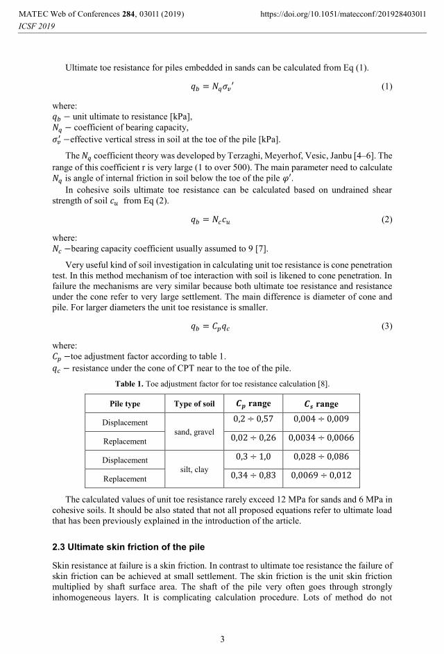
Table 1. Toe adjustment factor for toe resistance calculation [8].
Pile type Type of soil 𝑪𝒑 range 𝑪𝒔 range
Displacement sand, gravel
0,2 ÷ 0,57 0,004 ÷ 0,009
Replacement 0,02 ÷ 0,26 0,0034 ÷ 0,0066
Displacement silt, clay
0,3 ÷ 1,0 0,028 ÷ 0,086
Replacement 0,34 ÷ 0,83 0,0069 ÷ 0,012
The calculated values of unit toe resistance rarely exceed 12 MPa for sands and 6 MPa in
cohesive soils. It should be also stated that not all proposed equations refer to ultimate load
that has been previously explained in the introduction of the article.
2.3 Ultimate skin friction of the pile
Skin resistance at failure is a skin friction. In contrast to ultimate toe resistance the failure of
skin friction can be achieved at small settlement. The skin friction is the unit skin friction
multiplied by shaft surface area. The shaft of the pile very often goes through strongly
inhomogeneous layers. It is complicating calculation procedure. Lots of method do not
, 0 (2019) https://doi.org/10.1051/matecconf /201928MATEC Web of Conferences 284 40
ICSF 201930 30111 1
3
include it in calculation, because there is no clear and certain method which allow to properly
take it into account. Skin friction of the pile can be calculated similarly to toe resistance,
based on state of stress, angle of internal friction of soil, undrained shear strength of soil or
resistance obtained from CPT.
Skin friction of piles embedded in sands can be calculated from Eq (4).
𝑞𝑠 = 𝛽𝜎𝑣′ = 𝐾𝜎𝑣
′ tan 𝛿𝑘 (4)
where:
𝑞𝑠 − unit skin friction of the pile [kPa],
𝛽 = 𝐾 tan 𝛿𝑘 − skin friction coefficient,
𝐾 − earth pressure coefficient after pile installation which can be described as mean value of
passive, active and rest earth pressure coefficient 𝐾 =𝐾𝑎+𝐾0+𝐾𝑝
3 [9],
tan 𝛿𝑘 − coefficient of friction in the pile-soil interface,
𝜎𝑣′ −effective vertical stress in soil [kPa].
The presented method called also 𝛽-method based on friction law theory. Skin friction is
calculated based on radial stress on the shaft of the pile. It indicated that rough piles at large
depth rich higher values than smooth piles at smaller depths. In Eq. (4) it can be seen that the
horizontal component of stress in soil play main role. The spread of horizontal stress values
can be very wide. Before pile installation usually 𝐾 is smaller than 1. Pile instalation process
can disrupt it, and in displacement piles can increase 𝐾 to generete pasive earth pressure, and
sometimes in replacement piles can decrease 𝐾 to generate active earth pressure. Choosing
the proper 𝐾 coefficient in designing piles is very difficult. Skin friction calculated on Eq. (4)
can achieve 300 kPa but it should not exceed 150 kPa.
In cohesive soils skin friction is determined based on undrained shear strength of soil
according to Eq. (5).
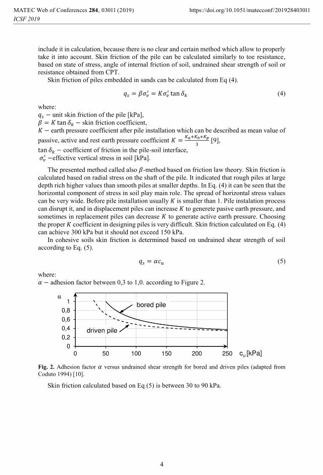
𝑞𝑠 = 𝛼𝑐𝑢 (5)
where:
𝛼 − adhesion factor between 0,3 to 1,0. according to Figure 2.
Fig. 2. Adhesion factor 𝛼 versus undrained shear strength for bored and driven piles (adapted from
Coduto 1994) [10].
Skin friction calculated based on Eq (5) is between 30 to 90 kPa.
, 0 (2019) https://doi.org/10.1051/matecconf /201928MATEC Web of Conferences 284 40
ICSF 201930 30111 1
4
Another method which allow to determine skin friction is method based on CPT
results [11, 12].
𝑞𝑠 = 𝐶𝑠𝑞𝑐 (6)
where:
𝐶𝑠 −skin adjustment factor according to table 1,
𝑞𝑐 − resistance under the cone of CPT along the shaft of the pile.
Skin friction calculated based on the CPT method can achieve almost 250 kPa. Unit skin
friction is usually much smaller (even 200 times) than unit toe resistance Eq. (7).
𝑓𝑠
𝑞𝑐= 𝑅𝑓 ∈ (0,5%; 8%) (7)
where:
𝑓𝑠 −unit skin friction in the CPT cone shaft,
𝑞𝑐 − resistance under the cone of CPT.
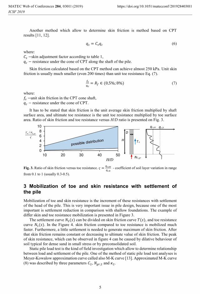
It has to be stated that skin friction is the unit average skin friction multiplied by shaft
surface area, and ultimate toe resistance is the unit toe resistance multiplied by toe surface
area. Ratio of skin friction and toe resistance versus H/D ratio is presented on Fig. 3.
Fig. 3. Ratio of skin friction versus toe resistance. 𝜍 =𝑞𝑐,𝑎𝑣
𝑞𝑐,𝑏 - coefficient of soil layer variation in range
from 0.1 to 1 (usually 0.3-0.5).
3 Mobilization of toe and skin resistance with settlement of the pile
Mobilization of toe and skin resistance is the increment of these resistances with settlement
of the head of the pile. This is very important issue in pile design, because one of the most
important is settlement reduction in comparison with shallow foundations. The example of
differ skin and toe resistance mobilization is presented in Figure 3.
The settlement curve 𝑁2(𝑠) can be divided on skin friction curve 𝑇(𝑠), and toe resistance
curve 𝑁1(𝑠). In the Figure 4. skin friction compared to toe resistance is mobilized much
faster. Furthermore, a little settlement is needed to generate maximum of skin friction. After
that skin friction remains constant or decreasing to ultimate value of skin friction. The peak
of skin resistance, which can be observed in figure 4 can be caused by dilative behaviour of
soil typical for dense sand in small stress or by preconsolidated soil.
Static pile load test is the kind of field investigation which allow to determine relationship
between load and settlement of the pile. One of the method of static pile load test analyses is
Meyer-Kowalow approximation curve called also M-K curve [13]. Approximated M-K curve
(8) was described by three parameters 𝐶2, 𝑁𝑔𝑟,2 and 𝜅2.
, 0 (2019) https://doi.org/10.1051/matecconf /201928MATEC Web of Conferences 284 40
ICSF 201930 30111 1
5

Fig. 4. Different distribution of load due to different way of skin and toe resistance mobilization.
Superscript (1) – distribution way No. 1. Superscript (2) – distribution way No. 2. Ultimate values of
resistances are the same.
𝑠(𝑁2) =𝐶2𝑁𝑔𝑟,2
𝜅2[(1 −
𝑁2
𝑁𝑔𝑟,2)
−𝜅2
− 1] (8)
Which can be also described as (9).
𝑁2 = 𝑁𝑔𝑟,2 [1 − (1 +𝜅2𝑠
𝐶2𝑁𝑔𝑟,2)
−1/𝜅2
] (9)
where:
𝐶2 −inverse of Winkler coefficient concerning to the head of the pile [mm/kN],
𝑁𝑔𝑟,2 −ultimate pile load capacity when uncontrolled settlement is observed [kN],
𝜅2 −dimensionless functional parameter of settlement curve.
First derivative of Eq (9) was equal to (10).
𝑁2′ =1
𝐶2(1 +
𝜅2𝑠
𝐶2𝑁𝑔𝑟,2)
−1−1
𝜅2 (10)
𝑁2′(𝑠 = 0) =1
𝐶2 (11)
Second derivative of Eq (9) was equal to (13).
𝑁2′′ = −
1
𝐶2𝑁𝑔𝑟,2(𝜅2 + 1) (1 +
𝑁2
𝑁𝑔𝑟,2)
𝜅2
(13)
𝑁2′′(𝑁2 = 0) = −
1
𝐶2𝑁𝑔𝑟,2(𝜅2 + 1) (14)
Tangent equation of the derivative 𝑁2′ can be described by Eq (15).
𝑁2′(𝑁2) = 𝑁2′′(0)𝑁2 + 𝑁2
′(0) = −1
𝐶2𝑁𝑔𝑟,2(𝜅2 + 1)𝑁2 +
1
𝐶2 (15)
, 0 (2019) https://doi.org/10.1051/matecconf /201928MATEC Web of Conferences 284 40
ICSF 201930 30111 1
6
In the Polish code [14] the ultimate pile load capacity is the value of load when 𝑁2′(𝑁2) =0 but the equations (14, 15) are usually calculated based on force range from the end of
settlement curve obtained from static pile load test. Author of the article proposed that the
design value of pile load capacity could be calculated based on the formulae (15). To
determine design load it should equate the Eq. (15) to zero using (𝜅2 + 1,4) instead of
(𝜅2 + 1) because for 𝜅2 = 0 it then will be similar to shallow foundation when 𝐹𝑆 = 1,4
usually is used.
𝑁2′(𝑁2) = 0 → 𝑁2,𝑑 =𝑁𝑔𝑟,2
𝜅2+1,4 (16)
where: 𝑁2,𝑑 −design value of pile load capacity [kN].
Using the proposed method the settlement according to the design load is independent of
optimized 𝜅2 parameters. It can also be assumed than the factor of safety FS can be
described by (13).
𝐹𝑆 = 𝑁𝑔𝑟,2
𝑁2,𝑝= 𝜅2 + 1,4 (17)
It can be observed that in high values of 𝜅2 the increasing of settlement in each subsequent
step of load is significant, and although the FS equal to 2, the settlement exceeds allowable
value. The Eq. (17) allow to find compromise between allowable settlement and design value
of load which take into account also factor of safety.
4 Practical approach of the analysis
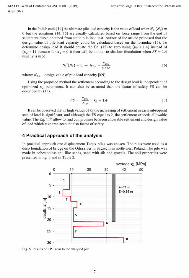
In practical approach one displacement Tubex piles was chosen. The piles were used as a
deep foundation of bridge on the Odra river in Szczecin in north-west Poland. The pile was
made in cohesionless soil like sands, sand with silt and gravels. The soil properties were
presented in fig. 5 and in Table 2.
Fig. 5. Results of CPT near to the analysed pile.
, 0 (2019) https://doi.org/10.1051/matecconf /201928MATEC Web of Conferences 284 40
ICSF 201930 30111 1
7
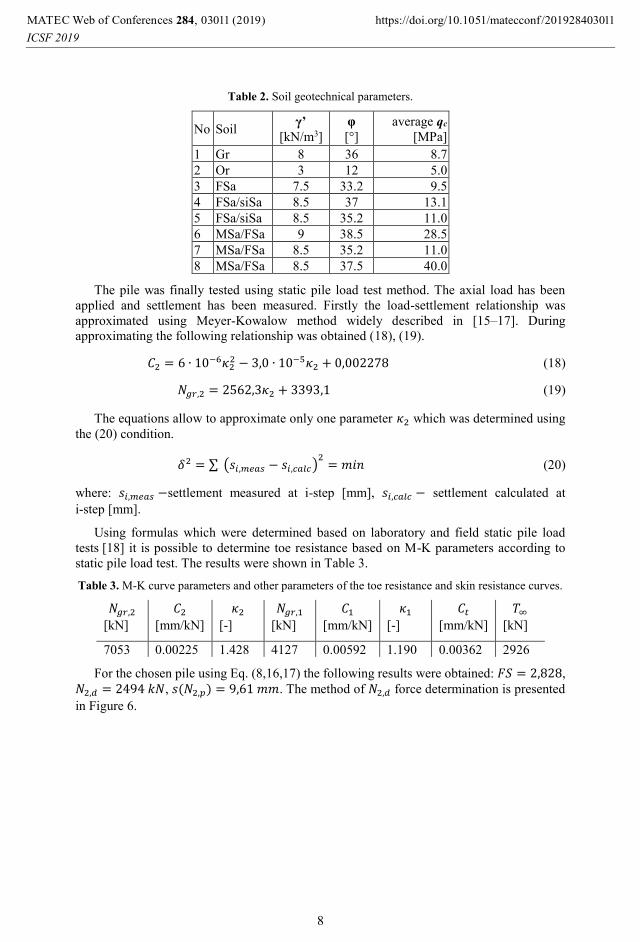
Table 2. Soil geotechnical parameters.
No Soil γ’
[kN/m3]
φ
[°]
average qc
[MPa]
1 Gr 8 36 8.7
2 Or 3 12 5.0
3 FSa 7.5 33.2 9.5
4 FSa/siSa 8.5 37 13.1
5 FSa/siSa 8.5 35.2 11.0
6 MSa/FSa 9 38.5 28.5
7 MSa/FSa 8.5 35.2 11.0
8 MSa/FSa 8.5 37.5 40.0
The pile was finally tested using static pile load test method. The axial load has been
applied and settlement has been measured. Firstly the load-settlement relationship was
approximated using Meyer-Kowalow method widely described in [15–17]. During
approximating the following relationship was obtained (18), (19).
𝐶2 = 6 ∙ 10−6𝜅22 − 3,0 ∙ 10−5𝜅2 + 0,002278 (18)
𝑁𝑔𝑟,2 = 2562,3𝜅2 + 3393,1 (19)
The equations allow to approximate only one parameter 𝜅2 which was determined using
the (20) condition.
𝛿2 = ∑ (𝑠𝑖,𝑚𝑒𝑎𝑠 − 𝑠𝑖,𝑐𝑎𝑙𝑐)2
= 𝑚𝑖𝑛 (20)
where: 𝑠𝑖,𝑚𝑒𝑎𝑠 −settlement measured at i-step [mm], 𝑠𝑖,𝑐𝑎𝑙𝑐 − settlement calculated at
i-step [mm].
Using formulas which were determined based on laboratory and field static pile load
tests [18] it is possible to determine toe resistance based on M-K parameters according to
static pile load test. The results were shown in Table 3.
Table 3. M-K curve parameters and other parameters of the toe resistance and skin resistance curves.
𝑁𝑔𝑟,2 𝐶2 𝜅2 𝑁𝑔𝑟,1 𝐶1 𝜅1 𝐶𝑡 𝑇∞
[kN] [mm/kN] [-] [kN] [mm/kN] [-] [mm/kN] [kN]
7053 0.00225 1.428 4127 0.00592 1.190 0.00362 2926
For the chosen pile using Eq. (8,16,17) the following results were obtained: 𝐹𝑆 = 2,828,
𝑁2,𝑑 = 2494 𝑘𝑁, 𝑠(𝑁2,𝑝) = 9,61 𝑚𝑚. The method of 𝑁2,𝑑 force determination is presented
in Figure 6.
, 0 (2019) https://doi.org/10.1051/matecconf /201928MATEC Web of Conferences 284 40
ICSF 201930 30111 1
8
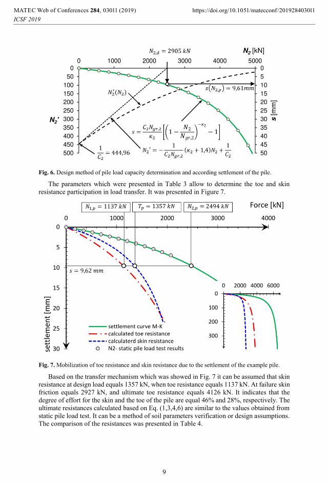
Fig. 6. Design method of pile load capacity determination and according settlement of the pile.
The parameters which were presented in Table 3 allow to determine the toe and skin
resistance participation in load transfer. It was presented in Figure 7.
Fig. 7. Mobilization of toe resistance and skin resistance due to the settlement of the example pile.
Based on the transfer mechanism which was showed in Fig. 7 it can be assumed that skin
resistance at design load equals 1357 kN, when toe resistance equals 1137 kN. At failure skin
friction equals 2927 kN, and ultimate toe resistance equals 4126 kN. It indicates that the
degree of effort for the skin and the toe of the pile are equal 46% and 28%, respectively. The
ultimate resistances calculated based on Eq. (1,3,4,6) are similar to the values obtained from
static pile load test. It can be a method of soil parameters verification or design assumptions.
The comparison of the resistances was presented in Table 4.
, 0 (2019) https://doi.org/10.1051/matecconf /201928MATEC Web of Conferences 284 40
ICSF 201930 30111 1
9

Table 4. Skin friction, toe bearing capacity and ultimate pile load capacity calculated based on
different methods.
Method Necessary parameters 𝑇∞
[kN]
𝑁1,𝑔𝑟
[kN] 𝑁2,𝑔𝑟
[kN] 1
CPT-
method
𝑞𝑐 from CPT
𝐶𝑠 = 0.0069
𝐶𝑝 = 0.6 2482 4212 6694
2
β-
method
𝜑, 𝜎𝑣′ from soil investigation
𝐾 =𝐾𝑎+𝐾0+𝐾𝑝
3= 𝐾(𝜑)
𝛿𝑘 = 𝜑
𝑁𝑞 = (tan 𝜑 + √1 + tan2 𝜑)2
𝑒2𝜂 tan 𝜑
𝜂 = 0.58𝜋
2728 3027 5755
3
M-K-
method
Meyer-Kowalow approximation parameters:
𝐶2, 𝑁𝑔𝑟,2, 𝜅2 [13] and
Żarkiewicz formulas for 𝐶1, 𝑁𝑔𝑟,1, 𝜅1 [18] 2927 4126 7053
Coefficient of soil layer variation used in Fig. 3 is equal to 0.34. For the ratio of
𝐻/𝐷 = 37,5 and the ultimate resistance for method 3 (Table 4), the relationship 𝑇∞
𝜍∙𝑁1,𝑔𝑟 is
equal to 2.09 and this is within the range presented in Fig. 3.
5 Conclusions
In the paper the method of pile load capacity analyses was proposed. The maximum load
which can be applied to the head of the pile is the sum of ultimate toe resistance and skin
friction. Mobilizing of these values require very high settlement of the pile. In practice
expected settlement in many solutions should not exceed 50 mm. At this settlement it could
be happen that skin resistance achieve the ultimate value, and sometimes decrease after that
settlement. This case in not a failure, because the toe resistance is still increasing. Despite
this can also be expected sudden increase in settlement of the pile which is sometimes very
dangerous because it may cause damages and consequently failure of the construction.
In the proposed case the main parameter influenced on pile-soil behaviour is parameter
𝜅2. Small values of 𝜅2 indicate that the behaviour is approximately linear so can be used less
factor of safety. The greater 𝜅2 indicate that the load-settlement relationship is strongly non-
linear and it this case the determinant of pile capacity should be allowable settlement
of the pile.
The analysed example showed that not only ultimate resistances are important but also
the way of their mobilization with settlement. The toe resistance at failure was 40 % bigger
than skin friction but in allowable settlement the participation was different: toe resistance
was 20% smaller than skin resistance. The proposed method can be used in diagnostics of
pile load capacity.
, 0 (2019) https://doi.org/10.1051/matecconf /201928MATEC Web of Conferences 284 40
ICSF 201930 30111 1
10
References
1. K. Żarkiewicz, Z. Meyer, Wiadomości Projektanta Budownictwa, 5 2016) [in Polish]
2. K. Żarkiewicz, Civ. Envion. Eng. Rep. 28(1), pp. 172-181 (2018)
3. K. Gwizdala, A. Krasinski, Bearing capacity of displacement piles in layered soils with
highly diverse strength parameters (Proceedings of the 18th International Conference on
Soil Mechanics and Geotechnical Engineering, Paris, 2013)
4. J. Tomlinson, M, Woodward, Pile design and construction practice (1995)
5. J. Briaud, Geotechnical Engineering. Unsaturated and saturated soils (Wiley, New
Jersey, Canada, 2013)
6. J. Briaud, L.M. Tucker, J. Geotech. Eng., 114(9), pp. 984-1001 (1988)
7. B. Wrana, Studia Geotechnica et Mechanica, 37(4), pp. 83-93 (2015) [in Polish]
8. C. Viggiani, G. Russo, A. Mandolini, Piles and piles foundation (CRC Press, New York,
Abingdon, Oxon, 2011)
9. Guidelines: NAVFAC DM 7.2. Foundation and Earth Structures (Naval Facilities
Engineering Command, Alexandria, USA, 1984)
10. C. Cherubini, G. Vessia, Can. Geotech. J. 44(11), pp. 1378-1390 (2007)
11. A. Eslami, F. Valikhah, M. Veiskarami, M. Salehi. Geotech. Geol. Eng. 35(6), pp. 2891-
2905 (2017)
12. D.J. White M.D. Bolton, P. I. Civil. Eng-Geotec. 158(1), pp. 3-14 (2005)
13. Z. Meyer, M. Kowalów, Inżynieria Morska i Geotechnika, 3, pp. 438-441 (2010)
[in Polish]
14. PN-B-02482:1983. Fundamenty budowlane -- Nośność pali i fundamentów palowych
[in Polish]
15. Z. Meyer, G. Szmechel, Inżynieria Morska i Geotechnika, 3, pp. 444-449 (2015)
[in Polish]
16. Z. Meyer, Studia Geotechnica et Mechanica, 36(2), pp. 45-49 (2014) [in Polish]
17. Z. Meyer, K. Żarkiewicz, Studia Geotechnica et Mechanica, 40(1), pp.1-5 (2018)
[in Polish]
18. K. Żarkiewicz, Analiza formowania się oporu pobocznicy pala w gruntach niespoistych
na podstawie modelowych badań laboratoryjnych (PhD dissertation, West Pomeranian
University of Technology, Szczecin, Poland, 2017) [in Polish]
, 0 (2019) https://doi.org/10.1051/matecconf /201928MATEC Web of Conferences 284 40
ICSF 201930 30111 1
11