Geotechnical risks, mitigation measures and performance of ...
Upload
independentCategory
view
3download
0
Physical Characterization of Municipal Solid Wastefor Geotechnical Purposes
Dimitrios Zekkos, M.ASCE1; Edward Kavazanjian Jr., F.ASCE2; Jonathan D. Bray, F.ASCE3;Neven Matasovic, M.ASCE4; and Michael F. Riemer, M.ASCE5
Abstract: A procedure to characterize municipal solid waste �MSW� for geotechnical engineering purposes is developed based onexperience with waste characterization and testing. Existing MSW classification systems are reviewed briefly, and the field and laboratorywaste characterization programs of two important projects are presented. Findings on the influence of the waste’s physical composition onits mechanical response from these projects and recent studies of MSW are integrated to develop a waste characterization procedure forefficient collection of the relevant information on landfill operation and waste physical characteristics that are most likely to affect thegeotechnical properties of MSW. A phased approach to implementation of this procedure is proposed as a best practice for the physicalcharacterization of MSW for geotechnical purposes. The scope of the phased procedure can be adjusted to optimize the effort required tocollect relevant information on a project-specific basis. The procedure includes a systematic evaluation of the moisture and organic contentof MSW, because they are important factors in the geotechnical characterization of MSW.
DOI: 10.1061/�ASCE�GT.1943-5606.0000326
CE Database subject headings: Municipal wastes; Solid wastes; Organic matter; Water content; Landfills.
Author keywords: Municipal solid waste; Organic content; Water content; Waste classification; Waste; Landfills; Geotechnicalcharacterization.
Introduction
Waste characterization procedures have been developed for a va-riety of applications. Depending on the intended application, thetype of information called for in a specific procedure varies. Forinstance, waste characterization studies performed by the Envi-ronmental Protection Agency and various state waste manage-ment organizations �e.g., California Environmental ProtectionAgency �CalEPA� �2006�� often collect information for the pur-pose of characterizing the waste stream to facilitate studies onwaste diversion, material recovery, waste processing, or conver-sion technologies. Geochemical characterization of waste �e.g.,Piatak et al. 2004� may be performed to evaluate the type andconcentration of chemicals in the waste and waste by-productsthat may impact the environment. Several MSW characterizationsystems for geotechnical purposes have been proposed since theearly 1990s. These systems have been developed to collect rel-evant information about the waste with respect to its geotechnical
1Assistant Professor, Dept. of Civil and Environmental Engineering,Univ. of Michigan, Ann Arbor, MI 48109–2125 �corresponding author�.
2Professor, School of Sustainable Engineering for the Built Environ-ment, Arizona State Univ., Tempe, AZ 85287–5306.
3Professor, Dept. of Civil and Environmental Engineering, Univ. ofCalifornia at Berkeley, CA 94720–1710.
4Associate, Geosyntec Consultants, Huntington Beach, CA, 92648.5Adjunct Professor, Dept. of Civil and Environmental Engineering,
Univ. of California at Berkeley, CA 94720–1710.Note. This manuscript was submitted on October 3, 2008; approved
on January 20, 2010; published online on January 25, 2010. Discussionperiod open until February 1, 2011; separate discussions must be submit-ted for individual papers. This paper is part of the Journal of Geotech-nical and Geoenvironmental Engineering, Vol. 136, No. 9, September 1,
2010. ©ASCE, ISSN 1090-0241/2010/9-1231–1241/$25.00.JOURNAL OF GEOTECHNICAL AND GEOEN
Downloaded 13 Aug 2010 to 141.212.44.41. Redistribu
response �e.g., hydraulic conductivity, shear strength, stiffness,and compressibility�. Geotechnical aspects of landfill perfor-mance include the overburden pressure due to the weight of thewaste mass, landfill stability under static and seismic conditions,settlement of the waste mass, performance of deep and shallowfoundations on or in the waste, and dynamic response of thewaste material during earthquakes.
This paper presents a phased approach to the physical charac-terization of municipal solid waste �MSW� for use in geotechnicalengineering analyses. The recommended procedure optimizes thecollection of physical information that has been shown to have asignificant influence on the mechanical properties of MSW. It isrecognized that the factors that influence the geotechnical proper-ties of MSW are not fully understood. However, recent studies�e.g., Kavazanjian et al. 1999; Zekkos 2005; Zekkos et al. 2006;Dixon and Langer 2006; Zekkos et al. 2008; Bray et al. 2009�have identified a variety of factors that can significantly affect themechanical properties of MSW. The proposed waste characteriza-tion procedure is designed to efficiently collect information onthese factors as well as other potentially useful information on itsphysical properties. As the understanding of the physical factorsinfluencing the mechanical response of MSW advances, modifi-cations to the proposed characterization procedure will be re-quired. However, the proposed procedure represents an importantfirst step in standardizing the manner in which MSW is charac-terized for engineering analyses.
Background
Existing MSW Classification Systems for GeotechnicalPurposesThe primary basis for many of the earliest MSW classification
systems that were developed for geotechnical purposes was a dis-VIRONMENTAL ENGINEERING © ASCE / SEPTEMBER 2010 / 1231
tion subject to ASCE license or copyright. Visithttp://www.ascelibrary.org
tinction between degradable and nondegradable waste constitu-ents. For instance, Landva and Clark �1990� divided the wasteconstituents into organic and inorganic materials. Organic mate-rial as defined by Landva and Clark �1990� included both pu-trescible waste �i.e., “readily” biodegradable waste� andnonputrescible waste �i.e., “slowly” biodegradable material�. In-organic waste included both mechanically degradable and nonde-gradable wastes. Grisolia et al. �1995� divided MSW into threeclasses of waste constituents: Class A included “inert stable ele-ments,” Class B included “highly deformable elements,” andClass C included “readily biodegradable elements.” A drawbackof the classification systems of Landva and Clark �1990� andGrisolia et al. �1995� is that various constituent categories areneither mutually exclusive nor easily distinguishable. For ex-ample, Class A in the classification system of Grisolia et al.�1995� includes soils, construction debris, and ash, whereas ClassC includes small-sized �i.e., material smaller than 20 mm in di-mension� degradable waste that is soil-like in physical appearanceand is not easily distinguishable from Class A waste.
Dixon and Langer �2006� made a comprehensive review ofpublished waste classification systems and found that none ofthese classification systems fulfilled the requirements of a rigor-ous classification framework. To fulfill this purpose, Dixon andLanger �2006� presented a framework for classifying waste con-stituents based on �1� their material type, �2� the constituentshape, �3� the constituent size, and �4� the constituent degradationpotential. The classification framework of Dixon and Langer�2006� has important advantages over previous waste classifica-tion systems in that it considers a broad range of waste constituentphysical and mechanical properties that appear to affect the engi-neering properties of the waste. However, the system of Dixonand Langer �2006� requires the careful segregation, physical de-scription, size measurement, and testing of all waste constituentsand was proposed primarily for use in research and not as a toolfor use in engineering practice. Segregating, describing, measur-ing, classifying, and testing all waste constituents are time con-suming and challenging tasks. Thus, this system is not anattractive option for use in practice, particularly if the classifica-tion scheme is to be implemented in the field.
MSW Organic Content and Moisture ContentMeasurements
Organic content and moisture content are two physical parametersthat are widely recognized as having an important influence onthe mechanical properties of geomaterials. Organic content isknown to influence significantly both short-term and long-termsettlement potentials. In general, a material with a higher organiccontent exhibits higher compressibility and lower shear strengthrelative to a material with a lower organic content. Moisture con-tent impacts the consistency of fine-grained materials as well asthe unit weight and the pore water suction in unsaturated materi-als. Moisture content may also impact settlement rate and shearstrength.
The standard procedure used in geotechnical practice to evalu-ate moisture content and organic content of organic soils �ASTMD2974� involves drying the material at 105°C and then at 440°Cto a constant mass. However, drying at 105°C may volatilize asignificant portion of the organic material in some MSW. To com-pensate for the potential for volatilization of organic waste, manyinvestigators recommend measuring the initial moisture contentand dry weight of MSW at a temperature below 105°C. However
there is no agreed upon �i.e., standardized� temperature at which1232 / JOURNAL OF GEOTECHNICAL AND GEOENVIRONMENTAL ENGIN
Downloaded 13 Aug 2010 to 141.212.44.41. Redistribu
to do this. There is also a lack of consensus on the size of speci-men that should be tested to obtain representative results as wellas on any processing �e.g., segregation of materials� that shouldbe conducted on the MSW specimen prior to testing.
Siegel et al. �1990� reported field moisture contents on MSWfrom the Operating Industries, Inc. �OII� landfill measured report-edly in general accordance with ASTM D2216-80, with the ex-ception that waste samples were dried at 60°C instead of 110°C.The samples were obtained using a 13-cm diameter acrylic tube-lined split-core barrel driven through a hollow stem auger. Gabrand Valero �1995� heated specimens at a temperature of 60°C for24 h to evaluate the moisture content of MSW cuttings recoveredfrom a hollow stem auger boring. However, they did not provideinformation on the sample size used to make their measurements.Gabr and Valero �1995� also reported measuring organic contentbased on ASTM D2974. They employed Method C, which callsfor heating the specimen from 105 to 440°C until “the specimenis completely ashed �no change in mass occurs after a furtherperiod of heating�.”
Sanchez-Alciturri et al. �1993� reported moisture contents forwaste recovered from the Meruello landfill in Spain, but no infor-mation is provided on the procedure used to determine the mois-ture content. Coumoulos et al. �1995� reported on moisturecontent for the Ano Liossia landfill in Athens, Greece. The ma-jority of the moisture content tests were performed in generalaccordance with ASTM D2216 by drying specimens at 110°Cover a period of 18 h. However, a few tests performed by dryingspecimens at 60°C for 48 h were reported to yield similar resultsto the tests conducted at 110°C for 18 h. Each specimen’s masswas approximately 1 kg �D. Zekkos, personal communication,2008�. Manassero et al. �1997� recommended evaluating MSWmoisture content by heating to 55°C to avoid potential combus-tion of volatile material, but no recommendations on sample sizeor duration were made.
Zornberg et al. �1999� estimated the moisture content forMSW from a landfill in Southern California by drying 51 23-kgbucket samples and 27 1.2-kg glass jar samples at a temperatureof approximately 85°C. The moisture content results from theglass jar samples showed approximately the same mean valueversus depth but larger scatter than those obtained from the largerbucket samples. Gomes et al. �2005� reported on moisture contentand organic content for fresh �less than three years� waste atSanto Tirso landfill �Portugal�. Moisture content was obtained bydrying specimens at 105°C over a period of 18 h. Gomes et al.�2005� expressed moisture content as a percentage of moistweight as opposed to dry weight. They reported that a few deter-minations were made at 60 and 90°C and variations in the dura-tion of the drying period were required to obtain similar results tothe tests at 105°C. Organic content was evaluated by Gomeset al. �2002� by heating the material at 450°C.
The differences in the definitions and procedures cited abovefor the evaluation of moisture content and organic content makecomparisons of different studies difficult. A consistent procedurefor the systematic evaluation of these two parameters is needed tostandardize their assessment for physical characterization ofMSW for geotechnical purposes.
Two Case Histories of MSW Characterization
MSW Characterization at the OII Landfill
As part of the predesign geotechnical investigation for closure of
the OII landfill, a superfund site in Monterey Park, Calif., a com-EERING © ASCE / SEPTEMBER 2010
tion subject to ASCE license or copyright. Visithttp://www.ascelibrary.org

JOURNAL OF GEOTECHNICAL AND GEOEN
Downloaded 13 Aug 2010 to 141.212.44.41. Redistribu
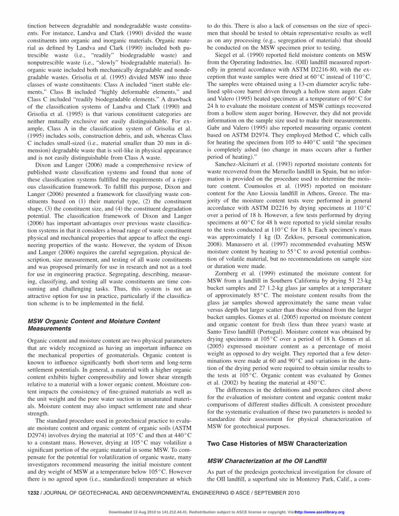
prehensive compositional characterization program was con-ducted on MSW recovered from three large-diameter bucketauger borings �Geosyntec 1996�. The locations of these borings aswell as the location of other field tests at the OII site are providedin Matasović and Kavazanjian �1998�. The three borings wereadvanced to depths of 33–45 m using an 840-mm diameter bucketauger �Fig. 1�. In situ unit weight measurements were conductedat selected locations within the boreholes using a gravel replace-ment procedure modeled after the sand cone test �Matasović andKavazanjian 1998�. MSW recovered in the bucket auger was con-tinuously logged in the field and selected samples were trans-ported to a field laboratory for more detailed compositionalcharacterization prior to waste specimen reconstitution for labo-ratory strength and compressibility testing. Fig. 1 shows wastebeing discharged from the bucket auger into a metal bin prior tofield logging. Following field logging, the waste was either dis-posed of back into the landfill or placed in a high density poly-ethylene drum and transported to the field laboratory. Comparisonof the waste recovered in the bucket auger borings to waste ex-posed in the wall of a 6-m deep by 6-m wide trench on the topdeck of the landfill indicated that the waste recovered in thebucket augers was generally representative in size and otherphysical characteristics of the waste within the landfill �Geosyn-tec 1996�.
The field logging and waste characterization system employedfor the OII project was developed using the best available infor-mation at that time on the factors most likely to influence themechanical properties of the waste. Field logging of the boringsincluded continuous visual descriptions of the moisture level,state of compaction, state of degradation, composition �i.e., wasteconstituents�, and apparent waste structure using the classificationscheme presented in Table 1. Field characterization also includedmeasurement of the temperature of the waste and video loggingof the borehole. MSW temperature was measured immediatelyafter the waste was discharged from the bucket to minimize tem-
Composition
1 Household—paper and plastics
2 Putrescible organics
3 Concrete, bricks
4 Wiring
5 Metal
6 Nonferrous metal
7 Tires
8 Asphalt
9 Soil
10 Medical
11 Indistinguishable
12 Glass
13 Other �specify�
Structure
1 Layered
2 Encapsulated
3 Fibrous
4 Interlocked
5 Indistinguishable
Table 1. OII Landfill Field Waste Classification Scheme �Geosyntec 1996�
Moisture content
1 Dry-damp moisture levels
2 Wet moisture levels
3 Standing water
Compaction
1 Slight—refuse easily falls out of bucket auger
2 Moderate—refuse falls out of bucket auger upon impact
3 Heavy—refuse falls out of bucket auger only after beingstruck multiple times
Degradation
1 None—newspaper very legible, no refuse discoloration
2 Slight—some newspapers still legible, discoloration
3 Moderate—newspaper partly legible, highly discolored
4 High—newspaper highly faded gray to black
Fig. 1. Bucket auger sample recovery at the OII landfill �Geosyntec1996�
VIRONMENTAL ENGINEERING © ASCE / SEPTEMBER 2010 / 1233
tion subject to ASCE license or copyright. Visithttp://www.ascelibrary.org

perature loss upon discharge of the waste. Continuous video log-ging of each borehole was conducted using a downhole cameratypically employed for oil well video logging.
The moisture level of the waste was classified in the field aseither “dry” or “damp,” “wet,” or “standing water” �when flowingor dripping water was observed in the borehole�. The assessmentof the state of compaction of the waste was based on the mannerin which the waste fell out of the bucket auger, with waste thatfell out easily described as “loose,” waste that fell out upon im-pact of the bucket with a hammer described as “moderate,” andwaste that fell out only after being struck with a hammer or joltedmultiple times as “heavy.” Degradation categories included“none” for waste in which newspapers were legible and there wasno apparent refuse discoloration, “slight” for waste with legiblenewspapers and some discoloration, “moderate” for partly legiblenewspaper with much discoloration, and “high” for waste wherenewspaper was illegible, highly faded gray or black. Constituentcomposition categories where based on ASTM D5231, standardtest method for determination of the composition of unprocessedMSW. Compositional categories used in classifying the OII land-fill waste included household paper and plastics, putrescible or-ganic matter, concrete and bricks, wiring, metal, nonferrousmetal, tires, asphalt, soil, medical waste, glass, indistinguishablematerial, and other distinguishable items. MSW structure was de-scribed based on the condition of the waste after it was emptiedfrom the bucket. Structure categories included “layered” when thelong axes of the waste constituents were oriented in a preferredorientation, “encapsulated” when the waste was encapsulated in asoil matrix, “fibrous” when waste constituents were intertwined,“interlocked” when waste constituents were interlocked in a com-pact, granular type of structure, and “indistinguishable.” Whenpossible, dates were recovered from newspapers and other printedmaterial to provide information on waste age. The field classifi-cation and temperature information were recorded on boring logs.Detailed classification information on representative samples ofwaste recovered from the OII landfill are presented by Matasovićet al. �1998�.
Graphical portrayals of field logging data were used to developan understanding of conditions within the OII landfill waste mass.For example, moisture content versus depth charts showed that
Fig. 2. Waste degradation versus depth at the OII Landfill �Geosyn-tec 1996�
the waste in boring BA-3 was relatively dry but it contained iso-
1234 / JOURNAL OF GEOTECHNICAL AND GEOENVIRONMENTAL ENGIN
Downloaded 13 Aug 2010 to 141.212.44.41. Redistribu
lated perched zones of standing water. Fig. 2, which presentsdegradation versus depth, shows a general trend of an increase indegradation with depth within boring BA-3, but it also showszones of no or slight degradation that correspond to relatively dryzones at depth within this boring. The temperature profile in Fig.3 shows temperature characteristic of anaerobic degradation �i.e.,55–70°C� at depths greater than 20 m, indicating that the tech-nique of measuring waste temperature as it emerges from theboring is a reasonable practical method for measuring waste tem-perature. The compaction data from the field investigationshowed a general trend of increasing compaction with depth. Ex-cept for one point representing dry waste in boring BA-2 at adepth of 16 m, one point representing dry waste from boringBA-1 at a depth of 19 m, and five points representing dry wastefrom boring BA-3 at depths greater than 23 m, slight waste com-paction was limited to depths of less than 12 m. Heavy compac-tion was limited to depths greater than 23 m. The structure datarecorded on waste discharged from the bucket auger were of littlevalue, as it was classified mostly as indistinguishable. However,the video logging �Fig. 4� showed that the waste had a horizon-tally layered structure.
Relatively detailed characterization was conducted on samplesof OII waste brought to the field laboratory for strength and com-pressibility testing. Based on visual assessment, a representative
Fig. 3. Waste temperature versus depth at the OII Landfill �Geosyn-tec 1996�
Fig. 4. View of the layered structure of the OII waste at a depth of10.7 m
EERING © ASCE / SEPTEMBER 2010
tion subject to ASCE license or copyright. Visithttp://www.ascelibrary.org

sample of waste, typically on the order of 5–10 kg of material,was selected for more detailed characterization. The sample wasthen separated into the following categories: paper; cardboard;plastics; rubber; wood products; textiles; concrete; metals; glass;soil and soil-like material; and miscellaneous materials. Each con-stituent was weighed and the soil and soil-like material was thenclassified in accordance with ASTM D2488. Moisture contentwas measured on selected specimens of the OII waste by heatingthe entire specimen at a temperature of 60°C until two successivereadings at least 12 h apart differed by less than 1%. Wherepossible, pH was measured on liquid extracted from the specimen�in all cases, the measured pH was approximately 7�. It should benoted that in some cases the temperature at which the moisturecontent was measured was less than the in situ temperature at thelocation where the waste was recovered. While it is possible thatthe moisture content of the waste recovered from locations wherethe in situ temperature exceeded 60°C may have increased as itcooled, this was not considered to be a major issue. However,subsequent to this investigation the writers adopted a procedurethat measures the moisture content at two different temperatures,as described in the next case history.
Waste specimens retained for laboratory testing were also clas-sified based on comparison of the shear-wave velocity at thedepth from which the sample was recovered as measured in aspectral analysis of surface wave �SASW� survey at the boringlocation �referred to herein as the boring value� to the mean andstandard deviation shear-wave velocity at that depth from 21SASW surveys conducted at the landfill �referred to herein as theglobal value� �Matasović and Kavazanjian 1998�. When the bor-ing value of the shear-wave velocity was approximately equal tothe global mean value at that depth, it was designated as a me-dium velocity �MV� sample. Samples designated as high velocitywere recovered from intervals where the boring value was equalto or greater than the mean plus one standard deviation globalvalue at that depth. Samples designated as low velocity were re-covered from intervals where the boring value was equal to orless than the mean minus one standard deviation global value atthat depth.
Table 2 presents an example of the laboratory characterizationof bucket auger waste sample BA1-MV1, which was recoveredfrom a depth of 9–12 m in boring BA-1. As denoted by the MVdesignation, the boring value of shear-wave velocity at this depth
Table 2. Classification of OII Bucket Auger BA1-MV1 �Geosyntec1996�
Constituents % by weight
Paper 0.9
Cardboard 0.7
Plastics 5.8
Rubber 1.2
Textiles 0.7
Wood 2.3
Concrete 0
Metals 0.6
Glass 2.5
Soil and organics 84.8
Miscellaneous 0.5
Note: �1� Soil and organics are 5% gravel, 10% sand, and classify as CLin the USCS; �2� moisture content equals 21.1%.
was approximately equal to the global mean value.
JOURNAL OF GEOTECHNICAL AND GEOEN
Downloaded 13 Aug 2010 to 141.212.44.41. Redistribu
MSW Characterization at the Tri-Cities Landfill
As part of a collaborative research project on the static and dy-namic properties of MSW, waste from the Tri-Cities landfill lo-cated in the San Francisco Bay Area was collected, characterized,and tested. The project investigated compositional influences onthe static and dynamic properties of MSW. Thus, efforts weremade to recover and test younger fresh waste and older moredegraded waste from the Tri-Cities landfill for compositionalanalysis and subsequent testing.
The subsurface investigation at the Tri-Cities landfill consistedof advancing two 960-mm-diameter bucket auger boreholes todepths of 9.5 m �B-1� and 32 m �B-2� at locations selected on thebasis of information on landfill operations to yield relativelyyoung �undegraded� waste �B-1� and older �more degraded� waste�B-2�. As described by Zekkos et al. �2006�, during drilling op-erations, in situ unit weight tests were performed in the bucketauger borings using a procedure similar to the gravel replacementprocedure used at the OII landfill. The recovered waste materialwas visually logged during drilling and bulk samples were col-lected for subsequent laboratory testing. The visual waste descrip-tion along with the location of in situ unit weight tests and thedepths from which the bulk samples were recovered were re-corded on field logs similar to those used in standard geotechnicalengineering investigations.
A handheld thermometer was used to measure the temperatureof the waste as soon as it was removed from the borehole andbrought to the surface in a similar manner as done for the OIIlandfill. The temperature profile developed in this manner for theTri-Cities landfill is shown in Fig. 5. The temperature was foundto increase with depth in both boreholes from 24°C near thesurface to as high as 46°C at depths greater than 22 m in boringB-2. A temperature of 55°C is considered generally indicative ofanaerobic decomposition, and higher temperatures are associatedwith aerobic decomposition. Thus, these relatively low tempera-tures suggest that little biological degradation was taking place inthe waste at the Tri-Cities landfill at the time the measurementswere taken �i.e., minimal oxygen was available to sustain aerobicdecomposition and limited moisture was available to sustainanaerobic decomposition�. This is consistent with the visual ob-servations of the waste recovered from the landfill. Even thedeepest waste recovered in the field investigation, which was ap-proximately 15 years old, was generally dry and still relativelyfresh, even though darker colors and more pronounced discolora-tion of waste constituents were observed.
Samples for large-scale laboratory testing were recovered from
Fig. 5. Temperature measurements versus depth for the two bore-holes at the Tri-Cities landfill
three depth intervals in borehole B-1 and 10 depth intervals in
VIRONMENTAL ENGINEERING © ASCE / SEPTEMBER 2010 / 1235
tion subject to ASCE license or copyright. Visithttp://www.ascelibrary.org

boring B-2. Samples from each depth interval were placed in twoto four 55-gal. drums to ensure that adequate material was col-lected for laboratory testing. A total of 39 drums were filled withwaste, sealed, and marked with the date, boring number, anddepth of retrieval. The drums were transported to the laboratoryfor subsequent characterization and laboratory testing.
Testing conducted on the OII waste indicated that waste shearstrength was roughly correlated to the amount of soil-like materialin a waste specimen �Kavazanjian 2001�. Furthermore, visual ob-servations of MSW recovered in large-diameter bucket auger bor-ings and test trenches at OII and the Tri-Cities landfill indicatedthat the soil-like material was less than 20 mm in dimension andmost of the distinguishable waste constituents were greater than20 mm in dimension. Therefore, the Tri-Cities waste specimenswere segregated into the fraction larger than 20 mm ��20 mm�and the fraction smaller than 20 mm ��20 mm�.
To separate the �20- and �20-mm fractions of MSW, a fork-lift was used to support the drum containing the waste in anelevated and nearly horizontal position. Two large 20-mm sieveswere placed next to the drum, just below the cap of the drum.Plastic tarps were placed on the floor to collect the �20-mmfraction as waste from the drum was emptied onto the sieves, asshown in Fig. 6. Precautions were taken to monitor for harmfulconcentrations of gasses released by the waste material duringprocessing of the waste. However, no harmful concentrations ofgasses were detected during the waste segregation �or testing�activities. When waste segregation was completed, the relativevolumes of the two fractions were estimated visually and the�20-mm fraction was visually characterized. Waste characteriza-tion forms presenting the information for each drum can be foundin Zekkos �2005�.
When the cap of the drum was removed, the methane �CH4�and carbon monoxide �CO� gas levels were recorded using ahandheld multigas monitor that was placed immediately next tothe open cap. The recorded gas levels are shown in Fig. 7. Thesemeasurements were made for safety reasons as well as to inves-tigate if they would provide a quantitative measure of the degreeof waste degradation. Older waste at higher depths appeared togenerate less CO and CH4 than shallower fresher waste. However,these were nonstandardized measurements recorded by simplyplacing the multigas monitor next to the cap of the drum as soonas it was opened.
Based on the dates on legible newspapers recovered during thecharacterization procedure, the profile of the waste age versus
Fig. 6. Processing of the waste through the 20-mm sieve
depth shown in Fig. 8 was established for the two Tri-Cities bor-
1236 / JOURNAL OF GEOTECHNICAL AND GEOENVIRONMENTAL ENGIN
Downloaded 13 Aug 2010 to 141.212.44.41. Redistribu
ings. The waste samples retained for testing were then divided inthree main classes for the purposes of the research project. ClassA waste was “deep old waste” that was retrieved from boreholeB-2 at depths greater than 25 m. Class B waste was “fibrous deepold waste” that was retrieved from borehole B-2 and at depth ofabout 29 m and was observed to include more fibrous particles inthe �20-mm fraction than Class A waste. Class C waste was“shallow fresh waste” that was retrieved from boreholes B-1 andB-2 and depths of 1–10 m.
Waste samples from each class and similar depths formed atotal of 11 waste sample groups �i.e., four Class A waste groups,one Class B waste group, and six Class C waste groups�. Five ofthese sample groups were further characterized. Characterizationincluded segregation of the �20-mm material into its constituentsand geotechnical characterization of the �20-mm material. The�20-mm waste fraction included household paper, householdplastics, putrescible organics, concrete and bricks, wiring, metal,nonferrous metal, tires, asphalt, medical, glass, scrap wood, andother waste products. Fig. 9 is a graphical representation of theresults of the segregation of the �20-mm material for the fivesample groups characterized from the Tri-Cities landfill. The totalweight of each sample group varied from 60 to 320 kg. Theresults indicate that the predominant constituents of the �20-mmmaterial are paper, plastic, and wood. Representative samples ofthese three predominant materials are shown in Fig. 10. While
0 200 400 60035
30
25
20
15
10
5
0
CO
Depth,m
Concentration CO , ppm
0 4000 8000 12000 16000
CH 4
Concentration CH 4 , ppm
Fig. 7. Concentration of the CO and CH4 in ppm as a function ofdepth for bulk samples of Tri-Cities landfill
Fig. 8. Depth versus age of waste for the two boreholes at the Tri-Cities landfill
EERING © ASCE / SEPTEMBER 2010
tion subject to ASCE license or copyright. Visithttp://www.ascelibrary.org

gravel represented a measurable percentage of the samples byweight because gravel is relatively heavy, it represented a negli-gibly small volume of the waste. The �20-mm waste materialrepresented 25–50% of the total weight of each of the five wastesample groups.
Three of the five sample groups were selected for testing andmore detailed characterization. These included the A3 wastegroup, retrieved from BH-2 at a depth of 25.6–26.2 m and 15years old at the time of drilling, the C6 waste group, retrievedfrom BH-1 at a depth of 7.6–9.6 m and less than one year old atthe time of drilling, and the C3 waste group, retrieved from BH-2at a depth of 3.5–4.5 m and two years old at the time of drilling.The �20-mm fraction of waste material from these three samplegroups was characterized using standard soil classification proce-dures. Dry sieve analyses of the �20-mm fraction of the threesample waste groups yielded similar results �as shown in Fig. 11�,which suggest that the �20-mm material was dominated by coversoil from a consistent borrow source. The �20-mm material is awell-graded sand �SW� with a uniformity coefficient �Cu� of 28and a coefficient of curvature �Cc� of 1. It should be noted thatdry sieve analyses of MSW tend to underestimate the amount offines when compared to wet sieve analyses �Gabr and Valero1995�. However, because of the organic nature of waste material,it was considered preferable to dry the material and then performthe sieve analyses rather than subject the material to the cycles ofdrying and wetting required to perform a wet sieve analysis.Moisture content of the �20-mm waste material was measuredusing an oven temperature of 55°C. The specimen was heated atthis temperature until it had dried to a constant mass as indicatedby a change in mass of less than 1% between two consecutivereadings taken 12 h apart. The �20-mm fraction had moisture
0
10
20
30
40
50
60
70
80
%byweight
Type of waste
A3
C1
C6
A1
C3
Fig. 9. Percentage by weight of the various waste types for fivedifferent waste sample groups for Tri-Cities waste
Fig. 10. View of the primary waste constituents of the �20-mm f
JOURNAL OF GEOTECHNICAL AND GEOEN
Downloaded 13 Aug 2010 to 141.212.44.41. Redistribu
contents of about 12% for the A3 and C6 waste groups and about23% for the C3 group. The samples were subsequently heated to105°C until dried to constant mass. The additional material lossupon heating from 55 to 105°C for the �20-mm fraction usingapproximately 1–2 kg of material was 0.5–2% for all specimensof the Tri-Cities waste.
Organic content was measured as the percentage of materialloss upon heating from 105 to 440°C using a muffle furnace. Dueto the size of the furnace, the specimens used to evaluate theorganic content weighed only about 50 g each. Larger specimensizes would be preferable if a suitable furnace was available. Tocompensate for the small sample size, the �20-mm material wasthoroughly homogenized, and two samples of the homogenizedmaterial were tested every time. As shown in Fig. 12, the twotests typically yielded relatively consistent values of organic con-tent. The organic content of the �20-mm fraction of samplegroup A3 was estimated to be between 13 and 23%. The organiccontent of the �20-mm fraction of the sample Group C6 wasestimated to be between 11 and 13%. The organic content of the�20-mm material of the C3 waste group was estimated to bebetween 17 and 27%.
The �20-mm material fraction appeared to have generallyhigher mass loss than the �20-mm fraction upon heating to55°C. For example, in sample Group A3, the mass loss of the�20-mm material upon heating to 55°C was measured to beabout double that of the �20-mm material �i.e., 24 and 12.5%,respectively�. For the C3 waste group the mass loss at 55°C ofthe �20-mm fraction was also higher than the mass loss of the�20-mm fraction �i.e., 31 and 23%, respectively�. No clear trendswere observed between the age of the waste and the mass loss onheating.
The small size of the muffle furnace did not allow the evalu-ation of the organic content of representative samples of the�20-mm material. Thus, only some limited tests were conductedon small samples of individual waste constituents. The mass lossat 440°C for wood and paper was estimated to be 84 and 60%,respectively. Thus, the measured organic content �as well as themoisture content� will be significantly affected by the composi-tion of the waste sample being tested. As an example, if the testedA3 sample included the paper, plastic, and wood inclusions, themeasured organic content would be significantly higher than theorganic content measured for the �20-mm fraction only. For ex-ample, the organic content of a sample that included 60%�20-mm material, 20% paper, and 20% wood would be approxi-mately 40% as opposed to the values of 13–23% measured for the�20-mm fraction only. In addition, the organic content of the�20-mm constituents is not of the same nature as the organiccontent of the �20-mm material. Thus, it is preferable that thevarious constituents of the waste material be tested separately.Similar discrepancies arise in the evaluation of the MSW mois-
for Tri-Cities waste: wood, paper, and plastic �from left to right�
ractionVIRONMENTAL ENGINEERING © ASCE / SEPTEMBER 2010 / 1237
tion subject to ASCE license or copyright. Visithttp://www.ascelibrary.org

ture content. Because standard procedures have not yet been es-tablished, it is essential that the amount and type of wastematerial tested be reported when values of the moisture and or-ganic content are provided.
Recommended MSW Physical CharacterizationProcedure
Overview
The cumulative experience of the waste characterization activitiesperformed at the OII landfill �Geosyntec 1996� and the Tri-Citieslandfill �Zekkos 2005� combined with recommendations fromprevious waste characterization programs can be integrated todevelop a standardized procedure for characterizing MSW forgeotechnical purposes. The recommended geotechnical character-ization procedure includes four phases:• Phase 1—Collection and review of available information.• Phase 2—Field characterization.• Phase 3—Primary geotechnical characterization.• Phase 4—Secondary geotechnical characterization.
In Phase 1, available information regarding waste sources, thehistory of waste placement, and landfill operations is collected. InPhase 2, qualitative compositional information is collected in thefield for relatively large amounts of waste material and selectedquantitative field information is also collected. In Phases 3 and 4,detailed compositional information is collected on smalleramounts of waste material selected from the recovered material.Depending on the engineering objectives of the characterizationactivities, different emphasis may be given to each of the four
0
20
40
60
80
100
0.010.1110100
%passing
Sieve size, mm
C6A1A3
Fig. 11. Dry sieve analyses of finer than 20-mm fraction for Tri-Cities waste
Fig. 12. Organic content for A3, C6, and C3 sample groups forTri-Cities waste for the �20-mm-sized waste specimens
1238 / JOURNAL OF GEOTECHNICAL AND GEOENVIRONMENTAL ENGIN
Downloaded 13 Aug 2010 to 141.212.44.41. Redistribu
phases. Detailed recommendations for each of the waste charac-terization phases are provided in the following sections.
Phase 1: Collection and Review of AvailableInformation
In this first phase of the proposed MSW characterization proce-dure, information about the waste received at the landfill, thehistory of landfill development, and the landfill operations arecollected. For landfills that have been operational for many years,a wealth of valuable information of this type may be available.This information should be collected and evaluated prior to theinitiation of subsequent studies. The collected information mayinclude details on the type of waste the landfill has historicallyreceived, types of waste excluded from the landfill, the amount ofwaste placed on a yearly basis, periodic aerial photos and topo-graphic maps showing waste elevation, and information on land-fill operations. Relevant information on landfill operationsincludes waste placement procedures, areas of the landfill dedi-cated to specific waste types, wet weather operations areas, dailyand interim cover placement, containment system details, leachateand gas management procedures, and surface water managementpractices. Sources of this information include interviews with cur-rent and former landfill staff, landfill permitting and design docu-ments, previous studies performed at the landfill, and landfillrecords on the amount and type of waste delivered to the landfillas well as any records of waste material encountered during theinstallation of the gas collection system. Annual �or periodic�landfill topographic surveys or aerial photos, when available, mayalso help establish the waste placement history of the site.
Information on waste sources and daily and interim coverplacement are of particular importance in terms of waste compo-sition. Regional studies on the composition of residential andcommercial waste streams may be useful with respect to identifi-cation of waste sources and evaluation of typical waste composi-tion. Information from operations personnel on daily and interimcover placement is also invaluable. However, in obtaining landfilloperations information, care should be taken to make sure that thequantity measures employed by the operation’s personnel are de-fined. For example, in reporting initial waste density, operatorsgenerally report refuse quantities only, without including dailycover quantities, and in citing daily and interim cover soil quan-tities operators generally report volume ratios as opposed to theengineering practice of reporting weight ratios �Kavazanjian2001�. Operational information is also valuable in identifying ifthere are designated areas for specific types of waste �e.g., ash,asbestos waste, or construction debris� and if changes in disposalpractices have occurred during the life of the landfill. Other rel-evant information on landfill operational practices include anypreprocessing conducted prior to waste placement, the means andamount of compaction during waste placement, and the type ofsoil �or alternative material� used for daily and interim cover.
Information on leachate and surface water management at thefacility is also important. In particular, leachate recirculation prac-tices may have an impact on the moisture content and state ofdegradation of the waste. The presence of a liner and a leachatecollection and removal system may also have an impact on thepresence of the leachate and the rate of waste decomposition.Surface water management practices may also impact the amountof water that will percolate in the waste mass. Finally, permitting
documents and previous engineering reports, including designEERING © ASCE / SEPTEMBER 2010
tion subject to ASCE license or copyright. Visithttp://www.ascelibrary.org

and construction quality assurance reports, may include valuableinformation on the history, construction, and operation of thelandfill.
Phase 2: Field Characterization
Based on the information collected in Phase 1, locations at thelandfill for subsurface investigation are selected. Depending onthe objectives of the project, areas where the waste is most rep-resentative of the MSW placed at the landfill or areas with MSWand subsurface conditions �e.g., perched leachate� that would beof particular concern �e.g., to evaluate stability� are identified.Noninvasive testing such as SASW surveys �Kavazanjian et al.1996� and electrical resistivity surveys or other geophysical mea-surements may be used to evaluate stiffness, moisture content,and spatial variability, depending on the project objectives.Downhole seismic velocity surveys �e.g., conventional downholeor suspension logging surveys� have also been performed forwaste characterization purposes at MSW landfills. However, theseare “point-specific” surveys generally conducted to evaluate prop-erties for engineering analyses, and they are not well suited forbroad areal surveys for characterization purposes due to theircost. If borings are to be performed, large-diameter �i.e., 750–900-mm-diameter� bucket auger borings are preferable to get rep-resentative data on larger waste constituents �this type of drillingequipment is typically employed for the construction of landfillgas collection wells�. Test pits allow excavation of shallow wasteand observation of waste structure.
During field investigations, visual descriptions of the predomi-nant constituents of the recovered waste, moisture level, and stateof degradation versus depth are recorded. The moisture level,state of degradation, and compositional categories in Table 1 pro-vide a basis for these visual descriptions �although it is now sug-gested that separate moisture level classifications of dry or dampbe used�. Representative bulk samples of waste materials may becollected for Phases 3 and 4 characterization activities as war-ranted by the project objectives. The bulk waste samples shouldbe placed in sealed drums to preserve the moisture content duringtransportation and storage. Storage time before testing should beminimized.
Dates from legible newspapers, magazines, or other docu-ments recovered during sampling should be recorded and com-bined with the waste placement information from Phase 1 todevelop a waste placement chronology. Field characterizationshould capture observed changes in waste texture, color, compo-sition, degradation, and moisture content as well as the presenceof flowing or standing leachate in the boring or test pit. Tempera-ture measurements of the waste, made within the bulk waste assoon as safely possible, may also provide useful information re-garding waste decomposition. Additional field investigation ac-tivities may include large-scale in situ unit weight tests �e.g.,Zekkos et al. 2006� and video logging �e.g., Geosyntec 1996�.
Phase 3: Primary Geotechnical Characterization
MSW samples selected for more detailed characterization shouldbe transported to a well-ventilated open area either in a laboratoryor a secure location at the landfill for Phases 3 and 4 character-ization activities. For geotechnical characterization, the MSWshould be separated into �20- and �20-mm waste fractions.Large 20-mm sieves are preferable for this task due to the largevolume of waste material typically involved in waste character-
ization activities.JOURNAL OF GEOTECHNICAL AND GEOEN
Downloaded 13 Aug 2010 to 141.212.44.41. Redistribu
Segregation into �20- and �20-mm waste fractions is recom-mended because there is a significant difference in the nature ofthe �20- and the �20-mm fractions of typical MSW. The�20-mm fraction is typically soil-like in nature �i.e., includessignificant amounts of daily cover soil and inorganic debris aswell as fine waste inclusions�, whereas, the �20-mm materialconsists primarily of waste generated at the source. The �20-mmMSW fraction is likely to include mostly plastics, paper, andwood, even though significant variations may exist between land-fills in different regions as well as within a landfill. Segregation ofthe �20- and �20-mm fractions is also advantageous because the�20-mm material can be characterized with typical soil mechan-ics testing equipment and procedures, whereas the �20-mm ma-terial is relatively easy to segregate by hand and categorizevisually.
The delineation between the �20- and �20-mm waste frac-tions has also been shown to be valuable in understanding theproperties of the waste material. Waste with lower amounts of�20-mm material �e.g., when large quantities of daily soil coveror other soil materials are used� has significantly higher unitweight than waste with higher amounts of �20-mm material pri-marily due to the low unit weight of the fibrous constituents of the�20-mm fraction �Zekkos et al. 2006�. Also, the unit weight ofwaste with high amounts of �20-mm material is found to in-crease significantly with overburden stress, while the increase inunit weight with overburden stress of MSW rich in �20-mm�such as the OII landfill� may be negligible �Zekkos et al. 2006�.Waste with a higher amount of �20-mm material will typicallyexhibit higher shear strength �Bray et al. 2009� if the fibrouswaste constituents are mobilized during shearing. The compress-ibility of waste will also, in general, increase with an increase in�20-mm material �Kavazanjian et al. 1999�. Finally, the dynamicproperties of MSW have been shown to be significantly affectedby the amount of �20-mm material �Zekkos et al. 2008�. As theamount of �20-mm material increases, the small strain shearmodulus reduces, and the volumetric threshold strain increasesindicating linear dynamic properties over a wider strain range�i.e., less reduction in shear modulus and lower material dampingat large strains �Zekkos et al. 2008��. These changes in the dy-namic properties can have significant impact on the seismic re-sponse of landfills �Athanasopoulos-Zekkos et al. 2008�.
After the sample is segregated into �20- and �20-mm frac-tions, the relative volumes of the two waste fractions are esti-mated visually and the weights of the two fractions are measured.Additional information is collected about the composition, age,moisture content, and degradation of these fractions. For the�20-mm fraction this information may include:• A more detailed qualitative description of the composition of
the �20-mm fraction based on the waste constituents identi-fied in Table 1.
• Additional information on the age of waste from magazines,newspapers, or other documents if legible.
• Quantification of the state of waste degradation based on thefour levels of degradation in Table 1.
• Visual characterization of the moisture level of the waste asdry, damp, or wet.Due to the difficulty in separating and characterizing the
�20-mm material, collection of additional information on the�20-mm fraction beyond visual classification is deferred to Phase
4.VIRONMENTAL ENGINEERING © ASCE / SEPTEMBER 2010 / 1239
tion subject to ASCE license or copyright. Visithttp://www.ascelibrary.org

Phase 4: Secondary Geotechnical Characterization
In Phase 4, the �20-mm material is segregated into its constitu-ents and the �20-mm material is characterized using conven-tional geotechnical classification procedures. Performing moisturecontent and organic content tests of the �20-mm material is rela-tively easy to do and yields potentially useful information, so itshould normally be done. In many cases, manually separating the�20-mm material into its constituents may not be worth the ef-fort. However, characterization may be valuable because recentstudies on synthetic waste indicate that the type of waste inclu-sions can have a major impact on the mechanical properties ofMSW �Athanasopoulos et al. 2008�. During the �20-mm segre-gation process, �20-mm material which was “trapped” within thelarger fraction should be separated as much as practical and addedto the �20-mm material. The weight of each of the �20-mmconstituents is measured to quantify the composition of the wastesample by weight. Although the size of the fibrous materials mayinfluence the properties of MSW, there is a paucity of data toconfirm this. Therefore, while this information may be valuablefor research purposes �e.g., Langer 2005; Dixon and Langer2006�, tracking the variability in the sizes of the fibrous materialswithin the MSW is not justified in engineering practice at thistime.
The �20-mm material can be characterized using traditionalgeotechnical classification procedures, including sieve analysis,moisture content, organic content, and Atterberg limits. Moisturecontent should be measured by heating to a temperature of 55°Cuntil a constant mass is achieved. Constant mass is achieved whenthe weight of the sample changes by less than 1% between twoconsecutive readings taken 12 h apart.
It is recommended that organic content be defined as the ratioof the weight of the specimen lost at 440°C according to theASTM D2974 procedure to the weight of the material upon heat-ing until constant mass of the same specimen at a temperature of55°C. For comparison purposes with conventional geotechnicalpractice, it may be desirable to make an intermediate measure-ment of the weight of the specimen at 105°C. A large enoughmass of material will need to be tested so that it is consideredrepresentative of the waste sample. The representative mass maydepend on the size of the original sample. If the sample size is toosmall to ensure that it is representative, multiple samples shouldbe tested to evaluate the variability of the organic content amongdifferent samples. Detailed documentation of the composition ofthe sample that is tested for moisture and organic content shouldaccompany the reported values.
With respect to the Phase 4 geotechnical characterization, afterthe waste is segregated into the �20- and �20-mm fractions, themoisture content and the dry mass of the �20-mm fraction mayhave to be evaluated separately for each constituent. As largefurnaces that can heat material to 440°C are typically not avail-able in geotechnical laboratories, it may be necessary to heatsamples of each constituent of the �20-mm fraction separatelyand then calculate a weighted average organic content. Even if alarge muffle furnace is available and larger quantities of the�20-mm material can be tested, it may be preferable to test con-stituents separately so that the loss of mass of each constituent isidentified. Furthermore, due to the inherent variability of MSW, itis recommended that at least two representative samples be heatedat 440°C to determine organic content. Measurement of the pH ofany free liquid that can be extracted from the waste may also bedesirable. Finally, if a more quantitative measure of the state of
waste degradation is required, the proposal of Hossain et al.1240 / JOURNAL OF GEOTECHNICAL AND GEOENVIRONMENTAL ENGIN
Downloaded 13 Aug 2010 to 141.212.44.41. Redistribu
�2003� to quantify degradation based on the ratio of cellulose plushemicellulose to lignin may be employed on the �20-mm frac-tion of MSW.
Conclusion
Based on existing MSW classification systems and experience inwaste characterization at the OII and Tri-Cities landfills, a recom-mended procedure for the physical characterization of MSW forgeotechnical engineering purposes has been developed. The fourphase characterization procedure is designed to capture the char-acteristics of MSW that may have a major influence on its me-chanical properties. Qualitative data collected in Phase 1 of thisprocedure include information on waste origin, landfill opera-tional procedures �e.g., waste processing and placement proce-dures�, climatic conditions, and waste age. While it is difficult toquantify the direct effects of these parameters on the engineeringproperties of MSW at the present time, this information is rela-tively easy to collect, is expected to play a role in the MSWproperties, and may prove valuable in the future. Furthermore,this information may prove useful in qualitatively assessing thespatial variability of the waste.
Phase 2 of the proposed procedure involves field characteriza-tion of the waste, including the recovery of bulk samples forPhase 3 and Phase 4 characterizations. The use of large-diameter�at least 750-mm� bucket auger boreholes is recommended forrecovery of bulk samples at depth to minimize comminuting oflarger waste particles. Visual characterization of the recoveredwaste should be performed as described in the paper, with theintent to capture the important characteristics of in situ wastecomposition. Field activities may also include geophysical explo-ration, in situ unit weight tests, and video logging of the bore-holes.
The most important aspect of Phase 3 characterization is theseparation of the recovered waste into the �20-mm fraction,which is largely waste materials, and the �20-mm fraction, whichis largely soil-like material. Testing on reconstituted waste speci-mens has shown that the percentage of �20-mm material in thewaste has a significant effect on MSW unit weight, shear strength,stiffness, and material damping during cyclic loading, and testingof synthetic waste suggests that the nature of the �20-mm mate-rial has also a significant effect on MSW mechanical response.Phase 3 includes segregation, weighing, and visual description ofthe �20-mm material to provide this critical information.
Phase 4 testing can provide useful quantitative data, such asmoisture content; however, some laborious parts of Phase 4 test-ing may not be considered necessary for all projects. In manycases, manually separating the �20-mm material into its constitu-ents may not be worth the effort. In Phase 4, the �20-mm mate-rial is characterized using conventional geotechnical soil testingprocedures, including grain size analysis, plasticity index, and, ifdesired, conventional geotechnical soil testing methods. Moisturecontent and organic content of both the �20-mm material and the�20-mm material are measured in Phase 4 using a temperature of55°C for the moisture content determination and a temperature of440°C to determine organic content. Detailed examination of the�20-mm material is also performed.
Many unanswered questions about the factors that most affectthe mechanical properties of MSW remain. The proposed charac-terization procedure is likely to be refined as new insights on themechanical response of MSW are garnered. However, the pro-
posed system is designed to capture the key aspects of wasteEERING © ASCE / SEPTEMBER 2010
tion subject to ASCE license or copyright. Visithttp://www.ascelibrary.org

composition that are believed to influence the geotechnical prop-erties of the MSW at the present time. Furthermore, the recom-mended procedure is designed to optimize the time and effortrequired to collect the most relevant information that governs thegeotechnical properties of MSW.
Acknowledgments
The work described in this paper was funded by the NationalScience Foundation Division of Civil and Mechanical Systemsunder Grant Nos. CMMI-0220064, CMMI-0635435, and CMMI-0220159 as part of a collaborative study by the University ofCalifornia at Berkeley, the Arizona State University, the Geo-syntec Consultants, the University of Texas at Austin, and theUniversity of Patras. Interactions with our other research collabo-rators, Dr. G. Athanasopoulos, Dr. E. Rathje, and Dr. K. Stokoewere invaluable. The writers would like also to thank S. Chickeyof Geosyntec Consultants for his help in the field investigation atthe Tri-Cities Landfill, B. Seos, Ph.D. student at Arizona StateUniversity, for his help in the classification of MSW, and Mr. GuyPetraborg of Waste Management for assisting with the wastesampling operations at the Tri-Cities landfill. More informationon this project and blank forms for future waste characterizationare available through the Geoengineer website at http://waste.geoengineer.org.
References
Athanasopoulos, G., Grizi, A., Zekkos, D., Founta, P., and Zisimatou, E.�2008�. “Municipal solid waste as a reinforced soil: Investigationusing synthetic waste.” ASCE-Geoinstitute Geocongress 2008, Geo-technics of Waste Management and Remediation, New Orleans, 168–175, Geotechnical Special Publication �GSP� No. 177.
Athanasopoulos-Zekkos, A., Zekkos, D., and Matasović, N. �2008�.“Validation of generic municipal solid waste material properties forseismic design of landfills.” Proc., 4th Geotechnical Earthquake En-gineering and Soil Dynamics Conf., ASCE, Reston, Va.
Bray, J. D., Zekkos, D., Kavazanjian, E., Athanasopoulos, G. A., andRiemer, M. F. �2009�. “Shear strength of municipal solid waste.” J.Geotech. Geoenviron. Eng., 135�6�, 709–722.
California Environmental Protection Agency �CalEPA�. �2006�. Targetedstatewide waste characterization study: Characterization and quanti-fication of residuals from materials recovery facilities, CaliforniaEnvironmental Protection Agency, Sacramento, Calif.
Coumoulos, D. G., Koryalos, T. P., Metaxas, I. L., and Gioka, D. A.�1995�. “The main landfill of Athens—Geotechnical investigation.”Proc., 5th Int. Landfill Symp., Sardinia ’95, CISA, Cagliari, Italy.
Dixon, N., and Langer, U. �2006�. “Development of a MSW classificationsystem for the evaluation of mechanical properties.” Waste Manage.,26�3�, 220–232.
Gabr, M. A., and Valero, S. N. �1995�. “Geotechnical properties of mu-nicipal solid waste.” Geotech. Test. J., 18, 241–254.
Geosyntec. �1996�. “Waste mass field investigation, Operating IndustriesInc. landfill, Monterey Park, California.” Rep. No. SWP-2, GeosyntecConsultants, Huntington Beach, Calif.
Gomes, C., Ernesto, A., Lopes, M. L., and Moura, C. �2002�. “Sanitarylandfill of Santo Tirso municipal waste physical, chemical and me-chanical properties.” Proc., 4th Int. Congress on Environmental Geo-
JOURNAL OF GEOTECHNICAL AND GEOEN
Downloaded 13 Aug 2010 to 141.212.44.41. Redistribu
technical, Brazil, Vol. 1, 255–261.Gomes, C., Lopes, M. L., and Lopes, M. G. �2005�. “A study of MSW
properties of a Portuguese landfill.” Int. Workshop Hydro-Physico-Mechanics of Landfills, Grenoble 1 University, Grenoble, France.
Grisolia, M., Napoleoni, Q., and Tangredi, G. �1995�. “Contribution to atechnical classification of municipal solid waste.” Proc., 5th Int.Landfill Symp., Sardinia ’95, Vol. 2, CISA, Cagliari, Italy, 703–710.
Hossain, M. S., Gabr, M. A., and Barlaz, M. A. �2003�. “Relationship ofcompressibility parameters to municipal solid waste decomposition.”J. Geotech. Geoenviron. Eng., 129�12�, 1151–1158.
Kavazanjian, E., Jr. �2001�. “Mechanical properties of municipal solidwaste.” Proc., 8th Int. Waste Management and Landfill Symp., Sar-dinia ‘01, Vol. III, Environmental Sanitary Engineering Centre�CISA�, Univ. of Padua, Padua, Italy, 415–424.
Kavazanjian, E., Jr., Matasović, N., and Bachus, R. C. �1999�. “Large-diameter static and cyclic laboratory testing of municipal solid waste.”Proc., 7th Int. Waste Management and Landfill Symp., Sardinia ‘99,Vol. 3, CISA, Cagliari, Italy, 437–444.
Kavazanjian, E., Jr., Matasović, N., Stokoe, K., and Bray, J. D. �1996�.“In-situ shear wave velocity of solid waste from surface wave mea-surements.” Proc., 2nd Int. Congress on Environmental Geotechnics,M. Kamon, ed., Vol. 1, Balkema, Rotterdam, The Netherlands, 97–102.
Landva, A. O., and Clark, J. I. �1990�. Geotechnics of waste fill, theoryand practice, STP 1070, A. Landva and G. D. Knowles, ed., ASTM,West Conshohocken, Pa., 86–103.
Langer, U. �2005�. “Shear and compression behavior of undegraded Mu-nicipal Solid Waste.” Ph.D. thesis, Loughborough Univ.
Manassero, M., Van Impe, W. F., and Bouazza, A. �1997�. “Waste dis-posal and containment.” Proc., 2nd Int. Congress on EnvironmentalGeotechnics, Vol. 2, Balkema, Rotterdam, The Netherlands, 1425–1474.
Matasović, N., and Kavazanjian, E., Jr. �1998�. “Cyclic characterizationof OII landfill solid waste.” J. Geotech. Geoenviron. Eng., 124�3�,197–210.
Matasović, N., Williamson, T. A., and Bachus, R. C. �1998�, “Cyclicdirect simple shear testing of OII landfill solid waste.” Proc., 11thEuropean Conf. on Soil Mechanics and Foundation Engineering, Vol.1, Balkema, Rotterdam, The Netherlands, 441–448.
Piatak, N. M., et al. �2004�. “Geochemical characterization of mine wasteat the Ely Copper Mine Superfund Site, Orange County, Vermont.”U.S. Geological Survey Open-File Rep. No. 2004-1248, Version 1.0,�http://pubs.usgs.gov/of/2004/1248/� �Feb. 26, 2009�.
Sanchez-Alciturri, J. M., Palma, J., Sagaseta, C., and Canizal, J. �1993�.Mechanical properties of wastes in a sanitary landfill, waste disposalby landfill—Green ’93, R. W. Sarsby, ed., Balkema, Rotterdam, TheNetherlands, 357–363.
Siegel, R. A., Robertson, R. J., and Anderson, D. G. �1990�. Slope sta-bility investigations at a landfill in southern California, AmericanSociety for Testing and Materials �ASTM�, West Conshohocken, Pa.,259–284, Special Technical Publication �STP� 1070.
Zekkos, D., Bray, J. D., and Riemer, M. F. �2008�. “Shear modulus andmaterial damping of municipal solid waste based on large-scale cyclictriaxial testing.” Can. Geotech. J., 45�1�, 45–58.
Zekkos, D. P. �2005�. “Evaluation of static and dynamic properties ofmunicipal solid-waste.” Ph.D. thesis, Dept. of Civil and Environmen-tal Engineering, Univ. of California, Berkeley, Calif., �http://waste.geoengineer.org�.
Zekkos, D. P., et al. �2006�. “Unit weight of municipal solid-waste.”J. Geotech. Geoenviron. Eng., 132�10�, 1250–1261.
Zornberg, J. G., Jernigan, B. L., Sanglerat, T. R., and Cooley, B. H.�1999�. “Retention of free liquids in landfills undergoing vertical ex-pansion.” J. Geotech. Geoenviron. Eng., 125�7�, 583–594.
VIRONMENTAL ENGINEERING © ASCE / SEPTEMBER 2010 / 1241
tion subject to ASCE license or copyright. Visithttp://www.ascelibrary.org
Copyright © 2022 FDOKUMEN