Photoelastic analysis of the singular stress field in a bimaterial wedge
7
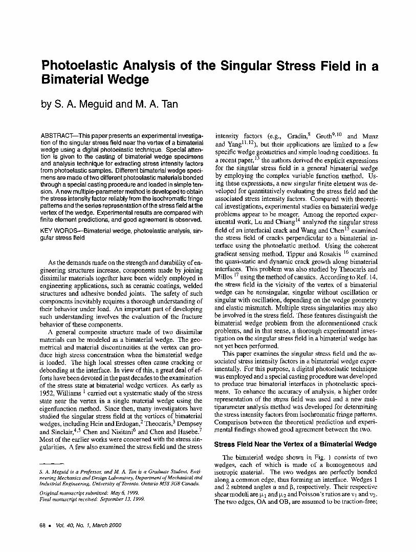
Photoelastic Analysis of the Singular Stress Field in a Bimaterial Wedge by S. A. Meguid and M. A. Tan ABSTRACT--This paper presents an experimental investiga- tion of the singular stress field near the vertex of a bimaterial wedge using a digital photoelastic technique. Special atten- tion is given to the casting of bimaterial wedge specimens and analysis technique for extracting stress intensity factors from photoelastic samples. Different bimaterial wedge speci- mens are made of two different photoelastic materials bonded through a special casting procedure and loaded in simple ten- sion. A new multiple-parameter method is developed to obtain the stress intensity factor reliablyfrom the isochromaticfringe patterns and the series representation of the stress field at the vertex of the wedge. Experimental results are compared with finite element predictions, and good agreement is observed. KEY WORDS--Bimaterial wedge, photoelastic analysis, sin- gular stress field As the demands made on the strength and durability of en- gineering structures increase, components made by joining dissimilar materials together have been widely employed in engineering applications, such as ceramic coatings, welded structures and adhesive bonded joints. The safety of such components inevitably requires a thorough understanding of their behavior under load. An important part of developing such understanding involves the evaluation of the fracture behavior of these components. A general composite structure made of two dissimilar materials can be modeled as a bimaterial wedge. The geo- metrical and material discontinuities at the vertex can pro- duce high stress concentration when the bimaterial wedge is loaded. The high local stresses often cause cracking or debonding at the interface. In view of this, a great deal of ef- forts have been devoted in the past decades to the examination of the stress state at bimaterial wedge vertices. As early as 1952, Williams 1 carried out a systematic study of the stress state near the vertex in a single material wedge using the eigenfunction method. Since then, many investigators have studied the singular stress field at the vertices of bimaterial wedges, including Hein and Erdogan, 2 Theocaris, 3 Dempsey and Sinclair,4,5 Chen and Nisitani6 and Chen and Hasebe.7 Most of the earlier works were concerned with the stress sin- gularities. A few also examined the stress field and the stress s. A. Meguid is a Professor, and M. A. Tan is a Graduate Student, Engi- neering Mechanics and Design Laboratory, Department of Mechanical and Industrial Engineering, University of Toronto, Ontario MSS 3G8 Canada. Original manuscript submitted: May 6, 1999. Final manuscript received: September 13, 1999. intensity factors (e.g., Gradin, 8 Groth 9,1~ and Munz and Yang 11,12), but their applications are limited to a few specific wedge geometries and simple loading conditions. In a recent paper,13 the authors derived the explicit expressions for the singular stress field in a general bimaterial wedge by employing the complex variable function method. Us- ing these expressions, a new singular finite element was de- veloped for quantitatively evaluating the stress field and the associated stress intensity factors. Compared with theoreti- cal investigations, experimental studies on bimaterial wedge problems appear to be meager. Among the reported exper- imental work, Lu and Chiang TM analyzed the singular stress field of an interfacial crack and Wang and Chen 15 examined the stress field of cracks perpendicular to a bimaterial in- terface using the photoelastic method. Using the coherent gradient sensing method, Tippur and Rosakis 16 examined the quasi-static and dynamic crack growth along bimaterial interfaces. This problem was also studied by Theocaris and Millos 17 using the method of caustics. According to Ref. 14, the stress field in the vicinity of the vertex of a bimaterial wedge can be nonsingular, singular without oscillation or singular with oscillation, depending on the wedge geometry and elastic mismatch. Multiple stress singularities may also be involved in the stress field. These features distinguish the bimaterial wedge problem from the aforementioned crack problems, and in that sense, a thorough experimental inves- tigation on the singular stress field in a bimaterial wedge has not yet been performed. This paper examines the singular stress field and the as- sociated stress intensity factors in a bimaterial wedge exper- imentally. For this purpose, a digital photoelastic technique was employed and a special casting procedure was developed to produce true bimaterial interfaces in photoelastic speci- mens. To enhance the accuracy of analysis, a higher order representation of the stress field was used and a new mul- tiparameter analysis method was developed for determining the stress intensity factors from isochromatic fringe patterns. Comparison between the theoretical prediction and experi- mental findings showed good agreement between the two. Stress Field Near the Vertex of a Bimaterial Wedge The bimaterial wedge shown in Fig. 1 consists of two wedges, each of which is made of a homogeneous and isotropic material. The two wedges are perfectly bonded along a common edge, thus forming an interface. Wedges 1 and 2 subtend angles ct and 13,respectively. Their respective shear moduli are Ix1 and Ix2 and Poisson's ratios are ~1 and ~2. The two edges, OA and OB, are assumed to be traction-free; 68 VoL 40, No. 1, March 2000
Transcript of Photoelastic analysis of the singular stress field in a bimaterial wedge
Photoelastic Analysis of the Singular Stress Field in a Bimaterial Wedge
by S. A. Meguid and M. A. Tan
ABSTRACT--This paper presents an experimental investiga- tion of the singular stress field near the vertex of a bimaterial wedge using a digital photoelastic technique. Special atten- tion is given to the casting of bimaterial wedge specimens and analysis technique for extracting stress intensity factors from photoelastic samples. Different bimaterial wedge speci- mens are made of two different photoelastic materials bonded through a special casting procedure and loaded in simple ten- sion. A new multiple-parameter method is developed to obtain the stress intensity factor reliably from the isochromatic fringe patterns and the series representation of the stress field at the vertex of the wedge. Experimental results are compared with finite element predictions, and good agreement is observed.
KEY WORDS--Bimaterial wedge, photoelastic analysis, sin- gular stress field
As the demands made on the strength and durability of en- gineering structures increase, components made by joining dissimilar materials together have been widely employed in engineering applications, such as ceramic coatings, welded structures and adhesive bonded joints. The safety of such components inevitably requires a thorough understanding of their behavior under load. An important part of developing such understanding involves the evaluation of the fracture behavior of these components.
A general composite structure made of two dissimilar materials can be modeled as a bimaterial wedge. The geo- metrical and material discontinuities at the vertex can pro- duce high stress concentration when the bimaterial wedge is loaded. The high local stresses often cause cracking or debonding at the interface. In view of this, a great deal of ef- forts have been devoted in the past decades to the examination of the stress state at bimaterial wedge vertices. As early as 1952, Williams 1 carried out a systematic study of the stress state near the vertex in a single material wedge using the eigenfunction method. Since then, many investigators have studied the singular stress field at the vertices of bimaterial wedges, including Hein and Erdogan, 2 Theocaris, 3 Dempsey and Sinclair, 4,5 Chen and Nisitani 6 and Chen and Hasebe. 7 Most of the earlier works were concerned with the stress sin- gularities. A few also examined the stress field and the stress
s. A. Meguid is a Professor, and M. A. Tan is a Graduate Student, Engi- neering Mechanics and Design Laboratory, Department of Mechanical and Industrial Engineering, University of Toronto, Ontario MSS 3G8 Canada.
Original manuscript submitted: May 6, 1999. Final manuscript received: September 13, 1999.
intensity factors (e.g., Gradin, 8 Groth 9,1~ and Munz and Yang 11,12), but their applications are limited to a few specific wedge geometries and simple loading conditions. In a recent paper,13 the authors derived the explicit expressions for the singular stress field in a general bimaterial wedge by employing the complex variable function method. Us- ing these expressions, a new singular finite element was de- veloped for quantitatively evaluating the stress field and the associated stress intensity factors. Compared with theoreti- cal investigations, experimental studies on bimaterial wedge problems appear to be meager. Among the reported exper- imental work, Lu and Chiang TM analyzed the singular stress field of an interfacial crack and Wang and Chen 15 examined the stress field of cracks perpendicular to a bimaterial in- terface using the photoelastic method. Using the coherent gradient sensing method, Tippur and Rosakis 16 examined the quasi-static and dynamic crack growth along bimaterial interfaces. This problem was also studied by Theocaris and Millos 17 using the method of caustics. According to Ref. 14, the stress field in the vicinity of the vertex of a bimaterial wedge can be nonsingular, singular without oscillation or singular with oscillation, depending on the wedge geometry and elastic mismatch. Multiple stress singularities may also be involved in the stress field. These features distinguish the bimaterial wedge problem from the aforementioned crack problems, and in that sense, a thorough experimental inves- tigation on the singular stress field in a bimaterial wedge has not yet been performed.
This paper examines the singular stress field and the as- sociated stress intensity factors in a bimaterial wedge exper- imentally. For this purpose, a digital photoelastic technique was employed and a special casting procedure was developed to produce true bimaterial interfaces in photoelastic speci- mens. To enhance the accuracy of analysis, a higher order representation of the stress field was used and a new mul- tiparameter analysis method was developed for determining the stress intensity factors from isochromatic fringe patterns. Comparison between the theoretical prediction and experi- mental findings showed good agreement between the two.
Stress Field Near the Vertex of a Bimaterial Wedge
The bimaterial wedge shown in Fig. 1 consists of two wedges, each of which is made of a homogeneous and isotropic material. The two wedges are perfectly bonded along a common edge, thus forming an interface. Wedges 1 and 2 subtend angles ct and 13, respectively. Their respective shear moduli are Ix 1 and Ix2 and Poisson's ratios are ~1 and ~2. The two edges, OA and OB, are assumed to be traction-free;
68 �9 VoL 40, No. 1, March 2000

Y
IJ
Fig. 1--A general bimaterial wedge
x
the stresses (lyy and ~xy and the displacements Ux and Uy are assumed to be continuous along the interface�9 By employing the complex variable method of Muskhelishivili, the stress field at the vertex of the bimaterial wedge can be expressed in the form of series expansions, such that 14
L (~};)(r, O) = l~=l rBl~tFi~)l (O)
M (s) 0 - } - E Fijm( )rf', (S) lnr)
m=l rl-~-''~ t t 'ml COS(@)ijm(O) -- rim
�9 (s) 3]m In r)] -~- Cm2 sln( Oij m (0) -
O)
(i, j = x, y).
The above series is arranged such that ~I < ~t+l and ~m < ~m+l- NO terms with Re(),) < 0 are in- cluded. In the above expressions, s indicates the material, ~z is the lth real eigenvalue, ~m, qm are the respective real and imaginary components of the ruth complex eigenvalue, !~ij l (0) are the angular variation functions corresponding to the lth real eigenvalue and Fijm(O), Oijm(O) are the angu- lar variation functions corresponding to the ruth complex eigenvalue.
It is worth mentioning that all the above parameters and functions (except BI, Cml and Cm2) are dependent on the wedge angles and the mechanical properties of the constituent materials. The coefficients Bt, C, n l and Cm2, on the other hand, are dependent on wedge angles, elastic mismatch and the loading condition. Details concerning eq (1) can be found in Ref. 14.
According to their real eigenvalue components, the terms in eq (1) can be categorized into three groups. Those that satisfy ~t < 1 or ~m < 1 are the singular terms that control
the singular stress field. The term with ~l = 1 represents the constant stresses around a vertex. The other higher order
terms ( 6l > | or ~m > l) are related to the nonsingular stresses, which vanish when the wedge vertex is approached but have a significant effect on the stress field away from the vertex.
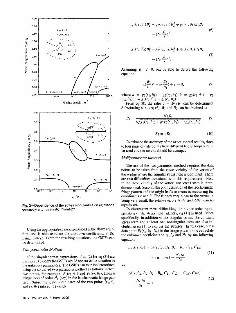
The singular stress field is the main concern in fracture mechanics studies. For the singular terms of eq (1), 1 - ~t and 1 - ~rn represent the strength of the stress singularity and ~m describes the severity of the stress oscillation. The corresponding coefficients Bt, Cml and Cm2, which are re- ferred to as the generalized stress intensity factors (GSIFs), characterize the stress intensity�9 There can be more than one singular term for a bimaterial wedge, and they may have different singularities. By defining a stress singularity as y = 1 - ~ + irl = g + irl with g and 11 characterizing the strength of the stress singularity and the severity of the stress oscillation, respectively, the dependence of stress singulari- ties on the wedge angles and the elastic mismatch are demon- strated in Fig. 2. Whereas Fig. 2(a) shows the variation of the stress singularities versus the wedge angle ~ for a sym- metric wedge, Fig. 2(b) demonstrates the effect of varying the elastic mismatch on the stress singularities of the wedge with a = 150 deg and ~ = 180 deg.
For some bimaterial wedge problems, there will be either one or two real singularities or two complex singularities that are conjugate to one another. A typical example is the prob- lem of an interfacial crack, where two complex singularities are present at the crack tip. For these problems, the singular stress field can be expressed as
crij(r, O) = B [ Fi~(O) + ~ F , ~ ( O ) r l -~ 1 r - ' , (2)
(i, j = x, y)
for real singularities or
Fq(O) (Iij (r, 0) = r 1----~ [Cl l cos (Oi j (0) - 1"1 In r)
-t- C12 sin(Oij (0) - rl In r)]
(i, j ,= x, y)
for complex singularities.
(3)
Determination of the GSIF Using Photoelastic Isochromatic Patterns
According to the stress-optics law, the maximum in-plane shear stress Xmax is related to the isochromatic fringe pattern by the following relation
Nf~ "[max ~--- , (4)
2t
where N is the fringe order at the point, f~ is the photoelastic material fringe value and t is the model thickness. Express- ing the maximum in-plane shear stress Xmax in terms of the Cartesian stress components and substituting it into eq (4) leads to the following equation:
('gmax)2 ~--" (Clxx --2 (Yyy )2 _at_ (1;xy)2 .~- ('-~-)N f~ ,2. (5)
Experimental Mechanics �9 69
t~ ..=
1.00
0.90
0.80
0.70
0.60
0.50
0.40
0.30
0.20
0.10
0.00 0.0
l.t 2 / I t 1=5
v 1 = v 2 = 0 . 3
; ,=;==;
~, L=~ 2=11L=r12= 0
4d.o 90.0 135.0 180.0
Wedge Angle, {X ~
p..
o')
0 . 8 . . . . . . , . . . , .
0 . 7
0 . 6
;,=~2=; 0.5
0.4
0.3
0�9
"q t = - - ~ 2=3]
2 - " , 10 ~ 10,7 10 f
V t = V 2 = 0 . 3
~=~2=0
10 0 10 f 10 z 10 ~
Fig. 2--Dependence of the stress singularities on (a) wedge geometry and (b) elastic mismatch
Using the appropriate stress expressions in the above equa- tion, one is able to relate the unknown coefficients to the fringe pattern. From the resulting equations, the GSIFs can be determined�9
Two-parameter Method
If the singular stress expressions of eq (2) [or eq (3)] are used in eq (5), only the GSIFs would appear in the equation as the unknown parameters. The GSIFs can then be determined using the so-called two-parameter method as follows�9 Select two points, for example, Pl(rl, 01) and P2(r2, 02), from a fringe loop of order N1 (say) in the isochromatic fringe pat- tern. Substituting the coordinates of the two points (rl, 01 and r2, 02) into eq (5) yields
gl (rl, 01)B 2 -I- g2(rl, 01)B 2 + g3(rl, 01)B1B2
f~,2 = (N1-7-)
(6)
g 1 (r2, 02) B2 + g2 (r2, 02) B 2 -I- g3 (r2, 02) B1 B2
fc~ ,2 (7) = (N1 T ) �9
Assuming Bl # O, one is able to derive the following equation:
a( -~)2 + O l b ( B ~ ) + c = 0, (8)
where a = g2(rl, 01) - g2(r2, 02), b = g3(rl, 01) - g3 (rE, 02), c = gl(rl, 01) -- gl(r2, 02).
From eq (8), the ratio O = B2/B1 can be determined. Substituting O into eq (6), B1 and B2 can be obtained as
Nl ft~ B 1 = (9)
t~/gl(rl, 01) + O2gE(rl, 01) + pg3(rl, 01)
B2 = oBI�9 (10)
To enhance the accuracy of the experimental results, three to four pairs of data points from different fringe loops should be used and the results should be averaged�9
Multiparameter Method
The use of the two-parameter method requires the data points to be taken from the close vicinity of the vertex of the wedge where the singular stress field is dominant. There are two difficulties associated with this requirement�9 First, in the close vicinity of the vertex, the stress state is three- dimensional�9 Second, the poor definition of the isochromatic fringe pattern and the origin leads to errors in measuring the coordinates r and 0. For fringes very close to the vertex, r being very small, the relative errors Ar/r and A0/O can be significant�9
To circumvent these difficulties, the higher order repre- sentation of the stress field [namely, eq (1)] is used. More specifically, in addition to the singular terms, the constant stress term and at least one nonsingular term are also in- cluded in eq (1) to express the stresses. In this case, for a data point Pk (rk, Oh, Nh) in the fringe pattern, one can relate the unknown coefficients to rk, Ok and Nh by the following equation:
"tmax(rk, Ok) = tk(rk, Ok, B1, B2, ..BL, Cll, C12,
...C1M, C2M) = ~ 2t
(11)
o r
tk(rk, Ok, B1, B2, ..BL, Cll, C12 .... C1M, C2M)
~ f ~ - - - - = 0 � 9
2t
(12)
70 �9 VoI. 40, No. 1, March 2000
Selecting a set of data points, say, NP points, from the fringe pattern and substituting their values of r, O and N f into the above equation leads to NP equations of the type of eq (12). From these equations, the unknown coefficients can be determined.
It is worth noting that due to errors in measuring r and O, eq (12) cannot hold exactly for each individual point. In view of this, we used a greater number of equations than the adequate equations (NP>L+2M). Furthermore, we used the least squares method to deal with the results. Such an approach provides statistically averaged results of the GSIFs.
The unknown coefficients in eq (12) appear as nonlinear terms. To solve these equations, we adopted the steepest descent algorithm. The entire procedure can be described as follows:
1. From the fringe pattern, select NP data points that characterize the distinguishing features of the pattern. Record (rk, 0k, Nk) for each of the NP points.
�9 -~NP ~N ~ /2h ~2 2. Calculate E T = Z..,k=lt k j c r / ) �9
3. Assume the initial values for the unknown coefficients.
4. Calculate the error function E R = ~ _ t ~ 1 T 2 for the current values of coefficients.
. If E R / E T < ~, where E is a preset tolerance (typically, = 0.001), the current values of the unknown coeffi-
cients are accepted as a solution. Otherwise, modify the current coefficients following the standard proce- dure of the steepest descent algorithm, then go back to step 4. Repeat the procedure until E R / E T < ~.
Experimental Procedure
Experimental Setup
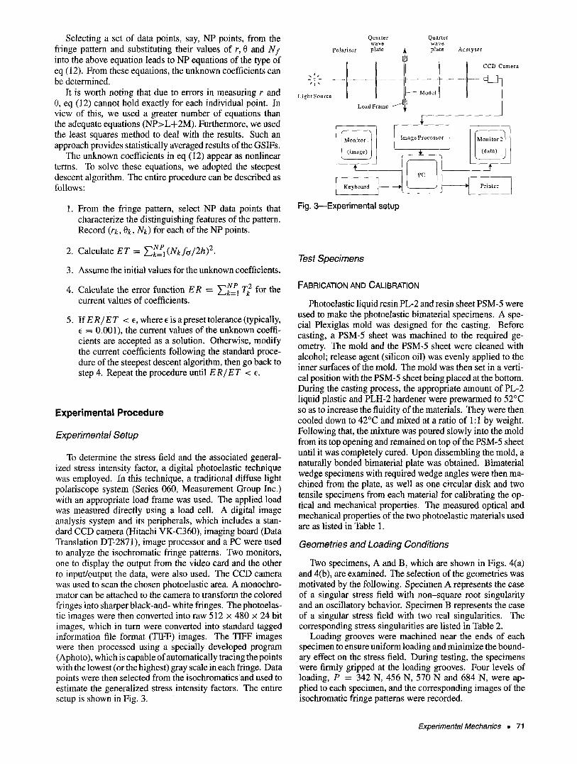
To determine the stress field and the associated general- ized stress intensity factor, a digital photoelastic technique was employed. In this technique, a traditional diffuse light polariscope system (Series 060, Measurement Group Inc.) with an appropriate load frame was used. The applied load was measured directly using a load cell. A digital image analysis system and its peripherals, which includes a stan- dard CCD camera (Hitachi VK-C360), imaging board (Data Translation DT-2871), image processor and a PC were used to analyze the isochromatic fringe patterns. Two monitors, one to display the output from the video card and the other to input/output the data, were also used. The CCD camera was used to scan the chosen photoelastic area. A monochro- mator can be attached to the camera to transform the colored fringes into sharper black-and- white fringes. The photoelas- tic images were then converted into raw 512 x 480 x 24 bit images, which in turn were converted into standard tagged information file format (TIFF) images. The TIFF images were then processed using a specially developed program (Aphoto), which is capable of automatically tracing the points with the lowest (or the highest) gray scale in each fringe. Data points were then selected from the isochromaticsand used to estimate the generalized stress intensity factors. The entire setup is shown in Fig. 3.
Quarter Quarter wave wave
Polariser plate ~ plate Analyser
i ...... ~o I_ . . . . . . . . . . . . . ~*t,~ . . . . . . . . . . . . . . . . . . . . . . . . . . . . . . . . . . . . . . . . . . . . . . . .
Light Source Model
LoadFrame ~-~ ~
Keyboard ]
ImageProcessor
Printer
Fig. 3--Experimental setup
Test Specimens
FABRICATION AND CALIBRATION
Photoelastic liquid resin PL-2 and resin sheet PSM-5 were used to make the photoelastic bimaterial specimens. A spe- cial Plexiglas mold was designed for the casting. Before casting, a PSM-5 sheet was machined to the required ge- ometry. The mold and the PSM-5 sheet were cleaned with alcohol; release agent (silicon oil) was evenly applied to the inner surfaces of the mold. The mold was then set in a verti- cal position with the PSM-5 sheet being placed at the bottom. During the casting process, the appropriate amount of PL-2 liquid plastic and PLH-2 hardener were prewarmed to 52~ so as to increase the fluidity of the materials. They were then cooled down to 42~ and mixed at a ratio of 1:1 by weight. Following that, the mixture was poured slowly into the mold from its top opening and remained on top of the PSM-5 sheet until it was completely cured. Upon dissembling the mold, a naturally bonded bimaterial plate was obtained. Bimaterial wedge specimens with required wedge angles were then ma- chined from the plate, as well as one circular disk and two tensile specimens from each material for calibrating the op- tical and mechanical properties. The measured optical and mechanical properties of the two photoelastic materials used are as listed in Table 1.
Geometries and Loading Conditions
Two specimens, A and B, which are shown in Figs. 4(a) and 4(b), are examined. The selection of the geometries was motivated by the following. Specimen A represents the case of a singular stress field with non-square root singularity and an oscillatory behavior. Specimen B represents the case of a singular stress field with two real singularities. The corresponding stress singularities are listed in Table 2.
Loading grooves were machined near the ends of each specimen to ensure uniform loading and minimize the bound- ary effect on the stress field. During testing, the specimens were firmly gripped at the loading grooves. Four levels of loading, P = 342 N, 456 N, 570 N and 684 N, were ap- plied to each specimen, and the corresponding images of the isochromatic fringe patterns were recorded.
Experimental Mechanics �9 71

TABLE 1--OPTICAL AND MECHANICAL PROPERTIES OF CONSTITUENT PHOTOELASTIC MATERIALS i
Material E (GPa) v fo (KN/m.fringe) 1 (PSM-5) 2.50 0.36 14.5 2 (PL-2) 0.22 0.42 7.0
TABLE 2--STRESS SINGULARITIES OF THE PHOTOELASTIC SPECIMENS i i i
Specimen ct(~ = ~) YI Y2 A 150 deg 0.385+0.019i 0.385-0.019i B 135 deg 0.414 0.167
Specimen A t'
PSM-51
Interface
~ 1~=150 ~
65 ram loading grooves
/
Specimen B
t" PSM-5
lmerfaeMe~
[~=1_3
65 mm
Thickness = 6.5 nan
loading grooves /
(a) (b)
Fig. Zl~Geometries and loading conditions of different specimens: (a) specimen A: ct = 13 = 150 deg, (b) specimen B: o~ = 15 = 150 deg
(a) (b)
Results and Discussion
Isochromatic Fringe Patterns in Bimaterial Wedges
In this section, we provide a comparison between the isochromatic fringe patterns resulting from the tensile load- ing of homogeneous and bimaterial wedges. Figures 5(a) and 5(b) show the fringe patterns in the photoelastic bimaterial wedges designated A and B, whereas Figs. 5(c) and 5(d) show the same geometries using a single homogeneous material. The fringe patterns reveal the following:
. The effect of the elastic mismatch dominates the field variables at the vertices of the bimaterial wedges, as evidenced by the lack of symmetry and the spacing between the fringes.
.
.
The symmetric isochromatic pattern resulting in the homogeneous case is remarkably different from that observed in the bimaterial case, in spite of the fact that the geometries and loading conditions were similar.
The stiffer region of the wedge shows a much increased resistance to loading. This is evident by the reduced number and density of the resulting fringe pattern.
Comparison between Theoretical and Experimental Results in Bimaterial Systems
Specimens A and B were loaded in tension: P = 342 N, 456 N, 570 N and 684 N. Some of the resulting isochromatic
(c) (d) Fig. 5--1sochromatic fringe patterns of four photoelastic models under a tensile load of P = 684 N: (a) bimaterial specimen A, (b) bimaterial specimen B, (c) single-material specimen C, (d) single-material specimen D. The geome- tries of specimens C and D are similar to A and B, respectively
fringe patterns are shown in Figs. 6(a), 6(b), 7(a) and 7(b). These isochromatic fringe patterns were analyzed and the results compared with the finite element predictions.
To illustrate the analysis procedure, let us examine Spec- imen A under a tensile load P = 684 N. In this case, the original isochromatic fringe pattern [Fig. 6(b)] was processed using Aphoto. The processed isochromatic fringe loops and the selected data points are shown in Fig. 8. Both the two- parameter and the multiparameter methods for extracting the GSIFs were used to process the data collected from Fig. 8. The results of GSIFs are listed in Table 3. The finite element predictions for the same case are also listed in Table 3.
The experimental results derived by using the two- parameter method and the multiparameter method are dif- ferent, implying that the higher order terms in the stress ex- pressions have significant influence on the fringe patterns. Furthermore, the two-parameter method can provide reason- ably good results by selecting the proper data points. In view of its simplicity, the two-parameter method could be used to provide a quick estimate of the GSIFs. The multiparameter
72 �9 Vol. 40, No. 1, March 2000
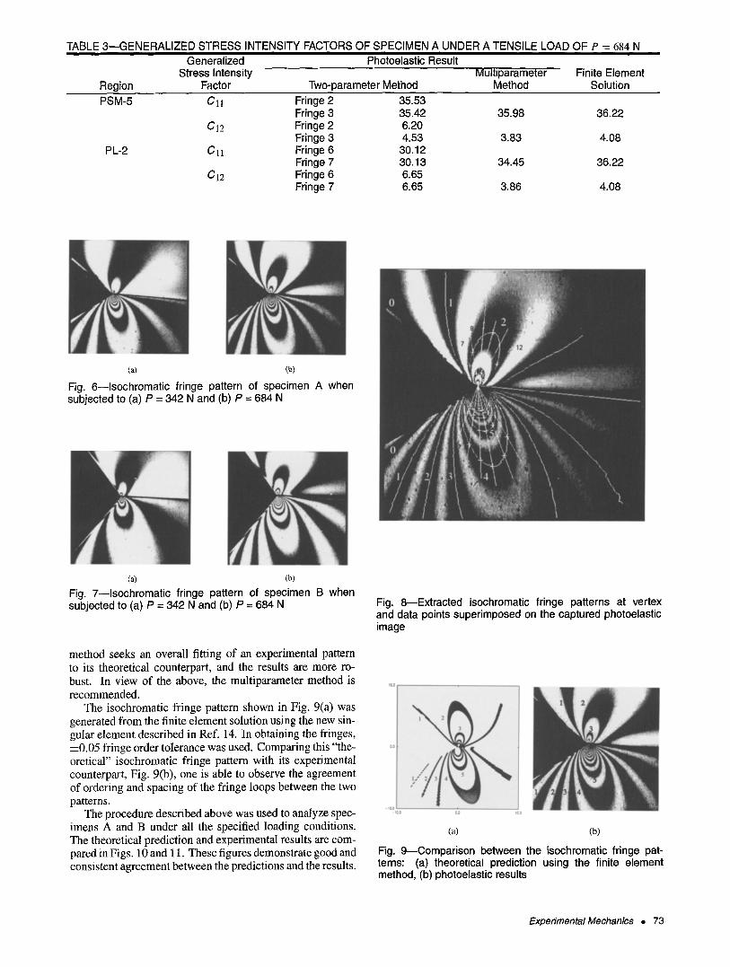
TABLE 3--GENERALIZED STRESS INTENSITY FACTORS OF SPECIMEN A UNDER A TENSILE LOAD OF P = 684 N Generalized Photoelastic Result
Stress Intensity Multiparameter Finite Element Region Factor Two-parameter Method Method Solution PSM-5 C11 Fringe 2 35.53
Fringe 3 35.42 35.98 36.22 CI2 Fringe 2 6.20
Fringe 3 4.53 3.83 4.08 PL-2 C]I Fringe 6 30.12
Fringe 7 30.13 34.45 36.22 C12 Fringe 6 6.65
Fringe 7 6.65 3.86 4.08
(a) (b)
Fig. 6--1sochromatic fringe pattern of specimen A when subjected to (a) P = 342 N and (b) P = 684 N
(a) (b) Fig. 7--1sochromatic fringe pattern of specimen B when subjected to (a) P = 342 N and (b) P = 684 N
method seeks an overall fitting of an experimental pattern to its theoretical counterpart, and the results are more ro- bust. In view of the above, the multiparameter method is recommended.
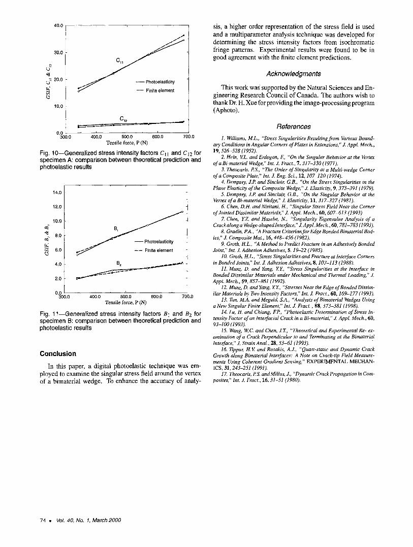
The isochromatic fringe pattern shown in Fig. 9(a) was generated from the finite element solution using the new sin- gular element described in Ref. 14. In obtaining the fringes, -4-0.05 fringe order tolerance was used. Comparing this "the- oretical" isochromatic fringe pattern with its experimental counterpart, Fig. 9(b), one is able to observe the agreement of ordering and spacing of the fringe loops between the two patterns.
The procedure described above was used to analyze spec- imens A and B under all the specifed loading conditions. The theoretical prediction and experimental results are com- pared in Figs. 10 and 11. These figures demonstrate good and consistent agreement between the predictions and the results.
Fig. 8---Extracted isochromatic fringe patterns at vertex and data points superimposed on the captured photoelastic image
(a) (b)
Fig. 9--Comparison between the isochromatic fringe pat- terns: (a) theoretical prediction using the finite element method, (b) photoelastic results
Experimental Mechanics �9 73
40.0
~ 30.0
20.0 ~ ~ Photoelasticity
~" ~ ---- Finite element
10.0
C12
0"O00.0 400.0 500.0 600.0 700.0 Tensile force, P (N)
Fig. 10--Generalized stress intensity factors Q1 and C12 for specimen A: comparison between theoretical prediction and photoelastic results
14.0
12,0
10,0
8,0
~ 6.0 ---- RnRe element
4.0 B ~
2.0
i i i
0"3000.0 400.0 500.0 600.0 700.0 Tensile force, P (N)
Fig. 11--Generalized stress intensity factors B t and B2 for specimen B: comparison between theoretical prediction and photoelastic results
Conclusion
In this paper, a digital photoelastic technique was em- ployed to examine the singular stress field around the vertex of a bimaterial wedge. To enhance the accuracy of analy-
sis, a higher order representation of the stress field is used and a multiparameter analysis technique was developed for determining the stress intensity factors from isochromatic fringe patterns. Experimental results were found to be in good agreement with the finite element predictions.
Acknowledgments
This work was supported by the Natural Sciences and En- gineering Research Council of Canada. The authors wish to thank Dr. H. Xue for providing the image-processing program (Aphoto).
References 1. Williams, M.L., "Stress Singularities Resulting from Various Bound-
ary Conditions in Angular Corners of Plates in Extensions," J. Appl. Mech., 19, 526-528 (1952).
2. Hein, V.L. and Erdogan, E, "'On the Singular Behavior at the Vertex of a Bi-material Wedge," Int. J. Fract., 7, 317-330 (1971).
3. Theocaris, P.S., "The Order of Singularity at a Multi-wedge Corner of a Composite Plate," Int. J. Eng. Sci., 12, 107-120 (1974).
4. Dempsey, J.P and Sinclair, G.B., "On the Stress Singularities in the Plane Elasticity of the Composite Wedge," J. Elasticity, 9, 373-391 (1979).
5. Dempsey, J.P and Sinclair, G.B., "On the Singular Behavior at the Vertex of a Bi-material Wedge," J. Elasticity, 11, 317-327 (1981).
6. Chen, D.H. and Nisitani, H., "Singular Stress Field Near the Corner of Jointed Dissimilar Materials," J. Appl. Mech., 60, 607-613 (1993).
Z Chen, Y.Z. and Hasebe, N., "Singularity Eigenvalue Analysis of a Crackalong a Wedge-shaped lnterface," Z AppL Mech., 60, 781-783 (1993).
8. Gradin, PA., "A Fracture Criterion for Edge Bonded Bimaterial Bod- ies," J. Composite Mat., 16, 448-456 (1982).
9. Groth, H.L., "A Method to Predict Fracture in an Adhesively Bonded Joint," Int. J. Adhesion Adhesives, 5, 19-22 (1985).
10. Groth, H.L., "Stress Singularities and Fracture at Interface Corners in Bonded Joints," Int. J. Adhesion Adhesives, 8, 107-113 (1988).
11. Munz, D. and Yang, Y.Y., "Stress Singularities at the Interface in Bonded Dissimilar Materials under Mechanical and Thermal Loading," J. Appl. Mech., 59, 857-861 (1992).
12. Munz, D. and Yang, Y.Y., "Stresses Near the Edge of Bonded Dissim- ilar Materials by Two Intensity Factors," Int. J. Fract., 60, 169-177 (1993).
13. Tan, M.A. and Meguid, S.A., "Analysis of Bimaterial Wedges Using a New Singular Finite Element," Int. J. Fract., 88, 373-381 (1998).
14. Lu, H. and Chiang, EP, "Photoelastic Determination of Stress In- tensity Factor of an lnterfacial Crack in a Bi-materiaI," J. AppL Mech., 60, 93-100 (1993).
15. Wang, W.C. and Chen, J.T., "Theoretical and Experimental Re- ex- amination of a Crack Perpendicular to and Terminating at the Bimaterial Interface," J. Strain Anal., 28, 53-61 (1993).
16. Tippur, H.V. and Rosakis, A.J., "Quasi-static and Dynamic Crack Growth along Bimaterial Interfaces: A Note on Crack-tip Field Measure- ments Using Coherent Gradient Sensing," EXPERIMENTAL MECHAN- ICS, 31,243-251 (1991).
17. Theocaris, B S. and Millos, J., "Dynamic Crack Propagation in Com- posites," Int. J. Fract., 16, 31-51 (1980).
74 �9 Vol. 40, No. 1, March 2000