Phase Change Materials (PCMs) and Their Optimum Position ...
25
sustainability Review Phase Change Materials (PCMs) and Their Optimum Position in Building Walls Zeyad Amin Al-Absi * , Mohd Hafizal Mohd Isa * and Mazran Ismail School of Housing, Building and Planning, Universiti Sains Malaysia, Penang 11800, Malaysia; [email protected] * Correspondence: [email protected] (Z.A.A.-A.); hafi[email protected] (M.H.M.I.) Received: 2 December 2019; Accepted: 14 January 2020; Published: 11 February 2020 Abstract: More than half of the energy consumption in buildings is utilized for the heating and/or cooling of the indoor environment. The building envelope plays a key role in controlling the effects of external weather and, therefore, is linked with many passive design strategies. Thermal energy storage (TES) and phase change materials (PCMs) are efficient techniques, which can store a high density of thermal energy. The PCMs attract many researchers to implement them in the components of buildings for thermal management. In building walls, they were implemented in different positions and have achieved different results. This paper aims to review the related literature that examines PCMs’ application in different positions within the building walls to locate their optimum position and the influential parameters. It was found that the optimum positions of PCMs are highly dependent on performing a daily complete melting/freezing cycle to be ready for the following day. Many parameters can influence this, including climate and weather conditions and the application target, PCMs’ melting temperature and heat of fusion, PCMs’ amount, the thermal properties of the wall’s materials, a mechanical heating/cooling or free-running indoor environment, and wall orientation. An optimization process using the simulation tools is suggested so that the optimum position of the PCMs can be located. Keywords: Thermal energy storage (TES); Phase Change Materials (PCMs); PCMs application in walls; PCMs optimum positions 1. Introduction Originally, buildings were commonly constructed using local materials. This helped to protect them from local climate conditions and respond to the ambient environment [1]. Traditional buildings were more climate-responsible as they were built to ensure the best control and utilization of climate factors for the inhabitants’ comfort based on the available materials and technologies. Therefore, they showed a better indoor environment and less energy consumption [2,3]. During the industrial revolution, with people migrating to urban areas, which caused overcrowding, the focus of the building construction sector changed from climatic requirements to economical consideration. This resulted in a high dependency on mechanical systems to achieve thermal comfort. However, due to the energy crisis and the negative effects associated with massive energy use, such as climate change, global warming, and greenhouse gas emissions, humans should reduce energy consumption for the sustainability of the planet [1]. Buildings are responsible for 40% of global energy consumption, with as much as 60% of this energy being used for heating and cooling [4]. The building envelop plays a major role in the heat gains and/or losses in buildings [5]. Therefore, buildings provide a great opportunity through their envelope to minimize this high energy consumption by introducing more promising solutions, like passive design strategies. Thermal energy storage (TES), particularly phase change materials (PCMs) are useful sustainable passive technologies that can be used in the building fabric to improve heat exchange and energy Sustainability 2020, 12, 1294; doi:10.3390/su12041294 www.mdpi.com/journal/sustainability
-
Upload
khangminh22 -
Category
Documents
-
view
1 -
download
0
Transcript of Phase Change Materials (PCMs) and Their Optimum Position ...

sustainability
Review
Phase Change Materials (PCMs) and Their OptimumPosition in Building Walls
Zeyad Amin Al-Absi * , Mohd Hafizal Mohd Isa * and Mazran Ismail
School of Housing, Building and Planning, Universiti Sains Malaysia, Penang 11800, Malaysia; [email protected]* Correspondence: [email protected] (Z.A.A.-A.); [email protected] (M.H.M.I.)
Received: 2 December 2019; Accepted: 14 January 2020; Published: 11 February 2020�����������������
Abstract: More than half of the energy consumption in buildings is utilized for the heating and/orcooling of the indoor environment. The building envelope plays a key role in controlling the effectsof external weather and, therefore, is linked with many passive design strategies. Thermal energystorage (TES) and phase change materials (PCMs) are efficient techniques, which can store a highdensity of thermal energy. The PCMs attract many researchers to implement them in the componentsof buildings for thermal management. In building walls, they were implemented in different positionsand have achieved different results. This paper aims to review the related literature that examinesPCMs’ application in different positions within the building walls to locate their optimum position andthe influential parameters. It was found that the optimum positions of PCMs are highly dependenton performing a daily complete melting/freezing cycle to be ready for the following day. Manyparameters can influence this, including climate and weather conditions and the application target,PCMs’ melting temperature and heat of fusion, PCMs’ amount, the thermal properties of the wall’smaterials, a mechanical heating/cooling or free-running indoor environment, and wall orientation.An optimization process using the simulation tools is suggested so that the optimum position of thePCMs can be located.
Keywords: Thermal energy storage (TES); Phase Change Materials (PCMs); PCMs application inwalls; PCMs optimum positions
1. Introduction
Originally, buildings were commonly constructed using local materials. This helped to protectthem from local climate conditions and respond to the ambient environment [1]. Traditional buildingswere more climate-responsible as they were built to ensure the best control and utilization of climatefactors for the inhabitants’ comfort based on the available materials and technologies. Therefore,they showed a better indoor environment and less energy consumption [2,3]. During the industrialrevolution, with people migrating to urban areas, which caused overcrowding, the focus of the buildingconstruction sector changed from climatic requirements to economical consideration. This resulted in ahigh dependency on mechanical systems to achieve thermal comfort. However, due to the energy crisisand the negative effects associated with massive energy use, such as climate change, global warming,and greenhouse gas emissions, humans should reduce energy consumption for the sustainability ofthe planet [1]. Buildings are responsible for 40% of global energy consumption, with as much as 60%of this energy being used for heating and cooling [4]. The building envelop plays a major role in theheat gains and/or losses in buildings [5]. Therefore, buildings provide a great opportunity throughtheir envelope to minimize this high energy consumption by introducing more promising solutions,like passive design strategies.
Thermal energy storage (TES), particularly phase change materials (PCMs) are useful sustainablepassive technologies that can be used in the building fabric to improve heat exchange and energy
Sustainability 2020, 12, 1294; doi:10.3390/su12041294 www.mdpi.com/journal/sustainability

Sustainability 2020, 12, 1294 2 of 25
efficiency and minimize energy consumption [6]. They can store a high density of thermal energywith slighter temperature change [7]. The favourability of using PCMs lies in the ability of a thinlayer of PCMs to store a large amount of heat. Many researchers implemented them in buildings toimprove the thermal performance of building materials and minimize energy consumption. Previousstudies extensively reviewed TES and PCMs in terms of materials’ development, type, properties,performance, methods of testing, and methods of application [8–17].
It was observed that some works examined the application of PCMs in different positions withinthe building walls (i.e., two positions—internally and externally—and up to 16 different positions)looking for the optimum position, which guarantees the best performance. However, different resultswere achieved. For instance, the optimum position was achieved in the internal layer of the wall [18–20],in the external layer of the wall [21,22] or within the wall section (i.e., in the middle, close to internalsurface or close to external surface) [7,23–27]. The current work, therefore, aims at reviewing thepreviously conducted studies, which examined PCMs in different positions within the buildings’ wallsto locate the optimum position of PCMs, and identify the parameters that have an impact on achievinga variety of PCMs’ optimum position in these studies. This work starts with a brief introductionon TES, then PCMs and their types, properties, advantages, requirements for their application, andmethods of integration into buildings. After that, it addresses the application of PCMs in buildings’walls, focusing mainly on reviewing and analysing previous works that have examined PCMs indifferent positions to find the best performance and the optimum position. The methodologies of theseworks were studied and reviewed in detail to identify the involved parameters and understand theirinfluence on PCMs performance.
2. Thermal Energy Storage (TES)
Thermal energy storage (TES) is basically the storing of the available thermal energy in order toreuse it during its shortage. The most significant value of TES is that it can solve the mismatch betweenthe supply and demand of energy [28]. For instance, with TES, solar energy during the day-time canbe stored to be used for heating the cold night-time, while the coolness of night-time can be used forcooling the warm day-time [29]. Furthermore, it is possible to store the heat of the warm summermonths for heating in winter, and the coolness of the winter for cooling in summer. This is knownas seasonal TES, which can help in meeting the energy needs caused by the seasonal temperaturefluctuations [28]. Water and ice are often regarded as the favoured storage mediums for heating andcooling, respectively. TES can improve the heat exchange and energy efficiency of buildings [6] andcan help in reducing fuel consumption through the effective use of equipment and systems that utilizethermal energy. Furthermore, the wasted low-cost energy, where its time of generation differs from thethermal demand period, such as passive and active solar heating and the internal heat produced byoccupants, lighting, cooking, and appliances, can be utilized through TES [14]. Moreover, low-costenergy can be purchased during off-peak periods and stored for high-rate periods. Besides, TESreduces the peaks in energy demand, which, in turn, reduces its associated cost [14].
TES capture (charge), store, and reuse (discharge) the thermal energy. Energy storage in materialshas three types, known as sensible heat, latent heat, and thermochemical [4,30]. The best known typesfor TES are sensible heat (i.e., storage by causing a temperature rise) and latent heat (i.e., storage bycausing a phase change) [28]. However, the latter is preferable [14].
3. Phase Change Materials (PCMS)
PCMs are the types of TES materials in which the latent heat is absorbed or released duringthe material’s phase change. They can help in regulating the ambient temperature within a specificrange close to their transition temperature. When the ambient temperature increases more than thePCMs’ melting temperature, the chemical bonds in the material break up causing the material toabsorbing the additional heat, while its state changes from solid to liquid. On the other hand, once thetemperature drops below the PCMs’ freezing temperature, the material discharges the energy and,

Sustainability 2020, 12, 1294 3 of 25
therefore, changes back to the solid-state [16]. If the material’s phase transition temperatures (i.e.,the melting and freezing temperatures) match with the required comfort temperature in buildings,it can help to maintain the indoor thermal environment within comfortable conditions and reducesthe total hours of thermal discomfort by absorbing the extra heat [4] and, thus, reducing the heatingand/or cooling loads. Figure 1a illustrates how PCMs can improve a building’s indoor environment byreducing indoor temperature peaks and fluctuation. Furthermore, the favourability of using PCMs liesin the ability of a thin layer of PCMs to store a large amount of heat. For instance, a wall made fromPCMs could be 20 times thinner than a wall made from concrete [31]. The point when the materialchanges its phase greatly enhances the material’s storage capacity [30], which can store a higher densityof thermal energy with a smaller change in temperature [7,29], as shown in Figure 1b.
Sustainability 2019, 11, x FOR PEER REVIEW 3 of 24
temperature drops below the PCMs’ freezing temperature, the material discharges the energy and, therefore, changes back to the solid-state [16]. If the material’s phase transition temperatures (i.e., the melting and freezing temperatures) match with the required comfort temperature in buildings, it can help to maintain the indoor thermal environment within comfortable conditions and reduces the total hours of thermal discomfort by absorbing the extra heat [4] and, thus, reducing the heating and/or cooling loads. Figure 1a illustrates how PCMs can improve a building’s indoor environment by reducing indoor temperature peaks and fluctuation. Furthermore, the favourability of using PCMs lies in the ability of a thin layer of PCMs to store a large amount of heat. For instance, a wall made from PCMs could be 20 times thinner than a wall made from concrete [31]. The point when the material changes its phase greatly enhances the material’s storage capacity [30], which can store a higher density of thermal energy with a smaller change in temperature [7,29], as shown in Figure 1b.
Temperature
Time
Peak temperature delay
less temperaturefluctuation
Temperature profile with PCMsTemperature profile without PCMs
Peak temperature reduction
(a)
Meltingtemperature
Latent heatSens
ible h
eat
Sensibl
e heat
Sensibl
e heat
Temperature
Stored HeatTotal stored heat (sensible)
Total stored heat with PCMs (sensible + Latent)
Additional stored heat
(b)
Figure 1. Role of PCMs application in regulating a building’s indoor temperature (a) [4], and the storage capacity of materials with latent heat compared to sensible heat only (b) [32].
Generally, phase-changing in materials has four types: solid–solid, solid–liquid, solid–gas and liquid–gas [4]. However, the solid–liquid variety can be practically applied in the building sector for many reasons, including its lesser volume alteration, requiring a smaller quantity of the material to store a given amount of energy, and the nearly constant temperature by which the thermal energy is stored [4,11,33]. PCMs come in various types. Generally, they are classified into three main categories: organic PCMs, inorganic PCMs, and eutectic PCMs. Each category can be divided based on the various components of the PCMs [4,11,16,34,35], as shown in Figure 2.
Figure 2. Phase change materials (PCMs) categories [35].
The selection of an ideal phase change material (PCM) for the building application is important and governed by a wide range of characteristics and requirements that should be fulfilled, including thermodynamic, chemical, kinetic, and technical and economic characteristics [4,11,12,15,36]. These characteristics and requirements are summarized in Figure 3.
Figure 1. Role of PCMs application in regulating a building’s indoor temperature (a) [4], and thestorage capacity of materials with latent heat compared to sensible heat only (b) [32].
Generally, phase-changing in materials has four types: solid–solid, solid–liquid, solid–gas andliquid–gas [4]. However, the solid–liquid variety can be practically applied in the building sector formany reasons, including its lesser volume alteration, requiring a smaller quantity of the material tostore a given amount of energy, and the nearly constant temperature by which the thermal energy isstored [4,11,33]. PCMs come in various types. Generally, they are classified into three main categories:organic PCMs, inorganic PCMs, and eutectic PCMs. Each category can be divided based on the variouscomponents of the PCMs [4,11,16,34,35], as shown in Figure 2.
Sustainability 2019, 11, x FOR PEER REVIEW 3 of 24
temperature drops below the PCMs’ freezing temperature, the material discharges the energy and,
therefore, changes back to the solid-state [16]. If the material’s phase transition temperatures (i.e., the
melting and freezing temperatures) match with the required comfort temperature in buildings, it can
help to maintain the indoor thermal environment within comfortable conditions and reduces the total
hours of thermal discomfort by absorbing the extra heat [4] and, thus, reducing the heating and/or
cooling loads. Figure 1a illustrates how PCMs can improve a building’s indoor environment by
reducing indoor temperature peaks and fluctuation. Furthermore, the favourability of using PCMs
lies in the ability of a thin layer of PCMs to store a large amount of heat. For instance, a wall made
from PCMs could be 20 times thinner than a wall made from concrete [31]. The point when the
material changes its phase greatly enhances the material’s storage capacity [30], which can store a
higher density of thermal energy with a smaller change in temperature [7,29], as shown in Figure 1b.
Temperature
Time
Peak temperature delay
less temperature
fluctuation
Temperature profile with PCMsTemperature profile without PCMs
Peak temperature reduction
(a)
Melting
temperatureLatent heat
Sensibl
e he
at
Sensibl
e he
at
Sensibl
e he
at
Temperature
Stored Heat
Total stored heat (sensible)
Total stored heat with PCMs (sensible + Latent)
Additional stored heat
(b)
Figure 1. Role of PCMs application in regulating a building’s indoor temperature (a) [4], and the
storage capacity of materials with latent heat compared to sensible heat only (b) [32].
Generally, phase-changing in materials has four types: solid–solid, solid–liquid, solid–gas and
liquid–gas [4]. However, the solid–liquid variety can be practically applied in the building sector for
many reasons, including its lesser volume alteration, requiring a smaller quantity of the material to
store a given amount of energy, and the nearly constant temperature by which the thermal energy is
stored [4,11,33]. PCMs come in various types. Generally, they are classified into three main categories:
organic PCMs, inorganic PCMs, and eutectic PCMs. Each category can be divided based on the
various components of the PCMs [4,11,16,34,35], as shown in Figure 2.
Organic PCM
Phase Change Materials (PCMs)
Inorganic PCM Eutectic PCM
Non-paraffinic PCMs
Paraffinic PCMs
Metalics
Salt Hydrates
Inorganic-Inorganic
Organic-Organic
Organic-InorganicFatty acids Esters Alcohols Glycols
Figure 2. Phase change materials (PCMs) categories [35].
The selection of an ideal phase change material (PCM) for the building application is important
and governed by a wide range of characteristics and requirements that should be fulfilled, including
thermodynamic, chemical, kinetic, and technical and economic characteristics [4,11,12,15,36]. These
characteristics and requirements are summarized in Figure 3.
Figure 2. Phase change materials (PCMs) categories [35].
The selection of an ideal phase change material (PCM) for the building application is importantand governed by a wide range of characteristics and requirements that should be fulfilled,including thermodynamic, chemical, kinetic, and technical and economic characteristics [4,11,12,15,36].These characteristics and requirements are summarized in Figure 3.

Sustainability 2020, 12, 1294 4 of 25
PCMs are integrated into building materials to enhance their thermal properties. According toHawes [37] and Kenisarin and Mahkamov [14], building materials that can be used to host the PCMsare preferred to fulfil the following conditions:
• Being widely used in various types of structures;• Possess a large contact surface that promotes heat transfer;• Possess a short heat exchange depth;• Ease of production and quality control using existing facilities;• Their geometry and structure help them to act as the thermal conduit in exploitation and improve
the function of heat reservoirs, heat exchangers and building elements;• Ease of constructing of test structures;• Their structure can retain the PCMs, even in the liquid state, by virtue of surface tension.
Sustainability 2019, 11, x FOR PEER REVIEW 4 of 24
PCMs are integrated into building materials to enhance their thermal properties. According to
Hawes [37] and Kenisarin and Mahkamov [14], building materials that can be used to host the PCMs
are required to fulfil the following conditions:
• They are being widely used and in a variety of structures;
• Have a large contact surface to encourage heat transfer;
• Have small heat exchange depth;
• Production and quality control of these materials can be carried out using existing facilities;
• Their location, geometry, and structure help them combine the function of a thermal conduit;
heat reservoirs, heat exchangers and building elements;
• Test structure can be easily constructed;
• Their structure can retain the PCMs, even in the liquid state, by virtue of surface tension.
Thermodynamic properties
PCMs selection requirements for building application
Chemical propertiesTechnical &
economical properties
Thermal conductivity
Transition temperature
Kinetic properties
- Within operating temperature- Thermal comfort requirement- Close to the average room temperature
- Good thermal conductivity for energy storage application- Low thermal conductivity for thermal insulation application
Higher latent heat of fusion
Higher specific heat capacity
Physical stability with Small volume changes
Consistent melting and freezing behavior
Complete reversible melting/freezing cycle
Long-term chemical stability
Proper cycling stability with no degradation after repeated melting/freezing cycles
Non-corrosive
Non-flammable
Non-explosive
Non-toxic
High crystallization rate
Super-cooling (sub-cooling)
- No or little super-cooling (tends to super-cool below the melting temperature before it starts solidify)
Available in large scale
Applicability, simplicity, effectiveness, compatibility with other materials, compactness, viability and reliability.
Effective low cost
Figure 3. Selection of a PCM based on its properties.
Different technologies are available for PCMs’ integration into building materials. These
technologies can be classified into direct incorporation, immersion, encapsulation, and stabilization
(Figure 4). With direct incorporation, the PCMs, in the solid-state, are added directly into the
materials, while, in immersion, the building materials and elements are immersed into the liquid
PCMs allowing for absorption by capillary action. Even though both technologies are economical and
practical, the leakage of PCMs, inflammability, and incompatibility with building materials are the
main drawbacks of these techniques. On the other hand, the PCMs’ encapsulation involves macro-
encapsulation, micro-encapsulation, and nano-encapsulation. In the macro-encapsulation, PCMs are
packed in different types of containers (tubes, spheres, panels, etc.), while, in the micro-encapsulation
and nano-encapsulation, the PCMs particles are enclosed in a thin shell (i.e., between 1000 and 1 µm
for micro-capsules and below 1000 nm for nano-capsules) [25,38]. Finally, PCMs stabilization means
that they are incorporated into a supporting porous structure such as high-density polyethylene [34].
Figure 3. Selection of a PCM based on its properties.
Different technologies are available for PCMs’ integration into building materials. These technologiescan be classified into direct incorporation, immersion, encapsulation, and stabilization [25] (Figure 4).With direct incorporation, the PCMs are added directly into the materials, while, in immersion, thebuilding materials and elements are immersed into the liquid PCMs allowing for absorption bycapillary action. Even though both technologies are economical and practical, the leakage of PCMs,inflammability, and incompatibility with building materials are the main drawbacks of these techniques.On the other hand, the PCMs’ encapsulation involves macro-encapsulation, micro-encapsulation, andnano-encapsulation. In the macro-encapsulation, PCMs are packed in different types of containers(tubes, spheres, panels, etc.), while, in the micro-encapsulation and nano-encapsulation, the PCMsparticles are enclosed in a thin shell (i.e., between 1000 and 1 µm for micro-capsules and below 1000nm for nano-capsules) [25,38]. Finally, PCMs stabilization means that they are incorporated into asupporting porous structure such as high-density polyethylene [34].

Sustainability 2020, 12, 1294 5 of 25
Sustainability 2019, 11, x FOR PEER REVIEW 5 of 24
Direct incorporation of PCM
Phase Change Materials Integration technologies
Impregnation of PCM
Stabilization of PCM
Liquid PCM incorporation
Solid PCM incorporation
Imbibing
Immersion
Form-stabilization
Shape-stabilization
Encapsulation of PCM
Micro/Nano-encapsulation
Macro-encapsulation
Figure 4. PCMs’ integration technologies into building materials.
3.1. PCMs Application in Building Walls
The PCMs have attracted many researchers to implement them into buildings’ walls for thermal
management. For instance, PCMs-enhanced bricks, blocks, wallboards, panels, and plaster were
developed and tested extensively [35,39]. Generally, PCMs layers are placed close to the indoor
environment [40]. For example, Ramakrishnan et al. [41] applied macro-encapsulated PCMs as the
inner linings of the walls and ceilings, which effectively reduced the indoor heat stress risks and
improved occupants’ comfort and health. Meng, Yu, and Zhou [42] applied a composite PCMs layer
made of two PCMs with different melting temperatures on the inner surface of the wall in one room
to improve the wall performance in summer and winter, and the results showed better thermal
performance in both seasons. Barzin et al. [6] applied PCM-impregnated gypsum boards on the
internal surface of the walls and tested it with a combination of night ventilation for cooling purposes,
which resulted in weekly electricity saving of 73%. Ascione et al. [43] numerically tested a 20 mm
thick PCMs layer applied on the internal surface of the building external wall and achieved a
reduction of 11.7% and 1.6% for summer cooling and winter heating, respectively.
PCMs layers are also placed in other positions within the buildings’ walls. For example, Lei et
al. [44] applied PCMs in combination with cool colours on the external surface of the walls to reduce
external heat gain in tropics, in order to decrease the cooling load, and achieved 2–15% savings.
Vicente and Silva [45] incorporated macro-incapsulated PCM into the centre of a brick masonry wall,
which helped to reduce and delay the temperature peaks. De Gracia et al. [46] applied macro-
encapsulated PCM panels inside the cavity of a ventilated façade to reduce both heating and cooling
loads during winter and summer, respectively. Cao et al. [47] experimentally developed a
geopolymer concrete wall containing micro-encapsulated PCM and tested it numerically, which
significantly reduced the annual energy consumption for heating and cooling.
Furthermore, multiple PCMs layers were implemented in buildings’ walls. However, each
PCMs layer was implemented for a different purpose. For instance, Zhu et al. [48] investigated the
possible energy saving achieved by the use of two layers of a shape-stabilized phase change
materials-wallboard (SSPCMs) in five typical climate regions of China. Two different SSPCMs
wallboards with different thermophysical properties were attached to a common concrete wall (i.e.,
one wallboard on the inner surface and the other on the outer surface), as shown in Figure 5. The
south wall of the simulated room was integrated with the SSPCMs wallboards, while the other three
walls, ceiling, and floor were thermally isolated. As an office building, the air-conditioner was set to
work from 7:00 to 18:00 with a set point of 18 °C for winter and/or 26 °C for summer based on the
heating and/or cooling requirements of each region.
Based on the experimental results, the external SSPCMs layer reduced external heat gain in
summer. Therefore, it reduced the cooling load for the regions that require cooling, while it reduced
the peak indoor temperature, leading to a more comfortable time if cooling is not required. On the
other hand, the internal SSPCMs layer stored the extra indoor heat and released it back during the
insufficient day-time heat in winter. Therefore, it reduced the heating load for regions that require
heating, while it improved the indoor temperature and the comfortable time in the regions that do
not require heating. In addition, they noticed that the indoor temperature influenced the optimum
Figure 4. PCMs’ integration technologies into building materials.
3.1. PCMs Application in Building Walls
The PCMs have attracted many researchers to implement them into buildings’ walls for thermalmanagement. For instance, PCMs-enhanced bricks, blocks, wallboards, panels, and plaster weredeveloped and tested extensively [35,39]. Generally, PCMs layers are placed close to the indoorenvironment [40]. For example, Ramakrishnan et al. [41] applied macro-encapsulated PCMs as theinner linings of the walls and ceilings, which effectively reduced the indoor heat stress risks andimproved occupants’ comfort and health. Meng, Yu, and Zhou [42] applied a composite PCMslayer made of two PCMs with different melting temperatures on the inner surface of the wall in oneroom to improve the wall performance in summer and winter, and the results showed better thermalperformance in both seasons. Barzin et al. [6] applied PCM-impregnated gypsum boards on the internalsurface of the walls and tested it with a combination of night ventilation for cooling purposes, whichresulted in weekly electricity saving of 73%. Ascione et al. [43] numerically tested a 20 mm thick PCMslayer applied on the internal surface of the building external wall and achieved a reduction of 11.7%and 1.6% for summer cooling and winter heating, respectively.
PCMs layers are also placed in other positions within the buildings’ walls. For example, Lei et al. [44]applied PCMs in combination with cool colours on the external surface of the walls to reduce externalheat gain in tropics, in order to decrease the cooling load, and achieved 2–15% savings. Vicente andSilva [45] incorporated macro-incapsulated PCM into the centre of a brick masonry wall, which helpedto reduce and delay the temperature peaks. De Gracia et al. [46] applied macro-encapsulated PCMpanels inside the cavity of a ventilated façade to reduce both heating and cooling loads during winterand summer, respectively. Cao et al. [47] experimentally developed a geopolymer concrete wallcontaining micro-encapsulated PCM and tested it numerically, which significantly reduced the annualenergy consumption for heating and cooling.
Furthermore, multiple PCMs layers were implemented in buildings’ walls. However, each PCMslayer was implemented for a different purpose. For instance, Zhu et al. [48] investigated the possibleenergy saving achieved by the use of two layers of a shape-stabilized phase change materials-wallboard(SSPCMs) in five typical climate regions of China. Two different SSPCMs wallboards with differentthermophysical properties were attached to a common concrete wall (i.e., one wallboard on the innersurface and the other on the outer surface), as shown in Figure 5. The south wall of the simulatedroom was integrated with the SSPCMs wallboards, while the other three walls, ceiling, and floor werethermally isolated. As an office building, the air-conditioner was set to work from 7:00 to 18:00 with aset point of 18 ◦C for winter and/or 26 ◦C for summer based on the heating and/or cooling requirementsof each region.
Based on the experimental results, the external SSPCMs layer reduced external heat gain insummer. Therefore, it reduced the cooling load for the regions that require cooling, while it reducedthe peak indoor temperature, leading to a more comfortable time if cooling is not required. On theother hand, the internal SSPCMs layer stored the extra indoor heat and released it back during theinsufficient day-time heat in winter. Therefore, it reduced the heating load for regions that require
Sustainability 2020, 12, 1294 6 of 25
heating, while it improved the indoor temperature and the comfortable time in the regions that donot require heating. In addition, they noticed that the indoor temperature influenced the optimummelting temperature of the internal PCM layer, while the outdoor ambient temperature influenced theoptimum melting temperature of the external PCM layer.
Sustainability 2019, 11, x FOR PEER REVIEW 6 of 24
melting temperature of the internal PCM layer, while the outdoor ambient temperature influenced the optimum melting temperature of the external PCM layer.
LimeInsulation 2
Insulation 1Concrete
LimePCM2
Insulation 1Concrete
Insulation 2Lime
PCM1Insulation 1
Double SSPCMs wallboard Reference wallboard
Outdoor Indoor Outdoor Indoor
Figure 5. Wall with PCM layers (left) and the reference wall without PCMs (right) [48].
3.2. Investigation of PCMs’ Optimum Position in Buildings’ Walls
The PCMs’ position in building walls showed various effects on the phase-change process of PCMs and, consequently, the improvement in the wall’s thermal performance [40]. Therefore, some researchers investigated the effects of changing the position of the PCMs layer in building walls, looking for the optimum position of the PCMs layer.
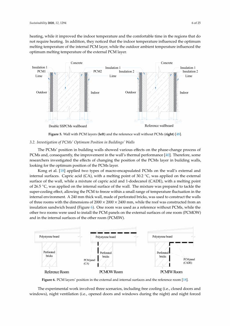
Kong et al. [18] applied two types of macro-encapsulated PCMs on the wall’s external and internal surfaces. Capric acid (CA), with a melting point of 30.2 °C, was applied on the external surface of the wall, while a mixture of capric acid and 1-dodecanol (CADE), with a melting point of 26.5 °C, was applied on the internal surface of the wall. The mixture was prepared to tackle the super-cooling effect, allowing the PCM to freeze within a small range of temperature fluctuation in the internal environment. A total of 240 mm perforated bricks was used to construct the walls of three rooms with the dimensions of 2000 × 2000 × 2400 mm, while the roof was constructed from an insulation sandwich board (Figure 6). One room was used as a reference without PCMs, while the other two rooms were used to install the PCM panels on the external surfaces of one room (PCMOW) and in the internal surfaces of the other room (PCMIW).
Polystyrene boardPolystyrene boardPolystyrene board
Reference Room PCMOW Room PCMIW Room
PCM panel(CA)
PCM panel(CADE)
Perforatedbricks
Perforatedbricks
Perforatedbricks
Figure 6. PCM layers’ position in the external and internal surfaces and the reference room [18].
The experimental work involved three scenarios, including free cooling (i.e., closed doors and windows), night ventilation (i.e., opened doors and windows during the night) and night forced ventilation (i.e., an air exhauster was installed on the window and operated during the night). The results showed that the PCM on the internal surface of the wall achieved a peak indoor temperature reduction of 2.3 °C and time delay of 3 h, compared to 1 °C and 2.1 h, respectively, for the case of PCM on the external surface. In addition, applying night ventilation and night forced ventilation further increased the reduction in the peak temperatures, especially with the PCM applied on the inner surface. This indicates the direct influence of the PCMs, which are applied on the internal
Figure 5. Wall with PCM layers (left) and the reference wall without PCMs (right) [48].
3.2. Investigation of PCMs’ Optimum Position in Buildings’ Walls
The PCMs’ position in building walls showed various effects on the phase-change process ofPCMs and, consequently, the improvement in the wall’s thermal performance [40]. Therefore, someresearchers investigated the effects of changing the position of the PCMs layer in building walls,looking for the optimum position of the PCMs layer.
Kong et al. [18] applied two types of macro-encapsulated PCMs on the wall’s external andinternal surfaces. Capric acid (CA), with a melting point of 30.2 ◦C, was applied on the externalsurface of the wall, while a mixture of capric acid and 1-dodecanol (CADE), with a melting pointof 26.5 ◦C, was applied on the internal surface of the wall. The mixture was prepared to tackle thesuper-cooling effect, allowing the PCM to freeze within a small range of temperature fluctuation in theinternal environment. A 240 mm thick wall, made of perforated bricks, was used to construct the wallsof three rooms with the dimensions of 2000 × 2000 × 2400 mm, while the roof was constructed from aninsulation sandwich board (Figure 6). One room was used as a reference without PCMs, while theother two rooms were used to install the PCM panels on the external surfaces of one room (PCMOW)and in the internal surfaces of the other room (PCMIW).
Sustainability 2019, 11, x FOR PEER REVIEW 6 of 24
melting temperature of the internal PCM layer, while the outdoor ambient temperature influenced the optimum melting temperature of the external PCM layer.
LimeInsulation 2
Insulation 1Concrete
LimePCM2
Insulation 1Concrete
Insulation 2Lime
PCM1Insulation 1
Double SSPCMs wallboard Reference wallboard
Outdoor Indoor Outdoor Indoor
Figure 5. Wall with PCM layers (left) and the reference wall without PCMs (right) [48].
3.2. Investigation of PCMs’ Optimum Position in Buildings’ Walls
The PCMs’ position in building walls showed various effects on the phase-change process of PCMs and, consequently, the improvement in the wall’s thermal performance [40]. Therefore, some researchers investigated the effects of changing the position of the PCMs layer in building walls, looking for the optimum position of the PCMs layer.
Kong et al. [18] applied two types of macro-encapsulated PCMs on the wall’s external and internal surfaces. Capric acid (CA), with a melting point of 30.2 °C, was applied on the external surface of the wall, while a mixture of capric acid and 1-dodecanol (CADE), with a melting point of 26.5 °C, was applied on the internal surface of the wall. The mixture was prepared to tackle the super-cooling effect, allowing the PCM to freeze within a small range of temperature fluctuation in the internal environment. A total of 240 mm perforated bricks was used to construct the walls of three rooms with the dimensions of 2000 × 2000 × 2400 mm, while the roof was constructed from an insulation sandwich board (Figure 6). One room was used as a reference without PCMs, while the other two rooms were used to install the PCM panels on the external surfaces of one room (PCMOW) and in the internal surfaces of the other room (PCMIW).
Polystyrene boardPolystyrene boardPolystyrene board
Reference Room PCMOW Room PCMIW Room
PCM panel(CA)
PCM panel(CADE)
Perforatedbricks
Perforatedbricks
Perforatedbricks
Figure 6. PCM layers’ position in the external and internal surfaces and the reference room [18].
The experimental work involved three scenarios, including free cooling (i.e., closed doors and windows), night ventilation (i.e., opened doors and windows during the night) and night forced ventilation (i.e., an air exhauster was installed on the window and operated during the night). The results showed that the PCM on the internal surface of the wall achieved a peak indoor temperature reduction of 2.3 °C and time delay of 3 h, compared to 1 °C and 2.1 h, respectively, for the case of PCM on the external surface. In addition, applying night ventilation and night forced ventilation further increased the reduction in the peak temperatures, especially with the PCM applied on the inner surface. This indicates the direct influence of the PCMs, which are applied on the internal
Figure 6. PCM layers’ position in the external and internal surfaces and the reference room [18].
The experimental work involved three scenarios, including free cooling (i.e., closed doors andwindows), night ventilation (i.e., opened doors and windows during the night) and night forced
Sustainability 2020, 12, 1294 7 of 25
ventilation (i.e., an air exhauster was installed on the window and operated during the night).The results showed that the PCM on the internal surface of the wall achieved a peak indoor temperaturereduction of 2.3 ◦C and time delay of 3 h, compared to 1 ◦C and 2.1 h, respectively, for the case of PCMon the external surface. In addition, applying night ventilation and night forced ventilation furtherincreased the reduction in the peak temperatures, especially with the PCM applied on the inner surface.This indicates the direct influence of the PCMs, which are applied on the internal surfaces, on theindoor environment. However, they mentioned that applying PCMs on the external surface of thewalls has a role of thermal insulation rather than as a temperature regulator.
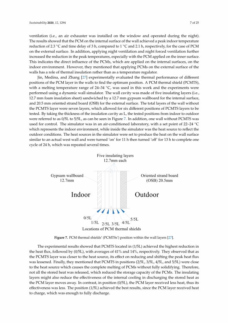
Jin, Medina, and Zhang [27] experimentally evaluated the thermal performance of differentpositions of the PCM layer in the walls to find the optimum position. A PCM thermal shield (PCMTS),with a melting temperature range of 24–34 ◦C, was used in this work and the experiments wereperformed using a dynamic wall simulator. The wall cavity was made of five insulating layers (i.e.,12.7 mm foam insulation sheet) sandwiched by a 12.7 mm gypsum wallboard for the internal surface,and 20.5 mm oriented strand board (OSB) for the external surface. The total layers of the wall withoutthe PCMTS layer were seven layers, which allowed for six different positions of PCMTS layers to betested. By taking the thickness of the insulation cavity as L, the tested positions from indoor to outdoorwere referred to as 0/5L to 5/5L, as can be seen in Figure 7. In addition, one wall without PCMTS wasused for control. The simulator was in an air-conditioned laboratory, with a set point of 22–24 ◦Cwhich represents the indoor environment, while inside the simulator was the heat source to reflect theoutdoor conditions. The heat sources in the simulator were set to produce the heat on the wall surfacesimilar to an actual west wall and were turned ‘on’ for 11 h then turned ‘off’ for 13 h to complete onecycle of 24 h, which was repeated several times.
Sustainability 2019, 11, x FOR PEER REVIEW 7 of 24
surfaces, on the indoor environment. However, they mentioned that applying PCMs on the external surface of the walls has a role of thermal insulation rather than as a temperature regulator.
Jin, Medina, and Zhang [27] experimentally evaluated the thermal performance of different positions of the PCM layer in the walls to find the optimum position. A PCM thermal shield (PCMTS), with a melting temperature range of 24–34 °C, was used in this work and the experiments were performed using a dynamic wall simulator. The wall cavity was made of five insulating layers (i.e., 12.7 mm foam insulation sheet) sandwiched by a 12.7 mm gypsum wallboard for the internal surface, and 20.5 mm oriented strand board (OSB) for the external surface. The total layers of the wall without the PCMTS layer were seven layers, which allowed for six different positions of PCMTS layers to be tested. By taking the thickness of the insulation cavity as L, the tested positions from indoor to outdoor were referred to as 0/5L to 5/5L, as can be seen in Figure 7. In addition, one wall without PCMTS was used for control. The simulator was in an air-conditioned laboratory, with a set point of 22–24 °C which represents the indoor environment, while inside the simulator was the heat source to reflect the outdoor conditions. The heat sources in the simulator were set to produce the heat on the wall surface similar to an actual west wall and were turned ‘on’ for 11 h then turned ‘off’ for 13 h to complete one cycle of 24 h, which was repeated several times.
OutdoorIndoor
Gypsum wallboard12.7mm
Oriented strand board(OSB) 20.5mm
Five insulating layers12.7mm each
0/5L1/5L 2/5L 3/5L 4/5L
5/5L
Locations of PCM thermal shields Figure 7. PCM thermal shields’ (PCMTSs’) position within the wall layers [27].
The experimental results showed that PCMTS located in (1/5L) achieved the highest reduction in the heat flux, followed by (0/5L), with averages of 41% and 14%, respectively. They observed that as the PCMTS layer was closer to the heat source, its effect on reducing and shifting the peak heat flux was lessened. Finally, they mentioned that PCMTS in positions (2/5L, 3/5L, 4/5L, and 5/5L) were close to the heat source which causes the complete melting of PCMs without fully solidifying. Therefore, not all the stored heat was released, which reduced the storage capacity of the PCMs. The insulating layers might also reduce the effectiveness of the internal cooling in discharging the stored heat as the PCM layer moves away. In contrast, in position (0/5L), the PCM layer received less heat, thus its effectiveness was less. The position (1/5L) achieved the best results, since the PCM layer received heat to charge, which was enough to fully discharge.
Zwanzig, Lian, and Brehob, [23] numerically investigated a PCMs composite wallboard incorporated into different positions in a multi-layered building wall under all seasonal conditions. The multi-layered wall consisted of: (1) 9.5 mm EIFS finish (exterior), (2) 25.4 mm insulation board, (3) 12.7 mm fibreboard sheathing, (4) 89.4 mm batt insulation and (5) 15.9 mm gypsum board (interior). They used a PCM composite wallboard containing paraffin PCM with a transition temperature range of 25–27.5 °C. Three different positions for a PCM layer were considered for evaluation: Case 1, between layers 1 and 2; Case 2, between layers 3 and 4; and case 3, replacing layer 5 (Figure 8). The indoor air temperature was selected to be 20 °C for the heating season and 24 °C for the cooling season. The results showed that Case 2 achieved the best results in peak load shifting and reductions compared to other cases during both heating and cooling seasons.
Figure 7. PCM thermal shields’ (PCMTSs’) position within the wall layers [27].
The experimental results showed that PCMTS located in (1/5L) achieved the highest reduction inthe heat flux, followed by (0/5L), with averages of 41% and 14%, respectively. They observed that asthe PCMTS layer was closer to the heat source, its effect on reducing and shifting the peak heat fluxwas lessened. Finally, they mentioned that PCMTS in positions (2/5L, 3/5L, 4/5L, and 5/5L) were closeto the heat source which causes the complete melting of PCMs without fully solidifying. Therefore,not all the stored heat was released, which reduced the storage capacity of the PCMs. The insulatinglayers might also reduce the effectiveness of the internal cooling in discharging the stored heat asthe PCM layer moves away. In contrast, in position (0/5L), the PCM layer received less heat, thus itseffectiveness was less. The position (1/5L) achieved the best results, since the PCM layer received heatto charge, which was enough to fully discharge.
Sustainability 2020, 12, 1294 8 of 25
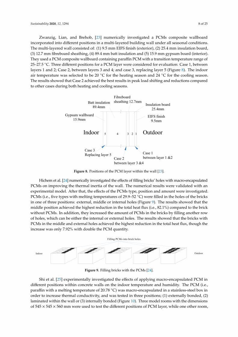
Zwanzig, Lian, and Brehob, [23] numerically investigated a PCMs composite wallboardincorporated into different positions in a multi-layered building wall under all seasonal conditions.The multi-layered wall consisted of: (1) 9.5 mm EIFS finish (exterior), (2) 25.4 mm insulation board,(3) 12.7 mm fibreboard sheathing, (4) 89.4 mm batt insulation and (5) 15.9 mm gypsum board (interior).They used a PCM composite wallboard containing paraffin PCM with a transition temperature range of25–27.5 ◦C. Three different positions for a PCM layer were considered for evaluation: Case 1, betweenlayers 1 and 2; Case 2, between layers 3 and 4; and case 3, replacing layer 5 (Figure 8). The indoorair temperature was selected to be 20 ◦C for the heating season and 24 ◦C for the cooling season.The results showed that Case 2 achieved the best results in peak load shifting and reductions comparedto other cases during both heating and cooling seasons.Sustainability 2019, 11, x FOR PEER REVIEW 8 of 24
OutdoorIndoor
Gypsum wallboard15.9mm
EIFS finish9.5mm
Case 3Replacing layer 5
Case 2between layer 3 &4
Case 1between layer 1 &2
Insulation board25.4mm
Fibreboardsheathing 12.7mmBatt insulation
89.4mm
12345
Figure 8. Positions of the PCM layer within the wall [23].
Hichem et al. [24] numerically investigated the effects of filling bricks’ holes with macro-encapsulated PCMs on improving the thermal inertia of the wall. The numerical results were validated with an experimental model. After that, the effects of the PCMs type, position and amount were investigated. PCMs (i.e., five types with melting temperatures of 29.9–52 °C) were filled in the holes of the bricks in one of three positions: external, middle or internal holes (Figure 9). The results showed that the middle position achieved the highest reduction in the total heat flux (i.e., 82.1%) compared to the brick without PCMs. In addition, they increased the amount of PCMs in the bricks by filling another row of holes, which can be either the internal or external holes. The results showed that the bricks with PCMs in the middle and external holes achieved the highest reduction in the total heat flux, though the increase was only 7.92% with double the PCM quantity.
OutdoorIndoor
Filling PCMs into brick holes
Figure 9. Filling bricks with the PCMs [24].
Shi et al. [25] experimentally investigated the effects of applying macro-encapsulated PCM in different positions within concrete walls on the indoor temperature and humidity. The PCM (i.e., paraffin with a melting temperature of 20.78 °C) was macro-encapsulated in a stainless-steel box in order to increase thermal conductivity, and was tested in three positions; (1) externally bonded, (2) laminated within the wall or (3) internally bonded (Figure 10). Three model rooms with the dimensions of 545 × 545 × 560 mm were used to test the different positions of PCM layer, while one other room, with concrete walls without PCMs, was used as a control. The total thickness of all walls in all room models was controlled to 60 mm, including all layers.
Out
door
Indo
or
PCM externallybonded
PCM laminatedwithin the wall
PCM internallybonded
Control room
Macro-encapsulated PCM(in stainless steel boxes)
Concrete wall
Out
door
Indo
or
Out
door
Indo
or
Out
door
Indo
or
Figure 10. Walls description showing different positions of the PCM layer [25].
Figure 8. Positions of the PCM layer within the wall [23].
Hichem et al. [24] numerically investigated the effects of filling bricks’ holes with macro-encapsulatedPCMs on improving the thermal inertia of the wall. The numerical results were validated with anexperimental model. After that, the effects of the PCMs type, position and amount were investigated.PCMs (i.e., five types with melting temperatures of 29.9–52 ◦C) were filled in the holes of the bricksin one of three positions: external, middle or internal holes (Figure 9). The results showed that themiddle position achieved the highest reduction in the total heat flux (i.e., 82.1%) compared to the brickwithout PCMs. In addition, they increased the amount of PCMs in the bricks by filling another rowof holes, which can be either the internal or external holes. The results showed that the bricks withPCMs in the middle and external holes achieved the highest reduction in the total heat flux, though theincrease was only 7.92% with double the PCM quantity.
Sustainability 2019, 11, x FOR PEER REVIEW 8 of 24
OutdoorIndoor
Gypsum wallboard15.9mm
EIFS finish9.5mm
Case 3Replacing layer 5
Case 2between layer 3 &4
Case 1between layer 1 &2
Insulation board25.4mm
Fibreboardsheathing 12.7mmBatt insulation
89.4mm
12345
Figure 8. Positions of the PCM layer within the wall [23].
Hichem et al. [24] numerically investigated the effects of filling bricks’ holes with macro-encapsulated PCMs on improving the thermal inertia of the wall. The numerical results were validated with an experimental model. After that, the effects of the PCMs type, position and amount were investigated. PCMs (i.e., five types with melting temperatures of 29.9–52 °C) were filled in the holes of the bricks in one of three positions: external, middle or internal holes (Figure 9). The results showed that the middle position achieved the highest reduction in the total heat flux (i.e., 82.1%) compared to the brick without PCMs. In addition, they increased the amount of PCMs in the bricks by filling another row of holes, which can be either the internal or external holes. The results showed that the bricks with PCMs in the middle and external holes achieved the highest reduction in the total heat flux, though the increase was only 7.92% with double the PCM quantity.
OutdoorIndoor
Filling PCMs into brick holes
Figure 9. Filling bricks with the PCMs [24].
Shi et al. [25] experimentally investigated the effects of applying macro-encapsulated PCM in different positions within concrete walls on the indoor temperature and humidity. The PCM (i.e., paraffin with a melting temperature of 20.78 °C) was macro-encapsulated in a stainless-steel box in order to increase thermal conductivity, and was tested in three positions; (1) externally bonded, (2) laminated within the wall or (3) internally bonded (Figure 10). Three model rooms with the dimensions of 545 × 545 × 560 mm were used to test the different positions of PCM layer, while one other room, with concrete walls without PCMs, was used as a control. The total thickness of all walls in all room models was controlled to 60 mm, including all layers.
Out
door
Indo
or
PCM externallybonded
PCM laminatedwithin the wall
PCM internallybonded
Control room
Macro-encapsulated PCM(in stainless steel boxes)
Concrete wall
Out
door
Indo
or
Out
door
Indo
or
Out
door
Indo
or
Figure 10. Walls description showing different positions of the PCM layer [25].
Figure 9. Filling bricks with the PCMs [24].
Shi et al. [25] experimentally investigated the effects of applying macro-encapsulated PCM indifferent positions within concrete walls on the indoor temperature and humidity. The PCM (i.e.,paraffin with a melting temperature of 20.78 ◦C) was macro-encapsulated in a stainless-steel box inorder to increase thermal conductivity, and was tested in three positions; (1) externally bonded, (2)laminated within the wall or (3) internally bonded (Figure 10). Three model rooms with the dimensionsof 545 × 545 × 560 mm were used to test the different positions of PCM layer, while one other room,

Sustainability 2020, 12, 1294 9 of 25
with concrete walls without PCMs, was used as a control. The total thickness of all walls in all roommodels was controlled to 60 mm, including all layers.
Sustainability 2019, 11, x FOR PEER REVIEW 8 of 24
OutdoorIndoor
Gypsum wallboard15.9mm
EIFS finish9.5mm
Case 3Replacing layer 5
Case 2between layer 3 &4
Case 1between layer 1 &2
Insulation board25.4mm
Fibreboardsheathing 12.7mmBatt insulation
89.4mm
12345
Figure 8. Positions of the PCM layer within the wall [23].
Hichem et al. [24] numerically investigated the effects of filling bricks’ holes with macro-encapsulated PCMs on improving the thermal inertia of the wall. The numerical results were validated with an experimental model. After that, the effects of the PCMs type, position and amount were investigated. PCMs (i.e., five types with melting temperatures of 29.9–52 °C) were filled in the holes of the bricks in one of three positions: external, middle or internal holes (Figure 9). The results showed that the middle position achieved the highest reduction in the total heat flux (i.e., 82.1%) compared to the brick without PCMs. In addition, they increased the amount of PCMs in the bricks by filling another row of holes, which can be either the internal or external holes. The results showed that the bricks with PCMs in the middle and external holes achieved the highest reduction in the total heat flux, though the increase was only 7.92% with double the PCM quantity.
OutdoorIndoor
Filling PCMs into brick holes
Figure 9. Filling bricks with the PCMs [24].
Shi et al. [25] experimentally investigated the effects of applying macro-encapsulated PCM in different positions within concrete walls on the indoor temperature and humidity. The PCM (i.e., paraffin with a melting temperature of 20.78 °C) was macro-encapsulated in a stainless-steel box in order to increase thermal conductivity, and was tested in three positions; (1) externally bonded, (2) laminated within the wall or (3) internally bonded (Figure 10). Three model rooms with the dimensions of 545 × 545 × 560 mm were used to test the different positions of PCM layer, while one other room, with concrete walls without PCMs, was used as a control. The total thickness of all walls in all room models was controlled to 60 mm, including all layers.
Out
door
Indo
or
PCM externallybonded
PCM laminatedwithin the wall
PCM internallybonded
Control room
Macro-encapsulated PCM(in stainless steel boxes)
Concrete wall
Out
door
Indo
or
Out
door
Indo
or
Out
door
Indo
or
Figure 10. Walls description showing different positions of the PCM layer [25]. Figure 10. Walls description showing different positions of the PCM layer [25].
The results from the three models with PCM layers showed less fluctuation, and less and delayedmaximum temperatures, compared to the control model, especially during sunny days, while theeffects were limited during cloudy days. In addition, the model with PCM laminated within thewall achieved the best temperature reduction (i.e., 4 ◦C) amongst the three models compared to thecontrol model, while the model with the internally bonded PCM achieved a better reduction in relativehumidity (i.e., 16%). However, the authors mentioned that the three PCM models were tested ondifferent days and for different durations and suggested carrying out the test on the same days toachieve a better comparison.
In another work, Jin, Medina, and Zhang [19] experimentally investigated the thermal performanceof three different positions of PCMTS using the dynamic wall simulator. A typical North Americanresidential wall system was selected for the test, which consists of (1) 12.7 mm gypsum wallboard,(2) cardboard, (3) PCMTS (4) two layers of 44.5 mm fiberglass insulation and (5) a 20.5 mm orientedstrand board (OSB). A PCMTS layer with cardboard was placed near to the gypsum wallboard, near tothe OSB and between the two insulation layers (Figure 11). The experimental setup was similar to theprevious work [27]. The results showed that the higher reduction in the peak heat fluxes was 11%,with the PCMTS layer near to the gypsum wallboard within the cavity. However, the reduction in thepeak heat fluxes was smaller when the PCMTS layer was placed between the two insulation layers,while there was no effect with the PCMTS layer placed within the cavity near to OSB. They concludedthat PCMTS should be placed closer to the conditioned space.
Sustainability 2019, 11, x FOR PEER REVIEW 9 of 24
The results from the three models with PCM layers showed less fluctuation, and less and delayed maximum temperatures, compared to the control model, especially during sunny days, while the effects were limited during cloudy days. In addition, the model with PCM laminated within the wall achieved the best temperature reduction (i.e., 4°C) amongst the three models compared to the control model, while the model with the internally bonded PCM achieved a better reduction in relative humidity (i.e., 16%). However, the authors mentioned that the three PCM models were tested on different days and for different durations and suggested carrying out the test on the same days to achieve a better comparison.
In another work, Jin, Medina, and Zhang [19] experimentally investigated the thermal performance of three different positions of PCMTS using the dynamic wall simulator. A typical North American residential wall system was selected for the test, which consists of (1) 12.7 mm gypsum wallboard, (2) cardboard, (3) PCMTS (4) two layers of 44.5 mm fiberglass insulation and (5) a 20.5 mm oriented strand board (OSB). A PCMTS layer with cardboard was placed near to the gypsum wallboard, near to the OSB and between the two insulation layers (Figure 11). The experimental setup was similar to the previous work [27]. The results showed that the higher reduction in the peak heat fluxes was 11%, with the PCMTS layer near to the gypsum wallboard within the cavity. However, the reduction in the peak heat fluxes was smaller when the PCMTS layer was placed between the two insulation layers, while there was no effect with the PCMTS layer placed within the cavity near to OSB. They concluded that PCMTS should be placed closer to the conditioned space.
OutdoorIndoor
Gypsum wallboard12.7mm
Oriented strand board(OSB) 20.5mm
Two fiberglass insulating layers44.5mm each
3 tested locations of PCMthermal shields with cardboard
Figure 11. Wall layers description and PCM’s positions [19].
Lee et al. [26] investigated the thermal performance of building walls integrated with a thin PCMTS layer in a different position. The experiment was conducted using two 1830 × 1830 × 1220 mm identical test houses. The walls consisted of 9.5 mm plywood siding, five layers of 12.7 mm rigid foam insulation and 9.5 mm wallboards. In one test house, the PCM layer was installed in the cavity of the south and the west walls, each in one position for a total of five different positions, starting next to the wallboard (first position) and proceeding between the foam insulation layers towards the exterior side of the wall (Figure 12). The second test house was used as the control. The indoor environments of both test houses were air-conditioned.
The results showed that the PCM layer in the south wall melted only partially in Positions 1 and 2 (i.e., close to interior wall surface), while the full melting process occurred in Positions 3, 4 and 5 (i.e., close to exterior wall surface). However, the solidification process did not fully occur in Positions 3, 4 and 5. In addition, Position 3 achieved the maximum reduction in peak heat flux (i.e., 52.3%), while Position 1 achieved maximum peak heat flux delays (i.e., 6.3 h). On the other hand, for the west wall, Position 2 achieved the maximum peak heat flux reduction and maximum peak hat flux delays (i.e., 29.7% and 2.3 h, respectively). The heat flux for the west wall was higher compared to the south wall, thus the optimum PCM position moved from Position 3 in the south wall to Position 2 in the west wall (i.e., away from the heat source, to achieve a better melting/freezing cycle).
Figure 11. Wall layers description and PCM’s positions [19].
Sustainability 2020, 12, 1294 10 of 25
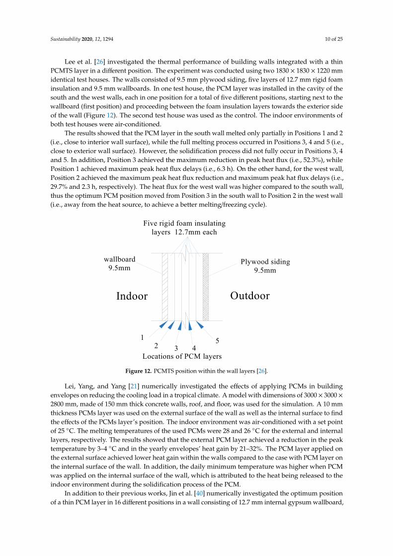
Lee et al. [26] investigated the thermal performance of building walls integrated with a thinPCMTS layer in a different position. The experiment was conducted using two 1830 × 1830 × 1220 mmidentical test houses. The walls consisted of 9.5 mm plywood siding, five layers of 12.7 mm rigid foaminsulation and 9.5 mm wallboards. In one test house, the PCM layer was installed in the cavity of thesouth and the west walls, each in one position for a total of five different positions, starting next to thewallboard (first position) and proceeding between the foam insulation layers towards the exterior sideof the wall (Figure 12). The second test house was used as the control. The indoor environments ofboth test houses were air-conditioned.
The results showed that the PCM layer in the south wall melted only partially in Positions 1 and 2(i.e., close to interior wall surface), while the full melting process occurred in Positions 3, 4 and 5 (i.e.,close to exterior wall surface). However, the solidification process did not fully occur in Positions 3, 4and 5. In addition, Position 3 achieved the maximum reduction in peak heat flux (i.e., 52.3%), whilePosition 1 achieved maximum peak heat flux delays (i.e., 6.3 h). On the other hand, for the west wall,Position 2 achieved the maximum peak heat flux reduction and maximum peak hat flux delays (i.e.,29.7% and 2.3 h, respectively). The heat flux for the west wall was higher compared to the south wall,thus the optimum PCM position moved from Position 3 in the south wall to Position 2 in the west wall(i.e., away from the heat source, to achieve a better melting/freezing cycle).
Sustainability 2019, 11, x FOR PEER REVIEW 10 of 24
OutdoorIndoor
wallboard9.5mm
Plywood siding9.5mm
Five rigid foam insulatinglayers 12.7mm each
12 3 4
5
Locations of PCM layers Figure 12. PCMTS position within the wall layers [26].
Lei, Yang, and Yang [21] numerically investigated the effects of applying PCMs in building envelopes on reducing the cooling load in a tropical climate. A model with dimensions of 3000 × 3000 × 2800 mm, made of 150 mm thick concrete walls, roof, and floor, was used for the simulation. A 10 mm thickness PCMs layer was used on the external surface of the wall as well as the internal surface to find the effects of the PCMs layer’s position. The indoor environment was air-conditioned with a set point of 25 °C. The melting temperatures of the used PCMs were 28 and 26 °C for the external and internal layers, respectively. The results showed that the external PCM layer achieved a reduction in the peak temperature by 3–4 °C and in the yearly envelopes’ heat gain by 21–32%. The PCM layer applied on the external surface achieved lower heat gain within the walls compared to the case with PCM layer on the internal surface of the wall. In addition, the daily minimum temperature was higher when PCM was applied on the internal surface of the wall, which is attributed to the heat being released to the indoor environment during the solidification process of the PCM.
In addition to their previous works, Jin et al. [40] numerically investigated the optimum position of a thin PCM layer in 16 different positions in a wall consisting of 12.7 mm internal gypsum wallboard, 89 mm insulation layer and 20.5 mm external oriented strand board (OSB). Assuming that the insulation layer thickness, L, is divided into 16 parts evenly, the PCM layer can be placed between the gypsum wallboard and the first part of the insulation layer (referred to as 0/16L), between the first and second parts of the insulation layers (1/16L), proceeding until the space between the last part of the insulation layer and the OSB (16/16L). The numerical model was experimentally validated using a dynamic wall simulator. The investigation involved examining the effects of PCM layer thickness, melting temperature and the heat of fusion and the internal surface temperature of the wall on the PCM’s positions and the heat flux of the wall. The results showed the following: 1) the increased PCM layer thickness caused the optimum position of PCM to move outward, closer to the heat source (i.e., more PCM can store more heat). However, beyond a certain position, the PCM’s effectiveness is reduced (i.e., it gets extra heat that keeps the PCM in the liquid state most of the time), 2) the increased PCM’s melting temperature and PCM’s heat of fusion caused the optimum position of PCM to move outward (i.e., closer to the outdoor heat), 3) the increased wall interior surface temperature caused the optimum position of PCM to move inward, closer to the internal environment (i.e., to get enough cooling to release the heat). However, it must be noted that the optimum position in all the investigated cases was moving between positions 1/16L and 5/16L, which means that the optimum position of the PCM layer was still in the internal part of the wall.
Fateh et al. [7] numerically and experimentally tested the PCM layer in four different positions within a lightweight wall made of XPS insulation. The control wall was made from three layers of XPS insulation with a total thickness of 33 mm. A PCM DuPont Energain® board of 5 mm thick was installed in the outer surface (Position 1), between the external and middle XPS layers (Position 2), between the internal and middle XPS layers (Position 3), or in the inner surface of the wall (Position 4), resulting in a total thickness of 38 mm (Figure 13). The wall samples were tested in an insulated
Figure 12. PCMTS position within the wall layers [26].
Lei, Yang, and Yang [21] numerically investigated the effects of applying PCMs in buildingenvelopes on reducing the cooling load in a tropical climate. A model with dimensions of 3000 × 3000 ×2800 mm, made of 150 mm thick concrete walls, roof, and floor, was used for the simulation. A 10 mmthickness PCMs layer was used on the external surface of the wall as well as the internal surface to findthe effects of the PCMs layer’s position. The indoor environment was air-conditioned with a set pointof 25 ◦C. The melting temperatures of the used PCMs were 28 and 26 ◦C for the external and internallayers, respectively. The results showed that the external PCM layer achieved a reduction in the peaktemperature by 3–4 ◦C and in the yearly envelopes’ heat gain by 21–32%. The PCM layer applied onthe external surface achieved lower heat gain within the walls compared to the case with PCM layer onthe internal surface of the wall. In addition, the daily minimum temperature was higher when PCMwas applied on the internal surface of the wall, which is attributed to the heat being released to theindoor environment during the solidification process of the PCM.
In addition to their previous works, Jin et al. [40] numerically investigated the optimum positionof a thin PCM layer in 16 different positions in a wall consisting of 12.7 mm internal gypsum wallboard,

Sustainability 2020, 12, 1294 11 of 25
89 mm insulation layer and 20.5 mm external oriented strand board (OSB). Assuming that the insulationlayer thickness, L, is divided into 16 parts evenly, the PCM layer can be placed between the gypsumwallboard and the first part of the insulation layer (referred to as 0/16L), between the first and secondparts of the insulation layers (1/16L), proceeding until the space between the last part of the insulationlayer and the OSB (16/16L). The numerical model was experimentally validated using a dynamicwall simulator. The investigation involved examining the effects of PCM layer thickness, meltingtemperature and the heat of fusion and the internal surface temperature of the wall on the PCM’spositions and the heat flux of the wall. The results showed the following: 1) the increased PCM layerthickness caused the optimum position of PCM to move outward, closer to the heat source (i.e., morePCM can store more heat). However, beyond a certain position, the PCM’s effectiveness is reduced(i.e., it gets extra heat that keeps the PCM in the liquid state most of the time), 2) the increased PCM’smelting temperature and PCM’s heat of fusion caused the optimum position of PCM to move outward(i.e., closer to the outdoor heat), 3) the increased wall interior surface temperature caused the optimumposition of PCM to move inward, closer to the internal environment (i.e., to get enough cooling torelease the heat). However, it must be noted that the optimum position in all the investigated caseswas moving between positions 1/16L and 5/16L, which means that the optimum position of the PCMlayer was still in the internal part of the wall.
Fateh et al. [7] numerically and experimentally tested the PCM layer in four different positionswithin a lightweight wall made of XPS insulation. The control wall was made from three layers ofXPS insulation with a total thickness of 33 mm. A PCM DuPont Energain® board of 5 mm thick wasinstalled in the outer surface (Position 1), between the external and middle XPS layers (Position 2),between the internal and middle XPS layers (Position 3), or in the inner surface of the wall (Position 4),resulting in a total thickness of 38 mm (Figure 13). The wall samples were tested in an insulated testchamber between two plates. The upper plate, which was set to the main temperature of 26.5 ◦Cand an oscillation amplitude of 12.5 ◦C, simulated the external temperature, while the bottom plate,which was set to 18 ◦C, simulated the internal temperature. Surface temperatures and heat flux weremeasured and showed a very good agreement with the numerical data.
Sustainability 2019, 11, x FOR PEER REVIEW 11 of 24
test chamber between two plates. The upper plate, which was set to the main temperature of 26.5 °C and an oscillation amplitude of 12.5 °C, simulated the external temperature, while the bottom plate, which was set to 18 °C, simulated the internal temperature. Surface temperatures and heat flux were measured and showed a very good agreement with the numerical data.
OutdoorIndoor
Three XPS insulation layers (11mm each)
43 2
1
Positions of PCM layers Figure 13. PCM layer position within the XPS insulation wall layers [7].
The results showed that placing the PCM layer close to the heating source caused a larger variation in temperature. On the other hand, as the PCM layer was placed farther from the heating source and closer to the indoor environment, the XPS insulation layers reduced the temperature fluctuation, which resulted in a very low variation in PCM layer’s temperatures, causing uncompleted activation of the PCM. In the studded conditions, they found that peak reduction in the thermal load was achieved in Positions 2 and 3. They concluded that integrating a PCMs layer in wall construction is influenced by the PCMs’ melting temperature, climate, wall orientation, and the seasons in which the PCMs are most useful.
Gounni and El Alami [22] experimentally investigated the optimal allocation of a PCM layer in a composite wall using a reduced scale test cell, i.e., 400 × 400 × 400 mm, to allow for more flexibility in testing several configurations of the walls. The PCM layer was a 5 mm thick flexible sheet containing composite PCM (i.e., 60% paraffin and 40% polyethylene) with a melting temperature range of 21.7–31 °C. The heating source was a controllable incandescent lamb in the centre of the testing cell representing the outdoor environment, while the test cell was located inside a conditioned laboratory kept at 15–17 °C, which represents the indoor environment. The first test involved three walls, each of 15 mm thick, made of two wood layers (control wall), 5 mm internal PCM and 10 mm external wood layers (PCM1-wall), and 10 mm internal wood and 5 mm external PCM layers (PCM2-wall). The second test involved four walls with different positions of the PCM layers. Each wall has two PCM layers and two wood layers with a total thickness of 30 mm, ordered from internal to external as follow; Wall1: wood, PCM, wood, and PCM; Wall2: PCM, wood, PCM, and wood; Wall3: two layers wood and two layers PCM; and Wall4: two layers PCM and two layers wood (Figure 14).
Out
door
Indo
or
Out
door
Indo
or
Out
door
Indo
or
Out
door
Indo
or
Out
door
Indo
or
Out
door
Indo
or
Out
door
Indo
or
Control PCM1 wall PCM2 wall Wall 1
PCM
Woo
d
Woo
d
Woo
d
Woo
d
Woo
d
Woo
d
Woo
d
Woo
d
Woo
d
Woo
d
Woo
d
PCM
PCM
PCM
PCM
PCM
PCM
PCM
PCM
PCM
Wall 2 Wall 3 Wall 4
Test 1 Test 2 Figure 14. PCM layers’ position within the wall; First test (left) and second test (right) [22].
Each test was performed for one complete cycle consists of 12 h heating, with a set point of 38 °C, followed by 12 h without heating. The results of the first test showed a time delay in temperature raising with PCM-walls compared to the control wall and the maximum reduction in the wall’s
Figure 13. PCM layer position within the XPS insulation wall layers [7].
The results showed that placing the PCM layer close to the heating source caused a larger variationin temperature. On the other hand, as the PCM layer was placed farther from the heating source andcloser to the indoor environment, the XPS insulation layers reduced the temperature fluctuation, whichresulted in a very low variation in PCM layer’s temperatures, causing uncompleted activation of thePCM. In the studied conditions, they found that peak reduction in the thermal load was achieved inPositions 2 and 3. They concluded that integrating a PCMs layer in wall construction is influencedby the PCMs’ melting temperature, climate, wall orientation, and the seasons in which the PCMs aremost useful.

Sustainability 2020, 12, 1294 12 of 25
Gounni and El Alami [22] experimentally investigated the optimal allocation of a PCM layer in acomposite wall using a reduced scale test cell, i.e., 400 × 400 × 400 mm, to allow for more flexibility intesting several configurations of the walls. The PCM layer was a 5 mm thick flexible sheet containingcomposite PCM (i.e., 60% paraffin and 40% polyethylene) with a melting temperature range of 21.7–31◦C. The heating source was a controllable incandescent lamb in the centre of the testing cell representingthe outdoor environment, while the test cell was located inside a conditioned laboratory kept at 15–17◦C, which represents the indoor environment. The first test involved three walls, each of 15 mmthick, made of two wood layers (control wall), 5 mm internal PCM and 10 mm external wood layers(PCM1-wall), and 10 mm internal wood and 5 mm external PCM layers (PCM2-wall). The second testinvolved four walls with different positions of the PCM layers. Each wall has two PCM layers and twowood layers with a total thickness of 30 mm, ordered from internal to external as follow; Wall1: wood,PCM, wood, and PCM; Wall2: PCM, wood, PCM, and wood; Wall3: two layers wood and two layersPCM; and Wall4: two layers PCM and two layers wood (Figure 14).
Sustainability 2019, 11, x FOR PEER REVIEW 11 of 24
test chamber between two plates. The upper plate, which was set to the main temperature of 26.5 °C and an oscillation amplitude of 12.5 °C, simulated the external temperature, while the bottom plate, which was set to 18 °C, simulated the internal temperature. Surface temperatures and heat flux were measured and showed a very good agreement with the numerical data.
OutdoorIndoor
Three XPS insulation layers (11mm each)
43 2
1
Positions of PCM layers Figure 13. PCM layer position within the XPS insulation wall layers [7].
The results showed that placing the PCM layer close to the heating source caused a larger variation in temperature. On the other hand, as the PCM layer was placed farther from the heating source and closer to the indoor environment, the XPS insulation layers reduced the temperature fluctuation, which resulted in a very low variation in PCM layer’s temperatures, causing uncompleted activation of the PCM. In the studded conditions, they found that peak reduction in the thermal load was achieved in Positions 2 and 3. They concluded that integrating a PCMs layer in wall construction is influenced by the PCMs’ melting temperature, climate, wall orientation, and the seasons in which the PCMs are most useful.
Gounni and El Alami [22] experimentally investigated the optimal allocation of a PCM layer in a composite wall using a reduced scale test cell, i.e., 400 × 400 × 400 mm, to allow for more flexibility in testing several configurations of the walls. The PCM layer was a 5 mm thick flexible sheet containing composite PCM (i.e., 60% paraffin and 40% polyethylene) with a melting temperature range of 21.7–31 °C. The heating source was a controllable incandescent lamb in the centre of the testing cell representing the outdoor environment, while the test cell was located inside a conditioned laboratory kept at 15–17 °C, which represents the indoor environment. The first test involved three walls, each of 15 mm thick, made of two wood layers (control wall), 5 mm internal PCM and 10 mm external wood layers (PCM1-wall), and 10 mm internal wood and 5 mm external PCM layers (PCM2-wall). The second test involved four walls with different positions of the PCM layers. Each wall has two PCM layers and two wood layers with a total thickness of 30 mm, ordered from internal to external as follow; Wall1: wood, PCM, wood, and PCM; Wall2: PCM, wood, PCM, and wood; Wall3: two layers wood and two layers PCM; and Wall4: two layers PCM and two layers wood (Figure 14).
Out
door
Indo
or
Out
door
Indo
or
Out
door
Indo
or
Out
door
Indo
or
Out
door
Indo
or
Out
door
Indo
or
Out
door
Indo
or
Control PCM1 wall PCM2 wall Wall 1
PCM
Woo
d
Woo
d
Woo
d
Woo
d
Woo
d
Woo
d
Woo
d
Woo
d
Woo
d
Woo
d
Woo
d
PCM
PCM
PCM
PCM
PCM
PCM
PCM
PCM
PCM
Wall 2 Wall 3 Wall 4
Test 1 Test 2 Figure 14. PCM layers’ position within the wall; First test (left) and second test (right) [22].
Each test was performed for one complete cycle consists of 12 h heating, with a set point of 38 °C, followed by 12 h without heating. The results of the first test showed a time delay in temperature raising with PCM-walls compared to the control wall and the maximum reduction in the wall’s
Figure 14. PCM layers’ position within the wall; First test (left) and second test (right) [22].
Each test was performed for one complete cycle consists of 12 h heating, with a set point of 38 ◦C,followed by 12 h without heating. The results of the first test showed a time delay in temperatureraising with PCM-walls compared to the control wall and the maximum reduction in the wall’sinternal surface temperature was achieved with PCM2-wall (i.e., PCM layer close to the heat source).They linked that to achieving complete melting of the PCM layer on the external surface of the wallcompared to partial melting on the internal surface of the wall. Similar results were obtained from thesecond test, where Wall1 and Wall3 achieved the lowest internal surface temperatures and peak heatflux. In both walls, the PCM layers were placed towards the outdoor environment, close to the heatsource. However, Wall1, which has PCM layers distributed in the wall, achieved a better performancethan Wall3, which has two PCM layers placed in the external wall.
L. Zhu et al. [20] numerically investigated the influence of the position, thickness, and orientationof the PCMs layer on the indoor thermal discomfort during summer in north China. A model room,i.e., 2400 × 2400 × 2400 mm, was used and made of 100 mm thick modular prefabricated EPS panels,covered by two 0.5 mm thick colour steel sheets on each side. An organic PCM (i.e., RT26) was placedin a 2200 × 2200 mm steel container with various thicknesses inside the EPS panel. The optimumposition of PCM layer, with a thickness of 5 mm, was investigated in the walls, roof, and floor inthree positions; in the internal surface (Case 1), in the middle (Case 2), and in the external surface(Case 3), as shown in Figure 15. The simulation was conducted for five days (i.e., 6–10 July), usingthe meteorological weather data of Tianjin, and the last day was used for analysis. The simulationwas validated experimentally in the outdoor environment using a modular prefabricated EPS panelwith a PCM layer (i.e., RT 42 with a melting point of 42 ◦C) placed on the exterior surface, and theresults showed good agreement. The effect of the PCM layer was numerically investigated in thesix orientations.
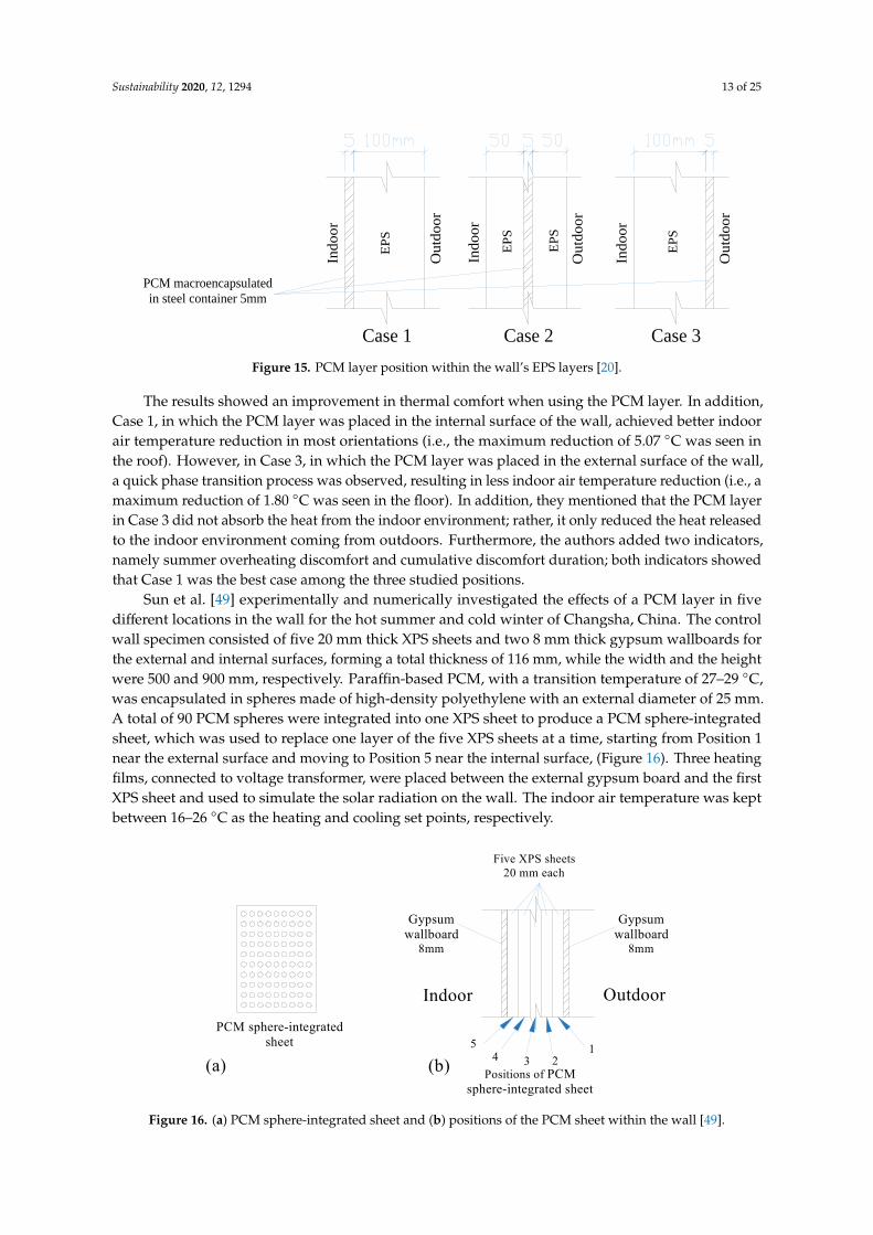
Sustainability 2020, 12, 1294 13 of 25
Sustainability 2019, 11, x FOR PEER REVIEW 12 of 24
internal surface temperature was achieved with PCM2-wall (i.e., PCM layer close to the heat source).
They linked that to achieving complete melting of the PCM layer on the external surface of the wall
compared to partial melting on the internal surface of the wall. Similar results were obtained from
the second test, where Wall1 and Wall3 achieved the lowest internal surface temperatures and peak
heat flux. In both walls, the PCM layers were placed towards the outdoor environment, close to the
heat source. However, Wall1, which has PCM layers distributed in the wall, achieved a better
performance than Wall3, which has two PCM layers placed in the external wall.
L. Zhu et al. [20] numerically investigated the influence of the position, thickness, and
orientation of the PCMs layer on the indoor thermal discomfort during summer in north China. A
model room, i.e., 2400 × 2400 × 2400 mm, was used and made of 100 mm thick modular prefabricated
EPS panels, covered by two 0.5 mm thick colour steel sheets on each side. An organic PCM (i.e., RT26)
was placed in a 2200 × 2200 mm steel container with various thicknesses inside the EPS panel. The
optimum position of PCM layer, with a thickness of 5 mm, was investigated in the walls, roof, and
floor in three positions; in the internal surface (Case 1), in the middle (Case 2), and in the external
surface (Case 3), as shown in Figure 15. The simulation was conducted for five days (i.e., 6–10 July),
using the meteorological weather data of Tianjin, and the last day was used for analysis. The
simulation was validated experimentally in the outdoor environment using a modular prefabricated
EPS panel with a PCM layer (i.e., RT 42 with a melting point of 42 °C) placed on the exterior surface,
and the results showed good agreement. The effect of the PCM layer was numerically investigated
in the six orientations.
Ou
tdo
or
Indoor
Ou
tdo
or
Indoor
Ou
tdo
or
Indoor
EP
S
EP
S
EP
S
Case 1 Case 2 Case 3
EP
S
PCM macroencapsulated
in steel container 5mm
Figure 15. PCM layer position within the wall’s EPS layers [20].
The results showed an improvement in thermal comfort when using the PCM layer. In addition,
Case 1, in which the PCM layer was placed in the internal surface of the wall, achieved better indoor
air temperature reduction in most orientations (i.e., the maximum reduction of 5.07 °C was seen in
the roof). However, in Case 3, in which the PCM layer was placed in the external surface of the wall,
a quick phase transition process was observed, resulting in less indoor air temperature reduction (i.e.,
a maximum reduction of 1.80 °C was seen in the floor). In addition, they mentioned that the PCM
layer in Case 3 did not absorb the heat from the indoor environment; rather, it only reduced the heat
released to the indoor environment coming from outdoors. Furthermore, the authors added two
indicators, namely summer overheating discomfort and cumulative discomfort duration; both
indicators showed that Case 1 was the best case among the three studied positions.
Sun et al. [49] experimentally and numerically investigated the effects of a PCM layer in five
different locations in the wall for the hot summer and cold winter of Changsha, China. The control
wall specimen consisted of five 20 mm thick XPS sheets and two 8 mm thick gypsum wallboards for
the external and internal surfaces, forming a total thickness of 116 mm, while the width and the height
were 500 and 900 mm, respectively. Paraffin-based PCM, with a transition temperature of 27–29 °C, was
encapsulated in spheres made of high-density polyethylene with an external diameter of 25 mm. A total
of 90 PCM spheres were integrated into one XPS sheet to produce a PCM sphere-integrated sheet,
which was used to replace one layer of the five XPS sheets at a time, starting from Position 1 near the
external surface and moving to Position 5 near the internal surface, (Figure 16). Three heating films,
connected to voltage transformer, were placed between the external gypsum board and the first XPS
Figure 15. PCM layer position within the wall’s EPS layers [20].
The results showed an improvement in thermal comfort when using the PCM layer. In addition,Case 1, in which the PCM layer was placed in the internal surface of the wall, achieved better indoorair temperature reduction in most orientations (i.e., the maximum reduction of 5.07 ◦C was seen inthe roof). However, in Case 3, in which the PCM layer was placed in the external surface of the wall,a quick phase transition process was observed, resulting in less indoor air temperature reduction (i.e., amaximum reduction of 1.80 ◦C was seen in the floor). In addition, they mentioned that the PCM layerin Case 3 did not absorb the heat from the indoor environment; rather, it only reduced the heat releasedto the indoor environment coming from outdoors. Furthermore, the authors added two indicators,namely summer overheating discomfort and cumulative discomfort duration; both indicators showedthat Case 1 was the best case among the three studied positions.
Sun et al. [49] experimentally and numerically investigated the effects of a PCM layer in fivedifferent locations in the wall for the hot summer and cold winter of Changsha, China. The controlwall specimen consisted of five 20 mm thick XPS sheets and two 8 mm thick gypsum wallboards forthe external and internal surfaces, forming a total thickness of 116 mm, while the width and the heightwere 500 and 900 mm, respectively. Paraffin-based PCM, with a transition temperature of 27–29 ◦C,was encapsulated in spheres made of high-density polyethylene with an external diameter of 25 mm.A total of 90 PCM spheres were integrated into one XPS sheet to produce a PCM sphere-integratedsheet, which was used to replace one layer of the five XPS sheets at a time, starting from Position 1near the external surface and moving to Position 5 near the internal surface, (Figure 16). Three heatingfilms, connected to voltage transformer, were placed between the external gypsum board and the firstXPS sheet and used to simulate the solar radiation on the wall. The indoor air temperature was keptbetween 16–26 ◦C as the heating and cooling set points, respectively.
Sustainability 2019, 11, x FOR PEER REVIEW 13 of 24
sheet and used to simulate the solar radiation on the wall. The indoor air temperature was kept between 16–26 °C as the heating and cooling set points, respectively.
The results demonstrated that the maximum temperature reduction achieved during the summer was with the PCM-sheet in the third position, while it was in the fourth position during winter (i.e., closer to the internal surface). As heat is required during the winter, the optimum position of the PCM-sheet was moved closer to the indoor environment to benefit from the stored heat for heating. However, for the entire year, the third position was the optimum one. They stated that the optimum PCM’s position is the closest one to the indoor environment, which allows for a complete phase transition of the PCM.
OutdoorIndoor
Gypsumwallboard
8mm
Five XPS sheets20 mm each
54 3 2
1
Positions of PCMsphere-integrated sheet
Gypsumwallboard
8mm
PCM sphere-integratedsheet
(a) (b)
Figure 16. (a) PCM sphere-integrated sheet and (b) positions of the PCM sheet within the wall [49].
Cao et al. [50] numerically investigated the thermal performance of a PCM-based multi-layer wall in the climatic conditions of Oslo, Norway. The control wall was made of two 100 mm thick geopolymer concrete layers with a 50 mm thick insulation layer in between. Micro-encapsulated PCM, with a melting point of 21.9 °C, was integrated into geopolymer concrete and its thermal properties were determined in [47]. The PCM-based geopolymer concrete was used to replace the geopolymer concrete layers in the control wall to produce the PCM-based wall. In addition, a PCM layer (RT21, Rubitherm, Germany) with a melting temperature of 21 °C and various thicknesses in the range 0–50 mm was integrated within the PCM-based geopolymer concrete layers close to the insulation layer (i.e., within the external layer for Position 1 or within the internal layer for Position 2) as shown in Figure 17. The indoor environment was kept within the comfort range of 19–21 °C. The results indicated that a higher reduction in the annual energy is achieved with more PCMs additions. For instance, the reduction was 13% with the use of PCM-based geopolymer concrete layers, while it increased to a maximum of 28% with the addition of a 50 mm PCM layer. In addition, the PCM layer in Position 1, closer to the outdoor environment, has a higher energy reduction, while in Position 2 the reduction was less, which was attributed to the lower temperature variations compared to the melting range, that minimizes the PCM’s performance.
OutdoorIndoor
Insulationlayer
PCM-basedgeopolymer concrete
(a) (b)
PCMslayer
OutdoorIndoor
Insulationlayer
PCM-basedgeopolymer concrete
PCMslayer
OutdoorIndoor
Insulationlayer
Geopolymer concrete
(c)Control Position 1 Position 2 Figure 17. (a) Geopolymer concrete wall (control), (b,c) PCM layer positions [50].
A summary of the reviewed works, ordered by the number of the investigated positions of the PCM layer, is included in Table 1.
Figure 16. (a) PCM sphere-integrated sheet and (b) positions of the PCM sheet within the wall [49].

Sustainability 2020, 12, 1294 14 of 25
The results demonstrated that the maximum temperature reduction achieved during the summerwas with the PCM-sheet in the third position, while it was in the fourth position during winter (i.e.,closer to the internal surface). As heat is required during the winter, the optimum position of thePCM-sheet was moved closer to the indoor environment to benefit from the stored heat for heating.However, for the entire year, the third position was the optimum one. They stated that the optimumPCM’s position is the closest one to the indoor environment, which allows for a complete phasetransition of the PCM.
Cao et al. [50] numerically investigated the thermal performance of a PCM-based multi-layerwall in the climatic conditions of Oslo, Norway. The control wall was made of two 100 mm thickgeopolymer concrete layers with a 50 mm thick insulation layer in between. Micro-encapsulated PCM,with a melting point of 21.9 ◦C, was integrated into geopolymer concrete and its thermal propertieswere determined in [47]. The PCM-based geopolymer concrete was used to replace the geopolymerconcrete layers in the control wall to produce the PCM-based wall. In addition, a PCM layer (RT21,Rubitherm, Germany) with a melting temperature of 21 ◦C and various thicknesses in the range 0–50mm was integrated within the PCM-based geopolymer concrete layers close to the insulation layer (i.e.,within the external layer for Position 1 or within the internal layer for Position 2) as shown in Figure 17.The indoor environment was kept within the comfort range of 19–21 ◦C. The results indicated thata higher reduction in the annual energy is achieved with more PCMs additions. For instance, thereduction was 13% with the use of PCM-based geopolymer concrete layers, while it increased to amaximum of 28% with the addition of a 50 mm PCM layer. In addition, the PCM layer in Position 1,closer to the outdoor environment, has a higher energy reduction, while in Position 2 the reductionwas less, which was attributed to the lower temperature variations compared to the melting range,that minimizes the PCM’s performance.
OutdoorIndoor
Insulationlayer
PCM-basedgeopolymer concrete
(a) (b)
OutdoorIndoor
Insulationlayer
PCM-basedgeopolymer concrete
PCMslayer
OutdoorIndoor
Insulationlayer
Geopolymer concrete
(c)Control Position 1 Position 2
Figure 17.
Climatic conditions Cold regions or winter time(heating is required)
Hot regions or summer time(heat is unwanted)
Inte
rnal
surf
ace
Wallsection Ex
tern
alsu
rfac
e
Application targetReduce internal heat (daytime)
and reuse it (nighttime)Reduce external heat gain
Absorb external heat (daytime)and reuse it (nighttime)
Indoor environment Free cooling - night ventilation
Mechanical cooling
Thermal propertiesof wall materials
Higher thermal resistance
Wall orientation andincident solar radiation
Higher incident solar radiation
PCMs properties
PCMs quantity
Higher melting temperatureand heat of fusion
Higher quantity
Storing heat in order to reuse itStoring heat in order to remove it
(works as a thermal insulation)
Cause PCMs layer to move inward or outwardto find the adequate heating and cooling for
complete daily melting and freezing
Indo
or
(PCMs move closer to heat source)
(PCMs move closer to heat source)
(PCMs move closer to heat source)
(PCMs move away from heat source)
(PCMs move away from cooling)
(PCMs move closer to cooling)
Out
door
Figure 19.
Figure 17. (a) Geopolymer concrete wall (control), (b,c) PCM layer positions [50].
A summary of the reviewed works, ordered by the number of the investigated positions of thePCM layer, is included in Table 1.

Sustainability 2020, 12, 1294 15 of 25
Table 1. Summary of the reviewed works that addressed the optimum position of PCMs in the building’s walls, ordered based on the number of investigatedPCMs positions.
Author Year Type of Study and Period Country and Climate PCMs Position PCMs Type and Properties Indoor Environment Findings
Kong et al. [18] 2013Fieldwork testing (27August 2012 to 10September 2012)
Tianjin, China, (hotand dry summer andcold winter)
Two positions: wall’sinner surface and theouter surface.
Macro-encapsulated PCMs.Two different types; capricacid for the external surface ofthe wall and a mixture ofcapric acid and 1-dodecanolfor the internal surface of thewall to reduce the freezingrange.
Three scenarios
• Free cooling;• Night ventilation;• Night
forced ventilation.
• PCM on the inner surface of thewall achieved better peakindoor temperature reductionand time delay;
• Night ventilation and forcedventilation further improved theperformance of PCM on theinner surface of the wall;
• PCM on the external surface ofthe walls have a role ofthermal insulation.
Zhu et al. [48] 2016 Simulation(year-round application)
China (five typicalclimate regions)
Two positions: wall’sinner surface and theouter surface.
Double-layer shape-stabilizedPCMs wallboard (SSPCM)paraffin and high-densitypolyethylene/expandedgraphite. Two differentmelting temperatures forsummer and winter.
Air-conditioned 7:00 to18:00 (office building) setpoint 26 ◦C for summer and18 ◦C for winter.
• External SSPCM reducedexternal heat gain in summer(reduced cooling load);
• Internal SSPCM stored the extraindoor heat in winter (reducedheating load);
• Indoor temperature influencesthe optimum meltingtemperature of internal PCMlayer, while the outdoorambient temperature influencesthe optimum meltingtemperature of externalPCM layer.
Lei et al. [21] 2016NumericalA daily and a monthlyreduction
Singapore, Tropicalclimate
Two positions: wall’sinner surface and theouter surface.
10 mm thickness PCMs layer(28 ◦C for outer surface and26 ◦C for inner surface).
Air-conditioned (set point25 ◦C).
• The PCM applied on theexternal surface achieved lowerheat gain within the walls;
• The daily minimumtemperature was higher whenPCM were applied on theinternal surface of the wall.

Sustainability 2020, 12, 1294 16 of 25
Table 1. Cont.
Author Year Type of Study and Period Country and Climate PCMs Position PCMs Type and Properties Indoor Environment Findings
Cao et al. [50] 2019 Numerical Oslo, Norway
Two positions: 50 mmfrom the outer surfaceand 50 mm from theinner surface.
Various thicknesses 0–50 mmPCM layer (RT21, Rubitherm,Germany) with a meltingtemperature of 21 ◦C.
Air-conditioned, keptwithin the comfort range of(19–21 ◦C).
• A higher reduction in the annualenergy is achieved with more PCM(using a 50 mm thick layer);
• The PCM layer closer to the outdoorenvironment has a higher energyreduction while the PCM layer closer tothe indoor environment receives lesstemperature variation, whichminimizes its performance.
Zwanzig et al. [23] 2013Numerical (Mathematicalmodel)All-season
USA, Various climatezones
Three positions:internal layer,two-thirds frominternal and nearexternal layer).
PCMs composite wallboardwith a melting temperaturerange 25–27.5 ◦C.
20 ◦C for the heating seasonand 24 ◦C for the coolingseason.
• PCM layer in position two-thirds fromthe internal surface of the wall achievedthe best results in peak load shiftingand reductions during both heatingand cooling seasons.
Hichem et al. [24] 2013 Numerical and laboratoryexperiment
Algeria, Ouargla Hotarid areas
Three positions:PCMs were filled inthe brick’s external,middle and internalholes.
Five types of PCMs withmelting temperatures varyingbetween 29–52 ◦C Paraffin,and a melting temperature of52–54 ◦C, was used forexperimental investigation.
Internal temperature equalto 27 ◦C.
• The middle position achieved thehighest reduction in the total heat flux;
• The addition of PCMs to external holesachieved a 7.92% improvement to thePCMs in the middle position only andwas better than the addition of PCMs tointernal holes.
Shi et al. [25] 2014Fieldwork testingTotal of 18 days duringApril and May 2012
Shenzhen, China
Three positions inconcrete walls:externally bonded,laminated within thewall and internallybonded.
Macro-encapsulated PCMs,paraffin in metal containers.Melting range 20.78–25.09 ◦C
Free running.
• Models with PCM showed lessfluctuation and less and delayedmaximum temperatures, especiallyduring sunny days;
• The model with PCM laminated withinthe wall achieved the bestthermal reduction.
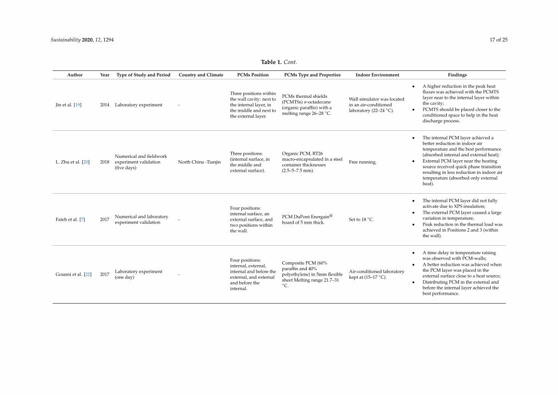
Sustainability 2020, 12, 1294 17 of 25
Table 1. Cont.
Author Year Type of Study and Period Country and Climate PCMs Position PCMs Type and Properties Indoor Environment Findings
Jin et al. [19] 2014 Laboratory experiment -
Three positions withinthe wall cavity: next tothe internal layer, inthe middle and next tothe external layer.
PCMs thermal shields(PCMTSs) n-octadecane(organic paraffin) with amelting range 26–28 ◦C.
Wall simulator was locatedin an air-conditionedlaboratory (22–24 ◦C).
• A higher reduction in the peak heatfluxes was achieved with the PCMTSlayer near to the internal layer withinthe cavity;
• PCMTS should be placed closer to theconditioned space to help in the heatdischarge process.
L. Zhu et al. [20] 2018Numerical and fieldworkexperiment validation(five days)
North China -Tianjin
Three positions:(internal surface, inthe middle andexternal surface).
Organic PCM, RT26macro-encapsulated in a steelcontainer thicknesses(2.5–5–7.5 mm).
Free running.
• The internal PCM layer achieved abetter reduction in indoor airtemperature and the best performance(absorbed internal and external heat);
• External PCM layer near the heatingsource received quick phase transitionresulting in less reduction in indoor airtemperature (absorbed only externalheat).
Fateh et al. [7] 2017 Numerical and laboratoryexperiment validation -
Four positions:internal surface, anexternal surface, andtwo positions withinthe wall.
PCM DuPont Energain®
board of 5 mm thick.Set to 18 ◦C.
• The internal PCM layer did not fullyactivate due to XPS insulation;
• The external PCM layer caused a largevariation in temperature;
• Peak reduction in the thermal load wasachieved in Positions 2 and 3 (withinthe wall).
Gounni et al. [22] 2017 Laboratory experiment(one day) -
Four positions:internal, external,internal and before theexternal, and externaland before theinternal.
Composite PCM (60%paraffin and 40%polyethylene) in 5mm flexiblesheet Melting range 21.7–31◦C.
Air-conditioned laboratorykept at (15–17 ◦C).
• A time delay in temperature raisingwas observed with PCM-walls;
• A better reduction was achieved whenthe PCM layer was placed in theexternal surface close to a heat source;
• Distributing PCM in the external andbefore the internal layer achieved thebest performance.

Sustainability 2020, 12, 1294 18 of 25
Table 1. Cont.
Author Year Type of Study and Period Country and Climate PCMs Position PCMs Type and Properties Indoor Environment Findings
Lee et al. [26] 2015 Fieldwork testing Lawrence, KS, USA
Five differentpositions within thewall cavity (Onlysouth and west walls).
Hydrated salt-based PCMswith melting temperatures inthe range of 24.79–31.36 ◦C.
Air-conditioned.
• Heat flux for the west wall was higherthan the south wall, thus the optimumPCM position moved from Position 3(near the middle) in the south wall toPosition 2 (towards the internal) in thewest wall (i.e., away from the heatsource to achieve bettermelting/freezing cycle).
Sun et al. [49] 2019 Laboratory experiment andnumerical investigation
Changsha, China, Hotsummer and coldwinter
Five differentpositions within thewall (replacing onelayer of the fiveinternal XPS layers ofthe wall).
Paraffin-based PCM,transition temperature 27–29◦C, encapsulated in 25 mmhigh-density polyethylenespheres.
Float between heating (setpoint 16 ◦C) and cooling (setpoint 26 ◦C).
• Maximum temperature reductionduring summer in the third position(from outdoors);
• Maximum temperature reductionduring winter in the fourth position(closer to indoors to use the heat);
• The third position was optimum for theentire year;
• The optimum PCM position is theclosest to the indoor environment, thatallows for a complete phase transitionof the PCM.
Jin et al. [27] 2013 Laboratory experiment -Six different positionswithin a wall cavity(Cavity divided by 5).
PCMs thermal shields(PCMTSs) hydrated salt, withmelting temperature range of24–34 ◦C.
Wall simulator was locatedin an air-conditionedlaboratory (22–24 ◦C).
• PCM in the second position from theinternal surface achieved betterperformance. followed by thefirst position;
• PCM close to the external surface fullymelted but did not fully solidify due tothe heat source.
Jin et al. [40] 2016 Numerical and laboratoryexperiment validation - 16 different positions
within the wall cavity.Rubitherm RT27, withmelting temperature 27 ◦C. Air-conditioned.
• The optimum position of PCM movestowards the exterior surface of the wallwith greater PCM thickness, highermelting temperatures and higher heatof fusion;
• The optimum position of PCM movestowards the interior surface of the wallwith increasing wall interiorsurface temperature.
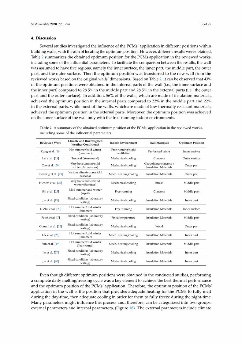
Sustainability 2020, 12, 1294 19 of 25
4. Discussion
Several studies investigated the influence of the PCMs’ application in different positions withinbuilding walls, with the aim of locating the optimum position. However, different results were obtained.Table 2 summarizes the obtained optimum position for the PCMs application in the reviewed works,including some of the influential parameters. To facilitate the comparison between the results, the wallwas assumed to have five regions, namely the inner surface, the inner part, the middle part, the outerpart, and the outer surface. Then the optimum position was transferred to the new wall from thereviewed works based on the original walls’ dimensions. Based on Table 2, it can be observed that 43%of the optimum positions were obtained in the internal parts of the wall (i.e., the inner surface andthe inner part) compared to 28.5% in the middle part and 28.5% in the external parts (i.e., the outerpart and the outer surface). In addition, 56% of the walls, which are made of insulation materials,achieved the optimum position in the internal parts compared to 22% in the middle part and 22%in the external parts, while most of the walls, which are made of low thermally resistant materials,achieved the optimum position in the external parts. Moreover, the optimum position was achievedon the inner surface of the wall only with the free-running indoor environments.
Table 2. A summary of the obtained optimum position of the PCMs’ application in the reviewed works,including some of the influential parameters.
Reviewed Work Climate and (InvestigatedWeather Conditions) Indoor Environment Wall Materials Optimum Position
Kong et al. [18] Hot summer/cold winter(Summer)
Free running/nightventilation Perforated bricks Inner surface
Lei et al. [21] Tropical (Year-round) Mechanical cooling Concrete Outer surface
Cao et al. [50] Very hot summer/mildwinter (All seasons) Mechanical cooling Geopolymer concrete +
Insulation Materials Outer part
Zwanzig et al. [23] Various climate zones (Allseasons) Mech. heating/cooling Insulation Materials Outer part
Hichem et al. [24] Very hot summer/mildwinter (Summer) Mechanical cooling Bricks Middle part
Shi et al. [25] Mild summer and winter(April) Free-running Concrete Middle part
Jin et al. [19] Fixed condition (laboratorytesting) Mechanical cooling Insulation Materials Inner part
L. Zhu et al. [20] Hot summer/cold winter(Summer) Free-running Insulation Materials Inner surface
Fateh et al. [7] Fixed condition (laboratorytesting) Fixed temperature Insulation Materials Middle part
Gounni et al. [22] Fixed condition (laboratorytesting) Mechanical cooling Wood Outer part
Lee et al. [26] Hot summer/cold winter(Summer) Mech. heating/cooling Insulation Materials Inner part
Sun et al. [49] Hot summer/cold winter(Year-round) Mech. heating/cooling Insulation Materials Middle part
Jin et al. [27] Fixed condition (laboratorytesting) Mechanical cooling Insulation Materials Inner part
Jin et al. [40] Fixed condition (laboratorytesting) Mechanical cooling Insulation Materials Inner part
Even though different optimum positions were obtained in the conducted studies, performinga complete daily melting/freezing cycle was a key element to achieve the best thermal performanceand the optimum position of the PCMs’ application. Therefore, the optimum position of the PCMs’application in the wall is the position that provides adequate heating for the PCMs to fully meltduring the day-time, then adequate cooling in order for them to fully freeze during the night-time.Many parameters might influence this process and, therefore, can be categorized into two groups:external parameters and internal parameters, (Figure 18). The external parameters include climate

Sustainability 2020, 12, 1294 20 of 25
and weather conditions (i.e., hot or cold regions and summer or winter times), application target(i.e., reduction in indoor temperature fluctuation, storing and reuse of heat, reduction in internalheat gain, or reduction in external heat gain), indoor environment (i.e., mechanical cooling and/orheating, free-running or all-day/night mechanical ventilation), and the wall’s orientation and materials.In contrast, the internal parameters include the PCMs thermal properties (i.e., melting and freezingpoints, enthalpy or heat of fusion, thermal conductivity, and specific heat capacity), and the PCMquantity and layer’s thickness.
Sustainability 2019, 11, x FOR PEER REVIEW 19 of 24
reduction in indoor temperature fluctuation, storing and reuse of heat, reduction in internal heat gain,
or reduction in external heat gain), indoor environment (i.e., mechanical cooling and/or heating, free-
running or all-day/night mechanical ventilation), and the wall’s orientation and materials. In contrast,
the internal parameters include the PCMs thermal properties (i.e., melting and freezing points,
enthalpy or heat of fusion, thermal conductivity, and specific heat capacity), and the PCM quantity
and layer’s thickness.
Climate and weather conditions influence the PCM application target. This, in turn, affects the
optimum position of PCM application. For instance, in the hot regions or during summer, the
optimum position of the PCM layer is in the external part of the wall, [21,48], as the application target
is to reduce the external heat gain in the indoor environment. Basically, the PCM layer absorbs the
unwanted external heat, which is received by the wall, during day-time, and releases it back to the
outdoor environment during night-time. In addition, the low thermal conductivity of the PCMs
provides a sort of thermal insulation. However, when the PCM layer is applied in the internal part of
the wall, it will release the heat back to the indoor environment during night-time, causing
overheating. Nevertheless, this scenario can be used to reduce the high day-time indoor temperature
if proper night ventilation is applied to remove the released heat during night-time. On the other
hand, in the cold regions or during winter, the optimum position of the PCM layer is in the internal
part of the wall, as the application target, in this case, is to store and reuse the heat. The internal PCM
layer absorbs the heat from the outdoor environment or the produced heat in the indoor environment
during day-time and releases it back to the indoor environment during night-time, which enhances
the indoor thermal environment and reduces the heating load.
External Parameters
Parameters influencing the optimum
position of PCMs application
Internal Parameters
Application target
Climate and weather Indoor environment
Wall orientation
Wall materialsPCMs quantity and layer
thickness
PCMs thermal properties
Hot or cold regions
Summer or winter seasons
Store and reuse the heat
(reduce heating load)
Reduce internal/external
heat gain (remove heat and
reduce cooling load)
Store energy during low
rate periods for the high
rate periods
Mechanical cooling and/or
heating
Free-running
All-day/night mechanical
ventilation
High thermal resistance
(Insulation)
Low thermal resistance
(Concrete, bricks, ..etc)
Melting and freezing points
Heat of fusion (enthalpy)
Thermal conductivity
Specific heat capacity
Figure 18. Main parameters that influence the optimum position of the PCM application in building
walls.
The indoor environment influences the freezing process of PCMs and their heat discharge. For
instance, an air-conditioned indoor environment might cause the PCM layer to move away from the
internal surface of the wall. The internal cooling can affect the melting process and cause partial
activation of the PCM, which reduces its efficiency. Besides, if the indoor environment is not adequate
to enhance the freezing process of the PCM, especially with a free running mode, the optimum
position of the PCM layer will move closer to the outdoor environment, which is cooler during night-
time and can enhance the freezing process, as seen in [24,25]. However, by introducing the cooler
outdoor air through the night ventilation to the indoor environment, the optimum position of the
PCM layer might be close to the internal surface, as in [18]. Moreover, if the indoor environment has
adequate heat to charge the PCM layer, the optimum position will be closer to the indoor
Figure 18. Main parameters that influence the optimum position of the PCM application in building walls.
Climate and weather conditions influence the PCM application target. This, in turn, affects theoptimum position of PCM application. For instance, in the hot regions or during summer, the optimumposition of the PCM layer is in the external part of the wall, [21,48], as the application target is to reducethe external heat gain in the indoor environment. Basically, the PCM layer absorbs the unwantedexternal heat, which is received by the wall, during day-time, and releases it back to the outdoorenvironment during night-time. In addition, the low thermal conductivity of the PCMs provides a sortof thermal insulation. However, when the PCM layer is applied in the internal part of the wall, it willrelease the heat back to the indoor environment during night-time, causing overheating. Nevertheless,this scenario can be used to reduce the high day-time indoor temperature if proper night ventilation isapplied to remove the released heat during night-time. On the other hand, in the cold regions or duringwinter, the optimum position of the PCM layer is in the internal part of the wall, as the applicationtarget, in this case, is to store and reuse the heat. The internal PCM layer absorbs the heat from theoutdoor environment or the produced heat in the indoor environment during day-time and releases itback to the indoor environment during night-time, which enhances the indoor thermal environmentand reduces the heating load.
The indoor environment influences the freezing process of PCMs and their heat discharge.For instance, an air-conditioned indoor environment might cause the PCM layer to move away fromthe internal surface of the wall. The internal cooling can affect the melting process and cause partialactivation of the PCM, which reduces its efficiency. Besides, if the indoor environment is not adequateto enhance the freezing process of the PCM, especially with a free running mode, the optimum positionof the PCM layer will move closer to the outdoor environment, which is cooler during night-time andcan enhance the freezing process, as seen in [24,25]. However, by introducing the cooler outdoor airthrough the night ventilation to the indoor environment, the optimum position of the PCM layer might

Sustainability 2020, 12, 1294 21 of 25
be close to the internal surface, as in [18]. Moreover, if the indoor environment has adequate heat tocharge the PCM layer, the optimum position will be closer to the indoor environment, otherwise theoptimum position will move outward, closer to the heat source in the outdoor environment.
The orientation and the materials of the wall can control the amount of heat received and conductedthrough the wall, respectively. Therefore, in both cases, the optimum position of the PCM layer mightmove inwards or outwards to achieve the required heating and cooling for the PCM. Depending onwall orientation, for instance, the amount of heat received by the wall and the heat flux through thewall will be different. This results in different optimum positions for each orientation, as found in [26].On the other hand, the wall materials, (i.e., brick, concrete, lightweight materials, thermal insulation,etc.), will affect the heat conduction through the wall section due to the different thermal resistanceof each material. For example, the optimum position of the PCM layer was obtained close to theindoor environment in [19,20,26,40,49], in which the walls were made of insulation layers. This mightbe attributed to the effect of the insulation layers on reducing the required cooling from the indoorenvironment for the PCM freezing process. However, the optimum position of the PCM layer willmove outwards if the insulation layers of the wall caused the internal PCMs layer to not fully activate,as in [7].
Furthermore, the internal parameters have an influence similar to the influence of the wallorientation and materials. For instance, a higher PCM melting temperature influences the optimumposition of the PCM layer to move outwards, closer to the heat source, to get a higher temperature thatenables a complete charging process. A higher PCM heat of fusion or enthalpy, and a higher PCMquantity and layer’s thickness, increases the heat storage capacity of the PCM, which influences theoptimum position of the PCM layer to move outwards, close to the heat source, as well. However,beyond a specific position, the solidification process might be affected, causing a reduction in PCMperformance. Therefore, based on the above discussion, the PCM layer is required to be in aposition that exactly provides the required heating and cooling for the PCMs’ melting and freezingprocesses, respectively.
Figure 19 illustrates a summary of the main findings showing the optimum position of PCMs’application in building walls based on the influences of the discussed parameters.
OutdoorIndoor
Insulationlayer
PCM-basedgeopolymer concrete
(a) (b)
OutdoorIndoor
Insulationlayer
PCM-basedgeopolymer concrete
PCMslayer
OutdoorIndoor
Insulationlayer
Geopolymer concrete
(c)Control Position 1 Position 2
Figure 17.
Climatic conditions Cold regions or winter time(heating is required)
Hot regions or summer time(heat is unwanted)
Inte
rnal
surf
ace
Wallsection Ex
tern
alsu
rfac
e
Application targetReduce internal heat (daytime)
and reuse it (nighttime)Reduce external heat gain
Absorb external heat (daytime)and reuse it (nighttime)
Indoor environment Free cooling - night ventilation
Mechanical cooling
Thermal propertiesof wall materials
Higher thermal resistance
Wall orientation andincident solar radiation
Higher incident solar radiation
PCMs properties
PCMs quantity
Higher melting temperatureand heat of fusion
Higher quantity
Storing heat in order to reuse itStoring heat in order to remove it
(works as a thermal insulation)
Cause PCMs layer to move inward or outwardto find the adequate heating and cooling for
complete daily melting and freezing
Indo
or
(PCMs move closer to heat source)
(PCMs move closer to heat source)
(PCMs move closer to heat source)
(PCMs move away from heat source)
(PCMs move away from cooling)
(PCMs move closer to cooling)
Out
door
Figure 19.
Figure 19. A summary of the main findings showing the optimum position of the PCM’s application inbuilding walls, based on several influential parameters.

Sustainability 2020, 12, 1294 22 of 25
Finally, selecting the optimum position of the PCMs’ application in building walls can be acomplicated process since it involves the influences of all the above parameters, which are connectedand linked to each other, and changing any of them will affect the other parameters. Besides, it isimportant to mention that the optimum position of the PCMs application is not only the position thatallows for the complete thermal cycle, but also the best thermal performance of the indoor environmentswith the lowest PCM application. Therefore, for each project, an optimization process is suggested inadvance, using the available simulation tools and involving all the mentioned parameters. By doingso, the optimum position of the PCMs application, which achieves the best thermal performance,can be located.
5. Conclusions
Thermal energy storage (TES) and phase change materials (PCMs) are promising passivetechnologies that aim at improving the building materials’ thermal performance and achievingthermally comfortable conditions within the indoor environment. This study reviewed TES and PCMstechnologies and their application in buildings. In addition, PCMs’ classification, selection requirementsfor building applications and integration technologies to building materials were discussed. The studyalso reviewed previous works, which investigated PCMs’ application in building walls with a focuson the optimum position of the PCMs’ application in the wall. Based on the review of the literature,it can be concluded that the optimum position of the PCMs’ application in building walls can varyin different projects. The PCMs’ performance efficiency is highly dependent on performing a dailycomplete melting/freezing cycle in order to be ready for the next cycle the following day. Otherwise,the PCMs will stay either in the solid-state or the liquid-state most of the time, causing a reduction intheir performance. Therefore, the optimum position of the PCMs’ application in building walls is theposition at which the daily complete melting/freezing cycle can be achieved. This might be influencedby many parameters such as:
• Climate and weather conditions: in hot regions or during the summer, in which cooling is needed,PCMs application might be required closer to the outdoor environment. However, in cold regionsor during the winter, in which heating is needed, PCMs application might be required closer tothe indoor environment;
• Application target: reducing the external heat gain requires the PCMs to be applied towardsthe external surface of the wall, while reducing the internal heat gain and indoor temperaturefluctuation requires the PCMs to be applied towards the internal surface of the wall;
• Indoor environment: applying free cooling, night ventilation or mechanical cooling/heating in theinternal environment can affect the PCMs’ solidification process, causing the optimum position tovary within the wall;
• Thermal properties of wall materials: a higher thermal resistance of wall materials can reducethe heat and coolness transfer to PCMs. This might cause the PCMs’ optimum position to moveoutwards, closer to the heat source, or inward, closer to the conditioned indoor environment;
• Orientation and the incident solar radiation: the optimum position of PCMs within a south-facingwall might differ from the west-facing wall due to the difference in the heat received by the walls;
• PCMs properties: a higher PCM’s melting temperature and a higher heat of fusion require thePCM to be closer to the heat source, i.e., closer to the external surface of the wall, up to a specificposition that allows for full freezing as well;
• PCMs’ quantity: a higher PCM quantity results in a higher thermal storage capacity. This willrequire more heat to be stored, which indicates that PCM might need to be applied near theexternal surface.
Therefore, for any PCMs application in building’s walls, an evaluation with the help of simulationtools is suggested based on the parameters discussed above to locate the optimum position for thePCMs application.
Sustainability 2020, 12, 1294 23 of 25
Author Contributions: All authors contributed equally to this research. All authors have read and agreed to thepublished version of the manuscript.
Funding: This research was funded by Universiti Sains Malaysia, Research University Grant number(1001/PPBGN/814285).
Acknowledgments: The authors would like to thank the Department of Architecture, Faculty of Engineering,Sana’a University, and School of Housing, Building and Planning, Universiti Sains Malaysia for financial support.
Conflicts of Interest: The authors declare no conflict of interest.
References
1. Dyball, D.L. An Innovative Wall-Lining for Buildings Incorporating Phase Change Materials. Ph.D. Thesis,The University of Brighton in collaboration with Omnova Wallcoverings (UK) Ltd., Brighton, UK, 2013.
2. Aboulnaga, M.M.; Elsheshtawy, Y.H. Environmental sustainability assessment of buildings in hot climates:The case of the UAE. Renew. Energy 2001, 24, 553–563. [CrossRef]
3. Nematchoua, M.K.; Tchinda, R.; Orosa, J.A. Thermal comfort and energy consumption in modern versustraditional buildings in Cameroon: A questionnaire-based statistical study. Appl. Energy 2014, 114, 687–699.[CrossRef]
4. Akeiber, H.; Nejat, P.; Majid, M.Z.A.; Wahid, M.A.; Jomehzadeh, F.; Zeynali Famileh, I.; Calautit, J.K.;Hughes, B.R.; Zaki, S.A. A review on phase change material (PCM) for sustainable passive cooling in buildingenvelopes. Renew. Sustain. Energy Rev. 2016, 60, 1470–1497. [CrossRef]
5. Nardi, I.; Lucchi, E.; de Rubeis, T.; Ambrosini, D. Quantification of heat energy losses through the buildingenvelope: A state-of-the-art analysis with critical and comprehensive review on infrared thermography.Build. Environ. 2018, 146, 190–205. [CrossRef]
6. Barzin, R.; Chen, J.J.J.; Young, B.R.; Farid, M.M. Application of PCM energy storage in combination withnight ventilation for space cooling. Appl. Energy 2015, 158, 412–421. [CrossRef]
7. Fateh, A.; Klinker, F.; Brütting, M.; Weinläder, H.; Devia, F. Numerical and experimental investigation of aninsulation layer with phase change materials (PCMs). Energy Build. 2017, 153, 231–240. [CrossRef]
8. Navarro, L.; de Gracia, A.; Niall, D.; Castell, A.; Browne, M.; McCormack, S.J.; Griffiths, P.; Cabeza, L.F.Thermal energy storage in building integrated thermal systems: A review. Part 2. Integration as passivesystem. Renew. Energy 2016, 85, 1334–1356. [CrossRef]
9. Nazir, H.; Batool, M.; Bolivar Osorio, F.J.; Isaza-Ruiz, M.; Xu, X.; Vignarooban, K.; Phelan, P.; Inamuddin;Kannan, A.M. Recent developments in phase change materials for energy storage applications: A review.Int. J. Heat Mass Transf. 2019, 129, 491–523. [CrossRef]
10. Rao, V.V.; Parameshwaran, R.; Ram, V.V. PCM-mortar based construction materials for energy efficientbuildings: A review on research trends. Energy Build. 2018, 158, 95–122. [CrossRef]
11. Wahid, M.A.; Hosseini, S.E.; Hussen, H.M.; Akeiber, H.J.; Saud, S.N.; Mohammad, A.T. An overview ofphase change materials for construction architecture thermal management in hot and dry climate region.Appl. Therm. Eng. 2017, 112, 1240–1259. [CrossRef]
12. Khadiran, T.; Hussein, M.Z.; Zainal, Z.; Rusli, R. Advanced energy storage materials for building applicationsand their thermal performance characterization: A review. Renew. Sustain. Energy Rev. 2016, 57, 916–928.[CrossRef]
13. Khan, Z.; Khan, Z.; Ghafoor, A. A review of performance enhancement of PCM based latent heat storagesystem within the context of materials, thermal stability and compatibility. Energy Convers. Manag. 2016, 115,132–158. [CrossRef]
14. Kenisarin, M.; Mahkamov, K. Passive thermal control in residential buildings using phase change materials.Renew. Sustain. Energy Rev. 2016, 55, 371–398. [CrossRef]
15. Konuklu, Y.; Ostry, M.; Paksoy, H.O.; Charvat, P. Review on using microencapsulated phase change materials(PCM) in building applications. Energy Build. 2015, 106, 134–155. [CrossRef]
16. Kalnæs, S.E.; Jelle, B.P. Phase change materials and products for building applications: A state-of-the-artreview and future research opportunities. Energy Build. 2015, 94, 150–176. [CrossRef]
17. Memon, S.A. Phase change materials integrated in building walls: A state of the art review. Renew. Sustain.Energy Rev. 2014, 31, 870–906. [CrossRef]
Sustainability 2020, 12, 1294 24 of 25
18. Kong, X.; Lu, S.; Huang, J.; Cai, Z.; Wei, S. Experimental research on the use of phase change materials inperforated brick rooms for cooling storage. Energy Build. 2013, 62, 597–604. [CrossRef]
19. Jin, X.; Medina, M.A.; Zhang, X. On the placement of a phase change material thermal shield within thecavity of buildings walls for heat transfer rate reduction. Energy 2014, 73, 780–786. [CrossRef]
20. Zhu, L.; Yang, Y.; Chen, S.; Sun, Y. Numerical study on the thermal performance of lightweight temporarybuilding integrated with phase change materials. Appl. Therm. Eng. 2018, 138, 35–47. [CrossRef]
21. Lei, J.; Yang, J.; Yang, E.H. Energy performance of building envelopes integrated with phase change materialsfor cooling load reduction in tropical Singapore. Appl. Energy 2016, 162, 207–217. [CrossRef]
22. Gounni, A.; El Alami, M. The optimal allocation of the pcm within a composite wall for surface temperatureand heat flux reduction: An experimental approach. Appl. Therm. Eng. 2017, 127, 1488–1494. [CrossRef]
23. Zwanzig, S.D.; Lian, Y.; Brehob, E.G. Numerical simulation of phase change material composite wallboard ina multi-layered building envelope. Energy Convers. Manag. 2013, 69, 27–40. [CrossRef]
24. Hichem, N.; Noureddine, S.; Nadia, S.; Djamila, D. Experimental and numerical study of a usual brick filledwith PCM to improve the thermal inertia of buildings. Energy Procedia 2013, 36, 766–775. [CrossRef]
25. Shi, X.; Memon, S.A.; Tang, W.; Cui, H.; Xing, F. Experimental assessment of position of macro encapsulatedphase change material in concrete walls on indoor temperatures and humidity levels. Energy Build. 2014, 71,80–87. [CrossRef]
26. Lee, K.O.; Medina, M.A.; Raith, E.; Sun, X. Assessing the integration of a thin phase change material (PCM)layer in a residential building wall for heat transfer reduction and management. Appl. Energy 2015, 137,699–706. [CrossRef]
27. Jin, X.; Medina, M.A.; Zhang, X. On the importance of the location of PCMs in building walls for enhancedthermal performance. Appl. Energy 2013, 106, 72–78. [CrossRef]
28. Dincer, I.; Rosen, M.A. Thermal Energy Storage Systems and Applications, 2nd ed.; John Wiley and Sons, Ltd.:Chichester, UK, 2011; ISBN 9780470747063.
29. Iten, M.; Liu, S.; Shukla, A. A review on the air-PCM-TES application for free cooling and heating in thebuildings. Renew. Sustain. Energy Rev. 2016, 61, 175–186. [CrossRef]
30. Tomlinson, J.J.; Kannberg, L.D. Thermal Energy Storage. Mech. Eng. 1990, 41, 393.31. Telkes, M. Thermal energy storage in salt hydrates. Sol. Energy Mater. 1980, 2, 381–393. [CrossRef]32. Isa, M.H.M.; Zhao, X.; Yoshino, H. Preliminary study of passive cooling strategy using a combination of
PCM and copper foam to increase thermal heat storage in building facade. Sustainability 2010, 2, 2365–2381.[CrossRef]
33. Sun, X.; Zhang, Q.; Medina, M.A.; Lee, K.O. Experimental observations on the heat transfer enhancementcaused by natural convection during melting of solid-liquid phase change materials (PCMs). Appl. Energy2016, 162, 1453–1461. [CrossRef]
34. Kosny, J. PCM-Enhanced Building Components: An Application of Phase Change Materials in Building Envelopesand Internal Structures, 1st ed.; Derby, B., Ed.; Springer: Cham, Switzerland, 2015; ISBN 9783319142852.
35. Al-Absi, Z.A.A.S.; Isa, M.H.M.; Ismail, M. Application of Phase Change Materials (PCMs) in Building Walls:A Review. In The Advances in Civil Engineering Materials. ICACE 2018. Lecture Notes in Civil Engineering, Volume19; Awang, M., Isa, M.H., Eds.; Springer Singapore: Singapore, 2019; pp. 73–82. ISBN 978-981-13-2511-3.
36. Waqas, A.; Ud Din, Z. Phase change material (PCM) storage for free cooling of buildings—A review. Renew.Sustain. Energy Rev. 2013, 18, 607–625. [CrossRef]
37. Hawes, D.W. Latent heat storage in building materials. Energy Build. 1993, 20, 77–86. [CrossRef]38. Rodríguez-cumplido, F.; Pabón-gelves, E.; Chejne-jana, F. Recent developments in the synthesis of
microencapsulated and nanoencapsulated phase change materials. J. Energy Storage 2019, 24, 100821.[CrossRef]
39. Soares, N.; Costa, J.J.; Gaspar, A.R.; Santos, P. Review of passive PCM latent heat thermal energy storagesystems towards buildings’ energy efficiency. Energy Build. 2013, 59, 82–103. [CrossRef]
40. Jin, X.; Medina, M.A.; Zhang, X. Numerical analysis for the optimal location of a thin PCM layer in framewalls. Appl. Therm. Eng. 2016, 103, 1057–1063. [CrossRef]
41. Ramakrishnan, S.; Wang, X.; Sanjayan, J.; Wilson, J. Thermal performance of buildings integrated with phasechange materials to reduce heat stress risks during extreme heatwave events. Appl. Energy 2017, 194, 410–421.[CrossRef]
Sustainability 2020, 12, 1294 25 of 25
42. Meng, E.; Yu, H.; Zhou, B. Study of the thermal behavior of the composite phase change material (PCM)room in summer and winter. Appl. Therm. Eng. 2017, 126, 212–225. [CrossRef]
43. Ascione, F.; Bianco, N.; De Masi, R.F.; Mastellone, M.; Peter Vanoli, G. Phase change materials for reducingcooling energy demand and improving indoor comfort: A step-by-step retrofit of a Mediterranean educationalbuilding. Energies 2019, 12, 3661. [CrossRef]
44. Lei, J.; Kumarasamy, K.; Zingre, K.T.; Yang, J.; Wan, M.P.; Yang, E.H. Cool colored coating and phase changematerials as complementary cooling strategies for building cooling load reduction in tropics. Appl. Energy2017, 190, 57–63. [CrossRef]
45. Vicente, R.; Silva, T. Brick masonry walls with PCM macrocapsules: An experimental approach. Appl. Therm.Eng. 2014, 67, 24–34. [CrossRef]
46. De Gracia, A.; Navarro, L.; Castell, A.; Cabeza, L.F. Numerical study on the thermal performance of aventilated facade with PCM. Appl. Therm. Eng. 2013, 61, 372–380. [CrossRef]
47. Cao, V.D.; Pilehvar, S.; Salas-Bringas, C.; Szczotok, A.M.; Bui, T.Q.; Carmona, M.; Rodriguez, J.F.;Kjøniksen, A.L. Thermal analysis of geopolymer concrete walls containing microencapsulated phasechange materials for building applications. Sol. Energy 2019, 178, 295–307. [CrossRef]
48. Zhu, N.; Liu, F.; Liu, P.; Hu, P.; Wu, M. Energy saving potential of a novel phase change material wallboardin typical climate regions of China. Energy Build. 2016, 128, 360–369. [CrossRef]
49. Sun, X.; Jovanovic, J.; Zhang, Y.; Fan, S.; Chu, Y.; Mo, Y.; Liao, S. Use of encapsulated phase change materialsin lightweight building walls for annual thermal regulation. Energy 2019, 180, 858–872. [CrossRef]
50. Cao, V.D.; Bui, T.Q.; Kjøniksen, A.L. Thermal analysis of multi-layer walls containing geopolymer concreteand phase change materials for building applications. Energy 2019, 186, 115792. [CrossRef]
© 2020 by the authors. Licensee MDPI, Basel, Switzerland. This article is an open accessarticle distributed under the terms and conditions of the Creative Commons Attribution(CC BY) license (http://creativecommons.org/licenses/by/4.0/).