PG–PLUS HYDROGEN GENERATOR - HANNOVER MESSE
32
DBS ® VICI AG International Parkstrasse 2 CH-6214 Schenkon Switzerland Phone: Int +41 41 925 62 00 Fax: Int +41 41 925 62 01 E-mail: [email protected] Web: www.vicidbs.com 1 PG–PLUS HYDROGEN GENERATOR Operation Manual
-
Upload
khangminh22 -
Category
Documents
-
view
1 -
download
0
Transcript of PG–PLUS HYDROGEN GENERATOR - HANNOVER MESSE
DBS ® VICI AG InternationalParkstrasse 2CH-6214 SchenkonSwitzerland
Phone: Int +41 41 925 62 00Fax: Int +41 41 925 62 01E-mail: [email protected]: www.vicidbs.com
1
PG–PLUS HYDROGEN GENERATOR Operation Manual
DBS ® VICI AG InternationalParkstrasse 2CH-6214 SchenkonSwitzerland
Phone: Int +41 41 925 62 00Fax: Int +41 41 925 62 01E-mail: [email protected]: www.vicidbs.com
2
TABLE OF CONTENTSTable of Contents
1. VERSION HISTORY ...................................................................................................................... 42. INTRODUCTION ......................................................................................................................... 4
2.1. SYMBOLS DEFINITION ...................................................................................................... 43. SAFETY ........................................................................................................................................ 5
3.1. NOTES OF FCC COMPLIANCE .......................................................................................... 53.2. CORRECT USE .................................................................................................................... 5
4. WARNING ................................................................................................................................... 55. SPECIFICATIONS ........................................................................................................................ 6
5.1. FUNCTIONALITY ................................................................................................................ 75.2. THE MOST COMMON OPTIONS ...................................................................................... 8
5.2.1. Remote Connections (optional) ................................................................................. 85.2.2. Cascading (optional) .................................................................................................. 95.2.3. Auto Refill (optional) ................................................................................................ 10
6. INSTALLATION AND INITIAL START UP ................................................................................... 116.1. RECEIVING THE GENERATOR ......................................................................................... 116.2. PACKING LIST ................................................................................................................... 126.3. PLACING THE GENERATOR............................................................................................. 126.4. GAS CONNECTIONS ....................................................................................................... 136.5. ELECTRICAL CONNECTIONS .......................................................................................... 136.6. INITIAL START-UP ............................................................................................................. 14
6.6.1. Filling the Water Tank ............................................................................................... 146.6.2. Installing the Deionizer Bag ...................................................................................... 156.6.3. Starting the Generator .............................................................................................. 16
7. OPERATION .............................................................................................................................. 177.1. LCD DISPLAY .................................................................................................................... 17
7.1.1. Layout of the Display ................................................................................................ 177.1.2. First Row - Status Information ................................................................................... 177.1.3. Second Row - Pressure Information .......................................................................... 187.1.4. Third Row - Hydrogen Flow ...................................................................................... 187.1.5. Fourth Row - Water Quality ...................................................................................... 197.1.6. Start/Stop - Reset Button .......................................................................................... 197.1.7. Exit - Menu Button .................................................................................................... 19

DBS ® VICI AG InternationalParkstrasse 2CH-6214 SchenkonSwitzerland
Phone: Int +41 41 925 62 00Fax: Int +41 41 925 62 01E-mail: [email protected]: www.vicidbs.com
3
TABLE OF CONTENTS
7.2. MENU OPERATION .......................................................................................................... 207.2.1. Configure Parameters ............................................................................................... 217.2.2. Diagnostic Display .................................................................................................... 227.2.3. Special Functions ...................................................................................................... 23
8. RETURNING THE GENERATOR ................................................................................................ 239. MAINTENANCE ........................................................................................................................ 25
9.1. ROUTINE MAINTENANCE ............................................................................................... 259.1.1. Cleaning ................................................................................................................... 259.1.2. Water Refilling .......................................................................................................... 269.1.3. Deionizer Bag Replacement ..................................................................................... 269.1.4. Installing the New Deionizer Bags ............................................................................ 279.1.5. Rinse Air Bubble Procedure ...................................................................................... 28
10. SPARE PARTS LIST ................................................................................................................... 30

DBS ® VICI AG InternationalParkstrasse 2CH-6214 SchenkonSwitzerland
Phone: Int +41 41 925 62 00Fax: Int +41 41 925 62 01E-mail: [email protected]: www.vicidbs.com
4
1. VERSION HISTORY
Version Date Comment/Change1.00.0100 10th January 2017 VICI DBS layout, initial release
1.01.0000 Update
1.02.0000 4th March 2019 Layout and photo updates
2. INTRODUCTIONThis manual provides operation and maintenance instructions for the models PG-100, PG-160, PG-250, PG-300, PG-400, PG-500 and PG-600 Plus Hydrogen generators.
2.1. SYMBOLS DEFINITION
Symbol DescriptionGeneral warning. Caution is necessary when operating the device close to where the symbol is placed, or to indicate that the current situation needs operator awareness or operator action in order to avoid undesirable consequences. The manual must be consulted in all cases where this symbol is marked on the device.
Risk of asphyxia. Caution is necessary when operating the device in a not sufficiently ventilated area.
Oxidant material. Caution is necessary due to the presence of oxidant material.
WEEE symbol. When discarding this product, it must be sent to separate collection facilities for recovery and recycling.
Fuse.
Earth symbol: This symbol marks the earth connections on the chassis of the Hydrogen generator.
or
or
or

DBS ® VICI AG InternationalParkstrasse 2CH-6214 SchenkonSwitzerland
Phone: Int +41 41 925 62 00Fax: Int +41 41 925 62 01E-mail: [email protected]: www.vicidbs.com
5
3. SAFETY3.1. NOTES OF FCC COMPLIANCE
3.2. CORRECT USE
This equipment has been tested and found to comply with the limits for a Class B digital device, pursuant to part 15 of the FCC Rules. These limits are designed to provide reasonable protection against harmful interference in a residential installation. This equipment generates, uses and can radiate radio frequency energy and, if not installed and used in accordance with the instructions, may cause harmful interference to radio communications. However, there is no guarantee that interference will not occur in a particular installation.
If this equipment does cause harmful interference to radio or television reception, which can be determined by turning the equipment off and on, the user is encouraged to try to correct the interference by one or more of the following measures:
• Reorient or relocate the receiving antenna.• Increase the distance between the equipment and the receiver.• Connect the equipment to an outlet on a circuit different from that to which the receiver is
connected.• Consult the dealer or an experienced radio/TV technician for help.
The Hydrogen generator is designed to produce Hydrogen for laboratory use. The unit should only be used for this purpose, according to the specifications and instructions provided in this manual. In particular, the following warnings must be observed at all times:
• Indoor use only.• Never operate the unit at temperatures below zero degrees C. This will cause irreversible
damage to the electrolysis cell.• Use only pure water (see “Filling the water tank”).• Operate the unit in a room with sufficient ventilation (see “Placing the unit”).• Always unplug the unit from the mains power supply before accessing the internal
components for service or repair work.
4. WARNING
Any changes or modifications to this equipment not expressly approved by the manufacturer may void the user’s authority to operate the equipment.
DBS ® VICI AG InternationalParkstrasse 2CH-6214 SchenkonSwitzerland
Phone: Int +41 41 925 62 00Fax: Int +41 41 925 62 01E-mail: [email protected]: www.vicidbs.com
6
5. SPECIFICATIONS
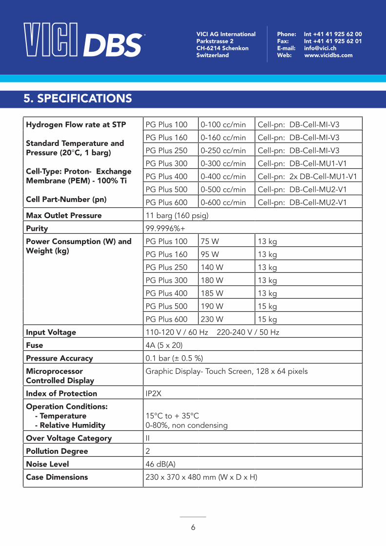
Hydrogen Flow rate at STP
Standard Temperature and Pressure (20°C, 1 barg)
Cell-Type: Proton- Exchange Membrane (PEM) - 100% Ti
Cell Part-Number (pn)
PG Plus 100 0-100 cc/min Cell-pn: DB-Cell-MI-V3
PG Plus 160 0-160 cc/min Cell-pn: DB-Cell-MI-V3
PG Plus 250 0-250 cc/min Cell-pn: DB-Cell-MI-V3
PG Plus 300 0-300 cc/min Cell-pn: DB-Cell-MU1-V1
PG Plus 400 0-400 cc/min Cell-pn: 2x DB-Cell-MU1-V1
PG Plus 500 0-500 cc/min Cell-pn: DB-Cell-MU2-V1
PG Plus 600 0-600 cc/min Cell-pn: DB-Cell-MU2-V1
Max Outlet Pressure 11 barg (160 psig)
Purity 99.9996%+
Power Consumption (W) and Weight (kg)
PG Plus 100 75 W 13 kg
PG Plus 160 95 W 13 kg
PG Plus 250 140 W 13 kg
PG Plus 300 180 W 13 kg
PG Plus 400 185 W 13 kg
PG Plus 500 190 W 15 kg
PG Plus 600 230 W 15 kg
Input Voltage 110-120 V / 60 Hz 220-240 V / 50 Hz
Fuse 4A (5 x 20)
Pressure Accuracy 0.1 bar (± 0.5 %)
Microprocessor Controlled Display
Graphic Display- Touch Screen, 128 x 64 pixels
Index of Protection IP2X
Operation Conditions: - Temperature - Relative Humidity
15°C to + 35°C0-80%, non condensing
Over Voltage Category II
Pollution Degree 2
Noise Level 46 dB(A)
Case Dimensions 230 x 370 x 480 mm (W x D x H)
DBS ® VICI AG InternationalParkstrasse 2CH-6214 SchenkonSwitzerland
Phone: Int +41 41 925 62 00Fax: Int +41 41 925 62 01E-mail: [email protected]: www.vicidbs.com
7
5.1. FUNCTIONALITY
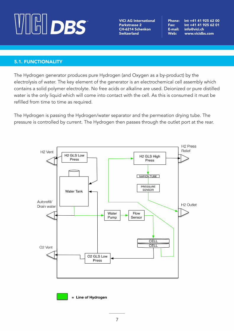
The Hydrogen generator produces pure Hydrogen (and Oxygen as a by-product) by the electrolysis of water. The key element of the generator is an electrochemical cell assembly which contains a solid polymer electrolyte. No free acids or alkaline are used. Deionized or pure distilled water is the only liquid which will come into contact with the cell. As this is consumed it must be refilled from time to time as required.
The Hydrogen is passing the Hydrogen/water separator and the permeation drying tube. The pressure is controlled by current. The Hydrogen then passes through the outlet port at the rear.
DBS ® VICI AG InternationalParkstrasse 2CH-6214 SchenkonSwitzerland
Phone: Int +41 41 925 62 00Fax: Int +41 41 925 62 01E-mail: [email protected]: www.vicidbs.com
8
5.2. THE MOST COMMON OPTIONS
5.2.1. Remote Connections (optional)
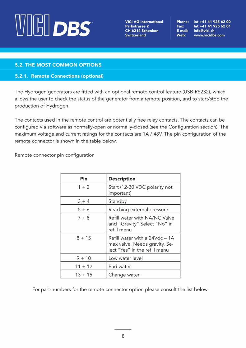
The Hydrogen generators are fitted with an optional remote control feature (USB-RS232), which allows the user to check the status of the generator from a remote position, and to start/stop the production of Hydrogen.
The contacts used in the remote control are potentially free relay contacts. The contacts can be configured via software as normally-open or normally-closed (see the Configuration section). The maximum voltage and current ratings for the contacts are 1A / 48V. The pin configuration of the remote connector is shown in the table below.
Remote connector pin configuration
Pin Description1 + 2 Start (12-30 VDC polarity not
important)
3 + 4 Standby
5 + 6 Reaching external pressure
7 + 8 Refill water with NA/NC Valve and “Gravity” Select “No” in refill menu
8 + 15 Refill water with a 24Vdc – 1A max valve. Needs gravity. Se-lect “Yes” in the refill menu
9 + 10 Low water level
11 + 12 Bad water
13 + 15 Change water
For part-numbers for the remote connector option please consult the list below
DBS ® VICI AG InternationalParkstrasse 2CH-6214 SchenkonSwitzerland
Phone: Int +41 41 925 62 00Fax: Int +41 41 925 62 01E-mail: [email protected]: www.vicidbs.com
9
5.2.2. Cascading (optional)
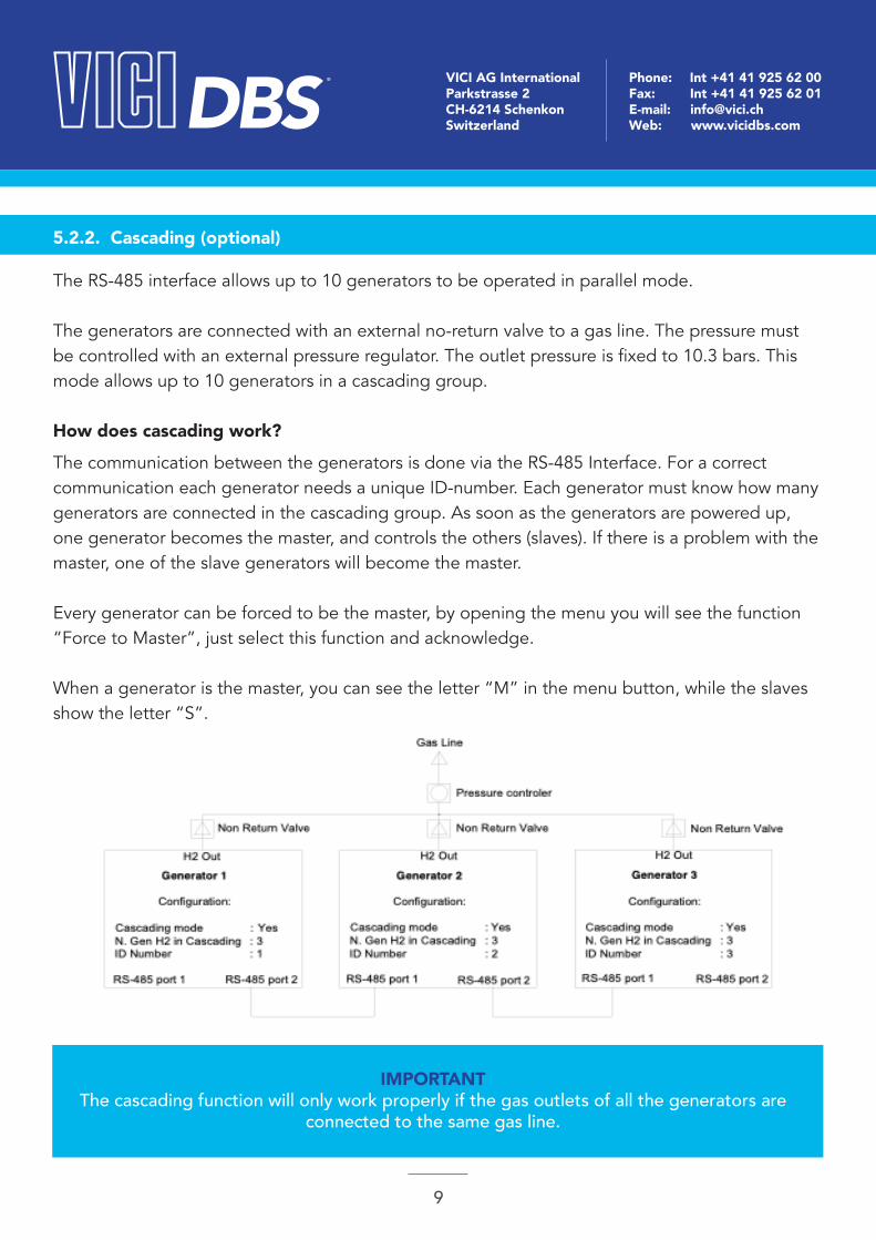
The RS-485 interface allows up to 10 generators to be operated in parallel mode.
The generators are connected with an external no-return valve to a gas line. The pressure must be controlled with an external pressure regulator. The outlet pressure is fixed to 10.3 bars. This mode allows up to 10 generators in a cascading group.
How does cascading work?
The communication between the generators is done via the RS-485 Interface. For a correct communication each generator needs a unique ID-number. Each generator must know how many generators are connected in the cascading group. As soon as the generators are powered up, one generator becomes the master, and controls the others (slaves). If there is a problem with the master, one of the slave generators will become the master.
Every generator can be forced to be the master, by opening the menu you will see the function “Force to Master”, just select this function and acknowledge.
When a generator is the master, you can see the letter “M” in the menu button, while the slaves show the letter “S”.
IMPORTANTThe cascading function will only work properly if the gas outlets of all the generators are
connected to the same gas line.
DBS ® VICI AG InternationalParkstrasse 2CH-6214 SchenkonSwitzerland
Phone: Int +41 41 925 62 00Fax: Int +41 41 925 62 01E-mail: [email protected]: www.vicidbs.com
10
5.2.3. Auto Refill (optional)
Description
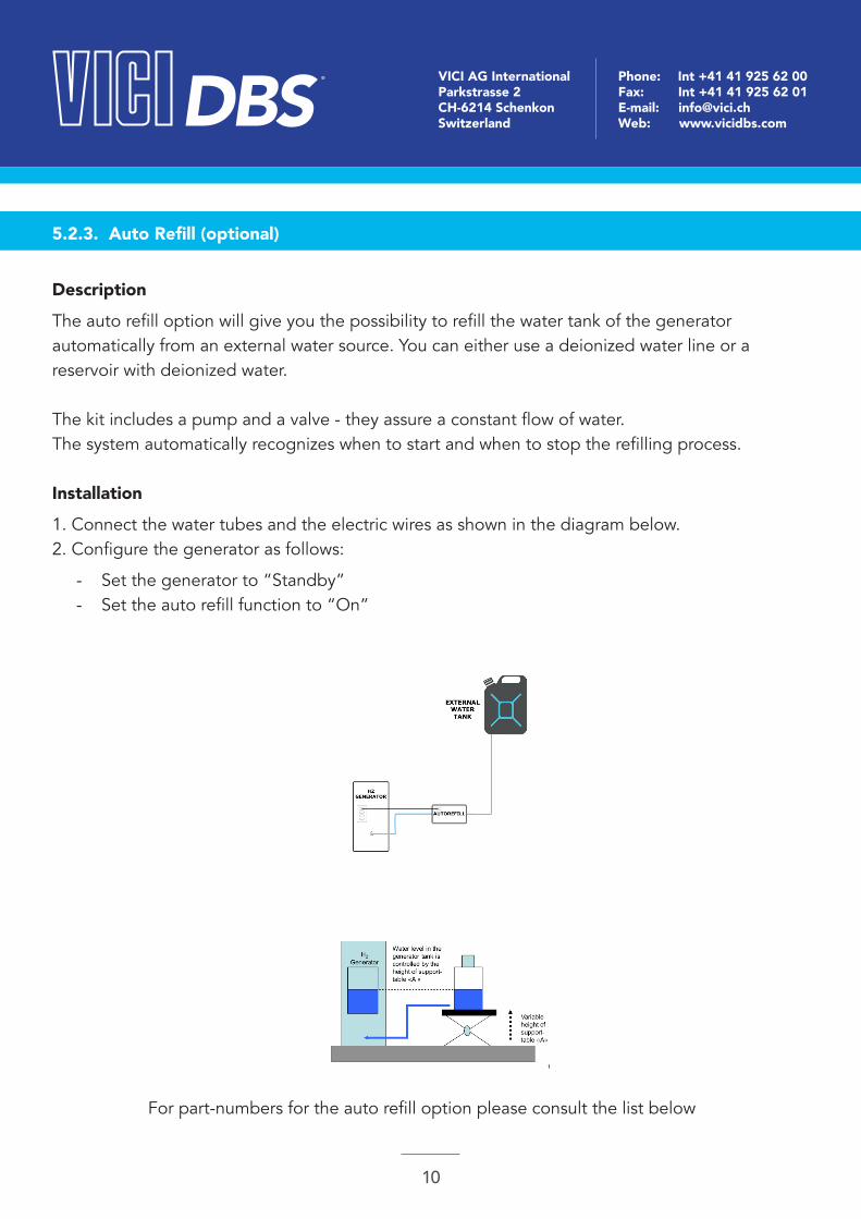
The auto refill option will give you the possibility to refill the water tank of the generator automatically from an external water source. You can either use a deionized water line or a reservoir with deionized water.
The kit includes a pump and a valve - they assure a constant flow of water.The system automatically recognizes when to start and when to stop the refilling process. Installation
1. Connect the water tubes and the electric wires as shown in the diagram below.2. Configure the generator as follows:
- Set the generator to “Standby” - Set the auto refill function to “On”
For part-numbers for the auto refill option please consult the list below

DBS ® VICI AG InternationalParkstrasse 2CH-6214 SchenkonSwitzerland
Phone: Int +41 41 925 62 00Fax: Int +41 41 925 62 01E-mail: [email protected]: www.vicidbs.com
11
Ordering Information for Options Part NumberBoards and InterfacesI/O Board for NM Plus and PG Plus pn: DB-10154
I/O Board for Rack/FID NM Plus and PG Plus pn: DB-10155
Cable for cascading, Requires I/O Board pn: DB-10157
Remote Control RS232 (Software + Cable) pn: DB-PH200-107
Remote Control USB (Software + Cable) pn: DB-PH200-108
CascadingCascading Hardware Kit pn: DB-CASC-001
On/Off and non-return Valve – high purity pn: DB-CASC-002
Buffer Reservoir 0.75 liters – high purity pn: DB-CASC-003
Pressure Regulator with Pressure Gauge pn: DB-CASC-004
Cascading Hardware Kit – high purity pn: DB-CASC-005
Pressure Regulator with Pressure Gauge – high purity pn: DB-CASC-006
Auto-RefillAuto-Refill Plus, requires I/O Board pn: DB-PH200-109
Auto-Refill Tubing Kit, Set A + B for 2 units pn: DB-10159
Auto-Refill Tubing Kit, Set C to add 1 more unit pn: DB-10160
H2-Sensor with Interface, controls VICI DBS s.r.l. Generators pn: DB-H2SE-INT
H2-Sensor with On/Off line Valve independent from Genera-tor Type
pn: DB-H2SE-VAL
6. INSTALLATION AND INITIAL START UP6.1. RECEIVING THE GENERATOR
All units have been carefully inspected before transport. Visual checks for damage and functional tests should be performed upon receipt. Any damage must immediately be noted and reported. The generator must only be returned according to the shipping instructions provided.
ATTENTION: Conserve the ORIGINAL packaging is case of a return.
DBS ® VICI AG InternationalParkstrasse 2CH-6214 SchenkonSwitzerland
Phone: Int +41 41 925 62 00Fax: Int +41 41 925 62 01E-mail: [email protected]: www.vicidbs.com
12
6.2. PACKING LIST
6.3. PLACING THE GENERATOR
List of items included in the shipment:
Quantity Description1 Hydrogen generator
1 Instruction USB key
1 Deionizer triangle bag
1 Water drain with flexible tubing
1 Power cable
1 USB cable
The Hydrogen generator must be placed on a flat, level, vibration- and shock-free surface. Do not place the generator near a heat source, as this may cause the generator to overheat. The unit should not be in contact with any other objects on any side, and the Air inlet must not be blocked. Leave at least 30 cm of free space at the rear for ventilation. Do not operate the generator in a sealed or unventilated room, near open flames or other sources of ignition. Do not operate the generator at temperatures below zero degrees C. Operation is guaranteed at temperatures between +15 and +35°C.
WARNINGNormal precautions as for any Hydrogen supply should be taken when using the generator.
DO NOT use in sealed or unventilated rooms. DO NOT use near open flames or other sources of ignition.
DBS ® VICI AG InternationalParkstrasse 2CH-6214 SchenkonSwitzerland
Phone: Int +41 41 925 62 00Fax: Int +41 41 925 62 01E-mail: [email protected]: www.vicidbs.com
13
6.4. GAS CONNECTIONS
6.5. ELECTRICAL CONNECTIONS
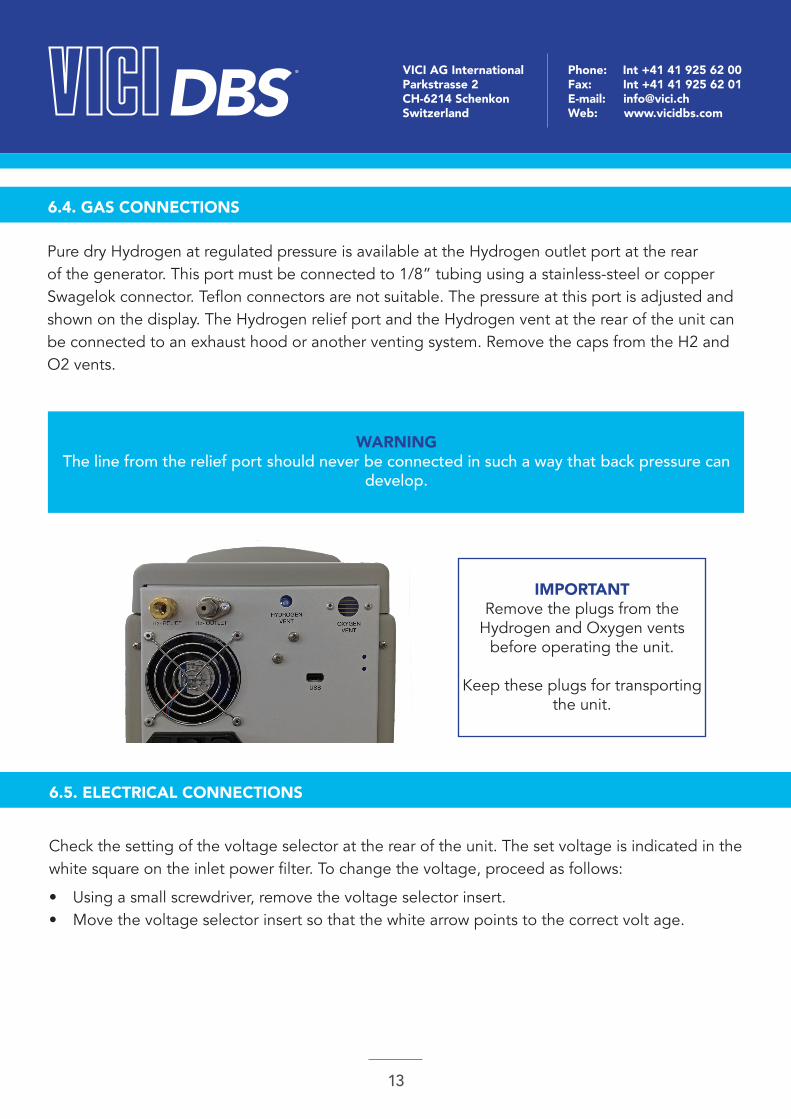
Pure dry Hydrogen at regulated pressure is available at the Hydrogen outlet port at the rear of the generator. This port must be connected to 1/8” tubing using a stainless-steel or copper Swagelok connector. Teflon connectors are not suitable. The pressure at this port is adjusted and shown on the display. The Hydrogen relief port and the Hydrogen vent at the rear of the unit can be connected to an exhaust hood or another venting system. Remove the caps from the H2 and O2 vents.
WARNINGThe line from the relief port should never be connected in such a way that back pressure can
develop.
IMPORTANTRemove the plugs from the
Hydrogen and Oxygen vents before operating the unit.
Keep these plugs for transporting the unit.
Check the setting of the voltage selector at the rear of the unit. The set voltage is indicated in the white square on the inlet power filter. To change the voltage, proceed as follows:
• Using a small screwdriver, remove the voltage selector insert.• Move the voltage selector insert so that the white arrow points to the correct volt age.
DBS ® VICI AG InternationalParkstrasse 2CH-6214 SchenkonSwitzerland
Phone: Int +41 41 925 62 00Fax: Int +41 41 925 62 01E-mail: [email protected]: www.vicidbs.com
14
6.6. INITIAL START-UP
6.6.1. Filling the Water Tank
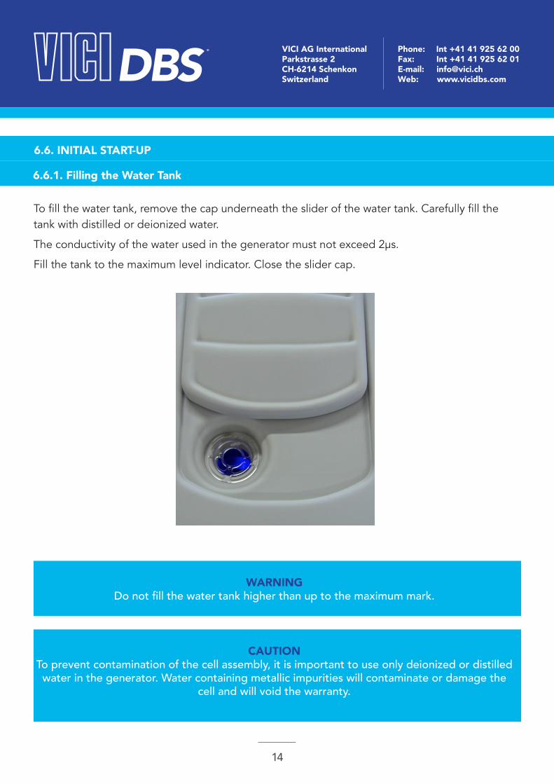
To fill the water tank, remove the cap underneath the slider of the water tank. Carefully fill the tank with distilled or deionized water.
The conductivity of the water used in the generator must not exceed 2μs.
Fill the tank to the maximum level indicator. Close the slider cap.
WARNINGDo not fill the water tank higher than up to the maximum mark.
CAUTIONTo prevent contamination of the cell assembly, it is important to use only deionized or distilled water in the generator. Water containing metallic impurities will contaminate or damage the
cell and will void the warranty.
DBS ® VICI AG InternationalParkstrasse 2CH-6214 SchenkonSwitzerland
Phone: Int +41 41 925 62 00Fax: Int +41 41 925 62 01E-mail: [email protected]: www.vicidbs.com
15
6.6.2. Installing the Deionizer Bag
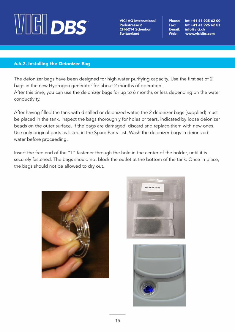
The deionizer bags have been designed for high water purifying capacity. Use the first set of 2 bags in the new Hydrogen generator for about 2 months of operation. After this time, you can use the deionizer bags for up to 6 months or less depending on the water conductivity.
After having filled the tank with distilled or deionized water, the 2 deionizer bags (supplied) must be placed in the tank. Inspect the bags thoroughly for holes or tears, indicated by loose deionizer beads on the outer surface. If the bags are damaged, discard and replace them with new ones. Use only original parts as listed in the Spare Parts List. Wash the deionizer bags in deionized water before proceeding.
Insert the free end of the “T” fastener through the hole in the center of the holder, until it is securely fastened. The bags should not block the outlet at the bottom of the tank. Once in place, the bags should not be allowed to dry out.

DBS ® VICI AG InternationalParkstrasse 2CH-6214 SchenkonSwitzerland
Phone: Int +41 41 925 62 00Fax: Int +41 41 925 62 01E-mail: [email protected]: www.vicidbs.com
16
6.6.3. Starting the Generator
1. Once the previous operations have been performed, the generator is ready for operation. 2. Check that the tank is filled with deionized water.3. Check that the Hydrogen outlet connector is tightly fitted.4. Check that the plug has been removed from the Oxygen vent.5. Turn the Power switch to the “ON” position.6. Enter the desired set pressure, using the menu buttons and selecting “Pressure Adjust”.7. Press the “Start” button to start the unit (if the unit has been configured for “Auto Start” - see Configuration - it will start automatically).8. The unit will immediately begin to build up pressure. The LCD display will show the message “Reaching Normal Pressure”, and the H2 flow bar will indicate maximum flow (fully illuminated). 9. Wait until the “Act Pressure” reaches the set value. These values are shown on the LCD display. It may take a few minutes to reach the set operating pressure.
1. Once the pressure reaches the set value, the LCD display will show the message “Normal Pressure” and the H2 flow bar will indicate no flow (no segments illuminated). This indicates that there are no gas leaks with in the generator itself.2. Open the shutoff valve. The outlet pressure will fall initially. The pressure drop and the duration are depending on the volume consumed by the external equipment connected to the genera tor.3. After the initial pressure drop, the outlet pressure should stabilize at the set pressure. A continuous pressure drop indicates a gas leak in the external equipment, or a too high Hydrogen consumption. Check the external equipment for leaks or excessive Hydrogen consumption.4. The generator is now in normal operating mode.
If the generator does not build up pressure as required, the unit will shut down. Refer to the troubleshooting table.
DBS ® VICI AG InternationalParkstrasse 2CH-6214 SchenkonSwitzerland
Phone: Int +41 41 925 62 00Fax: Int +41 41 925 62 01E-mail: [email protected]: www.vicidbs.com
17
7. OPERATION7.1. LCD DISPLAY
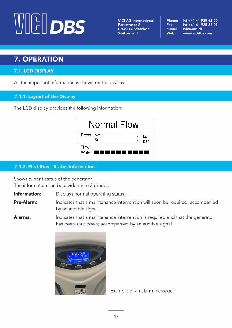
7.1.1. Layout of the Display
7.1.2. First Row - Status Information
All the important information is shown on the display.
The LCD display provides the following information:
Shows current status of the generator.The information can be divided into 3 groups:
Information: Displays normal operating status.
Pre-Alarm: Indicates that a maintenance intervention will soon be required; accompanied by an audible signal.
Alarms: Indicates that a maintenance intervention is required and that the generator has been shut down; accompanied by an audible signal.
Example of an alarm message
DBS ® VICI AG InternationalParkstrasse 2CH-6214 SchenkonSwitzerland
Phone: Int +41 41 925 62 00Fax: Int +41 41 925 62 01E-mail: [email protected]: www.vicidbs.com
18
7.1.3. Second Row - Pressure Information
“Act” is the actual pressure of the Hydrogen, whilst “Set” is the set pressure. The pressure can be increased using the up arrow button, or decreased using the down arrow button.
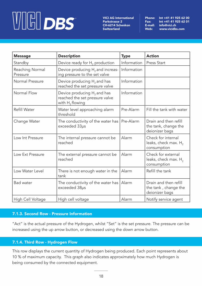
Message Description Type ActionStandby Device ready for H2 production Information Press Start
Reaching Normal Pressure
Device producing H2 and increas-ing pressure to the set valve
Information
Normal Pressure Device producing H2 and has reached the set pressure valve
Information
Normal Flow Device producing H2 and has reached the set pressure valve with H2 flowing
Information
Refill Water Water level approaching alarm threshold
Pre-Alarm Fill the tank with water
Change Water The conductivity of the water has exceeded 33μs
Pre-Alarm Drain and then refill the tank, change the deionizer bags
Low Int Pressure The internal pressure cannot be reached
Alarm Check for internal leaks, check max. H2 consumption
Low Ext Pressure The external pressure cannot be reached
Alarm Check for external leaks, check max. H2 consumption
Low Water Level There is not enough water in the tank
Alarm Refill the tank
Bad water The conductivity of the water has exceeded 38μs
Alarm Drain and then refill the tank , change the deionizer bags
High Cell Voltage High cell voltage Alarm Notify service agent
7.1.4. Third Row - Hydrogen Flow
This row displays the current quantity of Hydrogen being produced. Each point represents about 10 % of maximum capacity. This graph also indicates approximately how much Hydrogen is being consumed by the connected equipment.
DBS ® VICI AG InternationalParkstrasse 2CH-6214 SchenkonSwitzerland
Phone: Int +41 41 925 62 00Fax: Int +41 41 925 62 01E-mail: [email protected]: www.vicidbs.com
19
7.1.5. Fourth Row - Water Quality
This graph shows the quality of the water. With more than 3 points illuminated, water quality is good.
If only 3 or less points are illuminated, the conductivity of the water is around 10µs (pre-alarm level).
If only 1 or no point is illuminated, the conductivity of the water is equal to or greater than 15µs (alarm). The generator will be shut down.
7.1.6. Start/Stop - Reset Button
The “Start/Stop” button places the generator in normal operating mode from “Standby” and vice-versa. It is also used to re-start the unit following an alarm. When the problem leading to the alarm has been resolved, the generator must be reset using the “Reset” button, and then can be started again by pressing the “Start/Stop” button.
Silences the audible alarm. When the problem leading to the alarm has been resolved, the “Reset” button must be pressed before the generator can be restarted (also see “Special Functions”).
The “Reset” button is also used to access the menu.
7.1.7. Exit - Menu Button
“Exit” returns to previous display“Exit” confirms a selected parameter, e.g. YES/NO
NOTEOnly the last point on the flow graph will flash. This indicates that the generator is producing at maximum capacity. During normal operation, this should not be the case, as it indicates that the consumption is near the maximum limit and the unit may shut-down if consumption increases further. Maximum flow is normal when the unit is building up pressure.
DBS ® VICI AG InternationalParkstrasse 2CH-6214 SchenkonSwitzerland
Phone: Int +41 41 925 62 00Fax: Int +41 41 925 62 01E-mail: [email protected]: www.vicidbs.com
20
7.2. MENU OPERATION
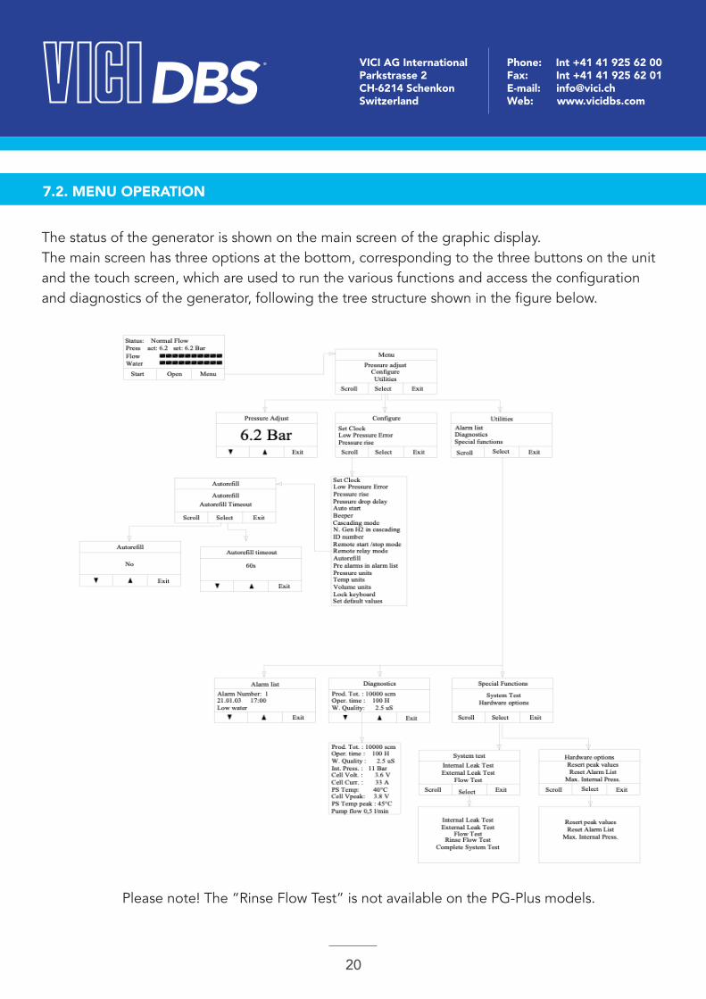
The status of the generator is shown on the main screen of the graphic display.The main screen has three options at the bottom, corresponding to the three buttons on the unit and the touch screen, which are used to run the various functions and access the configuration and diagnostics of the generator, following the tree structure shown in the figure below.
Please note! The “Rinse Flow Test” is not available on the PG-Plus models.
DBS ® VICI AG InternationalParkstrasse 2CH-6214 SchenkonSwitzerland
Phone: Int +41 41 925 62 00Fax: Int +41 41 925 62 01E-mail: [email protected]: www.vicidbs.com
21
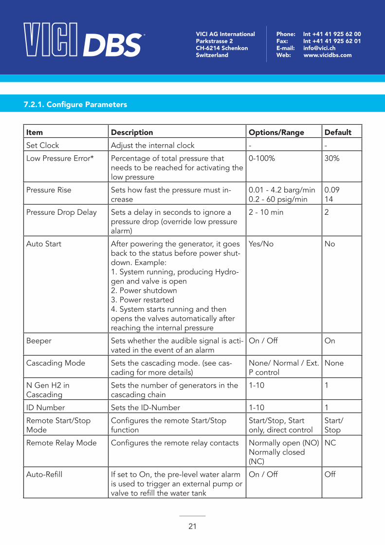
7.2.1. Configure Parameters
Item Description Options/Range DefaultSet Clock Adjust the internal clock - -
Low Pressure Error* Percentage of total pressure that needs to be reached for activating the low pressure
0-100% 30%
Pressure Rise Sets how fast the pressure must in-crease
0.01 - 4.2 barg/min0.2 - 60 psig/min
0.0914
Pressure Drop Delay Sets a delay in seconds to ignore a pressure drop (override low pressure alarm)
2 - 10 min 2
Auto Start After powering the generator, it goes back to the status before power shut-down. Example: 1. System running, producing Hydro-gen and valve is open2. Power shutdown3. Power restarted4. System starts running and then opens the valves automatically after reaching the internal pressure
Yes/No No
Beeper Sets whether the audible signal is acti-vated in the event of an alarm
On / Off On
Cascading Mode Sets the cascading mode. (see cas-cading for more details)
None/ Normal / Ext. P control
None
N Gen H2 in Cascading
Sets the number of generators in the cascading chain
1-10 1
ID Number Sets the ID-Number 1-10 1
Remote Start/Stop Mode
Configures the remote Start/Stop function
Start/Stop, Start only, direct control
Start/Stop
Remote Relay Mode Configures the remote relay contacts Normally open (NO)Normally closed (NC)
NC
Auto-Refill If set to On, the pre-level water alarm is used to trigger an external pump or valve to refill the water tank
On / Off Off

DBS ® VICI AG InternationalParkstrasse 2CH-6214 SchenkonSwitzerland
Phone: Int +41 41 925 62 00Fax: Int +41 41 925 62 01E-mail: [email protected]: www.vicidbs.com
22
* = If set at 100% generator never goes to External Pressure Alarm.
Pre Alarms in List If set to Yes, the pre alarms are also shown in the alarm log.
Yes/No No
Pressure Units Sets the desired unit for the pressure measurement
bar/psi/kPa bar
Temp. Units Sets the desired unit for the tempera-ture measurement
°C and °F °C
Volume Units Sets the desired unit for the volume measurement
scm (standard cubic meters)scf (standard cubic feet)
scm
Lock Keyboard Keyboard will be locked after the gen-erator is in the main window for more than 20s. To unlock, press the unlock key and hold for 5s
Yes/No No
Set Default Values Sets all configuration parameters to default
7.2.2. Diagnostic Display
Item DescriptionProduction Tot. Total production of Hydrogen
Operating Time (h) Total number of hours the unit is operational
Wat. Quality (μs) Actual water conductivity
Int. Press. Actual internal pressure of the unit
Cell Voltage (V) Actual cell voltage
Cell Current (A) Actual cell current
PS. Temp. Actual temperature of the power supply
Cell Voltage Peak (V) The maximum voltage the cell ever reached
PS. Temp. Peak The maximum temperature the power supply reached
Pump Flow (l/min) Actual flow of water
DBS ® VICI AG InternationalParkstrasse 2CH-6214 SchenkonSwitzerland
Phone: Int +41 41 925 62 00Fax: Int +41 41 925 62 01E-mail: [email protected]: www.vicidbs.com
23
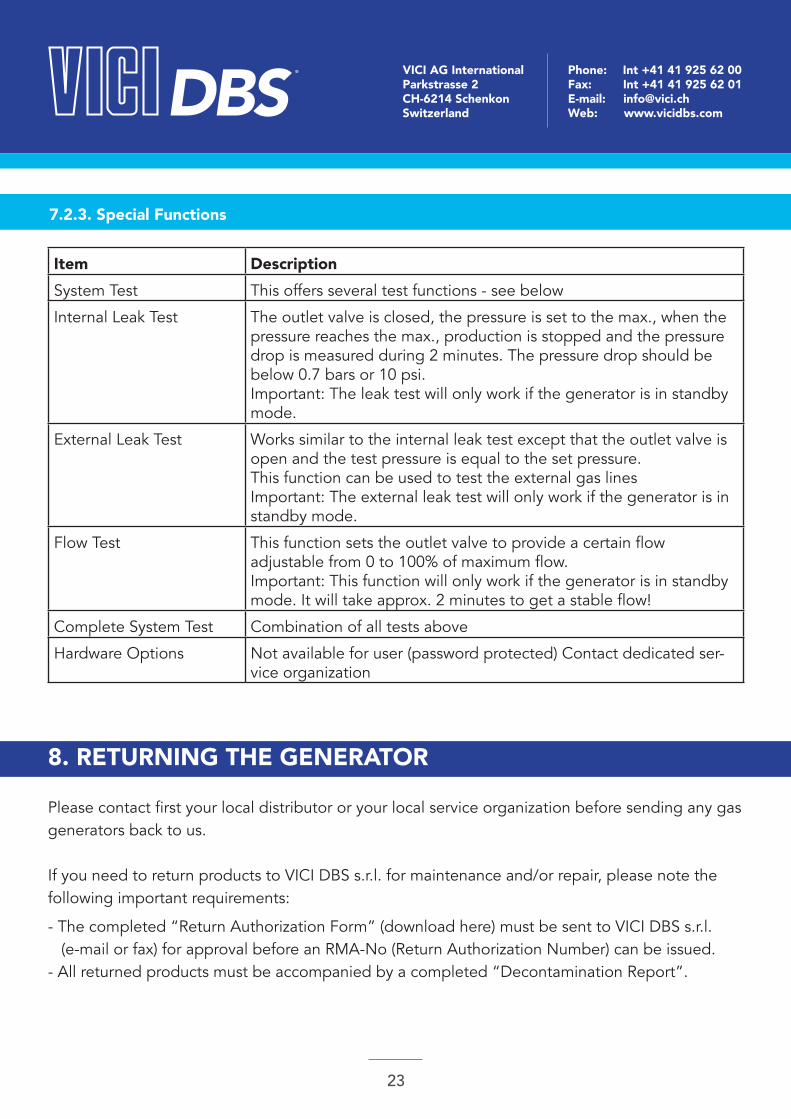
7.2.3. Special Functions
Item DescriptionSystem Test This offers several test functions - see below
Internal Leak Test The outlet valve is closed, the pressure is set to the max., when the pressure reaches the max., production is stopped and the pressure drop is measured during 2 minutes. The pressure drop should be below 0.7 bars or 10 psi.Important: The leak test will only work if the generator is in standby mode.
External Leak Test Works similar to the internal leak test except that the outlet valve is open and the test pressure is equal to the set pressure.This function can be used to test the external gas linesImportant: The external leak test will only work if the generator is in standby mode.
Flow Test This function sets the outlet valve to provide a certain flowadjustable from 0 to 100% of maximum flow.Important: This function will only work if the generator is in standby mode. It will take approx. 2 minutes to get a stable flow!
Complete System Test Combination of all tests above
Hardware Options Not available for user (password protected) Contact dedicated ser-vice organization
8. RETURNING THE GENERATOR
Please contact first your local distributor or your local service organization before sending any gas generators back to us.
If you need to return products to VICI DBS s.r.l. for maintenance and/or repair, please note the following important requirements:
- The completed “Return Authorization Form” (download here) must be sent to VICI DBS s.r.l. (e-mail or fax) for approval before an RMA-No (Return Authorization Number) can be issued.- All returned products must be accompanied by a completed “Decontamination Report”.
DBS ® VICI AG InternationalParkstrasse 2CH-6214 SchenkonSwitzerland
Phone: Int +41 41 925 62 00Fax: Int +41 41 925 62 01E-mail: [email protected]: www.vicidbs.com
24
- Remove all adapters, fittings or similar accessories that are not an integral part of the gas generator. VICI DBS s.r.l. will not be responsible for lost or damaged items that are not an integral part of the gas generator.- The gas generator must be drained of any fluids and residues and securely packed. As part of the service/repair request, you are responsible for the decontamination prior to shipping.- The decontamination report must be signed by a person authorized to take responsibility that the information provided on the form is correct.- The completed “Decontamination Report” must be secured to the outside of the shipping box.
These requirements are necessary because the health and safety of our staff is of paramount importance.
If any returned gas generator does not comply with the above requirements, VICI DBS s.r.l. reserves the right to quarantine or return the gas generator at the customers expense.
If following the inspection and quotation you decline the repair, you may be subject to a service fee to cover product decontamination, disassembly, cleaning and evaluation.
Please also be advised that by sending your gas generator back to us, you have authorized us to disassemble the gas generator for inspection and/or failure analysis. If the gas generator is subsequently deemed not repairable or you decline the repair and request the gas generator to be returned, we cannot ensure that it will be reassembled to working conditions.
We are sure that you share our concern for the safety of our personnel and we request your full cooperation in carrying out these few extra steps prior to returning any products to VICI DBS s.r.l..If anything is not clear or you have further questions, please contact the VICI DBS s.r.l. technical support team under [email protected].
Please also provide full details of the problem, including the model and serial numbers of your gas generator. Instructions will then be provided for the service or the return of the unit. If the warranty has expired, or the fault is due to misuse of the unit, all repair and shipping costs are to be paid by the customer. All other costs are also borne by the customer, except as otherwise expressly agreed upon.
DBS ® VICI AG InternationalParkstrasse 2CH-6214 SchenkonSwitzerland
Phone: Int +41 41 925 62 00Fax: Int +41 41 925 62 01E-mail: [email protected]: www.vicidbs.com
25
WARNINGIf the generator needs to be transported, make sure that the water tank is completely empty. Place the plug (supplied with the unit) on the Oxygen vent at the rear of the unit. Close the
water tank with the cap. Use the ORIGINAL packing material. The generator should be transported in an upright position; this warning should be marked at
the outside of the shipping box.
IMPORTANTThe manufacturer reserves the right to change or modify its products without prior notice.
9. MAINTENANCE
With proper care and maintenance, your Hydrogen generator should provide you with years of trouble-free operation. There are no adjustments to be made to the generator. The only routine service operations are those described below.
Nonetheless, the generator should be inspected approximately every 2 years. Contact your supplier.
9.1. ROUTINE MAINTENANCE
The following section describes the maintenance operations required for the correct operation of the Hydrogen generator.
9.1.1. Cleaning
The internal components of the Hydrogen generator do not need to be cleaned and should not be accessed by the user for cleaning. To clean the outside of the unit, only use a damp cloth (no detergents, acids or aggressive or abrasive substances).
DBS ® VICI AG InternationalParkstrasse 2CH-6214 SchenkonSwitzerland
Phone: Int +41 41 925 62 00Fax: Int +41 41 925 62 01E-mail: [email protected]: www.vicidbs.com
26
9.1.2. Water Refilling
9.1.3. Deionizer Bag Replacement
The tank must be refilled when the water level approaches the lower level, and the “Refill Water” pre-alarm message appears. Use distilled or deionized water.
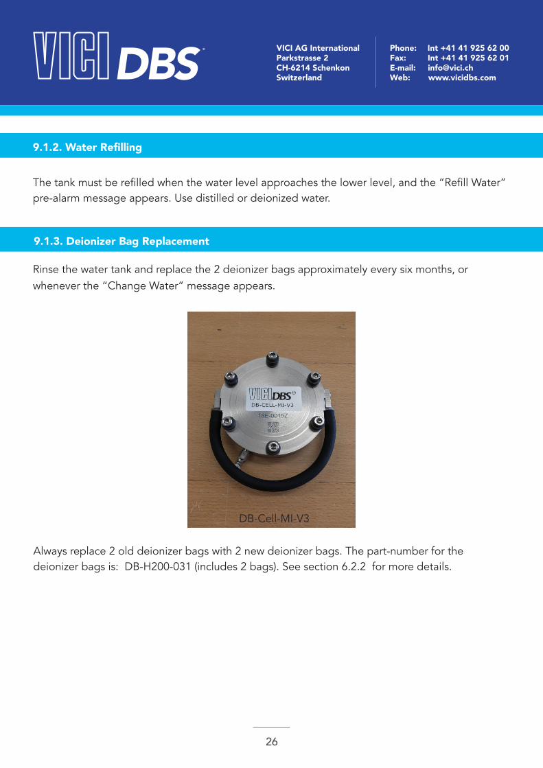
Rinse the water tank and replace the 2 deionizer bags approximately every six months, or whenever the “Change Water” message appears.
Always replace 2 old deionizer bags with 2 new deionizer bags. The part-number for the deionizer bags is: DB-H200-031 (includes 2 bags). See section 6.2.2 for more details.
DB-Cell-MI-V3
DBS ® VICI AG InternationalParkstrasse 2CH-6214 SchenkonSwitzerland
Phone: Int +41 41 925 62 00Fax: Int +41 41 925 62 01E-mail: [email protected]: www.vicidbs.com
27
9.1.4. Installing the New Deionizer Bags
See section 6.6.2 “Installing the deionizer Bags”
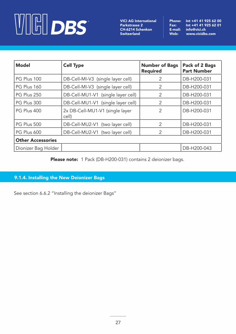
Model Cell Type Number of Bags Required
Pack of 2 Bags Part Number
PG Plus 100 DB-Cell-MI-V3 (single layer cell) 2 DB-H200-031
PG Plus 160 DB-Cell-MI-V3 (single layer cell) 2 DB-H200-031
PG Plus 250 DB-Cell-MU1-V1 (single layer cell) 2 DB-H200-031
PG Plus 300 DB-Cell-MU1-V1 (single layer cell) 2 DB-H200-031
PG Plus 400 2x DB-Cell-MU1-V1 (single layer cell)
2 DB-H200-031
PG Plus 500 DB-Cell-MU2-V1 (two layer cell) 2 DB-H200-031
PG Plus 600 DB-Cell-MU2-V1 (two layer cell) 2 DB-H200-031
Other AccessoriesDionizer Bag Holder DB-H200-043
Please note: 1 Pack (DB-H200-031) contains 2 deionizer bags.

DBS ® VICI AG InternationalParkstrasse 2CH-6214 SchenkonSwitzerland
Phone: Int +41 41 925 62 00Fax: Int +41 41 925 62 01E-mail: [email protected]: www.vicidbs.com
28
9.1.5. Rinse Air Bubble Procedure
The following procedure needs to be applied in case of a “Water Flow Error”This can happen if Air bubbles are trapped inside the water flow sensor of the water pump.
1. Open the service door at the left side of the generator (Photo1).
2. You see a water rapid connector tube as shown in the Photo 2, cut the tie that is blocking it (red arrow).
( Photo 1 ) ( Photo 2 )
DBS ® VICI AG InternationalParkstrasse 2CH-6214 SchenkonSwitzerland
Phone: Int +41 41 925 62 00Fax: Int +41 41 925 62 01E-mail: [email protected]: www.vicidbs.com
29
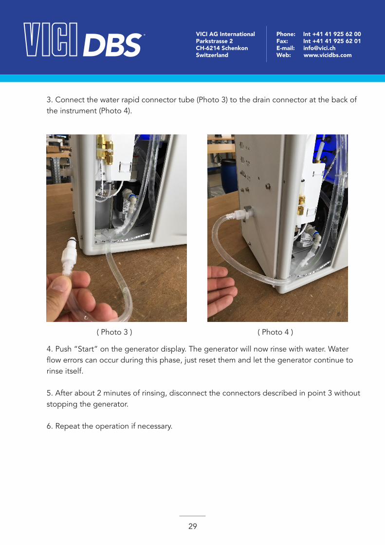
3. Connect the water rapid connector tube (Photo 3) to the drain connector at the back of the instrument (Photo 4).
4. Push “Start” on the generator display. The generator will now rinse with water. Water flow errors can occur during this phase, just reset them and let the generator continue to rinse itself.
5. After about 2 minutes of rinsing, disconnect the connectors described in point 3 without stopping the generator.
6. Repeat the operation if necessary.
( Photo 3 ) ( Photo 4 )

DBS ® VICI AG InternationalParkstrasse 2CH-6214 SchenkonSwitzerland
Phone: Int +41 41 925 62 00Fax: Int +41 41 925 62 01E-mail: [email protected]: www.vicidbs.com
30
10. SPARE PARTS LIST
Part Number DescriptionDB-PH200-000 Water tank complete for PG-Plus / NM-Plus (1 water outlet)
DB-PH201-000 Water tank complete for PG-Plus / NM-Plus (2 water outlets) (from s/n PNMX170115261 and PHGS170115343)
DB-PH200-001 Water tubing kit for NM-Plus / PG-Plus
DB-H200-005 Water drain outlet+tube (before S/N: PNMS170915368 & PHGS170915444)
DB-H200-006 Ball valve for cell IN, pre-mounted in a tubing
DB-H200-007 G/L separator,complete with fittings
DB-H200-008 G/L separator 1/8” tube quick straight fitting
DB-H200-034 Perma Pure
DB-H200-035 Pressure release valve
DB-H200-036 Gas outlet connector
DB-H200-038 H2 Separator
DB-H200-039 80mm axial fan
DB-PH200-002 Internal circulation fan for PG-Plus and NM-Plus
DB-PH200-003 Small Power Supply for PG- / NM Plus 100/160/250/300/400
DB-PH200-004 Big Power Supply for PG- / NM Plus 500/600/1000/1350
DB-PH200-005 Gas on/off valve for PG-Plus
DB-PH200-007 Display touch screen for PG-Plus and NM-Plus
DB-PH200-008 Plastic cover kit for PG-Plus
DB-H200-042 Display Membrane
DB-H200-043 Deionizer Bag Holder
DB-H200-045 Power inlet with filter and voltage selector
DB-PGP201-008 Main board for PG Plus 100
DB-PGP202-008 Main board for PG Plus 160
DB-PGP203-008 Main board for PG Plus 250
DB-PGP204-008 Main board for PG Plus 300
DB-10361 Main board for PG Plus 400
DB-PGP205-008 Main board for PG Plus 500

DBS ® VICI AG InternationalParkstrasse 2CH-6214 SchenkonSwitzerland
Phone: Int +41 41 925 62 00Fax: Int +41 41 925 62 01E-mail: [email protected]: www.vicidbs.com
31
DB-PGP206-008 Main board for PG Plus 600
DB-PGP201-008-JP
Main board for PG Plus 100 – Japan configuration
DB-PGP202-008-JP
Main board for PG Plus 160 – Japan configuration
DB-PGP203-008-JP
Main board for PG Plus 250 – Japan configuration
DB-PGP204-008-JP
Main board for PG Plus 300 – Japan configuration
DB-10362 Main board for PG Plus 400 – Japan configuration
DB-PGP205-008-JP
Main board for PG Plus 500 – Japan configuration
DB-PGP206-008-JP
Main board for PG Plus 600 – Japan configuration
DB-PGP207-008 Internal cables for PG-Plus
DB-PH200-009 Water flow sensor for PG-Plus / NM-Plus
DB-PH200-010 Water pump circulator for PG-Plus / NM-Plus
DB-PH200-011 USB port with cable
DB-H210000-005 Mini-Cell service (V1) for NM Plus 100 / PG Plus 100
DB-H216000-005 Mini-Cell service (V1) for NM Plus 160 / PG Plus 160
DB-H225000-003 Maxi-Cell service (V1) for PG Plus 250
DB-H230000-005 Maxi-Cell service (V1) for NM Plus 300 / PG Plus 300
DB-H250000-005 Maxi-Cell service (V1) for NM Plus 500 / PG Plus 500
DB-H260000-005 Maxi-Cell service (V1) for NM Plus 600 / PG Plus 600
DB-H2100000-005 Maxi-Cell service (V1) for NM Plus 1000 / PG Plus 1000
DB-H210000-006 Mini-Cell service (V2) for NM Plus 100 / PG Plus 100
DB-H216000-006 Mini-Cell service (V2) for NM Plus 160 / PG Plus 160
DB-H225000-004 Maxi-Cell service (V2) for PG Plus 250
DB-H230000-006 Maxi-Cell service (V2) for NM Plus 300 / PG Plus 300
DB-H250000-006 Maxi-Cell service (V2) for NM Plus 500 / PG Plus 500
DB-H260000-006 Maxi-Cell service (V2) for NM Plus 600 / PG Plus 600
DB-H2100000-006 Maxi-Cell service (V2) for NM Plus 1000 / PG Plus 600
DB-Cell-MI-V3 Complete Mini-Cell V3, full titanium

DBS ® VICI AG InternationalParkstrasse 2CH-6214 SchenkonSwitzerland
Phone: Int +41 41 925 62 00Fax: Int +41 41 925 62 01E-mail: [email protected]: www.vicidbs.com
32
DB-Cell-MU1-V1 Complete Multi 1-layer Cell V1, full titanium
DB-Cell-MU2-V1 Complete Multi 2-layer Cell V1, full titanium
DB-Cell-MI-V3-R Mini-Cell Service V3
DB-Cell-MU1-V1-R Multi-Cell 1-layer Service V1
DB-Cell-MU2-V1-R Multi-Cell 2-layer Service V1
DB-KIT-PUMP-PLUS
Upgrade kit with water pump and flow-meter for PG-Plus series (service upgrade only)
DB-PGP200-012 Maintenance kit for PG-Plus
DB-PGP200-013 Maintenance kit for PG-Plus with pump
DB-H202-205 Auto-refill on/off valve
DB-H200-047 Cell red+black power cables H2 generator
DB-H200-048 Rear panel water fitting (drain) (before S/N: PNMS170915368 & PHGS170915444)
DB-H200-049 Water drain outlet+tube (from S/N: PNMS170915368 & PHGS170915444)
DB-H200-050 Rear panel water fitting (drain) (from S/N: PNMS170915368 & PHGS170915444)
DB-H200-031 Deionizer bags (includes 2 bags)