Period #11: STATICALLY INDETERMINATE SHAFTS
10
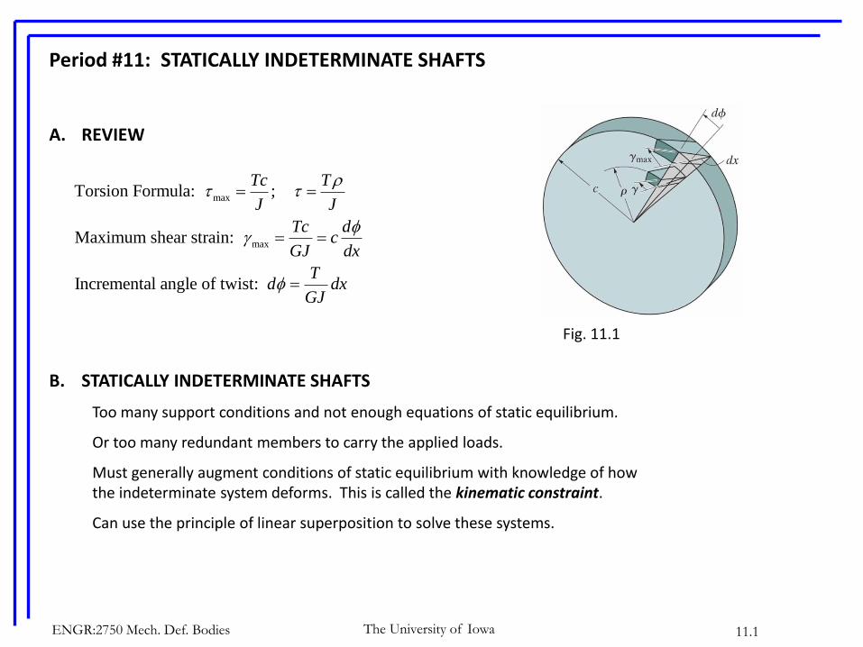
ENGR:2750 Mech. Def. Bodies 11.1 The University of Iowa Period #11: STATICALLY INDETERMINATE SHAFTS A. REVIEW B. STATICALLY INDETERMINATE SHAFTS Too many support conditions and not enough equations of static equilibrium. Or too many redundant members to carry the applied loads. Must generally augment conditions of static equilibrium with knowledge of how the indeterminate system deforms. This is called the kinematic constraint. Can use the principle of linear superposition to solve these systems. Fig. 11.1 max max Torsion Formula: ; Maximum shear strain: Incremental angle of twist: Tc T J J Tc d c GJ dx T d dx GJ
-
Upload
khangminh22 -
Category
Documents
-
view
0 -
download
0
Transcript of Period #11: STATICALLY INDETERMINATE SHAFTS
ENGR:2750 Mech. Def. Bodies 11.1The University of Iowa
Period #11: STATICALLY INDETERMINATE SHAFTS
A. REVIEW
B. STATICALLY INDETERMINATE SHAFTS
Too many support conditions and not enough equations of static equilibrium.
Or too many redundant members to carry the applied loads.
Must generally augment conditions of static equilibrium with knowledge of how the indeterminate system deforms. This is called the kinematic constraint.
Can use the principle of linear superposition to solve these systems.
Fig. 11.1
max
max
Torsion Formula: ;
Maximum shear strain:
Incremental angle of twist:
Tc T
J J
Tc dc
GJ dx
Td dx
GJ
The University of IowaENGR:2750 Mech. Def. Bodies 11.2
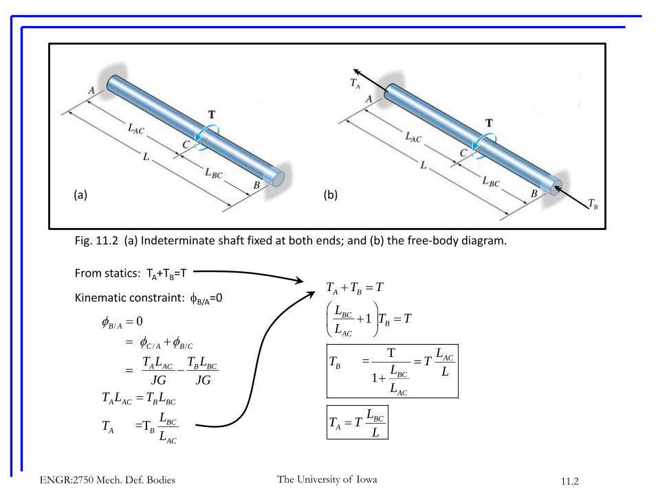
From statics: TA+TB=T
Kinematic constraint: B/A=0
/
/ /
0
=T
B A
C A B C
A AC B BC
A AC B BC
BCA B
AC
T L T L
JG JG
T L T L
LT
L
Fig. 11.2 (a) Indeterminate shaft fixed at both ends; and (b) the free-body diagram.
AT
BT(a) (b)
1
T =
1
A B
BCB
AC
ACB
BC
AC
BCA
T T T
LT T
L
LT T
L L
L
LT T
L
The University of IowaENGR:2750 Mech. Def. Bodies 11.3
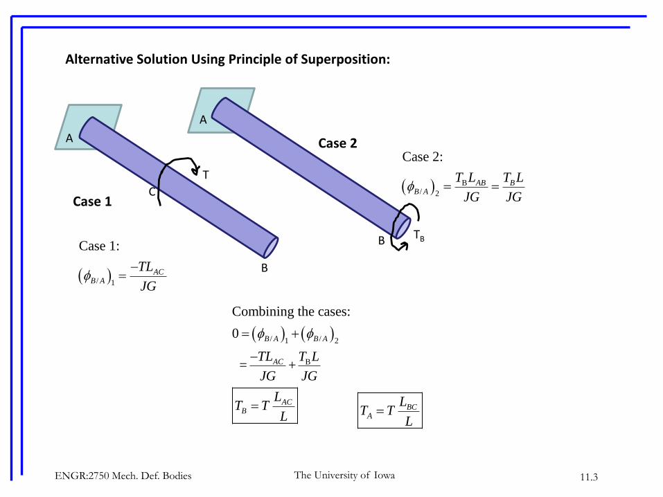
Alternative Solution Using Principle of Superposition:
T
A
B
CCase 1
TB
A
B
Case 2
/ /1 2
B
Combining the cases:
0
= +
B A B A
AC
ACB
TL T L
JG JG
LT T
L
B/ 2
Case 2:
AB BB A
T L T L
JG JG
/ 1
Case 1:
ACB A
TL
JG
BCA
LT T
L
ENGR:2750 Mech. Def. Bodies 11.4The University of Iowa
C. SHAFTS OF SOLID, NON-CIRCULAR CROSS-SECTIONS (TEXTBOOK, SECTION 5.6)
To this point, we’ve been concerned with shafts that have circular cross-sections.
What about shafts with non-circular cross-sections?
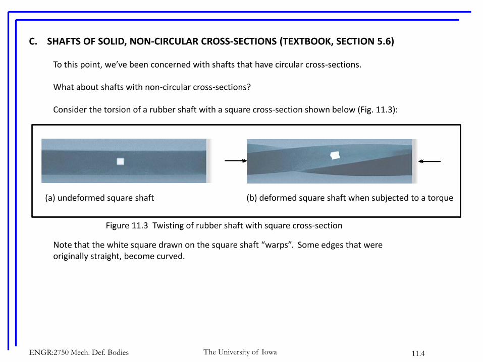
Consider the torsion of a rubber shaft with a square cross-section shown below (Fig. 11.3):
Note that the white square drawn on the square shaft “warps”. Some edges that were originally straight, become curved.
(a) undeformed square shaft (b) deformed square shaft when subjected to a torque
Figure 11.3 Twisting of rubber shaft with square cross-section

The University of IowaENGR:2750 Mech. Def. Bodies 11.5
With solid non-circular cross-sections, the shear stress distribution over the cross-section cannot vary linearly with radial distance from the center (Fig. 11.4a). This leads to warping of the shaft cross-section (Fig. 11.4b).
(a) (b)
Fig. 11.4 Noncircular shaft response to torsion

The University of IowaENGR:2750 Mech. Def. Bodies 11.6
Although the torsion formulae do not apply to shafts with non-circular cross-sections, the relevant properties of three sections are as indicated in the table below.
Table 11.1. Properties of non-circular sections.
The University of IowaENGR:2750 Mech. Def. Bodies 11.7
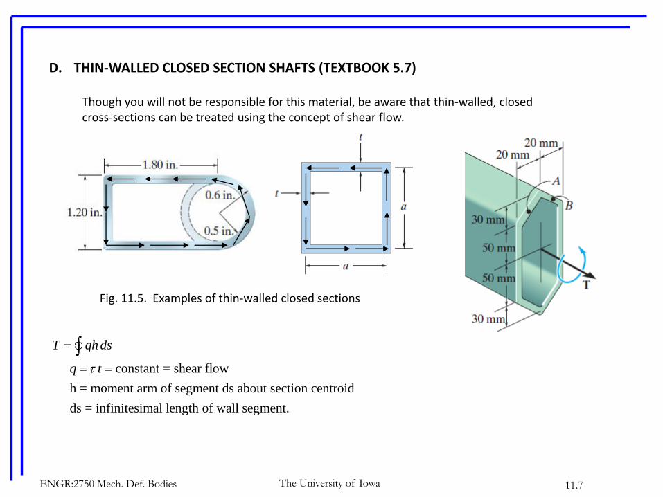
D. THIN-WALLED CLOSED SECTION SHAFTS (TEXTBOOK 5.7)
Though you will not be responsible for this material, be aware that thin-walled, closed cross-sections can be treated using the concept of shear flow.
Fig. 11.5. Examples of thin-walled closed sections
constant = shear flow
h = moment arm of segment ds about section centroid
ds = infinitesimal length of wall segment.
T qhds
q t
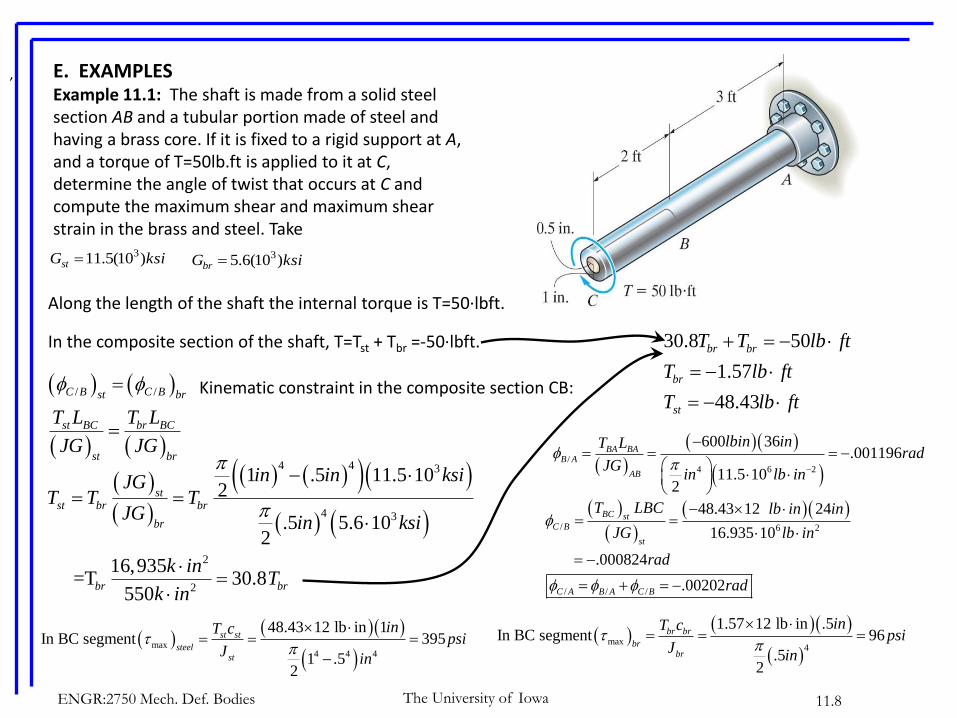
E. EXAMPLESExample 11.1: The shaft is made from a solid steel section AB and a tubular portion made of steel and having a brass core. If it is fixed to a rigid support at A, and a torque of T=50lb.ft is applied to it at C, determine the angle of twist that occurs at C and compute the maximum shear and maximum shear strain in the brass and steel. Take
ksiGst )10(5.11 3 ksiGbr )10(6.5 3
,
The University of IowaENGR:2750 Mech. Def. Bodies 11.8
Along the length of the shaft the internal torque is T=50∙lbft.
In the composite section of the shaft, T=Tst + Tbr =-50∙lbft.
Kinematic constraint in the composite section CB:
/ /C B C Bst br
st BC br BC
st br
T L T L
JG JG
4 4 3
4 3
2
2
1 .5 11.5 102
.5 5.6 102
16,935 =T 30.8
550
stst br br
br
br br
in in ksiJGT T T
JGin ksi
k inT
k in
30.8 50
1.57
48.43
br br
br
st
T T lb ft
T lb ft
T lb ft
/
4 6 2
600 36.001196
11.5 102
BA BAB A
AB
lbin inT Lrad
JGin lb in
/ 6 2
48.43 12 24
16.935 10
.000824
BC stC B
st
T LBC lb in in
JG lb in
rad
/ / / .00202C A B A C B rad
max
4 4 4
48.43 12 lb in 1In BC segment 395
1 .52
st st
steelst
inT cpsi
Jin
max
4
1.57 12 lb in .5In BC segment 96
.52
br br
brbr
inT cpsi
Jin
The University of IowaENGR:2750 Mech. Def. Bodies 11.9
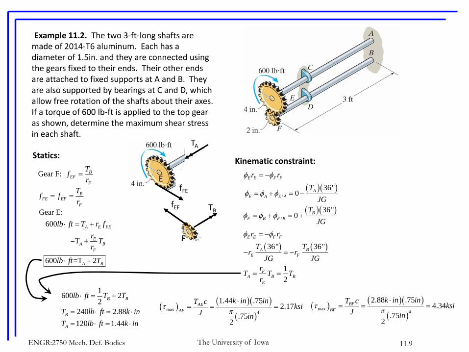
Example 11.2. The two 3-ft-long shafts are made of 2014-T6 aluminum. Each has a diameter of 1.5in. and they are connected using the gears fixed to their ends. Their other ends are attached to fixed supports at A and B. They are also supported by bearings at C and D, which allow free rotation of the shafts about their axes. If a torque of 600 lb-ft is applied to the top gear as shown, determine the maximum shear stress in each shaft.
TA
fFE
E
fEF TB
F
Statics:
Gear E:
600
=T
600 =T 2
A E FE
EA B
F
A B
lb ft T r f
rT
r
lb ft T
BFE EF
F
Tf f
r
Gear F: BEF
F
Tf
r
Kinematic constraint:
E E F Fr r
/
36"0
A
E A E A
T
JG
/
36"0
B
F B F B
T
JG
36" 36"
1
2
E E F F
A B
E F
FA B B
E
r r
T Tr r
JG JG
rT T T
r
1600 2
2
240 2.88
120 1.44
B B
B
A
lb ft T T
T lb ft k in
T lb ft k in
max
4
1.44 .752.17
.752
AE
AE
k in inT cksi
Jin
max
4
2.88 .754.34
.752
BF
BF
k in inT cksi
Jin
The University of IowaENGR:2750 Mech. Def. Bodies 11.10
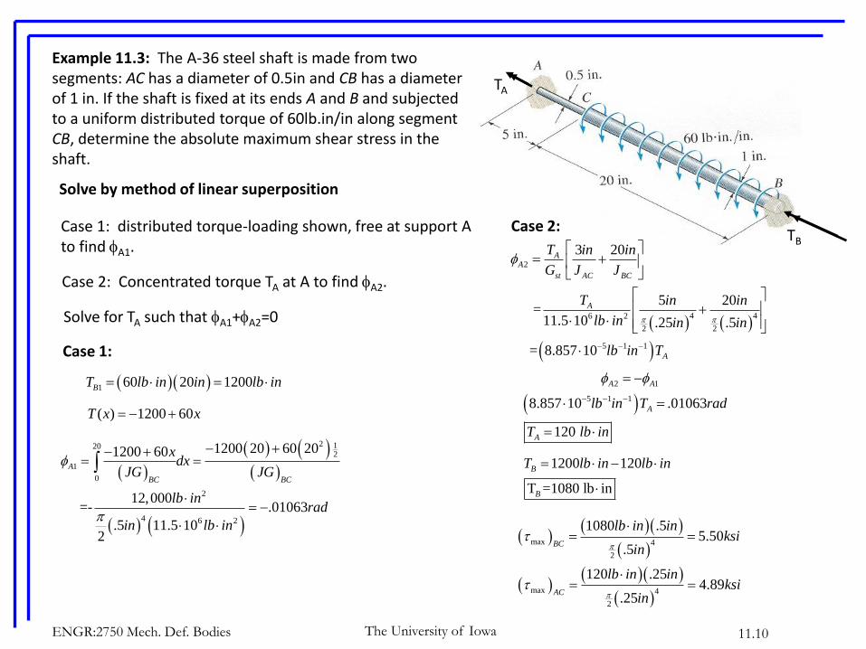
Example 11.3: The A-36 steel shaft is made from two segments: AC has a diameter of 0.5in and CB has a diameter of 1 in. If the shaft is fixed at its ends A and B and subjected to a uniform distributed torque of 60lb.in/in along segment CB, determine the absolute maximum shear stress in the shaft.
Solve by method of linear superposition
Case 1: distributed torque-loading shown, free at support Ato find A1.
Case 2: Concentrated torque TA at A to find A2.
Solve for TA such that A1+A2=0
Case 1:
1 60 20 1200BT lb in in lb in
( ) 1200 60T x x
2 1202
1
0
2
4 6 2
1200 20 60 201200 60
12,000 =- .01063
.5 11.5 102
A
BC BC
xdx
JG JG
lb inrad
in lb in
Case 2:TB
TA
2
4 46 2
2 2
5 1 1
3 20
5 20 =
11.5 10 .25 .5
= 8.857 10
AA
st AC BC
A
A
T in in
G J J
T in in
lb in in in
lb in T
2 1
5 1 1
8.857 10 .01063
120
A A
A
A
lb in T rad
T lb in
1200 120
T =1080 lb in
B
B
T lb in lb in
max 4
2
max 4
2
1080 .55.50
.5
120 .254.89
.25
BC
AC
lb in inksi
in
lb in inksi
in