Statically Indeterminate Members Solved Problems in ...
26
Statically Indeterminate Members When the reactive forces or the internal resisting forces over a cross section exceed the number of independent equations of equilibrium, the structure is called statically indeterminate. These cases require the use of additional relations that depend on the elastic deformations in the members. Solved Problems in Statically Indeterminate Members Problem 233 A steel bar 50 mm in diameter and 2 m long is surrounded by a shell of a cast iron 5 mm thick. Compute the load that will compress the combined bar a total of 0.8 mm in the length of 2 m. For steel, E = 200 GPa, and for cast iron, E = 100 GPa. Solution 233
-
Upload
khangminh22 -
Category
Documents
-
view
0 -
download
0
Transcript of Statically Indeterminate Members Solved Problems in ...

Statically Indeterminate Members When the reactive forces or the internal resisting forces over a cross section exceed the
number of independent equations of equilibrium, the structure is called statically
indeterminate. These cases require the use of additional relations that depend on the
elastic deformations in the members.
Solved Problems in Statically Indeterminate Members
Problem 233
A steel bar 50 mm in diameter and 2 m long is surrounded by a shell of a cast iron 5
mm thick. Compute the load that will compress the combined bar a total of 0.8 mm in
the length of 2 m. For steel, E = 200 GPa, and for cast iron, E = 100 GPa.
Solution 233

Problem 234
A reinforced concrete column 200 mm in diameter is designed to carry an axial
compressive load of 300 kN. Determine the required area of the reinforcing steel if the
allowable stresses are 6 MPa and 120 MPa for the concrete and steel, respectively. Use
Eco = 14 GPa and Est = 200 GPa.
Solution 234
Problem 235
A timber column, 8 in. × 8 in. in cross section, is reinforced on each side by a steel
plate 8 in. wide and t in. thick. Determine the thickness t so that the column will
support an axial load of 300 kips without exceeding a maximum timber stress of 1200
psi or a maximum steel stress of 20 ksi. The moduli of elasticity are 1.5 × 10⁶ psi for
timber, and 29 × 106 psi for steel.

Solution 235
Problem 236
A rigid block of mass M is supported by three symmetrically spaced rods as shown in fig
P-236. Each copper rod has an area of 900 mm2; E = 120 GPa; and the allowable stress
is 70 MPa. The steel rod has an area of 1200 mm2; E = 200 GPa; and the allowable
stress is 140 MPa. Determine the largest mass M which can be supported.
Figure P-236 and P-237

Solution 236
Problem 237
In Prob. 236, how should the lengths of the two identical copper rods be changed so
that each material will be stressed to its allowable limit?
Solution 237
Problem 238
The lower ends of the three bars in Fig. P-238 are at the same level before the uniform
rigid block weighing 40 kips is attached. Each steel bar has a length of 3 ft, and area of
1.0 in.2, and E = 29 × 106 psi. For the bronze bar, the area is 1.5 in.2 and E = 12 × 106
psi. Determine (a) the length of the bronze bar so that the load on each steel bar is
twice the load on the bronze bar, and (b) the length of the bronze that will make the
steel stress twice the bronze stress.
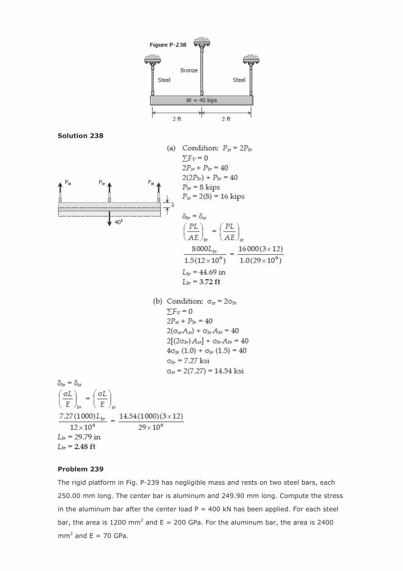
Solution 238
Problem 239
The rigid platform in Fig. P-239 has negligible mass and rests on two steel bars, each
250.00 mm long. The center bar is aluminum and 249.90 mm long. Compute the stress
in the aluminum bar after the center load P = 400 kN has been applied. For each steel
bar, the area is 1200 mm2 and E = 200 GPa. For the aluminum bar, the area is 2400
mm2 and E = 70 GPa.

Solution 239
Problem 240
Three steel eye-bars, each 4 in. by 1 in. in section, are to be assembled by driving rigid
7/8-in.-diameter drift pins through holes drilled in the ends of the bars. The center-line
spacing between the holes is 30 ft in the two outer bars, but 0.045 in. shorter in the
middle bar. Find the shearing stress developed in the drip pins. Neglect local
deformation at the holes.
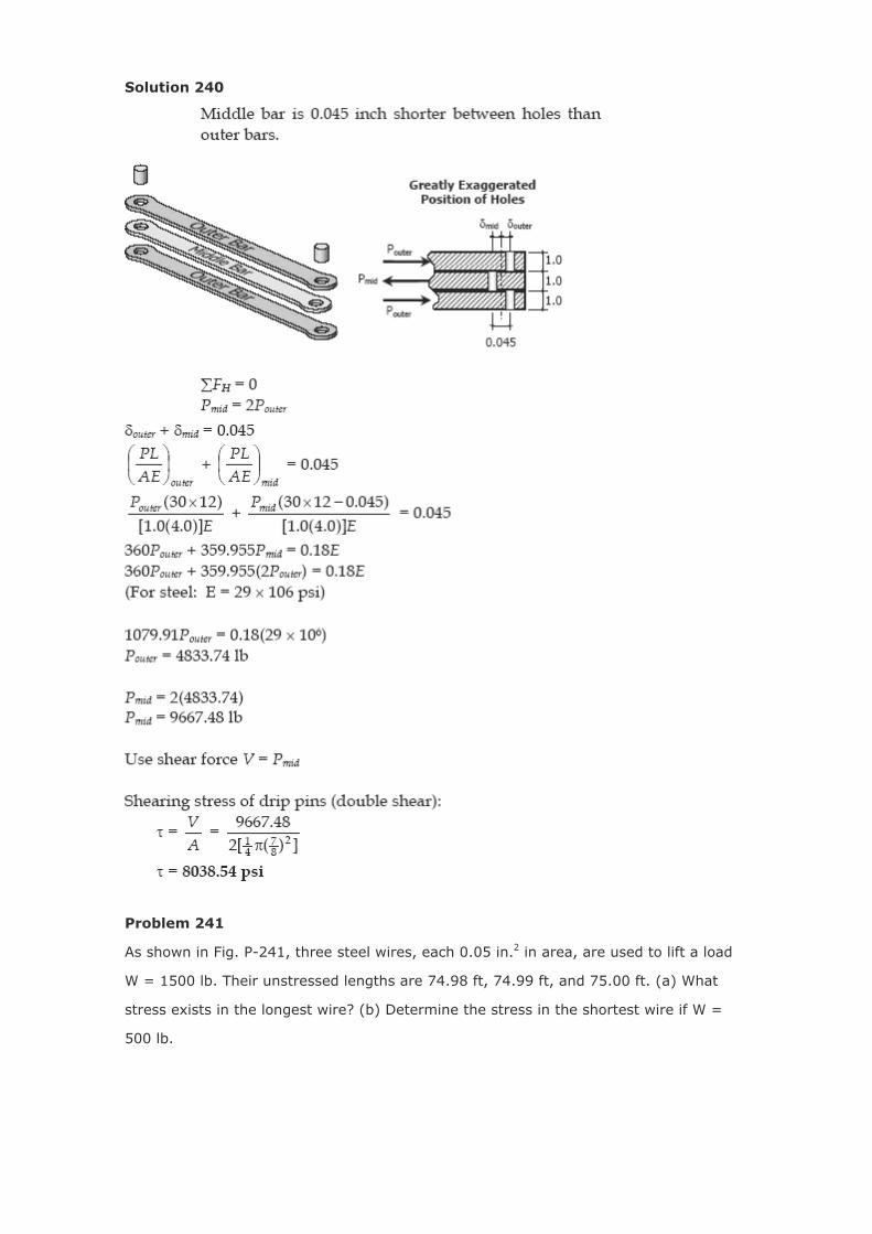
Solution 240
Problem 241
As shown in Fig. P-241, three steel wires, each 0.05 in.2 in area, are used to lift a load
W = 1500 lb. Their unstressed lengths are 74.98 ft, 74.99 ft, and 75.00 ft. (a) What
stress exists in the longest wire? (b) Determine the stress in the shortest wire if W =
500 lb.

Solution 241

Problem 242
The assembly in Fig. P-242 consists of a light rigid bar AB, pinned at O, that is attached
to the steel and aluminum rods. In the position shown, bar AB is horizontal and there is
a gap, Δ = 5 mm, between the lower end of the steel rod and its pin support at C.
Compute the stress in the aluminum rod when the lower end of the steel rod is attached
to its support.
Solution 242
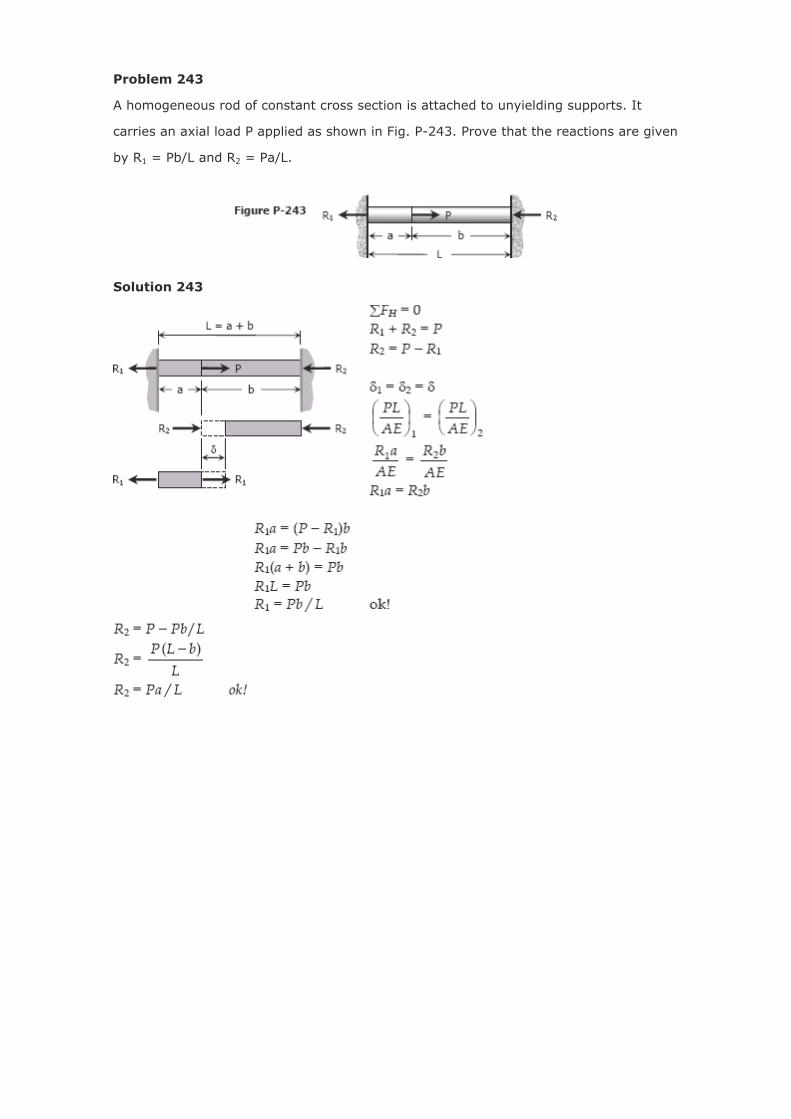
Problem 243
A homogeneous rod of constant cross section is attached to unyielding supports. It
carries an axial load P applied as shown in Fig. P-243. Prove that the reactions are given
by R1 = Pb/L and R2 = Pa/L.
Solution 243

Problem 244
A homogeneous bar with a cross sectional area of 500 mm2 is attached to rigid
supports. It carries the axial loads P1 = 25 kN and P2 = 50 kN, applied as shown in Fig.
P-244. Determine the stress in segment BC. (Hint: Use the results of Prob. 243, and
compute the reactions caused by P1 and P2 acting separately. Then use the principle of
superposition to compute the reactions when both loads are applied.)
Solution 244

Problem 245
The composite bar in Fig. P-245 is firmly attached to unyielding supports. Compute the
stress in each material caused by the application of the axial load P = 50 kips.
Solution 245

Problem 246
Referring to the composite bar in Prob. 245, what maximum axial load P can be applied
if the allowable stresses are 10 ksi for aluminum and 18 ksi for steel.
Solution 246
Problem 247
The composite bar in Fig. P-247 is stress-free before the axial loads P1 and P2 are
applied. Assuming that the walls are rigid, calculate the stress in each material if P1 =
150 kN and P2 = 90 kN.

Solution 247
Problem 248
Solve Prob. 247 if the right wall yields 0.80 mm.

Solution 248
Problem 249
There is a radial clearance of 0.05 mm when a steel tube is placed over an aluminum
tube. The inside diameter of the aluminum tube is 120 mm, and the wall thickness of
each tube is 2.5 mm. Compute the contact pressure and tangential stress in each tube
when the aluminum tube is subjected to an internal pressure of 5.0 MPa.

Solution 249

Problem 250
In the assembly of the bronze tube and steel bolt shown in Fig. P-250, the pitch of the
bolt thread is p = 1/32 in.; the cross-sectional area of the bronze tube is 1.5 in.2 and of
steel bolt is ¾ in.2 The nut is turned until there is a compressive stress of 4000 psi in
the bronze tube. Find the stresses if the nut is given one additional turn. How many
turns of the nut will reduce these stresses to zero? Use Ebr = 12 × 106 psi and Est = 29
× 106 psi.
Solution 250

Problem 251
The two vertical rods attached to the light rigid bar in Fig. P-251 are identical except for
length. Before the load W was attached, the bar was horizontal and the rods were
stress-free. Determine the load in each rod if W = 6600 lb.
Solution 251
Problem 252
The light rigid bar ABCD shown in Fig. P-252 is pinned at B and connected to two
vertical rods. Assuming that the bar was initially horizontal and the rods stress-free,
determine the stress in each rod after the load after the load P = 20 kips is applied.

Solution 252
Problem 253
As shown in Fig. P-253, a rigid beam with negligible weight is pinned at one end and
attached to two vertical rods. The beam was initially horizontal before the load W = 50
kips was applied. Find the vertical movement of W.
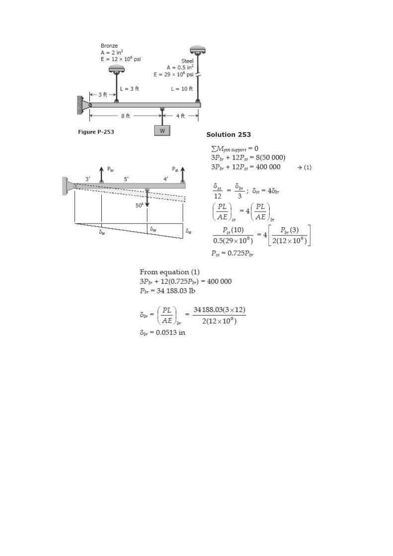
Solution 253

Problem 254
As shown in Fig. P-254, a rigid bar with negligible mass is pinned at O and attached to
two vertical rods. Assuming that the rods were initially tress-free, what maximum load P
can be applied without exceeding stresses of 150 MPa in the steel rod and 70 MPa in the
bronze rod.

Solution 254
Problem 255
Shown in Fig. P-255 is a section through a balcony. The total uniform load of 600 kN is
supported by three rods of the same area and material. Compute the load in each rod.
Assume the floor to be rigid, but note that it does not necessarily remain horizontal.

Solution 255
Problem 256
Three rods, each of area 250 mm2, jointly support a 7.5 kN load, as shown in Fig. P-
256. Assuming that there was no slack or stress in the rods before the load was applied,
find the stress in each rod. Use Est = 200 GPa and Ebr = 83 GPa.

Solution 256
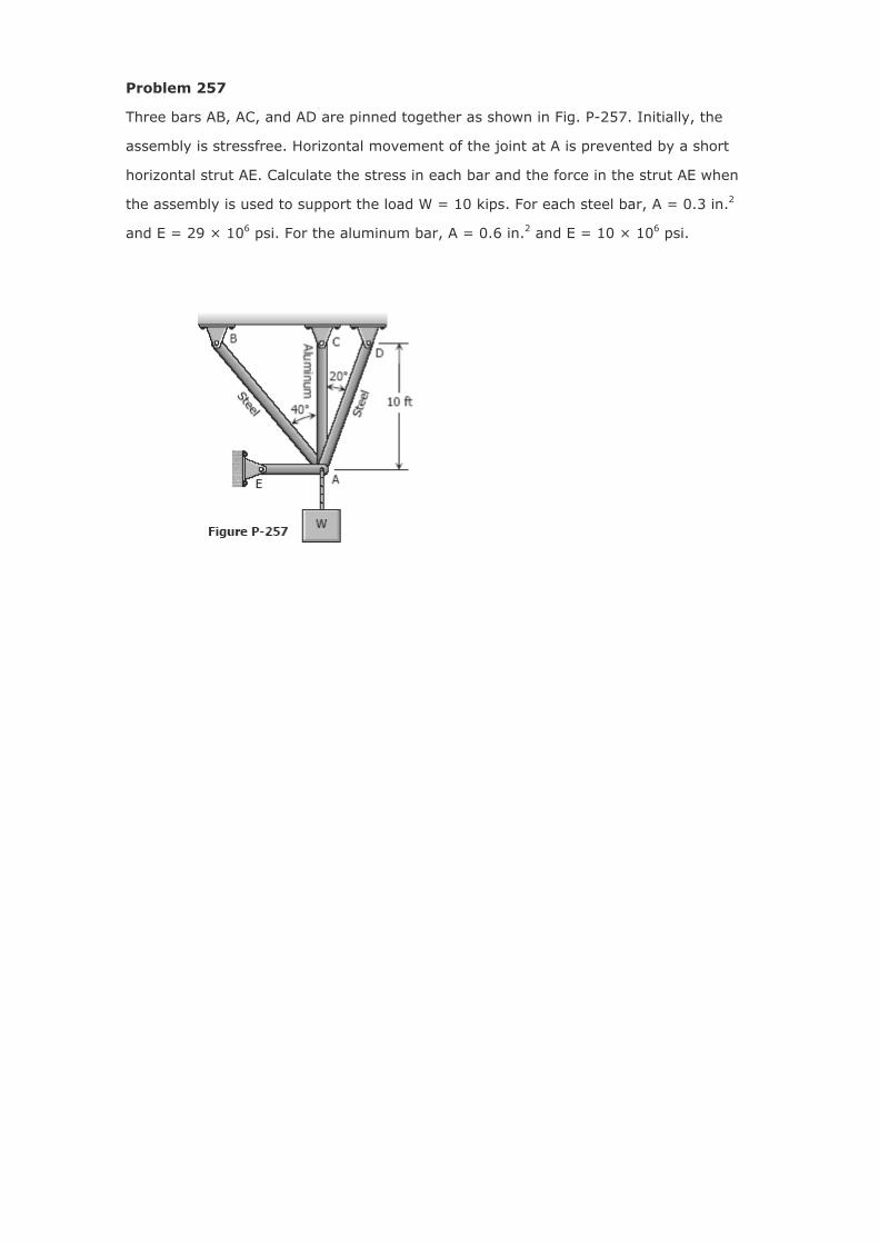
Problem 257
Three bars AB, AC, and AD are pinned together as shown in Fig. P-257. Initially, the
assembly is stressfree. Horizontal movement of the joint at A is prevented by a short
horizontal strut AE. Calculate the stress in each bar and the force in the strut AE when
the assembly is used to support the load W = 10 kips. For each steel bar, A = 0.3 in.2
and E = 29 × 106 psi. For the aluminum bar, A = 0.6 in.2 and E = 10 × 106 psi.

Solution 257