Performing Gateway Load Balancing in MANETs
148
Performing Gateway Load Balancing in MANETs Thesis for the degree of Philosophiae Doctor Trondheim, February 2012 Norwegian University of Science and Technology Faculty of Information Technology Mathematics and Electrical Engineering Department of Telematics Vinh Pham
Transcript of Performing Gateway Load Balancing in MANETs
Performing Gateway LoadBalancing in MANETs
Thesis for the degree of Philosophiae Doctor
Trondheim, February 2012
Norwegian University of Science and TechnologyFaculty of Information TechnologyMathematics and Electrical EngineeringDepartment of Telematics
Vinh Pham
NTNUNorwegian University of Science and Technology
Thesis for the degree of Philosophiae Doctor
Faculty of Information Technology,Mathematics and Electrical EngineeringDepartment of Telematics
© Vinh Pham
ISBN 978-82-471-3307-1 (printedversion)ISBN 978-82-471-3308-8 (electronicversion)ISSN 1503-8181
Doctoral theses at NTNU , 2012:23
Printed by NTNU-trykk
Abstract
During the last decades, the advances in Information Technology have formed thebasis for increased interest and research activity in the field of ad hoc wirelessmultihop networks or simply ad hoc networks. This emerging technology enablesinternetworking between wireless nodes that are deployed in an ad hoc and tem-porary manner. All nodes in an ad hoc network take the role as both hosts in anend-to-end communication session, or as routers to collaboratively relay data traf-fic in a multihop fashion on behalf of other nodes. Furthermore, ad hoc networksare highly dynamic in nature, i.e. nodes can join or leave the network at any time,and additionally, the nodes have also the flexibility to move around while being inthe network. The fact that ad hoc networks can be rapidly deployed with minimalprior planning, cost, and without the need of any pre-existing infrastructure makesthis technology very attractive and suitable in a number of applications, includingemergency and rescue operations, and military operations.
Although ad hoc networks represent a promising technology that offers a broadrange of potential useful applications, this technology is still in an immature phase.There are yet many issues and challenges that need to be resolved, which mainlyarise from the inherent unreliability of wireless communication, the dynamic na-ture of these networks, the limited availability in resources with respect to band-width, processing capacity, battery power, and from the possibly large scale ofthese networks. These challenges require that the networking protocols at all lay-ers in the network stack, that in many cases were originally designed for wirednetworks, must be modified or optimized, in order to adapt to the characteristic ofthe wireless environment.
The focus of this thesis has been devoted to the investigation of two specific issueswithin the field of ad hoc networking, i.e. node mobility and load balancing. Theaim is to provide solutions in order to improve the overall performance in ad hocnetworks.
Node mobility is one of the most important features in ad hoc networks, however, it
iii

iv Abstract
is also the reason for frequent link breaks and the constant change in the topology.An ongoing data transmission that is interrupted by a link break, must be reroutedto alternative paths in order to circumvent the broken link. However, this process ofrerouting traffic takes a certain amount of time, which is referred to as the reroutingtime. Minimizing the rerouting time is essential in order to reduce packet lossand improve network performance. In this thesis we investigate the factors thataffect the rerouting time in proactive routing protocols and propose solutions forminimizing it.
Load balancing refers to the process of distributing traffic load more evenly inthe network in order to minimize congestion and to optimize the usage of net-work resources. Performing load balancing in ad hoc networks is generally verychallenging due to the inherently interfering nature of the wireless medium. Inthis thesis we therefore investigate the feasibility and the potential benefits of per-forming load balancing in ad hoc networks. We consider two scenarios, i.e. loadbalancing for intradomain and interdomain traffic.
Intradomain traffic is traffic between nodes inside an ad hoc network. Performingload balancing on intradomain traffic can be done in two ways. The first is referredto as multipath load balancing where a traffic flow between a source and destina-tion pair is distributed over multiple alternative disjoint/semi-disjoint paths. Theaim is to maximize throughput and reduce the risk for packet loss. However, anumber of previous work has investigated and reported that this type of load bal-ancing can only provide a rather limited improvement in performance due to theinterference between the paths [1] [2]. Due to this reason, multipath load balanc-ing is therefore not considered in this thesis. Instead we focus on the second waywhich is referred to as transit routing. Transit routing is about routing part of thelocal traffic over a backbone network in order to relief the traffic load in the adhoc network. The assumption behind this concept is a network architecture similarto a Wireless Mesh Network (WMN), where a high capacity backbone networkis an integrated part of the Mobile Ad hoc Network (MANET). This backbonenetwork is commonly used to provide Internet-connectivity services, but can alsobe exploited to alleviate the traffic load in the MANET. In addition, for certainsource and destination pairs, performing transit routing can considerably increasethe throughput compared to if the traffic is routed within the ad hoc network.
Interdomain traffic refers to traffic between a node inside the ad hoc network anda remote node outside of the ad hoc network. Load balancing for interdomaintraffic considers the potential of distributing interdomain traffic among multiplegateways in order to avoid congestion at the gateways and maximize the capacityfor interdomain traffic. This type of load balancing is commonly referred to asgateway load balancing in the literature. Furthermore, interdomain can either be

v
inbound or outbound traffic. The work in this thesis mainly focuses on performingload balancing for outbound traffic. However, we believe that the results in ourwork are also applicable to inbound traffic as well.
The main contributions in this thesis are the investigation and the proposals ofdifferent solutions for intradomain and interdomain load balancing.

vi Abstract
Preface
This thesis is submitted to the Norwegian University of Science and Technology(NTNU) in Trondheim in partial fulfillment of the requirements for the degree ofPhilosophiae Doctor.
The work on this thesis began in December 2005, and was carried out at the Univer-sity Graduate Center (Unik) at Kjeller, under the supervision of Professor ØivindKure at the Norwegian University of Science and Technology and Professor PaalEngelstad at the University of Oslo (UiO), Telenor R&I and Simula Research Lab-oratory. Professor Knut Øvsthus at Bergen University College was also partlyinvolved in the supervision during the first year.
The research is supported by the Research Council of Norway (NFR) and is re-lated to two EU projects, the Quality of Service in Ad-hoc Networks (QUAD) andDeployable High Capacity Gateway for Emergency Services (DeHiGate) projects.The goal of these projects is to devise solutions for future broadband communica-tion system for emergency rescue operations.
vii

viii Preface

Dedication
I would like to dedicate this work to my beloved father who suddenly passed awayduring the course of this doctoral study.
ix

x Dedication

Acknowledgements
I would like to express my deepest and sincere appreciation to my supervisor Pro-fessor Øivind Kure and Professor Paal Engelstad for giving me the opportunity tobe their student. Without their patience, guidance, encouragement and understand-ing, my accomplishment would never been possible, but rather an illusion.
I am thankful to my employer, The Norwegian Defence Research Establishment(FFI), for the willingness and generosity in allowing me the opportunity to enrichmy knowledge as well as improving my skill as a researcher.
I would also like to express my gratitude to my former project manager at FFI,Professor Knut Øvsthus at Bergen University College, for his arrangement suchthat I could begin with the PhD study. He has given me many good advices andtaught me many useful things for my thesis work.
I would like to thank Dr. Erlend Larsen who has assisted me, all from the simplestthing to the most difficult technical matters. I have really learnt and enjoyed muchduring these years working close with him. I would also like to thank Dr. LarsLandmark for many good discussions and ideas.
My sincere appreciation to all friends and colleagues at Unik for giving me a joyfuland memorable time.
Finally I would like to thank my mother, my brother and sister, my wife and daugh-ter for their sacrifice, understanding, support and encouragement during theseyears.
Kjeller, October 15, 2011
Vinh Pham
xi

xii Acknowledgements

List of Publications
The thesis is based on the following five papers, referred to in the text by letters (A-E). Paper A is written in cooperation with Erlend Larsen and should be regarded asequally shared primary authorship with the author of this thesis. The author of thisthesis is the principal contributor of paper B to E. The co-authors provided withinvaluable contributions in terms of ideas, comments and corrections in all abovepapers. The author of this thesis has contributed to papers F to I as a discussionpartner and partly in the code implementation in paper I.
PAPER A: V. Pham, E. Larsen, K. Øvsthus, P. Engelstad and Ø. Kure, "Rerout-ing Time and Queueing in Proactive Ad Hoc Networks," In pro-ceedings of the International Performance Computing and Com-munications Conference 2007 (IPCCC 2007), New Orleans, USA,April 11-13, 2007, pp. 160-169.
PAPER B: V. Pham, E. Larsen, Ø. Kure and P. E. Engelstad, "Routing of Inter-nal MANET Traffic over External Networks," Mobile InformationSystems Journal, iiWAS/MoMM special issue, Volume 5, Number3, 2009
PAPER C: V. Pham, E. Larsen, P. E. Engelstad and Ø. Kure, "PerformanceAnalysis of Gateway Load Balancing in Ad Hoc Networks withRandom Topologies," Proceedings of The 7th ACM InternationalSymposium on Mobility Management and Wireless Access (Mobi-wac09), Tenerife, Canary Islands October 26-30, 2009
PAPER D: V. Pham, E. Larsen, Ø. Kure and P. Engelstad, "Gateway Load Bal-ancing in Future Tactical Networks", IEEE Military Communica-tions Conference 2010 (MILCOM 2010), San Jose, CA, USA, Oc-tober 31 - November 3, 2010
PAPER E: V. Pham, E. Larsen, Q. Le-Trung, P. Engelstad and Ø. Kure, "A Ra-dio Load Based Gateway Load Balancing Scheme with Admission
xiii
xiv List of Publications
Control," Proceedings of the International Symposium on Wire-less and Pervasive Computing (ISWPC 2011), Hong Kong, China,February 23-25, 2011.
Related papers:
PAPER F: E. Larsen, V. Pham, P. Engelstad, Ø. Kure, "Gateways and Capac-ity in Ad Hoc Networks," In proceedings of the International Con-ference on Advances in Human-oriented and Personalized Mecha-nisms, Technologies, and Services 2008, (I-CENTRIC 2008), Sliema,Malta, October 26-31, 2008, pp. 390-399, ISBN: 978-0-7695-3371-1
PAPER G: E. Larsen, L. Landmark, V. Pham, Ø. Kure and P. E. Engelstad,"Routing with Transmission Buffer Zones in MANETs," In pro-ceedings of the IEEE International Symposium on a World of Wire-less Mobile and Multimedia Networks 2009 (WoWMoM 2009),Kos, Greece, June 15-18, 2009.
PAPER H: E. Larsen, L. Landmark, V. Pham, P. E. Engelstad, Ø. Kure, "Pre-emption Mechanisms for Push-to-Talk in Ad Hoc Networks," The34th IEEE Conference on Local Computer Networks 2009 (LCN2009), Zürich, Switzerland, October 20-23, 2009
PAPER I: E. Larsen, L. Landmark, V. Pham, P. E. Engelstad, Ø. Kure, "Op-timized Group Communication for Tactical Military Networks,"IEEE Military Communications Conference 2010 (MILCOM 2010),San Jose, CA, USA, October 31–November 4, 2010.
Contents
Abstract iii
Preface vii
Dedication ix
Acknowledgements xi
List of Publications xiii
Contents xv
Abbreviations xxi
I Introduction 1
1 Introduction 31.1 Background . . . . . . . . . . . . . . . . . . . . . . . . . . . . . 31.2 Motivation and Objectives . . . . . . . . . . . . . . . . . . . . . 41.3 Research Methodology . . . . . . . . . . . . . . . . . . . . . . . 5
1.3.1 Theoretical Analysis . . . . . . . . . . . . . . . . . . . . 51.3.2 Simulations . . . . . . . . . . . . . . . . . . . . . . . . . 61.3.3 Real Life Experiments . . . . . . . . . . . . . . . . . . . 61.3.4 Research Method in this Thesis . . . . . . . . . . . . . . 7
1.4 Paper Contributions . . . . . . . . . . . . . . . . . . . . . . . . . 101.5 Thesis Outline . . . . . . . . . . . . . . . . . . . . . . . . . . . . 12
2 Challenges in Ad hoc Networks 152.1 Overview of Ad Hoc Networks . . . . . . . . . . . . . . . . . . . 15
2.1.1 Mobile Ad Hoc Networks . . . . . . . . . . . . . . . . . 15
xv

xvi Contents
2.1.2 Wireless Mesh Networks . . . . . . . . . . . . . . . . . . 162.1.3 Wireless Sensor Networks . . . . . . . . . . . . . . . . . 18
2.2 Network Connectivity . . . . . . . . . . . . . . . . . . . . . . . . 192.3 Node Mobility . . . . . . . . . . . . . . . . . . . . . . . . . . . . 212.4 Unidirectional Links . . . . . . . . . . . . . . . . . . . . . . . . 222.5 Network Capacity . . . . . . . . . . . . . . . . . . . . . . . . . . 222.6 Medium Access . . . . . . . . . . . . . . . . . . . . . . . . . . . 23
3 IEEE 802.11 253.1 The MAC-sublayer . . . . . . . . . . . . . . . . . . . . . . . . . 25
4 Unicast Routing Protocols for MANETs 294.1 Overview and Classification of MANET Routing Protocols . . . . 294.2 AODV . . . . . . . . . . . . . . . . . . . . . . . . . . . . . . . . 324.3 OLSR . . . . . . . . . . . . . . . . . . . . . . . . . . . . . . . . 334.4 Link Failure Detection . . . . . . . . . . . . . . . . . . . . . . . 364.5 Routing Metrics . . . . . . . . . . . . . . . . . . . . . . . . . . . 38
4.5.1 Per hop Round Trip Time (RTT) . . . . . . . . . . . . . . 384.5.2 Per-hop Packet Pair Delay . . . . . . . . . . . . . . . . . 394.5.3 Expected Transmission Count (ETX) . . . . . . . . . . . 394.5.4 Expected Transmission Time (ETT) . . . . . . . . . . . . 414.5.5 Radio load metric . . . . . . . . . . . . . . . . . . . . . . 41
5 Load balancing 435.1 General Description . . . . . . . . . . . . . . . . . . . . . . . . . 435.2 Gateway Load Balancing . . . . . . . . . . . . . . . . . . . . . . 445.3 Transit Routing . . . . . . . . . . . . . . . . . . . . . . . . . . . 485.4 Multipath Load Balancing . . . . . . . . . . . . . . . . . . . . . 50
6 Summary and Contributions 536.1 Summary of the Work . . . . . . . . . . . . . . . . . . . . . . . . 536.2 Contribution of paper A . . . . . . . . . . . . . . . . . . . . . . . 56
6.2.1 Related Work . . . . . . . . . . . . . . . . . . . . . . . . 566.2.2 Contributions . . . . . . . . . . . . . . . . . . . . . . . . 57
6.3 Contribution of paper B . . . . . . . . . . . . . . . . . . . . . . . 596.3.1 Related Work . . . . . . . . . . . . . . . . . . . . . . . . 606.3.2 Contributions . . . . . . . . . . . . . . . . . . . . . . . . 60
6.4 Contribution of paper C . . . . . . . . . . . . . . . . . . . . . . . 636.4.1 Related Work . . . . . . . . . . . . . . . . . . . . . . . . 646.4.2 Contributions . . . . . . . . . . . . . . . . . . . . . . . . 64
6.5 Contribution of paper D . . . . . . . . . . . . . . . . . . . . . . . 69
Contents xvii
6.5.1 Related Work . . . . . . . . . . . . . . . . . . . . . . . . 696.5.2 Contributions . . . . . . . . . . . . . . . . . . . . . . . . 70
6.6 Contribution of paper E . . . . . . . . . . . . . . . . . . . . . . . 726.6.1 Related Work . . . . . . . . . . . . . . . . . . . . . . . . 736.6.2 Contributions . . . . . . . . . . . . . . . . . . . . . . . . 73
6.7 Concluding Remarks . . . . . . . . . . . . . . . . . . . . . . . . 76
Bibliography 88
II Research papers 89
A Rerouting Time and Queueing in Proactive Ad Hoc Networks 91
B Routing of Internal MANET Traffic over External Networks 103
C Performance Analysis of Gateway Load Balancing in Ad Hoc Net-works with Random Topologies 127
D Gateway Load Balancing in Future Tactical Networks 139
E A Radio Load Based Load Balancing Scheme with Admission Control149

xviii Contents

List of Figures
1.1 Outline of contributed papers. . . . . . . . . . . . . . . . . . . . 11
2.1 Example of a MANET. . . . . . . . . . . . . . . . . . . . . . . . 162.2 Example of a WMN. . . . . . . . . . . . . . . . . . . . . . . . . 172.3 Example of a WSN. . . . . . . . . . . . . . . . . . . . . . . . . . 182.4 The hidden node and exposed node problems. . . . . . . . . . . . 23
3.1 The IEEE 802.11 Standards. . . . . . . . . . . . . . . . . . . . . 26
4.1 Classification of MANET routing protocols. . . . . . . . . . . . . 304.2 An example of MPR selection in Optimized Link State Routing
(OLSR). . . . . . . . . . . . . . . . . . . . . . . . . . . . . . . . 34
5.1 The concept of gateway load balancing . . . . . . . . . . . . . . . 445.2 The concept of transit routing. . . . . . . . . . . . . . . . . . . . 485.3 The concept of multipath load balancing . . . . . . . . . . . . . . 50
6.1 The queue build up during a link break . . . . . . . . . . . . . . . 576.2 Example of a MANET interconnected with the global Internet
through Access Points (APs) and Gateways (GWs) . . . . . . . . 616.3 Transit routing scenario . . . . . . . . . . . . . . . . . . . . . . . 626.4 The reference network model. . . . . . . . . . . . . . . . . . . . 646.5 Simulation results of uniformly distributed topologies. . . . . . . 666.6 Simulation results of asymmetric random topologies. . . . . . . . 686.7 An example of congestion map. The dark areas represent the most
congested areas in the network . . . . . . . . . . . . . . . . . . . 706.8 Example of topology that is subjected to the synchronized rerout-
ing problem . . . . . . . . . . . . . . . . . . . . . . . . . . . . . 736.9 RLAC Architecture . . . . . . . . . . . . . . . . . . . . . . . . . 74
xix

xx List of Figures
Abbreviations
AC Admission Control
ACK Acknowledgment
AODV Ad hoc On-Demand Distance Vector Routing
AP Access Point
CBR Constant Bit Rate
CDMA Code Division Multiple Access
CDS Connected Dominating Set
CEDAR Core Extraction Distributed Ad Hoc Routing
CSMA Carrier Sense Multiple Access
CSMA/CA Carrier Sense Multiple Access with Collision Avoidance
CSMA/CD Carrier Sense Multiple Access with Collision Detection
CTS Clear To Send
CW Contention Window
DCF Distributed Coordination Function
DeHiGate Deployable High Capacity Gateway for Emergency Services
DIFS Distributed Inter-Frame Space
DREAM Distance Routing Effect Algorithm for Mobility
DSDV Destination-Sequenced Distance-Vector Routing
DSSS Direct-Sequence Spread Spectrum
DSR Dynamic Source Routing
xxi

xxii Abbreviations
DYMO Dynamic Manet On-Demand Protocol
EL Even Load
ETT Expected Transmission Time
ETX Expected Transmission Count
FDMA Frequency Division Multiple Access
FHSS Frequency Hopping Spread Spectrum
FIFO First In First Out
FTP File Transfer Protocol
GPS Global Positioning System
GW Gateway
HNA Host and Network Association
HOLSR Hierarchical Optimized Link State Routing
HSR Hierarchical State Routing
IETF Internet Engineering Task Force
LAR Location-Aided Routing
LANMAR Landmark Ad Hoc Routing
MAC Medium Access Control
MACA Multiple Access with Collision Avoidance
MANET Mobile Ad hoc Network
MID Multiple Interface Declaration
MIP Mobile IP
MPR Multi Point Relay
NAM Network Animator
NHDP Neighbor Hood Discovery Protocol
ns-2 Network Simulator
OFDM Orthogonal Frequency-Division Multiplexing
OLSR Optimized Link State Routing
xxiii
OSI Open Systems Interconnection
OSPF Open Shortest Path First
PCF Point Coordination Function
PDA Personal Digital Assistant
PRNG Pseudo Random Number Generator
QoS Quality of Service
QUAD Quality of Service in Ad-hoc Networks
RERR Route Error
RLAC Radio Load Based Load Balancing with Admission Control
RLLB Radio Load Based Load Balancing
RREP Route Reply
RREQ Route Request
RTS Request To Send
RTT Round Trip Time
SIFS Short Inter-Frame Space
SLB Simple Load Balancing
SNR Signal to Noise Ratio
SP Shortest Path
TBRPF Topology Broadcast based on Reverse-Path Forwarding
TC Topology Control
TCP Transmission Control Protocol
TDMA Time Division Multiple Access
UDP User Datagram Protocol
VoIP Voice over IP
Wi-Fi Wireless Fidelity
WLAN Wireless LAN
WMN Wireless Mesh Network

xxiv Abbreviations
WSN Wireless Sensor Network
ZRP Zone Routing Protocol

Part I
Introduction
1

Chapter 1
Introduction
1.1 Background
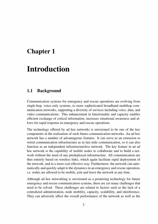
Communication systems for emergency and rescue operations are evolving fromsingle-hop, voice-only systems, to more sophisticated broadband multihop com-munication networks, supporting a diversity of services including voice, data, andvideo communications. This enhancement in functionality and capacity enablesefficient exchange of critical information, increases situational awareness and al-lows for rapid response in emergency and rescue operations.
The technology offered by ad hoc networks is envisioned to be one of the keycomponents in the realization of such future communication networks. An ad hocnetwork has a number of advantageous features. It can serve as an extension towired communication infrastructure as in last mile communication, or it can alsofunction as an independent infrastructureless network. The key feature in an adhoc network is the capability of mobile nodes to collaborate and to build a net-work without the need of any predeployed infrastructure. All communication arethus entirely based on wireless links, which again facilitate rapid deployment ofthe network, and in a more cost effective way. Furthermore, the network can auto-matically and quickly adapt to the dynamics in an emergency and rescue operation,i.e. nodes are allowed to be mobile, join and leave the network at any time.
Although ad hoc networking is envisioned as a promising technology for futureemergency and rescue communication systems, there are yet many challenges thatneed to be solved. These challenges are related to factors such as the lack of acentralized administration, node mobility, capacity, scalability, and interference.They can adversely affect the overall performance of the network as well as the
3
4 Introduction
experienced Quality of Service (QoS) of the end users. Hence, before it is possi-ble to adopt the ad hoc networking technology in such a communication system,solutions must be developed to overcome these challenges.
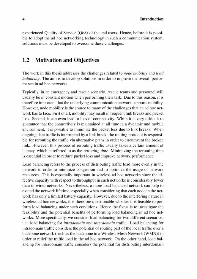
1.2 Motivation and Objectives
The work in this thesis addresses the challenges related to node mobility and loadbalancing. The aim is to develop solutions in order to improve the overall perfor-mance in ad hoc networks.
Typically, in an emergency and rescue scenario, rescue teams and personnel willusually be in constant motion when performing their task. Due to this reason, it istherefore important that the underlying communication network supports mobility.However, node mobility is the source to many of the challenges that an ad hoc net-work has to face. First of all, mobility may result in frequent link breaks and packetloss. Second, it can even lead to loss of connectivity. While it is very difficult toguarantee that the connectivity is maintained at all time in a dynamic and mobileenvironment, it is possible to minimize the packet loss due to link breaks. Whenongoing data traffic is interrupted by a link break, the routing protocol is responsi-ble for rerouting the traffic via alternative paths in order to circumvent the brokenlink. However, this process of rerouting traffic usually takes a certain amount oflatency, which is referred to as the rerouting time. Minimizing the rerouting timeis essential in order to reduce packet loss and improve network performance.
Load balancing refers to the process of distributing traffic load more evenly in thenetwork in order to minimize congestion and to optimize the usage of networkresources. This is especially important in wireless ad hoc networks since the ef-fective capacity with respect to throughput in such networks is considerably lowerthan in wired networks. Nevertheless, a more load-balanced network can help toextend the network lifetime, especially when considering that each node in the net-work has only a limited battery capacity. However, due to the interfering nature inwireless ad hoc networks, it is therefore questionable whether it is feasible to per-form load balancing under such conditions. Hence the focus is to investigate thefeasibility and the potential benefits of performing load balancing in ad hoc net-works. More specifically, we consider load balancing for two different scenarios,i.e. load balancing for intradomain and interdomain traffic. Load balancing forintradomain traffic considers the potential of routing part of the local traffic over abackbone network (such as the backbone in a Wireless Mesh Network (WMN)) inorder to relief the traffic load in the ad hoc network. On the other hand, load bal-ancing for interdomain traffic considers the potential for distributing interdomain
1.3. Research Methodology 5
traffic among multiple gateways in order to avoid congestion at the gateways andmaximizing the capacity for interdomain traffic.
To summarize, the focus in this thesis is to investigate the issues related to mobilityand load balancing as described above. In this context, a number of questions arisethat need to be answered:
Mobility:
• What are the factors that affect the rerouting time in proactive routing pro-tocols?
• Why does the rerouting time in many cases considerably exceeds the timeneeded to detect a link break?
• How can we minimize the rerouting time?
Load balancing:
• What is the feasibility and the potential benefit of performing load balancingin wireless ad hoc networks?
• What are the factors that affect the performance of load balancing?
• How can we perform load balancing in an efficient way?
1.3 Research Methodology
Research may be defined as the search for knowledge or a systematic investigation.Different methods or approaches can be applied in the research depending of thefield of concern. In this section we will discuss the research methods or approachesthat are common in the field of ad hoc networking. More importantly, we willdiscuss the research methods that we have used in our investigation and the searchfor the answers to our questions.
1.3.1 Theoretical Analysis
The method of theoretical analysis can be used to acquire fundamental knowledgeof the issues, mechanisms or system being investigated. In this approach, mathe-matical or statistical models are often used to describe a phenomenon, or to esti-mate the expected quantity of certain parameters. We have for example in paper Aderived a model to estimate the rerouting time. However, during the work in thisthesis, we experienced that many of the issues or scenarios being studied are too
6 Introduction
complicated to be solved by using a theoretical approach. This is especially true inscenarios where there are many nodes, and if these nodes are in addition mobile.Due to this reason, most of our work is therefore based on computer simulationsthat will be discussed in the following section.
1.3.2 Simulations
In cases where the issue or scenario being investigated is too complex, using themethod of performing simulations may be easier. This approach has a number ofadvantages:
1. Complex scenarios with many nodes and various traffic and mobility pat-terns, can be set up within a short amount of time in a simulator. The timerequired to perform a simulation depends on many factors such as the com-puter power, the number of nodes, the desired simulation time, the trafficand mobility pattern. In any case, performing investigations on complexscenarios can be conducted much faster and with lower cost than perform-ing similar investigations with real life experiments.
2. Any desired simulation data is easily accessible from the trace file, includingpacket transmissions, receptions and collisions at any nodes. The availabil-ity of these data makes it much easier to explore and analyze simulationresults.
3. The fact that simulation results are reproducible (by rerunning the same sim-ulation with the exact same random number seed) makes it possible to thor-oughly study a particular event of interest or a chain of events, through codetracing. In contrast, in real world experiments, it is usually very difficult toexactly recreate a particular event.
4. Using for example Linux shell scripts, it is possible to automate the simula-tion process in order to study a large number of different topologies, or theimpact of varying simulation parameters.
1.3.3 Real Life Experiments
The third method is conducting real life experiments, which is the most accuratemethod to evaluate the behavior of the scenario or the system being studied. Thisapproach allows the system to be exposed to all physical constraints and effects thatprevail in the real world, and should therefore be used when possible. In connec-tion with the investigation of the rerouting time in paper A, we initially conducted

1.3. Research Methodology 7
a number of real life experiments in order to measure the rerouting time. However,we experienced that retrieving all necessary data, such as the amount of queuedpackets, was very difficult due to the unavailability of source code for the wirelessnetwork interface’s firmware and drivers. Additionally, conducting real life exper-iments in practice is often very challenging and time consuming, especially whenthe network scenario consists of many nodes. Due to these reasons, all subsequentwork in paper B to E related to load balancing, are mainly based on simulationsand the analyses of the simulation results.
1.3.4 Research Method in this Thesis
MethodThroughout the work in this thesis we have used a combination of the three meth-ods discussed above. However, due to the complexity of the scenarios that we in-vestigated, much of the work is therefore based on simulations using the NetworkSimulator (ns-2) simulator [3] version 2.28-2.33. ns-2 is a discrete event networksimulator that began as a variant of the REAL network simulator in 1989 and hasevolved substantially over the past few years. It is one of the most popular sim-ulators in the networking research community due to the concept of open source,the rich availability of online documentation, and the active newsgroups. From thelarge community of users, it is easier to get support to the challenges that one mayencounter.
Code Validation/VerificationVarious algorithms/mechanisms for improving the network performance have beendeveloped in this thesis, including the radio load measurement algorithm, admis-sion control mechanism, various load balancing schemes, and the adaptive retrylimit mechanism for improving the rerouting time. These algorithms/mechanismsare implemented in ns-2, either at the network or the link layer. Moreover, we havealso implemented a number of tools used in the analysis of the simulation data. Inorder to assure that the algorithms and analysis tools fulfill their intended purposes,the implemented codes have been through comprehensive testing and debugging.For the network algorithms/mechanisms, we have used a variety of simple to morecomplex network models to verify the desired response or behavior.
ScenariosThroughout the work in this thesis, simulations are performed on a large numberof different topology configurations, including both simple static string and gridtopologies, to the more complex random static and mobile topologies. The sce-narios are created on the basis that they are simple and helped to underline the
8 Introduction
strengths and weaknesses of the studied mechanisms. The simple topologies areused to gain knowledge about the fundamental mechanisms that prevail in wire-less multihop networks such as the rerouting time, interference, and congestions.On the other hand, the complex random topologies are used to explore the behav-ior and performance of the proposed algorithms/mechanisms in scenarios closeto “real networks”. Furthermore, we used a large number of topologies in oursimulations with the purpose to achieve statistically more reliable results. Theresult may therefore serve as an estimate on the expected performance of the algo-rithms/mechanisms.
Propagation ModelFor all simulations in this thesis, the two-ray ground propagation model is used.The two-ray ground model assumes that the received signal strength is the sumof the direct line of sight path and the path of one reflection from the ground. Acommon restriction of this model and similar models is the fact that they do notallow to specify obstacles in the environment. In addition, the simulator allows thatonly one propagation model can be used for the entire duration of the simulation,meaning that the spatial and temporal variations cannot be modeled. We haveintentionally chosen to use this simple model in order to keep the test environmentas simple as possible. The purpose is to isolate the simulation scenarios fromfluctuating and temporary disturbances at the physical layer. Our focus is to study,gain knowledge, and provide improving solutions at the network or link layer, suchas those related to rerouting time or load balancing. Furthermore, since the two-rayground model is one of the most used propagation model, it is therefore a naturalchoice to also use it in our work. This enables comparison with results from otherwork.
Traffic PatternsOnly Constant Bit Rate (CBR) traffic over User Datagram Protocol (UDP) is usedin the simulations, which is the common transport protocol in research related toad hoc networks. We did not use Transmission Control Protocol (TCP), althoughit is the prevalent transport protocol in the Internet, due to several reasons. Firstof all, the work in [4] shows that the performance of TCP in wireless multihopnetworks is degraded using various Medium Access Control (MAC)-sublayer pro-tocol such as Carrier Sense Multiple Access (CSMA) and Multiple Access withCollision Avoidance (MACA). Second, when using TCP over IEEE 802.11, thereare problems such as throughput oscillation and severe unfairness, as demonstratedin [5]. Third, TCP does not differentiate between congestion-related packet dropsand transmission failures at link layer. TCP treats all packet losses as an indicationof network congestion and activates the internal congestion control mechanism.Consequently, this will result in a degradation in the throughput [6]. Due to the

1.3. Research Methodology 9
above drawbacks of TCP, we therefore omitted using it in order to avoid unfore-seen impacts on the simulation results. Since the main focus of this thesis is tostudy the rerouting time and the performance of load balancing, and not the per-formance of TCP, it is therefore naturally and reasonably to isolate these issuesfrom the potentially disturbing effects of the TCP protocol.
Measurement ParametersWhen evaluating the performance of the proposed algorithms, the throughput isused as the main measurement parameter. Even though not presented in the con-tributed papers, measurement on other parameters were also conducted during theinvestigations, including packet delay, jitter and different types of packet loss.However, throughput is chosen as the main measurement parameter since it is themost fundamental and important parameter, determining the capacity of the net-work in transporting data traffic. Especially in the work related to load balancing,the throughput is a more important parameter. Delay and jitter, on the other handare more important to certain types of applications such as Voice over IP (VoIP),while other applications such as File Transfer Protocol (FTP) and e-mail, are moreor less insensitive to these parameters.
Data ProcessingThe result of each simulation, can either be analyzed using the output trace file orusing the Network Animator (NAM) [7] visualization tool. However, we realizedearly that in order to perform in-depth analyses, it is essential to carefully analyzethe output trace files. Usually these files are very large which require a substantialamount of time to inspect and analyze. To ease this task it was therefore necessaryto develop a number of tools in Python and Linux shell scripts to parse the tracefiles and to extract data of interest. The extracted data is then used to make variousgraphs for further analyses. We also developed different visualization tools suchas the congestion maps in paper D. The NAM visualization tool was mainly usedto verify scenarios and traffic patterns.
LimitationsAlthough using simulations as a tool to perform studies of complex issues or sys-tems are convenient and efficient, the disadvantage of this approach is the inaccu-racy. This is due to the fact that it is very difficult to accurately model the physicalworld, and the models that are used in most simulators are only an approxima-tion and simplification of it. For example, in ns-2, the transmission range of aomnidirectional wireless interface is represented by a perfect circle with radius r.Radio communication is perfectly received within this range, while no signal canbe received at all beyond it. On the other hand, real radios usually have a non-uniform and non-circular radiation pattern [8] [9], with spatial and temporal signalfluctuation that may cause rapid changes in network connectivity and transmission

10 Introduction
range. The work in [10] has previously showed that the radio propagation modelsthat are often used in the research of ad hoc networks are inaccurate and may havenegative impact on the simulation results. The inaccuracies stem from the usage ofsimple assumptions in these models, such as the terrain is flat, all radios have equalrange, the signal strength is a simple function of distance, and the links are alwayssymmetrical. Furthermore, we also discovered an inaccuracy in the IEEE 802.11MAC-sublayer implementation of ns-2: while receiving a packet that is sent overthe wireless medium, the implemented MAC-sublayer model can only accountfor interfering signal from one single concurrent transmission, even though theremay be multiple concurrent interfering transmissions. In a more accurate model,the resulting interfering signal should be the sum of all concurrent transmissions.Therefore, this MAC-sublayer model may potentially overestimate the receivedsignal strength and consequently, a packet that should have been discarded due tosevere interference may instead be successfully received.
Despite the limitations of the simulator in modelling the real world, we still believeit is a good and appropriate tool in performing research. Even though simulationresults may not be 100% exact, they can still provide an indication of the behaviorcharacteristics to the system being studied. The work in [11] has demonstratedthat with proper adjustment of simulation parameters in ns-2, the accuracy may bequite good with respect to packet delivery ratio and connectivity graphs, but lessgood with respect to packet delay.
Finally, it is important to be aware that simulation setup and execution compre-hend many pitfalls, as reported in [12]. These pitfalls are related to issues such asmodel validation and verification, correctly setting Pseudo Random Number Gen-erator (PRNG) seed, scenario initialization, and performing statistical analyses.Avoiding these pitfalls are important to achieve more reliable simulation results.We have therefore, throughout the work in this thesis, strived to comply with therecommendations given in [12].
1.4 Paper Contributions
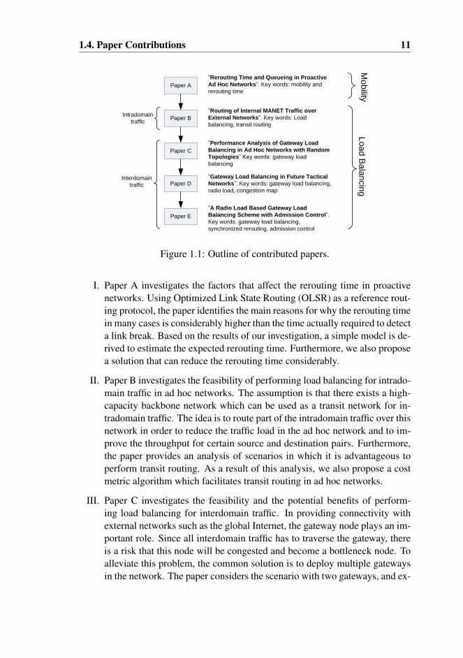
The contributions in this thesis are represented by five published papers, i.e. paperA to E, in peer-reviewed international conferences or journals. Paper A addressesmobility and rerouting time in proactive routing protocols. Paper B addresses theissue of transit routing or load balancing for intradomain traffic. Paper C to Eaddress gateway load balancing or load balancing for interdomain traffic. An over-view and summary of the contributed papers is shown in Figure 1.1, in chronolog-ical order.
1.4. Paper Contributions 11
Paper A
Paper B
Paper C
Paper D
Paper E
”Rerouting Time and Queueing in Proactive
Ad Hoc Networks”. Key words: mobility and
rerouting time
”Routing of Internal MANET Traffic over
External Networks”. Key words: Load
balancing, transit routing
”Performance Analysis of Gateway Load
Balancing in Ad Hoc Networks with Random
Topologies” Key words: gateway load
balancing
”Gateway Load Balancing in Future Tactical
Networks”. Key words: gateway load balancing,
radio load, congestion map
”A Radio Load Based Gateway Load
Balancing Scheme with Admission Control”.
Key words: gateway load balancing,
synchronized rerouting, admission control
Mo
bility
Lo
ad
Ba
lan
cin
g
Intradomain
traffic
Interdomain
traffic
Figure 1.1: Outline of contributed papers.
I. Paper A investigates the factors that affect the rerouting time in proactivenetworks. Using Optimized Link State Routing (OLSR) as a reference rout-ing protocol, the paper identifies the main reasons for why the rerouting timein many cases is considerably higher than the time actually required to detecta link break. Based on the results of our investigation, a simple model is de-rived to estimate the expected rerouting time. Furthermore, we also proposea solution that can reduce the rerouting time considerably.
II. Paper B investigates the feasibility of performing load balancing for intrado-main traffic in ad hoc networks. The assumption is that there exists a high-capacity backbone network which can be used as a transit network for in-tradomain traffic. The idea is to route part of the intradomain traffic over thisnetwork in order to reduce the traffic load in the ad hoc network and to im-prove the throughput for certain source and destination pairs. Furthermore,the paper provides an analysis of scenarios in which it is advantageous toperform transit routing. As a result of this analysis, we also propose a costmetric algorithm which facilitates transit routing in ad hoc networks.
III. Paper C investigates the feasibility and the potential benefits of perform-ing load balancing for interdomain traffic. In providing connectivity withexternal networks such as the global Internet, the gateway node plays an im-portant role. Since all interdomain traffic has to traverse the gateway, thereis a risk that this node will be congested and become a bottleneck node. Toalleviate this problem, the common solution is to deploy multiple gatewaysin the network. The paper considers the scenario with two gateways, and ex-
12 Introduction
plores the factors that affect the potential benefits of distributing outboundinterdomain traffic between these gateways, including the offered load, thelevel of asymmetry, the gateway distance, the level of spatial reuse (or fre-quency reuse) and the shape and size of the network area. The study is basedon extensive simulations with a large number of randomly generated topolo-gies in order to provide an estimation of the expected average throughputenhancement by performing load balancing.
IV. Paper D is a continuation of the work in Paper C in which we try to findthe answers for why the performance of gateway load balancing is consider-ably high for certain topologies, while it is very poor for others. The paperintroduces the concept of congestion map which can be used as a tool to ana-lyze how the specific layout of a topology may influence the performance ofload balancing. Furthermore, the paper also demonstrates through the pro-posed RLLB load balancing scheme that it is possible to take advantage ofthe radio load information provided by the underlying IEEE 802.11 MAC-sublayer for the purpose of performing load balancing.
V. Paper E is a continuation and an improvement of the work in Paper D. Thework in this paper addresses the problem of synchronized rerouting whenload balancing is performed distributedly. This is the main reason why theRLLB load balancing scheme in Paper D performs well in topologies withhigher level of asymmetry, but on the other hand, performs poorly when theasymmetry is low. To solve this problem, the RLAC scheme is proposed,which introduces the concept of probability based load balancing. The ideais to let the probability for a local node to select one gateway as default gate-way, be a function of parameters such as the difference in hop count and thedifference in gateway and bottleneck radio load. A further improvement inthe RLAC scheme is that it also performs admission control based on thesame radio load information as used in load balancing. While Paper C andD only consider static topologies, Paper E investigates the potential perfor-mance enhancement of load balancing in both static and mobile topologies.
1.5 Thesis Outline
This thesis is organized in two main parts. Part I provides an introduction to thework in this thesis and relevant background knowledge. The intention is to makeit easier to the reader to have a clearer understanding of the work herein. Part II isthe collection of contributed papers in peer-reviewed international conferences orjournals.
1.5. Thesis Outline 13
Part I consists of Chapter 1-6, where Chapter 1 provides an overview of this thesiswith respect to the motivation, the objectives, and the research methods used inthis work. Chapter 2 gives an introduction to ad hoc networking which is the mainresearch area in this thesis. Various types of ad hoc networks, i.e. Mobile Ad hocNetwork (MANET), WMN and Wireless Sensor Network (WSN) are presentedalong with their typical or envisioned applications. Although ad hoc networkingis a promising technology suitable in a number of applications, spanning fromcivilian to military scenarios, many challenges are yet to be solved. Chapter 2therefore discusses the main challenges that are characteristic to wireless networks.
Chapter 3 provides a description of the IEEE 802.11 MAC-sublayer, which is byfar the present most popular MAC protocol for ad hoc networks in the researchcommunity. The MAC protocol is responsible for the coordination of medium ac-cess, and enables single hop communication between adjacent nodes. A thoroughinsight into the inner workings of this protocol is essential for the understandingof the proposed solutions or mechanisms such as the Adaptive Retry Limit solutionin paper A, and the radio load metric in paper D and E.
While the MAC protocol provides single hop communication, the routing protocolon the other hand, makes it possible to perform multihop communication. Therouting protocol is the common language that enables the network formation andallows nodes inside the network to communicate with each other. MANET routingprotocols differ from traditional routing protocols in which they are tailored for thewireless environment with lower bandwidth and higher level of dynamic. Chapter4 provides an introduction to some of the most essential topics related to routingin MANETs, including an overview and classification of typical routing protocolsfor MANETs. A more detailed description on the reactive Ad hoc On-DemandDistance Vector Routing (AODV) and the proactive OLSR routing protocols isalso given to illustrate the diversity in routing approaches. The OLSR routingprotocol is especially important since it is used throughout the work in this thesis.Furthermore, we also discuss link failure detection, and routing metrics which aretwo important aspects related to the rerouting time in paper A and load balancingin paper B-E.
Chapter 5 provides an introduction to the topic of load balancing. A descriptionis given on various types of load balancing in MANETs and the challenges facedwhen performing load balancing in a wireless environment. The main focus in thisthesis is confined to the research of two types of load balancing, namely transitrouting and gateway load balancing addressed in paper B-E. A description onmultipath load balancing is also given for completeness. However, this type ofload balancing is not considered in this thesis since several previous works haveshowed that the potential benefit of multipath load balancing is rather limited in

14 Introduction
single channel wireless networks.
Finally, Chapter 6 provides an overall summary of the work in this thesis. In ad-dition, a more detailed description of the contributions in each individual paper isalso given. We round up with a conclusion of this thesis and give some suggestionsfor further research.
Chapter 2
Challenges in Ad hoc Networks
In recent years, the rapid development and growth of devices with networking ca-pabilities has made the research in ad hoc networks more relevant than ever. Thekey to the increased popularity and proliferation is the availability of low costdevices and the possibility for rapid deployment. The latter reason is especiallyattractive in applications such as emergency rescue and military operations. Eventhough ad hoc networking is a promising technology, there are yet many challengesthat need to be solved. In this chapter, we first provide an overview of differenttypes of network technologies classified under the ad hoc network family (Sec-tion 2.1). Second, in Section 2.2 to Section 2.6, we will discuss the challenges thatprevail in ad hoc networks. The motivation is to provide the reader a broader over-view of the ad hoc technology and its typical applications. Furthermore, a betterinsight into the challenges that ad hoc networks have to face is important in orderto bring forth innovative solutions or to be aware of the limitations.
2.1 Overview of Ad Hoc Networks
2.1.1 Mobile Ad Hoc Networks
The history of Mobile Ad hoc Network (MANET) can be traced back to the early1970s when DARPA developed the PRNET (Packet Radio Networks) [13] [14].This eventually evolved into the Survivable Adaptive Radio Networks (SURAN)program in the early 1980s [15]. The goal of these programs is to provide packetswitched networking that can be used in mobile and hostile environments relatedto military operations.
15

16 Challenges in Ad hoc Networks
Figure 2.1: Example of a MANET.
A MANET [16] is a collection of mobile nodes, capable to form a network evenwithout the existence of any pre-deployed fixed infrastructure, as illustrated in Fig-ure 2.1. Communication is thus performed over wireless links, using omnidirec-tional wireless radio interfaces. A MANET is highly dynamic in the sense that thenetwork is formed in a spontaneous and temporary manner. Nodes may randomlyjoin and leave the network or move around. Due to this dynamic nature of thenetwork, there is usually no centralized administration, but instead nodes equallyand autonomously collaborate in a distributed manner to form a multihop network.This implies that a node both takes the roles as a host in an end-to-end data com-munication, or as a router to relay data on behalf of other hosts that may not bewithin direct transmission range of their destinations. Furthermore, a MANET canoperate as a stand-alone network, or be integrated with external networks such asthe global Internet through gateway nodes. This is demonstrated in many papers,including paper B-E.
2.1.2 Wireless Mesh Networks
A Wireless Mesh Network (WMN) [17] consists of two types of entities: meshrouters and mesh clients. Mesh routers are usually stationary or have minimal mo-bility, and they form an infrastructure or backbone for clients that connect to them.These routers are usually equipped with multiple wired/wireless interfaces, whichcan support various access technologies in addition to the most commonly usedIEEE 802.11 technologies. The wireless interfaces can either be omnidirectionalor directional antennas. A mesh router is usually not a host in an end-to-end datacommunication. Rather, it is merely a router responsible for relaying data on be-half of other hosts. Additionally, a mesh router may possess gateway functionality
2.1. Overview of Ad Hoc Networks 17
Figure 2.2: Example of a WMN.
that enables integration with other external networks such as the global Internet,cellular networks, Wireless Fidelity (Wi-Fi) networks and so on.
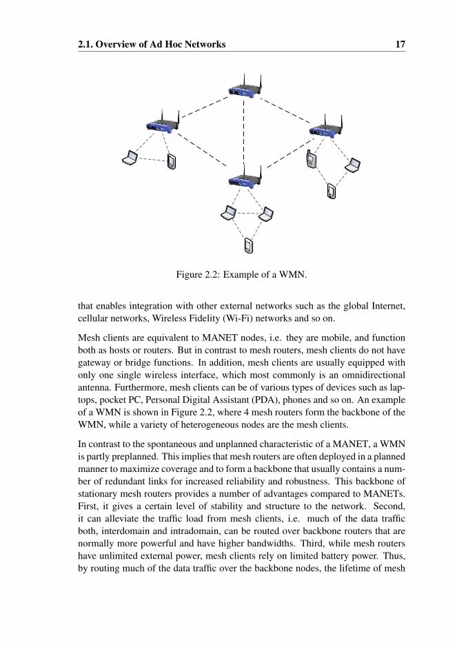
Mesh clients are equivalent to MANET nodes, i.e. they are mobile, and functionboth as hosts or routers. But in contrast to mesh routers, mesh clients do not havegateway or bridge functions. In addition, mesh clients are usually equipped withonly one single wireless interface, which most commonly is an omnidirectionalantenna. Furthermore, mesh clients can be of various types of devices such as lap-tops, pocket PC, Personal Digital Assistant (PDA), phones and so on. An exampleof a WMN is shown in Figure 2.2, where 4 mesh routers form the backbone of theWMN, while a variety of heterogeneous nodes are the mesh clients.
In contrast to the spontaneous and unplanned characteristic of a MANET, a WMNis partly preplanned. This implies that mesh routers are often deployed in a plannedmanner to maximize coverage and to form a backbone that usually contains a num-ber of redundant links for increased reliability and robustness. This backbone ofstationary mesh routers provides a number of advantages compared to MANETs.First, it gives a certain level of stability and structure to the network. Second,it can alleviate the traffic load from mesh clients, i.e. much of the data trafficboth, interdomain and intradomain, can be routed over backbone routers that arenormally more powerful and have higher bandwidths. Third, while mesh routershave unlimited external power, mesh clients rely on limited battery power. Thus,by routing much of the data traffic over the backbone nodes, the lifetime of mesh
18 Challenges in Ad hoc Networks
Sink
Internet
User
Sensor field
Sensor nodes
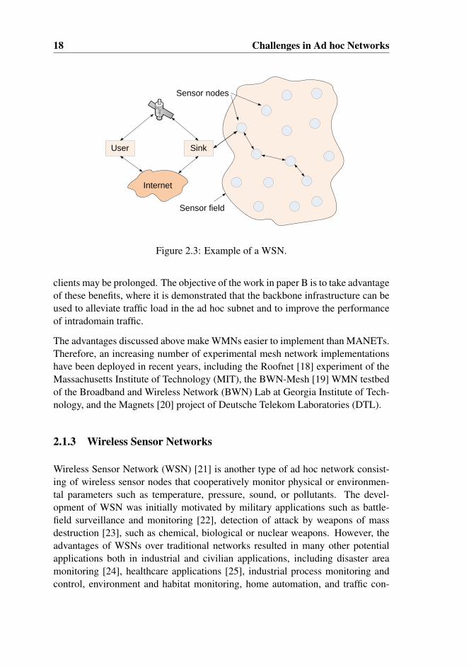
Figure 2.3: Example of a WSN.
clients may be prolonged. The objective of the work in paper B is to take advantageof these benefits, where it is demonstrated that the backbone infrastructure can beused to alleviate traffic load in the ad hoc subnet and to improve the performanceof intradomain traffic.
The advantages discussed above make WMNs easier to implement than MANETs.Therefore, an increasing number of experimental mesh network implementationshave been deployed in recent years, including the Roofnet [18] experiment of theMassachusetts Institute of Technology (MIT), the BWN-Mesh [19] WMN testbedof the Broadband and Wireless Network (BWN) Lab at Georgia Institute of Tech-nology, and the Magnets [20] project of Deutsche Telekom Laboratories (DTL).
2.1.3 Wireless Sensor Networks
Wireless Sensor Network (WSN) [21] is another type of ad hoc network consist-ing of wireless sensor nodes that cooperatively monitor physical or environmen-tal parameters such as temperature, pressure, sound, or pollutants. The devel-opment of WSN was initially motivated by military applications such as battle-field surveillance and monitoring [22], detection of attack by weapons of massdestruction [23], such as chemical, biological or nuclear weapons. However, theadvantages of WSNs over traditional networks resulted in many other potentialapplications both in industrial and civilian applications, including disaster areamonitoring [24], healthcare applications [25], industrial process monitoring andcontrol, environment and habitat monitoring, home automation, and traffic con-
2.2. Network Connectivity 19
trol [26] [27]. Furthermore, WSNs are especially suitable in inaccessible environ-ments such as volcanoes or at the sea bottom.
A typical example of a WSN is shown in Figure 2.3. The sensor nodes are tinydevices equipped with one or more sensors, a small microcontroller, and a radiotransceiver. While the sensors in a node are responsible for measuring physicalparameters such as those mentioned above, the processing capacity of the micro-controller allows the nodes to perform local computation on the sensed data. Theradio transceiver enables these nodes to exchange data between neighboring nodesor over multihop to the sink node, which is the point of aggregation of the senseddata. The sink node is usually a more powerful node compared to the sensor nodes,and possesses higher capacity in terms of processing power, storage and batterypower. In addition, it can also be equipped with a high bandwidth radio link totransmit the collected data, either over the global Internet or via a satellite, to aremote end user.
Sensor nodes in a WSN are often deployed in a large number, randomly anddensely distributed over the sensor field with minimal planning. One can forexample throw of drop sensor nodes from an aircraft to cover a certain area ofinterest. Similar to a MANET, nodes in a WSN autonomously collaborate in a dis-tributed manner to form a multihop network without the need of any pre-deployedinfrastructure. However, there are a number of differences between these types ofnetworks. First of all the number of nodes in a WSN can be several orders of mag-nitude larger than the number of nodes in a MANET. Second, sensor nodes aremore prone to failure and energy drain, and their battery sources are usually not re-placeable or rechargeable. Third, a WSN is data-centric, meaning that the queriesin a sensor network are addressed to nodes which have data satisfying some condi-tions. On the other hand, MANETs are address-centric, with queries addressed toparticular nodes specified by their unique address. Most routing protocols used inMANETs cannot be directly ported to WSNs because of the limitations in mem-ory, power, and processing capabilities in the sensor nodes. Besides, the generallynon-scalable nature of MANET protocols is incapable to handle the high numberof nodes in WSNs.
2.2 Network Connectivity
The topology in an ad hoc network is defined by the set of wireless links that existin the network. This is again closely related to the relative placement of nodesand the range of their radio transmitters. In ad hoc networks, nodes are usuallydeployed in an ad hoc manner, without pre-planning. Consequently, the placement

20 Challenges in Ad hoc Networks
of nodes may be regarded as a random process from which the network topologyemerges.
An important aspect in this process is the node density. The previous work in [28][29] showed that there is a clear relationship between node density and networkconnectivity. They used the theory of percolation to show that there is a cut-offpoint in node density, called the critical density. If the density is below this criticalpoint, then there is a risk for network partitioning, where the network topology isdivided into smaller unconnected subnetworks. On the other hand, if the densityis above this critical point, the network is more likely to be unpartitioned, andthere is connectivity between the majority of nodes in the network. However, ifthe node density is just above the critical point, then the resulting topology maybe quite sparse in terms of connectivity. Consequently a node must rely on a fewlinks only, in order to preserve connectivity with neighboring nodes or the network.Hence, a link break may have severe impact on the network connectivity in a sparsenetwork. In contrast, a dense network has usually many redundant links and pathsbetween the majority of the node pairs, and a link break does not affect the networkconnectivity to any extent. The redundancy provides a number of alternative pathsto circumvent a broken link. From this, it is apparent that in sparse networks, itis more challenging for the routing protocol to dynamically adapt to changes intopology caused by link failures, than in dense networks. Hence, the node densitydirectly affects the ability of the routing protocol in adapting to topology changes,and at the same time maintaining connectivity. When setting up scenarios forevaluating proposed algorithms/mechanism in paper B-E, care was therefore takenthat a suitable number of nodes is deployed in order to ensure connectivity andredundancy.
Furthermore, the node density has meaning only when treated relative to the nodes’radio transmission range. If the radio range is reduced while the number of nodesper unit area remains the same, then the connectivity in the network is also reduced.This implies that variations in node density as well as the radio range, are bothaffecting the network connectivity. The variations in radio range are for examplecaused by random variations in the environment such as topography or weathercondition. Variations in available power in each node may also be a second reason.This can for example be induced intentionally in order to save battery power or toreduce radio interference between nearby nodes [30] [31].
Another issue that affects network connectivity is the communication gray zoneproblem [32], in which unicast data packets cannot be exchanged even thoughlink sensing with broadcast control messages indicates neighbor reachability. Thisproblem is rooted in the difference in transmission range between broadcast andunicast data packets. In IEEE 802.11, a broadcast packet is always transmitted at
2.3. Node Mobility 21
the basic data rate, while a unicast packet is normally transmitted at higher rates.This is due to the fact that broadcasting is more unreliable than unicasting, sinceit is not protected by the retransmission mechanism at the link layer as in the caseof unicasting. Therefore broadcast packets are transmitted at the lowest data rateto increase reliability. However this also increases the radio range of broadcastpackets. This difference in transmission range between a broadcast and a unicastpacket is the main reason for communication gray zones to occur, resulting inestablishment of links that are potentially unusable for unicasting data packets.A possible solution to this problem is to use Signal to Noise Ratio (SNR) as ameasure to differentiate and discard “weak” control packets.
2.3 Node Mobility
In a MANET, nodes move around in a arbitrary manner. The presence of nodemobility causes frequent link breaks and formation of new links in the network.As a result, the network topology may continuously change. The challenge thatarises when the topology is changing, is the difficulty in keeping the routing tableup-to-date to correctly reflect the actual view of the topology. This is due to thefact that routing protocols generally need a certain amount of time to detect linkbreaks. For example, the work in paper A shows that proactive routing protocolscan use up to 6 seconds to detect a broken link (with default Hello intervals of 2seconds), in addition to the time needed to commence rerouting. Consequently,the perceived topology of the routing protocol will usually lag behind compared tothe actual network topology.
An important parameter is the average node velocity, which determines how fastthe network topology changes over time. The faster the velocity is, the more diffi-cult it is for the routing protocol to keep track with the changes. This is one of themajor challenges that we experienced in paper E, i.e. as the velocity increases, it iscorrespondingly more difficult for the routing protocol to perform load balancing.One way to improve this is to reduce control traffic interval as the node velocityincreases. However, this solution entails a significant increase in the amount ofcontrol traffic overhead.
Even though it is possible to keep up with the changes in the topology, the routingprotocol cannot predict how the topology will change in the near future. Packetsthat are forwarded on the basis of the current view of the topology may still bediscarded en-route to the destination due to unforeseen changes in the topology.Furthermore, as a consequence of frequent link breaks, the effective capacity in amobile network is usually lower than in a static topology.
22 Challenges in Ad hoc Networks
2.4 Unidirectional Links
Most research related to ad hoc networks is based on the simplifying assumptionsthat all wireless links in the network are bidirectional (also called symmetrical):if node a can hear node b, then node b can also hear node a. However, in thereal world, this is not always true. Unidirectional links (also called asymmetrical)do exist, and may occur due to various reasons. First, heterogeneity of receiverand transmitter hardware may lead to differences in radiation patterns and radiorange. Second, power control or topology control algorithms may be used to adaptthe transmission power to the remaining energy reserve, or to reduce the level ofinterference in the network [33] [34] [35]. Third, unidirectional links may alsoresult from interference due to concurrent transmissions. The level of interferencemay be different at node a and b, so that one of them cannot temporarily receivedata from the other [36]. The negative impact on network performance due to thepresence of unidirectional links is documented in various works [37] [38].
2.5 Network Capacity
The network capacity in terms of bandwidth or throughput is dependent on theapplied underlying physical layer. Most work related to ad hoc networks are basedon the IEEE 802.11 standards which can, in theory, provide a throughput up to150 Mbps. Despite the high data rates specified by these standards, the capacityis in reality much lower, especially in multihop networks. This is due to the factthat wireless communication must share a common medium. Therefore, multi-ple concurrent transmissions may potentially result in interference and disruption,unless the transmitters are located far enough from each other. The latter con-dition provides spatial separation and allows concurrent transmissions to occurwithout destructively interfering each other. This is commonly referred to as spa-tial reuse [39]. Higher level of spatial reuse can increase the throughput in thenetwork, but may however, also increase the probability for packet collisions, asshown in paper C. Hence, the trade-off between these two conflicting mechanismsneeds to be considered.
The analysis in [40] showed that the total end-to-end capacity in multihop wirelessnetworks is correlated with the number of nodes n in the network, and is roughlyO( n√
n). This implies that the per-node throughput capacity is just O( 1√
n), and
approaches zero as the number of nodes increases. Thus, in order to ensure areasonable amount of throughput capacity for each node, it is recommended tokeep the network size to a small number of nodes. This shows that scalability in
2.6. Medium Access 23
BA C D
Transmission
range
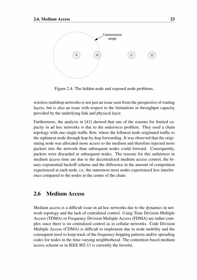
Figure 2.4: The hidden node and exposed node problems.
wireless multihop networks is not just an issue seen from the perspective of routinglayers, but is also an issue with respect to the limitations in throughput capacityprovided by the underlying link and physical layer.
Furthermore, the analysis in [41] showed that one of the reasons for limited ca-pacity in ad hoc networks is due to the unfairness problem. They used a chaintopology with one single traffic flow, where the leftmost node originated traffic tothe rightmost node through hop-by-hop forwarding. It was observed that the origi-nating node was allocated more access to the medium and therefore injected morepackets into the network than subsequent nodes could forward. Consequently,packets were discarded at subsequent nodes. The reasons for this unfairness inmedium access time are due to the decentralized medium access control, the bi-nary exponential backoff scheme and the difference in the amount of competitionexperienced at each node, i.e. the outermost most nodes experienced less interfer-ence compared to the nodes in the centre of the chain.
2.6 Medium Access
Medium access is a difficult issue in ad hoc networks due to the dynamics in net-work topology and the lack of centralized control. Using Time Division MultipleAccess (TDMA) or Frequency Division Multiple Access (FDMA) are rather com-plex since there is no centralized control as in cellular networks. Code DivisionMultiple Access (CDMA) is difficult to implement due to node mobility and theconsequent need to keep track of the frequency-hopping patterns and/or spreadingcodes for nodes in the time-varying neighborhood. The contention based mediumaccess scheme as in IEEE 802.11 is currently the favorite.

24 Challenges in Ad hoc Networks
In IEEE 802.11, a node must basically sense the medium before commencing atransmission in order to avoid collision. However, this approach can only to acertain extent reduce the probability for interference and collisions. It can notentirely eliminate it. The well known phenomena of hidden node and exposed nodeare examples of problems that carrier sensing cannot handle. Consider Figure 2.4,where four nodes are placed along a line, and we assume circular and uniformradio range for all nodes. The phenomenon of hidden node [42] takes place whennode C also sends traffic to D, while A is sending to B. This happens becausenode C, which is the hidden node to A, cannot sense the transmissions from A (andA cannot sense the transmissions from C), and therefore may commence sendingtraffic. Consequently, the result is interference and packet collisions at node B.During the work in paper C, we observed that this problem is especially severewhen the traffic load in the network is high. A possible means to alleviate thisis to increase the sensing range, which will result in lower probability for packetcollision and improved performance. Alternatively, as will be discussed later, theRTS/CTS mechanism can also be used to alleviate the hidden node problem.
The exposed node problem is more or less opposite to the hidden node problem.Suppose B sends traffic to A. At the same time, C has also traffic to send to D.However, since C can hear the signals from B and interprets the medium as busy,C therefore defers sending traffic to D. In reality, C could send traffic to D with-out interfering with the transmission from B to A. Consequently, this “misinter-pretation” results in non-optimized utilization of the medium and lower networkperformance.
Chapter 3
IEEE 802.11
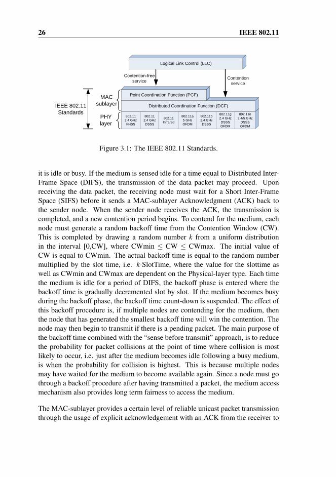
IEEE 802.11 refers to the set of standards for Wireless LANs (WLANs). Theoriginal version of the standard (IEEE 802.11), was first released in 1997 andsupported data rates of 1 and 2 Mbps. Later on new amendments were added, suchas IEEE 802.11a, b, g and n supporting data rates up 150 Mbps. The IEEE 802.11standards define both a Physical-layer and a MAC-sublayer (Figure 3.1), wherethe Physical-layer supports different modulation techniques such as FHSS, DSSSand OFDM, and operates at the 2.4 and 5 GHz frequency bands.
3.1 The MAC-sublayer
While the routing layer provides multihop communication, the MAC-sublayer pro-vides single hop communication. IEEE 802.11 MAC layer is by far the mostpopular MAC protocol in ad hoc networks. The IEEE 802.11 MAC-sublayer im-plements the access control mechanism that enables nodes to access and sharea common physical medium. The standard defines two types of operation modes,Distributed Coordination Function (DCF) and Point Coordination Function (PCF),where DCF is the basic mode of operation for ad hoc networks, while PCF is anoptional operation mode that is suitable for infrastructure-based networks.
DCF is a distributed and contention-based medium access method that is based onCarrier Sense Multiple Access with Collision Avoidance (CSMA/CA) combinedwith a random backoff procedure. CSMA protocols are well-known in the industry,where the most popular variant is Carrier Sense Multiple Access with CollisionDetection (CSMA/CD) that is used in the Ethernet or wired LAN. In DCF, when anode has a data packet to send, it must first sense the medium to determine whether
25
26 IEEE 802.11
802.11
2.4 GHz
FHSS
802.11
2.4 GHz
DSSS
802.11
Infrared
802.11a
5 GHz
OFDM
802.11b
2.4 GHz
DSSS
802.11g
2.4 GHz
DSSS
OFDM
802.11n
2.4/5 GHz
DSSS
OFDM
PHY
layer
Logical Link Control (LLC)
Distributed Coordination Function (DCF)
Point Coordination Function (PCF)MAC
sublayer
Contention-free
service
IEEE 802.11
Standards
Contention
service
Figure 3.1: The IEEE 802.11 Standards.
it is idle or busy. If the medium is sensed idle for a time equal to Distributed Inter-Frame Space (DIFS), the transmission of the data packet may proceed. Uponreceiving the data packet, the receiving node must wait for a Short Inter-FrameSpace (SIFS) before it sends a MAC-sublayer Acknowledgment (ACK) back tothe sender node. When the sender node receives the ACK, the transmission iscompleted, and a new contention period begins. To contend for the medium, eachnode must generate a random backoff time from the Contention Window (CW).This is completed by drawing a random number k from a uniform distributionin the interval [0,CW], where CWmin ≤ CW ≤ CWmax. The initial value ofCW is equal to CWmin. The actual backoff time is equal to the random numbermultiplied by the slot time, i.e. k·SlotTime, where the value for the slottime aswell as CWmin and CWmax are dependent on the Physical-layer type. Each timethe medium is idle for a period of DIFS, the backoff phase is entered where thebackoff time is gradually decremented slot by slot. If the medium becomes busyduring the backoff phase, the backoff time count-down is suspended. The effect ofthis backoff procedure is, if multiple nodes are contending for the medium, thenthe node that has generated the smallest backoff time will win the contention. Thenode may then begin to transmit if there is a pending packet. The main purpose ofthe backoff time combined with the “sense before transmit” approach, is to reducethe probability for packet collisions at the point of time where collision is mostlikely to occur, i.e. just after the medium becomes idle following a busy medium,is when the probability for collision is highest. This is because multiple nodesmay have waited for the medium to become available again. Since a node must gothrough a backoff procedure after having transmitted a packet, the medium accessmechanism also provides long term fairness to access the medium.
The MAC-sublayer provides a certain level of reliable unicast packet transmissionthrough the usage of explicit acknowledgement with an ACK from the receiver to
3.1. The MAC-sublayer 27
the sender. The lack of such an ACK after an ACKTimeout interval, may indicateto the sender that an error has occurred. The error can indistinguishably be a resultof a collision either to the data packet or the ACK message, or it can also be aresult of a temporary link failure or a persistent link break. Either way, each timea transmission is failed, a retransmission procedure is invoked. In this process,the data packet is scheduled for retransmission, in which a new backoff time isgenerated. However, in order to reduce the probability for collision, after eachfailed transmission, the CW is exponentially increased until the threshold CWmaxis reached. For example, the CW can sequentially be increased (using the equation2i−1, where i is an integer) from 7, 15, 31, 63, 127, and 255, where CWmin=7 andCWmax=255. After a successful transmission, the CW is again reset to CWmin.
Furthermore, a retry counter is maintained to account for the number of retransmis-sions that the current packet has experienced. Each time a packet is retransmitted,the retry counter is increased by one. After a successful retransmission the retrycounter is again reset to 0, while the CW is reset to CWmin. On the other hand, ifthe number of retransmission has reached a predefined threshold value, the packetis discarded, and the retry counter and the CW are reset. The MAC-sublayer isthen ready to handle the next pending packet in the queue.
In order to determine the state of the medium and to avoid collisions, the standardprovides two carrier sensing mechanisms, a physical and a virtual. The medium isconsidered as busy whenever either mechanisms indicate that the medium is busy,otherwise the medium is considered idle. The physical carrier sensing mechanismis provided by the underlying Physical-layer and is used to detect medium activityand avoid collisions at the sender node, but it cannot prevent collisions from oc-curring at the receiver node due to problems such as hidden node, as discussed inSection 2.6. In order to overcome this problem, the MAC-sublayer virtual carriersensing mechanism provides an optional hand-shake mechanism, using RequestTo Send (RTS) and Clear To Send (CTS) control messages, to schedule a datapacket transmission. Upon hearing one of these messages, either the RTS from thesender node or the CTS from the receiver node, nearby nodes can be made awareof the scheduled transmission and can thus defer any pending transmissions, evenif they are either outside of the sender’s or the receiver’s radio range.
Even though the RTS/CTS mechanism may alleviate the probability for collisions,the disadvantage of using this mechanism is the potential for reduced throughputdue to increased overhead. Besides, this mechanism only attributes to reducingthe effect of hidden node. It cannot eliminate the problem if the distance betweenthe sender and receiver is larger than 0.56 times the radio range, assuming a mini-mum SNR of 10 for successfully receiving a packet. The reason is that the powerlevel needed for interrupting a transmission is much smaller than that of success-

28 IEEE 802.11
fully delivering a packet as explained in [43]. Due to these reasons, the RTS/CTSmechanism has therefore not been used in our studies.
Chapter 4
Unicast Routing Protocols forMANETs
A routing protocol provides a set of rules and regulations for how nodes commu-nicate with each other. A major part of the work in this thesis is concerned aboutenhancing the functionality of the routing protocol in order to optimize networkperformance. This chapter provides an introduction to some of the most essen-tial topics related to routing in MANET. First, an overview and classification oftypical routing protocols for MANETs are given in Section 4.1. Section 4.2 and4.3 provide a more detailed description of two selected routing protocols, namelythe reactive AODV and the proactive OLSR protocol. These protocols are amongthe most cited, and variants of these concepts can be found in many other routingprotocols. The description of OLSR is however more important since it has beenused throughout the work in this thesis. Furthermore, Section 4.4 discusses animportant aspect related to routing protocols, i.e. the various mechanisms used byrouting protocols to detect link breaks. This topic is especially important in termsof the work in paper A. Finally, Section 4.5 provides an overview of common rout-ing metrics in MANETs, which are a vital component in performing QoS routingor load balancing.
4.1 Overview and Classification of MANET Routing Pro-tocols
To enable communication within an ad hoc network, a routing protocol is requiredto establish routes between source and destination pairs. A routing protocol may be
29
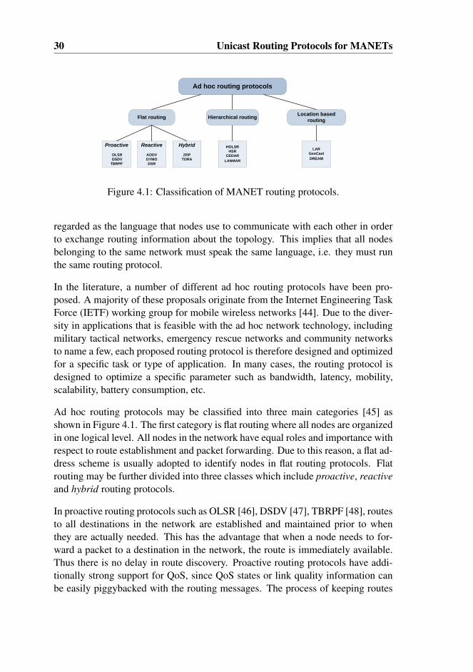
30 Unicast Routing Protocols for MANETs
Ad hoc routing protocols
Flat routing Hierarchical routingLocation based
routing
Proactive
OLSR
DSDV
TBRPF
Reactive
AODV
DYMO
DSR
HOLSR
HSR
CEDAR
LANMAR
LAR
GeoCast
DREAM
Hybrid
ZRP
TORA
Figure 4.1: Classification of MANET routing protocols.
regarded as the language that nodes use to communicate with each other in orderto exchange routing information about the topology. This implies that all nodesbelonging to the same network must speak the same language, i.e. they must runthe same routing protocol.
In the literature, a number of different ad hoc routing protocols have been pro-posed. A majority of these proposals originate from the Internet Engineering TaskForce (IETF) working group for mobile wireless networks [44]. Due to the diver-sity in applications that is feasible with the ad hoc network technology, includingmilitary tactical networks, emergency rescue networks and community networksto name a few, each proposed routing protocol is therefore designed and optimizedfor a specific task or type of application. In many cases, the routing protocol isdesigned to optimize a specific parameter such as bandwidth, latency, mobility,scalability, battery consumption, etc.
Ad hoc routing protocols may be classified into three main categories [45] asshown in Figure 4.1. The first category is flat routing where all nodes are organizedin one logical level. All nodes in the network have equal roles and importance withrespect to route establishment and packet forwarding. Due to this reason, a flat ad-dress scheme is usually adopted to identify nodes in flat routing protocols. Flatrouting may be further divided into three classes which include proactive, reactiveand hybrid routing protocols.
In proactive routing protocols such as OLSR [46], DSDV [47], TBRPF [48], routesto all destinations in the network are established and maintained prior to whenthey are actually needed. This has the advantage that when a node needs to for-ward a packet to a destination in the network, the route is immediately available.Thus there is no delay in route discovery. Proactive routing protocols have addi-tionally strong support for QoS, since QoS states or link quality information canbe easily piggybacked with the routing messages. The process of keeping routes
4.1. Overview and Classification of MANET Routing Protocols 31
and states up-to-date requires regular exchange and dissemination of neighbor andtopology information. This however incurs a constant amount of overhead, con-suming bandwidth, battery power and computation time, even though the routesare not always needed. If the network size is large or the level of mobility is high,the overhead in terms of control traffic and routing table storage may be of a sub-stantial size. Hence, proactive routing protocols do not scale very well. On theother side, the overhead is not affected by an increase in the fraction of nodes act-ing as traffic sources, since routes to all destinations are anyway maintained by therouting protocol.
Reactive routing protocols (also known as on demand routing protocols) are an-other class of flat routing protocols, specifically developed for MANETs. Exam-ples of frequently cited reactive routing protocols include AODV [49], DYMO [50]and DSR [51]. The focus of this class of routing protocols is to preserve networkresources with respect to bandwidth, routing table storage and processing time.With the reactive approach, routes are neither maintained nor established until theyare actually needed. The establishment of a route is usually initiated by flooding aRoute Request (RREQ) control message, and eventually responded with a unicastRoute Reply (RREP) message from either the destination node or an intermediatenode with a valid route to the destination. Reactive routing protocols thereforeincur a substantially lower constant overhead compared to proactive routing pro-tocols and are thus also more scalable. On the other hand, the disadvantage is theroute discovery latency that can be high if the destination node is many hops away.
In hybrid routing protocols, the advantages of both the proactive and reactive rout-ing strategies are combined in order to make a compromise between control trafficoverhead and route discovery latency. The idea is to utilize a proactive routing pro-tocol in the local neighborhood, i.e. for destinations inside a predefined zone withradius of k hops from the local node. On the other hand, routes to destinations be-yond the predefined zone are queried using a reactive routing protocol. Examplesof hybrid routing protocols include Zone Routing Protocol (ZRP) [52] which wasthe first hybrid routing protocol introduced by Haas in 1997, and Core ExtractionDistributed Ad Hoc Routing (CEDAR) [53].
When the network size is very large and beyond a certain threshold value, flat rout-ing protocols become unsuitable due to the excessive amount of overhead in termsof control traffic as well as processing time. In such case, hierarchical routingprotocols can be used as an alternative. Hierarchical routing protocols organizenodes into a hierarchy of clusters based on their relative proximity to one another.For each cluster, a cluster head is elected to be a local coordinator for transmis-sions within the cluster. Cluster heads at a lower level become members of thenext higher level cluster. This process is performed recursively to provide a mul-
32 Unicast Routing Protocols for MANETs
tilevel hierarchy of clusters. The motivation is to reduce the size of the routingtable and thus achieve better scalability. In contrast to flat routing protocols, hier-archical routing protocols usually apply a hierarchical addressing scheme in whichthe identity of a local node can for example be the sequence of addresses of theassociated cluster head nodes, from the top hierarchy to the node itself. Examplesof hierarchical routing protocols include Hierarchical State Routing (HSR) [54],Hierarchical Optimized Link State Routing (HOLSR) [55] and Landmark Ad HocRouting (LANMAR) [56]
In location based routing protocols, the position information provided by for ex-ample Global Positioning System (GPS) [57] is exploited to perform directionalpacket forwarding. In contrast to for example flat routing protocols, establishmentor maintenance of routes are not required. Based on the knowledge of the expectedposition to the destination node, a source node can forward data traffic direction-ally towards the destination. The advantage of location based routing protocolsis lower overhead with respect to control traffic. The disadvantage is the depen-dency on position information, which is not guaranteed to be available everywheresuch as inside a building. Examples of location based routing protocols includeLocation-Aided Routing (LAR) [58] and Distance Routing Effect Algorithm forMobility (DREAM) [59].
4.2 AODV
AODV is one of the most cited and studied reactive routing protocol for MANETs,and has also been standardized by the IETF [60]. In AODV [49], when a nodeneeds to send data traffic to a destination node that it has no route to, it then ini-tiates a route discovery process by flooding a RREQ message. Upon receivingthis message, an intermediate node refloods the message to its neighboring nodes.The process of reflooding the RREQ is repeated multiple times, covering an in-creasingly larger area, until either the destination or an intermediate node with avalid route to the requested destination is reached. During the route discovery pro-cess, each node that receives a RREQ message sets up a reverse route back to theoriginator of the received message, along the path that the message has traversed.
The destination node or an intermediate node with valid route to the destinationwill eventually receive the RREQ message. The node then responds with a RREPmessage containing the latest destination sequence number. This is one of thedistinguishing features of AODV, i.e. the usage of the destination sequence numberto ensure loop freedom. Duplicate RREQ messages, identified by their sequencenumber and originator address, that have taken alternative paths and are received at
4.3. OLSR 33
a later point of time are discarded. This implies that only the first RREQ messagereceived is processed and responded, based on the assumption that this messagehas traversed the best and shortest path, and therefore has arrived first. The RREPmessage is unicasted along the reverse route that was set up during the flooding ofthe RREQ message. Upon receiving the RREP message, an intermediate node setsup a forward route towards the destination node. The message is then forwarded tothe next hop along the reverse route towards the source node. Eventually when thesource node receives the RREP message, the path between source and destinationis now established and ready for sending data.
During data transmission, if there is a link break anywhere along the establishedpath, a Route Error (RERR) may be sent upstream to warn the source node. Thesource node can then reestablish a new route by initiating a new route discoveryprocess. Alternatively, an intermediate node upstream to the link break may tryto perform a local link repair by flooding a RREQ querying a new route to thedestination node.
Being a reactive routing protocol, the advantage of AODV is lower control trafficoverhead and routing table storage. Consequently it is more scalable than pro-active routing protocols, since only needed routes are stored and maintained in therouting table. However, the reactive approach incurs a certain amount of delay inroute discovery. Besides, the route discovery process often involves network-wideflooding of the route discovery message, which unfortunately incurs a substantialwaste of scarce network resource, especially if the requested destination is onlya few hops away from the initiator of the message. To alleviate this, the routediscovery process is usually performed in a progressive manner where the searcharea is incrementally expanded until the destination node is found. However, thisoptimization, known as expanding ring search, may further increase the averagelatency of the route discovery, since multiple discovery attempts and timeouts maybe needed before discovering a route to the destination node. Furthermore, dueto the overhead in route discovery, reactive routing protocols do not scale verywell, especially if there are many short lived traffic sources in the network and ifthe distance between source and destination pairs is far. The same also appliesif the mobility in the network is high, since link breaks may result in frequentre-initiation of route discovery.
4.3 OLSR
The OLSR routing protocol is an example on proactive routing protocol for MANET.This routing protocol is brought forward by the MANET WG starting from 1998.
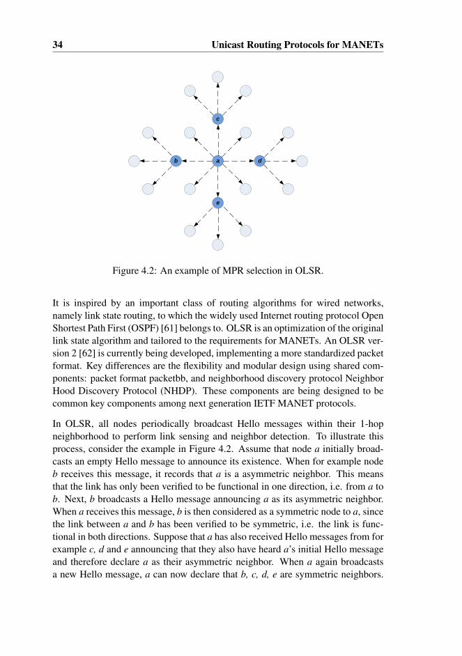
34 Unicast Routing Protocols for MANETs
ab
c
e
d
Figure 4.2: An example of MPR selection in OLSR.
It is inspired by an important class of routing algorithms for wired networks,namely link state routing, to which the widely used Internet routing protocol OpenShortest Path First (OSPF) [61] belongs to. OLSR is an optimization of the originallink state algorithm and tailored to the requirements for MANETs. An OLSR ver-sion 2 [62] is currently being developed, implementing a more standardized packetformat. Key differences are the flexibility and modular design using shared com-ponents: packet format packetbb, and neighborhood discovery protocol NeighborHood Discovery Protocol (NHDP). These components are being designed to becommon key components among next generation IETF MANET protocols.
In OLSR, all nodes periodically broadcast Hello messages within their 1-hopneighborhood to perform link sensing and neighbor detection. To illustrate thisprocess, consider the example in Figure 4.2. Assume that node a initially broad-casts an empty Hello message to announce its existence. When for example nodeb receives this message, it records that a is a asymmetric neighbor. This meansthat the link has only been verified to be functional in one direction, i.e. from a tob. Next, b broadcasts a Hello message announcing a as its asymmetric neighbor.When a receives this message, b is then considered as a symmetric node to a, sincethe link between a and b has been verified to be symmetric, i.e. the link is func-tional in both directions. Suppose that a has also received Hello messages from forexample c, d and e announcing that they also have heard a’s initial Hello messageand therefore declare a as their asymmetric neighbor. When a again broadcastsa new Hello message, a can now declare that b, c, d, e are symmetric neighbors.
4.3. OLSR 35
Upon receiving this message, b now knows that a is a symmetric neighbor. In ad-dition, b also knows about the 2-hops neighbors c, d, e, that can be reached via a.Thus, the exchange of Hello messages does not only allows a node to perform linksensing, but also enables it to obtain knowledge about the 2-hops neighborhood.
One of the most characteristic concepts in OLSR is the usage of Multi Point Re-lay (MPR) nodes to minimize control traffic overhead flooded in the network. Eachnode in the network selects an MPR set from among its 1-hop symmetric neigh-bors. This set is by default selected in such a way that the number of MPR nodesis kept as low as possible and at the same time satisfies the condition that all strict2-hops neighbors are reachable via these MPR nodes. The essential point of theMPR selection process is the formation of a Connected Dominating Set (CDS)consisting of MPRs which can be used to perform network wide flooding in amuch more efficient way. That is, when a control message is broadcasted through-out the whole network, only nodes selected as MPRs, for the node in which themessage is received from, can forward the message. This technique of MPR flood-ing substantially reduces the message overhead compared to the classical floodingmechanism where all nodes are responsible for retransmitting broadcast packets.Referring to the example in Figure 4.2, it is sufficient for node a to select the nodesb, c, d, and e as its MPRs. When a performs a network wide broadcast, only theseselected nodes need to forward the message from a. The transmissions from a andits MPRs are sufficient to disseminate the message to all nodes in the network.
While a Hello message is used to exchange local link state information and toperform neighbor detection in the local neighborhood, a Topology Control (TC)message is used to disseminate topology information to all nodes in the network.Only nodes selected as MPRs originate TC messages. Thus the overhead is furtherreduced since the number of control messages flooded in the network is minimized.In addition, an MPR by default only reports the links between itself and its MPRselectors (i.e. the nodes that have selected it as MPR) in the TC message it orig-inates. Hence, the overhead is reduced even more since only partial link state isreported. This implies that from a certain node’s point of view, the network topol-ogy beyond the 2-hops neighborhood consists only of the set of links between theMPRs and their MPR-selectors. Consequently, the constructed logical topologyhas fewer redundant links, but is still fully connected. The drawback is that it isless resilient to link failures.
The neighbor and topology information are updated periodically through the ex-change of Hello and TC messages, and enables each node to compute an up-to-date routing table to all known destinations in the network. The computation isperformed using Dijkstra’s shortest path algorithm, and the routes are thus op-timized with respect to the hop count. The advantage of this metric is that the

36 Unicast Routing Protocols for MANETs
number of transmissions needed to send a packet from a source to a destination isminimized, and is thus optimal with respect to the usage of network resources, i.e.bandwidth and energy. On the other hand, the shortest path to a given destinationis not always the best path when it comes to other parameters such as throughput,end-to-end delay or reliability. Hence, the work in paper B to E is therefore con-cerned about the potential of using different types of routing metrics in order toachieve load balancing and higher performance in terms of throughput.
In addition to the message types discussed above, OLSR also defines other typesof messages, i.e. Host and Network Association (HNA) and Multiple InterfaceDeclaration (MID) messages. The HNA message can be used by a gateway nodeto announce about its connectivity to external network domains such as the globalInternet. This is for example used in Paper B, where the access points and gate-way nodes periodically disseminate HNA messages to announce their presenceand connectivity to external networks. The MID message format is used to sup-port multiple interfaces. The additional information provided by the MID messageis needed to map different interface addresses of a node to its main address.
Being a proactive routing protocol, OLSR has the advantages and disadvantagethat are common in this family of routing protocols and mentioned earlier in theintroduction of this section. However, OLSR has gained much attention and pop-ularity since its appearance, due to its simplicity and interesting features such asMPR flooding and the ability to detect bidirectional links. Consequently, severalOLSR implementations exist for use under different platforms such as Windows,Mac OS and Linux [63], [64]. Furthermore, OLSR has been chosen and used inthe real-life olsrexperiment.net experiment in Berlin [65].
4.4 Link Failure Detection
In a MANET, the topology of the network usually changes over time either due tonode mobility or because nodes join or leave the network. In addition, packet lossdue to interference or temporal signal fluctuations may also affect the perceivedview of the topology. One of the biggest challenges of a routing protocol is tomaintain an up-to-date view of the network topology and to quickly detect and re-act to changes in the topology. This is important and necessary in order to correctlyroute data traffic. Otherwise there is a potential risk for wasting scarce resourcesand suffering from packet loss if the traffic is routed incorrectly. Generally, thereare three approaches to detect link failures as discussed below:

4.4. Link Failure Detection 37
Hello messagesThe most common approach is based on regular exchange of Hello messages,which is actually used in both reactive and proactive routing protocols such asAODV and OLSR. The assumption behind this approach is that the reception ofsuch “polling” packets indicates link availability with the originator of the Hellomessages. This approach has proven to work well in wired networks which sufferfrom few packet losses and topology changes. In order to maintain a link betweentwo neighboring nodes, it is required that these nodes must exchange Hello mes-sages to each other at regular intervals. Failing to receive three successive Hellomessages from a neighbor is interpreted as a sign of link failure to that neighbor.This approach is utilized in order to minimize the potential risk for erroneouslyinvalidating a link due to temporal loss or link fluctuations. The disadvantage isthat it takes a longer time to detect a link break. This issue is closely related to thework in paper A, in which it is shown how this latency in detecting the link breakcombined with other factors (such as the length of the link layer queue, and theretransmission mechanism at the MAC-sublayer), may result in a rerouting timethat considerably exceeds the time used to detect the link break.
Link layer feedbackThe link layer feedback can be alternatively used to detect a link break. When theMAC-sublayer fails to transmit a packet to a next hop neighbor node and after anumber of unsuccessful retransmissions, the packet is discarded. A callback is thenmade to the upper layer to explicitly notify the routing protocol about the failedtransmission. This notification from the MAC-sublayer indicates that the link tothe neighbor node is broken, and thus allows for a much faster detection timethan in the Hello message approach. However, the disadvantage of this approachis that temporal link fluctuations can be misinterpreted as a persistent link break.The work in [66] shows that the link layer feedback approach works better thanthe Hello message approach at low network load. However, if the network loadis high, the amount of incorrect link failure detections increases dramatically andresults in lower throughput performance.
Implicit acknowledgementThe third approach is implicit acknowledgement, where a node, after a packettransmission to the next hop on the route, continues to listen to the channel inorder to overhear whether the next hop node forwards the packet further or not.Absence of such a forwarding within a predefined time interval, indicates that thetransmission to this neighboring node has failed and the link is therefore probablybroken, unless the next hop node is the destination node itself. The drawbackof this approach is the requirement for the wireless network interfaces to supportoperation in promiscuous mode, which is extremely energy expensive. Due to this

38 Unicast Routing Protocols for MANETs
reason the implicit acknowledgement approach has not gained wide attention inthe ad hoc network research.
4.5 Routing Metrics
Routing metrics are criterions or algorithms used by a router to make routing de-cisions. The most common metric is the shortest path metric, which solely rely onthe hop count in performing routing. In the following subsections we will providean overview of other routing metrics common in MANETs. Among these, theradio load metric is the most relevant which is utilized both in paper D and E.
4.5.1 Per hop Round Trip Time (RTT)
The RTT metric is based on measuring the round trip delay between neighboringnodes using unicast probe packets [67]. To measure the RTT, a node periodi-cally sends a probe packet containing a timestamp to each of its neighbors. Uponreceiving a probe packet, each neighbor node immediately responds with a probe-ack packet echoing the timestamp. This enables the sender of the probe packet tocalculate the round trip time to each of its neighbors. The exponentially weightedmoving average method is used to avoid rapid fluctuations by smoothing out theRTT measurement. Based on per-hop RTT measurement, a routing protocol selectsa routing path with the least sum of RTTs of all links on the path.
The RTT metric is designed to measure several aspects related to the quality of alink. First of all, if the link between two neighboring nodes is busy due to trafficload, then either the probe packet or the probe-ack will be subjected to queue-ing delays, resulting in increased RTT delay. Second, if nodes in the vicinity aretransmitting, then the probe packet or the probe-ack will experience delay due tochannel contention, which again will result in higher RTT delay. Third, if thelink between two nodes is lossy, then either the probe packet or the probe-ack islikely to experience packet loss. In such cases, the retransmission mechanism atthe IEEE 802.11 MAC-sublayer will attempt to retransmit a number of times inorder to correctly deliver the packet. However, this will take some time which willresult in increased RTT delay.
To summarize, the RTT metric is capable to determine the quality of a link withrespect to traffic load, queueing delay, the packet loss ratio, and the level of con-tention in the surrounding neighborhood. Hence, based on this metric, the routingprotocol can avoid using highly loaded or lossy links. The disadvantage of this

4.5. Routing Metrics 39
metric is however the increased overhead, since every pair of nodes are required toregularly probe each other. Second, since RTT is a load-dependent metric, whichimplies that it is rather sensitive to traffic load and queueing delays, it may there-fore lead to route instability (or route flapping). This is a well known problem,and is also called self-interference by the authors in [68]. If a separate queue isassigned to the probe packets, then it is possible to accurately measure the linkquality but in return cannot reflect the traffic load. Finally, RTT does not explicitlytake link data rate into account, due to the small size of probe packets. Largerprobe packets could be used to achieve this, but would at the same time increasethe overhead.
4.5.2 Per-hop Packet Pair Delay
The packet pair delay is a well known technique in wired networks for measuringlink quality [69]. A node periodically sends two back-to-back probe packets toeach of its neighboring nodes. The first probe is small and the second is large.Upon receiving the probe packet pair, the neighboring node measures the delaybetween the receipt of the first and the second packet. The delay is then reportedback to the sending node. This delay is a measure of the link quality in terms of lossrate, bandwidth and traffic load in the vicinity of the sending node. The advantageof using the packet pair technique over RTT is that it does not suffer from distortionby queueing delays, since both probe packets will experience the same delay. Inaddition, using a larger second probe packet makes it possible to take the linkbandwidth into account in the measurement. On the other hand, the disadvantage ishigher overhead, since two packets are sent to each neighbor instead of one, and thesecond probe packet is larger. Furthermore, [70] reported that even this techniqueis not completely immune to the self-interference phenomenon. However, it is lesssevere than in the case of RTT.
4.5.3 Expected Transmission Count (ETX)
The ETX metric predicts the expected number of transmissions, including retrans-missions, required to send a unicast packet over a link [71]. The prediction isbased on measurements of the loss ratio of broadcast packets in both directions ofa wireless link. To calculate the ETX value, each node regularly broadcast probepackets with an average period of T seconds. Neighboring nodes count the numberof received probe packets within a time interval of W seconds. The loss ratio in
40 Unicast Routing Protocols for MANETs
one direction is then:
L = 1− (C
W/T) (4.1)
where C is the number of probes actually received and W/T is the number of probesthat should be received within the window W. In order to calculate the ETX, theloss ratios in both the forward and reverse directions are required. This is due tothe fact that a successful unicast data transfer using the IEEE 802.11 standards,involves a transmission of the data packet and receiving a link-layer acknowledge-ment from the receiver. The ETX value for a link is therefore a product of the lossratio in the forward Lf and reverse direction Lr
ETX =1
(1− Lf )(1− Lr)(4.2)
The ETX value given above, represents only the expected number of transmissionover a link, i.e. for one single hop. The ETX value for a route consisting of two ormore hops is the sum of ETX values for each link along the route.
The advantage of the ETX compared to the RTT and packet pair technique islower overhead since probe packet is broadcasted instead of being unicasted toeach neighbor. Besides, it also takes into account the potential difference in linkquality in the forward and reverse direction. Furthermore, ETX suffers little fromself-interference since loss ratio is measured instead of delay.
The ETX metric also have some disadvantages. Probe packets are small and sincethey are broadcasted, the transmission is performed at the lowest rate. They maytherefore not experience the same loss rate as data packets sent at higher rates.Moreover, this metric does not directly account for link load or available band-width and is therefore not very precise in capturing the characteristic of the link.A heavily loaded link may have very low loss rate, and two links with differentbandwidth may have the same loss rate.
In [68], the ETX metric was compared to the hop count metric and the end-to-enddelay metric. It was demonstrated that ETX gave significantly better performancein static networks, but was outperformed by the hop count metric in dynamic net-works because the probe based technique was too slow to adapt to the changes inthe network.
4.5. Routing Metrics 41
4.5.4 Expected Transmission Time (ETT)
The ETT metric estimates the expected transmission time required to send a datapacket over a link. This metric is based on the ETX, and is also called bandwidth-adjusted ETX. The ETT metric is defined as follows:
ETT = ETX · SB, (4.3)
where S is the average size on a data packet, and B is the raw bandwidth of the link.The ETX value is calculated as described in Section 4.5.3, while the bandwidth Bmay either be set to a fixed value, or alternatively the packet pair method may beused to estimate it. The latter method was for example used in [70] and [72] intheir implementations of ETT.
Based on the ETT metric, a routing protocol select the routing path in which thesum of ETT value on the path is the least. This implies that the ETT metric at-tempts to minimize the expected air time that is consumed in successfully deliver-ing a frame from the source to the end destination.
The weakness of the ETT metric is that it does not explicitly account for contention(i.e. backoff time waiting for the channel to be idle) due to traffic from nodesin the vicinity. This is because the raw bandwidth is used in the definition ofETT in Equation 4.3. One way to incorporate the impact of contention is to useavailable bandwidth instead for the raw bandwidth. However, according to theauthors in [70], current techniques to measure available bandwidth assume a point-to-point, First In First Out (FIFO) queuing model for the link, which is not thecase for wireless links. On the other hand, using available bandwidth will makethe metric to be more load dependent, which again will result in route instabilityin the network.
4.5.5 Radio load metric
The radio load is a measure for how busy the medium around a node is. Unlike theRTT, Packet Pair, ETX and ETT metrics, the radio load metric does not dependon probe packets to estimate how busy the medium is. Instead, the measurementis performed in a passive manner, where the IEEE 802.11 MAC-sublayer contin-uously monitors medium activity around the local node through the physical andvirtual carrier sensing mechanism and the internal transmission state, as discussedin Chapter 3. The medium around a node is considered as busy if either i) the nodeis in the transmitting or receiving state or ii) if the node senses a busy carrier with

42 Unicast Routing Protocols for MANETs
signal strength higher than the carrier sensing threshold. Otherwise the medium isconsidered idle. A similar technique is also applied in [73], but the difference isthat the idle time is measured instead of the effective busy time.
Here we define the radio load as the amount of time Tbusy within a time windowTwindow where the local channel is monitored busy. To estimate the average radioload L the exponential moving average is used as follows:
Lnew = α · Lprevious + (1− α) · TbusyTwindow
(4.4)
where α is the weighting factor defined as α ∈ [0,1].
Each node in the network is responsible for measuring the perceived local radioload and makes this information available to the upper routing layer. The primaryadvantage of this metric is as stated earlier that it does not rely on active probing.This implies that there is no overhead to consume scarce bandwidth resources andis therefore more scalable with respect to larger topologies. Besides, the radio loadmetric does not suffer from the problems with queuing delay, self-interference, asin the case of the RTT, Packet-pair, ETX or ETT metrics, since there is no probing.
The drawback of this solution is however, the violation of the reference architec-ture of the Open Systems Interconnection (OSI) model [74], since the solutiondepends on cross-layering. In our case this implies modification of the inter-face between the link-layer and the network-layer to support exchange of lowerlayer (link-layer) information to the upper layer (network-layer). The authorsin [75] [76], have emphasized the importance of architecture and discussed thearchitectural problems that cross-layering can create if done without care. Theyalso warned about the possibility of inadvertent performance degradation due tointeraction between conflicting cross-layer design proposals. If many violationsof the architecture accumulate over time, the original architecture can completelylose its meaning and adversely impact the longevity of the architecture. However,we believe that the modification to support the exchange of radio load informationis not harmful, since the fundamental behavior of the link-layer is unchanged. Theonly difference is that more information is presented to the upper layer.
Chapter 5
Load balancing
5.1 General Description
Load balancing is a key component in traffic engineering, and refers to the processof distributing traffic load more evenly in the network. It is an vital mechanism inorder to achieve more optimal usage of network resources and improved perfor-mance.
In MANET, without an intelligent scheme for routing network traffic, the trafficload in the network can easily become unevenly distributed. This may potentiallyresult in congestion at local hotspots, severe packet loss and degradation in thenetwork performance. Uneven load distribution is usually caused by uneven userdemands or uneven node distribution, where the latter may be a consequence of theunplanned and mobile nature of MANET. Furthermore, certain nodes in the net-work are more vulnerable to become congested than others due to their location orassigned role. Nodes located in the centre of the network tend to be more congestedthan nodes in the periphery, either because the majority of packets have to traversethese central nodes or they have to contend with a higher number of neighboringnodes for the medium. Nodes having the role as gateways between network do-mains may be more congested since all interdomain traffic has to traverse throughthem. Avoiding congestion at such key nodes is critical in maintaining networkconnectivity and the services they provide.
To prevent uneven load distribution and congestion in the network, parts of thetraffic load in a congested area has to be diverted to other areas that are less con-gested. In this process the routing protocol plays an important role. Traditionalrouting protocols usually select the shortest path between any source and desti-
43
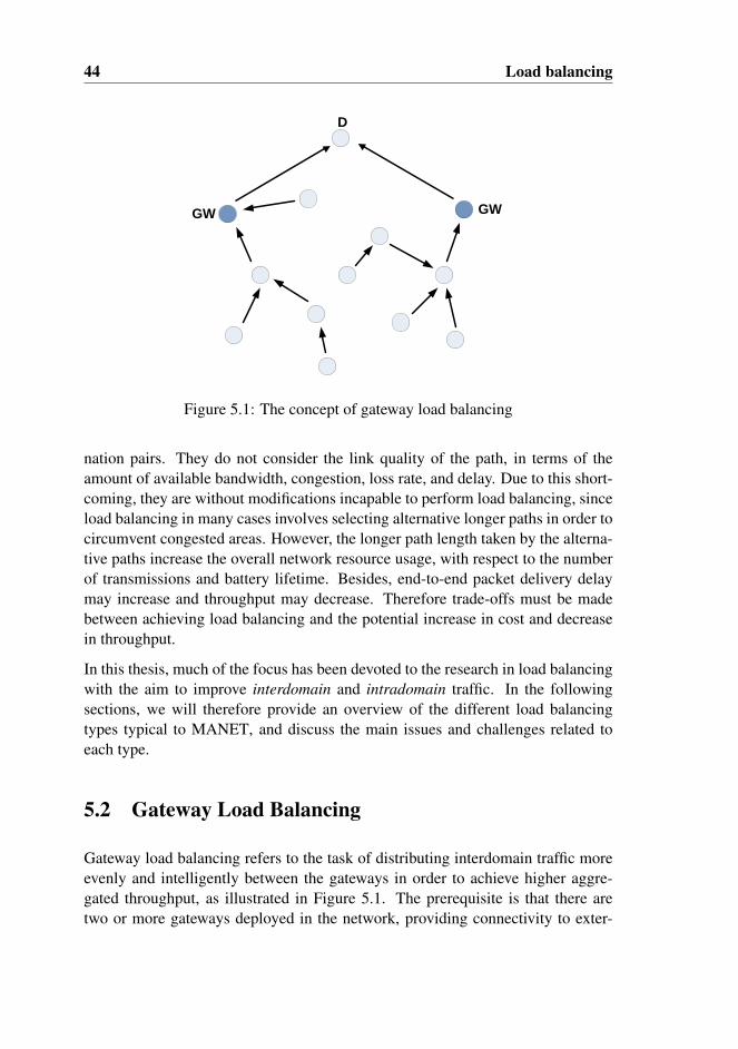
44 Load balancing
D
GW GW
Figure 5.1: The concept of gateway load balancing
nation pairs. They do not consider the link quality of the path, in terms of theamount of available bandwidth, congestion, loss rate, and delay. Due to this short-coming, they are without modifications incapable to perform load balancing, sinceload balancing in many cases involves selecting alternative longer paths in order tocircumvent congested areas. However, the longer path length taken by the alterna-tive paths increase the overall network resource usage, with respect to the numberof transmissions and battery lifetime. Besides, end-to-end packet delivery delaymay increase and throughput may decrease. Therefore trade-offs must be madebetween achieving load balancing and the potential increase in cost and decreasein throughput.
In this thesis, much of the focus has been devoted to the research in load balancingwith the aim to improve interdomain and intradomain traffic. In the followingsections, we will therefore provide an overview of the different load balancingtypes typical to MANET, and discuss the main issues and challenges related toeach type.
5.2 Gateway Load Balancing
Gateway load balancing refers to the task of distributing interdomain traffic moreevenly and intelligently between the gateways in order to achieve higher aggre-gated throughput, as illustrated in Figure 5.1. The prerequisite is that there aretwo or more gateways deployed in the network, providing connectivity to exter-
5.2. Gateway Load Balancing 45
nal network domains such as the global Internet. Since all interdomain traffic hasto traverse the gateway nodes, they are consequently more vulnerable to becomecongested. This why it is necessary to deploy multiple gateways in the networkin order to increase the overall capacity and to alleviate the probability for con-gestion. In addition, it also provides redundancy and increased robustness. If onegateway encounters failure, there are still others that can serve. Furthermore, itcan also lead to fairness improvement, i.e. with only one single gateway, differ-ent nodes enjoy different capacities depending on their proximity to the gateway.However, with multiple gateways, the average distance to the available gatewaysis the same for all nodes. This may therefore alleviate the unfairness problem [77].
Although the deployment of multiple gateways provides several advantages, how-ever, it also introduces a number of issues and challenges that need to be addressedeffectively in order to fully exploit these advantages. The authors in [77] provide adiscussion on these challenges as discussed below, and emphasize the importanceof performing load balancing between the gateways. Traditional shortest path rout-ing protocols lacks this functionality and may cause a gateway to be overloaded,while others may be strongly underutilized, either due to uneven node distributionor user demands. Hence, without proper load balancing there is a potential risk fora degradation in the performance.
CharacterizationPerforming gateway load balancing is essentially to select a default gateway inwhich interdomain traffic can be forwarded to. In order to make correct decisionsregarding which gateway to select as the default gateway, it is important to obtainstatistics on characteristics related to the gateways and nonetheless the paths to-wards these gateways. This can either be one of the following characteristics or acombination of them: the hop count, loss probability, end-to-end delay, throughputor the traffic load. The metrics discussed in Section 4.5 are the common methodsfor obtaining these characteristics. What needs to be considered when using thesemetrics is the accuracy of the metric and the incurred overhead. Every kind ofmeasurement is subject to some uncertainty, which can either come from the mea-surement instrument, the method being used, the environment, or other factors. Ina distributed network, each node must individually carry out the measurement onits own and disseminate the measured information throughout the network. Thisis important, since all nodes in the network must have the same view about thecondition of the network in order to distributedly and collaboratively perform loadbalancing in an efficient way. The dissemination of this information can either bedone reactively of proactively. The common approach for reactive routing proto-cols is to gather the necessary information during the route discovery process. Onthe other hand, with proactive routing protocols, the information is usually dissem-
46 Load balancing
inated periodically and typically piggy-backed together with the routing messages.This is for example demonstrated in paper D and E. One of the challenges here isthe unreliable nature of multihop wireless communication, which can potentiallyresult in loss of vital information. Alternatively, it can also results in severe delayvariations in the delivery of the information. These problems can be significantwhen the network load is high and when the dissemination is based on broad-casting, which is normally the case. Even with unicasting, it is not guaranteedthat all nodes will receive the measured information. Thus the uncertainty in thedissemination can result in inconsistent view of the traffic load in the network.Consequently, this can lead to non optimal or erroneous decisions and adverselyaffect the efficiency of load balancing.
Gateway selectionOnce the necessary statistics are obtained, the next issue to consider is which spe-cific gateway to select as default gateway. For outbound traffic, it is up to theoriginating node to decide to which gateway the traffic is forwarded to. For in-bound traffic, one possible solution is to let a master gateway as suggested in [77],to decide which slave gateway the traffic is forwarded to in order to achieve loadbalancing. The key parameters to consider when selecting default gateway arefirst of all the traffic load or available bandwidth at the gateways. Basically, theleast loaded gateway should be favored, while the most loaded should be avoided.The second parameter to consider is the distance in terms of hop length from thelocal node to the gateways. In general, a shorter path should be favored since itcan provide higher throughput, and has lower transmission cost and probability forend-to-end transmission failure. However, in cases where the nearest gateway isoverloaded, it may be beneficial to route traffic to an alternative less loaded gate-way, even though the distance is several hops longer away. The third parameterto consider is the characteristic of the paths towards the gateways. This may ei-ther be, the end-to-end delay, loss probability or bottleneck capacity. While thefirst parameter characterizes the condition at the gateways, the second and thirdparameters determine the characteristic of the paths towards the gateways. Thereare situations in which the first parameter favors one gateway while the second andthird may favor another. Thus, the gateway selection algorithm must consider thetrade-off between the parameters. The challenge is how to appropriately weightthe parameters in order to achieve an overall increase in performance.
Route flappingNormally, the gateway selection is performed distributedly where each node isresponsible for selecting its own default gateway. Without coordination in the en-deavor of distributing traffic more evenly, there is a potential risk for route flapping.In severe cases, a group of nodes may simultaneously and repeatedly reroute their
5.2. Gateway Load Balancing 47
traffic back and forth between two neighboring gateways. This is referred as thesynchronized rerouting problem and is discussed in more detail in paper E. The au-thors in [78] notice that it is very hard to maintain an absolute balance in the loaddistribution. Instead for a to aggressive approach in performing load balancing,care should be taken in order to avoid the ping pong effect. Besides, as the resultsin paper D show, it is not given that a perfectly even load distribution between thegateways will result in the most optimal performance. To alleviate the ping pongeffect, [78] proposes a load balancing scheme that triggers gateway selection onlywhen the measured load difference between two gateways exceeds a predefinedthreshold value. Alternatively, the authors in [79] propose a more centralized so-lution where a congested gateway may request one or more of its associated nodesto redirect their traffic to alternative less congested gateways.
Single vs Multiple Default GatewayA node may select one or multiple gateways as its default gateways. The advantageof multiple default gateways is the possibility for distributing traffic from a node toseveral of its selected gateways. This allows for increased flexibility and more fine-grained granularity in performing load balancing. A node can for example direct atraffic flow to one gateway while another flow is directed to another gateway. Foreven finer granularity, a node can split up its traffic at the packet-level and routeeach packet individually towards the selected gateways. However, the challengeis how to allocate the correct amount of traffic from each individual node to eachgateway. The authors in [80] argue that multiple default gateway architecture isvery complex and difficult to realize in practice, and therefore the usual approachis to use a single default gateway architecture.
Packet reorderingPerforming load balancing on multiple gateways can potentially cause packets toa single destination to traverse through different paths and gateways. This is espe-cially true if the multiple default gateway architecture is used. The consequence ishowever that packets may arrive at the end destination in an out of order fashion.Hence, a packet reordering scheme is needed in order to ensure a FIFO delivery atthe end destination. A possible solution to solve this is to use a master-gateway asmentioned earlier. The master gateway serves as an aggregation point or distribu-tion center for interdomain traffic, and is responsible for collecting and reorderinginbound/outbound packets such that they can be forwarded in the correct order.
The research in gateway load balancing is a central part in this thesis. The workin paper D and E is an effort to solve some of the issues and challenges discussedabove in order to bring forth efficient schemes for performing gateway load balanc-ing. In particular, the focus has been aimed at solving the main issues that are vitalto the realization of such a scheme which include characterization, gateway selec-
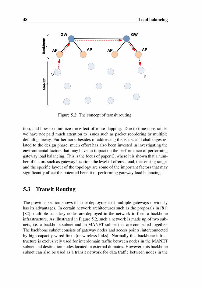
48 Load balancing
S
GW GW
AP AP AP AP
D
MA
NE
TB
ac
kb
on
e
Figure 5.2: The concept of transit routing.
tion, and how to minimize the effect of route flapping. Due to time constraints,we have not paid much attention to issues such as packet reordering or multipledefault gateway. Furthermore, besides of addressing the issues and challenges re-lated to the design phase, much effort has also been invested in investigating theenvironmental factors that may have an impact on the performance of performinggateway load balancing. This is the focus of paper C, where it is shown that a num-ber of factors such as gateway location, the level of offered load, the sensing range,and the specific layout of the topology are some of the important factors that maysignificantly affect the potential benefit of performing gateway load balancing.
5.3 Transit Routing
The previous section shows that the deployment of multiple gateways obviouslyhas its advantages. In certain network architectures such as the proposals in [81][82], multiple such key nodes are deployed in the network to form a backboneinfrastructure. As illustrated in Figure 5.2, such a network is made up of two sub-nets, i.e. a backbone subnet and an MANET subnet that are connected together.The backbone subnet consists of gateway nodes and access points, interconnectedby high capacity wired links (or wireless links). Normally this backbone infras-tructure is exclusively used for interdomain traffic between nodes in the MANETsubnet and destination nodes located in external domains. However, this backbonesubnet can also be used as a transit network for data traffic between nodes in the
5.4. Multipath Load Balancing 49
MANET as demonstrated in [83]. This has several advantages as discussed below:
• By routing part of the intradomain traffic over the high-capacity backbonesubnet, the traffic load in the MANET subnet can be alleviated. Thus wemay regard transit routing as a kind of load balancing for intradomain traffic.
• For certain source and destination pairs in the MANET subnet, e.g. in thecase from S to D, transit routing makes it possible to achieve a considerablyhigher end-to-end throughput, since the wired backbone has much higherbandwidth than wireless links in the MANET.
• Transit routing also provides a higher probability for successful transmis-sions, since the wired links are much more reliable compared to wirelesslinks.
• Wireless communication over multihop is often error prone and instable. Byrouting over the more reliable wired backbone, it is easier to maintain a morestable traffic stream between mobile nodes separated by many hops.
In order to support transit routing, there are a number of issues and challengesthat need to be addressed. Many of these issues and challenges are common tothe case of gateway load balancing, which include characterization, selection ofdefault gateways/access points, traffic allocation, packet reordering etc. The mainchallenge is however to complement the routing protocol with the functionalityfor transit routing. Most MANET routing protocols such as OLSR or AODV areby default based on the shortest path metric, and as discussed previously, withoutmodifications they are incapable of performing advanced tasks as transit routing,since it in many cases incur routing over longer path. To determine whether it isbeneficial to perform transit routing or not for a certain source and destination pair,the routing protocol basically needs to consider the cost Ci for routing the trafficover the “ad hoc” path (i.e. internally within the MANET subnet), and the costCii for the “wired path” (i.e. over the wired backbone subnet). The cost metricalgorithm must be designed such that transit routing is favored only in situationswhen there is a potential benefit in terms of increased throughput and/or reducedtraffic load in the MANET. The work in Paper B is an effort to address this issue,where the focus is to investigate the situations in which transit routing is benefi-cial or not, and thereby develop an appropriate cost metric algorithm in order tofacilitate transit routing. A more detailed description of our work related to transitrouting can be found in Section 6.3 and in Paper B.

50 Load balancing
S D
Figure 5.3: The concept of multipath load balancing
5.4 Multipath Load Balancing
Multipath routing is a routing approach that allows for load balancing of intrado-main traffic, and therefore it is also called multipath load balancing. The conceptis to distribute the traffic between a source and destination pair over multiple al-ternative disjoint/semi-disjoint paths as illustrated in Figure 5.3. Alternatively,multipath routing can also be used for other objectives such as to increase the re-liability and confidentiality of data transmission, optimize energy consumption inthe network, and to improve QoS in the network. A considerable number of previ-ous work have investigated and proposed different schemes for multipath routing.The study in [84] provides an overview of the diversity of multipath routing proto-cols for MANETs. The majority of these proposals are based on reactive routingprotocols such as AODV and Dynamic Source Routing (DSR), since the reactiveapproach provides an easier way to discover all possible disjoint paths between asource and destination pair.
Although the concept of multipath routing may contribute to improved perfor-mance, there are a number of issues and challenges that need to be considered asdiscussed in [85] and [84]. One of the issues is related to route discovery androute maintenance. These tasks are generally more costly to perform in terms ofoverhead and storage in multipath than in single path routing protocols. Further-more, in sparse networks it can be difficult to find multiple disjoint paths (eithernode or link disjoint). Even in densed networks the number of node disjoint pathsmay be limited. Disjoint paths offer certain advantages over non-disjoint paths.For instance, non-disjoint paths are less resilient against link breaks and may havelower aggregate throughput. Another issue is related to route selection. If there aremultiple paths between the source and the destination, the question is how manyof these paths should be used for data transmission. One may either select all thepaths or a subset of them, and the paths may be selected based on certain criteria

5.4. Multipath Load Balancing 51
such as link quality, delay, and bandwidth in order to achieve optimization. Oncethe source node has selected the paths, it must also decide how to allocate trafficto these paths. Traffic allocation may be performed at different granularity. Forinstance, a per-connection granularity can be used to allocate all traffic from oneconnection to a single path. Alternatively, a more fine-grained per-packet granu-larity may be used to distribute packets from a connection amongst the selectedpaths. It is reported that per-packet granularity results in the best performancesince it allows for fine tuning of the traffic distribution in the network [86]. How-ever, the disadvantage of the per-packet granularity is the increased risk for packetreordering at the destination. The last issue is when to trigger route discovery. Itcan either be triggered each time one of the paths is broken or only when all pathsare broken. The first may incur a considerable amount of control traffic overheadwhile the latter may result in performance degradation. A possible good compro-mise may be to initiate route discovery when a certain percentage of the paths arebroken.
With respect to performing load balancing, previous work have proposed differ-ent multipath load balancing schemes in order to maximize throughput, and at thesame time minimize packet delay and route failure. Multipath load balancing hasproven to be efficient in wired networks [86] [87] [88] [89], however, the sameeffect is difficult to achieve in wireless networks. In contradiction to wired net-works, the challenge with multipath load balancing in wireless networks is theinterfering nature of the wireless medium. The interference that occurs among thepaths limits the achievable gain in performance. The work in [1] refers to thisinterference as route coupling, and showed that this problem is especially severein single channel networks. They showed that the performance gains provided bymultipath load balancing is only negligible compared to single path routing. Routecoupling is less severe in multi-channel networks, due to locally unique channel as-signments. However, they showed through simulation results that route couplingstill exists even in multi-channel networks. Furthermore, by routing over morespatially separated paths, the effect of route coupling is reduced since the level ofspatial reuse is consequently higher. However, this often requires that the traffic isrouted over longer paths in terms of hop count, causing more network resourcesto be consumed. The results in [2] also confirmed the conclusion above. Theyshowed through analysis and simulations that the gain provided by multipath loadbalancing is negligible unless the traffic is distributed over a huge number of paths.Based on these reports, multipath load balancing has therefore not been consideredin this thesis.

52 Load balancing

Chapter 6
Summary and Contributions
6.1 Summary of the Work
The work in this thesis addresses two selected issues in the context of ad hocnetwork for emergency and rescue operations, i.e. mobility and load balancing.The aim is to investigate the shortcomings of current solutions with respect to theseissues, and bring forth new solutions to improve the performance of the networkas a whole or for the individual nodes. Thus, our work can be regarded as an efforton the way to realize an emergency and rescue communication system based onthe ad hoc network technology. While the work in paper A addresses the issue ofmobility, paper B to E address the issue of performing load balancing.
With respect to the issue of mobility, the focus is to investigate the factors thataffect the rerouting time in proactive routing protocols. That is, the time durationneeded to reroute and restore a broken communication path due to node mobility.The aim is to provide solutions for minimizing the rerouting time such that thepacket loss can be minimized and the performance in the network is maximized.As previously discussed in Section 4.4, the rerouting time can be reduced by re-ducing the link break detection time, for example by applying alternative methodsfor link break detection such as the Fast-OLSR scheme or the link layer feedbackmechanism. However, the drawback is that these solutions either incur increasedcontrol traffic overhead or the potential for erroneously declaring a link as invalid.The work in paper A shows that besides the impact of the link break detectionmechanism, other factors such as the queue length, the input packet rate and the re-transmission limit at the MAC-sublayer can affect the rerouting time significantly.To solve the rerouting time with respect to these factors, either the queue length
53
54 Summary and Contributions
or the number of retransmissions can be reduced. The problem with reducing thequeue length is the potential risk for packet loss due to buffer overflow at higherpacket rates. Therefore, paper A proposes a solution based on Adaptive retry limit,where the retransmission mechanism at the MAC-sublayer is gradually decreasedin the event of a link break. The reason for this is to minimize the number oftransmissions wasted on stale packets, i.e. packets with invalid next hop address.Simulation results show that the proposed solution is very effective. In fact, aslong as the data rate into the queue is safely below the capacity of the MAC, thesolution eliminates the queueing problem associated with the rerouting time.
With respect to the issue of load balancing, the focus is to investigate and ex-plore the feasibility as well as the potential benefits of performing load balancingin MANETs. The aim is to bring forth solutions that can optimize the usage ofnetwork resources and to improve the network performance in terms of increasedthroughput.
The work in paper B addresses load balancing for intradomain traffic. The assump-tion behind this work is that there exists a wired high capacity backbone subnet partof a MANET. Traditionally, such a backbone subnet is exclusively used to provideInternet connectivity to wireless nodes and to extend coverage area. However, thework in paper B demonstrates that it is also possible to exploit the capacity of thisbackbone subnet to alleviate the load in the MANET. This is achieved by rout-ing part of the intradomain traffic, i.e. traffic between nodes in a MANET, overthe backbone subnet. We refer to this kind of load balancing as transit routing.Transit routing does not only allow for load balancing, but for certain source anddestination pairs, the throughput can also be considerably increased. Paper B thusproposes a cost metric algorithm in order to facilitate transit routing. This algo-rithm is designed to commence transit routing only when appropriate. This meansthat when there is a performance gain in terms of throughput by using the alter-native path through the backbone subnet, the cost metric algorithm will favor thispath. Simulation results show that by using the concept of transit routing, it ispossible to enhance the throughput by 50% on the simulated topologies.
The work in paper C to E addresses load balancing for interdomain traffic. Theassumption is that there exist multiple gateways in the network that provide con-nectivity to external network domains, such as the global Internet. The advantageof having multiple gateways in the network is among others the increased capacityfor interdomain traffic. To exploit and optimize the usage of the increased capacity,gateway load balancing needs to be performed in order to distribute interdomaintraffic between the gateways more evenly. This is a rather challenging task espe-cially when talking about wireless networks. Thus the work in paper C investigatesthe feasibility of performing gateway load balancing and explores the factors that
6.1. Summary of the Work 55
affect the potential gain of it. It is shown that a number of factors can affect theefficiency of load balancing as listed below:
• Level of asymmetry
• Offered load
• Level of spatial reuse
• Sensing range
• Shape and size of the network
• Location of gateways
However, these factors alone cannot explain why the performance of load balanc-ing is high for certain topologies while it is poor for others. Obviously, the specificlayout of the topology is also an important factor.
The work in Paper D therefore focuses on investigating the importance of the lay-out of a topology. Using the congestion maps, a number of interesting character-istics are discovered, which contributes to explain why the layout of the topologyhas significant impact on the performance of load balancing. Based on these re-sults, two different load balancing schemes are proposed in Paper D and E. Theseschemes demonstrate that radio load information can be used to perform load bal-ancing in MANETs. The load balancing scheme in Paper D is based on a deter-ministic gateway selection algorithm, and is proven to perform well for topologieswith higher asymmetry level (with respect to node distribution and traffic load).However, for moderate asymmetry level, simulation results show that the solutionis inefficient. This is due to what we refer to as the synchronized rerouting prob-lem, and is in fact a consequence of the distributed nature of MANETs. Thus thefocus in paper E is to solve this problem by applying a randomized gateway selec-tion approach instead of a deterministic approach as is previously done in paper D.In addition to performing load balancing, the proposed scheme in paper E also per-forms admission control in order to prevent the network load in reaching a criticalhigh level. Simulation results show that the new scheme is indeed more efficientthan the scheme in paper D.
The work in all the above papers is tightly related to the preceding chapters. TheIEEE 802.11 MAC-sublayer and the OLSR routing protocol presented in Chapter 3and Chapter 4 represent the two fundamental technologies that are used throughoutthe work in this thesis. IEEE 802.11 is the dominating technology in the researchrelated to ad hoc networks. OLSR is one of the most popular proactive routingprotocols for MANET, and it is a natural choice in our research due to several rea-sons. First, an implementation of OLSR exists for the ns-2 simulator. Second, the
56 Summary and Contributions
advantage of using a proactive routing protocol is that it can quickly and dynam-ically adjust or rebalance traffic load to the changing conditions in the network.Third, routing metric parameters can be easily integrated with the routing protocolin order to achieve QoS routing.
Finally, the proposed solutions in our papers involve modifications or the integra-tion of new mechanisms into these protocols. The Adaptive retry limit solutionin paper A is an example of such a modification to the MAC-sublayer in orderto reduce the rerouting time. In addition, paper D and E demonstrate how theMAC-sublayer can be modified to provide radio load information to the routinglayer. Similarly, the work in paper B, D and E, show that with new functionality,it is possible to increase network performance through transit routing and gatewayload balancing.
6.2 Contribution of paper A: Rerouting Time and Queu-ing in Proactive Ad Hoc Networks
One of the features that characterize a MANET is that nodes are allowed to bemobile. Due to mobility, established links may be broken, and new links may beformed with new neighbors. This process of link breaks and formation of newlinks happens frequently if the level of mobility is high. While transmitting data, asudden link break will interrupt the forwarding of packets to the intended receiver.The routing protocol is designed to find alternative routes in these situations. How-ever, this rerouting takes times, and the latency of the rerouting is referred as thererouting time. Paper A investigates the factors that affect the rerouting time inproactive routing protocols.
6.2.1 Related Work
The work in [90] has previously investigated and compared various neighbor sens-ing approaches for OLSR: the original Hello based link sensing of OLSR, Fast-OLSR and OLSR with link layer feedback (OLSR-LL). They notice that during alink break caused by mobility, the accumulation of stale packets (i.e. packets withinvalid next hop addresses) in the interface queue is one of the reasons leadingto the deterioration of the performance. However, they do not provide any fur-ther analysis on why this accumulation occurs and the factors that are behind thisincident.
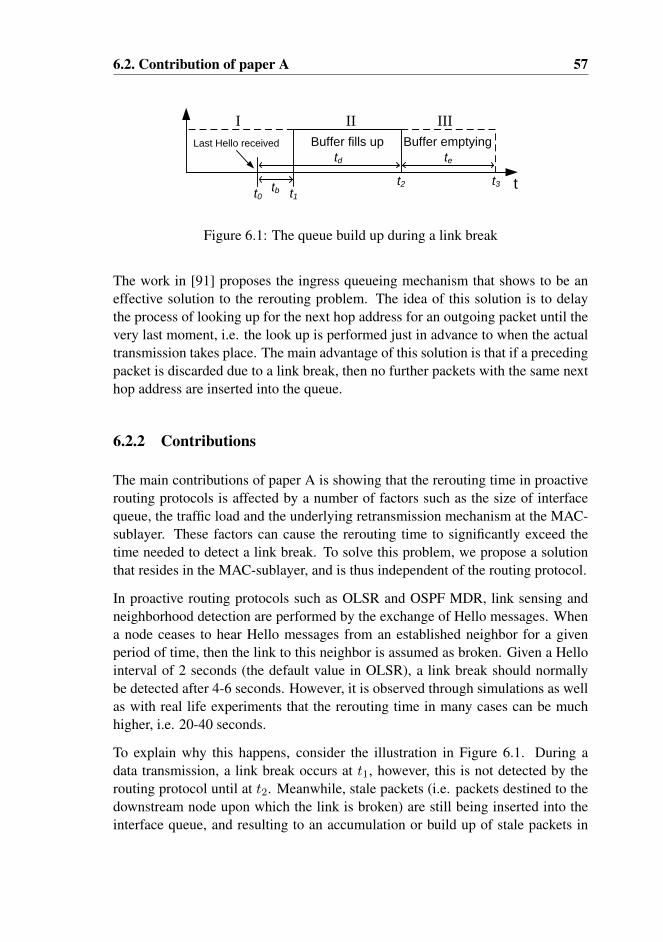
6.2. Contribution of paper A 57
Buffer fills up Buffer emptying
t
Last Hello received
t0 t1t2 t3
I II III
td te
tb
Figure 6.1: The queue build up during a link break
The work in [91] proposes the ingress queueing mechanism that shows to be aneffective solution to the rerouting problem. The idea of this solution is to delaythe process of looking up for the next hop address for an outgoing packet until thevery last moment, i.e. the look up is performed just in advance to when the actualtransmission takes place. The main advantage of this solution is that if a precedingpacket is discarded due to a link break, then no further packets with the same nexthop address are inserted into the queue.
6.2.2 Contributions
The main contributions of paper A is showing that the rerouting time in proactiverouting protocols is affected by a number of factors such as the size of interfacequeue, the traffic load and the underlying retransmission mechanism at the MAC-sublayer. These factors can cause the rerouting time to significantly exceed thetime needed to detect a link break. To solve this problem, we propose a solutionthat resides in the MAC-sublayer, and is thus independent of the routing protocol.
In proactive routing protocols such as OLSR and OSPF MDR, link sensing andneighborhood detection are performed by the exchange of Hello messages. Whena node ceases to hear Hello messages from an established neighbor for a givenperiod of time, then the link to this neighbor is assumed as broken. Given a Hellointerval of 2 seconds (the default value in OLSR), a link break should normallybe detected after 4-6 seconds. However, it is observed through simulations as wellas with real life experiments that the rerouting time in many cases can be muchhigher, i.e. 20-40 seconds.
To explain why this happens, consider the illustration in Figure 6.1. During adata transmission, a link break occurs at t1, however, this is not detected by therouting protocol until at t2. Meanwhile, stale packets (i.e. packets destined to thedownstream node upon which the link is broken) are still being inserted into theinterface queue, and resulting to an accumulation or build up of stale packets in
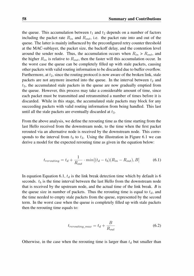
58 Summary and Contributions
the queue. This accumulation between t1 and t2 depends on a number of factorsincluding the packet rate Rin and Rout, i.e. the packet rate into and out of thequeue. The latter is mainly influenced by the preconfigured retry counter thresholdat the MAC-sublayer, the packet size, the backoff delay, and the contention levelaround the sender node. Thus, the accumulation occurs when Rin > Rout, andthe higher Rin is relative to Rout, then the faster will this accumulation occur. Inthe worst case the queue can be completely filled up with stale packets, causingother packets with valid routing information to be discarded due to buffer overflow.Furthermore, at t2, since the routing protocol is now aware of the broken link, stalepackets are not anymore inserted into the queue. In the interval between t2 andt3, the accumulated stale packets in the queue are now gradually emptied fromthe queue. However, this process may take a considerable amount of time, sinceeach packet must be transmitted and retransmitted a number of times before it isdiscarded. While in this stage, the accumulated stale packets may block for anysucceeding packets with valid routing information from being handled. This lastuntil all the stale packets are eventually discarded at t3.
From the above analysis, we define the rerouting time as the time starting from thelast Hello received from the downstream node, to the time when the first packetrerouted via an alternative node is received by the downstream node. This corre-sponds to the interval from t0 to t3. Using the illustration in Figure 6.1 we canderive a model for the expected rerouting time as given in the equation below:
trerouting = td +1
Rout·min[(td − tb)(Rin −Rout), B] (6.1)
In equation Equation 6.1, td is the link break detection time which by default is 6seconds. tb is the time interval between the last Hello from the downstream nodethat is received by the upstream node, and the actual time of the link break. B isthe queue size in number of packets. Thus the rerouting time is equal to td, andthe time needed to empty stale packets from the queue, represented by the secondterm. In the worst case when the queue is completely filled up with stale packetsthen the rerouting time equals to:
trerouting_max = td +B
Rout(6.2)
Otherwise, in the case when the rerouting time is larger than td but smaller than
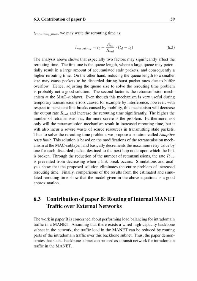
6.3. Contribution of paper B 59
trerouting_max, we may write the rerouting time as:
trerouting = tb +Rin
Rout· (td − tb) (6.3)
The analysis above shows that especially two factors may significantly affect thererouting time. The first one is the queue length, where a large queue may poten-tially result in a large amount of accumulated stale packets, and consequently ahigher rerouting time. On the other hand, reducing the queue length to a smallersize may cause packets to be discarded during burst packet rates due to bufferoverflow. Hence, adjusting the queue size to solve the rerouting time problemis probably not a good solution. The second factor is the retransmission mech-anism at the MAC-sublayer. Even though this mechanism is very useful duringtemporary transmission errors caused for example by interference, however, withrespect to persistent link breaks caused by mobility, this mechanism will decreasethe output rate Rout and increase the rerouting time significantly. The higher thenumber of retransmission is, the more severe is the problem. Furthermore, notonly will the retransmission mechanism result in increased rerouting time, but itwill also incur a severe waste of scarce resources in transmitting stale packets.Thus to solve the rerouting time problem, we propose a solution called Adaptiveretry limit. This solution is based on the modifications of the retransmission mech-anism at the MAC-sublayer, and basically decrements the maximum retry value byone for each discarded packet destined to the next hop node upon which the linkis broken. Through the reduction of the number of retransmissions, the rate Rout
is prevented from decreasing when a link break occurs. Simulations and anal-ysis show that the proposed solution eliminates the entire problem of increasedrerouting time. Finally, comparisons of the results from the estimated and simu-lated rerouting time show that the model given in the above equations is a goodapproximation.
6.3 Contribution of paper B: Routing of Internal MANETTraffic over External Networks
The work in paper B is concerned about performing load balancing for intradomaintraffic in a MANET. Assuming that there exists a wired high-capacity backbonesubnet in the network, the traffic load in the MANET can be reduced by routingparts of the intradomain traffic over this backbone subnet. Thus, the paper demon-strates that such a backbone subnet can be used as a transit network for intradomaintraffic in the MANET.
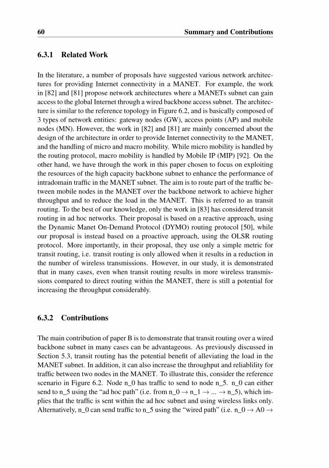
60 Summary and Contributions
6.3.1 Related Work
In the literature, a number of proposals have suggested various network architec-tures for providing Internet connectivity in a MANET. For example, the workin [82] and [81] propose network architectures where a MANETs subnet can gainaccess to the global Internet through a wired backbone access subnet. The architec-ture is similar to the reference topology in Figure 6.2, and is basically composed of3 types of network entities: gateway nodes (GW), access points (AP) and mobilenodes (MN). However, the work in [82] and [81] are mainly concerned about thedesign of the architecture in order to provide Internet connectivity to the MANET,and the handling of micro and macro mobility. While micro mobility is handled bythe routing protocol, macro mobility is handled by Mobile IP (MIP) [92]. On theother hand, we have through the work in this paper chosen to focus on exploitingthe resources of the high capacity backbone subnet to enhance the performance ofintradomain traffic in the MANET subnet. The aim is to route part of the traffic be-tween mobile nodes in the MANET over the backbone network to achieve higherthroughput and to reduce the load in the MANET. This is referred to as transitrouting. To the best of our knowledge, only the work in [83] has considered transitrouting in ad hoc networks. Their proposal is based on a reactive approach, usingthe Dynamic Manet On-Demand Protocol (DYMO) routing protocol [50], whileour proposal is instead based on a proactive approach, using the OLSR routingprotocol. More importantly, in their proposal, they use only a simple metric fortransit routing, i.e. transit routing is only allowed when it results in a reduction inthe number of wireless transmissions. However, in our study, it is demonstratedthat in many cases, even when transit routing results in more wireless transmis-sions compared to direct routing within the MANET, there is still a potential forincreasing the throughput considerably.
6.3.2 Contributions
The main contribution of paper B is to demonstrate that transit routing over a wiredbackbone subnet in many cases can be advantageous. As previously discussed inSection 5.3, transit routing has the potential benefit of alleviating the load in theMANET subnet. In addition, it can also increase the throughput and reliablility fortraffic between two nodes in the MANET. To illustrate this, consider the referencescenario in Figure 6.2. Node n_0 has traffic to send to node n_5. n_0 can eithersend to n_5 using the “ad hoc path” (i.e. from n_0→ n_1→ ...→ n_5), which im-plies that the traffic is sent within the ad hoc subnet and using wireless links only.Alternatively, n_0 can send traffic to n_5 using the “wired path” (i.e. n_0→ A0→

6.3. Contribution of paper B 61
Internet
n_0 n_5
A0 A1 A2 A3
GW0 GW1
n_12
n_18
n_17
n_23
n_1 n_2 n_3 n_4
n_6 n_7 n_8 n_9 n_10 n_11
n_13 n_14 n_15 n_16
n_19 n_20 n_21 n_22
Figure 6.2: Example of a MANET interconnected with the global Internet throughAPs and GWs
... → A3→ n_5) which goes over the backbone subnet. A packet sent over the adhoc path requires 5 successive wireless transmissions. On the other hand, sendig apacket over the wired path, requires “1+1” wireless transmissions (i.e. 2 non suc-cessive and distinct wireless transmissions), and 3 wired transmissions. Assumingthat the bandwidth of wired links is much higher, it is obvious that using the wiredpath is much more advantageous than the ad hoc path. Besides, wired links donot suffer from self-interference problems as is the case with wireless links, andthis is also the reason why the max throughput over wireless links decreases withincreasing number of hops. In fact, simulation shows that using the wired path forthe example above results in a throughput that is more than four times higher thanthe throughput of the ad hoc path. Thus the example shows that transit routingnot only can reduce the load in the ad hoc subnet, but also improve the throughputsignificantly.
Based on extensive simulations and analyses, we have proposed a cost metric al-gorithm to facilitate transit routing. This cost metric algorithm is designed to com-mence transit routing only when it is beneficial for the performance, either for theMANET or for the individual nodes. For the further discussion, let us considerFigure 6.3, which is a simplification and generalization of the scenario in Fig-ure 6.2. Assume that A is the source which has some data packets to send to B.

62 Summary and Contributions
AP_a
A
AP_b
B
m n
k
l
Figure 6.3: Transit routing scenario
The distance in number of hops from A to the nearest access point of A, which isAP_a, is m hops. Similarly, the distance from B to its nearest access point AP_bis n hops. The distance between A and B is k hops through the “ad hoc path”. Thedistance from AP_a to AP_b through the backbone subnet is l hops. Node A canthus send its data packets either through the ad hoc path using k wireless hops, oralternatively it can send the traffic via the “wired path”, i.e. through the backbonesubnet and then to node B, using m+n wireless hops and l wired hops.
In order to determine whether it is beneficial to utilize the ad hoc or wired path,a cost is calculated for each path. In the following, a brief description of the costmetric algorithm is given. A more detailed description can be found in paper B.The cost Ci for the wireless path is given in Equation 6.4, which is equal to thenumber of wireless hops k. The cost Cii for the wired path comes in two flavors,depending on whether the section m and n are interfering with each other or not.For the case without interference, the cost is given in Equation 6.5. On the otherhand, for the case with interference, the cost is given Equation 6.6. c is a constantwhich accounts for the bandwidth ratio between the wired and the wireless link.The essential point with respect to the costCii is that without interference, the maxthroughput of the wired path is constrained by the wireless section that containsmost hops, i.e. max(m,n). On the other hand, with interference, the max through-put of wired path is lower and is determined by the sum of m and n. Transit routingis thus most optimal when section m and n are not interfering with each other suchthat the highest throughput can be achieved.
Ci = k (6.4)

6.4. Contribution of paper C 63
Cii(no interference) = max(m,n) + c (6.5)
Cii(interference) = sum(m,n) + c (6.6)
Having calculated the cost for both paths, the algorithm below decides which paththat should be selected, i.e. the path with lowest cost (lines 4-7). The parameterg in line 1 is a preconfigured parameter that determines the “greediness” of thealgorithm. For example, if we want to limit transit routing only to cases wherethe wired path, at most, incur one additional hop compared to the ad hoc path, i.e.when “m+n” ≤ k+1, then g is set to 1. The purpose of this parameter is to controlthe accepted amount of extra load on the ad hoc subnet in exchange of a higherthroughput using the wired path.
1 if ((m+n)-k > g) #g= 0,1,22 ad_hoc_path3 else4 if (Cii < Ci)5 wired_path6 else7 ad_hoc_path
The cost metric algorithm above is evaluated by simulations on three differentrandom topologies. By using the transit routing, the results show that the averageenhancement in throughput for all three simulations is approximately 50 %.
6.4 Contribution of paper C: Performance Analysis ofGateway Load Balancing in Ad Hoc Networks withRandom Topologies
In MANETs or WMNs, a gateway is a node that provides connectivity to the out-side world such as the global Internet. Since all interdomain traffic has to traversethe gateway, it is vulnerable to congestion and become a bottleneck. To alleviatethis problem, the common solution is to deploy multiple gateways in the network.However, in order to take advantage of the increased capacity provided by multi-ple gateways, the routing protocol utilized must efficiently balance the traffic loadamong available gateways such that the network performance is optimized. This isreferred to as gateway load balancing, and is previously discussed in Section 5.2.

64 Summary and Contributions
GW0 GW1
A B C
1400m
800m
Figure 6.4: The reference network model.
6.4.1 Related Work
In the literature, a number of work have previously addressed the issue of gate-way load balancing, and a corresponding number of load balancing schemes havebeen proposed [79] [93] [78] [94]. However, to the best of our knowledge, nonehave made a study under the condition that the topology is random. Very of-ten, the topologies used in the evaluation are either very simple, consisting of afew nodes, or they are constructed in “unnatural” grid formations of various sizes.Hence, these topologies cannot be regarded as representative topologies from thereal world. They are rather simplified examples to illustrate the feasibility of theconcepts in a given setting. Consequently, it is questionable if these results arequalified to validate the actual performance of their proposals in a real and randomsetting.
6.4.2 Contributions
Due to the shortcomings discussed above, it is reasonable to question the fea-sibility of performing load balancing in a wireless and interfering environment.Furthermore, if feasible, to which extent does load balancing improve the networkperformance, and what are the factors that may set an upper limit for the perfor-mance that can be achieved? Thus, the contributions in paper C is concerned aboutfinding the answers to these questions based on simulations with a large numberof random topologies.
In this study, the default scenario used in most of the simulations is as shown inFigure 6.4. The network spans over an area of 1400 m by 800 m, and consists oftwo gateways (GW) and 50 randomly deployed nodes (not shown in the figure).The GWs are symmetrically placed at fixed locations inside the network area, andby default, the distance between the two GWs is 1000 m as shown in Figure 6.4.The aim is to study to which extent it is possible to improve the performance for
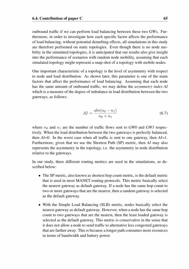
6.4. Contribution of paper C 65
outbound traffic if we can perform load balancing between these two GWs. Fur-thermore, in order to investigate how each specific factor affects the performanceof load balancing, without potential disturbing effects, all simulations in this studyare therefore performed on static topologies. Even though there is no node mo-bility in the simulated topologies, it is anticipated that our results also give insightinto the performance of scenarios with random node mobility, assuming that eachsimulated topology might represent a snap-shot of a topology with mobile nodes.
One important characteristic of a topology is the level of asymmetry with respectto node and load distribution. As shown later, this parameter is one of the mainfactors that affect the performance of load balancing. Assuming that each nodehas the same amount of outbound traffic, we may define the asymmetry index AIwhich is a measure of the degree of imbalance in load distribution between the twogateways, as follows:
AI =abs(n0 − n1)n0 + n1
(6.7)
where n0 and n1 are the number of traffic flows sent to GW0 and GW1 respec-tively. When the load distribution between the two gateways is perfectly balanced,then AI=0. In the worst case when all traffic is sent to one gateway, then AI=1.Furthermore, given that we use the Shortest Path (SP) metric, then AI may alsorepresents the asymmetry in the topology, i.e. the asymmetry in node distributionrelative to the gateways.
In our study, three different routing metrics are used in the simulations, as de-scribed below:
• The SP metric, also known as shortest hop count metric, is the default metricthat is used in most MANET routing protocols. This metric basically selectthe nearest gateway as default gateway. If a node has the same hop count totwo or more gateways that are the nearest, then a random gateway is selectedas the default gateway.
• With the Simple Load Balancing (SLB) metric, nodes basically select thenearest gateway as default gateway. However, when a node has the same hopcount to two gateways that are the nearest, then the least loaded gateway isselected as the default gateway. This metric is conservative in the sense thatit does not allow a node to send traffic to alternative less congested gatewaysthat are farther away. This is because a longer path consumes more resourcesin terms of bandwidth and battery power.
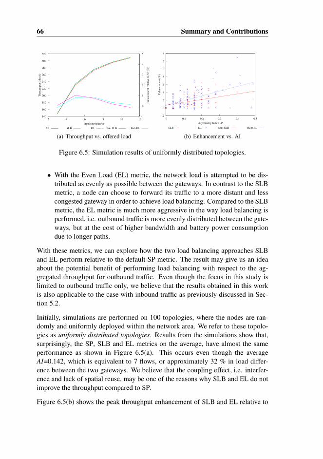
66 Summary and Contributions
140
160
180
200
220
240
260
280
300
320
2 4 6 8 10 12-1
0
1
2
3
4
5
Thro
ughput
(pkts
/s)
Enhan
cem
ent
rela
tive
to S
P (
%)
Input rate (pkts/s)
SP SLB EL Enh.SLB Enh.EL
(a) Throughput vs. offered load
-2
0
2
4
6
8
10
12
14
0 0.1 0.2 0.3 0.4 0.5
En
han
cem
ent
(%)
Asymmetry Index SP
SLB EL Regr.SLB Regr.EL
(b) Enhancement vs. AI
Figure 6.5: Simulation results of uniformly distributed topologies.
• With the Even Load (EL) metric, the network load is attempted to be dis-tributed as evenly as possible between the gateways. In contrast to the SLBmetric, a node can choose to forward its traffic to a more distant and lesscongested gateway in order to achieve load balancing. Compared to the SLBmetric, the EL metric is much more aggressive in the way load balancing isperformed, i.e. outbound traffic is more evenly distributed between the gate-ways, but at the cost of higher bandwidth and battery power consumptiondue to longer paths.
With these metrics, we can explore how the two load balancing approaches SLBand EL perform relative to the default SP metric. The result may give us an ideaabout the potential benefit of performing load balancing with respect to the ag-gregated throughput for outbound traffic. Even though the focus in this study islimited to outbound traffic only, we believe that the results obtained in this workis also applicable to the case with inbound traffic as previously discussed in Sec-tion 5.2.
Initially, simulations are performed on 100 topologies, where the nodes are ran-domly and uniformly deployed within the network area. We refer to these topolo-gies as uniformly distributed topologies. Results from the simulations show that,surprisingly, the SP, SLB and EL metrics on the average, have almost the sameperformance as shown in Figure 6.5(a). This occurs even though the averageAI=0.142, which is equivalent to 7 flows, or approximately 32 % in load differ-ence between the two gateways. We believe that the coupling effect, i.e. interfer-ence and lack of spatial reuse, may be one of the reasons why SLB and EL do notimprove the throughput compared to SP.
Figure 6.5(b) shows the peak throughput enhancement of SLB and EL relative to
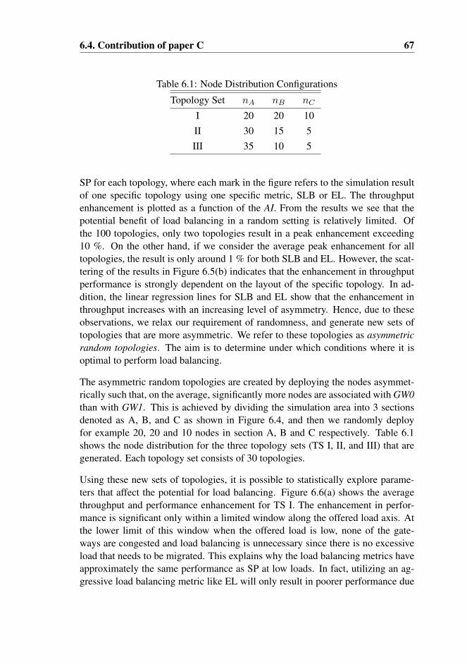
6.4. Contribution of paper C 67
Table 6.1: Node Distribution Configurations
Topology Set nA nB nC
I 20 20 10II 30 15 5III 35 10 5
SP for each topology, where each mark in the figure refers to the simulation resultof one specific topology using one specific metric, SLB or EL. The throughputenhancement is plotted as a function of the AI. From the results we see that thepotential benefit of load balancing in a random setting is relatively limited. Ofthe 100 topologies, only two topologies result in a peak enhancement exceeding10 %. On the other hand, if we consider the average peak enhancement for alltopologies, the result is only around 1 % for both SLB and EL. However, the scat-tering of the results in Figure 6.5(b) indicates that the enhancement in throughputperformance is strongly dependent on the layout of the specific topology. In ad-dition, the linear regression lines for SLB and EL show that the enhancement inthroughput increases with an increasing level of asymmetry. Hence, due to theseobservations, we relax our requirement of randomness, and generate new sets oftopologies that are more asymmetric. We refer to these topologies as asymmetricrandom topologies. The aim is to determine under which conditions where it isoptimal to perform load balancing.
The asymmetric random topologies are created by deploying the nodes asymmet-rically such that, on the average, significantly more nodes are associated with GW0than with GW1. This is achieved by dividing the simulation area into 3 sectionsdenoted as A, B, and C as shown in Figure 6.4, and then we randomly deployfor example 20, 20 and 10 nodes in section A, B and C respectively. Table 6.1shows the node distribution for the three topology sets (TS I, II, and III) that aregenerated. Each topology set consists of 30 topologies.
Using these new sets of topologies, it is possible to statistically explore parame-ters that affect the potential for load balancing. Figure 6.6(a) shows the averagethroughput and performance enhancement for TS I. The enhancement in perfor-mance is significant only within a limited window along the offered load axis. Atthe lower limit of this window when the offered load is low, none of the gate-ways are congested and load balancing is unnecessary since there is no excessiveload that needs to be migrated. This explains why the load balancing metrics haveapproximately the same performance as SP at low loads. In fact, utilizing an ag-gressive load balancing metric like EL will only result in poorer performance due
68 Summary and Contributions
100
120
140
160
180
200
220
240
260
280
2 3 4 5 6 7 8 9 10 11
0
2
4
6
8
10
Th
rou
gh
pu
t (p
kts
/s)
En
han
cem
ent
rela
tiv
e to
SP
(%
)
Input rate (pkts/s)
SP SLB EL Enh.SLB Enh.EL
(a) Throughput vs. offered load
0
2
4
6
8
10
12
14
0 0.1 0.2 0.3 0.4 0.5 0.6 0.7 0.8
Pea
k E
nhan
cem
ent
(%)
Asymmetry Index SP
UD
I
II
II
III
III
SLB EL
(b) Enhancement vs. asymmetry
Figure 6.6: Simulation results of asymmetric random topologies.
to the increased average path length, and consequently increased packet loss. Onthe other hand, when the offered load is high (i.e. in the upper limit of the windowor above), only nodes closest to the gateways will be able to successfully sendtraffic while nodes farther away will suffer from very high packet loss. In this sit-uation, load balancing will no longer be able to enhance the throughput, since it isonly the nodes closest to the gateway that contributes to the throughput anyway.
Furthermore, simulations are also performed on TS II and III, in order to explorehow the various levels of asymmetry affect on performance of load balancing.Figure 6.6(b) compares the average peak enhancement for both the uniformly dis-tributed and the 3 asymmetric topology sets. The results indicate that with increas-ing asymmetry, the benefit of load balancing is indeed greater, and at the best, theperformance is approximately 12% for the case of TS II. However, the results alsoindicate that above a certain level of asymmetry, the advantages of load balancingwill decrease as in the case of TS III. This is due to the fact that with a very highlevel of asymmetry, the chance for partitioning is also considerably higher. Fur-thermore, we also see that at higher levels of asymmetry, there is a stronger needfor a more aggressive load balancing approach, such as the EL metric. Thus, forthe topology set II and III, EL appears to yield a higher enhancement compared toSLB. On the other hand, at lower asymmetry level, a conservative approach such asthe SLB metric may be more appropriate. This is because both SLB and EL haveapproximately the same performance, but the cost in terms of network resources isless with SLB compared to EL.
Furthermore, although not shown in this summary, the work in paper C also showsthat other factors including gateway distance, the level of spatial reuse (or fre-quency reuse), the shape and size of the network area are also factors that can
6.5. Contribution of paper D 69
have an impact on the performance of load balancing. However, all the factorsdiscussed and mentioned above cannot alone explain why for some topologies, theperformance of load balancing is very good, i.e. up to 45% enhancement, whilefor others it is very poor. Indeed, the specific layout of the topology is anotherimportant factor that has a major impact on the performance.
6.5 Contribution of paper D: Gateway Load Balancing inFuture Tactical Networks
Paper D is a continuation of the study in paper C. From the results obtained inpaper C, we were left with the question of why the performance of gateway loadbalancing is considerably high for certain topologies, while it is very poor forothers. The results in paper C indicate that the specific layout of a topology islikely to play a crucial role on the efficiency of load balancing. The question iswhat are the differences that make a topology more suitable for load balancingthan others? Thus the motivation behind this work is related to the answer ofthis question, and the aim is to gain more knowledge in order to bring forth moreefficient solutions.
6.5.1 Related Work
Although a number of previous work have proposed different schemes for gatewayload balancing [78] [79] [94] [95] [80], very few provide an analysis of the factorsthat may affect the performance of load balancing. The results in paper C show thatload balancing is affected by a number of factors, including the offered load, gate-way locations, sensing range, and the level of asymmetry. However, these factorsalone cannot explain why for some topologies, the performance of load balancingis very good, while for others it is very poor. Unfortunately, the explanation tothis question cannot be found in any previous works. To our best knowledge, onlythe work in [77] provides some discussions on how the topology layout may affectdifferent aspects such as capacity, fairness and resiliency. However, their studyis not based on random topologies and neither do they provide an answer to thequestion above.
Furthermore, many proposed load schemes are based on a variety of metrics suchas, queue length, the number of active flows, RTT and ETT. As far as we know,none have tried to use the radio load metric for the purpose of performing load bal-ancing. Thus, the proposed scheme in this paper demonstrates that the radio load
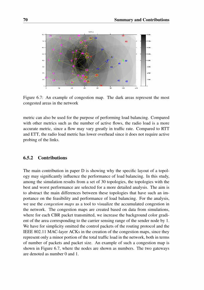
70 Summary and Contributions
Figure 6.7: An example of congestion map. The dark areas represent the mostcongested areas in the network
metric can also be used for the purpose of performing load balancing. Comparedwith other metrics such as the number of active flows, the radio load is a moreaccurate metric, since a flow may vary greatly in traffic rate. Compared to RTTand ETT, the radio load metric has lower overhead since it does not require activeprobing of the links.
6.5.2 Contributions
The main contribution in paper D is showing why the specific layout of a topol-ogy may significantly influence the performance of load balancing. In this study,among the simulation results from a set of 30 topologies, the topologies with thebest and worst performance are selected for a more detailed analysis. The aim isto abstract the main differences between these topologies that have such an im-portance on the feasibility and performance of load balancing. For the analysis,we use the congestion maps as a tool to visualize the accumulated congestion inthe network. The congestion maps are created based on data from simulations,where for each CBR packet transmitted, we increase the background color gradi-ent of the area corresponding to the carrier sensing range of the sender node by 1.We have for simplicity omitted the control packets of the routing protocol and theIEEE 802.11 MAC-layer ACKs in the creation of the congestion maps, since theyrepresent only a minor portion of the total traffic load in the network, both in termsof number of packets and packet size. An example of such a congestion map isshown in Figure 6.7, where the nodes are shown as numbers. The two gatewaysare denoted as number 0 and 1.
6.5. Contribution of paper D 71
By comparing the maps of the best and worst topologies, a number of importantaspects related to load balancing are discovered:
• The congestion maps show the areas of the network that, over time, arethe most congested. This is represented by the dark areas in the figure. Incontrary to what is commonly believed, the areas around the gateways arenot necessary the most congested. The congestion maps show that the areain the centre of the network (i.e. between the two gateways), is actually themost congested. This is due to the reason that the centre area is within thesensing range of a majority of nodes in the network.
• The congestion in the centre area explains why load balancing in wirelessenvironments is often very difficult. In many cases, the congested area rep-resents an obstacle or barrier, preventing traffic load to be efficiently divertedfrom a congested gateway to another less congested gateway.
• The essential point that determines whether load balancing is efficient or not,is where the nodes that actually reroute the traffic load are located relativeto the congested area. In Figure 6.7, the most congested gateway is GW0,since more nodes are associated with GW0 than GW1. Thus in order toreduce the load imbalance, part of the traffic load needs to be diverted toGW1. The nodes that actually perform rerouting are encircled, and as can beseen, these nodes are located on the correct side of the congested area, i.e. tothe right of it. This is very advantageous, since the traffic can be efficientlydiverted away from the congested area instead of crossing it. Due to thisreason, the throughput enhancement for this topology is about 20 %.
One of the important aspects of the above analysis is that in order to efficientlyperform load balancing, not only the gateway loads need to be considered, butit is also important to consider the properties of the paths towards the gatewayswith respect to the hop distance and the bottleneck capacity. While the gatewayloads give us an indication about which gateway more traffic should be reroutedto, the properties of the paths on the other hand, give us an idea about which pathwe should select in order to avoid crossing the congested area. Based on theseobservations, a new load balancing scheme is developed. The aim is to verifythe correctness of our observations, and second, to provide a better solution forgateway load balancing. We call this new scheme as the Radio Load Based LoadBalancing (RLLB) scheme, which relies on the radio load information in makingrouting decisions. The calculation of the radio load is performed at the MAC-sublayer as previously discussed in Section 4.5 and made available to the routingprotocol. Thus the RLLB scheme is a cross-layer based solution, and it is designedto take the above properties into account. This implies that rerouting of traffic is
72 Summary and Contributions
performed only when appropriate, i.e. when the route to the alternative gatewayis not crossing the most congested area. In contradiction to our proposal, manyprevious proposals do not consider all the above properties when performing loadbalancing. In most proposals, the load balancing algorithms are only based on onesingle parameter, i.e. the condition at the gateways.
Furthermore, in our proposal, the RLLB scheme is integrated with the OLSR rout-ing protocol. This has several advantages. First, the calculation of the bottleneckradio load can be easily performed using the Dijkstra’s algorithm that is part ofthe function for routing table calculation. Second, the radio load information canbe integrated with the OLSR’s control message, i.e. the TC message, in order totake advantage of the optimized flooding mechanism. Third, by using a proactiverouting protocol, load balancing can be performed more dynamically in order toadapt to the changes in the network.
Simulation results show that the RLLB metric results in better performance thanthe SP metric. The average peak enhancement for 30 random topologies is almost12%. Furthermore, the results also show that RLLB provides a better performancethan both the SLB and EL metric in paper C by around 5 % (average peak enhance-ment). This is due to the fact that the SLB metric is too conservative in performingload balancing. Hence, in many cases, it is incapable to reduce the load imbalancesufficiently. The EL metric is too aggressive in reducing the load imbalance, andmay therefore consume too much network resources, which again results in poorerperformance. On the other hand, the RLLB metric is designed to adapt the amountof load to divert according to the layout of the topology and the condition in thenetwork, and is thus more optimal than the other metrics.
6.6 Contribution of paper E: A Radio Load Based LoadBalancing Scheme with Admission Control
The work in paper E is a continuation of the work in paper D. Previous simu-lation results show that the proposed RLLB scheme in paper D performs well instatic topologies with higher levels of asymmetry. However, the performance is notoptimal for topologies with lower levels of asymmetry. This is due to the synchro-nized rerouting problem that may occur in distributed systems. Paper E addressesthis problem and proposes a new gateway load balancing scheme to resolve it. Inaddition to performing gateway load balancing, the new scheme also performs ad-mission control (AC) in order to prevent the network load from reaching a criticalhigh level. While the work in paper D only focuses on static topologies, paper Eaddresses both static and mobile topologies.

6.6. Contribution of paper E 73
Figure 6.8: Example of topology that is subjected to the synchronized reroutingproblem
6.6.1 Related Work
Although there are proposed a number of different schemes for load balancing, butvery little attention is given to the challenges that may arise when performing loadbalancing in a wireless and distributed system. To the best of our knowledge, onlya few papers address some of the challenges. The problem of route flapping ispreviously noticed in [96], and the work in [78] provides a solution for mitigatingroute flapping based on hysteresis. However, as far as we know, none of theseworks address the issue of synchronized rerouting.
As stated above, our proposed scheme jointly performs load balancing and admis-sion control. A similar approach is also applied in [97], where the authors proposean admission control scheme with load balancing functionality. In their proposal,the primary goal of their solution is to perform admission control, while load bal-ancing is the secondary goal, i.e. a flow is granted access to the least loaded path ifthere are multiple paths satisfying the requested bandwidth. On the other hand, theprimary goal of our proposal is performing gateway load balancing. Admissioncontrol is just a secondary mechanism, with the aim to prevent excessive trafficfrom entering the network when the network load is high.
6.6.2 Contributions
The main contribution in paper E is showing why the synchronized rerouting prob-lem may occur when performing load balancing in a distributed system. To solvethis problem, a new load balancing scheme is proposed using a randomized in-stead of a deterministic gateway selection approach. This new scheme which wecall Radio Load Based Load Balancing with Admission Control (RLAC) jointlyperforms load balancing and admission control.
Since a MANET is a distributed system where there is no centralized adminis-tration, each node in the network must take routing decisions on their own andindependent of each other. In the context of performing gateway load balancing,
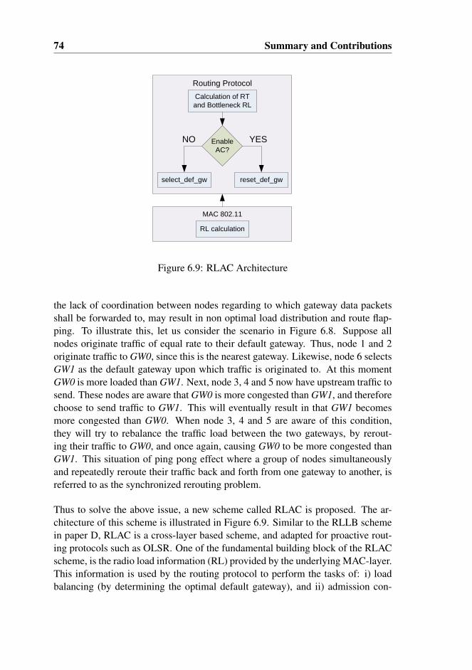
74 Summary and Contributions
select_def_gw
Calculation of RT
and Bottleneck RL
Enable
AC?
NO
reset_def_gw
YES
Routing Protocol
RL calculation
MAC 802.11
Figure 6.9: RLAC Architecture
the lack of coordination between nodes regarding to which gateway data packetsshall be forwarded to, may result in non optimal load distribution and route flap-ping. To illustrate this, let us consider the scenario in Figure 6.8. Suppose allnodes originate traffic of equal rate to their default gateway. Thus, node 1 and 2originate traffic to GW0, since this is the nearest gateway. Likewise, node 6 selectsGW1 as the default gateway upon which traffic is originated to. At this momentGW0 is more loaded than GW1. Next, node 3, 4 and 5 now have upstream traffic tosend. These nodes are aware that GW0 is more congested than GW1, and thereforechoose to send traffic to GW1. This will eventually result in that GW1 becomesmore congested than GW0. When node 3, 4 and 5 are aware of this condition,they will try to rebalance the traffic load between the two gateways, by rerout-ing their traffic to GW0, and once again, causing GW0 to be more congested thanGW1. This situation of ping pong effect where a group of nodes simultaneouslyand repeatedly reroute their traffic back and forth from one gateway to another, isreferred to as the synchronized rerouting problem.
Thus to solve the above issue, a new scheme called RLAC is proposed. The ar-chitecture of this scheme is illustrated in Figure 6.9. Similar to the RLLB schemein paper D, RLAC is a cross-layer based scheme, and adapted for proactive rout-ing protocols such as OLSR. One of the fundamental building block of the RLACscheme, is the radio load information (RL) provided by the underlying MAC-layer.This information is used by the routing protocol to perform the tasks of: i) loadbalancing (by determining the optimal default gateway), and ii) admission con-
6.6. Contribution of paper E 75
trol (AC). During the calculation of the routing table (RT), the bottleneck radioload to each destination is also calculated using Dijkstra’s algorithm. Once thisis completed, the scheme determines whether to enable/disable AC on the localnode. If AC is not enabled, the function select_def_gw is called where the processof default gateway selection is performed. On the other hand if AC is enabled,reset_def_gw is called to reset the default gateway.
One of the main differences of RLAC compared to RLLB lies in the gateway se-lection algorithm. In RLAC, a randomized instead of a deterministic gateway se-lection approach is used in order to solve the synchronized rerouting problem. Theselect_def_gw function calculates a probability P0 for selecting GW0 as defaultgateway as follows:
P0 =
0.5− a ·∆B − b ·∆L− c ·∆h
0 , P0 < 0
1 , P0 > 1
(6.8)
where ∆B, ∆L and ∆h are the differences in the bottleneck radio load, the gate-way radio load and hop distance, respectively. The constants a, b and c are usedto weight the above input parameters. The probability P1 for selecting GW1 asdefault gateway is simply:
P1 = 1− P0 (6.9)
Having calculated P0 and P1, a uniform random number R ∈ [0, 1] is drawn. If R <P0, the GW0 is selected as the default gateway, otherwise, GW1 is selected as thedefault gateway. If we take a look back to the example in Figure 6.8, since GW0is initially more congested than GW1, then P1>P0. Suppose that the calculatedprobability P0=1/3 and P1=2/3. Then in long run, we may expect that 2/3 of thenodes 3, 4 and 5 will select GW1 while 1/3 will select GW0 as the default gateway.Thus, using a randomized gateway selection approach, the risk for synchronizedrerouting to occur will be lower. To the best of our knowledge, no previous pro-posals utilize this approach in order to solve the rerouting problem. In fact, mostproposals utilize the deterministic approach when performing gateway selection.
The task of the AC mechanism in RLAC is to prevent the load in the network fromreaching a critical high level. This is especially important in wireless networksdue to the interfering nature of the shared medium, where packet transmissionsmay be more vulnerable to collisions and loss when the network is overloaded. Toprevent this we have implemented a simple AC scheme that works in the following
76 Summary and Contributions
way: If B0 and B1 (bottleneck radio load along the path towards GW0 and GW1)are higher than a given threshold AC_UPPER, seen from the point of view of alocal node n, then AC is enabled on n if n is located more than AC_MAX_HOPSaway from the nearest gateway. This implies that if the network load is high, ACis enabled on nodes that are located farther away from the gateways, in order togive priority to nodes closer to the gateways. This design choice may be justifiedby the fact that the cost of transmitting traffic destined to the gateways is higherfor nodes located farther away than for nodes in the proximity of the gateways.Furthermore, when the network load is high, nodes that are located farther awayfrom the gateways will most likely experience a very low packet delivery ratio.Enabling AC on these nodes is reasonable, since it does not matter whether no oronly a few packets can reach the destination. Once Admission Control (AC) isenabled, only traffic originated by the local node is discarded, while transit traffic(i.e. traffic not originated by the local node) may still be forwarded.
While previous results show that the RLLB performs not so well for static topolo-gies with lower asymmetry, simulations with the same set of topologies and usingthe RLAC metric, show that the throughput can in fact be enhanced by approx-imately 10 % relative to the SP metric. Furthermore, simulations with mobiletopologies show that performing load balancing under mobility is extremely diffi-cult. The reason for this includes frequent link breaks, the risk for network parti-tioning and the latency of the routing protocol in capturing the current topology ofthe network. Simulation results show that at low mobility levels, i.e. 1-2 m/s, theachieved enhancement relative to the SP metric is at best 4 %. At higher levels ofmobility such as 10 m/s, the performance of load balancing is practically zero.
6.7 Concluding Remarks
The work in this thesis is an effort to bring forth solutions in order to improve theperformance in a MANET. This is a small step on the way in realizing a futurecommunication system for emergency and rescue operations. However, some ofthe suggested solutions have a potential for further exploration and optimization.
In paper A, although Adaptive retry limit is an effective solution in solving thererouting problem, the reduction of the retry limit may potentially induce unfair-ness in the network due to less time in backoff. Thus a further investigation of thisaspect is needed. Another way to solve the rerouting time problem is to dynami-cally adjust the queue length. When experiencing packet drops due to a link break,the queue length can for example be decreased in order to reduce the amount ofstale packets inserted into the queue. Furthermore, considerations need also to be
6.7. Concluding Remarks 77
taken for the potential of buffer overflow when reducing the queue size.
The work in paper B demonstrates that transit routing can be very beneficial interms of increasing the throughput for certain source and destination pairs andreducing the load in the ad hoc subnet. Even though the work in this paper isfocused on optimizing the throughput for one single traffic flow, simulations withbackground traffic also show that the proposed solution is capable to considerablyenhance the throughput. However, in order to improve and make the solutionmore generic, one can for example to incorporate other metrics such as the radioload metric used in paper D and E. With the additional information on the trafficload distribution in the network, it is possible to derive an improved cost metricalgorithm that also accounts for multiple traffic flows.
The work in paper C-E investigate factors that affect the feasibility of perform-ing gateway load balancing, and propose two different load balancing schemes.However, the general assumption of these work is a network scenario with twogateways, in which gateway load balancing is performed on outbound traffic only.Although we believe that much of the concepts developed and results obtainedthrough our work are applicable to a more generic scenario, further investigationsshould be performed on scenarios with multiple gateways and inbound traffic inorder to validate and to potentially discover new aspects related to gateway loadbalancing.
Finally, even though the major part of our work assumes that the architecture ofthe emergency and rescue network is based on a mixture of MANET and WMN, itis however imaginable that future emergency and rescue communications systemswill be a combination of all the three types of ad hoc networks. The idea is to takeadvantage of the technology provided by each type of networks in order to forma more efficient communication platform for emergency and rescue operations.While the MANET technology can provide mobility and flexibility, the backboneinfrastructure of WMNs can increase reliability and robustness in the network. Onthe other hand, the technology in WSNs can provide the ability to monitor inac-cessible or potentially dangerous areas for a variety of environmental parameterssuch as hazardous gases or radiations. The same technology may also be used tomonitor the health conditions of rescue personnel at the emergency scene. Thus astudy on the integration of these network architectures would be very interestingto carry out.

78 Summary and Contributions
Bibliography
[1] M. Pearlman, Z. Haas, P. Sholander, and S. Tabrizi, “On the impact of alter-nate path routing for load balancing in mobile ad hoc networks,” in Mobileand Ad Hoc Networking and Computing, 2000. MobiHOC. 2000 First An-nual Workshop on, 2000, pp. 3 –10.
[2] Y. Ganjali and A. Keshavarzian, “Load balancing in ad hoc networks: single-path routing vs. multi-path routing,” in INFOCOM 2004. Twenty-third An-nualJoint Conference of the IEEE Computer and Communications Societies,vol. 2, march 2004, pp. 1120 – 1125 vol.2.
[3] J. Heidemann and T. Henderson (Editors). (2009, October) NetworkSimulator 2. [Online]. Available: http://nsnam.isi.edu/nsnam/index.php/Main_Page
[4] M. Gerla, K. Tang, and R. Bagrodia, “TCP Performance in Wireless Multi-hop Networks,” in Proceedings of the Second IEEE Workshop on MobileComputer Systems and Applications, ser. WMCSA ’99. Washington, DC,USA: IEEE Computer Society, 1999, pp. 41–.
[5] S. Xu and T. Saadawi, “Does the IEEE 802.11 MAC protocol work wellin multihop wireless ad hoc networks?” Communications Magazine, IEEE,vol. 39, no. 6, pp. 130–137, Jun 2001.
[6] R. Jiang, V. Gupta, and C. Ravishankar, “Interactions between TCP and theIEEE 802.11 MAC protocol,” in DARPA Information Survivability Confer-ence and Exposition, 2003. Proceedings, vol. 1, april 2003, pp. 273 – 282vol.1.
[7] Network Animator. [Online]. Available: http://www.isi.edu/nsnam/nam/
[8] D. Ganesan, B. Krishnamachari, A. Woo, D. Culler, D. Estrin, and S. Wicker,“Complex Behavior at Scale: An Experimental Study of Low-Power Wire-
79
80 Bibliography
less Sensor Networks,” UCLA Computer Science Department, Tech. Rep.,2002.
[9] G. Zhou, T. He, S. Krishnamurthy, and J. A. Stankovic, “Impact of radioirregularity on wireless sensor networks,” in Proceedings of the 2nd inter-national conference on Mobile systems, applications, and services, ser. Mo-biSys ’04. New York, NY, USA: ACM, 2004, pp. 125–138.
[10] D. Kotz, C. Newport, R. S. Gray, J. Liu, Y. Yuan, and C. Elliott, “Experi-mental evaluation of wireless simulation assumptions,” in Proceedings of the7th ACM international symposium on Modeling, analysis and simulation ofwireless and mobile systems, ser. MSWiM ’04. New York, NY, USA: ACM,2004, pp. 78–82.
[11] S. Ivanov, A. Herms, and G. Lukas, “Experimental validation of the ns-2wireless model using simulation, emulation, and real network,” in 4th Work-shop on Mobile Ad-Hoc Networks (WMAN’07), 2007, pp. 433–444.
[12] S. Kurkowski, T. Camp, and M. Colagrosso, “MANET simulation studies:the incredibles,” SIGMOBILE Mob. Comput. Commun. Rev., vol. 9, pp. 50–61, October 2005.
[13] J. Jubin and J. Tornow, “The DARPA packet radio network protocols,” Pro-ceedings of the IEEE, vol. 75, no. 1, pp. 21 – 32, jan. 1987.
[14] R. Kahn, S. Gronemeyer, J. Burchfiel, and R. Kunzelman, “Advances inpacket ratio technology,” Proceedings of the IEEE, vol. 66, no. 11, pp. 1468– 1496, nov. 1978.
[15] J. A. Freebersyser and B. Leiner, “A DoD perspective on mobile Ad hocnetworks,” in Ad hoc networking. Boston, MA, USA: Addison-WesleyLongman Publishing Co., Inc., 2001, pp. 29–51.
[16] S. Corson and J. Macker, “Mobile Ad hoc Networking (MANET): RoutingProtocol Performance Issues and Evaluation Considerations,” RFC 2501,pages 1–12, pp. 1–75, January 1999, network Working Group. [Online].Available: http://ietf.org/rfc/rfc2501.txt
[17] I. F. Akyildiz, X. Wang, and W. Wang, “Wireless mesh networks: a survey,”Comput. Netw. ISDN Syst., vol. 47, pp. 445–487, March 2005. [Online].Available: http://portal.acm.org/citation.cfm?id=1071644.1071646
[18] J. Bicket, D. Aguayo, S. Biswas, and R. Morris, “Architecture and evaluationof an unplanned 802.11b mesh network,” in Proceedings of the 11thannual international conference on Mobile computing and networking, ser.
Bibliography 81
MobiCom ’05. New York, NY, USA: ACM, 2005, pp. 31–42. [Online].Available: http://doi.acm.org/10.1145/1080829.1080833
[19] Georgia institute of technology bwn-mesh. [Online]. Available: http://www.ece.gatech.edu/research/labs/bwn/mesh/testbed.html
[20] R. Karrer, I. Matyasovszki, A. Botta, and A. Pescape, “MagNets - experi-ences from deploying a joint research-operational next-generation wirelessaccess network testbed,” in Testbeds and Research Infrastructure for the De-velopment of Networks and Communities, 2007. TridentCom 2007. 3rd Inter-national Conference on, may 2007, pp. 1–10.
[21] I. Akyildiz, W. Su, Y. Sankarasubramaniam, and E. Cayirci, “A survey onsensor networks,” Communications Magazine, IEEE, vol. 40, no. 8, pp. 102– 114, aug 2002.
[22] T. Bokareva, W. Hu, S. Kanhere, B. Ristic, T. Bessell, M. Rutten, and S. Jha,“Wireless sensor networks for battlefield surveillance,” in in Proc. of theLand Warfare Conference, 2006.
[23] Y.-M. Huang, M.-Y. Hsieh, and F. E. Sandnes, “Wireless Sensor Networksand Applications,” in Sensors, ser. Lecture Notes in Electrical Engineering,S. Mukhopadhyay and R. Huang, Eds. Springer Berlin Heidelberg, 2008,vol. 21, pp. 199–219.
[24] K. Lorincz, D. Malan, T. Fulford-Jones, A. Nawoj, A. Clavel, V. Shnayder,G. Mainland, M. Welsh, and S. Moulton, “Sensor networks for emergencyresponse: challenges and opportunities,” Pervasive Computing, IEEE, vol. 3,no. 4, pp. 16 – 23, oct.-dec. 2004.
[25] N. O’Donoughue, S. Kulkarni, and D. Marzella, “Design and Implementa-tion of a Framework for Monitoring Patients in Hospitals Using WirelessSensors in Ad Hoc Configuration,” in Engineering in Medicine and BiologySociety, 2006. EMBS ’06. 28th Annual International Conference of the IEEE,30 2006-sept. 3 2006, pp. 6449 –6452.
[26] K. Romer and F. Mattern, “The design space of wireless sensor networks,”Wireless Communications, IEEE, vol. 11, no. 6, pp. 54 – 61, dec. 2004.
[27] S. Hadim and N. Mohamed, “Middleware: middleware challenges and ap-proaches for wireless sensor networks,” Distributed Systems Online, IEEE,vol. 7, no. 3, pp. 1 –1, march 2006.
82 Bibliography
[28] O. Dousse, F. Baccelli, and P. Thiran, “Impact of interferences on connectiv-ity in ad hoc networks,” IEEE/ACM Trans. Netw., vol. 13, pp. 425–436, April2005.
[29] O. Dousse, P. Thiran, and M. Hasler, “Connectivity in ad-hoc and hybridnetworks,” in INFOCOM 2002. Twenty-First Annual Joint Conference of theIEEE Computer and Communications Societies. Proceedings. IEEE, vol. 2,2002, pp. 1079 – 1088 vol.2.
[30] V. Kawadia and P. Kumar, “Power control and clustering in ad hoc networks,”in INFOCOM 2003. Twenty-Second Annual Joint Conference of the IEEEComputer and Communications. IEEE Societies, vol. 1, march-3 april 2003,pp. 459 – 469 vol.1.
[31] J. Monks, V. Bharghavan, and W.-M. Hwu, “A power controlled multiple ac-cess protocol for wireless packet networks,” in INFOCOM 2001. TwentiethAnnual Joint Conference of the IEEE Computer and Communications Soci-eties. Proceedings. IEEE, vol. 1, 2001, pp. 219 –228 vol.1.
[32] H. Lundgren, E. Nordström, and C. Tschudin, “Coping with communica-tion gray zones in IEEE 802.11b based ad hoc networks,” in Proceedings ofthe 5th ACM international workshop on Wireless mobile multimedia (WOW-MOM). New York, NY, USA: ACM, 2002, pp. 49–55.
[33] W. H. Yuen and C. W. Sung, “On energy efficiency and network connectivityof mobile ad hoc networks,” in Proceedings of the 23rd International Con-ference on Distributed Computing Systems, ser. ICDCS ’03. Washington,DC, USA: IEEE Computer Society, 2003, pp. 38–.
[34] T. ElBatt, S. Krishnamurthy, D. Connors, and S. Dao, “Power managementfor throughput enhancement in wireless ad-hoc networks,” in Communica-tions, 2000. ICC 2000. 2000 IEEE International Conference on, vol. 3, Jun.2000, pp. 1506 –1513 vol.3.
[35] R. Ramanathan and R. Rosales-Hain, “Topology control of multihop wirelessnetworks using transmit power adjustment,” in INFOCOM 2000. NineteenthAnnual Joint Conference of the IEEE Computer and Communications Soci-eties. Proceedings. IEEE, vol. 2, Mar. 2000, pp. 404 –413 vol.2.
[36] J. G. Jetcheva and D. B. Johnson, “Routing characteristics of ad hoc networkswith unidirectional links,” Ad Hoc Netw., vol. 4, pp. 303–325, May 2006.
[37] R. Prakash, “Unidirectional links prove costly in wireless ad hoc networks,”in Proceedings of the 3rd international workshop on Discrete algorithms and
Bibliography 83
methods for mobile computing and communications, ser. DIALM ’99. NewYork, NY, USA: ACM, 1999, pp. 15–22.
[38] M. K. Marina and S. R. Das, “Routing performance in the presence of uni-directional links in multihop wireless networks,” in Proceedings of the 3rdACM international symposium on Mobile ad hoc networking & computing,ser. MobiHoc ’02. New York, NY, USA: ACM, 2002, pp. 12–23.
[39] F. Ye, S. Yi, and B. Sikdar, “Improving spatial reuse of IEEE 802.11 basedad hoc networks,” in Global Telecommunications Conference, 2003. GLOBE-COM ’03. IEEE, vol. 2, dec. 2003, pp. 1013 – 1017 Vol.2.
[40] P. Gupta, S. Member, and P. R. Kumar, “The capacity of wireless networks,”IEEE Transactions on Information Theory, vol. 46, pp. 388–404, 2000.
[41] J. Li, C. Blake, D. S. J. De Couto, H. I. Lee, and R. Morris, “Capacityof Ad Hoc wireless networks,” in MobiCom ’01: Proceedings of the7th annual international conference on Mobile computing and networking.New York, NY, USA: ACM Press, 2001, pp. 61–69. [Online]. Available:http://portal.acm.org/citation.cfm?id=381677.381684
[42] F. Tobagi and L. Kleinrock, “Packet Switching in Radio Channels: PartII–The Hidden Terminal Problem in Carrier Sense Multiple-Access andthe Busy-Tone Solution,” Communications, IEEE Transactions on, vol. 23,no. 12, pp. 1417–1433, Dec 1975.
[43] K. Xu, M. Gerla, and S. Bae, “How effective is the IEEE 802.11 RTS/CTShandshake in ad hoc networks,” in Global Telecommunications Conference,2002. GLOBECOM ’02. IEEE, vol. 1, nov. 2002, pp. 72 – 76 vol.1.
[44] Mobile Ad-hoc Networks (manet) working group. (2009, October) IETF.[Online]. Available: http://www.ietf.org/dyn/wg/charter/manet-charter.html
[45] X. Hong, K. Xu, and M. Gerla, “Scalable routing protocols for mobile ad hocnetworks,” Network, IEEE, vol. 16, no. 4, pp. 11–21, Jul/Aug 2002.
[46] T. Clausen, P. Jacquet (editors), C. Adjih, A. Laouiti, P. Minet,P. Muhlethaler, A. Qayyum, and L.Viennot, “Optimized Link State RoutingProtocol (OLSR),” RFC 3626, pages 1–75, pp. 1–75, October 2003, networkWorking Group. [Online]. Available: http://ietf.org/rfc/rfc3626.txt
[47] C. E. Perkins and P. Bhagwat, “Highly dynamic Destination-SequencedDistance-Vector routing (DSDV) for mobile computers,” SIGCOMM Com-put. Commun. Rev., vol. 24, no. 4, pp. 234–244, 1994.

84 Bibliography
[48] R. G. Ogier, F. Templin, and M. Lewis, “Topology Broad-cast based on Reverse-Path Forwarding (TBRPF), draft-ietf-manet-tbrpf-05.txt, INTERNET-DRAFT, MANET Working Group,”http://tools.ietf.org/html/draft-ietf-manet-tbrpf-11, 2003. [Online]. Avail-able: http://tools.ietf.org/wg/manet/draft-ietf-manet-dymo
[49] C. Perkins and E. Belding-Royer, “Ad-hoc On-Demand Distance VectorRouting,” in Proceedings of the 2nd IEEE Workshop on Mobile ComputingSystems and Applications, February 1999, pp. 90–100, new Orleans, LA.
[50] I. D. Chakeres and C. E. Perkins, “Dynamic MANET On-demand (DYMO) routing protocol,” http://tools.ietf.org/wg/manet/draft-ietf-manet-dymo, 2009. [Online]. Available: http://tools.ietf.org/wg/manet/draft-ietf-manet-dymo
[51] D. B. Johnson and D. A. Maltz, Dynamic Source Routing in Ad Hoc Wire-less Networks, ser. The International Series in Engineering and ComputerScience. Kluwer Academic Publishers, 1996, vol. 353, ch. 5, pp. 153–181.
[52] Z. J. Haas, “A New Routing Protocol for the Reconfigurable Wireless Net-works,” Proceedings of the IEEE International Conference on Universal Per-sonal Communications (ICUPC), pp. 562–566, 1997.
[53] R. Sivakumar, P. Sinha, and V. Bharghavan, “CEDAR: a core-extraction dis-tributed ad hoc routing algorithm,” Selected Areas in Communications, IEEEJournal on, vol. 17, no. 8, pp. 1454–1465, Aug 1999.
[54] G. Pei, M. Gerla, X. Hong, and C.-C. Chieang, “A Wireless HierarchicalRouting Protocol with Group Mobility,” in Wireless Communications andNetworking Conference, IEEE WCNC’99, New Orleans, LA, Sept. 1999,vol. 2, 1999, pp. 1538–1542.
[55] L. Villasenor-Gonzalez, Y. Ge, and L. Lament, “HOLSR: a hierarchical pro-active routing mechanism for mobile ad hoc networks,” CommunicationsMagazine, IEEE, vol. 43, no. 7, pp. 118 – 125, july 2005.
[56] M. Gerla, X. Hong, and G. Pei, “Landmark routing for large ad hoc wirelessnetworks,” in Global Telecommunications Conference, 2000. GLOBECOM’00. IEEE, vol. 3, nov. 2000, pp. 1702 –1706 vol.3.
[57] E. D. Kaplan and C. Hegarty, Understanding GPS: Principles and Applica-tions, Second Edition, 2nd ed. Artech House Publishers, November 2005.
[58] Y.-B. Ko and N. H. Vaidya, “Location-aided routing (LAR) in mobile ad hocnetworks,” Wirel. Netw., vol. 6, no. 4, pp. 307–321, 2000.

Bibliography 85
[59] S. Basagni, I. Chlamtac, V. R. Syrotiuk, and B. A. Woodward, “A distancerouting effect algorithm for mobility (DREAM),” in Proceedings of the 4thannual ACM/IEEE international conference on Mobile computing and net-working, ser. MobiCom ’98. New York, NY, USA: ACM, 1998, pp. 76–84.
[60] C. Perkins, E. Belding-Royer, and S. Das, “Ad hoc On-Demand DistanceVector (AODV) Routing,” RFC 3561 (Experimental), Internet EngineeringTask Force, Jul. 2003. [Online]. Available: http://www.ietf.org/rfc/rfc3561.txt
[61] J. Doyle and J. X. Carroll, Routing TCP/IP, Volume 1 (2nd Edition). CiscoPress, 2005.
[62] T. Clausen, C. Dearlove, P. Jacquet, and the OLSRv2 Design Team, “TheOptimized Link State Routing Protocol version 2,” Internet-Draft, MANETWG, draft-ietf-manet-smf-09, September 2009, work in progress. Intendedstatus: Standards Track, Expires: March 29, 2010. [Online]. Available:http://tools.ietf.org/html/draft-ietf-manet-olsrv2-10
[63] Olsrd. [Online]. Available: http://www.olsr.org/
[64] The nrl olsr routing protocol implementation. [Online]. Available:http://cs.itd.nrl.navy.mil/work/olsr/index.php
[65] olsrexperiment.net. [Online]. Available: http://berlin.freifunk.net/
[66] D. Marandin, “Performance Evaluation of Failed Link Detection in MobileAd Hoc Networks,” in Proc. of the 3nd Mediterranean Ad Hod networkingConference (MedHoc Net 2004), June 27-30, 2004, Bodrum, Turkey, 2004.
[67] A. Adya, P. Bahl, J. Padhye, A. Wolman, and L. Zhou, “A multi-radio unifi-cation protocol for IEEE 802.11 wireless networks,” in Broadband Networks,2004. BroadNets 2004. Proceedings. First International Conference on, oct.2004, pp. 344 – 354.
[68] R. Draves, J. Padhye, and B. Zill, “Comparison of routing metrics for staticmulti-hop wireless networks,” SIGCOMM Comput. Commun. Rev., vol. 34,pp. 133–144, August 2004.
[69] S. Keshav, “A control-theoretic approach to flow control,” SIGCOMM Com-put. Commun. Rev., vol. 21, pp. 3–15, August 1991.
[70] R. Draves, J. Padhye, and B. Zill, “Routing in multi-radio, multi-hop wirelessmesh networks,” in MobiCom ’04: Proceedings of the 10th annual interna-tional conference on Mobile computing and networking. New York, NY,USA: ACM, 2004, pp. 114–128.
86 Bibliography
[71] D. S. J. De Couto, D. Aguayo, J. Bicket, and R. Morris, “A High-ThroughputPath Metric for Multi-Hop Wireless Routing,” in Proceedings of the 9th an-nual international conference on Mobile computing and networking, ser. Mo-biCom ’03. New York, NY, USA: ACM, 2003, pp. 134–146.
[72] P. Esposito, M. Campista, I. Moraes, L. Costa, O. Duarte, and M. Rubinstein,“Implementing the Expected Transmission Time Metric for OLSR WirelessMesh Networks,” in Wireless Days, 2008. WD ’08. 1st IFIP, nov. 2008, pp. 1–5.
[73] Y. Yang and R. Kravets, “Contention-aware admission control for ad hocnetworks,” Mobile Computing, IEEE Transactions on, vol. 4, no. 4, pp. 363– 377, july-aug. 2005.
[74] H. Zimmermann, OSI reference model—The ISO model of architecture foropen systems interconnection. Norwood, MA, USA: Artech House, Inc.,1988, ch. 1, pp. 2–9.
[75] V. Kawadia and P. R. Kumar, “A cautionary perspective on cross-layerdesign,” Wireless Communications, IEEE, vol. 12, no. 1, pp. 3–11, 2005.[Online]. Available: http://dx.doi.org/10.1109/MWC.2005.1404568
[76] V. Srivastava and M. Motani, “Cross-layer design: a survey and the roadahead,” Communications Magazine, IEEE, vol. 43, no. 12, pp. 112–119,2005. [Online]. Available: http://dx.doi.org/10.1109/MCOM.2005.1561928
[77] S. Lakshmanan, K. Sundaresan, and R. Sivakumar, “On multi-gateway as-sociation in wireless mesh networks,” in Wireless Mesh Networks, 2006.WiMesh 2006. 2nd IEEE Workshop on, sept. 2006, pp. 64 –73.
[78] B. Xie, Y. Yu, A. Kumar, and D. P. Agrawal, “Load-balanced mesh routermigration for wireless mesh networks,” J. Parallel Distrib. Comput., vol. 68,pp. 825–839, June 2008.
[79] D. Nandiraju, L. Santhanam, N. Nandiraju, and D. P. Agrawal, “AchievingLoad Balancing in Wireless Mesh Networks Through Multiple Gateways,”in Mobile Adhoc and Sensor Systems (MASS), 2006 IEEE International Con-ference on, oct. 2006, pp. 807 –812.
[80] J. Shin, H. Lee, J. Na, A. Park, and S. Kim, “Load balancing among internetgateways in ad hoc networks,” in Vehicular Technology Conference, 2005.VTC-2005-Fall. 2005 IEEE 62nd, vol. 3, sept. 2005, pp. 1677 – 1680.
[81] M. Michalak and T. Braun, “Common Gateway Architecture for Mobile Ad-Hoc Networks,” in Proceedings of the Second Annual Conference on Wireless
Bibliography 87
On-demand Network Systems and Services. Washington, DC, USA: IEEEComputer Society, 2005, pp. 70–75.
[82] M. Benzaid, P. Minet, K. A. Agha, C. Adjih, and G. Allard, “Integrationof mobile-IP and OLSR for a universal mobility,” Wirel. Netw., vol. 10, pp.377–388, July 2004.
[83] F. Ros and P. Ruiz, “A Low Overhead Architecture for Infrastructure-basedWireless Mesh Networks,” in WiMeshNets 2006, Ontario, August 10, 2006,Washington, DC, USA, 2006.
[84] M. Tarique, K. E. Tepe, S. Adibi, and S. Erfani, “Survey of multipath routingprotocols for mobile ad hoc networks,” Journal of Network and ComputerApplications, vol. 32, no. 6, pp. 1125 – 1143, 2009. [Online]. Available:http://www.sciencedirect.com/science/article/pii/S1084804509001027
[85] S. Mueller, R. P. Tsang, and D. Ghosal, “Multipath Routing in Mobile AdHoc Networks: Issues and Challenges,” in Performance Tools and Applica-tions to Networked Systems, 2004, pp. 209–234.
[86] R. Krishnan and J. Silvester, “Choice of allocation granularity in multipathsource routing schemes,” in INFOCOM ’93. Proceedings.Twelfth AnnualJoint Conference of the IEEE Computer and Communications Societies. Net-working: Foundation for the Future. IEEE, 1993, pp. 322 –329 vol.1.
[87] R. Ogier and V. Rutenburg, “Minimum-expected-delay alternate routing,” inINFOCOM ’92. Eleventh Annual Joint Conference of the IEEE Computerand Communications Societies, IEEE, may 1992, pp. 617 –625 vol.2.
[88] N. Rao and S. Batsell, “QoS routing via multiple paths using bandwidthreservation,” in INFOCOM ’98. Seventeenth Annual Joint Conference of theIEEE Computer and Communications Societies. Proceedings. IEEE, vol. 1,mar-2 apr 1998, pp. 11 –18 vol.1.
[89] I. Cidon, R. Rom, and Y. Shavitt, “Analysis of multi-path routing,”IEEE/ACM Trans. Netw., vol. 7, pp. 885–896, December 1999.
[90] M. Voorhaen and C. Blondia, “Analyzing the Impact of Neighbor Sensingon the Performance of the OLSR protocol,” in Modeling and Optimization inMobile, Ad Hoc and Wireless Networks, 2006 4th International Symposiumon, April 2006, pp. 1–6.
[91] L. Landmark, K. Øvsthus, and Ø. Kure, “Alternative Packet Forwarding forOtherwise Discarded Packets,” in Future Generation Communication andNetworking (FGCN 2007), vol. 1, Dec. 2007, pp. 8–15.
88 Bibliography
[92] C. Perkins, “IP Mobility Support for IPv4,” RFC 3344, August 2002.[Online]. Available: http://tools.ietf.org/html/rfc3344
[93] R. Brannstrom, C. Ahlund, and A. Zaslavsky, “Port-based MultihomedMobile IPv6: Load-balancing in Mobile Ad hoc Networks,” in Local Com-puter Networks, 2007. LCN 2007. 32nd IEEE Conference on, oct. 2007, pp.269 –271.
[94] Y. Kim, Y. Lim, S. Ahn, H. Yu, J. Lee, and J. Choe, “Load BalancingMechanisms in the MANET with Multiple Internet Gateways,” in Infor-mation Networking. Advances in Data Communications and Wireless Net-works, ser. Lecture Notes in Computer Science, I. Chong and K. Kawa-hara, Eds. Springer Berlin / Heidelberg, 2006, vol. 3961, pp. 207–216,10.1007/11919568_21.
[95] J. Zhao, X. Yang, and H. Liu, “Load-balancing strategy of multi-gateway forad hoc Internet connectivity,” in Information Technology: Coding and Com-puting, 2005. ITCC 2005. International Conference on, vol. 2, april 2005, pp.592 – 596 Vol. 2.
[96] K. N. Ramachandran, M. M. Buddhikot, G. Chandranmenon, S. Miller,B. E. M. Royer, and K. C. Almeroth, “On the Design and Implementationof Infrastructure Mesh Networks,” Proceedings of the IEEE Workshop onWireless Mesh Networks (WiMesh). IEEE Press, 2005.
[97] D. Zhao, J. Zou, and T. Todd, “Admission control with load balancing inIEEE 802.11-based ESS mesh networks,” in Quality of Service in Heteroge-neous Wired/Wireless Networks, 2005. Second International Conference on,aug. 2005, pp. 8 pp. –11.

Part II
Research papers
89

Paper A :
Rerouting Time and Queueing inProactive Ad Hoc Networks
V. Pham, E. Larsen, K. Øvsthus, P. Engelstad and Ø. Kure
In proceedings of the International Performance Computing and CommunicationsConference (IPCCC), New Orleans, USA, April 11–13, 2007, pp. 160–169.
91

92 Rerouting Time and Queueing in Proactive Ad Hoc Networks

Rerouting Time and Queueing in Proactive Ad Hoc Networks
Vinh Pham1, Erlend Larsen1, Knut Øvsthus2, Paal Engelstad1 and Øivind Kure3 1UniK, Norway 2Bergen University College, Norway 3Q2S, NTNU, Norway
E-mail: 1,3{vph, erl, paalee, okure}@unik.no [email protected]
Abstract
In a MANET network where nodes move frequently,
the probability of connectivity loss between nodes might be high, and communication sessions may easily loose connectivity during transmission. The routing protocol is designed to find alternative paths in these situations. This rerouting takes time, and the latency is referred to as the rerouting time. This paper investigates the rerouting time of proactive routing protocols and shows that the rerouting time is considerably affected by queueing. Simulations and analysis are conducted to explore the problem. Finally, we propose a MAC-layer solution that reduces the rerouting time problems due to queueing. Simulations and analysis show that the solution is so effective that it eliminates the entire problem in many situations. 1. Introduction
The research efforts in the field of ad hoc networking have been going on for many decades. Ad hoc networking enables communication directly between nodes, without the need for extra infrastructure. This makes it very suitable for military and rescue operations. The standardization of routing protocols has been undertaken by the Mobile Ad Hoc Networking (MANET) working group in IETF [1]. They are set to bring forward two protocols, one reactive and one proactive.
A common characteristic of ad hoc networks is that links may break due to changes in radio conditions, node mobility and other types of network dynamics. The routing protocol is designed to find alternative paths in these situations. The time period before new paths are found is referred to as the rerouting interval, and the duration of the rerouting interval is referred to as the rerouting time.
During the rerouting interval, stale routes exist over the link that has been broken. Rerouting can only take
place after the routing protocol has detected that the link is broken. In fact, a significant part of the rerouting time is associated with the detection of the link break.
With proactive routing protocols, such as Optimized Link State Routing (OLSR) and Open Shortest Path First with MANET Designated Routers (OSPF-MDR), a link is maintained by the exchange of control packets. A link break is normally not detected until either a certain number of HELLO packets have been lost, or the lack of periodic updates results in a link timeout [2-4]. (Some implementations might let the link layer detect link breaks and signal this information to the routing protocol. Such cross-layer optimizations are outside scope of this paper. Here, we explore the common layered approach where HELLO packets are necessary for the detection of link breaks.)
With the default parameter settings of OLSR and OSPF-MDR, a link break should normally be detected after approximately 6 seconds. However, we conducted a series of lab experiments of OLSR [3] and OSPF-MDR [4] and observed rerouting times typically in the order of 20 - 40 seconds. Since the rerouting time depended on transmission rates of data traffic and on size of the transmission queues, we realized that the increased rerouting time in our experiment was mainly caused by the queueing of the data packets.
During the rerouting interval, the network layer at the node upstream to the broken link might try to forward data packets over the broken link. Instead, these packets are accumulated in the output queue. Due to the layered design, the link layer (L2) will keep trying to transmit the queued data traffic already designated to the broken link, even after the network layer (L3) has timed out the link. This does not only consume scarce radio resources. It also blocks the MAC layer. Thus the network layer is not able to announce that the link is broken, and the rerouting time increases correspondingly.
Finally, when all the stale data packets designated to the output queue have been dropped, the MAC layer is ready to transmit the link state announcement to
93
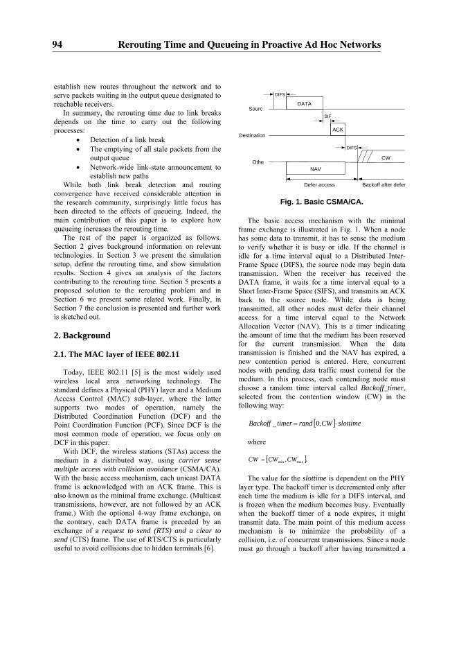
establish new routes throughout the network and to serve packets waiting in the output queue designated to reachable receivers.
In summary, the rerouting time due to link breaks depends on the time to carry out the following processes:
• Detection of a link break • The emptying of all stale packets from the
output queue • Network-wide link-state announcement to
establish new paths While both link break detection and routing
convergence have received considerable attention in the research community, surprisingly little focus has been directed to the effects of queueing. Indeed, the main contribution of this paper is to explore how queueing increases the rerouting time.
The rest of the paper is organized as follows. Section 2 gives background information on relevant technologies. In Section 3 we present the simulation setup, define the rerouting time, and show simulation results. Section 4 gives an analysis of the factors contributing to the rerouting time. Section 5 presents a proposed solution to the rerouting problem and in Section 6 we present some related work. Finally, in Section 7 the conclusion is presented and further work is sketched out.
2. Background 2.1. The MAC layer of IEEE 802.11
Today, IEEE 802.11 [5] is the most widely used wireless local area networking technology. The standard defines a Physical (PHY) layer and a Medium Access Control (MAC) sub-layer, where the latter supports two modes of operation, namely the Distributed Coordination Function (DCF) and the Point Coordination Function (PCF). Since DCF is the most common mode of operation, we focus only on DCF in this paper.
With DCF, the wireless stations (STAs) access the medium in a distributed way, using carrier sense multiple access with collision avoidance (CSMA/CA). With the basic access mechanism, each unicast DATA frame is acknowledged with an ACK frame. This is also known as the minimal frame exchange. (Multicast transmissions, however, are not followed by an ACK frame.) With the optional 4-way frame exchange, on the contrary, each DATA frame is preceded by an exchange of a request to send (RTS) and a clear to send (CTS) frame. The use of RTS/CTS is particularly useful to avoid collisions due to hidden terminals [6].
Fig. 1. Basic CSMA/CA. The basic access mechanism with the minimal
frame exchange is illustrated in Fig. 1. When a node has some data to transmit, it has to sense the medium to verify whether it is busy or idle. If the channel is idle for a time interval equal to a Distributed Inter-Frame Space (DIFS), the source node may begin data transmission. When the receiver has received the DATA frame, it waits for a time interval equal to a Short Inter-Frame Space (SIFS), and transmits an ACK back to the source node. While data is being transmitted, all other nodes must defer their channel access for a time interval equal to the Network Allocation Vector (NAV). This is a timer indicating the amount of time that the medium has been reserved for the current transmission. When the data transmission is finished and the NAV has expired, a new contention period is entered. Here, concurrent nodes with pending data traffic must contend for the medium. In this process, each contending node must choose a random time interval called Backoff_timer, selected from the contention window (CW) in the following way:
[ ] slottimeCWrandtimerBackoff ⋅= ,0_
where
[ ]., maxmin CWCWCW = The value for the slottime is dependent on the PHY
layer type. The backoff timer is decremented only after each time the medium is idle for a DIFS interval, and is frozen when the medium becomes busy. Eventually when the backoff timer of a node expires, it might transmit data. The main point of this medium access mechanism is to minimize the probability of a collision, i.e. of concurrent transmissions. Since a node must go through a backoff after having transmitted a
SourcDATA
DIFS
ACK
SIF
DIFS CW
Destination
OtheNAV
Defer access Backoff after defer
94 Rerouting Time and Queueing in Proactive Ad Hoc Networks

frame (also referred to as a post-backoff), the medium access mechanism also provides long term fairness to access the medium.
In a wireless environment where collision detection is hard or even impossible, a positive ACK from the receiver is used to confirm a successful transmission. The absence of such an ACK message indicates a collision, link failure or other reasons for an unsuccessful transmission. When this occurs, a retransmission is scheduled, and a new backoff value is chosen. However, in order to reduce the risk for consecutive collisions, after each unsuccessful transmission attempt, the CW is doubled until a predefined CWmax is reached.
There is a retry counter associated with the transmission of each frame, and the retry counter is incremented after each collision. After a successful retransmission, the CW is again reset to a predefined CWmin, and the retry counter is reset to null.
The maximum number of retransmissions for a frame is defined in the dot11ShortRetryLimit and dot11LongRetryLimit variables. The first variable is applicable for MAC frames transmitted with the minimal frame exchange (i.e. with length less than or equal to the dot11RTSThreshold parameter), while the latter is applicable to frames transmitted with RTS/CTS. For instance, each time a MAC frame of length less than or equal to the dot11RTSThreshold is transmitted, and it fails, the short retry counter is incremented. This will continue until there is a successful transmission or the counter has reached the dot11ShortRetryLimit and the packet is discarded. When this happens the short retry counter is reset to zero.
For simplicity, throughout the rest of this paper, we will use the term dot11ShortRetryLimit and “retry limit” interchangeably.
2.2. Queueing in the protocol stack
The unicast packets (multicast is considered out of scope) created by applications are passed down the protocol stack to TCP or UDP using the socket interface (Fig. 2). If the packet is a TCP packet, it may be queued to accommodate flow control. For UDP, and TCP eventually, the packet is passed down to L3 (i.e. the IP layer) for routing and designation of a next hop link layer address before passed down to the L2 (i.e. the link layer). There it is queued in the queue of the device driver until the buffer of the network interface is empty, and is then pulled onto the network interface. When the transmission medium is available, the packet is transmitted. If no ACK is received, the packet is
assumed lost due to a collision, and the packet will be scheduled for retransmission.
Application ApplicationUser
Space
Socket/INET
TCP/UDP
KernelSpace
DeviceDriver
IP
Hardware Fig. 2. Linux protocol stack [7].
When a packet is received at an interface, it is put in
a backlog queue. Then L3 processes it, and either forwards it out on an interface or pushes it up the stack to UDP or TCP. TCP has a receive queue to serve flow control.
The L2 queue should be of a minimum size to allow traffic to be sent without loss from applications at a rate higher than the network capacity, as the network bandwidth can be variable due to fading, mobility, interference, contention etc.
Both Linux and the network simulator ns-2 [8] implement a L2 queue for outgoing packets. In ns-2, using the CMU Monarchs wireless extensions, packets are queued in the interface priority queue (IFq). The network stack for a mobile node consists of a link layer (LL), an ARP module connected to LL, an interface priority queue, a MAC layer, a network interface, all connected to the channel. When a packet is created by the source application, the packet is queued in the IFq until all previous packets have been either sent or discarded.
2.3. Optimized Link State Routing Protocol (OLSR)
OLSR is a proactive routing protocol for ad hoc networks. The protocol is built around the notion of Multi Point Relay nodes (MPRs). The main purpose of MPRs is to create and forward link state messages. The MPRs are selected individually by each node in the
95

network in such a way that all nodes can reach their 2-hop neighbor nodes through an MPR.
The two most important message types in OLSR are the HELLO and the TC (Topology Control) messages:
1) HELLO Messages: Every node broadcasts HELLO messages periodically, to support link sensing, detection of neighbors and signaling of MPR selection. The recommended emission interval for HELLO messages is 2 seconds, and the holding time for neighbor information is 6 seconds. Thus a neighbor is considered lost 6 seconds after the last HELLO message received from the neighbor.
2) TC Messages: Based on the information collected through HELLO messages, link state (TC) messages are created and broadcasted throughout the network by each MPR. The recommended emission interval for TC messages is 5 seconds, and the holding time is 15 seconds.
3. Simulations 3.1. Description of the scenario
The scenario explored can be described as follows:
Three nodes A, B and C form an ad hoc network where A sends traffic to C at a Constant Bit Rate (CBR). At the beginning, A and B stretch out the network. Then C moves past B, and loses connectivity with A until traffic from A is rerouted via B. In this scenario, C has always direct connectivity with B.
Although the scenario seems simple, it is realistic and sufficient to explore important aspects of the rerouting time. Note also that all nodes are within a two-hop distance of each other. This means that the dissemination of TC messages will not affect the rerouting time, and we are able to explore the rerouting time associated only with the detection of the link break and with the queueing effects.
Fig. 3. Conceptual model for the simulations.
3.2. Simulation setup
All simulations were carried out using the network
simulator ns-2. In the beginning, all three nodes A, B
and C are in the immediate neighborhood of each other. Node A, which is the sender, sends UDP data packets of rate Rin packets per second directly to the receiver node C. (This flow is marked with "(1)" in Fig. 3.). While the data transmission is ongoing, node C moves away from node A. At a certain point where node A and C are no longer in the immediate neighborhood of each other, the connection between these two nodes is broken. In order to re-establish connectivity between node A and node C, node A has to reroute the traffic through node B. (This flow is marked with "(2)" in Fig. 3.). B forwards this traffic further on to node C.
In all simulations, the packet size was fixed at 1000 bytes. IEEE 802.11b [9] was used with the basic DCF mechanism (i.e. without RTS/CTS) and a nominal transmission rate of 11 Mbps. The RTS/CTS handshake mechanism is not necessary since there is no hidden node problem in our scenario. All nodes are inside each others sensing range.
Table 1. Simulation parameter settings.
Simulator ns-2 version 2.30Radio-propagation model TwoRayGround MAC type 802.11b Interface queue type FIFO with
DropTail Antenna model OmniAntenna Data rate 11 Mbps Basic rate 1 Mbps Packet Size IP 1000 Bytes Movement speed of node C 3.3 m/s OLSR HELLO_INTERVAL 2 seconds OLSR REFRESH_INTERVAL 2 seconds OLSR TC_INTERVAL 5 seconds OLSR NEIGHB_HOLD_TIME 6 seconds OLSR TOP_HOLD_TIME 15 seconds OLSR DUP_HOLD_TIME 30 seconds
The implementation of OLSR by the University of
Murcia was used as the proactive routing protocol for ns-2 [10]. In the OLSR configuration, the time interval between HELLO packets was set to 2 seconds, and the HELLO packets were given priority over data packets to avoid route instability. Furthermore, a link is considered down after the loss of 3 consecutive HELLO packets, leading to a detection time of link breaks of approximately 6 seconds:
INTERVALHELLOTIMEHOLDNEIGHBondsINTERVALHELLO
_3__sec2_
⋅==
Essential parameters used in the simulations setup
are summarized in Table 1.
96 Rerouting Time and Queueing in Proactive Ad Hoc Networks
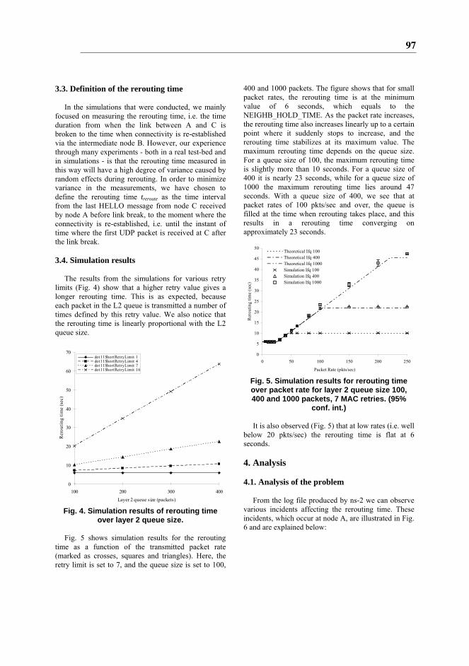
3.3. Definition of the rerouting time In the simulations that were conducted, we mainly
focused on measuring the rerouting time, i.e. the time duration from when the link between A and C is broken to the time when connectivity is re-established via the intermediate node B. However, our experience through many experiments - both in a real test-bed and in simulations - is that the rerouting time measured in this way will have a high degree of variance caused by random effects during rerouting. In order to minimize variance in the measurements, we have chosen to define the rerouting time treroute as the time interval from the last HELLO message from node C received by node A before link break, to the moment where the connectivity is re-established, i.e. until the instant of time where the first UDP packet is received at C after the link break.
3.4. Simulation results
The results from the simulations for various retry
limits (Fig. 4) show that a higher retry value gives a longer rerouting time. This is as expected, because each packet in the L2 queue is transmitted a number of times defined by this retry value. We also notice that the rerouting time is linearly proportional with the L2 queue size.
0
10
20
30
40
50
60
70
100 200 300 400Layer 2 queue size (packets)
Rer
outin
g tim
e (s
ec)
dot11ShortRetryLimit 1dot11ShortRetryLimit 4dot11ShortRetryLimit 7dot11ShortRetryLimit 16
Fig. 4. Simulation results of rerouting time
over layer 2 queue size. Fig. 5 shows simulation results for the rerouting
time as a function of the transmitted packet rate (marked as crosses, squares and triangles). Here, the retry limit is set to 7, and the queue size is set to 100,
400 and 1000 packets. The figure shows that for small packet rates, the rerouting time is at the minimum value of 6 seconds, which equals to the NEIGHB_HOLD_TIME. As the packet rate increases, the rerouting time also increases linearly up to a certain point where it suddenly stops to increase, and the rerouting time stabilizes at its maximum value. The maximum rerouting time depends on the queue size. For a queue size of 100, the maximum rerouting time is slightly more than 10 seconds. For a queue size of 400 it is nearly 23 seconds, while for a queue size of 1000 the maximum rerouting time lies around 47 seconds. With a queue size of 400, we see that at packet rates of 100 pkts/sec and over, the queue is filled at the time when rerouting takes place, and this results in a rerouting time converging on approximately 23 seconds.
0
5
10
15
20
25
30
35
40
45
50
0 50 100 150 200 250
Packet Rate (pkts/sec)
Rer
outin
g tim
e (s
ec)
Theoretical Ifq 100Theoretical Ifq 400Theoretical Ifq 1000Simulation Ifq 100Simulation Ifq 400Simulation Ifq 1000
Fig. 5. Simulation results for rerouting time over packet rate for layer 2 queue size 100, 400 and 1000 packets, 7 MAC retries. (95%
conf. int.) It is also observed (Fig. 5) that at low rates (i.e. well
below 20 pkts/sec) the rerouting time is flat at 6 seconds.
4. Analysis 4.1. Analysis of the problem
From the log file produced by ns-2 we can observe
various incidents affecting the rerouting time. These incidents, which occur at node A, are illustrated in Fig. 6 and are explained below:
97

Fig. 6. Illustrating different incidents at node A’s queue as function of time.
1) In region I, data packets are continuously
inserted into the transmit queue at node A. At time t0, the last HELLO message from C is received at A (short line in the figure). Then, after tb seconds, the direct link between A and C is broken at t1.
2) Although the link between A and C is broken, the routing protocol is still not aware of this, and therefore has not updated the routing table. As a result, “garbage” data packets with stale routing information continue to be put into the queue at node A.
3) In region II, i.e. t1< t <t2, the queue at node A is being filled up. This happens since each garbage data packet in the queue at node A is retransmitted L times, where L is the retry limit. Because of all the retransmissions for each packet, the packet rate out of queue Rout will be reduced considerably. As long as the packet rate Rin into the queue is higher than Rout, the queue will be filled up. This will last for td – tb seconds, where td is the timeout value for the routing protocol’s HELLO packets (which is equivalent with NEIGHB_HOLD_TIME in OLSR).
4) At t2, garbage packets are no longer put into the queue. The routing protocol has now updated the routing tables. New data packets are instead correctly rerouted to B.
5) In region III, i.e. t2< t <t3, the queue is being emptied for garbage packets. This will last for te seconds, depending on parameter values like Rin, L, packet size, queue size etc.
Note that packets are attempted transmitted and removed from the queue both in region II and region III. Thus, the queue will fill up in region II only if Rin>Rout. However, for the lowest packet rates, we will have Rin<Rout, and the queue will not be filled. In the latter case, both region II and region III will be non-existent, and the routing interval consists of only region I. This explains why the rerouting time is flat at 6 seconds for the lowest packet rates in Fig. 5.
In summary, the incidents in the time interval t0< t <t3 are the main contributions to the rerouting time as defined above. It is also worth noting that in our test scenario, the delay from a TC message is irrelevant for the rerouting time. This is due to the fact that prior to the link break, node A will have node C in both its 1-hop and 2-hop neighbor sets. When A discovers a link
break between A and C, A still has a route to C in its 2-hop neighbor table, i.e. through node B. Therefore, node A does not need to wait for any TC message from B in order to figure out how to reach C.
4.2. A model for the rerouting time Based on the observations above we have derived a
simple analytical model that can be used to predict the rerouting time. The derivation of the model is given below:
tdifs DCF interframe space tbo backoff time tdata delay for transmitting the data packet tsifs short interframe space tack delay of acknowledge Te slot time in IEEE 802.11 tRTS delay of a RTS packet tCTS delay of a CTS packet L number of retries B queue size 1) According to the 802.11 standard, the delay of
attempting to transmit a single packet over a broken link is
bocpacket tTt += (1)
where Tc is the delay associated with the
transmission attempt, and tbo is the delay associated with the backoff. In our scenario, no ACK is received when the link is broken, and the transmission attempt is therefore perceived as a collision. However, according to the standard, a node must wait an ACKTimeout amount of time without receiving an ACK frame before concluding that the transmission failed. In our case, this ACKTimeout corresponds to the transmission of an ACK for a successfully transmitted frame. Thus, the delay associated with the transmission attempt, Tc, is equal to the delay associated with a successful transmission, Ts:
acksifsdatadifssc ttttTT +++== . (2a)
With the RTS/CTS mechanism, on the contrary:
timoutCTSRTSdifsc tttT _++= . (2b)
Prior to each packet transmission, a backoff time is
uniformly chosen in the range (0, Wj -1). Here we
98 Rerouting Time and Queueing in Proactive Ad Hoc Networks
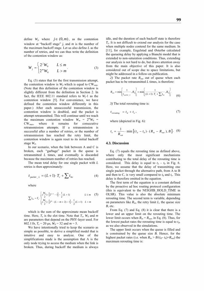
define Wj, where ),0( mj∈ , as the contention window at “backoff stage” j, and m is the number of the maximum backoff stage. Let us also define L as the number of retries, and we can thus write the definition of the contention window as:
⎩⎨⎧
>≤
=mLWmLW
W m
j
j0
0
22
. (3)
Eq. (3) states that for the first transmission attempt,
the contention window is W0 which is equal to CWmin. (Note that this definition of the contention window is slightly different from the definition in Section 2. In fact, the IEEE 802.11 standard refers to Wj-1 as the contention window [5]. For convenience, we have defined the contention window differently in this paper.) After each unsuccessful transmission, the contention window is doubled, and the packet is attempt retransmitted. This will continue until we reach the maximum contention window Wm = 2mW0 = CWmax, where it remains for consecutive retransmission attempts. If a retransmission is successful after a number of retries, or the number of retransmission has reached the retry limit, the contention window is again reset to its initial backoff stage W0.
In our scenario, when the link between A and C is broken, each “garbage” packet in the queue is retransmitted L times, and eventually is discarded because the maximum number of retries has reached.
The mean total delay for one single packet with L retries is then approximately:
∑+⋅+= bocLpacket tTLt )1(_ (4)
where
[ ]
[ ]⎪⎪⎩
⎪⎪⎨
⎧
>+−−+−⋅⋅
≤+−−⋅⋅=
+
∑mLLmL
W
mLLW
Ttm
L
ebo
)1(211)2(2)
2(
)1(2112)
2(
0
10 (5)
which is the sum of the approximate mean backoff
time. Here, Te is the slot time. Note that Te, W0 and m are parameters that depend on the PHY-layer used. For 802.11b, Te = 20 μs, W0 = 32 and m = 5.
We have intentionally tried to keep the scenario as simple as possible, to derive a simplified model that is intuitive and easy to analyze. One of the simplifications made is the assumption that A is the only node trying to access the medium when the link is broken. Thus, during backoff the medium is always
idle, and the duration of each backoff state is therefore Te. It is not difficult to extend our analysis for the case when multiple nodes contend for the same medium. In [11], for example, Engelstad and Østerbø calculated the queueing delay by applying a Bianchi model that is extended to non-saturation conditions. Thus, extending our analysis is not hard to do, but draws attention away from the main objective of this paper. It is also considered out of scope due to space limitations, but might be addressed in a follow-on publication.
2) The packet rate Rout out of queue when each packet has to be retransmitted L times, is therefore:
.,)1(
1min,1min_ ⎥
⎥⎦
⎤
⎢⎢⎣
⎡
+⋅+=
⎥⎥⎦
⎤
⎢⎢⎣
⎡=
∑ inboc
inLpacket
out RtTL
Rt
R (6)
3) The total rerouting time is:
edrerouting ttt += , (7)
where (depicted in Fig. 6):
[ ]BRRttR
t outinbdout
e ),()(min1−⋅−⋅= . (8)
4.3. Discussion
Eq. (7) equals the rerouting time as defined above,
where only the most significant mechanisms contributing to the total delay of the rerouting time is considered. This delay is equal to t3 – t0 in Fig. 6. Here, we assume that the delay of transmitting one single packet through the alternative path, from A to B and then to C, is very small compared to td and te. This delay is therefore omitted in the equation.
The first term of the equation is a constant defined by the proactive ad hoc routing protocol configuration (this is equivalent to the NEIGHB_HOLD_TIME in OLSR). This value is also the absolute minimum rerouting time. The second term is variable, depending on parameters like Rin, the retry limit L, the queue size B, etc.
From Eq. (7) and Eq. (8) it is clear that there is a lower and an upper limit on the rerouting time. The lower limit occurs when Rin = Rout, in Eq. (8). Thus, for the lowest packet rates the rerouting time is equal to td, as we also observed in the simulations.
The upper limit occurs when the queue is filled and is constrained by the queue size B. Hence, for the highest packet rates (i.e. when Rin > B/(td– tb)+Rout) the maximum rerouting time is:
99
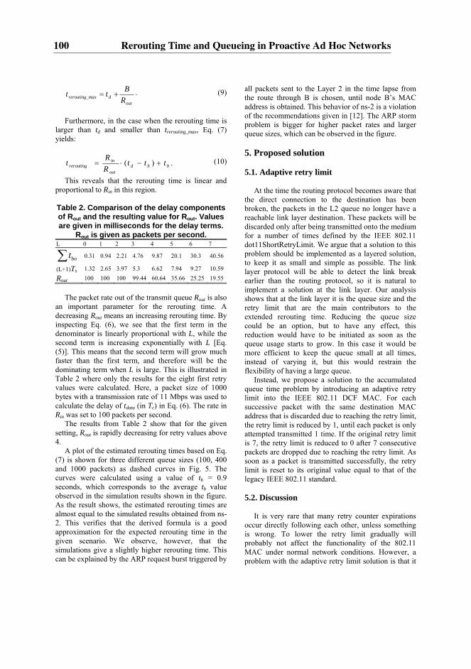
outdmaxrerouting_ R
Btt += . (9)
Furthermore, in the case when the rerouting time is
larger than td and smaller than trerouting_max, Eq. (7) yields:
.)( bbdout
inrerouting ttt
RR
t +−⋅= (10)
This reveals that the rerouting time is linear and proportional to Rin in this region.
Table 2. Comparison of the delay components of Rout and the resulting value for Rout. Values are given in milliseconds for the delay terms.
Rout is given as packets per second. L 0 1 2 3 4 5 6 7
∑ bot 0.31 0.94 2.21 4.76 9.87 20.1 30.3 40.56
(L+1)Ts 1.32 2.65 3.97 5.3 6.62 7.94 9.27 10.59
Rout 100 100 100 99.44 60.64 35.66 25.25 19.55
The packet rate out of the transmit queue Rout is also
an important parameter for the rerouting time. A decreasing Rout means an increasing rerouting time. By inspecting Eq. (6), we see that the first term in the denominator is linearly proportional with L, while the second term is increasing exponentially with L [Eq. (5)]. This means that the second term will grow much faster than the first term, and therefore will be the dominating term when L is large. This is illustrated in Table 2 where only the results for the eight first retry values were calculated. Here, a packet size of 1000 bytes with a transmission rate of 11 Mbps was used to calculate the delay of tdata (in Tc) in Eq. (6). The rate in Rin was set to 100 packets per second.
The results from Table 2 show that for the given setting, Rout is rapidly decreasing for retry values above 4.
A plot of the estimated rerouting times based on Eq. (7) is shown for three different queue sizes (100, 400 and 1000 packets) as dashed curves in Fig. 5. The curves were calculated using a value of tb = 0.9 seconds, which corresponds to the average tb value observed in the simulation results shown in the figure. As the result shows, the estimated rerouting times are almost equal to the simulated results obtained from ns-2. This verifies that the derived formula is a good approximation for the expected rerouting time in the given scenario. We observe, however, that the simulations give a slightly higher rerouting time. This can be explained by the ARP request burst triggered by
all packets sent to the Layer 2 in the time lapse from the route through B is chosen, until node B’s MAC address is obtained. This behavior of ns-2 is a violation of the recommendations given in [12]. The ARP storm problem is bigger for higher packet rates and larger queue sizes, which can be observed in the figure.
5. Proposed solution 5.1. Adaptive retry limit
At the time the routing protocol becomes aware that
the direct connection to the destination has been broken, the packets in the L2 queue no longer have a reachable link layer destination. These packets will be discarded only after being transmitted onto the medium for a number of times defined by the IEEE 802.11 dot11ShortRetryLimit. We argue that a solution to this problem should be implemented as a layered solution, to keep it as small and simple as possible. The link layer protocol will be able to detect the link break earlier than the routing protocol, so it is natural to implement a solution at the link layer. Our analysis shows that at the link layer it is the queue size and the retry limit that are the main contributors to the extended rerouting time. Reducing the queue size could be an option, but to have any effect, this reduction would have to be initiated as soon as the queue usage starts to grow. In this case it would be more efficient to keep the queue small at all times, instead of varying it, but this would restrain the flexibility of having a large queue.
Instead, we propose a solution to the accumulated queue time problem by introducing an adaptive retry limit into the IEEE 802.11 DCF MAC. For each successive packet with the same destination MAC address that is discarded due to reaching the retry limit, the retry limit is reduced by 1, until each packet is only attempted transmitted 1 time. If the original retry limit is 7, the retry limit is reduced to 0 after 7 consecutive packets are dropped due to reaching the retry limit. As soon as a packet is transmitted successfully, the retry limit is reset to its original value equal to that of the legacy IEEE 802.11 standard.
5.2. Discussion
It is very rare that many retry counter expirations
occur directly following each other, unless something is wrong. To lower the retry limit gradually will probably not affect the functionality of the 802.11 MAC under normal network conditions. However, a problem with the adaptive retry limit solution is that it
100 Rerouting Time and Queueing in Proactive Ad Hoc Networks

might lead to an unfair resource distribution in terms of collision avoidance. The node sending packets that go unacknowledged will be able to contend for the medium with a high probability of a smaller backoff-counter than its peers. On the other hand, the emptying of stale packets from the queue takes place in a small period of time, and it is much more efficient to send a garbage packet only one time, than sending it multiple times. Another drawback is that the transmission attempts of garbage packets consume network resources. More complex solutions where the MAC layer discards packets without attempting to transmit them is certainly also possible. In summary, there are a number of variations of the proposed adaptive retry limit solution. The performance of a number of these variations in various networking scenarios will be detailed and discussed in a follow-on publication.
5.3. Implementation
To do the actual implementation in ns-2 we needed
to introduce two new variables. The first of these new variables, IDt, keeps track of the destination of the last transmission attempt, and the second variable, called PCnt, counts the number of packets discarded because the retry counter has reached the retry limit.
Each time a packet is discarded because the retry counter has reached the retry limit, the PCnt is increased, until it reaches the value of the retry limit.
The PCnt is subtracted from the original retry limit, so that the effective retry limit gets lower and lower as the PCnt increases, until new packets are only transmitted once, and then discarded if not acknowledged by the receiving node.
If a packet is transmitted to a new destination, PCnt is set to 0 and IDt is updated. If the transmission was successful (indicated by a received ACK), the PCnt is set to 0.
5.4. Simulation results
In the simulation results of the adaptive retry limit
solution (Fig. 7, with L2 queue size 400 packets and 7 MAC retries) we observe that with the proposed solution the rerouting time is kept at 6 seconds (which equals to NEIGHB_HOLD_TIME) until the packet rate exceeds 600 pkts/sec. At this packet rate the bit rate approaches the theoretical maximum throughput (TMT) of 5.03 Mbps (for 1000 bytes sized packets, and for a network with one sender, where backoff time has to be taken into account). When the packet rate is higher than TMT, the L2 queue gets filled also when
the link between A and C is not broken. This is because Rout is smaller than Rin at all times.
0
5
10
15
20
25
0 100 200 300 400 500 600 700
Packet rate (pkts/sec)
Rer
outin
g tim
e (s
ec)
Theoretical Ifq 400Theoretical Adaptive Ifq 400Adaptive Ifq 400Simulation Ifq 400
TMT
Fig. 7. Simulated results for solution with
adaptive retry limit. (95% conf. int.) Our solution prevents Rout from decreasing when
the link between A and C is broken, by limiting the accumulated number of retransmissions. The results from the simulations have proven that the adaptive retry limit solution effectively eliminates the delay related to the queueing problem.
The proposed solution is a layered approach based at the link layer, but in some cases it would be more convenient to solve the problem at the IP-layer. This is left for further work.
6. Related work
An analysis of several neighbor sensing approaches
is presented in [13]. The objective is to better be able to optimize performance in an OLSR network.
In [14], the OLSR routing protocol is evaluated through both simulations and experiments. Both route-flapping and control packet collisions are described, and solutions for these problems are proposed.
The tuning of routing protocol parameters in order to improve the end-to-end connectivity is studied in [15]. A performance metric called Routing Change Latency (RCL) is defined and analyzed. This metric is defined as “the time needed to determine a new route after a link failure”, but it also comprises a time lapse after the new route is discovered, until it is actually used. This time lapse is denoted as Tnew_route. It is not explained, but observed to vary between 4.62 s and 8.86 s
101
7. Conclusions and further work The rerouting time is an important performance
measure in MANETs where node mobility is usually high, and connectivity between nodes may be disrupted frequently. For ongoing data traffic that suffers from link failures, it is highly desirable to reestablish connectivity through alternative paths as fast as possible. In this paper we have looked closer on a simple scenario where we have identified that queueing is among the main factors having considerable impact on the rerouting time.
The latency related to queueing is mainly affected by two parameters, namely the transmit queue size and the retry limit. A large transmit queue size may result in a too high amount of garbage packets with stale routing information being inserted into it. In addition, a high retry value may result in too many wasted retransmission attempts for these garbage packets. The combination of these factors might extend the rerouting time considerably.
We have derived a simple model that can be used to estimate the rerouting time. Comparisons of the estimated and simulated rerouting times have shown that the model is a good approximation. The analysis is used to explain how queueing might increase the rerouting time. In order to solve this problem, we have proposed a simple but very effective solution based on adaptive retry limit in the 802.11 DCF MAC. The queueing problem is resolved by decrementing the maximum retry value when successive packets for the same MAC destination are discarded due to expiration of the retry limit. The proposed solution was implemented and tested in simulations, and the results have shown how effective it can be. In fact, as long as the data rate into the queue is safely below the capacity of the MAC, the solution eliminates the queueing problem associated with the rerouting time.
Although the proposed solution seems to be very effective, there might be some problems associated with it. For example, the solution might lead to an unfair resource distribution in terms of collision avoidance. This needs to be explored in detail, and will be addressed by a follow-on publication.
It might also be possible to implement more complex solutions where the MAC layer discards packets without attempting to transmit them. Various variations of our solution will also be studied.
The proposed solution is a simple way to resolve queueing related delays. We believe there are other possibilities in solving the problem or improving the existing solution. A solution based on cross-layering, where L2 can send a notification up to L3, helping the
routing protocol to detect link breaks much earlier is an exciting area. All this is also left to future works.
8. Acknowledgment
This work was supported by the ITEA Easy
Wireless and CELTIC DeHiGate projects. We also thank the FFI project Tipper for their support.
References [1] IETF working group Mobile Ad-hoc Networks,
http://www.ietf.org/html.charters/manet-charter.html [2] T. Clausen, P. Jacquet, “Optimized Link State Routing
Protocol (OLSR)”, RFC 3626, October 2003. [3] http://www.olsr.org/ [4] IETF MANET OSPF design team repository,
http://hipserver.mct.phantomworks.org/ietf/ospf/ [5] ANSI/IEEE Std 802.11, 1999 Edition (R2003). [6] F. Tobagi and L. Kleinrock, “Packet Switching in
Radio Channels: Part 2-The Hidden Node Problem in Carrier Sense Multiple Access Modes and the Busy Tone Solution”, IEEE Trans. Comm., vol. 23, no. 12, pp. 1417-1433, 1975.
[7] G. Chuanxiong, Z. Shaoren, “Analysis and evaluation of the TCP/IP protocol stack of LINUX”, International Conference on Communication Technology Proceedings, 2000. WCC - ICCT 2000, Vol. 1 (2000), pp. 444-453 vol.1.
[8] Network Simulator ns-2, http://www.isi.edu/nsnam/ns/ [9] ANSI/IEEE Std 802.11b, 1999 Edition (R2003). [10] MANET Simulation and Implementation at the
University of Murcia (MASIMUM), http://masimum.dif.um.es/
[11] Engelstad, P.E., Østerbø, O.N., "Analysis of the Total Delay of IEEE 802.11e EDCA and 802.11 DCF", Proceedings of IEEE International Conference on Communication (ICC'2006), Istanbul, June 11-15, 2006. (See also: http://folk.uio.no/paalee)
[12] R. Braden (Editor), “Requirements for Internet Hosts – Communication Layers”, RFC 1122, October 1989.
[13] M. Voorhaen, C. Blondia, “Analyzing the Impact of Neighbor Sensing on the Performance of the OLSR protocol”, Proceedings of the 4th International Symposium on Modeling and Optimization in Mobile, Ad Hoc and Wireless Networks, 03-06 April 2006.
[14] T. Clausen, G. Hansen, L. Christensen, G. Behrmann, ”The Optimized Link State Routing Protocol Evaluation through Experiments and Simulation”, IEEE Symposium on “Wireless Personal Mobile Communications, September 2001.
[15] C. Gomez, D. Garcia, J. Paradells, “Improving Performance of a Real Ad-hoc Network by Tuning OLSR Parameters”, Proceedings of the 10th IEEE Symposium on Computers and Communications (ISCC), 2005.
102 Rerouting Time and Queueing in Proactive Ad Hoc Networks

Paper B :
Routing of Internal MANETTraffic over External Networks
V. Pham, E. Larsen, Ø. Kure, P. Engelstad,
Mobile Information Systems Journal, iiWAS/MoMM special issue, Volume 5,Number 3, 2009
103

Is not included due to copyright
Paper C :
Performance Analysis ofGateway Load Balancing in AdHoc Networks with RandomTopologies
V. Pham, E. Larsen, P. E. Engelstad, Ø. Kure
In proceedings of The 7th ACM International Symposium on Mobility Manage-ment and Wireless Access (Mobiwac09), Tenerife, Canary Islands October 26-30,2009
127

Is not included due to copyright
Paper D :
Gateway Load Balancing inFuture Tactical Networks
V. Pham, E. Larsen, Ø. Kure, P. Engelstad
In proceedings of The IEEE Military Communications Conference (MILCOM),San Jose, CA, USA, October 31–November 4, 2010.
139

140 Gateway Load Balancing in Future Tactical Networks

Abstract—In future tactical networks, gateway nodes will have
an important role in connecting different military
communications platforms together to form a consolidated
network. To increase capacity for upstream/downstream traffic
as well as resiliency, more than one gateway should be deployed.
In this context, performing gateway load balancing is vital in
order to take full advantage of the resources available and
thereby improve the performance. Previous work has shown that
a number of factors such as the level of asymmetry, offered load,
and gateway location may influence the performance of load
balancing. However these parameters alone cannot explain why
the performance of load balancing is high for certain topologies
while it is very poor for others. Obviously, the specific layout of a
topology also plays a crucial role on the efficiency of load
balancing. We question what are the differences between
topologies where load balancing is efficient from the topologies
where it is inefficient? The work in this paper thus aims to find
the answer to this question, and to explore the nature of
performing load balancing in wireless multi-hop networks.
Through the knowledge acquired we propose a Radio load based
Load Balancing scheme (RLLB). Simulations of many randomly
generated topologies show that the performance of RLLB is
promising.
I. INTRODUCTION
The advances in Information Technology have motivated for a transformation from a platform-centric towards a Network-centric warfare [1]. The key is more efficient information sharing and improved shared situational awareness facilitated by the underlying network communication infrastructure. In order to accommodate this vision, future tactical networks must support internetworking in multi-tiers networks and/or between heterogeneous communication platforms. An example is internetworking between troop Mobile Ad Hoc Networks (MANET) [2] and remote Tactical Operations Center via high capacity quasi-static backbone networks. Furthermore, internetworking between allied forces is also a highly desirable capability.
In this context, the gateway node plays an important role as a bridge between different networks domains. Since all upstream/downstream inter-domain traffic must traverse the gateway, this node will often become the bottleneck in the network. Furthermore, in a combat scenario, with a single gateway available, the network has a single point of failure and is vulnerable to loss of connectivity. Thus to improve the network in terms of capacity for inter-domain traffic as well as resiliency, more than one gateway should be deployed. However, in order to take full advantage of the increased capacity that comes with multiple gateways and achieve higher network performance, performing load balancing between gateways is vital.
In the literature, there are a number of proposals suggesting various load balancing schemes targeted for MANETs [3-6] and Wireless Mesh Networks (WMNs) [7-10]. These
proposals are in general based on a variety of techniques for evaluating the network load, such as RTT [10], average queue length [9,11,12] and number of active flows [13,14]. Furthermore, load balancing is commonly classified into two categories: multipath and gateway load balancing.
In multipath load balancing [3,4], the traffic load between a source node and a destination/gateway is distributed among a set of alternative paths in order to maximize throughput performance and minimize the impact of route failure. However, [3,4] report that multi-path load balancing in single channel wireless networks only provides a negligible improvement in the performance due to route coupling among the alternative paths. Multipath load balancing is therefore not of interest in this paper.
On the other hand, with the gateway load balancing approach, the traffic load is attempt distributed between gateways in order to reduce the load imbalance and to maximize the total network throughput. Such gateway load balancing is considered to improve the network performance more effectively than multipath load balancing [7]. In this paper, we therefore focus only on gateway load balancing, and we will refer to it simply as “load balancing” in the remainder of the paper.
The previous work in [15] has shown that a number of parameters such as the level of asymmetry (in node and load distribution), offered load, gateway distance, carrier sensing range, may influence the performance of load balancing. However these parameters alone cannot explain why for certain topologies, load balancing may considerably improve the throughput, while for others, the improvement is very poor. This indicates that the specific layout of a topology is another decisive factor for whether load balancing is efficient or not. The question is what is the difference between topologies where load balancing is efficient from those that are not? The work in this paper is thus concerned with the answers to this question through the analysis of static topologies. We argue that using static topologies for this purpose are suitable, in which the direct relation between the specific layout and the performance of load balancing may be revealed. With mobile topologies, this would not be possible. However, the insight and knowledge gained through this analysis may serve as a building block in the work of performing load balancing in mobile topologies.
Through the knowledge learnt, we developed the Radio-
load based Load Balancing scheme (RLLB) as a means to verify the results of the analysis. Simulation results show that the proposed scheme has a promising performance.
Finally, the study in this paper in based on IEEE 802.11 MAC- and PHY-layer [18] due to availability and secondly, we believe that the demand for high bandwidth capacity for supporting services such as video streaming is highly relevant
Vinh Pham*, Erlend Larsen*, Øivind Kure*, Paal E. Engelstad† *Q2S NTNU, †SimTel (Telenor/Simula)
Email: *†{vph, erl, paalee, okure}@unik.no
Gateway Load Balancing in Future Tactical Networks
141
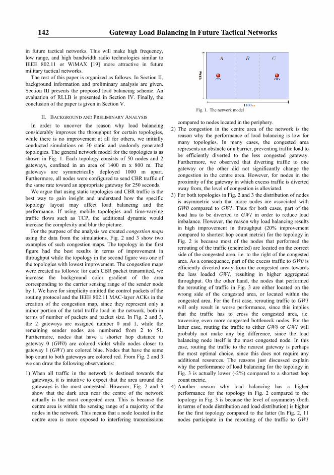
in future tactical networks. This will make high frequency, low range, and high bandwidth radio technologies similar to IEEE 802.11 or WiMAX [19] more attractive in future military tactical networks.
The rest of this paper is organized as follows. In Section II, background information and preliminary analysis are given. Section III presents the proposed load balancing scheme. An evaluation of RLLB is presented in Section IV. Finally, the conclusion of the paper is given in Section V.
II. BACKGROUND AND PRELIMINARY ANALYSIS
In order to uncover the reason why load balancing considerably improves the throughput for certain topologies, while there is no improvement at all for others, we initially conducted simulations on 30 static and randomly generated topologies. The general network model for the topologies is as shown in Fig. 1. Each topology consists of 50 nodes and 2 gateways, confined in an area of 1400 m x 800 m. The gateways are symmetrically deployed 1000 m apart. Furthermore, all nodes were configured to send CBR traffic of the same rate toward an appropriate gateway for 250 seconds.
We argue that using static topologies and CBR traffic is the best way to gain insight and understand how the specific topology layout may affect load balancing and the performance. If using mobile topologies and time-varying traffic flows such as TCP, the additional dynamic would increase the complexity and blur the picture.
For the purpose of the analysis we created congestion maps using the data from the simulations. Fig. 2 and 3 show two examples of such congestion maps. The topology in the first figure had the best results in terms of improvement in throughput while the topology in the second figure was one of the topologies with lowest improvement. The congestion maps were created as follows: for each CBR packet transmitted, we increase the background color gradient of the area corresponding to the carrier sensing range of the sender node by 1. We have for simplicity omitted the control packets of the routing protocol and the IEEE 802.11 MAC-layer ACKs in the creation of the congestion map, since they represent only a minor portion of the total traffic load in the network, both in terms of number of packets and packet size. In Fig. 2 and 3, the 2 gateways are assigned number 0 and 1, while the remaining sender nodes are numbered from 2 to 51. Furthermore, nodes that have a shorter hop distance to gateway 0 (GW0) are colored violet while nodes closer to gateway 1 (GW1) are colored blue. Nodes that have the same hop count to both gateways are colored red. From Fig. 2 and 3 we can draw the following observations:
1) When all traffic in the network is destined towards the gateways, it is intuitive to expect that the area around the gateways is the most congested. However, Fig. 2 and 3 show that the dark area near the centre of the network actually is the most congested area. This is because the centre area is within the sensing range of a majority of the nodes in the network. This means that a node located in the centre area is more exposed to interfering transmissions
Fig. 1. The network model
compared to nodes located in the periphery.
2) The congestion in the centre area of the network is the reason why the performance of load balancing is low for many topologies. In many cases, the congested area represents an obstacle or a barrier, preventing traffic load to be efficiently diverted to the less congested gateway. Furthermore, we observed that diverting traffic to one gateway or the other did not significantly change the congestion in the centre area. However, for nodes in the proximity of the gateway in which excess traffic is diverted away from, the level of congestion is alleviated.
3) For both topologies in Fig. 2 and 3 the distribution of nodes is asymmetric such that more nodes are associated with GW0 compared to GW1. Thus for both cases, part of the load has to be diverted to GW1 in order to reduce load imbalance. However, the reason why load balancing results in high improvement in throughput (20% improvement compared to shortest hop count metric) for the topology in Fig. 2 is because most of the nodes that performed the rerouting of the traffic (encircled) are located on the correct side of the congested area, i.e. to the right of the congested area. As a consequence, part of the excess traffic to GW0 is efficiently diverted away from the congested area towards the less loaded GW1, resulting in higher aggregated throughput. On the other hand, the nodes that performed the rerouting of traffic in Fig. 3 are either located on the wrong side of the congested area, or located within the congested area. For the first case, rerouting traffic to GW1 will only result in worse performance, since this implies that the traffic has to cross the congested area, i.e. traversing even more congested bottleneck nodes. For the latter case, routing the traffic to either GW0 or GW1 will probably not make any big difference, since the load balancing node itself is the most congested node. In this case, routing the traffic to the nearest gateway is perhaps the most optimal choice, since this does not require any additional resources. The reasons just discussed explain why the performance of load balancing for the topology in Fig. 3 is actually lower (-2%) compared to a shortest hop count metric.
4) Another reason why load balancing has a higher performance for the topology in Fig. 2 compared to the topology in Fig. 3 is because the level of asymmetry (both in terms of node distribution and load distribution) is higher for the first topology compared to the latter (In Fig. 2, 11 nodes participate in the rerouting of the traffic to GW1
142 Gateway Load Balancing in Future Tactical Networks
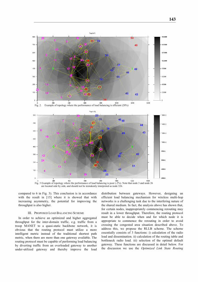
Fig. 2. Example of topology where the performance of load balancing is efficient (20%)
Fig. 3 Example of topology where the performance of load balancing is poor (-2%). Note that node 3 and node 26
are located side by side, and should not be mistakenly interpreted as node 326.
compared to 6 in Fig. 3). This conclusion is in accordance with the result in [15] where it is showed that with increasing asymmetry, the potential for improving the throughput is also higher.
III. PROPOSED LOAD BALANCING SCHEME
In order to achieve an optimized and higher aggregated throughput for the inter-domain traffic, e.g. traffic from a troop MANET to a quasi-static backbone network, it is obvious that the routing protocol must utilize a more intelligent metric instead of the traditional shortest path metric, when there are more than one gateway available. The routing protocol must be capable of performing load balancing by diverting traffic from an overloaded gateway to another under-utilized gateway and thereby improve the load
distribution between gateways. However, designing an efficient load balancing mechanism for wireless multi-hop networks is a challenging task due to the interfering nature of the shared medium. In fact, the analysis above has shown that, for certain nodes, inappropriately commencing rerouting may result in a lower throughput. Therefore, the routing protocol must be able to decide when and for which node it is appropriate to commence the rerouting in order to avoid crossing the congested area situation described above. To address this, we propose the RLLB scheme. The scheme essentially consists of 3 functions: i) calculation of the radio load and dissemination. ii) calculation of the routing table and bottleneck radio load. iii) selection of the optimal default gateway. These functions are discussed in detail below. For the discussion we use the Optimized Link State Routing
143

Protocol (OLSR) [16] as a reference routing protocol. However we believe that the same idea is also applicable to similar proactive routing protocols.
A. Calculation of Radio Load and Dissemination
The radio load is a measure for how busy the medium around a node is. If the radio load is high, it indicates either that the local node is transmitting a large amount of traffic, and/or nodes within the sensing range of the local node are sending a high amount of traffic. We define the radio load as the amount of time Tbusy within a time window Twindow where the local channel is monitored busy. To estimate the average radio load L we use the exponential moving average as follows:
(1 ) busy
new previous
window
TL L
Tα α= ⋅ + − ⋅ (1)
where α is the weighting factor defined as α ∈ [0,1]. Each node in the network monitors the channel and
calculates the perceived local radio load. This information is made available to the routing protocol, which is then responsible for disseminating this information throughout the network. In this paper, the RLLB scheme is integrated with the proactive OLSR routing protocol, and in order to minimize control traffic overhead, the radio load information is therefore disseminated using a modified version of the TC message. Upon receiving TC messages, the radio load information is stored in a local repository for later use by RLLB.
B. Calculation of Routing Table and Bottleneck Radio Load
The calculation of the routing table is performed in the same way as in the ordinary OLSR implementation, i.e. based on Dijkstra’s algorithm. However, during the calculation of the routing table, the bottleneck radio load Bi is also calculated for each destination Di that is added into the routing table. Bi is defined as the highest observed value of radio load along the path from the local node to the destination Di. In order to facilitate this, we introduce a new field R_radio_load in the routing table. This field stores the value of Bi for a given destination Di in the R_dest_addr field.
C. Selecting the Default Gateway
Using the radio load information that is disseminated in the network, a local node may determine the gateway which is the most optimal and then select it as the default gateway.
Fig. 4. Model for gateway selection
Consider the scenario in Fig. 4. A local node ni is located h0
and h1 hops from gateway GW0 and GW1 respectively. The reported radio load at gateway GW0 and GW1 is L0 and L1. B0 and B1 are the bottleneck radio load to GW0 and GW1
respectively. The pseudo code below implements the selection of the optimal default gateway:
1 if (h0 == h1) 2 if (L0 < L1) 3 default_gw = GW0 4 else 5 default_gw = GW1 6 else if abs(h0 - h1) > MAX_HOPS 7 if (h0 < h1) 8 default_gw = GW0 9 else 10 default_gw = GW1 11 else if abs(h0 - h1) ≤ MAX_HOPS 12 if (B0-B1 > THRESHOLD) and default_gw=GW0 13 default_gw = GW1 14 if (B1-B0 > THRESHOLD) and default_gw=GW1. 15 default_gw = GW0.
Lines 1-5 ensure that the least congested gateway is selected as default gateway when the local node has the same hop distance to both gateways. Lines 6-10 restrict a node to select an alternative less congested gateway if this gateway is more than MAX_HOPS farther away than the nearest gateway. This restriction is necessary to minimize the excessive usage of network resources for the purpose of load balancing. Besides, a long path (in number of hops) in wireless networks implies reduced end to end bandwidth and increased packet loss probability, which in turn will reduce the throughput. Finally, lines 11-15 basically enforce selecting the gateway GWi with the lowest bottleneck radio load Bi as default gateway. In order to avoid frequent route flapping (also know as the ping pong effect), the selection of a new default gateway is only commenced if the bottleneck radio load of the new gateway is less than the current gateway by the THRESHOLD value. Note that the bottleneck radio load Bi is used as metric for comparison, in contrast to line 2 where the local radio load Li is used. By using Bi instead of Li we can prevent crossing the congested area situation to occur. For example, if L0 > L1 and B0 < B1, this means that even though GW1 is less congested than GW0, selecting GW1 as the default gateway will probably result in a lower throughput, since the bottleneck radio load of the path to GW1 is higher than the path to GW0.
In the discussion above only two gateways were considered for simplicity. However this concept may be adapted to a more generic case with multiple gateways.
IV. EVALUATION
A. Routing Metrics
The evaluation of the proposed load balancing scheme is performed by simulations in ns-2 [17] on a large number of randomly generated topologies. In addition to simulations with the proposed RLLB metric, each topology is also simulated with 3 other types of routing metrics (used in [15]) to facilitate comparison. These routing metrics are described below.
TABLE 1. SIMULATION PARAMETERS
144 Gateway Load Balancing in Future Tactical Networks
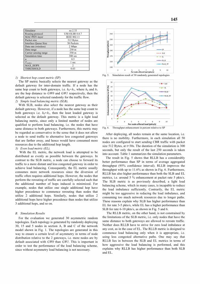
Simulator ns-2.33 Routing protocol UM-OLSR 0.8.7 MAC/PHY-layer IEEE 802.11 Packet size 512 Bytes Interface Queue Size 50 Packets Data rate (wireless) 2 Mbps Data range 250 m Carrier sensing range 550 m Simulation time 300 sec α 0.5 Twindow 1 sec MAX_HOPS 2 THRESHOLD 0.03
1) Shortest hop count metric (SP)
The SP metric basically selects the nearest gateway as the default gateway for inter-domain traffic. If a node has the same hop count to both gateways, i.e. h0=h1, where h0 and h1 are the hop distance to GW0 and GW1 respectively, then the default gateway is selected randomly for the traffic flow. 2) Simple load balancing metric (SLB),
With SLB, nodes also select the nearest gateway as their default gateway. However, if a node has the same hop count to both gateways i.e. h0=h1, then the least loaded gateway is selected as the default gateway. This metric is a light load balancing metric, since only a limited number of nodes are qualified to perform load balancing, i.e. the nodes that have same distance to both gateways. Furthermore, this metric may be regarded as conservative in the sense that it does not allow a node to send traffic to alternative less congested gateways that are farther away, and hence would have consumed more resources due to the additional hop length. 3) Even load metric (EL),
With the EL metric, the network load is attempted to be distributed as evenly as possible between the gateways. In contrast to the SLB metric, a node can choose to forward its traffic to a more distant and less congested gateway in order to achieve load balancing. Consequently, the EL metric usually consumes more network resources since the diversion of traffic often requires additional hops. However, the nodes that perform the rerouting of traffic are carefully selected such that the additional number of hops induced is minimized. For example, nodes that utilize one single additional hop have higher precedence to commence rerouting than nodes that utilize 2 additional hops. Similarly, nodes that utilize 2 additional hops have higher precedence than nodes that utilize 3 additional hops, and so on.
B. Simulation Results
For the evaluation we generated 30 asymmetric random topologies. Each topology is generated by randomly deploying 30, 15 and 5 nodes in section A, B and C of the network model shown in Fig. 1. The topologies are generated in this way to ensure a certain level of asymmetry in terms of node distribution relative to the 2 gateways, i.e. more nodes are by default associated with GW0 than GW1. This is important in order to test the performance of the load balancing scheme, since without asymmetry load balancing is not necessary.
Fig. 5. Simulation result of 30 randomly generated topologies
Fig. 6. Throughput enhancement in percent relative to SP
After deploying, all nodes remain at the same location, i.e. there is no mobility. Furthermore, in each simulation all 50 nodes are configured to start sending CBR traffic with packet size 512 Bytes, at t=30s. The duration of the simulation is 300 seconds, but only the result of the last 250 seconds is taken into account. Table 1 summarizes the simulation parameters.
The result in Fig. 5 shows that RLLB has a considerably better performance than SP in terms of average aggregated throughput (95% confidence interval). RLLB improves the throughput with up to 11.6% as shown in Fig. 6. Furthermore, RLLB has also higher performance than both the SLB and EL metrics, i.e. around 5 % enhancement at packet rate 5 pkts/s. The SLB metric is as previously described, a light load balancing scheme, which in many cases, is incapable to reduce the load imbalance sufficiently. Contrarily, the EL metric might be too aggressive in reducing the load imbalance, and consuming too much network resources due to longer paths. These reasons explain why SLB has higher performance than EL for rate 3-5 pkts/s, while EL has a higher performance than SLB for rate 6-10 pkts/s, as shown in Fig. 5 and 6.
The RLLB metric, on the other hand, is not constrained by the limitations of the SLB metric, i.e. only nodes that have the same distance to both gateways are allowed to reroute traffic. Neither does RLLB have to strive for zero load imbalance at any cost, as in the case of EL. The RLLB metric is designed to commence load balancing only when it is appropriate, i.e. using less congested alternative paths. One may say that RLLB lies in between the SLB and EL metrics in terms of how aggressive the load balancing is performed, and this explains why RLLB has higher performance than both SLB and EL.
130
150
170
190
210
230
250
3 4 5 6 7 8 9 10
Th
rou
gh
pu
t (p
kts
/s)
Per node offered load (pkts/s)
SP
SLB
EL
RLLB
RLLB_RT
0
2
4
6
8
10
12
14
16
3 4 5 6 7 8 9 10
En
ha
nce
me
nt
Re
lati
ve t
o S
P (
%)
Per node offered load (pkts/s)
SLB
EL
RLLB
RLLB_RT
145
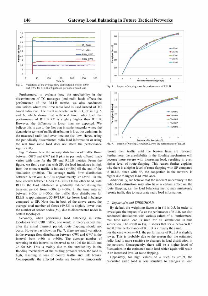
Fig. 7. Variations of the average flow distribution between GW0
and GW1 for RLLB at 8 pkts/s in per node offered load
Furthermore, to evaluate how the unreliability in the dissemination of TC messages (and radio load) affects the performance of the RLLB metric, we also conducted simulations where real time radio load is used instead of TC based radio load. The result is denoted as RLLB_RT in Fig. 5 and 6, which shows that with real time radio load, the performance of RLLB_RT is slightly higher than RLLB. However, the difference is lower than we expected. We believe this is due to the fact that in static networks where the dynamic in terms of traffic distribution is low, the variations in the measured radio load over time are also low. Hence, using the periodically disseminated radio load information or using the real time radio load does not affect the performance significantly.
Fig. 7 shows how the average distribution of traffic flows between GW0 and GW1 (at 8 pkts in per node offered load) varies with time for the SP and RLLB metrics. From the figure, we firstly see that with SP, the load imbalance is high from the moment traffic is initiated (t=30s) till the end of the simulation (t=300s). The average traffic flow distribution between GW0 and GW1 is approximately 39.72/9.61 in the time interval between t=50s to t=300s. On the other hand, with RLLB, the load imbalance is gradually reduced during the transient period from t=30s to t=50s. In the time interval between t=50s to t=300s, the traffic flow distribution for RLLB is approximately 35.39/13.94, i.e. lower load imbalance compared to SP. Note that in both of the above cases, the average total number of flows (49.33) is slightly lower than the number of sender nodes (50), due to disconnected nodes in certain topologies.
Secondly, when performing load balancing in static topologies with CBR traffic, one would in theory expect that after the initial transient period, route flapping should not occur. However, as shown in Fig. 7, there are small variations in the average flow distribution between GW0 and GW1 in the interval from t=50s to t=300s. The average number of rerouting in this interval is observed to be 10.6 for RLLB and 26 for SP. This is mainly due to the unreliability in the flooding mechanism of the routing protocol when the load is high, resulting in loss of control traffic and link breaks. Consequently, the affected nodes are forced to temporarily
Fig. 8. Impact of varying α on the performance of RLLB
Fig. 9. Impact of varying THRESHOLD on the performance of RLLB
reroute their traffic until the broken links are restored. Furthermore, the unreliability in the flooding mechanism will become more severe with increasing load, resulting in even higher level of route flapping. This reason further explains why there is a higher level of route flapping with SP compared to RLLB, since with SP, the congestion in the network is higher due to higher load imbalance.
Additionally, we believe that the inherent uncertainty in the radio load estimation may also have a certain effect on the route flapping, i.e. the load balancing metric may mistakenly reroute traffic due to inaccurate radio load information.
C. Impact of α and THRESHOLD
By default the weighting factor α in (1) is 0.5. In order to investigate the impact of α on the performance of RLLB, we also conducted simulations with various values of α. Furthermore, real time radio load is used for all simulations in this subsection. The result in Fig. 8 shows that for α between 0.3 and 0.7 the performance of RLLB is virtually the same. For the case when α=0.1, the performance of RLLB is slightly lower. This is probably due to the reason that the estimated radio load is more sensitive to changes in load distribution in the network. Consequently, there will be a higher level of fluctuations in the estimated radio load which again will result in an increased level of route flapping.
Oppositely, for high values of α such as α=0.9, the calculated radio load is less sensitive to changes in load
0
5
10
15
20
25
30
35
40
45
0 50 100 150 200 250 300
Nu
mb
er
of
flo
ws
Time (s)
SP_GW0
SP_GW1
RLLB_GW0
RLLB_GW1
140
160
180
200
220
240
1 2 3 4 5 6 7 8
Th
rou
gh
pu
t (p
kts
/s)
Per node offered load( pkts/s)
alfa0.1
alfa0.3
alfa0.5
alfa0.7
alfa0.9
140
160
180
200
220
240
260
3 4 5 6 7 8 9 10
Th
rou
gh
pu
t (p
kts
/s)
Per node offer load (pkts/s)
Thr0.01
Thr0.03
Thr0.05
Thr0.07
Thr0.09
146 Gateway Load Balancing in Future Tactical Networks

distribution, meaning that the radio load is too slow in capturing the changes. This again will adversely affect the RLLB metric, preventing it from performing load balancing in a timely manner. The result shows that using a too high value of α is more unfortunate than using a too low value.
The purpose of the THRESHOLD value is to control the level of route flapping. A low THRESHOLD will allow the routing protocol to freely perform rerouting when it is appropriate, but with the potential risk of a high degree of route flapping. On the other hand a high THRESHOLD, will reduce route flapping, but instead may prevent the routing protocol from performing the necessary load balancing. Hence, it is important to make a compromise when setting the value for the THRESHOLD. Fig. 9 shows the impact of the THRESHOLD on the performance. For THRESHOLDs between 0.01 and 0.05 the average throughput is approximately the same. For higher values of THRESHOLD (e.g., 0.07 and 0.09), the performance is lower due to the reason explained above.
V. CONCLUSIONS
In future tactical networks, the gateway nodes have the important role of connecting different network domains or platforms together, forming a consolidated network. We argue that there should be more than one gateway between two network domains in order to increase capacity and resiliency. However, in order to take full advantage of the increased capacity for inter-domain traffic, the routing protocol must be able to intelligently perform load balancing.
A common belief is that the gateways are the bottlenecks or most congested nodes in the network since all upstream or downstream traffic have to go through these nodes. However, we have through the work in this paper shown that this is not necessarily so. In fact for a network deployed with two gateways, the most congested area is actually located in the centre of the network, i.e. the area between the gateways. This explains why the efficiency of load balancing in many cases are very poor, since the congested area may act as an obstacle or barrier, preventing load to be effectively diverted to the alternative gateway with lower load.
Realizing this, we developed the RLLB load balancing scheme, which utilizes radio load information to make load balancing decisions. The RLLB metric is designed to improve the load distribution between gateways. Secondly the metric attempts to avoid routing traffic through the congested area such that the highest total network throughput can be achieved.
We have performed simulation on many randomly generated topologies using different load balancing metrics. The simulation results show that RLLB is more efficient than both SLB and EL in performing load balancing, i.e. approximately 5 % in throughput enhancement. Furthermore the throughput enhancement relative to the SP metric is on the average up to 11.6 %.
Finally, even though the study in this paper, for simplicity, is limited to the case with only two gateways, we believe the concept of the proposed load balancing scheme can also be
adapted to scenarios with multiple gateways. We intend in future works to further investigate load balancing under more dynamic conditions, i.e. with mobile topologies and time-varying traffic load.
REFERENCES
[1] D. S. Alberts, J. J. Garstka, F. P. Stein, “Network Centric Warfare, Developing and Leveraging Information Superiority” 2nd Edition, http://www.dodccrp.org/files/Alberts_NCW.pdf
[2] MANET Working Group of the Internet Engineering Task Force (IETF), http://www.ietf.org/html.charters/manet-charter.html
[3] M. Pearlman, P. Sholander and S. S. Tabrizi, “On the Impact of Alternate Path Routing for Load Balancing in Mobile Ad Hoc Networks”, ACM Mobicom, Boston, MA, August 2000.
[4] Yashar Ganjali and Abtin Keshavarzian, “Load Balancing in Ad Hoc Networks: Single-path Routing vs. Multi-path Routing”, INFOCOM 2004. Twenty-third Annual Joint Conference of the IEEE Computer and Communications Societies
[5] Asis Nasipuri and Samir R. Das, “On-Demand Multipath Routing for Mobile Ad Hoc Networks”, IEEE ICCCN, Boston, MA, October, 1999
[6] Robert Brännström, Christer Åhlund and Arkady Zaslavsky, ”Port-based Multihomed Mobile IPv6: Load-balancing in Mobile Ad hoc Networks”, Local Computer Networks, 2007. LCN 2007
[7] Sriram Lakshmanan, K. Sundaresan and R. Sivakumar, ”On Multi-Gateway Association in Wireless Mesh Networks” Wireless Mesh Networks, 2006. WiMesh 2006.
[8] Bin Xie, Yingbing Yub, Anup Kumarc, and Dharma P. Agrawala, ”Load-balanced mesh router migration for wireless mesh networks”, Journal of Parallel and Distributed Computing, Volume 68, Issue 6, June 2008
[9] Deepti Nandiraju, Lakshmi Santhanam, Nagesh Nandiraju, and Dharma P. Agrawal, “Achieving Load Balancing in Wireless Mesh Networks Through Multiple Gateways”, Mobile Adhoc and Sensor Systems (MASS), 2006, Vancouver, Canada
[10] Krishna N. Ramachandran et al., ”On the Design and Implementatation of Infrastructure Mesh Networks”, Proceedings of the IEEE Workshop on Wireless Mesh Networks (WiMesh). IEEE Press (2005)
[11] Young J. Lee and George F. Riley, “A Workload-Based Adaptive Load-Balancing Technique for Mobile Ad Hoc Networks”, Wireless Communications and Networking Conference, 2005 IEEE
[12] Vikrant Saigal, A. K. Nayakb, S. K. Pradhanc and R. Mall, ”Load balanced routing in mobile ad hoc networks”, Computer Communications, Vol. 27, No. 3. (15 February 2004)
[13] Pai-Hsiang Hsiao, Adon Hwang, H. T. Kung, and Dario Vlah, ”Load-Balancing Routing for Wireless Access Networks”, Proceeding of IEEE Infocom, 2001
[14] Hossam Hassanein and Audrey Zhou, “Routing with Load Balancing in Wireless Ad hoc Networks”, Proceedings of the 4th ACM international workshop on Modeling, analysis and simulation of wireless and mobile systems, 2001
[15] V. Pham, E. Larsen, P. E. Engelstad, and Ø. Kure, “Performance Analysis of Gateway Load Balancing in Ad Hoc Networks with Random Topologies”, Proceeding of The 7th ACM International Symposium on Mobility Management and Wireless Access, Mobiwac, October 2009
[16] T. Clausen, P. Jacquet, “Optimized Link State Routing Protocol (OLSR)”, RFC 3626, October 2003.
[17] “Network simulator 2 - ns2.” http://nsnam.isi.edu/nsnam/index.php/User_Information [18] IEEE 802.11: Wireless LAN Medium Access Control (MAC) and
Physical Layer (PHY) Specifications http://standards.ieee.org/getieee802/download/802.11-2007.pdf
[19] IEEE Std 802.16e-2005 http://standards.ieee.org/getieee802/download/802.16e-2005.pdf
147

148 Gateway Load Balancing in Future Tactical Networks
Paper E :
A Radio Load Based LoadBalancing Scheme withAdmission Control
V. Pham, E. Larsen, Q. Le-Trung, P. Engelstad, Ø. Kure
Proceedings of the International Symposium on Wireless and Pervasive Comput-ing (ISWPC 2011), Hong Kong, China, February 23-25, 2011.
149

150 A Radio Load Based Load Balancing Scheme with Admission Control
Abstract—In mobile ad hoc networks (MANETs) where there
exist multiple Internet gateways, performing load balancing
among available gateways is vital in order to take full advantage
of the network capacity and improve the performance. However,
performing load balancing in a wireless environment is very
challenging due to the inherently interfering and unreliable
nature that characterize wireless communication. Additionally,
the dynamic in ad hoc networks due to node mobility makes it
even more difficult. This paper explores the feasibility of
performing load balancing in ad hoc networks both in static and
mobile topologies, and proposes the RLAC scheme, that jointly
performs the task of load balancing and admission control.
RLAC relies on radio load information provided by the
underlying MAC-layer to make routing decisions. Simulations
with RLAC on a considerable number of random topologies,
both static and mobile, show that the proposed scheme has a
potential to improve performance with respect to the aggregated
throughput.
I. INTRODUCTION
In mobile ad hoc networks (MANETs), a gateway node is used to provide connectivity to external networks such as the global Internet. Since all traffic to and from the Internet has to traverse the gateway, it is therefore likely that this node will be congested and become a bottleneck, affecting the performance of the network. To alleviate this, the common solution is to deploy multiple gateways in the network. This does not only reduce the risk for congestion, but has also a number of advantages. First of all, the overall bandwidth capacity for Internet traffic is increased, both in terms of ingress and egress traffic. Secondly, multiple gateways will make the network more robust, i.e. if one gateway encounters failure, there are other gateways that can still provide connectivity to the global Internet. Thirdly, if multiple gateways are spread around in the network, the Internet traffic will also be naturally more distributed throughout the network even without any load balancing functionality.
With the traditional shortest path routing, a node will always send Internet traffic to the nearest gateway regardless of how congested this gateway is. Consequently, this will cause some gateways to be more congested than others, resulting in non optimal utilization of the network capacity. This shortcoming of the shortest path routing protocol therefore encourages the use of routing protocols with load balancing (LB) functionality, capable to control the load balance of traffic between the gateways more efficiently. However, performing LB in ad hoc networks is a very challenging task due to the inherently interfering and unreliable nature of wireless networks. The frequent changes in the topology due to node mobility will make it even more
difficult, if not impossible, if the level of mobility is too high. We have previously shown in [1,2] that performing LB on static topologies may improve network performance. The question is, will LB give the same result in mobile topologies? Thus, this paper explores to which extent it is possible to improve network performance in static as well as mobile topologies with different levels of mobility.
In this paper, we propose the RLAC scheme that jointly performs LB and admission control (AC). We argue that AC is an important and necessary mechanism that will further improve the performance in addition to the benefits provided by LB. When the network load is high, AC can be used to reduce excess traffic from being inserted into the network and thus avoid even higher congestion and augmentation in packet loss rate. Furthermore, in cases where the congestion is very high along the path from a source to a destination node, the probability for successful transmissions of data traffic along this path is consequently very low. In such cases, AC can be used to deny traffic, that most likely would not reach its final destination anyway, from entering the network.
The rest of this paper is organized as follows. In Section II, we discuss related work and the background for this study. Section III describes the proposed load balancing scheme in detail. Section IV presents the evaluation of RLAC. Finally, the conclusion of the paper is given in Section V.
II. RELATED WORK AND BACKGROUND
In the literature, there exists a number of proposals suggesting various LB scheme targeted for both MANETs [3,4,5,6] and Wireless Mesh Networks [7,8,9,10]. These proposals can be generally divided into two categories: Multipath Load Balancing (MLB) and Gateway Load
Balancing (GLB). In MLB [3,4,5], the traffic load between a source node and a
destination/gateway is distributed among a set of alternative paths in order to maximize performance and minimize the impact of route failure. However, [3,4] report that MLB in single channel wireless networks only provides a negligible improvement in the performance due to route coupling among the alternative paths. Thus MLB is not of interest in this paper.
On the other hand, in the GLB [1,2,6,7,8,9] approach, the traffic load is distributed among multiple gateways in order to maximize throughput performance and to reduce the load imbalance. GLB is considered to improve the network performance more effectively than MLB [7]. In this paper, we therefore focus only on GLB, and we will refer to it simply as LB in the remainder of the paper.
Vinh Pham*, Erlend Larsen*, Quan-Le-Trung‡, Paal E. Engelstad†, Øivind Kure* *Q2S NTNU, †SimTel (Telenor/Simula), ‡IFI UiO, Norway
Email: *†{vph, erl, paalee, okure}@unik.no ‡[email protected]
A Radio Load Based Load Balancing Scheme with Admission Control
151
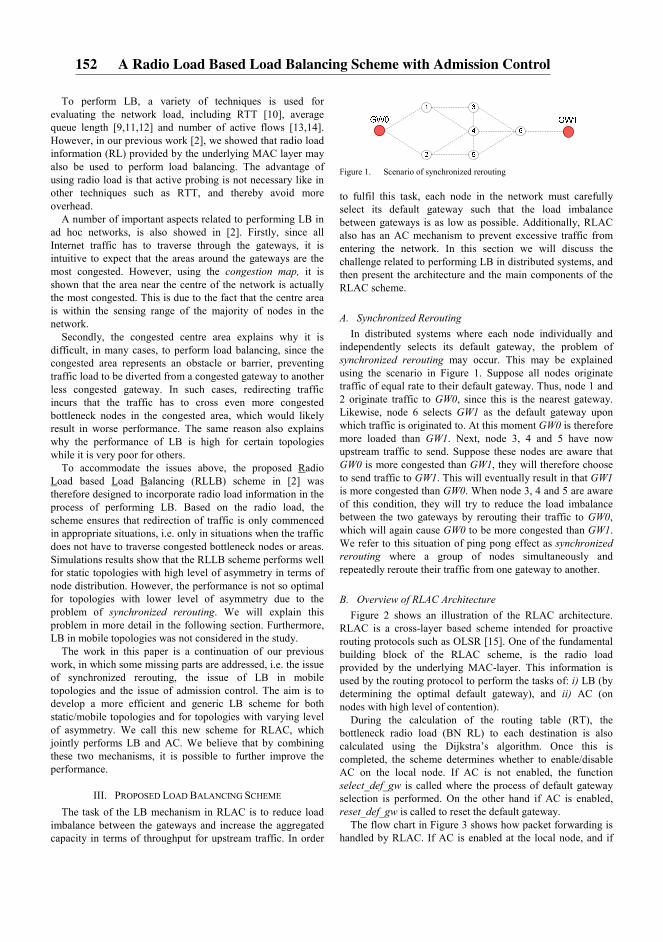
To perform LB, a variety of techniques is used for evaluating the network load, including RTT [10], average queue length [9,11,12] and number of active flows [13,14]. However, in our previous work [2], we showed that radio load information (RL) provided by the underlying MAC layer may also be used to perform load balancing. The advantage of using radio load is that active probing is not necessary like in other techniques such as RTT, and thereby avoid more overhead.
A number of important aspects related to performing LB in ad hoc networks, is also showed in [2]. Firstly, since all Internet traffic has to traverse through the gateways, it is intuitive to expect that the areas around the gateways are the most congested. However, using the congestion map, it is shown that the area near the centre of the network is actually the most congested. This is due to the fact that the centre area is within the sensing range of the majority of nodes in the network.
Secondly, the congested centre area explains why it is difficult, in many cases, to perform load balancing, since the congested area represents an obstacle or barrier, preventing traffic load to be diverted from a congested gateway to another less congested gateway. In such cases, redirecting traffic incurs that the traffic has to cross even more congested bottleneck nodes in the congested area, which would likely result in worse performance. The same reason also explains why the performance of LB is high for certain topologies while it is very poor for others.
To accommodate the issues above, the proposed Radio Load based Load Balancing (RLLB) scheme in [2] was therefore designed to incorporate radio load information in the process of performing LB. Based on the radio load, the scheme ensures that redirection of traffic is only commenced in appropriate situations, i.e. only in situations when the traffic does not have to traverse congested bottleneck nodes or areas. Simulations results show that the RLLB scheme performs well for static topologies with high level of asymmetry in terms of node distribution. However, the performance is not so optimal for topologies with lower level of asymmetry due to the problem of synchronized rerouting. We will explain this problem in more detail in the following section. Furthermore, LB in mobile topologies was not considered in the study.
The work in this paper is a continuation of our previous work, in which some missing parts are addressed, i.e. the issue of synchronized rerouting, the issue of LB in mobile topologies and the issue of admission control. The aim is to develop a more efficient and generic LB scheme for both static/mobile topologies and for topologies with varying level of asymmetry. We call this new scheme for RLAC, which jointly performs LB and AC. We believe that by combining these two mechanisms, it is possible to further improve the performance.
III. PROPOSED LOAD BALANCING SCHEME
The task of the LB mechanism in RLAC is to reduce load imbalance between the gateways and increase the aggregated capacity in terms of throughput for upstream traffic. In order
Figure 1. Scenario of synchronized rerouting
to fulfil this task, each node in the network must carefully select its default gateway such that the load imbalance between gateways is as low as possible. Additionally, RLAC also has an AC mechanism to prevent excessive traffic from entering the network. In this section we will discuss the challenge related to performing LB in distributed systems, and then present the architecture and the main components of the RLAC scheme.
A. Synchronized Rerouting
In distributed systems where each node individually and independently selects its default gateway, the problem of synchronized rerouting may occur. This may be explained using the scenario in Figure 1. Suppose all nodes originate traffic of equal rate to their default gateway. Thus, node 1 and 2 originate traffic to GW0, since this is the nearest gateway. Likewise, node 6 selects GW1 as the default gateway upon which traffic is originated to. At this moment GW0 is therefore more loaded than GW1. Next, node 3, 4 and 5 have now upstream traffic to send. Suppose these nodes are aware that GW0 is more congested than GW1, they will therefore choose to send traffic to GW1. This will eventually result in that GW1 is more congested than GW0. When node 3, 4 and 5 are aware of this condition, they will try to reduce the load imbalance between the two gateways by rerouting their traffic to GW0, which will again cause GW0 to be more congested than GW1. We refer to this situation of ping pong effect as synchronized
rerouting where a group of nodes simultaneously and repeatedly reroute their traffic from one gateway to another.
B. Overview of RLAC Architecture
Figure 2 shows an illustration of the RLAC architecture. RLAC is a cross-layer based scheme intended for proactive routing protocols such as OLSR [15]. One of the fundamental building block of the RLAC scheme, is the radio load provided by the underlying MAC-layer. This information is used by the routing protocol to perform the tasks of: i) LB (by determining the optimal default gateway), and ii) AC (on nodes with high level of contention).
During the calculation of the routing table (RT), the bottleneck radio load (BN RL) to each destination is also calculated using the Dijkstra’s algorithm. Once this is completed, the scheme determines whether to enable/disable AC on the local node. If AC is not enabled, the function select_def_gw is called where the process of default gateway selection is performed. On the other hand if AC is enabled, reset_def_gw is called to reset the default gateway.
The flow chart in Figure 3 shows how packet forwarding is handled by RLAC. If AC is enabled at the local node, and if
152 A Radio Load Based Load Balancing Scheme with Admission Control
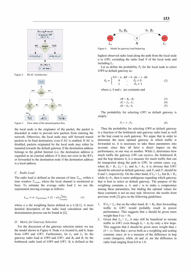
Figure 2. RLAC Architecture
Figure 3. Flow chart of the internal packet flow
the local node is the originator of the packet, the packet is discarded in order to prevent new packets from entering the network. Otherwise, the local node may still forward transit packets to its final destination, even if AC is enabled. If AC is disabled, packets originated by the local node may either be tunneled towards the default gateway if the destination address belongs to the global Internet (i.e. the destination address is regarded as an external address if it does not exist in the RT), or forwarded to the destination node if the destination address is a local address.
C. Radio Load
The radio load is defined as the amount of time Tbusy within a time window Twindow where the local channel is monitored as busy. To estimate the average radio load L we use the exponential moving average as follows:
���� � � · ���� �� � �1 � �� ������������ (1)
where α is the weighting factor defined as α ∈ [0,1]. A more detailed description of the radio load calculation and the dissemination process can be found in [2].
D. Metric for Gateway Selection
For the discussion of the gateway selection metric we use the model shown in Figure 4. Node n is located h0 and h1 hops from GW0 and GW1. Furthermore, let L0 and L1 be the gateway radio load at GW0 and GW1, and B0 and B1 be the bottleneck radio load of GW0 and GW1. Bi is defined as the
Figure 4. Model for gateway load balancing
highest observed radio load along the path from the local node n to GWi, excluding the radio load N of the local node and including Li.
Let us define the probability P0 for the local node to select GW0 as default gateway as:
! � # 0.5 � ' ( ∆* � + ( ∆� � , ( ∆-0 , ! / 0 1 , ! 0 1 1 (2)
where a, b and c are constants and
∆B = B0 - B1 (3)
∆L = L0 - L1 (4) ∆h = h0 - h1 (5)
The probability for selecting GW1 as default gateway is simply:
P1 = 1 - P0 (6)
Thus the probability for selecting GW0 as default gateway is a function of the bottleneck and gateway radio load as well as the hop count to each gateway. We argue that in order to determine the most optimal gateway in which traffic is forwarded to, it is necessary to take these parameters into account, since they all have a direct impact on the performance, in one way or another. While Li determines how much traffic the gateway GWi can receive, the bottleneck Bi and the hop distance hi is a measure for much traffic that can be transported along the path to GWi. In certain cases, e.g. when B0 > B1, L0 > L1 and h0 > h1, it is obvious that GW1 should be selected as default gateway, and P0 and P1 should be 0 and 1, respectively. On the other hand, if L0 > L1, but B0 < B1, while h0=h1, then is more ambiguous regarding which gateway that is best to select as default gateway. The purpose of the weighting constants a, b, and c is to make a compromise among these parameters, but finding the optimal values for these constants is not an easy task. However, the results from previous work [2] give us the following guidelines:
1. If L0 > L1, but on the other hand, B1 > B0, then forwarding
traffic to GW1 would probably result in poorer performance. This suggests that a should be given more weight than b (a > b).
2. Given that L0 > L1, it may still be beneficial to reroute traffic to GW1 even though h1 > h0 by only a few hops. This suggests that b should be given more weight than c
(b > c). Note that c serves both as a weighting and scaling constant, since ∆h is a measure of the difference in hop count (integers), while ∆B and ∆L are the difference in radio load ranging from 0.0 to 1.0.
153
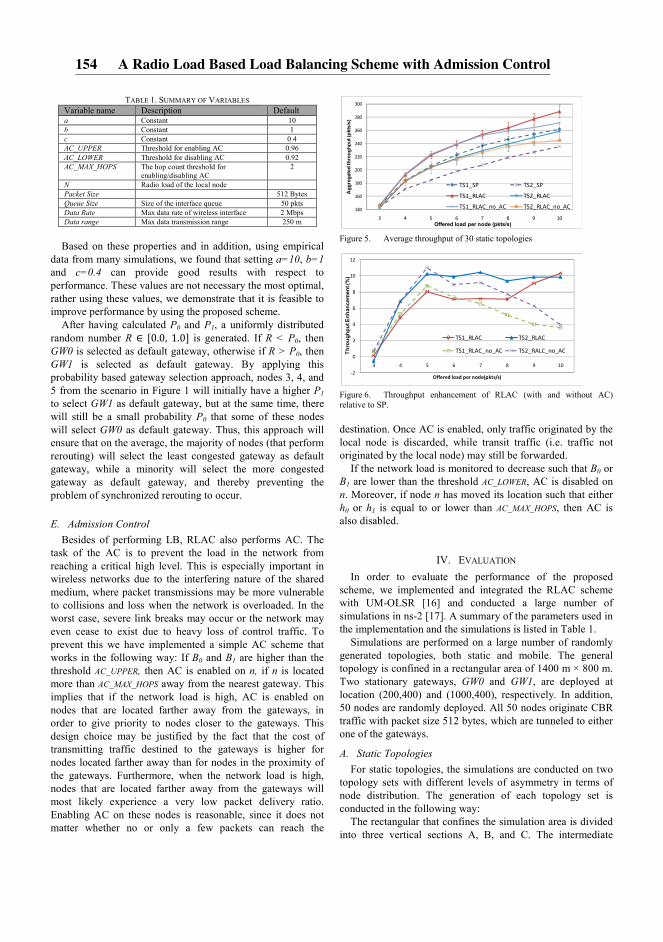
TABLE 1. SUMMARY OF VARIABLES Variable name Description Default a Constant 10 b Constant 1 c Constant 0.4 AC_UPPER Threshold for enabling AC 0.96 AC_LOWER Threshold for disabling AC 0.92 AC_MAX_HOPS The hop count threshold for
enabling/disabling AC 2
N Radio load of the local node Packet Size 512 Bytes Queue Size Size of the interface queue 50 pkts Data Rate Max data rate of wireless interface 2 Mbps Data range Max data transmission range 250 m
Based on these properties and in addition, using empirical
data from many simulations, we found that setting a=10, b=1
and c=0.4 can provide good results with respect to performance. These values are not necessary the most optimal, rather using these values, we demonstrate that it is feasible to improve performance by using the proposed scheme.
After having calculated P0 and P1, a uniformly distributed random number R ∈ [0.0, 1.0] is generated. If R < P0, then GW0 is selected as default gateway, otherwise if R > P0, then GW1 is selected as default gateway. By applying this probability based gateway selection approach, nodes 3, 4, and 5 from the scenario in Figure 1 will initially have a higher P1 to select GW1 as default gateway, but at the same time, there will still be a small probability P0 that some of these nodes will select GW0 as default gateway. Thus, this approach will ensure that on the average, the majority of nodes (that perform rerouting) will select the least congested gateway as default gateway, while a minority will select the more congested gateway as default gateway, and thereby preventing the problem of synchronized rerouting to occur.
E. Admission Control
Besides of performing LB, RLAC also performs AC. The task of the AC is to prevent the load in the network from reaching a critical high level. This is especially important in wireless networks due to the interfering nature of the shared medium, where packet transmissions may be more vulnerable to collisions and loss when the network is overloaded. In the worst case, severe link breaks may occur or the network may even cease to exist due to heavy loss of control traffic. To prevent this we have implemented a simple AC scheme that works in the following way: If B0 and B1 are higher than the threshold AC_UPPER, then AC is enabled on n, if n is located more than AC_MAX_HOPS away from the nearest gateway. This implies that if the network load is high, AC is enabled on nodes that are located farther away from the gateways, in order to give priority to nodes closer to the gateways. This design choice may be justified by the fact that the cost of transmitting traffic destined to the gateways is higher for nodes located farther away than for nodes in the proximity of the gateways. Furthermore, when the network load is high, nodes that are located farther away from the gateways will most likely experience a very low packet delivery ratio. Enabling AC on these nodes is reasonable, since it does not matter whether no or only a few packets can reach the
Figure 5. Average throughput of 30 static topologies
Figure 6. Throughput enhancement of RLAC (with and without AC) relative to SP.
destination. Once AC is enabled, only traffic originated by the local node is discarded, while transit traffic (i.e. traffic not originated by the local node) may still be forwarded.
If the network load is monitored to decrease such that B0 or B1 are lower than the threshold AC_LOWER, AC is disabled on n. Moreover, if node n has moved its location such that either h0 or h1 is equal to or lower than AC_MAX_HOPS, then AC is also disabled.
IV. EVALUATION
In order to evaluate the performance of the proposed scheme, we implemented and integrated the RLAC scheme with UM-OLSR [16] and conducted a large number of simulations in ns-2 [17]. A summary of the parameters used in the implementation and the simulations is listed in Table 1.
Simulations are performed on a large number of randomly generated topologies, both static and mobile. The general topology is confined in a rectangular area of 1400 m × 800 m. Two stationary gateways, GW0 and GW1, are deployed at location (200,400) and (1000,400), respectively. In addition, 50 nodes are randomly deployed. All 50 nodes originate CBR traffic with packet size 512 bytes, which are tunneled to either one of the gateways.
A. Static Topologies
For static topologies, the simulations are conducted on two topology sets with different levels of asymmetry in terms of node distribution. The generation of each topology set is conducted in the following way:
The rectangular that confines the simulation area is divided into three vertical sections A, B, and C. The intermediate
140
160
180
200
220
240
260
280
300
3 4 5 6 7 8 9 10
Aggregated throughput (pkts/s)
Offered load per node (pkts/s)
TS1_SP TS2_SP
TS1_RLAC TS2_RLAC
TS1_RLAC_no_AC TS2_RLAC_no_AC
-2
0
2
4
6
8
10
12
3 4 5 6 7 8 9 10
Throughput Enhancement (%)
Offered load per node(pkts/s)
TS1_RLAC TS2_RLAC
TS1_RLAC_no_AC TS2_RALC_no_AC
154 A Radio Load Based Load Balancing Scheme with Admission Control
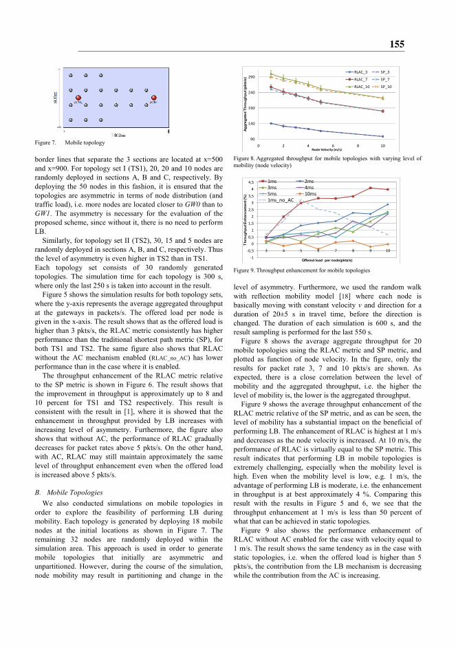
Figure 7. Mobile topology
border lines that separate the 3 sections are located at x=500 and x=900. For topology set I (TS1), 20, 20 and 10 nodes are randomly deployed in sections A, B and C, respectively. By deploying the 50 nodes in this fashion, it is ensured that the topologies are asymmetric in terms of node distribution (and traffic load), i.e. more nodes are located closer to GW0 than to GW1. The asymmetry is necessary for the evaluation of the proposed scheme, since without it, there is no need to perform LB.
Similarly, for topology set II (TS2), 30, 15 and 5 nodes are randomly deployed in sections A, B, and C, respectively. Thus the level of asymmetry is even higher in TS2 than in TS1. Each topology set consists of 30 randomly generated topologies. The simulation time for each topology is 300 s, where only the last 250 s is taken into account in the result.
Figure 5 shows the simulation results for both topology sets, where the y-axis represents the average aggregated throughput at the gateways in packets/s. The offered load per node is given in the x-axis. The result shows that as the offered load is higher than 3 pkts/s, the RLAC metric consistently has higher performance than the traditional shortest path metric (SP), for both TS1 and TS2. The same figure also shows that RLAC without the AC mechanism enabled (RLAC_no_AC) has lower performance than in the case where it is enabled.
The throughput enhancement of the RLAC metric relative to the SP metric is shown in Figure 6. The result shows that the improvement in throughput is approximately up to 8 and 10 percent for TS1 and TS2 respectively. This result is consistent with the result in [1], where it is showed that the enhancement in throughput provided by LB increases with increasing level of asymmetry. Furthermore, the figure also shows that without AC, the performance of RLAC gradually decreases for packet rates above 5 pkts/s. On the other hand, with AC, RLAC may still maintain approximately the same level of throughput enhancement even when the offered load is increased above 5 pkts/s.
B. Mobile Topologies
We also conducted simulations on mobile topologies in order to explore the feasibility of performing LB during mobility. Each topology is generated by deploying 18 mobile nodes at the initial locations as shown in Figure 7. The remaining 32 nodes are randomly deployed within the simulation area. This approach is used in order to generate mobile topologies that initially are asymmetric and unpartitioned. However, during the course of the simulation, node mobility may result in partitioning and change in the
Figure 8. Aggregated throughput for mobile topologies with varying level of mobility (node velocity)
Figure 9. Throughput enhancement for mobile topologies
level of asymmetry. Furthermore, we used the random walk with reflection mobility model [18] where each node is basically moving with constant velocity v and direction for a duration of 20±5 s in travel time, before the direction is changed. The duration of each simulation is 600 s, and the result sampling is performed for the last 550 s.
Figure 8 shows the average aggregate throughput for 20 mobile topologies using the RLAC metric and SP metric, and plotted as function of node velocity. In the figure, only the results for packet rate 3, 7 and 10 pkts/s are shown. As expected, there is a close correlation between the level of mobility and the aggregated throughput, i.e. the higher the level of mobility is, the lower is the aggregated throughput.
Figure 9 shows the average throughput enhancement of the RLAC metric relative of the SP metric, and as can be seen, the level of mobility has a substantial impact on the beneficial of performing LB. The enhancement of RLAC is highest at 1 m/s and decreases as the node velocity is increased. At 10 m/s, the performance of RLAC is virtually equal to the SP metric. This result indicates that performing LB in mobile topologies is extremely challenging, especially when the mobility level is high. Even when the mobility level is low, e.g. 1 m/s, the advantage of performing LB is moderate, i.e. the enhancement in throughput is at best approximately 4 %. Comparing this result with the results in Figure 5 and 6, we see that the throughput enhancement at 1 m/s is less than 50 percent of what that can be achieved in static topologies.
Figure 9 also shows the performance enhancement of RLAC without AC enabled for the case with velocity equal to 1 m/s. The result shows the same tendency as in the case with static topologies, i.e. when the offered load is higher than 5 pkts/s, the contribution from the LB mechanism is decreasing while the contribution from the AC is increasing.
90
140
190
240
290
0 2 4 6 8 10
Aggregated Throughput (pkts/s)
Node Velocity (m/s)
RLAC_3 SP_3
RLAC_7 SP_7
RLAC_10 SP_10
-1
-0,5
0
0,5
1
1,5
2
2,5
3
3,5
4
4,5
3 4 5 6 7 8 9 10
Throughput Enhancement (%)
Offered load per node(pkts/s)
1ms 2ms
3ms 4ms
5ms 10ms
1ms_no_AC
155

There are a number of reasons why the level of mobility has such a negative impact on the throughput as well as the beneficial of performing LB. First of all, link breaks occur more frequently with increasing level of mobility. This implies that the link life time will decrease with increasing mobility level, and consequently, the effective network capacity will become lower. Secondly, LB in many cases involves diverting traffic to a more distant gateway. This will unfortunately increase the probability for end to end transmission failure or packet loss due to the longer path distance that a packet must travel. Thirdly, in contrast to static topologies, partitioning is likely to occur in mobile topologies during the course of the simulation time. The probability for partitioning in the network increases as the mobility level is increased. When partitioning occurs such that the gateways are no longer connected, then performing LB is not feasible. Furthermore, with mobile topologies, it is difficult to maintain the same level of asymmetry as in the beginning (i.e. the initially induced asymmetry during generation of the topologies) for the entire duration of the simulation time. We observed that during the course of the simulation, the topologies either tend to be so asymmetric such that the network will eventually be partitioned, or oppositely the asymmetry is decreased to a minimum level. Either way, the condition for testing the performance of LB is non optimal.
Finally, the inherent latency of the routing protocol with respect to capturing the changes in the topology is another reason why the performance of LB and AC is low during mobility. In fact, the LB and AC mechanisms may even have an adverse impact on the performance when the routing information does not correctly reflect the actual view of the topology.
V. CONCLUSION
In a wireless network where there are multiple gateways, by not utilizing an appropriate routing scheme such that traffic load is distributed more evenly between available gateways, severe load imbalance may occur. This may potentially result in network instability as well as lower performance in terms of delay, throughput, packet loss etc. The focus in this paper is to investigate whether it is possible to achieve a higher performance in terms of throughput by applying a more intelligent routing protocol. The proposed radio load based RLAC metric is developed to meet this requirement, by jointly performing the task of LB and AC. Simulation results with static topologies show that the RLAC metric may improve the throughput up to around 10 % compared to the traditional SP metric. Furthermore, RLAC is capable to enhance the throughput even for mobile topologies. However, this is true only at low node velocity, i.e. 1-2 m/s. The achieved enhancement relative to the SP metric is around 4 %. There are a number of reasons why it is much more challenging to improve the throughput in mobile topologies than in static topologies. Frequent link breaks and the risk for network partitioning are some of the reasons that set an upper limit on the achieved enhancement in throughput. Another reason is the difficulty in maintaining the appropriate condition for
performing LB with respect to the level of asymmetry and avoiding partitioning.
In this study we have only focused on performing LB for upstream traffic, but we believe that the same concept may also be applicable to downstream traffic as well. In order to accomplish this, LB functionality must also be implemented at the gateways in a similar fashion as it was implemented at the nodes for the case with upstream traffic.
Finally we have for simplicity limited this study to only consider LB with two gateways in the network. However, the results and insight gained in this study may form a basis for further development of more generic LB metrics applicable for scenarios with multiple gateways.
REFERENCES
[1] V. Pham, E. Larsen, P. E. Engelstad and Ø. Kure, ”Performance Analysis of Gateway Load Balancing in Ad Hoc Networks with Random Topologies”, MSWiM 2009, International Workshop on Modeling Analysis and Simulation of Wireless and Mobile Systems, Proceedings of the 7th ACM international symposium on Mobility management and wireless access, Oct. 26-30, 2009, Tenerife, Spain, pp. 66-74
[2] V. Pham, E. Larsen, Ø. Kure and P. E. Engelstad, ”Gateway Load Balancing in Future Tactical Networks”, Milcom 2010, Oct. 31 – Nov. 3 2010, San Jose, CA
[3] M. Pearlman, P. Sholander and S. S. Tabrizi, “On the Impact of Alternate Path Routing for Load Balancing in Mobile Ad Hoc Networks”, ACM Mobicom, Boston, MA, August 2000.
[4] Yashar Ganjali and Abtin Keshavarzian, “Load Balancing in Ad Hoc Networks: Single-path Routing vs. Multi-path Routing”, INFOCOM 2004. Twenty-third Annual Joint Conference of the IEEE Computer and Communications Societies
[5] Asis Nasipuri and Samir R. Das, “On-Demand Multipath Routing for Mobile Ad Hoc Networks”, IEEE ICCCN, Boston, MA, October, 1999
[6] Robert Brännström, Christer Åhlund and Arkady Zaslavsky, ”Port-based Multihomed Mobile IPv6: Load-balancing in Mobile Ad hoc Networks”, Local Computer Networks, 2007. LCN 2007
[7] Sriram Lakshmanan, K. Sundaresan and R. Sivakumar, ”On Multi-Gateway Association in Wireless Mesh Networks” Wireless Mesh Networks, 2006. WiMesh 2006.
[8] Bin Xie, Yingbing Yub, Anup Kumarc, and Dharma P. Agrawala, ”Load-balanced mesh router migration for wireless mesh networks”, Journal of Parallel and Distributed Computing, Volume 68, Issue 6, June 2008
[9] Deepti Nandiraju, Lakshmi Santhanam, Nagesh Nandiraju, and Dharma P. Agrawal, “Achieving Load Balancing in Wireless Mesh Networks Through Multiple Gateways”, Mobile Adhoc and Sensor Systems (MASS), 2006, Vancouver, Canada
[10] Krishna N. Ramachandran et al., ”On the Design and Implementatation of Infrastructure Mesh Networks”, Proceedings of the IEEE Workshop on Wireless Mesh Networks (WiMesh). IEEE Press (2005)
[11] Young J. Lee and George F. Riley, “A Workload-Based Adaptive Load-Balancing Technique for Mobile Ad Hoc Networks”, Wireless Communications and Networking Conference, 2005 IEEE
[12] Vikrant Saigal, A. K. Nayakb, S. K. Pradhanc and R. Mall, ”Load balanced routing in mobile ad hoc networks”, Computer Communications, Vol. 27, No. 3. (15 February 2004)
[13] Pai-Hsiang Hsiao, Adon Hwang, H. T. Kung, and Dario Vlah, ”Load-Balancing Routing for Wireless Access Networks”, Proceeding of IEEE Infocom, 2001
[14] Hossam Hassanein and Audrey Zhou, “Routing with Load Balancing in Wireless Ad hoc Networks”, Proceedings of the 4th ACM international workshop on Modeling, analysis and simulation of wireless and mobile systems, 2001
[15] T. Clausen, P. Jacquet, “Optimized Link State Routing Protocol (OLSR)”, RFC 3626, October 2003.
[16] UM-OLSR, http://masimum.dif.um.es/?Software:UM-OLSR [17] “Network simulator 2 - ns2.” http://nsnam.isi.edu/nsnam/index.php/User_Information [18] Jean-Yves Le Boudec and Milan Vojnovic, “Perfect Simulation and
Stationarity of a Class of Mobility Models”, Infocom 2005
156 A Radio Load Based Load Balancing Scheme with Admission Control