Performance validation of a cascade control system ... - CyberLeninka
9
FULL-LENGTH ARTICLE Performance validation of a cascade control system through various network architectures A. Lakshmi Sangeetha a , N. Bharathi a , A. Balaji Ganesh b, * a Department of Electronics and Instrumentation, Velammal Engineering College, Chennai, India b TIFAC-CORE, Velammal Engineering College, Chennai, India Received 27 October 2014; revised 13 January 2016; accepted 11 February 2016 KEYWORDS Cascade control system; Internet; Wireless network; Mobile communication Abstract The work analyzes the performance characteristics of a cascade control system when interconnected with various network architectures, such as Internet, mobile and wireless networks. The cascade control system consists of level and flow as primary and secondary variables, respec- tively. The web-enabled monitoring and control are realized using three techniques namely remote client–server, ActiveX-data socket and web publishing tool. Mobile network is established by inter- facing the control system with a GSM modem which enables the monitoring of process parameters through mobile phones. The cascade control system is also monitored wirelessly from remote loca- tions with advent of an indigenous wireless sensor node. The performance analysis proved that wireless monitoring may be considered as an effective alternate technique to the Internet-based communication especially for shorter distances. Ó 2016 Production and hosting by Elsevier B.V. on behalf of Faculty of Computers and Information, Cairo University. 1. Introduction The vital role of network mediated automation has been signif- icantly appreciated in almost all kinds of industries in the last three decades. The networking of industrial processes can be established over a small-scale network as intranet (LAN) or over a large-scale network as Internet (WAN). The makeover process of Internet communication in conventional process environment is influenced by many factors, including number of nodes, Internet bandwidth, time-delay, processing speed, amount of data, managerial policies, safety and security [1,2]. Classical control theory suggested that a delay in the con- trol loop is an important factor causing the system instability as it increases the phase shift between the input and the output signals of the control system and this limits the maximum allowable gain [3]. Some researchers reported as today’s Inter- net provide no real time guaranteed delivery and have essen- tially unbounded end-to-end latency [4]. On the other hand, reports have experimentally proven that time-delays associated with the network do not affect most of the industrial process plants because of their sluggish nature [5,14]. In general, Programmable Logic Controller (PLC) and SCADA have been widely adopted for monitoring and controlling in many * Corresponding author. Tel.: +91 44 2659 1860; fax: +91 44 2659 1771. E-mail address: [email protected] (A.B. Ganesh). Peer review under responsibility of Faculty of Computers and Information, Cairo University. Production and hosting by Elsevier Egyptian Informatics Journal (2016) xxx, xxx–xxx Cairo University Egyptian Informatics Journal www.elsevier.com/locate/eij www.sciencedirect.com http://dx.doi.org/10.1016/j.eij.2016.02.001 1110-8665 Ó 2016 Production and hosting by Elsevier B.V. on behalf of Faculty of Computers and Information, Cairo University. Please cite this article in press as: Sangeetha AL et al., Performance validation of a cascade control system through various network architectures, Egyptian Infor- matics J (2016), http://dx.doi.org/10.1016/j.eij.2016.02.001
-
Upload
khangminh22 -
Category
Documents
-
view
2 -
download
0
Transcript of Performance validation of a cascade control system ... - CyberLeninka

Egyptian Informatics Journal (2016) xxx, xxx–xxx
Cairo University
Egyptian Informatics Journal
www.elsevier.com/locate/eijwww.sciencedirect.com
FULL-LENGTH ARTICLE
Performance validation of a cascade control system
through various network architectures
* Corresponding author. Tel.: +91 44 2659 1860; fax: +91 44 2659
1771.E-mail address: [email protected] (A.B. Ganesh).
Peer review under responsibility of Faculty of Computers and
Information, Cairo University.
Production and hosting by Elsevier
http://dx.doi.org/10.1016/j.eij.2016.02.0011110-8665 � 2016 Production and hosting by Elsevier B.V. on behalf of Faculty of Computers and Information, Cairo University.
Please cite this article in press as: Sangeetha AL et al., Performance validation of a cascade control system through various network architectures, Egyptiamatics J (2016), http://dx.doi.org/10.1016/j.eij.2016.02.001
A. Lakshmi Sangeetha a, N. Bharathi a, A. Balaji Ganesh b,*
aDepartment of Electronics and Instrumentation, Velammal Engineering College, Chennai, IndiabTIFAC-CORE, Velammal Engineering College, Chennai, India
Received 27 October 2014; revised 13 January 2016; accepted 11 February 2016
KEYWORDS
Cascade control system;
Internet;
Wireless network;
Mobile communication
Abstract The work analyzes the performance characteristics of a cascade control system when
interconnected with various network architectures, such as Internet, mobile and wireless networks.
The cascade control system consists of level and flow as primary and secondary variables, respec-
tively. The web-enabled monitoring and control are realized using three techniques namely remote
client–server, ActiveX-data socket and web publishing tool. Mobile network is established by inter-
facing the control system with a GSM modem which enables the monitoring of process parameters
through mobile phones. The cascade control system is also monitored wirelessly from remote loca-
tions with advent of an indigenous wireless sensor node. The performance analysis proved that
wireless monitoring may be considered as an effective alternate technique to the Internet-based
communication especially for shorter distances.� 2016 Production and hosting by Elsevier B.V. on behalf of Faculty of Computers and Information,
Cairo University.
1. Introduction
The vital role of network mediated automation has been signif-
icantly appreciated in almost all kinds of industries in the lastthree decades. The networking of industrial processes can beestablished over a small-scale network as intranet (LAN) or
over a large-scale network as Internet (WAN). The makeover
process of Internet communication in conventional processenvironment is influenced by many factors, including number
of nodes, Internet bandwidth, time-delay, processing speed,amount of data, managerial policies, safety and security[1,2]. Classical control theory suggested that a delay in the con-
trol loop is an important factor causing the system instabilityas it increases the phase shift between the input and the outputsignals of the control system and this limits the maximumallowable gain [3]. Some researchers reported as today’s Inter-
net provide no real time guaranteed delivery and have essen-tially unbounded end-to-end latency [4]. On the other hand,reports have experimentally proven that time-delays associated
with the network do not affect most of the industrial processplants because of their sluggish nature [5,14]. In general,Programmable Logic Controller (PLC) and SCADA have
been widely adopted for monitoring and controlling in many
n Infor-

Figure 1 Functional block diagram of various network architectures enabled cascade control system.
Figure 2 SCADA representation of cascade control system.
2 A.L. Sangeetha et al.
process industries. They have great features, including flexibil-ity, reliability, low power consumption and ease of expandabil-
ity [6,7]. SCADA stands for Supervisory, control and dataacquisition which offers graphical visual representation of pro-cess parameters even from the remote places [7]. It is under-stood that the efficiency of plant automation can be further
improved by integrating PLC with SCADA through tags ofinformation [8–11]. The Internet based engineering laborato-ries are seen as revolution in technical education which not
Please cite this article in press as: Sangeetha AL et al., Performance validation of amatics J (2016), http://dx.doi.org/10.1016/j.eij.2016.02.001
merely brings the equipments to the student’s home but alsoensures sharing of resources among universities [12,13]. All
the leading PLC manufacturers including Siemens and Allen-Bradley have started to adapt the web-enabled automationin order to increase the productivity.
Most of the industries prefer to use wireless communication
as it scores better than the wired to monitor the process param-eters from remote locations. The mobile and wireless networkrequires minimal effort for the installation and maintenance
cascade control system through various network architectures, Egyptian Infor-

Figure 3 Performance characteristics of cascade control system.
Performance validation of a cascade control system 3
since both not involve messy and lengthy cables [16,17]. Gen-erally, a wireless sensor node consists of a computational mod-ule, communication module, power supply and appropriate
sensing system [18,19,26]. Both wired and wireless technologiesare extensively used for monitoring and controlling [16,20]. Infuture, both wireless sensor network and mobile communica-tion may assume an indispensable part of our lives due to their
flexibility, deployment and low cost [21].The objective of this study is to analyze the changes in per-
formance indices, such as peak time, rise time and settling time
of PLC–SCADA enabled cascade control system when it isoperated through various network architectures namely, Inter-net, mobile and wireless networks. The error values such as
Integral Square Error (ISE) and Integral Absolute Error(IAE) are also calculated [22,23]. The cascade control systemis the combination of level (primary process) and flow (sec-
ondary) processes. The web-enabled monitoring and controlare realized through three techniques namely remote client–server, ActiveX-data socket and web publishing tool availablein LabVIEW software [15]. The effectiveness of mobile and
Zigbee communication is also practically examined. The sen-sor node performance is also validated by its power consump-tion, wireless range and throughput analysis.
2. Experimental overview
The architecture of a cascade control system integrated with
various network architectures is shown in Fig. 1.The description about the cascade control system and its
performance characteristics are validated and described else-
where [24]. In brief, the conventional cascade control systemconsists of a serial dual loop PID controller which has leveltransmitter as a primary measuring device and flow transmitter
as a secondary measuring device. A dedicated communicationis established through MODBUS (ADAM-4022T, M/s Advan-tech, Germany) with a personal computer and it is automatedusing SCADA based software architecture. In this study, PID
is implemented on Micrologix-1200 PLC and RSView-32SCADA has been used with RSLinx communication software.The PLC–SCADA control loop is implemented with real time
data analysis, set point modifications, automatic report gener-ation and integration of data with MS-Excel and MS-Access[24]. The controller produces controller output in the ranges
between 4 and 20 mA and the same is given to I/P (current
Please cite this article in press as: Sangeetha AL et al., Performance validation of amatics J (2016), http://dx.doi.org/10.1016/j.eij.2016.02.001
to pressure) converter which produces equivalent pressure inthe range of 3–15 psi. The pressure actuates the pneumaticcontrol valve which opens or closes and eventually the error
value is brought to zero. Generally, the experiments are con-ducted in run-time mode and visualization and modificationdone in the development mode.
The cascade process is considered as the product of the
transfer functions of primary loop (level process) and sec-ondary loop (flow process). The transfer function for the cas-cade control system is obtained using two time constant
method [25]. The transfer function is given in Eq. (1) asobtained from the experimental data.
Transfer function TðSÞ ¼ 0:604
158sþ 1
� �0:4
4:2sþ 1
� �e�6s ð1Þ
The web-based architecture of cascade control system iscreated with four functionalities, such as publishing process
variable over the Internet, sharing of data, remote controland distributed execution. An industrial standard GSMmodem (M/s Horner GSM 0308) is programmed usingCSCAPE software to monitor the live status of cascade control
system. The modem is operated at 900 MHz with the powertransmission of 2 W. The modem has been configured to deli-ver the alert message that can contain up to 20 variables to the
registered users for every one minute. This duration can bereprogrammed for any minutes, for seconds and for hoursdepending on the requirement.
A wireless sensor node that has been constructed usingPIC18LF4620, a nano-watt microcontroller is used along withZigbee wireless communication module (MRF24J40). The sen-sor node operates at 2.5 GHz frequency with the data rate of
250 Kbps [26,27]. In this study the wireless sensor nodedescribed in [26] is successfully interfaced with cascade controlsystem.
2.1. Interfacing of wireless sensor node with cascade control
system
The microcontroller in wireless sensor node has been pro-grammed as a full function device (FFD) and is responsiblefor operations such as computation, conversion of sensed
information into respective engineering unit and to performthe execution of Zigbee protocol stack for wireless communi-cation [28,29]. After immediate initiation, the node is
cascade control system through various network architectures, Egyptian Infor-

Table 1 Performance characteristics of cascade control system.
System characteristics Simulation Without PLC and NI DAQ card With PLC With NI DAQ card
Integral Square Error (ISE) 1.60E+05 3.70E+05 2.60E+05 1.95E+05
Integral Absolute Error (IAE) 2541.43 9185.6 6277 5766.44
Peak time (tp in sec) – – 234 –
Rise time (tr in sec) 41 186 129 59
Settling time (ts in sec) 107 838 406 332
Figure 4 Monitoring and controlling over the Internet using remote client–server method.
4 A.L. Sangeetha et al.
programmed to read the corresponding sensor port, performscomputation and eventually transmits the signal before it goes
to sleep mode. The software design of Zigbee protocol specifi-cations is implemented in medium access control layer (MAC)[30]. The hardware configurations are initiated and the Zigbee
processes are invoked to establish the wireless network. Afterestablishing the network, the primary process variable (level)is collected and eventually the computational analysis is per-
formed. After successful transmission of message the sensornode is entered into sleep mode for every 2 min and the aboveprocedures are repeated [26,27]. The present study comparesthe performance of wireless sensor network with mobile
Please cite this article in press as: Sangeetha AL et al., Performance validation of amatics J (2016), http://dx.doi.org/10.1016/j.eij.2016.02.001
communication as an extension of previous work describedelsewhere [27].
3. Results and discussion
Fig. 2 shows the SCADA representation of cascade control
system and its operational sequence. The process can be mon-itored either by individually (flow or level) or concurrentlyboth at a time. It has been configured to have history of data
by linking it with Ms-Excel.The performance characteristics such as peak time, rise time
and settling time of cascade control system when it is
cascade control system through various network architectures, Egyptian Infor-
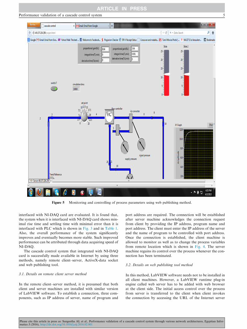
Figure 5 Monitoring and controlling of process parameters using web publishing method.
Performance validation of a cascade control system 5
interfaced with NI-DAQ card are evaluated. It is found that,the system when it is interfaced with NI-DAQ card shows min-imal rise time and settling time with minimal error than it is
interfaced with PLC which is shown in Fig. 3 and in Table 1.Also, the overall performance of the system significantlyimproves and eventually becomes more stable. Such improved
performance can be attributed through data acquiring speed ofNI-DAQ.
The cascade control system that integrated with NI-DAQcard is successfully made available in Internet by using three
methods, namely remote client–server, ActiveX-data socketand web publishing tool.
3.1. Details on remote client server method
In the remote client–server method, it is presumed that bothclient and server machines are installed with similar version
of LabVIEW software. To establish a connection, three com-ponents, such as IP address of server, name of program and
Please cite this article in press as: Sangeetha AL et al., Performance validation of amatics J (2016), http://dx.doi.org/10.1016/j.eij.2016.02.001
port address are required. The connection will be establishedafter server machine acknowledges the connection requestfrom client by providing the IP address, program name and
port address. The client must enter the IP address of the serverand the name of program to be controlled with port address.Once the connection is established, the client machine is
allowed to monitor as well as to change the process variablesfrom remote location which is shown in Fig. 4. The servermachine regains its control over the process whenever the con-nection has been terminated.
3.2. Details on web publishing tool method
In this method, LabVIEW software needs not to be installed in
all client machines. However, a LabVIEW runtime plug-inengine called web server has to be added with web browserat the client side. The initial access control over the process
from server is transferred to the client when client invokesthe connection by accessing the URL of the Internet server
cascade control system through various network architectures, Egyptian Infor-
Figure 6 Screen shot of web page created for cascade control system.
Figure 7 Accessing remote application using data socket method.
6 A.L. Sangeetha et al.
Please cite this article in press as: Sangeetha AL et al., Performance validation of a cascade control system through various network architectures, Egyptian Infor-matics J (2016), http://dx.doi.org/10.1016/j.eij.2016.02.001
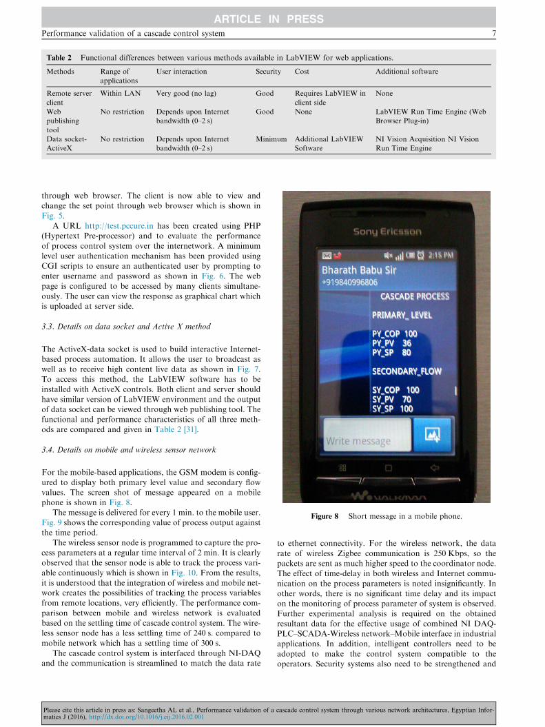
Table 2 Functional differences between various methods available in LabVIEW for web applications.
Methods Range of
applications
User interaction Security Cost Additional software
Remote server
client
Within LAN Very good (no lag) Good Requires LabVIEW in
client side
None
Web
publishing
tool
No restriction Depends upon Internet
bandwidth (0–2 s)
Good None LabVIEW Run Time Engine (Web
Browser Plug-in)
Data socket-
ActiveX
No restriction Depends upon Internet
bandwidth (0–2 s)
Minimum Additional LabVIEW
Software
NI Vision Acquisition NI Vision
Run Time Engine
Figure 8 Short message in a mobile phone.
Performance validation of a cascade control system 7
through web browser. The client is now able to view andchange the set point through web browser which is shown inFig. 5.
A URL http://test.pccure.in has been created using PHP(Hypertext Pre-processor) and to evaluate the performanceof process control system over the internetwork. A minimum
level user authentication mechanism has been provided usingCGI scripts to ensure an authenticated user by prompting toenter username and password as shown in Fig. 6. The web
page is configured to be accessed by many clients simultane-ously. The user can view the response as graphical chart whichis uploaded at server side.
3.3. Details on data socket and Active X method
The ActiveX-data socket is used to build interactive Internet-based process automation. It allows the user to broadcast as
well as to receive high content live data as shown in Fig. 7.To access this method, the LabVIEW software has to beinstalled with ActiveX controls. Both client and server should
have similar version of LabVIEW environment and the outputof data socket can be viewed through web publishing tool. Thefunctional and performance characteristics of all three meth-
ods are compared and given in Table 2 [31].
3.4. Details on mobile and wireless sensor network
For the mobile-based applications, the GSM modem is config-
ured to display both primary level value and secondary flowvalues. The screen shot of message appeared on a mobilephone is shown in Fig. 8.
The message is delivered for every 1 min. to the mobile user.Fig. 9 shows the corresponding value of process output againstthe time period.
The wireless sensor node is programmed to capture the pro-cess parameters at a regular time interval of 2 min. It is clearlyobserved that the sensor node is able to track the process vari-
able continuously which is shown in Fig. 10. From the results,it is understood that the integration of wireless and mobile net-work creates the possibilities of tracking the process variablesfrom remote locations, very efficiently. The performance com-
parison between mobile and wireless network is evaluatedbased on the settling time of cascade control system. The wire-less sensor node has a less settling time of 240 s. compared to
mobile network which has a settling time of 300 s.The cascade control system is interfaced through NI-DAQ
and the communication is streamlined to match the data rate
Please cite this article in press as: Sangeetha AL et al., Performance validation of amatics J (2016), http://dx.doi.org/10.1016/j.eij.2016.02.001
to ethernet connectivity. For the wireless network, the data
rate of wireless Zigbee communication is 250 Kbps, so thepackets are sent as much higher speed to the coordinator node.The effect of time-delay in both wireless and Internet commu-
nication on the process parameters is noted insignificantly. Inother words, there is no significant time delay and its impacton the monitoring of process parameter of system is observed.Further experimental analysis is required on the obtained
resultant data for the effective usage of combined NI DAQ-PLC–SCADA-Wireless network–Mobile interface in industrialapplications. In addition, intelligent controllers need to be
adopted to make the control system compatible to theoperators. Security systems also need to be strengthened and
cascade control system through various network architectures, Egyptian Infor-
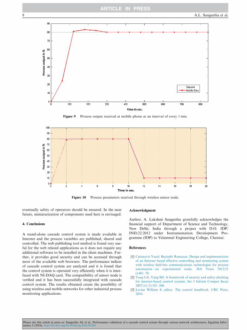
Figure 9 Process output received at mobile phone at an interval of every 1 min.
Figure 10 Process parameters received through wireless sensor node.
8 A.L. Sangeetha et al.
eventually safety of operators should be ensured. In the nearfuture, miniaturization of components used here is envisaged.
4. Conclusions
A stand-alone cascade control system is made available in
Internet and the process variables are published, shared andcontrolled. The web publishing tool method is found very use-ful for the web related applications as it does not require any
additional software to be installed in the client machines. Fur-ther, it provides good security and can be accessed throughmost of the available web browsers. The performance indices
of cascade control system are analyzed and it is found thatthe control system is operated very efficiently when it is inter-faced with NI-DAQ card. The compatibility of sensor node isverified and it has been successfully integrated with cascade
control system. The results obtained create the possibility ofusing wireless and mobile networks for other industrial processmonitoring applications.
Please cite this article in press as: Sangeetha AL et al., Performance validation of amatics J (2016), http://dx.doi.org/10.1016/j.eij.2016.02.001
Acknowledgment
Author, A. Lakshmi Sangeetha gratefully acknowledges the
financial support of Department of Science and Technology,New Delhi, India through a project with D.O. IDP/IND/22/2012 under Instrumentation Development Pro-
gramme (IDP) to Velammal Engineering College, Chennai.
References
[1] Cetinceviz Yucel, Bayindir Ramazan. Design and implementation
of an Internet based effective controlling and monitoring system
with wireless field-bus communications technologies for process
automation—an experimental study. ISA Trans 2012;51
():461–70.
[2] Yang Lili, Yang SH. A framework of security and safety checking
for internet-based control systems. Int J Inform Comput Secur
2007;1(1/2):185–200.
[3] Levine William S, editor. The control handbook. CRC Press;
2010.
cascade control system through various network architectures, Egyptian Infor-

Performance validation of a cascade control system 9
[4] Phuritatkul Jumpot, Nguyen Kien, Koibuchi Michihiro, Ji
Yusheng, Fukuda Kensuke, Abe Shunji, Matsukata Jun, Urushi-
dani Shigeo, Yamada Shigeki. Impact of QoS operations on an
experimental test-bed network. Simul Model Pract Theory
2009;17(3):528–37.
[5] Bauer NW, Donkers MCF, van de Wouw N, Heemels WPMH.
Decentralized observer-based control via networked communica-
tion. Automatica 2013;49(7):2074–86.
[6] Rehg JA, Sartori GJ. Programmable logic controllers. 2nd ed.
New Jersey: Prentice Hall; 2008.
[7] Boyer SA. SCADA: supervisory control and data acquisition. 4th
ed. International Society of Automation; 2009.
[8] Salihbegovic Adnan, Marinkovic Vlatko, Cico Zoran, Karavdic
Elvedin, Delic Nina. Web based multilayered distributed
SCADA/HMI system in refinery application. Comput Stand
Interfaces 2009;31:599–612.
[9] Bailey D, Wright E. Practical SCADA for industry. England:
Newnes; 2003.
[10] Igure VM, Laughtera SA, Williamsa RD. Security issues in
SCADA networks. Comput Secur 2006;25:498–506.
[11] Jun Kim Hyung. Security and vulnerability of SCADA systems
over IP-based wireless sensor networks. Int J Distrib Sens Netw
2012;2012:10 268478.
[12] Vargas H, Sanchez Moreno Jose, Jara CA, Candelas FA,
Torres F, Dormido S. A network of automatic control
web-based laboratories. IEEE Trans Learn Technol
2011;4:197–208.
[13] Vargas H, Farias G, Sanchez J, Dormido S, Esquembre F. Using
augmented reality in remote laboratories. Int J Comput Commun
2013;8:622–34.
[14] Ganesh AB, Sangeetha AL, Ravi VR. Network model based
automation of thermal processes using an embedded digital
controller. Proc Conf Emerg Trends Electr Photonic Devices Syst
2009:166–9.
[15] Whitepaper – NI tutorial-3301-en <http://www.ni.com/white-
paper/3301/en/>.
[16] Flammini Alessandra, Ferrari Paolo, Marioli Daniele, Sisinni
Emiliano, Taroni Andrea. Wired and wireless sensor networks for
industrial applications. Microelectron J 2009;40(9):1322–36.
Please cite this article in press as: Sangeetha AL et al., Performance validation of amatics J (2016), http://dx.doi.org/10.1016/j.eij.2016.02.001
[17] Jamsa-Jounela SL. Future trends in process automation. Annu
Rev Control 2007;31(2):211–20.
[18] Song Guangming, Zhou Yaoxin, Wei Zhigang, Song Aiguo. A
smart node architecture for adding mobility to wireless sensor
networks. Sens Actuators A 2008;147:216–21.
[19] Yan Ruqiang, Sun Hanghang, Qian Yuning. Energy-aware sensor
node design with its application in wireless sensor networks. IEEE
Trans Instrum Meas 2013;62:1183–91.
[20] Haydn AT. Wireless and internet communications technologies
for monitoring and control. Control Eng Pract 2004;12:781–91.
[21] Yick Jennifer, Mukherjee Biswanath, Ghosal Dipak. Wireless
sensor network survey. Comput Netw 2008;52(12):2292–330.
[22] Li Y, Ang KH, Chong GCY. PID control system analysis and
design. IEEE Control Syst Mag 2006;26(1):32–41.
[23] Lakhekar GV, Waghmare LM, Asutkar VG. Fuzzy approach for
cascade control of interconnected system. Int J Soft Comput
2010;5:116–27.
[24] Sangeetha AL, Kumar BN, Ganesh AB, Bharathi N. Experimen-
tal validation of PID based cascade control system through
SCADA-PLC-OPC and internet architectures. Measurement
2012;45:643–9.
[25] Bequette BW. Process dynamics: modeling, analysis, and simula-
tion. New Jersey: Prentice Hall; 2003.
[26] Jero SE, Ganesh AB, Radhakrishnan TK. Implementation of a
simple wireless sensor node for the detection of gaseous sub-
stances leakage. Int J Smart Sens Intell Syst 2011;4:482–95.
[27] Sangeetha AL, Jero SE, Palaniappan R, Ganesh AB, Bharathi N.
Integration of customizable wireless sensor node with cascade
control system. Proc Int Conf Adv Commun, Netw, Comput
2013:136–41.
[28] PIC18LF4620 data sheet. <http://www.microchip.com>.
[29] MRF24J40MA data sheet. <http://www.microchip.com>.
[30] Microchip stack for the ZigBeeTM protocol. <http://www.
microchip.com>.
[31] Naghedolfeizi M, Arora S, Garcia S. Survey of LabVIEW
technologies for building web/internet enabled experimental
setups. In: Proceedings of the 2002 American Society for
engineering education annual conference & exposition; 2002. p.
2248–57.
cascade control system through various network architectures, Egyptian Infor-