Community Benefits from Offshore Renewables: Good Practice Review
Upload
khangminh22Category
view
0download
0
1
Abstract-- Stand alone wind-diesel power systems can be an
attractive solution for the supply of remotely located consumers or the provision of enhanced energy independence. This study presents the dynamic behavior of a hybrid power system containing a prior wind generator and a supplementary generator set driven by a combustion engine, thus independently and economically supplying electrical load demand for the main hospital in Gaza-Strip – Palestine. Accumulator bank and electrolyzer plus hydrogen storage tank are added as short term and long term storage devices – respectively – in order to balance power in the system. To analyze the behavior of the above mentioned power system, the measurements for wind speed were taken from a meteorological station located in the relevant coastal area, for relatively more than one year; correspondingly, the electrical load shape of the hospital had been recorded in high temporal resolution. Stored hydrogen is injected to the generator set under a prescribed scenario of operation. The simulation results prove that continual electricity supply at low emissions and high degree of energy independence is possible.
Index Terms-- battery-bank; generator set; hydrogen storage tank; renewable energy; stand-alone system; wind turbine.
I. INTRODUCTION ver the past few years, the total electricity needs have steadily been on the rise. Recent studies are expecting
that conventional sources of primary energy will be rare, if not exhausted, thus encouraging scientists and engineers to find alternative and sustainable sources of energy. Moreover, environmental aspects play an important role to limit the green house effect gases exhausted by the fossil fuelled power plants. To achieve this, many projects have been supported to develop technologies to exploit, as efficiently as possible, clean energy sources. The technology with the greatest impact in this area is the wind power generation. Such alternative sources of energy are not required to fully replace conventional types everywhere; rather, they are useful to be a supplementary factor besides traditional sources, especially in developing public utilities – hospitals and water pumps – and rural areas where strong conventional energy grids do not yet exist or some external restrictions prevent demands to be supported. In these places, many diesel generators are used to
M. Mushtaha and G. Krost are with the Department of Electrical
Engineering, University Duisburg-Essen, Duisburg 47057, Germany (e-mail:{mohammed.mushtaha,Gerhard.krost}@uni-due.de).
meet the load demands. Nevertheless, several problems occur such as the extra cost to transport the fuel to the target area.
Transportation system breakdown is another problem to support the continuous need of fuel to the electric power generator. Furthermore, continuing escalation in the fuel price make it cost effective to use the renewable energy sources. Thus, they can play an important role in the future.
Wind-diesel power systems are the most appropriate hybrid systems utilized in weak or isolated power systems. The first commercial application of High-Penetration, No Storage, Wind-Diesel (HPNSWD) technology was installed in 1999 by Northern Power System (Vermont, USA) on St. Paul Island, Alaska [1]. One of the main challenges with these types of power systems is the reliability and quality of the produced power [2]. As a matter of fact, fluctuations in the output power result from variations in the wind speed. One way to overcome this problem is to include different kinds of energy storage (e.g., accumulator batteries for small appliances, or generation and storage of hydrogen gas by electrolysis and pressure tank – respectively – and use of this gas for a combustion motor driven generator).
Storage technologies which are based on hydrogen production and utilization – that is expected to be used for very different applications – constitute some interesting advantages in terms of cost, independency and environmental effects [3].
Combination of short term and long term energy storage devices has many advantages. A battery-bank can be used to meet the peak power demands as well as eliminate the fluctuations to the input power of the electrolyzer; hence, the size of the electrolyzer can be minimized while its life-time expectancy will evolute. A large electrolyzer is inefficient to respond to the fast changes and high peak power excess [4]. Thus, the combined energy storage system can be operated more efficiently than a single hydrogen storage system.
The Near-East region – especially Palestine – was selected as the area of study. Availability of appreciable wind speeds and solar radiations drew the attention of engineers to use the clean sources of energy to face the continuous lack of the produced power. Incredible increase of populations together with growth of societal development forced the responsibles to think in detached power systems. Unstable political situations and the age of the local power grid are also strong reasons
Performance Study of Self-sufficient and Renewables Based Electricity Supply of a
Hospital in the Near East Region M. Mushtaha, and G. Krost, Member IEEE
O
978-1-4673-2729-9/12/$31.00 ©2012 IEEE

staindapareprosouGahomo
dieapdeforstofolhysecdiethesimpodissecsum
sycoindenas acanresimtheStostralsma
A. Asof sypo
Fig
anding behinddependent from
pplications beceas within thesoved to be curces, i.e. a daza-Strip, Palesospital is locateore than 40% oThe objective
esel hybrid ppplication. Theemand, as wellr storing and orages. To achllowed by a
ydrogen – resction, the planesel power syse mechanism omulated modelossible real apscussion of soction V. Lastlymmary, and ou
A typical stanstem is illustr
ontained in the duction gener
ngine driven sywell as su
cumulator bannd storage tankspectively). FL
mportant role ine battery-bankored hydrogenrategy – in the so leading to eain target.
Wind Turbines indicated earf energy as it stems [1]. A
ower range (1
g. 1. Stand-alone w
d such kind om the local powcame more anse last years. A
competitive rediesel generatostine, is taken aed near the coaof Gazian peope of this work ower system system shoull as have an e
re-using the hieve that, a time estimato
spectively – ant description stem is briefly of storage and of the Alshiefpplication is come of the oby, section VI utlook.
II. PLANT CO
nd-alone hybrirated in Fig. proposed syste
rator (main soynchronous genupplementary nk and hydrogk (short-term LC together wn controlling thk and the elecn is injected combustion en
extensive energ
e rlier, the wind
is often the variety of w
100 kW up to
wind-diesel power
of systems totwer grid. Thusd more populActually, windgarding the trr set [5]. The as case study hastal area in Gple. is to develop afor the previ
ld be able to dffective and insurplus powe
Fuzzy Logic or and a presare applied. Iof a stand-alooutlined. Sect
d re-use of the fa hospital elecclarified in setained results is dedicated t
ONFIGURATION
d wind-diesel 1. Four main
em which are: ource of enernerator set (freand backup
gen path incluand long-term
with the time ehe flow of excectrolyzer as w
– according ngine driving thgy independen
turbine acts ascase in such
ind generatorso 5 MW) ba
r system (main com
ally isolated a, the ‘small wilar in the remd turbine usageraditional enemain hospital
here. The Alshiaza city. It ser
an efficient wiiously mentiondeliver the powntelligent strateer in the bi-fController (FL
scribed re-use In the followone hybrid wition III introdu
excess powertricity supply aection IV, whwill be foundo the conclusi
power generat
n components wind turbine wrgy), combustequency gover
power sourcuding electrolym energy storaestimator playess power towa
will be seen lato a pre-definhe generator, tcy – which is
s the main soudetached pow
s in the relevased on differ
mponents).
and ind’
mote e is
ergy l in iefa rves
ind-ned wer egy fold LC)
of wing ind-uces r. A as a hile d in ion,
tion are
with tion rnor ce), yzer age, an
ards ater. ned thus the
urce wer vant rent
aerodynavailablfollows the rotor
PWT=wher
PWT :cp : ρ : A : TuVwind: Wα : Tipβ : BlaV, Vc, Vffurling s
The mand α =
B. GeneDual
environmit can bcircumslong lowgeneratosystems
The iis not oestimatefuel is rrated cothen assthere shThis is generatoconsumapproximfull loadalmost consumpdependeengines.a reductamount above. Ton such
Detaimodes o
C. EnerOne
is choosenergy. play an
namic and elle. As the withe variations r speed as indi
0.5·cp α , βPnom 0
re Mechanical o Performance cAir density (k
urbine swept aWind speed (m/p speed ratio oade pitch angle Vf, Vr : wind spspeed, and ratemaximum valu0.81. For mor
erator Set l-fuel engine mental-sustain
be committed fstances, for insw wind periodor set plays an s since it regulaimpact of the w
obvious as it me fuel saving required to proonditions of thsume that for ehould be a pronot the case,
or decreases amed for a given
mation, fuel cod value, and tlinear or qu
mption to rateent, with the la. A decrease intion in fuel usethat would be
The actual fuefactors as the iled representaof operation wi
rgy storage sysof the main ch
sing the most aNot only the important rol
lectrical princind speed fluc
of the wind spicated in (1) [6
·ρ·A·Vwind 3 V
utput power ofcoefficient of t
kg/m³), area (m²), /s), f the rotor blad(deg.)
peed estimated ed speed in (m/ue of cp (0.48) e details see [8
as source onable – especiaflexibly and instance running s which are ve
n important roleates the frequenwind turbine o
might at first swould be to doduce a kWh
he diesel modeevery kWh proo rata drop inhowever, bec
at low load, amount of pro
onsumption atthe relationshiuadratic. Noteed fuel consuarger values con power generae, but it is typie calculated in el saving at desize, type, andations of the ill be discussed
stem hallenges for suappropriate stra
economical ale in selecting
ciples are coctuates, the oupeed as a cube, 7]. Vc ≤ V ≤ V Vr ≤ V ≤
V ≤ Vc and V ≥
f the turbine (Wthe turbine,
de tip speed to
at height h, cu/s), respectively is achieved fo
8].
of energy isally with dieselndependently fon diesel fuel
ery rare; furthee in the stand-ancy in the systeon diesel fuel ceem. The simpdetermine firstof electrical e
e generator setoduced by the wn diesel fuel cause the efficicausing more
oduced energyt no load is 15p for interven
e that the noumption ratio
orresponding toation will actuaically closer tothe simple wa
ecreased loadind the age of the
dual-fuel engd later.
uch isolated poategy for storinand environme
the most suit
2
ommercially utput power e function of
Vr
Vf
Vf
(1)
Watt),
wind speed,
ut-off speed, y. or β = 0 deg.
s not fully l mode – but from natural only during
ermore, such alone hybrid em. consumption plest way to t how much
energy under t. One might wind turbine onsumption. iency of the
e fuel to be . To a rough
5-30% of the ning loads is o load fuel o is engine o the smaller ally result in
o 2/3rd of the ay described ngs depends
e engine [9]. gine and the
ower systems ng the excess ental aspects table storage

dewe
ondaThmaacmode
e.gdesuran
eleaneffpelimin hyof
exhighyilluof
D.
knrulmaoucohaproim
Figfibval
evices, but the ell as cost consFor instance,
nly appropriatay/night cycleshey can also aain function incumulator banodel which is r
efinite (full) chaLonger term
g., electrolysisecomposed intorplus electric
n aqueous electr
H2OUnder ideal
ectricity and 8nd 1.0133 Bar)ficiency can n
erfectly ideal dmitations. The
the range of ydrogen storagf internal pressu
Shape of thexternal surface ghest challeng
ydrogen storagustrates a verti
f storage vessel
Fuzzy Logic Fuzzy logic
nowledge and les. It does noath equations g
utputs. It proviontrol because andled by ruleocess which r
mplementation.
g. 2. A schematicer and epoxy resinlve, (5) tube for hy
functionality osiderations can
customary acte for small s of smaller phact as short ten our work. Thnk can be detrun in parallel arging statusesand larger sca
s and hydrogeo its elementacurrent betweerolyte [13]:
O+electrical ecircumstance
.9 liters of wato produce 1
ever be reachedue to thermocurrent electro
f 52% to 82%e can be simpure. e hydrogen stand the type o
ges concerningge system. Forical section forls.
Controller andallows descrexperience in
ot require anygoverning the rides also an alit is closer to
es, membershipresults in impr
c view of the hybrn, (2) thin aluminuydrogen [15].
of each individalso determine
ccumulators arscale storag
hotovoltaic baserm energy buhe actual charermined by anand tuned from
s, e.g. [11]. ale storage canen storage [12ary componenten two electro
energy→ H2+es it requirester at normal ckg of hydroge
ed because theodynamics as olyzer efficienc
% [14]. The chply determined
torage vessel, of the storage mg the design ar more details,r one of the new
d Time Estimatribing complexn simple natu
y system moderelationship belternative solutthe real worldp functions, aroved performa
rid hydrogen storaum liner, (3) hydro
dual technologye the proper onre expensive a
ge, i.e. coversed systems [1
uffer which is rging status ofn observer bam time to time
n be achieved 2]. Water can ts by passing odes separated
12
O2 s 39.4 kWh conditions (25en. The maxime process is ne
well as matecies generally harging status
d by measurem
the liner of media are now and build-up o, see [15]. Figwest technolog
tor x systems usural-language-leling or competween inputs ation to non-lin
d. Non-linearityand the infereance and simp
age vessel: (1) carogen storage alloy
y as nes. and ring 10]. the
f an ased
for
by, be
the by
(2) of
° C mum ever erial
are s of
ment
the the
of a g. 2 gies
sing like plex and
near y is nce pler
rbon y, (4)
Regashould befficientto deterwhile thchargingfluctuatiset-poinallowedbefore sreduce expectanthe stratconsider
III. EX
As mstored tstrategieand the storage
A. FuzzThe
containiapproprcontrollefficienttargetingrelates tTHEN) of the hyto the Fexcess smethod
Thersplit pepresentssystem d
As wcontrollto drivethe life burnish
Fig. 3. Stestimator,electrolyz
IF (SOC iIF (SOC iIF (SOC THEN (TaIF (SOC i
arding the propbe managed intly. Fuzzy logirmine the actuthe battery-bang level in ordions. The time
nts of the electd time duratioswitching ON/
material strncy. The follow
ategy of the enrations.
XCESS POWER:mentioned befoto be used ines of the electdual-fuel gen
and re-use, res
zy control of elease of for
ing imprecise vriate means foer was used t split of the pg the operatiothe controller rules. Accum
ydrogen tank aFLC, while thesplit. Fig. 3 ill[16].
re are 23 fuzzercentage forws some exampdescribed in thwill be seen er is widely fl
e the electrolyztime of the
the portion
tructure of fuzzy c, which then pzer.
EXCERPT OF RUis Empty) THEN (is E-Medium) and is F-Medium) andank is High) is Full) and (Pressu
posed system, n the way that tic controller anual power set-nk has to be
der to cover the estimator cotrolyzer, but iton before cha/OFF the elec
ress and thewing section cnergy storage
: MECHANISM O
ore, excess pon the times trolyzer follow
nerator set conspectively.
lectrolyzer andrmulation of verbal expressor plant contrto achieve a
power excess ion set-point output to the
mulator State Oand the power e output is thelustrates the fu
zy logic rules warded to the ple rules of FLhis paper. later, the respluctuated. Suchzer. Thus, to inelectrolyzer, tn of exces
controller [16]; thprovides certain
TABLE I ULE BASE OF FUZZY(Tank is Zero) (Pressure is Dang
d (Pressure is Me
ure is not Dangero
storing the surthe electrolyzend time estima-point of the e kept on an he remaining rontrols not onlyt limits also thanging the sectrolyzer, both erefore enhancontains more dtaking into ac
OF STORAGE AN
wer has to beof deficiency.
wed by the timntrol the proces
d time estimatological oper
sions makes furol. Thus, a
situation depin the proposeof the electroinputs with a
Of Charge (SOexcess are the
e percentage ouzzy logic con
used to derive time estimat
LC that are ap
ponse of the h ripples are nncrease the effthe time estimss power en
e output is forwaroperational set-
Y LOGIC CONTROLL
gerous) THEN (Tadium) and (Exces
ous) THEN (Tank
3
rplus energy er is working ator are used electrolyzer, appropriate
rapid power y the power he minimum et-point and
in order to nce lifetime details about ccount some
ND RE-USE e efficientely . The work
me estimator ss of energy
r ration rules
uzzy logic an fuzzy logic
pendent and d system by olyzer. FLC a list of (IF-C), pressure three inputs
of the power ntrol analysis
e the power tor. Table I pplied in the
fuzzy logic not preferred fficiency and mator has to ntering the
rded to the time -points of the
LER
ank is Zero) ss is Abundant)
is High)

elechthe
B.
ento is igntot
priclealo • • wi• of • nutak • • • 80
en
cosyM
simPS
Figsetres
ectrolyzer by hanges, see Fige electrolyzer a
Dual-fuel GeA dual-fuel c
ngine that has butilize gaseoua true diesel
nition of the gtal energy of thThe dual-fue
imary benefit eaner cheaper one when nece1) Engine Cha a) HydrogRunning on gaAutomatic and
ithout loss of eTransfer to die
f engine power Automatic tri
umber of minutken in this stud b) Diesel MRunning on diTransfer to hyAutomatic tra
0% without lossFig. 5 illustra
ngine.
IVFor the inves
ontrol the applistem is requiratlab/Power SyPSB is a grap
mulation of poSB is used to
g. 4. Output signa-points finally gpectively [17].
constraining og. 4. For moreand the time es
nerator Set combustion enbeen fitted wits fuel as a suppand requires
gas as main fuehe fuel [18]. l engines hav
is that of fgaseous fuel
essary. aracteristics agen Gas Modeas and diesel pid instant trip tongine power anesel mode on rand speed. ip to diesel tes at engine lo
dy). Mode iesel fuel inject
ydrogen gas moansfer to hydros on engine poates the mode
V. MODELING A
stigation and iication of a simred. Regardingystem Blockset
phical tool that ower systems represent com
al of FLC and resgiven to the ele
operation perioe details aboutstimator, refer t
ngine – originath additional deplemental fuel.some level o
el, in practice a
ve a number ofuel flexibility
when availab
nd Operating me ilot fuel injectio diesel mode nd speed. request at any
mode after aoads below 15
tion. ode on request.ogen gas modwer and speeds of operation
AND SIMULATIO
implementationmulative modeg the case stut (PSB) is usedallows buildinin the Simul
mmon compon
sponse of the timectrolyzer), in bla
ods and set pot fuzzy controlto [17].
ally – is a dieevices allowin. This engine tyof diesel fuelaround 1% of
of advantages.y, operating wble and on die
modes [18]
ion. in alarm situat
load without l
a pre-determin5% (5 minutes
de at loads bel.
n of the dual-f
ONS n of proper plel of the compludy pursued hed for this issue.ng schematics alink environmenents and devi
e estimator (i.e. poack and red co
oint l of
esel ng it ype for the
. A with esel
tion
loss
ned are
low
fuel
lant lete ere, . and ent. ices
ower lors,
Fig. 5. M found iSimulin
Choosimulatemodel dLinearizoutput papplied describeto aerod
Thretraditionillustrateregulatospeed gsystem c
Fig. 6. Si
Fig. 7. Si
Modes of operation
in electrical pnk model of theosing the wind e the behaviodescriptions sized [19] or qupower of smalhere, the prod
es the power gdynamics. e main partsnally diesel ges the synchro
or (AVR), congovernor. Mocan be found in
imulink model of t
imulink model of d
of the dual-fuel en
power networke power system
turbine modelor of the renimulate the wiuadratic [20] eqller wind turb
duced power isgenerated by th
s constitute thgenerator as monous generato
nnected to the ore details abon [18].
the power system o
dual-fuel generator
ngine [18].
ks. Fig. 6 illm of the Alshiefl plays an impo
newable energyind turbine ouquations can r
bines. More prs represented bhe wind turbin
he dual-fuel mentioned earor with automdual-fuel engiout the dual-
of the Alshiefa ho
r [21].
4
lustrates the fa hospital. ortant role to y. Different utput power. represent the recisely, and by (1) which ne according
generator – rlier. Fig. 7
matic voltage ine with the -fuel engine
spital.

the– drawhter
(75thepropreeqPV
Z NH
R TVMH
prea sordtem(30hy
A.
indThneGaat apwisplocda(h
Fig
As shown froe rectified and for such dev
amatically thehich improve trm simulationsThe efficienc
5 %) includinge electrolyzer eoduced hydroessure of the h
quation [22]: where
Vi : is the init : is the com
H2 : is the hyd : is the ide
V,VV : are the vMH2. : is the mo
Note that the essure is lowerso called high pder to obviamperature is co00 K). Fig.
ydrogen storage
V
Wind and loaAs mentioned
dependent powhe Alshiefa hoear the sea. Thaza-Strip. The height hrof 5
pproximately 7ind speed is 5.4eed values fromcation. Equatio
ata recorded a= 56 m).
g. 8. Simulink mo
om Fig. 6, twocontrolled exc
vices given ine simulation spthe simulation s. cy of the batteg the inverter efficiency is ta
ogen is storedhydrogen tank
PV– PVi= Z
tial pressure ofmpressibility fadrogen flow in eal gas constantvessel temperatolecular mass o
compressibilitr than 140 Barpressure electr
ate an additioonsidered to b8 illustrates te tank.
V. RESULTS AN
ad profiles d before, the cwer supply of tspital is locate
he city has onoriginally mea
5 m – to be re-7 m/s, while t4 m/s. Fig. 9 shm August, 201on (4) is usef
at certain leve
del for hydrogen s
o main paths acess power. Thn Matlab/Simupeed. So, simspeed – were
ery-bank is conefficiency. On
aken constant hd in a vesselis obtained fr
Z·NH2·R·TV
MH2·VV
f the hydrogen actor of the hyd(moles/sec.), t, ture and volumof hydrogen. ty factor is equr [22], which isrolyzer that waonal compres
be constant at rthe Simulink
ND DISCUSSION
case study perthe main hospied at the west e of the best asured annual -calculated accthe minimum hows the mont0 to July, 2011ful to convert el to the estim
storage tank [22].
are introduced he detailed modulink – decre
mplified modele applied for lo
nsidered constn the other hahere at 75 %. Tl. The produ
rom the follow
in the vessel,drogen,
me; respectively
ual to 1 when s not exceededs assumed here
ssor. The vesroom temperatdiagram for
NS
rformed conceital in Gaza-Stpart of Gaza cwind potentialmean wind sp
cording to (4) –monthly aver
thly average w1 for the propo
the anemomemated hub cen
for dels ease s – ong
tant and, The
uced wing
(3)
y,
the d by e in ssel ture the
erns trip. city l in eed – is rage
wind osed eter nter
wherand α isto 1.4 at
A samillustratespeed reRecords
Fig.hospitalminuteselectricacycle; thweek. Afairly hiabout 11
B. OptiAs in
system storage relevantas descdriven inductioof energcable co
Fig. 9. Av
Fig. 10. Rthe small time as th
V
re Vr is the wins the ground sut the proposed mple of slightled in Fig. 10. ecords taken fs were measure11 shows the
l during a days in Decemberal load profilehis is evident sAccording to thigher than 800 1 MWh.
imization and Cndicated previconsists of a wsystem, and
t components (cribed in [23])
generator witon generator wgy are conneconnections.
verage monthly w
Recorded wind spexcerpt window
hose in Fig. 13 – 17
V = Vr · h h⁄nd speed measurface friction location.
ly more than oIt was collect
from August, 2ed every hour fmeasured elec
y. The load dar, 2009. It waes are almost since the clinic he consumptionkW, while the
Components Siiously, the exwind turbine, an electrical
(based on Part) has resultedth 800 kW,
was rated at 115cted to the va
wind speed values a
peed data (from Aushowing more de
7, so that they can
hr ured at referencoefficient wh
one year wind sted according 2010 to Septefor the whole tctrical load prata were taken
as identified ththe same duriservice contin
n records, the e daily consum
izing xample stand aa generator seload. The si
ticle Swarm Od in a combus
while the w50 kW. These ariable load th
at coastal area – G
ugust, 2010 to Sepetails is for the saimmediately be co
5(4)
nce height hr hich was set
speed data is to the wind
ember, 2011. time. rofile for the n every two hat the daily ing the year
nues 7 days a peak load is
med energy is
alone power et, an energy izing of the
Optimization, stion engine
wind turbine two sources
hrough short
aza.
ptember, 2011); ame periods of ompared.

Fig
MWtaneneleele
cotonthehy
Susim
C.
obSim
forof gethesppothe
ele
Fig
g. 11. Daily electr
The corresponWh, while thenk is 165 m³ –
nergy – and canectrolyzer outpectrolyzer is 10With this sizin
onsumption wons/year with pue produced hy
ydrogen re-use Fig. 12 repres
uzlon) wind tumulations. For
Simulation RThe simulatio
btained in mPowerSystemIt is clear from
r the wind turbf 1250 kW. Tenerator produce available wineed of 25 m/s.
ower that was pe wind turbine;In consequen
ectricity – eithe
g. 12. Characterist
ical load demand f
nding size of te volume of th
maximum capn withstand 14put. The nomi000 kW. ng of plant comould be only ure diesel base
ydrogen re-usedis much highersents the charaurbine – the dmore details, r
esults and Discon results show
Matlab-Simm toolbox. m Fig. 12 thatbine induction This means thces its maximund speed is abo
Fig. 13 illustrproduced durin; the simulationnce, the dualer by diesel fu
tics of S66-1.25MW
for Alshiefa hospit
the battery-banhe cylindrical pacity is 63 MW40 Bar as maxnal power of
mponents, the 530 tons/year d generation (id as fuel); ther, as to be seenacteristics of thata of which refer to [24].
cussions wn in the foll
mulink envir
t the rated windgenerator with
hat the wind tum power (125ove 14 m/s and ates the amoun
ng the whole pen resolution wal-fuel generat
uel or hydrogen
W wind turbine, S
tal.
nk should be 1hydrogen storWh of the surp
ximum pressurethe high-press
annual diesel finstead of 16
i.e. not yet have fuel saving wn later. he (S66-1.25Mwere used in
owing have bronment us
d speed is 14 mh a nominal powturbine induct0 kW) only whbelow the cut-
nt of the electrieriod of time fras set to 1 hourtor set produn gas – in orde
Suzlon.
1.44 rage plus e at sure
fuel 690
ving with
MW, the
een sing
m/s wer tion hen -off ical rom r.
uces r to
Fig. 13. D cover thillustratefrom thpower pMore prfrom booperatiofor diese
It is increasehydrogewater prpressurecase 12
Fig. 14. hydrogen gas modes
Delivered power b
he instantaneoes the shared a
he diesel fuel, produced durinrecisely, the proth modes ofon – would be el mode and hyobserved in Fi
es sharply. Inen pressure, a 2reparation is coe of the hydro0 Bar); this ca
Delivered power gas mode; for the
s, respectively, see
y the wind turbine
ous deficit eleamount of the while Fig. 14
ng the hydrogeroduced amou
f operation – 660 MWh an
ydrogen gas mig. 15 that the
n order to av200 kW additionnected to thegen tank excean be seen in
(a)
(b)
from dual-fuel gee ratio of maximae section III.
e.
ectrical powerelectrical pow
4(b) shows theen gas mode, runt of the elect
for the wholnd 1065 MWh mode. e electrical loadvoid dangerouional resistive e system direct
eeds a certain lFig. 15 in the
enerator set; (a) dal powers in diese
6
. Fig. 14(a) wer produced e amount of respectively. trical energy le period of sequentially
d sometimes us levels of
load for hot tly when the limit (in our e months of
iesel mode; (b) el and hydrogen
Minsexthe
theFigtimdifele[17
preIt (72
Fig
Fig
Fig
ay, June and stantaneous loa
xceeds the genee accumulator To investigat
e proposed eng. 16 – should
me estimator gfference betweectrolyzer is st7]. The SOC of
essure of the his observed th20 kWh) at t
g. 15. Electrical lo
g. 16. Power exces
g. 17. Response of
July. It conad increase witerator set nomibank. e the effectiveergy storage sbe considered
giving the set een excess powteadily compe
the battery-bahydrogen storaghat the SOC wthe beginning
oad demand for Al
ss to be stored.
f the time estimato
ntinues at leasthin these perioinal power – c
eness of the FLsystem, electricd. Fig. 17 show
points of the wer and powernsated by the
ank and the dege tank are illuwas specified t of simulatio
shiefa hospital.
or.
st 6 hours. Aods of time – t
can be covered
LC in controllc power exces
ws the evolutionelectrolyzer. T
r absorbed by accumulator,
evelopment of ustrated in Fig. to a certain len and is larg
Any that
d by
ling ss – n of The the see
the 18.
evel gely
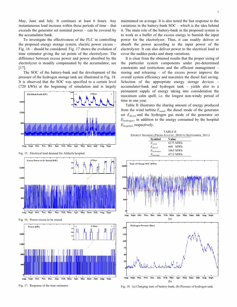
maintainvariationit. The mto workpower fabsorb electrolycover th
It is cthe parconstraistoring overall sSelectioaccumupermanemaximutime in o
Tablefrom theset EdiesEhydrogen
Ehospital,
EN
Fig. 18. (
ned on averagens in the battermain role of thk as a buffer ofor the electrothe power a
yzer. It can alshe sudden peakclear from the rticular systemints and restriand releasing
system efficienon of the apulator-bank anent supply ofum calm spellone year. e II illustrates e wind turbineseland the hy
n, in addition t, respectively.
NERGY SHARING (FSymEwinEdiesEhydEhos
(a) Charging state
e. It is also notry-bank SOC –
he battery-bankf the excess enolyzer. Thus, according to so deliver powks and sharp va
obtained resulm componentctions and the
g – of the exncy and maximppropriate en
nd hydrogen tf energy takinl; i.e. the long
the sharing ameEwind, the die
ydrogen gas mto the energy
TABLE II FROM AUGUST, 20
mbol Value nd 6375 Msel 660 M
drogen 1065 Mspital 4715 M
(a)
(b)
of battery-bank; (b
ted the fast res– which is the
k in the proposnergy to burniit can readilythe input po
wer to the electariations. lts that the propts under pree efficient maxcess power imize the diesel nergy storage tank – yieldsng into considgest non-wind
mount of energesel mode of thmode of the g
consumed by
010 TO SEPTEMBER
MWh MWh MWh MWh
b) Pressure of hyd
7
sponse to the idea behind
sed system is ish the input y deliver or
ower of the trical load to
per sizing of e-determined anagement – improve the fuel saving. devices –
s also to a deration the
dy period of
gy produced he generator
generator set the hospital
R, 2011)
drogen tank.

8
It is noticed that the diesel fuel consumption is only 280 tons instead of 1975 tons with pure diesel based generation for the same period of time. More deeply, one can strongly say that the proposed hybrid wind-diesel power system performs significant cost advantages in comparison with diesel fuel only; and this even under inclusion of the investment cost as shown in [23]. The corresponding fuel cost is relatively higher than 0.4 Million Euro, being less than 15% of a diesel-only solution (about 2.96 Million Euro) to provide independence of the public grid.
These impressive results – especially economically ones – encourage the responsibles to use such clean sources of energy, achieve fuel cost saving and relative independence of fuel delivery, as mentioned before.
VI. CONCLUSION, SUMMARY, AND OUTLOOK A hybrid wind-diesel power system was investigated in this
paper, applied to a stand-alone electricity supply of the main hospital in Gaza-Strip as a relevant and realistic case study. MATLAB/Simulink models were introduced for the wind generator, dual-fuel generator set, hydrogen storage path and accumulator bank. Simulation results over one year, based on real wind harvest and load data, proved that the chosen rating of components in connection with the implemented operation strategy for the plant leads to efficient, continuous and independent supply with an amount of used diesel fuel below 15% of that needed for conventional independent electricity supply purely based on diesel generation.
Further work will aim in additionally investigating re-use of the waste heat of the combustion engine. Regarding the hospital example, surgical demands, air conditioning (by absorption coolers) as well as hot water supply are vigorous heat absorbents. In this way, the overall efficiency of the system can further be enhanced.
VII. ACKNOWLEDGMENT The authors thank the German Academic Exchange Service
– Deutscher Akademischer Austausch-Dienst – (DAAD) for providing scholarship for M. Mushtaha to pursue his PhD degree at University Duisburg-Essen.
VIII. REFERENCES [1] L. Mott (NPS) and B. Saulnier (IREQ), “Commercial wind-diesel
project, St. Paul Island, Alaska,” 14th Prime Power Diesel Inter-Utility Conference, Winnipeg, Manitoba, Canada, May 28-June 2.
[2] A. J. del Real, A. Arce, and C. Bordons, “Optimization strategy for element sizing in hybrid power systems,” Journal of Power Source, vol. 193, pp. 315-321, 2009.
[3] J. Kaldellis and D. Zafirakis, “Optimum energy storage techniques for the improvement of renewable energy sources-based electricity generation economic efficiency,” Energy, vol. 32, pp. 2295-2305, 2007.
[4] F. J. Pino, L. Valverde, and F. Rosa, “Influence of wind turbine power curve and electrolyzer operating temperature on hydrogen production in wind–hydrogen systems,” Journal of Power Sources, vol. 196, pp. 4418-4426, 2011.
[5] J. G. McGowan, W. Q. Jeffries, and J. F. Manwell, “Development of Dynamic Models for no Storage Wind-Diesel Systems,” Proceedings of the 17th British Wind Energy Association Conference, UK, July-1995, pp. 111-116.
[6] E. Muljadi, J. Sallan, M. Sanz, and C. P. Butterfield, “Investigation of self-excited induction generators for wind turbine applications,” IEEE
Industry Applications Society, Annual Meeting, Phoenix-Arizona, October, 1999.
[7] M. Druga, C. Nichita, G. Barakat and E. Ceanga, “Stand-Alone Wind Power System Operation with a Specific Storage Structure,” International Conference on Renewable Energies and Power Quality (ICREPQ’09), Valencia (Spain), Apr. 2009.
[8] S. Heier, “Grid Integration of Wind Energy Conversion Systems,” John Wiley & Sons Ltd, 1998, ISBN 0-471-97143-X.
[9] R. Hunter and G. Elliot, “Wind-Diesel Systems: A guide to the Technology and its Implementation,” Cambridge University Press, 1994.
[10] Press Release Saft-Batteries, New design of specialized rechargeable nickel-cadmium battery, http:/saftbatteries.com.
[11] P. Beckhaus, C. Hardt, G. Krost, and S. Souzani, “Ladezustandserkennung durch simulative Batteriebeobachtung” (Recognition of battery state of charge by simulative observer), 18th Symposium on Photovoltaic Solar Energie, Staffelstein (Germany), March 2003 (in German).
[12] P. Beckhaus, G Buchholz, A. Graw, G. Krost, and J. Matics, “Solar hydrogen based energy supply for residential development,” World Renewable Energy Congress (WREC-VII), Cologne (Germany), July 2002.
[13] M. J. Khan and M. T. Iqbal, “Dynamic Modeling and Simulation of a Small Wind-Fuel Cell Hybrid Energy System,” Renewable Energy, vol. 30, pp. 421-439, 2005.
[14] G. Saur, “Wind-To-Hydrogen Project: Electrolyzer Capital Cost Study,” National Renewable Energy Laboratory, 1617 Cole Boulevard, Golden, Colorado 80401-3393, Tech. rep. NREL/TP-550-44103, Dec. 2008.
[15] N. Takeichi, H. Senoh, T. Yokota, H. Tsuruta, K. Hamada, H. T. Takeshita, H. Tanaka, T. Kiyobayashi, T. T. Takano, and N. Kuriyama, “Hybrid hydrogen storage vessel, a novel high-pressure hydrogen storage vessel combined with hydrogen storage material”, International Journal of Hydrogen Energy, vol. 28, pp. 1121-1129, 2003.
[16] K. Jeong, W. Lee, and C. Kim, “Energy management strategies for a fuel cell/battery hybrid system using fuzzy logic,” Jounal of Power Sources, vol. 145, pp. 319-326, 2005.
[17] M. Mushtaha, and G. Krost, “Independent and Clean Electricity Supply for a Hospital in Palestine Controlled by Fuzzy Rules and Time Estimator,” 16th International Conference on Intelligent System Applications to Power Systems (ISAP), Crete, Greece, Sept. 2011.
[18] B. Thijssen, “Dual-Fuel Electric LNG Carriers: LNG Shipping Operation,” Wärtsilä Finland Oy, Hamburg, Germany, Sept. 2006.
[19] Z. Wei, and Y. Hongxing, “One optimal sizing method for designing hybrid solar-wind-diesel power generation systems,” Proceedings of ISES Solar World Congress 2007, Solar energy and Human Settlements, vol. 4, pp. 1489-1494, 2007.
[20] R. Pallabazzer, and A. A. Gabow, “Wind generator potentiality in Somalia,” Renewable Energy, vol. 2, No. 4/5, pp. 353-361, 1992.
[21] K. Yeager, and J. Willis, “Modeling of Emergency Diesel Generators in an 800 Megawatt Nuclear Power Plant,” IEEE Transactions on Energy Conversion, vol. 8, No. 3, pp. 433-441, Sept. 1993.
[22] H. Görgün, “Dynamic modelling of a proton exchange membrane (PEM) electrolyzer,” International Journal of Hydrogen Energy, vol. 31, pp. 29-38, 2006.
[23] M. Mushtaha, and G. Krost, “Sizing a Self-sustaining Wind-Diesel Power Supply by Particle Swarm Optimization,” IEEE Symposium Series on Computational Intelligence, Paris, France, Apr. 2011.
[24] Suzlon, “Powering and Green Tomorrow, S66-1.25MW Technical Overview,” [online]. Available: http://www.suzlon.com.
Copyright © 2022 FDOKUMEN