
Performance of vapor compression systems with compressor oil flooding and regeneration
11
Purdue University Purdue e-Pubs Publications of the Ray W. Herrick Laboratories School of Mechanical Engineering 10-27-2010 Performance of Vapor Compression Systems with Compressor Oil Flooding and Regeneration Ian H. Bell Purdue University Eckhard A. Groll Purdue University James E. Braun Purdue University This document has been made available through Purdue e-Pubs, a service of the Purdue University Libraries. Please contact [email protected] for additional information. Bell, Ian H.; Groll, Eckhard A.; and Braun, James E., "Performance of Vapor Compression Systems with Compressor Oil Flooding and Regeneration" (2010). Publications of the Ray W. Herrick Laboratories. Paper 4. http://docs.lib.purdue.edu/herrick/4
Transcript of Performance of vapor compression systems with compressor oil flooding and regeneration

Purdue UniversityPurdue e-Pubs
Publications of the Ray W. Herrick Laboratories School of Mechanical Engineering
10-27-2010
Performance of Vapor Compression Systems withCompressor Oil Flooding and RegenerationIan H. BellPurdue University
Eckhard A. GrollPurdue University
James E. BraunPurdue University
This document has been made available through Purdue e-Pubs, a service of the Purdue University Libraries. Please contact [email protected] foradditional information.
Bell, Ian H.; Groll, Eckhard A.; and Braun, James E., "Performance of Vapor Compression Systems with Compressor Oil Flooding andRegeneration" (2010). Publications of the Ray W. Herrick Laboratories. Paper 4.http://docs.lib.purdue.edu/herrick/4

Performance of Vapor Compression Systems with Compressor Oil Flooding andRegeneration
I. Bella,∗, E. Grolla, J. Brauna
aPurdue University Department of Mechanical Engineering, 140 S. Martin Jischke Drive, West Lafayette, IN, 47906
Abstract
Vapor compression refrigeration technology has seen great improvement over the last several decades in terms ofcycle efficiency through a concerted effort of manufacturers, regulators, and research engineers. As the standard vaporcompression systems approach practical limits, cycle modifications should be investigated to increase system efficiencyand capacity. One possible means of increasing cycle efficiency is to flood the compressor with a large quantity of oil toachieve a quasi-isothermal compression process, in addition to using a regenerator to increase refrigerant subcooling.
In theory, compressor flooding and regeneration can provide a significant increase in system efficiency over the standardvapor compression system. The effectiveness of compressor flooding and regeneration increases as the temperature lift ofthe system increases. Therefore, this technology is particularly well suited towards lower evaporating temperatures andhigh ambient temperatures as seen in supermarket refrigeration applications. While predicted increases in cycle efficiencyare over 40% for supermarket refrigeration applications, this technology is still very beneficial for typical air-conditioningapplications, for which improvements in cycle efficiency greater than 5% are predicted. It has to be noted though thatthe beneficial effects of compressor flooding can only be realized if a regenerator is used to exchange heat between therefrigerant vapor exiting the evaporator and the liquid exiting the condenser.
Key words:Air conditioning, Refrigeration, Regeneration, Flooding, High Efficiency, Flooded Compression
Nomenclature
cp Specific heat (kJ kg−1 K−1)COP Coefficient of performance
E Rate of irreversibility generation (kW)h Enthalpy (kJ kg−1)∆h Difference in enthalpy (kJ kg−1)m Mass flow rate (kg s−1)s Entropy (kJ kg−1 K−1)p Pressure (kPa)T Temperature (K,◦C)∆T Difference in temperature (K)
Q Heat transfer rate (kW)v Specific volume (m3 kg−1)
W Power (kW)x Mass flow rate fraction (mass %)ε Effectiveness of regeneratorη Adiabatic efficiency
Subscripts
∗Corresponding AuthorEmail addresses: [email protected] (I. Bell),
[email protected] (E. Groll), [email protected] (J. Braun)
1, 2, 3, . . . State point1m, 2m, 3m, . . . Mixture property at state point0 Referencecomp Compressorcond Condensercrit Critical property of refrigerantevap Evaporationexp Hydraulic ExpanderG GasL Liquidmax Maximummixer Mixeroil-cooler Oil coolerpinch Heat exchanger approachreg Regeneratorsep Separatorsh Superheatsink Hot thermal reservoirsource Cold thermal reservoir
Preprint submitted to International Journal of Refrigeration October 27, 2010

1. Introduction
From consideration of the polytropic compression pro-cess of an ideal gas, it is readily seen that the compres-sion process which minimizes the gas specific work is anisothermal compression process where the heat of com-pression is removed from the gas during the compressionprocess. Isothermal compression is the ultimate goal ofthermal engineers, but challenging to achieve in practice.A number of means have been proposed to achieve isother-mal compression, including cooling the compressor duringthe compression process (Kim et al., 2008).
One of the most promising means of achieving quasi-isothermal compression is the addition of a large amountof high specific heat fluid to the refrigerant flow to absorbthe heat of compression of the refrigerant. In practice, lu-bricity considerations would almost certainly require thatthe fluid be liquid oil, but other fluids are possible. Hugen-roth et al. (2006; 2006) have extensively studied liquidflooding in order to approximate the Ericsson cycle, andalso showed from simplified compressor modeling that theideal flooding liquid was water due to its low specific vol-ume and high specific heat. The low specific volume isbeneficial since the liquid must be pumped to the dischargepressure of the compressor along with the refrigerant anda low specific volume minimizes the specific compressionwork of the liquid. In addition, with a high liquid specificheat, less liquid is required to absorb the same amount ofheat from the compression process.
Other methods have been proposed to cool the compres-sor during the compression process, including refrigerantvapor and liquid refrigerant injection (Winandy and Le-brun, 2002). When considering the limit of an infinitenumber of injection points, the compression process canfollow along the saturated vapor curve, and the increases insystem efficiency can be significant(Mathison et al., 2011).
In the last few decades, a number of screw compressorresearchers have investigated flooding with oil in order toimprove the sealing of the compressor(Bein and Hamilton,1982; Li and Jin, 2004; Huagen et al., 2004; Fujiwara andOsada, 1995; Tang and Fleming, 1992; Stosic et al., 1990;Wu and Jin, 1988; Stosic et al., 1988; Blaise and Dutto,1988; Singh and Patel, 1984). However, the oil flow ratesto achieve proper sealing are significantly lower than theoil flow rates proposed here. Recently a number of authorshave applied oil flooding to refrigerant scroll compressors(Hiwata et al., 2002; Sakuda et al., 2001), for which somepositive results have been found. However, the compres-sors that were used were not optimized for flooded com-pression.
The literature on the details of a combined compressionof refrigerant and pumping of liquid process is quite lim-ited. However, there has been some recent detailed mech-anistic modeling of the liquid-flooded compression and ex-pansion processes in scroll compressors and expanders, re-spectively, (Bell et al., 2008a,b; Lemort et al., 2008) fromwhich a thorough understanding of the impact of oil has
been obtained.The only prior work in open literature which deals with
the cycle modeling of vapor compression systems with oilflooding is that of Hugenroth et al. (2007), though theiranalysis did not take into account the possibility of addinga regenerator to the system.
2. Flooded Compression
The technology of flooded vapor compression is basedon a standard vapor-compression cooling cycle. Figure 1shows the standard four-component vapor compression cy-cle which is modified to add a regenerator and an oil-processing circuit. In this configuration, oil and refrig-erant vapor are mixed adiabatically prior to injection intothe compressor, and then are compressed together in thecompressor from state point 1 to state point 2. Afterexiting the compressor, the two-phase mixture of liquidand refrigerant vapor enters the high-pressure separatorat state point 2, and fully-separated oil and refrigerantvapor streams exit the separator at state points 9 and 3,respectively. The oil and refrigerant are cooled in par-allel circuits in the condenser/oil cooler to slightly abovethe heat sink temperature. The oil exiting the oil cooler atstate point 10 is expanded back to state point 11, at whichpoint it is mixed back into the refrigerant vapor exiting theregenerator at state point 8. After being condensed in thecondenser, the liquid refrigerant at state point 4 passesthrough a regenerator where it exchanges heat with therefrigerant vapor exiting the evaporator and the saturatedliquid is sub-cooled. The sub-cooled refrigerant at statepoint 5 is throttled through the expansion device to statepoint 6 and then evaporated to exit the evaporator at statepoint 7.
The baseline cycle defined for comparison with theflooded system is a standard four component vapor com-pression system with compressor, condenser, expansionvalve, and evaporator. For a fair comparison betweenflooded and non-flooded systems, the same pinch temper-ature difference, subcooling and superheat are used. Inaddition, the compressor isentropic efficiency is the same,but the system operates without a regenerator and with-out any oil flooding.
As a result of flooded compression, the thermodynamicproperty plots for the refrigerant exhibit some unique fea-tures. Figure 2 compares the baseline cycle, shown withdashed lines, to the flooded cycle, shown with solid lines.Although the total mixture specific enthalpy increases asthe gas-liquid mixture is compressed from low to high pres-sure, Figure 2 shows that the specific enthalpy of the gasactually decreases due to the oil’s ability to absorb theheat of compression of the refrigerant vapor. Also, withthe presence of the regenerator, the gas-liquid mixture willalways enter the compressor at approximately the sameamount above the ambient temperature. This is due tothe fact that the oil is cooled in the oil cooler to nearthe hot reservoir temperature, and will always exit the oil
2

����������
��������
��������
����������
���
��
��
���������
������������������������������� ���
�
�
�
�
�
�
�
�
�
��
�����������
�������
�����
���
�
���
����
Figure 1: Flooded compression system schematic
cooler at the same temperature by the assumption of aconstant pinch temperature. By design, the capacitanceflow rate of the oil is significantly higher than that of thegas, and the gas will take on the oil temperature duringthe mixing process.
3. Cycle Modeling
The modeling of flooded compression cycles is similarto that of standard, one-fluid, vapor compression systems.The primary differences are due to considering the oil andits properties during the compression process and in theoil loop. Several simplifying assumptions are utilized inorder to evaluate the mixture properties. It is assumedthat the oil and refrigerant are in thermal and mechani-cal equilibrium; thus both the oil and refrigerant phasesare at the same temperature and pressure. Additionally,it is assumed that the phases exit the oil separator com-pletely separated, i.e., there is no refrigerant dissolved inthe oil stream or oil droplets carried in the refrigerant va-por stream. Effective separation of refrigerant and floodingagent, low solubility of refrigerant, and good lubricity inthe compressor can be achieved by selection of the appro-priate flooding agent. From a simplified thermodynamicanalysis carried out by Bell et al. (2010b), it is shown thatrefrigerant solubility in the flooding agent in the separatorhas a deleterious impact on overall system capacity andefficiency, but these effects are not considered here as theyare relatively small for solubility fractions on the order ofa few percent.
For the cycle analysis, the necessary thermodynamicmixture properties are the mixture enthalpy and mixtureentropy as functions of temperature and pressure. As-suming homogeneous mixtures, the mixture enthalpy andmixture entropy can be expressed as a function of temper-ature, pressure and oil mass flow fraction as
hm(T, p, xL) = xLhL + (1− xL)hG
sm(T, p, xL) = xLsL + (1− xL) sG(1)
which is simply an oil-mass-flow-fraction weighted averageof the properties of the separated oil and gas phases evalu-ated at the given temperature and pressure. The oil massflow fraction, xL, is given as the ratio of the mass flowrates of oil to the total mass flow rate, defined by
xL =mL
mL + mG(2)
The below system of equations shown in this sectionis implemented in MATLAB (Mathworks, 1994-2009) andthe refrigerant thermodynamic properties are providedthrough a link with Refprop 7.0 (Lemmon et al., 2002).The oil considered in this analysis is a polyalkyl glycol(PAG) oil 0-OB-1020 whose properties are obtained fromBooser (1997). The specific heat and density data are fitwith linear curves as a function of temperature, and shownhere for reference
cp,L = 0.00274374 · T + 1.08646ρL = −0.726923 · T + 1200.33
(3)
where cp,L, ρL and T are in units of kJ kg−1 K−1, kg m−3,and ◦C respectively.
While the analysis permits the addition of a hydraulicexpander to capture some of the work of compression ofthe oil, the first analysis uses a simple throttling valveto expand the oil back to the compressor suction pres-sure, implemented computationally by using a hydraulicexpander isentropic efficiency of 0.0. The nominal param-eters in Table 1 were used unless otherwise stated. In ad-dition, it is assumed that the pressure drop irreversibilitiesin the flooding liquid loop can be neglected since appropri-ate component sizing should result in low pressure drops.In addition, the length of tube that the liquid must bepumped through is relatively small since all the floodingliquid will reside in the condensing unit.
3.1. Compressor
In the compressor, a mixture of oil and gas is compressedfrom the suction pressure to the condensing pressure. A
3

�400�200 0 200Enthalpy [kJ/kg]
0
1000
2000
3000
4000
5000
6000
7000
8000P
ress
ure
[kP
a]
1,8
2,345
6 7 �1.8�1.4�1.0�0.6�0.2Entropy [kJ/kg ·K]
200
250
300
350
400
450
Tem
pera
ture
[K
]
1,8
2,3
45
6 7
Figure 2: Flooded compression pressure-enthalpy and temperature-entropy plots of the refrigerant(Dashed lines: baseline cycle)
Table 1: Nominal values used in modeling
Parameter ValuemG [kg/s] 1
∆Tpinch [◦C] 5
∆Tsub [◦C] 1.0
∆Tsh [◦C] 1.0
ηcomp [−] 0.7ηexp [−] 0.0ϵreg [-] 0.9T0 [K] 298
constant compressor isentropic efficiency, defined based onmixture properties, is taken for the compressor. The ex-perimental work of Bell et al. (2008a) investigated oil-flooding in an off-the-shelf automotive scroll compressoroperating with nitrogen as the refrigerant. They showedthat the isentropic efficiency of the compressor decreasesmonotonically with an increase in oil mass flow fraction.Subsequent optimization of the scroll compressor with oilflooding has been carried out, and the results suggest thata high isentropic efficiency with high oil mass fractions canstill be achieved (Bell et al., 2010a). The equations usedto model the compressor are
h1m = h (T1, p1, xL1)s1m = s (T1, p1, xL1)h2sm = h (p2, xL2, s1)
ηcomp =h2sm − h1m
h2m − h1m
Wcomp = mm (h2m − h1m)
Ecomp=T0mm (s2m − s1m)
(4)
3.2. Oil Separator
The oil separator takes the two-phase mixture of oil andrefrigerant vapor exiting the compressor and separates theoil and refrigerant vapor into disparate phases. It is as-sumed that there is no heat transfer or pressure drops,
and thus, the oil separator is modeled by
T3 = T9 = T2
p3 = p9 = p2xL3 = 0xL9 = 1
Esep = 0
(5)
3.3. Condenser
The condenser takes the dry, superheated refrigerant va-por exiting the separator and condenses it to subcooled liq-uid, or in the case of supercritical carbon dioxide, cools itto the gas cooler outlet temperature at constant pressure.
T4 = Tsink +∆Tpinch
h4 =
{hsat (T4, x = 0) p4 < pcrith (p4, T4) p4 > pcrit
Qcond = mG (h4 − h3)
Econd= T0
[mG (s4 − s3)−
Qcond
Tsink
] (6)
3.4. Oil Cooler / Hydraulic Expander
In the oil cooler, the hot oil exiting the oil separator iscooled back towards the sink temperature. After exitingthe oil cooler, the oil is expanded back to the compres-sor suction pressure through a hydraulic expander. If athrottling valve is used in place of the hydraulic expander,the adiabatic efficiency of the expander can be taken tobe equal to 0.0. The oil cooler/hydraulic expander can bemodeled by
T10 = Tsink +∆Tpinch
Qoil−cooler = mL (h9 − h10)
Wexp = ηexpvL (p10 − p11)
Wexp = mL (h10 − h11)
Eexp=T0mL (s11 − s10)
(7)
4

3.5. Regenerator
The regenerator allows for heat exchange between therefrigerant vapor exiting the evaporator and the liquid re-frigerant exiting the condenser. This is a critical compo-nent of the oil flooding technology. It can be modeled by
∆hreg,max = min
{h4 − h (T7, p4)h (T4, p7)− h7
ε =∆hreg
∆hreg,max
h5 = h4 −∆hreg
h7 = h8 +∆hreg
Ereg = T0mG [(s8 + s5)− (s4 + s7)]
(8)
3.6. Evaporator/Expansion Valve
The expansion valve throttles the sub-cooled refrigerantexiting the regenerator to the evaporator pressure. Thisrefrigerant is then evaporated and exits the evaporator su-perheated at the evaporation pressure. The superheat isfixed for the evaporator, though it should be as close tozero as is practicable, to maximize internal heat exchangein the regenerator.
Tevap = Tsource −∆Tpinch −∆Tsh
h7 = h (Tevap +∆Tsh, pevap)
Qevap = mG (h7 − h6)
Eevap = T0
[mG (s7 − s6)−
Qevap
Tsource
] (9)
3.7. Mixer
Finally the oil and refrigerant streams are mixed backtogether at constant pressure, resulting in a mixture tem-perature approximately equal to the temperature of theoil exiting the oil cooler. This can be modeled by
mLh11 + mGh8 − (mL + mG)h1m = 0
Emixer = T0 [(mL + mG) s1m − mGs8 − mLs11](10)
3.8. Cycle performance
In order to characterize the the flooded and non-floodedsystems, the system efficiency must be defined. The cycleefficiency, or Coefficient of Performance (COP) is definedwith the typical definition
COP =Qevap
Wcomp + Wexp
(11)
where for cycles operating with a throttling valve, the hy-draulic expander power is zero.
4. Flooding and the compression process
For fixed heat source (cool space) and heat sink (am-bient) temperatures as well as superheat, subcooling andpinch temperature differences, the suction pressure, suc-tion temperature, and discharge pressure of the compres-sor are fixed. Therefore, the only free parameter affectingthe compression power is the oil mass flow fraction. Theoil flow rate impacts five irreversibility terms - the irre-versibilities in the hydraulic expander, the irreversibilitiesin the compressor, the irreversibilities in the condenser(gas cooler in the case of supercritical CO2), the irre-versibilities in the oil cooler, and the irreversibilities in themixer. The decrease in irreversibilities in the condenserwith oil flooding are due to the fact that the flooding de-creases the condenser superheat horn and results in a lowercondenser inlet temperature. For a R410A cooling cycleoperating between source and sink temperatures of 5◦Cand 28◦C respectively, the maximum system COP will beobtained for the oil mass flow fraction which minimizes thesystem irreversibilities. Figure 3 demonstrates that as theoil mass flow fraction increases, both the compressor andhydraulic expander irreversibilities increase since neitherthe compression or expansion of the oil proceeds isentropi-cally, and more oil flow results in more irreversibility. Eventhough the oil helps to decrease the discharge temperatureand approach an isothermal compression process, there isstill an increase in compression irreversibility. The reasonis that the oil still needs to be compressed in the compres-sor and the irreversibilities in the oil compression processare significant. On the other hand, the condenser irre-versibilities are decreased since the desuperheating hornis reduced due to a more isothermal compression process.Typical oil mass flow fractions for non-flooded systems areon the order of a few percent or less.
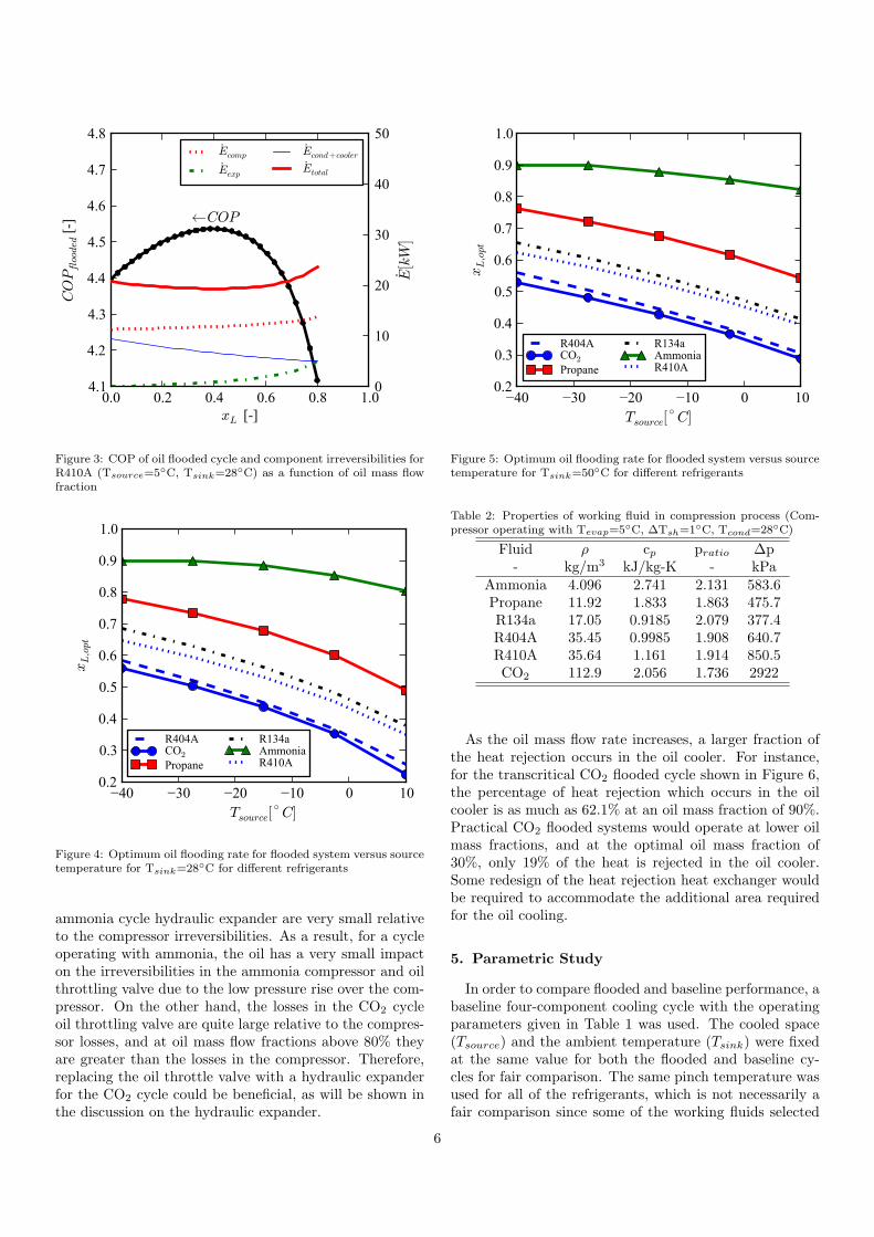
The same methodology can be carried out for a widerange of refrigerants, and their optimum oil mass flow frac-tion can be found for a given operating condition. Theoptimum oil flow rate for a number of different refriger-ants was determined by using the optimization toolbox inMATLAB. Figures 4 and 5 show the optimal oil mass flowfractions for sink temperatures of 28◦C and 50◦C respec-tively.
Considering the extreme cases of CO2 and ammonia,the distributions of component irreversibility are signifi-cantly different. This results in different optimum oil massflow fractions. Figures 6 and 7 demonstrate the differencein optimal oil mass flow fraction for CO2 and ammonia.As seen in Table 2, the pressure difference between thehigh and low pressure sides for a CO2 cooling cycle op-erating subcritically is five times higher than for ammo-nia operating between the same reservoir temperatures.This pressure difference is even higher if the CO2 systemhigh-side-pressure is supercritical. This has a very signif-icant impact on the losses in the hydraulic expander andthe compressor. Since for ammonia the pressure differenceover the hydraulic expander is very small, the losses in the
5
0.0 0.2 0.4 0.6 0.8 1.0
xL [-]
4.1
4.2
4.3
4.4
4.5
4.6
4.7
4.8
COPflooded [
-]
0
10
20
30
40
50
E[kW
]
←COP
Ecomp
Eexp
Econd+cooler
Etotal
Figure 3: COP of oil flooded cycle and component irreversibilities forR410A (Tsource=5◦C, Tsink=28◦C) as a function of oil mass flowfraction
−40 −30 −20 −10 0 10
Tsource[◦
C]
0.2
0.3
0.4
0.5
0.6
0.7
0.8
0.9
1.0
xL,opt
R404ACO2
Propane
R134aAmmoniaR410A
Figure 4: Optimum oil flooding rate for flooded system versus sourcetemperature for Tsink=28◦C for different refrigerants
ammonia cycle hydraulic expander are very small relativeto the compressor irreversibilities. As a result, for a cycleoperating with ammonia, the oil has a very small impacton the irreversibilities in the ammonia compressor and oilthrottling valve due to the low pressure rise over the com-pressor. On the other hand, the losses in the CO2 cycleoil throttling valve are quite large relative to the compres-sor losses, and at oil mass flow fractions above 80% theyare greater than the losses in the compressor. Therefore,replacing the oil throttle valve with a hydraulic expanderfor the CO2 cycle could be beneficial, as will be shown inthe discussion on the hydraulic expander.
−40 −30 −20 −10 0 10
Tsource[◦
C]
0.2
0.3
0.4
0.5
0.6
0.7
0.8
0.9
1.0
xL,opt
R404ACO2
Propane
R134aAmmoniaR410A
Figure 5: Optimum oil flooding rate for flooded system versus sourcetemperature for Tsink=50◦C for different refrigerants
Table 2: Properties of working fluid in compression process (Com-pressor operating with Tevap=5◦C, ∆Tsh=1◦C, Tcond=28◦C)
Fluid ρ cp pratio ∆p- kg/m3 kJ/kg-K - kPa
Ammonia 4.096 2.741 2.131 583.6Propane 11.92 1.833 1.863 475.7R134a 17.05 0.9185 2.079 377.4R404A 35.45 0.9985 1.908 640.7R410A 35.64 1.161 1.914 850.5CO2 112.9 2.056 1.736 2922
As the oil mass flow rate increases, a larger fraction ofthe heat rejection occurs in the oil cooler. For instance,for the transcritical CO2 flooded cycle shown in Figure 6,the percentage of heat rejection which occurs in the oilcooler is as much as 62.1% at an oil mass fraction of 90%.Practical CO2 flooded systems would operate at lower oilmass fractions, and at the optimal oil mass fraction of30%, only 19% of the heat is rejected in the oil cooler.Some redesign of the heat rejection heat exchanger wouldbe required to accommodate the additional area requiredfor the oil cooling.
5. Parametric Study
In order to compare flooded and baseline performance, abaseline four-component cooling cycle with the operatingparameters given in Table 1 was used. The cooled space(Tsource) and the ambient temperature (Tsink) were fixedat the same value for both the flooded and baseline cy-cles for fair comparison. The same pinch temperature wasused for all of the refrigerants, which is not necessarily afair comparison since some of the working fluids selected
6

0.0 0.2 0.4 0.6 0.8 1.0
xL [-]
1.0
1.5
2.0
2.5
3.0
3.5
4.0
COPflooded [
-]
0
20
40
60
80
100
E[kW
]
←COP
Ecomp
Eexp
Econd+cooler
Etotal
Figure 6: COP of oil flooded cycle and component irreversibilitiesfor CO2 (Tsource=5◦C, Tsink=28◦C) as a function of oil mass flowfraction
0.0 0.2 0.4 0.6 0.8 1.0
xL [-]
4.0
4.2
4.4
4.6
4.8
5.0
5.2
5.4
5.6
COPflooded [
-]
0
50
100
150
200
E[kW
]
←COP
Ecomp
Eexp
Econd+cooler
Etotal
Figure 7: COP of oil flooded cycle and component irreversibilitiesfor ammonia (Tsource=5◦C, Tsink=28◦C) as a function of oil massflow fraction
(namely carbon dioxide) have singularly good heat trans-fer characteristics and might be able to achieve lower pinchtemperatures for the same heat exchanger size than theother refrigerants.
Most of the common refrigerants studied here have beenanalyzed in subcritical conditions, the only exception be-ing carbon dioxide, which was always studied in a trans-critical configuration. For carbon dioxide, the gas coolerpressure was determined by finding the gas cooler pressurewhich optimized the baseline cycle COP, and the samepressure was used for the flooded cycle.
−40 −30 −20 −10 0 10
Tsource[◦C]
1.00
1.05
1.10
1.15
1.20
1.25
1.30
COPflood/C
OPbase
[
� ] R404ACO2
PropaneR134aAmmoniaR410A
Figure 8: Ratio of flooded system to baseline system COP versussource temperature for Tsink = 28◦C for different refrigerants
−40 −30 −20 −10 0 10
Tsource[◦C]
1.0
1.1
1.2
1.3
1.4
1.5
1.6
1.7
1.8
COPflood/C
OPbase
[
� ] R404ACO2
PropaneR134aAmmoniaR410A
Figure 9: Ratio of flooded system to baseline system COP versussource temperature for Tsink = 50◦C for different refrigerants
In order to have an equal comparison between refriger-ants, properties of PAG oil were used as the flooding liquidfor all of the refrigerants. In practical application, it is nec-essary that the liquid and the refrigerant are partially orwholly immiscible and insoluble since gravitational sepa-ration would generally be used to separate liquid and re-frigerant. The optimal oil mass flow fraction was used inorder to obtain the best performance for the flooded cycle.
Figures 8 and 9 show that the impact of oil flooding onsystem efficiency is dependent on working fluid selectionand operating temperatures. Oil flooding is particularlybeneficial for high heat-of-compression working fluids op-erating over large pressure ratios as they are prone to large
7

−40 −30 −20 −10 0 10
Tsource[◦C]
0.95
1.00
1.05
1.10
1.15
1.20
1.25
COPflood/C
OPbase
[
� ]ε = 0 to 1
Figure 10: Ratio of flooded to baseline system COP versus sourcetemperature for varying regenerator effectiveness for CO2 (Tsink =28◦C)
compression and desuperheating losses. At lower sourcetemperatures, the losses for the baseline cycle are predom-inantly throttling, compression and desuperheating losses.The flooding primarily decreases the desuperheating lossesin the condenser, which is why the improvement in cycleperformance is greatest at the lowest source temperatures.
The regenerator is a critical component of the floodedvapor compression system. Figure 10 shows that the ef-ficiency of the flooded system is in fact worse than thatof the baseline system as the regenerator efficiency ap-proaches zero. This reduction in efficiency is due to thereduction in refrigerant subcooling prior to the expansionvalve while the oil-vapor mixture entering the compressoris still quite superheated from mixing with the hot oil fromthe oil cooler. As a result, the compression power is higher,yet the cooling capacity is the same as the baseline system,resulting in worse efficiency. Figure 11 shows the impacton system performance of systems with and without 90%effective regenerators and optimal oil-flooding. These re-sults show that both regenerator and oil flooding need tobe utilized in concert in order to realize the full potentialof oil flooding.
As shown above in Figure 7, the oil throttling losses forammonia are quite minimal, which suggests that addingthe capital cost of a hydraulic expander to the systemwould not be a good investment. On the other hand, theoil throttling losses for CO2 are larger due to the largepressure difference. When comparing the performance ofthree system configurations for CO2, namely the baselinesystem, a flooded system with an oil throttling valve, anda flooded system with a hydraulic expander with isentropicefficiency of 70%, as shown in Figure 12, it is clear that thehydraulic expander has a relatively small effect. With the
−40 −30 −20 −10 0 10
Tsource[◦C]
0.95
1.00
1.05
1.10
1.15
1.20
1.25
COPflood/C
OPbase
[
� ] Regenerator & OilRegenerator - No OilOil - No Regenerator
Figure 11: Ratio of flooded to baseline system COP versus sourcetemperature for systems with and without regenerator and oil flood-ing for CO2 (Tsink = 28◦C)
0.1 0.2 0.3 0.4 0.5 0.6 0.7 0.8 0.9 1.0
xL [-]
0.80
0.85
0.90
0.95
1.00
1.05
1.10
1.15
1.20
COPflood/C
OPbase
[-]
No Hydraulic ExpanderWith Hydraulic Expander
Figure 12: Ratio of flooded system to baseline system COP offlooded+throttling valve and flooded+expander systems versus oilmass flow fraction for CO2 (Tsource=-30◦C, Tsink=28◦C)
addition of oil flooding and regeneration to a large temper-ature lift system, the COP increases by 16.7% above thebaseline cycle, while with the addition of the hydraulic ex-pander to the flooded system, the COP increases to 17.7%above the baseline cycle. The relatively weak impact ofthe hydraulic expander on cycle efficiency is due to therelatively small amount of power that is added to the oilin the compression process.
6. Practical Considerations
Typically, compressors are designed for a fairly smallamount of oil circulation in order to lubricate the moving
8

surfaces. Some compressor styles, such as reciprocatingcompressors, are not amenable to large amounts of oil in-jection. On the other hand, scroll compressors can readilyhandle large amounts of oil, as has been demonstrated byHugenroth (2007), and Bell (2008a; 2008b). Therefore,the most significant challenge is to properly optimize thecompressor design to handle large amounts of oil. Theprimary compressor design considerations are to give theoil a smooth flow path with few flow obstructions and toensure that the suction and discharge ports are sufficientlylarge.
The design of the hydraulic expander is not consideredchallenging as there is a wide body of knowledge in thefield of hydraulics which could be readily applied to thistechnology. In addition, the design of the oil separatoris considered straight-forward as they are commonly usedfor screw compressors as well as in the chemical processingindustry.
Otherwise, all other components of the cycle are stan-dard off-the-shelf components for vapor compression sys-tems which would require no modification. Thus, theamount of new design work required for this technologyis considered fairly limited.
7. Conclusion
The addition of compressor flooding with regenerationin vapor compression systems results in a more isothermalcompression process that can have a significant impact onsystem efficiency for large temperature lifts. Of the refrig-erants considered, compressor flooding and regenerationhas the greatest impact for R404A, and the least impact forammonia. For refrigerants with large pressure differencesacross the compressor, the use of a hydraulic expandercan also help to recapture some of the work of compres-sion of the flooding liquid. The engineering challenges inimplementation of this technology are reasonable, whichsuggests that it could be applied readily, either as retrofitsor in new construction.
8. Acknowledgment
The authors of this paper would like to thank Prof.Galen King, Department of Mechanical Engineering, Pur-due University, and Prof. Travis Horton, Department ofCivil Engineering, Purdue University for their contribu-tions to this paper.
References
Bein, T. W., Hamilton, J. F., 1982. Computer modeling of an oilflooded single screw air compressor. In: 1982 International Com-pressor Engineering Conference at Purdue University.
Bell, I., Groll, E., Braun, J., Horton, T., 2010a. Flooded compressionin CO2 scroll compressors. In: 9th Gustav Lorentzen Conferenceon Natural Working Fluids, Sydney, Australia.
Bell, I., Groll, E., Braun, J., Horton, W., 2010b. Impact of Oil Sol-ubility and Refrigerant Flashing on the Performance of Trans-critical CO2 Vapor Compression Systems with Oil Flooding andRegeneration. In: 2010 International Refrigeration and Air Con-ditioning Conference at Purdue. No. 2148.
Bell, I., Lemort, V., Braun, J., Groll, E., 2008a. Analysis of Liquid-Flooded Compression Using a Scroll Compressor. In: 19th Inter-national Compressor Engineering Conference at Purdue Univer-sity. No. 1263.
Bell, I., Lemort, V., Braun, J., Groll, E., 2008b. Development ofLiquid-Flooded Scroll Compressor and Expander Models. In: 19thInternational Compressor Engineering Conference at Purdue Uni-versity. No. 1283.
Blaise, J., Dutto, T., 1988. Influence of oil injection and pressureratio on single screw performances at high temperatures. In: 1988International Compressor Engineering Conference at Purdue Uni-versity.
Booser, E. R. (Ed.), 1997. Tribology Data Handbook. CRC Press.Fujiwara, M., Osada, Y., 1995. Performance analysis of an oil-
injected screw compressor and its application. Int. J. Refrig. 18,220–227.
Hiwata, A., Iida, N., Futagami, Y., Sawai, K., Ishii, N., 2002. Perfor-mance investigation with oil-injection to compression chambers onCO2-scroll compressor. In: 2002 Purdue Compressor Conference.No. C18-4.
Huagen, W., Ziwen, X., Pengcheng, S., 2004. Theoretical and ex-perimental study on indicator diagram of twin screw refrigerationcompressor. Int. J. Refrig. 27, 331–338.
Hugenroth, J., 2006. Liquid Flooded Ericsson Cycle Cooler. Ph.D.thesis, Purdue University.
Hugenroth, J., Braun, J., Groll, E., King, G., 2006. Oil FloodedCompression in Vapor Compression Heat Pump Systems. In: IHR-IRHACE Conference. pp. 492–499.
Hugenroth, J., Braun, J., Groll, E., King, G., 2007. Thermodynamicanalysis of a liquid-flooded Ericsson cycle cooler. Int. J. Refrig.207, 331–338.
Kim, Y., Shin, D., Lee, J., 2008. A New Ericsson Cycle Comprising aScroll Expander and a Scroll Compressor for Power and Refriger-ation Applications. In: 2008 Compressor Engineering Conferenceat Purdue University. No. R022.
Lemmon, E., McLinden, M., Huber, M., 2002. Refprop 7.0.http://www.nist.gov/srd/nist23.htm.
Lemort, V., Bell, I., Groll, E., Braun, J., 2008. Analysis of liquid-flooded expansion using a scroll expander. In: 2008 InternationalCompressor Engineering Conference at Purdue University.
Li, H., Jin, L., 2004. Design optimization of an oil-flooded refriger-ation single-screw compressor. In: 2004 International CompressorEngineering Conference at Purdue University. No. C077.
Mathison, M., Braun, J., Groll, E., 2011. Performance Limit forEconomized Cycles with Continuous Refrigerant Injection. Int. J.Refrig. Submitted, In Review.
Mathworks, 1994-2009. MATLAB. http://www.mathworks.com/.Sakuda, A., Sawai, K., Iida, N., Hiwata, A., Morimoto, T., Ishii, N.,
2001. Performance improvement of scroll compressor with newsealing-oil supply mechanism. In: International Conference onCompressors and their Systems. No. C591/019.
Singh, P. J., Patel, G. C., 1984. A generalized performance computerprogram for oil flooded twin-screw compressors. In: 1984 Interna-tional Compressor Engineering Conference at Purdue University.
Stosic, N., Kovacevic, A., Hanjalic, K., Milutinovic, L., 1988. Math-ematical Modelling of the oil influence upon the working cycle ofscrew compressors. In: 1988 International Compressor Engineer-ing Conference at Purdue University.
Stosic, N., Milutinovic, L., Hanjalic, K., Kovacevic, A., 1990. Ex-perimental investigation of the influence of oil injection upon thescrew compressor working process. In: 1990 International Com-pressor Engineering Conference at Purdue University.
Tang, Y., Fleming, J. S., 1992. Simulation of the Working Processof an oil flooded helical screw compressor with liquid refrigerantinjection. In: 1992 International Compressor Engineering Confer-ence at Purdue University.
9

Winandy, E. L., Lebrun, J., 2002. Scroll compressors using gas andliquid injection- experimental analysis and modelling. Int. J. Re-frig. 25, 1143–1156.
Wu, J., Jin, G., 1988. The Computer Simulation of oil-flooded singlescrew compressors. In: 1988 International Compressor Engineer-ing Conference at Purdue University.
10