Performance of a fuel cell optimized for in situ X-ray absorption experiments
7
electronic reprint Journal of Synchrotron Radiation ISSN 0909-0495 Editors: A ˚ . Kvick, D. M. Mills and T. Ohta Performance of a fuel cell optimized for in situ X-ray absorption experiments Emiliano Principi, Andrea Di Cicco, Agnieszka Witkowska and Roberto Marassi Copyright © International Union of Crystallography Author(s) of this paper may load this reprint on their own web site provided that this cover page is retained. Republication of this article or its storage in electronic databases or the like is not permitted without prior permission in writing from the IUCr. J. Synchrotron Rad. (2007). 14, 276–281 Emiliano Principi et al. Fuel cell for in situ XAS
Transcript of Performance of a fuel cell optimized for in situ X-ray absorption experiments

electronic reprint
Journal of
SynchrotronRadiation
ISSN 0909-0495
Editors: A. Kvick, D. M. Mills and T. Ohta
Performance of a fuel cell optimized for in situ X-ray absorptionexperiments
Emiliano Principi, Andrea Di Cicco, Agnieszka Witkowska and Roberto Marassi
Copyright © International Union of Crystallography
Author(s) of this paper may load this reprint on their own web site provided that this cover page is retained. Republication of this article or itsstorage in electronic databases or the like is not permitted without prior permission in writing from the IUCr.
J. Synchrotron Rad. (2007). 14, 276–281 Emiliano Principi et al. � Fuel cell for in situ XAS

research papers
276 doi:10.1107/S0909049507013593 J. Synchrotron Rad. (2007). 14, 276–281
Journal of
SynchrotronRadiation
ISSN 0909-0495
Received 3 November 2006
Accepted 21 March 2007
# 2007 International Union of Crystallography
Printed in Singapore – all rights reserved
Performance of a fuel cell optimized for in situX-ray absorption experiments
Emiliano Principi,a* Andrea Di Cicco,a,b Agnieszka Witkowskaa,c‡2and
Roberto Marassid
aCNISM, CNR-INFM CRS SOFT, Dipartimento di Fisica, Universita di Camerino, I-62032 Camerino
(MC), Italy, bIMPMC-CNRS UMR 7590, Universite Pierre et Marie Curie, 140 rue de Lourmel,
75015 Paris, France, cDepartment of Solid State Physics, Gdansk University of Technology, 80-952
Gdansk, Poland, and dDipartimento di Chimica, Universita di Camerino, I-62032 Camerino (MC),
Italy. E-mail: [email protected]
A commercial fuel cell has been successfully modified to carry out X-ray
absorption spectroscopy (XAS) measurements under optimized in operando
conditions. The design is conceived for the performance of XAS experiments in
transmission mode over a wide range of X-ray energies above 6 keV, owing to
the reduced absorption of the cell. The wide angular aperture allows the
collection of XAS in fluorescence mode and of X-ray diffraction patterns when
needed. Details of the design of the cell and its performances are given. The
quality of the extended X-ray absorption fine-structure spectra under working
conditions has been verified at the ESRF and ELETTRA synchrotron radiation
facilities, showing that relatively fast and low-noise transmission measurements
on electrodes over a wide range of catalyst concentrations and energies are
feasible.
Keywords: in situ XAS; fuel cell.
1. Introduction
Fuel cells are promising sustainable energy systems which may
replace most current combustion systems in various energy
end-use sectors in the long term. There are several types of
fuel cell which have been developed and undergone
commercial development (Larminie & Dicks, 2003; Markovic
& Ross, 2000; Steele & Heinzel, 2001). One of the most
important and universal is the proton exchange membrane
(PEM) fuel cell (Scott & Shukla, 2004; Ralph & Hogarth,
2002a,b). Owing to its numerous advantages, the PEM fuel cell
is a viable choice for portable power, automobile and resi-
dential applications.
Many efforts are currently devoted to the study of metallic
electrocatalysts in order to improve the performances of PEM
fuel cells and to reduce their cost, mainly by reducing the
amount of noble metals in nanocatalysts.
Characterization and understanding of the catalyst struc-
ture and properties is recognized as a forefront research
activity for improving performances and reliability of the fuel
cells. In this context, X-ray absorption spectroscopy (XAS)
(Koningsberger & Prins, 1988; Filipponi et al., 1995) is a
powerful tool providing unique information on the local
atomic arrangement around selected catalytic metal sites and
their average oxidation state (Russell & Rose, 2004). More-
over, XAS measurements can be realised at synchrotron
radiation facilities under actual fuel cell working conditions.
Nevertheless, owing to the background absorption of the cell
components and to the low mass content of metal catalysts,
reliable and high-quality data can only be obtained using
specially designed fuel cells and an optimized experimental
set-up.
In the literature, electrochemical cells specially designed for
XAS (McBreen et al., 1987; Herron et al., 1992 Maniquet et al.,
2000) and modified for transmission and fluorescence XAS
(Viswanathan et al., 2002; Roth et al., 2002; Wiltshire et al.,
2005) have been described. In all cases, cell elements were
conceived to reduce the background absorption owing to the
various components of the cell.
For example, in a particular cell design for XAS (Viswa-
nathan et al., 2002) in transmission mode, the graphite plates
were thinned to about 4 mm in a small rectangular X-ray
window, a solution also used by other authors (Roth et al.,
2002, 2005). This solution was found to give good results for
collecting near-edge absorption data (Pt L3-edge) but the
absorption background is still very high for collecting low-
noise EXAFS spectra, especially for catalysts with low atomic
number and for metal loading below 1 mg cm�2. However, a
typical noble metal loading for a promising electrocatalyst is
below 0.3 mg cm�2 and under these conditions in situ XAS
measurements can be carried out in fluorescence mode. We
are aware of only one in situ fluorescence study of a PEM fuel‡ Present address: CNR-ISM, Via del Fosso del Cavaliere 100, 00133 Roma,Italy.
electronic reprint

cell (Wiltshire et al., 2005), using a 1.5 mm thin graphite X-ray
window in a miniature fuel cell.
In this work we present a modified fuel cell for XAS
measurements under in situ conditions, with the specific aim of
realising a more efficient device for this purpose. The original
design of the cell is conceived for the performance of low-
noise XAS experiments in transmission mode, as well as for
the collection of XAS in fluorescence mode and of X-ray
diffraction patterns, over a wide range of X-ray energies and
metal loading. The paper is organized as follows: in x2 we
report on the design and expected performances of the cell; in
x3 we discuss important details of the XAS set-up, and some
examples of typical in situ XAS measurements collected using
this set-up at the ESRF and ELETTRA facilities are
presented; x4 is devoted to the conclusions and perspectives
of the present work.
2. Design and performances of the XAS PEM fuel cells
The basic need for in situ X-ray investigations of active
materials in fuel cells is to reduce the background absorption
owing to the various components of the cells. If we focus our
attention on investigations of the valence and structure of
metals participating in the catalytic process, severe restrictions
are imposed on the thickness of the electrodes and membranes
used in the construction of the cell. Most of the commercially
available PEM fuel cells must be modified for this purpose, by
designing suitable windows for X-ray investigations in the
body of the cell. In fact, metal shields and thick graphite plates
(at least of the order of 10 mm) usually do not allow photon
transmission at energies below 20 keV, while the amount of
catalyst is usually too low for obtaining low-noise XAS
measurements in transmission mode. In order to perform low-
noise XAS measurements in transmission mode, we have
modified an EFC-05-02 (Electrochem) fuel cell with the
specific aim of achieving high transmission rates for photon
energies in the 5–15 keV energy range, where most of the core
levels of the metals used in the catalytic process are located.
The basic characteristics of the commercial fuel cell are the
presence of two isotropic graphite separator plates, a 5 cm2
active area (serpentine flow pattern) and two gold-plated
current collectors. The graphite plates are held together by
eight screws, inducing a high enough compression on the
membrane electrode assembly (MEA) and providing a good
electrical contact.
The EFC-05-02 cell has been modified to have thin graphite
windows for maximum X-ray transmittance, still being light-
and gas-tight. The overall thickness of the graphite was care-
fully thinned by drilling truncated prism-shaped holes, up to
0.25 mm in thickness, over a flat 1 mm � 7 mm area, providing
a double window for XAS in transmission mode and possible
X-ray fluorescence and X-ray diffraction measurements owing
to the wide angular acceptance (�100� on the beam plane,
�5% covered solid angle), as shown in Fig. 1. The X-ray
window is positioned to be parallel (y) and in correspondence
(z) with the serpentine channels (width 0.8 mm) in order to
minimize absorption. This allows XAS measurements under
standard conditions at EXAFS beamlines, using a typical
beam size of �0.4 mm � 5 mm (see x3). The position of the
cell with respect to the beam can be easily changed, thus
obtaining the best geometry requested by the experimental
technique used.
As shown in Fig. 2, the calculated transmittance of the
graphite windows and of the Nafion membrane strongly limits
the energy window available for X-ray absorption studies. In
particular, two 4 mm graphite windows (see Viswanathan et
al., 2002; Roth et al., 2002, 2005) limit the available X-ray
range above 10 keV (transmittance is below 10% at the Pt L3-
edge). Therefore, using a proper drilling geometry, graphite
can be safely machined up to the hundreds of mm thickness
range. The 250 mm thin graphite windows used in this work
have been found to match the requirements of tightness and
mechanical stability necessary for a smooth operation of the
fuel cell and to increase transmittance significantly (e.g. for
10 keV up to 80%, see Fig. 2). At the same time the absorption
of typical PEMs is comparable with that of the graphite
windows, so, for experiments at low energies, both absorption
components must be accounted for. The calculated transmit-
tance for typical membranes (Nafion N-117 and Nafion N-115
by DuPont; see also Oberbroeckling et al., 2002) is also shown
in Fig. 2. Absorption of Nafion was tested at fixed energy in
our in-house X-ray laboratories (Di Cicco et al., 2006). Other
research papers
J. Synchrotron Rad. (2007). 14, 276–281 Emiliano Principi et al. � Fuel cell for in situ XAS 277
Figure 1Design for a fuel cell optimized for in situ X-ray absorption measure-ments (front and side views, dimensions given in mm). The front viewshows the perforation of the graphite electrode for reducing the X-rayabsorption while saving space for the inlets and paths of the fuel(hydrogen and oxygen). The minimal thickness of each graphite plate isreduced to about 0.25 mm, thus minimizing the absorption along theX-ray path (x, see inset). The side view shows the wide angular apertureallowing for possible X-ray diffraction and X-ray fluorescence measure-ments, as well as the positioning of the MEA inside the cell.
electronic reprint
possible sources of absorption under working conditions,
namely gases and water flowing into the gas channels and
impregnating the membranes, and the background absorption
owing to the gas diffusion layers and catalysts layers, have
been found to be practically negligible in the energy region of
interest.
Fig. 2 shows that the present fuel cell gives more than 50%
transmission at 9 keV. The use of thinner Nafion membranes
(Nafion N-115, 127 mm) improves transmission at low energies
and we can easily arrive at transmissions of around 10% at
6 keV. Using this fuel cell prototype, XAS measurements can
be performed in transmission and fluorescence mode for a
wide selection of catalyst materials (atomic numbers above
Z = 23).
3. In situ XAS measurements
3.1. Fuel cell set-up for XAS experiments
The XAS fuel cell described in x2 has been tested during
dedicated beam time at the European Synchrotron Radiation
Facility (ESRF, Grenoble, France) and ELETTRA Synchro-
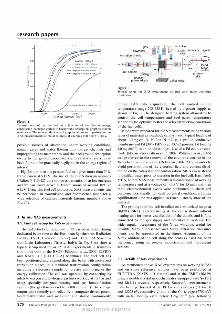
tron Light Laboratory (Trieste, Italy). In Fig. 3 we show a
typical set-up used for in situ XAS experiments in transmis-
sion mode both at the BM29 (Filipponi et al., 2000) (ESRF)
and XAFS 11.1 (ELETTRA) beamlines. The fuel cell has
been positioned and aligned along the beam with motorized
translation stages, in a standard transmission configuration
including a reference sample for precise monitoring of the
energy calibration. The cell was operated by connecting its
inlets to oxygen and hydrogen gas lines working at 1.2 bar and
using specially designed heating and gas humidification
systems (the gas flow was set to �100 ml min�1). The voltage
output was remotely controlled by a computer-driven poten-
tiostat/galvanostat and measured and stored continuously
during XAS data acquisition. The cell worked in the
temperature range 293–353 K, heated by a power supply as
shown in Fig. 3. The designed heating system allowed us to
control the cell temperature and fuel gases temperature
separately (to optimize better the relevant working conditions
of the fuel cell).
MEAs were prepared for XAS measurements using various
types of materials as a cathode catalyst (with typical loading of
about 1.0 mg cm�2), Nafion N-117 as a proton-conductive
membrane and Pd (30% Pd/Vulcan XC-72 powder, Pd loading
1.0 mg cm�2) as an anode catalyst. Use of a Pd counter elec-
trode (like in Viswanathan et al., 2002; Wiltshire et al., 2005)
was preferred to the removal of the counter electrode in the
X-ray beam window region (Roth et al., 2002, 2005) in order to
avoid perturbations of the electrical field and current distri-
bution on the catalyst under consideration. MEAs were stored
in distilled water prior to insertion in the fuel cell. Each fresh
MEA, before XAS measurements, was conditioned at working
temperature and at a voltage of �0.5 V for 15 min, and then
rapid electrochemical cycles were performed to check cell
performances. Finally, for each potential condition, a 10 min
equilibration time was applied to reach a steady-state of the
catalyst.
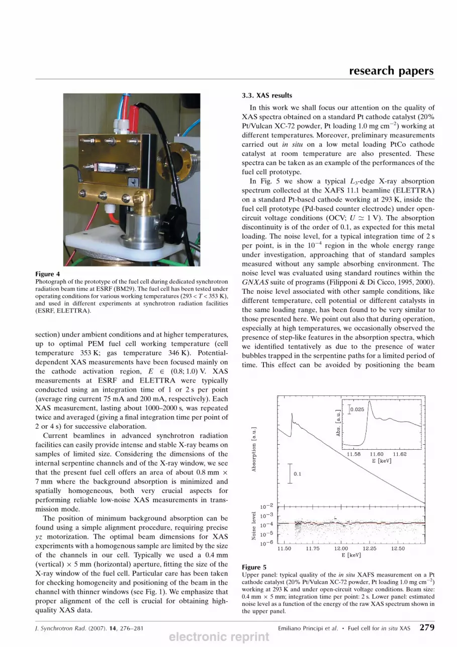
The prototype of the cell installed on a motorized stage at
BM29 (ESRF) is shown in Fig. 4. The cell is shown without
heating unit for better visualization of the details, and is fully
connected to the gas supply and potentiostat systems. The
wide angular acceptance of the X-ray windows, useful for
possible X-ray fluorescence and X-ray diffraction measure-
ments, can be appreciated in the figure. Alignment of the
X-ray window of the cell along the beam (x axis) has been
performed using yz precise motorization and fluorescent
screens.
3.2. Details of XAS experiments
As mentioned above, XAS experiments on working MEAs
and on some reference samples have been performed at
ELETTRA (XAFS 11.1 station) and at the ESRF (BM29)
using a double-crystal monochromator equipped with Si(111)
and Si(311) crystals, respectively. Successful measurements
have been performed at the Pt L3- and L2-edges (11564 eV
and 13273 eV, respectively) and at the Co K-edge (7709 eV)
with metal loading even below 1 mg cm�2 (see following
research papers
278 Emiliano Principi et al. � Fuel cell for in situ XAS J. Synchrotron Rad. (2007). 14, 276–281
Figure 3Typical set-up for XAS experiments on fuel cells under operatingconditions.
Figure 2Transmittance of the fuel cell as a function of the photon energy,considering the major sources of background absorption: graphite, Nafionmembrane. The reduced thickness of graphite allows us to perform in situXAS measurements of metal catalysts at energies well below 10 keV.
electronic reprint
section) under ambient conditions and at higher temperatures,
up to optimal PEM fuel cell working temperature (cell
temperature 353 K; gas temperature 346 K). Potential-
dependent XAS measurements have been focused mainly on
the cathode activation region, E 2 (0.8; 1.0) V. XAS
measurements at ESRF and ELETTRA were typically
conducted using an integration time of 1 or 2 s per point
(average ring current 75 mA and 200 mA, respectively). Each
XAS measurement, lasting about 1000–2000 s, was repeated
twice and averaged (giving a final integration time per point of
2 or 4 s) for successive elaboration.
Current beamlines in advanced synchrotron radiation
facilities can easily provide intense and stable X-ray beams on
samples of limited size. Considering the dimensions of the
internal serpentine channels and of the X-ray window, we see
that the present fuel cell offers an area of about 0.8 mm �7 mm where the background absorption is minimized and
spatially homogeneous, both very crucial aspects for
performing reliable low-noise XAS measurements in trans-
mission mode.
The position of minimum background absorption can be
found using a simple alignment procedure, requiring precise
yz motorization. The optimal beam dimensions for XAS
experiments with a homogenous sample are limited by the size
of the channels in our cell. Typically we used a 0.4 mm
(vertical) � 5 mm (horizontal) aperture, fitting the size of the
X-ray window of the fuel cell. Particular care has been taken
for checking homogeneity and positioning of the beam in the
channel with thinner windows (see Fig. 1). We emphasize that
proper alignment of the cell is crucial for obtaining high-
quality XAS data.
3.3. XAS results
In this work we shall focus our attention on the quality of
XAS spectra obtained on a standard Pt cathode catalyst (20%
Pt/Vulcan XC-72 powder, Pt loading 1.0 mg cm�2) working at
different temperatures. Moreover, preliminary measurements
carried out in situ on a low metal loading PtCo cathode
catalyst at room temperature are also presented. These
spectra can be taken as an example of the performances of the
fuel cell prototype.
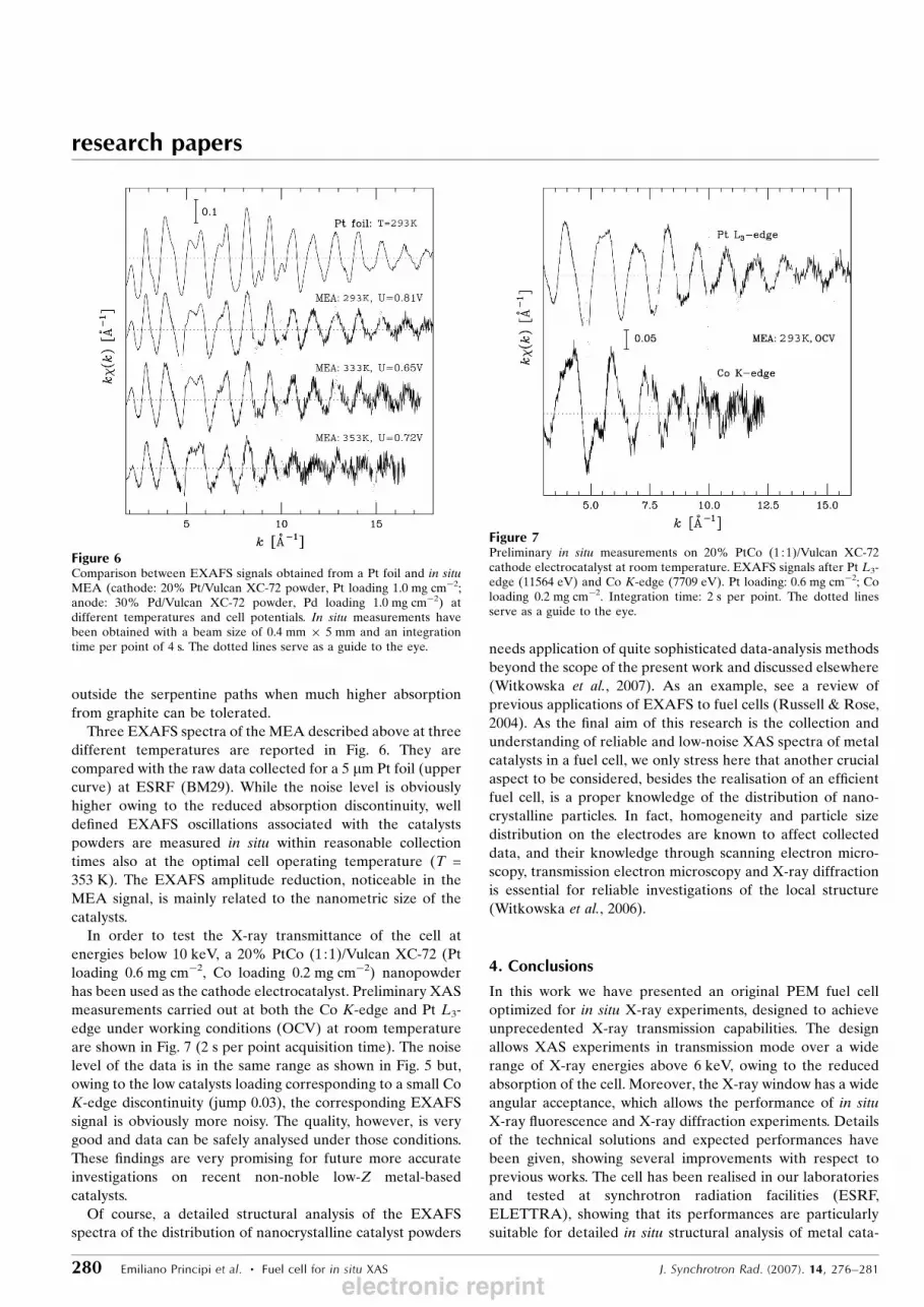
In Fig. 5 we show a typical L3-edge X-ray absorption
spectrum collected at the XAFS 11.1 beamline (ELETTRA)
on a standard Pt-based cathode working at 293 K, inside the
fuel cell prototype (Pd-based counter electrode) under open-
circuit voltage conditions (OCV; U ’ 1 V). The absorption
discontinuity is of the order of 0.1, as expected for this metal
loading. The noise level, for a typical integration time of 2 s
per point, is in the 10�4 region in the whole energy range
under investigation, approaching that of standard samples
measured without any sample absorbing environment. The
noise level was evaluated using standard routines within the
GNXAS suite of programs (Filipponi & Di Cicco, 1995, 2000).
The noise level associated with other sample conditions, like
different temperature, cell potential or different catalysts in
the same loading range, has been found to be very similar to
those presented here. We point out also that during operation,
especially at high temperatures, we occasionally observed the
presence of step-like features in the absorption spectra, which
we identified tentatively as due to the presence of water
bubbles trapped in the serpentine paths for a limited period of
time. This effect can be avoided by positioning the beam
research papers
J. Synchrotron Rad. (2007). 14, 276–281 Emiliano Principi et al. � Fuel cell for in situ XAS 279
Figure 5Upper panel: typical quality of the in situ XAFS measurement on a Ptcathode catalyst (20% Pt/Vulcan XC-72 powder, Pt loading 1.0 mg cm�2)working at 293 K and under open-circuit voltage conditions. Beam size:0.4 mm � 5 mm; integration time per point: 2 s. Lower panel: estimatednoise level as a function of the energy of the raw XAS spectrum shown inthe upper panel.
Figure 4Photograph of the prototype of the fuel cell during dedicated synchrotronradiation beam time at ESRF (BM29). The fuel cell has been tested underoperating conditions for various working temperatures (293 < T < 353 K),and used in different experiments at synchrotron radiation facilities(ESRF, ELETTRA).
electronic reprint
outside the serpentine paths when much higher absorption
from graphite can be tolerated.
Three EXAFS spectra of the MEA described above at three
different temperatures are reported in Fig. 6. They are
compared with the raw data collected for a 5 mm Pt foil (upper
curve) at ESRF (BM29). While the noise level is obviously
higher owing to the reduced absorption discontinuity, well
defined EXAFS oscillations associated with the catalysts
powders are measured in situ within reasonable collection
times also at the optimal cell operating temperature (T =
353 K). The EXAFS amplitude reduction, noticeable in the
MEA signal, is mainly related to the nanometric size of the
catalysts.
In order to test the X-ray transmittance of the cell at
energies below 10 keV, a 20% PtCo (1:1)/Vulcan XC-72 (Pt
loading 0.6 mg cm�2, Co loading 0.2 mg cm�2) nanopowder
has been used as the cathode electrocatalyst. Preliminary XAS
measurements carried out at both the Co K-edge and Pt L3-
edge under working conditions (OCV) at room temperature
are shown in Fig. 7 (2 s per point acquisition time). The noise
level of the data is in the same range as shown in Fig. 5 but,
owing to the low catalysts loading corresponding to a small Co
K-edge discontinuity (jump 0.03), the corresponding EXAFS
signal is obviously more noisy. The quality, however, is very
good and data can be safely analysed under those conditions.
These findings are very promising for future more accurate
investigations on recent non-noble low-Z metal-based
catalysts.
Of course, a detailed structural analysis of the EXAFS
spectra of the distribution of nanocrystalline catalyst powders
needs application of quite sophisticated data-analysis methods
beyond the scope of the present work and discussed elsewhere
(Witkowska et al., 2007). As an example, see a review of
previous applications of EXAFS to fuel cells (Russell & Rose,
2004). As the final aim of this research is the collection and
understanding of reliable and low-noise XAS spectra of metal
catalysts in a fuel cell, we only stress here that another crucial
aspect to be considered, besides the realisation of an efficient
fuel cell, is a proper knowledge of the distribution of nano-
crystalline particles. In fact, homogeneity and particle size
distribution on the electrodes are known to affect collected
data, and their knowledge through scanning electron micro-
scopy, transmission electron microscopy and X-ray diffraction
is essential for reliable investigations of the local structure
(Witkowska et al., 2006).
4. Conclusions
In this work we have presented an original PEM fuel cell
optimized for in situ X-ray experiments, designed to achieve
unprecedented X-ray transmission capabilities. The design
allows XAS experiments in transmission mode over a wide
range of X-ray energies above 6 keV, owing to the reduced
absorption of the cell. Moreover, the X-ray window has a wide
angular acceptance, which allows the performance of in situ
X-ray fluorescence and X-ray diffraction experiments. Details
of the technical solutions and expected performances have
been given, showing several improvements with respect to
previous works. The cell has been realised in our laboratories
and tested at synchrotron radiation facilities (ESRF,
ELETTRA), showing that its performances are particularly
suitable for detailed in situ structural analysis of metal cata-
research papers
280 Emiliano Principi et al. � Fuel cell for in situ XAS J. Synchrotron Rad. (2007). 14, 276–281
Figure 7Preliminary in situ measurements on 20% PtCo (1 : 1)/Vulcan XC-72cathode electrocatalyst at room temperature. EXAFS signals after Pt L3-edge (11564 eV) and Co K-edge (7709 eV). Pt loading: 0.6 mg cm�2; Coloading 0.2 mg cm�2. Integration time: 2 s per point. The dotted linesserve as a guide to the eye.
Figure 6Comparison between EXAFS signals obtained from a Pt foil and in situMEA (cathode: 20% Pt/Vulcan XC-72 powder, Pt loading 1.0 mg cm�2;anode: 30% Pd/Vulcan XC-72 powder, Pd loading 1.0 mg cm�2) atdifferent temperatures and cell potentials. In situ measurements havebeen obtained with a beam size of 0.4 mm � 5 mm and an integrationtime per point of 4 s. The dotted lines serve as a guide to the eye.
electronic reprint
lysts. In particular, a noise level in the 10�4 range has been
obtained for XAS measurements in transmission mode on a
Pt-based electrode inside a working fuel cell. Successful
measurements have been obtained in situ also at the Co K-
edge, confirming the high transmittance of the cell at low
X-ray energies. To the best of our knowledge, the performance
of this cell allows collection, in a reasonable length of time, of
XAS spectra of unprecedented quality for relatively low metal
concentrations. We believe that, by taking advantage of the
cell and of the improvements in the experimental conditions, it
will be possible to obtain key structural information about
possible structural and chemical modifications occurring at
catalytic sites as a function of the operating conditions.
We gratefully acknowledge the BM29 staff (S. De Panfilis)
at the ESRF (Grenoble) and the XAFS 11.1 beamline staff
(L. Olivi) at ELETTRA (Trieste) for their invaluable support
during the experiments, carried out during dedicated beam
time at those facilities (experiment MA-121, ESRF; experi-
ment 2006388, ELETTRA). Invaluable technical support
from C. Santoni and also help from M. Minicucci and S. Dsoke
during measurements are acknowledged. This research has
been carried out within the NUME Project ‘Development of
composite proton membranes and of innovative electrode
configurations for polymer electrolyte fuel cells’ (MIUR,
FISR 2003).
References
Di Cicco, A., Gunnella, R., Marassi, R., Minicucci, M., Natali, R.,Pratesi, G. & Stizza, S. (2006). J. Non-Cryst. Solids, 352, 4155–4165.
Filipponi, A., Borowski, M., Bowron, D. T., Ansell, S., Di Cicco, A.,De Panfilis, S. & Itie, J.-P. (2000). Rev. Sci. Instrum. 71, 2422–2432.
Filipponi, A. & Di Cicco, A. (1995). Phys. Rev. B, 52, 15135–15149.Filipponi, A. & Di Cicco, A. (2000). Task Q. 4, 575–669.Filipponi, A., Di Cicco, A. & Natoli, C. R. (1995). Phys. Rev. B, 52,
15122–15134.Herron, M., Doyle, S., Pizzini, S., Roberts, K., Robinson, J., Hards, G.
& Walsh, F. (1992). J. Electroanal. Chem. 324, 243–258.Koningsberger, D. & Prins, R. (1988). X-ray Absorption: Principles,Applications, Techniques of EXAFS, SEXAFS and XANES. NewYork: Wiley-Interscience.
Larminie, J. & Dicks, A. (2003). Fuel Cell Systems Explained. London:J. Wiley and Sons.
McBreen, J., O’Grady, W. E., Pandya, K., Hoffman, R. & Sayers, D.(1987). Langmuir, 3, 428–433.
Maniquet, S., Mathew, R. & Russell, A. (2000). J. Phys. Chem. B, 104,1998–2004.
Markovic, N. & Ross, P. (2000). CATTECH, 4, 110–126.Oberbroeckling, K., Dunwoody, D., Minteer, S. & Leddy, J. (2002).Anal. Chem. 74, 4794–4799.
Ralph, T. & Hogarth, M. (2002a). Platinum Met. Rev. 46, 3–14.Ralph, T. & Hogarth, M. (2002b). Platinum Met. Rev. 46, 117–135.Roth, C., Benker, N., Buhrmester, T., Mazurek, M., Loster, M., Fuess,
H., Koningsberger, D. & Ramaker, D. (2005). J. Am. Chem. Soc.127, 14607–14615.
Roth, C., Martz, N., Buhrmester, T., Scherer, J. & Fuess, H. (2002).Phys. Chem. Chem. Phys. 4, 3555–3557.
Russell, A. & Rose, A. (2004). Chem. Rev. 104, 4613–4635.Scott, K. & Shukla, A. (2004). Rev. Environ. Sci. Biotech. 3, 273–280.Steele, B. & Heinzel, A. (2001). Nature (London), 414, 345–352.Viswanathan, R., Hou, G., Liu, R., Bare, S., Modica, F., Mickelson, G.,
Segre, C., Leyarovska, N. & Smotkin, E. (2002). J. Phys. Chem. B,106, 3458–3465.
Wiltshire, R., King, C., Rose, A., Wells, P., Hogarth, M., Thompsett, D.& Russell, A. E. (2005). Electrochim. Acta, 50, 5208–5217.
Witkowska, A., Di Cicco, A. & Principi, E. (2007). In preparation.Witkowska, A., Principi, E., Di Cicco, A. & Marassi, R. (2006). AIPConf. Proc. 882, 684–686.
research papers
J. Synchrotron Rad. (2007). 14, 276–281 Emiliano Principi et al. � Fuel cell for in situ XAS 281electronic reprint