Performance Evaluation of WiMAX Broadband from High Altitude Platform Cellular System and...
10
Hindawi Publishing Corporation EURASIP Journal on Wireless Communications and Networking Volume 2008, Article ID 348626, 9 pages doi:10.1155/2008/348626 Research Article Performance Evaluation of WiMAX Broadband from High Altitude Platform Cellular System and Terrestrial Coexistence Capability Z. Yang, A. Mohammed, and T. Hult School of Engineering, Blekinge Institute of Technology, 372 25 Ronneby, Sweden Correspondence should be addressed to Z. Yang, [email protected] Received 1 November 2007; Revised 23 April 2008; Accepted 14 August 2008 Recommended by Marina Mondin The performance obtained from providing worldwide interoperability for microwave access (WiMAX) from high altitude platforms (HAPs) with multiple antenna payloads is investigated, and the coexistence capability with multiple-operator terrestrial WiMAX deployments is examined. A scenario composed of a single HAP and coexisting multiple terrestrial WiMAX base stations deployed inside the HAP coverage area (with radius of 30 km) to provide services to fixed users with the antenna mounted on the roof with a directive antenna to receive signals from HAPs is proposed. A HAP cellular configuration with different possible reuse patterns is established. The coexistence performance is assessed in terms of HAP downlink and uplink performance, interfered by terrestrial WiMAX deployment. Simulation results show that it is effective to deliver WiMAX via HAPs and share the spectrum with terrestrial systems. Copyright © 2008 Z. Yang et al. This is an open access article distributed under the Creative Commons Attribution License, which permits unrestricted use, distribution, and reproduction in any medium, provided the original work is properly cited. 1. INTRODUCTION Delivering worldwide interoperability for microwave access (WiMAX) services in the 3.5 GHz band from HAPs is an effective way to provide wireless broadband commu- nications. HAPs, recently proposed novel aerial platforms operating at an altitude of 17–22 km, have been suggested by the International Telecommunication Union (ITU) for providing communications in mm-wave broadband wireless access (BWA) and the third-generation (3G) communication frequency bands [1–3]. Investigations on HAPs have there- fore been mainly concentrated in mm-wave band and code division multiple access (CDMA) schemes delivered from HAPs. HAP systems have many characteristics including high receiver elevation angle, line of sight (LOS) transmis- sion, large coverage area, and mobile deployment. These characteristics make HAPs to be competitive to conventional terrestrial and satellite systems, and furthermore contribute to a better overall system performance, greater system capacity and cost-effective deployment. Many countries have made significant efforts in the research of HAPs and potential applications. Some well- known projects are: (1) the HeliNet and CAPANINA projects funded by the European Union (EU) [4], (2) the SkyNet project in Japan [1], (3) a HAP project started by ETRI and KARI in Korea [5], (4) a series of research and demon- strations of HAP practical applications carried out in the U.S. by Sanswire Technologies Inc. (Fort Lauderdale, USA), and Angel Technologies [6] (St. Louis, USA). These projects mainly focus on international mobile telecommunications 2000 (IMT-2000) services, IEEE802.1x services and fixed broadband wireless access (FBWA) in different frequency bands. WiMAX is a standard-based wireless technology for providing high-speed, last-mile BWA up to 50km for fixed stations and 5–15 km for mobile stations in frequency bands ranging from 2 to 66 GHz [7]. In contrast, the wireless fidelity (WiFi/802.11) wireless local area network (WLAN) standards are limited in most cases to only 100–300 feet (30–100 m). WiMAX has been regarded as one of the most promising standards for delivering broadband services in the next few years and a strong competitor to the 3G system. Its standards based on IEEE 802.16a offer the potential to deliver a significantly enhanced nonline of sight (NLOS) coverage
-
Upload
independent -
Category
Documents
-
view
1 -
download
0
Transcript of Performance Evaluation of WiMAX Broadband from High Altitude Platform Cellular System and...
Hindawi Publishing CorporationEURASIP Journal on Wireless Communications and NetworkingVolume 2008, Article ID 348626, 9 pagesdoi:10.1155/2008/348626
Research ArticlePerformance Evaluation of WiMAX Broadband fromHigh Altitude Platform Cellular System and TerrestrialCoexistence Capability
Z. Yang, A. Mohammed, and T. Hult
School of Engineering, Blekinge Institute of Technology, 372 25 Ronneby, Sweden
Correspondence should be addressed to Z. Yang, [email protected]
Received 1 November 2007; Revised 23 April 2008; Accepted 14 August 2008
Recommended by Marina Mondin
The performance obtained from providing worldwide interoperability for microwave access (WiMAX) from high altitudeplatforms (HAPs) with multiple antenna payloads is investigated, and the coexistence capability with multiple-operator terrestrialWiMAX deployments is examined. A scenario composed of a single HAP and coexisting multiple terrestrial WiMAX base stationsdeployed inside the HAP coverage area (with radius of 30 km) to provide services to fixed users with the antenna mounted on theroof with a directive antenna to receive signals from HAPs is proposed. A HAP cellular configuration with different possible reusepatterns is established. The coexistence performance is assessed in terms of HAP downlink and uplink performance, interfered byterrestrial WiMAX deployment. Simulation results show that it is effective to deliver WiMAX via HAPs and share the spectrumwith terrestrial systems.
Copyright © 2008 Z. Yang et al. This is an open access article distributed under the Creative Commons Attribution License, whichpermits unrestricted use, distribution, and reproduction in any medium, provided the original work is properly cited.
1. INTRODUCTION
Delivering worldwide interoperability for microwave access(WiMAX) services in the 3.5 GHz band from HAPs isan effective way to provide wireless broadband commu-nications. HAPs, recently proposed novel aerial platformsoperating at an altitude of 17–22 km, have been suggestedby the International Telecommunication Union (ITU) forproviding communications in mm-wave broadband wirelessaccess (BWA) and the third-generation (3G) communicationfrequency bands [1–3]. Investigations on HAPs have there-fore been mainly concentrated in mm-wave band and codedivision multiple access (CDMA) schemes delivered fromHAPs. HAP systems have many characteristics includinghigh receiver elevation angle, line of sight (LOS) transmis-sion, large coverage area, and mobile deployment. Thesecharacteristics make HAPs to be competitive to conventionalterrestrial and satellite systems, and furthermore contributeto a better overall system performance, greater systemcapacity and cost-effective deployment.
Many countries have made significant efforts in theresearch of HAPs and potential applications. Some well-
known projects are: (1) the HeliNet and CAPANINA projectsfunded by the European Union (EU) [4], (2) the SkyNetproject in Japan [1], (3) a HAP project started by ETRIand KARI in Korea [5], (4) a series of research and demon-strations of HAP practical applications carried out in theU.S. by Sanswire Technologies Inc. (Fort Lauderdale, USA),and Angel Technologies [6] (St. Louis, USA). These projectsmainly focus on international mobile telecommunications2000 (IMT-2000) services, IEEE802.1x services and fixedbroadband wireless access (FBWA) in different frequencybands.
WiMAX is a standard-based wireless technology forproviding high-speed, last-mile BWA up to 50 km for fixedstations and 5–15 km for mobile stations in frequency bandsranging from 2 to 66 GHz [7]. In contrast, the wirelessfidelity (WiFi/802.11) wireless local area network (WLAN)standards are limited in most cases to only 100–300 feet(30–100 m). WiMAX has been regarded as one of the mostpromising standards for delivering broadband services in thenext few years and a strong competitor to the 3G system. Itsstandards based on IEEE 802.16a offer the potential to delivera significantly enhanced nonline of sight (NLOS) coverage

2 EURASIP Journal on Wireless Communications and Networking
area from HAPs in the frequency bands below 11 GHz,which leads to a more favorable propagation path due toits unique position compared with traditional base stationslocated on mountains or tall buildings. Providing WiMAXfrom HAPs is a novel approach, and some preliminaryresearch has been done to show its effectiveness [3, 8,9]. In this paper, we focus on the application scenariofor delivering WiMAX IEEE802.16a from HAPs. In ourscenarios, we assume fixed users with the directive antennamounted on the roof to receive signals from HAPs. Itis anticipated that providing WiMAX from HAPs is acompetitive approach with a low deployment complexity ofbroadband services.
Terrestrial cellular architectures described by Lee in [10]are based on a division of the coverage area into a number ofcells which are assigned to different channels with respect toadjacent cells, in order to manage cochannel interference andachieve frequency reuse. Conventionally, cells are groupedinto clusters of three, four, seven, or nine cells, with all theavailable frequency bands allocated between them. A clusterwith a larger number of cells has a greater reuse distancebut fewer number of channels per cell. Previous works[8] have initially examined the fundamental performanceachievable from a single-HAP and a single-terrestrial basestation without considering cellular deployment for bothsystems. In a HAP cellular system with multiple antennas,interference is mainly caused by antennas serving cells onthe same channel employing the terrestrial frequency reuseschedule [11].
This paper focuses on the system performance in dif-ferent cellular reuse schemes and investigates coexistenceperformance with terrestrial WiMAX deployments. Thepaper is organized as follows. In Section 2, the descriptionof the HAP WiMAX cellular system model, the signal pathloss, and antenna models considered for HAPs and thatof the terrestrial deployments is described. In Section 3,the downlink and uplink HAP WiMAX cellular systemperformance is evaluated in terms of criteria such as carrierto interference ratio (CIR) and carrier to interference plusnoise ratio (CINR). In Section 4, a coexistence scenariois proposed to investigate the coexistence capability ofHAP and terrestrial systems. In Section 5, an approachto improve HAP system performance by increasing thefrequency reuse factor is shown. Conclusions are given inSection 6.
2. HAP WiMAX SYSTEM
Most of the research on HAPs considers the stratosphericplatform equipped with a multiantenna payload projectinga number of spot beams within its coverage area. HAPsare employed as a group of base stations in terrestrialcommunication systems. A spot beam antenna architectureis able to rapidly provide a high system capacity to a numberof users with a narrow beamwidth [1]. Consequently, weassume that the HAP is fitted with WiMAX base stationsonboard.
HAP
ϕH
ϕH
ϕH
R
UplinkDownlink
Desired signalBoresight of HAP antennaAngle from the boresightHAP coverage area
ϕHR
Figure 1: HAP cellular system with a multiantenna payload servingmultiple cells.
Cell deployment of HAP intra-coverage area
−40
−30
−20
−10
0
10
20
30
40
Ydi
stan
cefr
omth
en
adir
ofH
AP
(km
)
−40 −30 −20 −10 0 10 20 30 40
X distance from the nadir of HAP (km)
HAP radiusCell radius
Figure 2: Plane view of cell deployment of HAP coverage area.
2.1. HAP cellular system
A scenario including a HAP cellular system is proposedin Figure 1. It consists of a single HAP with multiantennapayload at an altitude of 17 km serving multiple cells.The radius of the HAP coverage area and a HAP cellis typically 30 km and 8 km, respectively. We assume thatcells are hexagonally arranged and clustered in differ-ent frequency reuse patterns to cover the HAP servicearea.
The receiver shown in Figure 1, which we refer to as a“user”, is assumed to be located on the ground on a regulargrid with one kilometer separation distance. This allows theperformance of the coverage plot to be evaluated. After theperformance is evaluated at one point, the user is moved

Z. Yang et al. 3
to the next point and the same simulation test is carriedout again. At anytime only one user is considered to beinvolved in the simulation, so interference between multipleusers is not taken into account. The user is located onthe grid points, spaced of one kilometer in the horizontaland vertical direction. The reason of choosing the onekilometer spacing distance is that CNR or CINR does notchange significantly over the distances of less than onekilometer, and also to ensure that the computation burdenis not heavy especially when the coverage area is extendedfurther.
Figure 2 shows a plane view of a HAP ground cellulardeployment. Hereby, we assume a single cell radius of 8 km,which is a typical value in WiMAX system. It results in19 cells inside the HAP coverage area. The “x” markers inFigure 2 indicate the footprints of boresight of the HAPantennas.
2.2. HAP antenna and user antenna patterns
An antenna radiation pattern is an important and criticaldesign factor in determining the performance of radiocommunication systems. Ideally in cellular system, theantenna pattern would radiate uniform power across itsserving cell and no power should fall outside. In practice,there is unavoidably power spilling outside the coverage area,which can cause interference to other cells.
In this paper, we employ a directive antenna patternin [11], which can ensure more power radiated in thedesired directions and decrease the power radiated towardsundesired directions, on both the HAP and ground user.Antenna models are presented in (1) and (2), respectively.The gain AH(ϕ) of the HAP antennas at an angle ϕ withrespect to its boresight, and that of the ground receiverantenna AU(θ) at an angle θ away from its boresight areapproximated by a cosine function raised to a power roll-offfactor n and a notional flat sidelobe level s f . GH and GU
represent the boresight gain of the HAP antenna and userantenna, respectively:
AH(ϕ) = GH(max
[cos (ϕ)nH , s f
]), (1)
AU(θ) = GU(max
[cos (θ)nU , s f
]). (2)
The antenna peak directivity, which is usually achievedin the direction of the boresight, is assumed to be achievedat the centre of each HAP cell corresponding to its servingantenna. The boresight gain is calculated as
Gboresight = 32 ln 22θ2
3 dB. (3)
In this paper, the HAP antenna payload is composed ofmultiple antennas with the same pattern. The beamwidthϕ10 dB is initially set to be equal to the subtended angleψedge edge at the subplatform point (SPP) with a circularbeamwidth pattern as illustrated in Figure 3. This allowsantenna directivities to be specified independently of theangle of the cell edge. Here, θ3 dB is the 3-dB antennabeamwidth at which the directivity curve, controlled by aroll-off factor n, is 3 dB lower than its maximum value.
HAP
ψedge = ϕH
SPP
HAP coverage area
R
Boresight of HAP antennaAngle from the boresightHAP coverage area radius
ϕHR
Figure 3: HAP antenna beamwidth definition.
HAP antenna radiation mask
5
10
15
20G
ain
(dB
)
0 1 2 3 4 5 6 7 8
Distance from the cell centre (km)
HAP antenna HPBW= 50.5 deg
(a)
User antenna radiation mask
−20
−10
0
10
20
Gai
n(d
B)
0 5 10 15 20 25 30 35 40 45
Angle away from the boresight (deg)
User antenna HPBW= 17.6 deg
(b)
Figure 4: HAP and user antenna radiation masks.
Figure 4 shows HAP, and user antenna radiation masksdefined above. Figure 5 shows the performance of the HAPantenna payload on the ground. It illustrates that the bestperformance is achieved at the centre, where the boresightof antenna is pointing. Since all the antennas employ thecommon beamwidth of the antenna serving the central cellillustrated in Figure 3, cells further away from the centre havea better performance due to a smaller subtended angle at thecell edge from its boresight.

4 EURASIP Journal on Wireless Communications and Networking
Multi beam HAP antenna performance
−30
−20
−10
0
10
20
30
Dis
tan
cefr
omSP
Pof
HA
P(k
m)
−30 −20 −10 0 10 20 30
Distance from SPP of HAP (km)
7
8
9
10
11
12
13
14
15
16
Figure 5: HAP cellular antenna payload performance.
j i k HAP
ϕcell k
ϕcell i
ϕcell j
r 2r 2r RCell j Cell i Cell k
Desired signalInterfering signalBoresight of HAP antennaAngle from the boresightHAP coverage area radiusHAP cell radius
ϕ
Rr
Figure 6: HAP cellular cochannel interference evaluation scenario.
2.3. HAP cellular cochannel interference evaluation
In a HAP cellular system, the interference is due to HAPantennas serving cells in the same frequency band. Acochannel interference scenario is proposed in Figure 6.The user is assumed to be located in HAP cell i. When itcommunicates with the HAP antenna i, the user is interferedby the HAP antenna j and k, which are assumed to operatein the same frequency band as the antenna serving thecell i. Since each HAP antenna has its boresight footprintin the centre of the corresponding cell, angles from theboresight can be calculated separately in order to access theinterference.
2.4. HAP cellular reuse pattern
The WiMAX performance from a HAP cellular sys-tem is evaluated by assuming that the user inside the
HAP coverage area communicates with the HAP andis interfered by the cochannel HAP antennas. In prac-tice, a precise hexagonal pattern cannot be generated,due to topographical limitations, local signal propagationconditions, and practical limitations on sitting antennas[12].
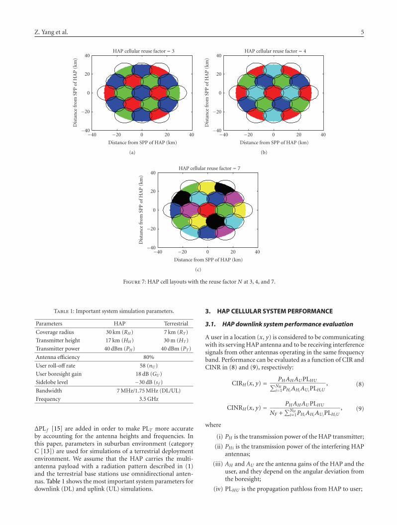
In this paper, we use a circular shape to approximatelycover the ideally proposed hexagonal pattern in HAP cover-age area. The frequency reuse pattern in HAP cellular systemconsists of N cells assigned the same number of frequencies,which are defined as cochannel cells. N is termed as a reusefactor, which decides the number of cells in a repetitiouspattern and is defined in [12]
N = I2 + J2 + (I × J), I , J = 0, 1, 2, 3, . . . . (4)
Hence, we test 3, 4, and 7 as possible values of N.Accordingly, the minimum distance between the cochannelcells is given as [12]
D = rcell·√
3N. (5)
Figure 7 shows examples of frequency reuse patternsin HAP cellular system. Cochannel cells are depicted withthe same colour. Frequency reuse allows the use of samefrequency already employed in other cells nearby, thusallowing frequencies to be used for multiple simultaneouscommunications.
2.5. Path loss calculations and simulation parameters
Currently, most HAP research papers adopt the free spacepath loss (FSPL) presented in (6) as the propagation modelused for HAP transmission, where d is distance from thetransmitter and λ is the signal wavelength. Until now, nospecific propagation model has been established for HAPs at3.5 GHz, and therefore FSPL has been widely used in currentresearch. Propagation models have been developed for HAPsin mm-wave band at 47/48 GHz, but they are not applicablein the 3.5 GHz frequency band. It should also be noted thatdirectional user antennas are likely to be installed at a fixedlocation with this scenario. High elevation angles owing tothe relatively small radius of HAP coverage also mean thatthe LOS propagation to the HAP is a reasonable assumption.Therefore, FSPL is used in this article, and diffraction andshadowing are not explicitly considered without loss ofgeneral validity:
PLH =(
4πdλ
)2
. (6)
The propagation pathloss model PLT is shown in (7) forthe terrestrial signal propagation model as presented in [13,14]:
PLT = PLm + ΔPL f + ΔPLh. (7)
PLT is composed of a median path loss PLm, the receiverantenna height correction term ΔPLh and the frequencycorrection term ΔPL f . The two-correction terms ΔPLh and
Z. Yang et al. 5
HAP cellular reuse factor = 3
−40
−20
0
20
40
Dis
tan
cefr
omSP
Pof
HA
P(k
m)
−40 −20 0 20 40
Distance from SPP of HAP (km)
(a)
HAP cellular reuse factor = 4
−40
−20
0
20
40
Dis
tan
cefr
omSP
Pof
HA
P(k
m)
−40 −20 0 20 40
Distance from SPP of HAP (km)
(b)
HAP cellular reuse factor = 7
−40
−20
0
20
40
Dis
tan
cefr
omSP
Pof
HA
P(k
m)
−40 −20 0 20 40
Distance from SPP of HAP (km)
(c)
Figure 7: HAP cell layouts with the reuse factor N at 3, 4, and 7.
Table 1: Important system simulation parameters.
Parameters HAP Terrestrial
Coverage radius 30 km (RH) 7 km (RT)
Transmitter height 17 km (HH) 30 m (HT)
Transmitter power 40 dBm (PH) 40 dBm (PT)
Antenna efficiency 80%
User roll-off rate 58 (nU)
User boresight gain 18 dB (GU)
Sidelobe level −30 dB (s f )
Bandwidth 7 MHz/1.75 MHz (DL/UL)
Frequency 3.5 GHz
ΔPL f [15] are added in order to make PLT more accurateby accounting for the antenna heights and frequencies. Inthis paper, parameters in suburban environment (categoryC [13]) are used for simulations of a terrestrial deploymentenvironment. We assume that the HAP carries the multi-antenna payload with a radiation pattern described in (1)and the terrestrial base stations use omnidirectional anten-nas. Table 1 shows the most important system parameters fordownlink (DL) and uplink (UL) simulations.
3. HAP CELLULAR SYSTEM PERFORMANCE
3.1. HAP downlink system performance evaluation
A user in a location (x, y) is considered to be communicatingwith its serving HAP antenna and to be receiving interferencesignals from other antennas operating in the same frequencyband. Performance can be evaluated as a function of CIR andCINR in (8) and (9), respectively:
CIRH(x, y) = PHAHAUPLHU∑NH
i=1PHiAHiAUiPLHiU
, (8)
CINRH(x, y) = PHAHAUPLHUNF +
∑NHi=1PHiAHiAUiPLHiU
, (9)
where
(i) PH is the transmission power of the HAP transmitter;
(ii) PHi is the transmission power of the interfering HAPantennas;
(iii) AH and AU are the antenna gains of the HAP and theuser, and they depend on the angular deviation fromthe boresight;
(iv) PLHU is the propagation pathloss from HAP to user;

6 EURASIP Journal on Wireless Communications and Networking
3
3
3
3
3
3
3
3
3
3
7
7
7
7
7
7
7
7
7
7
7
7
7
7 7
7
7
7
7
77
7
7
7
14
14
14
14
14
14
14
14
14
14
14
14
14 14
1414
14
14
14
141414
1414
14
14
14
14
14
14
1414
14
21
21
21
21
21
21
21
21
21
21
21
21
21
21
21
21
21
21
21
21
21
21
21
21
21
21
21
21
21
21
21
21 21
21
21
22
22
22
22
22
22
22
2222
22
22
22
22
22
22
22
22
22
22
22
22
22
22
22
CIRHHAP system performance(reuse factor= 3)
−30
−20
−10
0
10
20
30
Dis
tan
cefr
omSP
Pof
HA
P(k
m)
−30 −20 −10 0 10 20 30
Distance from SPP of HAP (km)
4
6
8
10
12
14
16
18
20
22
Figure 8: CIR performance of a HAP WiMAX system with reusefactor = 3.
CDF of CIRH and CINRH of HAP WiMAXsystem (refuse factor= 3)
0
0.2
0.4
0.6
0.8
1
Pr
(CIR
Hor
CIN
RH<X
)
4 6 8 10 12 14 16 18 20 22
X (dB)
CIRH
CINRH
Figure 9: CDF of CIR and CINR performance of a HAP WiMAXsystem with reuse factor = 3.
(v) NH is the total number of cochannel cells in the HAPsystem;
(vi) NF is the noise power (−100.5 dBm).
Figure 8 illustrates the CIR performance in the HAPcoverage area when considering the cochannel interference.Contours inside each cell have approximately the sameshape as that in Figure 5, which demonstrates that cellu-lar performance is not susceptible to cochannel interfer-ence.
Figure 9 shows the cumulative distribution function(CDF) of CIRH and CINRH of a HAP WiMAX system. Itcan be seen that WiMAX services can be provided on average21 dB in both scenarios with values of CIR or CINR largeror equal to 21 dB. Interference from cochannel is dominantcompared to noise in the system since the curves in Figure 9are overlapping. Hence, strategies for system performanceimprovement should mainly focus on reducing excess powerfrom cochannel interference.
CDF of CIRUH and CINRUH of HAP WiMAXuplink system (N = 4)
0
0.2
0.4
0.6
0.8
1
Pr
(CIR
UH
orC
INRUH<X
)
14 16 18 20 22 24
X (dB)
CIRUH
CINRUH
Figure 10: CDF of uplink CIR and CINR performance in a HAPuplink system with reuse factor = 4.
3.2. HAP uplink system performance evaluation
Uplink performance of a HAP WiMAX system can be evalu-ated by considering a user in a location (x, y) communicatingwith its serving HAP antenna and other antennas servingother cells in the same frequency band. CIR and CINR canbe expressed as
CIRUH(x, y) = PUAUAHPLUH∑NH
i=1PUAUiAHiPLUHi
,
CINRUH(x, y) = PUAUAHPLUHNF +
∑NHi=1PUAUiAHiPLUHi
,
(10)
where
(i) PU is the transmission power of user in the target cell(30 dBm);
(ii) PLUH is the propagation pathloss from user to HAP;
(iii) NF is the noise power (−106.5 dBm).
Figure 10 shows the CDF of uplink CIR and CINR ofHAP WiMAX system. It can be seen that WiMAX uplinkservices can be provided averagely around 22 dB in bothcases. Cochannel interference is also dominant compared tonoise.
4. PERFORMANCE OF A HAP COEXISTENCE SCENARIO
Providing WiMAX from HAPs is a novel means to deliverbroadband services. Thus, it is vital to consider its coexis-tence capability with current terrestrial WiMAX system inorder to get an assessment of the performance. In this paper,we mainly focus on evaluating interference from terrestrialWiMAX to the HAP system.
4.1. HAP coexistence scenario
The considered coexistence model is depicted in Figure 11.We assume that the terrestrial WiMAX system employsthe same cellular configuration as the HAP system. There
Z. Yang et al. 7
ϕHi
ϕ
θ
Desired signalInterfering signalBoresight of HAP antennasAngle away from the boresightHAP/terrestrial system cellHAP cochannel cell
Terrestrial base station
φ, θ
Figure 11: Coexistence model of HAP and terrestrial WiMAXsystem.
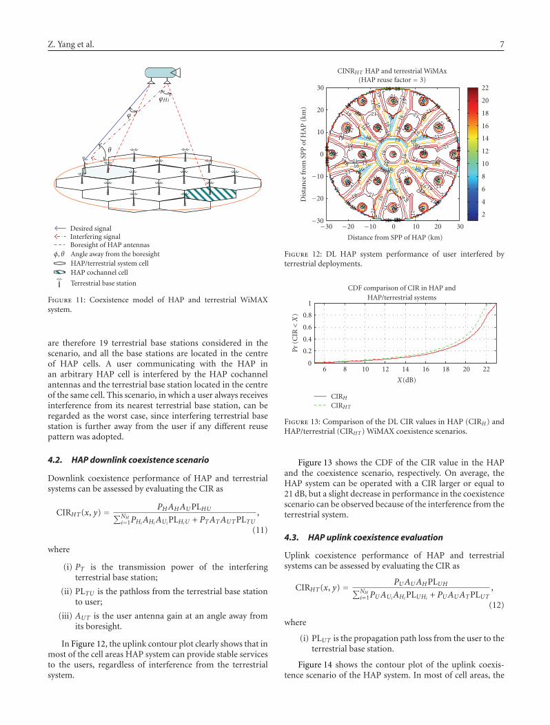
are therefore 19 terrestrial base stations considered in thescenario, and all the base stations are located in the centreof HAP cells. A user communicating with the HAP inan arbitrary HAP cell is interfered by the HAP cochannelantennas and the terrestrial base station located in the centreof the same cell. This scenario, in which a user always receivesinterference from its nearest terrestrial base station, can beregarded as the worst case, since interfering terrestrial basestation is further away from the user if any different reusepattern was adopted.
4.2. HAP downlink coexistence scenario
Downlink coexistence performance of HAP and terrestrialsystems can be assessed by evaluating the CIR as
CIRHT(x, y) = PHAHAUPLHU∑NH
i=1PHiAHiAUiPLHiU + PTATAUTPLTU,
(11)
where
(i) PT is the transmission power of the interferingterrestrial base station;
(ii) PLTU is the pathloss from the terrestrial base stationto user;
(iii) AUT is the user antenna gain at an angle away fromits boresight.
In Figure 12, the uplink contour plot clearly shows that inmost of the cell areas HAP system can provide stable servicesto the users, regardless of interference from the terrestrialsystem.
10
10
10
10
10
1010
10
1010
10
1010 10
10
10
10
10
10
1010
10
10
1010
10
10
10
10 10
1010
10
10
10
1010
1010
10
16
16
16
16
16
1616
16
1616
16
1616 16
16
16
16
16
16
1616
16
16
16
16
16
16
16
16
16
16
1616
16
16
16
1616
16
16
16 16
16
16
16
16
1616
16
16
16
16
19
19
19
19
19 19
19
19
19
19
19
19
19 19
19
19
19
19
19
19
19
19
19
19
19
19
19
19
19
19
19
19
19
19
19
19
19
19
19
19
19
19
19
19
19
19
19
19
19
1919
21
21
21
21
21
21 21
21
21
21
21
21
21
21
21
21
21
2121
21
21
21
21
21
21
2121
21
21
21
21
21
21
21
21
21
21
21 21
21
21
21
21
21
21
21
CINRHT HAP and terrestrial WiMAx(HAP reuse factor = 3)
−30
−20
−10
0
10
20
30
Dis
tan
cefr
omSP
Pof
HA
P(k
m)
−30 −20 −10 0 10 20 30
Distance from SPP of HAP (km)
2
4
6
8
10
12
14
16
18
20
22
Figure 12: DL HAP system performance of user interfered byterrestrial deployments.
CDF comparison of CIR in HAP andHAP/terrestrial systems
0
0.2
0.4
0.6
0.8
1P
r(C
IR<X
)
6 8 10 12 14 16 18 20 22
X(dB)
CIRH
CIRHT
Figure 13: Comparison of the DL CIR values in HAP (CIRH) andHAP/terrestrial (CIRHT) WiMAX coexistence scenarios.
Figure 13 shows the CDF of the CIR value in the HAPand the coexistence scenario, respectively. On average, theHAP system can be operated with a CIR larger or equal to21 dB, but a slight decrease in performance in the coexistencescenario can be observed because of the interference from theterrestrial system.
4.3. HAP uplink coexistence evaluation
Uplink coexistence performance of HAP and terrestrialsystems can be assessed by evaluating the CIR as
CIRHT(x, y) = PUAUAHPLUH∑NH
i=1PUAUiAHiPLUHi + PUAUATPLUT,
(12)
where
(i) PLUT is the propagation path loss from the user to theterrestrial base station.
Figure 14 shows the contour plot of the uplink coexis-tence scenario of the HAP system. In most of cell areas, the

8 EURASIP Journal on Wireless Communications and Networking
12
12
1212
12
12
12
12
12 12
12
12
12
12
12
1212
12
12
12
12 12
12
12
12
12
12
12
12
18
18
18
18
18
1818
18
18
1818
18
18
18 18
18
18
18
18
18
18
18
18
18
18 18
18
18
1818
18
18
18
18
18
18
18
18
24 24
24
24
24
24
24
24
24
24
24
24
24
24
24
24
2424 24
24
24
24
24
24
24
24
24
24
24
CIRHT of HAP system interfered byterrestrial system (N = 4)
−30
−20
−10
0
10
20
30
Dis
tan
cefr
omSP
Pof
HA
P(k
m)
−30 −20 −10 0 10 20 30
Distance from SPP of HAP (km)
2
4
6
8
10
12
14
16
18
20
22
24
Figure 14: UL CIR value of HAP system (CIRHT) interfered by theterrestrial system.
CDF of CIRH of different frequency reusescheme in HAP cellular system
0
0.2
0.4
0.6
0.8
1
Pr
(CIR<X
)
5 10 15 20 25
X (dB)
Reuse factor = 3Reuse factor = 4Reuse factor = 7
Figure 15: DL CIRH performance of HAP system with differentvalues of the reuse factor N (3, 4, and 7).
HAP can provide stable uplink services to users, which arenot susceptible to interference from the terrestrial system.
5. HAP WiMAX SYSTEM IMPROVEMENT
A number of approaches have been used to improve the cel-lular system performance, for example, adding new channels,cell splitting, cell sectoring. Increasing D, the minimumdistance between cochannel cells, is an effective approach,since it can keep the cochannel cells further away fromeach other and therefore decrease the interference withoutrequiring more spectrum.
Figure 15 shows the downlink CIRH performance ofthe HAP system for different values of D, obtained byincreasing the reuse factor N. It shows that a CIR increase ofapproximately 2 dB can be achieved with each increment ofN in the figure (from 3 to 4, or from 4 to 7). Usually the totalnumber of frequencies allotted to the system is constant, soincreasing D, on the other hand, decreases available channelresources in each cell of the system.
6. CONCLUSIONS
In this paper, we have shown the performance of both down-link and uplink WiMAX broadband standard transmittedfrom a HAP cellular system in the 3.5 GHz band across acoverage area of 30 km radius, while operating in the samefrequency band with terrestrial WiMAX deployments basedon a proposed coexistence scenario. A cellular configurationhas been proposed for the HAP WiMAX system based on thetypical WiMAX terrestrial system. The HAP coverage areawas divided into 19 individual cells served by multiantennapayload. WiMAX broadband system performance of indi-vidual HAP system was evaluated both separately and whentaking into account the cochannel interference from theantennas operating in the same frequency band. Coexistencecapability was investigated based on a proposed coexistencescenario and examined by considering interference from thenearest terrestrial base station to HAP system. Simulationresults clearly demonstrate that the internal cochannelinterference was dominant when delivering WiMAX viaHAPs, and HAP system can effectively share the spectrumwith terrestrial WiMAX systems.
REFERENCES
[1] J.-J. Huang, W.-T. Wang, and H.-W. Ferng, “Uplink capacityenhancement for an integrated HAPS-terrestrial CDMA sys-tem,” IEEE Communications Letters, vol. 11, no. 1, pp. 10–12,2007.
[2] Z. E. O. Elshaikh, R. Islam, A. P. Ismail, and O. O. Khalifa,“High altitude platform for wireless communications andother services,” in Proceedings of the 4th International Confer-ence on Electrical and Computer Engineering (ICECE ’06), pp.432–438, Dhaka, Bangladesh, December 2006.
[3] B. T. Ahmed, “WiMAX in high altitude platforms (HAPs)communications,” in Proceedings of the 9th European Con-ference on Wireless Technology (ECWT ’06), pp. 245–248,Manchester, UK, September 2006.
[4] D. Grace, M. Mohorcic, M. Oodo, M. H. Capstick, M. B.Pallavicini, and M. Lalovic, “CAPANINA—communicationsfrom aerial platform networks delivering broadband informa-tion for all,” in Proceedings of the 14th IST Mobile and Wirelessand Communications Summit, Dresden, Germany, June 2005.
[5] J.-M. Park, B.-J. Ku, Y.-S. Kim, and D.-S. Ahn, “Technol-ogy development for wireless communications system usingstratospheric platform in Korea,” in Proceedings of the 13thIEEE International Symposium on Personal, Indoor and MobileRadio Communications (PIMRC ’02), vol. 4, pp. 1577–1581,Lisbon, Portugal, September 2002.
[6] T. C. Hong, B. J. Ku, J. M. Park, D.-S. Ahn, and Y.-S. Jang,“Capacity of the WCDMA system using high altitude plat-form stations,” International Journal of Wireless InformationNetworks, vol. 13, no. 1, pp. 5–17, 2006.
[7] IEEE802.16 Broadband Wireless Access Working Group,“IEEE802.16-2004 part 16: air interface for fixed broadbandwireless access system,” October 2004.
[8] P. Likitthanasate, D. Grace, and P. D. Mitchell, “Coexistenceperformance of high altitude platform and terrestrial systemssharing a common downlink WiMAX frequency band,”Electronics Letters, vol. 41, no. 15, pp. 858–860, 2005.
[9] Z. Yang, A. Mohammed, T. Hult, and D. Grace, “Optimizingdownlink coexistence performance of WiMAX services in

Z. Yang et al. 9
HAP and terrestrial deployments in shared frequency bands,”in Proceedings of the 3rd International Waveform Diversity andDesign Conference (WDD ’07), pp. 79–82, Pisa, Italy, June2007.
[10] W. C. Y. Lee, “Spectrum efficiency in cellular,” IEEE Transac-tions on Vehicular Technology, vol. 38, no. 2, pp. 69–75, 1989.
[11] J. Thornton, D. Grace, M. H. Capstick, and T. C. Tozer,“Optimizing an array of antennas for cellular coverage froma high altitude platform,” IEEE Transactions on WirelessCommunications, vol. 2, no. 3, pp. 484–492, 2003.
[12] W. Stallings, Wireless Communications and Networking,Prentice-Hall, Upper Saddle River, NJ, USA, 2002.
[13] IEEE Standard 802.16a-2003, “Modifications and additionalphysical layer specifications for 2-11 GHz,” 2003.
[14] V. Erceg, L. J. Greenstein, S. Y. Tjandra, et al., “An empiricallybased path loss model for wireless channels in suburban envi-ronments,” IEEE Journal on Selected Areas in Communications,vol. 17, no. 7, pp. 1205–1211, 1999.
[15] IEEE802.16 Broadband Wireless Access Working Group,“Channel models for fixed wireless applications,” June 2003.
Photograph © Turisme de Barcelona / J. Trullàs
Preliminary call for papers
The 2011 European Signal Processing Conference (EUSIPCO 2011) is thenineteenth in a series of conferences promoted by the European Association forSignal Processing (EURASIP, www.eurasip.org). This year edition will take placein Barcelona, capital city of Catalonia (Spain), and will be jointly organized by theCentre Tecnològic de Telecomunicacions de Catalunya (CTTC) and theUniversitat Politècnica de Catalunya (UPC).EUSIPCO 2011 will focus on key aspects of signal processing theory and
li ti li t d b l A t f b i i ill b b d lit
Organizing Committee
Honorary ChairMiguel A. Lagunas (CTTC)
General ChairAna I. Pérez Neira (UPC)
General Vice ChairCarles Antón Haro (CTTC)
Technical Program ChairXavier Mestre (CTTC)
Technical Program Co Chairsapplications as listed below. Acceptance of submissions will be based on quality,relevance and originality. Accepted papers will be published in the EUSIPCOproceedings and presented during the conference. Paper submissions, proposalsfor tutorials and proposals for special sessions are invited in, but not limited to,the following areas of interest.
Areas of Interest
• Audio and electro acoustics.• Design, implementation, and applications of signal processing systems.
l d l d d
Technical Program Co ChairsJavier Hernando (UPC)Montserrat Pardàs (UPC)
Plenary TalksFerran Marqués (UPC)Yonina Eldar (Technion)
Special SessionsIgnacio Santamaría (Unversidadde Cantabria)Mats Bengtsson (KTH)
FinancesMontserrat Nájar (UPC)• Multimedia signal processing and coding.
• Image and multidimensional signal processing.• Signal detection and estimation.• Sensor array and multi channel signal processing.• Sensor fusion in networked systems.• Signal processing for communications.• Medical imaging and image analysis.• Non stationary, non linear and non Gaussian signal processing.
Submissions
Montserrat Nájar (UPC)
TutorialsDaniel P. Palomar(Hong Kong UST)Beatrice Pesquet Popescu (ENST)
PublicityStephan Pfletschinger (CTTC)Mònica Navarro (CTTC)
PublicationsAntonio Pascual (UPC)Carles Fernández (CTTC)
I d i l Li i & E hibiSubmissions
Procedures to submit a paper and proposals for special sessions and tutorials willbe detailed at www.eusipco2011.org. Submitted papers must be camera ready, nomore than 5 pages long, and conforming to the standard specified on theEUSIPCO 2011 web site. First authors who are registered students can participatein the best student paper competition.
Important Deadlines:
P l f i l i 15 D 2010
Industrial Liaison & ExhibitsAngeliki Alexiou(University of Piraeus)Albert Sitjà (CTTC)
International LiaisonJu Liu (Shandong University China)Jinhong Yuan (UNSW Australia)Tamas Sziranyi (SZTAKI Hungary)Rich Stern (CMU USA)Ricardo L. de Queiroz (UNB Brazil)
Webpage: www.eusipco2011.org
Proposals for special sessions 15 Dec 2010Proposals for tutorials 18 Feb 2011Electronic submission of full papers 21 Feb 2011Notification of acceptance 23 May 2011Submission of camera ready papers 6 Jun 2011