Performance Evaluation of Multisensor Architectures for Tracking
12
Performance Evaluation of Multisensor Architectures for Tracking Stefano Maludrottu, Alessio Dore, Hany Sallam and Carlo S. Regazzoni Department of Biophysical and Electronic Engineering - DIBE University of Genova Abstract. In recent years the development of distributed fusion sys- tems for real-world services (tracking, surveillance...) has remarked the importance of good design choices for both logical and physical archi- tecture. The main objective of this paper is to implement a model of a distributed fusion architecture in order to evaluate the overall per- formance as well as the interactions of its subparts. The advantage of the proposed architecture analysis method are: 1) to allow quantitative comparison of different fusion structures through the evaluation of per- formance metrics and 2) to validate the algorithms involved as well as the physical structure (communication links, computational load...). Fi- nally example structures are compared in order to find the best solution to some benchmark problems. Keywords: Data Fusion Architecture, Tracking, Performance Evalua- tion, Multisensor 1 Introduction Performance evaluation of data fusion systems for tracking is a key task for the correct design of effective and robust architecture. In fact in many applica- tions, as videosurveillance or radar flight tracking, a precise target localization is required over time. In these domains multisensor approaches are successfully employed because of the capability of resolving problems caused by misleading observations, exploiting the redundancy introduced by the possibility of having multiple measurements for the same target. The architecture of these systems is typically complex and composed by many sensors that monitor wide areas and fusion modules providing a unique scene representation. Therefore in this domain several processing units and communications links are involved in this process and their behaviors affect performances. In this paper a model of a data fusion system for tracking is proposed that takes into account different aspects of such system architectures to assess their performances for what concerns the algorithms accuracy and also to consider communication and computational complexity issues that can arise in complex multisensor systems. inria-00326760, version 1 - 5 Oct 2008 Author manuscript, published in "Workshop on Multi-camera and Multi-modal Sensor Fusion Algorithms and Applications - M2SFA2 2008, Marseille : France (2008)"
Transcript of Performance Evaluation of Multisensor Architectures for Tracking

Performance Evaluation of MultisensorArchitectures for Tracking
Stefano Maludrottu, Alessio Dore, Hany Sallam and Carlo S. Regazzoni
Department of Biophysical and Electronic Engineering - DIBEUniversity of Genova
Abstract. In recent years the development of distributed fusion sys-tems for real-world services (tracking, surveillance...) has remarked theimportance of good design choices for both logical and physical archi-tecture. The main objective of this paper is to implement a model ofa distributed fusion architecture in order to evaluate the overall per-formance as well as the interactions of its subparts. The advantage ofthe proposed architecture analysis method are: 1) to allow quantitativecomparison of different fusion structures through the evaluation of per-formance metrics and 2) to validate the algorithms involved as well asthe physical structure (communication links, computational load...). Fi-nally example structures are compared in order to find the best solutionto some benchmark problems.
Keywords: Data Fusion Architecture, Tracking, Performance Evalua-tion, Multisensor
1 Introduction
Performance evaluation of data fusion systems for tracking is a key task forthe correct design of effective and robust architecture. In fact in many applica-tions, as videosurveillance or radar flight tracking, a precise target localizationis required over time. In these domains multisensor approaches are successfullyemployed because of the capability of resolving problems caused by misleadingobservations, exploiting the redundancy introduced by the possibility of havingmultiple measurements for the same target. The architecture of these systemsis typically complex and composed by many sensors that monitor wide areasand fusion modules providing a unique scene representation. Therefore in thisdomain several processing units and communications links are involved in thisprocess and their behaviors affect performances.
In this paper a model of a data fusion system for tracking is proposed thattakes into account different aspects of such system architectures to assess theirperformances for what concerns the algorithms accuracy and also to considercommunication and computational complexity issues that can arise in complexmultisensor systems.
inria
-003
2676
0, v
ersi
on 1
- 5
Oct
200
8Author manuscript, published in "Workshop on Multi-camera and Multi-modal Sensor Fusion Algorithms and Applications - M2SFA2
2008, Marseille : France (2008)"

2 M2SFA2 2008: Workshop on Multi-camera and Multi-modal Sensor Fusion
1.1 Previous Works and Motivations
This paper presents a novel modeling method for distributed fusion architectureevaluation. In particular within this domain the problem of performing multi-camera tracking of moving objects using multiple of active sensors is addressed.
In the literature various approaches have been proposed for distributed fu-sion architecture modeling: in [1] a twofold architecture description is defined onphysical and logical level that we take as an inspiration: the physical architec-ture described as a graph constituted of nodes (processing resources as sensorsor fusion nodes) and links (heterogeneous communication channels) while logicalarchitecture is defined outlining a task decomposition (i.e. tracking) into sub-tasks (i.e. data acquisition, filtering etc.); thus the distribution of intelligence ina fusion system architecture can be defined as a mapping of the subtasks in thevarious parts of the physical architecture. In [2], a hierarchical architecture isproposed for video surveillance and tracking; the camera network sends the datagathered to the upper level nodes in which tracking data are fused in a central-ized manner. In some related works are introduced specific metrics in order tomeasure the reliability of each subpart involved in the data fusion. The impor-tance of this topic is demonstrated by the relevant body of research evaluatingreliability and accuracy in automatic tracking. The vast majority of the worksfound in literature defines metrics related to specific parts of the architecturemissing a more generic analysis. However, during the design of complex data fu-sion based systems, it is important to consider the influence of the architecturalaspects of the system on the overall performances.
The work described in [3] focuses on defining the main requirements for ef-fective performance analysis for tracking methods. In [4], a number of metricsis defined for trajectory comparison, in order to determine how precisely a tar-get is tracked by a computer vision system. In [5], an evaluation benchmarkis presented to compare different visual surveillance algorithms developed forPETS (Performance Evaluation of Tracking and Surveillance) workshops. PETSmetrics are specifically developed to provide an automatic mechanism to quan-titatively compare similar purpose algorithms operating on the same data. In[6] a complex framework is proposed for direct comparison of event detectionsolutions based on any image analysis and understanding module. In the workpresented in [7], the authors develop a tool to automatically generate accurateground truth of realistic situations in multicamera videosurveillance systemsbased on a commercial game engine.
2 Data Fusion Frameworks for Tracking
2.1 Data Fusion architecture for Target Tracking
A general data fusion architecture of a system aiming at target tracking can besubdivided into several module in a hierarchic way. The lower level is constitutedby sensors that gather information from the environment and try to detect the
inria
-003
2676
0, v
ersi
on 1
- 5
Oct
200
8
M2SFA2 2008: Workshop on Multi-camera and Multi-modal Sensor Fusion 3
targets position within their field of view (i.e the area observable by the sen-sor). Target tracking can be performed in several scenarios and the typologiesof sensors that can be used may change from video cameras to radars, sonarsor microphones. Despite the variability of the input data the sensor can be con-sidered as a module that perceives the variations in the environment producedby the target and it converts resulting signals to position information. However,usually in a general situation the single sensor observation of the scene is affectedby noise that can produce erroneous localization and tracking.
For example typical problems arising in video data flow are due to the su-perimposition of targets and elements of the scene occupying different 3D in theimage plane. This issue, called occlusion, causes a momentary lack of observa-tions with consequent difficulties in the position estimation procedure. Moreover,background elements can produce misleading observations (or clutter) that areto be excluded from the measurements-target association procedures. A possi-ble and widely exploited approach to overcome these issues and to enhance thetracking robustness consists in using more sensors monitoring with complete orpartial fields of view overlapping the same area. In this way it is possible toobtain multiple observations of the same entity whose joint processing likely im-proves tracking performance. The fusion module can be considered as a functionthat associates in a proper way the data produced by the sensors with overlappedfields of views and estimate an unique scene representation.
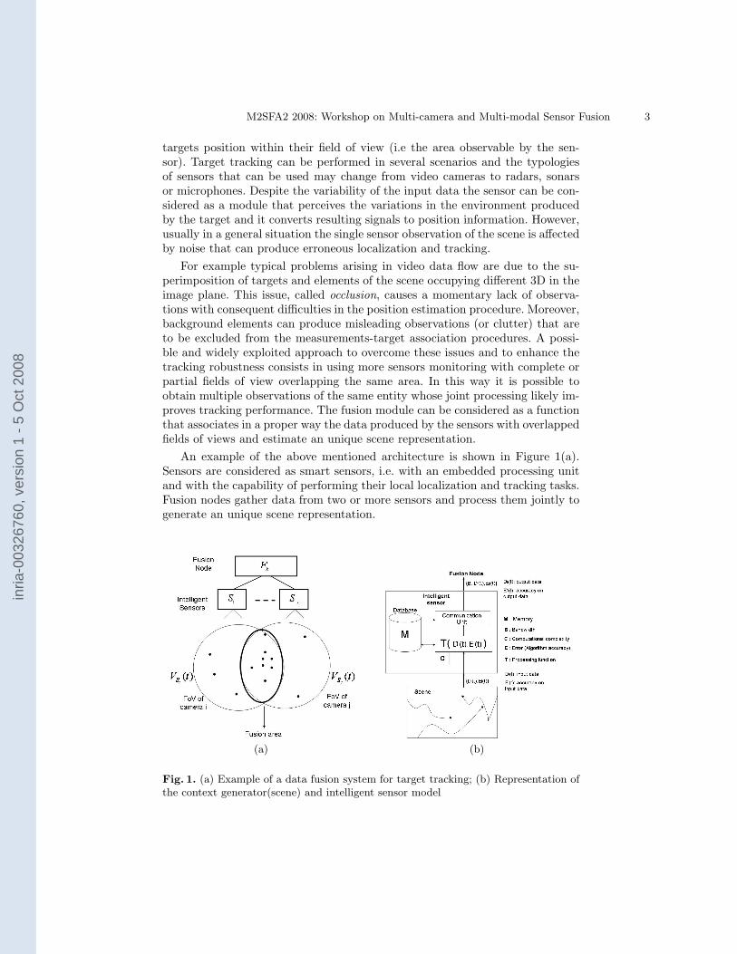
An example of the above mentioned architecture is shown in Figure 1(a).Sensors are considered as smart sensors, i.e. with an embedded processing unitand with the capability of performing their local localization and tracking tasks.Fusion nodes gather data from two or more sensors and process them jointly togenerate an unique scene representation.
(a) (b)
Fig. 1. (a) Example of a data fusion system for target tracking; (b) Representation ofthe context generator(scene) and intelligent sensor model
inria
-003
2676
0, v
ersi
on 1
- 5
Oct
200
8

4 M2SFA2 2008: Workshop on Multi-camera and Multi-modal Sensor Fusion
In the following a model for smart sensors Si together with fusion nodesFk that allows us to define a general architecture of a data fusion system fortarget tracking. In this work we will consider only a structure where sensors canexchange data only with the fusion node and vice-versa. This structure has beenchosen since the focus of this work is on the hierarchical architecture where thefusion node overlooks the sensors and, eventually it modifies their parameters orit passes information gathered from other sensors. This model can be constitutedby one or more fusion nodes according to the extension of the monitored areaand the total number of sensors. Without loss of generality, we will consider theoverall fields of view (FOVs) of the fusion nodes contiguous non-overlapped. Infact, if this is not the case it would be sufficient to introduce a higher fusion levelperforming the same tasks of the fusion nodes on their outputs.
Performance evaluation of a data fusion architecture does not pertain only onalgorithms accuracy in localization but several other aspects must be consideredas the data communication between sensors and fusion nodes, the computationalcomplexity and the memory used. Then, in order to define a procedure to assessthe performances of this kind of systems a general model of smart sensors andof fusion nodes has been studied that takes into account the elements involvedin a multisensor tracking process.
2.2 Smart Sensor Model
Each smart sensor Si observing a certain area VSi(t) is modeled as composed bythree fundamental elements (see Fig.1(b):
– processing function Ti: it represents a tracking algorithm that produces acertain output data Dfi(t) given an input data Di(t) referring to the sceneobserved in VSi(t). The input noise is modeled with Ei(t) and the noise onthe processed data sent to the fusion node is Efi(t). The variables Di(t),Dfi(t), Ei(t) and Efi(t) are vectors of dimension equal to the number oftargets Ni(t) detected by Si at time t. The computational complexity Cfunction of Di(t) is associated to the processing function.The error vector in this tracking application coincides with the accuracy er-ror that has to be evaluated through a suitable performance metric. In thispaper, the considered metric is the distance between the estimated targetposition and the ground truth.Another error that must be taken into account in this scenario is the detect-ing error ED
i (t) caused by occlusions or clutter. The detection error impliesthat the estimated number of targetsNi(t) is different to the real oneNGTi(t)due to the false alarm or miss detection.
– database: it represents the memory M of the smart sensor. It has beendecided to address it as database since in many tracking application algo-rithms require to compare actual measurements with past detected targets.The algorithm T exchanges information with the database that can also sendadditional information to the fusion node.
inria
-003
2676
0, v
ersi
on 1
- 5
Oct
200
8

M2SFA2 2008: Workshop on Multi-camera and Multi-modal Sensor Fusion 5
– communication unit: it is responsible for transmitting data to the fusionnode. The communication unit has to satisfy the requirements of error freedata transmission considering possible bandwidth B limitations of the linktoward the fusion node.
– orientation: each smart sensor is considered to be placed in a certain knownposition; its FOV depends on its orientation. If a smart sensor has a fixedorientation its FOV VSi(t) becomes a constant VSi.
2.3 Fusion Node Model
In this stage the data coming from each sensor are integrated to realize an ac-curate single model of target position. Its structure similar to the smart sensormodel but some differences are present in the processing function and commu-nication unit.
– genetic optimization: genetic algorithms are population based search algo-rithms [8] used as optimization tools in a lot of different applications. Inthis paper we implemented a GA-based optimization algorithm to find thebest orientations of a group of smart sensors in a distributed multisensorarchitecture. The input to GA is the current position of moving objects inthe environment as perceived by the fusion node and the output is the ori-entation angle of each camera. The fitness function to be optimized for eachsensor separately is formulated as
∑i widi, where di is the perpendicular
distance from an object position to the central line of FOV of sensor i andw is the number of objects in a given position. The camera is considered tobe best oriented minimizing the sum of distances.
– processing function TF : the fusion node processing function TF takes M dataDfi(t) (together with the respective error measure Efi(t), i = 1, . . . ,M) asinput, where M is the number of smart sensors connected to the fusion nodeFk. Thus, the transfer function is: TF (Df1(t), . . . ,DfM (t),Ef1(t), . . . ,EfM (t)).The cardinality of DF (t) and EF (t) vectors is NF (t) = TF (card(Df1(t) ∪Df2(t) ∪ . . .DfM (t))) i.e. the intersection of the targets detected by thesensors processed by the fusion algorithm TF that manages the overlaps andhandles the false alarm and miss detection problems. Due to the overlap-ping fields of view the Dfi(t) vectors have common elements, relative to thetargets detected by multiple sensors). The output of T (Ef1(t), . . . ,EfM (t))produces an error vector EF (t) in which each value is lower than the respec-tive error value in Ei(t) detected from the i-th sensor. Worth of note is thatthe computational complexity C of the fusion node processing is related tothe dimension of the overlapped fields of view and the number of targetspresent in that zone.
– database: the database performs the same tasks described for the smartsensor
– communication unit: it analyzes the transmission load for each communica-tion link connecting the fusion node to the smart sensors. It can also sendmessages to the smart sensor communication unit in order to perform an
inria
-003
2676
0, v
ersi
on 1
- 5
Oct
200
8

6 M2SFA2 2008: Workshop on Multi-camera and Multi-modal Sensor Fusion
adaptive optimization of the data transmission. For example, if one link isoverused the fusion node can ask to all the smart sensor connected to thatlink to reduce their transmission rate by a higher compression.
3 Simulation and Results
3.1 Multisensor Tracking System Simulator
On the basis of the architectural model described in Sect. 2 a tracking simulatorhas been realized to demonstrate the possibility to evaluate the system perfor-mances. A context generator has been designed in order to produce a set ofrealistic target trajectories simulating moving objects with stochastic dynamics.The simulated smart sensor Si acquires data from the context generator onlyfor what concerns his field of view Vi(t) and processed them using a KalmanFilter. Multiple sensors with overlapped fields of view send their processed datato one fusion node Fk that processes the data using a modified Kalman Filter inaddition to a Nearest Neighbor data association technique [9]. This experimentintends to show how it is possible to adapt a real tracking system into our pro-posed model.Context Generator The context generator produces trajectories with linearautoregressive first order model with Gaussian noise. Trajectories lies in a two-dimensional space representing a map of a monitored environment. A Poissoniandistribution is used to describe the probability of new target born and death.Occlusions are also simulated when two targets are aligned with respect to thecamera line of sight and they are sufficiently close one to another. Clutter noiseis also introduced at each scan as a Poisson process.The context generator allows us to have a realistic but controllable environmentby which simulating different situations automatically generating the correspon-dent ground truth.
Smart sensor
– Processing function: when a target trajectory enters in the field of view Vi(t)of the i-th sensor a single-view tracking task is initialize to permit to knowthe position and to follow the movements of targets. For each target, in orderto estimate the position of tracked objects a Kalman filter is used [10], whoseequations are:
x(k + 1) = Awx(k) + ww(k) (1)z(k) = Hwx(k) + vw(k) (2)
wl and vl are, respectively, the image plane and the measurement noise andthey are independent, white Gaussian and zero mean. Al and H l respectivelyare the state transition matrix and the measurement matrix.In this work the computational complexity is a linear function of the numberof targets present in the FOV. When this function exceeds a threshold defined
inria
-003
2676
0, v
ersi
on 1
- 5
Oct
200
8
M2SFA2 2008: Workshop on Multi-camera and Multi-modal Sensor Fusion 7
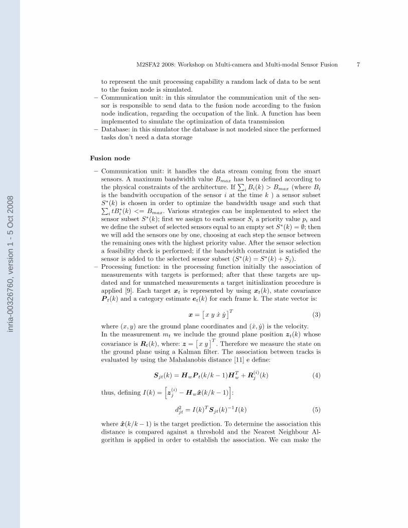
to represent the unit processing capability a random lack of data to be sentto the fusion node is simulated.
– Communication unit: in this simulator the communication unit of the sen-sor is responsible to send data to the fusion node according to the fusionnode indication, regarding the occupation of the link. A function has beenimplemented to simulate the optimization of data transmission
– Database: in this simulator the database is not modeled since the performedtasks don’t need a data storage
Fusion node
– Communication unit: it handles the data stream coming from the smartsensors. A maximum bandwidth value Bmax has been defined according tothe physical constraints of the architecture. If
∑iBi(k) > Bmax (where Bi
is the bandwith occupation of the sensor i at the time k ) a sensor subsetS∗(k) is chosen in order to optimize the bandwidth usage and such that∑
i tB∗i (k) <= Bmax. Various strategies can be implemented to select the
sensor subset S∗(k); first we assign to each sensor Si a priority value pi andwe define the subset of selected sensors equal to an empty set S∗(k) = ∅; thenwe will add the sensors one by one, choosing at each step the sensor betweenthe remaining ones with the highest priority value. After the sensor selectiona feasibility check is performed; if the bandwidth constraint is satisfied thesensor is added to the selected sensor subset (S∗(k) = S∗(k) + Sj).
– Processing function: in the processing function initially the association ofmeasurements with targets is performed; after that these targets are up-dated and for unmatched measurements a target initialization procedure isapplied [9]. Each target xt is represented by using xt(k), state covarianceP t(k) and a category estimate et(k) for each frame k. The state vector is:
x =[x y x y
]T (3)
where (x, y) are the ground plane coordinates and (x, y) is the velocity.In the measurement mt we include the ground plane position zt(k) whosecovariance is Rt(k), where: z =
[x y]T . Therefore we measure the state on
the ground plane using a Kalman filter. The association between tracks isevaluated by using the Mahalanobis distance [11] e define:
Sjt(k) = HwP t(k/k − 1)HTw + R
(i)j (k) (4)
thus, defining I(k) =[z
(i)j −Hwx(k/k − 1)
]:
d2jt = I(k)T Sjt(k)−1I(k) (5)
where x(k/k− 1) is the target prediction. To determine the association thisdistance is compared against a threshold and the Nearest Neighbour Al-gorithm is applied in order to establish the association. We can make the
inria
-003
2676
0, v
ersi
on 1
- 5
Oct
200
8

8 M2SFA2 2008: Workshop on Multi-camera and Multi-modal Sensor Fusion
hypothesis that for each target, in one view, there is at most one measure-ment, i.e.
∑j β
(i)jt ≤ 1; naturally if the measurement misses then
∑j β
(i)jt = 0.
The overall measurement for each target is the result of single camera mea-surements weighted with their covariance R
(i)j as follows:
Rt =
∑i
∑j
β(i)jt
(R
(i)j
)−1
−1
(6)
zt = Rt
∑i
∑j
β(i)jt
(R
(i)j
)−1
z(i)t
(7)
These equations express the accuracy improvement obtained thanks to thefusion of all the views; as a matter of fact Equation 6 implies that the over-all uncertainty is lower than the one provided by a single camera. MoreoverEquation 7 ensures that the fused measurement is biased to the most accu-rate measurement from one camera. The target updating is, then, attainedin the following way:
xt(k/k) = xt(k/k − 1) + Kt(k) [zt(k)−Hwxt(k/k − 1)] (8)
Kt(k) = P t(k/k − 1)HTw
hHwP t(k/k − 1)HT
w + Rt(k)i−1
(9)
its covariance is: P t(k/k) = [I −Kt(k)Hw] P t(k/k − 1) with 0 < η < 1.For those measurements not matched to any existing targets a target initial-ization procedure has to be applied. Hence, every unmatched measurementfrom a camera must be checked against the other unmatched measurementsfrom other cameras to find new targets.We call z
(i∗)j∗ the unmatched measurement from the i∗th camera and xn the
new target associated with it. All the association matrices β(i) are extendedby one column, β(i)
jn , for the new target xn; its elements represent the asso-ciation between the jth measurement from ith camera and the new target.For the i∗th camera the elements of the columns nth, referring to the newtarget, are:
β(i∗)jn =
{1 if j = j∗
0 otherwise(10)
Then the Mahalanobis distance between z(i∗)j∗ and each unmatched measure-
ment z(i)j from ith camera is calculated:
d2i∗j =
hz
(i)j (k)− z
(i∗)j∗
iT hR
(i)j −R
(i∗)j∗
i−1 hz
(i)j (k)− z
(i∗)j∗
i(11)
where R(i)j and R
(i∗)j∗ are the measurement covariances. Then, the new target
is initialised as follows:
xn(k/k) =[zn(k)T 0 0
]T (12)
inria
-003
2676
0, v
ersi
on 1
- 5
Oct
200
8

M2SFA2 2008: Workshop on Multi-camera and Multi-modal Sensor Fusion 9
Fig. 2. Representation of the ground truth (’o’) and fused target tracking (’*’)
P n(k/k) =[Rn(k) O2
O2 σ2vI2
](13)
where O2 and I2 are 2× 2 zero and identity matrices, respectively.The processing capability of the fusion node is limited due to the hardwarespecific processing resources (CPU, memory...). Similarly to the communi-cation unit we define a maximum CPU load Cmax; each of the Si ⊂ S∗(k)sensors (output of the communication unit at a given time k) produces aCPU usage Ci(k). If
∑i Ci(k) >= Cmax we define a priority-based selec-
tion of the data streams in order to obtain a feasible subset S′(k) such that
C′
i(S′
i(k)) <= Cmax. This selection will cause a loss of input data in order topreserve the computational feasibility; thus the data fusion will be performedusing only a subset of the whole input data to the fusion node.
– Database: in this simulator the database is not modeled since the performedtasks don’t need a data storage
3.2 Experimental results
Three scenarios have been investigated in order to demonstrate the possibilityof fusion architecture evaluation using the proposed method. The performancemetric is defined as
perf =∑
i |fi − gi|+ w ·mi
TOTi(14)
where |fi − gi| is the euclidean distance between the target position fiand itscorresponding ground truth gi at timestep i. The term w is a penalty value setequal to 10, mi the number of missing associations between ground truth dataand fused tracks at timestep i and TOTi is the total number of timesteps of thegenerated context (see Figure 2).
First scenario Two alternative fusion architectures are defined to be eval-uated using the proposed method in order to find which one has better per-formances. The overall structure (5 smart sensors, 1 fusion node and wireless
inria
-003
2676
0, v
ersi
on 1
- 5
Oct
200
8

10 M2SFA2 2008: Workshop on Multi-camera and Multi-modal Sensor Fusion
communications) is maintained fixed and only the sensors position has beenchanged (always ensuring the complete coverage of the context area) to find thebest configuration. In the first structure the field of view of the smart sensorsdoes not change over time, while in the second structure the field of view dy-namically change according to the genetic-based optimization technique definedin Sect. 2.3. Ten different scenes with a fixed number of trajectories (10) havebeen provided by the context generator as input for the model. Parameters ofGA are inizialized as follows: population size of 20, number of generations equalto 100 and crossover and mutation rate respectively 0.8 and 0.04. There aremany parameters that influence the context generator algorithm behavior: thetotal number of trajectories, the generation rate, the Gaussian noise (i.e. mea-surement error in smart sensors), etc. Those parameters have been randomlymodified for each context generation in order to provide a ground truth as di-versified as possible. Table 3 presents the different results (obtained using themetric defined in Eq. 14 )of the sample architectures and shows the connec-tion between different camera placement strategies and performances: dynamicchanging camera orientation outperforms a fixed orientation solution up to 20%.
Fig. 3. Performance comparison of Architecture 1 (fixed camera orientation - in blue)and Architecture 2 (genetic-based algorithm for optimization of camera orientations -in violet)
Second scenario Focusing on the architectures defined in the previous test,the overall result of the data fusion has been compared with the tracks producedby each smart sensor in the architecture in order to point out the contributionof each one to the performance of the fusion architecture. As shown in Table1 sensor 3 has the worst performance: it acts like a bottleneck for the entirestructure; a better placement or perhaps a more efficient sensor could improve
inria
-003
2676
0, v
ersi
on 1
- 5
Oct
200
8

M2SFA2 2008: Workshop on Multi-camera and Multi-modal Sensor Fusion 11
Cont Node S1 S2 S3 S4 S5
1 0.0188 0.16 0.11 0.61 0.02 0.03
2 0.0214 0.11 0.19 0.65 0.02 0.03
3 0.0182 0.15 0.12 0.60 0.03 0.03
4 0.0218 0.14 0.22 0.69 0.03 0.02
5 0.0362 0.17 0.2 0.98 0.1 0.05
6 0.0356 0.17 0.28 1.04 0.08 0.06
7 0.0439 0.14 0.26 1.17 0.09 0.08
8 0.0306 0.13 0.15 0.75 0.04 0.07
9 0.0348 0.18 0.19 0.68 0.04 0.11
10 0.035 0.12 0.17 0.68 0.04 0.09
Avg 0.0296 0.15 0.19 0.78 0.05 0.06
Cont Node S1 S2 S3 S4 S5
1 0.0162 0.12 0.10 0.55 0.03 0.03
2 0.0189 0.11 0.17 0.58 0.02 0.04
3 0.0153 0.11 0.10 0.49 0.02 0.03
4 0.0184 0.11 0.18 0.58 0.03 0.04
5 0.03 0.13 0.14 0.67 0.08 0.05
6 0.0288 0.19 0.21 0.81 0.07 0.06
7 0.0347 0.14 0.23 0.8 0.06 0.05
8 0.0275 0.11 0.15 0.65 0.03 0.05
9 0.0296 0.13 0.15 0.52 0.04 0.10
10 0.033 0.11 0.21 0.55 0.04 0.11
Avg 0.0252 0.13 0.16 0.62 0.04 0.06
Table 1. (a) Performance comparison of subparts of Architecture 1(fixed camera ori-entation); (b) Performance comparison of subparts of Architecture 2 (genetic-basedalgorithm for optimization of camera orientations). Cont refers to the context used asinput. Avg is the average performance over ten experiments. Performances are evalu-ated using the metric defined in Eq. 14.
the performance of the entire structure.
Third scenario Two different fusion structures have been compared: archi-tecture A has five sensors, an average communication link and average compu-tational resources while architecture B has only three sensors with wider fieldsof view (60◦ instead of 45◦) and a more accurate target detection and track-ing, a better communication link and better fusion node hardware. 10 differentscenes with a fixed number of trajectories (10) have been provided as input forthe model. In Table 2 is shown that architecture A, even with worse hardwareobtains a better overall result thanks to the higher number of sensor placed onthe area.
4 Conclusions and Future Works
In this paper a model of a system architecture for multisensor tracking has beenproposed. The aim of this model is to represent basic tasks performed by sucha system in order to address the problem of performance evaluation. This de-scription allows one to validate algorithms and system design with respect tothe monitored scenario. A simulator of a multisensor hierarchic tracking systemhas been presented to show the possibility of using the model as a tool to assesssystem architectures and algorithms.Future works will be devoted to apply the model to decentralised fusion archi-tectures and to realise a more accurate model of different tipologies of smartsensors.
inria
-003
2676
0, v
ersi
on 1
- 5
Oct
200
8

12 M2SFA2 2008: Workshop on Multi-camera and Multi-modal Sensor Fusion
Context Arch. A Arch. B
1 0.0254 0.0303
2 0.0198 0.023
3 0.0238 0.0316
4 0.0176 0.0201
5 0.0164 0.0271
6 0.0176 0.0.275
7 0.0258 0.0295
8 0.022 0.0278
9 0.0178 0.025
10 0.0312 0.0404
Average Perf. 0.0217 0.0282
Table 2. Performance comparison of different fusion architectures. Performances areevaluated using the metric defined in Eq. 14.
References
1. Marcenaro, L., Oberti, F., Foresti, G.L., Regazzoni, C.S.: Distributed architecturesand logical-task decomposition in multimedia surveillance systems. Proceedings ofthe IEEE 89 (2001) 1419–1440
2. Micheloni, C., Foresti, G., Snidaro, L.: A network of cooperative cameras forvisual-surveillance. IEE Visual, Image & Signal Processing 152 (2005) 205–212
3. Ellis, T.: Performance metrics and methods for tracking in surveillance. In: PETS2002, Copenhagen. (2002)
4. Needham, C.J., Boyle, R.D.: Performance evaluation metrics and statistics forpositional tracker evaluation. In: Computer Vision Systems, Third InternationalConference, ICVS 2003. (2003)
5. Young, D., Ferryman, J.: PETS metrics: On-line performance evaluation service.In: VS-PETS 2005. (2005)
6. Ziliani, F., Velastin, S., Porikli, F., Marcenaro, L., Kelliher, T., Cavallaro, A.,Bruneaut, P.: Performance evaluation of event detection solutions: the creds expe-rience. In: AVSS ’05, Como, Italy (2005)
7. Taylor, G.R., Chosak, A.J., Brewer, P.C.: Ovvv: Using virtual worlds to designand evaluate surveillance systems. In: VS 2007, Minneapolis, MN, US (2007)
8. Holland, J.H.: Adaptation in natural and artificial systems. MIT Press (1992)9. Xu, M., Orwell, J., Lowey, L., Thirde, D.: Architecture and algorithms for tracking
football players with multiple cameras. IEE Proceedings - Vision, Image and SignalProcessing 152 (2005) 232–241
10. Kalman, R.E.: A new approach to linear filtering and prediction problems. Trans-action of the ASME - Journal of Basic Engineering (1960) 35–45
11. Mahalanobis, P.: On the generalized distance in statistics. Proceedings of theNational Institute of Science of India 12 (1936) 49–55
inria
-003
2676
0, v
ersi
on 1
- 5
Oct
200
8