perturbations of cellular membranes with synthetic - CiteSeerX
Upload
khangminh22Category
view
3download
0
MINGJING YANG
PERFORMANCE DES MEMBRANES EN POLYURÉTHANE POUR
APPLICATIONS CARDIOVASCULAlRES
Thèse
présentée à la Faculté des études suérieures
de l'Université Laval pour l'obtention
du grade de Philosophiae Doctor (Ph-D.)
Médecine Expérimentale FACULTÉ DE MÉDEcINE
UNIVERSITÉ LAVAL QUÉBEC
O Mingjing Yang, 1997

National Libraiy Bibliothèque nationale du Canada
Acquisitions and Acquisitions et Bibliographie Services services bibliographiques
The author has granted a non- L'auteur a accordé me licence non exclusive licence allowing the exclusive permettant à la National Library of Canada to Bibliothèque nationale du Canada de reproduce, loan, distribute or seii reproduire, prêter, distribuer ou copies of this thesis in microform, vendre des copies de cette thèse sous paper or electronic formats. la forme de microfiche/nlm, de
reproduction sur papier ou sur format électronique.
The author retains ownership of the L'auteur conserve la propriété du copyright in this thesis. Neither the droit d'auteur qui protège cette thèse. thesis nor substantial extracts h m it Ni la thèse ni des extraits substantiels may be printed or otherwise de celle-ci ne doivent être imprimés reproduced without the author's ou autrement reproduits sans son permission. autorisation.

Je dédie ce travail
à mes parents
à mon épouse HANG
à notre fils JIYü
et à tous ceux
qui m'ont encouragé
tout au long de mes études
sur les biomatériau.

REMERCIEMENTS
Les travaux présentés dans ce mémoire ont été réalisés au Laboratoire de chuurgie
expérimentale de l'université Laval et à l'Institut des Biomatériaux du Québec, Pavillon St-
François D'Assise, CHUQ à Québec.
Je remercie le Dr. Robert Guidoin, mon directeur de recherche, de m'avoir accepté dans
son équipe et de m'avoir aidé et soutenu dans mes travaux.
Je remercie le Dr. Ze Zhang, pour son aide dans les analyses des résultats en
chromatographie liquide et son effort soutenu dans la révision de mes articles scientifiques.
Je remercie le Dr. Xiaoyan Deng, pour sa contribution lors des techniques de mesure du
taux de perméabilité a l'eau au travers de membranes.
Je remercie le Dr. Gaétan Laroche, pour sa contribution lors des analyses des spectres
infra rouges.
Je remercie le Dr. Martin W. King, pour son effort soutenu dans la révision de mes
articles scientifiques.
Enfin, je tiens à remercier les différentes personnes pour leur assistance technique:
Suzanne Bourassa, Yves Marois, Louis Guay , Jean Françoi S.
Ce travail fut supporté en partie par le Conseil de la Recherche Médicale du Canada et
par la Fondation "Coeur Artificiel" de Genève (Suisse).


Malgré leurs faiblesses, les polyuréthanes représentent toujours une famille de
polymères à privilégier lorsqu'il faut concevoir et valider des membranes qui viendront en
contact avec le sang. L'utilisation des polyuréthanes dans les ballons intra-aortiques
représente une porte d'entrée pour les ventricules des weurs artificiels. Afin d'évaluer
l'innocuité de la réutilisation des ballons intraaortiques (BIA) à usage unique, 1 12 dispositifs
ont été étudiés pour leur intégrité physique, fuite d'air, perfomance mécanique, chimie et
morphologie de surface et stabilité physique. La plupart des BIA à usage unique examinés
dans cette étude ont maintenu des propriétés physiques et mécaniques comparables à celles
des dispositifs vierges. La chimie de la surface des parois des ballons n'était pas modifiée
après un seul usage. Cependant, il semble évident qu'aucun protocole de nettoyage,
stérilisation ou d' inspection de ces dispositifs, ne pourra être établi. La présence de débris
organiques résiduels ne peut pas être complètement éliminée, elle demeure donc un sérieux
obstacle a la réutilisation des BIA.
Une méthode par capillaire a été developpée afin de mesurer la diffusion d'eau au travers
de membranes en polyuréthane destinées à la fabrication de ventricules pour des coeurs
artificiels implantables. Le taw de peméabilité à l'eau au travers des membranes est
proportionel à la perte deau dans la chambre à échantillon et dépend de l'épaisseur de la
membrane. A des pressions variables, aucun changement du taux de peméabilité à la vapeur
d'eau au trwers des membranes n'a été observé. Les résultats suggèrent que la peméabilité à
l'eau au travers des membranes de polyuréthane est contrôlée par un processus de diffusion
plutôt que par un phénomène de convection.
Les matériaux polymériques pouvant convenir à la fabrication de ventricules ont été
identifiés. Les propriétés de perméabilité à l'eau au travers de quatre membranes fabriquées à


Despite their weakness, polyurethanes are always a group of polymers to priviiagiate
when the membranes d l be in contact with blood. The use of polyurethanes for intraaortic
balloons is a start for the fabrication of ventricles in the artificial heart. To assess the safety
of reusing single-use intraaodc bailoon devices (IABs), the polyurethane balloons of 112 used
devices were investigated in term of physicai integrity, gas leakage inspection, mechanid
performance, sufiace chemistry and rnorphology, and physical stability . Most of the used
polyurethane balloons maintained physical and mechanical properties similar to those of the
virgin ones. The chernistry of the balloon material was stable after short-tenn in vivo use.
However, it does not seem possible to establish a ngorous protocol of cleaning, sterilization,
and inspection to guarantee a d e reuse of these devices. The presence of residual organic
debris that cannot eliminated results in an imperative preclusion not to rase the IABs.
A capillary method has been developed to measure the rate of water transmission
through polyurethane membranes prepared for use as ventricles in artificid hearrs. The rate
of water transmission through the test membrane was found to be proportionai to the water
loss in the sarnple chamber, and dependent on the membrane thickness. Although the
concentration of water vapor in the receiver cornparmient did a f k t the rate of water vapor
transmission through the mern brane, within the pressure range, the effect was negügible.
These findings suggest that water transmission through a polyurethane membrane is
dominated by a difision process rather than the bulk convection.
To identiQ alternative polymenc materials that would be satisfactory for manufacturing
the ventricles, the water permeability through membranes made fiom four commercial
polycarbonate urethanes, narnely the carbothane@ PC3570A, ~hronoflex@ a corethane@
80q and Corethane@ 55D were detennined by a capillary method, in cornparison to those


TABLE DES M A m
REMERCIEMENTS
SUMMARY
SUMMARY
TABLE DES MATIÈREs
LISTE DES TABLEAUX
LISTE DES FIGUEES
INTRODUCTION
CHAPITRE 1: ARE INTRAAORTIC BALLOONS SUITABLE FOR REUSE ? A SURVEY STUDY OF 112 U S E . NEAAORTIC BALLOONS RÉsUMÉ SUMMARY 1. ILNTRODUCTION 2. MATERIALS AND METHODS 3. RESULTS 4. DISCUSSION 5. CONCLuSION REFERENCE
CHAPITRE 2: A CAPILLARY METHOD TO MEASURE WATER TRANSMISSION THROUGH POLYURETHANE MEMBRANES RÉsUMÉ S m Y 1. INTRODUCTION 2. MATERIALS AND METHODS 3. RESULTS 4. DISCUSSION 5. CONCLUSION REFERENCE

CHAPITRE 3: A TOTALLY IMPLANTABLE ARTIFICIAL HEART: SELECTING AN IMPERMEABLE POLYCARBONATE URETHANE TO MANUFACTURE THE VENTRICLES RÉsuMÉ SUMMARY 1 . INTRODUCTION 2. MATERIALS AND METHODS 3. RESULTS 4. DISCUSSION 5. CONCLUSION REFERENCE
CHAPITRE 4: TOTALLY IMPLANTABLE ARTIFICIAL HEART: ASSESSING THE CALCIFIC CAPACITY OF POLYURETHANES FOR THE FABFUCATION OF DURABLE VENTRICLES RÉsW S m Y 1. INTRODUCTION 2. MATERIALS AND METHODS 3. RESULTS 4. DISCUSSION 5. CONCLUSION REFERENCE
GENERAL CONCLUSIONS

LISTE DES TABLEAUX
Table 1: Manufacturing information on the 1 12 retneved IABs. 58
Table 2: Clinical data of the retrieved IABs. 59
Table 3: Mechanical properties and statistid analyses of new and used IAB bailoons fiom two manufacturers. 60
Table 4: Glass transition and melting temperature on the differential scanning calorimetry awes of the new and retrieved Datascope IABs. 61
Table 5: Glass transition and melting temperature on the differential scanning caiorirnetry curves of the new and retrieved Anes IABs. 62
CHAPITRE 2
Table 1 : The water vapor transmission rates of~ecoflex@E~80~ membranes wi th different thicknesses. 97
Table 1: Peak assignments for FTIR spectra of polyurethane membranes.
Table 2: The chernical compositions of polyurethane membranes.
Table 3: The renilts of DSC measurements on the polyurethane membranes.
Table 1 : Surface elementai compositions of the incubated polyurethane specimens.
Table 2: Contributions of the chernical groups to Cls spectra of the incubated pol yurethane specimens.
Table 3: Results of DSC measurernents on the incubated polyurethane specimens.

LISTE DES FIGURES
Figure 1:
Figure 2:
Figure 3:
Figure 4:
Figure 5:
Figure 6:
Figure 7:
Figure 8:
Figure 9:
The configuration of an IAB is illu~trafed.
The specially desiped leakage-fatigue testing system which was used to veriQ the physical integrity @as Ieakage) of the used IAB devices is shown.
Light rnacrographic photographs showing the bending deformation at the central lumen (A) and cracking at the meddle of the sheath of used IABs (B).
This light macrographic photograph shows the significant sanpuineous contamination on the balloon and inside of the centrai lumen of a used IAB.
The fiequency of the defects and the bioburden contaminations on various components of the IAB devices is shown.
This SEM photomicrograph shows the abrasion that darnaged the external surface of I out of 98 used bdoons-
SEM photomicrographs show the significant and irregdar surface modifications on the intemal surface of used Aries (A) and Datascope (A) balloons.
This SEM photomicrograph shows the manufachiring defects observed on the external surface of a new WB balloon.
Representative stress-strain curves of the bailoon materials fiom different manufacturers are shown.
Figure 10: The representative thermograms of new Datascope and Anes materials are shown.
CHAPITRE 2
Figure 1: Schematic diagram of the apparatus used to mesure the rate of water transmission through membranes.
Figure 2: Cross-section of the sample chamber and the receiver cornpartment.

Figure 3:
Figure 4:
Figure 5:
Figure 6:
Figure 7:
Figure 8:
Figure 9:
Figure 1A:
Figure 1B:
Figure 1C:
Figure 2:
Figure 3:
Figure 4:
Figure 5:
Scanning electron photomicrograph of a cross section cut through the 0.13 mm thick Tecoflex membrane.
Displacement of the air bubbie in the capillary against time when the pressure is 200 mmHg and dry air flow rate is 5 L/rnin. (A) 0.09 mm thick membrane; (B) 0.34 mm thick membrane.
Displacement of the air bubble in the capillary flow meter against time for the 0.19 mm thick membrane.
Effect of applied pressure on the rate of water transmission through the 0.19 mm thick membrane,
Effect of the flow rate of dry air on the rate of water transmission through the 0.21 mm thick membrane.
Efféct of the membrane thickness on the rate of water transmission through the membrane when the appiied pressure is 200 mmHg and flow rate of dry air is 5 Umin.
Extrapolation of water transmission through Tecoflex membranes within the thickness range of nomal working ventricles.
Cross-sectional scanning electron photomicrographs of the two cast pol y ether urethanes. A: ~ e c o f l e x @ E ~ 8 0 ~ . B: ~ecothane@TT-1074~.
Cross-sectional scanning electron photomicrographs of the two cast polycarbonate urethanes. A: ~arbothane@?P~3 5 ~ O A B : ~ h r o n o f l e x @ ~ ~ .
Cross-sectional scanning electron photomicrographs of the two cast polycarbonate urethanes. A: ~orethane@80~. B: corethanea55~.
Average contact angle results of six polyurethane membranes.
FTIR spectra of six polyurethane membranes.
DSC thermograms of six polyurethane membranes.
Nurnber average and weight average weights of six pol yurethane membranes.

Figure 6: Displacernent of the air bubble in the capillary flowmeter against time f a the six polyurethane membranes. Pressure: 200 xnmHg6 Air flow rate: 5 Umin. Liquid: deionized water.
Figure 7: Water transmission nites of the six polyurdane membranes when exposed to deionized mer, saline and albumin-Krebs solution.
Figure 8: Relationship between the water transmission rates of the six polyurethane membranes and their glass transition temperature.
CHAPITRE 4
Figure 1A:
Figure 1B:
Figure 1C:
Figure 1D:
Figure 1E:
Figure 1F:
Figure 2:
Figure 3:
Figure 4:
Figure 5:
S d n g electron photomicrographs of the ~ e c o f l e x % ~ 8 0 ~ specirnens incubated in the calcification solution. A: 15 days. B: 30 days. C: 60 days.
Scanning electron photomicrographs of the ~ecothane@TT-1074~ specimens incubated in the calcincation solution. A: 15 days. B: 30 days. C: 60 days.
Scanning electron photomicrographs of the ~arbothane@P~3570~ specimens incubated in the calcification solution. A: 15 days. B: 30 days. C: 60 days.
Scanning electron photomicrographs of the ~hronoflex@AR specimens incubated in the calcification solution. A: 15 days. B: 30 days. C: 60 days.
Scanning electron photomicrographs of the ~orethane@80~ specimens incubated in the calcifi cation solution. A: 15 days. B: 30 days. C: 60 days.
Scanning electron photomicrographs of the ~orethane@55~ specimens incubated in the calcification solution. A: 15 days. B: 30 days. C: 60 days.
Percentages of the calcific areas at the air-facing surfaces of the polyurethana as measured by SEM.
The crystal structure of the calcific deposits at the surfaces of polyurethanes.
Relative amount of calcium at the air-facing surfaces of the six polyurethanes as measured by ESCA.
Changes in the ether and urethane groups at the air-facing surfaces of the two polyether urethanes.

Figure 6: Changes in the d o n a t e and urethane groups at the air-facing surfaces of the three polycarbonate urethanw. 189
Figure 7: Changes in the ether and amide groups at the air-facing surfaces of the ~arbothane%~3 5 7 0 ~ . 190
Figure 8: ATR-FTIR specîra on the air-facng surfaces of the six polyurethanes treated by the calcification solution for 60 days. 191
Figure 9: Changes of the ratio of the hard to soft segments at the air-facing of the six polyurethanes. 192


1. FUNDAMENTAL PROPERTIES OF POLYURETHANES
1.1 Polyurethane chemistry
Polyurethanes were discovered in 1937, and the research on the synthesis of
polyurethanes has gained momenturn, partidarly since Woxid War II [Il. The generic narne
polyurethane refers to a polymer with a urethaue linkage (-MI-CO-O-) in the chain. In
urethane copolymers, the ureîhane groups constitute only a fraction of the total number of
linkages in the polymer chain.
1 -1 .1 Linear homopol yurethanes and urethane copoly mers
Linear urethane homopolymers cm be synthesized by two main preparative methods.
Narnel y, the condensation reaction of a bischloroformate wi th a diamine:
C 1 -CO-O-R-O-CO-Cl + H2N-R'-N& -(-CO-O-R-O-CO-MI-Rt-NH->D + 2n HCI
and the addition reaction of a diisqanate with a di01 :
These homopolymen are usually very stiff and highly crystalline, and the physical
properties are similar to those of aliphatic polyamides. Their use was discontinued in the
early 1960s due to the lack of commercial sigdicance [2-3 1.

In contrast to linear urethane homopdymas, urethane copolymers have been applied
in many areas baruise they can be produced in a variet. of forms and with a wide range of
physical and chernical properties. Thermoplastic polyurethane elastomer can be defined as
linear block copolymers of the (AB), type. One block of the polyrner chain is compnsed of a
rel ativel y 1 ong, flexï ble " soA-segment" derived h m a hydroxyl-teminated aliphatic polyester,
polyether, and polycarbonate, with a rnoledar weight of between 500 and 5000. The highly
polar and rather stiff block of the copolymer, caiied the "hard-segment", is f o d by the
reaction of diisocyanates with low moleailar weight di01 or diamine chah extenders.
1.1.2 Monomers for the synthesis of urethane copolymers
The most frequently used aromatic diisocyanates are 4,4'-disphenylmethane
diisocyanates (MDI) and toluene diisocyanates (TDI). T'DI is a colorless liquid supplied as
an 80120 mixture of the 2,4 and 2,6 isomers. The polyurethanes produced by TDI have been
used in many industrial fields. In cornparison, MD1 contains two equally reactive isocyanate
groups (-N=C=O), and is comrnercially available either as so-called "pure" monomer in a solid
form, or as an isomer mixture in a liquid form. MD1 has been widely used for the synthesis of
various medical-grade polyurethane elastomers. Because polyurethanes containhg either
MD1 or TDI aromatic diisocyanates tend to yellow under prolonged exposure to sunlight,
many efforts have been made in recent years to develop polyurethane elastomers base- on
aliphatic diisocyanates that exhibit improved light stability as weil as better resistance to
hydrolysis and thermal degradation [4]. The first comrnercially available aliphatic
diisocyanate was the 1,6-hexamethylene diisocyanate [l]. The aliphatic diisocyanate
currently used in the fabrication of medical-grade aliphatic polyurethanes is the 4,4'-
dicyclohexylmethane diisocyanate (HI2MDI), which is c~nmercially available only as a
mixture of isomers (trans-tram, tram-cis, cis-cis). The hard-segment produced from this
monomer is isomeûic. A lack of regularity in the hard-segments may interfere with the close

packing of these segments with adjacent chains. This leads to a polymer network can be
readily disnipted by heat or water 151. In addition, it has been found that aliphatic
diisocyanates are less reactive than aromatic diisocyanates [6].
Polyols used for the sy nthesis of pol yurethane elastomers are hy droxy 1-terminated,
low mol ecuiar weight polyesters, pol y ethers, pol y carbonates, and pol y dimethy lsiloxanes [7].
Polyesters can be prepared by the polyesterification of dicarboxylic acids with diols. In
general, adipic acid, phthalic anhydride, sebacic acid, d c &ci, maleic acid or dimerid
linoleic acid are reacted with diols such as ethylene diol, propylene diol, 18-butylene diol.
1,6-hexylene diol, etc. Polyether diols are usually synthesized by the addition reaction of
alkylene oxides (ethylene oxide, propylene oxide) to diols, polyols or diamides, and by ~ g -
opening polymerization of tetrahydrohan. Among hem, the most commonly used
polyether diols for medical applications is polytetramethylene ether glycol (PTMEG). In
addition to polyesters and polyethers, some cycloaliphatic polycarbonates have also been
reportedly used in ment years as polyols to produce commercial, medicd-grade
polycarbonate urethanes. One of preferred polycarbonate diols is pol y (I,6-hexyl 1,2-ethyl
carbonate) diol, condensation product of 1,6-hexanediol with a cy clic, ethy lene carbonate. 1 t
can be reacted with MD1 extended with a chain extender to mate a polycarbonate urethane
el astomer [8].
A number of di- and polyfunctionai, active hydrogen reactants are used as chah
extenders or crosslinkers during the production of polyurethanes. The moa important chah
extenders are aliphatic diols and diamines. Both 1,4- butanediol and ethylene diamine (EDA)
are widely used as chah extenders to produce various medical-grade polyurethanes. The use
of diamines, however, results in urea Iinkages in polyurethanes rather than urethane ones.
Polyurethaneureas prepared 4th a diamine chah extender have been found to have better
physical properties over the polyurethanes chain-extended with aliphatic diols. This may be

associated with the presence of rires linkages which increase the intermoldar bond strength
presumably due to increased hydrogen bonding. Howevq polyurethaaetireas cannot be
processeci as melt, which may limit their clinical applications.
1.1.3 Synthesis of urethane copolymers
Linear copolyurethanes can be obtained by the reaction of diiwcyanates with
low m d d a r weight polyols and diols or diamines as chah extenders. The use of
polyfunctional reagents can result in highly crosslinked polymer networks. Copolyurethanes
cm be produced in either a one-step or a two-step process, by either bulk or solution
polymerization. In the one-step process, all of the reactants are initially mixed together and
the final product has a basic, random distribution of monomer units dong the chah In
cornpanson, alternating and block copolyurethanes can be obtained in the two-step process,
where diisocyanates and polyols are first reacted followed by a coupling reaction which is
controIled by adding a di01 or diamine chah extender:
20=C=N-R-N=C=û + HO-(IV)-OH s O=C=N-R-MI-CO-O-(R')n-O-CO-NH-R-N=C=O
Prepolyrner
O=C=N-R-NH-CO-O-~)cO-CO-NH-R-N=C=O + H2N-RI'-NH2
Prepol ymer diamine

The most frequently used polyurethane elastomers for medical applications are
produced by the two-step solution polymerization.
1 -2 Structure-property relationships of polyurethanes
1.2.1 Hydrogen bonding in polyurethanes
Hydrogen bonding in polyurethanes orighates ffom the presence of the -NH groups
which are the proton donors, and the carbonyl or ether oxygen groups which are the hydrogen
bond acceptors. The hydrogen bond acceptor may be either the hard-segment (the farbonyl of
the urethane group) or the =fi-segment (an ester carbonyl or ether oxygen). Relative amounts
of the two types of the hydrogen bonding are dependent upon the extend of microphase
segregation [9- 1 O]. Increased phase segregation favors inter-urethane hy drogen bonding [ 1 1 1.
At room temperature, approximately 80-90 % of the -MI groups in the hard-segments of
polyurethanes are hydrogen-bonded. In polyether urethanes, approximately 65 % of the
carbonyl groups participate in hydrogen bond formation with the -NH groups [II-131, while
the ether oxygen presurnably accounts for the rest of the -NH groups' association. By raising
the temperature, the extent of hydrogen bonding in polyurethanes dirninishes, although
approximately 35-40 % of these bonds may remain present even a 200" C [12]. Stretching
polyurethanes below 300 % does not significantly break up later the hydrogen bonding [14].
Hard-soft-segment hydrogen bonding is usually weaker than the inter-urethane
bonding, and always dissociates fiat upon heating from room temperature. The rigidiv of the
hard-segment below their Tg can restrain the disruption of hydrogen bonding in

polyurethanes. The higher the extent of inter-urethane hydrogen boading in the materials, the
betîer phase segregation and reguiarity of the hard-segment domains [II]. With a rapid
increase in r n o l d a r mobility, hydrogen bonding in polyurethmes c m be rapidly dissociateci,
which suggests that m o l d a r mobility appears not to be controkd by hydrogen bonding.
Thus, hydrogen bonding is not a dominant factor afSécting the thermal transition and final
mechani cal properties of pol yurethanes, although hydrogen bonding can contri bute indi r d y
to domain cohesiveness [15- 161.
1 -2.2 Phase segregation in pol yurethanes
Most pol yurethane elastomers are segmenteci block copol y mers, corn prised of
altemating soft and hard blocks. The sof't-segments, usuaily polyesters, polyethers or
polycarbonates, have a glas transition temperature Tg below the nomal temperature of use,
and are therefore rubbery . On the other hand, the hard-segments can be either aliphatic or
aromatic diisocyanates, extendeâ with &OIS or diamines. As their Tgs or meiting points (for
the cry stallinic pol y mers) a& nomal utilization temperatures, they are gl assy or
crystalline. Incompatibility between the segments forces their segregation into hard and sofi-
segment domains, respective1 y [ 1 0, 1 71. The hard-segment domains, which di splay strong
dipole-dipole interaction and are hydrogen-bonded, act as fillen or physical crosslinks for the
rubbery soft-segment matrix [la-201. The thermdly reversible two-phase domain structure of
copol yurethanes is a basic determinant of the properties.
The factors affecting phase segregation in polyurethanes include segment pol arity ,
length and cry stallizabili ty , tendency for hard-segment-sofi-segment interaction, overall
sarnple composition, and molecuiar weight 121, 221. Longer block lengths result in a higher
degree of phase segregation, and well ordered hard-segment domains [23]. Higher hard-
segment content leads to more hard-segments disperseci within the sof't-segment phase [23].

Polar sofi-segments which can fom strong hydrogen boading with the hard-segments usually
demonstrate a lower tendency for segregation, Le., a higher extent of phase mhhg As a
result, polyester soft-segments are usually more compatible with wethane hard-segments,
than are polyether, because the strength and degree of hard-segment-soft-segment hydrogen
bonding is greater for the ester carbonyl group than for the ether oxygen group [24]. Aromatic
polyurethanes generally display better phase segregation over aliphatic ones [25]. It is
worthy to note that the phase segregation of polyurethanes also depends on the temperature.
Raising the temperature can induce mixing of a polyurethane system, while coolùig causes
phase segregation [26-271.
1.2.3 Physical characteristics
The physicai properties of polyurethane elastomers are directly associateci with the
extent of the hard-soft-segment domain segregation. Hence, the symmetry of monomen,
chemical composition, molecular weight and polydispersity, hard and sofi-segment ratio, type
of interaction between these segments, and crystallinity will together detemine the final
properties of pol yurethanes [28-291.
Sofi-segment chemical composition, moleailar weight, and degree of phase mixing can
affect the glass transition temperature, tensile modulus, ultimate stress and ultimate strain of
polyurethanes [29-3 O]. An increase in the ester group concentration in polyurethanes can lead
to reduced flexibility at low temperature, increased hardness, increased tensile modulus, and
signi fi cantl y decreased ultirnate strain [3 11. In contrast to pol yether-based urethanes, the use
of polycarbonates as sofi-segments will r e d t in a higher Tg and tensile modulus, and a lower
ultimate strain [32]. Incming the molecular weight of polyether sofi-segments at a fixed
hard-segment length give lower Tg polyurethanes, lower tensile modulus and ultimate stress,
higher ultimate strain, increased tendency of the soft segments to crystallize, decreased

amount of soft-segment domains with poor crystallinity, increased tendency for the hard-
segment domains to be isolateci h m the continuous phase of sofi-segments ma& For a
series of polyurethaneureas based on MDI, ED and PTMEG with a molecular weight of 1000
to 200, an increase of either the hard-segment content at fked soft-segment molecular weight
or the length of the soft-segment at fixed hard-segment content, resdts in a higher tensile
modulus, higher dtimate stress, and lower dtimate strain [33]. In theory, the effkct of
increased soft-segment rnolecular weight and hard-segment content on the ph y sical properties
of polyurethane is similar for both aliphatic and aromatic hard-segments. A decreased soft-
segment pol y di spersity on1 y results in a slightly increased tensile modulus, rnoderately
increased ultimate stress and ultimate strain, and decreased Tg [34]. An opposite trend was
also observed on polyester urethanes prepared from MDI, 1,4-butane diol, and linear random
wpolyesters from adipic acid and a mixture of ethylene di01 with butylene di01 [3 51.
The chernical struchue, the volume hction of hard-segments, and their symmetry ail
control tensile modulus level, ultimate stress and hi&-temperature softening behavior [29-301.
In contrast to the aliphatic polyether urethanes, the aromatic polyether urethanes demonstrate
better flex fatigue life, higher wet ultimate stress, and better thermal stability [SI. Substituting
rel ativel y rigid, readil y cry stallizable hard-segments based on aromati c dii socy anate
(H&DI), may lead to materids with smaller domains, higher ultimate stress, and lower
ul ti mate strain when compared to those of corresponding aromatic hard-segment materials
[18]. Replacement of MD1 with TDI results in a mataial with lower ultimate stress, and
tensile modulus, and higher Tg, which is probably associated with the mUMg of the hard-
segment with the soft-segment phase. Apparently, the symmetrid structure of diisocyanate
is one of the dominant factors affecting the extent of microphase segregaiion in polyurethanes
[36-371. Increasing the hard-segment content at constant sofi-segment molecular weight may
result in the following : increased cry stallinity , higher hard-segment cry stalline melting point,
increased tendency of the materials to fom a morphology with a continuous phase of hard-

segment mathv and isolateci soft-segment domains, hcreased interfacial areas, iacreased
ultimate stress and tensile modulus and d d ultimate strain. It may also enhance the
mixing of the wntinuous and dispersed phase at above 60 wt % of hard-segment contenf and
increase the Tg. Nevertheless, a decrease in tensile strength with an increase of hard-segment
content was observed on a polyester urethane. A decrease of the hard-segment
polydispersity may significantly increase the tende moduius, ultimate stress, and ultimate
strain [37].
1.2.4 Effects of stress on polyurethanes
Pol yurethanes that undergo multiple stretching display hy steresis, which is attributed
to the disruption of hard-segment domains under strain, reducing their ability to reinforce the
nibbery phase. Stress hysteresis is a b c t i o n of domain restmchinng, reducibility, and the
character of the mked hard and soft-segment regions [38]. In polyurethanes, hard-segment
crystallization has been found to incrase hysteresis, pemanent set and ultimate stress.
Under ultimate tensile stress polyurethanes are subject to heterogeneous fractures, where
cracks, notches, inclusions, or accumulated cracked nuclei act as macroscopic stress
concentration sites. Growing cracks cm be evenhially deflected and bifurcated at the phase
boundaries, while the high-tensile modulus hard-segment phase cm also relieve stress
concentration by undergoing deformation or interna1 structure reorganization [39].
2. P 0 L Y U l R E T H . S FOR CARDIOVASCULAR APPLICATIONS
2.1 Requirements of materials for cardiovascular applications
The requirements of polymeric materials for the fabrication of various cardiovascular
devices depend heavily on intended duration of use, intended method of application, and

hct ion. Generally, they can be classified into three types of cardiovadar devices, namely,
transient, interim and permanent [40].
Transient cardiovadar devices are used routinely in emergency situations from
several days to several weeks. They include the intraaortic balloon pump, the
cardiopulrnonary bypass, the temporary left ventricular assist device @NAD), and the
biventricular bypass device. Once the failing nahiral hart remvers, the devices are remwed
so that the patient's heart may resume its normal function.
Interim cardiovasailar devices are used for transplant patients awaiting a suitable
donor heart. They inciude the ventncular assist devices and the total hart. The mechanical
kart used in this way is dled a "bridge" to transplantation [4 11. These devices can also be
applied to heart transplant recipients duing a rejection crisis with the transplanted heart. As
a temporary measure to Save a dying patient, these devices need not be totally implantable, as
their use is intended for one month at the most.
Permanent cardiovascul as devices (such as totally irn planîabl e mechanical devices)
intended for a potential two years or longer of tether-free residence within the body, are still
under development. Electrically actuated left ventridar assist systems are cumently under
going preclinical evaluation. The wmponents include the blood pump, energy converter,
variable volume corn pensati on device, intemal and extemal batteries, transcutaneous energy
transmission systems, and diagnostic systems.
Biomaterials are the basis for the fabrication of various cardiovascular devices. In
theory, the matenals must display a number of fundamental features [42]:
1. The can be reproducibly produced as pure matenals;

2. They can be manufactured in the d e s i d form without being degraded or altered;
3. They possess the required chemicai, physicai, and mechanid properties to perfonn their
fundons;
4. They can be sterilized with no changes to their properties or form;
5. They wiii not have their physicd, chernical, and mechanical properties adversely aitered
by the biologi cal environment;
6. They should have no adverse effect on the recipient of the implant.
Considering that most cardiovascular devices are in contact with blood in clinical use,
the materials must also Mfill a series of complimentary requirements:
They must not induce thrombosis or abnormal intima1 fomiation nor intedere with the
normal clomng mechani sm;
They must not alter the configuration or stability of any cellular or soluble materials in the
blood that might lead to ce11 fiagility or aging, or allergic, hypersensitive or toxic reaction;
They must not activate the complement system;
They must not cause the biomaterial-associated calcification.
The successful design and fabrication of cardiovascular devices depends on an
appropriate material of choice. Unfortunately, there are no polymers available to meet al1 of
these specifications.
2.2 History of pol yurethanes for cardiovascular applications
The introduction of pol yurethanes to clinical use may onginate from several individual
cases. In the late 1950s, Panpan first descnbed a composition polyurethane foam breast
prosthesis [43]. At that time, the oniy commercially available polyurethanes were polyester

urethanes and dortunately, these hydrolytically unstable polyurethane foams found their
way into Panpan's research on the composite breast implant Subsequently, the polyester
urethane foam was reportedly used in situ bone fixation, and as a coating for cardiovadar
implants. The final outcome here was also poor, due to premature degradation of the polymer
WI -
The use of pol yurethanes for the fabrication of cardiovascular devices resulted fiom
Boretos and Pierce's work on polyether urethanes. They found that specific polyether
urethanes were hydrolytically stable in vivo and suitable for long-term surgical implants [45].
This discovery first resulted in the application of aromatic polyetherurethane ureas and
aromatic polyethemrethanes for pacemaker Iead insulator and pacemaker connecter modules.
These pacing leads with polyurethane insulation were eventually approved for ciinid use in
1 975 [46]. As pol y ether urethanes exhibited excellent mechanical properties, p d cularl y
elastom& c behavior, hi@ tensile strength, low-stress relaxation, and resistance to 1 ong-term
cyclic flex failure, they were rapidly used in various cardiovascular devices such as the
artificid h a r t [47], vascular grafts [48], catheters 1491, blood pump diaphragms in artificial
heart systems [SOI, intraaortic balloon pumps [5 11, and heart valves [52], to name a few. In
1982, the Jarvik 7 Total Amficial Heari with polyether urethane ventricles was first
implanted in a human. The patient swived with this device up to 620 days [53].
2.3 Blood compatibility of polyurethanes
When blood cornes in contact with a cardiovascular device, the first response is the
adsorption of proteins. This is followed by platelet, white blood ceIl, and red blood cell
interaction, which eventually leads to the formation, growth, and detachment of thrombi.
Blood compatibility is usually defined as the inability of an artificial surface to activate the
i n ~ n s i c blood coagulation system or to attract or alter platelets or leukocytes. Therefore, the

surface of a matenal that interacts with blood is thought to be moût cruciai to its blood
compatibility. The blood compatibility of poIyur*hanes has been under intenseness because
of their applications in many cardiovascular devices. Mauy studies based on the prolongation
of clotting time, platelet adhesion and thrombus accumulation have suggested a good blood
compatibility for pol yurethanes [54]. However, these -dies usually do not differentiate
between the materials that are non-thrombogenic and those that are only non-
thromboadhesive. Polyurethanes which appear " b l d compatible" in these tests may in faa
shed small clots or emboli fiom their surfaces, which rnay lead to signincant complications for
the patient, or thrombogenicity of the cardiovasailar devices in long-term use.
Because the interaction between a polyurethane and blood murs at the blood-polymer
interface, many attempts have been made to correlate the surface parameters with their blood
compatibility [5 5-56].
Surface electrical properties (such as surface electrical charge and surface potential) and
polarity have been implicated as factors in the blood compatibility of polyurethanes. In an e<
vivo study on the blood cornpatibility of a series of uncharged, anionic, caîionic, and
Nntterionic polyether urethanes, the polyurethane mitterionomer and anionorner were found
to be more thromboresistant than was the uncharged polyurethane, and the polyurethane
cationorner was the most thrombogenic among the materials sîudied [57].
Hydrophilicity is another related surface parameter that plays an important role in
blood-polyurethane interactions. In a few in vitro and in vivo studies [58-591, some aspects
of the polyurethane hydrophilicity, in terms of either swelling in water, pol yether content, or
contact angle measurement have been correlated with their blood compatibility . In theory , the
more hydrophilic materials exhibited a more favorable b l d response over the more
hydrophobie polymers. Nevertheless, some studies have also suggested that a g d

hydrophilic-hydrophobie wxnponent balance may also be important to the optimal blood
compatibility of polyurethanes [60].
The relationshi p between polyurethane surfkce sofi-segment (or hard-segment)
concentration and thrombogenicity is of interest. S e v d at vivo and in vitro studies have
indicated that blood compatibility can be improved by increasing the soft-segment
concentration on the surface [61]. A decrease in platelet adhesion or surface-iaduced
spreading, with an increase in the relative concentration of polyether soft-segments has also
been observed [62]. However, wnflicting results have been reported elsewhere. Picha et al.
found that the degree of phase segregation was of importance in blood-polyurethane
interaction, bu: that changes in the amount of polyether soft-segment did not significantiy
affect platelet adhesion fiom anticoagulated human blood [63]. Hanson et al. discovered a
strong inverse correlation between baboon platelet consumption per unit area and the d a c e
fhction of carbon atoms foming C-H chemical bonds [Ml. These findings suggest that an
increased soft-segment concentration on the surface may lead to reduced blood compatibility.
In addition to the effect of relative sofi-segment concentration on blood compatibility,
the effect of the chemical structure and moleailar weight of the polyurethane components has
also been studied [65-661. It was found that cherniai analogs of the hard-segment, for
example, the copolymer of a diisocyanate and a diamine, can cause sipificant response on
platelet activation [67]. In cornparison with different types of soft-segments, polyurethanes
containing a poly (ethylene oxide) soft-segment were found to display less platelet adhesion
or shape change than did correspondhg polyurethanes containing poly (propylene oxide) or
poly(tetrarnethy1ene oxide) in an in vitro test [66]. However, in an acute canine ex vivo shunt,
it was shown that, in contrast to the poly(tetramethy1ene mide) or poly (propylene oxide)
urethane, the poly (ethylene oxide) urethane was more thrombogenic [68]. Some researchers
found that a minimum amount of platelet shape change occurred in vitro, when an intermediate

molecula. weight of soft-segment was used [66]. Today, the relationship between the type or
wncentrati on of the pol yurethane sofi-segment and its blood compatibility m a i n s
wntroversial because of the contradictory data published.
Because the sudiace composition is so important in blood wmpatibility, various
approaches have been applied to produce an antithrombogenic d a c e . Incorporating negative
charges on the surface, immobiiizing anionic groups, or producing neutral polymers with
negative zeta potential improve the surface blood compatibility of polyurethanes 1691.
Binding heparin by ionic or covalent iinking to polyurethanes, and coating with a heparin-
polyvinyl alcohol hydrogel can also enbance the thromboresistance of polyurethanes [70], due
to the inhibition of the surface-induced activation of the intrinsic coagulation [71]. Moreover,
albumin coating of surfaces may be helpful in improving the blood compatibility by deaeasing
plate1 et adhesi on [72]. Neverthel ess, not al1 coatiag techniques y ield satisfactory results [73].
The grafhng of hydrophilic monomers onto segmented polyurethanes offers an
attractive means for improving the blood compatibility of these materials while maintainhg
the basic properties of the polymers. Several monorners such as N-vinyl pyrrolidine [74], 2-
hydroxyethyl methacrylate [75], 2,3-expoxypropyl methacqlate, and acrylamide [76] have
been reported to gr& ont0 segmented polyurethanes by yirradiation. Copolymerization with
hydrophilic monomers may also be a useful method, but this probably causes the alteration of
the chernical structure and mechanicd properties which may affect the end use of the
materials. The most important copolymerization of polyurethanes has been carried out with
siloxane. It has fomd that silicone-urethane copolymers can be with a thrombogenic or
nonîbrornbogenic, depending on the surface concentration of the silicone component [77].
The casting of the solution at different temperatures and the different evaporation rates can
cause anisotropy of the silicone content and cm alter the blood compatibility of
polyurethanes [78].

Some eady studies on polyurethanes raised the issue of their potential mutagenicity
and carcinogenicity [79-801. Mutagenicity and carcinogenicity fiom polyurethanes rnay be
elicited by the leachable impunties (catalyst, plasticizexs, pigments, residual monomers, etc.)
introduced into the polymer during the polymerization process or foxmed in the polyurethane
upon its degradation (e-g., 4,Cdiphenlmethane diamine (MDA)) [8 1-82]. If this is tme,
aiiphatic polyurethanes should be safer than their aromatic center parts, as they do not
direaly contain the aromatic MD1 [83]. In a study on 17 polyurethanes of different
compositions (icluding both aromatic and aliphatic polyurethanes) as well as polyethylene
samples of the same size implanted as controls in rats, d of them were found to induce
malipant tumors. Approximately 90% of all the cases were fiber-sarcomas, and 3 4 %
carcinomas [80]. However, in another set of experiments, no rnutagenicity or evidence of
tumors was found with a commercial aromatic polyurethane (based on MDI) implanted in rats
up to 2 years, and no tumors were observeci in rats and pigs implanted for up to one year with
degradable vasdar prostheses made of aliphatic polyestemrethanes [46]. When analyzing
the data on the carcinogenic potential of some polyurethanes collectai using rodents as the
acpenmental model, there was also no evidence of a carcinogenic response to polyurethanes in
humans body [84]. It is now believed that the issue of the carcinogenic potential of
polyurethanes may have been over stated.
2.5 Biostabilit- of polyurethanes
It is interesting to note that not only can the initial properties of a polyurethane affect
its behavior in biomedical use. The bidogical medium, particularly blood, is a very adverse
medium for wdiovasdar materials due to the presence of various ions, enzymes, cells and
ceil fragments other than water. As a result of interaction with these components in the
biological medium, the in situ and in vivo behavior of the polyurethanes differs significantly .

Upon implantation, the processes which take place are the production of leachables (such as
fillers, monomers, solvents, catalysts, etc.), the adsorption and absorption of bidogical
moleailes (nich as platelets, lipids and proteins) or m d i i c ions, as weli as cross-linking,
degradation, and minerbation. Any of these processes may lead to the deterioration of the
polyurethane properties, which affect the longevity of cardiovascular devices.
2.5.1 Biodegradation
Polyester urethanes have been known to rapidy degrade a h r four months when
implanted in the human body [84]. The degradation of these polyester uredianes in vivo is
not surprising, because the ester linkage of the polyester soft-segment can be readily
hydrolyzed by the acids, oxidants, and enzymes released fiom migrating cells [85]. Once the
ester linkage begins to hydrolyze, it produces acid groups which M e r enhance the acidity
surrounding the degradhg pol yurethane and may autocatal yze i ts destniction 181.
Furthemore, the presence of the enzyme cholesterol esterase may also have a profound d e c t
on the degradation of polyester urethanes [86]. Obviously, polyester urethanes are not
suitable for cardiovascular devices in long-terni use.
Attention was shifted to the ether-based polyurethanes because they were less
susceptible to hydrolytic cleavage when compared to ester-based polyurethanes. A senes of
biomedical-grade pol y ether urethanes were therefore produced [87-881. However, the
biomaterial world leamed that even polyether urethanes were potentially subject to signifiant
surface degradation when used in vivo. Parins et al. first reported the degradation of polyether
urethane lead insulating materials where mud-cracking was observed at 12 weeks [89]. More
studies soon followed, describing the stress cracking and the d a c e pining and cracking of
polyether urethane materials due to degradation [go-911. Meanwhile, various mechanisms
were proposed to explain the degradation of polyether urethanes. The major causes of the
degradation were attributed to environmental stress cracking, oxidation, hydrolysis, and
calcification. Stokes et al. described the d a c e cracking of pacemaker lead insulators and

popularized the terni " environmental stress cracking" @SC) and "metal ion &dem (MIO) [9 1 - 921. ESC involves tissue contact, stress contact, stress and subsequent degradation, whereas
MI0 occurs only when maal is in contact with a matenal and the metal corrodes. Szycher
and MacArthur argued that polyether urethanes were susceptible to in vivo oxidation of the
polyether chah [go]. Their study showed that the -CH2 group in the aipha position to the
ether oxygen in the soft-segment of polyurethanes can be oxidized and eventually deaved via
oxidation, leading to a signincant reduction in moledar weight on the surface, as well as
surface fissuring. Based on this thwry, some investigators hypothesized that substances
released from phagocytes or other cells such as hydrogen ions, enzymes, oxygen radicais, and
peroxides may be involved in the oxidation degradation of polyether urethanes 1931. In
addition, other studies showed that the degradation of polyether urethanes may also be related
to hydrolysis via enzyme activity. In one series of tests, papain and urease were found to
degrade some polyether urethanes [94]. Subsequentiy, many enzymes were reported as being
able to degrade polyether urethanes 1951.
Exhaustive studies on the degradation behavior of both polyester and pol y ether
urethanes have resulted in the discovery that the weak links in these materials is the ester or
ether bonds of their soft-segments [90, 96-97]. For this reason, many polyether urethanes
have been either discontinued or are no longer available for clinical applications. In order to
obtain more biostable polyurethanes biomaterial scientists have b e n searching for a
replacement for these unstable soft-segments, one of them is the polycarbonate urethane. The
carbonate groups, like the methane or carbarnate groups, has x electrons spread over four
atoms, which is believed to stabilize the linkages in cornparison with the ester or ether linkages
[98]. In a recent study, polycarbonate sofl-segments were shown to cleave less via oxidation,
although hydrolysis of the carbonate Linkages is possible [32,99]. These biostable
polycarbonate urethanes are gradually replacing the traditional polyether urethanes.

2.5.2 Calcification
When cardiovadar medicai devices made from polyurethanes, particularl y artificial
hearts, are im planted for long-term use, calcification (i .e-, deposition of calcium-containhg
apatitic minerais) frequently ocairs on both the smooth and mugh surfaces of the devices
[100]. Calcific crystal deposits on the flexing surfaces limit the fiinciional longevity of the
blood pump, as these ngid deposits ain cause a deterioration in the performance of
cardiovascular devices by a loss of bladder pliability or the initiation of tears, or by becQning
a site for thrombi and providing a source of emboli [101]. Despite the clinical importance of
this problem, the mechanism of calcification is not yet clear, furthemore, there is no effective
therapy available.
Calcificaîion is believed to be a cornplex phenornenon governed by biochemical,
physiological, and species-related factors [102]. Because blood pump calcincation generally
predominates dong the flexing axes of the diaphragrn in the free diaphragm-type blood pump
and diaphragm-housing junction, as well as in the flacing areas of the pusher plate-type
diaphragm, mechanical factors have been thought to play an important role in promoting the
calcification of cardiovascular devices[ 1031. It has been suggested that the stress
concentration may raise the local temperature in the dynamic regions of polyurethanes,
thereby altering the polymer structure and facilitahg the deposition of calcium phosphate
and its msformation to apatite [104]. Dynamic mechanical deformation may also damage
adherent cells, resulting in calcification. Calcific deposits have been reported to be fiequently
associateci with surface defects which possibly originate from bladder fabrication or are the
resuit of environment stress cracking. These surface defects and subsurface voids may
become the preferred sites for calcific deposits on smooth surfaces by accumulating calcium-
binding proteins and lipids, but not necessarily secondary to thrombus formation [103].
Nevertheless, some investigators have found that soft-segment portions of po1 yurethanes

have the aninity for calcium ions; calcium may be absorbed into the inside of polymers
dire& y and fomi the calcification via metal ion campiexation [ 1 OS].
2.6 Sterilization of polvurethanes
In general, dry heat sterilization at 125 O C for 6h has no significant effect on the
mechanicd properîies, but will cause a siight discoloration. Sofi-grade polyurethanes may
cloud as a result of the migration of processing aids to the sdace. Steam autoclaving (125 OC,
1 Sh) and boiling water sterilization are not suitable for polyurethanes because they may
result in polyrner degradation. In the case of aromatic polyurethanes, degradation gives rise to
the formation of 4,4'-diphenylmethane diamine, which has been as a carcinogen at
the ppb level.
Ethylene oxide (ETO) stenlization is usually conducted at 21-66 OC with a 30 to 60 %
relative humidity . Effective gas concentrations range fkom 400- 1600 m a . Ethylene oxide
can be used in its pure form, or as 12/88 % and 20 1 80 % mixhires with freon or carbon
dioxide, respectively. The sterilization is time-dependent with respect to sterilizer size, load,
material mass, and material density. The disadvantages of ET0 sterilization regard the
possibility of by-product formation in the sterilized material and the necessity for matenal
degassing to rernove the gas residues. ET0 residues in poorly degassed objects may cause
imtation of the skin and the mucous membranes. Moreover, they may also result in tissue
bums due to the reaction of ET0 with tissue proteins. By-products in ETO-sterilized
polymers are ethylene di01 and ethylene chlorohydrin. Polyurethanes can be sterilized with
ET0 at a low temperature and humidity . Sterilized materials have to be carefully evacuated,
possibly in combination with a flushing with an inert gas (e.g., Cod.

Gamma or Beta radiation sterilization requires doses ranging from 1.5 to 2.5 Mrad,
dthough doses up to 6 Mrad may be necessary to eliminate some microorganisms [106].
Polyurethanes can be radiation sterilized with no signincant changes to their physical
properties. In general, the radiation stenlization of polyurethanes causes a slight increase in
ultimate stress, but dtimate main is not affected. Multiple sterilization, howwer, may cause
the crosslinking or degradation of polyurethanes. Gamma (CO? sterilization is chmcterized
by a hi@ efficiency and high penetration depth, although it does require a long exposure tirne,
which may result in damage to the materials. In contrast, Beta sterilization (high energy
electrons fiom a van for GrafY accelerator) is highly efficient and requires a shorter exposure
tirne. However, it is worth noting that for higher-density polymers, the penetration depth of
beta radiation rnay be insufncient, although with dose rates as high as 18 MeV, the electrons
have penetrating power similar to that of gamma radiation [106].
3. SOME COMMERCIAL BIOMEDICAL POLYüRETHANES
The f i rst generati on of commercial biomedical-grade polyurethanes is ~stane@ (B.F.
Goodrich, Cleveland OH), a polyester urethane. Although ~stane@ has been reported to have
a greater susceptibility for hydrolytic degradation over polyether urethanes [107], it is now
used for the fabrication of transient cardiovascular devices such as catheters, intraaortic
balloons, etc.
The second generation of commercial biomedical-grade polyurethanes are the polyether
urethanes represented by ~iorner> el let ha ne^, ~ardiothane@, ~ecoflex@, etc. ~iorner@
(Ethicon, Somendle, NJ) is made by combining PTMEG with MD1 to produce an
isocyanate-terminated prepolymer. Ethylene diamine is used as the chah extender, which
gives the final polymer urea linkages. Because the decomposition temperature of ~iome@ is

within 2 OC of its melting temperature, it *in only be processed by dipaating and solution-
casting techniques. ~ iomer@ is generally supplied as a 30 wt % solution in DMAc. Because
of its exceptional fatigue endurance and biostability, it has been used to make both the
pumping diaphragm and semi-rigid housing (fabri ereidorced) of the highl y publicized
Symbion Jarvik-7 Artificial Heart [108]. It is also used for the fabrication of various other
cardiovascular devices such as bladders, casting for lefi ventriailar assist pump, catheters and
heart valves [42]. However because of the potential legai liability involved, Ethicon das been
reluctant to offer ~iomer@ to most device manufachuers where it would be used in clinical
applications.
pellethane@ 2363, distributed by Dow Chernical (La Porte, TX) is dso a meciid-
grade, linear-segrnented aromatic polyether urethane. Simil ar to BiomerQ ~ e l l ethane@ 23 63 i s
made with a prepolymer of MD1 and PTEMG, but its hard segment chain is extended with
1,4-butanediol (BD) rather than ED. pellethane@ is tisually suppiied in a granular form which
makes it convenient for processing by most thermoplastic techniques such as extrusion,
injection molding, thermofoming, and solution casting. p el let ha ne@ 2363 showed good blood
compatibility [109]. It is presently king used for many biomedical applications including
balloon catheters, coating on bl ood-contact caîheters, pacemaker lead insulators and heart
pacemaker connectors. It has also been used for the fabrication of adficial heart valves, blood
pum p housing, pumping diaphragms, and cardiac assist devices [ 1 1 O]. Unfortunatel y, as
u el let ha ne@ 2363 has exhibited surface cracking upon implantation [log], it has been
withdrawn from the biomedical market.
~ardiothane@ 5 1, from Kontron Inc. (Everett, MA), is one of the first wmmercially
available biomedical elastomers to couple polyurethane with polydimethylsiloxane.
~ardiothane@ 51 uses the same backbone as pellethane@ (PTMEG, MD1 and BD), with
approximately 10 % acetoxy-terminated polydimethylsiloxane grafted onto the base

polyurethane polymer. Optimal properties for ~ardiothane@ 5 1 cm only be obtained b y
solution casting fiom a 2 : 1 mkûm of tetrahydroh (THF) and 1,4dioxane under
precisely wntrolled temperature, humidity, and rate of solvent evaporation. ~ardiothanem 5 1
displays good mechanical properties, fatigue endurance, and reasonable blood compatibility
and has been used to make intra-aortic balloon and catheter as weli as artificial heart and blood
tube.
A senes of medical-pde aliphatic polyurethanes include ~ecoflexa from Thexmedics
Inc. (Wobum, MA). ~ewflex@ is synthesized using PTMEG with the BD extender, but uses
aliphatic Hl* MD1 as the hard segment, which produces an aliphatic polyether urethane with a
lowermeting point and piocessing temperature [111]. For this raison, ~ecoflex@ cannot be
steam-sterilized , but can be readily processed by extrusion, injection molding, and solution
casting. ~ecoflex@ is clairneci to be hemocompatible, thromboresistant, biocompatible,
noncarcinogenic and nonmotagenic [83]; however it has been reported to be less water and
heat stable than its aromatic analog pellethane@ [15]. ~ecoflex@ has been successfÛIly used
to fabricate the blood tubes, extrusions and blood-pumping diaphragms, and is currentiy king
evaluated for the controlled release of lidocaine for the treatment of tachycardia [112].
As many of the traditional biomedical polyether urethanes are no longer commercially
available for biomedical applications, the development of permanent cardiac devices has been
irnpeded by this shortage of satisfactoq materials. Fominately, many more biostable
polyurethanes are new commercially available and may becorne alternatives to aDsting
traditional polyether urethanes. The first patented commercially available "biostable" material
is corethane@ (CoMta Corporation, Miami, FL), made of polycarbonate glycol as the soft
segment, then reacted with MD1 and extended with BD [113]. Porous filament of
corethane@ samples implanted for six months showed no cracking on the surface [114].

PolyMedia Industries (Wobum, MA) also marketed a "biostable" polyurethane with
the aiiphatic HI2MDI, chah extended with ED, named ~hronoflex@ AR. The soft segment
used in the ~hronoflex@ AR is also a polycarbonate glycd, however the chan id structure
may differ fiom that of the corethane@. A three-month Stock test for the ~hronoflex@
indicated improved biostability in contrast to the polyether wethanes [98]. These
polycarbonate urethanes may bring new hope to the development of cardiovascular devices.
Nevertheless, the suitability of these sxaiied biostable polyurethanes for the fabrication of
permanent cardiovascular devices still requires m e r investigations.
Various forms of polyurethane cardiovasnilar devices have been used as part of the
therapy to provide life-saving assistance to patients with cardiovasdar diseases. Of the
many devices studied, the intraaortic bailoon counterpulsation device (IAB), a transient
cardiovascular device made of polyurethane, has gained wide clinical acceptance. Some 80 000
patients a year are now treated with intraaortic bdoon pumping. Due to the rising cost of
health care during the past 10 years, reusing various disposable diagnostic and therapeutic
devices (including some transient cardiovascular devices in hospitals) has becorne increasingly
conventional, despite the fact that these devices were manufactured for single use only. The
practice of reusing disposable medical devices has aroused increasing concems regarding the
addi tional risks to the patients, including infection, pyrogenic reacti on, toxici ty, particulate
contamination, biocompatibility, and device breakage. Therefore, one of objectives in the
present research was to validate the possibility of r&ng IABs made of polyurethane by
systernatically investigating the physical, mechanical, and chernical properties of retrieved
IABs, in cornparison with new devices.

The dinical application of the artificial hem is cu~~ently limited as a temporary
bridging device for hart transplantation. Efforts are being made to develop the totally
implantable artificial heart for long-temi use, which will allow patients to go home to a nomal
life. To meet this chailenge, the polymeric venûicles of artincial hearts should be impemious
to water vapor. The rate of water vapor transmission through the polymeric membranes must
therefore be carefidly investigated by the appropriate methods. As the precision and
reliability of the traditional weighed-cell method is not entirely satisfactory, and as other
methods currently require sophisticated instrumentation, we should look to develop a new
method which can readily and precisely measure the rate of water vapor transmission thrwgh
membranes of various thicknesses. The innovative test rnethod may prove to be a usehl tool
in the development of a totally implantable artificial heart for long-tem use.
As both polyester urethanes and polyether urethanes have been exposed to
degradation and calcification in the bidogical environmenf they fail to meet the rigorous
criteria for the fabrication of various permanent cardiovascular devices. The development of
these devices, particularly permanent ones, has b e n hampered by the lack of satisfactory
materials with sufficient durability and strength. The new generation of more biostable
polycarbonate urethanes may provide the right material for the fabrication of the permanent
cardiovascular devices. A primary objective presented in this dissertation was to identify and
select an appropriate materiai among the various available polycarbonate urethanes for the
fabrication of new ventricles in a totally implantable a r t i f i d heart. The investigations were
centered on some specific propexties of polycahonate urethanes, such as for example, water
permeability , and calcification that are relevant to their long-term perfwmance and reliability
in a biological environment.

1. Bayer 0. (1947) The diisocyanate polyaddition procas (polyurethanes): Description of a new principle for building up high-moldar compounds. (1937-1945). Angew Chem., 59,257-272.
2. Saunders J.H. (1960) Relations between polymer structure and properties in methanes. Rubber Chem. Technol., 3 3,1259- 1292.
3. Lyman D.J. (1960). Polyurethane 1: The solution polymerization of diisocyanates
with ethylene glycol. J. Polym. Sci., 45,49-59.
4. Mennicken G.L. (1966). New development in the field of polyurethane lacquers. J.
Oil Colour Chemists' Assoc., 49,639-645.
5. White KA., Ward ES., and Riffle J.S. (1985, August). Cornparison of aliphatic and aromatic polyurethanes for biomedicd use: II. Results of accelerated biaxiai flex testing at 37 OC. Proceeding of the 1 1' Annual Meeting of the Society for Biomaterids, San Diego, 8,
1985, p.57.
6. Dieter J.W., and Byme C.A. (1987). Aliphatic polyurethane elastomers with high perfomance properties. Polym. Eng. Sci ., 27,673-683.
7. Takahara A., Coury A. J., Hergemother R W., and Cooper S.L. (1 99 1). Effect of sofi- segment chemistry on the biostability of segment polyurethanes. 1. In vitro oxidation. J.
Biomed. Mater. Res., 25,341-356.
8. Pinchuk L. (1 994). A review of the biostability and carcinogenicity of polyurethane in
medicine and the new generation of "biostable" polyurethane. J. Biomater. Sci. Polymer Edn.,
6 (3), 167-225.
9. Bonart R., Morbizer L., and Müller E.H. (1974). X-ray investigations conceming the
phy sical structure of crosslinking in urethane elastomers. m. Common structure prïnci ples
for extensions with aliphatic diamines and diols. Macromol . Sci-Phys., B9,44746 1.

10. Paik Sung C.S., Smith T.W., and Sung N X (1980). Properties of segmented polyether
poly(urethaneureas) based on 2,4-toluene diisocyanate. 2. Infrard and mechanical studies. Macromolecules, 13, 117-121.
11- Srichatrapimuk V.W., and Cooper SL. (1978). Wared thmal analysis of
polyurethane block polymers. J. Macromol. Sci-Phys. B 15,267-3 1 1.
12. Seymour RW., and Cooper S.L. (1973). Thermal analysis of polyurethane block
polymers. Macromolecules, 6,48-53.
13. Paik Sung C.S., and Schneider N.S. (1977). Temperature dependence of hydrogen bonding in toluene diisocyanate-based polyurethane. Macromolecules, 10,452-458.
14. Seymour RW., Estes G.M. and Cooper SL. (1970). Mrared studies of segmented
pol yurethane el astomers. 1. Hy drogen bonding . Macromolecul es, 3,s 79-5 83.
15. Ishihara H., Kimura L, Saito K., and Ono H. (1 974). Wared studies on segrnented
polyurethane-urea elastomers. J. Macromol. Sci-Phys, B 10, 59 1-6 1 8.
16. Brunette C.M., Hsu S.L., and MacKnight P.A. (1982). Hydrogen-bonding of hard- segment mode1 compound in polyurethane block copolymers. Macromolecules, 15, 7 1-77.
17. Seymour RW., and Cooper S.L. (1971). Differential scanning calorimetry @SC)
studies of polyurethane block polymen. 3. Polymer. Sci., Part B : 9,689-694.
18. Van Bogart J.W.C., Gibson P.E. and Cooper S.L. (1983). Structure-property relationships in polycaprolactone-polyurethanes. J. Polymer. Sci. Phys. Ed., 2 1, 65-95.
19. Hu C.B., Ward Jr RS., and Schneider N.S. (1982). A new criterion of phase separation : The effect of diamine chain extender on the properties of polyurethaneureas. J. Appl. Polym. Sci., 27, 2167-21 77.
20. Hwang K.K.S., Lin S.B., Tsay S.Y., and Cooper S.L. (1984). Properties of
polyurethane oligomenc blends versus high molecular-weight block copolymers. Polymer, 25,
947-962.

21. Camberiin Y., and Pascauit JP. (1984). Phase segregation kinetics in segmented linear
polyurethanes between equilibrium degree of segregation and interaction parameter. J. Polym. Sci. Phys. Ed., 22, 1835-1844.
22. Kwei T.K. (1982). Phase sepration in segmenteci polyurethanes. J. Appl. Polym. Sci., 27,2891-2899.
23. Van Bogart J.W.C., Lilaonitkul A., Lemer LE. and Cooper SL. (1 980). Morphology
and properties of short-segment block copolymers. J. Macromol. SciPhys., B 17,267-30 1.
24. Van Bogart J.W.C., Lilaonitkd A., and Cooper SL. (1979). ~Morphology and properties of segmented copolymers. In: "Multiphase Polymers", SL. Cooper, and G.M. Estes (Eh.), ACS Adv. Chem. Ser., 176, 3-30.
25. Camberlin Y., and Pascault J.P. (1983). Quantitative DSC evaluation of phase
segregation rate in linear segmented pol yurethanes and po1 yurethaneureas. J. Pol y m. Su. Chem. Ed., 21,415423.
26. Hesketh TR., van Bogard J.W.C., and Cooper SL. (1980). Differential scanning calorimetry analysis of morphological changes in segmented elastomers. Polym. Eng. Sci., 20,
190-1 97.
27. Ophir Z.H., and Wilkes G.L. (1979). Time dependence of mechanical properties and domain formation of linear and crosslinked segmented pol yurethane. In: "Mu1 ti p has e
Polymers", S.L.: Cooper, and G.M. Estes (Eds.), ACS Adv. Chem. Ser., 1 76, 53-67.
28. Blackwall J., (1979). Gardner K.H. Structure of the hard segments in polyurethane elastomer. Polyrner, 20, 13-1 7.
29. Zdrahala RJ., Gerkin RM., Hager S. L., and Critchfield FE. (1979). Polyether-based
thennoplastic polyurethane 1. Effect of the hard-segment content. J. AppI. Polym. Sci. 24, 2041 -2050.
30. NgN.H.,AllegrezaA.E.,SeymourR.W.,andCooperS.L.(1975). Effectofsegment
size and polydispersity on the properties of polyurethane blodc polymers. Polymer, 14,
25 5-26 1.

3 1. Hasirci H. (1994). Polyurethane. In: "High Pafomance Biornaterials: A
cornprehensive guide to medicd and pharmaceuticd applications", M. Szycher (Ed.), Lancaster, PA: Technomic, pp. 7 1-94.
32. Mathur A-B., Collier T.O., Kao W.J., Wiggins M., Schubec M.K., Hiltner A, and
Anderson JM. (1997). In vivo biocompatibility and biostability of modified polyurethanes.
J. Biomed. Mater. Res., 36, 246-257.
33. Wang C.B., Cooper SL. (1983). Morphology and properties of segmented polyether
polyurethaneureas. MacromolecuIes, 16,775-786.
34. Harrel Jr. LL. (1969). Segmented polyurethane. Properties as a function of
segmented size and distibution. Macromoledes, 2, 607612.
35. Lunardon G., Sumida Y., and Vogl0. (1980). EffectS of moleailar weight distribution
of polyester-based soft segment on the physical properties of linear polyurethane elastomen.
Angew Makromol Chem. 87, 1-33.
3 6. Seymour R.W ., (1 973). Allegregrezza Jr..AE., and Cooper S.L. Segmented orientation
shidies of block polymers. 1. Hydrogen-bonded polyurethanes. Macromolecules, 6, 896.
37. Seefried Jr. C.G., Koleske J.V., and CritcM~eId FE. (1975). Thennoplastic urethane
elastomers. II. Effects of variation in hard-segment concentration. J. Appl. Polym. Sci., 19, 2503-25 13.
38. Bonard RJ. (1968). X-ray investigation conceming the physical structure of crosslinking segmented wethane elastomen. Macromol. Sci-Phys. B2, 1 15- 138.
39. Smith T.L. (1977). Strength of elastomers. A perspective. Polym. Eng Sci., 17, 129- 143.
40. Hill J.D., Farrar D.J., Hershon J.J., Compton P.G., Avery G. J., Lwin B.S., and Brent
B.N. (1986). Use of prosthetic ventricle as a bridge to cardiac transplantation for post-
infarction cardiogenic shock. New Eng. J. Med., 3 14 (1 O), 626-628.

41. Kambic HE. and Nosé Y. (1991). Biomataials for b l d pumps. In: "Blood-
compatible materials and devices: Perspecîives towards the 2 1" centwyn, CP. Shanna and M. Szycher (Eds.), Technomic, Lancaster, P 4 pp. 14 1 -1 5 1 .
42. Lelah, MD., and Cooper SL. (1986). Polyurethane in medicine. Boca Raton, FL: CRS Press 1nc.FL.
43. Panpan W.J. (1 958). Compound prosthesis dwices. U.S. Pat. 2, 775-842.
44. Bloch B., and Hasting G.W. (1972). Plastics materials in surgery. Springfield II: Thomas CC, hiblishers.
45. Boretos, J.W. and Pierce W.S. (1 967). Segmented polyurethane: A new elastorner for
biomedical applications. Science, 158, 148 1-1482.
46. Stokes K., and Cobian K. (1982). Polyether polyurethanes for implantable pacemaker leads. Biomaterials, 3,225-231.
47. Lawson J.H., Olsen D.B ., Henhgold E., Kolff J., Hadfield K., and Kolff W.J. (1975).
A comparison of polyurethane and silastic artificial heart in 10 long-&val experiments in
calves. ASAIO Tram., 2 1,368-373.
48. Lyman D.J., Fazzio F.J., Robinsono G., and Albo Jr. D. (1978). Cornpliance as a
factor affecting the patency of a copolyurethane vascular gr& J. Biomed. Mater. Res., 12, 337-345.
49. Durst S., Leslie J., Morre R., and Amplatz K. (1974). A comparison of the
thrombogenicity of commercially available catheter. Radiology , 1 1 3, 599-600.
50. PhillipsW.M.,PierceW.S.,RosenbergG.,andDonachy J.H. The useof segmented polyurethane in ventricular assist devices and a r t i f i d hem. (1980) In: "Synthetic biomedical
polymers: Concepts and applications", Technomic Publishing Co. Inc., M. Szycher and W. J. Robinson (Eds.), Westport, CT, pp. 39-57.
51. Brash J.L. Fritzinger B.K., and Bruck SD. (1973). Development of block copolyether
urethane intra-aortic balloon and other medical devices. J. Biomed. Mater. Res., 7,3 13-334.

52. Wisman, C.B., Pierce W.S., Donachy J.H., Pae WE., Myers JL. and Prophet GA. (1 982). A polyurethane triieafiet cardiac valve prosthesis : In vitro and in vivo studies. ASAIO T ~ s . , 28, 164-168.
53. Joyce L.D., DeVries W.C., Hasting WL., Olsen DB., JaMk RK., and Koiff W .J.
(1983). Response of the humm body to the first permanent implant of the Jarvik-7 Total Amficial Heart. ASAIO Trans., 29, 81-87.
54. Lyman D.J., Muir W.M., and Lee IJ . (1965). The effect of chernical structure and
surface properîies of polymer on the coagulation of b h d , 1. Surface energy effects. ASAIO
Trans., 11, 301-306.
55. Bischoff K.B. (1968). Discussion of correlations of b l d coagulation with surface
properties of materials. J. Biomed. Mater. Res., 2, 89-93.
56. Sharp W.V., Taylor B.C. Wright J., and Finelli A.F. (1971). Experience with
negatively charged polyurethane-backed velour. J. Biomed. Mater. Res., 5, 75-8 1.
57. Lelah M.D., Pierce J.A., Lambrecht LX., and Cooper SL. (1 985). Polyether urethane ionomers d a c e property / ex vivo blood cornpatibility relationship. J. Colloid Interface S I . 104,422439.
58. Memll E.W., Sa da Costa V., Salmian E.W., Brier-Russell D., Kuchner L., Waugh
D.F., Trudle G., Stopper S., and Vital V. (1982). A critical study of segmenteci polyurethanes. In: 'cBiornaterials: Interfacial phenomena and applications", S.L. Cooper and
N.A. Peppas (Eds.) ACS Adv. Chem. Ser., 199,95-107.
59. Andrade J.D. (1 973). International phenomena and biornaterials, Med. Instnim ., 7 (2),
110-120.
60. Ratner BD., Hoffian AS., Hanson AR., Harker L.A., Whiffen J.D. (1979). Blood-
corn patibi lity -water-content rel ationshi ps for radiation-graM hydrogels. J . Pol yrn . Sci- Polym. Symp., 66, 363-375.

6 1. Sa da Costa V., Brier-RusseiI D., Saltmian E.W. and Merrill E.W. (1 98 1). ESCA studies of polyurethanes: B l d plateiet activation in relation to sdace composition. J. Colloid Interface Sa., 80,44542.
62. Lyman D.J., Metcalf L.C., Albo Jr. D., Richards K.F. and Lamb J. (1974). The &ect of chemicai structure and surface properties of synthetic polymer on the coagulation of blood. m. In vivo absorption of proteins on polymer surfaces. ASA10 Trans., 208,474478.
63. Picha G.J., Gibbons D.F., and Auabach RA. (1978). EfTect of pdyurethane morphology on blood coagulation. J. Bioeng-, e, 301-3 1 1.
64. Hanson S R , Harker L.A., Ratner BD. and Hoffman AS. (1980). In vivo evaluation
of a r t i f i d nirface with a non-human primate mode1 of artificial thrombosis. J. Lab. Clin. Med., 95,289-304.
65. Takahara A., Tashita J., Kajiyama T., Takayanagi M., and MacKnight W.J. (1985). Microphase-separated structure, surface composition and blood compatibility of segmenteci poly(urethaneureas) with various soft-segment components. Polymer, 26, 987-996.
66. Takahara A., Tashita J., Kajiyama T., and Takayanagi M. (1 982). Blood compatibility and mi crophase-se parated stmcture of segmenteci pol y (urethaneureas) with various soft- segment components. Pept. Progr. Polym. Phys., 25, 841-844.
67. Sa da Costa V, Brier-Russell D., Trudel G., Waugh D.F., Salzrnan E.W ., and Memll
E.W. (1981). Polyether-polyurethane d a c e : thrombin adsorption, platelet adsorption and ESCA scanning. J. Colloid Interface Sci. ,76, 594-596.
68. Michael D.L., Grasel T.G., Pierce J.A. and Cooper S.L. (1984). Ex vivo interaction and
surface property relationships of polyetherurethanes. J. Biomed. Mater. Res., 18, 1059-1072.
69. Murphy P.V., La Croix A., Bernhard W. (1971). Development of blood compatible polymer using the electret effect. J. Biomed. Mater. Res., 5, 59-74.
70. Gwsen M.F. A., Sefion M.V. (1 979). Heparinized styrene-butadiene-styrene
elastomers. J. Biomed. Mater. Res., 13,3470364.

7 1. Evangelista RA., Se* MV. (1986). Coating of two polyether-polyurethanes and
polyethylene with a heparin-poly<vinylalcohol) hydrogel. Biomaterials 7,206-21 1.
72. Lande A.J., Edward L., Bloch J.H, Carlson R.G., Subramanian, Aschem RS., Scheidt
S., Fillmore S., Killip T., and Lillehei C.W. (1970). Prolonged cardia-pulmonary support with a practical membrane oxygenator. ASA10 Trans., 16,352-3 56.
73. Amander C. (1989). Enhanced patency of smalldiameter tubing after surface immobilization of heparin hgments. A study in dogs. J. Biomed. Mater. Res., 23,285294.
74- Egboh S.H., George M.H., Barrie J.A. (1984). The y-radiation indu& Braftuig of
unsaturated segrnented polyurethanes with N-vinylpymolidone polymers. Polymer, 25,
1157-1 160.
75. Lee H.B., Shim HS., and Andrade J.D. (1972). Radiation m g a synthetic hydrogels to inert polymer surfaces 1. Hydroxyethylmethacrylate. Am. Chem. Soc., Div. Polym. Chem. Polym. Prep., 13 (2), 729-735.
76. Jansen B., and Ellinghorst G. (1984). Modification of polyether urethane for biomedicd application by radiation-induced grathng II. Water sorption, surface properties,
and protein adsorption of grafled film. J. Biomed. Mater. Res., 18,655-669.
77. Paik Sung C.S., H u C.B., Memll E.W., and S a b a n E.W. (1978). Surfke chemistry analysis of Avcothane and Biomer by fourier transform IR interna1 reflection spectroscopy. J. Biomed. Mater. Res., 12, 79 1.
78. Nyilas E. and Ward Jr. RS. (1974). Development of blood compatibility of
Avcothane elastomers. J. Biomed. Mater. Res., 8,69.
79. Bischoff F., and Byrson G. (1 964). Carcinogenesis through solid-state surface. Progr. Exptl. Tumor Res., 5, 85-133.
80. Autian J., Singh A.R., Turner J.E., Hung G.W.C., Nunez L.J., and Laurence W.H.
(1 975). Carcinogenesis fiom polyurethane. Cancer Res., 35, 159 1-1 596.

81. Darby T.D., Johnson H.J., and Northup SJ. (1978). An evaluation of a polyurethane for use as a medical -grade plastic. Toxiwl. Appl. Pharmacol. 46,449453.
82. Daka J.N. and Chawla AS. Release of chernicals nom polyurethane foam in the Même
breast implant. (1 993) Biomater. Artif. Cells Immobli. Biotechnol., 2 1,2346.
83. Szycher M., Poirier V., and Dempsey D.J. (1983). Development of an aliphatic biomedical-grade pol yurethane el astomer. J. Elast Plast 1 5, 8 1-95.
84. Gogolewski S., Galletti G., and Ussia G. (1987). Polyurethane vascular prostheses in
pigs. J. Colloid Interface Sci., 265,774778.
85. Amin P., wille J., Shah K., and Kydonieus A. (1993). Analysis of the exfractive and hy drol ytic b ehavior of microthane pol y (ester-urethane) foam by hi& pressure liquid chromatography. J. Biomed. Mater. Res., 27,655466.
86. Duguay DG., McLean D.D., Santme JP., and Labow RS. (1992). Quantitative
waluation of the in-vitroznzymatic degradation of a polyurethane. h: "Proceeding of the
13& Annual Conference of the Canadian Biornaterids Society", Can. Biomat. Soc., Kingston, Ont., Canada, 7-8.
87. Boretos, J. W., and Pierce (1968). Segmented polyurethane: A poly ether poly mer. An
initial evaluation for biomedical application. J. Biomed. Mater. Res., 2, 121-130.
88. Lyman D. J., Brash J.L., and Klein K. G. (1969) The effect of chernical structure and
d a c e properties of synthetic polymers on coagulation of blood. In: "Proceedings of the
Artificiai Heart Program USGPO", R.J. Hegyeli (Ed.), Washington, DC, p. 113.
89. Parins D.J., McCoy K.D., Horvath N., and Olson RW. (1985). In vivo degradation of
a polyurethane: Preclinical studies. In: "Corrosion and Degradation of Implant Materials:
Second Symposium: ASTM STP 859" A.C. Fraker and C.D. Grifin Pds.), Amencan Society
for Testing and Materials, Philadelphia, pp. 322-339.

90. Szycher M. and MacArthur W.A (1985). Surface fissuring of polyurethanes following in vivo exposure. In: "Corrosion and Degmdation of Implant Materials: Second
Symposium. ASTM STP 859" AC. Fraker and CD. Griffin (Eds.), Arnerican Society for Testing and Materials Philadelphia, pp. 308-321.
91. Stokes K. (1988). Polyether polyurethanes: Bioaable or not T. Biomater. Appl., 3, 228-259.
92. Stokes K., Urbanski P., and Upton J. (1990). The in vivo auto-oxidation of polyether polyurethane by metal ions. J. Biomater. Sci. Polymer Ed., 1,207-23 0.
93. Zhao Q.H., McNally A.K., Rubin KR., Renier M., Wu Y., Rose-Caprara V., Anderson J.M., Hiltner A., Urbanski P., and Stokes K. (1993). Human plasma a2-
macroglobulin promotes in vitro oxidative stress cracking of Pellethane 2363-80A: In vivo and in vitro correlations. J. Biomed. Mater. Res., 27,379-389.
94. Phua K., Castillo E., Anderson J.M. and Iitner. (1987). Bidegradation of polyurethane in vitro. J. Biomed. Mater. Res., 21, 23 1-246.
95. Smith R, Williams and Oliver C. (1 987) The biodegradation of poly(etherurethanes).
J. Biorned. Mater. Res., 2 1, 1 14% 1 166.
96. Pinchuk L., Martin J.B., Esquivel MC., and MacGregor D.C. (1988) The use of
silicone/polyurethane graft polymers as a means of eliminating surface cracbg of
polyurethane prostheses. J. Biomater. Appl., 3, 260-296.
97. Pande G.S. (1983). Thennoplastic polyurethanes as insulating materials for long-life
cardiac pacing leads. PACE, 6,858-867.
98. Stokes K., Anderson J.M., and McVenes R (1995). Polyurethane elastomers
biostability . J. Biomater. Appl., 9, 321-354.
99. Reed A., Szycher M., and Potter J. (1994) A solution-grade biostable polyurethane
elastomer: ChronoFlex AR. J. Biomater. Appl., 8,210-236.

100. Nose Y ., Harasaki H., and Murray 1. (198 1). Minerdization of a r i i f i d surfaces that
contact bl&. ASA10 Trans., 27,714-71 8.
101. Schoai F.J., Harasaki 8, Kim KM., Anderson H.C., and Levy RJ. (1988).
Biomaterid-associated calcification : Pathology medianisn, and strategies for preventi on. J . Biomed. Mater. Res., 22, Al, 1 1-36.
102. Bruck S.D. (1985). Calcincation of materials in b l d contachg implants. Int. J.
Artif. Organs., 8,6548.
103. Coleman D. (198 1). Mineralization of blood pump bladders. ASA10 Trans., 27, 708-
713.
104. Thoma R.J., PhiIIip RE. (1 987). Calcification of poly(ether) urethanes. Proceedings of the 1 O& Annual Meeting for the Society for Biornaterials, p. 245.
105. Phillip RE., and Thoma R.J. (1987). Metal ion wmplacation of polyurethane: A
proposed mechanism for calcification. In: ccPolyurethanes in biomedical engineering II", H. Planck, 1. Syré, M. Dauner, and G. Egbers (Eds.), Amsterdam, Netherlands, Elsevier Science
Publishers B.V., p. 91-107.
106. Dempsey D.J. and Thirucote R.R (1989). Sterilization of medical devices: A review. J. Biomater. Appl., 3,454-523.
107. Szycher M., Poirier V., and Keiser J. (1977). Selection of materials for ventricular
assist pump development and fabrication. ASAIO Trans., 23, 116.
1 08. McMiilin C.R (1 994). An assessrnent of elastomers for biomedical applications. In: Wigh perfomance biomaterials: A cumprehensive guide to medical and pharrnaceuti cal applications", M. Szycher Ed., Lancaster, PA Technomic: pp. 3 7-49.
109. Devanathan T., Sluetz JE., and Young K A (1980). In vivo thrombogeniàty of implantable cardiac pacing 1 eads. Biomat. Devices Artif. Organs, 8,369-3 79.
110. Coury A.J., Cobian K.E., Cahalan P.T. and Jevene P.T. (1984). Advances in Urethane
Sciences and Technology, 9, 130.

11 1. Szycher M., Clay W., Gemes D., and Sherman C. (1986). Themedics' approach to ventricuiar support systems. J. Biomater. Appl., 1, 39-1 05.
1 12. Sintov A., Scott W., BeckeI K., Siden R, and Levy R.J. (1987). Roceedings of the
15" Annual Meeting of the Society for Biomaterials, p. 136.
1 13. Pinchuk L. (1992). Crack-resistant polycarbonate urethane polymer prostheses. US. Pat., 5, 133,742.
1 14. MacGregor D.C., Pinchuk L., Esquivel M.C., Martin Jr. J. B., and Wilson G.J. (199 1). Corethane as a substitute for Pellethane for pacemaker lead insulators. PACE, 14,694.

ARE INTRAAORTIC BALLOONS SUITABLE FOR REUSE ?
A SURVEY STUDY OF 112 USED INTRAAORTIC BALLOONS

Dans le but d'évaluer I'innoallté des ballons intraaortiques (BU) à usage unique, 112
dispositifs ont été étudiés pour leur intégrité physique, fuite d'air, performance mécanique,
chimie et morphologie de surface et stabilité physique. Ces BIA ont été employés en dinique
lors d'une utilisation simple et la durée de service in vivo s'échelonnait de 6 à 3 12 heures.
L'examen macroscopique n'a démontré aucun changement notable dans la morphologie et la
couleur des ballons ainsi que dans les cathéters extemes. Aucun signe d'abrasion ou de rupture
n'a été observé. Cependant, 6 1% des ballons étaient fioissés don que 40% de la lumière
centrale et 2 1% des gaines démontraient des signes visibles de fissures. De plus, dans 65%
des ballons et 38% de la lumière centrale, des débns organiques résiduels contaminaient le
dispositif. L'intégrité physique de chacun a été évaluée pendant 72 heures à l'aide d'un
appareil à tester les fuites causées par la fatigue. Quatre-vingt dix-sept pourcent des
dispositifs passèrent cette inspection. Les analyses des tests de contrainte de cisaillement, de
la calorimétrîe différentielle à balayage, d'infra rouge à transformer de Fourier et de
mi croswpie électronique à balayage ont clairement indiqué qu'il n'y avait aucune différence
significative dans les propriétés mécaniques, la morphologie du maténei, la chimie de surface
et la morphologie externe de surface entre les ballons utilisés et les contrôles vierges. Malgré
quelques modifications présentes à fa suiface interne des ballons, la sudace externe n'était
généraiement pas endommagée. La plupart des BIA à usage unique examinés dans cette étude,
ont maintenu des propriétés physiques et méicaniques comparable à celles des dispositifs
vierges. La chimie des parois des ballons était stable après usage unique. Cependant, il
semble évident qu'aucun protocole de lavage, stérilisation ou d' inspection de ces dispositifs,
ne pourra être établi. La présence de débns organiques résiduels ne pouvant être éliminée, elle
demeure un sérieux obstacle a la réutilisation des BIA.

To assess the safety of reusing single-use intraaortic b d w n daices (IABs), 112 used
devices were iavestigated in term of physical integrity, gas leakage inspection, mechanical
performance, d a c e cherni* and morphology, and physical stability . These IABs were aü
used clinically only once, and the duration of IABs in vivo ranged ftom 6 to 312 h.
Macroscopic examination of the balloons and the outer catheters revealed no obvious change
in either shape or wlor. No discernible abrasions or cracks were observed on the balloons.
However, 61% of the balloons were creased, and 40% of the central lumens and 21% of the
sheaths showed visible bending flaws. Moreover, 65% of the balloons and 38% of the cenaal
lumens were contaminated by visible residual organic debris. The physical integrity of eadi
device was verified in a speciaily designed lealcage-fatigue tester for 72h. Ninety-seven
percent of the devi ces passed the leakage inspection. Stress-strain testing, differential
scanning calorimetry , attenuated total refiection-Fourier transfomi infrared, and scanning
electron microswpy analyses clearly indicated that there were no significant differences in the
mechanical properties, bulk material morphology, Surface chemistry, and extenial surface
morphology benireen the used balloons and Wgin controls. Although some surface
modifications occurred on the internai side of the balloons, the externat surfaces of most
balloons suffered no trauma Most of the used IABs examined in this study maintained
phy sicai and mechanical properties similar to those of the Wgin devices. The chemistry of
the balloon material was stable afler short-tenn in vivo use. However, it does not seem
possible to establish a rigorous protocol of deaning, sterilization, and inspection to guarantee
a d e reuse of thece devices. The presence of residual o@c debns that cannot eliminated
results in an imperative preclusion not to reuse the IABs.

1. INTRODUCTION
Since its introduction by Kantrowitz in 1967 [Il, the intraaortic baiioon
counterpulsation device (UB) has been widely used as an important cirdatory aid or
counterpulsation device in the treatment of patients with critical cardiogenic shock, left
vennicular fadure, low output syndrome and as an aid in weaning patients fiom
cardiopulmonary bypass [2]. Although only 3-5% of d l cardiac surgical cases caU for the use
of IAB s, this represents a worldwide use of approximately 80,000 devices per year [3].
Because of the rising costs of health m e , the practice of reusing various disposable
medical devices have been adopted by many hospitals [4-51. The major concans in raising
sin@ e-use items regard various potential risks to patients such as infection[6-81, toxicity[9],
contamination, biologic incompatibility and device breakage [IO-1 11. In 1993, a detailed shidy
regarding the reuse of single-use cardiac catheters was reported by Jacob et al.[lZ]. The risk
for patients was considered acceptable as long as the rigorous procedures related to cleaning,
sterilization, and quality control were well established. Further, there has been a tendency
toward multiple use of al1 types of catheters.
To validate the possibility of reusing IABs, 112 used IABs were retrieved and
systematically investigated with regard to their physical, mechanical, and chernical properties,
in cornparison with new devices. The results of the present study shed new Iight on the pros
and cons of reusing retxïeved IABs.

2. MATERIALS AND METHODS
2.1 IABs
From October 1986 to March 1993, 112 used IABs were provided by three cardiac
surgery facilities in the province of Quebec, Canada, namely Laval Hospital, Sainte-Foy;
Sacré-Coeur Hospital, Montreal; and CHUS, Sherbrooke. Once received, the devices were
rinsed gentl y in deionized water, dried in air, and kept at room temperature for anal ysis. The
manufachring information of these devices is summarized in Table 1, and the clinid data are
presented in Table 2. Three virgin devices (two from Datascope Corp., Panunus, NJ, U.S.A.
and one from Aries, Woburn, MA, U.S.A.) were used as wntrols.
Four main components of the IAB devices, narnely the balloon, the outer catheter, the
central lumen, and one accessoiy component, the sheath, were examined separately (Figure 1).
2.2 Methods
2.2.1 Macroscopic examination
Ali of the 1 12 devices were subj ected to strict visual inspection. Special attention was
paid to the changes in shape and cdor in both the balloon and outer catheter, mechaniai
flaws, and residual organic debris. Various flaws and deposits on the devices were
photographed using a Tessovar photomacrographie zoom system (Zeiss, Oberkochen,
Gexmany) at magnifications ranging from 0.4 to 12.8~.

Specirnens were cut fkom the proximal end of each balloon, wated with go14 and
examineci under a Je01 JSM 3SCF scanning deciron microscope (JEOL, Peabody, MA,
U.S.A.) at a 15KV accelerating voltage. Observations were carrieci out on both intemal and
extemal surfaces of specimens.
2.2.3 Leakage inspection.
The physical integrity of 1 12 IABs was verifid with a specially designed leakage
fatigue tester (Figure 2). Each balloon was mounted on a test shelf, immersed in a water tank,
and then activated by compressed air at a frepuency of 25 cpm. The pressure inside the
balloon varied from 30 mmHg to 200 mmHg and was monitored by a pressure gmge
connected to the air supply pipe. Each balloon was tested wnsecutively for 72 houn or up
to the deteaion of any gas leakage. During the entire p e r d , the balloons were inspected
hourly for 8 h, then inspected every 16 hours up to end of the trial.
2.2.4 Mechanical analysis
Tensile tests were peifonned on 98 used balloons (86 from Datascope, 12 from Aries)
and 2 control s (1 from Daîaswpe, 1 corn Aries) using an Instron tende tester (Mode1 1 1 3 0,
Instron Canada, Ltd., Laval, Qc, Canada). Six durnbbell-shaped specimens were cut from
different sites on each balloon. Each specimen were stretched using a load ceil of 500N at a
fixed cross-head speed of 10 cmhnin. Elongation versus loading force was recorded.
The ballcmns were divided into groups according to the manufacturers and the duration
of services. The mean 100% tensile modulus, the 300% tensile modulus, the ultirnate strain

and stress of specimens were calculated h m the recordeci curves. Statistical ciifferences in
mechanical properties between each group of specirnens were exarnined by a student's t-test.
The ciifference was considered signifiant at p c 0.05 ( 95% degree of confidence ).
2.2.5 Infrared spectroscopy
infiareci (IR) analysis was performed on the extemal surface of the 98 used balloons and
the 2 control bdoons using a Nicolet Magna 550 Fourier transform infrared (FTR)
spectrophotometer in an attenuated total reflection (ATR) mode (Nicolet Instrument,
Madison, WI, U.S.A.). Three spectra were obtained from the proximal, medial, and distal
portions of each balloon using a Split Pea ATR attachment ( Hamck Scientific Corp.,
Ossining, N'Y, U.S.A.), featurng a Si hernispheric crystal. Fifty scans were cdlected at a
resolution of four wavenumbers.
2.2.6 Differential scanning calorimetry
The macrornolecular organization of the 98 used balloon materials was analyzed using a
di fferential scanning calorimeter (Perkin-Elmer DSC-7, Perkin-Elmer, Nonualk, CT, U. S.A.).
For each balloon, two specimens weighing between 5 and 10 mg were run at the heating rate of
20 OC/min from the -100 OC to 250 OC under purge with helium. Pure water and indium were
used to calibrate the instrument before the experiment.

3 - 1 Macroscopi c examination
The shape and color of balloons and outer catheter appeared similar to those of the
vira devices. The balloons remaineci flexible and smwth. No apparent aging, cracks and
abrasions were noticed. However, 40% of devices had visible bending flaws in their central
lumens (Figure 3A), and 21% of the sheaths showed deformation or cracks at their proximal or
medial portions (Figure 3B). Moreover, 65% of the balloons and 3 8% of the centrai lumens
were significantl y contaminated by visible residuai organic debri s (Figure 4) with blood clots
Frequently adhenng to the tail cone of the balloons as well as inside the sheaths. In addition,
61% of devices lefi severe creases on the balloon. The frequency of these defects and the
bioburden contaminations on various components of devices are illustrated in Figure 5.
3 -2 Scanning electron microscopy
Careful observation of specimens from the 98 retrieved balloons indicated that the
extemal surfaces of most used balloons were fairly clean and smooth, and essentially
unchanged when compared with the controls, except for one on which a slight abrasion were
noticed (Figure 6). On the other hand, significant and irregular modification were visible on
the intemal surfaces. Rather than the normal smooth surface, the intemal surface of the
retrieved Aries balloons showed various pits of different diameters (Figure 7A), and the
intemal surface of the used Datascope bailoons became rougher with various visible deposits
and microcrackings (Figure 7B). Moreover, manufacturing imperfection were also found on
the virgin devices and on some of the used ballmns, resulting in microc~eakings on the
extemal surface (Figure 8).

3 -3 Leakap;e inspection
huing the entire testing period, 1 09 (97%) of the 1 12 balloons operated nomially, and
no gas leakage was observed. Of the 3 balloons in which lealcage was detectal, 2 cases were
caused by the rupture of the central lumen, and the third case was caused by membrane
perforation at the tip of the balloon. These 3 leakages were detected during the initiai testing
stage. In addition, 32% of the balloons had a small amoum of liquid accunulateci inside.
3 -4 TensiIe behavior
Two representative stress-main m e s of the balloon materials fiom Datascope and
Aries are illustrated in Figure 9, and al1 of the testing data are summarized in Table 3. The
shape of these airves reflect the typical characteristics of the crosslinked rubber without
creep before mpture. In cornparison, Datascope showed significantly higher tensile moduli at
both 100% and 300% tensile ratio as well as higher ultimate stress whereas Anes showed
better flexibility.
When shidying the used Datascope balloons, it was apparent that the tensile moduli and
ultimate stress tended to be higher and the ultimate strain values tended to be lower than those
ofthevirgin controls. However, these ciifference were not statistically Sgnincant in most of
the cases studied. As for the Aries balloons, although the data were more dispersed than with
Datascope, the tensile moduli appeared lower than the controls, but no statistical difference
was found.
3.5 Infiared spectroscopv

The spectnim of the Datascope balloon showed very strong absorption at 1 179 cm-',
reveding that the balloon was made of polyesterurethane. The strong absorption at 1105 cm-1
of the Aries bdoon indicated that the balloon was composeci of polyetherurethane. For both
balloon materials, the characteristic absorptions at 1596, 1414, and 1019 cm-1 showed the
aromatic nature of the hard segments. Lack of the urea absorption at 1650 cm-1 indicated that
the chain extender was di01 rather than diamine. All the other major absorption peaks were
identified and found in agreement with the vaiues in the literature 113-161.
Cornparisons between the spectra of the bailoons under different durations in vivo and
the controls fiom the same manufacturer showed no substantïal difference. Spectral
subtraction produced an approximate straight lin+ indicating that no detectable chgnical
changes had occurred on either the internai or the extemal surface of the balloons because of in
vivo use.
3.6 Differential scanning calorim etry
The thermograrns of the Datascope and Aries IAB are presented in Figure 10, and data
are sumrnered in Table 4 and 5. New Datascope balloon materials usudly exhibited glass-
transition temperature (Tg) at around -28 OC, and three other endotherms (T,i to T d ) at
around 70, 90 and 149 OC, respectively (Table 4). Some of the used balloons showed
significant lowering of T d and Tm2 by a few degrees, but the Tg values were constant. The
endothem at 70 O C in the therrnogram of the new material was quite weak and eventually
disappeared after in vivo use. Although no significant difference was obsented among groups,
the ballwn used in vivo for the longest period (13days) recorded the lowest Tm2 and Tm3

The new M e s bailoon material had a Tg at -50 OC and five endothemis (Tmi to Tm5)
ranging from 47 OC to 180 O C (Table 5). Some used balloons showed significandy higha Tg,
increased Tw, and lower T a As for Tmi to Tm3, no significant change was identified.
4. DISCUSSION
With the rising costs of health care during the past 10 years, reusing various disposable
diagnostic and therapeutic devices in hospitals has become increasingly conventional despite
the fact that many devices were manufactureci for single use only. The practice of reusing
disposable medical devices has aroused increasing concems regarding the additional nsks to
the patients including infection, pyrogenic reaction, toxicity , particulate contamination,
biocompatibility and device breakage. In recent years, it has been documentecl that the
presence of calcific atheroma in patients and improper operation techniques may cause
senous traumas to the balloon of an IAB [17-201. Although this kind of trauma is infrequent
in clinicai use, it is very difficult to locate by visual examination alone because of the
transparency of the membrane. Reusing IABs &et aich trauma inmases the nsk of balloon
rupture.
None of the 1 12 used IABs had failed in initial use. BalIoon rupture has been well
acknowledged as a complication of counterpulsation but is fortunately very rare [21-221. The
present study has investigated the impact of the clinicd use of these devices which had been
used satisfactorily in humans for varying periods of tirne.
Naked eye macroscopic inspection revealed that the used balloons al1 maintained their
original shape and color. No major abrasion or apparent crack was observed. Although the

singie case of slight abrasion identifieci imda scanning electron microscopy emphasized the
nsk of relying on visuai inspection alone, the occurrence of such d e f a is very low.
Furthemore, the fact that 109 of the 112 balloons passed the aitical 72 h gas leakage test was
a clear indication that the phy sical reliability of most of the balloons was well presewed.
Mechanical measurements showed a 15- 17% increase in the 300% tensile moduli and a
597% decrease in ultimate saain (significant at the 95% level of confidence by a two-tail
Student's t test) of some of the used Datascope ballwns that had been exposed to in vivo
conditions for 1-9 days. The 100% tensile moduli and the ultimate stress also showed
marginal increases although the difference with new balloons were not statistically significant.
Taking into account the working environment of the balloons, two mechanisms can be
proposed to explain these changes. Fir* because polyurethane usually has relatively wide
molecular weight distribution, low moleailar weight components that have a higher difision
coefficient may have mi- out of the polyurethane material to the biological medium,
resulting in the slight stiffhess of the balloons. The second possibility may be the increased
molecular weight of the polyurethane material after being used in a aqueous environment,
which would also increase the moduli of the matenal. This phenornenon has been reported as
being caused by the reaction of residual isocyanate groups in the polyurethanes [23].
However, these changes in mechanical properti es remained marginal and ap parent1 y did n ot
affect the functionality of the balloons as a purnping device, Le., rapid inflation and deflation.
As for the Aries balloons, the original mechanical properties were no significantly affécted. In
general, from the mechanical point of view, the used balloons rernain acceptable for many
more hours of usage.
Although the long-terni biostability of polyurethanes is under question, the durability of
the polymen selected for the manufacture of these IABs is acceptable on a short-tenn basis.
The ART-FTIR study revealed no detectable modification in chemistry of the bailwn
materials. As indicated in Table 4 and 5, the bulk phase separation structure of the ballwn

materiais experienced some mild changes. The decreased Td and T d on the thennograrns of
the Datascope balloons suggested a catain degree of mkhg of kd-segment and sofi-segment
domains. Similar phasernixing phenomena were obsemed in the Aries ballwns as indicated
by the increased Tg and decreased Tm4 Because the phase separation structure of
polyurethane materials is extrernely important for their outstanding elasticity and adfatigue
properties, the observed phase-mixing phenomena d d be cunsidered as the tendency of
bailoon materiais to deteriorate phy sically . Nevertheless, this tendency should be negligible at
the present stage because the mechanical properties of the balloons were not largely affécted.
Most of the defects of the used IAB devices were observed on the central lumen and the
sheath (Figure 6). Forty percent of the central lumens and 21% of the sheaths showed visible
bending flaws: one of the major concems in reusing IABs. Although in the most of the cases
these flaws did not adverseiy affect the gas leakage inspection, it is believed that they would
increase the nsk of breakage of the central lumen, result in a higher possibility of mechanid
failure of the devices if put in conjunction with additional applications. In fact, two of three
devices failed to p a s the gas leakage inspection because of the breakage of the ceniral lumen.
Furthemore, a defomed central lumen rnight hinder the advance of the balloon over to J-tip
guide wire in the insertion operation 1241. Because most of the defects on the central lumens
and sheaths were bending, the reûieval procedures were reviewed. It is suggested that these
bending defects may have been the result of the retrieving process because these devices were
bent for insertion into plastic bags. Apparently, this kind of defect could be reduced
significantl y b y siightl y modifying the adopted retrieving procedure. Another kind of defect
related to the retrieving procedure was the creases left on the balloons. These creases were
caused by incorrectly folding the ballwns in the plastic bags while collecting them after use.
Such creases may lead to nonunifonn wrapping of the balloon in the preparation, hence
obstructing percutaneous insertion of the balloon in fuhire clinical use. These crease may also
be prevented if fùrther weful manipulation is introduced.

hiriog leakage inspection, 32% of the 112 balloons tested had tiny amounts of liquid
drops and mists accumuiating on the internai surfaces of the bdloons. Water in the testhg
tank should be the only source of this accumulation because the gas used to inflate the bailoon
was dry air. Similar phenornena were observeci by Kayser [26] who bdieved that tiny holes
might ex& on the balloon. hiring the inflation phase, the tiny holes may enlarge so that the
balloon membrane becornes slightly parneable to liquid. At the same the , because of the
concentration gradient of gas between the two sides of the balloon membrane, gas may aiso be
able to diffuse through the membrane to the blood. Nevertheless, its quantity should be
negligible, instantly dissolving in the blood. Thus, no danger will be present in the application
of IABs. Another possible answer may be the rno1ecuIa.r diffusion of water through the
balloon membrane; however, this should be investigated M e r before any clear conclusion
can be pronounced.
Our results clearly indicate that despite more than 100,000 inflation and deflation cycles
in vivo, no deterioration of the balloon materials in term of mechanid properàes, surface
chemistry, and bufk physicd property was recorded to significantly affect the proper
functionality of these retrieved balloons. The external surface of most of the bailwns d e r e d
no mechanid trauma. Therefore, the durable life of the IABs should be high. It has been
repofied that the balloon of an IAB device operated for 15,000,000 cycles without failure in
accelerated test and was able to sustain pumping for 14 month at 80 cpm in other experiments
[26-271. Asher and Turcotte [28] reported the success of an IAB used in a patient for 327
days at more than 30,000,000 cycles. Based on our results and these reports, we conclude
that the mechanical and physical conditions of most of the retrieved IAB devices render them
acceptable for M e r clinical use.
Most importantly, because many lABs in our study were contaminated by residual
organic debris, reusing LAE3s will warrant thorough cleaning and strict ethylene oxide
stenlization according to a sy stematic and standardized guideline [9]. Removal of particulate

contaminants and deposits on used IABs d d be a formidable task, particularly when the
deposits are located on the inside of the c d lumen. Although the deaning method was
beyond the scope of this paper, it could be suggested that the rebieved devices should be
deaned immediately d3er clinical use or keep in a physiological solution before cleaning which
would prevent the strong adhesion of the debns caused by drying. In addition to enable a
thorough washing in a physiological solution with the help of an ultrasonic device, detergents
such as sodium dodecyl sulfate and Triton X-100 may be recommended. However, the
deposits located on the inside of the control lumen cannot be eliminated. The n s k s of
damaging the balloons during deaning are hi&. It is evident that the cleaning and stenlization
procedures shouid not damage the mechmical pefiomance of the device, nor change the
surface chanical properties of the balloon, nor reduce the device's safety. The presence of
residual organic debris which carmot be elimioated without aitering the integrity of the IABs
appears to be an imperative preclusion not reuse the IABs. Complete prevention of the
accumulation of these debris would required a different design of the IABs, a highly unlikely
development in the predictable fuhire.
5. CONCLUSION
From the point of view of mechanicd functionality and materiai stability, most of the
used IABs are suitable to undergo additional clinical application. However, the bending fiaws
on the lumens and the heavy crases on the balloons must be avoided by introducing stricter
reûievai procedures. The examination procedures and the gas lealcage t&ng involved in this
study a n be adopted as the first mode1 of this protocol. Unfortunately, eliminating the
residual organic debns is uniikely. Therefore, the reuse of IABs cannot be recommended.

1. Kantrowitz A., Tjanneland S., Freed P.S., Phillips S.J., Butner AN., and Sherman J.L.
Initial clinicd experience with intraaortic balIoon pumping in cardiogenic shock. JAMA, 203,
135-140(1968)
2. Karl T.W., and Joseph S.J. Intraaortic balloon counterpulsation: A review of
physiological pnnciples, clinid results and device saf'. Ann. Thorac. Surg., 17, 602-
636(1974)
3 Alvarez J.M., Brady P.W., and McWilson R Intraaortic balloon mpture: An
increasing trend? ASAIO Tram., 3 8, 862-863(1992)
4 Campbell B.A., Wells G.A., Palmer W.N., and Matin D.L. Reuse of disposable
medical devices in Canadian hospitals. Am. J. Infect. Control, 15, l96-200(1987)
5 Sylvain P., Bradley H.S., Gilles G., Randel K.W., and Robert J.C. Reuse of balloon
catheter for coronary angioplasty : A potential cost-saving strategy ? J. Am. Coll. Cardiol.,
24, 1475-1481(1994)
6 Frank U., Herz L., and Daschner F.D. The infection risk of cardiac catheterization and
artenal angiography with single and multiple use disposable. Clin. Cardiol., 11, 785-
787(1988)
7 Ravin C.E., and Koehler PR. Reuse of disposable catheters and guide wires.
Radiology, 122,s 77-579(1977)

8 Jacobson J.A., Schwartz C.E., Maeshall H.W., Conti U, and Burke J.P. Fever, chill,
and hypotension foliowing cardiac d e t e r i d o n with Sngle and multiple use disposable
catheters. Catheterization Cardiovasc. Diagn., 9,3946(1983)
9. Greene V.W. Reuse of disposable medical devices: Historical and current aspects.
Inféct. Coneol, 7,508-5 13(1986)
10. Bentolila P., Jacob R., and Roberge F. Effects of reuse on the physical characteri stic of
angiographie catheîer. J. Md. Eng. Technol., 16,254-259(1990)
1 1. Schneider W., Fomes RE., Stuckey W.C., Gibert RD.., and Reter RH. Fracture of
a polyurethane cardiac catheter in the aortic arch: A complication related to polymer aging.
Catheterization Cardiovasc. Diagn., 9, l97-207(1983)
12. Conseil d'évduluation des technologies de la santé du Québec (CETS). The reuse of
single-use cardiac catheters. Montreal, Quebec, Canada: CETS, 1993.
13. Dillon J.G., Hughes M.K. Degradation of five polyurethane gasaic bubbles following
in vivo use: SEC, ATR-IR and DSC studies. Biornaterials, 13,240-248(1992)
14. Bellany L.M. he Infrared Spectra of Complex Molecules. Chapman and Hall, London,
1975.
I S. Srichatrapimuk V.W., and Cooper SL. Infiard thermal analysis of polyurethane
block polymers. J. Macromol. Sci. Phys., B 15, 267-3 1 l(l978)
16. Nakayama K., Iro T., and Matsuhara 1. Infiared spectra and structure of polyurethane
elastomer fiom pol ytetrahy drohran diphenyhethane-4,4'-dii socy anate and ethylenediamine.
J. Macromol. Sci. Chem., A3, 1005-1020(1969)
17. Stahl K.D., Tariolani A.J., Nelson RL., Hall M.H., Moccio CG. , and Parnell V.A.
Intra aortic balloon rupture. ASA10 Trans., 34,496-499(1988)

18. Rajani R, Keon W .J., and Bédard P. Rupture of an intraaortic balloon. J-Thorac.
Cardiovasc. Surg., 79,301-302(1980)
19. Vicent J R , Moreno E., Fernandez L., and Loma-Osono A. Spontaneous mpture of
an intra-aortic balloon pump. Intensive Care Md., 7,3 1 1-3 12(198 1)
20. Mayerhofer KE., Billhardt RA, and Codini M. A. Delayed abrasion perforation of
two intraaortic ballwns. Am. Heart J., 108, 1361-1363(I984)
21. Drande AM., Martinelli L., Graffigna A., and Vïgmo M. Retained intraaortic ballwn.
Case report and review of the literature. Tex. Heart Inst J., 22,332-334(1995)
22. PatelJ.F.,Kopistansky C.,Boston B.,McBrideR.,RzepelaA.,DeAslaRA.,and
Cohen M. Prospective evaluation of factors associated with intraaortic balloon rupture.
ASAIO Trans., 42, 3 7-40(1996)
23. Phua S.K., Castillo E., Anderson J.M., and Hiltner A. Biodegradation o f a
polyurethane in vitro. T. Biomed. Mater., 2 1, 23 1 -246(1987)
24. Bregman D. Percutaneous intraaortic balloon pumping four years from Ti bl isi . Artif.
Organs, 11,405-412(1987)
25. Kayser KL. Abrasion perforation of intra-aortic balIoon. Am. Heart J., 110,
I l 3 l(1985)
26. Kantrowitz A. Lntroduce of left ventricular assistance. ASA10 Trans., 33, 39-
48(1987)
27. Intro- Aortic BaiIoon Pump Operators Manual, Roche Medical Electronics Division,
AVCO, Cranbury, NJ, 1973.

28. Ashar B., and Turcotte L.R Analyses of longest intra-aodc balloon implant in human
patient (327days). ASA10 Tm., 27,372-379 (1 981).

TABLE 1: MANUFACTZTRING INFORMATION ON THE 112 RETREVED IABs
Datascope Datascope Datascope Datascope
Anes Aria Total
Type Volume Number
10.5 Fr 40cc Pol yeste~îethane 6 9.5 Fr 40cc Polyesterurethane 59 9.5 Fr 34 cc Pol yesterurethane 10 8.5 Fr 40cc Polyestemthane 11
40cc Polyethenirethane 23 30 cc Polyethemthane 3
112

TABLE 2: CLINICAL DATA OF THE ETREVED IABs
Gender Ages (yrs) Duration of IAB support (hrs)
n * sex n range n range
59 male 6 5 50 36 1 24
23 female 16 5 1-60 26 24-49
30 unknown 27 6 1-70 21 48-72
29 > 70 7 72-96
34 unknown 8 > 96
14 unknown
n: numbers of M s .


TABLE 4: GLASS TRANSITION AND MELTING TEMPERATURE ON THE DIFFERENTIAL SCANNING CALONMETRY CURVES OF THE NEW AND RETNEVED DATASCOPE IABS (MEANISD)
a Very weak. A significant difference was found at the a=0.05 leavel by one-tail Student's t-test when compared with new balloon materials (O days). The numbers in parentheses are the freedom tests.

TABLE 5: GLASS TRANSITION AND MELTlNG TEMPERATURE ON THE DIFFERENTIAL SCANNING CALORIMETRY CURVES OF THE NEW AND RETRIEVED ARIES IABS (MEANSD)
a A significant difference was found at the a=0.05 level by one-tail Student's t-test when compared with virgin balloon materials (O days). The numbers in parentheses are the freedom tests .
b Detectable in one specimen only.


Figure 3: Light rnacrographic photographs showing the bending Qfomation at the central
lumen (A) and the cracking at the middle part of the sheath of u x d IABs (B).

Figure 4: This ligh t macrographic photograph shows the signitkant sanguineous contamination on the bailoon and inside ofthe centrd lumen of a w d M.

Sheaths with cracks and deformation 21 %
Central lumens with permanent folds
Bailoons 4th non-sanguineous deposits 49%
Central lumens with deposits 38%
Figure 5: The frequency of the defats and the bioburden contaminations on various components of the IAB devices is shown.
Sheaths with depobits i\\\\\\\\\\\\\\\\\\\\\\\ 869

Figure 6: This SEM photomicrogr~ph shows the abrasion that damaged the extemal suda~e
of 1 out of 98 used balloons.

Figure 7: SEM photomicrognphs show the si_~niticant and irregular surface modifications
on the intemal surface of used Anes (A) and Datascopr (BI balloons.

Figure 8: This SEM photomicrograph shows the manufacturing defecm observed on the
externa. surface of a new [AB balloon.

+ DATASCOPE
+ ARIES
S train
Figure 9: Representative stress-strain c w e s of the balloon materials from different manufacturers are shown.

-50 O 50 100 150 200
Temperature (OC)
Figure 10: The representative thermograms of new Datascope and Aries materials are shown.

A CAPILLARY METHOD TO MEASURE WATER TRANSMISSION
THROUGH POLYURETHANE MEMBRANES

Une méthode par capillaire a été développée afin de mesurer la diffusion d'eau au travers
de membranes en polyuréthane destinées à la fabrication de ventricules pour des coeurs
artificiels. Ce système comporte principalement une chambre à échantillon étanche contenant
de l'eau, un capillaire de verre permettant la mesure du flux et un compartiment réceptacle à
ventilation continue d'air sec. Le capillaire permet la mesure de la perte d'eau dans la chambre
à échantillon. Le taux de perméabilité a l'eau au travers des membranes est proportionnel à la
perte d'eau dans la chambre à échantillon et dépend de l'épaisseur de la membrane. Pour des
épaisseurs variant de 0.09 mm à 0.34 mm, la perméabilité de la vapeur d'eau s'échelonne de
7.53 x 10⁻⁸ à 2.76 x 10⁻⁸ mole /s*crn2 respectivement. Pour des pressions variant entre 50 et
100 mznHg, aucun changement du taux de perméabilité à la vapeur d'eau au travers des
membranes n'a été observé. Nos résultats suggèrent que la perméabilité à l'eau au travers des
membranes de polyuréthane est contrôlée par un processus de difision plutôt que par un
phénomène de convection.

A capillary method has been developed to rneasure the rate of water transmission
through polyurethane membranes prepared for use as ventncles in artificial hearts. The
system consisted pnrnarily of a le&-proof sample chamber containing the water, a glas
ca$Iary flow meter, and a receiver cornparmient with continuous dry air ventilation. The
capillasr flow meter monitored the volume of water loss in the sample chamber. The rate of
water transmission through the test membrane was found to be proportional to the water loss
in the sample chamber, and dependent on the membrane thickness. For thickness fi-om 0.09
mm to 0.34 mm, water vapor transmission rate ranged from 7.53 x IO-* to 2.76 x 10⁻⁸ mole
/s-cm2, respective1 y. Although the concentration of water vapor in the receiver cornpartmen t
did affect the rate of water vapor transmission through the membrane, within the pressure
range 50-200 mmHg there was very little effect. These findings niggest that water
transmission through a polyurethane membrane is dominated by a difision process rather
than the buIk convection.

1. INTRODUCTION
A critical componeot of the totally implantable artificial heart is the polymenc ventricle
that allows blood to circulate as a result of reciprocating compressive and expansive
movement. Segrnented polyurethanes are the materiais of choice for the manufacture of
bladders because of their superior flexural endurance properties and good blood cornpatibility
[1-4]. However, similady to most polymers, these segmenteci polyurethanes are not
completely impewious to gases and fluids [SI. If water accumulates on the components of
the motor or the screw drive of the amficial heart, the performance of the device will be
advenely affected and will eventually lead to failure. To guarantee the reliability of a totally
implantable artificial heart, the water vapor penneability of candidate materials for the
ventricles must be reduced to zero.
An innovative capillary method has been developed that can to readily and precisely
measure the rate of water transmission through membranes of various thicknesses under
controlled conditions of pressure and temperature. The validation of this method by
quantiQing the amount of water percolating through the polyurethane membrane is described.
~ecoflex@ polymer was selected for the fabrication and testing of membranes in thi s
study. ~ecoflex@ is one of the segmented aliphatic polyurethanes that can be used in the
fabrication of ventricles for artificial hearts or blood pumps [6]. It is synthesized from
pol ytetramethy 1 ene ether glycol (PTMEG), hy drogenated methy lene diisocy anate (HMDI),
and 1,4-dibutanol as chah extender. ~ecoflsr@ membranes have been reported to be
permeable to water vapor [5,73. Before accepting a material for making the veniricles of
totally implantable artificial hearts, its rate of water transmission must be evaluated in detail
using appropri ate methods.

2. MATERIALS AND METHODS
2.1 Experimentai system
Figure 1 presents a schematic drawing of the apparatus used to measure the rate of
water transmission. It consists of a leak-proof sample chamber with an attachai capillary
flow meter, a pressurization system, and a water vapor r-ver cornpartment connected to a
ventilation system. The test membrane was mounted at the bottorn of the sarnple chambq
with the lower side of the membrane exposed to the rec&ver cornpartment. The
pressurization system was used to pressurize the sample chamber, and the ventilation system
was used to control the concentration of water vapor in the receiver cornpartment. The water
volume loss in the sarnple chamber was monitored by means of the capillary flow meter. The
rate of water vapor transmission thrwgh the test membrane could then be calcuiated by
measuring the displacement of an air bubble injected into the calibrated capillary as a function
of time using the following equation:
where J, = the water flux through the testing membrane; D = the capillary coefficient; S = the
diffision area of the test membrane, and dVdt is the first derivative of the air bubble
displacement with respect to time (Le. the velocity of the air bubble within the capillary).
2.1.1 Sample chamber

A cross-section of the sample chamber is shown schematicaily in Figure 2. The
chamber was comprised of a cylindrical ceIl made of transparent Plexiglas. The inner diameter
of the charnber was 21 -5 mm. The test membrane was mounted secure1y at the bottom
opening of the sample chamber with the help of a ring-ciamp device allowed a 363 mm2
ciradar diffusion area of the membrane to be exposed to the receiver cornpartment. B y
tightening the six metd screws positioned symmetncally around the ring-clamp device, the
chamber was sealed water tight with the help of a 30 mm diameter mbber O-ring embedded in
the wall of the sample chamber. As recommended by the American Society for Testing and
Material s (ASTM) standard test method, a circular 20 mesh screen metal disk was mounted
and fixed by the ring clamp device so as to support the test membrane and prevent it from
experiencùig gross deformation under pressure [8]. The sample chamber was fitted with an
inlet port for injecting water or other liquid into the chamber and an outiet port for discharging
substances. A pressure gauge monitored the pressure within the chamber.
2.1.2 Receiver compartment
The receiver compartment was wnstructed from a 54 mm imer diameter cylinder with
an air inlet and a ventilation outlet, and was placed under the sample charnber Figure 2). This
arrangement allowed ody the diffusion area of the test membrane to be exposed to the
receiver cornpartment, and ensured that the water vapor concentration on the lower side of
the test membrane could be controlled by the flow of dry air.
2.1.3 Capiliaxy flow meter
The capillary flow meter was uie most important element of the measurement
apparatus, and was used to monitor the water volume loss fiom the sample chamber caused

by water vapor transmission through the test membrane. The capillary flow meter consisted
of a glas capillary tube (1.0 mm inner diameter xlûû mm, KIMAX-51, Kimble Glass
Company, Fisher Saentific Ltd., Nepean, ON, Canada) connecteci to the inlet port of the
sample chamber, and a tniveling microscope positioned above the capilhy tube. By injecting
an air bubble into the column of water in the capillary, the traveling microscope was able to
measure the displacement of the air bubble as a function of time. The capillary tube was
calibrateci by injecting known volumes of distilled and deionized water and measuring the
length of the liquid column. The mass of water containeci in a 1 crn length of the capillaq was
defined as the capillary coefficient. For the capillary flow meter, the capillary coefficient @)
was found to be 0.0096 g/cm. The capillaq was placed inside a transparent Plexiglas tube to
protect it fiom damage.
2.1.4 Ventilation system
The ventilation system was used to remove any water vapor fkom the receiver
compartment. This is because the concentration of water vapor in the receiver compartment
was found to be an important parameter that influenceci the rate of water transmission
through the test membrane. During the entire length of each experiment, dry air flowed
through the receiver cornparmient. By increasing the rate of air flow using a valve (shown in
Figure l), the water vapor concentration in the receiver compartment could be reduced. An
air flow meter monitored the rate of air flow through the receiver compartment.
2.1.5 Pressurization system
During eadi experiment, the sample chamber was pressurized by compressed air fiom
an air tank. The compressed air was introduced into the sample chamber through the

capillary flow meter, and the pressure was wntrolled by an adjustable valve connected to the
tank and monitored by a pressure gauge.
2.1 -6 Equalizer valve
When the sample chamber and measuring system were pressurized, the compressed air
caused a dramatic displacement of the air bubble in the capillary flow meter. To readjust the
position of the air bubble and to facilitate reading of the capillary meter, a 5ml syringe was
comected to the outlet port of the sample chamber by means of a three-way stopcock, and
used as an equalizer to adjust the gas bubble's position within the capillary. M e r king filled
with water, the sample chamber was shut off fiom the outside atmosphere and opened to the
equalizer. Once the sample chamber had been pressunzed, the air bubble was moved back to
its initial position by using the equalizer valve to inject water into, or withdrawing water fiom
the sample chamber. Mer readjusting the position of the air bubble, the connection between
the sample charnber and the equalizer valve could be shut off by the three-way stopwck.
2.2 Preparation of test membranes and quality wntrol
2.2.1 Preparation
A series of six testing membranes with different thickness was prepared by a multiple-
casting technique. Fifty gram of ~ecoflex@ granules (Thermedics Inc., Woburn, MA,
U.S.A.) were dissolved in 1000 ml N, N-dimethylacetamide (J.T. Baker Inc., Phillipsburg, NI,
U.S.A.) and left for one week to produce a 5% w/v hornogeneous polyurethane solution. The
resulting solution was cast directly ont0 a cirailar glas plate measuring 12.5 cm in diameter.

The polyurethane film was dried by plachg the g l a s plate for 3 hours in a hot air oven at a
temperature of 70 O C. The film was then ready for other casting, as necesmy. The
thickness of the membrane was conirofled by the number of the castings, and when the
desired thickness was achieved, the membrane and its support were placed over night in the
hot air oven. After drying was complete, the membrane was carefiilly peeled nom the glass
plate.
2.2.2 Quality control
The membranes were subj ected to strict visual inspection to eliminate those containing
air bubbles or flaws. In addition, cross-sections and both surfaces of the membranes were
examined under a Je01 JSM 35CF scanning electron microscope (JEOL, Peabody, MA, USA )
at a 1 SkV accelerating voltage so as to confirm a continuous and unifom microstructure.
Circdar test specirnens measuring 3.8 cm in diameter were cut from the cast
membranes. The thickness of each membrane was measured using digital calipers. Ten
measurements were taken at different positions across each test specimen, and the thickness
was calculated in term of the mean + standard deviation (Table 1).
2.3 Experimental methods
2.3.1 Testing procedures
The test membrane was mounted in the sample chamber. Care was taken to ensure that
the specimen was in a relaxed state and not under any tension. Dry air was passed through
the receiver compartment at a chosen flow rate. Ten minutes after the begiIlRing of the

ventilation, the sample charnba was filied with distiiied and deionized water through the
capillary flow meter connected to one of the inlet ports. To prevent any measurement error
under elevated pressure, al1 air bubbles were atpelled fiom the chamber by opening the outlet
port at the top (Figure 2). Next, the air bubble was injected into the capillary flow meter, and
the sampIe chamber was pressurized to the required Iwel. mer repositioning of the air
bubble in the capillary flow meter by adjusting the equalizer valve, the position of the bubble
was recorded every 10 minutes.
2.3 -2 Leakage examination
Prior to taking measurements on the test membrane, a composite non permeable control
membrane consisting of a polystyrene sheet (0.22 mm thick) sandwiched between two
duminum Iayen (each 0.0 13 mm thick) was used to inspect for leakage in the chamber. The
apparatus was monitored for 7 hours under a pressure of 250 mrnHg. Any movement of the
air bubble in the capillary flow meter would have indicated that the sample charnber was
leaking.
2.3.3 Effect of pressure
To test the effect of pressure, water vapor transmission through a 0.19 mm thick test
membrane was first measured at three pressures: 50, 100, and 200 rnmHg. For this set of
measurements, the flow rate of dry air was rnaintained at 5 L/min.
2.3.4 Effect of dry air flow rate

Another series of measurements was conducted to test the &ect of the rate of d q air
fiow on the rate of water transmission. The test membrane for this series of tests was 0.2 1
mm thick. The flow nites of dry air through the receiver cornpartment were set at O Umin, 3
Umin, 5 L/min, and 7 Umin, while maintainhg the pressure constant at 200 mrnHg.
2.3 -5 Ef'fect of wail thickness
The rate of water vapor transmission was rneasured on six different membranes with
thicknesses ranging from 0.09 mm to 0.34 mm. In this series of tests, the pressure was
maintained at 200 mrnHg, and the flow rate of dry air was 5 Umin. All of the measurements
were camied out at roorn temperature (Le., 23 f 0.5 OC).
3. RESULTS
3.1 Microstructure of testing membrane
Scanning electron microphotographs of the cross-section of the six di fferent m m brana
confirmeci that the microsmicnire was uniform and dense, and was devoid of any visible
pinholes or microcracks; an example is shown in Figure 3 . in addition, observation of the
sunaces of the six membranes by SEM revealed that both surfaces of each were fairly
smooth, and contained no obvious flaws.
3 -2 Leakage examination

During the 7 hou penod of examioation, the air bubble within the capillary flow meter
remained at its original position, wafi.nning that the device had no leaks.
3.3 Graphic and numeric analysis
The two m e m e cuves showing the displacement of the air bubble in the capillary
againa time for the thickest and thinnest membranes are presented in Figure 4. Each curve
has two distinct regions: a initial non linear iransimt region, followed by a steady linear
region. The transient phase reflects the water loss from the sample chamber due to
rehydration of the polyurethane membrane until saturation was achieved. This process lasted
approximately 70 minutes. Once the saturation points was reached, the curve displayed a
steady linear region represented by a straight line. The dope of this straight line was the rate
of water transmission and was calculated by a statistical least squares regression analysis for
the last ten points of the bubble displacement as a function of time.
3.4 Effect of pressure
Figure 5 presents the displacement of the air bubble in the capillary flow meter against
time at the three pressures of 50, 100, and 200 mmHg. The results demonstrate that both
transient phase behavior and the position the a w e s Vary with the applied pressure.
However, the different pressures had no signifiant effect on the rate of water transmission
through the test membranes (Figure 6).
3 -5 Effect of dry air fiow rate

The receiver cornpartment was first purged to remove any trace of water vapor. Figure
7 illustrates the effect of the rate of air flow on the water vapor transmission through the
0.21mm thick test membrane. The rate of water vapor transmission through the membrane
was significantly lower in d l air (0 L/min) than when the dry air fiowed at 5 Umie Further
increases in the dry air flow rate from 5 Umin to 7 Umin resulted in no signifiant increases in
the water transmission rate, indicating that the rate of water vapor remmal in the receiver
cornpartment had reached its maximum at a ~ I Y air fiow rate of 5 L/min.
3.6 ERect of thickness
The water transmission rate of the membranes of six different thicknesses is listed in
Table 1. With an increase of membrane thickness fiom 0.09 mm to 0.35 mm, the rate of water
transmission through a membrane decreased corn 7.53 x 10⁻⁸ to 2.76 x le mole/s*cm2. This
decrease was not a linear relationship, but was found to follow a power-law decay mode1
(Figure 8).
4. DISCUSSION
At this point in time, the dinical application of the artificid heart remains limited as a
temporary bridging device for heart transplantation. Efforts are being made to develop a new
genemtion of totally implantable artificial hearts that will be smaller, more convenient, and
saf'e for long-terni use. To meet this challenge, one of the important requirements for the
polymerk ventricles is that they should be impervious to water vapor. The rate of water

vapor transmission of candidate mataials must, thedore, be carefûlly investigated by
appropriate methods. The new test method describecl in this papa may, therefore, provide a
usefid tool to assist in the development of a permanent, totally implantable df ic ia l heart.
4.1 The need for a new measurement system
The rate of water vapor transmission through a polywethane membrane can be
m m e d using a oumber of different methods. Among them, the weighedd method,
described in ASTM Standard D814-86, is the most conventional one in which water
transmission is determined by the weight loss of liquid in an enclosed chamber over time [8].
In the early 1970s, nlinger et al. used this particular method to measure the water
permeability of polyurethanes with various compositions [9]. McGee and McMillin et al.
also used this method to carry out extensive investigations on water transmission through
polyurethanes [7,10]. Despite its simplicity, cheapness, and lack of sophistication, the
weighed-cell method lacks control of the water vapor concentration at the downstream
boundary of the test membrane, which we have shown is a crucial factor in the measurement
protocol. Consequently, the precision and reliability of this method is not entirely
satisfactory. Moreover, the weighed-ce11 method tends to be very time consuming (at l em 5
days), which compounds measurement e m because of the permeability coefficient of the
membrane varying with the ambient temperature during the period of the test. In 1985, Reid
et al. developed a new measurement method in which an optical dewpoint sensor is used to
measure the water vapor concentration in the receiver compartment, which enables the
effective diffusion coeficient of the test membrane to be detennined by the lagtime in water
transmission [ 1 11. However, this method requires sophisticated instrumentation and cannot
be used conveniently in most laboratories.

This article describes an imovative measuring system in which the water transmission
rate through the test membrane is determined directly by the volume of water loss in the
sarnple chamber. This system is not ody easy to handle without the need for sophisticated
instrumentation, but provides a more precise and accurate iwel of measurement. With this
device, water loss from the sample chamber as snali as 0.096 mg can be detected by the
capillary flow meter. Furthemore, when compared to the weigheddi method, this method
can significantly reduce the time reyked to make a measurernent. The results of this study
show that this capillary method is diable and can be used as a routine method to measure the
rate of water vapor transmission through polymeric membranes. The experhental values
obtained on the six polyurethane membranes prepared for this study have the same order of
magnitude as values obtained by other methods [S, 10-1 11
4.2 Mechani sm of water transmission through ~ecoflex@ membrane
The water transport mechanism through a polyurethane membrane greatly depends on
the m c t u r e and pore distribution of the membrane. In the case of a membrane with large
pores, mass transport is primarily determined by buik flow driven by both the pressure
gradient across the membrane and Fickian diffusion, due to a concentration gradient across the
pores. Conversely, if the diameter of the pore is smaller than the mean free path of the water
molecule, Knudsen diffision is more likely to be the controlling process [12,13]. Knudsen
diffision is referred to as nirface difision, and combines characteristics of both adsorption
and ordinary diffision. In a dense membrane with no visible microcracks or pinholes, water
transmission is thought to occur through a mechanism called activated diffusion, in which
water vapor dissolves into the film on one surface, then migrates through the membrane under
a concentration gradient, and finally desorbs or evaporates frorn the surface at a lower
conceniration. The total penneation process, therefore, consists of sorption, Fickian
diffision, and desorption [12,13].

The structure of a polyurethane membrane is largdy determineci by the conditions used
during the casting process. In this saidy, a sexies of multiple castings were involved in which
a polyurethane solution was poured onto a rnold and subsequent cured at an elevated
temperature to remove the solvent. Rapid waporation of the solvent together with any gases
dissolveci in the membrane can result in microporous channels bang fomed within the
membrane. Under such circumstances, water may pemeate tbrough the membrane by bulk
flow (convection) driven by the presence of a hydrostatic pressure gradient across the
membrane. In this case, the water flux depends on the pressure pdia i t , as desnbed in the
following equation
[14]:
where J = the flux of water due to bulk flow through the membrane, K = the permeability
coefficient, and dpldh = the pressure gradient across the membrane. The rate of water
transmission through a membrane by this mechanism is usually much more rapid than the flux
experienced by a pure diffision mechanisn and, hence, is more likely to result in the
accumulation of water on the downstream. Obviously, membranes with this kind of stnicture
are totally unacceptable for use as the ventricles of an dficial heart.
In the present study, çcanning electron microscopy revealed that the cast T'ecoflex@
membrane had a uniform and dense structure with no apparently internai voids or
microcracks. Moreover, the resul ts under the different appli ed pressures al so indicate that
the rate of water transmission through the test specimens was insensitive to pressure. Thus,
we conclude that water transport through the ~ecofle.x@ polyurethane membrane is most
likely controlled by an activateci diffision rather than by buik convection.

According to the diffusion theory, when water vapor is transmiaed through a membrane
by Fickian difhision alone, it can be mathematicaily describeci by Fick's first law [12,13]:
where J = the water vapor flux through the membrane, D = the diffusion coefficient, and dddx
= water vapor concentration gradient across the thickness. If D is a constant, then integration
across the membrane thickness (h) gives:
where Cl and C2 = the water vapor concentrations at the two surfaces of the membrane.
According to Equation (4), the rate of transport of water through a membrane (J) will
decrease with an increase of membrane thickness (h), and with an increase in water
concentration (C2) at the downstream boundary of the membrane. These îrend are in geieral
agreement with our expenmental results of the ~ecoflex@ membranes. However, Equation (4)
indicates that the flux of water through a membrane is inversely and linearly proportional to
the membrane thickness, whereas our empirical data suggest that the flux of water across the
~ecoflexa membrane is indirectly related to the membrane thickness by a power-law decay
equation (Figure 8). This suggests that the transport mechanism of water vapor transmission
through the ~ecoflexa membrane is more complex than simple Fickian diffusion. One
possible explanation is that the unique segregated structure of segmented polyurethane
membranes changes dunng sorption and desorption of water at the two boundary layen.

4.3 Factors that affect the water transmission measwement
4.3.1 Pressure
In the present study, pressure had no significant effect on the rate of water transmission
through the test membrane. However, both the initial transient period and the displacement
of the air bubble are sensitive to pressure. When the hydrostatic pressure in the sample
chamber was increased fiom 50 mmHg to 200 mmHg, not only was the transient phase
shortened from 150 minutes to 70 minutes, but the shape of the transient airve changed from
an exponential to a logarithmic form (Figure 5). This suggests that pressurïzation can increase
the speed of the rehydration of the membrane. Therefore, to d u c e measurement errors and
shorten the duration of the test, a high working pressure of 200 rnrnHg is recommended.
4.3 .2 Dry air flow rate
This study has demonstrated that controIling the concentration of water vapor in
receiver compartment is essential to ensure accurate meanirement. This is because the
presence of water vapor in the receiver compaitment reduced the humidity gradient across the
membrane as well as reducing the rate of evaporation or desorption at the downstream
d a c e . To remove the water vapor from the reçeiver compartment, the flow rate of air
shodd be d k i e n t l y hi@. For the system described in this paper, a flow rate of 5 Umin
was found to be suficient.
4.3.3 Metallic mesh screen

As the test membranes are extensible materiais, a rigid support screea must be used to
prwent the test membrane fiom experiencing gross deformations under pressure. Even with a
mnallic in place, the membrane undexgoes some slight deformation as it is pressed into the
open spaces between the wires of mesh. Such deformation might affect the displacement of
air bubble in the capillary during the initial transient phase. It will, however, rem& constant
once an equilibrium pressure has been established. Consequently, it will not affect the rate of
water transmission calculateû during the steady phase. It couid be argued that the use of a
metallic screen causes measurement error because the wire mesh prevents diffusion fiom the
membrane's lower surface into the receiver wmpartment. Further experimental work is
required to venfy or disprove such a claim. Reid et al. found that the use of metai screen wi th
56% opening did not affect the measurement results [12], and similar findings are reported
Flynn et ai. [l 51. Because the percent opening of the 20 mesh screen used in this study also
exceeded 50%, it is believed that it had a minimal effect on the results reported here.
4.4 Applications as ventricles of a totally implantable a r t i f i d heart
The findings fiom this study suggest that it is unredistic to imagine that one can totally
elirninate water vapor transmission through a ~ecoflexa membrane. Because the thickness of
polyurethane bladders normally used in m e n t adficial hearts ranges between 0.5 mm and 1
mm, by extrapolation of the water transmission curve against membrane thickness (Figure 8),
it is possible to predicts that the bladder made of polyurethane would be permeable to some
water vapor regardles of their thickness (Figure 9). According to Reid et al. [12], if a
vennicle allows water to be transported through a membrane by means of a diffision process
rather than by bdk convection, because the motor chamber of the artificial hearts is
completel y air tight, its intemal water vapor concentration will reach equili brium wi th the
water vapor concentration at body temperature. With the disappearance of the concentration
gradient across the membrane, water vapor diffision will be automatically terminated. In this

situation, no additional water d l accumulate in the motor chamber unless there is a sudden
change in temperature. Despite these factors, it is still coasidered unacceptable for the
electrical motor of totaily implantable artinciai heart to nin for any length of time in a moist
envi ronmen t .
Unfortunately, despite the fact that polyurethanes display an undesirable level of water
permeability, there appears to be no aiternarive material available at this tirne for the
fabrication of ventricles for a totally implantable artificial heart that match the superior flexure
endurance performance and the good blood compatibility of polyurethanes. To overcome this
problem in the fÙture, new techniques must be developed to mate or synthesize an
impervious membrane. S m e exarnples of the approaches that could be taken include: the
synthesis of i m p e ~ o u s polyisobutylene directly into the polyurethane molecular chain,
coating a polyurethane layer onto the i m p e ~ o u s polyisobutylene mimix or g d i n g a
hydrophobic group to the polyurethane surface by plasma treatment [5,16-181. An
alternative strategy would be to design the motors and other components in motor house so
that they can tolerate a moist environment.
CONCLUSION
An innovative capillary method has been dweloped and described that measures the
rate of water vapor transmission through the ~ecoflex@ polyurethane membranes that cwld
be used for the fabrication of ventricles in a totally implantable artificial heart. This novel
method is not only easy to perfonn without the need for sophisticated instrumentation, but it
also maintains a high degree of accuracy. Results fiom initial experiments reveal that the rate


1. Pierce W.S. Polymers in biomedical devices: Matenals for artiticial heart and
circulatory assis devices. In: "Pol ymers in Medicine and Surgery " RL. Kronenthal, 2. Oser
and E. Martin Eds., Plenum Publishing Corp., New York, NY, USA, 1975, pp 263-285.
2. Imachi K., Fujimasa L, Miyake H., Takido N., Nakajima M., A. Kouno, Ono T.,
Moyi Y., Nagaoka S., Kawase S., Kikuchi T., and Atsumi K. Evaluation of polyurethane sac
type pump after 232 and 288 days total artificial hart (TAH) pumping without
anticoagulant. ASA10 Trans., 27, 1 18-l2l(W8 1)
3. Lyman D. J., Kwan-Gett C., Zwart H. J., Bland A., Eastwood N., Kawai J., and
Kolff W.I. The development and implantation of a polyurethane hernisphencal artificial
heart. ASAIO Trans., 17,456-459(197 1)
4, Phillips W.M., Pierce W.S., Rosenberg G., and Donachy J.H. The use of segmented
polyurethane in ventricular assist devices and artificial hearts. In: "Synthetic Biomedical
Polymers: Concepts and Applications" M-Szycher, and W. J. Robinson Eds., Technomic
Publishing Co. Inc., Westport, CT, USA, 1980, pp. 39-57.
5 . McGee M. Szycher, M., Turner S., Clay W., Trono R, Davis G, and Norman J. Use
of a composite biorner/butyl rubber/bioma material to prevent transdiaphragmatic water
permeation during long-texm, electrically-actuated left ventricular assist device (LVAD)
pumping. ASA10 Trans., 26,299-303(1980)
6. Szycher M., Poirier V., Keiser I. Selection of materiais for ventriailar assist pump
development and fabrication. ASA10 Trans. 23,116- l26(1977)

7. Poirier V. Fabrication and testing of flodced blood pump bladders. in: "Synthetic
Biomedical Polymers: Concepts and Applications" M.Sycher, and W. J. Robinson Eds.,
Technomic Publishing Co. Inc., Westport, CT, US& 1980, pp. 73-1 15.
8. American Society for Testing and Materials, Standard test method for rubber
properties. Vapor transmission of volatile liquids. D814-86, Annual Book of ASTM
Standard, Vol. 09.01, Philadelphia, PA, USA, 1986.
9. IUinger J.L., Schneider N.S., and Karaze F.E. Water vapor transport in hydrophilic
polyurethanes. In: "Permeability of Plastic Films and Coatings to Gasses, Vapors, and
Liquids" Polymer Science and Technology, Vol. 6, H.B. Hopfenberg Ed., Plenum Press, New
York, NY, USA 1974, pp. 183-196.
10. McMillin C.R. Physical testing of polymers for use in circulatory assist devices.
12th Progress Report, NHLBI contract NO1 HV 02909, Monsanto Corp. (3-8), March 1984.
11. Reid J.S., Rosenberg G., and Pierce W.S. Transmission of water through a
biocompatible polyurethane: Application to circulatory assist devices. J. Biomed. Mater.
Res., 19, 1181-1202(1985)
12. meth WR. Difksion In and Through Polymers. Oxford University Press, New
York, NY, USA 1991, pp.73-106.
13. Ward RS., and White K. A. Banier films that breathe. Chemtech, 21, 670-
676(199 1)
14. Martin D.K. Water transport in dehydrating hydrogel contact lenses: Implication for
wmeal desiccation. J. Biomed. Mater. Res., 29, 857-865(1995)
15. Flynn G.L., and Smith E.W. Membrane Diffusion 1: Design and testing of a new
multifeatured diffusion cell. J. Pharm. Sci., 60, 1713-1 717(Wl)

16. Yeh J.T., Gordon III B., and Rosenberg G. P B - P W linear multiblock copol ymer: A
new blood sac material for the Penns state artificial heart. Transactions of 20th Annual
Meeting of the Society for Biomateriais, April 5-9, 1994, Boston, MA, USA. pp.47
17. TakaharaA.,OkbemaAZ.,andCopper S.L. Effectofsudacehydrophilicityonex-
vivo blood compatibility of segmenteci polyurethanes. Biomaterials, 12,324-334(199 1)
18. Ratner B.D., Chilboti A.Z., and Lopey G.P. Plasma deposition and treatment for
hernomedicai applications. 1n:"Plasma Deposition, Treatment, and Etching of Polymers" R
D'Aaostinel Ed., Academic Press, San Diego, C A USA 1990, pp.463-5 16.

TABLE 1 : THE WATER VAPOR TRANSMISSION RATES OF TECOFLEX@ MEMBRANES WITH DIFFERENT TEXKNESSES
Thickness Water vapor transmission rate
(mm) (rn01e/sec~~rn~ x 10 -* ) 0-09 I 0.01 7.53
0.13 f 0.01 5.64
O. 19 I 0.01 4.2 1 0.21 f 0.01 3.79
0.29 i 0.01 3.27
0.34 I 0.02 2.76
Pressure: 200 mmHg; dry air flow rate: 5 Llmin.

Sample
Met Port \ -
Air +=
Cap il la ry Flowmeter
Pressure Gauge ,'
Testing Membrane
Metallic 0 Mesh
Receiver Chamber
I I
Figure 1: Schernatic diagram of the apparatus used to measure the rate of water transmission through membranes.

Outlet Port
Figure 2: Cross-section of the sample chamber and the receiver compamnenr

Figure 3: Scanning rlectron rnicrograph of a cross section cut through the 0.13 mm thick
Tecotlex membrane.

Transient phase 1
I
Steady phase
100 150 Time (min)
Figure 4: Displacement of the air bubble in the capillary against tirne when the pressure is 200 mmHg and dry air flow rate is 5 Vmin. (A) 0.09 mm thick membrane; (B) 0.34 thick membrane.

260 250 Time (min)
Figure 5: Displacement of the air bubble in the capillary flow meter against tirne for the 0.19 mm thick membrane at t h e different pressures.

40 60 80 100 120 140 160 180 200 220 Pressure (rnrnHg)
Figure 6: Effect of applied pressure on the rate of water transmission through the 0.19 mm thick membrane.

Figure 7: Effect of the flow rate of dry air on the rate of water transmission through the 0.2 1 thick membrane.
5
4- R œ
3
2 I I I 1 I
O 2 4 6 Air flow rate (Lhin)

Membrane thickness (mm)
Figure 8: Effect of the membrane thickness on the rate of water transmission through the membrane when the applied pressure is 200 mmHg and flow rate of dry air is 5 Urnin.

Membrane thickness (mm)
Figure 9: Extrapolation of water transmission through Tecoflex membranes within the thickness range of normal working ventricles.

A TOTALLY IMPLANTABLE ARTIFICIAL HEART: SELECTING AN IMPERMEABLE POLYCARBONATE URETHANE TO MANUF'ACT'URE
THE VENTR][CLES

La sélection de matériaux acceptables pour la fabrication de ventricules représente un
défi considérable pour le développement d'une nouvelle génération de coeurs amficiels
totalement implantable. Les polyéther-uréthanes segmentés ont été les matériaux retenus à
l'origine à cause de résistance à la flexion, leur compatibilité sanguine et leur facilité de
traitement. Cependant, ils sont reconnus pour être perméables à I'eau et ils se d&radent, aussi
ils ne peuvent rencontrer le cahier des charges rigoureux requis pour la nouvelle génération de
coeurs artificiels implantable. L'objectif de la présente étude est d'identifier les matériaux
polymériques pouvant convenir à la fabrication de ventricules et en particulier, de déteminer
les propriétés de perméabilité à l'eau au travers de quatre membranes fabriquées à l'aide des
polycarbonate uréthanes commerciaux suivants: le Carbothane@ PC3 5704 le ~hronoflar@
AR, le Coréthane@ 80A et le Coréthane@ SSD, en les comparant à deux polyéther uréthanes
traditionnels, le ~écoflexa EG80A et le ~écothanea TT-1 O74A. Après avoir déterminé le
taux de perméabilité à I'eau sous pression des six membranes exposées à I'eau déionisée, à une
solution saline et à une solution de Krebs albuminée et après avoir mesuré le déplacement de
liquide par une méthode par capillaire innovatrice, les propriétés inhérentes de d a c e et les
caractéristiques chimiques des 6 membranes ont été analysées à l'aide de la microscopie
électronique à balayage, l'mg1 e de contact, l'hfh-rouge a transformer de Fourier, la calorimétrie
différentielle à balayage, et la chromatographie de perméabilité par gel. Les résultats de l'étude
ont démontré que le taw de perméabilité à l'eau au travers des quatre membranes en
polycarbonate uréthane était significativement plus faible que ceux en pol y éther uréthane. De
fait, les valeurs les plus faibles ont été observées chez les deux membranes Coréthane@ avec le
polymère dur de type 55D présentant une valeur plus faible que celle du type 80A plus
souple. Ce taux de perméabilité, qui apparaît contrôlé par un mécanisme de diffision Fickien,
est 2 a 4 fois plus faible que celui obtenu avec les membranes traditionnelles en

polyéthewethanes d'@aisseur équivalente. La perfomance supérieure des polycarbonate
uréthanes est vraisemblablement causée par une mobilité plus faible des chaînes inhérente a la
structure du carbonate dans la phase segmentaire souple. De plus, cette étude nous a permis
d'augmenter l'imperméabilité à I'eau en sélectionnant un polyuréthane à contenu élevé en
segments durs, en utilisant un cornonomère aromatique au lieu d un aliphatique et en créant
une surface plus hydrophobe. L'utilisation â'un polyuréthane de poids molécuiaire élevé n'est
pas d'une grande utilité si les exigences mentionnées précédemment ne sont pas rencontrées.
Comme la loi de Raoult mous permet de croire, notre étude démontre que l'utilisation d'un
milieu physiologique, à l'instar de I'eau déionisée, diminue le taux perméabilité à l'eau,
pui squ'aucun des polyuréthanes commerciaux n'est imperméable à l'eau, d'autres études seront
nécessaire afin de développer des polymères plus étanches ou d'appliquer des traitements
additionnels aux candidats déjà existant pour obtenir des matériaux satisfaisants et
imperméables pour la confection de ventricules.

In the development of a new generation of totally implantable artificial hearts for long
temi use, the selection of an acceptable material for the fabrication of the ventricles probably
represents one of the greatest challenges. Segmented polyether urethanes used to be the
matenals of choice due to their superior flanrral performance, acceptable b l d compatibility ,
and ease of processing. However, since they are known to degrade and to be readily
permeable to water, they can not meet the rigorous requirements needed for a new generation
of implantable artificial hearts. The objective of the present study was therefore to identie
alternative polymeric matenals that would be s a t i s f a m for fabricating the ventricles, and in
particular, to determine the water permeability through membranes made from four
commercial polycarbonate urethanes, namely the carbothane@ PC3570A, Chronoflex@ AR,
corethane@ 804 and corethane@ 55D, in cornparison to those made from two traditional
pot yether urethanes, ~ecoflex@ EG8OA and the ~ecothane@ TT- 1 OWA. In addition to
determining the rate of water transmission ttirough the six membranes by exposing them to
deionized water, saline and albumin-Krebs solution under pressure and m&ng the
displacement of liquid by means of a recently developed capillary method, the inherent
surface and chernical properties of the six membranes were characterized by SEM, contact
angle measurement, FTIR, DSC and GPC techniques. The results of the study demonstrated
that the rate of water transmission through the four polycarbonate urethane membranes was
significantly lower than through two polyether urethanes. Ln fact, the lowest values were
recorded with two corethane@ membranes, with the harder Type 55D polymer having a
lower value (2.7 x10 -7 g/scm2) than the sofl 80A version (3.3 x10 -7 glç-cm2). This level of
water vapor permeability, which appears to be controlled primarily by a Fickian diffusion
mechanism, is between two and four times lower than that obtained with traditionai polyether
urethanes of equivaient thickness. The superior performance of the polycarbonate urethanes

is likely due to the inherently lower diain mobility of the carbonate structure in the soft
segment phase. In addition, the study has shown that additional impermeability ?O water
vapor can be achieved by selecàng a polyurethane polymer with a high hard segment content,
an ammatic rather than aliphatic isocyanate cornonomer, and a more hydrophobie surface.
The use of a higher molecular weight polyurethane is not necessarily efficacious if the above
requirements are not met. As expected by Raoult's Law, the saidy found that the use of
physiological media instead of deionized water M e r decreases the rate of water vapor
transmission. Since none of today' s commercial polyurethane are totally i m p e ~ o u s to water
vapor transmission, additional work is needed to develop wen less penneable poiymen or to
apply additional treatments to existing candidates so as to achieve an acceptable impermeable
ventridar matenals.

In the development of a new generation of totally implantable artifid hearts for long
tem use, the seleciion of an afceptable material to fabricate artificial ventricles represents
probably one of the most chailenging problems. First ofail, this materid must be an elastomer
so that it can be flexed back and forth during the pump cycle. Second, the material must not
exhibit mechanical fatigue over the designated lifetime of the device. Third, the material's
surface must have an acceptably low propensity for thrombus formation and the best possible
blood compatibility. Forth, the material must be capable of behg processed easily into the
cornplex shape required by the pump design. Finally, the material must be impervious to
water and water vapor in order to prevent moisture entering the motor housing [l -21.
In past years, segmented polyether urethanes were the materials of choice for the
fabrication of the artscia1 ventricles in various a r t i f i d hearts due to their superior flexure
endurance, good blood compatibility, and ease of processing. Since Boretos and Pierce
reported the first application of a segmented polyether urethane in an ventricular assist pump
in 1967 [3], such polyether urethanes have been widely used in various artificial hearts and
other circulatory support devices [4-81. Urfortunately, polyether urethanes have been found
to degrade due to environmental stress cracking [9]. Such traditional polyether urethanes,
such as ~iomer@ and pellethane@, have therefore been either discontinued or are no longer
available for biomedical applications due to their Iack of long-texm performance and the
liabili ty associated with thei r implantation [ 1 O]. In addition, these pol y ether urethanes appear
to be relatively permeable to water and water vapor. For example, McGee et al. found that
both ~iomer@ and ~ecoflexm membranes with a thickness of 0.025 inch had water
transmission rates of 0.020 and 0.022 g/cm2 respectively over a 24 hour penod [II].
McMillin also observed a water transmission rate of 1022 mg-mm/sm2 for a ~iomer@

membrane (0.0366 cm thick) and 375 m g - d s - m 2 for an quivalent Pellethane@ membrane
[12]. These fïndings support the fact that moisture passes through a veneicular wall made
fkom polyether urethanes and contaminates the motor housing of devices during long term use.
This in tum adversely affects the reliabiiity of such devices and eventually leads to their
failure [II] . As a result traditional polyether urethanes cannot meet the ngorous requirements
of the new genemtion of totally implantable artincial hearts. It is, therefore, necessary to
identiS, and to select more biostable and impermeable materials for use in fabncating the new
generation of ventrides
The trade narnes corethane@, Chronoflex@, and Carbothane@ belong to a new type of
commercial polyurethane. These polymers contain a conjugated carbonate linkages (-O-CO-
O-) in the soft segment which is believed to be more stable than the ether linkages (-C-O-C-)
when exposed to biological environment [13]. Pinchuk ei ai. found that the corethane@ films
are more biostable than the pellethane@ 2363-80A ones when evaluated by the Stokes 400%
main test [14]. Reed et al. also reported that the ~hronoflex@ films are stronger than
~iomer@ ones when exposed to the same Stokes strain method [15]. These midies suggest
that polycarbonate urethanes have significant advantages over the polyether wethanes in term
of biostability. They will therefore likely become the materials of choice for the fabrication of
the ventricles in any newly developed totally implantable artificial heart.
The objective of the present study was therefore to determine the relative pemeability
to moisture of six different types of commercial polyurethanes, four polycarbonate urethanes
and two polyether wethanes. In addition, to characterizing the surface and bulk properties of
each type, the study was particularly interested in assessing the relative rates of water vapor
iransmission from three different aqueous liquids, narnely deionized water, saline and albumin-
Kreb solution, using a recently developed capillary test method. It was anticipated that the
results fiom such an evaluation would provide essential data about the type or types of

polyurethane that have the lowest rate of water pemeability, and therefore would make the
best candidates for the construction of ventricles in a totally implantable amficial heart.
2. IMATElUALS AND METHODS
2.1 Preparation of pol yurethane membranes
Six types of commercial medical grade polyurethanes were purchased from their
manufacturers and used as the test matends in this snidy. Among them were ~arbothane@
PC3 S7OA (Thermedics Inc., Wobum MA, U.S.A.), ~hronoflex@ AR (Polyrnedica Inc.,
Wobum, MA, U.S.A.), and corethane@ Types, 80A and 55D (CoMta Corp., Miami, FL,
U.S.A.) which are sold as polycarbonate urethanes as weil as ~ecoflexa EG80A and
~ecothane@ TT- 10 74A (Thermedics Inc., Wobum, MA, U.S.A.) which were included as
polyether urethane controls. Al1 of these polyurethanes were received in granule fom, except
for Chronoflex@ Aq which was supplied as a 20 % solution @y weight) in N,N-
dimethylacetamide @MAC).
Test membranes were prepared by a casting technique. Except for the case of
Chronoflex@ AR, 10 g of granules of each the polyurethanes were dissolved in 100 ml DMAc
(J.T. Baker Inc., Phillipsburg, NJ, U.S.A.) at ambient temperature for one week in order to
generate a homogeneous 10% polyurethane solution. With respect to ~hronoflex@ 50 ml
of the original 20% solution were diluted to a 10% by adding an additional 50 ml DMAc
solvent. About 30 ml of each polyurethane solution were cast ont0 a circular plain glas plate
measuring 12.5 cm in diameter so as to obtain test membranes with similar thicknesses. The

plates were then dried ovemight at 70 OC in a hot& oven, and after complete drying and
cooling the membranes were carefiilly separated by peeling fiom the plates.
The thickness of each membrane was m m e d by a micrometer. Ten measurements
were taken at different sites of each test membrane and averaged. Those membmnes whose
thickness fell within the range of 0.1 1-0.13 mm were selected for the study. They were
exposed to a series of Characterization tests as well as the capillary method for the
measurement of the rate of water transmission.
2.2 Physical and chernical characterization of membranes
2.2.1 Surface and cross section morphology
Specimens measuring approximately 5x5 mm in size were cut from the cast membranes
using a surgical knife. AU specimens were then sputter coated with gold and examined in a
Je01 JSM 35CF scanning electron microscope (SEM) (JEOL, Peabody, MA, U.S.A. ) at a 15
kV accelerating voltage. Observations were made on the cross-sections as well as on both
sides of each specimen.
2.2 -2 Surface hydrophilicity
The surface hydrophilicity was determined by measuring the contact angle of water on
the surfaces of the six polyurethane membranes. The higher the contact angle, the lower the
surface hydrophilicity of the membranes. In this study, the advancing contact angle formed
between a droplet of deionized water and both sides of each membrane was measured at 23 i

0.5 'C and the ambient atmospheric pressure using an NRL C.A. goniorneter ( Model 100-
00115, Ramé-Hart, Inc., NJ, U.S.A.). The average and standard deviation were cdailated
from five measurements taken on the air side and the g l a s side of each membrane.
2.2.3 SUTface chemistry
The surface chemistry of the six polyurethane membranes was analyzed by a Nicoiet
Magna 550 System FTIR spectrophotomner wculet Instrument, Madison, WI, U.S.A.) in
an ATR mode using a Split Pea ATR atrachment ( Harrick Scientific Corp., Ossining,
NY,U.S.A.). Spectra were obtained from both sides of each membrane. For each
measuremenc one hundred scans were collecteci at a resolution of four wavenumbers at an
angle of incidence of 45".
2.2.4 Bu1 k thermal properties
The bulk themal properties including the glass transition temperatures and the melting
temperature were measured by di fferential scanning cdorimetry (Pekin-Elmer D SC-7, Perkin-
Elmer, Norwdk, CT, U.S.A.). For each membrane, a specimen weighting between 10 and 12
mg was heated at a rate of 20 OC/min from -100°C to 250°C under a purge of dry helium.
Known mass of pure water and indium were used to calibrate the instrument. Liquid nitrogen
was used as the coolant so that the scans could be starteci below rwm temperature.
2.2.5 Molecular weight
The weight average and number average molecular weight (MW and M d of the Sx
polyurethanes were determined by a Waters MiIlipore Model 590 gel permeation

chromatograph (Millipore C d Ltd., Vie St-laure115 Quebec, Canada), which was
c o m d to a Wyatt / Optilab 903 intmferometric refiactometer (Wyatt Technology
Corporation, Santa Barbara, CA, U.S.A). The chromatograph was fitted with an
Ultrastyragel linear gel penneation column (Millipore Canada Ltd.) and Shodex KF-804, KF-
802.5, and KF-801 columns (Showa Denko KK, Millipore Canada Ltd.) in senes to provide
maximum size exclusion limits of 4 x 10 6, 4 x 10 5, 2 x 10 4, and 1.5 x 10 3 respectively.
Except for the Chronoflex@ AR polymer, the mobile phase was GPC gmde tetrahydrohran
(TEE) (99.95%) that was filtered with 0.45 p n and 0.2 p pore size nylon filters. Solutions
of each sample were prepared at 0.3% (w/v). For the ~hronoflex@ AR, GPC gmde N.N-
dimethylformamide @MF) (99.99%) was filtered in the same fashions as above, and used as
the mobile phase to prepare the solution at the sarne concentration. Al1 of the solutions were
filtered with a 0.4 jun pore size nylon filter before use. The flow rate through the columns
was 1 .O rnlhin, and the amount of each solution injected was 250 pl. Monodisperse
polystyrene standards were used to calibrate the GPC columns and caldate the molecular
weight of the polyurethanes.
2.3 Rate of water transmission through the membranes
2.3.1 Experimental sy stem
The arperimental system used in our laboratos, to rneasure the rate of water
transmission has been described previously [16]. Bnefly, the equipment consists of a leak-
proof sample charnber with a pressurization system and attached capillary flow meter. The
sarnple chamber is mounted on the top of a receiver chamber that is connected to a ventilation
system. The test membrane is placed on the top of a 20 mesh metallic screen and sealed
between the two chambers. The effective area of the exposed specimen is 3.63 cm2. The

pressurization system dlows the sample chamber containhg a liquid above the membrane to
be pressurized, and the ventilation qstem is used to wntrol the water vapor concentration in
the receiver chamber. Both the ambient temperature and the temperature of the fluids are
monitored by thermorneters. By measuring the displacernent of an air bubble injecteci into the
calibrateci capillary flow meter as a function of time, the rate of water vapor transmission
through the test specimen can be calculated using the following equation:
where J (g/scm2) is the flux of water andlor water vapor through the test membrane, D &/cm)
is the capillary coefficient, S (cm2) is the effective area of diffusion of the test specimen and
dl/dt ( c d s ) is the first derivative of the air bubble displacement with respect to time.
2.3.2 Test liquids
Three test liquids were used for the water transmission measurements. They were
deionized water, saline (0.9% wt NaCl ) and fieshly prepared alburnin-Krebs solution using
the following formulation: 1 18 mM NaCl, 4.7mM KCl, 25 mM NaHC03, 1.2 m M KH2P04,
2.5 m M CaC12, 1 1 mM glucose. Bovine serum aibumin (Fraction V, Sigma Chernical Co. St.
Louis, MO, U.S.A.) was then added in the Krebs solution to give a concentration of 0.1 g/dl.
Finally, the pH of this solution was adjusted to 7.3 1171.
2.3.3 Capillary coefficient

Capillary coefficient is ddined as the weight of the test liquid containeci in one
centimeta of the capillary. Rior to taking a measmement, the capillary flow meter was
calibrateci by injecting a known mass of each test liquid and measuring the leagth of that liquid
in the capillary. The capillary coefficients were determined as follows: deionized water
0.0096 g/cm; saline, 0.0097 g/cm; alburnin-Krebs solution, 0.00% gkm.
2.3 -4 Expenmental procedures and conditions
A c i rda r specimen meauring 3.8 cm in diameter was cut from each of the six cast
polyurethane membranes. The specimen was mounted in the sarnple chamber in a rdaxed
state without subjecting it to any tension. Using the previously established experimental
conditions [16], dry air was passed through the receiver chamber at a rate of SL/min to remove
any ambient water vapor. Ten minutes &er starting the air ventilation , the sample chamber
was slowly filled with the test liquid. During the filling process, al1 air bubbles were carefiilly
expelled from the chamber by operating the outlet valve on the top. This procedure was
required in order to prevent any measurement errors. When the chamber was full, an air
bubble was injected with a synnge into the capillary 80w meter, and the sample chamber was
pressurized to 200 mmHg. The initial position of the air bubble in the capillary flow meter
was adjusted with an equdizer valve, and the movement of the air bubble dong the capillary,
which reflects the volume of water lost from the sample chamber, was recorded every 10
minutes. These measurement were continued over a period of four hours at a ambient
temperature of 23 f 0.5 OC.

3.1 Physical and chernical characterization of membranes
3.1.1 Surface and cross section morphology
Examinaiion of the membranes confirmed that both surfaces of al1 six membranes had a
fairly smooth appearance, and no apparent pores, voids or surface defects were observed.
Figure 1 shows SEM photomicrographs of the cross-sections of each membrane. Ail six the
membranes appear to have a solid homogeneous structure with no evidence of interval voids
or communicaiing pores within their cross-section.
3.1 -2 Surface hydrophiliciq
The results of the advancing contact angle measurements on both sides of the
polyurethane membranes are illustrated in Figure 2. There are no significant differences in the
surface hydrophilicity between the two sides of al1 six membranes. The two polyether
urethanes had a àmilar and relatively hydrophilic character with an average contact angles of
about 81 O. A similar value was obtained for the Corethane@ 80A membrane, suggesting that it
has similar hydrophilic-hydrophobic characteristics as the two polyether urethanes. In
contrast, the carbothane@ PC3570A and Corethane@ 5SD membranes were considerably
more hydrophobic in character with contact angles of about 96". Finally, the ~hronoflex@ AR
membrane was found to have an irnmediate surface hydrophilicity with a contact angle of
about 86".

3.1 -3 Surface chemistry
The in£rared spectra obtained h m the surfaces of the Sx polyurethane membranes are
show in Figure 3, with peak assignments presented in Table 1 [18-191. As expected, the
Tecoflexa EG80A and the ~ecothane@ TT-1074A polymers exhibit very strong absorption at
1 1 O6 cm-1. confhmhg the presence of an aliphatic ether group [19]. The absence of a urea
absorption at 1650 cm-l StggeN that a di01 is used as the chah extender for these two
polyurethanes. The appearance of an absorption at 1598 cm-1 in the ~ecothane@ TT-1 O74A
indicates the presence of an aromatic component in its hard segment. In view of the fact that
the spectmrn of the ~ecoflexa EG80A membrane does not show this absorption, it can be
concluded that the Tecoflex polymer is aliphatic in nature.
It is not surprising to find that ail of the polycarbonate urethane membranes exhibit
common absorptions around 1737,125 1,956 and 791 cm-1 around, which are attributed to the
presence of carbonate groups in the soft segment [18]. For the two corethane@ membranes,
the absorptions at 1597 cm-' indicates the inclusion of an aromatic component in the hard
segment [19]. Despite the fact that the ~hronoflex@ AR has been reported as an aliphatic
polycarbonate urethane [ I l , 151, the spectmm obtained in this study included a medium
absorption at 1598 cm-1. which suggests that its hard segment may contain some aromatic
species. In addition, the ~hronoflex@ AR specmim shows an absorption at 1637 c d , which
implies that a diamine may have been used as the chah extender. Among of four
polycarbonate urethanes, only carbothane@ PC3570A shows no aromatic absorption at 1598
cm-', and, since there is no absorption around 1650 cm-l, it is concluded that this
polycarbonate urethane is composed of an aliphatic diisocyanate and a di01 as the chah
extender. Using the results from this FTIR analy sis and other references [ 1 3,15,18,19], the
chemical composition of these polyurethanes is summarized in Table 2.

3.1.4 Bulk thermal properties
Figure 4 presents typical DSC t h e m i w s of the six polyurethane membranes. The
glas transition temperature (Tg) and the temperature ranges of the endothems have been
summarized in Table 3. From this table, it is clear that two polyether urethanes, ~ecoflex'@
EG80A and ~ecothanea TT1074A, have signuficantly lower Tg's than the polycarbonate
urethanes, with values recorded at -70 OC and -51 OC, respectively. In cornparison, the Tg's
for the polycarbonate urethane membranes range fiom -35 to -13 OC, with corethane@ 55D
having the highest Tg at -13.9 OC. Ail six polyurethanes exhibit an endotherm in the 60-82 O C
range. They are associated with a loss of some short range order within the hard segment [ZO].
Among hem, the two aliphatic polyurethanes, namely the ~ecoflex@ EG80A and the
Carbothane@ 3 5 7 0 4 have endotherms at a higher temperature than the arornatic
polyurethanes. In addition, four of the polymers but not ~ecoflexa EGIOA and the
Chronoflex@ AR, also exhibit a small additional endotherm within 80-100 OC range. Only the
corethane@ 55D polymer has a well defined melt peak at a temperature of around 178 OC,
indicating that it is only polymer of the six tested that has a well defined long range order and
semicrystalline state within the hard segment [21].
3.1.5 Molecular weight
The renilts of the number average and weight average molecular weights are illustrated in
Figure 5. It shows that there is a wide range of m o l d a r weights among the four
polycarbonate urethanes, with Mn ranging fiom 7 x 10⁴ to 15 x 104 and the MW ranghg fiom
13 x 104 and 24 x 104. The highest m o l d a r weight values were obtained from the
Chronoflex@ AR and corethane@ 80A polymers, whereas the carbothane@ 3570A and
Corethane@ 55D membranes gave similar and lowest molecular weights. The number average

and weight average m o l d a r weights for the two polyether urethane feu within an
intermediate range between the highest and lowest polycarbonate urethane results.
3.2 Rate of water transmission through the membranes
The relative rates of water transmission through the six membranes can be readily seen
in Figure 6, which shows the displacement of air bubble in the capillary flow meter as a
function of time when the membranes were exposed to deionized water. The initiai portion of
each curve experiences a nonlinear transient phase for about 80 minutes, which reflects the
rehydration of the membrane before it is saturated with water. Following this initial phase,
the hydration of the membrane reaches a steady state, and the rest of each cwve displays a
linear steady phase. The rate of water transmission of each membrane was calculated from the
slope of this linear aeady phase using a statistical least squares regression analysis of the last
ten points of the bubble displacement recordeci between the 1 50th and 240th minutes of the
experiment. These calculated rates are presented for al1 three liquids in Figure 7.
With respect to the results obtained with deionized water, it is clear from Figure 7 that
the rates of water transmission for the four polycarbonate urethane membranes are
significantly lower than those of the two polyether urethane polymers. n ie lowest values of
2.7 x 1 V7 and 3.3 x 1 O-' g/s-cm2 were for the Corethane@ 55D and corethane@ 80A polymers,
respectively. Such water transmission rates were considerably lower than those of the two
polyether urethane membranes, namely ~ecoflexa EG80A ( by factors of 76% and 72%) and
~ecothanea TT-1074A @y factors of 59% and 51% respectively), as well as bang
significantly lower than those of the other two polycarbonate urethane polymers, the
carbothane@ PC3 57OA and the ~hronoflex@ AR candidates.
The experimental results using saline and albumin-Krebs solutions demonstrated that the
relative rates of water transmission for the six membrane remain the same, regardess of the

type of liquid being used. However, the magnitude of the transmission rate decreased to
different extents depending on the liquids Figure 7. In saline, the ~ecothanea TT10744 the
corethane@ 80A and the corethane@ S5D mernbmne experienced a drop of pa te r than 100/o
compared to using deionized water, whereas the other three membranes showed only a slight
decrease. With respect to the albumin-Krebs solution, a drop in excess 10% was observed
with al1 of membranes except for the ~ecoflexa EG80A polyether urethane.
4. DISCUSSION
4.1 Transport rnechanism
Several authors have previously investigated the transport characteristics of water and
water vapor passing through various polyurethane membranes. One of them, Reid et ai.
reported that the water transport through the polyether urethane membrane, ~iomer@,
basically follows Ficken difision with negligible boundary layers as described by Fick's first
law [22]. The authon of this paper previously found that the water transmission rates
through solid ~ecoflexa EG80A membranes are not influenceci by the hydrostatic pressure
across the membrane [16]. These studies support the concept that the dominant mechanism
of water vapor transport through such membranes is a diffision process dnven by the
concentration gradient across the membrane, d e r than a bulk flow or liquid convection
phenornenon. Since the six membranes involved in the present study were al l fabricated to a
similar thickness fiom segmented polyurethanes with a similar solid, non-porous structure,
there is no reason to believe that the mechanism controlling the water vapor transport is not
likewise dominated by a Fickan diffision process.

4.2 The effect of polymer chemistry and microstructure
Given this diffusion mechanism, the transport of water molecules through a solid, non-
porous polywethane membrane involves three distinct steps; first, the absorption of water at
the d a c e of the membrane on the high water concentration side, then ciiffision of these
water molecules through the membrane driven by the humidity gradient, and finally
desorption from the other surface with the low water concentration [23-241.
The six different polyurethane membranes tested in this study gave different rates of
water vapor transport. Because of the importance of fabicating ventricles h m a
polyurethane with low pemeability to water and water vapor, it would be usefùl to determine
which chernical and microstructural properties of a polymer effectively reduce the rate of the
three steps described above. The following paragraphs discuss the likely effect of soft
segment chah mobility, surface hydrophilicity and moleailar weight on the water vapor
di f i s ion process.
4.2.1 Chain mobility of the soft segment
It is well known that segmented polyurethanes can form unique segregated microphase
structure in which segregated hard segment domains are dispersed within the continuous soft
segment phase. Because the hard segment domains usually scia in the glassy or
semicrystalline state with lirnited chah mobility, few intemal void space and strong
intennolecular forces, penneability of other m o l d e s occurs primarily through the soft
segment domains in the mbbery state [23]. When one compares the water permeability of the
six polyurethane membrane tested in this study with their bulk thermal properties, it is found
that there is a close correlation between the water transmission rates and the glas transition

temperature (Tg) (Figure 8). And it is this temperature that corresponds to the extent of the
chain mobility in the sofi segments of these membrane materials The higher the Tg, the lower
the rate of water transmission through the polyurethane membrane. This suggests that the
chab mobility of the sofi segment may play a key role in controlling the velocity of water
transmission through a polyurethane membrane. This is because the greater chain mobility is
associated with a larger fiee volume in the soft segment domains, which in tum facilitates the
unhindered passage of water mo ldes .
Table 3 clearl y shows that the Tg's of the four polycarbonate urethanes included in thi s
study were significantly higher than those of the two polyether urethanes. The lower chah
mobility in the soft segment of these polycarbonate urethane membranes may be due to a
number of factors [13]. First of dl, the carbonate group itself is known to be inherently Iess
flexible than the ether group. It is associated with large in Van der Waals volume; 18.9
cm3/mole for a carbonate group, compared to 5.0 cm3/mole for an ether group [25]. Hence, it
is not only associated with greater steric hindrance, but its conjugated planer configuration
prevents the C-O bond from rotating as easily as in the ether group. This is supported by the
experimental Tg values reported in Table 3. By comparing the temperatures for the polyether
urethanes, ~ecoflexa EG80A and ~ecothanea TT- 1 OWA, with their equivalent
polycarbonate urethanes havhg the same chernical structure for the hard segment and chah
extender (Table 2), i.e. Carbothane@ PC3 S7OA and corethane@ 80A respectively, the
polycarbonate urethane Tg's are consistently higher by about 35 OC.
A second factors concerns the ease of crystallinity of the hard segment domain. It has
been reported that polyurethanes containing an aromatic hard segment can form ordered
domains more readily than those containing an aliphatic hard segment wmonomer with its
many more conformational isomers and non-planar configurations [26]. Such aromatic hard
segment constituent are believed to directly influence the chah mobility of adjacent soft
segment domains resulting in higher Tg values. This has ben observed in the DSC results of

this study (Table 3) in which ~ecothanea TT-1074A with its armatic diisocyanate, MDI,
showed improved short term order in the hard segment domains as weil as a higher Tg
compared to the Tecoflex@ EG80A polyurethane with its aliphatic HMDI cornonomer (Table
2
A third factor is related to the relative proportion of hard and soft segment domains. A
larger hard segment content corresponds to a s n d e r soft segment phase. Hence, b y
increasing the long range order or sernicrystallinity of the hard segments, as has been achiwed
with the corethane@ 5SD polymer compared with its softer corethane@ 80A wusin, not
only are the hard segment domains Less penneable, but the reduced volume of the soft segment
phase is likely to result in a longer and more tomious difision path through the membrane,
and hence reduced water vapor transport [26].
4.2.2 Hydrophilicity of the membrane surface
In general, the slower the rate of absorption of water molecules at the surface of a
polyurethane membrane, the slower the rate of water transmission will be through the
membrane. This is because as well as retarding the first step in the diffusion process, there
will be a smaller humidity gradient across the membrane to drive the second step [23]. Illinger
et al. have already reported that the rate of water transmission rate through the membrane can
v q due to changes in surface hydrophilicity caused by changing the proportion of
poly(ethy1ene mide) (Pm) and poly@ropylene oxide) (PPO) in soft segment phase 1271.
Hunke et al. have also found that the water penneability and absorption characteristics of
polyurethane membrane were quite different for a series of polyether urethanes composed of
polyethylene glycol with different molecular weight, Le. 600, 1000, and 1540, which changed
their surface hydrophilicity [28].

It is clear nom the results of this study that the use of a polycarbonate urethane rather
than a polyether urethane does not of itself produce a more hydrophobic membrane surface,
compared the results from ~ e c o f l d EGgOA, ~ecothanea TT-1074A and Corethane@ 80A
in Figure 2. This can be iderred theoretically by comparing the carbonate and ether group
contributions to the solubility parameter of polymers, 6. The carbonate group value of 28.3
J "'-%xn3n does not m e r significantly from 29.7 J 1R/cm3n for the ether group [29]. So
while it is assumed that a more hydrophobic surface will increase the impemeability of a
membrane to water vapor, the results fiom this study for the two corethane@ polymers
indicate that this property appears to be iduenced more directly by the hard segment content
than the use of polycarbonate urethane chemistry (Table 2, Figure 2).
4.2.3 Molecular weight
With homopolymen it is generally accepted that the use of a higher molecular weight
polymer, with inherently less chah mobility, fewer end groups, greater interrnolecular bonding
and fewer discontinuities within its ordered or crystalline regions, will usually be more
resistant to water vapor transmission [13]. For the polyurethanes included in this study,
however, this is clearly not the case, since the corethane@ 55D with the lowest water vapor
transmission rate had one of the lowest molecular weights ( Figure 5). The molecular weight
of a polyurethane is therefore a less important factor in controlling the polymer's water vapor
permeability, and should be selected so that the desired content of higldy ordered hard
segment domains can be realized. OAen, too high a rnolecdar weight with less chah mobility
can limit the extent of segmentation of the polymer into two phase, and hence, result in a
higher sofi segment content and a permeable membrane.
4.3 Effect of the phvsiological media
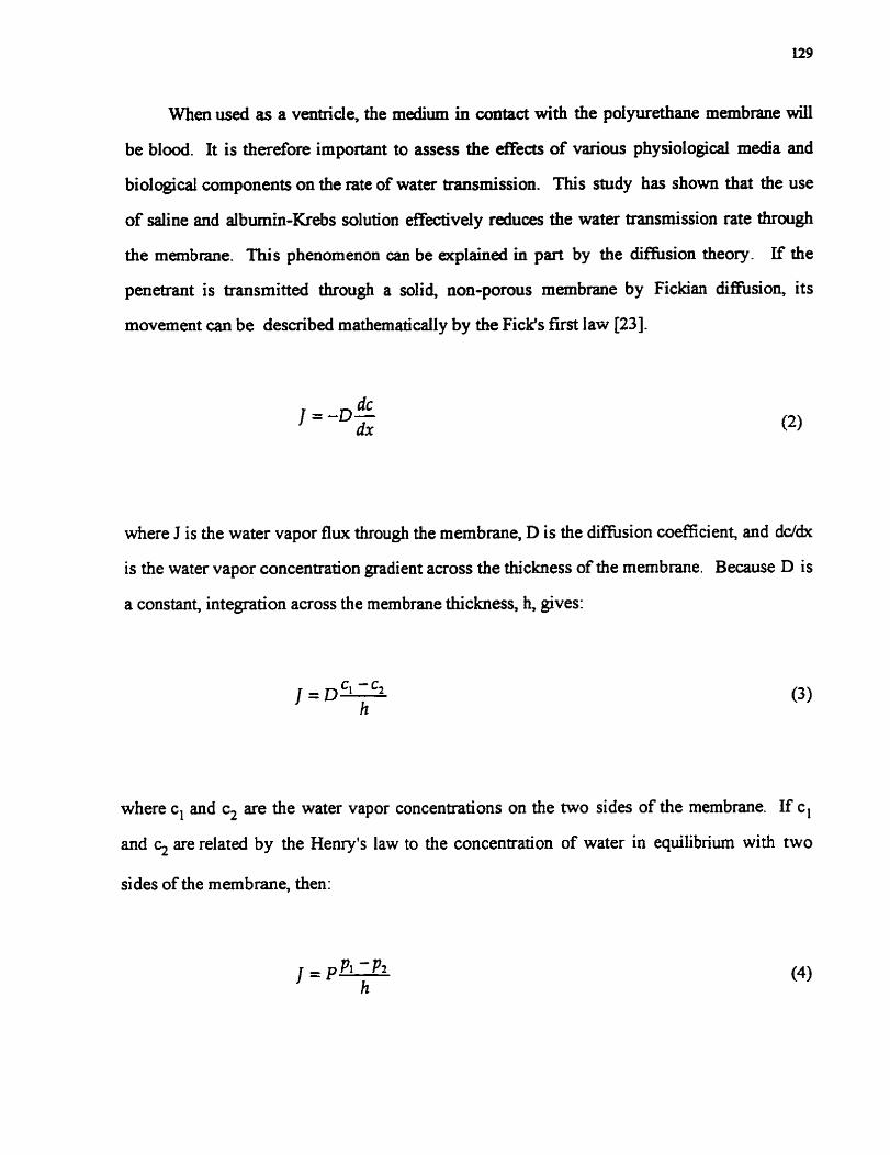
When used as a ventricle, the medium in contact with the polyurethane membrane wiU
be blood. It is therefore important to assess the effects of various physiological media and
biological components on the rate of water transmission. This study has show that the use
of saline and aibumin-Krebs solution effectively reduces the water transmission rate through
the membrane. This phenornenon can be explained in part by the diffusion theory. If the
penetmt is transmitted through a solid, non-porous membrane by Fickian diffision, its
movement can be describeci mathematically by the Ficlr's first law [23].
where J is the water vapor flux through the membrane, D is the diffision coefficient, and dddx
is the water vapor concentration gradient across the thickness of the membrane. Because D is
a constant, integration across the membrane thickness, h, gives:
where cl and c2 are the water vapor concentrations on the two sides of the membrane. If cl
and c2 are related by the Henry's law to the concentration of water in equilibrium with two
sides of the membrane, then:

where P is known as the penneability constant, namely, the product of the diffusion
coefficient and the Henry's law constant- From Equation (4). it is cIear that the rate of water
transmission through polyurethane membrane is proportional to the difference in vapor
pressure between the two sides, and is inversely proportional to the membrane thickness.
In the case of the saline and albumin-Krebs solution, the presence of nonvolatile solutes
in the test liquid l ads to a lowering of water vapor pressure at the upstream boundary of the
membrane (pl) according to the Raoult's law [30]:
where x is the mole fiaction of the solvent in solution. Consequently, it is not surprising that
the observed rates of water transmission for the two physiological media were lower than the
values for deionized water, and that the albuminaKrebs solution with its lower mole fraction of
solvent gave even lower values than saline in each case (Figure 7)
However, despite the mole fractions of the two solvents remaining constant for aii six
experiments, the observed reductions in water transport were not predictable or uniform
across all six membranes (Figure 7). There is no simple explanation for this phenomenon,
except to indicate that the absorption of proteins and ionic salts does occur rapidly at the
surface of polyurethane membranes [31], and that the extent of such absorption wiIl depend
on the type of polyurethane. Such absorption is known to result in changes in surface
hydrophilicity, in the degree of phase segmentation and in the hard segment content at the
surface, which in nini will likely influence the rate of rnoisture vapor diffusion. In conclusion,
the introduction of any biological media will decrease the rate of water transmission through a
polyurethane membrane when compared with deionized water. This conclusion will be
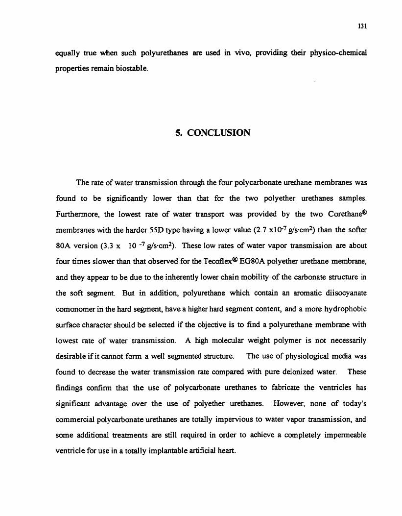
equaily tme when such polyurethanes are used in vivo, providing their physim-chemical
properties remain biostable.
5. CONCLUSION
The rate of water transmission through the four polycarbonate urethane membranes was
found to be significantly lower than that for the two polyether urethanes samples.
Furthemore, the lowest rate of water transport was provided by the two corethane@
membranes with the harder 55D type having a lower value (2.7 x10-' g/s-cm21 than the softer
80A version (3.3 x 10 -' gis-cd). These low rates of water vapor transmission are about
four times slower than that obsewed for the ~ecoflexo EGSOA polyether urethane membrane,
and they appear to be due to the inherently lower chah mobility of the carbonate structure in
the sofi segment. But in addition, polyurethane which contain an aromatic diisocyanate
wmonomer in the hard segment, have a higher hard segment content, and a more hydrophobie
surface character should be selected if the objective is to find a polyurethane membrane with
lowest rate of water transmission. A high moledar weight polyrner is not necessarily
desirable if it cannot fom a well segmented structure. The use of physiological media was
found to decrease the water transmission rate compared with pure deionized water. These
findings confirm that the use of polycarbonate urethanes to fabricate the ventricles has
signifiant advantage over the use of polyether urethanes. However, none of today's
commercial polycarbonate urethanes are totally impervious to water vapor transmission, and
some additional treatments are still reguired in order to achieve a completely impermeable
ventricle for use in a totally implantable artificial heart.

REFERENCE
1. Gibbons D .F. Cardiac assist Devices. In: "Cardiovascular Biomaterials" G.W.
Hasting. Ed., Springer-Vedag, New York, NY, USA, 1992, pp 185-194
2. Yeh J.T., Gordon III B. Rosenberg G. PB-PUU linear multiblock copolymer: a new
blood sac material for the Pems state artificial heart. Transactions of the 20th Annual
Meeting of the Society for Biomaterials, April 5-9, 1994, Boston, MA, USA, pp.47
3. Boretos 3. W., Pierce W. S. Segrnented polywethane: A new elastomer for biomedical
applications. Science, 158, 148 1-1482(1967)
4. Pierce W.S. Polymers in biomedicd devices: Materials for artificial heart and
circulatory assi st devi ces. In: "Polymer in Medicine and Surgery " RL. Kronenthal, 2. Oser
and E. Martin. Eds., Plenum Publishing Corp., New York, NY, USA, 1975, pp 263-285.
5 . Imachi K., Fujimasa I., Miyake H., Takido N., Nakajima M., A. Kouno, Ono T.,
Moyi Y., Nagaoka S., Kawase S., Kikuchi T., and Atsumi K. Evaluation of polyurethane sac
type pump after 232 and 288 days total artificial h a r t (TM) pumping without anticoagulant.
ASAIO Trans., 27, 118-121(1981)
6. Lyman D. J., Kwan-Gett C., Zwart H. J., Bland A., Eastwood N., Kawai J., and
Kolff W.J. The development and implantation of a polyurethane hemispherical artificid heart
ASA10 Trans., 17, 456-459(1971)
7. Phillips W.M., Pierce W.S., Rosenberg G., and Donachy J.H. The use of segmenteci
polyurethane in ventncular assist devices and adficial heart. In: "Synthetic Biomedical

Polymers: Concepts and Applications" M-Szycher, W. J. Robinson Eds., Technomic
Publishing Co. Inc., Westport, CT, USA, 1980, pp. 39-57.
8. Szycher M., Poirier V., Keiser J. Selection of materials for ventricular assist pump
development and fabrication. ASA10 Trans., 23, 1 16-126(1977)
9. Poirier V. Fabrication and tedng of flocked blood pump bladder. In: "Synthetic
Biomedical Polymers: Concepts and Applications" M-Szycher, W. I. Robinson Eds.,
Technomic Publishing Co. Inc., Westport, CT, USA, 1980, pp. 73-1 15.
10. Szycher M., McArthur W.A. Surface Fiswing of polyurethanes following in vivo
exponire. In: " Corrosion and Degradation of Implant Materials: Second Symposium, ASTM,
STP 859" A. C. Fraker, and C. D. Griffin Eds., Amencan Society for Testing and Materials,
Philadelphia, PA, 1985, pp. 308-321
11. McGee M., Szycher M., Turner S., Clay W., Trono R, Davis G, and Norman J. Use
of a composite biomerhutyl rubberhiomer materid to prevent transdiaphragmatic water
pemeation during long-term, electrically-actuated left ventr iah assi st device (LVAD)
pumping. ASAXO Trans., 26,299-303(1980)
12. McMi1linC.R. Physicaltestingofelastomersforuseincirnilatoryassist devices.
Artificial Organs 7, 78-91 (1 983)
13. Deanin RD. Structure-property relation in polyurethanes. In:" High Performance
Biomaterials: A Comprehensive Guide to Medical and Pharmaceutical Applications"
M-Szycher Ed., Technomic, Lancaster, P 4 1991, pp. 5 1-69
14. Pinchuk L. A review of the biostability and carcinogenicity of polyurethanes in the
medicine and the new generation of 'biostable' polyurethanes. J. Biomat. Sci. Polymer Edn., 6,
225-267(1994)

15. Reed A. M., Potter J. and Szycher M. A solution grade biostable polyurethane
elastomer: Chronoflex@AR. J. Biomater. Appl., 8.2 1 O-236(1994)
16. Yang M., Deng X., Laroche G, Hahn C. King M. and Guidoin R A capillary method
to measure water transmission through polyurethane membranes. ASAICI Trans., (In Press).
17. Taebell LM., Lever, MI, Caro C.G. The effect of varying albumin concentration of
the hydraulic conductivity of the rabbit cornmon carotid artery. Microvascular research, 35,
204-220(1988)
18. Zhang Z., King M. W., Guidoin R, Themen M., Pezolet M., Adnot A., Ukpabi P.,
and Vanta1 M.H. Morphological, physical and chernical waluation of the ~ascugraft@ artenal
prosthesis: Cornparison of a novel polyurethane device with other microporous structure.
Biomaterials, 15,483-50 l(l994)
19. Dillon J.G., Hughes M.K. Degradation of £ive polyurethane gastric bubbles following
in vivo use: SEC, ATR-IR and DSC studies. Biomatenais, 13,240-248(1992)
20. Abouzahr S., Wilkes G.L., and Ophir 2. Structure-property behavior of segrnented
polyether-MDI-butanediol based urethane: Effect of composition ratio. Polymer, 23(7
SUPPI), 1077- lO86(1982)
2 1. Seymour R W ., Cooper S.L. Themal analysis of polyurethane block polymers.
Macromolecules, 6,48-53(1973)
22. Reid J.S., Rosenberg G., Pierce W.S. Transmission of water through a biocompatible
polyurethane: Application to circulatory assist devices. J. Biomed. Mater. Res., 19, 1 1 8 1 -
1202(1985)
23. Meth W.R. Diffision In and Through polymers. M o r d University Press, New
York, NY, USA, 1991, pp.73-106.

24. Ward ES., and White K. A. Barrier films that breathe. Chemtezh 21 : 670676, 199 1.
25. KreveIen D. W .V. Properties of Polymers: their Correlation with Chernical Structure;
their Numerical Estimation and Prediction fiom Additive Group Contributions. Elsevier
Scientific publishing Company, Amsterdam, Netherlands, 1990, pp.74-75
26. Hergenrother R W., Wabers H.D. and Cooper SL. Efféct of hard segment chernistry
and strain on the stability of polyurethanes: In vivo biostability. Biomaterials, 13, 240-
248(1992)
27. Illinger J.L., Schneider N.S., and Karaze FE. Water vapor transport in hydrophilic
polyurethane. In: "Pemeability of Plastic Films and Coatings to Gasses, Vapors, and
Liquids" Polymer Science and Technology, Vol. 6, H.B. Hopfenberg Ed., Plenum Press, New
York, NY, US4 1974, pp. 183-196.
28. Hunke W.A., and Matheson Jr. LE. Mass Transport Properties of Co(po1yether)
polyurethane membrane II: Pemeability and sorption characteristics. J. Pham. Sci., 70, 13 13-
1318(1981)
29. Krevelen D.W.V. Properties of Polymers: their Correlatiûn with Chernical Structure;
their Numencal Estimation and Prediction fiom Additive Group Contributions. Elsevier
Scientific publishing Company, Amsterdam, Netherlands, 1990, pp. 196-197
30. Castellan G.W. Physical Chemistry Second Edition. Addison-Wesley Publishing
Company, Inc. Philippines, 197 1, pp.284-302
3 1. Zhang Z., King M. W., Guidoin R., Themen M., Doillon C., Diehi-Jones WL., and
Huebner E. In vitro exposure of a novel polyethenirethane graft to enzymes: A study of the
bio stability of the VascugraftB arterial prosthesis. Biomaterials, 1 5, 1 129-1 144(1994).

TABLE i: PEAK ASSIGNMENTS FOR FTIR SPECTU OF POLMJRETHANE MEMBRANES
Wave number (cm-l) Relative ~ss i~nment f '
A B C D E F intensity*
3317 3314 3302 3327 3335 3328 W v(N-H),H-bond
2934 2938 2927 2939 2938 2939 M va(GH) in CH2
2854 2855 2857 2863 2863 2861 S va or vo(GH) in CH2
2797 2797 - - - - - - O - W va(GH) in CH2
1716 1730 1737 1740 1738 1739 S v ( M ) urethane amide 1,nonbonded
1699 1703 1721 - - - - 1701 S 8 s h v(Ca) urethane amide I,H-bonded
- - - - - - 1637 - - - - W v(Ca) in urea
- - 1598 - - 1592 1597 1597 W v(C=C) aromatic ring
1527 1531 1518 1530 1529 1529 S v(C-N)+G(N-H) âmidell
1446 1447 1464 1463 1469 1468 M 6(GH) in CH2
- - 1413 - - - - 1412 1413 S v(C-C) aromatic ring
1368 1368 1366 - - a - - - M o(GH) in CH2
1319 1310 1316 - - 1309 1308 S v(C-N)+G(N-H) amide11 l
- - - 1249 1249 1250 1252 VS v(0-GO) in carbonate
1229 1221 - - - - 1223 1228 VS v(C-N)+6(N-H)
1106 1106 1100 1113 1112 1 1 1 1 VSorS va(C-O-C) aliphatic ether
1053 1083 1042 1065 1065 1078 VSorS vd(O=C-O)
1014 1018 - - 1018 1018 1018 S 6(GH) in plane,aromatic ring+vo(C-O-Z!
- - - - 955 956 955 960 S va(O-GO) in carbonate
- - 816 - - - - - - - O S o(C-H) arorna!ic ring
- - - - 791 791 791 791 S u(0-CO-O)
- - - - 729 730 730 732 W p(CH2) in (CH2)6
A: ~ecoflexa EGIOA. B: ~ecothane@ TT-1074A- C: carbothane@ PC3570A- D: ~hronoflex@ AR. E: corethane@ 8 0 k F: corethane@ 55D.
* Relative intensity based on specimens rneasured at the room remperatm: W=weak; M=medium; S=strong; VS=very strong; sh=shoulder.
i v=stretching; va=asymmenic stretching; vesymmetic stretching; kbending; wwagging y=out-of-plane bending; p=in-plane bending or rocking.

TABLE 2: THE CHEMICAL COMPûS~ONS OF POLYUEEWM MEMBRANES
Trade name Shore hardness Soft-segment Hard-segment Extender
Tecoflex EG80A PTMEG HMDf BD Tecothane TT- 1 074A PTMEG MD1 BD Carbo thane PC3570A Polycarbonate HMDI BD
glycol Chronoflex Polycarbonate MDI EDA,
glycol DAMAUSoln Core thane 80A PHECD MD1 BD Co re thane 55D PHECD MDI BD
PIUEG: Polyteuamechylene ether glycol. HMDI: Hydrogenated methylene düsocyanare. MDI: Methylene düsocyanate. PHECD: Poly (1.6-hexyl 1.2-ethyl carbonate) dioL BD: 1.4-B utanediol. EDA: Eth ylene diamine. DAMCH: Diaminoc yclo hexane.

TABLE 3: THE RESULTS OF DSC MEASUREMENTS ON THE POLYURE- M E M B M S *
Trade name Tg ('cl Tl ('Cl T2 ( O c ) Tmh (Oc) ~ecoflex@ EGSOA -70.4 81.1 -- -- ~ecothanem T ï - 1 074A -5 i -O 62.0 96.8 --
carbothane@ PC3570A -28.9 80.3 98.5 -- ~hronoflex@ AR -34.3 78.3 -- -- corethane@ 80A -17.8 60.7 88.1 -- corethane@ 55D -13.9 64.7 88.1 178.3
* Tg: G l a s transition temperature of soft segrnenr Tmh: Melting temperature of hard segments.

Figun: 1 A: Cniss-scctianal scanning eltictron photumicrographs of the two cast polyethrr
unrthane membranes. A: ~ e c o f l o x @ EG80A. B: ~eçolhane@ TT- 107-lA.

Figure lB: Cross-scctiond scanning rlectron photomi~rugr~phs of the two cast polycarbonatc
urethanr. membranes. A: ~lirbothanct@ PC3570A. B: ~hronot lex@ AR.

Figure LC: Cross-seccional scming elrctron photomicrographs of the two cast polycarbontite
urerhanc membranes. A: corethane@ 80A. B: corethane@ 55D.

Teco thane@ TT- 1 O74A
Air side
Figure 2: Average contact angle results of six polyurethane membranes.

Figure 3: FTIR spectra of six po1yurethane membranes.

Figure 4: DSC thermograms of six polyurethane membranes.

Figure 5: Number average and weight average weights of six polyurethane membranes.

Transient phase Steady ph=/
Figure 6: Displacement of the air bubble in the capiUary flowmeter against tirne for the six polyurethane membranes. Pressure: 200 mmHg. Air flow rate: SLlmin. Liquid: deionized water.

Figure 7: Water transmission rates of the six polyurethane membranes when exposed to deionized water, saline and albumin-Krebs solution.

Figure 8: Relationship between the water transmission rates of the six polyurethane membranes and their g las transition temperature.

CHAPTER FOUR
ASSESSING THE RESISTANCE OF POLYURETHANES TO CALCIFICATION FOR THE MAMJF'ACTURE OF DURABLE
VENTRICLES IN A TOTALLY IMPLANTABLE ARTIFICLAL HEAlRT

Les ventricules fabriqués en polyither Uféfharies sont des biomatériaux fkéquemment
associés à la calcification La propagation de cette caicincation sur le ventricule entraîne un
durcissement et une fragilité accrus du matenel ventnailaire qui sont nuisibles au
fonctionnement nomal du ventricule et qui peuvent conduire à son échec à court terme.
Comme il n' existe actuellement aucune méthode valable pour prévenir la calcincxtion, une
solution envisageable consiste donc à choisir des matériaux avec un faible potentiel intrinsèque
de calcification pour la fabncation des ventricules afin de diminuer les effets de cette
calcification sur la durée de vie du ventride et d'assurer ainsi sa durabilité à long terme. Par
conséquent, il est important d'évaluer la résistance à la calcification des matériaux pouvant
entrer dans la fabrication des ventricules par un protocole approprié. Dans la présente étude,
un protocole de cdcification in vitro a été utilisé afin de déterminer l'affinité relative des six
polyuréthanes suivant à se calcifier: carbothane@ PC3 5704 ~hronoflex@ AR, oré éthane@
804 coréthane@ SSD, ~écoflexa EG80A, et écoth ha ne@ TT1074A. Les résultats
expérimentaux ont démontré que tous les polyuréthanes testés se calcifiaient après incubation
dans la solution de calcification. De plus, le degré de calcification était intimement associé à la
chimie de surface des polyuréthanes. Après 60 jours d'incubation, le écoth ha ne@ TT1074A
possédait le degré de calcification le plus élevé parmi les six polyuréthanes testés. Les deux
polymères, coréthane@ 80A et 55D, ont démontré une propension à se calcifier plus faible
que les autres polyuréthanes. Ils peuvent être considérés w m e les meilleurs candidats pour
la fabncation de ventricules dans le coeur artificiel total implantable. De plus, dans les
conditions présentes, la calcification est survenue principalement à la d a c e des
polyuréthanes testés et la majorité de la microphase n'était pas affectée. Cependant, des
modèles plus efficaces devraient être développés afin de faciliter l'évaluation de la résistance
des biomatériaux à se calcifier.

Ventricles made fiom segmented pol yether urethanes frequentl y undergo bioma?aial-
associateci calcification. This caicification renders the ventriailar materiai hard and bride,
which is devastating for the normal fuaction of a ventticle and has even led to early failure of
some devices. As no effective method is currentiy amilable to prwent biornaterials nom
calci%ng a practical solution would be to select materials with a relatively high resistance to
calcification so as to extend ventriailar durability, and ensure the long term longevity of a
manufactured ventricle. It is therefore important to evaluate, using an appropriate protocol,
the resistance to calcification of potential materials for the fabrication of ventricles. In the
present study, an in vitro calcification protocol was used to determine the resistance to
cal cifi cation, of six different pol yurethanes, narnel y, carbothane@ PC3 5 7OA, ~hronoflex@
& corethane@ 804 corethane@ 55D, ~ecothane@ EG8OA, and ~ecothane@ TT1074A.
The experimental results demonstrate that al1 of these polyurethanes became dcified during
incubation in the calcification solution. The degree of calcification was found to be associated
with the surface chemistry of the polyurethane specimens. M e r 60 days of incubation, the
~ecothane@ TT 1 OWA exhibited the stronc s t calcification among the six polyurethanes
tested. The corethane@ polymers, 80A and 55D, showed a reiatively lower propensity to
calcify, and can therefore considered as the most appropriate materials for the fabrication of
the ventricle in the totally implantable a r t i f i d heart In addition, the calcification occurred
primarily at the d a c e of the polyurethanes tested in the present study, and the bulk
microphase was not affected. Further research will be required to develop a more effetive
mode1 to assess the calcification on the inside of biomatenals.

Each year, approxhately 150,000 patients in the western world require heart
transplantation ; however, only s m e 4000 of them can receive a donor heart [l]. The
development of a totaily implantable dficial har t (TIAH) for long-tem use must be
developed to assia the rest of these patients.
One of the obstacles in the development of TIAHs for long-term use is the design and
fabrication of a durable ventncle which requires an elastomer able to withstand at l e s t 40
million cyclic deformations or flexings per year while in contact with blood [2]. Segmented
polyether urethanes (PRls) used to be thought of as relatively ideal materials because of their
superior flexure endurance, acceptable blood compati bili ty, and ease of processing [3 -81.
However, previous studies have separated that ventricles made fiom PEUs have undergone
biomaterîal-associated calcification when the implant longevit- exceeded 1 00 day s 191. The
propagation of calci fi cation on the mechanicall y active ventricle made the ventricular material
hard and brittle, which destroyed the normal function of the ventricle and even led to the early
failure of some devices. Despite the fact the mechanism of calcincation remains unclea. ; that
many ap proaches have been proposed to prevent biomaterial s fkom calci@ng [ 1 0- 1 1 1,
consequently, no effective method is available to prevent this occurrence. The pratical
solution would be to select a material with a relatively high resistance to calcification for the
fabrication of a ventricle with extended durability .
Carbothaad, ~hronoflex@, and corethane@ belong to a new generation of medical-
me polyurethanes: polycarbonate urethanes (PCUs). It is believed that the chemical-
conjugated carbonate linkages (-O-CO-O-) in the sofi segments of PCUs are less likely to be
cleaved via oxidation when compared to the ether linkages (-C-O-C-) in the soft-segments of

the PEUs in a biological environment [12-151. Preliminary studies have shown that PCUs not
only maintain excellent mechanicd properties and acceptable biocompatibility similar to those
of PEUs, but aiso have signincant advantage over the PEUs in terms of their biostability
[13,16] and imperrneability [17]. The present work wmpared the resistance to calcincation
and two PEUs using an in vitro mode1 in order to identie the most appropriate candidate for
the fabrication of the ventricle.
2. MATERXALS AND IMETHODS
2.1 Seledon of the polwrethanes
The following medical-grade polyurethanes were selected as the test materials:
carbothane@ PC3570A (Themedics Inc., Woburn, MA, U.S.A.), ~hronoflex@ AR (Cardio
Tech International-, Woburn, MA, U.S.A.), corethane@ 804 and corethane@ 55D (Corvita
Corp., Miami, FL, U.S.A.) which are PCUs, and ~ecoflexa EG8OA and ~ecothanea
lT1074A (Themedics hc.), included as PEUs. These six polyurethanes were obtained in
granular fom, with the exception of the ~hronoflexa sample which was supplied as a 20 wP/o
solution in N,N-dimethy lacetami de @MAC).
2.1 Preparation of the polyurethane membranes
The membranes to be tested were prepared by a casting technique. Except for the
~hronoflex@ AK, ten grams of granules of each polyurethane were directly dissolved in 1 O û m l
DMAc ( Regent grade, J.T. Baker Inc., Phillipsburg, NJ, U.S.A.) at room temperature for one

week to fonn a 100/0 w/v homogeneous polyurethane solution. Regarding the Chronofiex AR,
50 ml of the original solution (20%wt) were diluted to lO%w/v by adding 50 ml DMAc
solvent Approximately 30 ml of each polyurethane solution were cast onto a 12.5 cm
diameter ciradar plain glass plate. The plate was then dned for 48 hours at 70 O C on a heater
in the clan room. Subsequently, the membraues were carefiilly peeled off of the glas plate,
rnoved in a glass petri dish (1 50 mm in diameter), and dried again at 65 C under a vacuum of
125 mmHg for 48 hours. The membranes whose thickness fell within the range of 0.15-0.17
mm were selected for fkther analy sis.
2.3 Calcification solution
The calci ficati on solution was prepared using the following formulation: [ ~ a + ] = 1 3 6.8
m.M, [Cl-] = 144.5 mM, [c&] = 3.87 mM, ~ 0 ~ 2 - ] = 2.32 mM, w+] = 1.16 mM. The
solution was buffered in 50mM Tris buffer with pH=7.4 at room temperature [ 18- 191. In this
system, the calcium concentration was similar to the mean level of the calcium concentration
in a total S e m , and the ratio of Ca/P04 was 1.67, identical to hydroxyapatite (HAP).
Meanwhile, a control buffer solution with no calcium ion was prepared accurding to the
following formulation: ma+] = 136.8 mM, [CI-] = 136.8 mM, ~ 0 ~ 2 - ] = 2.32mM, [K+ ] =
1.16 m . .
In vitro calcifidon incubation
The calcification incubation was conducteci as reported by other groups [18,19]. Six
rectangular specimens 20 x 10 mm were nit fiom each polyurethane membrane. Three
specimens were put into three separate bottles, each containhg 3 0 mi of the calcification
solution. The other three specimens were treated with the control buffer solution in the same

marzner. The bottles were seded and placed in a shaker (100 revolutions/min) with water bath
at 37 OC. The specimens were inspected daily ckrring the entire period of incubation. Both
the calcification and the control b e e r solutions were refkhed every 15 days. One specirnen
of each polywethane was w ~ p ! s l from the calcification solution and control buffer solution,
respectively, every 15,30, and 60 days. The specimens were rinsed ttuee times with distilled
water to remove any residual solution and loosely attached deposits, then dned in a vacuum
oven (250 mmHg) for 48 hours at rwm temperature.
2.5 Scannina electron microscopy (SEM)
Specimens approximately 5 x 5 mm in size were cut nom the incubated ana virgin
pol yurethane specimens. The air-facing surface of each specimen was gold-wated, then
viewed under a Je01 JSM 3 5CF scanning electron microscope (JEOL, Peabody, MA, U.S.A. )
at a 15kV accekrating voltage. Furthemore, the percentages of the area occupied by the
calcium deposits on the representative SEM photomicrographs of the six polyurethane
specimens were caldateci using Adobe Photoshop 4.0 software. The total area analyzed
from each specimen was 0.32 mm? In addition, the cross-sections from the six specimens
incubated in the calcification solution for 60 days were also examinexi in order to evaluate the
calcification inside of polyurethanes.
2.6 Electron sDectroscopv for chemical analvsis (ESCA)
ESCA measurements were carried out on the air-facuig d a c e of each incubated and
virgin specimen using a Perkin-Elmer PHI mode1 5600 X-ray photoelectron spectrometer
(Eden Prairie, MN, U.S.A.). With a monochromatized AlKa as the radiation source, the X-
ray gun was operated at 15kV. The vacuum in the sample chamber was 2 x 10 -Io Torr and

the analyzer pass energy was 178 eV (survey scans) and 5.85 eV (high resolution scans). The
take-off angle was 45 degree. The CI, peak was deconvoluted by assuming the following shifts
of binding energy [20] :
CGC (backbone hydrocarbon) at the bind energy of 285 eV;
CO&-N at C g plus 1.5 f 0.1 eV; - C=O, N g C at CGC plus 3 .O f 0.1 eV; -
NSOO (methane) at C g plus 4.0 f 0.1 eV;
OC00 (carbonate) at CGC plus 5.5 f 0.1 eV.
The total surface area andyzed was 2.84 mm2.
2.7 Fourier transfom attenuated total reflectance i d k e d spectroscopy @TIR)
FTIR spectra were wllected fkom the air-facing d a c e of each incubated and virgin
specimens with a Nicolet Magna 5 50 Fourier transform infiared spectrophotometer (Ni wlet
Instrument, Madison, WI, U.S.A. ) in the ATR mode (Split Pea ATR attachmenî, Hanick
Scientific Corp., Ossining, NY, U.S.A.). One hundred scans were recorded beîween 400 and
4000 cm-' at a resolution of four wavenumbers and at an incidence angle of 45 degree.
2.8 Differential scanning calorimetry D S C )
To provide insight into the changes of the specimens in the bulk morphology, including
glas transition temperature and microphase separation structure, the incubated and virgin
specimens were tested ushg a di Eerentiai scanning dorimeter pekin-Elmer DSC-7, Perkin-

Elmer, Norwailg CT, U.S.A.). Samples weighing between 10 and 12 mg w a e run at a heating
rate of 20 'Chin from -100 O C to 250 OC under a purge with helium. Pure water and indium
were chosen to calibrate the instrument prior to measurement.
3.1 V~sual observations during the incubation
Al1 of the test specimens were found to suspend in either the calcification solution or
the control bufFer solution during the entire incubation period. At day 2, white calufic
deposits were first observed on the ~ecoflex@ EG80A specimens immersed in the
calcification solution. M e r 5 days of incubation, similar deposits appeared on the
~ecothane@ TT- 1 O74A and corethane@ 80A specimens incubated in the calcification
solution. At day 7, al1 of the specimens incubated in the calcification solution showed calcific
deposits on their surface. In contrast, no deposits were observed on the specimens incubated
in the control buffer solution.
3.2 SEM observations
The photomicrographie observations of üie virgin specimens of the six pol yurethanes
showed that al1 of the specimens had very smooth surfaces, with no visuai defects.
Representative SEM photomicrographs of each pol yurethane specimen treated by the
calcification solution at various durations are presented in Figure 1 (A-F). The plaque-like
calcific deposits were randomly distributed on the surface of these specimens, but the number

and the size of the deposits varieci according to the periods of incubation. Accding to the
resdts calculated nom the percentage areas occupied by the calcific deposits on the
representative SEM photomicrographs of the six polyurethanes (Figure 2), the two PEUs
displayed a greater at 15 days degree of calcification than did the four PCUs. The ~ecoflex@
EG8OA spechnen recordeci the highest value of the calcincaticm area at 19 %? and the four
PCUs had the lowest values in the range of 6-8 %. With the duration of incubation, the areas
with calcification on the d a c e of both the carbothane@ PC3570 and the ~hronoflex@ AR
experienced a slight increase up to 30 days, and rose sharply up to 31 % and 24 %
respectively in the last 30 days. The most highly calcified area was recorded 5y the
~ecothane@ TT1 O74A at 60 days, which went as high as 38 %, even though it displayed an
intermediate value at day 15 and the day 30 within six polyurethanes. The two corethane@
polymers accurnulated the deposits progressively; with the exception of the corethane@ 80A
at day 30 , their calcification areas were the lowest among the test specimens with values
recording only at 14 % and 16 % ; respectively after 60 days incubation. It was also observed
t!!at the deposits were quite uniformly scattered over the surface? but did not cover the entire
surface of each specimen.
At a larger mapification, the deposits on the specimens appeared in a rosene crysral
structure (Figure 3) resembling the structure of octacalcium phosphate (OCP) or HAP [18,
2 11. However, fiirther inspection of the specimens cross-sections failed to reveal any calcific
deposits, indicating that such deposits did not occur or did not migrate through the
pol yurethane membranes.
3.3 ESCA results
Table 1 gives the compositions of the major chernical elements on the air-facing surface
of the polyurethane specirnens. For the Wgin specimens (except for the carbothane@

PC3570A) three out of four PCUs revealed higher axygen percentages ranging from 23% to
25%, cornpareci to those of the two PEUs (17% and 18%). While the carbothane@ PC3570A
showed the lowest q g e n percentage (IO0%), it recordeci a 5% nitrogen content which was
significantly higher than for the othen. The ~hronoflex@ AR had a 5% silicon concentration,
which was the highest among the six polywethanes. In addition to traces of sulphur detected
on three specimens, no other minor elements were identified. Incubation in the calcification
solution resulted in new peaks at 346.6 eV and 129.9 eV which were attributed to the
presence of calcium and phosphorous elements. In contras& the specimens inaibated in the
wntrol buffer solution did not show any calcium or phosphorus. The relative percentages of
calcium on the air-facing surface of the polyurethanes specimens were measured and presented
in Figure 4. After 15 days of incubation, the calcification level was higher in the two PEU
specimens than in the four PCUs. The ~ecoflex@ EG80A showed the highest amount of
calcium at 2.3%, and the four PCUs registered the lowest values, in the 0.3-0.9% range. With
the incubation progressing to 30 days, both the corethane@ 55D and chonofleu@ AR
reported a continuous increase in the amount calcium on their surface. corethane@ 80A and
carbothane@ PC3570A did not show signifiant change. However, the calcium on the two
PEUs unexpectedly decreaseù. This decrease might have been causeci by the agitation in the
rinsing process. In the last 30 days, al1 of the test specimens rwealed an inaease in the
amount calcium on their s h c e . nie ~ecothane@ TT10744 ~hronoflex@ AR, and
carbothane@ PC3570A d b i t e d a marked increase. At the end of the expenment, the
~ecothanem TT1074A specimen recorded the highest value at 7.2%, followed by the
~hronoflex@ AR and Carbothane 3570A at 4.3% and 2.9%, respectively. The corethane@
80A registered the lowea calcium level at 0.9% .
In the specimens treated by the control bufFer solution, the ~ecoflexa EG80A showed
an initiai increase in the amount of the oxygen atoms (O) fiom 17% to 21%, then remaineci
constant. The ~ecothane@ TT1 O74A and carbothane@ PC3 57OA recorded a steady inaease
of oxygen with incubation time. The rea of the polyurethanes showed no significant changes

in oxygen content. ki cornparison, a constant inmase of axygen was observed in d of the
cal&ed specirnens. As for the nitrogen content, most of the specimens treated with the
control buffer solution remained unchanged or showed a slight increase, except for the
~ e w t h a n e a 'IT1074A in which the lwel of nimgen dropped afkr incubation in the control
buffer solution. AU of the specimens treated with the calcincation solution rezorded mixed
changes in nitrogen content.
The high-resolution scans of the carbon 1s (Cls) spectra were decornposed through
me-fitting, and the results are nimmarized in Table 2. In general, the specimens showed
shifts, with respect to the peak due to CGC at 285 eV, of 1.5 t 0.1 and 5.5 + 0.1 eV,
wrresponding to the ether and carbonate groups in the soft segments [22], and a 4.3 f 0.1 eV
shift from the urethane groups in the hard segments [20]. The exception was the
carbothane@ PC3570A: although showing no urethane peak, it recordeci a shift at 3.0 f 0.1
eV assignai to the amide groups. In addition, a small peak with a shift between 2.5 and 3.0 eV
was found in the two PEUs incubated specimens.
The changes in the percentages of the soft and hard segments on the air-facing surface of
the specimens treated with the control buffer solution are presented in Figures 5 and 6. Of the
virgin specimens, two PEU, the ~ecoflexa EGSOA had a higher ether and lower urethane
percentages over the ~ecothane@ TT1074A. Following incubation in the control buffer
solution, the ether contents of the two PEUs decreased and eventually reached the same level
(Figure 5). In the meantirne, the urethane groups at the suface of the ~ecothanea TTl074A
specimen decreased slightly, and the ~ecoflex@ EG80A recordeci an increased urethane
percentage towards the end of the aiai. The PCUs (except for the carbothane@ PC3570A)
are Bdiibited a decrease in the carbonate soft segments and enrichment in the urethane hard
segments on their surface with the duration of the incubation (Figure 6). The two corethane@
specimens showed higher carbonate and urethane percentages over the ~hronoflex@ AR
throughout the experiment. In addition, it is of interesting to note the convergence of the data

in Figures 5 and 6 (e-g. the ether groups of the two PEUs, and the carbonate and urethane
groups of the three PCUs following incubation in the control buffer solution).
The carbothane@ PC3570A adiihited a surface simila- to that of the polyurethane-
based specimen on the poly(ether amides). The ether groups were very low on the surfâce of
the Wgin specimen, but increased sharply accdïng to the duration of incubation in the
cuntrol bufFer solution (Figure 7). The amide groups, with a higher d a c e concentration mer
the urethane groups of the other polyurethanes, increased at 15 and 30 days but dropped
below the Wgin specimen's value at 60 days (Figure 7).
3.4 FTIR results
The spectra of the six specimens of virgin polyurethanes were similar to those published
in a previous study [17]. The PCUs registered cornmon absorptions at 1737, 125 1, 956, and
791 cm-', attributed to the carbonate groups in the sofi segments [20, 23-24]. In cornparison,
the two PEUs showed a very strong absorption at 1106 c d , indicating the presence of ether
linkages 1251. As for the spectra of the two corethane@ polymers, ~hronoflex@ AR and
~ecothane@ TT10744 the absorptions at 1596 and 1018 cm-1- respectively confinned the
aromatic features in their hard segments. Both the carbothane@ PC3570A and ~ecoflex@
EG804 composed by aliphatic diisocyanate, showed no aromatic-related absorptions. Only
the ~hronoflex@ AR exhibited an absorption at 1646 cmg1, indicating the presence of urea
linkages resulting fiom the use of diamine as the chain extender. Diols were used as the chah
extenders for the rest of the polyurethanes.
With the duration of incubation in the calcification solution, three bands gradually
emerged at 1029,602, and 562 cm-1 of the spectra of the specimens tested. These new bands
evidenced the presence ofthe calcific deposits on the surface of the specimens [26-271. Mer
15 days, only the ~ecoflexe EG80A specimen exhibited detectable bands at 603, and

562 cm-1. Mer 30 days of incubation, the ~ecothanea TT10744 and the two ~oreth.ane@
specimens also showed absoqtions at 603 and 562 c d . mer 60 days, distinct peaks were
noticed at 603 and 562 cm-1 auised by the calcification in ail of the specimens exposed to the
calafication solution (Figure 8). Arnong the six polyurethanes, the ~ecothanem TT1074A
remrded the strongest absorption peaks at 603 and 562 cm-1, followed by the carbothane@
PC3570A and the ~hronoflex@ AR. The absorption intensity at 603 and 562 cm-1 was
sigmflcantly lower for the two corethane@ and ~ e d e x @ EG80A specimens than for the
polyurethanes mentioned above.
The effects of incubation on the hard segment/soA segment ratio of polyurethane were
studied by calcdating the ratio of peak height of 1524 to 1249 cmo= for the PCUs treated with
the control b a e r solution and 1527 to 1 1 O6 cm-1 for the PEUs (Figure 9). With the duration
of incubation, the four PCUs remained constant or showed a slight increase in the ratio of the
hard to sofi segments. The ratios for the two PEU specirnens revealed a drop after 15 days of
incubation, then gradua11 y increased with the duration of incubation.
3.5 DSC results
DSC results are presented in Table 3, showing that the Wgin PCUs had higher glass
transition temperatures (Tg) than did the two PEUs, with a range h m -34 to -1 1 OC. In
cornparison, the Tg's for the two PEUs recorded at -75 and -52 O C . All six virgin specimens
displayed an endotherm in the range of 64 to 86 OC (Tl), associated with the short-range
ordering in the hard-segment domains [28-291. The corethane@ exhibited an endotherm at
144 OC (Tz), which was probably relevant to the long-range ordering in hard-segment domains.
Only the corethane@ showed a relatively strong melting endothem at 176 OC (Tm),
suggesting the presence of well-defined, hard-segment ordering [28-291. In cornparison with
the virgin specimens, the pol yurethane specimens incubated in the cal ci fi cation solution

recorded an increase in both Tg and Tl. The mdothamic peak at 144 OC (7'2) of the
corethane@ 80A specimens broke into two mal1 endothemis (T3 and T4) at 124 and 162 OC
respectively. A slight increase of the endothexm at 176 OC (Tm) was observed on the
corethane@ 55D specimens. Sunilar changes in Tg and Tl were also observed on the
specimens treated with the buKer control solution; however the increment was less h m than
for the specimens treated with the calcification solution.
4. DISCUSSION
4.1 Validation of the experimental mode1
Due to the complexity of the problem of calcification in vivo, it is important to apply
the appropriate protocol capable of modeling the effects of various factors on the calcification
process. Costly and timeconsuming a n i d models have thus far been unsuccessful in
providing detailed and reliable information on the role of each of the various parameters
involved [18,Z 11. In contrast, in vitro models have many advantages such as well-controlled
expenmental conditions, relative ease in interpretation of results, good repeatability, and low
cost, which make them suitable for detailed investigations on specific factors involved in
cal cification [3 O]. In earl y studies, heparinized bovine plasma and buffered salt solution
containing Ca2+ and ~ 0 ~ 3 - were used as the calcification solutions to study the effects of
calcification on the mechanical propertïes of pol yurethanes [3 0-3 11. However the data failed
to show any signifiant ditference between the specimens treated with the calcification
solution and the controls, because the calcification capacity of these solutions was
unsatisfactory. In a recent study, it was proven that a calcification solution containing 3.87

mM calcium and 2.32 mM phosphate, yielding a ratio of CalPo4 = 1.67 (as in hydroxyapatite
(HAP)), signifimtly enhanceci the calcification capacity of biomaterials [18]. An accelaated
calcification solution (ACS) to study the caiüfic capacity of biomataials was developed by
Liu et al. [19].
In the present study, a calcification solution similar to ACS was used to assess the
cdcific capacity of various polyurethanes. The results showed that the calcincation solution
was able to calciS. all of the polyurethane specimens within a relatively short incubation
period (60 days). Both SEM and ESCA techniques were used to analyze the calcification
level on the surface of the polyurethanes in this protocol, providing a new approach for
studying the calcification of polyurethanes. However, ESCA is known to be limited by both
the sarnple depth that is smaller than the dimension of the large caicific deposits, and the
"shadow effect" which rnay shield some deposits under the shadow being analyzed. SEM, on
the other hanci, is Iirnited to morphological changes. Because of these limitations, the
measurement results may not exactly reflect die absolute uptake of the calbfic deposits at the
surface. In fact, the degree of calcification of the six polyurethanes measured by SEM (Figure
2) was not completely in agreement in that measured by ESCA (Figure 4), which rnay the
result of these limited meanirement techniques. Despite ail this, the meanirement results
from this study still clearly exhibit the differences of the polyurethanes in their propensity for
calcification. This protocol can therefore be used as a pre-screening method to select potential
materials for the fabrication of ventricles in a TIAH.
4.2 The calcific capacity of the six polyurethanes
In the development of a TIAH, the ventricl es are required to undergo at least 40 million
cyclic deformations or flexings per year while in contact with blood. The material used to
fabricate the ventrides must MM several fùndamental requirements ; namely, they must

display a stable chernicd structure, good flexure endurance and blood wmpatibility, as weli as
impenneability [32]. In the last decade, many commercialiy wailable elastomers have been
tested as potential candidates for this application but have fàiled due to their poor blood
wmpatibility, pwr processability, inadequate fatigue life, or a combination of the three. Only
segmented polyether urethanes such as ~iomer@, pellethane@, ~ec~f lex@ etc. and ~ e x s ~ n @ ,
a polyolefin rubber, have achieved some success in this field [8]. However, several recent
studi es indicated that ventri cles made f?om segmentecl pol y ether urethanes underwent
biomaterial-associated calcification when the implantation exceeded 1 00 day s [9, 3 3 -341. As
the mechanisns of calcincation remain obscure, no effective therapy has been found to
prevent material fiom calcification. Long-terni dumbility of the ventricles relies only on those
matenais that display a relatively high resistance to aicification. Therefore, the cdcific
capacity of candidate materials m u t be determined by the appropriate protocol.
The resulu of the ESCA and SEM analyses demonstrate that al1 of the test
pol y urethanes becarne calcified after calcification incubation; however, the degree of
calcification on these polyurethanes differed significantly. After 15 days, the two PEUs
exhibited a higher lwel of calcification than did the four PCUs, which suggests that the PEUs
may have a stronger propensity to calci@ at the initid phase of calcification. During the
calcific incubation, the ~ecothanea TT1074A sarnple showed a sharp increase in the
dcification lwel during the laa 30 days, as did the two PCUs, carbothane@ PC3 S7OA and
~hronoflex@ AR. At 60 days, ~ecothane@ TT10744 an aromatic PEU, exhibited the
strongest pro pensi ty to calcify. Both carbothane@ PC3 5 7OA and c hronoflex@ AR
registered a level of calcification which exceeded or was similar to that reported by the
~ecoflex@ EG8OA, but which was lower than for the ~ecothane@ TT 1 OXA. The two
corethane@ polymers showed a lower level of calcification in contras to the other
polyurethanes. From this study, the two corethane@ polymers can therefore be considered
as the most appropriate materials for the fabrication of ventricles, aithough additional
treamient to prevent calcification may still be required.

4.3 The role of the surface chemistrv in polyurethane calcification
For many years, calcification has been an issue of conceni in the long-terni viability of
ventricles[3 5-3 61. Many theuries regarding pol yurethane calcin cation centered on c d -
mediated extrinsic calcification, which depends on the contribution nom the material surface
rnorphology, including surface imperfection and chemistry [37]. S u r f " defects are thought
to create sites for the entrapment of thrombi [9] which promote serves as a nidus invite for
the formation of cdcific deposits. However, other studies have shown that plaques of calcium
deposits cm form on smooth surfaces, while nearby defects show no calcification [38].
Furthemore, the calcification has also been seen to form in the deep layer of the polyurethane
blood pump without cellular involvement [34,39]. These hdings suggest that calcification
may not require a cellular component but rather OCCLUS through the interactions between the
polymer backbone and the ionic blood components, particularly calcium and phosphate. It
has been hypothesized that the soft segment of polyurethane provides bhding sites for the
fornation of calcific nuclei [4041]. In a suitable environment, the cd&c nuclei may grow
leading to formation of calcific deposits. Our shidy supports such a hypothesis. Al1 of the
specimens in the present study, displayed a very smooth surface microscopically and were
treated under the same experimental conditions. Thus, the difference in calcific capacity of
these polyurethanes is believed to be the result of the surface inherent chemicd properties.
The chemicai composition in soi3 segments rnay play a criticai role in the calcification of
polyurethanes. Afier 15 days, the four PCUs exhibitecl a relatively lower level of
calcification, in contrast to the two PEUs, which may result from the different chemical
composition of the soft segments in how they attract calcium ions. In a cornparison of the
carbonate with ether group contributions to the solubility parameter of polymers, 6, the
carbonate group value of 44.1 Jin / cm 2'3 was found to be significantly lower than for the
ether group, at 79.4 J'n 1 cm [42]. Therefore, wbile it is assumed that the carbonate

groups, as affinity sites for calcium ions, were not as strong as the ether groups, the
calcification level of PCUs was thereby lower relative to P N s . On the other hand, the soft-
segment surface wncenIation may also affect the calcification level of polyurethanes. At the
initial calcification phase (1 5 days), the ~ecoflexm EG 80A (containhg a higher ether group
percentage at the surface) registered a higher calcification level than did the ~ecothane@
TT1 074 A (Figure 5). Likewise, the corethane@ 80A with a higher carbonate group at the
d a c e (Figure 6), exhibiteci a higher calcific degree over the corethane@ 55D and
~hronoflex@ AR specimens tested.
However, with the duration of incubation, the calcification level of the polyurethanes
appeared not be Lùiked to the chexnical composition and d a c e concentration of the sofl
segments. During the last 30 days, the ~ecothane@ TT1074A specirnen showed a sharp
increase in the cal cification level, while the sofi-segment concentration increased only slighti y.
Meanwhile, the calcification levels for both the ~hronoflex@ AR and corethane@ 5 5D ais0
increased, in contrast to the soft-segment concentration on their surface which had demeased.
As the urethane groups of these t h e polymers were found to be enriched on their d a c e
during the corresponding pend, one plausible expl ana tion is that the hard segment of these
polyurethanes may aiso be partly involved in the calcification process. This can be inferred
theoreticdl y by comparing the urethane with carbonate group contributions to the solubility
parameter of polymers, 6. Aithough the carbonate group value of 44.1 J'n / cm 213 was
significantly lower than the ether value (79.4 J I R 1 cm ), it remaineci higher than the
urethane ( 35.1 Jin / cm 2") 1421 in its affinity for calcium. Thus, it is assurned that the
urethane groups can aiso attract calcium similar to the other groups, resulting in increased
calcification on the surface. Nevertheless, as the increase of the urethane groups on the
d a c e of ~ecothanea TT1074 A and chronoflex@ AR was very marginal, it still cannot
completely explain why these two polyurethanes registered a sharp increase in the
calcification lwel during the last 30 days. As the ~hronoflex@ AR was reportai to use
diamine as a chain extender, the increased presence of nitrogen to create urea rather than

urethane links rnay also renilt in an increase in preferentially available calcium-binding sites,
yielding a hi& level of calcification 1461.
carbothane@ PC3570A is a polycarbonate urethane with polyether amide as its d a c e
chemistry. The percentage of ether groups on the surface was much lower than for the other
polyurethanes, despite the fact that than it increesed dramaticaily dunng the incubation. Also,
the content of its amide linkage was sipiflcant higher than the urethane linkage content of the
other polyurethanes. Among the six polyurethanes, the ~arb&ane@ PC3 SîOA recorded the
highest percentage of C-C-C stnicture as well as low microphase separation nmilar to that of
the ~hronoflex@ AR and the two PEUs. With regard to calcitication l e d , the carbothane@
PC3570A was the lowest at 15 and 30 days. However, this low level of calcification
increased dramatically in the last 30 days to becorne the second highea level measured b y
SEM. Because the percentage of the ether groups of the carbothane@ PC3570A was dso
found to increase sharply in last 30 days the rapid increase in calcification may be related to
the enrichment of ether groups on the surface Figure 7). Lf this is tme, the low level of the
calcification in the initial period may be attributed to the lowest ether surface content and the
presence of amide rather than urethane groups.
4.4 Effects of calcification on the bulk microphase separation
Intrinsic calcification was observed in the deep layer of the PU blood pump, the
ventricles of the artificiai heart, and the PU-based conduits, which suggests that calcium ions
are able to migrate inside the polyurethanes to nucleate, resulting in the loss of flexibility of
the polyurethanes. In a previous study, some calcific deposits were observed in the cross-
sections of a non-porous polyurethane specimens that had been incubated in a calcification
solution for 30 days [18]. In the present study, the SEM microphotographie observaiions of
the cross-sections of polyurethane specimens incubated in a calcification solution for 60 days

showed no calcXc deposits on the inside the polyunzthane specimens. A themial analysis
also showed no significant diffefence in the glass transition and other e n d o t h d c
temperatures between the specimens and the controls. These results suggest that the
calcification occurred primarily on the SU£ace of the polyurethane specimens. The bulk
microphase was not affecteci. Therefore, a more effective mode1 must be developed to assess
the calcification inside of biomaterials.
5. CONCLUSION
An in vitro calcification protocol was used to determine the capacity of different
polyurethanes for calcification. This protocol was helpfid in selecoing an appropriate material
for the fabrication of a durable ventricle in a totally implantable adficial heart. The
experimentd results demonstrated that al1 of the polyurethanes tested became calcifieci under
caicification incubation. The degree of calcification was found to be linked to the Surface
chemistry of the polyurethane specirnens. M e r 60 days incubation in the calcification
solution, the ~ecothane@ TT1 074A specimen exhibited the strongest calcification arnong the
six polyurethane specimens. The two corethane@ polymers, 80A and 55D, registered a
relatively lower propensity to c a l e when compared to the other polyurethanes, and can
therefore be considered as the best candidate materials for the manufacture of the ventricle in
the totally implantable &ficial hem. In addition, the calcification occurred primarily on the
surface of the polyurethane specimens, and the bulk microphase was not affected. A more
effective mode1 must therefore be developed to assess the calcific inside response on the of
biomaterials.

1. Wkkelgren L New devices are helping transfonn coronary care. Science, 272,668-670
(1 996).
2. Gibbons D.F. Cardiac assist devices. In: "Cardiovadar Biornaterials" G.W. Hasting
Ed., Springer-Verlag, New York NY, USA 1992, pp. 185-194.
3. Pierce W.S. Polymers in biomedical devices: Materials for artificiai heart and
circulatory assist devices. In: "Polymer in Medicine and Surgery " RL. Kronenthal, 2. Oser
and E. Martin Eds., Plenum Publishing Corp., New York, NY, USA, 1975, pp. 263-285.
4. Irnachi K., Fujimasa I., Miyake H., Takido N., Nakajirna M., Kouno A., Ono T.,
Moyi Y., Nagaoka S., Kawase S., Kikuchi T., and Atsumi K. Evaluation of polyurethane sac-
type pump after 232 and 288 days total artificial h a r t (TAH) pumping without anticoagulant.
ASAIO Trans., 27, pp. 118-121 (1981).
5 . Lyman D. J., Kwan-Gett C., Zwart H. J., B lad A., Eastwood N., Kawai J., and
Kolff W.J. The development and implantation of a polyurethane hemisphencd artificial h a r t .
ASA10 Trans., 17, pp. 456-459 (1971).
6. Phillips W.M., Pierce W.S., Rosenberg G., and Donachy J.H.. The use of segmented
polyurethane in ventricular assist devices and amficial heart h: "Synthetic Biomedical
Polymer: Concepts and Applications" M-Sqcher and W. J. Robinson Eds., Technomic
Publishing Co. Inc., Westport, CT, USA, 1980, pp. 39-57.
7. Szycher M., Poirier V., Keiser J. Selection of materials for ventricular assist pump
development and fabrication. ASA10 Trans., 23, pp. 1 16- l26(1977).

8. Poirier V. Fabrication and testing of flocked blood pump bladder. In: "Synthetic
Biomedical Polymer: Concepts and Applications" M-Sycher and W. J. Robinson Eds.,
Technomic Publishing Co. hc., Westport, CT, USA, 1980, pp. 73-1 15.
9. Colman DL. Mineralization of blood pump bladder. ASAIO Trans., 27, pp. 708-
73 l(l98l).
10. PierceW.S.,DonachyJ.H.,andRosaibergG. Calcificaîioninsideartüicial hearts:
Inhibition by warfarin-sodium. Science, 208, pp. 601403 (1980).
11. ParkK.D.,LeeWX.,YunJ.Y.,IfanD.K.,KimS.K.,KimY.H.,KimH.M.,andKim
KT. Novel anti-calcification treatment of biologieal tissues by gdüng of sulphonated
poly(ethy1ene oxide). Biomaterials, 18, pp. 47-5 1 (1996).
12. Stokes K., Anderson J.M., and McVenes R Polyurethane elastomer biostability . J.
Biomater. Appl., 9, pp. 321-354 (1995).
13. Reed A.M., Potter J. and Szycher M. A solution grade-biostable polyurethane
elastomer: ~hronoflex@AR. J. Biomater. Appl., 8, pp. 2 10-236 (1 994).
14. Pinchuk L., Kato Y.P., Eckstein M.L., Wilson G.J., and MacGregor D.C.
Polycarbonateas elastomeric materials for long-term implant applications. Transaction of the
Society for Biomaterials, Vol. 17, 1994, p. 47.
15 Coury A.J., Hobot CM., Slaikeu P.C., Stokes KB., and Cahalan P.T. A new farnily
of implantable biostable polyurethanes. Transactions of the Society for Biomaterial s, Vol. 13,
1990, p. 158.
16. Pinchuk L. A review of the biostability and carcinogenicity of polyurethanes in
medicine and the new generaîion of 'biostable' polyurethanes. J. Biomater. Sci. Polymer Edn.,
6, pp. 225-267 (1994).

17. Yang M., Zhang Ze., Hahn C., Laroche G., King MW., and Guidoin R A totally
implantable a r t i f i d heart: Selecting an impermeable polycarbonate uretbane to manufachire
the ventricles. J. Biomed. Mater. Res. (Appl . Biomater.) (Accepted).
18. Golornb G., and Wagner D. Developrnent of a new in vitro mode1 for studying
implantable polyurethane calcification. Biomaterials, 12, pp. 397-405 (1991).
19. Liu Q., Weng J., De Wijin J.R, and Van Bli t ted jk C.A. A novel in vitro mode1 to
study the calcification ability of biomaterials. noceedings of the 5th Worfd Biomaterials
Congress, Toronto, Canada, May 28-June 1, 1996,1149.
20. Zhang Z., KUlg M.W., Guidoin R, Themen M., Pezolet M., Adnot A., Ukpabi P.,
and Vantal M.H. Morphological, physical and chemi cd evduation of the ~ a s c u ~ r a f l @ arterial
prosthesi s: Comparison of a novel polyurethane device with other microporous stnictures.
Biomatenak, 15, pp. 483-501(1994).
21. Kapolos J., Mawilas D., Missirlis Y., and Koutsoukos P.G. Mode1 experimental
system for investigation of heart valve calcification in vitro. J. Biomed. Mater. Res.(Appl.
Biomater.), 38, pp. 83-190 (1 997).
22. Bnggs D., and Beamson G. PrimaIy and secondary oxygen-induced Cls binding
energy shihs in X-ray photoeiectron spectroscopy of polymers. Anal. Chem., 64, pp. 1729-
1736 (1992).
23. Dillon J.G. Infiared Spectroscopie Altas of Polyurethanes. Technomic, Lancaster,
PA, USA, 1989.
24. Mathur A.B., Collier T.O., Kao W.J., Wiggins M., Schubert M.A., Hiltner A., and
Anderson J.M. In vivo biocompatibility and biostability of modified polyurethanes. J.
Biomed. Mater. Res., 36, pp. 246-257 (1997).

25. Dillon J.G., and Hughes MX. Depidation of five polyurethane gashic bubbles
following in vivo use: SEC, ATR-IR and DSC studies. Biomaterials, 13, pp. 240-248 (1992).
26. Gadsdeo J.A Infrared Spectra of Minerals and Related Inorganic Compounds.
Butterworth, MA, USA., 1975.
27. Behman I., and Bo&eld W. Charactenzation of hydroxyapatite and carbonated
apatite by photo acoustic FTlR spectroscopy. J. Mater. Sa. (Mater. in Med.), 8, pp. 1-4
(1997).
28. HeskethT.R,VanBogartJ.W.C.,andCooperSL. Differentialscanningcalonmetry
analysis of morphological changes in segment elastomer. Polym. Eng Sci., 20, 190- 197
(1 980).
29. Abouzahr S., Wilkes G.L., and Ophir 2. Srnichire-propew behavior of segmented
polyether-MDI-butanediol-based urethanes: Effect of composition ratio. Polymer,
23(Suppl.), pp. 1077-1086 (1982).
30. Fisher A.C., Bemaaa. G.M., Mackay T.G., Dimitri W R , Wilkinson R., and
Wheatley D.J. Calcification modeling in artificial hart valves. Int. J. Artif. Org., 15, pp. 284-
288 (1992).
3 1. Glasmacher-Seiler B., Erens B., Doersch M., Red H., Rau G., Wick G., and Pietsch H.
Testing of some polyurethanes for calcification and biodegradation: an in vitro snidy . In:
"Chical Implant Matenals", G. Heimke, U. Soltésq and A.J.C. Lee Eds., Advances in
Biomaterial s, Vol. 9, Elsevier Science Publishers B.V., Amsterdam, Netherlands 1990, p p .
105-1 10.
32. Yeh J. T., Gordon III B., and Rosenberg G. PIB-PUU linear multiblock copolymer: A
new blood sac materiai for the Penn State artificial hem. Transactions of The Society for
Biomaterids Vol. 17, 1994, p. 47.

33. Nosé Y., Harasaki H, and Murray J. Mineralization of artifïcial surfaces that contact
blood. ASA10 Trans., 27, pp. 714-719 (1981).
34. H&dH.,GemtyR,KiralyR,JacobsG. ,and NoséY. Cald ica t ion inb ld
pumps. ASAIû Trans., 25, pp. 305-310 (1979).
35. Schoen F.J., Harasaki H., Kim KM., Anderson H.C., and Levy R.J. Biomaterial-
associated calcification: Pathology mechanism, and strategies for prevention. J. Biomed.
Mater. Res., 22, pp. 11-36 (1988).
36. Bmck S.D. Calcification of matends in bloodcontacting implants. Iat. J. Artif- ûrg.,
8,65-68 (1985).
3 7. Thorna R J. Pol y (ether)urethane reactivity with metal ion calcification and
environmental stress cracking. J. Biomater. Appl., 1,449-486 (1 987).
38. Singh PI., Cumming R.D., Ledexman D.M., and Lian J.B. Mechanicd etiology of
calcification. National H e a ~ Lung, and Blood Institute, Contractors Meeting Program, 1983,
p. 158.
39. Cumming RD., Snow J.L., Sin& P.I., Romero LH., Harpster N.K., and Lian J.B.
Mechanical etiology of calcification. National Heart, h g , and Blood Institute, Contractors
Meeting Prograrn, 1985, p. 104.
40. Phillip RE., and Thoma RJ. Metal ion complexation of polyurethane: A proposed
mechanism for calcification. In:" Polyurethanes in Biomedical Engineering II", H. Planclq 1.
Syré, M. Damer, and G. Egbers Eds., Elsevier Science Publishers B.V., Amsterdam,
Netherlands, 1987, pp. 91 -1 07.

4 1. Thoma RL, Hmg T.Q., Nyilas E, Phillips RE. Metal ion-enhanced environmental
stress cracking of poly(ether)uretfianes. Transactions of The Society for Biomaterials Vol. 9,
1986, p. 47.
42. Krevelen D.W.V. Properties of Polymers: their Correlation with Chernical Stmcture;
Their Numeri cal Estimation and Rediction from Additive Group Contri butions. Elsevier
Scientific publishing Company, Amsterdam, Netherlands, 1990, pp. 2 1 5-2 1 7.

TABLE 1: S W A C E ELEMENTAL COMPOSITIONS OF THE INCUBATED POL- SPECMENS
incubation Specimens Ç N 4 C a P S N a Q
(days) Tecoflex Virgin 81.0 1.1 17.4
Buffer
Teco thane Calcification
B uffer
Carbo thane Calfication
Control
Chronoflex Caldication
B uffer
Corethane80A Calcification
CorethaneSSD Calcification
B uffer
1s 30 60 15 30 60
Virgin 15 30 60 15 30 60
vugin 15 30 60 15 30 60
Virgin 15 30 60 15 30 60
vitgin 15 30 60 15 30 60
Virgin 15 30 60 15 30

TABLE 2: CONTRIBUTIONS OF CHEMlCAL GROUPS TO C IS SPECTRA OF THE INCUBATED POLYURETHANE SPECIMENS
Incu baaon CÇoc Specimens periods CGC 0 or Wm
(days) mm
Tecoflex Virgin 6 1.3 38.3 O -4 NÇoc
Calcification
Buffer
Tecothane Calcification
Buffer
Carbo thane Carbo thane Calcification
Chronofl ex Calcification
B uffer
Corethane80A Calcification
B uffer
Core thane55D Calcification
B uffer
Virgin 15 30 60 15 30 60
Virgin Virgin*
15 30 60 15 30 60
Visgin 15 30 60 15 30 60
Virgin 15
Virgin 1s
* C 1s spectra at the surface of inside of the Carbothane granule.

TABLE 3: PFULTS OF DSC MEASUREMENTS ON THE INCUBATED POLYURETHANE SPECIMENS
Incubation
B uf fer
Carbothane Calc&ation
Control
Cbronoflex Calcification
Buffer
Corethane80A Calcification
Buffer
Corethane55D Calcification
Buffer
30 60 1s 30 60
Virgin 15 30 60 15 30 60
VUgin 15 30 60 15 30 60
virgin 15 30 60 15 30 60
Virgin 15 30 60 15 30 60
virpin 15 30 60 15 30


-C Tecoflex EG80A - + Tecothane Tr1074
Carbothane PC3570A + Chronoflex AR
- + Corethane 80A + Corethane 55D
10 20 30 40 50 60 70
Incubation Time (days)
Figure 2: Percentages of the caicific areas at the air-facing surfaces of the six polyurethanes as measured by SEM.

Figure 3: The crystal structure of the calciîïc deposits at the surfaces of polyurethanes.

- -
+ Tecoflex
+ Tecothane
+ Carbothane
+ Chronoflex
+ CorethanesOA
4- CorethanPcSD
Incubation period (days)
Figure 4: Relative amount of calcium at the air-facing surfaces of the six polyurethanes as measured by ESCA.

+ Tecoflex EG80A + Tecothane TT1 074A -
-
-
Urethane
I O 20 30 40 50 60 70
Time of Incubation (Days)
Figure 5: Changes in the ether and urethane groups at the air-facing surfaces of the two
polyether urethanes.

- -C Chronoflex AR -it- Corethane 80A
- -I- Corethane 55D
-
-
O 1 O 20 30 40 50 60 70
Time of lncu bation (Days)
Figure 6: Changes in the carbonate and urethane groups at the air-facing surfaces of the t h ~ e
polycarbonate urethanes.

Carbothane PC3570A
- + Ether + Amide
-
-
-
I I I I I I I
O 10 20 30 40 50 60 70
Time of Incubation (Days)
Figure 7: Changes in the ether and amide groups at the air-facing surfaces of the carbothane@ PC3570A.

Figure 8: ATR-FiIR spectra on the air-facing surfaces of the six polyurethanes treated by
the calcification solution for 60 days.

+ Tecoflex + Chronoflex
+ Tecohue + Corethane80A
+ Carbothane 4 Corethane55D
Incubation penod (days)
Figure 9: Changes of the ratio of the hard to sofi segments at the air fachg surfaces of the six polyurethanes.

GENERAL CONCLUSIONS

To date, various forms of cardiwascular devices have been extensively used part of the
therapy to provide iifè-aving assistance to patients with cardiovascular di seases.
Biomaterials form the basis for the wmtmction of these cardiovascuiar devices. The
performance and safety of the devices rely to a great extent on the hdamental properties of
the chosen materiais. As polyurethanes have an important role in the fabrication of
cardiovadar devices, it is of great interest to investigate the fiindamental properties of
various polyurethanes in tems of the requirements of the cardiovasailar devices in vivo.
The intraaortic balioon counterpulsation device (IAB) is a tmnsient cardiovasdar
device used in the treatment of patients suffering with critical cardiogenic shock, left
ventricular failure, and low output syndrome, and as an aid in weaning patients off of the
cardiopulmonary bypass. The IABs are made fkom either polyester urethanes or polyether
urethanes. Because of the rising a s t s of health care during the past 10 years, remhg various
disposable diagnostic and therapeutic devices in hospitais has become conventional, despite
the fact that many devices were manufactured for single use only. The practice of reusing
di sposable medical devices has aroused inaeasing wncems regarding the additional risks t O
the patients including infdon , pyrogenic reaction, toxicity , particdate contamination,
biocompati bility , and device breakage.
In this study, the possibility of reusing IABs was systernatically investigated with
regard to their physical, mechanical, and chemical properties, in cornparison with new devices.
The results revealed that despite the fact that these used IABs experienced more than 100,000
inflation and defiation cycles in vivo, no deterioration of the balloon materials was recorded in
tems of their mechanicd properties, surface chemistq, and bulk physical properties to

siBnif~cantly affect the proper fiinctionality of these reârieved balloons. Although some
d a c e modifications ocairred on the internai side of the balloons, the extenial surfaces of
most b d w n s d e r e d no trauma. The durable life of the IABs is high enough to raider them
acceptable for M e r clinical use on a short-terni basis. However, the presence of residual
organic debns which cannot be eliminated without altering the integrity of the IABs appears
to be an imperative preclusion against reuse. Complete prevention of the accumulation of
these debris would warrant a different design of the IABs, a highly unlikely development in
the predictable future. Therefore, the rase of IABs cannot be recommended unless it is
possible to establish a rigorous protocol of deaning. sterilization, and inspection to guarantee
d e reuse of these devices.
A critical component of the totally implantable ahficial hart is the polyrneric ventricle
that allows blood to circulate as a result of reciprocating compressive and expansive
movement. To guarantee the reliability of a totally irnplantable artificial heart, the water
vapor perrneability of the ventricles must be reduced to zero. An innovative capillary method
has been developed to measure the rate of water transmission through polyurethane
membranes prepared for use as ventricles in adficiai hearts under controlled pressure and
temperature. The water transmission rate through the test membrane can be detedned
directly by the volume of water loss in the sarnple chamber. This system is not ody easy to
handle, requiring no sophisticated instrumentation, but also provides a more precise and
accurate level of measurement, and will therefore be very useful in the development of a
permanent, totally implantable artificial heart. Using this capillaxy method, it was found that
the rate of water transmission through the ~ecoflexm EG8OA membrane, an aliphatic
polyether urethane, was dependent on membrane thickness. Although the concentration of

water vapor in the d v e r cornpartment affected the rate of water vapor transmission
through the membrane, there was very linle effect within the pressure range. These hdings
suggest that water transmission through a polywethane membrane is dominated by a
ciiffision process rather than the bulk convection. To totally deviate water transmission,
new techniques must dwelop or synthesize an impervious membrane. Sane approaches
which could be taken include the synthesis of impe~ous polyisobutylene diredy into the
polyurethane m o l d a r chain, coating a polyurethane layer onto the impe~ous
polyisobutylene matrix, or gratting a hydrophobie group to the polyurethane surface by
plasma treatment. Another strategy wouid be to design new motors and other wmponents in
the motor house which would enable them to work in a moist environment.
The clinical applications of the amficiai hart remains limited to use as a temporary
bndging device to hart transplantation. morts are being made to develop a new generation of
totally implantable artificid hearts that will be smaller, more convenient, and d e r for long-
term use. Because segrnented polyether urethanes have been reported to degrade, cal@, and
to be readily permeable to water, they fd to meet the rigorws requirements of a new
generatim of implantable artificial hearts. Therefore, we must identiQ the alternative
polymenc materiais to satisfy the new requirements for the fabrication of the ventricles.
In the present study, four wmmercial polycarbonate urethanes narnely, the
carbothane@ PC35704 ~hronoflex@ & corethane@ 804 and corethane@ 55D, were
selected as potenti al materials. Their fundamental properties were identifieci with the
emphasis on water impermeability and resistance to calcification in comparison with these of
two traditional polyether urethanes, namely, ~ecoflex@ EG80A and ~ecothane@ TT-1 O74A.

The study of the water permeability of the six polyinethanes demonstrated that the rate of
water transmission was signifïcantly lower duo@ the four polycarbonate urethane
membranes than through the two polyeuier urethanes. The lowea values record4 were with
the two corethane@ membranes. The water vapor penneability, which appeared to be
controlled primarily by a Fickian difision mechanism, was between two and four times lower
than that obtained with the traditional polyether urethanes of equal thickness. The superior
performance of the polycarbonate methanes is likely due to the inherently lower chah
rnobility of the carbonate structure in the sofl-segment phase. Additionai irnpermeability to
water vapor may be achieved by a polyurethane polymer with a high hard-segment content,
an aromatic rather than aliphatic isoqanate ca-monomer, and a more hy drophobic surface. A
higher rnolecular weight polyurethane may not necessarily be appropnate if unable to meet
the above requirements. With regard to the resistance of the six polyurethanes to calcification,
the results of this sîudy show that among the six polyurethanes, the ~ecothanee TT1074A
displayed the highest level of calcification. The two corethane@ polymers, 80A and 55D,
showed a relatively lower propensity ta c a l e in contrast to the other polyurethanes. The
degree of calcification of the six polyurethanes was associated with their nirface chemistry.
This study suggests that the two corethane@ polyrners, (80A and 55D) have significant
advantages over the polyether urethanes in terms of water impermeability and resistance to
calcification. They will therefore most likely becorne ideal candidates for the fabrication of
ventncles in the newly developed totally implantable artifid heart. Nevenheless, as none of
the available commercial polyurethanes meet al1 of the requirements for the totally implantable
artificial heart, fûrther research will htlp to develop new polymers or to upgrade existing
materials to achieve acceptable ventricular materials.

l MAGE EVALUATION TEST TARGET (QA-3)
APPLIED & INLAGE . lnc 1653 East Main Sîmet - -. , Rochester. NY 14609 USA -- -- - - Phone: 71 6/482-0300 -- -- - - Fax: 71 61'280-5989
Copyright © 2022 FDOKUMEN