Performance analysis of a wave energy converter using numerical simulation technique
6
SCIENCE CHINA Technological Sciences © Science China Press and Springer-Verlag Berlin Heidelberg 2010 tech.scichina.com www.springerlink.com *Corresponding author (email: [email protected]) • ARTICLES • January 2010 Vol. 53 No.1: 13−18 doi: 10.1007/s11431-010-0026-3 Performance analysis of a wave energy converter using numerical simulation technique Mohammed Asid ZULLAH 1* , Deepak PRASAD 1 , Mohammed Rafiuddin AHMED 2 & Young-Ho LEE 3 1 Graduate School, Korea Maritime University, Dongsam-dong Youngdo-ku, Busan 606-791, Republic of Korea; 2 Division of Mechanical Engineering, University of the South Pacific, Private Mail Bag, Laucala Campus, Suva, Fiji Islands; 3 Division of Mechanical & Information Engineering, Korea Maritime University, Dongsam-dong Youngdo-ku, Busan 606-791, Republic of Korea Received August 23, 2009; accepted October 13, 2009 A general purpose viscous flow solver Ansys CFX was used to study a Savonius type wave energy converter in a 3D numerical viscous wave tank. This paper presents the results of a computational fluid dynamics (CFD) analysis of the effect of blade con- figuration on the performance of two Savonius rotors for wave energy extraction. A piston-type wave generator was incorpo- rated in the computational domain to generate the desired incident waves. A complete OWC system with a 3-bladed Savonius rotor was modeled in a three dimensional numerical wave tank and the hydrodynamic conversion efficiency was estimated. The flow over the rotors was assumed to be two-dimensional (2D), viscous, turbulent and unsteady. The CFX code was used with a solver of the coupled conservation equations of mass, momentum and energy, with an implicit time scheme and with the adoption of the hexahedral mesh and the moving mesh techniques in areas of moving surfaces. Turbulence was modeled with the k-e model. The results indicated that the developed models are suitable to analyze the water flows both in the chamber and in the turbine. For the turbine, the numerical results of pressure and torque were compared for the two cases. wave energy, Ansys CFX code, Savonius rotor, numerical simulation, torque, efficiency Citation: Zullah M A, Prasad D, Ahmed M R, et al. Performance analysis of a wave energy converter using numerical simulation technique. Sci China Tech Sci, 2010, 53: 13−18, doi: 10.1007/s11431-010-0026-3 Nomenclature Ydis: wave maker plate displacement α : wave amplitude, m ω : wave frequency, Hz P Tave : average torque power, W P Wave : wave power, W g: acceleration due to gravity, 9.81 m 2 /s ρ : water density, 998 kg/m 3 H i : Incoming wave height, m λ: wave lenght, m T: wave time period, s b: width of the chamber opening, m d: water depth, m τ : the average torque N: rotational speed of the turbine, RPM 1 Introduction Ocean energy is available in a variety of forms such as ma- rine currents, tidal currents, geothermal vents, and waves. All are concentrated forms of solar or gravitational energy to some extent. Moreover, wave energy provides 15–20 times more available energy per square meter than either wind or solar according to the Wavemill Energy Corp [1].
-
Upload
independent -
Category
Documents
-
view
0 -
download
0
Transcript of Performance analysis of a wave energy converter using numerical simulation technique
SCIENCE CHINA Technological Sciences
© Science China Press and Springer-Verlag Berlin Heidelberg 2010 tech.scichina.com www.springerlink.com
*Corresponding author (email: [email protected])
• ARTICLES • January 2010 Vol. 53 No.1: 13−18
doi: 10.1007/s11431-010-0026-3
Performance analysis of a wave energy converter using numerical simulation technique
Mohammed Asid ZULLAH1*, Deepak PRASAD1, Mohammed Rafiuddin AHMED2 & Young-Ho LEE3
1 Graduate School, Korea Maritime University, Dongsam-dong Youngdo-ku, Busan 606-791, Republic of Korea; 2 Division of Mechanical Engineering, University of the South Pacific, Private Mail Bag, Laucala Campus, Suva, Fiji Islands;
3 Division of Mechanical & Information Engineering, Korea Maritime University, Dongsam-dong Youngdo-ku, Busan 606-791, Republic of Korea
Received August 23, 2009; accepted October 13, 2009
A general purpose viscous flow solver Ansys CFX was used to study a Savonius type wave energy converter in a 3D numerical viscous wave tank. This paper presents the results of a computational fluid dynamics (CFD) analysis of the effect of blade con-figuration on the performance of two Savonius rotors for wave energy extraction. A piston-type wave generator was incorpo-rated in the computational domain to generate the desired incident waves. A complete OWC system with a 3-bladed Savonius rotor was modeled in a three dimensional numerical wave tank and the hydrodynamic conversion efficiency was estimated. The flow over the rotors was assumed to be two-dimensional (2D), viscous, turbulent and unsteady. The CFX code was used with a solver of the coupled conservation equations of mass, momentum and energy, with an implicit time scheme and with the adoption of the hexahedral mesh and the moving mesh techniques in areas of moving surfaces. Turbulence was modeled with the k-e model. The results indicated that the developed models are suitable to analyze the water flows both in the chamber and in the turbine. For the turbine, the numerical results of pressure and torque were compared for the two cases.
wave energy, Ansys CFX code, Savonius rotor, numerical simulation, torque, efficiency
Citation: Zullah M A, Prasad D, Ahmed M R, et al. Performance analysis of a wave energy converter using numerical simulation technique. Sci China Tech
Sci, 2010, 53: 13−18, doi: 10.1007/s11431-010-0026-3
Nomenclature
Ydis: wave maker plate displacement α : wave amplitude, m ω : wave frequency, Hz PTave: average torque power, W PWave: wave power, W g: acceleration due to gravity, 9.81 m2/s ρ : water density, 998 kg/m3 Hi: Incoming wave height, m λ: wave lenght, m T: wave time period, s
b: width of the chamber opening, m d: water depth, m τ : the average torque N: rotational speed of the turbine, RPM
1 Introduction
Ocean energy is available in a variety of forms such as ma-rine currents, tidal currents, geothermal vents, and waves. All are concentrated forms of solar or gravitational energy to some extent. Moreover, wave energy provides 15–20 times more available energy per square meter than either wind or solar according to the Wavemill Energy Corp [1].
14 Mohammed Asid ZULLAH, et al. Sci China Tech Sci January (2010) Vol.53 No.1
The most commercially viable resources studied so far are ocean currents and waves.
Solar energy creates wind which then blows over the ocean, converting wind energy to wave energy. NOAA Li-brary’s Oceanic and Atmospheric Science [2] reported that once converted, this wave energy can travel thousands of miles with little energy loss. Most importantly, waves are a regular source of power with an intensity that can be accu-rately predicted several days before their arrival. Further-more, wave energy is more predictable than wind or solar energy.
The use of wave energy for power generation would re-duce the world’s dependence upon fossil fuels. This renew-able resource is pollution free, does not contribute to global warming, does not produce acid rain and does not add con-taminants to air or water. Bedard et al. [3] (2005) mentioned that wave power has important advantages to power genera-tion due to its density, intermittency and predictability. Of the all the renewable resources, wave power has the highest power density. Thus a wave energy converter (WEC) would need less physical surface area to capture the same amount of energy compared to other renewable sources. Wave power is more continuous than wind power and much more predictable than solar power.
A number of devices were developed to extract energy from the waves and are described by Mehaute [4] , Twidell and Weir [5] and Falnes [6]. Wave energy is attracting a lot of attention now, as it is available 90% of the time at a given site compared to solar and wind energies which are available 20%–30% of the time (Pelc and Fujita [7]). Ac-cording to McCormick [8], there are some basic concepts on which wave energy extraction devices are based: heaving and pitching bodies make use of the surface displacement of water as an energy source; pressure devices utilize the hy-drostatic and dynamic pressure changes beneath the water waves; surging wave energy converters capture wave en-ergy as waves enter the surf zone; cavity resonators make use of the displacement of water in a water column; particle motion converters obtain energy from the moving water particles, they require that the moving elements of the en-ergy extraction device should have their motions match those of the orbiting water particles.
2 Savonius rotor
Savonius rotor is of ‘‘S-shaped’’ cross-section constructed by three semi-circular buckets developed by Savonius [9]. It is simple in structure, has good starting characteristics and operates at relatively low operating speeds.
According to studies carried out by Menet [10] and Re-upke et al. [11], Savonius rotors spin due to the differential drag on the curved surfaces. These rotors develop high torque at low rotational speeds, but have a low power coef-ficient. Ocean currents can be used to drive vertical axis Savonius rotors submerged in water. The geometry of the
blades is such that any flow of water will produce a positive force on the rotor. The rotors depend on the force of the current on the blades to create torque. Savonius rotors have also been tried to extract wave energy. Savonius obtained power by using rotors with their axis horizontal and perpen-dicular to the direction of wave propagation. Also Khan et al. [12], and Jabb [13] and Merriam [14] suggested that the kinetic energy of the water particles’ orbital motion should be used to drive small Savonius rotors,and that the diameter of the rotors should be less than the length of the rotor and the wave height. The end of each rotor would have small dynamos to convert the mechanical energy of the rotors to electrical energy. The characteristics of the waves were first studied and then a suitable rotor was designed and tested for energy extraction from the OWC chamber. There was no reported work on the design and testing of such rotors.
3 Numerical method
Nowadays, efforts are being made to establish numerical techniques that give accurate results comparable to experi-mental results. CFD is an important tool which can substi-tute the experimental wave tank for flexibility in modeling and simulations (Dong and Huang [15]).
CFD modeling provides a good description of flow field variables, velocities, temperatures, or a mass concentration anywhere in the region with details not usually available through physical modeling. It is especially useful for deter-mining the parametric effects of a certain process variable. A basic model was established by Park [16], with paramet-ric runs accomplished with reduced effort .
3.1 Problem setup
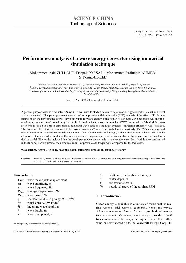
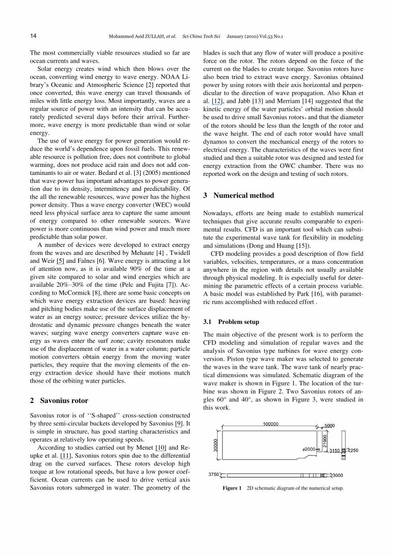
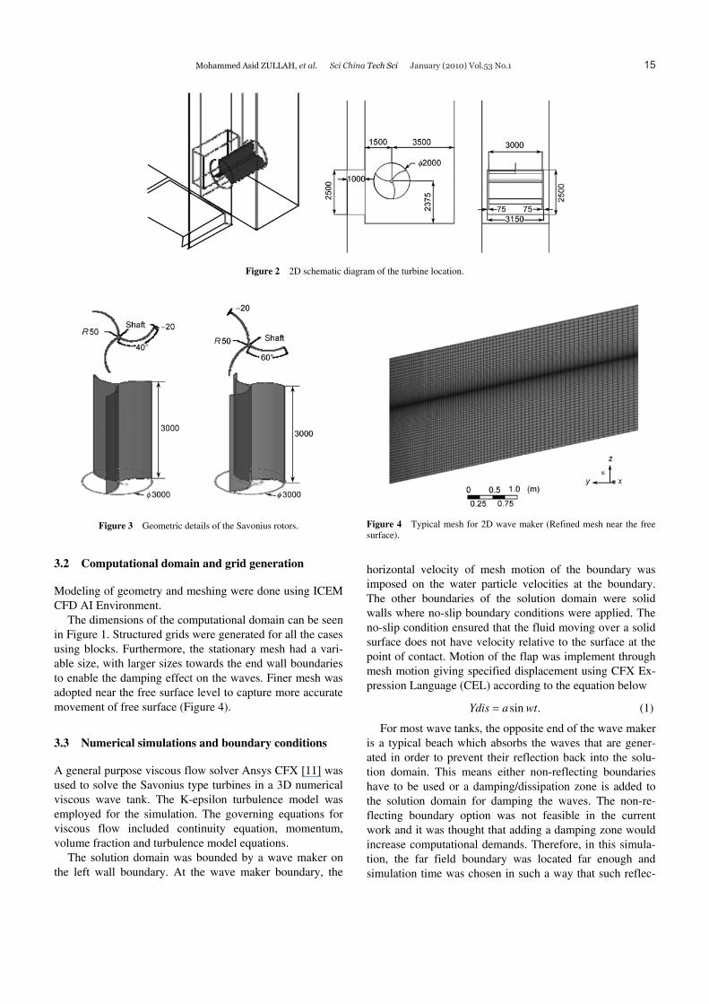
The main objective of the present work is to perform the CFD modeling and simulation of regular waves and the analysis of Savonius type turbines for wave energy con-version. Piston type wave maker was selected to generate the waves in the wave tank. The wave tank of nearly prac-tical dimensions was simulated. Schematic diagram of the wave maker is shown in Figure 1. The location of the tur-bine was shown in Figure 2. Two Savonius rotors of an-gles 60° and 40°, as shown in Figure 3, were studied in this work.
Figure 1 2D schematic diagram of the numerical setup.
Mohammed Asid ZULLAH, et al. Sci China Tech Sci January (2010) Vol.53 No.1 15
Figure 2 2D schematic diagram of the turbine location.
Figure 3 Geometric details of the Savonius rotors.
3.2 Computational domain and grid generation
Modeling of geometry and meshing were done using ICEM CFD AI Environment.
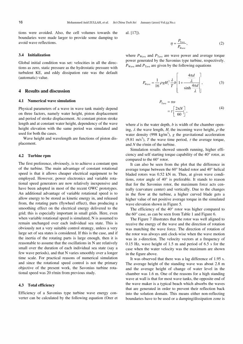
The dimensions of the computational domain can be seen in Figure 1. Structured grids were generated for all the cases using blocks. Furthermore, the stationary mesh had a vari-able size, with larger sizes towards the end wall boundaries to enable the damping effect on the waves. Finer mesh was adopted near the free surface level to capture more accurate movement of free surface (Figure 4).
3.3 Numerical simulations and boundary conditions
A general purpose viscous flow solver Ansys CFX [11] was used to solve the Savonius type turbines in a 3D numerical viscous wave tank. The K-epsilon turbulence model was employed for the simulation. The governing equations for viscous flow included continuity equation, momentum, volume fraction and turbulence model equations.
The solution domain was bounded by a wave maker on the left wall boundary. At the wave maker boundary, the
Figure 4 Typical mesh for 2D wave maker (Refined mesh near the free surface).
horizontal velocity of mesh motion of the boundary was imposed on the water particle velocities at the boundary. The other boundaries of the solution domain were solid walls where no-slip boundary conditions were applied. The no-slip condition ensured that the fluid moving over a solid surface does not have velocity relative to the surface at the point of contact. Motion of the flap was implement through mesh motion giving specified displacement using CFX Ex-pression Language (CEL) according to the equation below
sin .Ydis a wt= (1)
For most wave tanks, the opposite end of the wave maker is a typical beach which absorbs the waves that are gener-ated in order to prevent their reflection back into the solu-tion domain. This means either non-reflecting boundaries have to be used or a damping/dissipation zone is added to the solution domain for damping the waves. The non- re-flecting boundary option was not feasible in the current work and it was thought that adding a damping zone would increase computational demands. Therefore, in this simula-tion, the far field boundary was located far enough and simulation time was chosen in such a way that such reflec-
16 Mohammed Asid ZULLAH, et al. Sci China Tech Sci January (2010) Vol.53 No.1
tions were avoided. Also, the cell volumes towards the boundaries were made larger to provide some damping to avoid wave reflections.
3.4 Initialization
Global initial condition was set: velocities in all the direc-tions as zero, static pressure as the hydrostatic pressure with turbulent KE, and eddy dissipation rate was the default (automatic) value.
4 Results and discussion
4.1 Numerical wave simulation
Physical parameters of a wave in wave tank mainly depend on three factors, namely water height, piston displacement and period of stroke displacement. At constant piston stroke length and at constant water height, dependency of the wave height elevation with the same period was simulated and used for both the cases.
Wave height and wavelength are functions of piston dis-placement.
4.2 Turbine rpm
The first preference, obviously, is to achieve a constant rpm of the turbine. The main advantage of constant rotational speed is that it allows cheaper electrical equipment to be employed. However, power electronics and variable rota-tional speed generators are now relatively inexpensive and have been adopted in most of the recent OWC prototypes. An additional advantage of variable rotational speed is to allow energy to be stored as kinetic energy in, and released from, the rotating parts (flywheel effect), thus producing a smoothing effect on the electrical energy delivered to the grid; this is especially important in small grids. Here, even when variable rotational speed is simulated, N is assumed to remain unchanged over each individual sea state. This is obviously not a very suitable control strategy, unless a very large set of sea states is considered. If this is the case, and if the inertia of the rotating parts is large enough, then it is reasonable to assume that the oscillations in N are relatively small over the duration of each individual sea state (say a few wave periods), and that N varies smoothly over a longer time scale. For practical reasons of numerical simulation and since the rotational speed control is not the primary objective of the present work, the Savonius turbine rota-tional speed was 20 r/min from previous study.
4.3 Total efficiency
Efficiency of a Savonius type turbine wave energy con-verter can be calculated by the following equation (Orer et
al. [17]).
Tave
Wave
,P
Pη = (2)
where PWave and PTave are wave power and average torque power generated by the Savonius type turbine, respectively. PWave and PTave are given by the following equations
2Wave
41
1 ,416 sinh
i
d
P gH bdT
λ λρ
λ
π⎡ ⎤⎢ ⎥
= +⎢ ⎥π⎢ ⎥⎢ ⎥⎣ ⎦
(3)
Tave
2,
60
P
N
τω
τ
=
π⎡ ⎤= ⎢ ⎥⎣ ⎦
(4)
where d is the water depth, b is width of the chamber open-ing, λ the wave length, Hi the incoming wave height, ρ the water density (998 kg/m3), g the gravitational acceleration (9.81 m/s2), T the wave time period, τ the average torque, and N the r/min of the turbine.
Simulation results showed smooth running, higher effi-ciency and self starting torque capability of the 40° rotor, as compared to the 60° rotor.
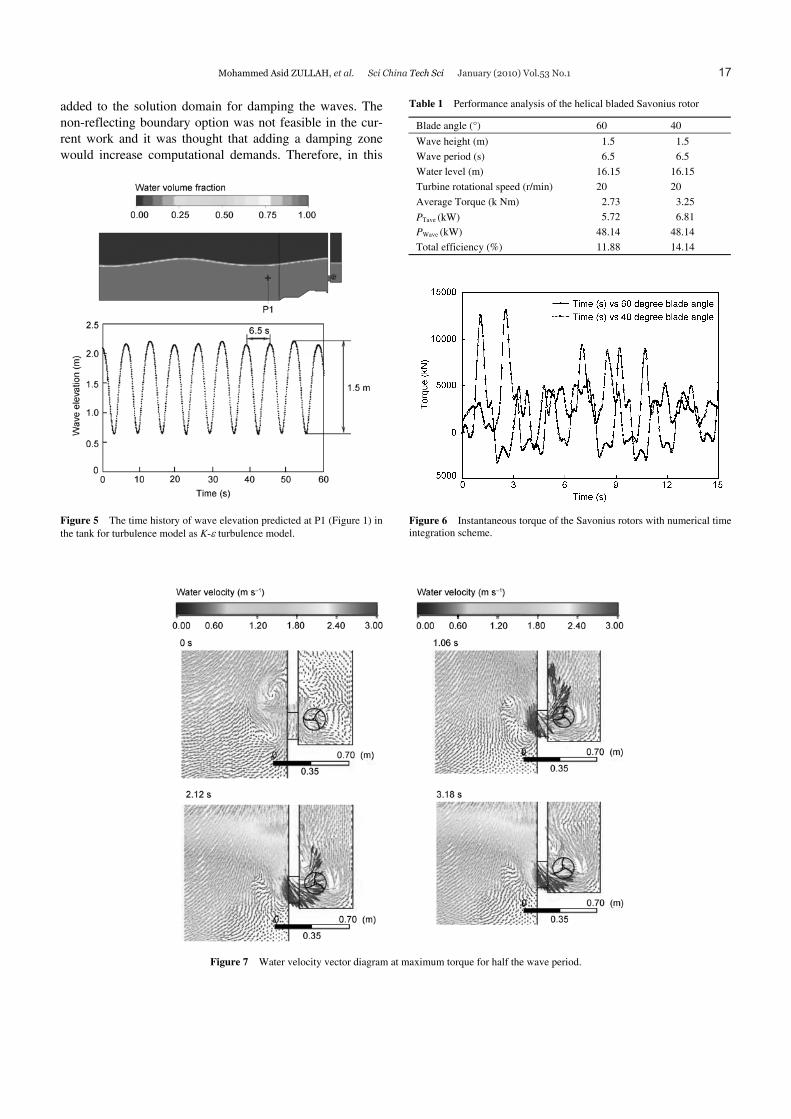
It can also be seen from the plot that the difference in average torque between the 60° bladed rotor and 40° helical bladed rotors was 0.52 kN m. Thus, at given wave condi-tions, rotor angle of 40° is preferable. It stands to reason that for the Savonius rotor, the maximum force acts cen-trally (curvature center) and vertically. Due to the changes in the flow at the turbine, a higher curved blade gets a higher value of net positive average torque in the simulated wave elevation shown in Figure 5.
The efficiency of the 40° rotor was higher compared to the 60° case, as can be seen from Table 1 and Figure 6.
The Figure 7 illustrates that the rotor was well aligned to receive the energy of the wave and the direction of rotation was matching the wave force. The direction of rotation of the rotor was always anti clock-wise when the wave motion was in x-direction. The velocity vectors at a frequency of 0.15 Hz, wave height of 1.5 m and period of 6.5 s for the case when the water velocity was the maximum are shown in the figure above.
It was observed that there was a lag difference of 1.95 s. The average height of the standing wave was about 2.8 m and the average height of change of water level in the chamber was 1.6 m. One of the reasons for a high standing wave at wall is that for most wave tanks, the opposite end of the wave maker is a typical beach which absorbs the waves that are generated in order to prevent their reflection back into the solution domain. This means either non-reflecting boundaries have to be used or a damping/dissipation zone is
Mohammed Asid ZULLAH, et al. Sci China Tech Sci January (2010) Vol.53 No.1 17
added to the solution domain for damping the waves. The non-reflecting boundary option was not feasible in the cur-rent work and it was thought that adding a damping zone would increase computational demands. Therefore, in this
Figure 5 The time history of wave elevation predicted at P1 (Figure 1) in the tank for turbulence model as K-ε turbulence model.
Table 1 Performance analysis of the helical bladed Savonius rotor
Blade angle (°) 60 40
Wave height (m) 1.5 1.5
Wave period (s) 6.5 6.5
Water level (m) 16.15 16.15
Turbine rotational speed (r/min) 20 20
Average Torque (k Nm) 2.73 3.25
PΤave (kW) 5.72 6.81
PWave (kW) 48.14 48.14
Total efficiency (%) 11.88 14.14
Figure 6 Instantaneous torque of the Savonius rotors with numerical time integration scheme.
Figure 7 Water velocity vector diagram at maximum torque for half the wave period.
18 Mohammed Asid ZULLAH, et al. Sci China Tech Sci January (2010) Vol.53 No.1
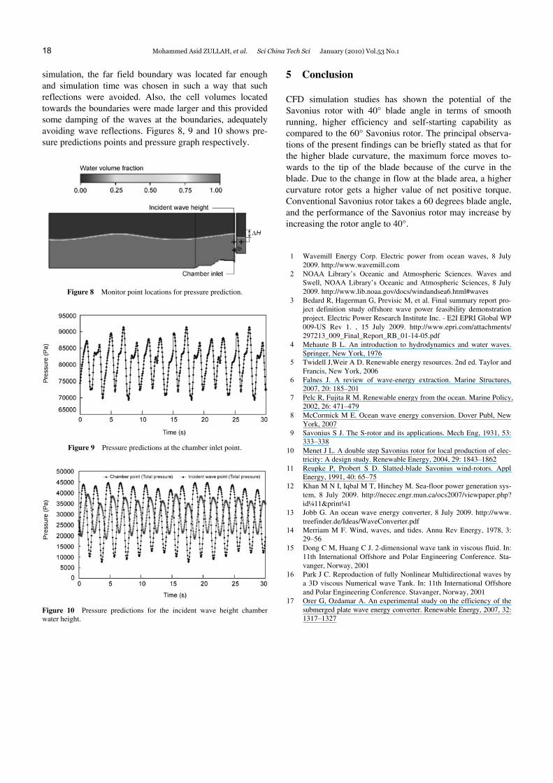
simulation, the far field boundary was located far enough and simulation time was chosen in such a way that such reflections were avoided. Also, the cell volumes located towards the boundaries were made larger and this provided some damping of the waves at the boundaries, adequately avoiding wave reflections. Figures 8, 9 and 10 shows pre-sure predictions points and pressure graph respectively.
Figure 8 Monitor point locations for pressure prediction.
Figure 9 Pressure predictions at the chamber inlet point.
Figure 10 Pressure predictions for the incident wave height chamber water height.
5 Conclusion
CFD simulation studies has shown the potential of the Savonius rotor with 40° blade angle in terms of smooth running, higher efficiency and self-starting capability as compared to the 60° Savonius rotor. The principal observa-tions of the present findings can be briefly stated as that for the higher blade curvature, the maximum force moves to-wards to the tip of the blade because of the curve in the blade. Due to the change in flow at the blade area, a higher curvature rotor gets a higher value of net positive torque. Conventional Savonius rotor takes a 60 degrees blade angle, and the performance of the Savonius rotor may increase by increasing the rotor angle to 40°.
1 Wavemill Energy Corp. Electric power from ocean waves, 8 July 2009. http://www.wavemill.com
2 NOAA Library’s Oceanic and Atmospheric Sciences. Waves and Swell, NOAA Library’s Oceanic and Atmospheric Sciences, 8 July 2009. http://www.lib.noaa.gov/docs/windandsea6.html#waves
3 Bedard R, Hagerman G, Previsic M, et al. Final summary report pro-ject definition study offshore wave power feasibility demonstration project. Electric Power Research Institute Inc. - E2I EPRI Global WP 009-US Rev 1. , 15 July 2009. http://www.epri.com/attachments/ 297213_009_Final_Report_RB_01-14-05.pdf
4 Mehaute B L. An introduction to hydrodynamics and water waves. Springer, New York, 1976
5 Twidell J,Weir A D. Renewable energy resources. 2nd ed. Taylor and Francis, New York, 2006
6 Falnes J. A review of wave-energy extraction. Marine Structures, 2007, 20: 185–201
7 Pelc R, Fujita R M. Renewable energy from the ocean. Marine Policy, 2002, 26: 471–479
8 McCormick M E. Ocean wave energy conversion. Dover Publ, New York, 2007
9 Savonius S J. The S-rotor and its applications. Mech Eng, 1931, 53: 333–338
10 Menet J L. A double step Savonius rotor for local production of elec-tricity: A design study. Renewable Energy, 2004, 29: 1843–1862
11 Reupke P, Probert S D. Slatted-blade Savonius wind-rotors. Appl Energy, 1991, 40: 65–75
12 Khan M N I, Iqbal M T, Hinchey M. Sea-floor power generation sys-tem, 8 July 2009. http://necec.engr.mun.ca/ocs2007/viewpaper.php? id¼11&print¼1
13 Jobb G. An ocean wave energy converter, 8 July 2009. http://www. treefinder.de/Ideas/WaveConverter.pdf
14 Merriam M F. Wind, waves, and tides. Annu Rev Energy, 1978, 3: 29–56
15 Dong C M, Huang C J. 2-dimensional wave tank in viscous fluid. In: 11th International Offshore and Polar Engineering Conference. Sta-vanger, Norway, 2001
16 Park J C. Reproduction of fully Nonlinear Multidirectional waves by a 3D viscous Numerical wave Tank. In: 11th International Offshore and Polar Engineering Conference. Stavanger, Norway, 2001
17 Orer G, Ozdamar A. An experimental study on the efficiency of the submerged plate wave energy converter. Renewable Energy, 2007, 32: 1317–1327