Perforation of steel and aluminum targets using a modified Johnson–Cook
9
This article appeared in a journal published by Elsevier. The attached copy is furnished to the author for internal non-commercial research and education use, including for instruction at the authors institution and sharing with colleagues. Other uses, including reproduction and distribution, or selling or licensing copies, or posting to personal, institutional or third party websites are prohibited. In most cases authors are permitted to post their version of the article (e.g. in Word or Tex form) to their personal website or institutional repository. Authors requiring further information regarding Elsevier’s archiving and manuscript policies are encouraged to visit: http://www.elsevier.com/copyright
Transcript of Perforation of steel and aluminum targets using a modified Johnson–Cook
This article appeared in a journal published by Elsevier. The attachedcopy is furnished to the author for internal non-commercial researchand education use, including for instruction at the authors institution
and sharing with colleagues.
Other uses, including reproduction and distribution, or selling orlicensing copies, or posting to personal, institutional or third party
websites are prohibited.
In most cases authors are permitted to post their version of thearticle (e.g. in Word or Tex form) to their personal website orinstitutional repository. Authors requiring further information
regarding Elsevier’s archiving and manuscript policies areencouraged to visit:
http://www.elsevier.com/copyright
Author's personal copy
Nuclear Engineering and Design 250 (2012) 108– 115
Contents lists available at SciVerse ScienceDirect
Nuclear Engineering and Design
jo u r n al hom epage : www.elsev ier .com/ locate /nucengdes
Perforation of steel and aluminum targets using a modified Johnson–Cookmaterial model
Z.S. Liua,∗∗, S. Swaddiwudhipongb,∗, M.J. Islamb
a Institute of High Performance Computing, Fusionopolis Way, #16-16 Connexis, 138632, Singaporeb Department of Civil and Environmental Engineering, National University of Singapore, No. 1 Engineering Drive 2, 117576, Singapore
h i g h l i g h t s
� Proposed constitutive model for metals focusing on strain rate and adiabatic heating effects.� Detailed procedure for evaluating material properties of the proposed model.� Establishing material model properties for steel and aluminum based on test results.� High velocity perforation study of steel and aluminum targets and comparison with test results.� Application of the coupled smooth particle hydrodynamics-finite element method.
a r t i c l e i n f o
Article history:Received 3 August 2011Received in revised form 14 June 2012Accepted 15 June 2012
a b s t r a c t
Numerical perforation studies involving finite element method (FEM) suffer from severe mesh distortionproblem when subjected to large deformation in high velocity projectile impact cases. Severe elementdistortion causes negative volume problem and introduces numerical errors in the simulated results.Mesh free methods, such as smoothed particle hydrodynamics (SPH) method is capable of handlinglarge deformation without any numerical problems, but at substantially high computational resources.To mitigate the problem, coupled smoothed particle hydrodynamics–finite element method (SFM) hasbeen implemented to study the high velocity perforations of steel and aluminum target plates, wherethe SPH method is adopted only in severely distorted regions and the FEM further away. Strain rate andadiabatic heating have a considerable effect on material properties, especially at high velocity impact, andhence, a new material model with high strain rate and adiabatic temperature effects is adopted herein.Material properties for Weldox 460E steel and AA5083-H116 aluminum plates are determined and usedto perform perforation of target plates with varying thicknesses and projectile nose geometries, such asblunt, conical and ogival noses. Numerical residual and ballistic limit velocities show good correlationwith the published experimental results. The study demonstrates that the new material model is ableto emulate failure characteristics of the steel and aluminum plates as observed in various experimentalobservations.
© 2012 Elsevier B.V. All rights reserved.
1. Introduction
Projectile perforation problems have been investigated for cen-turies in many engineering branches including military defenseand attack, industrial hazardous accident, and in protection ofnuclear facilities and spacecrafts. A lot of effort has been givento better understanding of the phenomenon involving collid-ing bodies. The studies on and design of nuclear facilities and
∗ Corresponding author. Tel.: +65 65162173; fax: +65 67791635.∗∗ Corresponding author.
E-mail addresses: [email protected] (Z.S. Liu), [email protected](S. Swaddiwudhipong).
containing structures due to an aircraft impact were recentlyreported by Petrangeli (2010) and Sato et al. (2010). Variousapproaches, namely, experimental, analytical and numerical, havebeen developed to analyse the impact dynamics of the structuresunder projectile impacts. Although each approach has its own mer-its and demerits, the numerical method is the most robust amongthem, since it provides detailed comprehensive information whichcan be used to validate and improve engineering models.
Numerical studies of high velocity projectile impact problemsrequire a well defined discretization method and robust materialmodel. Finite element method (FEM) is one of the leading dis-cretization procedures in engineering analyses and widely appliedfor various problems involving solid structures. Since early 1960s,FEM has been used for high velocity impact problems (Backman
0029-5493/$ – see front matter © 2012 Elsevier B.V. All rights reserved.http://dx.doi.org/10.1016/j.nucengdes.2012.06.026
Author's personal copy
Z.S. Liu et al. / Nuclear Engineering and Design 250 (2012) 108– 115 109
and Goldsmith, 1978; Johnson, 1977; Wilkins, 1963; Zukas, 1990).However, it has one major drawback. It suffers from severe ele-ment distortion problem in case of large deformation that causesnegative volume problems and numerical errors in the simulationresults. Mesh free method, like smoothed particle hydrodynam-ics (SPH) method can be an alternative approach for high velocityimpact studies. Because of their variable nodal connectivity, par-ticles in the SPH method can incorporate larger deformations inthe simulation without causing negative volume problem as nor-mally encountered in Lagrangian finite element models. The SPHmethod has been applied for solid mechanics problems with somesuccess since early 1990s (Libersky and Petschek, 1991; Liberskyet al., 1993; Liu et al., 2002, 2004). Although it has been a preferablechoice for high velocity impact simulations, it is computationallydemanding and suffers from instability problems in certain con-ditions (Johnson, 1994). Both SPH and finite element (FE) methodsare Lagrangian based which makes it possible to couple both meth-ods with appropriate conditions at the interface (Attaway et al.,1994; Johnson, 1994; Swaddiwudhipong et al., 2010). In the cou-pled SPH-FE method (SFM), the SPH method is used at the region oflarge deformation and damage, and the FEM elsewhere. By adopt-ing the SFM, it is possible to resolve any numerical problems due tolarge deformation, while improving the accuracy of the results sig-nificantly at reasonable computational effort. Although couplingbetween the SPH and FEM is not a new idea, there are very fewstudies available involving high velocity perforations.
At high velocity impact, materials are subjected to large plasticdeformation, high strain rate, adiabatic temperature rise and dam-age. Work done due to plastic deformation in metal is converted toheat (Taylor and Quinney, 1934) and dissipation of this tempera-ture depends on the thermal diffusion distance, and hence, variesinversely with the strain rate. That is at high strain rate, gener-ated heat in the specimen remains mostly within the specimen.This condition is referred to as adiabatic heating (Klepaczko, 1984).However, a small portion of the converted heat is diffused throughradiation and heat conduction (Taylor and Quinney, 1934). Temper-ature rise due to the adiabatic condition at high strain rate reduceswork hardening rate of material which causes material soften-ing. Although most material models, like Johnson–Cook (JC) model(Johnson and Cook, 1983, 1985) include effect of temperature,they do not consider adiabatic heating phenomenon. Therefore, amodified Johnson–Cook model is proposed and applied for variousperforation studies.
The main objective of this study is to propose a constitu-tive model including effects of large strain, high strain rates andadiabatic temperature for metals. Following the constitutive equa-tions of the material model, procedures for determining the modelparameters are described. Material properties of Weldox 460 Esteel and AA5083-H116 aluminum are obtained from uniaxialtest at various strain rates and temperatures. The SFM has beenused to simulate the perforation of steel and aluminum targetplates. The study involves (i) perforation of steel plates with vari-ous thicknesses by blunt projectile, (ii) perforation of steel platesby projectiles with various nose shapes and (iii) perforation ofaluminum plates with various thicknesses by conical projectiles.Numerical residual and ballistic limit velocities of various platesare compared with experimental results.
2. Modified Johnson–Cook model
During high velocity perforation, work done in plastic flow isconverted to heat. Except for a small portion of the converted heatwhich disseminates due to radiation and heat conduction, most of itremains within the specimen. Since adiabatic shear failure is promi-nent to high velocity impact problems for metals it is necessary to
include temperature effect due to adiabatic condition and to assignactual percentage of heat that remains within the specimen. TheJohnson–Cook (JC) model incorporates high strain rate, large strainand temperature effects. However, it does not include tempera-ture rise due to adiabatic condition during high strain rate event.Therefore, a modified Johnson–Cook (MJC) model allowing adia-batic heating, high strain rate and large strain effects, is proposedin this study.
The temperature increment due to adiabatic condition can bederived using the following equation,
�T = ˇ
�Cp
∫�(εp)dεp (1)
where, Cp is the specific heat, � is the density of the material, � is thestress and εp is the equivalent plastic strain. The value of describesthe percentage of heat remains within the material and varies fromzero (isothermal) to one (adiabatic). Mason et al. (1994) calcu-lated ˇ value by using the infrared radiometer for Ti–6Al–4V, 4340steel and 2024 aluminum at strain rates of 1500 s−1, 3000 s−1and2500 s−1 respectively, and observed that the value varies between0.5 and 0.95. Kapoor and Nemat-Nasser (1998) and Nemat-Nasserand Kapoor (2001) conducted tests on several materials, namely1018 steel, OFHC copper, 6061-T6 aluminum, titanium, Ti–6Al–4Vand Ta-2.5% W at high strain rates (2000–3000 s−1) and found that
equals to 1.0 within the test error. From the rapid torsion andcompression tests on mild steel and copper, Taylor and Quinney(1934) concluded the value of 0.9. Considering all these, a ratio-nal value of = 0.9 is proposed in the MJC model for all the metaltargets under high velocity impact adopted herein.
The strain rate constant C in the JC model varies with the ref-erence strain rate, ε0. To resolve the problem, a simple but elegantstrain rate effect expression is proposed for the MJC model whichexcludes reference strain rate parameters. The equivalent stress,damage and fracture strain of the MJC model are expressed as,
� = [A + B(εp)a][εp]C
[1 −
(T − Tr
Tm − Tr
)b]
(2)
D =∑ �εp
εf(3)
εf =(
D1 + D2 exp D3
(�ave
�e
))(εp)D4
(1 + D5
(T − Tr
Tm − Tr
))(4)
In Eq. (2), εp is the plastic strain rate, (˙) implies differentiationwith respect to time, Tmelt and Troom are the melting and roomtemperatures respectively, �ave and �e are the average of normalstresses and Von Mises stress respectively, A, B, a, C and b are thematerial constants. The three brackets in Eq. (2) take into accountthe effects of plastic strains, strain rates and temperature respec-tively. D1 to D5 in Eq. (4) are the five damage parameters. Sincethe SFM is not subjected to severe element distortion problem, thedamage model is not considered for the present study.
2.1. Determining the MJC material parameters
Determining the material model parameters for the modi-fied Johnson–Cook (MJC) requires careful consideration and welldefined procedures. There are five material parameters required todetermine the equivalent stress for the MJC model. The first threeparameters (A, B and a) describe the elastic–plastic deformation ofthe material, the fourth and fifth parameters C and b reflect thestrain rate effect and temperature effects. Three steps are essentialto evaluate the five parameters for any materials and the procedurefor obtaining the values for Weldox 460 E steel and aluminum alloyAA5083-H116 are elaborated below.
All the parameters for Weldox 460 E steel are calculatedfrom the tests performed by Børvik et al. (2001). The strength
Author's personal copy
110 Z.S. Liu et al. / Nuclear Engineering and Design 250 (2012) 108– 115
( )0.4816 6503 10 581 10 pσ ε= × + ×
0 0.2 0. 4 0.6 0.8 1 1.2 1. 4 1.6
0.0E+000
2.0E+008
4.0E+008
6.0E+008
8.0E+008
1.0E+009
1.2E+009
Test da ta
MJC
Str
ess
(P
a)
Plastic Strain
(a)
0 0.04 0.08 0.12 0.16 0.2
0
0.004
0.008
0.012
0.016
0.02
C
Plastic Stra in
0 0.04 0.08 0.12 0.16 0.2
0
0.4
0.8
1.2
1.6
MJC
100oC
500oC
b
Plasti c Str ain
)c( )b(
Fig. 1. MJC material properties for Weldox 460 E steel.
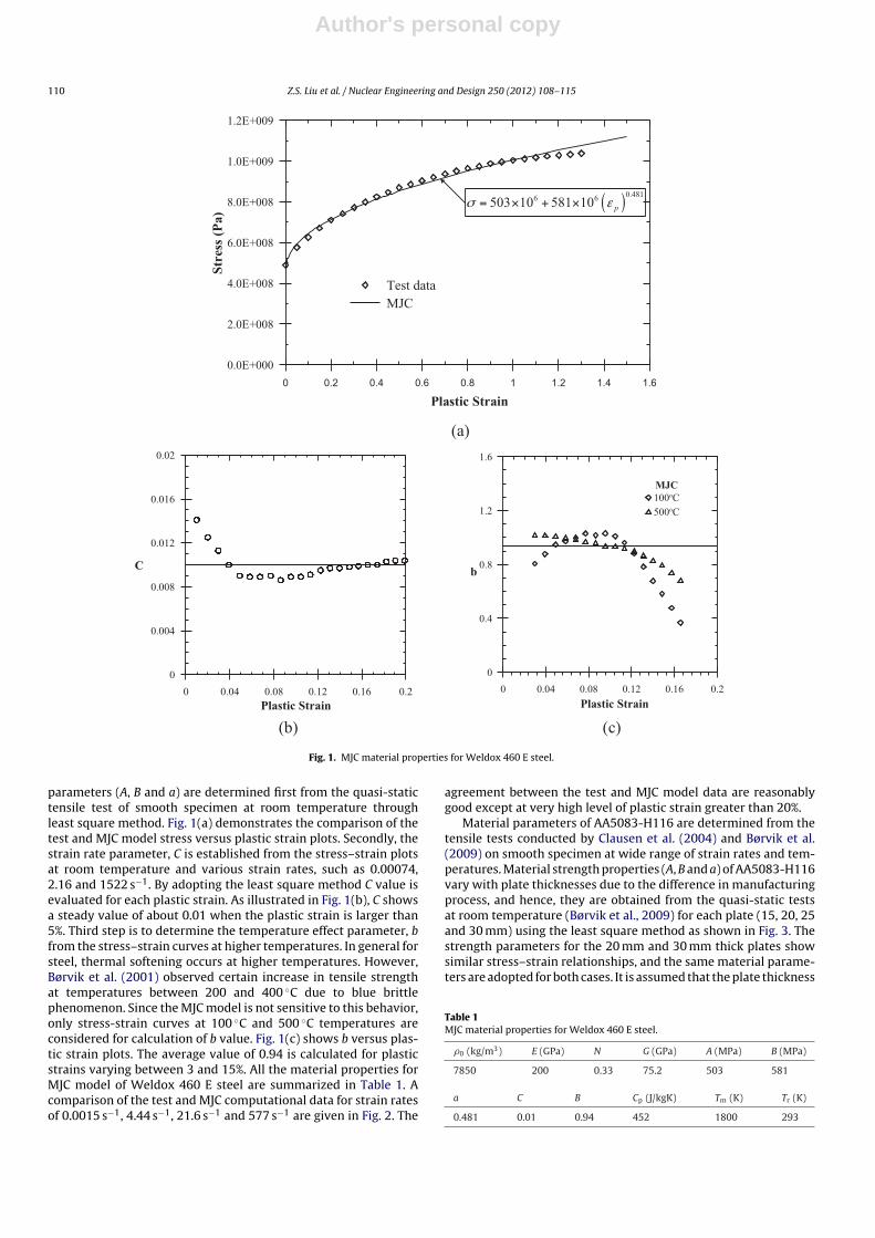
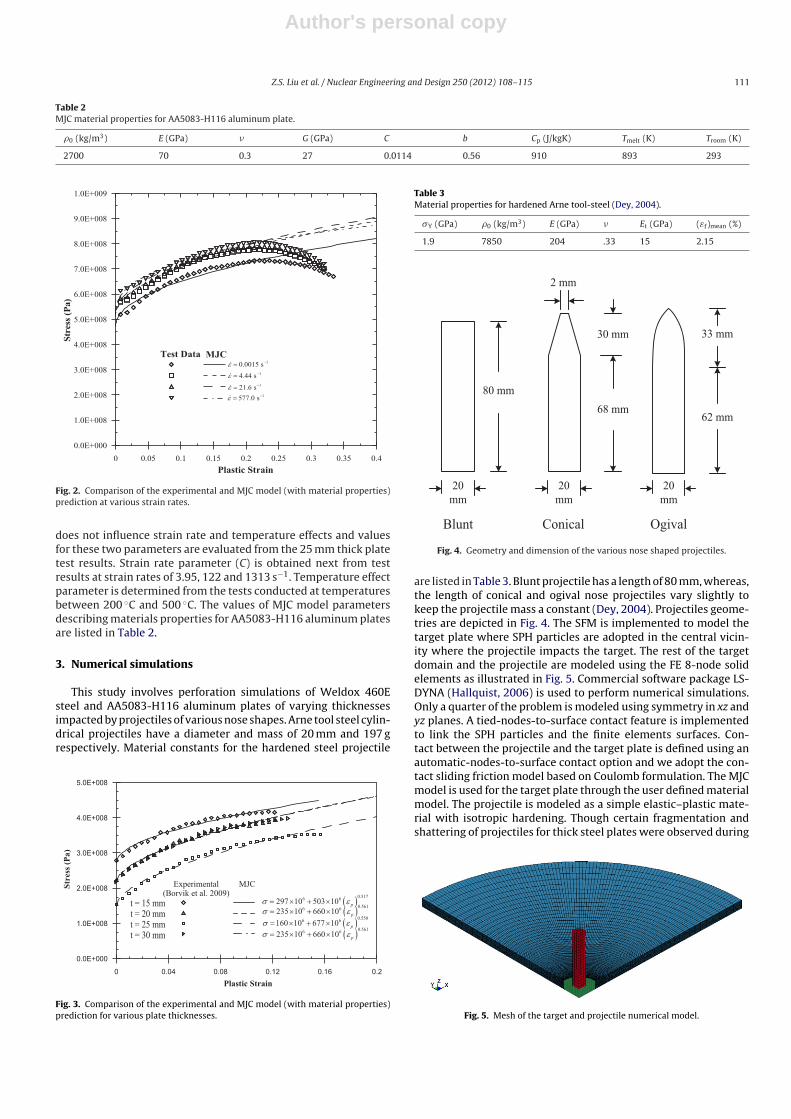
parameters (A, B and a) are determined first from the quasi-statictensile test of smooth specimen at room temperature throughleast square method. Fig. 1(a) demonstrates the comparison of thetest and MJC model stress versus plastic strain plots. Secondly, thestrain rate parameter, C is established from the stress–strain plotsat room temperature and various strain rates, such as 0.00074,2.16 and 1522 s−1. By adopting the least square method C value isevaluated for each plastic strain. As illustrated in Fig. 1(b), C showsa steady value of about 0.01 when the plastic strain is larger than5%. Third step is to determine the temperature effect parameter, bfrom the stress–strain curves at higher temperatures. In general forsteel, thermal softening occurs at higher temperatures. However,Børvik et al. (2001) observed certain increase in tensile strengthat temperatures between 200 and 400 ◦C due to blue brittlephenomenon. Since the MJC model is not sensitive to this behavior,only stress-strain curves at 100 ◦C and 500 ◦C temperatures areconsidered for calculation of b value. Fig. 1(c) shows b versus plas-tic strain plots. The average value of 0.94 is calculated for plasticstrains varying between 3 and 15%. All the material properties forMJC model of Weldox 460 E steel are summarized in Table 1. Acomparison of the test and MJC computational data for strain ratesof 0.0015 s−1, 4.44 s−1, 21.6 s−1 and 577 s−1 are given in Fig. 2. The
agreement between the test and MJC model data are reasonablygood except at very high level of plastic strain greater than 20%.
Material parameters of AA5083-H116 are determined from thetensile tests conducted by Clausen et al. (2004) and Børvik et al.(2009) on smooth specimen at wide range of strain rates and tem-peratures. Material strength properties (A, B and a) of AA5083-H116vary with plate thicknesses due to the difference in manufacturingprocess, and hence, they are obtained from the quasi-static testsat room temperature (Børvik et al., 2009) for each plate (15, 20, 25and 30 mm) using the least square method as shown in Fig. 3. Thestrength parameters for the 20 mm and 30 mm thick plates showsimilar stress–strain relationships, and the same material parame-ters are adopted for both cases. It is assumed that the plate thickness
Table 1MJC material properties for Weldox 460 E steel.
�0 (kg/m3) E (GPa) N G (GPa) A (MPa) B (MPa)
7850 200 0.33 75.2 503 581
a C B Cp (J/kgK) Tm (K) Tr (K)
0.481 0.01 0.94 452 1800 293
Author's personal copy
Z.S. Liu et al. / Nuclear Engineering and Design 250 (2012) 108– 115 111
Table 2MJC material properties for AA5083-H116 aluminum plate.
�0 (kg/m3) E (GPa) � G (GPa) C b Cp (J/kgK) Tmelt (K) Troom (K)
2700 70 0.3 27 0.0114 0.56 910 893 293
Fig. 2. Comparison of the experimental and MJC model (with material properties)prediction at various strain rates.
does not influence strain rate and temperature effects and valuesfor these two parameters are evaluated from the 25 mm thick platetest results. Strain rate parameter (C) is obtained next from testresults at strain rates of 3.95, 122 and 1313 s−1. Temperature effectparameter is determined from the tests conducted at temperaturesbetween 200 ◦C and 500 ◦C. The values of MJC model parametersdescribing materials properties for AA5083-H116 aluminum platesare listed in Table 2.
3. Numerical simulations
This study involves perforation simulations of Weldox 460Esteel and AA5083-H116 aluminum plates of varying thicknessesimpacted by projectiles of various nose shapes. Arne tool steel cylin-drical projectiles have a diameter and mass of 20 mm and 197 grespectively. Material constants for the hardened steel projectile
Fig. 3. Comparison of the experimental and MJC model (with material properties)prediction for various plate thicknesses.
Table 3Material properties for hardened Arne tool-steel (Dey, 2004).
�Y (GPa) �0 (kg/m3) E (GPa) � Et (GPa) (εf)mean (%)
1.9 7850 204 .33 15 2.15
80 mm
30 mm
68 mm
20
mm
20
mm
20
mm
2 mm
Blunt Conical Ogival
62 mm
33 mm
Fig. 4. Geometry and dimension of the various nose shaped projectiles.
are listed in Table 3. Blunt projectile has a length of 80 mm, whereas,the length of conical and ogival nose projectiles vary slightly tokeep the projectile mass a constant (Dey, 2004). Projectiles geome-tries are depicted in Fig. 4. The SFM is implemented to model thetarget plate where SPH particles are adopted in the central vicin-ity where the projectile impacts the target. The rest of the targetdomain and the projectile are modeled using the FE 8-node solidelements as illustrated in Fig. 5. Commercial software package LS-DYNA (Hallquist, 2006) is used to perform numerical simulations.Only a quarter of the problem is modeled using symmetry in xz andyz planes. A tied-nodes-to-surface contact feature is implementedto link the SPH particles and the finite elements surfaces. Con-tact between the projectile and the target plate is defined using anautomatic-nodes-to-surface contact option and we adopt the con-tact sliding friction model based on Coulomb formulation. The MJCmodel is used for the target plate through the user defined materialmodel. The projectile is modeled as a simple elastic–plastic mate-rial with isotropic hardening. Though certain fragmentation andshattering of projectiles for thick steel plates were observed during
Fig. 5. Mesh of the target and projectile numerical model.
Author's personal copy
112 Z.S. Liu et al. / Nuclear Engineering and Design 250 (2012) 108– 115
Res
idual
Pro
ject
ile
Vel
ocit
y(m
/s)
100
0
100
200
300
400
t =t =t =t =t =t =
Res
idual
Pro
ject
ile
Vel
ocit
y (
m/s
)
Exper(Borvik
= 6 mm= 8 mm= 10 mm= 12 mm= 16 mm= 20 mm
200
rimenta let al. 2003)
SF(J
Initial P
FMJC)
rojectile Velo
SFM(MJC)
300
ocity (m/s )
400
Fig. 6. Experimental and SFM residual velocities for blunt projectile perforatingsteel plates.
the penetration, damages in the projectiles are not considered inthe present study.
The appropriate SPH domain size and particle distance in theSFM has to be chosen judicially. It is essential to strike the bal-ance between the SPH domain size for accuracy of results andthe economy of computational resources. Damage region normallygoverns the SPH domain size. The effect of the SPH domain sizehas been conducted earlier (Swaddiwudhipong et al., 2010), and aSPH domain radius of 24 mm is adopted in this study for 10 mmradius projectile. The effect of SPH particle distance is also signifi-cant, especially for target plates with adiabatic shear failures (Dey,2004). The effect of particle distance has been performed previously(Swaddiwudhipong et al., 2010) and the SPH particle distance of0.6 mm is selected for subsequent simulations.
Blunt projectile penetrates the target plate through adiabaticshear failure with minimum surface contact between the targetand the projectile. Therefore, no friction is considered for the bluntprojectile perforation. However, sharp projectiles like conical andogival nose projectiles, penetrate the target by pushing the mate-rials in front of the projectile inducing substantial contact betweenthe projectile and the target, and hence the friction coefficient (�f)values of 0.08 and 0.02 are adopted for conical and ogival noseprojectile perforations of Weldox 460 E steel and AA5083-H116aluminum targets respectively (Swaddiwudhipong et al., 2010).
4. Results and discussion
4.1. Perforation of Weldox 460 E steel plates
Steel plate perforation simulations are conducted using the SFMwith the MJC model for target plates. Two cases are chosen forsteel plate perforation, one to perforate steel plates of varyingthicknesses (6–20 mm) by steel blunt projectiles, and another toperforate 12 mm thick steel plates by steel projectiles with var-ious nose shapes (blunt, conical and ogival). Impact velocities ofthe projectiles vary between 100 and 400 m/s. Residual velocityof the projectile is captured when it reaches a steady state afterperforating the target.
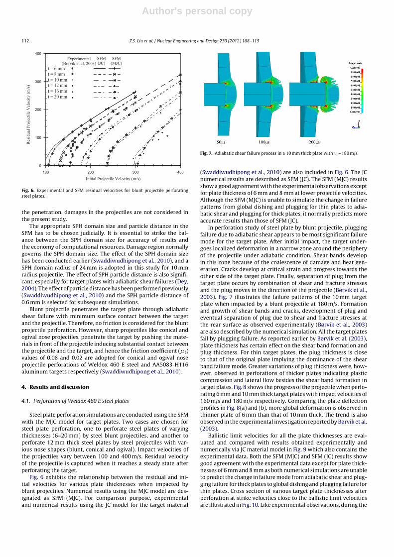
Fig. 6 exhibits the relationship between the residual and ini-tial velocities for various plate thicknesses when impacted byblunt projectiles. Numerical results using the MJC model are des-ignated as SFM (MJC). For comparison purpose, experimentaland numerical results using the JC model for the target material
Fig. 7. Adiabatic shear failure process in a 10 mm thick plate with �i = 180 m/s.
(Swaddiwudhipong et al., 2010) are also included in Fig. 6. The JCnumerical results are described as SFM (JC). The SFM (MJC) resultsshow a good agreement with the experimental observations exceptfor plate thickness of 6 mm and 8 mm at lower projectile velocities.Although the SFM (MJC) is unable to simulate the change in failurepatterns from global dishing and plugging for thin plates to adia-batic shear and plugging for thick plates, it normally predicts moreaccurate results than those of SFM (JC).
In perforation study of steel plate by blunt projectile, pluggingfailure due to adiabatic shear appears to be most significant failuremode for the target plate. After initial impact, the target under-goes localized deformation in a narrow zone around the peripheryof the projectile under adiabatic condition. Shear bands developin this zone because of the coalescence of damage and heat gen-eration. Cracks develop at critical strain and progress towards theother side of the target plate. Finally, separation of plug from thetarget plate occurs by combination of shear and fracture stressesand the plug moves in the direction of the projectile (Børvik et al.,2003). Fig. 7 illustrates the failure patterns of the 10 mm targetplate when impacted by a blunt projectile at 180 m/s. Formationand growth of shear bands and cracks, development of plug andeventual separation of plug due to shear and fracture stresses atthe rear surface as observed experimentally (Børvik et al., 2003)are also described by the numerical simulation. All the target platesfail by plugging failure. As reported earlier by Børvik et al. (2003),plate thickness has certain effect on the shear band formation andplug thickness. For thin target plates, the plug thickness is closeto that of the original plate implying the dominance of the shearband failure mode. Greater variations of plug thickness were, how-ever, observed in perforations of thicker plates indicating plasticcompression and lateral flow besides the shear band formation intarget plates. Fig. 8 shows the progress of the projectile when perfo-rating 6 mm and 10 mm thick target plates with impact velocities of160 m/s and 180 m/s respectively. Comparing the plate deflectionprofiles in Fig. 8(a) and (b), more global deformation is observed inthinner plate of 6 mm than that of 10 mm thick. The trend is alsoobserved in the experimental investigation reported by Børvik et al.(2003).
Ballistic limit velocities for all the plate thicknesses are eval-uated and compared with results obtained experimentally andnumerically via JC material model in Fig. 9 which also contains theexperimental data. Both the SFM (MJC) and SFM (JC) results showgood agreement with the experimental data except for plate thick-nesses of 6 mm and 8 mm as both numerical simulations are unableto predict the change in failure mode from adiabatic shear and plug-ging failure for thick plates to global dishing and plugging failure forthin plates. Cross section of various target plate thicknesses afterperforation at strike velocities close to the ballistic limit velocitiesare illustrated in Fig. 10. Like experimental observations, during the

Author's personal copy
Z.S. Liu et al. / Nuclear Engineering and Design 250 (2012) 108– 115 113
Fig. 8. Progress of the projectile with (a) �i = 160 m/s into a 6 mm thick plate; (b)�i = 180 m/s into a 10 mm thick plate.
target plate perforation simulations global deformation decreaseswith increasing plate thicknesses. However, rear side bulging of thetarget plates are absent in the simulations. This is because of theprominent shear fracture observed than the adiabatic shear failureat the rear surface in the simulation.
Effect of the projectile nose geometries on the Weldox 460 Esteel target plate is also studied using the SFM (MJC). A 12 mm
Bal
list
icL
imit
Vel
oci
ty(m
/s)
4
0
100
200
300
Bal
list
ic L
imit
Vel
oci
ty (
m/s
)
8
Experim
SFM (J
SFM (M
T
12
mental (Borvik
JC)
MJC)
Target Plate Th
16
k et al. 2003)
hickness (mm)
6 220 24
Fig. 9. Experimental and numerical ballistic limit velocities for steel plates.
Fig. 10. Cross sections of the perforated target plates at strike velocities (110, 135,160, 195, 240 and 310 m/s respectively).
thick steel plate is impacted by projectiles with three differentnose geometries (blunt, conical and ogival). Residual velocities ofthe projectile with maximum initial impact velocity up to 400 m/sare monitored and compared with experimental data (Dey, 2004).The SFM (MJC) simulation is able to provide a good prediction ofthe experimentally observed values, as shown in Fig. 11, exceptfor the blunt projectile at lower velocities where the target platebehaves stiffer during the simulations. The figure also incorporatesthe SFM (JC) results (Swaddiwudhipong et al., 2010) which show abetter representation of the experimental data for the blunt noseprojectile.
4.2. Perforation of AA5083-H116 aluminum plates
Perforation of aluminum alloy AA5083-H116 plates by conicalnose steel projectiles has been performed using the MJC as thetarget material model. Numerical residual and ballistic limit veloc-ities are compared with experimental data reported earlier byBørvik et al. (2004). Both JC and MJC models are used for aluminumtarget plates. Variation of the residual velocities with the initialvelocities for different plate thicknesses of 15, 20, 25 and 30 mmare presented in Fig. 12. Ballistic limit velocities increase linearly
Experimental(Dey 2004)
Blunt Projectile:Conical Projectile:Ogival Projectile:
Initial Projectile Velocity (m/s)
Res
idual
Pro
ject
ile
Vel
oci
ty (
m/s
)
100 200 300 400
0
100
200
300
400
SFM (JC)
SFM (MJC)
Fig. 11. Comparison of experimental and numerical residual velocities for variousnose projectiles.
Author's personal copy
114 Z.S. Liu et al. / Nuclear Engineering and Design 250 (2012) 108– 115
100 200 300 400
0
100
200
300
400Experimental
(Borvik et al. 2004)
t = 15 mmt = 20 mmt = 25 mmt = 30 mm
Initial Projectile Veloci ty (m/s)
Res
idual
Pro
ject
ile
Vel
oci
ty (
m/s
)
SFM(JC)
SFM(MJC)
Fig. 12. Numerical and experimental residual velocities of conical projectiles per-forating aluminum plates.
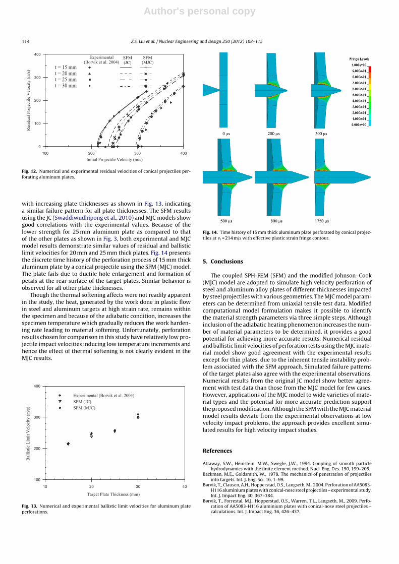
with increasing plate thicknesses as shown in Fig. 13, indicatinga similar failure pattern for all plate thicknesses. The SFM resultsusing the JC (Swaddiwudhipong et al., 2010) and MJC models showgood correlations with the experimental values. Because of thelower strength for 25 mm aluminum plate as compared to thatof the other plates as shown in Fig. 3, both experimental and MJCmodel results demonstrate similar values of residual and ballisticlimit velocities for 20 mm and 25 mm thick plates. Fig. 14 presentsthe discrete time history of the perforation process of 15 mm thickaluminum plate by a conical projectile using the SFM (MJC) model.The plate fails due to ductile hole enlargement and formation ofpetals at the rear surface of the target plates. Similar behavior isobserved for all other plate thicknesses.
Though the thermal softening affects were not readily apparentin the study, the heat, generated by the work done in plastic flowin steel and aluminum targets at high strain rate, remains withinthe specimen and because of the adiabatic condition, increases thespecimen temperature which gradually reduces the work harden-ing rate leading to material softening. Unfortunately, perforationresults chosen for comparison in this study have relatively low pro-jectile impact velocities inducing low temperature increments andhence the effect of thermal softening is not clearly evident in theMJC results.
10 20 30 40
100
200
300
400
Experimental (Borvik et al. 2004)
SFM (JC)
SFM (MJC)
Target Plate Thickness (mm)
Bal
list
ic L
imit
Vel
oci
ty (
m/s
)
Fig. 13. Numerical and experimental ballistic limit velocities for aluminum plateperforations.
Fig. 14. Time history of 15 mm thick aluminum plate perforated by conical projec-tiles at �i = 214 m/s with effective plastic strain fringe contour.
5. Conclusions
The coupled SPH-FEM (SFM) and the modified Johnson–Cook(MJC) model are adopted to simulate high velocity perforation ofsteel and aluminum alloy plates of different thicknesses impactedby steel projectiles with various geometries. The MJC model param-eters can be determined from uniaxial tensile test data. Modifiedcomputational model formulation makes it possible to identifythe material strength parameters via three simple steps. Althoughinclusion of the adiabatic heating phenomenon increases the num-ber of material parameters to be determined, it provides a goodpotential for achieving more accurate results. Numerical residualand ballistic limit velocities of perforation tests using the MJC mate-rial model show good agreement with the experimental resultsexcept for thin plates, due to the inherent tensile instability prob-lem associated with the SFM approach. Simulated failure patternsof the target plates also agree with the experimental observations.Numerical results from the original JC model show better agree-ment with test data than those from the MJC model for few cases.However, applications of the MJC model to wide varieties of mate-rial types and the potential for more accurate prediction supportthe proposed modification. Although the SFM with the MJC materialmodel results deviate from the experimental observations at lowvelocity impact problems, the approach provides excellent simu-lated results for high velocity impact studies.
References
Attaway, S.W., Heinstein, M.W., Swegle, J.W., 1994. Coupling of smooth particlehydrodynamics with the finite element method. Nucl. Eng. Des. 150, 199–205.
Backman, M.E., Goldsmith, W., 1978. The mechanics of penetration of projectilesinto targets. Int. J. Eng. Sci. 16, 1–99.
Børvik, T., Clausen, A.H., Hopperstad, O.S., Langseth, M., 2004. Perforation of AA5083-H116 aluminium plates with conical-nose steel projectiles – experimental study.Int. J. Impact Eng. 30, 367–384.
Børvik, T., Forrestal, M.J., Hopperstad, O.S., Warren, T.L., Langseth, M., 2009. Perfo-ration of AA5083-H116 aluminium plates with conical-nose steel projectiles –calculations. Int. J. Impact Eng. 36, 426–437.
Author's personal copy
Z.S. Liu et al. / Nuclear Engineering and Design 250 (2012) 108– 115 115
Børvik, T., Hopperstad, O.S., Berstad, T., Langseth, M., 2001. A computational modelof viscoplasticity and ductile damage for impact and penetration. Eur. J. Mech.– A/Solids 20, 685–712.
Børvik, T., Hopperstad, O.S., Langseth, M., Malo, K.A., 2003. Effect of target thicknessin blunt projectile penetration of Weldox 460 E steel plates. Int. J. Impact Eng.28, 413–464.
Clausen, A.H., Børvik, T., Hopperstad, O.S., Benallal, A., 2004. Flow and fracturecharacteristics of aluminium alloy AA5083-H116 as function of strain rate, tem-perature and triaxiality. Mater. Sci. Eng. A 364, 260–272.
Dey, S., 2004. High-strength Steel Plates Subjected to Projectile Impact – An Experi-mental and Numerical Study. Norwegian University of Science and Technology,Trondheim.
Hallquist, J.O., 2006. LS-DYNA Theory Manual. Livermore Software Technology Cor-poration, Livermore, California, USA.
Johnson, G.R., 1977. High velocity impact calculations in three dimensions. J. Appl.Mech. Trans. ASME 44, 95–100.
Johnson, G.R., 1994. Linking of Lagrangian particle methods to standard finite ele-ment methods for high velocity impact computations. Nucl. Eng. Des. 150,265–274.
Johnson, G.R., Cook, W.H.,1983. A constitutive model and data for metals subjectedto large strains, high strain rates and high temperatures. In: 7th InternationalSymposium on Ballistics. The Hague, The Netherlands, pp. 541–547.
Johnson, G.R., Cook, W.H., 1985. Fracture characteristics of three metals subjectedto various strains, strain rates, temperatures and pressures. Eng. Fracture Mech.21, 31–48.
Kapoor, R., Nemat-Nasser, S., 1998. Determination of temperature rise during highstrain rate deformation. Mech. Mater. 27, 1–12.
Klepaczko, J.R., 1984. Loading rate spectra for fracture initiation in metals. Theor.Appl. Fracture Mech. 1, 181–191.
Libersky, L.D., Petschek, A.G., 1991. Smooth particle hydrodynamics with strength ofmaterials. In: Trease, H.E., Fritts, M.F., Crowley, W.P. (Eds.), Advances in the Free-Lagrange Method Including Contributions on Adaptive Gridding and the Smooth
Particle Hydrodynamics Method: Proceedings of the Next Free-Lagrange Con-ference Held at Jackson Lake. Lodge, Moran, WY, USA. 3–7 June 1990. SpringerBerlin/Heidelberg, pp. 248–257.
Libersky, L.D., Petschek, A.G., Carney, T.C., Hipp, J.R., Allahdadi, F.A., 1993. High strainLagrangian hydrodynamics: a three-dimensional SPH code for dynamic materialresponse. J. Comput. Phys. 109, 67–75.
Liu, Z.S., Swaddiwudhipong, S., Koh, C.G., 2002. Stress wave propagation in 1-D and2-D media using smooth particle hydrodynamics method. Struct. Eng. Mech. 14(4), 455–472.
Liu, Z.S., Swaddiwudhipong, S., Koh, C.G., 2004. High velocity impact dynamicresponse of structures using SPH method. Int. J. Comput. Eng. Sci. 5, 315–326.
Mason, J.J., Rosakis, A.J., Ravichandran, G., 1994. On the strain and strain ratedependence of the fraction of plastic work converted to heat: an experimen-tal study using high speed infrared detectors and the Kolsky bar. Mech. Mater.17, 135–145.
Nemat-Nasser, S., Kapoor, R., 2001. Deformation behavior of tantalum and a tanta-lum tungsten alloy. Int. J. Plast. 17, 1351–1366.
Petrangeli, G., 2010. Large airplane crash on a nuclear plant: design study againstexcessive shaking of components. Nucl. Eng. Des. 240, 4037–4042.
Sato, T., Akinaga, M., Kojima, Y., Murakami, T., Hosomi, K., 2010. Three types of apassive safety containment for a near future BWR with active and passive safetysystems. In: Proceedings International Conference on Nuclear Engineering, vol.3, pp. 559–568.
Swaddiwudhipong, S., Islam, M.J., Liu, Z.S., 2010. High velocity pentra-tion/perforation using coupled smooth particle hydrodynamics-finite elementmethod. Int. J. Protective Struct. 1, 489–506.
Taylor, G.I., Quinney, H., 1934. The latent energy remaining in a metal after coldworking. Proc. R. Soc. Ser. A 143, 307–326.
Wilkins, M.L., 1963. Calculation of Elastic–Plastic Flow. University of CaliforniaLawrence Radiation Lab, p. 66.
Zukas, J.A., 1990. High velocity impact dynamics. John Wiley & Sons, Inc., New York,p. 935.