
Peplink Balance Multi-WAN Bonding Routers - User Manual
261
User Manual For Models: ONE/20/30/30 LTE/50/210/310/305/380/580/710/1350/2500 MediaFast 200/500 Peplink Balance Firmware 6.2.1 June 2015 Copyright & trademark specifications are subject to change without prior notice. Copyright © 2015 Peplink International Ltd. All Rights Reserved. Peplink and the Peplink logo are trademarks of Peplink International Ltd. Other brands or products mentioned may be trademarks or registered trademarks of their respective owners. Peplink Balance Multi-WAN Bonding Routers
-
Upload
khangminh22 -
Category
Documents
-
view
1 -
download
0
Transcript of Peplink Balance Multi-WAN Bonding Routers - User Manual
User Manual For Models: ONE/20/30/30 LTE/50/210/310/305/380/580/710/1350/2500 MediaFast 200/500 Peplink Balance Firmware 6.2.1 June 2015
Copyright & trademark specifications are subject to change without prior notice. Copyright © 2015 Peplink International Ltd. All Rights Reserved. Peplink and the Peplink logo are trademarks of Peplink International Ltd. Other brands or products mentioned may be trademarks or registered trademarks of their respective owners.
Peplink Balance Multi-WAN Bonding Routers
USER MANUAL Peplink Balance Series
http://www.peplink.com -2 / 261- Copyright © 2015 Peplink
TABLE OF CONTENTS 1 INTRODUCTION AND SCOPE ·····················································································7
2 GLOSSARY ·····················································································································8
3 PRODUCT COMPARISON CHART ··············································································9
Capacity ······················································································································· 9 Core Functionality ······································································································ 10 VPN Functionality ······································································································· 11 WLAN Control ············································································································ 12 Advanced QoS ··········································································································· 13 Networking Functionality ···························································································· 14 Device ························································································································ 16 Hardware ···················································································································· 18
4 PRODUCT FEATURES ································································································19
4.1 Supported Network Features············································································· 19 4.2 WAN ·················································································································· 19 4.3 LAN ··················································································································· 19 4.4 VPN ··················································································································· 19 4.5 Inbound Traffic Management············································································· 20 4.6 Outbound Policy ································································································ 20 4.7 AP Controller ····································································································· 20 4.8 QoS ··················································································································· 20 4.9 Firewall ·············································································································· 20 4.10 Captive Portal ································································································· 21 4.11 Other Supported Features ·············································································· 21
5 PACKAGE CONTENTS ·······························································································22
5.1 Peplink Balance One ························································································· 22 5.2 Peplink Balance 20/30/30 LTE/50 ····································································· 22 5.3 Peplink Balance 210/310 ··················································································· 22 5.4 Peplink Balance 305/380/580/710/1350/2500 ··················································· 22 5.5 Peplink MediaFast 200 ······················································································ 22 5.6 Peplink MediaFast 500 ······················································································ 22
6 PEPLINK BALANCE OVERVIEW ··············································································23
6.1 Peplink Balance One ························································································· 23 6.2 Peplink Balance 20 ···························································································· 25 6.3 Peplink Balance 30 ···························································································· 27 6.4 Peplink Balance 30 LTE ···················································································· 29 6.5 Peplink Balance 50 ···························································································· 31
USER MANUAL Peplink Balance Series
http://www.peplink.com -3 / 261- Copyright © 2015 Peplink
6.6 Peplink Balance 210 ·························································································· 33 6.7 Peplink Balance 310 ·························································································· 35 6.8 Peplink Balance 305 ·························································································· 37 6.9 Peplink Balance 380 ·························································································· 40 6.10 Peplink Balance 580 ······················································································· 43 6.11 Peplink Balance 710 ······················································································· 46 6.12 Peplink Balance 1350 ····················································································· 49 6.13 Peplink Balance 2500 ····················································································· 52 6.14 Peplink MediaFast 500 ··················································································· 56
7 INSTALLATION·············································································································59
7.1 Preparation ········································································································ 59 7.2 Constructing the Network ·················································································· 59 7.3 Configuring the Network Environment ······························································· 61
8 BASIC CONFIGURATION ···························································································62
8.1 Connecting to the Web Admin Interface ···························································· 62 8.2 Configuration with the Setup Wizard ································································· 63 8.3 Advanced Setup ································································································ 67 8.4 Cellular WAN ····································································································· 68
9 MEDIAFAST CONFIGURATION ·················································································74
9.1 Setting Up MediaFast Content Caching ···························································· 74 9.2 Scheduling Content Prefetching ········································································ 75 9.3 Viewing MediaFast Statistics ············································································· 77
10 CONFIGURING THE LAN INTERFACE(S) ·······························································79
11 DROP-IN MODE ············································································································91
12 CONFIGURING THE WAN INTERFACE(S) ······························································94
12.1 Connection Method(s) ···················································································· 97 12.2 Physical Interface Settings ··········································································· 104 12.3 WAN Health Check ······················································································ 105 12.4 Bandwidth Allowance Monitor ······································································ 108 12.5 Additional Public IP Settings ········································································· 109 12.6 Dynamic DNS Settings ················································································· 110
13 PEPVPN WITH BANDWIDTH BONDING SPEEDFUSIONTM ································ 112
13.1 SpeedFusionTM Settings ··············································································· 112 13.2 The Peplink Balance Behind a NAT Router·················································· 118 13.3 SpeedFusionTM Status ·················································································· 119
14 IPSEC VPN ·················································································································· 120
14.1 IPsec VPN Settings ······················································································ 120
USER MANUAL Peplink Balance Series
http://www.peplink.com -4 / 261- Copyright © 2015 Peplink
14.2 IPsec Status ································································································· 123
15 OUTBOUND POLICY MANAGEMENT ···································································· 124
15.1 Outbound Policy ··························································································· 125 15.2 Custom Rules for Outbound Policy ······························································ 126
16 INBOUND ACCESS ···································································································· 134
16.1 Definition of Servers on LAN ········································································ 134 16.2 Definition of Port Forwarding ········································································ 135 16.3 Inbound Access Services ············································································· 137 16.4 Reverse Lookup Zones ················································································ 153 16.5 DNS Record Import Wizard ·········································································· 157
17 NAT MAPPINGS ········································································································· 161
18 CAPTIVE PORTAL ····································································································· 163
19 QOS ······························································································································ 166
19.1 User Groups ································································································· 166 19.2 Bandwidth Control ························································································ 167 19.3 Application ···································································································· 168
20 FIREWALL ··················································································································· 170
20.1 Outbound and Inbound Firewall Rules ························································· 170
21 OSPF & RIPV2 ············································································································ 177
22 MISCELLANEOUS SETTINGS ················································································· 182
22.1 High Availability ···························································································· 182 22.2 PPTP Server ································································································ 185 22.3 Certificate Manager ······················································································ 185 22.4 Service Forwarding ······················································································ 185 22.5 Service Passthrough ···················································································· 187
23 AP ································································································································· 189
23.1 AP Controller ································································································ 189 23.2 Wireless SSID ······························································································ 190 23.3 Profiles ········································································································· 195 23.4 Info ··············································································································· 199 23.5 Usage ··········································································································· 200 23.6 AP Status ····································································································· 202 23.7 Rogue AP ····································································································· 204 23.8 Toolbox········································································································· 204
24 SYSTEM SETTINGS ··································································································· 205
24.1 Admin Security ····························································································· 205

USER MANUAL Peplink Balance Series
http://www.peplink.com -5 / 261- Copyright © 2015 Peplink
24.2 Firmware ······································································································ 209 24.3 Time ············································································································· 210 24.4 Email Notification ·························································································· 211 24.5 Event Log ····································································································· 213 24.6 SNMP ··········································································································· 214 24.7 InControl ······································································································· 216 24.8 Configuration ································································································ 217 24.9 Feature Add-ons ··························································································· 218 24.10 Reboot ······································································································· 218
25 TOOLS·························································································································· 219
25.1 Ping ·············································································································· 219 25.2 Traceroute Test ···························································································· 220 25.3 CLI (Command Line Interface) Support ························································ 220
26 STATUS ······················································································································· 222
26.1 Device ·········································································································· 222 26.2 Active Sessions ···························································································· 224 26.3 Client List ······································································································ 226 26.4 WINS Client ·································································································· 226 26.5 OSPF & RIPv2 ····························································································· 226 26.6 SpeedFusionTM Status ·················································································· 227 26.7 Event Log ····································································································· 229 26.8 Bandwidth ····································································································· 231
APPENDIX A. RESTORATION OF FACTORY DEFAULTS ·········································· 236
APPENDIX B. ROUTING UNDER DHCP, STATIC IP, AND PPPOE ···························· 237
B.1 Routing Via Network Address Translation (NAT) ········································· 237 B.2 Routing Via IP Forwarding············································································ 238
APPENDIX C. CASE STUDIES ························································································· 239
C.1 Performance Optimization ············································································ 239 C.2 Maintaining the Same IP Address Throughout a Session ···························· 243 C.3 Bypassing the Firewall to Access Hosts on LAN ·········································· 244 C.4 Inbound Access Restriction ·········································································· 245 C.5 Outbound Access Restriction ······································································· 246
APPENDIX D. TROUBLESHOOTING ··············································································· 247
APPENDIX E. PRODUCT SPECIFICATIONS ·································································· 249
E.1 Peplink Balance 20, 30, 30 LTE, and 50 ······················································ 249 E.2 Peplink Balance 210 and 310 ······································································· 250 E.3 Peplink Balance 380 ····················································································· 251 E.4 Peplink Balance 305 ····················································································· 252

USER MANUAL Peplink Balance Series
http://www.peplink.com -6 / 261- Copyright © 2015 Peplink
E.5 Peplink Balance 380 ····················································································· 253 E.6 Peplink Balance 580 ····················································································· 254 E.7 Peplink Balance 710 ····················································································· 255 E.8 Peplink Balance 1350 ··················································································· 256 E.9 Peplink Balance 2500 ··················································································· 257 E.10 Peplink MediaFast 200/500 ·········································································· 258
APPENDIX F. DECLARATION ·························································································· 259
USER MANUAL Peplink Balance Series
http://www.peplink.com -7 / 261- Copyright © 2015 Peplink
1 Introduction and Scope The Peplink Balance series provides link aggregation and load balancing across up to thirteen WAN connections. The Peplink Balance series offers cost-effective solutions suitable for SOHO/power users and small businesses. The Balance lineup also features a range of advanced enterprise solutions. Peplink enterprise routers are ideal single-box solutions for medium to large business environments, and they allow service providers to enable highly available multi-network services. The Peplink MediaFast series downloads and buffers video, audio, iTunes/iTunes U, HTTP, and other content for uninterrupted learning and fun anytime. This manual applies to the following Peplink Balance products: Peplink Balance 20/30 (firmware version v6.2.1) Peplink Balance 30 LTE (firmware version v6.2.1) Peplink Balance 50 (firmware version v6.2.1) Peplink Balance 210/310 (firmware version v6.2.1) Peplink Balance 380 (firmware version v6.2.1) Peplink Balance 580 (firmware version v6.2.1) Peplink Balance 710 (firmware version v6.2.1) Peplink Balance 1350 (firmware version v6.2.1) Peplink Balance 2500 (firmware version v6.2.1) Peplink MediaFast 200/500 (firmware version v6.2.1)
The manual covers setting up your Peplink Balance or MediaFast and provides a collection of case studies detailing the advanced features of the Peplink Balance.
Important Note to Users Upgrading from Firmware 4.7 or below
If your current firmware version is 4.7 or below, please upgrade to Firmware 4.8.2 before upgrading to Firmware 6.2.1
Important Note to Users of the Peplink Balance 30 (Classic Edition)
Firmware 5.0 or above is NOT applicable to the Peplink Balance 30 (Classic Edition). For more information on identifying the generation of your Peplink Balance 30, please visit our knowledge base at <http://www.peplink.com/index.php?view=faq&id=231&path=16>.
USER MANUAL Peplink Balance Series
http://www.peplink.com -8 / 261- Copyright © 2015 Peplink
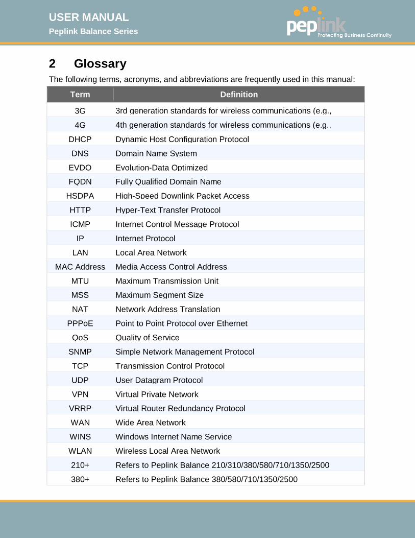
2 Glossary The following terms, acronyms, and abbreviations are frequently used in this manual:
Term Definition
3G 3rd generation standards for wireless communications (e.g., 4G 4th generation standards for wireless communications (e.g., DHCP Dynamic Host Configuration Protocol
DNS Domain Name System
EVDO Evolution-Data Optimized
FQDN Fully Qualified Domain Name
HSDPA High-Speed Downlink Packet Access
HTTP Hyper-Text Transfer Protocol
ICMP Internet Control Message Protocol
IP Internet Protocol
LAN Local Area Network
MAC Address Media Access Control Address
MTU Maximum Transmission Unit
MSS Maximum Segment Size
NAT Network Address Translation
PPPoE Point to Point Protocol over Ethernet
QoS Quality of Service
SNMP Simple Network Management Protocol
TCP Transmission Control Protocol
UDP User Datagram Protocol
VPN Virtual Private Network
VRRP Virtual Router Redundancy Protocol
WAN Wide Area Network
WINS Windows Internet Name Service
WLAN Wireless Local Area Network
210+ Refers to Peplink Balance 210/310/380/580/710/1350/2500
380+ Refers to Peplink Balance 380/580/710/1350/2500

USER MANUAL Peplink Balance Series
http://www.peplink.com -9 / 261 - Copyright © 2015 Peplink
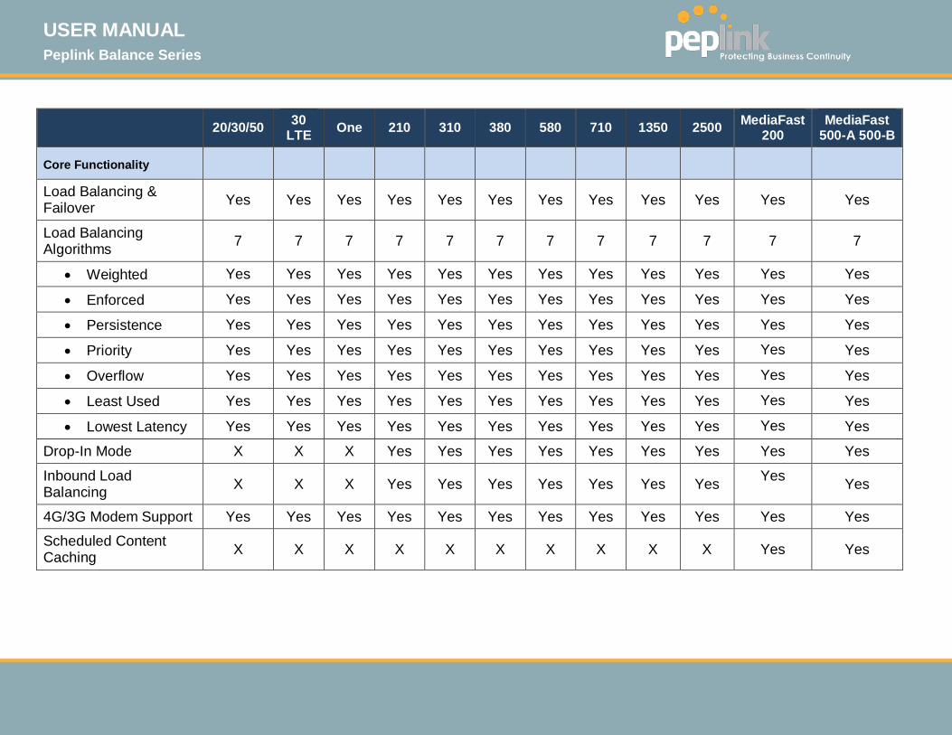
3 Product Comparison Chart
20/30/50 30 LTE One 210 310 380 580 710 1350 2500 MediaFast
200
MediaFast 500-A 500-B
Capacity
WAN Ports (GbE)/Internet Links
2/3/5 2 2 2 3 3 5 7 13 12 21 51
USB WAN Modem Port 1 1 1 1 1 1 1 1 1 1 1 1
Embedded LTE Modem X 1 X X X X X X X X X X
Recommended Users 1-25 1-25 1-50 1-50 1-50 50-
500 300-1000
500- 2000+
1000- 5000+
5000- 20000+ 1-50 300-1000
Router Throughput 100M 100M 1Gbps 200M 200M 400M 800M 1Gbps 2Gbps 8Gbps 80<M 250M
1 MediaFast 200 has WAN 1 activated. To activate WAN 2, a Load Balancing or SpeedFusion license is required. MediaFast 500-B WAN ports 1-5 are active by default. Load balancing or SpeedFusion license is required to activate MediaFast 500-A WAN ports 2-5.
USER MANUAL Peplink Balance Series
http://www.peplink.com -10 / 261 - Copyright © 2015 Peplink
20/30/50 30 LTE One 210 310 380 580 710 1350 2500 MediaFast
200 MediaFast
500-A 500-B
Core Functionality
Load Balancing & Failover Yes Yes Yes Yes Yes Yes Yes Yes Yes Yes Yes Yes
Load Balancing Algorithms 7 7 7 7 7 7 7 7 7 7 7 7
• Weighted Yes Yes Yes Yes Yes Yes Yes Yes Yes Yes Yes Yes
• Enforced Yes Yes Yes Yes Yes Yes Yes Yes Yes Yes Yes Yes
• Persistence Yes Yes Yes Yes Yes Yes Yes Yes Yes Yes Yes Yes
• Priority Yes Yes Yes Yes Yes Yes Yes Yes Yes Yes Yes Yes
• Overflow Yes Yes Yes Yes Yes Yes Yes Yes Yes Yes Yes Yes
• Least Used Yes Yes Yes Yes Yes Yes Yes Yes Yes Yes Yes Yes
• Lowest Latency Yes Yes Yes Yes Yes Yes Yes Yes Yes Yes Yes Yes
Drop-In Mode X X X Yes Yes Yes Yes Yes Yes Yes Yes Yes
Inbound Load Balancing X X X Yes Yes Yes Yes Yes Yes Yes Yes Yes
4G/3G Modem Support Yes Yes Yes Yes Yes Yes Yes Yes Yes Yes Yes Yes
Scheduled Content Caching X X X X X X X X X X Yes Yes
USER MANUAL Peplink Balance Series
http://www.peplink.com -11 / 261 - Copyright © 2015 Peplink
20/30/50 30 LTE One 210 310 380 580 710 1350 2500 MediaFast
200
MediaFast 500-A 500-B
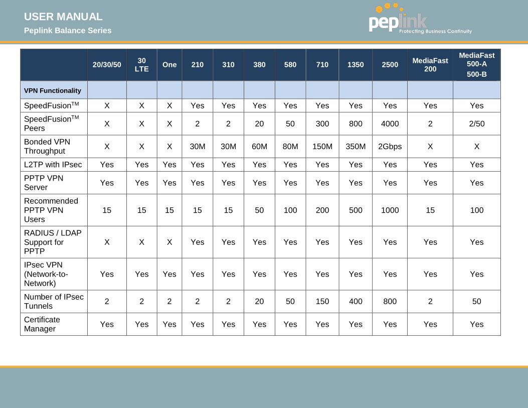
VPN Functionality
SpeedFusionTM X X X Yes Yes Yes Yes Yes Yes Yes Yes Yes
SpeedFusionTM
Peers X X X 2 2 20 50 300 800 4000 2 2/50
Bonded VPN Throughput X X X 30M 30M 60M 80M 150M 350M 2Gbps X X
L2TP with IPsec Yes Yes Yes Yes Yes Yes Yes Yes Yes Yes Yes Yes
PPTP VPN Server Yes Yes Yes Yes Yes Yes Yes Yes Yes Yes Yes Yes
Recommended PPTP VPN Users
15 15 15 15 15 50 100 200 500 1000 15 100
RADIUS / LDAP Support for PPTP
X X X Yes Yes Yes Yes Yes Yes Yes Yes Yes
IPsec VPN (Network-to-Network)
Yes Yes Yes Yes Yes Yes Yes Yes Yes Yes Yes Yes
Number of IPsec Tunnels 2 2 2 2 2 20 50 150 400 800 2 50
Certificate Manager Yes Yes Yes Yes Yes Yes Yes Yes Yes Yes Yes Yes
USER MANUAL Peplink Balance Series
http://www.peplink.com -12 / 261 - Copyright © 2015 Peplink
20/30/50 30 LTE One 210 310 380 580 710 1350 2500 MediaFast 200
MediaFast 500-A 500-B
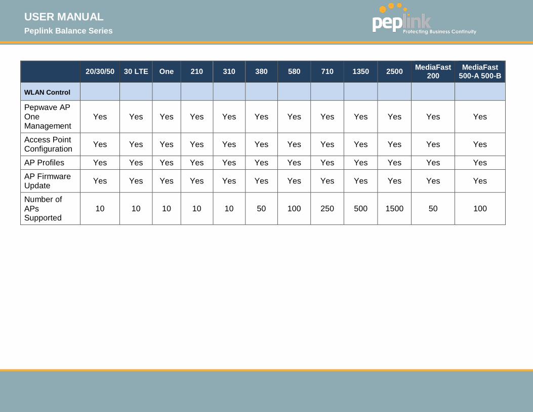
WLAN Control
Pepwave AP One Management
Yes Yes Yes Yes Yes Yes Yes Yes Yes Yes Yes Yes
Access Point Configuration Yes Yes Yes Yes Yes Yes Yes Yes Yes Yes Yes Yes
AP Profiles Yes Yes Yes Yes Yes Yes Yes Yes Yes Yes Yes Yes
AP Firmware Update Yes Yes Yes Yes Yes Yes Yes Yes Yes Yes Yes Yes
Number of APs Supported
10 10 10 10 10 50 100 250 500 1500 50 100

USER MANUAL Peplink Balance Series
http://www.peplink.com -13 / 261 - Copyright © 2015 Peplink
20/30/50 30 LTE One 210 310 380 580 710 1350 2500 MediaFast 200
MediaFast 500-A 500-B
Advanced QoS
Bandwidth Usage Monitor
Yes Yes Yes Yes Yes Yes Yes Yes Yes Yes Yes Yes
QoS for VoIP and Ecommerce
Yes Yes Yes Yes Yes Yes Yes Yes Yes Yes Yes Yes
DSL/Cable Optimization Yes Yes Yes Yes Yes Yes Yes Yes Yes Yes Yes Yes
Application Prioritization Yes Yes Yes Yes Yes Yes Yes Yes Yes Yes Yes Yes
Application Prioritization by User Group
X X X X X Yes Yes Yes Yes Yes Yes Yes
User Group Bandwidth Reservation
X X X X X Yes Yes Yes Yes Yes Yes Yes
Individual Bandwidth Limit
Yes Yes Yes Yes Yes Yes Yes Yes Yes Yes Yes Yes
USER MANUAL Peplink Balance Series
http://www.peplink.com -14 / 261 - Copyright © 2015 Peplink
20/30/50 30 LTE One 210 310 380 580 710 1350 2500 MediaFast
200 MediaFast
500-A 500-B
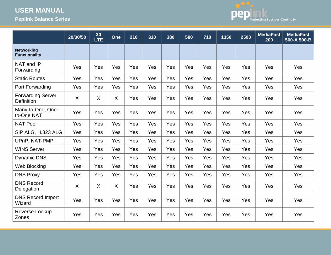
Networking Functionality
NAT and IP Forwarding Yes Yes Yes Yes Yes Yes Yes Yes Yes Yes Yes Yes
Static Routes Yes Yes Yes Yes Yes Yes Yes Yes Yes Yes Yes Yes
Port Forwarding Yes Yes Yes Yes Yes Yes Yes Yes Yes Yes Yes Yes
Forwarding Server Definition X X X Yes Yes Yes Yes Yes Yes Yes Yes Yes
Many-to-One, One-to-One NAT Yes Yes Yes Yes Yes Yes Yes Yes Yes Yes Yes Yes
NAT Pool Yes Yes Yes Yes Yes Yes Yes Yes Yes Yes Yes Yes
SIP ALG, H.323 ALG Yes Yes Yes Yes Yes Yes Yes Yes Yes Yes Yes Yes
UPnP, NAT-PMP Yes Yes Yes Yes Yes Yes Yes Yes Yes Yes Yes Yes
WINS Server Yes Yes Yes Yes Yes Yes Yes Yes Yes Yes Yes Yes
Dynamic DNS Yes Yes Yes Yes Yes Yes Yes Yes Yes Yes Yes Yes
Web Blocking Yes Yes Yes Yes Yes Yes Yes Yes Yes Yes Yes Yes
DNS Proxy Yes Yes Yes Yes Yes Yes Yes Yes Yes Yes Yes Yes
DNS Record Delegation X X X Yes Yes Yes Yes Yes Yes Yes Yes Yes
DNS Record Import Wizard Yes Yes Yes Yes Yes Yes Yes Yes Yes Yes Yes Yes
Reverse Lookup Zones Yes Yes Yes Yes Yes Yes Yes Yes Yes Yes Yes Yes

USER MANUAL Peplink Balance Series
http://www.peplink.com -15 / 261 - Copyright © 2015 Peplink
Inter-VLAN Routing Yes Yes Yes Yes Yes Yes Yes Yes Yes Yes Yes Yes
DHCP Relay Yes Yes Yes Yes Yes Yes Yes Yes Yes Yes Yes Yes
BOOTP Support Yes Yes Yes Yes Yes Yes Yes Yes Yes Yes Yes Yes
Inbound Access Services Yes Yes Yes Yes Yes Yes Yes Yes Yes Yes Yes Yes
Outbound Policy Management Yes Yes Yes Yes Yes Yes Yes Yes Yes Yes Yes Yes
LACP (802.3ad) support X X X X X Yes Yes Yes Yes Yes X Yes
OSPF and RIPv2 Support Yes Yes Yes Yes Yes Yes Yes Yes Yes Yes Yes Yes
Service/SMTP/Web Proxy/DNS Forwarding
Yes Yes Yes Yes Yes Yes Yes Yes Yes Yes Yes Yes
Service Passthrough Yes Yes Yes Yes Yes Yes Yes Yes Yes Yes Yes Yes
Ping/Traceroute Test Yes Yes Yes Yes Yes Yes Yes Yes Yes Yes Yes Yes
PepVPN Test/Analyzer X X X Yes Yes Yes Yes Yes Yes Yes Yes Yes
CLI Support Yes Yes Yes Yes Yes Yes Yes Yes Yes Yes Yes Yes

USER MANUAL Peplink Balance Series
http://www.peplink.com -16 / 261 - Copyright © 2015 Peplink
20/30/50 30 LTE One 210 310 380 580 710 1350 2500 MediaFast 200
MediaFast 500-A 500-B
Device
Web Administrative Interface
Yes Yes Yes Yes Yes Yes Yes Yes Yes Yes Yes Yes
Admin/User Access Levels Yes Yes Yes Yes Yes Yes Yes Yes Yes Yes Yes Yes
Active Client List Yes Yes Yes Yes Yes Yes Yes Yes Yes Yes Yes Yes
Active Session List Yes Yes Yes Yes Yes Yes Yes Yes Yes Yes Yes Yes
WINS Client List Yes Yes Yes Yes Yes Yes Yes Yes Yes Yes Yes Yes
Bandwidth Allowance Monitor
Yes Yes Yes Yes Yes Yes Yes Yes Yes Yes Yes Yes
Web Reporting Services Yes Yes Yes Yes Yes Yes Yes Yes Yes Yes Yes Yes
Email Notification Yes Yes Yes Yes Yes Yes Yes Yes Yes Yes Yes Yes
Syslog Yes Yes Yes Yes Yes Yes Yes Yes Yes Yes Yes Yes
SNMP v1, v2c and v3 Yes Yes Yes Yes Yes Yes Yes Yes Yes Yes Yes Yes
InControl Yes Yes Yes Yes Yes Yes Yes Yes Yes Yes Yes Yes
WAN Health Yes Yes Yes Yes Yes Yes Yes Yes Yes Yes Yes Yes
USER MANUAL Peplink Balance Series
http://www.peplink.com -17 / 261 - Copyright © 2015 Peplink
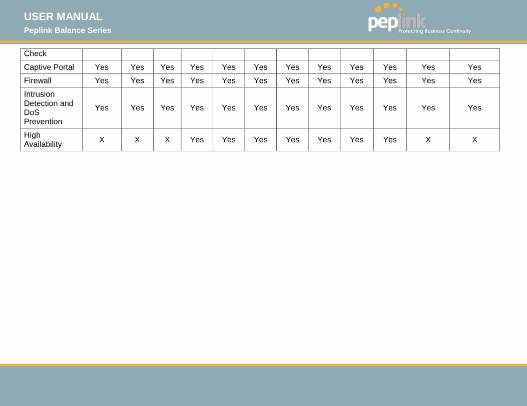
Check
Captive Portal Yes Yes Yes Yes Yes Yes Yes Yes Yes Yes Yes Yes
Firewall Yes Yes Yes Yes Yes Yes Yes Yes Yes Yes Yes Yes
Intrusion Detection and DoS Prevention
Yes Yes Yes Yes Yes Yes Yes Yes Yes Yes Yes Yes
High Availability X X X Yes Yes Yes Yes Yes Yes Yes X X
USER MANUAL Peplink Balance Series
http://www.peplink.com -18 / 261 - Copyright © 2015 Peplink
20/30/5
0 30 LTE One 210 310 380 580 710 1350 2500 MediaFast 200
MediaFast 500-A 500-B
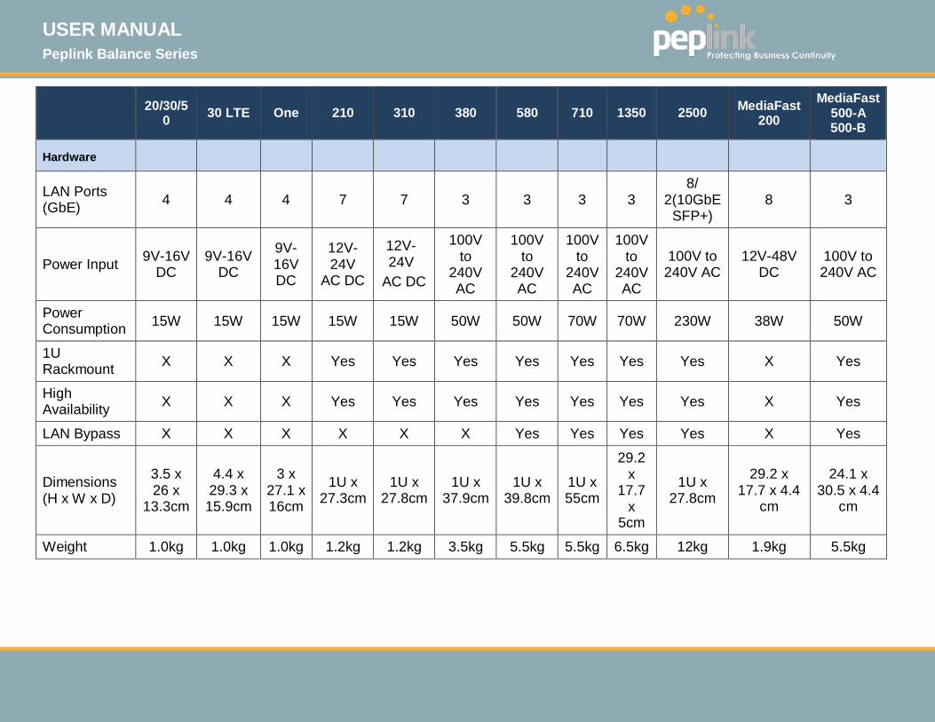
Hardware
LAN Ports (GbE) 4 4 4 7 7 3 3 3 3
8/ 2(10GbE
SFP+) 8 3
Power Input 9V-16V DC
9V-16V DC
9V-16V DC
12V-24V
AC DC
12V-24V
AC DC
100V to
240V AC
100V to
240V AC
100V to
240V AC
100V to
240V AC
100V to 240V AC
12V-48V DC
100V to 240V AC
Power Consumption 15W 15W 15W 15W 15W 50W 50W 70W 70W 230W 38W 50W
1U Rackmount X X X Yes Yes Yes Yes Yes Yes Yes X Yes
High Availability X X X Yes Yes Yes Yes Yes Yes Yes X Yes
LAN Bypass X X X X X X Yes Yes Yes Yes X Yes
Dimensions (H x W x D)
3.5 x 26 x
13.3cm
4.4 x 29.3 x
15.9cm
3 x 27.1 x 16cm
1U x 27.3cm
1U x 27.8cm
1U x 37.9cm
1U x 39.8cm
1U x 55cm
29.2 x
17.7 x
5cm
1U x 27.8cm
29.2 x 17.7 x 4.4
cm
24.1 x 30.5 x 4.4
cm
Weight 1.0kg 1.0kg 1.0kg 1.2kg 1.2kg 3.5kg 5.5kg 5.5kg 6.5kg 12kg 1.9kg 5.5kg
USER MANUAL Peplink Balance Series
http://www.peplink.com -19 / 261 - Copyright © 2015 Peplink
4 Product Features Peplink Balance Series products enable all LAN users to share broadband Internet connections and provide advanced features to enhance Internet access. The following is a list of supported features:
4.1 Supported Network Features
4.2 WAN Multiple public IP support (DHCP, PPPoE, static IP address) Static IP support for PPPoE 10/100/1000Mbps Ethernet connection in full/half duplex Built-in HSPA and EVDO cellular modems USB mobile connection (only one USB modem can be connected at a time) Drop-in mode on selectable WAN port with MAC address passthrough network
address translation (NAT) / port address translation (PAT) Inbound and outbound NAT mapping Multiple static IP addresses per WAN connection MAC address clone Customizable MTU and MSS values WAN connection health check Dynamic DNS (supported service providers: changeip.com, dyndns.org, no-
ip.org,tzo.com, and DNS-O-Matic) Ping, DNS lookup, and HTTP-based health check
4.3 LAN DHCP server on LAN Extended DHCP option support Static routing rules Local DNS proxy server VLAN on LAN support
4.4 VPN Secure SpeedFusionTM SpeedFusion performance analyzer X.509 certificate support (feature activation required on some Balance
models) Bandwidth bonding and failover among selected WAN connections Ability to route traffic to a remote VPN peer Optional pre-shared key setting
USER MANUAL Peplink Balance Series
http://www.peplink.com -20 / 261 - Copyright © 2015 Peplink
Layer 2 bridging Layer 2 Peer Isolation SpeedFusionTM throughput, ping, and traceroute tests Built-in L2TP / PPTP VPN server Authenticate L2TP / PPTP clients using RADIUS and LDAP servers Multi-Site PepVPN Profile IPsec VPN for network-to-network connections (works with Cisco and Juniper
only) L2TP / PPTP and IPsec passthrough
4.5 Inbound Traffic Management TCP/UDP traffic redirection to dedicated LAN server(s) Inbound link load balancing by means of DNS
4.6 Outbound Policy Link load distribution per TCP/UDP service Persistent routing for specified source and/or destination IP addresses per
TCP/UDP service Prioritize and route traffic to VPN tunnels with Priority and Enforced algorithms
4.7 AP Controller • Configure and manage Pepwave AP devices • Review the status of connected AP
4.8 QoS Quality of service for different applications and custom protocols User group classification for different service levels Bandwidth usage control and monitoring on group- and user-level Application prioritization for custom protocols and DSL optimization
4.9 Firewall Outbound (LAN to WAN) firewall rules Inbound (WAN to LAN) firewall rules per WAN connection Intrusion detection and prevention Specification of NAT mappings Web blocking
USER MANUAL Peplink Balance Series
http://www.peplink.com -21 / 261 - Copyright © 2015 Peplink
Outbound firewall rules can be defined by destination domain name
4.10 Captive Portal Social Wi-Fi Hotspot Support Splash screen of open networks, login page for secure networks Customizable built-in captive portal Supports linking to outside page for captive portal
4.11 Other Supported Features Easy-to-use web administration interface HTTP and HTTPS support for web administration interface Configurable web administration port and administrator password Read-only user for web admin Shared-IP drop-in mode Authentication and accounting by RADIUS server for web admin Firmware upgrades, configuration backups, ping, and traceroute via web
administration interface Remote web-based configuration (via WAN and LAN interfaces) Remote reporting to Peplink Balance reporting server Hardware high availability via VRRP, with automatic configuration
synchronization Real-time, hourly, daily and monthly bandwidth usage reports and charts Hardware backup via LAN bypass Built-in WINS server Time server synchronization SNMP Email notification Syslog SIP passthrough PPTP packet passthrough Active sessions Active client list WINS client list UPnP / NAT-PMP Improved active sessions page Event log is persistent across reboots IPv6 support Support for USB tethering on Android 2.2+ phones
USER MANUAL Peplink Balance Series
http://www.peplink.com -22 / 261 - Copyright © 2015 Peplink
5 Package Contents The contents of Peplink Balance product packages are as follows:
5.1 Peplink Balance One Peplink Balance One Power adapter Information slip
5.2 Peplink Balance 20/30/30 LTE/50 Peplink Balance 20/30/30 LTE/50 Power adapter Information slip
5.3 Peplink Balance 210/310 Peplink Balance 210/310 Power adapter Information slip Rackmount kit
5.4 Peplink Balance 305/380/580/710/1350/2500 Peplink Balance 305/380/580/710/1350/2500 Power cord Information slip Rackmount kit
5.5 Peplink MediaFast 200 Peplink MediaFast 200 Power adapter Information slip
5.6 Peplink MediaFast 500 Peplink MediaFast 500 Power cord Information slip Rackmount kit
USER MANUAL Peplink Balance Series
http://www.peplink.com -23 / 261 - Copyright © 2015 Peplink
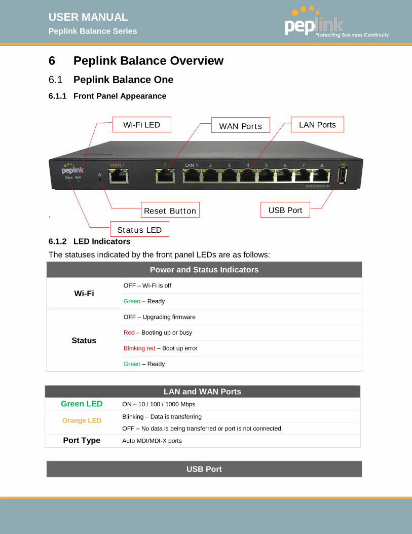
6 Peplink Balance Overview 6.1 Peplink Balance One 6.1.1 Front Panel Appearance
.
6.1.2 LED Indicators The statuses indicated by the front panel LEDs are as follows:
Power and Status Indicators
Wi-Fi OFF – Wi-Fi is off
Green – Ready
Status
OFF – Upgrading firmware
Red – Booting up or busy
Blinking red – Boot up error
Green – Ready
LAN and WAN Ports
Green LED ON – 10 / 100 / 1000 Mbps
Orange LED Blinking – Data is transferring
OFF – No data is being transferred or port is not connected
Port Type Auto MDI/MDI-X ports
USB Port
Status LED
USB Port
LAN Ports
WAN Ports
Reset Button
Wi-Fi LED
USER MANUAL Peplink Balance Series
http://www.peplink.com -24 / 261 - Copyright © 2015 Peplink
USB Ports For future functionality
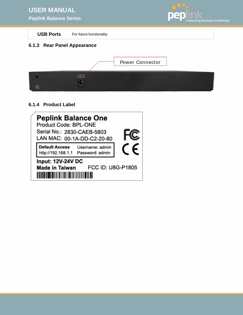
6.1.3 Rear Panel Appearance
6.1.4 Product Label
Power Connector
USER MANUAL Peplink Balance Series
http://www.peplink.com -25 / 261 - Copyright © 2015 Peplink
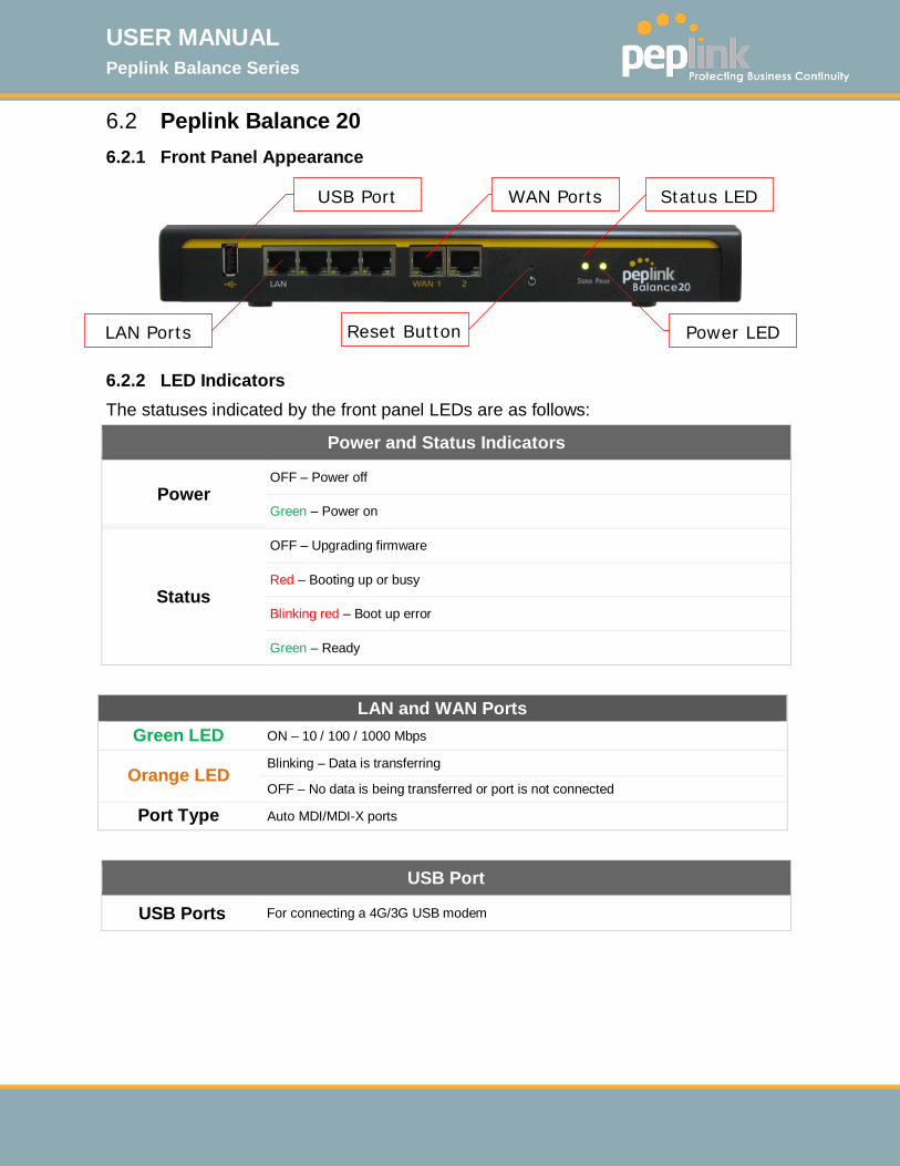
6.2 Peplink Balance 20 6.2.1 Front Panel Appearance
6.2.2 LED Indicators The statuses indicated by the front panel LEDs are as follows:
Power and Status Indicators
Power OFF – Power off
Green – Power on
Status
OFF – Upgrading firmware
Red – Booting up or busy
Blinking red – Boot up error
Green – Ready
LAN and WAN Ports
Green LED ON – 10 / 100 / 1000 Mbps
Orange LED Blinking – Data is transferring
OFF – No data is being transferred or port is not connected
Port Type Auto MDI/MDI-X ports
USB Port
USB Ports For connecting a 4G/3G USB modem
LAN Ports
Power LED
Reset Button
Status LED
WAN Ports
USB Port

USER MANUAL Peplink Balance Series
http://www.peplink.com -26 / 261 - Copyright © 2015 Peplink
6.2.3 Rear Panel Appearance
6.2.4 Unit Base Appearance
Serial Number and LAN MAC Address
Power Connector
Kensington Security Slot
USER MANUAL Peplink Balance Series
http://www.peplink.com -27 / 261 - Copyright © 2015 Peplink
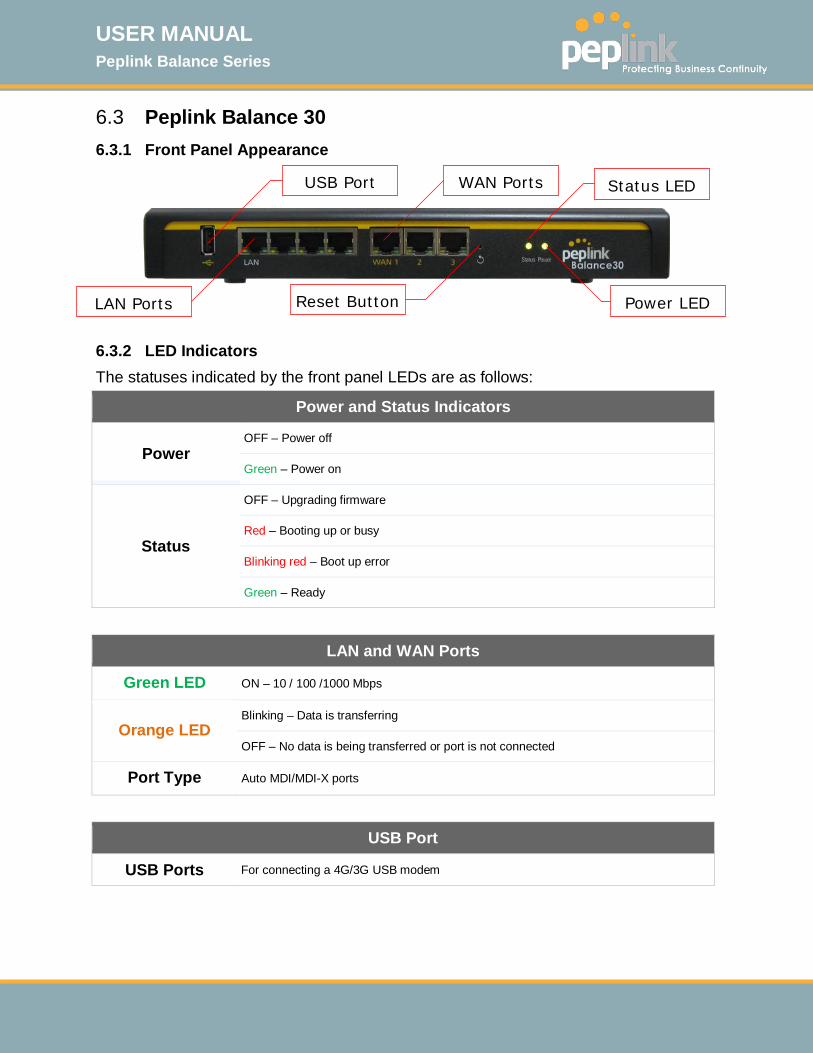
6.3 Peplink Balance 30 6.3.1 Front Panel Appearance
6.3.2 LED Indicators The statuses indicated by the front panel LEDs are as follows:
Power and Status Indicators
Power OFF – Power off
Green – Power on
Status
OFF – Upgrading firmware
Red – Booting up or busy
Blinking red – Boot up error
Green – Ready
LAN and WAN Ports
Green LED ON – 10 / 100 /1000 Mbps
Orange LED Blinking – Data is transferring
OFF – No data is being transferred or port is not connected
Port Type Auto MDI/MDI-X ports
USB Port
USB Ports For connecting a 4G/3G USB modem
Reset Button
Power LED
Status LED
LAN Ports
WAN Ports
USB Port
USER MANUAL Peplink Balance Series
http://www.peplink.com -28 / 261 - Copyright © 2015 Peplink
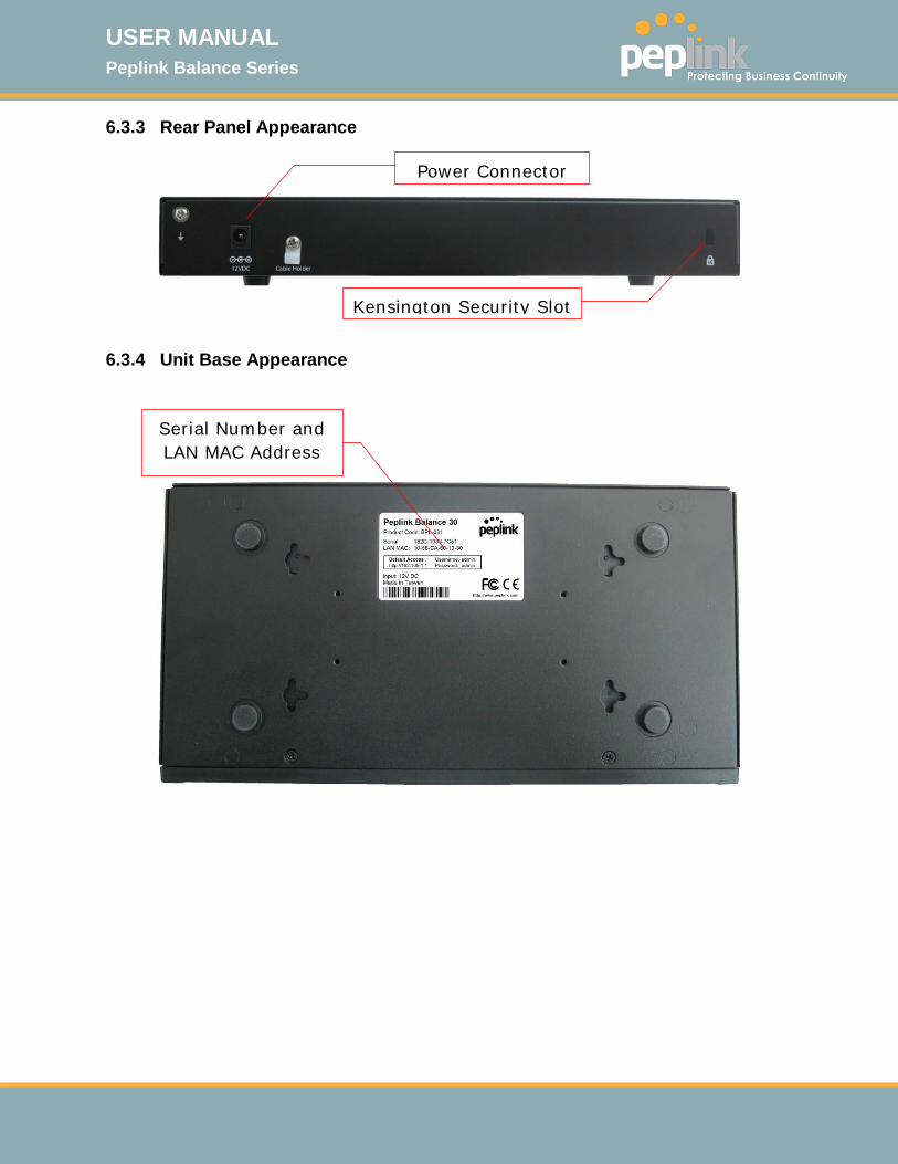
6.3.3 Rear Panel Appearance
6.3.4 Unit Base Appearance
Serial Number and LAN MAC Address
Power Connector
Kensington Security Slot
USER MANUAL Peplink Balance Series
http://www.peplink.com -29 / 261 - Copyright © 2015 Peplink
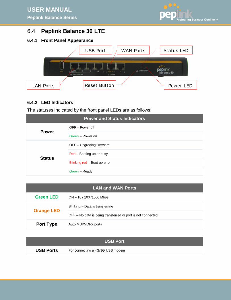
6.4 Peplink Balance 30 LTE 6.4.1 Front Panel Appearance
6.4.2 LED Indicators The statuses indicated by the front panel LEDs are as follows:
Power and Status Indicators
Power OFF – Power off
Green – Power on
Status
OFF – Upgrading firmware
Red – Booting up or busy
Blinking red – Boot up error
Green – Ready
LAN and WAN Ports
Green LED ON – 10 / 100 /1000 Mbps
Orange LED Blinking – Data is transferring
OFF – No data is being transferred or port is not connected
Port Type Auto MDI/MDI-X ports
USB Port
USB Ports For connecting a 4G/3G USB modem
Reset Button
Power LED
Status LED
LAN Ports
WAN Ports
USB Port

USER MANUAL Peplink Balance Series
http://www.peplink.com -30 / 261 - Copyright © 2015 Peplink
6.4.3 Rear Panel Appearance
6.4.4 Unit Base Appearance
Serial Number and LAN MAC Address
Power Connector
Cellular SIM Slot

USER MANUAL Peplink Balance Series
http://www.peplink.com -31 / 261 - Copyright © 2015 Peplink
6.5 Peplink Balance 50 6.5.1 Front Panel Appearance
6.5.2 LED Indicators The statuses indicated by the front panel LEDs are as follows:
Power and Status Indicators
Power OFF – Power off
Green – Power on
Status
OFF – Upgrading firmware
Red – Booting up or busy
Blinking red – Boot up error
Green – Ready
LAN and WAN Ports
Green LED ON – 10 / 100 /1000 Mbps
Orange LED Blinking – Data is transferring
OFF – No data is being transferred or port is not connected
Port Type Auto MDI/MDI-X ports
USB Port
USB Ports For connecting a 4G/3G USB modem
USB Port
LAN Ports
WAN Ports
Reset Button
Status LED
Power LED
USER MANUAL Peplink Balance Series
http://www.peplink.com -32 / 261 - Copyright © 2015 Peplink
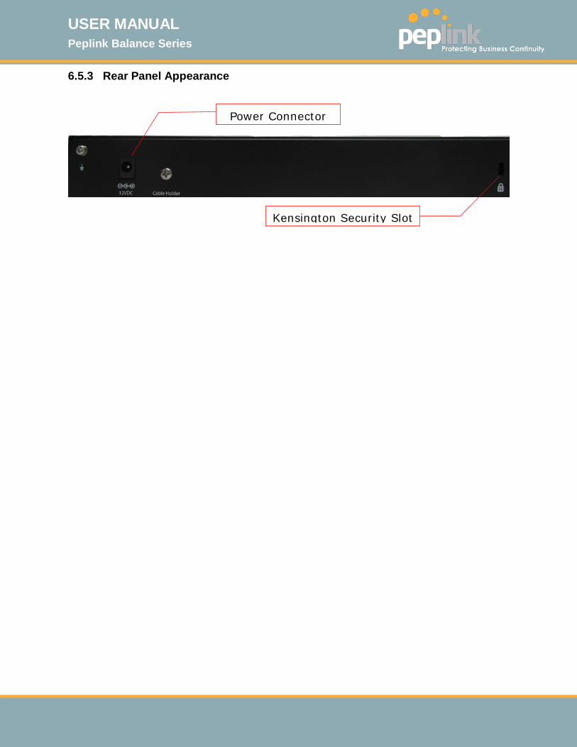
6.5.3 Rear Panel Appearance
Power Connector
Kensington Security Slot
USER MANUAL Peplink Balance Series
http://www.peplink.com -33 / 261 - Copyright © 2015 Peplink
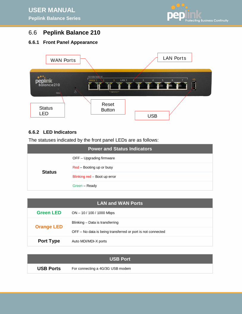
6.6 Peplink Balance 210 6.6.1 Front Panel Appearance
6.6.2 LED Indicators The statuses indicated by the front panel LEDs are as follows:
Power and Status Indicators
Status
OFF – Upgrading firmware
Red – Booting up or busy
Blinking red – Boot up error
Green – Ready
LAN and WAN Ports
Green LED ON – 10 / 100 / 1000 Mbps
Orange LED Blinking – Data is transferring
OFF – No data is being transferred or port is not connected
Port Type Auto MDI/MDI-X ports
USB Port
USB Ports For connecting a 4G/3G USB modem
WAN Ports
LAN Ports
Status LED
Reset Button
USB
USER MANUAL Peplink Balance Series
http://www.peplink.com -34 / 261 - Copyright © 2015 Peplink
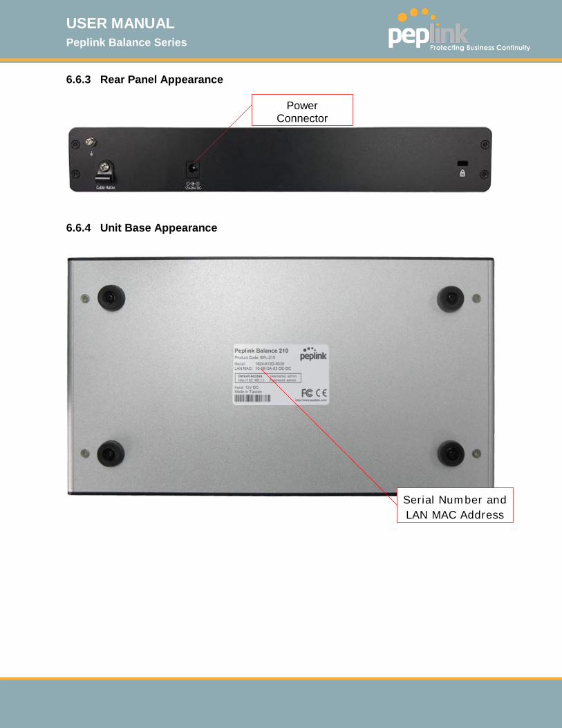
6.6.3 Rear Panel Appearance
6.6.4 Unit Base Appearance
Serial Number and LAN MAC Address
Power Connector
USER MANUAL Peplink Balance Series
http://www.peplink.com -35 / 261 - Copyright © 2015 Peplink
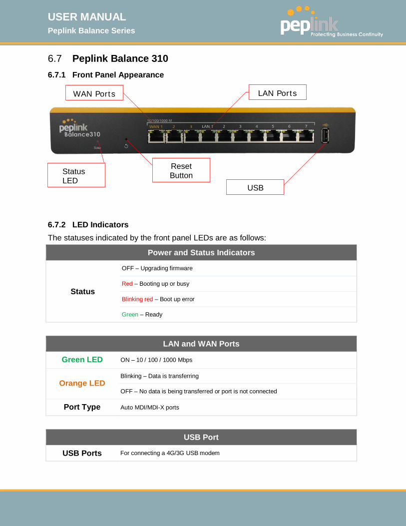
6.7 Peplink Balance 310 6.7.1 Front Panel Appearance
6.7.2 LED Indicators The statuses indicated by the front panel LEDs are as follows:
Power and Status Indicators
Status
OFF – Upgrading firmware
Red – Booting up or busy
Blinking red – Boot up error
Green – Ready
LAN and WAN Ports
Green LED ON – 10 / 100 / 1000 Mbps
Orange LED Blinking – Data is transferring
OFF – No data is being transferred or port is not connected
Port Type Auto MDI/MDI-X ports
USB Port
USB Ports For connecting a 4G/3G USB modem
WAN Ports
LAN Ports
Status LED
Reset Button
USB
USER MANUAL Peplink Balance Series
http://www.peplink.com -36 / 261 - Copyright © 2015 Peplink
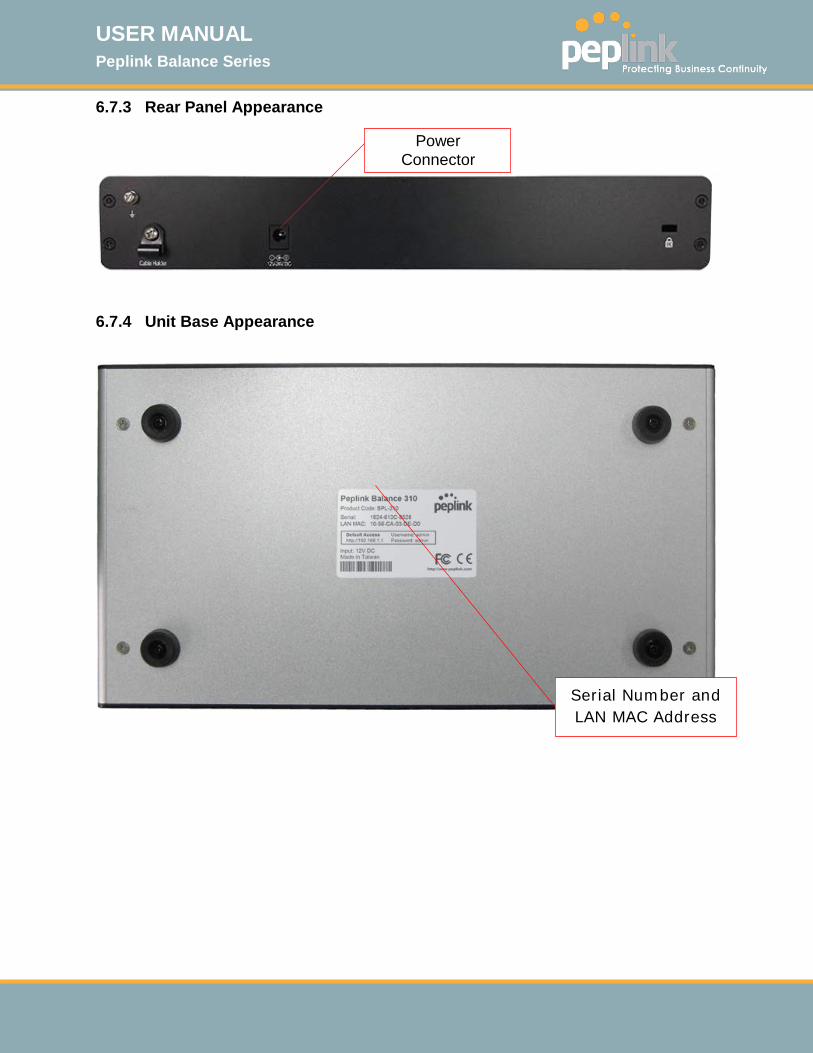
6.7.3 Rear Panel Appearance
6.7.4 Unit Base Appearance
Serial Number and LAN MAC Address
Power Connector
USER MANUAL Peplink Balance Series
http://www.peplink.com -37 / 261 - Copyright © 2015 Peplink
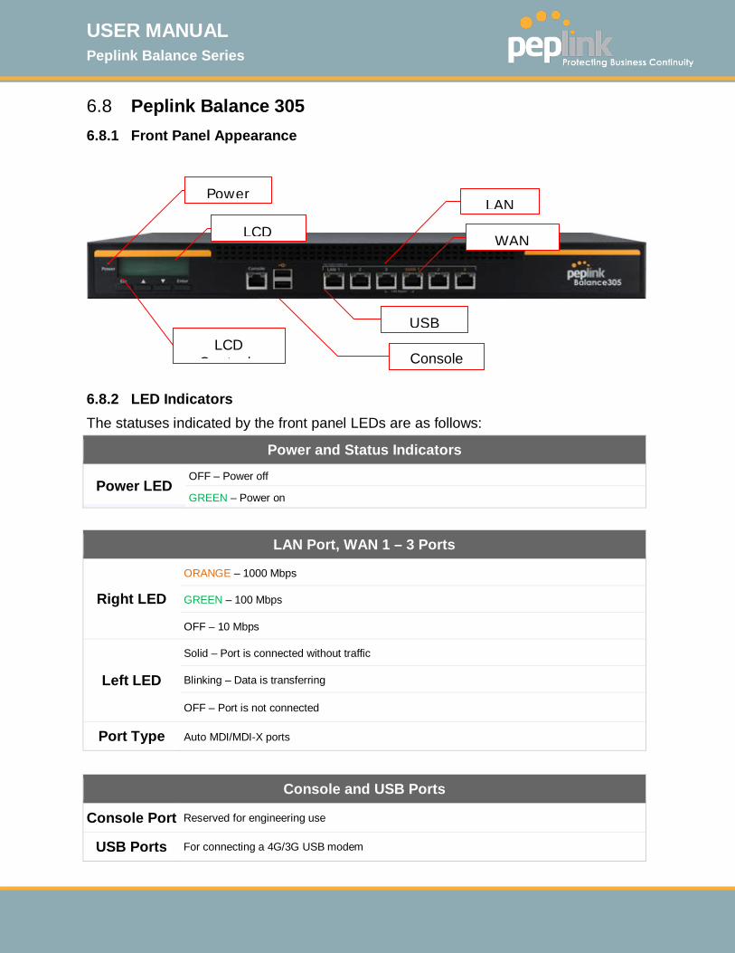
6.8 Peplink Balance 305 6.8.1 Front Panel Appearance
6.8.2 LED Indicators The statuses indicated by the front panel LEDs are as follows:
Power and Status Indicators
Power LED OFF – Power off
GREEN – Power on
LAN Port, WAN 1 – 3 Ports
Right LED
ORANGE – 1000 Mbps
GREEN – 100 Mbps
OFF – 10 Mbps
Left LED
Solid – Port is connected without traffic
Blinking – Data is transferring
OFF – Port is not connected
Port Type Auto MDI/MDI-X ports
Console and USB Ports
Console Port Reserved for engineering use
USB Ports For connecting a 4G/3G USB modem
LCD
Console LCD
C t l
LAN
Power
WAN
USB

USER MANUAL Peplink Balance Series
http://www.peplink.com -38 / 261 - Copyright © 2015 Peplink
6.8.3 LCD Display Menu
> HA State: Master/Slave > LAN IP > VIP > System Status > System > Firmware ver. (shows firmware version) > Serial number (shows serial number) > System time (shows current time) > System up time (shows system uptime since last reboot) > CPU load (shows current CPU loading, 0-100%) > LAN > Status (shows LAN port physical status) > IP address (shows LAN IP address) > Subnet mask (shows LAN subnet mask) > Link status (shows Connected/Disconnected, IP address list) > WAN1 > WAN2 > WAN3 > VPN status (shows Connected/Disconnected) >VPN Profile 1 >VPN Profile 2 >… >VPN Profile n > Link usage > Throughput in (shows transfer rate in Kbps) > WAN1 > WAN2 > WAN3 > Throughput out (shows transfer rate in Kbps) > WAN1 > WAN2 > WAN3 > Data Transfer’d (shows volume transferred since last reboot in MB) > WAN1 > WAN2 > WAN3 > Maintenance > Reboot > Reboot? (Yes/No) (to reboot the unit) > Factory default > Factory default? (Yes/No) (to restore factory defaults) > LAN config > Port speed (shows port speed: Auto, 10baseT-FD, 10baseT-HD, > LAN 100baseTx-FD, 100baseTx-HD, 1000baseTx-FD) > WAN1 > WAN2 > WAN3

USER MANUAL Peplink Balance Series
http://www.peplink.com -39 / 261 - Copyright © 2015 Peplink
6.8.4 Rear Panel Appearance
Connector Ports
Power Connector AC input 110/220V
Switch
Power Switch Pressing and holding the key for 4 seconds will power down the unit. When the unit is powered off, pressing this switch will power on the unit
6.8.5 Unit Label Appearance
Power Connector
Power Switch
Serial Number and
LAN MAC Address

USER MANUAL Peplink Balance Series
http://www.peplink.com -40 / 261 - Copyright © 2015 Peplink
6.9 Peplink Balance 380 6.9.1 Front Panel Appearance
6.9.2 LED Indicators The statuses indicated by the front panel LEDs are as follows:
Power and Status Indicators
Power LED OFF – Power off
GREEN – Power on
LAN Port, WAN 1 – 3 Ports
Right LED
ORANGE – 1000 Mbps
GREEN – 100 Mbps
OFF – 10 Mbps
Left LED
Solid – Port is connected without traffic
Blinking – Data is transferring
OFF – Port is not connected
Port Type Auto MDI/MDI-X ports
Console and USB Ports
Console Port Reserved for engineering use
USB Ports For connecting a 4G/3G USB modem
LCD
Console LCD
LAN
Power
WAN
USB

USER MANUAL Peplink Balance Series
http://www.peplink.com -41 / 261 - Copyright © 2015 Peplink
6.9.3 LCD Display Menu
> HA State: Master/Slave > LAN IP > VIP > System Status > System > Firmware ver. (shows firmware version) > Serial number (shows serial number) > System time (shows current time) > System up time (shows system uptime since last reboot) > CPU load (shows current CPU loading, 0-100%) > LAN > Status (shows LAN port physical status) > IP address (shows LAN IP address) > Subnet mask (shows LAN subnet mask) > Link status (shows Connected/Disconnected, IP address list) > WAN1 > WAN2 > WAN3 > VPN status (shows Connected/Disconnected) >VPN Profile 1 >VPN Profile 2 >… >VPN Profile n > Link usage > Throughput in (shows transfer rate in Kbps) > WAN1 > WAN2 > WAN3 > Throughput out (shows transfer rate in Kbps) > WAN1 > WAN2 > WAN3 > Data Transfer’d (shows volume transferred since last reboot in MB) > WAN1 > WAN2 > WAN3 > Maintenance > Reboot > Reboot? (Yes/No) (to reboot the unit) > Factory default > Factory default? (Yes/No) (to restore factory defaults) > LAN config > Port speed (shows port speed: Auto, 10baseT-FD, 10baseT-HD, > LAN 100baseTx-FD, 100baseTx-HD, 1000baseTx-FD) > WAN1 > WAN2 > WAN3
USER MANUAL Peplink Balance Series
http://www.peplink.com -42 / 261 - Copyright © 2015 Peplink
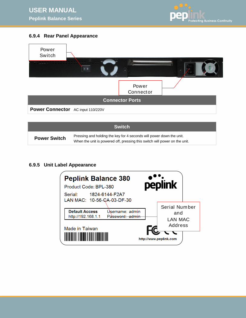
6.9.4 Rear Panel Appearance
Connector Ports
Power Connector AC input 110/220V
Switch
Power Switch Pressing and holding the key for 4 seconds will power down the unit. When the unit is powered off, pressing this switch will power on the unit.
6.9.5 Unit Label Appearance
Power Connector
Power Switch
Serial Number and
LAN MAC Address
USER MANUAL Peplink Balance Series
http://www.peplink.com -43 / 261 - Copyright © 2015 Peplink
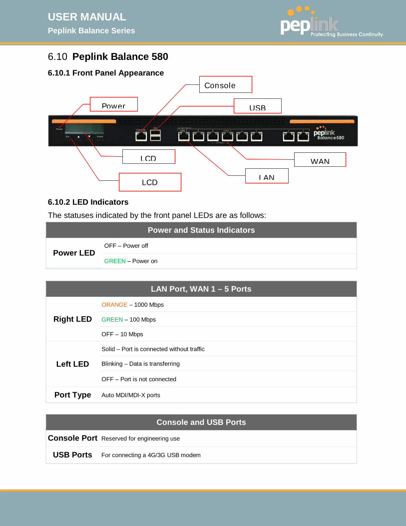
6.10 Peplink Balance 580 6.10.1 Front Panel Appearance
6.10.2 LED Indicators The statuses indicated by the front panel LEDs are as follows:
Power and Status Indicators
Power LED OFF – Power off
GREEN – Power on
LAN Port, WAN 1 – 5 Ports
Right LED
ORANGE – 1000 Mbps
GREEN – 100 Mbps
OFF – 10 Mbps
Left LED
Solid – Port is connected without traffic
Blinking – Data is transferring
OFF – Port is not connected
Port Type Auto MDI/MDI-X ports
Console and USB Ports
Console Port Reserved for engineering use
USB Ports For connecting a 4G/3G USB modem
LCD
Console
LCD
LAN
Power
WAN
USB

USER MANUAL Peplink Balance Series
http://www.peplink.com -44 / 261 - Copyright © 2015 Peplink
6.10.3 LCD Display Menu
> HA State: Master/Slave > LAN IP > VIP > System Status > System > Firmware ver. (shows firmware version) > Serial number (shows serial number) > System time (shows current time) > System up time (shows system uptime since last reboot) > CPU load (shows current CPU loading, 0-100%) > LAN > Status (shows LAN port physical status) > IP address (shows LAN IP address) > Subnet mask (shows LAN subnet mask) > Link status (shows Connected/Disconnected, IP address list) > WAN1 > WAN2
> … >WAN5 > VPN status (shows Connected/Disconnected) >VPN Profile 1 >VPN Profile 2 >… >VPN Profile n > Link usage > Throughput in (shows transfer rate in Kbps) > WAN1 > WAN2
> … >WAN5 > Throughput out (shows transfer rate in Kbps) > WAN1 > WAN2
> … >WAN5 > Data Transfer’d (shows volume transferred since last reboot in MB) > WAN1 > WAN2
> … >WAN5 > Maintenance > Reboot > Reboot? (Yes/No) (to reboot the unit) > Factory default > Factory default? (Yes/No) (to restore factory defaults) > LAN config > Port speed (shows port speed: Auto, 10baseT-FD, 10baseT-HD, > LAN 100baseTx-FD, 100baseTx-HD, 1000baseTx-FD) > WAN1 > WAN2
> … >WAN5
USER MANUAL Peplink Balance Series
http://www.peplink.com -45 / 261 - Copyright © 2015 Peplink
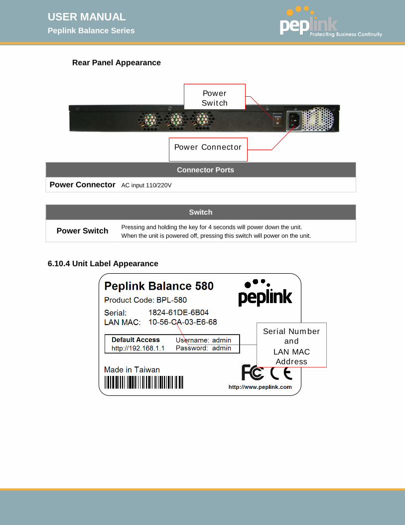
Rear Panel Appearance
Connector Ports
Power Connector AC input 110/220V
Switch
Power Switch Pressing and holding the key for 4 seconds will power down the unit. When the unit is powered off, pressing this switch will power on the unit.
6.10.4 Unit Label Appearance
Power Connector
Power Switch
Serial Number and
LAN MAC Address

USER MANUAL Peplink Balance Series
http://www.peplink.com -46 / 261 - Copyright © 2015 Peplink
6.11 Peplink Balance 710 6.11.1 Front Panel Appearance
Status indicated in the front panel is as follows:
LAN Port, WAN 1 – 7 Ports
Green LED ON – 1000 Mbps
OFF – 100/10 Mbps
Orange LED Solid – Port is connected without traffic
Blinking – Data is transferring
OFF – Port is not connected
Port Type Auto MDI/MDI-X ports
LED Indicator
Power LED OFF – Power off
GREEN – Power on
Console & USB Ports
Console Port Reserved for engineering use
USB Ports For connecting a 4G/3G USB modem
LCD
LCD C t l
WAN Port
LAN Port
Power
USB
Console

USER MANUAL Peplink Balance Series
http://www.peplink.com -47 / 261 - Copyright © 2015 Peplink
6.11.2 LCD Display Menu
> HA State: Master/Slave >LAN IP > VIP > System Status > System > Firmware ver. (shows firmware version) > Serial number (shows serial number) > System time (shows current time) > System up time (shows system uptime since last reboot) > CPU load (shows current CPU loading, 0-100%) > LAN > Status (shows LAN port physical status) > IP address (shows LAN IP address) > Subnet mask (shows LAN subnet mask) > Link status (shows Connected/Disconnected, IP address list) > WAN1 > WAN2 > … > WAN7 > VPN status (shows Connected/Disconnected) >VPN Profile 1 >VPN Profile 2 >… >VPN Profile n > Link usage > Throughput in (shows transfer rate in Kbps) > WAN1 > WAN2 > … > WAN7 > Throughput out (shows transfer rate in Kbps) > WAN1 > WAN2 > … > WAN7 > Data Transfer’d (shows volume transferred since last reboot in MB) > WAN1 > WAN2 > … > WAN7 > Maintenance > Reboot > Reboot? (Yes/No) (to reboot the unit) > Factory default > Factory default? (Yes/No) (to restore factory defaults) > LAN config > Port speed (shows port speed: Auto, 10baseT-FD, > LAN 10baseT-HD, 100baseTx-FD, 100baseTx-HD, > WAN1 1000baseTx-FD) > WAN2 > … > WAN7
USER MANUAL Peplink Balance Series
http://www.peplink.com -48 / 261 - Copyright © 2015 Peplink
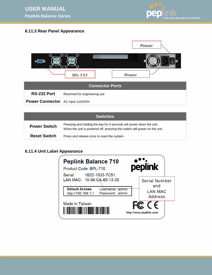
6.11.3 Rear Panel Appearance
Connector Ports
RS-232 Port Reserved for engineering use
Power Connector AC input 110/220V
Switches
Power Switch Pressing and holding the key for 4 seconds will power down the unit. When the unit is powered off, pressing this switch will power on the unit.
Reset Switch Press and release once to reset the system.
6.11.4 Unit Label Appearance
RS-232
Power
Power
Serial Number and
LAN MAC Address
USER MANUAL Peplink Balance Series
http://www.peplink.com -49 / 261 - Copyright © 2015 Peplink
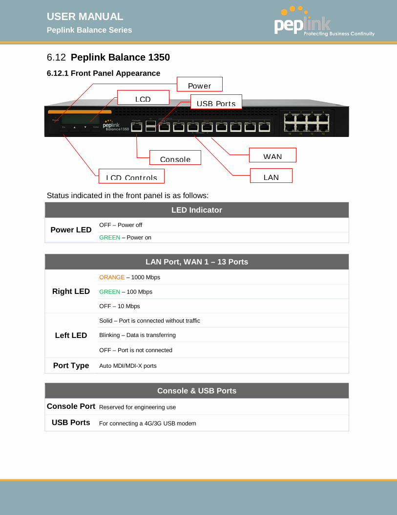
6.12 Peplink Balance 1350 6.12.1 Front Panel Appearance Status indicated in the front panel is as follows:
LAN Port, WAN 1 – 13 Ports
Right LED
ORANGE – 1000 Mbps
GREEN – 100 Mbps
OFF – 10 Mbps
Left LED
Solid – Port is connected without traffic
Blinking – Data is transferring
OFF – Port is not connected
Port Type Auto MDI/MDI-X ports
LED Indicator
Power LED OFF – Power off
GREEN – Power on
Console & USB Ports
Console Port Reserved for engineering use
USB Ports For connecting a 4G/3G USB modem
Console
LCD Controls
LAN
WAN
Power
LCD
USB Ports
USER MANUAL Peplink Balance Series
http://www.peplink.com -50 / 261 - Copyright © 2015 Peplink
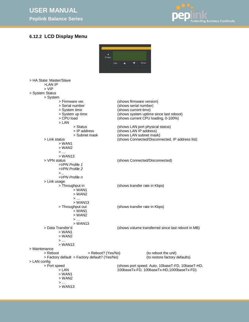
6.12.2 LCD Display Menu
> HA State: Master/Slave >LAN IP > VIP > System Status > System > Firmware ver. (shows firmware version) > Serial number (shows serial number) > System time (shows current time) > System up time (shows system uptime since last reboot) > CPU load (shows current CPU loading, 0-100%) > LAN > Status (shows LAN port physical status) > IP address (shows LAN IP address) > Subnet mask (shows LAN subnet mask) > Link status (shows Connected/Disconnected, IP address list) > WAN1 > WAN2 > … > WAN13 > VPN status (shows Connected/Disconnected) >VPN Profile 1 >VPN Profile 2 >… >VPN Profile n > Link usage > Throughput in (shows transfer rate in Kbps) > WAN1 > WAN2 > … > WAN13 > Throughput out (shows transfer rate in Kbps) > WAN1 > WAN2 > … > WAN13 > Data Transfer’d (shows volume transferred since last reboot in MB) > WAN1 > WAN2 > … > WAN13 > Maintenance > Reboot > Reboot? (Yes/No) (to reboot the unit) > Factory default > Factory default? (Yes/No) (to restore factory defaults) > LAN config > Port speed (shows port speed: Auto, 10baseT-FD, 10baseT-HD, > LAN 100baseTx-FD, 100baseTx-HD,1000baseTx-FD) > WAN1 > WAN2 > … > WAN13

USER MANUAL Peplink Balance Series
http://www.peplink.com -51 / 261 - Copyright © 2015 Peplink
6.12.3 Rear Panel Appearance
Connector Ports
Power Connector AC input 110/220V
Switches
Power Switch Pressing and holding the key for 4 seconds will power down the unit. When the unit is powered off, pressing this switch will power on the unit.
6.12.4 Unit Label Appearance
Power Connector
Power Switch
Serial Number and
LAN MAC Address
USER MANUAL Peplink Balance Series
http://www.peplink.com -52 / 261 - Copyright © 2015 Peplink
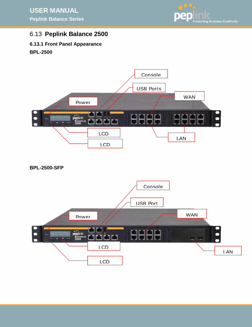
6.13 Peplink Balance 2500 6.13.1 Front Panel Appearance BPL-2500
BPL-2500-SFP
Console
LCD
Power
LCD
WAN
LAN
USB Ports
Console
LCD
Power
LCD
WAN
LAN
USB Port
USER MANUAL Peplink Balance Series
http://www.peplink.com -53 / 261 - Copyright © 2015 Peplink
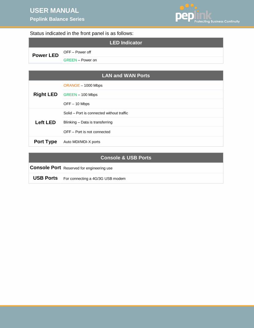
Status indicated in the front panel is as follows:
LAN and WAN Ports
Right LED
ORANGE – 1000 Mbps
GREEN – 100 Mbps
OFF – 10 Mbps
Left LED
Solid – Port is connected without traffic
Blinking – Data is transferring
OFF – Port is not connected
Port Type Auto MDI/MDI-X ports
LED Indicator
Power LED OFF – Power off
GREEN – Power on
Console & USB Ports
Console Port Reserved for engineering use
USB Ports For connecting a 4G/3G USB modem

USER MANUAL Peplink Balance Series
http://www.peplink.com -54 / 261 - Copyright © 2015 Peplink
6.13.2 LCD Display Menu
> HA State: Master/Slave >LAN IP > VIP > System Status > System > Firmware ver. (shows firmware version) > Serial number (shows serial number) > System time (shows current time) > System up time (shows system uptime since last reboot) > CPU load (shows current CPU loading, 0-100%) > LAN > Status (shows LAN port physical status) > IP address (shows LAN IP address) > Subnet mask (shows LAN subnet mask) > Link status (shows Connected/Disconnected, IP address list) > WAN1 > WAN2 > … > WAN13 > VPN status (shows Connected/Disconnected) >VPN Profile 1 >VPN Profile 2 >… >VPN Profile n > Link usage > Throughput in (shows transfer rate in Kbps) > WAN1 > WAN2 > … > WAN13 > Throughput out (shows transfer rate in Kbps) > WAN1 > WAN2 > … > WAN13 > Data Transfer’d (shows volume transferred since last reboot in MB) > WAN1 > WAN2 > … > WAN13 > Maintenance > Reboot > Reboot? (Yes/No) (to reboot the unit) > Factory default > Factory default? (Yes/No) (to restore factory defaults) > LAN config > Port speed (shows port speed: Auto, 10baseT-FD, 10baseT-HD, > LAN 100baseTx-FD, 100baseTx-HD,1000baseTx-FD) > WAN1 > WAN2 > … > WAN13
USER MANUAL Peplink Balance Series
http://www.peplink.com -55 / 261 - Copyright © 2015 Peplink
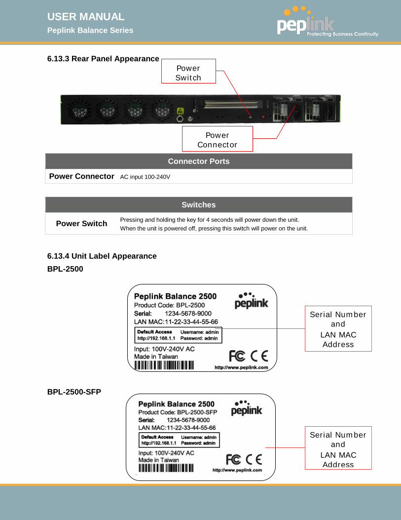
6.13.3 Rear Panel Appearance
Connector Ports
Power Connector AC input 100-240V
Switches
Power Switch Pressing and holding the key for 4 seconds will power down the unit. When the unit is powered off, pressing this switch will power on the unit.
6.13.4 Unit Label Appearance BPL-2500
BPL-2500-SFP
Power Connector
Power Switch
Serial Number and
LAN MAC Address
Serial Number and
LAN MAC Address

USER MANUAL Peplink Balance Series
http://www.peplink.com -56 / 261 - Copyright © 2015 Peplink
6.14 Peplink MediaFast 500 6.14.1 Front Panel Appearance
Status indicated in the front panel is as follows:
LAN 1-3 Ports, WAN 1-5 Ports
Right LED
ORANGE – 1000 Mbps
GREEN – 100 Mbps
OFF – 10 Mbps
Left LED
Solid – Port is connected without traffic
Blinking – Data is transferring
OFF – Port is not connected
Port Type Auto MDI/MDI-X ports
LED Indicator
Power LED OFF – Power off
GREEN – Power on
Console & USB Ports
Console Port Reserved for engineering use
USB Ports For connecting 4G/3G USB modems
Power
LCD
LCD Controls
Console
USB Ports
LAN
WAN
WAN

USER MANUAL Peplink Balance Series
http://www.peplink.com -57 / 261 - Copyright © 2015 Peplink
6.14.2 LCD Display Menu
> HA State: Master/Slave > LAN IP > VIP > System Status > System > Firmware ver. (shows firmware version) > Serial number (shows serial number) > System time (shows current time) > System up time (shows system uptime since last reboot) > CPU load (shows current CPU loading, 0-100%) > LAN > Status (shows LAN port physical status) > IP address (shows LAN IP address) > Subnet mask (shows LAN subnet mask) > Link status (shows Connected/Disconnected, IP address list) > WAN1 > WAN2
> … >WAN5 > VPN status (shows Connected/Disconnected) >VPN Profile 1 >VPN Profile 2 >… >VPN Profile n > Link usage > Throughput in (shows transfer rate in Kbps) > WAN1 > WAN2
> … >WAN5 > Throughput out (shows transfer rate in Kbps) > WAN1 > WAN2
> … >WAN5 > Data Transfer’d (shows volume transferred since last reboot in MB) > WAN1 > WAN2
> … >WAN5 > Maintenance > Reboot > Reboot? (Yes/No) (to reboot the unit) > Factory default > Factory default? (Yes/No) (to restore factory defaults) > LAN config > Port speed (shows port speed: Auto, 10baseT-FD, 10baseT-HD, > LAN 100baseTx-FD, 100baseTx-HD, 1000baseTx-FD) > WAN1 > WAN2
> … >WAN5

USER MANUAL Peplink Balance Series
http://www.peplink.com -58 / 261 - Copyright © 2015 Peplink
6.14.3 Rear Panel Appearance
Connector Ports
Power Connector AC input 100-240V
Switches
Power Switch Pressing and holding the key for 4 seconds will power down the unit. When the unit is powered off, pressing this switch will power on the unit.
Power Switch
Power Connector

USER MANUAL Peplink Balance Series
http://www.peplink.com -59 / 261 - Copyright © 2015 Peplink
7 Installation The following section details connecting the Peplink Balance to your network:
7.1 Preparation Before installing your Peplink Balance, please prepare the following: At least one Internet/WAN access account For each network connection, one 10/100BaseT UTP cable with RJ45 connector,
one 1000BaseT Cat5E UTP cable for the Gigabit port, or one USB modem for the USB WAN port.
A computer with the TCP/IP network protocol and a web browser installed. Supported browsers include Microsoft Internet Explorer 8.0 and above, Mozilla Firefox 10.0 and above, Apple Safari 5.1 and above, and Google Chrome 18 and above.
7.2 Constructing the Network At the high level, construct the network according to the following steps: 1. With an Ethernet cable, connect a computer to one of the LAN ports on the Peplink
Balance. For Peplink Balance models that support multiple connections, repeat with different cables for up to 4 computers to be connected.
2. With another Ethernet cable, connect the WAN/broadband modem to one of the WAN ports on the Peplink Balance. Repeat using different cables to connect from 2 to 13 WAN/broadband connections or connect a USB modem to the USB WAN port.
3. Connect the provided power adapter or cord to the power connector on the Peplink Balance, and then plug the power adapter into a power outlet.
The following figure schematically illustrates the resulting configuration:

USER MANUAL Peplink Balance Series
http://www.peplink.com -60 / 261 - Copyright © 2015 Peplink
USER MANUAL Peplink Balance Series
http://www.peplink.com -61 / 261 - Copyright © 2015 Peplink
7.3 Configuring the Network Environment To ensure that your Peplink Balance works properly in the LAN environment and can access the Internet via the WAN connections, please refer to the following setup procedures: LAN configuration
For basic configuration, refer to Section 8, Basic Configuration. For advanced configuration, refer to Section 10, Configuring the LAN Interface(s).
WAN configuration For basic configuration, refer to Section 8, Basic Configuration. For advanced configuration, refer to Section 12, Configuring the WAN Interface(s).
MediaFast configuration For MediaFast configuration, refer to Section 9, MediaFast Configuration.
USER MANUAL Peplink Balance Series
http://www.peplink.com -62 / 261 - Copyright © 2015 Peplink
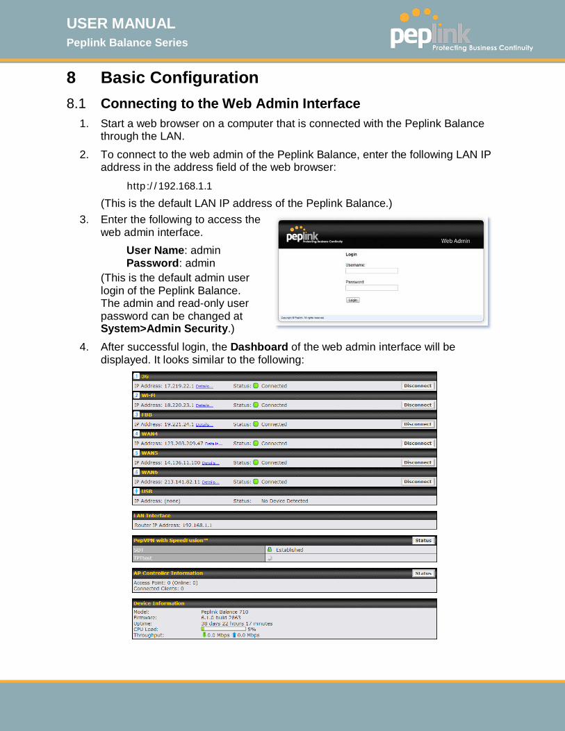
8 Basic Configuration 8.1 Connecting to the Web Admin Interface
1. Start a web browser on a computer that is connected with the Peplink Balance through the LAN.
2. To connect to the web admin of the Peplink Balance, enter the following LAN IP address in the address field of the web browser:
http://192.168.1.1
(This is the default LAN IP address of the Peplink Balance.) 3. Enter the following to access the
web admin interface. User Name: admin Password: admin
(This is the default admin user login of the Peplink Balance. The admin and read-only user password can be changed at System>Admin Security.)
4. After successful login, the Dashboard of the web admin interface will be displayed. It looks similar to the following:

USER MANUAL Peplink Balance Series
http://www.peplink.com -63 / 261 - Copyright © 2015 Peplink
Important Note
The Save button causes the changes to be saved. Configuration changes (e.g., WAN, LAN, admin settings, etc.) take effect after clicking the Apply Changes button on each page’s top-right corner.
8.2 Configuration with the Setup Wizard The Setup Wizard simplifies the task of configuring WAN connection(s) by guiding the configuration process step-by-step. To begin, click Setup Wizard after connecting to the web admin interface.
Click Next >> to begin.
Select Yes if you want to set up drop-in mode using the Setup Wizard.
USER MANUAL Peplink Balance Series
http://www.peplink.com -64 / 261 - Copyright © 2015 Peplink
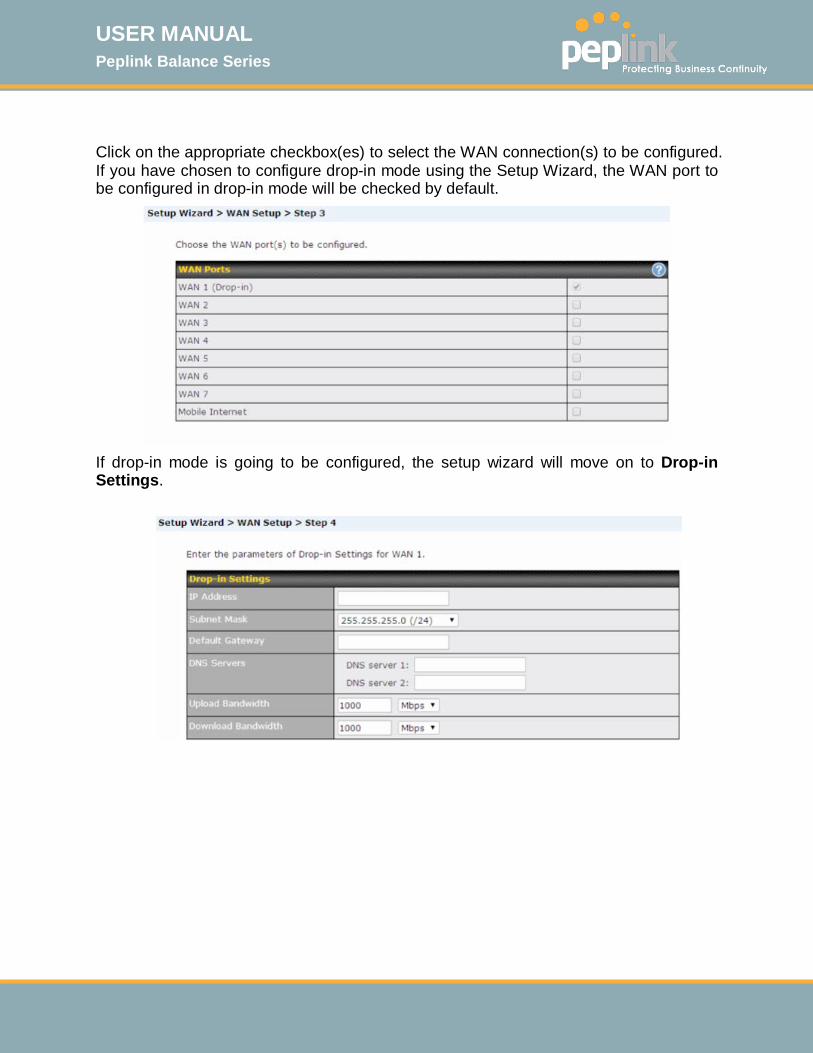
Click on the appropriate checkbox(es) to select the WAN connection(s) to be configured. If you have chosen to configure drop-in mode using the Setup Wizard, the WAN port to be configured in drop-in mode will be checked by default.
If drop-in mode is going to be configured, the setup wizard will move on to Drop-in Settings.
USER MANUAL Peplink Balance Series
http://www.peplink.com -65 / 261 - Copyright © 2015 Peplink
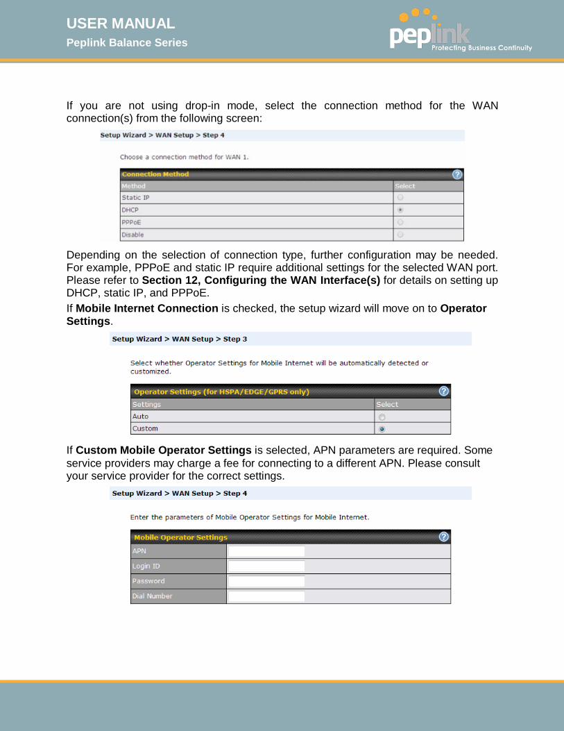
If you are not using drop-in mode, select the connection method for the WAN connection(s) from the following screen:
Depending on the selection of connection type, further configuration may be needed. For example, PPPoE and static IP require additional settings for the selected WAN port. Please refer to Section 12, Configuring the WAN Interface(s) for details on setting up DHCP, static IP, and PPPoE. If Mobile Internet Connection is checked, the setup wizard will move on to Operator Settings.
If Custom Mobile Operator Settings is selected, APN parameters are required. Some service providers may charge a fee for connecting to a different APN. Please consult your service provider for the correct settings.
USER MANUAL Peplink Balance Series
http://www.peplink.com -66 / 261 - Copyright © 2015 Peplink
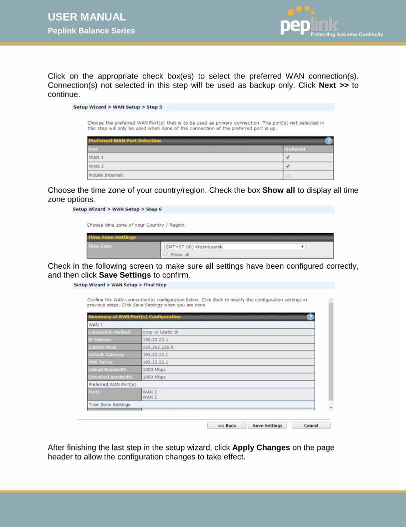
Click on the appropriate check box(es) to select the preferred WAN connection(s). Connection(s) not selected in this step will be used as backup only. Click Next >> to continue.
Choose the time zone of your country/region. Check the box Show all to display all time zone options.
Check in the following screen to make sure all settings have been configured correctly, and then click Save Settings to confirm.
After finishing the last step in the setup wizard, click Apply Changes on the page header to allow the configuration changes to take effect.
USER MANUAL Peplink Balance Series
http://www.peplink.com -67 / 261 - Copyright © 2015 Peplink
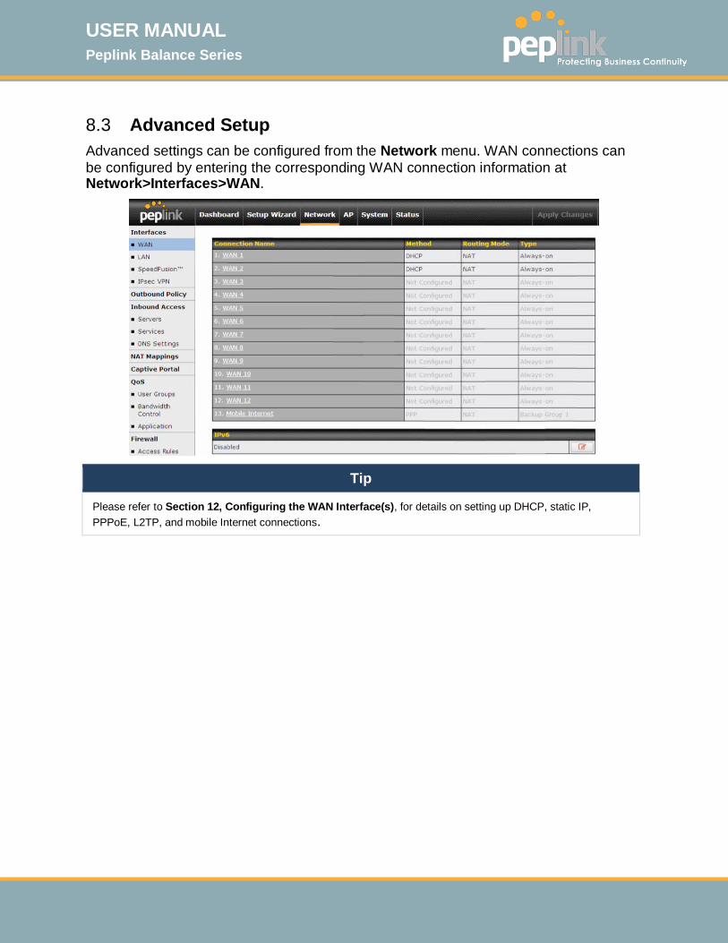
8.3 Advanced Setup Advanced settings can be configured from the Network menu. WAN connections can be configured by entering the corresponding WAN connection information at Network>Interfaces>WAN.
Tip
Please refer to Section 12, Configuring the WAN Interface(s), for details on setting up DHCP, static IP, PPPoE, L2TP, and mobile Internet connections.
USER MANUAL Peplink Balance Series
http://www.peplink.com -68 / 261 - Copyright © 2015 Peplink
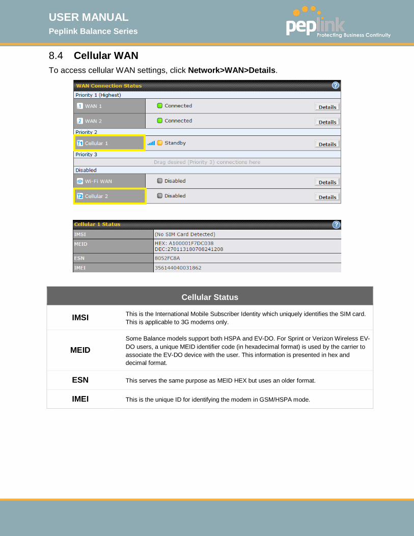
8.4 Cellular WAN To access cellular WAN settings, click Network>WAN>Details.
Cellular Status
IMSI This is the International Mobile Subscriber Identity which uniquely identifies the SIM card. This is applicable to 3G modems only.
MEID Some Balance models support both HSPA and EV-DO. For Sprint or Verizon Wireless EV-DO users, a unique MEID identifier code (in hexadecimal format) is used by the carrier to associate the EV-DO device with the user. This information is presented in hex and decimal format.
ESN This serves the same purpose as MEID HEX but uses an older format.
IMEI This is the unique ID for identifying the modem in GSM/HSPA mode.
USER MANUAL Peplink Balance Series
http://www.peplink.com -69 / 261 - Copyright © 2015 Peplink
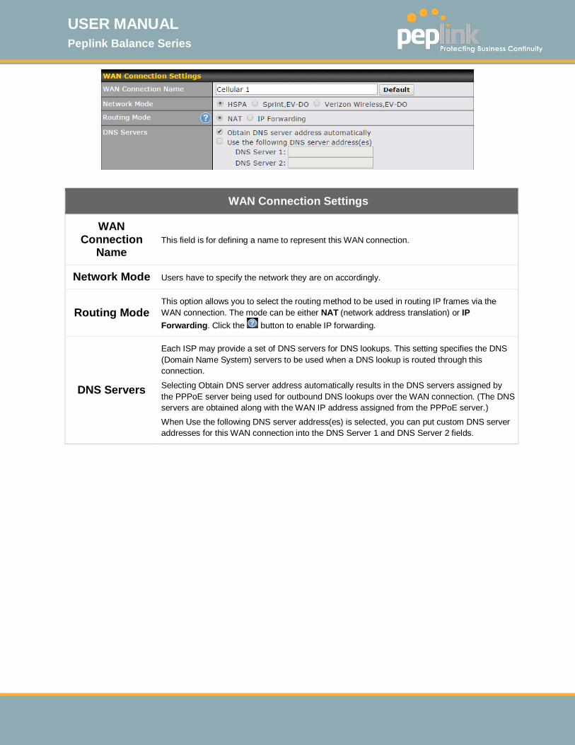
WAN Connection Settings
WAN Connection
Name This field is for defining a name to represent this WAN connection.
Network Mode Users have to specify the network they are on accordingly.
Routing Mode This option allows you to select the routing method to be used in routing IP frames via the WAN connection. The mode can be either NAT (network address translation) or IP Forwarding. Click the button to enable IP forwarding.
DNS Servers
Each ISP may provide a set of DNS servers for DNS lookups. This setting specifies the DNS (Domain Name System) servers to be used when a DNS lookup is routed through this connection.
Selecting Obtain DNS server address automatically results in the DNS servers assigned by the PPPoE server being used for outbound DNS lookups over the WAN connection. (The DNS servers are obtained along with the WAN IP address assigned from the PPPoE server.) When Use the following DNS server address(es) is selected, you can put custom DNS server addresses for this WAN connection into the DNS Server 1 and DNS Server 2 fields.

USER MANUAL Peplink Balance Series
http://www.peplink.com -70 / 261 - Copyright © 2015 Peplink
Cellular Settings
8.4.1.1 Network Selection
8.4.1.2 By default, the router will automatically select the cellular network. Click on the button to enable manual network selection.
3G/2G Band selection to restrict cellular on a particular band. Click on the button to enable the selection of specific bands.
Authentication Choose from Auto, PAP Only, or CHAP Only to authenticate celluarl connections.
Band Selection Choose bands to restrict cellular traffic to those bands.
Data Roaming This checkbox enables data roaming on this particular SIM card. Please check your service provider’s data roaming policy before proceeding.
Operator Settings
This setting applies to 3G / EDGE / GPRS modems only. It does not apply to EVDO / EVDO Rev. A modems. This allows you to configure the APN settings of your connection. If Auto is selected, the mobile operator should be detected automatically. The connected device will be configured, and connection will be made automatically afterwards. If there is any difficulty in making a connection, you may select Custom to enter your carrier’s APN, Login, Password, and Dial Number settings manually. The correct values can be obtained from your carrier. The default

USER MANUAL Peplink Balance Series
http://www.peplink.com -71 / 261 - Copyright © 2015 Peplink
and recommended value for Operator Settings is Auto.
APN / Username / Password /
SIM PIN
When Auto is selected, the information in these fields will be filled automatically. Select Custom to customize these parameters. The parameter values are determined by and can be obtained from the ISP.
Bandwidth Allowance
Monitor
Check the “Enable” box to enable bandwidth usage monitoring on this WAN connection for each billing cycle. When this option is not enabled, bandwidth usage of each month is still being tracked, but no action will be taken.
Action
If Email Notification is enabled, you will be notified by email when usage hits 75% and 95% of the monthly allowance.
If Disconnect when usage hits 100% of monthly allowance is checked, this WAN connection will be disconnected automatically when the usage hits the monthly allowance. It will not resume connection unless this option has been turned off or the usage has been reset when a new billing cycle starts.
Start Day This option allows you to define which day of the month each billing cycle begins.
Monthly Allowance
This field is for defining the maximum bandwidth usage allowed for the WAN connection each month.
General Settings
IP Passthrough
When this IP Passthrough option is active, after the cellular WAN connection is up, the router's DHCP server will offer the connection's IP address to one LAN client. All incoming or outgoing traffic will be routed without NAT.
Regardless the WAN connection's state, the router always binds to the LAN IP address (Default: 192.168.50.1). So when the cellular WAN is connected, the LAN client could access the router's web admin by manually configuring its IP address to the same subnet as the router's LAN IP address (e.g. 192.168.50.10).
Note: when this option is firstly enabled, the LAN client may not be able to refresh its IP address to the cellular WAN IP address in a timely fashion. The LAN client may have to manually renew its IP address from DHCP server. After this option is enabled, the DHCP lease time will be 2 minutes. I.e. the LAN client could refresh its IP address and access the network at most one minute after the cellular WAN connection goes up.
Standby State This option allows you to choose whether to remain connected or disconnect when this WAN connection is no longer in the highest priority and has entered the standby state.

USER MANUAL Peplink Balance Series
http://www.peplink.com -72 / 261 - Copyright © 2015 Peplink
When Remain connected is chosen, setting this WAN connection as active will make it immediately available for use.
Idle Disconnect When Internet traffic is not detected within the user specified timeframe, the modem will automatically disconnect. Once the traffic is resumed by the LAN host, the connection will be reactivated.
Health Check Settings
Heath Check Method
This setting allows you to specify the health check method for the cellular connection. The available options are Disabled, Ping, DNS Lookup, HTTP, and SmartCheck. The default method is DNS Lookup. See Section 12.3 for configuration details.
Timeout If a health check test cannot be completed within the specified amount of time, the test will be treated as failed.
Health Check Interval This is the time interval between each health check test.
Health Check Retries This is the number of consecutive check failures before treating a connection as down.
Recovery Retries
This is the number of responses required after a health check failure before treating a connection as up again.

USER MANUAL Peplink Balance Series
http://www.peplink.com -73 / 261 - Copyright © 2015 Peplink
Dynamic DNS Settings
Dynamic DNS Service Provider
This setting specifies the dynamic DNS service provider to be used for the WAN based on supported dynamic DNS service providers:
• changeip.com
• dyndns.org
• no-ip.org
• tzo.com
• DNS-O-Matic
Select Disabled to disable this feature. See Section 12.6 for configuration details.
MTU
MTU Determine the maximum allowable size per packet. The unit is in bytes.

USER MANUAL Peplink Balance Series
http://www.peplink.com -74 / 261 - Copyright © 2015 Peplink
9 MediaFast Configuration MediaFast settings can be configured from the Network menu.
9.1 Setting Up MediaFast Content Caching To access MediaFast content caching settings, select Network>MediaFast.
MediaFast
Enable Click the checkbox to enable MediaFast content caching.
Domains / IP Addresses
Choose to Cache on all domains, or enter domain names and then choose either Whitelist (Cache the specified domains only) or Blacklist (Do not cache the specified domains).
The Secure Content Caching menu operates identically to the MediaFast menu, except it is for secure contenting accessible through (https://)

USER MANUAL Peplink Balance Series
http://www.peplink.com -75 / 261 - Copyright © 2015 Peplink
Cache Control
Content Type Check these boxes to cache the listed content types or leave boxes unchecked to disable caching for the listed types.
Cache Lifetime Settings
Enter a file extension, such as JPG or DOC. Then enter a lifetime in days to specify how long files with that extension will be cached. Add or delete entries using the controls on the right.
9.2 Scheduling Content Prefetching Content prefetching allows you to download content on a schedule that you define, which can help to preserve network bandwidth during busy times and keep costs down. To access MediaFast content prefetching settings, select Network>MediaFast>Prefetch Schedule.

USER MANUAL Peplink Balance Series
http://www.peplink.com -76 / 261 - Copyright © 2015 Peplink
Prefetch Schedule Settings
Name This field displays the name given to the scheduled download.
Status Check the status of your scheduled download here.
Next Run Time/Last Run
Time These fields display the date and time of the next and most recent occurrences of the scheduled download.
Last Duration Check this field to ensure that the most recent download took as long as expected to complete. A value that is too low might indicate an incomplete download or incorrectly specified download target, while a value that is too long could mean a download with an incorrectly specified target or stop time.
Result This field indicates whether downloads are in progress ( ) or complete ( ).
Last Download
Check this field to ensure that the most recent download file size is within the expected range. A value that is too low might indicate an incomplete download or incorrectly specified download target, while a value that is too long could mean a download with an incorrectly specified target or stop time. This field is also useful for quickly seeing which downloads are consuming the most storage space.
Actions
To begin a scheduled download immediately, click . To cancel a scheduled download, click . To edit a scheduled download, click . To delete a scheduled download, click .
New Schedule To begin creating a new scheduled download, click this button.
Clear Web Cache To clear all cached content, click this button. Note that this action cannot be undone.
Clear Statistics To clear all prefetch and status page statistics, click this button.

USER MANUAL Peplink Balance Series
http://www.peplink.com -77 / 261 - Copyright © 2015 Peplink
9.3 MDM Settings In addition to performing content caching, MediaFast enable routers can also serve as an MDM, administrating to client devices.
MDM Settings
Enable Click this checkbox to enable MDM on your router.
Account Settings
Click Follow Web Admin Account for client devices to use the built-in administrator account when performing MDM. Set Custom to specify a username and password with which your router will log into your client devices.

USER MANUAL Peplink Balance Series
http://www.peplink.com -78 / 261 - Copyright © 2015 Peplink
9.4 Viewing MediaFast Statistics To get details on storage and bandwidth usage, select Status>MediaFast.

USER MANUAL Peplink Balance Series
http://www.peplink.com -79 / 261 - Copyright © 2015 Peplink
10 Configuring the LAN Interface(s) LAN Interface settings are located at Network>Interfaces>LAN. Begin setting up your physical LAN by entering IP settings (VLAN configuration will be covered following physical LAN setup).
IP Settings
IP Address & Subnet Mask
Enter the Peplink Balance’s IP address and subnet mask values to be used on the LAN. To
enable multiple VLANs, press the button on the top right-hand corner
Network Settings
Name Enter the name of your network here
Inter-VLAN routing Click here to enable Inter-VLAN routing on your local area network.
Captive Portal Click here to enable Captive Portal on your local area network.
If drop-in mode will be used, you can configure it in the next section.

USER MANUAL Peplink Balance Series
http://www.peplink.com -80 / 261 - Copyright © 2015 Peplink
Drop-in Mode Settings
Enable Drop-in mode eases the installation of the Peplink Balance on a live network between the existing firewall and router, such that no configuration changes are required on existing equipment. Check the box to enable the drop-in mode feature.
Please refer to Section 11, Drop-in Mode for details.
WAN for Drop-In Mode
Select the WAN port to be used for drop-in mode. If WAN 1 with LAN Bypass is selected, the high availability feature will be disabled automatically.
Shared Drop-In IPA
When this option is enabled, the passthrough IP address will be used to connect to WAN hosts (email notification, remote syslog, etc.). The Balance will listen for this IP address when WAN hosts access services provided by the Balance (web admin access from the WAN, DNS server requests, etc.). To connect to hosts on the LAN (email notification, remote syslog, etc.), the default gateway address will be used. The Balance will listen for this IP address when LAN hosts access services provided by the Balance (web admin access from the WAN, DNS proxy, etc.).
Shared IP AddressA
Access to this IP address will be passed through to the LAN port if this device is not serving the service being accessed. The shared IP address will be used in connecting to hosts on the WAN (e.g., email notification, remote syslog, etc.) The device will also listen on the IP address when hosts on the WAN access services served on this device (e.g., web admin accesses from WAN, DNS server, etc.)
WAN Default Gateway
Enter the WAN router's IP address in this field. If there are more hosts in addition to the router on the WAN segment, click the button next to “WAN Default Gateway” and check the I have other host(s) on WAN segment box and enter the IP address of the hosts that need to access LAN devices or be accessed by others.
WAN DNS Servers Enter the selected WAN's corresponding DNS server IP addresses.
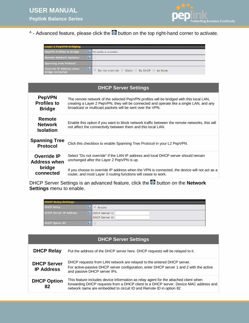
USER MANUAL Peplink Balance Series
http://www.peplink.com -81 / 261 - Copyright © 2015 Peplink
A - Advanced feature, please click the button on the top right-hand corner to activate.
DHCP Server Settings
PepVPN Profiles to
Bridge
The remote network of the selected PepVPN profiles will be bridged with this local LAN, creating a Layer 2 PepVPN, they will be connected and operate like a single LAN, and any broadcast or multicast packets will be sent over the VPN.
Remote Network Isolation
Enable this option if you want to block network traffic between the remote networks, this will not affect the connectivity between them and this local LAN.
Spanning Tree Protocol Click this checkbox to enable Spanning Tree Protocol in your L2 PepVPN.
Override IP Address when
bridge connected
Select "Do not override" if the LAN IP address and local DHCP server should remain unchanged after the Layer 2 PepVPN is up. If you choose to override IP address when the VPN is connected, the device will not act as a router, and most Layer 3 routing functions will cease to work.
DHCP Server Settings is an advanced feature, click the button on the Network Settings menu to enable.
DHCP Server Settings
DHCP Relay Put the address of the DHCP server here. DHCP requests will be relayed to it.
DHCP Server IP Address
DHCP requests from LAN network are relayed to the entered DHCP server. For active-passive DHCP server configuration, enter DHCP server 1 and 2 with the active and passive DHCP server IPs.
DHCP Option 82
This feature includes device information as relay agent for the attached client when forwarding DHCP requests from a DHCP client to a DHCP server. Device MAC address and network name are embedded to circuit ID and Remote ID in option 82
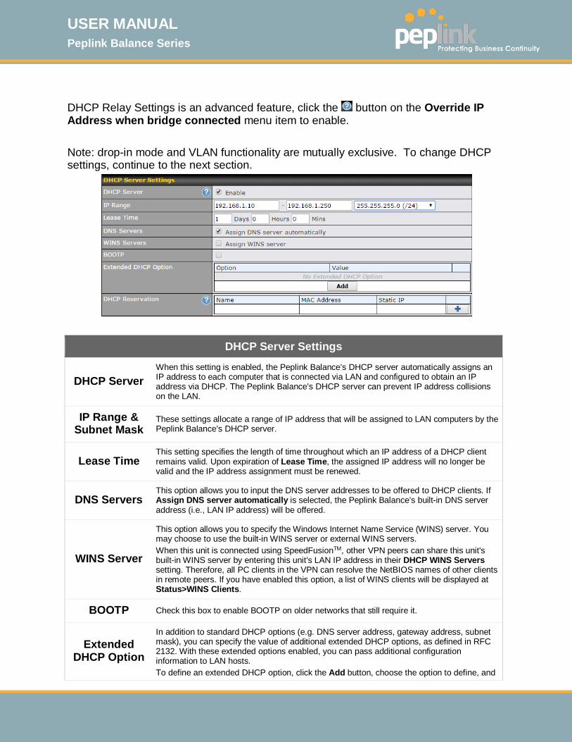
USER MANUAL Peplink Balance Series
http://www.peplink.com -82 / 261 - Copyright © 2015 Peplink
DHCP Relay Settings is an advanced feature, click the button on the Override IP Address when bridge connected menu item to enable. Note: drop-in mode and VLAN functionality are mutually exclusive. To change DHCP settings, continue to the next section.
DHCP Server Settings
DHCP Server When this setting is enabled, the Peplink Balance’s DHCP server automatically assigns an IP address to each computer that is connected via LAN and configured to obtain an IP address via DHCP. The Peplink Balance’s DHCP server can prevent IP address collisions on the LAN.
IP Range & Subnet Mask
These settings allocate a range of IP address that will be assigned to LAN computers by the Peplink Balance’s DHCP server.
Lease Time This setting specifies the length of time throughout which an IP address of a DHCP client remains valid. Upon expiration of Lease Time, the assigned IP address will no longer be valid and the IP address assignment must be renewed.
DNS Servers This option allows you to input the DNS server addresses to be offered to DHCP clients. If Assign DNS server automatically is selected, the Peplink Balance’s built-in DNS server address (i.e., LAN IP address) will be offered.
WINS Server
This option allows you to specify the Windows Internet Name Service (WINS) server. You may choose to use the built-in WINS server or external WINS servers. When this unit is connected using SpeedFusionTM, other VPN peers can share this unit's built-in WINS server by entering this unit's LAN IP address in their DHCP WINS Servers setting. Therefore, all PC clients in the VPN can resolve the NetBIOS names of other clients in remote peers. If you have enabled this option, a list of WINS clients will be displayed at Status>WINS Clients.
BOOTP Check this box to enable BOOTP on older networks that still require it.
Extended DHCP Option
In addition to standard DHCP options (e.g. DNS server address, gateway address, subnet mask), you can specify the value of additional extended DHCP options, as defined in RFC 2132. With these extended options enabled, you can pass additional configuration information to LAN hosts. To define an extended DHCP option, click the Add button, choose the option to define, and
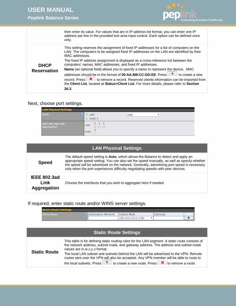
USER MANUAL Peplink Balance Series
http://www.peplink.com -83 / 261 - Copyright © 2015 Peplink
then enter its value. For values that are in IP address list format, you can enter one IP address per line in the provided text area input control. Each option can be defined once only.
DHCP Reservation
This setting reserves the assignment of fixed IP addresses for a list of computers on the LAN. The computers to be assigned fixed IP addresses on the LAN are identified by their MAC addresses. The fixed IP address assignment is displayed as a cross-reference list between the computers’ names, MAC addresses, and fixed IP addresses. Name (an optional field) allows you to specify a name to represent the device. MAC addresses should be in the format of 00:AA:BB:CC:DD:EE. Press to create a new record. Press to remove a record. Reserved clients information can be imported from the Client List, located at Status>Client List. For more details, please refer to Section 26.3.
Next, choose port settings.
LAN Physical Settings
Speed The default speed setting is Auto, which allows the Balance to detect and apply an appropriate speed setting. You can also set the speed manually, as well as specify whether the speed will be advertised on the network. Generally, advertising port speed is necessary only when the port experiences difficulty negotiating speeds with peer devices.
IEEE 802.3ad Link
Aggregation Choose the interfaces that you wish to aggregate here if needed.
If required, enter static route and/or WINS server settings.
Static Route Settings
Static Route
This table is for defining static routing rules for the LAN segment. A static route consists of the network address, subnet mask, and gateway address. The address and subnet mask values are in w.x.y.z format. The local LAN subnet and subnets behind the LAN will be advertised to the VPN. Remote routes sent over the VPN will also be accepted. Any VPN member will be able to route to the local subnets. Press to create a new route. Press to remove a route.
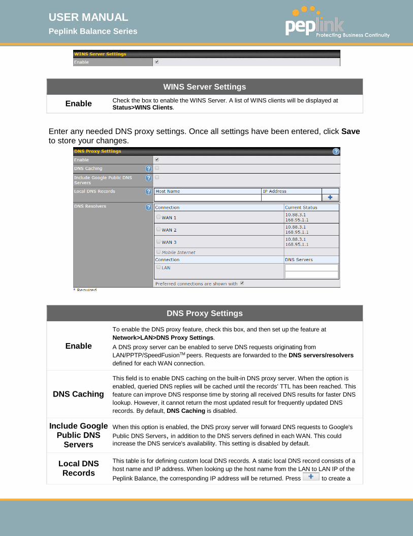
USER MANUAL Peplink Balance Series
http://www.peplink.com -84 / 261 - Copyright © 2015 Peplink
WINS Server Settings
Enable Check the box to enable the WINS Server. A list of WINS clients will be displayed at Status>WINS Clients.
Enter any needed DNS proxy settings. Once all settings have been entered, click Save to store your changes.
DNS Proxy Settings
Enable
To enable the DNS proxy feature, check this box, and then set up the feature at Network>LAN>DNS Proxy Settings. A DNS proxy server can be enabled to serve DNS requests originating from LAN/PPTP/SpeedFusionTM peers. Requests are forwarded to the DNS servers/resolvers defined for each WAN connection.
DNS Caching
This field is to enable DNS caching on the built-in DNS proxy server. When the option is enabled, queried DNS replies will be cached until the records’ TTL has been reached. This feature can improve DNS response time by storing all received DNS results for faster DNS lookup. However, it cannot return the most updated result for frequently updated DNS records. By default, DNS Caching is disabled.
Include Google Public DNS
Servers
When this option is enabled, the DNS proxy server will forward DNS requests to Google's Public DNS Servers, in addition to the DNS servers defined in each WAN. This could increase the DNS service's availability. This setting is disabled by default.
Local DNS Records
This table is for defining custom local DNS records. A static local DNS record consists of a host name and IP address. When looking up the host name from the LAN to LAN IP of the Peplink Balance, the corresponding IP address will be returned. Press to create a

USER MANUAL Peplink Balance Series
http://www.peplink.com -85 / 261 - Copyright © 2015 Peplink
new record. Press to remove a record.
DNS ResolversA
Check the box to enable the WINS Server. A list of WINS clients will be displayed at Network>LAN>DNS Proxy Settings>DNS Resolvers. This field specifies which DNS resolvers will receive forwarded DNS requests. If no WAN/VPN/LAN DNS resolver is selected, all of the WAN’s DNS resolvers will be selected. If a SpeedFusionTM peer is selected, you may enter the VPN peer’s DNS resolver IP address(es). Queries will be forwarded to the selected connections’ resolvers. If all of the selected connections are down, queries will be forwarded to all resolvers on healthy WAN connections.
A - Advanced feature, please click the button on the top right hand corner to activate. Finally, if needed, configure your Bonjour Forwarding Settings. Once all settings have been entered, click Save to store your changes.
Bonjour Forwarding Settings
Enable Check this box to turn on Bonjour forwarding.
Bonjour Service
Choose Service and Client networks from the drop-down menus, and then click to add the networks. To delete an existing Bonjour listing, click .
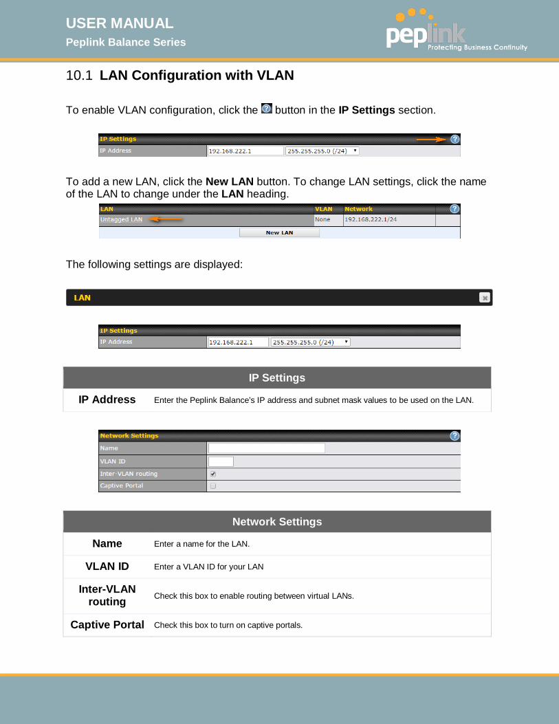
USER MANUAL Peplink Balance Series
http://www.peplink.com -86 / 261 - Copyright © 2015 Peplink
10.1 LAN Configuration with VLAN To enable VLAN configuration, click the button in the IP Settings section.
To add a new LAN, click the New LAN button. To change LAN settings, click the name of the LAN to change under the LAN heading.
The following settings are displayed:
IP Settings
IP Address Enter the Peplink Balance’s IP address and subnet mask values to be used on the LAN.
Network Settings
Name Enter a name for the LAN.
VLAN ID Enter a VLAN ID for your LAN
Inter-VLAN routing Check this box to enable routing between virtual LANs.
Captive Portal Check this box to turn on captive portals.
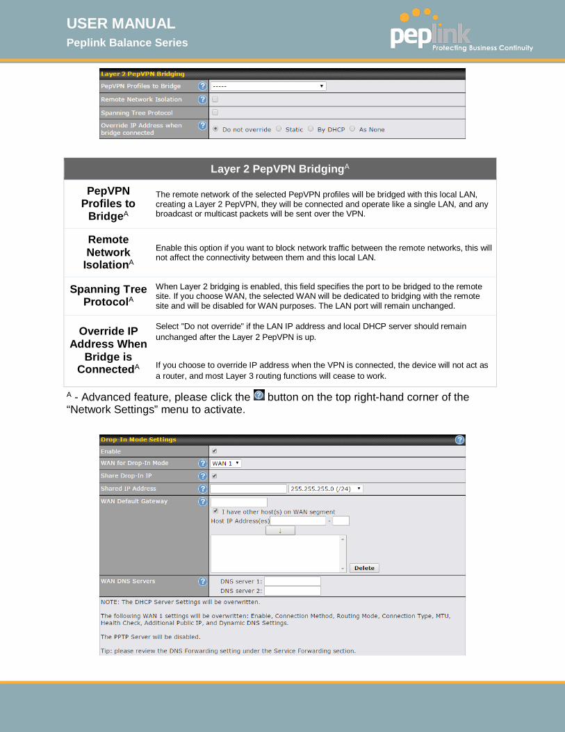
USER MANUAL Peplink Balance Series
http://www.peplink.com -87 / 261 - Copyright © 2015 Peplink
Layer 2 PepVPN BridgingA
PepVPN Profiles to
BridgeA
The remote network of the selected PepVPN profiles will be bridged with this local LAN, creating a Layer 2 PepVPN, they will be connected and operate like a single LAN, and any broadcast or multicast packets will be sent over the VPN.
Remote Network
IsolationA Enable this option if you want to block network traffic between the remote networks, this will not affect the connectivity between them and this local LAN.
Spanning Tree ProtocolA
When Layer 2 bridging is enabled, this field specifies the port to be bridged to the remote site. If you choose WAN, the selected WAN will be dedicated to bridging with the remote site and will be disabled for WAN purposes. The LAN port will remain unchanged.
Override IP Address When
Bridge is ConnectedA
Select "Do not override" if the LAN IP address and local DHCP server should remain unchanged after the Layer 2 PepVPN is up. If you choose to override IP address when the VPN is connected, the device will not act as a router, and most Layer 3 routing functions will cease to work.
A - Advanced feature, please click the button on the top right-hand corner of the “Network Settings” menu to activate.
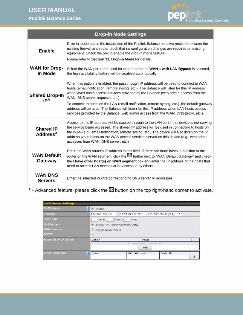
USER MANUAL Peplink Balance Series
http://www.peplink.com -88 / 261 - Copyright © 2015 Peplink
Drop-in Mode Settings
Enable Drop-in mode eases the installation of the Peplink Balance on a live network between the existing firewall and router, such that no configuration changes are required on existing equipment. Check the box to enable the drop-in mode feature. Please refer to Section 11, Drop-in Mode for details.
WAN for Drop-In Mode
Select the WAN port to be used for drop-in mode. If WAN 1 with LAN Bypass is selected, the high availability feature will be disabled automatically.
Shared Drop-In IPA
When this option is enabled, the passthrough IP address will be used to connect to WAN hosts (email notification, remote syslog, etc.). The Balance will listen for this IP address when WAN hosts access services provided by the Balance (web admin access from the WAN, DNS server requests, etc.).
To connect to hosts on the LAN (email notification, remote syslog, etc.), the default gateway address will be used. The Balance will listen for this IP address when LAN hosts access services provided by the Balance (web admin access from the WAN, DNS proxy, etc.).
Shared IP AddressA
Access to this IP address will be passed through to the LAN port if this device is not serving the service being accessed. The shared IP address will be used in connecting to hosts on the WAN (e.g., email notification, remote syslog, etc.) The device will also listen on the IP address when hosts on the WAN access services served on this device (e.g., web admin accesses from WAN, DNS server, etc.)
WAN Default Gateway
Enter the WAN router's IP address in this field. If there are more hosts in addition to the router on the WAN segment, click the button next to “WAN Default Gateway” and check the I have other host(s) on WAN segment box and enter the IP address of the hosts that need to access LAN devices or be accessed by others.
WAN DNS Servers Enter the selected WAN's corresponding DNS server IP addresses.
A - Advanced feature, please click the button on the top right-hand corner to activate.

USER MANUAL Peplink Balance Series
http://www.peplink.com -89 / 261 - Copyright © 2015 Peplink
DHCP Server Settings
DHCP Server When this setting is enabled, the Peplink Balance’s DHCP server automatically assigns an IP address to each computer that is connected via LAN and configured to obtain an IP address via DHCP. The Peplink Balance’s DHCP server can prevent IP address collisions on the LAN.
IP Range & Subnet Mask
These settings allocate a range of IP address that will be assigned to LAN computers by the Peplink Balance’s DHCP server.
Lease Time This setting specifies the length of time throughout which an IP address of a DHCP client remains valid. Upon expiration of Lease Time, the assigned IP address will no longer be valid and the IP address assignment must be renewed.
DNS Servers This option allows you to input the DNS server addresses to be offered to DHCP clients. If Assign DNS server automatically is selected, the Peplink Balance’s built-in DNS server address (i.e., LAN IP address) will be offered.
WINS Servers
This option allows you to specify the Windows Internet Name Service (WINS) server. You may choose to use the built-in WINS server or external WINS servers. When this unit is connected using SpeedFusionTM, other VPN peers can share this unit's built-in WINS server by entering this unit's LAN IP address in their DHCP WINS Servers setting. Therefore, all PC clients in the VPN can resolve the NetBIOS names of other clients in remote peers. If you have enabled this option, a list of WINS clients will be displayed at Status>WINS Clients.
BOOTP Check this box to enable BOOTP on older networks that still require it.
Extended DHCP Option
In addition to standard DHCP options (e.g. DNS server address, gateway address, subnet mask), you can specify the value of additional extended DHCP options, as defined in RFC 2132. With these extended options enabled, you can pass additional configuration information to LAN hosts. To define an extended DHCP option, click the Add button, choose the option to define, and then enter its value. For values that are in IP address list format, you can enter one IP address per line in the provided text area input control. Each option can be defined once only.
DHCP Reservation
This setting reserves the assignment of fixed IP addresses for a list of computers on the LAN. The computers to be assigned fixed IP addresses on the LAN are identified by their MAC addresses. The fixed IP address assignment is displayed as a cross-reference list between the computers’ names, MAC addresses, and fixed IP addresses. Name (an optional field) allows you to specify a name to represent the device. MAC addresses should be in the format of 00:AA:BB:CC:DD:EE. Press to create a new record. Press to remove a record. Reserved clients information can be imported from the Client List, located at Status>Client List. For more details, please refer to Section 26.3.
Once configuration is complete, click Save to store the changes. To configure DHCP relay, first click the button found next to the DHCP Server option to display the settings.

USER MANUAL Peplink Balance Series
http://www.peplink.com -90 / 261 - Copyright © 2015 Peplink
DHCP Relay Settings
Enable Check this box to turn on DHCP relay.
DHCP Server IP Address
Enter the IP addresses of one or two DHCP servers in the provided fields. The DHCP servers entered here will receive relayed DHCP requests from the LAN. For active-passive DHCP server configurations, enter active and passive DHCP server relay IP addresses in DHCP Server 1 and DHCP Server 2.
DHCP Option 82
DCHP Option 82 includes device information as relay agent for the attached client when forwarding DHCP requests from client to server. This option also embeds the device’s MAC address and network name in circuit and remote IDs. Check this box to enable DHCP Option 82.
Once DHCP is set up, press “Save” and configure LAN Physical Settings, Static Route Settings, WINS Server Settings, DNS Proxy Settings, and Bonjour Forwarding as noted above.

USER MANUAL Peplink Balance Series
http://www.peplink.com -91 / 261 - Copyright © 2015 Peplink
11 Drop-in Mode Drop-in mode (or transparent bridging mode) eases the installation of the Peplink Balance on a live network between the firewall and router, such that changes to the settings of existing equipment are not required. The following diagram illustrates drop-in mode setup: Enable drop-in mode using the Setup Wizard. After enabling this feature and selecting the WAN for drop-in mode, various settings, including the WAN's connection method and IP address, will be automatically updated. When drop-in mode is enabled, the LAN and the WAN for drop-in mode ports will be bridged. Traffic between the LAN hosts and WAN router will be forwarded between the devices. In this case, the hosts on both sides will not notice any IP or MAC address changes. After successfully setting up the Peplink Balance as part of the network using drop-in mode, it will, depending on model, support one or more WAN connections. Some MediaFast units also support multiple WAN connections after activating drop-in mode, though a SpeedFusion license may be required to activate more than one WAN port.
IMPORTANT NOTE for customers using Drop-in Mode and planning to upgrade from Firmware 4.8.2 or below to 5.0+
MAC address pass through for drop-in mode is implemented in Firmware 5.0 and above. If drop-in mode is enabled when upgrading from a previous firmware version, the ARP tables on hosts on LAN and WAN segments must be flushed once. Alternately, the hosts may be rebooted. Otherwise, hosts on one side may not be able to reach hosts on the other side of the Peplink Balance until old ARP records expire. Units not using drop-in mode are not affected.
NOTE
The PPTP server will be disabled in drop-in mode.
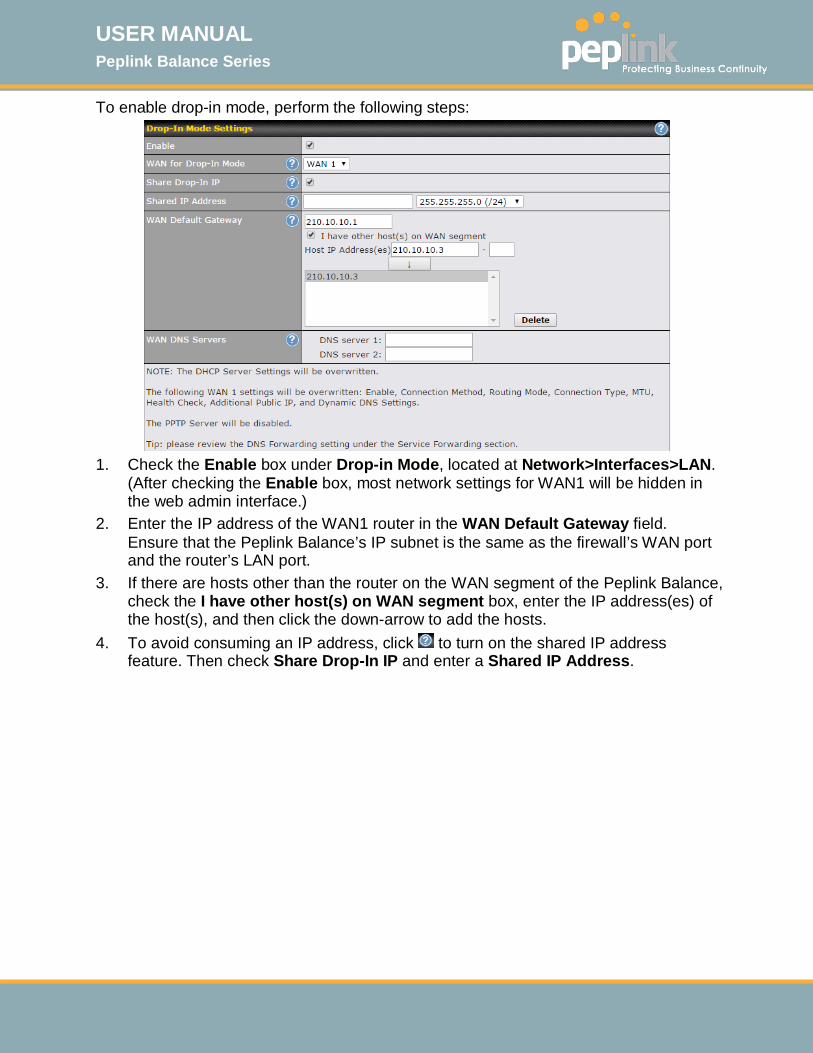
USER MANUAL Peplink Balance Series
http://www.peplink.com -92 / 261 - Copyright © 2015 Peplink
To enable drop-in mode, perform the following steps:
1. Check the Enable box under Drop-in Mode, located at Network>Interfaces>LAN.
(After checking the Enable box, most network settings for WAN1 will be hidden in the web admin interface.)
2. Enter the IP address of the WAN1 router in the WAN Default Gateway field. Ensure that the Peplink Balance’s IP subnet is the same as the firewall’s WAN port and the router’s LAN port.
3. If there are hosts other than the router on the WAN segment of the Peplink Balance, check the I have other host(s) on WAN segment box, enter the IP address(es) of the host(s), and then click the down-arrow to add the hosts.
4. To avoid consuming an IP address, click to turn on the shared IP address feature. Then check Share Drop-In IP and enter a Shared IP Address.

USER MANUAL Peplink Balance Series
http://www.peplink.com -93 / 261 - Copyright © 2015 Peplink
The following diagram illustrates:
Important Note
Starting from Firmware version 5.0, drop-in mode can be configured on any WAN port. Please note that only one WAN port can be configured in drop-in mode. If you have selected the LAN bypass port as the WAN for drop-in mode, the high availability feature will be DISABLED automatically.
Tip
Want to know more about drop-in mode? Visit our YouTube Channel for video tutorials!
http://youtu.be/lZG2-VPml5w
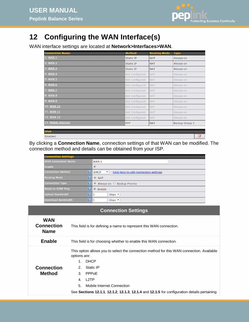
USER MANUAL Peplink Balance Series
http://www.peplink.com -94 / 261 - Copyright © 2015 Peplink
12 Configuring the WAN Interface(s) WAN interface settings are located at Network>Interfaces>WAN.
By clicking a Connection Name, connection settings of that WAN can be modified. The connection method and details can be obtained from your ISP.
Connection Settings
WAN Connection
Name This field is for defining a name to represent this WAN connection.
Enable This field is for choosing whether to enable this WAN connection.
Connection Method
This option allows you to select the connection method for this WAN connection. Available options are:
1. DHCP 2. Static IP 3. PPPoE 4. L2TP 5. Mobile Internet Connection
See Sections 12.1.1, 12.1.2, 12.1.3, 12.1.4 and 12.1.5 for configuration details pertaining

USER MANUAL Peplink Balance Series
http://www.peplink.com -95 / 261 - Copyright © 2015 Peplink
to each connection method.
Routing Mode This field shows that NAT (network address translation) will be applied to the traffic routing over this WAN connection. IP Forwarding is also available when you click the link in the help text. For further details, please refer to Appendix B, Routing under DHCP, Static IP, and PPPoE.
Connection Type
This setting specifies the utilization of the WAN connection. Always-on results in the WAN connection being used whenever it is available. If Backup Priority and a priority group are selected, the WAN connection is treated as a backup connection and is used only in the absence of available always-on WAN connection(s) and higher priority backup connection(s).
The default and recommended connection type is Always-on.
Reply to ICMP Ping
If this field is disabled, the WAN connection will not respond to ICMP ping requests. By default, this setting is enabled.
Upload Bandwidth
This setting specifies the data bandwidth in the outbound direction from the LAN through the WAN interface. This value is provided by your ISP and should reflect the actual speed of the WAN. This value is referenced when default weight is chosen for outbound traffic and traffic prioritization. Setting the correct value here can result in effective traffic prioritization and efficient use of upload bandwidth.
Download Bandwidth
This setting specifies the data bandwidth in the inbound direction from the WAN interface to the LAN. This value is provided by your ISP and should reflect the actual speed of the WAN. This value is referenced as the default weight value when using the Least Used or Persistence (Auto) algorithms in Outbound Policy with Managed by Custom Rules chosen.
IPv6
IPv6
IPv6 support can be enabled on one of the available Ethernet WAN ports. On this screen, you can choose which WAN will support IPv6.
To enable IPv6 support on a WAN, the WAN router must respond to stateless address auto configuration advertisements and DHCPv6 requests. IPv6 clients on the LAN will acquire their IPv6, gateway, and DNS server addresses from it. The device will also acquire an IPv6 address for performing ping/traceroute checks and accepting web admin accesses.
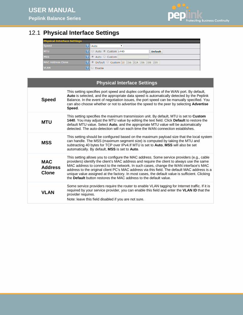
USER MANUAL Peplink Balance Series
http://www.peplink.com -96 / 261 - Copyright © 2015 Peplink
12.1 Physical Interface Settings
Physical Interface Settings
Speed
This setting specifies port speed and duplex configurations of the WAN port. By default, Auto is selected, and the appropriate data speed is automatically detected by the Peplink Balance. In the event of negotiation issues, the port speed can be manually specified. You can also choose whether or not to advertise the speed to the peer by selecting Advertise Speed.
MTU This setting specifies the maximum transmission unit. By default, MTU is set to Custom 1440. You may adjust the MTU value by editing the text field. Click Default to restore the default MTU value. Select Auto, and the appropriate MTU value will be automatically detected. The auto-detection will run each time the WAN connection establishes.
MSS This setting should be configured based on the maximum payload size that the local system can handle. The MSS (maximum segment size) is computed by taking the MTU and subtracting 40 bytes for TCP over IPv4.If MTU is set to Auto, MSS will also be set automatically. By default, MSS is set to Auto.
MAC Address Clone
This setting allows you to configure the MAC address. Some service providers (e.g., cable providers) identify the client’s MAC address and require the client to always use the same MAC address to connect to the network. In such cases, change the WAN interface’s MAC address to the original client PC’s MAC address via this field. The default MAC address is a unique value assigned at the factory. In most cases, the default value is sufficient. Clicking the Default button restores the MAC address to the default value.
VLAN Some service providers require the router to enable VLAN tagging for Internet traffic. If it is required by your service provider, you can enable this field and enter the VLAN ID that the provider requires. Note: leave this field disabled if you are not sure.

USER MANUAL Peplink Balance Series
http://www.peplink.com -97 / 261 - Copyright © 2015 Peplink
12.2 Connection Method(s) There are four possible connection methods:
1. DHCP 2. Static IP 3. PPPoE 4. L2TP 5. Mobile Internet Connection (for USB WAN)
12.2.1 DHCP Connection The DHCP connection method is suitable if your ISP provides an IP address automatically using DHCP (e.g., cable, metro Ethernet, etc.).
DHCP Settings
Hostname (Optional)
If your service provider's DHCP server requires you to supply a hostname value upon acquiring an IP address, you may enter the value here. If your service provider does not provide you with a hostname, you can safely bypass this option.
DNS Servers
Each ISP may provide a set of DNS servers for DNS lookups. This setting specifies the DNS (Domain Name System) servers to be used when a DNS lookup is routed through this connection. Selecting Obtain DNS server address automatically results in the DNS servers assigned by the WAN DHCP server being used for outbound DNS lookups over the connection. (The DNS servers are obtained along with the WAN IP address assigned by the DHCP server.) When Use the following DNS server address(es) is selected, you may
enter custom DNS server addresses for this WAN connection into the DNS server 1 and DNS server 2 fields.
Please refer to Sections 12.3, 12.4, 12.5, and 12.6 for details about WAN Health Check, Bandwidth Allowance Monitor, Additional Public IP Settings, and Dynamic DNS Settings.
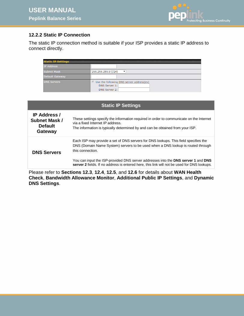
USER MANUAL Peplink Balance Series
http://www.peplink.com -98 / 261 - Copyright © 2015 Peplink
12.2.2 Static IP Connection The static IP connection method is suitable if your ISP provides a static IP address to connect directly.
Static IP Settings
IP Address / Subnet Mask /
Default Gateway
These settings specify the information required in order to communicate on the Internet via a fixed Internet IP address. The information is typically determined by and can be obtained from your ISP.
DNS Servers
Each ISP may provide a set of DNS servers for DNS lookups. This field specifies the DNS (Domain Name System) servers to be used when a DNS lookup is routed through this connection. You can input the ISP-provided DNS server addresses into the DNS server 1 and DNS server 2 fields. If no address is entered here, this link will not be used for DNS lookups.
Please refer to Sections 12.3, 12.4, 12.5, and 12.6 for details about WAN Health Check, Bandwidth Allowance Monitor, Additional Public IP Settings, and Dynamic DNS Settings.

USER MANUAL Peplink Balance Series
http://www.peplink.com -99 / 261 - Copyright © 2015 Peplink
12.2.3 PPPoE Connection This connection method is suitable if your ISP provides a login ID/password to connect via PPPoE.
PPPoE Settings
PPPoE User Name /
Password Enter the required information in these fields in order to connect via PPPoE to your ISP. The parameter values are determined by and can be obtained from your ISP.
Confirm PPPoE Password Verify your password by entering it again in this field.
Server Name (Optional)
Server name is a PPPoE parameter which is provided by your ISP. Note: Leave this field blank unless it is provided by your ISP.
IP Address PPPoE server address is a parameter which is provided by your ISP. Note: Leave this field blank unless it is provided by your ISP.
DNS Servers
Each ISP may provide a set of DNS servers for DNS lookups. This setting specifies the DNS (Domain Name System) servers to be used when a DNS lookup is routed through this connection. Selecting Obtain DNS server address automatically results in the DNS servers assigned by the PPPoE server to be used for outbound DNS lookups over the WAN connection. (The DNS servers are obtained along with the WAN IP address assigned from the PPPoE server.) When Use the following DNS server address(es) is selected, you can enter custom DNS server addresses for this WAN connection into the DNS server 1 and DNS server 2 fields.
Please refer to Sections 12.3, 12.4, 12.5, and 12.6 for details about WAN Health Check, Bandwidth Allowance Monitor, Additional Public IP Settings, and Dynamic DNS Settings.
Note
A PPPoE connection made from a firewall does not work with drop-in mode.

USER MANUAL Peplink Balance Series
http://www.peplink.com -100 / 261 - Copyright © 2015 Peplink
12.2.4 L2TP Connection L2TP has all the compatibility and convenience of PPTP with greater security. Combine this with IPsec for a good balance between ease of use and security.
L2TP Settings
L2TP User Name /
Password Enter the required information in these fields in order to connect via L2TP to your ISP. The parameter values are determined by and can be obtained from your ISP.
Confirm L2TP Password Verify your password by entering it again in this field.
Server IP Address / Host
L2TP server address is a parameter which is provided by your ISP. Note: Leave this field blank unless it is provided by your ISP.
Address Type Your ISP will also indicate whether the server IP address is Dynamic or Static. Please click the appropriate value.
DNS Servers
Each ISP may provide a set of DNS servers for DNS lookups. This setting specifies the DNS (Domain Name System) servers to be used when a DNS lookup is routed through this connection. Selecting Obtain DNS server address automatically results in the DNS servers assigned by the PPPoE server to be used for outbound DNS lookups over the WAN connection. (The DNS servers are obtained along with the WAN IP address assigned from the PPPoE server.) When Use the following DNS server address(es) is selected, you can enter custom DNS server addresses for this WAN connection into the DNS server 1 and DNS server 2 fields.

USER MANUAL Peplink Balance Series
http://www.peplink.com -101 / 261 - Copyright © 2015 Peplink
12.2.5 Mobile Internet Connection The Mobile Internet Connection method is suitable for USB modem mobile connections, such as 3G, WiMAX, LTE, EVDO, EDGE, and GPRS. Currently, it only applies to connections made via the Balance’s USB mobile WAN port, except in the case of the Balance units that include a built-in 4G LTE modem. For a list of supported modems, please refer to Peplink Modem Support page at http://www.peplink.com/modem.
Mobile Internet Connection Settings
12.2.5.1 WAN Connectio
n Name 12.2.5.2 Enter a name for this WAN connection.
Enable Click the box to enable the connection.
Connection Type This setting specifies the utilization of the WAN connection. Always-on results in the WAN connection being used whenever it is available. If Backup is selected, the WAN connection is treated as a backup connection and is used only in the absence of an available always-on WAN. The default and recommended connection type is Always-on.
Standby State This option allows you to choose whether to remain connected or disconnect when this WAN connection is no longer in the highest priority and has entered the standby state. When Remain connected is chosen and this WAN connection is made active, the WAN connection will be immediately available for use.
Idle Disconnect With this option enabled, an idle connection will be disconnected after a specified period of time. This time value specified is global and will affect all WAN profiles. The mobile connection will re-establish on demand.
Reply to ICMP Ping
If this field is disabled, the WAN connection will not respond to ICMP ping requests. By default, this setting is enabled.
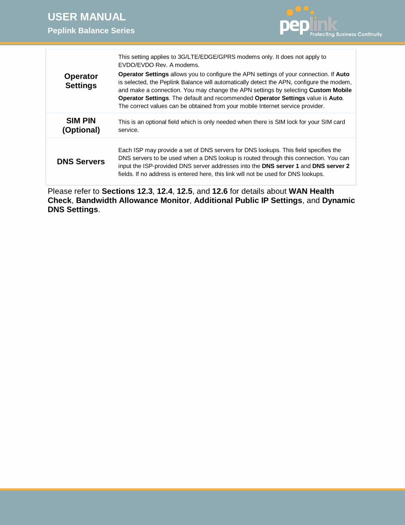
USER MANUAL Peplink Balance Series
http://www.peplink.com -102 / 261 - Copyright © 2015 Peplink
Operator Settings
This setting applies to 3G/LTE/EDGE/GPRS modems only. It does not apply to EVDO/EVDO Rev. A modems. Operator Settings allows you to configure the APN settings of your connection. If Auto is selected, the Peplink Balance will automatically detect the APN, configure the modem, and make a connection. You may change the APN settings by selecting Custom Mobile Operator Settings. The default and recommended Operator Settings value is Auto. The correct values can be obtained from your mobile Internet service provider.
SIM PIN (Optional)
This is an optional field which is only needed when there is SIM lock for your SIM card service.
DNS Servers Each ISP may provide a set of DNS servers for DNS lookups. This field specifies the DNS servers to be used when a DNS lookup is routed through this connection. You can input the ISP-provided DNS server addresses into the DNS server 1 and DNS server 2 fields. If no address is entered here, this link will not be used for DNS lookups.
Please refer to Sections 12.3, 12.4, 12.5, and 12.6 for details about WAN Health Check, Bandwidth Allowance Monitor, Additional Public IP Settings, and Dynamic DNS Settings.
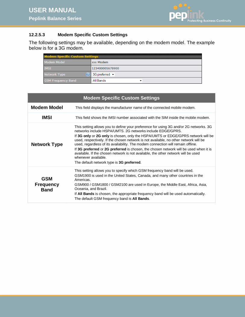
USER MANUAL Peplink Balance Series
http://www.peplink.com -103 / 261 - Copyright © 2015 Peplink
12.2.5.3 Modem Specific Custom Settings
The following settings may be available, depending on the modem model. The example below is for a 3G modem.
Modem Specific Custom Settings
Modem Model This field displays the manufacturer name of the connected mobile modem.
IMSI This field shows the IMSI number associated with the SIM inside the mobile modem.
Network Type
This setting allows you to define your preference for using 3G and/or 2G networks. 3G networks include HSPA/UMTS. 2G networks include EDGE/GPRS. If 3G only or 2G only is chosen, only the HSPA/UMTS or EDGE/GPRS network will be used, respectively. If the chosen network is not available, no other network will be used, regardless of its availability. The modem connection will remain offline. If 3G preferred or 2G preferred is chosen, the chosen network will be used when it is available. If the chosen network is not available, the other network will be used whenever available. The default network type is 3G preferred.
GSM Frequency
Band
This setting allows you to specify which GSM frequency band will be used. GSM1900 is used in the United States, Canada, and many other countries in the Americas. GSM900 / GSM1800 / GSM2100 are used in Europe, the Middle East, Africa, Asia, Oceania, and Brazil. If All Bands is chosen, the appropriate frequency band will be used automatically. The default GSM frequency band is All Bands.

USER MANUAL Peplink Balance Series
http://www.peplink.com -104 / 261 - Copyright © 2015 Peplink
12.2.5.4 WiMAX Settings
If a WiMAX modem is present in the system, its settings user interface can be accessed at Network>Interfaces>WAN>Mobile Internet. The example shown here relates to Sprint’s 250U or 600U WiMAX modems.
Modem Specific Custom Settings
Modem Model The brand of the modem is automatically detected and appears here.
ESN The modem's electronic serial number (ESN) is also auto-detected and appears here.
Network Type This is to specify the network type (e.g., 3G or 4G) to be used with the modem.
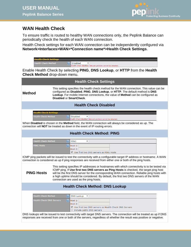
USER MANUAL Peplink Balance Series
http://www.peplink.com -105 / 261 - Copyright © 2015 Peplink
WAN Health Check To ensure traffic is routed to healthy WAN connections only, the Peplink Balance can periodically check the health of each WAN connection. Health Check settings for each WAN connection can be independently configured via Network>Interfaces>WAN>*Connection name*>Health Check Settings.
Enable Health Check by selecting PING, DNS Lookup, or HTTP from the Health Check Method drop-down menu.
Health Check Settings
Method This setting specifies the health check method for the WAN connection. This value can be configured as Disabled, PING, DNS Lookup, or HTTP. The default method is DNS Lookup. For mobile Internet connections, the value of Method can be configured as Disabled or SmartCheck.
Health Check Disabled
When Disabled is chosen in the Method field, the WAN connection will always be considered as up. The connection will NOT be treated as down in the event of IP routing errors.
Health Check Method: PING
ICMP ping packets will be issued to test the connectivity with a configurable target IP address or hostname. A WAN connection is considered as up if ping responses are received from either one or both of the ping hosts.
PING Hosts
This setting specifies IP addresses or hostnames with which connectivity is to be tested via ICMP ping. If Use first two DNS servers as Ping Hosts is checked, the target ping host will be the first DNS server for the corresponding WAN connection. Reliable ping hosts with a high uptime should be considered. By default, the first two DNS servers of the WAN connection are used as the ping hosts.
Health Check Method: DNS Lookup
DNS lookups will be issued to test connectivity with target DNS servers. The connection will be treated as up if DNS responses are received from one or both of the servers, regardless of whether the result was positive or negative.
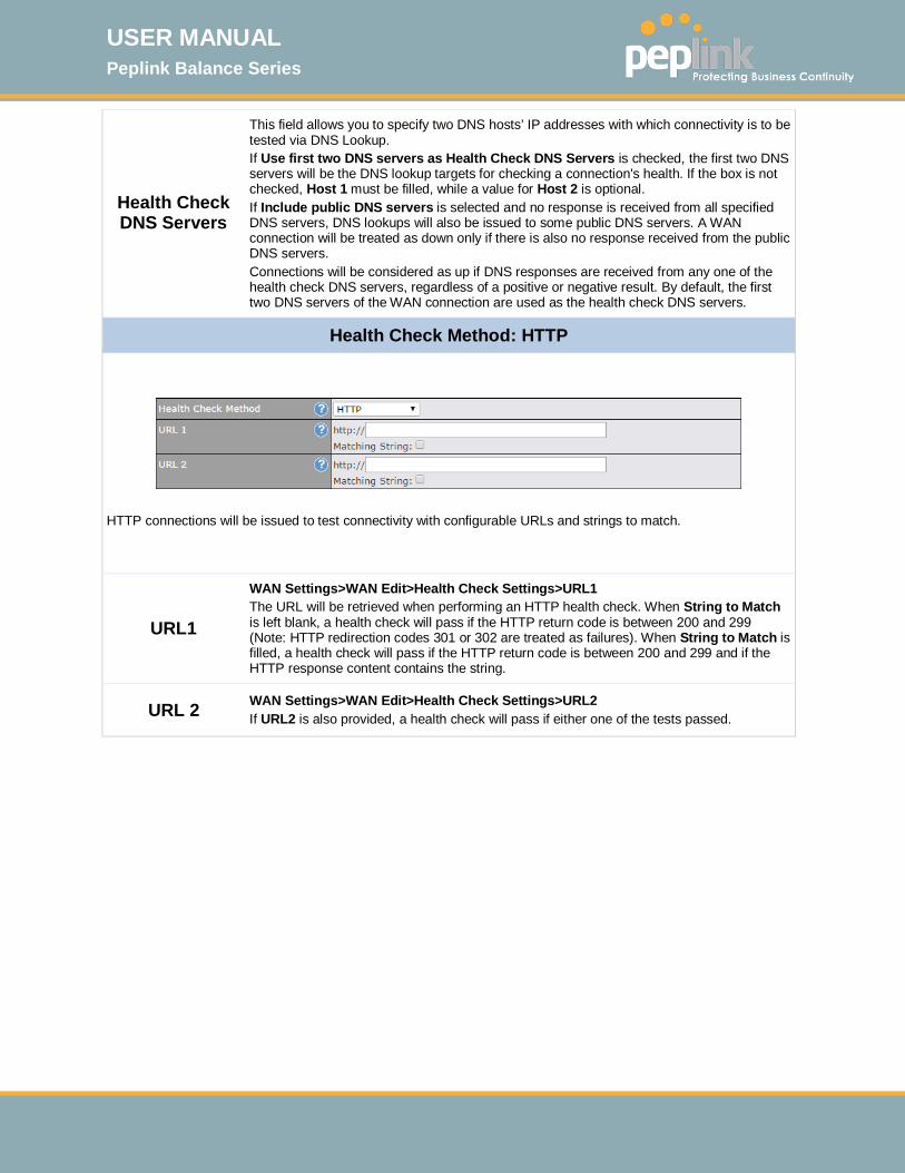
USER MANUAL Peplink Balance Series
http://www.peplink.com -106 / 261 - Copyright © 2015 Peplink
Health Check DNS Servers
This field allows you to specify two DNS hosts’ IP addresses with which connectivity is to be tested via DNS Lookup. If Use first two DNS servers as Health Check DNS Servers is checked, the first two DNS servers will be the DNS lookup targets for checking a connection's health. If the box is not checked, Host 1 must be filled, while a value for Host 2 is optional. If Include public DNS servers is selected and no response is received from all specified DNS servers, DNS lookups will also be issued to some public DNS servers. A WAN connection will be treated as down only if there is also no response received from the public DNS servers. Connections will be considered as up if DNS responses are received from any one of the health check DNS servers, regardless of a positive or negative result. By default, the first two DNS servers of the WAN connection are used as the health check DNS servers.
Health Check Method: HTTP
HTTP connections will be issued to test connectivity with configurable URLs and strings to match.
URL1
WAN Settings>WAN Edit>Health Check Settings>URL1 The URL will be retrieved when performing an HTTP health check. When String to Match is left blank, a health check will pass if the HTTP return code is between 200 and 299 (Note: HTTP redirection codes 301 or 302 are treated as failures). When String to Match is filled, a health check will pass if the HTTP return code is between 200 and 299 and if the HTTP response content contains the string.
URL 2 WAN Settings>WAN Edit>Health Check Settings>URL2 If URL2 is also provided, a health check will pass if either one of the tests passed.
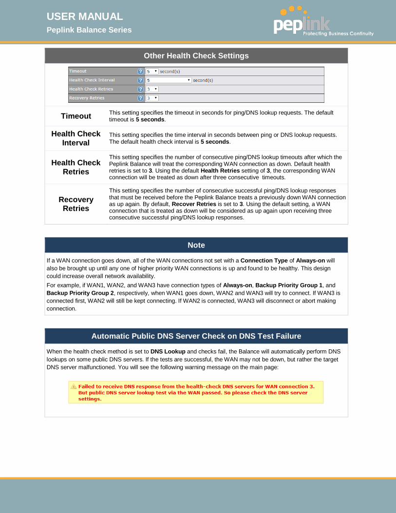
USER MANUAL Peplink Balance Series
http://www.peplink.com -107 / 261 - Copyright © 2015 Peplink
Other Health Check Settings
Timeout This setting specifies the timeout in seconds for ping/DNS lookup requests. The default timeout is 5 seconds.
Health Check Interval
This setting specifies the time interval in seconds between ping or DNS lookup requests. The default health check interval is 5 seconds.
Health Check Retries
This setting specifies the number of consecutive ping/DNS lookup timeouts after which the Peplink Balance will treat the corresponding WAN connection as down. Default health retries is set to 3. Using the default Health Retries setting of 3, the corresponding WAN connection will be treated as down after three consecutive timeouts.
Recovery Retries
This setting specifies the number of consecutive successful ping/DNS lookup responses that must be received before the Peplink Balance treats a previously down WAN connection as up again. By default, Recover Retries is set to 3. Using the default setting, a WAN connection that is treated as down will be considered as up again upon receiving three consecutive successful ping/DNS lookup responses.
Note
If a WAN connection goes down, all of the WAN connections not set with a Connection Type of Always-on will also be brought up until any one of higher priority WAN connections is up and found to be healthy. This design could increase overall network availability. For example, if WAN1, WAN2, and WAN3 have connection types of Always-on, Backup Priority Group 1, and Backup Priority Group 2, respectively, when WAN1 goes down, WAN2 and WAN3 will try to connect. If WAN3 is connected first, WAN2 will still be kept connecting. If WAN2 is connected, WAN3 will disconnect or abort making connection.
Automatic Public DNS Server Check on DNS Test Failure
When the health check method is set to DNS Lookup and checks fail, the Balance will automatically perform DNS lookups on some public DNS servers. If the tests are successful, the WAN may not be down, but rather the target DNS server malfunctioned. You will see the following warning message on the main page:
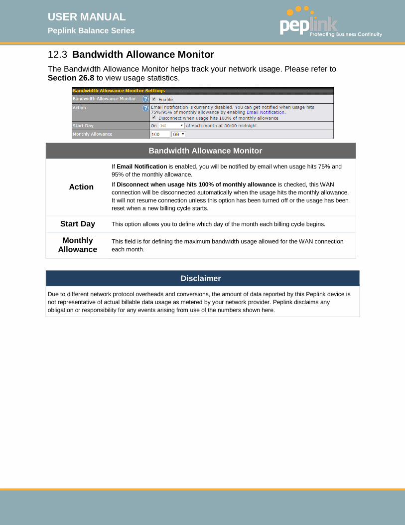
USER MANUAL Peplink Balance Series
http://www.peplink.com -108 / 261 - Copyright © 2015 Peplink
12.3 Bandwidth Allowance Monitor The Bandwidth Allowance Monitor helps track your network usage. Please refer to Section 26.8 to view usage statistics.
Bandwidth Allowance Monitor
Action
If Email Notification is enabled, you will be notified by email when usage hits 75% and 95% of the monthly allowance. If Disconnect when usage hits 100% of monthly allowance is checked, this WAN connection will be disconnected automatically when the usage hits the monthly allowance. It will not resume connection unless this option has been turned off or the usage has been reset when a new billing cycle starts.
Start Day This option allows you to define which day of the month each billing cycle begins.
Monthly Allowance
This field is for defining the maximum bandwidth usage allowed for the WAN connection each month.
Disclaimer
Due to different network protocol overheads and conversions, the amount of data reported by this Peplink device is not representative of actual billable data usage as metered by your network provider. Peplink disclaims any obligation or responsibility for any events arising from use of the numbers shown here.
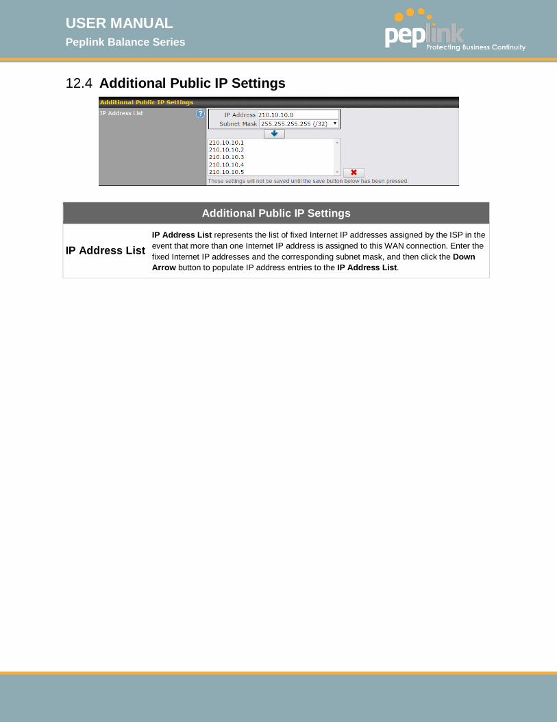
USER MANUAL Peplink Balance Series
http://www.peplink.com -109 / 261 - Copyright © 2015 Peplink
12.4 Additional Public IP Settings
Additional Public IP Settings
IP Address List IP Address List represents the list of fixed Internet IP addresses assigned by the ISP in the event that more than one Internet IP address is assigned to this WAN connection. Enter the fixed Internet IP addresses and the corresponding subnet mask, and then click the Down Arrow button to populate IP address entries to the IP Address List.
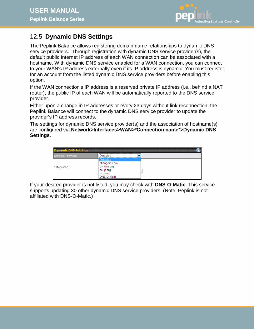
USER MANUAL Peplink Balance Series
http://www.peplink.com -110 / 261 - Copyright © 2015 Peplink
12.5 Dynamic DNS Settings The Peplink Balance allows registering domain name relationships to dynamic DNS service providers. Through registration with dynamic DNS service provider(s), the default public Internet IP address of each WAN connection can be associated with a hostname. With dynamic DNS service enabled for a WAN connection, you can connect to your WAN's IP address externally even if its IP address is dynamic. You must register for an account from the listed dynamic DNS service providers before enabling this option. If the WAN connection's IP address is a reserved private IP address (i.e., behind a NAT router), the public IP of each WAN will be automatically reported to the DNS service provider. Either upon a change in IP addresses or every 23 days without link reconnection, the Peplink Balance will connect to the dynamic DNS service provider to update the provider’s IP address records. The settings for dynamic DNS service provider(s) and the association of hostname(s) are configured via Network>Interfaces>WAN>*Connection name*>Dynamic DNS Settings.
If your desired provider is not listed, you may check with DNS-O-Matic. This service supports updating 30 other dynamic DNS service providers. (Note: Peplink is not affiliated with DNS-O-Matic.)
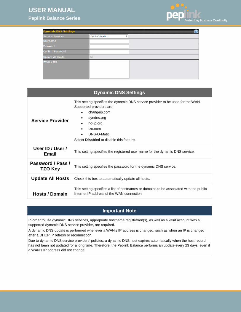
USER MANUAL Peplink Balance Series
http://www.peplink.com -111 / 261 - Copyright © 2015 Peplink
Dynamic DNS Settings
Service Provider
This setting specifies the dynamic DNS service provider to be used for the WAN. Supported providers are:
• changeip.com • dyndns.org • no-ip.org • tzo.com • DNS-O-Matic
Select Disabled to disable this feature.
User ID / User / Email This setting specifies the registered user name for the dynamic DNS service.
Password / Pass / TZO Key This setting specifies the password for the dynamic DNS service.
Update All Hosts Check this box to automatically update all hosts.
Hosts / Domain
This setting specifies a list of hostnames or domains to be associated with the public Internet IP address of the WAN connection.
Important Note
In order to use dynamic DNS services, appropriate hostname registration(s), as well as a valid account with a supported dynamic DNS service provider, are required. A dynamic DNS update is performed whenever a WAN’s IP address is changed, such as when an IP is changed after a DHCP IP refresh or reconnection. Due to dynamic DNS service providers’ policies, a dynamic DNS host expires automatically when the host record has not been not updated for a long time. Therefore, the Peplink Balance performs an update every 23 days, even if a WAN’s IP address did not change.

USER MANUAL Peplink Balance Series
http://www.peplink.com -112 / 261 - Copyright © 2015 Peplink
13 PepVPN with Bandwidth Bonding SpeedFusionTM
Peplink Balance bandwidth bonding SpeedFusionTM functionality securely connects one or more branch offices to your company's main headquarters or to other branches. The data, voice, and video communications between these locations are kept confidential across the public Internet. The bandwidth bonding SpeedFusionTM of the Peplink Balance is specifically designed for multi-WAN environments. The Peplink Balance can bond all WAN connections’ bandwidth for routing SpeedFusionTM traffic. Unless all the WAN connections of one site are down, the Peplink Balance can keep the VPN up and running. Bandwidth bonding is enabled by default.
13.1 SpeedFusionTM Settings Some Peplink Balance models support making multiple SpeedFusionTM connections with a remote Peplink Balance, MediaFast, or Pepwave MAX mobile router. A Peplink Balance that supports multiple VPN connections can act as a central hub which connects branch offices. For example, if Branch Office A and Branch Office B make VPN connections to Headquarters C, both branch office LAN subnets and the subnets behind them (i.e., static routes) will also be advertised to Headquarters C and the other branches. So Branch Office A will be able to access Branch Office B via Headquarters C in this case. The local LAN subnet and subnets behind the LAN (defined under Static Route on the LAN settings page) will be advertised to the VPN. All VPN members (branch offices and headquarters) will be able to route to local subnets. Note that all LAN subnets and the subnets behind them must be unique. Otherwise, VPN members will not be able to access each other.

USER MANUAL Peplink Balance Series
http://www.peplink.com -113 / 261 - Copyright © 2015 Peplink
All data can be routed over the VPN with 256-bit AES encryption standard. To configure this, navigate to Network>SpeedFusion.
To configure a new SpeedFusion profile, navigate to Network>SpeedFusion>New Profile.
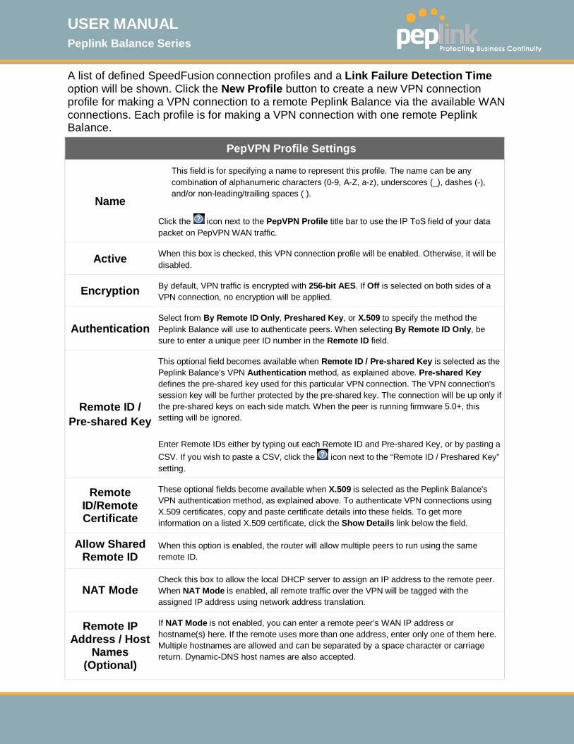
USER MANUAL Peplink Balance Series
http://www.peplink.com -114 / 261 - Copyright © 2015 Peplink
A list of defined SpeedFusion connection profiles and a Link Failure Detection Time option will be shown. Click the New Profile button to create a new VPN connection profile for making a VPN connection to a remote Peplink Balance via the available WAN connections. Each profile is for making a VPN connection with one remote Peplink Balance.
PepVPN Profile Settings
Name
This field is for specifying a name to represent this profile. The name can be any combination of alphanumeric characters (0-9, A-Z, a-z), underscores (_), dashes (-), and/or non-leading/trailing spaces ( ).
Click the icon next to the PepVPN Profile title bar to use the IP ToS field of your data packet on PepVPN WAN traffic.
Active When this box is checked, this VPN connection profile will be enabled. Otherwise, it will be disabled.
Encryption By default, VPN traffic is encrypted with 256-bit AES. If Off is selected on both sides of a VPN connection, no encryption will be applied.
Authentication Select from By Remote ID Only, Preshared Key, or X.509 to specify the method the Peplink Balance will use to authenticate peers. When selecting By Remote ID Only, be sure to enter a unique peer ID number in the Remote ID field.
Remote ID / Pre-shared Key
This optional field becomes available when Remote ID / Pre-shared Key is selected as the Peplink Balance’s VPN Authentication method, as explained above. Pre-shared Key defines the pre-shared key used for this particular VPN connection. The VPN connection's session key will be further protected by the pre-shared key. The connection will be up only if the pre-shared keys on each side match. When the peer is running firmware 5.0+, this setting will be ignored. Enter Remote IDs either by typing out each Remote ID and Pre-shared Key, or by pasting a CSV. If you wish to paste a CSV, click the icon next to the “Remote ID / Preshared Key” setting.
Remote ID/Remote Certificate
These optional fields become available when X.509 is selected as the Peplink Balance’s VPN authentication method, as explained above. To authenticate VPN connections using X.509 certificates, copy and paste certificate details into these fields. To get more information on a listed X.509 certificate, click the Show Details link below the field.
Allow Shared Remote ID
When this option is enabled, the router will allow multiple peers to run using the same remote ID.
NAT Mode Check this box to allow the local DHCP server to assign an IP address to the remote peer. When NAT Mode is enabled, all remote traffic over the VPN will be tagged with the assigned IP address using network address translation.
Remote IP Address / Host
Names (Optional)
If NAT Mode is not enabled, you can enter a remote peer’s WAN IP address or hostname(s) here. If the remote uses more than one address, enter only one of them here. Multiple hostnames are allowed and can be separated by a space character or carriage return. Dynamic-DNS host names are also accepted.
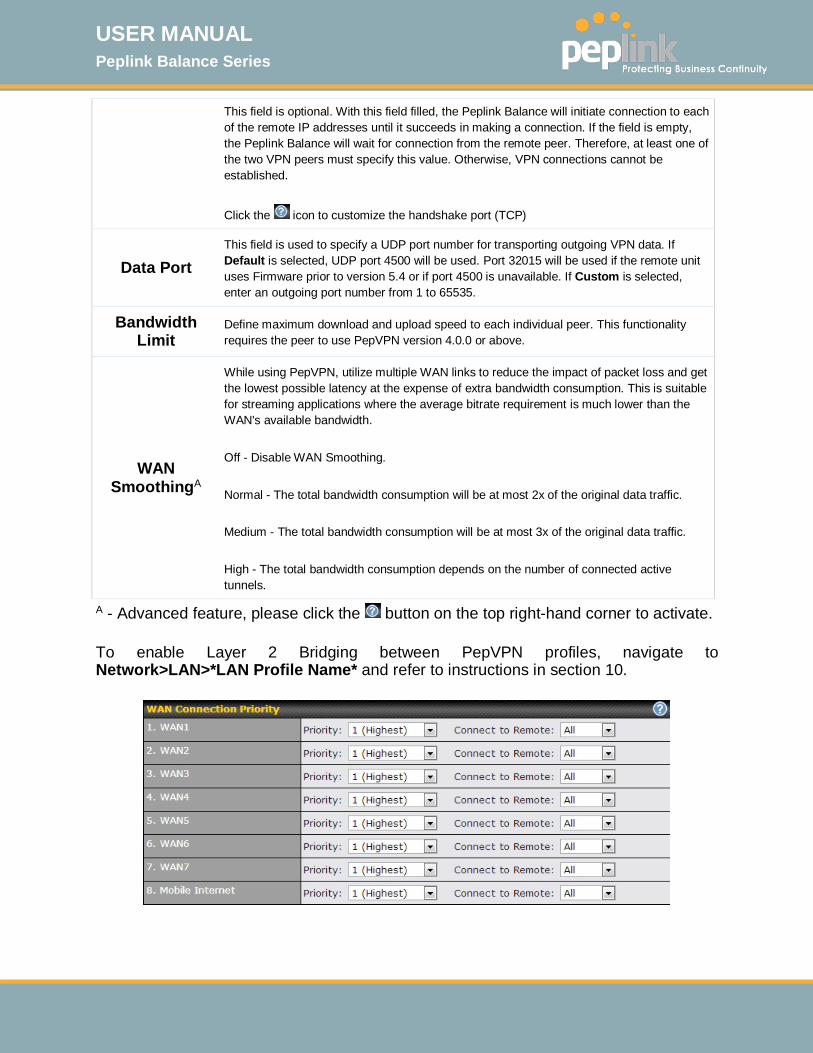
USER MANUAL Peplink Balance Series
http://www.peplink.com -115 / 261 - Copyright © 2015 Peplink
This field is optional. With this field filled, the Peplink Balance will initiate connection to each of the remote IP addresses until it succeeds in making a connection. If the field is empty, the Peplink Balance will wait for connection from the remote peer. Therefore, at least one of the two VPN peers must specify this value. Otherwise, VPN connections cannot be established.
Click the icon to customize the handshake port (TCP)
Data Port This field is used to specify a UDP port number for transporting outgoing VPN data. If Default is selected, UDP port 4500 will be used. Port 32015 will be used if the remote unit uses Firmware prior to version 5.4 or if port 4500 is unavailable. If Custom is selected, enter an outgoing port number from 1 to 65535.
Bandwidth Limit
Define maximum download and upload speed to each individual peer. This functionality requires the peer to use PepVPN version 4.0.0 or above.
WAN SmoothingA
While using PepVPN, utilize multiple WAN links to reduce the impact of packet loss and get the lowest possible latency at the expense of extra bandwidth consumption. This is suitable for streaming applications where the average bitrate requirement is much lower than the WAN's available bandwidth. Off - Disable WAN Smoothing. Normal - The total bandwidth consumption will be at most 2x of the original data traffic. Medium - The total bandwidth consumption will be at most 3x of the original data traffic. High - The total bandwidth consumption depends on the number of connected active tunnels.
A - Advanced feature, please click the button on the top right-hand corner to activate.
To enable Layer 2 Bridging between PepVPN profiles, navigate to Network>LAN>*LAN Profile Name* and refer to instructions in section 10.
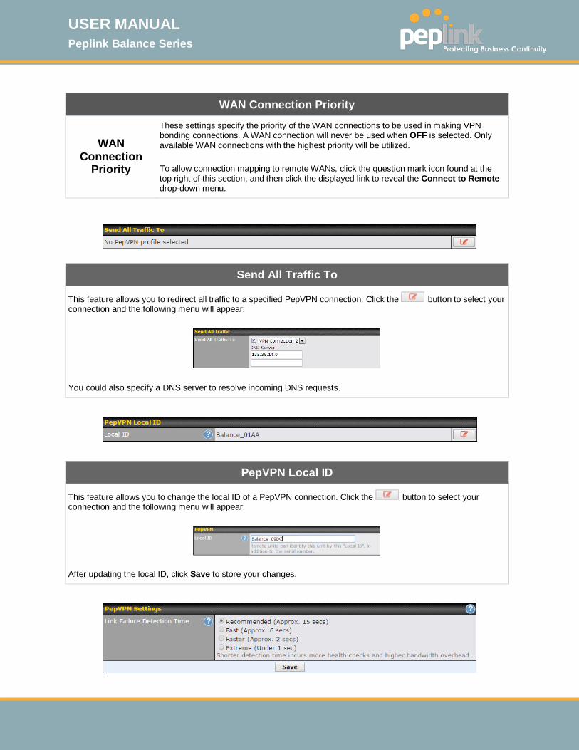
USER MANUAL Peplink Balance Series
http://www.peplink.com -116 / 261 - Copyright © 2015 Peplink
WAN Connection Priority
WAN Connection
Priority
These settings specify the priority of the WAN connections to be used in making VPN bonding connections. A WAN connection will never be used when OFF is selected. Only available WAN connections with the highest priority will be utilized. To allow connection mapping to remote WANs, click the question mark icon found at the top right of this section, and then click the displayed link to reveal the Connect to Remote drop-down menu.
Send All Traffic To
This feature allows you to redirect all traffic to a specified PepVPN connection. Click the button to select your connection and the following menu will appear:
You could also specify a DNS server to resolve incoming DNS requests.
PepVPN Local ID
This feature allows you to change the local ID of a PepVPN connection. Click the button to select your connection and the following menu will appear:
After updating the local ID, click Save to store your changes.
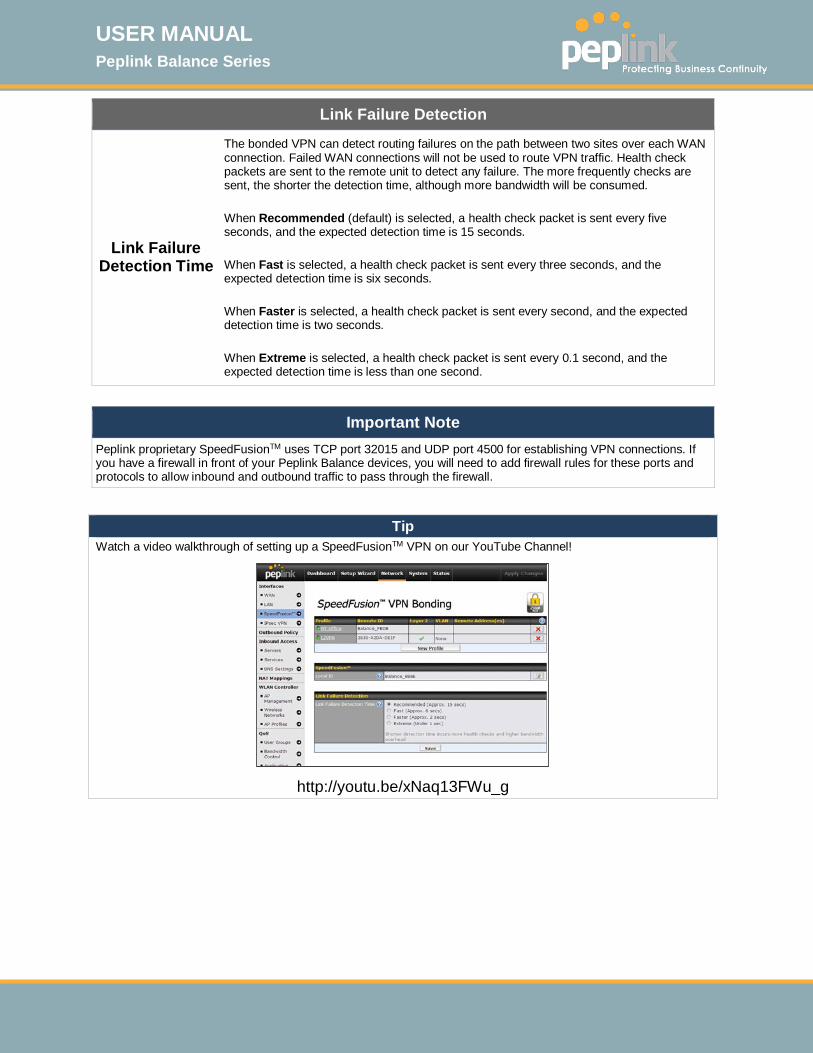
USER MANUAL Peplink Balance Series
http://www.peplink.com -117 / 261 - Copyright © 2015 Peplink
Link Failure Detection
Link Failure Detection Time
The bonded VPN can detect routing failures on the path between two sites over each WAN connection. Failed WAN connections will not be used to route VPN traffic. Health check packets are sent to the remote unit to detect any failure. The more frequently checks are sent, the shorter the detection time, although more bandwidth will be consumed. When Recommended (default) is selected, a health check packet is sent every five seconds, and the expected detection time is 15 seconds. When Fast is selected, a health check packet is sent every three seconds, and the expected detection time is six seconds. When Faster is selected, a health check packet is sent every second, and the expected detection time is two seconds. When Extreme is selected, a health check packet is sent every 0.1 second, and the expected detection time is less than one second.
Important Note Peplink proprietary SpeedFusionTM uses TCP port 32015 and UDP port 4500 for establishing VPN connections. If you have a firewall in front of your Peplink Balance devices, you will need to add firewall rules for these ports and protocols to allow inbound and outbound traffic to pass through the firewall.
Tip
Watch a video walkthrough of setting up a SpeedFusionTM VPN on our YouTube Channel!
http://youtu.be/xNaq13FWu_g
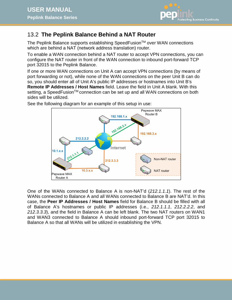
USER MANUAL Peplink Balance Series
http://www.peplink.com -118 / 261 - Copyright © 2015 Peplink
13.2 The Peplink Balance Behind a NAT Router The Peplink Balance supports establishing SpeedFusionTM over WAN connections which are behind a NAT (network address translation) router. To enable a WAN connection behind a NAT router to accept VPN connections, you can configure the NAT router in front of the WAN connection to inbound port-forward TCP port 32015 to the Peplink Balance. If one or more WAN connections on Unit A can accept VPN connections (by means of port forwarding or not), while none of the WAN connections on the peer Unit B can do so, you should enter all of Unit A’s public IP addresses or hostnames into Unit B’s Remote IP Addresses / Host Names field. Leave the field in Unit A blank. With this setting, a SpeedFusionTM connection can be set up and all WAN connections on both sides will be utilized. See the following diagram for an example of this setup in use:
One of the WANs connected to Balance A is non-NAT’d (212.1.1.1). The rest of the WANs connected to Balance A and all WANs connected to Balance B are NAT’d. In this case, the Peer IP Addresses / Host Names field for Balance B should be filled with all of Balance A’s hostnames or public IP addresses (i.e., 212.1.1.1, 212.2.2.2, and 212.3.3.3), and the field in Balance A can be left blank. The two NAT routers on WAN1 and WAN3 connected to Balance A should inbound port-forward TCP port 32015 to Balance A so that all WANs will be utilized in establishing the VPN.

USER MANUAL Peplink Balance Series
http://www.peplink.com -119 / 261 - Copyright © 2015 Peplink
13.3 SpeedFusionTM Status SpeedFusionTM status is shown in the Dashboard. The connection status of each connection profile is shown as below.
After clicking the Status button at the top right corner of the SpeedFusionTM table, you will be forwarded to Status>SpeedFusionTM, where you can view subnet and WAN connection information for each VPN peer. Please refer to Section 26.6 for details.
IP Subnets Must Be Unique Among VPN Peers
The entire interconnected SpeedFusionTM network is a single non-NAT IP network. Avoid duplicating subnets in your sites to prevent connectivity problems when accessing those subnets.
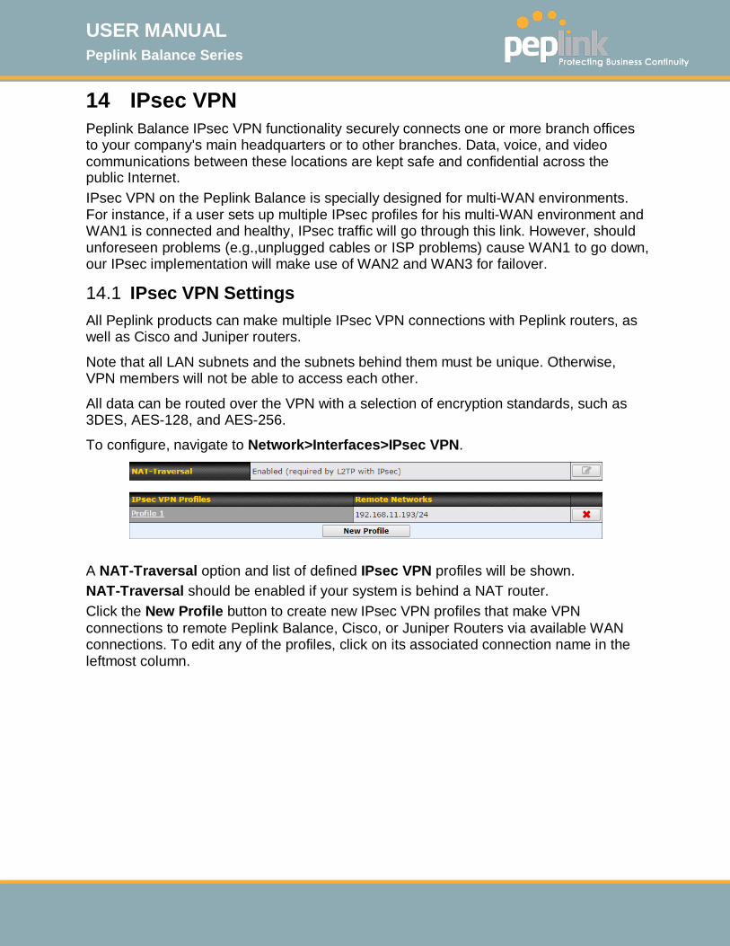
USER MANUAL Peplink Balance Series
http://www.peplink.com -120 / 261 - Copyright © 2015 Peplink
14 IPsec VPN
Peplink Balance IPsec VPN functionality securely connects one or more branch offices to your company's main headquarters or to other branches. Data, voice, and video communications between these locations are kept safe and confidential across the public Internet. IPsec VPN on the Peplink Balance is specially designed for multi-WAN environments. For instance, if a user sets up multiple IPsec profiles for his multi-WAN environment and WAN1 is connected and healthy, IPsec traffic will go through this link. However, should unforeseen problems (e.g.,unplugged cables or ISP problems) cause WAN1 to go down, our IPsec implementation will make use of WAN2 and WAN3 for failover.
14.1 IPsec VPN Settings All Peplink products can make multiple IPsec VPN connections with Peplink routers, as well as Cisco and Juniper routers.
Note that all LAN subnets and the subnets behind them must be unique. Otherwise, VPN members will not be able to access each other.
All data can be routed over the VPN with a selection of encryption standards, such as 3DES, AES-128, and AES-256.
To configure, navigate to Network>Interfaces>IPsec VPN.
A NAT-Traversal option and list of defined IPsec VPN profiles will be shown. NAT-Traversal should be enabled if your system is behind a NAT router. Click the New Profile button to create new IPsec VPN profiles that make VPN connections to remote Peplink Balance, Cisco, or Juniper Routers via available WAN connections. To edit any of the profiles, click on its associated connection name in the leftmost column.
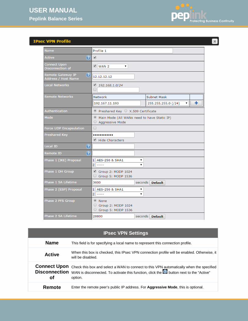
USER MANUAL Peplink Balance Series
http://www.peplink.com -121 / 261 - Copyright © 2015 Peplink
IPsec VPN Settings
Name This field is for specifying a local name to represent this connection profile.
Active When this box is checked, this IPsec VPN connection profile will be enabled. Otherwise, it will be disabled.
Connect Upon Disconnection
of
Check this box and select a WAN to connect to this VPN automatically when the specified WAN is disconnected. To activate this function, click the button next to the “Active” option.
Remote Enter the remote peer’s public IP address. For Aggressive Mode, this is optional.
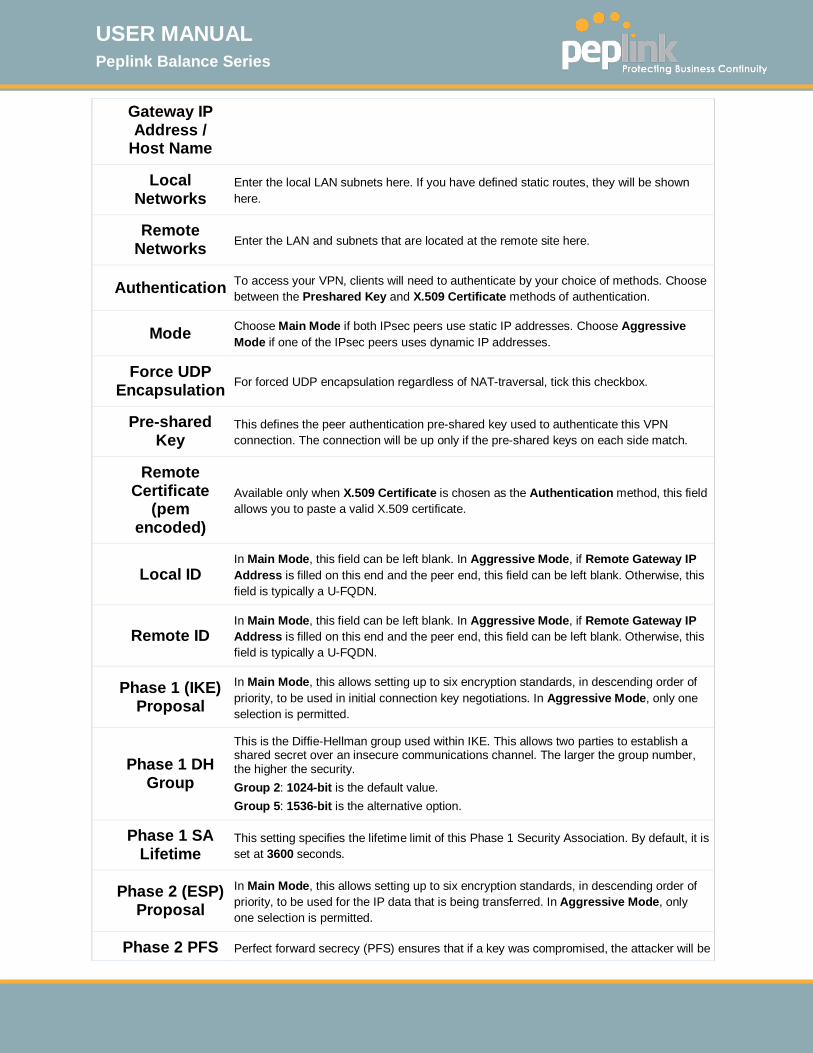
USER MANUAL Peplink Balance Series
http://www.peplink.com -122 / 261 - Copyright © 2015 Peplink
Gateway IP Address /
Host Name
Local Networks
Enter the local LAN subnets here. If you have defined static routes, they will be shown here.
Remote Networks Enter the LAN and subnets that are located at the remote site here.
Authentication To access your VPN, clients will need to authenticate by your choice of methods. Choose between the Preshared Key and X.509 Certificate methods of authentication.
Mode Choose Main Mode if both IPsec peers use static IP addresses. Choose Aggressive Mode if one of the IPsec peers uses dynamic IP addresses.
Force UDP Encapsulation For forced UDP encapsulation regardless of NAT-traversal, tick this checkbox.
Pre-shared Key
This defines the peer authentication pre-shared key used to authenticate this VPN connection. The connection will be up only if the pre-shared keys on each side match.
Remote Certificate
(pem encoded)
Available only when X.509 Certificate is chosen as the Authentication method, this field allows you to paste a valid X.509 certificate.
Local ID In Main Mode, this field can be left blank. In Aggressive Mode, if Remote Gateway IP Address is filled on this end and the peer end, this field can be left blank. Otherwise, this field is typically a U-FQDN.
Remote ID In Main Mode, this field can be left blank. In Aggressive Mode, if Remote Gateway IP Address is filled on this end and the peer end, this field can be left blank. Otherwise, this field is typically a U-FQDN.
Phase 1 (IKE) Proposal
In Main Mode, this allows setting up to six encryption standards, in descending order of priority, to be used in initial connection key negotiations. In Aggressive Mode, only one selection is permitted.
Phase 1 DH Group
This is the Diffie-Hellman group used within IKE. This allows two parties to establish a shared secret over an insecure communications channel. The larger the group number, the higher the security. Group 2: 1024-bit is the default value. Group 5: 1536-bit is the alternative option.
Phase 1 SA Lifetime
This setting specifies the lifetime limit of this Phase 1 Security Association. By default, it is set at 3600 seconds.
Phase 2 (ESP) Proposal
In Main Mode, this allows setting up to six encryption standards, in descending order of priority, to be used for the IP data that is being transferred. In Aggressive Mode, only one selection is permitted.
Phase 2 PFS Perfect forward secrecy (PFS) ensures that if a key was compromised, the attacker will be
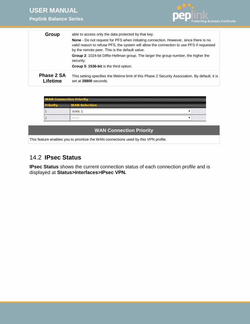
USER MANUAL Peplink Balance Series
http://www.peplink.com -123 / 261 - Copyright © 2015 Peplink
Group able to access only the data protected by that key. None - Do not request for PFS when initiating connection. However, since there is no valid reason to refuse PFS, the system will allow the connection to use PFS if requested by the remote peer. This is the default value. Group 2: 1024-bit Diffie-Hellman group. The larger the group number, the higher the security. Group 5: 1536-bit is the third option.
Phase 2 SA Lifetime
This setting specifies the lifetime limit of this Phase 2 Security Association. By default, it is set at 28800 seconds.
WAN Connection Priority
This feature enables you to prioritize the WAN connections used by this VPN profile.
14.2 IPsec Status IPsec Status shows the current connection status of each connection profile and is displayed at Status>Interfaces>IPsec VPN.
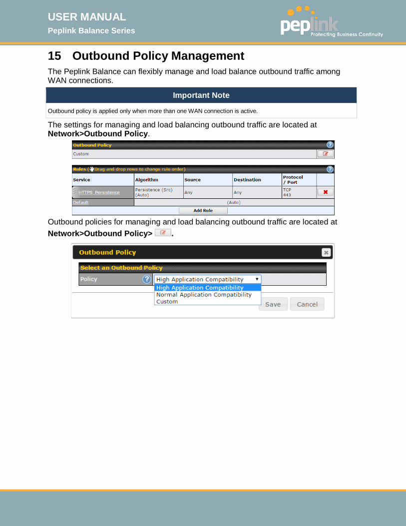
USER MANUAL Peplink Balance Series
http://www.peplink.com -124 / 261 - Copyright © 2015 Peplink
15 Outbound Policy Management The Peplink Balance can flexibly manage and load balance outbound traffic among WAN connections.
Important Note
Outbound policy is applied only when more than one WAN connection is active.
The settings for managing and load balancing outbound traffic are located at Network>Outbound Policy.
Outbound policies for managing and load balancing outbound traffic are located at Network>Outbound Policy> .
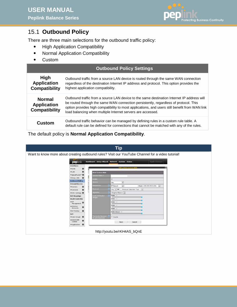
USER MANUAL Peplink Balance Series
http://www.peplink.com -125 / 261 - Copyright © 2015 Peplink
15.1 Outbound Policy There are three main selections for the outbound traffic policy: High Application Compatibility Normal Application Compatibility Custom
Outbound Policy Settings
High Application
Compatibility
Outbound traffic from a source LAN device is routed through the same WAN connection regardless of the destination Internet IP address and protocol. This option provides the highest application compatibility.
Normal Application
Compatibility
Outbound traffic from a source LAN device to the same destination Internet IP address will be routed through the same WAN connection persistently, regardless of protocol. This option provides high compatibility to most applications, and users still benefit from WAN link load balancing when multiple Internet servers are accessed.
Custom Outbound traffic behavior can be managed by defining rules in a custom rule table. A default rule can be defined for connections that cannot be matched with any of the rules.
The default policy is Normal Application Compatibility.
Tip Want to know more about creating outbound rules? Visit our YouTube Channel for a video tutorial!
http://youtu.be/rKH4AS_bQnE
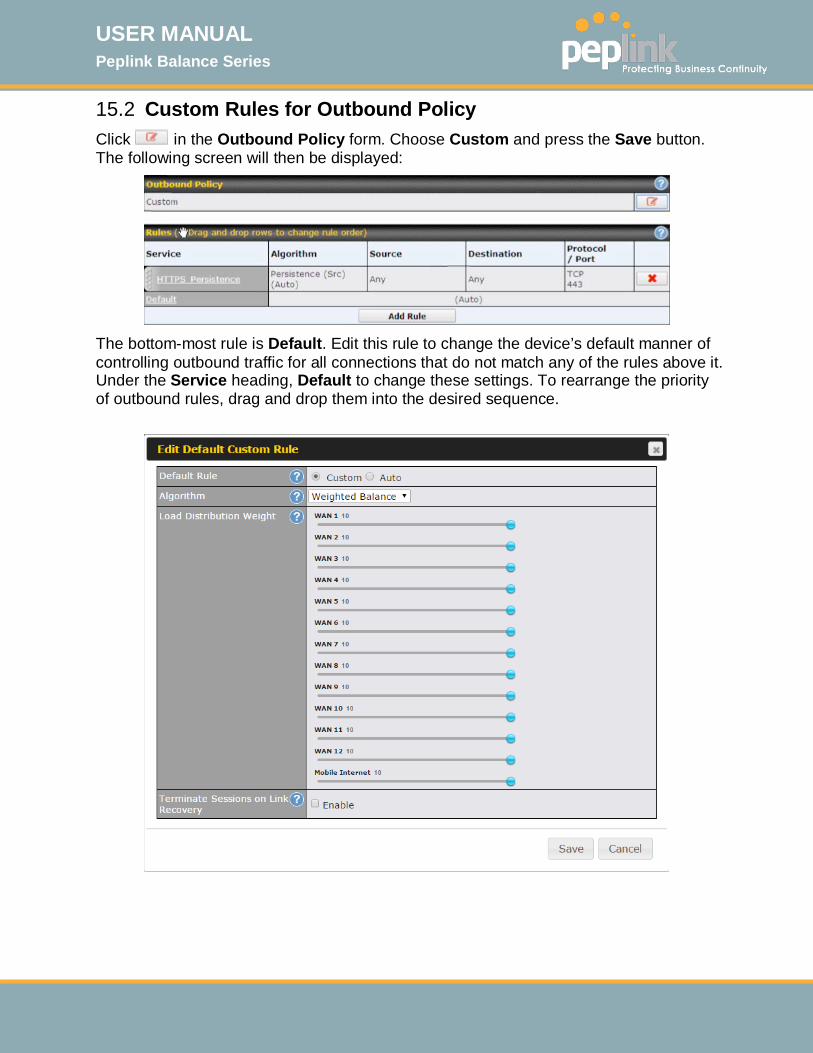
USER MANUAL Peplink Balance Series
http://www.peplink.com -126 / 261 - Copyright © 2015 Peplink
15.2 Custom Rules for Outbound Policy Click in the Outbound Policy form. Choose Custom and press the Save button. The following screen will then be displayed:
The bottom-most rule is Default. Edit this rule to change the device’s default manner of controlling outbound traffic for all connections that do not match any of the rules above it. Under the Service heading, Default to change these settings. To rearrange the priority of outbound rules, drag and drop them into the desired sequence.
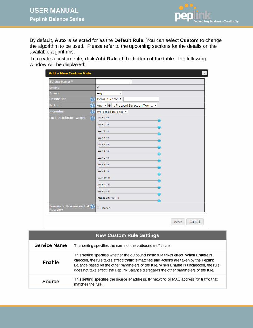
USER MANUAL Peplink Balance Series
http://www.peplink.com -127 / 261 - Copyright © 2015 Peplink
By default, Auto is selected for as the Default Rule. You can select Custom to change the algorithm to be used. Please refer to the upcoming sections for the details on the available algorithms. To create a custom rule, click Add Rule at the bottom of the table. The following window will be displayed:
New Custom Rule Settings
Service Name This setting specifies the name of the outbound traffic rule.
Enable This setting specifies whether the outbound traffic rule takes effect. When Enable is checked, the rule takes effect: traffic is matched and actions are taken by the Peplink Balance based on the other parameters of the rule. When Enable is unchecked, the rule does not take effect: the Peplink Balance disregards the other parameters of the rule.
Source This setting specifies the source IP address, IP network, or MAC address for traffic that matches the rule.
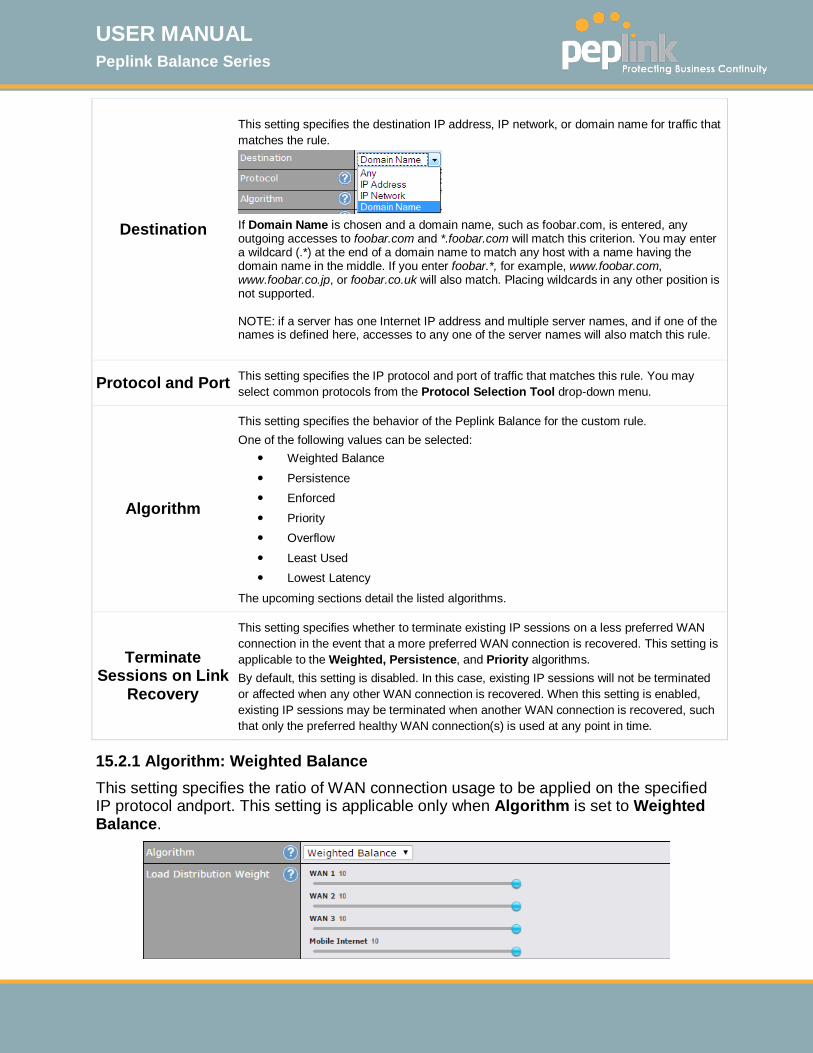
USER MANUAL Peplink Balance Series
http://www.peplink.com -128 / 261 - Copyright © 2015 Peplink
Destination
This setting specifies the destination IP address, IP network, or domain name for traffic that matches the rule.
If Domain Name is chosen and a domain name, such as foobar.com, is entered, any outgoing accesses to foobar.com and *.foobar.com will match this criterion. You may enter a wildcard (.*) at the end of a domain name to match any host with a name having the domain name in the middle. If you enter foobar.*, for example, www.foobar.com, www.foobar.co.jp, or foobar.co.uk will also match. Placing wildcards in any other position is not supported. NOTE: if a server has one Internet IP address and multiple server names, and if one of the names is defined here, accesses to any one of the server names will also match this rule.
Protocol and Port This setting specifies the IP protocol and port of traffic that matches this rule. You may select common protocols from the Protocol Selection Tool drop-down menu.
Algorithm
This setting specifies the behavior of the Peplink Balance for the custom rule. One of the following values can be selected:
Weighted Balance Persistence Enforced Priority Overflow Least Used Lowest Latency
The upcoming sections detail the listed algorithms.
Terminate Sessions on Link
Recovery
This setting specifies whether to terminate existing IP sessions on a less preferred WAN connection in the event that a more preferred WAN connection is recovered. This setting is applicable to the Weighted, Persistence, and Priority algorithms. By default, this setting is disabled. In this case, existing IP sessions will not be terminated or affected when any other WAN connection is recovered. When this setting is enabled, existing IP sessions may be terminated when another WAN connection is recovered, such that only the preferred healthy WAN connection(s) is used at any point in time.
15.2.1 Algorithm: Weighted Balance This setting specifies the ratio of WAN connection usage to be applied on the specified IP protocol andport. This setting is applicable only when Algorithm is set to Weighted Balance.
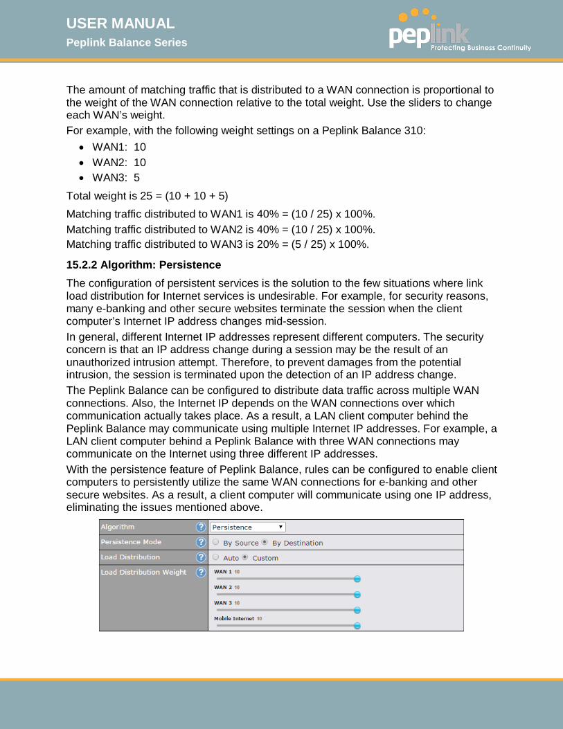
USER MANUAL Peplink Balance Series
http://www.peplink.com -129 / 261 - Copyright © 2015 Peplink
The amount of matching traffic that is distributed to a WAN connection is proportional to the weight of the WAN connection relative to the total weight. Use the sliders to change each WAN’s weight. For example, with the following weight settings on a Peplink Balance 310:
• WAN1: 10 • WAN2: 10 • WAN3: 5
Total weight is 25 = (10 + 10 + 5) Matching traffic distributed to WAN1 is 40% = (10 / 25) x 100%. Matching traffic distributed to WAN2 is 40% = (10 / 25) x 100%. Matching traffic distributed to WAN3 is 20% = (5 / 25) x 100%.
15.2.2 Algorithm: Persistence The configuration of persistent services is the solution to the few situations where link load distribution for Internet services is undesirable. For example, for security reasons, many e-banking and other secure websites terminate the session when the client computer’s Internet IP address changes mid-session. In general, different Internet IP addresses represent different computers. The security concern is that an IP address change during a session may be the result of an unauthorized intrusion attempt. Therefore, to prevent damages from the potential intrusion, the session is terminated upon the detection of an IP address change. The Peplink Balance can be configured to distribute data traffic across multiple WAN connections. Also, the Internet IP depends on the WAN connections over which communication actually takes place. As a result, a LAN client computer behind the Peplink Balance may communicate using multiple Internet IP addresses. For example, a LAN client computer behind a Peplink Balance with three WAN connections may communicate on the Internet using three different IP addresses. With the persistence feature of Peplink Balance, rules can be configured to enable client computers to persistently utilize the same WAN connections for e-banking and other secure websites. As a result, a client computer will communicate using one IP address, eliminating the issues mentioned above.
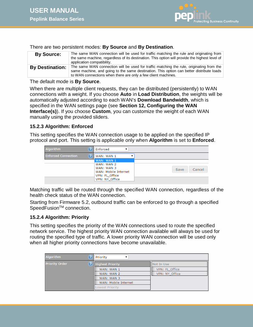
USER MANUAL Peplink Balance Series
http://www.peplink.com -130 / 261 - Copyright © 2015 Peplink
There are two persistent modes: By Source and By Destination.
By Source: The same WAN connection will be used for traffic matching the rule and originating from the same machine, regardless of its destination. This option will provide the highest level of application compatibility.
By Destination: The same WAN connection will be used for traffic matching the rule, originating from the same machine, and going to the same destination. This option can better distribute loads to WAN connections when there are only a few client machines.
The default mode is By Source. When there are multiple client requests, they can be distributed (persistently) to WAN connections with a weight. If you choose Auto in Load Distribution, the weights will be automatically adjusted according to each WAN’s Download Bandwidth, which is specified in the WAN settings page (see Section 12, Configuring the WAN Interface(s)). If you choose Custom, you can customize the weight of each WAN manually using the provided sliders.
15.2.3 Algorithm: Enforced This setting specifies the WAN connection usage to be applied on the specified IP protocol and port. This setting is applicable only when Algorithm is set to Enforced.
Matching traffic will be routed through the specified WAN connection, regardless of the health check status of the WAN connection. Starting from Firmware 5.2, outbound traffic can be enforced to go through a specified SpeedFusionTM connection.
15.2.4 Algorithm: Priority This setting specifies the priority of the WAN connections used to route the specified network service. The highest priority WAN connection available will always be used for routing the specified type of traffic. A lower priority WAN connection will be used only when all higher priority connections have become unavailable.
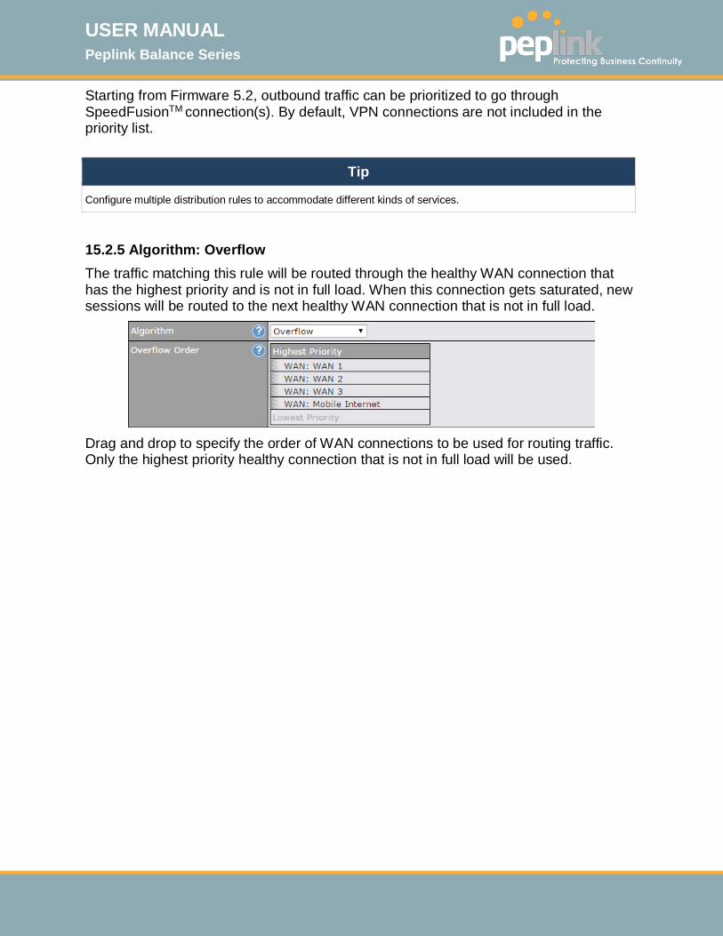
USER MANUAL Peplink Balance Series
http://www.peplink.com -131 / 261 - Copyright © 2015 Peplink
Starting from Firmware 5.2, outbound traffic can be prioritized to go through SpeedFusionTM connection(s). By default, VPN connections are not included in the priority list.
Tip
Configure multiple distribution rules to accommodate different kinds of services.
15.2.5 Algorithm: Overflow The traffic matching this rule will be routed through the healthy WAN connection that has the highest priority and is not in full load. When this connection gets saturated, new sessions will be routed to the next healthy WAN connection that is not in full load.
Drag and drop to specify the order of WAN connections to be used for routing traffic. Only the highest priority healthy connection that is not in full load will be used.
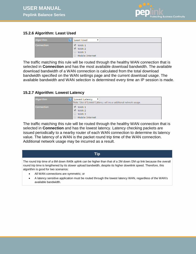
USER MANUAL Peplink Balance Series
http://www.peplink.com -132 / 261 - Copyright © 2015 Peplink
15.2.6 Algorithm: Least Used
The traffic matching this rule will be routed through the healthy WAN connection that is selected in Connection and has the most available download bandwidth. The available download bandwidth of a WAN connection is calculated from the total download bandwidth specified on the WAN settings page and the current download usage. The available bandwidth and WAN selection is determined every time an IP session is made.
15.2.7 Algorithm: Lowest Latency
The traffic matching this rule will be routed through the healthy WAN connection that is selected in Connection and has the lowest latency. Latency checking packets are issued periodically to a nearby router of each WAN connection to determine its latency value. The latency of a WAN is the packet round trip time of the WAN connection. Additional network usage may be incurred as a result.
Tip
The round trip time of a 6M down /640k uplink can be higher than that of a 2M down /2M up link because the overall round trip time is lengthened by its slower upload bandwidth, despite its higher downlink speed. Therefore, this algorithm is good for two scenarios:
• All WAN connections are symmetric; or • A latency sensitive application must be routed through the lowest latency WAN, regardless of the WAN’s
available bandwidth.
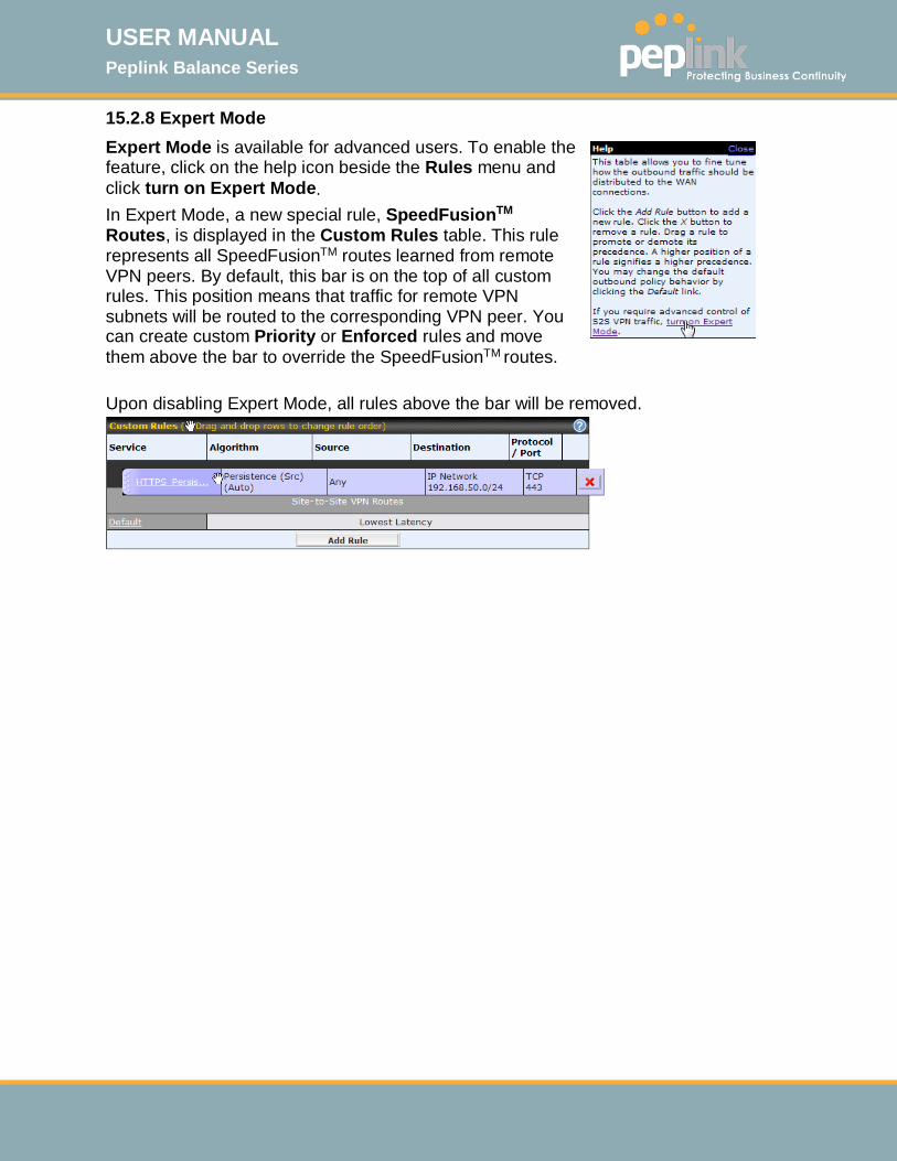
USER MANUAL Peplink Balance Series
http://www.peplink.com -133 / 261 - Copyright © 2015 Peplink
15.2.8 Expert Mode Expert Mode is available for advanced users. To enable the feature, click on the help icon beside the Rules menu and click turn on Expert Mode. In Expert Mode, a new special rule, SpeedFusionTM Routes, is displayed in the Custom Rules table. This rule represents all SpeedFusionTM routes learned from remote VPN peers. By default, this bar is on the top of all custom rules. This position means that traffic for remote VPN subnets will be routed to the corresponding VPN peer. You can create custom Priority or Enforced rules and move them above the bar to override the SpeedFusionTM routes. Upon disabling Expert Mode, all rules above the bar will be removed.
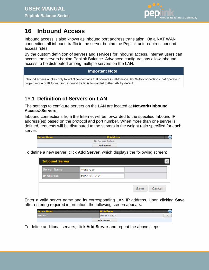
USER MANUAL Peplink Balance Series
http://www.peplink.com -134 / 261 - Copyright © 2015 Peplink
16 Inbound Access Inbound access is also known as inbound port address translation. On a NAT WAN connection, all inbound traffic to the server behind the Peplink unit requires inbound access rules. By the custom definition of servers and services for inbound access, Internet users can access the servers behind Peplink Balance. Advanced configurations allow inbound access to be distributed among multiple servers on the LAN.
Important Note
Inbound access applies only to WAN connections that operate in NAT mode. For WAN connections that operate in drop-in mode or IP forwarding, inbound traffic is forwarded to the LAN by default.
16.1 Definition of Servers on LAN The settings to configure servers on the LAN are located at Network>Inbound Access>Servers. Inbound connections from the Internet will be forwarded to the specified Inbound IP address(es) based on the protocol and port number. When more than one server is defined, requests will be distributed to the servers in the weight ratio specified for each server.
To define a new server, click Add Server, which displays the following screen:
Enter a valid server name and its corresponding LAN IP address. Upon clicking Save after entering required information, the following screen appears.
To define additional servers, click Add Server and repeat the above steps.
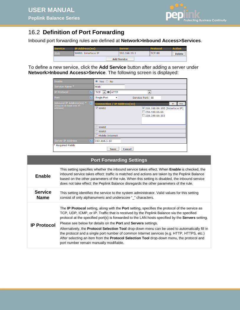
USER MANUAL Peplink Balance Series
http://www.peplink.com -135 / 261 - Copyright © 2015 Peplink
16.2 Definition of Port Forwarding Inbound port forwarding rules are defined at Network>Inbound Access>Services.
To define a new service, click the Add Service button after adding a server under Network>Inbound Access>Service. The following screen is displayed:
Port Forwarding Settings
Enable This setting specifies whether the inbound service takes effect. When Enable is checked, the inbound service takes effect: traffic is matched and actions are taken by the Peplink Balance based on the other parameters of the rule. When this setting is disabled, the inbound service does not take effect: the Peplink Balance disregards the other parameters of the rule.
Service Name
This setting identifies the service to the system administrator. Valid values for this setting consist of only alphanumeric and underscore “_” characters.
IP Protocol
The IP Protocol setting, along with the Port setting, specifies the protocol of the service as TCP, UDP, ICMP, or IP. Traffic that is received by the Peplink Balance via the specified protocol at the specified port(s) is forwarded to the LAN hosts specified by the Servers setting. Please see below for details on the Port and Servers settings. Alternatively, the Protocol Selection Tool drop-down menu can be used to automatically fill in the protocol and a single port number of common Internet services (e.g. HTTP, HTTPS, etc.) After selecting an item from the Protocol Selection Tool drop-down menu, the protocol and port number remain manually modifiable.
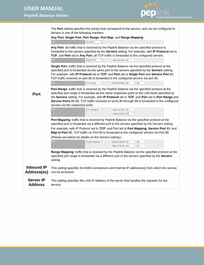
USER MANUAL Peplink Balance Series
http://www.peplink.com -136 / 261 - Copyright © 2015 Peplink
Port
The Port setting specifies the port(s) that correspond to the service, and can be configured to behave in one of the following manners: Any Port, Single Port, Port Range, Port Map, and Range Mapping
Any Port: all traffic that is received by the Peplink Balance via the specified protocol is forwarded to the servers specified by the Servers setting. For example, with IP Protocol set to TCP, and Port set to Any Port, all TCP traffic is forwarded to the configured servers.
Single Port: traffic that is received by the Peplink Balance via the specified protocol at the specified port is forwarded via the same port to the servers specified by the Servers setting. For example, with IP Protocol set to TCP, and Port set to Single Port and Service Port 80, TCP traffic received on port 80 is forwarded to the configured servers via port 80.
Port Range: traffic that is received by the Peplink Balance via the specified protocol at the specified port range is forwarded via the same respective ports to the LAN hosts specified by the Servers setting. For example, with IP Protocol set to TCP, and Port set to Port Range and Service Ports 80-88, TCP traffic received on ports 80 through 88 is forwarded to the configured servers via the respective ports.
Port Mapping: traffic that is received by Peplink Balance via the specified protocol at the specified port is forwarded via a different port to the servers specified by the Servers setting. For example, with IP Protocol set to TCP, and Port set to Port Mapping, Service Port 80, and Map to Port 88, TCP traffic on Port 80 is forwarded to the configured servers via Port 88. (Please see below for details on the Servers setting.)
Range Mapping: traffic that is received by the Peplink Balance via the specified protocol at the specified port range is forwarded via a different port to the servers specified by the Servers setting.
Inbound IP Address(es)
This setting specifies the WAN connections and Internet IP address(es) from which the service can be accessed.
Server IP Address
This setting specifies the LAN IP address of the server that handles the requests for the service.
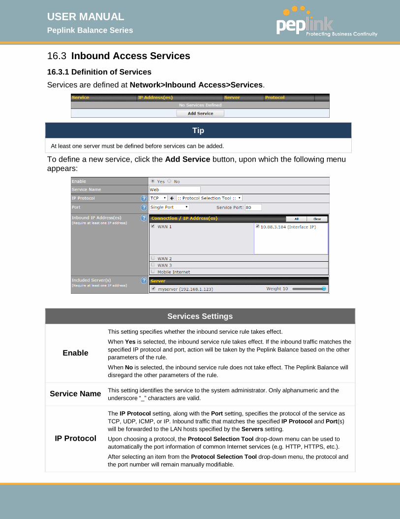
USER MANUAL Peplink Balance Series
http://www.peplink.com -137 / 261 - Copyright © 2015 Peplink
16.3 Inbound Access Services 16.3.1 Definition of Services Services are defined at Network>Inbound Access>Services.
Tip
At least one server must be defined before services can be added.
To define a new service, click the Add Service button, upon which the following menu appears:
Services Settings
Enable
This setting specifies whether the inbound service rule takes effect.
When Yes is selected, the inbound service rule takes effect. If the inbound traffic matches the specified IP protocol and port, action will be taken by the Peplink Balance based on the other parameters of the rule.
When No is selected, the inbound service rule does not take effect. The Peplink Balance will disregard the other parameters of the rule.
Service Name This setting identifies the service to the system administrator. Only alphanumeric and the underscore “_” characters are valid.
IP Protocol
The IP Protocol setting, along with the Port setting, specifies the protocol of the service as TCP, UDP, ICMP, or IP. Inbound traffic that matches the specified IP Protocol and Port(s) will be forwarded to the LAN hosts specified by the Servers setting. Upon choosing a protocol, the Protocol Selection Tool drop-down menu can be used to automatically the port information of common Internet services (e.g. HTTP, HTTPS, etc.).
After selecting an item from the Protocol Selection Tool drop-down menu, the protocol and the port number will remain manually modifiable.
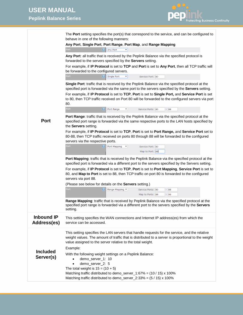
USER MANUAL Peplink Balance Series
http://www.peplink.com -138 / 261 - Copyright © 2015 Peplink
Port
The Port setting specifies the port(s) that correspond to the service, and can be configured to behave in one of the following manners: Any Port, Single Port, Port Range, Port Map, and Range Mapping
Any Port: all traffic that is received by the Peplink Balance via the specified protocol is forwarded to the servers specified by the Servers setting. For example, if IP Protocol is set to TCP and Port is set to Any Port, then all TCP traffic will be forwarded to the configured servers.
Single Port: traffic that is received by the Peplink Balance via the specified protocol at the specified port is forwarded via the same port to the servers specified by the Servers setting. For example, if IP Protocol is set to TCP, Port is set to Single Port, and Service Port is set to 80, then TCP traffic received on Port 80 will be forwarded to the configured servers via port 80.
Port Range: traffic that is received by the Peplink Balance via the specified protocol at the specified port range is forwarded via the same respective ports to the LAN hosts specified by the Servers setting. For example, if IP Protocol is set to TCP, Port is set to Port Range, and Service Port set to 80-88, then TCP traffic received on ports 80 through 88 will be forwarded to the configured servers via the respective ports.
Port Mapping: traffic that is received by the Peplink Balance via the specified protocol at the specified port is forwarded via a different port to the servers specified by the Servers setting. For example, if IP Protocol is set to TCP, Port is set to Port Mapping, Service Port is set to 80, and Map to Port is set to 88, then TCP traffic on port 80 is forwarded to the configured servers via port 88. (Please see below for details on the Servers setting.)
Range Mapping: traffic that is received by Peplink Balance via the specified protocol at the specified port range is forwarded via a different port to the servers specified by the Servers setting.
Inbound IP Address(es)
This setting specifies the WAN connections and Internet IP address(es) from which the service can be accessed.
Included Server(s)
This setting specifies the LAN servers that handle requests for the service, and the relative weight values. The amount of traffic that is distributed to a server is proportional to the weight value assigned to the server relative to the total weight. Example: With the following weight settings on a Peplink Balance:
• demo_server_1: 10 • demo_server_2: 5
The total weight is 15 = (10 + 5) Matching traffic distributed to demo_server_1:67% = (10 / 15) x 100% Matching traffic distributed to demo_server_2:33% = (5 / 15) x 100%

USER MANUAL Peplink Balance Series
http://www.peplink.com -139 / 261 - Copyright © 2015 Peplink
16.3.2 UPNP / NAT-PMP SETTINGS UPnP and NAT-PMP are network protocols which allow a computer connected to the LAN port to automatically configure the router to allow parties on the WAN port to connect to itself. That way, the process of inbound port forwarding becomes automated. When a computer creates a rule using these protocols, the specified TCP/UDP port of all WAN connections' default IP address will be forwarded. Check the corresponding box(es) to enable UPnP and/or NAT-PMP. Enable these features only if you trust the computers connected to the LAN ports.
When the options are enabled, a table listing all the forwarded ports under these two protocols can be found at Network>Services>UPnP / NAT-PMP.
16.3.3 Definition of DNS Records The built-in DNS server functionality of the Peplink Balance facilitates inbound load balancing. With this functionality, NS/SOA DNS records for a domain name can be delegated to the Internet IP address(es) of the Peplink Balance. Upon receiving a DNS query, the Peplink Balance can return (as an “A” record) the IP address for the domain name on the most appropriate healthy WAN connection. It can also act as a generic DNS server for hosting “A”, “CNAME”, “MX”, “TXT” and “NS” records. For example: (This example is for illustration only; the actual resolution that takes place in implementation will likely be different.) The DNS resolution of the domain name www.mycompany.com is delegated to the WAN2 Internet IP addresses of the Peplink Balance. Upon receiving the DNS query, the Peplink Balance returns (as an “A” record) the IP address for www.mycompany.com on WAN1 because WAN1 is the most appropriate healthy link. The settings for defining the DNS records to be hosted by the Peplink Balance are located at Network>Inbound Access>DNS Settings.
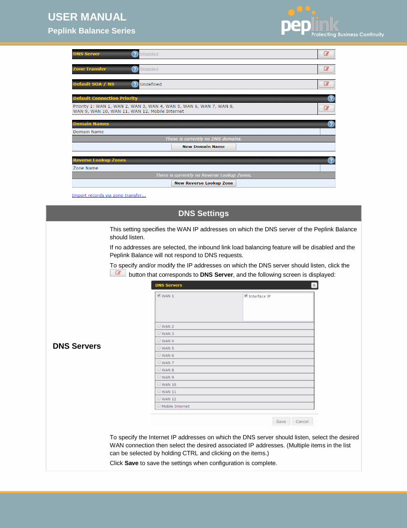
USER MANUAL Peplink Balance Series
http://www.peplink.com -140 / 261 - Copyright © 2015 Peplink
DNS Settings
DNS Servers
This setting specifies the WAN IP addresses on which the DNS server of the Peplink Balance should listen. If no addresses are selected, the inbound link load balancing feature will be disabled and the Peplink Balance will not respond to DNS requests.
To specify and/or modify the IP addresses on which the DNS server should listen, click the button that corresponds to DNS Server, and the following screen is displayed:
To specify the Internet IP addresses on which the DNS server should listen, select the desired WAN connection then select the desired associated IP addresses. (Multiple items in the list can be selected by holding CTRL and clicking on the items.) Click Save to save the settings when configuration is complete.

USER MANUAL Peplink Balance Series
http://www.peplink.com -141 / 261 - Copyright © 2015 Peplink
Zone Transfer
This setting specifies the IP address(es) of the secondary DNS server(s)authorized to retrieve zone records from the DNS server of the Peplink Balance. The zone transfer server of the Peplink Balance listens on TCP port 53.
The Peplink Balance serves both the clients that are accessing from the specified IP addresses, and the clients that are accessing its LAN interface.
Routing Control by
Subnet Database
When this function is enabled, the system will check to see if an incoming DNS client is within any WAN's ISP subnet. Only the matched WAN(s)'s IP addresses will be returned. Note that this feature is available only when a subnet database has been defined.
Default SOA / NS
Click the button to define a default SOA / NS record for all domain names. For configuration details please refer to Section 16.3.5.
When defining a default SOA record, Name Server IP Address is optional. If left blank, the Address (A) record for the same server should be defined manually in each domain. For defining default NS records, the host [domain] indicates that this record is for the domain name itself without a sub-domain prefix. To add a secondary NS server, just create a second NS record with the Host field left empty. When the entered name server is a fully qualified domain name (FQDN), the IP Address field will be disabled.
Default Connection
Priority
Default Connection Priority defines the default priority group of each WAN connection in resolving A records. It applies to Address (A) records which have the Connection Priority set to Default. Please refer to Section 16.3.9 for details.
The WAN connection(s) with the highest priority (smallest number) will be chosen. Those with lower priorities will not be chosen in resolving A records unless the higher priority ones become unavailable.
To specify the primary and backup connections, click the button that corresponds to Default Connection Priority. The following screen will appear:
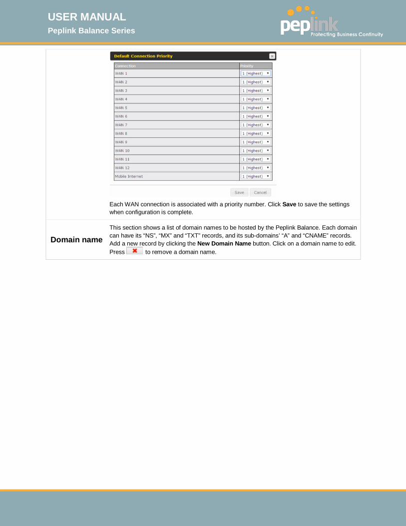
USER MANUAL Peplink Balance Series
http://www.peplink.com -142 / 261 - Copyright © 2015 Peplink
Each WAN connection is associated with a priority number. Click Save to save the settings when configuration is complete.
Domain name This section shows a list of domain names to be hosted by the Peplink Balance. Each domain can have its “NS”, “MX” and “TXT” records, and its sub-domains’ “A” and “CNAME” records. Add a new record by clicking the New Domain Name button. Click on a domain name to edit. Press to remove a domain name.
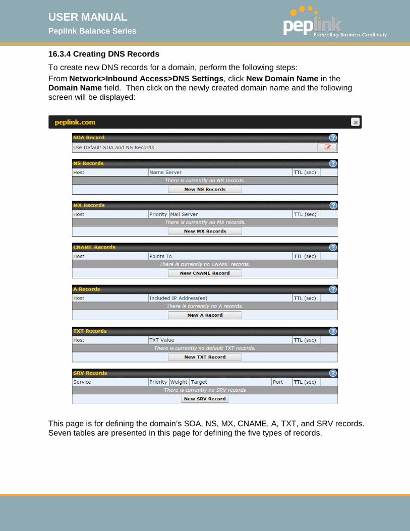
USER MANUAL Peplink Balance Series
http://www.peplink.com -143 / 261 - Copyright © 2015 Peplink
16.3.4 Creating DNS Records To create new DNS records for a domain, perform the following steps: From Network>Inbound Access>DNS Settings, click New Domain Name in the Domain Name field. Then click on the newly created domain name and the following screen will be displayed:
This page is for defining the domain’s SOA, NS, MX, CNAME, A, TXT, and SRV records. Seven tables are presented in this page for defining the five types of records.
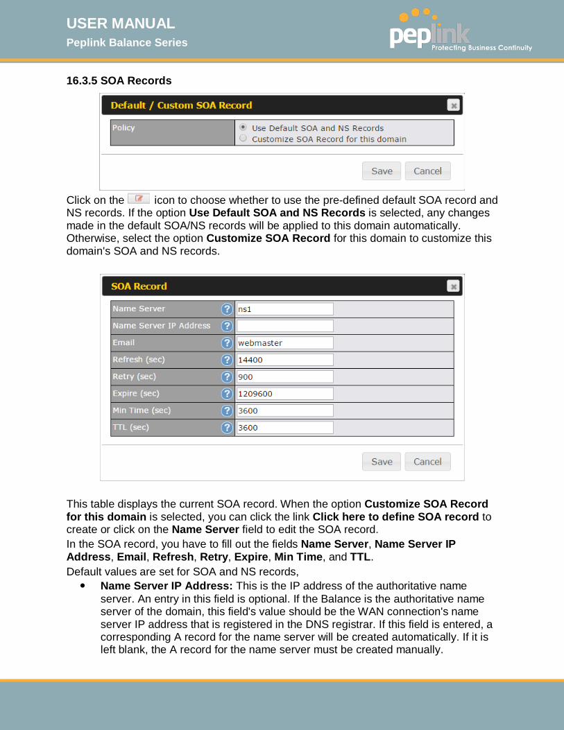
USER MANUAL Peplink Balance Series
http://www.peplink.com -144 / 261 - Copyright © 2015 Peplink
16.3.5 SOA Records
Click on the icon to choose whether to use the pre-defined default SOA record and NS records. If the option Use Default SOA and NS Records is selected, any changes made in the default SOA/NS records will be applied to this domain automatically. Otherwise, select the option Customize SOA Record for this domain to customize this domain's SOA and NS records.
This table displays the current SOA record. When the option Customize SOA Record for this domain is selected, you can click the link Click here to define SOA record to create or click on the Name Server field to edit the SOA record. In the SOA record, you have to fill out the fields Name Server, Name Server IP Address, Email, Refresh, Retry, Expire, Min Time, and TTL. Default values are set for SOA and NS records, Name Server IP Address: This is the IP address of the authoritative name
server. An entry in this field is optional. If the Balance is the authoritative name server of the domain, this field's value should be the WAN connection's name server IP address that is registered in the DNS registrar. If this field is entered, a corresponding A record for the name server will be created automatically. If it is left blank, the A record for the name server must be created manually.
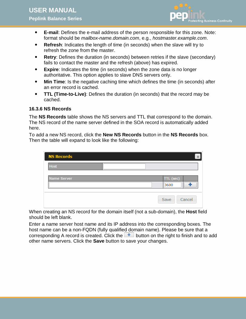
USER MANUAL Peplink Balance Series
http://www.peplink.com -145 / 261 - Copyright © 2015 Peplink
E-mail: Defines the e-mail address of the person responsible for this zone. Note: format should be mailbox-name.domain.com, e.g., hostmaster.example.com.
Refresh: Indicates the length of time (in seconds) when the slave will try to refresh the zone from the master.
Retry: Defines the duration (in seconds) between retries if the slave (secondary) fails to contact the master and the refresh (above) has expired.
Expire: Indicates the time (in seconds) when the zone data is no longer authoritative. This option applies to slave DNS servers only.
Min Time: Is the negative caching time which defines the time (in seconds) after an error record is cached.
TTL (Time-to-Live): Defines the duration (in seconds) that the record may be cached.
16.3.6 NS Records The NS Records table shows the NS servers and TTL that correspond to the domain. The NS record of the name server defined in the SOA record is automatically added here. To add a new NS record, click the New NS Records button in the NS Records box. Then the table will expand to look like the following:
When creating an NS record for the domain itself (not a sub-domain), the Host field should be left blank. Enter a name server host name and its IP address into the corresponding boxes. The host name can be a non-FQDN (fully qualified domain name). Please be sure that a corresponding A record is created. Click the button on the right to finish and to add other name servers. Click the Save button to save your changes.
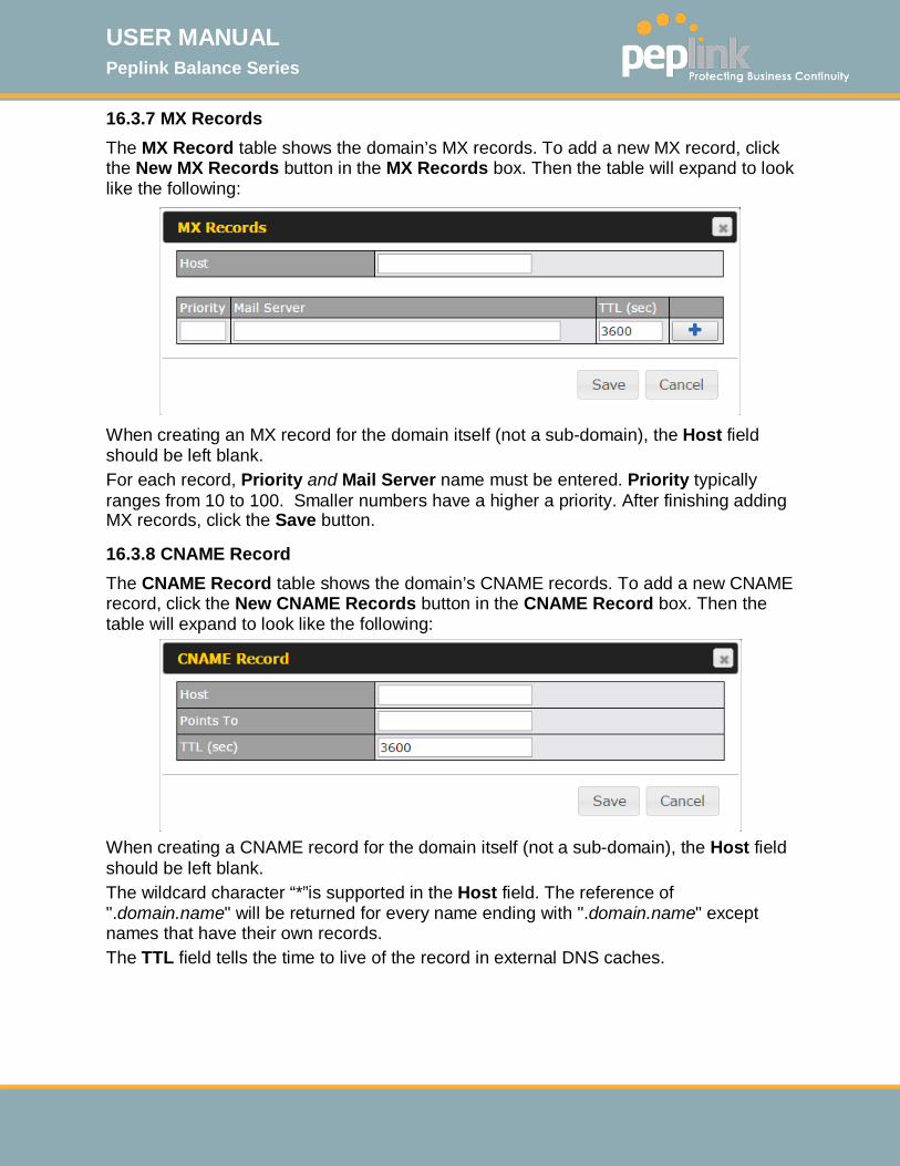
USER MANUAL Peplink Balance Series
http://www.peplink.com -146 / 261 - Copyright © 2015 Peplink
16.3.7 MX Records The MX Record table shows the domain’s MX records. To add a new MX record, click the New MX Records button in the MX Records box. Then the table will expand to look like the following:
When creating an MX record for the domain itself (not a sub-domain), the Host field should be left blank. For each record, Priority and Mail Server name must be entered. Priority typically ranges from 10 to 100. Smaller numbers have a higher a priority. After finishing adding MX records, click the Save button.
16.3.8 CNAME Record The CNAME Record table shows the domain’s CNAME records. To add a new CNAME record, click the New CNAME Records button in the CNAME Record box. Then the table will expand to look like the following:
When creating a CNAME record for the domain itself (not a sub-domain), the Host field should be left blank. The wildcard character “*”is supported in the Host field. The reference of ".domain.name" will be returned for every name ending with ".domain.name" except names that have their own records. The TTL field tells the time to live of the record in external DNS caches.
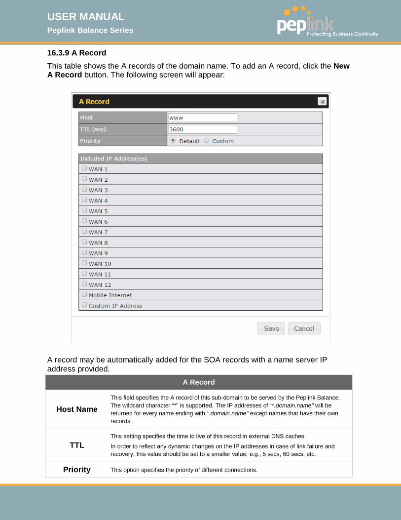
USER MANUAL Peplink Balance Series
http://www.peplink.com -147 / 261 - Copyright © 2015 Peplink
16.3.9 A Record This table shows the A records of the domain name. To add an A record, click the New A Record button. The following screen will appear:
A record may be automatically added for the SOA records with a name server IP address provided.
A Record
Host Name This field specifies the A record of this sub-domain to be served by the Peplink Balance. The wildcard character “*” is supported. The IP addresses of “*.domain.name" will be returned for every name ending with ".domain.name" except names that have their own records.
TTL This setting specifies the time to live of this record in external DNS caches.
In order to reflect any dynamic changes on the IP addresses in case of link failure and recovery, this value should be set to a smaller value, e.g., 5 secs, 60 secs, etc.
Priority This option specifies the priority of different connections.
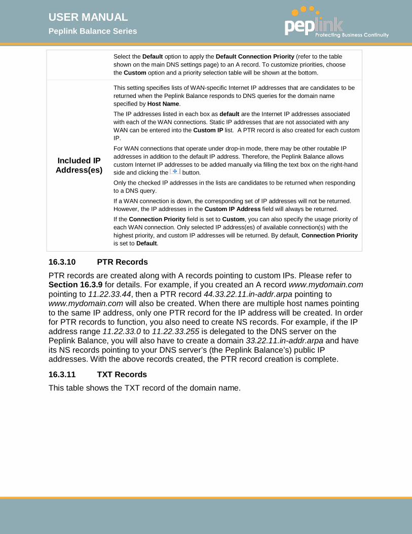
USER MANUAL Peplink Balance Series
http://www.peplink.com -148 / 261 - Copyright © 2015 Peplink
Select the Default option to apply the Default Connection Priority (refer to the table shown on the main DNS settings page) to an A record. To customize priorities, choose the Custom option and a priority selection table will be shown at the bottom.
Included IP Address(es)
This setting specifies lists of WAN-specific Internet IP addresses that are candidates to be returned when the Peplink Balance responds to DNS queries for the domain name specified by Host Name. The IP addresses listed in each box as default are the Internet IP addresses associated with each of the WAN connections. Static IP addresses that are not associated with any WAN can be entered into the Custom IP list. A PTR record is also created for each custom IP.
For WAN connections that operate under drop-in mode, there may be other routable IP addresses in addition to the default IP address. Therefore, the Peplink Balance allows custom Internet IP addresses to be added manually via filling the text box on the right-hand side and clicking the button. Only the checked IP addresses in the lists are candidates to be returned when responding to a DNS query.
If a WAN connection is down, the corresponding set of IP addresses will not be returned. However, the IP addresses in the Custom IP Address field will always be returned. If the Connection Priority field is set to Custom, you can also specify the usage priority of each WAN connection. Only selected IP address(es) of available connection(s) with the highest priority, and custom IP addresses will be returned. By default, Connection Priority is set to Default.
16.3.10 PTR Records PTR records are created along with A records pointing to custom IPs. Please refer to Section 16.3.9 for details. For example, if you created an A record www.mydomain.com pointing to 11.22.33.44, then a PTR record 44.33.22.11.in-addr.arpa pointing to www.mydomain.com will also be created. When there are multiple host names pointing to the same IP address, only one PTR record for the IP address will be created. In order for PTR records to function, you also need to create NS records. For example, if the IP address range 11.22.33.0 to 11.22.33.255 is delegated to the DNS server on the Peplink Balance, you will also have to create a domain 33.22.11.in-addr.arpa and have its NS records pointing to your DNS server’s (the Peplink Balance’s) public IP addresses. With the above records created, the PTR record creation is complete.
16.3.11 TXT Records This table shows the TXT record of the domain name.
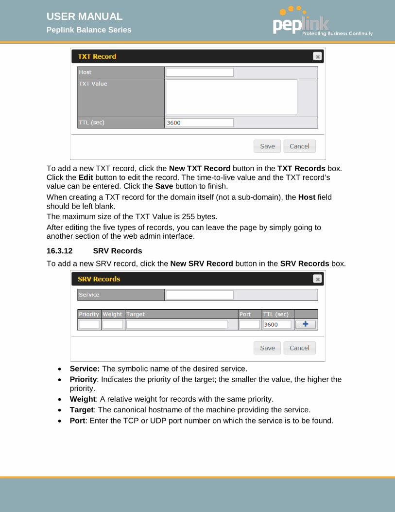
USER MANUAL Peplink Balance Series
http://www.peplink.com -149 / 261 - Copyright © 2015 Peplink
To add a new TXT record, click the New TXT Record button in the TXT Records box. Click the Edit button to edit the record. The time-to-live value and the TXT record’s value can be entered. Click the Save button to finish. When creating a TXT record for the domain itself (not a sub-domain), the Host field should be left blank. The maximum size of the TXT Value is 255 bytes. After editing the five types of records, you can leave the page by simply going to another section of the web admin interface.
16.3.12 SRV Records To add a new SRV record, click the New SRV Record button in the SRV Records box.
• Service: The symbolic name of the desired service. • Priority: Indicates the priority of the target; the smaller the value, the higher the
priority. • Weight: A relative weight for records with the same priority. • Target: The canonical hostname of the machine providing the service. • Port: Enter the TCP or UDP port number on which the service is to be found.
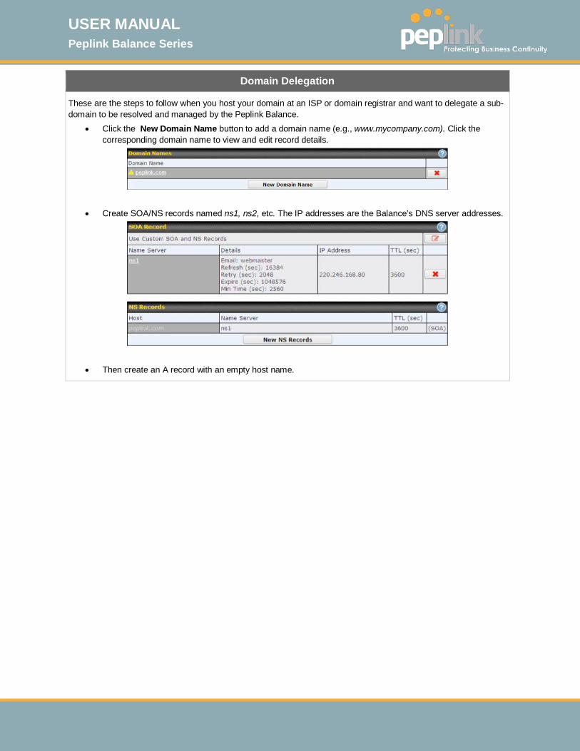
USER MANUAL Peplink Balance Series
http://www.peplink.com -150 / 261 - Copyright © 2015 Peplink
Domain Delegation
These are the steps to follow when you host your domain at an ISP or domain registrar and want to delegate a sub-domain to be resolved and managed by the Peplink Balance.
• Click the New Domain Name button to add a domain name (e.g., www.mycompany.com). Click the corresponding domain name to view and edit record details.
• Create SOA/NS records named ns1, ns2, etc. The IP addresses are the Balance’s DNS server addresses.
• Then create an A record with an empty host name.
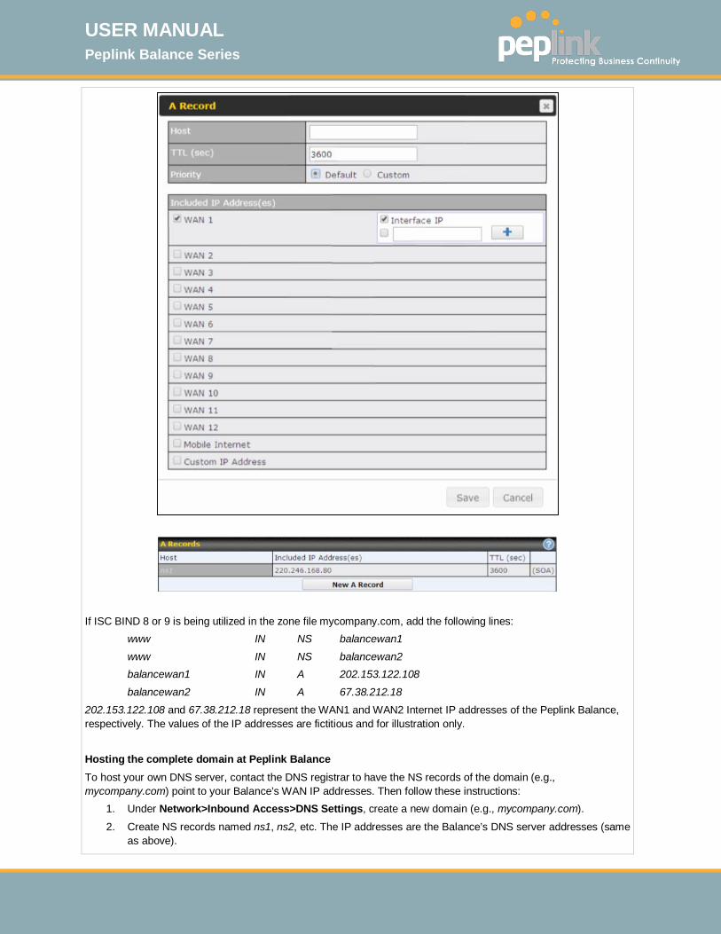
USER MANUAL Peplink Balance Series
http://www.peplink.com -151 / 261 - Copyright © 2015 Peplink
If ISC BIND 8 or 9 is being utilized in the zone file mycompany.com, add the following lines: www IN NS balancewan1
www IN NS balancewan2 balancewan1 IN A 202.153.122.108
balancewan2 IN A 67.38.212.18
202.153.122.108 and 67.38.212.18 represent the WAN1 and WAN2 Internet IP addresses of the Peplink Balance, respectively. The values of the IP addresses are fictitious and for illustration only. Hosting the complete domain at Peplink Balance To host your own DNS server, contact the DNS registrar to have the NS records of the domain (e.g., mycompany.com) point to your Balance’s WAN IP addresses. Then follow these instructions:
1. Under Network>Inbound Access>DNS Settings, create a new domain (e.g., mycompany.com).
2. Create NS records named ns1, ns2, etc. The IP addresses are the Balance’s DNS server addresses (same as above).

USER MANUAL Peplink Balance Series
http://www.peplink.com -152 / 261 - Copyright © 2015 Peplink
3. Create the corresponding A, CNAME, MX, and TXT records as you wish. The A record resembles the one below:
Testing the DNS Configuration
The following steps can be used to test the DNS configuration:
From a host on the Internet, use an IP address of the Peplink Balance and nslookup to lookup the corresponding host name. Check the information that is returned for the expected results. An nslookup in Windows will appear as follows:
C:\Documents and Settings\User Name>nslookup
Default Server: ns1.myisp.com Address: 147.22.11.2
>server 202.153.122.108 (This is Peplink Balance’s WAN IP address.) Default Server: balance.mycompany.com
Address: 202.153.122.108 >www.mycompany.com (This is the hostname to be looked up.) Default Server: balance.mycompany.com Address: 202.153.122.108
Name: www.mycompany.com Address: 202.153.122.109, 67.38.212.19
Please note that the values of the IP addresses are fictitious and for illustration only.

USER MANUAL Peplink Balance Series
http://www.peplink.com -153 / 261 - Copyright © 2015 Peplink
16.4 Reverse Lookup Zones Reverse lookup zones can be configured in Network>Inbound Access>DNS Settings.
Reverse lookup refers to performing a DNS query to find one or more DNS names associated with a given IP address. The DNS stores IP addresses in the form of specially formatted names as pointer (PTR) records using special domains/zones. The zone is in-addr.arpa. To enable DNS clients to perform a reverse lookup for a host, perform two steps:
• Create a reverse lookup zone that corresponds to the subnet network address of the host. In the reverse lookup zone, add a pointer (PTR) resource record that maps the host IP address to the host name.
• Click the New Reverse Lookup Zone button and enter a reverse lookup zone name. If you are delegated the subnet 11.22.33.0/24, the Zone Name should be 33.22.11.in-arpa.addr. PTR records for 11.22.33.1, 11.22.33.2, ... 11.22.33.254 should be defined in this zone where the host IP numbers are 1, 2, ... 254, respectively.

USER MANUAL Peplink Balance Series
http://www.peplink.com -154 / 261 - Copyright © 2015 Peplink
16.4.1 SOA Record You can click the link Click here to define SOA record to create or click on the Name Server field to edit the SOA record.
Name Server: Enter the NS record's FQDN server name here. For example: "ns1.mydomain.com" (equivalent to "www.1stdomain.com.") "ns2.mydomain.com." Email, Refresh, Retry, Expire, Min Time, and TTL are entered in the same way as in the forward zone. Please refer to Section 16.3.5 for details.
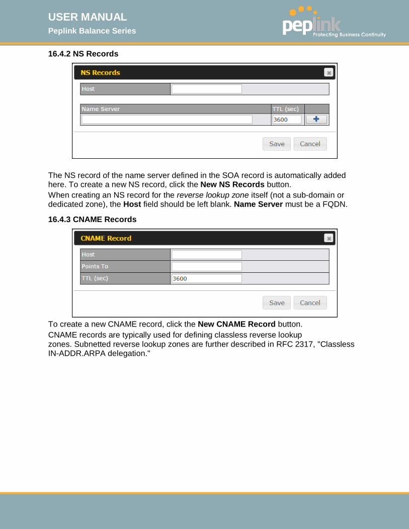
USER MANUAL Peplink Balance Series
http://www.peplink.com -155 / 261 - Copyright © 2015 Peplink
16.4.2 NS Records
The NS record of the name server defined in the SOA record is automatically added here. To create a new NS record, click the New NS Records button. When creating an NS record for the reverse lookup zone itself (not a sub-domain or dedicated zone), the Host field should be left blank. Name Server must be a FQDN.
16.4.3 CNAME Records
To create a new CNAME record, click the New CNAME Record button. CNAME records are typically used for defining classless reverse lookup zones. Subnetted reverse lookup zones are further described in RFC 2317, "Classless IN-ADDR.ARPA delegation."
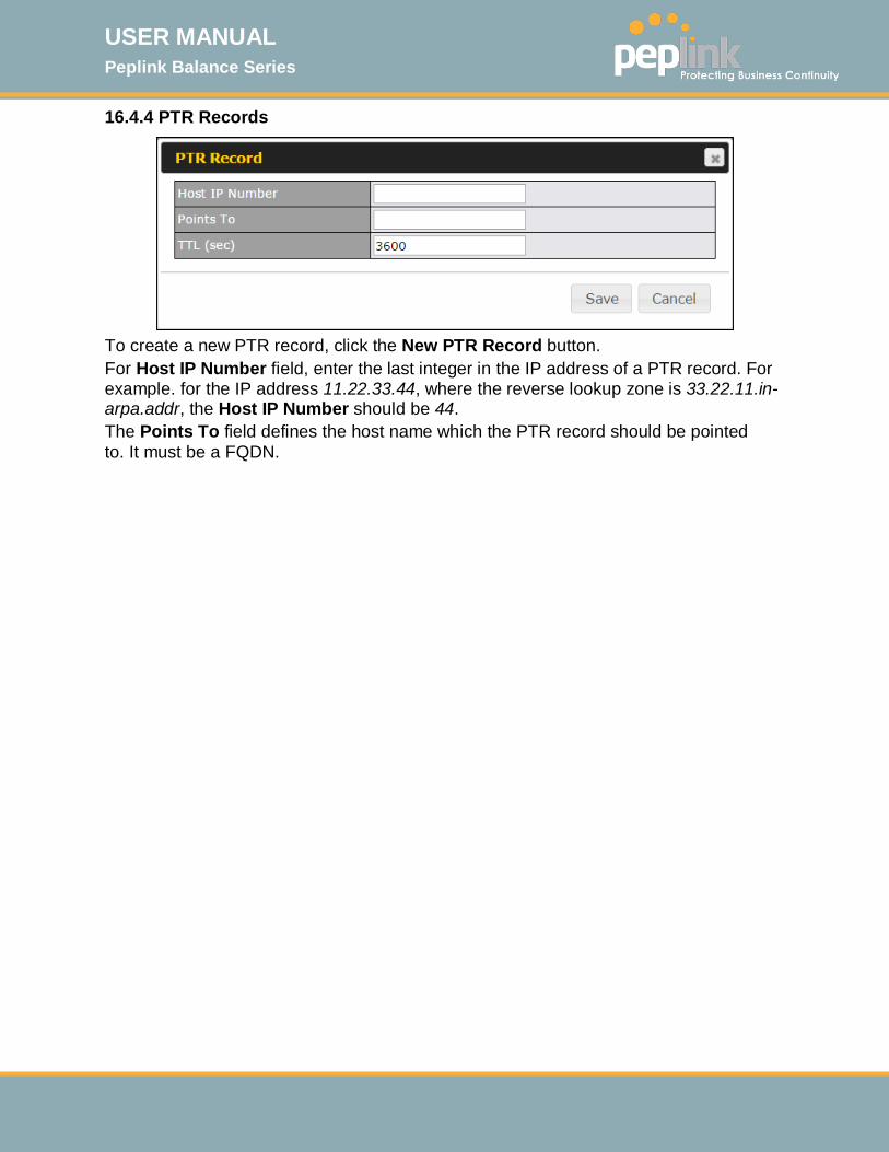
USER MANUAL Peplink Balance Series
http://www.peplink.com -156 / 261 - Copyright © 2015 Peplink
16.4.4 PTR Records
To create a new PTR record, click the New PTR Record button. For Host IP Number field, enter the last integer in the IP address of a PTR record. For example. for the IP address 11.22.33.44, where the reverse lookup zone is 33.22.11.in-arpa.addr, the Host IP Number should be 44. The Points To field defines the host name which the PTR record should be pointed to. It must be a FQDN.

USER MANUAL Peplink Balance Series
http://www.peplink.com -157 / 261 - Copyright © 2015 Peplink
16.5 DNS Record Import Wizard At the bottom of the DNS settings page, the link Import records via zone transfer…is used to import DNS record using an import wizard.
• Select Next >> to continue.
• In the Target DNS Server IP Address field, enter the IP address of the DNS
server. • In the Transfer via…field, choose the connection which you would like to
transfer through. • Select Next >> to continue.
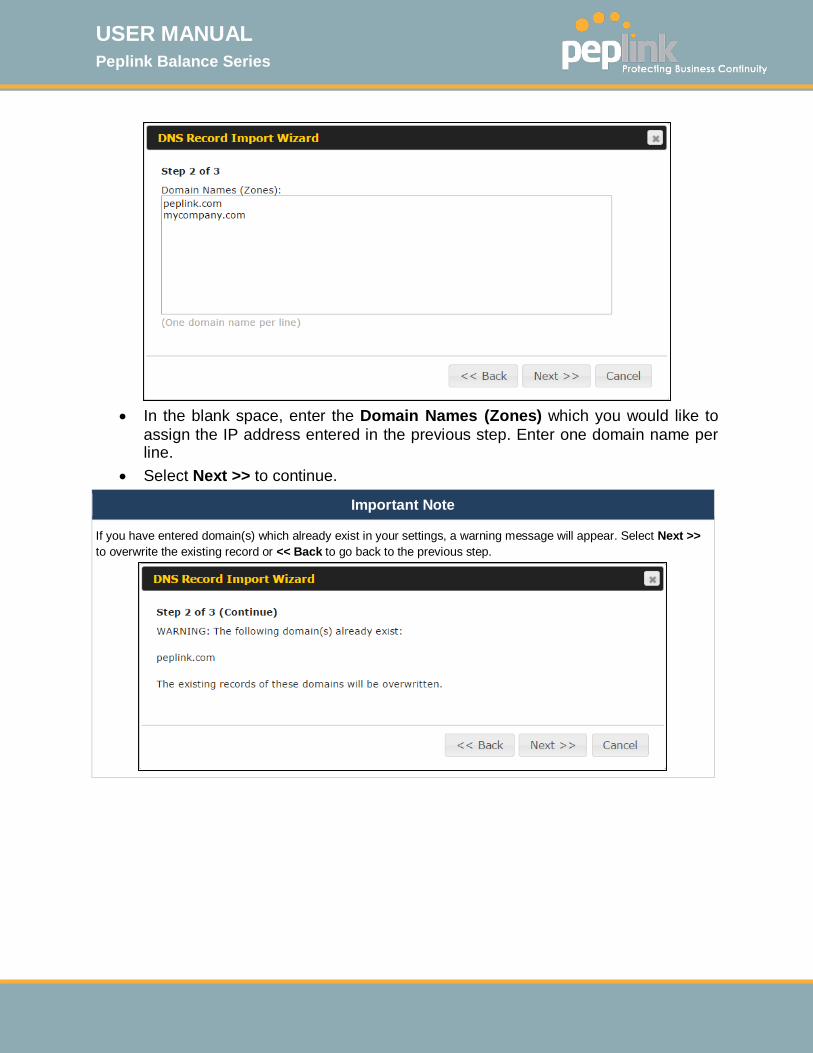
USER MANUAL Peplink Balance Series
http://www.peplink.com -158 / 261 - Copyright © 2015 Peplink
• In the blank space, enter the Domain Names (Zones) which you would like to
assign the IP address entered in the previous step. Enter one domain name per line.
• Select Next >> to continue.
Important Note
If you have entered domain(s) which already exist in your settings, a warning message will appear. Select Next >> to overwrite the existing record or << Back to go back to the previous step.

USER MANUAL Peplink Balance Series
http://www.peplink.com -159 / 261 - Copyright © 2015 Peplink

USER MANUAL Peplink Balance Series
http://www.peplink.com -160 / 261 - Copyright © 2015 Peplink
After the zone records process have been fetched, the fetch results would be shown as above. You can view import details by clicking the corresponding hyperlink on the right-hand side.

USER MANUAL Peplink Balance Series
http://www.peplink.com -161 / 261 - Copyright © 2015 Peplink
17 NAT Mappings The Peplink Balance allows the IP address mapping of all inbound and outbound NAT’ed traffic to and from an internal client IP address. NAT mappings can be configured at Network>NAT Mappings.
To add a rule for NAT mappings, click Add NAT Rule and the following screen will be displayed:
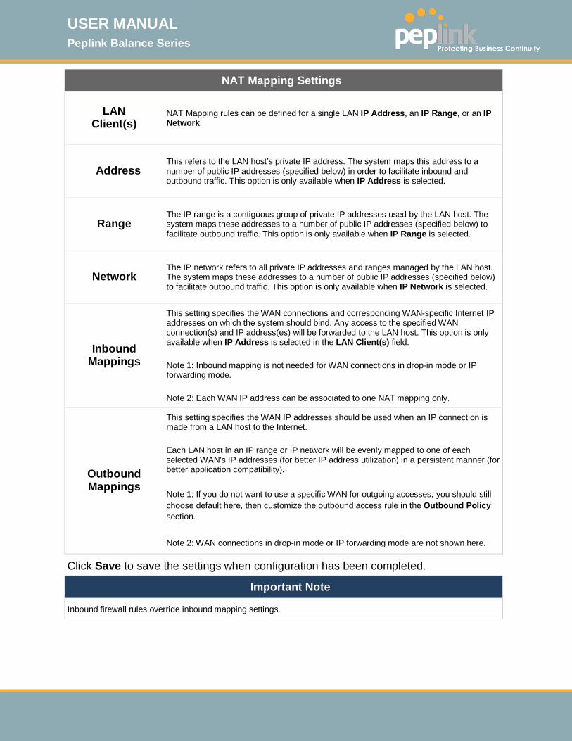
USER MANUAL Peplink Balance Series
http://www.peplink.com -162 / 261 - Copyright © 2015 Peplink
NAT Mapping Settings
LAN Client(s)
NAT Mapping rules can be defined for a single LAN IP Address, an IP Range, or an IP Network.
Address This refers to the LAN host’s private IP address. The system maps this address to a number of public IP addresses (specified below) in order to facilitate inbound and outbound traffic. This option is only available when IP Address is selected.
Range The IP range is a contiguous group of private IP addresses used by the LAN host. The system maps these addresses to a number of public IP addresses (specified below) to facilitate outbound traffic. This option is only available when IP Range is selected.
Network The IP network refers to all private IP addresses and ranges managed by the LAN host. The system maps these addresses to a number of public IP addresses (specified below) to facilitate outbound traffic. This option is only available when IP Network is selected.
Inbound Mappings
This setting specifies the WAN connections and corresponding WAN-specific Internet IP addresses on which the system should bind. Any access to the specified WAN connection(s) and IP address(es) will be forwarded to the LAN host. This option is only available when IP Address is selected in the LAN Client(s) field. Note 1: Inbound mapping is not needed for WAN connections in drop-in mode or IP forwarding mode. Note 2: Each WAN IP address can be associated to one NAT mapping only.
Outbound Mappings
This setting specifies the WAN IP addresses should be used when an IP connection is made from a LAN host to the Internet. Each LAN host in an IP range or IP network will be evenly mapped to one of each selected WAN's IP addresses (for better IP address utilization) in a persistent manner (for better application compatibility). Note 1: If you do not want to use a specific WAN for outgoing accesses, you should still choose default here, then customize the outbound access rule in the Outbound Policy section. Note 2: WAN connections in drop-in mode or IP forwarding mode are not shown here.
Click Save to save the settings when configuration has been completed.
Important Note
Inbound firewall rules override inbound mapping settings.
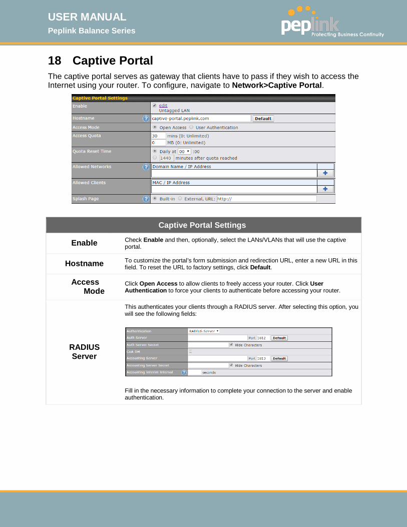
USER MANUAL Peplink Balance Series
http://www.peplink.com -163 / 261 - Copyright © 2015 Peplink
18 Captive Portal The captive portal serves as gateway that clients have to pass if they wish to access the Internet using your router. To configure, navigate to Network>Captive Portal.
Captive Portal Settings
Enable Check Enable and then, optionally, select the LANs/VLANs that will use the captive portal.
Hostname To customize the portal’s form submission and redirection URL, enter a new URL in this field. To reset the URL to factory settings, click Default.
Access Mode
Click Open Access to allow clients to freely access your router. Click User Authentication to force your clients to authenticate before accessing your router.
RADIUS Server
This authenticates your clients through a RADIUS server. After selecting this option, you will see the following fields:
Fill in the necessary information to complete your connection to the server and enable authentication.

USER MANUAL Peplink Balance Series
http://www.peplink.com -164 / 261 - Copyright © 2015 Peplink
LDAP Server
This authenticates your clients through a LDAP server. Upon selecting this option, you will see the following fields:
Fill in the necessary information to complete your connection to the server and enable authentication.
Access Quota
Set a time and data cap to each user’s Internet usage.
Quota Reset Time
This menu determines how your usage quota resets. Setting it to Daily will reset it at a specified time every day. Setting a number of minutes after quota reached establish a timer for each user that begins after the quota has been reached.
Allowed Networks
To whitelist a network, enter the domain name / IP address here and click . To delete an existing network from the list of allowed networks, click the button next to the listing.
Allowed Clients
To whitelist a client, enter the MAC address / IP address here and click . To delete an existing client from the list of allowed clients, click the button next to the listing.
Splash Page Here, you can choose between using the Balance’s built-in captive portal and redirecting clients to a URL you define.
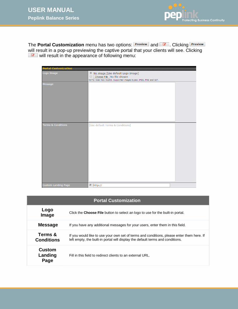
USER MANUAL Peplink Balance Series
http://www.peplink.com -165 / 261 - Copyright © 2015 Peplink
The Portal Customization menu has two options: and . Clicking will result in a pop-up previewing the captive portal that your clients will see. Clicking
will result in the appearance of following menu:
Portal Customization
Logo Image
Click the Choose File button to select an logo to use for the built-in portal.
Message If you have any additional messages for your users, enter them in this field.
Terms & Conditions
If you would like to use your own set of terms and conditions, please enter them here. If left empty, the built-in portal will display the default terms and conditions.
Custom Landing
Page
Fill in this field to redirect clients to an external URL.
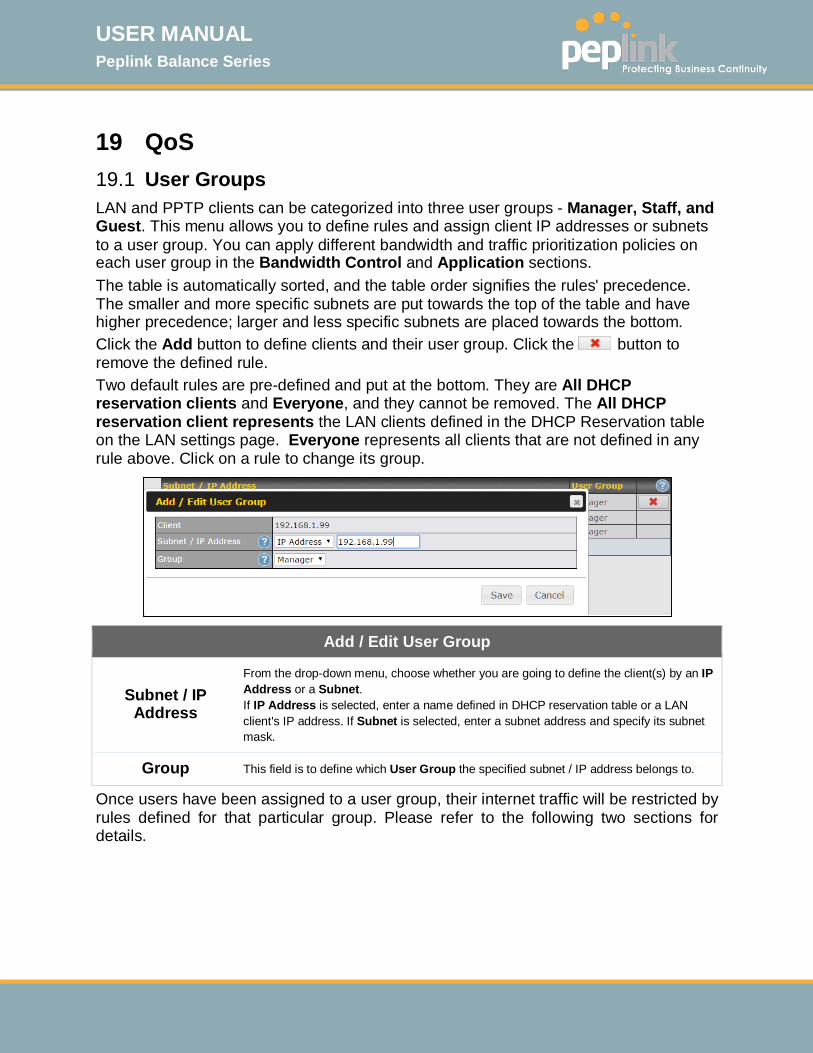
USER MANUAL Peplink Balance Series
http://www.peplink.com -166 / 261 - Copyright © 2015 Peplink
19 QoS 19.1 User Groups LAN and PPTP clients can be categorized into three user groups - Manager, Staff, and Guest. This menu allows you to define rules and assign client IP addresses or subnets to a user group. You can apply different bandwidth and traffic prioritization policies on each user group in the Bandwidth Control and Application sections. The table is automatically sorted, and the table order signifies the rules' precedence. The smaller and more specific subnets are put towards the top of the table and have higher precedence; larger and less specific subnets are placed towards the bottom. Click the Add button to define clients and their user group. Click the button to remove the defined rule. Two default rules are pre-defined and put at the bottom. They are All DHCP reservation clients and Everyone, and they cannot be removed. The All DHCP reservation client represents the LAN clients defined in the DHCP Reservation table on the LAN settings page. Everyone represents all clients that are not defined in any rule above. Click on a rule to change its group.
Add / Edit User Group
Subnet / IP Address
From the drop-down menu, choose whether you are going to define the client(s) by an IP Address or a Subnet. If IP Address is selected, enter a name defined in DHCP reservation table or a LAN client's IP address. If Subnet is selected, enter a subnet address and specify its subnet mask.
Group This field is to define which User Group the specified subnet / IP address belongs to.
Once users have been assigned to a user group, their internet traffic will be restricted by rules defined for that particular group. Please refer to the following two sections for details.
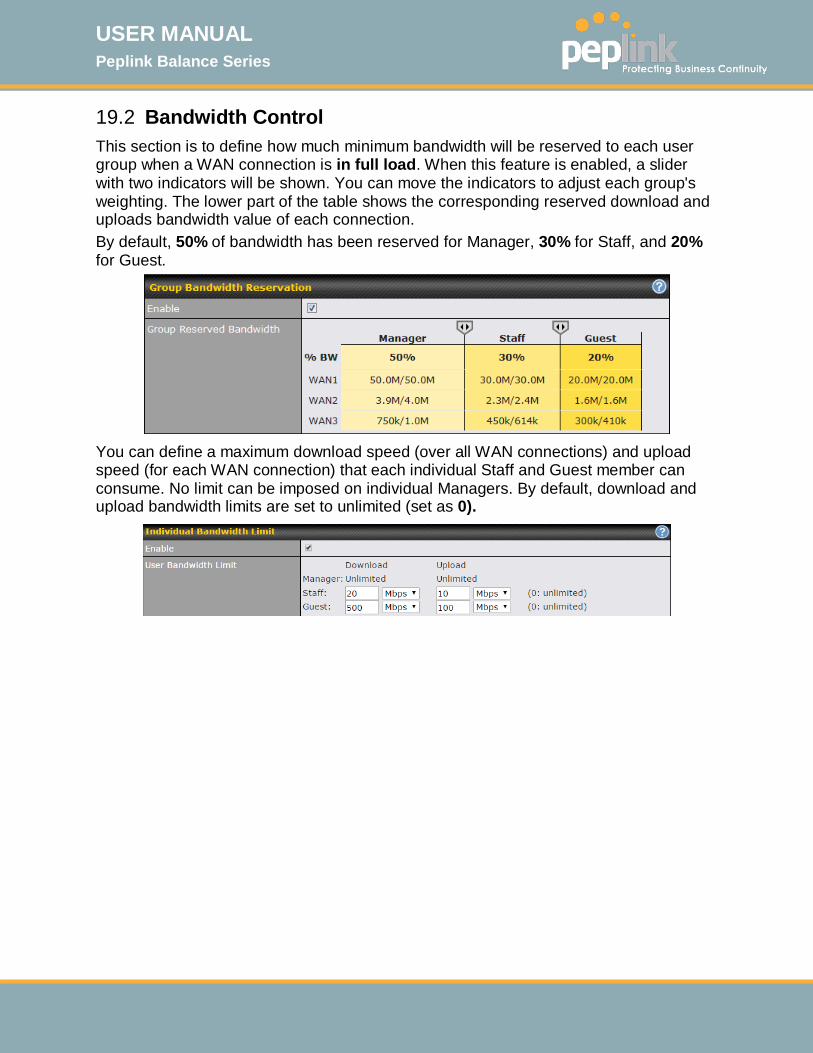
USER MANUAL Peplink Balance Series
http://www.peplink.com -167 / 261 - Copyright © 2015 Peplink
19.2 Bandwidth Control This section is to define how much minimum bandwidth will be reserved to each user group when a WAN connection is in full load. When this feature is enabled, a slider with two indicators will be shown. You can move the indicators to adjust each group's weighting. The lower part of the table shows the corresponding reserved download and uploads bandwidth value of each connection. By default, 50% of bandwidth has been reserved for Manager, 30% for Staff, and 20% for Guest.
You can define a maximum download speed (over all WAN connections) and upload speed (for each WAN connection) that each individual Staff and Guest member can consume. No limit can be imposed on individual Managers. By default, download and upload bandwidth limits are set to unlimited (set as 0).
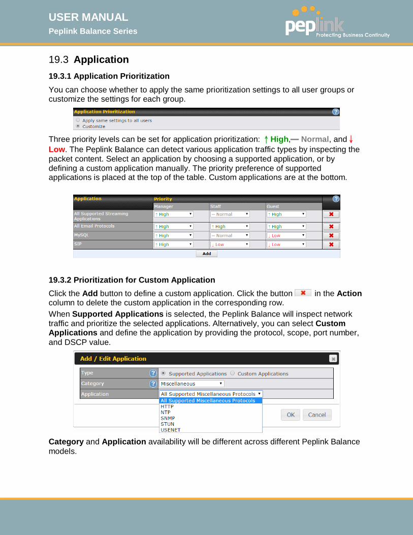
USER MANUAL Peplink Balance Series
http://www.peplink.com -168 / 261 - Copyright © 2015 Peplink
19.3 Application 19.3.1 Application Prioritization You can choose whether to apply the same prioritization settings to all user groups or customize the settings for each group.
Three priority levels can be set for application prioritization: ↑High,━ Normal, and↓Low. The Peplink Balance can detect various application traffic types by inspecting the packet content. Select an application by choosing a supported application, or by defining a custom application manually. The priority preference of supported applications is placed at the top of the table. Custom applications are at the bottom.
19.3.2 Prioritization for Custom Application Click the Add button to define a custom application. Click the button in the Action column to delete the custom application in the corresponding row. When Supported Applications is selected, the Peplink Balance will inspect network traffic and prioritize the selected applications. Alternatively, you can select Custom Applications and define the application by providing the protocol, scope, port number, and DSCP value.
Category and Application availability will be different across different Peplink Balance models.
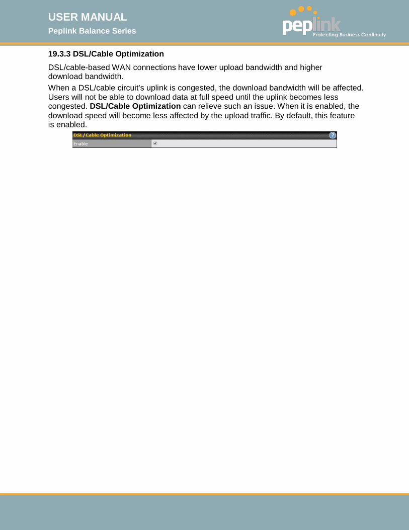
USER MANUAL Peplink Balance Series
http://www.peplink.com -169 / 261 - Copyright © 2015 Peplink
19.3.3 DSL/Cable Optimization DSL/cable-based WAN connections have lower upload bandwidth and higher download bandwidth. When a DSL/cable circuit's uplink is congested, the download bandwidth will be affected. Users will not be able to download data at full speed until the uplink becomes less congested. DSL/Cable Optimization can relieve such an issue. When it is enabled, the download speed will become less affected by the upload traffic. By default, this feature is enabled.

USER MANUAL Peplink Balance Series
http://www.peplink.com -170 / 261 - Copyright © 2015 Peplink
20 Firewall A firewall is a mechanism that selectively filters data traffic between the WAN side (the Internet) and the LAN side of the network. It can protect the local network from potential hacker attacks, access to offensive websites, and/or other inappropriate uses. The firewall functionality of Peplink Balance supports the selective filtering of data traffic in both directions: Outbound (LAN to WAN)
Inbound (WAN to LAN) The firewall also supports the following functionality:
Intrusion detection and DoS prevention Web blocking
With SpeedFusionTM enabled, the firewall rules also apply to VPN tunneled traffic.
20.1 Outbound and Inbound Firewall Rules 20.1.1 Access Rules The outbound firewall settings are located at Network>Firewall>Access Rules.
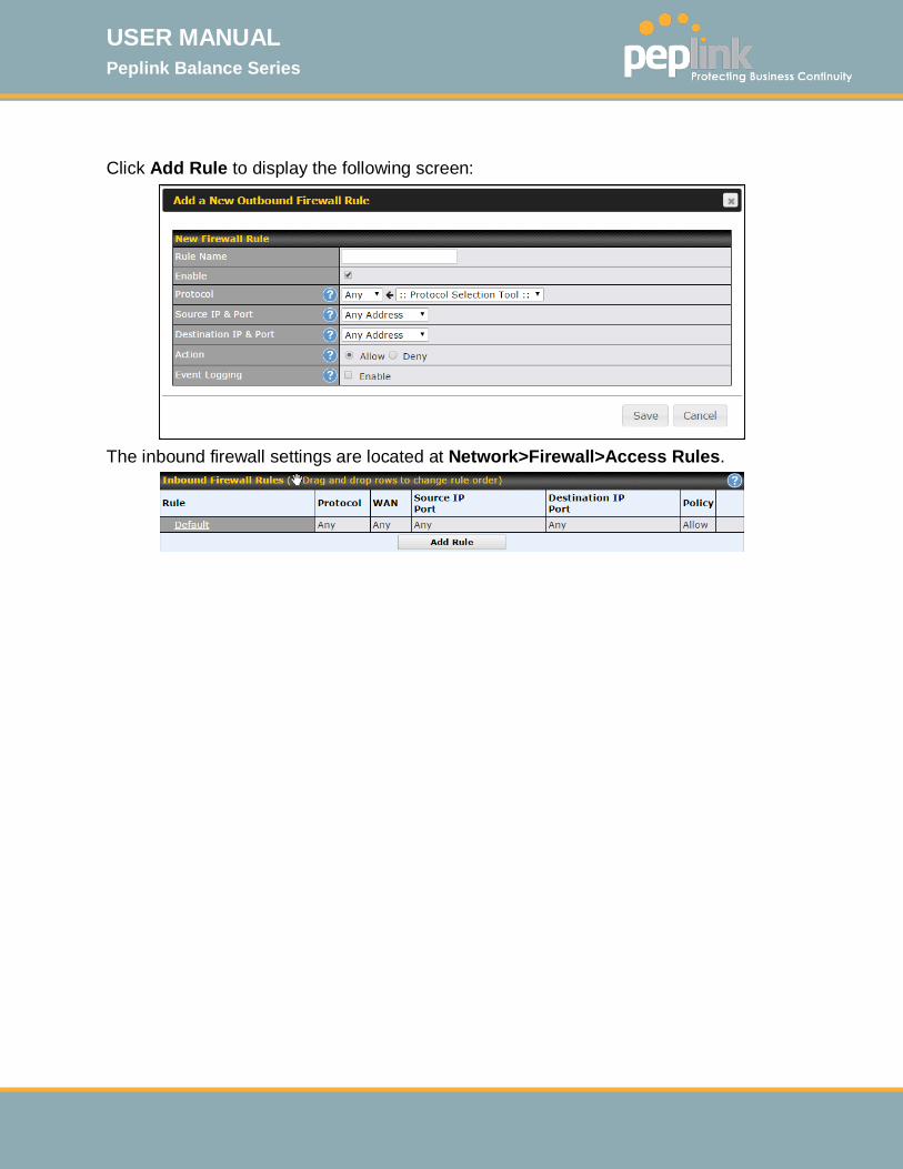
USER MANUAL Peplink Balance Series
http://www.peplink.com -171 / 261 - Copyright © 2015 Peplink
Click Add Rule to display the following screen:
The inbound firewall settings are located at Network>Firewall>Access Rules.
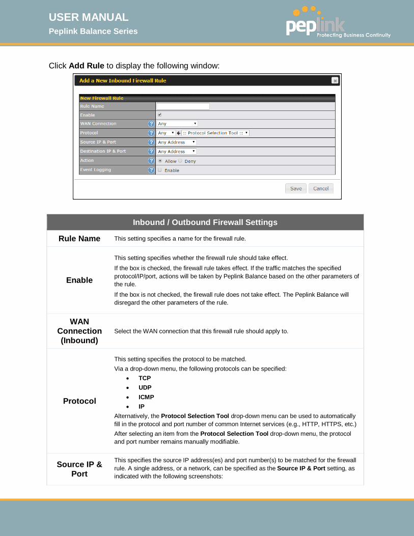
USER MANUAL Peplink Balance Series
http://www.peplink.com -172 / 261 - Copyright © 2015 Peplink
Click Add Rule to display the following window:
Inbound / Outbound Firewall Settings
Rule Name This setting specifies a name for the firewall rule.
Enable
This setting specifies whether the firewall rule should take effect. If the box is checked, the firewall rule takes effect. If the traffic matches the specified protocol/IP/port, actions will be taken by Peplink Balance based on the other parameters of the rule.
If the box is not checked, the firewall rule does not take effect. The Peplink Balance will disregard the other parameters of the rule.
WAN Connection (Inbound)
Select the WAN connection that this firewall rule should apply to.
Protocol
This setting specifies the protocol to be matched. Via a drop-down menu, the following protocols can be specified:
• TCP • UDP • ICMP • IP
Alternatively, the Protocol Selection Tool drop-down menu can be used to automatically fill in the protocol and port number of common Internet services (e.g., HTTP, HTTPS, etc.) After selecting an item from the Protocol Selection Tool drop-down menu, the protocol and port number remains manually modifiable.
Source IP & Port
This specifies the source IP address(es) and port number(s) to be matched for the firewall rule. A single address, or a network, can be specified as the Source IP & Port setting, as indicated with the following screenshots:
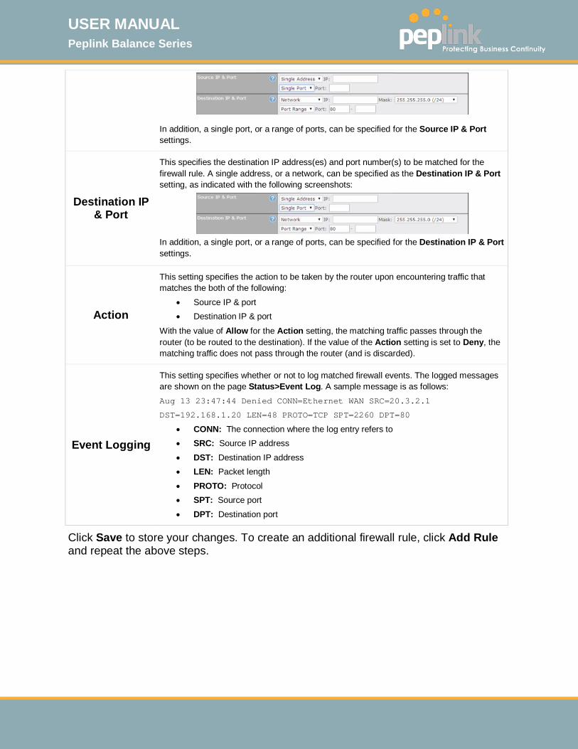
USER MANUAL Peplink Balance Series
http://www.peplink.com -173 / 261 - Copyright © 2015 Peplink
In addition, a single port, or a range of ports, can be specified for the Source IP & Port settings.
Destination IP & Port
This specifies the destination IP address(es) and port number(s) to be matched for the firewall rule. A single address, or a network, can be specified as the Destination IP & Port setting, as indicated with the following screenshots:
In addition, a single port, or a range of ports, can be specified for the Destination IP & Port settings.
Action
This setting specifies the action to be taken by the router upon encountering traffic that matches the both of the following:
• Source IP & port • Destination IP & port
With the value of Allow for the Action setting, the matching traffic passes through the router (to be routed to the destination). If the value of the Action setting is set to Deny, the matching traffic does not pass through the router (and is discarded).
Event Logging
This setting specifies whether or not to log matched firewall events. The logged messages are shown on the page Status>Event Log. A sample message is as follows: Aug 13 23:47:44 Denied CONN=Ethernet WAN SRC=20.3.2.1
DST=192.168.1.20 LEN=48 PROTO=TCP SPT=2260 DPT=80
• CONN: The connection where the log entry refers to • SRC: Source IP address • DST: Destination IP address • LEN: Packet length • PROTO: Protocol • SPT: Source port • DPT: Destination port
Click Save to store your changes. To create an additional firewall rule, click Add Rule and repeat the above steps.

USER MANUAL Peplink Balance Series
http://www.peplink.com -174 / 261 - Copyright © 2015 Peplink
To change a rule’s priority, simply drag and drop the rule: • Hold the left mouse button on the rule. • Move it to the desired position. • Drop it by releasing the mouse button.
To remove a rule, click the button. Rules are matched from top to the bottom. If a connection matches any one of the upper rules, the matching process will stop. If none of the rules match the connection, the Default rule will be applied. The Default rule is Allow for both outbound and inbound access.
Tip
If the default inbound rule is set to Allow for NAT-enabled WANs, no inbound Allow firewall rules will be required for inbound port forwarding and inbound NAT mapping rules. However, if the default inbound rule is set as Deny, a corresponding Allow firewall rule will be required.
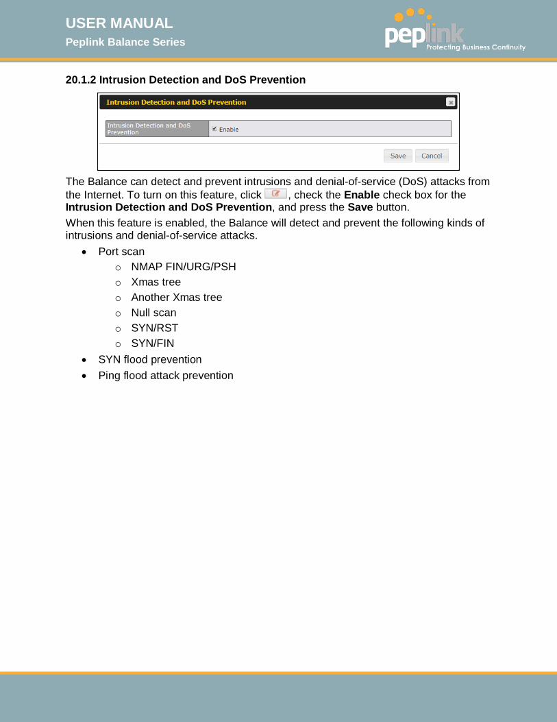
USER MANUAL Peplink Balance Series
http://www.peplink.com -175 / 261 - Copyright © 2015 Peplink
20.1.2 Intrusion Detection and DoS Prevention
The Balance can detect and prevent intrusions and denial-of-service (DoS) attacks from the Internet. To turn on this feature, click , check the Enable check box for the Intrusion Detection and DoS Prevention, and press the Save button. When this feature is enabled, the Balance will detect and prevent the following kinds of intrusions and denial-of-service attacks.
• Port scan o NMAP FIN/URG/PSH o Xmas tree o Another Xmas tree o Null scan o SYN/RST o SYN/FIN
• SYN flood prevention • Ping flood attack prevention
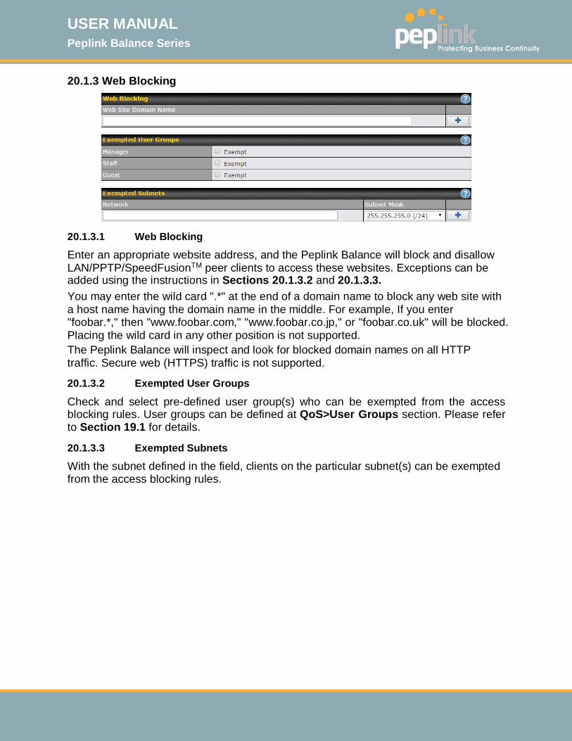
USER MANUAL Peplink Balance Series
http://www.peplink.com -176 / 261 - Copyright © 2015 Peplink
20.1.3 Web Blocking
20.1.3.1 Web Blocking
Enter an appropriate website address, and the Peplink Balance will block and disallow LAN/PPTP/SpeedFusionTM peer clients to access these websites. Exceptions can be added using the instructions in Sections 20.1.3.2 and 20.1.3.3. You may enter the wild card ".*" at the end of a domain name to block any web site with a host name having the domain name in the middle. For example, If you enter "foobar.*," then "www.foobar.com," "www.foobar.co.jp," or "foobar.co.uk" will be blocked. Placing the wild card in any other position is not supported. The Peplink Balance will inspect and look for blocked domain names on all HTTP traffic. Secure web (HTTPS) traffic is not supported.
20.1.3.2 Exempted User Groups
Check and select pre-defined user group(s) who can be exempted from the access blocking rules. User groups can be defined at QoS>User Groups section. Please refer to Section 19.1 for details.
20.1.3.3 Exempted Subnets
With the subnet defined in the field, clients on the particular subnet(s) can be exempted from the access blocking rules.
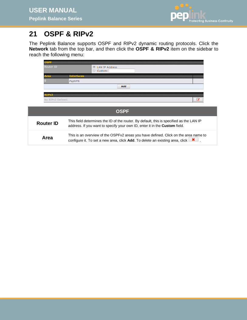
USER MANUAL Peplink Balance Series
http://www.peplink.com -177 / 261 - Copyright © 2015 Peplink
21 OSPF & RIPv2 The Peplink Balance supports OSPF and RIPv2 dynamic routing protocols. Click the Network tab from the top bar, and then click the OSPF & RIPv2 item on the sidebar to reach the following menu:
OSPF
Router ID This field determines the ID of the router. By default, this is specified as the LAN IP address. If you want to specify your own ID, enter it in the Custom field.
Area This is an overview of the OSPFv2 areas you have defined. Click on the area name to configure it. To set a new area, click Add. To delete an existing area, click .

USER MANUAL Peplink Balance Series
http://www.peplink.com -178 / 261 - Copyright © 2015 Peplink
OSPF Settings
Area ID Determine the name of your Area ID to apply to this group. Machines linked to this group will send and receive related OSPF packets, while unlinked machines will ignore it.
Link Type Choose the network type that this area will use.
Authentication Choose an authentication method, if one is used, from this drop-down menu. Available options are MD5 and Text. Enter the authentication key next to the drop-down menu.
Interfaces Determine which interfaces this area will use to listen to and deliver OSPF packets
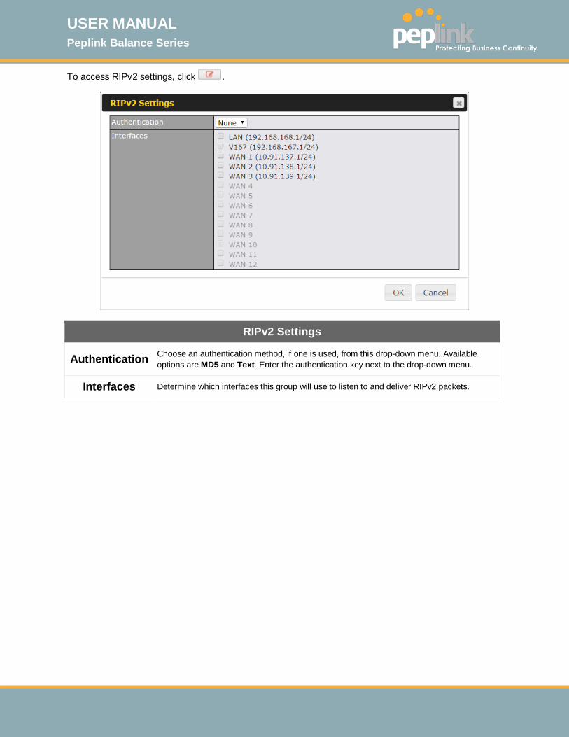
USER MANUAL Peplink Balance Series
http://www.peplink.com -179 / 261 - Copyright © 2015 Peplink
To access RIPv2 settings, click .
RIPv2 Settings
Authentication Choose an authentication method, if one is used, from this drop-down menu. Available options are MD5 and Text. Enter the authentication key next to the drop-down menu.
Interfaces Determine which interfaces this group will use to listen to and deliver RIPv2 packets.

USER MANUAL Peplink Balance Series
http://www.peplink.com -180 / 261 - Copyright © 2015 Peplink
22 Remote User Access
Networks routed by a Peplink Balance can be remotely accessed via L2TP with IPsec or PPTP. To configure this feature, navigate to Network > Remote User Access
Remote User Access Settings
Enable Click the checkbox to enable Remote User Access.
VPN Type Determine whether remote devices can connect to the Balance using L2TP with IPsec or PPTP. For greater security, we recommend you connect using L2TP with IPsec.
Preshared Key Enter your preshared key in the text field. Please note that remote devices will need this preshared key to access the Balance.
Listen On This setting is for specifying the WAN IP addresses where the PPTP server of the router should listen on.
User Accounts This setting allows you to define the PPTP User Accounts. Click Add to input username and password to create an account. After adding the user accounts, you can click on a username to edit the account password. Click the button X to delete the account in its

USER MANUAL Peplink Balance Series
http://www.peplink.com -181 / 261 - Copyright © 2015 Peplink
corresponding row.
Click the button to switch to enters user accounts by pasting the information in.CSV format.
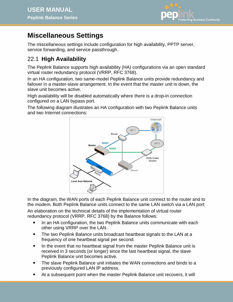
USER MANUAL Peplink Balance Series
http://www.peplink.com -182 / 261 - Copyright © 2015 Peplink
Miscellaneous Settings The miscellaneous settings include configuration for high availability, PPTP server, service forwarding, and service passthrough.
22.1 High Availability The Peplink Balance supports high availability (HA) configurations via an open standard virtual router redundancy protocol (VRRP, RFC 3768). In an HA configuration, two same-model Peplink Balance units provide redundancy and failover in a master-slave arrangement. In the event that the master unit is down, the slave unit becomes active. High availability will be disabled automatically where there is a drop-in connection configured on a LAN bypass port. The following diagram illustrates an HA configuration with two Peplink Balance units and two Internet connections:
In the diagram, the WAN ports of each Peplink Balance unit connect to the router and to the modem. Both Peplink Balance units connect to the same LAN switch via a LAN port. An elaboration on the technical details of the implementation of virtual router redundancy protocol (VRRP, RFC 3768) by the Balance follows: In an HA configuration, the two Peplink Balance units communicate with each
other using VRRP over the LAN. The two Peplink Balance units broadcast heartbeat signals to the LAN at a
frequency of one heartbeat signal per second. In the event that no heartbeat signal from the master Peplink Balance unit is
received in 3 seconds (or longer) since the last heartbeat signal, the slave Peplink Balance unit becomes active.
The slave Peplink Balance unit initiates the WAN connections and binds to a previously configured LAN IP address.
At a subsequent point when the master Peplink Balance unit recovers, it will

USER MANUAL Peplink Balance Series
http://www.peplink.com -183 / 261 - Copyright © 2015 Peplink
once again become active. You can configure high availability at Network>Misc. Settings>High Availability.
Interface for Master Router Interface for Slave Router
High Availability
Enable Checking this box specifies that the Peplink Balance unit is part of a high availability configuration.
Group Number This number identifies a pair of Peplink Balance units operating in a high availability configuration. The two Peplink Balance units in the pair must have the same Group Number value.
Preferred Role This setting specifies whether the Peplink Balance unit operates in master or slave mode. Click the corresponding radio button to set the role of the unit. One of the units in the pair must be configured as the master, and the other unit must be configured as the slave.
Resume Master Role
Upon Recovery
This option is displayed when Master mode is selected in Preferred Role. If this option is enabled, once the device has recovered from an outage, it will take over and resume its Master role from the slave unit.
Configuration Sync.
This option is displayed when Slave mode is selected in Preferred Role. If this option is enabled and the Master Serial Number entered matches with the actual master unit's, the master unit will automatically transfer the configuration to this unit. Please make sure the LAN IP Address and the Subnet Mask fields are set correctly in the LAN settings page. You can refer to the Event Log for the configuration synchronization status.
Master Serial Number
If Configuration Sync. is checked, the serial number of the master unit is required here for the feature to work properly.
Virtual IP The HA pair must share the same Virtual IP. The Virtual IP and the LAN Administration IP must be under the same network.
LAN Administration
IP This setting specifies a LAN IP address to be used for accessing administration functionality. This address should be unique within the LAN.
Subnet Mask This setting specifies the subnet mask of the LAN.
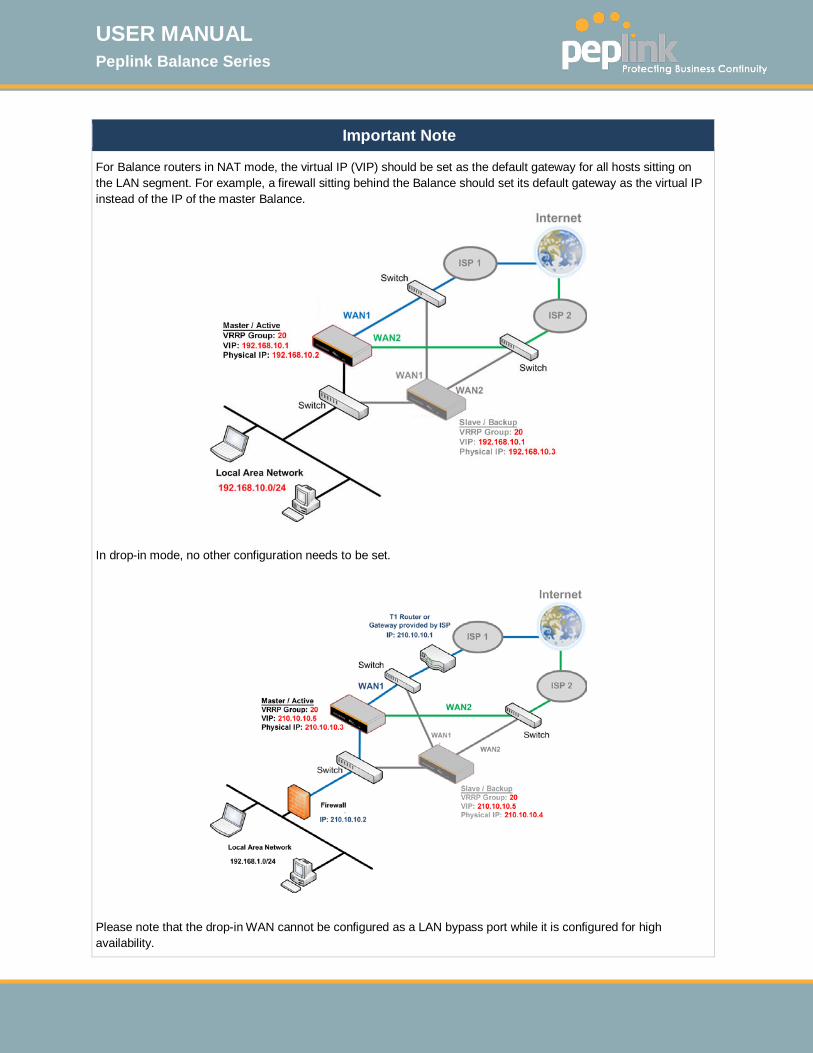
USER MANUAL Peplink Balance Series
http://www.peplink.com -184 / 261 - Copyright © 2015 Peplink
Important Note
For Balance routers in NAT mode, the virtual IP (VIP) should be set as the default gateway for all hosts sitting on the LAN segment. For example, a firewall sitting behind the Balance should set its default gateway as the virtual IP instead of the IP of the master Balance.
In drop-in mode, no other configuration needs to be set.
Please note that the drop-in WAN cannot be configured as a LAN bypass port while it is configured for high availability.

USER MANUAL Peplink Balance Series
http://www.peplink.com -185 / 261 - Copyright © 2015 Peplink
22.2 Certificate Manager
This section allows you to assign certificates for local VPN and web admin SSL. The local keys will not be transferred to another device by any means.
22.3 Service Forwarding Service forwarding settings are located at Network>Misc. Settings>Service Forwarding.
Service Forwarding
SMTP Forwarding When this option is enabled, all outgoing SMTP connections destined for any host at TCP port 25 will be intercepted. These connections will be redirected to a specified SMTP server and port number. SMTP server settings for each WAN can be specified after selecting Enable.
Web Proxy Forwarding
When this option is enabled, all outgoing connections destined for the proxy server specified in Web Proxy Interception Settings will be intercepted. These connections will be redirected to a specified web proxy server and port number. Web proxy interception settings and proxy server settings for each WAN can be specified after selecting Enable.
DNS Forwarding
When this option is enabled, all outgoing DNS lookups will be intercepted and redirected to the built-in DNS name server. If any LAN device is using the DNS name servers of a WAN connection, you may want to enable this option to enhance the DNS availability without modifying the DNS server setting of the clients. The built-in DNS name server will distribute DNS lookups to corresponding DNS servers of all available WAN connections. In this case, DNS service will not be interrupted, even if any WAN connection is down.
Custom Service Forwarding
When this option is enabled, incoming connections from specified ports will be intercepted and forwarded to a local server.
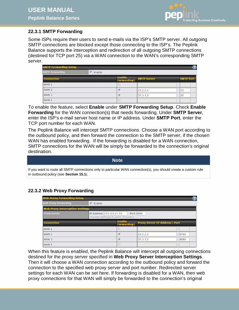
USER MANUAL Peplink Balance Series
http://www.peplink.com -186 / 261 - Copyright © 2015 Peplink
22.3.1 SMTP Forwarding Some ISPs require their users to send e-mails via the ISP’s SMTP server. All outgoing SMTP connections are blocked except those connecting to the ISP’s. The Peplink Balance supports the interception and redirection of all outgoing SMTP connections (destined for TCP port 25) via a WAN connection to the WAN’s corresponding SMTP server.
To enable the feature, select Enable under SMTP Forwarding Setup. Check Enable Forwarding for the WAN connection(s) that needs forwarding. Under SMTP Server, enter the ISP’s e-mail server host name or IP address. Under SMTP Port, enter the TCP port number for each WAN. The Peplink Balance will intercept SMTP connections. Choose a WAN port according to the outbound policy, and then forward the connection to the SMTP server, if the chosen WAN has enabled forwarding. If the forwarding is disabled for a WAN connection, SMTP connections for the WAN will be simply be forwarded to the connection’s original destination.
Note
If you want to route all SMTP connections only to particular WAN connection(s), you should create a custom rule in outbound policy (see Section 15.1).
22.3.2 Web Proxy Forwarding
When this feature is enabled, the Peplink Balance will intercept all outgoing connections destined for the proxy server specified in Web Proxy Server Interception Settings. Then it will choose a WAN connection according to the outbound policy and forward the connection to the specified web proxy server and port number. Redirected server settings for each WAN can be set here. If forwarding is disabled for a WAN, then web proxy connections for that WAN will simply be forwarded to the connection’s original

USER MANUAL Peplink Balance Series
http://www.peplink.com -187 / 261 - Copyright © 2015 Peplink
destination.
22.3.3 DNS Forwarding
When DNS forwarding is enabled, all clients’ outgoing DNS requests will also be intercepted and forwarded to the built-in DNS proxy server.
22.3.4 Custom Service Forwarding
After clicking the enable checkbox, enter your TCP port for traffic heading to the router, and then specify the IP Address and Port of the server you wish to forward to the service to.
22.4 Service Passthrough Service passthrough settings can be found at Network>Misc. Settings>Service Passthrough.
Some Internet services need to be specially handled in a multi-WAN environment. The Peplink Balance can handle these services such that Internet applications do not notice it is behind a multi-WAN router. Settings for service passthrough support are available here.
Service Passthrough Support
SIP Session initiation protocol, aka SIP, is a voice-over-IP protocol. The Peplink Balance can act as a SIP application layer gateway (ALG) which binds connections for the same SIP session to the same WAN connection and translate IP address in the SIP packets correctly in NAT mode. Such passthrough support is always enabled and there are two
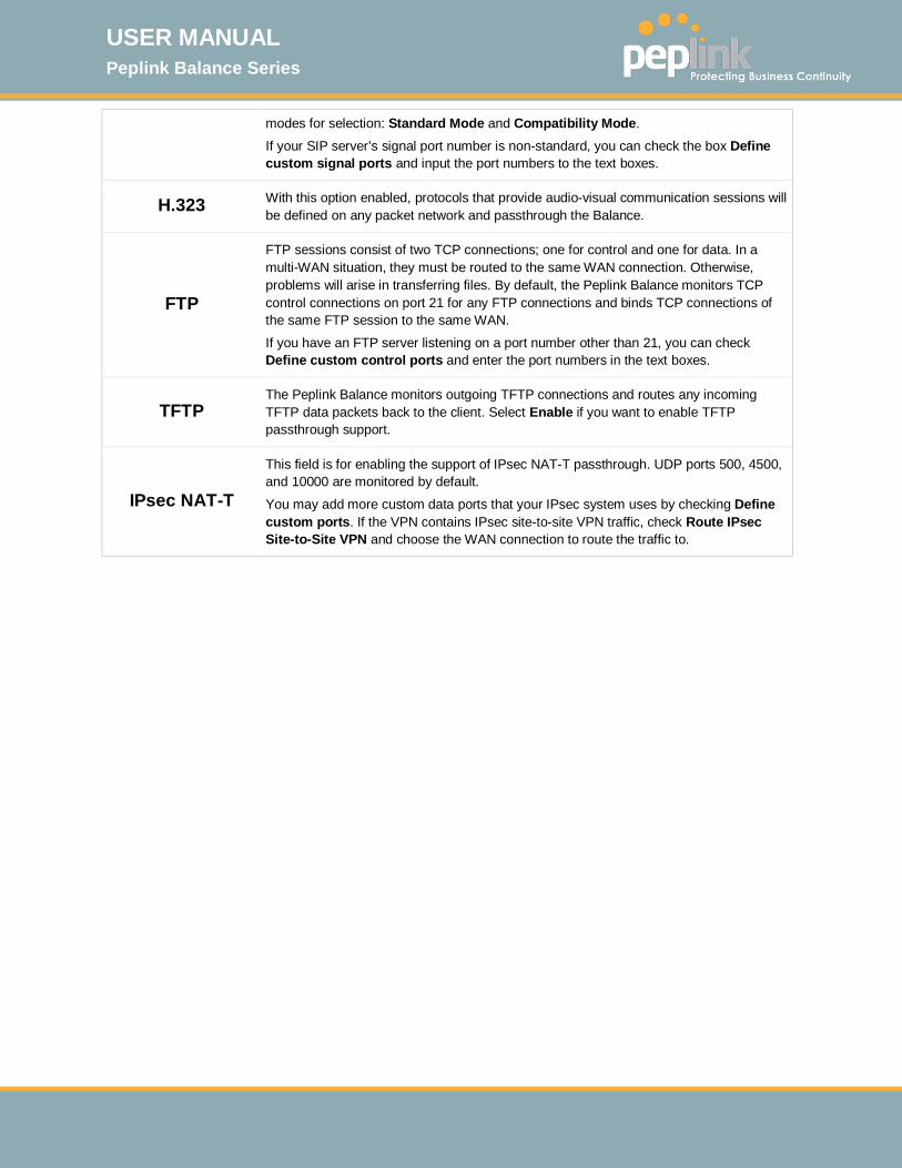
USER MANUAL Peplink Balance Series
http://www.peplink.com -188 / 261 - Copyright © 2015 Peplink
modes for selection: Standard Mode and Compatibility Mode.
If your SIP server’s signal port number is non-standard, you can check the box Define custom signal ports and input the port numbers to the text boxes.
H.323 With this option enabled, protocols that provide audio-visual communication sessions will be defined on any packet network and passthrough the Balance.
FTP
FTP sessions consist of two TCP connections; one for control and one for data. In a multi-WAN situation, they must be routed to the same WAN connection. Otherwise, problems will arise in transferring files. By default, the Peplink Balance monitors TCP control connections on port 21 for any FTP connections and binds TCP connections of the same FTP session to the same WAN.
If you have an FTP server listening on a port number other than 21, you can check Define custom control ports and enter the port numbers in the text boxes.
TFTP The Peplink Balance monitors outgoing TFTP connections and routes any incoming TFTP data packets back to the client. Select Enable if you want to enable TFTP passthrough support.
IPsec NAT-T
This field is for enabling the support of IPsec NAT-T passthrough. UDP ports 500, 4500, and 10000 are monitored by default.
You may add more custom data ports that your IPsec system uses by checking Define custom ports. If the VPN contains IPsec site-to-site VPN traffic, check Route IPsec Site-to-Site VPN and choose the WAN connection to route the traffic to.

USER MANUAL Peplink Balance Series
http://www.peplink.com -189 / 261 - Copyright © 2015 Peplink
23 AP The AP controller acts as a centralized controller of Pepwave AP devices. With this feature, users will be able to customize and manage multiple APs from a single Peplink Balance interface.
Special Note
With the installation of Firmware 6.2.1 and upwards, full AP support is included free.
23.1 AP Controller Clicking on the AP tab will default to this menu, where you can view basic AP management options:
AP Controller
AP Management
The AP controller for managing Pepwave APs can be enabled by checking this box. When this option is enabled, the AP controller will wait for management connections originating from APs over the LAN on TCP and UDP port 11753. It will also wait for captive portal connections on TCP port 443. An extended DHCP option, CAPWAP Access Controller addresses (field 138), will be added to the DHCP server. A local DNS record, AP Controller, will be added to the local DNS proxy.
Support Remote AP
The AP controller supports remote management of Pepwave APs. When this option is enabled, the AP controller will wait for management connections originating from remote APs over the WAN on TCP and UDP port 11753. It will also wait for captive portal connections on TCP port 443. The DHCP server and/or local DNS server of the remote AP’s network should be configured in the DNS Proxy Settings menu under Network>LAN. The procedure is as follows: 1. Define an extended DHCP option, CAPWAP Access Controller addresses (field
138), in the DHCP server, where the values are the AP controller's public IP addresses; and/or
2. Create a local DNS record for the AP controller with a value corresponding to the AP controller's public IP address.
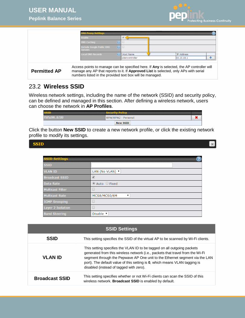
USER MANUAL Peplink Balance Series
http://www.peplink.com -190 / 261 - Copyright © 2015 Peplink
Permitted AP Access points to manage can be specified here. If Any is selected, the AP controller will manage any AP that reports to it. If Approved List is selected, only APs with serial numbers listed in the provided text box will be managed.
23.2 Wireless SSID Wireless network settings, including the name of the network (SSID) and security policy, can be defined and managed in this section. After defining a wireless network, users can choose the network in AP Profiles.
Click the button New SSID to create a new network profile, or click the existing network profile to modify its settings.
SSID Settings
SSID This setting specifies the SSID of the virtual AP to be scanned by Wi-Fi clients.
VLAN ID
This setting specifies the VLAN ID to be tagged on all outgoing packets generated from this wireless network (i.e., packets that travel from the Wi-Fi segment through the Pepwave AP One unit to the Ethernet segment via the LAN port). The default value of this setting is 0, which means VLAN tagging is disabled (instead of tagged with zero).
Broadcast SSID This setting specifies whether or not Wi-Fi clients can scan the SSID of this wireless network. Broadcast SSID is enabled by default.

USER MANUAL Peplink Balance Series
http://www.peplink.com -191 / 261 - Copyright © 2015 Peplink
Data Rate A Select Auto to allow the Peplink Balance to set the data rate automatically, or select Fixed and choose a rate from the displayed drop-down menu.
Multicast FilterA This setting enables the filtering of multicast network traffic to the wireless SSID.
Multicast RateA This setting specifies the transmit rate to be used for sending multicast network traffic. The selected Protocol and Channel Bonding settings will affect the rate options and values available here.
IGMP Snooping A To allow the Peplink Balance to listen to internet group management protocol (IGMP) network traffic, select this option.
DHCP Option 82 A If you use a distributed DHCP server/relay environment, you can enable this option to provide additional information on the manner in which clients are physically connected to the network.
Network Priority (QoS) A
Select from Gold, Silver, and Bronze to control the QoS priority of this wireless network’s traffic.
Layer 2 Isolation A Layer 2 refers to the second layer in the ISO Open System Interconnect model. When this option is enabled, clients on the same VLAN, SSID, or subnet are isolated to that VLAN, SSID, or subnet, which can enhance security. Traffic is passed to upper communication layer(s). By default, the setting is disabled.
Band Steering A Band steering allows the Peplink Balance to steer AP clients from the 2.4 GHz band to the 5GHz band for better usage of bandwidth. To make steering mandatory, select Enforce. To cause the Peplink Balance to preferentially choose steering, select Prefer. The default for this setting is Disable.
A - Advanced feature. Click the button on the top right-hand corner to activate.
Security Settings
Security Policy
This setting configures the wireless authentication and encryption methods. Available options are Open (No Encryption), WPA/WPA2 - Personal, WPA/WPA2 – Enterprise and Static WEP.

USER MANUAL Peplink Balance Series
http://www.peplink.com -192 / 261 - Copyright © 2015 Peplink
Access Control
Restricted Mode
The settings allow administrator to control access using Mac address filtering. Available options are None, Deny all except listed, Accept all except listed, and RADIUS MAC Authentication. When WPA/WPA2 - Enterprise is configured, RADIUS-based 802.1 x authentication is enabled. Under this configuration, the Shared Key option should be disabled. When using this method, select the appropriate version using the V1/V2 controls. The security level of this method is known to be very high. When WPA/WPA2- Personal is configured, a shared key is used for data encryption and authentication. When using this configuration, the Shared Key option should be enabled. Key length must be between eight and 63 characters (inclusive). The security level of this method is known to be high. The configuration of Static WEP parameters enables pre-shared WEP key encryption. Authentication is not supported by this method. The security level of this method is known to be weak.
MAC Address List
Connection coming from the MAC addresses in this list will be either denied or accepted based the option selected in the previous field.
RADIUS Server Settings
Host Enter the IP address of the primary RADIUS server and, if applicable, the secondary RADIUS server.
Secret Enter the RADIUS shared secret for the primary server and, if applicable, the secondary RADIUS server.
Authentication Port
In field, enter the UDP authentication port(s) used by your RADIUS server(s) or click the Default button to enter 1812.
Accounting Port
In field, enter the UDP accounting port(s) used by your RADIUS server(s) or click the Default button to enter 1813.
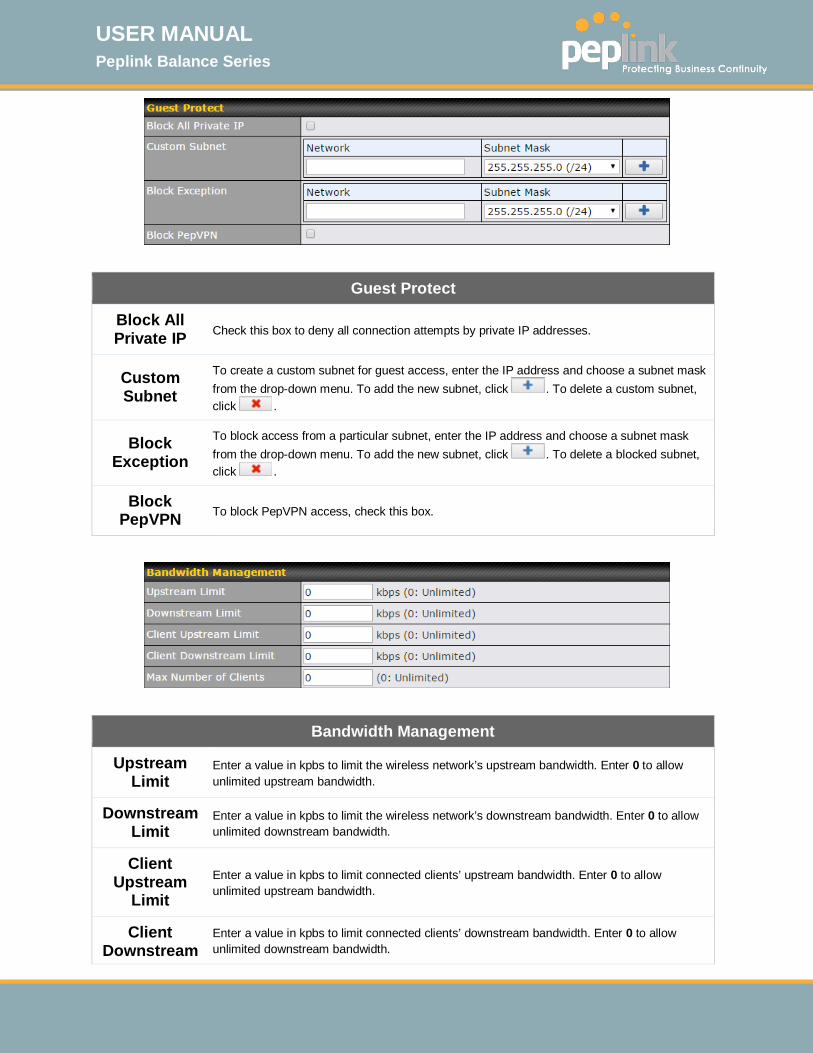
USER MANUAL Peplink Balance Series
http://www.peplink.com -193 / 261 - Copyright © 2015 Peplink
Guest Protect
Block All Private IP Check this box to deny all connection attempts by private IP addresses.
Custom Subnet
To create a custom subnet for guest access, enter the IP address and choose a subnet mask from the drop-down menu. To add the new subnet, click . To delete a custom subnet, click .
Block Exception
To block access from a particular subnet, enter the IP address and choose a subnet mask from the drop-down menu. To add the new subnet, click . To delete a blocked subnet, click .
Block PepVPN To block PepVPN access, check this box.
Bandwidth Management
Upstream Limit
Enter a value in kpbs to limit the wireless network’s upstream bandwidth. Enter 0 to allow unlimited upstream bandwidth.
Downstream Limit
Enter a value in kpbs to limit the wireless network’s downstream bandwidth. Enter 0 to allow unlimited downstream bandwidth.
Client Upstream
Limit Enter a value in kpbs to limit connected clients’ upstream bandwidth. Enter 0 to allow unlimited upstream bandwidth.
Client Downstream
Enter a value in kpbs to limit connected clients’ downstream bandwidth. Enter 0 to allow unlimited downstream bandwidth.
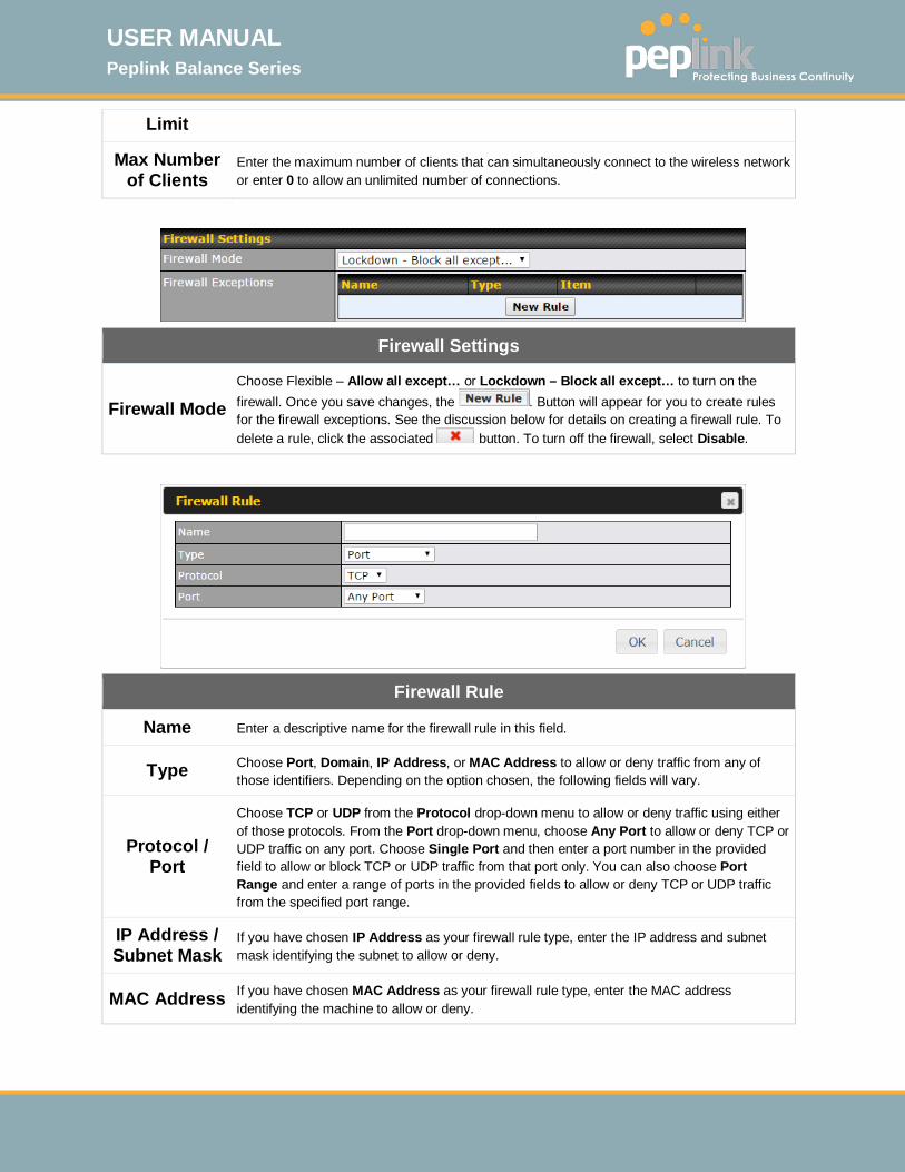
USER MANUAL Peplink Balance Series
http://www.peplink.com -194 / 261 - Copyright © 2015 Peplink
Limit
Max Number of Clients
Enter the maximum number of clients that can simultaneously connect to the wireless network or enter 0 to allow an unlimited number of connections.
Firewall Settings
Firewall Mode Choose Flexible – Allow all except… or Lockdown – Block all except… to turn on the firewall. Once you save changes, the . Button will appear for you to create rules for the firewall exceptions. See the discussion below for details on creating a firewall rule. To delete a rule, click the associated button. To turn off the firewall, select Disable.
Firewall Rule
Name Enter a descriptive name for the firewall rule in this field.
Type Choose Port, Domain, IP Address, or MAC Address to allow or deny traffic from any of those identifiers. Depending on the option chosen, the following fields will vary.
Protocol / Port
Choose TCP or UDP from the Protocol drop-down menu to allow or deny traffic using either of those protocols. From the Port drop-down menu, choose Any Port to allow or deny TCP or UDP traffic on any port. Choose Single Port and then enter a port number in the provided field to allow or block TCP or UDP traffic from that port only. You can also choose Port Range and enter a range of ports in the provided fields to allow or deny TCP or UDP traffic from the specified port range.
IP Address / Subnet Mask
If you have chosen IP Address as your firewall rule type, enter the IP address and subnet mask identifying the subnet to allow or deny.
MAC Address If you have chosen MAC Address as your firewall rule type, enter the MAC address identifying the machine to allow or deny.
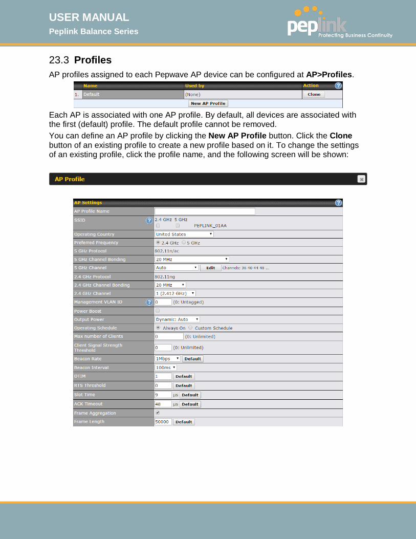
USER MANUAL Peplink Balance Series
http://www.peplink.com -195 / 261 - Copyright © 2015 Peplink
23.3 Profiles AP profiles assigned to each Pepwave AP device can be configured at AP>Profiles.
Each AP is associated with one AP profile. By default, all devices are associated with the first (default) profile. The default profile cannot be removed. You can define an AP profile by clicking the New AP Profile button. Click the Clone button of an existing profile to create a new profile based on it. To change the settings of an existing profile, click the profile name, and the following screen will be shown:

USER MANUAL Peplink Balance Series
http://www.peplink.com -196 / 261 - Copyright © 2015 Peplink
AP Settings
AP Profile Name This field specifies the name of this AP profile.
SSID These buttons specify which wireless networks will use this AP profile. You can also select the frequencies at which each network will transmit. Please note that the Peplink Balance does not detect whether the AP is capable of transmitting at both frequencies. Instructions to transmit at unsupported frequencies will be ignored by the AP.
Operating Country
This drop-down menu specifies the national / regional regulations which the AP should follow.
• If a North American region is selected, RF channels 1 to 11 will be available and the maximum transmission power will be 26 dBm (400 mW).
• If European region is selected, RF channels 1 to 13 will be available. The maximum transmission power will be 20 dBm (100 mW).
NOTE: Users are required to choose an option suitable to local laws and regulations. Per FCC regulation, the country selection is not available on all models marketed in US. All US models are fixed to US channels only.
Preferred Frequency
These buttons determine the frequency at which access points will attempt to broadcast. This feature will only work for APs that can transmit at both 5.4GHz and 5GHz frequencies.
5 GHz Protocol This section displays the 5 GHz protocols your APs are using.
5GHz Channel Bonding
There are three options: 20 MHz, 20/40 MHz, and 40 MHz. With this feature enabled, the Wi-Fi system can use two channels at once. Using two channels improves the performance of the Wi-Fi connection.
5 GHz Channel This drop-down menu selects the 5 GHz 802.11 channel to be utilized. If Auto is set, the system will perform channel scanning based on the scheduled time set and choose the most suitable channel automatically.
2.4 GHz Protocol This section displays the 2.4 GHz protocols your APs are using.
2.4 GHz Channel Bonding
There are three options: 20 MHz, 20/40 MHz, and 40 MHz. With this feature enabled, the Wi-Fi system can use two channels at once. Using two channels improves the performance of the Wi-Fi connection.
2.4 GHz Channel
This drop-down menu selects the 802.11 channel to be utilized. Available options are from 1 to 11 and from 1 to 13 for the North America region and Europe region, respectively. (Channel 14 is only available when the country is selected as Japan with protocol 802.11b.) If Auto is set, the system will perform channel scanning based on the scheduled time set and choose the most suitable channel automatically.
Management VLAN ID
This field specifies the VLAN ID to tag to management traffic, such as AP to AP controller communication traffic. The value is 0 by default, meaning that no VLAN tagging will be applied. NOTE: change this value with caution as alterations may result in loss of connection to the AP controller.
Power BoostA With this option enabled, the AP under this profile will transmit using additional power. Please note that using this option with several APs in close proximity will lead to increased interference.

USER MANUAL Peplink Balance Series
http://www.peplink.com -197 / 261 - Copyright © 2015 Peplink
Output PowerA
This drop-down menu determines the power at which the AP under this profile will broadcast. When fixed settings are selected, the AP will broadcast at the specified power level, regardless of context. When Dynamic settings are selected, the AP will adjust its power level based on its surrounding APs in order to maximize performance. The Dynamic: Auto setting will set the AP to do this automatically. Otherwise, the Dynamic: Manual setting will set the AP to dynamically adjust only of instructed to do so. If you have set Dynamic:Manual, you can go to AP>Toolbox>Auto Power Adj. to give your AP further instructions.
Operating ScheduleA
These buttons determine the time period at which the AP under this profile will be activated. Clicking the Custom Schedule option will open the following diagram:
Click the desired time periods to toggle the activation state of APs under this profile.
Max number of ClientsA
This field determines the maximum clients that can be connected to APs under this profile.
Client Signal Strength
ThresholdA This field determines that maximum signal strength each individual client will receive. The measurment unit is megawatts.
Beacon RateA This drop-down menu provides the option to send beacons in different transmit bit rates. The bit rates are 1Mbps, 2Mbps, 5.5Mbps, 6Mbps, and 11Mbps.
Beacon IntervalA This drop-down menu provides the option to set the time between each beacon send. Available options are 100ms, 250ms, and 500ms.
DTIMA This field provides the option to set the frequency for beacon to include delivery traffic indication messages (DTIM). The interval unit is measured in milliseconds.
RTS ThresholdA This field provides the option to set the minimum packet size for the unit to send an RTS using the RTS/CTS handshake. Setting 0 disables this feature.
Slot TimeA This field provides the option to modify the unit wait time before it transmits. The default value is 9μs.
ACK TimeoutA This field provides the option to set the wait time to receive acknowledgement packet before doing retransmission. The default value is 48μs.
Frame AggregationA
With this feature enabled, throughput will be increased by sending two or more data frames in a single transmission.
Frame Length This field is only available when Frame Aggregation is enabled. It specifies the frame
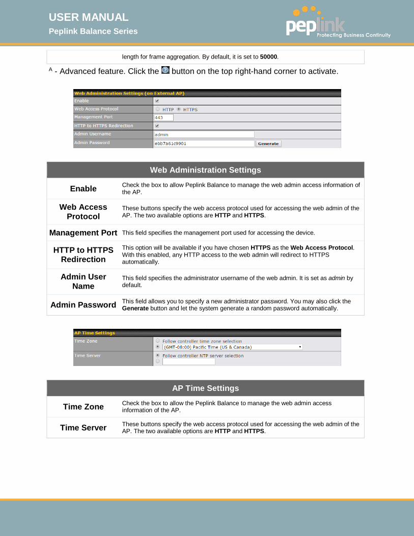
USER MANUAL Peplink Balance Series
http://www.peplink.com -198 / 261 - Copyright © 2015 Peplink
length for frame aggregation. By default, it is set to 50000.
A - Advanced feature. Click the button on the top right-hand corner to activate.
Web Administration Settings
Enable Check the box to allow Peplink Balance to manage the web admin access information of the AP.
Web Access Protocol
These buttons specify the web access protocol used for accessing the web admin of the AP. The two available options are HTTP and HTTPS.
Management Port This field specifies the management port used for accessing the device.
HTTP to HTTPS Redirection
This option will be available if you have chosen HTTPS as the Web Access Protocol. With this enabled, any HTTP access to the web admin will redirect to HTTPS automatically.
Admin User Name
This field specifies the administrator username of the web admin. It is set as admin by default.
Admin Password This field allows you to specify a new administrator password. You may also click the Generate button and let the system generate a random password automatically.
AP Time Settings
Time Zone Check the box to allow the Peplink Balance to manage the web admin access information of the AP.
Time Server These buttons specify the web access protocol used for accessing the web admin of the AP. The two available options are HTTP and HTTPS.
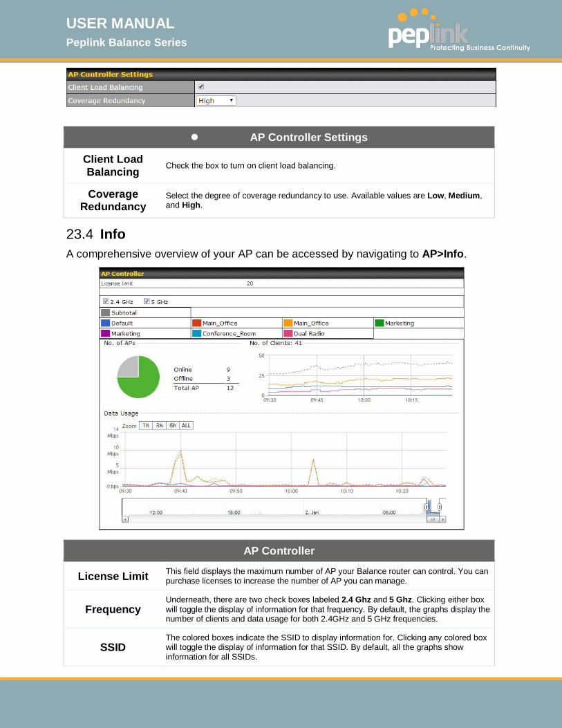
USER MANUAL Peplink Balance Series
http://www.peplink.com -199 / 261 - Copyright © 2015 Peplink
AP Controller Settings
Client Load Balancing Check the box to turn on client load balancing.
Coverage Redundancy
Select the degree of coverage redundancy to use. Available values are Low, Medium, and High.
23.4 Info A comprehensive overview of your AP can be accessed by navigating to AP>Info.
AP Controller
License Limit This field displays the maximum number of AP your Balance router can control. You can purchase licenses to increase the number of AP you can manage.
Frequency Underneath, there are two check boxes labeled 2.4 Ghz and 5 Ghz. Clicking either box will toggle the display of information for that frequency. By default, the graphs display the number of clients and data usage for both 2.4GHz and 5 GHz frequencies.
SSID The colored boxes indicate the SSID to display information for. Clicking any colored box will toggle the display of information for that SSID. By default, all the graphs show information for all SSIDs.

USER MANUAL Peplink Balance Series
http://www.peplink.com -200 / 261 - Copyright © 2015 Peplink
No. of APs This pie chart and table indicates how many APs are online and how many are offline.
No.of Clients This graph displays the number of clients connected to each network at any given time. Mouse over any line on the graph to see how many clients connected to a specific SSID for that point in time.
Data Usage This graph enables you to see the data usage of any SSID for any given time period. Mouse over any line on the graph to see the data usage by each SSID for that point in time. Use the buttons next to Zoom to select the time scale you wish to view. In addition, you could use the sliders at the bottom to further refine your timescale.
Events
This event log displays all activity on your AP network, down to the client level. Click View Alerts to see only alerts, and click the More… link for additional records.
23.5 Usage A detailed breakdown of data usage for each AP is available at AP> AP Status. The information is organized by device groups as defined in Section 22.3.
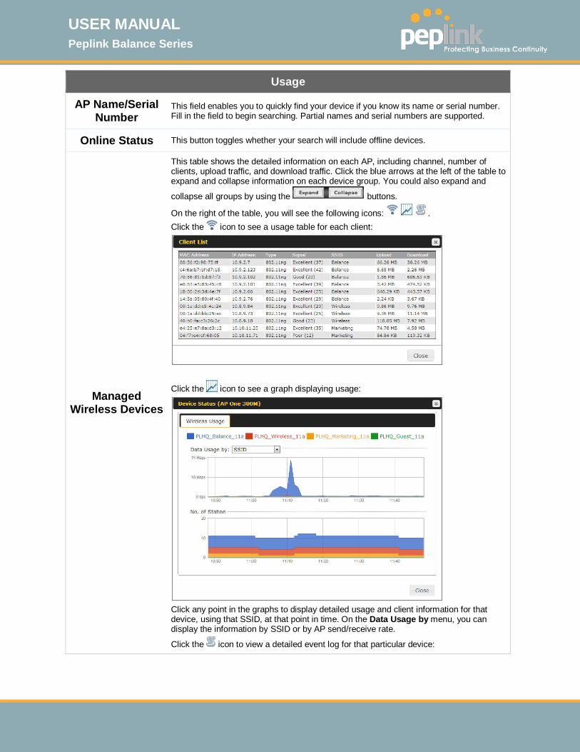
USER MANUAL Peplink Balance Series
http://www.peplink.com -201 / 261 - Copyright © 2015 Peplink
Usage
AP Name/Serial Number
This field enables you to quickly find your device if you know its name or serial number. Fill in the field to begin searching. Partial names and serial numbers are supported.
Online Status This button toggles whether your search will include offline devices.
Managed Wireless Devices
This table shows the detailed information on each AP, including channel, number of clients, upload traffic, and download traffic. Click the blue arrows at the left of the table to expand and collapse information on each device group. You could also expand and
collapse all groups by using the buttons.
On the right of the table, you will see the following icons: . Click the icon to see a usage table for each client:
Click the icon to see a graph displaying usage:
Click any point in the graphs to display detailed usage and client information for that device, using that SSID, at that point in time. On the Data Usage by menu, you can display the information by SSID or by AP send/receive rate.
Click the icon to view a detailed event log for that particular device:

USER MANUAL Peplink Balance Series
http://www.peplink.com -202 / 261 - Copyright © 2015 Peplink
23.6 AP Status A detailed breakdown of the status of each device is available at AP>Status. The information is organized by device groups as defined in Section 22.3.

USER MANUAL Peplink Balance Series
http://www.peplink.com -203 / 261 - Copyright © 2015 Peplink
AP Status
AP Name/Serial Number
This field enables you to quickly find your device if you know its name or serial number. Fill in the field to begin searching. Partial names and serial numbers are supported.
Online Status This button toggles weather your search will include offline devices.
Managed APs
This table displays the MAC address, IP address, firmware version, and specific
configurations of each device. Clicking the button for each device will display the following menu:
Here, you can edit the name and location of your AP. You can also choose the channel to transmit from. You can also batch configure devices on this table by selecting the
items you wish to configure, then clicking .
After selecting your devices you wish to configure, click to reach the following menu:
Select the pull-down menu to choose a firmware pack for the devices that you have selected.
After selecting your devices you wish to configure, click to reach the following menu:
Select the pull-down menu to choose an AP profile for the devices that you have selected.
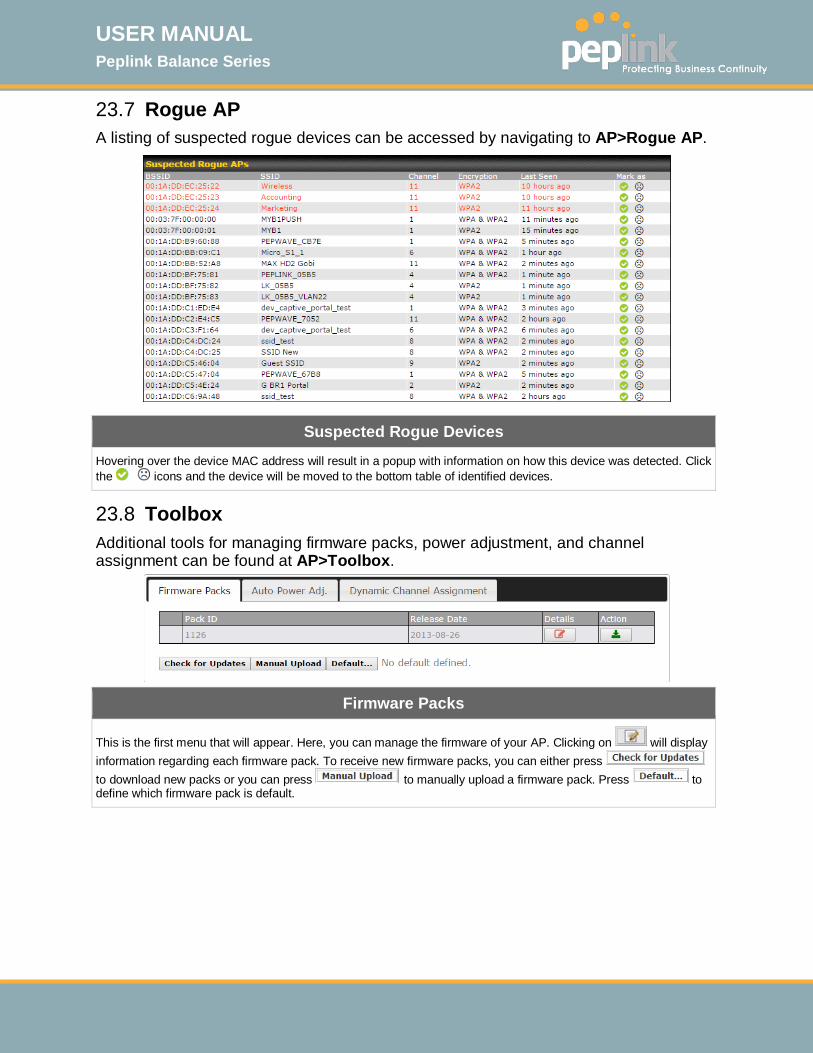
USER MANUAL Peplink Balance Series
http://www.peplink.com -204 / 261 - Copyright © 2015 Peplink
23.7 Rogue AP A listing of suspected rogue devices can be accessed by navigating to AP>Rogue AP.
Suspected Rogue Devices
Hovering over the device MAC address will result in a popup with information on how this device was detected. Click the icons and the device will be moved to the bottom table of identified devices.
23.8 Toolbox Additional tools for managing firmware packs, power adjustment, and channel assignment can be found at AP>Toolbox.
Firmware Packs
This is the first menu that will appear. Here, you can manage the firmware of your AP. Clicking on will display information regarding each firmware pack. To receive new firmware packs, you can either press to download new packs or you can press to manually upload a firmware pack. Press to define which firmware pack is default.

USER MANUAL Peplink Balance Series
http://www.peplink.com -205 / 261 - Copyright © 2015 Peplink
24 System Settings 24.1 Admin Security There are two types of user accounts available for accessing the web admin: admin and user. They represent two user levels: the admin level has full administration access, while the user level is read-only. The user level can access only the device's status information; users cannot make any changes on the device.
A web login session will be logged out automatically when it has been idle longer than the Web Session Timeout. Before the session expires, you may click the Logout button in the web admin to exit the session. 0 hours 0 minutes signifies an unlimited session time. This setting should be used only in special situations, as it will lower the system security level if users do not logout before closing the browser. Default: 4 hours 0 minutes. For security reasons, after logging in to the web admin Interface for the first time, it is recommended to change the administrator password. Configuring the administration interface to be accessible only from the LAN can further improve system security. Administrative settings configuration is located at System>Admin Security.
Admin account UI
User account UI
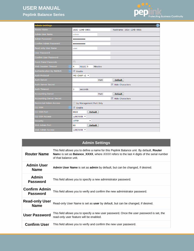
USER MANUAL Peplink Balance Series
http://www.peplink.com -206 / 261 - Copyright © 2015 Peplink
Admin Settings
Router Name This field allows you to define a name for this Peplink Balance unit. By default, Router Name is set as Balance_XXXX, where XXXX refers to the last 4 digits of the serial number of that balance unit.
Admin User Name Admin User Name is set as admin by default, but can be changed, if desired.
Admin Password This field allows you to specify a new administrator password.
Confirm Admin Password This field allows you to verify and confirm the new administrator password.
Read-only User Name Read-only User Name is set as user by default, but can be changed, if desired.
User Password This field allows you to specify a new user password. Once the user password is set, the read-only user feature will be enabled.
Confirm User This field allows you to verify and confirm the new user password.

USER MANUAL Peplink Balance Series
http://www.peplink.com -207 / 261 - Copyright © 2015 Peplink
Password
Front Panel Passcode
To require a 4-digit passcode to access front panel controls, check this box and then select the code from the drop-down menus.
Web Session Timeout
This field specifies the number of hours and minutes that a web session can remain idle before the Balance terminates its access to the web admin interface. By default, it is set to 4 hours.
Authentication by RADIUS
With this box is checked, the web admin will authenticate using an external RADIUS server. Authenticated users are treated as either "admin" with full read-write permission or “user” with read-only access. Local admin and user accounts will be disabled. When the device is not able to communicate with the external RADIUS server, local accounts will be enabled again for emergency access. Additional authentication options will be available once this box is checked.
Auth Protocol This specifies the authentication protocol used. Available options are MS-CHAP v2 and PAP.
Auth Server This specifies the access address and port of the external RADIUS server.
Auth Server Secret This field is for entering the secret key for accessing the RADIUS server.
Auth Timeout This option specifies the time value for authentication timeout.
Accounting Server This specifies the access address and port of the external accounting server.
Accounting Server Secret This field is for entering the secret key for accessing the accounting server.
Network Connection
This option is for specifying the network connection to be used for authentication. Users can choose from LAN, WAN, and VPN connections.
Restricted Admin Access
Check this box to restrict management to administrators connected to the management port.
CLI SSH & Console
The CLI (command line interface) can be accessed via SSH. It can also be accessed from the serial console port on some Peplink Balance models. This field enables CLI support. For additional information regarding CLI, please refer to Section 22.5.
CLI SSH Port This field determines the port on which clients can access CLI SSH.
CLI SSH Access
This menu allows you to choose between granting access to LAN and WAN clients, or to LAN clients only.
Security
This option is for specifying the protocol(s) through which the web admin interface can be accessed:
• HTTP • HTTPS

USER MANUAL Peplink Balance Series
http://www.peplink.com -208 / 261 - Copyright © 2015 Peplink
• HTTP/HTTPS
Web Admin Port
This field is for specifying the port number on which the web admin interface can be accessed.
Web Admin Access
This option is for specifying the network interfaces through which the web admin interface can be accessed:
• LAN only • LAN/WAN
If LAN/WAN is chosen, the WAN Connection Access Settings form will be displayed.
WAN Connection Access Settings
Allowed Source IP Subnets
This field allows you to restrict access to the web admin to only defined IP subnets. • Any - Allow web admin accesses from anywhere, without IP address restrictions. • Allow access from the following IP subnets only – Restricts the ability to access
web admin to only defined IP subnets. When this option is chosen, a text input area will appear:
Enter your allowed IP subnet addresses into this text area. Each IP subnet must be in the form of w.x.y.z/m. w.x.y.z represents an IP address (e.g., 192.168.0.0), and m represents the subnet mask in CIDR format, which is between 0 and 32 inclusively. For example: 192.168.0.0/24.
To define multiple subnets, separate each IP subnet, one per line. For example: 192.168.0.0/24 10.8.0.0/16
Allowed WAN IP Address(es) This is to choose which WAN IP address(es) the web server should listen on.

USER MANUAL Peplink Balance Series
http://www.peplink.com -209 / 261 - Copyright © 2015 Peplink
24.2 Firmware The firmware of Peplink Balance is upgradeable through the web admin interface. Firmware upgrade functionality is located at System>Firmware.
There are two ways to upgrade the unit. The first method is through an online download. The second method is to upload a firmware file manually. To perform an online download, click on the Check for Firmware button. The Peplink Balance will check online for new firmware. If new firmware is available, the Peplink Balance will automatically download the firmware. The rest of the upgrade process will be automatically initiated. You may also download a firmware image from the Peplink website and update the unit manually. To update using a firmware image, click Choose File to select the firmware file from the local computer, and then click Manual Upgrade to send the firmware to the Peplink Balance. It will then automatically initiate the firmware upgrade process. Please note that all Peplink devices can store two different firmware versions in two different partitions. A firmware upgrade will always replace the inactive partition. If you want to keep the inactive firmware, you can simply reboot your device with the inactive firmware and then perform the firmware upgrade.
Firmware Upgrade Status
Status LED Information during firmware upgrade: • OFF – Firmware upgrade in progress (DO NOT disconnect power.) • Red – Unit is rebooting • Green – Firmware upgrade successfully completed
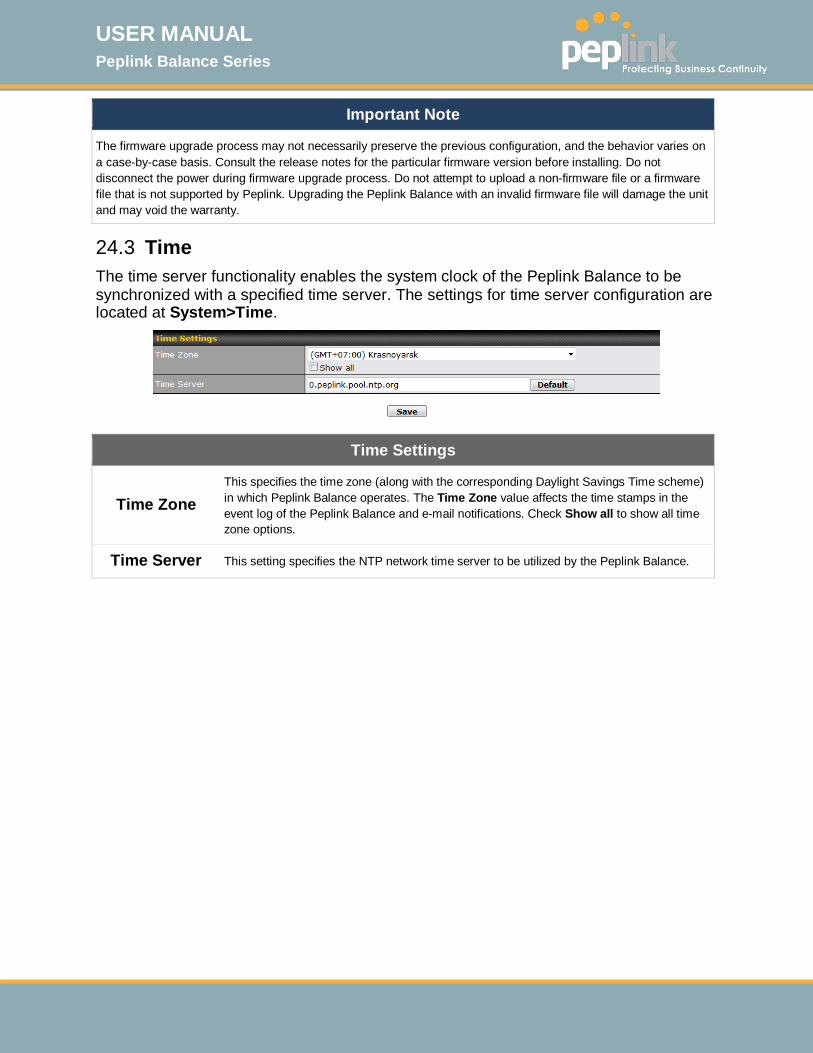
USER MANUAL Peplink Balance Series
http://www.peplink.com -210 / 261 - Copyright © 2015 Peplink
Important Note
The firmware upgrade process may not necessarily preserve the previous configuration, and the behavior varies on a case-by-case basis. Consult the release notes for the particular firmware version before installing. Do not disconnect the power during firmware upgrade process. Do not attempt to upload a non-firmware file or a firmware file that is not supported by Peplink. Upgrading the Peplink Balance with an invalid firmware file will damage the unit and may void the warranty.
24.3 Time The time server functionality enables the system clock of the Peplink Balance to be synchronized with a specified time server. The settings for time server configuration are located at System>Time.
Time Settings
Time Zone This specifies the time zone (along with the corresponding Daylight Savings Time scheme) in which Peplink Balance operates. The Time Zone value affects the time stamps in the event log of the Peplink Balance and e-mail notifications. Check Show all to show all time zone options.
Time Server This setting specifies the NTP network time server to be utilized by the Peplink Balance.

USER MANUAL Peplink Balance Series
http://www.peplink.com -211 / 261 - Copyright © 2015 Peplink
24.4 Email Notification The email notification functionality of the Peplink Balance provides a system administrator with up-to-date information on network status. The settings for configuring email notification are found at System>Email Notification.
Email Notification Settings
Email Notification
This setting specifies whether or not to enable email notification. If Enable is checked, the Peplink Balance will send email messages to system administrators when the WAN status changes or when new firmware is available. If Enable is not checked, email notification is disabled and the Peplink Balance will not send email messages.
SMTP Server This setting specifies the SMTP server to be used for sending email. If the server requires authentication, check Require authentication.
SSL Encryption Check the box to enable SMTPS. When the box is checked, SMTP Port will be changed to 465 automatically.
SMTP Port This field is for specifying the SMTP port number. By default, this is set to 25; when SSL Encryption is checked, the default port number will be set to 465. You may customize the port number by editing this field. Click Default to restore the number to its default setting.
SMTP User Name /
Password This setting specifies the SMTP username and password while sending email. These options are shown only if Require authentication is checked in the SMTP Server setting.
Confirm SMTP Password This field allows you to verify and confirm the new administrator password.
Sender’s Email Address
This setting specifies the email address which the Peplink Balance will use to send its reports.
Recipient’s This setting specifies the email address(es) to which the Peplink Balance will send email

USER MANUAL Peplink Balance Series
http://www.peplink.com -212 / 261 - Copyright © 2015 Peplink
Email Address notifications. For multiple recipients, separate each email using the enter key.
After you have finsihed setting up email notifications, you can click the Test Email Notification button to test the settings before saving. After Test Email Notification is clicked, you will see this screen to confirm the settings:
Click Send Test Notification to confirm. In a few seconds, you will see a message with detailed test results.

USER MANUAL Peplink Balance Series
http://www.peplink.com -213 / 261 - Copyright © 2015 Peplink
24.5 Event Log Event log functionality enables event logging at a specified remote syslog server. The settings for configuring the remote system log can be found at System>Event Log.
Remote Syslog Settings
Remote Syslog This setting specifies whether or not to log events at the specified remote syslog server.
Remote Syslog Host This setting specifies the IP address or hostname of the remote syslog server.
Push Events
The Peplink Balance can also send push notifications to mobile devices that have our Mobile Router Utility installed. Check the box to activate this feature.
For more information on the Router Utility, go to: www.peplink.com/products/router-utility
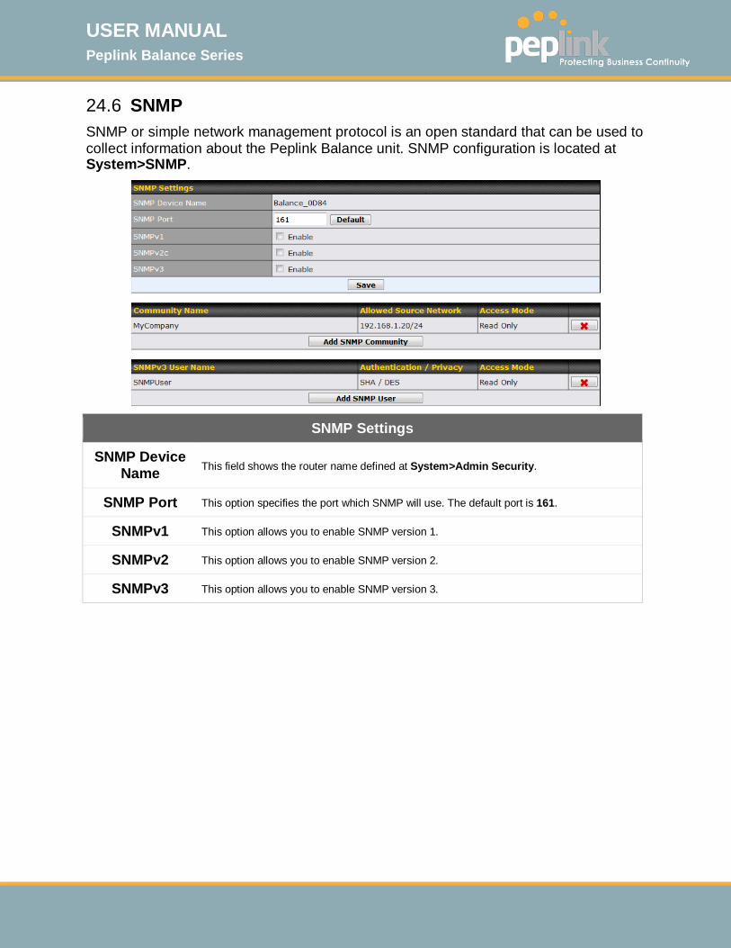
USER MANUAL Peplink Balance Series
http://www.peplink.com -214 / 261 - Copyright © 2015 Peplink
24.6 SNMP SNMP or simple network management protocol is an open standard that can be used to collect information about the Peplink Balance unit. SNMP configuration is located at System>SNMP.
SNMP Settings
SNMP Device Name This field shows the router name defined at System>Admin Security.
SNMP Port This option specifies the port which SNMP will use. The default port is 161.
SNMPv1 This option allows you to enable SNMP version 1.
SNMPv2 This option allows you to enable SNMP version 2.
SNMPv3 This option allows you to enable SNMP version 3.
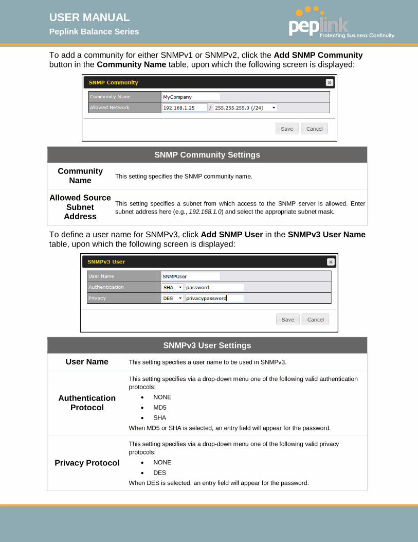
USER MANUAL Peplink Balance Series
http://www.peplink.com -215 / 261 - Copyright © 2015 Peplink
To add a community for either SNMPv1 or SNMPv2, click the Add SNMP Community button in the Community Name table, upon which the following screen is displayed:
SNMP Community Settings
Community Name This setting specifies the SNMP community name.
Allowed Source Subnet
Address This setting specifies a subnet from which access to the SNMP server is allowed. Enter subnet address here (e.g., 192.168.1.0) and select the appropriate subnet mask.
To define a user name for SNMPv3, click Add SNMP User in the SNMPv3 User Name table, upon which the following screen is displayed:
SNMPv3 User Settings
User Name This setting specifies a user name to be used in SNMPv3.
Authentication Protocol
This setting specifies via a drop-down menu one of the following valid authentication protocols:
• NONE • MD5 • SHA
When MD5 or SHA is selected, an entry field will appear for the password.
Privacy Protocol
This setting specifies via a drop-down menu one of the following valid privacy protocols:
• NONE • DES
When DES is selected, an entry field will appear for the password.

USER MANUAL Peplink Balance Series
http://www.peplink.com -216 / 261 - Copyright © 2015 Peplink
24.7 InControl
InControl is a cloud-based service which allows you to manage all of your Peplink and Pepwave devices with one unified system. With it, you can generate reports, gather statistics, and configure your devices automatically. All of this is now possible with InControl. When this check box is checked, the device's status information will be sent to the Peplink InControl system. This device's usage data and configuration will be sent to the system if you enable the features in the system. Alternately, you could also privately host InControl. Simply check the box beside the “Privately Host InControl” open, and enter the IP Address of your InControl Host. You can sign up for an InControl account at https://incontrol2.peplink.com. You can register your devices under the account, monitor their status, see their usage reports, and receive offline notifications.
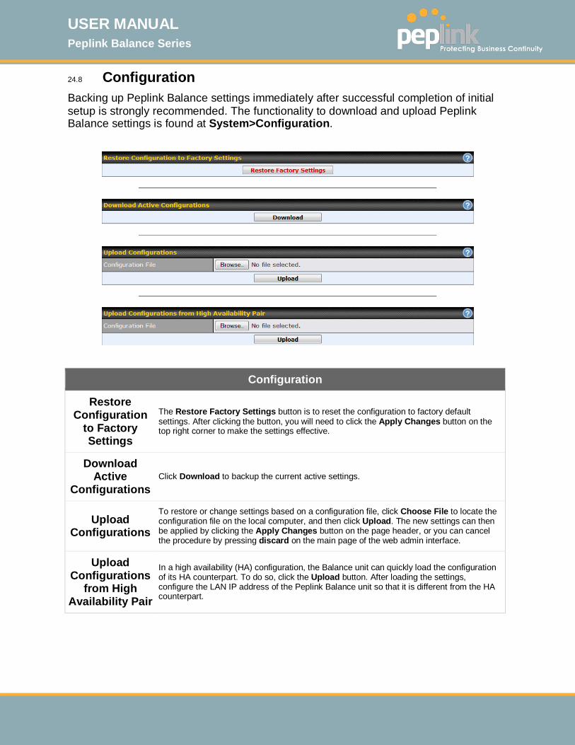
USER MANUAL Peplink Balance Series
http://www.peplink.com -217 / 261 - Copyright © 2015 Peplink
24.8 Configuration
Backing up Peplink Balance settings immediately after successful completion of initial setup is strongly recommended. The functionality to download and upload Peplink Balance settings is found at System>Configuration.
Configuration
Restore Configuration
to Factory Settings
The Restore Factory Settings button is to reset the configuration to factory default settings. After clicking the button, you will need to click the Apply Changes button on the top right corner to make the settings effective.
Download Active
Configurations Click Download to backup the current active settings.
Upload Configurations
To restore or change settings based on a configuration file, click Choose File to locate the configuration file on the local computer, and then click Upload. The new settings can then be applied by clicking the Apply Changes button on the page header, or you can cancel the procedure by pressing discard on the main page of the web admin interface.
Upload Configurations
from High Availability Pair
In a high availability (HA) configuration, the Balance unit can quickly load the configuration of its HA counterpart. To do so, click the Upload button. After loading the settings, configure the LAN IP address of the Peplink Balance unit so that it is different from the HA counterpart.
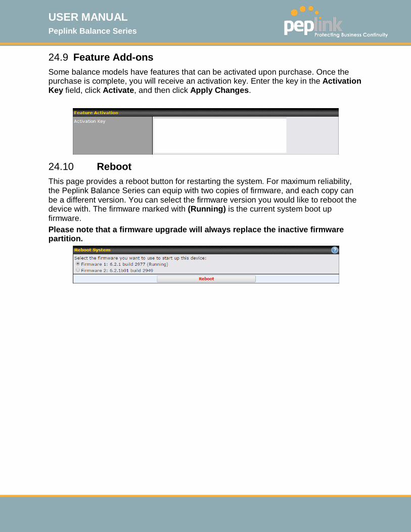
USER MANUAL Peplink Balance Series
http://www.peplink.com -218 / 261 - Copyright © 2015 Peplink
24.9 Feature Add-ons Some balance models have features that can be activated upon purchase. Once the purchase is complete, you will receive an activation key. Enter the key in the Activation Key field, click Activate, and then click Apply Changes.
24.10 Reboot This page provides a reboot button for restarting the system. For maximum reliability, the Peplink Balance Series can equip with two copies of firmware, and each copy can be a different version. You can select the firmware version you would like to reboot the device with. The firmware marked with (Running) is the current system boot up firmware. Please note that a firmware upgrade will always replace the inactive firmware partition.
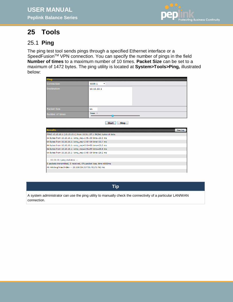
USER MANUAL Peplink Balance Series
http://www.peplink.com -219 / 261 - Copyright © 2015 Peplink
25 Tools 25.1 Ping The ping test tool sends pings through a specified Ethernet interface or a SpeedFusionTM VPN connection. You can specify the number of pings in the field Number of times to a maximum number of 10 times. Packet Size can be set to a maximum of 1472 bytes. The ping utility is located at System>Tools>Ping, illustrated below:
Tip
A system administrator can use the ping utility to manually check the connectivity of a particular LAN/WAN connection.
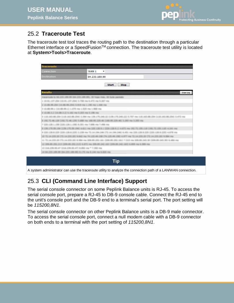
USER MANUAL Peplink Balance Series
http://www.peplink.com -220 / 261 - Copyright © 2015 Peplink
25.2 Traceroute Test The traceroute test tool traces the routing path to the destination through a particular Ethernet interface or a SpeedFusionTM connection. The traceroute test utility is located at System>Tools>Traceroute.
Tip
A system administrator can use the traceroute utility to analyze the connection path of a LAN/WAN connection.
25.3 CLI (Command Line Interface) Support The serial console connector on some Peplink Balance units is RJ-45. To access the serial console port, prepare a RJ-45 to DB-9 console cable. Connect the RJ-45 end to the unit's console port and the DB-9 end to a terminal's serial port. The port setting will be 115200,8N1. The serial console connector on other Peplink Balance units is a DB-9 male connector. To access the serial console port, connect a null modem cable with a DB-9 connector on both ends to a terminal with the port setting of 115200,8N1.

USER MANUAL Peplink Balance Series
http://www.peplink.com -221 / 261 - Copyright © 2015 Peplink

USER MANUAL Peplink Balance Series
http://www.peplink.com -222 / 261 - Copyright © 2015 Peplink
26 Status
26.1 Device System information is located at Status>Device.

USER MANUAL Peplink Balance Series
http://www.peplink.com -223 / 261 - Copyright © 2015 Peplink
System Information
Router Name This is the name specified in the Router Name field located at System>Admin Security.
Model This shows the model name and number of this device.
Hardware Revision This shows the hardware version of this device.
Serial Number This shows the serial number of this device.
Firmware This shows the firmware version this device is currently running.
Uptime This shows the length of time since the device has been rebooted.
System Time This shows the current system time.
Diagnostic Report The Download link is for exporting a diagnostic report file required for system investigation.
Remote Assistance Click Turn on to enable remote assistance.
The second table shows the MAC address of each LAN/WAN interface connected.
Important Note
If you encounter issues and would like to contact the Peplink Support Team (http://www.peplink.com/contact/), please download the diagnostic report file and attach it along with a description of your issue. In Firmware 5.1 or before, the diagnostic report file can be obtained at System>Reboot.
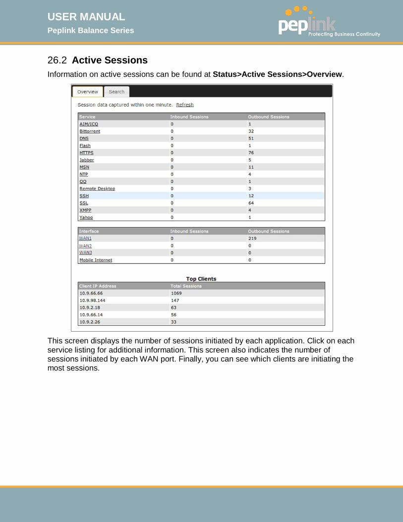
USER MANUAL Peplink Balance Series
http://www.peplink.com -224 / 261 - Copyright © 2015 Peplink
26.2 Active Sessions Information on active sessions can be found at Status>Active Sessions>Overview.
This screen displays the number of sessions initiated by each application. Click on each service listing for additional information. This screen also indicates the number of sessions initiated by each WAN port. Finally, you can see which clients are initiating the most sessions.
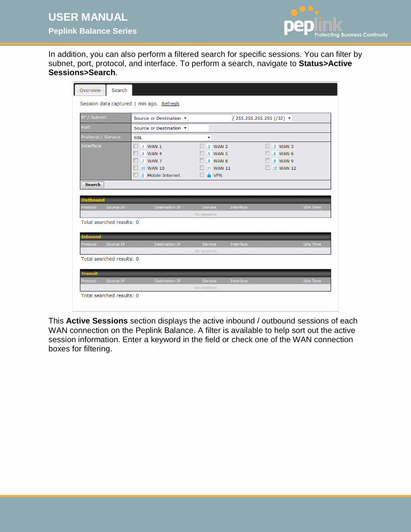
USER MANUAL Peplink Balance Series
http://www.peplink.com -225 / 261 - Copyright © 2015 Peplink
In addition, you can also perform a filtered search for specific sessions. You can filter by subnet, port, protocol, and interface. To perform a search, navigate to Status>Active Sessions>Search.
This Active Sessions section displays the active inbound / outbound sessions of each WAN connection on the Peplink Balance. A filter is available to help sort out the active session information. Enter a keyword in the field or check one of the WAN connection boxes for filtering.
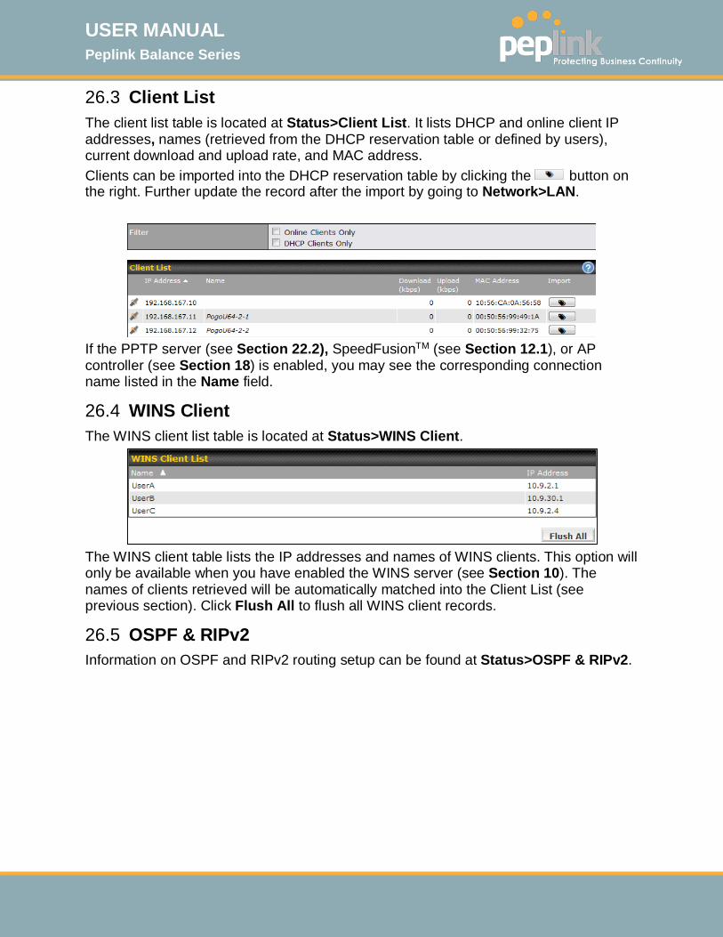
USER MANUAL Peplink Balance Series
http://www.peplink.com -226 / 261 - Copyright © 2015 Peplink
26.3 Client List The client list table is located at Status>Client List. It lists DHCP and online client IP addresses, names (retrieved from the DHCP reservation table or defined by users), current download and upload rate, and MAC address. Clients can be imported into the DHCP reservation table by clicking the button on the right. Further update the record after the import by going to Network>LAN.
If the PPTP server (see Section 22.2), SpeedFusionTM (see Section 12.1), or AP controller (see Section 18) is enabled, you may see the corresponding connection name listed in the Name field.
26.4 WINS Client The WINS client list table is located at Status>WINS Client.
The WINS client table lists the IP addresses and names of WINS clients. This option will only be available when you have enabled the WINS server (see Section 10). The names of clients retrieved will be automatically matched into the Client List (see previous section). Click Flush All to flush all WINS client records.
26.5 OSPF & RIPv2 Information on OSPF and RIPv2 routing setup can be found at Status>OSPF & RIPv2.
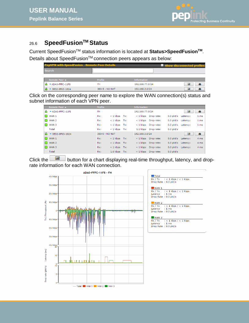
USER MANUAL Peplink Balance Series
http://www.peplink.com -227 / 261 - Copyright © 2015 Peplink
26.6 SpeedFusionTM Status
Current SpeedFusionTM status information is located at Status>SpeedFusionTM. Details about SpeedFusionTM connection peers appears as below:
Click on the corresponding peer name to explore the WAN connection(s) status and subnet information of each VPN peer.
Click the button for a chart displaying real-time throughput, latency, and drop-rate information for each WAN connection.

USER MANUAL Peplink Balance Series
http://www.peplink.com -228 / 261 - Copyright © 2015 Peplink
When pressing the button, the following menu will appear:
After clicking the icon, the following menu appears:
Select the L2 protocol (TCP/UDP), direction, and duration and click the Start button to begin the general throughput test.
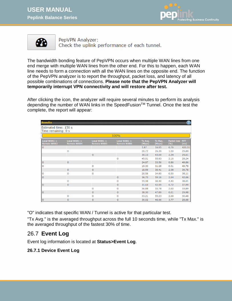
USER MANUAL Peplink Balance Series
http://www.peplink.com -229 / 261 - Copyright © 2015 Peplink
The bandwidth bonding feature of PepVPN occurs when multiple WAN lines from one end merge with multiple WAN lines from the other end. For this to happen, each WAN line needs to form a connection with all the WAN lines on the opposite end. The function of the PepVPN analyzer is to report the throughput, packet loss, and latency of all possible combinations of connections. Please note that the PepVPN Analyzer will temporarily interrupt VPN connectivity and will restore after test. After clicking the icon, the analyzer will require several minutes to perform its analysis depending the number of WAN links in the SpeedFusionTM Tunnel. Once the test the complete, the report will appear:
"O" indicates that specific WAN / Tunnel is active for that particular test. "Tx Avg." is the averaged throughput across the full 10 seconds time, while "Tx Max." is the averaged throughput of the fastest 30% of time.
26.7 Event Log Event log information is located at Status>Event Log.
26.7.1 Device Event Log

USER MANUAL Peplink Balance Series
http://www.peplink.com -230 / 261 - Copyright © 2015 Peplink
The log section displays a list of events that has taken place on the Peplink Balance unit. Check Auto Refresh to refresh log entries automatically. Click the Clear Log button to clear the log.
26.7.2 IPsec Event Log
This section displays a list of events that has taken place within an IPsec VPN connection. Check the box next to Auto Refresh and the log will be refreshed automatically. For an AP event log, navigate to AP>Info.
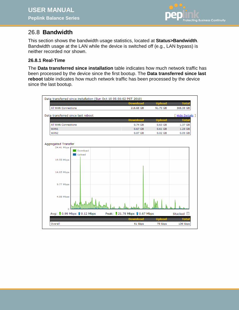
USER MANUAL Peplink Balance Series
http://www.peplink.com -231 / 261 - Copyright © 2015 Peplink
26.8 Bandwidth This section shows the bandwidth usage statistics, located at Status>Bandwidth. Bandwidth usage at the LAN while the device is switched off (e.g., LAN bypass) is neither recorded nor shown.
26.8.1 Real-Time The Data transferred since installation table indicates how much network traffic has been processed by the device since the first bootup. The Data transferred since last reboot table indicates how much network traffic has been processed by the device since the last bootup.
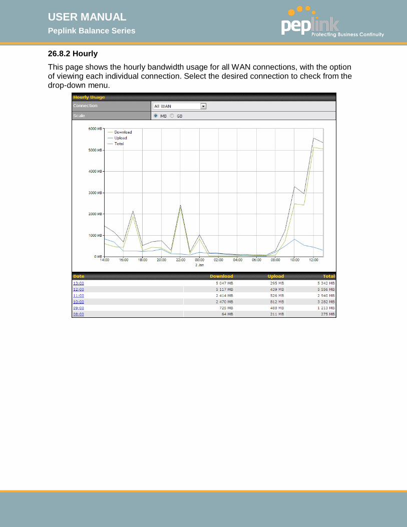
USER MANUAL Peplink Balance Series
http://www.peplink.com -232 / 261 - Copyright © 2015 Peplink
26.8.2 Hourly This page shows the hourly bandwidth usage for all WAN connections, with the option of viewing each individual connection. Select the desired connection to check from the drop-down menu.
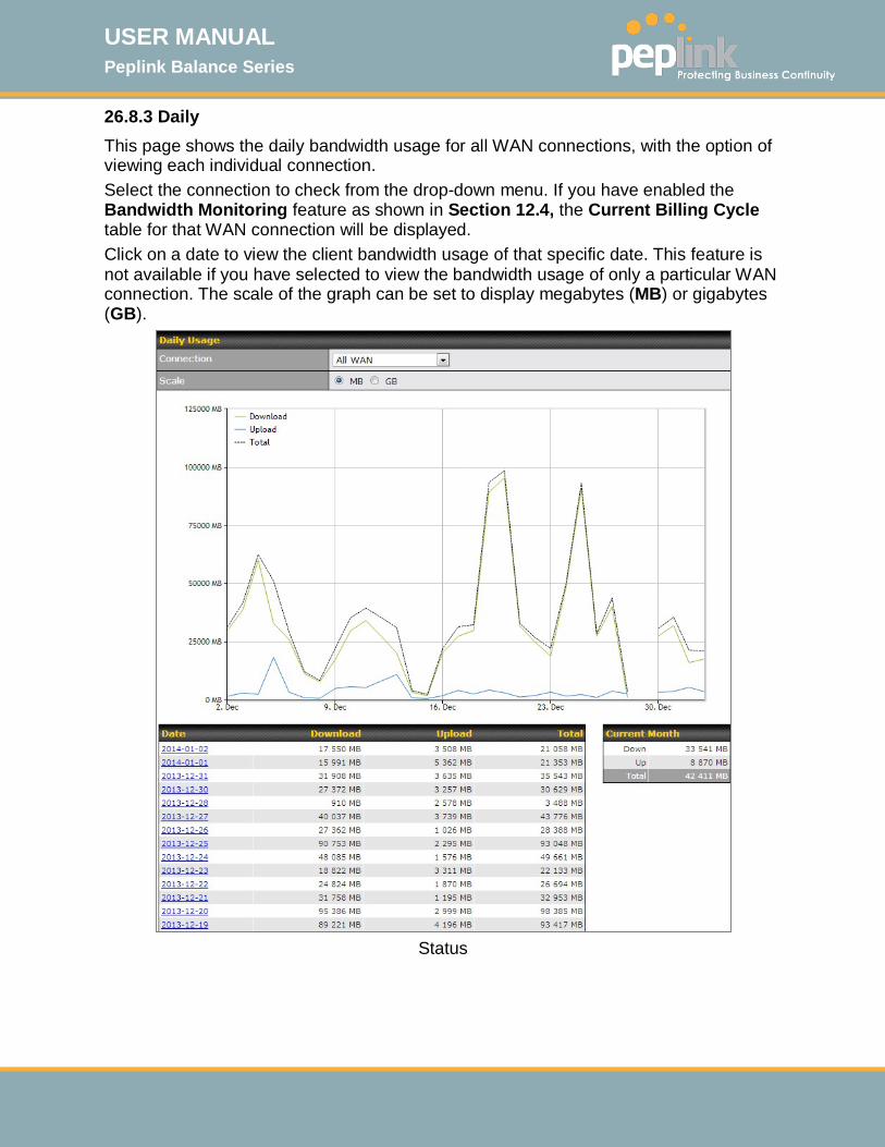
USER MANUAL Peplink Balance Series
http://www.peplink.com -233 / 261 - Copyright © 2015 Peplink
26.8.3 Daily This page shows the daily bandwidth usage for all WAN connections, with the option of viewing each individual connection. Select the connection to check from the drop-down menu. If you have enabled the Bandwidth Monitoring feature as shown in Section 12.4, the Current Billing Cycle table for that WAN connection will be displayed. Click on a date to view the client bandwidth usage of that specific date. This feature is not available if you have selected to view the bandwidth usage of only a particular WAN connection. The scale of the graph can be set to display megabytes (MB) or gigabytes (GB).
Status
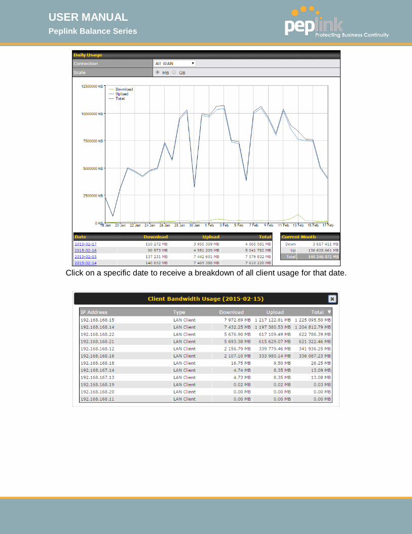
USER MANUAL Peplink Balance Series
http://www.peplink.com -234 / 261 - Copyright © 2015 Peplink
Click on a specific date to receive a breakdown of all client usage for that date.

USER MANUAL Peplink Balance Series
http://www.peplink.com -235 / 261 - Copyright © 2015 Peplink
26.8.4 Monthly This page shows the monthly bandwidth usage for each WAN connection. If you have enabled Bandwidth Monitoring feature as shown in Section 12.4, you can check the usage of each particular connection and view the information by Billing Cycle or by Calendar Month. Click the first two rows to view the client bandwidth usage in the last two months. This feature is not available if you have chosen to view the bandwidth of an individual WAN connection. The scale of the graph can be set to display megabytes (MB) or gigabytes (GB).
Click on a specific month to receive a breakdown of all client usage for that month.

USER MANUAL Peplink Balance Series
http://www.peplink.com -236 / 261 - Copyright © 2015 Peplink
Appendix A. Restoration of Factory Defaults To restore the factory default settings on a Peplink Balance unit, perform the following: For Balance models with a reset button:
1. Locate the reset button on the Peplink Balance unit. 2. With a paper clip, press and keep the reset button pressed for at least 10
seconds, until the unit reboots itself. For Balance/MediaFast models with an LCD menu: Use the buttons on front panel to control the LCD menu to go to
Maintenance>Factory Defaults, and then choose Yes to confirm. Afterwards, the factory default settings will be restored.
Important Note
All user settings will be lost after restoring the factory default settings. Regular backup of configuration parameters is strongly recommended.
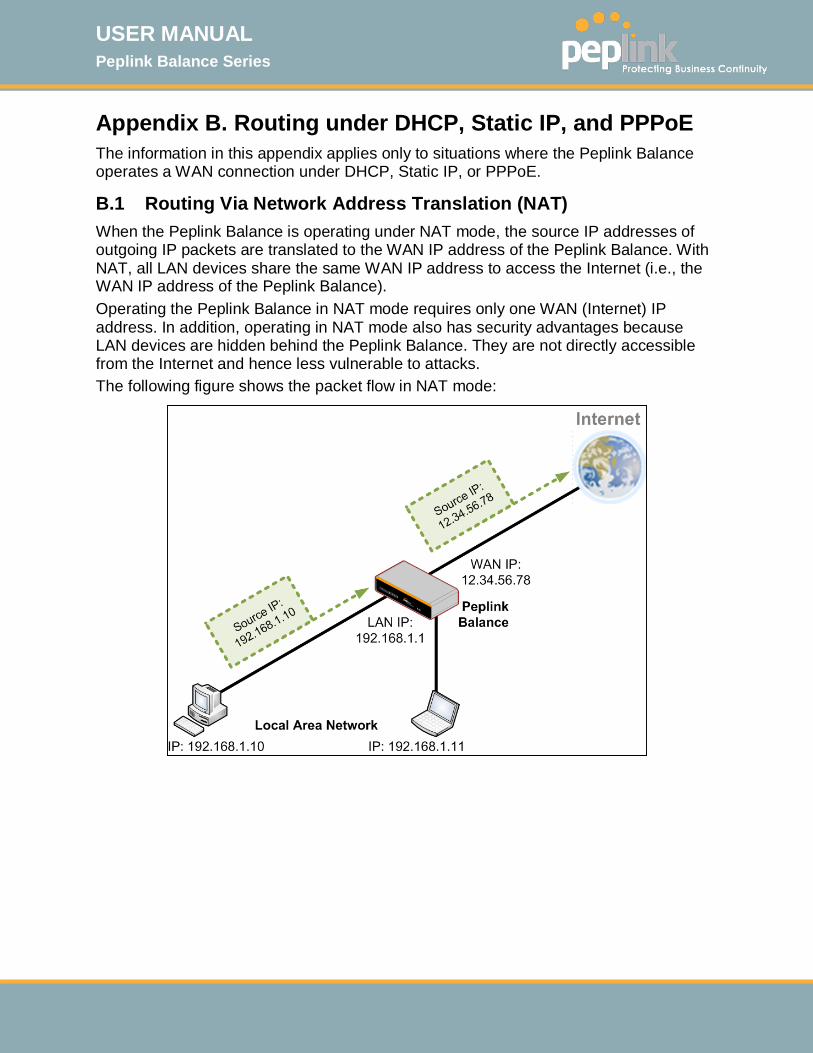
USER MANUAL Peplink Balance Series
http://www.peplink.com -237 / 261 - Copyright © 2015 Peplink
Appendix B. Routing under DHCP, Static IP, and PPPoE The information in this appendix applies only to situations where the Peplink Balance operates a WAN connection under DHCP, Static IP, or PPPoE.
B.1 Routing Via Network Address Translation (NAT) When the Peplink Balance is operating under NAT mode, the source IP addresses of outgoing IP packets are translated to the WAN IP address of the Peplink Balance. With NAT, all LAN devices share the same WAN IP address to access the Internet (i.e., the WAN IP address of the Peplink Balance). Operating the Peplink Balance in NAT mode requires only one WAN (Internet) IP address. In addition, operating in NAT mode also has security advantages because LAN devices are hidden behind the Peplink Balance. They are not directly accessible from the Internet and hence less vulnerable to attacks. The following figure shows the packet flow in NAT mode:
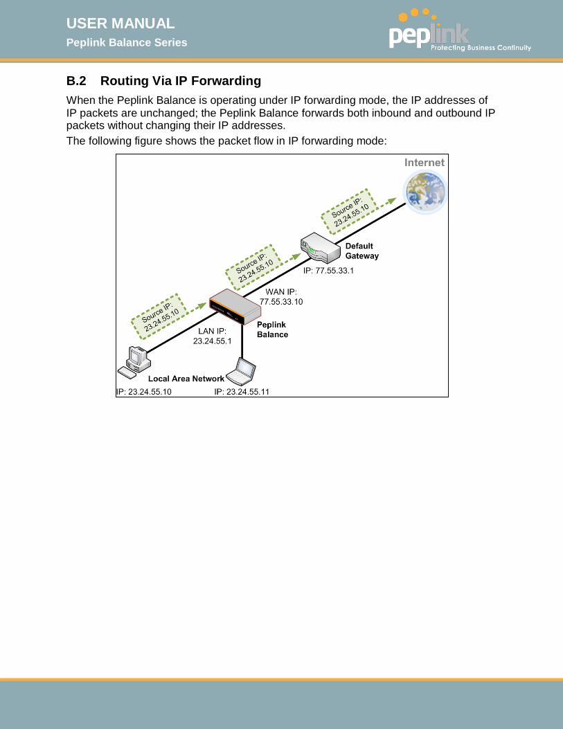
USER MANUAL Peplink Balance Series
http://www.peplink.com -238 / 261 - Copyright © 2015 Peplink
B.2 Routing Via IP Forwarding When the Peplink Balance is operating under IP forwarding mode, the IP addresses of IP packets are unchanged; the Peplink Balance forwards both inbound and outbound IP packets without changing their IP addresses. The following figure shows the packet flow in IP forwarding mode:
USER MANUAL Peplink Balance Series
http://www.peplink.com -239 / 261 - Copyright © 2015 Peplink
Appendix C. Case Studies C.1 Performance Optimization C.1.1 Scenario In this scenario, email and web browsing are the two main Internet services used by LAN users. The mail server is external to the network. The connections are ADSL (WAN1, with slow uplink and fast downlink) and Metro Ethernet (WAN2, symmetric).
C.1.2 Solution For optimal performance with this configuration, individually set the WAN load balance according to the characteristics of each service. Web browsing mainly downloads data; sending e-mails mainly consumes upload
bandwidth. Both connections offer good download speeds; WAN2 offers good upload
speeds. Define WAN1 and WAN2's inbound and outbound bandwidths to be 3M/512k
and 4M/4M, respectively. This will ensure that outbound traffic is more likely to be routed through WAN2.
For HTTP, set the weight to 3:4. For SMTP, set the weight to 1:8, such that users will have a greater chance to be
routed via WAN2 when sending e-mail.
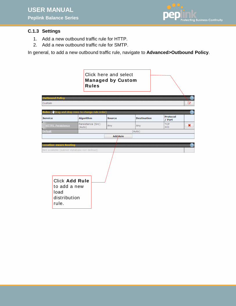
USER MANUAL Peplink Balance Series
http://www.peplink.com -240 / 261 - Copyright © 2015 Peplink
C.1.3 Settings 1. Add a new outbound traffic rule for HTTP. 2. Add a new outbound traffic rule for SMTP.
In general, to add a new outbound traffic rule, navigate to Advanced>Outbound Policy.
Click Add Rule to add a new load distribution rule.
Click here and select Managed by Custom Rules

USER MANUAL Peplink Balance Series
http://www.peplink.com -241 / 261 - Copyright © 2015 Peplink
Settings for HTTP:
Set the weight of WAN1 and WAN2 for HTTP to 3 and 4, respectively.

USER MANUAL Peplink Balance Series
http://www.peplink.com -242 / 261 - Copyright © 2015 Peplink
Settings for SMTP:
Set the weight of WAN1 and WAN2 for SMTP to 1 and 8, respectively.
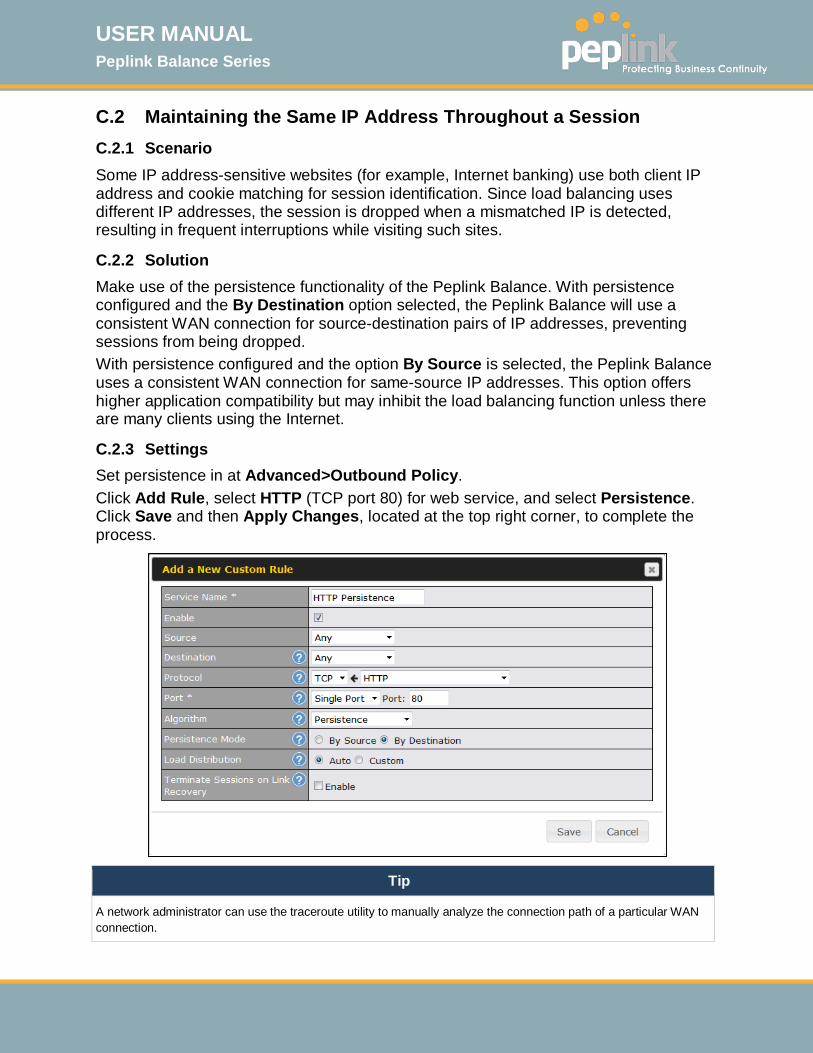
USER MANUAL Peplink Balance Series
http://www.peplink.com -243 / 261 - Copyright © 2015 Peplink
C.2 Maintaining the Same IP Address Throughout a Session C.2.1 Scenario Some IP address-sensitive websites (for example, Internet banking) use both client IP address and cookie matching for session identification. Since load balancing uses different IP addresses, the session is dropped when a mismatched IP is detected, resulting in frequent interruptions while visiting such sites.
C.2.2 Solution Make use of the persistence functionality of the Peplink Balance. With persistence configured and the By Destination option selected, the Peplink Balance will use a consistent WAN connection for source-destination pairs of IP addresses, preventing sessions from being dropped. With persistence configured and the option By Source is selected, the Peplink Balance uses a consistent WAN connection for same-source IP addresses. This option offers higher application compatibility but may inhibit the load balancing function unless there are many clients using the Internet.
C.2.3 Settings Set persistence in at Advanced>Outbound Policy. Click Add Rule, select HTTP (TCP port 80) for web service, and select Persistence. Click Save and then Apply Changes, located at the top right corner, to complete the process.
Tip
A network administrator can use the traceroute utility to manually analyze the connection path of a particular WAN connection.
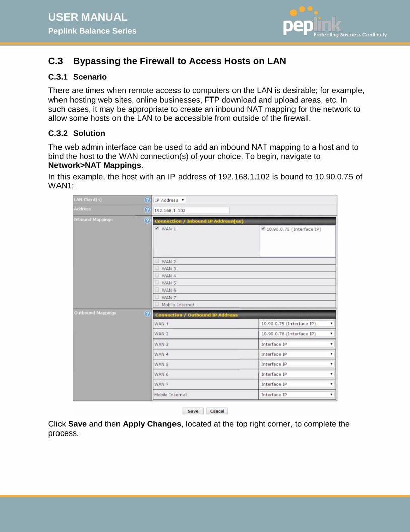
USER MANUAL Peplink Balance Series
http://www.peplink.com -244 / 261 - Copyright © 2015 Peplink
C.3 Bypassing the Firewall to Access Hosts on LAN C.3.1 Scenario There are times when remote access to computers on the LAN is desirable; for example, when hosting web sites, online businesses, FTP download and upload areas, etc. In such cases, it may be appropriate to create an inbound NAT mapping for the network to allow some hosts on the LAN to be accessible from outside of the firewall.
C.3.2 Solution The web admin interface can be used to add an inbound NAT mapping to a host and to bind the host to the WAN connection(s) of your choice. To begin, navigate to Network>NAT Mappings. In this example, the host with an IP address of 192.168.1.102 is bound to 10.90.0.75 of WAN1:
Click Save and then Apply Changes, located at the top right corner, to complete the process.

USER MANUAL Peplink Balance Series
http://www.peplink.com -245 / 261 - Copyright © 2015 Peplink
C.4 Inbound Access Restriction C.4.1 Scenario A firewall is required in order to protect the network from potential hacker attacks and other Internet security threats.
C.4.2 Solution Firewall functionality is built into the Peplink Balance. By default, inbound access is unrestricted. Enabling a basic level of protection involves setting up firewall rules. For example, in order to protect your private network from external access, you can set up a firewall rule between the Internet and your private network. To do so, navigate to Advanced>Firewall>Access Rules. Then click the Add Rule button in the Inbound Firewall Rules table and change the settings according to the following screenshot:
After the fields have been entered as in the screenshot, click Save to add the rule. Afterwards, change the default inbound rule to Deny by clicking the default rule in the Inbound Firewall Rules table. Click Apply Changes on the top right corner to complete the process.

USER MANUAL Peplink Balance Series
http://www.peplink.com -246 / 261 - Copyright © 2015 Peplink
C.5 Outbound Access Restriction C.5.1 Scenario For security reasons, it may be appropriate to restrict outbound access. For example, you may want to prevent LAN users from using ftp to transfer files to and from the Internet. This can easily be achieved by setting up an outbound firewall rule with the Peplink Balance.
C.5.2 Solution To setup a firewall between Internet and private network for outbound access, navigate to Advanced>Firewall>Access Rules. Click the Add Rule button in the Outbound Firewall Rules table, and then adjust settings according the screenshot:
After the fields have been entered as in the screenshot, click Save to add the rule. Click Apply Changes on the top right corner to complete the process.
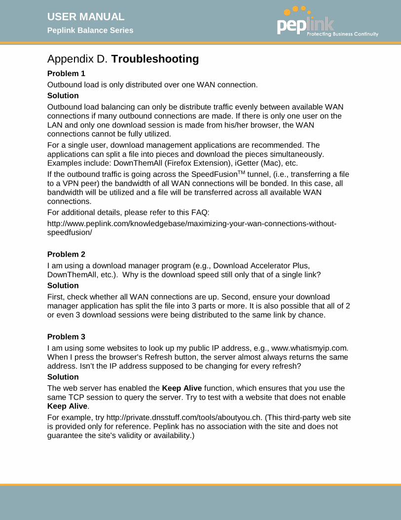
USER MANUAL Peplink Balance Series
http://www.peplink.com -247 / 261 - Copyright © 2015 Peplink
Appendix D. Troubleshooting Problem 1 Outbound load is only distributed over one WAN connection. Solution Outbound load balancing can only be distribute traffic evenly between available WAN connections if many outbound connections are made. If there is only one user on the LAN and only one download session is made from his/her browser, the WAN connections cannot be fully utilized. For a single user, download management applications are recommended. The applications can split a file into pieces and download the pieces simultaneously. Examples include: DownThemAll (Firefox Extension), iGetter (Mac), etc. If the outbound traffic is going across the SpeedFusionTM tunnel, (i.e., transferring a file to a VPN peer) the bandwidth of all WAN connections will be bonded. In this case, all bandwidth will be utilized and a file will be transferred across all available WAN connections. For additional details, please refer to this FAQ: http://www.peplink.com/knowledgebase/maximizing-your-wan-connections-without-speedfusion/ Problem 2 I am using a download manager program (e.g., Download Accelerator Plus, DownThemAll, etc.). Why is the download speed still only that of a single link? Solution First, check whether all WAN connections are up. Second, ensure your download manager application has split the file into 3 parts or more. It is also possible that all of 2 or even 3 download sessions were being distributed to the same link by chance. Problem 3 I am using some websites to look up my public IP address, e.g., www.whatismyip.com. When I press the browser's Refresh button, the server almost always returns the same address. Isn’t the IP address supposed to be changing for every refresh? Solution The web server has enabled the Keep Alive function, which ensures that you use the same TCP session to query the server. Try to test with a website that does not enable Keep Alive. For example, try http://private.dnsstuff.com/tools/aboutyou.ch. (This third-party web site is provided only for reference. Peplink has no association with the site and does not guarantee the site's validity or availability.)
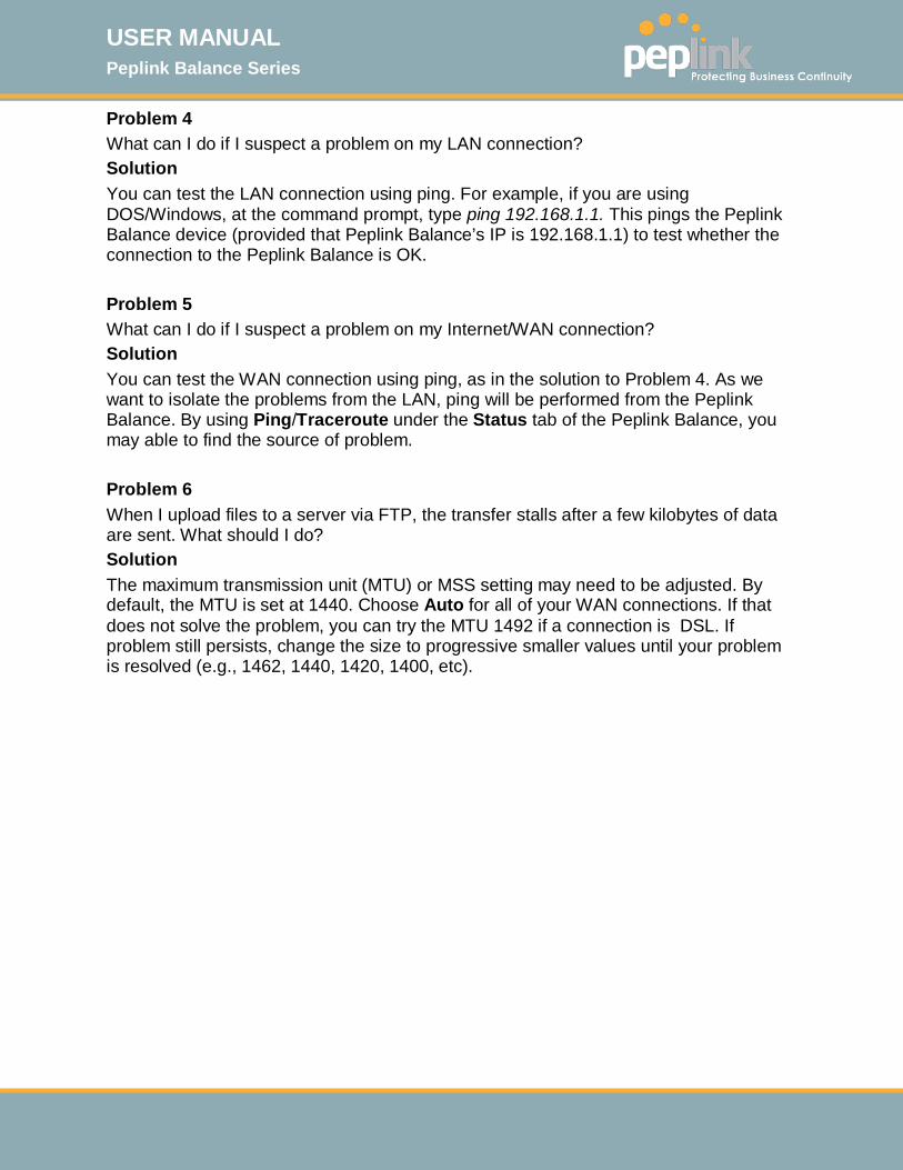
USER MANUAL Peplink Balance Series
http://www.peplink.com -248 / 261 - Copyright © 2015 Peplink
Problem 4 What can I do if I suspect a problem on my LAN connection? Solution You can test the LAN connection using ping. For example, if you are using DOS/Windows, at the command prompt, type ping 192.168.1.1. This pings the Peplink Balance device (provided that Peplink Balance’s IP is 192.168.1.1) to test whether the connection to the Peplink Balance is OK. Problem 5 What can I do if I suspect a problem on my Internet/WAN connection? Solution You can test the WAN connection using ping, as in the solution to Problem 4. As we want to isolate the problems from the LAN, ping will be performed from the Peplink Balance. By using Ping/Traceroute under the Status tab of the Peplink Balance, you may able to find the source of problem. Problem 6 When I upload files to a server via FTP, the transfer stalls after a few kilobytes of data are sent. What should I do? Solution The maximum transmission unit (MTU) or MSS setting may need to be adjusted. By default, the MTU is set at 1440. Choose Auto for all of your WAN connections. If that does not solve the problem, you can try the MTU 1492 if a connection is DSL. If problem still persists, change the size to progressive smaller values until your problem is resolved (e.g., 1462, 1440, 1420, 1400, etc).

USER MANUAL Peplink Balance Series
http://www.peplink.com -249 / 261 - Copyright © 2015 Peplink
Appendix E. Product Specifications E.1 Peplink Balance 20, 30, 30 LTE, and 50 Routing
• Flexible Custom Outbound Routing Policy WAN Support
• DHCP, PPPoE and Static IP • Outbound Link Load Balance
Device Management
• Wizard & Menu Driven Web Management Interface over HTTP / HTTPS • Remote Reporting and Management • Configurations Upload and Download
Internet Access Sharing
• SUA (Single User Account) / Multi-to-Multi NAT • NAT supports PAT (Port Address Translation)
Security
• IPsec (Network-to-Network) • Compatible with IPsec and PPTP VPN Passthrough • Rules-based Stateful Firewall, with IP, Protocol, and Port filtering • Intrusion Detection System
Physical Interface • Two (Balance 20) / Three (Balance 30, 30 LTE)/ Five (Balance 50) RJ-45 for an
IEEE 802.3u 10/100/1000M WAN • Four RJ-45 for an IEEE 802.3ab 10/100/1000M LAN
Power Specification DC Input 9-16V
Operating Environment
• Kensington Lock Interface • Temperature: 0°C - 55°C • Humidity: 10% - 90% (non-condensing)

USER MANUAL Peplink Balance Series
http://www.peplink.com -250 / 261 - Copyright © 2015 Peplink
E.2 Peplink Balance 210 and 310 Routing Drop-in Mode and NAT Flexible Custom Outbound Routing Policy
WAN Support DHCP, PPPoE and Static IP Inbound and Outbound Link Load Balance
Device Management Wizard & Menu Driven Web Management Interface over HTTP / HTTPS Remote Reporting and Management Bandwidth Usage Monitor Configurations Upload and Download
Internet Access Sharing SUA (Single User Account) / Multi-to-Multi NAT NAT supports PAT (Port Address Translation)
Security PPTP VPN Server IPsec (Network-to-Network) Rules-based Stateful Firewall, with IP, Protocol, and Port filtering Bandwidth Bonding SpeedFusionTM VPN Encryption: 256-bit AES Intrusion Detection System
Physical Interface (Balance 210 Hardware Revision 4) Two RJ-45 for an IEEE 802.3u 10/100/1000M WAN One feature activated RJ-45 for an IEEE 802.3u 10/100/1000M WAN Seven RJ-45 for an IEEE 802.3ab 10/100/1000M LAN
Physical Interface (Balance 310 Hardware Revision 4) Three RJ-45 for an IEEE 802.3u 10/100/1000M WAN Seven RJ-45 for an IEEE 802.3ab 10/100/1000M LAN
Power Specification DC Input 12-24V
Operating Environment Temperature: 0°C - 65°C Humidity: 10% - 90% (non-condensing)

USER MANUAL Peplink Balance Series
http://www.peplink.com -251 / 261 - Copyright © 2015 Peplink
E.3 Peplink Balance 380 Routing Drop-in Mode and NAT Flexible Custom Outbound Routing Policy
WAN Support DHCP, PPPoE and Static IP Inbound and Outbound Link Load Balance
Device Management Wizard & Menu Driven Web Management Interface over HTTP / HTTPS Remote Reporting and Management Bandwidth Usage Monitor Configurations Upload and Download
Internet Access Sharing SUA (Single User Account) / Multi-to-Multi NAT NAT supports PAT (Port Address Translation)
Security PPTP VPN Server IPsec (Network-to-Network) Rules-based Stateful Firewall, with IP, Protocol, and Port Filtering Bandwidth Bonding SpeedFusionTM VPN Encryption: 256-bit AES Intrusion Detection System
Physical Interface (Balance 380 Hardware Revision 5) Three RJ-45 for an IEEE 802.3ab 10/100M/1000M WAN One RJ-45 for an IEEE 802.3ab 10/100M/1000M LAN One RJ-45 Console / Serial Port
Power Specification AC input 100-240V
Operating Environment Temperature: 0°C - 40°C Humidity: 10% - 90% (non-condensing)

USER MANUAL Peplink Balance Series
http://www.peplink.com -252 / 261 - Copyright © 2015 Peplink
E.4 Peplink Balance 305 Routing Drop-in Mode and NAT Flexible Custom Outbound Routing Policy
WAN Support DHCP, PPPoE and Static IP Inbound and Outbound Link Load Balance
Device Management Wizard & Menu Driven Web Management Interface over HTTP / HTTPS Remote Reporting and Management Bandwidth Usage Monitor Configurations Upload and Download
Internet Access Sharing SUA (Single User Account) / Multi-to-Multi NAT NAT supports PAT (Port Address Translation)
Security PPTP VPN Server IPsec (Network-to-Network) Rules-based Stateful Firewall, with IP, Protocol, and Port filtering VPN Encryption: 256-bit AES Intrusion Detection System
Physical Interface • Three RJ-45 for an IEEE 802.3ab 10/100M/1000M WAN • One RJ-45 for an IEEE 802.3ab 10/100M/1000M LAN • One RJ-45 Console / Serial Port
Power Specification AC input 100-240V
Operating Environment Temperature: 0°C - 40°C Humidity: 10% - 90% (non-condensing)
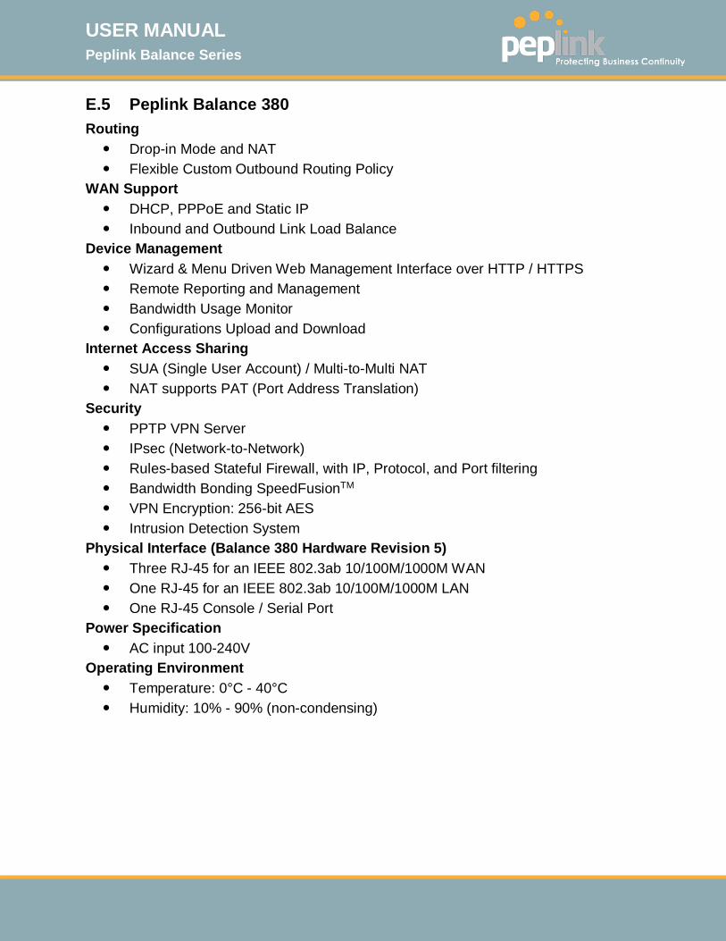
USER MANUAL Peplink Balance Series
http://www.peplink.com -253 / 261 - Copyright © 2015 Peplink
E.5 Peplink Balance 380 Routing Drop-in Mode and NAT Flexible Custom Outbound Routing Policy
WAN Support DHCP, PPPoE and Static IP Inbound and Outbound Link Load Balance
Device Management Wizard & Menu Driven Web Management Interface over HTTP / HTTPS Remote Reporting and Management Bandwidth Usage Monitor Configurations Upload and Download
Internet Access Sharing SUA (Single User Account) / Multi-to-Multi NAT NAT supports PAT (Port Address Translation)
Security PPTP VPN Server IPsec (Network-to-Network) Rules-based Stateful Firewall, with IP, Protocol, and Port filtering Bandwidth Bonding SpeedFusionTM VPN Encryption: 256-bit AES Intrusion Detection System
Physical Interface (Balance 380 Hardware Revision 5) Three RJ-45 for an IEEE 802.3ab 10/100M/1000M WAN One RJ-45 for an IEEE 802.3ab 10/100M/1000M LAN One RJ-45 Console / Serial Port
Power Specification AC input 100-240V
Operating Environment Temperature: 0°C - 40°C Humidity: 10% - 90% (non-condensing)
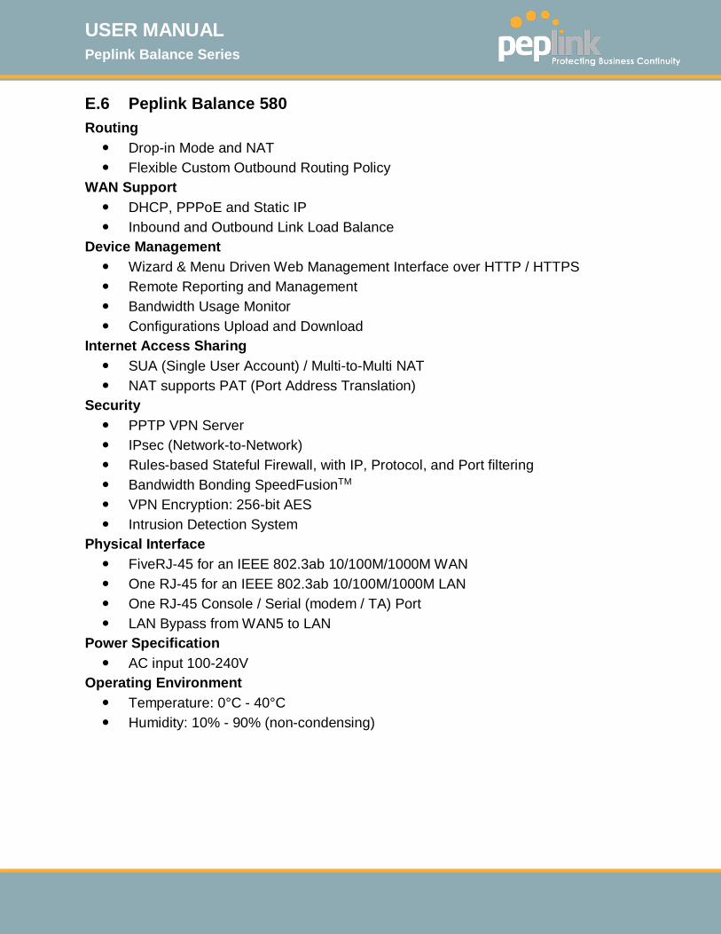
USER MANUAL Peplink Balance Series
http://www.peplink.com -254 / 261 - Copyright © 2015 Peplink
E.6 Peplink Balance 580 Routing Drop-in Mode and NAT Flexible Custom Outbound Routing Policy
WAN Support DHCP, PPPoE and Static IP Inbound and Outbound Link Load Balance
Device Management Wizard & Menu Driven Web Management Interface over HTTP / HTTPS Remote Reporting and Management Bandwidth Usage Monitor Configurations Upload and Download
Internet Access Sharing SUA (Single User Account) / Multi-to-Multi NAT NAT supports PAT (Port Address Translation)
Security PPTP VPN Server IPsec (Network-to-Network) Rules-based Stateful Firewall, with IP, Protocol, and Port filtering Bandwidth Bonding SpeedFusionTM VPN Encryption: 256-bit AES Intrusion Detection System
Physical Interface FiveRJ-45 for an IEEE 802.3ab 10/100M/1000M WAN One RJ-45 for an IEEE 802.3ab 10/100M/1000M LAN One RJ-45 Console / Serial (modem / TA) Port LAN Bypass from WAN5 to LAN
Power Specification AC input 100-240V
Operating Environment Temperature: 0°C - 40°C Humidity: 10% - 90% (non-condensing)
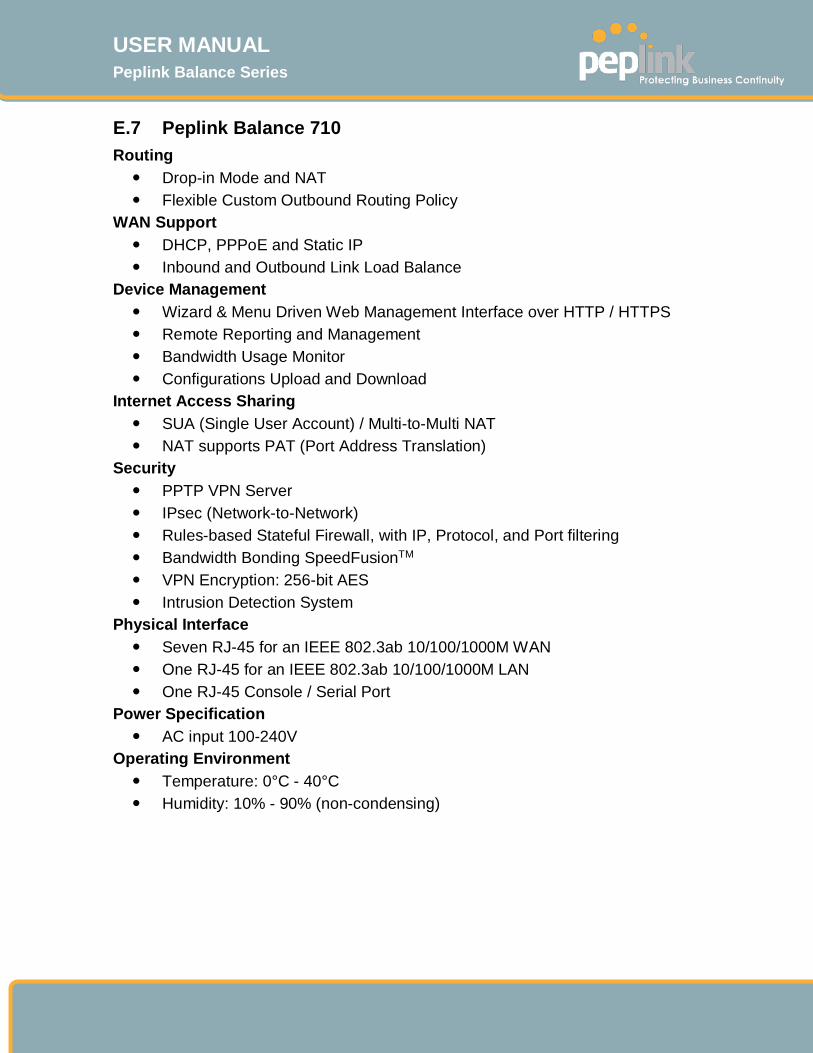
USER MANUAL Peplink Balance Series
http://www.peplink.com -255 / 261 - Copyright © 2015 Peplink
E.7 Peplink Balance 710 Routing Drop-in Mode and NAT Flexible Custom Outbound Routing Policy
WAN Support DHCP, PPPoE and Static IP Inbound and Outbound Link Load Balance
Device Management Wizard & Menu Driven Web Management Interface over HTTP / HTTPS Remote Reporting and Management Bandwidth Usage Monitor Configurations Upload and Download
Internet Access Sharing SUA (Single User Account) / Multi-to-Multi NAT NAT supports PAT (Port Address Translation)
Security PPTP VPN Server IPsec (Network-to-Network) Rules-based Stateful Firewall, with IP, Protocol, and Port filtering Bandwidth Bonding SpeedFusionTM VPN Encryption: 256-bit AES Intrusion Detection System
Physical Interface Seven RJ-45 for an IEEE 802.3ab 10/100/1000M WAN One RJ-45 for an IEEE 802.3ab 10/100/1000M LAN One RJ-45 Console / Serial Port
Power Specification AC input 100-240V
Operating Environment Temperature: 0°C - 40°C Humidity: 10% - 90% (non-condensing)
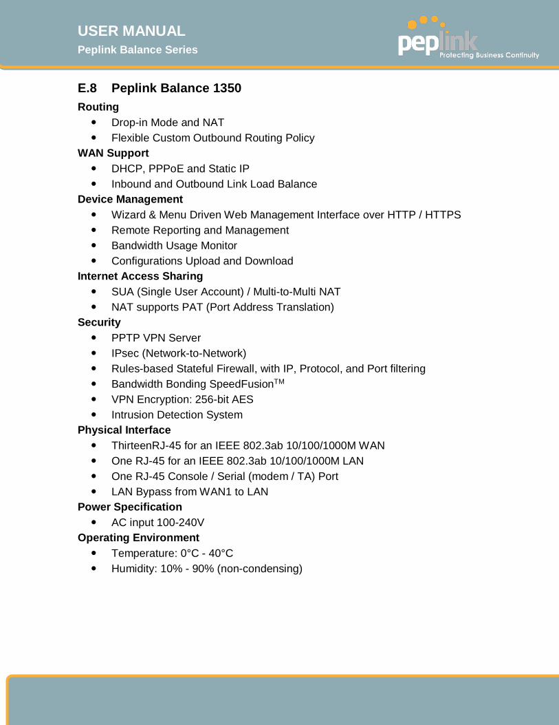
USER MANUAL Peplink Balance Series
http://www.peplink.com -256 / 261 - Copyright © 2015 Peplink
E.8 Peplink Balance 1350 Routing Drop-in Mode and NAT Flexible Custom Outbound Routing Policy
WAN Support DHCP, PPPoE and Static IP Inbound and Outbound Link Load Balance
Device Management Wizard & Menu Driven Web Management Interface over HTTP / HTTPS Remote Reporting and Management Bandwidth Usage Monitor Configurations Upload and Download
Internet Access Sharing SUA (Single User Account) / Multi-to-Multi NAT NAT supports PAT (Port Address Translation)
Security PPTP VPN Server IPsec (Network-to-Network) Rules-based Stateful Firewall, with IP, Protocol, and Port filtering Bandwidth Bonding SpeedFusionTM VPN Encryption: 256-bit AES Intrusion Detection System
Physical Interface ThirteenRJ-45 for an IEEE 802.3ab 10/100/1000M WAN One RJ-45 for an IEEE 802.3ab 10/100/1000M LAN One RJ-45 Console / Serial (modem / TA) Port LAN Bypass from WAN1 to LAN
Power Specification AC input 100-240V
Operating Environment Temperature: 0°C - 40°C Humidity: 10% - 90% (non-condensing)
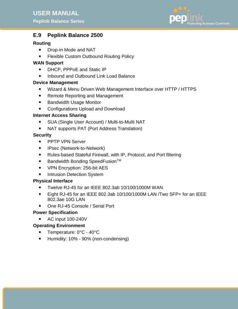
USER MANUAL Peplink Balance Series
http://www.peplink.com -257 / 261 - Copyright © 2015 Peplink
E.9 Peplink Balance 2500 Routing Drop-in Mode and NAT Flexible Custom Outbound Routing Policy
WAN Support DHCP, PPPoE and Static IP Inbound and Outbound Link Load Balance
Device Management Wizard & Menu Driven Web Management Interface over HTTP / HTTPS Remote Reporting and Management Bandwidth Usage Monitor Configurations Upload and Download
Internet Access Sharing SUA (Single User Account) / Multi-to-Multi NAT NAT supports PAT (Port Address Translation)
Security PPTP VPN Server IPsec (Network-to-Network) Rules-based Stateful Firewall, with IP, Protocol, and Port filtering Bandwidth Bonding SpeedFusionTM VPN Encryption: 256-bit AES Intrusion Detection System
Physical Interface Twelve RJ-45 for an IEEE 802.3ab 10/100/1000M WAN Eight RJ-45 for an IEEE 802.3ab 10/100/1000M LAN /Two SFP+ for an IEEE
802.3ae 10G LAN One RJ-45 Console / Serial Port
Power Specification AC input 100-240V
Operating Environment Temperature: 0°C - 40°C Humidity: 10% - 90% (non-condensing)

USER MANUAL Peplink Balance Series
http://www.peplink.com -258 / 261 - Copyright © 2015 Peplink
E.10 Peplink MediaFast 200/500 WAN Support DHCP, PPPoE, and Static IP Inbound and Outbound Link Load Balance
Device Management Wizard & Menu Driven Web Management Interface over HTTP / HTTPS Remote Reporting and Management Bandwidth Usage Monitor Configurations Upload and Download
Internet Access Sharing SUA (Single User Account) / Multi-to-Multi NAT NAT supports PAT (Port Address Translation)
Security PPTP VPN Server IPsec (Network-to-Network) Rules-based Stateful Firewall, with IP, Protocol, and Port filtering Bandwidth Bonding SpeedFusionTM VPN Encryption: 256-bit AES Intrusion Detection System
Physical Interface Five RJ-45 for an IEEE 802.3ab 10/100/1000M WAN1 Three RJ-45 for an IEEE 802.3ab 10/100/1000M LAN /Two SFP+ for an IEEE
802.3ae 10G LAN One RJ-45 Console / Serial Port One USB for 3G/4G LTE Cellular Modem Connection
Power Specification AC input 100-240V
Operating Environment Temperature: 0°C - 40°C Humidity: 10% - 90% (non-condensing)
1 MediaFast 500-B WAN ports 1-5 are active by default. Load balancing and/or a SpeedFusion license is required to activate MediaFast 500-A WAN ports 2-
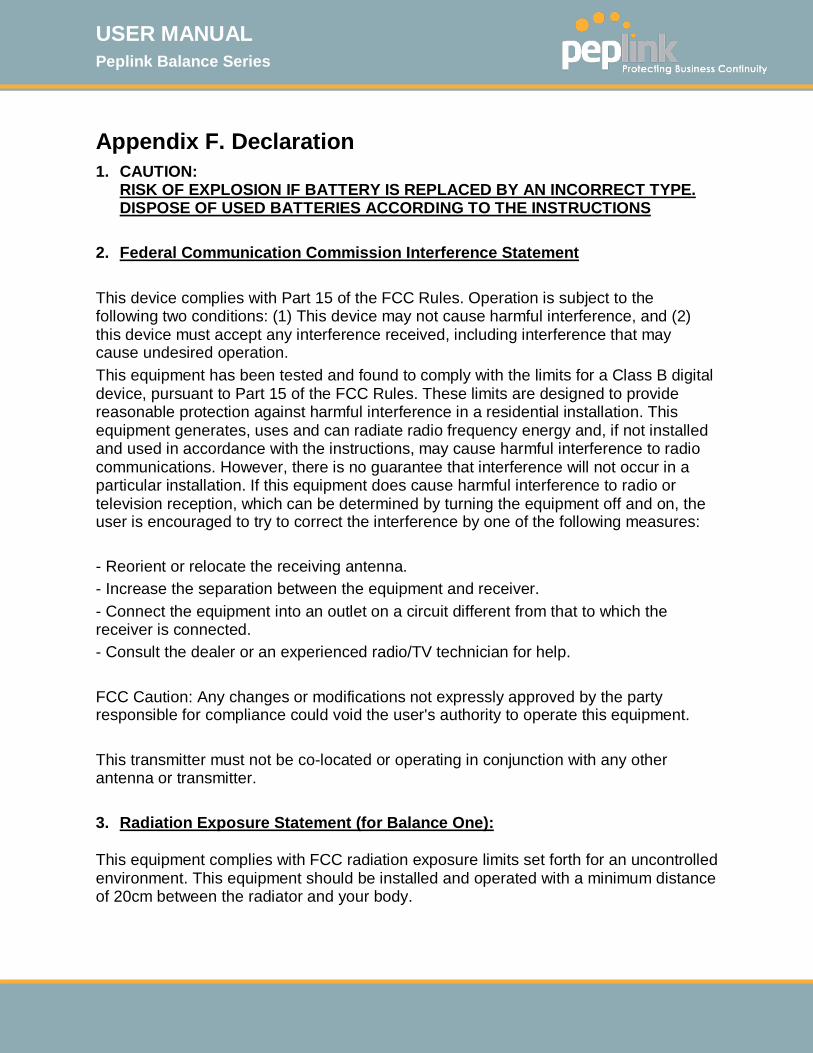
USER MANUAL Peplink Balance Series
http://www.peplink.com -259 / 261 - Copyright © 2015 Peplink
Appendix F. Declaration 1. CAUTION:
RISK OF EXPLOSION IF BATTERY IS REPLACED BY AN INCORRECT TYPE. DISPOSE OF USED BATTERIES ACCORDING TO THE INSTRUCTIONS
2. Federal Communication Commission Interference Statement This device complies with Part 15 of the FCC Rules. Operation is subject to the following two conditions: (1) This device may not cause harmful interference, and (2) this device must accept any interference received, including interference that may cause undesired operation. This equipment has been tested and found to comply with the limits for a Class B digital device, pursuant to Part 15 of the FCC Rules. These limits are designed to provide reasonable protection against harmful interference in a residential installation. This equipment generates, uses and can radiate radio frequency energy and, if not installed and used in accordance with the instructions, may cause harmful interference to radio communications. However, there is no guarantee that interference will not occur in a particular installation. If this equipment does cause harmful interference to radio or television reception, which can be determined by turning the equipment off and on, the user is encouraged to try to correct the interference by one of the following measures: - Reorient or relocate the receiving antenna. - Increase the separation between the equipment and receiver. - Connect the equipment into an outlet on a circuit different from that to which the receiver is connected. - Consult the dealer or an experienced radio/TV technician for help. FCC Caution: Any changes or modifications not expressly approved by the party responsible for compliance could void the user's authority to operate this equipment. This transmitter must not be co-located or operating in conjunction with any other antenna or transmitter. 3. Radiation Exposure Statement (for Balance One):
This equipment complies with FCC radiation exposure limits set forth for an uncontrolled environment. This equipment should be installed and operated with a minimum distance of 20cm between the radiator and your body.

USER MANUAL Peplink Balance Series
http://www.peplink.com -260 / 261 - Copyright © 2015 Peplink
Note: The country code selection is for non-US models only and is not available to all US models. Per FCC regulation, all WiFi products marketed in US must fixed to US operation channels only.
Contact Us: Sales http://www.peplink.com/contact/sales/ Support http://www.peplink.com/contact/ Certified Peplink Partner http://www.peplink.com/partners/channel-partner-program/