PDF - INTERNATIONAL SOCIETY FOR SOIL MECHANICS ...
6
INTERNATIONAL SOCIETY FOR SOIL MECHANICS AND GEOTECHNICAL ENGINEERING This paper was downloaded from the Online Library of the International Society for Soil Mechanics and Geotechnical Engineering (ISSMGE). The library is available here: https://www.issmge.org/publications/online-library This is an open-access database that archives thousands of papers published under the Auspices of the ISSMGE and maintained by the Innovation and Development Committee of ISSMGE.
-
Upload
khangminh22 -
Category
Documents
-
view
4 -
download
0
Transcript of PDF - INTERNATIONAL SOCIETY FOR SOIL MECHANICS ...
INTERNATIONAL SOCIETY FOR
SOIL MECHANICS AND
GEOTECHNICAL ENGINEERING
This paper was downloaded from the Online Library of the International Society for Soil Mechanics and Geotechnical Engineering (ISSMGE). The library is available here:
https://www.issmge.org/publications/online-library
This is an open-access database that archives thousands of papers published under the Auspices of the ISSMGE and maintained by the Innovation and Development Committee of ISSMGE.
3b/7
The Buckling of Piles in Soft Clay
Le Flambage des Pieux dans les Argiles Tendres
by H. Q. G o l d e r , D.Eng., M.I.C.E., and B. O. Sk i p p , Ph.D., F.G.S., Soil Mechanics Limited, London, England
Summary
The paper reviews previous experience and theoretical work on the problem, refers to new theories presented for the first time at this conférence and gives the results of some model tests carried out in the authors’ laboratory.
Notation
c = Cohesive strength (<f> = 0), lb./sq. ft.
E = Young’s modulus of pile material, lb./sq. in.
Ë = Young’s modulus of clay, lb./sq. in.
G = Rigidity modulus of clay, lb./sq. in.
P = Axial loadP Q = Theoretical failure load for slendemess ratio l/k = 0
for brass tubes (Granholm)•n2E I
Pe = Theoretical Euler load = — , / = second moment of
area; / is length of pile
p = Poisson’s ratio
z = Vertical displacement of top of pile under load
ai = Angle in radians
Introduction
U ntil recently the possibility of a slender pile buckling under
load when completely embedded in clay was ignored. N o cases
of buckling in soft soils were known and the theory referred to
(G r a n h o l m , 1929) showed that buckling could not take place
except in such soft material where the pile could well be designed
as a free standing column.There is much evidence in the üterature (C u m m in g s , 1938;
C a s a g r a n d e , 1947; Sp o l f o r d , 1936) that piles in very soft
clay could bear, in test, loads well in excess o f their Euler loads.
Within the last two or three years there have been some
examples of piles failing under loads inducing axial stresses
below the yield point of the pile material. W hen these piles
were extracted it could be seen that they had failed at a part of
their length which was in a very soft stratum (B j e r r u m , 1956).
The theory usually quoted, due to G r a n h o l m (1929), as
sumes an elastic clay and an elastic pile. Subséquent treat-
ments (C u m m in g s , 1938; G l i c k , 1948; B a n e r j e e , 1951) pro-
duced a design formula based on a maximum permissible stress
in the pile and an initial deformation of the pile, and Glick
modified G ranholm ’s concept o f ‘coefficient of latéral résis
tance’ while still basing it on classical elastic theory.
Recently, a t the authors’ request, D r. R. E. Gibson has used
an energy method based on a function which was independently
suggested by Engineer V o i t u s v a n H a m m e (1949) some years
ago. The G erm an engineer H. Walter derived in 1951
a design formula in which he took into account the stresses set
up in the pile by ground réaction, as well as by axial load. In
addition to this recent work, Professor Geuze (Delft) has
developed a theory, not yet published, which is based on
the rheological properties o f the clay.
From a practical point o f view an idéal theory must take into
account the real properties of the ground and the pile. Ail the
Sommaire
Ce mémoire fait le compte rendu du problème du point de vue pratique et théorique. Les théories nouvelles, présentées à cette réunion, sont discutées. Les résultats des essais de laboratoire sur des modèles réduits de pieux sont donnés.
theories mentioned above assume the pile material to be elastic
a t the point o f failure, and the theories o f Granholm, Glick,
Banerjee and Walter assume an elastic soil.
Now one would expect the failure load of a slender pile to
increase with increasing shear strength of the surrounding soil
until the crushing strength of the pile material is reached.
I t might be noted here that a distinction must be made
between the type of failure characteristic o f a slender column
in free air, namely, an elastic buckle, and that which exists for
most types of failure in a soft soil, namely, a ‘non-elastic’ failure.
The problem becomes rather similar to that of deciding what
approach to make in the design of a compression strut of
moderate slendemess ratio. In fact as far as stress design goes
one can think of the clay as decreasing the effective slendemess
ratio of the pile.
The Clay Parameters
There has been some différence of opinion in the past as to
which ‘elastic m odulus’ (or more correctly ‘deformation
m odulus’) o f the clay Controls the pile stability. I f the latéral
deformations of a pile, just before a critical load is reached, are
very small and if the load is applied very slowly it is con-
ceivable that pore-water migration and consolidation will take
place and an appropriate modulus would have to be measured.
A laboratory procédure has been described by Glick, and
Gibson, adapting this approach, suggests oedometer and
drained triaxial tests on clay samples.
I f the pile deformations are appréciable before failure, a
plastic behaviour o f the clay must be considered and Gibson
uses the value of drained shear strength in his expression for
the ground response.In this paper the value of Ë obtained when neglecting con
solidation is used. The results o f the vane stress/strain tests
gave values of G which did not differ greatly (10 to 15 per cent)
for a range of rates o f strain (5-0 to 30 x 10-3 oj/min). By
assuming Poisson’s ratio, ft = 0-5, it was possible to achieve a
fair degree of corrélation with the unconfined compression
values of Ë using the relation :
r Ë 2(1 + /a)
The application of load was quite rapid in the buckling tests
described later (the rods failing within a few minutes). Latéral
deflection at the rate of about 0-002 in. a minute was shown to
take place. Variation in the rate of loading in those soft clays
where failure was elastic and could be repeated gave no signifi-
35
cant change in supporting capacity of the clay. Latéral deflec-
tions of the order o f 0-002 in. in 15 sec. could be achieved.
U ntil the advent o f the laboratory vane it had not been
possible to measure the shear strength of clays below about
150 lb./sq. ft. (73-3 g/cm2) with any accuracy, and even less
possible to measure a modulus. It is clays of this consistency,
and the support they afford to slender piles, which are of
interest.
Expérimental Work
In the absence o f enough detailed field experience of buckling,
against which to test the various theories, it was decided to carry
out a number of loading tests on model piles completely em-
bedded in clays of différent consistency.
Experiments on the buckling o f model piles have been carried
out by Granholm and later by W a l t e r (1951). Granholm
buckled a num ber of brass tubes in clay, the rigidity modulus
of which was 228 lb./sq. in. He recognized the failure as non-
elastic and found that the results could be expressed thus:
where the load P0 has a value corresponding to a slenderness
ratio, l/k = 0, where the load P e is the theoretical Euler load
for failure.W alter loaded a steel strip to which were fixed a number of
cantilever springs acting as an elastic ‘ground’. H e claims
adequate corrélation with his theory.
So far as the authors are aware the literature does not contain
a description of any buckling tests, in clays of différent and
known consistency, in which the axial load versus vertical
deflection relation has been determined.
The first objective o f the laboratory work described in this
paper was to simulate a straight pin-ended pile completely
embedded in a soft uniform clay. The model piles consisted
of Steel rods 11-8 in. long, with a circular section of 0-125 in.
diameter. The ends o f the rods were tum ed to form a cone
with a 30 degree apex angle.
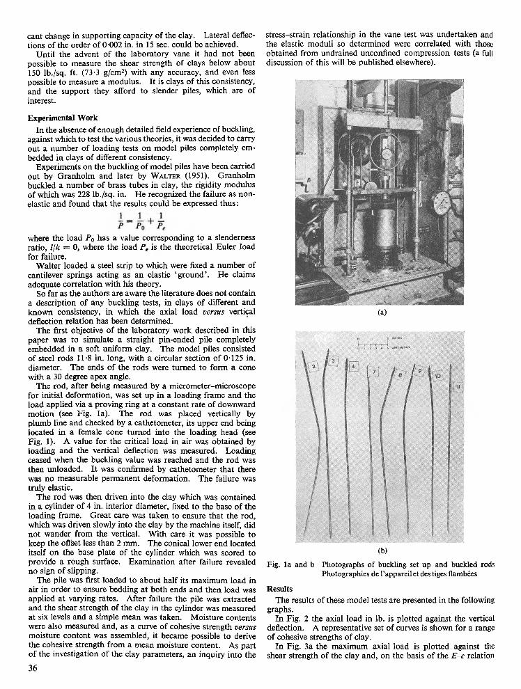
The rod, after being measured by a micrometer-microscope
for initial deformation, was set up in a loading frame and the
load applied via a proving ring at a constant rate of downward
motion (see Fig. la). The rod was placed vertically by
plumb line and checked by a cathetometer, its upper end being
located in a female cone tum ed into the loading head (see
Fig. 1). A value for the critical load in air was obtained by
loading and the vertical deflection was measured. Loading
ceased when the buckling value was reached and the rod was
then unloaded. I t was confirmed by cathetometer that there
was no measurable permanent deformation. The failure was
truly elastic.
The rod was then driven into the clay which was contained
in a cylinder of 4 in. interior diameter, fixed to the base of the
loading frame. G reat care was taken to ensure that the rod,
which was driven slowly into the clay by the machine itself, did
no t wander from the vertical. W ith care it was possible to
keep the offset less than 2 mm. The conical lower end located
itself on the base plate o f the cylinder which was scored to
provide a rough surface. Exam ination after failure revealed
no sign of slipping.
The pile was first loaded to about half its maximum load in
air in order to ensure bedding a t both ends and then load was
applied at varying rates. A fter failure the pile was extracted
and the shear strength of the clay in the cylinder was measured
at six levels and a simple mean was taken. M oisture contents
were also measured and, as a curve of cohesive strength versus
moisture content was assembled, it became possible to dérivé
the cohesive strength from a mean moisture content. As part
o f the investigation of the clay parameters, an inquiry into the
stress-strain relationship in the vane test was undertaken and
the elastic moduli so determined were correlated with those
obtained from undrained unconfined compression tests (a full
discussion of this will be published elsewhere).
(a)
(b)
Fig. la and b Photographs of buckling set up and buckled rods
Photographies de l’appareil et des tiges flambées
Results
The results of these model tests are presented in the following
graphs.
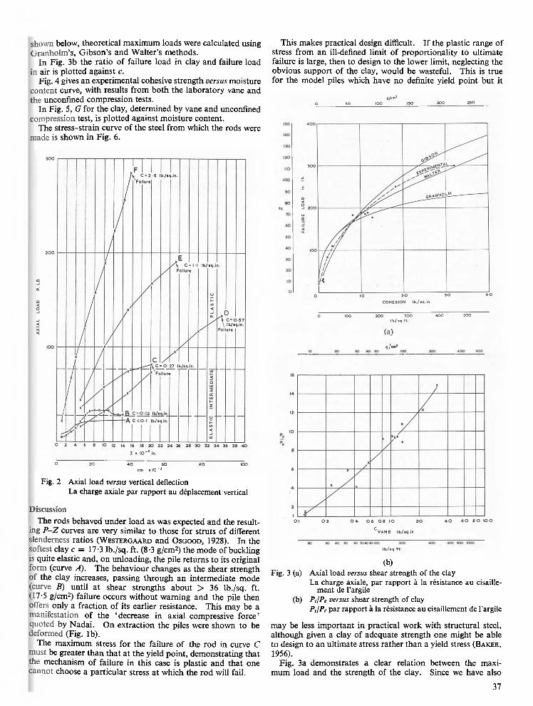
In Fig. 2 the axial load in lb. is plotted against the vertical
deflection. A représentative set o f curves is shown for a range
o f cohesive strengths of clay.
In Fig. 3a the maximum axial load is plotted against the
shear strength of the clay and, on the basis o f the E -c relation
36
shown below, theoretical maximum loads were calculated using
G ra n h o lm ’s, G ibson’s and W alter’s methods.
In Fig. 3b the ratio of failure load in clay and failure load
in air is plotted against c.
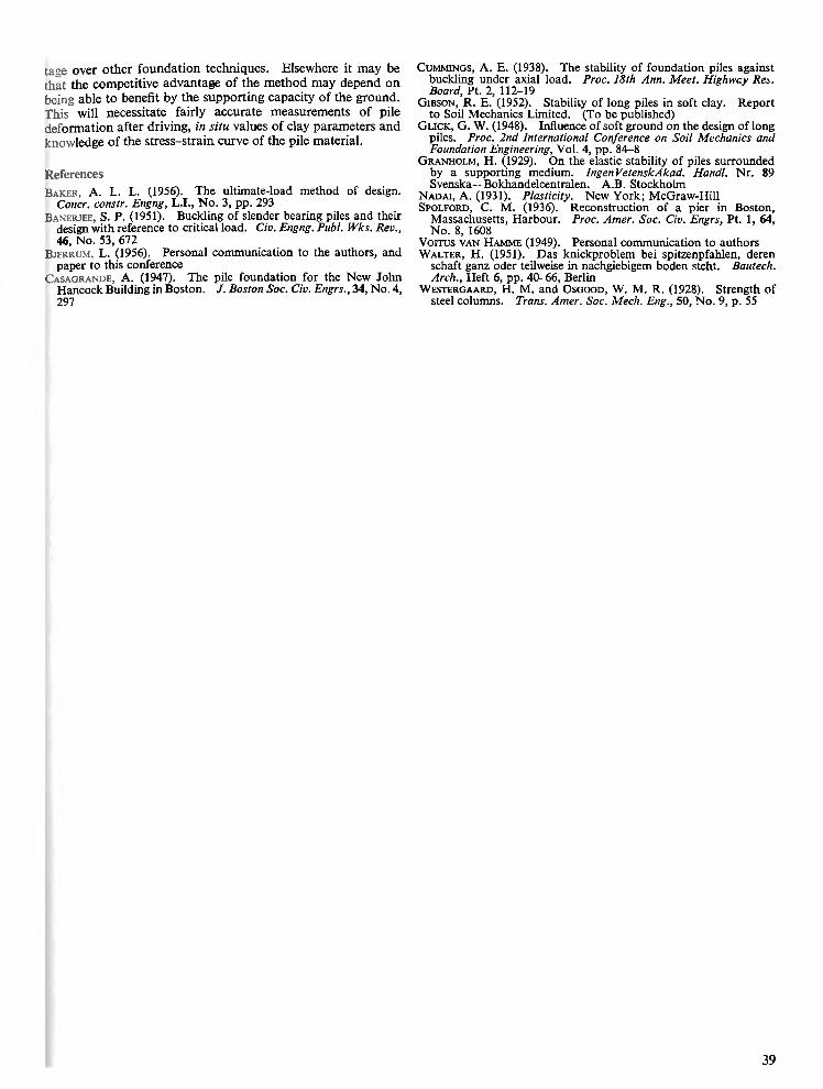
Fig. 4 gives an experimental cohesive strength versus moisture
content curve, with results from both the laboratory vane and
the unconftned compression tests.
In Fig. 5, G for the clay, determined by vane and unconfined compression test, is plotted against moisture content.
The stress-strain curve of the Steel from which the rods were
made is shown in Fig. 6.
O 2 0 4 0 6 0 8 0 IOO
c m x l O " 3
Fig. 2 Axial load versus vertical deflection
La charge axiale par rapport au déplacement vertical
Discussion
The rods behaved under load as was expected and the result-
ing P -Z curves are very similar to those for struts o f différent
slendemess ratios (W e s t e r g a a r d and O s g o o d , 1928). In the
softest clay c = 17-3 lb./sq. ft. (8-3 g/cm2) the mode of buckling
is quite elastic and, on unloading, the pile returns to its original
form (curve A). The behaviour changes as the shear strength
of the clay increases, passing through an intermediate mode
(curve E) until a t shear strengths about > 36 lb./sq. ft.
(17-5 g/cm2) failure occurs without waming and the pile then
ofTers only a fraction of its earlier résistance. This may be a
manifestation of the ‘decrease in axial compressive force’
quoted by Nadai. On extraction the piles were shown to be deformed (Fig. lb).
The maximum stress for the failure of the rod in curve C
must be greater than that a t the yield point, demonstrating that
the mechanism of failure in this case is plastic and that one
cannot choose a particular stress at which the rod will fail.
This makes practical design difficult. I f the plastic range of
stress from an ill-defined limit of proportionality to ultimate
failure is large, then to design to the lower limit, neglecting the
obvious support of the clay, would be wasteful. This is true
for the model piles which have no definite yield point but it
«/="JO _______ 5 0 ____________IOO___________ 150___________2 0 0 __________ 250
O IOO 2 0 0 3 0 0 4 0 0 5 0 0
IbV * q .t t .
(a)
g /c m 1
0-1 0-2 O * 0-6 0 8 1-0 20 4 0 60 8 0 IOO
C V A N E Ib V tq .in .
Ib ./ i q . t t .
(b)
Fig. 3 (a) Axial load versus shear strength of the clay
La charge axiale, par rapport à la résistance au cisaillement de l’argile
(b) PcIPe versus shear strength of clay
PcjPe par rapport à la résistance au cisaillement de l'argile
may be less im portant in practical work with structural Steel,
although given a clay of adequate strength one might be able
to design to an ultimate stress rather than a yield stress (B a k e r .
1956).Fig. 3a demonstrates a clear relation between the maxi
mum load and the strength of the clay. Since we have also
37
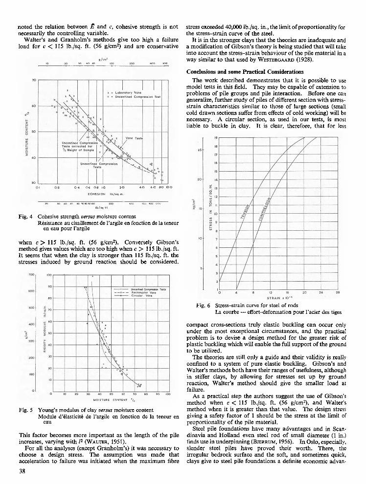
noted the relation between Ë and c, cohesive strength is not necessarily the controlling variable.
W alter’s and Granholm ’s methods give too high a failure
load for c < 115 lb./sq. ft. (56 g/cm2) and are conservative
, / c ,
30 40 SO 400 400
0 - 4 0 6 0 -8 1-0 2 0
C O H E S IO N lb ./» q .in .
4 0 6 0 8 0 IO O
20 *0 40 SO 60 708090100 400 600 800 IOOO
Ib./ « q .t t .
Fig. 4 Cohesive strength versus moisture content
Résistance au cisaillement de l’argile en fonction de la teneur en eau pour l’argile
when c > 115 lb./sq. ft. (56 g/cm2). Conversely Gibson’s
m ethod gives values which are too high when c > 115 lb./sq. ft.
I t seems that when the clay is stronger than 115 lb./sq. ft. the
stresses induced by ground reaction should be considered.
stress exceeded 40,000 lb./sq. in., the limit o f proportionality for
the stress-strain curve of the steel.
I t is in the stronger clays that the theories are inadéquate and
a modification of G ibson’s theory is being studied tha t will take
into account the stress-strain behaviour o f the pile material in a
way similar to that used by W e s t e r g a a r d (1928).
Conclusions and sonie Practical Considérations
The work described demonstrates that it is possible to use
model tests in this field. They may be capable of extension to
problems of pile groups and pile interaction. Before one can
generalize, further study of piles of différent section with stress-
strain characteristics similar to those o f large sections (small
cold drawn sections suffer from effects o f cold working) will be
necessary. A circular section, as used in our tests, is most
liable to buckle in clay. I t is clear, therefore, that for less
Fig. 6 Stress-strain curve for steel of rods
La courbe — effort-deformation pour l’acier des tiges
O IO 2 0 3 0 4 0 5 0 6 0 7 0 8 0 9 0 IOO
M O ISTU R E C ON TEN T ° / 0
Fig. 5 Young’s modulus of clay versus moisture content
Module d’élasticité de l’argile en fonction de la teneur en eau
This factor becomes more im portant as the length of the pile
increases, varying with l2 (W a l t e r , 1951).
F or ail the analyses (except G ranholm ’s) it was necessary to
choose a design stress. The assumption was made that
accélération to failure was initiated when the maximum fibre
compact cross-sections truly elastic buckling can occur only
under the most exceptional circumstances, and the practical
problem is to devise a design m ethod for the greater risk of
plastic buckling which will enable the full support o f the ground
to be utilized.
The theories are still only a guide and their validity is really
confined to a system of pure elastic buckling. G ibson’s and
W alter’s methods bo th have their ranges o f usefulness, although
in stiffer clays, by allowing for stresses set up by ground
reaction, W alter’s method should give the smaller load at
failure.
As a practical step the authors suggest the use of Gibson’s
method when c < 115 lb./sq. ft. (56 g/cm2), and W alter’s
m ethod when it is greater than that value. The design stress
giving a safety factor o f 1 should be the stress a t the limit of
proportionality o f the pile material.
Steel pile foundations have many advantages and in Scan-
dinavia and Holland even steel rod of small diameter (1 in.)
finds use in underpinning (B j e r r u m , 1956). In Oslo, especially,
slender steel piles have proved their worth. There, the
irregular bedrock surface and the soft, and sometimes quick,
clays give to steel pile foundations a definite economic advan-
38
tage over other foundation techniques. Elsewhere it may be
that the compétitive advantage of the method may depend on
being able to benefit by the supporting capacity of the ground.
This will necessitate fairly accurate measurements o f pile
deformation after driving, in situ values of clay parameters and
knowledge of the stress-strain curve of the pile material.
Référencés
B a k e r , A. L. L. (1956). The ultimate-load method of design.Concr. constr. Engng, L.I., No. 3, pp. 293
B a n e r j e e , S. P. (1951). Buckling of slender bearing piles and their design with référencé to critical load. Civ. Engng. Publ. Wks. Rev., 46, No. 53, 672
B j e r r u m , L. (1956). Personal communication to the authors, and paper to this conférence
C a s a g r a n d e , A. (1947). The pile foundation for the New John Hancock Building in Boston. J. Boston Soc. Civ. Engrs., 34, No. 4, 297
C u m m i n g s , A. E. (1938). The stability of foundation piles against buckling under axial load. Froc. 18th Ann. Meet. Highwcy Res. Board, Pt. 2, 112-19
G i b s o n , R. E. (1952). Stability of long piles in soft clay. Report to Soil Mechanics Limited. (To be published)
G l i c k , G . W. (1948). Influence of soft ground on the design of long piles. Proc. 2nd International Conférence on Soil Mechanics and Foundation Engineering, Vol. 4, pp. 84-8
G r a n h o l m , H. (1929). On the elastic stability of piles surrounded by a supporting medium. IngenVetenskAkad. Handl. Nr. 89 Svenska—Bokhandelcentralen. A.B. Stockholm
N a d a i , A. (1931). Plasticity. New Y o r k ; McGraw-Hill Sp o l f o r d , C. M. (1936). Reconstruction of a pier in Boston,
Massachusetts, Harbour. Proc. Amer. Soc. Civ. Engrs, Pt. 1, 64, N o . 8, 1608
Vorrus v a n H a m m e (1949). Personal communication to authors W a l t e r , H. (1951). Das knickproblem bei spitzenpfahlen, deren
schaft ganz oder teilweise in nachgiebigem boden steht. Bautech. Arch., Heft 6, pp. 40-66, Berlin
W e s t e r g a a r d , H. M. and O s g o o d , W . M. R. (1928). Strength of Steel columns. Trans. Amer. Soc. Mech. Eng., 50, No. 9, p. 55
39