PDF Green Building - Guidebook for Sustainable Architecture
209
-
Upload
khangminh22 -
Category
Documents
-
view
4 -
download
0
Transcript of PDF Green Building - Guidebook for Sustainable Architecture

Green Building – Guidebook for Sustainable Architecture
ISBN 978-3-642-00634-0 e-ISBN 978-3-642-00635-7DOI 10.1007/978-3-642-00635-7Springer Heidelberg Dordrecht London New York
Library of Congress Control Number: 2009938435
Original German edition published by Callwey Verlag, Munich, 2007© Springer-Verlag Berlin Heidelberg 2010This work is subject to copyright. All rights are reserved, whether the whole or part of the material is concerned, specifi cally the rights of translation, reprin-ting, reuse of illustrations, recitation, broadcasting, reproduction on microfi lm or in any other way, and storage in data banks. Duplication of this publication or parts thereof is permitted only under the provisions of the German Copy-right Law of September 9, 1965, in its current version, and permission for use must always be obtained from Springer. Violations are liable to prosecution under the German Copyright Law.The use of general descriptive names, registered names, trademarks, etc. in this publication does not imply, even in the absence of a specifi c statement, that such names are exempt from the relevant protective laws and regulations and therefore free for general use.
Cover design: wmxDesign GmbH, Heidelberg, according to the design of independent Medien-Design
Printed on acid-free paper
Springer is part of Springer Science+Business Media (www.springer.com)
Prof. Dr. Michael Bauer Peter MösleDr. Michael Schwarz
Drees & Sommer Advanced Building Technologies GmbHObere Waldplätze 1170569 StuttgartGermany
By Michael Bauer, Peter Mösle and Michael Schwarz
Green Building – Guidebook for Sustainable Architecture
Table of Contents
The Motivation behind the Green Building Idea
Increased Public Focus on Sustainability and Energy Efficiency 10Supportive Framework and General Conditions 12
CO2 Emission Trade 13Rating Systems for Sustainable Buildings 15
An integrated View of Green Buildings – Life Cycle Engineering 20
Green Building Requirements
B1 Sustainable Design 24Perceived Use defines the Concept 25Relationship between Level of Well-Being
and healthy Indoor Climate 26Relationship between Comfort Level and Performance Ability 27Operative Indoor Temperature in Occupied Rooms 28Operative Temperature in Atria 30Indoor Humidity 32Air Velocity and Draught Risk 34Clothing and Activity Level 35Visual Comfort 36Acoustics 40Air Quality 42Electromagnetic Compatibility 45
Individualized Indoor Climate Control 47
B2 Conscientious Handling of Resources 50Energy Benchmarks as Target Values for Design 51Fossils and Regenerative Energy Resources 52
Today’s Energy Benchmark – Primary Energy Demand for Indoor Climate Conditioning 53Heating Energy Demand 54Energy Demand for Water Heating 55Cooling Energy Demand 56Electricity Demand for Air Transport 57Electricity Demand for Artificial Lighting 58
Future Energy Benchmark – Primary Energy Demand over the Life Cycle of a Building 59Cumulative Primary Energy Demand of Building Materials 60Primary Energy Demand – Use-related 61
Water Requirements 62
A B
Design, Construction, Commissioning and Monitoring for Green Buildings
C1 Buildings 66Climate 67Urban Development and Infrastructure 69Building Shape and Orientation 71Building Envelope 74
Heat Insulation and Building Density 74Solar Protection 80Glare Protection 85Daylight Utilization 86Noise Protection 88Façade Construction Quality Management 90
Building Materials and Furnishings 92Indoor Acoustics 94Smart Materials 97
Natural Resources 100Innovative Tools 105
C2 Building Services Engineering 108Benefits Delivery 109
Concepti and Evaluation of Indoor Climate Control Systems 110Heating 112Cooling 113Ventilation 114
Energy Generation 120Trigeneration or Trigen Systems (CCHP) 121Solar Energy 124Wind Energy 126Geothermics 127Biomass 128
C3 Commissioning 130Sustainable Building Procedure Requirements 131Blower Door Test – Proof of Air-Tightness 132Thermography – Proof of Thermal Insulation and Evidence of Active Systems 133Proof of Indoor Comfort 134Air Quality 135Noise Protection 136Daylight Performance and Nonglaring 137Emulation 138
C4 Monitoring and Energy Management 140
A closer Look – Green Buildings in Detail
D1 Dockland Building in Hamburg 146Interview with the Architect Hadi Teherani of BRT Architects, Hamburg 147Interview with Christian Fleck, Client, Robert Vogel GmbH & Co. KG 149Highly transparent and yet sustainable 150
D2 SOKA Building in Wiesbaden 154Excerpts from the Book titled »SOKA Building« by Prof. Thomas Herzog
and Hanns Jörg Schrade of Herzog und Partner, Munich 155Interview with Peter Kippenberg, Board Member of SOKA Construction 156Robust and Energy-Efficient 158Optimizing Operations – Total Energy Balance for 2005:
Heat, Cooling, Electricity 159
D3 KSK Tuebingen 160Interview with Prof. Fritz Auer of Auer + Weber + Associates, Architects 161Transparently Ecological 163
D4 LBBW Stuttgart 166Interview with the Architect Wolfram Wöhr of W. Wöhr – Jörg Mieslinger
Architects, Munich, Stuttgart 167Interview with the Client Fred Gaugler, BWImmobilien GmbH 168High and Efficient 169
D5 The Art Museum in Stuttgart 172Interview with the Architects Prof. Rainer Hascher and Prof. Sebastian Jehle 173Crystal Clear 175
D6 New Building: European Investment Bank (EIB) in Luxembourg 178Interview with Christoph Ingenhoven of Ingenhoven Architects 179Sustainably Comfortable 181
D7 Nycomed, Constance 184Interview with the Architect Th. Pink of Petzinka Pink Technol.
Architecture, Duesseldorf 185Interview with the Client Prof. Franz Maier of Nycomed 185Efficient Integration 187
D8 DR Byen, Copenhagen 190Interview with the Clients Kai Toft & Marianne Fox of DR Byen 191Interview with the Architect Stig Mikkelsen, Project Leader
and Partner of Dissing + Weitling 192Adjusted Climate Considerations 194
D9 D&S Advanced Building Technologies Building, Stuttgart 196Low-Energy Building Prototype 197Basic Evaluation and Course of Action 198Indoor Climate and Façade Concept 199Usage of Geothermal Energy for Heat and Cooling Generation 200
Appendix 202
C D
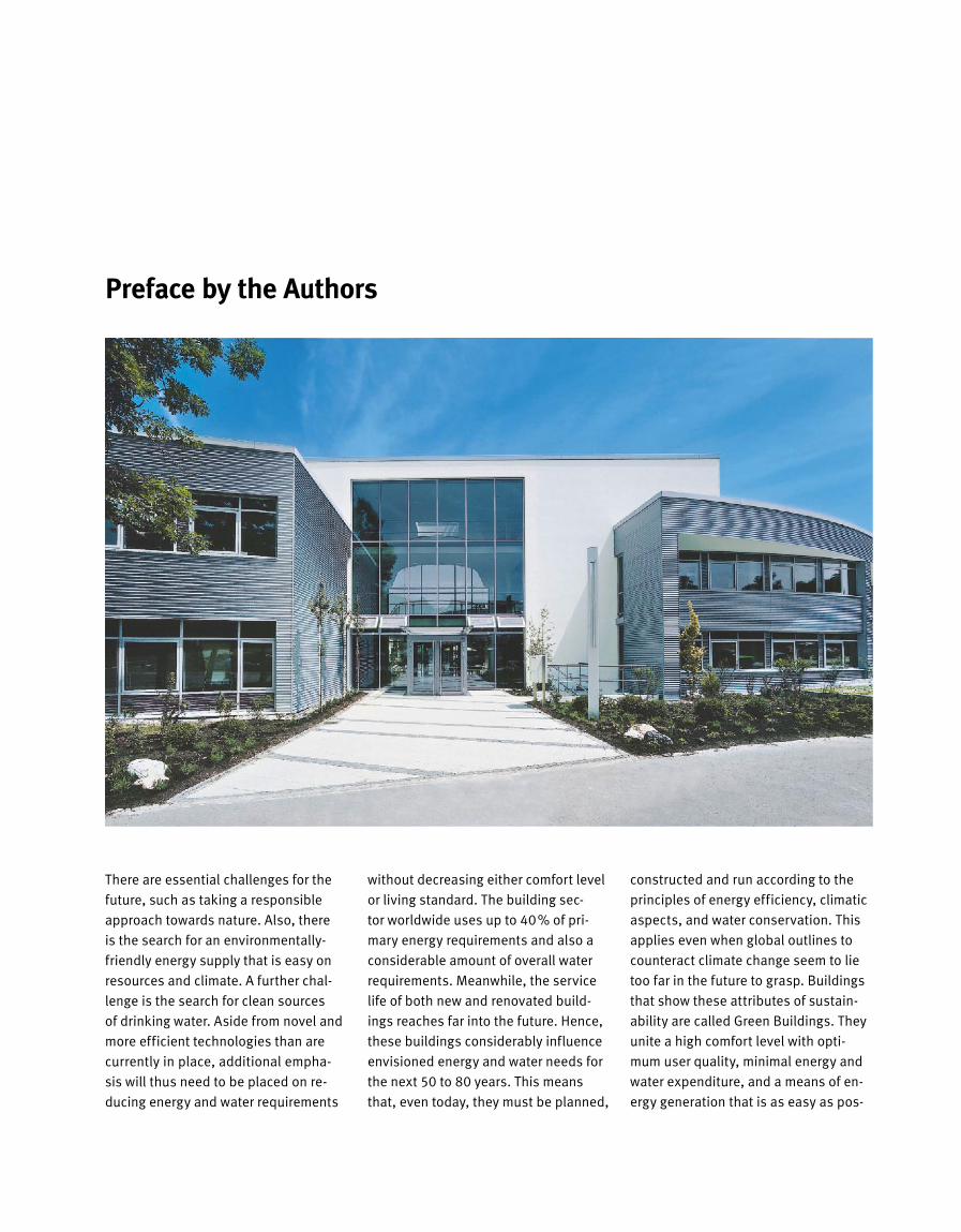
Preface by the Authors
There are essential challenges for the
future, such as taking a responsible
approach towards nature. Also, there
is the search for an environmentally-
friendly energy supply that is easy on
resources and climate. A further chal-
lenge is the search for clean sources
of drinking water. Aside from novel and
more efficient techno logies than are
currently in place, ad ditional empha-
sis will thus need to be placed on re-
ducing energy and water requirements
without decreasing either comfort level
or living standard. The building sec-
tor worldwide uses up to 40% of pri-
mary energy requirements and also a
considerable amount of overall water
requirements. Meanwhile, the service
life of both new and renovated build-
ings reaches far into the future. Hence,
these buildings considerably influence
envisioned energy and water needs for
the next 50 to 80 years. This means
that, even today, they must be planned,
constructed and run according to the
principles of energy efficiency, climatic
aspects, and water conservation. This
applies even when global outlines to
counteract climate change seem to lie
too far in the future to grasp. Buildings
that show these attributes of sustain-
ability are called Green Buildings. They
unite a high comfort level with opti-
mum user quality, minimal energy and
water expenditure, and a means of en-
ergy generation that is as easy as pos-

sible on both climate and resources,
all this under economic aspects with a
pay-back span of 5 to 15 years. Green
Buildings are also capable of meeting
even the most stringent demands for
aesthetics and architecture, which is
something that the examples given in
this book clearly show. Planning these
buildings, according to an integrated
process, requires the willingness of all
those involved: to regard the numer-
ous interfaces as seams of individual
assembly sections, the synergies of
which are far from being exhausted yet.
An holistic and specific knowledge is
needed, regarding essential climatic,
thermal, energy-related, aero-physical
and structural-physical elements and
product merits, which does not end at
the boundaries of the individual trades.
Further, innovative evaluation and
simulation tools are being used, which
show in detail the effects throughout
the building’s life cycle. The examples
in this book show that a building can in-
deed be run according to the principles
of energy and resource conservation
when – from the base of an integrated
energy concept – usage within a given
establishment is being consistently
tracked and optimized. The resulting
new fields of consulting and planning
are called energy design, energy man-
agement and Life Cycle Engineering. In
this particular field, Drees & Sommer
now has over 30 years of experience, as
one of the leading engineering and con-
sulting firms for the planning and op-
eration of Green Buildings. Our cross-
trade, integrated knowledge stems
from Drees & Sommer’s performance
sectors of Engineering, Property Con-
sulting and Project Management.
The contents of this book are based
on the extensive experience of the
authors and their colleagues – during
their time at Drees & Sommer Advanced
Building Technologies GmbH – in plan-
ning, construction and operation of
such buildings. It documents, through
examples, innovative architectural and
technical solutions and also the target-
oriented use of specialist tools for both
planning and operation. This book is
directed primarily at investors, archi-
tects, construction planners and build-
ing operators, looking for an energy
approach that is easy on resources. It
is meant as a guideline for planning,
building and operation of sustainable
and energy-efficient buildings.
At this stage, we would also like to
thank all the renowned builders and
ar chitects together with whom, over
the last years, we had the honour of
planning, executing and operating
these attractive and innovative build-
ings. The level of trust they put in us
is also shown by the statements they
gave us for this book and the provided
documentation for many prominent
buildings. For their kind assistance in
putting together this book, a special
thanks is due.
We would be pleased if, by means
of this book, we succeeded in rais-
ing the level of motivation for erecting
Green Buildings anywhere in the world,
whether from scratch or as renovation
projects. Engineering solutions to make
this happen are both available and eco-
nomically viable. Our sustainability ap-
proach goes even further, incidental ly.
The CO2 burden resulting from the pro-
duction and distribution of this book, for
instance, we have decided to compen-
sate for by obtaining CO2 certificates for
CO2 reducing measures. Hence, you
are free to put all your energy into read-
ing this book!
We would now like to invite you to
join us on a journey into the world of
Green Buildings, to have fun while read-
ing about it, and above all, to also dis-
cover new aspects that you can then
use for your own buildings in future.
Heubach, Gerlingen, Nuertingen
Michael Bauer
Peter Mösle
Michael Schwarz
A B
The Motivation behind the Green Building Idea
C D
10 The Motivation behind the Green Building Idea
Increased Public Focus on Sustainability and Energy Efficiency
Man’s strive for increased comfort and
financial independence, the densifica
tion of congested urban areas, a strong
increase in traffic levels and the grow
ing electric smog problem due to new
communication technologies all cause
ever rising stress levels in the immedi
ate vicinity of the individual. Quality of
life is being hampered and there are ne
gative health effects. All this, coupled
with frequent news about the glo bal
climate change, gradually leads to a
change of thought throughout society.
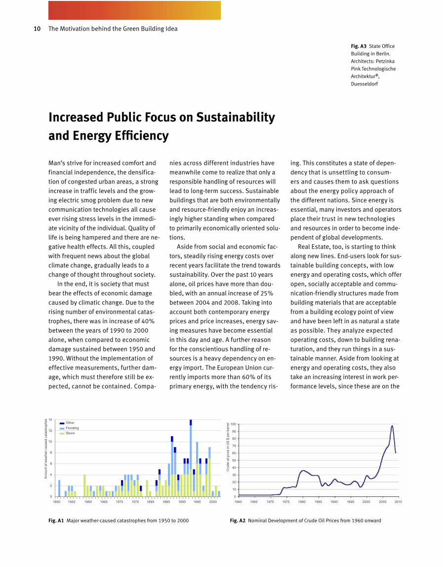
In the end, it is society that must
bear the effects of economic damage
caused by climatic change. Due to the
rising number of environmental catas
trophes, there was in increase of 40%
between the years of 1990 to 2000
alone, when compared to economic
damage sustained be tween 1950 and
1990. Without the implementation of
effective measurements, further dam
age, which must therefore still be ex
pected, cannot be contained. Compa
nies across different industries have
meanwhile come to realize that only a
responsible handling of resources will
lead to longterm success. Sustainable
buildings that are both environmentally
and resourcefriendly enjoy an increas
ingly higher standing when compared
to primarily economically oriented solu
tions.
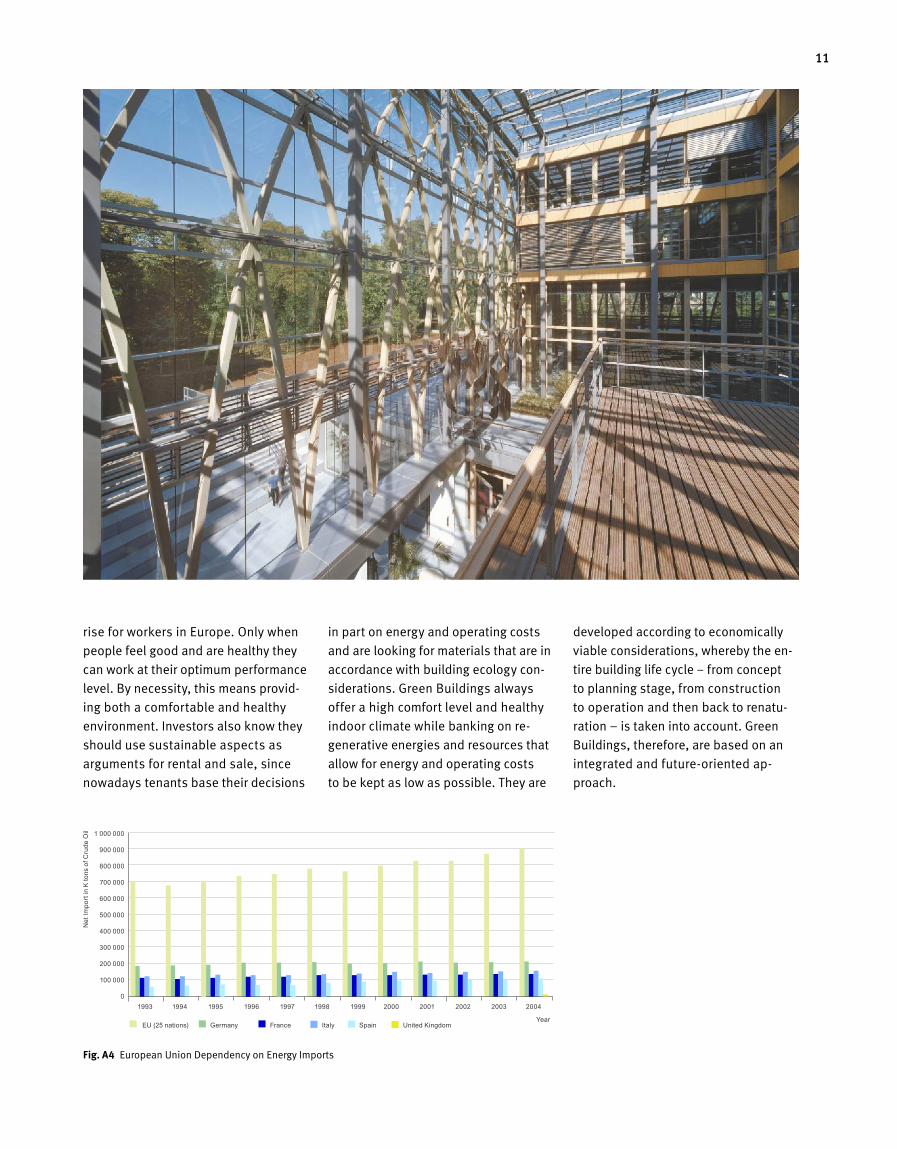
Aside from social and economic fac
tors, steadily rising energy costs over
recent years facilitate the trend towards
sustainability. Over the past 10 years
alone, oil prices have more than dou
bled, with an annual increase of 25%
between 2004 and 2008. Taking into
account both contemporary energy
prices and price increases, energy sav
ing measures have become essential
in this day and age. A further rea son
for the conscientious handling of re
sources is a heavy dependency on en
ergy import. The European Union cur
rently imports more than 60% of its
primary energy, with the tendency ris
ing. This constitutes a state of depen
dency that is unsettling to consum
ers and causes them to ask questions
about the energy policy approach of
the different nations. Since energy is
essential, many investors and operators
place their trust in new technologies
and resources in order to become inde
pendent of global developments.
Real Estate, too, is starting to think
along new lines. Endusers look for sus
tainable building concepts, with low
energy and operating costs, which offer
open, socially acceptable and commu
nicationfriendly structures made from
building materials that are acceptable
from a building ecology point of view
and have been left in as natural a state
as possible. They analyze expected
operating costs, down to building rena
turation, and they run things in a sus
tainable manner. Aside from looking at
energy and operating costs, they also
take an increasing interest in work per
formance levels, since these are on the
Fig. A 1 Major weathercaused catastrophes from 1950 to 2000 Fig. A 2 Nominal Development of Crude Oil Prices from 1960 onward
Fig. A 3 State Office
Building in Berlin.
Architects: Petzinka
Pink Technologische
Architektur ®,
Duesseldorf
Am
ount
of w
eath
er-c
ause
d ca
tast
roph
es OtherFloodingStorm
1950 1955 1960 1965 1970 1975 1980 1985 1990 1995 2000
14
12
10
8
6
4
2
0
Cru
de o
il pr
ice
in U
S $
per b
arre
l
1960 1965 1970 1975 1980 1985 1990 1995 2000 2005 2010
100
90
80
70
60
50
40
30
20
10
0
11
rise for workers in Europe. Only when
people feel good and are healthy they
can work at their optimum performance
level. By necessity, this means provid
ing both a comfortable and healthy
environment. Investors also know they
should use sustainable aspects as
arguments for rental and sale, since
nowadays tenants base their decisions
in part on energy and operating costs
and are looking for materials that are in
accordance with building ecology con
siderations. Green Buildings always
offer a high comfort level and healthy
indoor climate while banking on re
generative energies and resources that
allow for energy and operating costs
to be kept as low as possible. They are
developed according to economically
viable considerations, whereby the en
tire building life cycle – from concept
to planning stage, from construction
to operation and then back to renatu
ration – is taken into account. Green
Buildings, therefore, are based on an
integrated and futureoriented ap
proach.
A1.04
Fig. A 4 European Union Dependency on Energy Imports
1993 1994 1995 1996 1997 1998 1999 2000 2001 2002 2003 2004
EU (25 nations) Germany France Italy Spain United KingdomYear
Net
Impo
rt in
K to
ns o
f Cru
de O
il 1 000 000
900 000
800 000
700 000
600 000
500 000
400 000
300 000
200 000
100 000
0
12 The Motivation behind the Green Building Idea
Supportive Framework and General Conditions
Owing to rising public interest in sus-
tainable and ecological solutions, the
last few years have resulted in the es-
tablishment of numerous framework
conditions that facilitate the use of
energy-saving technologies, energy
sources that are easy on resources and
sustainable products for the property
sector.
The base of a sustainable energy
policy can be found in various nation-
al, European and International laws,
standards, norms and stipulations that
specify measurable standards of ener-
gy efficiency for buildings and facili-
ties. Further, the norms define the mini-
mum standard for energy efficiency of
buildings and facilities. The norms also
set minimum standards for thermal
com fort, air quality and visual comfort.
Across Europe, there is currently a
drive to unify these standards. On an
international level, however, the dif-
ferent nations are setting their own
guidelines and these cannot necessar-
ily be directly compared to each other.
The standards are being supported by
a variety of available and targeted
grants for promising technologies that
are currently not yet economical on a
regenerative level. Examples for this in
Germany would be the field of photo-
voltaics, for instance, or of near-surface
geothermics, solar thermics, biogas
plants or energy-conserving measures
for the renovation of old buildings.
In the currently available laws, stan-
d ards and stipulations, however, not all
the essential building and facility areas
are being considered. This means that
many of these areas are unable to ful-
fil their true potential when it comes
to the possibility of optimisation on an
energy level. Further, legally defined
critical values for energy consumption
are generally below those required for
Green Buildings. These critical values
are usually set in a manner that allows
for marketable products to be used.
Laws and stipulations will, therefore,
always be backward when compared
to the actual market possibilities for
obtaining maximum energy efficiency.
This gap can be bridged by the use of
Green Building labels, guidelines and
quality certificates, since these can at
least recommend adherence to more
stringent guidelines. The higher de-
mands placed on true energy efficien-
cy can also be justified by the fact that
the technology in buildings and facility
has a great lifespan. This means that a
CO2 emission limit specified today will
have long-ranging effects into the fu-
ture. Today’s decisions, therefore, are
essential aspects in determining future
emission levels.
13
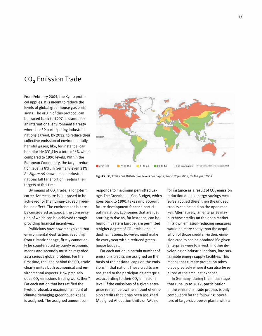
From February 2005, the Kyoto proto-
col applies. It is meant to reduce the
levels of global greenhouse gas emis-
sions. The origin of this protocol can
be traced back to 1997. It stands for
an international environmental treaty
where the 39 participating industrial
nations agreed, by 2012, to reduce their
collective emission of environmentally
harmful gases, like, for instance, car-
bon dioxide (CO2) by a total of 5% when
compared to 1990 levels. Within the
European Community, the target reduc-
tion level is 8%, in Germany even 21%.
As Figure A6 shows, most industrial
nations fall far short of meeting their
targets at this time.
By means of CO2 trade, a long-term
corrective measure is supposed to be
achieved for the human-caused green-
house effect. The environment is here -
by considered as goods, the conserva-
tion of which can be achieved through
providing financial incentives.
Politicians have now recognized that
environmental destruction, resulting
from climatic change, firstly cannot on-
ly be counteracted by purely economic
means and secondly must be regarded
as a serious global problem. For the
first time, the idea behind the CO2 trade
clearly unites both economical and en-
vironmental aspects. How precisely
does CO2 emissions trading work, then?
For each nation that has ratified the
Kyoto protocol, a maximum amount of
climate-damaging greenhouse gases
is assigned. The assigned amount cor-
responds to maximum permitted us-
age. The Greenhouse Gas Budget, which
goes back to 1990, takes into account
future development for each partici-
pating nation. Economies that are just
starting to rise as, for in stance, can be
found in Eastern Europe, are permitted
a higher degree of CO2 emissions. In-
dustrial nations, however, must make
do every year with a reduced green-
house budget.
For each nation, a certain number of
emissions credits are assigned on the
basis of the national caps on the emis-
sions in that nation. These credits are
assigned to the participating enterpris-
es, according to their CO2 emissions
level. If the emissions of a given enter-
prise remain below the amount of emis-
sion credits that it has been assigned
(Assigned Allocation Units or AAUs),
for instance as a result of CO2 emission
reduction due to energy-savings mea-
sures applied there, then the unused
credits can be sold on the open mar-
ket. Alternatively, an enterprise may
purchase credits on the open market
if its own emission-reducing measures
would be more costly than the acqui-
sition of those credits. Further, emis-
sion credits can be obtained if a given
enterprise were to invest, in other de-
veloping or industrial nations, into sus-
tainable energy supply facilities. This
means that climate protection takes
place precisely where it can also be re-
alized at the smallest expense.
In Germany, during the initial stage
that runs up to 2012, participation
in the emissions trade process is only
com pulsory for the following: opera -
tors of large-size power plants with a
CO2 Emission Trade
Fig. A 5 CO2 Emissions Distribution levels per Capita, World Population, for the year 2004
equator
over 11.0 7.1 to 11.0 4.1 to 7.0 0.0 to 4.0 no information in t CO2/inhabitants for the year 2004

14 The Motivation behind the Green Building Idea
thermal furnace capacity in excess
of 20 MW and also operators of power-
intensive industrial plants. With this,
ca. 55% of the CO2 emissions poten -
tial directly participates in the trade.
Currently, neither the traffic nor the
building sectors are part of the trade
in either a private or commercial man-
ner. However, in Europe, efforts are
already underway to extend emissions
trading to all sectors in the long run.
In other, smaller European nations like,
for instan ce, Latvia and Slovenia,
plants with a lower thermal output are
already participating in the emissions
trade. This is explicitly permitted in the
Emissions Trade Bill as an opt-in rule.
The evaluation and financing of build-
Year
Fig. A 6 Reduction Targets, as agreed in the Kyoto Protocol, and current Standing
of CO2 Emission Levels for the worldwide highest global Consumers
Fig. A 7 Sustainability wedges and an end to overshoot
India **
China **
Iceland
Australia*
Norway
Ukraina
Russia
New Zealand
Croatia*
Canada
Japan
USA*
Romania
Bulgaria
Switzerland
Monaco*
Liechtenstein
EU
Status in 2004
Target oriented on 1990
Kyoto protocol signed but not ratified
Emissions status in 2002
72.17 %
6.53 %
14.30 %
18.34 %
38.98 %
7.93 %10.00 %
10.24 %1.00 %
-55.33 %
-31.96 %
-5.47 %-5.00 %
-6.00 %
-6.00 %
-7.00 %
-8.00 %
-8.00 %
-8.00 %
-8.00 %
-8.00 %
-8.00 %-0.58 %
-3.70 %
-41.06 %
-48.98 %
-80.0 % -60.0 % -40.0 % -20.0 % 0.0 % 20.0 % 40.0 % 60.0 % 80.0 %
0.00 %
0.00 %
0.00 %
0.38 %
21.32 %
26.58 %
*
**
USA 23%
China 17%
Russia 7%
Japan 5%
India 4%
Germany 3%
Other 25 EU Nations 12% Rest of the World 29%
Fig. A 8 Distribution of CO2 Emissions by World
Nations for the Year 2004
ings based on their CO2 market value
is something that, in the not-too-distant
future, will reach the property sector
as well. A possible platform for build-
ing-related emissions trade already ex-
ists with the EU directive on overall en-
ergy efficiency and with the mandatory
energy passport. Our planet earth only
has limited biocapacity in order to re-
generate from harmful substances and
consumption of its resources. Since the
Nineties, global consumption levels ex-
ceed available biocapacity. In order to
reinstate the ecological balance of the
earth, the CO2 footprint needs to be de-
creased. Target values that are suitable
for sustainable development have been
outlined in Figure A7.
Status 2008:Number of people: 6,5 MrdCO2-Footprint Worldwide: 1,41 gha/PersonCO2-Footprint – Germany: 2,31 gha/PersonCO2-Footprint – Europe: 2,58 gha/Person
Status 2050:Number of people: 9 MrdTarget CO2-Footprint Worldwide: 0,7 gha/PersonMeasures:- Energy Efficienty in Construction and Technology- Renewable Energies2008 – 2050:
Prognosis for the CO2-Footprint of the World, if no measures are undertaken
Biocapacityreserve
Ecological Footprint
Biocapacity
Ecological dept
2100208020602040
2050
2020200019801960
2.0
2,5
Num
ber o
f pla
net E
arth
s
1.5
0.0
0.5
1.0
15
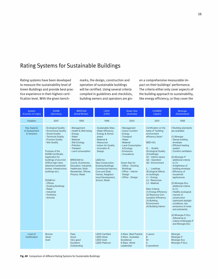
Rating systems have been developed
to measure the sustainability level of
Green Buildings and provide best-prac-
tice experience in their highest certi-
fication level. With the given bench-
marks, the design, construction and
operation of sustainable buildings
will be certified. Using several criteria
compiled in guidelines and checklists,
building owners and operators are giv-
en a comprehensive measurable im-
pact on their buildings’ performance.
The criteria either only cover aspects of
the building approach to sustainability,
like energy efficiency, or they cover the
Fig. A9 Comparison of different Rating Systems for Sustainable Buildings
Rating Systems for Sustainable Buildings
- Ecological Quality - Economical Quality - Social Quality - Technical Quality - Process Quality - Site Quality Purpose of the DGNB Certificate: Application for buildings of any kind (Office high-rises, detached residential homes, infrastructure buildings etc.) DGNB for: - Offices - Existing Buildings - Retail - Industrial - Portfolios - Schools
Key Aspects of Assessment
& Versions
Bronze Silver Gold
Level of Certification
LEED Certified LEED Silver LEED Gold LEED Platinum
4 Stars: ‚Best Practice‘ 5 Stars: ‚Australien Excellence‘ 6 Stars: ‚World Leadership‘
C (poor) B B+ A S (excellent)
Minergie Minergie-P Minergie-Eco Minergie-P-Eco
Pass Good Very good Excellent Outstanding
System (Country of origin)
Initiation
DGNB (Germany)
2007
BREEAM (Great Britain))
1990
LEED (USA)
1998
Green Star (Australia)
2003
CASBEE (Japan)
2001
Minergie (Switzerland)
1998
- Management - Health & Well-being - Energy - Water - Material - Site Ecology - Pollution - Transport - Land consumption BREEAM for: Courts, EcoHomes, Edu ca tion, Industrial, Healthcare, Multi- Residential, Offices, Prisons, Retail
- Sustainable Sites - Water Efficiency - Energy & At mo s- phere - Material & Resources - Indoor Air Quality - Innovation & Design LEED for: New Construction, Existing Buildings, Commercial Interiors, Core and Shell, Homes, Neighbor-hood Development, School, Retail
- Management - Indoor Comfort - Energy - Transport - Water - Material - Land Consumption & Ecology - Emissions - Innovations Green Star for: - Office – Existing Buildings - Office – Interior Design - Office – Design
Certification on the basis of “building-environment efficiency factor“ BEE=Q/L Q … Quality (Ecological Quality of buildings) Q1 - Interior space Q2 - Operation Q3 - Environment L … Loadings (Ecological effects on buildings) L1 - Energy L2 - Resources L3 - Material Main Criteria: (1) Energy Efficiency (2) Resource Con- sumption Efficiency (3) Building Environment (4) Building Interior
4 Building standards are available: (1) Minergie - Dense building envelope - Efficient heating system - Comfort ventilation (2) Minergie-P addi tional criteria to (1): - Airtightness of building envelope - Efficiency of household applicances (3) Minergie-Eco additional criteria to (1): - Healthy ecological manner of construction (optimized daylight conditions, low emissions of noise and pollutants) (4) Minergie-P-Eco Adherence to criteria of Minergie-P and Minergie-Eco
16 The Motivation behind the Green Building Idea
whole building approach by identify-
ing performance in key areas like sus-
tainable site development, human and
envi ronmental health, water savings,
materials selection, indoor environmen-
tal quality, social aspects and econo-
mical quality.
Furthermore, the purpose of rating
systems is to certify the different as-
pects of sustainable development
during the planning and construction
stages. The certification process means
quality assurance for building owners
and users. Important criteria for suc-
cessful assessments are convenience,
usability and adequate effort during the
different stages of the design process.
The result of the assessment should be
easy to communicate and should be
showing transparent derivation and re-
liability.
Structure of Rating SystemsThe different aspects are sorted in over -
all categories, like ›energy‹ or quality
groups ›ecology‹, ›economy‹ and ›so-
cial‹ demands (triple bottom line). For
each aspect, one or more benchmarks
exist, which need to be verified in order
to meet requirements or obtain points.
Depending on the method used, indi-
vidual points are either added up or
initially weighted and then summed up
to obtain the final result. The number
of points is ranked in the rating scale,
which is divided into different levels:
The higher the number of points, the
better the certification.
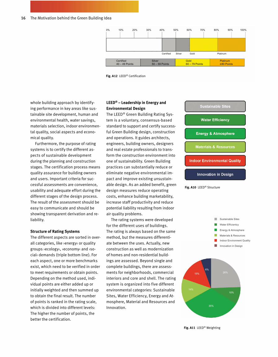
LEED® – Leadership in Energy and Environmental DesignThe LEED® Green Building Rating Sys -
tem is a voluntary, consensus-based
standard to support and certify success -
ful Green Building design, construction
and operations. It guides architects,
engineers, building owners, designers
and real estate professionals to trans-
form the construction environment into
one of sustainability. Green Building
practices can substantially reduce or
eliminate negative environmental im-
pact and improve existing unsustain-
able design. As an added benefit, green
design measures reduce operating
costs, enhance building marketability,
increase staff productivity and reduce
potential liability resulting from indoor
air quality problems.
The rating systems were developed
for the different uses of buildings.
The rating is always based on the same
method, but the measures differenti-
ate between the uses. Actually, new
construction as well as modernization
of homes and non-residential build-
ings are assessed. Beyond single and
complete buildings, there are assess-
ments for neighborhoods, commercial
interiors and core and shell. The rating
system is organized into five different
environmental categories: Sustainable
Sites, Water Efficiency, Energy and At-
mosphere, Material and Resources and
Innovation.
Certified Silver Gold Platinum
Certified Silver Gold Platinum 40 – 49 Points 50 – 59 Points 60 – 79 Points ≥80 Points
Fig. A10 LEED® Structure
Fig. A 12 LEED® Certification
Fig. A11 LEED® Weighting
26%
10%
35%
14%
15%6%
Sustainable Sites
Water Efficientcy
Energy & Atmosphere
Materials & Resources
Indoor Environment Quality
Innovation in Design
0% 10% 20% 30% 40% 50% 60% 70% 80% 90% 100%
17
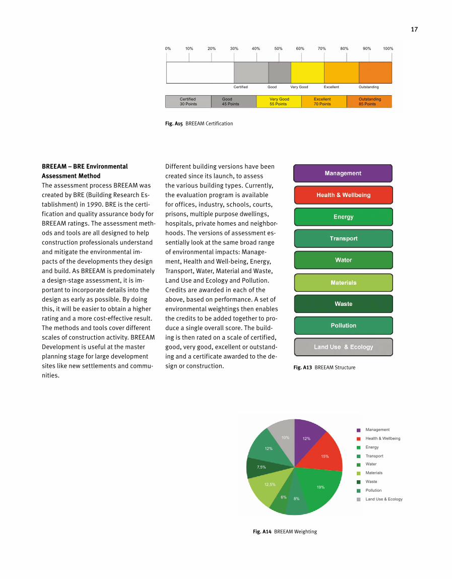
Different building versions have been
created since its launch, to assess
the various building types. Currently,
the evaluation program is available
for offices, industry, schools, courts,
prisons, multiple purpose dwell ings,
hospitals, private homes and neighbor-
hoods. The versions of assessment es-
sentially look at the same broad range
of environmental impacts: Manage-
ment, Health and Well-being, Energy,
Transport, Water, Material and Waste,
Land Use and Ecology and Pollution.
Credits are awarded in each of the
above, based on performance. A set of
environmental weightings then enables
the credits to be added toge ther to pro-
duce a single overall score. The build-
ing is then rated on a scale of certified,
good, very good, excellent or outstand-
ing and a certificate awarded to the de-
sign or construction.
BREEAM – BRE Environmental Assessment MethodThe assessment process BREEAM was
created by BRE (Building Research Es-
tablishment) in 1990. BRE is the certi-
fication and quality assurance body for
BREEAM ratings. The assessment meth-
ods and tools are all designed to help
construction professionals understand
and mitigate the environmental im-
pacts of the developments they design
and build. As BREEAM is predominately
a design-stage assessment, it is im-
portant to incorporate details into the
design as early as possible. By doing
this, it will be easier to obtain a higher
rating and a more cost-effective result.
The methods and tools cover dif ferent
scales of construction activity. BREEAM
Development is useful at the master
planning stage for large development
sites like new settlements and commu-
nities.Fig. A13 BREEAM Structure
Fig. A14 BREEAM Weighting
15%
19%
8%6%
12,5%
7,5%
10%
12%
12%
Management
Health & Wellbeing
Energy
Transport
Water
Materials
Waste
Pollution
Land Use & Ecology
0% 10% 20% 30% 40% 50% 60% 70% 80% 90% 100%
Certified Good Very Good Excellent Outstanding
Certified Good Very Good Excellent Outstanding 30 Points 45 Points 55 Points 70 Points 85 Points
Fig. A15 BREEAM Certification

18 The Motivation behind the Green Building Idea
DGNB – German Sustainable Building Certificate (GeSBC)In contrast to comparable systems, the
GeSBC label takes all three sustainabil-
ity dimensions in account in its assess-
ment structure, examining ecological,
economic and socio-cultural aspects.
As the result of legislation, the Ger-
man real estate industry already has a
high standard of sustainability. In addi-
tion to the Energy Passport, the GeSBC
addresses all items defining sustain-
ability to meet the demands.
The German Sustainable Building
Council (DGNB) was founded in June
2007 and created the German Sustain-
able Building Certificate together with
the German Federal Ministry of Trans-
port, Construction and Urban Develop-
ment. The goal is »to create living envi-
ronments that are environmentally com-
patible, resource-friendly and economi-
cal and that safeguard the health, com-
Fig. A16 DGNB Structure
Ecology Economy
Technical Quality
Process Quality
Site Quality
Social Quality
Fig. A 19 Certification medals
with DGNB Gold, Silver, Bronze
Fig. A17 DGNB Weighting
Process Quality
Technical Quality
Ecological Quality
Economical Quality
Social Quality
22,5%
22,5%
22,5%
22,5%10%
fort and performance of their users«.
The certification was introduced to
the real estate market in January 2009.
It is now possible to certify at three dif -
ferent levels, »Bronze«, »Silver« and
»Gold«. As shown in Fig. A16, site qual-
ity will be addressed, but a se parate
mark will be given for this, since the
boundary for the overall assessment is
defined as the building itself.
MINERGIE ECO®
Minergie® is a sustainability brand for
new and refurbished buildings. It is
supported jointly by the Swiss Confed-
eration and the Swiss Cantons along
with Trade and Industry. Suppliers in-
clude architects and engineers as well
as manufacturers of materials, compo-
nents and systems.
The comfort of occupants living or
working in the building is the heart of
Minergie®. A comprehensive level of
comfort is made possible by high-grade
building envelopes and the continuous
renewal of air.
The evaluation program is available
for homes, multiple dwellings, offices,
schools, retail buildings, restaurants,
meeting halls, hospitals, industry and
depots. Specific energy consumption
is used as the main indicator of Miner-
gie®, to quantify the required building
quality. The aim of the Standard »Min-
ergie-P®« is to qualify buildings that
achieve lower energy consumption than
the Minergie® standard. The Minergie
and the Minergie-P® Standard are pre-
requisites for the Minergie ECO® as-
sessment. The ECO® Standard comple-
ments Minergie with the cate gories
of health and ecology. The criteria are
assessed by addressing questions
on different aspects of lighting, noise,
ventilation, material, fabrication and
deconstruction. The affirmation of the
Fig. A 18 DGNB Certification
0% 10% 20% 30% 40% 50% 60% 70% 80% 90% 100%
Bronze Silver Gold
19
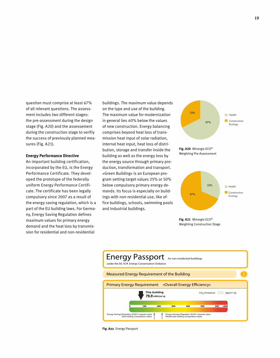
buildings. The maximum value depends
on the type and use of the building.
The maximum value for modernization
in general lies 40% below the values
of new construction. Energy balancing
comprises beyond heat loss of trans-
mission heat input of solar radi ation,
internal heat input, heat loss of distri-
bution, storage and transfer inside the
building as well as the energy loss by
the energy source through primary pro-
duction, transformation and transport.
»Green Building« is an European pro-
gram setting target values 25% or 50%
below compulsory primary energy de-
mands. Its focus is especially on build-
ings with non-residential use, like of-
fice buildings, schools, swimming pools
and industrial buildings.
question must comprise at least 67%
of all relevant questions. The assess-
ment includes two different stages:
the pre-assessment during the design
stage (Fig. A20) and the assessement
during the construction stage to verifiy
the success of previously planned mea-
sures (Fig. A21).
Energy Performance DirectiveAn important building certification,
incorporated by the EU, is the Energy
Performance Certificate. They devel-
oped the prototype of the federally
uniform Energy Performance Certifi-
cate. The certificate has been legally
compulsory since 2007 as a result of
the energy saving regulation, which is a
part of the EU building laws. For Germa-
ny, Energy Saving Regulation defines
maximum values for primary energy
demand and the heat loss by transmis-
sion for residential and non-residential
Fig. A22 Energy Passport
Health
Construction Ecology
67%
33%
Fig. A 20 Minergie ECO®
Weighting Pre-Assessment
Fig. A 21 Minergie ECO®
Weighting Construction Stage
67%
33% Health
Construction Ecology
20 The Motivation behind the Green Building Idea
An integrated View of Green Buildings – Life Cycle Engineering
Green Buildings are buildings of any
usage category that subscribe to the
principle of a conscientious handling of
natural resources. This means causing
as little environmental interference as
possible, the use of environmentally-
friendly materials that do not constitute
a health hazard, indoor solutions that
facilitate communication, low energy
requirements, renewable energy use,
high-quality and longevity as a guide-
line for construction, and, last but not
least, an economical operation. In
order to achieve this, an integrated,
cross-trade approach is required to
allow for an interface-free, or as inter-
face-free as possible, handling of the
trades of architecture, support struc-
ture, façade, building physics, build-
ing technology and energy while tak-
ing into account both usage consider-
ations and climatic conditions. To this
end, innovative planning and simula-
tion tools are employed, according
to standards, during the design and
planning stages for Green Buildings.
They allow for new concepts since – by
means of simulation of thermal, flow
and energy behaviour – detailed cal-
culations can be achieved already dur-
ing the design stage. Attainable com-
fort levels and energy efficiency can
thus be calculated in advance and this
means that, already during the design
stage, it is possible to achieve best
possible security in regards to costs
and cost efficiency. Equipped with
these kinds of tools, Green Building de-
signers and planners can safely tread
new paths where they may develop
novel concepts or products.
Aside from an integrated design and
work approach, and the development
and further development of products
and tools, sustainability must be ex-
panded so that the planners are able
to gather valuable experience even
during the operation of the buildings.
This is the only way that a constructive
back-flow of information into the build-
ing design process can be achieved,
something that, until now, does not ap-
ply for contemporary building construc-
tion. This approach is to be expanded
to encompass renaturation, in order
to make allowances for the recycling
capability of materials used even dur-
ing the planning stage. In other indus-
trial sectors, this is already required by
law but, in the building sector, we are
clearly lagging behind in this aspect.
On account of consistent and rising en-
vironmental stress, however, it is to
be expected that sustainability will also
be demanded of buildings in the medi-
um-term and thus not-too-distant fu-
ture.
The path from sequential to integral
planning, hence, needs to be developed
on the basis of an integral approach
to buildings and is to be extended in the
direction of a Life Cycle Engineering
approach. This term stands for integral
design and consultation knowledge,
which always evaluates a given concept
or planning decision under the aspects
of its effects on the entire life-cycle of
a given building. This long-term evalu-
ation, then, obliges a sustainable han-
dling of all resources.
The authors consider Life Cycle En-
gineering to be an integral approach,
which results in highest possible sus-
tainability levels during construction.
It unites positive factors from integral
planning and/or design, the manifold
possibilities of modern planning and
calculation tools, ongoing optimisation
processes during operation, and con-
scientious handling during renaturation
of materials. All this results in a Green
Building that, despite hampering nature
as little as possible, can provide a com-
fortable living environment to meet the
expectations of its inhabitants.
21
Renewal Investments
Servicing and Inspection
Interest on Capital
Maintenance
Energy
A3.03
Sequential Planning Integral Planning Life Cycle Engineering
Planning
Building Construction
Building Construction
Building Construction
Client
Architect
Expert Planner 1Expert Planner 2
........
Client
Architect
Expert Planner 1Expert Planner 2
........
Client
Architect
Expert Planner 1Expert Planner 2
........
Operator/Tenant Operator/Tenant Operator/Tenant
Conceptual Knowledge
Operation
Rec
yclin
g
Rec
yclin
g
Rec
yclin
gOperation OperationPlanning Planning
0
1
2
3
4
5
6
2000 2030 2020 2040 2080 2100
a
b
a: rising world population level, no change in energy policy
b: stagnation of world population level, sustainable energy policy
Ventilation SystemHeating SystemGlazingComposite Heat Insulation SystemGeothermal Probe/Ground-coupled Heat ExchangerConcrete Support Structure
Year
Ove
rall
Glo
bal T
empe
ratu
re R
ise
in °
C
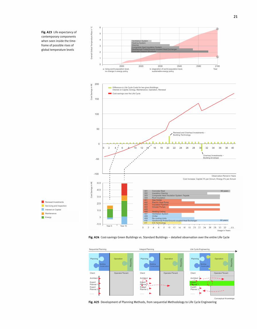
Fig. A 24 Cost-savings Green Buildings vs. Standard Buildings – detailed observation over the entire Life Cycle
Fig. A 25 Development of Planning Methods, from sequential Methodology to Life Cycle Engineering
Fig. A 23 Life expectancy of
contemporary components
when seen inside the time-
frame of possible rises of
global temperature levels
-100
-50
0
50
100
150
200
0 2 4 6 8 10 12 14 16 18 20 22 24 26 28 30 32 34 36 38 40
0 2 4 6 8 10 12 14 16 18 20 22 24 26 28 30 32 ....80...
-100
0
100
200
300
400
500
Renewal and Overhaul Investments – Building Technology
Year 5 Year 15
Usage in Years
Observation Period in Years Cost Increase: Capital 2% per Annum, Energy 5% per Annum
Overhaul Investments – Building Envelope
Concrete SteelInsulation GlazingComposite Heat Insulation System: FaçadeRoof InsulationGas HolderElectric Heat PumpInsulated PipelinesCircular Pumps
Heating CeilingVentilation SystemChillerRe-cooling UnitsGeothermal Probe/Ground-coupled Heat ExchangerICA Technology
301302303304401402403404405406407408409410411
80 years
60 years
Cos
t Sav
ings
in K
€
Difference in Life Cycle Costs for two given Buildings: Interest on Capital, Energy, Maintenance, Operation, Renewal
Cost-savings over the Life CycleC
ost S
avin
gs in
K€
A B

Green Building Requirements
C D
Sustainable Design
A B 1
25
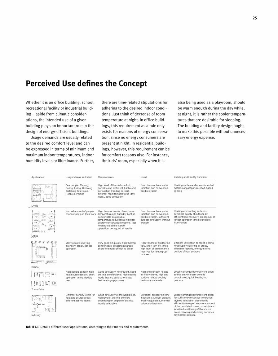
Perceived Use defines the Concept
Whether it is an office building, school,
recreational facility or industrial build-
ing – aside from climatic consider-
ations, the intended use of a given
building plays an important role in the
design of energy-efficient buildings.
Usage demands are usually related
to the desired comfort level and can
be expressed in terms of minimum and
maximum indoor temperatures, indoor
humidity levels or illuminance. Further,
there are time-related stipulations for
adhering to the desired indoor condi-
tions. Just think of decrease of room
temperature at night. In office build-
ings, this requirement as a rule only
exists for reasons of energy conserva-
tion, since no energy consumers are
present at night. In residential build-
ings, however, this requirement can be
for comfort reasons also. For instance,
the kids’ room, especially when it is
Tab. B 1.1 Details different user applications, according to their merits and requirements
also being used as a playroom, should
be warm enough during the day while,
at night, it is rather the cooler tempera-
tures that are desirable for sleeping.
The building and facility design ought
to make this possible without unneces-
sary energy expense.
Building and Facility Function
Heating surfaces, demand-oriented addition of outdoor air, need-based lighting Heating and cooling surfaces, sufficient supply of outdoor air, efficient heat recovery, on account of longer operation times: sufficient illumination Efficient ventilation concept, optimal heat supply covering all areas, adequate lighting, energy-saving outflow of heat sources Locally arranged layered ventilation so that only the user zone is coordinated, quick heating-up process Locally arranged layered ventilation for sufficient work place ventilation, layered ventilation also used to efficiently transport source areas out of the populated zones, possibly also localized suctioning of the source areas, heating and cooling surfaces for thermal balance
Need
Even thermal balance for radiation and convection, flexible system Even thermal balance for radiation and convection, flexible system, sufficient outdoor air supply, without draught High volume of outdoor air flow, short turn-off times, high level of performance reserves for heating-up process High and surface-related air flow volume, high and surface related cooling performance levels Sufficient outdoor air flow - if possible: without draught, locally adjustable, thermal balance adjustment
Requirements
High level of thermal comfort, partially also sufficient if achieved per section (reading corner), different room temperatures (day/night), good air quality High thermal comfort level, room temperature and humidity kept as comfortable as possible, temperature reduction at night for energy conservation reasons, fast heating-up at the start of operation, very good air quality Very good air quality, high thermal comfort level covering all areas, short-term turn-off during break Good air quality, no draught, good thermal comfort level, high cooling loads that are surface-oriented, fast heating-up process Good air quality at the work place, high level of thermal comfort depending on degree of activity, locally adaptable
Usage Means and Merit
Few people, Playing, Eating, Living, Cleaning, Watching Television, Hobbies, Parties Normal amount of people, concentrating on their work Many people studying intensely, break, school operation High people density, high heat source density, short operation times, flexible use Different density levels for heat and source areas, different activity levels
Application
Living
Office
School
Trade Fairs
Industry
26
Relationship between Level of Well-Being and healthy Indoor Climate
Buildings, as a kind of third skin, are
an important factor for our health and
quality of life. A high performance level
at work can only be obtained when a
high level of well-being exists also.
This gives rise to creative processes
and ideas and also allows our body to
regenerate and heal. The related high
performance capacity of man is reflect-
ed in both work life and inter-human
relationships. Naturally, there are many
different influences and sizes of those
influences on man’s well-being and
biorhythm. Some can be physically
meas ured, such as air temperature or
indoor noise level. Other factors are
of a biological nature, like age and state
of health, or ethically different educa-
tion levels. For thermal comfort levels,
it is also important what type of cloth-
ing is worn during which activities. In -
termediate well-being criteria are also,
for instance, whether a colleague in a
two-person office is liked or not. There
are also other influences that only be-
come noticeable when one is subjec-
ted to them over longer periods of time.
Among these, for instance, are high-
emission materials (for instance, ad-
hes ives) and electromagnetic rays that
continue to gain ever-increasing influ-
ence (see table B1.2).
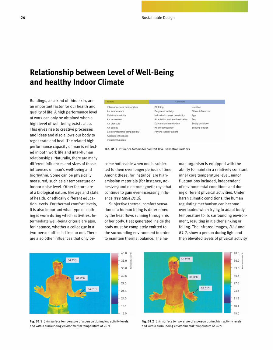
Subjective thermal comfort sensa-
tion of a human being is determined
by the heat flows running through his
or her body. Heat generated inside the
body must be completely emitted to
the surrounding environment in order
to maintain thermal balance. The hu-
man organism is equipped with the
abil ity to maintain a relatively constant
in ner core temperature level, minor
fluctuations included, independent
of environmental conditions and dur-
ing different physical activities. Under
harsh climatic conditions, the human
regulating mechanism can become
overloaded when trying to adapt body
temperature to its surrounding environ-
ment, resulting in it either sinking or
falling. The in fra red images, B1.1 and
B1.2, show a person during light and
then elevated levels of physical activity
Sustainable Design
Tab. B 1.2 Influence factors for comfort level sensation indoors
Fig. B 1.2 Skin surface temperature of a person during high activity levels
and with a surrounding environmental temperature of 26 °C
Fig. B 1.1 Skin surface temperature of a person during low activity levels
and with a surrounding environmental temperature of 26 °C
Factors Conditions
Internal surface temperature
Air temperature
Relative humidity
Air movement
Air pressure
Air quality
Electromagnetic compatibility
Acoustic influences
Visual influences
Clothing
Degree of activity
Individual control possibility
Adaptation and acclimatization
Day and annual rhythm
Room occupancy
Psycho-social factors
Nutrition
Ethnic influences
Age
Sex
Bodily condition
Building designTe
mpe
ratu
re in
°C
34.7°C
40.0
36.9
33.8
30.6
27.5
24.4
21.3
18.1
15.0
40.0
36.9
33.8
30.6
27.5
24.4
21.3
18.1
15.0
35.2°C
34.2°C 35.8°C
34.3°C 35.0°C
Tem
pera
ture
in °
C

27
employee. When this is now applied to
the gross floor a rea (GFA) of a typical
office building, an annual loss of 500
to 2000 Euros per square meter GFA
results. Comp are this to the required
costs for the installation and operation
of a cooling system, which are, on av
erage, only 15 to 25 Euros per square
meter GFA per annum. You will see
that this is a relatively small amount
by comparison. Figure B1.4 shows
phys ical and mental perfor mance ca
pacity as it relates to room temperature
and was determined by past research.
It shows that, from room temperatures
of about 25°C to 26°C upwards, perfor
mance capacity notic eably decreases.
From 28 to 29°C onwards, work effi
ciency clearly decreases.
Relationship between Comfort Level and Performance Ability
The work performance level of a person
and the required work efficiency level
have risen in recent years, especially
in industrial nations, on account of
glob al competition. Building owners
and tenants have recognized by now
that comfortable indoor climate lev
els are a decisive factor when it comes
to upholding productivity levels. If,
for instance, a company suffers from
an unacceptable indoor climate for
10% of work time, this leads to a more
or less noticeable decrease in work
performance levels, spread over 200
hours or 25 days per annum per staff
member. For service enterprises with
daily rates of 500 to 2000 Euro per day,
this means a financial loss of between
12 500 to 50 000 Euro per annum per
Fig. B 1.3 Heat emission rates for a person as
it relates to surrounding environmental tempera
ture. From a temperature of 34°C, the body can
exclusively emit heat via evaporation (sweating),
since the surface temperature of the human skin
is also 34 °C.
Fig. B 1.4 Performance capacity of a person
as it relates to room temperature.
and also the corresponding tempera
ture distribution on the skin surface.
These differences show that, in both
cases, thermal comfort can only be
achieved when either the temperat
ure of the surrounding environment
or the clothing worn has been chosen
according to the situation. Uncomfort
able sweating (high level of evapora
tion) can be largely avoided, for in
stance, when a skin surface tempera
ture of about 34°C is not exceeded
and the surrounding environmental
temperatures range somewhere just
below the 26°C level.
As the infrared images also clearly
show, the highest surface temperat
ures for people are around the head
region, the lowest at the point farthest
from the heart, the feet region. This al
lows for the conclusion that thermal
comfort can only be obtained whenever
surface temperatures of room envelope
surfaces are adjusted to human need.
A ceiling that is too warm inside a heat
ed room, for instance, prevents heat
em ission in the head region and quick
ly leads to headaches. Likewise, cold
floors elevate heat loss levels via the
feet and increase surface temperature
differences of the human body (Figure
B1.3).
Hea
t Em
issi
on R
ate
in W
Perf
orm
ance
cap
acity
in %
Air Temperature in °C
EvaporationConvectionRadiation
Room Temperature in °C
Mental perform - ance capacity according to Wyon
Physical and mental perform - ance capacity according to Hettinger
Perceived per - formance capacity according to D&S Advanced Building Technologies
28
Operative Indoor Temperature in Occupied Rooms
Prof. P. O. Fanger of the University of
Den mark at Copenhagen, undertook
some research into how precisely the
level of well-being of people indoors
is perceived under different thermal
conditions. The basis for the research
was the essential influential factors of
man on thermal body balance: activity
level and type, clothing, air and radia-
tion temperature, air velocity and air
humidity levels. Research results were
interpreted in such a manner as to al-
low calculation of prospective and sub-
jective heat sensation, so long as the
above-mentioned factors can be deter-
mined. They also show that it is impos-
sible to please everyone, on account of
the individuality of man. A study with
more than 1300 human subjects has
shown that at least 5% of the subjects
will perceive the indoor climate as being
of an uncomfortable level. For heat sen-
sation, according to valid and current
international and European standards,
three different categories of thermal
comfort have been defined: Category
A, the highest (very good) has a prob-
ability of 6% dissatisfied, the medium
category B (good) has 10% dissatisfied
and in category C (acceptable) there
is a high probability of the presence of
about 15% dissatisfied people.
Temperature is the decisive factor
for subjective thermal comfort. Depend-
ing on mood, duration of stay and lo-
cale, the same situation is being per-
ceived differently by the same person.
Direct solar radiation on the body, for
instance, can be perceived as pleasant
when it happens during relaxation in
one’s own living room. In stress situa-
tions, however, the same heat supply
source is perceived as uncomfortable.
A person perceives temperature as it
results from the adjacent air tempera-
tures, individual temperatures of sur-
rounding surfaces and, possibly, direct
solar radiation. This temperature is
known as operative temperature.
For rooms with a longer duration of
stay, the criteria used are the mean
operative temperature without direct
solar radiation. To simplify matters, this
becomes the mean value, resulting
from the present surface temperatures
of interior surface areas and indoor
temperature in general. Surface tem-
peratures are also known as radiation
temperatures. The relation between
rad iation and air temperatures can be
changed by means of heat insulating
merits of the façade system, building
mass present or through the techni-
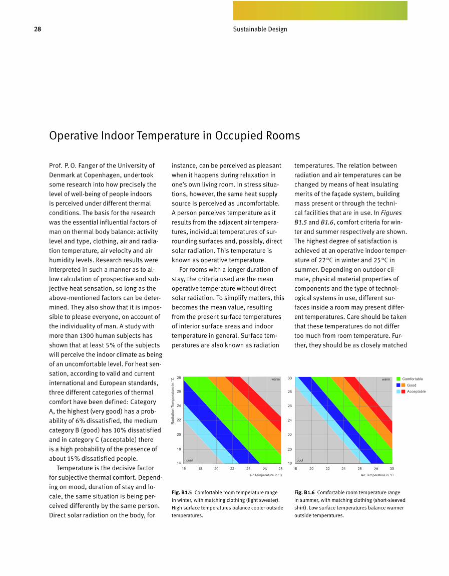
cal facilities that are in use. In Figures
B1.5 and B1.6, comfort criteria for win-
ter and summer respectively are shown.
The highest degree of satisfaction is
achieved at an operative indoor tem per-
ature of 22°C in winter and 25°C in
sum mer. Depending on outdoor cli-
mate, physical material properties of
components and the type of technol -
o gical systems in use, different sur-
faces inside a room may present differ-
ent temperatures. Care should be taken
that these temperatures do not differ
too much from room temper ature. Fur-
ther, they should be as closely matched
Fig. B 1.5 Comfortable room temperature range
in winter, with matching clothing (light sweater).
High surface temperatures balance cooler outside
temperatures.
Fig. B 1.6 Comfortable room temperature range
in summer, with matching clothing (short-sleeved
shirt). Low surface temperatures balance warmer
outside temperatures.
Sustainable Design
Rad
iatio
n Te
mpe
ratu
re in
°C
Air Temperature in °C
cool
warm
cool
warm
Good
Acceptable
Comfortable
Air Temperature in °C
29
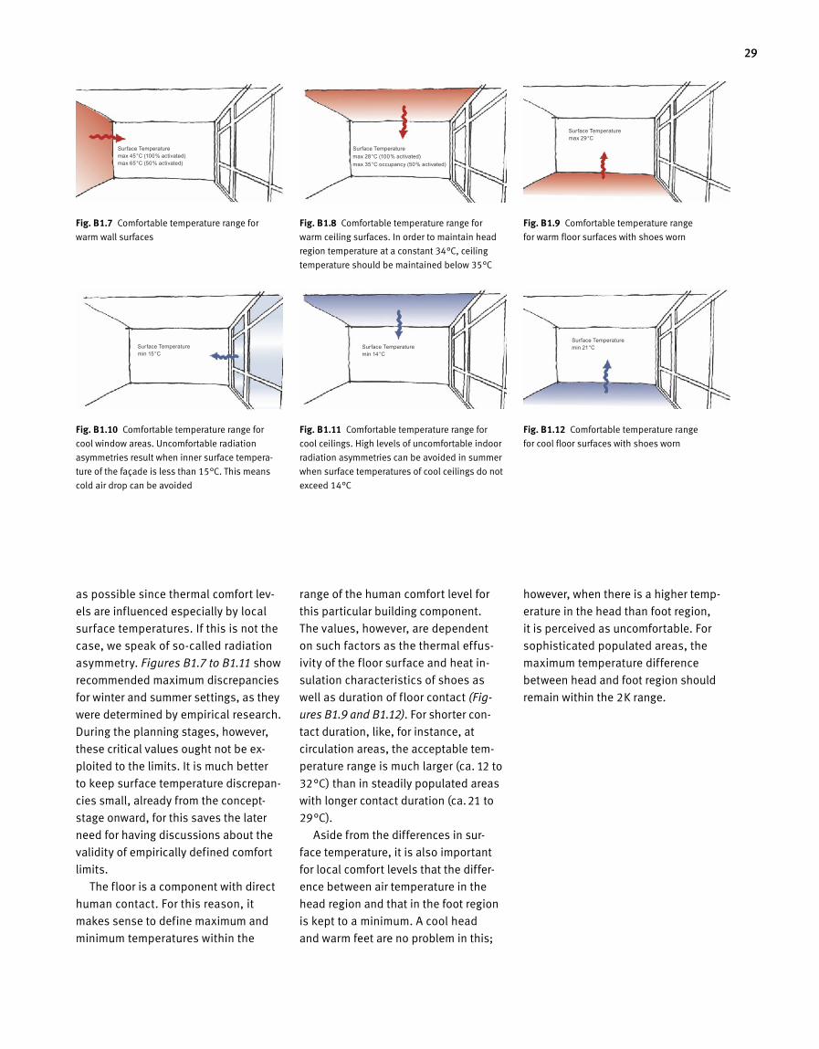
Fig. B 1.11 Comfortable temperature range for
cool ceilings. High levels of uncomfortable indoor
radiation asymmetries can be avoided in summer
when surface temperatures of cool ceilings do not
exceed 14°C
as possible since thermal comfort lev-
els are influenced especially by local
surface temperatures. If this is not the
case, we speak of so-called radiation
asymmetry. Figures B1.7 to B1.11 show
recommended max imum discrepancies
for winter and summer settings, as they
were determined by empirical research.
During the planning stages, however,
these critical values ought not be ex-
ploited to the limits. It is much better
to keep surface temperature discrepan-
cies small, already from the concept-
stage onward, for this saves the later
need for having discussions about the
validity of empirically defined comfort
limits.
The floor is a component with di rect
human contact. For this reason, it
makes sense to define maximum and
minimum temperatures within the
range of the human comfort level for
this particular building component.
The values, however, are dependent
on such factors as the thermal effus-
ivity of the floor surface and heat in-
sulation characteristics of shoes as
well as duration of floor contact (Fig-
ures B1.9 and B1.12). For shorter con-
tact duration, like, for instance, at
circulation areas, the acceptable tem-
perature range is much larger (ca. 12 to
32°C) than in stead ily populated areas
with longer contact duration (ca. 21 to
29°C).
Aside from the differences in sur -
face temperature, it is also important
for local comfort levels that the differ-
ence between air temperature in the
head region and that in the foot region
is kept to a minimum. A cool head
and warm feet are no problem in this;
how ever, when there is a higher temp-
erature in the head than foot region,
it is perceived as uncomfortable. For
sophisticated populated areas, the
maximum temperature difference
between head and foot region should
remain within the 2K range.
Fig. B 1.7 Comfortable temperature range for
warm wall surfaces
Fig. B 1.9 Comfortable temperature range
for warm floor surfaces with shoes worn
Fig. B 1.10 Comfortable temperature range for
cool window areas. Uncomfortable radiation
asymmetries result when inner surface tempera-
ture of the façade is less than 15°C. This means
cold air drop can be avoided
Fig. B 1.12 Comfortable temperature range
for cool floor surfaces with shoes worn
Fig. B 1.8 Comfortable temperature range for
warm ceiling surfaces. In order to maintain head
region temperature at a constant 34°C, ceiling
temperature should be maintained below 35°C
Surface Temperature max 45°C (100% activated) max 65°C (50% activated)
Surface Temperature min 15°C
Surface Temperature max 28°C (100% activated) max 35°C occupancy (50% activated)
Surface Temperature min 14°C
Surface Temperature max 29°C
Surface Temperature min 21°C
30
Operative Temperature in Atria
Evaluation criteria for common rooms
cannot be applied to atria and halls in
anything but a limited manner since
these areas are, as a whole, used as
circulation areas and only at times al
so serve as settings for functions. As
a guideline for design, in this case, we
need rather to look at operative out
door temperatures in comparison. This
depends largely on temperature differ
ences between winter and summer,
wind velocity and sunlight influence.
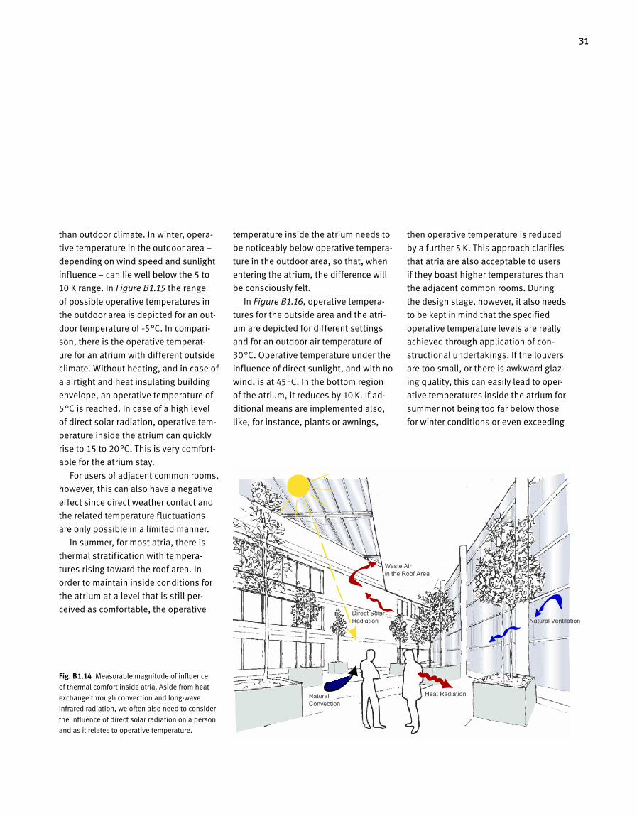
In Figure B1.14, the magnitude of in
fluence on physically operative tempe
rature (PET) is depicted: aside from the
known magnitudes of influence like air
temperature, surface temperature and
air velocity, in this case there is also a
relationship to be taken into account
between direct solar radiation and the
resulting operative temperature. When
designing halls and atria for Green
Buildings, hence, it is important to ob
tain an indoor climate – by the exclu
sive use of construction means and
natural resources – that for most of the
year will be experienced as being nicer
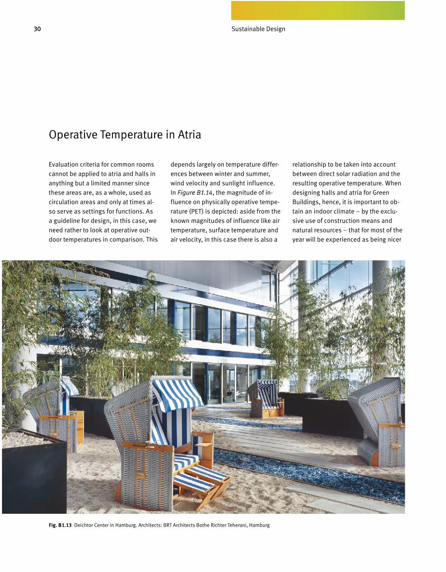
Fig. B 1.13 Deichtor Center in Hamburg. Architects: BRT Architects Bothe Richter Teherani, Hamburg
Sustainable Design
31
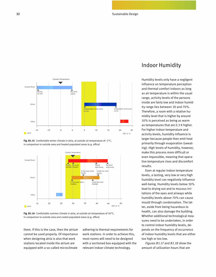
than outdoor climate. In win ter, opera
tive temperature in the outdoor area –
depending on wind speed and sunlight
influence – can lie well below the 5 to
10 K range. In Figure B1.15 the range
of possible operative temperatures in
the outdoor area is depicted for an out
door temperature of –5°C. In compari
son, there is the operative temperat
ure for an atrium with different outside
climate. Without heating, and in case of
a airtight and heat insulating build ing
envelope, an operative temperature of
5°C is reached. In case of a high level
of direct solar radiation, operative tem
perature inside the atrium can quickly
rise to 15 to 20°C. This is very comfort
able for the atrium stay.
For users of adjacent common rooms,
however, this can also have a negative
effect since direct weather contact and
the related temperature fluctuations
are only possible in a limited manner.
In summer, for most atria, there is
thermal stratification with tempera
tures rising toward the roof area. In
order to maintain inside conditions for
the atrium at a level that is still per
ceived as comfortable, the operative
temperature inside the atrium needs to
be noticeably below operative tempera
ture in the outdoor area, so that, when
entering the atrium, the difference will
be consciously felt.
In Figure B1.16, operative tempera
tures for the outside area and the atri
um are depicted for different settings
and for an outdoor air temperature of
30°C. Operative temperature under the
influence of direct sunlight, and with no
wind, is at 45°C. In the bottom region
of the atrium, it reduces by 10 K. If ad
ditional means are implemented also,
like, for instance, plants or awnings,
then operative temperature is reduced
by a further 5 K. This approach clarifies
that atria are also acceptable to users
if they boast higher tempe r a tures than
the adjacent common rooms. During
the design stage, how ever, it also needs
to be kept in mind that the specified
operative temp erature lev els are really
achieved through application of con
structional undertakings. If the louvers
are too small, or there is awkward glaz
ing quality, this can easily lead to oper
ative temperatures inside the atrium for
summer not being too far below those
for winter conditions or even exceed ing
Fig. B 1.14 Measurable magnitude of influence
of thermal comfort inside atria. Aside from heat
exchange through convection and longwave
infrared radiation, we often also need to consider
the influence of direct solar radiation on a person
and as it relates to operative temperature.
Waste Air in the Roof Area
Direct Solar Radiation
Natural Convection
Heat Radiation
Natural Ventilation
32 Bedarfsgerechtes Design
Humidity levels only have a negligent
influence on temperature perception
and thermal comfort indoors as long
as air temperature is within the usual
range, activity levels of the persons
inside are fairly low and indoor humid-
ity range lies between 30 and 70%.
Therefore, a room with a relative hu-
midity level that is higher by around
10% is perceived as being as warm
as temperatures that are 0.3 K higher.
For higher indoor temperature and
activity levels, humidity influence is
lar g er because people then emit heat
primarily through evaporation (sweat-
ing). High levels of humidity, however,
make this process more difficult or
even impossible, meaning that opera-
tive temperature rises and discomfort
results.
Even at regular indoor temperature
levels, a lasting, very low or very high
humidity level can negatively influence
well-being. Humidity levels below 30%
lead to drying out and to mucous irri-
tations of the eyes and airways while
humidity levels above 70% can cause
mould through condensation. The lat-
ter, aside from being hazardous to
health, can also damage the building.
Whether additional technological mea-
sures need to be undertaken, in order
to control indoor humidity levels, de-
pends on the frequency of occurrence
of indoor humidity levels that are either
too high or too low.
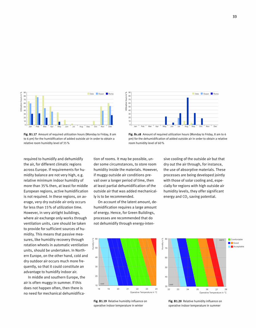
Figures B1.17 and B1.18 show the
amount of utilization hours that are
Indoor Humidity
them. If this is the case, then the atrium
cannot be used properly. Of importance
when designing atria is also that work
stations located inside the atrium are
equipped with a so-call ed microclimate
adhering to thermal requirements for
work stations. In order to achieve this,
most rooms will need to be designed
with a sectioned box equipped with the
relevant indoor climate technology.
Fig. B 1.16 Comfortable summer climate in atria, at outside air temperature of 30°C,
in comparison to outside area and cooled populated areas (e.g. office)
Fig. B 1.15 Comfortable winter climate in atria, at outside air temperature of –5°C,
in comparison to outside area and heated populated areas (e.g. office)
Outside Room
Atrium
Office
Outside Room
Atrium
Office
Outside Temperature
Outside Temperature
Windy, shaded
Windy and sunny
No wind, shaded
No wind and sunny
In the lower area: shaded
In the lower area: sunny
Under the roof, sunny
Under the roof, shaded
good
good
Windy, no sun
No wind, sunny
Independent of the wind, no sun
Independent of the wind, sunny
PET in °C
Sustainable Design
PET in °C
33
required to humidify and dehumidify
the air, for different climatic regions
across Europe. If requirements for hu
midity balance are not very high, e.g.
relative minimum indoor humidity of
more than 35% then, at least for middle
European regions, active humidification
is not required. In these regions, on av
erage, very dry outside air only occurs
for less than 15% of utilization time.
However, in very airtight buildings,
where air exchange only works through
ventilation units, care should be taken
to provide for sufficient sources of hu
midity. This means that passive mea
sures, like humidity recovery through
rotation wheels in automatic ventilation
units, should be undertaken. In North
ern Europe, on the other hand, cold and
dry outdoor air occurs much more fre
quently, so that it could constitute an
advantage to humidify indoor air.
In middle and southern Europe, the
air is often muggy in summer. If this
does not happen often, then there is
no need for mechanical dehumidifica
tion of rooms. It may be possible, un
der some circumstances, to store room
humidity inside the materials. However,
if muggy outside air conditions pre
vail over a longer period of time, then
at least partial dehumidification of the
outside air that was added mechanical
ly is to be recommended.
On account of the latent amount, de
humidification requires a large amount
of energy. Hence, for Green Buildings,
processes are recommended that do
not dehumidify through energyinten
Fig. B 1.19 Relative humidity influence on
operative indoor temperature in winter
sive cooling of the outside air but that
dry out the air through, for instance,
the use of absorptive materials. These
processes are being developed jointly
with those of solar cooling and, espe
cially for regions with high outside air
humidity levels, they offer significant
energy and CO2 saving potential.
Fig. B 1.17 Amount of required utilization hours (Monday to Friday, 8 am
to 6 pm) for the humidification of added outside air in order to obtain a
relative room humidity level of 35 %
Fig. B 1.18 Amount of required utilization hours (Monday to Friday, 8 am to 6
pm) for the dehumidification of added outside air in order to obtain a relative
room humidity level of 60 %
Oslo Essen Rome
Operative Temperature in °C
cool cool
warm
Oslo Essen Rome
Util
izat
ion
hour
s in
%
Hum
idity
in %
Hum
idity
in %
Util
izat
ion
hour
s in
%Jan Feb Mar Apr May Jun Jul Aug Sep Oct Nov Dec Jan Feb Mar Apr May Jun Jul Aug Sep Oct Nov Dec
Good
Acceptable
Comfortable
Fig. B 1.20 Relative humidity influence on
operative indoor temperature in summer
Operative Temperature in °C
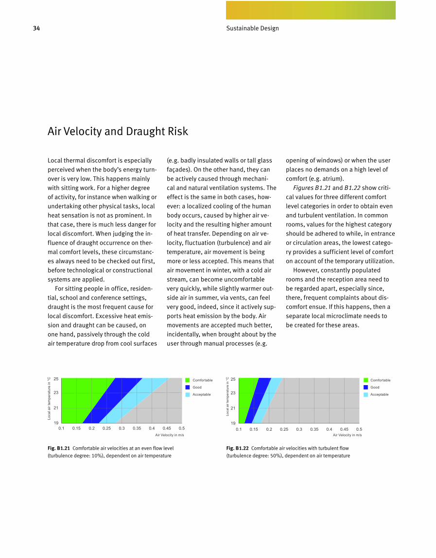
34 Bedarfsgerechtes Design
Air Velocity and Draught Risk
Local thermal discomfort is especially
perceived when the body’s energy turn-
over is very low. This happens mainly
with sitting work. For a higher degree
of activity, for instance when walking or
undertaking other physical tasks, local
heat sensation is not as prominent. In
that case, there is much less danger for
local discomfort. When judging the in-
fluence of draught occurrence on ther-
mal comfort levels, these circumstanc-
es always need to be checked out first,
before technological or constructional
systems are applied.
For sitting people in office, residen-
tial, school and conference settings,
draught is the most frequent cause for
local discomfort. Excessive heat emis-
sion and draught can be caused, on
one hand, passively through the cold
air temperature drop from cool surfaces
(e.g. badly insulated walls or tall glass
façades). On the other hand, they can
be actively caused through mechani-
cal and natural ventilation systems. The
effect is the same in both cases, how-
ever: a localized cooling of the human
body occurs, caused by higher air ve-
locity and the resulting higher amount
of heat transfer. Depending on air ve-
locity, fluctuation (turbulence) and air
temperature, air movement is being
more or less accepted. This means that
air movement in winter, with a cold air
stream, can become uncomfortable
very quickly, while slightly warmer out-
side air in summer, via vents, can feel
very good, indeed, since it actively sup-
ports heat emission by the body. Air
movements are accepted much better,
incidentally, when brought about by the
user through manual processes (e.g.
opening of windows) or when the user
places no demands on a high level of
comfort (e.g. atrium).
Figures B1.21 and B1.22 show criti-
cal values for three different comfort
level categories in order to obtain even
and turbulent ventilation. In common
rooms, values for the highest category
should be adhered to while, in entrance
or circulation areas, the lowest catego-
ry provides a sufficient level of comfort
on account of the temporary utilization.
However, constantly populated
rooms and the reception area need to
be regarded apart, especially since,
there, frequent complaints about dis-
comfort ensue. If this happens, then a
separate local microclimate needs to
be created for these areas.
Fig. B 1.22 Comfortable air velocities with turbulent flow
(turbulence degree: 50%), dependent on air temperature
Fig. B 1.21 Comfortable air velocities at an even flow level
(turbulence degree: 10%), dependent on air temperature
Air Velocity in m/s Air Velocity in m/s
Loca
l air
tem
pera
ture
in °
C
Loca
l air
tem
pera
ture
in °
CComfortable
Good
Acceptable
Comfortable
Good
Acceptable
Sustainable Design
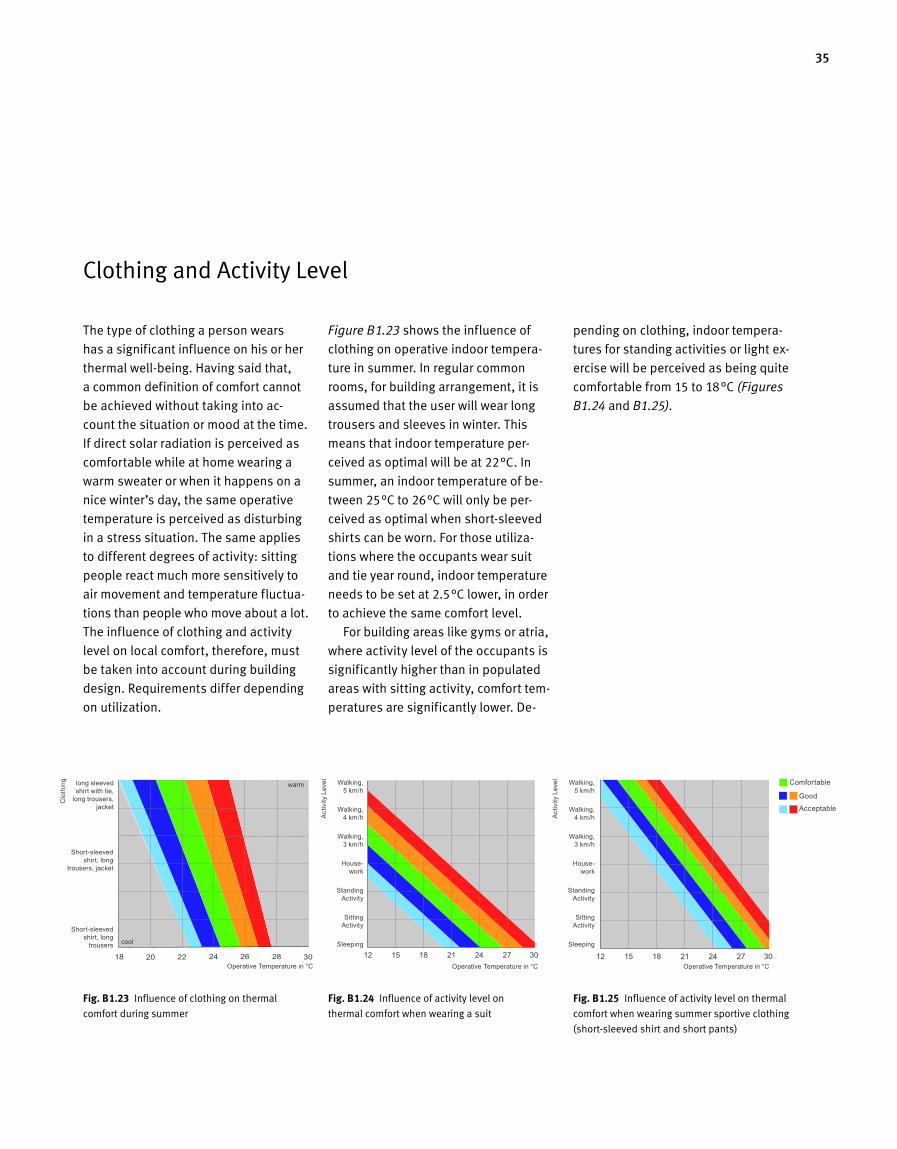
35
Clothing and Activity Level
The type of clothing a person wears
has a significant influence on his or her
thermal wellbeing. Having said that,
a common definition of comfort cannot
be achieved without taking into ac
count the situation or mood at the time.
If direct solar radiation is perceived as
comfortable while at home wearing a
warm sweater or when it happens on a
nice winter’s day, the same operative
temperature is perceived as disturbing
in a stress situation. The same applies
to different degrees of activity: sitting
people react much more sensitively to
air movement and temperature fluctua
tions than people who move about a lot.
The influence of clothing and activity
level on local comfort, therefore, must
be taken into account during building
design. Requirements differ depending
on utilization.
Figure B1.23 shows the influence of
clothing on operative indoor tempera
ture in summer. In regular common
rooms, for building arrangement, it is
assumed that the user will wear long
trousers and sleeves in winter. This
means that indoor temperature per
ceived as optimal will be at 22°C. In
summer, an indoor temperature of be
tween 25°C to 26°C will only be per
ceived as optimal when shortsleeved
shirts can be worn. For those utiliza
tions where the occupants wear suit
and tie year round, indoor temperature
needs to be set at 2.5°C lower, in order
to achieve the same comfort level.
For building areas like gyms or atria,
where activity level of the occupants is
significantly higher than in populated
areas with sitting activity, comfort tem
peratures are significantly lower. De
pending on clothing, indoor tempera
tures for standing activities or light ex
ercise will be perceived as being quite
comfortable from 15 to 18°C (Figures
B1.24 and B1.25).
Fig. B 1.24 Influence of activity level on
thermal comfort when wearing a suit
Fig. B 1.23 Influence of clothing on thermal
comfort during summer
Fig. B 1.25 Influence of activity level on thermal
comfort when wearing summer sportive clothing
(shortsleeved shirt and short pants)
Walking, 5 km/h
Walking, 4 km/h
Walking, 3 km/h
House-work
Standing Activity
Sitting Activity
Sleeping
Walking, 5 km/h
Walking, 4 km/h
Walking, 3 km/h
House-work
Standing Activity
Sitting Activity
Sleeping
Operative Temperature in °C Operative Temperature in °C
long sleeved shirt with tie,
long trousers, jacket
Short-sleeved shirt, long
trousers, jacket
Short-sleeved shirt, long
trousers
Operative Temperature in °C
cool
warm
Clo
thin
g
Act
ivity
Lev
el
Act
ivity
Lev
el
Good
Acceptable
Comfortable
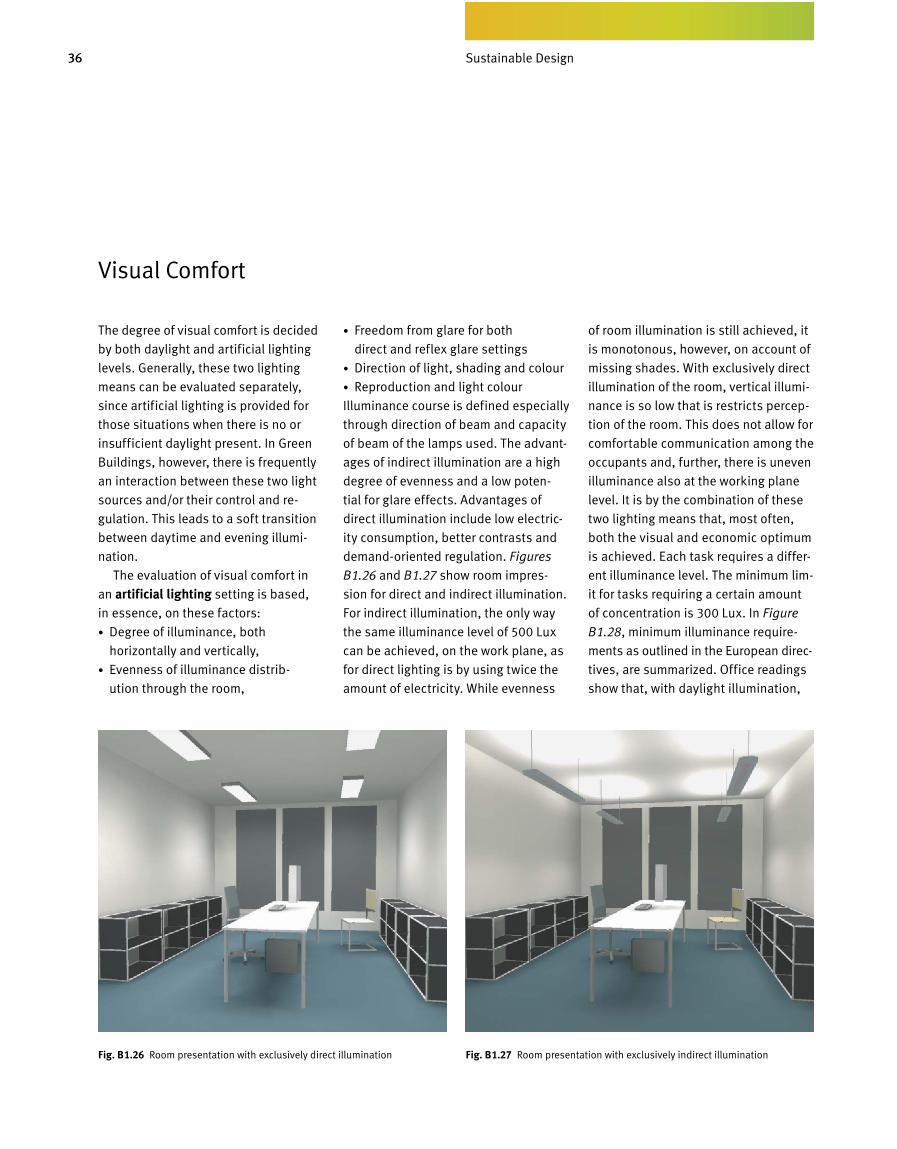
36 Bedarfsgerechtes Design
Visual Comfort
The degree of visual comfort is decided
by both daylight and artificial lighting
levels. Generally, these two lighting
means can be evaluated separately,
since artificial lighting is provided for
those situations when there is no or
insufficient daylight present. In Green
Buildings, however, there is frequently
an interaction between these two light
sources and/or their control and re
gulation. This leads to a soft transition
between daytime and evening illumi
nation.
The evaluation of visual comfort in
an artificial lighting setting is based,
in essence, on these factors:
• Degree of illuminance, both
horizontally and vertically,
• Evenness of illuminance distri b
ution through the room,
• Freedom from glare for both
direct and reflex glare settings
• Direction of light, shading and colour
• Reproduction and light colour
Illuminance course is defined especially
through direction of beam and capacity
of beam of the lamps used. The advant
ages of indirect illumination are a high
degree of evenness and a low poten
tial for glare effects. Advantages of
direct illumination include low electric
ity consumption, better contrasts and
demandoriented regulation. Figures
B1.26 and B1.27 show room impres
sion for direct and indirect illumination.
For indirect illumination, the only way
the same il l u minance level of 500 Lux
can be achiev ed, on the work plane, as
for direct light ing is by using twice the
amount of electricity. While evenness
of room illumination is still achieved, it
is mono tonous, however, on account of
missing shades. With exclusively direct
illumination of the room, vertical illumi
nance is so low that is restricts percep
tion of the room. This does not allow for
comfortable communication among the
oc cupants and, further, there is uneven
illuminance also at the working plane
level. It is by the combination of these
two lighting means that, most often,
both the visual and economic optimum
is achiev ed. Each task requires a differ
ent illuminance level. The minimum lim
it for tasks requiring a certain amount
of concentration is 300 Lux. In Figure
B1.28, minimum illuminance require
ments as outlined in the European dir ec
tives, are summarized. Office readings
show that, with daylight illuminat ion,
Fig. B 1.26 Room presentation with exclusively direct illumination Fig. B 1.27 Room presentation with exclusively indirect illumination
Sustainable Design
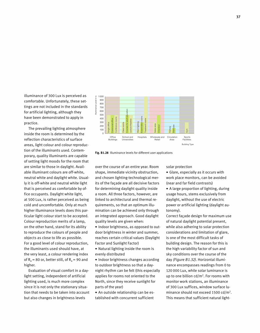
37
illuminance of 300 Lux is perceived as
comfortable. Unfortunately, these set
tings are not included in the standards
for arti ficial lighting, although they
have been demonstrated to apply in
practice.
The prevailing lighting atmosphere
inside the room is determined by the
reflection characteristics of surface
areas, light colour and colour reproduc
tion of the illuminants used. Contem
porary, quality illuminants are capable
of setting light moods for the room that
are similar to those in daylight. Avail
able illuminant colours are offwhite,
neu tral white and daylight white. Usual
ly it is offwhite and neutral white light
that is perceived as comfortable by of
fice occupants. Daylight white light,
at 500 Lux, is rather perceived as being
cold and uncomfortable. Only at much
higher illuminance levels does this par
ticular light colour start to be accepted.
Colour reproduction merits of a lamp,
on the other hand, stand for its ability
to reproduce the colours of people and
objects as close to life as possible.
For a good level of colour reproduction,
the illuminants used should have, at
the very least, a colour rendering index
of Ra = 80 or, better still, of Ra = 90 and
higher.
Evaluation of visual comfort in a day
light setting, independent of artificial
lighting used, is much more complex
since it is not only the stationary situa
tion that needs to be taken into account
but also changes in brightness levels
over the course of an entire year. Room
shape, immediate vicinity obstruction,
and chosen lightingtechnological mer
its of the façade are all decisive factors
for determining daylight quality inside
a room. All three factors, however, are
linked to architectural and thermal re
quirements, so that an optimum illu
mination can be achieved only through
an integrated approach. Good daylight
quality levels are given when:
• Indoor brightness, as opposed to out
door brightness in winter and summer,
reaches certain critical values (Daylight
Factor and Sunlight Factor)
• Natural lighting inside the room is
evenly distributed
• Indoor brightness changes according
to outdoor brightness so that a day
night rhythm can be felt (this especially
applies for rooms not oriented to the
North, since they receive sunlight for
parts of the year)
• An outside relationship can be es
tablished with concurrent sufficient
solar protection
• Glare, especially as it occurs with
work place monitors, can be avoided
(near and far field contrasts)
• A large proportion of lighting, dur ing
usage hours, stems exclusively from
daylight, without the use of electric
power or artificial lighting (daylight au
tonomy).
Correct façade design for maximum use
of natural daylight potential present,
while also adhering to solar protection
considerations and limitation of glare,
is one of the most difficult tasks of
building design. The reason for this is
the high variability factor of sun and
sky conditions over the course of the
day (Figure B1.32). Horizontal illumi
nance encompasses readings from 0 to
120 000 Lux, while solar luminance is
up to one billion cd/m2. For rooms with
monitor work stations, an illuminance
of 300 Lux suffices, window surface lu
minance should not exceed 1500 cd/m2.
This means that sufficient natural light
Fig. B 1.28 Illuminance levels for different user applications
Building Type
Illum
inan
ce L
evel
in lx
Office Buildings
School and Universities
Hospitals Wholesale and Retail
Circulation Area
Sports Facilities
Sin
gle
offic
e
Com
mun
al o
ffice
Con
fere
nce
room
s
Cla
ss ro
oms
Cou
rses
for a
dult
educ
atio
n
Lect
ure
thea
tres
War
d lig
htin
g
Exa
min
atio
n ro
oms
Trea
tmen
t roo
ms
Sal
es a
rea
Che
ckou
t
Hal
lway
Sta
ircas
e
Gym

38 Bedarfsgerechtes Design
ing is achieved if a mere 0.3% of day
light in summer and 6% in winter can
be transported onto the work planes.
The degree of diffi culty is mainly due to
the fact that sky luminance simultane
ously needs to be reduced to between
3 and 13%, and solar luminance to
0.0002%.
Daylight and solar factors define day
light quality inside a room. Both values
define the relationship of illuminance
on the working plane to outdoor bright
ness. The daylight factor is calculated
for an overcast sky, in order to evaluate
a given room independent of any solar
protective devices or systems. The solar
factor, on the other hand, is calculated
for a sunny room with solar protection
in order to allow evaluation of daylight
conditions with solar protection active.
This distinction is of importance in or
der to compare façades, with and with
out daylighting systems, across the
board for any sky condition.
The measurement variable called
luminance can be imagined as the level
of light perception for the eye. Differ
ent luminance levels lead to contrast
formation. Contrasts are important so
that the eye can even identify objects.
Yet, if contrasts are too high, they lead
to glare effects that are hard on the hu
man organism. In order to attain a com
fortable and sufficient visual level at
the monitor, contrasts between working
field and near field should not exceed
3:1 and between working field and far
field should not be greater than 10:1.
The near field runs concentric around
the main viewing direction, with a beam
angle of 30°C. The far field has twice
that opening angle. Research shows
that higher contrast levels for both near
and far field are acceptable to the user.
This can be traced back to the fact that,
through the psychologically positive
effect of daylight on people, higher lu
minance levels outside the window are
not perceived as bothersome. Contem
porary monitors are mainly nonreflect
ing and boast own luminance levels of
between 100 and 400 cd/m2. Figures
B1.33 and B1.34 show an evaluation of
luminance distribution on that basis,
as well as of contrasts for the near and
far field.
Contrary to artificial lighting, a high
level of evenness for onesided daylight
illumination is much harder to achieve.
Illumination equability is defined as
the ratio of minimum illuminance level
and medium illuminance level of a giv
en area of the room. For artificial light
ing, the ratio should be larger than 0.6.
For daylight illumination, however, this
value can scarcely be achieved, or only
Fig. B 1.29 Magnitude of Influence when designing
artificial lighting
Fig. B 1.30 Magnitude of Influence for daylight
design (winter)
Fig. B 1.31 Magnitude of Influence for daylight
design (summer)
Reflectance Coefficient Envelope Surfaces
Reflectance Coefficient Envelope Surfaces
Indirect Lighting
Course of Brightness
Far Field Contrasts
Daylighting
Outside relationship
Near Field Contrasts
Direct Lighting
Light Transmission
Sustainable Design
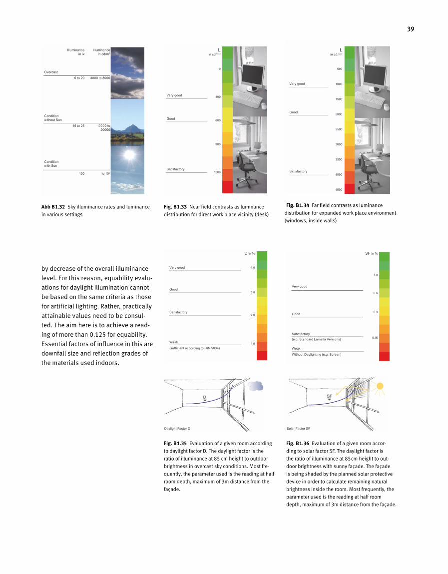
39
Fig. B 1.36 Evaluation of a given room accor
ding to solar factor SF. The daylight factor is
the ratio of illuminance at 85cm height to out
door brightness with sunny façade. The façade
is being shaded by the planned solar protective
device in order to calculate remaining natural
brightness inside the room. Most frequently, the
parameter used is the reading at half room
depth, maximum of 3m distance from the façade.
Fig. B 1.35 Evaluation of a given room according
to daylight factor D. The daylight factor is the
ratio of illuminance at 85 cm height to outdoor
brightness in overcast sky conditions. Most fre
quently, the parameter used is the reading at half
room depth, maximum of 3m distance from the
façade.
Fig. B 1.34 Far field contrasts as luminance
distribution for expanded work place environment
(windows, inside walls)
Fig. B 1.33 Near field contrasts as luminance
distribution for direct work place vicinity (desk)
Abb B 1.32 Sky illuminance rates and luminance
in various settings
by decrease of the overall illuminance
level. For this reason, equability evalu
ations for daylight illumination cannot
be based on the same criteria as those
for artificial lighting. Rather, practically
attainable values need to be consul
ted. The aim here is to achieve a read
ing of more than 0.125 for equability.
Essential factors of influence in this are
downfall size and reflection grades of
the materials used indoors.
Overcast Condition without Sun
Condition with Sun
Very good
Good
Satisfactory
Very good
Good
Satisfactory
Weak
(sufficient according to DIN 5034)
Daylight Factor D Solar Factor SF
Very good
Good
Satisfactory (e.g. Standard Lamella Versions)
Weak
Without Daylighting (e.g. Screen)
Very good
Good
Satisfactory
Illuminance in cd/m2
3000 to 8000
10000 to 20000
to 109
L in cd/m2
0
300
600
900
1200
D in %
4.0
3.0
2.0
1.0
SF in %
1.0
0.6
0.3
0.15
L in cd/m2
500
1000
1500
2000
2500
3000
3500
4000
4500
Illuminance in lx
5 to 20
15 to 25
120
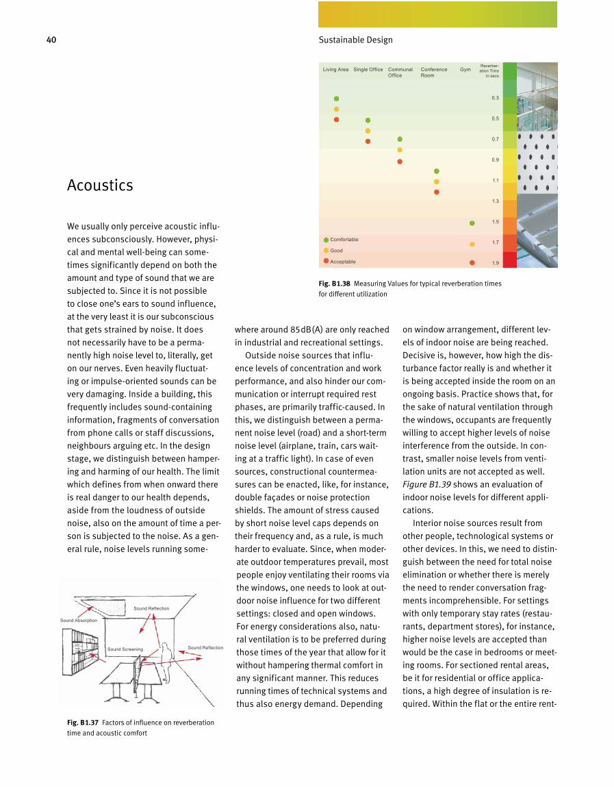
40 Bedarfsgerechtes Design
where around 85dB(A) are only reached
in industrial and recreational settings.
Outside noise sources that influ-
ence levels of concentration and work
performance, and also hinder our com-
munication or interrupt required rest
phases, are primarily traffic-caused. In
this, we distinguish between a perma-
nent noise level (road) and a short-term
noise level (airplane, train, cars wait-
ing at a traffic light). In case of even
sources, constructional countermea-
sures can be enacted, like, for instance,
double façades or noise protection
shields. The amount of stress caused
by short noise level caps depends on
their frequency and, as a rule, is much
harder to evaluate. Since, when moder-
ate outdoor temperatures prevail, most
people enjoy ventilating their rooms via
the windows, one needs to look at out-
door noise influence for two different
settings: closed and open windows.
For energy considerations also, natu-
ral ventilation is to be preferred during
those times of the year that allow for it
without hampering thermal comfort in
any significant manner. This reduces
running times of technical systems and
thus also energy demand. Depending
on window arrangement, different lev-
els of indoor noise are being reached.
Decisive is, however, how high the dis-
turbance factor really is and whether it
is being accepted inside the room on an
ongoing basis. Practice shows that, for
the sake of natural ventilation through
the windows, occupants are frequently
willing to accept higher levels of noise
interference from the outside. In con-
trast, smaller noise levels from venti-
lation units are not accepted as well.
Figure B1.39 shows an evaluation of
indoor noise levels for different appli-
cations.
Interior noise sources result from
other people, technological systems or
other devices. In this, we need to distin-
guish between the need for total noise
elimination or whether there is merely
the need to render conversation frag-
ments incomprehensible. For settings
with only temporary stay rates (restau-
rants, department stores), for instance,
higher noise levels are accepted than
would be the case in bedrooms or meet-
ing rooms. For sectioned rental areas,
be it for residential or office applica-
tions, a high degree of insulation is re-
quired. Within the flat or the entire rent-
Acoustics
We usually only perceive acoustic influ-
ences subconsciously. However, physi-
cal and mental well-being can some-
times significantly depend on both the
amount and type of sound that we are
subjected to. Since it is not possible
to close one’s ears to sound influence,
at the very least it is our subconscious
that gets strained by noise. It does
not necessarily have to be a perma-
nently high noise level to, literally, get
on our nerves. Even heavily fluctuat-
ing or impulse-oriented sounds can be
very damaging. Inside a building, this
frequently includes sound-containing
information, fragments of conversation
from phone calls or staff discussions,
neighbours arguing etc. In the design
stage, we distinguish between hamper-
ing and harming of our health. The limit
which defines from when onward there
is real danger to our health depends,
aside from the loudness of outside
noise, also on the amount of time a per-
son is subjected to the noise. As a gen-
eral rule, noise levels running some-
Fig. B 1.38 Measuring Values for typical reverberation times
for different utilization
Fig. B 1.37 Factors of influence on reverberation
time and acoustic comfort
Comfortable
Good
Acceptable
Living Area Single Office Communal Office
Conference Room
Gym
0.3
0.5
0.7
0.9
1.1
1.3
1.5
1.7
1.9
Reverbe r-ation Time
in secs
Sound Absorption
Sound Reflection
Sound Screening Sound Reflection
Sustainable Design
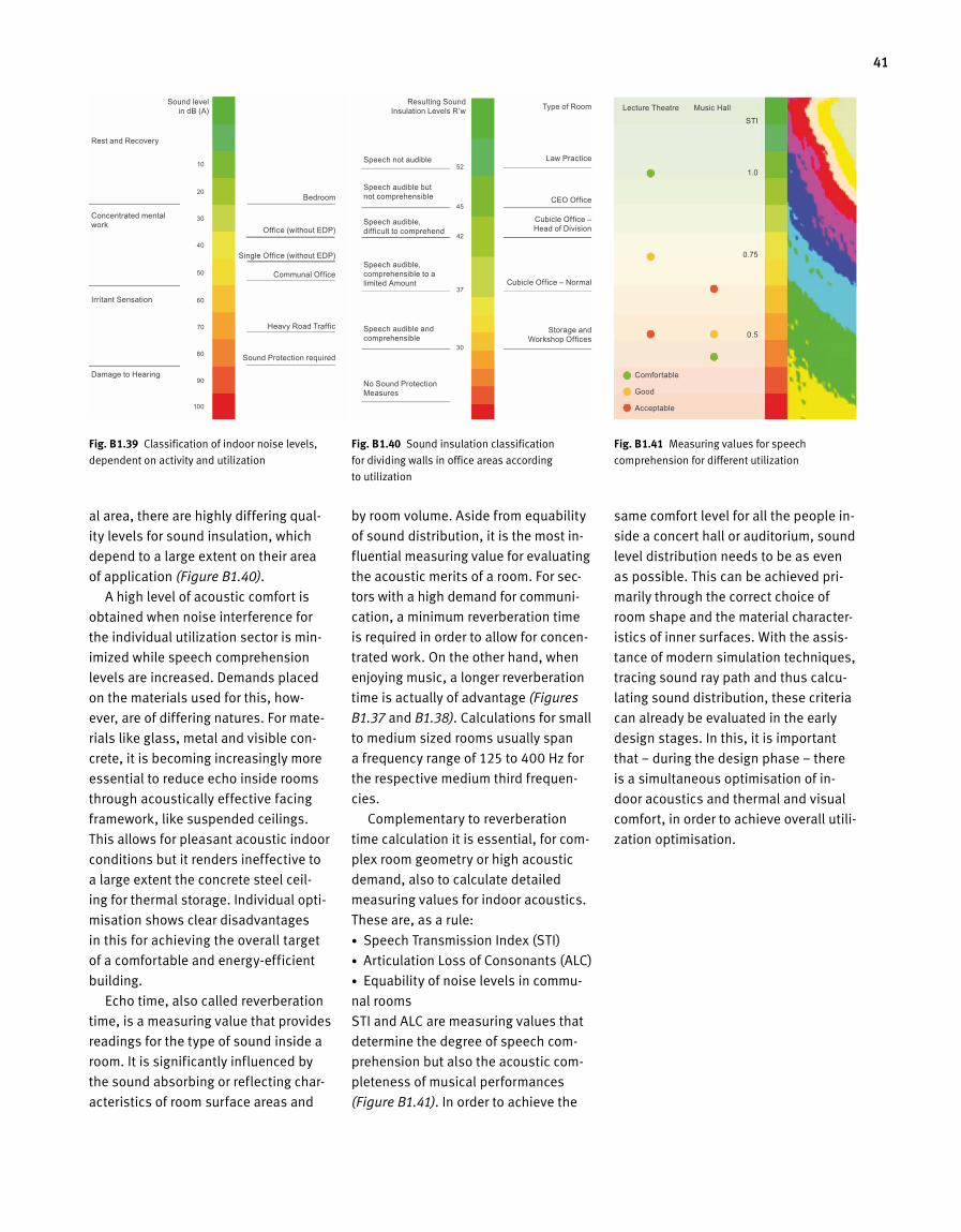
41
Fig. B 1.39 Classification of indoor noise levels,
dependent on activity and utilization
Fig. B 1.40 Sound insulation classification
for dividing walls in office areas according
to utilization
al area, there are highly differing qual
ity levels for sound insulation, which
depend to a large extent on their area
of application (Figure B1.40).
A high level of acoustic comfort is
obtained when noise interference for
the individual utilization sector is min
imized while speech comprehension
levels are increased. Demands placed
on the materials used for this, how
ever, are of differing natures. For mate
rials like glass, metal and visible con
crete, it is becoming increasingly more
essen tial to reduce echo inside rooms
through acoustically effective facing
framework, like suspended ceilings.
This allows for pleasant acoustic in door
conditions but it renders ineffective to
a large extent the concrete steel ceil
ing for thermal storage. Individual opti
misation shows clear disadvantages
in this for achieving the overall target
of a comfortable and energyefficient
building.
Echo time, also called reverberation
time, is a measuring value that provides
readings for the type of sound inside a
room. It is significantly influenced by
the sound absorbing or reflecting char
acteristics of room surface areas and
by room volume. Aside from equability
of sound distribution, it is the most in
fluential measuring value for evaluating
the acoustic merits of a room. For sec
tors with a high demand for communi
cation, a minimum reverberation time
is required in order to allow for concen
trated work. On the other hand, when
enjoying music, a longer reverberation
time is actually of advantage (Figures
B1.37 and B1.38). Calculations for small
to medium sized rooms usually span
a frequency range of 125 to 400 Hz for
the respective medium third frequen
cies.
Complementary to reverberation
time calculation it is essential, for com
plex room geometry or high acoustic
demand, also to calculate detailed
measuring values for indoor acoustics.
These are, as a rule:
• Speech Transmission Index (STI)
• Articulation Loss of Consonants (ALC)
• Equability of noise levels in commu
nal rooms
STI and ALC are measuring values that
determine the degree of speech com
prehension but also the acoustic com
pleteness of musical performances
(Figure B1.41). In order to achieve the
same comfort level for all the people in
side a concert hall or auditorium, sound
level distribution needs to be as even
as possible. This can be achieved pri
marily through the correct choice of
room shape and the material character
istics of inner surfaces. With the assis
tance of modern simulation techniques,
tracing sound ray path and thus calcu
lating sound distribution, these criteria
can already be evaluated in the early
design stages. In this, it is important
that – during the design phase – there
is a simultaneous opti misation of in
door acoustics and thermal and visual
comfort, in order to achieve overall utili
zation optimisation.
Fig. B 1.41 Measuring values for speech
comprehension for different utilization
Rest and Recovery
Concentrated mental work
Irritant Sensation
Damage to Hearing
Speech not audible
Speech audible but not comprehensible
Speech audible, difficult to comprehend
Speech audible, comprehensible to a limited Amount
Speech audible and comprehensible
No Sound Protection Measures
Lecture Theatre Music Hall
Bedroom
Office (without EDP)
Single Office (without EDP)
Communal Office
Heavy Road Traffic
Sound Protection required
Type of Room
Law Practice
CEO Office
Cubicle Office – Head of Division
Cubicle Office – Normal
Storage and Workshop Offices
STI
1.0
0.75
0.5
Sound level in dB (A)
Resulting Sound Insulation Levels R‘w
Comfortable
Good
Acceptable
10
20
30
40
50
60
70
80
90
100
52
45
42
37
30
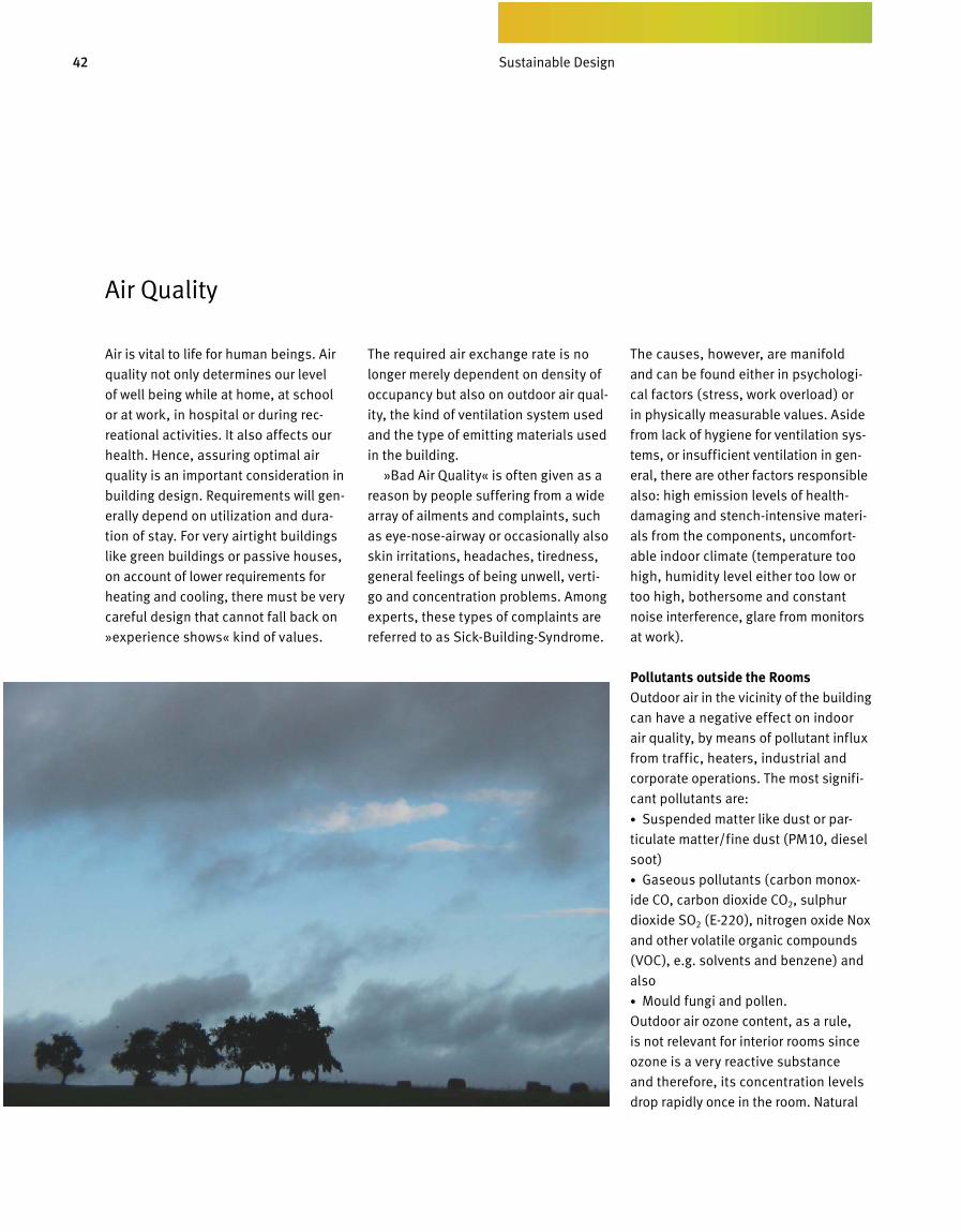
42 Bedarfsgerechtes Design
Air is vital to life for human beings. Air
quality not only determines our level
of well being while at home, at school
or at work, in hospital or during rec-
reational activities. It also affects our
health. Hence, assuring optimal air
quality is an important consideration in
building design. Requirements will gen-
erally depend on utilization and dura-
tion of stay. For very airtight buildings
like green buildings or passive houses,
on account of lower requirements for
heating and cooling, there must be very
careful design that cannot fall back on
»experience shows« kind of values.
The required air exchange rate is no
longer merely dependent on density of
occupancy but also on outdoor air qual-
ity, the kind of ventilation system used
and the type of emitting materials used
in the building.
»Bad Air Quality« is often given as a
reason by people suffering from a wide
array of ailments and complaints, such
as eye-nose-airway or occasionally also
skin irritations, headaches, tiredness,
general feelings of being unwell, verti-
go and concentration problems. Among
experts, these types of complaints are
referred to as Sick-Building-Syndrome.
The causes, however, are manifold
and can be found either in psychologi-
cal factors (stress, work overload) or
in phys ically measurable values. Aside
from lack of hygiene for ventilation sys-
tems, or insufficient ventilation in gen-
eral, there are other factors responsi ble
also: high emission levels of health-
damaging and stench-intensive materi-
als from the components, uncomfort-
able indoor climate (temperature too
high, humidity level either too low or
too high, bothersome and constant
noise interference, glare from monitors
at work).
Pollutants outside the RoomsOutdoor air in the vicinity of the building
can have a negative effect on indoor
air quality, by means of pollutant influx
from traffic, heaters, industrial and
corporate operations. The most signifi-
cant pollutants are:
• Suspended matter like dust or par-
ticulate matter/fine dust (PM10, diesel
soot)
• Gaseous pollutants (carbon monox-
ide CO, carbon dioxide CO2, sulphur
dioxide SO2 (E-220), nitrogen oxide Nox
and other volatile organic compounds
(VOC), e.g. solvents and benzene) and
also
• Mould fungi and pollen.
Outdoor air ozone content, as a rule,
is not relevant for interior rooms since
ozone is a very reactive substance
and therefore, its concentration levels
drop rapidly once in the room. Natural
Air Quality
Sustainable Design
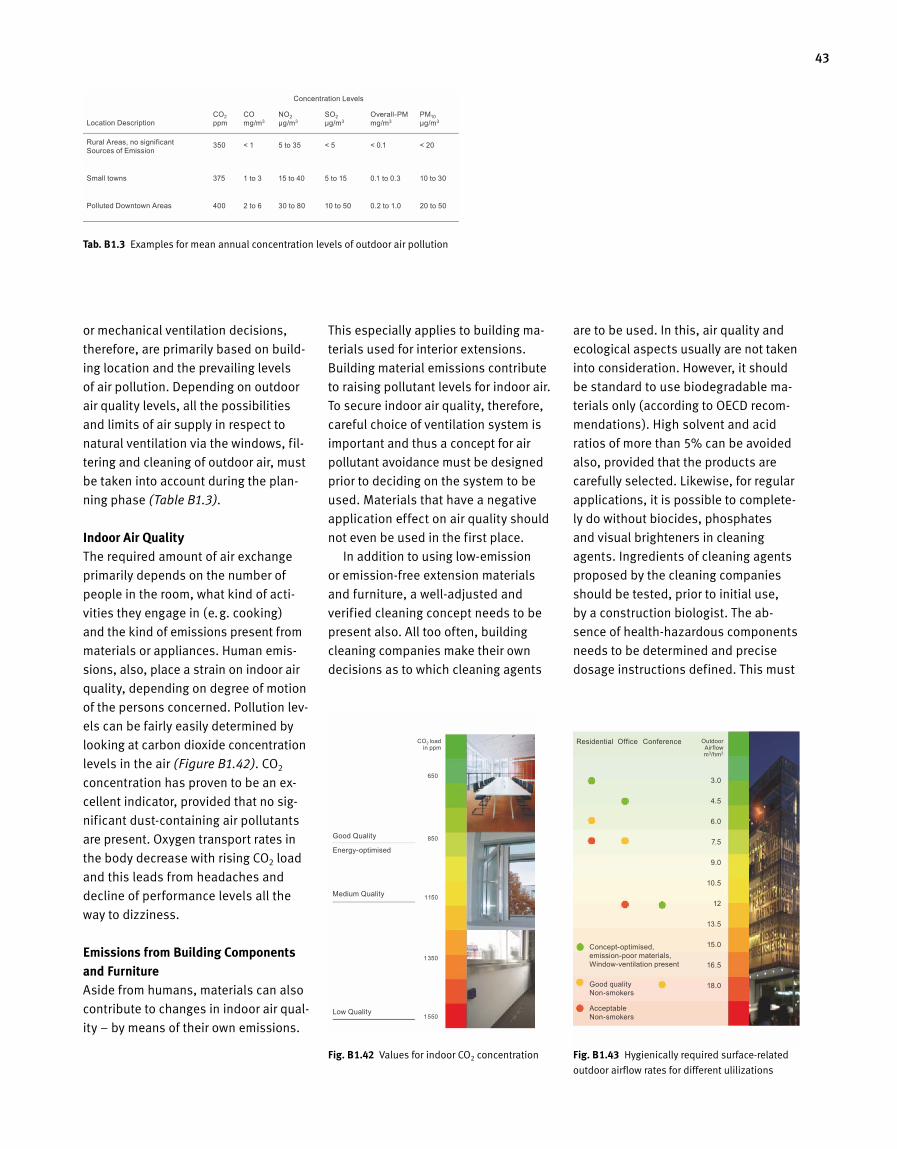
43
Tab. B 1.3 Examples for mean annual concentration levels of outdoor air pollution
or mechanical ventilation decisions,
therefore, are primarily based on build-
ing location and the prevailing levels
of air pollution. Depending on outdoor
air quality levels, all the possibilities
and limits of air supply in respect to
natural ventilation via the windows, fil-
tering and cleaning of outdoor air, must
be taken into account during the plan-
ning phase (Table B1.3).
Indoor Air QualityThe required amount of air exchange
primarily depends on the number of
people in the room, what kind of acti-
vities they engage in (e.g. cooking)
and the kind of emissions present from
materials or appliances. Human emis -
sions, also, place a strain on indoor air
quality, depending on degree of motion
of the persons concerned. Pollution lev-
els can be fairly easily determined by
looking at carbon dioxide concentration
levels in the air (Figure B1.42). CO2
concentration has proven to be an ex-
cellent indicator, provided that no sig-
nificant dust-containing air pollutants
are present. Oxygen transport rates in
the body decrease with rising CO2 load
and this leads from headaches and
decline of performance levels all the
way to dizziness.
Emissions from Building Components and FurnitureAside from humans, materials can also
contribute to changes in indoor air qual-
ity – by means of their own emissions.
This especially applies to building ma-
terials used for interior extensions.
Building material emissions contribute
to raising pollutant levels for indoor air.
To secure indoor air quality, therefore,
careful choice of ventilation system is
important and thus a concept for air
pollutant avoidance must be designed
prior to deciding on the system to be
used. Materials that have a negative
application effect on air quality should
not even be used in the first place.
In addition to using low-emission
or emission-free extension materials
and furniture, a well-adjusted and
verified cleaning concept needs to be
present also. All too often, building
cleaning companies make their own
decisions as to which cleaning agents
are to be used. In this, air quality and
ecological aspects usually are not taken
into consideration. However, it should
be standard to use biodegradable ma-
terials only (according to OECD recom-
mendations). High solvent and acid
ratios of more than 5% can be avoided
also, provided that the products are
carefully selected. Likewise, for regular
applications, it is possible to complete-
ly do without biocides, phosphates
and visual brighteners in cleaning
agents. Ingredients of cleaning a gents
proposed by the cleaning companies
should be tested, prior to initial use,
by a construction biologist. The ab-
sence of health-hazardous components
needs to be determined and precise
dosage instructions defined. This must
Fig. B 1.42 Values for indoor CO2 concentration Fig. B 1.43 Hygienically required surface-related
outdoor airflow rates for different ulilizations
Location Description
Rural Areas, no significant Sources of Emission
Small towns
Polluted Downtown Areas
Good Quality
Energy-optimised
Medium Quality
Low Quality
CO2 load in ppm
Outdoor Airflow m3/hm2
3.0
4.5
6.0
7.5
9.0
10.5
12
13.5
15.0
16.5
18.0
Residential Office Conference
350
375
400
CO2
ppm
< 1
1 to 3
2 to 6
CO
mg/m3
5 to 35
15 to 40
30 to 80
NO2
µg/m3
< 5
5 to 15
10 to 50
SO2
µg/m3
< 0.1
0.1 to 0.3
0.2 to 1.0
Overall-PM
mg/m3
< 20
10 to 30
20 to 50
PM10
µg/m3
Concentration Levels
Concept-optimised, emission-poor materials, Window-ventilation present
Good quality Non-smokers
Acceptable Non-smokers
650
850
1150
1350
1550
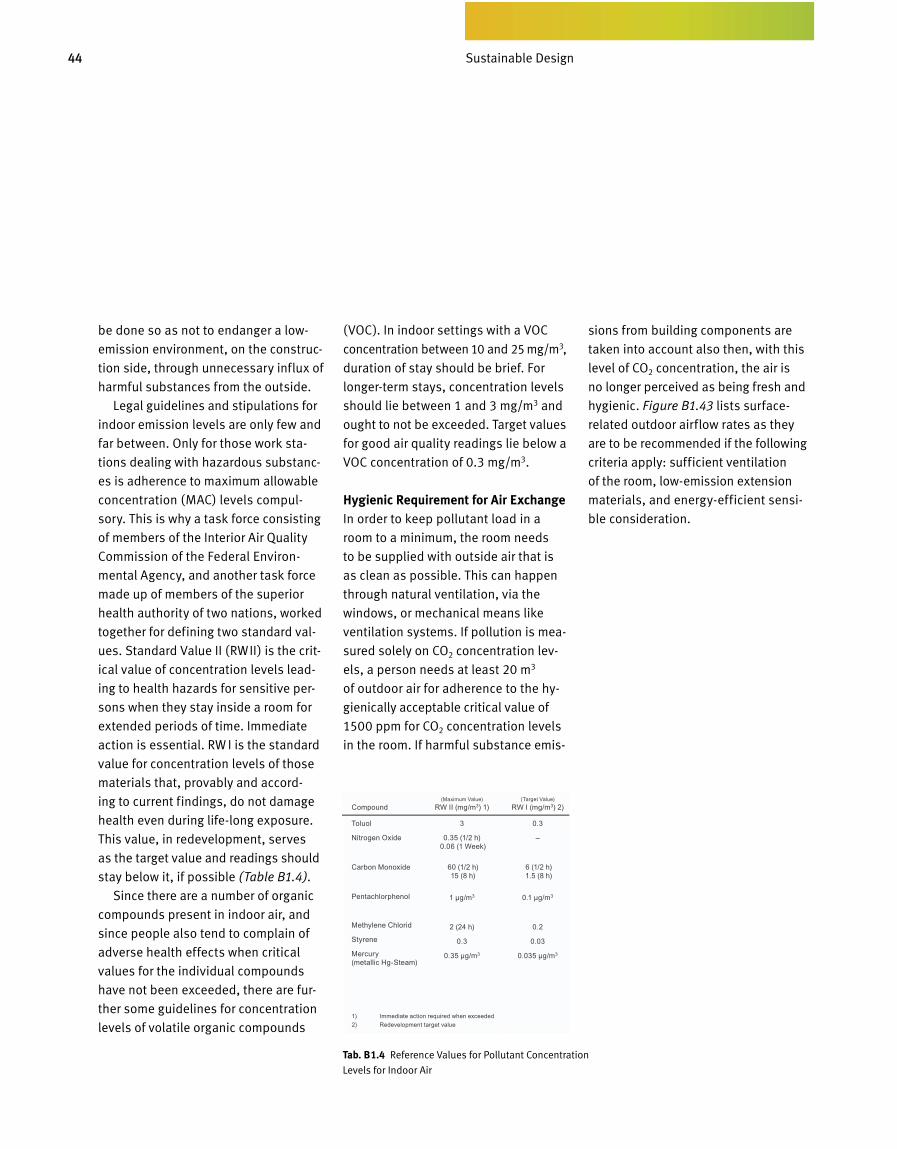
44 Bedarfsgerechtes Design
be done so as not to endanger a low-
emission environment, on the construc-
tion side, through unnecessary influx of
harmful substances from the outside.
Legal guidelines and stipulations for
indoor emission levels are only few and
far between. Only for those work sta-
tions dealing with hazardous substanc-
es is adherence to maximum allowable
concentration (MAC) levels compul-
sory. This is why a task force consisting
of members of the Interior Air Quality
Commission of the Federal Environ-
mental Agency, and another task force
made up of members of the superior
health authority of two nations, worked
together for defining two standard val-
ues. Standard Value II (RWII) is the crit-
ical value of concentration levels lead-
ing to health hazards for sensitive per-
sons when they stay inside a room for
extended periods of time. Immediate
action is essential. RW I is the standard
value for concentration levels of those
materials that, provably and accord-
ing to current findings, do not damage
health even during life-long exposure.
This value, in redevelopment, serves
as the target value and readings should
stay below it, if possible (Table B1.4).
Since there are a number of organic
compounds present in indoor air, and
since people also tend to complain of
adverse health effects when critical
values for the individual compounds
have not been exceeded, there are fur-
ther some guidelines for concentration
levels of volatile organic compounds
(VOC). In indoor settings with a VOC
concentration between 10 and 25 mg/m3,
duration of stay should be brief. For
longer-term stays, concentration levels
should lie between 1 and 3 mg/m3 and
ought to not be exceeded. Target va l u es
for good air quality readings lie below a
VOC concentration of 0.3 mg/m3.
Hygienic Requirement for Air ExchangeIn order to keep pollutant load in a
room to a minimum, the room needs
to be supplied with outside air that is
as clean as possible. This can happen
through natural ventilation, via the
windows, or mechanical means like
ventilation systems. If pollution is mea-
sured solely on CO2 concentration lev-
els, a person needs at least 20 m3
of outdoor air for adherence to the hy-
gienically acceptable critical value of
1500 ppm for CO2 concentration levels
in the room. If harmful substance emis-
sions from building components are
taken into account also then, with this
level of CO2 concentration, the air is
no longer perceived as being fresh and
hygienic. Figure B1.43 lists surface-
related outdoor airflow rates as they
are to be recommended if the following
criteria apply: sufficient ventilation
of the room, low-emission extension
materials, and energy-efficient sensi-
ble consideration.
Tab. B 1.4 Reference Values for Pollutant Concentration
Levels for Indoor Air
Compound
Toluol
Nitrogen Oxide
Carbon Monoxide
Pentachlorphenol
Methylene Chlorid
Styrene
Mercury (metallic Hg-Steam)
1) Immediate action required when exceeded 2) Redevelopment target value
(Maximum Value) RW II (mg/m3) 1)
3
0.35 (1/2 h) 0.06 (1 Week)
60 (1/2 h) 15 (8 h)
1 µg/m3
2 (24 h)
0.3
0.35 µg/m3
(Target Value) RW I (mg/m3) 2)
0.3
–
6 (1/2 h) 1.5 (8 h)
0.1 µg/m3
0.2
0.03
0.035 µg/m3
Sustainable Design
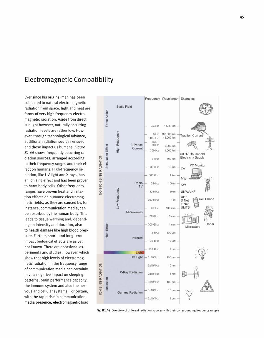
45
Electromagnetic Compatibility
Ever since his origins, man has been
sub jected to natural electromagnetic
radiation from space: light and heat are
forms of very high frequency electro
magnetic radiation. Aside from direct
sunlight however, naturally occurring
radiation levels are rather low. How
ever, through technological advance,
additional radiation sources ensued
and these impact us humans. Figure
B1.44 shows frequently occurring ra
diation sources, arranged according
to their frequency ranges and their ef
fect on humans. Highfrequency ra
diation, like UV light and Xrays, has
an ionising effect and has been proven
to harm body cells. Other frequency
ranges have proven heat and irrita
tion effects on humans: electromag
netic fields, as they are caused by, for
instance, communication media, can
be absorbed by the human body. This
leads to tissue warming and, depend
ing on intensity and duration, also
to health damage like high blood pres
sure. Further, short and longterm
impact biological effects are as yet
not known. There are occasional ex
periments and studies, however, which
show that high levels of electromag
netic radiation in the frequency range
of communication media can certainly
have a negative impact on sleeping
patterns, brain performance capacity,
the immune system and also the ner
vous and cellular systems. For certain,
with the rapid rise in communication
media presence, electromagnetic load
Fig. B 1.44 Overview of different radiation sources with their corresponding frequency ranges
Static Field
Traction Current
50 HZ Household Electricity Supply
PC Monitor
Cell Phone
LW
MW
KW
UKW/VHFUHFD NetE NetUMTS
MicrowaveRadar
Frequency Wavelength Examples
3-Phase Current
Radio TV
Microwaves
Infrared
Light UV Light
X-Ray Radiation
Gamma Radiation
NO
N-IO
NIS
ING
RA
DIA
TIO
NIO
NIS
ING
RA
DIA
TIO
N
Low
Fre
quen
cyH
igh
Freq
uenc
y
Ioni
satio
n H
eat E
ffect
S
timul
atio
n Ef
fect
Fo
rce
Actio
n
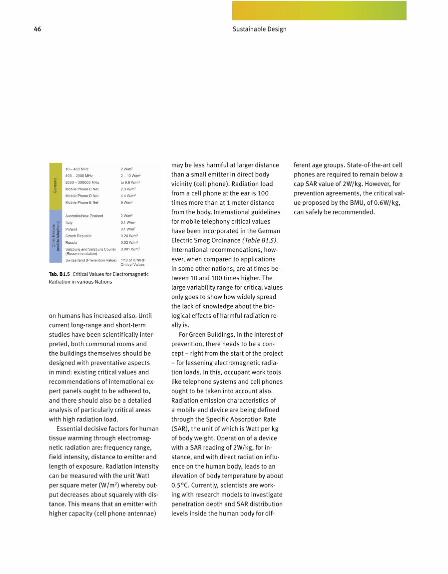
46 Bedarfsgerechtes Design
on humans has increased also. Until
current long-range and short-term
studies have been scientifically inter-
preted, both communal rooms and
the buildings themselves should be
designed with preventative aspects
in mind: existing critical values and
recommen dations of international ex-
pert panels ought to be adhered to,
and there should also be a detailed
analysis of particularly critical areas
with high radiation load.
Essential decisive factors for human
tissue warming through electromag-
netic radiation are: frequency range,
field intensity, distance to emitter and
length of exposure. Radiation intensity
can be measured with the unit Watt
per square meter (W/m2) whereby out-
put decreases about squarely with dis-
tance. This means that an emitter with
higher capacity (cell phone antennae)
may be less harmful at larger distance
than a small emitter in direct body
vicinity (cell phone). Radiation load
from a cell phone at the ear is 100
times more than at 1 meter distance
from the body. International guidelines
for mobile telephony critical values
have been incorporated in the German
Electric Smog Ordinance (Table B1.5).
In ternational recommendations, how-
ever, when compared to applications
in some other nations, are at times be-
tween 10 and 100 times higher. The
large variability range for critical values
only goes to show how widely spread
the lack of knowledge about the bio-
logical effects of harmful radiation re-
ally is.
For Green Buildings, in the interest of
prevention, there needs to be a con-
cept – right from the start of the project
– for lessening electromagnetic radia-
tion loads. In this, occupant work tools
like telephone systems and cell phones
ought to be taken into account also.
Radiation emission characteristics of
a mobile end device are being defined
through the Specific Absorption Rate
(SAR), the unit of which is Watt per kg
of body weight. Operation of a device
with a SAR reading of 2W/kg, for in-
stance, and with direct radiation influ-
ence on the human body, leads to an
elevation of body temperature by about
0.5°C. Currently, scientists are work-
ing with research models to investigate
penetration depth and SAR distribution
levels inside the human body for dif-
ferent age groups. State-of-the-art cell
phones are required to remain below a
cap SAR value of 2W/kg. However, for
prevention agreements, the critical val-
ue proposed by the BMU, of 0.6W/kg,
can safely be recommended.
Tab. B 1.5 Critical Values for Electromagnetic
Radiation in various Nations
Oth
er N
atio
ns
(mob
ile te
leph
ony)
10 – 400 MHz
400 – 2000 MHz
2000 – 300000 MHz
Mobile Phone C Net
Mobile Phone D Net
Mobile Phone E Net
Australia/New Zealand
Italy
Poland
Czech Republic
Russia
Salzburg and Salzburg County (Recommendation)
Switzerland (Prevention Value)
2 W/m2
2 – 10 W/m2
to 9.8 W/m2
2.3 W/m2
4.4 W/m2
9 W/m2
2 W/m2
0.1 W/m2
0.1 W/m2
0.24 W/m2
0.02 W/m2
0.001 W/m2
1/10 of ICNIRP Critical Values
Ger
man
y
Sustainable Design
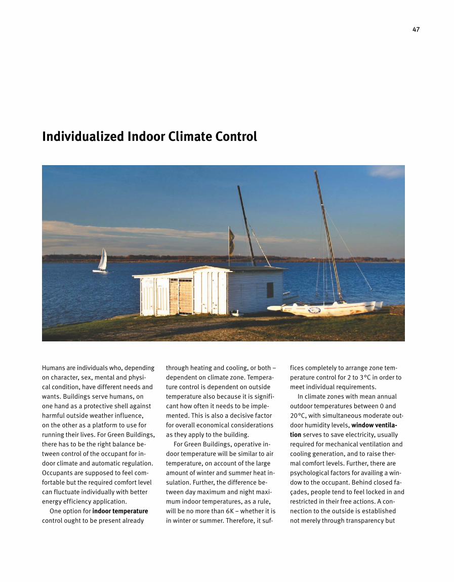
47
Humans are individuals who, depending
on character, sex, mental and physi
cal condition, have different needs and
wants. Buildings serve humans, on
one hand as a protective shell against
harmful outside weather influence,
on the other as a platform to use for
running their lives. For Green Buildings,
there has to be the right balance be
tween control of the occupant for in
door climate and automatic regulation.
Occupants are supposed to feel com
fortable but the required comfort level
can fluctuate individually with better
energy efficiency application.
One option for indoor temperature
control ought to be present already
through heating and cooling, or both –
dependent on climate zone. Tempera
ture control is dependent on outside
temperature also because it is signifi
cant how often it needs to be imple
mented. This is also a decisive factor
for overall economical considerations
as they apply to the building.
For Green Buildings, operative in
door temperature will be similar to air
temperature, on account of the large
amount of winter and summer heat in
sulation. Further, the difference be
tween day maximum and night maxi
mum indoor temperatures, as a rule,
will be no more than 6K – whether it is
in winter or summer. Therefore, it suf
fices completely to arrange zone tem
perature control for 2 to 3°C in order to
meet individual requirements.
In climate zones with mean annual
outdoor temperatures between 0 and
20°C, with simultaneous moderate out
door humidity levels, window ventila-tion serves to save electricity, usually
required for mechanical ventilation and
cooling generation, and to raise ther
mal comfort levels. Further, there are
psychological factors for availing a win
dow to the occupant. Behind closed fa
çades, people tend to feel locked in and
restricted in their free actions. A con
nection to the outside is established
not merely through transparency but
Individualized Indoor Climate Control
48 Bedarfsgerechtes Design
through the actual action of opening
a window, and then hearing the sounds
outside and the feeling the outside
air on the skin. Survey among tenants
have shown that windows that can be
opened are among the most signifi -
cant criteria when it comes to making
a decision on renting a building or parts
thereof. This even applies for the King
Fahad National Library Project in Riad,
Saudi-Arabia. The occupant placed im-
mense emphasis on windows that can
be opened, even though outdoor tem-
peratures there only drop below 20°C
from December to January during the
day.
Transparency, then, and establish-
ing a connection to the outside are both
important characteristics for building
where the occupants feel comfortable.
Daylight, also, has a very positive ef-
fect on human well-being. An individu-
ally controllable anti-glare device is
then inevitable, depending on utiliza-
tion. The solar protection device ought
to be individually controllable when-
ever the room becomes very shaded
and thus connection to the outside is
restricted. However, an additional auto-
matic control is also essential in order
to opera te the building in an energy-
efficient manner, independent of occu-
pant behaviour.
Lighting should be individually con-
trollable, similar to temperature regula-
tion, owing to different human require-
ments. It needs to be ascertained, how-
ever, that artificial lighting automati-
cally goes off when sufficient daylight
illumination is present. This is done in
order to operate on an energy-efficient
level. It needs to be kept in mind that
the addition of artificial light, in that
case, does not contribute significantly
to the elevation of illuminance.
Variable indoor noise levels can still
be created nowadays through opening
and closing of windows. Further, there
are concepts that elevate overall qual-
ity of indoor noise levels and thus serve
to counteract sound propagation even
in large rooms. Unfortunately, this is
no solution for an individually control-
lable interior noise level and the result-
ing speech comprehension. For office
buildings, the future path would lead
toward controllable high-tech absorbers
in order to fully exploit the advantages
of open space areas while at the same
time matching them to individual de-
mand. There are already absorbers for
multi-purpose halls that function either
as sound reflecting or sound absorb-
ing, depending on rotational angle, and
therefore can adapt to conditions at
hand.
Indoor Air Quality (IAQ) ought to be
able to be influenced through opening
the windows, depending on outdoor
temperature and outdoor climate. Only
when low-emission extension materials
are used and the design has provided
for a good level of airflow, can mechani-
cal ventilation rates be reduced to a
minimum. Even so, intermittent airing
for special situations is important. Ef-
fective window ventilation depends on
window size and type. Whether window
ventilation suffices for air exchange
should be evaluated also in case of
complex façades, since in most cases it
constitutes an important component of
the overall concept.
Occupant/User AcceptanceMost buildings serve humans for pur-
poses of working, living, relaxing and
recovery. The average person living
in an industrial nation spends about
85% of lifetime indoors. Buildings,
thus, can be considered as a kind of
third skin for humans. They can and
may be designed differently accord-
ing to mentality and origin of the us-
ers, yet they should have something in
common: adherence to indoor comfort
levels within a certain tolerance range
and the use of non health-hazardous
material. The tolerance range is deter-
mined primarily by ethnic and national-
geographic differences. Higher summer
indoor temperatures are being accept-
ed better in Northern nations than in
nations with a warm climate year round,
since maximum indoor temperatures
occur there simultaneously with the few
hot days of the year. On the reverse,
this also applies for minimum tempera-
tures: in Northern Europe, tempera-
tures of 20°C are frequently perceived
as being too cool in winter while, in
Southern nations, indoor temperatures
of 18°C – on account of their rare occur-
rence – are accepted by a large part of
Sustainable Design
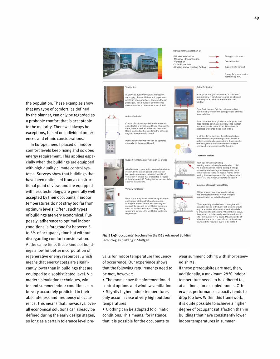
49
the population. These examples show
that any type of comfort, as defined
by the planner, can only be regarded as
a probable comfort that is acceptable
to the majority. There will always be
exceptions, based on individual prefer-
ences and ethnic considerations.
In Europe, needs placed on indoor
comfort levels keep rising and so does
energy requirement. This applies espe-
cially when the buildings are equipped
with high quality climate control sys-
tems. Surveys show that buildings that
have been optimised from a construc-
tional point of view, and are equipped
with less technology, are generally well
accepted by their occupants if indoor
temperatures do not stray too far from
optimum levels. Often, such types
of buildings are very economical. Pur-
posely, adherence to optimal indoor
conditions is foregone for between 3
to 5% of occupancy time but without
disregarding comfort consideration.
At the same time, these kinds of build-
ings allow for better incorporation of
regenerative energy resources, which
means that energy costs are signifi-
cantly lower than in buildings that are
equipped to a sophisticated level. Via
modern simulation techniques, win-
ter and summer indoor conditions can
be very accurately predicted in their
ab soluteness and frequency of occur-
rence. This means that, nowadays, over-
all eco nomical solutions can already be
defined during the early design stages,
so long as a certain tolerance level pre-
vails for indoor temperature frequency
of occurrence. Our experience shows
that the following requirements need to
be met, however:
•Theroomshavetheaforementioned
control options and window ventilation
•Slightlyhigherindoortemperatures
only occur in case of very high outdoor
temperatures
•Clothingcanbeadaptedtoclimatic
conditions. This means, for instance,
that it is possible for the occupants to
wear summer clothing with short-sleev-
ed shirts.
If these prerequisites are met, then,
additionally,amaximum28°Cindoor
temperature needs to be adhered to,
at all times, for occupied rooms. Oth-
erwise, performance capacity tends to
drop too low. Within this framework,
it is quite possible to achieve a higher
degree of occupant satisfaction than in
buildings that have consistently lower
indoor temperatures in summer.
Fig. B 1.45 Occupants’ brochure for the D&S Advanced Building
Technologies building in Stuttgart
Manual for the operation of
- Window ventilation - Marginal Strip Activation - Ventilation - Solar Protection - Cooling and/or Heating Ceiling
Ventilation
In order to assure constant multizone air supply, the ventilation unit is perma- nently in operation here. Through the air pas sages, fresh outdoor air flows into the multi-zone nd waste air is suctioned.
Atrium Ventilation
Control of roof and façade flaps is automatic and adapted to climate conditions. Through the flaps, there is fresh air inflow into the atrium. Doors leading to offices and into the cafeteria ought to always remain closed.
Roof and façade flaps can also be operated manually via the control board
Supportive mechanical ventilation for offices
All offices are connected to a central ventilation system. In the interim period, with outdoor temperature ranges of between 5 and 20°C, ventilation in offices that are located in façade vicinity is turned off. During that period, ventilati-on is via the windows.
Window Ventilation
Each office is equipped with rotating windows and hopper windows that can be opened. During the interim period, windows ought to regularly be opened for ventilation purposes (min. for 10 minutes every 2 hours). During winter and summer, the ventilation system is responsible.
Solar Protection
Solar protection (outside shutter) is controlled automatically. It can, however, also be adjusted manually via a switch located beneath the window.
From April through October, solar protection automatically drops down during periods of direct solar radiation
From November through March, solar protection does not drop down automatically once outdoor temperature falls below 15°C. This allows for heat loss avoidance inside the building
In winter, during daytime, the solar protection device should only be brought down if there is a glare sensation because, during those months, every single sunray can be used to conserve energy otherwise expended for heating.
Thermal Comfort
Heating and Cooling CeilingMeeting rooms or being heated and/or cooled via a heating and/or cooling ceiling. Settings for heating and cooling can be regulated via a control located in the respective rooms. When leaving the meeting rooms, the regulators should be set to 0 and windows ought to be closed.
Marginal Strip Activation (MSA)
Offices always have a temperate ceiling and a temperate floor as well as marginal strip activation for individual control
With a specially installed switch, marginal strip activation can be individually set. Cooling should only be activated when window ventilation fails to provide sufficient cooling. When MSA is active, there should only be interim ventilation of about 5 to 10 minutes every 2 hours. MSA should be off when there is no occupancy for more than three hours and the regulator ought to be set to 0.
Energy conscious
Cost-effective
Supportive to comfort
Especially energy-saving operation by YOU

Conscientious Handling of Resources
A B 2
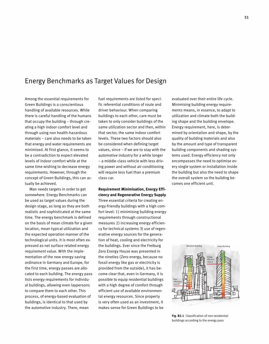
51
Energy Benchmarks as Target Values for Design
Among the essential requirements for
Green Buildings is a conscientious
handling of available resources. While
there is careful handling of the humans
that occupy the building – through cre-
ating a high indoor comfort level and
through using non health-hazardous
materials – care also needs to be taken
that energy and water requirements are
minimised. At first glance, it seems to
be a contradiction to expect elevated
levels of indoor comfort while at the
same time wishing to decrease energy
requirements. However, through the
concept of Green Buildings, this can ac-
tually be achieved.
Man needs targets in order to get
somewhere. Energy Benchmarks can
be used as target values during the
design stage, as long as they are both
realistic and sophisticated at the same
time. The energy benchmark is defined
on the basis of mean climate for a given
location, mean typical utilization and
the expected operation manner of the
technological units. It is most often ex-
pressed as net surface related energy
requirement value. With the imple-
mentation of the new energy saving
ordinan ce in Germany and Europe, for
the first time, energy passes are allo-
cated to each building. The energy pass
lists en er gy requirements for individu-
al buildings, allowing even laypersons
to compare them to each other. This
process, of energy-based evaluation of
buildings, is identical to that used by
the automotive industry. There, mean
fuel require ments are listed for speci -
fic referential conditions of route and
driver behaviour. When comparing
buildings to each other, care must be
taken to only consider buildings of the
same utilization sector and then, within
that sector, the same indoor comfort
levels. These two factors should also
be considered when defining target
values, since – if we are to stay with the
automotive industry for a while longer
– a middle-class vehicle with less driv-
ing power and without air conditioning
will require less fuel than a premium
class car.
Requirement Minimisation, Energy Effi-ciency and Regenerative Energy SupplyThree essential criteria for creating en-
ergy-friendly buildings with a high com-
fort level: 1) minimising building energy
requirements through constructional
measures 2) increasing energy efficien-
cy for technical systems 3) use of regen-
erative energy sources for the genera-
tion of heat, cooling and electricity for
the build ings. Ever since the Freiburg
Zero Energy House was presented in
the nineties (Zero energy, because no
fossil energy like gas or electricity is
provided from the outside), it has be-
come clear that, even in Germany, it is
possible to equip residential buildings
with a high degree of comfort through
efficient use of available environmen-
tal energy resources. Since property
is very often used as an investment, it
makes sense for Green Buildings to be
evaluated over their entire life cycle.
Minimising building energy require-
ments means, in essence, to adapt to
utilization and climate both the build-
ing shape and the building envelope.
Energy requirement, here, is deter-
mined by orientation and shape, by the
quality of building materials and also
by the amount and type of transparent
building components and shading sys-
tems used. Energy efficiency not only
encompasses the need to optimise ev-
ery single system or installation inside
the building but also the need to shape
the overall system so the building be-
comes one efficient unit.
Standard Building
Poor efficiency: Class D
Energy Efficient: Class A
Green Building
Fig. B 2.1 Classification of non-residential
buildings according to the energy pass
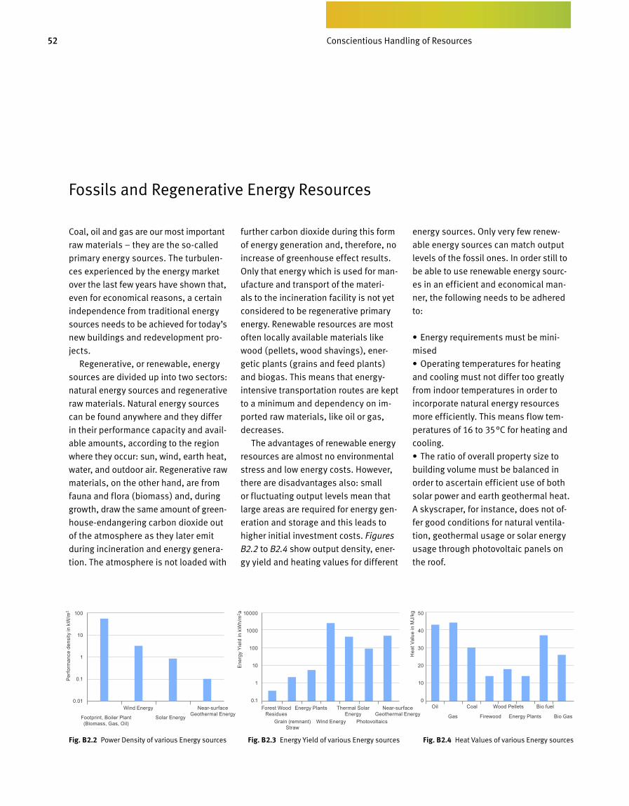
52 Bewusster Umgang mit Ressourcen
Fossils and Regenerative Energy Resources
Coal, oil and gas are our most important
raw materials – they are the so-called
primary energy sources. The turbulen-
ces experienced by the energy market
over the last few years have shown that,
even for economical reasons, a certain
independence from traditional energy
sources needs to be achieved for today’s
new buildings and redevelopment pro-
jects.
Regenerative, or renewable, energy
sources are divided up into two sectors:
natural energy sources and regenera tive
raw materials. Natural energy sources
can be found anywhere and they differ
in their performance capacity and avail-
able amounts, according to the region
where they occur: sun, wind, earth heat,
water, and outdoor air. Regenerative raw
materials, on the other hand, are from
fauna and flora (biomass) and, during
growth, draw the same amount of green -
house-endangering carbon dioxide out
of the atmosphere as they later emit
during incineration and energy genera-
tion. The atmosphere is not loaded with
further carbon dioxide during this form
of energy generation and, therefore, no
increase of greenhouse effect results.
Only that energy which is used for man-
ufacture and transport of the materi-
als to the incineration facility is not yet
considered to be regenerative primary
energy. Renewable resources are most
often locally available materials like
wood (pellets, wood shavings), ener-
getic plants (grains and feed plants)
and biogas. This means that energy-
intensive transportation routes are kept
to a minimum and dependency on im-
ported raw ma terials, like oil or gas,
decreases.
The advantages of renewable energy
resources are almost no environmental
stress and low energy costs. However,
there are disadvantages also: small
or fluctuating output levels mean that
large areas are required for energy gen-
eration and storage and this leads to
higher initial investment costs. Figures
B2.2 to B2.4 show output density, ener-
gy yield and heating values for different
energy sources. Only very few renew-
able energy sources can match output
levels of the fossil ones. In order still to
be able to use renewable energy sourc-
es in an efficient and economical man-
ner, the following needs to be adhered
to:
•Energyrequirementsmustbemini-
mised
•Operatingtemperaturesforheating
and cooling must not differ too greatly
from indoor temperatures in order to
in corporate natural energy resources
more efficiently. This means flow tem-
peratures of 16 to 35°C for heating and
cooling.
•Theratioofoverallpropertysizeto
building volume must be balanced in
order to ascertain efficient use of both
solar power and earth geothermal heat.
A skyscraper, for instance, does not of-
fer good conditions for natural ventila-
tion, geothermal usage or solar energy
usage through photovoltaic panels on
the roof.
Footprint, Boiler Plant (Biomass, Gas, Oil)
100
10
1
0.1
0.01
10000
1000
100
10
1
0.1
50
40
30
20
10
0
Solar EnergyGrain (remnant)
Straw
Gas Bio GasFirewood Energy PlantsWind Energy Photovoltaics
Wind Energy Energy PlantsForest Wood Residues
Oil Coal Wood Pellets Bio fuelNear-surface Geothermal Energy
Near-surface Geothermal Energy
Thermal Solar Energy
Perf
orm
ance
den
sity
in k
W/m
2
Ener
gy Y
ield
in k
Wh/
m2 a
Hea
t Val
ue in
MJ/
kg
Conscientious Handling of Resources
Fig. B 2.2 Power Density of various Energy sources Fig. B 2.3 Energy Yield of various Energy sources Fig. B 2.4 Heat Values of various Energy sources
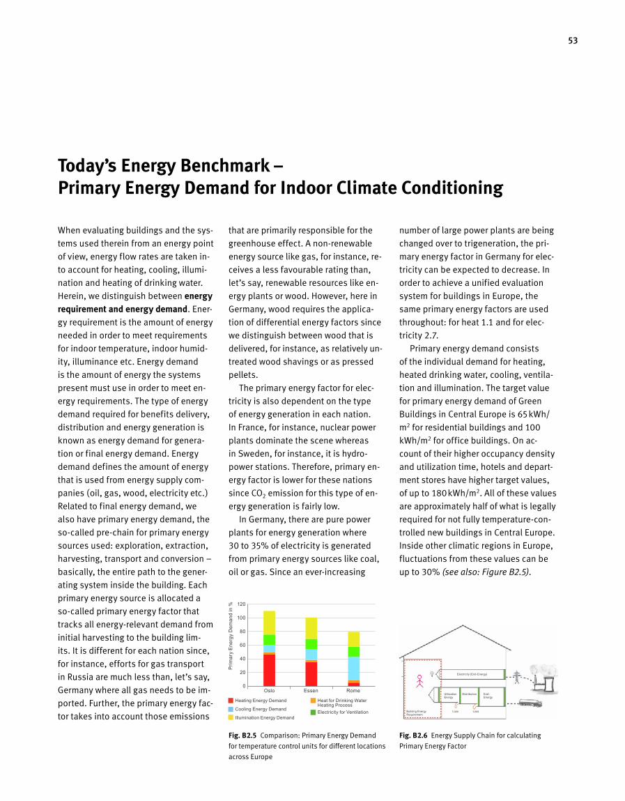
53
Today’s Energy Benchmark – Primary Energy Demand for Indoor Climate Conditioning
that are primarily responsible for the
greenhouse effect. A non-renewable
energy source like gas, for instance, re-
ceives a less favourable rating than,
let’s say, renewable resources like en-
ergy plants or wood. However, here in
Germany, wood requires the applica-
tion of differential energy factors since
we dis tinguish between wood that is
delivered, for instance, as relatively un-
treated wood shavings or as pressed
pellets.
The primary energy factor for elec-
tri city is also dependent on the type
of energy generation in each nation.
In France, for instance, nuclear power
plants dominate the scene whereas
in Sweden, for instance, it is hydro-
power stations. Therefore, primary en-
ergy factor is lower for these nations
since CO2 emission for this type of en-
ergy generation is fairly low.
In Germany, there are pure power
plants for energy generation where
30 to 35% of electricity is generated
from primary energy sources like coal,
oil or gas. Since an ever-increasing
num ber of large power plants are being
changed over to trigeneration, the pri-
mary energy factor in Germany for elec-
tricity can be expected to decrease. In
order to achieve a unified evaluation
system for buildings in Europe, the
same primary energy factors are used
throughout: for heat 1.1 and for elec-
tricity 2.7.
Primary energy demand consists
of the individual demand for heating,
heated drinking water, cooling, ventila-
tion and illumination. The target value
for primary energy demand of Green
Buildings in Central Europe is 65kWh/
m2 for residential buildings and 100
kWh/m2 for office buildings. On ac-
count of their higher occupancy density
andutilizationtime,hotelsanddepart-
ment stores have higher target values,
of up to 180kWh/m2. All of these values
are approximately half of what is legally
required for not fully temperature-con-
trolled new buildings in Central Europe.
Inside other clima tic regions in Europe,
fluctuations from these values can be
up to 30% (see also: Figure B2.5).
When evaluating buildings and the sys-
tems used therein from an energy point
of view, energy flow rates are taken in-
to account for heating, cooling, illumi-
nation and heating of drinking water.
Herein, we distinguish between energy requirement and energy demand. Ener-
gy requirement is the amount of energy
needed in order to meet requirements
for indoor temperature, indoor humid-
ity, illuminance etc. Energy demand
is the amount of energy the systems
present must use in order to meet en-
ergy requirements. The type of energy
demand required for benefits delivery,
distribution and energy generation is
known as energy demand for genera-
tion or final energy demand. Energy
demand defines the amount of energy
that is used from energy supply com-
panies (oil, gas, wood, electricity etc.)
Related to final energy demand, we
also have primary energy demand, the
so-called pre-chain for primary energy
sources used: exploration, extraction,
harvesting, transport and conversion –
basically, the entire path to the gener-
ating system inside the building. Each
primary energy source is allocated a
so-called primary energy factor that
tracks all energy-relevant demand from
initial harvesting to the building lim-
its. It is different for each nation since,
for instance, efforts for gas transport
in Russia are much less than, let’s say,
Germany where all gas needs to be im-
ported. Further, the primary energy fac-
tor takes into account those emissions
Fig. B 2.5 Comparison: Primary Energy Demand
for temperature control units for different loca tions
across Europe
Fig. B 2.6 Energy Supply Chain for calculating
Primary Energy Factor
120
100
80
60
40
20
0Oslo Essen Rome
Building Energy Requirement
Utilization Energy
Distribution End-Energy
Loss Loss
Electricity (End-Energy)
Prim
ary
Ener
gy D
eman
d in
%
Heat for Drinking Water Heating Process Electricity for Ventilation
Heating Energy Demand
Cooling Energy Demand
Illumination Energy Demand
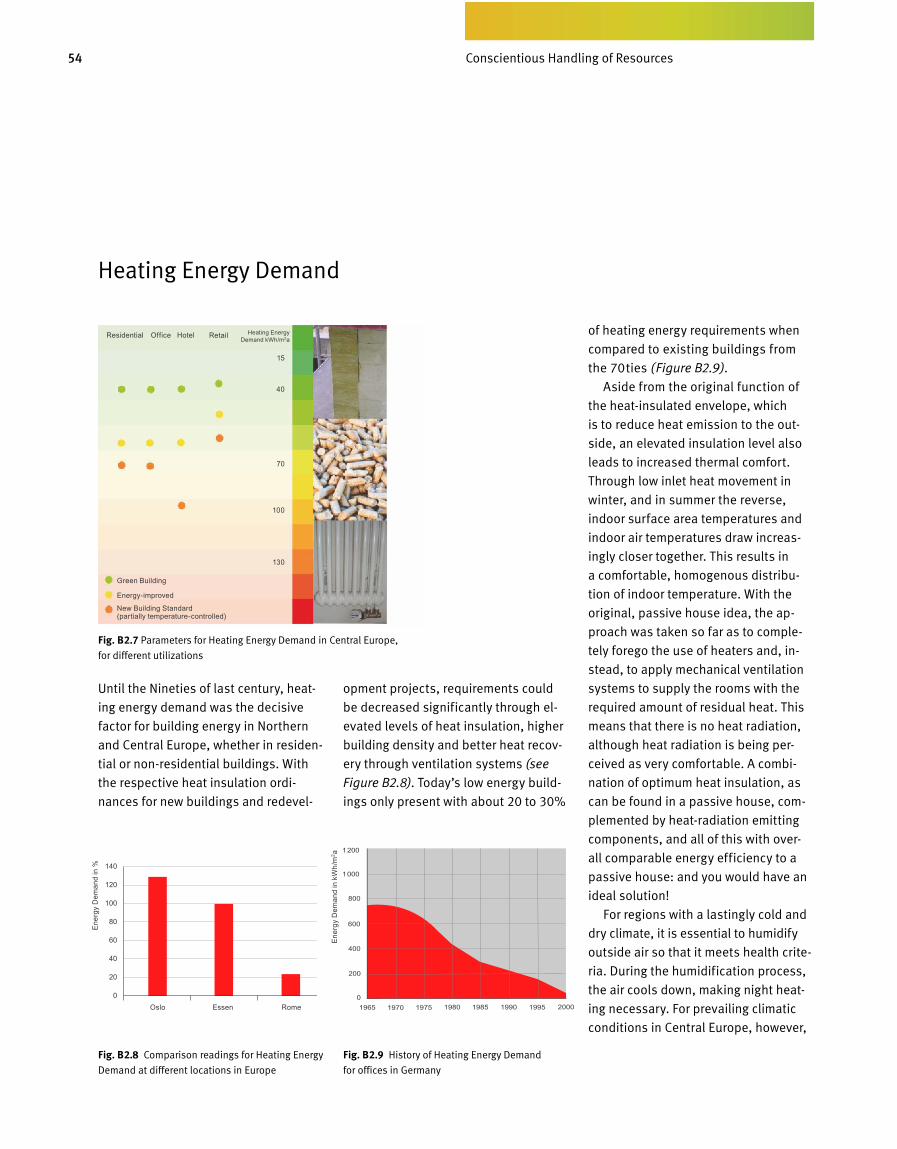
54 Bewusster Umgang mit Ressourcen
Until the Nineties of last century, heat-
ing energy demand was the decisive
factor for building energy in Northern
and Central Europe, whether in residen-
tial or non-residential buildings. With
the respective heat insulation or di-
nances for new buildings and redevel-
opment projects, requirements could
be decreased significantly through el-
evated levels of heat insulation, higher
building density and better heat recov-
ery through ventilation systems (see
Figure B2.8). Today’s low energy build-
ings only present with about 20 to 30%
of heating energy requirements when
compared to ex ist ing buildings from
the 70ties (Figure B2.9).
Aside from the original function of
the heat-insulated envelope, which
is to reduce heat emission to the out-
side, an elevated insulation level also
leads to increased thermal comfort.
Through low inlet heat movement in
winter, and in summer the reverse,
indoor surface area temperatures and
indoor air temperatures draw increas-
ingly closer together. This results in
a comfortable, homogenous distribu-
tion of indoor tem p erature. With the
original, passive house idea, the ap-
proach was taken so far as to comple-
tely forego the use of heaters and, in-
stead, to apply mechanical ventilation
systems to supply the rooms with the
required amount of residual heat. This
means that there is no heat radiation,
although heat radiation is being per-
ceived as very comfortable. A combi-
nation of optimum heat insulation, as
can be found in a passive house, com-
plemented by heat-radiation emitting
components, and all of this with over-
all comparable energy efficiency to a
passive house: and you would have an
ideal solution!
For regions with a lastingly cold and
dry climate, it is essential to humidify
outside air so that it meets health crite-
ria. During the humidification process,
the air cools down, making night heat-
ing necessary. For prevailing climatic
conditions in Central Europe, however,
Heating Energy Demand
Fig. B 2.9 History of Heating Energy Demand
for offices in Germany
Fig. B 2.8 Comparison readings for Heating Energy
Demand at different locations in Europe
Fig. B 2.7 Parameters for Heating Energy Demand in Central Europe,
for different utilizations
Green Building
Energy-improved
New Building Standard (partially temperature-controlled)
15
40
70
100
130
Heating Energy Demand kWh/m2a
Oslo Essen Rome
Ener
gy D
eman
d in
%
Ener
gy D
eman
d in
kW
h/m
2 aResidential Office Hotel Retail
Conscientious Handling of Resources
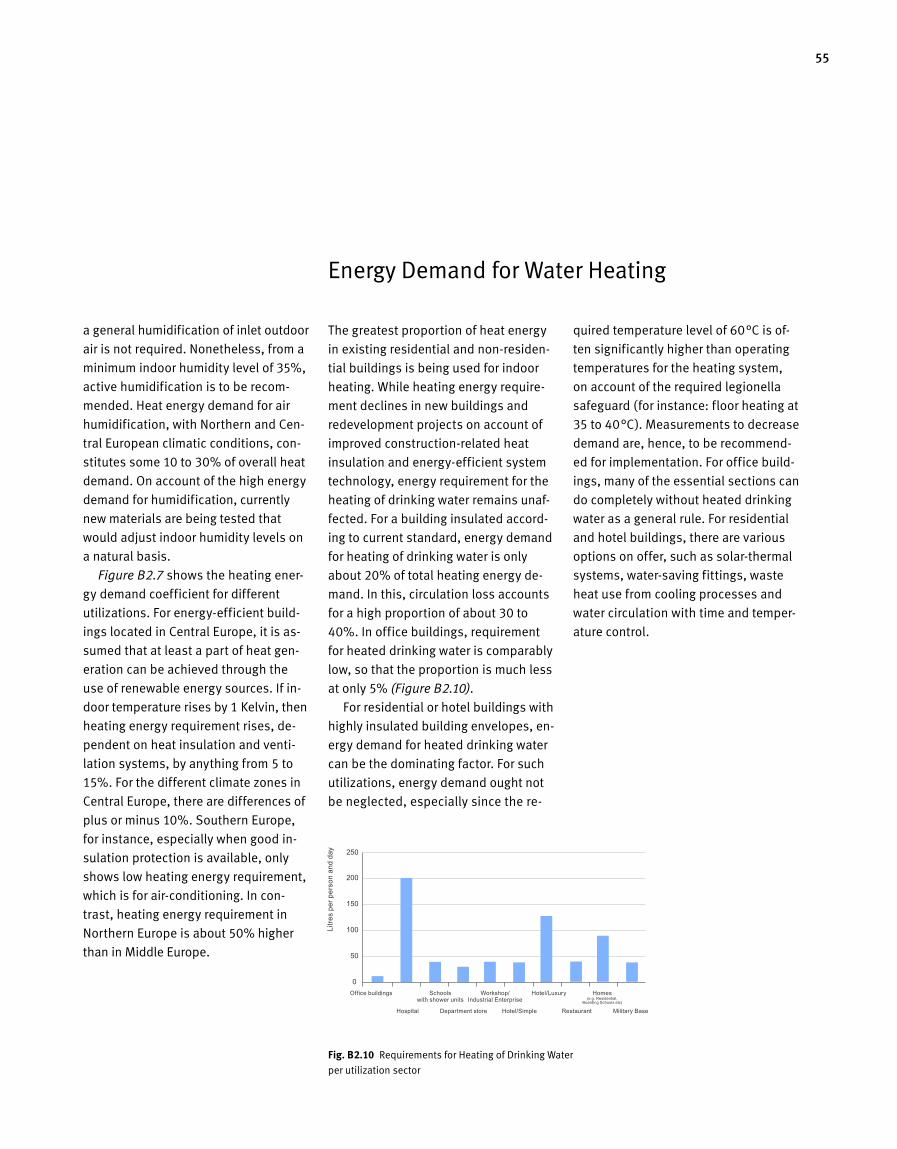
55
Fig. B 2.10 Requirements for Heating of Drinking Water
per utilization sector
Energy Demand for Water Heating
The greatest proportion of heat energy
in existing residential and non-residen-
tial buildings is being used for indoor
heating. While heating energy require-
ment declines in new buildings and
redeve lopment projects on account of
improv ed construction-related heat
insulation and energy-efficient system
technology, energy requirement for the
heating of drinking water remains unaf-
fected. For a building insulated accord-
ing to current standard, energy demand
for heating of drinking water is only
about 20% of total heating energy de-
mand. In this, circulation loss accounts
for a high proportion of about 30 to
40%. In office buildings, requirement
for heated drinking water is comparably
low, so that the proportion is much less
at only 5% (Figure B2.10).
For residential or hotel buildings with
highly insulated building envelopes, en-
er gy demand for heated drinking water
can be the dominating factor. For such
utilizations, energy demand ought not
be neglected, especially since the re-
quired temperature level of 60°C is of-
ten significantly higher than operating
temperatures for the heat ing system,
on account of the required legionella
safeguard (for instance: floor heating at
35 to 40°C). Measurements to decrease
demand are, hence, to be recommend-
ed for implementation. For office build-
ings, many of the essential sections can
do completely without heat ed drinking
water as a general ru le. For residential
and hotel buildings, there are various
options on offer, such as solar-thermal
systems, water-saving fittings, waste
heat use from cooling processes and
water circu lation with time and temper-
ature control.
a general humidification of inlet outdoor
air is not required. Nonetheless, from a
minimum indoor humidity level of 35%,
active humidification is to be recom-
mended. Heat energy demand for air
humidification, with Northern and Cen-
tral European climatic conditions, con-
stitutes some 10 to 30% of overall heat
demand. On account of the high energy
demand for humidification, currently
new materials are being tested that
would adjust indoor humidity levels on
a natural basis.
Figure B2.7 shows the heating ener-
gy demand coefficient for different
utilizations. For energy-efficient build-
ings located in Central Europe, it is as-
sumed that at least a part of heat gen-
eration can be achieved through the
use of renewable energy sources. If in-
door temperature rises by 1 Kelvin, then
heating energy requirement rises, de-
pendent on heat insulation and venti-
lation systems, by anything from 5 to
15%. For the different climate zones in
Central Europe, there are differences of
plus or minus 10%. Southern Europe,
for instance, especially when good in-
sulation protection is available, only
shows low heating energy requirement,
which is for air-conditioning. In con-
trast, heating energy requirement in
Northern Europe is about 50% higher
than in Middle Europe.
Office buildings Schools with shower units
Hospital Department store Hotel/Simple Restaurant Military Base
Workshop/ Industrial Enterprise
Hotel/Luxury Homes (e.g. Residential,
Boarding Schools etc)
Litre
s pe
r per
son
and
day
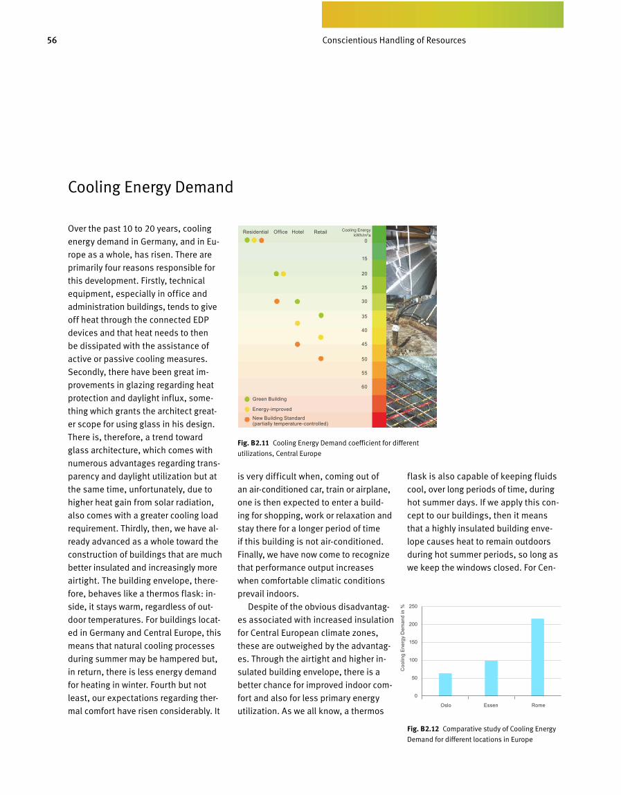
56 Bewusster Umgang mit Ressourcen
Fig. B 2.12 Comparative study of Cooling Energy
Demand for different locations in Europe
is very difficult when, coming out of
an air-conditioned car, train or airplane,
one is then expected to enter a build -
ing for shopping, work or relaxation and
stay there for a longer period of time
if this building is not air-conditioned.
Finally,wehavenowcometorecognize
that performance output increases
when comfortable climatic conditions
prevail indoors.
Despite of the obvious disadvantag-
es associated with increased insulation
forCentralEuropeanclimatezones,
these are outweighed by the advantag-
es. Through the airtight and higher in-
sulated building envelope, there is a
better chance for improved indoor com-
fort and also for less primary energy
utilization.Asweallknow,athermos
flask is also capable of keeping fluids
cool, over long periods of time, during
hot summer days. If we apply this con-
cept to our buildings, then it means
that a highly insulated building enve-
lope causes heat to remain outdoors
during hot summer periods, so long as
we keep the windows closed. For Cen-
Fig. B 2.11 Cooling Energy Demand coefficient for different
utilizations,CentralEurope
Over the past 10 to 20 years, cooling
en ergy demand in Germany, and in Eu-
rope as a whole, has risen. There are
primarily four reasons responsible for
this development. Firstly, technical
equipment, especially in office and
administration buildings, tends to give
off heat through the connected EDP
devices and that heat needs to then
be dissipated with the assistance of
active or passive cooling measures.
Secondly, there have been great im-
provementsinglazingregardingheat
protection and daylight influx, some-
thing which grants the architect great-
er scope for using glass in his design.
There is, therefore, a trend toward
glass architecture, which comes with
numerous advantages regarding trans-
parencyanddaylightutilizationbutat
the same time, unfortunately, due to
higher heat gain from solar radiation,
also comes with a greater cooling load
requirement. Thirdly, then, we have al-
ready advanced as a whole toward the
construction of buildings that are much
better insulated and increasingly more
airtight. The building envelope, there-
fore, behaves like a thermos flask: in-
side, it stays warm, regardless of out-
door temperatures. For buildings locat-
ed in Germany and Central Europe, this
means that natural cooling processes
during summer may be hampered but,
in return, there is less energy demand
for heating in winter. Fourth but not
least, our expectations regarding ther-
mal comfort have risen considerably. It
Cooling Energy Demand
Green Building
Energy-improved
New Building Standard (partially temperature-controlled)
0
15
20
25
30
35
40
45
50
55
60
Cooling Energy kWh/m2a
Residential Office Hotel Retail
Oslo Essen Rome
Coo
ling
Ener
gy D
eman
d in
%
Conscientious Handling of Resources
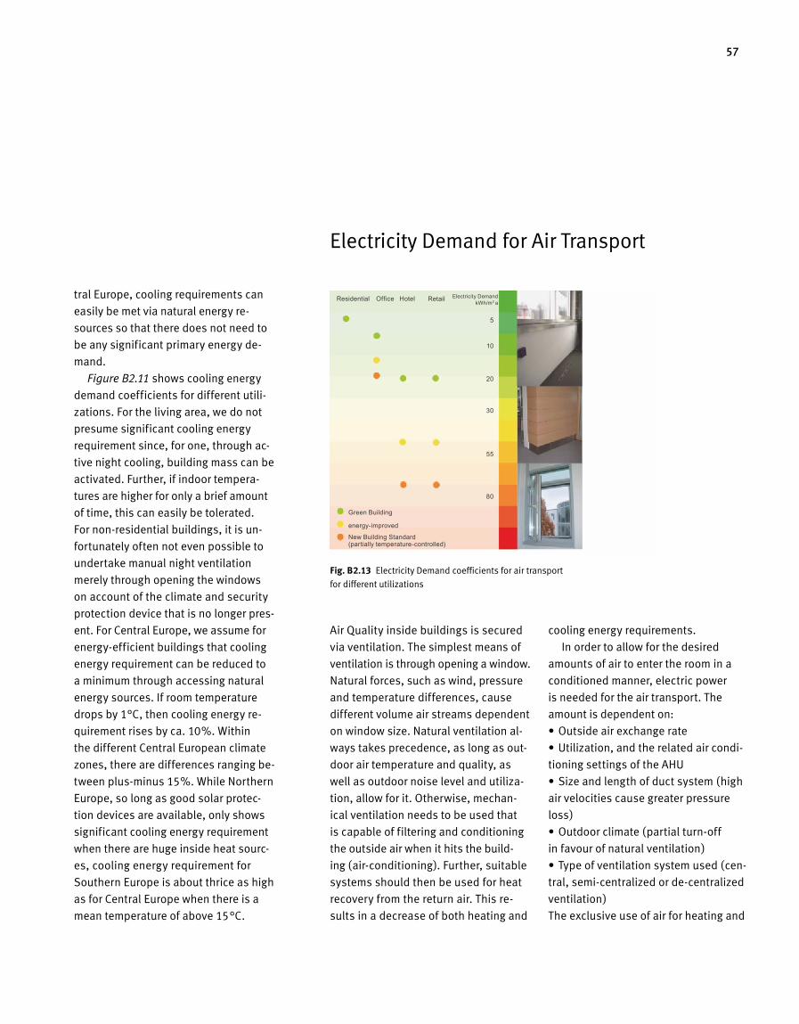
57
tral Europe, cooling requirements can
easily be met via natural energy re-
sources so that there does not need to
be any significant primary energy de-
mand.
Figure B2.11 shows cooling energy
demand coefficients for different utili-
zations.Forthelivingarea,wedonot
presume significant cooling energy
requirement since, for one, through ac-
tive night cooling, building mass can be
activated. Further, if indoor tempera-
tures are higher for only a brief amount
of time, this can easily be tolerated.
For non-residential buildings, it is un-
fortunately often not even possible to
undertake manual night ventilation
merely through opening the windows
on account of the climate and security
protection device that is no longer pres-
ent. For Central Europe, we assume for
energy-efficient buildings that cooling
energy requirement can be reduced to
a minimum through accessing natural
energy sources. If room temperature
drops by 1°C, then cooling energy re-
quirement rises by ca. 10%. Within
the different Central European climate
zones,therearedifferencesrangingbe-
tween plus-minus 15%. While Northern
Europe, so long as good solar protec-
tion devices are available, only shows
significant cooling energy requirement
when there are huge inside heat sourc-
es, cooling energy requirement for
Southern Europe is about thrice as high
as for Central Europe when there is a
mean temperature of above 15°C.
Air Quality inside buildings is secured
via ventilation. The simplest means of
ventilation is through opening a window.
Natural forces, such as wind, pressure
and temperature differences, cause
different volume air streams dependent
onwindowsize.Naturalventilational-
ways takes precedence, as long as out-
door air temperature and quality, as
wellasoutdoornoiselevelandutiliza-
tion, allow for it. Otherwise, mechan -
i cal ventilation needs to be used that
is cap able of filtering and conditioning
the outside air when it hits the build-
ing (air-conditioning). Further, suitable
systems should then be used for heat
recovery from the return air. This re-
sults in a decrease of both heating and
cooling energy requirements.
In order to allow for the desired
amounts of air to enter the room in a
conditioned manner, electric power
is needed for the air transport. The
amount is depend ent on:
•Outsideairexchangerate
•Utilization,andtherelatedaircondi-
tioning settings of the AHU
•Sizeandlengthofductsystem(high
air velocities cause greater pressure
loss)
•Outdoorclimate(partialturn-off
in favour of natural ventilation)
•Typeofventilationsystemused(cen-
tral,semi-centralizedorde-centralized
ventilation)
The exclusive use of air for heating and
Fig. B 2.13 Electricity Demand coefficients for air transport
fordifferentutilizations
Electricity Demand for Air Transport
Green Building
energy-improved
New Building Standard (partially temperature-controlled)
5
10
20
30
55
80
Electricity Demand kWh/m2 a
Residential Office Hotel Retail
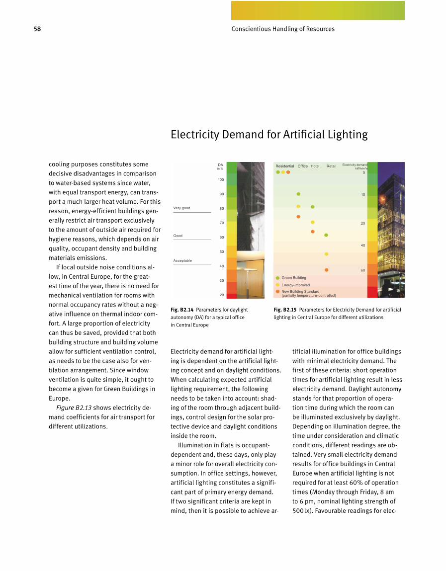
58 Bewusster Umgang mit Ressourcen
Electricity demand for artificial light-
ing is dependent on the artificial light-
ing concept and on daylight conditions.
When calculating expected artificial
lighting requirement, the following
needs to be taken into account: shad-
ing of the room through adjacent build-
ings, control design for the solar pro-
tective device and daylight conditions
inside the room.
Illumination in flats is occupant-
dependent and, these days, only play
a minor role for overall electricity con-
sumption. In office settings, however,
artificial lighting constitutes a signifi-
cant part of primary energy demand.
If two significant criteria are kept in
mind, then it is possible to achieve ar-
tificial illumination for office buildings
with minimal electricity demand. The
first of these criteria: short operation
times for artificial lighting result in less
electricity demand. Daylight autonomy
stands for that proportion of opera-
tion time du ring which the room can
be illumina ted exclusively by daylight.
Depending on illumination degree, the
time under consideration and climatic
conditions, different readings are ob-
tained. Very small electricity demand
results for office buildings in Central
Europe when artificial lighting is not
required for at least 60% of operation
times (Monday through Friday, 8 am
to 6 pm, nominal lighting strength of
500lx). Favourable readings for elec-
Fig. B 2.14 Parameters for daylight
auto nomy (DA) for a typical office
in Central Europe
Fig. B 2.15 Parameters for Electricity Demand for artificial
lightinginCentralEuropefordifferentutilizations
Electricity Demand for Artificial Lighting
cooling purposes constitutes some
decisive disadvantages in comparison
to water-based systems since water,
with equal transport energy, can trans-
port a much larger heat volume. For this
reason, energy-efficient buildings gen-
erally restrict air transport exclusively
to the amount of outside air required for
hygiene reasons, which depends on air
quality, occupant density and building
materials emissions.
If local outside noise conditions al-
low, in Central Europe, for the great -
est time of the year, there is no need for
mechanical ventilation for rooms with
normal occupancy rates without a neg-
ative influence on thermal indoor com-
fort. A large proportion of electricity
can thus be saved, provided that both
building structure and building volume
allow for sufficient ventilation control,
as needs to be the case also for ven-
tilation arrangement. Since window
vent ilation is quite simple, it ought to
become a given for Green Buildings in
Europe.
Figure B2.13 shows electricity de-
mand coefficients for air transport for
differentutilizations.
Green Building
Energy-improved
New Building Standard (partially temperature-controlled)
5
10
20
40
60
100
90
80
70
60
50
40
30
20
Electricity demand kWh/m2a
DAin %
Very good
Good
Acceptable
Residential Office Hotel Retail
Conscientious Handling of Resources

59
tricity demand are obtained when the
daylight and sunlight factors outlined
in Figure B1.35 (see chapter B1) can be
achieved at the »very good« level.
The second of the essential criteria
for a more efficient approach to artifi-
cial lighting operation is a low electric-
ity connected load for the lighting. This
canbeachievedthroughtheutiliza-
tion of highly effective illuminants and
when a direct-indirect lighting concept
applies. If these two criteria are being
met, it is possible to achieve low elec-
tricity demand readings for office light-
ing. Further reduction can be achieved
with a demand-oriented controls sys-
tem: artificial lighting is not handled
manually in a layered manner but,
rather, artificial lighting is automati-
cally dimmed to the required illumina-
tion level via regulating devices and
then lowered or increased via presence-
sensing devices. Figure B2.15 shows
guide values for electricity demand for
artificial lighting in office buildings.
Fig. B 2.16 Comparison of Electricity Demand
for artificial lighting for different locations in
Europe
Future Energy Benchmark – Primary Energy Demand over the Life Cycle of a Building
For new buildings and redevelopment
projects, primary energy demand for
any systems used for conditioning a
roommust,dependingonutilization,
stay below certain critical values. Imple-
mentation of these Europe-wide re-
quirements was a big step in the right
direction, for once, but it does not suf-
fice. Energy-based evaluation of ener-
gy-efficient and sustainable buildings
must take into account all energy flows
including, for instance, energy demand
for the manufacture, renewal and main-
tenance of building materials as well
as electricity demand for furnishings
supplied by the occupant. Only if there
are additional stipulations, for restrict-
ing total energy flow, can all who are
part of the construction process be
forced into treading new paths and
therefore having to provide innova-
tive solutions. Today’s business plans
for big companies frequently include
life cycle costs as a management in-
strument. Shortsighted action can be
avoided if all expected expenses are
being considered from the start. The
same should apply for primary energy
demand in the building industry. Here,
too, the entire life cycle needs to be
looked at. What good is it to have the
best insulation materials if, for their
manufacture, we need many times over
the energy that they eventually save?
Energy sector develop ments over re-
cent years have shown that energy-ef-
ficient products can also be supplied
within an economical fra me. All that
is needed is for the market to demand
them.
Fig. B 2.17 Spread of primary energy demand
over the life cycle of a building. In future,
Europe will only regulate energy demand for
systems needed for room conditioning
Fig. B 2.18 Approximate parameters for Primary
Energy Demand over the life cycle of a building
inCentralEuropefordifferentutilizations
Oslo Essen Rome
Building Life Cycle over 80 years
Manufacture Consumption during operation
Renewal during operation
Recycling
Ener
gy D
eman
d in
%
Bui
ldin
gs w
ith s
yste
ms
fo
r roo
m c
ondi
tioni
ngFu
rnis
hing
s
by o
ccup
ants
Green Building
Energy-improved
New Building Standard (partially temperature-controlled)
120
180
240
300
360
Primary Energy over the life cycle
kWh/m2a
Residential Office
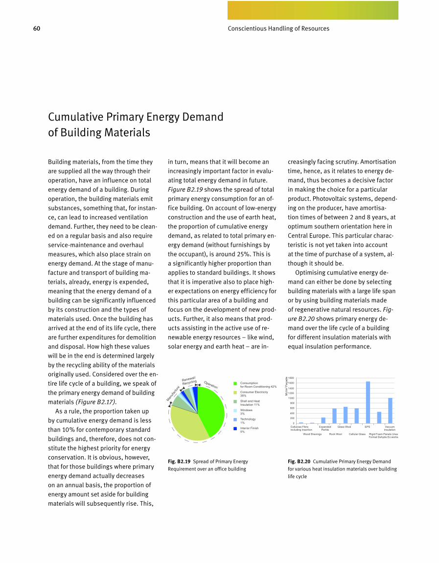
60 Bewusster Umgang mit Ressourcen
Cumulative Primary Energy Demand of Building Materials
Building materials, from the time they
are supplied all the way through their
operation, have an influence on total
energy demand of a building. During
operation, the building materials emit
substances, something that, for instan
ce, can lead to increased ventilation
demand. Further, they need to be clean
ed on a regular basis and also require
servicemaintenance and overhaul
measures, which also place strain on
energy demand. At the stage of manu
facture and transport of building ma
terials, already, energy is expended,
meaning that the energy demand of a
building can be significantly influenced
by its construction and the types of
materials used. Once the building has
arrived at the end of its life cycle, there
are further expenditures for demolition
and disposal. How high these values
will be in the end is determined largely
by the recycling ability of the materials
originally used. Considered over the en
tire life cycle of a building, we speak of
the primary energy demand of building
materials (Figure B2.17).
As a rule, the proportion taken up
by cumulative energy demand is less
than 10% for contemporary standard
buildings and, therefore, does not con
stitute the highest priority for energy
conservation. It is obvious, however,
that for those buildings where primary
energy demand actually decreases
on an annual basis, the proportion of
energy a mount set aside for building
mate rials will subsequently rise. This,
in turn, means that it will become an
increasingly important factor in evalu
ating total energy demand in future.
Figure B2.19 shows the spread of total
primary energy consumption for an of
fice building. On account of lowenergy
construction and the use of earth heat,
the proportion of cumulative energy
demand, as related to total primary en
ergy demand (without furnishings by
the occupant), is around 25%. This is
a significantly higher proportion than
applies to standard buildings. It shows
that it is imperative also to place high
er expectations on energy efficiency for
this particular area of a building and
focus on the development of new prod
ucts. Further, it also means that prod
ucts assisting in the active use of re
newable energy resour ces – like wind,
solar energy and earth heat – are in
creasingly facing scrutiny. Amortisation
time, hence, as it relates to energy de
mand, thus becomes a decisive factor
in making the choice for a particular
pro duct. Photovoltaic systems, depend
ing on the producer, have amortisa
tion times of between 2 and 8 years, at
op timum southern orientation here in
Central Europe. This particular charac
teristic is not yet taken into account
at the time of purchase of a system, al
though it should be.
Optimising cumulative energy de
mand can either be done by selecting
building materials with a large life span
or by using building materials made
of regenerative natural resources. Fig-
ure B2.20 shows primary energy de
mand over the life cycle of a building
for different insulation materials with
equal insulation performance.
Fig. B 2.19 Spread of Primary Energy
Requirement over an office building
Fig. B 2.20 Cumulative Primary Energy Demand
for various heat insulation materials over building
life cycle
Consumption for Room Conditioning 42%
Consumer Electricity 38%
Shell and Heat Insulation 11%
Windows 3%
Technology 1%
Interior Finish 5%
Manuf
actu
re
Renewal/
Recycling Operation
Cellulose Fibre including insertion
Wood Shavings Rock Wool Cellular Glass Rigid Foam Panels Urea Formal Dehyde Ex works
Expanded Perlite
Glass Wool EPS Vacuum insulation
MJ/
m2 Fa
çade
Conscientious Handling of Resources
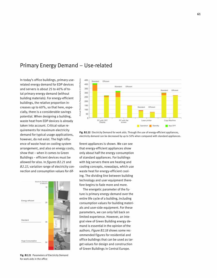
61
Primary Energy Demand – Userelated
ferent appliances is shown. We can see
that energyefficient app liances show
only about half the energy consumption
of standard appliances. For buildings
with big servers there are heating and
cooling concepts, nowadays, which use
waste heat for energyefficient cool
ing. The dividing line between building
technology and user equipment there
fore begins to fade more and more.
The energetic parameter of the fu
ture is primary energy demand over the
entire life cycle of a building, including
consumption values for building materi
als and userside equipment. For these
parameters, we can only fall back on
li mited experience. However, an inte
gral view of Green Building energy de
mand is essential in the opinion of the
authors. Figure B2.18 shows some rec
ommended figures for residential and
office build ings that can be used as tar
get values for design and construction
of Green Buildings in Central Europe.
Fig. B 2.22 Electricity Demand for work aids. Through the use of energyefficient appliances,
electricity demand can be decreased by up to 50% when compared with standard appliances.
Fig. B 2.21 Parameters of Electricity Demand
for work aids in the office
Energy-efficient
Standard
Huge Consumption
Ann
ual E
lect
ricity
Req
uire
men
ts in
kW
h/D
evic
e
15
25
35
50
Electricity Demand in kWh/m2a
PC with CRT Display
Standard
Standard
Standard
Standard
Efficient
Efficient
Efficient
Efficient
PC with flat screen
Operation Standby App.OFF
Laser printer Copy Machine
In today’s office buildings, primary use
related energy demand for EDP devices
and servers is about 25 to 40% of to
tal primary energy demand (without
build ing materials). For energyefficient
buildings, the relative proportion in
creases up to 60%, so that here, espe
cially, there is a considerable savings
potential. When designing a building,
waste heat from EDP devices is already
taken into account. Critical value re
quirements for maximum electricity
demand for typical usage applications,
however, do not exist. The high influ
ence of waste heat on cooling sys tem
arrangement, and also on energy costs,
show that – when it comes to Green
Buildings – efficient devices must be
allowed for also. In figures B2.21 and
B2.22, variation range of electricity con
nection and consumption values for dif
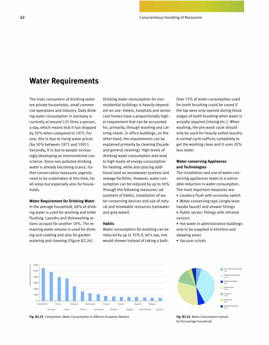
62 Bewusster Umgang mit Ressourcen
The main consumers of drinking water
are private households, small commer
cial operations and industry. Daily drink
ing water consumption in Germa ny is
currently at around 125 litres a person,
a day, which means that it has dropped
by 20% when compared to 1975. For
one, this is due to rising water prices
(by 50% between 1971 and 1991).
Secondly, it is due to people increas
ingly developing an environmental con
science. Since nonpolluted drinking
water is already becoming scarce, fur
ther conservation measures urgently
need to be undertaken at this time, for
all areas but especially also for house
holds.
Water Requirement for Drinking WaterIn the average household, 68% of drink
ing water is used for washing and toilet
flushing. Laundry and dishwashing ac
tions account for another 19%. The re
maining water volume is used for drink
ing and cooking and also for garden
watering and cleaning (Figure B2.24).
Drinking water consumption for non
residential buildings is heavily depend
ent on use. Hotels, hospitals and senior
care homes have a proportionally high
er requirement that can be account ed
for, primarily, through washing and ca t
e r ing needs. In office buildings, on the
other hand, the requirements can be
explained primarily by cleaning (faça de
and general cleaning). High levels of
drinking water consumption also lead
to high levels of energy consumption
for heating, while also placing addi
tional load on wastewater systems and
sewage facilities. However, water con
sumption can be reduced by up to 50%
through the following measures: ad
justment of habits, installation of wa
terconserving devices and use of natu
ral and renewable resources (rainwater
and grey water).
HabitsWater consumption for washing can be
reduced by up to 35% if, let’s say, one
would shower instead of taking a bath.
Over 75% of water consumption used
for tooth brushing could be saved if
the tap were only opened during those
stages of tooth brushing when water is
actually required (rinsing etc.). When
washing, the prewash cycle should
only be used for heavily soiled laundry.
A normal cycle suffices completely to
get the washing clean and it uses 20%
less water.
Water-conserving Appliances and TechnologiesThe installation and use of watercon
serving appliances leads to a notice
able reduction in water consumption.
The most important measures are:
•Lavatory flush with economy switch
•Waterconserving taps (single lever
handle faucet) and shower fittings
•Public sector: fittings with infrared
sensors
•Hot water in administrative buildings
only to be supplied in kitchens and
sleep ing areas
•Vacuum urinals
Fig. B 2.24 Water Consumption spread
for the average household
Water Requirements
Fig. B 2.23 Comparison: Water Consumption in different European Nations
Drinking and Cooking 5 %
Personal Grooming 37 %
Washing Dishes 6 %
Toilet Flush 31 %
Laundry 13 %
Cleaning 4 %
Garden Watering 4 %
Great Britain France Romania Netherlands Norway Austria Belgium Bulgaria
Germany Spain Poland Switzerland Sweden Hungary Czech Republic Denmark
Con
sum
ptio
n (M
io.)
in m
3 /a
Conscientious Handling of Resources
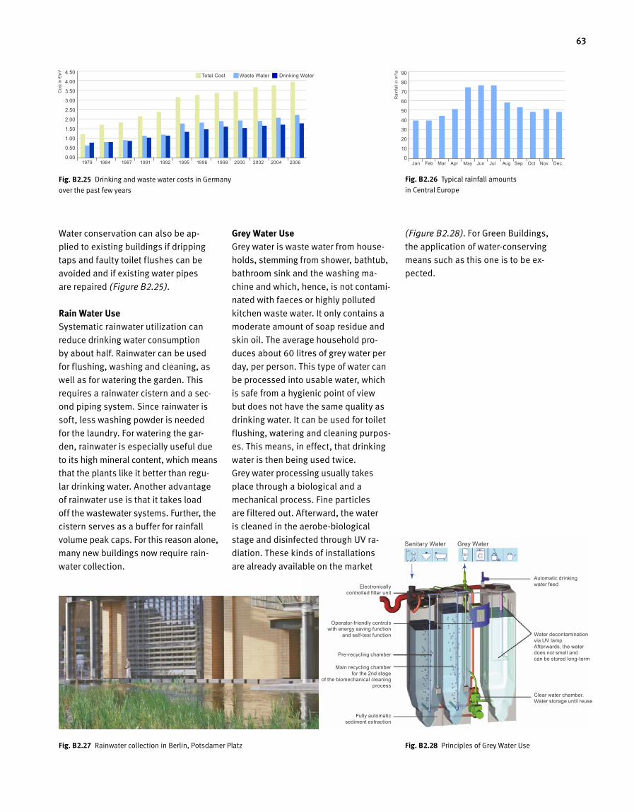
63
Water conservation can also be ap -
plied to existing buildings if dripping
taps and faulty toilet flushes can be
avoided and if existing water pipes
are repaired (Figure B2.25).
Rain Water UseSystematic rainwater utilization can
re duce drinking water consumption
by about half. Rainwater can be used
for flushing, washing and cleaning, as
well as for watering the garden. This
requires a rainwater cistern and a sec-
ond piping system. Since rainwater is
soft, less washing powder is needed
for the laundry. For watering the gar-
den, rainwater is especially useful due
to its high mineral content, which means
that the plants like it better than regu -
lar drinking water. Another advantage
of rainwater use is that it takes load
off the wastewater systems. Further, the
cistern serves as a buffer for rainfall
vol ume peak caps. For this reason a lone,
many new buildings now require rain-
water collection.
Grey Water UseGrey water is waste water from house-
holds, stemming from shower, bath tub,
bathroom sink and the washing ma-
chine and which, hence, is not contami-
nated with faeces or highly polluted
kitchen waste water. It only contains a
moderate amount of soap residue and
skin oil. The average household pro-
duces about 60 litres of grey water per
day, per person. This type of water can
be processed into usable water, which
is safe from a hygienic point of view
but does not have the same quality as
drinking water. It can be used for toilet
flushing, watering and cleaning purpos-
es. This means, in effect, that drinking
water is then being used twice.
Grey water processing usually takes
place through a biological and a
mechanical process. Fine particles
are filtered out. Afterward, the water
is cleaned in the aerobe-biological
stage and disinfected through UV ra-
diation. These kinds of installations
are already available on the market
(Figure B2.28). For Green Buildings,
the application of water-conserving
means such as this one is to be ex-
pected.
Fig. B 2.27 Rainwater collection in Berlin, Potsdamer Platz Fig. B 2.28 Principles of Grey Water Use
Total Cost Waste Water Drinking Water
Cos
t in
€/m
3
Rai
nfal
l in
m3 /a
Jan Feb Mar Apr May Jun Jul Aug Sep Oct Nov Dec1979 1984 1987 1991 1992 1995 1996 1998 2000 2002 2004 2006
Automatic drinking water feed
Water decontamination via UV lamp. Afterwards, the water does not smell and can be stored long-term
Clear water chamber. Water storage until reuse
Electronically controlled filter unit
Operator-friendly controls with energy saving function
and self-test function
Pre-recycling chamber
Main recycling chamber for the 2nd stage
of the biomechanical cleaning process
Fully automatic sediment extraction
Sanitary Water Grey Water
Fig. B 2.26 Typical rainfall amounts
in Central EuropeFig. B 2.25 Drinking and waste water costs in Germany
over the past few years
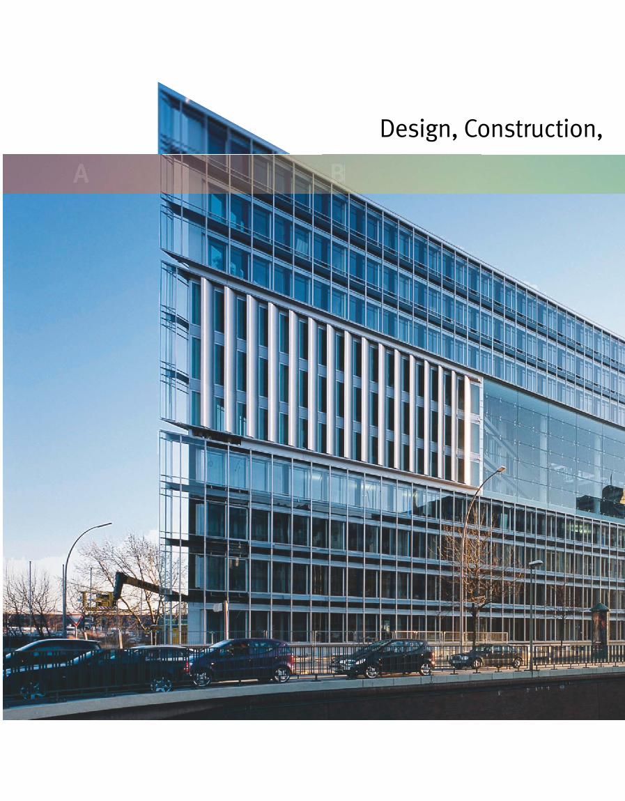
Design, Construction, Commissioning and Monitoring for Green Buildings
A B
Design, Construction, Commissioning and Monitoring for Green Buildings
C D

AC 1 D
Buildings
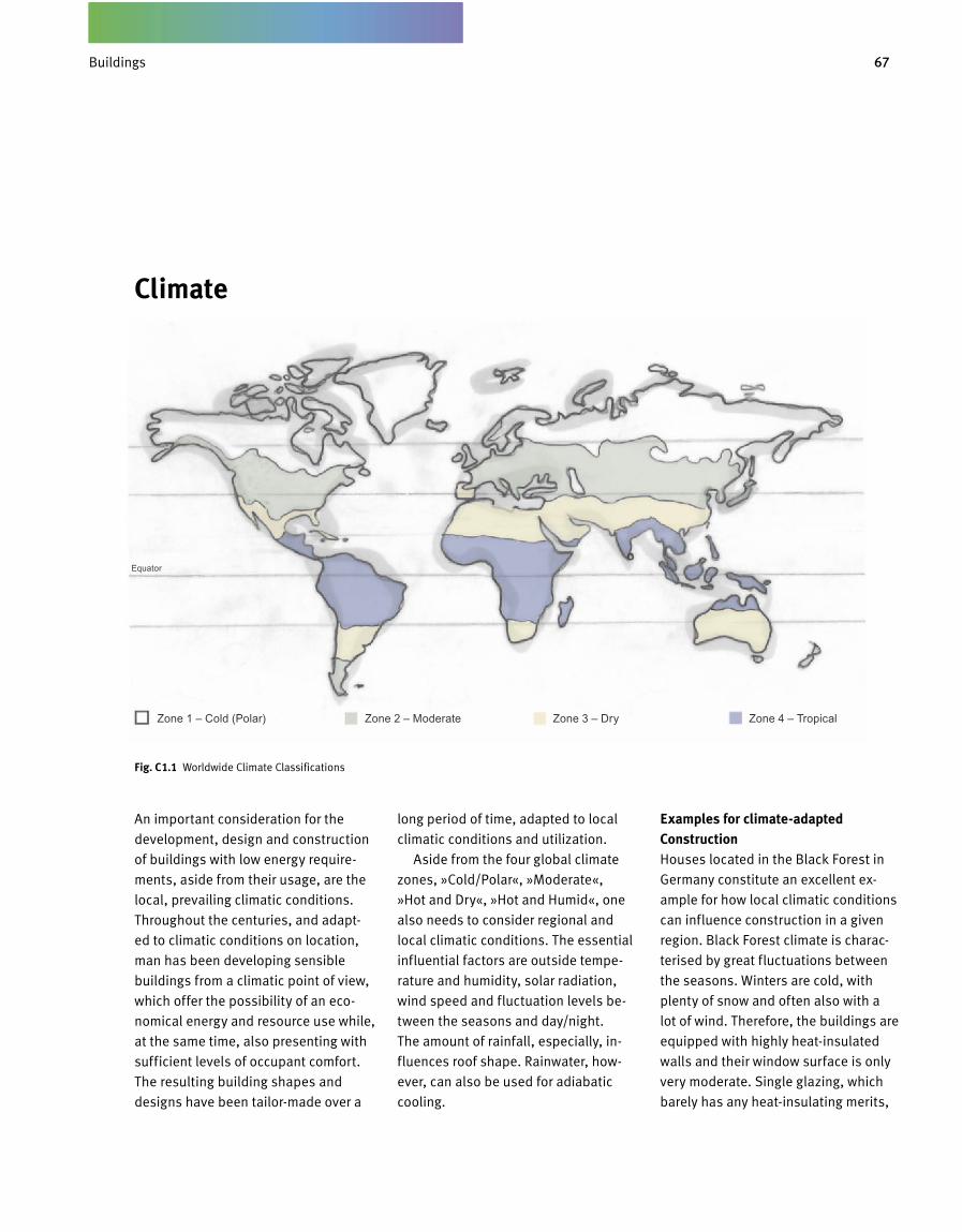
67Gebäude
Climate
An important consideration for the
development, design and construction
of buildings with low energy require-
ments, aside from their usage, are the
local, prevailing climatic conditions.
Throughout the centuries, and adapt -
ed to climatic conditions on location,
man has been developing sensible
buildings from a climatic point of view,
which offer the possibility of an eco-
nomical energy and resource use while,
at the same time, also presenting with
sufficient levels of occupant comfort.
The resulting building shapes and
designs have been tailor-made over a
long period of time, adapted to local
climatic conditions and utilization.
Aside from the four global climate
zones, »Cold/Polar«, »Moderate«,
»Hot and Dry«, »Hot and Humid«, one
also needs to consider regional and
local climatic conditions. The essential
influential factors are outside tempe-
rature and humidity, solar radiation,
wind speed and fluctuation levels be-
tween the seasons and day/night.
The amount of rainfall, especially, in -
flu ences roof shape. Rainwater, how-
ever, can also be used for adiabatic
cooling.
Examples for climate-adapted ConstructionHouses located in the Black Forest in
Germany constitute an excellent ex-
ample for how local climatic conditions
can influence construction in a given
region. Black Forest climate is charac-
terised by great fluctuations between
the seasons. Winters are cold, with
plenty of snow and often also with a
lot of wind. Therefore, the buildings are
equipped with highly heat-insulated
walls and their window surface is only
very moderate. Single glazing, which
barely has any heat-insulating merits,
Fig. C 1.1 Worldwide Climate Classifications
Zone 1 – Cold (Polar) Zone 2 – Moderate Zone 3 – Dry Zone 4 – Tropical
Equator
Buildings
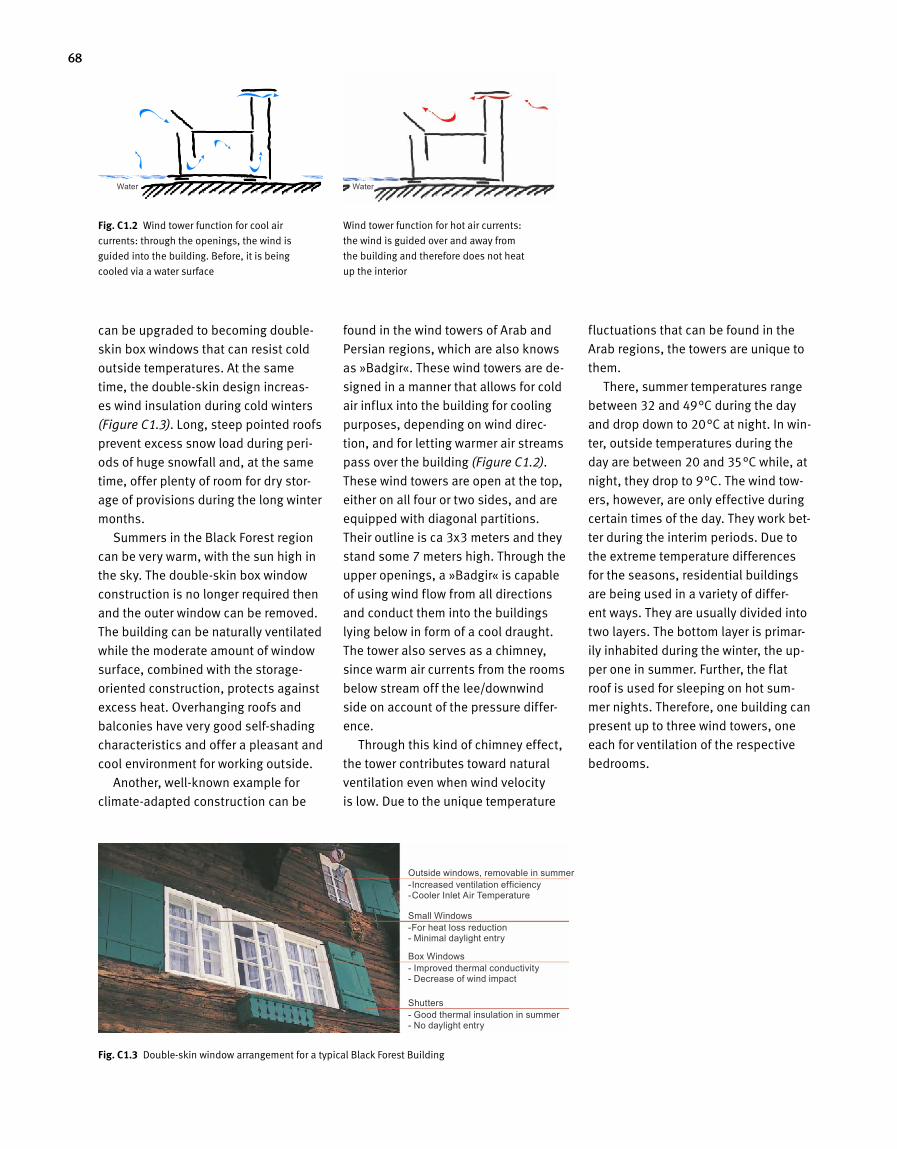
68
can be upgraded to becoming double-
skin box windows that can resist cold
outside temperatures. At the same
time, the double-skin design increas-
es wind insulation during cold winters
(Figure C1.3). Long, steep pointed roofs
prevent excess snow load during peri-
ods of huge snowfall and, at the same
time, offer plenty of room for dry stor-
age of provisions during the long winter
months.
Summers in the Black Forest region
can be very warm, with the sun high in
the sky. The double-skin box window
construction is no longer required then
and the outer window can be removed.
The building can be naturally ventilated
while the moderate amount of window
surface, combined with the storage-
oriented construction, protects against
excess heat. Overhanging roofs and
balconies have very good self-shading
characteristics and offer a pleasant and
cool environment for working outside.
Another, well-known example for
climate-adapted construction can be
found in the wind towers of Arab and
Persian regions, which are also knows
as »Badgir«. These wind towers are de-
signed in a manner that allows for cold
air influx into the building for cooling
purposes, depending on wind direc-
tion, and for letting warmer air streams
pass over the building (Figure C1.2).
These wind towers are open at the top,
either on all four or two sides, and are
equipped with diagonal partitions.
Their outline is ca 3x3 meters and they
stand some 7 meters high. Through the
upper openings, a »Badgir« is capable
of using wind flow from all directions
and conduct them into the buildings
lying below in form of a cool draught.
The tower also serves as a chimney,
since warm air currents from the rooms
below stream off the lee/downwind
side on account of the pressure differ-
ence.
Through this kind of chimney effect,
the tower contributes toward natural
ventilation even when wind velocity
is low. Due to the unique temperature
fluctuations that can be found in the
Arab regions, the towers are unique to
them.
There, summer temperatures range
between 32 and 49°C during the day
and drop down to 20°C at night. In win-
ter, outside temperatures during the
day are between 20 and 35°C while, at
night, they drop to 9°C. The wind tow-
ers, however, are only effective during
certain times of the day. They work bet-
ter during the interim periods. Due to
the extreme temperature differences
for the seasons, residential buildings
are being used in a variety of differ-
ent ways. They are usually divided into
two layers. The bottom layer is primar-
ily inhabited during the winter, the up-
per one in summer. Further, the flat
roof is used for sleeping on hot sum-
mer nights. Therefore, one building can
present up to three wind towers, one
each for ventilation of the respective
bedrooms.
Fig. C 1.3 Double-skin window arrangement for a typical Black Forest Building
Fig. C 1.2 Wind tower function for cool air
currents: through the openings, the wind is
guided into the building. Before, it is being
cooled via a water surface
Wind tower function for hot air currents:
the wind is guided over and away from
the building and therefore does not heat
up the interior
Water Water
Outside windows, removable in summer- Increased ventilation efficiency- Cooler Inlet Air Temperature
Small Windows-For heat loss reduction - Minimal daylight entry
Box Windows- Improved thermal conductivity - Decrease of wind impact
Shutters- Good thermal insulation in summer - No daylight entry
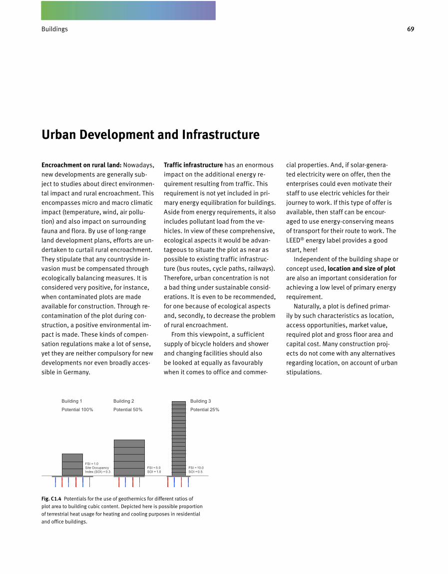
69Gebäude
Urban Development and Infrastructure
Encroachment on rural land: Nowadays,
new developments are generally sub-
ject to studies about direct environmen-
tal impact and rural encroachment. This
encompasses micro and macro climatic
impact (temperature, wind, air pollu-
tion) and also impact on surrounding
fauna and flora. By use of long-range
land development plans, efforts are un-
dertaken to curtail rural encroachment.
They stipulate that any countryside in-
vasion must be compensated through
ecologically balancing measures. It is
considered very positive, for instance,
when contaminated plots are made
avail able for construction. Through re-
contamination of the plot during con-
struction, a positive environmental im-
pact is made. These kinds of compen-
sation regulations make a lot of sense,
yet they are neither compulsory for new
developments nor even broadly acces-
sible in Germany.
Traffic infrastructure has an enormous
impact on the additional energy re-
quirement resulting from traffic. This
requirement is not yet included in pri-
mary energy equilibration for buildings.
Aside from energy requirements, it also
includes pollutant load from the ve-
hicles. In view of these comprehensive,
ecological aspects it would be advan-
tageous to situate the plot as near as
possible to existing traffic infrastruc-
ture (bus routes, cycle paths, railways).
Therefore, urban concentration is not
a bad thing under sustainable consid-
erations. It is even to be recommended,
for one because of ecological aspects
and, secondly, to decrease the problem
of rural encroachment.
From this viewpoint, a sufficient
supply of bicycle holders and shower
and changing facilities should also
be looked at equally as favourably
when it comes to office and commer -
cial properties. And, if solar-genera-
ted electricity were on offer, then the
en terprises could even motivate their
staff to use electric vehicles for their
journey to work. If this type of offer is
available, then staff can be encour-
aged to use energy-conserving means
of transport for their route to work. The
LEED® energy label provides a good
start, here!
Independent of the building shape or
concept used, location and size of plot are also an important consideration for
achieving a low level of primary energy
requirement.
Naturally, a plot is defined primar-
ily by such characteristics as location,
access opportunities, market value,
required plot and gross floor area and
capital cost. Many construction proj-
ects do not come with any alternatives
regarding location, on account of urban
stipulations.
Fig. C 1.4 Potentials for the use of geothermics for different ratios of
plot area to building cubic content. Depicted here is possible proportion
of terrestrial heat usage for heating and cooling purposes in residential
and office buildings.
Building 1
Potential 100%
Building 2
Potential 50%
Building 3
Potential 25%
FSI = 1.0 Site Occupancy Index (SOI) = 0.3
FSI = 5.0 SOI = 1.0
FSI = 10.0 SOI = 0.5
Buildings

70
However, when plot location is not de-
fined from the outset and there are sev-
eral different options, then factors like
primary energy requirement and envi-
ronmental stress should become part
of the decision process.
The floor space index describes the
relationship between floor area and
plot area and thus constitutes a mea-
suring value for densification as well as
available roof and office areas. These
values allow us to recognize to what
extent energy demand can be met from
natural resources like sun or soil. The
following rules of thumb apply:
• Integration of near-surface geother-
mal facilities up to a depth of 200 m
only makes sense when sufficient plot
area is available for positioning differ-
ent types of soil heat exchangers. Floor
space index for residential construction
should be somewhere between 3 to
max 5 for this. For office buildings, val-
ues between 3 to max 6 are desirable. If
this can be achieved, then a large pro-
portion of heating and cooling energy
for energy-efficient buildings in North-
ern and Central Europe can be supplied
from the soil (Figure C1.4).
• If solar power is to be used for heat
generation, then there must be suffi-
cient roof space available for position-
ing the collectors. The façade is only
suitable in a limited manner for this
since, for most rooms, daylight is re-
quired and yet the amount of sunshine
on façade area only constitutes a maxi-
mum of 70 % of optimum yield. In order
to cover a large proportion of drinking
water heating requirements through
solar energy, there should be no more
than 10 to maximum 20 floors to the
building (Figures C1.5 and C1.6).
•When using solar power for electricity
generation there should be a maximum
of 3 to 5 floors for residential, and 2 to
4 floors for office buildings. That is, if
a large proportion of electricity require-
ments for room conditioning systems
and for household and EDP appliances
is to be met via photovoltaic systems.
This rule of thumb applies for buildings
located in Northern and Central Europe
where no opportunities whatsoever ex-
ist for installing photovoltaic facilities
on the property. In Southern Europe,
the amount of solar radiation may be
higher but so is requirement for solar
electricity generation or solar-powered
cooling. Since, in Southern Europe,
geothermics can only be used in a very
limited manner for cooling, the same
rule of thumb applies for electricity
supply from photovoltaic systems as it
does for Central Europe.
Fig. C 1.5 Potentials for the use of thermal solar power for different ratios of
roof area to building cubic content. Depicted here is possible proportion
of solar energy usage for the purpose of drinking water heating in residential
buildings.
Fig. C 1.6 Potentials for photovoltaic solar energy usage for different ratios
of roof area to building cubic content. Depicted here is possible proportion
of solar energy usage for meeting electricity requirements in residential and
office buildings.
Building 1
Potential 100% Potential: Residential Building 100% Office Building 60%
Potential: Residential Building 50% Office Building 40%
Potential: Residential Building 15% Office Building 10%
Building 2
Potential 100%
Building 3
Potential 40%
FSI = 5.0 SOI = 1.0
FSI = 1.0 SOI = 0.3
FSI = 10.0 SOI = 0.5
FSI = 5.0 SOI = 1.0
FSI = 1.0 SOI = 0.3
FSI = 10.0 SOI = 0.5
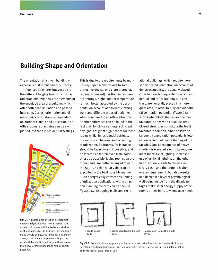
71Gebäude
Building Shape and Orientation
The orientation of a given building –
especially of its transparent surfaces
– influences its energy budget due to
the different heights from which solar
radiation hits. Windows are elements of
the envelope area of a building, which
offer both heat insulation and passive
heat gain. Correct orientation and di-
mensioning of windows is dependent
on outdoor climate and utilization. For
office rooms, solar gains can be ex-
ploited less than in residential settings.
This is due to the requirements by mon-
itor-equipped workstations (a solar
protective device, or a glare protector,
is usually present). Further, in residen-
tial settings, higher indoor temperature
is much better accepted by the occu-
pants, on account of different clothing
worn and different types of activities
when compared to an office situation.
Another difference can be found in the
fact that, for office settings, sufficient
daylight is of great significance for most
rooms while, in residential settings,
the rooms can be arranged according
to utilization. Bedrooms, for instance,
should be facing North if possible, and
be located as far removed from noise
stress as possible. Living rooms, on the
other hand, are better arranged toward
the South, so that solar gains can be
exploited in the best possible manner.
An energetically correct positioning
of utilization applications within an ur-
ban planning concept can be seen in
figure C1.7. Shopping malls and recre-
ational buildings, which require more
sophisticated ventilation on account of
dense occupancy, are usually placed
close to heavily frequented roads. Resi-
dential and office buildings, in con-
trast, are generally placed in a more
quiet area, in order to fully exploit natu-
ral ventilation potential. Figure C1.8
shows what block shapes are the most
favourable ones with equal use area.
Closed structures constitute the least
favourable solution, since passive so-
lar energy exploitation potential is low-
est on account of heavy shading of the
façades. One consequence of heavy
shading is elevated electricity require-
ment for artificial lighting. Increased
use of artificial lighting, on the other
hand, not only leads to raised elec-
tricity costs and therefore to higher
energy requirement, but also results
in a decreased level of psychological
well-being. Aside from the disadvan-
tages that a solar energy supply of the
rooms brings in its tow, one also needs
Buildings
Fig. C 1.7 Example for an urban development
energy analysis. Outdoor noise sections are
divided into zones with limited or no window
ventilation possible. Utilizations like shopping
malls should be situated in the nose-intensive
areas, so as to leave ample room for placing
residential and office buildings in those areas
that allow for maximum use of natural energy
potential.
Window ventilation impossible
Window ventilation possible to a limited extent
Window ventilation possible without limitations
Fig. C 1.8 Example of an energy analysis for basic construction forms in the framework of urban
development. Depending on construction form, different energy gains result from solar radiation
on the façade at equal area of use.
Façade closed100 %
Façade open toward the East108 %
Façade open toward the South111 %
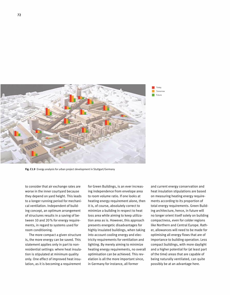
72
to consider that air exchange rates are
worse in the inner courtyard because
they depend on yard height. This leads
to a longer running period for mechani-
cal ventilation. Independent of build-
ing concept, an optimum arrangement
of structures results in a saving of be-
tween 10 and 20 % for energy require-
ments, in regard to systems used for
room conditioning.
The more compact a given structure
is, the more energy can be saved. This
statement applies only in part to non-
residential settings: where heat insula-
tion is stipulated at minimum quality
only. One effect of improved heat insu-
lation, as it is becoming a requirement
for Green Buildings, is an ever increas-
ing independence from envelope area
to room volume ratio. If one looks at
heating energy requirement alone, then
it is, of course, absolutely correct to
minimize a building in respect to heat
loss area while aiming to keep utiliza-
tion area as is. However, this approach
presents energetic disadvantages for
highly insulated buildings, when taking
into account cooling energy and elec-
tricity requirements for ventila tion and
lighting. By merely aiming to minimize
heating energy requirements, no overall
optimisation can be achieved. This rev-
elation is all the more important since,
in Germany for instance, all former
and current energy conservation and
heat insulation stipulations are based
on measuring heating energy require-
ments according to its proportion of
total energy requirements. Green Build-
ing architecture, hence, in future will
no longer orient itself solely on building
compactness, even for colder regions
like Northern and Central Europe. Rath-
er, allowances will need to be made for
optimising all energy flows that are of
importance to building operation. Less
compact buildings, with more daylight
and a higher potential for (at least part
of the time) areas that are capable of
being naturally ventilated, can quite
possibly be at an advantage here.
Today
Tomorrow
Future
Fig. C 1.9 Energy analysis for urban project development in Stuttgart/Germany
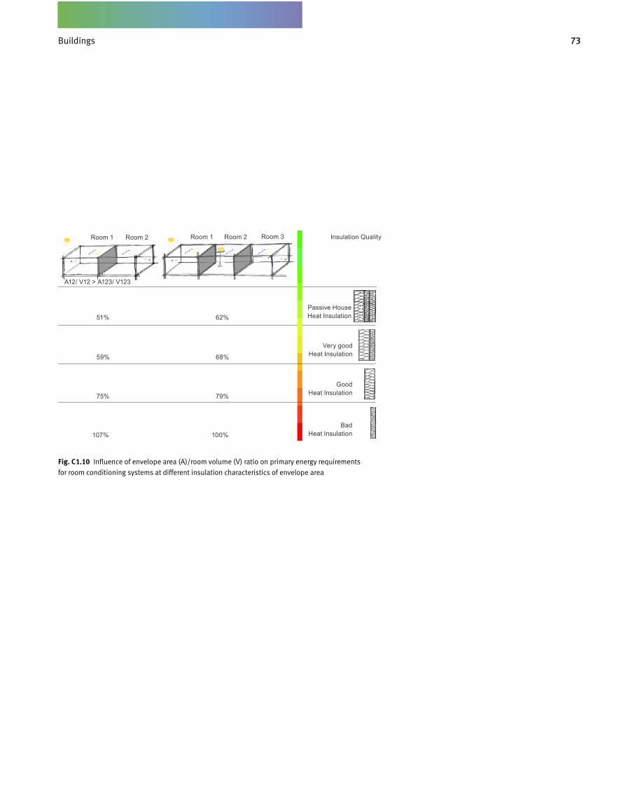
73GebäudeBuildings
Fig. C 1.10 Influence of envelope area (A)/room volume (V) ratio on primary energy requirements
for room conditioning systems at different insulation characteristics of envelope area
A12/ V12 > A123/ V123
Room 1 Room 2 Room 1 Room 2 Room 3 Insulation Quality
Passive House Heat Insulation
Very good Heat Insulation
Good Heat Insulation
Bad Heat Insulation
51%
59%
75%
107%
62%
68%
79%
100%

74
The façade of a building constitutes the
interface between outside and indoor
climatic conditions. While indoor cli-
mate in rooms that are occupied year-
round tends to fluctuate only within
a narrow corridor of 4 to 8 K, outdoor
climate can present temperature differ-
ences of up to 80 K, depending on loca-
tion. For instance, in Chicago/USA, min-
imum outdoor temperatures in winter
of –40°C are no rarity. In summer, they
may rise to +40°C.
For Northern and Central Europe,
heat insulation is desired primarily
because of the long winter duration.
Minimum insulation strength values, in
the 8oties, were primarily used to pre-
vent physics of buildings damage to
outer components. The aim here was
to move a component’s dew point as
much to the outside as possible in or-
der to avoid inner surface condensa-
tion. Moist walls on the inside inevita-
bly lead to mould formation and place
a heavy load on indoor air quality and
human health. With the now prevail-
ing insulation strengths for Central
and Northern Europe, there is no more
danger of condensation at the interior
of the room, so long as correctly con-
structed external components are pres-
ent. Nowadays, insulation strength is
oriented on the following criteria: heat-
ing energy requirements, thermal com-
fort through high interior surface tem-
peratures, and a sustainable economi-
cal approach for the building envelope
and technology system.
Good heat insulation, however, not
only makes sense for countries sub-
jected to long-lasting, cold outdoor
climate. This becomes clear once we
take a closer look. In Southern Europe,
many buildings are not equipped with
any kind of heating installation. An ac-
ceptable indoor comfort level, hence,
can only be achieved by improved insu-
lation. For countries with a hot outdoor
climate of up to 50°C, as are found
in the Middle East, there is nearly the
same temperature gradient (outdoor/
indoor climate, 25 to 30K) as in Germa-
ny, only in reverse. The building does
not lose heat to the outside but, rather,
gains it from there. In order to uphold
thermal comfort levels, one does not
need to heat but cool. Of course, there
are climate zones that do not require
high levels of heat insulation on ac-
count of their continental, even outdoor
climate. In Central Africa, for instance,
outdoor temperature presents even-
ly, day and night, winter and summer,
somewhere between 10 and 30°C. Yet,
these regions should still be provided
with some kind of heat insulation, es-
pecially in view of damage sustained
through humidity (very high outdoor
humidity), and also with sound pro-
tection (if lots of outdoor noise is the
case).
Adjustable Heat Insulation Designing
heat insulation in an adjustable man-
ner remains a target for energy-efficient
construction. In the 90ties, double-
skin façades were partially equipped
with motorized flaps, which allowed
shutting off the air inlets for the build-
ing and thus creating a »winter garden
effect« by preventing heat loss from
the building during periods of, for in-
stance, solar radiation. The flaps can
be opened when outdoor temperatures
are high, something which avoids over-
heating of the rooms. Another manner
of adjusting summer or winter heat in-
sulation is by arranging transparent
membranes, in form of foils, on the
inside ceiling region by placing them
one behind the other at different prox-
imity. This results in different air cush-
ions between the foils. Added up, they
provide good heat insulation. Figures
C1.12 and C1.13 show an example for
this, from a study object for a transpar-
ent customer centre: in winter, the bot-
Building Envelope
Heat Insulation and Building Density
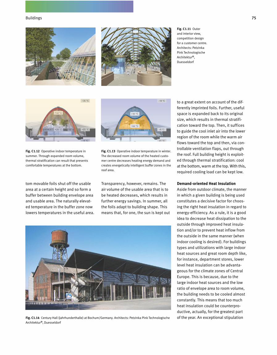
75Gebäude
tom movable foils shut off the usable
area at a certain height and so form a
buffer between building envelope area
and usable area. The naturally elevat-
ed temperature in the buffer zone now
lowers temperatures in the useful area.
Transparency, however, remains. The
air volume of the usable area that is to
be heated decreases, which results in
further energy savings. In summer, all
the foils adapt to building shape. This
means that, for one, the sun is kept out
to a great extent on account of the dif-
ferently imprinted foils. Further, useful
space is expanded back to its original
size, which results in thermal stratifi-
cation toward the top. Then, it suffices
to guide the cool inlet air into the lower
region of the room while the warm air
flows toward the top and then, via con-
trollable ventilation flaps, out through
the roof. Full building height is exploit-
ed through thermal stratification: cool
at the bottom, warm at the top. With this,
required cooling load can be kept low.
Demand-oriented Heat Insulation Aside from outdoor climate, the manner
in which a given building is being used
constitutes a decisive factor for choos-
ing the right heat insulation in regard to
energy-efficiency. As a rule, it is a good
idea to decrease heat dissipation to the
outside through improved heat insula-
tion and/or to prevent heat inflow from
the outside in the same manner (when
indoor cooling is desired). For buildings
types and utilizations with large indoor
heat sources and great room depth like,
for instance, department stores, lower
level heat insulation can be advanta-
geous for the climate zones of Central
Europe. This is because, due to the
large indoor heat sources and the low
ratio of envelope area to room volume,
the building needs to be cooled almost
constantly. This means that too much
heat insulation could be counterpro-
ductive, actually, for the greatest part
of the year. An exceptional stipulation
Fig. C 1.11 Outer
and interior view,
compe tition design
for a customer centre.
Architects: Petzinka
Pink Technologische
Architektur ®,
Duesseldorf
Fig. C 1.13 Operative indoor temperature in winter.
The decreased room volume of the heated custo -
mer centre decreases heating energy demand and
creates energetically intelligent buffer zones in the
roof area.
Fig. C 1.12 Operative indoor temperature in
summer. Through expanded room volume,
thermal stra ti fic ation can result that presents
comfortable temperatures at the bottom.
Fig. C1.14 Century Hall (Jahrhunderthalle) at Bochum/Germany. Architects: Petzinka Pink Technologische
Architektur ®, Duesseldorf
Buildings
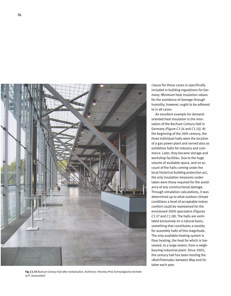
76
clause for those cases is specifically
included in building regulations for Ger-
many. Minimum heat insulation values
for the avoidance of damage through
humidity, however, ought to be adhered
to in all cases.
An excellent example for demand-
oriented heat insulation is the reno-
vation of the Bochum Century Hall in
Germany (Figure C1.14 and C1.15). At
the beginning of the 20th century, the
three individual halls were the location
of a gas power plant and served also as
exhibition halls for industry and com-
merce. Later, they became storage and
workshop facilities. Due to the huge
volume of available space, and on ac-
count of the halls coming under the
local historical building protection act,
the only insulation measures under-
taken were those required for the avoid-
ance of any constructional damage.
Through simulation calculations, it was
determined up to what outdoor climate
conditions a level of acceptable indoor
comfort could be maintained for the
envisioned 2000 spectators (Figures
C1.17 and C1.18). The halls are venti-
lated exclusively on a natural basis,
something that constitutes a novelty
for assembly halls of this magnitude.
The only available heating system is
floor heating, the heat for which is har-
vested, to a large extent, from a neigh-
bouring industrial plant. Since 2003,
the century hall has been hosting the
»RuhrTriennale« between May and Oc-
tober each year.
Fig. C 1.15 Bochum Century Hall after revitalisation. Architects: Petzinka Pink Technologische Architek-
tur ®, Duesseldorf
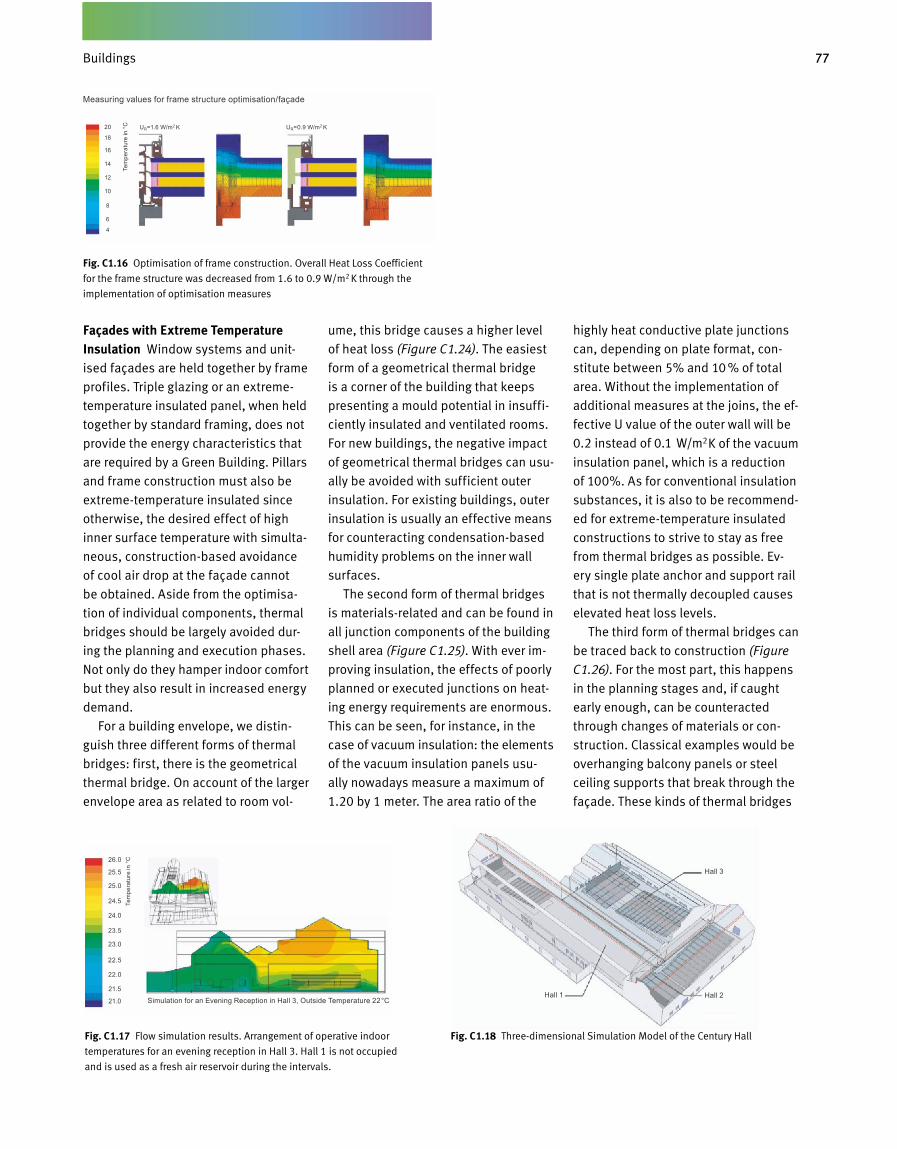
77Gebäude
Façades with Extreme Temperature Insulation Window systems and unit
ised façades are held together by frame
profiles. Triple glazing or an extreme
temperature insulated panel, when held
together by standard framing, does not
provide the energy characteristics that
are required by a Green Building. Pillars
and frame construction must also be
extremetemperature insulated since
otherwise, the desired effect of high
inner surface temperature with simulta
neous, constructionbased avoidance
of cool air drop at the façade cannot
be obtained. Aside from the optimisa
tion of individual components, thermal
bridges should be largely avoided dur
ing the planning and execution phases.
Not only do they hamper indoor comfort
but they also result in increased energy
demand.
For a building envelope, we distin
guish three different forms of thermal
bridges: first, there is the geometrical
thermal bridge. On account of the larger
envelope area as related to room vol
ume, this bridge causes a higher level
of heat loss (Figure C1.24). The easiest
form of a geometrical thermal bridge
is a corner of the building that keeps
presenting a mould potential in insuffi
ciently insulated and ventilated rooms.
For new buildings, the negative impact
of geometrical thermal bridges can usu
ally be avoided with sufficient outer
insulation. For existing buildings, outer
insulation is usually an effective means
for counteracting condensationbased
humidity problems on the inner wall
surfaces.
The second form of thermal bridges
is materialsrelated and can be found in
all junction components of the building
shell area (Figure C1.25). With ever im
proving insulation, the effects of poorly
planned or executed junctions on heat
ing energy requirements are enormous.
This can be seen, for instance, in the
case of vacuum insulation: the elements
of the vacuum insulation panels usu
ally nowadays measure a maximum of
1.20 by 1 meter. The area ratio of the
highly heat conductive plate junctions
can, depending on plate format, con
stitute between 5% and 10 % of total
area. Without the implementation of
additio nal measures at the joins, the ef
fective U value of the outer wall will be
0.2 instead of 0.1 W/m2K of the vacuum
insulation panel, which is a reduction
of 100%. As for conventional insulation
substances, it is also to be recommend
ed for extremetemperature insulated
constructions to strive to stay as free
from thermal bridges as possible. Ev
ery single plate anchor and support rail
that is not thermally decoupled causes
elevated heat loss levels.
The third form of thermal bridges can
be traced back to construction (Figure
C1.26). For the most part, this happens
in the planning stages and, if caught
early enough, can be counteracted
through changes of materials or con
struction. Classical examples would be
overhanging balcony panels or steel
ceiling supports that break through the
façade. These kinds of thermal bridges
Fig. C1.16 Optimisation of frame construction. Overall Heat Loss Coefficient
for the frame structure was decreased from 1.6 to 0.9 W/m2 K through the
implementation of optimisation measures
Fig. C 1.17 Flow simulation results. Arrangement of operative indoor
temperatures for an evening reception in Hall 3. Hall 1 is not occupied
and is used as a fresh air reservoir during the intervals.
Fig. C 1.18 Threedimensional Simulation Model of the Century Hall
Measuring values for frame structure optimisation/façade
20
18
16
14
12
10
8
6
4
UR=1.6 W/m2 K UR=0.9 W/m2 KTe
mpe
ratu
re in
°C
Simulation for an Evening Reception in Hall 3, Outside Temperature 22°CHall 1 Hall 2
Hall 3
Tem
pera
ture
in °
C26.0
25.5
25.0
24.5
24.0
23.5
23.0
22.5
22.0
21.5
21.0
Buildings
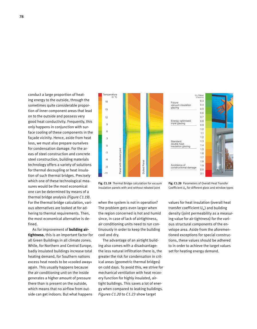
78
conduct a large proportion of heat-
ing energy to the outside, through the
sometimes quite considerable propor-
tion of inner component areas that lead
on to the outside and possess very
good heat conductivity. Frequently, this
only happens in conjunction with sur-
face cooling of these components in the
façade vicinity. Hence, aside from heat
loss, we must also prepare ourselves
for condensation damage. For the ar-
eas of steel construction and concrete
steel construction, building materials
technology offers a variety of solutions
for thermal decoupling or heat insula-
tion of such thermal bridges. Precisely
which one of these technological mea-
sures would be the most economical
one can be determined by means of a
thermal bridge analysis (Figure C1.19).
For the thermal bridge calculation, vari-
ous alternatives are looked at for ad-
hering to thermal requirements. Then,
the most economical alternative is de-
fined.
As for improvement of building air- tightness, this is an important factor for
all Green Buildings in all climate zones.
While, for Northern and Central Europe,
badly insulated buildings increase total
heating demand, for Southern nations
excess heat needs to be »cooled away«
again. This usually happens because
the air conditioning unit on the inside
generates a higher amount of pressure
there than is present on the outside,
which means that no airflow from out-
side can get indoors. But what happens
when the system is not in operation?
The problem gets even larger when
the region concerned is hot and humid
since, in case of lack of airtightness,
air conditioning units need to run con-
tinuously in order to keep the building
cool and dry.
The advantage of an airtight build-
ing also comes with a disadvantage:
the less natural infiltration there is, the
greater the risk for condensation in crit-
ical areas (geometric thermal bridges)
on cold days. To avoid this, we strive for
mechanical ventilation with heat recov-
ery function for highly insulated, air-
tight buildings. This saves a lot of ener-
gy when compared to leaking buildings.
Figures C1.20 to C1.23 show target
values for heat insulation (overall heat
transfer coefficient Uw) and building
density (joint permeability as a measur-
ing value for air tightness) for the vari-
ous structural components of the en-
velope area. Aside from the aforemen-
tioned exceptions for special construc-
tions, these values should be adhered
to in order to achieve the target values
set for heating energy demand.
Fig. C1.19 Thermal Bridge calculation for vacuum
insulation panels with and without rebated joint
Fig. C 1.20 Parameters of Overall Heat Transfer
Coefficient Uw for different glass and window types
18
15
12
9
6
3
0
-3
-6
-9
-11
0.3 0.40.50.60.70.80.91.01.11.21.31.41.51.61.71.81.92.02.1
Temperature in °C
Pane
l with
reba
ted
join
t
Future: vacuum insulation glazing
Energy-optimised: triple glazing
Standard: double heat insulation glazing
Avoidance of constructional damage
Dul
led
Pane
l
UW Value in W/m2 K
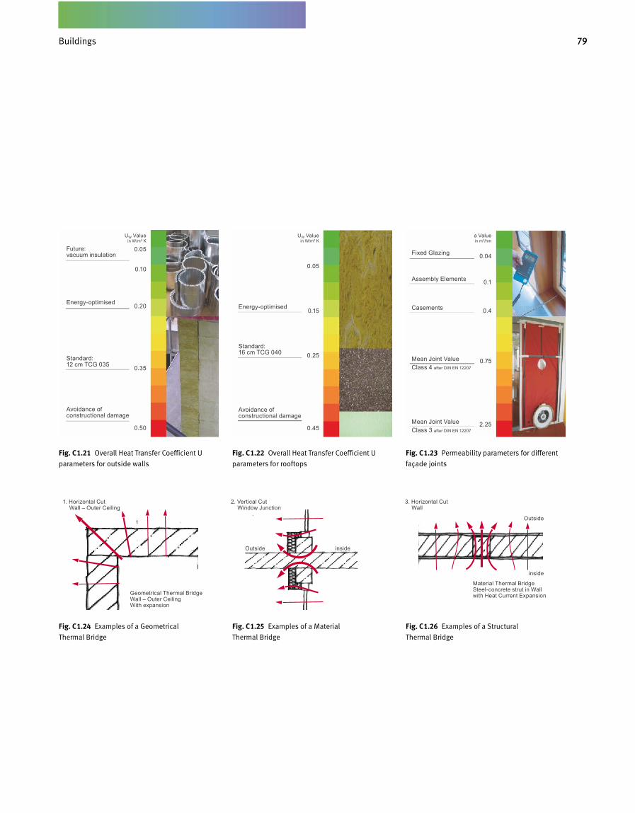
79Gebäude
Fig. C 1.22 Overall Heat Transfer Coefficient U
parameters for rooftops
Fig. C 1.23 Permeability parameters for different
façade joints
Fig. C 1.21 Overall Heat Transfer Coefficient U
parameters for outside walls
Fig. C 1.24 Examples of a Geometrical
Thermal Bridge
Fig. C 1.25 Examples of a Material
Thermal Bridge
Fig. C 1.26 Examples of a Structural
Thermal Bridge
0.05
0.10
0.20
0.35
0.50
0.04
0.1
0.4
0.75
2.25
0.05
0.15
0.25
0.45
Future: vacuum insulation
Energy-optimised
Standard: 12 cm TCG 035
Avoidance of constructional damage
1. Horizontal Cut Wall – Outer Ceiling
Geometrical Thermal Bridge Wall – Outer Ceiling With expansion
Material Thermal Bridge Steel-concrete strut in Wall with Heat Current Expansion
2. Vertical Cut Window Junction
3. Horizontal Cut Wall
Outside
Outside
inside
inside
Fixed Glazing
Assembly Elements
Casements
Mean Joint Value Class 4 after DIN EN 12207
Mean Joint Value Class 3 after DIN EN 12207
Energy-optimised
Standard: 16 cm TCG 040
Avoidance of constructional damage
UW Value in W/m2 K
a Value in m3/hm
UW Value in W/m2 K
Buildings

80
A good level of solar protection is es-
sential to Green Buildings. The aim here
is to afford the building sufficient so-
lar protection so as to keep both cool-
ing energy requirements and expected
cooling load as low as possible. Solar
protection arrangement is according
to manner and type of glazing and it
can be regulated via an additional ele-
ment in either rigid or movable version.
Aside from the course of the sun for the
specific location, for mobile solar pro-
tection devices that are located on the
outside, we also need to take into ac-
count during the conception stage how
stable the wind is. Since glazing and
solar protection influence the amount
of daylight in a given room, there is a
direct proportional effect between en-
ergy requirements for room cooling and
artificial lighting.
Solar Protection
Solar protection shading demands are
largely independent of both location
and type of use. Naturally, for different
climatic regions and design desires,
there are different solution approaches
also. However, they all need to meet the
same requirements for effective shad-
ing. Figure C1.28 shows target values
for solar protection as an effective total
energy permeability grade of the fa-
çade. The effective total energy perme-
ability grade consists of window area
proportion of the façade (interior view)
and total energy permeability grade of
glazing when combined with solar pro-
tection device. For smaller window ar-
eas, less effective solar protection can
be used, for instance something like
transparent screens. Larger window
areas require a highly effective outside
solar protection device. Inside solar
Fig. C 1.28 Parameters of total energy permeability
grade gtot in relation to window area proportion f
of the façade for occupied rooms. The effective
total energy permeability grade consists of the
combined characteristics of glazing and solar
protection device. When multiplied by window
area proportion, a parameter for occupied rooms
results. It defines to a great proportion both
cooling energy requirements and indoor comfort
in summer.
Fig. C 1.27 King Fahad National Library in Riad, Saudi Arabia. Architects: Gerber Architekten, Dortmund
0.06
0.08
0.10
0.12
0.14
0.16
Very good
Good
Acceptable in cooler regions
f x gtot

81Gebäude
protection devices usually heat up to a
high degree, something that has a neg-
ative effect on cooling energy require-
ment and on local operative tempera-
ture in façade vicinity. When choosing
a suitable solar protection system, es-
pecially when an inside arrangement
applies, it is absolutely essential to
calculate total energy permeability only
in combination with the type of glazing
used. To this day, the values provided
by many manufacturers only go for out-
side systems.
Very warm regions occur at latitudes
where the sun is rises very rapidly
high into the sky. For these regions,
a rigid solar protection device is to
be recommended, since this can be
used year-round in most cases. Fig-
ure C1.27 shows the solar sail arrange-
ment for the Riad National Library in
Saudi Arabia. Through 3-dimensional
simulation calculations, sail geometry
is optimised in for view of solar energy
yield while still presenting vista (Figure
C1.30). Aside from direct radiation, dif-
fuse sunlight, which gets reflected into
the room either from the façade or the
sails, needs to be taken into account.
In wind-intensive regions there are
three basic varieties for sufficient sum-
mer heat insulation: the first is a rigid
outside solar protection device, often
executed in form of a roof protrusion.
This form of solar protection, however,
only provides adequate protection for
southern nations where the sun is high
in the sky and then only for cases of di-
rect solar radiation. In Central Europe,
with Southern orientation, additional
solar protective measures need to be
undertaken. The second variation con-
sists of installing an overhanging glass
construction as a wind-protected solar
screen. This is typically done for double
skin façades. Third is the use of a wind-
resistant, movable kind of construction.
It may consist of a variety of materials,
be they wood, aluminium or even im-
printed glass. If an interior sunscreen is
desired behind sun protection glazing
then, in Central Europe, this frequently
leads to exceeding maximum effective
total energy permeability grade unless,
that is, the window surface areas of the
façade present a very low ratio of 30
to 40 %. This, however, would greatly
reduce daylight entry rates and, aside
from an adverse psychological effect,
also result in greater energy demand for
artificial lighting. Only for some North-
ern European regions, where warm and
sunny days are a rarity, solutions can
be implemented in an energy-efficient
manner to include larger window areas
and inside solar protection systems.
When revitalizing or renovating pro-tected façades, there is often a conflict
during conception already between
design and efficiency. Because of the
buildings being protected, it is often
not possible to equip them with an
outside solar protective device. Yet,
the new indoor climate must still pres-
ent good thermal comfort. Unlike new
buildings, existing buildings used for
offices often have low thermal storage
ability (e.g. rib ceilings that are less
than 15 cm thick), so that cooling re-
quirements very quickly increase. Fig-
ure C1.31 shows the Kaiserhof office
tower in Hamburg: the building’s pro-
tected façade was recreated almost
completely, with only one add-on at the
Fig. C 1.29 Visualization of shading grade generated by solar sails, depending on seasonal and daytime considerations.
Fig. C 1.30 Simulation model for calculating solar influx, dependent on sail geometry
and the position of the sun
December, 7 am December, 9 am June, 6 am June, 7 am
Direct Sunlight
Diffuse Sunlight
Reflected Sunlight
2nd Floor
1st Floor
Buildings
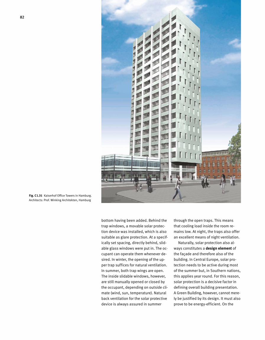
82
bottom having been added. Behind the
trap windows, a movable solar protec-
tion device was installed, which is also
suitable as glare protection. At a specif-
ically set spacing, directly behind, slid-
able glass windows were put in. The oc-
cupant can operate them whenever de-
sired. In winter, the opening of the up-
per trap suffices for natural ventilation.
In summer, both trap wings are open.
The inside slidable windows, however,
are still manually opened or closed by
the occupant, depending on outside cli-
mate (wind, sun, temperature). Natural
back ventilation for the solar protective
device is always assured in summer
through the open traps. This means
that cooling load inside the room re-
mains low. At night, the traps also offer
an excellent means of night ventilation.
Naturally, solar protection also al-
ways constitutes a design element of
the façade and therefore also of the
building. In Central Europe, solar pro-
tection needs to be active during most
of the summer but, in Southern nations,
this applies year round. For this reason,
solar protection is a decisive factor in
defining overall building presentation.
A Green Building, however, cannot mere -
ly be justified by its design. It must also
prove to be energy-efficient. On the
Fig. C 1.31 Kaiserhof Office Towers in Hamburg.
Architects: Prof. Winking Architekten, Hamburg
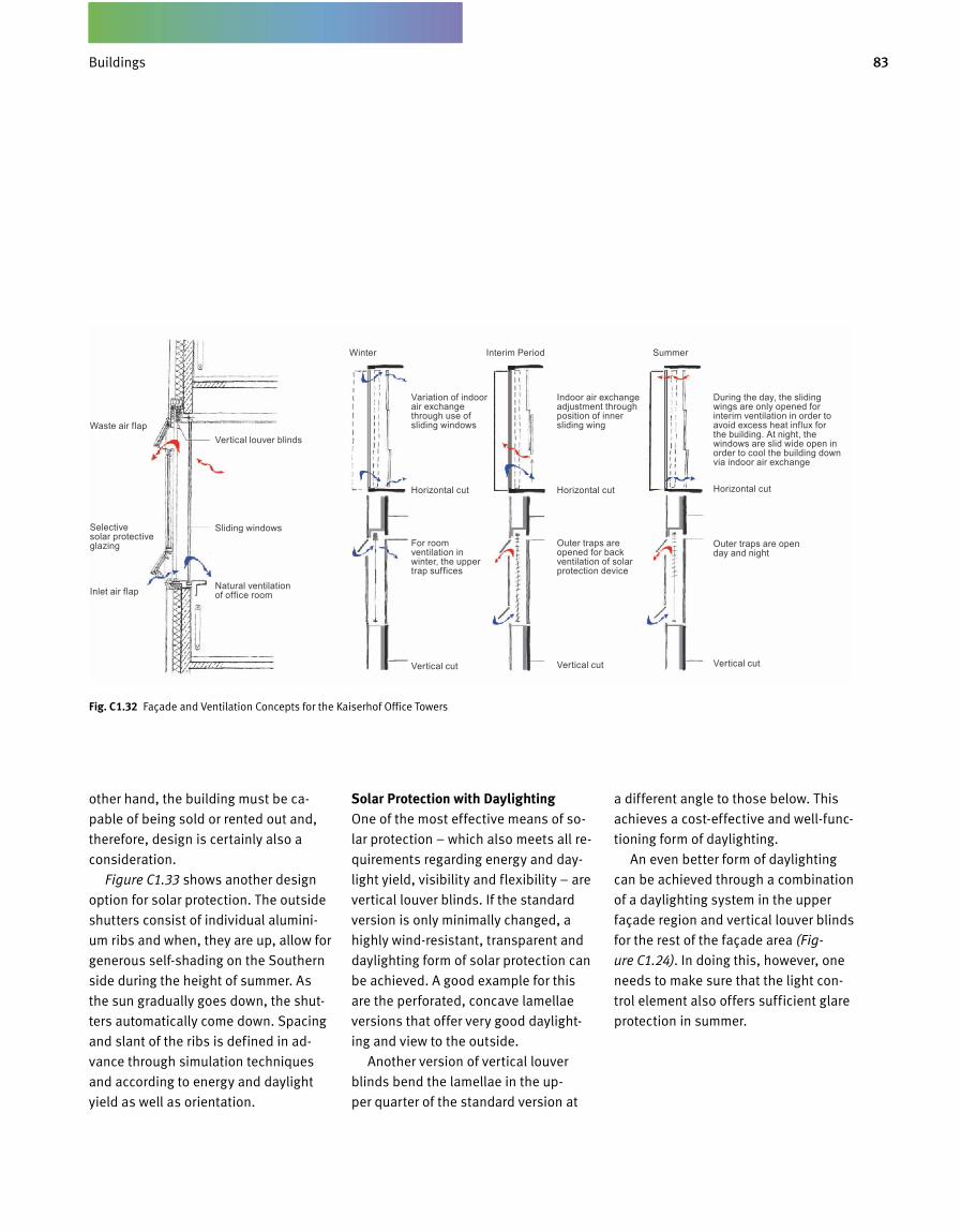
83Gebäude
other hand, the building must be ca-
pable of being sold or rented out and,
therefore, design is certainly also a
consideration.
Figure C1.33 shows another design
option for solar protection. The out side
shutters consist of individual alumini-
um ribs and when, they are up, allow for
generous self-shading on the Southern
side during the height of summer. As
the sun gradually goes down, the shut-
ters automatically come down. Spacing
and slant of the ribs is defined in ad-
vance through simulation techniques
and according to energy and daylight
yield as well as orientation.
Solar Protection with Daylighting One of the most effective means of so-
lar protection – which also meets all re-
quirements regarding energy and day-
light yield, visibility and flexibility – are
vertical louver blinds. If the standard
version is only minimally changed, a
highly wind-resistant, transparent and
daylighting form of solar protection can
be achieved. A good example for this
are the perforated, concave lamellae
versions that offer very good daylight-
ing and view to the outside.
Another version of vertical louver
blinds bend the lamellae in the up-
per quarter of the standard version at
a different angle to those below. This
achieves a cost-effective and well-func-
tioning form of daylighting.
An even better form of daylighting
can be achieved through a combination
of a daylighting system in the upper
façade region and vertical louver blinds
for the rest of the façade area (Fig-
ure C1.24). In doing this, however, one
needs to make sure that the light con-
trol element also offers sufficient glare
protection in summer.
Fig. C 1.32 Façade and Ventilation Concepts for the Kaiserhof Office Towers
Waste air flap
Selective solar protective glazing
Inlet air flap
Vertical louver blinds
Sliding windows
Natural ventilation of office room
Variation of indoor air exchange through use of sliding windows
Horizontal cut
For room ventilation in winter, the upper trap suffices
Vertical cut
Indoor air exchange adjustment through position of inner sliding wing
Horizontal cut
Outer traps are opened for back ventilation of solar protection device
Vertical cut
During the day, the sliding wings are only opened for interim ventilation in order to avoid excess heat influx for the building. At night, the windows are slid wide open in order to cool the building down via indoor air exchange
Horizontal cut
Outer traps are open day and night
Vertical cut
Winter Interim Period Summer
Buildings
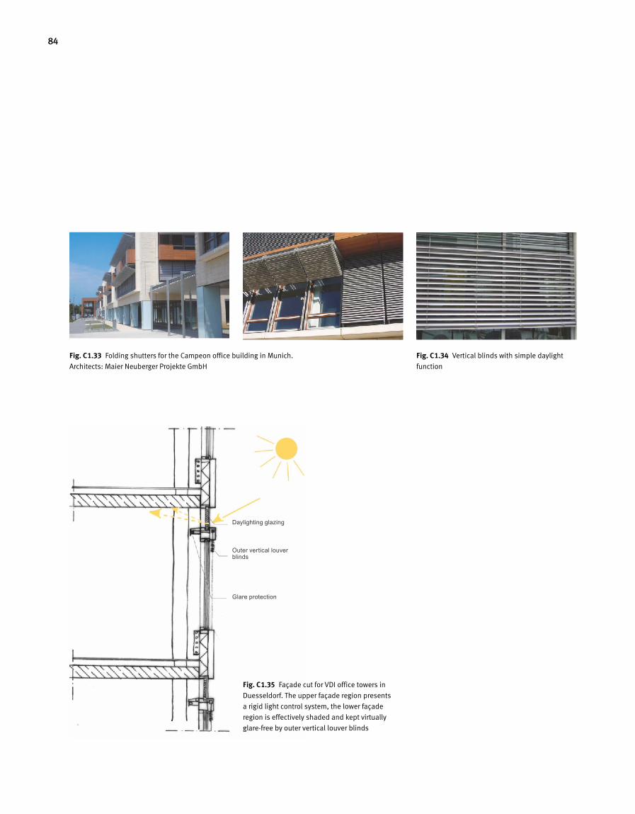
84
Fig. C 1.35 Façade cut for VDI office towers in
Duesseldorf. The upper façade region presents
a rigid light control system, the lower façade
region is effectively shaded and kept virtually
glare-free by outer vertical louver blinds
Daylighting glazing
Outer vertical louver blinds
Glare protection
Fig. C 1.33 Folding shutters for the Campeon office building in Munich.
Architects: Maier Neuberger Projekte GmbH
Fig. C 1.34 Vertical blinds with simple daylight
function
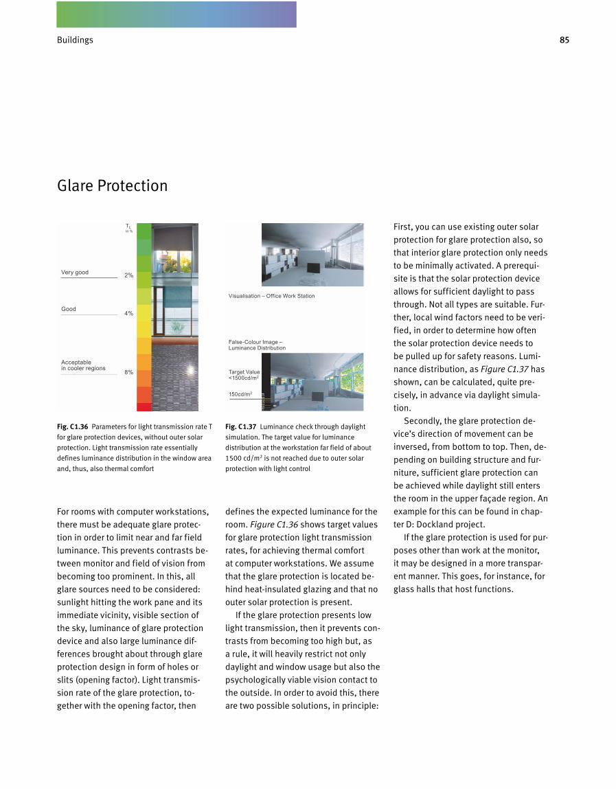
85Gebäude
Glare Protection
For rooms with computer workstations,
there must be adequate glare protec-
tion in order to limit near and far field
luminance. This prevents contrasts be-
tween monitor and field of vision from
becoming too prominent. In this, all
glare sources need to be considered:
sunlight hitting the work pane and its
immediate vicinity, visible section of
the sky, luminance of glare protection
device and also large luminance dif-
ferences brought about through glare
protection design in form of holes or
slits (opening factor). Light transmis-
sion rate of the glare protection, to-
gether with the opening factor, then
defines the expected luminance for the
room. Figure C1.36 shows target values
for glare protection light transmission
rates, for achieving thermal comfort
at computer workstations. We assume
that the glare protection is located be-
hind heat-insulated glazing and that no
outer solar protection is present.
If the glare protection presents low
light transmission, then it prevents con-
trasts from becoming too high but, as
a rule, it will heavily restrict not only
daylight and window usage but also the
psychologically viable vision contact to
the outside. In order to avoid this, there
are two possible solutions, in principle:
First, you can use existing outer solar
protection for glare protection also, so
that interior glare protection only needs
to be minimally activated. A prerequi-
site is that the solar protection device
allows for sufficient daylight to pass
through. Not all types are suitable. Fur-
ther, local wind factors need to be veri-
fied, in order to determine how often
the solar protection device needs to
be pulled up for safety reasons. Lumi-
nance distribution, as Figure C1.37 has
shown, can be calculated, quite pre-
cisely, in advance via daylight simula-
tion.
Secondly, the glare protection de-
vice’s direction of movement can be
inversed, from bottom to top. Then, de-
pending on building structure and fur-
niture, sufficient glare protection can
be achieved while daylight still enters
the room in the upper façade region. An
example for this can be found in chap-
ter D: Dockland project.
If the glare protection is used for pur-
poses other than work at the monitor,
it may be designed in a more transpar-
ent manner. This goes, for instance, for
glass halls that host functions.
Fig. C 1.36 Parameters for light transmission rate T
for glare protection devices, without outer solar
protection. Light transmission rate essentially
defines luminance distribution in the window area
and, thus, also thermal comfort
2%
4%
8%
Very good
Good
Acceptable in cooler regions
Visualisation – Office Work Station
False-Colour Image – Luminance Distribution
Target Value <1500cd/m2
150cd/m2
TL in %
Fig. C 1.37 Luminance check through daylight
simulation. The target value for luminance
distribution at the workstation far field of about
1500 cd/m2 is not reached due to outer solar
protection with light control
Buildings
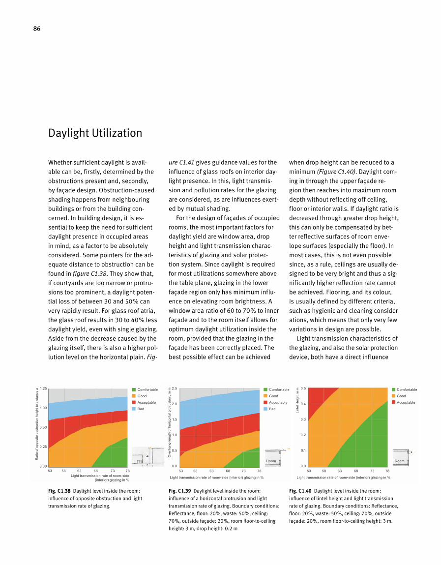
86
Daylight Utilization
Whether sufficient daylight is avail-
able can be, firstly, determined by the
obstructions present and, secondly,
by façade design. Obstruction-caused
shading happens from neighbouring
buildings or from the building con-
cerned. In building design, it is es-
sential to keep the need for sufficient
daylight presence in occupied areas
in mind, as a factor to be absolutely
considered. Some pointers for the ad-
equate distance to obstruction can be
found in figure C1.38. They show that,
if courtyards are too narrow or protru-
sions too prominent, a daylight poten-
tial loss of between 30 and 50 % can
very rapidly result. For glass roof atria,
the glass roof results in 30 to 40 % less
daylight yield, even with single glazing.
Aside from the decrease caused by the
glazing itself, there is also a higher pol-
lution level on the horizontal plain. Fig-
when drop height can be reduced to a
minimum (Figure C1.40). Daylight com-
ing in through the upper façade re-
gion then reaches into maximum room
depth without reflecting off ceiling,
floor or interior walls. If daylight ratio is
decreased through greater drop height,
this can only be compensated by bet-
ter reflective surfaces of room enve-
lope surfaces (especially the floor). In
most cases, this is not even possible
since, as a rule, ceilings are usually de-
signed to be very bright and thus a sig-
nificantly higher reflection rate cannot
be achieved. Flooring, and its colour,
is usually defined by different criteria,
such as hygienic and cleaning consider-
ations, which means that only very few
variations in design are possible.
Light transmission characteristics of
the glazing, and also the solar protection
device, both have a direct influence
ure C1.41 gives guidance values for the
influence of glass roofs on interior day-
light presence. In this, light transmis-
sion and pollution rates for the glazing
are considered, as are influences exert-
ed by mutual shading.
For the design of façades of occupied
rooms, the most important factors for
daylight yield are window area, drop
height and light transmission charac-
teristics of glazing and solar protec-
tion system. Since daylight is required
for most utilizations somewhere above
the table plane, glazing in the lower
façade region only has minimum influ-
ence on elevating room brightness. A
window area ratio of 60 to 70 % to inner
façade and to the room itself allows for
optimum daylight utilization inside the
room, provided that the glazing in the
façade has been correctly placed. The
best possible effect can be achieved
Fig. C 1.38 Daylight level inside the room:
influence of opposite obstruction and light
transmission rate of glazing.
Fig. C 1.40 Daylight level inside the room:
influence of lintel height and light transmission
rate of glazing. Boundary conditions: Reflectance,
floor: 20%, waste: 50%, ceiling: 70%, outside
façade: 20%, room floor-to-ceiling height: 3 m.
Fig. C 1.39 Daylight level inside the room:
influence of a horizontal protrusion and light
transmission rate of glazing. Boundary conditions:
Reflectance, floor: 20%, waste: 50%, ceiling:
70%, outside façade: 20%, room floor-to-ceiling
height: 3 m, drop height: 0.2 m
Light transmission rate of room-side (interior) glazing in %
Rat
io o
f opp
osite
obs
truct
ion
heig
ht to
dis
tanc
e a Comfortable
Good
Acceptable
Bad
1.25
1.00
0.50
0.25
0.0053 58 63 68 73 78
Light transmission rate of room-side (interior) glazing in % Light transmission rate of room-side (interior) glazing in %
Room Room
Ove
rhan
g-le
ngth
of h
oriz
onta
l pro
trusi
on L
in m
Lint
el H
eigh
t in
mComfortable
Good
Acceptable
Bad
Comfortable
Good
Acceptable
2.5
2.0
1.5
1.0
0.5
0.0
0.5
0.4
0.3
0.2
0.1
0.053 58 63 68 73 78 53 58 63 68 73 78
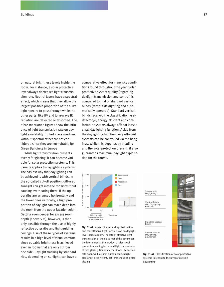
87Gebäude
Effective Light Transmission of roof
of the Atrium in %
Courtyard
Comfortable
Good
Acceptable
Bad
1.00
0.67
0.33
0.00
Rat
io o
f hei
ght h
to d
ista
nce
a of
Cou
rtya
rdon natural brightness levels inside the
room. For instance, a solar protective
layer always decreases light transmis-
sion rate. Neutral layers have a spectral
effect, which means that they allow the
largest possible proportion of the sun’s
light spectre to pass through while the
other parts, like UV and long-wave IR
radiation are reflected or absorbed. The
afore-mentioned figures show the influ-
ence of light transmission rate on day-
light availability. Tinted glass windows
without spectral effect are not con-
sidered since they are not suitable for
Green Buildings in Europe.
While light transmission presents
evenly for glazing, it can become vari-
able for solar protection systems. This
usually applies to daylighting systems.
The easiest way that daylighting can
be achieved is with vertical blinds. In
the so-called cut-off position, diffused
sunlight can get into the rooms without
causing overheating there. If the up-
per ribs are arranged horizontally and
the lower ones vertically, a high pro-
portion of daylight can reach deep into
the room from the upper façade region.
Getting even deeper for excess room
depth (above 5 m), however, is then
only possible through the use of highly
reflective outer ribs and light guiding
ceilings. Use of these types of systems
results in a high level of visual comfort
since equable brightness is achieved
even in rooms that are only lit from
one side. Daylight tracking by standard
ribs, depending on sunlight, can have a
comparative effect for many sky condi-
tions found throughout the year. Solar
protective system quality (regarding
daylight transmission and control) is
compared to that of standard vertical
blinds (without daylighting and auto-
matically operated). Standard vertical
blinds received the classification »sat-
isfactory«; energy-efficient and com-
fortable systems always offer at least a
small daylighting function. Aside from
the daylighting function, very efficient
systems can be controlled via the hang-
ings. While this depends on shading
and the solar protection present, it also
guarantees maximum daylight exploita-
tion for the rooms.
Fig. C 1.42 Classification of solar protective
systems in regard to the level of existing
daylighting
Fig. C 1.41 Impact of surrounding obstruction
and roof effective light transmission on daylight
level inside a room. The rate of effective light
transmission of the glass roof of the atrium can
be determined at the product of glass roof
proportion, soiling factor and light transmission
of roof glazing. Boundary conditions: Reflection
rate floor, wall, ceiling, outer façade, height
clearance, drop height, light transmission office
glazing
30 65 10
System with Daylighting
Vertical Blinds with Daylighting Function
Standard Vertical Blinds
System without Daylighting, e.g. Screen
Buildings
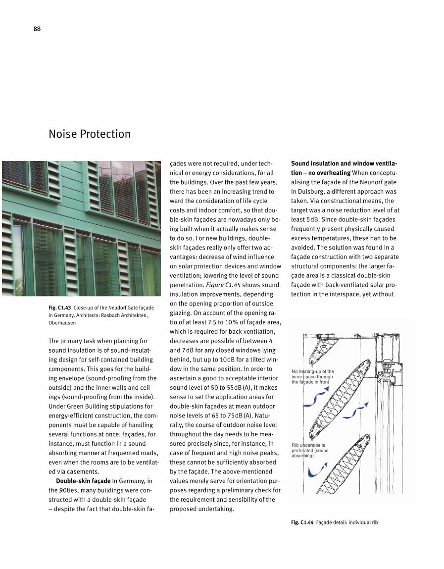
88
The primary task when planning for
sound insulation is of sound-insulat-
ing design for self-contained building
components. This goes for the build-
ing envelope (sound-proofing from the
outside) and the inner walls and ceil-
ings (sound-proofing from the inside).
Under Green Building stipulations for
energy-efficient construction, the com-
ponents must be capable of handling
several functions at once: façades, for
instance, must function in a sound-
absorbing manner at frequented roads,
even when the rooms are to be ventilat-
ed via casements.
Double-skin façade In Germany, in
the 90ties, many buildings were con-
structed with a double-skin façade
– despite the fact that double-skin fa-
çades were not required, under tech-
nical or energy considerations, for all
the buildings. Over the past few years,
there has been an increasing trend to-
ward the consideration of life cycle
costs and indoor comfort, so that dou-
ble-skin façades are nowadays only be-
ing built when it actually makes sense
to do so. For new buildings, double-
skin façades really only offer two ad-
vantages: decrease of wind influence
on solar protection devices and window
ventilation; lowering the level of sound
penetration. Figure C1.45 shows sound
insulation improvements, depending
on the opening proportion of outside
glazing. On account of the opening ra-
tio of at least 7.5 to 10 % of façade area,
which is required for back ventilation,
decreases are possible of between 4
and 7dB for any closed windows lying
behind, but up to 10dB for a tilted win-
dow in the same position. In order to
ascertain a good to acceptable interior
sound level of 50 to 55dB(A), it makes
sense to set the application areas for
double-skin façades at mean outdoor
noise levels of 65 to 75dB(A). Natu-
rally, the course of outdoor noise level
throughout the day needs to be mea-
sured precisely since, for instance, in
case of frequent and high noise peaks,
these cannot be sufficiently absorbed
by the façade. The above-mentioned
values merely serve for orientation pur-
poses regarding a preliminary check for
the requirement and sensibility of the
proposed undertaking.
Sound insulation and window ventila-tion – no overheating When conceptu-
alising the façade of the Neudorf gate
in Duisburg, a different approach was
taken. Via constructional means, the
target was a noise reduction level of at
least 5dB. Since double-skin façades
frequently present physically caused
excess temperatures, these had to be
avoided. The solution was found in a
façade construction with two separate
structural components: the larger fa-
çade area is a classical double-skin
façade with back-ventilated solar pro-
tection in the interspace, yet without
Fig. C 1.43 Close-up of the Neudorf Gate façade
in Germany. Architects: Rasbach Architekten,
Oberhausen
Noise Protection
Fig. C 1.44 Façade detail: individual rib
No heating-up of the inner space through the façade in front
Rib underside is perforated (sound absorbing)
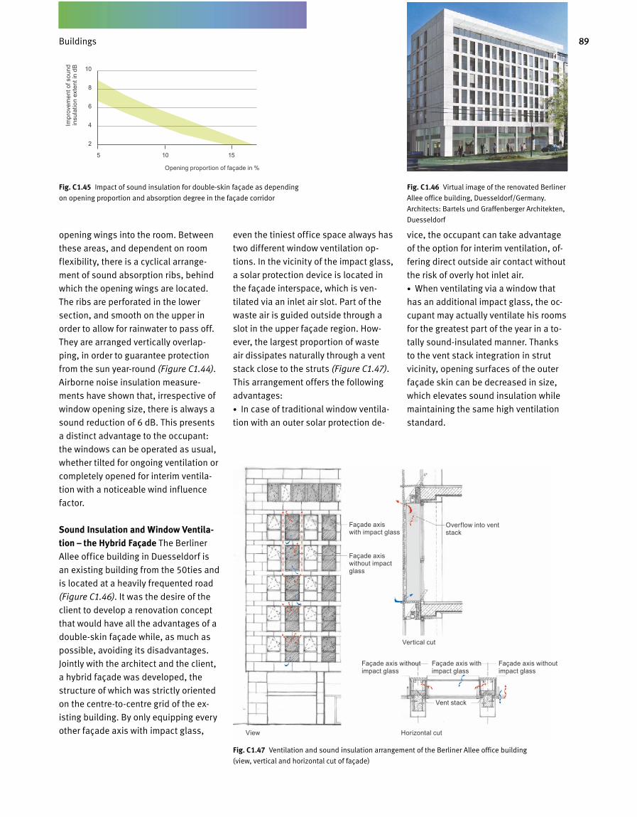
89Gebäude
opening wings into the room. Between
these areas, and dependent on room
flexibility, there is a cyclical arrange-
ment of sound absorption ribs, behind
which the opening wings are located.
The ribs are perforated in the lower
section, and smooth on the upper in
order to allow for rainwater to pass off.
They are arranged vertically overlap-
ping, in order to guarantee protection
from the sun year-round (Figure C1.44).
Airborne noise insulation measure-
ments have shown that, irrespective of
window opening size, there is always a
sound reduction of 6 dB. This presents
a distinct advantage to the occupant:
the windows can be operated as usual,
whether tilted for ongoing ventilation or
completely opened for interim ventila-
tion with a noticeable wind influence
factor.
Sound Insulation and Window Ventila-tion – the Hybrid Façade The Berliner
Allee office building in Duesseldorf is
an existing building from the 50ties and
is located at a heavily frequented road
(Figure C1.46). It was the desire of the
client to develop a renovation concept
that would have all the advantages of a
double-skin façade while, as much as
possible, avoiding its disadvantages.
Jointly with the architect and the client,
a hybrid façade was developed, the
structure of which was strictly oriented
on the centre-to-centre grid of the ex-
isting building. By only equipping every
other façade axis with impact glass,
even the tiniest office space always has
two different window ventilation op-
tions. In the vicinity of the impact glass,
a solar protection device is located in
the façade interspace, which is ven-
tilated via an inlet air slot. Part of the
waste air is guided outside through a
slot in the upper façade region. How-
ever, the largest proportion of waste
air dissipates naturally through a vent
stack close to the struts (Figure C1.47).
This arrangement offers the following
advantages:
• In case of traditional window ventila-
tion with an outer solar protection de-
vice, the occupant can take advantage
of the option for interim ventilation, of-
fering direct outside air contact without
the risk of overly hot inlet air.
• When ventilating via a window that
has an additional impact glass, the oc-
cupant may actually ventilate his rooms
for the greatest part of the year in a to-
tally sound-insulated manner. Thanks
to the vent stack integration in strut
vicinity, opening surfaces of the outer
façade skin can be decreased in size,
which elevates sound insulation while
maintaining the same high ventilation
standard.
Fig. C 1.47 Ventilation and sound insulation arrangement of the Berliner Allee office building
(view, vertical and horizontal cut of façade)
Fig. C 1.46 Virtual image of the renovated Berliner
Allee office building, Duesseldorf/Germany.
Architects: Bartels und Graffenberger Architekten,
Duesseldorf
Façade axis with impact glass
Façade axis without impact glass
Overflow into vent stack
Vertical cut
Horizontal cutView
Façade axis without impact glass
Façade axis with impact glass
Vent stack
Façade axis without impact glass
Opening proportion of façade in %
Impr
ovem
ent o
f sou
nd
insu
latio
n ex
tent
in d
B 10
8
6
4
2
5 10 15
Fig. C 1.45 Impact of sound insulation for double-skin façade as depending
on opening proportion and absorption degree in the façade corridor
Buildings
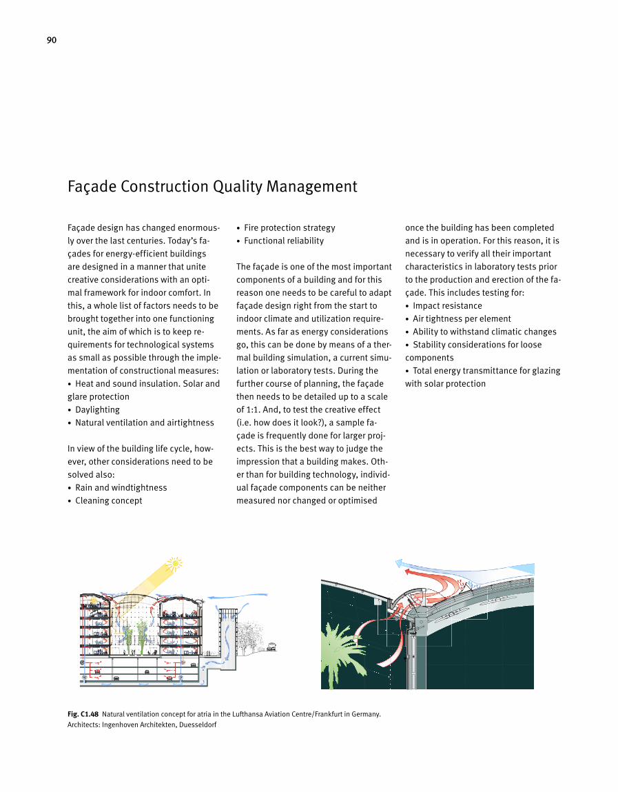
90
Façade Construction Quality Management
Façade design has changed enormous-
ly over the last centuries. Today’s fa-
çades for energy-efficient buildings
are designed in a manner that unite
creative considerations with an opti-
mal framework for indoor comfort. In
this, a whole list of factors needs to be
brought together into one functioning
unit, the aim of which is to keep re-
quirements for technological systems
as small as possible through the imple-
mentation of constructional measures:
• Heat and sound insulation. Solar and
glare protection
• Daylighting
• Natural ventilation and airtightness
In view of the building life cycle, how-
ever, other considerations need to be
solved also:
• Rain and windtightness
• Cleaning concept
• Fire protection strategy
• Functional reliability
The façade is one of the most important
components of a building and for this
reason one needs to be careful to adapt
façade design right from the start to
indoor climate and utilization require-
ments. As far as energy considerations
go, this can be done by means of a ther-
mal building simulation, a current simu-
lation or laboratory tests. During the
further course of planning, the façade
then needs to be detailed up to a scale
of 1:1. And, to test the creative effect
(i.e. how does it look?), a sample fa-
çade is frequently done for larger proj-
ects. This is the best way to judge the
impression that a building makes. Oth-
er than for building technology, individ-
ual façade components can be neither
measured nor changed or optimised
once the building has been completed
and is in operation. For this reason, it is
necessary to verify all their important
characteristics in laboratory tests prior
to the production and erection of the fa-
çade. This includes testing for:
• Impact resistance
• Air tightness per element
• Ability to withstand climatic changes
• Stability considerations for loose
components
• Total energy transmittance for glazing
with solar protection
Fig. C1.48 Natural ventilation concept for atria in the Lufthansa Aviation Centre/Frankfurt in Germany.
Architects: Ingenhoven Architekten, Duesseldorf
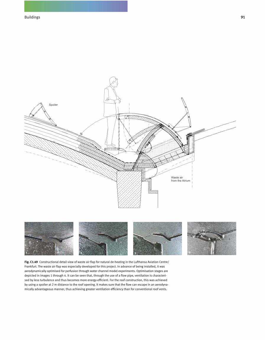
91Gebäude
Fig. C1.49 Constructional detail view of waste air flap for natural de-heating in the Lufthansa Aviation Centre/
Frankfurt. The waste air flap was especially developed for this project. In advance of being installed, it was
aerodynamically optimised for perfusion through water channel model experiments. Optimisation stages are
depicted in images 1 through 4. It can be seen that, through the use of a flow pipe, ventilation is characteri-
sed by less turbulence and thus becomes more energy-efficient. For the roof construction, this was achieved
by using a spoiler at 2 m distance to the roof opening. It makes sure that the flow can escape in an aerodyna-
mically advantageous manner, thus achieving greater ventilation efficiency than for conventional roof vents.
Optimierung in 4 Abbildungen
1 2
3 4
Optimierung in 4 Abbildungen
1 2
3 4
Optimierung in 4 Abbildungen
1 2
3 4
Optimierung in 4 Abbildungen
1 2
3 4
1 2 3 4
Spoiler
Buildings
Waste air from the Atrium
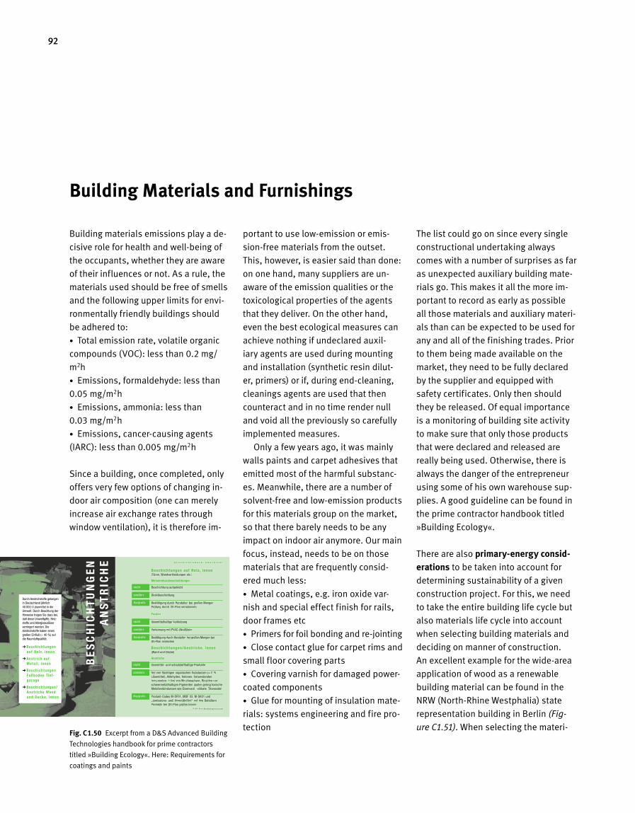
92
Building materials emissions play a de-
cisive role for health and well-being of
the occupants, whether they are aware
of their influences or not. As a rule, the
materials used should be free of smells
and the following upper limits for envi-
ronmentally friendly buildings should
be adhered to:
• Total emission rate, volatile organic
compounds (VOC): less than 0.2 mg/
m2h
• Emissions, formaldehyde: less than
0.05 mg/m2h
• Emissions, ammonia: less than
0.03 mg/m2h
• Emissions, cancer-causing agents
(IARC): less than 0.005 mg/m2h
Since a building, once completed, only
offers very few options of changing in-
door air composition (one can merely
increase air exchange rates through
window ventilation), it is therefore im-
portant to use low-emission or emis-
sion-free materials from the outset.
This, however, is easier said than done:
on one hand, many suppliers are un-
aware of the emission qualities or the
toxicological properties of the agents
that they deliver. On the other hand,
even the best ecological measures can
achieve nothing if undeclared auxil-
iary agents are used during mounting
and installation (synthetic resin dilut-
er, primers) or if, during end-cleaning,
cleanings agents are used that then
counteract and in no time render null
and void all the previously so carefully
implemented measures.
Only a few years ago, it was mainly
walls paints and carpet adhesives that
emitted most of the harmful substanc-
es. Meanwhile, there are a number of
solvent-free and low-emission products
for this materials group on the market,
so that there barely needs to be any
impact on indoor air anymore. Our main
focus, instead, needs to be on those
materials that are frequently consid-
ered much less:
• Metal coatings, e.g. iron oxide var-
nish and special effect finish for rails,
door frames etc
• Primers for foil bonding and re-jointing
• Close contact glue for carpet rims and
small floor covering parts
• Covering varnish for damaged power-
coated components
• Glue for mounting of insulation mate-
rials: systems engineering and fire pro-
tection
The list could go on since every single
constructional undertaking always
comes with a number of surprises as far
as unexpected auxiliary building mate-
rials go. This makes it all the more im-
portant to record as early as possible
all those materials and auxiliary materi-
als than can be expected to be used for
any and all of the finishing trades. Prior
to them being made available on the
market, they need to be fully declared
by the supplier and equipped with
safety certificates. Only then should
they be released. Of equal importance
is a monitoring of building site activity
to make sure that only those products
that were declared and released are
really being used. Otherwise, there is
always the danger of the entrepreneur
using some of his own warehouse sup-
plies. A good guideline can be found in
the prime contractor handbook titled
»Building Ecology«.
There are also primary-energy consid-erations to be taken into account for
determining sustainability of a given
construction project. For this, we need
to take the entire building life cycle but
also materials life cycle into account
when selecting building materials and
deciding on manner of construction.
An excellent example for the wide-area
application of wood as a renewable
building material can be found in the
NRW (North-Rhine Westphalia) state
representation building in Berlin (Fig-
ure C1.51). When selecting the materi-
Building Materials and Furnishings
Fig. C 1.50 Excerpt from a D&S Advanced Building
Technologies handbook for prime contractors
titled »Building Ecology«. Here: Requirements for
coatings and paints
BE
SC
HIC
HT
UN
GE
NA
NS
TR
ICH
E
Durch Anstrichstoffe gelangenin Deutschland jährlich40.000 t Lösemittel in dieUmwelt. Durch Beachtung derHinweise tragen Sie dazu bei,daß diese Umweltgifte, Reiz-stoffe und Allergieauslöser verringert werden. DieAnstrichstoffe haben einengroßen Einfluß (≈ 40 %) auf die Raumluftqualität.
� Beschichtungen auf Holz , innen
� Anstr ich aufMetal l , innen
� BeschichtungenFußboden Tief-garage
� Beschichtungen/Anstr iche Wand und Decke, innen
B E S C H I C H T U N G E N / A N S T R I C H E
Beschichtungen auf Holz , innen(Türen, Wandverkleidungen etc.)
Melaminharzbeschichtungen
nicht Beschichtung aufgeklebt
sondern Direktbeschichtung
Kontrolle Bestätigung durch Hersteller, bei großen MengenPrüfung durch DS-Plan veranlassen
Furnier
nicht lösemittelhaltige Verklebung
sondern Verleimung mit PVAC-(Weiß)leim
Kontrolle Bestätigung durch Hersteller, bei großen Mengen bei DS-Plan einreichen
© D S - P l a n B a u ö k o l o g i e z e n t r u m
C4.04 18.12 Beschichtungen Anstriche
Beschichtungen/Anstr iche, innen (Wand und Decke)
Anstriche
nicht lösemittel- und schadstoffhaltige Produkte
sondern frei von flüchtigen organischen Substanzen (= 0 %Lösemittel), Aldehyden, Ketonen, freiwerdendenIsocyanaten � frei von Weichmachern, Bioziden undschwermetallhaltigen Pigmenten (außer gering toxischeMetallverbindungen wie Eisenoxid, -silikate, Titanoxide)
Kontrolle Produkt-Codes M-DF01, MDF 03, M-SK01 und „(emissions- und) lösemittelfrei“ auf den Behältern,Produkte bei DS-Plan prüfen lassen
B E S C H I C H T U N G E N / A N S T R I C H E
Beschichtungen auf Holz , innen(Türen, Wandverkleidungen etc.)
Melaminharzbeschichtungen
nicht Beschichtung aufgeklebt
sondern Direktbeschichtung
Kontrolle Bestätigung durch Hersteller, bei großen MengenPrüfung durch DS-Plan veranlassen
Furnier
nicht lösemittelhaltige Verklebung
sondern Verleimung mit PVAC-(WVV eiß)leim
Kontrolle Bestätigung durch Hersteller, bei großen Mengen beiDS-Plan einreichen
© D S - P l a n B a u ö k o l o g i e z e n t r u m
Beschichtungen/Anstr iche, innen(Wand und Decke)
Anstriche
nicht lösemittel- und schadstoffhaltige Produkte
sondern frei von flüchtigen organischen Substanzen (= 0 %Lösemittel), Aldehyden, Ketonen, freiwerdendenIsocyanaten � frei von Weichmachern, Bioziden undschwermetallhaltigen Pigmenten (außer gering toxischeMetallverbindungen wie Eisenoxid, -silikate, Titanoxide)
Kontrolle Produkt-Codes M-DF01, MDF 03, M-SK01 und „(emissions- und) lösemittelfrei“ auf den Behältern,Produkte bei DS-Plan prüfen lassen
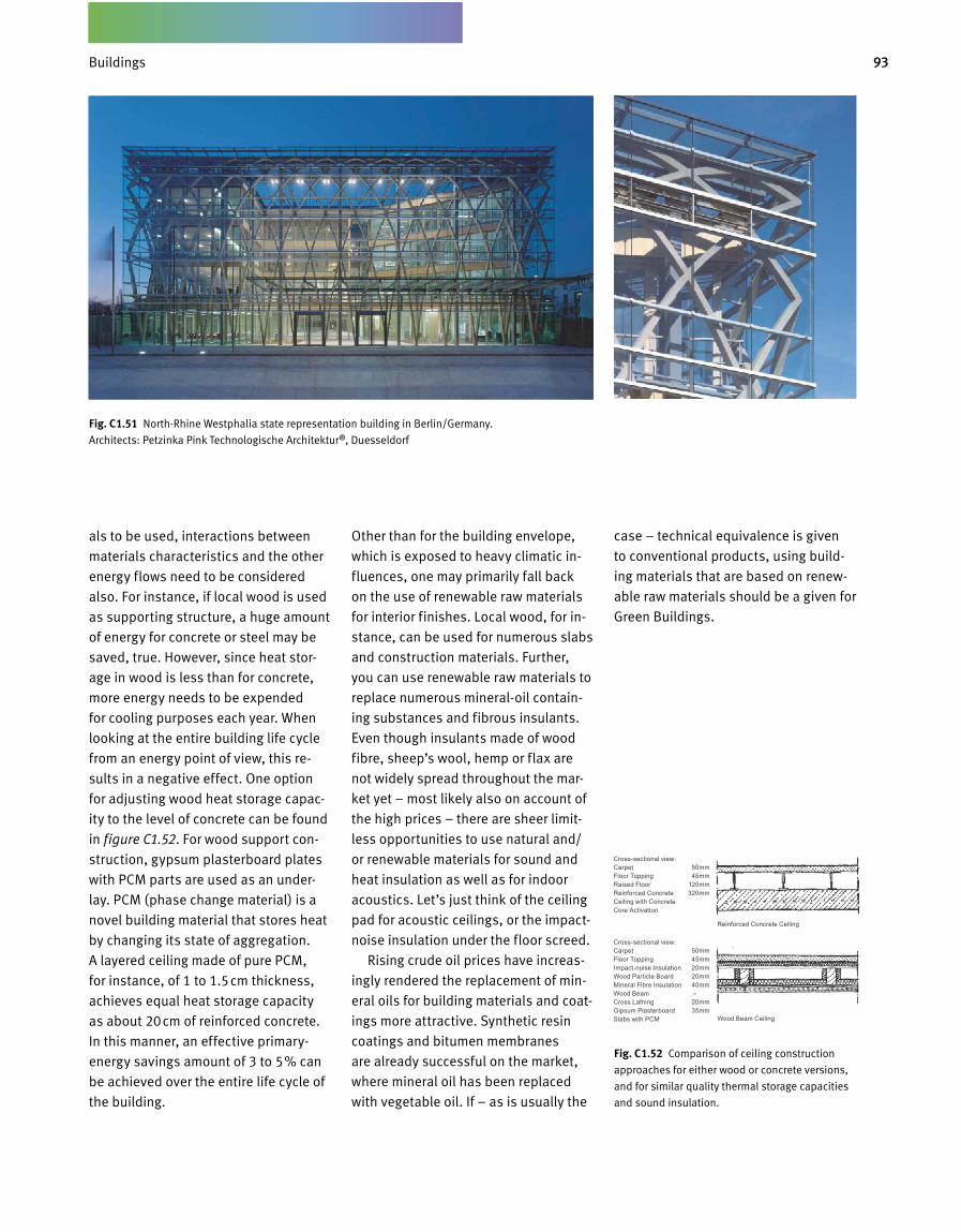
93Gebäude
als to be used, interactions between
materials characteristics and the other
energy flows need to be considered
also. For instance, if local wood is used
as supporting structure, a huge amount
of energy for concrete or steel may be
saved, true. However, since heat stor-
age in wood is less than for concrete,
more energy needs to be expended
for cooling purposes each year. When
looking at the entire building life cycle
from an energy point of view, this re-
sults in a negative effect. One option
for adjusting wood heat storage capac-
ity to the level of concrete can be found
in figure C1.52. For wood support con-
struction, gypsum plasterboard plates
with PCM parts are used as an under-
lay. PCM (phase change material) is a
novel building material that stores heat
by changing its state of aggregation.
A layered ceiling made of pure PCM,
for instance, of 1 to 1.5cm thickness,
achieves equal heat storage capacity
as about 20cm of reinforced concrete.
In this manner, an effective primary-
energy savings amount of 3 to 5 % can
be achieved over the entire life cycle of
the building.
Other than for the building envelope,
which is exposed to heavy climatic in-
fluences, one may primarily fall back
on the use of renewable raw materials
for interior finishes. Local wood, for in-
stance, can be used for numerous slabs
and construction materials. Further,
you can use renewable raw materials to
replace numerous mineral-oil contain-
ing substances and fibrous insulants.
Even though insulants made of wood
fibre, sheep’s wool, hemp or flax are
not widely spread throughout the mar-
ket yet – most likely also on account of
the high prices – there are sheer limit-
less opportunities to use natural and/
or renewable materials for sound and
heat insulation as well as for indoor
acoustics. Let’s just think of the ceiling
pad for acoustic ceilings, or the impact-
noise insulation under the floor screed.
Rising crude oil prices have increas-
ingly rendered the replacement of min-
eral oils for building materials and coat-
ings more attractive. Synthetic resin
coatings and bitumen membranes
are already successful on the market,
where mineral oil has been replaced
with vegetable oil. If – as is usually the
case – technical equivalence is given
to conventional products, using build-
ing materials that are based on renew-
able raw materials should be a given for
Green Buildings.
Fig. C 1.52 Comparison of ceiling construction
approaches for either wood or concrete versions,
and for similar quality thermal storage capacities
and sound insulation.
Fig. C 1.51 North-Rhine Westphalia state representation building in Berlin/Germany.
Architects: Petzinka Pink Technologische Architektur ®, Duesseldorf
Cross-sectional view:CarpetFloor ToppingRaised FloorReinforced Concrete Ceiling with Concrete Core Activation
Cross-sectional view:CarpetFloor ToppingImpact-noise InsulationWood Particle BoardMineral Fibre InsulationWood BeamCross LathingGipsum Plasterboard Slabs with PCM
Reinforced Concrete Ceiling
Wood Beam Ceiling
50mm45mm
120mm320mm
50mm45mm20mm20mm40mm–20mm35mm
Buildings
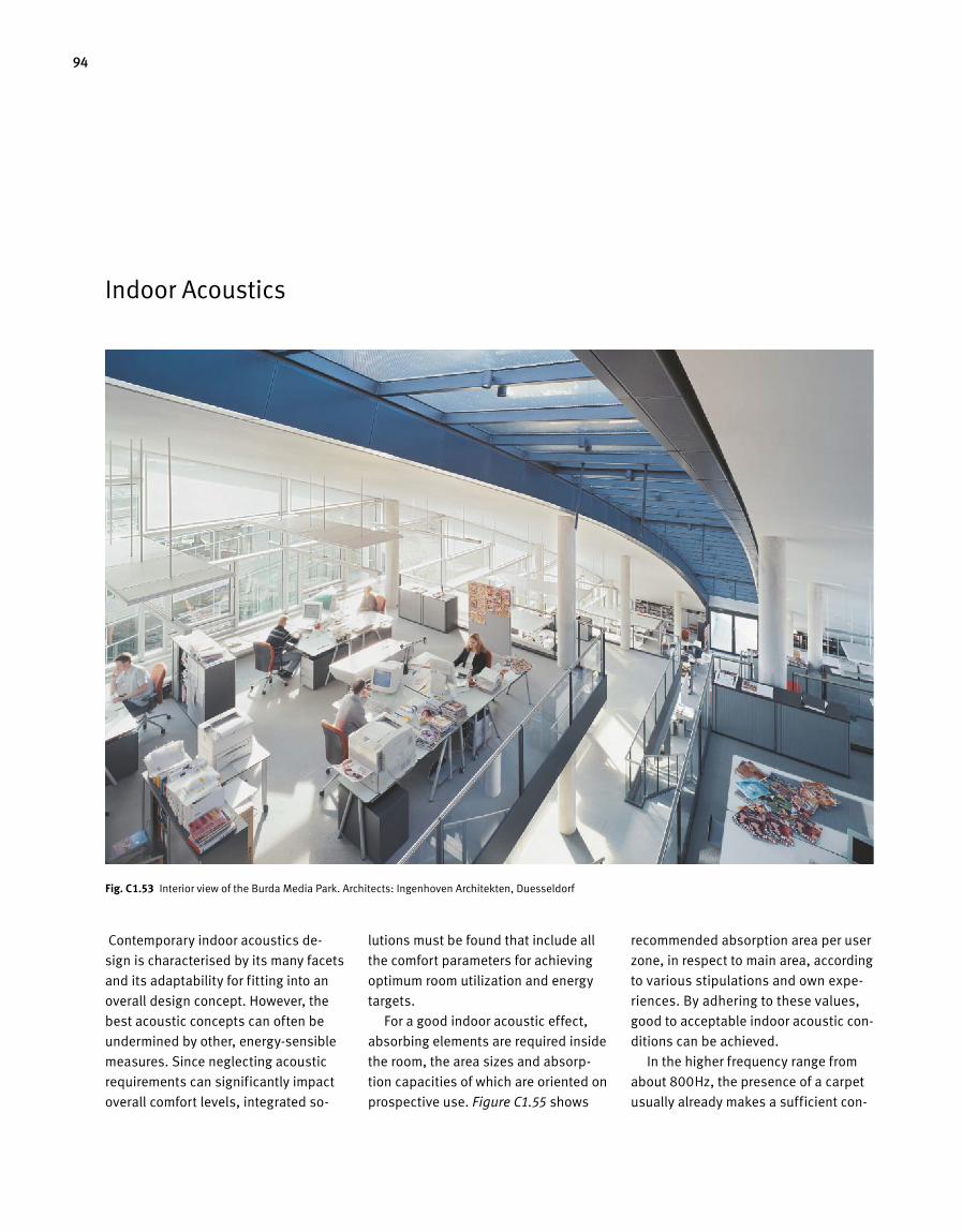
94
Indoor Acoustics
Contemporary indoor acoustics de-
sign is characterised by its many facets
and its adaptability for fitting into an
overall design concept. However, the
best acoustic concepts can often be
undermined by other, energy-sensible
measures. Since neglecting acoustic
requirements can significantly impact
overall comfort levels, integrated so-
lutions must be found that include all
the comfort parameters for achieving
optimum room utilization and energy
targets.
For a good indoor acoustic effect,
absorbing elements are required inside
the room, the area sizes and absorp-
tion capacities of which are oriented on
prospective use. Figure C1.55 shows
recommended absorption area per user
zone, in respect to main area, according
to various stipulations and own expe-
riences. By adhering to these values,
good to acceptable indoor acoustic con-
ditions can be achieved.
In the higher frequency range from
about 800Hz, the presence of a carpet
usually already makes a sufficient con-
Fig. C 1.53 Interior view of the Burda Media Park. Architects: Ingenhoven Architekten, Duesseldorf
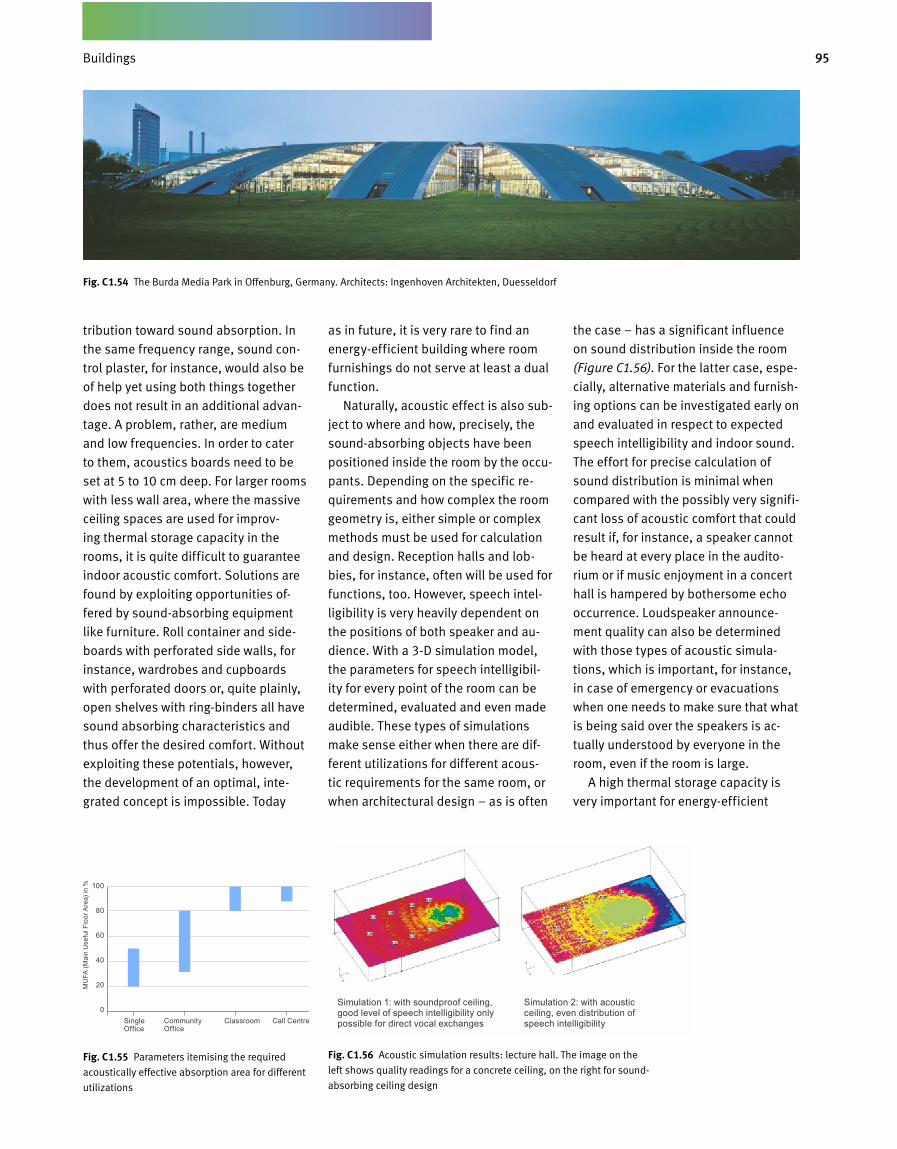
95Gebäude
Fig. C 1.55 Parameters itemising the required
acoustically effective absorption area for different
utilizations
Fig. C 1.56 Acoustic simulation results: lecture hall. The image on the
left shows quality readings for a concrete ceiling, on the right for sound-
absorbing ceiling design
tribution toward sound absorption. In
the same frequency range, sound con-
trol plaster, for instance, would also be
of help yet using both things together
does not result in an additional advan-
tage. A problem, rather, are medium
and low frequencies. In order to cater
to them, acoustics boards need to be
set at 5 to 10 cm deep. For larger rooms
with less wall area, where the massive
ceiling spaces are used for improv-
ing thermal storage capacity in the
rooms, it is quite difficult to guarantee
indoor acoustic comfort. Solutions are
found by exploiting opportunities of-
fered by sound-absorbing equipment
like furniture. Roll container and side-
boards with perforated side walls, for
instance, wardrobes and cupboards
with perforated doors or, quite plainly,
open shelves with ring-binders all have
sound absorbing characteristics and
thus offer the desired comfort. Without
exploiting these potentials, however,
the development of an optimal, inte-
grated concept is impossible. Today
as in future, it is very rare to find an
energy-efficient building where room
furnishings do not serve at least a dual
function.
Naturally, acoustic effect is also sub-
ject to where and how, precisely, the
sound-absorbing objects have been
positioned inside the room by the occu-
pants. Depending on the specific re-
quirements and how complex the room
geometry is, either simple or complex
methods must be used for calculation
and design. Reception halls and lob-
bies, for instance, often will be used for
functions, too. However, speech intel-
ligibility is very heavily dependent on
the positions of both speaker and au-
dience. With a 3-D simulation model,
the parameters for speech intelligibil-
ity for every point of the room can be
determined, evaluated and even made
audible. These types of simulations
make sense either when there are dif-
ferent utilizations for different acous-
tic requirements for the same room, or
when architectural design – as is often
the case – has a significant influence
on sound distribution inside the room
(Figure C1.56). For the latter case, espe-
cially, alternative materials and furnish-
ing options can be investigated early on
and evaluated in respect to expected
speech intelligibility and indoor sound.
The effort for precise calculation of
sound distribution is minimal when
compared with the possibly very signifi-
cant loss of acoustic comfort that could
result if, for instance, a speaker cannot
be heard at every place in the audito-
rium or if music enjoyment in a concert
hall is hampered by bothersome echo
occurrence. Loudspeaker announce-
ment quality can also be determined
with those types of acoustic simula-
tions, which is important, for instance,
in case of emergency or evacuations
when one needs to make sure that what
is being said over the speakers is ac-
tually understood by everyone in the
room, even if the room is large.
A high thermal storage capacity is
very important for energy-efficient
Fig. C 1.54 The Burda Media Park in Offenburg, Germany. Architects: Ingenhoven Architekten, Duesseldorf
Simulation 1: with soundproof ceiling, good level of speech intelligibility only possible for direct vocal exchanges
Simulation 2: with acoustic ceiling, even distribution of speech intelligibility
MU
FA (M
ain
Use
ful F
loor
Are
a) in
% 100
80
60
40
20
0Single Office
Community Office
Classroom Call Centre
Buildings
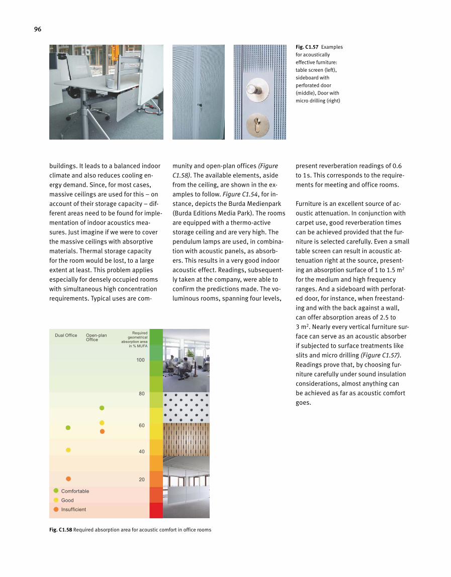
96
buildings. It leads to a balanced indoor
climate and also reduces cooling en-
ergy demand. Since, for most cases,
massive ceilings are used for this – on
account of their storage capacity – dif-
ferent areas need to be found for imple-
mentation of indoor acoustics mea-
sures. Just imagine if we were to cover
the massive ceilings with absorptive
materials. Thermal storage capacity
for the room would be lost, to a large
extent at least. This problem applies
especially for densely occupied rooms
with simultaneous high concentration
requirements. Typical uses are com-
munity and open-plan offices (Figure
C1.58). The available elements, aside
from the ceiling, are shown in the ex-
amples to follow. Figure C1.54, for in-
stance, depicts the Burda Medienpark
(Burda Editions Media Park). The rooms
are equipped with a thermo-active
storage ceiling and are very high. The
pendulum lamps are used, in combina-
tion with acoustic panels, as absorb-
ers. This results in a very good indoor
acoustic effect. Readings, subsequent-
ly taken at the company, were able to
confirm the predictions made. The vo-
luminous rooms, spanning four levels,
present reverberation readings of 0.6
to 1 s. This corresponds to the require-
ments for meeting and office rooms.
Furniture is an excellent source of ac-
oustic attenuation. In conjunction with
carpet use, good reverberation times
can be achieved provided that the fur-
niture is selected carefully. Even a small
table screen can result in acoustic at-
tenuation right at the source, present-
ing an absorption surface of 1 to 1.5 m2
for the medium and high frequency
ranges. And a sideboard with perforat-
ed door, for instance, when freestand-
ing and with the back against a wall,
can offer absorption areas of 2.5 to
3 m2. Nearly every vertical furniture sur-
face can serve as an acoustic absorber
if subjected to surface treatments like
slits and micro drilling (Figure C1.57).
Readings prove that, by choosing fur-
niture carefully under sound insulation
considerations, almost anything can
be achieved as far as acoustic comfort
goes.
Fig. C 1.57 Examples
for acoustically
effective furniture:
table screen (left),
sideboard with
perforated door
(middle), Door with
micro drilling (right)
Fig. C 1.58 Required absorption area for acoustic comfort in office rooms
Comfortable
Good
Insufficient
Dual Office Open-plan Office
100
80
60
40
20
Required geo metrical
absorp tion area in % MUFA
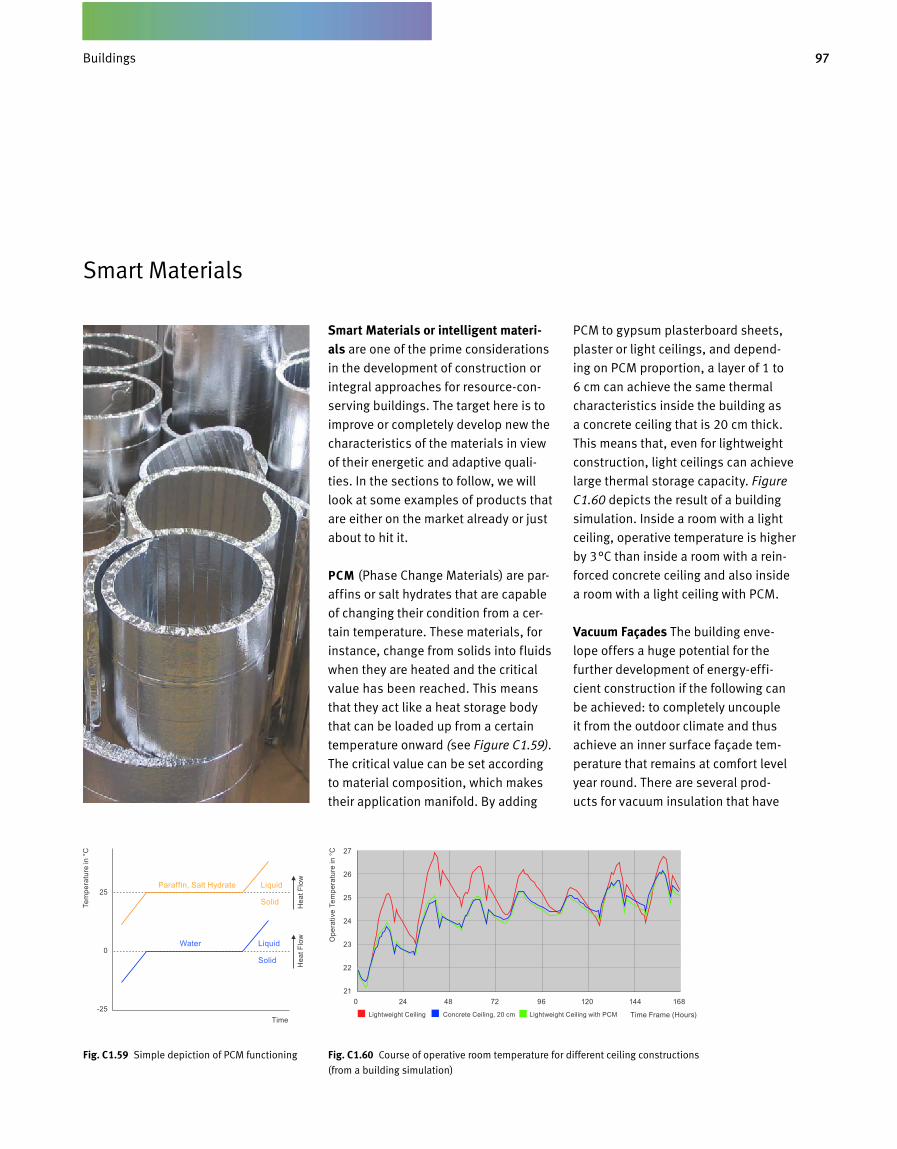
97Gebäude
Smart Materials or intelligent materi-als are one of the prime considerations
in the development of construction or
integral approaches for resource-con-
serving buildings. The target here is to
improve or completely develop new the
characteristics of the materials in view
of their energetic and adaptive quali-
ties. In the sections to follow, we will
look at some examples of products that
are either on the market already or just
about to hit it.
PCM (Phase Change Materials) are par-
affins or salt hydrates that are capable
of changing their condition from a cer-
tain temperature. These materials, for
instance, change from solids into fluids
when they are heated and the critical
value has been reached. This means
that they act like a heat storage body
that can be loaded up from a certain
temperature onward (see Figure C1.59).
The critical value can be set according
to material composition, which makes
their application manifold. By adding
PCM to gypsum plasterboard sheets,
plaster or light ceilings, and depend-
ing on PCM proportion, a layer of 1 to
6 cm can achieve the same thermal
characteristics inside the building as
a concrete ceiling that is 20 cm thick.
This means that, even for lightweight
construction, light ceilings can achieve
large thermal storage capacity. Figure
C1.60 depicts the result of a building
simulation. Inside a room with a light
ceiling, operative temperature is higher
by 3°C than inside a room with a rein-
forced concrete ceiling and also inside
a room with a light ceiling with PCM.
Vacuum Façades The building enve-
lope offers a huge potential for the
further development of energy-effi-
cient construction if the following can
be achieved: to completely uncouple
it from the outdoor climate and thus
achieve an inner surface façade tem-
perature that remains at comfort level
year round. There are several prod-
ucts for vacuum insulation that have
Smart Materials
Fig. C 1.60 Course of operative room temperature for different ceiling constructions
(from a building simulation)
Fig. C 1.59 Simple depiction of PCM functioning
25
0
-25
27
26
25
24
23
22
21
Time
0 24 48 72 96 120 144 168
Lightweight Ceiling Concrete Ceiling, 20 cm Lightweight Ceiling with PCM Time Frame (Hours)
Paraffin, Salt Hydrate Liquid
Solid
Water Liquid
Solid
Tem
pera
ture
in °
C
Ope
rativ
e Te
mpe
ratu
re in
°C
Hea
t Flo
wH
eat F
low
Buildings
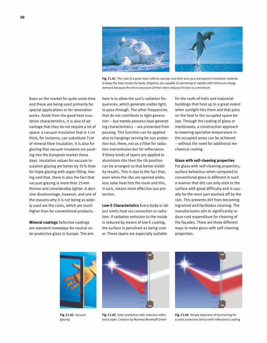
98
been on the market for quite some time
and these are being used primarily for
special applications or for renovation
works. Aside from the good heat insu-
lation characteristics, it is also of ad-
vantage that they do not require a lot of
space: a vacuum insulation that is 1cm
thick, for instance, can substitute 7cm
of mineral fibre insulation. It is also for
glazing that vacuum insulants are push-
ing into the European market these
days. Insulation values for vacuum in-
sulation glazing are better by 35 % than
for triple glazing with argon filling. Hav-
ing said that, there is also the fact that
vacuum glazing is more than 25mm
thinner and considerably lighter. A deci-
sive disadvantage, however, and one of
the reasons why it is not being as wide-
ly used are the costs, which are much
higher than for conventional products.
Mineral coatings Selective coatings
are standard nowadays for neutral so-
lar protective glass in Europe. The aim
here is to allow the sun’s radiation fre-
quencies, which generate visible light,
to pass through. The other frequencies
that do not contribute to light genera-
tion – but merely possess heat-generat-
ing characteristics – are prevented from
passing. This function can be applied
also to hangings serving for sun protec-
tion but, there, not as a filter for radia-
tion transmission but for reflectance.
If these kinds of layers are applied to
aluminium ribs then the rib position
can be arranged so that better visibil-
ity results. This is due to the fact that,
even when the ribs are opened wider,
less solar heat hits the room and this,
in turn, means more effective sun pro-
tection.
Low-E Characteristics Every body or ob-
ject emits heat via convection or radia-
tion. If radiation emission to the inside
is reduced by means of low-E coating,
the surface is perceived as being cool-
er. These layers are especially suitable
for the roofs of halls and industrial
buildings that heat up to a great extent
when sunlight hits them and that pass
on the heat to the occupied space be-
low. Through the coating of glass or
membranes, a construction approach
to lowering operative temperature in
the occupied areas can be achieved
– without the need for additional me-
chanical cooling.
Glass with self-cleaning properties
For glass with self-cleaning properties,
surface behaviour when compared to
conventional glass is different in such
a manner that dirt can only stick to the
surface with great difficulty and is usu-
ally for the most part washed off by the
rain. This prevents dirt from becoming
ingrained and facilitates cleaning. The
manufacturers aim to significantly re-
duce cost expenditure for cleaning of
the façades. There are three different
ways to make glass with self-cleaning
properties.
Fig. C 1.62 Vacuum
glazing
C2.4.16
UV - Licht InfrarotLichtFig. C 1.63 Solar protection with selective reflec-
tance layer. Creation by Warema Renkhoff GmbHUV - Licht InfrarotLicht
C2.4.17
Fig. C 1.64 Simply depiction of functioning for
a solar protective device with reflectance coating
Fig. C 1.61 The coat of a polar bear collects sunrays and then acts as a transparent insulation material
to keep the heat inside the body. Dolphins are capable of swimming to rapidly with minimum energy
demand because the micro-structure of their skins reduces friction to a minimum
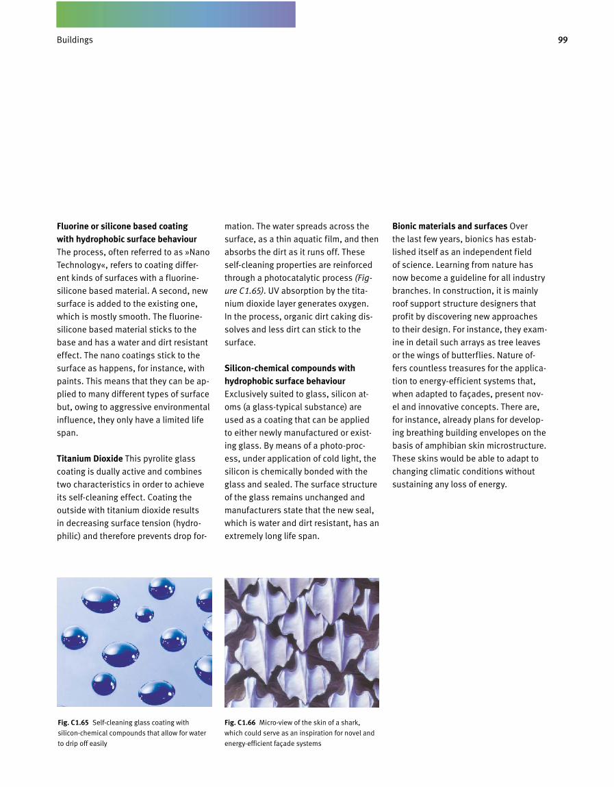
99Gebäude
Fluorine or silicone based coating with hydrophobic surface behaviour
The process, often referred to as »Nano
Technology«, refers to coating differ-
ent kinds of surfaces with a fluorine-
silicone based material. A second, new
surface is added to the existing one,
which is mostly smooth. The fluorine-
silicone based material sticks to the
base and has a water and dirt resistant
effect. The nano coatings stick to the
surface as happens, for instance, with
paints. This means that they can be ap-
plied to many different types of surface
but, owing to aggressive environmental
influence, they only have a limited life
span.
Titanium Dioxide This pyrolite glass
coating is dually active and combines
two characteristics in order to achieve
its self-cleaning effect. Coating the
outside with titanium dioxide results
in decreasing surface tension (hydro-
philic) and therefore prevents drop for-
mation. The water spreads across the
surface, as a thin aquatic film, and then
absorbs the dirt as it runs off. These
self-cleaning properties are reinforced
through a photocatalytic process (Fig-
ure C1.65). UV absorption by the tita-
nium dioxide layer generates oxygen.
In the process, organic dirt caking dis-
solves and less dirt can stick to the
surface.
Silicon-chemical compounds with hydrophobic surface behaviour
Exclusively suited to glass, silicon at-
oms (a glass-typical substance) are
used as a coating that can be applied
to either newly manufactured or exist-
ing glass. By means of a photo-proc -
ess, under application of cold light, the
silicon is chemically bonded with the
glass and sealed. The surface structure
of the glass remains unchanged and
manufacturers state that the new seal,
which is water and dirt resistant, has an
extremely long life span.
Bionic materials and surfaces Over
the last few years, bionics has estab-
lished itself as an independent field
of science. Learning from nature has
now become a guideline for all industry
branches. In construction, it is mainly
roof support structure designers that
profit by discovering new approaches
to their design. For instance, they exam-
ine in detail such arrays as tree leaves
or the wings of butterflies. Nature of-
fers countless treasures for the applica-
tion to energy-efficient systems that,
when adapted to façades, present nov-
el and innovative concepts. There are,
for instance, already plans for develop-
ing breathing building envelopes on the
basis of amphibian skin microstructure.
These skins would be able to adapt to
changing climatic conditions without
sustaining any loss of energy.
Fig. C 1.65 Self-cleaning glass coating with
silicon-chemical compounds that allow for water
to drip off easily
Fig. C 1.66 Micro-view of the skin of a shark,
which could serve as an inspiration for novel and
energy-efficient façade systems
Buildings
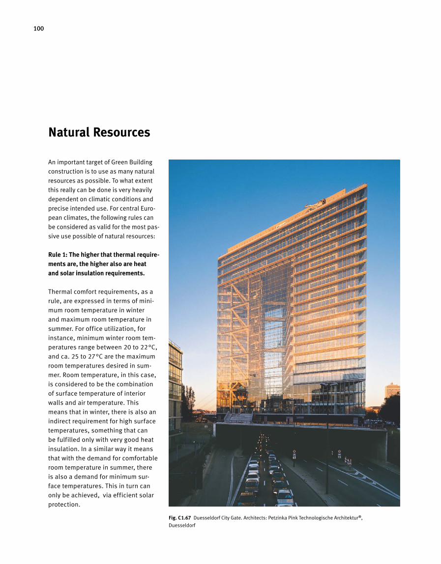
100
Natural Resources
An important target of Green Building
construction is to use as many natural
resources as possible. To what extent
this really can be done is very heavily
dependent on climatic conditions and
precise intended use. For central Euro-
pean climates, the following rules can
be considered as valid for the most pas-
sive use possible of natural resources:
Rule 1: The higher that thermal require-ments are, the higher also are heat and solar insulation requirements.
Thermal comfort requirements, as a
rule, are expressed in terms of mini-
mum room temperature in winter
and maximum room temperature in
summer. For office utilization, for
instance, minimum winter room tem-
peratures range between 20 to 22°C,
and ca. 25 to 27°C are the maximum
room temperatures desired in sum-
mer. Room temperature, in this case,
is considered to be the combination
of surface temperature of interior
walls and air temperature. This
means that in winter, there is also an
indirect requirement for high surface
temperatures, something that can
be fulfilled only with very good heat
insulation. In a similar way it means
that with the demand for comfortable
room temperature in summer, there
is also a demand for minimum sur-
face temperatures. This in turn can
only be achieved, via efficient solar
pro tection.
Fig. C 1.67 Duesseldorf City Gate. Architects: Petzinka Pink Technologische Architektur ®,
Duesseldorf
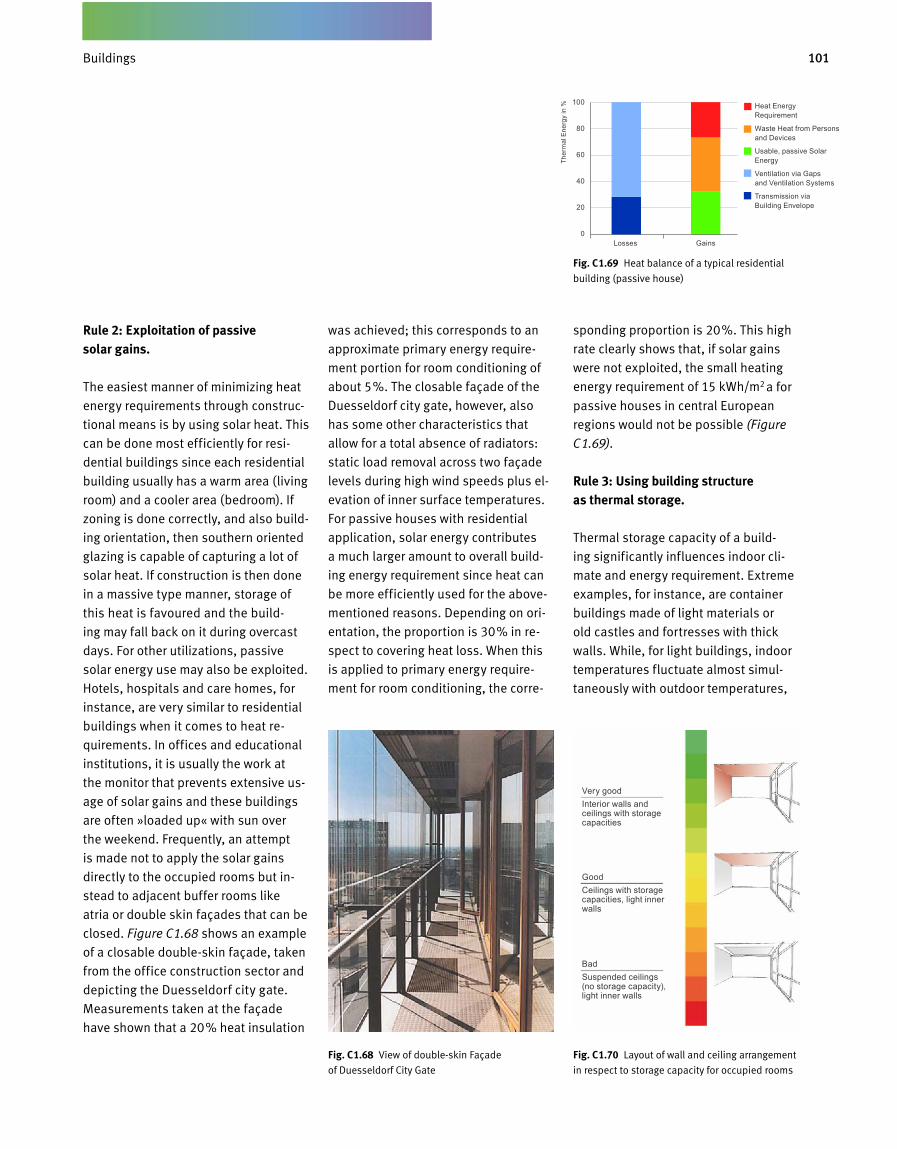
101Gebäude
Fig. C 1.68 View of double-skin Façade
of Duesseldorf City Gate
Rule 2: Exploitation of passive solar gains.
The easiest manner of minimizing heat
energy requirements through construc-
tional means is by using solar heat. This
can be done most efficiently for resi-
dential buildings since each residential
building usually has a warm area (living
room) and a cooler area (bedroom). If
zoning is done correctly, and also build-
ing orientation, then southern oriented
glazing is capable of capturing a lot of
solar heat. If construction is then done
in a massive type manner, storage of
this heat is favoured and the build-
ing may fall back on it during overcast
days. For other utilizations, passive
solar energy use may also be exploited.
Hotels, hospitals and care homes, for
instance, are very similar to residential
buildings when it comes to heat re-
quirements. In offices and educational
institutions, it is usually the work at
the monitor that prevents extensive us-
age of solar gains and these buildings
are often »loaded up« with sun over
the weekend. Frequently, an attempt
is made not to apply the solar gains
directly to the occupied rooms but in-
stead to adjacent buffer rooms like
atria or double skin façades that can be
closed. Figure C1.68 shows an example
of a closable double-skin façade, taken
from the office construction sector and
depicting the Duesseldorf city gate.
Measurements taken at the façade
have shown that a 20 % heat insulation
was achieved; this corresponds to an
approximate primary energy require-
ment portion for room conditioning of
about 5 %. The closable façade of the
Duesseldorf city gate, however, also
has some other characteristics that
allow for a total absence of radiators:
static load removal across two façade
levels during high wind speeds plus el-
evation of inner surface temperatures.
For passive houses with residential
application, solar energy contributes
a much larger amount to overall build-
ing energy requirement since heat can
be more efficiently used for the above-
mentioned reasons. Depending on ori-
entation, the proportion is 30 % in re-
spect to covering heat loss. When this
is applied to primary energy require-
ment for room conditioning, the corre-
sponding proportion is 20 %. This high
rate clearly shows that, if solar gains
were not exploited, the small heating
energy requirement of 15 kWh/m2 a for
passive houses in central European
regions would not be possible (Figure
C 1.69).
Rule 3: Using building structure as thermal storage.
Thermal storage capacity of a build-
ing significantly influences indoor cli-
mate and energy requirement. Extreme
examples, for instance, are container
buildings made of light materials or
old castles and fortresses with thick
walls. While, for light buildings, indoor
temperatures fluctuate almost simul-
taneously with outdoor temperatures,
Fig. C 1.69 Heat balance of a typical residential
building (passive house)
Fig. C 1.70 Layout of wall and ceiling arrangement
in respect to storage capacity for occupied rooms
Heat Energy Requirement
Waste Heat from Persons and Devices
Usable, passive Solar Energy
Ventilation via Gaps and Ventilation Systems
Transmission via Building Envelope
Very goodInterior walls and ceilings with storage capacities
GoodCeilings with storage capacities, light inner walls
BadSuspended ceilings (no storage capacity), light inner walls
100
80
60
40
20
0Losses Gains
Ther
mal
Ene
rgy
in %
Buildings
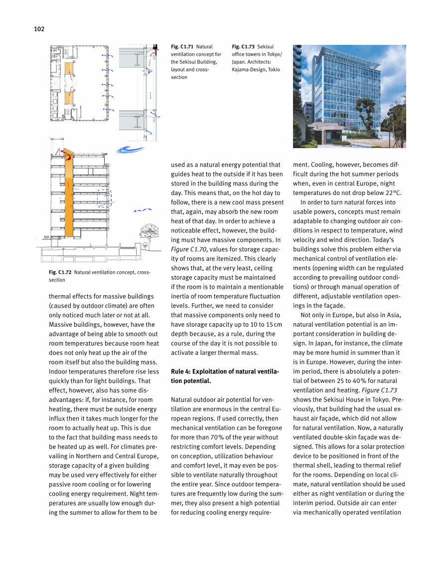
102
thermal effects for massive buildings
(caused by outdoor climate) are often
only noticed much later or not at all.
Massive buildings, however, have the
advantage of being able to smooth out
room temperatures because room heat
does not only heat up the air of the
room itself but also the building mass.
Indoor temperatures therefore rise less
quickly than for light buildings. That
effect, however, also has some dis
advantages: if, for instance, for room
heating, there must be outside energy
influx then it takes much longer for the
room to actually heat up. This is due
to the fact that building mass needs to
be heated up as well. For climates pre
vailing in Northern and Central Europe,
storage capacity of a given building
may be used very effectively for either
passive room cooling or for lowering
cooling energy requirement. Night tem
peratures are usually low enough dur
ing the summer to allow for them to be
used as a natural energy potential that
guides heat to the outside if it has been
stored in the building mass during the
day. This means that, on the hot day to
follow, there is a new cool mass present
that, again, may absorb the new room
heat of that day. In order to achieve a
noticeable effect, however, the build
ing must have massive components. In
Figure C1.70, values for storage capac
ity of rooms are itemized. This clearly
shows that, at the very least, ceiling
storage capacity must be maintained
if the room is to maintain a mentionable
inertia of room temperature fluctuation
levels. Further, we need to consider
that massive components only need to
have storage capacity up to 10 to 15cm
depth because, as a rule, during the
course of the day it is not possible to
activate a larger thermal mass.
Rule 4: Exploitation of natural ventila-tion potential.
Natural outdoor air potential for ven
tilation are enormous in the central Eu
ropean regions. If used correctly, then
mechanical ventilation can be foregone
for more than 70 % of the year without
restricting comfort levels. Depending
on conception, utilization behaviour
and comfort level, it may even be pos
sible to ventilate naturally throughout
the entire year. Since outdoor tempera
tures are frequently low during the sum
mer, they also present a high potential
for reducing cooling energy require
ment. Cooling, however, becomes dif
ficult during the hot summer periods
when, even in central Europe, night
temperatures do not drop below 22°C.
In order to turn natural forces into
usable powers, concepts must remain
adaptable to changing outdoor air con
ditions in respect to temperature, wind
velocity and wind direction. Today’s
buildings solve this problem either via
mechanical control of ventilation ele
ments (opening width can be regulated
according to prevailing outdoor condi
tions) or through manual operation of
different, adjustable ventilation open
ings in the façade.
Not only in Europe, but also in Asia,
natural ventilation potential is an im
portant consideration in building de
sign. In Japan, for instance, the climate
may be more humid in summer than it
is in Europe. However, during the inter
im period, there is absolutely a poten
tial of between 25 to 40 % for natural
ventilation and heating. Figure C1.73
shows the Sekisui House in Tokyo. Pre
viously, that building had the usual ex
haust air façade, which did not allow
for natural ventilation. Now, a naturally
ventilated doubleskin façade was de
signed. This allows for a solar protection
device to be positioned in front of the
thermal shell, leading to thermal relief
for the rooms. Depending on local cli
mate, natural ventilation should be used
either as night ventilation or during the
interim period. Outside air can enter
via mechanically operated ventilation
Fig. C 1.73 Sekisui
office towers in Tokyo/
Japan. Architects:
KajamaDesign, Tokio
Grundriss
Schnitt
Fig. C 1.71 Natural
ventilation concept for
the Sekisui Building,
layout and cross
section
Fig. C 1.72 Natural ventilation concept, cross
section
Detailausschnitt der Fassade
C2.5.11

103Gebäude
flaps, which are actuated in a natural
manner: in the middle of the building,
there are two large shafts that suction
off the air via the roof. In the roof re -
gion of the waste air opening, there is
a constant suction effect caused by
wind current. The resulting pressure dif-
ference from the wind forces, superim-
posed by the chimney effect, results in
air current through the building. In or-
der to ensure that each level receives an
equal amount of air, the overflow open-
ings leading from the office area to the
shafts must be arranged at different
sizes, depending on level and height ef-
fect. Flow balancing of the opening, as
experts call it, is calculated by means
of simulation technology.
A further example for an effective natu-
ral ventilation concept can be found in
the Playmobil Funpark (Figure C1.77).
This is a completely glazed hall, mean-
ing that heat and cooling loads must
be analysed very carefully. Usual cal-
culation procedures do not suffice for
these types of buildings when it comes
to defining optimum indoor climate.
The following are important criteria, in
this case, for determining both dimen-
sions and arrangement of heating and
cooling elements inside the room: cool
air drop at façades and the roof, venti-
lation loss via joints during high wind
speeds, local operative temperature in
occupied zones and thermal buoyancy.
Such detailed analyses require simul-
ation calculations for thermal-dynamic
Fig. C 1.74 Interior view of the double-skin façade of the Sekisui Building
Buildings
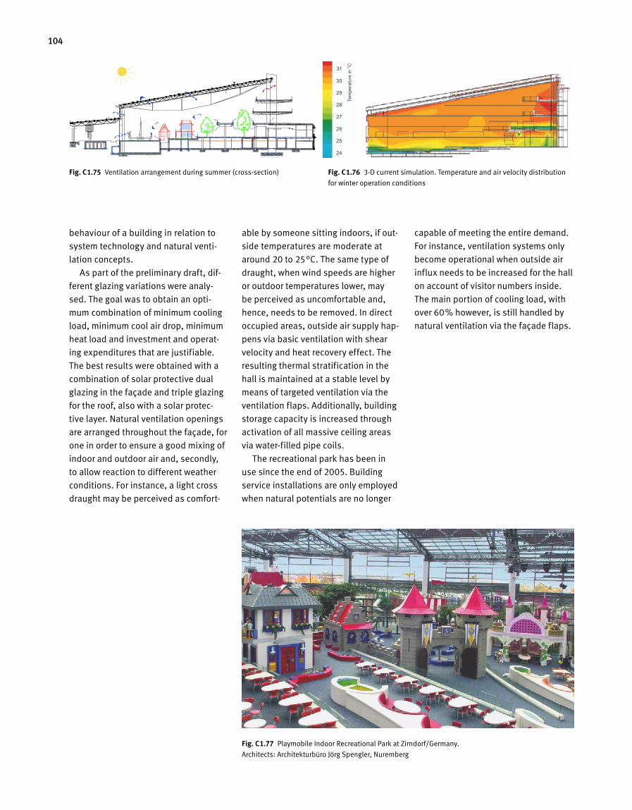
104
Fig. C 1.76 3-D current simulation. Temperature and air velocity distribution
for winter operation conditions
C2.5.15 Playmobil Sommerfall Fig. C 1.75 Ventilation arrangement during summer (cross-section)
behaviour of a building in relation to
system technology and natural venti-
lation concepts.
As part of the preliminary draft, dif-
ferent glazing variations were analy-
sed. The goal was to obtain an opti-
mum combination of minimum cooling
load, minimum cool air drop, minimum
heat load and investment and operat-
ing expenditures that are justifiable.
The best results were obtained with a
combination of solar protective dual
glazing in the façade and triple glazing
for the roof, also with a solar protec-
tive layer. Natural ventilation openings
are arranged throughout the façade, for
one in order to ensure a good mixing of
indoor and outdoor air and, secondly,
to allow reaction to different weather
conditions. For instance, a light cross
draught may be perceived as comfort-
able by someone sitting indoors, if out -
side temperatures are moderate at
around 20 to 25°C. The same type of
draught, when wind speeds are higher
or outdoor temperatures lower, may
be perceived as uncomfortable and,
hence, needs to be removed. In direct
occupied areas, outside air supply hap-
pens via basic ventilation with shear
velocity and heat recovery effect. The
resulting thermal stratification in the
hall is maintained at a stable level by
means of targeted ventilation via the
ventilation flaps. Additionally, building
storage capacity is increased through
activation of all massive ceiling areas
via water-filled pipe coils.
The recreational park has been in
use since the end of 2005. Building
service installations are only employed
when natural potentials are no longer
capable of meeting the entire demand.
For instance, ventilation systems only
become operational when outside air
influx needs to be increased for the hall
on account of visitor numbers inside.
The main portion of cooling load, with
over 60 % however, is still handled by
natural ventilation via the façade flaps.
Fig. C 1.77 Playmobile Indoor Recreational Park at Zirndorf/Germany.
Architects: Architekturbüro Jörg Spengler, Nuremberg
Tem
pera
ture
in °
C
31
30
29
28
27
26
25
24
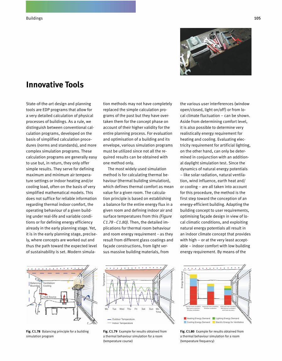
105Gebäude
State-of-the-art design and planning
tools are EDP programs that allow for
a very detailed calculation of physical
processes of buildings. As a rule, we
distinguish between conventional cal-
culation programs, developed on the
basis of simplified calculation proce-
dures (norms and standards), and more
complex simulation programs. These
calculation programs are generally easy
to use but, in return, they only offer
simple results. They serve for defining
maximum and minimum air tempera-
ture settings or indoor heating and/or
cooling load, often on the basis of very
simplified mathematical models. This
does not suffice for reliable information
regarding thermal indoor comfort, the
operating behaviour of a given build-
ing under real-life and variable condi-
tions or for defining energy efficiency
already in the early planning stage. Yet,
it is in the early planning stage, precise-
ly, where concepts are worked out and
thus the path toward the expected level
of sustainability is set. Modern simula-
tion methods may not have completely
replaced the simple calculation pro-
grams of the past but they have over-
taken them for the concept phase on
account of their higher validity for the
entire planning process. For evaluation
and optimisation of a building and its
envelope, various simulation programs
must be utilized since not all the re-
quired results can be obtained with
one method only.
The most widely used simulation
method is for calculating thermal be-
haviour (thermal building simulation),
which defines thermal comfort as mean
value for a given room. The calcula-
tion principle is based on establishing
a balance for the entire energy flux in a
given room and defining indoor air and
surface temperatures from this (Figure
C1.78 – C1.80). Then, the detailed im-
plications for thermal room behaviour
and room energy requirement – as they
result from different glass coatings and
façade constructions, from light ver-
sus massive building materials, from
the various user interferences (window
open/closed, light on/off) or from lo-
cal climate fluctuation – can be shown.
Aside from determining comfort level,
it is also possible to determine very
realistically energy requirement for
heating and cooling. Evaluating elec-
tricity requirement for artificial lighting,
on the other hand, can only be deter-
mined in conjunction with an addition-
al daylight simulation test. Since the
dynamics of natural energy potentials
– like solar radiation, natural ventila-
tion, wind influence, earth heat and/
or cooling – are all taken into account
for this procedure, the method is the
first step toward the conception of an
energy-efficient building. Adapting the
building concept to user requirements,
optimising façade design in view of lo-
cal climatic conditions, and exploiting
natural energy potentials all result in
an indoor climate concept that provides
with high – or at the very least accept-
able – indoor comfort with low building
energy requirement. By means of the
Fig. C 1.78 Balancing principle for a building
simulation program
Fig. C 1.80 Example for results obtained from
a thermal behaviour simulation for a room
(temperature frequency)
Fig. C 1.79 Example for results obtained from
a thermal behaviour simulation for a room
(temperature course)
Innovative Tools
Balancing Boundary
Ventilation/ Cooling Te
mpe
ratu
re
Ener
gy D
eman
d
Heat Source
Mo Tue Wed Thu Fri Sat Sun Mo
Heating Energy Demand Lighting Energy Demand
Cooling Energy Demand Electric Energy for Ventilation
Normal heat insulationBad solar protectionWindow ventilation
Improved heat insulationWindow ventilation
Improved heat insulationMechanical ventilation
with heat recovery
Outdoor Temperature
Indoor Temperature
Time
Buildings
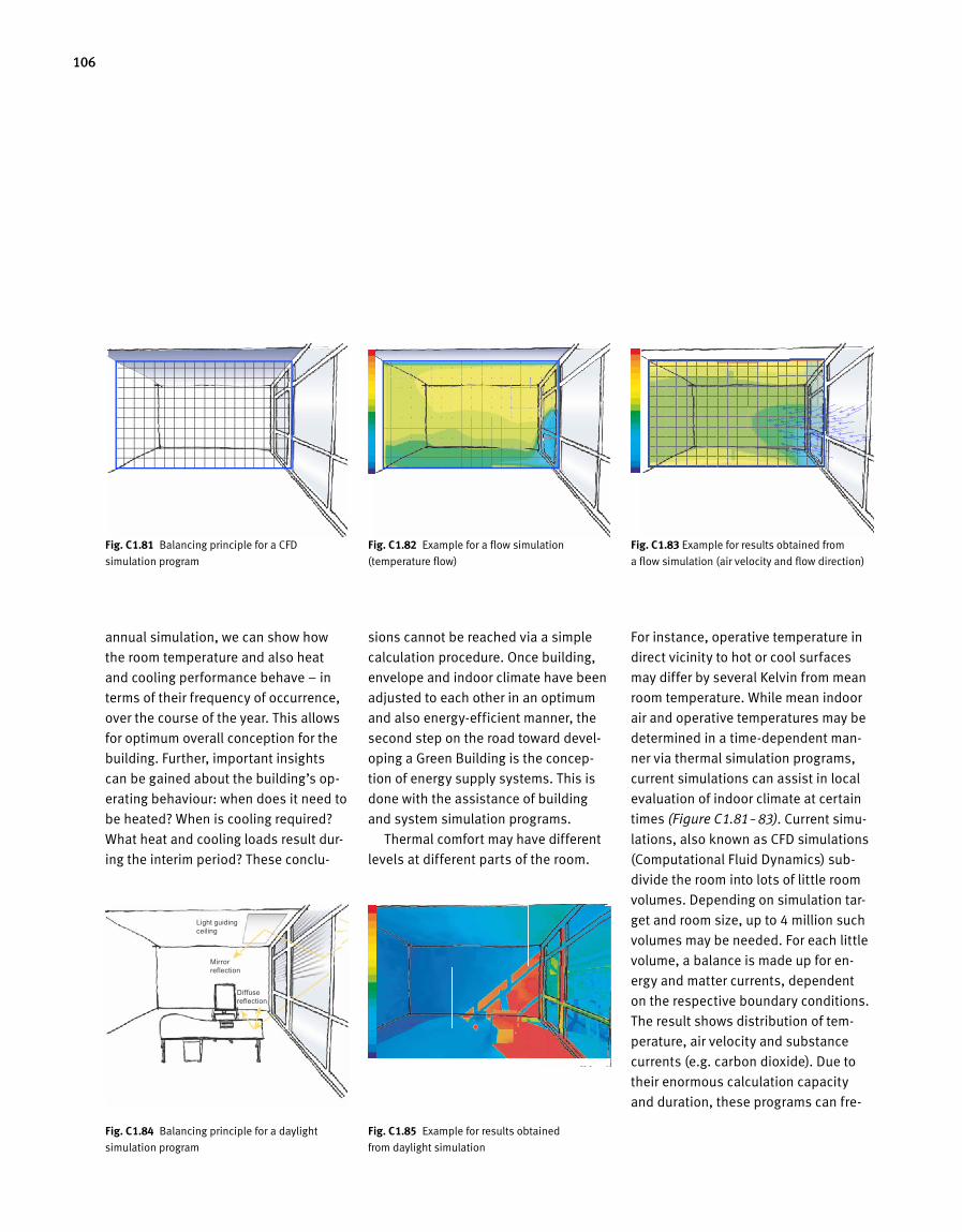
106
annual simulation, we can show how
the room temperature and also heat
and cooling performance behave – in
terms of their frequency of occurrence,
over the course of the year. This allows
for optimum overall conception for the
building. Further, important insights
can be gained about the building’s op-
erating behaviour: when does it need to
be heated? When is cooling required?
What heat and cooling loads result dur-
ing the interim period? These conclu-
sions cannot be reached via a simple
calculation procedure. Once building,
envelope and indoor climate have been
adjusted to each other in an optimum
and also energy-efficient manner, the
second step on the road toward devel-
oping a Green Building is the concep-
tion of energy supply systems. This is
done with the assistance of building
and system simulation programs.
Thermal comfort may have different
levels at different parts of the room.
For instance, operative temperature in
direct vicinity to hot or cool surfaces
may differ by several Kelvin from mean
room temperature. While mean indoor
air and operative temperatures may be
determined in a time-dependent man-
ner via thermal simulation programs,
current simulations can assist in local
evaluation of indoor climate at certain
times (Figure C1.81 – 83). Current simu-
lations, also known as CFD simulations
(Computational Fluid Dynamics) sub-
divide the room into lots of little room
volumes. Depending on simulation tar-
get and room size, up to 4 million such
volumes may be needed. For each little
volume, a balance is made up for en-
ergy and matter currents, dependent
on the respective boundary conditions.
The result shows distribution of tem-
perature, air velocity and substance
currents (e.g. carbon dioxide). Due to
their enormous calculation capacity
and duration, these programs can fre-
Fig. C 1.84 Balancing principle for a daylight
simulation program
C2. mw.02 Falschfarbenbild : Tageslichtverteilung im Raum
Bel
euch
tung
sstä
rke
Fig. C 1.85 Example for results obtained
from daylight simulation
C2-mw.04aFig. C 1.81 Balancing principle for a CFD
simulation program C2-mw.04b
Tem
pera
tur
Fig. C 1.82 Example for a flow simulation
(temperature flow) C2-mw.04c
Luftg
esch
win
digk
eit
Fig. C 1.83 Example for results obtained from
a flow simulation (air velocity and flow direction)
Light guiding ceiling
Mirror reflection
Diffuse reflection
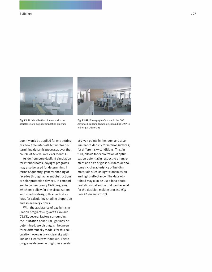
107Gebäude
quently only be applied for one setting
or a few time intervals but not for de-
termining dynamic processes over the
course of several weeks or months.
Aside from pure daylight simulation
for interior rooms, daylight programs
may also be used for determining, in
terms of quantity, general shading of
façades through adjacent obstructions
or solar protection devices. In compari-
son to contemporary CAD programs,
which only allow for one visualisation
with shadow design, this method al-
lows for calculating shading proportion
and solar energy flows.
With the assistance of daylight sim-
ulation programs (Figures C1.84 and
C1.85), several factors surrounding
the utilization of natural light may be
de termined. We distinguish between
three different sky models for this cal-
culation: overcast sky, clear sky with
sun and clear sky without sun. These
programs determine brightness levels
at given points in the room and also
luminance density for interior surfaces,
for different sky conditions. This, in
turn, allows for exploitation of optimi-
sation potential in respect to arrange-
ment and size of glass surfaces or pho-
tometric characteristics of building
materials such as light transmission
and light reflectance. The data ob-
tained may also be used for a photo-
realistic visualisation that can be valid
for the decision making process (Fig-
ures C1.86 and C1.87).
Fig. C 1.87 Photograph of a room in the D&S
Advanced Building Technologies building OWP 11
in Stuttgart/Germany
Fig. C 1.86 Visualisation of a room with the
assistance of a daylight simulation program
Buildings
Building Services Engineering
C 2 D
109Gebäudetechnik
Benefits Delivery
An essential interface for Green Build
ings is that between indoor climate
tech nology and façade. It is a decisive
factor for thermal comfort, occupant
satisfaction and, to a large extent, also
for the energy efficiency of a given build
ing. Thus, utmost care must be taken in
respect to the correct approach to this
particular interface.
We start the conception from the
base of user demands from his or her
immediate environment. Contrary to
prevailing opinion, these are quite
clearly expressed in terms of immediate
vicinity surface temperatures, air tem
perature, air velocity, illuminance level
and luminance density etc. The plan
ning engineer, therefore, as a first step
uses balancing in order to verify ther
mal comfort requirements and lighting
requirements in terms of prevailing cli
mate at the building site and characteri
stics of the planned façade.
For residential and office buildings
in central Europe, he or she will find
out that the heat balancing in winter
cannot be closed. This means that the
natural, passive energy and heat gains
through the sun and interior heat sour
ces through utilization do not suffice
to meet user requirements for thermal
comfort. This deficiency, in turn, allows
for defining the characteristics of the
heating system in order to eventually
meet thermal comfort requirements.
Through variations in the building enve
lope, the required functions of the heat
ing system may be optimised for certain
values. This not only applies in respect
to required heat load for meeting spe
cified room temperature levels. The in
fluence of local surface temperatures
on thermal comfort may also be meas
ured. It is then up to the planning en
gineer to decide whether a surface
tem perature that is too low may be
pre vented through an increased heat
insula tion stand ard or through a tar
geted heating system.
This method may be applied to any
and all areas of indoor climate techno
logy, heating, cooling, ventilation and
lighting. For this, user requirements
must be clearly defined throughout the
year, which allows for concrete definiti
on of required system characteristics.
The specific characteristic of a given
systems technology to hand over heat,
cold, air and light in such a manner that
indoor temperature, air velocity, illumi
nance level and luminance density meet
user requirements in terms of time and
location, is known as benefits delivery.
Not only for heating, but for cooling
also, thermal comfort requirements are
expressed in terms of surface and air
temperatures and also air velocity. The
heat balance for residential and of
fice buildings in Central Europe shows
that, on days with high cooling load
and many interior heat sources, air and
surface temperature requirements fre
quently cannot be met. The resulting
heat excess leads to overheating of the
rooms. Together with the planning team,
the planning engineer needs to analy
se whether increased air and surface
temperatures can be avoided through
improved summer heat protection or
through an effective room cooling sys
tem. Further, for the areas of ventilation
and lighting, system characteristics
can be worked out on the basis of the
existing requirements.
The resulting and defined characteri
stics requirements for heating, cooling,
ventilation and lighting become a kind
of »specification manual« for the room
climate systems to be designed. Com
fort deficits actually lead to greater en
ergy demand during final operation. As
a rule, the user is not willing to accept
comfort deficits. Rather, he or she will
attempt to reinstate a comfortable in
door climate by adjusting system tech
nology usage levels.
Building Services Engineering
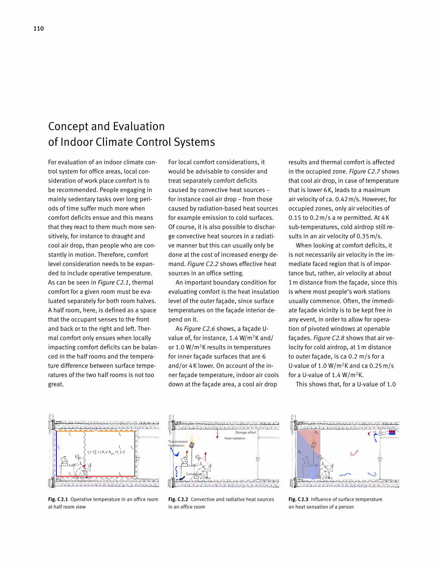
110
For evaluation of an indoor climate con
trol system for office areas, local con
si deration of work place comfort is to
be recommended. People engaging in
mainly sedentary tasks over long peri
ods of time suffer much more when
comfort deficits ensue and this means
that they react to them much more sen
sitively, for instance to draught and
cool air drop, than people who are con
stantly in motion. Therefore, comfort
level consideration needs to be expan
ded to include operative temperature.
As can be seen in Figure C2.1, thermal
comfort for a given room must be eva
luated separately for both room halves.
A half room, here, is defined as a space
that the occupant senses to the front
and back or to the right and left. Ther
mal comfort only ensues when locally
impacting comfort deficits can be balan
ced in the half rooms and the tempera
ture difference between surface tempe
ratures of the two half rooms is not too
great.
For local comfort considerations, it
would be advisable to consider and
treat separately comfort deficits
caused by convective heat sources –
for instance cool air drop – from those
caused by radiationbased heat sources
for example emission to cold surfaces.
Of course, it is also possible to dischar
ge convective heat sources in a radiati
ve manner but this can usually only be
done at the cost of increased energy de
mand. Figure C2.2 shows effective heat
sources in an office setting.
An important boundary condition for
evaluating comfort is the heat insulation
level of the outer façade, since surface
temperatures on the façade interior de
pend on it.
As Figure C2.6 shows, a façade U
value of, for instance, 1.4 W/m2K and/
or 1.0 W/m2K results in temperatures
for inner façade surfaces that are 6
and/or 4K lower. On account of the in
ner façade temperature, indoor air cools
down at the façade area, a cool air drop
Concept and Evaluation of Indoor Climate Control Systems
Fig. C 2.2 Convective and radiative heat sources
in an office room
results and thermal comfort is affected
in the occupied zone. Figure C2.7 shows
that cool air drop, in case of temperature
that is lower 6K, leads to a maximum
air velocity of ca. 0.42m/s. However, for
occupied zones, only air velocities of
0.15 to 0.2m/s a re permitted. At 4K
subtemperatures, cold airdrop still re
sults in an air velocity of 0.35m/s.
When looking at comfort deficits, it
is not necessarily air velocity in the im
mediate faced region that is of impor
tance but, rather, air velocity at about
1m distance from the façade, since this
is where most people’s work stations
usually commence. Often, the immedi
ate façade vicinity is to be kept free in
any event, in order to allow for opera
tion of pivoted windows at openable
façades. Figure C2.8 shows that air ve
locity for cold airdrop, at 1m distance
to outer façade, is ca 0.2 m/s for a
Uvalue of 1.0 W/m2K and ca 0.25m/s
for a Uvalue of 1.4 W/m2K.
This shows that, for a Uvalue of 1.0
Thermische Betonkerntemperierung und mechanische Lüftungsanlage
AH
AF
tF AF ≤ tH AH
L ( U= 1,0 W/m²K ) = 1,7 mL ( U= 1,4 W/m2K ) = 2,6 m
C3.06
AH= HeizflächeAF= Innenoberfläche Fenster t= Temperaturdifferenz zwischen Oberfläche und Raumluft L= Abstand zur Fassade
Fig. C 2.3 Influence of surface temperature
on heat sensation of a person
Transmission Ventilation
Storage effect
Heat radiation
Convection
4-5 m
t1
t3
t2 t
5
t4
t6
tL
tE= (∑ ( t
i A
i )/ A
ges.+t
L )/ 2
Behaglichkeit HalbraumbetrachtungC3.01
3 m
t1-t
6= Temperaturen der Innenoberflächen
tE
= EmpfindungstemperaturtL
= Temperatur der RaumluftFig. C 2.1 Operative temperature in an office room
at half room view
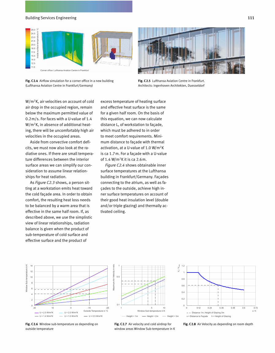
111Gebäudetechnik
W/m2K, air velocities on account of cold
air drop in the occupied region, remain
below the maximum permitted value of
0.2m/s. For faces with a Uvalue of 1.4
W/m2K, in absence of additional heat
ing, there will be uncomfortably high air
velocities in the occupied areas.
Aside from convective comfort defi
cits, we must now also look at the ra
dia tive ones. If there are small tempera
ture differences between the interior
surface areas we can simplify our con
sideration to assume linear relation
ships for heat radiation.
As Figure C2.3 shows, a person sit
ting at a workstation emits heat toward
the cold façade area. In order to obtain
comfort, the resulting heat loss needs
to be balanced by a warm area that is
effective in the same half room. If, as
described above, we use the simplistic
view of linear relationships, radiation
balance is given when the product of
subtemperature of cold surface and
effective surface and the product of
excess temperature of heating surface
and effective heat surface is the same
for a given half room. On the basis of
this equation, we can now calculate
distance L, of workstation to façade,
which must be adhered to in order
to meet comfort requirements. Mini
mum distance to façade with thermal
activation, at a Uvalue of 1.0 W/m2K
is ca 1.7m. For a façade with a Uvalue
of 1.4 W/m2K it is ca 2.6m.
Figure C2.4 shows obtainable inner
surface temperatures at the Lufthansa
building in Frankfurt/Germany. Façades
connecting to the atrium, as well as fa
çades to the outside, achieve high in
ner surface temperatures on account of
their good heat insulation level (double
and/or triple glazing) and thermally ac
tivated ceiling.
Fig. C 2.5 Lufthansa Aviation Centre in Frankfurt.
Architects: Ingenhoven Architekten, Duesseldorf
Fig. C 2.4 Airflow simulation for a corner office in a new building
(Lufthansa Aviation Centre in Frankfurt/Germany)
Fig. C 2.6 Window subtemperature as depending on
outside temperature
Fig. C 2.8 Air Velocity as depending on room depthFig. C 2.7 Air velocity and cold airdrop for
window areas Window Subtemperature in K
Corner office: Lufthansa Aviation Centre in Frankfurt
25.0
24.5
23.0
21.5
20.0
18.5
17.0
15.5
14.0
12.5
11.0
Insi
de s
urfa
ce te
mpe
ratu
re in
°C
20 10 0 -10 -20 0 0.12 0.24 0.36 0.48 0.6 0.721 5 10Outside Temperature in °C x / hWindow Sub-temperature in K
U = 2.5 W/m2K U = 2.0 W/m2K
U = 1.4 W/m2K U = 1.0 W/m2K U = 0.5 W/m2K
Distance 1m, Height of Glazing 3m
x = Distance to Façade h = Height of GlazingHeight = 1m Height = 2m Height = 3m
14
12
10
8
6
4
2
0
1.2
1
0.8
0.6
0.4
0.2
0
1
0.5
0.1
Win
dow
Sub
-tem
pera
ture
in K
Vx /
Vm
ax
Max
imum
Air
Velo
city
in m
/s
Building Services Engineering
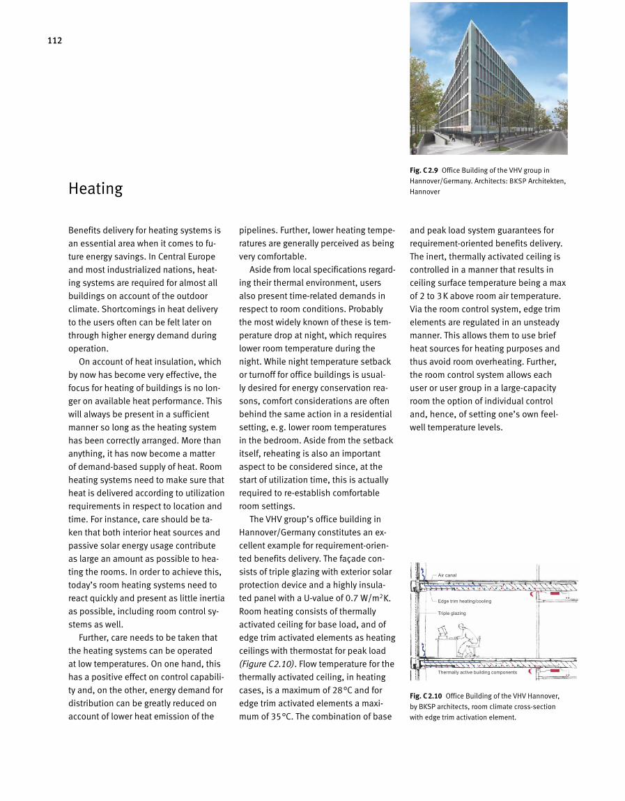
112
Fig. C 2.9 Office Building of the VHV group in
Hannover/Germany. Architects: BKSP Architekten,
Hannover
Benefits delivery for heating systems is
an essential area when it comes to fu
ture energy savings. In Central Europe
and most industrialized nations, heat
ing systems are required for almost all
buildings on account of the outdoor
climate. Shortcomings in heat delivery
to the users often can be felt later on
through higher energy demand du ring
operation.
On account of heat insulation, which
by now has become very effective, the
focus for heating of buildings is no lon
ger on available heat performance. This
will always be present in a sufficient
manner so long as the heating system
has been correctly arranged. More than
anything, it has now become a matter
of demandbased supply of heat. Room
heating systems need to make sure that
heat is delivered according to utilization
requirements in respect to location and
time. For instance, care should be ta
ken that both interior heat sources and
passive solar energy usage contribute
as large an amount as possible to hea
ting the rooms. In order to achieve this,
today’s room heating sys tems need to
react quickly and present as little inertia
as possible, including room control sy
stems as well.
Further, care needs to be taken that
the heating systems can be operated
at low temperatures. On one hand, this
has a positive effect on control capabili
ty and, on the other, energy demand for
distribution can be greatly reduced on
account of lower heat emission of the
pipelines. Further, lower heating tempe
ratures are generally perceived as being
very comfortable.
Aside from local specifications regard
ing their thermal environment, users
also present timerelated demands in
respect to room conditions. Probably
the most widely known of these is tem
perature drop at night, which requires
lower room temperature during the
night. While night temperature setback
or turnoff for office buildings is usual
ly desired for energy conservation rea
sons, comfort considerations are often
behind the same action in a residential
setting, e.g. lower room temperatures
in the bedroom. Aside from the setback
itself, reheating is also an important
aspect to be considered since, at the
start of utilization time, this is actually
required to reestablish comfortable
room settings.
The VHV group’s office building in
Hannover/Germany constitutes an ex
cellent example for requirementorien
ted benefits delivery. The façade con
sists of triple glazing with exterior solar
protection device and a highly insula
ted panel with a Uvalue of 0.7 W/m2K.
Room heating consists of thermally
activated ceiling for base load, and of
edge trim activated elements as heating
ceilings with thermostat for peak load
(Figure C2.10). Flow temperature for the
thermally activated ceiling, in heating
cases, is a maximum of 28°C and for
edge trim activated elements a maxi
mum of 35°C. The combination of base
and peak load system guarantees for
requirementoriented benefits delivery.
The inert, thermally activated ceil ing is
controlled in a manner that results in
ceiling surface temperature being a max
of 2 to 3K above room air temperature.
Via the room control system, edge trim
elements are regulated in an unsteady
manner. This allows them to use brief
heat sources for heating purposes and
thus avoid room overheating. Further,
the room control system allows each
user or user group in a largecapacity
room the option of individual control
and, hence, of setting one’s own feel
well temperature levels.
Fig. C 2.10 Office Building of the VHV Hannover,
by BKSP architects, room climate crosssection
with edge trim activation element.
Heating
Air canal
Edge trim heating/cooling
Triple glazing
Thermally active building components
113Gebäudetechnik
Cooling
Benefits delivery for room cooling sy
stem, as a rule, is very similar to that of
heating systems. The main difference
is that we now have reverse heat flow.
When arranging room cooling systems,
we must therefore also consider ener
gy balance for the room as well as local
surface temperatures based on utiliza
tion requirements. The essential energy
gains here are solar radiation and radia
tion from interior heat sources like peo
ple, lighting or machinery. Since cooling
has a high energy demand, cooling de
mand should be reduced as much as
possible through constructional means.
This leaves mechanical application at a
minimum.
On account of the good insulation
levels that have risen steadily over the
past few years, buildings emit very little
heat during the low temperature periods
at night. Interior heat sources, hence,
can very quickly lead to overheating for
office buildings in Central Europe, mean
ing that even at outdoor temperatures
of 26°C upward, mechanical cooling is
already required. Reducing these types
of heat sources and optimising façades
toward as low a heat intake as possible
while, at the same time, exploiting max
imum daylight utilization options, are
among the essential targets for future
developments and for Green Buildings
in general.
Meanwhile, cooling systems are al
ready under consideration for residen
tial settings since, on account of their
high quality insulation, they barely emit
heat anymore at night when cool out
door temperatures prevail. This is coun
terproductive when it comes to Green
Buildings and, on account of low night
temperatures in Central Europe, is also
not required. Residential buildings,
even today, can be designed in a man
ner that means they do not require coo
ling expenditure.
Cooling demand depends on solar
radiation, size and transparency lev el of
the façade and interior heat sources. For
other climatic regions, e.g. in desert or
subtropical settings, outdoor conditions
may be so far removed from those on
the inside that cooling requirement de
pends on outdoor air conditio ning.
Cooling happens either via cool sur
faces inside the room or via cooled air.
Due to the lower heat capacity of air in
comparison to water, energy demand for
cooling by means of air is greater than
with water. For Green Buildings, hence,
we need to take care that, as a first
step, the »cooling« and »ventila tion«
functions are considered independently
of each other.
Cooling surfaces are to be arranged
in a manner that allows them to absorb
excess heat radiation as efficiently as
possible. Ideally, cooling areas should
be situated at the room ceiling since
the head presents the highest surface
temperature and thus the highest heat
emission. Head heat is absorbed by the
cooling surface at the ceiling, some
thing that occupants always experience
as being very comfortable indeed. The
floor in the immediate façade vicinity
presents another option for the arrange
ment of cooling surfaces. Solar radiation
coming in through the façade can be
directly absorbed here and then remo
ved via the cooled floor prior to heat
reaching the room again. This principle
was applied successfully at the Bochum
Century Hall, as Figure C2.11 shows.
There is considerable solar influx on
account of the glass roof and this is
successfully discharged via the cooled
floor.
Aside from direct heat discharge via
the floor or comfortable heat discharge
through the ceiling, energy efficiency
may be optimised via the size of heat
conducting surfaces, analogous to the
heating system. The larger heat con
ducting surface size, the more closely
operating temperature may be to room
temperature. We speak of a high tem
perature cooling system in this case
whereas, for office settings, tempera
tures of ca 18 to 20°C are sufficient.
Especially for cooling, outdoor climate
may also be used as a resourcecon
serving concept. For moderate, Central
European climates, night air tempe
ratures usually stay below 18°C. This
means that this particular cooling
potential may be used via a daynight
storage arrangement. In this case, we
speak of thermally activated building
components (TAB). Via storage mass of
the components, night cooling stores a
certain cooling potential that then beco
mes available for cooling during the day.
Building Services Engineering
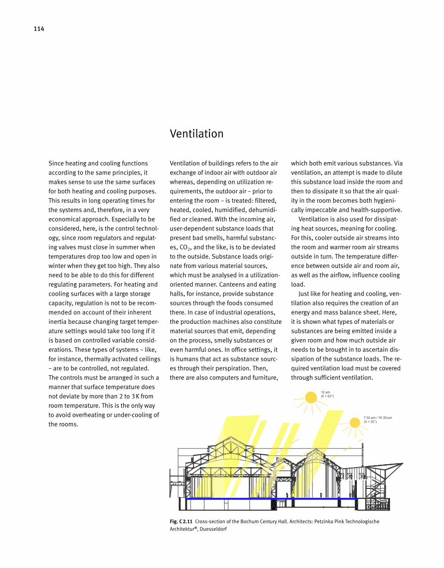
114
Fig. C 2.11 Cross-section of the Bochum Century Hall. Architects: Petzinka Pink Technologische
Architektur ®, Duesseldorf
Since heating and cooling functions
according to the same principles, it
makes sense to use the same surfaces
for both heating and cooling purposes.
This results in long operating times for
the systems and, therefore, in a very
economical approach. Especially to be
considered, here, is the control technol-
ogy, since room regulators and regulat-
ing valves must close in summer when
temperatures drop too low and open in
winter when they get too high. They also
need to be able to do this for different
regulating parameters. For heating and
cooling surfaces with a large storage
capacity, regulation is not to be recom-
mended on account of their in herent
inertia because changing target temper-
ature settings would take too long if it
is based on controlled variable consid-
erations. These types of systems – like,
for instance, thermally activated ceilings
– are to be controlled, not regulated.
The controls must be arranged in such a
manner that surface temperature does
not deviate by more than 2 to 3K from
room temperature. This is the only way
to avoid overheating or under-cooling of
the rooms.
Ventilation of buildings refers to the air
exchange of indoor air with outdoor air
whereas, depending on utilization re-
quirements, the outdoor air – prior to
entering the room – is treated: filtered,
heated, cooled, humidified, dehumidi-
fied or cleaned. With the incoming air,
user-dependent substance loads that
present bad smells, harmful substanc-
es, CO2, and the like, is to be deviated
to the outside. Substance loads origi-
nate from various material sources,
which must be analysed in a utilization-
oriented manner. Canteens and eating
halls, for instance, provide substance
sources through the foods consumed
there. In case of industrial operations,
the production machines also constitute
material sources that emit, depend ing
on the process, smelly substances or
even harmful ones. In office settings, it
is humans that act as substance sourc-
es through their perspiration. Then,
there are also computers and furniture,
which both emit various substances. Via
ventilation, an attempt is made to dilute
this substance load inside the room and
then to dissipate it so that the air qual-
ity in the room becomes both hygieni-
cally impeccable and health-supportive.
Ventilation is also used for dissipat-
ing heat sources, meaning for cooling.
For this, cooler outside air streams into
the room and warmer room air streams
outside in turn. The temperature differ-
ence between outside air and room air,
as well as the airflow, influence cooling
load.
Just like for heating and cooling, ven-
tilation also requires the creation of an
energy and mass balance sheet. Here,
it is shown what types of materials or
substances are being emitted inside a
given room and how much outside air
needs to be brought in to ascertain dis-
sipation of the substance loads. The re-
quired ventilation load must be covered
through sufficient ventilation.
Ventilation
Sonnenstand am 21. JuniSonnenhöhe= h
7h30 / 16h30(h= 32°)
12h00(h= 63°)
C3 - K1
Sonnenstand am 21. JuniSonnenhöhe= h
7h30 / 16h30(h= 32°)
12h00(h= 63°)
C3 - K1
7.30 am / 16.30 pm (h = 32°)
12 am (h = 63°)
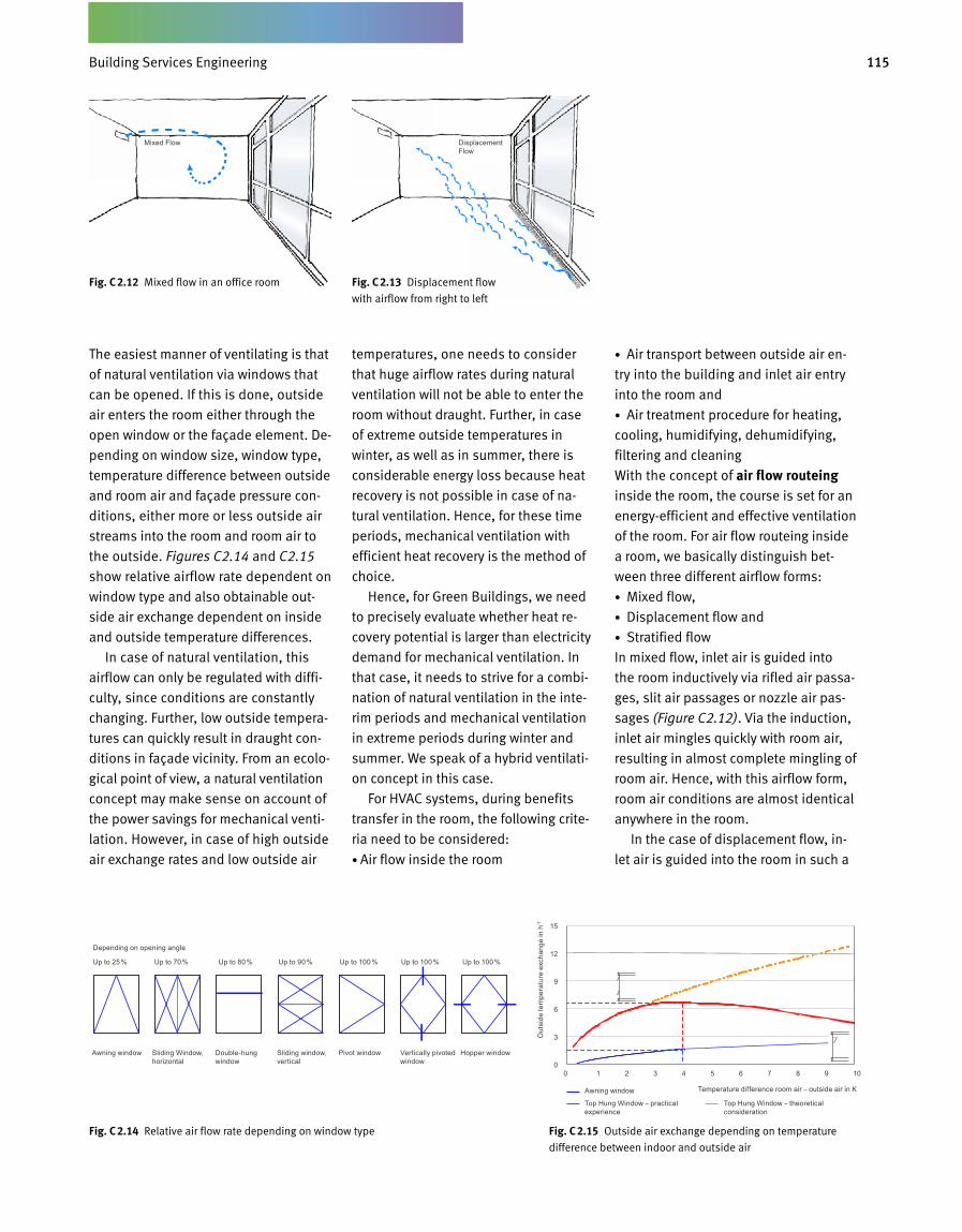
115Gebäudetechnik
The easiest manner of ventilating is that
of natural ventilation via windows that
can be opened. If this is done, outside
air enters the room either through the
open window or the façade element. De
pending on window size, window type,
temperature difference between outside
and room air and façade pressure con
ditions, either more or less outside air
streams into the room and room air to
the outside. Figures C2.14 and C2.15
show relative airflow rate dependent on
window type and also obtainable out
side air exchange dependent on inside
and outside temperature differences.
In case of natural ventilation, this
air flow can only be regulated with diffi
c ulty, since conditions are constantly
changing. Further, low outside tempera
tures can quickly result in draught con
ditions in façade vicinity. From an ecolo
gical point of view, a natural ventilation
concept may make sense on account of
the power savings for mechanical venti
lation. However, in case of high outside
air exchange rates and low outside air
temperatures, one needs to consider
that huge airflow rates during natural
ventilation will not be able to enter the
room without draught. Further, in case
of extreme outside temperatures in
winter, as well as in summer, there is
considerable energy loss because heat
recovery is not possible in case of na
tural ventilation. Hence, for these time
periods, mechanical ventilation with
efficient heat recovery is the method of
choice.
Hence, for Green Buildings, we need
to precisely evaluate whether heat re
covery potential is larger than electricity
demand for mechanical ventilation. In
that case, it needs to strive for a combi
nation of natural ventilation in the inte
rim periods and mechanical ventilation
in extreme periods during winter and
summer. We speak of a hybrid ventilati
on concept in this case.
For HVAC systems, during benefits
transfer in the room, the following crite
ria need to be considered:
• Air flow inside the room
• Air transport between outside air en
t ry into the building and inlet air entry
into the room and
• Air treatment procedure for heating,
cooling, humidifying, dehumidifying,
filtering and cleaning
With the concept of air flow routeing
inside the room, the course is set for an
energyefficient and effective ventilation
of the room. For air flow routeing inside
a room, we basically distinguish bet
ween three different airflow forms:
• Mixed flow,
• Displacement flow and
• Stratified flow
In mixed flow, inlet air is guided into
the room inductively via rifled air passa
ges, slit air passages or nozzle air pas
sages (Figure C2.12). Via the induction,
inlet air mingles quickly with room air,
resulting in almost complete mingling of
room air. Hence, with this airflow form,
room air conditions are almost identical
anywhere in the room.
In the case of displacement flow, in
let air is guided into the room in such a
Fig. C 2.14 Relative air flow rate depending on window type Fig. C 2.15 Outside air exchange depending on temperature
difference between indoor and outside air
Fig. C 2.12 Mixed flow in an office room Fig. C 2.13 Displacement flow
with airflow from right to left
Mixed Flow Displacement Flow
Depending on opening angle
Up to 25 % Up to 70 % Up to 80 % Up to 90 % Up to 100 % Up to 100 % Up to 100 %
Awning window Sliding Window, horizontal
Double-hung window
Sliding window, vertical
Pivot window Vertically pivoted window
Hopper window
0 1 2 3 4 5 6 7 8 9 10
Awning window
Top Hung Window – practical experience
Top Hung Window – theoretical consideration
15
12
9
6
3
0
Out
side
tem
pera
ture
exc
hang
e in
h-1
Temperature difference room air – outside air in K
Building Services Engineering
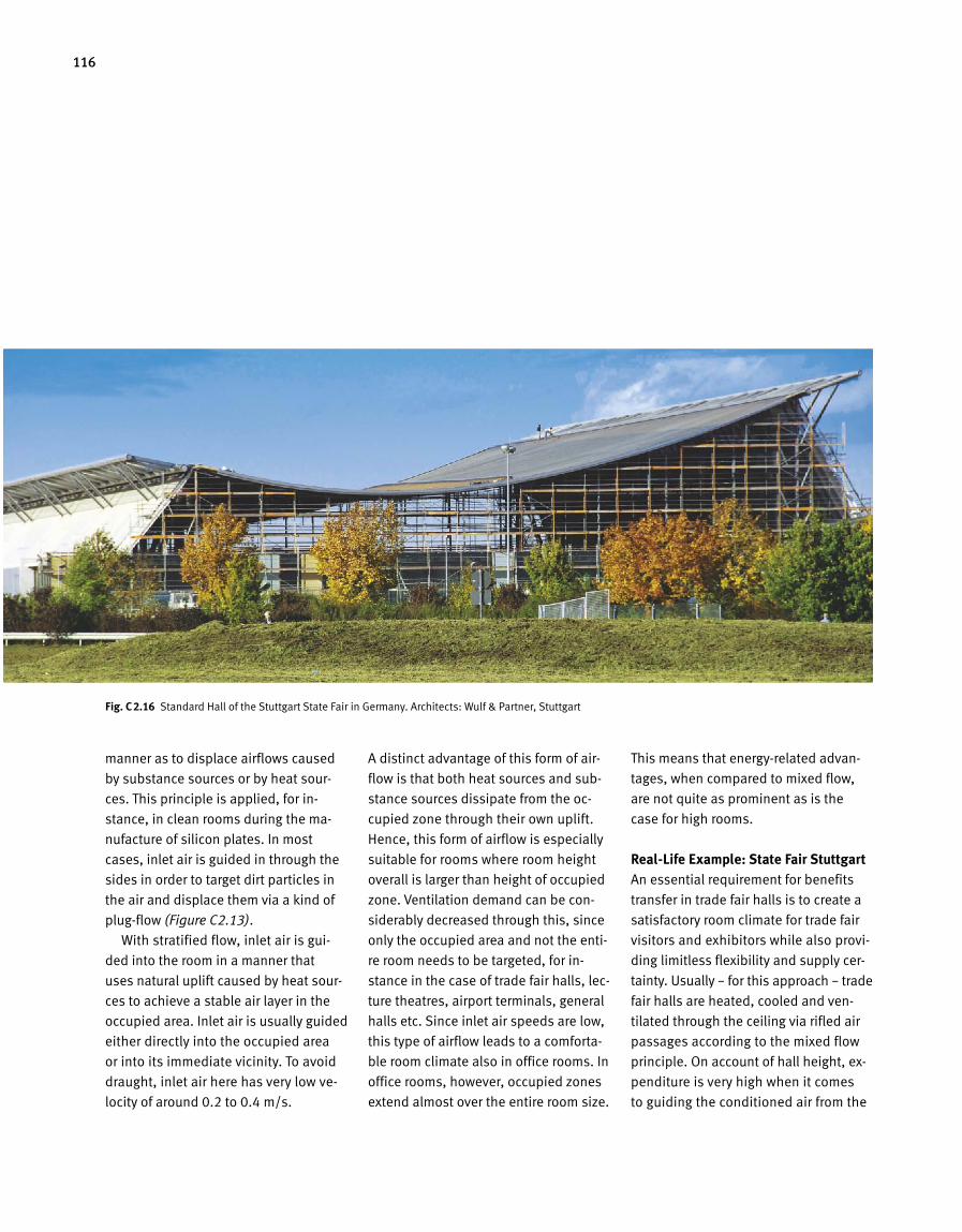
116
manner as to displace airflows caused
by substance sources or by heat sour
ces. This principle is applied, for in
stance, in clean rooms during the ma
nufacture of silicon plates. In most
cases, inlet air is guided in through the
sides in order to target dirt particles in
the air and displace them via a kind of
plugflow (Figure C2.13).
With stratified flow, inlet air is gui
ded into the room in a manner that
uses natural uplift caused by heat sour
ces to achieve a stable air layer in the
occupied area. Inlet air is usually guided
either directly into the occupied area
or into its immediate vicinity. To avoid
draught, inlet air here has very low ve
locity of around 0.2 to 0.4 m/s.
A distinct advantage of this form of air
flow is that both heat sources and sub
stance sources dissipate from the oc
cupied zone through their own uplift.
Hence, this form of airflow is especially
suitable for rooms where room height
overall is larger than height of occupied
zone. Ventilation demand can be con
siderably decreased through this, since
only the occupied area and not the enti
re room needs to be targeted, for in
stance in the case of trade fair halls, lec
ture theatres, airport terminals, general
halls etc. Since inlet air speeds are low,
this type of airflow leads to a comforta
ble room climate also in office rooms. In
office rooms, however, occupied zones
extend almost over the entire room size.
This means that energyrelated advan
tages, when compared to mixed flow,
are not quite as prominent as is the
case for high rooms.
Real-Life Example: State Fair StuttgartAn essential requirement for benefits
transfer in trade fair halls is to create a
satisfactory room climate for trade fair
visitors and exhibitors while also provi
ding limitless flexibility and supply cer
tainty. Usually – for this approach – trade
fair halls are heated, cooled and ven
tilated through the ceiling via rifled air
passages according to the mixed flow
principle. On account of hall height, ex
penditure is very high when it comes
to guiding the conditioned air from the
Fig. C 2.16 Standard Hall of the Stuttgart State Fair in Germany. Architects: Wulf & Partner, Stuttgart
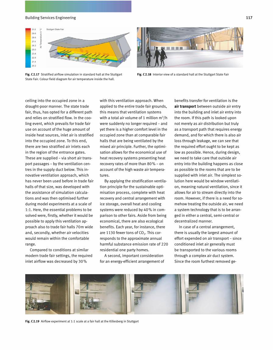
117Gebäudetechnik
ceiling into the occupied zone in a
draughtpoor manner. The state trade
fair, thus, has opted for a different path
and relies on stratified flow. In the coo
ling event, which prevails for trade fair
use on account of the huge amount of
inside heat sources, inlet air is stratified
into the occupied zone. To this end,
there are two stratified air inlets each
in the region of the entrance gates.
These are supplied – via short air trans
port passages – by the ventilation cen
tres in the supply duct below. This in
novative ventilation approach, which
has never been used before in trade fair
halls of that size, was developed with
the assistance of simulation calcula
tions and was then optimised further
during model experiments at a scale of
1:1. Here, the essential problems to be
solved were, firstly, whether it would be
possible to apply this ventilation ap
proach also to trade fair halls 70m wide
and, secondly, whether air velocities
would remain within the comfortable
range.
Compared to conditions at similar
modern trade fair settings, the required
inlet airflow was decreased by 30%
with this ventilation approach. When
applied to the entire trade fair grounds,
this means that ventilation systems
with a total air volume of 1 million m3/h
were suddenly no longer required – and
yet there is a higher comfort level in the
occupied zone than at comparable fair
halls that are being ventilated by the
mixed air principle. Further, the optimi
sation allows for the economical use of
heat recovery systems presenting heat
recovery rates of more than 80% – on
account of the high waste air tempera
tures.
By applying the stratification ventila
tion principle for the sustainable opti
misation process, complete with heat
recovery and central arrangement with
ice storage, overall heat and cooling
sys tems were reduced by 40% in com
parison to other fairs. Aside from being
economical, there are also ecological
benefits. Each year, for instance, there
are 1130 fewer tons of CO2. This cor
responds to the approximate annual
harmful substance emission rate of 220
residential one party homes.
A second, important consideration
for an energyefficient arrangement of
benefits transfer for ventilation is the
air transport between outside air entry
into the building and inlet air entry into
the room. If this path is looked upon
not merely as air distribution but truly
as a transport path that requires energy
demand, and for which there is also air
loss through leakage, we can see that
the required effort ought to be kept as
low as possible. Hence, during design,
we need to take care that outside air
entry into the building happens as close
as possible to the rooms that are to be
supplied with inlet air. The simplest so
lution here would be window ventilati
on, meaning natural ventilation, since it
allows for air to stream directly into the
room. However, if there is a need for so
mehow treating the outside air, we need
a system technology that is to be arran
ged in either a central, semicentral or
decentralized manner.
In case of a central arrangement,
the re is usually the largest amount of
ef fort expended on air transport – since
conditioned inlet air generally must
be transported to the various rooms
through a complex air duct system.
Since the room furthest removed ge
Fig. C 2.18 Interior view of a standard hall at the Stuttgart State FairFig. C 2.17 Stratified airflow simulation in standard hall at the Stuttgart
State Fair. Colour field diagram for air temperature inside the hall.
Fig. C 2.19 Airflow experiment at 1:1 scale at a fair hall at the Killesberg in Stuttgart
Stuttgart State Fair31.0
29.6
28.6
27.4
26.2
25.0
23.8
22.6
21.4
20.2
Air
Tem
pera
ture
in °
C
Building Services Engineering
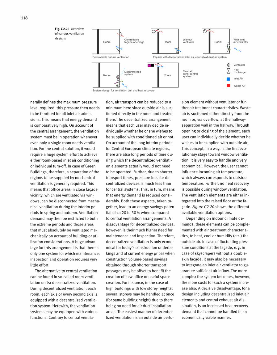
118
nerally defines the maximum pressure
level required, this pressure then needs
to be throttled for all inlet air admis
sions. This means that energy demand
is comparatively high. On account of
the central arrangement, the ventilation
system must be in oper ation whenever
even only a single room needs ventila
tion. For the central solution, it would
require a huge system effort to achieve
either roombased inlet air conditioning
or individual turnoff. In case of Green
Buildings, therefore, a separation of the
regions to be supplied by mechanical
ventilation is generally required. This
means that office areas in close façade
vicinity, which are ventilated via win
dows, can be disconnected from mecha
nical ventilation during the interim pe
riods in spring and autumn. Ventilation
demand may then be restric ted to both
the extreme periods and those areas
that must absolutely be ventilated me
chanically on account of buildingor uti
lization considerations. A huge advan
tage for this arrangement is that there is
only one system for which maintenance,
inspection and operation requires very
little effort.
The alternative to central ventilation
can be found in socalled room venti
lation units: decentralized ventilation.
During decentralized ventilation, each
room, each axis or every second axis is
equipped with a decentralized ventila
tion system. Herewith, the ventilation
systems may be equipped with various
functions. Contrary to central ventila
tion, air transport can be reduced to a
minimum here since outside air is suc
tioned directly in the room and treated
there. The decentralized arrangement
means that each user may decide in
dividually whether he or she wishes to
be supplied with conditioned air or not.
On account of the long interim periods
for Central European climate regions,
there are also long periods of time du
ring which the decentralized ventilati
on elements actually would not need
to be operated. Further, due to shorter
transport times, pressure loss for de
centralized devices is much less than
for central systems. This, in turn, means
that energy demand is reduced consi
derably. Both these aspects, taken to
gether, lead to an energysavings poten
tial of ca 20 to 30% when compared
to central ventilation arrangements. A
disadvantage for decentralized devices,
however, is their much higher need for
maintenance and inspection. Therefore,
decentralized ventilation is only econo
mical for today’s construction underta
kings and at current energy prices when
construction volumebased savings
obtained through shorter transport
passages may be offset to benefit the
creation of new office or useful space
creation. For instance, in the case of
high buildings with low storey heights,
several storeys may be handled at once
(for same build ing height) due to there
being no need for air duct installation
areas. The easiest manner of decentra
lized ventilation is an outside air perfu
sion element without ventilator or fur
ther air treatment characteristics. Waste
air is suctioned either directly from the
room or, via overflow, at the hallway
separation wall in the hallway. Through
opening or closing of the element, each
user can individually decide whether he
wishes to be supplied with outside air.
This concept, in a way, is the first evo
lutionary stage toward window ventila
tion. It is very easy to handle and very
economical. However, the user cannot
influence incoming air temperature,
which always corresponds to outside
temperature. Further, no heat recovery
is possible during window ventilation.
The ventilation elements are either in
te grated into the raised floor or the fa
ça de. Figure C2.20 shows the different
available ventilation options.
Depending on indoor climate de
mands, these elements can be comple
mented with air treatment characteris
tics, to heat, cool or humidify (etc.) the
outside air. In case of fluctuating pres
sure conditions at the façade, e.g. in
case of skyscrapers without a double
skin façade, it may also be necessary
to integrate an inlet air ventilator to gu
arantee sufficient air inflow. The more
complex the system becomes, however,
the more costs for such a system incre
ase also. A decisive disadvantage, for a
design including decentralized inlet air
elements and central exhaust air dis
sipation, is an increased heat recovery
demand that cannot be handled in an
economically viable manner.
Fig. C 2.20 Overview
of various ventilation
designsRoom
Room
Controllable façade openings
Decentralized system
Ventilator
Heat Exchanger
Inlet Air
Waste Air
Without ventilator
With inlet air ventilator
Central/ semi-central system
Controllable natural ventilation
System design for ventilation unit and heat recovery
Façade with decentralized inlet air, central exhaust air system
Room
Room
Room

119Gebäudetechnik
While waste air volume flow can be
cooled down via a heat exchanger, wast e
air temperature level is not that high
and, therefore, distribution effort im
mense. Alternatively, waste airflow can
be cooled down with a heat pump in
order to achieve a higher temperature
level for the infeed. However, high heat
exchange costs do not allow for econo
mically viable handling of this option,
even for rising energy prices. These ty
pes of arrangements, hence, are not to
be recommended for Green Build ings.
Decentralized ventilation concepts
for Green Buildings, hence, must offer
the option of heat recovery through a
decentralized ventilation element,
which means that – aside from inlet
air – waste air is also handled by this
element. Solutions of this kind require
the highest integration level of HVAC
into the façade, and that already at a
very early stage of planning. An advan
tage of this arrangement, however, is a
highly efficient heat recovery approach,
coupled with individual user operation
where the user can turn the ventilation
element on or off according to require
ment. For Green Buildings, therefore,
this is to be highly recommended. A
disadvantage is found in the costs,
which are still very high on account of
more complex system requirements.
Further, these are always individua
lized solutions, which must be adapted
to respective building or façade type
and thus can only be manufactured in
lower numbers.
The third of these criteria during benefits
transfer can be found in actual air treat-ment in the ventilation device itself. De
pending on requirements, the outside
air needs to be heated, cooled, humidi
fied, dehumidified, filtered or cleaned.
For the various climatesystem proce
dures, care needs to be taken that de
mands placed on inlet air are met with
as little energy demand as possible.
Here, too, demandoriented regulation
or control is a must.
Fig. C 2.21 Decentralized ventilation element with inlet and waste air heatrecovery,
at a width of about 33 cm. Project: Nycomed in Constance
Waste Air Flap
Waste Air Ventilator
Waste Air Filter
Heat/Humidity Recovery
Sound Insulator
Waste Air Tangential Fan
Four Phase Heat Exchanger Heating/Cooling
Inlet Air Ventilator
Outside Air Filter
Outside Air Flap
Building Services Engineering
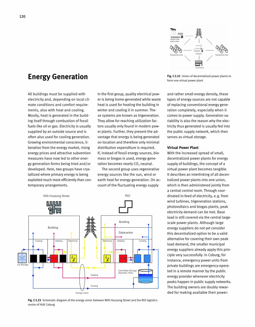
120
Fig. C 2.22 Union of decentralized power plants to
form one virtual power plant
All buildings must be supplied with
electricity and, depending on local cli
mate conditions and comfort require
ments, also with heat and cooling.
Mostly, heat is generated in the build
ing itself through combustion of fossil
fuels like oil or gas. Electricity is usually
supplied by an outside source and is
often also used for cooling generation.
Growing environmental conscience, li
beration from the energy market, rising
energy prices and attractive subvention
meas ures have now led to other ener
gy generation forms being tried and/or
developed. Here, two groups have crys
tallized where primary energy is being
exploited much more efficiently than con
temporary arrangements.
In the first group, quality electrical pow
er is being homegenerated while waste
heat is used for heating the building in
winter and cooling it in summer. The
se systems are known as trigeneration.
They allow for reaching utilization fac
tors usually only found in modern pow
er plants. Further, they present the ad
vantage that energy is being generated
on location and therefore only minimal
distribution expenditure is required.
If, instead of fossil energy sources, bio
mass or biogas is used, energy gene
ration becomes nearly CO2 neutral.
The second group uses regenerative
energy sources like the sun, wind or
earth heat for energy generation. On ac
count of the fluctuating energy supply
and rather small energy density, these
types of energy sources are not capable
of replacing conventional energy gene
ration completely, especially when it
comes to power supply. Generation va
riability is also the reason why the elec
tricity thus generated is usually fed into
the public supply network, which then
serves as virtual storage.
Virtual Power PlantWith the increased spread of small,
decentralized power plants for energy
supply of buildings, the concept of a
virtual power plant becomes tangible.
It describes an interlinking of all decen
tralized power plants into one union,
which is then administered jointly from
a central control room. Through coor
dinated infeed of electricity, e.g. from
wind turbines, trigeneration stations,
photovoltaics and biogas plants, peak
electricity demand can be met. Base
load is still covered via the central large
scale power plants. Although large
energy suppliers do not yet consider
this decentralized option to be a valid
alternative for covering their own peak
load demand, the smaller municipal
energy suppliers already apply this prin
ciple very successfully. In Coburg, for
instance, emergency power units from
private buildings are emergencyopera
ted in a remote manner by the public
energy provider whenever electricity
peaks happen in public supply networks.
The building owners are doubly rewar
ded for making available their power:
Fig. C 2.23 Schematic diagram of the energy union between WilliHussong Street and the RIO logistics
centre of HUK Coburg
Energy Generation
Large-scale power plant
Residential Area Residential AreaIndustry
Commerce
Willi-Hussong Street
Building
Cooling Heating Electricity
Cold Water Storage (Sprinkler Tank)
Ice Storage
Energy Union
Heating
Cooling
Electricity Heating Cooling
Building
Datacentre
RIO
CHP CHP
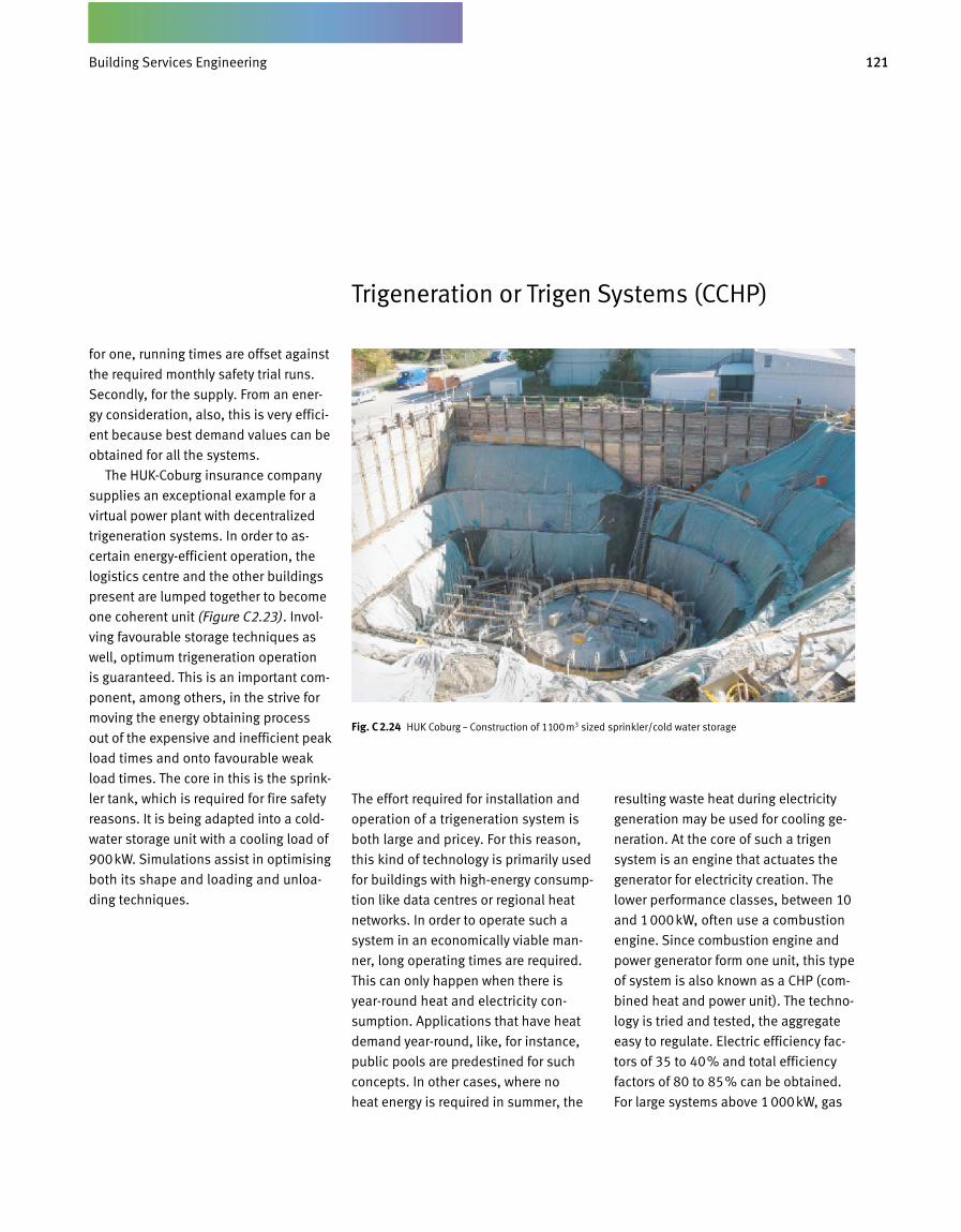
121Gebäudetechnik
Trigeneration or Trigen Systems (CCHP)
The effort required for installation and
operation of a trigeneration system is
both large and pricey. For this reason,
this kind of technology is primarily used
for buildings with highenergy consump
tion like data centres or regional heat
networks. In order to operate such a
system in an economically viable man
ner, long operating times are required.
This can only happen when there is
yearround heat and electricity con
sumption. Applications that have heat
demand yearround, like, for instance,
public pools are predestined for such
concepts. In other cases, where no
heat energy is required in summer, the
resulting waste heat during electricity
generation may be used for cooling ge
neration. At the core of such a trigen
system is an engine that actuates the
generator for electricity creation. The
lower performance classes, between 10
and 1000kW, often use a combustion
en gine. Since combustion engine and
pow er generator form one unit, this type
of system is also known as a CHP (com
bined heat and power unit). The techno
logy is tried and tested, the aggregate
easy to regulate. Electric efficiency fac
tors of 35 to 40% and total efficiency
factors of 80 to 85% can be obtained.
For large systems above 1 000kW, gas
for one, running times are offset against
the required monthly safety trial runs.
Secondly, for the supply. From an ener
gy consideration, also, this is very effici
ent because best demand values can be
obtained for all the sys tems.
The HUKCoburg insurance company
supplies an exceptional example for a
virtual power plant with decentralized
trigeneration systems. In order to as
certain energyefficient operation, the
logistics centre and the other buildings
present are lumped together to become
one coherent unit (Figure C2.23). Invol
ving favourable storage techniques as
well, optimum trigeneration operation
is guaranteed. This is an important com
ponent, among others, in the strive for
moving the energy obtaining process
out of the expensive and inefficient peak
load times and onto favourable weak
load times. The core in this is the sprink
ler tank, which is required for fire safety
reasons. It is being adapted into a cold
water storage unit with a cooling load of
900kW. Simulations assist in optimising
both its shape and loading and unloa
ding techniques.
Fig. C 2.24 HUK Coburg – Construction of 1 100m3 sized sprinkler/cold water storage
Building Services Engineering
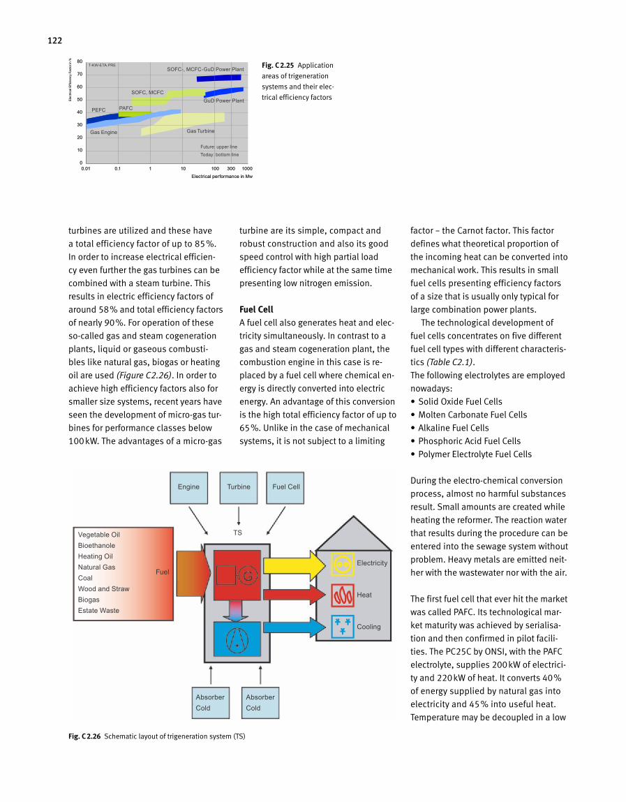
122
turbines are utilized and these have
a total efficiency factor of up to 85%.
In order to increase electrical efficien-
cy even further the gas turbines can be
combined with a steam turbine. This
results in electric efficiency factors of
around 58% and total efficiency factors
of nearly 90%. For operation of these
so-called gas and steam cogeneration
plants, liquid or gaseous combusti-
bles like natural gas, biogas or heating
oil are used (Figure C2.26). In order to
achieve high efficiency factors also for
smaller size systems, recent years have
seen the development of micro-gas tur-
bines for performance classes below
100kW. The advantages of a micro-gas
turbine are its simple, compact and
robust construction and also its good
speed control with high partial load
efficiency factor while at the same time
presenting low nitrogen emission.
Fuel CellA fuel cell also generates heat and elec-
tricity simultaneously. In contrast to a
gas and steam cogeneration plant, the
combustion engine in this case is re-
placed by a fuel cell where chemical en-
ergy is directly converted into electric
energy. An advantage of this conversion
is the high total efficiency factor of up to
65%. Unlike in the case of mechanical
sys tems, it is not subject to a limiting
factor – the Carnot factor. This factor
de fines what theoretical proportion of
the incoming heat can be converted into
mechanical work. This results in small
fuel cells presenting efficiency factors
of a size that is usually only typical for
large combination power plants.
The technological development of
fuel cells concentrates on five different
fuel cell types with different characteris-
tics (Table C2.1).
The following electrolytes are employed
nowadays:
•SolidOxideFuelCells
•MoltenCarbonateFuelCells
•AlkalineFuelCells
•PhosphoricAcidFuelCells
•PolymerElectrolyteFuelCells
During the electro-chemical conversion
process, almost no harmful substan ces
result.Smallamountsarecreatedwhile
heating the reformer. The reaction water
that results during the procedure can be
entered into the sewage sys tem without
problem. Heavy metals are emitted neit-
her with the wastewater nor with the air.
The first fuel cell that ever hit the market
wascalledPAFC.Itstechnologicalmar-
ket maturity was achieved by serialisa-
tion and then confirmed in pilot facili-
ties.ThePC25CbyONSI,withthePAFC
electrolyte,supplies200kWofelectrici-
tyand220kWofheat.Itconverts40%
of energy supplied by natural gas into
electricityand45%intousefulheat.
Temperature may be decoupled in a low
Fig. C 2.25 Application
areas of trigeneration
systems and their elec-
trical efficiency factors
Fig. C 2.26 Schematiclayoutoftrigenerationsystem(TS)
0.01 0.1 1 10 100 300 1000
80
70
60
50
40
30
20
10
0
Ele
ctric
al E
ffici
ency
Fac
tor i
n %
Electrical performance in Mw
Vegetable OilBioethanoleHeating OilNatural GasCoalWood and StrawBiogasEstate Waste
FuelElectricity
Heat
Cooling
Engine Turbine Fuel Cell
AbsorberCold
AbsorberCold
TS
0.01 0.1 1 10 100 300 1000
80
70
60
50
40
30
20
10
0
Ele
ctric
al E
ffici
ency
Fac
tor i
n %
Electrical performance in Mw
Future: upper line
Today: bottom line
Gas Engine Gas Turbine
GuD Power Plant
SOFC-, MCFC-GuD Power Plant
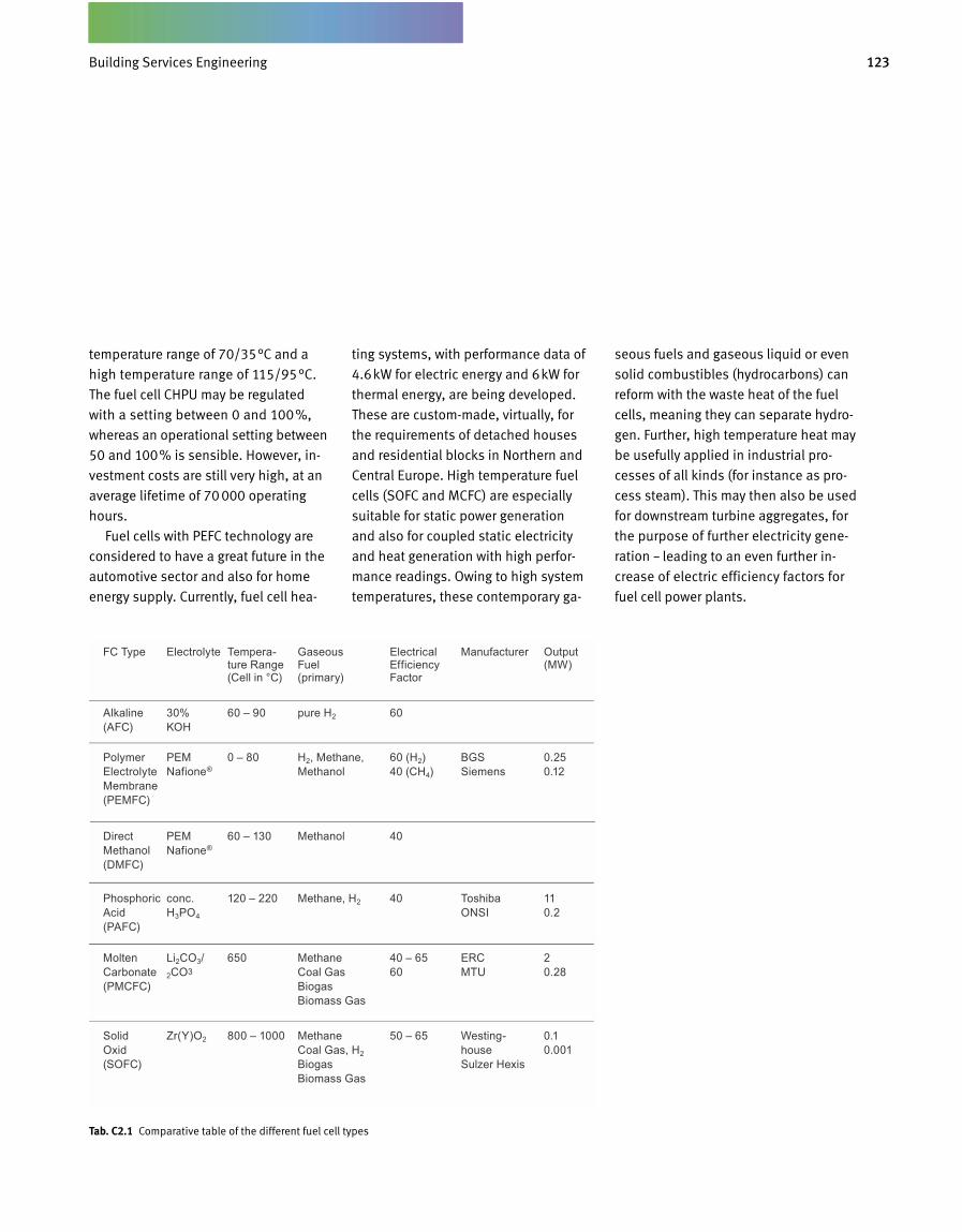
123Gebäudetechnik
Tab. C2.1 Comparative table of the different fuel cell types
temperature range of 70/35°C and a
high temperature range of 115/95°C.
ThefuelcellCHPUmayberegulated
with a setting between 0 and 100%,
whereas an operational setting be tween
50 and 100% is sensible. However, in-
vestment costs are still very high, at an
average lifetime of 70 000 operating
hours.
FuelcellswithPEFCtechnologyare
considered to have a great future in the
automotive sector and also for home
energy supply. Currently, fuel cell hea-
ting systems, with performance data of
4.6kWforelectricenergyand6kWfor
thermal energy, are being developed.
These are custom-made, virtually, for
the requirements of detached houses
andresidentialblocksinNorthernand
CentralEurope.Hightemperaturefuel
cells(SOFCandMCFC)areespecially
suitable for static power generation
and also for coupled static electricity
and heat generation with high perfor-
mancereadings.Owingtohighsystem
temperatures, these contemporary ga-
seous fuels and gaseous liquid or even
solidcombustibles(hydrocarbons)can
reform with the waste heat of the fuel
cells, meaning they can separate hydro-
gen. Further, high temperature heat may
be usefully applied in industrial pro-
cessesofallkinds(forinstanceaspro-
cesssteam).Thismaythenalsobeused
for downstream turbine aggregates, for
the purpose of further electricity gene-
ration – leading to an even further in-
crease of electric efficiency factors for
fuel cell power plants.
Electrical Efficiency Factor
FC Type Electrolyte Tempera-ture Range (Cell in °C)
Gaseous Fuel (primary)
Manufacturer Output (MW)
60Alkaline (AFC)
30% KOH
60 – 90 pure H2
60 (H2) 40 (CH4)
Polymer Electrolyte Membrane (PEMFC)
PEM Nafione®
0 – 80 H2, Methane, Methanol
BGS Siemens
0.25 0.12
40Phosphoric Acid (PAFC)
conc. H3PO4
120 – 220 Methane, H2 Toshiba ONSI
11 0.2
40 – 65 60
Molten Carbonate (PMCFC)
Li2CO3/ 2CO3
650 Methane Coal Gas Biogas Biomass Gas
ERC MTU
2 0.28
50 – 65 Solid Oxid (SOFC)
Zr(Y)O2 800 – 1000 Methane Coal Gas, H2 Biogas Biomass Gas
Westing-house Sulzer Hexis
0.1 0.001
40Direct Methanol (DMFC)
PEM Nafione®
60 – 130 Methanol
BuildingServicesEngineering
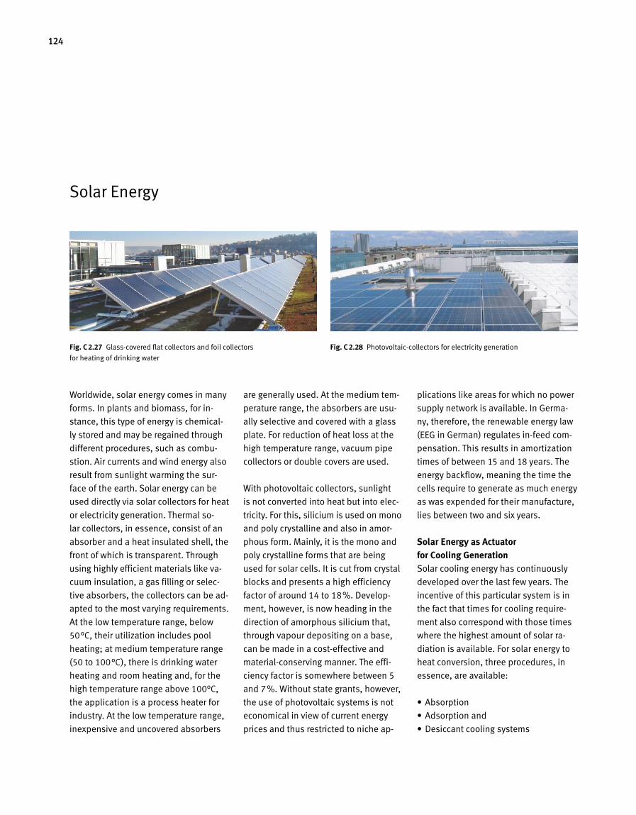
124
Solar Energy
Worldwide, solar energy comes in many
forms. In plants and biomass, for in
stance, this type of energy is chemical
ly stored and may be regained through
different procedures, such as combu
stion. Air currents and wind energy also
result from sunlight warming the sur
face of the earth. Solar energy can be
used directly via solar collectors for heat
or electricity generation. Thermal so
lar collectors, in essence, consist of an
absorber and a heat insulated shell, the
front of which is transparent. Through
using highly efficient materials like va
cuum insulation, a gas filling or selec
tive absorbers, the collectors can be ad
apted to the most varying requirements.
At the low tem perature range, below
50°C, their utilization includes pool
heating; at medium temperature range
(50 to 100°C), there is drinking water
heating and room heating and, for the
high temperature range above 100°C,
the application is a process heater for
industry. At the low temperature range,
inexpensive and uncovered absorbers
are generally used. At the medium tem
perature range, the absorbers are usu
ally selective and covered with a glass
plate. For reduction of heat loss at the
high temperature range, vacuum pipe
collectors or double covers are used.
With photovoltaic collectors, sunlight
is not converted into heat but into elec
tricity. For this, silicium is used on mono
and poly crystalline and also in amor
phous form. Mainly, it is the mono and
poly crystalline forms that are being
used for solar cells. It is cut from crystal
blocks and presents a high efficiency
factor of around 14 to 18%. Develop
ment, however, is now heading in the
direction of amorphous silicium that,
through vapour depositing on a base,
can be made in a costeffective and
materialconserving manner. The effi
ciency factor is somewhere between 5
and 7%. Without state grants, however,
the use of photovoltaic systems is not
economical in view of current energy
prices and thus restricted to niche ap
plications like areas for which no power
supply network is available. In Germa
ny, therefore, the renewable energy law
(EEG in German) regulates infeed com
pensation. This results in amortization
times of between 15 and 18 years. The
energy backflow, meaning the time the
cells require to generate as much energy
as was expended for their manufacture,
lies between two and six years.
Solar Energy as Actuator for Cooling GenerationSolar cooling energy has continuously
developed over the last few years. The
incentive of this particular system is in
the fact that times for cooling require
ment also correspond with those times
where the highest amount of solar ra
diation is available. For solar energy to
heat conversion, three procedures, in
essence, are available:
• Absorption
• Adsorption and
• Desiccant cooling systems
Fig. C 2.27 Glasscovered flat collectors and foil collectors
for heating of drinking water
Fig. C 2.28 Photovoltaiccollectors for electricity generation
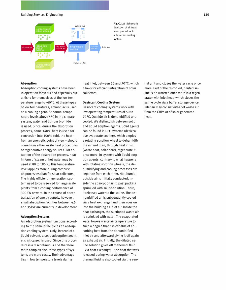
125Gebäudetechnik
AbsorptionAbsorption cooling systems have been
in operation for years and especially cut
a niche for themselves at the low tem-
perature range to –60°C. At these types
of low temperatures, ammoniac is used
as a cooling agent. At normal tempe-
rature levels above 5°C in the climate
system, water and lithium bromide
is used. Since, during the absorption
process, some 140% heat is used for
conversion into 100% cold, the heat –
from an energetic point of view – should
come from either waste heat procedures
or regenerative energy sources. For ac-
tuation of the absorption process, heat
in form of steam or hot water may be
used at 80 to 180°C. This temperature
level applies more during combusti-
on processes than for solar collectors.
The highly efficient trigeneration sys-
tem used to be reserved for large-scale
plants from a cooling performance of
300kW onward. In the course of decen-
tralization of energy supply, however,
small absorption facilities between 4.5
and 35kW are currently in development.
Adsorption SystemsAn adsorption system functions accord-
ing to the same principle as an absorp-
tion cooling system. Only, instead of a
liquid solvent, a solid adsorption agent,
e.g. silica gel, is used. Since this proce-
dure is a discontinuous and therefore
more complex one, these types of sys-
tems are more costly. Their advantage
lies in low temperature levels during
heat inlet, between 50 and 90°C, which
allows for efficient integration of solar
collectors.
Desiccant Cooling SystemDesiccant cooling systems work with
low operating temperatures of 50 to
90°C. Outside air is dehumidified and
cooled. We distinguish between solid
and liquid sorption agents. Solid agents
can be found in DEC systems (desicca-
tive evaporate cooling), which employ
a rotating sorption wheel to dehumidify
the air and then, through heat influx
(waste heat, solar heat), regenerate it
once more. In systems with liquid sorp-
tion agents, contrary to what happens
with rotating sorption wheels, the de-
humidifying and cooling processes are
separate from each other. Hot, humid
outside air is initially conducted, in-
side the absorption unit, past packing
sprinkled with saline-solution. There,
it releases water to the saline. The de-
humidified air is subsequently cooled
via a heat exchanger and then goes on
into the building as inlet air. Inside the
heat exchanger, the suctioned waste air
is sprinkled with water. The evaporated
water lowers waste air temperature to
such a degree that it is capable of ab-
sorbing heat from the dehumidified
inlet air and afterward giving it off again
as exhaust air. Initially, the diluted sa-
line solution gives off to thermal fluid
– via heat exchanger – the heat that was
released during water absorption. The
thermal fluid is also cooled via the cen-
tral unit and closes the water cycle once
more. Part of the re-cooled, diluted sa-
line is de-watered once more in a regen-
erator with inlet heat, which closes the
saline cycle via a buffer storage device.
Inlet air may consist either of waste air
from the CHPs or of solar generated
heat.
Fig. C 2.29 Schematic
depiction of air treat-
ment procedure in
a desiccant cooling
system
Outside Air Dry, warm outside Air
Dry, cool inlet Air
Evaporation cooling
Inlet Air
Waste AirConcentrated saline solution
Filling with carrier material
Diluted saline solution
Exhaust Air
Building Services Engineering
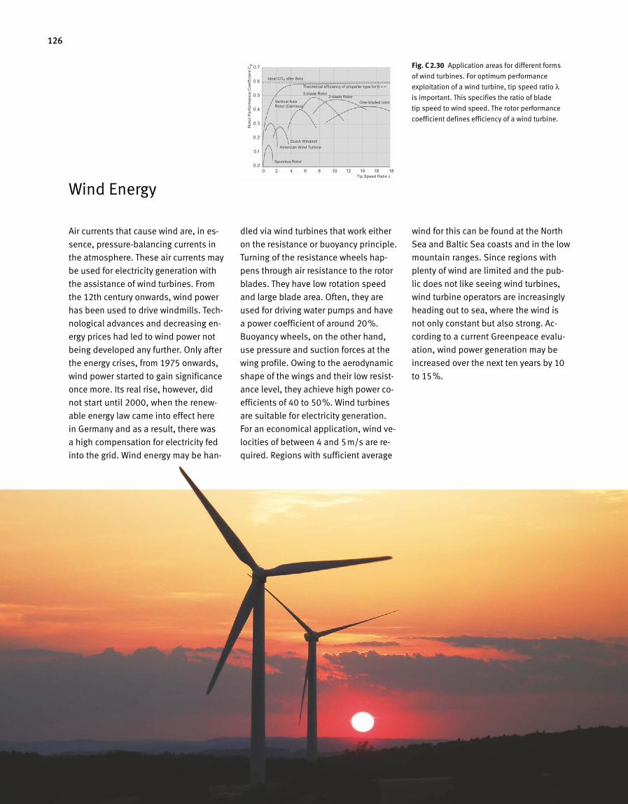
126
Air currents that cause wind are, in es-
sence, pressure-balancing currents in
the atmosphere. These air currents may
be used for electricity generation with
the assistance of wind turbines. From
the 12th century onwards, wind power
has been used to drive windmills. Tech-
nological advances and decreasing en-
ergy prices had led to wind power not
being developed any further. Only after
the energy crises, from 1975 onwards,
wind power started to gain significance
once more. Its real rise, however, did
not start until 2000, when the renew-
able energy law came into effect here
in Germany and as a result, there was
a high compensation for electricity fed
into the grid. Wind energy may be han-
dled via wind turbines that work either
on the resistance or buoyancy principle.
Turning of the resistance wheels hap-
pens through air resistance to the rotor
blades. They have low rotation speed
and large blade area. Often, they are
used for driving water pumps and have
a power coefficient of around 20%.
Buoyancy wheels, on the other hand,
use pressure and suction forces at the
wing profile. Owing to the aerodynamic
shape of the wings and their low resist-
ance level, they achieve high power co-
efficients of 40 to 50%. Wind turbines
are suitable for electricity generation.
For an economical application, wind ve-
locities of between 4 and 5m/s are re-
quired. Regions with sufficient average
wind for this can be found at the North
Sea and Baltic Sea coasts and in the low
mountain ranges. Since regions with
plenty of wind are limited and the pub-
lic does not like seeing wind turbines,
wind turbine operators are increasingly
heading out to sea, where the wind is
not only constant but also strong. Ac-
cording to a current Greenpeace evalu-
ation, wind power generation may be
increased over the next ten years by 10
to 15%.
Fig. C 2.30 Application areas for different forms
of wind turbines. For optimum performance
exploitation of a wind turbine, tip speed ratio λ
is important. This specifies the ratio of blade
tip speed to wind speed. The rotor performance
coefficient defines efficiency of a wind turbine.
Wind Energy0 2 4 6 8 10 12 14 16 18
0.7
0.6
0.5
0.4
0.3
0.2
0.1
0.0
Rot
or P
erfo
rman
ce C
oeffi
cien
t Cp
Tip Speed Ratio λ
Ideal COP after Betz
Vertical Axis Rotor (Darrieus)
3-blade Rotor
Dutch WindmillAmerican Wind Turbine
Savonius Rotor
2-blade RotorOne-bladed rotor
Theoretical efficiency of propeller type for E = ∞
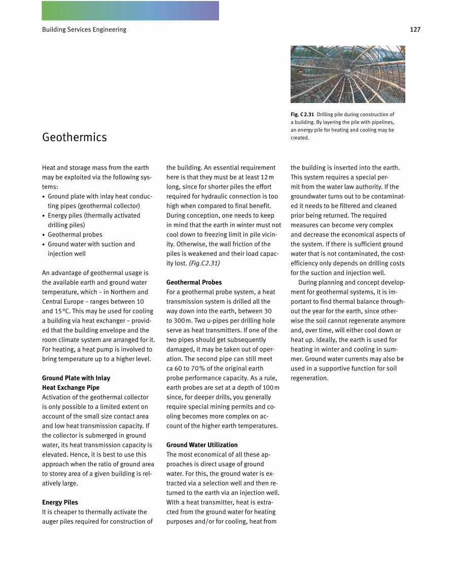
127Gebäudetechnik
Geothermics
Heat and storage mass from the earth
may be exploited via the following sys-
tems:
• Ground plate with inlay heat conduc-
ting pipes (geothermal collector)
• Energy piles (thermally activated
drilling piles)
• Geothermal probes
• Ground water with suction and
injection well
An advantage of geothermal usage is
the available earth and ground water
temperature, which – in Northern and
Central Europe – ranges between 10
and 15°C. This may be used for cooling
a building via heat exchanger – provid-
ed that the building envelope and the
room climate system are arranged for it.
For heating, a heat pump is involved to
bring temperature up to a higher level.
Ground Plate with Inlay Heat Exchange PipeActivation of the geothermal collector
is only possible to a limited extent on
account of the small size contact area
and low heat transmission capacity. If
the collector is submerged in ground
water, its heat transmission capacity is
elevated. Hence, it is best to use this
approach when the ratio of ground area
to storey area of a given building is rel-
atively large.
Energy PilesIt is cheaper to thermally activate the
auger piles required for construction of
the building. An essential requirement
here is that they must be at least 12m
long, since for shorter piles the effort
required for hydraulic connection is too
high when compared to final benefit.
During conception, one needs to keep
in mind that the earth in winter must not
cool down to freezing limit in pile vicin-
ity. Otherwise, the wall friction of the
piles is weakened and their load capac-
ity lost. (Fig.C 2.31)
Geothermal ProbesFor a geothermal probe system, a heat
transmission system is drilled all the
way down into the earth, between 30
to 300m. Two u-pipes per drilling hole
serve as heat transmitters. If one of the
two pipes should get subsequently
damaged, it may be taken out of oper-
ation. The second pipe can still meet
ca 60 to 70% of the original earth
probe performance capacity. As a rule,
earth probes are set at a depth of 100m
since, for deeper drills, you generally
require special mining permits and co-
oling becomes more complex on ac-
count of the higher earth temperatures.
Ground Water UtilizationThe most economical of all these ap-
proaches is direct usage of ground
water. For this, the ground water is ex-
tracted via a selection well and then re-
turned to the earth via an injection well.
With a heat transmitter, heat is extra-
cted from the ground water for heat ing
purposes and/or for cooling, heat from
Aufbau eines Energiepfahls
C3.28 11.12
Fig. C 2.31 Drilling pile during construction of
a building. By layering the pile with pipelines,
an energy pile for heating and cooling may be
created.
the building is inserted into the earth.
This system requires a special per-
mit from the water law authority. If the
groundwater turns out to be contaminat-
ed it needs to be filtered and cleaned
prior being returned. The required
measures can become very complex
and decrease the economical aspects of
the system. If there is sufficient ground
water that is not contaminated, the cost-
efficiency only depends on drilling costs
for the suction and injection well.
During planning and concept develop -
ment for geothermal systems, it is im-
portant to find thermal balance through-
out the year for the earth, since other-
wise the soil cannot regenerate anymore
and, over time, will either cool down or
heat up. Ideally, the earth is used for
heating in winter and cooling in sum-
mer. Ground water currents may also be
used in a supportive function for soil
regeneration.
Building Services Engineering
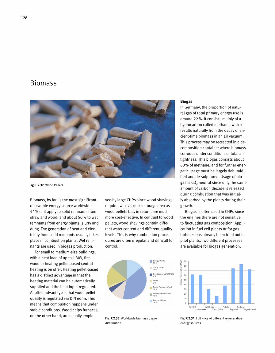
128
Biomass
Biomass, by far, is the most significant
renewable energy source worldwide.
44% of it apply to solid remnants from
straw and wood, and about 50% to wet
remnants from energy plants, slurry and
dung. The generation of heat and elec-
tricity from solid remnants usually takes
place in combustion plants. Wet rem-
nants are used in biogas production.
For small to medium-size buildings,
with a heat load of up to 1 MW, fire
wood or heating pellet based central
heating is on offer. Heating pellet-based
has a distinct advantage in that the
heating material can be automatically
supplied and the heat input regulated.
Another advantage is that wood pellet
quality is regulated via DIN norm. This
means that combustion happens under
stable conditions. Wood chips furnaces,
on the other hand, are usually emplo-
yed by large CHPs since wood shavings
require twice as much storage area as
wood pellets but, in return, are much
more cost-effective. In contrast to wood
pellets, wood shavings contain diffe-
rent water content and different quality
levels. This is why combustion proce-
dures are often irregular and difficult to
control.
BiogasIn Germany, the proportion of natu-
ral gas of total primary energy use is
around 22%. It consists mainly of a
hydrocarbon called methane, which
results naturally from the decay of an-
cient-time biomass in an air vacuum.
This process may be recreated in a de-
composition container where biomass
corrodes under conditions of total air
tightness. This biogas consists about
60% of methane, and for further ener-
getic usage must be largely dehumidi-
fied and de-sulphured. Usage of bio-
gas is CO2 neutral since only the same
amount of carbon dioxide is released
during combustion that was initial-
ly absorbed by the plants during their
growth.
Biogas is often used in CHPs since
the engines there are not sensitive
to fluctuating gas composition. Appli-
cation in fuel cell plants or for gas
turbines has already been tried out in
pilot plants. Two different processes
are available for biogas generation.
Fig. C 2.33 Worldwide biomass usage
distribution
Fig. C 2.34 Full Price of different regenerative
energy sources
Fig. C 2.32 Wood Pellets
Energy Plants 39 %
Slurry, Dung 11 %
Sewage and Landfill Gas 4 %
Other 2 %
Forest Remnant Wood 16 %
Other Remnant Wood 14 %
Remnant Straw 14 %
Full Oil Split Logs Pellets Biodiesel Natural Gas Wood Chips Rape Oil Vegetable Oil
90
80
70
60
50
40
30
20
10
0
Ener
gy P
rices
in E
uro/
MW
h
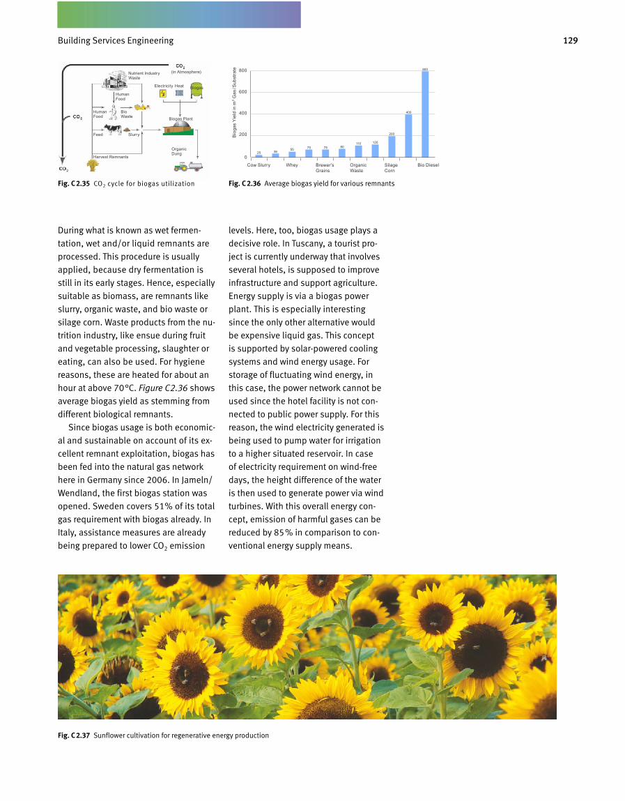
129Gebäudetechnik
During what is known as wet fermen-
tation, wet and/or liquid remnants are
processed. This procedure is usually
applied, because dry fermentation is
still in its early stages. Hence, especially
suita ble as biomass, are remnants like
slurry, organic waste, and bio waste or
silage corn. Waste products from the nu-
trition industry, like ensue during fruit
and vegetable processing, slaughter or
eating, can also be used. For hygiene
reasons, these are heated for about an
hour at above 70°C. Figure C2.36 shows
average biogas yield as stemming from
different biological remnants.
Since biogas usage is both economic-
al and sustainable on account of its ex-
cellent remnant exploitation, biogas has
been fed into the natural gas network
here in Germany since 2006. In Jameln/
Wendland, the first biogas station was
opened. Sweden covers 51% of its total
gas requirement with biogas already. In
Italy, assistance measures are already
being prepared to lower CO2 emission
levels. Here, too, biogas usage plays a
decisive role. In Tuscany, a tourist pro-
ject is currently underway that involves
several hotels, is supposed to improve
infrastructure and support agriculture.
Energy supply is via a biogas power
plant. This is especially interesting
since the only other alternative would
be expensive liquid gas. This concept
is supported by solar-powered cooling
systems and wind energy usage. For
storage of fluctuating wind energy, in
this case, the power network cannot be
used since the hotel facility is not con-
nected to public power supply. For this
reason, the wind electricity generated is
being used to pump water for irrigation
to a higher situated reservoir. In case
of electricity requirement on wind-free
days, the height difference of the water
is then used to generate power via wind
turbines. With this overall energy con-
cept, emission of harmful gases can be
reduced by 85% in comparison to con-
ventional energy supply means.
Fig. C 2.37 Sunflower cultivation for regenerative energy production
Fig. C 2.36 Average biogas yield for various remnantsFig. C 2.35 CO2 cycle for biogas utilization
Harvest Remnants
Feed
Human Food
Human Food
Nutrient Industry Waste
(in Atmosphere)
BiogasElectricity Heat
Biogas Plant
Bio Waste
Slurry
Organic Dung
Cow Slurry Whey Bio Diesel
800
600
400
200Bio
gas
Yie
ld in
m3 G
as / S
ubst
rate
Brewer’s Grains
Organic Waste
Silage Corn
Building Services Engineering
Commissioning
DC 3 DDDD
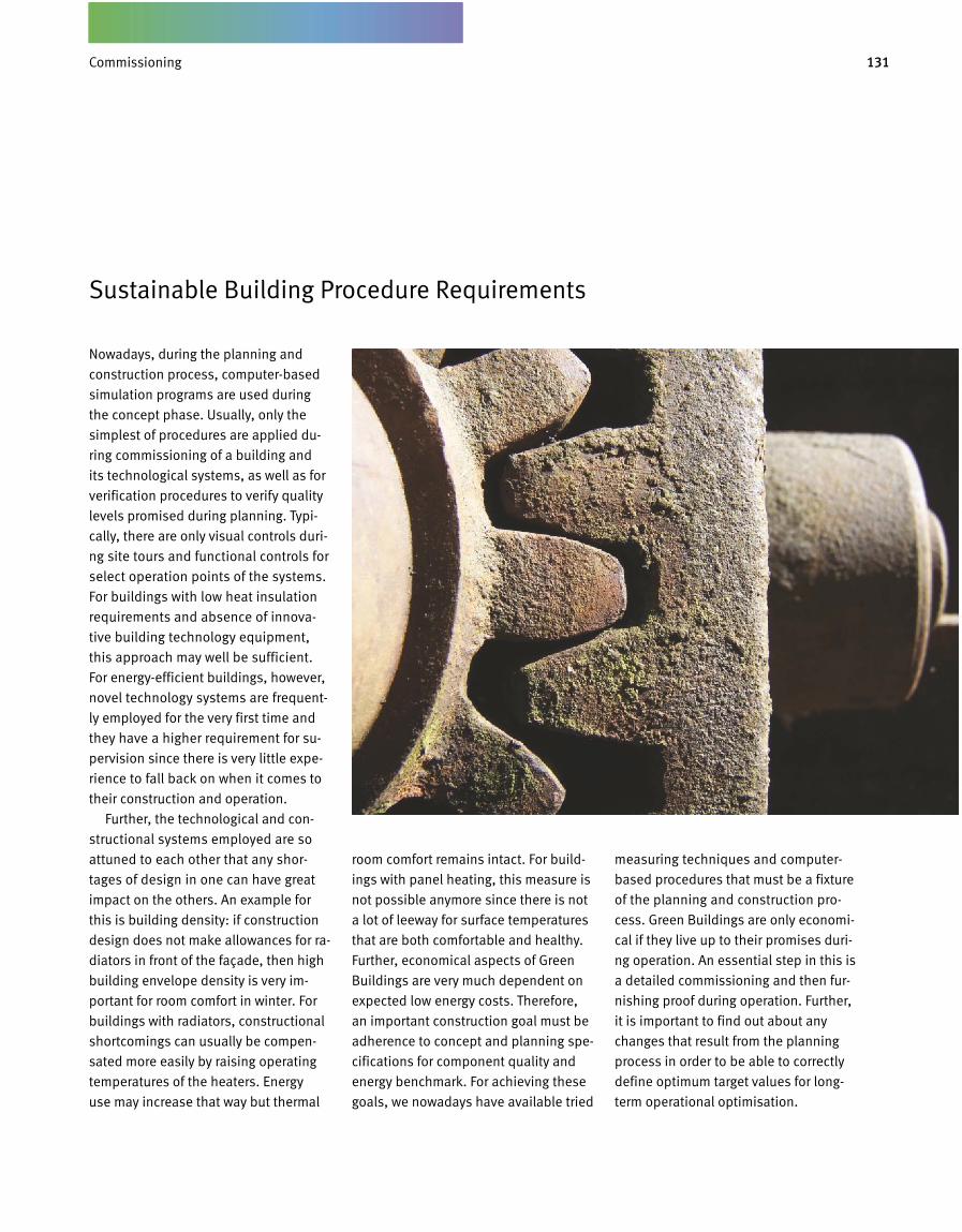
131Inbetriebnahme und Nachweisführung
Sustainable Building Procedure Requirements
Nowadays, during the planning and
construction process, computer-based
simulation programs are used during
the concept phase. Usually, only the
simplest of procedures are applied du-
ring commissioning of a building and
its technological systems, as well as for
verification procedures to verify quality
levels promised during planning. Typi-
cally, there are only visual controls duri-
ng site tours and functional con trols for
select operation points of the systems.
For buildings with low heat insulation
requirements and absence of innova-
tive building technology equipment,
this approach may well be sufficient.
For energy-efficient buildings, however,
novel technology systems are frequent-
ly employed for the very first time and
they have a higher requirement for su-
pervision since there is very little expe-
rience to fall back on when it comes to
their construction and operation.
Further, the technological and con-
structional systems employed are so
attuned to each other that any shor-
tages of design in one can have great
impact on the others. An example for
this is building density: if construction
design does not make allowances for ra-
diators in front of the façade, then high
building envelope density is very im-
portant for room comfort in winter. For
buildings with radiators, constructional
shortcomings can usually be compen-
sated more easily by raising operating
temperatures of the heaters. Energy
use may increase that way but thermal
room comfort remains intact. For build-
ings with panel heating, this measure is
not possible anymore since there is not
a lot of leeway for surface temperatures
that are both comfortable and healthy.
Further, economical aspects of Green
Buildings are very much dependent on
expected low energy costs. Therefore,
an important construction goal must be
adherence to concept and planning spe-
cifications for component quality and
energy benchmark. For achieving these
goals, we nowadays have available tried
measuring techniques and computer-
based procedures that must be a fixture
of the planning and construction pro-
cess. Green Buildings are only economi-
cal if they live up to their promises duri-
ng operation. An essential step in this is
a detailed commissioning and then fur-
nishing proof during operation. Further,
it is important to find out about any
changes that result from the planning
process in order to be able to correctly
define optimum target values for long-
term operational optimisation.
C5.01 18.12
Commissioning
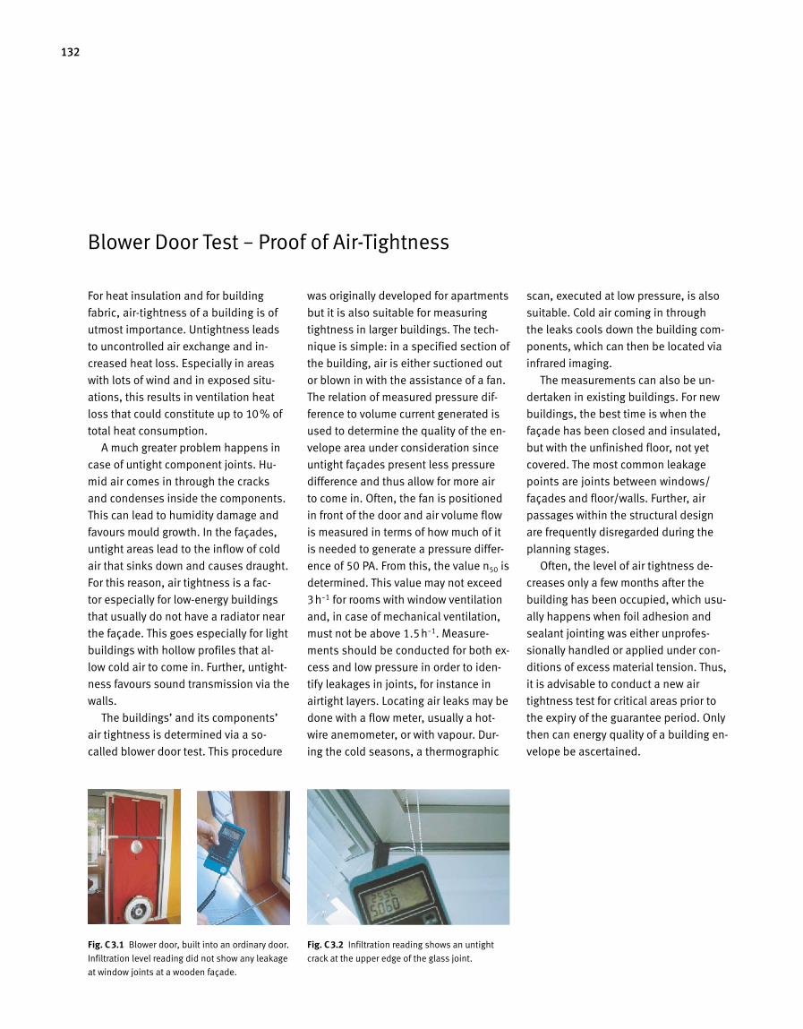
132
Blower Door Test – Proof of Air-Tightness
For heat insulation and for building
fabric, air-tightness of a building is of
utmost importance. Untightness leads
to uncontrolled air exchange and in-
creased heat loss. Especially in areas
with lots of wind and in exposed situ-
ations, this results in ventilation heat
loss that could constitute up to 10% of
total heat consumption.
A much greater problem happens in
case of untight component joints. Hu-
mid air comes in through the cracks
and condenses inside the components.
This can lead to humidity damage and
favours mould growth. In the façades,
untight areas lead to the inflow of cold
air that sinks down and causes draught.
For this reason, air tightness is a fac-
tor especially for low-energy buildings
that usually do not have a radiator near
the façade. This goes especially for light
buildings with hollow profiles that al-
low cold air to come in. Further, untight-
ness favours sound transmission via the
walls.
The buildings’ and its components’
air tightness is determined via a so-
called blower door test. This procedure
was originally developed for apartments
but it is also suitable for measuring
tightness in larger buildings. The tech-
nique is simple: in a specified section of
the building, air is either suctioned out
or blown in with the assistance of a fan.
The relation of measured pressure dif-
ference to volume current generated is
used to determine the quality of the en-
velope area under consideration since
untight façades present less pressure
difference and thus allow for more air
to come in. Often, the fan is positioned
in front of the door and air volume flow
is measured in terms of how much of it
is needed to generate a pressure differ-
ence of 50 PA. From this, the val ue n50 is
determined. This value may not exceed
3h-1 for rooms with window ventilation
and, in case of mechanical ventilation,
must not be above 1.5h-1. Measure-
ments should be conducted for both ex-
cess and low pressure in order to iden-
tify leakages in joints, for instance in
airtight layers. Locating air leaks may be
done with a flow meter, usually a hot-
wire anemometer, or with vapour. Dur-
ing the cold seasons, a thermographic
scan, executed at low pressure, is also
suitable. Cold air coming in through
the leaks cools down the build ing com-
ponents, which can then be located via
infrared imaging.
The measurements can also be un-
dertaken in existing buildings. For new
buildings, the best time is when the
façade has been closed and insulated,
but with the unfinished floor, not yet
covered. The most common leakage
points are joints between windows/
façades and floor/walls. Further, air
passages within the structural design
are frequently disregarded during the
planning stages.
Often, the level of air tightness de-
creases only a few months after the
building has been occupied, which usu-
ally happens when foil adhesion and
sealant jointing was either unprofes-
sionally handled or applied under con-
ditions of excess material tension. Thus,
it is ad visable to conduct a new air
tightness test for critical areas prior to
the expiry of the guarantee period. Only
then can energy quality of a building en-
velope be ascertained.
Einbausituation der Blower Door in einer Tür
C5.02 18,12 Fig. C 3.1 Blower door, built into an ordinary door.
Infiltration level reading did not show any leakage
at window joints at a wooden façade.
Fig. C 3.2 Infiltration reading shows an untight
crack at the upper edge of the glass joint.

133Inbetriebnahme und Nachweisführung
Thermography – Proof of Thermal Insulation and Evidence of Active Systems
Over the last few years, thermography
has become a multifunctional tool for
construction applications. For new build
ings, it often serves as a control tool for
the building envelope and for heating
and cooling systems. During revitaliza
tions, the images allow for swift analy
sis of building envelope quality lev
els and for location of hidden heating
ducts.
A high quality building envelope,
with respect to heat insulation, is a
prerequisite for lower heating energy
consumption and, hence, for energy ef
ficiency. There should also be as few
thermal bridges as possible. The con
struction management conducts visual
controls to this end. However, this can
not determine whether the specified
quality levels and values that were pre
viously measured in the laboratory are
actually obtained for the various as
sembly groups after completion. With
an infrared camera, images of surface
temperature course can be obtained.
»Backward calculations« are then ap
plied to determine the level of insula
tion quality and also the number of
thermal bridges present. Weak points,
which can be identified with a thermo
graphic camera, can often lead either
to unwanted energy loss or to below
freezing temperatures in the building
interior. Hence, through early use of this
technology, financial and constructional
damage can be prevented in time. The
new buildings of the LBBW in Stuttgart/
Germany had their façades subject
ed – after completion – to random air
tightness tests and also to a fullscale
thermographic imaging. These types of
controls were part of the encompassing
inspections and of the commissioning
procedure. In this case, a high energy
quality of the building was proven (Fig-
ure C3.3).
In a supportive function, thermogra
phy may also be applied during Blower
Door tests. This applies especially in
cases when the inlet air passage via
the façade cannot be absolutely traced
during the blowerdoor test. Infrared
images clearly show air leakage for win
dows, doors and glass façades, which
means that also the air tightness levels
of small façade areas may be precisely
evaluated.
Panel heating and cooling systems
have low operating temperatures for
heating and high ones for cooling. This
means that manual function control
becomes impossible. Further, it is not
only sheer surface temperature but also
an even perfusion level that is of impor
tance for optimum operation conditions.
Infrared images allow for swift identifi
cation of correct surface activation with
the correct homogenous temperature
distribution level (Figure C3.4). For new
and existing buildings, thermography
offers the opportunity of widearea
façade imaging that, in turn, allows for
analysis of heat insula tion levels and
leakages and for im plementation, on
that basis, of energypreserving meas
ures. To this end, simulation calculation
results are compared to those obtained
from thermographic imaging and then
adjusted accordingly. This allows for
practiceoriented, concrete conclusions
to be drawn for energy consumption
and energy cost savings.
Fig. C 3.3 Infrared imaging shows that the sup
ports penetration of an overhanging ceiling does
not cause thermal bridges
Fig. C 3.4 Thanks to infrared technology, load
conditions of thermally activated components
can be determined via surface temperatures
At start
75 minutes after target value adjustment
Commissioning
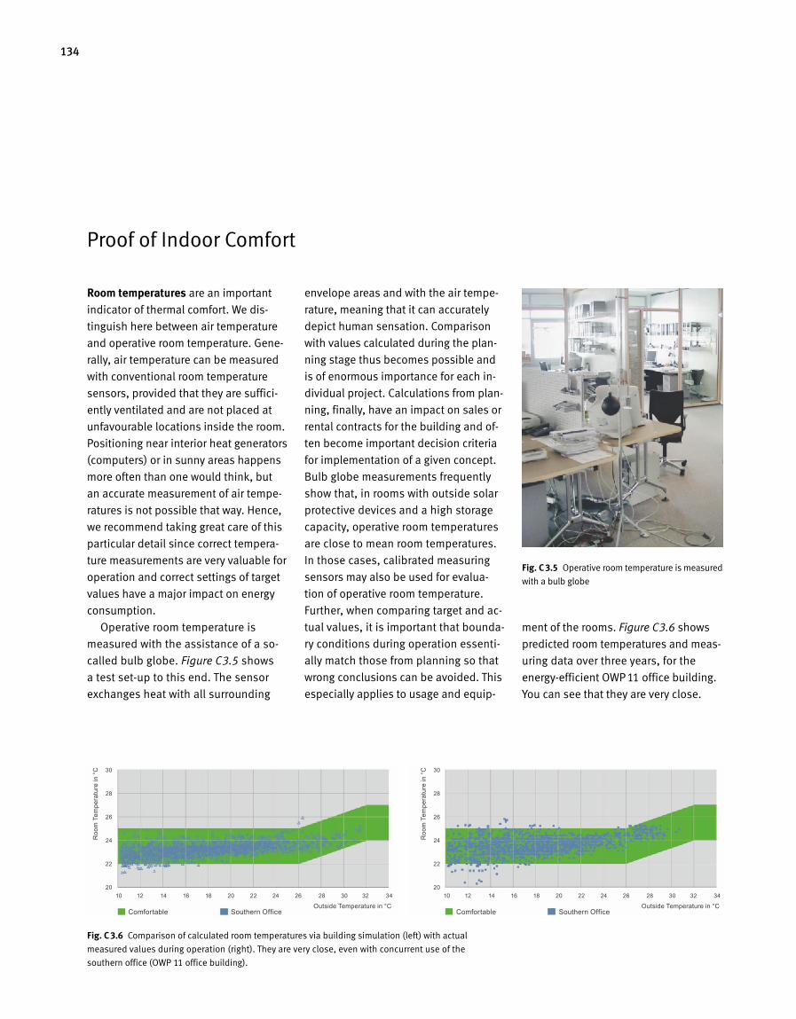
134
Proof of Indoor Comfort
Room temperatures are an important
indicator of thermal comfort. We dis
tinguish here between air temperature
and operative room temperature. Gene
rally, air temperature can be measured
with conventional room temperature
sensors, provided that they are suffici
ently ventilated and are not placed at
unfavourable locations inside the room.
Positioning near interior heat generators
(computers) or in sunny areas happens
more often than one would think, but
an accurate measurement of air tempe
ratures is not possible that way. Hence,
we recommend taking great care of this
particular detail since correct tempera
ture measurements are very valuable for
operation and correct settings of target
values have a major impact on energy
consumption.
Operative room temperature is
mea s ured with the assistance of a so
called bulb globe. Figure C3.5 shows
a test setup to this end. The sensor
ex changes heat with all surrounding
en velope areas and with the air tempe
rature, meaning that it can accurately
depict human sensation. Comparison
with values calculated during the plan
ning stage thus becomes possible and
is of enormous importance for each in
dividual project. Calculations from plan
ning, finally, have an impact on sales or
rental contracts for the building and of
ten become important decision criteria
for implementation of a given concept.
Bulb globe measurements frequently
show that, in rooms with outside solar
protective devices and a high storage
capacity, operative room temperatures
are close to mean room temperatures.
In those cases, calibrated measuring
sensors may also be used for evalua
tion of operative room temperature.
Further, when comparing target and ac
tual values, it is important that bounda
ry conditions during operation essenti
ally match those from planning so that
wrong conclusions can be avoided. This
especially applies to usage and equip
ment of the rooms. Figure C3.6 shows
predicted room temperatures and meas
uring data over three years, for the
energyefficient OWP 11 office building.
You can see that they are very close.
Fig. C 3.6 Comparison of calculated room temperatures via building simulation (left) with actual
measured values during operation (right). They are very close, even with concurrent use of the
southern office (OWP 11 office building).
Fig. C 3.5 Operative room temperature is meas ured
with a bulb globe
10 12 14 16 18 20 22 24 26 28 30 32 34 10 12 14 16 18 20 22 24 26 28 30 32 34
Comfortable Southern Office Comfortable Southern Office
30
28
26
24
22
20
30
28
26
24
22
20
Roo
m T
empe
ratu
re in
°C
Roo
m T
empe
ratu
re in
°C
Outside Temperature in °C Outside Temperature in °C
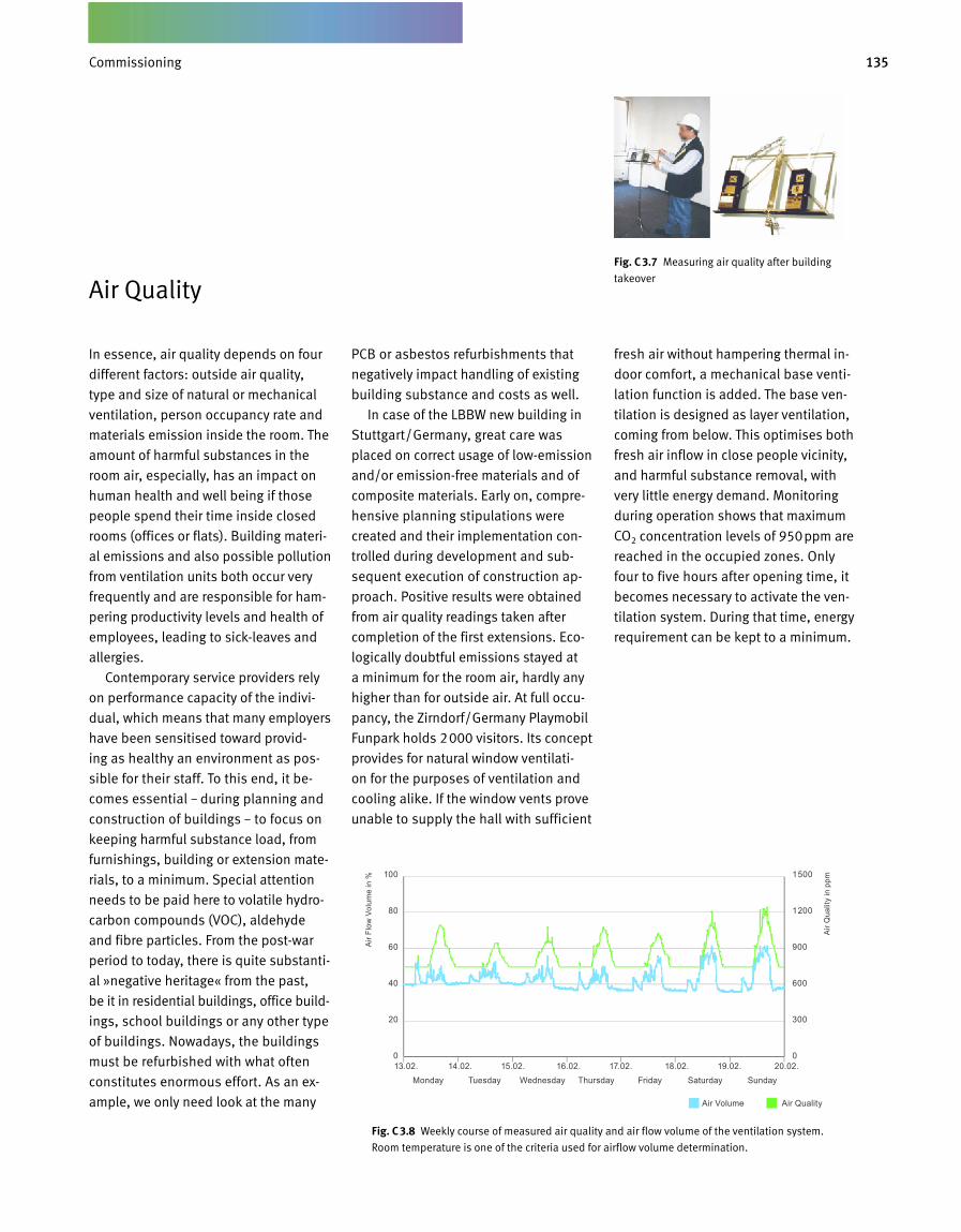
135Inbetriebnahme und Nachweisführung
In essence, air quality depends on four
different factors: outside air quality,
type and size of natural or mechanical
ventilation, person occupancy rate and
materials emission inside the room. The
amount of harmful substances in the
room air, especially, has an impact on
human health and well being if those
people spend their time inside closed
rooms (offices or flats). Building materi
al emissions and also possible pollution
from ventilation units both occur very
frequently and are responsible for ham
pering productivity levels and health of
employees, leading to sickleaves and
allergies.
Contemporary service providers rely
on performance capacity of the indivi
dual, which means that many employers
have been sensitised toward provid
ing as healthy an environment as pos
sible for their staff. To this end, it be
comes essential – during planning and
construction of buildings – to focus on
keeping harmful substance load, from
furnishings, building or extension mate
rials, to a minimum. Special attention
needs to be paid here to volatile hydro
carbon compounds (VOC), aldehyde
and fibre particles. From the postwar
period to today, there is quite substanti
al »negative heritage« from the past,
be it in residential buildings, office build
ings, school buildings or any other type
of buildings. Nowadays, the buildings
must be refurbished with what often
constitutes enormous effort. As an ex
ample, we only need look at the many
PCB or asbestos refurbishments that
negatively impact handling of existing
building substance and costs as well.
In case of the LBBW new building in
Stuttgart/Germany, great care was
placed on correct usage of lowemission
and/or emissionfree materials and of
composite materials. Early on, compre
hensive planning stipulations were
cre ated and their implementation con
trolled during development and sub
sequent execution of construction ap
proach. Positive results were obtained
from air quality readings taken after
completion of the first extensions. Eco
logically doubtful emissions stayed at
a minimum for the room air, hardly any
higher than for outside air. At full occu
pancy, the Zirndorf/Germany Playmobil
Funpark holds 2000 visitors. Its concept
provides for natural window ventilati
on for the purposes of ventilation and
cooling alike. If the window vents prove
unable to supply the hall with sufficient
fresh air without hampering thermal in
door comfort, a mechanical base venti
lation function is added. The base ven
tilation is designed as layer ventilation,
coming from below. This optimises both
fresh air inflow in close people vicinity,
and harmful substance removal, with
very little energy demand. Monitoring
during operation shows that maximum
CO2 concentration levels of 950ppm are
reached in the occupied zones. Only
four to five hours after opening time, it
becomes necessary to activate the ven
tilation system. During that time, energy
requirement can be kept to a minimum.
Fig. C 3.7 Measuring air quality after building
takeover
Fig. C 3.8 Weekly course of measured air quality and air flow volume of the ventilation system.
Room temperature is one of the criteria used for airflow volume determination.
Air Quality
13.02. 14.02. 15.02. 16.02. 17.02. 18.02. 19.02. 20.02.Monday Tuesday Wednesday Thursday Friday Saturday Sunday
100
80
60
40
20
0
1500
1200
900
600
300
0
Air
Flow
Vol
ume
in %
Air
Qua
lity
in p
pm
Air Volume Air Quality
Commissioning
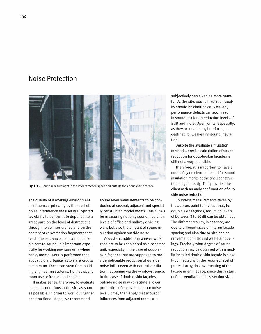
136
Noise Protection
The quality of a working environment
is influenced primarily by the level of
noise interference the user is subjected
to. Ability to concentrate depends, to a
great part, on the level of distractions
through noise interference and on the
content of conversation fragments that
reach the ear. Since man cannot close
his ears to sound, it is important espe-
cially for working environments where
heavy mental work is performed that
ac oustic disturbance factors are kept to
a minimum. These can stem from build-
ing engineering systems, from adjacent
room use or from outside noise.
It makes sense, therefore, to evaluate
acoustic conditions at the site as soon
as possible. In order to work out further
constructional steps, we recommend
sound level measurements to be con-
ducted at several, adjacent and special-
ly constructed model rooms. This allows
for measuring not only sound insulation
levels of office and hallway dividing
walls but also the amount of sound in-
sulation against outside noise.
Acoustic conditions in a given work
zone are to be considered as a coherent
unit, especially in the case of double-
skin façades that are supposed to pro-
vide noticeable reduction of outside
noise influx even with natural ventila-
tion happening via the windows. Since,
in the case of double-skin façades,
outside noise may constitute a lower
propor tion of the overall indoor noise
level, it may then apply that acoustic
influences from adjacent rooms are
subjectively perceived as more harm-
ful. At the site, sound insulation qual-
ity should be clarified early on. Any
performance defects can soon result
in sound insulation reduction levels of
5dB and more. Open joints, especially,
as they occur at many interfaces, are
destined for weakening sound insula-
tion.
Despite the available simulation
methods, precise calculation of sound
reduction for double-skin façades is
still not always possible.
Therefore, it is important to have a
model façade element tested for sound
insulation merits at the shell construc-
tion stage already. This provides the
client with an early confirmation of out-
side noise reduction.
Countless measurements taken by
the authors point to the fact that, for
double skin façades, reduction levels
of between 3 to 10dB can be obtained.
The different results, in essence, are
due to different sizes of interim façade
spacing and also due to size and ar-
rangement of inlet and waste air open-
ings. Precisely what degree of sound
reduction may be obtained with a read-
ily installed double-skin façade is close-
ly connected with the required level of
protection against overheating of the
façade interim space, since this, in turn,
defines ventilation cross-section size.
Fig. C 3.9 Sound Measurement in the interim façade space and outside for a double-skin façade
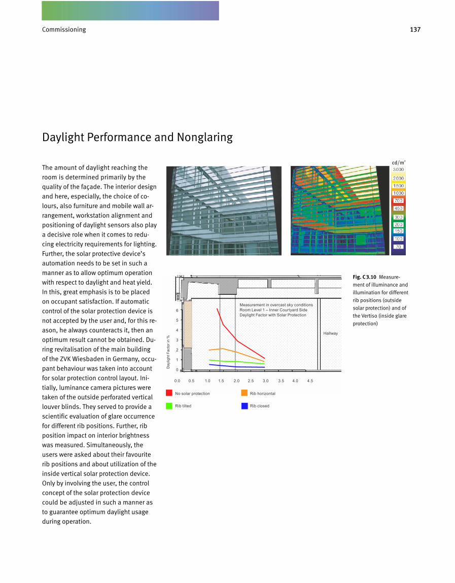
137Inbetriebnahme und Nachweisführung
Daylight Performance and Nonglaring
The amount of daylight reaching the
room is determined primarily by the
quality of the façade. The interior design
and here, especially, the choice of co-
lours, also furniture and mobile wall ar-
rangement, workstation alignment and
positioning of daylight sensors also play
a decisive role when it comes to redu-
cing electricity requirements for lighting.
Further, the solar protective device’s
automation needs to be set in such a
manner as to allow optimum operation
with respect to daylight and heat yield.
In this, great emphasis is to be placed
on occupant satisfaction. If automatic
control of the solar protection device is
not accepted by the user and, for this re-
ason, he always counteracts it, then an
optimum result cannot be obtained. Du-
ring revitalisation of the main building
of the ZVK Wiesbaden in Germany, occu-
pant behaviour was taken into account
for solar protection control layout. Ini-
tially, luminance camera pictures were
taken of the outside perforated vertical
louver blinds. They served to provide a
scientific evaluation of glare occurrence
for different rib positions. Further, rib
position impact on interior brightness
was measured. Simultaneously, the
users were asked about their favourite
rib positions and about utilization of the
inside vertical solar protection device.
Only by involving the user, the control
concept of the solar protection device
could be adjusted in such a manner as
to guarantee optimum daylight usage
during operation.
Fig. C 3.10 Measure-
ment of illuminance and
illumination for different
rib positions (outside
solar protection) and of
the Vertiso (inside glare
protection)
cd/m2
0.0 0.5 1.0 1.5 2.0 2.5 3.0 3.5 4.0 4.5
6
5
4
3
2
1
0Day
light
Fac
tor i
n %
No solar protection Rib horizontal
Rib tilted Rib closed
Measurement in overcast sky conditionsRoom Level 1 – Inner Courtyard SideDaylight Factor with Solar Protection
Hallway
Commissioning
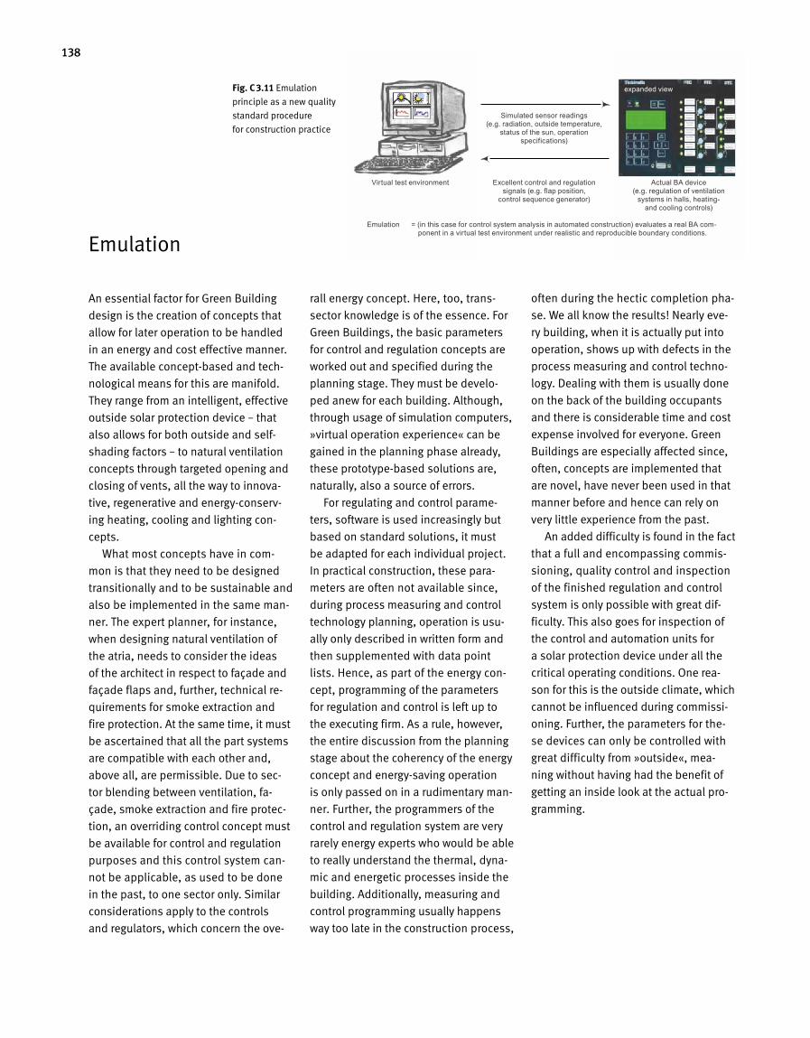
138
Emulation
An essential factor for Green Building
design is the creation of concepts that
allow for later operation to be handled
in an energy and cost effective manner.
The available concept-based and tech-
nological means for this are manifold.
They range from an intelligent, effective
outside solar protection device – that
also allows for both outside and self-
shading factors – to natural ventilation
concepts through targeted opening and
closing of vents, all the way to innova-
tive, regenerative and energy-conserv-
ing heating, cooling and lighting con-
cepts.
What most concepts have in com-
mon is that they need to be designed
transitionally and to be sustainable and
also be implemented in the same man-
ner. The expert planner, for instance,
when designing natural ventilation of
the atria, needs to consider the ideas
of the architect in respect to façade and
façade flaps and, further, technical re-
quirements for smoke extraction and
fire protection. At the same time, it must
be ascertained that all the part systems
are compatible with each other and,
above all, are permissible. Due to sec-
tor blending between ventilation, fa-
çade, smoke extraction and fire protec-
tion, an overriding control concept must
be available for control and regulation
purposes and this control system can-
not be applicable, as used to be done
in the past, to one sector only. Similar
consi de rations apply to the controls
and regulators, which concern the ove-
rall energy concept. Here, too, trans-
sec tor knowledge is of the essence. For
Green Build ings, the basic parameters
for control and regulation concepts are
worked out and specified during the
planning stage. They must be develo-
ped anew for each building. Although,
through usage of simulation computers,
»virtual operation experience« can be
gained in the planning phase already,
these prototype-based solutions are,
naturally, also a source of errors.
For regulating and control parame-
ters, software is used increasingly but
based on standard solutions, it must
be adapted for each individual project.
In practical construction, these para-
meters are often not available since,
during process measuring and control
technology planning, operation is usu-
ally only described in written form and
then supplemented with data point
lists. Hence, as part of the energy con-
cept, programming of the parameters
for regulation and control is left up to
the ex ecuting firm. As a rule, however,
the entire discussion from the planning
stage about the coherency of the energy
concept and energy-saving opera tion
is only passed on in a rudimentary man-
ner. Further, the programmers of the
control and regulation system are very
rarely energy experts who would be able
to really understand the thermal, dyna-
mic and energetic processes inside the
building. Additionally, measuring and
control programming usually happens
way too late in the con struction process,
often during the hectic completion pha-
se. We all know the results! Nearly eve-
ry building, when it is actually put into
operation, shows up with defects in the
process measuring and control techno-
logy. Dealing with them is usually done
on the back of the building occupants
and there is considerable time and cost
expense involved for everyone. Green
Buildings are especially affected since,
often, concepts are implemented that
are novel, have never been used in that
manner before and hence can rely on
very little experience from the past.
An added difficulty is found in the fact
that a full and encompassing commis-
sioning, quality control and inspection
of the finished regulation and control
system is only possible with great dif-
ficulty. This also goes for inspection of
the control and automation units for
a solar protection device under all the
critical operating conditions. One rea-
son for this is the outside climate, which
can not be influenced during commissi-
oning. Fur ther, the parameters for the-
se devices can only be controlled with
great difficulty from »outside«, mea-
ning without having had the benefit of
getting an inside look at the actual pro-
gramming.
Fig. C 3.11 Emulation
principle as a new quality
standard procedure
for construction practice
Virtual test environment
expanded view
Emulation = (in this case for control system analysis in automated construction) evaluates a real BA com - ponent in a virtual test environment under realistic and reproducible boundary conditions.
Simulated sensor readings (e.g. radiation, outside temperature,
status of the sun, operation specifications)
Excellent control and regulation signals (e.g. flap position,
control sequence generator)
Actual BA device (e.g. regulation of ventilation
systems in halls, heating- and cooling controls)
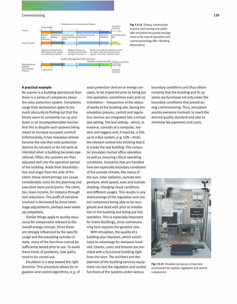
139Inbetriebnahme und Nachweisführung
A practical exampleNo sooner is a building operational than
there is a series of complaints about
the solar protection system. Complaints
range from workstation glare to too
much obscurity to finding out that the
blinds seem to constantly run up and
down in an incomprehensible manner.
And this is despite such systems being
meant to increase occupant comfort!
Unfortunately, it has nowadays almost
become the rule that solar protection
devices do not work or do not work as
intended when a building becomes ope-
rational. Often, the systems are then
adjusted well into the operation period
of the building. Aside from dissatisfac-
tion and anger from the side of the
client, these shortcomings can cause
considerable costs for the planning and
execution team participants. The client,
too, loses income, for instance through
rent reductions. The profit of everyone
involved is decreased by these latter-
stage adjustments, perhaps even eaten
up completely.
Similar things apply to quality assu-
rance for components relevant to the
overall energy concept. Since these
are strongly influenced by the specific
usage and the prevailing outside cli-
mate, many of the functions cannot be
sufficiently tested prior to use. To avoid
these kinds of problems, new paths
need to be carved out.
Emulation is a step toward the right
direction. This procedure allows for re-
gulation and control algorithms, e.g. of
solar protection devices or energy con-
cepts, to be inspected prior to being put
into operation, sometimes even prior to
installation – irrespective of the status
of works at the building site. During the
emulation process, control and regula-
tion devices are integrated into a virtual
test setting. The test setting – which, in
essence, consists of a computer, rea-
ders and loggers and, if need be, a link-
up to a Bus system, e.g. LON – tricks
the relevant control into think ing that it
is inside the real building. The compu-
ter simulates normal office operation
as well as choosing critical operating
conditions. Scenarios that are handled
here are especially boundary conditions
of the outside climate, like status of
the sun, solar radiation, outside tem-
perature, wind speed, auto and outside
shading, changing cloud conditions
and different usages. This results in any
shortcomings of the regulation and con-
trol component being able to be reco-
gnized and dealt with prior to installa-
tion in the building and being put into
operation. This is especially important
for Green Buildings, since commissio-
ning here requires the greatest care.
With emulation, the quality of a
building also improves, which consti-
tutes an advantage for everyone invol-
ved. Clients, users and tenants are pro-
vided with a functional building right
from the start. The architect and the
planners of the building services equip-
ment can test the regulation and control
functions of the systems under various
boundary conditions and thus obtain
certainty that the building and its sy-
stems are functional not only under the
boundary conditions that prevail du-
ring commissioning. Thus, emulation
assists everyone involved: to reach the
desired quality standard and also to
minimise fee payments and costs.
Fig. C 3.12 Theory, construction
practice and carving new paths
with emulation for quality manage-
ment in the area of regulation and
control technology (BA = Building
Automation)
Fig. C 3.13 Emulator set-up as a virtual test
environment for realistic regulation and control
components
Timeframe of a Construction Project
Quality Management with Emulation
Project Start
Project Start
Theory
Usual Practice
D&S Advanced Build ing Technologies Practice
Prelimi-nary Planning
During commissioning, BA functions are usually not sufficiently verified
Negative impact on occupant comfort and energy consumption
Plenty of trouble and additional costs for clients, planners and executive agents, even after operation start
Schematic Design
Construction Documentation (CD)
Handover Deadline
Commissioning BA
?????
Optimum operating conditions
Parallel commissioning BA
Commissioning and Inspection
Handover Deadline
Handover Deadline
Commissioning
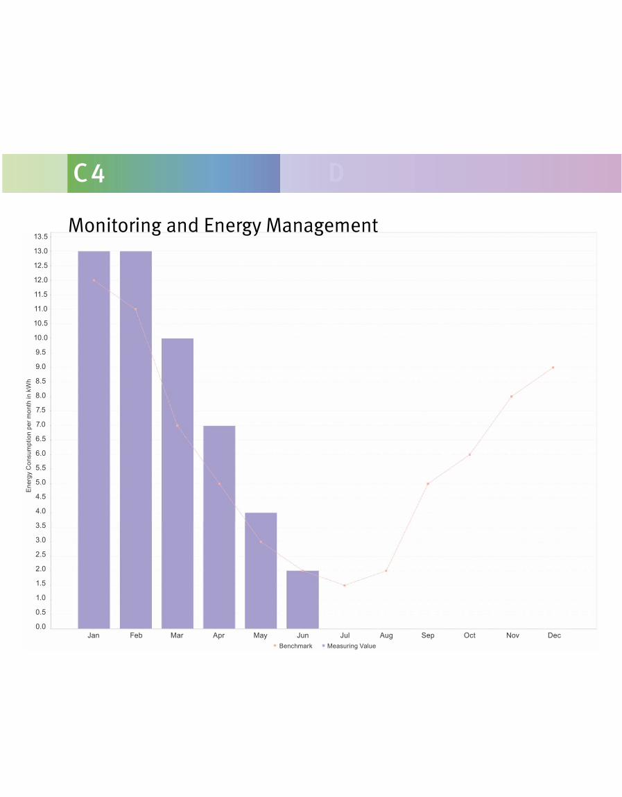
C 4 D
Monitoring and Energy Management13.5
13.0
12.5
12.0
11.5
11.0
10.5
10.0
9.5
9.0
8.5
8.0
7.5
7.0
6.5
6.0
5.5
5.0
4.5
4.0
3.5
3.0
2.5
2.0
1.5
1.0
0.5
0.0
Ener
gy C
onsu
mpt
ion
per m
onth
in k
Wh
Benchmark Measuring ValueJan Feb Mar Apr May Jun Jul Aug Sep Oct Nov Dec
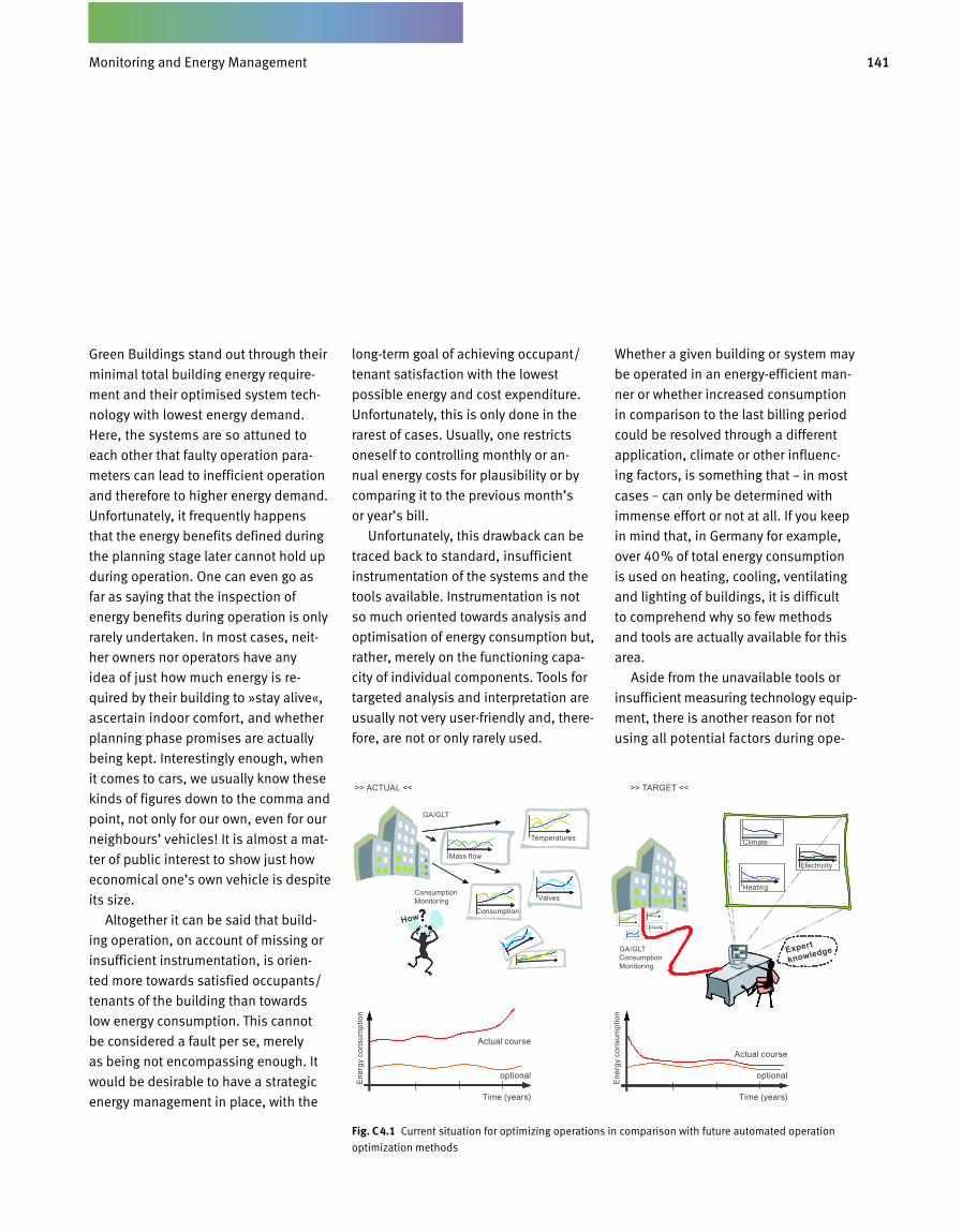
141Betriebsbegleitendes Energiemanagement
Green Buildings stand out through their
minimal total building energy require
ment and their optimised system tech
nology with lowest energy demand.
Here, the systems are so attuned to
each other that faulty operation para
meters can lead to inefficient operation
and therefore to higher energy demand.
Unfortunately, it frequently happens
that the energy benefits defined during
the planning stage later cannot hold up
during operation. One can even go as
far as saying that the inspection of
energy benefits during operation is only
rarely undertaken. In most cases, neit
her owners nor operators have any
idea of just how much energy is re
quired by their building to »stay alive«,
ascertain indoor comfort, and whether
planning phase promises are actua lly
being kept. Interestingly enough, when
it comes to cars, we usually know the se
kinds of figures down to the comma and
point, not only for our own, even for our
neighbours’ vehicles! It is almost a mat
ter of public interest to show just how
economical one’s own vehicle is despite
its size.
Altogether it can be said that build
ing operation, on account of missing or
insufficient instrumentation, is orien
ted more towards satisfied occupants/
tenants of the building than towards
low energy consumption. This cannot
be considered a fault per se, merely
as being not encompassing enough. It
would be desirable to have a strategic
energy management in place, with the
longterm goal of achieving occupant/
tenant satisfaction with the lowest
pos sible energy and cost expenditure.
Unfortunately, this is only done in the
rarest of cases. Usually, one restricts
oneself to controlling monthly or an
nual energy costs for plausibility or by
comparing it to the previous month’s
or year’s bill.
Unfortunately, this drawback can be
traced back to standard, insufficient
instrumentation of the systems and the
tools available. Instrumentation is not
so much oriented towards analysis and
optimisation of energy consumption but,
rather, merely on the functioning capa
city of individual components. Tools for
targeted analysis and interpretation are
usually not very userfriendly and, there
fore, are not or only rarely used.
Whether a given building or system may
be operated in an energyefficient man
ner or whether increased consumption
in comparison to the last billing period
could be resolved through a different
application, climate or other influenc
ing factors, is something that – in most
cases – can only be determined with
immense effort or not at all. If you keep
in mind that, in Germany for ex ample,
over 40% of total energy consumption
is used on heating, cooling, ventilating
and lighting of buildings, it is difficult
to comprehend why so few methods
and tools are actually available for this
area.
Aside from the unavailable tools or
insufficient measuring technology equip
ment, there is another reason for not
using all potential factors during ope
Fig. C 4.1 Current situation for optimizing operations in comparison with future automated operation
optimization methods
Monitoring and Energy Management
Ener
gy c
onsu
mpt
ion
Ener
gy c
onsu
mpt
ion
Actual courseActual course
optional
GA/GLT Consumption Monitoring
GA/GLT
Consumption Monitoring
>> TARGET <<>> ACTUAL <<
Climate
Heating
Mass flow
Consumption
Temperatures
Valves
Electricity
Expert
knowledge
How
Time (years)
optional
Time (years)
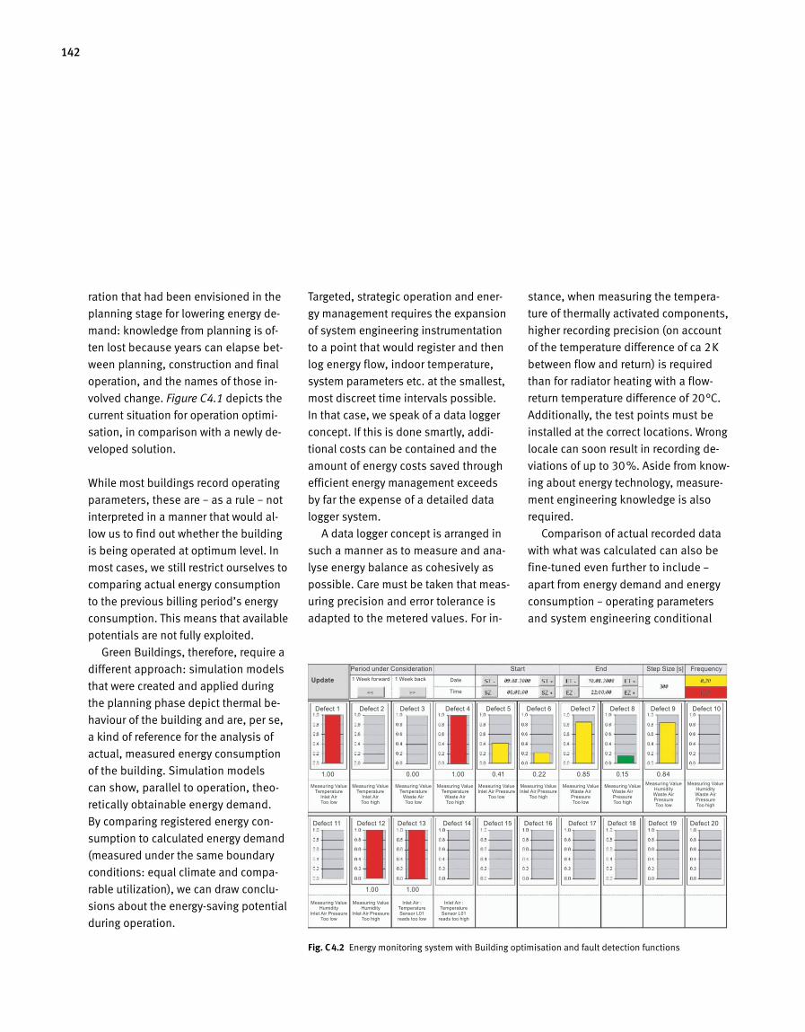
142
ration that had been envisioned in the
planning stage for lowering energy de
mand: knowledge from planning is of
ten lost because years can elapse bet
ween planning, construction and final
operation, and the names of those in
volved change. Figure C4.1 depicts the
current situation for operation optimi
sation, in comparison with a newly de
veloped solution.
While most buildings record operating
parameters, these are – as a rule – not
interpreted in a manner that would al
low us to find out whether the building
is being operated at optimum level. In
most cases, we still restrict ourselves to
comparing actual energy consumption
to the previous billing period’s energy
consumption. This means that available
potentials are not fully exploited.
Green Buildings, therefore, require a
different approach: simulation models
that were created and applied during
the planning phase depict thermal be
haviour of the building and are, per se,
a kind of reference for the analysis of
actual, measured energy consumption
of the building. Simulation models
can show, parallel to operation, theo
retically obtainable energy demand.
By comparing registered energy con
sumption to calculated energy demand
(measured under the same boundary
conditions: equal climate and compa
rable utilization), we can draw conclu
sions about the energysaving potential
during operation.
Targeted, strategic operation and ener
gy management requires the expansion
of system engineering instrumentation
to a point that would register and then
log energy flow, indoor temperature,
system parameters etc. at the smallest,
most discreet time intervals possible.
In that case, we speak of a data logger
concept. If this is done smartly, addi
tional costs can be contained and the
amount of energy costs saved through
efficient energy management exceeds
by far the expense of a detailed data
logger system.
A data logger concept is arranged in
such a manner as to measure and ana
lyse energy balance as cohesively as
possible. Care must be taken that meas
uring precision and error tolerance is
adapted to the metered values. For in
stance, when measuring the tempera
ture of thermally activated components,
higher recording precision (on account
of the temperature difference of ca 2K
between flow and return) is required
than for radiator heating with a flow
return temperature difference of 20°C.
Additionally, the test points must be
installed at the correct locations. Wrong
locale can soon result in recording de
viations of up to 30%. Aside from know
ing about energy technology, meas ure
ment engineering knowledge is also
required.
Comparison of actual recorded data
with what was calculated can also be
finetuned even further to include –
apart from energy demand and energy
consumption – operating parameters
and system engineering conditional
Fig. C 4.2 Energy monitoring system with Building optimisation and fault detection functions
Period under Consideration Start End Step Size [s] Frequency1 Week forward 1 Week back Date
Time
Update
Measuring Value Temperature
Inlet Air Too low
Measuring Value Temperature
Inlet Air Too high
Measuring Value Temperature
Waste Air Too low
Measuring Value Temperature
Waste Air Too high
Measuring Value Inlet Air Pressure
Too low
Measuring Value Waste Air Pressure Too low
Measuring Value Humidity Waste Air Pressure Too low
Measuring Value Humidity
Inlet Air Pressure Too low
Inlet Air : Temperature Sensor L01
reads too low
Measuring Value Inlet Air Pressure
Too high
Measuring Value Waste Air Pressure Too high
Measuring Value Humidity Waste Air Pressure Too high
Measuring Value Humidity
Inlet Air Pressure Too high
Inlet Air : Temperature Sensor L01
reads too high
Defect 1 Defect 2 Defect 3 Defect 4 Defect 5 Defect 6 Defect 7 Defect 8 Defect 9 Defect 10
Defect 11 Defect 12 Defect 13 Defect 14 Defect 15 Defect 16 Defect 17 Defect 18 Defect 19 Defect 20
1.00 0.00 1.00 0.41 0.22 0.85 0.15 0.84
1.00 1.00
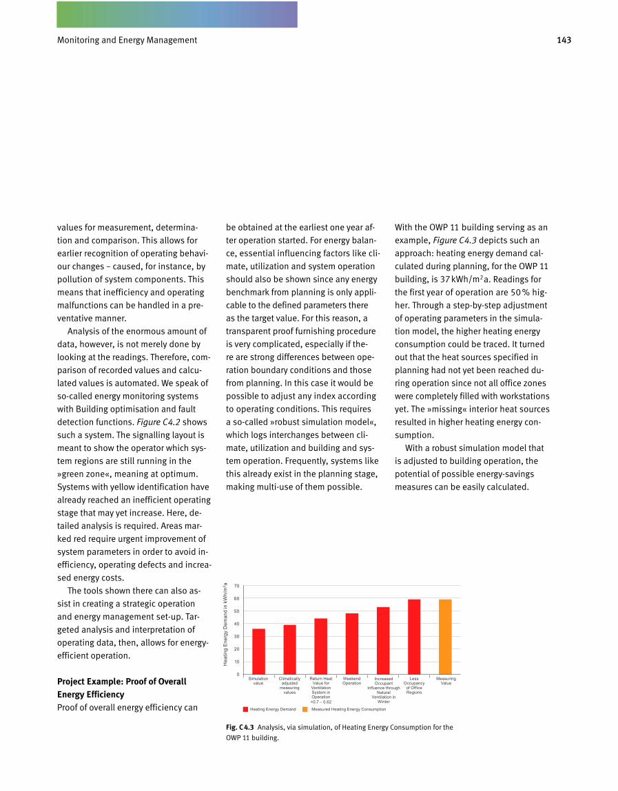
143Betriebsbegleitendes Energiemanagement
values for measurement, determina
tion and comparison. This allows for
earlier recognition of operating behavi
our changes – caused, for instance, by
pollution of system components. This
means that ineffici ency and operating
malfunctions can be handled in a pre
ventative manner.
Analysis of the enormous amount of
data, however, is not merely done by
looking at the readings. Therefore, com
parison of recorded values and calcu
lated values is automated. We speak of
socalled energy monitoring systems
with Building optimisation and fault
detection functions. Figure C4.2 shows
such a system. The signalling layout is
meant to show the operator which sys
tem regions are still running in the
»green zone«, meaning at optimum.
Systems with yellow identification have
already reached an inefficient operating
stage that may yet increase. Here, de
tailed analysis is required. Areas mar
ked red require urgent improvement of
system parameters in order to avoid in
efficiency, operating defects and increa
sed energy costs.
The tools shown there can also as
sist in creating a strategic operation
and energy management setup. Tar
geted analysis and interpretation of
operating data, then, allows for energy
efficient operation.
Project Example: Proof of Overall Energy EfficiencyProof of overall energy efficiency can
be obtained at the earliest one year af
ter operation started. For energy balan
ce, essential influencing factors like cli
mate, utilization and system operation
should also be shown since any energy
benchmark from planning is only appli
cable to the defined parameters there
as the target value. For this reason, a
transparent proof furnishing procedure
is very complicated, especially if the
re are strong differences between ope
ration boundary conditions and those
from planning. In this case it would be
possible to adjust any index according
to operating conditions. This requires
a socalled »robust simulation model«,
which logs interchanges between cli
mate, utilization and building and sys
tem operation. Frequently, systems like
this already exist in the planning stage,
making multiuse of them possible.
With the OWP 11 building serving as an
example, Figure C4.3 depicts such an
approach: heating energy demand cal
culated du ring planning, for the OWP 11
building, is 37kWh/m2a. Readings for
the first year of operation are 50 % hig
her. Through a stepbystep adjustment
of operating parameters in the simula
tion model, the higher heating energy
consumption could be traced. It turned
out that the heat sources specified in
planning had not yet been reached du
ring operation since not all office zones
were completely filled with workstations
yet. The »missing« interior heat sources
resulted in higher heating energy con
sumption.
With a robust simulation model that
is adjusted to building operation, the
potential of possible energysavings
meas ures can be easily calculated.
Fig. C 4.3 Analysis, via simulation, of Heating Energy Consumption for the
OWP 11 building.
Simulation value
Heating Energy Demand Measured Heating Energy Consumption
Climatically adjusted
measuring values
Weekend Operation
Increased Occupant
Influence through Natural
Ventilation in Winter
Less Occupancy
of Office Regions
Measuring Value
70
60
50
40
30
20
10
0
Hea
ting
Ener
gy D
eman
d in
kW
h/m
2 a
Return Heat Value for
Ventilation System in Operation
Monitoring and Energy Management
<0.7 – 0.62
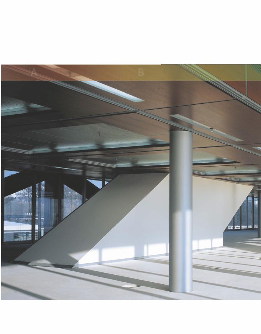
A B
A closer Look – Green Buildings in Detail
C D
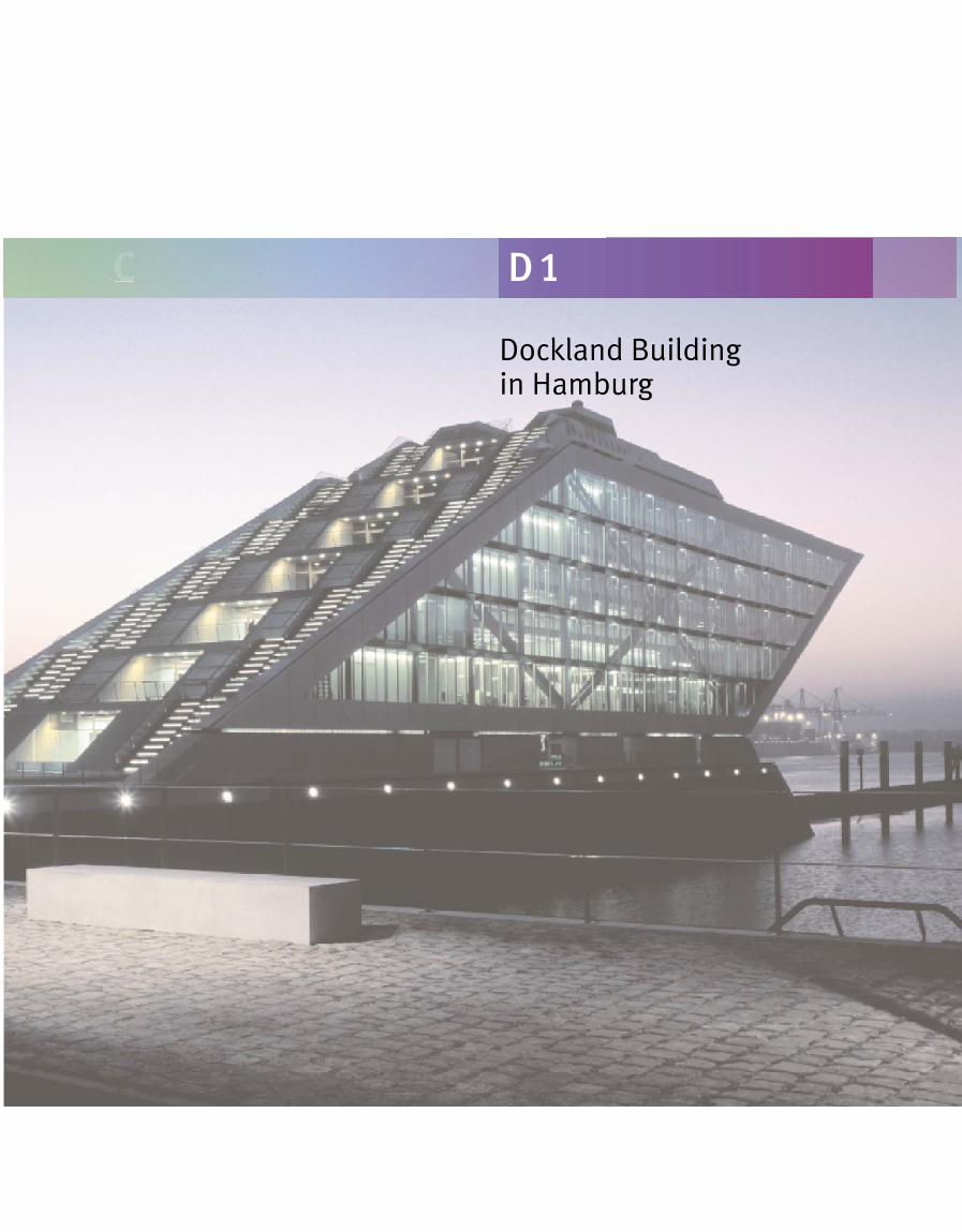
Dockland Building in Hamburg
C D 1
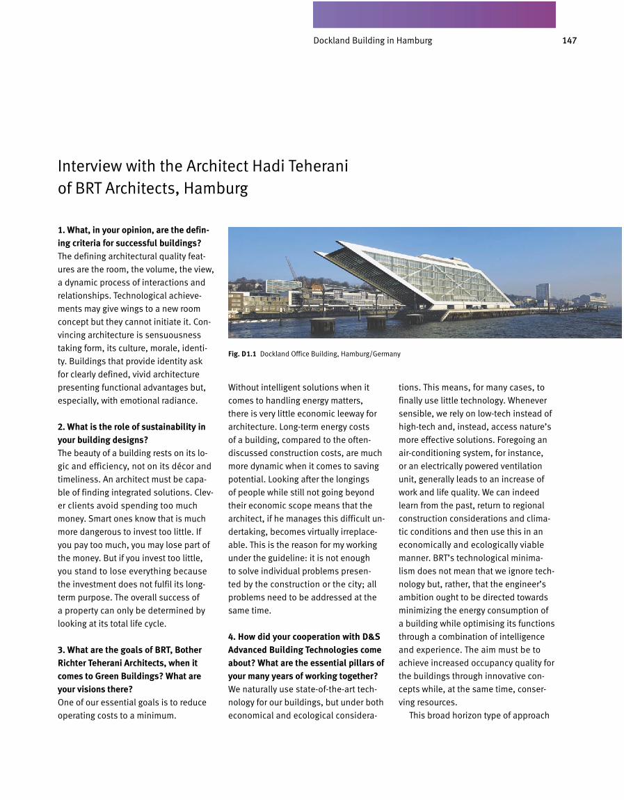
147Dockland in Hamburg
Interview with the Architect Hadi Teherani of BRT Architects, Hamburg
1. What, in your opinion, are the defining criteria for successful buildings?The defining architectural quality feat
ures are the room, the volume, the view,
a dynamic process of interactions and
relationships. Technological achieve
ments may give wings to a new room
concept but they cannot initiate it. Con
vincing architecture is sensuousness
taking form, its culture, morale, identi
ty. Buildings that provide identity ask
for clearly defined, vivid architecture
presenting functional advantages but,
especially, with emotional radiance.
2. What is the role of sustainability in your building designs?The beauty of a building rests on its lo
gic and efficiency, not on its décor and
timeliness. An architect must be capa
ble of finding integrated solutions. Clev
er clients avoid spending too much
money. Smart ones know that is much
more dangerous to invest too little. If
you pay too much, you may lose part of
the money. But if you invest too little,
you stand to lose everything because
the investment does not fulfil its long
term purpose. The overall success of
a property can only be determined by
looking at its total life cycle.
3. What are the goals of BRT, Bother Richter Teherani Architects, when it comes to Green Buildings? What are your visions there?One of our essential goals is to reduce
operating costs to a minimum.
Without intelligent solutions when it
comes to handling energy matters,
there is very little economic leeway for
architecture. Longterm energy costs
of a building, compared to the often
discussed construction costs, are much
more dynamic when it comes to saving
potential. Looking after the longings
of people while still not going beyond
their economic scope means that the
architect, if he manages this difficult un
dertaking, becomes virtually irreplace
able. This is the reason for my working
under the guideline: it is not enough
to solve individual problems presen
ted by the construction or the city; all
problems need to be addressed at the
same time.
4. How did your cooperation with D&S Advanced Building Technologies come about? What are the essential pillars of your many years of working together?We naturally use stateoftheart tech
nology for our buildings, but under both
economical and ecological considera
tions. This means, for many cases, to
finally use little technology. Whenever
sensible, we rely on lowtech instead of
hightech and, instead, access nature’s
more effective solutions. Foregoing an
airconditioning system, for instance,
or an electrically powered ventilation
unit, generally leads to an increase of
work and life quality. We can indeed
learn from the past, return to regional
construction considerations and clima
tic conditions and then use this in an
economically and ecologically viable
manner. BRT’s technological minima
lism does not mean that we ignore tech
nology but, rather, that the engineer’s
ambition ought to be directed towards
minimizing the energy consumption of
a building while optimising its functions
through a combination of intelligence
and experience. The aim must be to
achieve increased occupancy quality for
the buildings through innovative con
cepts while, at the same time, conser
ving resources.
This broad horizon type of approach
Fig. D 1.1 Dockland Office Building, Hamburg/Germany
Dockland Building in Hamburg
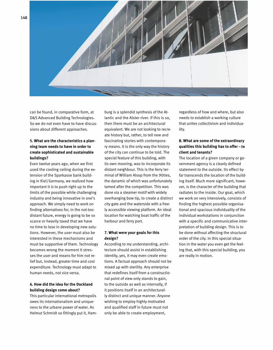
148
can be found, in comparative form, at
D&S Advanced Building Technologies.
So we do not even have to have discus
sions about different approaches.
5. What are the characteristics a plan-ning team needs to have in order to create sophisticated and sustainable buildings?Even twelve years ago, when we first
used the cooling ceiling during the ex
tension of the Sparkasse bank build
ing in Kiel/Germany, we realized how
important it is to push right up to the
limits of the possible while challenging
industry and being innovative in one’s
approach. We simply need to work on
finding alternatives for, in the nottoo
distant future, energy is going to be so
scarce or heavily taxed that we have
no time to lose in developing new solu
tions. However, the user must also be
interested in these mechanisms and
must be supportive of them. Technology
becomes wrong the moment it stres
ses the user and means for him not re
lief but, instead, greater time and cost
expenditure. Technology must adapt to
human needs, not vice versa.
6. How did the idea for the Dockland building design come about?This particular international metropolis
owes its internationalism and unique
ness to the urbane power of water. As
Helmut Schmidt so fittingly put it, Ham
burg is a splendid synthesis of the At
lantic and the Alster river. If this is so,
then there must be an architectural
equivalent. We are not looking to recre
ate history but, rather, to tell new and
fascinating stories with contempora
ry means. It is the only way the history
of the city can continue to be told. The
special feature of this building, with
its own mooring, was to incorporate its
distant neighbour. This is the ferry ter
minal of William Alsop from the 90ties,
the dynamic of which was unfortunately
tamed after the competition. This was
done via a steamer motif with widely
overhanging bow tip, to create a distinct
city gate and the waterside with a free
ly accessible viewing platform. An ideal
location for watching boat traffic of the
harbour and ferry port.
7. What were your goals for this design?According to my understanding, archi
tecture should assist in establishing
identity, yes, it may even create emo
tions. A factual approach should not be
mixed up with sterility. Any enterprise
that redefines itself from a constructio
nal point of view only stands to gain,
to the outside as well as internally, if
it positions itself in an architectural
ly distinct and unique manner. Anyone
wishing to employ highly motivated
and qualified staff in future must not
only be able to create employment,
regardless of how and where, but also
needs to establish a working culture
that unites collectivism and individua
lity.
8. What are some of the extraordinary qualities this building has to offer – to client and tenants?The location of a given company or go
vernment agency is a clearly defined
statement to the outside. Its effect by
far transcends the location of the build
ing itself. Much more significant, howe
ver, is the character of the building that
radiates to the inside. Our goal, which
we work on very intensively, consists of
finding the highest possible organisa
tional and spacious individuality of the
individual workstations in conjunction
with a specific and communicative inter
pretation of building design. This is to
be done without affecting the structural
order of the city. In this special situa
tion in the water you even get the feel
ing that, with this special building, you
are really in motion.
149Dockland in Hamburg
1. What, in your opinion, are the defin-ing criteria for successful buildings?Location, aspiration and its implemen
tation, good architecture, economical
operation, occupant identification with
the building, as little technology as pos
sible – as much as necessary, low associa
ted costs, easy operation, minimal energy
use, conservation of resources, good mar
keting options also in future, longevity.
2. What does living inside a building mean to you? What factors are essen-tially decisive as to whether you feel comfortable or not?Location, environment, rooms, archi
tecture, view, insight, harmonic pro
portions, heat, cooling, uncomplicated
handling, understanding.
3. What is the role of sustainability, of life-cycle consideration, in your build-ing stipulations?We develop, build and operate our build
ings. For this reason, lifecycle conside
ration plays a decisive role for us. Aside
from a huge, also ethical (toward fu tu
re generations) responsibility, sustaina
bility is based on clear economical con
siderations, too. In future, responsible
handling of resources (especially of re
newable ones) with respect to associa
ted costs, is going to become extremely
important. High associated costs also
mean a low basic rent. Further, compa
nies with a good image will continue
to have clear market advantages. The
asset holder, therefore, will always be
more concerned with quality than the
»simple« investor.
4. You experience the entire process, from design to operation. Where do you see the greatest improvement po-tential: in the process itself, in find-ing ideas, planning implementation, constructional execution or operating behaviour?Small teams, trust. In the finding pro
cess, some other aspects need to come
into consideration also, like easy hand
ling, user relation, low operating costs,
sustainable handling of resources and
the environment.
Personally, I believe that the plan
ning processes are frequently hampered
through too many people being invol
ved in both the planning and the build
ing process. There are simply too many
experts for everything, project supervi
sors, special surveyors, consultants etc.
who only unnecessarily delay everything
and money is wasted that then needs
to be recovered again during the actual
execution phase. Here, savings are then
made and this has a negative impact on
quality. Naturally, the projects are beco
ming more sophisticated but often the
decisionmakers (also on the client’s
site) do not grow with the project.
I also feel that the construction pro
cess itself is not yet very progressive –
we plan and plan and then put out a
call for the bid and only then the other
companies get involved – when, really,
industry and other firms should be in
volved much sooner in order to achieve
synergies for everyone.
Especially during the initial design
stages, planning should have a higher
status (like, for instance, sometimes
happens in boat building), which would
allow for basics and concepts to be
clarified and scrutinized in more detail.
The first two HOAI stages (HOAI = offi
cial scale of fees for services of archi
tects and engineers) – basic evaluation
and preliminary planning – are often
merely touched upon.
5. What are the characteristics a plan-ning team needs to have in order to create sophisticated and sustainable buildings?Expert knowledge, experience, dedica
tion, passion, personal involvement –
weren’t these the words of D&S Advanced
Building Technologies? – staying power
to clarify everything over and over again,
fun, a sense of responsibility.
The planners should not only be ca
pable of acting inside their own range
but also to look beyond the horizon.
6. What are some of the extraordinary qualities this building has to offer – to client and tenants?Unique location, exceptional architecture,
premium quality, maximum flexibility,
stateoftheart technology; everything a
modern and innovative building needs
in order to hold its own on the market for
at least the next 20 years. It is one of the
new symbols of Hamburg.
Interview with Christian Fleck, Client, Robert Vogel GmbH & Co. KG
Dockland Building in Hamburg
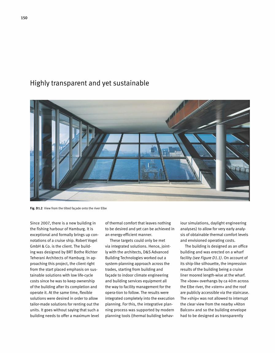
150
Highly transparent and yet sustainable
Since 2007, there is a new building in
the fishing harbour of Hamburg. It is
exceptional and formally brings up con-
notations of a cruise ship. Robert Vogel
GmbH & Co. is the client. The build-
ing was designed by BRT Bothe Richter
Teherani Architects of Hamburg. In ap-
proaching this project, the client right
from the start placed emphasis on sus-
tainable solutions with low life-cycle
costs since he was to keep ownership
of the building after its completion and
operate it. At the same time, flexible
solutions were desired in order to allow
tailor-made solutions for renting out the
units. It goes without saying that such a
building needs to offer a maximum level
of thermal comfort that leaves nothing
to be desired and yet can be achieved in
an energy-efficient manner.
These targets could only be met
via integrated solutions. Hence, joint-
ly with the architects, D&S Advanced
Build ing Technologies worked out a
system-planning approach across the
trades, starting from building and
façade to indoor climate engineering
and building services equipment all
the way to facility management for the
opera -tion to follow. The results were
integrated completely into the execution
planning. For this, the integrative plan-
ning process was supported by modern
planning tools (thermal building behav-
iour simulations, daylight engineering
analyses) to allow for very early analy-
sis of obtainable thermal comfort levels
and envisioned operating costs.
The building is designed as an office
building and was erected on a wharf
facility (see Figure D1.1). On account of
its ship-like silhouette, the impression
results of the building being a cruise
liner moored length-wise at the wharf.
The »bow« overhangs by ca 40m across
the Elbe river, the »stern« and the roof
are publicly accessible via the staircase.
The »ship« was not allowed to interrupt
the clear view from the nearby »Alton
Balcon« and so the building envelope
had to be designed as transparently
Fig. D 1.2 View from the tilted façade onto the river Elbe
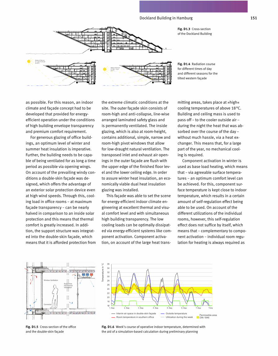
151Dockland in Hamburg
Fig. D 1.3 Cross-section
of the Dockland Building
as possible. For this reason, an indoor
climate and façade concept had to be
developed that provided for energy-
efficient operation under the conditions
of high building envelope transparency
and premium comfort requirement.
For generous glazing of office build-
ings, an optimum level of winter and
summer heat insulation is imperative.
Further, the building needs to be capa-
ble of being ventilated for as long a time
period as possible via opening wings.
On account of the prevailing windy con-
ditions a double-skin façade was de-
signed, which offers the advantage of
an exterior solar protection device even
at high wind speeds. Through this, cool-
ing load in office rooms – at maximum
façade transparency – can be nearly
halved in comparison to an inside solar
protection and this means that thermal
comfort is greatly increased. In addi-
tion, the support structure was integrat-
ed into the double-skin façade, which
means that it is afforded protection from
the extreme climatic conditions at the
site. The outer façade skin consists of
room-high and anti-collapse, line-wise
arranged laminated safety glass and
is permanently ventilated. The inside
glazing, which is also at room-height,
contains additional, simple, narrow and
room-high pivot windows that allow
for low-draught natural ventilation. The
transposed inlet and exhaust air open-
ings in the outer façade are flush with
the upper edge of the finished floor lev-
el and the lower ceiling edge. In order
to as sure winter heat insulation, an eco-
nomically viable dual heat insula tion
glazing was installed.
This façade was able to set the scene
for energy-efficient indoor climate en-
gineering at excellent thermal and visu -
al comfort level and with simultaneous
high building transparency. The low
cool ing loads can be optimally dissipat-
ed via energy-efficient systems like com -
ponent activation. Component activa-
tion, on account of the large heat trans-
mitting areas, takes place at »high«
cooling temperatures of above 18°C.
Building and ceiling mass is used to
pass off – to the cooler outside air –
during the night the heat that was ab-
sorbed over the course of the day –
without much has sle, via a heat ex-
changer. This means that, for a large
part of the year, no mechanical cool -
ing is required.
Component activation in winter is
used as base load heating, which means
that – via agreeable surface tempera-
tures – an optimum comfort level can
be achieved. For this, com ponent sur-
face temperature is kept close to indoor
temperature, which results in a certain
amount of self-regu lation effect being
able to be used. On account of the
different utilizations of the individual
rooms, however, this self-regulation
effect does not suffice by itself, which
means that – complementary to compo-
nent activa tion – individual room regu-
lation for heating is always required as
Fig. D 1.5 Cross-section of the office
and the double-skin façade
Fig. D 1.6 Week’s course of operative indoor temperature, determined with
the aid of a simulation-based calculation during preliminary planning
Fig. D 1.4 Radiation course
for different times of day
and different seasons for the
tilted western façade
Window Ventilation
Status of the sun 21. June 16.30 pm (h=32°)
Status of the sun 21. Dec. 15 pm (h=7°)
Convector
Supportive mechanical Ventilation
1. Sep. 2. Sep. 3. Sep. 4. Sep. 5. Sep. 6. Sep. 7. Sep. Time
Interim air space in double-skin façade Outside temperatureRoom temperature in southern office Utilization during the week
Permissible area DIN 1946
36
34
32
30
28
26
24
22
20
18
16
Tem
pera
ture
in °
C
Dockland Building in Hamburg
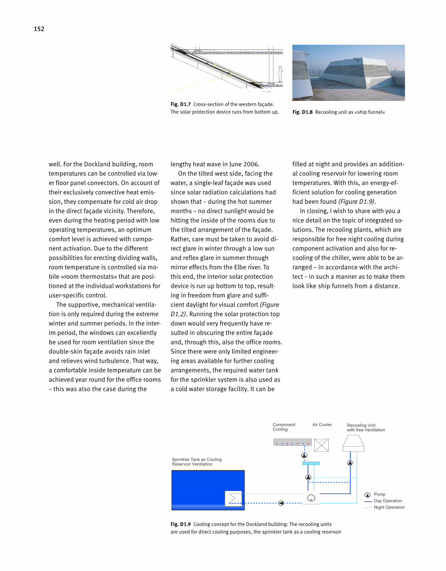
152
well. For the Dockland building, room
temperatures can be controlled via low-
er floor panel convectors. On account of
their exclusively convective heat emis-
sion, they compensate for cold air drop
in the direct façade vicinity. Therefore,
even during the heating period with low
operating temperatures, an optimum
comfort lev el is achieved with compo-
nent activation. Due to the different
possibilities for erecting dividing walls,
room temperature is controlled via mo-
bile »room thermostats« that are posi-
tioned at the individual workstations for
user-specific control.
The supportive, mechanical ventila-
tion is only required during the extreme
winter and summer periods. In the inter-
im period, the windows can excellent ly
be used for room ventilation since the
double-skin façade avoids rain inlet
and relieves wind turbulence. That way,
a comfortable inside temperature can be
achieved year round for the office rooms
– this was also the case during the
lengthy heat wave in June 2006.
On the tilted west side, facing the
water, a single-leaf façade was used
since solar radiation calculations had
shown that – during the hot summer
months – no direct sunlight would be
hitting the inside of the rooms due to
the tilted arrangement of the façade.
Rather, care must be taken to avoid di-
rect glare in winter through a low sun
and reflex glare in summer through
mirror effects from the Elbe river. To
this end, the interior solar protection
device is run up bottom to top, result-
ing in freedom from glare and suffi-
cient daylight for visual comfort (Figure
D1.2). Running the solar protection top
down would very frequently have re-
sulted in obscuring the entire façade
and, through this, also the office rooms.
Since there were only limited engineer-
ing areas available for further cooling
arrangements, the required water tank
for the sprinkler sys tem is also used as
a cold water storage facility. It can be
filled at night and provides an addition-
al cooling reservoir for lowering room
temperatures. With this, an energy-ef-
ficient solution for cooling generation
had been found (Figure D1.9).
In closing, I wish to share with you a
nice detail on the topic of integrated so-
lutions. The recooling plants, which are
responsible for free night cooling during
component activation and also for re-
cooling of the chiller, were able to be ar-
ranged – in accordance with the archi-
tect – in such a manner as to make them
look like ship funnels from a distance.
Fassadenausschnitt der Westfassade
Fig. D 1.7 Cross-section of the western façade.
The solar protection device runs from bottom up.
Fig. D 1.9 Cooling concept for the Dockland building: The recooling units
are used for direct cooling purposes, the sprinkler tank as a cooling reservoir
Fig. D 1.8 Recooling unit as »ship funnel«
Sprinkler Tank as Cooling Reservoir Ventilation
Component Cooling
Air Cooler Recooling Unit with free Ventilation
PumpDay OperationNight Operation
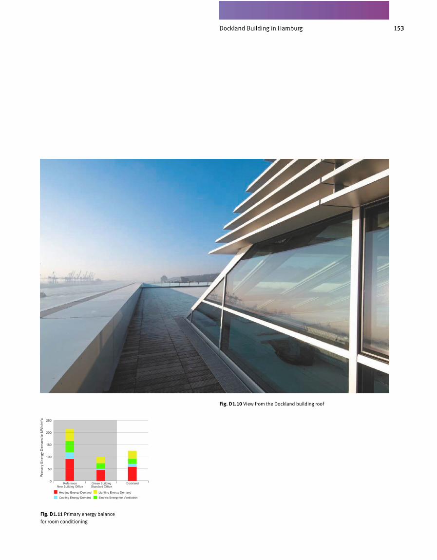
153Dockland in Hamburg
Fig. D 1.10 View from the Dockland building roof
Fig. D 1.11 Primary energy balance
for room conditioning
Reference New Building Office
Green Building Standard Office
Dockland
Heating Energy Demand Lighting Energy Demand
Cooling Energy Demand Electric Energy for Ventilation
250
200
150
100
50
0
Prim
ary
Ener
gy D
eman
d in
kW
h/m
2 a
Dockland Building in Hamburg
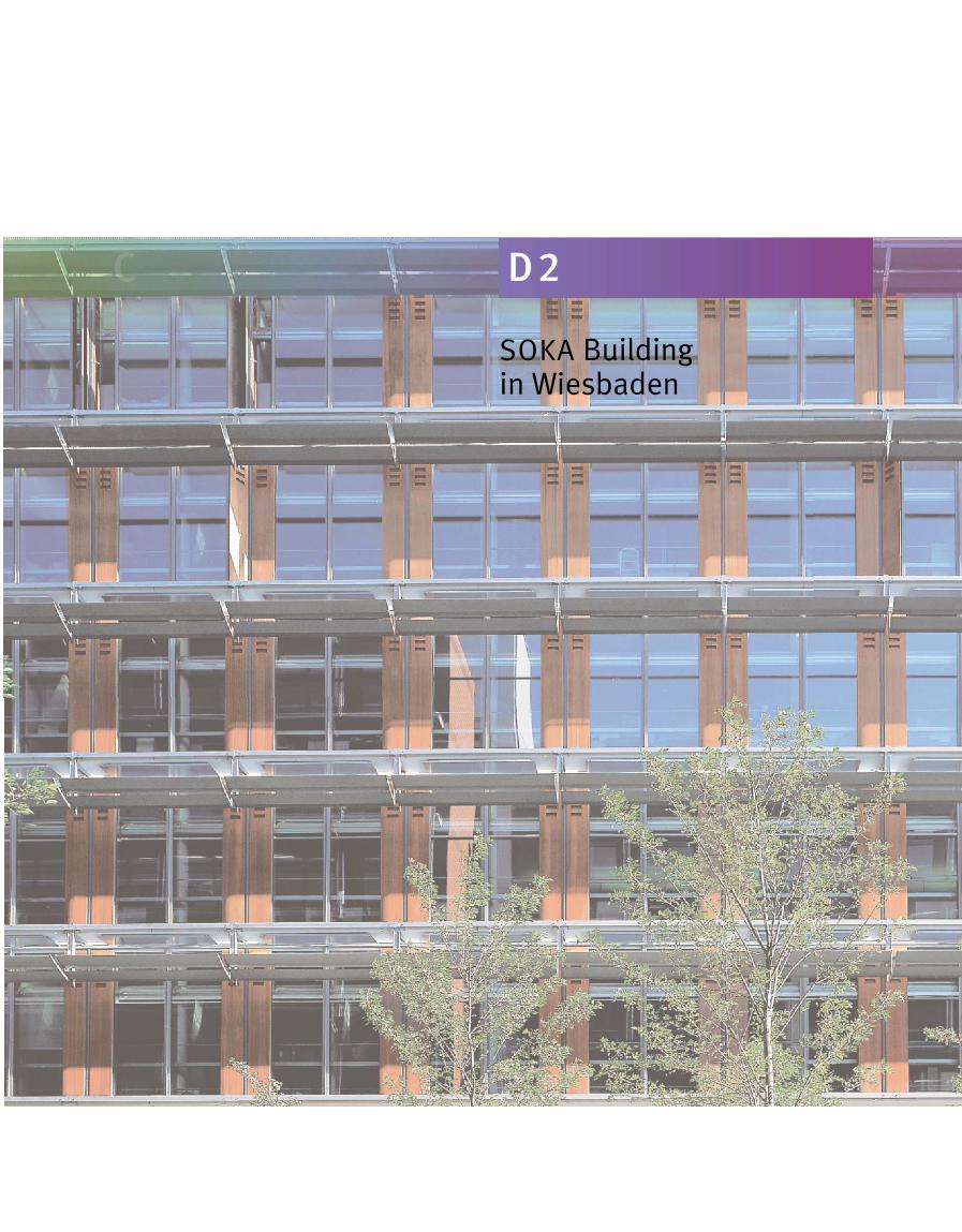
C D 2
SOKA Building in Wiesbaden
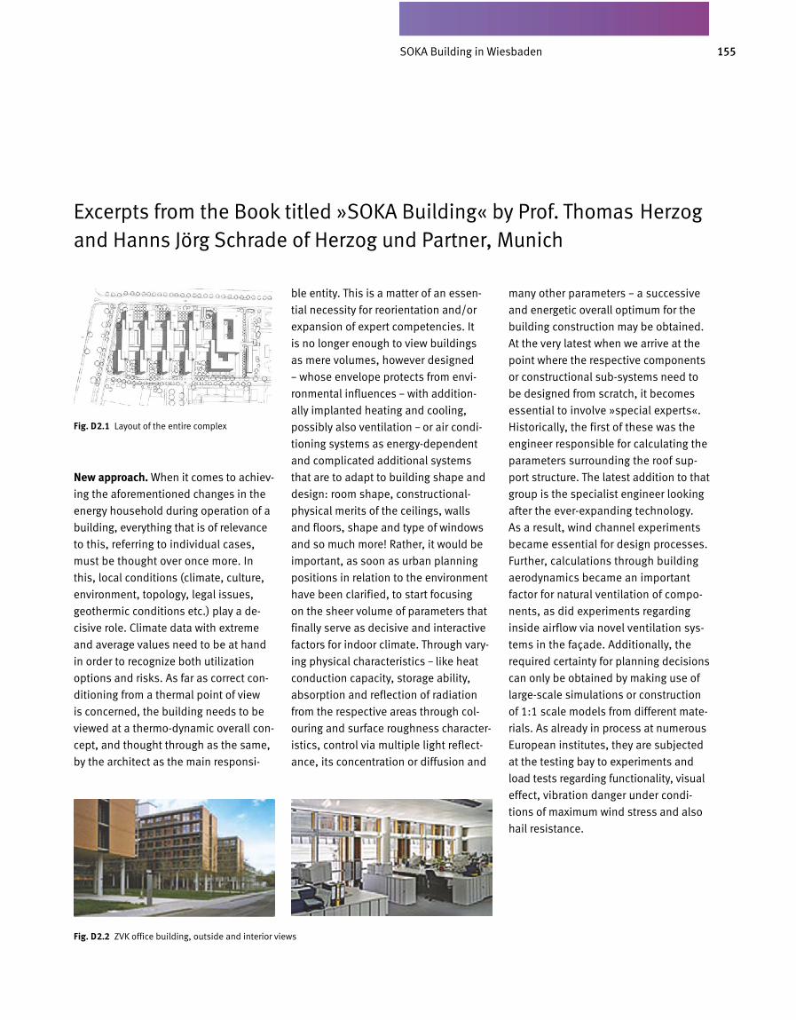
155SOKA-BAU in Wiesbaden
New approach. When it comes to achiev-
ing the aforementioned changes in the
energy household during operation of a
building, everything that is of relevance
to this, referring to individual cases,
must be thought over once more. In
this, local conditions (climate, culture,
environment, topology, legal issues,
geothermic conditions etc.) play a de-
cisive role. Climate data with extreme
and average values need to be at hand
in order to recognize both utilization
options and risks. As far as correct con-
ditioning from a thermal point of view
is concerned, the building needs to be
viewed at a thermo-dynamic overall con-
cept, and thought through as the same,
by the architect as the main responsi-
ble entity. This is a matter of an essen-
tial necessity for reorientation and/or
expansion of expert competencies. It
is no longer enough to view buildings
as mere volumes, however designed
– whose envelope protects from envi-
ronmental influences – with addition-
ally implanted heating and cooling,
possibly also ventilation – or air condi-
tioning systems as energy-dependent
and complicated additional systems
that are to adapt to building shape and
design: room shape, constructional-
physical merits of the ceilings, walls
and floors, shape and type of windows
and so much more! Rather, it would be
important, as soon as urban planning
positions in relation to the environment
have been clarified, to start focusing
on the sheer volume of parameters that
finally serve as decisive and interactive
factors for indoor climate. Through vary-
ing physical characteristics – like heat
conduction capacity, storage ability,
absorption and reflection of radiation
from the respective areas through col-
ouring and surface roughness character-
istics, control via multiple light reflect-
ance, its concentration or diffusion and
many other parameters – a successive
and energetic overall optimum for the
building construction may be obtained.
At the very latest when we arrive at the
point where the respective components
or constructional sub-systems need to
be designed from scratch, it becomes
essential to involve »special experts«.
Historically, the first of these was the
engineer responsible for calculating the
parameters surrounding the roof sup-
port structure. The latest addition to that
group is the specialist engineer looking
after the ever-expanding technology.
As a result, wind channel experiments
became essential for design processes.
Further, calculations through building
aerodynamics became an important
factor for natural ventilation of compo-
nents, as did experiments regarding
inside airflow via novel ventilation sys-
tems in the façade. Additionally, the
required certainty for planning decisions
can only be obtained by making use of
large-scale simulations or construction
of 1:1 scale models from different mate-
rials. As already in process at nume rous
European institutes, they are subjected
at the testing bay to experiments and
load tests regarding functionality, visual
effect, vibration danger under condi-
tions of maximum wind stress and also
hail resistance.
Excerpts from the Book titled »SOKA Building« by Prof. Thomas Herzog and Hanns Jörg Schrade of Herzog und Partner, Munich
D2.02 Lageplan (SOKA-Bau) ZVK
Fig. D 2.1 Layout of the entire complex
Fig. D 2.2 ZVK office building, outside and interior views
SOKA Building in Wiesbaden

156
1. What, in your opinion, are the defin-ing criteria for successful buildings?Buildings are commodities that ought
to meet user requirements and at the
same time also be pleasant to look
at. To me, lighting is important, and
this includes both daylight and arti
ficial lighting. Good room arrangement
should be a given, with practical de
sign and passages that are as short
as possible. Further, office building
should be easy and inexpensive to re
design, since a building’s and even an
administration’s organization changes
constantly, if not only due to techno
logical advances. In the age of resource
scarcity and rising energy prices, ener
gyconserving concepts are becoming
increasingly more significant.
2. What does living inside a building mean to you? What factors are essen-tially decisive as to whether you feel comfortable or not?As I already stated in reply to your first
question, lighting is essential for me, a
feeling of freedom and generosity. Even
if conventional cubicle offices were put
in, one should plan for glass areas bet
ween room and hallway, as is done in a
combioffice situation, so that the indi
vidual feels less isolated at his worksta
tion. Of importance are not only comfor
table room temperatures in winter and
summer but also a favourable radiation
environment. This factor is not suffici
ently considered. In the era of computer
workstations, staff must be able to work
in a glare free environment with low lu
minance contrast so that their eyes do
not become too strained by the contrast
between the dark computer screen and
the bright room.
3. What is the role of sustainability, of life-cycle consideration, in your buid ing stipulations?We considered this right from the start
in our planning. To give you an example:
our architects wanted to implement the
thermally active ceiling concept by in
graining waterconducting pipes in the
slab. I vetoed this because the suppor
tive structure of a building is the part
that needs to last longest and nobody
knows how long the synthetic hoses
that are nowadays used for heat ing
and cooling of components will last.
I demanded that the water pipes be
ingrained into the floor screed. This
makes repairs that much easier. My
prompt, at the time, initiated some sci
entific inves tigations in which D&S Ad
vanced Building Technologies played a
decisive role and from which, I believe,
they gained some additional knowledge
as well.
Sustainability has made an impact in
other areas as well. For instance, one
of my stipulations said that the building
must be usable for any different office
types that work on the same ceiling
height, like cellular offices, combi of
fices or open space offices. This makes
it possible to flexibly adapt office rooms
to the organisation forms of the future.
A further advantage can be found in the
fact that the entire power supply (high
and low voltage, ITcables) was moved
into the façade so that, by shifting the
mobile dividing walls, the newly created
rooms could be interconnected virtual
ly by computer without the need to lay
anew the electrical wiring. Virtually, we
handle the rooms via the window raster,
which makes it easy to recombine areas
for lighting according to different room
organisation modes.
4. You experience the entire process, from design to operation. Where do you see the greatest improvement poten-tial: in the process, in finding ideas, planning implementation, constructio-nal execution or operating behaviour?The most important thing, in my expe
rience as client of several large projects,
is that – as client – you need to know
precisely what you want prior to issuing
the planning order. For instance, before
entering the architectural competition,
and also before involving the project
control division of Drees & Sommer –
with whom we were very satis fied, inci
dentally – I had asked a professor spe
cializing in utilization planning to com
pile a basic survey that outlines what
possibilities for building there are. On
our part, we clarified what office
organisation we wanted for our building,
what auxiliary utilizations we required
and what prerequisites needed to be
in place for making the building availa
ble to be rented out. It also needed to
Interview with Peter Kippenberg, Board Member of SOKA Construction
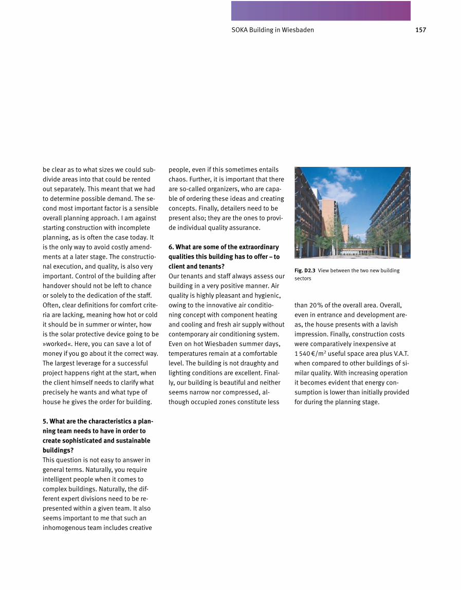
157SOKABAU in Wiesbaden
be clear as to what sizes we could sub
divide areas into that could be rented
out separately. This meant that we had
to determine possible demand. The se
cond most important factor is a sensible
overall planning approach. I am against
starting construction with incomplete
planning, as is often the case today. It
is the only way to avoid costly amend
ments at a later stage. The constructio
nal execution, and quality, is also very
important. Control of the building after
handover should not be left to chance
or solely to the dedication of the staff.
Often, clear definitions for comfort crite
ria are lacking, meaning how hot or cold
it should be in summer or winter, how
is the solar protective device going to be
»worked«. Here, you can save a lot of
money if you go about it the correct way.
The largest leverage for a successful
project happens right at the start, when
the client himself needs to clarify what
precisely he wants and what type of
house he gives the order for building.
5. What are the characteristics a plan-ning team needs to have in order to create sophisticated and sustainable buildings?This question is not easy to answer in
general terms. Naturally, you require
intelligent people when it comes to
complex buildings. Naturally, the dif
ferent expert divisions need to be re
presented within a given team. It also
seems important to me that such an
inhomogenous team includes creative
people, even if this sometimes entails
chaos. Further, it is important that there
are socalled organizers, who are capa
ble of ordering these ideas and creating
concepts. Finally, detailers need to be
present also; they are the ones to provi
de individual quality assurance.
6. What are some of the extraordinary qualities this building has to offer – to client and tenants?Our tenants and staff always assess our
building in a very positive manner. Air
quality is highly pleasant and hy gienic,
owing to the innovative air conditio
ning concept with component heating
and cooling and fresh air supply without
contemporary air conditioning system.
Even on hot Wiesbaden summer days,
temperatures remain at a comfortable
level. The building is not draughty and
lighting conditions are excellent. Final
ly, our building is beautiful and neither
seems narrow nor compressed, al
though occupied zones constitute less
than 20% of the overall area. Overall,
even in entrance and development are
as, the house presents with a lavish
impression. Finally, construction costs
were comparatively inexpensive at
1540€/m2 useful space area plus V.A.T.
when compared to other buildings of si
milar quality. With increasing operation
it becomes evident that energy con
sumption is lower than initially provided
for during the planning stage.
Fig. D 2.3 View between the two new building
sectors
SOKA Building in Wiesbaden
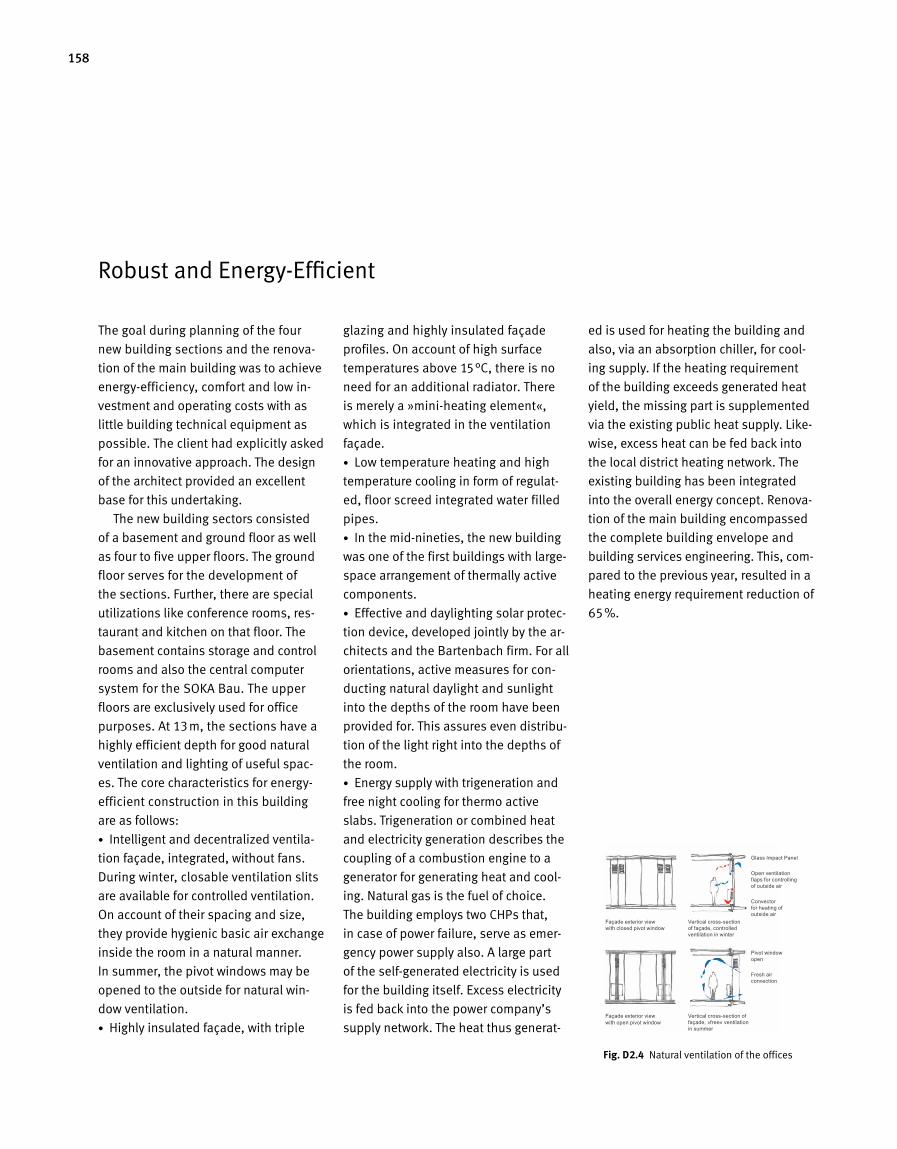
158
The goal during planning of the four
new building sections and the renova-
tion of the main building was to achieve
energy-efficiency, comfort and low in-
vestment and operating costs with as
little building technical equipment as
possible. The client had explicitly asked
for an innovative approach. The design
of the architect provided an excellent
base for this undertaking.
The new building sectors consisted
of a basement and ground floor as well
as four to five upper floors. The ground
floor serves for the development of
the sections. Further, there are special
utilizations like conference rooms, res-
taurant and kitchen on that floor. The
basement contains storage and control
rooms and also the central computer
system for the SOKA Bau. The upper
floors are exclusively used for office
purposes. At 13m, the sections have a
highly efficient depth for good natural
ventilation and lighting of useful spac-
es. The core characteristics for energy-
efficient construction in this building
are as follows:
• Intelligent and decentralized ventila-
tion façade, integrated, without fans.
During winter, closable venti lation slits
are available for controlled ventilation.
On account of their spacing and size,
they provide hygienic basic air exchange
inside the room in a natural manner.
In summer, the pivot windows may be
opened to the outside for natural win-
dow ventilation.
• Highly insulated façade, with triple
glazing and highly insulated fa çade
profiles. On account of high surface
temperatures above 15°C, there is no
need for an additional radiator. There
is merely a »mini-heating element«,
which is integrated in the ven tilation
façade.
• Low temperature heating and high
temperature cooling in form of regulat-
ed, floor screed integrated water filled
pipes.
• In the mid-nineties, the new building
was one of the first buildings with large-
space arrangement of thermally active
components.
• Effective and daylighting solar protec-
tion device, developed jointly by the ar-
chitects and the Bartenbach firm. For all
orientations, active meas ures for con-
ducting natural daylight and sunlight
into the depths of the room have been
provided for. This assures even distribu-
tion of the light right into the depths of
the room.
• Energy supply with trigeneration and
free night cooling for thermo active
slabs. Trigeneration or combined heat
and electricity generation describes the
coupling of a combustion engine to a
generator for generating heat and cool-
ing. Natural gas is the fuel of choice.
The building employs two CHPs that,
in case of power failure, serve as emer-
gency power supply also. A large part
of the self-generated electricity is used
for the building itself. Excess electricity
is fed back into the power company’s
supply network. The heat thus generat-
ed is used for heating the building and
also, via an absorption chiller, for cool-
ing supply. If the heating requirement
of the build ing exceeds generated heat
yield, the missing part is supplemented
via the existing public heat supply. Like-
wise, excess heat can be fed back into
the local district heating network. The
existing building has been integrated
into the overall energy concept. Renova-
tion of the main building encompassed
the complete building envelope and
building services engineering. This, com -
pared to the previous year, resulted in a
heating energy requirement reduction of
65%.
Robust and Energy-Efficient
Fig. D 2.4 Natural ventilation of the offices
Façade exterior view with closed pivot window
Glass Impact Panel
Open ventilation flaps for controlling of outside air
Convector for heating of outside air
Pivot window open
Fresh air convection
Vertical cross-section of façade, controlled ventilation in winter
Façade exterior view with open pivot window
Vertical cross-section of façade, »free« ventilation in summer
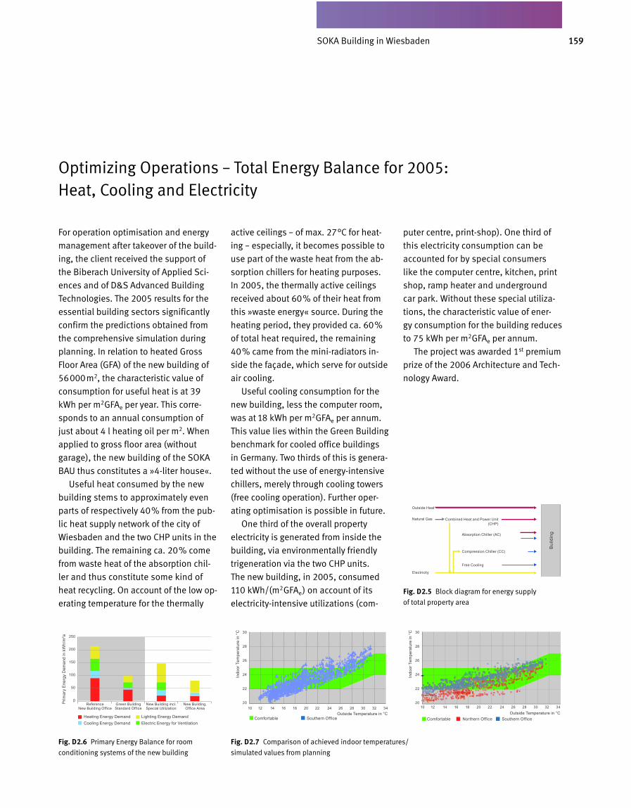
159SOKA-BAU in Wiesbaden
Optimizing Operations – Total Energy Balance for 2005: Heat, Cooling and Electricity
For operation optimisation and energy
management after takeover of the build-
ing, the client received the support of
the Biberach University of Applied Sci-
ences and of D&S Advanced Building
Technologies. The 2005 results for the
essential building sectors signi ficantly
confirm the predictions obtained from
the comprehensive simu lation during
planning. In relation to heated Gross
Floor Area (GFA) of the new building of
56000m2, the characteristic val ue of
consumption for useful heat is at 39
kWh per m2GFAe per year. This corre-
sponds to an annual consumption of
just about 4 l heating oil per m2. When
applied to gross floor area (without
garage), the new building of the SOKA
BAU thus constitutes a »4-liter house«.
Useful heat consumed by the new
building stems to approximately even
parts of respectively 40% from the pub-
lic heat supply network of the city of
Wiesbaden and the two CHP units in the
building. The remaining ca. 20% come
from waste heat of the absorption chil-
ler and thus constitute some kind of
heat recycling. On account of the low op -
erating temperature for the thermally
active ceilings – of max. 27°C for heat-
ing – especially, it becomes possible to
use part of the waste heat from the ab-
sorption chillers for heating purposes.
In 2005, the thermally active ceilings
received about 60% of their heat from
this »waste energy« source. During the
heating period, they provided ca. 60%
of total heat required, the remaining
40% came from the mini-radiators in-
side the façade, which serve for outside
air cooling.
Useful cooling consumption for the
new building, less the computer room,
was at 18 kWh per m2GFAe per annum.
This value lies within the Green Building
benchmark for cooled office buildings
in Germany. Two thirds of this is genera-
ted without the use of energy-intensive
chillers, merely through cooling towers
(free cooling operation). Further oper-
ating optimisation is possible in future.
One third of the overall property
electricity is generated from inside the
build ing, via environmentally friendly
trigeneration via the two CHP units.
The new building, in 2005, consumed
110 kWh/(m2GFAe) on account of its
electricity-intensive utilizations (com-
puter centre, print-shop). One third of
this electricity consumption can be
accounted for by special consumers
like the computer centre, kitchen, print
shop, ramp heater and underground
car park. Without these special utiliza-
tions, the characteristic value of ener -
gy consumption for the building reduces
to 75 kWh per m2GFAe per annum.
The project was awarded 1st premium
prize of the 2006 Architecture and Tech-
nology Award.
Fig. D 2.6 Primary Energy Balance for room
conditioning systems of the new building
Fig. D 2.7 Comparison of achieved indoor temperatures/
simulated values from planning
Fig. D 2.5 Block diagram for energy supply
of total property area
Reference New Building Office 10 12 14 16 18 20 22 24 26 28 30 32 34 10 12 14 16 18 20 22 24 26 28 30 32 34
Comfortable Southern Office Comfortable Northern Office Southern OfficeOutside Temperature in °C Outside Temperature in °C
Green Building Standard Office
New Building incl. Special Utilization
New Building, Office Area
Heating Energy Demand Lighting Energy DemandCooling Energy Demand Electric Energy for Ventilation
250
200
150
100
50
0
30
28
26
24
22
20
30
28
26
24
22
20Prim
ary
Ener
gy D
eman
d in
kW
h/m
2 a
Indo
or T
empe
ratu
re in
°C
Indo
or T
empe
ratu
re in
°C
Outside Heat
Natural Gas
Electricity
Combined Heat and Power Unit (CHP)
Bui
ldin
gAbsorption Chiller (AC)
Compression Chiller (CC)
Free Cooling
SOKA Building in Wiesbaden
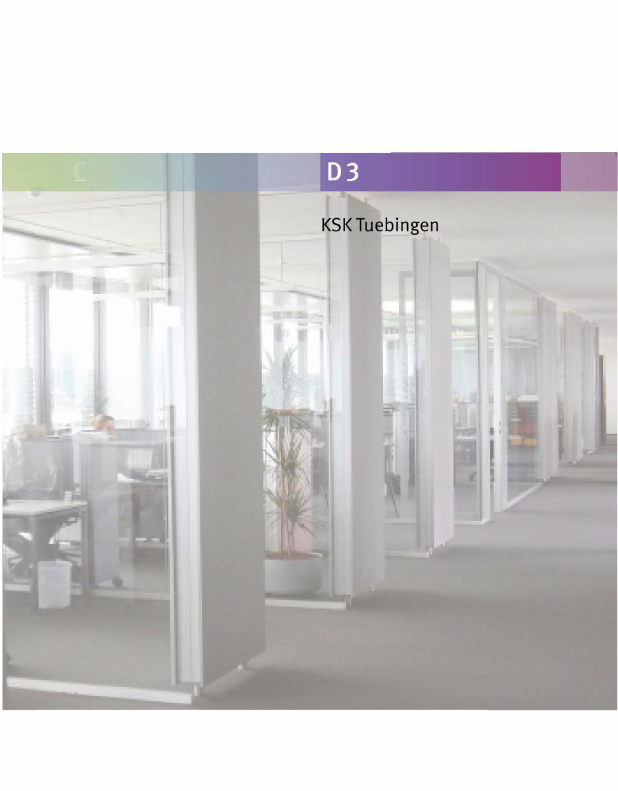
KSK Tuebingen
C D 3
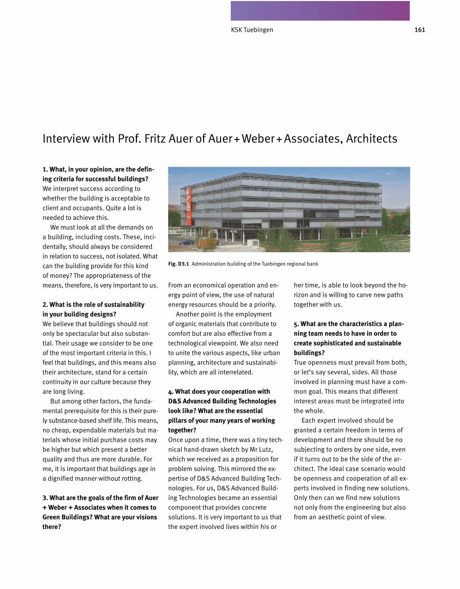
161KSK Tübingen
1. What, in your opinion, are the defining criteria for successful buildings?We interpret success according to
whether the building is acceptable to
client and occupants. Quite a lot is
needed to achieve this.
We must look at all the demands on
a building, including costs. These, inci
dentally, should always be considered
in relation to success, not isolated. What
can the building provide for this kind
of money? The appropriateness of the
means, therefore, is very important to us.
2. What is the role of sustainability in your building designs?We believe that buildings should not
on ly be spectacular but also substan
tial. Their usage we consider to be one
of the most important criteria in this. I
feel that buildings, and this means also
their ar chitecture, stand for a certain
continuity in our culture because they
are long living.
But among other factors, the funda
mental prerequisite for this is their pure
ly substancebased shelf life. This means,
no cheap, expendable materials but ma
terials whose initial purchase costs may
be higher but which present a better
quality and thus are more durable. For
me, it is important that buildings age in
a dignified manner without rotting.
3. What are the goals of the firm of Auer + Weber + Associates when it comes to Green Buildings? What are your visions there?
From an economical operation and en
ergy point of view, the use of natural
energy resources should be a priority.
Another point is the employment
of organic materials that contribute to
comfort but are also effective from a
technological viewpoint. We also need
to unite the various aspects, like urban
planning, architecture and sustainabi
lity, which are all interrelated.
4. What does your cooperation with D&S Advanced Building Technologies look like? What are the essential pillars of your many years of working together?Once upon a time, there was a tiny tech
nical handdrawn sketch by Mr Lutz,
which we received as a proposition for
problem solving. This mirrored the ex
pertise of D&S Advanced Building Tech
nologies. For us, D&S Advanced Build
ing Technologies be came an essential
component that provides concrete
solutions. It is very important to us that
the expert involved lives within his or
her time, is able to look beyond the ho
rizon and is willing to carve new paths
together with us.
5. What are the characteristics a planning team needs to have in order to create sophisticated and sustainable buildings?True openness must prevail from both,
or let’s say several, sides. All those
involved in planning must have a com
mon goal. This means that different
interest areas must be integrated into
the whole.
Each expert involved should be
granted a certain freedom in terms of
devel opment and there should be no
subjecting to orders by one side, even
if it turns out to be the side of the ar
chitect. The ideal case scenario would
be openness and cooperation of all ex
perts involved in finding new solutions.
Only then can we find new solutions
not only from the engineering but also
from an aesthetic point of view.
Interview with Prof. Fritz Auer of Auer + Weber + Associates, Architects
Fig. D 3.1 Administration building of the Tuebingen regional bank
KSK Tuebingen
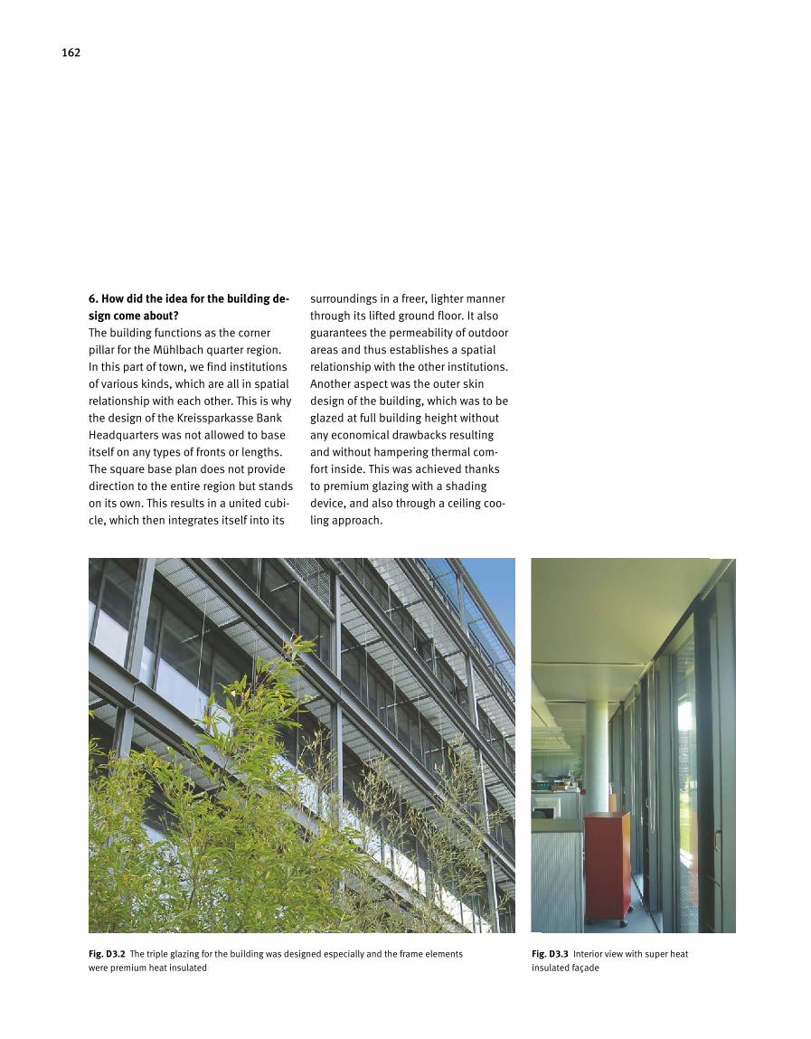
162
6. How did the idea for the building design come about?The building functions as the corner
pillar for the Mühlbach quarter region.
In this part of town, we find institutions
of various kinds, which are all in spatial
relationship with each other. This is why
the design of the Kreissparkasse Bank
Headquarters was not allowed to base
itself on any types of fronts or lengths.
The square base plan does not provide
direction to the entire region but stands
on its own. This results in a united cubi
cle, which then integrates itself into its
surroundings in a freer, lighter manner
through its lifted ground floor. It also
guarantees the permeability of outdoor
areas and thus establishes a spatial
relationship with the other institutions.
Another aspect was the outer skin
design of the building, which was to be
glazed at full building height without
any economical drawbacks resulting
and without hampering thermal com
fort inside. This was achieved thanks
to premium glazing with a shading
device, and also through a ceiling coo
ling approach.
Fig. D 3.2 The triple glazing for the building was designed especially and the frame elements
were premium heat insulated
Fig. D 3.3 Interior view with super heat
insulated façade
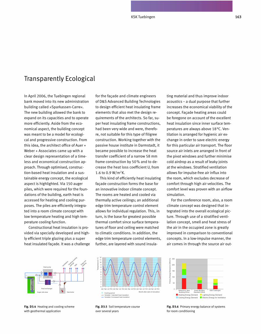
163KSK Tübingen
In April 2006, the Tuebingen regional
bank moved into its new administration
building called »Sparkassen-Carre«.
The new building allowed the bank to
expand on its capacities and to operate
more efficiently. Aside from the eco-
nomical aspect, the building concept
was meant to be a model for ecologi -
cal and progressive construction. From
this idea, the architect office of Auer +
Weber + Associates came up with a
clear design representation of a time-
less and economical construction ap-
proach. Through optimised, construc -
tion-based heat insulation and a sus-
tainable energy concept, the ecological
aspect is highlighted. Via 150 auger
piles, which were required for the foun-
dations of the building, earth heat is
accessed for heat ing and cooling pur-
poses. The piles are efficiently integra-
ted into a room climate concept with
low tempe rature heating and high tem-
perature cooling function.
Constructional heat insulation is pro-
vided via specially developed and high-
ly efficient triple glazing plus a super
heat insulated façade. It was a challenge
for the façade and climate engineers
of D&S Advanced Building Technologies
to design efficient heat insulating frame
elements that also met the design re-
quirements of the architects. So far, su-
per heat insulating frame construc tions,
had been very wide and were, therefo-
re, not suitable for this type of filigree
construction. Working together with the
passive house insti tute in Darmstadt, it
became possible to increase the heat
transfer coefficient of a narrow 58 mm
frame construction by 50% and to de-
crease the heat loss coefficient Ur from
1.6 to 0.9 W/m2K.
This kind of efficiently heat insulating
façade construction forms the base for
an innovative indoor climate concept.
The rooms are heated and cooled via
thermally active ceilings; an additional
edge trim temperature control element
allows for individual regulation. This, in
turn, is the base for greatest possible
thermal comfort since surface tempera-
tures of floor and ceiling were matched
to climatic conditions. In addition, the
edge trim temperature control elements,
further, are layered with sound insula-
ting material and thus improve indoor
acoustics – a dual purpose that further
increases the economical viability of the
concept. Façade heating areas could
be foregone on account of the excellent
heat insulation since inner surface tem-
peratures are always above 18°C. Ven-
tilation is arranged for hygienic air ex-
change in order to save electric energy
for this particular air transport. The floor
source air inlets are arranged in front of
the pivot windows and further minimise
cold airdrop as a result of leaky joints
at the windows. Stratified ventilation
allows for impulse-free air influx into
the room, which excludes decrease of
comfort through high air velocities. The
comfort level was proven with an airflow
simulation.
For the conference room, also, a room
climate concept was designed that in-
tegrated into the overall ecological pic-
ture. Through use of a stratified venti-
lation concept, smell and heat stress of
the air in the occupied zone is greatly
improved in comparison to conventional
concepts. In a low-impulse manner, the
air comes in through the source air out-
Transparently Ecological
Fig. D 3.4 Heating and cooling scheme
with geothermal application
Fig. D 3.5 Soil temperature course
over several years
Fig. D 3.6 Primary energy balance of systems
for room conditioning
Jan Apr Jul Oct Jan Apr Jul Oct Jan Apr Jul Oct Jan Apr Jul Oct Jan Apr Jul Oct
Month after start of simulationReference: New Building Office
Green Building Standard Office
KSK TuebingenCooling periodVariable 1 standard heat insulationVariable 2 increased heat insulation
Heating Energy Demand Lighting Energy DemandCooling Energy Demand Electric Energy for Ventilation
1211109876543210
250
200
150
100
50
0
Tem
pera
ture
in °
C
Prim
ary
Ener
gy D
eman
d in
kW
h/m
2 a
Heat pump
Heat exchanger
Auger pile area Gas boiler
Ventilatio
n
Heating-co
oling
ceilin
gsEdge t
rim
heating
TBA
KSK Tuebingen
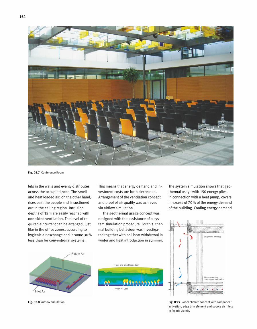
164
lets in the walls and evenly distributes
across the occupied zone. The smell
and heat loaded air, on the other hand,
rises past the people and is suctioned
out in the ceiling region. Intrusion
depths of 15m are easily reached with
one-sided ventilation. The level of re-
quired air current can be arranged, just
like in the office zones, according to
hygienic air exchange and is some 30%
less than for conventional systems.
This means that energy demand and in -
vestment costs are both decreased.
Arrangement of the ventilation concept
and proof of air quality was achieved
via airflow simulation.
The geothermal usage concept was
designed with the assistance of a sys-
tem simulation procedure. For this, ther-
mal building behaviour was investiga-
ted together with soil heat withdrawal in
winter and heat introduction in summer.
The system simulation shows that geo-
thermal usage with 150 energy piles,
in connection with a heat pump, covers
in excess of 70% of the energy demand
of the building. Cooling energy demand
Fig. D 3.9 Room climate concept with component
activation, edge trim element and source air inlets
in façade vicinity
Fig. D 3.7 Conference Room
Fig. D 3.8 Airflow simulation
Return Air
Heat and smell loaded air
Edge trim heating
Thermo-active component activation
Fresh Air LakeInlet Air
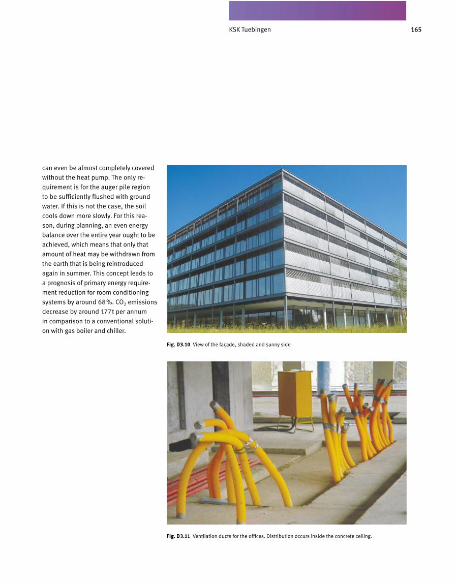
165KSK Tübingen
can even be almost completely covered
without the heat pump. The only re
quire ment is for the auger pile region
to be sufficiently flushed with ground
water. If this is not the case, the soil
cools down more slowly. For this rea
son, during planning, an even energy
balance over the entire year ought to be
achieved, which means that only that
amount of heat may be withdrawn from
the earth that is being reintroduced
again in summer. This concept leads to
a prog nosis of primary energy require
ment reduction for room conditioning
sys tems by around 68%. CO2 emissions
decrease by around 177t per annum
in comparison to a conventional soluti
on with gas boiler and chiller.
Fig. D 3.11 Ventilation ducts for the offices. Distribution occurs inside the concrete ceiling.
Fig. D 3.10 View of the façade, shaded and sunny side
KSK Tuebingen
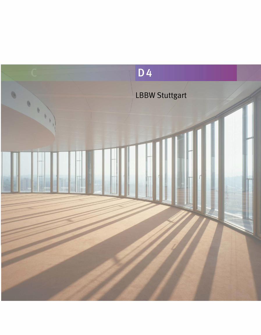
C D 4
LBBW Stuttgart
167LBBW Stuttgart
1. What, in your opinion, are the defining criteria for successful buildings?I believe that successful buildings
distinguish themselves by their sustai-
nability in regard to their aesthetic
appearance but also their technologi -
cal features. Modern buildings, there-
fore, should always have a relation ship
with the inventory and react to their
environment. Then they guarantee op-
timum usage.
2. What is the role of sustainability in your building designs?There are many different aspects that
work together in order to help a build-
ing become part of an integrated whole:
we need to look at its technological,
functional, urban-planning and aesthe-
tic arrangement. The growing world
population and the increase in urban
settlements with simultaneous decline
of rural areas is a challenge to desig-
ners. They need to create places worth
living in for the generations to come.
3. What are the goals of Wöhr and Mieslinger Architects when it comes to Green Buildings? What are your visions there?A futuristic topic that increasingly keeps
occupying our minds – aside from con-
stant progression of modern building
technologies and their aesthetic appea-
rance – is how can we resuscitate exist-
ing building stock? With several of our
projects, we have already undertaken
building refurbishments that contribute
towards an ecologically sensible, sustai-
nable use of the building stock.
4. How did your cooperation with D&S Advanced Building Technologies come about? What are the essential pillars of your many years of working together?Our cooperation with D&S Advanced
Build ing Technologies is char acterized
by openness and excellent teamwork.
A high level of expert knowledge always
results in successful execution of a
given project.
5. What are the characteristics a planning team needs to have in order to create sophisticated and sustainable buildings?A successful planning team must have
both expert knowledge and creativity
as well as, to a high degree, team spirit
and the ability to communicate.
6. How did the idea for the LBBW building design come about?Initially, there were a lot of urban plan-
ning factors to keep in mind. We were
facing a special situation here, which
was the connecting of the new building
to the existing LBBW buildings on the
site of Stuttgart 21. This gave rise to the
idea of a space-creating city extension.
It was important to me to set a solid
mark that would define and distinguish
the place.
7. What were your goals for this design?With Stuttgart 21, I wanted to create a
new, lively and vivacious part of town
to exist as a functioning component of
the inner city. For this reason, the his-
torical building stipulations in Stuttgart,
perimeter block development, were an
important guideline for the new build-
ing. The materials used, also, were
supposed to adapt to old traditions and
form one solid unit with those already
present. In the next step, I looked at
optimisation of working space quality
via organisation and interior make-up
of the buildings. Another topic that is al-
ways close to my heart is the accessibi-
lity of a building from the outside.
8. What are some of the extraordinary qualities this building has to offer – to client and tenants?A building speaks its very own language
and this language fulfils representative
as well as identification-related require-
ments. An excellent working place qual-
ity level is mirrored in this particular
building’s architecture. The layout is flex-
ibly variable, which means that a swift
reaction to changing requirements be
comes possible and, for each new utili za-
tion, an optimum working environment
can be created once more.
Interview with the Architect Wolfram Wöhr of W. Wöhr – Jörg Mieslinger Architects, Munich, Stuttgart
LBBW Stuttgart
168
1. What, in your opinion, are the defining criteria for successful buildings?The first is a high degree of flexibility.
For this reason, there should be as few
user-specific fixtures in the areas to be
rented out. The second of the criteria
is an economical layout. Correct build-
ing depth contributes towards econo-
mical operation, especially in the case
of open office configuration. The third
aspect is usage quality. With today’s
dense occupancy rates, cooling of the
useful areas is a must. Its quality level
should not be subject to economisation.
2. What does living inside a building mean to you? What factors are essentially decisive as to whether you feel comfortable or not?Well-chosen colours on all visible surfac-
es, for instance, are an important factor.
I am looking for warm wood tones and
manageable room size. The se measu res
serve to create a sense of comfort, which,
here in Germany, we call »Gemütlich-
keit«. Another important factor is the
chance for occupants to socialize with
each other. Nothing is more important
than the tea kitchen or the copy room,
regardless of how small they might be.
For an open office configuration, on the
other hand, you need meeting areas
where you can socia lize and discuss top-
ics that may go beyond the immediate
work subjects as well. In other words,
during planning one needs to ask the oc-
cupants what their expectations of the
rooms are, in terms of their character.
3. What is the role of sustainability, of life cycle consideration, in your building stipulations?This aspect, indeed, is as important as
the initial investment for the building
itself since you really have to live with
both factors. The decision on the initial
investment is usually a matter of a few
minutes. However, once operating costs
get out of hand, the damage is consi-
derable. For this reason, each building
we handle should be considered from
a life-cycle aspect also and we wish to
improve in this area with each building
we erect. During planning, and later
also during operation, we test each sys-
tem and component for its sustaina-
bility. Further, we determine whether it
is causing or saving costs. Therefore,
this discussion is no longer limited to
initial investment only.
4. You experience the entire process, from design to operation. Where do you see the greatest improvement potential: in the process, in finding ideas, planning implementation, constructional execution or operating behaviour?All of the above. Just like D&S Advanced
Building Technologies does for its pro-
ject support, we also need to be aware
early on that it is during the initial plan-
ning phase where you need to make
the correct decisions. During the actual
building stage, it is very important for
someone on the client’s side to look
after quality control. When it comes to
operating costs, we do two things: first,
Interview with the Client Fred Gaugler, BWImmobilien GmbH
as already mentioned, there are sustai-
nable decisions during planning. Then,
we strive to lower energy costs even
further during operation and we do this
by forming a so-called operations team
which has certain sav ings targets and
also goes out to seek advice during the
initial phase.
5. What are the characteristics a planning team needs to have in order to create sophisticated and sustainable buildings?Above all, it needs to be creative and
persistent in following its goals. Aside
from their architecture and investment
costs, the energy consumption of build-
ings nowadays is a big factor.
6. What are some of the extraordinary qualities the LBBW building has to offer – to client and tenants?This building complex is located at the
entrance to the City of Stuttgart and
impresses through its prominent High-
rise design. I like both its overall ap-
pearance and also its interior design,
which not only pleases us as clients but
also the occupants. Further, I think the
ecological approach to operating the
building is remarkable. One should not
forget that Green Building as a term is
synony mous for buildings that not only
strive to be aesthetically pleasing but
also take into account the energy aspect
and hence, satisfy their owners and oc-
cupants.
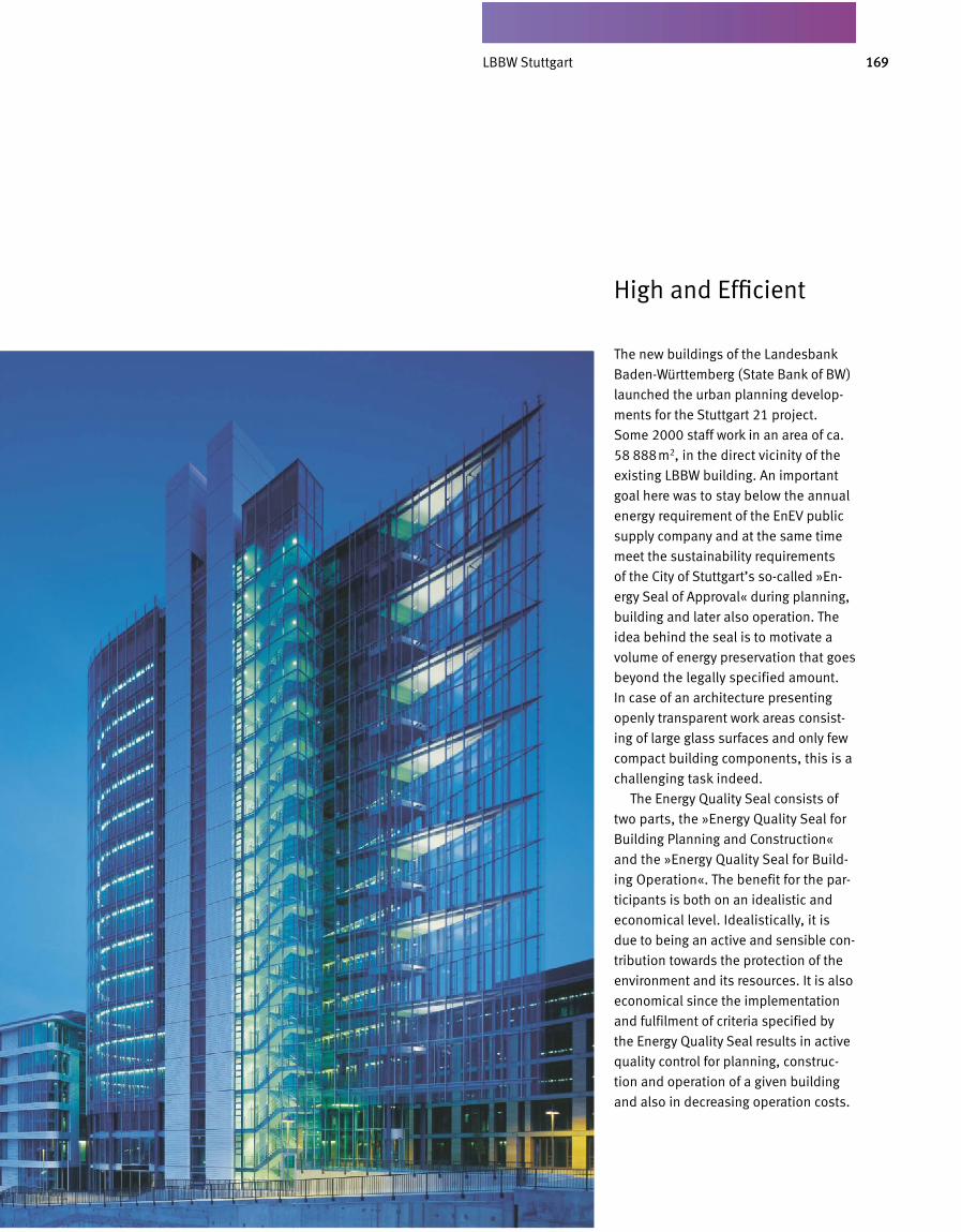
169LBBW Stuttgart
The new buildings of the Landesbank
Baden-Württemberg (State Bank of BW)
launched the urban planning develop-
ments for the Stuttgart 21 project.
Some 2000 staff work in an area of ca.
58 888m2, in the direct vicinity of the
existing LBBW building. An important
goal here was to stay below the annual
energy requirement of the EnEV public
supply company and at the same time
meet the sustainability requirements
of the City of Stuttgart’s so-called »En-
ergy Seal of Approval« during planning,
building and later also opera tion. The
idea behind the seal is to moti vate a
volume of energy preservation that goes
beyond the legally specified amount.
In case of an architecture presenting
openly transparent work areas consist-
ing of large glass surfaces and only few
compact building com ponents, this is a
challeng ing task indeed.
The Energy Quality Seal consists of
two parts, the »Energy Quality Seal for
Building Planning and Construction«
and the »Energy Quality Seal for Build-
ing Operation«. The benefit for the par-
ticipants is both on an idealistic and
economical level. Idealistically, it is
due to being an active and sensible con -
tribution towards the protection of the
environment and its resources. It is also
economical since the implementation
and fulfilment of criteria specified by
the Energy Quality Seal results in active
quality control for planning, construc-
tion and operation of a given building
and also in decreasing operation costs.
High and Efficient
LBBW Stuttgart
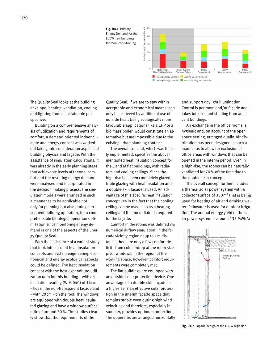
170
The Quality Seal looks at the building
envelope, heating, ventilation, cooling
and lighting from a sustainable per
spective.
Building on a comprehensive analy
sis of utilization and requirements of
comfort, a demandoriented indoor cli
mate and energy concept was worked
out taking into consideration aspects of
building physics and façade. With the
assistance of simulation calculations, it
was already in the early planning stage
that achievable levels of thermal com
fort and the resulting energy demand
were analysed and incorporated in
the decision making process. The sim
ulation models were arranged in such
a manner as to be applicable not
only for planning but also during sub
sequent building operation, for a com
prehen sible (strategic) operation opti
misation since monitoring energy de
mand is one of the aspects of the Ener
gy Quality Seal.
With the assistance of a variant study
that took into account heat insulation
concepts and system engineering, eco
nomical and energy ecological aspects
could be defined. The heat insulation
concept with the best expenditureutili
zation ratio for this building – with an
insulation reading (WLG 040) of 14cm
– lies in the nontransparent façade and
– with 20cm – on the roof. The windows
are equipped with double heat insula
ted glazing and have a window surface
ratio of around 70%. The studies clear
ly show that the requirements of the
Quality Seal, if we are to stay within
acceptable and economical means, can
only be achieved by additional use of
outside heat. Using ecologically more
favourable applications like a CHP or a
bio mass boiler, would constitute an al
ternative but are impossible due to the
existing urban planning contract.
The overall concept, which was final
ly implemented, specifies the above
mentioned heat insulation concept for
the L and M flat buildings, with radia
tors and cooling ceilings. Since the
highrise has been completely glazed,
triple glazing with heat insulation and
a doubleskin façade is used. An ad
vantage of this specific heat insulation
concept lies in the fact that the cooling
ceiling can be used also as a heating
ceiling and that no radiator is required
for the façade.
Comfort in the rooms was defined via
numerical airflow simulation. In the fa
çade vicinity region at up to 1m dis
tance, there are only a few comfort de
fi cits from cold airdrop at the room size
pivot windows. In the region of the
working space, however, comfort requi
rements were completely met.
The flat buildings are equipped with
an outside solar protection device. One
advantage of a double skin façade in
a highrise is an effective solar protec
tion in the interim façade space that
remains stable even during high wind
velocities and therefore, especially in
summer, provides optimum protection.
The upper ribs are arranged horizontal ly
and support daylight illumination.
Control is per room and/or façade and
takes into account shading from adja
cent buildings.
Air exchange in the office rooms is
hygienic and, on account of the open
space setting, arranged dually. Air dis
tribution has been designed in such a
manner as to allow for exclusion of
office areas with windows that can be
opened in the interim period. Even in
a highrise, the rooms can be naturally
ventilated for 70% of the time due to
the doubleskin concept.
The overall concept further includes
a thermal solar power system with a
collector surface of 350m2 that is being
used for heating of air and drinking wa
ter. Rainwater is used for outdoor irriga
tion. The annual energy yield of the so
lar power system is around 135 MWh/a
Fig. D 4.2 Façade design of the LBBW highrise
Fig. D 4.1 Primary
Energy Demand for the
LBBW new buildings
for room conditioning
Heating Energy Demand Lighting Energy Demand
Cooling Energy Demand Electric Energy for Ventilation
250
200
150
100
50
0
Prim
ary
Ener
gy D
eman
d in
kW
h/m
2 a
Reference: New Building Office
Green Building Standard Office
LBBW Component L
LBBW Component M
LBBW Component N
Heating/Cooling Ceiling

171LBBW Stuttgart
and can be included in meeting overall
primary energy demand.
Diverse new tools were developed to
meet the Quality Seal’s requirements
for construction and operation. The fa
çade, once completed, was subjected
to random testing for density and also
to a complete infrared thermography.
These controls were part of the encom
passing inspection and commissioning
procedure.
The simulation models from planning
can be used for inspection of ICA func
tions prior to installation of the DDC de
vices. This allows for early identification
of malfunctions, which prevents later
trouble, increased energy consumption
or uncomfortable room conditions du
ring later operation. These simulation
models are used as a referential base
for the subsequent operation optimisa
tion. The simulation models create a
kind of ideal operation situation. Com
paring actual with ideal operation, op
ti misation potentials can be worked out
that were previously impossible with
the usual systems. For the Energy Quali
ty Seal, the tools are currently applied
in order to define actual energy con
sumption and the resulting level of
energy efficiency. Table D4.1 shows
qual ity seal requirements for lighting,
and results of the readings. Annual en
ergy demand calculation was handled
via simulation, and validated through
the readings. Measuring heating, coo
ling and electricity consumption was
handled according to the same system.
Primary energy con sumption lies some
where between the demand of the re
ference building and the target value of
the Green Building Standard Office. The
highrise, with its improved heat insula
tion, presents the lowest primary energy
consumption lev el and remains about
20% above the target value. The re
sults for the first two years of operation
are satisfactory but also point towards
a further optimisation potential that is
meant to be realised over the next ope
ration years through operational energy
management.
Tab. D 4.1 Summary of Quality Seal requirements for lighting, and readings
Fig. D 4.3 Electricity consumption for lighting for a communal office
1500
1350
1200
1050
900
750
600
450
300
150
0
50 000
45 000
40 000
35 000
30 000
25 000
20 000
15 000
10 000
5 000
Ener
gy c
onsu
mpt
ion
of li
ghtin
g in
W
Out
door
Brig
htne
ss in
lx
00:00 02:00 04:00 06:00 08:00 10:00 12:00 14:00 16:00 18:00 20:00 22:00 00:00
Time
Community Office 500 lx
Hallway 100 lx
Stock Evaluation
Community Office
Interior Trafficked Areas
Hallways
Installed Capacity [W/m2] Energy Requirement [kWh/m2a]
Installed Capacity [W/m2] Energy Consumption [kWh/m2a]
boundary value target value boundary value target value 15 11 22 13
4.5 3.5 4.5 1.5
11.3 17.0
5.0 4.0
4.4 3.5
LBBW Stuttgart
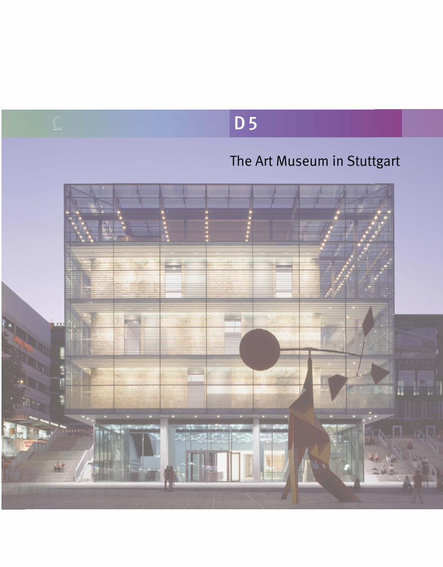
C D 5
The Art Museum in Stuttgart
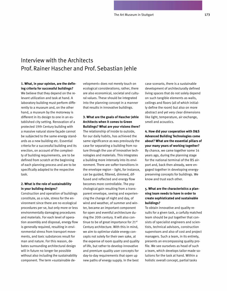
173Kunstmuseum
1. What, in your opinion, are the defining criteria for successful buildings?We believe that they depend on the re
levant utilization and task at hand. A
laboratory building must perform diffe
rently to a museum and, on the other
hand, a museum by the motorway is
different in its design to one in an es
tablished city setting. Renovation of a
protected 19th Century building with
a massive natural stone façade cannot
be subjected to the same energy stand
ards as a new building etc. Essential
criteria for a successful building and its
erection, on account of the complexi
ty of building requirements, are to be
defined from scratch at the beginning
of each planning process and are to be
specifically adapted to the respective
task.
2. What is the role of sustainability in your building designs?Construction and operation of buildings
constitute, as a rule, stress for the en
vironment since there are no ecological
procedures per se, but only more or less
environmentally damaging procedures
and materials. For each level of opera
tion assembly and disposal, energy flow
is generally required, resulting in envi
ronmental stress from transport move
ments, and toxic substances result for
man and nature. For this reason, de
bates surrounding architectural design
will in future no longer be possible
without also including the sustainability
component. The term »sustainable de
velopment« does not merely touch on
ecological considerations; rather, there
are also economical, societal and cultu
ral values. These should be integrated
into the planning concept in a manner
that results in innovative buildings.
3. What are the goals of Hascher Jehle Architects when it comes to Green Buildings? What are your visions there?The relationship of inside to outside,
for our daily habits, has achieved the
same significance as was previously the
case for separating a building from na
ture through the use of innovative tech
nologies and materials. This integrates
a building more intensely into its envi
ronment. There are softer transitions in
the envelope region – light, for instance,
can be guided, filtered, dimmed, dif
fused and reflected and energy flow
becomes more controllable. The psy
chological gain resulting from a trans
parent envelope, seeing and experien
cing the change of night and day, of
wind and weather, of summer and win
ter, became an important component
for open and eventful architecture du
ring the 20th century. It will also con
tinue to be of great importance for 21st
Century architecture. With this in mind,
we aim to optimise viable energy con
cepts not solely for their own sake, at
the expense of room quality and quality
of life, but rather to develop innovative
and premium quality user concepts for
daytoday requirements that open up
new paths of energy supply. In the best
case scenario, there is a sustai n able
development of architecturally defined
living spaces that do not solely depend
on such tangible elements as walls,
ceilings and floors (all of which initial
ly define the room) but also on more
abstract and yet very clear di mensions
like light, temperature, air exchange,
smell and acoustics.
4. How did your cooperation with D&S Advanced Building Technologies come about? What are the essential pillars of your many years of working together?By chance, we came together some 14
years ago, during the planning stage
for the national terminal of the BS air
port and, back then already, were en
gaged together in developing energy
preserving concepts for buildings. We
know and trust each other.
5. What are the characteristics a planning team needs to have in order to create sophisticated and sustainable buildings?To obtain innovative and quality re
sults for a given task, a carfully matched
team should be put together that con
sists of specialist engineers and scien
tists, technical advisors, construction
super visors and also of cost and project
managers. Such a team, in its entirety,
presents an encompassing quality pro
file. We see ourselves as head of such
a team, which develops tailormade so
lutions for the task at hand. Within a
holistic overall concept, partial tasks
Interview with the Architects Prof. Rainer Hascher and Prof. Sebastian Jehle
The Art Museum in Stuttgart
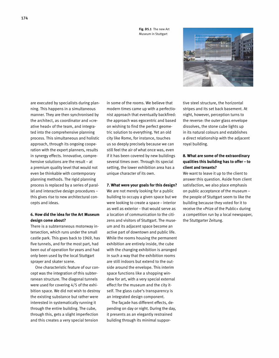
174
are executed by specialists during plan
ning. This happens in a simultan eous
manner. They are then synchronised by
the architect, as coordinator and »cre
ative head« of the team, and integra
ted into the comprehensive planning
process. This simultaneous and holistic
approach, through its ongoing coope
ration with the expert planners, results
in synergy effects. Innovative, compre
hensive solutions are the result – at
a premium quality level that would not
even be thinkable with contemporary
planning methods. The rigid planning
process is replaced by a series of paral
lel and interactive design pro ce dures –
this gives rise to new architectural con
cepts and ideas.
6. How did the idea for the Art Museum design come about?There is a subterraneous motorway in
tersection, which runs under the small
castle park. This goes back to 1969, has
five tunnels, and for the most part, had
been out of operation for years and had
only been used by the local Stuttgart
sprayer and skater scene.
One characteristic feature of our con
cept was the integration of this subter
ranean structure. The diagonal tunnels
were used for covering 4/5 of the exhi
bition space. We did not wish to destroy
the existing substance but rather were
interested in systematically running it
through the entire building. The cube,
through this, gets a slight imperfection
and this creates a very special tension
in some of the rooms. We believe that
modern times came up with a perfectio
nist approach that eventually backfired:
the approach was egocentric and based
on wishing to find the perfect geome
tric solution to everything. Yet an old
city like Rome, for instance, touches
us so deep ly precisely because we can
still feel the air of what once was, even
if it has been covered by new buildings
several times over. Through its special
setting, the lower exhibition area has a
unique character of its own.
7. What were your goals for this design?We are not merely looking for a public
building to occupy a given space but we
were looking to create a space – interior
as well as exterior – that would serve as
a location of communication to the citi
zens and visitors of Stuttgart. The muse
um and its adjacent space become an
active part of downtown and public life.
While the rooms housing the permanent
exhibition are entirely inside, the cube
with the changing exhibition is arranged
in such a way that the exhibition rooms
are still indoors but extend to the out
side around the envelope. This interim
space functions like a shopping win
dow for art, with a very special external
effect for the museum and the city it
self. The glass cube‘s transparency is
an integrated design component.
The façade has different effects, de
pending on day or night. During the day,
it presents as an elegantly restrained
building through its minimal suppor
tive steel structure, the horizontal
stripes and its set back basement. At
night, how e ver, perception turns to
the reverse: the outer glass envelope
dissolves, the stone cube lights up
in its na tural colours and establishes
a direct relationship with the adjacent
royal building.
8. What are some of the extraordinary qualities this building has to offer – to client and tenants?We want to leave it up to the client to
answer this question. Aside from client
satisfaction, we also place emphasis
on public acceptance of the museum –
the people of Stuttgart seem to like the
building because they voted for it to
receive the »Prize of the Public« during
a competition run by a local newspaper,
the Stuttgarter Zeitung.
Fig. D 5.1 The new Art
Museum in Stuttgart
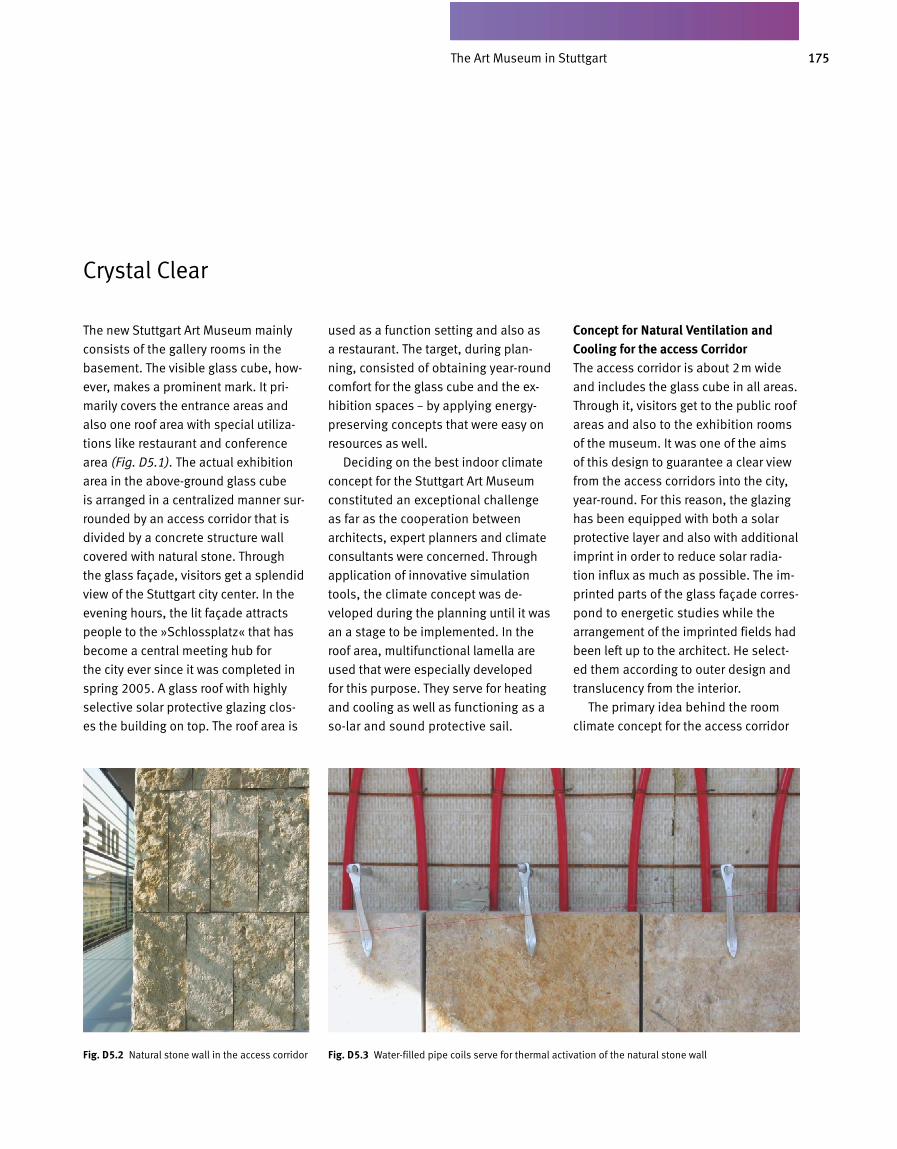
175Kunstmuseum
Crystal Clear
The new Stuttgart Art Museum mainly
consists of the gallery rooms in the
basement. The visible glass cube, ho w-
ever, makes a prominent mark. It pri-
marily covers the entrance areas and
also one roof area with special utiliza-
tions like restaurant and conference
area (Fig. D5.1). The actual exhibition
area in the above-ground glass cube
is arranged in a centralized manner sur-
rounded by an access corridor that is
divided by a concrete structure wall
covered with natural stone. Through
the glass façade, visitors get a splen did
view of the Stuttgart city center. In the
evening hours, the lit façade attracts
people to the »Schlossplatz« that has
become a central meeting hub for
the city ever since it was completed in
spring 2005. A glass roof with highly
selective solar protective glazing clos-
es the building on top. The roof area is
used as a function setting and also as
a res taurant. The target, during plan-
ning, consisted of obtaining year-round
comfort for the glass cube and the ex-
hibition spaces – by applying energy-
preserving concepts that were easy on
resources as well.
Deciding on the best indoor climate
concept for the Stuttgart Art Museum
constituted an exceptional challenge
as far as the cooperation between
architects, expert planners and climate
consultants were concerned. Through
application of innovative simulation
tools, the climate concept was de-
veloped during the planning until it was
an a stage to be implemented. In the
roof area, multifunctional lamella are
used that were especially developed
for this purpose. They serve for heating
and cooling as well as functioning as a
so -lar and sound protective sail.
Concept for Natural Ventilation and Cooling for the access CorridorThe access corridor is about 2m wide
and includes the glass cube in all areas.
Through it, visitors get to the public roof
areas and also to the exhibition rooms
of the museum. It was one of the aims
of this design to guarantee a clear view
from the access corridors into the city,
year-round. For this reason, the glazing
has been equipped with both a solar
protective layer and also with additional
imprint in order to reduce solar radia-
tion influx as much as possible. The im-
printed parts of the glass fa çade corres-
pond to energetic studies while the
arrangement of the imprinted fields had
been left up to the architect. He select-
ed them according to outer design and
translucency from the interior.
The primary idea behind the room
cli mate concept for the access corridor
D5.03 5.12
Fig. D 5.2 Natural stone wall in the access corridor Fig. D 5.3 Water-filled pipe coils serve for thermal activation of the natural stone wall
The Art Museum in Stuttgart
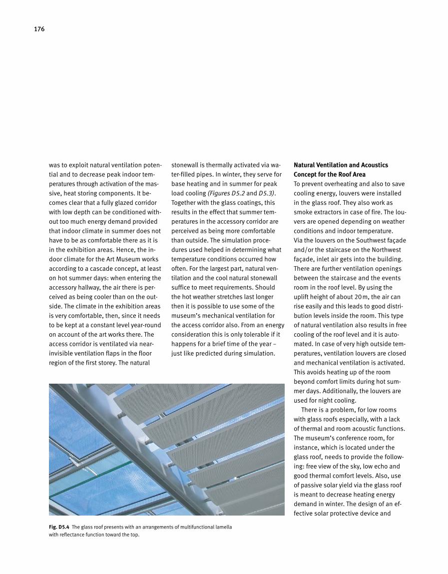
176
was to exploit natural ventilation poten-
tial and to decrease peak indoor tem-
peratures through activation of the mas-
sive, heat storing components. It be-
comes clear that a fully glazed corridor
with low depth can be conditioned with-
out too much energy demand pro vided
that indoor climate in summer does not
have to be as comfortable there as it is
in the exhibition areas. Hence, the in-
door climate for the Art Museum works
according to a cascade concept, at least
on hot summer days: when entering the
accessory hallway, the air there is per-
ceived as being cool er than on the out-
side. The climate in the exhibition areas
is very comforta ble, then, since it needs
to be kept at a constant level year-round
on account of the art works there. The
access cor ridor is ventilated via near-
invisible ventilation flaps in the floor
region of the first storey. The natural
stonewall is thermally activated via wa-
ter-filled pipes. In winter, they serve for
base heating and in summer for peak
load cooling (Figures D5.2 and D5.3).
Together with the glass coatings, this
results in the effect that summer tem-
peratures in the accessory corridor are
perceived as being more comfortable
than outside. The simulation proce-
dures used helped in determining what
temperature conditions occurred how
often. For the largest part, natural ven-
tilation and the cool natural stonewall
suffice to meet requirements. Should
the hot weather stretches last longer
then it is possible to use some of the
museum’s mechanical ventilation for
the access corridor also. From an energy
consideration this is only tolerable if it
happens for a brief time of the year –
just like predicted during simulation.
Natural Ventilation and Acoustics Concept for the Roof AreaTo prevent overheating and also to save
cooling energy, louvers were in stalled
in the glass roof. They also work as
smoke extractors in case of fire. The lou-
vers are opened depending on weather
conditions and indoor tem perature.
Via the louvers on the South west façade
and/or the staircase on the Northwest
façade, inlet air gets into the building.
There are further ventilation openings
between the staircase and the events
room in the roof level. By using the
uplift height of about 20m, the air can
rise easily and this leads to good distri-
bution levels inside the room. This type
of natural ventilation also results in free
cooling of the roof level and it is auto-
mated. In case of very high out side tem-
peratures, ventilation louvers are closed
and mechanical ventilation is acti vated.
This avoids heating up of the room
beyond comfort limits during hot sum-
mer days. Additionally, the louvers are
used for night cooling.
There is a problem, for low rooms
with glass roofs especially, with a lack
of thermal and room acoustic functions.
The museum’s conference room, for
in stance, which is located under the
glass roof, needs to provide the follow-
ing: free view of the sky, low echo and
good thermal comfort levels. Also, use
of passive solar yield via the glass roof
is meant to decrease heating energy
demand in winter. The design of an ef-
fective solar protective device and
Fig. D 5.4 The glass roof presents with an arrangements of multifunctional lamella
with reflectance function toward the top.
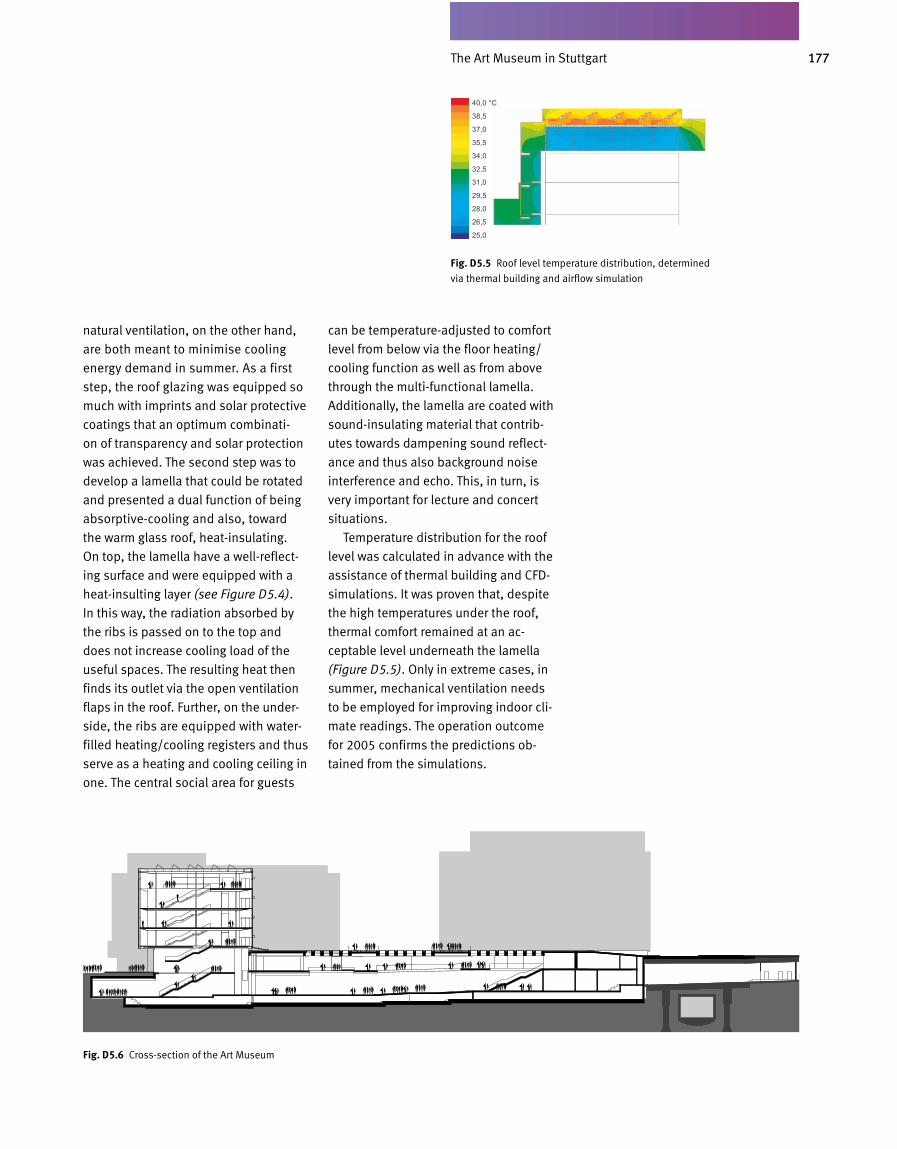
177Kunstmuseum
Fig. D 5.5 Roof level temperature distribution, determined
via thermal building and airflow simulation
natural ventilation, on the other hand,
are both meant to minimise cooling
energy demand in summer. As a first
step, the roof glazing was equipped so
much with imprints and solar protective
coat ings that an optimum combinati-
on of transparency and solar protection
was achieved. The second step was to
devel op a lamella that could be ro tated
and presented a dual function of being
ab sorptive-cooling and also, toward
the warm glass roof, heat-insulating.
On top, the lamella have a well-reflect-
ing surface and were equipped with a
heat-insulting layer (see Figure D5.4).
In this way, the radiation absorbed by
the ribs is passed on to the top and
does not increase cooling load of the
useful spaces. The resulting heat then
finds its outlet via the open ventilation
flaps in the roof. Further, on the under-
side, the ribs are equipped with water-
filled heating/cooling registers and thus
serve as a heating and cooling ceiling in
one. The central social area for guests
can be temperature-adjusted to comfort
level from below via the floor heating/
cooling function as well as from above
through the multi-functional lamella.
Additionally, the lamella are coated with
sound-insulating material that contrib-
utes towards dampening sound reflect-
ance and thus also background noise
interference and echo. This, in turn, is
very important for lecture and concert
situations.
Temperature distribution for the roof
level was calculated in advance with the
assistance of thermal building and CFD-
simulations. It was proven that, despite
the high temperatures under the roof,
thermal comfort remained at an ac-
ceptable level underneath the lamella
(Figure D5.5). Only in extreme cases, in
summer, mechanical venti lation needs
to be employed for im pro ving indoor cli-
mate readings. The operation outcome
for 2005 confirms the predictions ob-
tained from the simulations.
D5.02 5.12
Fig. D 5.6 Cross-section of the Art Museum
The Art Museum in Stuttgart
C D 6
New building: European Investment Bank (EIB) in Luxembourg‘Excellent’
179EIB in Luxemburg
1. What, in your opinion, are the defining criteria for successful buildings?A successful building should make
people happy who live and work there.
It should render their lives easier and
happier. Naturally, building cannot be
a substitute for life per se and we can-
not bring about the well-being of a per-
son through a building but we can, at
least, make it possible in a supportive
function.
2. What is the role of sustainability in your building designs?Sustainability plays a decisive role for
our building design. We have a clear
idea according to which ideas and cri te-
ria these kinds of buildings are to be
designed. We also strive to reduce ener-
gy requirement in whatever possible
manner. Aside from energy savings we
also develop concepts for user-friend-
liness. One example would be the sim-
ple idea of opening a window. This may
sound easy but we know how difficult
it can eventually be for many buildings
to achieve ventilation and activation in
this manner. The possibility of opening
windows and doors to influence room
temperatures, possibly also solar pro-
tection, is also connected with the su-
stainability of a building. Buildings, one
must envision, can only be successful
when they are »humane«, which means
when human beings do not lose their
right to think and read-through techno-
logical systems with perfect control
mechanisms.
3. What are the goals of Ingenhoven Architects when it comes to Green Buildings? What are your visions there?Once you have subscribed to the idea
of sustainable buildings or Green Build-
ing design, in my opinion, this means
nothing else but the need to think of
yourself as a kind of spearhead for mak-
ing a certain type of avant-garde archi-
tecture possible. By avant-garde, I do
not mean in terms of shape or outer
form but, rather, in terms of conserving
resources. In the energy sector, for in-
stance, we would desire for buildings
to present at least an even, better still,
a positive CO2 balance. Another tar-
get might be that one uses an en ergy-
efficient building operation and build-
ing planning for one thing to use very,
very little energy for erection and opera-
tion of the building in the first place.
Further, that the tiny bit of energy we do
require is generated via alternative, re-
newable energy sources like sun, wind,
earth heat etc. With the possibly resul-
ting excess for a given building, one
would then help the not so energy-effi-
cient installations obtain a more even
balance. Yet, there are also other means
of compensation, for instance when loo-
king at a high-rise project in downtown.
It should be possible, really, to reinstate
the square meters that are being used
up for building on one hand, by erec-
ting atria, gardens, roof gardens and
the like, perhaps even on or over seve-
ral floors. This would return to the peo-
ple what they have lost and these could
be cultivated in such a manner as to
disturb the microclimate as little as pos-
sible. Or we could work with intelligent
roof materials that a void, for instance,
the occurrence of heat islands, col lect
rainwater via non-contaminated roof
material and then, in a filtered form,
return it to the soil via the gardens, if
possible on or very close to the original
source.
4. How did your cooperation with D&S Advanced Building Technologies come about? What are the essential pillars of your many years of working together? What are the characteristics a planning team needs to have in order to create sophisticated and sustainable buildings?We had been looking for reliable part-
ners for a very long time. Eventually,
we got to a point where it was no longer
possible to handle our self-defined tar-
gets – taking a very innovative approach
to ecological architecture and possibly
also to continue advancing in this area –
with our usual consultants and engineer
firms. We always try to surround oursel-
ves with the very best and then to esta-
blish long-term relationships. I feel that
it is part of our work to sub scribe to this
type of team spirit. Then came a time
when we realized that we had to reori-
ent ourselves in the sector of domestic
engineering and that this included a
comprehensive responsibility for buil
ding comfort. It has now been more than
15 years but this was how our initial
contact with D&S Advanced Building
Interview with Christoph Ingenhoven of Ingenhoven Architects
European Investment Bank in Luxembourg
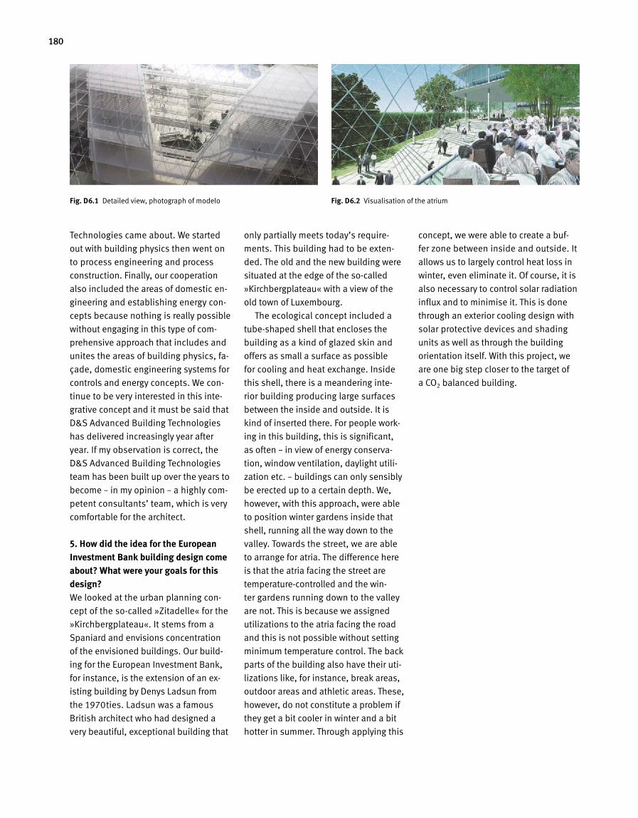
180
Fig. D 6.1 Detailed view, photograph of modelo Fig. D 6.2 Visualisation of the atrium
Technologies came about. We started
out with building physics then went on
to process engineering and process
construction. Finally, our cooperation
also included the areas of domestic en
gineering and establishing energy con
cepts because nothing is really possible
without engaging in this type of com
prehensive approach that includes and
unites the areas of build ing physics, fa
çade, domestic engine ering sys tems for
controls and energy concepts. We con
tinue to be very inter ested in this inte
grative concept and it must be said that
D&S Advanced Building Technologies
has deliv ered increasingly year after
year. If my observation is correct, the
D&S Advanced Building Technologies
team has been built up over the years to
become – in my opinion – a highly com
petent consultants’ team, which is very
comfortable for the architect.
5. How did the idea for the European Investment Bank building design come about? What were your goals for this design?We looked at the urban planning con
cept of the socalled »Zitadelle« for the
»Kirchbergplateau«. It stems from a
Spaniard and envisions concentration
of the envisioned buildings. Our build
ing for the European Investment Bank,
for instance, is the extension of an ex
is t ing building by Denys Ladsun from
the 1970ties. Ladsun was a famous
Brit ish architect who had designed a
very beautiful, exceptional building that
only partially meets today’s require
ments. This building had to be exten
ded. The old and the new building were
situated at the edge of the socalled
»Kirchbergplateau« with a view of the
old town of Luxembourg.
The ecological concept included a
tubeshaped shell that encloses the
building as a kind of glazed skin and
offers as small a surface as possible
for cooling and heat exchange. Inside
this shell, there is a meandering inte
rior building producing large surfaces
between the inside and outside. It is
kind of inserted there. For people work
ing in this building, this is significant,
as often – in view of energy conserva
ti on, window ventilation, daylight utili
zation etc. – buildings can only sensibly
be erected up to a certain depth. We,
however, with this approach, were able
to position winter gardens inside that
shell, running all the way down to the
valley. Towards the street, we are able
to arrange for atria. The difference here
is that the atria facing the street are
temperaturecontrolled and the win
ter gardens running down to the valley
are not. This is because we assigned
utilizations to the atria facing the road
and this is not possible without setting
minimum temperature control. The back
parts of the building also have their uti
lizations like, for instance, break areas,
outdoor areas and athletic areas. These,
however, do not constitute a problem if
they get a bit cooler in winter and a bit
hotter in summer. Through applying this
concept, we were able to create a buf
fer zone between inside and outside. It
allows us to largely control heat loss in
winter, even eliminate it. Of course, it is
also necessary to control solar radiation
influx and to minimise it. This is done
through an exterior coo ling design with
solar protective devices and shading
units as well as through the building
orien tation itself. With this project, we
are one big step closer to the target of
a CO2 balanced building.
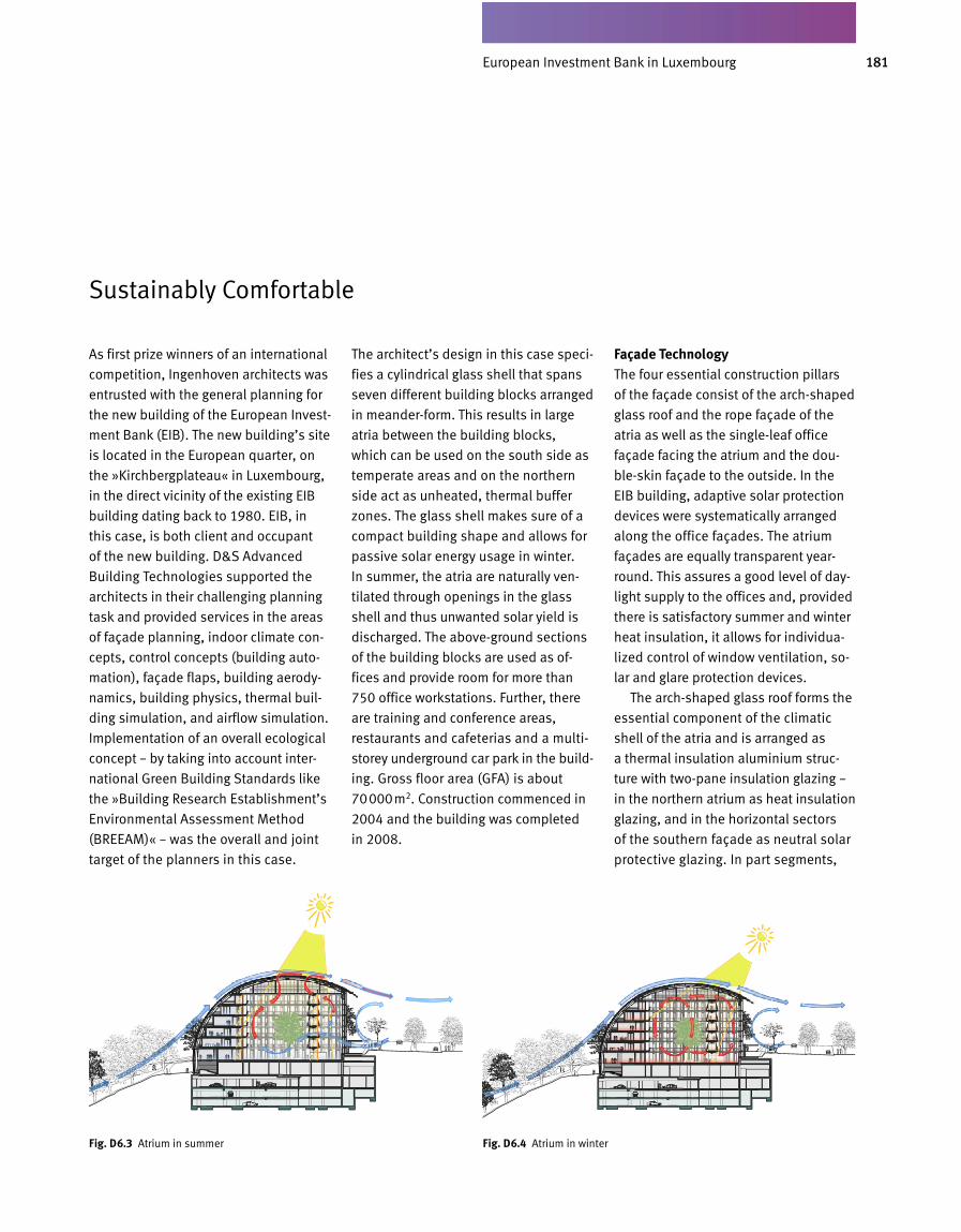
181EIB in Luxemburg
As first prize winners of an international
competition, Ingenhoven architects was
entrusted with the general planning for
the new building of the European Invest
ment Bank (EIB). The new building’s site
is located in the European quarter, on
the »Kirchbergplateau« in Luxembourg,
in the direct vicinity of the exist ing EIB
build ing dating back to 1980. EIB, in
this case, is both client and occupant
of the new building. D&S Advanced
Building Technologies supported the
architects in their challenging planning
task and provided services in the areas
of façade planning, indoor climate con
cepts, control concepts (building auto
mation), façade flaps, building aerody
namics, building physics, thermal buil
ding simulation, and airflow simulation.
Implementation of an overall ecological
concept – by taking into account inter
national Green Building Standards like
the »Building Research Establishment’s
Environmental Assessment Method
(BREEAM)« – was the overall and joint
target of the planners in this case.
The architect’s design in this case speci
fies a cylindrical glass shell that spans
seven different building blocks arranged
in meanderform. This results in large
atria between the building blocks,
which can be used on the south side as
temperate areas and on the northern
side act as unheated, thermal buffer
zones. The glass shell makes sure of a
compact building shape and allows for
passive solar energy usage in winter.
In summer, the atria are natural ly ven
tilated through openings in the glass
shell and thus unwanted solar yield is
discharged. The aboveground sections
of the building blocks are used as of
fices and provide room for more than
750 office workstations. Further, there
are training and conference areas,
res taurants and cafeterias and a multi
storey underground car park in the build
ing. Gross floor area (GFA) is about
70000m2. Construction commenced in
2004 and the building was completed
in 2008.
Façade TechnologyThe four essential construction pillars
of the façade consist of the archshaped
glass roof and the rope façade of the
atria as well as the singleleaf office
façade facing the atrium and the dou
bleskin façade to the outside. In the
EIB building, adaptive solar protection
devices were systematically arranged
along the office façades. The atrium
façades are equally transparent year
round. This assures a good level of day
light supply to the offices and, provided
there is satisfactory summer and winter
heat insulation, it allows for individua
lized control of window ventilation, so
lar and glare protection devices.
The archshaped glass roof forms the
essential component of the climatic
shell of the atria and is arranged as
a thermal insulation aluminium struc
ture with twopane insulation glazing –
in the northern atrium as heat insula tion
glazing, and in the horizontal sectors
of the southern façade as neutral solar
protective glazing. In part segments,
Sustainably Comfortable
D6.07a D6.07b_ beheiztes Atrium im Winter
Fig. D 6.3 Atrium in summer Fig. D 6.4 Atrium in winter
European Investment Bank in Luxembourg
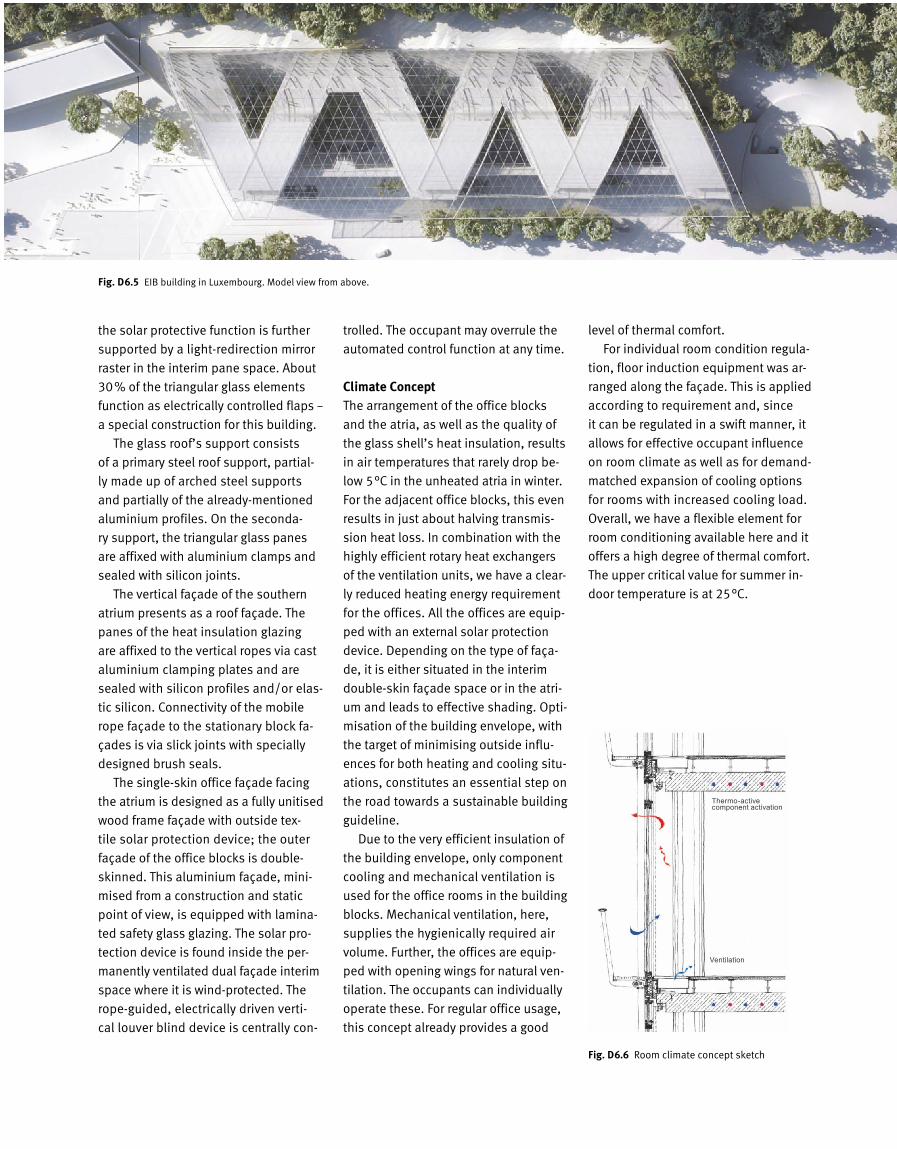
182
the solar protective function is further
supported by a light-redirection mirror
raster in the interim pane space. About
30% of the triangular glass elements
function as electrically controlled flaps –
a special construction for this building.
The glass roof’s support consists
of a primary steel roof support, partial-
ly made up of arched steel supports
and partially of the already-mentioned
aluminium profiles. On the seconda-
ry support, the triangular glass panes
are affixed with aluminium clamps and
sealed with silicon joints.
The vertical façade of the southern
atrium presents as a roof façade. The
panes of the heat insulation glazing
are affixed to the vertical ropes via cast
aluminium clamping plates and are
sealed with silicon profiles and/or elas-
tic silicon. Connectivity of the mobile
rope façade to the stationary block fa-
çades is via slick joints with specially
designed brush seals.
The single-skin office façade facing
the atrium is designed as a fully unitised
wood frame façade with outside tex-
tile solar protection device; the outer
façade of the office blocks is double-
skinned. This aluminium façade, mini-
mised from a construction and static
point of view, is equipped with lamina-
ted safety glass glazing. The solar pro-
tection device is found inside the per-
manently ventilated dual façade interim
space where it is wind-protected. The
rope-guided, electrically driven verti-
cal louver blind device is centrally con-
trolled. The occupant may overrule the
automated control function at any time.
Climate ConceptThe arrangement of the office blocks
and the atria, as well as the quality of
the glass shell’s heat insulation, results
in air temperatures that rarely drop be-
low 5°C in the unheated atria in winter.
For the adjacent office blocks, this even
results in just about halving transmis-
sion heat loss. In combination with the
highly efficient rotary heat exchangers
of the ventilation units, we have a clear-
ly reduced heating energy requirement
for the offices. All the offices are equip-
ped with an external solar protection
device. Depending on the type of faça-
de, it is either situated in the interim
double-skin façade space or in the atri-
um and leads to effective shading. Opti-
misation of the building envelope, with
the target of minimising outside influ-
ences for both heating and cooling situ-
ations, constitutes an es sential step on
the road towards a sus tainable building
guideline.
Due to the very efficient insulation of
the building envelope, only component
cooling and mechanical ventilation is
used for the office rooms in the building
blocks. Mechanical ventilation, here,
supplies the hygienically required air
volume. Further, the offices are equip-
ped with opening wings for natural ven-
tilation. The occupants can individually
operate these. For regular office usage,
this concept already provides a good
level of thermal comfort.
For individual room condition regula-
tion, floor induction equipment was ar-
ranged along the façade. This is applied
according to requirement and, since
it can be regulated in a swift manner, it
allows for effective occupant influence
on room climate as well as for demand-
matched expansion of cooling options
for rooms with increased cooling load.
Overall, we have a flexible element for
room conditioning available here and it
offers a high degree of thermal comfort.
The upper critical value for summer in-
door temperature is at 25°C.
Fig. D 6.5 EIB building in Luxembourg. Model view from above.
Fig. D 6.6 Room climate concept sketch
Ventilation
Thermo-active component activation
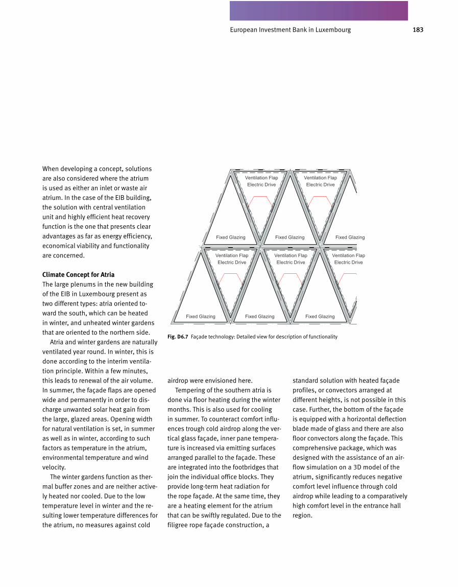
183EIB in Luxemburg
When developing a concept, solutions
are also considered where the atrium
is used as either an inlet or waste air
atrium. In the case of the EIB building,
the solution with central ventilation
unit and highly efficient heat recovery
function is the one that presents clear
advantages as far as energy effi ciency,
economical viability and functio nality
are concerned.
Climate Concept for AtriaThe large plenums in the new building
of the EIB in Luxembourg present as
two different types: atria oriented to
ward the south, which can be heated
in winter, and unheated winter gardens
that are oriented to the northern side.
Atria and winter gardens are naturally
ventilated year round. In winter, this is
done according to the interim ventila
tion principle. Within a few min utes,
this leads to renewal of the air volume.
In summer, the façade flaps are opened
wide and permanently in order to dis
charge unwanted solar heat gain from
the large, glazed areas. Opening width
for natural ventilation is set, in summer
as well as in winter, according to such
factors as temperature in the atrium,
environmental temperature and wind
velocity.
The winter gardens function as ther
mal buffer zones and are neither active
ly heated nor cooled. Due to the low
temperature level in winter and the re
sulting lower temperature differences for
the atrium, no measures against cold
airdrop were envisioned here.
Tempering of the southern atria is
done via floor heating during the winter
months. This is also used for cooling
in summer. To counteract comfort influ
ences trough cold airdrop along the ver
tical glass façade, inner pane tempera
ture is increased via emitting surfaces
arranged parallel to the façade. These
are integrated into the footbridges that
join the individual office blocks. They
provide longterm heat radiation for
the rope façade. At the same time, they
are a heating element for the atrium
that can be swiftly regulated. Due to the
filigree rope façade construction, a
standard solution with heated façade
profiles, or convectors arranged at
dif ferent heights, is not possible in this
case. Further, the bottom of the façade
is equipped with a horizontal deflection
blade made of glass and there are also
floor convectors along the façade. This
comprehensive package, which was
designed with the assistance of an air
flow simulation on a 3D model of the
atrium, significantly reduces negative
comfort level influence through cold
airdrop while leading to a comparatively
high comfort level in the entrance hall
region.
Fig. D 6.7 Façade technology: Detailed view for description of functionality
Fixed Glazing
Fixed Glazing
Fixed Glazing
Fixed Glazing
Fixed Glazing
Fixed Glazing
Ventilation FlapElectric Drive
Ventilation FlapElectric Drive
Ventilation FlapElectric Drive
Ventilation FlapElectric Drive
Ventilation FlapElectric Drive
European Investment Bank in Luxembourg
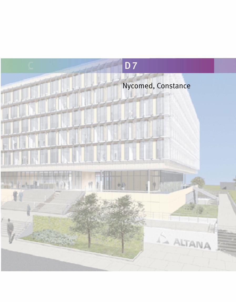
Nycomed, Constance
C D 7
185Altana Pharma in Konstanz
1. What, in your opinion, are the defining criteria for successful buildings?They were designed and built in a res
ponsible manner.
2. What is the role of sustainability in your building designs?The greatest one.
3. What are the goals of Petzinka Pink Technol. Architecture® when it comes to Green Buildings? What are your visions there?To provide knowhow.
4. How did your cooperation with D&S Advanced Building Technologies come about? What are the essential pillars of your many years of working together?Mutual respect.
5. What are the characteristics a planning team needs to have in order to create sophisticated and sustainable buildings?Passion, a progressive approach, social
competency, the ability to be visionary.
6. What were your goals for this design?To solve the building engineering task
and to convey a perspective for the fu
ture.
7. What are some of the extraordinary qualities this building has to offer – to client and tenants?A perspective for the future.
Interview with the Architect Th. Pink of Petzinka Pink Tech nol. Architecture®, Duesseldorf
1. What, in your opinion, are the defining criteria for successful buildings?I would like to point out, in answering
this question, that it is primarily occu
pant satisfaction, enthusiasm and per
haps even a euphoric response that
defines the success of a given building.
For this reason, it was very impor
tant to us to hold a variety of workshops
and also engage in intensive occupant
discussions during the preliminary plan
ning phase in order to find out about
the desires, suggestions and ideas of
the employees. We also wanted to con
sider the fears and worries that these
types of modern and transparent build
ings can bring in their wake for any
individual staff member.
Our target was to erect the »best pos
sible office building« for the occupants,
with a clearly defined ecological pro
file, a high degree of economic viability,
flexibility, innovation and resourcemi
nimising energy consumption (thermal
component activation, triple glazing and
pellet furnace). Further, the architecture
was supposed to mirror the innovative
drive of the enterprise and its core val
ues.
2. What does living inside a building mean to you? What factors are essentially decisive as to whether you feel comfortable or not?It means a feeling of safety while
main taining a certain degree of self
defined individuality. The comfort
effect depends on several factors:
• Can I control windows and solar pro
tection on my own?
• How individually designed are light
ing, acoustics and view to the outside?
• Are colours and plants possible in the
office zone?
• Is it possible to achieve comfortable
indoor temperatures?
• Is there a large amount of daylight
and a low degree of acoustic interfe
rence?
• Are there a sufficient number of so
cial meeting points where I can socialize
with my colleagues?
• Does the architecture allow for com
munal space but also for withdrawal
space?
• Welldesigned outdoor areas for
usage during the breaks?
All these are components that influence,
to a varying degree, the level of accep
tance and comfort that a given staff
member displays towards the building.
3. What is the role of sustainability, of lifecycle consideration, in your build ing stipulations?When erecting any building, investment
costs are initially in the forefront while
usage or operating costs over the entire
life cycle usually tend to be rather dis
regarded. However, they are actually
more significant and must be involved
in initial consideration because it only
takes a few years before the sum total
of maintenance costs reaches the level
of initial investment costs.
Interview with the Client Prof. Franz Maier of Nycomed
Nycomed in Constance
186
By means of a lifecycle concept, we
strive not only to optimise operating
costs but also to achieve the highest
possible synergy effect for all the trades.
This is influenced by standardising in
dividual components and systems. We
are open to any sustainable innovations
but, in case of doubt, will grant prefe
rence to tried and tested, longlasting
materials and systems.
4. You experience the entire process, from design to operation. Where do you see the greatest improvement potential: in the process itself, in finding ideas, planning implementation, constructional execution or operating behaviour?The planning process for the individual
trades needs to be integrated and co
ordinated much better still. Interfaces
must be reduced both in volume and
in terms of how complex they are. Nei
ther are crosstrade planning, coordi
nation and integration of the systems
at an ideal level yet.
Planners need to be increasingly re
warded for their innovative ideas ra
ther than for rigid contracts that are only
oriented on construction costs. For the
execution, a functioning quality control
system at the site is essential. For this,
it is necessary that all activities on site
be handled with the assistance of a
tried and tested, practiceoriented qua
lity manual. The entire process must
be closely monitored, from plans to ma
terials being delivered, to installation
and mounting, all the way to inspection.
Correct and complete revision plans
with qualified approval of services ter
minate this process. Another decisive
factor is that quality of planning and
construction needs to be applied and
implemented in a consistent manner if
we are to be spared subsequent lengthy
lists of faults, enormous conflicts and
even court proceedings.
When it comes to launching the build
ing, we found out that modern simula
tion techniques may be of assistance
but that actual building operation is
required over the course of an entire
annual decade in order to adjust room
climate especially to a stable operating
stage.
For limiting occupant conflicts and
promoting tolerance we pass on this
in formation to the respective employe
es during the launch phase and prior
to the actual occupation of the building.
Prior to occupation, all buildings
are introduced to the staff members by
means of a very simply written »user
ma nual« that is easy to understand and
contains many illustrations.
5. What are the characteristics a planning team needs to have in order to create sophisticated and sustainable buildings?The members of the planning team
should always act as though they were
in the process of planning and de
signing a building that they will sub
sequently occupy themselves. A higher
degree of motivation and responsibili
ty is barely imaginable, even if it only
happens at virtual level. There must be
a conscientious and active approach
towards the ecological and economical
responsibility for a building with an ave
rage life span of 50 years.
6. What will modern office concepts look like by 2050?We have no way of telling because they
may not be compatible with today’s re
ality, even. Will they be highly mobile,
flex ible or emotional? Will colours,
smells, music, art and similar elements
be integrated into our working life that
intermingles ever more with our private
life? Will there even still be a division
between work and recreation?
All the various options and alterna
tives, are food for thought to an inno
vative planning team and they provide
a good base for building design of the
future.
We need to maintain an increasingly
optimistic and positive approach, true
to the motto:
»In our world, the old and the new
need to stick together until such a point
that the new has proven to supersede
the old.«
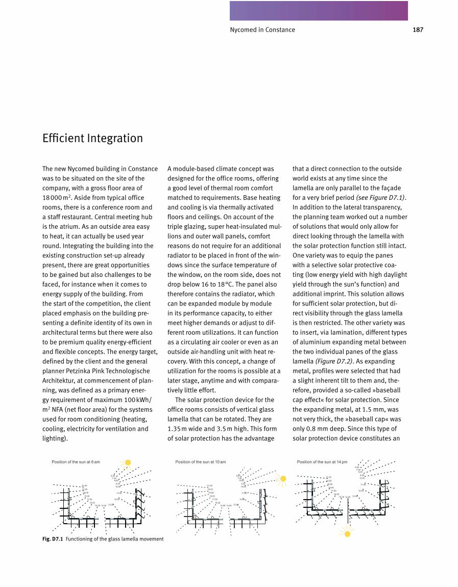
187Altana Pharma in Konstanz
The new Nycomed building in Constance
was to be situated on the site of the
company, with a gross floor area of
18000m2. Aside from typical office
rooms, there is a conference room and
a staff restaurant. Central meeting hub
is the atrium. As an outside area easy
to heat, it can actually be used year
round. Integrating the building into the
existing construction set-up already
present, there are great opportunities
to be gained but also challenges to be
faced, for instance when it comes to
energy supply of the building. From
the start of the competition, the client
placed emphasis on the building pre-
senting a definite identity of its own in
architectural terms but there were also
to be premium quality energy-efficient
and flexible concepts. The energy target,
defined by the client and the general
planner Petzinka Pink Tech nologische
Architektur, at commencement of plan-
ning, was defined as a pri mary ener-
gy requirement of maximum 100kWh/
m2 NFA (net floor area) for the systems
used for room conditioning (heating,
cooling, electricity for ventilation and
light ing).
A module-based climate concept was
designed for the office rooms, offering
a good level of thermal room comfort
matched to requirements. Base heat ing
and cooling is via thermally activated
floors and ceilings. On account of the
triple glazing, super heat-insulated mul-
lions and outer wall panels, comfort
reasons do not require for an additional
radiator to be placed in front of the win-
dows since the surface temperature of
the window, on the room side, does not
drop below 16 to 18°C. The panel also
therefore contains the radiator, which
can be expanded module by module
in its performance capacity, to either
meet higher demands or adjust to dif-
ferent room utilizations. It can function
as a circulating air cooler or even as an
outside air-handling unit with heat re-
covery. With this concept, a change of
utilization for the rooms is possible at a
later stage, anytime and with compara-
tively little effort.
The solar protection device for the
office rooms consists of vertical glass
lamella that can be rotated. They are
1.35m wide and 3.5m high. This form
of solar protection has the advantage
that a direct connection to the outside
world exists at any time since the
lamella are only parallel to the façade
for a very brief period (see Figure D7.1).
In addition to the lateral transparency,
the planning team worked out a number
of solutions that would only allow for
direct looking through the lamella with
the solar protection function still intact.
One variety was to equip the panes
with a selective solar protective coa-
ting (low energy yield with high daylight
yield through the sun’s function) and
additional imprint. This solution allows
for sufficient solar protection, but di-
rect visibility through the glass lamella
is then restricted. The other variety was
to insert, via lamination, different types
of aluminium expanding metal between
the two individual panes of the glass
lamella (Figure D7.2). As expanding
metal, profiles were selected that had
a slight inherent tilt to them and, the-
refore, provided a so-called »baseball
cap effect« for solar protection. Since
the expanding metal, at 1.5 mm, was
not very thick, the »baseball cap« was
only 0.8 mm deep. Since this type of
solar protection device constitutes an
Efficient Integration
Fig. D 7.1 Functioning of the glass lamella movement
Position of the sun at 6 am Position of the sun at 10 am Position of the sun at 14 pm
Nycomed in Constance

188
entirely new invention it is necessary, as
a first step, to test its structural make
up as well as its thermal effect. Suita
ble expanding grids were selected and
compared with the target solar shading
value of 0.1, for the solar protection de
vice had to fit in with the room climate
concept. In the end, the simulation re
sults were able to show that only a very
effective solar protection device is able
to bring the basis room climate concept
to the point of assuring sufficient ther
mal comfort. We needed to be absolu
tely sure about the selected expansion
grids and so, in the laboratory, we set
out to define both solar transmission
and luminance distribution for different
elevation angles of the sun. The results
even went beyond the target values,
with equally good view and avoidance
from glare, from a solar elevation an
gle of 35°. From a construction point of
view, also, we were able to master the
challenges that presented themselves.
Figure D7.4 shows some of the techni
cal details.
Energy supply was arranged in accor
dance with the existing buildings, which
tap into regional heat supply. In the
course of a building and system simu
lation for all outlets of the regional
heating system (mainly the laborato
ries), the existing heat load profile
for the regional heat distribution was
defined. It turned out that, owing to
the required heat performance for hot
D7.05 6.12Fig. D 7.2 Glass rib with expansion metal

189Altana Pharma in Konstanz
Fig. D 7.5 Primary energy balance of the building for room conditioning systems
for new Nycomed office building F11
water and reheating for the ventilation
units, there was a high heat load in
summer also. Our calculations showed
that a pel let boiler with a heat load of
1000kW could be operated at full load
for more than 7000 hours per year.
When taking into account the lower en-
ergy prices of pellets in com parison to
gas, a return on investment is possible
within two years. At the same time,
there is a saving of 1750t of CO2 emis-
sions. This corresponds to the level
of heating-related CO2 emissions from
580 own homes. Cooling is achieved
through chillers operating at elevated
tempera ture (12/16°C) and hybrid re-
coolers with water spray function. Since
component cooling takes place at night
only, over 70% of chilled water can
be gained by exploiting the cool night
air. Overall, actual energy demand lies
far beneath the target value defined
during planning (Figure D7.5). Excellent
architecture and a high level of flexibil-
ity have resulted in a building that both
occupants and facility management can
feel good about.
Fig. D 7.4 View and cross-section of the office façade
mittle
re L
eu
ch
tdic
hte
in
cd
/m²
Einstrahlwinkel 25°
Messungen des Glassonnenschutzes am ISE zur Optimierung Glaslamellenkonstruktion
D7.07 18.01
Einstrahlwinkel 45°
10
40
100
150
300
600
1000
1500
6000
15000
50000
Fig. D 7.3 Luminance density images for different angles of elevation
Vertical Cut
Mea
n Lu
min
ance
Den
sity
in c
d/m
2
Incidence Angle 25°
Horizontal Cut View
Incidence Angle 45°
Heating Energy Demand Lighting Energy Demand
Cooling Energy Demand Electric Energy for Ventilation
250
200
150
100
50
0
Prim
ary
Ener
gy D
eman
d in
kW
h/m
2 a
Reference: New Building Office
Green Building Standard Office
New Building F11 Office
New Building F11 incl. Special Usage
Nycomed in Constance
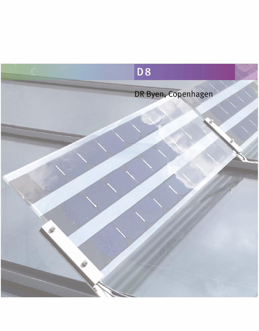
DR Byen, Copenhagen
C D 8

191DR Byen in Kopenhagen
1. What, in your opinion, are the defi-ning criteria for successful buildings?The most important criteria include
optimum organisation of the manage-
ment, clearly defined strategies and
excellent communication on all levels.
This also goes for any subsequent pro-
cedures and decisions during the entire
planning and construction process.
2. What does living inside a building mean to you? What factors are essen-tially decisive as to whether you feel comfortable or not?To the Danmark Radio staff, room cli-
mate and floor plan of the building is
of prime importance. We do not define
a comfortable room climate merely on
such physical factors as temperature,
air quality, acoustics or lighting. We also
consider architecture to be important,
involving occupant interests as an inte-
grative part of both planning and room
design.
3. What is the role of sustainability, of life-cycle consideration, in your build-ing stipulations?We placed emphasis on a flexible de-
sign in order to be able to react to fu-
ture technological and organisational
advances in the multimedia field, which
means that we could subsequently gu-
arantee a long lifespan. Many building
materials were selected according to life
cycle considerations. During planning,
our focus was on minimising resource
consumption over the entire life cycle
of the building. We were especially con-
cerned with reducing energy consump-
tion while at the same time looking for
ecologically viable materials. Since Den-
mark Radio owns a huge property, we
felt obliged to explore the use of novel
technologies with ecological considera-
tions and set an example for other Da-
nish property owners and developers.
4. You experience the entire process, from design to operation. Where do you see the greatest improvement po-tential: in the process itself, in find-ing ideas, planning implementation, constructional execution or operating behaviour?The main focus always needs to be on
optimising operations because this is
where environmental impact is at its
greatest. However, it is during the initial
stages of planning that the most perti-
nent improvements can be made since
this is where we define the frame con-
ditions for later design of the building.
During engineering and in the construc-
tion phase, these stipulations must be
consistently monitored at all costs. For
actual operation, the ecological potenti-
al of the building needs to be exploited
in full. This, also, requires constant ve-
rification.
5. What are the characteristics a plan-ning team needs to have in order to create sophisticated and sustainable buildings?The planning team needs to have solid
ecological knowledge – in all areas of
planning. It is just as important to then
apply that knowledge through engaging
in interdisciplinary teamwork. Ecologi-
cal design is based on comprehensive
considerations that require the vision,
dedication and cooperation of every -
one involved for implementing ecologi-
cal goals.
6. What are some of the extraordinary qualities this building has to offer – to client and tenants?As a large, semi-public enterprise in
the public service sector, Denmark
Radio considered it high priority to set
an excellent example for the Danish
construction industry. Byen’s vision for
Denmark Radio was that of a »flexible
and open place of work and a vivacious
atmosphere fostering creative team-
work«. In the end and thanks to the eco -
logical focus, we were able to create
a building with comparatively low ope-
rating costs for consumption of energy,
water and other resources but also for
waste management.
Interview with the Clients Kai Toft & Marianne Fox of DR Byen
DR Byen in Copenhagen
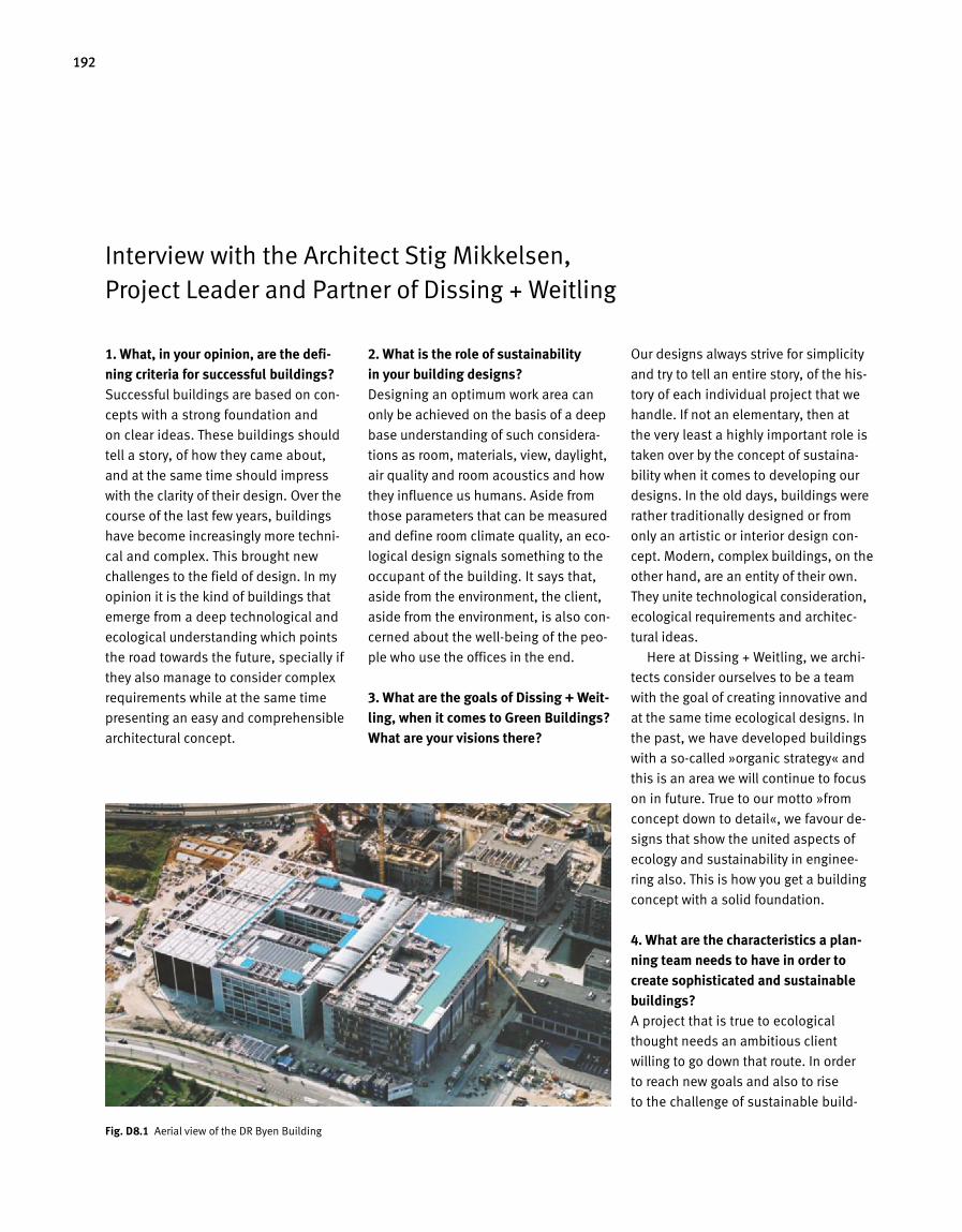
192
1. What, in your opinion, are the defining criteria for successful buildings?Successful buildings are based on con
cepts with a strong foundation and
on clear ideas. These buildings should
tell a story, of how they came about,
and at the same time should impress
with the clarity of their design. Over the
course of the last few years, buildings
have become increasingly more techni
cal and complex. This brought new
challenges to the field of design. In my
opinion it is the kind of buildings that
emerge from a deep technological and
ecological understanding which points
the road towards the future, specially if
they also manage to consider complex
requirements while at the same time
presenting an easy and comprehen sible
architectural concept.
2. What is the role of sustainability in your building designs?Designing an optimum work area can
only be achieved on the basis of a deep
base understanding of such considera
tions as room, materials, view, daylight,
air quality and room acoustics and how
they influence us humans. Aside from
those parameters that can be measured
and define room climate quality, an eco
logical design signals something to the
occupant of the building. It says that,
aside from the environment, the client,
aside from the environment, is also con
cerned about the wellbeing of the peo
ple who use the offices in the end.
3. What are the goals of Dissing + Weitling, when it comes to Green Buildings? What are your visions there?
Our designs always strive for simplicity
and try to tell an entire story, of the his
tory of each individual project that we
handle. If not an elementary, then at
the very least a highly important role is
taken over by the concept of sustaina
bility when it comes to developing our
designs. In the old days, buildings were
rather traditionally designed or from
only an artistic or interior design con
cept. Modern, complex buildings, on the
other hand, are an entity of their own.
They unite technological consideration,
ecological requirements and architec
tural ideas.
Here at Dissing + Weitling, we archi
tects consider ourselves to be a team
with the goal of creating innovative and
at the same time ecological designs. In
the past, we have developed buildings
with a socalled »organic strategy« and
this is an area we will continue to focus
on in future. True to our motto »from
concept down to detail«, we favour de
signs that show the united aspects of
ecology and sustainability in enginee
ring also. This is how you get a building
concept with a solid foundation.
4. What are the characteristics a planning team needs to have in order to create sophisticated and sustainable buildings?A project that is true to ecological
thought needs an ambitious client
willing to go down that route. In order
to reach new goals and also to rise
to the challenge of sustainable build
Interview with the Architect Stig Mikkelsen, Project Leader and Partner of Dissing + Weitling
Fig. D 8.1 Aerial view of the DR Byen Building
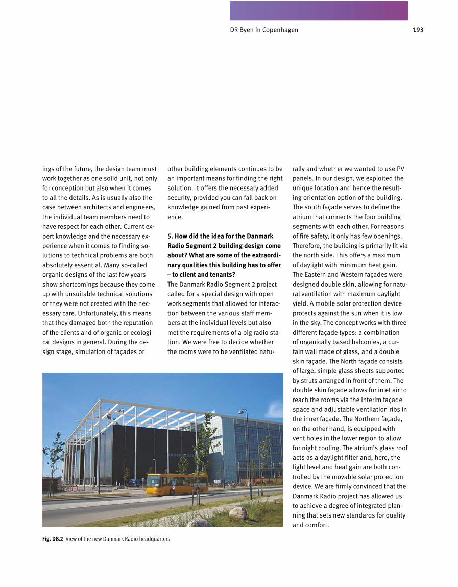
193DR Byen in Kopenhagen
ings of the future, the design team must
work together as one solid unit, not only
for conception but also when it comes
to all the details. As is usually also the
case between architects and engineers,
the individual team members need to
have respect for each other. Current ex-
pert knowledge and the necessary ex-
perience when it co mes to finding so-
lutions to technical problems are both
absolutely essen tial. Many so-called
organic designs of the last few years
show shortcomings because they come
up with unsuitable technical solutions
or they were not created with the nec-
essary care. Unfortunately, this means
that they damaged both the reputation
of the clients and of organic or ecologi-
cal designs in general. During the de-
sign stage, simulation of façades or
other building elements continues to be
an important means for finding the right
solution. It offers the necessary added
security, provided you can fall back on
knowledge gained from past experi-
ence.
5. How did the idea for the Danmark Radio Segment 2 building design come about? What are some of the extraordi-nary qualities this building has to offer – to client and tenants?The Danmark Radio Segment 2 project
called for a special design with open
work segments that allowed for interac-
tion between the various staff mem-
bers at the individual levels but also
met the requirements of a big radio sta-
tion. We were free to decide whether
the rooms were to be ventilated natu-
rally and whether we wanted to use PV
panels. In our design, we exploited the
unique location and hence the result-
ing orientation option of the building.
The south façade serves to define the
atrium that connects the four building
segments with each other. For reasons
of fire safety, it only has few openings.
Therefore, the building is primarily lit via
the north side. This offers a maximum
of daylight with minimum heat gain.
The Eastern and Western façades were
designed double skin, allowing for natu-
ral ventilation with maximum daylight
yield. A mobile solar protection device
protects against the sun when it is low
in the sky. The concept works with three
different façade types: a combination
of organically based balconies, a cur-
tain wall made of glass, and a double
skin façade. The North façade consists
of large, simple glass sheets supported
by struts arranged in front of them. The
double skin façade allows for inlet air to
reach the rooms via the interim façade
space and adjustable ventilation ribs in
the inner façade. The Northern façade,
on the other hand, is equipped with
vent holes in the lower region to allow
for night cooling. The atrium’s glass roof
acts as a daylight filter and, here, the
light level and heat gain are both con-
trolled by the movable solar protection
device. We are firmly con vinced that the
Danmark Radio project has allowed us
to achieve a degree of integrated plan-
ning that sets new standards for quality
and comfort.
Fig. D 8.2 View of the new Danmark Radio headquarters
DR Byen in Copenhagen
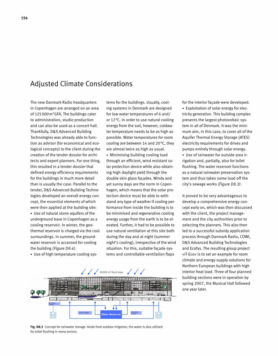
194
The new Danmark Radio headquarters
in Copenhagen are arranged on an area
of 125000m2GFA. The buildings cater
to administration, studio production
and can also be used as a concert hall.
Thankfully, D&S Advanced Building
Technologies was already able to func
tion as advisor (for economical and eco
logical concepts) to the client du ring the
creation of the tender dossier for archi
tects and expert planners. For one thing,
this resulted in a tender dossier that
defined energy efficiency requirements
for the buildings in much more detail
than is usually the case. Parallel to the
tender, D&S Advanced Building Techno
logies developed an overall energy con
cept, the essential elements of which
were then applied at the building site:
• Use of natural stone aquifers of the
underground base in Copenhagen as a
cooling reservoir. In winter, the geo
thermal reservoir is charged via the cool
surroundings. In summer, the ground
water reservoir is accessed for cooling
the building (Figure D8.4).
• Use of high temperature cooling sys
tems for the buildings. Usually, cool
ing systems in Denmark are designed
for low water temperatures of 6 and/
or 12°C. In order to use natural cooling
energy from the soil, however, coldwa
ter temperature needs to be as high as
possible. Water temperatures for room
cooling are between 14 and 20°C, they
are almost twice as high as usual.
• Minimising building cooling load
through an efficient, wind resistant so
lar protection device while also obtain
ing high daylight yield through the
double skin glass façades. Windy and
yet sunny days are the norm in Copen
hagen, which means that the solar pro
tection device must be able to with
stand any type of weather if cooling per
formance from inside the building is to
be minimised and regenerative cool ing
energy usage from the earth is to be el
evated. Further, it had to be possible to
use natural ventilation at this site both
during the day and at night (summer
night’s cooling), irrespective of the wind
situation. For this, suitable façade sys
tems and controllable ventilation flaps
for the interior façade were developed.
• Exploitation of solar energy for elec
tricity generation. This building complex
presents the largest photovoltaic sys
tem in all of Denmark. It was the mi ni
mum aim, in this case, to cover all of the
Aquifer Thermal Energy Storage (ATES)
electricity requirements for drives and
pumps entirely through solar energy.
• Use of rainwater for outside area ir
rigation and, partially, also for toilet
flush ing. The water reservoir functions
as a natural rainwater preservation sys
tem and thus takes some load off the
city’s sewage works (Figure D8.3).
It proved to be very advantageous to
develop a comprehensive energy con
cept early on, which was then discussed
with the client, the project manage
ment and the city authorities prior to
selecting the planners. This also then
led to a successful subsidy application
process through Danmark Radio, COWI,
D&S Advanced Building Technologies
and Ecofys. The resulting group project
»ITEco« is to set an example for room
climate and energy supply solutions for
Northern European buildings with high
interior heat load. Three of four planned
building sections were in operation by
spring 2007, the Musical Hall followed
one year later.
Adjusted Climate Considerations
Fig. D 8.3 Concept for rainwater storage. Aside from outdoor irrigation, the water is also utilized
for toilet flushing in many sectors.
29 000 m2 Roof Area
Water ReservoirCooling TowerRiver Water
Cooling Tower
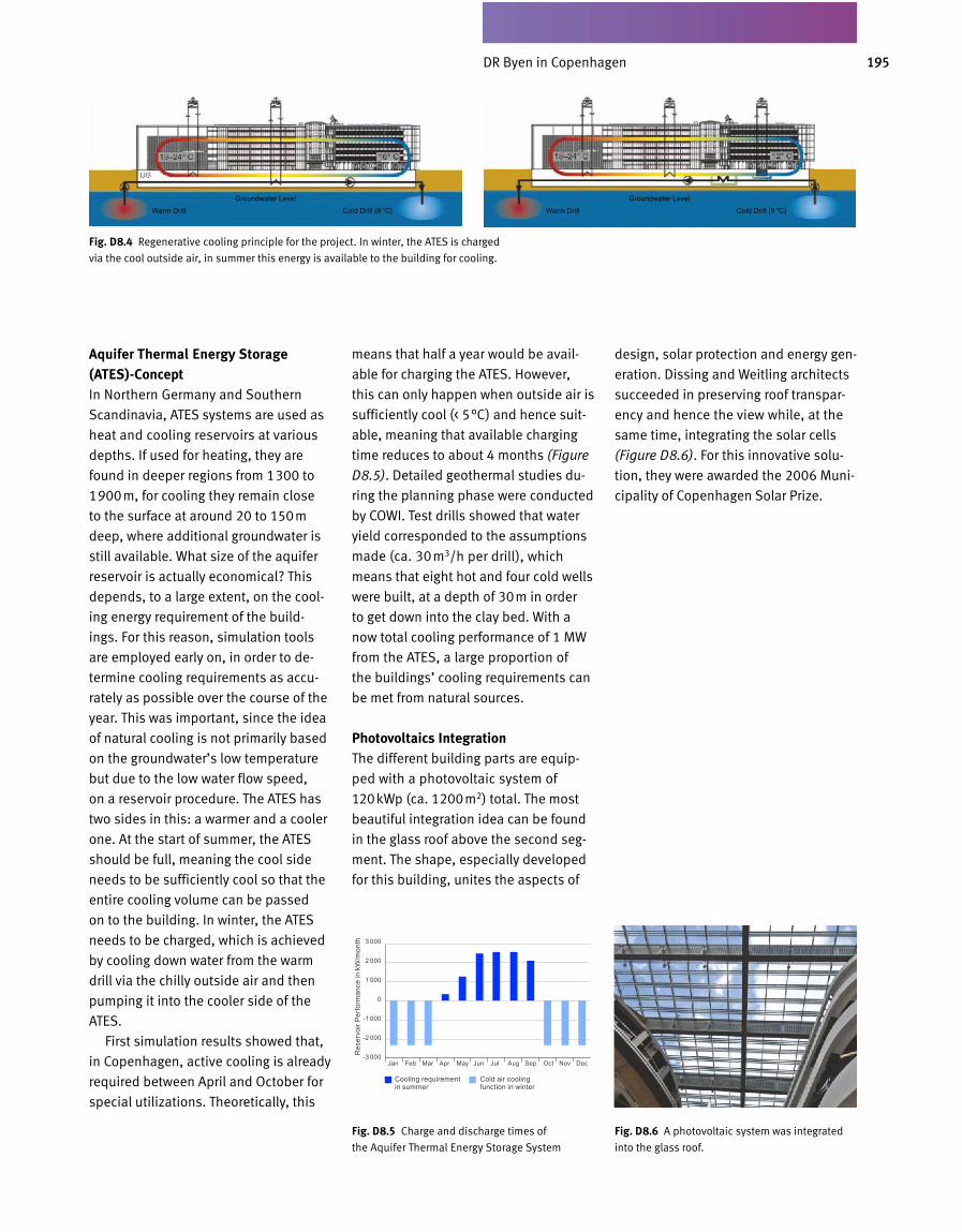
195DR Byen in Kopenhagen
Aquifer Thermal Energy Storage (ATES)-ConceptIn Northern Germany and Southern
Scandinavia, ATES systems are used as
heat and cooling reservoirs at vari ous
depths. If used for heating, they are
found in deeper regions from 1300 to
1900m, for cooling they remain close
to the surface at around 20 to 150m
deep, where additional groundwater is
still available. What size of the aquifer
reservoir is actually economical? This
depends, to a large extent, on the cool
ing energy requirement of the build
ings. For this reason, simulation tools
are employed early on, in order to de
termine cooling requirements as accu
rately as possible over the course of the
year. This was important, since the idea
of natural cooling is not primarily based
on the groundwater’s low temperature
but due to the low water flow speed,
on a reservoir procedure. The ATES has
two sides in this: a warmer and a cooler
one. At the start of summer, the ATES
should be full, meaning the cool side
needs to be sufficiently cool so that the
entire cooling volume can be passed
on to the building. In winter, the ATES
needs to be charged, which is achieved
by cooling down water from the warm
drill via the chilly outside air and then
pumping it into the cooler side of the
ATES.
First simulation results showed that,
in Copenhagen, active cooling is already
required between April and October for
special utilizations. Theoretically, this
means that half a year would be avail
able for charging the ATES. However,
this can only happen when outside air is
sufficiently cool (< 5°C) and hence suit
able, meaning that available charging
time reduces to about 4 months (Figure
D8.5). Detailed geothermal studies du
ring the planning phase were conducted
by COWI. Test drills showed that water
yield corresponded to the assumptions
made (ca. 30m3/h per drill), which
means that eight hot and four cold wells
were built, at a depth of 30m in order
to get down into the clay bed. With a
now total cooling performance of 1 MW
from the ATES, a large proportion of
the buildings’ cooling requirements can
be met from natural sources.
Photovoltaics IntegrationThe different building parts are equip
ped with a photovoltaic system of
120kWp (ca. 1200m2) total. The most
beautiful integration idea can be found
in the glass roof above the second seg
ment. The shape, especially developed
for this building, unites the aspects of
design, solar protection and energy gen
eration. Dissing and Weitling architects
succeeded in preserving roof transpar
ency and hence the view while, at the
same time, integrating the solar cells
(Figure D8.6). For this innovative solu
tion, they were awarded the 2006 Muni
cipality of Copenhagen Solar Prize.
Fig. D 8.4 Regenerative cooling principle for the project. In winter, the ATES is charged
via the cool outside air, in summer this energy is available to the building for cooling.
Fig. D 8.5 Charge and discharge times of
the Aquifer Thermal Energy Storage System
D8.10a
Fig. D 8.6 A photovoltaic system was integrated
into the glass roof.
Cooling requirement in summer
Cold air cooling function in winter
3 000
2 000
1 000
0
-1 000
-2 000
-3 000Res
ervo
ir Pe
rfor
man
ce in
kW
/mon
th
Jan Feb Mar Apr May Jun Jul Aug Sep Oct Nov Dec
Warm Drill Warm Drill
Groundwater Level Groundwater Level
Cold Drill (9 °C) Cold Drill (9 °C)
DR Byen in Copenhagen
D&S Advanced Building Technologies Building, Obere Waldplaetze 11, Stuttgart
C D 9
‘Gold’
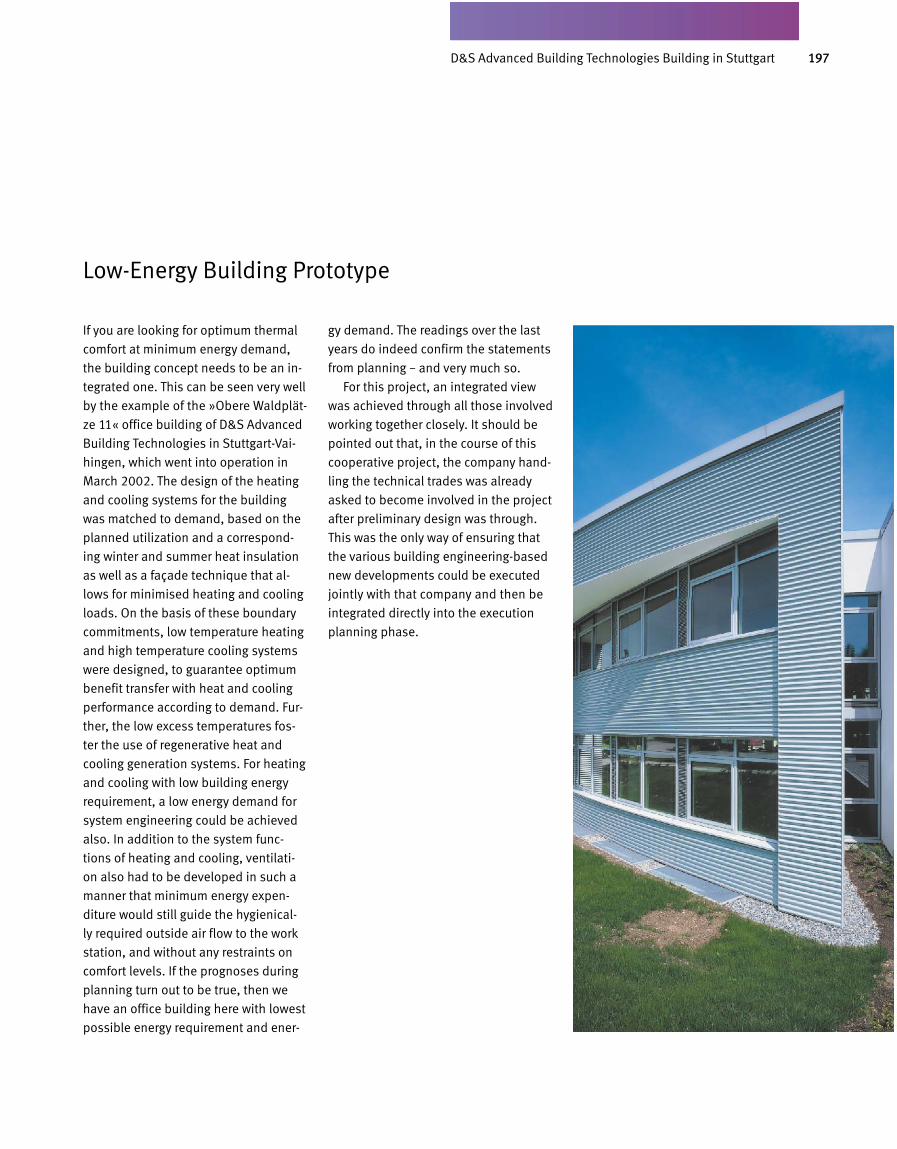
197DS-Plan Gebäude Obere Waldplätze 11, Stuttgart
If you are looking for optimum thermal
comfort at minimum energy demand,
the building concept needs to be an in-
tegrated one. This can be seen very well
by the example of the »Obere Waldplät-
ze 11« office building of D&S Advanced
Building Technologies in Stuttgart-Vai-
hingen, which went into operation in
March 2002. The design of the heating
and cooling systems for the building
was matched to demand, based on the
planned utilization and a correspond-
ing winter and summer heat insulation
as well as a façade technique that al-
lows for minimised heating and cooling
loads. On the basis of these boundary
commitments, low temperature heating
and high temperature cooling systems
were designed, to guar antee optimum
benefit transfer with heat and cooling
performance according to demand. Fur-
ther, the low excess temperatures fos-
ter the use of regenerative heat and
cooling generation systems. For heating
and cooling with low build ing energy
requirement, a low energy demand for
system engineering could be achieved
also. In addition to the sys tem func-
tions of heating and cooling, ventilati-
on also had to be developed in such a
manner that minimum energy expen-
diture would still guide the hygienical-
ly required outside air flow to the work
station, and without any restraints on
comfort levels. If the prognoses du ring
planning turn out to be true, then we
have an office building here with lowest
possible energy requirement and ener-
gy demand. The readings over the last
years do indeed confirm the statements
from planning – and very much so.
For this project, an integrated view
was achieved through all those involved
working together closely. It should be
pointed out that, in the course of this
cooperative project, the company hand-
ling the technical trades was already
asked to become involved in the project
after preliminary design was through.
This was the only way of ensuring that
the various building engineering-based
new developments could be executed
jointly with that company and then be
integrated directly into the execution
planning phase.
Low-Energy Building Prototype
D&S Advanced Building Technologies Building in Stuttgart
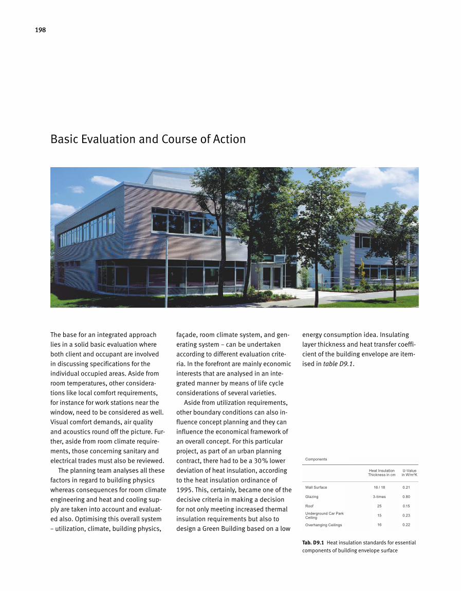
198
Basic Evaluation and Course of Action
The base for an integrated approach
lies in a solid basic evaluation where
both client and occupant are involved
in discussing specifications for the
individual occupied areas. Aside from
room temperatures, other considera
tions like local comfort requirements,
for instance for work stations near the
window, need to be considered as well.
Visual comfort demands, air quality
and acoustics round off the picture. Fur
ther, aside from room climate require
ments, those concerning sanitary and
electrical trades must also be reviewed.
The planning team analyses all these
factors in regard to building physics
whereas consequences for room climate
engineering and heat and cooling sup
ply are taken into account and evaluat
ed also. Optimising this overall system
– utilization, climate, building physics,
façade, room climate system, and gen
erating system – can be undertaken
according to different evaluation crite
ria. In the forefront are mainly economic
interests that are analysed in an inte
grated manner by means of life cycle
considerations of several varieties.
Aside from utilization requirements,
other boundary conditions can also in
fluence concept planning and they can
influence the economical framework of
an overall concept. For this particular
project, as part of an urban planning
contract, there had to be a 30% lower
deviation of heat insulation, according
to the heat insulation ordinance of
1995. This, certainly, became one of the
decisive criteria in making a decision
for not only meeting increased thermal
insulation requirements but also to
design a Green Building based on a low
energy consumption idea. Insulating
layer thickness and heat transfer coeffi
cient of the building envelope are item
ised in table D9.1.
Tab. D 9.1 Heat insulation standards for essential
components of building envelope surface
Components
Wall Surface
Glazing
Roof
Underground Car Park Ceiling
Overhanging Ceilings
16 / 18
3-times
25
15
16
0.21
0.80
0.15
0.23
0.22
Heat Insulation Thickness in cm
U-Value in W/m2K

199DSPlan Gebäude Obere Waldplätze 11, Stuttgart
Optimisation of the building envelope
in regard to lower heating and cooling
loads, passive solar energy exploita
tion, primarily natural ventilation and its
accordingly adapted room climate en
gineering concepts, as well as heat and
cooling generation, were defined, ana
lysed and optimised during the plan
ning phase by means of coupled build
ing and system simulations. With very
good Uvalues and outside tempera
tures of –12°C, subnormal temperatures
for inner surfaces of the outside walls
are at ca. 1 to 2K and for the window
and façade area at ca. 3 to 4K. For work
stations in window vicinity, this means
that directed heat withdrawal through
the cooler window surface lies below
the operative level. In order to re duce
solar load, façade areas were designed
with a railing. Cool airdrop, which hap
pens along the cooler window areas,
also stays below the operative threshold
at maximum air velocities of below
0.1m/s and it is possible to do without
radiators under the windows while not
reducing ther mal comfort levels.
To achieve optimum levels of ther
mal comfort we had to compensate
heat emission within the same half
room. This was achieved through so
called edge rim activation that func
tions at maximum flow temperatures
of ca. 33°C. Thermal component acti
vation serves as the base load system
and, on account of the large surfaces,
it can be operated at minimal excess
temperatures. The minimum outside
airflow required for air hygiene is heat
ed via a ventilation unit with heat
recovery, and then subsequently
gui ded into the room isothermally via
newly developed slit air inlets in the
floor. For optimum benefit transfer,
the benefit transfer system’s reaction
speed also needs to be considered.
Aside from swift regulation response,
low operating temperatures are re
quired as well as a low storage capacity
of the room heating system to be regu
lated. Parallel to this, in the case of an
integrated approach, cooling is also re
quired and this must be considered.
In this case, we desire storage capacity
but must also strive for demandorien
ted regulation of cooling performance
to achieve optimum benefit transfer
in combination with operating tempera
tures that are as high as possible. On
the basis of these considerations, bene
fit transfer for heating and cooling
was arranged as a combination system,
consisting of a highstorage base load
sys tem in the form of concrete core ac
tivation and an edge rim element that is
close to the surface, swift to react and
has a low amount of storage mass. The
surfaces, which are kept as large as pos
sible, result in low excess temperatures
for heating and low subnormal temper
atures for cooling. Figures D9.1 and
D9.2 show the systems described, for
the office areas, as two photographs
taken during the course of construction.
For heating and cooling, concrete
core activation serves as the base load
system while edge trim activation is
individually controlled via individual
room sensors, allowing for heating and
cooling performance to be adjusted
according to requirement. In the inte
rim period, it is essentially only edge
trim activation that is used for heating
and cooling purposes. This means that,
for both winter and the interim period,
edge trim activation influences ener
gy demand for benefit transfer. Room
temperatures, as determined during
Indoor Climate and Façade Concept
Fig. D 9.2 Thermally active components and venti
lation pipes, integrated into the concrete ceilings
Fig. D 9.1 Edge trim element as factory
assembled unit
D&S Advanced Building Technologies Building in Stuttgart
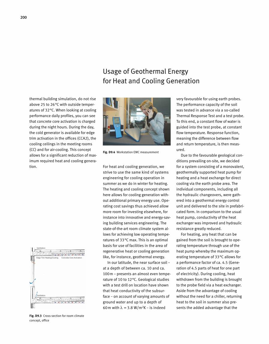
200
Usage of Geothermal Energy for Heat and Cooling Generation
For heat and cooling generation, we
strive to use the same kind of systems
engineering for cooling operation in
summer as we do in winter for heating.
The heating and cooling concept shown
here allows for cooling generation with
out additional primary energy use. Ope
rating cost savings thus achieved allow
more room for investing elsewhere, for
instance into innovative and energysav
ing building services engineering. The
stateoftheart room climate system al
lows for achieving low operating tempe
ratures of 33°C max. This is an optimal
basis for use of facil ities in the area of
regenerative heat or cooling generation
like, for instance, geothermal energy.
In our latitude, the near surface soil –
at a depth of between ca. 10 and ca.
100m – presents an almost even tempe
rature of 10 to 12°C. Geological studies
with a test drill on location have shown
that heat conductivity of the subsur
face – on account of varying amounts of
ground water and up to a depth of
60m with = 3.8 W/m2K – is indeed
very favourable for using earth probes.
The performance capacity of the soil
was tested in advance via a socalled
Thermal Response Test and a test probe.
To this end, a constant flow of water is
guided into the test probe, at constant
flow temperature. Response function,
meaning the difference between flow
and return temperature, is then meas
ured.
Due to the favourable geological con
ditions prevailing onsite, we decided
for a system consisting of a monovalent,
geothermally supported heat pump for
heating and a heat exchange for direct
cooling via the earth probe area. The
individual components, including all
the hydraulic changeovers, were gath
ered into a geothermal energy control
unit and delivered to the site in prefabri
cated form. In comparison to the usual
heat pump, conductivity of the heat
exchanger was improved and hydraulic
resistance greatly reduced.
For heating, any heat that can be
gained from the soil is brought to ope
rating temperature through use of the
heat pump whereby the maximum op
erating temperature of 33°C allows for
a performance factor of ca. 4.5 (Gene
ration of 4.5 parts of heat for one part
of electricity). During cooling, heat
withdrawn from the building is brought
to the probe field via a heat exchanger.
Aside from the advantage of cooling
without the need for a chiller, returning
heat to the soil in summer also pre
sents the added advantage that the
thermal building simulation, do not rise
above 25 to 26°C with outside temper
atures of 32°C. When looking at cooling
performance daily profiles, you can see
that concrete core activation is charged
during the night hours. During the day,
the cold generator is available for edge
trim activation in the offices (CCA2), the
cooling ceilings in the meeting rooms
(CC) and for aircooling. This concept
al lows for a significant reduction of max
imum required heat and cooling genera
tion.
Fig. D 9.3 Crosssection for room climate
concept, office
D9.10 Messung Dect-Telefon-StrahlungFig. D 9.4 Workstation EMC measurement
Edge Trim Heating/Cooling Concrete Core Activation
Ventilation
Ventilation
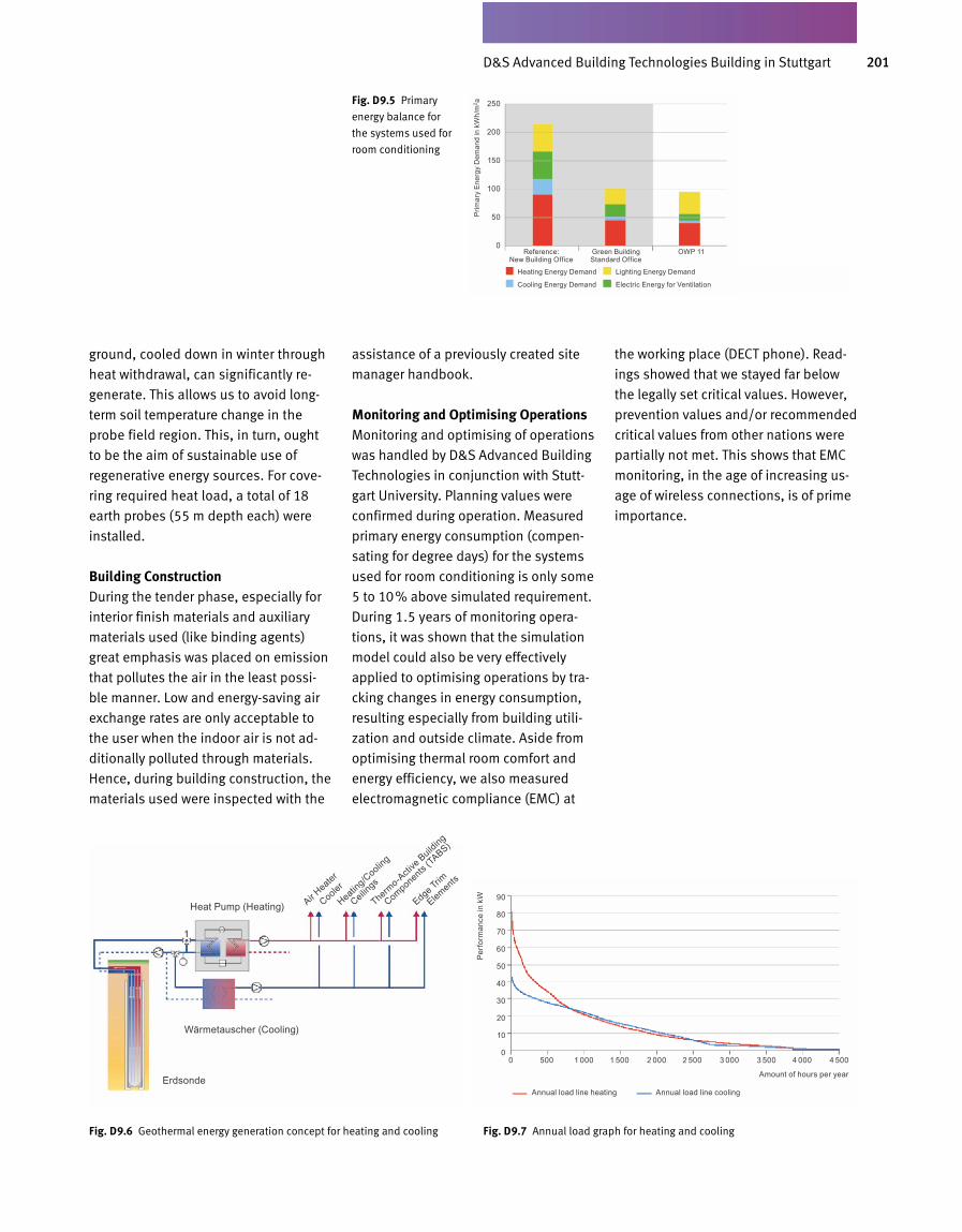
201DS-Plan Gebäude Obere Waldplätze 11, Stuttgart
Fig. D 9.5 Primary
energy balance for
the systems used for
room conditioning
ground, cooled down in winter through
heat withdrawal, can signi fi cantly re-
generate. This allows us to avoid long-
term soil temperature change in the
probe field region. This, in turn, ought
to be the aim of sustainable use of
regenera tive energy sources. For cove-
ring required heat load, a total of 18
earth probes (55 m depth each) were
installed.
Building ConstructionDuring the tender phase, especially for
interior finish materials and auxiliary
materials used (like binding agents)
great emphasis was placed on emission
that pollutes the air in the least possi-
ble manner. Low and energy-saving air
exchange rates are only acceptable to
the user when the indoor air is not ad-
ditionally polluted through materials.
Hence, during building construction, the
materials used were inspected with the
assistance of a previously created site
manager handbook.
Monitoring and Optimising OperationsMonitoring and optimising of operations
was handled by D&S Advanced Building
Technologies in conjunction with Stutt-
gart University. Planning val ues were
confirmed during operation. Measured
primary energy consumption (compen-
sating for degree days) for the systems
used for room conditioning is only some
5 to 10% above simulated requirement.
During 1.5 years of moni toring opera-
tions, it was shown that the simulation
model could also be very effectively
applied to optimising operations by tra-
cking changes in energy consumption,
resulting especially from building utili-
zation and outside climate. Aside from
optimising thermal room comfort and
energy efficiency, we also measured
electromagnetic compliance (EMC) at
the working place (DECT phone). Read-
ings showed that we stayed far below
the legally set critical values. However,
prevention values and/or recommended
critical values from other nations were
partially not met. This shows that EMC
monitoring, in the age of increasing us-
age of wireless connections, is of prime
importance.
Fig. D 9.6 Geothermal energy generation concept for heating and cooling Fig. D 9.7 Annual load graph for heating and cooling
Heat Pump (Heating)
Wärmetauscher (Cooling)
Erdsonde
Air Heate
r
Cooler
Heating/C
ooling
Thermo-A
ctive
Building
Edge Trim
Elements
Ceilings
Components (T
ABS)
Heating Energy Demand Lighting Energy Demand
Cooling Energy Demand Electric Energy for Ventilation
250
200
150
100
50
0
Prim
ary
Ener
gy D
eman
d in
kW
h/m
2 a
Reference: New Building Office
Green Building Standard Office
OWP 11
Annual load line heating Annual load line cooling
90
80
70
60
50
40
30
20
10
0
Perf
orm
ance
in k
W
0 500 1 000 1 500 2 000 2 500 3 000 3 500 4 000 4 500
Amount of hours per year
D&S Advanced Building Technologies Building in Stuttgart
202
C Appendix
203
Glossary of Terms
Acoustic 40 f., 93 ff., 136, 163, 173, 176, 185, 191 f., 198
Acoustic Comfort 41Acoustic Simulation 95Activity Level 25 ff., 32, 35 f., 41Air Exchange 33, 42 ff., 48, 57, 72, 83, 92,
114 f., 132, 158, 163 f., 170, 173, 201Air Quality 12, 25 f., 42 ff., 48, 57 f., 74, 114,
135, 157, 164, 191 f., 198Artificial Lighting 36 ff., 48, 58 f., 71, 80 f.,
105, 156
Benefits Delivery 53, 109, 112 f.Biogas 12, 52, 120 ff., 128 f.Biomass 52, 120 ff., 128 f.Bionic Materials 99Blower Door Test 132 f.BRE’s Environmental Assessment Method
(BREEAM) 15 ff., 181Buffer Storage 125Building Density 54, 74, 78, 131Building Ecology 10 f., 92Building Orientation 71, 101, 180Building Shape 51, 67, 69, 71, 75, 155, 181Building Simulation 90, 97, 105, 134, 142,
181, 200Bulb Globe 134
CFD Simulation 106, 177Climate Zone 47, 55 ff., 67, 74 ff.Clothing 26 ff., 35, 49, 71Cold Air Drop 29, 111, 152Comfort Level 11, 20, 25 ff., 34 f., 41, 47 ff., 74,
94, 97, 102 ff., 110, 117, 150 ff., 163, 176 f., 183, 197 ff.
Comfort Temperature 35Commissioning 65, 130 ff., 171Cooling Ceiling 49, 148, 163, 170, 177, 200Cooling Energy Demand 53, 56 f., 96, 105,
153, 159, 163 f., 170, 177, 189, 201Cooling System 27, 61, 109, 113, 117, 124 f.,
129, 133, 194, 197CO2 Concentration 43 f., 135CO2 Emission 12 ff., 53, 129, 165, 189CO2 Trade 13
Daylight 36 ff., 48, 56 ff., 68 ff., 80 ff., 105 ff., 113, 137, 150 ff., 156 ff., 170, 180 f., 185 ff., 192 ff.
Daylight Autonomy 37, 58Daylight Factor 37 ff., 137Daylighting 38 f., 83 f., 87, 90, 158Daylight Simulation 85, 105 ff.Daylight Utilization 56, 86, 113, 180
Dockland Building, Hamburg 146 ff.Double-skin Façade 88 f., 101 ff., 136, 151 f.,
170, 181 f.Drinking Water Heating 53 ff., 70, 124, 170Draught 25, 34, 68, 104, 110, 115 ff., 132, 151,
157Draught Risk 34DR Byen, Copenhagen 190 ff.D&S Advanced Building Technologies Buil-
ding 49, 107, 139, 196 ff.
Electricity Demand 57 ff., 115, 120Electromagnetic Compatibility 26, 45Electromagnetic Radiation 45 f.Emission Credits 13Emissions 13 ff., 43 f., 53, 58, 92, 135, 165,
189Emulation 138Energy Benchmarks 51Energy Management 7, 140 ff., 159, 171Energy Pile 127, 164European Investment Bank, Luxembourg 178 ff.
Façade Construction Quality Management 90Façade Design 37, 86, 90, 105, 170Field Intensity 46Flat Collectors 124Fuel Cell 122 f., 128
Geothermal Probe 21, 127Geothermics 12, 69 f., 127Glare Protection 48, 71, 78, 82 ff., 90, 137, 181Glass, self-cleaning 98Greenhouse Gas 13, 52 f.Grey Water Use 63Ground Water Utilization 127
Heat Emission 27, 34, 54, 112 f., 152, 199Heat Energy Requirement 101Heating Energy Demand 53 ff., 75, 78, 105,
143, 153, 159, 163, 170, 176, 189, 201Heating Systems 112 f.Heat Values 52, 143HUK Coburg 120 f.Hybrid Façade 89
Indoor Acoustics 41, 93 ff., 163Indoor Climate 11, 26 ff., 42, 47, 53, 74, 81, 90,
96, 101 ff., 109 f., 118, 150 ff., 163, 170 ff., 181, 199
Indoor Humidity 25, 32 f., 53 ff.
Jahrhunderthalle 75 f.
Kreissparkasse (KSK) Tuebingen 160 ff.Kyoto Protocol 13 f.
Layered Ventilation 25LBBW Stuttgart 166 ff.Leadership in Energy & Environmental Design
(LEED) 15 ff., 69Life Cycle 7, 11, 20 f., 51, 59 ff., 88 ff., 147,
149 f., 156, 168, 185 f., 191, 198Life Cycle Engineering 7, 20 f.Light Transmission 38, 85 ff., 107Louver 31, 83 f., 137, 176, 182
Maxiumum Allowable Concentration (MAC) 44Microclimate 32 ff., 179Mobile Phone 46Monitoring 65, 92, 135, 140 ff., 170, 201
Near Field Contrast 38 f.Night Cooling 57, 113, 152, 158, 176, 193Night Ventilation 57, 82, 102Noise Level 26, 40 f., 48, 57, 88, 136Noise Protection 40, 88, 136Nycomed, Constance 184 ff.
Open-plan Office 96Operational Optimisation 131Operative Temperature 28, 30 ff., 81, 97 f., 103,
106, 110Orientation 51, 60, 71, 81 ff., 88, 101, 155, 158,
180, 193Overall Energy Efficiency 14, 143
Passive House 42, 54, 73, 101, 163Performance Level 10 f., 25 ff., 43Phase Change Materials (PCM) 93, 97Photovoltaics 12, 52, 120, 195Pollutant Concentration 44Pollutants 42 f.Power Generation 123, 126Primary Energy Demand 53, 57 ff., 153, 159,
163, 170 f., 189, 201Primary Energy Demand of Building
Materials 60Primary Energy Factor 53Prof. P. O. Fanger 28
Radiation Asymmetry 29Rain Water Use 63Rape Oil 128Reflection Characteristics 37Regenerative Energy Resources 49 ff.
204
Requirement Minimisation 51Residential Building 25, 51, 53 ff., 62, 68, 70,
101, 113, 135Reverberation Time 40 f., 96
Shading System 51, 58, 68, 71, 80 ff., 107, 138 f., 162, 170, 180 ff., 188
Sick-Building-Syndrome 42SOKA Building, Wiesbaden 154 ff.Solar Energy 52, 60, 70 f., 81, 101, 107, 112,
124, 181, 194, 199Solar Protection 37 f., 48 f., 57, 80 ff., 98 ff.,
112, 137 ff., 151 f., 158, 170, 177 ff., 181 ff., 187 f., 193 ff.
Sound Absorption 40, 89, 95Sound Measurement 136Speech Transmission Index 41Sunlight Factor 37, 59Surface Temperature 26 ff., 74, 77, 100 f., 105,
109 ff., 131 ff., 151, 158, 163, 187
Temperature Gradient 74The Art Museum, Stuttgart 170 ff.Thermal Bridges 77 f., 133Thermal Comfort 12, 25 ff., 40, 47 ff., 54 ff.,
74, 81 ff., 100 ff., 134, 150 f., 162 f., 170 ff., 182, 188, 197 ff.
Thermography 133, 171Total Energy Permeability Grade 80Trigeneration 53, 120 ff., 158 f.
Urban Development 69 ff.User Acceptance 48Utilization 100 ff., 107 ff., 112 ff., 118, 120 ff.,
137, 142 f., 151, 155 f., 158 f., 167, 170 ff., 180, 187, 195 ff.
Vacuum Façade 97Vacuum Insulation 60, 77 ff., 97 f., 124Ventilation Element 102, 118 f.Ventilation Flap 75, 104, 158, 176 f., 183, 194Ventilation System 21, 34, 42 ff., 49, 54 ff.,
101, 104, 117 f., 135, 138, 143, 155Visual Comfort 12, 36 f., 41, 87, 152, 198Volatile Organic Compounds (VOC) 42, 44, 92
Water Consumption 62 f.Well-Being 26, 28, 32, 35, 40, 48, 71, 92, 179, 192Wind Energy 52, 124, 126, 129Window Ventilation 43, 47 ff., 58, 71, 88 f.,
92, 105, 117 f., 132, 135, 151, 158, 180 f.Wood 52 f., 60, 81, 92 f., 122, 128, 132, 168, 182Wood Pellets 52, 128Wood Shavings 52 f., 60, 128
Sources
Chapter ABauer, M., Schwarz, M.: Gütesiegel ›Energie-
effizienz‹ für die Gebäudeplanung und den Betrieb, Deutsches Architektenblatt, 10/05
GEFMA 200, Kostenrechnung im Faci lity Ma-nagement, Teil Nutzungskosten von Ge-bäuden und Dienstleistungen, State: July 2004, Deutscher Verband für Facility Ma-nagement
BMVBW, Leitfaden Nachhaltiges Bauen, Bundesministerium für Verkehr-, Bau- und Wohnungswesen, First Reprint, State: January 2001, Berlin
International Energy Agency 2003 (IEA) – CO2 Emissions from Fuel Combustion, 1971–2001, Paris 2003
Umweltbundesamt (Hrsg.), Deutsches Treib-hausgasinventar 1990–2003, Nationaler Inventarbericht 2005
BP Statistical Review of World Energy, July 2005
IPCC Plenary XVIII, Climate Change 2001 Synthesis Report
Große wetterbedingte Naturkatastrophen 1950 bis 2002, GeoRisikoforschung, Münchner Rück, 2003
Evolution of the crude oil price, BP 2005
The Kyoto Protocol, to the United Nations Framework Convention on Climate Change which entered into force on 16th February 2005
Richtlinie 2004/101/EG des Europäischen Parlaments und des Rates vom 27.10.2004 zur Änderung der Richtlinie 2003/87/EG über ein System für den Handel mit Treib-hausgasemissionszertifikaten in der Ge-meinschaft im Sinne der projektbezogenen Mechanismen des Kyoto-Protokolls
VDI 2067: Wirtschaftlichkeit gebäudetechni-scher Anlagen, September 2000
DIN 18960: Nutzungskosten im Hochbau, Berlin 1999
www.eurostat.com
www.gvst.de/site/steinkohle/ herausforderung_klimaschutz.htm
www.env-it.de/umweltdaten/
www.umweltbundesamt.de
www.dehst.de
WWF, for a living planet: Living Planet Report 2008, www.panda.org/about_our_earth/all_publications /living_planet_ report/, 2008
Leadership in Energy and Environmental Design (LEED), www.usgbc.org
BRE Environmental Assessment Method (BREEAM), www.breeam.org, State May 2009
BRE Manual: 2008 BREEAM Offices Assessor manual, August 2008
DGNB, www.dgnb.de, State May 2009Mösle, P.; Bauer, M.; Hoinka, T.: Green Buil-
ding Label. Green Building 01-02, Issue 1, p. 50-55, 2009
UNEP Sustainable Building and Construction Initiative, Information Note, available on the Internet: www.unepsbci.org/SBCI-News/PressRelease/, 2006
Chapter B1Leitfaden Nachhaltiges Bauen, Richtwerte für
Innenraumluft, Deutsches Bundesminis-terium für Verkehr, Bau und Wohnungswe-sen, Berlin, January 2001
Neufert, P.u. C., Neff, L., Franken, C.: Neufert Bauentwurfslehre. Braunschweig/Wiesba-den 2002, 37. Edition
Recknagel, H., Sprenger, E., Schramek, R.: Taschenbuch für Heizung und Klima 03/04, Munich 2003
von Kardorff, G., Schwarz, M.: Raumluftqua-lität und Baustoffauswahl, Baumeister, 09/1999
Mayer, E.: Tagesgang für thermisches Behag-lichkeitsempfinden. Gesundheitsinge- nieur – gi 107, 1986, Issue 3, p. 173–176
Mayer, E.: Ist die bisherige Zuordnung von PMV und PPD noch richtig? Kl Luft- und Kältetechnik 34, 1998, Issue 12, p. 575–577
CEN-Bericht CR1752: Auslegungskriterien für Innenräume. European Committee for Standardization, Central Office Brussels, December 1998
Witthauer, Horn, Bischof: Raumluft qualität: Belastung, Bewertung, Beeinflussung, Karlsruhe 1993
Bericht der Bundesregierung über die For-schungsergebnisse in Bezug auf Emissions- minderungsmöglichkeiten der gesamten Mobilfunktechnologie und in Bezug auf gesundheitliche Auswirkungen, Drucksache 15/4604, 27.12.2004
Deutschland, Elektrosmogverordnung (26. BImSchV)
Diss. F. Sick: Einfluss elementarer architek-tonischer Maßnahmen auf die Tageslicht-qualität in Innenräumen, Fraun hofer IRB
205
Verlag, 2003Verbundprojekt Licht in Büroräumen – Son-
nenschutz, Abschlussbericht 2004, Uni-versität Dortmund und Fachhochschule Aachen 2004
Voss, K., Löhnert, G., Herkel, S., Wagner, A., Wambsganß, M. (Hrsg.): Bürogebäude mit Zukunft, TÜV Verlag, 2005
Urteil mit enormer Tragweite – Im Büro gilt die 26 °C-Grenze, CCI-Print, Issue 7, 2003
DIN EN 13779: Lüftung von Nichtwohngebäu-den – Allgemeine Grundlagen und Anfor-derungen an Lüftungs- und Klimaanlagen; Deutsche Fassung EN 13779: 2004
DIN EN ISO 13732/2: Ergonomics of the ther-mal environment – Methods for the as-sessment of human responses to contact with surfaces – Part 2: Human contact with surfaces at moderate temperature, March 2001
DIN EN ISO 13732/3: Ergonomie der thermi-schen Umgebung – Bewertungsmethoden für Reaktionen des Menschen bei Kontakt mit Oberflächen – Teil 3: Kalte Oberflächen, March 2005
DIN EN 15251 (Entwurf): Bewertungs kriterien für den Innenraum einschließlich Tempe-ratur, Raumluftqualität, Licht und Lärm, July 2005
DIN 1946: Teil 2 Raumlufttechnik, Berlin 1994DIN 4109: Schallschutz im Hochbau, Berlin
1989DIN 5034: Teil 1 Tageslicht in Innenräumen.
Allg. Anforderungen, Berlin 1999DIN 5034: Teil 2 Tageslicht in Innen räumen –
Grundlagen, Berlin 1985DIN 18041: Hörsamkeit in kleinen bis mittel-
großen Räumen, Berlin 2001DIN EN 12646-1: Beleuchtung von Arbeits-
stätten, Brussels 2002DIN EN 12464-2: Beleuchtung von Arbeits-
stätten, Berlin 2003DIN EN 12665: Grundlegende Begriffe und
Kriterien für die Festlegung von Anforde-rungen an die Beleuchtung, Berlin 2002
DIN EN ISO 7730: Analytische Bestimmung und Interpretation der thermi schen Be-haglichkeit durch Berechnung des PMV- und des PPO-Indexes und der lokalen thermischen Behaglichkeit. Berlin 2003
Arbeitsstättenrichtlinien (ASR 5) LüftungArbeitsstättenrichtlinien (ASR 5) 6/1 u. 3
RaumtemperaturenArbeitsstättenrichtlinien (ASR 5) 7/1 Sicht-
verbindungen nach außen
Arbeitsstättenrichtlinien (ASR 5) 7/3 Künstli-che Beleuchtung
VDI 3787/2 Umweltmeteorologie – Metho-den zur human-biometeorologischen Be-wertung von Klima und Lufthygiene für die Stadt- und Regional planung, January 1998
International Commission on Non-Ionizing Radiaton Protection (ICNIRP), www.icnirp.de
Chapter B2Treiber, M.: IKE Stuttgart, interner BerichtWilkins, C., Hosni, M. H.: Heat Gain From Of-
fice Equipment. ASHRE Journal 2000Ulm, Tobias: Primärenenergiebilanz für Büro-
gebäude, (Diplomarbeit), Universität Karls- ruhe, 2003
Eyerer, P., Reinhardt, H.-W.: Ökologische Bi-lanzierung von Baustoffen und Gebäuden, Wege zu einer ganzheitlichen Bilanzierung, Basel 2000
Voss, K., Löhnert, G., Herkel, S., Wagner, A., Wambsganß, M. (Hrsg.): Bürogebäude mit Zukunft, TÜV Verlag, 2005
Testreferenzjahre für Deutschland für mittlere und extreme Klimaverhältnissse (TRY), Deutscher Wetterdienst, 2004, available on the Internet: www.dwd.de/TRY
Stromsparcheck für Gebäude – Ein Arbeits-dokument für Planer und Investoren, Se-minardokumentation, IMPULS-Programm Hessen
Referentenentwurf: Verordnung über energie-sparenden Wärmeschutz und energie-sparende Anlagentechnik bei Gebäuden (Energieeinsparverordnung EnEV), Novem-ber 2006
Directive 2002/91/EC on the Energy Perfor-mance of Buildings of 16. 12. 2002, Offi-cial Journal of the European Communities, 01/2003
Energie im Hochbau SIA 380/4, Schweizer Ingenieur- und Architektenverein, Zurich, 1995, available on the Internet: www.380-4.ch
GEMIS 4.14 (2002): Globales Emissionsmo-dell Integrierter Systeme, Ergebnistabel-len, Öko-Institut Freiburg, www.oeko.de/service/gemis
Leitfaden Energie im Hochbau, Hessisches Ministerium Umwelt, Energie, Jugend, Familie und Gesundheit, Wiesbaden, Re-vised Version 2000
Produktkatalog Grauwassernutzung, Pontos GmbH, Carl-Zeiss-Str. 3, 77656 Offenburg
DIN 18599: Energetische Bewertung von Ge-
bäuden – Berechnung des Nutz-, End- und Primärenergiebedarfs für Heizung, Küh-lung, Lüftung, Trinkwarmwasser und Be-leuchtung Teile 1 bis 10, February 2007
VDI 4600 Kumulierter Energieaufwand, June 1997
DIN 4701 Teil 10: Energetische Bewertung Heiz- und raumlufttechnischer Anlagen, Berlin 2001
VDI 3807: Energieverbrauchskennwerte für Gebäude, Sheet 1, 1994, Sheet 2, 1997, Berlin
www.blauer-engel.dewww.energielabel.dehttp://epp.eurostat.ec.europa.euwww.meteotest.ch
Chapter C1Daniels, K.: Technologie des ökologischen
Bauens. Grundlagen und Maßnahmen, Beispiele und Ideen. Basel/Boston/Berlin 1995
DIN 277: Grundflächen und Rauminhalte von Bauwerken im Hochbau, Berlin 2000
Behling, S. u. S.: Sol Power. Munich/Berlin/London/New York 1997
Oesterle, E., Lutz, M., Lieb, R.-D., Heus ler, W.: Doppelschalige Fassaden. Ganzheitliche Planung. Konstruktion, Bauphysik, Aero-physik, Raumkonditionierung, Wirtschaft-lichkeit. Munich 1999
Mösle, P.: Zwischen den Schalen. Die Auswir-kungen der Gestaltung und Konzeption mehrschaliger Fassaden auf die Raum-konditionierung, db deutsche bauzeitung, 01/2001
Fischer, C., Einck, J.: Hochschall dämmende Fensterkonstruktionen, Intelligente Archi-tektur, 7–9/2005
Bauer, M.: Alte Montagehalle für neuen Kunst-genuss, Liegenschaft aktuell, 06/2006
Lutz, M.: Sanierung von Fassaden und Ge-bäuden: Wenn der Denkmalschutz mit-spielt, Liegenschaften aktuell, 01/2007
Stahl, W., Goetzberger, A., Voss K.: Das ener-gieautarke Solarhaus – Mit der Sonne wohnen, Heidelberg 1997
EnEV: Verordungen über energiesparenden Wärmeschutz und energie sparende An-lagentechnik bei Gebäuden – Energiespar-verordnung, 2004, www.enev-online.info
Hauser, G., Siegel, H.: Wärmebrückenatlas für den Mauerwerksbau, Wiesbaden/Ber-lin 1996
Zukunftsorientiertes Energiekonzept für das

206
Projekt Stuttgart 21, Planungs gebiet A1, Ar - beitsgemeinschaft Stuttgart 21, Prof. Dr.-Ing. Eberhard Oesterle et altera, Fachzeitung Untersuchungen zur Umwelt, 11/1998
Evacuated Glazing – State of the Art and Po-tential, Dr. Weinläder, ZAE Bayern, Glastec 2006
Neue Baumaterialien der Zukunft, Behling Braun, Jahrbuch 2004
Schweizer Ingenieur- und Architekten verein (SIA) 180: Wärme- und Feuchteschutz im Hochbau, January 2000
DIN 4109: Schallschutz im Hochbau, Novem-ber 1989
DIN 4108: Wärmeschutz im Hochbau Teil 1–3, August 1981, July 2001, July 2003
DIN EN 14501: Abschlüsse – Thermischer und visueller Komfort – Leistungsanforde-rungen und Klassifizierung, January 2006
DIN 18599/5: Energetische Bewertung von Gebäuden – Berechnung des Nutz-, End- und Primärenergiebedarfs für Heizung, Kühlung, Lüftung, Trinkwarmwasser und Beleuchtung, February 2007
DIN ISO 12207: Fenster und Türen – Luft-durchlässigkeit, Klassifizierung, June 2000
ISO 15099: Thermal performance of windows, doors and shading devices – Detailed cal-culations, November 2003
DIN EN 13363/1/2: Sonnenschutzeinrich-tungen in Kombination mit Vergla sungen – Berechnung der Solar strahlung und des Lichttransmissionsgrades, January/April 2007
VDI 2569 Schallschutz und akustische Ge-staltung im Büro, January 1990
www.ecoinvent.org
Chapter C2Fischer, C.: Es ist fast alles machbar. Mobile
Akustik als Zukunfts aufgabe im flexiblen Büro, Mensch & Büro, 06/2003
Bauer, M.: Flächenheizungen II. Baustein eines ganzheitlichen Konzeptes. Im Winter heizen, im Sommer kühlen. Deutsches Architektenblatt, 12/04
Schwarz, M.: Sonne, Erde, Luft: Das Konzept der NRW-Vertretung, HLH, No. 6/2004
Bauer, M.: Regenerative Energiesyteme in der Gebäudetechnik – sorptions gestützte Kühlung, industrieBAU, 05/2005
Bauer, M.: Das Raumklima und Energiekonzept der Landesmesse Stuttgart: Ener getische Spitzenleistung für variable Spitzenzeiten,
industrieBau Spezial ENERGIE, 01/2007Lutz, M., Schaal, G.: Dezentrale Raumluftkon-
ditionierung. Gestaltungsfreiheit für die Architekten und hohe Flexi bilität für die Nutzer, TAB, 12/2006
Schmidt, M., Treiber, M.: Entwicklung eines innovativen Gesamtkonzeptes mit ener-giesparender Raumklimatechnik für die regenerative Wärme- und Kälteerzeugung, gefördert durch die Deutsche Bundes-stiftung Umwelt, Abschlussbericht, Uni-versität Stuttgart, Lehrstuhl für Heiz- und Raumlufttechnik, July 2005
Oesterle, E., Mösle, P.: Träge und doch aktiv. Heizen und Kühlen mit Betonteilen, db deutsche bauzeitung, 04/2001
Recknagel, H., Sprenger, E. u. Schramek, E.: Taschenbuch für Heizung- + Klimatechnik, Oldenbourg Verlag 97/98
Schoofs, S. u. Lang J.: Kraft-Wärme-Kopplung mit Brennstoffzellen, Fachinformations-zentrum Karlsruhe 2000
Schoofs, S. u. J. Lang: PEM-Brennstoff zellen, Fachinformationszentrum Karlsruhe 1998
Dehli, M.: Möglichkeiten der dezentralen Er-zeugung von Strom und Wärme, FHT Ess-lingen 2005
Milles, U.: Windenergie, Fachinformations-zentrum Karlsruhe 2003
Röben: Sorptionsgestützte Entfeuchtung mit verschiedenen wässrigen Salzlösungen. Dissertation am Institut für Angewandte Thermodynamik und Klimatechnik, Univer-sität Essen, Aachen 1997
Gottschau, T. und Fuchs, O.: Biogas, Fachin-formationszentrum Karlsruhe 2003
Levermann, E.-M. und Milles, U.: Biogas, Fachinformationszentrum Karlsruhe 2002
WAREMA Sonnenschutztechnik, Produktka-talog
ZAE Bayern: Bayerisches Zentrum für Ange-wandte Energieforschung e. V., Walther-Meißner-Str. 6, 85748 Garching near Mu-nich
Arbeitskreis Schulinformation Energie: Lehrerinformation: Brennstoffzellen, Frank-furt/Main, August 1998
Infozentrale der Elektrizitätswirtschaft e. V.: Strombasiswissen: Brennstoff zellen, Frankfurt/Main, January 1999
BINE Informationsdienst, Basis Energie 3: Photovoltaik. Fachinformationszentrum Karlsruhe 2003
BINE Informationsdienst, Basis Energie 4:
Thermische Nutzung der Solarenergie. Fachinformationszentrum Karlsruhe 2003
BINE Informationsdienst, Basis Energie 13: Holz-Energie aus Biomasse. Fachinforma-tionszentrum Karlsruhe 2002
BINE Informationsdienst, Basis Energie 16: Biogas. Fachinformationszentrum Karlsru-he 2003
BINE Informationsdienst, Projektinfo 05/2000. Kraft-Wärme-Kopplung mit Brennstoffzellen. Fachinformationszentrum Karlsruhe 2000
VDI 6030: Auslegung von freien Raumheiz-flächen – Grundlagen und Auslegung von Raumheizkörpern. Berlin 2002
ASUE: Mikro-KWK Motoren, Turbinen und Brennstoffzellen, www.asue.de/2001
www.bine.infowww.zbt-duisburg.dewww.diebrennstoffzelle.dewww.energieberatung.ibs-hlk.dewww.cooretec.dewww.isi.fraunhofer.dewww.carmen-ev.de
Chapter C3 and C4Mösle, P., Bauer, M.: Behagliche Temperatu-
ren im Glashaus, Deutsches Architekten-blatt, 05/2006
Grob, R., Bauer, M.: Emulation. Computerge-stützte Vorabinbetriebnahme von Regel- und Steuerungsanlagen, TAB, 10/2004
von Kardorff, G.: Ökomanagement am Pots-damer Platz. Kostendruck schließt den Umweltschutz nicht aus, leonardo-online, 03/1999
Chapter DHerzog, Th (Hrsg.).: SOKA-Bau. Nutzung Effi-
zienz Nachhaltigkeit, Munich 2006Bauer, M., Mösle, P.: Raumklima- und Fas-
sadenkonzept »Dockland« Hamburg, AIT, 10/2006
Oesterle, E.: Bürogebäude mit innovativem Energiekonzept – Heizen und Kühlen mit Erdwärme, EB Energieeffizientes Bauen, 01/2003
Bauer, M., Niewienda, A., Koch, H.P.: Alles Gute kommt von unten – Mit geringem Energiebedarf zu geringem Energieauf-wand, HLH, 11/2001
Niewienda, A.: Entwicklung der Klimakonzep-te für das Kunstmuseum Stuttgart, Bau-physik, Issue 2/2005
www.drbyen.dk

207
List of Authors
Michael Bauer03. 05.1966Prof. Dr.-Ing. Maschinenwesen, Stuttgart UniversityManaging Director, D&S Advanced Building Technologies
Peter Mösle19. 09.1969Dipl.-Ing. Energietechnik, Stuttgart UniversityMember of Executive Board, D&S Advanced Building Technologies
Michael Schwarz21. 02.1961Dr.-Ing. Maschinenwesen, Stuttgart UniversityTeam Manager Energy Management, D&S Advanced Building Technologies
Ralf Buchholz03. 07.1968Dipl.-Ing. (FH) Bauphysik, Stuttgart University of Applied SciencesTeam Manager Building Physics, D&S Advanced Building Technologies
Andreas Niewienda19. 08.1964Dipl.-Physiker, Freiburg UniversityConsultant Energy Design/Management, D&S Advanced Building Technologies
Michael Jurenka12. 11.1968Dipl.-Ing. Maschinenwesen, Stuttgart UniversityConsultant Energy Design, D&S Advanced Building Technologies
Ralf Wagner15. 05.1965Dipl.-Ing. (FH) Elektrische EnergietechnikConsultant Building Services Engineering, D&S Advanced Building Technologies
Herwig Barf23. 11.1963Dipl.-Ing. ArchitektTeam Manager Façade Technology, D&S Advanced Building Technologies
Christian Fischer02. 04.1951Dr.-Ing., “öbuv” Expert Surveyor,Building Physics, D&S Advanced Building Technologies
Hans-Peter Schelkle30. 06.1970Dr.-Ing. Bauingenieurwesen, Stuttgart UniversityConsultant Facility Management, D&S Advanced Building Technologies
Heinzpeter Kärner30. 07.1970Dipl.-KaufmannOrganisation and Coordination, D&S Advanced Building Technologies
Ulrike Fischer20. 06.1964Assistant to the Executive Board, D&S Advanced Building Technologies
Ulrike Schweizer24. 08.1977Dipl.-Betriebswirtin (FH)Organisation and Coordination, Drees & Sommer AG
208
Thank You
We would like to thank especially all those architects, clients and companies who made available to us their drawings and image ma-terial and who allowed us to interview them about their respective projects. They made a decisive contribution towards the contents of this book:
Bothe Richter Teherani, Hamburg
Robert Vogel GmbH & Co. KG, Hamburg
Herzog und Partner, Munich
Soka-Bau, Wiesbaden
Auer + Weber + Assoziierte, Stuttgart
Kreissparkasse Tuebingen
LBBW, Stuttgart
Wöhr Mieslinger Architekten, Stuttgart
Petzinka Pink Technologische Architektur ®, Duesseldorf
Nycomed, Constance
Ingenhoven Architekten, Duesseldorf
Architekturbüro Hascher und Jehle, Berlin
COWI, Copenhagen
DR Byen, Copenhagen
Drees & Sommer, Stuttgart
Glaser FMB GmbH & Co. KG, Beverungen
va-Q-tec AG, Wuerzburg
Kajima Design, Tokyo
Institut für Industrieaerodynamik, Aachen
Gerber Architekten International, Dortmund
Maier Neuberger Architekten, Munich
Colt International GmbH, Eltingen
Rasbach Architekten, Oberhausen
MEAG, Munich
Bartels und Graffenberger Architekten, Duesseldorf
Steelcase Werndl AG, Rosenheim
Warema Renkhoff GmbH, Marktheidenfeld
Purratio AG, Neuhausen a.d. Fildern
Stefan Behling, Fosters + Partners, London
Prof.-Dr. Ing. Koenigsdorff, FH Biberach
Spengler Architekten, Nuremberg
Playmobil geobra Brandstätter GmbH & Co. KG, Zirndorf
VHV-Gruppe, Hannover
Architekten BKSP, Hannover
Professor Bernhard Winking
Architekten, Hamburg
Architekten Wulff und Partner, Stuttgart
Projektgesellschaft Neue Messe GmbH & Co. KG, Stuttgart
Pontos GmbH, Offenburg
Dittrich-Planungs-GmbH, Wunsiedel
Further, we would like to thank our expert col-leagues at D&S Advanced Building Technolo-gies from the various teams:
Life Cycle Engineering
Energy Design and Management
Building Services Engineering
Façade Technology
Building Physics, Building Ecology
Facility Management
Image Material
All the drawings in this book were created especially. Photographs without credit are archive material of D&S Advanced Building Technologies.
ForewordDietmar Strauß, Besigheim p. 6
Chapter AJörg Hempel, Aachen p. 11 toppixelio.de p. 8–9 and p. 12 bottom
Chapter BJörg Hempel, Aachen p. 30 bottompixelio.de p. 42 and p. 47 Chapter CArchitekten BKSP p. 112 topArchitekten Bartels and Graffenberger p. 87artur / Tomas Riehle p. 100BioKoN Saarbruecken p. 99 bottom right
Firma Colt International GmbH, Elchingen p. 84Firma Warema Renkhoff GmbH p. 98 bottom
rightGeobra Brandstätter GmbH & Co. KG, Zirndorf
p. 104 bottom rightGerber Architekten International GmbH,
Fotograf: Hans-Jürgen Landes p. 80Glaser FMB GmbH & Co. KG p. 98 bottom leftH. G. Esch, Hennef p. 66, p. 94, p. 95, p. 111
top rightJörg Hempel, Aachen p. 64Kajima Design, Tokyo p. 102 top right, p. 103Mackevision Medien Design GmbH p. 116,
p. 117Martin Lutz p. 71Petzinka Pink Technologisch Architektur ®
p. 75, p. 76, p. 114pixelio.de p. 108, p. 126, p. 129, p. 131Professor Werner Nachtigall p. 98Taufik Kenan, Berlin, for Petzinka Pink Tech-
nologische Architektur ® p. 93 top left and top right
wodtke GmbH p. 128
Chapter D Hans-Georg Esch, Hennef p. 166–171COWI Beratende Ingenieure p. 172–195Herzog + Partner p. 154–159Ingenhoven Architekten, Duesseldorf p. 181
and p. 182 bottomISE Freiburg p. 189 topJörg Hempel, Aachen for Robert Vogel
GmbH & Co. KG, Hamburg p. 144–153Model photos: Holger Khauf, Duesseldorf Pho-
tography: H. G. Esch, Hennef p. 178–183Petzinka Pink Technologische Architektur ®
p. 184–189Roland Halbe, Stuttgart p. 160–165 and
p. 172–177
CoverHans-Georg Esch, Hennef Back, bottom leftJörg Hempel for Robert Vogel GmbH & Co. KG,
Hamburg Cover ImageIngenhoven Architekten, Duesseldorf Back,
top leftTaufik Kenan, Berlin, for Petzinka PinkTechnologische Architektur ® Back, top right