PDF-EN - International Journal of Railway Research
12
International Journal of Railway Research, Vol. 7, No. 1, (2020), 61-72 * Corresponding author, Assistant professor Email: [email protected] 1. Introduction In urban rail transportation systems such as heavy and light metro, monorail and tram, needed traction power to move the train is distributed in a number of cars, which forms up a combination of motorized and trailer cars as Fig.1.a [1] will be created in a train-set [2], [3] and [4]. On the other hand, in the structure of the last generation of metro trains equipped with three-phase induction motors, the propulsion system often includes a DC supply (either of the third-rail shoes or an overhead pantograph) and input filters, power distribution boxes, High speed circuit breaker, DC to AC converters such as traction converters and auxiliary loads converters, traction motors, train control and management system (TCMS), and communication links [1], [2] and [3]. Generally, these types of common propulsion systems are divided into car based type like in [2] and bogie based type like in [3] in terms of separation of power and control scheme. In the car based type according to Fig.1.b, one inverter module feeds all the traction motors of each motorized car. In the bogie based type according to Fig.1.d, there are two inverter modules in each motorized car that each of them feeds the traction motors of each bogie separately. In this case, each inverter module is equipped with one DC-link capacitor, one High Speed Circuit Breaker (HSCB) as well as the switching control unit separately. International Journal of Railway Research Analysis of Semi-Bogie Based Propulsion System Used in Tehran Metro Trains in Degraded Mode of Operation Mohamamd Babaeyzadeh 1 , Seyed saeed Fazel 1* 1 School of Railway Engineering, Iran University of Science and Technology, Tehran, Iran ARTICLE INFO A B S T R A C T Article history: Received: 14.02.2020 Accepted: 27.04.2020 Published: 26.06.2020 During the supply process of rolling stocks for metro systems, the propulsion system of trains in terms of separate power and control scheme, should be selected based on the Reliability, availability, maintainability and safety (RAMS) parameters along with some expected indexes in operation plan. This means that, in addition to undeniable control and operation advantages of a train that are equipped with the bogie based propulsion system, the performance of the train is very important when an inverter module or each propulsion system's component fails, and therefore it should be considered to choose the propulsion system type. Now, a technical grading of propulsion system types can be made from the point of origin which is car based type with the minimum advantages of operation, to the point of destination which is bogie based type with the maximum advantages of operation. Therefore, the semi-bogie based type that has been applied in Tehran metro trains with one common DC link, input protection circuit and control, is located in the middle of this grading. However, the definitions of the above mentioned propulsion system types are presented at the beginning of this paper, in order to clarify the functional behavior of semi-bogie based type in degraded and faulty mode of operation to determine its exact position in above mentioned grading between the first two types, some investigation will be done based on the simulation in MATLAB and the results will be presented. Keywords: Propulsion system Car based Bogie based Semi-bogie based Degraded mode RAMS ISSN: 2423-3838
-
Upload
khangminh22 -
Category
Documents
-
view
1 -
download
0
Transcript of PDF-EN - International Journal of Railway Research
International Journal of Railway Research, Vol. 7, No. 1, (2020), 61-72
*Corresponding author, Assistant professor Email: [email protected]
1. Introduction
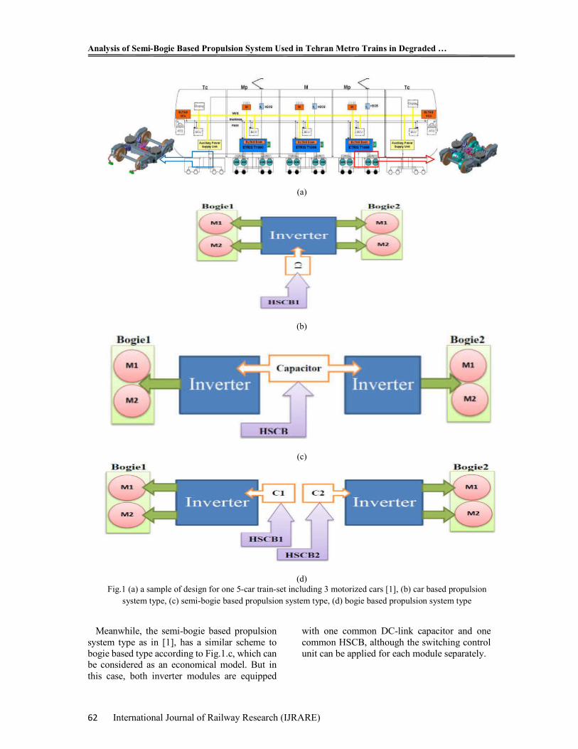
In urban rail transportation systems such as heavy and light metro, monorail and tram, needed traction power to move the train is distributed in a number of cars, which forms up a combination of motorized and trailer cars as Fig.1.a [1] will be created in a train-set [2], [3] and [4]. On the other hand, in the structure of the last generation of metro trains equipped with three-phase induction motors, the propulsion system often includes a DC supply (either of the third-rail shoes or an overhead pantograph) and input filters, power distribution boxes, High speed circuit breaker, DC to AC converters such as traction converters and auxiliary loads
converters, traction motors, train control and management system (TCMS), and communication links [1], [2] and [3]. Generally, these types of common propulsion systems are divided into car based type like in [2] and bogie based type like in [3] in terms of separation of power and control scheme. In the car based type according to Fig.1.b, one inverter module feeds all the traction motors of each motorized car. In the bogie based type according to Fig.1.d, there are two inverter modules in each motorized car that each of them feeds the traction motors of each bogie separately. In this case, each inverter module is equipped with one DC-link capacitor, one High Speed Circuit Breaker (HSCB) as well as the switching control unit separately.
International Journal of
Railway Research
Analysis of Semi-Bogie Based Propulsion System Used in Tehran Metro Trains in Degraded Mode of Operation
Mohamamd Babaeyzadeh1, Seyed saeed Fazel1*
1School of Railway Engineering, Iran University of Science and Technology, Tehran, Iran
ARTICLE INFO A B S T R A C T
Article history:
Received: 14.02.2020
Accepted: 27.04.2020
Published: 26.06.2020
During the supply process of rolling stocks for metro systems, the propulsion system of trains in terms of separate power and control scheme, should be selected based on the Reliability, availability, maintainability and safety (RAMS) parameters along with some expected indexes in operation plan. This means that, in addition to undeniable control and operation advantages of a train that are equipped with the bogie based propulsion system, the performance of the train is very important when an inverter module or each propulsion system's component fails, and therefore it should be considered to choose the propulsion system type. Now, a technical grading of propulsion system types can be made from the point of origin which is car based type with the minimum advantages of operation, to the point of destination which is bogie based type with the maximum advantages of operation. Therefore, the semi-bogie based type that has been applied in Tehran metro trains with one common DC link, input protection circuit and control, is located in the middle of this grading. However, the definitions of the above mentioned propulsion system types are presented at the beginning of this paper, in order to clarify the functional behavior of semi-bogie based type in degraded and faulty mode of operation to determine its exact position in above mentioned grading between the first two types, some investigation will be done based on the simulation in MATLAB and the results will be presented.
Keywords:
Propulsion system
Car based
Bogie based
Semi-bogie based
Degraded mode
RAMS
ISSN: 2
423
-383
8
Analysis of Semi-Bogie Based Propulsion System Used in Tehran Metro Trains in Degraded …
62 International Journal of Railway Research (IJRARE)
Meanwhile, the semi-bogie based propulsion system type as in [1], has a similar scheme to bogie based type according to Fig.1.c, which can be considered as an economical model. But in this case, both inverter modules are equipped
with one common DC-link capacitor and one common HSCB, although the switching control unit can be applied for each module separately.
(a)
(b)
(c)
(d) Fig.1 (a) a sample of design for one 5-car train-set including 3 motorized cars [1], (b) car based propulsion
system type, (c) semi-bogie based propulsion system type, (d) bogie based propulsion system type
Babaeyzadeh & Fazel
International Journal of Railway Research (IJRARE) 63
Finally, some parameters like supply costs, safety and operation criterion affect the choice of propulsion system of trains. However, it is clear that the performance of trains equipped with different types of propulsion systems are essentially same in normal operating conditions, and in case of failure such as of critical system parts, the above mentioned systems operate differently and it effects RAMS parameters [4] and [5]. The case study in this paper is the semi-bogie based type that has been designed by Bombardier in the trains of the last generation of the metro lines in Tehran [6].
2. Problem Statement
Although-based on the descriptions in the previous section-without any simulation, the performance of above mentioned three types of systems are clearly predictable in normal operation mode. However, the exact position of the semi-bogie based system between other two types in above mentioned grading, causes buyers make mistake while choosing the type of system due to economic considerations. In fact, the problem arises when buyers see the difference between semi-bogie based and bogie based system just in a DC link capacitor and an additional HSCB in the converter input, and so they mistakenly judge that the different performance of these two types is based on this small hardware difference.
To investigate the issue, the performance of three types of system is considered in the two main operation modes: normal and degraded. In the first case, the train is moved by traction power under normal operating conditions for all equipment of propulsion system, the performance of all three types of system is completely identical because all the traction motors in each motorized car are fed, and therefore its analysis is ignored in this paper. But in the second case, the fundamental difference between the systems performance will be evident, where at least one critical part of system has been damaged and makes the operation of the propulsion system defective. Obviously, any defect that results in loss of an inverter module in each motorized car will result in traction motors power cut by related module, and therefore a percentage of total train’s power will be lost according to the traction motors’ power losses. This means that any defect that results in loss of an inverter module in each motorized car,
will lead to loss of power of all related motorized car in a train equipped with a car based propulsion system type, and also half of power of the related motorized car in a train equipped with a bogie based propulsion system certainly. However, in the case of the semi-bogie based type, the judgment is harder and the simulations will determine the similarity of the dynamic behavior of this type of system during each possible fault to car based or bogie based type. The importance of this issue will become more significant where the operators prefer the semi-bogie based to a full bogie based type in order to save the cost, without taking into account the operational considerations and, in particular, considering the train availability as a part of the RAMS parameters.
Therefore, in this paper by focusing on the behavior of a semi-bogie based propulsion system which has been used in Tehran subway’s trains, the performance of system in the various conditions of probable faults is analyzed and its exact position in the grading between two car based and bogie base types of the propulsion system will be determined.
3. Definition of Probable Faults
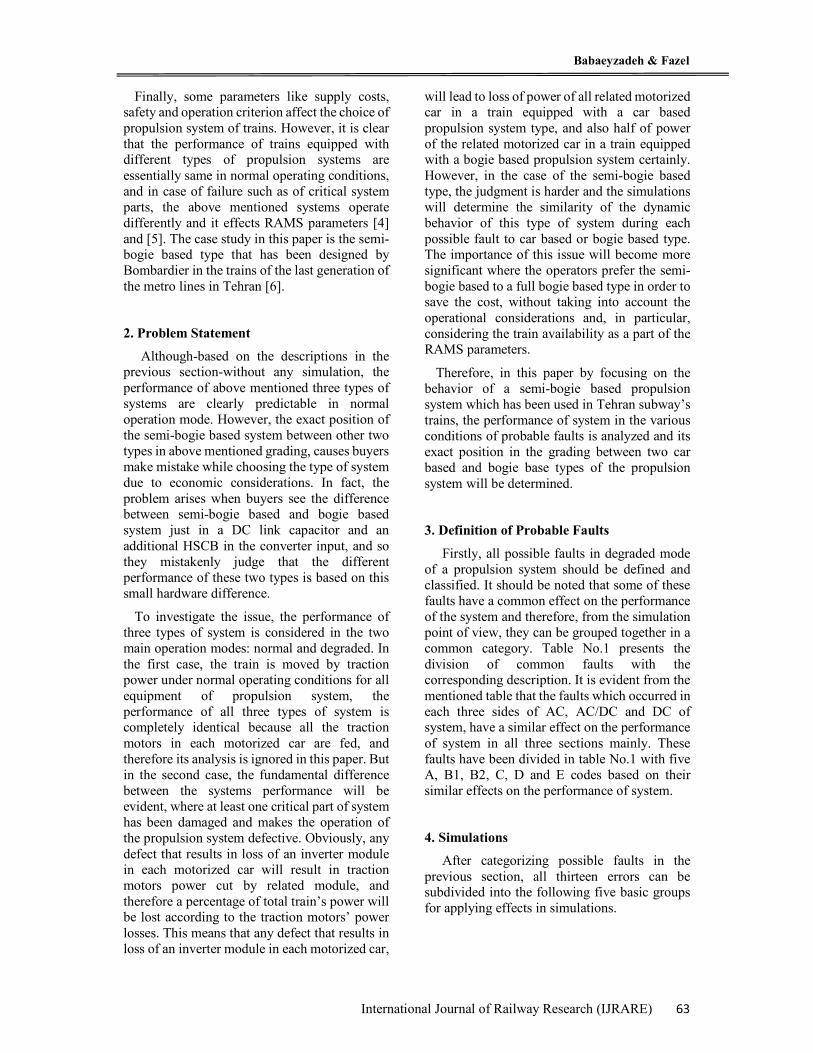
Firstly, all possible faults in degraded mode of a propulsion system should be defined and classified. It should be noted that some of these faults have a common effect on the performance of the system and therefore, from the simulation point of view, they can be grouped together in a common category. Table No.1 presents the division of common faults with the corresponding description. It is evident from the mentioned table that the faults which occurred in each three sides of AC, AC/DC and DC of system, have a similar effect on the performance of system in all three sections mainly. These faults have been divided in table No.1 with five A, B1, B2, C, D and E codes based on their similar effects on the performance of system.
4. Simulations
After categorizing possible faults in the previous section, all thirteen errors can be subdivided into the following five basic groups for applying effects in simulations.
Analysis of Semi-Bogie Based Propulsion System Used in Tehran Metro Trains in Degraded …
64 International Journal of Railway Research (IJRARE)
Note that when the faults No. 7, 8, 12 and 13 happen, the safety in operation will be eliminated and the TCMS stops operating immediately. Therefore, their simulation is ignored in this paper.
1. Three phases output short circuit with code A: Includes faults No. 1, 2 and 3 of table 1.
2. DC link short circuit with code B1: Includes faults No. 4, 5, 9 and 11 of table 1
3. Open circuit in DC link with B2 code: Includes faults No. 9 and 10 of Table 1
4. Short circuit in switches with code B1 or C: Includes faults No. 4, 5 and 6 of table 1.
5. Open circuit in switches with codes B1 or C: Includes faults No. 4, 5 and 6 of table 1.
Currently, it is sufficient to apply the five above-mentioned conditions in the simulations. For this purpose, based on the structure of figure No.1.c, two three-phase 2-level H-Bridge inverters equipped with IGBT switches have been simulated in the MATLAB-Simulink. The simulations have been done for a semi-bogie based system with 750 V-DC input used in
Tehran subway’s rolling stock. This system has been designed by Swedish Bombardier Company for Chinese CRC rolling stock manufacturer. The main parameters of simulation have been presented in table No.2 as below. In all simulations, the curves will be simulated for t=0-0.15s (7.5 cycles with f=50Hz) and each fault happens in t=0.08s.
5. Simulation Results and Discussions
Finally, the simulation results are shown for the five categories listed in the previous section, respectively.
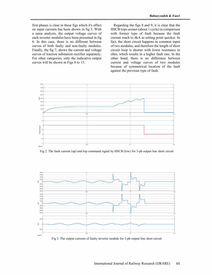
In order to prevent repetition of unimportant issues in this paper, all the related voltage and current curves are presented in Figs 2 to 7 only for the first category of faults. As shown in Fig 2, the HSCB trips after about two cycles because of rising rate of fault current. It effects on the curves for two cycles before HSCB tripping, and after that, the circuits will be cut totally. Figs 3 and 4 show the current curves of two faulty and non-faulty modules 3-phase outputs respectively. The fault current flow between two
Table 1. Categorizing the possible faults
No. Place possible fault type Equivalent fault in simulation 1
AC side (motors side)
Traction motor fault A: 3-ph output line short circuit 2 Gearbox damage
3 3-ph output line short circuit 4 DC/AC side
(inverter module)
Switch fault B1: probable DC input line short circuit
5 Gate driver unit fault 6 Interface units fault C: unsuitable performance of motors 7
DC side (line side)
Brake resistors fault D: loosing of safety and power losses
8 Brake resistors’ switches fault 9
DC link capacitor fault B1 or B2: probable DC input line short circuit or open circuit
10 Capacitor’s charging circuit fault B2: DC input line open circuit 11 DC input line short circuit B1: DC input line short circuit 12 HSCB fault
E: isolating of converter by TCMS 13 Line inductor filter fault
Table 2. Parameters’ rates of simulation
No. Section Part Descriptions 1 Stations
And Track
Traction Substation rectifier 3-phases diode based 750 V-DC 2 Third Rail Line R= 1 m ohm , L=0.1 mH 3 Track Rail R= 1 m ohm , L=0.1 mH 4 Train's Power Input Line Inductor L=5mH 5 Train's
Propulsion System DC-Link Capacitor C=20mF
6 Inverter Modules Two IGBT-VSIs in parallel 7 HSCB Fault current setting: 4 kA 8 Traction load Traction Motors Loads: P=4×200kw , PF=0.8
Babaeyzadeh & Fazel
International Journal of Railway Research (IJRARE) 65
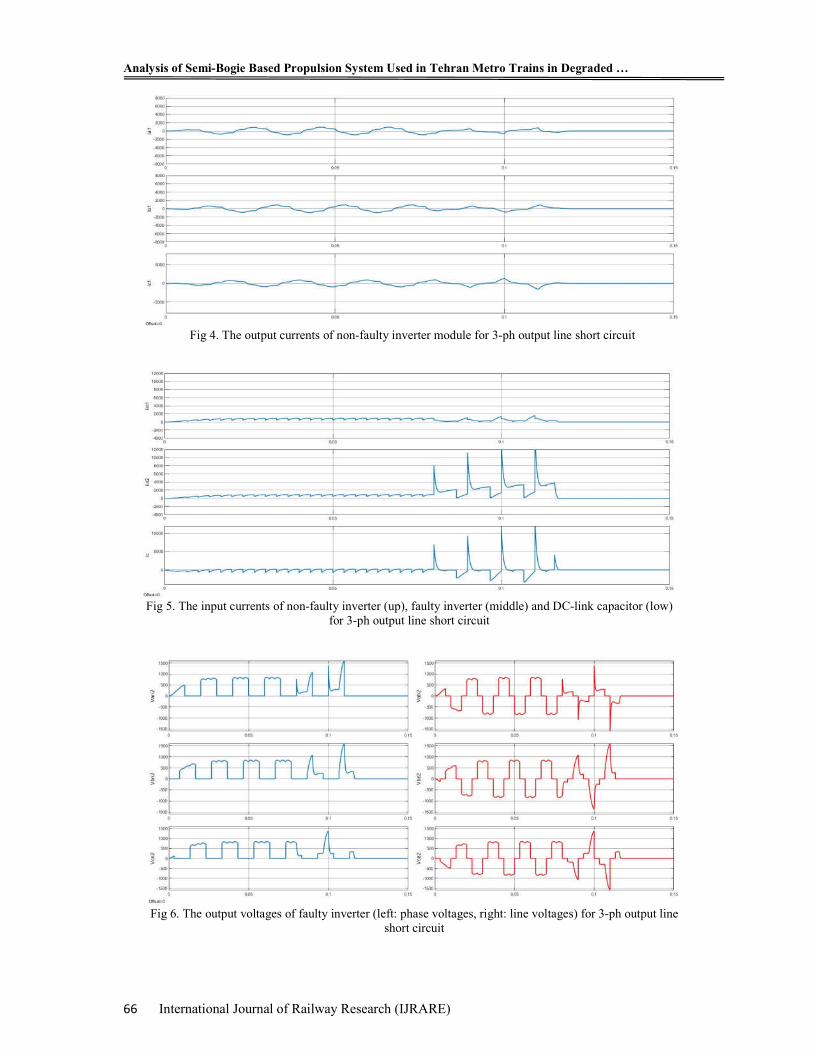
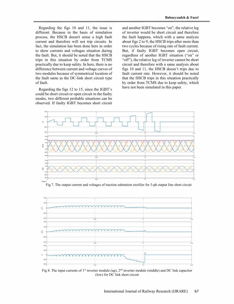
first phases is clear in these figs which it's effect on input currents has been shown in fig 5. With a same analysis, the output voltage curves of each inverter modules have been presented in fig 6. In this case, there is no different between curves of both faulty and non-faulty modules. Finally, the fig 7, shows the current and voltage curves of traction substation rectifier separately. For other categories, only the indicative output curves will be shown in Figs 8 to 15.
Regarding the figs 8 and 9, it is clear that the HSCB trips sooner (about 1 cycle) in comparison with former type of fault because the fault current reach to 4kA as setting point quicker. In fact, the short circuit happens in common input of two modules, and therefore the length of short circuit loop is shorter with lower resistance in ohm, which results in a higher fault rate. In the other hand, there is no difference between current and voltage curves of two modules because of symmetrical location of the fault against the previous type of fault.
Fig 2. The fault current (up) and trip command signal by HSCB (low) for 3-ph output line short circuit
Fig 3. The output currents of faulty inverter module for 3-ph output line short circuit
Analysis of Semi-Bogie Based Propulsion System Used in Tehran Metro Trains in Degraded …
66 International Journal of Railway Research (IJRARE)
Fig 5. The input currents of non-faulty inverter (up), faulty inverter (middle) and DC-link capacitor (low)
for 3-ph output line short circuit
Fig 4. The output currents of non-faulty inverter module for 3-ph output line short circuit
Fig 6. The output voltages of faulty inverter (left: phase voltages, right: line voltages) for 3-ph output line
short circuit
Babaeyzadeh & Fazel
International Journal of Railway Research (IJRARE) 67
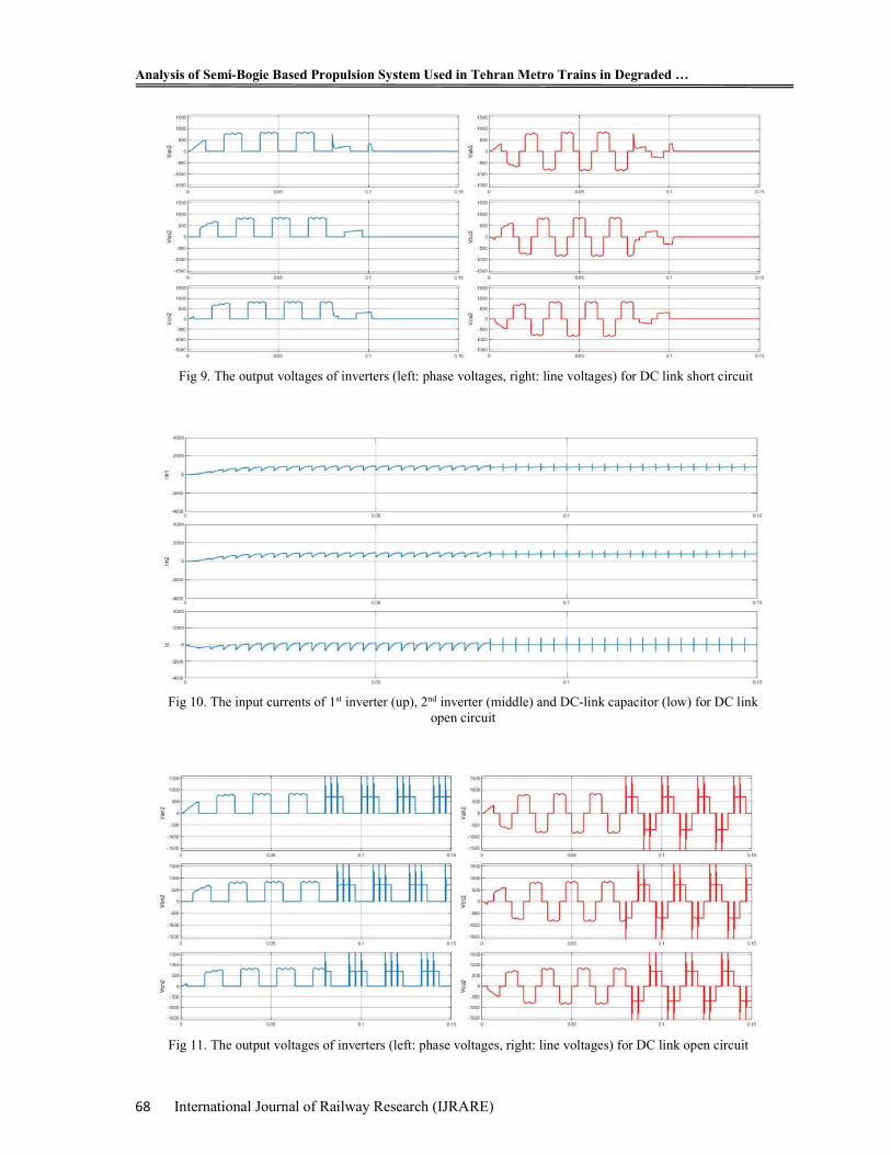
Regarding the figs 10 and 11, the issue is different. Because in the basis of simulation process, the HSCB doesn't sense a high fault current and therefore will not trip circuits. In fact, the simulation has been done here in order to show currents and voltages situation during the fault. But, it should be noted that the HSCB trips in this situation by order from TCMS practically due to keep safety. In here, there is no difference between current and voltage curves of two modules because of symmetrical location of the fault same as the DC-link short circuit type of fault.
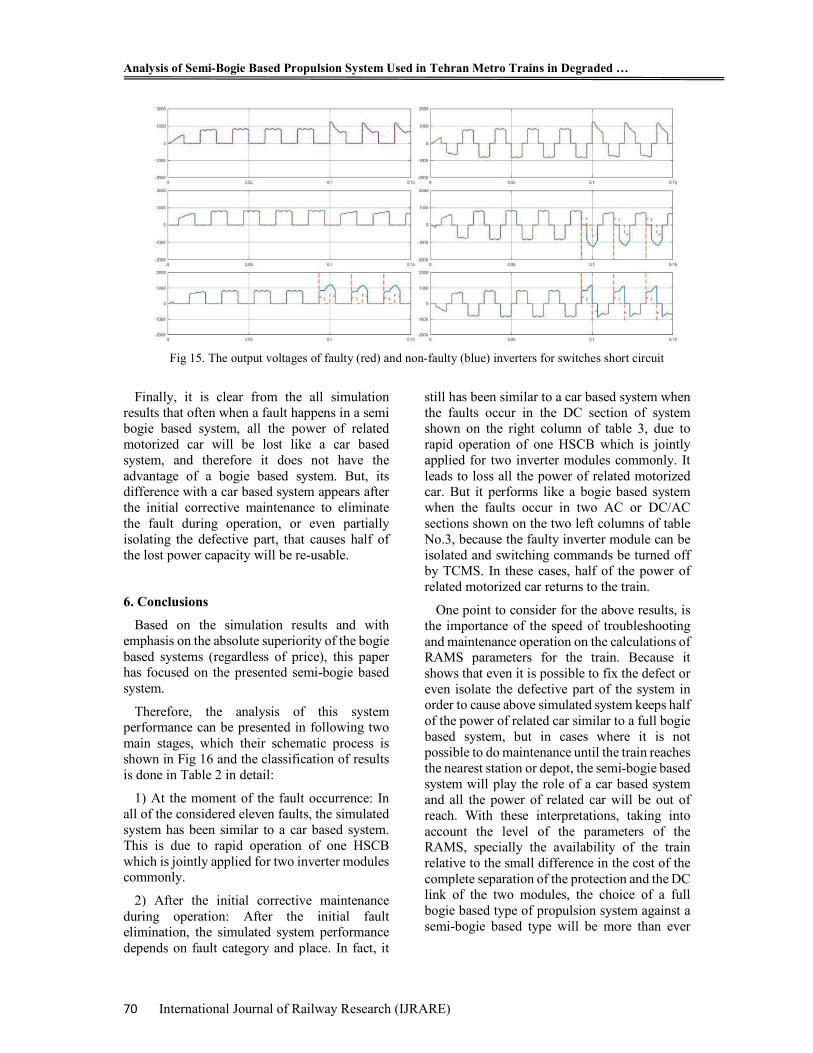
Regarding the figs 12 to 15, since the IGBT’s could be short circuit or open circuit in the faulty modes, two different probable situations can be observed. If faulty IGBT becomes short circuit
and another IGBT becomes “on”, the relative leg of inverter would be short circuit and therefore the fault happens, which with a same analysis about figs 2 to 9, the HSCB trips after more than two cycles because of rising rate of fault current. But, if faulty IGBT becomes open circuit, regardless of another IGBT situation (“on” or “off”), the relative leg of inverter cannot be short circuit and therefore with a same analysis about figs 10 and 11, the HSCB doesn’t trips due to fault current rate. However, it should be noted that the HSCB trips in this situation practically by order from TCMS due to keep safety, which have not been simulated in this paper.
Fig 7. The output current and voltages of traction substation rectifier for 3-ph output line short circuit
Fig 8. The input currents of 1st inverter module (up), 2nd inverter module (middle) and DC link capacitor
(low) for DC link short circuit
Analysis of Semi-Bogie Based Propulsion System Used in Tehran Metro Trains in Degraded …
68 International Journal of Railway Research (IJRARE)
Fig 9. The output voltages of inverters (left: phase voltages, right: line voltages) for DC link short circuit
Fig 10. The input currents of 1st inverter (up), 2nd inverter (middle) and DC-link capacitor (low) for DC link
open circuit
Fig 11. The output voltages of inverters (left: phase voltages, right: line voltages) for DC link open circuit

Babaeyzadeh & Fazel
International Journal of Railway Research (IJRARE) 69
Fig 12. The input currents of faulty (up), non-faulty (middle) inverter, DC-link capacitor (low) for
switches short circuit
Fig 13. The output voltages of faulty inverter (left: phase voltages, right: line voltages) for switches short
circuit
Fig 14. The input currents of faulty (up), non-faulty (middle) inverter, DC-link capacitor (low) for
switches open circuit
Analysis of Semi-Bogie Based Propulsion System Used in Tehran Metro Trains in Degraded …
70 International Journal of Railway Research (IJRARE)
Finally, it is clear from the all simulation results that often when a fault happens in a semi bogie based system, all the power of related motorized car will be lost like a car based system, and therefore it does not have the advantage of a bogie based system. But, its difference with a car based system appears after the initial corrective maintenance to eliminate the fault during operation, or even partially isolating the defective part, that causes half of the lost power capacity will be re-usable.
6. Conclusions
Based on the simulation results and with emphasis on the absolute superiority of the bogie based systems (regardless of price), this paper has focused on the presented semi-bogie based system.
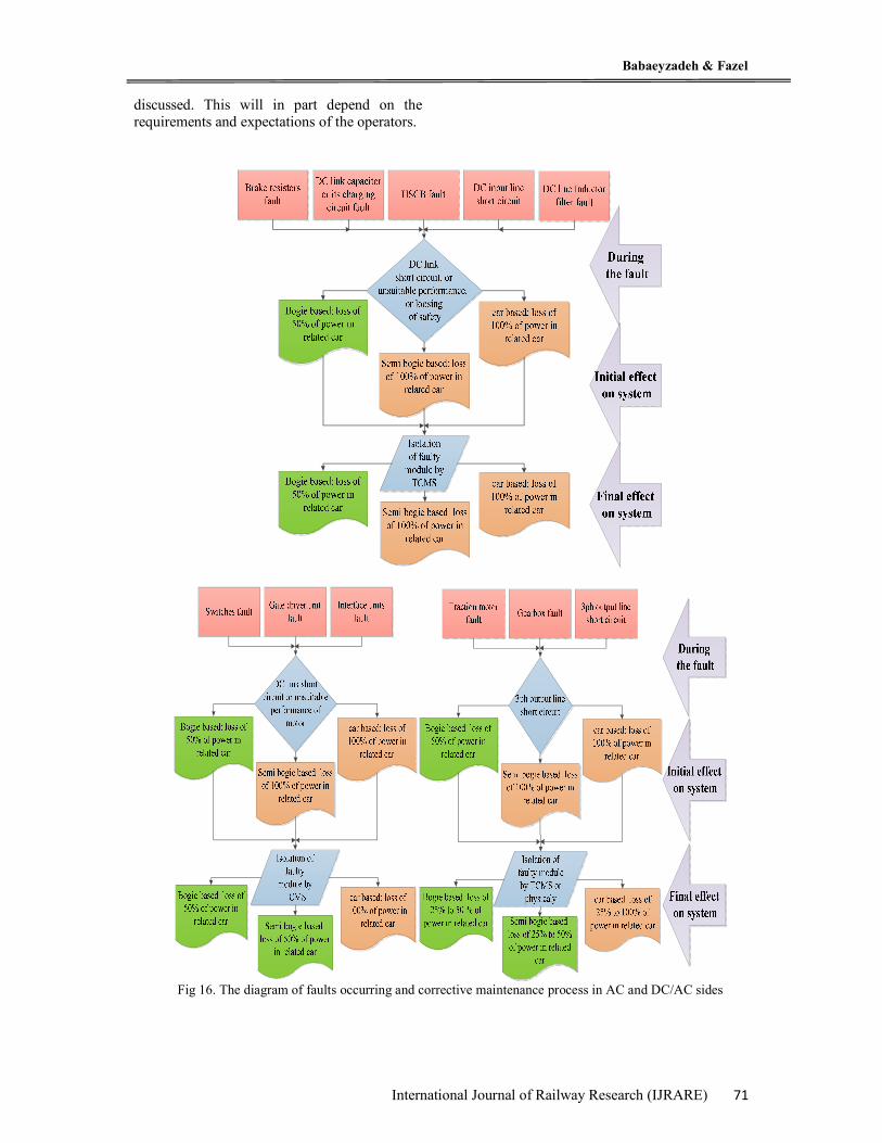
Therefore, the analysis of this system performance can be presented in following two main stages, which their schematic process is shown in Fig 16 and the classification of results is done in Table 2 in detail:
1) At the moment of the fault occurrence: In all of the considered eleven faults, the simulated system has been similar to a car based system. This is due to rapid operation of one HSCB which is jointly applied for two inverter modules commonly.
2) After the initial corrective maintenance during operation: After the initial fault elimination, the simulated system performance depends on fault category and place. In fact, it
still has been similar to a car based system when the faults occur in the DC section of system shown on the right column of table 3, due to rapid operation of one HSCB which is jointly applied for two inverter modules commonly. It leads to loss all the power of related motorized car. But it performs like a bogie based system when the faults occur in two AC or DC/AC sections shown on the two left columns of table No.3, because the faulty inverter module can be isolated and switching commands be turned off by TCMS. In these cases, half of the power of related motorized car returns to the train.
One point to consider for the above results, is the importance of the speed of troubleshooting and maintenance operation on the calculations of RAMS parameters for the train. Because it shows that even it is possible to fix the defect or even isolate the defective part of the system in order to cause above simulated system keeps half of the power of related car similar to a full bogie based system, but in cases where it is not possible to do maintenance until the train reaches the nearest station or depot, the semi-bogie based system will play the role of a car based system and all the power of related car will be out of reach. With these interpretations, taking into account the level of the parameters of the RAMS, specially the availability of the train relative to the small difference in the cost of the complete separation of the protection and the DC link of the two modules, the choice of a full bogie based type of propulsion system against a semi-bogie based type will be more than ever
Fig 15. The output voltages of faulty (red) and non-faulty (blue) inverters for switches short circuit
Babaeyzadeh & Fazel
International Journal of Railway Research (IJRARE) 71
discussed. This will in part depend on the requirements and expectations of the operators.
Fig 16. The diagram of faults occurring and corrective maintenance process in AC and DC/AC sides
Analysis of Semi-Bogie Based Propulsion System Used in Tehran Metro Trains in Degraded …
72 International Journal of Railway Research (IJRARE)
References
[1] Siemens Co.,” Technical proposal of car based Propulsion System - Contract of 315 cars for 3 cities in Iran”, No.IRTCO-2008, Book 7, 2008.
[2] BOMBARDIER Co.,” Detailed Design of High voltage, semi bogie based propulsion, auxiliary and battery charging systems of 315 cars for 3 cities metro lines in Iran”, No.IRTCO-2008, 3EST000228-3623, 2014.
[3] CRRC Zhozhou Times Electric Co.,” Technical proposal of bogie based propulsion system –Contract of 630 cars project for Tehran metro lines”, No. 51067-2019, B33-9, 2017.
[4] IEC, EN, UIC, Electrical Equipment Standards in Rolling Stock such as:" CECC·42000, EN 50124-1, EN 50155, EN
50207, JEC 60349-2 (1993), IEC 60310, IEC 60411-5".
[5] EN50126:”Railway Applications - the specification and demonstration of Reliability, Availability, Maintainability and Safety”. 1999
[6] BOMBARDIER Co. ,” Detailed Design of High voltage, semi bogie based propulsion, auxiliary and battery charging systems of 455 metro cars project for Tehran metro lines”, TUSRC-RS, Book 2, 2007.
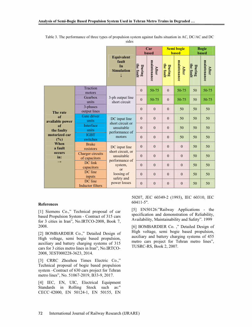
Table 3. The performance of three types of propulsion system against faults situation in AC, DC/AC and DC sides
Equivalent fault
In Simulation
↓
Car based
Semi bogie based
Bogie based
Du
ring
the fa
ult
After
main
tena
nce
Du
ring
the fa
ult
After
main
tena
nce
Du
ring
the fa
ult
After
main
tena
nce
The rate of
available power of
the faulty motorized car
(%) When a fault occurs
in: →
Traction motors
3-ph output line short circuit
0 50-75 0 50-75 50 50-75
Gearbox units
0 50-75 0 50-75 50 50-75
3-phases output lines
0 0 0 50 50 50
Gate driver units DC input line
short circuit or unsuitable
performance of motors
0 0 0 50 50 50
Interface units
0 0 0 50 50 50
IGBT switches
0 0 0 50 50 50
Brake resistors DC input line
short circuit, or unsuitable
performance of system,
or loosing of safety and
power losses
0 0 0 0 50 50
Charger circuits of capacitors
0 0 0 0 50 50
DC link capacitors
0 0 0 0 50 50
DC line inputs
0 0 0 0 50 50
DC line Inductor filters
0 0 0 0 50 50