PC-12 Aircraft Maintenance Manual Doc. No. 02049
214
SCHEDULED / UNSCHEDULED MAINTENANCE INTRODUCTION Table of Contents Page SCHEDULED / UNSCHEDULED MAINTENANCE - INTRODUCTION..................................... 1 1 General................................................................................................................... 2 2 How to Transition to the New Maintenance Program............................................. 2 2.1 100 Hour and Annual Inspection Program............................................................. 2 2.2 Progressive Inspection Program............................................................................ 2 3 New Maintenance Program With Increased Interval Extension............................. 2 3.1 Time Limits............................................................................................................. 2 3.2 Scheduled Maintenance Check Lists..................................................................... 3 3.3 Scheduled Maintenance Checks............................................................................ 3 3.4 Unscheduled Maintenance Checks........................................................................ 3 4 Definition of Terminology........................................................................................ 3 4.1 Flying Hours (FH)................................................................................................... 3 4.2 Months.................................................................................................................... 3 4.3 Landings................................................................................................................. 3 5 Permissible Tolerances........................................................................................... 4 5.1 Flying Hour Based Intervals................................................................................... 4 5.2 Calendar Time Based Intervals.............................................................................. 4 5.3 Landing Based Intervals......................................................................................... 4 5.4 Examples................................................................................................................ 4 Index of Tables Page 1 References............................................................................................................. 1 References Table 1 References Data module/Technical publication Title 12- A- 05- 10- 00- 00A- 018A- A TIME LIMITS - INTRODUCTION 12- A- 05- 10- 10- 00A- 281A- A OVERHAUL AND REPLACEMENT SCHEDULE - SCHED- ULED INSPECTIONS 12- A- 05- 10- 20- 00A- 281A- A TIME LIMITED INSPECTION REQUIREMENTS - SCHED- ULED INSPECTIONS 12- A- 05- 20- 00- 00A- 018A- A SCHEDULED MAINTENANCE CHECK LISTS - INTRODUC- TION 12- A- 05- 40- 00- 00A- 000B- A MASTER MAINTENANCE PLAN 12- A- 05- 50- 00- 00A- 018A- A UNSCHEDULED MAINTENANCE CHECKS - INTRODUC- TION 12-A-AM-00-00-00-I UNCLASSIFIED Effectivity: All 12-A-05-00-00-00A-018A-A UNCLASSIFIED 2020-05-15 Page 1
-
Upload
khangminh22 -
Category
Documents
-
view
2 -
download
0
Transcript of PC-12 Aircraft Maintenance Manual Doc. No. 02049

SCHEDULED / UNSCHEDULED MAINTENANCE
INTRODUCTION
Table of Contents Page
SCHEDULED / UNSCHEDULED MAINTENANCE - INTRODUCTION..................................... 11 General................................................................................................................... 22 How to Transition to the New Maintenance Program............................................. 22.1 100 Hour and Annual Inspection Program............................................................. 22.2 Progressive Inspection Program............................................................................ 23 New Maintenance Program With Increased Interval Extension............................. 23.1 Time Limits............................................................................................................. 23.2 Scheduled Maintenance Check Lists..................................................................... 33.3 Scheduled Maintenance Checks............................................................................ 33.4 Unscheduled Maintenance Checks........................................................................ 34 Definition of Terminology........................................................................................ 34.1 Flying Hours (FH)................................................................................................... 34.2 Months.................................................................................................................... 34.3 Landings................................................................................................................. 35 Permissible Tolerances........................................................................................... 45.1 Flying Hour Based Intervals................................................................................... 45.2 Calendar Time Based Intervals.............................................................................. 45.3 Landing Based Intervals......................................................................................... 45.4 Examples................................................................................................................ 4
Index of Tables Page
1 References............................................................................................................. 1
ReferencesTable 1 References
Data module/Technical publication Title
12-A-05-10-00-00A-018A-A TIME LIMITS - INTRODUCTION
12-A-05-10-10-00A-281A-A OVERHAUL AND REPLACEMENT SCHEDULE - SCHED-ULED INSPECTIONS
12-A-05-10-20-00A-281A-A TIME LIMITED INSPECTION REQUIREMENTS - SCHED-ULED INSPECTIONS
12-A-05-20-00-00A-018A-A SCHEDULED MAINTENANCE CHECK LISTS - INTRODUC-TION
12-A-05-40-00-00A-000B-A MASTER MAINTENANCE PLAN
12-A-05-50-00-00A-018A-A UNSCHEDULED MAINTENANCE CHECKS - INTRODUC-TION
12-A-AM-00-00-00-I
UNCLASSIFIED
Effectivity: All 12-A-05-00-00-00A-018A-A
UNCLASSIFIED 2020-05-15 Page 1

Description
1 General
This data module describes the recommended Scheduled / Unscheduled Maintenance Program for the PC-12,PC-12/45 and PC-12/47 aircraft.
The current PC-12 maintenance policy (100 Hour and Annual Inspection Program as well a Progressive InspectionProgram (PIP)) is superseded by a revised maintenance program issued with Revision 36 of the AMM. This newprogram increases the inspection interval and allows greater flexibility in scheduling maintenance to reduce thenumber of inspections.
Chapter 5 contains a new Master Maintenance Plan (MMP), a revised Time Limited Inspection Requirements datamodule and a number of inspection packages with defined intervals based on a combination of fight hours, numberof landings and/or calendar time.
NoteIt is the responsibility of the owner or operator to make sure the times are monitored correctly.
NoteFor the engine scheduled maintenance tasks, refer to P&WC Engine Maintenance Manual (EMM).
2 How to Transition to the New Maintenance Program
2.1 100 Hour and Annual Inspection Program
If you are on the 100 Hour and Annual Inspection Program, you must complete an Annual Inspection in accordancewith the AMM (at Revision 35) before you use the new maintenance program with the extended inspectionintervals.
2.2 Progressive Inspection Program
If you are on the PIP you need to complete the inspection program cycle (Phase 1 to 6) given in the AMM (atRevision 35) as scheduled before you use the new maintenance program with the extended inspection intervals.Alternatively, at the next scheduled inspection, complete the outstanding inspection phases.
3 New Maintenance Program With Increased Interval Extension
The new maintenance program has these sections:− Time Limits− Scheduled Maintenance Check Lists− Scheduled Maintenance Check− Unscheduled Maintenance Check.
3.1 Time Limits
This section consists of a list of time limited inspection requirements. These tasks do not fit in one of the predefinedscheduled inspection packages. Refer to 12-A-05-10-00-00A-018A-A.
There is no change to the Overhaul and Replacement Schedule and, the Supplemental Inspection Program.
12-A-AM-00-00-00-I
UNCLASSIFIED
Effectivity: All 12-A-05-00-00-00A-018A-A
UNCLASSIFIED 2020-05-15 Page 2

3.2 Scheduled Maintenance Check Lists
This section gives the details of the scheduled inspection for the aircraft. Refer to AMM 12-A-05-20-00-00A-018A-A.
3.3 Scheduled Maintenance Checks
The scheduled maintenance checks gives the MMP and the scheduled inspection for different flying hours orcalendar time based inspection packages.
The Master Maintenance Plan (MMP) gives the list of all the Airworthiness Limitations (AL), Time Limits andScheduled maintenance checks by S1000D system, sub-system order. Refer to AMM 12-A-05-40-00-00A-000B-A.
For those operators that would like to repackage the task requirements, the MMP can be used as long as the givenintervals are not exceeded. Refer to AMM 12-A-05-40-00-00A-000B-A.
3.4 Unscheduled Maintenance Checks
This section gives inspection requirements which are necessary after a special or unusual circumstance hasoccurred which may have damaged the aircraft. Refer to AMM 12-A-05-50-00-00A-018A-A.
4 Definition of Terminology
It is the responsibility of the owner or operator to make sure that the time intervals are monitored correctly.
If the interval is given as any combination of Flying Hours, Months or Landings, such as 600 FH or 12 Months, theinterval is understood as “whichever comes first”.
4.1 Flying Hours (FH)
Flying hours are defined as the total time between take-off and landing.
4.2 Months
The date on the aircraft data plate is used as the start time for all the calendar month intervals.
The subsequent monitoring procedure, for all the calendar time limited items after their initial replacement orinspection will be in elapsed time or installed time. This is given with each component interval in these datamodules, refer to AMM 12-A-05-10-10-00A-281A-A and AMM 12-A-05-10-20-00A-281A-A
Elapsed time is the time interval since manufacture of the component.
Installed time is the time interval since the installation of the component on the aircraft.
For calendar based time limited items, the inspection requirement is to be done no later than the last day of themonth of the calendar interval given. This is also applicable to all the subsequent calendar time limited inspectionrequirements.
4.3 Landings
All landings of a flight including the final landing; touch-and-goes; full stop landing with a follow on take-off in thesame flight.
12-A-AM-00-00-00-I
UNCLASSIFIED
Effectivity: All 12-A-05-00-00-00A-018A-A
UNCLASSIFIED 2020-05-15 Page 3

5 Permissible Tolerances
The following paragraphs outline the permissible tolerances that can be applied to the interval of the tasks listed inthe Time Limits and Scheduled maintenance sections. The tolerance is not cumulative.
It is the responsibility of the owner or operator to make sure that any maintenance interval extension is accepted bythe local Airworthiness Authority of the country of registration of the affected aircraft.
The owner or operator is responsible for complying with all national regulations.
5.1 Flying Hour Based Intervals
The tolerance permissible for the flying hour based intervals is ±10%, but not more than 500 FH.
5.2 Calendar Time Based Intervals
The tolerance permissible for the calendar time based intervals is ±10%, but not more than 6 months.
The subsequent monitoring procedure for all the calendar time limited items after their initial replacement orinspection, will be in installed or elapsed time. Each task with a calendar time is understood as installed time unlessstated as “elapsed”. This applies to tasks in Chapter 4 and Chapter 5.
5.3 Landing Based Intervals
The tolerance permissible for the landings based intervals is ±10%, but not more than 500 landings.
5.4 Examples
If you do an inspection inside the permitted tolerance, the planned inspection times do not shift. Two exampleshave been provided for reference:
− The 300 FH inspection package can be accomplished any time between 270 FH and 330 FH (±10% or ±30FH). The next inspection is still due at 600 FH (±30 FH). The inspection intervals do not change
− The 12 months inspection package can be accomplished any time between 11 months and 13 months (±10%or 1 month). The next inspection is still due at 24 months (±1 month). The inspection intervals do not change.
If you do an inspection earlier and outside the given tolerance, then the planned inspection time will shift, examplesshown below:
If you do the 300 FH and the 300 FH / 12 Months inspection packages earlier and outside the given tolerance,for example at 150 FH (2 months of operation), the inspection interval shifts. In this case the following inspectionis due at 450 FH (6 months of operation) with a ±10% or ±30 FH tolerance since only the 300 FH and the 300FH / 12 Months inspection packages are due. However, the next inspection would then be at 600 FH (8 months ofoperation) where only the 600 FH and the 600 FH / 12 Months inspection packages are due and as a result, ±10%or ±60 FH tolerance can be applied. If the operation continues like this, at 1800 FH (24 months of operation) the600 FH, 600 FH / 12 Months, 1200 FH / 12 Months and 2400 FH / 24 Months inspection packages will be due witha ±10% or ±60 FH tolerance. The tolerance for the inspection is always driven by the inspection package that isdue with the lowest interval. The tolerance can be calendar time driven, if the inspection package calendar timeinterval is reached first.
12-A-AM-00-00-00-I
UNCLASSIFIED
Effectivity: All 12-A-05-00-00-00A-018A-A
UNCLASSIFIED 2020-05-15 Page 4

CalendarTime
2 Months 6 Months 8 Months 10Months
12Months
14Months
16Months
18Months
22Months
24Months
AircraftFlyingHours
150 FH 450 FH 600 FH 750 FH 900 FH 1050 FH 1200 FH 1350 FH 1650 FH 1800 FH
Inspec-tionPacks
300 FH300 FH /12Months
300 FH300 FH /12Months
600 FH600 FH /12Months
300 FH300 FH /12Months
1200FH / 12Months
300 FH300 FH /12Months
600 FH600 FH /12Months
300 FH300 FH /12Months
300 FH300 FH /12Months
600 FH600 FH /12Months1200FH /12Months2400FH / 24Months
Toler-ance(+/-)
30 FH 30 FH 60 FH 30 FH 120 FH 30 FH 60 FH 30 FH 30 FH 60 FH
12-A-AM-00-00-00-I
UNCLASSIFIED
Effectivity: All 12-A-05-00-00-00A-018A-A
End of data moduleUNCLASSIFIED 2020-05-15 Page 5
12-A-AM-00-00-00-I
UNCLASSIFIED
Intentionally left blank
Effectivity: All 12-A-05-00-00-00A-018A-A
UNCLASSIFIED 2020-05-15 Page 6

TIME LIMITS
INTRODUCTION
Table of Contents Page
TIME LIMITS - INTRODUCTION................................................................................................ 11 General................................................................................................................... 12 Time Limited Inspection Requirements.................................................................. 22.1 General................................................................................................................... 22.2 Time Limited Inspection Intervals........................................................................... 23 Overhaul and Replacement Schedule.................................................................... 24 Supplemental Inspection Program......................................................................... 2
Index of Tables Page
1 References............................................................................................................. 1
ReferencesTable 1 References
Data module/Technical publication Title
12-A-04-00-00-00A-000A-A STRUCTURAL, COMPONENT AND MISCELLANEOUS - AIR-WORTHINESS LIMITATIONS
12-A-05-10-10-00A-281A-A OVERHAUL AND REPLACEMENT SCHEDULE - SCHED-ULED INSPECTIONS
12-A-05-10-20-00A-281A-A TIME LIMITED INSPECTION REQUIREMENTS - SCHED-ULED INSPECTIONS
12-A-05-10-30-00A-280A-A SUPPLEMENTAL STRUCTURAL INSPECTION DOCUMENT
12-A-05-20-00-00A-018A-A SCHEDULED MAINTENANCE CHECK LISTS - INTRODUC-TION
Description
1 General
The section has these data modules:− Time Limited Inspection Requirements, refer to AMM 12-A-05-10-20-00A-281A-A− Overhaul and Replacement Schedule, refer to AMM 12-A-05-10-10-00A-281A-A− Supplemental Inspection Program, refer to AMM 12-A-05-10-30-00A-280A-A.
12-A-AM-00-00-00-I
UNCLASSIFIED
Effectivity: All 12-A-05-10-00-00A-018A-A
UNCLASSIFIED 2018-05-24 Page 1

2 Time Limited Inspection Requirements
2.1 General
The time limits stated are based on average usage and average environmental conditions.
The stated time limits do not constitute a guarantee that the item will reach the time without malfunction as thefactors mentioned before cannot be controlled by the manufacturer. Particularly, if an aircraft is operated in extremeclimatic conditions such as humid tropics, extreme cold, damp climates, or salt-laden conditions.
2.2 Time Limited Inspection Intervals
This data module gives a list of items that require inspecting or testing at different intervals. The intervals areexpressed in flying hours, calendar time, or landings.
To give the best utilization, each item listed in this section has been given an individual optimized periodicity. Forthis reason, they are listed in a separate data module titled Scheduled Maintenance Checks Lists. Refer to AMM12-A-05-20-00-00A-018A-A.
When a scheduled inspection is completed, the section should be reviewed and all requirements complied with.
3 Overhaul and Replacement Schedule
This data module lists component overhaul times and replacement times. The time limits for the componentsare based on flying hours, calendar time or landings. The first overhaul and/or replacement of a component isrecommended to be done at the stated interval (permissible tolerances applicable). Based on the inspection resultsat the end of the first overhaul or replacement task, the operator can use these results to determine subsequentintervals applicable to the individual airplane or fleet operation, provided the operator has an approved conditionmonitoring system. If such an approved monitoring system is not available, subsequent overhaul and replacementof components should be done at the stated interval. Refer to AMM 12-A-05-10-10-00A-281A-A
The requirements of this topic may be accomplished by either:− disassembly, inspection, assembly and test of overhauled components in accordance with the appropriate
Component Maintenance Manual or− exchange parts from Pilatus Aircraft Limited may be purchased and installed. Compliance with one of these
two options is at the discretion of the maintenance center carrying out the time limit requirement.
Components not listed in the Overhaul and Replacement Schedule need only to be replaced when their conditionshows that replacement is necessary.
4 Supplemental Inspection Program
This data module gives the additional structural and component life limits and the supplemental inspections neededfor aircraft that have 25,000 flying hours or 30,000 landings or more and forms the Supplemental StructuralInspection Document (SSID) needed to increase the life of the airframe. Refer to AMM 12-A-04-00-00-00A-000A-Aand 12-A-05-10-30-00A-280A-A.
12-A-AM-00-00-00-I
UNCLASSIFIED
Effectivity: All 12-A-05-10-00-00A-018A-A
End of data moduleUNCLASSIFIED 2018-05-24 Page 2

OVERHAUL AND REPLACEMENT SCHEDULE
SCHEDULED INSPECTIONS
Table of Contents Page
OVERHAUL AND REPLACEMENT SCHEDULE - SCHEDULED INSPECTIONS.................... 1
Index of Tables Page
1 References............................................................................................................. 12 Overhaul and Replacement Schedule.................................................................... 1
ReferencesTable 1 References
Data module/Technical publication Title
None
DescriptionTable 2 Overhaul and Replacement Schedule
Task number Component Discard Interval Overhaul Interval24-30/19 Starter/Generator (except P/N
978.91.23.407, 978.91.23.408 and978.91.23.409)
- 1,000 FH
24-30/20 Generator 2 drive assembly aft bear-ing (smaller inner diameter) (Pre SB24-010)
10,000 FH -
24-30/21 Generator 2 drive assembly aft bear-ing (smaller inner diameter) (Post SB24-010 and MSN 231 - 999)
3,000 FH -
24-30/491 Starter/Generator (P/N 978.91.23.407,978.91.23.408 and 978.91.23.409)
- 1,200 FH
25-10/293 Crew seat cushion (P/N 0A318-0203installed on IPECO Seat P/N 959.30.01.135 and 136)
36 Months(elapsed for factory new orspare part new from EASAForm 1 date)
-
25-10/294 Crew seat belts - Task deleted from theMaintenance Plan
25-20/295 Passenger seat belts and extensions - Task deleted from theMaintenance Plan
25-63/23 ELT battery After 1 hour of use or asshown on the battery label
-
12-A-AM-00-00-00-I
UNCLASSIFIED
Effectivity: All 12-A-05-10-10-00A-281A-A
UNCLASSIFIED 2021-12-04 Page 1

Table 2 Overhaul and Replacement Schedule (Continued from previous page)Task number Component Discard Interval Overhaul Interval25-63/434 ELT Nav interface unit serial memory
module (if Kannad 406 AF Nav inter-face unit installed)
16,000 FH / 120 Months
NoteUnits which have alreadyoperated more than theallowed interval must bereplaced within 500 flyinghours or 6 months, which-ever comes first
-
27-50/27 Flap power drive unit (P/N978.73.20.001 and 002)
4500 FH since new, or lastoverhaul
-
27-50/28 Flap power drive unit (P/N978.73.20.003)
- 10,000 FH / 13,500 LDG
27-50/29 Flap actuators (white colored) (P/N978.73.20.302, 303, 304, 305 and 306)
4,500 FH -
27-50/30 Flap actuators (black anodized)(P/N 978.73.20.307, 978.73.20.308,978.73.20.309)
- 5,000 FH / 7,000 LDG
27-50/31 Flap flexible drive shafts (P/N945.02.02.203, 204, 205 and 206)
10,000 FH / 13,500 LDG -
28-20/32 Engine driven pump - 3,500 FH31-50/34 CAWS CACU clock battery, MSN 321
and 401-99924 Months -
61-10/37 Propeller - 4,000 FH / 72 Months(Refer to Hartzell SL 61)
71-00/38 Engine shock mount assemblies - At engine overhaul but notlater than 5000 FH
72-00/39 Engine - 3,500 FHP&WC SB 14603 latest re-vision
72-00/308 Engine accessories - P&WC SB 14603 latest re-vision
79-20/43 Oil cooler - At engine overhaul
12-A-AM-00-00-00-I
UNCLASSIFIED
Effectivity: All 12-A-05-10-10-00A-281A-A
End of data moduleUNCLASSIFIED 2021-12-04 Page 2

TIME LIMITED INSPECTION REQUIREMENTS
SCHEDULED INSPECTIONS
Table of Contents Page
TIME LIMITED INSPECTION REQUIREMENTS - SCHEDULED INSPECTIONS.................... 1
Index of Tables Page
1 References............................................................................................................. 12 Required Conditions............................................................................................... 33 Support equipment................................................................................................. 34 Supplies.................................................................................................................. 35 Spares.................................................................................................................... 36 Time Limited Inspection Requirements.................................................................. 37 Required Conditions............................................................................................... 13
ReferencesTable 1 References
Data module/Technical publication Title
12-A-12-20-06-00A-902A-A WHEEL BEARING - SERVICING
12-A-20-40-00-00A-901A-A CORROSION CONTROL - MAINTENANCE PRACTICES
12-A-21-30-00-00A-903A-A PRESSURIZATION CONTROL - ADJUSTMENT/TEST
12-A-21-30-07-00A-903A-A CABIN ALTITUDE SWITCH - ADJUSTMENT/TEST
12-A-21-30-08-00A-903A-A CABIN DIFFERENTIAL PRESSURE SWITCH - ADJUST-MENT/TEST
12-A-21-40-06-00A-903A-A OVER TEMPERATURE SWITCH - ADJUSTMENT/TEST
12-A-21-50-00-00A-903A-A VAPOUR CYCLE COOLING SYSTEM (REFRIGERANT R12) -ADJUSTMENT/TEST
12-A-21-50-00-00A-903B-A VAPOUR CYCLE COOLING SYSTEM (REFRIGERANTR134A) - ADJUSTMENT/TEST
12-A-21-50-03-00A-313A-A COMPRESSOR DRIVE MOTOR - INSPECTION/CHECK
12-A-21-60-05-00A-903A-A DUCT OVER TEMPERATURE SWITCH - ADJUST-MENT/TEST
12-A-24-30-00-00A-901A-A CORROSION PROTECTION OF GROUND POINTS - MAIN-TENANCE PRACTICES
12-A-24-30-04-00A-313A-A GENERATOR 2 DRIVE ASSEMBLY HOUSING - INSPEC-TION/CHECK
12-A-24-30-07-00A-920A-A BATTERY - REMOVAL/INSTALLATION
12-A-AM-00-00-00-I
UNCLASSIFIED
Effectivity: All 12-A-05-10-20-00A-281A-A
UNCLASSIFIED 2021-12-04 Page 1

Data module/Technical publication Title
12-A-24-52-51-00A-920A-A EMERGENCY POWER SUPPLY (EPS) UNIT - REMOVAL/IN-STALLATION
12-A-25-21-03-00A-920A-A EXECUTIVE TRIM - REMOVAL/INSTALLATION
12-A-25-22-03-00A-920A-A STANDARD TRIM - REMOVAL/INSTALLATION
12-A-27-00-00-00A-313A-A FLIGHT CONTROLS - INSPECTION/CHECK
12-A-27-20-00-00A-903A-A RUDDER CONTROL SYSTEM (MSN 101 – 683) - ADJUST-MENT/TEST
12-A-27-30-00-00A-903A-A ELEVATOR CONTROL SYSTEM - ADJUSTMENT/TEST
12-A-27-50-00-00A-902A-A FLAPS - SERVICING
12-A-27-50-03-00A-313A-A FLAP ACTUATOR (WHITE COLORED FLAP ACTUATORS) -INSPECTION/CHECK
12-A-27-50-03-00A-313B-A FLAP ACTUATOR (BLACK COLORED FLAP ACTUATORS) -INSPECTION/CHECK
12-A-28-10-01-00A-903A-A TANK CROSS VENT PIPE AND OUTWARD CHECK VALVE -ADJUSTMENT/TEST
12-A-28-40-00-00A-903A-A FUEL QUANTITY INDICATION (MSN 101 – 105) - ADJUST-MENT/TEST
12-A-28-40-00-00A-903B-A FUEL QUANTITY INDICATION (MSN 106 – 999) - ADJUST-MENT/TEST
12-A-32-10-00-00A-313A-A MLG HINGE PIN AND BUSHES (PC12/45 AND PC12/47) -INSPECTION/CHECK
12-A-34-11-10-00A-903A-A SINGLE P–S SYSTEM - ADJUSTMENT/TEST
12-A-34-11-20-00A-903A-A DUAL PITOT STATIC SYSTEM - ADJUSTMENT/TEST
12-A-34-21-00-00A-903A-A STANDBY MAGNETIC COMPASS - ADJUSTMENT/TEST
12-A-34-25-00-00A-903A-A ATTITUDE AND HEADING REFERENCE SYSTEM - AD-JUSTMENT/TEST
12-A-34-54-00-00A-903A-A AIR TRAFFIC CONTROL TRANSPONDER SYSTEM (KT70OR KT71 ATC SYSTEM) - ADJUSTMENT/TEST
12-A-34-54-00-00A-903B-A AIR TRAFFIC CONTROL TRANSPONDER SYSTEM(GTX330D ATC SYSTEM) - ADJUSTMENT/TEST
12-A-35-20-00-00A-313A-A PASSENGER OXYGEN SYSTEM - INSPECTION/CHECK
12-A-52-10-00-00A-313A-A PASSENGER/CREW DOOR - INSPECTION/CHECK
12-A-52-10-06-00A-353A-A PASSENGER/CREW DOOR SHOOT BOLTS - EDDY CUR-RENT INSPECTION
12-A-52-30-00-00A-313A-A CARGO DOOR - INSPECTION/CHECK
12-A-56-11-02-00A-313A-A COCKPIT SIDE WINDOWS - INSPECTION/CHECK
12-A-57-00-00-00A-313A-A WING AND FUSELAGE FITTINGS - INSPECTION/CHECK
12-A-76-10-02-00A-903A-A PROPELLER FEATHER MICROSWITCHES - ADJUST-MENT/TEST
12-A-AM-00-00-00-I
UNCLASSIFIED
Effectivity: All 12-A-05-10-20-00A-281A-A
UNCLASSIFIED 2021-12-04 Page 2

Required ConditionsTable 2 Required Conditions
Action / Condition Data module/Technical publication
None
Support equipmentTable 3 Support equipment
Name Identifications/References Qty Reference Remark
None
SuppliesTable 4 Supplies
Name Identifications/References Qty Reference Remark
None
SparesTable 5 Spares
Name Identifications/References Qty Reference Remark
None
Safety ConditionsNone
Procedure1 Time Limited Inspection Requirements
Table 6 Time Limited Inspection RequirementsTask number Item Name Task Description Interval Data Module Refer-
ence00-00/45 Aircraft Do the corrosion and
corrosion protectioninspections
AMM 12-B-20-40-00-00A-901A-A
12-A-20-40-00-00A-901A-A
21-30/46 Cabin pressurizationpositive pressure re-lief valve
Functional test 4,800 FH / 48 Months 12-A-21-30-00-00A-903A-A
21-30/48 Cabin altitude switch Functional test 60 Months 12-A-21-30-07-00A-903A-A
21-30/49 Cabin differentialpressure switch
Functional test 60 Months 12-A-21-30-08-00A-903A-A
21-40/51 Overtemperatureswitch
Functional test 4,800 FH / 60 Months 12-A-21-40-06-00A-903A-A
12-A-AM-00-00-00-I
UNCLASSIFIED
Effectivity: All 12-A-05-10-20-00A-281A-A
UNCLASSIFIED 2021-12-04 Page 3

Table 6 Time Limited Inspection Requirements (Continued from previous page)Task number Item Name Task Description Interval Data Module Refer-
ence21-40/52 Duct overtemperature
switchFunctional test 4,800 FH / 60 Months 12-A-21-60-05-00A-
903A-A21-50/58 Vapor cycle compres-
sor motor (if installed)Inspection/check 500 Operating hours 12-A-21-50-03-00A-
313A-A21-50/59 Vapor cycle compres-
sor motor drive belt (ifinstalled)
Check for tension 500 Operating hours 12-A-21-50-00-00A-903A-A12-A-21-50-00-00A-903B-A
21-50/433 Vapor cycle compres-sor condenser mod-ule (including motor)(if installed)
Clean, refer toOSCMM
Initially at eachscheduled inspection,then based on fieldexperience the inter-val can be adjustedto a more effectivelevel
-
21-50/461 Vapor cycle compres-sor motor (CCM P/N959.90.22.140, if in-stalled)
Inspection/check 600 Operating hours 12-A-21-50-03-00A-313A-A
21-50/462 Vapor cycle compres-sor motor drivebelt (CCM P/N959.90.22.140, if in-stalled)
Check for tension 600 Operating hours 12-A-21-50-00-00A-903A-A12-A-21-50-00-00A-903B-A
24-30/62 Generator 1 and 2ground pointsBattery 1 and 2ground points (if in-stalled)
Examine the corro-sion protective layer
24 Months 12-A-24-30-00-00A-901A-A
24-30/65 Generator 2 drive as-sembly housing (PreSB 24-010)
Inspection/check 1,200 FH 12-A-24-30-04-00A-313A-A
24-30/66 Generator 2 drive as-sembly housing (PostSB 24-010 and MSN231- 999)
Inspection/check 1,800 FH 12-A-24-30-04-00A-313A-A
24-30/67 Ni-Cad battery orbatteries (if 2nd bat-tery installed) (P/N976.17.31.301)
Remove and service 300 FH / 3 Months 12-A-24-30-07-00A-920A-Aand CMM
24-30/68 Ni-Cad battery orbatteries (if 2nd bat-tery installed) (P/N976.17.31.302)
Remove and service 400 FH / 12 Months 12-A-24-30-07-00A-920A-Aand CMM
12-A-AM-00-00-00-I
UNCLASSIFIED
Effectivity: All 12-A-05-10-20-00A-281A-A
UNCLASSIFIED 2021-12-04 Page 4
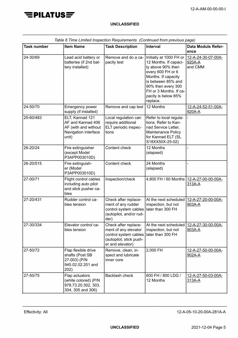
Table 6 Time Limited Inspection Requirements (Continued from previous page)Task number Item Name Task Description Interval Data Module Refer-
ence24-30/69 Lead acid battery or
batteries (if 2nd bat-tery installed)
Remove and do a ca-pacity test
Initially at 1000 FH or12 Months. If capaci-ty above 90% thenevery 600 FH or 6Months. If capacityis between 85% and90% then every 300FH or 3 Months. If ca-pacity is below 85%replace.
12-A-24-30-07-00A-920A-Aand CMM
24-50/70 Emergency powersupply (if installed)
Remove and cap test 12 Months 12-A-24-52-51-00A-920A-A
25-60/483 ELT, Kannad 121AF and Kannad 406AF (with and withoutNavigation interfaceunit)
Local regulation canrequire additionalELT periodic inspec-tions
Refer to local regula-tions. Refer to Kan-nad Service Letter,Maintenance Policyfor Kannad ELT (SLS18XX50X-25-02)
-
26-20/24 Fire extinguisher(except ModelP3APP003010D)
Content check 12 Months(elapsed)
-
26-20/515 Fire extinguish-er (ModelP3APP003010D)
Content check 24 Months(elapsed)
-
27-00/71 Flight control cablesincluding auto pilotand stick pusher ca-bles
Inspection/check 4,800 FH / 60 Months 12-A-27-00-00-00A-313A-A
27-20/431 Rudder control ca-bles tension
Check after replace-ment of any ruddercontrol system cables(autopilot, and/or rud-der)
At the next scheduledinspection, but notlater than 300 FH
12-A-27-20-00-00A-903A-A
27-30/334 Elevator control ca-bles tension
Check after replace-ment of any elevatorcontrol system cables(autopilot, stick push-er and elevator)
At the next scheduledinspection, but notlater than 300 FH
12-A-27-30-00-00A-903A-A
27-50/72 Flap flexible driveshafts (Post SB27-003) (P/N945.02.02.201 and202)
Remove, clean, in-spect and lubricateinner core
2,000 FH 12-A-27-50-00-00A-902A-A
27-50/75 Flap actuators(white colored) (P/N978.73.20.302, 303,304, 305 and 306)
Backlash check 600 FH / 800 LDG /12 Months
12-A-27-50-03-00A-313A-A
12-A-AM-00-00-00-I
UNCLASSIFIED
Effectivity: All 12-A-05-10-20-00A-281A-A
UNCLASSIFIED 2021-12-04 Page 5

Table 6 Time Limited Inspection Requirements (Continued from previous page)Task number Item Name Task Description Interval Data Module Refer-
ence27-50/76 Flap actuators
(black anodized)(P/N 978.73.20.307,978.73.20.308,978.73.20.309)
Backlash check 2,400 FH /3,200 LDG /24 Months
12-A-27-50-03-00A-313B-A
28-10/306 Fuel cross vent andoutward check valve
Operational test 2,400 FH 12-A-28-10-01-00A-903A-A
28-40/78 Fuel low level warn-ing system
Operational test 1,200 FH / 48 Months MSN 101-105 12-A-28-40-00-00A-903A-AMSN 106-999 12-A-28-40-00-00A-903B-A
30-10/79 Airfoil de-icers Apply a surface coat-ing of Age MasterNo. 1 in accordancewith the manufactur-ers instructions CMM30-10-31 (latest is-sue)
NoteThe deice boot treat-ment with Age Mas-ter No 1 can beperformed by the op-erator IAW the in-structions given inthe AFM §8 DeicingBoot Care
6 Months -
32-10/80 Main and nose wheelbearings
Lubricate Tire change or 12Months whichevercomes first
12-A-12-20-06-00A-902A-A
32-10/81 Main landing gearhinge pin and bush-es (PC-12/45 andPC-12/47 aircraft)
Inspection/check 2,400 FH / 12 Months 12-A-32-10-00-00A-313A-A
34-11/82 Pitot and static sys-tem
Leak check 24 Months Single system 12-A-34-11-10-00A-903A-ADual system 12-A-34-11-20-00A-903A-A
34-14/83 Altimeter Check calibration atan approved centerin accordance withthe regulation in force(Ref. FAR Part 91411)
24 Months -
12-A-AM-00-00-00-I
UNCLASSIFIED
Effectivity: All 12-A-05-10-20-00A-281A-A
UNCLASSIFIED 2021-12-04 Page 6

Table 6 Time Limited Inspection Requirements (Continued from previous page)Task number Item Name Task Description Interval Data Module Refer-
ence34-21/84 Standby magnetic
compassCheck swing 24 Months 12-A-34-21-00-00A-
903A-A34-25/85 Attitude Heading
Reference System(AHRS)
Check swing 24 Months 12-A-34-25-00-00A-903A-A
34-54/86 Transponder system(single and dual sys-tems)
Functional test 24 Months 12-A-34-54-00-00A-903A-Aor 12-A-34-54-00-00A-903B-A
35-20/87 Passenger oxygenmasks
Inspection/check 36 Months 12-A-35-20-00-00A-313A-A
52-10/88 Passenger/crew door Examine with trim re-movedExamine the top steparea around the insu-lation mat for corro-sion. If corrosion isfound, write to Pilatusfor a specific repair.Examine door hingepin and hinges.
Mild Corrosive Envi-ronment: 6000 FH or72 MonthsModerate CorrosiveEnvironment: 4000FH or 48 MonthsSevere Corrosive En-vironment: 2000 FHor 24 Months
NoteLocal conditions maybe more or less se-vere. Based on fieldexperience the inter-val can be adjustedto more or less fre-quent, until an effec-tive interval can beset.
12-A-25-21-03-00A-920A-Aor12-A-25-22-03-00A-920A-Aand12-A-52-10-00-00A-313A-A
52-10/472 Passenger/crew doorshoot bolt fitting (onlyif SB 52–007 Part Cis done)
Eddy current inspec-tion
3,000 FH /3,600 LDG
12-A-52-10-06-00A-353A-A
12-A-AM-00-00-00-I
UNCLASSIFIED
Effectivity: All 12-A-05-10-20-00A-281A-A
UNCLASSIFIED 2021-12-04 Page 7

Table 6 Time Limited Inspection Requirements (Continued from previous page)Task number Item Name Task Description Interval Data Module Refer-
ence52-30/89 Cargo door Examine with trim re-
movedExamine door hingepin, hinges and thelock mechanism
Mild Corrosive Envi-ronment: 6000 FH or72 MonthsModerate CorrosiveEnvironment: 4000FH or 48 MonthsSevere Corrosive En-vironment: 2000 FHor 24 Months
NoteLocal conditions maybe more or less se-vere. Based on fieldexperience the inter-val can be adjustedto more or less fre-quent, until an effec-tive interval can beset.
12-A-25-21-03-00A-920A-Aor 12-A-25-22-03-00A-920A-Aand12-A-52-30-00-00A-313A-Aand12-A-52-30-00-00A-313A-A
53-00/90 Front pressure bulk-head
Examine with insu-lation on engineand cockpit sides re-moved. If insulationon cockpit side iswet, remove, dry andreinstall insulation.
Mild Corrosive Envi-ronment: 6000 FH or72 MonthsModerate CorrosiveEnvironment: 4000FH or 48 MonthsSevere Corrosive En-vironment: 2000 FHor 24 Months
NoteLocal conditions maybe more or less se-vere. Based on fieldexperience the inter-val can be adjustedto more or less fre-quent, until an effec-tive interval can beset.
-
12-A-AM-00-00-00-I
UNCLASSIFIED
Effectivity: All 12-A-05-10-20-00A-281A-A
UNCLASSIFIED 2021-12-04 Page 8

Table 6 Time Limited Inspection Requirements (Continued from previous page)Task number Item Name Task Description Interval Data Module Refer-
ence53-00/91 Fuselage internal bot-
tom surfaceExamine Frames 10,21, 24, 36 andframes adjacent todoors and to emer-gency exit, with insu-lation removed. If cor-rosion is found, ex-amine all fuselagebottom surface withinsulation removed. Ifinsulation is wet, re-move, dry and rein-stall insulation
Mild Corrosive Envi-ronment: 6000 FH or72 MonthsModerate CorrosiveEnvironment: 4000FH or 48 MonthsSevere Corrosive En-vironment: 2000 FHor 24 Months
NoteLocal conditions maybe more or less se-vere. Based on fieldexperience the inter-val can be adjustedto more or less fre-quent, until an effec-tive interval can beset.
-
53-00/92 Rear pressure bulk-head
Examine with trim re-moved
Mild Corrosive Envi-ronment: 6000 FH or72 MonthsModerate CorrosiveEnvironment: 4000FH or 48 MonthsSevere Corrosive En-vironment: 2000 FHor 24 Months
NoteLocal conditions maybe more or less se-vere. Based on fieldexperience the inter-val can be adjustedto more or less fre-quent, until an effec-tive interval can beset.
-
12-A-AM-00-00-00-I
UNCLASSIFIED
Effectivity: All 12-A-05-10-20-00A-281A-A
UNCLASSIFIED 2021-12-04 Page 9

Table 6 Time Limited Inspection Requirements (Continued from previous page)Task number Item Name Task Description Interval Data Module Refer-
ence53-00/93 Structure around win-
dowsExamine Mild Corrosive Envi-
ronment: 6000 FH or72 MonthsModerate CorrosiveEnvironment: 4000FH or 48 MonthsSevere Corrosive En-vironment: 2000 FHor 24 Months
NoteLocal conditions maybe more or less se-vere. Based on fieldexperience the inter-val can be adjustedto more or less fre-quent, until an effec-tive interval can beset.
-
53-00/94 Door frames andemergency exit frame
Examine. If insulationis installed in the doorframes and is wet,remove and discardit (no longer installedon production)
Mild Corrosive Envi-ronment: 6000 FH or72 MonthsModerate CorrosiveEnvironment: 4000FH or 48 MonthsSevere Corrosive En-vironment: 2000 FHor 24 Months
NoteLocal conditions maybe more or less se-vere. Based on fieldexperience the inter-val can be adjustedto more or less fre-quent, until an effec-tive interval can beset.
-
12-A-AM-00-00-00-I
UNCLASSIFIED
Effectivity: All 12-A-05-10-20-00A-281A-A
UNCLASSIFIED 2021-12-04 Page 10

Table 6 Time Limited Inspection Requirements (Continued from previous page)Task number Item Name Task Description Interval Data Module Refer-
ence55-10/95 Horizontal stabilizer
internal surfacesand horizontal/verti-cal stabilizer interface
Examine as far aspossible with panelsremoved
Mild Corrosive Envi-ronment: 6000 FH or72 MonthsModerate CorrosiveEnvironment: 4000FH or 48 MonthsSevere Corrosive En-vironment: 2000 FHor 24 Months
NoteLocal conditions maybe more or less se-vere. Based on fieldexperience the inter-val can be adjustedto more or less fre-quent, until an effec-tive interval can beset.
-
55-10/96 Vertical stabilizer in-ternal surfaces
Examine as far aspossible with panelsremoved
Mild Corrosive Envi-ronment: 6000 FH or72 MonthsModerate CorrosiveEnvironment: 4000FH or 48 MonthsSevere Corrosive En-vironment: 2000 FHor 24 Months
NoteLocal conditions maybe more or less se-vere. Based on fieldexperience the inter-val can be adjustedto more or less fre-quent, until an effec-tive interval can beset.
-
56-11/332 Cockpit side windows Inspection/check 11,000 FH /120 Months
12-A-56-11-02-00A-313A-A
12-A-AM-00-00-00-I
UNCLASSIFIED
Effectivity: All 12-A-05-10-20-00A-281A-A
UNCLASSIFIED 2021-12-04 Page 11

Table 6 Time Limited Inspection Requirements (Continued from previous page)Task number Item Name Task Description Interval Data Module Refer-
ence57-00/97 Wing internal surfa-
ces and flap compart-ment
Examine as far aspossible with all wingpanels removed
Mild Corrosive Envi-ronment: 6000 FH or72 MonthsModerate CorrosiveEnvironment: 4000FH or 48 MonthsSevere Corrosive En-vironment: 2000 FHor 24 Months
NoteLocal conditions maybe more or less se-vere. Based on fieldexperience the inter-val can be adjustedto more or less fre-quent, until an effec-tive interval can beset.
-
57-00/98 Landing gear com-partments
Examine, especiallymain and rear sparparts
Mild Corrosive Envi-ronment: 6000 FH or72 MonthsModerate CorrosiveEnvironment: 4000FH or 48 MonthsSevere Corrosive En-vironment: 2000 FHor 24 Months
NoteLocal conditions maybe more or less se-vere. Based on fieldexperience the inter-val can be adjustedto more or less fre-quent, until an effec-tive interval can beset.
-
57-00/99 Wing to fuselage at-tachments
Examine attachmentfittings with wings re-moved
11,000 FH /120 Months
12-A-57-00-00-00A-313A-A
61-00/456 Four-bladed alumi-num propeller
Refer to HartzellOwner’s Manual 149- Periodic Inspectionsand Maintenance anddo the time limited in-spection items
Refer to HartzellOwner’s Manual 149- Periodic Inspectionsand Maintenance
-
12-A-AM-00-00-00-I
UNCLASSIFIED
Effectivity: All 12-A-05-10-20-00A-281A-A
UNCLASSIFIED 2021-12-04 Page 12

Table 6 Time Limited Inspection Requirements (Continued from previous page)Task number Item Name Task Description Interval Data Module Refer-
ence71-00/432 Power plant and ac-
cessoriesRefer to P&WC EMMChapter 72-00-00 Pe-riodic Inspection anddo the minor andtime limited inspec-tion items
Refer to P&WC EMMChapter 72-00-00 Pe-riodic Inspection
-
76-10/117 Propeller featheringmicroswitches
Functional test 3,000 FH / 12 Months 12-A-76-10-02-00A-903A-A
Requirements after job completion
Required ConditionsTable 7 Required Conditions
Action / Condition Data module/Technical publication
None
12-A-AM-00-00-00-I
UNCLASSIFIED
Effectivity: All 12-A-05-10-20-00A-281A-A
End of data moduleUNCLASSIFIED 2021-12-04 Page 13

12-A-AM-00-00-00-I
UNCLASSIFIED
Intentionally left blank
Effectivity: All 12-A-05-10-20-00A-281A-A
UNCLASSIFIED 2021-12-04 Page 14

LIFE EXTENSION PROGRAM AFFECTED STRUCTURAL COMPONENTS
GENERAL
Table of Contents Page
LIFE EXTENSION PROGRAM AFFECTED STRUCTURAL COMPONENTS - GENERAL....... 11 Introduction............................................................................................................. 12 Structural Component Definition............................................................................. 23 Restrictions............................................................................................................. 44 Process................................................................................................................... 4
Index of Tables Page
1 References............................................................................................................. 12 Serialized Structural Components Affected by LEP I and II................................... 2
Index of Figures Page
1 Serialized Structural Components - LEP Flowchart............................................... 5
ReferencesTable 1 References
Data module/Technical publication Title
None
Description
1 Introduction
Only structural components that are serialized (a placard installed with the component part number and serialnumber) may remain in service provided that compliance is shown to Service Bulletin 04-009 (latest revision) andthe Supplemental Structural Inspection Document (SSID).
To show compliance with Service Bulletin 04-009 and the SSID, Pilatus recommends that you follow the processgiven in Para 4.
In addition to the guidelines given in this document, useful information is given in FAA Advisory Circular 120.93 and20-62E.
12-A-AM-00-00-00-I
UNCLASSIFIED
Effectivity: All 12-A-05-10-30-00A-010A-A
UNCLASSIFIED 2017-06-30 Page 1

2 Structural Component Definition
Serialized structural components affected by the life extension program (LEP) I and II are defined in Table 2. Thelist is based on the inventory list of a PC-12 aircraft. Restrictions in use for other applications are given in Para 3.
Table 2 Serialized Structural Components Affected by LEP I and IIATA Structural Component Consisting of Pilatus P/N Remarks
(IPC terminology) (* = or subsequent re-placements. The exactP/N to be defined whenthe component serialnumber is known)
32 NOSE LANDING GEAR Nose landing gear com-plete
532.20.12.039* entire NLG includingshimmy damper andspring strut
32 MAIN LANDING GEARRH
Main landing gear assy,RH
532.10.12.052* includes the upper andlower forging, all axlesand the shock absorber32 MAIN LANDING GEAR
LHMain landing gear assy,LH
532.10.12.051*
52 PASSENGER DOOR Structure assy, passen-ger door
552.10.12.041* Includes everything ex-cept the counterbalancemechanism and thehinge pin
Mechanism assy, pas-senger door
552.10.12.051*
Seal installation 552.10.12.071*Stair installation 552.10.12.063*Handrail installation 552.10.12.086*Note: P/N on door plac-ard
552.05.12.00x (Pilatusinternal P/N)
52 EMERGENCY EXITDOOR
Exit assy, emergency 552.20.12.036* Including mechanismNote: P/N on door plac-ard
552.05.12.00x (Pilatusinternal P/N)
52 CARGO DOOR Door installation, freight 552.30.12.001* Including mechanismand strutsNote: P/N on door plac-
ard552.05.12.00x (Pilatusinternal P/N)
55 HORIZONTAL TAIL Horizontal tail assy 555.10.12.037*55 ELEVATOR LH Elevator assy LH 555.20.12.039*55 ELEVATOR RH Elevator assy RH 555.20.12.040*55 VERTICAL STABILIZER Fin assy 555.30.12.036*55 RUDDER ASSY Rudder assy 555.40.12.036*56 WINDSHIELD LH Windshield heated LH 959.81.10.101*56 WINDSHIELD RH Windshield heated RH 959.81.10.102*56 WINDOW, SIDE LH Window, side LH 959.81.10.111*56 WINDOW, SIDE RH Window, side RH 959.81.10.112*57 FLAP RH Flap assy RH 557.50.12.004*57 AILERON LH Aileron assy LH 557.60.12.033*
Note: P/N on aileronplacard
557.05.12.00x (Pilatusinternal P/N)
12-A-AM-00-00-00-I
UNCLASSIFIED
Effectivity: All 12-A-05-10-30-00A-010A-A
UNCLASSIFIED 2017-06-30 Page 2

Table 2 Serialized Structural Components Affected by LEP I and II (Continued from previous page)ATA Structural Component Consisting of Pilatus P/N Remarks
(IPC terminology) (* = or subsequent re-placements. The exactP/N to be defined whenthe component serialnumber is known)
57 WING LH Wing general LHexcluding:
557.00.12.003* Wing installation (wingattachment bolts) exclu-ded as they are nottraceable. Wing tip, flapand aileron excluded(LEP done separately).Landing gear door, flapmechanism, and aileronmechanism included asit makes sense to leavethese components onthe wing.
- wing installation LH 557.10.12.001*- wing tip assy LH 557.33.12.033*- flap assy LH 557.50.12.003*- aileron installation LH 557.60.12.003*- aileron assy LH 557.60.12.033*including:+ MLG door assy LH 532.11.12.051*+ flap control installa-tion, wing LH
527.52.12.003*
+ aileron control installa-tion, wing LH
527.12.12.003*
57 FLAP LH Flap assy LH 557.50.12.003*57 AILERON RH Aileron assy RH 557.60.12.034*
Note: P/N on aileronplacard
557.05.12.00x (Pilatusinternal P/N)
57 WING RH Wing general RHexcluding:
557.00.12.003* Wing installation (wingattachment bolts) exclu-ded as they are nottraceable. Wing tip, flapand aileron excluded(LEP done separately).Landing gear door, flapmechanism, and aileronmechanism included asit makes sense to leavethese components onthe wing.
- wing installation RH 557.10.12.002*- wing tip assy RH 557.33.12.034*- flap assy RH 557.50.12.004*- aileron installation RH 557.60.12.004*- aileron assy RH 557.60.12.034*including:+ MLG door assy RH 532.11.12.052*+ flap control installa-tion, wing RH
527.52.12.004*
+ aileron control installa-tion, wing RH
527.12.12.004*
57 WING TIP LH Wingtip assy LH 557.33.12.033*57 WING TIP RH Wingtip assy RH 557.33.12.034*
12-A-AM-00-00-00-I
UNCLASSIFIED
Effectivity: All 12-A-05-10-30-00A-010A-A
UNCLASSIFIED 2017-06-30 Page 3

Table 2 Serialized Structural Components Affected by LEP I and II (Continued from previous page)ATA Structural Component Consisting of Pilatus P/N Remarks
(IPC terminology) (* = or subsequent re-placements. The exactP/N to be defined whenthe component serialnumber is known)
71 ENGINE MOUNT Engine mount (welded) 571.20.12.036* Only the two weldedtubular structures aredefined as LEP compo-nent. Shockmounts ex-cluded since they haveto be overhauled atengine overhaul. Attach-ment bolts excludedsince they are life limi-ted.
3 Restrictions
Structural components not listed in Table 2 are not recommended to be removed from the original aircraft for useon another aircraft since these components are not serialized parts. Parts that are not serialized cannot properly betracked once installed on another aircraft unless they become serialized.
On request, Pilatus may evaluate on a case-by-case basis if a non-serialized component may remain in service onan aircraft other than the original, or be used as a spare part after 20,000 flying hours or 27,000 landings.
Certain kinds of structural components, for example non-serialized primary structural elements (frames, stringers,fuselage skins, primary attachment fittings etc.) typically attached with rivets are not allowed to be used forapplications other than the original aircraft.
4 Process
The flowchart given in Fig. 1 is applicable to a single structural component that is affected by Service Bulletin04-009 and/or the SSID and was removed from the original aircraft, but remains in service after 20,000 flying hoursor 27,000 landings on another aircraft or is a spare part. It also applies to structural components that have beenremoved from an older aircraft and installed on another aircraft before 20,000 flying hours or 27,000 landings andwould become due for Service Bulletin 04-009 prior to the aircraft that it is installed on.
12-A-AM-00-00-00-I
UNCLASSIFIED
Effectivity: All 12-A-05-10-30-00A-010A-A
UNCLASSIFIED 2017-06-30 Page 4

12-A-052030-A-S4080-79203-A-01-1
Structural component listed inpara 2
Perform those parts of SB 04-009(latest revision) that affect
this component
SB 04-009 successfullycompleted and S/N specific
release statement available forthis component?
Establish a tracking system forthis component (see FAA AC120.93 App. 7 Part 43 §43.9)
Continue operation up to thelife limit or SSID threshold
inspection (whichever comes first)
Start the SupplementalStructural Inspection Programm(SSIP) as defined in AMM Ch.04and perform the required initial
inspections and reviews
S/N specific release statementavailable for this component?
Continue operation up to thelife limit or LOV, whichevercomes first, i.a.w the SSID.
Component must stay on theoriginal aircraft, or be scrapped
Scrap the component
yes
1
no
no
yes
yes
2
3
4
5
6
7
8
no
Figure 1 Serialized Structural Components - LEP Flowchart
12-A-AM-00-00-00-I
UNCLASSIFIED
Effectivity: All 12-A-05-10-30-00A-010A-A
UNCLASSIFIED 2017-06-30 Page 5

Legend:
1 Only for structural components listed in Para 3 a life extension LEP I or LEP II can be performed separatefrom the aircraft. All other structural components must remain on the original aircraft, or be scrapped.
2 Those parts of Service Bulletin 04-009 that affect the specific component must be performed.3 On successful completion, a LEP I release statement (as defined in Service Bulletin 04-009) must be ob-
tained for the specific component. The release statement must contain the part number and serial number ofthe specific component.
4 A tracking system must be established to enable proper tracking of the specific component. The tracking sys-tem must clearly identify the flying hours, landings and calendar time consumed by the specific componentand list all deviations or limitations. Useful guidance is given in FAA AC 120.93 App. 7 and Part 43 §43.9. It isthe operator’s responsibility to ensure that the tracking system is acceptable to the local authority.
5 The specific component may be returned to service, under consideration of all required maintenance actions,up to the life limit or the SSID threshold inspection at 25,000 flying hours or 30,000 landings (whichevercomes first).
6 Those parts of the SSID that affect the specific component must be performed.7 On successful completion, a LEP II release statement (as defined in the SSID) must be obtained for the
specific component. The release statement must contain the part number and serial number of the specificcomponent.
8 The specific component may be returned to service, under consideration of all required maintenance actions,up to the life limit or the Limit of Validity (LOV) of this component (whichever comes first). The componentmust be scrapped when one of the two limits has been reached.
12-A-AM-00-00-00-I
UNCLASSIFIED
Effectivity: All 12-A-05-10-30-00A-010A-A
End of data moduleUNCLASSIFIED 2017-06-30 Page 6

SUPPLEMENTAL STRUCTURAL INSPECTION DOCUMENT
INSPECTIONS
Table of Contents Page
SUPPLEMENTAL STRUCTURAL INSPECTION DOCUMENT - INSPECTIONS...................... 1
Index of Tables Page
1 References............................................................................................................. 12 Required Conditions............................................................................................... 23 Support equipment................................................................................................. 24 Supplies.................................................................................................................. 25 Spares.................................................................................................................... 26 Supplemental Inspections...................................................................................... 27 Required Conditions............................................................................................... 4
ReferencesTable 1 References
Data module/Technical publication Title
12-A-04-00-00-00A-000A-A STRUCTURAL, COMPONENT AND MISCELLANEOUS - AIR-WORTHINESS LIMITATIONS
12-A-32-50-00-00A-310A-A NOSE WHEEL STEERING - EXAMINE
12-A-52-00-01-00A-353A-A PASSENGER/CREW DOOR HINGE - EDDY CURRENT IN-SPECTION
12-A-52-10-01-00A-353A-A PASSENGER/CREW DOOR SKINS - EDDY CURRENT IN-SPECTION
12-A-52-30-00-01A-353A-A CARGO DOOR HINGE - EDDY CURRENT INSPECTION
12-A-52-30-01-00A-353A-A CARGO DOOR SKINS - EDDY CURRENT INSPECTION
12-A-53-30-02-00A-353A-A REAR FUSELAGE FRAMES - EDDY CURRENT INSPEC-TION
12-A-55-30-03-00A-353A-A VERTICAL STABILIZER SPARS - EDDY CURRENT INSPEC-TION
12-A-55-40-04-00A-310A-A RUDDER TRIM TAB - EXAMINE
12-A-57-20-01-00A-353A-A WING SKINS - EDDY CURRENT INSPECTION
12-A-57-33-00-00A-310A-A WING TIP - EXAMINE
12-A-57-60-04-00A-310A-A AILERON TRIM TAB - EXAMINE
12-A-AM-00-00-00-I
UNCLASSIFIED
Effectivity: All 12-A-05-10-30-00A-280A-A
UNCLASSIFIED 2021-12-04 Page 1

Required ConditionsTable 2 Required Conditions
Action / Condition Data module/Technical publication
None
Support equipmentTable 3 Support equipment
Name Identifications/References Qty Reference Remark
None
SuppliesTable 4 Supplies
Name Identifications/References Qty Reference Remark
None
SparesTable 5 Spares
Name Identifications/References Qty Reference Remark
None
Safety ConditionsNone
Procedure1 This data module is referenced from the AMM Airworthiness Limitations data module 12-A-04-00-00-
00A-000A-A.
Do these supplemental structural inspections to increase the life of the airframe above more than25000 flying hours or 30000 landings:
Table 6 Supplemental InspectionsSUPPLEMENTAL INSPECTIONS
Task number Inspection/Reference Threshold (whichev-er comes first)
Repeated Interval (whichevercomes first)
FlyingHours Landings Flying
Hours Landings Years
27-00/402 Bonding leads to all flight control surfacesExamine
32,500 42,000 12,500 15,000 6
32-20/403 NLGOverhaulCMM 02100Parts kit P/N 500.60.12.029
25,000 30,000 8,300 10,000
6
12-A-AM-00-00-00-I
UNCLASSIFIED
Effectivity: All 12-A-05-10-30-00A-280A-A
UNCLASSIFIED 2021-12-04 Page 2

Table 6 Supplemental Inspections (Continued from previous page)SUPPLEMENTAL INSPECTIONS
Task number Inspection/Reference Threshold (whichev-er comes first)
Repeated Interval (whichevercomes first)
FlyingHours Landings Flying
Hours Landings Years
32-50/404 NLG steering mechanismExamine12-A-32-50-00-00A-310A-A
32,500 42,000 8,300 10,0006
52-10/405 Passenger/crew door piano hingeEddy current inspection12-A-52-00-01-00A-353A-A
32,500 42,000 12,500 15,000
52-10/406 Passenger/crew door skinEddy current inspection12-A-52-10-01-00A-353A-A
25,000 30,000 12,500 15,0006
52-30/407 Cargo door piano hingeEddy current inspection12-A-52-30-00-01A-353A-A
32,500 42,000 12,500 15,000
52-30/408 Cargo door skinEddy current inspection12-A-52-30-01-00A-353A-A
25,000 30,000 12,500 15,0006
53-00/419 Frame 40Eddy current inspection12-A-53-30-02-00A-353A-Aor 12-A-55-30-03-00A-353A-A
32,500 42,000 12,500 15,000
55-30/420 Vertical stabilizer forward attachment toFrame 40Eddy current inspection12-A-55-30-03-00A-353A-A
32,500 42,000 12,500 15,000
55-40/410 Rudder trim tabExamine12-A-55-40-04-00A-310A-A
32,500 42,000 12,500 15,0006
57-00/412 Wing tipsExamine12-A-57-33-00-00A-310A-A
32,500 42,000 12,500 15,0006
57-00/413 Wing skin around drain holesEddy current inspection12-A-57-20-01-00A-353A-A
25,000 30,000 2,500 3,000
57-60/411 Aileron trim tabExamineInspection kit P/N 500.50.12.317 orInspection kit P/N 500.60.12.039 andInspection kit P/N 500.60.12.04012-A-57-60-04-00A-310A-A
32,500 42,000 12,500 15,000
6
12-A-AM-00-00-00-I
UNCLASSIFIED
Effectivity: All 12-A-05-10-30-00A-280A-A
UNCLASSIFIED 2021-12-04 Page 3

Requirements after job completion
Required ConditionsTable 7 Required Conditions
Action / Condition Data module/Technical publication
None
12-A-AM-00-00-00-I
UNCLASSIFIED
Effectivity: All 12-A-05-10-30-00A-280A-A
End of data moduleUNCLASSIFIED 2021-12-04 Page 4

SCHEDULED MAINTENANCE CHECK LISTS
INTRODUCTION
Table of Contents Page
SCHEDULED MAINTENANCE CHECK LISTS - INTRODUCTION........................................... 11 Inspection Requirements........................................................................................ 22 Inspection Sheets................................................................................................... 53 Inspection Guidelines............................................................................................. 54 Inspection Terms and Definitions............................................................................ 5
Index of Tables Page
1 References............................................................................................................. 12 Interval Packages................................................................................................... 23 Terms and Definitions............................................................................................. 5
Index of Figures Page
1 150 FH Per Year Operational Profile...................................................................... 32 300 FH Per Year Operational Profile...................................................................... 33 1200 FH Per Year Operational Profile.................................................................... 4
ReferencesTable 1 References
Data module/Technical publication Title
12-A-05-10-00-00A-018A-A TIME LIMITS - INTRODUCTION
12-A-05-40-01-01A-000B-A 300 FH INSPECTION
12-A-05-40-01-02A-000B-A 300 FH OR 12 MONTHS INSPECTION
12-A-05-40-01-03A-000B-A 600 FH INSPECTION
12-A-05-40-01-04A-000B-A 600 FH OR 12 MONTHS INSPECTION
12-A-05-40-01-05A-000B-A 1200 FH OR 12 MONTHS INSPECTION
12-A-05-40-01-06A-000B-A 2400 FH OR 24 MONTHS INSPECTION
12-A-AM-00-00-00-I
UNCLASSIFIED
Effectivity: All 12-A-05-20-00-00A-018A-A
UNCLASSIFIED 2018-05-24 Page 1

Description
1 Inspection Requirements
Chapter 05 sections 12-A-05-40-01-01A-000B-A thru 12-A-05-40-01-06A-000B-A provide pre-package tasks forschedule maintenance according to the interval packages presented in Table 2. The schedule maintenancerequirements are packaged in groups of intervals given in flying hours, calendar months, or a combination ofboth flying hours and monthly intervals.
Examples of Flying Hours (FH) Per Year Operational Profile
Fig. 1 , Fig. 2 and Fig. 3 .
NoteIn most cases, two or more packages are required for planning a single scheduled maintenance inspection.
Example 1: When flying 150 FH per year, the “300 FH or 12 Months”, “600 FH or 12 Months” and “1200 FH or 12Months“ inspection packages must be considered.
Example 2: When flying 300 FH per year, the ”300 FH”, “300 FH or 12 Months”, “600 FH or 12 Months” and “1200FH or 12 Months“ inspection packages must be considered.
Example 3: When flying 1200 FH per year; at 300 FH the “300 FH”, “300 FH or 12 Months” inspection packagesmust be considered. At 600 FH the “300 FH”, “300 FH or 12 Months”, “600 FH”, “600 FH or 12 Months” inspectionpackages must be considered. At 900 FH the “300 FH”, “300 FH or 12 Months” inspection packages must beconsidered. At 1200 FH the “300 FH”, “300 FH or 12 Months”, “600 FH”, “600 FH or 12 Months” and “1200 FH or 12Months” inspection packages must be considered
NoteThe scheduled maintenance packages do not include requirements with special intervals or requirements from theCorrosion Protection Control Program. For reference to such requirements, refer to 12-A-05-10-00-00A-018A-A.
The owner or operator is primarily responsible for maintaining the aircraft in an airworthy condition. This includescompliance with Airworthiness Directives and any additional maintenance requirements from Chapter 04 and theTime Limits section of this chapter. It is further the responsibility of the owner or operator to make sure that theaircraft is inspected in accordance with the inspection sheet.
NoteThe owner or operator is responsible for complying with all national regulations.
Table 2 Interval Packages300 FH 12-A-05-40-01-01A-000B-A300 FH or 12 Months 12-A-05-40-01-02A-000B-A600 FH 12-A-05-40-01-03A-000B-A600 FH or 12 Months 12-A-05-40-01-04A-000B-A1200 FH or 12 Months 12-A-05-40-01-05A-000B-A2400 FH or 24 Months 12-A-05-40-01-06A-000B-A
12-A-AM-00-00-00-I
UNCLASSIFIED
Effectivity: All 12-A-05-20-00-00A-018A-A
UNCLASSIFIED 2018-05-24 Page 2

12-B-052000-A-S4080-01499-A-01-1
12 Months±1 Month
150 FH±30 FH
24 Months±1 Month
300 FH±30 FH
48 Months±1 Month
600 FH±30 FH
36 Months±1 Month
450 FH±30 FH
72 Months±1 Month
900 FH±30 FH
60 Months±1 Month
750 FH±30 FH
300 FH / 12 Months
600 FH / 12 Months
1200 FH / 12 Months
300 FH / 12 Months
600 FH / 12 Months
1200 FH / 12 Months
300 FH / 12 Months
600 FH / 12 Months
1200 FH / 12 Months
300 FH
300 FH / 12 Months
600 FH / 12 Months
1200 FH / 12 Months
2400 FH / 24 Months
300 FH
300 FH / 12 Months
600 FH
600 FH / 12 Months
1200 FH / 12 Months
2400 FH / 24 Months
300 FH
300 FH / 12 Months
600 FH / 12 Months
1200 FH / 12 Months
2400 FH / 24 Months
Months
FlightHours
150 FH Per Year Operational Profile
Figure 1 150 FH Per Year Operational Profile
1200 FH / 12 Months
2400 FH / 24 Months
1200 FH / 12 Months
2400 FH / 24 Months
300 FH
300 FH / 12 Months
600 FH / 12 Months
300 FH
300 FH / 12 Months
600 FH / 12 Months
300 FH
300 FH / 12 Months
600 FH
600 FH / 12 Months
1200 FH / 12 Months
300 FH
300 FH / 12 Months
600 FH
600 FH / 12 Months
1200 FH / 12 Months
2400 FH / 24 Months
300 FH
300 FH / 12 Months
600 FH
600 FH / 12 Months
1200 FH / 12 Months
Months
FlightHours
300 FH Per Year Operational Profile
12-B-052000-A-S4080-01501-A-01-1
12 Months±1 Month
300 FH±30 FH
24 Months±1 Month
600 FH±30 FH
48 Months±1 Month
1200 FH±30 FH
36 Months±1 Month
900 FH±30 FH
72 Months±1 Month
1800 FH±30 FH
60 Months±1 Month
1500 FH±30 FH
1200 FH / 12 Months
300 FH
300 FH / 12 Months
600 FH / 12 Months
Figure 2 300 FH Per Year Operational Profile
12-A-AM-00-00-00-I
UNCLASSIFIED
Effectivity: All 12-A-05-20-00-00A-018A-A
UNCLASSIFIED 2018-05-24 Page 3

300 FH±30 FH
600 FH±30 FH
12 Months±1 Month
1200 FH±30 FH
900 FH±30 FH
1500 FH±30 FH
300 FH
300 FH / 12 Months
300 FH
300 FH / 12 Months
300 FH
300 FH / 12 Months
300 FH
300 FH / 12 Months
600
600 FH / 12 Months
300 FH
300 FH / 12 Months
600 FH
600 FH / 12 Months
1200 FH / 12 Months
Months
FlightHours
1200 FH Per Year Operational Profile
2100 FH±30 FH
24 Months±1 Month
2400 FH±30 FH
300 FH
300 FH / 12 Months
300 FH
300 FH / 12 Months
600 FH
600 FH / 12 Months
2400 FH / 24 Months
1200 FH / 12 Months
1800 FH±30 FH
300 FH
300 FH / 12 Months
600 FH
600 FH / 12 Months
12-B-052000-A-S4080-01502-A-01-1
Figure 3 1200 FH Per Year Operational Profile
12-A-AM-00-00-00-I
UNCLASSIFIED
Effectivity: All 12-A-05-20-00-00A-018A-A
UNCLASSIFIED 2018-05-24 Page 4
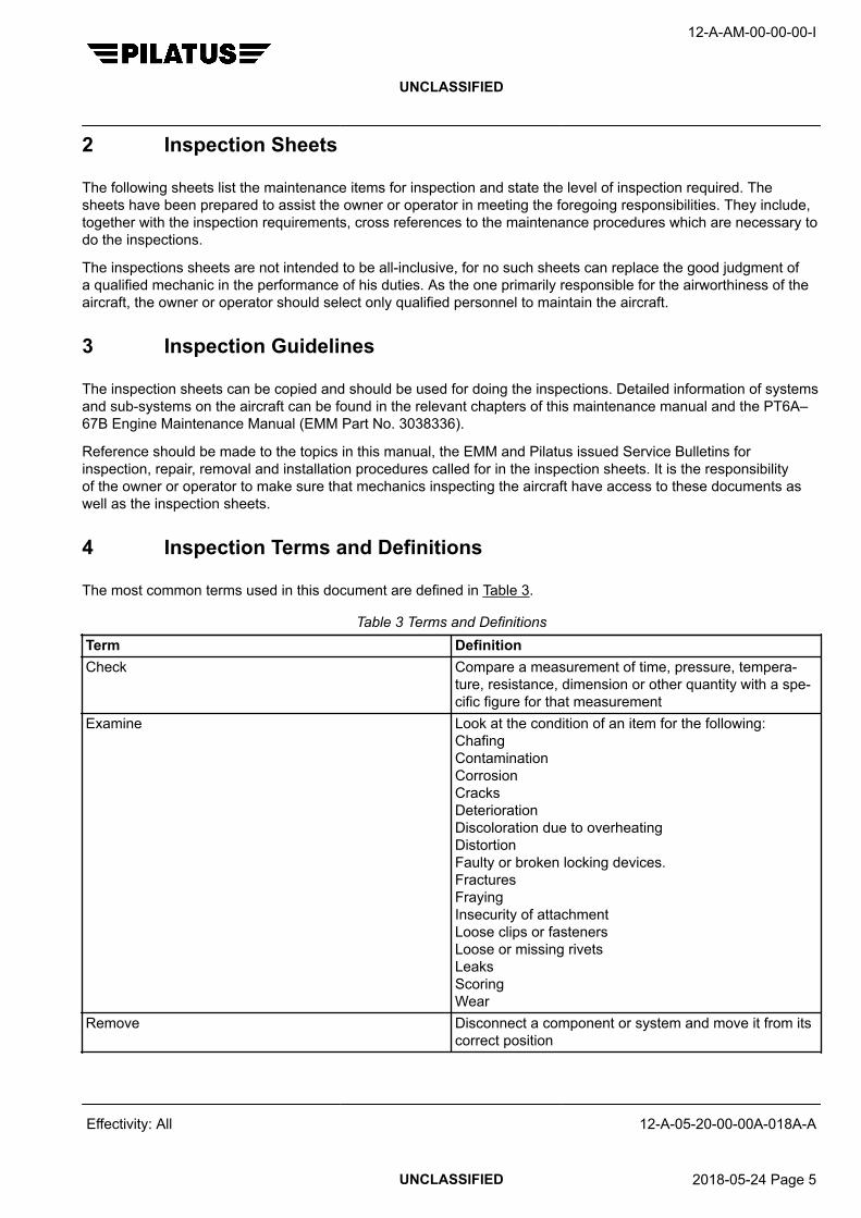
2 Inspection Sheets
The following sheets list the maintenance items for inspection and state the level of inspection required. Thesheets have been prepared to assist the owner or operator in meeting the foregoing responsibilities. They include,together with the inspection requirements, cross references to the maintenance procedures which are necessary todo the inspections.
The inspections sheets are not intended to be all-inclusive, for no such sheets can replace the good judgment ofa qualified mechanic in the performance of his duties. As the one primarily responsible for the airworthiness of theaircraft, the owner or operator should select only qualified personnel to maintain the aircraft.
3 Inspection Guidelines
The inspection sheets can be copied and should be used for doing the inspections. Detailed information of systemsand sub-systems on the aircraft can be found in the relevant chapters of this maintenance manual and the PT6A–67B Engine Maintenance Manual (EMM Part No. 3038336).
Reference should be made to the topics in this manual, the EMM and Pilatus issued Service Bulletins forinspection, repair, removal and installation procedures called for in the inspection sheets. It is the responsibilityof the owner or operator to make sure that mechanics inspecting the aircraft have access to these documents aswell as the inspection sheets.
4 Inspection Terms and Definitions
The most common terms used in this document are defined in Table 3.
Table 3 Terms and DefinitionsTerm DefinitionCheck Compare a measurement of time, pressure, tempera-
ture, resistance, dimension or other quantity with a spe-cific figure for that measurement
Examine Look at the condition of an item for the following:ChafingContaminationCorrosionCracksDeteriorationDiscoloration due to overheatingDistortionFaulty or broken locking devices.FracturesFrayingInsecurity of attachmentLoose clips or fastenersLoose or missing rivetsLeaksScoringWear
Remove Disconnect a component or system and move it from itscorrect position
12-A-AM-00-00-00-I
UNCLASSIFIED
Effectivity: All 12-A-05-20-00-00A-018A-A
UNCLASSIFIED 2018-05-24 Page 5

Table 3 Terms and Definitions (Continued from previous page)Term DefinitionInstall Put a component in the correct position and attach it
correctlyReplace Remove an item and install a new or serviceable item in
its placeFunctional Test A test to show the system, equipment or component
functions correctly to specified parameters. Usually spe-cial test equipment is necessary to complete this test
Operational Test Show by normal operation and with no special equip-ment or measurements, that a system or componentoperates correctly
Lubricate Apply lubricantFill Fill to the correct level, pressure or quantity. This also
includes where necessary the following:Remove caps or coversExamine caps, covers, gaskets, sealsInstall caps, coversInstall locking devices if appropriate
12-A-AM-00-00-00-I
UNCLASSIFIED
Effectivity: All 12-A-05-20-00-00A-018A-A
End of data moduleUNCLASSIFIED 2018-05-24 Page 6

JOB SET UP / CLOSE UP
GENERAL MAINTENANCE PROCEDURE
Table of Contents Page
JOB SET UP / CLOSE UP - GENERAL MAINTENANCE PROCEDURE.................................. 1
Index of Tables Page
1 References............................................................................................................. 12 Required Conditions............................................................................................... 23 Support equipment................................................................................................. 24 Supplies.................................................................................................................. 25 Spares.................................................................................................................... 26 Job Set Up.............................................................................................................. 27 Job Close Up.......................................................................................................... 48 Required Conditions............................................................................................... 5
ReferencesTable 1 References
Data module/Technical publication Title
12-A-05-20-00-00A-018A-A SCHEDULED MAINTENANCE CHECK LISTS - INTRODUC-TION
12-A-06-20-00-00A-040A-A ACCESS PROVISIONS - DESCRIPTION
12-A-07-10-00-00A-901A-A JACKING - MAINTENANCE PRACTICES
12-A-12-20-01-00A-902A-A AIRCRAFT EXTERIOR WASHING - SERVICING
12-A-12-20-02-00A-902A-A AIRCRAFT WINDOWS CLEANING - SERVICING
12-A-12-20-03-00A-902A-A AIRCRAFT INTERIOR CLEANING - SERVICING
12-A-25-10-01-00A-920A-A CREW SEATS (MSN 101 – 660) - REMOVAL/INSTALLATION
12-A-25-10-05-00A-920A-A CREW SEATS (MSN 661 – 999) - REMOVAL/INSTALLATION
12-A-25-20-01-00A-920A-A BENCH SEAT - REMOVAL/INSTALLATION
12-A-25-21-01-00A-920A-A EXECUTIVE SEATS - REMOVAL/INSTALLATION
12-A-25-22-01-00A-920A-A STANDARD SEATS - REMOVAL/INSTALLATION
12-A-71-00-00-00A-903A-A POWERPLANT - ADJUSTMENT/TEST
12-A-AM-00-00-00-I
UNCLASSIFIED
Effectivity: All 12-A-05-20-00-00A-913A-A
UNCLASSIFIED 2021-12-04 Page 1
Required ConditionsTable 2 Required Conditions
Action / Condition Data module/Technical publication
None
Support equipmentTable 3 Support equipment
Name Identifications/References Qty Reference Remark
None
SuppliesTable 4 Supplies
Name Identifications/References Qty Reference Remark
None
SparesTable 5 Spares
Name Identifications/References Qty Reference Remark
None
Safety ConditionsNone
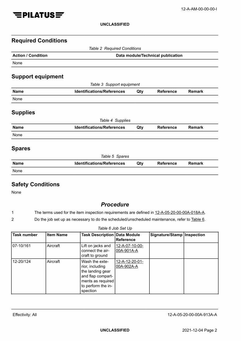
Procedure1 The terms used for the item inspection requirements are defined in 12-A-05-20-00-00A-018A-A.2 Do the job set up as necessary to do the scheduled/unscheduled maintenance, refer to Table 6.
Table 6 Job Set UpTask number Item Name Task Description Data Module
ReferenceSignature/Stamp Inspection
07-10/161 Aircraft Lift on jacks andconnect the air-craft to ground
12-A-07-10-00-00A-901A-A
12-20/124 Aircraft Wash the exte-rior, includingthe landing gearand flap compart-ments as requiredto perform the in-spection
12-A-12-20-01-00A-902A-A
12-A-AM-00-00-00-I
UNCLASSIFIED
Effectivity: All 12-A-05-20-00-00A-913A-A
UNCLASSIFIED 2021-12-04 Page 2

Table 6 Job Set Up (Continued from previous page)Task number Item Name Task Description Data Module
ReferenceSignature/Stamp Inspection
12-20/125 Windshields andwindows
Clean 12-A-12-20-02-00A-902A-A
12-20/126 Cockpit and cabin Clean 12-A-12-20-03-00A-902A-A
25-10/296 Crew seats Remove as nec-essary to do theinspection
MSN 101-660 12-A-25-10-01-00A-920A-AMSN 661-999 12-A-25-10-05-00A-920A-A
25-20/298 Passenger seats Remove as nec-essary to do theinspection
12-A-25-20-01-00A-920A-A12-A-25-21-01-00A-920A-A12-A-25-22-01-00A-920A-A
27-50/143 Flaps Lower to 40° asnecessary to dothe inspection
-
71-00/287 Power plant Do an inspec-tion ground runas necessary. Re-cord any defects.
NoteA pre-inspectionground run is nota prerequisitebut may be use-ful to determineany repair workneeded to main-tain the airwor-thiness of theaircraft.
12-A-71-00-00-00A-903A-A
71-10/207 Engine cowlingsENG 43AL andENG 43AR
Open and exam-ine, particularlyfor condition ofrubbing strips andfasteners. Lubri-cate the hing-es with a mini-mum of materialP10-001.
-
3 Do the job close up as necessary to do the scheduled / unscheduled maintenance. Refer to Table 7
12-A-AM-00-00-00-I
UNCLASSIFIED
Effectivity: All 12-A-05-20-00-00A-913A-A
UNCLASSIFIED 2021-12-04 Page 3

Table 7 Job Close UpTask number Item Name Task Description Data Module
ReferenceSignature/Stamp Inspection
00-00/121 Aircraft Airworthiness Di-rectives andService Bulletinsreviewed andcomplied with asrequired.
-
00-00/122 Aircraft Chapter 4and Chapter5 - Overhauland ReplacementSchedule andTime Limited In-spection Require-ments DMs re-viewed and anyadditional require-ments are com-plied with
-
00-00/481 Aircraft Check AircraftFlight Manual isat the latest revi-sion.
-
07-10/160 Aircraft Lower to theground, removejacks and discon-nect from ground
12-A-07-10-00-00A-901A-A
25-10/297 Crew seats Install as neces-sary to close theinspection
MSN 101-660 12-A-25-10-01-00A-920A-AMSN 661-999 12-A-25-10-05-00A-920A-A
25-20/299 Passenger seats Install as neces-sary to close theinspection
12-A-25-20-01-00A-920A-A12-A-25-21-01-00A-920A-A12-A-25-22-01-00A-920A-A
27-50/475 Flaps Retract to 0°as necessary toclose the inspec-tion
-
71-00/204 Power plant Post inspectionground run tests
12-A-71-00-00-00A-903A-A
71-00/476 P&WC airworthi-ness directivesand service bulle-tins
Reviewed andcomplied with asnecessary
-
12-A-AM-00-00-00-I
UNCLASSIFIED
Effectivity: All 12-A-05-20-00-00A-913A-A
UNCLASSIFIED 2021-12-04 Page 4

Table 7 Job Close Up (Continued from previous page)Task number Item Name Task Description Data Module
ReferenceSignature/Stamp Inspection
71-10/208 Engine cowlingsENG 43AL andENG 43AR
Close -
Requirements after job completion
Required ConditionsTable 8 Required Conditions
Action / Condition Data module/Technical publication
None
12-A-AM-00-00-00-I
UNCLASSIFIED
Effectivity: All 12-A-05-20-00-00A-913A-A
End of data moduleUNCLASSIFIED 2021-12-04 Page 5

12-A-AM-00-00-00-I
UNCLASSIFIED
Intentionally left blank
Effectivity: All 12-A-05-20-00-00A-913A-A
UNCLASSIFIED 2021-12-04 Page 6

MASTER MAINTENANCE PLAN
FUNCTION, DATA FOR PLANS AND DESCRIPTION
Table of Contents Page
MASTER MAINTENANCE PLAN - FUNCTION, DATA FOR PLANS AND DESCRIPTION....... 11 General................................................................................................................... 92 Purpose.................................................................................................................. 93 Task List.................................................................................................................. 9
Index of Tables Page
1 References............................................................................................................. 12 Master Maintenance Plan Task List........................................................................ 10
ReferencesTable 1 References
Data module/Technical publication Title
12-A-04-00-00-00A-000A-A STRUCTURAL, COMPONENT AND MISCELLANEOUS - AIR-WORTHINESS LIMITATIONS
12-A-06-20-00-00A-040A-A ACCESS PROVISIONS - DESCRIPTION
12-A-07-10-00-00A-901A-A JACKING - MAINTENANCE PRACTICES
12-A-11-00-00-00A-040A-A PLACARDS AND MARKINGS - DESCRIPTION AND OPERA-TION
12-A-11-00-00-00A-901A-A PLACARDS AND MARKINGS - MAINTENANCE PRACTICES
12-A-12-10-02-00A-902A-A BRAKES - SERVICING
12-A-12-10-04-00A-902A-A TIRES - SERVICING
12-A-12-20-01-00A-902A-A AIRCRAFT EXTERIOR WASHING - SERVICING
12-A-12-20-02-00A-902A-A AIRCRAFT WINDOWS CLEANING - SERVICING
12-A-12-20-03-00A-902A-A AIRCRAFT INTERIOR CLEANING - SERVICING
12-A-12-20-04-00A-902A-A LANDING GEAR - SERVICING
12-A-12-20-06-00A-902A-A WHEEL BEARING - SERVICING
12-A-12-20-07-00A-902A-A FLAP UP AND DOWN LIMIT SWITCHES - SERVICING
12-A-20-40-00-00A-901A-A CORROSION CONTROL - MAINTENANCE PRACTICES
12-A-21-30-00-00A-903A-A PRESSURIZATION CONTROL - ADJUSTMENT/TEST
12-A-21-30-01-00A-250A-A PRESSURIZATION CONTROL - CLEAN
12-A-21-30-07-00A-903A-A CABIN ALTITUDE SWITCH - ADJUSTMENT/TEST
12-A-AM-00-00-00-I
UNCLASSIFIED
Effectivity: All 12-A-05-40-00-00A-000B-A
UNCLASSIFIED 2021-12-04 Page 1

Data module/Technical publication Title
12-A-21-30-08-00A-903A-A CABIN DIFFERENTIAL PRESSURE SWITCH - ADJUST-MENT/TEST
12-A-21-40-00-00A-903A-A AUXILIARY HEATING SYSTEM (MSN 321 – 999 ANDA/C WITH MODIFIED AUX HEATING SYSTEM) - ADJUST-MENT/TEST
12-A-21-40-01-00A-313A-A REFRIGERATION PACK - INSPECTION/CHECK
12-A-21-40-01-00A-902A-A REFRIGERATION PACK - SERVICING
12-A-21-40-02-00A-250A-A WATER SEPARATOR - CLEAN AND APPLY SURFACE PRO-TECTION
12-A-21-40-06-00A-903A-A OVER TEMPERATURE SWITCH - ADJUSTMENT/TEST
12-A-21-40-09-00A-903A-A SECONDARY HEATERS THERMAL PROTECTIONSWITCHES (MSN 101 – 320 WITHOUT A MODIFIED AUXILI-ARY HEATING SYSTEM) - ADJUSTMENT/TEST
12-A-21-40-11-00A-903A-A FOOT HEATER THERMAL PROTECTION SWITCH (POSTSB 21–004 AND AIRCRAFT WITH A FOOT HEATER SYS-TEM) - ADJUSTMENT/TEST
12-A-21-50-00-00A-903A-A VAPOUR CYCLE COOLING SYSTEM (REFRIGERANT R12) -ADJUSTMENT/TEST
12-A-21-50-00-00A-903B-A VAPOUR CYCLE COOLING SYSTEM (REFRIGERANTR134A) - ADJUSTMENT/TEST
12-A-21-50-03-00A-313A-A COMPRESSOR DRIVE MOTOR - INSPECTION/CHECK
12-A-21-60-05-00A-903A-A DUCT OVER TEMPERATURE SWITCH - ADJUST-MENT/TEST
12-A-22-10-00-00A-313A-A AUTOPILOT - INSPECTION/CHECK
12-A-22-20-00-00A-903A-A SPEED AND ATTITUDE CORRECTION SYSTEM - ADJUST-MENT/TEST
12-A-24-00-00-00A-901A-A ELECTRICAL POWER - MAINTENANCE PRACTICES
12-A-24-20-00-00A-903A-A AC GENERATION SYSTEM - ADJUSTMENT/TEST
12-A-24-30-00-00A-901A-A CORROSION PROTECTION OF GROUND POINTS - MAIN-TENANCE PRACTICES
12-A-24-30-00-00A-903A-A DC GENERATION SYSTEM (MSN 101 – 320, 322 – 400) -ADJUSTMENT/TEST
12-A-24-30-00-00A-903B-A DC GENERATION SYSTEM (MSN 321, 401 – 999) - ADJUST-MENT/TEST
12-A-24-30-01-00A-313A-A STARTER/GENERATOR - INSPECTION/CHECK
12-A-24-30-02-00A-313A-A GENERATOR 2 - INSPECTION/CHECK
12-A-24-30-03-00A-903A-A GENERATOR 2 DRIVE BELT (PRE SB 24–010) - ADJUST-MENT/TEST
12-A-24-30-03-00A-903B-A GENERATOR 2 DRIVE BELT (POST SB 24–010 AND MSN231 – 999) - ADJUSTMENT/TEST
12-A-AM-00-00-00-I
UNCLASSIFIED
Effectivity: All 12-A-05-40-00-00A-000B-A
UNCLASSIFIED 2021-12-04 Page 2
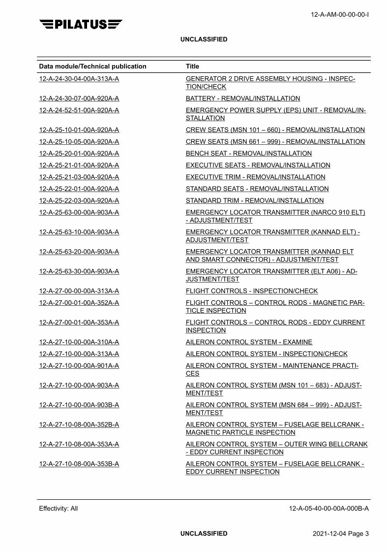
Data module/Technical publication Title
12-A-24-30-04-00A-313A-A GENERATOR 2 DRIVE ASSEMBLY HOUSING - INSPEC-TION/CHECK
12-A-24-30-07-00A-920A-A BATTERY - REMOVAL/INSTALLATION
12-A-24-52-51-00A-920A-A EMERGENCY POWER SUPPLY (EPS) UNIT - REMOVAL/IN-STALLATION
12-A-25-10-01-00A-920A-A CREW SEATS (MSN 101 – 660) - REMOVAL/INSTALLATION
12-A-25-10-05-00A-920A-A CREW SEATS (MSN 661 – 999) - REMOVAL/INSTALLATION
12-A-25-20-01-00A-920A-A BENCH SEAT - REMOVAL/INSTALLATION
12-A-25-21-01-00A-920A-A EXECUTIVE SEATS - REMOVAL/INSTALLATION
12-A-25-21-03-00A-920A-A EXECUTIVE TRIM - REMOVAL/INSTALLATION
12-A-25-22-01-00A-920A-A STANDARD SEATS - REMOVAL/INSTALLATION
12-A-25-22-03-00A-920A-A STANDARD TRIM - REMOVAL/INSTALLATION
12-A-25-63-00-00A-903A-A EMERGENCY LOCATOR TRANSMITTER (NARCO 910 ELT)- ADJUSTMENT/TEST
12-A-25-63-10-00A-903A-A EMERGENCY LOCATOR TRANSMITTER (KANNAD ELT) -ADJUSTMENT/TEST
12-A-25-63-20-00A-903A-A EMERGENCY LOCATOR TRANSMITTER (KANNAD ELTAND SMART CONNECTOR) - ADJUSTMENT/TEST
12-A-25-63-30-00A-903A-A EMERGENCY LOCATOR TRANSMITTER (ELT A06) - AD-JUSTMENT/TEST
12-A-27-00-00-00A-313A-A FLIGHT CONTROLS - INSPECTION/CHECK
12-A-27-00-01-00A-352A-A FLIGHT CONTROLS – CONTROL RODS - MAGNETIC PAR-TICLE INSPECTION
12-A-27-00-01-00A-353A-A FLIGHT CONTROLS – CONTROL RODS - EDDY CURRENTINSPECTION
12-A-27-10-00-00A-310A-A AILERON CONTROL SYSTEM - EXAMINE
12-A-27-10-00-00A-313A-A AILERON CONTROL SYSTEM - INSPECTION/CHECK
12-A-27-10-00-00A-901A-A AILERON CONTROL SYSTEM - MAINTENANCE PRACTI-CES
12-A-27-10-00-00A-903A-A AILERON CONTROL SYSTEM (MSN 101 – 683) - ADJUST-MENT/TEST
12-A-27-10-00-00A-903B-A AILERON CONTROL SYSTEM (MSN 684 – 999) - ADJUST-MENT/TEST
12-A-27-10-08-00A-352B-A AILERON CONTROL SYSTEM – FUSELAGE BELLCRANK -MAGNETIC PARTICLE INSPECTION
12-A-27-10-08-00A-353A-A AILERON CONTROL SYSTEM – OUTER WING BELLCRANK- EDDY CURRENT INSPECTION
12-A-27-10-08-00A-353B-A AILERON CONTROL SYSTEM – FUSELAGE BELLCRANK -EDDY CURRENT INSPECTION
12-A-AM-00-00-00-I
UNCLASSIFIED
Effectivity: All 12-A-05-40-00-00A-000B-A
UNCLASSIFIED 2021-12-04 Page 3

Data module/Technical publication Title
12-A-27-10-09-00A-353A-A AILERON CONTROL SYSTEM – FUSELAGE CABLE QUAD-RANT - EDDY CURRENT INSPECTION
12-A-27-15-00-00A-903A-A AILERON TRIM (MSN 101 – 683) - ADJUSTMENT/TEST
12-A-27-15-00-00A-903B-A AILERON TRIM (MSN 684 – 999) - ADJUSTMENT/TEST
12-A-27-20-00-00A-310A-A RUDDER CONTROL SYSTEM - EXAMINE
12-A-27-20-00-00A-313A-A RUDDER CONTROL SYSTEM - INSPECTION/CHECK
12-A-27-20-00-00A-903A-A RUDDER CONTROL SYSTEM (MSN 101 – 683) - ADJUST-MENT/TEST
12-A-27-20-00-00A-903B-A RUDDER CONTROL SYSTEM (MSN 684 – 999) - ADJUST-MENT/TEST
12-A-27-20-05-00A-310A-A RUDDER CONTROL SYSTEM – CABLE QUADRANT - EX-AMINE
12-A-27-25-00-00A-903A-A RUDDER TRIM - ADJUSTMENT/TEST
12-A-27-30-00-00A-310A-A ELEVATOR CONTROL SYSTEM - EXAMINE
12-A-27-30-00-00A-313A-A ELEVATOR CONTROL SYSTEM - INSPECTION/CHECK
12-A-27-30-00-00A-903A-A ELEVATOR CONTROL SYSTEM - ADJUSTMENT/TEST
12-A-27-30-05-00A-353A-A ELEVATOR CONTROL LEVER - EDDY CURRENT INSPEC-TION
12-A-27-40-00-00A-903A-A HORIZONTAL STABILIZER TRIM - ADJUSTMENT/TEST
12-A-27-40-01-00A-313A-A PITCH TRIM ACTUATOR AND ATTACHMENTS - INSPEC-TION/CHECK
12-A-27-40-02-00A-920A-A HORIZONTAL STABILIZER TRIM – TRIM ACTUATOR FAIL-SAFE PLATES - REMOVAL/INSTALLATION
12-A-27-50-00-00A-901A-A FLAPS (PRE SB 27–013, PRE AND POST SB 27–014 ONMSN 101 – 400) - MAINTENANCE PRACTICES
12-A-27-50-00-00A-902A-A FLAPS - SERVICING
12-A-27-50-00-00A-903A-A FLAPS (PRE SB 27–013) - ADJUSTMENT/TEST
12-A-27-50-00-00A-903B-A FLAPS (POST SB 27–013 and MSN 401 – 999) - ADJUST-MENT/TEST
12-A-27-50-03-00A-313A-A FLAP ACTUATOR (WHITE COLORED FLAP ACTUATORS) -INSPECTION/CHECK
12-A-27-50-03-00A-313B-A FLAP ACTUATOR (BLACK COLORED FLAP ACTUATORS) -INSPECTION/CHECK
12-A-27-51-00-00A-310A-A FLAP DRIVE SYSTEM - EXAMINE
12-A-27-51-00-00A-313A-A FLAP DRIVE SYSTEM - IN SITU INSPECTION/CHECK
12-A-27-51-00-00A-353A-A FLAP DRIVE SYSTEM - IN SITU EDDY CURRENT INSPEC-TION
12-A-27-51-01-00A-353A-A FLAP DRIVE SYSTEM – WING – INBOARD MECHANISM -EDDY CURRENT INSPECTION
12-A-AM-00-00-00-I
UNCLASSIFIED
Effectivity: All 12-A-05-40-00-00A-000B-A
UNCLASSIFIED 2021-12-04 Page 4

Data module/Technical publication Title
12-A-27-51-02-00A-353A-A FLAP DRIVE SYSTEM – WING – CENTER MECHANISM -EDDY CURRENT INSPECTION
12-A-27-51-03-00A-353A-A FLAP DRIVE SYSTEM – WING – OUTBOARD MECHANISM -EDDY CURRENT INSPECTION
12-A-28-10-01-00A-903A-A TANK CROSS VENT PIPE AND OUTWARD CHECK VALVE -ADJUSTMENT/TEST
12-A-28-20-01-00A-250A-A FUEL FILTER ELEMENT - CLEAN AND APPLY SURFACEPROTECTION
12-A-28-20-01-00A-920A-A FUEL FILTER ELEMENT - REMOVAL/INSTALLATION
12-A-28-20-07-00A-903A-A FLOAT VALVE - ADJUSTMENT/TEST
12-A-28-40-00-00A-903A-A FUEL QUANTITY INDICATION (MSN 101 – 105) - ADJUST-MENT/TEST
12-A-28-40-00-00A-903B-A FUEL QUANTITY INDICATION (MSN 106 – 999) - ADJUST-MENT/TEST
12-A-29-00-00-00A-902A-A HYDRAULIC SYSTEM (MSN 101 – 230) - SERVICING
12-A-29-00-00-00A-902B-A HYDRAULIC SYSTEM (MSN 231 – 999) - SERVICING
12-A-29-10-02-00A-901A-A ACCUMULATOR - MAINTENANCE PRACTICES
12-A-29-10-04-00A-313A-A RETURN LINE FILTER DIFFERENTIAL PRESSURE INDICA-TOR - INSPECTION/CHECK
12-A-30-10-00-00A-313A-A AIRFOIL DE-ICING BOOTS - INSPECTION/CHECK
12-A-30-10-00-00A-903A-A AIRFOIL DE-ICE SYSTEM - ADJUSTMENT/TEST
12-A-30-20-00-00A-903A-A AIR INTAKE DEICE SYSTEM (MSN 101 – 320, 322 – 400) -ADJUSTMENT/TEST
12-A-30-20-00-00A-903B-A AIR INTAKE DEICE SYSTEM (MSN 321 AND 401 – 999) -ADJUSTMENT/TEST
12-A-30-30-10-00A-903A-A STANDARD PROBES DEICE SYSTEM (AIRCRAFT WITHSINGLE P – S SYSTEM) - ADJUSTMENT/TEST
12-A-30-30-20-00A-903A-A PROBES DEICE SYSTEM (AIRCRAFT WITH DUAL PITOTSTATIC SYSTEM AND A P–S FAIL INDICATOR) - ADJUST-MENT/TEST
12-A-30-30-20-00A-903B-A PROBES DEICE SYSTEM (MSN 321, 401 – 999) - ADJUST-MENT/TEST
12-A-30-40-00-00A-903A-A WINDSHIELD DE–ICE SYSTEM (WINDSHIELDS WITH TWOHEATING ELEMENTS) - ADJUSTMENT/TEST
12-A-30-40-00-00A-903B-A WINDSHIELD DE–ICE SYSTEM (WINDSHIELDS WITHTHREE HEATING ELEMENTS) - ADJUSTMENT/TEST
12-A-30-60-00-00A-313A-A PROPELLER DE–ICE SYSTEM - INSPECTION/CHECK
12-A-30-60-00-00A-903A-A PROPELLER DE-ICE SYSTEM (WITHOUT PROPELLER DE-ICE TEST SET) - ADJUSTMENT/TEST
12-A-AM-00-00-00-I
UNCLASSIFIED
Effectivity: All 12-A-05-40-00-00A-000B-A
UNCLASSIFIED 2021-12-04 Page 5

Data module/Technical publication Title
12-A-30-60-00-00A-903B-A PROPELLER DE-ICE SYSTEM (WITH PROPELLER DE-ICETEST SET) - ADJUSTMENT/TEST
12-A-32-10-00-00A-310A-A MAIN LANDING GEAR ASSEMBLY - ATTACHMENT BOLTSAND NUTS - EXAMINE
12-A-32-10-00-00A-313A-A MLG HINGE PIN AND BUSHES (PC12/45 AND PC12/47) -INSPECTION/CHECK
12-A-32-10-00-00A-902A-A MLG SHOCK ABSORBER - SERVICING
12-A-32-20-00-00A-902A-A NLG SHOCK ABSORBER - SERVICING
12-A-32-20-03-00A-250A-A SPRING STRUT (PART NO. 532.20.12.250) - CLEAN ANDAPPLY SURFACE PROTECTION
12-A-32-20-03-00A-920A-A SPRING STRUT - REMOVAL/INSTALLATION
12-A-32-20-06-00A-313A-A DRAG LINK RIGHT PART - INSPECTION/CHECK
12-A-32-30-00-00A-903A-A EXTENSION AND RETRACTION - ADJUSTMENT/TEST
12-A-32-50-00-00A-310A-A NOSE WHEEL STEERING - EXAMINE
12-A-33-40-00-00A-903A-A EXTERIOR LIGHTS (MSN 101 – 320, 322 – 400) - ADJUST-MENT/TEST
12-A-33-40-00-00A-903B-A EXTERIOR LIGHTS (MSN 321, 401 – 999) - ADJUST-MENT/TEST
12-A-34-11-10-00A-901A-A SINGLE P–S SYSTEM - MAINTENANCE PRACTICES
12-A-34-11-10-00A-903A-A SINGLE P–S SYSTEM - ADJUSTMENT/TEST
12-A-34-11-20-00A-901A-A DUAL PITOT STATIC SYSTEM - MAINTENANCE PRACTI-CES
12-A-34-11-20-00A-903A-A DUAL PITOT STATIC SYSTEM - ADJUSTMENT/TEST
12-A-34-21-00-00A-903A-A STANDBY MAGNETIC COMPASS - ADJUSTMENT/TEST
12-A-34-25-00-00A-903A-A ATTITUDE AND HEADING REFERENCE SYSTEM - AD-JUSTMENT/TEST
12-A-34-54-00-00A-903A-A AIR TRAFFIC CONTROL TRANSPONDER SYSTEM (KT70OR KT71 ATC SYSTEM) - ADJUSTMENT/TEST
12-A-34-54-00-00A-903B-A AIR TRAFFIC CONTROL TRANSPONDER SYSTEM(GTX330D ATC SYSTEM) - ADJUSTMENT/TEST
12-A-35-00-00-00A-903A-A OXYGEN SYSTEM - ADJUSTMENT/TEST
12-A-35-20-00-00A-313A-A PASSENGER OXYGEN SYSTEM - INSPECTION/CHECK
12-A-52-00-01-00A-353A-A PASSENGER/CREW DOOR HINGE - EDDY CURRENT IN-SPECTION
12-A-52-10-00-00A-310A-A PASSENGER/CREW DOOR - EXAMINE
12-A-52-10-00-00A-313A-A PASSENGER/CREW DOOR - INSPECTION/CHECK
12-A-52-10-01-00A-353A-A PASSENGER/CREW DOOR SKINS - EDDY CURRENT IN-SPECTION
12-A-AM-00-00-00-I
UNCLASSIFIED
Effectivity: All 12-A-05-40-00-00A-000B-A
UNCLASSIFIED 2021-12-04 Page 6

Data module/Technical publication Title
12-A-52-10-06-00A-353A-A PASSENGER/CREW DOOR SHOOT BOLTS - EDDY CUR-RENT INSPECTION
12-A-52-20-00-00A-310A-A EMERGENCY EXIT - EXAMINE
12-A-52-30-00-00A-310A-A CARGO DOOR - EXAMINE
12-A-52-30-00-00A-313A-A CARGO DOOR - INSPECTION/CHECK
12-A-52-30-00-01A-353A-A CARGO DOOR HINGE - EDDY CURRENT INSPECTION
12-A-52-30-01-00A-353A-A CARGO DOOR SKINS - EDDY CURRENT INSPECTION
12-A-52-70-00-00A-903A-A DOOR WARNING - ADJUSTMENT/TEST
12-A-53-00-00-00A-310A-A FUSELAGE - ANTENNA STRUCTURE – EXAMINE
12-A-53-00-00-00A-353A-A FUSELAGE - ANTENNA STRUCTURE – EDDY CURRENTINSPECTION
12-A-53-00-01-00A-663A-A NLG ACTUATOR ATTACHMENT BRACKET REPAIRRM07274 - SPECIAL REPAIR PROCEDURES
12-A-53-10-00-00A-310A-A FORWARD FUSELAGE - EXAMINE
12-A-53-10-06-01A-353A-A FORWARD FUSELAGE – FRAME 10 LONGERONS - EDDYCURRENT INSPECTION
12-A-53-10-16-00A-310A-A FORWARD FUSELAGE – WINDOW STRUCTURE - EXAM-INE
12-A-53-20-00-00A-310A-A CENTER FUSELAGE - EXAMINE
12-A-53-20-02-00A-313A-A CENTER FUSELAGE FRAMES – CARRY THROUGHFRAMES - INSPECTION/CHECK
12-A-53-20-02-00A-353A-A CENTER FUSELAGE FRAMES – CARRY THROUGHFRAMES - EDDY CURRENT INSPECTION
12-A-53-30-00-00A-310A-A REAR FUSELAGE - EXAMINE
12-A-53-30-02-00A-353A-A REAR FUSELAGE FRAMES - EDDY CURRENT INSPEC-TION
12-A-54-20-02-00A-664A-A ENGINE FRAME DAMAGED PAINT AND CORROSION RE-MOVAL - SPECIAL REPAIR PROCEDURES
12-A-55-00-00-00A-313A-A STABILIZERS ATTACHMENT FITTINGS - INSPEC-TION/CHECK
12-A-55-00-00-00A-353A-A VERTICAL STABILIZER ATTACHMENT FITTINGS - EDDYCURRENT INSPECTION
12-A-55-00-01-00A-664A-A VERTICAL STABILIZER - SKIN CRACK REPAIR TM-02-078 -SPECIAL REPAIR PROCEDURES
12-A-55-20-00-00A-310A-A ELEVATORS - EXAMINE
12-A-55-20-01-00A-353A-A ELEVATOR DRIVE LEVER AND HINGE - EDDY CURRENTINSPECTION
12-A-55-20-01-00A-904B-A ELEVATOR LEVER FITTING - UP AND DOWN STOP - RE-PAIR
12-A-AM-00-00-00-I
UNCLASSIFIED
Effectivity: All 12-A-05-40-00-00A-000B-A
UNCLASSIFIED 2021-12-04 Page 7

Data module/Technical publication Title
12-A-55-30-00-00A-310A-A VERTICAL STABILIZER - EXAMINE
12-A-55-30-02-00A-353A-A VERTICAL STABILIZER – PITCH TRIM ACTUATOR ATTACH-MENT - EDDY CURRENT INSPECTION
12-A-55-30-03-00A-353A-A VERTICAL STABILIZER SPARS - EDDY CURRENT INSPEC-TION
12-A-55-40-00-00A-310A-A RUDDER - EXAMINE
12-A-55-40-00-00A-313A-A RUDDER - INSPECTION/CHECK
12-A-55-40-04-00A-310A-A RUDDER TRIM TAB - EXAMINE
12-A-55-40-05-00A-353A-A RUDDER HINGE - EDDY CURRENT INSPECTION
12-A-56-00-00-00A-313A-A WINDOWS - INSPECTION/CHECK
12-A-56-11-01-00A-310A-A WINDSHIELD - EXAMINE
12-A-56-11-02-00A-310A-A COCKPIT SIDE WINDOWS - EXAMINE
12-A-56-11-02-00A-313A-A COCKPIT SIDE WINDOWS - INSPECTION/CHECK
12-A-57-00-00-00A-310A-A WINGS - EXAMINE
12-A-57-00-00-00A-313A-A WING AND FUSELAGE FITTINGS - INSPECTION/CHECK
12-A-57-00-03-00A-353A-A WING AND FUSELAGE ATTACHMENT FITTINGS - EDDYCURRENT INSPECTION
12-A-57-00-03-01A-353A-A WING AND FUSELAGE ATTACHMENT FITTINGS – HOLLOWBOLTS - EDDY CURRENT INSPECTION
12-A-57-20-01-00A-353A-A WING SKINS - EDDY CURRENT INSPECTION
12-A-57-20-05-00A-353A-A WING STRUCTURE – RIBS - EDDY CURRENT INSPECTION– RIB 6 STRAP
12-A-57-20-10-00A-353A-A WING STRUCTURE – SPARS AND AUXILIARY STRUCTURE– MAIN SPAR - EDDY CURRENT INSPECTION
12-A-57-20-10-00A-353B-A WING STRUCTURE – SPARS AND AUXILIARY STRUCTURE– REAR SPAR - EDDY CURRENT INSPECTION
12-A-57-20-10-00A-353C-A WING STRUCTURE – SPARS AND AUXILIARY STRUCTURE– REAR SPAR - EDDY CURRENT INSPECTION
12-A-57-20-10-00A-353D-A WING STRUCTURE – SPARS AND AUXILIARY STRUCTURE– MAIN SPAR – RIB 6 STRAP FASTENER - EDDY CURRENTINSPECTION
12-A-57-33-00-00A-310A-A WING TIP - EXAMINE
12-A-57-60-00-00A-310A-A AILERONS - EXAMINE
12-A-57-60-04-00A-310A-A AILERON TRIM TAB - EXAMINE
12-A-57-60-06-00A-353A-A AILERON HINGE - EDDY CURRENT INSPECTION
12-A-71-00-00-00A-903A-A POWERPLANT - ADJUSTMENT/TEST
12-A-71-00-00-00A-903H-A POWERPLANT TEST 6 – TORQUE LIMITER - ADJUST-MENT/TEST
12-A-AM-00-00-00-I
UNCLASSIFIED
Effectivity: All 12-A-05-40-00-00A-000B-A
UNCLASSIFIED 2021-12-04 Page 8

Data module/Technical publication Title
12-A-71-00-00-00A-903I-A POWERPLANT TEST 7 – ENGINE PERFORMANCE - AD-JUSTMENT/TEST
12-A-71-00-03-00A-250A-A ELECTRICAL CONNECTORS - CLEAN AND APPLY SUR-FACE PROTECTION
12-A-71-00-05-00A-352A-A POWERPLANT MOUNTING FRAME - MAGNETIC PARTICLEINSPECTION
12-A-74-00-00-00A-903A-A IGNITION SYSTEM - ADJUSTMENT/TEST
12-A-76-10-00-00A-903A-A POWER CONTROLS - ADJUSTMENT/TEST
12-A-76-10-02-00A-903A-A PROPELLER FEATHER MICROSWITCHES - ADJUST-MENT/TEST
12-A-76-20-00-00A-903A-A MANUAL OVERRIDE - ADJUSTMENT/TEST
12-A-77-40-00-00A-903A-A ENGINE INDICATION (MSN 101 – 111) - ADJUST-MENT/TEST
12-A-77-40-00-00A-903B-A ENGINE INDICATION (MSN 112 – 320, 322 – 400) - ADJUST-MENT/TEST
12-A-77-40-00-00A-903C-A ENGINE INDICATING (MSN 321, 401 – 999) - ADJUST-MENT/TEST
12-A-79-30-01-00A-903A-A CHIP DETECTOR - ADJUSTMENT/TEST
Description
1 General
The Master Maintenance Plan (MMP) lists all the maintenance tasks from the Airworthiness Limitations (AL) DM,Time Limits DM and the Schedule Maintenance. The tasks have a task number and are listed in S1000D system,sub-system order.
2 Purpose
The purpose of this MMP is to provide the operator or maintainer with a complete overview of the maintenancewhich is applicable for the PC-12, PC-12/45 and PC-12/47. This plan is intended as a tool to assist the operator/maintainer in planning.
3 Task List
The MMP task list is provided in Table 2.
The tasks numbers marked with an asterisk symbol (*) are Chapter 4 tasks. Refer to AMM 12-A-04-00-00-00A-000A-A. These tasks are only marked with an asterisk symbol in the MMP for Chapter 4 task identificationpurposes. In Chapter 4, this symbol is not shown.
The notes below correspond to some of the AL tasks identified by the asterisk.
Note 1
12-A-AM-00-00-00-I
UNCLASSIFIED
Effectivity: All 12-A-05-40-00-00A-000B-A
UNCLASSIFIED 2021-12-04 Page 9

Do not do the inspection more than 500 flying hours or 500 landings before the stated inspection or life limit.
Note 2
A 10% tolerance only to the calendar time interval is applicable.
Note 3
A 10% tolerance is applicable to the flying hour and calendar time intervals.
Note 4
Aircraft with rudder bellcrank with more than 20’000 flying hours or 27’000 landings, whichever comes first, musthave the rudder bellcrank replaced within 12 months after publishing date of the AMM Revision 41.
Note 5
Aircraft with attachment bolts and nuts that are 6 years or older must be examined by 31 December 2016.
Note 6
Aircraft with attachment bolts more than 60 months old must have the bolts replaced within 6 months or 300 flyinghours, whichever comes first.
Note 7
The inspection is applicable to all aircraft except MSN 170, 222, 233, 234, 237, 240, 244, 250 and 324 whichhave performed the inspection as part of a fleet leader inspection survey and aircraft that have performed ServiceBulletin 04-009 Revision 1 or later.
Note 8
Wings with more than 15,500 flying hours or 22,000 landings, whichever comes first, must perform the inspectionwithin the next 500 flying hours or 500 landings, whichever comes first.
Table 2 Master Maintenance Plan Task ListTask number Item Name Task Description Interval Data Module Refer-
ence00-00/45 Aircraft Do the corrosion and
corrosion protectioninspections
AMM 12-B-20-40-00-00A-901A-A
12-A-20-40-00-00A-901A-A
00-00/121 Aircraft Airworthiness Direc-tives and Service Bul-letins reviewed andcomplied with as re-quired.
Job Close Up -
00-00/122 Aircraft Chapter 4 and Chap-ter 5 - Overhaul andReplacement Sched-ule and Time Limi-ted Inspection Re-quirements DMs re-viewed and any ad-ditional requirementsare complied with
Job Close Up -
00-00/481 Aircraft Check Aircraft FlightManual is at the lat-est revision.
Job Close Up -
12-A-AM-00-00-00-I
UNCLASSIFIED
Effectivity: All 12-A-05-40-00-00A-000B-A
UNCLASSIFIED 2021-12-04 Page 10
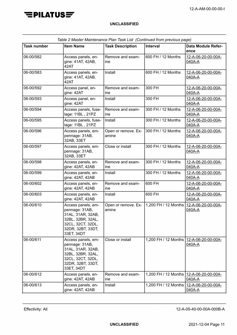
Table 2 Master Maintenance Plan Task List (Continued from previous page)Task number Item Name Task Description Interval Data Module Refer-
ence06-00/582 Access panels, en-
gine: 41AT, 42AB,42AT
Remove and exam-ine
600 FH / 12 Months 12-A-06-20-00-00A-040A-A
06-00/583 Access panels, en-gine: 41AT, 42AB,42AT
Install 600 FH / 12 Months 12-A-06-20-00-00A-040A-A
06-00/592 Access panel, en-gine: 42AT
Remove and exam-ine
300 FH 12-A-06-20-00-00A-040A-A
06-00/593 Access panel, en-gine: 42AT
Install 300 FH 12-A-06-20-00-00A-040A-A
06-00/594 Access panels, fuse-lage: 11BL , 21PZ
Remove and exam-ine
300 FH / 12 Months 12-A-06-20-00-00A-040A-A
06-00/595 Access panels, fuse-lage: 11BL , 21PZ
Install 300 FH / 12 Months 12-A-06-20-00-00A-040A-A
06-00/596 Access panels, em-pennage: 31AB,32AB, 33ET
Open or remove. Ex-amine
300 FH / 12 Months 12-A-06-20-00-00A-040A-A
06-00/597 Access panels, em-pennage: 31AB,32AB, 33ET
Close or install 300 FH / 12 Months 12-A-06-20-00-00A-040A-A
06-00/598 Access panels, en-gine: 42AT, 42AB
Remove and exam-ine
300 FH / 12 Months 12-A-06-20-00-00A-040A-A
06-00/599 Access panels, en-gine: 42AT, 42AB
Install 300 FH / 12 Months 12-A-06-20-00-00A-040A-A
06-00/602 Access panels, en-gine: 42AT, 42AB
Remove and exam-ine
600 FH 12-A-06-20-00-00A-040A-A
06-00/603 Access panels, en-gine: 42AT, 42AB
Install 600 FH 12-A-06-20-00-00A-040A-A
06-00/610 Access panels, em-pennage: 31AB,31AL, 31AR, 32AB,32BL, 32BR, 32AL,32CL, 32CT, 32DL,32DR, 32BT, 33DT,33ET, 34DT
Open or remove. Ex-amine
1,200 FH / 12 Months 12-A-06-20-00-00A-040A-A
06-00/611 Access panels, em-pennage: 31AB,31AL, 31AR, 32AB,32BL, 32BR, 32AL,32CL, 32CT, 32DL,32DR, 32BT, 33DT,33ET, 34DT
Close or install 1,200 FH / 12 Months 12-A-06-20-00-00A-040A-A
06-00/612 Access panels, en-gine: 42AT, 42AB
Remove and exam-ine
1,200 FH / 12 Months 12-A-06-20-00-00A-040A-A
06-00/613 Access panels, en-gine: 42AT, 42AB
Install 1,200 FH / 12 Months 12-A-06-20-00-00A-040A-A
12-A-AM-00-00-00-I
UNCLASSIFIED
Effectivity: All 12-A-05-40-00-00A-000B-A
UNCLASSIFIED 2021-12-04 Page 11

Table 2 Master Maintenance Plan Task List (Continued from previous page)Task number Item Name Task Description Interval Data Module Refer-
ence06-00/620 Access panels, wing:
51AB, 51BB, 61AB,61BB
Remove and exam-ine
2,400 FH / 24 Months 12-A-06-20-00-00A-040A-A
06-00/621 Access panels, wing:51AB, 51BB, 61AB,61BB
Install 2,400 FH / 24 Months 12-A-06-20-00-00A-040A-A
06-00/622 Access panels, fuse-lage: 11BR, 12BZ,12EZ, 12HZ, 21QZ
Remove and exam-ine
300 FH 12-A-06-20-00-00A-040A-A
06-00/623 Access panels, fuse-lage: 11BR, 12BZ,12EZ, 12HZ, 21QZ
Install 300 FH 12-A-06-20-00-00A-040A-A
06-00/624 Access panels, fuse-lage: 11AL, 12EL,21PZ
Remove and exam-ine
600 FH / 12 Months 12-A-06-20-00-00A-040A-A
06-00/625 Access panels, fuse-lage: 11AL, 12EL,21PZ
Install 600 FH / 12 Months 12-A-06-20-00-00A-040A-A
06-00/626 Access panel, wing:52NB
Remove and exam-ine
600 FH / 12 Months 12-A-06-20-00-00A-040A-A
06-00/627 Access panel, wing:52NB
Install 600 FH / 12 Months 12-A-06-20-00-00A-040A-A
06-00/628 Access panels, fuse-lage: 11AL, 11AR,11BR, 11BL, 12AL,12AR, 12AB, 12EL,12HZ, 12JZ, 12MZ,11BZ, 12AZ, 12BZ,12DZ, 12GZ, 12BL,12BR, 12EZ, 12ER,12KZ, 12CZ, 12FZ,12IZ, 12LZ, 21JZ,21QZ, 21GZ, 21HZ,22TZ, 22PZ, 22UZ
Open or remove. Ex-amine and make surethe access paneldrain holes are clear
1,200 FH / 12 Months 12-A-06-20-00-00A-040A-A
06-00/629 Access panels, fuse-lage: 11AL, 11AR,11BR, 11BL, 12AL,12AR, 12AB, 12EL,12HZ, 12JZ, 12MZ,11BZ, 12AZ, 12BZ,12DZ, 12GZ, 12BL,12BR, 12EZ, 12ER,12KZ, 12CZ, 12FZ,12IZ, 12LZ, 21JZ,21QZ, 21GZ, 21HZ,22TZ, 22PZ, 22UZ
Close or install 1,200 FH / 12 Months 12-A-06-20-00-00A-040A-A
12-A-AM-00-00-00-I
UNCLASSIFIED
Effectivity: All 12-A-05-40-00-00A-000B-A
UNCLASSIFIED 2021-12-04 Page 12

Table 2 Master Maintenance Plan Task List (Continued from previous page)Task number Item Name Task Description Interval Data Module Refer-
ence06-00/630 Access panels, wing:
51AB, 51BB, 51JB,51LB, 52MB, 52NB,52OB, 52KB, 51MB,51NB, 52TB, 52SB,52RB, 52PB, 51KB,61AB, 61BB, 62KB,62MB, 62NB, 62OB,62SB, 62RB, 62PB,61KB, 61MB, 61NB,62TB
Remove and exam-ine
1,200 FH / 12 Months 12-A-06-20-00-00A-040A-A
06-00/631 Access panels, wing:51AB, 51BB, 51JB,51LB, 52MB, 52NB,52OB, 52KB, 51MB,51NB, 52TB, 52SB,52RB, 52PB, 51KB,61AB, 61BB, 62KB,62MB, 62NB, 62OB,62SB, 62RB, 62PB,61KB, 61MB, 61NB,62TB
Install 1,200 FH / 12 Months 12-A-06-20-00-00A-040A-A
06-00/632 Access panels, fuse-lage: 11AL, 11AZ,11BL, 11CZ, 12EL,12ER, 12EZ, 21JZ
Open or remove. Ex-amine and make surethe access paneldrain holes are clear
2,400 FH / 24 Months 12-A-06-20-00-00A-040A-A
06-00/633 Access panels, fuse-lage: 11AL, 11AZ,11BL, 11CZ, 12EL,12ER, 12EZ, 21JZ
Close or install 2,400 FH / 24 Months 12-A-06-20-00-00A-040A-A
06-00/634 Access panels, em-pennage: 31AB,32AB, 32CT, 33ET
Remove and exam-ine
2,400 FH / 24 Months 12-A-06-20-00-00A-040A-A
06-00/635 Access panels, em-pennage: 31AB,32AB, 32CT, 33ET
Install 2,400 FH / 24 Months 12-A-06-20-00-00A-040A-A
06-00/636 Access panel, en-gine: 42AT
Remove and exam-ine
2,400 FH / 24 Months 12-A-06-20-00-00A-040A-A
06-00/637 Access panel, en-gine: 42AT
Install 2,400 FH / 24 Months 12-A-06-20-00-00A-040A-A
07-10/160 Aircraft Lower to the ground,remove jacks anddisconnect fromground
Job Close Up 12-A-07-10-00-00A-901A-A
07-10/161 Aircraft Lift on jacks and con-nect the aircraft toground
Job Set Up 12-A-07-10-00-00A-901A-A
12-A-AM-00-00-00-I
UNCLASSIFIED
Effectivity: All 12-A-05-40-00-00A-000B-A
UNCLASSIFIED 2021-12-04 Page 13

Table 2 Master Maintenance Plan Task List (Continued from previous page)Task number Item Name Task Description Interval Data Module Refer-
ence10-10/428 External protective
coversExamine. Replace ifany part of the coveris missing, damaged,torn or does not in-stall properly
300 FH / 12 Months -
11-00/220 Placards and mark-ings
Examine and attachnew placards if nec-essary
1,200 FH / 12 Months 12-A-11-00-00-00A-040A-A12-A-11-00-00-00A-901A-A
12-20/124 Aircraft Wash the exterior,including the land-ing gear and flapcompartments as re-quired to perform theinspection
Job Set Up 12-A-12-20-01-00A-902A-A
12-20/125 Windshields and win-dows
Clean Job Set Up 12-A-12-20-02-00A-902A-A
12-20/126 Cockpit and cabin Clean Job Set Up 12-A-12-20-03-00A-902A-A
21-20/127 ECS emergencyshut-off system
Check ECS EMERshut-off lever maxpull force 100 N (22.5lbf) and make sureram air scoop is com-pletely open
1,200 FH / 12 Months -
21-20/221 ECS and bleedair ducts, pipelines,equipment and asso-ciated clamps in theengine compartment
Examine 2,400 FH / 24 Months -
21-30/46 Cabin pressurizationpositive pressure re-lief valve
Functional test 4,800 FH / 48 Months 12-A-21-30-00-00A-903A-A
21-30/47 Cabin pressurizationpositive pressure re-lief valve and outflowvalve
Check for contamina-tion of the valve pop-pet and poppet seat.If contamination isfound remove andclean
2,400 FH / 24 Months 12-A-21-30-01-00A-250A-A
21-30/48 Cabin altitude switch Functional test 60 Months 12-A-21-30-07-00A-903A-A
21-30/49 Cabin differentialpressure switch
Functional test 60 Months 12-A-21-30-08-00A-903A-A
21-40/50 Water separator con-denser
Clean 1,200 FH / 12 Months 12-A-21-40-02-00A-250A-A
21-40/51 Overtemperatureswitch
Functional test 4,800 FH / 60 Months 12-A-21-40-06-00A-903A-A
12-A-AM-00-00-00-I
UNCLASSIFIED
Effectivity: All 12-A-05-40-00-00A-000B-A
UNCLASSIFIED 2021-12-04 Page 14

Table 2 Master Maintenance Plan Task List (Continued from previous page)Task number Item Name Task Description Interval Data Module Refer-
ence21-40/52 Duct overtemperature
switchFunctional test 4,800 FH / 60 Months 12-A-21-60-05-00A-
903A-A21-40/53 Secondary heaters
thermal protectionswitches (MSN101-320 without amodified auxiliaryheating system)
Operational test 1,200 FH / 12 Months 12-A-21-40-09-00A-903A-A
21-40/54 Secondary heatersthermal protectionswitches (MSN321-999 and aircraftwith a modified auxili-ary heating system)
Operational test 1,200 FH / 12 Months 12-A-21-40-00-00A-903A-A
21-40/55 Cold air unit Add oil 600 FH 12-A-21-40-01-00A-902A-A
21-40/56 Heat exchanger ma-trix
Inspection/check 600 FH 12-A-21-40-01-00A-313A-A
21-40/128 Flight compartmentfoot heater (if instal-led) thermal protec-tion switch
Operational test 1,200 FH / 12 Months 12-A-21-40-11-00A-903A-A
21-50/58 Vapor cycle compres-sor motor (if installed)
Inspection/check 500 Operating hours 12-A-21-50-03-00A-313A-A
21-50/59 Vapor cycle compres-sor motor drive belt (ifinstalled)
Check for tension 500 Operating hours 12-A-21-50-00-00A-903A-A12-A-21-50-00-00A-903B-A
21-50/223 Vapor cycle coolingsystem (if installed)
Examine the coolingunit
1,200 FH / 12 Months -
21-50/433 Vapor cycle compres-sor condenser mod-ule (including motor)(if installed)
Clean, refer toOSCMM
Initially at eachscheduled inspection,then based on fieldexperience the inter-val can be adjustedto a more effectivelevel
-
21-50/461 Vapor cycle compres-sor motor (CCM P/N959.90.22.140, if in-stalled)
Inspection/check 600 Operating hours 12-A-21-50-03-00A-313A-A
21-50/462 Vapor cycle compres-sor motor drivebelt (CCM P/N959.90.22.140, if in-stalled)
Check for tension 600 Operating hours 12-A-21-50-00-00A-903A-A12-A-21-50-00-00A-903B-A
12-A-AM-00-00-00-I
UNCLASSIFIED
Effectivity: All 12-A-05-40-00-00A-000B-A
UNCLASSIFIED 2021-12-04 Page 15

Table 2 Master Maintenance Plan Task List (Continued from previous page)Task number Item Name Task Description Interval Data Module Refer-
ence22-10/60 Servo mount (pitch,
roll and yaw)Remove for clutchcheck
1,200 FH / 12 Months 12-A-22-10-00-00A-313A-A
22-10/233 Pitch, roll, and yawactuators and cap-stan control cables
Examine 2,400 FH / 24 Months -
22-20/129 Angle of Attack(AOA) transmitters
Examine 300 FH / 12 Months -
22-20/130 Stick pusher system Check 300 FH 12-A-22-20-00-00A-903A-A
22-20/226 Stick pusher system Functional test 1,200 FH / 12 Months 12-A-22-20-00-00A-903A-A
24-20/227 AC electrical system Operational test 1,200 FH / 12 Months 12-A-24-20-00-00A-903A-A
24-30/19 Starter/Generator(except P/N978.91.23.407,978.91.23.408 and978.91.23.409)
Overhaul 1,000 FH -
24-30/20 Generator 2 drive as-sembly aft bearing(smaller inner diame-ter) (Pre SB 24-010)
Discard 10,000 FH -
24-30/21 Generator 2 drive as-sembly aft bearing(smaller inner diame-ter) (Post SB 24-010and MSN 231 - 999)
Discard 3,000 FH -
24-30/61 Starter/Generator(except P/N978.91.23.407,978.91.23.408 and978.91.23.409)
Brush check 300 FH 12-A-24-30-01-00A-313A-A
24-30/62 Generator 1 and 2ground pointsBattery 1 and 2ground points (if in-stalled)
Examine the corro-sion protective layer
24 Months 12-A-24-30-00-00A-901A-A
24-30/63 Generator 2 brushes(P/N 524.32.12.158Mod. B)
Inspection/check 300 FH 12-A-24-30-02-00A-313A-A
24-30/64 Generator 2 brushes(P/N 524.32.12.158Mod. A, Mod. C andabove)
Inspection/check 600 FH 12-A-24-30-02-00A-313A-A
24-30/65 Generator 2 drive as-sembly housing (PreSB 24-010)
Inspection/check 1,200 FH 12-A-24-30-04-00A-313A-A
12-A-AM-00-00-00-I
UNCLASSIFIED
Effectivity: All 12-A-05-40-00-00A-000B-A
UNCLASSIFIED 2021-12-04 Page 16

Table 2 Master Maintenance Plan Task List (Continued from previous page)Task number Item Name Task Description Interval Data Module Refer-
ence24-30/66 Generator 2 drive as-
sembly housing (PostSB 24-010 and MSN231- 999)
Inspection/check 1,800 FH 12-A-24-30-04-00A-313A-A
24-30/67 Ni-Cad battery orbatteries (if 2nd bat-tery installed) (P/N976.17.31.301)
Remove and service 300 FH / 3 Months 12-A-24-30-07-00A-920A-Aand CMM
24-30/68 Ni-Cad battery orbatteries (if 2nd bat-tery installed) (P/N976.17.31.302)
Remove and service 400 FH / 12 Months 12-A-24-30-07-00A-920A-Aand CMM
24-30/69 Lead acid battery orbatteries (if 2nd bat-tery installed)
Remove and do a ca-pacity test
Initially at 1000 FH or12 Months. If capaci-ty above 90% thenevery 600 FH or 6Months. If capacityis between 85% and90% then every 300FH or 3 Months. If ca-pacity is below 85%replace.
12-A-24-30-07-00A-920A-Aand CMM
24-30/131 Generator 2 drive belt Examine and adjust-ment/test
300 FH / 12 Months 12-A-24-30-03-00A-903A-A12-A-24-30-03-00A-903B-A
24-30/132 Battery (Batteries - if2nd battery installed)
Examine and opera-tional test
300 FH / 12 Months 12-A-24-30-00-00A-903A-A12-A-24-30-00-00A-903B-A
24-30/228 External power Operational test 2,400 FH / 24 Months 12-A-24-30-00-00A-903A-A12-A-24-30-00-00A-903B-A
24-30/482 Starter/Generator(P/N 978.91.23.407,978.91.23.408 and978.91.23.409)
Brush check 600 FH 12-A-24-30-01-00A-313A-A
24-30/491 Starter/Generator(P/N 978.91.23.407,978.91.23.408 and978.91.23.409)
Overhaul 1,200 FH -
24-40/229 External Power Unit(EPU) receptacle
Examine 2,400 FH / 24 Months -
24-50/70 Emergency powersupply (if installed)
Remove and cap test 12 Months 12-A-24-52-51-00A-920A-A
12-A-AM-00-00-00-I
UNCLASSIFIED
Effectivity: All 12-A-05-40-00-00A-000B-A
UNCLASSIFIED 2021-12-04 Page 17

Table 2 Master Maintenance Plan Task List (Continued from previous page)Task number Item Name Task Description Interval Data Module Refer-
ence24-60/133 Cockpit circuit break-
er panels and switchpanels
Examine 2,400 FH / 24 Months -
25-10/134 Crew seat belts Examine 300 FH / 12 Months -25-10/135 Crew seats Examine as far as
possible with seatsinstalled
300 FH -
25-10/293 Crew seat cushion(P/N 0A318-0203 in-stalled on IPECOSeat P/N 959.30.01.135 and 136)
Discard 36 Months(elapsed for factorynew or spare partnew from EASA Form1 date)
-
25-10/294 Crew seat belts - Task deleted from theMaintenance Plan
-
25-10/296 Crew seats Remove as necessa-ry to do the inspec-tion
Job Set Up MSN 101-660 12-A-25-10-01-00A-920A-AMSN 661-999 12-A-25-10-05-00A-920A-A
25-10/297 Crew seats Install as necessaryto close the inspec-tion
Job Close Up MSN 101-660 12-A-25-10-01-00A-920A-AMSN 661-999 12-A-25-10-05-00A-920A-A
25-10/300 Crew seats Remove cushions,covers and shells(Refer CMM) and ex-amine seat. Installcushions, covers andshells
1,200 FH / 12 Months The CMM documentnumbers are given inAMM12-A-25-10-01-00A-920A-A
*25-10/486 Backrest tubes oncrew seats with a re-cline systemSeat P/N959.30.01.111Seat P/N959.30.01.112Seat P/N959.30.01.121Seat P/N959.30.01.122
Life limit 5,000 FH -
12-A-AM-00-00-00-I
UNCLASSIFIED
Effectivity: All 12-A-05-40-00-00A-000B-A
UNCLASSIFIED 2021-12-04 Page 18
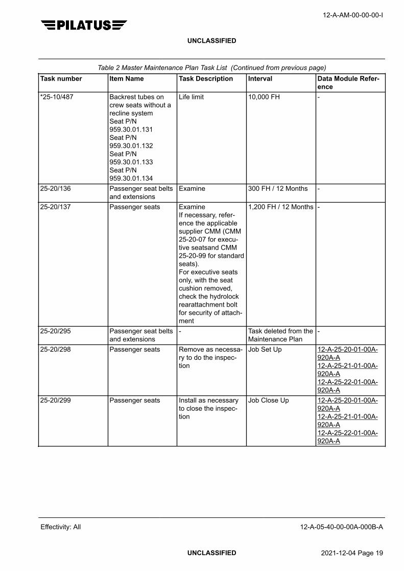
Table 2 Master Maintenance Plan Task List (Continued from previous page)Task number Item Name Task Description Interval Data Module Refer-
ence*25-10/487 Backrest tubes on
crew seats without arecline systemSeat P/N959.30.01.131Seat P/N959.30.01.132Seat P/N959.30.01.133Seat P/N959.30.01.134
Life limit 10,000 FH -
25-20/136 Passenger seat beltsand extensions
Examine 300 FH / 12 Months -
25-20/137 Passenger seats ExamineIf necessary, refer-ence the applicablesupplier CMM (CMM25-20-07 for execu-tive seatsand CMM25-20-99 for standardseats).For executive seatsonly, with the seatcushion removed,check the hydrolockrearattachment boltfor security of attach-ment
1,200 FH / 12 Months -
25-20/295 Passenger seat beltsand extensions
- Task deleted from theMaintenance Plan
-
25-20/298 Passenger seats Remove as necessa-ry to do the inspec-tion
Job Set Up 12-A-25-20-01-00A-920A-A12-A-25-21-01-00A-920A-A12-A-25-22-01-00A-920A-A
25-20/299 Passenger seats Install as necessaryto close the inspec-tion
Job Close Up 12-A-25-20-01-00A-920A-A12-A-25-21-01-00A-920A-A12-A-25-22-01-00A-920A-A
12-A-AM-00-00-00-I
UNCLASSIFIED
Effectivity: All 12-A-05-40-00-00A-000B-A
UNCLASSIFIED 2021-12-04 Page 19

Table 2 Master Maintenance Plan Task List (Continued from previous page)Task number Item Name Task Description Interval Data Module Refer-
ence25-20/302 Passenger seats Examine as far as
possible with seatsinstalled. Move therecline mechanismand swivel function(executive seat only)through its full motionand check for correctoperation. If necessa-ry, refer to the appli-cable supplier CMM(CMM 25-20-07 forexecutive seats andCMM 25-20-99 forstandard seats)
300 FH -
25-60/231 ELT Operational test 300 FH / 12 Months 12-A-25-63-00-00A-903A-Aor 12-A-25-63-10-00A-903A-Aor 12-A-25-63-20-00A-903A-Aor 12-A-25-63-30-00A-903A-A
25-60/232 ELT installation Examine 1,200 FH / 12 Months -25-60/483 ELT, Kannad 121
AF and Kannad 406AF (with and withoutNavigation interfaceunit)
Local regulation canrequire additionalELT periodic inspec-tions
Refer to local regula-tions. Refer to Kan-nad Service Letter,Maintenance Policyfor Kannad ELT (SLS18XX50X-25-02)
-
25-63/23 ELT battery Discard After 1 hour of use oras shown on the bat-tery label
-
25-63/434 ELT Nav interfaceunit serial memorymodule (if Kannad406 AF Nav interfaceunit installed)
Discard 16,000 FH /120 Months
NoteUnits which have al-ready operated morethan the allowed in-terval must be re-placed within 500flying hours or 6months, whichevercomes first
-
12-A-AM-00-00-00-I
UNCLASSIFIED
Effectivity: All 12-A-05-40-00-00A-000B-A
UNCLASSIFIED 2021-12-04 Page 20

Table 2 Master Maintenance Plan Task List (Continued from previous page)Task number Item Name Task Description Interval Data Module Refer-
ence*26-20/2 Fire extinguisher
(except ModelP3APP003010D)
Life limit 120 Months(elapsed)
-
26-20/24 Fire extinguisher(except ModelP3APP003010D)
Content check 12 Months(elapsed)
-
26-20/515 Fire extinguish-er (ModelP3APP003010D)
Content check 24 Months(elapsed)
-
*26-20/516 Fire extinguish-er (ModelP3APP003010D)
Life limit 144 Months(elapsed)
-
27-00/71 Flight control cablesincluding auto pilotand stick pusher ca-bles
Inspection/check 4,800 FH / 60 Months 12-A-27-00-00-00A-313A-A
27-00/138 Aileron, elevator andrudder controls
Operate, make surefull and free travel
300 FH -
27-00/402 Bonding leads to allflight control surfaces
Examine Threshold32,500 FH /42,000 LDGRepeat12,500 FH /15,000 LDG / 6 Year
-
27-10/139 Aileron LH and RH Examine and lubri-cate the trim hingeswith minimum quanti-ty of CPC (P10-001)
300 FH / 12 Months -
27-10/234 Aileron LH and RHrods and levers
ExamineSpray PTFE TeflonSpray OKS 571 (orequivalent) aroundthe aileron pushrodguide roller sleevesat all three locationsin each wing
1,200 FH / 12 Months -
27-10/235 Aileron electricalbonding straps
Examine 1,200 FH / 12 Months -
27-10/236 Aileron control sys-tem
Inspection/check 1,200 FH / 12 Months 12-A-27-10-00-00A-313A-A
27-10/237 Aileron cable tension Check 1,200 FH / 12 Months MSN 101-683 12-A-27-10-00-00A-903A-AMSN 684-999 12-A-27-10-00-00A-903B-A
12-A-AM-00-00-00-I
UNCLASSIFIED
Effectivity: All 12-A-05-40-00-00A-000B-A
UNCLASSIFIED 2021-12-04 Page 21
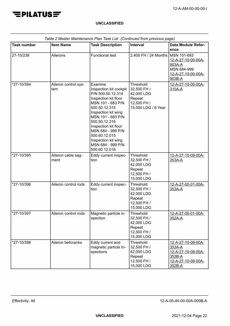
Table 2 Master Maintenance Plan Task List (Continued from previous page)Task number Item Name Task Description Interval Data Module Refer-
ence27-10/238 Ailerons Functional test 2,400 FH / 24 Months MSN 101-683
12-A-27-10-00-00A-903A-AMSN 684-999 12-A-27-10-00-00A-903B-A
*27-10/394 Aileron control sys-tem
ExamineInspection kit cockpitP/N 500.50.12.314Inspection kit floorMSN 101 - 683 P/N500.50.12.315Inspection kit wingMSN 101 - 683 P/N500.50.12.316Inspection kit floorMSN 684 - 999 P/N500.60.12.015Inspection kit wingMSN 684 - 999 P/N500.60.12.016
Threshold32,500 FH /42,000 LDGRepeat12,500 FH /15,000 LDG / 6 Year
12-A-27-10-00-00A-310A-A
*27-10/395 Aileron cable seg-ment
Eddy current inspec-tion
Threshold32,500 FH /42,000 LDGRepeat12,500 FH /15,000 LDG
12-A-27-10-09-00A-353A-A
*27-10/396 Aileron control rods Eddy current inspec-tion
Threshold32,500 FH /42,000 LDGRepeat12,500 FH /15,000 LDG
12-A-27-00-01-00A-353A-A
*27-10/397 Aileron control rods Magnetic particle in-spection
Threshold32,500 FH /42,000 LDGRepeat12,500 FH /15,000 LDG
12-A-27-00-01-00A-352A-A
*27-10/398 Aileron bellcranks Eddy current andmagnetic particle In-spections
Threshold32,500 FH /42,000 LDGRepeat12,500 FH /15,000 LDG
12-A-27-10-08-00A-353A-A12-A-27-10-08-00A-353B-A12-A-27-10-08-00A-352B-A
12-A-AM-00-00-00-I
UNCLASSIFIED
Effectivity: All 12-A-05-40-00-00A-000B-A
UNCLASSIFIED 2021-12-04 Page 22

Table 2 Master Maintenance Plan Task List (Continued from previous page)Task number Item Name Task Description Interval Data Module Refer-
ence*27-10/400 Aileron hinge points Eddy current inspec-
tionThreshold32,500 FH /42,000 LDGRepeat12,500 FH /15,000 LDG
12-A-57-60-06-00A-353A-A
*27-10/444 Flight control cables,aileron
Life limit 20,000 FH /27,000 LDG
-
*27-10/445 Autopilot control ca-ble, aileron
Life limit 20,000 FH /27,000 LDG
-
27-10/470 Aileron control sys-tem bearings
Lubricate 1,200 FH / 12 Months 12-A-27-10-00-00A-901A-A
27-15/239 Aileron trim Functional test 2,400 FH / 24 Months MSN 101-683 12-A-27-15-00-00A-903A-AMSN 684-999 12-A-27-15-00-00A-903B-A
27-20/140 Rudder Inspection/check 300 FH / 12 Months 12-A-55-40-00-00A-313A-A
27-20/240 Rudder static dis-chargers
Examine 2,400 FH / 24 Months -
27-20/241 Rudder control sys-tem
Inspection/check 1,200 FH / 12 Months 12-A-27-20-00-00A-313A-A
27-20/242 Aileron/rudder inter-connect system,MSN 101-683
Make sure the lock-ing mechanism isfully engaged withthe flaps at 40° andthe moving parts (pis-ton and housing) arelubricated. If neces-sary apply grease(P04-002) with abrush.Retract the flaps to0° and make sure thelocking mechanism isfully disengaged.
1,200 FH / 12 Months -
27-20/243 Rudder cable tension Check 1,200 FH / 12 Months 12-A-27-20-00-00A-903A-A12-A-27-20-00-00A-903B-A
27-20/244 Rudder Functional test 2,400 FH / 24 Months 12-A-27-20-00-00A-903A-A12-A-27-20-00-00A-903B-A
12-A-AM-00-00-00-I
UNCLASSIFIED
Effectivity: All 12-A-05-40-00-00A-000B-A
UNCLASSIFIED 2021-12-04 Page 23

Table 2 Master Maintenance Plan Task List (Continued from previous page)Task number Item Name Task Description Interval Data Module Refer-
ence27-20/245 Rudder trim Functional test 2,400 FH / 24 Months 12-A-27-25-00-00A-
903A-A27-20/246 Rudder electrical
bonding strapsExamine 1,200 FH / 12 Months -
*27-20/374 Rudder control sys-tem
ExamineInspection kit rud-der control P/N500.60.12.018
Threshold32,500 FH /42,000 LDGRepeat12,500 FH /15,000 LDG / 6 Year
12-A-27-20-00-00A-310A-A
*27-20/375 Rudder bellcrank Task deleted fromthe Scheduled Main-tenance Plan
- -
*27-20/376 Rudder cable quad-rant shear spigot
Examine Threshold32,500 FH /42,000 LDGRepeat12,500 FH /15,000 LDG / 6 Year
12-A-27-20-05-00A-310A-A
27-20/431 Rudder control ca-bles tension
Check after replace-ment of any ruddercontrol system cables(autopilot, and/or rud-der)
At the next scheduledinspection, but notlater than 300 FH
12-A-27-20-00-00A-903A-A
*27-20/446 Flight control cables,rudder
Life limit 20,000 FH /27,000 LDG
-
*27-20/447 Autopilot control ca-bles, rudder
Life limit 20,000 FH /27,000 LDG
-
*27-20/575 Rudder bellcrank Life limit 20,000 FH /27,000 LDGSee Note 4
-
27-30/141 Elevators Examine 300 FH / 12 Months -27-30/247 Elevator electrical
bonding strapsExamine 1,200 FH / 12 Months -
27-30/248 Elevator static dis-chargers
Examine 2,400 FH / 24 Months -
27-30/249 Elevator control sys-tem
Inspection/check 1,200 FH / 12 Months 12-A-27-30-00-00A-313A-A
27-30/250 Elevator cable ten-sion
Check 1,200 FH / 12 Months 12-A-27-30-00-00A-903A-A
27-30/251 Elevator Functional test 2,400 FH / 24 Months 12-A-27-30-00-00A-903A-A
12-A-AM-00-00-00-I
UNCLASSIFIED
Effectivity: All 12-A-05-40-00-00A-000B-A
UNCLASSIFIED 2021-12-04 Page 24

Table 2 Master Maintenance Plan Task List (Continued from previous page)Task number Item Name Task Description Interval Data Module Refer-
ence27-30/334 Elevator control ca-
bles tensionCheck after replace-ment of any elevatorcontrol system cables(autopilot, stick push-er and elevator)
At the next scheduledinspection, but notlater than 300 FH
12-A-27-30-00-00A-903A-A
*27-30/363 Elevator control sys-tem
ExamineInspection kit ele-vator control P/N500.60.12.019
Threshold32,500 FH /42,000 LDGRepeat12,500 FH /15,000 LDG / 6 Year
12-A-27-30-00-00A-310A-A
*27-30/364 Elevator control rods Eddy current inspec-tion
Threshold32,500 FH /42,000 LDGRepeat12,500 FH /15,000 LDG
12-A-27-00-01-00A-353A-A
*27-30/365 Elevator control rods Magnetic particle in-spection
Threshold32,500 FH /42,000 LDGRepeat12,500 FH /15,000 LDG
12-A-27-00-01-00A-352A-A
*27-30/366 Elevator control lever Eddy current inspec-tion
Threshold32,500 FH /42,000 LDGRepeat12,500 FH /15,000 LDG
12-A-27-30-05-00A-353A-A
*27-30/448 Flight control cables,elevator
Life limit 20,000 FH /27,000 LDG
-
*27-30/449 Autopilot control ca-bles, elevator
Life limit 20,000 FH /27,000 LDG
-
*27-30/450 Stick pusher cables Life limit 20,000 FH /27,000 LDG
-
27-30/514 Elevator stops Examine. If foundmissing, loose ordamaged, install anew or repair thestops.
1,200 FH / 12 Months 12-A-55-20-01-00A-904B-A
*27-40/1 Horizontal stabilizertrim
Functional test oftrim runaway auralwarning system (FAACMR)
3,000 FH / 12 MonthsSee Note 2
12-A-27-40-00-00A-903A-A
*27-40/3 Pitch trim actuator Life limit 20,000 FH /27,000 LDG
-
12-A-AM-00-00-00-I
UNCLASSIFIED
Effectivity: All 12-A-05-40-00-00A-000B-A
UNCLASSIFIED 2021-12-04 Page 25

Table 2 Master Maintenance Plan Task List (Continued from previous page)Task number Item Name Task Description Interval Data Module Refer-
ence*27-40/25 Pitch trim actuator
(P/N 978.73.14.201)Overhaul 1,500 FH -
*27-40/26 Pitch trim actuator(P/N 978.73.14.202and 978.73.14.203)
Overhaul 5000 FH or 5 Yearsor4200 FH or 6 Yearsor3400 FH or 7 Years
-
27-40/142 Horizontal stabilizertrim interrupt and al-ternate trim switches
Operational test 300 FH / 12 Months 12-A-27-40-00-00A-903A-A
27-40/252 Pitch trim actuatorand attachments
Inspection/check 1,200 FH / 12 Months 12-A-27-40-01-00A-313A-A
27-40/291 Horizontal stabilizertrim system
Operational test 300 FH 12-A-27-40-00-00A-903A-A
27-40/292 Horizontal stabilizertrim system
Functional test 1,200 FH / 12 Months 12-A-27-40-00-00A-903A-A
*27-40/307 Pitch trim actuator at-tachment parts, failsafe plates andtheir attachment parts(IPD 12-20-00-07)
Life limitFail safe plate remov-al/installation
10,000 FH 12-A-27-40-02-00A-920A-A
*27-50/4 Flap actuators(black anodized)(P/N 978.73.20.307,978.73.20.308,978.73.20.309)
Life limit 20,000 FH /27,000 LDG
-
27-50/27 Flap power drive unit(P/N 978.73.20.001and 002)
Discard 4500 FH since new,or last overhaul
-
27-50/28 Flap power drive unit(P/N 978.73.20.003)
Overhaul 10,000 FH /13,500 LDG
-
27-50/29 Flap actuators(white colored) (P/N978.73.20.302, 303,304, 305 and 306)
Discard 4,500 FH -
27-50/30 Flap actuators(black anodized)(P/N 978.73.20.307,978.73.20.308,978.73.20.309)
Overhaul 5,000 FH /7,000 LDG
-
27-50/31 Flap flexibledrive shafts (P/N945.02.02.203, 204,205 and 206)
Discard 10,000 FH /13,500 LDG
-
12-A-AM-00-00-00-I
UNCLASSIFIED
Effectivity: All 12-A-05-40-00-00A-000B-A
UNCLASSIFIED 2021-12-04 Page 26

Table 2 Master Maintenance Plan Task List (Continued from previous page)Task number Item Name Task Description Interval Data Module Refer-
ence27-50/72 Flap flexible drive
shafts (Post SB27-003) (P/N945.02.02.201 and202)
Remove, clean, in-spect and lubricateinner core
2,000 FH 12-A-27-50-00-00A-902A-A
27-50/73 Flap actuators(white colored) (P/N978.73.20.302, 303,304, 305 and 306)
Lubricate 300 FH / 12 Months 12-A-27-50-00-00A-902A-A
27-50/74 Flap actuators(black anodized)(P/N 978.73.20.307,978.73.20.308,978.73.20.309)
Lubricate 300 FH / 12 Months 12-A-27-50-00-00A-902A-A
27-50/75 Flap actuators(white colored) (P/N978.73.20.302, 303,304, 305 and 306)
Backlash check 600 FH / 800 LDG /12 Months
12-A-27-50-03-00A-313A-A
27-50/76 Flap actuators(black anodized)(P/N 978.73.20.307,978.73.20.308,978.73.20.309)
Backlash check 2,400 FH /3,200 LDG /24 Months
12-A-27-50-03-00A-313B-A
27-50/77 Flap electrical system(MSN 101-400 PreSB 27-013)
Do the flap electricalsystem maintenancepractices tests
300 FH 12-A-27-50-00-00A-901A-A
27-50/143 Flaps Lower to 40° as nec-essary to do the in-spection
Job Set Up -
27-50/144 Flaps and flap sup-port mechanism
Examine 300 FH / 12 Months -
27-50/253 Flaps electrical bond-ing straps
Examine 1,200 FH / 12 Months -
27-50/254 Flap motor, actuatorsand flexible driveshafts
Examine 1,200 FH / 12 Months -
27-50/255 Flaps Functional test andasymmetry monitortest
1,200 FH / 12 Months Pre SB 27-01312-A-27-50-00-00A-903A-APost SB 27-013 andMSN 401-99912-A-27-50-00-00A-903B-A
12-A-AM-00-00-00-I
UNCLASSIFIED
Effectivity: All 12-A-05-40-00-00A-000B-A
UNCLASSIFIED 2021-12-04 Page 27

Table 2 Master Maintenance Plan Task List (Continued from previous page)Task number Item Name Task Description Interval Data Module Refer-
ence*27-50/386 Flap mechanism Examine
Inspection kit flapLH inner P/N500.60.12.021Inspection kit flapRH inner P/N500.60.12.022Inspection kit flapLH center P/N500.60.12.023Inspection kit flapRH center P/N500.60.12.024Inspection kit flap LHand RH outer (onekit required for each)P/N 500.60.12.025
Threshold30,000 FH /39,000 LDGRepeat10,000 FH /12,000 LDG / 6 Year
12-A-27-51-00-00A-310A-A
*27-50/387 Flap drive arm (notremoved)
Eddy current inspec-tion
Threshold25,000 FH /30,000 LDGRepeat2,500 FH /3,000 LDG
12-A-27-51-00-00A-353A-A
*27-50/388 Flap drive arm (re-moved)
Eddy current inspec-tion
Threshold30,000 FH /39,000 LDGRepeat10,000 FH /12,000 LDG
12-A-27-51-01-00A-353A-Aor 12-A-27-51-02-00A-353A-Aor 12-A-27-51-03-00A-353A-A
*27-50/389 Flap support arm Eddy current inspec-tion
Threshold30,000 FH /39,000 LDGRepeat10,000 FH /12,000 LDG
12-A-27-51-01-00A-353A-Aor 12-A-27-51-02-00A-353A-Aor 12-A-27-51-03-00A-353A-A
*27-50/390 Flap cove rib fittings Eddy current inspec-tion
Threshold30,000 FH /39,000 LDGRepeat10,000 FH /12,000 LDG
12-A-27-51-01-00A-353A-Aor 12-A-27-51-02-00A-353A-Aor 12-A-27-51-03-00A-353A-A
12-A-AM-00-00-00-I
UNCLASSIFIED
Effectivity: All 12-A-05-40-00-00A-000B-A
UNCLASSIFIED 2021-12-04 Page 28

Table 2 Master Maintenance Plan Task List (Continued from previous page)Task number Item Name Task Description Interval Data Module Refer-
ence*27-50/391 Flap aft links Eddy current inspec-
tionThreshold30,000 FH /39,000 LDGRepeat10,000 FH /12,000 LDG
12-A-27-51-01-00A-353A-Aor 12-A-27-51-02-00A-353A-Aor 12-A-27-51-03-00A-353A-A
*27-50/392 Flap bellcranks Eddy current inspec-tion
Threshold30,000 FH /39,000 LDGRepeat10,000 FH /12,000 LDG
12-A-27-51-01-00A-353A-Aor 12-A-27-51-02-00A-353A-Aor 12-A-27-51-03-00A-353A-A
*27-50/414 Flaps Life limit 25,000 FH /30,000 LDG
-
*27-50/437 Inboard flapdrive arms (P/N527.52.12.153 or P/N527.52.12.154)
In-situ inspec-tion/check
600 FH / 12 MonthsSee Note 3
12-A-27-51-00-00A-313A-A
27-50/443 Flap up and downlimit switches
Servicing 300 FH / 12 Months 12-A-12-20-07-00A-902A-A
*27-50/451 Flap tension rods(P/N 527.52.12.135,527.52.12.136,527.52.12.137)
Life limit 20,000 FH /27,000 LDG
-
27-50/475 Flaps Retract to 0° as nec-essary to close theinspection
Job Close Up -
28-10/145 Fuel tank filler caps Examine 300 FH / 12 Months -28-10/146 Fuel Remove a sample
from each drain valveand examine for wa-ter
300 FH / 12 Months -
28-10/306 Fuel cross vent andoutward check valve
Operational test 2,400 FH 12-A-28-10-01-00A-903A-A
28-20/32 Engine driven pump Overhaul 3,500 FH -28-20/147 Fuel tank vent valve
and flame arrestorOperational test 300 FH / 12 Months 12-A-28-20-07-00A-
903A-A28-20/148 Fuel filter element Remove and clean 300 FH / 12 Months 12-A-28-20-01-00A-
920A-Aand 12-A-28-20-01-00A-250A-A
12-A-AM-00-00-00-I
UNCLASSIFIED
Effectivity: All 12-A-05-40-00-00A-000B-A
UNCLASSIFIED 2021-12-04 Page 29

Table 2 Master Maintenance Plan Task List (Continued from previous page)Task number Item Name Task Description Interval Data Module Refer-
ence28-20/149 Firewall shutoff valve Operate FUEL
EMERG SHUTOFFlever and make surefirewall shutoff valveopens and closesfully to each deadstop. Make suremovement is free andcheck if initial pull outforce at lever outerend is below 44.5 N(10 lbf)
600 FH / 12 Months -
28-20/150 Engine driven pump Examine 300 FH / 12 Months -28-20/256 Fuel system compo-
nentsExamine as faras possible withthose access panelsopened/removed inthis inspection pack-age.
2,400 FH / 24 Months -
28-40/78 Fuel low level warn-ing system
Operational test 1,200 FH / 48 Months MSN 101-105 12-A-28-40-00-00A-903A-AMSN 106-999 12-A-28-40-00-00A-903B-A
29-10/151 Return line filter dif-ferential pressure in-dicator
Make sure that it hasnot come out. If indi-cator found out, dothe inspection/checkprocedure.
600 FH / 12 Months 12-A-29-10-04-00A-313A-A
29-10/152 Hydraulic system MSN 101-230. Checkfluid sensor and lev-el using maintenanceswitch box. Fill asnecessary.MSN 231-999. Makesure fluid level indica-tor on the reservoirtank shows full. Fillas necessary.
300 FH / 12 Months MSN 101-230 12-A-29-00-00-00A-902A-AMSN 231-999 12-A-29-00-00-00A-902B-A
29-10/153 Reservoir tank Make sure nitrogenpressure is correct.Pressurize as neces-sary
300 FH / 12 Months MSN 101-230 (If in-stalled) 12-A-29-00-00-00A-902A-AMSN 231-999 (If in-stalled) 12-A-29-00-00-00A-902B-A
12-A-AM-00-00-00-I
UNCLASSIFIED
Effectivity: All 12-A-05-40-00-00A-000B-A
UNCLASSIFIED 2021-12-04 Page 30

Table 2 Master Maintenance Plan Task List (Continued from previous page)Task number Item Name Task Description Interval Data Module Refer-
ence29-10/257 Power pack Examine, specially
for leaks and crackson the end platesand where motor isattached
1,200 FH / 12 Months -
29-10/258 Nitrogen accumulator(P/N 960.30.01.291)
Check nitrogen pres-sure and fill as nec-essary
1,200 FH / 12 Months 12-A-29-10-02-00A-901A-A
29-10/259 Power pack electricmotor shaft seal drainfluid collector bottle(Post SB 29-002 andMSN 181-999)
Remove, clean andreinstall
1,200 FH / 12 Months -
*29-10/418 Nitrogen accumulator Life limit 25,000 FH /30,000 LDG
-
29-10/471 Nitrogen accumulator(P/N 960.30.01.292)
Check nitrogen pres-sure and fill as nec-essary
2,400 FH / 24 Months 12-A-29-10-02-00A-901A-A
30-10/79 Airfoil de-icers Apply a surface coat-ing of Age MasterNo. 1 in accordancewith the manufactur-ers instructions CMM30-10-31 (latest is-sue)
NoteThe deice boot treat-ment with Age Mas-ter No 1 can beperformed by the op-erator IAW the in-structions given inthe AFM §8 DeicingBoot Care
6 Months -
30-10/154 Wing and horizontalstabilizer airfoil de-iceboots
Inspection/check 300 FH / 12 Months 12-A-30-10-00-00A-313A-A
30-10/155 Inertial separationsystem
Operational test 600 FH / 12 Months MSN 101-320 and322-400 12-A-30-20-00-00A-903B-AMSN 321 and401-999 12-A-30-20-00-00A-903A-A
30-10/260 Airfoil de-ice system Functional test 1,200 FH / 12 Months 12-A-30-10-00-00A-903A-A
12-A-AM-00-00-00-I
UNCLASSIFIED
Effectivity: All 12-A-05-40-00-00A-000B-A
UNCLASSIFIED 2021-12-04 Page 31

Table 2 Master Maintenance Plan Task List (Continued from previous page)Task number Item Name Task Description Interval Data Module Refer-
ence30-20/156 Engine air intake de-
ice lipExamine and look forsigns of gas leaks -none are permitted
300 FH / 12 Months -
30-20/261 Air by-pass door andoperating mechanism
Examine and lubri-cate with minimumquantity of CPC(P10-001)
1,200 FH / 12 Months -
30-30/157 Probes de-ice system Operational test 600 FH / 12 Months Single system 12-A-30-30-10-00A-903A-ADual system and pitotstatic fail indicator 12-A-30-30-20-00A-903A-AMSN 321 and401-999 12-A-30-30-20-00A-903B-A
30-40/262 Windshield de-icesystem
Operational test 2,400 FH / 24 Months 12-A-30-40-00-00A-903A-Aor 12-A-30-40-00-00A-903B-A
30-60/158 Propeller de-ice sys-tem
Inspection/check 600 FH / 12 Months 12-A-30-60-00-00A-313A-A
30-60/159 Propeller de-ice sys-tem
Operational test 600 FH / 12 Months 12-A-30-60-00-00A-903A-Aor 12-A-30-60-00-00A-903B-A
31-50/34 CAWS CACU clockbattery, MSN 321 and401-999
Discard 24 Months -
32-10/80 Main and nose wheelbearings
Lubricate Tire change or 12Months whichevercomes first
12-A-12-20-06-00A-902A-A
32-10/81 Main landing gearhinge pin and bush-es (PC-12/45 andPC-12/47 aircraft)
Inspection/check 2,400 FH / 12 Months 12-A-32-10-00-00A-313A-A
32-10/162 Main landing gear Lubricate 600 FH / 12 Months 12-A-12-20-04-00A-902A-A
32-10/163 Main landing gearlegs
Examine 600 FH / 12 Months -
32-10/164 Main landing gearcompartments
Examine 600 FH / 12 Months -
12-A-AM-00-00-00-I
UNCLASSIFIED
Effectivity: All 12-A-05-40-00-00A-000B-A
UNCLASSIFIED 2021-12-04 Page 32

Table 2 Master Maintenance Plan Task List (Continued from previous page)Task number Item Name Task Description Interval Data Module Refer-
ence32-10/165 Main landing gear
shock strutsCheck nitrogen pres-sure
600 FH / 12 Months 12-A-32-10-00-00A-902A-A
32-10/263 Main landing gearelectrical bondingstraps
Examine 1,200 FH / 12 Months -
32-10/264 Main landing gear leftand right axle bolt(Pre SB 32-006)
Remove and exam-ine. Replace if dam-aged. Install a serv-iceable bolt
600 FH / 12 Months -
*32-10/346 MLG Yoke fitting Overhaul and eddycurrent inspection,CMM 02099
Threshold25,000 FH /30,000 LDGRepeat8,300 FH /10,000 LDG / 6 Year
-
*32-10/347 MLG Trailing Link Overhaul and eddycurrent inspection,CMM 02099
Threshold25,000 FH /30,000 LDGRepeat8,300 FH /10,000 LDG / 6 Year
-
*32-10/436 Main landing gearshock absorber topand bottom attach-ment bolts and nuts
Examine 12 MonthsSee Note 2
12-A-32-10-00-00A-310A-A
*32-10/438 Main landing gear legforward attachmentbolt and bush andrear attachment boltand nut
Examine 6 YearSee Note 5
12-A-32-10-00-00A-310A-A
32-20/166 Nose landing gearshock strut
Check nitrogen pres-sure
600 FH / 12 Months 12-A-32-20-00-00A-902A-A
32-20/167 Nose landing gear Lubricate 600 FH / 12 Months 12-A-12-20-04-00A-902A-A
32-20/168 Nose landing gearleg and steeringmechanism
Examine, in particularthe steering rod end(P/N 532.20.12.134)for the complete re-tention of bearing intothe steering rod endhousing.
600 FH / 12 Months -
32-20/169 Nose landing gearcompartment
Examine 600 FH / 12 Months -
32-20/265 Nose landing gearelectrical bondingstraps
Examine 1,200 FH / 12 Months -
12-A-AM-00-00-00-I
UNCLASSIFIED
Effectivity: All 12-A-05-40-00-00A-000B-A
UNCLASSIFIED 2021-12-04 Page 33

Table 2 Master Maintenance Plan Task List (Continued from previous page)Task number Item Name Task Description Interval Data Module Refer-
ence32-20/266 Nose landing gear
spring strut (P/N532.20.12.250)
Remove, clean andlubricate
1,200 FH / 12 Months 12-A-32-20-03-00A-920A-Aand 12-A-32-20-03-00A-250A-A
32-20/305 Nose landing gearactuator fuselage at-tachment fitting (P/N553.10.12.326)
Examine, if cracksare found replace at-tachment fitting
1,200 FH / 12 Months SRM 12-A-53-00-01-00A-663A-A
*32-20/335 NLG torque tube (P/N532.50.12.047)
Life limit 11,000 FH /15,000 LDG /10 Years
-
*32-20/336 NLG upper draglink right part (P/N532.20.12.289 or532.20.12.140)
Inspection/check Initially 2000 FH or2500 landings, thenevery 300 FH or 400landings
12-A-32-20-06-00A-313A-A
32-20/403 NLG OverhaulCMM 02100Parts kit P/N500.60.12.029
Threshold25,000 FH /30,000 LDGRepeat8,300 FH /10,000 LDG / 6 Year
-
*32-20/416 NLG upper right handdrag link (except forP/N 532.20.12.140)
Life limit 25,000 FH /30,000 LDG
-
*32-20/532 NLG upper draglink right part (P/N532.20.12.289 or532.20.12.140)
Life limit 4,000 LDG -
32-30/170 Extension and retrac-tion system (Hydraul-ic landing gear)
Functional test of ex-tension and retractionsystem and emergen-cy extension system
1,200 FH / 12 Months 12-A-32-30-00-00A-903A-A
*32-30/417 MLG hydraulic actua-tor
Life limit 25,000 FH /30,000 LDG
-
*32-30/442 Main landing gear ac-tuator top and bottomattachment bolts andnuts
Examine 6 YearsSee Note 5
12-A-32-10-00-00A-310A-A
*32-30/518 Main landing gearactuator bottom at-tachment bolts P/N532.10.12.218 (iden-tified with .218 andVLG on bolt head)
Life limit 60 MonthsSee Note 6
-
12-A-AM-00-00-00-I
UNCLASSIFIED
Effectivity: All 12-A-05-40-00-00A-000B-A
UNCLASSIFIED 2021-12-04 Page 34

Table 2 Master Maintenance Plan Task List (Continued from previous page)Task number Item Name Task Description Interval Data Module Refer-
ence32-40/171 Main wheels Examine. Rotate
wheels, make surebearing movement issmooth and free andno excessive play ex-ists
600 FH / 12 Months -
32-40/172 Main wheel tires Examine and checktire pressure
300 FH / 12 Months 12-A-12-10-04-00A-902A-A
32-40/173 Nose wheel Examine. Rotatewheel, make surebearing movement issmooth and free andno excessive play ex-ists
600 FH / 12 Months -
32-40/174 Nose wheel tire Examine and checktire pressure
300 FH / 12 Months 12-A-12-10-04-00A-902A-A
32-40/175 Brake system Apply the parkingbrake. Examine thebrake units. Makesure that pad wearindicators protrudefrom housing.
300 FH / 12 Months -
32-40/176 Fluid reservoir Check and replenish,if necessary
300 FH / 12 Months 12-A-12-10-02-00A-902A-A
32-50/404 NLG steering mecha-nism
Examine Threshold32,500 FH /42,000 LDGRepeat8,300 FH /10,000 LDG / 6 Year
12-A-32-50-00-00A-310A-A
33-40/177 Exterior lighting Operational test 300 FH / 12 Months MSN 101-320 and322-400 12-A-33-40-00-00A-903A-AMSN 321 and401-999 12-A-33-40-00-00A-903B-A
33-41/178 Landing lights Examine 300 FH / 12 Months -33-42/179 Taxi lights Examine 300 FH / 12 Months -33-43/180 Navigation and
strobe lightsExamine 300 FH / 12 Months -
33-44/181 Recognition lights (ifinstalled)
Examine 300 FH / 12 Months -
33-46/182 Beacon lights (if in-stalled)
Examine 300 FH / 12 Months -
12-A-AM-00-00-00-I
UNCLASSIFIED
Effectivity: All 12-A-05-40-00-00A-000B-A
UNCLASSIFIED 2021-12-04 Page 35

Table 2 Master Maintenance Plan Task List (Continued from previous page)Task number Item Name Task Description Interval Data Module Refer-
ence34-00/183 Communications and
navigation antennasExamine 2,400 FH / 24 Months -
34-00/184 Cockpit instrumentsand avionic equip-ment
Examine 300 FH / 12 Months -
34-11/82 Pitot and static sys-tem
Leak check 24 Months Single system 12-A-34-11-10-00A-903A-ADual system 12-A-34-11-20-00A-903A-A
34-11/185 Pitot tube Examine 300 FH / 12 Months -34-11/186 Static ports Examine 300 FH / 12 Months -34-11/268 Pitot and static sys-
temDrain 1,200 FH / 12 Months Single system
12-A-34-11-10-00A-901A-ADual system 12-A-34-11-20-00A-901A-A
34-14/83 Altimeter Check calibration atan approved centerin accordance withthe regulation in force(Ref. FAR Part 91411)
24 Months -
34-21/84 Standby magneticcompass
Check swing 24 Months 12-A-34-21-00-00A-903A-A
34-25/85 Attitude HeadingReference System(AHRS)
Check swing 24 Months 12-A-34-25-00-00A-903A-A
34-54/86 Transponder system(single and dual sys-tems)
Functional test 24 Months 12-A-34-54-00-00A-903A-Aor 12-A-34-54-00-00A-903B-A
*35-10/6 Oxygen bottle Life limit 180 Months(elapsed)
-
12-A-AM-00-00-00-I
UNCLASSIFIED
Effectivity: All 12-A-05-40-00-00A-000B-A
UNCLASSIFIED 2021-12-04 Page 36
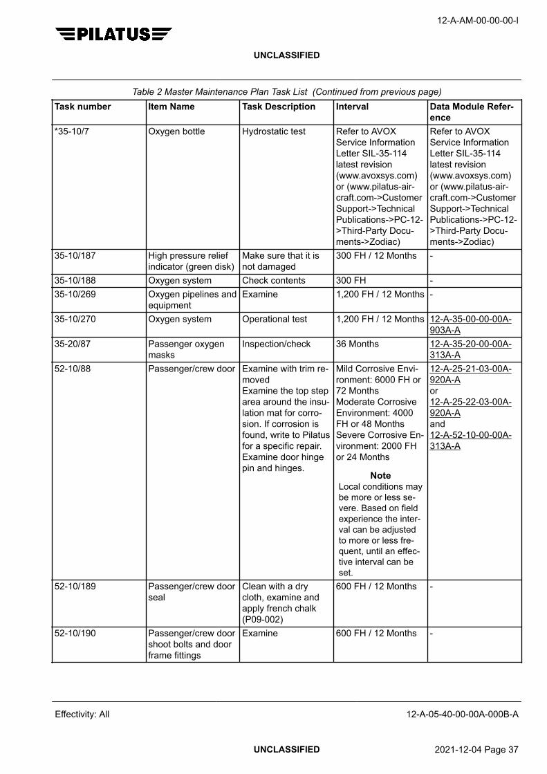
Table 2 Master Maintenance Plan Task List (Continued from previous page)Task number Item Name Task Description Interval Data Module Refer-
ence*35-10/7 Oxygen bottle Hydrostatic test Refer to AVOX
Service InformationLetter SIL-35-114latest revision(www.avoxsys.com)or (www.pilatus-air-craft.com->CustomerSupport->TechnicalPublications->PC-12->Third-Party Docu-ments->Zodiac)
Refer to AVOXService InformationLetter SIL-35-114latest revision(www.avoxsys.com)or (www.pilatus-air-craft.com->CustomerSupport->TechnicalPublications->PC-12->Third-Party Docu-ments->Zodiac)
35-10/187 High pressure reliefindicator (green disk)
Make sure that it isnot damaged
300 FH / 12 Months -
35-10/188 Oxygen system Check contents 300 FH -35-10/269 Oxygen pipelines and
equipmentExamine 1,200 FH / 12 Months -
35-10/270 Oxygen system Operational test 1,200 FH / 12 Months 12-A-35-00-00-00A-903A-A
35-20/87 Passenger oxygenmasks
Inspection/check 36 Months 12-A-35-20-00-00A-313A-A
52-10/88 Passenger/crew door Examine with trim re-movedExamine the top steparea around the insu-lation mat for corro-sion. If corrosion isfound, write to Pilatusfor a specific repair.Examine door hingepin and hinges.
Mild Corrosive Envi-ronment: 6000 FH or72 MonthsModerate CorrosiveEnvironment: 4000FH or 48 MonthsSevere Corrosive En-vironment: 2000 FHor 24 Months
NoteLocal conditions maybe more or less se-vere. Based on fieldexperience the inter-val can be adjustedto more or less fre-quent, until an effec-tive interval can beset.
12-A-25-21-03-00A-920A-Aor12-A-25-22-03-00A-920A-Aand12-A-52-10-00-00A-313A-A
52-10/189 Passenger/crew doorseal
Clean with a drycloth, examine andapply french chalk(P09-002)
600 FH / 12 Months -
52-10/190 Passenger/crew doorshoot bolts and doorframe fittings
Examine 600 FH / 12 Months -
12-A-AM-00-00-00-I
UNCLASSIFIED
Effectivity: All 12-A-05-40-00-00A-000B-A
UNCLASSIFIED 2021-12-04 Page 37

Table 2 Master Maintenance Plan Task List (Continued from previous page)Task number Item Name Task Description Interval Data Module Refer-
ence52-10/191 Passenger/crew door
handle lock pin andlatch
Make sure movementis free.Lubricate with CPC(P10-001) as neces-sary when operatingin freezing conditions.
600 FH / 12 Months -
52-10/192 Passenger/crew doorhinges
Examine and lubri-cate as necessarywith minimum quanti-ty of CPC (P10-001)
600 FH / 12 Months -
52-10/271 Passenger/crew door,counterbalance andcable support brack-ets
Examine 1,200 FH / 12 Months -
*52-10/348 Passenger/crew door Examine all structuralelements
Threshold32,500 FH /42,000 LDGRepeat12,500 FH /15,000 LDG / 6 Year
12-A-52-10-00-00A-310A-A
52-10/405 Passenger/crew doorpiano hinge
Eddy current inspec-tion
Threshold32,500 FH /42,000 LDGRepeat12,500 FH /15,000 LDG
12-A-52-00-01-00A-353A-A
52-10/406 Passenger/crew doorskin
Eddy current inspec-tion
Threshold25,000 FH /30,000 LDGRepeat12,500 FH /15,000 LDG / 6 Year
12-A-52-10-01-00A-353A-A
52-10/472 Passenger/crew doorshoot bolt fitting (onlyif SB 52–007 Part Cis done)
Eddy current inspec-tion
3,000 FH /3,600 LDG
12-A-52-10-06-00A-353A-A
52-20/272 Emergency door Examine (door re-moved)
1,200 FH / 12 Months -
52-20/273 Emergency door seal Clean with a wetcloth, dry and exam-ine and apply frenchchalk (P09-002)
1,200 FH / 12 Months -
*52-20/349 Emergency door Examine all structuralelements
Threshold32,500 FH /42,000 LDGRepeat12,500 FH /15,000 LDG / 6 Year
12-A-52-20-00-00A-310A-A
12-A-AM-00-00-00-I
UNCLASSIFIED
Effectivity: All 12-A-05-40-00-00A-000B-A
UNCLASSIFIED 2021-12-04 Page 38

Table 2 Master Maintenance Plan Task List (Continued from previous page)Task number Item Name Task Description Interval Data Module Refer-
ence*52-30/8 Cargo door lower lug
fittings (qty 3)Life limit 13,000 FH /
17,000 LDG-
52-30/89 Cargo door Examine with trim re-movedExamine door hingepin, hinges and thelock mechanism
Mild Corrosive Envi-ronment: 6000 FH or72 MonthsModerate CorrosiveEnvironment: 4000FH or 48 MonthsSevere Corrosive En-vironment: 2000 FHor 24 Months
NoteLocal conditions maybe more or less se-vere. Based on fieldexperience the inter-val can be adjustedto more or less fre-quent, until an effec-tive interval can beset.
12-A-25-21-03-00A-920A-Aor 12-A-25-22-03-00A-920A-Aand12-A-52-30-00-00A-313A-Aand12-A-52-30-00-00A-313A-A
52-30/193 Cargo door seal Clean with a drycloth, examine andapply french chalk(P09-002)
600 FH / 12 Months -
52-30/194 Cargo door shootbolts, door frame fit-tings and hooks
Examine. Make surethe hook roller bush-es are free to rotate.For roller bush wearlimits refer to AMM.
600 FH / 12 Months 12-A-52-30-00-00A-313A-A
52-30/195 Cargo door hinges Examine and lubri-cate as necessarywith minimum quanti-ty of CPC (P10-001)
600 FH / 12 Months -
52-30/274 Cargo door Examine 1,200 FH / 12 Months -*52-30/350 Cargo door Examine all structural
elementsThreshold32,500 FH /42,000 LDGRepeat12,500 FH /15,000 LDG / 6 Year
12-A-52-30-00-00A-310A-A
52-30/407 Cargo door pianohinge
Eddy current inspec-tion
Threshold32,500 FH /42,000 LDGRepeat12,500 FH /15,000 LDG
12-A-52-30-00-01A-353A-A
12-A-AM-00-00-00-I
UNCLASSIFIED
Effectivity: All 12-A-05-40-00-00A-000B-A
UNCLASSIFIED 2021-12-04 Page 39

Table 2 Master Maintenance Plan Task List (Continued from previous page)Task number Item Name Task Description Interval Data Module Refer-
ence52-30/408 Cargo door skin Eddy current inspec-
tionThreshold25,000 FH /30,000 LDGRepeat12,500 FH /15,000 LDG / 6 Year
12-A-52-30-01-00A-353A-A
52-70/275 Door warning system Operational test 1,200 FH / 12 Months 12-A-52-70-00-00A-903A-A
*53-00/9 Fuselage and associ-ated structure (PreSB 04-009)
Life limit 20,000 FH /27,000 LDGSee Note 1
-
53-00/90 Front pressure bulk-head
Examine with insu-lation on engineand cockpit sides re-moved. If insulationon cockpit side iswet, remove, dry andreinstall insulation.
Mild Corrosive Envi-ronment: 6000 FH or72 MonthsModerate CorrosiveEnvironment: 4000FH or 48 MonthsSevere Corrosive En-vironment: 2000 FHor 24 Months
NoteLocal conditions maybe more or less se-vere. Based on fieldexperience the inter-val can be adjustedto more or less fre-quent, until an effec-tive interval can beset.
-
12-A-AM-00-00-00-I
UNCLASSIFIED
Effectivity: All 12-A-05-40-00-00A-000B-A
UNCLASSIFIED 2021-12-04 Page 40

Table 2 Master Maintenance Plan Task List (Continued from previous page)Task number Item Name Task Description Interval Data Module Refer-
ence53-00/91 Fuselage internal bot-
tom surfaceExamine Frames 10,21, 24, 36 andframes adjacent todoors and to emer-gency exit, with insu-lation removed. If cor-rosion is found, ex-amine all fuselagebottom surface withinsulation removed. Ifinsulation is wet, re-move, dry and rein-stall insulation
Mild Corrosive Envi-ronment: 6000 FH or72 MonthsModerate CorrosiveEnvironment: 4000FH or 48 MonthsSevere Corrosive En-vironment: 2000 FHor 24 Months
NoteLocal conditions maybe more or less se-vere. Based on fieldexperience the inter-val can be adjustedto more or less fre-quent, until an effec-tive interval can beset.
-
53-00/92 Rear pressure bulk-head
Examine with trim re-moved
Mild Corrosive Envi-ronment: 6000 FH or72 MonthsModerate CorrosiveEnvironment: 4000FH or 48 MonthsSevere Corrosive En-vironment: 2000 FHor 24 Months
NoteLocal conditions maybe more or less se-vere. Based on fieldexperience the inter-val can be adjustedto more or less fre-quent, until an effec-tive interval can beset.
-
12-A-AM-00-00-00-I
UNCLASSIFIED
Effectivity: All 12-A-05-40-00-00A-000B-A
UNCLASSIFIED 2021-12-04 Page 41
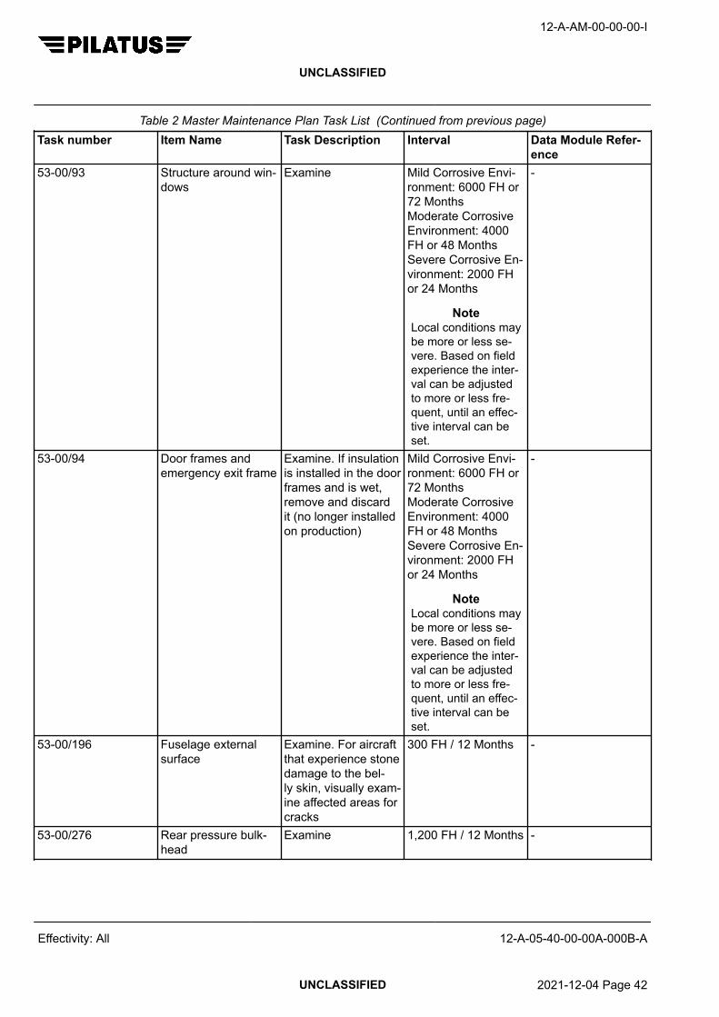
Table 2 Master Maintenance Plan Task List (Continued from previous page)Task number Item Name Task Description Interval Data Module Refer-
ence53-00/93 Structure around win-
dowsExamine Mild Corrosive Envi-
ronment: 6000 FH or72 MonthsModerate CorrosiveEnvironment: 4000FH or 48 MonthsSevere Corrosive En-vironment: 2000 FHor 24 Months
NoteLocal conditions maybe more or less se-vere. Based on fieldexperience the inter-val can be adjustedto more or less fre-quent, until an effec-tive interval can beset.
-
53-00/94 Door frames andemergency exit frame
Examine. If insulationis installed in the doorframes and is wet,remove and discardit (no longer installedon production)
Mild Corrosive Envi-ronment: 6000 FH or72 MonthsModerate CorrosiveEnvironment: 4000FH or 48 MonthsSevere Corrosive En-vironment: 2000 FHor 24 Months
NoteLocal conditions maybe more or less se-vere. Based on fieldexperience the inter-val can be adjustedto more or less fre-quent, until an effec-tive interval can beset.
-
53-00/196 Fuselage externalsurface
Examine. For aircraftthat experience stonedamage to the bel-ly skin, visually exam-ine affected areas forcracks
300 FH / 12 Months -
53-00/276 Rear pressure bulk-head
Examine 1,200 FH / 12 Months -
12-A-AM-00-00-00-I
UNCLASSIFIED
Effectivity: All 12-A-05-40-00-00A-000B-A
UNCLASSIFIED 2021-12-04 Page 42

Table 2 Master Maintenance Plan Task List (Continued from previous page)Task number Item Name Task Description Interval Data Module Refer-
ence53-00/277 Floor top and bottom
surface and seat railsExamine as far aspossible with carpetand floor panels inTask 06–00/218 re-moved
1,200 FH / 12 Months -
53-00/278 Baggage/freight netmounting plates at-tachment bolts andsurrounding structure
Examine for corro-sion
2,400 FH / 24 Months -
53-00/279 Baggage compart-ment
Examine 2,400 FH / 24 Months -
53-00/280 Rear fuselage inter-nal structure
Examine as far aspossible, in particu-lar examine batterymounting tray for cor-rosion
1,200 FH / 12 Months -
*53-00/324 Fuselage and associ-ated structure (PostSB 04-009)
Life limit 25,000 FH /30,000 LDGSee Note 1
-
53-00/337 Carry throughFrames 21 and 24
Inspection/check 1,200 FH / 12 Months 12-A-53-20-02-00A-313A-A
*53-00/351 Upper longeronsFrame 10
Eddy current inspec-tionInspection kit longer-on frame 10 P/N500.60.12.032
Threshold32,500 FH /42,000 LDGRepeat12,500 FH /15,000 LDG
12-A-53-10-06-01A-353A-A
*53-00/352 Fuselage Frames 10to 16
Examine all structuralelements
Threshold32,500 FH /42,000 LDGRepeat12,500 FH /15,000 LDG / 6 Year
12-A-53-10-00-00A-310A-A
*53-00/353 Fuselage Frames 16to 36
Examine all structuralelements
Threshold32,500 FH /42,000 LDGRepeat12,500 FH /15,000 LDG / 6 Year
12-A-53-20-00-00A-310A-A
*53-00/354 Fuselage Frames 36to 43
Examine all structuralelements
Threshold32,500 FH /42,000 LDGRepeat12,500 FH /15,000 LDG / 6 Year
12-A-53-30-00-00A-310A-A
12-A-AM-00-00-00-I
UNCLASSIFIED
Effectivity: All 12-A-05-40-00-00A-000B-A
UNCLASSIFIED 2021-12-04 Page 43

Table 2 Master Maintenance Plan Task List (Continued from previous page)Task number Item Name Task Description Interval Data Module Refer-
ence*53-00/355 Antenna structure Examine Threshold
32,500 FH /42,000 LDGRepeat12,500 FH /15,000 LDG / 6 Year
12-A-53-00-00-00A-310A-A
*53-00/356 Antenna - Bottom fu-selage skin
Eddy current inspec-tion
Threshold28,300 FH /37,000 LDGRepeat8,300 FH /10,000 LDG
12-A-53-00-00-00A-353A-A
*53-00/357 Antenna - Upper fu-selage skin
Eddy current inspec-tion
Threshold32,500 FH /42,000 LDGRepeat12,500 FH /15,000 LDG
12-A-53-00-00-00A-353A-A
*53-00/359 Frames 21 and 24wing attachments
Eddy current inspec-tion
Threshold30,000 FH /39,000 LDGRepeat10,000 FH /12,000 LDG
12-A-57-00-03-00A-353A-A
*53-00/360 Frames 21 and 24side frame attach-ments
Eddy current inspec-tionInspection kit carrythrough frames P/N500.50.12.327
Threshold30,000 FH /39,000 LDGRepeat10,000 FH /12,000 LDG
12-A-53-20-02-00A-353A-A
*53-00/361 Frames 41 and 43stabilizer attachment
Eddy current inspec-tionInspection kit verti-cal stabilizer P/N500.50.12.325
Threshold32,500 FH /42,000 LDGRepeat12,500 FH /15,000 LDG
12-A-53-30-02-00A-353A-Aor 12-A-55-30-03-00A-353A-A
53-00/419 Frame 40 Eddy current inspec-tion
Threshold32,500 FH /42,000 LDGRepeat12,500 FH /15,000 LDG
12-A-53-30-02-00A-353A-Aor 12-A-55-30-03-00A-353A-A
*55-00/10 Tail structure (Pre SB04-009)
Life limit 20,000 FH /27,000 LDGSee Note 1
-
*55-00/325 Tail structure (PostSB 04-009)
Life limit 25,000 FH /30,000 LDGSee Note 1
-
12-A-AM-00-00-00-I
UNCLASSIFIED
Effectivity: All 12-A-05-40-00-00A-000B-A
UNCLASSIFIED 2021-12-04 Page 44

Table 2 Master Maintenance Plan Task List (Continued from previous page)Task number Item Name Task Description Interval Data Module Refer-
ence55-10/95 Horizontal stabilizer
internal surfacesand horizontal/verti-cal stabilizer interface
Examine as far aspossible with panelsremoved
Mild Corrosive Envi-ronment: 6000 FH or72 MonthsModerate CorrosiveEnvironment: 4000FH or 48 MonthsSevere Corrosive En-vironment: 2000 FHor 24 Months
NoteLocal conditions maybe more or less se-vere. Based on fieldexperience the inter-val can be adjustedto more or less fre-quent, until an effec-tive interval can beset.
-
55-10/96 Vertical stabilizer in-ternal surfaces
Examine as far aspossible with panelsremoved
Mild Corrosive Envi-ronment: 6000 FH or72 MonthsModerate CorrosiveEnvironment: 4000FH or 48 MonthsSevere Corrosive En-vironment: 2000 FHor 24 Months
NoteLocal conditions maybe more or less se-vere. Based on fieldexperience the inter-val can be adjustedto more or less fre-quent, until an effec-tive interval can beset.
-
55-10/197 Horizontal stabilizerexternal surface
Examine 300 FH / 12 Months -
55-10/319 Horizontal/verticalstabilizer attachment
Inspection/check 1,200 FH / 12 Months 12-A-55-00-00-00A-313A-A
*55-10/415 Horizontal stabilizer Life limit 25,000 FH /30,000 LDG
-
12-A-AM-00-00-00-I
UNCLASSIFIED
Effectivity: All 12-A-05-40-00-00A-000B-A
UNCLASSIFIED 2021-12-04 Page 45

Table 2 Master Maintenance Plan Task List (Continued from previous page)Task number Item Name Task Description Interval Data Module Refer-
ence*55-20/362 Elevator Examine Threshold
32,500 FH /42,000 LDGRepeat12,500 FH /15,000 LDG / 6 Year
12-A-55-20-00-00A-310A-A
*55-20/367 Elevator drive lever Eddy current inspec-tion
Threshold32,500 FH /42,000 LDGRepeat12,500 FH /15,000 LDG
12-A-55-20-01-00A-353A-A
*55-20/368 Elevator hinges Eddy current inspec-tion
Threshold32,500 FH /42,000 LDGRepeat12,500 FH /15,000 LDG
12-A-55-20-01-00A-353A-A
55-30/198 Vertical stabilizer ex-ternal surface
Examine, speciallyaround rear spar toprivets. If cracks arefound, refer to SRMfor repair procedure.
300 FH / 12 Months 12-A-55-00-01-00A-664A-A
55-30/199 Vertical stabilizer rearspar strap and loweraft fairing shear plate(Pre SB 55-002)
Examine, if wear isfound refer to SB55-002
300 FH / 12 Months -
55-30/281 Vertical stabilizerelectrical bondingstraps
Examine 1,200 FH / 12 Months -
*55-30/369 Vertical stabilizer Examine Threshold32,500 FH /42,000 LDGRepeat12,500 FH /15,000 LDG / 6 Year
12-A-55-30-00-00A-310A-A
*55-30/370 Vertical stabilizermain and rear sparattachment to fuse-lage
Eddy current inspec-tion
Threshold32,500 FH /42,000 LDGRepeat12,500 FH /15,000 LDG
12-A-53-30-02-00A-353A-Aor 12-A-55-30-03-00A-353A-A
*55-30/371 Vertical stabilizermain attachment tohorizontal stabilizer
Eddy current inspec-tion
Threshold32,500 FH /42,000 LDGRepeat12,500 FH /15,000 LDG
12-A-55-00-00-00A-353A-A
12-A-AM-00-00-00-I
UNCLASSIFIED
Effectivity: All 12-A-05-40-00-00A-000B-A
UNCLASSIFIED 2021-12-04 Page 46

Table 2 Master Maintenance Plan Task List (Continued from previous page)Task number Item Name Task Description Interval Data Module Refer-
ence*55-30/372 Vertical stabilizer
pitch trim actuator fit-ting and attachment
Eddy current inspec-tion
Threshold32,500 FH /42,000 LDGRepeat12,500 FH /15,000 LDG
12-A-55-30-02-00A-353A-A
55-30/420 Vertical stabilizer for-ward attachment toFrame 40
Eddy current inspec-tion
Threshold32,500 FH /42,000 LDGRepeat12,500 FH /15,000 LDG
12-A-55-30-03-00A-353A-A
*55-40/373 Rudder Examine Threshold32,500 FH /42,000 LDGRepeat12,500 FH /15,000 LDG / 6 Year
12-A-55-40-00-00A-310A-A
*55-40/377 Rudder hinges Eddy current inspec-tion
Threshold32,500 FH /42,000 LDGRepeat12,500 FH /15,000 LDG
12-A-55-40-05-00A-353A-A
55-40/410 Rudder trim tab Examine Threshold32,500 FH /42,000 LDGRepeat12,500 FH /15,000 LDG / 6 Year
12-A-55-40-04-00A-310A-A
*56-11/12 Cockpit outer side,DV windows and cab-in windows
Replace If cracked -
*56-11/13 Cockpit inner andouter side, DV win-dows and cabin win-dows
Refer to AMM for lim-itations
If chipped, cracked(only for inner sidewindows), crazing,scratched, bubbles ordelaminated
12-A-56-00-00-00A-313A-A
*56-11/14 Windshield LH andRH
Replace If cracked in innerlamination
-
*56-11/15 Windshield LH andRH
Only unpressurizedflight is permitted upto the next scheduledinspection providing itdoes not cause visualproblems.
If cracked in outerlamination
-
56-11/200 Windshield LH andRH
Examine 300 FH / 12 Months 12-A-56-00-00-00A-313A-A
12-A-AM-00-00-00-I
UNCLASSIFIED
Effectivity: All 12-A-05-40-00-00A-000B-A
UNCLASSIFIED 2021-12-04 Page 47

Table 2 Master Maintenance Plan Task List (Continued from previous page)Task number Item Name Task Description Interval Data Module Refer-
ence56-11/332 Cockpit side windows Inspection/check 11,000 FH /
120 Months12-A-56-11-02-00A-313A-A
*56-11/378 Windshield LH andRH and cockpit sidewindows
Examine with wind-shield and side win-dows removedInspection kitwindshield P/N500.50.12.326
Threshold32,500 FH /42,000 LDGRepeat12,500 FH /15,000 LDG / 6 Year
12-A-56-11-01-00A-310A-Aand 12-A-56-11-02-00A-310A-Aand 12-A-53-10-16-00A-310A-A
56-11/517 Cockpit DV Window Make sure that youcan open and closethe DV window withone hand
1,200 FH / 12 Months -
56-20/201 Cockpit and cabinwindows
Examine 300 FH / 12 Months 12-A-56-00-00-00A-313A-A
*57-00/11 Wing structure (PreSB 04-009)
Life limit 20,000 FH /27,000 LDGSee Note 1
-
57-00/97 Wing internal surfa-ces and flap compart-ment
Examine as far aspossible with all wingpanels removed
Mild Corrosive Envi-ronment: 6000 FH or72 MonthsModerate CorrosiveEnvironment: 4000FH or 48 MonthsSevere Corrosive En-vironment: 2000 FHor 24 Months
NoteLocal conditions maybe more or less se-vere. Based on fieldexperience the inter-val can be adjustedto more or less fre-quent, until an effec-tive interval can beset.
-
12-A-AM-00-00-00-I
UNCLASSIFIED
Effectivity: All 12-A-05-40-00-00A-000B-A
UNCLASSIFIED 2021-12-04 Page 48
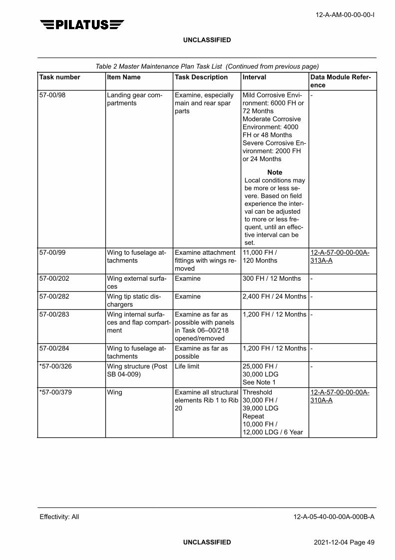
Table 2 Master Maintenance Plan Task List (Continued from previous page)Task number Item Name Task Description Interval Data Module Refer-
ence57-00/98 Landing gear com-
partmentsExamine, especiallymain and rear sparparts
Mild Corrosive Envi-ronment: 6000 FH or72 MonthsModerate CorrosiveEnvironment: 4000FH or 48 MonthsSevere Corrosive En-vironment: 2000 FHor 24 Months
NoteLocal conditions maybe more or less se-vere. Based on fieldexperience the inter-val can be adjustedto more or less fre-quent, until an effec-tive interval can beset.
-
57-00/99 Wing to fuselage at-tachments
Examine attachmentfittings with wings re-moved
11,000 FH /120 Months
12-A-57-00-00-00A-313A-A
57-00/202 Wing external surfa-ces
Examine 300 FH / 12 Months -
57-00/282 Wing tip static dis-chargers
Examine 2,400 FH / 24 Months -
57-00/283 Wing internal surfa-ces and flap compart-ment
Examine as far aspossible with panelsin Task 06–00/218opened/removed
1,200 FH / 12 Months -
57-00/284 Wing to fuselage at-tachments
Examine as far aspossible
1,200 FH / 12 Months -
*57-00/326 Wing structure (PostSB 04-009)
Life limit 25,000 FH /30,000 LDGSee Note 1
-
*57-00/379 Wing Examine all structuralelements Rib 1 to Rib20
Threshold30,000 FH /39,000 LDGRepeat10,000 FH /12,000 LDG / 6 Year
12-A-57-00-00-00A-310A-A
12-A-AM-00-00-00-I
UNCLASSIFIED
Effectivity: All 12-A-05-40-00-00A-000B-A
UNCLASSIFIED 2021-12-04 Page 49

Table 2 Master Maintenance Plan Task List (Continued from previous page)Task number Item Name Task Description Interval Data Module Refer-
ence*57-00/380 Wing main and rear
spar to fuselage at-tachment
Eddy current inspec-tionInspection kit wingattachment P/N500.60.12.004Inspection kit dou-ble bush P/N500.60.12.007
Threshold30,000 FH /39,000 LDGRepeat10,000 FH /12,000 LDG
12-A-57-00-03-00A-353A-Aand 12-A-57-00-03-01A-353A-A
*57-00/382 Wing rear spar at Rib8 flap arm attachment
Eddy current inspec-tion
Threshold25,000 FH /30,000 LDGRepeat12,500 FH /15,000 LDG
12-A-57-20-10-00A-353C-A
*57-00/383 Wing main spar fas-tener holes Rib 1 thruRib 6
Eddy current inspec-tionInspection kitfirst oversize P/N500.60.12.030orInspection kit sec-ond oversize P/N500.60.12.020
Threshold25,000 FH /30,000 LDGRepeat3,300 FH /4,000 LDG
12-A-57-20-10-00A-353A-A
*57-00/384 Wing main spar fas-tener holes strap Rib6
Eddy current inspec-tionInspection kitfirst oversize P/N500.60.12.031orInspection kit sec-ond oversize P/N500.60.12.043
Threshold25,000 FH /30,000 LDGRepeat3,300 FH /4,000 LDG
12-A-57-20-05-00A-353A-A
*57-00/385 Wing rear spar fas-tener holes Rib 2 thruRib 3
Eddy current inspec-tion
Threshold25,000 FH /30,000 LDGRepeat12,500 FH /15,000 LDG
12-A-57-20-10-00A-353B-A
57-00/412 Wing tips Examine Threshold32,500 FH /42,000 LDGRepeat12,500 FH /15,000 LDG / 6 Year
12-A-57-33-00-00A-310A-A
12-A-AM-00-00-00-I
UNCLASSIFIED
Effectivity: All 12-A-05-40-00-00A-000B-A
UNCLASSIFIED 2021-12-04 Page 50

Table 2 Master Maintenance Plan Task List (Continued from previous page)Task number Item Name Task Description Interval Data Module Refer-
ence57-00/413 Wing skin around
drain holesEddy current inspec-tion
Threshold25,000 FH /30,000 LDGRepeat2,500 FH /3,000 LDG
12-A-57-20-01-00A-353A-A
*57-00/427 Wing main spar fas-tener holes strap Rib6
Eddy current inspec-tionNo cracks arepermitted. If youfind cracks, con-tact Pilatus Custom-er Support for ad-vice, www.pilatus-air-craft.com -> contact.
Threshold 16,000wing flying hours or22,500 wing landings.All wings with nolanding records mustapply a calculatedapplicable landingsequal to 2 x flyinghours.See Notes 1, 7 and 8
12-A-57-20-10-00A-353D-A
*57-60/393 Aileron Examine Threshold32,500 FH /42,000 LDGRepeat12,500 FH /15,000 LDG / 6 Year
12-A-57-60-00-00A-310A-A
57-60/411 Aileron trim tab ExamineInspection kit P/N500.50.12.317 orInspection kit P/N500.60.12.039 andInspection kit P/N500.60.12.040
Threshold32,500 FH /42,000 LDGRepeat12,500 FH /15,000 LDG / 6 Year
12-A-57-60-04-00A-310A-A
61-00/456 Four-bladed alumi-num propeller
Refer to HartzellOwner’s Manual 149- Periodic Inspectionsand Maintenance anddo the time limited in-spection items
Refer to HartzellOwner’s Manual 149- Periodic Inspectionsand Maintenance
-
61-10/37 Propeller Overhaul 4,000 FH / 72 Months(Refer to Hartzell SL61)
-
61-20/286 Propeller governor,overspeed governorand beta controls
Examine 1,200 FH / 12 Months -
*71-00/16 Engine mountingframe (Pre SB04-009)
Life limit 20,000 FH /27,000 LDGSee Note 1
-
*71-00/17 Engine mountingframe, replace allbolts, washers andnuts
Life limit 11,000 FH -
12-A-AM-00-00-00-I
UNCLASSIFIED
Effectivity: All 12-A-05-40-00-00A-000B-A
UNCLASSIFIED 2021-12-04 Page 51

Table 2 Master Maintenance Plan Task List (Continued from previous page)Task number Item Name Task Description Interval Data Module Refer-
ence71-00/38 Engine shock mount
assembliesOverhaul At engine overhaul
but not later than5000 FH
-
71-00/101 Power plant torquelimiter
Operational test 600 FH / 12 Months 12-A-71-00-00-00A-903H-A
71-00/102 Power plant perform-ance
Operational test 600 FH / 12 Months 12-A-71-00-00-00A-903I-A
71-00/106 Oil pressure trans-ducer electrical con-nector (Pre SB79-004)
Clean 600 FH / 12 Months 12-A-71-00-03-00A-250A-A
71-00/107 Engine torque andstick pusher torquetransducer electricalconnectors
Clean 600 FH / 12 Months 12-A-71-00-03-00A-250A-A
71-00/204 Power plant Post inspectionground run tests
Job Close Up 12-A-71-00-00-00A-903A-A
71-00/205 Engine tubularmounting frame andshockmounts
Examine. Replaceshockmount if cracksin elastomer aremore than 25,4 mm(1 in) long and/or 1,5mm (0.06 in) deep.
1,200 FH / 12 Months -
71-00/209 Engine drain mastand tank
Examine the drainmast for fuel leaks(no leaks permitted)and drain the collec-tor tank.
300 FH / 12 Months -
71-00/287 Power plant Do an inspectionground run as neces-sary. Record any de-fects.
NoteA pre-inspectionground run is not aprerequisite but maybe useful to deter-mine any repair workneeded to maintainthe airworthiness ofthe aircraft.
Job Set Up 12-A-71-00-00-00A-903A-A
12-A-AM-00-00-00-I
UNCLASSIFIED
Effectivity: All 12-A-05-40-00-00A-000B-A
UNCLASSIFIED 2021-12-04 Page 52

Table 2 Master Maintenance Plan Task List (Continued from previous page)Task number Item Name Task Description Interval Data Module Refer-
ence71-00/301 Engine tubular
mounting frame fire-wall attachment fit-tings
Examine with firewallinsulation blanket re-moved as necessary.If cracked, blisteredor flaking paint isfound on the mount-ing frame refer toSRM.
1,200 FH / 12 Months SRM 12-A-54-20-02-00A-664A-A
*71-00/327 Engine mountingframe (Post SB04-009)
Life limit 25,000 FH /30,000 LDGSee Note 1
-
*71-00/401 Engine mount Magnetic particle in-spectionInspection kit en-gine mount P/N500.60.12.006
Threshold26,600 FH /35,000 LDGRepeat6,600 FH /8,000 LDG
12-A-71-00-05-00A-352A-A
71-00/432 Power plant and ac-cessories
Refer to P&WC EMMChapter 72-00-00 Pe-riodic Inspection anddo the minor andtime limited inspec-tion items
Refer to P&WC EMMChapter 72-00-00 Pe-riodic Inspection
-
71-00/476 P&WC airworthinessdirectives and servicebulletins
Reviewed and com-plied with as neces-sary
Job Close Up -
71-10/207 Engine cowlings ENG43AL and ENG 43AR
Open and examine,particularly for condi-tion of rubbing stripsand fasteners. Lubri-cate the hinges with aminimum of materialP10-001.
Job Set Up -
71-10/208 Engine cowlings ENG43AL and ENG 43AR
Close Job Close Up -
*72-00/18 Engine rotor compo-nents
Life limit P&WC SB 14002 lat-est revision
-
72-00/39 Engine Overhaul 3,500 FHP&WC SB 14603 lat-est revision
-
72-00/308 Engine accessories Overhaul P&WC SB 14603 lat-est revision
-
74-00/288 Ignition system Operational test 300 FH / 12 Months 12-A-74-00-00-00A-903A-A
76-00/210 Engine controls in en-gine compartment
Examine 600 FH / 12 Months -
12-A-AM-00-00-00-I
UNCLASSIFIED
Effectivity: All 12-A-05-40-00-00A-000B-A
UNCLASSIFIED 2021-12-04 Page 53
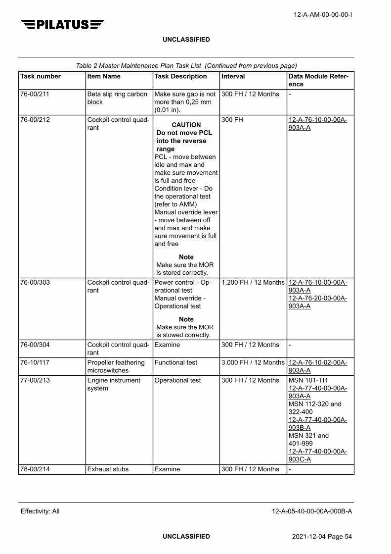
Table 2 Master Maintenance Plan Task List (Continued from previous page)Task number Item Name Task Description Interval Data Module Refer-
ence76-00/211 Beta slip ring carbon
blockMake sure gap is notmore than 0,25 mm(0.01 in).
300 FH / 12 Months -
76-00/212 Cockpit control quad-rant CAUTION
Do not move PCLinto the reverserange
PCL - move betweenidle and max andmake sure movementis full and freeCondition lever - Dothe operational test(refer to AMM)Manual override lever- move between offand max and makesure movement is fulland free
NoteMake sure the MORis stored correctly.
300 FH 12-A-76-10-00-00A-903A-A
76-00/303 Cockpit control quad-rant
Power control - Op-erational testManual override -Operational test
NoteMake sure the MORis stowed correctly.
1,200 FH / 12 Months 12-A-76-10-00-00A-903A-A12-A-76-20-00-00A-903A-A
76-00/304 Cockpit control quad-rant
Examine 300 FH / 12 Months -
76-10/117 Propeller featheringmicroswitches
Functional test 3,000 FH / 12 Months 12-A-76-10-02-00A-903A-A
77-00/213 Engine instrumentsystem
Operational test 300 FH / 12 Months MSN 101-11112-A-77-40-00-00A-903A-AMSN 112-320 and322-40012-A-77-40-00-00A-903B-AMSN 321 and401-99912-A-77-40-00-00A-903C-A
78-00/214 Exhaust stubs Examine 300 FH / 12 Months -
12-A-AM-00-00-00-I
UNCLASSIFIED
Effectivity: All 12-A-05-40-00-00A-000B-A
UNCLASSIFIED 2021-12-04 Page 54

Table 2 Master Maintenance Plan Task List (Continued from previous page)Task number Item Name Task Description Interval Data Module Refer-
ence79-00/215 Oil filler cap/dipstick Energize aircraft
electrical system, re-fer to AMM. Removefiller cap, examineand make sure theseal is in goodcondition. Set andhold AIR/GROUNDswitch to GROUNDand make sure af-ter 60 seconds theCAWS OIL QTY cap-tion comes on. In-stall filler cap andmake sure the lock-ing mechanism oper-ates correctly
600 FH / 12 Months 12-A-24-00-00-00A-901A-A
79-20/43 Oil cooler Overhaul At engine overhaul -79-20/289 Engine oil cooler Examine. Make sure
outlet door has fulland free movement.
1,200 FH / 12 Months -
79-20/290 Oil system chip de-tector indication sys-tem
Operational test 300 FH / 12 Months 12-A-79-30-01-00A-903A-A
12-A-AM-00-00-00-I
UNCLASSIFIED
Effectivity: All 12-A-05-40-00-00A-000B-A
End of data moduleUNCLASSIFIED 2021-12-04 Page 55

12-A-AM-00-00-00-I
UNCLASSIFIED
Intentionally left blank
Effectivity: All 12-A-05-40-00-00A-000B-A
UNCLASSIFIED 2021-12-04 Page 56

ENGINE GROUND RUN TESTS
FUNCTION, DATA FOR PLANS AND DESCRIPTION
Table of Contents Page
ENGINE GROUND RUN TESTS - FUNCTION, DATA FOR PLANS AND DESCRIPTION....... 11 General................................................................................................................... 12 Engine Ground Run Tests...................................................................................... 1
Index of Tables Page
1 References............................................................................................................. 1
ReferencesTable 1 References
Data module/Technical publication Title
12-A-71-00-00-00A-903A-A POWERPLANT - ADJUSTMENT/TEST
Description
1 General
This data module gives the engine ground run tests and the associated interval at which the test is required.
2 Engine Ground Run Tests
The tests that follow have procedures detailed in AMM 12-A-71-00-00-00A-903A-A.
Test No. Type of Test Interval1 Engine oil pressure 300FH / 12 Months, whichever comes first2 Propeller blade feather 1200 FH / 12 Months, whichever comes first3 DC Generation system 1200 FH / 12 Months, whichever comes first4 Maximum propeller speed 1200 FH / 12 Months, whichever comes first6 Torque limiter 600 FH / 12 Months, whichever comes first7 Engine performance 600 FH / 12 Months, whichever comes first8 Torquemeter function 1200 FH / 12 Months, whichever comes first9 Acceleration 1200 FH / 12 Months, whichever comes first10 Overspeed governor 1200 FH / 12 Months, whichever comes first11 Nf governor 1200 FH / 12 Months, whichever comes first
12-A-AM-00-00-00-I
UNCLASSIFIED
Effectivity: All 12-A-05-40-00-00A-000C-A
UNCLASSIFIED 2018-05-24 Page 1

Test No. Type of Test Interval12 FCU dead band 1200 FH / 12 Months, whichever comes first13 Propeller low pitch warning 1200 FH / 12 Months, whichever comes first14 Ground idle speed 1200 FH / 12 Months, whichever comes first15 Flight idle speed 1200 FH / 12 Months, whichever comes first16 Manual override 1200 FH / 12 Months, whichever comes first17 Reverse power 1200 FH / 12 Months, whichever comes first18 Environmental Control System (ECS) 1200 FH / 12 Months, whichever comes first19 Engine stop time 300 FH / 12 Months, whichever comes first20 After engine stop 300 FH / 12 Months, whichever comes first
12-A-AM-00-00-00-I
UNCLASSIFIED
Effectivity: All 12-A-05-40-00-00A-000C-A
End of data moduleUNCLASSIFIED 2018-05-24 Page 2

300 FH INSPECTION
FUNCTION, DATA FOR PLANS AND DESCRIPTION
Table of Contents Page
300 FH INSPECTION - FUNCTION, DATA FOR PLANS AND DESCRIPTION......................... 11 General................................................................................................................... 12 Inspections............................................................................................................. 2
Index of Tables Page
1 References............................................................................................................. 12 300 FH Inspection.................................................................................................. 2
ReferencesTable 1 References
Data module/Technical publication Title
12-A-05-20-00-00A-018A-A SCHEDULED MAINTENANCE CHECK LISTS - INTRODUC-TION
12-A-22-20-00-00A-903A-A SPEED AND ATTITUDE CORRECTION SYSTEM - ADJUST-MENT/TEST
12-A-24-30-01-00A-313A-A STARTER/GENERATOR - INSPECTION/CHECK
12-A-24-30-02-00A-313A-A GENERATOR 2 - INSPECTION/CHECK
12-A-27-40-00-00A-903A-A HORIZONTAL STABILIZER TRIM - ADJUSTMENT/TEST
12-A-27-50-00-00A-901A-A FLAPS (PRE SB 27–013, PRE AND POST SB 27–014 ONMSN 101 – 400) - MAINTENANCE PRACTICES
12-A-76-10-00-00A-903A-A POWER CONTROLS - ADJUSTMENT/TEST
Description
1 General
The terms used for the item inspection requirements are defined in 12-A-05-20-00-00A-018A-A.
12-A-AM-00-00-00-I
UNCLASSIFIED
Effectivity: All 12-A-05-40-01-01A-000B-A
UNCLASSIFIED 2021-12-04 Page 1

2 Inspections
Table 2 300 FH InspectionTask number Item Name Task Description Data Module
ReferenceSignature/Stamp Inspection
06-00/592 Access panel, en-gine: 42AT
Remove and ex-amine
12-A-06-20-00-00A-040A-A
06-00/593 Access panel, en-gine: 42AT
Install 12-A-06-20-00-00A-040A-A
06-00/622 Access panels,fuselage: 11BR,12BZ, 12EZ,12HZ, 21QZ
Remove and ex-amine
12-A-06-20-00-00A-040A-A
06-00/623 Access panels,fuselage: 11BR,12BZ, 12EZ,12HZ, 21QZ
Install 12-A-06-20-00-00A-040A-A
22-20/130 Stick pusher sys-tem
Check 12-A-22-20-00-00A-903A-A
24-30/61 Starter/Generator(except P/N978.91.23.407,978.91.23.408and978.91.23.409)
Brush check 12-A-24-30-01-00A-313A-A
24-30/63 Generator 2brushes (P/N524.32.12.158Mod. B)
Inspection/check 12-A-24-30-02-00A-313A-A
25-10/135 Crew seats Examine as faras possible withseats installed
-
25-20/302 Passenger seats Examine as faras possible withseats installed.Move the reclinemechanism andswivel function(executive seatonly) through itsfull motion andcheck for cor-rect operation.If necessary, re-fer to the applica-ble supplier CMM(CMM 25-20-07for executiveseats and CMM25-20-99 forstandard seats)
-
12-A-AM-00-00-00-I
UNCLASSIFIED
Effectivity: All 12-A-05-40-01-01A-000B-A
UNCLASSIFIED 2021-12-04 Page 2

Table 2 300 FH Inspection (Continued from previous page)Task number Item Name Task Description Data Module
ReferenceSignature/Stamp Inspection
27-00/138 Aileron, elevatorand rudder con-trols
Operate, makesure full and freetravel
-
27-40/291 Horizontal stabil-izer trim system
Operational test 12-A-27-40-00-00A-903A-A
27-50/77 Flap electricalsystem (MSN101-400 Pre SB27-013)
Do the flapelectrical sys-tem maintenancepractices tests
12-A-27-50-00-00A-901A-A
35-10/188 Oxygen system Check contents -76-00/212 Cockpit control
quadrant CAUTIONDo not movePCL into thereverse range
PCL - move be-tween idle andmax and makesure movement isfull and freeCondition lever -Do the operation-al test (refer toAMM)Manual overridelever - move be-tween off andmax and makesure movement isfull and free
NoteMake sure theMOR is storedcorrectly.
12-A-76-10-00-00A-903A-A
12-A-AM-00-00-00-I
UNCLASSIFIED
Effectivity: All 12-A-05-40-01-01A-000B-A
End of data moduleUNCLASSIFIED 2021-12-04 Page 3

12-A-AM-00-00-00-I
UNCLASSIFIED
Intentionally left blank
Effectivity: All 12-A-05-40-01-01A-000B-A
UNCLASSIFIED 2021-12-04 Page 4

300 FH OR 12 MONTHS INSPECTION
FUNCTION, DATA FOR PLANS AND DESCRIPTION
Table of Contents Page
300 FH OR 12 MONTHS INSPECTION - FUNCTION, DATA FOR PLANS ANDDESCRIPTION...........................................................................................................................
1
1 General................................................................................................................... 22 Inspections............................................................................................................. 3
Index of Tables Page
1 References............................................................................................................. 12 300 FH or 12 Month Inspection.............................................................................. 3
ReferencesTable 1 References
Data module/Technical publication Title
12-A-05-20-00-00A-018A-A SCHEDULED MAINTENANCE CHECK LISTS - INTRODUC-TION
12-A-12-10-02-00A-902A-A BRAKES - SERVICING
12-A-12-10-04-00A-902A-A TIRES - SERVICING
12-A-12-20-07-00A-902A-A FLAP UP AND DOWN LIMIT SWITCHES - SERVICING
12-A-24-30-00-00A-903A-A DC GENERATION SYSTEM (MSN 101 – 320, 322 – 400) -ADJUSTMENT/TEST
12-A-24-30-00-00A-903B-A DC GENERATION SYSTEM (MSN 321, 401 – 999) - ADJUST-MENT/TEST
12-A-24-30-03-00A-903A-A GENERATOR 2 DRIVE BELT (PRE SB 24–010) - ADJUST-MENT/TEST
12-A-24-30-03-00A-903B-A GENERATOR 2 DRIVE BELT (POST SB 24–010 AND MSN231 – 999) - ADJUSTMENT/TEST
12-A-25-63-00-00A-903A-A EMERGENCY LOCATOR TRANSMITTER (NARCO 910 ELT)- ADJUSTMENT/TEST
12-A-25-63-10-00A-903A-A EMERGENCY LOCATOR TRANSMITTER (KANNAD ELT) -ADJUSTMENT/TEST
12-A-25-63-20-00A-903A-A EMERGENCY LOCATOR TRANSMITTER (KANNAD ELTAND SMART CONNECTOR) - ADJUSTMENT/TEST
12-A-25-63-30-00A-903A-A EMERGENCY LOCATOR TRANSMITTER (ELT A06) - AD-JUSTMENT/TEST
12-A-AM-00-00-00-I
UNCLASSIFIED
Effectivity: All 12-A-05-40-01-02A-000B-A
UNCLASSIFIED 2021-12-04 Page 1

Data module/Technical publication Title
12-A-27-40-00-00A-903A-A HORIZONTAL STABILIZER TRIM - ADJUSTMENT/TEST
12-A-27-50-00-00A-902A-A FLAPS - SERVICING
12-A-28-20-01-00A-250A-A FUEL FILTER ELEMENT - CLEAN AND APPLY SURFACEPROTECTION
12-A-28-20-01-00A-920A-A FUEL FILTER ELEMENT - REMOVAL/INSTALLATION
12-A-28-20-07-00A-903A-A FLOAT VALVE - ADJUSTMENT/TEST
12-A-29-00-00-00A-902A-A HYDRAULIC SYSTEM (MSN 101 – 230) - SERVICING
12-A-29-00-00-00A-902B-A HYDRAULIC SYSTEM (MSN 231 – 999) - SERVICING
12-A-30-10-00-00A-313A-A AIRFOIL DE-ICING BOOTS - INSPECTION/CHECK
12-A-33-40-00-00A-903A-A EXTERIOR LIGHTS (MSN 101 – 320, 322 – 400) - ADJUST-MENT/TEST
12-A-33-40-00-00A-903B-A EXTERIOR LIGHTS (MSN 321, 401 – 999) - ADJUST-MENT/TEST
12-A-55-40-00-00A-313A-A RUDDER - INSPECTION/CHECK
12-A-56-00-00-00A-313A-A WINDOWS - INSPECTION/CHECK
12-A-74-00-00-00A-903A-A IGNITION SYSTEM - ADJUSTMENT/TEST
12-A-77-40-00-00A-903A-A ENGINE INDICATION (MSN 101 – 111) - ADJUST-MENT/TEST
12-A-77-40-00-00A-903B-A ENGINE INDICATION (MSN 112 – 320, 322 – 400) - ADJUST-MENT/TEST
12-A-77-40-00-00A-903C-A ENGINE INDICATING (MSN 321, 401 – 999) - ADJUST-MENT/TEST
12-A-79-30-01-00A-903A-A CHIP DETECTOR - ADJUSTMENT/TEST
Description
1 General
The terms used for the item inspection requirements are defined in 12-A-05-20-00-00A-018A-A.
12-A-AM-00-00-00-I
UNCLASSIFIED
Effectivity: All 12-A-05-40-01-02A-000B-A
UNCLASSIFIED 2021-12-04 Page 2

2 Inspections
Table 2 300 FH or 12 Month InspectionTask number Item Name Task Description Data Module
ReferenceSignature/Stamp Inspection
06-00/594 Access panels,fuselage: 11BL ,21PZ
Remove and ex-amine
12-A-06-20-00-00A-040A-A
06-00/595 Access panels,fuselage: 11BL ,21PZ
Install 12-A-06-20-00-00A-040A-A
06-00/596 Access panels,empennage:31AB, 32AB,33ET
Open or remove.Examine
12-A-06-20-00-00A-040A-A
06-00/597 Access panels,empennage:31AB, 32AB,33ET
Close or install 12-A-06-20-00-00A-040A-A
06-00/598 Access panels,engine: 42AT,42AB
Remove and ex-amine
12-A-06-20-00-00A-040A-A
06-00/599 Access panels,engine: 42AT,42AB
Install 12-A-06-20-00-00A-040A-A
10-10/428 External protec-tive covers
Examine. Re-place if any partof the coveris missing, dam-aged, torn ordoes not installproperly
-
22-20/129 Angle of Attack(AOA) transmit-ters
Examine -
24-30/131 Generator 2 drivebelt
Examine and ad-justment/test
12-A-24-30-03-00A-903A-A12-A-24-30-03-00A-903B-A
24-30/132 Battery (Batteries- if 2nd battery in-stalled)
Examine and op-erational test
12-A-24-30-00-00A-903A-A12-A-24-30-00-00A-903B-A
25-10/134 Crew seat belts Examine -25-20/136 Passenger seat
belts and exten-sions
Examine -
12-A-AM-00-00-00-I
UNCLASSIFIED
Effectivity: All 12-A-05-40-01-02A-000B-A
UNCLASSIFIED 2021-12-04 Page 3

Table 2 300 FH or 12 Month Inspection (Continued from previous page)Task number Item Name Task Description Data Module
ReferenceSignature/Stamp Inspection
25-60/231 ELT Operational test 12-A-25-63-00-00A-903A-Aor 12-A-25-63-10-00A-903A-Aor 12-A-25-63-20-00A-903A-Aor 12-A-25-63-30-00A-903A-A
27-10/139 Aileron LH andRH
Examine and lu-bricate the trimhinges with mini-mum quantity ofCPC (P10-001)
-
27-20/140 Rudder Inspection/check 12-A-55-40-00-00A-313A-A
27-30/141 Elevators Examine -27-40/142 Horizontal stabil-
izer trim interruptand alternate trimswitches
Operational test 12-A-27-40-00-00A-903A-A
27-50/73 Flap actua-tors (white col-ored) (P/N978.73.20.302,303, 304, 305and 306)
Lubricate 12-A-27-50-00-00A-902A-A
27-50/74 Flap actua-tors (black ano-dized) (P/N978.73.20.307,978.73.20.308,978.73.20.309)
Lubricate 12-A-27-50-00-00A-902A-A
27-50/144 Flaps and flapsupport mecha-nism
Examine -
27-50/443 Flap up and downlimit switches
Servicing 12-A-12-20-07-00A-902A-A
28-10/145 Fuel tank fillercaps
Examine -
28-10/146 Fuel Remove a sam-ple from eachdrain valve andexamine for water
-
12-A-AM-00-00-00-I
UNCLASSIFIED
Effectivity: All 12-A-05-40-01-02A-000B-A
UNCLASSIFIED 2021-12-04 Page 4

Table 2 300 FH or 12 Month Inspection (Continued from previous page)Task number Item Name Task Description Data Module
ReferenceSignature/Stamp Inspection
28-20/147 Fuel tank ventvalve and flamearrestor
Operational test 12-A-28-20-07-00A-903A-A
28-20/148 Fuel filter element Remove andclean
12-A-28-20-01-00A-920A-Aand 12-A-28-20-01-00A-250A-A
28-20/150 Engine drivenpump
Examine -
29-10/152 Hydraulic system MSN 101-230.Check fluid sen-sor and level us-ing maintenanceswitch box. Fill asnecessary.MSN 231-999.Make sure fluidlevel indicator onthe reservoir tankshows full. Fill asnecessary.
MSN 101-230 12-A-29-00-00-00A-902A-AMSN 231-999 12-A-29-00-00-00A-902B-A
29-10/153 Reservoir tank Make sure nitro-gen pressure iscorrect. Pressur-ize as necessary
MSN 101-230 (Ifinstalled) 12-A-29-00-00-00A-902A-AMSN 231-999 (Ifinstalled) 12-A-29-00-00-00A-902B-A
30-10/154 Wing and hori-zontal stabilizerairfoil de-iceboots
Inspection/check 12-A-30-10-00-00A-313A-A
30-20/156 Engine air intakede-ice lip
Examine and lookfor signs of gasleaks - none arepermitted
-
32-40/172 Main wheel tires Examine andcheck tire pres-sure
12-A-12-10-04-00A-902A-A
32-40/174 Nose wheel tire Examine andcheck tire pres-sure
12-A-12-10-04-00A-902A-A
12-A-AM-00-00-00-I
UNCLASSIFIED
Effectivity: All 12-A-05-40-01-02A-000B-A
UNCLASSIFIED 2021-12-04 Page 5

Table 2 300 FH or 12 Month Inspection (Continued from previous page)Task number Item Name Task Description Data Module
ReferenceSignature/Stamp Inspection
32-40/175 Brake system Apply the parkingbrake. Examinethe brake units.Make sure thatpad wear indica-tors protrude fromhousing.
-
32-40/176 Fluid reservoir Check and re-plenish, if neces-sary
12-A-12-10-02-00A-902A-A
33-40/177 Exterior lighting Operational test MSN 101-320and 322-400 12-A-33-40-00-00A-903A-AMSN 321 and401-999 12-A-33-40-00-00A-903B-A
33-41/178 Landing lights Examine -33-42/179 Taxi lights Examine -33-43/180 Navigation and
strobe lightsExamine -
33-44/181 Recognition lights(if installed)
Examine -
33-46/182 Beacon lights (ifinstalled)
Examine -
34-00/184 Cockpit instru-ments and avion-ic equipment
Examine -
34-11/185 Pitot tube Examine -34-11/186 Static ports Examine -35-10/187 High pressure
relief indicator(green disk)
Make sure that itis not damaged
-
53-00/196 Fuselage externalsurface
Examine. For air-craft that experi-ence stone dam-age to the bel-ly skin, visuallyexamine affectedareas for cracks
-
55-10/197 Horizontal stabil-izer external sur-face
Examine -
12-A-AM-00-00-00-I
UNCLASSIFIED
Effectivity: All 12-A-05-40-01-02A-000B-A
UNCLASSIFIED 2021-12-04 Page 6

Table 2 300 FH or 12 Month Inspection (Continued from previous page)Task number Item Name Task Description Data Module
ReferenceSignature/Stamp Inspection
55-30/198 Vertical stabilizerexternal surface
Examine, special-ly around rearspar top rivets. Ifcracks are found,refer to SRM forrepair procedure.
12-A-55-00-01-00A-664A-A
55-30/199 Vertical stabilizerrear spar strapand lower aft fair-ing shear plate(Pre SB 55-002)
Examine, if wearis found refer toSB 55-002
-
56-11/200 Windshield LHand RH
Examine 12-A-56-00-00-00A-313A-A
56-20/201 Cockpit and cabinwindows
Examine 12-A-56-00-00-00A-313A-A
57-00/202 Wing externalsurfaces
Examine -
71-00/209 Engine drainmast and tank
Examine thedrain mast forfuel leaks (noleaks permitted)and drain the col-lector tank.
-
74-00/288 Ignition system Operational test 12-A-74-00-00-00A-903A-A
76-00/211 Beta slip ring car-bon block
Make sure gapis not more than0,25 mm (0.01in).
-
76-00/304 Cockpit controlquadrant
Examine -
77-00/213 Engine instru-ment system
Operational test MSN 101-11112-A-77-40-00-00A-903A-AMSN 112-320and 322-40012-A-77-40-00-00A-903B-AMSN 321 and401-99912-A-77-40-00-00A-903C-A
78-00/214 Exhaust stubs Examine -79-20/290 Oil system chip
detector indica-tion system
Operational test 12-A-79-30-01-00A-903A-A
12-A-AM-00-00-00-I
UNCLASSIFIED
Effectivity: All 12-A-05-40-01-02A-000B-A
End of data moduleUNCLASSIFIED 2021-12-04 Page 7

12-A-AM-00-00-00-I
UNCLASSIFIED
Intentionally left blank
Effectivity: All 12-A-05-40-01-02A-000B-A
UNCLASSIFIED 2021-12-04 Page 8

600 FH INSPECTION
FUNCTION, DATA FOR PLANS AND DESCRIPTION
Table of Contents Page
600 FH INSPECTION - FUNCTION, DATA FOR PLANS AND DESCRIPTION......................... 11 General................................................................................................................... 12 Inspections............................................................................................................. 2
Index of Tables Page
1 References............................................................................................................. 12 600 FH Inspection.................................................................................................. 2
ReferencesTable 1 References
Data module/Technical publication Title
12-A-05-20-00-00A-018A-A SCHEDULED MAINTENANCE CHECK LISTS - INTRODUC-TION
12-A-21-40-01-00A-313A-A REFRIGERATION PACK - INSPECTION/CHECK
12-A-21-40-01-00A-902A-A REFRIGERATION PACK - SERVICING
12-A-24-30-01-00A-313A-A STARTER/GENERATOR - INSPECTION/CHECK
12-A-24-30-02-00A-313A-A GENERATOR 2 - INSPECTION/CHECK
Description
1 General
The terms used for the item inspection requirements are defined in 12-A-05-20-00-00A-018A-A.
12-A-AM-00-00-00-I
UNCLASSIFIED
Effectivity: All 12-A-05-40-01-03A-000B-A
UNCLASSIFIED 2021-12-04 Page 1

2 Inspections
Table 2 600 FH InspectionTask number Item Name Task Description Data Module
ReferenceSignature/Stamp Inspection
06-00/602 Access panels,engine: 42AT,42AB
Remove and ex-amine
12-A-06-20-00-00A-040A-A
06-00/603 Access panels,engine: 42AT,42AB
Install 12-A-06-20-00-00A-040A-A
21-40/55 Cold air unit Add oil 12-A-21-40-01-00A-902A-A
21-40/56 Heat exchangermatrix
Inspection/check 12-A-21-40-01-00A-313A-A
24-30/64 Generator 2brushes (P/N524.32.12.158Mod. A, Mod. Cand above)
Inspection/check 12-A-24-30-02-00A-313A-A
24-30/482 Starter/Generator(P/N978.91.23.407,978.91.23.408and978.91.23.409)
Brush check 12-A-24-30-01-00A-313A-A
12-A-AM-00-00-00-I
UNCLASSIFIED
Effectivity: All 12-A-05-40-01-03A-000B-A
End of data moduleUNCLASSIFIED 2021-12-04 Page 2

600 FH OR 12 MONTHS INSPECTION
FUNCTION, DATA FOR PLANS AND DESCRIPTION
Table of Contents Page
600 FH OR 12 MONTHS INSPECTION - FUNCTION, DATA FOR PLANS ANDDESCRIPTION...........................................................................................................................
1
1 General................................................................................................................... 22 Inspections............................................................................................................. 2
Index of Tables Page
1 References............................................................................................................. 12 600 FH or 12 Month Inspection.............................................................................. 2
ReferencesTable 1 References
Data module/Technical publication Title
12-A-05-20-00-00A-018A-A SCHEDULED MAINTENANCE CHECK LISTS - INTRODUC-TION
12-A-12-20-04-00A-902A-A LANDING GEAR - SERVICING
12-A-24-00-00-00A-901A-A ELECTRICAL POWER - MAINTENANCE PRACTICES
12-A-29-10-04-00A-313A-A RETURN LINE FILTER DIFFERENTIAL PRESSURE INDICA-TOR - INSPECTION/CHECK
12-A-30-20-00-00A-903A-A AIR INTAKE DEICE SYSTEM (MSN 101 – 320, 322 – 400) -ADJUSTMENT/TEST
12-A-30-20-00-00A-903B-A AIR INTAKE DEICE SYSTEM (MSN 321 AND 401 – 999) -ADJUSTMENT/TEST
12-A-30-30-10-00A-903A-A STANDARD PROBES DEICE SYSTEM (AIRCRAFT WITHSINGLE P – S SYSTEM) - ADJUSTMENT/TEST
12-A-30-30-20-00A-903A-A PROBES DEICE SYSTEM (AIRCRAFT WITH DUAL PITOTSTATIC SYSTEM AND A P–S FAIL INDICATOR) - ADJUST-MENT/TEST
12-A-30-30-20-00A-903B-A PROBES DEICE SYSTEM (MSN 321, 401 – 999) - ADJUST-MENT/TEST
12-A-30-60-00-00A-313A-A PROPELLER DE–ICE SYSTEM - INSPECTION/CHECK
12-A-30-60-00-00A-903A-A PROPELLER DE-ICE SYSTEM (WITHOUT PROPELLER DE-ICE TEST SET) - ADJUSTMENT/TEST
12-A-30-60-00-00A-903B-A PROPELLER DE-ICE SYSTEM (WITH PROPELLER DE-ICETEST SET) - ADJUSTMENT/TEST
12-A-AM-00-00-00-I
UNCLASSIFIED
Effectivity: All 12-A-05-40-01-04A-000B-A
UNCLASSIFIED 2021-12-04 Page 1

Data module/Technical publication Title
12-A-32-10-00-00A-902A-A MLG SHOCK ABSORBER - SERVICING
12-A-32-20-00-00A-902A-A NLG SHOCK ABSORBER - SERVICING
12-A-52-30-00-00A-313A-A CARGO DOOR - INSPECTION/CHECK
12-A-71-00-00-00A-903H-A POWERPLANT TEST 6 – TORQUE LIMITER - ADJUST-MENT/TEST
12-A-71-00-00-00A-903I-A POWERPLANT TEST 7 – ENGINE PERFORMANCE - AD-JUSTMENT/TEST
12-A-71-00-03-00A-250A-A ELECTRICAL CONNECTORS - CLEAN AND APPLY SUR-FACE PROTECTION
Description
1 General
The terms used for the item inspection requirements are defined in 12-A-05-20-00-00A-018A-A.
2 Inspections
Table 2 600 FH or 12 Month InspectionTask number Item Name Task Description Data Module
ReferenceSignature/Stamp Inspection
06-00/582 Access panels,engine: 41AT,42AB, 42AT
Remove and ex-amine
12-A-06-20-00-00A-040A-A
06-00/583 Access panels,engine: 41AT,42AB, 42AT
Install 12-A-06-20-00-00A-040A-A
06-00/624 Access panels,fuselage: 11AL,12EL, 21PZ
Remove and ex-amine
12-A-06-20-00-00A-040A-A
06-00/625 Access panels,fuselage: 11AL,12EL, 21PZ
Install 12-A-06-20-00-00A-040A-A
06-00/626 Access panel,wing: 52NB
Remove and ex-amine
12-A-06-20-00-00A-040A-A
06-00/627 Access panel,wing: 52NB
Install 12-A-06-20-00-00A-040A-A
12-A-AM-00-00-00-I
UNCLASSIFIED
Effectivity: All 12-A-05-40-01-04A-000B-A
UNCLASSIFIED 2021-12-04 Page 2

Table 2 600 FH or 12 Month Inspection (Continued from previous page)Task number Item Name Task Description Data Module
ReferenceSignature/Stamp Inspection
28-20/149 Firewall shutoffvalve
Operate FUELEMERG SHUT-OFF lever andmake sure fire-wall shutoff valveopens and closesfully to each deadstop. Make suremovement is freeand check if initialpull out force atlever outer end isbelow 44.5 N (10lbf)
-
29-10/151 Return line filterdifferential pres-sure indicator
Make sure thatit has not comeout. If indicatorfound out, do theinspection/checkprocedure.
12-A-29-10-04-00A-313A-A
30-10/155 Inertial separationsystem
Operational test MSN 101-320and 322-400 12-A-30-20-00-00A-903B-AMSN 321 and401-999 12-A-30-20-00-00A-903A-A
30-30/157 Probes de-icesystem
Operational test Single system 12-A-30-30-10-00A-903A-ADual system andpitot static fail in-dicator 12-A-30-30-20-00A-903A-AMSN 321 and401-999 12-A-30-30-20-00A-903B-A
30-60/158 Propeller de-icesystem
Inspection/check 12-A-30-60-00-00A-313A-A
30-60/159 Propeller de-icesystem
Operational test 12-A-30-60-00-00A-903A-Aor 12-A-30-60-00-00A-903B-A
32-10/162 Main landing gear Lubricate 12-A-12-20-04-00A-902A-A
12-A-AM-00-00-00-I
UNCLASSIFIED
Effectivity: All 12-A-05-40-01-04A-000B-A
UNCLASSIFIED 2021-12-04 Page 3
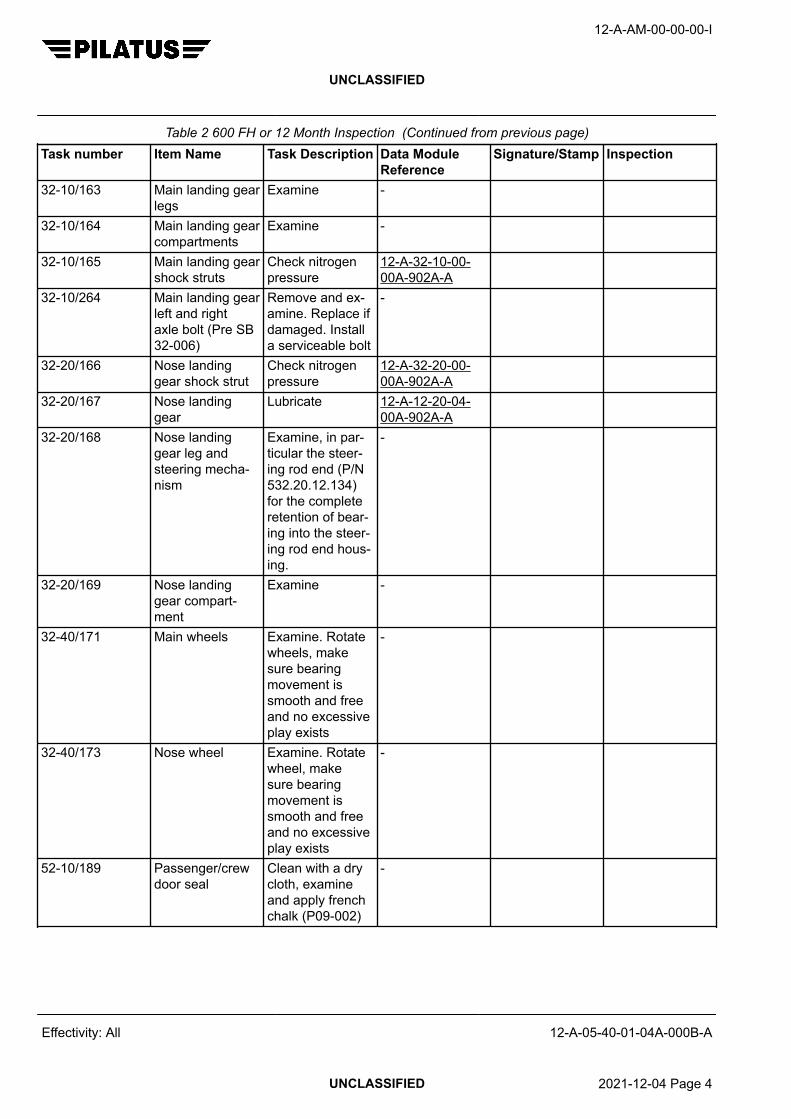
Table 2 600 FH or 12 Month Inspection (Continued from previous page)Task number Item Name Task Description Data Module
ReferenceSignature/Stamp Inspection
32-10/163 Main landing gearlegs
Examine -
32-10/164 Main landing gearcompartments
Examine -
32-10/165 Main landing gearshock struts
Check nitrogenpressure
12-A-32-10-00-00A-902A-A
32-10/264 Main landing gearleft and rightaxle bolt (Pre SB32-006)
Remove and ex-amine. Replace ifdamaged. Installa serviceable bolt
-
32-20/166 Nose landinggear shock strut
Check nitrogenpressure
12-A-32-20-00-00A-902A-A
32-20/167 Nose landinggear
Lubricate 12-A-12-20-04-00A-902A-A
32-20/168 Nose landinggear leg andsteering mecha-nism
Examine, in par-ticular the steer-ing rod end (P/N532.20.12.134)for the completeretention of bear-ing into the steer-ing rod end hous-ing.
-
32-20/169 Nose landinggear compart-ment
Examine -
32-40/171 Main wheels Examine. Rotatewheels, makesure bearingmovement issmooth and freeand no excessiveplay exists
-
32-40/173 Nose wheel Examine. Rotatewheel, makesure bearingmovement issmooth and freeand no excessiveplay exists
-
52-10/189 Passenger/crewdoor seal
Clean with a drycloth, examineand apply frenchchalk (P09-002)
-
12-A-AM-00-00-00-I
UNCLASSIFIED
Effectivity: All 12-A-05-40-01-04A-000B-A
UNCLASSIFIED 2021-12-04 Page 4

Table 2 600 FH or 12 Month Inspection (Continued from previous page)Task number Item Name Task Description Data Module
ReferenceSignature/Stamp Inspection
52-10/190 Passenger/crewdoor shoot boltsand door framefittings
Examine -
52-10/191 Passenger/crewdoor handle lockpin and latch
Make sure move-ment is free.Lubricate withCPC (P10-001)as necessarywhen operatingin freezing condi-tions.
-
52-10/192 Passenger/crewdoor hinges
Examine and lu-bricate as nec-essary with mini-mum quantity ofCPC (P10-001)
-
52-30/193 Cargo door seal Clean with a drycloth, examineand apply frenchchalk (P09-002)
-
52-30/194 Cargo door shootbolts, door framefittings and hooks
Examine. Makesure the hook roll-er bushes arefree to rotate.For roller bushwear limits referto AMM.
12-A-52-30-00-00A-313A-A
52-30/195 Cargo door hing-es
Examine and lu-bricate as nec-essary with mini-mum quantity ofCPC (P10-001)
-
71-00/101 Power plant tor-que limiter
Operational test 12-A-71-00-00-00A-903H-A
71-00/102 Power plant per-formance
Operational test 12-A-71-00-00-00A-903I-A
71-00/106 Oil pressuretransducer elec-trical connector(Pre SB 79-004)
Clean 12-A-71-00-03-00A-250A-A
71-00/107 Engine torqueand stick pushertorque transducerelectrical connec-tors
Clean 12-A-71-00-03-00A-250A-A
12-A-AM-00-00-00-I
UNCLASSIFIED
Effectivity: All 12-A-05-40-01-04A-000B-A
UNCLASSIFIED 2021-12-04 Page 5

Table 2 600 FH or 12 Month Inspection (Continued from previous page)Task number Item Name Task Description Data Module
ReferenceSignature/Stamp Inspection
76-00/210 Engine controlsin engine com-partment
Examine -
79-00/215 Oil filler cap/dip-stick
Energize aircraftelectrical system,refer to AMM.Remove fillercap, examineand make surethe seal is ingood condition.Set and hold AIR/GROUND switchto GROUND andmake sure after60 seconds theCAWS OIL QTYcaption comeson. Install fillercap and makesure the lockingmechanism oper-ates correctly
12-A-24-00-00-00A-901A-A
12-A-AM-00-00-00-I
UNCLASSIFIED
Effectivity: All 12-A-05-40-01-04A-000B-A
End of data moduleUNCLASSIFIED 2021-12-04 Page 6

1200 FH OR 12 MONTHS INSPECTION
FUNCTION, DATA FOR PLANS AND DESCRIPTION
Table of Contents Page
1200 FH OR 12 MONTHS INSPECTION - FUNCTION, DATA FOR PLANS ANDDESCRIPTION...........................................................................................................................
1
1 General................................................................................................................... 32 Inspections............................................................................................................. 3
Index of Tables Page
1 References............................................................................................................. 12 1200 FH or 12 Month Inspection............................................................................ 3
ReferencesTable 1 References
Data module/Technical publication Title
12-A-05-20-00-00A-018A-A SCHEDULED MAINTENANCE CHECK LISTS - INTRODUC-TION
12-A-11-00-00-00A-040A-A PLACARDS AND MARKINGS - DESCRIPTION AND OPERA-TION
12-A-11-00-00-00A-901A-A PLACARDS AND MARKINGS - MAINTENANCE PRACTICES
12-A-21-40-00-00A-903A-A AUXILIARY HEATING SYSTEM (MSN 321 – 999 ANDA/C WITH MODIFIED AUX HEATING SYSTEM) - ADJUST-MENT/TEST
12-A-21-40-02-00A-250A-A WATER SEPARATOR - CLEAN AND APPLY SURFACE PRO-TECTION
12-A-21-40-09-00A-903A-A SECONDARY HEATERS THERMAL PROTECTIONSWITCHES (MSN 101 – 320 WITHOUT A MODIFIED AUXILI-ARY HEATING SYSTEM) - ADJUSTMENT/TEST
12-A-21-40-11-00A-903A-A FOOT HEATER THERMAL PROTECTION SWITCH (POSTSB 21–004 AND AIRCRAFT WITH A FOOT HEATER SYS-TEM) - ADJUSTMENT/TEST
12-A-22-10-00-00A-313A-A AUTOPILOT - INSPECTION/CHECK
12-A-22-20-00-00A-903A-A SPEED AND ATTITUDE CORRECTION SYSTEM - ADJUST-MENT/TEST
12-A-24-20-00-00A-903A-A AC GENERATION SYSTEM - ADJUSTMENT/TEST
12-A-25-10-01-00A-920A-A CREW SEATS (MSN 101 – 660) - REMOVAL/INSTALLATION
12-A-25-10-05-00A-920A-A CREW SEATS (MSN 661 – 999) - REMOVAL/INSTALLATION
12-A-AM-00-00-00-I
UNCLASSIFIED
Effectivity: All 12-A-05-40-01-05A-000B-A
UNCLASSIFIED 2021-12-04 Page 1

Data module/Technical publication Title
12-A-27-10-00-00A-313A-A AILERON CONTROL SYSTEM - INSPECTION/CHECK
12-A-27-10-00-00A-901A-A AILERON CONTROL SYSTEM - MAINTENANCE PRACTI-CES
12-A-27-10-00-00A-903A-A AILERON CONTROL SYSTEM (MSN 101 – 683) - ADJUST-MENT/TEST
12-A-27-10-00-00A-903B-A AILERON CONTROL SYSTEM (MSN 684 – 999) - ADJUST-MENT/TEST
12-A-27-20-00-00A-313A-A RUDDER CONTROL SYSTEM - INSPECTION/CHECK
12-A-27-20-00-00A-903A-A RUDDER CONTROL SYSTEM (MSN 101 – 683) - ADJUST-MENT/TEST
12-A-27-20-00-00A-903B-A RUDDER CONTROL SYSTEM (MSN 684 – 999) - ADJUST-MENT/TEST
12-A-27-30-00-00A-313A-A ELEVATOR CONTROL SYSTEM - INSPECTION/CHECK
12-A-27-30-00-00A-903A-A ELEVATOR CONTROL SYSTEM - ADJUSTMENT/TEST
12-A-27-40-00-00A-903A-A HORIZONTAL STABILIZER TRIM - ADJUSTMENT/TEST
12-A-27-40-01-00A-313A-A PITCH TRIM ACTUATOR AND ATTACHMENTS - INSPEC-TION/CHECK
12-A-27-50-00-00A-903A-A FLAPS (PRE SB 27–013) - ADJUSTMENT/TEST
12-A-27-50-00-00A-903B-A FLAPS (POST SB 27–013 and MSN 401 – 999) - ADJUST-MENT/TEST
12-A-29-10-02-00A-901A-A ACCUMULATOR - MAINTENANCE PRACTICES
12-A-30-10-00-00A-903A-A AIRFOIL DE-ICE SYSTEM - ADJUSTMENT/TEST
12-A-32-20-03-00A-250A-A SPRING STRUT (PART NO. 532.20.12.250) - CLEAN ANDAPPLY SURFACE PROTECTION
12-A-32-20-03-00A-920A-A SPRING STRUT - REMOVAL/INSTALLATION
12-A-32-30-00-00A-903A-A EXTENSION AND RETRACTION - ADJUSTMENT/TEST
12-A-34-11-00-00A-040A-A PITOT–STATIC SYSTEM - DESCRIPTION AND OPERATION
12-A-34-11-20-00A-901A-A DUAL PITOT STATIC SYSTEM - MAINTENANCE PRACTI-CES
12-A-35-00-00-00A-903A-A OXYGEN SYSTEM - ADJUSTMENT/TEST
12-A-52-70-00-00A-903A-A DOOR WARNING - ADJUSTMENT/TEST
12-A-53-00-01-00A-663A-A NLG ACTUATOR ATTACHMENT BRACKET REPAIRRM07274 - SPECIAL REPAIR PROCEDURES
12-A-53-20-02-00A-313A-A CENTER FUSELAGE FRAMES – CARRY THROUGHFRAMES - INSPECTION/CHECK
12-A-54-20-02-00A-664A-A ENGINE FRAME DAMAGED PAINT AND CORROSION RE-MOVAL - SPECIAL REPAIR PROCEDURES
12-A-55-00-00-00A-313A-A STABILIZERS ATTACHMENT FITTINGS - INSPEC-TION/CHECK
12-A-AM-00-00-00-I
UNCLASSIFIED
Effectivity: All 12-A-05-40-01-05A-000B-A
UNCLASSIFIED 2021-12-04 Page 2

Data module/Technical publication Title
12-A-55-20-01-00A-904B-A ELEVATOR LEVER FITTING - UP AND DOWN STOP - RE-PAIR
12-A-76-10-00-00A-903A-A POWER CONTROLS - ADJUSTMENT/TEST
12-A-76-20-00-00A-903A-A MANUAL OVERRIDE - ADJUSTMENT/TEST
Description
1 General
The terms used for the item inspection requirements are defined in 12-A-05-20-00-00A-018A-A.
2 Inspections
Table 2 1200 FH or 12 Month InspectionTask number Item Name Task Description Data Module
ReferenceSignature/Stamp Inspection
06-00/610 Access panels,empennage:31AB, 31AL,31AR, 32AB,32BL, 32BR,32AL, 32CL,32CT, 32DL,32DR, 32BT,33DT, 33ET,34DT
Open or remove.Examine
12-A-06-20-00-00A-040A-A
06-00/611 Access panels,empennage:31AB, 31AL,31AR, 32AB,32BL, 32BR,32AL, 32CL,32CT, 32DL,32DR, 32BT,33DT, 33ET,34DT
Close or install 12-A-06-20-00-00A-040A-A
06-00/612 Access panels,engine: 42AT,42AB
Remove and ex-amine
12-A-06-20-00-00A-040A-A
06-00/613 Access panels,engine: 42AT,42AB
Install 12-A-06-20-00-00A-040A-A
12-A-AM-00-00-00-I
UNCLASSIFIED
Effectivity: All 12-A-05-40-01-05A-000B-A
UNCLASSIFIED 2021-12-04 Page 3

Table 2 1200 FH or 12 Month Inspection (Continued from previous page)Task number Item Name Task Description Data Module
ReferenceSignature/Stamp Inspection
06-00/628 Access panels,fuselage: 11AL,11AR, 11BR,11BL, 12AL,12AR, 12AB,12EL, 12HZ,12JZ, 12MZ,11BZ, 12AZ,12BZ, 12DZ,12GZ, 12BL,12BR, 12EZ,12ER, 12KZ,12CZ, 12FZ,12IZ, 12LZ, 21JZ,21QZ, 21GZ,21HZ, 22TZ,22PZ, 22UZ
Open or remove.Examine andmake sure the ac-cess panel drainholes are clear
12-A-06-20-00-00A-040A-A
06-00/629 Access panels,fuselage: 11AL,11AR, 11BR,11BL, 12AL,12AR, 12AB,12EL, 12HZ,12JZ, 12MZ,11BZ, 12AZ,12BZ, 12DZ,12GZ, 12BL,12BR, 12EZ,12ER, 12KZ,12CZ, 12FZ,12IZ, 12LZ, 21JZ,21QZ, 21GZ,21HZ, 22TZ,22PZ, 22UZ
Close or install 12-A-06-20-00-00A-040A-A
06-00/630 Access panels,wing: 51AB,51BB, 51JB,51LB, 52MB,52NB, 52OB,52KB, 51MB,51NB, 52TB,52SB, 52RB,52PB, 51KB,61AB, 61BB,62KB, 62MB,62NB, 62OB,62SB, 62RB,62PB, 61KB,61MB, 61NB,62TB
Remove and ex-amine
12-A-06-20-00-00A-040A-A
12-A-AM-00-00-00-I
UNCLASSIFIED
Effectivity: All 12-A-05-40-01-05A-000B-A
UNCLASSIFIED 2021-12-04 Page 4

Table 2 1200 FH or 12 Month Inspection (Continued from previous page)Task number Item Name Task Description Data Module
ReferenceSignature/Stamp Inspection
06-00/631 Access panels,wing: 51AB,51BB, 51JB,51LB, 52MB,52NB, 52OB,52KB, 51MB,51NB, 52TB,52SB, 52RB,52PB, 51KB,61AB, 61BB,62KB, 62MB,62NB, 62OB,62SB, 62RB,62PB, 61KB,61MB, 61NB,62TB
Install 12-A-06-20-00-00A-040A-A
11-00/220 Placards andmarkings
Examine and at-tach new plac-ards if necessary
12-A-11-00-00-00A-040A-A12-A-11-00-00-00A-901A-A
21-20/127 ECS emergencyshut-off system
Check ECSEMER shut-offlever max pullforce 100 N(22.5 lbf) andmake sure ramair scoop is com-pletely open
-
21-40/50 Water separatorcondenser
Clean 12-A-21-40-02-00A-250A-A
21-40/53 Secondary heat-ers thermal pro-tection switches(MSN 101-320without a modi-fied auxiliaryheating system)
Operational test 12-A-21-40-09-00A-903A-A
21-40/54 Secondary heat-ers thermal pro-tection switches(MSN 321-999and aircraft with amodified auxiliaryheating system)
Operational test 12-A-21-40-00-00A-903A-A
21-40/128 Flight compart-ment foot heat-er (if installed)thermal protectionswitch
Operational test 12-A-21-40-11-00A-903A-A
12-A-AM-00-00-00-I
UNCLASSIFIED
Effectivity: All 12-A-05-40-01-05A-000B-A
UNCLASSIFIED 2021-12-04 Page 5

Table 2 1200 FH or 12 Month Inspection (Continued from previous page)Task number Item Name Task Description Data Module
ReferenceSignature/Stamp Inspection
21-50/223 Vapor cycle cool-ing system (if in-stalled)
Examine the cool-ing unit
-
22-10/60 Servo mount(pitch, roll andyaw)
Remove forclutch check
12-A-22-10-00-00A-313A-A
22-20/226 Stick pusher sys-tem
Functional test 12-A-22-20-00-00A-903A-A
24-20/227 AC electrical sys-tem
Operational test 12-A-24-20-00-00A-903A-A
25-10/300 Crew seats Remove cush-ions, covers andshells (ReferCMM) and exam-ine seat. Installcushions, coversand shells
The CMM docu-ment numbersare given in AMM12-A-25-10-01-00A-920A-A
25-20/137 Passenger seats ExamineIf necessary,reference theapplicable suppli-er CMM (CMM25-20-07 for ex-ecutive seatsandCMM 25-20-99for standardseats).For executiveseats only, withthe seat cush-ion removed,check the hydro-lock rearattach-ment bolt for se-curity of attach-ment
-
25-60/232 ELT installation Examine -27-10/234 Aileron LH and
RH rods and lev-ers
ExamineSpray PTFE Tef-lon Spray OKS571 (or equiv-alent) aroundthe aileron push-rod guide rollersleeves at allthree locations ineach wing
-
12-A-AM-00-00-00-I
UNCLASSIFIED
Effectivity: All 12-A-05-40-01-05A-000B-A
UNCLASSIFIED 2021-12-04 Page 6

Table 2 1200 FH or 12 Month Inspection (Continued from previous page)Task number Item Name Task Description Data Module
ReferenceSignature/Stamp Inspection
27-10/235 Aileron electricalbonding straps
Examine -
27-10/236 Aileron controlsystem
Inspection/check 12-A-27-10-00-00A-313A-A
27-10/237 Aileron cable ten-sion
Check MSN 101-683 12-A-27-10-00-00A-903A-AMSN 684-999 12-A-27-10-00-00A-903B-A
27-10/470 Aileron controlsystem bearings
Lubricate 12-A-27-10-00-00A-901A-A
27-20/241 Rudder controlsystem
Inspection/check 12-A-27-20-00-00A-313A-A
27-20/242 Aileron/rudder in-terconnect sys-tem, MSN101-683
Make sure thelocking mecha-nism is fully en-gaged with theflaps at 40° andthe moving parts(piston and hous-ing) are lubrica-ted. If necessa-ry apply grease(P04-002) with abrush.Retract the flapsto 0° and makesure the lockingmechanism isfully disengaged.
-
27-20/243 Rudder cable ten-sion
Check 12-A-27-20-00-00A-903A-A12-A-27-20-00-00A-903B-A
27-20/246 Rudder electricalbonding straps
Examine -
27-30/247 Elevator electricalbonding straps
Examine -
27-30/249 Elevator controlsystem
Inspection/check 12-A-27-30-00-00A-313A-A
27-30/250 Elevator cabletension
Check 12-A-27-30-00-00A-903A-A
12-A-AM-00-00-00-I
UNCLASSIFIED
Effectivity: All 12-A-05-40-01-05A-000B-A
UNCLASSIFIED 2021-12-04 Page 7
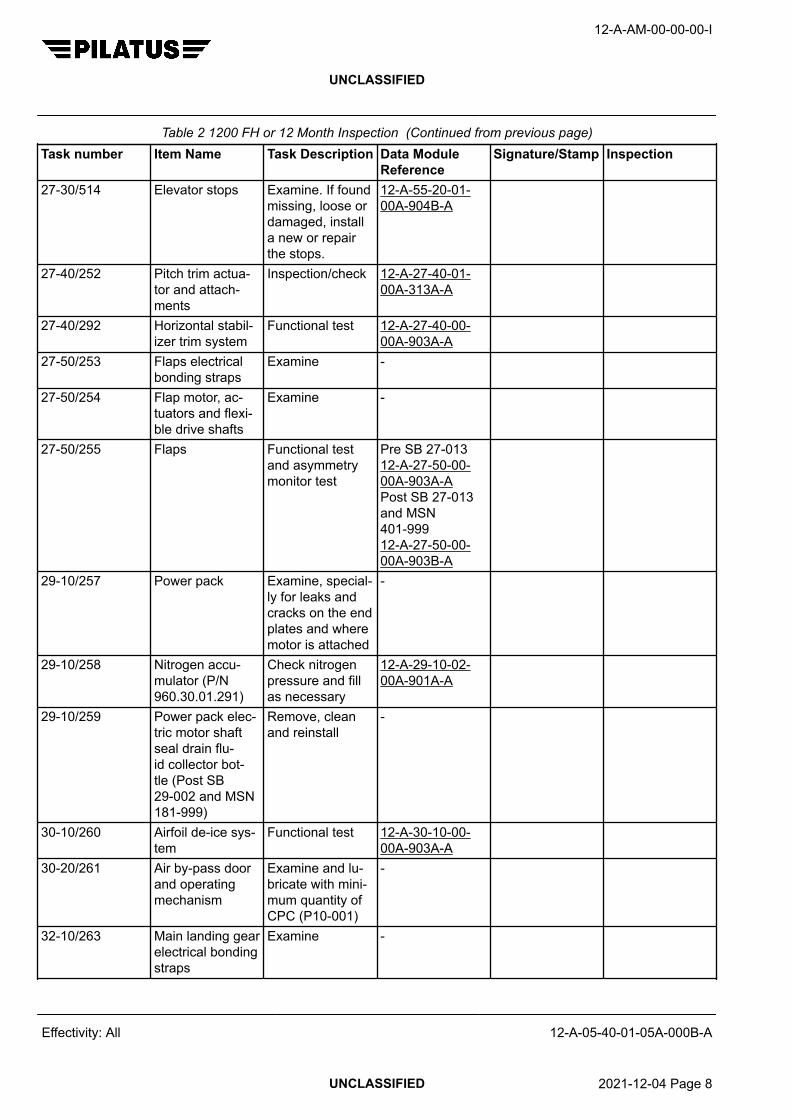
Table 2 1200 FH or 12 Month Inspection (Continued from previous page)Task number Item Name Task Description Data Module
ReferenceSignature/Stamp Inspection
27-30/514 Elevator stops Examine. If foundmissing, loose ordamaged, installa new or repairthe stops.
12-A-55-20-01-00A-904B-A
27-40/252 Pitch trim actua-tor and attach-ments
Inspection/check 12-A-27-40-01-00A-313A-A
27-40/292 Horizontal stabil-izer trim system
Functional test 12-A-27-40-00-00A-903A-A
27-50/253 Flaps electricalbonding straps
Examine -
27-50/254 Flap motor, ac-tuators and flexi-ble drive shafts
Examine -
27-50/255 Flaps Functional testand asymmetrymonitor test
Pre SB 27-01312-A-27-50-00-00A-903A-APost SB 27-013and MSN401-99912-A-27-50-00-00A-903B-A
29-10/257 Power pack Examine, special-ly for leaks andcracks on the endplates and wheremotor is attached
-
29-10/258 Nitrogen accu-mulator (P/N960.30.01.291)
Check nitrogenpressure and fillas necessary
12-A-29-10-02-00A-901A-A
29-10/259 Power pack elec-tric motor shaftseal drain flu-id collector bot-tle (Post SB29-002 and MSN181-999)
Remove, cleanand reinstall
-
30-10/260 Airfoil de-ice sys-tem
Functional test 12-A-30-10-00-00A-903A-A
30-20/261 Air by-pass doorand operatingmechanism
Examine and lu-bricate with mini-mum quantity ofCPC (P10-001)
-
32-10/263 Main landing gearelectrical bondingstraps
Examine -
12-A-AM-00-00-00-I
UNCLASSIFIED
Effectivity: All 12-A-05-40-01-05A-000B-A
UNCLASSIFIED 2021-12-04 Page 8

Table 2 1200 FH or 12 Month Inspection (Continued from previous page)Task number Item Name Task Description Data Module
ReferenceSignature/Stamp Inspection
32-20/265 Nose landinggear electricalbonding straps
Examine -
32-20/266 Nose landinggear springstrut (P/N532.20.12.250)
Remove, cleanand lubricate
12-A-32-20-03-00A-920A-Aand 12-A-32-20-03-00A-250A-A
32-20/305 Nose landinggear actuatorfuselage attach-ment fitting (P/N553.10.12.326)
Examine, ifcracks are foundreplace attach-ment fitting
SRM 12-A-53-00-01-00A-663A-A
32-30/170 Extension and re-traction system(Hydraulic landinggear)
Functional test ofextension and re-traction systemand emergencyextension system
12-A-32-30-00-00A-903A-A
34-11/268 Pitot and staticsystem
Drain Single system 12-A-34-11-10-00A-901A-ADual system 12-A-34-11-20-00A-901A-A
35-10/269 Oxygen pipelinesand equipment
Examine -
35-10/270 Oxygen system Operational test 12-A-35-00-00-00A-903A-A
52-10/271 Passenger/crewdoor, counterbal-ance and cablesupport brackets
Examine -
52-20/272 Emergency door Examine (door re-moved)
-
52-20/273 Emergency doorseal
Clean with a wetcloth, dry andexamine and ap-ply french chalk(P09-002)
-
52-30/274 Cargo door Examine -52-70/275 Door warning
systemOperational test 12-A-52-70-00-
00A-903A-A53-00/276 Rear pressure
bulkheadExamine -
12-A-AM-00-00-00-I
UNCLASSIFIED
Effectivity: All 12-A-05-40-01-05A-000B-A
UNCLASSIFIED 2021-12-04 Page 9

Table 2 1200 FH or 12 Month Inspection (Continued from previous page)Task number Item Name Task Description Data Module
ReferenceSignature/Stamp Inspection
53-00/277 Floor top and bot-tom surface andseat rails
Examine as far aspossible with car-pet and floor pan-els in Task 06–00/218 removed
-
53-00/280 Rear fuselage in-ternal structure
Examine as far aspossible, in par-ticular examinebattery mountingtray for corrosion
-
53-00/337 Carry throughFrames 21 and24
Inspection/check 12-A-53-20-02-00A-313A-A
55-10/319 Horizontal/verticalstabilizer attach-ment
Inspection/check 12-A-55-00-00-00A-313A-A
55-30/281 Vertical stabilizerelectrical bondingstraps
Examine -
56-11/517 Cockpit DV Win-dow
Make sure thatyou can openand close the DVwindow with onehand
-
57-00/283 Wing internal sur-faces and flapcompartment
Examine as far aspossible with pan-els in Task 06–00/218 opened/removed
-
57-00/284 Wing to fuselageattachments
Examine as far aspossible
-
61-20/286 Propeller gover-nor, overspeedgovernor and be-ta controls
Examine -
71-00/205 Engine tubularmounting frameand shockmounts
Examine. Re-place shock-mount if cracksin elastomer aremore than 25,4mm (1 in) longand/or 1,5 mm(0.06 in) deep.
-
12-A-AM-00-00-00-I
UNCLASSIFIED
Effectivity: All 12-A-05-40-01-05A-000B-A
UNCLASSIFIED 2021-12-04 Page 10
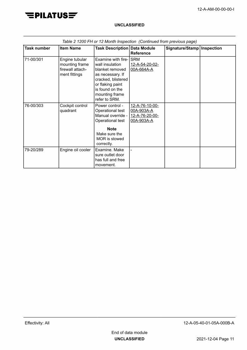
Table 2 1200 FH or 12 Month Inspection (Continued from previous page)Task number Item Name Task Description Data Module
ReferenceSignature/Stamp Inspection
71-00/301 Engine tubularmounting framefirewall attach-ment fittings
Examine with fire-wall insulationblanket removedas necessary. Ifcracked, blisteredor flaking paintis found on themounting framerefer to SRM.
SRM 12-A-54-20-02-00A-664A-A
76-00/303 Cockpit controlquadrant
Power control -Operational testManual override -Operational test
NoteMake sure theMOR is stowedcorrectly.
12-A-76-10-00-00A-903A-A12-A-76-20-00-00A-903A-A
79-20/289 Engine oil cooler Examine. Makesure outlet doorhas full and freemovement.
-
12-A-AM-00-00-00-I
UNCLASSIFIED
Effectivity: All 12-A-05-40-01-05A-000B-A
End of data moduleUNCLASSIFIED 2021-12-04 Page 11

12-A-AM-00-00-00-I
UNCLASSIFIED
Intentionally left blank
Effectivity: All 12-A-05-40-01-05A-000B-A
UNCLASSIFIED 2021-12-04 Page 12

2400 FH OR 24 MONTHS INSPECTION
FUNCTION, DATA FOR PLANS AND DESCRIPTION
Table of Contents Page
2400 FH OR 24 MONTHS INSPECTION - FUNCTION, DATA FOR PLANS ANDDESCRIPTION...........................................................................................................................
1
1 General................................................................................................................... 22 Inspections............................................................................................................. 2
Index of Tables Page
1 References............................................................................................................. 12 2400 FH or 24 Month Inspection............................................................................ 2
ReferencesTable 1 References
Data module/Technical publication Title
12-A-05-20-00-00A-018A-A SCHEDULED MAINTENANCE CHECK LISTS - INTRODUC-TION
12-A-21-30-01-00A-250A-A PRESSURIZATION CONTROL - CLEAN
12-A-24-30-00-00A-903A-A DC GENERATION SYSTEM (MSN 101 – 320, 322 – 400) -ADJUSTMENT/TEST
12-A-24-30-00-00A-903B-A DC GENERATION SYSTEM (MSN 321, 401 – 999) - ADJUST-MENT/TEST
12-A-27-10-00-00A-903A-A AILERON CONTROL SYSTEM (MSN 101 – 683) - ADJUST-MENT/TEST
12-A-27-10-00-00A-903B-A AILERON CONTROL SYSTEM (MSN 684 – 999) - ADJUST-MENT/TEST
12-A-27-15-00-00A-903A-A AILERON TRIM (MSN 101 – 683) - ADJUSTMENT/TEST
12-A-27-15-00-00A-903B-A AILERON TRIM (MSN 684 – 999) - ADJUSTMENT/TEST
12-A-27-20-00-00A-903A-A RUDDER CONTROL SYSTEM (MSN 101 – 683) - ADJUST-MENT/TEST
12-A-27-20-00-00A-903B-A RUDDER CONTROL SYSTEM (MSN 684 – 999) - ADJUST-MENT/TEST
12-A-27-25-00-00A-903A-A RUDDER TRIM - ADJUSTMENT/TEST
12-A-27-30-00-00A-903A-A ELEVATOR CONTROL SYSTEM - ADJUSTMENT/TEST
12-A-29-10-02-00A-901A-A ACCUMULATOR - MAINTENANCE PRACTICES
12-A-AM-00-00-00-I
UNCLASSIFIED
Effectivity: All 12-A-05-40-01-06A-000B-A
UNCLASSIFIED 2021-12-04 Page 1
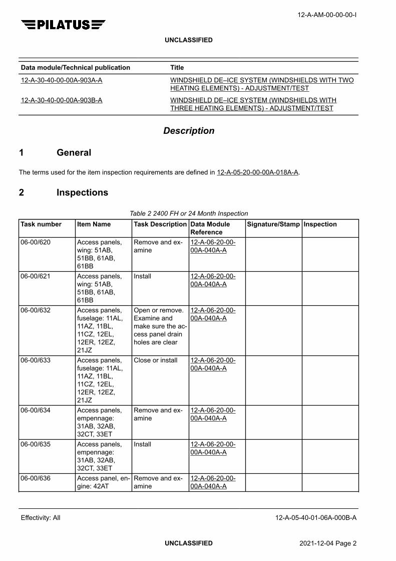
Data module/Technical publication Title
12-A-30-40-00-00A-903A-A WINDSHIELD DE–ICE SYSTEM (WINDSHIELDS WITH TWOHEATING ELEMENTS) - ADJUSTMENT/TEST
12-A-30-40-00-00A-903B-A WINDSHIELD DE–ICE SYSTEM (WINDSHIELDS WITHTHREE HEATING ELEMENTS) - ADJUSTMENT/TEST
Description
1 General
The terms used for the item inspection requirements are defined in 12-A-05-20-00-00A-018A-A.
2 Inspections
Table 2 2400 FH or 24 Month InspectionTask number Item Name Task Description Data Module
ReferenceSignature/Stamp Inspection
06-00/620 Access panels,wing: 51AB,51BB, 61AB,61BB
Remove and ex-amine
12-A-06-20-00-00A-040A-A
06-00/621 Access panels,wing: 51AB,51BB, 61AB,61BB
Install 12-A-06-20-00-00A-040A-A
06-00/632 Access panels,fuselage: 11AL,11AZ, 11BL,11CZ, 12EL,12ER, 12EZ,21JZ
Open or remove.Examine andmake sure the ac-cess panel drainholes are clear
12-A-06-20-00-00A-040A-A
06-00/633 Access panels,fuselage: 11AL,11AZ, 11BL,11CZ, 12EL,12ER, 12EZ,21JZ
Close or install 12-A-06-20-00-00A-040A-A
06-00/634 Access panels,empennage:31AB, 32AB,32CT, 33ET
Remove and ex-amine
12-A-06-20-00-00A-040A-A
06-00/635 Access panels,empennage:31AB, 32AB,32CT, 33ET
Install 12-A-06-20-00-00A-040A-A
06-00/636 Access panel, en-gine: 42AT
Remove and ex-amine
12-A-06-20-00-00A-040A-A
12-A-AM-00-00-00-I
UNCLASSIFIED
Effectivity: All 12-A-05-40-01-06A-000B-A
UNCLASSIFIED 2021-12-04 Page 2

Table 2 2400 FH or 24 Month Inspection (Continued from previous page)Task number Item Name Task Description Data Module
ReferenceSignature/Stamp Inspection
06-00/637 Access panel, en-gine: 42AT
Install 12-A-06-20-00-00A-040A-A
21-20/221 ECS and bleedair ducts, pipe-lines, equipmentand associatedclamps in the en-gine compartment
Examine -
21-30/47 Cabin pressuriza-tion positive pres-sure relief valveand outflow valve
Check for con-tamination of thevalve poppet andpoppet seat. Ifcontamination isfound removeand clean
12-A-21-30-01-00A-250A-A
22-10/233 Pitch, roll, andyaw actuatorsand capstan con-trol cables
Examine -
24-30/228 External power Operational test 12-A-24-30-00-00A-903A-A12-A-24-30-00-00A-903B-A
24-40/229 External PowerUnit (EPU) recep-tacle
Examine -
24-60/133 Cockpit circuitbreaker panelsand switch panels
Examine -
27-10/238 Ailerons Functional test MSN 101-683 12-A-27-10-00-00A-903A-AMSN 684-999 12-A-27-10-00-00A-903B-A
27-15/239 Aileron trim Functional test MSN 101-683 12-A-27-15-00-00A-903A-AMSN 684-999 12-A-27-15-00-00A-903B-A
27-20/240 Rudder static dis-chargers
Examine -
27-20/244 Rudder Functional test 12-A-27-20-00-00A-903A-A12-A-27-20-00-00A-903B-A
12-A-AM-00-00-00-I
UNCLASSIFIED
Effectivity: All 12-A-05-40-01-06A-000B-A
UNCLASSIFIED 2021-12-04 Page 3

Table 2 2400 FH or 24 Month Inspection (Continued from previous page)Task number Item Name Task Description Data Module
ReferenceSignature/Stamp Inspection
27-20/245 Rudder trim Functional test 12-A-27-25-00-00A-903A-A
27-30/248 Elevator staticdischargers
Examine -
27-30/251 Elevator Functional test 12-A-27-30-00-00A-903A-A
28-20/256 Fuel system com-ponents
Examine as faras possible withthose accesspanels opened/removed in thisinspection pack-age.
-
29-10/471 Nitrogen accu-mulator (P/N960.30.01.292)
Check nitrogenpressure and fillas necessary
12-A-29-10-02-00A-901A-A
30-40/262 Windshield de-icesystem
Operational test 12-A-30-40-00-00A-903A-Aor 12-A-30-40-00-00A-903B-A
34-00/183 Communicationsand navigationantennas
Examine -
53-00/278 Baggage/freightnet mountingplates attachmentbolts and sur-rounding struc-ture
Examine for cor-rosion
-
53-00/279 Baggage com-partment
Examine -
57-00/282 Wing tip staticdischargers
Examine -
12-A-AM-00-00-00-I
UNCLASSIFIED
Effectivity: All 12-A-05-40-01-06A-000B-A
End of data moduleUNCLASSIFIED 2021-12-04 Page 4
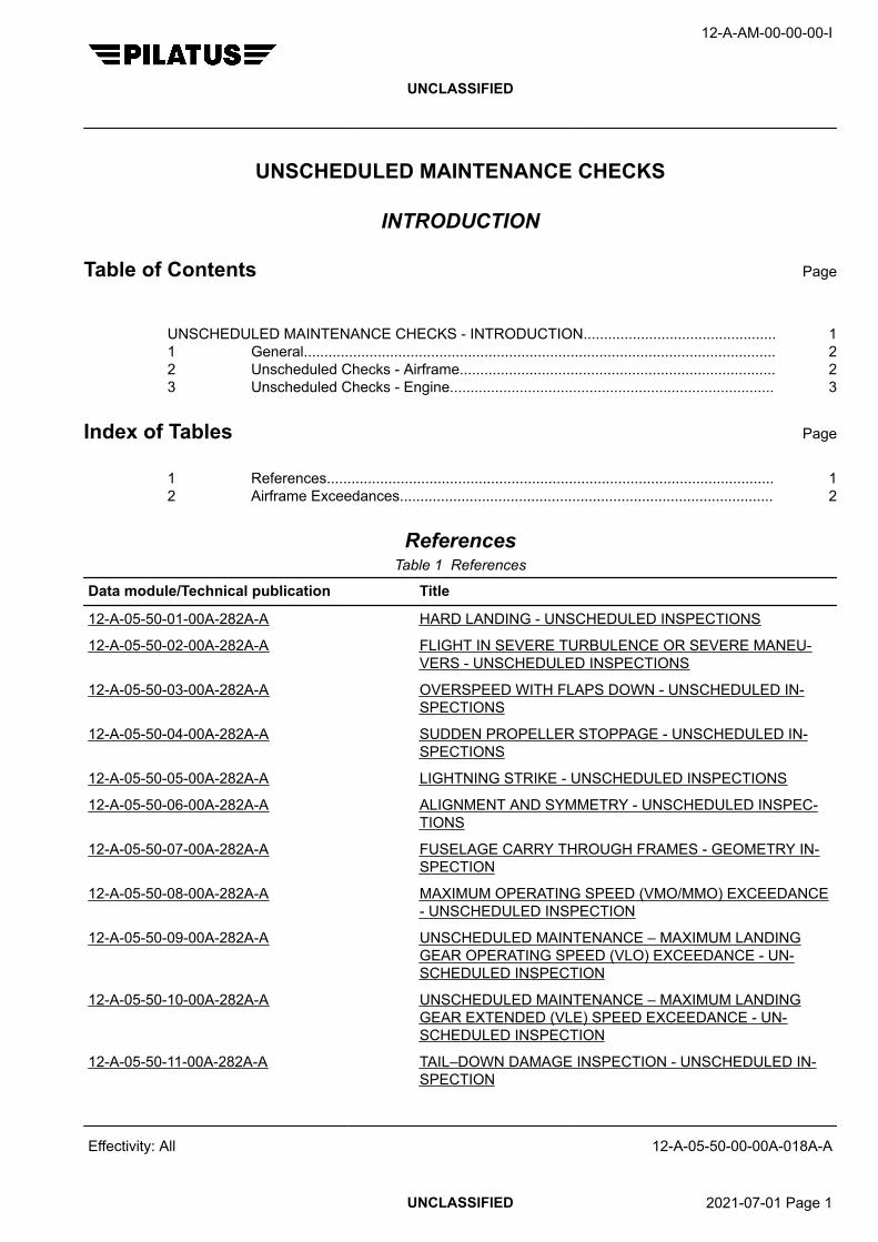
UNSCHEDULED MAINTENANCE CHECKS
INTRODUCTION
Table of Contents Page
UNSCHEDULED MAINTENANCE CHECKS - INTRODUCTION............................................... 11 General................................................................................................................... 22 Unscheduled Checks - Airframe............................................................................. 23 Unscheduled Checks - Engine............................................................................... 3
Index of Tables Page
1 References............................................................................................................. 12 Airframe Exceedances........................................................................................... 2
ReferencesTable 1 References
Data module/Technical publication Title
12-A-05-50-01-00A-282A-A HARD LANDING - UNSCHEDULED INSPECTIONS
12-A-05-50-02-00A-282A-A FLIGHT IN SEVERE TURBULENCE OR SEVERE MANEU-VERS - UNSCHEDULED INSPECTIONS
12-A-05-50-03-00A-282A-A OVERSPEED WITH FLAPS DOWN - UNSCHEDULED IN-SPECTIONS
12-A-05-50-04-00A-282A-A SUDDEN PROPELLER STOPPAGE - UNSCHEDULED IN-SPECTIONS
12-A-05-50-05-00A-282A-A LIGHTNING STRIKE - UNSCHEDULED INSPECTIONS
12-A-05-50-06-00A-282A-A ALIGNMENT AND SYMMETRY - UNSCHEDULED INSPEC-TIONS
12-A-05-50-07-00A-282A-A FUSELAGE CARRY THROUGH FRAMES - GEOMETRY IN-SPECTION
12-A-05-50-08-00A-282A-A MAXIMUM OPERATING SPEED (VMO/MMO) EXCEEDANCE- UNSCHEDULED INSPECTION
12-A-05-50-09-00A-282A-A UNSCHEDULED MAINTENANCE – MAXIMUM LANDINGGEAR OPERATING SPEED (VLO) EXCEEDANCE - UN-SCHEDULED INSPECTION
12-A-05-50-10-00A-282A-A UNSCHEDULED MAINTENANCE – MAXIMUM LANDINGGEAR EXTENDED (VLE) SPEED EXCEEDANCE - UN-SCHEDULED INSPECTION
12-A-05-50-11-00A-282A-A TAIL–DOWN DAMAGE INSPECTION - UNSCHEDULED IN-SPECTION
12-A-AM-00-00-00-I
UNCLASSIFIED
Effectivity: All 12-A-05-50-00-00A-018A-A
UNCLASSIFIED 2021-07-01 Page 1

Data module/Technical publication Title
12-A-05-50-12-00A-282A-A NOSE LANDING GEAR OVERTURNING - UNSCHEDULEDINSPECTION
12-A-05-50-15-00A-282A-A AFTER A FLIGHT THROUGH VOLCANIC ASH OR SMOKE -UNSCHEDULED INSPECTION
Description
1 General
Unscheduled maintenance checks are necessary if unusual incidents occur.
These checks must be done before the next flight following the incident.
2 Unscheduled Checks - Airframe
These checks must be done after the following incidents occur or permitted deviations are exceeded:
Check ReferenceHard landing 12-A-05-50-01-00A-282A-AFlight in severe turbulence or after severe maneuvers 12-A-05-50-02-00A-282A-AOverspeed with flaps down 12-A-05-50-03-00A-282A-APropeller sudden stoppage 12-A-05-50-04-00A-282A-ALightning strike 12-A-05-50-05-00A-282A-AAlignment and Symmetry 12-A-05-50-06-00A-282A-AFuselage carry through frames 12-A-05-50-07-00A-282A-AMaximum operating speed exceedance 12-A-05-50-08-00A-282A-AMaximum landing gear operating speed exceedance 12-A-05-50-09-00A-282A-AMaximum landing gear extended speed exceedance 12-A-05-50-10-00A-282A-ATail down damage inspection 12-A-05-50-11-00A-282A-ANose landing gear overturning 12-A-05-50-12-00A-282A-AFlight through volcanic ash or smoke 12-A-05-50-15-00A-282A-A
Table 2 Airframe ExceedancesLimitation Abbreviation Unit Trigger Exceed-
ancerange
Maintenance Action
OVER-SPEED
Max operatingspeed
Vmo knots Pilot report ≤245 None≤252 12-A-05-50-08-00A-282A-A>252 Contact Pilatus¹
Max flap exten-ded speed
Vfe ≤15° knots Pilot report ≤170 None≤180 12-A-05-50-03-00A-282A-A>180 Contact Pilatus¹
12-A-AM-00-00-00-I
UNCLASSIFIED
Effectivity: All 12-A-05-50-00-00A-018A-A
UNCLASSIFIED 2021-07-01 Page 2

Table 2 Airframe Exceedances (Continued from previous page)Limitation Abbreviation Unit Trigger Exceed-
ancerange
Maintenance Action
Max flap exten-ded speed
Vfe >15° knots Pilot report ≤135 None≤145 12-A-05-50-03-00A-282A-A>145 Contact Pilatus¹
Max landinggear operationspeed
Vlo knots Pilot report ≤185 None≤195 12-A-05-50-09-00A-282A-A>195 Contact Pilatus¹
Max landinggear extendedspeed
Vle knots Pilot report ≤245 None≤252 12-A-05-50-10-00A-282A-A>252 Contact Pilatus¹
Contact Pilatus¹ - when you contact Pilatus give a detailed report of the aircraft exceedance.
3 Unscheduled Checks - Engine
These checks must be done after the following incidents occur (Ref. P&WC EMM):− Engine overspeed (Gas generator or propeller)− Overtemperature− Overtorque− Sudden propeller stoppage− Loss of oil pressure− CAWS or EIS CHIP light on
12-A-AM-00-00-00-I
UNCLASSIFIED
Effectivity: All 12-A-05-50-00-00A-018A-A
End of data moduleUNCLASSIFIED 2021-07-01 Page 3

12-A-AM-00-00-00-I
UNCLASSIFIED
Intentionally left blank
Effectivity: All 12-A-05-50-00-00A-018A-A
UNCLASSIFIED 2021-07-01 Page 4

HARD LANDING
UNSCHEDULED INSPECTIONS
Table of Contents Page
HARD LANDING - UNSCHEDULED INSPECTIONS................................................................. 1
Index of Tables Page
1 References............................................................................................................. 12 Required Conditions............................................................................................... 13 Support equipment................................................................................................. 14 Supplies.................................................................................................................. 25 Spares.................................................................................................................... 26 Required Conditions............................................................................................... 3
ReferencesTable 1 References
Data module/Technical publication Title
12-A-05-50-06-00A-282A-A ALIGNMENT AND SYMMETRY - UNSCHEDULED INSPEC-TIONS
12-A-07-10-00-00A-901A-A JACKING - MAINTENANCE PRACTICES
12-A-27-51-00-00A-313A-A FLAP DRIVE SYSTEM - IN SITU INSPECTION/CHECK
12-A-32-30-00-00A-903A-A EXTENSION AND RETRACTION - ADJUSTMENT/TEST
12-A-34-21-00-00A-903A-A STANDBY MAGNETIC COMPASS - ADJUSTMENT/TEST
12-A-34-25-00-00A-903A-A ATTITUDE AND HEADING REFERENCE SYSTEM - AD-JUSTMENT/TEST
Required ConditionsTable 2 Required Conditions
Action / Condition Data module/Technical publication
None
Support equipmentTable 3 Support equipment
Name Identifications/References Qty Reference Remark
None
12-A-AM-00-00-00-I
UNCLASSIFIED
Effectivity: All 12-A-05-50-01-00A-282A-A
UNCLASSIFIED 2018-11-29 Page 1

SuppliesTable 4 Supplies
Name Identifications/References Qty Reference Remark
None
SparesTable 5 Spares
Name Identifications/References Qty Reference Remark
None
Safety ConditionsNone
Procedure1 General
After a hard or overweight landing the following examination should be carried out before furtherflight. An initial examination consists of determining if any external damage has occurred and a moredetailed level of examination of any areas found damaged during the initial examination. If no damageis found during the initial examination then it is not necessary to do the more detailed examination.
If distortion of the skin is found do the Alignment and Symmetry Checks, refer to AMM 12-A-05-50-06-00A-282A-A.
2 Initial Examination2.1 Structure2.1.1 Look for fuel leaks or seepage from seams and rivet heads in the wing integral tank areas.2.1.2 CAUTION
ALTHOUGH SMALL DISTORTIONS FOUND ON FUSELAGE AND WING SKINS MAY SEEMSUFFICIENTLY SMALL AS TO BE IGNORED, A CAREFUL EXAMINATION OF THE INTERNALSUPPORTING STRUCTURE COULD SHOW MAJOR DAMAGE.
2.2 Landing Gear2.2.1 Examine the tires and wheels for damage.2.2.2 Examine the landing gear legs for leaks and damage.2.2.3 Examine the landing gear attachment points for damage.2.2.4 Examine the shock absorber top and bottom attachment points for damage.2.2.5 Examine the landing gear compartments for damage.3 Detailed Examination3.1 Preparation
Raise the aircraft on jacks, refer to AMM 12-A-07-10-00-00A-901A-A.3.2 Structure3.2.1 Remove access panels near the damaged area and examine internal structure as far as possible.
12-A-AM-00-00-00-I
UNCLASSIFIED
Effectivity: All 12-A-05-50-01-00A-282A-A
UNCLASSIFIED 2018-11-29 Page 2

3.2.2 Lower the flaps. Examine the flaps and flap coves. Raise the flaps. Make sure flap movement issmooth.
3.2.3 Examine the flap drive arms, refer to AMM 12-A-27-51-00-00A-313A-A.3.2.4 Move the ailerons up and down and make sure movement is smooth and there are no unusual noises.3.3 Landing Gear3.3.1 Make sure that the wheels are free to rotate.3.3.2 Move the rudder pedals left and right and make sure that the nose wheel steering movement is
satisfactory.3.3.3 Do the adjustment/test of landing gear, refer to AMM 12-A-32-30-00-00A-903A-A.3.4 Engine
Do the engine heavy/hard landing inspection (Ref. P&WC EMM 72-00-00).3.5 Navigation
Do a check swing of the main and standby compass systems, refer to AMM 12-A-34-25-00-00A-903A-A and 12-A-34-21-00-00A-903A-A.
4 Close Up4.1 Lower the aircraft and remove the jacks, refer to AMM 12-A-07-10-00-00A-901A-A.4.2 List all damage found and refer to the Structural Repair Manual for repair information. If serious
structural damage has occurred contact Pilatus Aircraft Ltd. for assistance.
Requirements after job completion
Required ConditionsTable 6 Required Conditions
Action / Condition Data module/Technical publication
None
12-A-AM-00-00-00-I
UNCLASSIFIED
Effectivity: All 12-A-05-50-01-00A-282A-A
End of data moduleUNCLASSIFIED 2018-11-29 Page 3

12-A-AM-00-00-00-I
UNCLASSIFIED
Intentionally left blank
Effectivity: All 12-A-05-50-01-00A-282A-A
UNCLASSIFIED 2018-11-29 Page 4

FLIGHT IN SEVERE TURBULENCE OR SEVERE MANEUVERS
UNSCHEDULED INSPECTIONS
Table of Contents Page
FLIGHT IN SEVERE TURBULENCE OR SEVERE MANEUVERS - UNSCHEDULEDINSPECTIONS............................................................................................................................
1
Index of Tables Page
1 References............................................................................................................. 12 Required Conditions............................................................................................... 13 Support equipment................................................................................................. 14 Supplies.................................................................................................................. 25 Spares.................................................................................................................... 26 Required Conditions............................................................................................... 3
ReferencesTable 1 References
Data module/Technical publication Title
12-A-05-50-06-00A-282A-A ALIGNMENT AND SYMMETRY - UNSCHEDULED INSPEC-TIONS
12-A-27-51-00-00A-313A-A FLAP DRIVE SYSTEM - IN SITU INSPECTION/CHECK
12-A-55-00-00-00A-313A-A STABILIZERS ATTACHMENT FITTINGS - INSPEC-TION/CHECK
Required ConditionsTable 2 Required Conditions
Action / Condition Data module/Technical publication
None
Support equipmentTable 3 Support equipment
Name Identifications/References Qty Reference Remark
None
12-A-AM-00-00-00-I
UNCLASSIFIED
Effectivity: All 12-A-05-50-02-00A-282A-A
UNCLASSIFIED 2021-07-01 Page 1

SuppliesTable 4 Supplies
Name Identifications/References Qty Reference Remark
None
SparesTable 5 Spares
Name Identifications/References Qty Reference Remark
None
Safety ConditionsNone
Procedure1 General
This examination should be done after a flight in severe turbulence or when severe maneuverconditions are reported by the pilot.
If distortion of the skin is found do the Alignment and Symmetry Checks, refer to AMM 12-A-05-50-06-00A-282A-A.
2 CAUTIONALTHOUGH SMALL DISTORTIONS FOUND ON FUSELAGE AND WING SKINS MAY SEEMSUFFICIENTLY SMALL AS TO BE IGNORED, A CAREFUL EXAMINATION OF THE INTERNALSUPPORTING STRUCTURE COULD SHOW MAJOR DAMAGE.
Detailed Examination2.1 Wing2.1.1 Look for fuel leaks from seams and rivet heads in the wing integral tank areas.2.1.2 Examine the top and bottom skins for distortion at rivet rows and for loose or missing rivets.2.1.3 Remove access panels from the wing dry areas and examine the internal structure.2.1.4 Lower the flaps. Examine the flaps and flap coves. Raise the flaps. Make sure flap movement is
smooth.2.1.5 Examine the flap drive arms, refer to AMM 12-A-27-51-00-00A-313A-A.2.1.6 Move the ailerons up and down and make sure movement is smooth and there are no unusual noises.
2.2 Fuselage2.2.1 Examine the fuselage skin for distortion at rivet rows and for loose or missing rivets.2.2.2 Examine the passenger/crew, cargo and emergency exit doors for distortion and correct closing.2.2.3 Examine the battery area for no electrolyte spillage.2.2.4 Examine the battery for security of attachment.2.2.5 Examine the engine cowlings for distortion and security of attachment.
12-A-AM-00-00-00-I
UNCLASSIFIED
Effectivity: All 12-A-05-50-02-00A-282A-A
UNCLASSIFIED 2021-07-01 Page 2

2.3 Stabilizers2.3.1 Examine outside skins for distortion.2.3.2 Move the elevator up and down and make sure there are no unusual noises.2.3.3 Move the rudder left and right and make sure there are no unusual noises.2.3.4 Move the horizontal stabilizer up and down at the tip and make sure there is not too much play, refer to
AMM 12-A-55-00-00-00A-313A-A.
2.4 Repair of Damage
List all damage found and refer to the Structural Repair Manual for repair information. If seriousstructural damage has occurred contact Pilatus Aircraft Ltd. for assistance.
Requirements after job completion
Required ConditionsTable 6 Required Conditions
Action / Condition Data module/Technical publication
None
12-A-AM-00-00-00-I
UNCLASSIFIED
Effectivity: All 12-A-05-50-02-00A-282A-A
End of data moduleUNCLASSIFIED 2021-07-01 Page 3

12-A-AM-00-00-00-I
UNCLASSIFIED
Intentionally left blank
Effectivity: All 12-A-05-50-02-00A-282A-A
UNCLASSIFIED 2021-07-01 Page 4

OVERSPEED WITH FLAPS DOWN
UNSCHEDULED INSPECTIONS
Table of Contents Page
OVERSPEED WITH FLAPS DOWN - UNSCHEDULED INSPECTIONS................................... 1
Index of Tables Page
1 References............................................................................................................. 12 Required Conditions............................................................................................... 13 Support equipment................................................................................................. 14 Supplies.................................................................................................................. 25 Spares.................................................................................................................... 26 Required Conditions............................................................................................... 2
ReferencesTable 1 References
Data module/Technical publication Title
12-A-27-50-00-00A-903A-A FLAPS (PRE SB 27–013) - ADJUSTMENT/TEST
12-A-27-50-00-00A-903B-A FLAPS (POST SB 27–013 and MSN 401 – 999) - ADJUST-MENT/TEST
12-A-27-51-00-00A-313A-A FLAP DRIVE SYSTEM - IN SITU INSPECTION/CHECK
Required ConditionsTable 2 Required Conditions
Action / Condition Data module/Technical publication
None
Support equipmentTable 3 Support equipment
Name Identifications/References Qty Reference Remark
None
12-A-AM-00-00-00-I
UNCLASSIFIED
Effectivity: All 12-A-05-50-03-00A-282A-A
UNCLASSIFIED 2020-05-15 Page 1

SuppliesTable 4 Supplies
Name Identifications/References Qty Reference Remark
None
SparesTable 5 Spares
Name Identifications/References Qty Reference Remark
None
Safety ConditionsNone
Procedure1 General
Do this check if the maximum flap extended speed quoted in the Airplane Flight Manual has beenexceeded.
2 Overspeed with Flaps Down2.1 Examine wing top and bottom skin surfaces for distortion and loose or missing rivets.2.2 Lower the flaps. Remove the flap fairings and examine the flaps and flap covers for distortion and
loose or missing rivets.2.3 Examine the flap support mechanism, flap hinge points and bearings. For the flap drive arms, refer to
AMM 12-A-27-51-00-00A-313A-A.2.4 Do the functional test of the flap system, refer to AMM 12-A-27-50-00-00A-903A-A or 12-A-27-50-00-
00A-903B-A.
NoteWhen the flaps are moving, listen for unusual noises indicating malfunction of the system.
Requirements after job completion
Required ConditionsTable 6 Required Conditions
Action / Condition Data module/Technical publication
None
12-A-AM-00-00-00-I
UNCLASSIFIED
Effectivity: All 12-A-05-50-03-00A-282A-A
End of data moduleUNCLASSIFIED 2020-05-15 Page 2
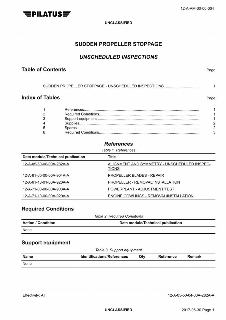
SUDDEN PROPELLER STOPPAGE
UNSCHEDULED INSPECTIONS
Table of Contents Page
SUDDEN PROPELLER STOPPAGE - UNSCHEDULED INSPECTIONS.................................. 1
Index of Tables Page
1 References............................................................................................................. 12 Required Conditions............................................................................................... 13 Support equipment................................................................................................. 14 Supplies.................................................................................................................. 25 Spares.................................................................................................................... 26 Required Conditions............................................................................................... 3
ReferencesTable 1 References
Data module/Technical publication Title
12-A-05-50-06-00A-282A-A ALIGNMENT AND SYMMETRY - UNSCHEDULED INSPEC-TIONS
12-A-61-00-00-00A-904A-A PROPELLER BLADES - REPAIR
12-A-61-10-01-00A-920A-A PROPELLER - REMOVAL/INSTALLATION
12-A-71-00-00-00A-903A-A POWERPLANT - ADJUSTMENT/TEST
12-A-71-10-00-00A-920A-A ENGINE COWLINGS - REMOVAL/INSTALLATION
Required ConditionsTable 2 Required Conditions
Action / Condition Data module/Technical publication
None
Support equipmentTable 3 Support equipment
Name Identifications/References Qty Reference Remark
None
12-A-AM-00-00-00-I
UNCLASSIFIED
Effectivity: All 12-A-05-50-04-00A-282A-A
UNCLASSIFIED 2017-06-30 Page 1

SuppliesTable 4 Supplies
Name Identifications/References Qty Reference Remark
None
SparesTable 5 Spares
Name Identifications/References Qty Reference Remark
None
Safety ConditionsNone
Procedure1 General
Sudden propeller stoppage occurs when the propeller rotation stops due to contact with a hard object.A propeller strike occurs when either; a rotating propeller hits an object or a stationary propeller is hitby a moving object.
If distortion of the skin is found do the Engine Alignment Check (Ref. 12-A-05-50-06-00A-282A-A).2 When A Sudden Propeller Stoppage Occurs2.1 Remove the power plant access panels (Ref. 12-A-71-10-00-00A-920A-A).2.2 Remove the propeller (Ref. 12-A-61-10-01-00A-920A-A) and replace or overhaul.2.3 Examine the engine (Ref. P&WC EMM 72-00-00).2.4 Examine the engine mounting tubular frame (visually and using a straightedge) for distortion.
Distortion is not permissible.2.5 Examine the firewall for distortion.2.6 Install a new or overhauled propeller (Ref. 12-A-61-10-01-00A-920A-A).2.7 Install the power plant access panels (Ref. 12-A-71-10-00-00A-920A-A).2.8 Do the adjustment/test of the engine (Ref. 12-A-71-00-00-00A-903A-A).3 WARNING
WHEN A PROPELLER BLADE IS BENT OR TWISTED, REPAIR IS MAJOR AND AN OVERHAULOF THE PROPELLER MUST BE DONE.
CAUTIONPROPELLER BLADES MUST BE REPAIRED IMMEDIATELY AFTER DAMAGE IS FOUND ORBLADE FAILURE CAN OCCUR.
When A Sudden Propeller Strike Occurs3.1 Remove the power plant access panels 12-A-71-10-00-00A-920A-A.3.2 Examine the propeller.3.3 Minor damage to the propeller blades can be repaired if the damage is less than the permitted limits,
refer to 12-A-61-00-00-00A-904A-A.
12-A-AM-00-00-00-I
UNCLASSIFIED
Effectivity: All 12-A-05-50-04-00A-282A-A
UNCLASSIFIED 2017-06-30 Page 2

3.4 Examine the engine (Ref. P&WC EMM 72-00-00).3.5 Install the power plant access panels (Ref. 12-A-71-10-00-00A-920A-A).
Requirements after job completion
Required ConditionsTable 6 Required Conditions
Action / Condition Data module/Technical publication
None
12-A-AM-00-00-00-I
UNCLASSIFIED
Effectivity: All 12-A-05-50-04-00A-282A-A
End of data moduleUNCLASSIFIED 2017-06-30 Page 3

12-A-AM-00-00-00-I
UNCLASSIFIED
Intentionally left blank
Effectivity: All 12-A-05-50-04-00A-282A-A
UNCLASSIFIED 2017-06-30 Page 4

LIGHTNING STRIKE
UNSCHEDULED INSPECTIONS
Table of Contents Page
LIGHTNING STRIKE - UNSCHEDULED INSPECTIONS.......................................................... 1
Index of Tables Page
1 References............................................................................................................. 12 Required Conditions............................................................................................... 13 Support equipment................................................................................................. 14 Supplies.................................................................................................................. 25 Spares.................................................................................................................... 26 Required Conditions............................................................................................... 3
ReferencesTable 1 References
Data module/Technical publication Title
12-A-32-30-00-00A-903A-A EXTENSION AND RETRACTION - ADJUSTMENT/TEST
12-A-34-21-00-00A-903A-A STANDBY MAGNETIC COMPASS - ADJUSTMENT/TEST
12-A-34-25-00-00A-903A-A ATTITUDE AND HEADING REFERENCE SYSTEM - AD-JUSTMENT/TEST
Required ConditionsTable 2 Required Conditions
Action / Condition Data module/Technical publication
None
Support equipmentTable 3 Support equipment
Name Identifications/References Qty Reference Remark
None
12-A-AM-00-00-00-I
UNCLASSIFIED
Effectivity: All 12-A-05-50-05-00A-282A-A
UNCLASSIFIED 2018-11-29 Page 1

SuppliesTable 4 Supplies
Name Identifications/References Qty Reference Remark
None
SparesTable 5 Spares
Name Identifications/References Qty Reference Remark
None
Safety ConditionsNone
Procedure1 General
Do this check if the aircraft is hit by lightning or it is suspected that it has been hit by lightning.2 Lightning Strike2.1 Find the point at which the lightning hit the aircraft.2.2 Look for secondary damage such as burns or pit near the area of the lightning hit.2.3 Examine the aircraft for signs of discharge.2.4 Examine the static dischargers.2.5 Examine the bonding leads between the area of the lightning hit and the discharge point.2.6 If the aircraft was hit by lightning while on the ground, examine for damage:2.6.1 The landing gear.2.6.2 The nosewheel steering mechanism.2.6.3 The wheels and tires. Make sure that the tire pressures are correct.2.7 If the lightning hit the aircraft on a control surface examine the hinge and bearings on the control
surface.2.8 Operationally test the flight controls and make sure that the movement is full and smooth.2.9 Examine the propeller (Ref. Hartzell POM 149, 61-00-49).2.10 Examine the engine (Ref. P&WC EMM 72-00-00).2.11 Examine the engine mounting frame for signs of burning.2.12 Operationally test all electrical and avionic equipment.2.13 Do a check swing on the main and standby compass systems, refer to AMM 12-A-34-25-00-00A-
903A-A and 12-A-34-21-00-00A-903A-A.2.14 If the aircraft was hit by lightning while on the ground, do a Functional Test of the Extension and
Retraction System, refer to AMM 12-A-32-30-00-00A-903A-A.
12-A-AM-00-00-00-I
UNCLASSIFIED
Effectivity: All 12-A-05-50-05-00A-282A-A
UNCLASSIFIED 2018-11-29 Page 2

Requirements after job completion
Required ConditionsTable 6 Required Conditions
Action / Condition Data module/Technical publication
None
12-A-AM-00-00-00-I
UNCLASSIFIED
Effectivity: All 12-A-05-50-05-00A-282A-A
End of data moduleUNCLASSIFIED 2018-11-29 Page 3

12-A-AM-00-00-00-I
UNCLASSIFIED
Intentionally left blank
Effectivity: All 12-A-05-50-05-00A-282A-A
UNCLASSIFIED 2018-11-29 Page 4

ALIGNMENT AND SYMMETRY
UNSCHEDULED INSPECTIONS
Table of Contents Page
ALIGNMENT AND SYMMETRY - UNSCHEDULED INSPECTIONS......................................... 1
Index of Tables Page
1 References............................................................................................................. 12 Required Conditions............................................................................................... 13 Support equipment................................................................................................. 24 Supplies.................................................................................................................. 25 Spares.................................................................................................................... 26 Required Conditions............................................................................................... 11
Index of Figures Page
1 Longitudinal and Lateral Levelling.......................................................................... 62 Reference Points and Dimensions......................................................................... 73 Recommended In Service Check Form.................................................................. 94 Recommended Comparison Table......................................................................... 10
ReferencesTable 1 References
Data module/Technical publication Title
12-A-00-00-00-00A-060A-A GENERAL - AEROSPACE GROUND EQUIPMENT (AGE)AND TOOLS
12-A-07-10-00-00A-901A-A JACKING - MAINTENANCE PRACTICES
12-A-12-10-01-00A-902A-A FUEL - SERVICING
12-A-32-30-00-00A-903A-A EXTENSION AND RETRACTION - ADJUSTMENT/TEST
Preliminary Requirements
Required ConditionsTable 2 Required Conditions
Action / Condition Data module/Technical publication
None
12-A-AM-00-00-00-I
UNCLASSIFIED
Effectivity: All 12-A-05-50-06-00A-282A-A
UNCLASSIFIED 2021-12-04 Page 1

Support equipmentTable 3 Support equipment
Name Identifications/References Qty Reference Remark
Transit theodolite Part T05-004 As re-quired
Levelling bars x 2 (Steel rulers 5ft (1,5 M))
Part Local supply As re-quired
Tape measure, steel high preci-sion (25 ft (7 M))
Part Local supply As re-quired
Plumb-line Part Local supply As re-quired
SuppliesTable 4 Supplies
Name Identifications/References Qty Reference Remark
None
SparesTable 5 Spares
Name Identifications/References Qty Reference Remark
None
Safety ConditionsWARNING
IF PERMITTED DEVIATIONS ARE EXCEEDED, THE AIRCRAFT SHOULD NOT BE OPERATED UNTILIT HAS BEEN RECTIFIED AND BROUGHT WITHIN ITS DESIGN STRENGTH, SHAPE AND ALIGNMENTTOLERANCES.
NoteTo identify the AGE and tools used in this procedure refer to the list of AGE and tools TEM 12-A-00-00-00-00A-060A-A.
Procedure1 General
These checks are done by taking selected measurements for comparison with the measurementstaken at the same points when the aircraft was prepared for delivery at the manufacturers.
Before the checks are done:
1 The aircraft must be empty of fuel.
2 The aircraft must be parked in a hangar for a minimum of one hour.
3 The aircraft must not be exposed to direct sunlight.
12-A-AM-00-00-00-I
UNCLASSIFIED
Effectivity: All 12-A-05-50-06-00A-282A-A
UNCLASSIFIED 2021-12-04 Page 2

4 The hangar floor must be of concrete, or a similar material.
5 The aircraft must be on jacks with the landing gear retracted.
A record of the Aircraft Build Checks can be obtained from Pilatus Aircraft Ltd.
If the measurements taken are not in the limits given, the aircraft must not be operated, and Pilatusadvised before any further action is taken.
Pilatus will provide any assistance required on receipt of copies of the In-Service Check Form andComparison Table and a full report on the incident which made the check necessary. Details ofstructural damage discovered during the subsequent investigation, should also be included.
2 Alignment and Symmetry2.1 General
A Reference Point (RP) is identified with contrasting paint (usually colored red) and by a washer underthe rivet head.
Reference Dimensions (A, B, C and D) are distances between two reference points.
2.2 Job Set Up2.2.1 Defuel the aircraft , refer to AMM 12-A-12-10-01-00A-902A-A.2.2.2 Prepare an In-Service Check Form.2.2.3 Put the aircraft on jacks, refer to AMM 12-A-07-10-00-00A-901A-A.2.2.4 Retract the landing gear, refer to AMM 12-A-32-30-00-00A-903A-A.2.2.5 Set the horizontal stabilizer trim on the trim indicator to the green diamond position.
2.3 Longitudinal Levelling Check
(Ref. Fig. 1 )
NoteWith the floor carpets installed it will be necessary to put 8 mm spacers on the seat rails below thelevelling bars to give the bars a level surface.
2.3.1 Put a levelling bar across the four seat rails adjacent to the passenger/crew door.2.3.2 Put a levelling bar across the four seat rails adjacent to the cargo door.2.3.3 Set up the theodolite:2.3.3.1 Adjust the tripod to allow readings to be taken at a level approximately 100 to 200 mm below lowest
point of fuselage.2.3.3.2 Level the theodolite base, turn through 360° and check each 90° to make sure that the base is level.2.3.3.3 Level the theodolite head by turning leveling adjuster to match bubble halves visible through the small
leveling eyepiece.2.3.4 Hold the tape measure against the bottom of the front levelling bar.2.3.5 Zoom and focus the theodolite on the tape and make a note of the reading.2.3.6 Hold the tape measure against the bottom of the rear levelling bar.2.3.7 Zoom and focus the theodolite on the tape and make a note of the reading.2.3.8 Compare the front and rear readings. If the readings are not the same, adjust the tail jack and do the
check again.
12-A-AM-00-00-00-I
UNCLASSIFIED
Effectivity: All 12-A-05-50-06-00A-282A-A
UNCLASSIFIED 2021-12-04 Page 3

2.4 Lateral Levelling Check
NoteThe recorded reading is the Correction Factor. The Correction Factor is needed to help determine thedeformation check.
(Ref. Fig. 1 )
NoteIf it is not possible to do the lateral levelling check because of damage to the wing(s), speak to Pilatusfor the data on how to continue.
2.4.1 Set up the theodolite:2.4.1.1 Adjust the tripod to allow readings to be taken approximately 750 mm below RP 6.2.4.1.2 Level the theodolite base, turn through 360° and check each 90° to make sure that the base is level.2.4.1.3 Level the theodolite head by turning leveling adjuster to match bubble halves visible through the small
leveling eyepiece.2.4.2 Hold the tape measure against the RP 6 left.2.4.3 Zoom and focus the theodolite on the tape and make a note of the reading.2.4.4 Hold the tape measure against the RP 6 right.2.4.5 Zoom and focus the theodolite on the tape and make a note of the reading.2.4.6 Compare the left and right reference point readings. If the readings are not the same, adjust the main
jacks and do the check again.
2.5 Deformation and Symmetry Check
(Ref. Fig. 1 , Fig. 2 and Fig. 3 )2.5.1 Put the theodolite in position so that readings can be taken from a measuring tape suspended from
Reference Points 2, 3, 4, 5, 6, 7, 10 and 13.2.5.2 Set up the theodolite:2.5.2.1 Adjust the tripod to allow readings to be taken at a level approximately 100 to 200 mm below lowest
point of fuselage.2.5.2.2 Level the theodolite head by turning leveling adjuster to match bubble halves visible through the small
leveling eyepiece.2.5.3 Hold the tape measure against the RP 6 left, with the zero mark at the center of the painted rivet head,
and approximately 1m of tape exposed so that the scale faces the theodolite.2.5.4 Zoom and focus the theodolite on the tape and make a note of the readings from the measuring tape.
Make a record on the check form.2.5.5 Hold the tape measure against the RP 6 right.2.5.6 Zoom and focus the theodolite on the tape and make a note of the readings from the measuring tape.
Make a record on the check form.2.5.7 Repeat steps 3, 4, 5 and 6 for the Reference Points 7, 5, 4, 3, 2, 10 and 13 (left and right sides).2.5.8 Measure the dimension A, left and right from RP 12 on top surface of wing to RP 10 on the horizontal
stabilizer. Make a record on the check form.2.5.9 Measure the dimensions B, left and right, from RP 12 to RP 8 on the upper leading edge of the vertical
stabilizer. Make a record on the check form.2.5.10 Measure the dimensions C, left and right, from RP 12 to RP 13 on the side of the rear fuselage. Make
a record on the check form.
12-A-AM-00-00-00-I
UNCLASSIFIED
Effectivity: All 12-A-05-50-06-00A-282A-A
UNCLASSIFIED 2021-12-04 Page 4

2.6 Engine Alignment Check
(Ref. Fig. 1 , Fig. 2 and Fig. 3 )
NoteThe propeller blade measure point is to be taken at a radius of 1 meter.
2.6.1 Select one propeller blade as the master blade.2.6.2 Measure 320 mm from the outer tip and mark it over the whole blade chord.
NoteThe distance of 320 mm from the tip is the same as the 1 m distance from the rotation centre.
2.6.3 Position the master blade horizontally.2.6.4 Measure the dimension D on the left hand side, from the trailing edge of the master propeller blade to
the start of the fuselage skin (75 mm forward of frame 10). Make a record on the check form.2.6.5 Turn the master blade through 180° so that the blade is horizontal.2.6.6 Measure the dimension D on the right hand side, from the trailing edge of the master propeller blade
to the start of the fuselage skin (75 mm forward of frame 10). Make a record on the check form.2.6.7 Position the master blade vertically.2.6.8 Put a plumb line in position in front of the propeller.2.6.9 Measure dimension E from the front edge of the master blade to the plumb line. Make a record on the
check form.2.6.10 Turn the master blade through 180° so that the blade is vertical.2.6.11 Measure dimension E from the front edge of the master blade to the plumb line. Make a record on the
check form.
2.7 Completion of Comparison Table
(Ref. Fig. 3 and Fig. 4 )2.7.1 From the information recorded on the In Service Check Form complete the Comparison Table.2.7.2 If the deviation from the build checks is not in the limits given contact Pilatus for advice.
NoteGive as much information as possible about the incident which made the check necessary.
2.8 Close Up2.8.1 Remove the levelling bars and spacers.2.8.2 Lower the landing gear, refer to AMM 12-A-32-30-00-00A-903A-A.2.8.3 Lower the aircraft from jacks, refer to AMM 12-A-07-10-00-00A-901A-A.2.8.4 Refuel the aircraft, refer to AMM 12-A-12-10-01-00A-902A-A.
12-A-AM-00-00-00-I
UNCLASSIFIED
Effectivity: All 12-A-05-50-06-00A-282A-A
UNCLASSIFIED 2021-12-04 Page 5

TRANSIT THEODOLITE
TRANSIT THEODOLITE
0510
1
RP6 RIGHT RP6 LEFT
LEVELLING BARS
Figure 1 Longitudinal and Lateral Levelling
12-A-AM-00-00-00-I
UNCLASSIFIED
Effectivity: All 12-A-05-50-06-00A-282A-A
UNCLASSIFIED 2021-12-04 Page 6

0510
2
1
2
3
4
5
6
7
810
12
13
A
B
C
D
1
R1000
FUS. SKIN END(75mm FORWARD FRAME 10)
D
13
1
1
35
2 4
7
6
10
SAME BLADE LEFT ANDRIGHT HORIZONTAL
A
B
C
12
Figure 2 Reference Points and Dimensions
12-A-AM-00-00-00-I
UNCLASSIFIED
Effectivity: All 12-A-05-50-06-00A-282A-A
UNCLASSIFIED 2021-12-04 Page 7

0510
3
E
R10
00
SAME BLADE UP ANDDOWN HORIZONTAL
LEAD
E
AB
C
8
10
13
8
10 10
2 34 5
6 7
2 34 5
6 7
Figure 2 Reference Points and Dimensions
12-A-AM-00-00-00-I
UNCLASSIFIED
Effectivity: All 12-A-05-50-06-00A-282A-A
UNCLASSIFIED 2021-12-04 Page 8

0510
4
In S
ervi
ce A
lignm
ent a
nd S
ymm
etry
Che
ck F
orm
Ref
eren
ceP
oint
s
Rea
ding
Left
Rea
ding
Rig
ht
Dim
ensi
onLe
ft
Dim
ensi
onR
ight
32
45
67
1013
AB
CD
E
Bot
tom
Top
Figure 3 Recommended In Service Check Form
12-A-AM-00-00-00-I
UNCLASSIFIED
Effectivity: All 12-A-05-50-06-00A-282A-A
UNCLASSIFIED 2021-12-04 Page 9
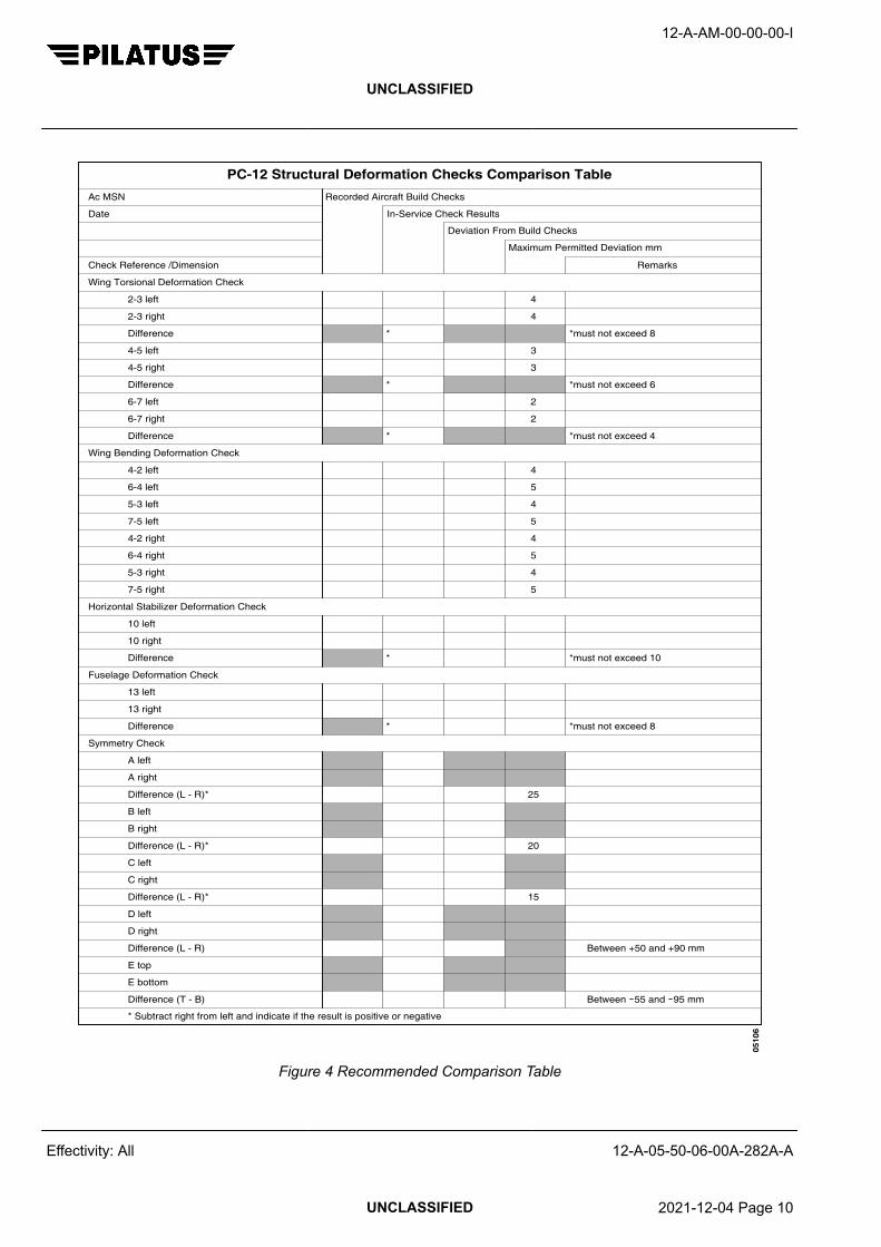
0510
6
Difference (T - B)
E bottom
E top
Difference (L - R)
D right
D left
Difference (L - R)*
C right
C left
Difference (L - R)*
B right
B left
Difference (L - R)*
A right
A left
Symmetry Check
Difference
13 right
13 left
Fuselage Deformation Check
Difference
10 right
10 left
Horizontal Stabilizer Deformation Check
7-5 right
5-3 right
6-4 right
4-2 right
7-5 left
5-3 left
6-4 left
4-2 left
Wing Bending Deformation Check
Difference
6-7 right
6-7 left
Difference
4-5 right
4-5 left
Difference
2-3 right
2-3 left
Wing Torsional Deformation Check
Check Reference /Dimension
Date
Ac MSN
* Subtract right from left and indicate if the result is positive or negative
Deviation From Build Checks
Maximum Permitted Deviation mm
Recorded Aircraft Build Checks
In-Service Check Results
Remarks
*
*
*
*
*
15
20
25
5
4
5
4
5
4
5
4
2
2
3
3
4
4
*must not exceed 8
*must not exceed 10
*must not exceed 4
*must not exceed 6
*must not exceed 8
Between 55 and 95 mm
Between +50 and +90 mm
PC-12 Structural Deformation Checks Comparison Table
Figure 4 Recommended Comparison Table
12-A-AM-00-00-00-I
UNCLASSIFIED
Effectivity: All 12-A-05-50-06-00A-282A-A
UNCLASSIFIED 2021-12-04 Page 10

Requirements after job completion
Required ConditionsTable 6 Required Conditions
Action / Condition Data module/Technical publication
None
12-A-AM-00-00-00-I
UNCLASSIFIED
Effectivity: All 12-A-05-50-06-00A-282A-A
End of data moduleUNCLASSIFIED 2021-12-04 Page 11

12-A-AM-00-00-00-I
UNCLASSIFIED
Intentionally left blank
Effectivity: All 12-A-05-50-06-00A-282A-A
UNCLASSIFIED 2021-12-04 Page 12

FUSELAGE CARRY THROUGH FRAMES
GEOMETRY INSPECTION
Table of Contents Page
FUSELAGE CARRY THROUGH FRAMES - GEOMETRY INSPECTION................................. 1
Index of Tables Page
1 References............................................................................................................. 12 Required Conditions............................................................................................... 23 Support equipment................................................................................................. 24 Supplies.................................................................................................................. 25 Spares.................................................................................................................... 36 Lug Gap dimensions............................................................................................... 57 Required Conditions............................................................................................... 10
Index of Figures Page
1 Jig Assembly LH & RH Lug Bush Fitment.............................................................. 62 Frame 21 and 24 Pin Fitment................................................................................. 73 Lug Gap Identification and Measurements............................................................. 84 Wing Alignment and Longitudinal/Roll Checks....................................................... 9
ReferencesTable 1 References
Data module/Technical publication Title
12-A-05-50-06-00A-282A-A ALIGNMENT AND SYMMETRY - UNSCHEDULED INSPEC-TIONS
12-A-57-00-00-00A-313A-A WING AND FUSELAGE FITTINGS - INSPECTION/CHECK
12-A-57-00-00-00A-520A-A WINGS – LEFT WING - REMOVAL
12-A-57-00-00-00A-720A-A WINGS – LEFT WING - INSTALLATION
12-A-57-00-00-00B-520A-A WINGS – RIGHT WING - REMOVAL
12-A-57-00-00-00B-720A-A WINGS – RIGHT WING - INSTALLATION
12-A-AM-00-00-00-I
UNCLASSIFIED
Effectivity: All 12-A-05-50-07-00A-282A-A
UNCLASSIFIED 2017-06-30 Page 1

Preliminary Requirements
Required ConditionsTable 2 Required Conditions
Action / Condition Data module/Technical publication
None
Support equipmentTable 3 Support equipment
Name Identifications/References Qty Reference Remark
Jig Kit Assembly LH (Includesitems listed below)
Part BM 6107806 1
Jig Kit Assembly RH (Includesitems listed below)
Part BM 6107807 1
Stepped Pin - Frame 21 Upper Part 6107806-05 1 (per kitassy)
Long Pin - Frame 21 Lower Part 6107806-06 1 (per kitassy)
Short Pin - Frame 24 Lower Part 6107806-07 1 (per kitassy)
Knurled Nut Part 6107806-08 1 (per kitassy)
Washer Part 6107806-09 1 (per kitassy)
Bush - Lugs C3 and D3 Part 6107806-10 2 (per kitassy)
Bush - Lugs D1 and D5 Part 6107806-11 2 (per kitassy)
Bush - Lug E2 Part 6107806-12 1 (per kitassy)
Bush - Lug C5 Part 6107806-13 1 (per kitassy)
Bush - Lug C1 Part 6107806-14 1 (per kitassy)
Conical Centre Fittings Part 6107806-20 4 (per kitassy)
SuppliesTable 4 Supplies
Name Identifications/References Qty Reference Remark
None
12-A-AM-00-00-00-I
UNCLASSIFIED
Effectivity: All 12-A-05-50-07-00A-282A-A
UNCLASSIFIED 2017-06-30 Page 2

SparesTable 5 Spares
Name Identifications/References Qty Reference Remark
None
Safety ConditionsCAUTION
THE JIGS ARE PRECISION MADE DELICATE EQUIPMENT AND MUST BE PROTECTED AGAINSTSHOCKS OR HIGH LOADS. DO NOT USE FORCE TO MAKE THE JIGS FIT DEFORMED STRUCTURE.YOU CAN DAMAGE THE JIGS AND/OR THE LUGS ON THE FUSELAGE FRAMES.
Procedure1 General
After a hard landing/ground strike, particularly one bad enough to significantly damage one or bothwings, the fuselage frames may have been distorted or displaced significantly. This can affect adecision to repair or scrap the fuselage. The following procedure provides a means of checkingthat the alignment of the fuselage wing carry-through frames (Frames 21 and 24) conform to theproduction build tolerances. The check is carried out using a pair of dedicated Pilatus jigs.
NoteDo the inspection before the aircraft flies again.
2 Inspection2.1 Carefully examine the fuselage belly skin between Frames 21 and 24 for signs of wrinkling, buckling or
working rivets. Such skin damage indicates that the frames have been laterally displaced.2.2 Carefully examine all rivets, stringers, longerons and panels to the fore, aft and side of each frame for
signs of distortion or cracking.2.3 Carefully inspect the bolted joints to the upper sections of Frames 21 and 24 for cracks.2.4 It is highly recommended (if the wings are not too damaged) that you do an aircraft alignment
check, in accordance with AMM 12-A-05-50-06-00A-282A-A before the wings are removed from theaircraft. The results, when compared with the production alignment check data (available from PilatusCustomer Support), can provide helpful data regarding fuselage alignment or damage.
3 Inspect the Carry-Through Frames
NoteThe following inspections require levelling or angular measurements to a high tolerance. A typicaldigital inclinometer is not accurate for some of the following inspections; use an accurate laser levellingsystem.
NoteThe following procedures do not check the alignment of the whole fuselage (notably the engine mountsor empennage) with the centre fuselage.
3.1 Aircraft Setup3.1.1 Support the fuselage using the Frame 21 hard points and the rear fuselage hard points.3.1.2 Remove the wings, refer to AMM 12-A-57-00-00-00A-520A-A (LH Wing) and AMM 12-A-57-00-00-
00B-520A-A (RH Wing).3.1.3 Remove the loose lug bushes.
12-A-AM-00-00-00-I
UNCLASSIFIED
Effectivity: All 12-A-05-50-07-00A-282A-A
UNCLASSIFIED 2017-06-30 Page 3

3.1.4 Clean the lugs of any dirt or other material that may damage the lug bores.3.1.5 Check the loose and bonded bushes for any signs of damage.3.1.6 Replace damaged bushes, refer to AMM 12-A-57-00-00-00A-313A-A3.2 Fuselage Levelling3.2.1 Level the aircraft longitudinally, refer to AMM 12-A-05-50-06-00A-282A-A.3.2.2 Level the aircraft laterally, using Frame 21 upper surface, refer to AMM 12-A-05-50-06-00A-282A-A.3.2.3 Check the level of Frame 24 upper surface. This must be parallel to Frame 21, within ±0.1 degree.3.3 CAUTION
DO NOT FORCE ANY OF THE PINS INTO POSITION AS THIS MAY CAUSE SERIOUSDAMAGE TO THE JIGS AND/OR LUGS.
Interface Geometry
Install the LH and RH Jig Assemblies to the aircraft as follows:
NoteThree persons are needed for this procedure - two to support the weight of each jig, while the thirdperson inserts the pins (alternatively, a hoist could be used to support the weight of the jig).
3.3.1 Install all the lug bushes removed at Step 3.1.3.3.3.2 Install the Bush - Lug C5 (Pt.No. 6107806-13) Figure 1 [1] into position on the Jig Assembly LH
Figure 1 [3], upper aft lug Figure 1 [2],orientated as shown: all other jig lugs have bushes permanentlyfitted.
3.3.3 Install the Bush - Lug C5 (Pt.No. 6107806-13) Figure 1 [1] into position on the Jig Assembly RHFigure 1 [5], upper aft lug Figure 1 [4], orientated as shown: all other jig lugs have bushes permanentlyfitted.
3.3.4 Install the Jig Assembly LH Figure 2 [7] onto the LH fuselage lugs as follows:3.3.4.1 Insert pin Figure 2 [2] into Frame 21 upper lugs Figure 2 [3] and pin Figure 2 [8] into Frame 24 lower
lugs Figure 2 [9].3.3.4.2 Insert pin Figure 2 [1] into Frame 21 lower lug Figure 2 [4]. If there are any difficulties fitting this pin,
consult Pilatus Customer Support for further advice.3.3.4.3 Install Washer (Pt.No. 6107806-09) Figure 2 [5] and Knurled Nut (Pt.No. 6107806-08) Figure 2 [6]
onto the end of pin Figure 2 [2] and hand tighten. This action locates the jig in the correct fore-aftposition.
3.3.5 Install the Jig Assembly RH Figure 2 [7] to the RH fuselage lugs as follows:3.3.5.1 Insert pin Figure 2 [2] into Frame 21 upper lugs Figure 2 [3] and pin Figure 2 [8] into Frame 24 lower
lugs Figure 2 [9].3.3.5.2 Insert pin Figure 2 [1] into the Frame 21 lower lugs Figure 2 [4]. If there are any difficulties fitting this
pin, consult Pilatus Customer Support for further advice.3.3.5.3 Install Washer (Pt.No. 6107806-09) Figure 2 [5] and Knurled Nut (Pt.No. 6107806-08) Figure 2 [6]
onto the end of pin Figure 2 [2] and hand tighten. This action locates the jig in the correct fore-aftposition.
3.3.6 Measure the gaps between the LH and RH Jig Assemblies Figure 3 [1] and the fuselage lugs onFrame 21 Figure 3 [2] and Frame 24 Figure 3 [3]. Check that the measurements are compliant withthe information contained in Fig. 3 and Table 6. Any deviation from these dimensions indicates localbending of lugs has occurred.
12-A-AM-00-00-00-I
UNCLASSIFIED
Effectivity: All 12-A-05-50-07-00A-282A-A
UNCLASSIFIED 2017-06-30 Page 4
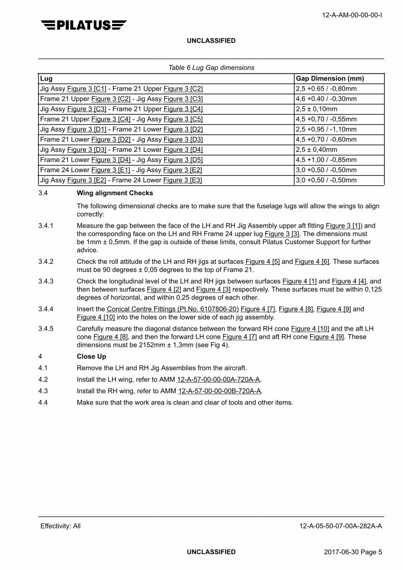
Table 6 Lug Gap dimensionsLug Gap Dimension (mm)Jig Assy Figure 3 [C1] - Frame 21 Upper Figure 3 [C2] 2,5 +0.65 / -0,80mmFrame 21 Upper Figure 3 [C2] - Jig Assy Figure 3 [C3] 4,6 +0.40 / -0,30mmJig Assy Figure 3 [C3] - Frame 21 Upper Figure 3 [C4] 2,5 ± 0,10mmFrame 21 Upper Figure 3 [C4] - Jig Assy Figure 3 [C5] 4,5 +0,70 / -0,55mmJig Assy Figure 3 [D1] - Frame 21 Lower Figure 3 [D2] 2,5 +0,95 / -1,10mmFrame 21 Lower Figure 3 [D2] - Jig Assy Figure 3 [D3] 4,5 +0,70 / -0,60mmJig Assy Figure 3 [D3] - Frame 21 Lower Figure 3 [D4] 2,5 ± 0,40mmFrame 21 Lower Figure 3 [D4] - Jig Assy Figure 3 [D5] 4,5 +1,00 / -0,85mmFrame 24 Lower Figure 3 [E1] - Jig Assy Figure 3 [E2] 3,0 +0,50 / -0,50mmJig Assy Figure 3 [E2] - Frame 24 Lower Figure 3 [E3] 3,0 +0,50 / -0,50mm
3.4 Wing alignment Checks
The following dimensional checks are to make sure that the fuselage lugs will allow the wings to aligncorrectly:
3.4.1 Measure the gap between the face of the LH and RH Jig Assembly upper aft fitting Figure 3 [1]) andthe corresponding face on the LH and RH Frame 24 upper lug Figure 3 [3]. The dimensions mustbe 1mm ± 0,5mm. If the gap is outside of these limits, consult Pilatus Customer Support for furtheradvice.
3.4.2 Check the roll attitude of the LH and RH jigs at surfaces Figure 4 [5] and Figure 4 [6]. These surfacesmust be 90 degrees ± 0,05 degrees to the top of Frame 21.
3.4.3 Check the longitudinal level of the LH and RH jigs between surfaces Figure 4 [1] and Figure 4 [4], andthen between surfaces Figure 4 [2] and Figure 4 [3] respectively. These surfaces must be within 0,125degrees of horizontal, and within 0,25 degrees of each other.
3.4.4 Insert the Conical Centre Fittings (Pt.No. 6107806-20) Figure 4 [7], Figure 4 [8], Figure 4 [9] andFigure 4 [10] into the holes on the lower side of each jig assembly.
3.4.5 Carefully measure the diagonal distance between the forward RH cone Figure 4 [10] and the aft LHcone Figure 4 [8], and then the forward LH cone Figure 4 [7] and aft RH cone Figure 4 [9]. Thesedimensions must be 2152mm ± 1,3mm (see Fig 4).
4 Close Up4.1 Remove the LH and RH Jig Assemblies from the aircraft.4.2 Install the LH wing, refer to AMM 12-A-57-00-00-00A-720A-A.4.3 Install the RH wing, refer to AMM 12-A-57-00-00-00B-720A-A.4.4 Make sure that the work area is clean and clear of tools and other items.
12-A-AM-00-00-00-I
UNCLASSIFIED
Effectivity: All 12-A-05-50-07-00A-282A-A
UNCLASSIFIED 2017-06-30 Page 5

1
1
3
5
12-A-055007-A-S4080-00016-A-01-1
2
4
Figure 1 Jig Assembly LH & RH Lug Bush Fitment
12-A-AM-00-00-00-I
UNCLASSIFIED
Effectivity: All 12-A-05-50-07-00A-282A-A
UNCLASSIFIED 2017-06-30 Page 6

A
A
A
5
6
1
2
7
89
3
12-A-055007-A-S4080-00017-A-01-1
4
LH SHOWNRH OPPOSITE
Figure 2 Frame 21 and 24 Pin Fitment
12-A-AM-00-00-00-I
UNCLASSIFIED
Effectivity: All 12-A-05-50-07-00A-282A-A
UNCLASSIFIED 2017-06-30 Page 7

C
E
D
C
B
A
12-A-055007-A-S4080-00023-A-01-1
A
A
D
E
C1 C2 C3 C4 C5
D1 D2 D3 D4 D5
E1 E2 E3
1
2
3
3
1
1
2
1
2
1
3
1 mm± 0.5 mm
B
Figure 3 Lug Gap Identification and Measurements
12-A-AM-00-00-00-I
UNCLASSIFIED
Effectivity: All 12-A-05-50-07-00A-282A-A
UNCLASSIFIED 2017-06-30 Page 8

2152 mm ± 1.3 mm
12-A-055007-A-S4080-00019-A-01-1
A
A
1
5
4
5
5
5
2
3
6
6
6
6
7
8
9
10
2152 mm ± 1.3 mm
A
Figure 4 Wing Alignment and Longitudinal/Roll Checks
12-A-AM-00-00-00-I
UNCLASSIFIED
Effectivity: All 12-A-05-50-07-00A-282A-A
UNCLASSIFIED 2017-06-30 Page 9

Requirements after job completion
Required ConditionsTable 7 Required Conditions
Action / Condition Data module/Technical publication
None
12-A-AM-00-00-00-I
UNCLASSIFIED
Effectivity: All 12-A-05-50-07-00A-282A-A
End of data moduleUNCLASSIFIED 2017-06-30 Page 10

MAXIMUM OPERATING SPEED (VMO/MMO) EXCEEDANCE
UNSCHEDULED INSPECTION
Table of Contents Page
MAXIMUM OPERATING SPEED (VMO/MMO) EXCEEDANCE - UNSCHEDULEDINSPECTION..............................................................................................................................
1
Index of Tables Page
1 References............................................................................................................. 12 Required Conditions............................................................................................... 13 Support equipment................................................................................................. 14 Supplies.................................................................................................................. 25 Spares.................................................................................................................... 26 Required Conditions............................................................................................... 5
Index of Figures Page
1 Vmo/Mmo Exceedance Envelope.......................................................................... 4
ReferencesTable 1 References
Data module/Technical publication Title
None
Required ConditionsTable 2 Required Conditions
Action / Condition Data module/Technical publication
None
Support equipmentTable 3 Support equipment
Name Identifications/References Qty Reference Remark
None
12-A-AM-00-00-00-I
UNCLASSIFIED
Effectivity: All 12-A-05-50-08-00A-282A-A
UNCLASSIFIED 2017-06-30 Page 1

SuppliesTable 4 Supplies
Name Identifications/References Qty Reference Remark
None
SparesTable 5 Spares
Name Identifications/References Qty Reference Remark
None
Safety ConditionsNone
Procedure1 General
This procedure gives the inspection requirements if an aircraft has exceeded the maximum operatingspeed (Vmo) of 240 KCAS or Mmo of 0,48, whichever is the lesser.
1.1 If the exceedance is known:− to be within the Altitude/KCAS Exceedance Envelope, defined in Fig 1, AND− that no vibration or buffeting was experienced during the event, AND− there were no other concurrent exceedances,
do the inspections at Step 2.1.2 If the exceedance:
− is outside the Altitude/KCAS Exceedance Envelope defined in Fig 1, OR− if vibration or buffeting was experienced, OR− if there were any other concurrent exceedances, OR− if the exact details of the exceedance are unknown,
you must do further inspections for damage. Send details of the exceedance to Pilatus Aircraft Limitedand request maintenance advice before the aircraft flies again.
2 Inspections2.1 Do these inspections after an aircraft has exceeded the Vmo/Mmo limits (see Step 1.1):2.1.1 Do a visual examination of the external surface of the fuselage, wings, horizontal and vertical
stabilizers for the following types of damage:− deformation− distortion− cracks− loose or missing fasteners.
12-A-AM-00-00-00-I
UNCLASSIFIED
Effectivity: All 12-A-05-50-08-00A-282A-A
UNCLASSIFIED 2017-06-30 Page 2

2.1.2 Do a visual examination of the flight control surfaces; ailerons, spoilers, elevators, rudder and flaps forthe following damage:− deformation− distortion− cracks− loose or missing fasteners− security of attachment of the mass balance weights.
2.1.3 Do a visual examination of the aircraft servicing doors, blade antennae, cowlings and landing geardoors; their hinge fittings, latches, mechanisms and their attachment to the aircraft structure for thefollowing types of damage:− deformation− distortion− cracks− loose or missing fasteners.
2.1.4 Make sure that the aircraft servicing doors, cowlings and the landing gear doors, close correctlyagainst the frame structure.
2.1.5 Do visual and operational control checks for full and free movement of the following control surfaces:− the ailerons− the elevators− the rudder.
2.1.6 Do an extension and retraction of the flaps and do a visual check for the following:− correct symmetrical extension and retraction.− that the operational speed of the flap drive motor is constant, with no difference of speed of
operation during the extension or retraction cycles of the flaps.2.2 If any damage is found, before you fly the aircraft again, you must advise Pilatus Aircraft Limited of the
damage found, and request maintenance advice.
12-A-AM-00-00-00-I
UNCLASSIFIED
Effectivity: All 12-A-05-50-08-00A-282A-A
UNCLASSIFIED 2017-06-30 Page 3

12-A-055008-A-S4080-00021-A-01-1
0170 180 190 200 210 220 230 240 250 260 270
5000
10000
15000
20000
25000
30000
VMO
/MMO
EXCEEDANCE ENVELOPE
DE
NS
ITY
ALT
ITU
DE
(ft)
KCAS
176 185
196 206
218 229
240
252
M 0.4800
M 0.5035
KCAS ENVELOPE (AFM)
EXCEEDANCE ENVELOPE
Figure 1 Vmo/Mmo Exceedance Envelope
12-A-AM-00-00-00-I
UNCLASSIFIED
Effectivity: All 12-A-05-50-08-00A-282A-A
UNCLASSIFIED 2017-06-30 Page 4

Requirements after job completion
Required ConditionsTable 6 Required Conditions
Action / Condition Data module/Technical publication
None
12-A-AM-00-00-00-I
UNCLASSIFIED
Effectivity: All 12-A-05-50-08-00A-282A-A
End of data moduleUNCLASSIFIED 2017-06-30 Page 5

12-A-AM-00-00-00-I
UNCLASSIFIED
Intentionally left blank
Effectivity: All 12-A-05-50-08-00A-282A-A
UNCLASSIFIED 2017-06-30 Page 6

UNSCHEDULED MAINTENANCE – MAXIMUM LANDING GEAR OPERATINGSPEED (VLO) EXCEEDANCE
UNSCHEDULED INSPECTION
Table of Contents Page
UNSCHEDULED MAINTENANCE – MAXIMUM LANDING GEAR OPERATING SPEED(VLO) EXCEEDANCE - UNSCHEDULED INSPECTION...........................................................
1
Index of Tables Page
1 References............................................................................................................. 12 Required Conditions............................................................................................... 13 Support equipment................................................................................................. 14 Supplies.................................................................................................................. 25 Spares.................................................................................................................... 26 Required Conditions............................................................................................... 2
ReferencesTable 1 References
Data module/Technical publication Title
12-A-05-50-00-00A-018A-A UNSCHEDULED MAINTENANCE CHECKS - INTRODUC-TION
12-A-32-30-00-00A-903A-A EXTENSION AND RETRACTION - ADJUSTMENT/TEST
Required ConditionsTable 2 Required Conditions
Action / Condition Data module/Technical publication
None
Support equipmentTable 3 Support equipment
Name Identifications/References Qty Reference Remark
None
12-A-AM-00-00-00-I
UNCLASSIFIED
Effectivity: All 12-A-05-50-09-00A-282A-A
UNCLASSIFIED 2017-06-30 Page 1

SuppliesTable 4 Supplies
Name Identifications/References Qty Reference Remark
None
SparesTable 5 Spares
Name Identifications/References Qty Reference Remark
None
Safety ConditionsNone
Procedure1 Refer to AMM 12-A-05-50-00-00A-018A-A. If the aircraft has exceeded the maximum landing gear
operating speed (VLO) do the inspections that follow:1.1 Examine these landing gear components for damage or distortion:
− Nose landing gear drag link assembly− Nose landing gear actuator assembly− Left and right main landing gear actuator assembly.
1.2 Damage or distortion is not allowed. Replace damaged or distorted parts as needed.1.3 Do the adjustment/test of the extension and retraction system, AMM 12-A-32-30-00-00A-903A-A.
Requirements after job completion
Required ConditionsTable 6 Required Conditions
Action / Condition Data module/Technical publication
None
12-A-AM-00-00-00-I
UNCLASSIFIED
Effectivity: All 12-A-05-50-09-00A-282A-A
End of data moduleUNCLASSIFIED 2017-06-30 Page 2

UNSCHEDULED MAINTENANCE – MAXIMUM LANDING GEAR EXTENDED(VLE) SPEED EXCEEDANCE
UNSCHEDULED INSPECTION
Table of Contents Page
UNSCHEDULED MAINTENANCE – MAXIMUM LANDING GEAR EXTENDED (VLE) SPEEDEXCEEDANCE - UNSCHEDULED INSPECTION......................................................................
1
Index of Tables Page
1 References............................................................................................................. 12 Required Conditions............................................................................................... 13 Support equipment................................................................................................. 14 Supplies.................................................................................................................. 25 Spares.................................................................................................................... 26 Required Conditions............................................................................................... 2
ReferencesTable 1 References
Data module/Technical publication Title
12-A-05-50-00-00A-018A-A UNSCHEDULED MAINTENANCE CHECKS - INTRODUC-TION
12-A-05-50-08-00A-282A-A MAXIMUM OPERATING SPEED (VMO/MMO) EXCEEDANCE- UNSCHEDULED INSPECTION
12-A-32-30-00-00A-903A-A EXTENSION AND RETRACTION - ADJUSTMENT/TEST
Required ConditionsTable 2 Required Conditions
Action / Condition Data module/Technical publication
None
Support equipmentTable 3 Support equipment
Name Identifications/References Qty Reference Remark
None
12-A-AM-00-00-00-I
UNCLASSIFIED
Effectivity: All 12-A-05-50-10-00A-282A-A
UNCLASSIFIED 2017-06-30 Page 1
SuppliesTable 4 Supplies
Name Identifications/References Qty Reference Remark
None
SparesTable 5 Spares
Name Identifications/References Qty Reference Remark
None
Safety ConditionsNone
Procedure1 Refer to AMM 12-A-05-50-00-00A-018A-A. If the aircraft has exceeded the maximum landing gear
extended speed:1.1 Do the maximum operating speed exceedance inspection, AMM 12-A-05-50-08-00A-282A-A.1.2 Examine the main and the nose landing gear doors for:
− distortion− loose/missing fasteners− excessive play.
1.3 Examine the brake pipes for:− security− chafing− leaks.
1.4 Damage is not allowed. Replace parts as needed.1.5 Do the adjustment/test of the extension and retraction system, AMM 12-A-32-30-00-00A-903A-A.
Requirements after job completion
Required ConditionsTable 6 Required Conditions
Action / Condition Data module/Technical publication
None
12-A-AM-00-00-00-I
UNCLASSIFIED
Effectivity: All 12-A-05-50-10-00A-282A-A
End of data moduleUNCLASSIFIED 2017-06-30 Page 2

TAIL–DOWN DAMAGE INSPECTION
UNSCHEDULED INSPECTION
Table of Contents Page
TAIL–DOWN DAMAGE INSPECTION - UNSCHEDULED INSPECTION.................................. 1
Index of Tables Page
1 References............................................................................................................. 12 Required Conditions............................................................................................... 23 Support equipment................................................................................................. 24 Supplies.................................................................................................................. 25 Spares.................................................................................................................... 26 Required Conditions............................................................................................... 10
Index of Figures Page
1 Rudder Control Cables – Adjustment .................................................................... 62 Cable Quadrant – Removal/Installation.................................................................. 73 Rudder Hinge Fittings – Removal/Installation........................................................ 84 Vertical Stabilizer Attachment and Spars............................................................... 9
ReferencesTable 1 References
Data module/Technical publication Title
12-A-07-10-00-00A-901A-A JACKING - MAINTENANCE PRACTICES
12-A-27-20-00-00A-903A-A RUDDER CONTROL SYSTEM (MSN 101 – 683) - ADJUST-MENT/TEST
12-A-27-20-00-00A-903B-A RUDDER CONTROL SYSTEM (MSN 684 – 999) - ADJUST-MENT/TEST
12-A-27-30-00-00A-903A-A ELEVATOR CONTROL SYSTEM - ADJUSTMENT/TEST
12-A-27-40-00-00A-903A-A HORIZONTAL STABILIZER TRIM - ADJUSTMENT/TEST
12-A-51-00-00-00A-353A-A STRUCTURES – STANDARD PRACTICES - EDDY CUR-RENT INSPECTION
12-A-51-10-00-00A-041A-A INVESTIGATION, CLEAN–UP AND AERODYNAMICSMOOTHNESS - DESCRIPTION
12-A-51-60-03-00A-276A-A RUDDER BALANCE - BALANCE
12-A-51-70-00-00A-041A-A REPAIRS - DESCRIPTION
12-A-AM-00-00-00-I
UNCLASSIFIED
Effectivity: All 12-A-05-50-11-00A-282A-A
UNCLASSIFIED 2021-12-04 Page 1

Data module/Technical publication Title
12-A-51-70-04-00A-663A-A COMPOSITE COMPONENTS - STANDARD REPAIR PROCE-DURES
12-A-53-30-20-00A-664A-A REAR FUSELAGE STRAKES REPAIR RM09184 - SPECIALREPAIR PROCEDURES
12-A-55-40-01-00A-920A-A RUDDER - REMOVAL/INSTALLATION
Preliminary Requirements
Required ConditionsTable 2 Required Conditions
Action / Condition Data module/Technical publication
None
Support equipmentTable 3 Support equipment
Name Identifications/References Qty Reference Remark
Inspection equipment Part Olympus NORTEC 2000 orequivalent
1
Safety clip (circuit breaker holdopen)
Part T12-030 AR
Warning sign (DO NOT OPER-ATE THE FLIGHT CONTROLS)
Part Local supply AR
SuppliesTable 4 Supplies
Name Identifications/References Qty Reference Remark
None
SparesTable 5 Spares
Name Identifications/References Qty Reference Remark
Bearing CSN 55-40-00-02-115 1
Bolt CSN 55-40-00-01-050 1
Bolt CSN 55-40-00-01-070 1
Bolt CSN 55-30-00-01-140 1
Cotter pin CSN 55-40-00-01-055 1
Cotter pin CSN 27-20-00-01-075 2
12-A-AM-00-00-00-I
UNCLASSIFIED
Effectivity: All 12-A-05-50-11-00A-282A-A
UNCLASSIFIED 2021-12-04 Page 2

Name Identifications/References Qty Reference Remark
Locking clips CSN 27-20-00-01-065 4
Nut CSN 55-40-00-01-060 1
Nut CSN 55-30-00-01-150 1
Retaining ring CSN 55-40-00-02-110 1
Washer CSN 55-30-00-01-145 1
Washer CSN 55-40-00-01-065 1
Safety ConditionsNote
To identify the AGE and tools used in this procedure refer to the list of AGE and tools, TEM 12-A-00-00-00-00A-060A-A.
Procedure1 General
The aircraft tail may hit the ground when loading the aircraft without the tail support stand in position.As a consequence of a tail-down incidence, the rear fuselage and rudder mounting structure require adetailed inspection.
This inspection procedure gives the inspection procedure for aircraft that have experienced a tail-downincidence when on the ground.
To find, identify and make an estimate of the damage to the aircraft structure, refer to SRM 12-A-51-10-00-00A-041A-A.
For small damage repairs and approved repairs to the aircraft structure and to composite parts, referto SRM 12-A-51-70-00-00A-041A-A.
Even if there is no damage, do the functional test of the rudder control system, refer to AMM 12-A-27-20-00-00A-903A-A or AMM 12-A-27-20-00-00A-903B-A.
2 During the Inspection Procedure
If you find damage during this procedure, contact Pilatus.
3 Preparation3.1 Lift the aircraft on jacks, refer to AMM 12-A-07-10-00-00A-901A-A.3.2 Make sure the flaps are set to 0°.3.3 Open and install a Safety clip (circuit breaker hold open) (Pt.No. T12-030) on this circuit breaker:
− A/P (AVIONIC 2 BUS)3.4 Put up a Warning sign (DO NOT OPERATE THE FLIGHT CONTROLS) (Pt.No. Local supply) in the
flight compartment.3.5 Remove the horizontal stabilizer fairing and the rear vertical stabilizer fairing (32CT).3.6 Open access panels 11AL, 31AB, 32AL, 32AR, 32CL and 32CR.
4 Procedure4.1 Remove the four locking clips Figure 1 [1] from the turnbuckles Figure 1 [2]. Discard the locking clips.
12-A-AM-00-00-00-I
UNCLASSIFIED
Effectivity: All 12-A-05-50-11-00A-282A-A
UNCLASSIFIED 2021-12-04 Page 3

4.2 Loosen the turnbuckles Figure 1 [2].4.3 Remove the rudder from the aircraft, refer to AMM 12-A-55-40-01-00A-920A-A.4.4 Remove the two cotter pins Figure 2 [8] from the control cables Figure 2 [9]. Discard the cotter pins.4.5 Disconnect the rudder cables Figure 2 [9] from the cable quadrant Figure 2 [3].4.6 Remove the cotter pin Figure 2 [7] nut Figure 2 [6] bolt Figure 2 [1] and washer Figure 2 [2].4.7 Remove the cable quadrant Figure 2 [3]. Discard the nut Figure 2 [6] bolt Figure 2 [1] and washer
Figure 2 [2].4.8 Remove the bearing Figure 2 [4] from the cable quadrant Figure 2 [3]. Discard the bearing Figure 2 [4]
and the retaining ring Figure 2 [5].4.9 Remove the nuts Figure 3 [7] washers Figure 3 [6] bolts Figure 3 [2] and bonding leads Figure 3 [3].
Remove the rudder stop fitting/assembly Figure 3 [1].4.10 Aircraft MSN 141 and Up. Disassemble the rudder stop Figure 3 [15].4.11 Remove the hinge bracket Figure 3 [4].4.12 Remove the hinge support fitting Figure 3 [5]. Discard the bolt Figure 3 [12], nut Figure 3 [10] and
washer Figure 3 [11].
5 Required Inspection
NoteNDT inspection (eddy current or dye penetrant) is used to detect surface cracks in metals. No cracksare allowed. If cracks are found, replace the component or contact Pilatus. For information on the NDTinspection procedure, refer to SRM 12-A-51-00-00-00A-353A-A.
NoteCrack inspection by NDT (eddy current or dye penetrant) is required for specific items as identified with(NDT) in the following procedure. In addition to the specific NDT inspections, all items must have avisual inspection. If a crack is suspected from visual inspection, do the NDT inspection to confirm theresult.
NoteIf composite material has minor damage, such as cracks, scratches, surface delamination and/orabrasion, use the standard repair procedures given in SRM 12-A-51-70-04-00A-663A-A.
5.1 Examine the cable quadrant and bearing housing for cracks (NDT), deformation, and/or distortion.5.2 Examine the rudder stop fitting/assembly Figure 3 [1] for cracks (NDT) or any damage.5.3 Examine the rudder for signs of cracks or deformation.5.4 Examine the hinge bracket Figure 3 [4] for signs of cracks (NDT) and/or distortion.5.5 Examine the hinge support fitting Figure 3 [5] for signs of cracks (NDT) and/or distortion.5.6 Examine the strakes for damage. Use the SRM 12-A-53-30-20-00A-664A-A to repair any damage or
to replace the strakes.5.7 Examine the internal structure where the strake spigot beams attach to the fuselage frames, FR 38 to
FR 40. Check for cracks and/or deformation.5.8 Examine the lower fuselage area for damage. Examine the antenna(s) to make sure they did not hit
the ground and do not have damage.5.9 Examine the sidewalls of the rear fuselage structure and the rear fuselage at frame 43 for signs of
cracks and/or deformation.
12-A-AM-00-00-00-I
UNCLASSIFIED
Effectivity: All 12-A-05-50-11-00A-282A-A
UNCLASSIFIED 2021-12-04 Page 4

5.10 Examine the top hinge bracket Figure 4 [2] for cracks (NDT), deformation and/or displacement.Examine the bearing Figure 4 [3] and the attachment of the top hinge bracket to the structure.
5.11 Examine the vertical stabilizer spars, in the attachment area to FR 43, for cracks (NDT) and/ordeformation.
5.12 Examine the vertical stabilizer outer surface for cracks, skin distortion and deformation.5.13 Examine the vertical stabilizer fairing 32CT for damage.5.14 Examine the composite lower rudder fairing 32AB for damage.5.15 Look at the rudder mechanism below the cockpit floor and examine the rudder stops for damage.
6 Installation6.1 Install the hinge support fitting Figure 3 [5] to the fuselage structure with a new Bolt Figure 3 [12] new
Washer Figure 3 [11] and new Nut Figure 3 [10].6.2 Install the hinge bracket Figure 3 [4] to the fuselage structure with the bolts Figure 3 [14] washers
Figure 3 [13] washers Figure 3 [9] and nuts Figure 3 [8].6.3 Aircraft MSN 141 and Up. Assemble the rudder stop Figure 3 [15] to the rudder stop assembly
Figure 3 [1].6.4 Install the rudder stop fitting/assembly Figure 3 [1] and the bonding leads Figure 3 [3].6.5 Install a new Bearing Figure 2 [4] in the cable quadrant Figure 2 [3]. Secure with a new Retaining
ring Figure 2 [5].6.6 Install the cable quadrant Figure 2 [3]. Use a new Bolt Figure 2 [1] new Washer Figure 2 [2] new
Nut Figure 2 [6] and a new Cotter pin Figure 2 [7].6.7 Attach the rudder cables Figure 2 [9] to the cable quadrant Figure 2 [3] and secure each rudder cable
with a new Cotter pin Figure 2 [8].6.8 Install the rudder, refer to AMM 12-A-55-40-01-00A-920A-A. After installation of the rudder, do an
adjustment and test of the rudder control system, refer to AMM 12-A-27-20-00-00A-903A-A or AMM12-A-27-20-00-00A-903B-A.
NoteIf a new rudder is installed, make sure the painted rudder is balanced before installation. To balance therudder, refer to SRM 12-A-51-60-03-00A-276A-A.
NoteUse a new Bolt Figure 4 [1] when you attach the rudder to the top hinge.
6.9 Do the functional test of the rudder control system, refer to AMM 12-A-27-20-00-00A-903A-A or AMM12-A-27-20-00-00A-903B-A.
6.10 Install the rear vertical stabilizer fairing 32CT and the horizontal stabilizer fairing.6.11 Do the functional check of the elevator, refer to AMM 12-A-27-30-00-00A-903A-A.6.12 Do the operational test of the horizontal stabilizer trim, refer to AMM 12-A-27-40-00-00A-903A-A.6.13 Close access panels 31AB, 32AL, 32AR, 32CL and 32CR.
12-A-AM-00-00-00-I
UNCLASSIFIED
Effectivity: All 12-A-05-50-11-00A-282A-A
UNCLASSIFIED 2021-12-04 Page 5
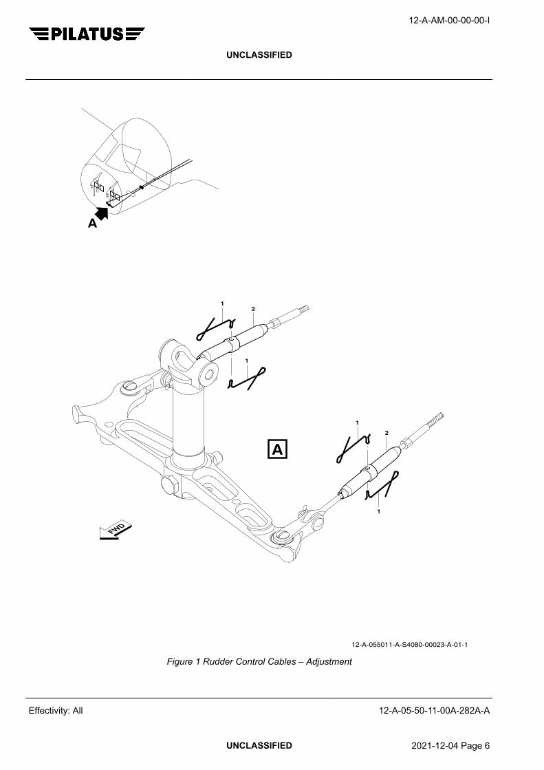
12-A-055011-A-S4080-00023-A-01-1
A
A
12
1
1
2
1
Figure 1 Rudder Control Cables – Adjustment
12-A-AM-00-00-00-I
UNCLASSIFIED
Effectivity: All 12-A-05-50-11-00A-282A-A
UNCLASSIFIED 2021-12-04 Page 6

12-A-055011-A-S4080-00024-A-01-1
A
C
D
C
A
B
B
D
8
9
3
7
6
1
2
4
5
Figure 2 Cable Quadrant – Removal/Installation
12-A-AM-00-00-00-I
UNCLASSIFIED
Effectivity: All 12-A-05-50-11-00A-282A-A
UNCLASSIFIED 2021-12-04 Page 7
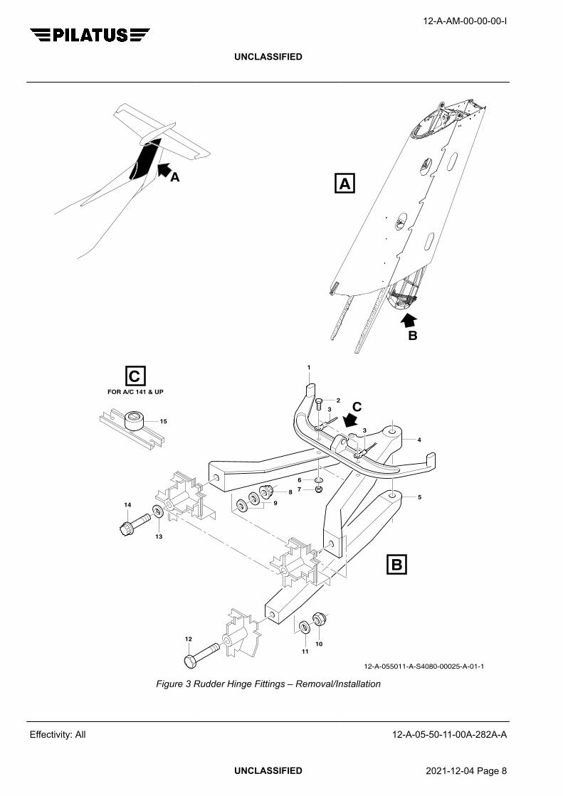
12-A-055011-A-S4080-00025-A-01-1
A
B
A
B
C
76
15
FOR A/C 141 & UP
1011
12
58
9
13
4
2C
1
3
3
14
Figure 3 Rudder Hinge Fittings – Removal/Installation
12-A-AM-00-00-00-I
UNCLASSIFIED
Effectivity: All 12-A-05-50-11-00A-282A-A
UNCLASSIFIED 2021-12-04 Page 8

12-A-055011-A-S4080-00026-A-01-1
AA
B1
2
3
B
Figure 4 Vertical Stabilizer Attachment and Spars
12-A-AM-00-00-00-I
UNCLASSIFIED
Effectivity: All 12-A-05-50-11-00A-282A-A
UNCLASSIFIED 2021-12-04 Page 9

Requirements after job completion
Required ConditionsTable 6 Required Conditions
Action / Condition Data module/Technical publication
None
12-A-AM-00-00-00-I
UNCLASSIFIED
Effectivity: All 12-A-05-50-11-00A-282A-A
End of data moduleUNCLASSIFIED 2021-12-04 Page 10

NOSE LANDING GEAR OVERTURNING
UNSCHEDULED INSPECTIONS
Table of Contents Page
NOSE LANDING GEAR OVERTURNING - UNSCHEDULED INSPECTIONS.......................... 1
Index of Tables Page
1 References............................................................................................................. 12 Required Conditions............................................................................................... 23 Support equipment................................................................................................. 24 Supplies.................................................................................................................. 25 Spares.................................................................................................................... 26 Required Conditions............................................................................................... 6
Index of Figures Page
1 Nose Landing Gear Overturning - Unscheduled Inspection................................... 5
ReferencesTable 1 References
Data module/Technical publication Title
12-A-07-10-00-00A-901A-A JACKING - MAINTENANCE PRACTICES
12-A-20-31-00-00A-070A-A STANDARD PRACTICES - CONSUMABLE MATERIALS LIST
12-A-27-20-00-00A-903A-A RUDDER CONTROL SYSTEM (MSN 101 – 683) - ADJUST-MENT/TEST
12-A-27-20-00-00A-903B-A RUDDER CONTROL SYSTEM (MSN 684 – 999) - ADJUST-MENT/TEST
12-A-32-30-00-00A-903A-A EXTENSION AND RETRACTION - ADJUSTMENT/TEST
12-A-32-40-02-00A-920A-A NOSE WHEEL - REMOVAL/INSTALLATION
12-A-32-50-00-00A-310A-A NOSE WHEEL STEERING - EXAMINE
12-A-32-50-00-00A-903A-A NOSE WHEEL STEERING - ADJUSTMENT/TEST
12-A-51-00-00-00A-351A-A PROCESS - NON-DESTRUCTIVE TEST - DYE PENETRANTINSPECTION
12-A-51-00-00-00A-353A-A STRUCTURES – STANDARD PRACTICES - EDDY CUR-RENT INSPECTION
12-A-51-70-05-00A-663A-A RIVETED STRUCTURE REPLACEMENT - STANDARD RE-PAIR PROCEDURES
12-A-AM-00-00-00-I
UNCLASSIFIED
Effectivity: All 12-A-05-50-12-00A-282A-A
UNCLASSIFIED 2021-07-01 Page 1

Preliminary Requirements
Required ConditionsTable 2 Required Conditions
Action / Condition Data module/Technical publication
None
Support equipmentTable 3 Support equipment
Name Identifications/References Qty Reference Remark
Inspection equipment Part Olympus NORTEC 2000 orequivalent
1
Light source Part Local supply AR
Magnifying glass (10x magnifica-tion)
Part Local supply AR
SuppliesTable 4 Supplies
Name Identifications/References Qty Reference Remark
Solvent Part P01-010 AR
Lockwire, (standard) Part P02-001 AR
Absorbent paper Part P02-031 AR
Stop plate Part 532.20.12.118 AR
Bolt, NAS1954C2H Part 932.35.16.702 AR
SparesTable 5 Spares
Name Identifications/References Qty Reference Remark
Wedge (shear plate) CSN 32-20-00-03-260 2
Rivet CSN 32-20-00-03-263 AR
Safety ConditionsWARNING
BE CAREFUL WHEN YOU USE THE CONSUMABLE MATERIALS. OBEY THE MANUFACTURERS' HEALTHAND SAFETY INSTRUCTIONS AND ALL THE APPLICABLE LOCAL INSTRUCTIONS. CONSUMABLEMATERIALS CAN BE DANGEROUS AND CAN CAUSE DEATH OR INJURY TO PERSONNEL AND/ORDAMAGE TO EQUIPMENT.
12-A-AM-00-00-00-I
UNCLASSIFIED
Effectivity: All 12-A-05-50-12-00A-282A-A
UNCLASSIFIED 2021-07-01 Page 2

NoteTo identify the consumable items used in this procedure refer to the Consumable Materials List, AMM 12-A-20-31-00-00A-070A-A.
Procedure1 General
During movement of the aircraft on the ground/aircraft towing, the nose wheel steering mechanism isused to steer the aircraft. Red marks on the front of the NLG, above the taxi light, show the limits of leftand right movement of the mechanism.
If the nose wheel steering mechanism exceeds its limits (overturning), shear plates on each side of theNLG break. This requires replacement of the shear plates and an inspection of the NLG before furtherflight.
This procedure gives the instructions to replace the shear plates and do an unscheduled inspection ofthe NLG. The procedure is in three parts:− Inspection of the primary load path (lower part of the NLG)− Inspection of the secondary load path (upper part of the NLG)− Testing.
2 Inspection of the Primary Load Path
Refer to Fig. 1 .2.1 Remove the nose wheel, refer to AMM 12-A-32-40-02-00A-920A-A.2.2 Use Absorbent paper (Pt.No. P02-031) made moist with Solvent (Pt.No. P01-010) to clean the NLG
fork and axle.2.3 Examine the NLG fork:2.3.1 Visually examine the fork legs for twist and deformation.2.3.2 Insert the axle through the fork legs and examine the axle lugs for concentricity and alignment.2.3.3 Use a Magnifying glass (10x magnification) (Pt.No. Local supply) and Light source (Pt.No. Local
supply) and inspect the fork legs and axle for cracks.2.3.3.1 If cracks are suspected, do an NDT inspection, refer to SRM 12-A-51-00-00-00A-351A-A or 12-A-51-
00-00-00A-353A-A.2.3.4 If there is any deformation, displacement, cracks, damaged bores or other damage:
− Replace or repair the affected part, refer to the CMM or contact Pilatus Aircraft Ltd.2.4 Examine the torque link:2.4.1 Visually examine for twist and deformation.2.4.2 Use a Magnifying glass (10x magnification) (Pt.No. Local supply) and Light source (Pt.No. Local
supply) and visually inspect the torque link for cracks.2.4.2.1 If cracks are suspected, disassemble the torque link and do an NDT inspection, refer to SRM 12-A-51-
00-00-00A-351A-A or 12-A-51-00-00-00A-353A-A.2.4.3 If there is any deformation, displacement, cracks, damaged bores or other damage:
− Replace or repair the affected part, refer to the CMM or contact Pilatus Aircraft Ltd.2.5 Examine the stop plate for damage:
12-A-AM-00-00-00-I
UNCLASSIFIED
Effectivity: All 12-A-05-50-12-00A-282A-A
UNCLASSIFIED 2021-07-01 Page 3

2.5.1 If the stop plate is damaged, deformed, broken, cracked or has loose attachment fittings, replace thestop plate and/or the attachment fittings:− Stop plate (Pt.No. 532.20.12.118)− Bolt, NAS1954C2H (Pt.No. 932.35.16.702)− Lockwire, (standard) (Pt.No. P02-001).
2.6 Replace the damaged/broken shear plates with new Wedge (shear plate) and new Rivet , refer toSRM 12-A-51-70-05-00A-663A-A.
2.7 Install the nose wheel, refer to AMM 12-A-32-40-02-00A-920A-A.
3 Inspection of the Secondary Load Path
Refer to Fig. 1 .3.1 Examine the components of the nose wheel steering mechanism as follows, refer to 12-A-32-50-00-
00A-310A-A:− Steering collar− Swivel joint− Bellcrank− Steering spring strut− Torque tube− Connecting rod.
3.2 Examine the rudder bellcrank fitting (P/N 527.20.12.116) for damage.3.3 If there is any deformation, displacement, cracks damaged bores or other damage:
− Replace or repair the affected part, refer to the CMM or contact Pilatus Aircraft Ltd.
4 Testing
The tests given here in Step 4 must be completed, to do the tests the aircraft must be raised on jacks.If you are unable to raise the aircraft on jacks, the aircraft can be flown (ferry flight) to a maintenancefacility were these tests can be completed. It must be flown with the landing gear extended and lockedin the extended position. Before the ferry flight, the procedures given in Step 2 and Step 3 must becompleted and any problems corrected.
4.1 Lift the aircraft on jacks, refer to AMM 12-A-07-10-00-00A-901A-A.4.2 Do the NLG steering adjustment, refer to AMM 12-A-32-50-00-00A-903A-A.4.3 Do the functional test of the NLG extension system, refer to AMM 12-A-32-30-00-00A-903A-A.4.4 Do the rudder steering adjustment, refer to AMM 12-A-27-20-00-00A-903A-A or 12-A-27-20-00-00A-
903B-A as applicable.
5 Close Up5.1 Lower the aircraft off jacks, refer to AMM 12-A-07-10-00-00A-901A-A.5.2 Remove all the equipment, tools and materials from the work area. Make sure that the work area is
clean.
12-A-AM-00-00-00-I
UNCLASSIFIED
Effectivity: All 12-A-05-50-12-00A-282A-A
UNCLASSIFIED 2021-07-01 Page 4

A
STEERING
SHEAR PLATE
RED MARK RED MARK
RED MARK
RUDDER BELLCRANK
STEERINGCOLLAR
JOINTSWIVEL
BELLCRANK
CONNECTING RODTORQUE TUBE
SPRING STRUT
12-A-055000-A-S4080-02184-A-01-1
ASTOP PLATE
TORQUE LINK
NLG FORK
NLG AXLE
(PART OF RUDDER CONTROL SYSTEM)
PRIMARYPATH
SECONDARYPATH
LEFT HARD STOP
RIGHT HARD STOP
Figure 1 Nose Landing Gear Overturning - Unscheduled Inspection
12-A-AM-00-00-00-I
UNCLASSIFIED
Effectivity: All 12-A-05-50-12-00A-282A-A
UNCLASSIFIED 2021-07-01 Page 5

Requirements after job completion
Required ConditionsTable 6 Required Conditions
Action / Condition Data module/Technical publication
None
12-A-AM-00-00-00-I
UNCLASSIFIED
Effectivity: All 12-A-05-50-12-00A-282A-A
End of data moduleUNCLASSIFIED 2021-07-01 Page 6

AFTER A FLIGHT THROUGH VOLCANIC ASH OR SMOKE
UNSCHEDULED INSPECTION
Table of Contents Page
AFTER A FLIGHT THROUGH VOLCANIC ASH OR SMOKE - UNSCHEDULEDINSPECTION..............................................................................................................................
1
Index of Tables Page
1 References............................................................................................................. 12 Required Conditions............................................................................................... 23 Support equipment................................................................................................. 24 Supplies.................................................................................................................. 25 Spares.................................................................................................................... 26 Required Conditions............................................................................................... 4
ReferencesTable 1 References
Data module/Technical publication Title
12-A-05-50-05-00A-282A-A LIGHTNING STRIKE - UNSCHEDULED INSPECTIONS
12-A-12-20-01-00A-256A-A AIRCRAFT EXTERIOR - POLISH AND APPLY PROTECTION
12-A-12-20-01-00A-902A-A AIRCRAFT EXTERIOR WASHING - SERVICING
12-A-21-30-01-00A-250A-A PRESSURIZATION CONTROL - CLEAN
12-A-21-40-01-00A-313A-A REFRIGERATION PACK - INSPECTION/CHECK
12-A-21-40-02-00A-250A-A WATER SEPARATOR - CLEAN AND APPLY SURFACE PRO-TECTION
12-A-21-40-02-00A-920A-A WATER SEPARATOR - REMOVAL/INSTALLATION
12-A-34-11-10-00A-903A-A SINGLE P–S SYSTEM - ADJUSTMENT/TEST
12-A-34-11-20-00A-903A-A DUAL PITOT STATIC SYSTEM - ADJUSTMENT/TEST
12-A-71-00-00-00A-903T-A POWERPLANT TEST 18 – ENVIRONMENTAL CONTROLSYSTEM - ADJUSTMENT/TEST
12-A-AM-00-00-00-I
UNCLASSIFIED
Effectivity: All 12-A-05-50-15-00A-282A-A
UNCLASSIFIED 2017-06-30 Page 1

Preliminary Requirements
Required ConditionsTable 2 Required Conditions
Action / Condition Data module/Technical publication
None
Support equipmentTable 3 Support equipment
Name Identifications/References Qty Reference Remark
None
SuppliesTable 4 Supplies
Name Identifications/References Qty Reference Remark
Soft bristle brush Part Local supply As re-quired
SparesTable 5 Spares
Name Identifications/References Qty Reference Remark
None
Safety ConditionsNone
Procedure1 If the aircraft has flown through suspected, or actual volcanic ash or smoke, the following
examinations should be carried out before further flight.
If any damage is found, use the aircraft AMM and/or SRM to do general repairs. If no repair procedureis available, contact Pilatus Aircraft Ltd.
2 Exterior Fuselage2.1 Do a visual inspection of the areas that follow, for abrasion, contamination and/or damage:
− Exterior fuselage− Stabilizers− Wings− De-ice boots− Flight control surfaces
12-A-AM-00-00-00-I
UNCLASSIFIED
Effectivity: All 12-A-05-50-15-00A-282A-A
UNCLASSIFIED 2017-06-30 Page 2

− Antennas− Windshields− Side windows− DV windows− Cabin windows− Wheels− All exterior lights
2.2 Examine the AoA probes as follows:2.2.1 Make sure that the AoA probes are free from abrasion, contamination or damage.2.2.2 Make sure that the AoA probes are not seized and can move freely.3 Aircraft Wash3.1 Do a wash of the aircraft exterior, refer to AMM 12-A-12-20-01-00A-902A-A.3.2 If the external surface needs to be polished and sealed, do Step 4 thru Step 8 first, and then do the
Close Up procedure.4 Internal Fuselage4.1 Do a visual inspection of all the aircraft compartments for contamination in the areas where there are
access doors.4.2 Do a visual inspection of all the aircraft compartments for contamination in the areas where the
fuselage skin has venting and/or NACA inlets.5 Engine Area5.1 Do a visual inspection of the Environmental Control System (ECS) heat exchanger matrix for
contamination, refer to AMM 12-A-21-40-01-00A-313A-A.5.2 Remove the ECS water separator, refer to AMM 12-A-21-40-02-00A-920A-A.5.3 Do a visual inspection of the ECS water separator for contamination. If contamination is found, do this
work:5.3.1 Clean the separator, refer to AMM 12-A-21-40-02-00A-250A-A.5.3.2 Install the separator, refer to AMM 12-A-21-40-02-00A-920A-A.5.4 Do a visual inspection of the air intake and inertial separator for contamination. If contamination is
found, rinse with clean water.
NoteDo a rinse of the air intake and inertial separator before you do an engine compressor and turbinewash.
5.5 Do a visual inspection of the engine oil cooler assembly as follows:5.5.1 Make sure that the outlet door has full and free movement.5.5.2 If necessary, clean the oil cooler heat exchanger matrix using a Soft bristle brush (Pt.No. Local
supply).5.6 Do a visual inspection of the propeller for abrasion, contamination and/or damage.6 Cabin Pressurization6.1 Do a visual inspection through the inlet of the outflow and safety valves of the cabin pressurization
system for contamination.
12-A-AM-00-00-00-I
UNCLASSIFIED
Effectivity: All 12-A-05-50-15-00A-282A-A
UNCLASSIFIED 2017-06-30 Page 3

6.2 If contamination is found, remove and clean the contaminated item, refer to AMM 12-A-21-30-01-00A-250A-A.
7 Pitot/Static System7.1 Make sure that the pitot/static system is free from contamination as follows:7.1.1 Disconnect the pitot/static system from the aircraft equipment.7.1.2 Remove the pitot/static system drain traps.7.1.3 Blow clean dry low pressure air through the pitot/static lines from the pitot heads and static ports.7.1.4 Install the pitot/static system drain traps.7.1.5 Connect the pitot/static system to the aircraft equipment.7.2 Do a pitot/static system leak check as follows:
− For aircraft with a single pitot/static system, refer to AMM 12-A-34-11-10-00A-903A-A.− For aircraft with a dual pitot/static system, refer to AMM 12-A-34-11-20-00A-903A-A.
8 Detailed Examination/Test8.1 Do an operational test of the aircraft flight controls to make sure that movement is full, free and
smooth.8.2 If the aircraft has, or is suspected to have been struck by a coronal discharge (St. Elmo's Fire), do the
lightning strike unscheduled inspection, refer to AMM 12-A-05-50-05-00A-282A-A.8.3 Inspect the engine, refer to P&WC EMM 72-00-00, Unscheduled Inspection - Aircraft Flown Through
Volcanic Ash or Smoke.8.4 Do Step 5.2 and Step 5.3 again.8.5 Do the functional test of the ECS temperature conditioning system, refer to AMM 12-A-71-00-00-00A-
903T-A.9 Close Up9.1 Make sure that the work areas are clean and clear of tools and other items.9.2 If necessary, polish and seal the aircraft external surface, refer to AMM 12-A-12-20-01-00A-256A-A.
Requirements after job completion
Required ConditionsTable 6 Required Conditions
Action / Condition Data module/Technical publication
None
12-A-AM-00-00-00-I
UNCLASSIFIED
Effectivity: All 12-A-05-50-15-00A-282A-A
End of data moduleUNCLASSIFIED 2017-06-30 Page 4