PB95138749.pdf - NEHRP Clearing House
300
1111111 111111111111111111111111111111 PB95-138749 Information is our business. PROCEEDINGS OF THE U.S.-ITALY WORKSHOP ON GUIDELINES FOR SEISMIC EVALUATION AND REHABILITATION OF UNREINFORCED MASONRY BUILDINGS. HELD IN PAVIA, ITALY ON JUNE 22-24, 1994 ILLINOIS UNIV. AT URBANA-CHAMPAIGN. DEPT. OF CIVIL ENGINEERING 20 JUL 94 u.s. DEPARTMENT OF COMMERCE National Technical Information Service
-
Upload
khangminh22 -
Category
Documents
-
view
3 -
download
0
Transcript of PB95138749.pdf - NEHRP Clearing House

1111111 111111111111111111111111111111
PB95-138749 Information is our business.
PROCEEDINGS OF THE U.S.-ITALY WORKSHOP ONGUIDELINES FOR SEISMIC EVALUATION ANDREHABILITATION OF UNREINFORCED MASONRYBUILDINGS. HELD IN PAVIA, ITALY ONJUNE 22-24, 1994
ILLINOIS UNIV. AT URBANA-CHAMPAIGN. DEPT. OF CIVIL ENGINEERING
20 JUL 94
u.s. DEPARTMENT OF COMMERCENational Technical Information Service


NATIONAL CENTER FOR EARTHQUAKEENGINEERING RESEARCH
State University of New York at Buffalo
Proceedingsof the
U.S.-Italy Workshop onGuidelines for Seismic Evaluation and
Rehabilitation of Unreinforced Masonry Buildings
Edited by
D.P. AbramsUniversity of Illinois at Urbana-Champaign
Department of Civil Engineering205 N. Mathews Avenue
Urbana, Illinois 61801and
C.M. CalviUniversity of Pavia
Department of Structural MechanicsVia Abbiategrasso 211
Pavia, Italy 27100.
Technical Report NCEER-94-0021
JulY 20, 1994REPRODUCED BY: NIlS.
u.s. Department of Commerce-a-
National Technicallnfonnation ServiceSpringfield, Virginia 22161
This workshop was conducted at the University of Pavia, Italy.It was part~ally supported by the National Science Foundation under Grant No. BCS 90-25010...::-anq th~ew York State Science and Technology Foundation under Grant No. NEC-91029.

NOTICEThis report was prepared by the University of lliinois at UrbanaChampaign and the University of Pavia as a result of researchsponsored by the National Center for Earthquake EngineeringResearch (NCEER) through grants from the National ScienceFoundation, the New York State Science arid Technology Foundation, and other sponsors. Neither NCEER, associates ofNCEER, its sponsors, the University of lliinois at UrbanaChampaign and theUniversity of Pavia, nor any person actingon their behalf:
a. makes any warranty, express or implied, with respect to theuse of any information, apparatus, method, or processdisclosed in this report or that such use may not infringe uponprivately owned rights; or
b. assumes any liabilities of whatsoever kind with respect to theuse of, or the damage resulting from the use of, any information, apparatus, method or process disclosed in this report.
Any opinions, findings, and conclusions or recommendationsexpressed in this publication are those of the author(s) and donot necessarily reflect the views of the National Science Foundation, the New York State Science and Technology Foundation,or other sponsors.
.>
/;-
\.,

-~~~-~~~~UM~~U~nO~NI~LR~~~~~~.~~~1~~~~3 ~IU~~~~~IUI~~"~lm ~-=::-:---:-P::-'A7.G:::E:-- ...L.-1__' N_C_E_E_R_-_94_-_0.....0_2_1 ...L.- -+__-.:P:.:B:::::9-5 -13 8749~ TItle end Subtitle 5. R.port D.te
Proceedings of the U.S.-Italy Workshop on Guidelines for July 20, 1994Seismic Evaluation and Rehabilitation of Unreinforced MasonryBuildinCls
'. Authot(s)
D.P. Abrams and G.M. Calvi'. Perf_Inc Orpnlzatlon H..... • nd AddressUniversity of Illinois at Urbana-ChampaignDept. of Civil Engineering, 205 N. Mathews
University of PaviaDept. of Structural MechanicsVia Abbiateqrasso 211, Pavia, Italy 27100.
Ave., Urbana, IL. lL c:om..ct(Q or Gnlnt(G) No.
(Q BCS 90-25010(G) NEC-91029
"
z. SpOMOrinc Orpnlzat'- H.....·.nd Address
National Center for Earthquake Engineering ResearchState University of New York at BuffaloRed Jacket QuadrangleBuffalo New York 14261
l3. Tl'IM 01 .Report " Period CovefoecI
Technical report
5. SuppIe....ntary Not.. This workshop was conducted at the UniverSity of Pavia, Italy. It waspartially supported by the National Science Foundation under Grant No. BCS 90-25010 andthe New York State Science and Technology Foundation under Grant No. NEC-91029.
Co AbRnd: (IJmlt: 200 -us)
In an effort to assist in the development of engineering procedures for the seismic evaluation and rehabilitation of unreinforced masonry buildings; designed, if at all, for gravityloads only, this' workshop volume compares the Italian and American experience in theseareas. The intent of the workshop was to review hazard mitigation for URM buildings as awhole. Thus, workshop topics inCluded ·architectural issues in bUilding",-preservation andrehabilitation, development of Eurocode 8 and FEMA-BSSC-ATC-33, case studies of retrofitting prgjects and in situ testing methods for masonry construction. The workshopprogram called for introduction of each general topic, followed by the presentation of apaper on that topic from one Italian and one American participant, and by grOup discussion.Accordingly, this volume offers 16 paired papers, as well as the complete text of the
, workshop resolutions concernhlg future research and cooperation' in .this field.
7. Document Analysis .. DescrIptors
b. ldentlfiers/Open.£nded T.rms
Earthquake engineering. Unreinforced masonry buildings. Seismic rehabilitation.Building safety evaluation. Repaired buildings. Experimental tests. Seismic performance.Analytical models. Seismic evaluation. Failure criteria. Case studies. Test methods.International cooperation. Technology transfer. United States. Italy. Retrofitting.Architectural design. Historic buildings.
Co COSAn F1.ld/G.....p
L A_II.bllity St.tement
Release Unlimited
e AHSI-Z39.18)
IS. Security Cl..s (ThIs Report)
UnClassified20. Security Class (Thl~ P.ce)
UnClassifiedS.. InstrvctloltS Oft R...,.rse
2L Ha. of Paces290
22. Price
OPTIOHAL FORM Z7Z (4-77)(Formerly Hns-3S)


IIProceedings
of theU.S.-Italy Workshop on
Guidelines for Seismic Evaluation and Rehabilitationof Unreinforced Masonry Buildings
held at theDepartment of Structural Mechanics
University of Pavia, ItalyJune 22-24, 1994
Edited by D.P. Abrams! and G.M. CalvPJuly 20, 1994
Technical Report NCEER-94-0021
NCEER Task Number 93-3703
NSF Master Contract Number BCS 90-25010and
NYSSTF Grant Number NEC-91029
In cooperation with theItalian Gruppo Nazionale
per la Difesa dai Terremoti (GNDT)
1 Professor, Department of Civil Engineering, University of Illinois at Urbana-Champaign2 Associate Professor, Department of Structural Mechanics, University of Pavia, Italy
NATIONAL CENTER FOR EARTHQUAKE ENGINEERING RESEARCHState University ofNew York at BuffaloRed Jacket Quadrangle, Buffalo, NY 14261


PREFACE
Past earthquakes in both Italy and the United States have demonstrated the vulnerability of unreinforcedmasonry construction to moderate or strong ground shaking. In recent times, substantial masonrydamage has been reported from earthquakes in Friuli (1976), Perugia (1979), Campania/Basilicata(1980), Whittier (1987), Loma Prieta (1989) and Northridge (1994). Because of the fears that futureearthquakes will occur in the eastern United States, or in Italy where unreinforced masonry buildings arepredominant, there is an immediate need to develop engineering procedures for seismic evaluation andrehabilitation of this type of structural system. Like older Italian masonry construction that has been
• designed only for gravity forces, and not lateral forces, seismic evaluation and rehabilitation ofunreinforced masonry buildings in the eastern United States poses a challenging engineering problem.Much can be learned from the Italian experience with unreinforced masonry because of thepreponderance of buildings in Italy of this type. Correspondingly, Italians can learn from Americanpractices in rehabilitation strategies, earthquake engineering research, and code development.
On May 26, 1993 a Memorandum of Understanding was signed by Professors George Lee and VincenzoPetrini for cooperative research and collaboration between the Gruppo Nazionale per la Difesa daiTerremoti (GNDT) of the Consiglio Nazionale delle Ricerche (National Group for the Protection fromEarthquakes of the National Research Council of Italy) and the National Center for EarthquakeEngineering Research of the United States. The object of the agreement is to promote and enhancecooperation and collaboration among and between research institutions, academic organizations,colleagues and others in Italy and the National Center for Earthquake Engineering Research at the StateUniversity of New York at Buffalo; to improve the body of knowledge available and thereby reduc~
future losses of life and property damage from earthquakes; to develop a planned program of cooperativeand collaborative research in the area of earthquake hazards mitigation; and to allow for the widestpossible publication and discussion of the results of that collaboration. The area of initial cooperativeresearch was defined as seismic behavior and protection of existing masonry buildings.
The first formal activity under the Memorandum of Understanding is this workshop. The topic ofguidelines for seismic evaluation and rehabilitation was chosen so that the workshop focus could besufficiently broad to apply to the general problem of hazards mitigation. Because efforts are underwayin both Italy and the United States on development of seismic guidelines for existing buildings, theworkshop papers and resolutions were felt to be appropriate to augment these ongoing activities.
Rather than concentrate on the narrow subjects of computational modeling or laboratory research,workshop topics included architectural issues in building preservation and rehabilitation, development ofEurocode 8 and the FEMAIBSSC/ATC-33 Guidelines, case studies of building retrofit projects, andinsitu testing methods for masonry construction. Thus, the papers contained in these proceedingsprovide a snapshot of the overall hazard mitigation problem rather than an in-depth collection oftechnical papers on a single topic.
The workshop program was arranged by first selecting the general topics, and then seeking one Italianand one American speaker. Ample time was allotted for each paper presentation which was followed bydiscussion periods on each topic. At the conclusion of the workshop, twenty-six resolutions wereformulated based on the discussions with each set of papers.
iii

The workshop was preceded by a half-day Italian Seminar on Numerical Modeling of UnreinforcedMasonry Buildings. Analytical modeling efforts by various investigators throughout Italy weresummarized and compared at the seminar. True analytical predictions were first presented for lateralforce behavior of a two-story research building that had been tested within the structural engineeringlaboratory at the University of Pavia. Then, previously concealed test data on behavior of the teststructure was revealed and used to judge the accuracy of each analytical prediction.
Following the workshop, a field trip was held in the historical center of Pavia. Sites included an ancientunreinforced masonry tower structure that has been recently strengthened, and the Pavia Duomo whosestructural system is continuously being monitored for movements.
The workshop and related activities were well attended with over seventy participants (see Appendix foraddress listings). Because of the success of this initial activity under the NCEER-GNDT Memorandumof Understanding, subsequent collaborations are expected to develop between Italian and Americanresearchers in the area of earthquake hazards mitigation. Possible avenues for future cooperation areadditional workshops, the exchange of scholars and the transfer of technical documents between the twocountries.
The workshop would not have been possible without the financial support of the National Center forEarthquake Engineering Research (Project Number 93-3703) which is funded by the U.S. NationalScience Foundation and the New York State Science and Technology Foundation, and the ItalianNational Group for the Defense against Earthquakes (GNDT) which is funded by the Italian NationalResearch Council (CNR). Appreciation is extended to the Department of Structural Mechanics at theUniversity of Pavia for hosting the workshop, and to the Italian brick supplier, Gruppo RDB, forsponsoring the workshop lunches.
Observations, opinions, findings, and conclusions presented in these workshop proceedings are those ofthe individual participants, and do not necessarily reflect those of the NCEER, NSF, NYSSTF, GNDT orCNR.
Daniel P. AbramsProfessorDepartment of Civil EngineeringUniversity of Illinois at Urbana-ChampaignUnited States of America
G. Michele CalviAssociate ProfessorDepartment of Structural MechanicsUniversity of PaviaItaly
IV

~
<
""
Par
tici
pant
s,U
S-I
tali
anW
orks
hop
onG
uide
line
sfo
rSe
ism
icE
valu
atio
nan
dR
ehab
ilit
atio
no
fUnr
einf
orce
dM
ason
ryB
uild
ings


RESOLUTIONS
US-Italian Workshop on:
Guidelines for Seismic Evaluation and Rehabilitation ofUnreinforced Masonry Buildings
University of Pavia, ItalyJune 22-24, 1994
Over the three days of the workshop, a number of themes tended to emerge from the paper presentationsand discussions which followed. Many of the comments, criticisms and views were common for Italianand American participants. At the end of the workshop, these opinions were consolidated into thefollowing set of resolutions. They are classified by subject and are not necessarily in order of priority.These resolutions represent a consensus of the workshop participants, and do not necessarily reflectopinions ofNCEER or GNDT.
General
1. The GNDT-NCEER Memorandum of Understanding signed on May 26, 1993 has initiated afruitful cooperation between Italian and American researchers in the area of seismic behavior andprotection of existing masonry buildings. Continued cooperation between the GNDT and NCEERin the future is encouraged.
2. The exchange of researchers between the United States and Italy should continue with long-termvisits of junior researchers, or short-term visits of senior researchers.
3. A process should be developed for the efficient exchange of technical documents between theUnited States and Italy.
4. A similar US-Italian Workshop should be held in two years in the United States.
Development of Guidelines for Seismic Rehabilitation
1. Development of seismic evaluation or rehabilitation codes/guidelines should be shared betweenItalian and Americans.
2. Intervention strategies for seismic rehabilitation of unreinforced masonry buildings shouldcontinue to be discussed between Italian and American engineers and architects.
3. Research should be pursued to investigate relative feasibilities of various rehabilitation strategiesfor improving seismic resistance of unreinforced masonry buildings.
4. Relations between various seismic performance limits, and limit states for unreinforced masonrystructures need to be defined.
Vll

RESOLUTIONS
Experimental Research
1. Experimental research should be continued as a means for identifying basic resistance mechanismsand calibrating computational models.
2. Further laboratory tests should be done on different structural configurations of URM buildingsystems.
3. Ultimate load testing of actual buildings should be pursued to help understand the relationsbetween idealized analytical or physical models and typical construction.
4. The seismic performance of retrofitted unreinforced masonry buildings during earthquakes shouldbe examined.
5. Development of technical procedures for real-time monitoring of historic structures should beshared between the two countries.
6. Research on brick and block construction should be extended to include stone masonry.
7. Further research should be done to examine characteristics of existing and older mortars, and theirinfluence on response of masonry construction.
8. Further development of insitu test procedures for measuring mechanical properties of masonryshould be pursued.
Analytical Research
1. Analytical modeling of unreinforced masonry buildings should be pursued as a means forextrapolating laboratory test data.
2. Sensitivity studies should be done using analytical models to identify critical modelingparameters. Once identified, more experimental research should be done to better quantify thosecritical parameters.
3. Analytical procedures prescribed in future guidelines or codes for general seismic rehabilitation ofbuildings should be examined for their applicability to unreinforced masonry construction.
4. Research on analytical modeling should be focused towards development of engineeringguidelines for seismic rehabilitation of unreinforced masonry buildings.
5. Both analytical and experimental research should strive to develop simple analytical models forseismic evaluation of rehabilitated buildings.
6. Seismic response of building clusters should be studied.
Vlll

RESOLUTIONS
Condition Assessments
1. Methods need to be developed for relating results of condition assessments to structural analysesprocedures.
2. Research should be done to develop more accurate condition assessment procedures for multip1ewythe masonry walls and rubble walls.
Social and Economic Issues
1. Cost differences for various seismic rehabilitation schemes should be studied.
2. Fundamental philosophies of architectural preservation should be shared between the twocountries.
3. Limits of professional liability should be defined as they relate to seismic rehabilitation.
IX


Section
TABLE OF CONTENTS
Title Page
I Issues in Building Rehabilitation and Preservation
Architectural Issues in the Seismic Rehabilitation of Masonry Buildings 1-3Randolph Langenbach
Actuality and Modeling of Historical Masonry 1-17Antonino Giuffre, Caterina Carocci, Gianmarco de Felice, andCesare Tocci
II Development of Guidelines for Seismic Rehabilitation
An European Code for Rehabilitation and Strengthening .2-3.Giorgio Macchi
Summary ofthe ATC-33 Project on Guidelines for Seismic Rehabilitation 2-11of Buildings
Daniel P. Abrams
III Research on Performance and Response of URM Building Systems
Research on Unreinforced Masonry at the Joint Research Center of the .3-3European Commission
Armelle AnthoineResearch on the Seismic Performance of Repaired URM Walls 3-17
Sherwood Prawel and Hsien Hua LeeDynamic Response Measurements for URM Building Systems 3-27
Daniel P. Abrams and Andrew CostleyExperimental Research on Response ofURM Building Systems 3-41
G. Michele Calvi and Guido Magenes
IV Analysis Methods for Evaluation of Rehabilitated Buildings
Simplified Methods for Evaluation of Rehabilitated Buildings .4-3Peter Gergely and Ronald Hamburger
Modeling Unreinforced Brick Masonry Walls .4-17Luigi Gambarotta, and Sergio Lagomarsino
Failure Criterion for Brick Masonry Under In-plane Load: .4-31A Micromechanical Approach
Gianmarco de Felice
Xl

Section
TABLE OF CONTENTS (Cont'd)
Title Page
V Case Studies of Building Preservation Projects
Rehabilitation ofURM Buildings in the Eastern United States 5-3John Theiss
Rehabilitation ofURM Buildings in Italy 5-37Carlo Gavarini
VI Testing Methods for Evaluation of Insitu Material Properties
Measuring Masonry Material Properties 6-3Luigia Binda, Giulio Mirabella Roberti, Claudio Tiraboschi,and Silvia Abbaneo
In-Place Evaluation of Masonry Materials 6-25Richard H Atkinson
Development and Use of a Mobile Laboratory for the Assessment of 6-39URM Buildings
Mauro Cadei, Paolo Panzeri, Alberto Peano, and Paolo Salvaneschi
Appendix A - Conference Information
Workshop Program A-3
List of Participants A-7
XlI

Section I
Issues in Building Rehabilitidion and Preservation
Architectural Issues in the Seismic Rehabilitation of Masonry BuildingsRandolph Langenbach
Actuality and Modeling of Historical MasonryAntonino Giuffre, Caterina Carocci, Gianmarco de Felice, andCesare Tocci
1-1


ARCHITECTURAL ISSUES IN THESEISMIC REHABILITATION OF MASONRY BUILDINGS
Randolph Langenbach *
ABSTRACT
This paper explores the architectural and historic preservation issues raised by seismicrepair and retrofit work on masonry buildings. The first part examines the sources ofmeaning in historical buildings as cultural artifacts, using examples to illustrate howbuildings can have significance beyond their visual image or architectural style. For thisreason, if preservation is to be successful, the actual material fabric of an artifact must bepreserved. This fact must be recognized by seismic design engineers so that seismicretrofit work can be carried out with the least possible irrevocable alteration to the historicstructural system as well as the historic architectural finishes. The paper goes on to exploresome of the opposing differences which have existed between contemporary conservationtechnology and seismic retrofit practice, analyzing how seismic retrofit work may be ableto benefit from knowledge and research developed in the conservation field. In conclusion,the paper suggests four areas where further work is needed to improve seismic retrofitpractice with historic masonry buildings: research on mortars and post-elastic behavior ofthe masonry, the development of existing building-type specific building codes, findingways to limit liability for design professionals dealing with existing buildings, and furtheranalysis on what is an acceptable life safety goal for historic buildings.
INTRODUCTION
Our approach to the structure of buildings has gone through a transformation in modemtimes. Traditionally, most major buildings were solid walled structures with the wallsbearing directly on the ground. With the current predominance of steel and reinforcedconcrete as the materials of choice for larger buildings, we are now used to the erection offrames, onto which the enclosure cladding system is attached.
With the "Postmodem" fascination with historical fonns and details, the contrast betweenthe old and new systems has only recently become particularly noticeable. This style shifthas brought back a desire to design buildings which have the solid walls of their historiccounterparts, but which, unlike them, have to be constructed as a series of light, jointedpanels attached to the underlying frame. Often the results simply fail to capture the kind oftexture and meaning which is found in the older buildings. Architects continue to strugglefor solutions, only to find that the source of the feeling they are trying to capture is simplynot accessible in Dryvit, GFRC, Fiberglas, or panelized veneer brick, with their frequentneed for expansion joints cutting across the architectural details. As engineers work hardto convert the highly indetenninate, ambiguous and non-linear behavior of historicmasonry construction into something which can be understood with mathematicalcertainty, architects struggle to wrest control of the seemingly rigid and unyieldingmaterials of modem day conventional building systems, trying to breathe the kind of subtlelife .into them that they find at the root of the aesthetic quality of historic structures.
*Senior Analyst and Historic Building Specialist, Federal Emergency Management Agency
1-3

This transformation in construction technology parallels a similar change in engineeringpractice which now relies to a great extent on frame analysis for the design of buildingstructures. Traditional heavy wall masonry buildings tend to defy analysis by the usualpresent day methods, forcing many practicing professionals to do what they do not like todo - designing in part by guess work. Research in the area of unreinforced masonry is soimportant because without it, historical buildings will be lost simply because engineers andarchitects will be loath to touch them because they cannot be made to fit their mathematicaldesign models. This may be true even though the same structures have withstood majorpast earthquakes, and the damage records is known. For example, a number of historicbuildings in California which survived the 1906 San Francisco earthquake are threatenednow more by hazard mitigation legislation than by future earthquakes.
THE CULTURAL SIGNIFICANCE OF HISTORIC BUILDING FABRIC
Modern Engineering science, new materials, and current codes have gone a long waystowards reducing the fear of catastrophe and death from earthquakes. This has been truedespite the spectacular failures which each major earthquake seems to leave in its wake.Earthquake design is an evolving and constantly changing practice largely because theactual events are so rare, and when they do occur, the earthquake forces can be so largethat some structural damage is expected even in new structures. As a result, the linebetween acceptable and unacceptable risk and performance is vague and fluid.
In the field of historic preservation, the problem of seismic risk can not be solved bystricter design codes, better new materials, or a more stringent engineering design. It isexactly these things which heighten the dilemma with older structures, threatening the veryhistorical qualities which we seek to save.
It has become a familiar sight in many parts of the world to see the stone exterior walls ofgutted buildings held up by shoring while they await the construction of new interior floorsand roof. Fine old masonry buildings are often stripped of their interior finishes, with thesteel reinforcing rods being erected against the inside of the exterior walls in preparationfor a sheet of concrete. Roofs of ancient tiles or slate are torn off to be replaced by newtiles and slate after the obligatory concrete or plywood diaphragm is installed.
One might ask: "what's the fuss - the exterior walls have been preserved, have they not?The interior will be rebuilt and the new work will be hidden - the view will be just the samewhen it is all completed." Many architects, not just engineers, fail to understand themeaning of what is lost along the way when this kind of work is carried out. DonaldAppleyard observed in 1978:
The prqfessional and scientific view ofthe environment usually suppressesits meaning.... Environmental professionals have not been aware of thesymbolic content ofthe environment, or ofthe symbolic nature oftheir ownplans and projects.... Professionals see the environment as a physicalentity, a functional container,...a setting for social action or programs, apattern of land uses, a sensuous experience-but seldom as a social orpolitical symbol.]
Historic buildings do not just carry their cultural significance as relics by image alone.While understanding the architectural style and decorative form of historic structures is
1-4

important, the cultural meaning of many of the most significant buildings is resident withinthe reality of the artifact itself. An historic structure is important because it is exactly that it is old, and thus has been a part of human lives. As the English critic John Ruskineloquently stated:
Indeed the greatest glory Qfa building is not in its stones, or in its gold. Itsglory is in its Age, and in that deep sense ofvoicefulness, ofstern watching,ofmysterious sympathy, nay, even ofapproval or condemnation, which wefeel in walls that have long been washed by the passing waves ofhumanity....
It is in that golden stain oftime that we are to look for the real light, andcolor, and preciousness ofarchitecture; and it is not until a building hasassumed this character, till it has been entrusted with the fame, andhallowed by the deeds ofmen, till its walls have been witnesses ofsuffering,and its pillars rise out of the shadows of death, that its existence, morelasting a..Iii it is than that ofthe natural objects ofthe world around it, can begifted with even so much as these possess oflanguage and oflife.2
Seismic protection and strengthening forces us to confront one of the central dilemmas ofhistoric preservation - the fact that preservation is forced to encompass change andrenewal. Unlike maintenance and rehabilitation from decay, a seismic project may tearapart a building which was otherwise in good repair and make it almost entirely new. Insuch an instance, only the image, rather than the substance, of much of the historic fabric ispreserved. Masonry buildings are particularly vulnerable to this approach.
Sometimes seismic projects are promoted as opportunities to "restore" the originalappearance of a buildings, stripping away the later alterations in order to return them totheir original appearance. In Sacramento, California, the State Capitol is such an example.The Capitol was completely gutted in 1976, leaving only the exterior walls and the centraldrum and dome. All of the interior floors and walls were removed and replaced inreinforced concrete. The remaining masonry was covered with an internal skin of shotcreteand the floors were replaced in reinforced concrete. As a result, while the interior of thisbuilding is now genuinely spectacular, with impressive museum rooms, excellentcraftsmanship, rich materials, stunning colors and textures, none of it is genuine. A "hearttransplant" was authorized when an "ace bandage" may have been all that was needed.The Capitol needed to be strengthened and repaired, but one should ask whether the riskidentified in 1971 could not have been satisfactorily alleviated by less drastic, destructive,and expensive measures.
The quest for authenticity, and the search for "real" meaning through"honesty" ofform, often leads to the destruction of that which it seeks byinducing fakery....Authenticity is not a property ofenvironmental form, butofprocess and relationship....Authentic meaning cannot be created throughthe manipulation or purification of form, since authenticity is the verysource from which form gains meaning. 3
This gutting of structures for seismic strengthening is not limited to the United States. Forexample, following the 1979 earthquake in Montenegro, Yugoslavia, many structures inthe historic city of Kotor have been reconstructed with reinforced concrete floors, replacingthe original heavy timber. In some of these structures, reinforced concrete columns have
1-5

been cut into the masonry, forming completely new reinforced concrete structures, with thehistoric masonry reduced to a veneer.
Another example, in Portugal, is the little mountain village of Pi6dau. The Portuguesegovernment recently listed this picturesque mountain village of stone buildings as anhistorical site. Located in earthquake-prone country, many of the stone houses are beingstrengthened. The typical seismic strengthening consists of replacing their timber floor androof structures with reinforced concrete. Some of the walls, which had been laid with verylittle mortar, are being re-laid in strong cement mortar. While undoubtedly safer, the visualeffect of this work is the loss of the texture and feel of the traditional surfaces. The patinaand sense of the country masons' and plasterers' handiwork is erased. If the approach hadbeen to repair and augment the timber interior structures and tie them to the existing walls,rather than replace them, the historical quality of the buildings would have survived the lifesafety improvements.
The debate over such alternatives always turns to the question of how much life safetyprotection is enough. When existing archaic construction remains in use, even if improved,can it be relied on to perform adequately? However, at the core of this issue is the factthat, unless the architects, planners and engineers identify and understand the importanceof the original structural and interior fabric of the historical buildings, and bring thisunderstanding into their designs, such destruction will continue because they will do whatthey are used to doing with new structures. This consideration must include the evidenceof the original handiwork, rather than just the appearance of a building from a distance.
Another striking example is South Hall at the University of California, Berkeley.Constructed of brick with timber floors in the 1870's, South Hall is the oldest survivingbuilding on the campus. In the 1980's, it was gutted to undergo seismic strengtheningunder the University's campus wide program. The retrofit plans included the reinforcedconcrete "shotcrete" jacketing of the inside surface of many of the exterior walls, and thedemolition and replacing of the timber floors with steel and concrete. In the process ofcarving channels into the walls, it was discovered that the original builders had installedbond-iron in the masonry - continuous bars of wrought iron which extended from corner tocorner above and below the windows in all of the building's walls. Dog anchors, whichsecured the floors to the walls, were also discovered hidden in the walls. At the corners,the bond iron bars were secured by large bosses on gigantic cast iron plates which formedpart of the architecture of the building.
Because the designers had never thought to investigate the structural history of thebuilding, including whether these great cast iron ornamental plates on the corners of thebuilding served a structural purpose, the existence of the bond iron was not known until thedemolition for the retrofit. All of these bond-iron ars were cut as a result. In addition, ashistorically significant and advanced as this original system was, no recordation of itsdesign was ever conducted. The irony was that one of the engineers said that, had theyknown of the existence of the bond iron and the dog anchors, their designs may have beendifferent and less extensive. When it was discovered, however, it was too late to changethe designs, and the early seismic technology was destroyed.
One may ask, "why is it important to preserve what had been hidden in the historic walls nobody could see it anyway?" Perhaps documenting it, which was not done, would havebeen sufficient, but this example also illustrates one of the important points about seismicdesign - that is that many engineers and architects have the false belief that the today's
1-6

engineering design is, not only better than anything which has been done in the past, but isthe ultimate solution which will require no further interventions. They believe that theirwork will make the building strong and complete, and that no one will have to do anythingother than maintenance and superficial remodeling ever again. Here, at South Hall, thedesigners failed to know what had been put into the walls to resist earthquakes a mere 100years ago, despite the fact that great cast iron plates to which the bond iron straps wereattached, were fully exposed on the outside of the building. What is there to make certainthat our successors will be any better informed about the work done today?
In addition, with the irreversible conversion of the masonry walls of South Hall into aveneer of masonry on reinforced concrete, the integrity of those walls as masonry wallswas destroyed. One of the principle advantages of masonry is that it can be repaired bybeing dismantled and re-laid. Now it has been fused together into one solid mass ofunyielding concrete. Years later, should it be necessary to repair the brickwork or replacethe concrete jacket because of rusting of the re-bars or another reason, it will not bepossible. The present day seismic work will indeed last the life of the building simplybecause the building's life is now forced to be limited to that of the new work.
This point may seem far-fetched, but historical buildings are worthy of such long termconsideration. It should be remembered that the Nineteenth Century restorers of theParthenon introduced iron cramps which, when they rusted in the Twentieth Century,destroyed some of the original marbles. Should anyone wonder whether the state-of-theart at the time of the 19th century restoration represented progress from earlier times, theyshould consider the fact that the ancient builders had used a less rust-prone iron, which,when protected by a lead jacket, survived over 2,000 years to this day without distress.
LEARNING FROM mE PAST
Many people make the mistake of thinking that it is only our generation which hasdiscovered ways of resisting the threat of earthquakes in structural design. They come tobelieve that older forms of construction practice must be more dangerous simply becausethey were designed before current seismic codes were promulgated, or before currentengineering knowledge about earthquakes had been developed. Certainly, the introductionof steel provides ductility where masonry could not, and yet the recent discoveries of thefailures of the welds in over 100 of the 400 steel buildings affected by the NorthridgeEarthquake should provide some humility in the face of this awesome force. While manymasonry buildings have tumbled in earthquakes, they have not always tumbled. As waswitnessed in Armenia recently, it was the modem reinforced concrete buildings whichcollapsed killing thousands, while the older masonry buildings nearby remained mostlyintact, providing refuge for the displaced occupants of the newer buildings.
In places as diverse as Turkey, Yugoslavia, Kashmir, and Nicaragua, indigenous forms ofconstruction were developed or adapted to respond to the earthquake threat where availableresources demanded that masonry continue to be used. In Kashmir, an elaborate system ofinterlocking horizontal timber runner beams was used, without vertical wood columns, tohold the rubble masonry and soft mud mortar buildings together on the silty soil.Historical reports confIrm that these buildings withstood earth9.uakes better than the nearbyunreinforced brick palace and British built government buildmgs. Today, many of thesevernacular structures are falling in favor of reinforced concrete structures, which, because
1-7

of poor local construction practices, may actually prove to be less resistant than their lowtech, unengineered historic predecessors.
Restoration professionals sometimes fail to understand the subtleties of seismic resistancein older structures. Believing that strength and stiffness is necessary, they destroy originalconstruction systems to gain shear strength at the expense of earlier solutions which maystill be valid. In Dubrovnick, before the recent civil war, restorers of the historic palaceuncovered an interior wall they had thought was solid masonry to fInd a basket wave ofsmall timber studs, with brick or stone masonry loosely fItted together between the studs.The restoration engineer stated at a conference that this ''poorly constructed wall wasimmediately removed and replaced during the restoration of the building." Instead ofbeing "poorly constructed," this wall deliberately may have been constructed in thisfashion to resist earthquakes. The wall, which was similar to Bahareque constructionfound in Central America, may have represented a far greater understanding of seismicengineering than pre-modern builders are given credit for today.
BUfi,DING CONSERVATION PRACTICE VS.SEISMIC STRENGTHENING
While it is impossible to ignore present day advances and advocate a return to traditionalconstruction practice, the narrow assumption that new is always better can blind us to thepotential gains which an understanding of the earlier forms of construction may provide usin the present. This is particularly true for the ~dvancement of building conservation andseismic rehabilitation practice. For years, these have been seen as separate and opposingfIelds of practice, with solutions which seem in basic conflict with each other. Forexample, for years, conservation professionals have specifIed that restoration mortarconsist of a high lime mix which is weaker than the masonry units. Code requirementshave established that mortar must consist of a high cement mixture and meet high strengthstandards which have proven to be anathema to proper conservation of older masonrywalls. The discovery of the importance of reducing or eliminating Portland cement frommasonry mortars in restoration is one of the cornerstones of recent conservation practice:
The use oflime-sand monar ...furnishes a plastic cushion that allows bricksor stones some movement relative to each other. The entire structuralsystem depends upon some flexibility in the masonry components of abuilding. A cushion of soft monar fUrnishes sufficient flexibility tocompensate for uneven settlement offoundations, walls, piers and arches:gradual adjustment over a period of months or years is possible. In astructure that lacks flexibility, stones and bricks break, monar joints openand serious damage results. 4
This was not meant to refer to masonry in earthquakes, but in light of the Kashmiriexperience it is intriguing to ask, whether the notion of a "plastic cushion" might be anappropriate concept for walls subjected to earthquake forces. It is worth noting the conflictbetween the Historic Preservation documents which recommend using the weakest andmost lime rich ASTM formula (K) (1 unit cement) to (2 1/4 to 4 units lime) for restorationwork, and the Uniform Building Code, which prohibits the use of mortar weaker than thethree strongest categories, known as ASTM types M, S & N: (1 unit cement) to (1/4 to 11/4 lime) for any mortar used in structural masonry (which includes, of course, mosthistoric masonry walls.)
1-8

One reason for this conflict is that while the Code is founded upon the performance of thewall under load at its design strength at the point of construction, the preservationdocuments are aimed towards maximizing the long-term durability of walls with relativelyweak masonry units in response to all environmental conditions. One only needs tocompare the long-term performance of ancient masonry and modem masonry to see themerits in the softer, high lime mortars, and yet, the codes now make beneficial use of thisknowledge difficult. Other examples abound where modem uses of masonry has provenshort-lived because of environmental degradation of the system. Seismic design must fitinto a larger performance picture, where other environmental assaults are considered aswell as the occasional earthquake.
A CRISIS OF COST
Concerns over the impact of seismic strengthening policies is more than just one ofpotential loss of original fabric. It is also one of economics. As long as politicians and thepublic believe that historic masonry buildings are enormously risky unless great sums ofmoney are spent to convert their structural systems into steel or concrete, vast numbers ofimportant cultural monuments are at risk. This issue has expanded recently in the UnitedStates to include large scale 20th century masonry buildings constructed with steel orconcrete frames. It is exactly the current crisis with these types of buildings which confirmthe importance of engineering research and the development of specialized codes formasonry buildings and historic buildings in general.
The crisis can be illustrated by an example in Oakland, California, where one brick andterra cotta clad steel frame historical building, the City Hall, is being repaired from LomaPrieta Earthquake damage and seismically upgraded at the extraordinary cost of $530 persquare foot ($5,700/square meter), which is more than 3 times the cost of a new building ofcomparable quality. Six blocks away, another office building, the Oakland MedicalBuilding, was just repaired and seismically upgraded to the same codes for a cost of only$11 per square foot ($118/square meter). The City Hall design uses the now popular newlydeveloped base isolation technology, while the Medical Building is a fixed base design, butboth schemes were promoted as "cost-effective" designs to meet the requirements of thebuilding code. (See figure 1)
With a difference between two projects, both promoted as necessary and expedient, of over35 times, it is evident that there is little consensus in this particular field over what isrequired and beneficial to meet the seismic threat. While certainly the expectedperformance of the base isolated design is greater than the fixed base design, and eventhough part of the difference is for interior remodeling of the City Hall, it is questionablewhether this justifies 35 times the cost. While many celebrated the repair and upgradesolution for City Hall because it preserved the building, historic preservation suffers in thelong run from such gargantuan projects as that of the Oakland City Hall because the publicbegins to believe that such costly solutions are the only way to make such buildings safe.
The situation with bearing wall masonry buildings in California is no longer as distorted.The reason for this is that recent research has resulted in the development of a new codespecific to this building type. While public perception on the safety of masonry buildingsis still unduly negative, and price spreads between different engineers' designs can still belarge, the existence of this new code has helped to narrow the spread, and makeeconomical solutions possible.
1-9

S76mJllion
•
cost
retrofit costs per sq. ft.
total project costs per sq. ft.
tolal project costs
Repair and retrofit costs
cos, of new monumental• buHding
S54million
•• cost of premium new office I.buHding
costcost!sq.ft.
S3751sq.fl.
S53OIsq.ft. ---I~'P'P'I'I""'t-------
- .
- ..
185,000 SQ.FT. ORIGINALLY143,000 SQ. FT. AFTER BASE ISOLATION
45.00OSQ.FT.
FIGURE 1: COST COMPARISON BETWEEN TWO RETROFIT PROJECTS
The code for masonry buildings, which has now been adopted as a model code inCalifornia is Appendix, Chapter 1 of the Uniform Code for Building Conservation. Thisappendix contains the engineering provisions for bearing wall masonry structures. Theseprovisions were derived from the "ABK Methodology," an engineering designmethodology for unreinforced masonry bearing wall buildings developed by a team ofengineers in Los Angeles under a research grant from the National Science Foundation.
One of the principal features of this methodology is the provisions which anticipate andexploit the post-elastic behavior of the wood and plaster interior partitions and floordiaphragms, thus computing a consequential reduction in the forces on the masonry walls.Another result of the ABK research is the finding that masonry buildings actually responddifferently than the way the traditional codes and engineering approaches assumed. Ratherthan amplifying the forces of the earthquake, the heavy masonry walled building has theeffect of dampening the shaking by acting as a II rigid rocking block on a soft soil base.II
This is to be compared with the common code analysis of seismic force on a buildingwhich models the building as a IIsingle degree offreedom, 5% damped elastic oscillatorwith a fixed base.5 II
Using the ABK method of analysis, the computed force levels in an unreinforced masonrybuilding are lower than found under conventional code analysis. The results of this
1-10

methodology on the design of retrofit strategies for individual masonry buildings is that theamount of strengthening work which is computed to be required is less than that shown asneeded when conventional strength based linear elastic analysis is used. This approachthus reduces the retrofit intervention and costs.
An even more significant step for historical buildings in general has been taken inCalifornia with the adoption of the State Historical Building Code. This Code, whichapplies to all historical buildings, including even those which are only on local lists, allowsmuch greater design and engineering flexibility than is possible under the conventionalprevailing code which is primarily meant for new buildings. Instead of proscriptiverequirements, the State Historical Building Code describes general performance objectiveswhich must be met. The specific solutions are left up to the designers. The code alsoencourages the use of archaic materials and systems as part of the structural system,providing some minimum values for these systems where they are available.
AREAS FOR FURTIIER RESEARCH AND DEVELOPMENT
1) Engineering research
Three topics for further research which would benefit masonry building preservationparticularly come to mind. One is the study of the effects of mortars of varying strengthand constituents, a second is further study to develop code values for stone masonry,particularly with a random ashIer or rubble wall bedding pattern, and a third is furtherstudy on the post-elastic in-plane strength and behavior of masonry bearing and infill walls.
Mortar: Most masonry wall studies have not introduced mortar strength andmortar ingredients as the principal variable in laboratory experiments. The potentialbenefits of high lime mortar in construction are well known in the field of buildingconservation technology, but not adequately explored in terms of its effects on seismicperformance. Historic walls are often treated only as dead load in lateral capacity analysisbecause of low mortar strength, but when combined with certain bedding plane andwindow frame reinforcing techniques, the performance of such walls may be madesatisfactory by restraining deformations and avoiding collapse potential, while allowing forcracking and energy dissipation. The objectives of such research would be to establish asound basis for the preservation of the integrity of historic stone and brick masonry byavoiding the need for destructive concrete coatings.
The most important attribute of mortar strengths below that of the masonry units is that,when the wall does crack, it does so along the mortar joints. This results in greater overallstability than if the units themselves were to fracture. At the 1988 InternationalBrickIBlock Masonry Conference in Dublin, a paper by Dr. W. Mann, Univ. of Darmstadt,generated criticism around the assertion that masonry bedded in mortar with "low cohesion[is] favorable" because it contributes to "a type of "ductile" behavior.
Such a statement is diametrically opposed to the conventional wisdom that mortar must bestrong to resist earthquakes. However, in the traditional examples described above, wherethe weak mortar is combined with the overall flexibility of the building structure, therestraint provided by the timber beams, and the pre-compression provided by the weight ofthe overburden, weak mortar may be more resistant to catastrophic fracture and collapse byallowing the cracks to be distributed throughout the wall. The flexibility and internal
1-11

damping of the structure can serve to change the building's response, reducing the out-ofplane forces in the masonry walls while the timber serves to keep the weaker masonry inplace. While research has shown that weak mortar can cause problems with unreinforcedmasonry walls, particularly for out-of-plane shaking, perhaps some mechanical ties withinthe walls can fill the role that the timbers did in traditional construction by holding themasonry units in place while the wall deforms.
There has been some significant progress in this direction in Europe, and even in NewZealand. In Greece and New Zealand, several projects have achieved seismicstrengthening by simply wrapping cables around the masonry structure, which are hiddenby the stucco, or left visible on the surface. Utilizing the strengthening effect caused bytying the masonry together to create horizontal bands similar in their purpose to the timberrunners of the Dhajji-Dwari system, these buildings continue bear their own weight on theunaltered existing masonry. Such systems have the advantage of causing little disruptionto the historic masonry surface or the integrity of the wall. The cables are also accessiblefor inspection and can easily be replaced. What is radical about this, and other surfacemounted strengthening systems that the retrofit work is left visible as a frank statement ofthis part of the building's historical evolution. Sometimes it is important to recognize that,as was the case with South Hall, greater damage may be incurred by making changeshidden behind walls which have been radically altered or rebuilt, than by exposing thechanges in front of walls which are thus left intact.
Stone masonry code values: The need for more information on capacity valuesfor rubble and random ashIer masonry which can be introduced into the building codes.Engineers are loath to apply the values which have been developed for brick masonry, butthe recommended test techniques, such as the push test, are only remotely applicable tostone masonry situations. Lacking even minimum code capacity values, the conservativeapproach is to impart little or no capacity to the existing masonry. In the United States,this. has resulted in costly and invasive designs for many stone buildings and theunnecessary demolition of a number of important historical buildings because retrofitschemes proposed proved to be too expensive.
Post-elastic behavior: More research is also needed on the post elastic behavior ofmasonry of all types. Even the recent unreinforced masonry building codes developed inCalifornia stop short of including values derived from the behavior of masonry when it iscracking and yielding in an earthquake. The codes for present day construction such assteel and reinforced concrete are based on linear elastic calculations using reduced forcesto approximate post elastic actual behavior, but designers often give very low values tomasonry because of its lack of material ductility. However, as a system, there is substantialremaining capacity in a wall which has begun to crack before it becomes unstable. Ifbuildings fell down the moment masonry walls exceed their elastic strength, there would befar greater death and destruction in past earthquakes. Practicing engineers are often loathto depend on masonry for part of the load resisting mechanism because of the lack ofrealistic code values on which to base their design, and thus protect their liability in theevent that an earthquake exceeds the strength of the wall.
2) Building Codes:
The adoption of the Uniform Code for Building Conservation as a State of California'smodel code for existing buildings, and the enactment of the State ofCalifornia HistoricalBuilding Code have both gone a long ways to allowing for sensitive and cost-effective
1-12

improvements to historical buildings in California A code specific to the masonry infillframe building type is under development by a team of California engineers. The absenceof such a code has been made conspicuous by the breadth of costs between differentprojects, and the sometimes acrimonious disagreements over what strengthening isnecessary.
In Europe, as the EEC has moved towards unified building codes, the problem of makingexisting buildings, particularly historical buildings in different countries, fit into the asingle universal code must be dealt with. It is strongly recommended that a separate codefor historical buildings be developed. Like the State Historical Building Code inCalifornia, this code should be based on performance objectives, rather than proscriptiveconstruction procedures or systems. An Internationally standard codes which applies tonew and old buildings alike, will fail to cover the specific needs of historical building typeswhich vary from region to region. What may be sound practice in one area, may bedestructive of cultural value in another. Provisions for existing buildings with archaicconstruction systems, and earlier interior layouts, must be included into alternate codes ormany buildings will be lost.
3) Engineer's liability:
A discussion of codes inevitably leads to a discussion of the problems surroundingprofessional liability. In the United States, many preservation problems result from thefact that engineers and architects are afraid of malpractice claims if they undertakesolutions which are different from the code, and damage occurs in an earthquake. This hasoften forced them to be more conservative with existing masonry buildings than theyIwould have to be with new buildings. This is true because the code for new buildings,although expecting structural damage to occur in a major earthquake, is very specific in theconstruction requirements. With old buildings with archaic pre-code structural systemswhich cannot be made to meet the letter of the current code, designers feel vulnerable tolawsuits regardless of the level of damage.
In a sense, present day professionals thus feel forced to take responsibility for theperformance of the existing building structures designed by others before their time, whenall they have been hired to do is to provide some improvement to them. As a result, theowner's desire for the most minimal upgrade often balloons into a major expensive project,with hundreds or thousands of pages of engineering anallsis and justification. For everyproject of this kind which is constructed, hundreds 0 buildings remain without anyimprovements because of the severe cost and liability implications if they are touched atall.
4) Life Safety:
Finally, a discussion of appropriate codes, professional liability, and even topics forscientific research must include also a discussion and resolution of what level of seismicprotection is necessary. Codes serve to establish a lower bound of performance, but theyare not designed to provide guidance as to what should be the upper bound. Economicforces are expected to provide this, but in the field of seismic upgrading, particularly forlarge public projects involving government funds, confusion over how much is enough hasprevented people from reaching consensus on this issue. This has been true largelybecause the issue of life-safety is so unclear. It is as laudable as a goal as it is vague as abenchmark. For example, while modern building codes assume structural damage may
1-13

occur to a code confonning new building in the event of an earthquake, many engineersand architects are loath to define what is acceptable damage for historic masonry buildings,resulting in vast expenses for new supporting structural systems. What had beenacceptable only 50 years ago, is now suddenly unacceptable. In the case of frame and infillmasonry buildings, provisions are sometimes even made to resist the potential of collapsein building types which have not had a history of collapsing in earthquakes in the past.
CONCLUSION
Historic structures have something to tell us which transcends their formal architecturallanguage. This gift from the past can be erased if the integrity of the original structure isdestroyed to meet the demands of hazard mitigation. Understanding both the positive andthe negative attributes of masonry construction can guide us towards methods which maybe less destructive of original fabric. Some of these methods may even be more effectiveover the long term, not only because they build on strengths which already exist, but alsobecause they are more closely derived from local social, and economic conditions. Thepurpose of historic preservation is not limited to the static freezing of artifacts. It also hasto do with preserving continuity within the slow evolution of building traditions - acontinuity which may in the end provide the most effective and lasting defense againstearthquakes.
Regardless of whether a masonry building is modeled by an engineer as a "rigid block onsoil springs," or as a "non-ductile, rigid mass on a fixed base," in truth it has life. Itmoves, it changes color, it ages, and it responds to our own images and dreams of whatbuildings should be. By "moves", this is not intended to mean falling down in anearthquake, but rather the slow and subtle movement over time - by the heat of the day by the gradual settlement of the foundations - or by the slow erosion of the mortar bed orof the bricks or stones themselves. This almost organic quality is essential to the aestheticquality of historic masonry. If we could arrest the effects of time, traditional masonrymight lose its magic. Even in earthquake country, it is this essential quality of buildingwhich must be preserved.
IDonald Appleyard, The Environment as a Social Symbol: Towards a Theory ofEnvironmental Action andPerception, Berkeley, Institute of Urban and Regional Development, U. C., Berkeley, (unpublished paper),1978,p.2.
2JoOO Ruskin, The Seven Lamps ofArchitecture, p.I77.
3David Seamon and Robert Mugerauer, Dwelling, Place and Environment: Towards a Phenomenology ofPerson and World, Martin Nijhoff, Dordrecht, 1985, p.33.
4Harley McKee, Masonry. National Trust/Columbia Univ. Series, Washington DC, 1980, p61. (tensechanged for clarity)
5JoOO Kariotis, interview, 3/6/89, & Kariotis, J{!t a~ ABK Methodology for the Mitigation of SeismicHazards in URM (unreinforced masomy) Buildings. ABK, A Joint Venture, National Science FoundationTopical Report 08, January, 1984, p 2-4.
1-14

FIGURE 2: A BUILDING IN SRINAGAR, KASMIR WHICH HAS SURVIVEDMANY EARTHQUAKES BECAUSE OF ITS TIMBER RUNNER BEAMS.The ends of the floor joists can be seen penetrating the wall betweenthe horizontal beams. Tere are no vertical supports in the masonry wall.
1-15

1-16
FIGURE 3: BAHAREQUECONSTRUCTION IN ELSALVADOR AFTER THE 1986EARTHQUAKE. The racking fromthe earthquake caused all of thestucco to fall off, but left thebuilding standing.
FIGURE 4: A UNIVERSITYBUILDING IN CHRISTCHURCH,NEW ZEALAND. Steel 'tensioncables have been wrapped aroundthe structure to reinforce it.

ACTUALITY AND MODELING OF HISTORICAL MASONRY
Antonino GiuffriP), Caterina Carocci(2), Gianmarco de Felice(2), Cesare Tocci(2)
ABSTRACT
The following presentation deals with the masonry hauses in historical towns, regarding themwith the aim to understand their constructive actuality and to point out the most suitable wayof mechanical modeling.The research is not at its conclusion and only the main steps of its development can beillustrated toghether with some partial results, nevertheless both the approach to theconstructive analysis and the modeling proposal are worth, in our opinion, to be presentedand discussed. The first of them, as it will be illustrated, shows the peculiar feature of themasonry work present in historical towns in Italy and in large part of western area. Fromsuch peculiarity the second item derives: a consequent way to model, from a mechanicalpoint of view, such masonry walls.
STATISTICAL ANALYSIS AND LIST OF THE MOST FREQUENT TYPES OFHISTORICAL MASONRY STRUCTURES IN THE ITALIAN SEISMIC AREAS
This item of the resarch is the duty of Caterina Carocci. It is going on on the basis of theseismic zoning of the territory and a direct inspection of the buildings in historical towns. Ofcourse so extensive investigation requires a precise methodology in order to be carried outwithout ambiguity and in reasonable times; it is as much difficult and onerous as themechanical informations to be accounted for the schedule of the structural types are detailed.The first step only account for number of stories, which is indicative of the mean stress at thebase of the walls; a second, non parametric, information regards the urban texture: theassembling of the buildings in relation to streets and squares, which is indicative of thequantities of external walls. But the presence of voults in the structure of the houses, thequality of the masonry and the interaxes between the walls, the structure of the roofs, thestone frame of the openings, and so on, are other important items of the schedule.How to implement the definition of a limited number of types, representative of themechanically relevant reality of the urban fabrics is not yet clearly stated. In the present stageof the research we go on compearing the structural features of the buildings examined in
(1) Professor, Third University of Rome - Departement of "Progettazione e Scienze dell'Architettura"
(2) Doctor student, Third University ofRome - Departement of "Progettazione e Scienze dell'Architettura"
1-17

several towns. It is evident how the hauses of different towns can be similar and howdissimilar.The following plates show some exemples.
I
2
1-2 Houses in Matera (South Italy) are built with two vaults laid upon, and the same arehouses in Santorini (a greec iland), But the first ones have walls and vault made with squared
1-18

stones and a weak mortar while the second have been built with raw stones and an extremelystrong mortar.
3
3 houses in Barbarano (Central Italy) are completely different from houses in Ortigia(Sicily), but the number of stories is the same.
4aORTIGIA
1-19

4bCITTA' DI CASTELLO
4 It can be useful to observe the plan of different towns: a district in Citta di Castello(Central Italy) and one in Ortigia. Both the towns have been built putting near buildings oneafter the other, in agreement with local rules, but the different aggregation mechanisms atthe base of the urban fabric produce different conditions in the reciprocal support of thebuildings.
THE HISTORICAL HOUSE IS BUILTBY SUPERPOSITION OF ELEMENTS
1-20
The second story can be builtcontempc?rarely to the first one
or adding an npper floor
5

Such process of aggregation, which produces the historical town, can be observed in thesingle building:5 the whole building is made by laying every element on the previous one: the beemsof the floor are placed on the walls, and even the upper stories are placed on the lower oneswithout other continuity that the unilateral support. The handbooks of XIX century illustratewith numerous details such technics of superimposition.
SQUARED STONEMASONRY(opus quadratum)
ROW STONEMASONRY
The masonry wall is made of superimposed stones: their interlocking conditions thepossibility of an "monolitic"behaviour.
6
7 8
1-21

6 As the house is built laying down piece upon piece so the wall is made ofsuperimposed stones; that is evident in walls constructed with roughly squared stones(masonry wall in Viterbo) or in raw stone masonry (Ortigia); even in Santorini, where thestrong mortar achieve a significant cohesion, the dimensions of the stones suggest theirsetting one after the other.It is of extreme importance to notice how the way to arrange the stone conditions themechanical behaviour of the wall.7-8 The first consequence of the arrangement of the stones through the wall is theirresistence against the tum over. Analyses of masonry walls in different place allowed torepresent some tipical transversal section, pointing out dimension and arrangement of thestones. Two opposite cases are represented by a sectioned wall in Citta di Castello and another in Castelvetere. (It should be interesting to point out how the evident better quality ofthe first masonry in comparison with the second, is correlate to the better constructive culturein the important town Citta di Castello as regards to the peasant culture in the little village ofCastelvetere).Typical cross sections of walls observed indifferent towns have been collected andcompared.9 An experimental research allowed to evaluate the dacay of resistence to overturningactions as function of the quantity of diatones, transversal stones.
F
0,8
a. 0,6-
0,4
0,2
F= Fo (1- 0,1350)
.----....~.~.-.--------.----.
-~..... _~ -
P 0,43 0,66 0,87 1,09 1,31 1,53 1,15 1,91. 2,19 2,41 2,62 2.84 3,06 3,28 3,50 3,12 3,94 4,16
b.
0,8
0,4
p = Po (1- 0,20)~. Ii is the dislance between the diatones
appearing on a face related to the thickness
0,29 0.58 0,81 1,11 1,46 1,15 2,04 2,33 2,63 2.92 3,21
OVERTURNING STRENGTH RELATED TO NUMBER OF DIATONES 9
10 The "in plane" behaviour is affected too by the dimension of the stones: in Ortigia wefound three types of masonry walls different for the dimensions of the stones, and we knowthat they depends from the economic possibility of the builder (little stones were lessexpensive then big ones).
1-22

Masonry walls in Siracusa: front, horizontal and vertical sections.
A ~i-! B
2·2
c
The relative percentage of big and small stones conditions the "in plane" behaviour
10
11 In Viterbo the usage of different shaped stones is characteristic of different historicalages, as archeologists affirm.How the different sites of the stones conditions the "in plane" resistence will be illustrated abit later, but, if the importance of the dimensions and the arrangement of the stones is agreedit must be accepted that the first investigation on a masonry wall regards its composition.
-I-'~ -, ••• - C r-' ~=J[--j JOOlJOOODL_J[-_JD .J :: ~ :;:
mC!]l N
LOr~JD[~_~r=
::
LJJI' TIJOOOO~ ci51;
· ~.__ J[--;:o. -=;
· ~-~r'-][ , {J[=JOOfJitrtt: ·~s~ ~~J[~=-][7l N
~·--35·0(.0
JOlJCJDO.oo",,1
". .,. ____ . ., ___ . ____.. "1 1-:-=-_=-, --,...=-=_ --",.
5ECONDTVPE FIR5T TYPE THIRD TVI'\;
MASONRY WALLS IN VITERBO 11
12 As an example it is shown how a masonry wall in Viterbo has been surveyed: the twofaces have been examined pointing out the stones placed across the section, and the wholestructure has been recognized.Only after such analysis the mechanical quality of the wall can be examined.13 The "in plane" behaviour should be examined accounting for the relative dimensionsof the stones. The three quality of walls pointed out in Ortigia suggest the comparisonbetween as many simplified models different for the shape of the units.Walls made with the ratio of base over height of briks 4.6 - 2.3 - 1.0 have been examined.Little models made with squared stone units superimposed without mortar wereexperimentally tested at first by Lorena Sguerri.Different load conditions were examined:a) self weight only;b) distributed vertical load on the upper base of the wall, applied with 5 separate
loads;c) the same loads applied on a beam connecting the top ofthe wall;d) only one load applied off center keeping the connecting beam.
1-23

Significant differences have been pointed out for different brick ratios, and that proves theimportance of the size of units in the mechanical behaviour of the wall.
MaS<>nry layeBdtrlved bythe obsCrvationor thC surfaces
ANALYSIS OF THE STRUCTURAL CONFIGURAnON
1-24
12
13

NUMERICAL APPROACH
Two numerical approachs have been implemented.The first one has been applied by Cesare Tocci together with Tommaso Pagnoni. It is basedon the Discrete Element Method applied tp brick walls where contact with friction is the onlytransfer mechanism.Rigid elements have been selected as units, and the joints were modeled with a no tensionnormal spring and an elastoplastic tangenzial spring simulating a Coulomb's frictionmechanism.14 It can be seen how the numerical results are quite similar to the experimental ones. Inthis case (the brick ratio is 4.6) the failor of the wall follows an almost rigid overturningmechanism with or without upper load, and without connecting beam.
14
15 The brick ratio 2.3 leads to more various results: if the walls is not loaded (first case)it fails by disgregation. In this case the wall cannot achieve the rigid body failure since an"internal failure" occurs earlier.By applying a distributed vertical load (secon case) the experimental collapse mechanismbecomes closer to that of rigid body. The presence of a connecting beam at the top of thewall (third case) leads the failure mode to the rigid one, and so appen (fourth case) for aconcentrate load.16 The brick ratio 1, only numerically examined, shows how earlier the collaps isreached, due to the weak interlocking of the stones.
1-25

Selfweight
Test 4.;".... -0.37(e)
Distributed loadwithout top beam
Test S• AN... - O.3i(t)
Distn1luted loadwith top beam
Test 8 • """" -0.33(8) .
Eccentric load
Test to • ;"....- o.sO(h)
15
Both numerical and experimental analyses show the mechanical importance of the size andthe shape of the stones, so if a continuum model has to be implemented it must account ofsuch characteristic.
16
1-26

A proposal has been fonnulated by Gianmarco de Felice, following the homogenizetionmethod, and it is more deeply illustrated by himself in other part of this conference.17 A lattice material made by the repetition of one elementary cell can be transfonnedin continuum after a carefull analysis of the cell. Such analysis explores the local failuremechanism, dependent from the shape and the arrangement of the units and from theirstrength too, and points out a failure domain which can be used in a Finite-Elements nonlinear approach. In such way the internal structure of the masonry is correctly accounted for.
OUTLINE OF HOMOGENIZATION METHOD
auxiliary problem on the unit cell
of the periodic medium
(b)
17
(b)
(a)
initial problem on an
heterogeneous periodic material
homogenized problem on a
" ~um homogeneo;s material
~(C) t
tG (x)
18 The same cases previously analyzed through the Discrete Elements Method havebeen examined with the new approach, and the results are very close to the first ones.
LJ I I firL I I I! I I I
I III
1t-
"-=0,22 "-=0,31
18"-=0,22 "-=0,32 "-=0,33
1-27

More extensive computations are going on regarding more complex structures. Suchnumerical approach should be improved in order to study tridimensional problems. Then themethodology for the analysis of historical buildings (limited to the walls) could be carriedout as following:19 a) the masonry work shall be examined as said before, looking to all its stones.
19MASONRY WALLS IN MATERA: SURVEY ANALYSIS OF THE STRUCTURAL CONFIGURATION
20 b) a model of the masonry shall be performed as a regular structure statisticallyderived by the observation. The idealized structure will be made by the repetition ofelementary cells.
20MASONRY WALLS IN MATERA: MODELING OF STRUCTURAL CONFIGURATION BY STATISTICAL ANALYSIS
1-28

The omogenizetion method will be able to derives by the cell the correct failure domain for aNon Linear Finite Element analysis.21 Several cases have been examined and the elementary cells have been poined out.
MODELING ACTUAL MASONRY AS "OPUS QUADRATUM"
FUTURE PROGRAM
21
The research here briefly illustrated has the proposal to point out the actual kind ofmasonry buildings present in the historical towns subjected to seismic risk in Italy, and thento prepare suitable failure domains for each of the masonry types.Such results make able the engeneer to carry out Finite Element analysis, in non lineardomain, to evaluate the statical strength of the masonry wall and to verify the seismic safetyof the buildings.
1-29


Section II
Development of Guidelines for Seismic Rehabilitation
An European Code for Rehabilitation and StrengtheningGiorgio Macchi
Summary of the ATC-33 Project on Guidelines for Seismic Rehabilitation ofBuildings
Daniel P. Abrams
2-1


AN EUROPEAN CODE FOR REHABILITATION AND STRENGTHENING
Giorgio MacchP
ABSTRACT
The seismic Eurocode (EC8) includes a section called "Repair and Strengthening," which will besubmitted to a final vote at the end of this year. The paper exposes the criteria of the draft code forthe evaluation, the decision for structural intervention, and the redesign of buildings. Specificmeasures for masonry buildings are included.
STRENGTHENING AND REPAIR WITHIN THE SEISMIC EUROCODE
The Commission of the European Communities is establishing a set of harmonized codes(Eurocodes) for the design of buildings and civil engineering works, which would initially be analternative to the different rules presently in force in the member states, and will ultimately replacethem.
Several Eurocode parts have been already approved as Prestandards (ENV) with an initial life ofthree years; they are namely:
Eurocode 1-1
Eurocode 2-1
Eurocode 3-1
Eurocode 4-1
Eurocode 5-1
Eurocode 6-1
Basis ofDesign (a material independent code)
Concrete Structures
Steel Structures
Composite Structures
Timber Structures
Masonry Structures
Eurocode 8-1, Design Provisions for Earthquake Resistance of Structures is a further materialindependent code, but includes additional "specific rules" for buildings of different materials (Part1.3). In this frame, additional rules are included for masonry structures (Part 1.3.6).
IProfessor of Structural Engineering, University of Pavia, Italy
2-3

The code "Repair and Strengthening" is Part 1.4 of the Seismic Eurocode 8-1. It could appear moreappropriate to produce clauses to be applied in a general case, and then add special clauses for aseismic situation; however, redesign after earthquake damages and retrofitting against expectedearthquakes are essential parts ofthe entire process for seismic protection, so that such clauses werefelt to be immediately needed in seismic areas, and the work began in this field, in spite of theobjective difficulties ofthe topics.
Therefore, such a part of EC8 is a quite general framework dealing with assessment, decisionmaking and redesign, which as such may also be applied in different situations. The code has beendrafted by a project team of CEN TC 250/SC82 . Informative annexes are included dealing withdifferent materials which provide concise descriptions of intervention techniques.
INFORMATION
A minimum amount of information is needed for the assessment of the existing structure; theexamination of the existing files (if any) shall be supplemented by field investigations and by tests.Such data are needed to identify the structure add allocate it in one ofthe ductility classes and in oneof the regularity classes envisaged by the code. The identification of the subsoil class is needed inorder to define the response spectrum to be used.
A preliminary survey and tests shall be sufficient to define the geometrical dimensions and evaluatethe strength of the materials so that the strength verifications may be performed. Site investigationsshould discover possible gross errors of the structural concept and deficiencies of detailing ormaterials.
EVALUATION
The existing structure shall be evaluated in its actual state taking into account all of the informationreceived; however, the methods of assessment are somewhat different from the method of design ofnew structures.
Modified Seismic Action
The peak ground acceleration prescribed in the specific seismic zone may be reduced for someexisting buildings, if a reduced life of the building may be envisaged; the reduction may beenvisaged also in consideration of socio-economic optimizations, when" e.g. in the case ofretrofitting entire urban areas, the cost of a complete adequacy is too high. It may apply also tohistorical buildings, in order to avoid unacceptable alterations.
2 Members of the Project Team: T.P. Tassios (Convenor), E.C. Carvalho, M.Fardis, C. Gavarini, A.Giuffre', and G. Macchi
2-4

Modified Material Strengths and Safety Factors
Original data on the strength of the materials are very seldom available. "Characteristic values" ofthe strength, based on the concept of a 5% fractile, shall be evaluated, on the basis of field tests,taking into account the additional variability inherent to the experimental method (destructive or nondestructive) which is used.
For old masonry buildings, nominal values of strength may be issued by the competent authorities,and possibly be better defined by test results.
In damaged regions of the structure, the partial safety factors for material strength shall beincreased, in order to take account of inadequacy of the resisting models, which are normallyconceived for undamaged regions.
Structural Data
When assessing an existing structure before intervention, the residual stiffuess of the structuralelements shall be evaluated, in order to get the best estimation of the natural vibration period, takingaccount of the previous damages. An evaluation of the regularity level and of the ductility class isalso needed; they shall take into account the previous damages. The efficiency of the floors as stiffdiaphragms shall be evaluated.
Analysis before the Intervention
For the structural analysis, the rule is the "reference method", i.e. a linear elastic model of thestructure and the modal response spectrum analysis. For regular masonry buildings of usual heightit may be used in its "simplified" formulation, where only the fundamental mode is considered. Amodel uncertainty factor shall be introduced.
Only for some reinforced concrete or steel structures a sophisticated time-history, nonlinear analysismay be envisaged, with artificial accelerograms and hysteretic modelling ofthe critical regions.
For plain masonry buildings, approximate static nonlinear methods are allowed. They may be basedon nonlinear force-displacement relationships of the structural elements (walls). A step-by-stepprocedure is followed, gradually introducing decreased stiffuesses of the walls as the lateral loadincreases. For the laterally loaded walls an elasto-plastic behaviour may be assumed.
Verification
Both "computational verification" and "vulnerability evaluation" methods are allowed. Theconventional "computational verification" shall check that
1r SdSnew.d ~-- R,.ew.d
rRd
2-5

It means that the design value of the action effect, S, shall not be more than the correspondingdesign resistance, R, of the structural element; the verification is therefore based on the verificationof the individual cross sections. However, the action is increased (by the model uncertainty factor)in comparison with the case of new structures; similarly, the resistance is decreased (by applicationof the additional uncertainty factor of the resisting model) in comparison with the case of newstructures.
In special cases, global "vulnerability evaluation methods" may be applied instead of the abovedescribed computational verification. Such procedures, based on a semi-empirical classification ofthe structural features of the buildings, have limited fields of application stated by the nationalauthorities. They may be particularly useful in the assessment of entire urban areas and consequentcost estimation oftheir retrofitting; the methods are specially suggested for old masonry buildings.
DECISIONS FOR STRUCTURAL INTERVENTION
Criteria and Type of Intervention
Depending on the results of the verification, the decision can range from "no intervention at all" to"total demolition". The extent ofthe strengthening intervention and the type of works depend on theresults ofa decision procedure seeking to optimize social interests.
Criteria are given in the code for the choice of the intervention, which may basically be foundamong the following ones:
1. Restriction or change ofbuilding use.
2. Mass reduction.
3. Modification of the structural system, by repair or strengthening of damaged or undamagedelements, by transformation of non-structural elements into structural, by modification into amore regular or more ductile arrangement, by a beneficial change ofnatural period.
4. Addition of new structural elements, of a new structural system to take the seismic action, ofdamping or isolation devices, etc.
It is reminded that the ductility may be effected by the intervention, and that a mere increase instrength may result in a decrease in ductility.
Priority of Interventions
When the "vulnerability" indexation mentioned above is used, it directly gives a priority scale, towhich only the consideration ofthe importance ofthe building should be added.
When, on the contrary, the "computational verification" is used, it is suggested to combine a "localseismic resistance" of each critical region into a "global seismic resistance" of the structure in thefollowing way.
2-6

First, a local seismic resistance index is computed for each critical section:
where R is the design resistance of the section, S (N.S.A.) is the action effect of all non-seismicactions, and S is the action effect ofthe design seismic action.
Then, the global seismic resistance index ofthe entire structure is:
IW(LRlGR =......;1:-·-----,--
IW(~lI LR
where L are the local indices limited between 0 and 1.3, W are weighting factors accounting for thesignificance ofthe local effects and 'A is equal to 0.5.
Finally, the priority index is:
where 10 is a reference priority index taking into account the importance of the building (from 1 to2.5).
REDESIGN
Redesign Verification
As mentioned before, the analysis and the verification of the strengthened structure shall concern theultimate limit state and are applied to:
1. The connections ofthe additional parts to the existing parts.
2. The critical sections ofthe entire structure.
The strength of the materials shall be reduced by additional safety factors allowing for the possiblealterations in the reconstruction operations, and for model uncertainty. Stiffness, ductility (andconsequent behaviour factors) shall be evaluated for the strengthened structure. The resistance ofthe new materials and ofthe connections shall be evaluated.
2-7

Basic Data for Force Transfer
The structural characteristics ofthe repaired or strengthened building shall take account of the forcetransfer mechanisms along the interfaces between existing to additional material. Specialconsideration is given to the following mechanisms:
1. compression against precracked interfaces
2. adhesion between non-metallic materials
3. friction between non-metallic materials
4. load transfer through resin layers
5. clamping effect of steel across interfaces
6. dowel action
7. anchoring of reinforcement
8. welding of steel elements
9. connection oftimber-to-timber elements.
Local and Global Ductility: Behaviour Factor
Repaired or strengthened regions should be provided with the appropriate ductility in relation to theselected ductility class. Possible local brittleness due to the intervention require an appropriatereduction ofthe behaviour factor used in the re-analysis.
Structural regularity shall also be assumed, and differences in overstrength or interstory drift ofconsecutive floors should be limited.
Analysis for Redesign
The re-analysis shall take into account the fact that the intervention is applied to an already stressedstructure. Effects of temporary shoring and possible redistributions of action-effects should beconsidered.
Stiffuesses and resistances of the structure after intervention shall be estimated in one of thefollowing ways.
1. By an analytical estimation based on conservative constitutive laws of force-transfermechanisms along the interfaces, taking account of cyclic degradation.
2. By a simplified estimation, in which the initial structural characteristic of a critical region isreduced by appropriate empirical "model correction factors" taking account of the behavior atthe interfaces.
2-8

QUALITY ASSURANCE OF INTERVENTIONS
Design, execution, use and maintenance shall be subject to a complete quality assurance plan,developed in function ofthe type of intervention.
FURTHER PARTS AND ANNEXES OF THE CODE
The material independent part ofthe code is followed by:
Section 11-Concrete StructuresSteel StructuresMasonry StructuresTimber Structures
Annex A Post-earthquake measuresAnnex B Information for structural assessmentAnnex C Conceptual bases for reduced pga valuesAnnex D Vulnerability methodsAnnex E Quality assurance of interventionsAnnex F Particular considerations for historical buildings and monuments.
2-9


SUMMARY OF THE ATC-33 PROJECT ONGUIDELINES FOR SEISMIC REHABILITATION OF BUILDINGS
Daniel P. Abramsl
ABSTRACT
An overview is presented on the current state ofdevelopment for a national effort to write guidelinesfor seismic rehabilitation of buildings. Much of the introductory material from the 25% draft of anew document under development is presented to help illustrate the approach of the overall effort.This is followed by brief summaries of some ofthe issues encountered by the document writers in itspreparation.
INTRODUCTION
The reoccurrence of devastating earthquakes in the United States has alerted many building ownersand municipalities to question the seismic performance of their buildings. Instead of simplystrengthening buildings for protection of life safety, owners are now becoming concerned about theexpected performance of their buildings during a future earthquake. They are now recognizing thatrehabilitation costs can vary with different levels of building serviceability and anticipated amountsof damage. However, other than a compilation of suggested details (4), there are no nationalstandards for rehabilitating existing buildings in America, let alone a consistent set of methods forevaluating a rehabilitated building to various performance limits.
In an effort to provide the tools for reducing earthquake hazards in existing buildings, the FederalEmergency Management Agency (FEMA), as part of the National Earthquake Hazards ReductionProgram (NEHRP), has planned and is sponsoring development of a set of Guidelines for SeismicRehabilitation ofBuildings and related Commentary (7). The Applied Technology Council (ATC)is developing the document under contract to the Building Seismic Safety Council (BSSC).Preparation ofthe Guidelines and Commentary is known as the ATC-33 project.
In preparation for development of the Guidelines a project was done to identify and resolve generalissues related to formation of a document on seismic rehabilitation. This project is known as theATC-28 project and is summarized in (6). The subsequent and current ATC-33 project has a termof three-years, and is now nearing 50% completion. In January of 1994 a 25% draft (7) wassubmitted to BSSC for review. The final draft is expected in early 1996.
Iprofessor of Civil Engineering, University of Illinois at Urbana-Champaign, USA
2-11

This paper provides an introduction to the purpose and scope of the ATC-33 project, and what isgenerally contained in the Guidelines. Because the document is still in the development stage, thispaper should be regarded as a work-in-progress report towards development of a set of Guidelinesthat will change before completion. However, the information contained in this paper will be of useto communicate what state-of-the-art developments are underway in the United States on the topicof seismic rehabilitation ofbuildings.
OBJECTIVES AND SCOPE OF ATC-33 GUIDELINES
Objectives of Guidelines
The intended use, purpose and limitations of the Guidelines are explained in the first chapter of thedraft (7). A few excerpts from the document are provided here to give a general idea of objectives.
The Guidelines and Commentary are intended to be usefUl to architects, engineers,building officials, building owners, government agencies, legislators and building codeauthorities in all parts of the United States. Most of the provisions are writtenpresuming that the reader has the expertise ofa structural engineer.
The purpose of the document is to provide a set of technically sound, nationallyapplicable guidelines for the seismic rehabilitation ofbuildings.
The document is neither a code nor a standard. It is a resource document that isintended to be suitable for adaptation and adoption into model codes and standards.The purpose of this document for existing buildings is thus parallel with that ofguidelines for the seismic design ofnew buildings (1). The document is not intended toprovide a ready-to-adopt complete set ofbuilding code-type regulations.
Unlike the provisions for new buildings, this document contains options for selectingamong ground motion criteria and performance objectives to achieve the desired intentof the user. The Guidelines may be used as a reference. document by an engineer inassisting a building owner in the selection of seismic protection criteria and theconception of a seismic rehabilitation design in cases where the owner's hazardreduction efforts are purely voluntary.
Scope of Guidelines
The scope ofthe Guidelines is clearly identified with the following text taken from Chapter I of thefirst draft (7).
The Guidelines apply to the overall structural system, its lateral-force resistingelements, and the constituent components of the elements as well as selectednonstructural components. Methods of reducing seismic risk that do not physicallychange the building, such as reducing the number ofoccupants, are not within the scopeof the Guidelines. Rehabilitation techniques include methods for reducing seismicdemand, such as the introduction of isolation or damping devices, in addition toincreasing strength and ductility.
2-12

The scope includes existing buildings and excludes new buildings, except that newcomponents added to an existing building are included within the scope.
Nothing in the Guidelines relates to the decision to rehabilitate. The Guidelines providedetailed engineering guidance on how to conduct seismic rehabilitation analysis oncethe decision to apply these provisions has been made. The question of when theGuidelines are mandatory is beyond the scope ofthe document. Also beyond the scopeof the specific engineering requirements is the determination of which performanceobjective should be achievedfor a particular building and what level and probability ofground motion will be used in connection with that objective. Once the intendedperformance objective and the ground motion criteria are known, the Guidelines provideconsistent procedures that specify how to meet a selected goal.
The document can be applied to all buildings regardless of importance, occupancy,historic features, size or other characteristics, which for any reason are deficient intheir ability to resist the effects ofearthquake shaking. Excepted are farm buildings notintended for human habitation and non-building structures such as elevated tanks andbillboards unless they are part ofa building. Also excepted are buildings or structurescovered by special codes or standards such as bridges and nuclear power plants. Therepair or stabilization ofearthquake-damaged buildings is also beyond the document'sscope.
THE SEISMIC REHABILITATION PROCESS
The document assumes the seismic rehabilitation process begins after an engineering evaluationstudy has concluded that the building needs to be seismically improved and had preliminaryidentified the weak links or critical types ofdeficiencies. The Guidelines do not prescribe what typeof analysis should be used for this evaluation, but the provisions are based on the assumption thatthe building has been evaluated using FEMA 178 (5), or other procedures that achieve an equivalentlevel ofaccuracy.
Another assumption is that the design professional has already developed one or more preliminaryseismic rehabilitation approaches before consulting the analytical procedures in the Guidelines, orthat the designer will iteratively produce schematic solutions, test them against the acceptancecriteria ofthe Guidelines and progressively refine the design.
The overall flow of procedures contained in the document as they relate to the broader scope of theoverall seismic rehabilitation process are illustrated in Fig. 1. After a decision has been made torehabilitate a building, a hazard reduction strategy or preliminary design should be produced tomeet specific performance objectives which must be defined. Then, based on desired ground motioncriteria, design forces are selected for given construction types. The building system is then analyzedfor its response to seismic forces, and results are compared with acceptability criteria. If theestimated response is unacceptable, then the re-eonstruction scheme, the ground motion criteriaand/or the performance objectives must be altered. The global perfonnance analysis is done throughanalytical modeling ofthe system comprised ofvertical, horizontal and foundation elements. Once arehabilitation scheme is chosen, construction documents and quality control procedures areestablished.
2-13

EVALUATION vs. REHABILITATION
The evaluation process is one where the seismic response of an existing building is examined usingsome engineering assessment procedure. The rehabilitation process is one where portions of anexisting building are modified, or new elements are added on the basis of some engineering designprocedure. Costs for a seismic evaluation project are primarily for engineering time whereas costsfor a seismic rehabilitation project are primarily for construction materials and labor.
The two processes have a similarity in that some analysis of the building system must be donewhether it is for the existing structure or the rehabilitated one. In fact, the analysis procedure can bethe same for each process. However, the implications of the analysis may be much differentdepending on how it is being used. If results of an evaluation study show that some strengtheningmust be done, then a commitment to rehabilitate must be made which implies a major financialcommitment for reconstruction. If results of a rehabilitation study show that certain members mayneed to be increased in size, then the financial margin will be small since a commitment torehabilitate has already been established. Thus the consequences of the same analysis method fortwo different processes may be much different. Because ofthis, analyses done for evaluation can beassociated with a smaller margin of safety than if the same analyses done for a rehabilitation.
One cannot think of the evaluation process separately from the rehabilitation process. When newelements are added to an existing building as a rehabilitation measure, the entire system of new andold structural components must be analyzed together. To insure equivalence for an existing nonrehabilitated building and a building with a very minor enhancement, the same analytical methodsmust be used for both. Thus, much of the product of developing analysis procedures forrehabilitation guidelines will also be applicable to seismic evaluation of existing buildings.However, as stated previously, the Guidelines are not intended to preclude earlier criteriadevelopment on seismic evaluation procedures.
SAFETY AND OTHER PERFORMANCE OBJECTIVES
Performance limits are defined as specific levels of serviceability to which an owner, architect orbuilding official may expect their building to respond. Performance objectives are reachingparticular performance limits for specific levels of earthquake intensities. A performance-baseddesign, as included in the Guidelines, is one where a building is rehabilitated to perform to somepre-defined limit for a given earthquake.
Performance-based design is a new concept for development of structural engineering criteria. Inthe past, the only codes and specifications were for design ofnewly constructed buildings. For theseprovisions, the sole criteria was that buildings remain safe under prescribed loadings. Safety factorsgreater than one were applied to loads while capacity reduction factors less than one were applied tostrengths. Designs were also constrained by serviceability criteria that were imposed by checkingdeflections (determined without safety factors) with permissible values.
With a performance based design, only one performance limit is associated with safety, that beingthe limit ofsubstantial life safety, or the assurance that lives will not be lost because of the buildingcollapsing, or its elements or components falling to the ground or inhibiting egress. The other
2-14

perfonnance limits are based on innnediate use of the building following the earthquake which istermed immediate occupancy, or protection against complete collapse of the system which is termedglobal stability. In addition to these discrete perfonnance limits, there are also two ranges ofperfonnance that may be considered. The first is damage control where the rehabilitation designmay be tuned towards a specific level of damage somewhere between that for innnediate occupancyand that for substantial life safety. The second range is risk reduction which varies betweensubstantial life safety and collapse. This range is intended for those building owners who cannotafford to rehabilitate their buildings up to the necessary level to insure life safety, but wish to spendwhat available funds they do have in the most effective way to reduce the seismic risk as much aspossible. Despite the favorable connotation, the words "risk reduction" under this definition, implythat the structure does not meet code.
Limit states are specific occurrences of damage to a particular structural element. An unreinforcedmasonry wall, for example, has limit states of initial cracking, extensive cracking, crushing, rockingor dislodgment of masonry units. Limit states are used to define performance limits when astructural element is used in a building with a known occupancy and importance. However, therelation between what limit states are acceptable for various performance limits goes beyondstructural engineering. Social and economic factors enter in as well.
For the wall example, what extent of masonry cracking might be acceptable so that a building canbe innnediately re-occupied following an earthquake? Even if there were no loss of strength as aresult of the cracking, would occupants still refrain from using the building with cracked walls?Would their decision be different if the building were a hospital, or a parking garage? Or, wouldthe local building department upon seeing the cracked wall, innnediately place a "red tag" on thebuilding (a warning so that no one can enter the building until a structural engineer makes anassessment of structural integrity), and thus limit the innnediate occupancy of the building.Conversely, innnediate occupancy may be encumbered even if the masonry wall is uncracked ifnonstructural components such as windows, partitions, or utilities are damaged.
Thus, it is difficult to associate the limit state of a structural element with the performance limit fora building system without taking into consideration the occupancy and importance of the building aswell as the vitality of its operation to the damage of nonstructural components. To associate limitstates for structural elements with perfonnance limits for building systems can be impossible togeneralize for all buildings. Despite this, the Guidelines writers shall make a first attempt atperfonnance-based design by limiting the document to typical buildings with typical occupancies.
SIMPLE AND COMPLEX ANALYTICAL METHODS
The Guidelines suggest the use of various analytical methods, ranging from static equivalent lateralforce methods to dynamic response spectrum and time-step integration methods for estimatinganticipated seismic response of rehabilitated buildings. Methods similar to those used for newconstruction are specified with modifications to model a mixed system of existing and new elementsconstructed of various materials. In addition, there are also new methods prescribed in theGuidelines for estimating nonlinear dynamic response of a mixed system.
2-15

Force Methods
Equivalent Lateral Force Method
The equivalent lateral force method (ELF) proposed in the Guidelines is similar to that contained incodes for new construction (1). A system base shear demand is calculating using the followingequation.
Equation 1
where Cs is the seismic design coefficient obtained from an equation based on the fundamentalperiod and the ground accelerations, R<t is a demand modification factor to account for damping andsite effects for buildings with different periods and W is the weight of the building and anticipatedlive loads.
The ELF method is based on reducing the elastic forces by a reduction factor to account forinelastic action. The reduction factor R~ is introduced when checking the acceptability of aparticular component (see discussion with Equation 2) rather than with the base shear equation sothat systems with several different types of components can be analyzed.
Response Spectrum Analysis
A linear elastic dynamic analysis of the rehabilitated building may be done using common analysisprocedures. Peak modal responses are determined from calculated modal periods and spectralresponse curves. Maximum modal contributions are combined statistically to estimate totalstructural response. If the value of base shear from the response spectrum analysis is less than theunreduced base shear given by Equation 1, then element forces and displacements are factored bythe ratio ofthe equivalent base shear to the response spectrum base shear.
Determination ofComponent Acceptability
The Guidelines distinguish between structural components that are likely to undergo large inelasticdisplacements (frames and walls) and those that are sensitive to forces (such as connections,columns subjected to large axial forces or beams subjected to large shear force). For the case ofdisplacement controlled elements Equation 2 is used to determine component acceptability.
Equation 2
Where Qn ~ and Qs are the gravity dead, live and snow loads, and OF: is the unreducedearthquake demand force. Rs is the structural quality coefficient for the entire building and is aweighted average based on relative shear forces for each component of the lateral-force resistingsystem. Rs varies between 0.5 for soft-story systems to 1.5 for moment resisting frames. ~ is ademand reduction factor to account for the ductility in a component. It is based on the inelastic
2-16

deformation capacity of an element and may range from 1 for columns with large axial force to 7for a steel frame. C is the capacity ofthe component
For the case offorce-eontrolled elements Equation 3 is used to determine component acceptability.
Equation 3
Where Rf is a demand reduction factor to account for the probable maximum strength demand on acomponent. It ranges from 1.5 to 3 for various force sensitive components.
In addition, story drifts must be less than permissible values.
Simplified Nonlinear Analysis Method
The push-over analysis is a piece-wise linear method that represents the nonlinear static behavior ofa structural system. Lateral forces are increased to the system as individual members deform pasttheir proportional limits. A nonlinear relation between base shear and top-level deflection isobtained from a series of incremental linear analyses.
The global force-deflection curve of system capacity is then superimposed on a spectral responsecurve for a given damping ratio. Instead of the common horizontal period axis, the spectral curve isplotted versus an equivalent spectral displacement axis that can be compared directly with thesystem capacity curve. The intersection of the capacity and spectrum curves is then defined as theexpected nonlinear displacements for the system which must then be compared with acceptabilitycriteria for particular limit states. The name for this approach is thus the capaCity-spectrummethod
The capacity spectrum technique is useful for estimating peak response of a rehabilitated buildingbecause the inelastic behavior of components constructed of different materials can be modeled.Furthermore, the method solves for the peak lateral deflections of a system which then can becompared with limit states for specific performance limits.
Nonlinear Response History Computation
If a user wished to go further with the analysis, the Guidelines permit the use of nonlinear responsehistory computations. However, there are no recommendations given as to what hysteresis rules, orsample earthquake ground motions to use. Results of the response history computations must showhowever an equivalent level ofacceptability with the other more simple methods ofanalysis.
THE USE OF CAPACITY REDUCTION FACTORS
Capacity reduction factors contained in standards for new construction are used to provide safeestimates of structural strengths. Lower bound estimates of strength are prescribed based on the
2-17

certainty of obtaining expected material and component strengths. For design of new construction,knowledge of material or component strengths can only be anticipated since the building is in theconceptual stage at the time of engineering design. Alternately, for evaluation and rehabilitation ofexisting buildings, material and component strengths can be measured insitu or in the laboratory,and information is available on the as-built construction. Separation of loads and resistances usingcapacity reduction factors, as is done for codes for new construction, is not applicable for existingbuildings if the strength ofthe existing structure can be measured rather than anticipated.
Capacity reduction factors can be applied to nominal strengths in a rationale manner if load effectsare to be compared directly with strengths as is done with the LRFD method or the strength designmethod of ACI 318. If the analysis method uses a surrogate method of representing displacementswith equivalent lateral forces (as is done with the ELF procedure), then lower-bound values ofcapacity should be replaced with nominal expected values of capacity. To estimate yield in areinforced wall for example, the analysis should attempt to model the most accurate depiction oftheyield force level rather than a lower bound value which may not always be conservative. The levelof conservatism should be applied to the acceptability criteria for a particular performance limitrather than to the analytically derived deflection.
Former building codes for new construction have had but one performance objective, that being lifesafety. The overall factor of safety against collapse has been often referred to as the ratio of theload factors to the capacity reduction factors. When the object of the analysis is to assess theperformance ofan existing structural system at various performance limits other than life safety, theuse ofcapacity reduction factors is inappropriate since safety is not the concern.
Capacity reduction factors are proposed when the life safety performance of a rehabilitatedstructure is to be checked. Design of additioital new components to an existing building should beconsistent with that done for newly constructed buildings. However, when immediate occupancy,risk reduction or damage control is to be considered for a particular structure, best estimates ofcapacity are recommended with no capacity reduction factors. In such case, capacity reductionfactors expressed in codes for new construction should be neglected.
The level ofknowledge regarding a particular structural system should be represented by applying aknowledge-based factor, K, to the acceptable displacements for a given performance objective. Ifas-built drawings are available, the level of quality control during construction is known, and athorough condition assessment is made, then 1C should be equal to 1.0. To the contrary, if there isno knowledge of as-built condition or quality control procedures and no condition assessment ismade, then 1C should be equal to 0.4.
ELEMENT ATTRIBUTES: STEEL, CONCRETE, TIMBER AND MASONRY
The Guidelines include separate chapters on each material typically used in existing buildings: steel,concrete, timber and masonry. Considerations are given in each chapter regarding structuralattributes of vertical and horizontal lateral-force resisting elements of each material. Existingelements, enhanced elements and new elements are considered in each chapter. Reference is made towhat codes for new construction may be applicable, with modifications, for design of new elementsadded to an existing building. Systems comprised of elements of various materials can be analyzedby referring to each of the various material chapters. Thus, if a mixed system of existingunreinforced masonry walls and new steel frames are to be considered, then the user would refer to
2-18

separate masonry and steel chapters to determine the attributes for each material to use in thegeneral analyses procedures.
Stiffness Assumptions
The Guidelines and the Commentary provide information on modeling the elastic and inelasticstiffuesses of existing, enhanced and new structural elements. Although previous codes for newconstruction have avoided specific recommendations for stiffuess assumptions (e.g. the ACI 318code for new concrete construction states "any reasonable assumption made be made to model thestiffuess ofa reinforced concrete member") the Guidelines will include such directives. This is againbecause the document includes performance-based design encompassing several performanceobjectives.
As an example of stiffuess assumptions for an unreinforced masonry shear wall, the following textwill appear in the 50% draft ofthe Guidelines.
Stiffness of masonry walls shall be determined based on the minimum net sections ofmortared and grouted masonry in accordance with the guidelines ofthis subsection.
The stiffness ofan unreinforced masonry wall or pier resisting lateral forces within itsplane shall be estimated based on linear elastic behavior ifit is determined that the wallshall not crack when subjected to lateral forces. The masonry assemblage of units,mortar and grout shall be considered to be a homogeneous medium for stiffnesscomputations.
Uncracked sections based on the net mortared/grouted area shall be considered fordetermination ofgeometrical properties prOVided that netflexural tensile stress does notexceed tensile strengths. Cracked sections shall be considered for walls or piers whennetflexural tensile stress exceeds tensile strength prOVided that vertical stress ofat least25 psi is present. The length offlexural cracks shall be determined based on thelocation of the resultant vertical compreSSive force, and used to determine reducedsection properties.
The stiffness of solid masonry walls subjected to lateral forces shall be determinedconsidering both flexural and shear deformations.
The lateral stiffness of a perforated shear wall shall be determined considering theflexibility ofpiers between openings. Ifthe combination ofthe spandrel and the floor orroof diaphragm is sufficiently stiff in flexure, a pier may be considered to be fullyrestrained against rotation at its top and bottom for the determination ofdistributingstory shears and assessing stress levels. Pier stiffness shall be based on both flexuraland shear deformations.
Strength Acceptability Criteria
Codes and standards for new construction primarily consist of criteria for required strengths ofstructural elements and components. These documents are referred to in the Guidelines whereapplicable. In general, there is no difference made between the principles of structural mechanics for
2-19

new and old construction. Material properties may be different depending on age and condition, butthe analytical methods for determination of flexural and shear strengths are assumed to be the same.
For evaluating strength of existing unreinforced masonry walls, methods are adapted from theUCBC (3) and FEMA 178 (5). These methods have emerged over the past decade from the LosAngeles Division 88 procedures which are based on research done with the ABK project done in thelate seventies. Wall shear strength is estimated by multiplying reduced results from the in-placeshear test by the gross area of a wall. For strength of a new unreinforced masonry wall that isadded to an existing building, the Guidelines refer the user to the NEHRP Recommended Provisionsfor New BUildings (1) which in turn refers the user to a strength modified version of the MasonryStandards Joint Committee code, formerly the ACI 530 code (2). Here, permissible values ofmaximum wall shear stresses are given that are multiplied by section properties to give wallstrength. A paradox arises when lateral strength of a system of existing and new walls must beestimated, and these two radically different codes must be merged. Development work is underwaywith the Guidelines to insure the consistency of such procedures.
Strength of reinforced masonry walls will follow the newly developed Limit States Design procedurefor new construction. Although this procedure is still under development, it will be completed beforethe Guidelines and should replace the present 1992 MSJC code (2), and be endorsed through theNEHRP provisions for new buildings (1). Existing reinforced masonry walls will need to meet thestandards for new construction ifthese provisions are to be applied.
Acceptable Deformations for Particular Limit States
In addition to stiffuess assumptions and strength crite~, acceptable deformations for structuralelements and components need to be specified. Although the concept of permissible deflections isnew with performance based design, it is equally as relevant to the overall problem as the modelingprocedures and assumptions of structural properties. Results from the analytical models, usuallyexpressed in terms of a lateral drift of the structure, are compared against deflections that areacceptable to meet a particular limit state such as initial cracking, extensive cracking, yield ofreinforcement, crushing of masonry or overturning for a masonry wall. If computed results exceedacceptable deformations, then the rehabilitated scheme must be revised, or the performancestandards relieved.
The accuracy of the modeling should not exceed that of the acceptability criteria. However, sincethe criteria are often based on arbitrarily assumed estimates, this situation often exists. Asmentioned previously, there is also the problem of associating a particular performance limit with aspecific limit state for a structural element. As the concept of performance based design isintroduced to the engineering community through the Guidelines and other documents, quantitativedefinitions of performance limits may become more clearly defined, and the precision of modelingprocedures may become commensurate with the inaccuracies inherent in defining acceptabledeflections.
2-20

ROLE OF INSITU TESTING
The Guidelines encourage the use of insitu tests of materials. Ifno test data is available, a penaltymust be paid by using lower bound values of material strengths. These may be several times lessthan actual strengths because they must represent the minimum strengths possible for a wide rangeand age ofmaterials.
Lower bound values of assumed material strengths are given in the Guidelines for masonrycompressive strength, flexural tension strength, shear strength, and elastic and shear moduli.Conservative values ofeach property are given for masonry in good, fair and poor condition. In theabsence of test data, the structural condition is subject to the qualitative judgment of the engineerwhich augments the degree of conservatism inherent in the lower bound estimates of strength.Because a penalty is included with each lower bound value, there is no need to assign an additionalpenalty with a variable capacity reduction factor for condition.
Insitu test data will reflect the general condition of a particular structural component. High testvalues will imply good condition where low values will suggest poor condition. Insitu measurementofmaterial properties eliminates the need to make assumptions regarding condition.
For masonry structures, the Guidelines refer to standard methods for measuring strength andcondition. Visual methods are described along with wave velocity tests for condition assessments.Methods are recommended for in-place destructive tests for measuring shear strength, flexural bondstrength, vertical compressive stress and elastic modulus. In addition methods are discussed forlaboratory destructive tests of samples extracted from existing buildings, and large-scale destructiveload tests of actual building elements.
CONCLUDING REMARKS
This paper has provided a summary of present development towards constructing a set ofengineering guidelines for seismic rehabilitation of buildings that will have the potential of beingadopted throughout the United States as well as other parts ofthe world. Although the descriptionsof the Guidelines as provided herein will change before the final draft of the document in the nexttwo years, this preliminary view should help both Italians and United States participants understandwhat directions are being taken towards seismic rehabilitation ofexisting buildings.
ACKNOWLEDGMENTS
The author wishes to acknowledge the financial support of the Federal Emergency ManagementAgency for supporting the ATC-33 effort, and to the National Center for Earthquake EngineeringResearch and the University of Pavia for sponsoring the workshop. Views and opinions expressedin this paper are those of the author, and do not necessarily reflect those of the ATC-33 Guidelinesauthors, FEMA or BSSC.
2-21
REFERENCES
1. NEHRP Recommended Provisions for the Development of Seismic Regulations for NewBUildings, Federal Emergency Management Agency Report No. 222.
2. BUilding Code Requirements for Masonry Structures (ACI 530-92/ASCE 5-92fTMS 40292), Specifications for Masonry Structures (ACI 530.1-92/ASCE 6-92fTMS 602-92),Commentary on Building Code Requirements for Masonry Structures (ACI 530-92/ASCE5-92fTMS 402-92), and Commentary on Specifications for Masonry Structures (ACI 530.192/ASCE 6-92fTMS 602-92).
3. Uniform Code for Building Preservation, Appendix Chapter 1: Seismic StrengtheningProvisions for Unreinforced Masonry Bearing Wall BUildings, International Conference ofBuilding Officials, Whittier, California, 1991, pp.2l-33.
4. NEHRP Handbook for Seismic Rehabilitation of Existing BUildings, Federal EmergencyManagement Agency Report No. 172, June 1992, 197pp.
5. NEHRP Handbookfor the Seismic Evaluation ofExisting BUildings, Appendix Chapter C:Evaluation of Unreinforced Bearing Wall BUildings, Federal Emergency ManagementAgency Report 178, June 1992, pp. C-l to C-21.
6. Seismic Rehabilitation ofBUildings: Phase 1: Issues Identification and Resolution, FederalEmergency Management Agency Report No. 237, November 1992.
7. Guidelines and Commentary for the Seismic Rehabilitation of BUildings: 25% Draft,Applied Technology Council Report No. ATC-33.0lA, January 1994.
2-22

Ground motion cr~eria are stipulated only for Substantial LifeSafety. Map Area partly determines acceptable analysismethods but doesn't always define the ground motion cr~eria.
A
within the scopeof ATC-33
ConstructionCharacteristics
KEY
If unacceptable, one ormore of the above mustbe revised.
outside of scopeOfATC-33~
<E:::3>Chapter number
A preliminary design must beproduced before using theGuidelines' procedures. whichapply to the after-rehabil~ated stateof the bUilding.
Map Area'-__....I(NEHAP Provisions 1-----<.
for new buildings)
14
/ ',..,..•....,..,
..·/Evaluation/·~··· .. Evaluation to decide which buildings,..... . / to rehabilitate is outside the scope
......... .. ",. of this document as discussed in-'" ./ Chapter 1.
........../ .....
VerticalElements
HorizontalElements
FoundationElements
5 6 7
Component Performance AnalysIs
~force-deformation tests <\l factors(or conservative assumptions) destructive & non-destructive tests
~ 10,11, 12. 13. 14 IIf oomponent acceptance cr~eria are not met, one or more of the above steps must be revised.
i Other Factors! -Cost, Schedulei -Socia-economic 10.---------ji -Arch~ecture ii-Historic i I, Ai,,---------_.:.._---While very important, these otherfactors are largely beyond the scope ofthis document.
ConstructionDocuments
3
Contracting &Construction
3
Only engineering qualityassurance duringconstruction is covered bythis document.
Fig. 1 Flowchart for Building Rehabilitation (from Ref. 7)
2-23


Section III
Research on Performance and Responseof URM Building Systems
Research on Unreinforced Masonry at the Joint Research Center of theEuropean Commision
Armelle Anthoine
Research on the Seismic Performance of Repaired URM WallsSherwood Prawel and Hsien Hua Lee
Dynamic Response Measurements for URM Building SystemsDaniel P. Abrams and Andrew Costley
Experimental Research on Response of URM Building SystemsG. Michele Calvi and Guido Magenes
3-1


RESEARCH ON UNREINFORCED MASONRYAT THE JOINT RESEARCH CENTER OF THE EUROPEAN COMMISSION
Armelle Anthoine1
ABSTRACT
The experimental and numerical research activities of the Joint Research Centre of the EuropeanCommission in the field of unreinforced masonry are presented. The experimental activities arecentred around the ELSA reaction-wall facility, where masonry panels and masonry infilled framesare subjected to static and/or pseudo-dynamic testing. All numerical activities are performed withina unique computer code CASTEM 2000, where different levels of modelling may coexist: at amicro level, brick and mortar are modelled separately; at a meso level, masonry may be consideredas a plane homogeneous (anisotropic) media; at a macro level, each masonry infilVwall may berepresented by one global element.
INTRODUCTION
The present paper is intended to give an overview of the research on unreinforced masonrycurrently carried on at the Joint Research Centre ofthe European Commission.
The paper is divided into two parts. The first part is devoted to experimental activities which areperformed in the ELSA reaction-wall laboratory: testing of masonry panels and reinforced concreteframes infilled with masonry. In the second part, are presented the numerical activities, which areperformed in a common computer code (CASTEM 2000): homogenization of masonry, modellingof masonry panels and infilled frames.
EXPERIMENTAL RESEARCH
Presentation of ELSA, the European Laboratory for Structural Assessment
The Safety Technology Institute (STI) of the Joint Research Centre (IRC) of the EuropeanCommission has built a structural assessment laboratory, based on a 16m high, 21m wide reactionwall. Designed to resist the forces, typically several hundred tonnes, which are necessary to deformand seriously damage full-scale test models of structures, the ELSA reaction-wall is one of thelargest facilities of its type in the world, only exceeded in Japan.
In addition to static and cyclic tests on large structures and components, the facility is equipped to
1Applied Mechanics Unit, Safety Technology Institute, Joint Research Centre of the EuropeanCommission, Italy
3-3

perform tests utilizing the so-called pseudo-dynamic (PSD) test technique which enables, forexample, the simulation of earthquake loading of full-scale buildings.
The facility, which cost about 7 Million ECU, is used within the framework of Community-wideintegrated research programmes, so that the existing expertise and facilities within the Memberstates are fully used. To this end, the European Association of Structural Mechanics Laboratorieswas set up, at the instigation of the Applied Mechanics Unit of the STI. This association, which hasmore than twenty-five members, is helping to define the detailed programmes - the first of whichconcerns the response of civil engineering structures to severe earthquake loading.
In addition to the above programme of scientific research involving both the study of the non-lineardynamic behaviour of structures and the development of appropriate testing methods, a specificprogramme (HCM-PREC8 network) is currently giving support to the European Commission forthe EUROCODES - the harmonized European standards for construction.
The facility is also available to external customers, for performing demonstration and qualificationtests on large-scale prototypes and/or validating innovative constructions. Negotiations are inprogress with several potential customers from industry and from authorities responsible fornational research programmes.
The details of the reaction-walll strong-floor system are given in Fig. 1. The dimensions allow thetesting of full-scale buildings up to five-storeys high, either quasi-statically or pseudo-dynamically.Real-time dynamic tests can also be performed on lighter models such as, for example, pipingsystems.
16m..... ,~... , ............ L ..... L',~... ,~hors
(1 me,e spacing)
Load capacity characteristics
REACTION Bending Moment .........200 MNm
WALL Base Shear .....................20 MN
REACTION
FLOOR Bending Moment ..........240 MNm
ANCHOR LOAD
CAPACITY Axial Force .................. 500 kN
Hydraulic characteristics
FLOW 15001/min.
PRESSURE 210bar
ACTUATORS Load (MN}.............( 0.25, 0.5, or 1.)
Stroke (m) ....((+1- 0.25) -- (+1- 0.5))
Figure 1- Characteristics of the ELSA-Reaction Wall Laboratory.
Each actuator is driven via a digital controller which is connected in a local area network (LAN),through an optical fibre, to the main computers running the pseudo-dynamic test algorithm (capableof using explicit or implicit methods of time integration). The deformation of the tested structure ismonitored primarily by displacement transducers (both digital and analogue transducers areavailable, covering ranges from 1mm to 1m). The laboratory has also a long experience in strain-
3-4

gauge systems and related instrumentation. The data acquisition system is able to record up to 200channels (distributed on 6 PC's) having a 12 bit resolution and a global sampling frequency of10KHz.
The principle of the pseudo-dynamic method is schematically illustrated on Fig. 2. The kinematicsof the building is supposed to be well represented by a small number of degrees of freedom, e.g. thehorizontal displacements at each floor. A record of an actual (or artificially generated) earthquakeground acceleration history is given to the computer. At the first (small) time step, the horizontaldisplacements d of the floors are calculated through (explicit or implicit) numerical integration ofthe equation of motion, where inertial and viscous forces are modelled analytically (matrices M andC). These displacements are then applied to the structure by servo-controlled hydraulic actuatorsattached to the reaction wall. Load-cells on the actuators measure the forces F necessary to achievethe required deformation (structural restoring forces) and these are then used at the next time stepfor determining the next displacements d to be applied to the building.
Computercalculates next displacements from current
values of input and reaction forcesMa+Cv+F=MA
EarthquakeGround motion record
Acceleration A
~(s)
Servo hydraulic controapplies displacements
d
Data acquisition system
measures reaction forcesF
Figure 2- Pseudo-dynamic test (schematic)
Since the inertial forces are represented analytically, there is no need to perform the test in the realtime-scale and, typically, an earthquake of ten seconds is simulated pseudo-dynamically in aboutone hour. Here is one of the major advantages of the pseudo-dynamic method, when compared tothe conventional test methods (shaking table): it is possible to test very large models, with a modesthydraulic power. The second major advantage, over shaking table testing, is the possibility ofmonitoring very closely the progression of damage in the structure: a pseudo-dynamic test may bestopped at any moment for a detailed examination or for preventing a complete collapse.
The potential of the PSD test method has not yet been fully exploited and new fields of applicationcan be expected. The IRe installation is the first to use fully digital servo control of the applieddisplacements, allowing a highly accurate test procedure and a much more versatile use of thevarious mathematical algorithms for numerical time integration of the equations of motion.
3-5

By using a mathematical technique known as sub-structuring, significant further developments arepossible. With this procedure, only the most interesting part of a structure is tested experimentally,whilst the rest is modelled analytically. The computer takes into account the interactions betweenthe two parts of the structure, when calculating the displacements of the tested part. Thus, structuresmuch larger than the laboratory itself, such as bridges, can be tested: the physical testing can belimited to the piers alone, if the bridge deck is assumed to remain elastic and thus is easily modellednumerically. Fig. 3 shows the general arrangement of such a PSD testing.
BRIDGE
Various deck cross sections
c:=t'
PIERS (tested structure)
,Pier cross section
DECK (computed substructure)
Castem 2000(substructure)
..Network communicationvia Berkeley Sockets
Figure 3- Pseudo-dynamic testing with substructuring: a four piers bridge case.
A further advantage, which is again well suited for bridges, is the possibility of dealing withvarying/asynchronous seismic excitations at the base of the piers. Alternatively, when the structuralmaterial exhibits a strongly rate-dependent behaviour, much faster testing speeds can be achievedby reducing the physical model to those few components which are behave non-linearly, whilst therest is simulated in the computer.
Shear-compression testing of brick masonry walls
The objective of this experimental research was to investigate the seismic behaviour of brickmasonry walls subjected to complex loading conditions. Two types of walls have been chosen forbeing the key-elements of the building prototype to be tested at the Pavia University within theframework of a cooperative research programme ("Experimental evaluation for the seismicbehaviour of structures") promoted by the Consiglio Nazionale delle Ricerche (CNR - Italy).
Five specimens having the same width d = 1m, the same thickness t =O.25m (english bond) butdifferent heights h =1.35m or 2m, have been built. Three of them have been tested quasi-staticallywhereas the two remaining ones are planned to be tested pseudo-dynamically. The experimentalset-up is schematically represented on Fig. 4.
The loading conditions have been chosen so as to reproduce as well as possible the real conditionsundergone by the panels during a seismic event (constant vertical load, double bending moment). A
3-6

h
Figure 4- Schematic view of the test set-up.
uniform vertical compression stress was applied first by means of the two vertical actuators, theresulting vertical load being Fy =FyI + Fy2 ' Next, the lateral displacement Ux was imposed bymeans of the horizontal actuator. At each step, the forces FyI and Fy2 in the two vertical actuatorswere adjusted so as to maintain the same value of the vertical load as well as the horizontality of thesteel beam; thus, with the notations of Fig. 4, the forces and the displacements in the two verticalactuators were such that FyI + Fy2 =Fy and Uy1 =Uy2 =Uy.
For the quasi-static test, the vertical load was Fy =150kN and alternated lateral displacements Ux ofincreasing amplitude have been imposed. The walls were fully instrumented in order to get a largeamount of data susceptible to be compared with finite element results (not only forces anddisplacements at the top, but also deformed shape of the wall).
Fx (kN)80
60
40
20Ux (mm)
-20
-40
-60
-80-12 -9 -6 -3 3 6 9 12
Figure 5- Horizontal force Fx versus lateral displacement Ux for the low wall.
3-7

The results of the quasi-static loading put in evidence the effect of the height/width ratio on thebehaviour of the walls (Fig. 5 and Fig. 6): the ultimate load and displacement, the ductility, thedegradation, the deformed shape and the failure mode are strongly influenced.
80Fx (kN)
60
40
20Ux(mm)
-20
-40
-60
-80-12 -9 -6 -3 3 6 9 12
Figure 6- Horizontal force Fx versus lateral displacement Ux for the high wall.
The pseudo-dynamic testing of the low wall has also been performed. The loading conditionswere the same as in the quasi-static test. The base acceleration, the vertical load and thevalue and position of the mass have been chosen so as to reproduce the shaking table testsperformed on identical walls at the Laboratorio Nacional de Engenharia Civil (LNEC-Portugal): six accelerograms of increasing intensity (measured on the shaking table) have beensuccessively applied (Fig. 7), the vertical load was 270 kN and a mass of 5 tons was considered at the top of the wall.
O. TIME (s)o.o.O.o.
-10.
-15.
ACCELERATION (m1s2)15.
10.
Figure 7- The six successive accelerograms.
3-8

Despite the great stiffness of the tested structure, the pseudo-dynamic test was almost perfectly controlled: in particular, the vertical load remained constant, even if each of the twovertical forces were subjected to noticeable variations (Fig. 8).
FORCE (kN)
90.
60.
30.
Total vertical load Fy = FyI + Fy2
Left vertical load FyI /
10. 20. 30. 40. 50. TIME (s)
Figure 8- Total and left vertical loads during the pseudo dynamic test.
The response of the wall remained elastic until the last accelerogram where failureoccurred by diagonal cracking. The hysteretic loops (horizontal force versus horizontal displacement) are displayed on Fig. 9.
FORCE (kN)100.
75.
50.
25.
-25.
-50.
-75.
100.-8. -6. -4. -2. 2.
Figure 9- Horizontal force versus horizontal displacement at the top of the wall.
3-9

Testing of infilled frames
Within the framework of the HCM-PREC8 network (topic 2: effect on infills on the seismicresponse of frames), a 4-storey infilled reinforced concrete frame is planned to be tested pseudodynamically. The two lateral frames of this structure (parallel to the direction of loading) will becompletely filled with masonry. The frame is composed of two bays, one 4m wide, the other 6mwide. The columns are 400 x 400 rom, the beams are 300 x 450 mm. The bricks used for themasonry infills are 245 mm long, 190 rom high and 112 mm thick and are hollowed vertically.
NUMERICAL RESEARCH
The modelling strategy
One of the key feature that differentiate modelling formulations for masonry structures is the levelof discretization. For instance, a masonry wall may be considered as an assemblage of threedimensional periodic cells, bricks and mortar being represented separately (micro level), as ahomogeneous (anisotropic) two-dimensional media under plane stress (meso level), or even, as asingle global element characterized by generalized stresses (moment, shear) and correspondingdisplacements (macro level). These formulations are complementary: refined but time-consumingmodels may be used to define, validate and/or calibrate less refined but more economic models.Such a deductive strategy is easy to follow when the different levels of modelling are availablewithin the same computational environment: this is the case of the finite element code CASTEM2000 used at the Applied Mechanics Unit, thanks to the generality of its data structure [2]. Differentlevels of modelling may thus coexist, even during the same computation.
Three examples, belonging to the micro and meso levels of modelling, are presented below.
Homogenization of masonry
Through the homogenization theory for periodic media [8], the macroscopic behaviour of masonrymay be derived from the behaviour of its constitutive materials (brick and mortar). Such aprocedure has been used by many authors but always in an approximate manner. In particular, thehomogenization procedure has always been performed in several successive steps, head joints andbed joints being introduced successively [3][6][7]; moreover, masonry has always been consideredeither as infinitely thin (two-dimensional media under plane stress [3]), or as infinitely thick (twodimensional media under generalized plane strain [6][7]), so that its finite thickness was nevertaken into account.
In order to determine the range of validity of either assumption, the homogenization theory hasbeen implemented in a rigorous way, i.e. in one step and on the real geometry of masonry(finite thickness and actual bond pattern). Both brick and mortar being assumed as subjected toisotropic damage [4], numerical computations show that, in the linear range (elasticity), bothassumptions give satisfactory results (Table 1), even if the plane stress hypothesis isscarcely verified by the three-dimensional stress fields [1]. However, in the non-linearrange, i.e. when damage occurs, the plane stress assumption may lead to erroneous results
3-10

quantitatively (value of the ultimate load on Fig. 10), as well as qualitatively (mode offailure on Fig. 11) in particular, under the plane stress assumption, failure occurs by cracking(vertical joint) and crushing (horizontal joint) of the mortar. The failure mode under the generalizedplain strain assumption agrees well with the three-dimensional one (cracking of the vertical mortarjoint and ofthe brick).:
Table 1: Homogenized elastic constants of running bond masonry (brick dimensions: 120 x 55 x 90mm, joint thickness: IOmm, E, V : 1l000MPa and 0.20 for brick, 2200Mpa and 0.25 for mortar).
Plane stress Generalized plane strain Three-dimensional
E 1 (MPa) 7,700 7,820 7,800
Ez (MPa) 6,590 6,810 6,780
v 12 0.195 0.201 0.200
G 12 (MPa) 2,480 2,490 2,490
Since the generalized plane strain assumption gives satisfactory results even in the non-linearrange, it should be preferred to the plane stress assumption, whenever three-dimensionalcalculations can not be afforded. Note however that three-dimensional calculations remainnecessary as soon as the characteristics of the masonry vary through the thickness of the wall(hollow bricks, composite walls, complex bonds).
-20.
-40.
-30.
-10.
Lzz(MPa)
10.
-0.5-1.0
Plane stress - __..........
-1.5-2.0
Three-dimensional
Generalized plane strai
Mortar
-2.5
Brick -50.
Figure 10- Uniaxial vertical compression curves.
3-11

Plane stress
Damage
o0.3o0.4
o0.5
I 0.6I 0.7I 0.8I 0.9
Generalized plane strain
Figure 11- Damage at maximum compression stress.
Numerical modelling of brick masonry walls
Numerical simulations of the small masonry panels mentioned in the first part, have been carriedout, always in the same finite element code (CASTEM 2000): masonry has been modelled as a twodimensional continuum subjected to isotropic damage [4]. The parameters of the model have beenchosen according to preliminary tests performed on small scale specimens (masonry wallettes). Theloading conditions of the test were respected but the lateral displacement was simply monotonouslyincreased. The numerical results are qualitatively in accordance with the experimentalobservations. In particular, the failure mode and the cracking pattern are well predicted (Fig. 12),
3-12

o.00U.17mJj .33II .50I .67I .83I 1.0
Figure 12- Computed damage index at maximum lateral displacement: the high wall failsby rocking whereas the low wall fails by diagonal cracking.
independently of little variations of the constitutive parameters. However, further refinement of themodel (cyclic loading, anisotropy) is needed in order to achieve a better accuracy.
Numerical modelling of infilled frames
The purpose of this study was: to assess the possibility of identifying/calibrating simple macromodels for infilled frames (equivalent diagonal struts) through a more refined modelling of thestructure; to evaluate the degree of interaction between the adjacent infilled frames of a building; toget a rough idea of the lateral forces required for testing the 4-storey infilled frame mentioned inthis first part.
Different sub-structures of the lateral infilled frame are considered: each one of the two bays of thefirst storey, the first storey, the two first storeys and, of course, the whole frame. In each case, thebehaviour of the (unfilled) bare frame is also computed in order to quantify the effect of themasonry infills.
The complete building being composed of three frames, it is assumed that the internal framesupports half of the dead load, whereas each lateral frames supports a quarter of it. The total deadload being 850 kN per storey, a load 5 =850/4 =212.5 kN is distributed on each beam (except theupper one) of the external frame. The own weight is omitted. In the case of a sub-structure, the deadload corresponding to the missing storeys (5 for two missing storeys, 25 for three) is applied on thetop of the three columns in the following proportions: 1/5, 1/2 and 3110. The lateral load consists in
3-13

increasing concentrated forces, proportional to the height and applied at each storey. In order todistribute these forces along the beams, it is assumed that all points lying on the mean fibre of thesame horizontal beam undergo the same horizontal displacement.
Computations are performed under the plane stress assumption. The reinforced concrete frame isconsidered as a two-dimensional composite media, steel and concrete being modelled separately:the steel bars are represented by one-dimensional finite elements embedded in the two-dimensionalconcrete elements. Masonry is considered as a homogeneous material (homogenized media) so thatbricks and mortar joints are not represented. As far as behaviour law are concerned, the steel isassumed elastic perfectly plastic whereas both concrete and masonry are described by an isotropicmodel [5], combining plasticity in compression (Drucker-Prager criterion with softening) andsmeared cracking along two orthogonal fixed directions in tension (maximum tensile stresscriterion with softening). Unilateral contact without friction is assumed at the infill/frame interface.
F (kN)
Infilled frame1200
900
600
5 10 15 20 Ux (mm)
Lateral force versus lateral displacement at storey
I~ Yielding in the "eel h"" ~
Damage index from O. (white) to 1. (black)
ImIt!i EEIiIEE!1;EE1!7HEEJPIIlEE!';E',\;EEIlEIitt!!EEl!7F11'EJDi,plocemen'" (x 50) _ .....'FrFFft"f"Fl"'f"fi.,.."..,"'F!'"Ff"'El'===ET->
~ JFigure 13- Results for the first storey with and without infill.
3-14

The results obtained for the first storey are presented on Fig. 13. When the masonry infills areadded, the strength and stiffness of the frame are substantially increased: for the same level oflateral displacement, the lateral force is 2.5 times higher. Furthermore, the yielding in the steel barsdoes not occur exactly at the same locations, and the damage is spread along the left column of thebare frame. Failure of the infills occurs by diagonal cracking, as observed experimentally.
CONCLUSION
The current experimental and numerical research activities of the JRC-EC in the field ofunreinforced masonry, have been briefly reviewed. The two aspects (experimental and numerical)are developed in parallel: experimental results allow to calibrate/validate numerical models;conversely, numerical analyses help in designing/interpreting experimental tests.
REFERENCES
1. Anthoine, A., "Derivation of the in-plane elastic characteristics of masonry through homogenization theory", to appear in Int. J. Solids Structures.
2. CASTEM 2000, Guide d'utilisation, CEA, France, 1990.
3. Maier G., Nappi A, Papa E., "Damage models for masonry as a composite material: a numerical and experimental analysis", in Constitutive laws for Engineering Materials (edited by C.S.Desai, E. Krempl, G. Frantziskonis and H. Saadatmanesh), ASME press, New York, 1991.
4. Mazars J., "A description of micro- and macroscale damage of concrete structures", Engn.Fract. Mech., 25, 1986, pp. 729-737.
5. Nahas, G., "Calcul ala ruine des structures en beton", These de Docteur de l'Universite PARISVI,1986.
6. Pande, G.N., Liang, JX., Middleton, J. (1989), Equivalent elastic moduli for brick masonry,Computers and Geotechnics 8(5), 243-265.
7. Pietruszczak, S., Niu, X. (1992), A mathematical description of macroscopic behaviour ofbrick masonry, Int. J. Solids Structures 29(5), pp. 531-546.
8. Suquet, P.-M. (1987), Elements of homogenization for inelastic solid mechanics, in: Homogenization Techniques for Composite Media (edited by E. Sanchez-Palencia and A Zaoui),Springer, pp. 193-279.
3-15


RESEARCH ON THE SEISMIC PERFORMANCE OF REPAIRED URM WALLS
Sherwood P. Prawel l
Hsien Hua Lee2
ABSTRACT
Older unreinforced brick masonry buildings that were originally designed with little or no provision forlateral loading occur in large numbers in most areas ofthe world. The risk represented by this old buildingstock has been recognized as one of the major problems facing the Earthquake Engineer today. Theresearch described in this paper involves the development of an alternate type of upgrading procedurewhereby a thin coating of a ferrocement like material is attached to both sides of the masonry. The methodis shown to be very effective in the seismic upgrading of such walls for strength, displacement demand andenergy dissipation. Enhancement in strength ofup to three times is not uncommon. All ofthe other factorsinvolved in the dynamic behavior of the walls are similarly improved. The result of the testing programshows quite clearly the value of the method of renovation. A new hysteresis model is introduced whichallows a nonlinear time history analysis to be made of the wall.
INTRODUCTION
The large numbers of older masonry structures, that were originally designed with little or no provision forlateral loading, represent one ofthe major problems facing the Earthquake Engineer today. Such buildingscan be found in most areas of the world and probably account for upwards of 70% of the existing buildingstock. Strengthening these buildings against earthquakes has become a critically important activity.
The research described in this paper involves the development of a new upgrading procedure where by athin coating of a ferrocement like material is attached to both sides of old unreinforced brick walls. Earlypreliminary research (5) indicated quite clearly that ferrocement had a high potential as a material forincreasing the earthquake resistance of unreinforced brick masonry. Subsequent work was directed todetermining the bonding and mechanical connector requirements and static shear behavior through a seriesof standard diagonal split tests (1). It was found that ferrocement sheets, used in the manner described, hada great deal of potential as a material for increasing the earthquake resistance of unreinforced masonrystructures.
THE TEST PROGRAM
Four series of test have been conducted to determine the general behavior of the system and to establish itspracticality. The first was to determine the bonding between the masonry and the coating and the requiredconnect or size and spacing by performing standard diagonal split tests. The other three were to study the
I Associate Professor, Dept. of Civil Engineering, University at Buffalo, Buffalo, N.Y. USA2 Associate Professor, Dept. of the Marine Enviornment, SUNYAT-SEN University, Kaohsiung,
Taiwan, ROC
3-17

hysteretic and dynamic behavior of the masonry walls upgraded with ferrocement, using both slow cyclicloading tests and the shake table.
In the first phase of the study, ten pairs of thin ferrocement sheets each 42 inches x 42 inches x 1/2 inch(I.07M, 1.27cm) were subjected to shear or diagonal split tests in a universal testing machine to establishthe buckling behavior and the size and spacing of connectors required. Four masonry specimens of thesame plan size were constructed from old reclaimed brick and were also subjected to diagonal split.
In the second group of tests, eight brick walls each two wythes thick and six feet wide and eight feet high(1.83M x 2.44M) were tested. Half of the walls were coated with a 1/2 inch (1.27cm) thick ferrocementoverlay on both sides and were subjected to a series ofpsudo-static, cyclic loading tests.
The third phase of the study, involved earthquake simulation tests, in which eight additional walls weretested on the shake table under simulated earthquake ground motion. These tests were necessary toinvestigate the upper strength limits, ductility requirements, energy dissipation, and strength and stiffnessdegradation characteristics for the coated unreinforced masonry wall system. In addition, the data from theshake table tests was used to verify predictions of behavior from a hysteric model developed for the systemfrom the data gathered in the cyclic testing.
The fourth phase, currently underway, involves the testing under cyclic loading of a series of low aspectratio walls in shear. Consideration in this case is given to the effect of various reinforcementconfigurations within the ferrocement coating.
Figure I shows a wall specimen in the process of being coated. The mesh layers are attached to theunreinforced brick wall specimen by thru-bolts as shown. The bolts will later be covered by the portlandcement matrix material, which is forced through the mesh so that it bonds with the wet brick, as shown inthe firgure. A coated specimen ready for in-plane shake table testing is shown in Fig. 2. Note that thecoating is placed on both sides of the brick wall forming a composite sandwich that can be seen to beclosely related to the well-known Jacketing procedures used for slender members. Future testing willinvolve the in-plane and out-of-plane behavior of medium aspect ratio unreinforced walls and the responseoftall walls bent out-of-plane by simulated earthquake loading.
The Diagonal Split Tests
After preliminary testing (5) which illustrated the feasibility of the procedure, the first series of diagonalsplit tests were to determine the connector characteristics, size and spacing needed to prevent delimitationby buckling of the layer away from the wall. After a series of trials, it was determined that 1/4 inch(.64cm) thru-bolts were needed spaced at about 12 to 18 inches (.3M - .46M) depending on the thicknessofthe coating layer.
The second phases (1) of the diagonal split tests were performed on four 42 inches x 8 inches(l.07M x .2M) specimens constructed from old reclaimed brick using ASTM Type M mortar. Three ofthem were coated on both sides with the ferrocement overlay, each with a different type of meshreinforcement. One specimen was left uncoated as a control. All of the specimens were tested under staticload after proper curing in the moist room. After coating and further curing, they were tested in a highcapacity universal testing machine. At first, the results were quite unsatisfactory with the diagonal crackthat developed in the brick core transferring itself directly to the coating and causing a large single split inthe coating. Brittle behavior followed. It was clear that the connecting bolts were too rigid and forcing thecoating to follow the brick core.
3-18

To correct this problem, the holes in the coating through which the bolts passed were enlarged whichallowed for movement between the coating and the brick. When this was done, instead of a single crack inthe coating, a whole series of closely spaced hair-line cracks developed due to the load redistribution asillustrated in Fig. 3. The ductility of the system was greatly enhanced. In all cases, behavior was linear upto the load at which the brick core cracked. This point was indicated by noises from within the specimenand a small drop in the load carrying capacity. The ultimate load reached was on the order of 2.5 to 3times that of the uncoated specimen. This can be attributed to the confining effect of the coating andconnecting bolts. The ultimate strength of the composite specimen was largely independent of the coatingthickness and the type of reinforcement used. Visible cracks in the coating did not appear until after theload reached a value close to the brick cracking load. These small cracks formed in a fairly wide bandbetween the loaded corners and were more numerous with the smaller mesh sizes.
Pseudostatic Tests
On the basis ofthe preliminary diagonal split tests, a II2 inch x 1/2 inch (1.27cm) with 19 gage galvanizedwire mesh was chosen as the standard for the ferrocement overlay which was attached to the unreinforcedbrick walls. In this testing program a total of 16 walls each six feet wide, eight feet high and eight inchesthick were (2.44M, .2M) constructed from reclaimed old bricks. Half of the walls were coated with aII2 inch (1.27cm) layer offerrocement containing two layers of mesh. As was defined from earlier tests,II4 inches (.64cm) bolts spaced at 12 inches (.3M) were used to prevent delimitation of the wall. Themortar strength averaged about 2200psi (15.l7Mpa). The prism strength was about 2400psi (l6.55Mpa)while the coating cement had a strength ofabout 4000psi (27.58).
The test setup for the pseudostatic cyclic loading tests is shown in Fig. 4. Two wall specimens weremounted on a relatively rigid test base that was anchored to the laboratory strong floor. A ten ton ballastblock was used to represent the overburden loads at the first floor level of a typical two-story masonrybuilding. The block was attached in such a way that a freely rotating condition existed at the top. Thebase of the wall was fixed. A servo hydraulic actuator was connected between the ballast block and areaction wall, as shown. The ballast block acted as a rigid diaphragm connecting the tops of the pair ofwalls. This set up using a pair ofwalls was chosen for reasons of stability.
Calibrated sonic displacement transducers were used to measure displacements. All data wasautomatically recorded. Displacement measurements were at intervals along each wall, as shown, on theballast block to sense any twisting, at the fixed base to detect any rotation or uplifting of the wall base.Tests using the same test set up were carried out for both in-plane and out-of-plane loading and for bothcoated and uncoated specimens.
Each pair of walls was chosen based upon the results of free vibration tests and were subjected to a seriesof incremental lateral loadings. For each level of load, three cycles of a saw tooth load at a frequency of.02Hz were applied to the test specimens. After each load set, a check on the ambient frequency of thesystem was made in order to detect internal damage. The amplitude of the controlled displacement wasgradually increased until the test specimens reached failure that was defined as the load level that producedno further loss in frequency with increasing amplitude.
All of the wall specimens displayed a flexural mode of failure. During the early loading stages, flexuralcracks were initiated several bricks above the base of the uncoated walls, while the ferrocement coatedspecimen's damage usually took place somewhat above the fixed end. The hair-line cracks then spread andallowed for a rocking and uplifting type of motion about the interior crack in the brick. The difference in
3-19

the cracking behavior for the coated wall and the plain wall specimens was that no major cracks developedin the coating and the whole system behaved much like a sandwich beam.
Details of the results of these tests are given in Refs. (2, 3). Briefly, the in-plane strength was increasedabout three times where the brick wall specimen was coated by the ferrocement overlay. Similarimprovements were noted in the flexural strength of the coated walls. Not only was the initial hystereticstiffitess as defined by the hysteretic envelope increased, the degradation in stiffitess was reduced duringeach incremental loading step. The initial stiffitess under out-of-plane loading was increased by about twotimes. In addition, all other important dynamic characteristics such as energy dissipation and dampingwere considerable enhanced by the coating with the energy dissipation increased by three to six times.
Hysteric Model
On the basis of the results of the series of cyclic load tests, a new hysteretic model was developed to enablethe prediction of nonlinear cyclic response under any disturbance. The model was based on continuousalgebraic function with parameters to control the height, width, slope and area of the loops and backbonecurve. For details relating to the model, see Reference 4. The ability of the model to reproduce the cyclictest hysteretic loop was very good.
Simulated Earthquake Tests
The test set-up that was used for the simulation test series was basically the same as that used for the cyclicload tests, Fig. 4. For this test, the specimens were driven by an earthquake type loading generated by ahigh capacity shaking table located in the NCEER/Buffalo Labs.
After pairs of walls showing the nearest frequency response, as defined by a free vibration test, wereselected, a banded white noise excitation having a frequency range of 0-20Hz and a time duration of 40seconds was applied. From this preliminary test, the model frequency mode shape and modal dampingfactor could be estimated.
Each pair of walls, joined at the top by the 10 ton diaphragm-ballast block, were subjected to a simulatedearthquake loading by the shake table. The N-S component of the 1940 El Centro Earthquake was used todrive the table. The earthquake record was attenuated so that increasing load intensities could be applied tothe pair of walls. The intensity was gradually increased until failure was noted in the walls. In order tomonitor the extent of damage in the walls, a white noise test was made between each test run. As for thepseudostatic tests, was defined as that intensity for which the frequency of the walls did not change fromone run to the next. A typical wall response time history is shown in Fig. 5.
In order to test the hysteresis model described earlier, the measured out-of-plane response was compared tothat predicted by the model. The results of this comparison are shown in Fig. 6. The ability of the modelto predict the wall response under earthquake loading is seen to be good.
In addition to the above, a new series of in-plane shear tests has been completed. A series ten walls, eachfour foot (I.22M) high and six feet (1.83M) long, two of which were uncoated, were tested under a slowreversing cyclic load. The brick walls were all the same. The coatings however were all different. Forthese tests, each wall was loaded separately using a test facility as shown in Fig. 7. No shake table tests orout-of-plane tests are planned for this size wall. As for the taller walls, the uncoated walls responded in abrittle fashion while the coated walls usually acted ductility by developing an extensive pattern of hair-linecracks along the wall diameter see Fig. 8. In all cases, the resistance of the coated wall was higher than
3-20

that of the uncoated walls. In-as-much as the data for these tests is still being reduced, no precise figurescan be given here.
A new hysteresis model that can be used to define the loops for these low aspect ratio walls has also beendeveloped. This model has basically the same form as the earlier model. Differences include the way inwhich the calibration constraints are represented. These changes lead to a simpler computation to definethe constants. This work is also currently underway. Results so far look quite promising.
In addition to the tall walls in the first test series, and the low walls in the second, a third series isanticipated involving six feet (1.83M) by six feet (1.83M) brick wall specimens. Sufficient walls havebeen built for in-plane and out-of-plane tests, both coated and uncoated. The in-plane tests will use thesame test fixture that was used for the low walls. The out-of-plane tests will be conducted on the shaketable using a sine input. When the data for these tests becomes available, a hysteresis model of the typedescribed previously will be developed. It is anticipated that the model will be suitable for both directionsof loading. As with the tall wall model, only the calibration constants will change.
DISCUSSION OF THE TEST RESULTS
The general characteristics discussed in this section consist ofthe hysteretic behavior including the ultimatestrength and strength deterioration, stiffuess degradation, energy dissipation, ductility, and general dynamicbehavior such as frequency response and the variation of the clamping factor for both plane and coatedwalls. The only parameter considered was the effect of the ferracement overlay while other parameterssuch as overburden load and mortar strengths were held constant. The discussion here relates to thediagonal split tests and the tall wall tests. While the details have not yet been completely defined for thelow wall tests, observations indicate behavior that is similar to that ofthe tall walls.
The in-plane strength is improved by about three times when the brick wall specimens are coated by theferracement overlay. Considerable improvement in the flexural strength of the coated walls was alsoindicated. Figures 9 and 10 show the hysteresis envelopes for the cyclic loading tests of the plain and thecoated walls when subjected to both in-plane and out-of-plane loading. Each point shown in the hystereticenvelopes was obtained from the hysteresis loops by averaging the absolute extreme values of the six peaksof the load cycles and the corresponding absolute values of the relative lateral displacement for each teststage. It can be seen that the ultimate strength of the masonry wall was upgraded by three to four times bythe overlay.
The hysteretic stiffuess was defined as the slope of the hysteretic envelope. It is clear that not only was theinitial stiffuess of the coated wall specimens improved, but the degradation of stiffuess was reduced duringeach incremental loading step. The improvement in the initial stiffuess of the coated wall specimen loadedout-of-plane under simulated earthquake loading was about two times.
Ductility, an important indicator of earthquake resistant ability, was obtained from the hysteretic envelopesand defined as the ratio of maximum displacement at the failure point to the displacement corresponding tothe same load level as indicated by the envelope. Using this definition, the ductility for the walls in theout-of-plane test was found to be 6.70 and 9.50 for the plain and coated walls respectively, while for thein-plane test it was 3.50 and 4.00. It is evident that the ductility of the masonry walls was improved by theapplication ofthe ferracement coatings.
The energy dissipation capacity is taken as the average area contained in the hysteresis loops for threecycles of repeated loading for each stage ofthe test. It can be seen in the hysteresis loops that in general, in
3-21

the early loading stages, the energy disappointed in both the plain and the coated walls are very small sincethe response was in the elastic range. In later loading stages, significant dissipation of energy was found inthe coated wall specimen, particularly for the out-of-plane case. The energy dissipation capacity of theunreinforced brick masonry wall was improved three to six times by the ferrocement overlay.
A banded white noise test with very small amplitude was perfonned after each level of simulatedearthquake loading. The frequency was then taken directly from a spectrum analyzer. The frequencydegradation curve for each specimen developed by plotting the frequency versus the load level. The naturalfrequency was found to decrease with an increase in loading intensity. The degradation rate of frequencyfor the coated wall specimens appeared to be slower than for the uncoated walls.
The damping factor for both the coated and plain walls was calculated (3) and plotted against thecorresponding load intensity. Generally, the damping factor is increased corresponding to the increase inloading intensity. Higher damping was found in the coated walls, especially during the later load stages.
CONCLUSIONS
Brief conclusions that can be drawn from the results of these tests are as follows: (1) The mode of failurefor both the coated and plain wall specimens subjected to either in-plane or out-of-plane loading wasflexural. (2) The original stifIhess of coated masonry walls was increased up to two times as much as thatfor the uncoated walls. (3) The shear strength is increased about 1.5-2 times, and the flexural strength ofthe masonry walls in tenns of moment capacity is increased about three times by the ferrocementreinforcement. (4) The energy dissipation capacity and the ductility are improved when coatings areapplied. (5) The coated wall specimens become more stiff and have a shorter period. (6) The dampingfactor increased with load intensity. In the in-plane test, the coated walls had higher damping than the plainwalls at the same load intensity. (7) The tests indicate that coatings of the type studied have good potentialas a retrofit material for certain unreinforced brick walls.
REFERENCES
1. Prawel, S.P., Reinhorn, AM., and Quazi, S.A, "Upgrading the Seismic Resistance of UnreinforcedBrick Masonry Using Ferrocement Coatings," Proceedings 8th International Brick/Block MasonryConference, Dublin Ireland, September 1988.
2. Prawel, S.P. and Lee, HH., "The Perfonnance of Upgraded Brick Masonry Piers Subjected toIn-plane Motion," Fourth US. National Conference on Earthquake Engineering, Palm Springs,California, May 1990.
3. Prawel, S.P. and Lee, HH, "The Perfonnance of Upgraded Brick Masonry Piers Subjected toOut-of-Plane Motion," Proceedings of Fifth North American Masonry Conference, University ofIllinois at Urbana-Champaign, June 1990.
4. Prawel, S.P. and Lee, HH, "Ferrocement as a Surface Coating for the Seismic Upgrading of OldUnreinforced Brick Masonry Walls: Hysteretic Modeling," Proceedings 9th InternationalBrick/BlockMasonry Conference, Berlin, Gennany, October 1991.
5. Reinhorn, AM., Prawel, S.P. and Jia, Z.H, "Experimental Study on External Ferrocement Coatingsfor Masonry Walls," Journal ofFerrocement, Vol. 15, 1985, pp. 247-260.
3-22

Fig. 1 - Coating Being Applied To Brick Wall.
Fig. 2 - Coated Wall.
3-23
Fig. 3 - Hairline Cracks.

._r----...------,-----r------,
-.i5lBBt----+-----t-----f---~
Figure (a) Experimental Results for OPW Walli-Test Pha.se I
0.5
0.'
0.3
! 0.2
~0.1a
~~0
S' -0.1
•~ -0.2E
-0.3
-0.'
-0.5
10 20 30 ..11NE (SECONDS)
Fig. 4 - Test Frame For Tall Walls.
Figure (b) Analytieal Results for OPWWalls-Test Phase I
Fi g. 6
~c:<0a:.5!4PUlc:0Q.UlQ)
II:
CGl
E L{)Q)0aI
0:a.Ul iii .r-0 Gl l.L.
'0t-Gl
Ul :a.!! asg t-
4PUl~
:f aI.cGl enE .5i=
1
{
~
I,;
1~
~
~-
.::;
...,; ~=;!~
...lI:lt:l
_ZUZIoIIIt
~ II •
...lI:lt:llI:l
t:l
3-24

"'"
"C
OU
PA
RIS
ON
OF"
CQ
.l.T
m6:
UN
CQ
AT
tDW
AU
...... t.O
Ul
coat
edpi
er~
I--.
.J:U 2
.4
--_.
~"
2.2
rlL
0:<
-'2
::E:
-.. .....
Iu
-'1.
B:oE
:0
: o..
OJ
...c
1.B
--'
~~
1.4
I--'
:t,
.,...
1.2
-l
~!
(1)
1V
l~
"I
c+~
0O
.B
O.B
un
coat
edpi
erp
=t-:
duct
ilit
y"-S
IO
J0
.43
0.2
(1)
i..
0
00
.4O
.B1.
21.
82
2.4
WLA
TD
W.
llI.5
PU
oCD
.IEIlT
(IN
)I
Fig.
9H
yste
resi
sE
nvel
ope
for
ou
t-o
fpl
ane
test
tv VI
CO
NP
AR
lSO
NO
FC
OIIT
ED
•U
NC
O'T
ED
WA
LL12 11
/..,
coal
edpi
er1
0
"•
IlL g.
B...
;,u
•7
"..
~-'
/j'
~~
B
I."
:t•
.....O
le:.
St.O
~~4
..-.,
..v
I0
0~
.I
/u
nco
ated
pier
'L 00
.04
o.oa
0.'
20
.16
0.2
0.2
40.
2B
LAT
DW
.D
ISPU
oCE>
.IEIlT
(IN
)
~ig.
10H
yste
resi
sE
nvel
ope
for
Inpl
ane
test


DYNAMIC RESPONSE MEASUREMENTS FOR URM BUILDING SYSTEMS
Daniel P. Abrams! and Andrew C. Costley2
ABSTRACT
Results from an instrumented building and a laboratory study are presented that demonstrate thedynamic performance of typical unreinforced masonry bearing wall building systems with flexiblefloor diaphragms. The overall focus of the paper is to suggest ways that present engineeringmethods for seismic evaluation and rehabilitation can be improved through results of research ondynamic response ofmasonry building systems.
INTRODUCTION
Seismic performance of unreinforced masonry construction is generally considered to be poor.Most unreinforced brick masonry buildings in the eastern and midwestern United States wereconstructed at a time when the sole criterion was gravity loads. With a growing concern forearthquake safety across the United States, the seismic performance of many of these unreinforcedmasonry buildings is now being questioned. However, technologies used for the basis of evaluationmethodologies are often borrowed from previous methods that have evolved for frame systems withrigid diaphragms. In lieu of such approaches, overly simplistic prescriptive approaches are usedwhich can be conservative for some aspects of building performance while neglecting other aspectsin total. Exceptions are the Appendix C of FEMA Report 178 on Evaluation of UnreinforcedMasonry Buildings (7) and Appendix 1 of the 1991 UCBC on Seismic Strengthening Provisionsfor Unreinforced Masonry Bearing Wall BUildings (8). However, procedures set forth in thesedocuments have not been substantiated with experimental data from tests of complete buildingsystems. Evaluation and rehabilitation technologies can be improved if knowledge of nonlineardynamic response mechanisms for the overall wall-diaphragm system can be refined.
The research presented in this paper helps to improve the understanding of how unreinforcedmasonry building systems with flexible diaphragms respond to light, moderate and intenseearthquake motions.
lprofessor of Civil Engineering, University of Illinois at Urbana-Champaign, USA2Graduate Research Assistant, Department of Civil Engineering, University of Illinois
at Urbana-Champaign, USA
3-27

INSTRUMENTED BUILDING IN LOMA PRIETA EARTHQUAKE
A first look at true dynamic response for an unreinforced masonry building with flexible floordiaphragms was seen soon after the 1989 Loma Prieta Earthquake. A historic brick firehouse (Fig.1) built before the tum of the century had been instrumented with three accelerometers at its baseand three instruments at the roof level. The two-story structure withstood the 1906 San Franciscoearthquake with little or no damage. An extensive analytical study was done to understand whythe building behaved as it did, and to study the accuracy of various analytical models for computing
29.5 m 62'-5"
12.93 m (42'-5')
E •N
~ .'cO l(J
E :.~ ~<?
__ ~Ground
south elevation east elevation
Fig. 1 Instrumented Firehouse at Gilroy, California
dynamic response ofURM bearing wall buildings.
The roof and floor of the firehouse were constructed of timber joists and sheathing which were tiedto the brick walls with steel anchors. The maximum diaphragm span was 42 feet (12.8 m) in thenorth-south direction. The building system was comprised of perforated walls on the south and eastelevations, and nearly solid walls on the west and north elevations. In addition, a nearly solidinterior wall ran in the east-west direction. The ratio of masonry wall area to floor area wasapproximately 10%.
The peak ground acceleration in the east-west direction was measured at 0.29g. The measureddata suggest that the in-plane walls and the soil-foundation system had some flexibility since wallaccelerations at the top of the wall were 1.41 that of the ground. Also, the span of the roofdiaphragm could be considered flexible since its acceleration was 2.72 times that of the ground, and1.93 times that at the top ofthe wall.
3-28

A linear elastic finite-element model was usedto determine the mode shapes and frequencies.The first mode shape (Fig. 2) illustrates theflexibility of the floor and roof diaphragms inthe east-west direction, and helps explain whythe diaphragms amplified the wallaccelerations so much. Response estimatesbased on equivalent static forces, spectralresponse, and time-step integration werecompared to investigate their relativeaccuracies for determining normal and shearstresses. All three methods in addition to asimple hand calculation showed that peakshear stresses were less than permissible valuesbased on the in-place shear test. This findingwas consistent with the observation that verylittle cracking was seen.
Fig. 2 Computed First-Mode Shape
More information on the firehouse, and on analytical studies to study its seismic response can befound in (5).
DESCRIPTIONS OF SHAKING TABLE EXPERIMENTS
Whereas there is nothing more representative than measured response of an actual building duringan actual earthquake, the Gilroy study was limited because the amplitude of shaking did not result incracking of the masonry. Therefore, a subsequent laboratory study was done to investigate theinteraction between flexible diaphragm response and progressive damage to the masonry. The teststructure was not intended to replicate the firehouse for that would have been overly detailed for thescope of the project. Instead, an attempt was made to model the essential response characteristicsfor a flexible diaphragm system with stiff in-plane, perforated unreinforced brick masonry walls,and flexible out-of-plane walls. In particular, it was of interest to examine dynamic response of atwo-story building system which had floor and roof diaphragms with fundamental frequenciesapproximately equal to one third ofthat for a similar building system with rigid diaphragms.
Specimen Design
A photograph ofthe test structure is shown in Fig. 3. Dimensions ofthe story heights, wall lengths,pier heights and pier widths (Fig. 4) were equal to 3/8ths of those for a full-scale test structuretested statically at the University of Pavia (3). One in-plane shear wall had three window openingsper story and was connected to transverse walls at both ends. The height-to-Iength aspect ratio was1.34 for the two interior piers and 1.89 for the two exterior piers. The other in-plane shear wall hadtwo door openings at the first story and two window openings at the second story of the same width.A vertical expansion joint was placed at each end of this wall to eliminate any flange effects. The
3-29

height-to-Iength aspect ratio was1.18 for the interior pier and 1.85for the two exterior piers at thefirst story.
Model bricks were cut from fullsize molded pavers, and laid inrunning bond with headers atevery sixth course. Nominalbrick compressive strength was7200 psi (50 MPa). The mortarwas designed to have a lowstrength so that masonry shearstrength would be low. A Type 0mortar was used (1:2:9 parts ofcement, lime and sand). The ratioof mortar joint thickness to brickheight was modeled according totypical American construction.Prism compressive strengthdetermined from pre-eonstructiontest samples was 1900 psi (13MPa). Diagonal compressiontests of square sample panelsrevealed a low value of shearstrength equal to 46 psi (0.32MPa) which was comparable tothe masonry shear strength for theItalian counterpart test structurewhich was 50 psi (0.35 MPa).
Steel plates with a total weight of Fig. 3 Test Structure on Shaking Table
5000 lbs. (22kN) were added to each story level so that inertial forces would be large enough tocause damage at base accelerations within the operable range of the earthquake simulator. With theadded masses at each story, 40% of the total mass was in the walls, and 60% was placed across thediaphragms.
The objective of the diaphragm design was to support both gravity and seismic loads with a floorsystem whose horizontal frequency was in the range of one-third that of the rigid-diaphragm system.A finite-element analysis showed that the fundamental translational frequency of the building systemwith rigid diaphragms was approximately 30 Hertz. Thus, the target frequency for the diaphragmsystem was 10 Hertz. The measured frequency of the floor system when vibrating in the horizontalplane was equal to 9 Hertz.
3-30

The floor and roof diaphragms were constructed using identical arrangements of steel beams thatspanned from shear wall to shear wall. A rectangular beam section was aligned so that major axisbending would be congruent with bending within the horizontal plane. Horizontal inertial forces atthe ends of the beams were reacted through a specially designed connection that permittedunrestrained rotation in the horizontal plane. More information on the specimen design can befound in (4).
HOem
108 em
north elevation (door wall) south elevation (window wall)
242 em
Fig. 4 Dimensions of Shaking Table StructureBase Motions
The model earthquake which was input to the earthquake simulator was the motion measured at theBattlement Creek site in Nahanni of the Northwest Territories of Canada on December 23, 1985.The record was selected because its large magnitude, shallow depth, high frequency content andintraplate epicenter were similar to characteristics for earthquakes in the eastern United States. Theduration of the recorded earthquake motions was compressed by a factor of 1.6 so that thefrequencies of the test structure would lie within similar ranges of spectral response curves as foractual buildings subjected to actual earthquakes. The scaling factor was also equal to the squareroot of the length scale factor so that accelerations of the reduced scale test structure would beconsistent with those ofthe full-scale prototype.
The structure was subjected to a total of 12 test runs. Amplitudes of the base motions wereprogressively increased so that response of the test structure could be observed (a) in the precracking range, (b) in the post-eracking range and (c) at the ultimate limit state. No crackingconsequential to overall behavior was observed for the first ten runs.
3-31

Instrumentation
Accelerometers were placed' at the base of the structure, on the diaphragm mass and on each shearwall at each story level, and on the transverse walls. Displacement transducers recorded the lateraldeflection of the building system with respect to its base. Strain gages on the steel floor beamsprovided a redundant measurement of inertial force.
Histories ofhorizontal inertial force applied to each shear wall were determined by mulitplying onehalf of the floor mass times the recorded diaphragm acceleration, and adding it with the product ofthe tributary wall mass times the wall acceleration. Forces were summed about the base to givehistories ofbase shear and overturning moment.
RESULTS FROM SHAKING TABLE EXPERIMENTS
Sample test results are presented below to substantiate conclusions deduced from the shaking tableexperiments.
Amplification of Base Accelerations
One object of the shaking table test was to confirm if the large diaphragm amplification ratiosobserved with the Gilroy firehouse could be replicated with another flexible diaphragm structurewith a similar ratio of diaphragm-to-system frequency (in this case one to three). The ratios of peakdiaphragm acceleration to peak ground and wall accelerations are shown in Fig. 5 for the last fivetest runs ofthe shaking table structure.
For the test structure, the roof diaphragm accelerated close to a maximum of 3.5 times the peakbase acceleration. A slight increase in amplification factor was observed as the earthquake motiongrew more intense from Run 8 to Run 10. Once the structure started to crack (during Run 11), theoverall amplification factor dropped to a value as low as 1.5. This decrease was attributable to anincrease in damping and a drop in frequency.
4,----------------,
South
North2,5 ...11;5 .
1 ·
.....::;::3.5 .
----·--Gilroy-··-~·-··-c 2,5~====~~===:=S;;:=~i } ~~~~.o... ,.~« 1.5 ..
0.5 .. 0.5 .......
10EQ#
11 12 10EQ#
11 12
Fig. 5 Diaphragm Amplification of Base and Wall Motions
3-32

The amplification of wall accelerations was more constant across the test runs than theamplifiaction of base motions. This was because the steel diaphragm beams did not go beyond theelastic range. When the north wall (with the door openings) cracked~ the wall frequency droppedand caused a slight reduction in the wall-to-diaphragm amplification ratio.
Superimposed on the plots are the amplification factors measured from the Gilroy firehouse as wellas another building in Palo Alto, California which had also been instrumented during the LornaPrieta Earthquake, and had a flexible diaphragm and masonry shear walls (6). The closecorrespondence in amplification ratios particularly for the early low-amplitude test runsdemonstrates that the design parameters for the shaking table structure were appropriate.
Seismic Strength and Drift Levels
The overall force-deflection relation for the sequence oftest runs is shown with the envelope relationof diaphragm acceleration vs. top-level wall deflection (Fig. 6). This is shown for both the north(with door openings) and the south (with window openings) shear walls. The deflection is divided bythe height to the second level of86 inches (2.18 meters) to give the lateral drift percentage.
Cracking was first observed during Run 11. Before this run, the forces and deflections were linear.The drift level associated with first cracking can be inferred from Fig. 6 to be slightly less than0.1%. After cracking, the structure continued to resist additional force until a drift level ofapproximately 0.3%. During the last test run (Run 12) the structure still continued to resist 80% ofits peak load at drift levels in the range of 0.6%.
Two aspects of the measured response that were not conceived prior to the experiment were thelarge lateral strength ofthe system and its capacity for inelastic deformation.
Preliminary estimates of strength were three times less than the measured cracking strength. Tworeasons were found for the apparent overstrength of the test structure. One, the masonry tensile
3.5 .""
3 /<:~::.=.~~~~~~=~~~~.;.;:::~:~.»~~.......... ~:~h.,te~-:'---- ............ £J 12...... -.; -EJ--
~10 South2.5 ···········f+·········································.................................................. '------,:"
Oi 2 .1.:. .~ "~ /"u •« 1.5 ······1'"9-············································· .
,,1 -/- .,,,
0.5 ·Jiij·················································· .
0.60.50.40.10'+----,----.---------.----,----..-----1o
Fig. 6 Measured Top-Level Diaphragm Acceleration vs. Drift
3-33

strength was stronger than anticipated. A low value was assumed for the calculations, but the wallswere able to resist flexural tensile stresses as high as 145 psi (1.0 MPa). Secondly, lateral forceswere estimated by entering the spectral response curve with a frequency corresponding to thefundamental mode of the system (as is commonly done for rigid diaphragm systems). In hindsight,lateral forces applied to the walls should have been estimated by reading spectral response curvesfor the wall motions corresponding to the lower diaphragm frequency. This would have resulted ina smaller wall force for a given intensity of shaking.
Measured Force-Deflection Behavior
One common opinion among structural engineers in the United States is that unreinforced masonrywalls loose their strength after cracking. This myth has been disputed by the first author on thebasis of static tests of URM walls subjected to vertical compressive stress (1,2). The test datashown in Fig.6 provide additional evidence that an unreinforced masonry system can resist loadsnear its capacity at many times its cracking deflection. This is an important distinction in terms ofthe equivalent lateral forces for which a building system must be designed or evaluated.
10.00
North Wall
-5.00 0.00 5.00Top Floor Displacement (mm)
Filter 15/5EQ 11
40
60-,-----------,-----------,
-40
c o+----~9777"_7
~:::E -20
E 20I
6
Ductility for the unreinforced masonry system can be seen by the measured moment-deflectioncurves for each shear wall (Fig. 7). Moment has been deduced from the two diaphragm records andthe two wall acceleration records.Displacement is measured at the top level(at a height of 86 in or 2.18 m) relative tothe base. Data is shown for Run II whichcaused initial cracking. The accelerationand deflection records were filtered toinclude frequency components less than 15Hertz (with a transition range between 15and 20 Hertz) to eliminate wall vibrationsand spurious high frequency measurements.
10.00
South WallEQ 11 Filter 15/5
-60'+CO~~TTT...,..~r_rf_~rrr_>__.__.,~~._.__.j-10.00 -5.00 0.00 5.00
Top Floor Displacement (mm)
-40
60-,-----------,----------,
40
E 20I
6c o+-----r-+-If-.
~:::E -20
Fig. 7 Measured Moment-Deflection Relations
Again, the deformation capacity of themasonry walls was striking. The north wall(with door openings) was pushed to 0.4%drift with a 30% loss of peak strength. Themaximum drift for the south wall (withwindow openings) was approximately onehalf of this amount. Furthermore, thehysteresis loops were not pinched. Becauseof the vertical compressive stress, cracksclosed before the lateral force was reversed,and thus no sudden change in the rate ofdeflection was observed. This implies thatsubstantial energy was being dissipatedthrough hysteresis.
3-34

Pier Rocking Mechanisms
During Run 11, horizontal bed-joint cracks were observed at the top and bottom of the three piersadjacent to the door openings at the first story of the north wall. Rocking of these piers about theirtoes was clearly observed. The shape of the hysteresis envelope for the north wall in Fig. 7 ischaracteristic of rocking behavior for unreinforced masonry piers. After cracking, the ultimatecapacity agrees well with a simple hand calculation of rocking strength. Pier rocking capacity wasassumed as the simple product of pier gravity loads times the width of each pier divided by theheight of each pier. Lateral strength ofthe base story was assumed to be equal to the summation ofpier rocking strengths. The gravity load was assumed to act at the edge of the pier where contact ismade. Axial forces due to overturning moments were neglected when determining rocking capacityofthe story because of symmetry.
Lateral Deflected Shapes
Measured deflected shapes are shown in Fig. 8 for the north wall at times of peak top-leveldeflection for Runs 10, 11 and 12. Data has been taken from deflection data that was filtered offrequency components larger than 15 Hertz (with a transition range between 15 and 20 Hertz).Similar deflected shapes were observed for the south wall. Rocking behavior at the base-storywas prevalent on the displaced shapes for Runs 11 and 12 where a very large percentage of thedeflection was observed to occur.
11ur-~...-----,,----.-{)112
The measured displaced shape can be quantified in terms of the ratio of the first to second leveldeflections. A sample plot ofthis ratio versus time is shown in Fig. 9 for the north wall during Run11. Low and high values should be disregarded because they occur at low displacement amplitudes.Still, the variation in the deflected shape during theshaking is significant.
0000:aJ 040
Qift(O~
orr-----L----f----'---+--'----l
000
~o 1 tlr--t---I--t----fr-~-__j
Ci5
For response of an elastic shear beam with equal storystiffuesses, the ratio of first to second level deflectionsranges from 0.50 for a concentrated force at the toplevel to 0.67 if the lateral force is distributed equallybetween the first and second levels. The addition ofglobal flexure with the story shear mechanism wouldlower these values since the displacement ratio for aflexure beam would be less than 0.50. For a first-storyrocking mechanism and a rigid second story, thedisplacement ratio would be 1.0.
The predominant displacement ratios shown in Fig. 9were in the range of 0.50 to 1.00 suggesting that thewall was behaving as an elastic system at lowamplitudes and as a rocking system for largeramplitudes.
Fig. 8 Deflected Shapes for North Wall
3-35

Test 11 Filter 15/5 North Wall2.00 -,----------,-------,------,---------,
N" 1.50 -t-------j-------.:::"""'O'---I-.".-----/------1o
G::
.......
g1.00 -t-----+~~-,p-t,!S.....C<IJ
E<IJU-K 0.50 -t---------1fli>.;'(f)
o00
16.0012.008.00Time (sec)
4.000.00 -+-r--.-r,...,-.,-"""'-r-r--rT-T-r-....-,--hrr-T--rT--.-r....-+-r--rro---rT--rT-rl
0.00
Fig. 9 Ratio of First to Second Level Deflection vs. Time - Run 11
Lateral Force Distributions
South WallFilter 15/5
0.75
EQ 11
(f)<IJU" 0.80 -+---___
......0'C
~ 0.60 +-----+~<IJ
0::
'0:<:: 0.40 -j-----r-----:'----;,....-<>--I----.:.---.j-----10'
'Qj:r:
~ 0.20 -j------II-:----=---I-----+-----1u<IJ
5
The distribution ofhorizontal inertial forces along the height did not remain constant throughout theduration of an earthquake simulation, nor did it approach the common inverted triangulardistribution that is often assumed for rigid diaphragm systems. As viewed on a computer animation,lateral forces did approach a uniform distribution, particularly near times of peak response. Thiswas because the two diaphragms had almost identical stiffuess and mass, and the two shear wallswere much stiffer than the diaphragms. The two diaphragms were excited at the same time andremained in phase for most of the duration. An alternate verification is shown in Fig. 10 where theheight ofthe resultant force is plotted versus time for the north wall during Run 11. If forces at thefirst and second levels are equal, the resultant is at the midheight of the second level, or at 75% ofthe total height of the structure. Themeasured data shown in Fig. 10 wasclose to this value.
Unlike the deflected shape whichvaried with the amplitude of motion(Fig. 9), the height of lateral forceresultant was clustered about anarrow range that was nearlyconstant for all test runs. Inertialforces at the two levels from theelastic diaphragms remained similardespite the level of damage to themasonry walls.
4.00 8.00Time (sec)
12.00 16.00
Fig. 10 Height of Lateral Force Centroid vs. Time - Run 11
3-36

If the masses or floor systems had not been identical at the two levels, the frequencies of the twodiaphragms would have been different, and the lateral forces would not have been insynchronization. Thus, the lateral force distribution would have varied for every instant in time.However, the worst case scenario for base shear or base moment would be when the two forceswould reach their peaks simultaneously. If each diaphragm had the same amplification of groundmotions, then forces could be assigned to each level in proportion to the relative amounts of floormass to the total mass.
Flexible Diaphragm Effects
The floor and roof diaphragms were designed so that the two shear walls would be truly decoupled.As a result, there was little or no twisting of the diaphragms in plan which implied no torsionalforces. Each wall vibrated independently within its plane. Deflections, frequencies and phaseangles were different for the two walls.
One common convention for flexible diaphragm systems is to assign seismic forces to individualshear walls on the basis of tributary mass. Because the stiffness of the diaphragm is assumed to besmall, there will be no load sharing with the stiffer walls. However, the experiment revealed thatinelastic action in one wall can limit the force attracted to the other wall. This was because thediaphragm acted as a simply supported beam between the two walls. When the base-story piers ofthe north wall started to rock, the north wall could not react any further lateral force. With the lostreaction of the north wall, no additional inertial loads could be developed and applied to the southwall. By definition, the peak lateral force applied to the north wall was the same as that applied tothe south wall (note that the force axes in Fig. 7 are the same for both walls). Thus, because thestrength of the south wall was slightly larger than that for the north wall, the south wall did notdevelop its full strength.
This observation implies a new method for seismic rehabilitation of existing buildings. Floor-towall connections can be retrofitted so that diaphragms span as simply supported beams betweenadjacent parallel walls. To limit the strength demands on one wall, the strength of the adjacent wallcan be decreased. Weakening can be done by enlarging the height of window openings so that theheight-to-width aspect ratio of piers is increased. The pier aspect ratio should be controlled so thatthe rocking strength will be less than the pier shear strength. If the piers carry gravity forces, theywill rock in a ductile mode. Following an earthquake, horizontal bed joint cracks caused byrocking will close under gravity stress and little or no damage will be detected. In this case, seismicrehabilitation does not infer strengthening but weakening.
3-37

SUMMARY AND CONCLUSIONS
The shaking table study reported herein is still in progress. However, the following generalconclusions have emerged upon an initial study ofthe measured data.
a. Amplification ratios for the shaking table structure were similar to those observed with anactual building in a seismic event. In-plane masonry shear walls can amplify ground motionsby as much as 2.0. Flexible roof diaphragms can amplify ground motions by as much as 3.5.
b. The building system for the shaking-table test was much stronger than was anticipated.
c. Lateral forces attracted to shear walls are a direct result of the frequencies of the diaphragmand not the overall frequencies of the system. Spectral response of the diaphragm should bedetermined to estimate lateral forces to be resisted by in-plane shear walls.
d. An URM building system can be ductile if shear walls support significant verticalcompressive force.
e. Pier rocking was the prevalent mechanism for one in-plane wall with door openings. Themaximum story shear was easily estimated by summing static rocking capacities of each pier.
f. Lateral deflection of the perforated in-plane shear walls was primarily a result of pierdistortion. Measured deflected shapes could be estimated with a simple story-shear modelthat neglected global flexural behavior.
g. Because the mass and flexibility of the roof and floor diaphragms were nearly equal, and thestiffuess of the shear walls was large' relative to the diaphragm stiffuess, maximumamplitudes of lateral force at the first and second levels were nearly the same, and manytimes in synchronization with each other.
h. No torsion or transverse coupling between the two parallel shear walls was observed.
1. Because the diaphragm forces were shared equally by the two parallel walls, the lateral forceattracted to the stronger wall was limited to the strength ofthe weaker wall.
Further research is being done to correlate measured response with estimates based on numericalmodels.
ACKNOWLEDGMENTS
The authors wish to acknowledge the financial support of the National Science Foundation for theGilroy study (Grant No. BCS-90-03654) and the National Center for Earthquake EngineeringResearch for the shaking table study (Project No. 933112). The Brick Institute of America donatedthe bricks used for the shaking table structure. Appreciation is extended to Mr. Glen Manak forconstructing the two-story reduced-scale brick building, to Dr. Greg Kingsley for reducing some ofthe dynamic test data, and to Drs. G. Michele Calvi and Guido Magenes for their discussionsregarding the test data.
3-38

REFERENCES
1. Abrams, D.P., "Strength and Behavior of Unreinforced Masonry Elements," Proceedings ofTenth World Conference on Earthquake Engineering, Madrid, July 1992, pp. 3475-3480.
2. Abrams, D.P., and N. Shah, "Cyclic Load Testing of Unreinforced Masonry Walls,"Advanced Construction Technology Center Report No. 92-26-10, University of Illinois atUrbana-Champaign, December 1992, 46pp.
3. Calvi, G.M., G. Magenes, A Pavese, and D.P. Abrams, "Large-Scale Seismic Testing of anUnreinforced Brick Masonry Building," Proceedings ofFifth u.s. National Conference onEarthquake Engineering, Chicago, July 1994, 10pp.
4. Costley, AC., D.P. Abrams and G.M. Calvi, "Shaking Table Testing of an UnreinforcedBrick Masonry Building," Proceedings ofFifth u.s. National Conference on EarthquakeEngineering, Chicago, July 1994, 9pp.
5. Tena-Colunga, A, and D.P. Abrams, "Response of an Unreinforced Masonry Buildingduring the Loma Prieta Earthquake, Structural Research Series No. 576, Department ofCivil Engineering, University of Illinois at Urbana-Champaign, December 1992, 288pp.
6. Tena-Colunga, A, and D.P. Abrams, "Response of an Intrumented Masonry Shear WallBuilding with Flexible Diaphragms during the Lorna Prieta Earthquake, Structural ResearchSeries No. 577, Department of Civil Engineering, University of Illinois at UrbanaChampaign, December 1992, 114pp.
7. NEHRP Handbook for the Seismic Evaluation ofExisting Buildings, Appendix Chapter C:Evaluation of Unreinforced Bearing Wall Buildings, Federal Emergency ManagementAgency Report 178, June 1992, pp. C-l to C-21.
8. Uniform Code for Building Preservation, Appendix Chapter 1: Seismic StrengtheningProvisions for Unreinforced Masonry Bearing Wall Buildings, International Conference ofBuilding Officials, Whittier, California, 1991, pp.21-33.
3-39


EXPERIMENTAL RESEARCH ON RESPONSE OF URM BUILDING SYSTEMS
G. M. Calvi l and G. Magenes2
ABSTRACT
Results from a laboratory study on the seismic response of urm structures are presented. Shearcompression tests on walls were performed first, followed by tests on the same walls damaged andrepaired. Finally a test on a full scale building prototype has been performed, that will then berepaired, strengthened and re-tested. Some preliminary comments on the comparison with thedynamic response of a similar model (scaled to 3/8) are also presented. The paper tries to correlateseveral different experimental and numerical experiences to give a overall picture of the impact oflaboratory studies on the understanding of seismic response ofurm buildings.
INTRODUCTION
The evaluation of the seismic vulnerability of existing buildings has been recognized as a majorproblem either because of the large number of buildings constructed before the development ofrational seismic codes and because of the lack of knowledge about the properties of the materialsused and about the seismic response of single elements and whole complex structural systems. Thisis particularly emphasized for the Italian historical centers, where the great majority of the buildingswere constructed with heterogeneous masonry materials whose properties are almost totallyunknown apart from the considerable mass density.The interactions between different structural elements are in general also unknown and complex:consider as significant examples the interaction between perpendicular walls whose connections arenot clear, or the interaction between masonry walls and timber floors.Effective models for the numerical simulations of such buildings should therefore be more refined inthe constitutive relations of the structural elements and of their connections rather than be able torepresent the exact geometrical configuration.Also, it has to be noted that these types of buildings usually show a rather low initial fundamentalperiod of vibration and a highly non linear response even at low level of excitation, dissipatingenergy both by friction and by hysteresis. It is therefore fundamental to investigate not only thestrength of the structural elements, but also the energy dissipation capacity associated with all thepossible damage or failure mechanisms, in order to be able to define rational force reduction factors
1 Associate Professor, Universita degli Studi di Pavia, Italy2 Post-doc Research Associate, Universita degli Studi di Pavia, Italy
3-41

to be used in simplified evaluation processes.
The research presented in this paper summarizes the research carried out in the recent years at theUniversity of Pavia on urm systems and contributes to understand the seismic response of urmbuildings with flexible floor diaphragms, discussing the kind of knowledge that can be learned fromdifferent kinds of tests and numerical analyses.
SHEAR-COMPRESSION TESTS ON URM WALLS
Materials, geometry and testing procedures
Fired clay solid bricks and lime mortar were used to prepare specimens that should have been able tomatch the properties of ancient materials.A number of tests were performed on bricks, mortar and small masonry assemblies. The mortar wasprepared with hydraulic lime and sand, in volumetric ratio 1:3. The main results of these tests arepresented in table 1. The wallettes tested in compression were 250 mm (thickness, two unit breadth)x 765 mm x 680 mm (height).Particular care was used in testing brick triplets to evaluate the apparent cohesion and frictioncoefficient between bricks and mortar. The best estimate for the relation between shear strength andnormal stress is given by equation (1), derived from a linear regression on the experimental data (5):
't =0.206 + 0.813 a (1)
These results confirmed that the mechanical properties of the masonry were similar to those of a verygood quality old masonry.A total of five full scale specimens were then prepared, all being 1500 mm wide and 380 mm thick(three wythes), with a height of 2 m (three walls) and 3 m (two walls). The purpose was to performone preliminary monotonic test, and to explore two aspect ratio values and two nominal verticalcompression stress values (0.4 and 1.2 MPa). The reasons for these choices were discussed by thesame authors in ref. (3). The shear-compression tests were performed in a double bending condition(rotations at the top and at the bottom were restrained) (5). The vertical force was applied first andthe horizontal cyclic load was then applied keeping the valves of the vertical jacks closed. As aconsequence of the testing procedure the vertical load increased together with the horizontal load,depending upon the stiffuess degradation of the wall. The axial load increment was percentuallymore significant for a lower nominal value, but the forces in the jacks were obviously monitored andacquired with continuity.
Experimental results
The results of the tests are summarized in table 2 and in figure 1, some comments are presented inwhat follows.
3-42

Table I. Tests on the materials used for the Table 2. Actions at first shear cracking andshear-compression tests. stresses at the center of the panels according to
f.e. analyses (5,6)
.AI~ sup
v
Orr '.b . 6i
, ~
Mllm ; MIl I MI2 MI3 I MI4 I
v
d
h (ril) 2.0 2.0 3.0 3.0hid 1.33 1.33 2.0 2.0
N (kN) 580; 639 386 705 393Vi (kN) 259; 259 227 185 153
M;"' (kNm) 185 ; 228 223 228 219M.'up (kNm) 335 ; 290 231 327 240
U z (MPa) -1.023 ; -1.123 -.668 -1.245 .691u. (Mpa) -.066; -.05 -.111 -.002 -.017
Un (MPa) -.695 ; -.679 -.602 -.486 -.402uI-flu (MPa) .287; .280 .274 .165 .163
ull (MPa) -1.377 ; -1.452 -1.052 -1.413 -0.8818 (gradi) -27.7 ; -25.8 -32.6 -19.0 -25.0
X - u./u. .065; .045 .165 .002 .024
test type
compressionon brick fb 28 19.72 8.82%
splittingon brick fmt 29 1.26 20.28%
compression
on mortar 1m 15 4.33 1.84%
splitting
on mortar Imt 14 0.66 8.44%
mod. of rupt.
on mortar f:nt 15 1.59 3.47%
direct tensionon mortar joint lit 13 0.073 10.53%
compression onmasonry lu 5 7.92 20.2%
E 4 2991 15.1%
Wall Mllm and Mil, h = 2 m, (jrn = 1.2 MPa.Wall Mllm was tested monotonically, wall Mil cyclically. The maximum horizontal loadcorresponded to the first diagonal crack, and decreased rapidly to a lower value function of thefriction in the mortar beds. The failure mode concerned mainly the mortar beds, with slight damagein the bricks.Wall MI2, h = 2 m, (jrn = 0.4 MPa.The first failure was due to a shear sliding mechanism located at the top mortar layer, with anapparent friction coefficient between 0.57 and 0.65. Thanks to the axial load increment thehorizontal load also increased up to the formation of diagonal cracks. The post peak behaviour wassimilar to case MI I.Wall MI3, h = 3 m, (jrn = 1.2 MPa.The failure mode involved sub-vertical cracks started in the central area of the panel, with extensivebrick damage. The cracks extended slowly, cycle after cycle, with a correspondent strengthdeterioration.
3-43

- .0 -15.0 -10.0 - 0 0.0 5..0 10.0 15.0 20.0Horizontal displacement {j [rom]
Z JOO+--f......9""---"-"'f---""""'-f--jbHhl---+_--..j~> 200+---+---t---+--+":-
~ 100:1--+--+--+-""':'III
..c:l.,iii-;:;- lloo-lf--t---,4--,44,Mo.~ -·200T--+~I::"1f?'"1~ dii9'Jl'"+---t--_+-_I----1o=-.JOO+--+---f"~""'1_-_+-_I--I__-_1__------l
[mm]Horizontal displacement {j
/~0 F ...all
~I-- r ...all
1...----.--. ( 1m)
I,
-J ~, ---,
\
f 1/1/ J- ,"
.I / :;;/ 1/ ,,, ,
II !I! , / ,l!J If 1/ 1/ I
/I II /I I
0.0 2.5 5.0 7 10.0 12.5 15.0 17.5 20.0o
-Zbso>~~OO
III..c:l"150
iii....§100
.!:l'"~50
600.,--,--,---,---,----,---,-----,.----,
Z~400'J--+--+--+----!--h!tI-+--+--1
>~ 2OO~---j--+--+--h
II"-.; "l2OO:J.--+--'''::-~,...."
.~=~8_-+--Hrt--I_---t--+--+--+-
- .0 -1.0 -1.0 -.0 0.0 5.0 10.0 15.0 20.0
Horizontal displacement 6 [mm]
6OO1,,-.,....----,----,.----,--r--~--r--~
z~ 400'T---+---+--+-_I--1__--lA_+---I
>~ 200':1---+---+--+-_1-
III..c:l.,iii....§-2'oo'l--j---h-~N
-J:::l3-4ll~-__/;A_,~----Jf__-+--+_-_+_-_I_--
-60_)~2t.;;0~±~+!""m};!'"""'~~~!""""....-.,:h:=,....",5.:h0~=20.0
[rom]
3001,---.,....----,----,.------,,--.--..,.---,-----,
z~ 2OO1+---+--+--+--....jf..---+---I----+---i>-e100
il 0-+-----f..,........:.:.+-..."...,~;:4l:a /",'"~ -'oo+':>.."c-:-+--~~~e::-_+-_1_-_+-+--l
t=.:>0<>1--+-+--+--+--\--+--1---1
3OO,---.,....--r---,-----,--~-r_-~-~
z~ 2oo-t--+--+--+-___!--f..---+---l---..j>... loo+---+---t---+--+cOIII
..c:l., 0+---1---1---;>,4--"
:3§ -100-+--f--f-'::>""\i4/.!:l...~ -200+--+--+-_+--+--+--....jf..---+------1
-20.0 -15.0 -10.0 -5.0 0.0 5.0 10.0 15.0 20.0Horizontal displacement 0 [mm]
-20,.0 -15.0 -10.0 -5.0 0.0 5.0 10.0 15.0 20.0Horizontal displacement () [mm]
Fig. 1. Results of the shear-eompression tests on brick masonry walls. Dashed line: original walls;solid line: repaired walls.
Wall MI4, h = 3 m, O'rn = 0.4 MPa.The mortar joints collapsed, allowing the formation of two wide diagonal cracks. The increment ofthe vertical load was is this case critical to avoid a flexural failure.
In table 2 it can be seen how the apparent tensile strength ftu of the different masonry panel isaffected by a considerable variability, and seems to assume two rougWy constant values, associated
3-44

with the two different aspect ratios. It has to be noticed that this seems to be true even for cases inwhich the orientation of the principal stress is approximately the same. This result suggests that themodels based on the tensile strength of masonry assumed as a constant parameter should be usedwith care when the masonry is strongly orthotropic as in this case.
Further experimental tests on full scale masonry walls were then performed using a PSD techniqueat the JRC of the CEC in Ispra and on a shaking table at the LNEC in Lisbon, and the results arestill to be published.The geometry of the walls was similar to those tested previously, except for the fact that alldimensions were scaled to 2/3, having therefore a thickness of 250 mm (two unit breadth instead ofthree).
SHEAR-COMPRESSION TESTS ON URM WALLS DAMAGED AND REPAIRED
Repairing techniques
Two commercially available materials were selected to repair the walls described above, to be usedas a function of crack width and distribution (4). A cementitious grout specifically oriented toapplications in historical masonry was injected into walls MIlm, MIl, MI4 and MA (an additionalwall built with common lime mortar and tested with the same procedure as the other walls), wherethe main cracks were generally larger than 10 mm, while a two-component epoxy resin was injectedinto walls MI2 and MI3, where the majority of the cracks were thinner than 1 mm.In addition to an appropriate choice of the material properties, a major element determining theeffectiveness of the repairs through injections is the procedure followed during injection. Skilledlabour is therefore required. For the walls repaired with cementitious grout the following procedurewas followed:
• core-drilling (bit 20 mm dia.) of the holes for injection; in the case of diagonal cracks the holeswere drilled only in proximity of the main cracks;
• washing of cracks and holes with water, to remove the debris and to give a preliminaryimbibition to the masonry;
• positioning of small plastic tubes (internal dia. 10 mm) in the holes;• application of fine plastic nets with a gypsum plaster to the surface of the walls to avoid grout
spills;• injection of water (soak of the bricks), from the bottom to the top of the walls, followed by the
injection of a "substrate conditioner" fluid, aiming to restrain the water absorption from thegrout to the bricks;
• injection of grout, starting from the bottom to the top of the wall, with injection pressure lowerthan 0.5 atm;
• after curing of the grout, removal of the gypsum plaster.
The procedure for the injection of epoxy resin was the following:
• core-drilling (bit 10 mm dia.) of the holes for injection;• washing of cracks and holes with water;
3-45

• positioning of small plastic tubes (internal dia. 6 mm) in the holes;• after drying of the masonry, coating of the wall with plastic nets and gypsum plaster;• injection of resin, from the bottom to the top of the walls, with the aid of a mixer with pressure
regulator (pressure lower than 0.5 atm);• after curing of the resin, removal of the gypsum plaster.
The quantity of injected material was between 1.6 and 4.1 % of the volume of the walls in the case ofcementitious material, and between 5.5 and 7.7 % of the volume of the wall in the case of resin. Therepaired walls, after curing of the injected materials, were subjected to a shear and compression test,according to the procedures followed in the original undamaged condition.
Experimental results
In all the tests on walls repaired with cementitious grout (MUm, MU,MI4, MA) the cracks due toshear developed at a different location than the repaired cracks; in wall MI4 however the failure wasinitiated by the propagation of a thin existing crack, which was not filled by the grout. The crackwas not visible before the application of any load. The experimental plots of fig. 1 and table 3 showhow the original shear strength (expressed in terms offtu) has been restored practically in all walls:all specimens showed a slight increase in strength, with the exception of wall MI4, where the slightlylower strength can be attributed to the mentioned pre-existing crack.
The walls repaired with epoxy resin (MI2, MI3) increased the strength to such a level that the testshad to be stopped because the limits of the reaction system for the horizontal force had been reached,without any sign of cracking in the repaired zone at the center of the panels. In both walls MI2 andMI3 the maximum horizontal load reached in the test was higher than 500 kN. The numbers shownin table 4 are therefore based on the maximum shear loads Vt (and corresponding N) reached in thetests. It should be reported that, when the tests had to be stopped, some signs of crushing incompression ofthe masonry were detected at the top and bottom comers ofthe walls.The increase in shear strength was much higher than expected: it is known in fact that the shearstrength in masonry is generally limited by the strength of the joints and the tensile strength of thebricks. The dramatic increase in strength can be justified by considering that the high injectability ofthe resin has allowed its penetration in extremely small cracks and voids, creating an internal"lattice" structure of high strength. This structure was able to absorb the tensile stresses induced bythe horizontal shear. This hypothesis is supported by the high amount of resin which had to beinjected, and will be verified by cutting and inspecting the interior of the walls.
The apparent stiffuess of the repaired walls was not significantly different from that of the virginwalls, varying between 80 and 120 % of the initial value. Where resin was used the repaired wallstended to behave linearly, therefore showing a significantly higher stiffuess at high load levels.
3-46

cyc IC tests , su scnpt m to e mean 0 e two va ues.
wall h ftu,l ftu,2 ftu,m Ftu,l Ftu, 2 f'tu,m {;:u,ml
[ml rMPa] [MPa] [MPa] [MPa] [MPal rMPa] /r t1J m
Mllm 2 .284 - .284 .317 - .317 1.12Mil 2 .269 .259 .264 .358 .292 .325 1.23MI4 3 .208 .185 .196 .178 .140 .159 0.81MA 2 .140 .129 .134 .198 .171 .184 1.37
Table 3. Walls repaired with cementitious grout: calculated strength of the original walls (t) and ofthe repaired walls (f). Subscripts 1,2 correspond to the strength calculated in opposite directions(r ) b' th fth I
su scnpl m 0 e mean 0 e ova ues.
wall h ftu,l ftU,211
ftu,m f'tu,l f'tu,2 {'tu,m ~;:u,rrIrm] [MPa] [MPa [MPa] [MPal [MPal MPa] /rt1J m
MI2 2 .323 .293 .308 .670 .652 .661 2.15MI3 3 .169 .146 .157 .631 .598 .614 3.91
Table 4. Walls repaired with epoxy: calculated strength of the original walls (t) and of the repairedwalls (f). Subscripts 1,2 correspond to the strength calculated in opposite directions (cyclic tests),
b . t t th fth tw I
LABORATORY TEST ON A FULL SCALE URM BUILDING PROTOTYPE
A test on a full scale two storey building was designed and is in progress at present. In this test theseismic forces are simulated by statically applied horizontal forces. The criterion followed for theapplication of the seismic actions was derived from a shake table test performed at the University ofIllinois at Urbana-Champaign, U.S.A., described in (1), and will be discussed in the followingsections.
Description of the building prototype
The building to be tested has been built with two-wythe solid brick walls, arranged in English bond,with a total wall thickness of 250 mm. The plan dimensions are 6 x 4.4 m and the height is 6.4 m,with non-symmetric openings as shown in figure 2; a disconnection between one of the longitudinalwalls (wall D or "door wall", parallel to the direction ofloading) and the two transverse walls (wallsA and C) are also shown. All the walls are glued to the laboratory strong floor, so that any crack orslip will take place in the structural walls and not at the interface between walls and foundation.Fourteen flat jacks have been embedded at the base of the walls to allow a measure of the variationin vertical stresses due to the application of the horizontal displacements simulating the seismicaction.The floors consist of a series of isolated steel beams (I section, h = 140 mm), which ensure asufficient strength for vertical loads and a light coupling between longitudinal walls, as typical offlexible floors. The beams are directly embedded into the masonry walls, without any concrete tiebeam.
3-47

Front view wall A
Front view wall D
I I I I I I I I I I I
D DI I I I I I I I I I I
r--- -
440
94 1I5182115 94
Direction of loading
600
64 93 90 106 90 93 64- -BIII
~\C>
A C <:>..,...,.
0- - !~115 , 94 182 94 1I5
Plan
III III-6 I I I I I I I I I I I -6..,
~...III D D D III,.; ,.;~ ~
III
=- ~ =-\C> \C>... I I I I I I I I I I I :::
III D D D,.;III
~ ~......=-
64 93 90 106 90 93 64
Front view wall B
Fig.2. Plan, front, lateral views and dimensions of the prototype, dimensions in centimeters.
After the first destructive test, which is being completed at the time of writing, some retrofittingmeasure will be taken, in addition to the repair of the cracked masonry. A concrete slab will be castto connect the floor beams. Tie-beams will be introduced to connect floors and walls, and theintersecting disconnected walls will be tied together.
Load application system
Both vertical and horizontal loads were applied through the floor beams.Concrete blocks were used to simulate gravity loads, for a total added vertical load of 10 kN/m2 perfloor. Each block is simply supported on two adjacent beams with interposition of teflon sheets toavoid the formation of a rigid floor through the load system. The state of stress resulting from dead
3-48

weight and added load results in vertical stresses ranging up to 0.4+0.5 MPa at the reduced sectionbetween the openings level at the ground floor. Such stress can be considered as corresponding to.floors eA1:ending on both sides of a wall, in more complex buildings, or to a higher number ofstoreys.The seismic forces were simulated by the application of four concentrated horizontal forces appliedat the two longitudinal walls at the floor levels (fig. 3). The horizontal actions were introduced intothe floors at the intersections between floors and beams, by means of four displacement-eontrolledscrew jacks. The displacement history to be applied at each jack was derived from the responserecorded from the shake table test on the scaled building, in order to allow an appropriatecomparison of the static and dynamic response. The alternative of a pseudodinamic test based on thesame accelerograms has been excluded because of the difficulties in a proper simulation of thedistributed masses and of the recognized dependence of masonry behaviour from the rate of loadingdue to crack propagation (8).The four screw jacks have a stroke of 400 mm and a maximum static force of 1000 kN, are allequipped with swivels at both ends and with load cells. The end plate of each actuator is connectedto four steel rods, shown in figure 4, which in turn distribute the loads to the floor beams; the ~ods
are instrumented with strain gauges at each wall opening, in order to allow an estimate of thehorizontal force transmitted to each masonry pier during the loading history, which should vary as a
Fig. 3. The seismic forces in the full scale static test are simulated with four concentrated forces.
3-49

Fig. 4. View of the floor beams during construction. The longitudinal bars used to distribute thehorizontal forces to the floor beams are visible
function of local damage.The jacks are driven by electric motors with gear reducer and an impulse modulation frequencyconverter, allowing a variation of the linear velocity of the screw jack from 0.025 to 0.25 mm/s. Thescrew shaft position is read by digital displacement transducers (Sony Magnescale) at intervals of100 ms, and fed back to a computer which adjusts the velocity in function of the distance from thetarget displacement and stops the jack when it is reached within the desired tolerance (the minimumusable tolerance is 5 f.1m).The use of screw jacks, coupled with the high stiffness of the reaction system, assures the possibilityof applying true displacement histories and of following the brittle phenomena and softeningbranches typical of the response of masonry structures.
Data acquisition system
The data acquisition system consists of an analog to digital converter which assures the possibility ofscanning 231 channels at a rate of 2-;.-3 samples per second per channel.Three types of transducers are used during the quasi-static tests: linear potentiometers, strain-gaugesand pressure transducers. The instrumentation includes transducers for the following measurements:
horizontal absolute displacements (hybrid-track linear potentiometers);vertical absolute displacements and possible uplifts or slips at the base (hybrid-track linearpotentiometers);deformation of each masonry pier (linear potentiometers, 6 for each pier);force at each jack (4 load cells);forces at different locations along the load distribution rods (strain gauges);vertical stresses at the base of the longitudinal walls (flat jacks with pressuretransducers).
3-50

Dynamic and static identification
The destructive test on the prototype was preceded by a series of dynamic identification tests, using ahydraulic excitator to input inertia forces into the structures, and reading the generated accelerationsignals at 8 different locations of the structure by means of servo-accelerometers.Tests on the undamaged structure were completed using a sinusoidal excitation (sine sweep) in therange 3-18 Hz. Other tests on the damaged structure are foreseen, using also other types ofexcitation (e.g. pulse excitation).The identification algorithms used were previously developed for the case of brick masonry towers(7).The first two significant (non-local) modes of vibration were detected at frequencies of 5.90 and10.00 Hz, the first one being a flexural mode and the second a torsional mode which involvedflexural deformation of the two longitudinal walls in opposite directions.A four-by-four stiffuess matrix was also experimentally determined using either flexibility andstiffuess methods, i.e. loading one screw jack at a time and reading four displacements or applyingone displacement and reading four reaction forces.The experimental stiffuess matrix in the undamaged state is reported in table 5.
Table 5. Four-by four stiffuess matrix ofthe prototype.Experimental (static test), undamaged state [kN/mm]
238.69 -97.05 -0.62 -2.23-97.05 100.60 -3.90 -5.34-0.62 -3.90 207.47 -77.31-2.23 -5.34 -77.31 87.44
Numerical analysis
Linear dynamic and simplified nonlinear static analyses were performed to have a first estimate ofthe behaviour ofthe prototype.The dynamic modal analyses were performed to determine the frequency intervals to investigate inthe dynamic identification tests. Several linear finite element models with different levels of detailwere used. The most accurate was made with 3-d solid elements using the fe. code ADINA. Themasonry was modeled as orthotropic, and the values of the elastic moduli (E= 1900 MPa, G= 570MPa, v = 0.1) were derived from the results of the static in-plane shear tests. The influence of thetype of connection between floors and transverse walls was also investigated. As expected, asignificant number of modes are associated with out of plane bending of the walls. In particular, therole of out-of plane bending of the transverse walls A and C (fig. 1) is strongly affected by thepresence or absence of links at the floor level with the floor beams or with the longitudinal walls.Depending on the presence or absence of these links, the first global translational mode in thelongitudinal direction varies of approximately 15 %, and the mass participation factor ranges from62 %to 79 %.
3-51

0.0010 0.0020 0.0030 0.0040 0.0050
Interstorey displacement (m)0.001 a 0.0020 0.0030 0.0040 0.0050 0.0060Total displ. at 2nd floor (m)
-well B---- well 0
,,,,,,,,,,,,,,,,,,,,/,
,/,,,
z~
150_00I..III~
.dlrl~ 100.00lrl.0
,t:l
200.00
-~ 50.00o
Eo<
·---------1
I
\
I\
\
II
\
//
-. ;_.~ .. '.,/ :
/
-------- 2nd storey woll 0200.00 1-- 1st storey wall 0
- - - - 2nd storey woll BZ - - - 1st storey wall B ------,
~
---- 150.00...<0Ili
..c::rn>~100.00
V..o.,.,rnt 50.00.,.,E
Figure 5. Calculated interstorey shear-driftenvelopes for walls B (window wall)and D (door wall).
Figure 6. Example of calculated sheardisplacement envelopes for walls B andD, assuming a III ratio for the seismicforces at 1st and 2nd storey.
Nonlinear static analyses were performed to estimate the ultimate horizontal load carrying capacityof the walls. A simplified "storey mechanism" approach (9) was followed, where the failuremechanism of each storey is modeled as a "pier- failure" mechanism. The behaviour of each pier isexpressed by means of a horizontal load-horizontal displacement envelope, in the form of a bi-linear(elastic-perfectly plastic behaviour), which is determined by the maximum or ultimate strength, theelastic stiffuess, and the ultimate displacement, beyond which the reacting force is assumed to dropto zero. The ultimate strength of each pier is defined as the lowest shear associated to a) diagonalcracking (Yr), b) flexural failure (toe crushing) (Vf), c) shear sliding (Vs)' The initial elasticstiffuess, as well as the strength parameters, were derived from the interpretation of the static cyclictests on masonry piers.With such an approach, the interstorey shear-drift envelope for each wall of each storey wascalculated by imposing horizontal displacement compatibility. Figure 5 shows the interstorey sheardrift envelopes for the longitudinal walls D (door wall) and B (window wall), where the collaborationof the transverse walls is neglected. From the interstorey envelopes it is possible to estimate the totalshear carrying capacity of the whole wall, assuming a ratio between the forces (or the interstoreydrifts) at the first and second storey. As an example, in fig. 6 the total base shear vs. the absolutedisplacement at the top of the building is reported, in the case where the seismic forces at the firstand second storey are assumed to have a III ratio. Such approach, though simplified, can also givean estimate of the sequence of failures and the associated failure mode in the piers.
3-52

SMALL SCALESTRUCTURE FORSHAKING TABLETEST
SIMPLIFIEDMODEL OFSTRUCTURE
Fig. 7. Idealization of the response of the shake table model tested in Urbana.
Suggestions from the dynamic response observed in Urbana
It happens sometimes that after an experimental test it is realized that some aspects of the responseshould have been obvious even before testing, on the base of simple physical observations. In thecase of the shake table test on the scaled prototype the relative stiffness of floors and walls was suchthat the response was dominated by the behaviour of the flexible floor diaphragms, which weresupporting approximately 60 % of the total mass of the building (fig. 7). Since the masses at the twofloors were equal, the peak acceleration at the floors tended to be equal, and, as a consequence, thefour forces resulting at the intersection of floors and walls were essentially equal, particularly atpeak displacement. This fact is reported and explained in (1), where it is shown that if the height ofthe resultant force in the several test runs is considered, the centroid of the data is close to 0.75, avalue which corresponds to equal force distribution between the first and second floor. A triangularforce distribution would have been therefore farther from reality.The same kind of observation does not apply to displacements, since the relative displacement at theupper and lower storey was dominated by the response of the walls, and therefore by the damagedistribution and by a significant rocking response. Therefore no constant ratio betweendisplacements was noticed.The low coupling of the two longitudinal walls was confirmed, but the fact that equal forces wereforced in the two walls by equilibrium, resulted in a force limitation according to the strength of theweaker wall, the stronger wall being therefore unable to develop his full strength capacity.The implication of these observations on the static test with imposed displacements are simple inprinciple and partially difficult to implement:- the low coupling and the similar stiffness of the walls suggest to apply equal displacements at the
top, with the advantage ofhaving zero force transmitted across the upper floor diaphragm;
3-53

- the equal force distribution and the lower sensitivity of the walls to changes in the force distributionthan to changes in the displacement distribution suggest to control the lower jacks displacement inorder to have the same load as at the upper storey, and this implied the development of a specialcontrol algorithm to be used during the test.
The displacement history applied at the top of the walls is shown in figure 8. In each run the peaktarget displacement was corresponding to a total drift (top displacementJheight of the building at 2ndfloor) of 0.025 %, 0.05 %, 0.075 %, 0.1 %, 0.2 % and 0.3 %. The history refers to the testscompleted at present. Other runs at higher drifts will be performed soon.
20.000 ,-----------------------=-~
10.000
E-5.
0.000 -ff-I:fT!I('f-'H--T-fiJ'TI-+-f-+--Prl+f-+-+-H1t-t+-t-l--l--f---t-H-.J--+-----fj0..!!1Cl
-10.000
-20.000 --'---------- -----l
TIme
Fig. 8. Displacement history applied at the top floor in the runs already completed.
Preliminary test results
Since testing has not yet been completed at the time of writing, and data interpretation is at an initialstage, only preliminary impressions can be presented here.
In figure 9 and 10 the overall response is shown for each wall, in terms of interstorey shear versusinterstorey drift and in terms of base shear versus top displacement. The maximum horizontal forcein wall B (window wall) is attained at a total drift of approximately 0.2 % after which a decrease inshear is noticed at 0.3% drift. The maximum horizontal force in wall D (door wall) is reached at 0.2% drift, but no significant decrease in the first cycle at 0.3 % can be noticed.The progression of damage propagation was very interesting. Clearly the damage started in thespandrels, reducing the coupling between different masonry piers, but the ultimate strength has beengoverned by shear cracking and failure of the central masonry piers.
3-54

100-l--+--1-+--+--+-+-~fA-"#-I-+-I---l
!50-I--+-1-+-+--+-~
~1Il 0+--l---l-+--l--A-.pJ1:'
~ -SD+-t--+--I-,L...!..#f./,
~-1oo-l-+---"!<---+94~;44--+-I-+--+--If-+--I
150 TT_EST_SrO_l--,-06'---r-DOO.::..::...,R,W--=N.l::.:;--.--r_-,----_--r----=s'Tec~on~d~Fl~oo~r
150 TTE:...:STST °:...:1,-0:..:.6---r-W--=INOO::...r-W-=.W::.;:AlL=-,----,---,-_--,-~Fl~''''~t...!..Fl~oo~r-,
100+--+--+-+--+--+-1--
! '50+---f--+-f--+---+--+o~til O+--+-+-f-+-+A1:'! -SO+-I-+---+<'--b~
-1oot--+A--I*l~Vf-t-+-+-II-+-+-1
-150i-n->t-r-n+.,.,.,..+:n-rh-n+rrrf,-,-,rf,-,nf,rrrJ",--h....-h.,..J-12 -10 -8 -6 -4 -2 ° 2 4 6 8 10 12
lntBrstory Di~Qcement (mm)
150 ,-TE_S,TS,O--=l,-O--=6-,--WI_NOO-,-W--=W:,:AlL=---.,,---.--._-,--_--~Se~c~Ond~F~lo::;or
100+--+--+-+--+--+-I--+--+--If-+--+-I 100
! 50
~°til
C
~~
-l00+--+--+-+--+--+-I--+--+--If-+--J--I
-12 -10 -8 -6 -4 -2 ° 2 4 6 8 10 12Int:erstory Displacement (mm)
-100+--+--+-+--+--+-I--+--+--If-+--J--I
-150+n-,f,.,....f,..,.,.+rrrh-rr+~h-r-r+r-,,+n-rlb+,.,.,.+,.....-rl-12 -10 -8 -6 -4 -2 ° 2 4 6 8 10 12
Interstory Displacement (mm)
Fig. 9. Experimental interstorey shear vs. interstorey displacement curves
From the simplified progressive displacement profiles, shown in figure 11, the different response ofthe two walls can be noted: in the case of the door wall the contribution of the lower storey to thetotal displacement at the top was more significant than in the case of the window wall, where thedeflected shape was essentially linear even after significant damage. The measured maximumupward vertical displacement at the top of the building was also significantly different in the twocases, being in the range of 25 % of the horizontal displacement in the door wall, and in the range of10 % in the case of the window wall.
CONCLUSIONS
The study reported herein is still in progress, and the authors believe that the data interpretation willallow important conclusion on a number of topics, such as:
validation and improvement of numerical models;• effectiveness of preliminary tests on materials and sub-assemblages in giving information for the
prediction of the behaviour of complex structural systems;• effectiveness of non-destructive tests and structural identification methods;• comparison of static and dynamic response (damage distribution, stiffuess, hysteresis)• interaction of wall sub-elcments with the adjacent parts of the buildings;
3-55

TESTS 01 - 06 DOOR WALL150T:..:..:....r--.~,.::-:-::.:.:.,..:::..::=-r---,------.-=>rr:::'=-;:,..,--,
100+--1--+-+--1-+-
!5O-f--l---l--I-......J--
"".g _.5O-I1--+-.J--A--//lt
-IIDO-:I--+~-I--t~~~-+--t-+-+---+----J
-1501-j-,-"":;:':\-r-T,..f-"'::"-/-r..--.-1h-r-rl-rrT-h-r-r+-,-,-"+"-rr-h-,...-20 -16 -12 -8 -4 0 4 8 12 16 20
Top Displacement (mm)
lESTS 01 - 06 W1NOOW WALL15O-.----,--,--..,.---,---,--~~-~-~~
100-j----1--+--I---j----l-........,W;4H-+----.IC---I
! 50-1----1--+--+--+--+c~ O+--t--+--+-"""'/-~enu
".g -5O-I1--t--¥~",;&
-1001-j-~~_H~+r~---!--+---+-+-I--I
-1501-j-,-"T""T""mtt"'+rrrl-rr,.-hn-,-+-.-.......+-,-,-rh-rr-!-,..,...-20 -16 -12 -8 -4 0 4 8 12 16 20
Top o;splccemont (mm)
Fig. 10. Top displacement vs. base shear for walls D (door wall) and wall B (window wall) .
1.0
...... Ooor Wellae_ Window Wall
0.2 0.4 0.6 0.8Normalized Displacement
Displacement Profiles. Tests 01 - 06
400
100
500
200
l';300~--l---I--+--+--W.".ri"---I--+-~I---
"x200
400
-- Door Wall-_. Window Wall
o4-r-T"T"'rrT"T""T""rrT-,-,-"'-rr~n-T"T"T"'rrT"T""T"",....,...,.-,-,-"'-rl-20 -16 -12 -8 -4 0 4 8 12 16 20
Displacement (mm)
600 Disptacement Profiles, Tests 01 - 06
100
500
!~300
~x
Fig. 11. Experimental displacement profiles.
• effects of openings and of damage localization;• load redistribution between different walls;• effect of flexible floors;• effect of different connections between intersecting walls;• effectiveness of repair and strengthening intervention;• implications on evaluation and rehabilitation methods.
It can be already anticipated that unreinforced masonry structures subjected to horizontal loads donot necessarily show brittle response, allowing significant increase of the horizontal displacementwithout loss of strength. The conditions for which this happens win be discussed after an in-depthexamination of experimental and numerical data.
3-56

REFERENCES
1. Abrams, D.P. and A.C.Costley, "Dynamic Response Measurements for URM BuildingSystems", US-Italian Workshop on Guidelines for Seismic Evaluation and rehabilitation ofUnreinforced Masonry Buildings, University of Pavia, Italy, June 22-24, 1994.
2. Ballio, G., G.M. Calvi, and G. Magenes (eds.). "Experimental and Numerical Investigation on aBrick Masonry Building Prototype - Report 2.0 - Program of Scientific Cooperations."Dipartimento di Meccanica Strutturale dell'Universita di Pavia, May 1993.
3. Calvi, G.M., Gi. Magenes, Gu. Magenes, and A.Pavese. "Experimental and NumericalInvestigation on a Brick Masonry Building Prototype - Report 1.1 - Design of the ExperimentalTests." Dipartimento di Meccanica Strutturale dell'Universita di Pavia, February 1992.
4. Calvi, G.M. and G. Magenes, "Experimental Results on Unreinforced Masonry Shear WallsDamaged and Repaired", Proceedings ofthe 10th International Brick/BlockMasonryConference, July 5-7,1994, Calgary, Canada, 1994
5. Magenes, G., and G.M. Calvi. "Cyclic Behaviour of Brick Masonry Walls", Proceedings ofthe10th World Conference on Earthquake Engineering, Madrid 1992. Rotterdam: Balkema,1992, vol VIII, 3517-3522.
6. Magenes, G., "Comportamento sismico di murature di mattoni: resistenza e meccanismi dirottura di maschi murari", PhD Thesis, Politecnico di Milano - Universita degli Studi di Pavia,February 1992 (in Italian)
7. Pavese, A., and M. Fanelli. "Diagnosis of Masonry Towers by Dynamic Identification UsingParametric Techniques". Proceedings ofthe IABSE Symposium "Structural Preservation oftheArchitectural Heritage", Roma, Italy, 1993.
8. Paulson, T.J., and D.P. Abrams. "Correlation between Static and Dynamic Response of ModelMasonry Structures." Earthquake Spectra, Journal ofEERI, VoI.6, No.3, August 1990,573592.
9. Tomazevic, M., and P. Weiss. "A Rational, Experimentally Based Method for the Verificationof Earthquake Resistance of Masonry Buildings." Proceedings ofthe 4th Us. NationalConference on Earthquake Engineering, Palm Springs, CA, May 1990, Vol.2, 349-359.
ACKNOWLEDGMENTS
The research program described is funded by the Italian National Research Council (C.N.R.,Progetto Finalizzato Gruppo Nazionale per la Difesa dai Terremoti). A formal cooperationagreement has been established with the NCEER, U.S.A. The authors express their gratitude to Dr.Gregory R. Kingsley and to Prof. Daniel P. Abrams for their contributions to the study on the fullscale prototype.
3-57


Section IV
Analysis Methods for Evaluation of Rehabilitated Buildings
Simplified Methods for Evaluation of Rehabilitated BuildingsPeter Gergely and Ronald Hamburger
Modeling Unreinforced Brick Masonry WallsLuigi Gambarotta, and Sergio Lagomarsino
Failure Criterion for Brick Masonry Under In-plane Load:A Micromechanical Approach
Gianmarco de Felice
4-1


SIMPLIFIED METHODS FOR EVALUATION OF REHABILITATEDBUILDINGS
Peter Gergelyl and Ronald O. Hamburger2
ABSTRACT
Several approximate and simple methods of analysis are described which consider thenonlinear response of structures. These are being considered for guidelines for the retrofit of
existing buildings but they might also be appropriate for codes for the design of newbuildings. These methods are based on the static nonlinear analysis of the building. Several
examples are given.
INTRODUCTION
Current seismic codes account for the reduction of response as a result of nonlinear action ina very approximate way. Response reduction factors (R in the USA, Q in Europe) are usedto reduce the design force levels for various structural systems based on nonlinearity, excesscapacity, and observed performance in past earthquakes. Although this approach is simpleand works reasonable well for regular and uniform structures, it cannot account forirregularities which change the force distribution as nonlinearities develop.
Increased attention is being paid worldwide to the rehabilitation (retrofit) of existingstructures because most buildings have not been properly designed for earthquake resistanceand most of the risk to society comes from the deficiencies in the existing building inventory.The retrofit of existing buildings is much more complicated and more expensive than thesei smic design of new buildings. Therefore, evolving guidelines for the rehabilitation ofexisting buildings, such as the FEMA project (1), are considering more realistic analysismethods. The additional engineering work required by these methods is justified by themuch higher cost and greater complexity of the problem. However, it is expected that these
methods will eventually be incorporated also into codes for the design of new buildings.
1Professor of Structural Engineering, Cornell University, Ithaca, NY
2Vice President, EQE International Inc., San Francisco, CA
4-3

Another reason for the need for more realistic analysis methods is a growing trend towardperformance-based design. CUlTent codes are based largely on the prevention of collapse forthe design earthquake. However, owners, society, and municipalities may expect better
performance in many cases. For example, for certain important facilities we may want to
limit damage, avoid loss of life even if there is no collapse, or even try to assure continuedoperation of the facility. The design for these performance levels may depend on the seismichazard. Current analysis methods are insufficient because they cannot realistically predict theforces and deformations in irregular structures, especially in systems where nonlinearities donot develop uniformly throughout the structure. Improved analysis methods should reflectthe change in inertial force and element deformation distributions as nonlinearities occur.
IMPROVED ELASTIC ANALYSIS (lOR) METHOD
A significant improvement over the use of a single R (or Q) factor is afforded by theInelastic Demand Ratio (lDR) approach. This procedure continues to rely on linear analysisand, therefore, does not account for the inelastic redistribution of forces and deformations. Aregular lateral force analysis (or modal analysis) is performed, as in current codes, withoutthe R factor. The elastic member forces are divided by the member capacities at the samemember deformation (end rotation) levels and the resulting Inelastic Demand Ratios arecompared to limiting values for various member types. Typical values are (11): Ductilesteel and concrete beams 3.0, steel beams in braced frames 2.0, K-braces and connections
1.25, flexure of concrete walls 2.0 (single steel layer) or 3.0 (two layers). If the limitingvalues are exceeded, redesign is necessary or a nonlinear analysis approach must be used tomore carefully examine demands.
STATIC NONLINEAR ANALYSIS METHODS
The various simple nonlinear analysis methods being considered for code use rely on staticnonlinear analyses because nonlinear time-history analysis is too complex and unreliable foruse in design offices, except by a few experienced engineers. On the other hand, the static
nonlinear analysis of structures is relatively simple.
The Pushover Curve
The plot of the total lateral force (base shear) versus the deformation (usually the roofdisplacement) is called the "pushover curve". This analysis is relatively fool-proof since
4-4

most engineers can easily estimate the story shear capacities and thus get an idea of the peak
load level. It is likely that computer codes will be improved to include such static"pushover" analysis automatically. In the meantime, an easy way to perform pushoveranalysis is to reduce the stiffnesses of members whenever the elastic limit is reached andadditional load is applied to the structure with the new stiffnesses. Often it is not necessaryto modify the stiffness for every hinge formation, but only after several new hinges have
formed. The forces and displacements are calculated incrementally. A typical pushover
analysis result is shown in Fig. 1. The pushover analysis curves tend to be nearly elasto
plastic (bilinear) for frame structures because a story mechanism develops soon after the first
flexural hinge forms. On the other hand, the force increases to much higher levels for
structural systems with walls.
frame
Roof displacement
Fig. 1 Typical Pushover Curves
The pushover curve reveals significant information about the characteristics of the structure
and is, therefore, important even if no further use is made of it. It shows the progress of
damage in the structure, the concentration of hinges, and indicates whether there is a softstory (story mechanism developing before significant hinging occurs elsewhere in thestructure). It also helps trace the load transfer among the various load-resisting structural
systems in the nonlinear range. This is important because many failures have occurred inearthquakes as a result of poor load transfer.
In the simplest approach, the pushover analysis is performed for an elastic force distribution,
for example for the code forces which are functions of the floor masses and the heights.
Alternatively, the lateral force distribution is obtained from a modal analysis, though the
4-5

combination of modal forces at each floor level cannot be done in a rational manner. Theforces by either approach are still elastic and do not reflect the stiffness changes. Forexample, the force distribution for a building with a soft story is significantly different from
that of a regular structure.
The reduced (tangent) member stiffness may be too low since the actual member response is
cyclic. To account for the higher effective member stiffness, one may assume a secantstiffness for members with nonlinearities, corresponding to an assumed member
deformation level (Fig. 2), and perform the next step on the stepwise force analysis. If the
resulting member deformation is different from the assumed one, another secant stiffness isassumed. This iterative analysis converges rapidly.
assumed Deformations
Fig. 2 Secant Member Stiffness for Iterative Approach
For irregular structures it may be necessary to improve the force distribution in the pushover
analysis. One way is to generate a load vector as the product of the current displacements
and the masses. The new displacements from this load application is an improved inertia
force vector shape. If used iteratively, it would converge to the first mode shape for the
current stiffness matrix and we could also get the natural frequency from the Rayleigh
quotient. Again, this analysis can easily be performed by an ordinary static analysis
program.
The pushover curve is a property of the structure; thus we need to estimate the seismicdemand. Several approximate ways have been proposed for code use.
4-6

The Capacity Spectrum Method
An appealing way of estimating the demand on a system described by its pushover curve is
the Capacity Spectrum (10). The base shear and the roof displacement values at each pointon the pushover curve are transformed into spectral acceleration and spectral displacementvalues, usually for the first mode, using the basic equations of modal analysis. The resulting
curve is the Capacity Spectrum, which is superposed on the response spectrum curve of thedesign earthquake, as shown in Fig. 3 for a ten-story steel frame with five bays, one ofwhich has infills. The intersection of the capacity spectrum curve and the response spectrumcurve for a selected value of damping gives an estimated response from which the damagestate and displacements can be readily calculated.
0.30 -,------------------------,
2% damping
0.20
0.25
zot=<a:w..JWoo<
0.15
0.10
0.05
5% damping
FAl w/wa/ls
FAl w/o walls
0.00 +--.-~...J,-__r--.-_1'--.--r__..--.,..._-.-_,__.__.--.-__"T---.-r__....-;
0.0 1.0 2.0 3.0 4.0 5.0 6.0 7.0 8.0 9.0 10.0
PERIOD (sec)
Fig. 3 The Capacity Spectrum Method for a Ten-story Infilled Steel Frame
It is necessary to employ an interpolation scheme between the spectral curves for various
amounts of damping. The reduction in response caused by period lengthening is included inthe method. However, the hysteretic energy absorption is not. Although it is not possible toreplace ductility effects by equivalent viscous damping for the entire frequency range, usingan increased damping approximately accounts for the hysteretic effects; this may be
4-7

inaccurate for short-period structures. As the intersection is further to the right on the
capacity spectrum curve, higher damping is appropriate. Relationships have been suggested
by Iwan (8) and others for estimating the effective viscous damping as a function of global
ductility. On the other hand, the lower spectral curves are for higher damping. Thus the
interpolation needs to balance this opposing trends on the curve.
An interesting and more revealing way to plot response spectra is to plot the spectral
acceleration Sa versus the spectral displacement Sd (rather than versus the period). Such a
plot is indicated in Fig. 4. Constant period lines are rays from the origin. This plot shows
the relationship of acceleration and displacement and indicates the effects of changing period.
A hypothetical capacity spectrum curve is shown in Fig. 5, together with an interpolation
method (4) in which the elastic response (initial period and low level of damping) is
identified as point A on a code-type design spectrum. The collapse stage (point B) defines
the corresponding period line, which intersects the spectrum with high damping at point C.
The line connecting points A and C intersects the capacity spectrum at point D, which is
defines the actual response.
Taft N21E Component, PGA =0.2g1.4r------.------,----,-----,-----,----.-------,-----'-,
43.53
,_.._------~-.:-
2% damping
2.5
T=O.5 sec
2~.5IO~--L----.L...---.l...---...l-__--l...-____L______l___._J
o 0.5
0.2
1.2
Spectral Displacement (in)
Fig. 4 Response Spectrum Curve Plotted in a New Way
4-8

INFILLED FRAMES
A relatively simple and a sophisticated analysis method has been tried to predict the static anddynamic response of infilled frames. Many buildings worldwide consist of light steel orconcrete frames that were designed only for gravity loads and unreinforced concrete infills.The response of such structures is being studied analytically and experimentally at CornellUniversity and elsewhere.
UBe / SEAOC: Z -= 0.4-) S~
12
i ".-.?" -, ---:- .•. - ,•...
2 4 6 8 10Spectral Displacement, Sd (inches)
Fig. 5 Capacity Spectrum Method Interpolation
oo
,.--.OJ......... 1ro(f)
§ 0.8
1.2
...roL-
.~ O.6 -lI)-~.o.-;~~otf
oo~_ 0.4ro'...og£ 0.2 -liH-I-I-:JIIF-/- ~~~~,,,.....r:
(f)
In the simpler model the infill is modelled by three parallel struts in each direction (2): the
central strut is diagonal, the other two intersect the beams or columns at a distance from thejoint. The three-stlUt model is able to account for hinges forming in the beams or columnsafter the infill clUshes at the corners and thus the central strut loses its stiffness. The modelallows efficient dynamic analysis of multistory infilled frames and gives a reasonablyaccurate picture of the overall response. The three-strut model was used in calculating thepushover curve in Fig. 3.
4-9

The detailed analysis (5) used the finite element program DIANA (3) which can modelcracking, plastification, initial gaps, and sliding. Bilinear relationships were used for normaland tangential forces at the wall-frame interface. Good agreement with experiments wasobtained for the load-displacement relationship (Fig. 6). Current research concentrates on
infills with window and door openings.
EXAMPLE APPLICATIONS
The use of these simple inelastic evaluations methods can permit rapid, and more
importantly, realistic evaluations of the demands and capacities of complex structures. Toillustrate this, an example analysis of a ten-story steel frame building with infill unreinforcedbrick masonry is presented. The building, located in San Francisco, California, has a
rectangular footprint, with side dimensions 37 by 45 meters. Infill wall panels are typically43 cm thick, and have regularly distributed penetrations for windows on all sides. Fig. 7
shows a partial elevation of a typical wall. Stories are 3.8 meters tall and bays 4.1 meters
wide. Bays are penetrated by pairs of centrally located window openings, 2.1 meters high by
1.1 meters wide.
...........................
Infilled Frame - FEMInfilled FrameBare Frame - FEM
- - Bare Frame
10
1 2 3 4 567
Top Story Lateral Deformation (mm)8 9 10
Fig. 6 Comparison of DIANA Analysis of an Infilled Frame with Experiment
4-10

I I• •• .1
Typical Bayincluded in local model
I II III
Fig. 7 Partial Elevation of Infill Masonry Wall
At low levels of lateral loading, masonry walls infilled within frame structures behave asshear diaphragms. However, at relatively moderate load levels, principal tensile stresses
induced in the masonry by shearing forces result in cracking of the masonry. Followingsuch behavior, the masonry tends to behave primarily as a compressive material to resistlateral deformations induced in the frame. A number of models have been proposed byresearchers for physical representation of these phenomena. Solid infilled panels arecommonly represented by a series of diagonal struts which span between opposing comersof the frame panels. Following initiation of cracking in such panels, secondary failure modesare typified by compressive crushing of the end bearing zones of masonry against the frame,
followed by either plastic hinging or shear failure of frame elements. A three-strut model (2)has recently been demonstrated to be capable of capturing these progressive failure modes.
Alternative models have been proposed for infill panels with large penetrations, such as thosein the subject building. Finite element modeling (6) indicates that such infIlI panels tend to
from a system of skewed fields, tangent to the openings in the panels, similar to thoseindicated in Fig. 8. For masonry of average strength, failure sequences for thesecompressive fields, classically described as diagonal shear cracking of the piers andspandrels. Following initiation of such cracking, a series of plastic hinges form in the
framing elements, until a complete mechanism can form. The ultimate strength of suchpanels tends to substantially exceed the first formation of shear cracking and occurs at muchlarger lateral deformation levels.
4-11

I II I
Fig. 8 Typical Compressive Fields in Laterally Loaded Penetrated Wall Panel
Such behavior for a typical bay can be modeled fairly simply, using pairs of inclined braces,
located on either side of the central pressure lines indicated in Fig. 8b. Such a model was
developed for the typical bay of the example building, and is shown in Fig. 9. Based onprevious studies, struts in this model were assigned axial areas equal to a rectangular sectionwith thickness matching that of the wall and width equal to twice that of the wall. Steelcolumn elements were modeled conventionally. Each beam was broken into a series ofsegments, this allows the relatively low plastic moment capacity of the semi-rigid framingconnections to be modeled separately from the larger plastic moment capacity of the steelsection.
Fig. 9. Simple Model of Infill Strut Behavior
4-12

DRAIN 2D (12) software was used to perform a static pushover analysis of the model
representing the typical bay. This curve is presented in Fig. 10. At any lateral deformation
level, the total story stiffness may be taken as the stiffness of the representative panel,
factored by N/2, where N is the total number of columns in the frame at the particular story.An iterative solution technique was then utilized to determine the demands induced on thestructure by the design earthquake, following an approach previously suggested in (9). Inthis approach, a three dimensional analytical model of the structure was created. The steelframe was modeled using the elastic properties of the beams and columns. The stiffening
effect of the masonry infill was modeled by a pair of diagonal struts across each bay of the
frame. The stiffness of the struts is selected to match the secant stiffness of the typical bay
model presented above, at a given deformation level.
Initially, a demand deformation resulting from the design earthquake is estimated usingjudgment and an appropriate secant modulus determined for the infill masonry. Then, theglobal diagonally braced frame model is subjected to a response spectrum analysis, using thestiffness obtained from the first estimate, and a response spectrum adjusted for anappropriate amount of effective damping, based on the expected extent of hysteretic
response. The analysis will typically indicate a somewhat different pattern of storydeformations than originally estimated. Using these new estimates of the deformation
demand on the structure, a new series of secant modulus stiffnesses is selected from the local
pushover model, and the global three dimensional model is revised using these properties.The response spectrum analysis is repeated and a new pattern of deformations derived.Typically, three or four iterations will result in convergence of the predicted deformationpattern. When this convergence occurs, the displacement demand on the structure will havebeen determined and the stress state on masonry and framing elements can be obtaineddirectly from the nonlinear model and DRAIN analysis. For the example structure,
interstory drifts of approximately 6.3 cm, uniformly distributed throughout the structure,
were determined as the demand produced by the design response spectrum. This
corresponded to achievement of nearly a full mechanism in the frame, as indicated by the
location of the final secant in Fig. 10. Evaluation of compressive demands in the various
masonry struts for this demand level were acceptable. However, axial loads in the endcolumns of frames resulting from structure overturning were excessive, indicating apotentially hazardous condition. Strengthening of the structure, through local reinforcement
of the corner columns, could pern1it the building to withstand the expected demands.
4-13

Single Story Pushover CurveStory Shear - kips250 ,-----------------;;r----~
200
150
100
50
Final Secant Stiffness82.8k/i.__
Initial Secant Stiffness75 klin
OLL .c-__.c- ---J
0.0 0.4 0.8 1.2 1.6 2.0 2.4 2.8 3.2 3.6 4.0
0.2 0.6 1.0 1.4 1.8 2.2 2.6 3.0 3.4 3.8
Story Displacement - inches
Fig. 10 Pushover Curve for Story, showing iterative deflection estimation approach
A capacity spectrum method analysis of the building was also performed, as a check on theiterative approach. To perform this analysis, a stick model was constructed consisting of aseries of shear beams, each representing the stiffness of an individual story, stacked oneupon the other. The stick model was subjected to an incrementally increased pattern of lateralloads, with a vertical distribution equal to that specified by the Uniform Building Code (7)for the static analysis procedure. At a given level of lateral loading, the stiffness of each storywas taken as that predicted by the individual story pushover analysis previously described.The total pushover curve for the structure, consisting of a plot of the lateral deflection at the
center of mass against the total applied base shear was then plotted against the designresponse spectrum, as shown in Fig. 11. The intersection of the two curves represents the
total demand base shear and lateral deflection of the structure.
The intersection of the two curves occurs at a lateral deflection of the center of mass of thestructure of approximately 51 cm. Note that this corresponds to a roof deflection ofapproximately 64 cm, which corresponds well with the 6.3 cm average interstory driftpredicted by the iterative approach. Therefore, the two approaches to estimating theearthquake induced demand on the structure produced similarresults.
4-14

Capacity Spectrum PlotBase Shear Kips
20,000.-----------------------,
Pushover Curve
10% Damped ElasticResponse Spectrum
10,000
15,000
5,000 ~,;;::::::::::::::;;;========:==~~~:=Jo 0 5 10 15 20 25 30 35
Roof Displacement - Inches
Fig. 11 Capacity Spectrum Plot for Example Structure
CONCLUSIONS
Current elastic seismic analysis methods are inadequate for the estimation of the internalforce and displacement distributions. Codes and guidelines under development areintroducing relatively simple nonlinear approaches. Several variations of this approach aredescribed, among them the Capacity Spectrum Methods, which relies on a nonlinear staticpushover analysis of the structure. Examples are given for this approach, including infilledframes.
REFERENCES
1. ATC-33.01A "Guidelines and Commentary for the Seismic Rehabilitation ofBuildings," Applied Technology Council; under contract to the Building Seismic SafetyCouncil, Federal Emergency Management Agency, draft in progress, January 1994.
2. Chrysostomou, C.Z., P. Gergely, and J.F. Abel, "Preliminary Studies of the Effects ofDegrading INfill Walls on the Nonlinear Seismic Response of Steel Frames," NCEER-880046, National Center for Earthquake Engineering Research, Buffalo, December 1988.
3. DIANA, Displacement Analyser, TNO Building and Construction Research, Delft. TheNetherlands.
4. Freeman, S. A. "The Capacity Spectrum Method for Determining the DemandDisplacement", ACI 1994 Spring Convention, March 23, 1993.
4-15

5. Gergely, P., R.N. White, and K.M. Mosalam, "Evaluation and Modeling of InfilledFrames," Proc. of NCEER Workshop on Seismic Response of Masonry Infills," Ed. D.P.Abrams, NCEER-94-0004, March 1994.
6. Hamburger, R.O. and A,S, Chakradeo, "Methodology for Seismic Capacity Evaluationof Steel Frame Buildings with Infill Masonry Walls," Proc. 1993 National EarthquakeConference, Memphis, pp. 173-182.
7. International Conference of Building Officials, "Uniform Building Code," 1991,Whittier, California.
8. Iwan, W. D. and N.C. Gates, "Estimating Earthquake Response of Simple HystereticStructures," Jou. of the Engineering Mechanics Division, ASCE, Vol. 105, No. EM3, June
1979.
9. Kariotis, J., G. Hart, and P. Ewing, "Evaluation of Instrumented Framer Structureswith Infill Masonry", California Strong Motion Instrumentation Program., CSMIP, 1993.
10. Mahaney, J.A., T.F. Paret, B.E. Kehoe, and S.A. Freeman, "The Capacity SpectrumMethods for Evaluating Structural Response dtlfing the Lorna Prieta Earthquake," Proc.1993 National Earthquake Conference, Memphis, pp. 501-510.
11. National Institute of Standards and Technology, "Standards of Seismic Safety forExisting Federally Owned or Leased Buildings," ICSSC RP 4, February 1994.
12. Prakash, V., G.H. Powell, and F.C. Fillipou, "DRAIN-2DX", Report No.UCB/SEMM-92/30, Department of Civil Engineering, University of California, Berkeley,December 1992.
4-16
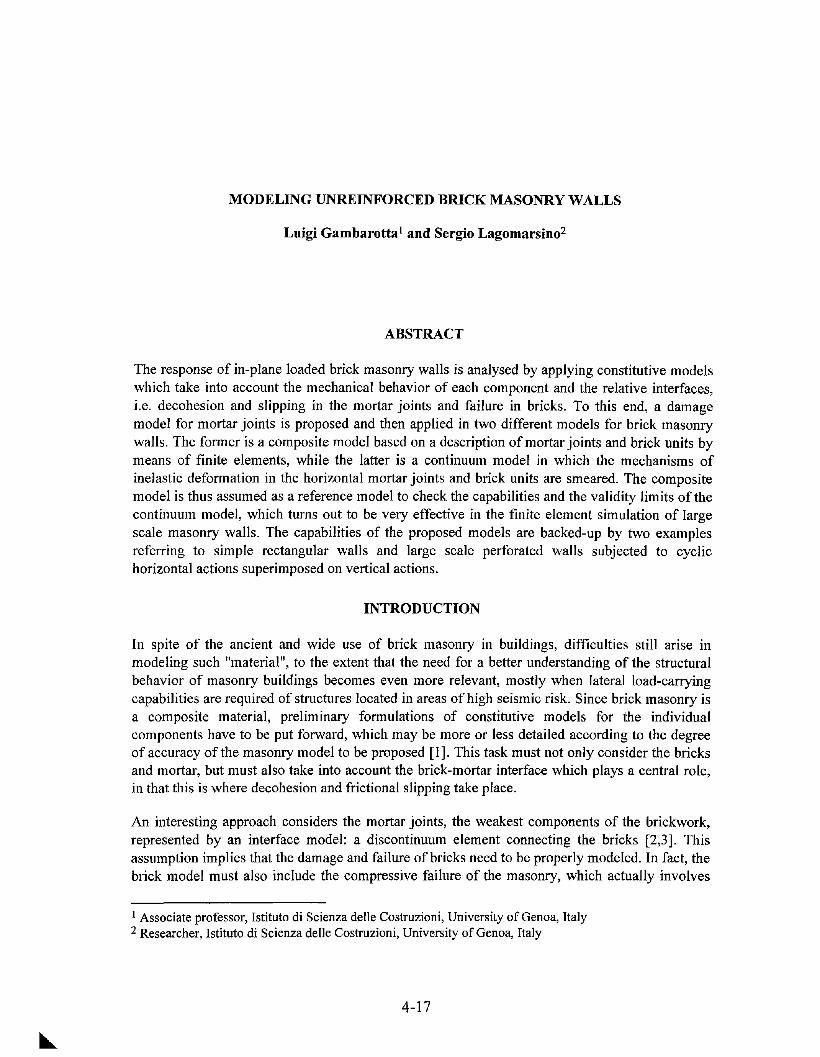
MODELING UNREINFORCED BRICK MASONRY WALLS
Luigi Gambarotta l and Sergio Lagomarsino2
ABSTRACT
The response of in-plane loaded brick masonry walls is analysed by applying constitutive modelswhich take into account the mechanical behavior of each component and the relative interfaces,i.e. decohesion and slipping in the mortar joints and failure in bricks. To this end, a damagemodel for mortar joints is proposed and then applied in two different models for brick masonrywalls. The former is a composite model based on a description of mortar joints and brick units bymeans of finite elements, while the latter is a continuum model in which the mechanisms ofinelastic deformation in the horizontal mortar joints and brick units are smeared. The compositemodel is thus assumed as a reference model to check the capabilities and the validity limits of thecontinuum model, which turns out to be very effective in the finite element simulation of largescale masonry walls. The capabilities of the proposed models are backed-up by two examplesreferring to simple rectangular walls and large scale perforated walls subjected to cyclichorizontal actions superimposed on vertical actions.
INTRODUCTION
In spite of the ancient and wide use of brick masonry in buildings, difficulties still arise inmodeling such "material", to the extent that the need for a better understanding of the structuralbehavior of masonry buildings becomes even more relevant, mostly when lateral load-carryingcapabilities are required of structures located in areas of high seismic risk. Since brick masonry isa composite material, preliminary formulations of constitutive models for the individualcomponents have to be put forward, which may be more or less detailed according to the degreeof accuracy of the masonry model to be proposed [1]. This task must not only consider the bricksand mortar, but must also take into account the brick-mortar interface which plays a central role,in that this is where decohesion and frictional slipping take place.
An interesting approach considers the mortar joints, the weakest components of the brickwork,represented by an interface model: a discontinuum element connecting the bricks [2,3]. Thisassumption implies that the damage and failure of bricks need to be properly modeled. In fact, thebrick model must also include the compressive failure of the masonry, which actually involves
1 Associate professor, Istituto di Scienza delle Costruzioni, University of Genoa, Italy2 Researcher, Istituto di Scienza delle Costruzioni, University of Genoa, Italy
4-17

both bricks and mortar, in that the interface ignores the Poisson effect and then only partiallydescribes the brick-mortar interaction. On these bases, the masonry may be analysed by a"composite" scheme, allowing the wall response to horizontal actions superimposed on verticalforces to be accurately simulated through finite element models. However, the description of eachbrick by means of several finite elements turns out to be computationally intensive, so precludingthe analysis of shear walls in real cases. These cases need to be analyzed by means of continuummodels, whose constitutive equations have to be obtained through the homogenization of thecontributions to the mean strain given by each masonry component. In this context, the compositemodel may be assumed as a reference for the validation of the continuum model.
In this paper, a continuum model for brick masonry is formulated, based on a mortar joint modelcapable of taking into account the effects of the compressive stress on the joint damage and thehysteretic response to cyclic shearing strains. At first, this joint model is applied in a compositemodel for masonry, in which the failure ofbiaxially stressed bricks is also taken into account, andwhose validity has been verified by the simulation of experimental tests on shear walls. Once thisreference model has been defined, the continuum model is then considered, based on thehomogenization of a stratified medium representative of the brick masonry. In this approach,which seems to be interesting due to its simplicity, two typical layers are considered: the mortarbed joint layer and the layer representing the brick rows together with the head mortar joints.However, the mechanisms of inelastic deformation in the head joints, related to horizontalextension and dilation, are neglected, since from the analyses carried out it results that theirinfluence on the global wall response is weak. The constitutive equations obtained have beenapplied in the finite element analysis of shear walls under horizontal forces superimposed onvertical forces.
A DAMAGE MODEL FOR MORTAR JOINTS
Let us consider a mortar joint between two bricks, reproducing the test configuration used byAtkinson et al. [4] in testing masonry bed joints under direct shear. The mean strainEm = {O 82 y}t in the mortar joint, which takes into account the damage in the mortar and thedecohesion in the mortar-brick interface, is assumed as depending on the mean stress0" m = {O"1 0"2 't}t, 0"2 and 't being the components of the resolved stress on the joint plane.Considering stress states which only induce inelastic deformation in mortar, the mean strain maybe split into the elastic and inelastic strain components:
(1)
where ~ is the elastic compliance matrix of the mortar and E:n ={O 8:n y:n}t represents theinelastic extension and sliding of the mortar joint. Denoting the joint damage variable as am~O,
the extension and sliding are assumed as follows:
(2.1)
(2.2)
where fJ.(am) and ~(am) represent the opening and sliding compliance of the mortar joint, whichincrease with the damage variable from the initial state '"CO)=~O)=O. In equation (2.1), the
4-18

Heaviside function X(0"2) takes into account the unilateral response of the joint. Finally, f isrepresentative of the friction in the mortar-brick interface [5]; when tensile stress acts on themortar joint (0"2>0) the variable f vanishes, while under compressive stresses it limits the slidingactivated by the shear stress.
Equations (1) and (2) imply that the internal variables am andfmust be known at any step of theloading history through evolution equations. To this end, it is worth noting that the variables y:nand am are associated to f and hm, respectively, the latter being the strain energy release ratedefined as follows:
(3)
The evolution equations of the internal variables are formulated on the basis of two conditions tobe satisfied at any time in the loading process. The variable f has to satisfy the friction limitcondition
involving the friction coefficient J.l, to which the simple flow rule
. . .y* =VA , A~ 0 ,m
(4)
(5)
is associated (v=j7lfl=±1). The damage evolution is also ruled by imposing the strain energyrelease rate to be less than or equal to the mortar joint toughness tA;m (assumed as depending onam), that is
(6). .
when the limit condition is attained (<I>dm = <I> dm = 0) the joint damage rate (am~O) is assumed totake place in the infinitesimal load step.
Due to the complexities of the damaging mechanisms in the mortar joint, the compliancefunctions "'Cam) and fc(am) cannot be deduced on a mechanical basis. Consequently, the followingsimple assumption, implying hm to be independent of am' is put forward:
~(am) = Gmn am ,~(am) = Gmt am (7)
When tensile stress is active on the mortar joint (0"2~0), condition (6) may be rewritten as follows:
<l>tm=tGmn(~+Rn't2)-tA;m(am):S;0 , (8)
Once the stress state and the function tA;m(am) are given, the damage variable am can be evaluated
by solving equation <1>+ = O. From this, it follows that the existence of a limit state (0"2' 't)m'dmrepresentative of failure, is subordinate to the existence of a maximum for the toughness function
tA;m(am). While the phase preceding this limit condition (tA;'m=dtA;m/dam>O) is characterized by a
stable response, the subsequent phase tA;'m <0. is stable only if strain is controlled. Thus, it is
4-19

assumed that the toughness function reaches a maximum t\;mc for u m=l; the failure condition ofthe mortar joint under tensile stresses is then obtained from condition (8):
~+ Rn't2 = 2t\;mc / cmn = crfu = Rn't~ , (9)
where O"m and 'tmrepresent the tensile and shearing strength of the mortar joints.
. .When the compressive stress acts on the joint (0"2<0), the sliding y~ and damage Urn rates mustbe evaluated considering conditions (4) and(6) which, through assumptions (2) and (7), become
~s = l't- y~/cmtuml +1l0"2 :5: 0 , (10)
~dm =ty;J/cmtU~-t\;m(um):5:0 (11)
If the friction limit condition ~s=O is reached, two different evolutions are possible in the
infinitesimal load step. When ~dm < 0, only sliding rate y~ can take place, which may be
evaluated by solving a linear complementarity problem. On the other hand, if ~dm = ~dm = 0,
sliding y* and damage Urn rates may take place; a linear complementarity problem must also bem
solved in this case, giving a unique or double solution if t\;:n>0 or t\;:n <0. Finally, the failure
condition is obtained by imposing ~dm(um=l)=O and ~s(um=I)=O, and by virtue of equations (2),(7) and (4), turns out to be expressed as:
(12)
Once O"m' 'tm and Il are given, both the limiting resistance domains, delimited by the curves ofequations (9) and (12), and the limiting sliding domain, obtained from equation (10) assumingy* = 0, are defined in the plane (0"2' l't I) as shown by Figure 1a.
m
The response to normal tensile stresses by the proposed mortar joint model is shown in Figure 1b,which exhibits both linear unloading, stiffness deterioration and strain-softening. These diagramsare obtained by assuming the following toughness function:
(13)
which attains its maximum t\;mc when u m=l and asymptotically tends to vanish for urn increasing(f3 >0).
Figure 1c shows the model response to cyclic shearing strains superimposed on normalcompressive stress. During the loading phase the response is elastic until 't:5:-1l0"2(G*=1+Gmcmt(1+1l0"2hm)); once this stress level is reached, sliding and damage take place. Thestrain-softening phase is characterized by the asymptotic tendency of the shearing stress, forincreasing shearing strains, towards the value -1l0"2' In addition, unloading is at first characterizedby an elastic response with no sliding until the friction limit condition is reached, after which
4-20

sliding takes place with reduced stiffness, according to the damage level previously attained. Thisresponse is characteristic of mortar bed joints as shown in Figure ld, where the theoretical resultsfrom the present model fit in well with the experimental results obtained by Atkinson et al. [6].
(a)
-.5
-4
GCm t=l
t-Llu2 1/Tm=O.25
{3=O.8
-2 2
(c)
4
- proposed model
'''- (d)- experiments [4J
........,
18
12
-6
E-<0
{3=O.8
Emcmn=l
2 3 4 -12 -12 -6 0 6 12
C2/Crn v (mm)
Figure 1. Damage model for mortar joint: (a) sliding and failure curves in the (0"2' I't I) plane; (b)model response to tensile stresses; (c) model response to cyclic shearing strains;
(d) simulation of direct shear tests by Atkinson et al. [4].
A COMPOSITE MODEL FOR BRICK MASONRY
Let us now consider brick masonry walls subjected to constant vertical forces and monotonicallyor cyclically increasing horizontal forces. In order to determine the effect of the damage in themortar joints and bricks on the structural response of the wall, a composite model is considered.The model assumes the brick masonry wall as consisting of rectangular continuum elements,representing the bricks, connected by interface elements representing the mortar joints.
Failure in bricks leads to the activation of further mechanisms of inelasticity in the mortar, nottaken into consideration in the joint model described in the previous Section. In order to simplifymatters, these effects are incorporated in the continuum elements. To this end, the properties ofthe continuum elements are determined considering, as a reference, the compressive failure in themasonry, which starts in the bricks due to the Poisson effect, and the tensile failure in the bricks.Moreover, this approach requires the joint to be reduced to a one-dimensional interface whichonly considers the normal and tangential stresses on the joint plane.
4-21
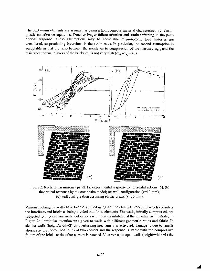
The continuum elements are assumed as being a homogeneous material characterized by: elastoplastic constitutive equations, Drucker-Prager failure criterion and strain-softening in the postcritical response. These assumptions may be acceptable if monotonic load histories areconsidered, so precluding inversions in the strain rates. In particular, the second assumption isacceptable in that the ratio between the resistance to compression of the masonry O'Mc and theresistance to tensile stress of the bricks O'bt is not very high (O'MJO'bt:::::2+3)0
--6 -4 -2 o 2
(b)
- inelatic bricks- elastic bricks
4 6 8 ~-";:;2----'------;;O-L---;C2:;-~4-';---'----=-6-L---.J8
V (mm)
Figure 20 Rectangular masonry panel: (a) experimental response to horizontal actions [6]; (b)theoretical response by the composite model; (c) wall configuration (v=10 mm);
(d) wall configuration assuming elastic bricks (v=10 mm).
Various rectangular walls have been examined using a finite element procedure which considersthe interfaces and bricks as being divided into finite elements. The walls, initially compressed, aresubjected to imposed horizontal deflections with rotation inhibited at the top edge, as illustrated inFigure 2co Particular attention was given to walls with different geometric ratios and fabric. Inslender walls (height/width:::::2) an overturning mechanism is activated; damage is due to tensilestresses in the mortar bed joints at two comers and the response is stable until the compressivefailure ofthe bricks at the other comers is reached. Vice versa, in squat walls (height/width:::::l) the
4-22

damage takes place in the bed joints on the diagonal, inducing the limit state of resistance; thecorresponding stress states are characterized by the formation of two inclined compressed bands.In the subsequent post-peak response, the bricks on the diagonal break under tensile stresseswhile crushing takes place at the comers.
As an example, the results of tests carried out on a wall [6] of average slenderness have beenconsidered and reported in Figure 2a in terms of applied lateral deflection v and correspondinghorizontal force F. The wall is 100 cm wide and 135 cm high, the brick size is 24 cm x 12 cm x5.5 cm and the thickness of the mortar joints is s=1 cm. The simulation by the proposedcomposite model is shown in Figure 2b, from which it can be seen, in addition to a goodagreement with the experimental results, that the failure mechanisms in the bricks only influencethe post-peak behaviour. The theoretical response was obtained by using parameter valuesobtained from tests on the materials [7]: EM=1800 MPa, vM=O.2, 1l=0.5, O"m=O.l MPa, 'tm=0.25MPa, f3=0.9, sct=0.5 mmIMPa, O"Mc=4.8 MPa, O"bt=2 MPa. Figure 2b also shows somecharacteristic states: I) failure of the mortar bed joints on the diagonal; II) failure of the mortarbed joints at the base; III) tensile failure of the bricks and failure of the mortar head joints on thediagonal; IV) compression failure of the bricks at the comer.
Figure 2c represents the configuration of the wall corresponding to the top deflection v=10 mm.In the diagonal band, a considerable dilation of the head joints, sliding of the horizontal joints andthe tensile failure of some bricks can be seen, while the compressed bricks at the comers exhibitnotable inelastic deformation. Moreover, Figure 2d shows the configuration obtained by theassumption of elastic bricks, which turns out to be similar except for less dilation in the centralzone of the wall.
Therefore, the results obtained represent a reference for the evaluation of simpler constitutivemodels, as illustrated in the next section.
A CONTINUUM MODEL FOR BRICK MASONRY
In order to formulate a continuum model, brick masonry is assumed as being a stratified mediumconsisting of bed joint layers and layers representing bricks and mortar head joints. Thissimplification, analogous to that by Pietruszczak and Niu [8], only considers the inelasticdeformation in the mortar bed joints and in the bricks; however, it neglects the mechanismsinvolving both bed and head mortar joints, which cause vertical extension and dilation (Figure2c,d). The constitutive equations can be deduced by homogenizing mortar bed joints and bricklayers and considering the effective thickness of the mortar bed joint [9]. The mean strain is thengiven by:
(14)
where cr is the mean stress in the masonry, 11mand 11b are the volume fractions of the mortar jointsand brick units respectively (11 m+11b=I), and K is the elastic orthotropic compliance of themasonry, which depends on the elastic moduli of mortar and brick and on the volume fraction 11m,The inelastic strain in the mortar joint E:n is obtained according to the mortar joint modelpreviously proposed. Moreover, the inelastic strain Ej; due to damage and failure in bricks, only
4-23

considers the main contributions of brick damage, induced by compressive and shear stresses, soneglecting the effect of the horizontal component 0"1 of the stress.
Then the components of the inelastic strain in bricks Ei,={0 8b YbP are assumed, similarly to themortar joint model, as follows:
8b = cbn Ub %(-0"2) 0"2 '
Yb = CbtUb 'I: •
(15.1)
(15.2)
Here, the normal strain 8~ only takes into account the compressive stress effect by means of theHeaviside function. Moreover, both strain components linearly depend on the damage variable ubof bricks and on the brick compliance parameters cbn and Cbt. The strain energy release rate inbricks, associated to the damage variable ub ' is then expressed by
(16)
where Pb=cbtCbn' Thus, as with the mortar joint model, the damage evolution is assumed to beruled by the condition
(17). .
so that when the limit condition ($db = $db = 0) is attained, the brick damage (Ub20) is assumed totake place in the infinitesimal load step. In condition (17) the toughness function rA;b(ub) of bricksis introduced and in the following is assumed as expressed in the form given in equation (13) (theparameter rA;be being considered at this point).
This formulation gives the failure condition for monotonic compressive stresses (0"2<0) asfollows:
0"2 + (\ '1:2 = 2rA; / C = 0"2 = (\ '1: 22 1'"'0 be bn b t"'O b ' (18)
where ab represents the compressive strength of the masonry, while 'l:b is the shear strength ofthe bricks. In the (0"2' I'I: I) plane the sliding and failure curves relating to monotonic stress pathsare shown in Figure 3, exhibiting both the joint failure and the cap model due to the bricks failure.
brick failure
Uz
Figure 3. Joint and brick failure domains in the (0"2' 1'1: I) plane.
4-24

These simple assumptions for the brick model imply a brittle response of the masonry incompression, similar to that shown in Figure Ib for the mortar joint. On the other hand, a complexdescription of the inelastic deformation in bricks implies notable complexities in the applicationof the model.
The continuum model proposed has been applied in an incremental finite element procedure forthe in-plane analysis of brick masonry walls based on isoparametric elements. The incrementalsolution is obtained by means of an iterative "initial stress" method whose fundamentalpeculiarity concerns the algorithm for the finite load step integration of the constitutive equations.In fact, this task turns out to be very complex due to the interaction of the three mechanisms ofinelastic deformation involved in the present model. The finite increments of the stress andinternal variables corresponding to finite strain increments are obtained by means of a predictorcorrector procedure, similar to that proposed by Simo et al. [II], in which the correction phase isbased on a Newton-Raphson algorithm involving the limit functions of the active mechanisms ateach iteration.
This procedure has been applied to analyze both rectangular shear walls, having the samegeometry as that described in the previous section, and a large scale perforated wall; in both casesvalues of the model parameters directly correlated to those applied in the composite modelpreviously described have been considered (Table I). Furthermore, in order to take into accountsize effects, rectangular finite elements were chosen with dimensions such that, for each point ofintegration, a representative volume element of the brick masonry is considered as having widthequal to the mean distance between the head joints, and height equal to one course of bricks andmortar.
Table 1. Model parameters.
Em (MPa) Vm E b (MPa) Vb 11 m
elastic moduli 539 0.18 2200 0.28 0.154
crm (MPa) 'tm (MPa) ~ l/cmt (MPa) f3m
mortar joint 0.05 0.23 0.577 520 0.8
crb (MPa) 'tb (MPa) l/cbn (MPa) f3m
bricks 5 2 2500 0.4
In the case of slender walls both the response and the collapse mode obtained by the continuummodel are almost coincident with that obtained by the composite model. Small differences in theoverall response of squat walls come out of the two models, even if the composite model suppliesextension and dilation in its central zone that the continuum does not. The diagram in Figure 4shows the response of the squat wall, which turns out to be very close to the experimentalresponse [6]. In particular, at the state A (corresponding to the top deflection v=7 mm) thedamage is spread over two diagonal bands and in the upper corners, as shown in Figure 5b; thecorresponding stress state is characterized by two compressed parallel bands and an unloadedband between them (Figure 5a).
4-25

A
--.zC 0 r---+--+--+---+-..,.""'''' 'f7.~~-+--+--+--+---t---1r---+--if--I--/l+-----l-+---+--+--+---+-----.j
8642o2o-2-4-6 4 6 8-2
V (mm)
Figure 4. Lateral hysteretic response of a squat wall: (a) experimental, (b) continuum model.
(a)
az (MPa)0/005
-05/0
11- 1/- 05
11-2/- 1
.-44/-2
(b)
ex• 100/460
II 10/100
II 1/10
0/1
o
Figure 5. Rectangular wall: vertical stress (a) and joint damage am (b) distributions at the state A.
The second example concerns the simulation of the in-plane behavior of the perforated shear wallof the prototype brick masonry building experimented by Calvi et al. [12] in Pavia, the finiteelement model of which is shown in Figure 6. The experimetal hysteretic response to cyclichorizontal displacements applied to each floor level, imposing to the two story forces to be equal,is shown in the diagram of Figure 7a. The model response (Figure 7b) is able to catch both thehorizontal strength of the wall (150 kN) and its dissipative behaviour; the small differences thatappear in the first cycles may be attributed to a non uniform distribution of the joint strength inthe real wall. Figure 8 shows the vertical stress and the mortar joints damage distributionscorresponding to 0.2% drift. The damage evolution is characterized by a first degradation of the
4-26

mortar joints over the four lintels, which appears at 0.1 % drift, followed by the damage at thebase of the wall sections, and then of the central panel. Increasing the lateral displacement thedamage propagates in the central panel in the form of a "Y" till the collapse. As shown in Figure8a, the vertical stress is not very high, so the effects of bricks failure are limited; moreover, it canbe observed that one lateral pier is unloaded, while in the central one there is an unloaded band inwhich extensions and slidings take place in the mortar joints. Finally, it is also worth noting that aconsiderable rotation at the top of the wall apperas, due to the non uniform compression in thepiers.
Figure 6: Finite element model of the large scale perforated wall [12].
drift (%)-0.3 -0.2 -0.1 ° 0.1 0.2 0.3
150
100
""'Z.0£ 50'--'
....0Q) 0..c(f)
~ -500.Q
-100
-150
-20 -10 0 10 20 -20 -10 0 10 20
W2 (mm) w2 (mm)
Figure 7. Experimental (a) and theoretical (b) lateral hysteretic response of the large scaleperforated wall [12].
4-27

(a)
Uz (MPa)0/027
-05/0
.-1/-05
• -2/-1
.-34/-2
(b)
ex• 100/645
• 10/100
• 1/100/1
a
Figure 8. Large scale perforated wall: vertical stress (a) and mortar joint damage am (b)distributions for 0.2 % drift.
CONCLUSIONS
The proposed continuum model, which considers damage mechanisms both in mortar bed jointsand in bricks, allows the response of masonry walls subjected to horizontal forces to be obtainedwith some accuracy. Moreover, several characteristics of the brick masonry behavior can be takeninto account, such as brittleness under tensile stress, hysteretic response to cyclic loads,increasing of the lateral strength and ductility with compressive vertical stress, and influence ofthe slenderness of the walls on the collapse mechanism.
The simulation of some experimental results obtained from rectangular shear walls [6] and largescale perforated walls [12] have shown the good capabilities of the continuum model to describethe hysteretic response, the failure strength, the damage evolution and the post-peak behavior. Onthe other hand, the composite model presented here is a useful tool for stating the validity limitsof the continuum model and thus improving it.
The proposed models could also be useful tools for setting-up experiments, for evaluating theinfluence of the material parameters and the geometry and, finally, for developing simplifiedprocedures for the analysis of masonry buildings.
4-28

REFERENCES
[1] J.G. Rots, Numerical simulation of cracking in structural masonry, Heron, 36, 49-63, 1991.
[2] H.R. Lofti and P. Benson Shing, Interface model applied to fracture of masonry structures, J.Struct. Engrg., ASCE, 120(1),63-80, 1994.
[3] P.B. Lourenco, J.G. Rots and J. Blaauwendraad, Implementation of an interface cap modelfor the analysis of masonry structures, Proc. Int. Con! Compo Modelling of Concr. Struct.,123-134, Innsbruck, Austria, 1994.
[4] R. H. Atkinson, P.B. Amadei, S. Saeb and S. Sture, Response of masonry bed joints in directshear, J. Struct. Engrg., ASCE, 115, (9), 2276-2296, 1989.
[5] L. Gambarotta and S. Lagomarsino, A microcrack damage model for brittle materials, Int. J.Solids Struct., 30, 177-198, 1993.
[6] A. Anthoine, 1. Donea, A. Pinto, Experimental and numerical investigation on a brickmasonry building prototype, CNR-GNDT, Report 2.0, 1993.
[7] L. Binda, G. Mirabella, C. Tiraboschi and S. Abbaneo, Measuring masonry materialproperties, U.S.-Italian Workshop on Guidelines for Seismic Evaluation and Rehabilitation ofUnreinforced Masonry Buildings, Pavia, 22-24 June, 1994.
[8] S. Pietruszczak and X. Niu, A mathematical description of macroscopic behaviour of brickmasonry, Int. J. Solids Struct., 29,531-546, 1992.
[9] L. Gambarotta and S. Lagomarsino, Fragilita e duttilita di pareti murarie ad azioniorizzontali: interpretazione con il modello di muratura a piani di danneggiamento, Proc. 6thItalian Nat. Con! on Earthq. Engrg., 513-522, Perugia, Italy, 1993.
[10] L. Gambarotta and S. Lagomarsino, Damage in brick masonry shear walls, Proc. Europeus. Workshop on Fracture and Damage in Quasibrittle Structures: Experiment, Modelingand Computer Analysis, Prague, 1994.
[11] J.C. Simo, J.G. Kennedy and S. Govindjee, Non-smooth muitisurface plasticity andviscoplasticity. Loading and unloading conditions and numerical algorythms, Int. J. Numer.Methods Engrg., 26, pp. 2161-2185, 1988.
[12] G. M. Calvi and G. Magenes, Experimental research on response of URM building systems,U.S.-Italian Workshop on Guidelines for Seismic Evaluation and Rehabilitation ofUnreinforced Masonry Buildings, Pavia, 22-24 June, 1994.
4-29


FAILURE CRITERION FOR BRICK MASONRY UNDER IN PLANE LOAD:
A MICROMECHANICAL APPROACH
Gianmarco de Felice (1)
ABSTRACT
An homogenization procedure is outlined to identify the overall mechanical properties of masonryby a micromechanical approach. Starting from the sole knowledge of the strength properties oftheir constituents (bricks and mortar) and of their disposition within the wall, a failure condition isanalitically obtained for single lined brickwork. All the parameters in the equation have a clearmechanical meaning and, as expected from experimental results, strength properties explicitlydepend on the geometry of bricks. The above failure condition is finally applied to compute thecollapse load of walls subjected to in plane increasing loads and its effectiveness is chekedcomparing the results with experimental ones and with other numerical approachs.
INTRODUCTION
As pointed out by several tests (12, 15) a correct modeling of historical masonry has to be relatedto the geometry of brick units and to their texture within the wall. This is required especially whenthe mechanical properties of masonry are highly eterogeneous (mortar is much weaker thanbrick). To better undersand the importance of the inner structure of masonry, small scale brickwalls without mortar have been tested by placing the wall on a table which was slowly inclineduntil failure occurs (2). The results (Figure 1) clearly show how the shape of the bricks influencesthe overall resistence of the wall.With this in mind, the main task of this study is to bring to the level of the overall response ofmasonry the informations regarding its inner structure. This is the first step towards a generalprocedure for identifying the macroscopic properties of masonry, from those of bricks and mortar,by means of a micromechanical approach.The basic assumption of such approach is that masonry can be regarded as a periodic mediumobtained by the repetition of a volume element. While in a brickwork the presence of suchrepresentative volume is obvious, in an irregular stone masonry, the representative volume ishidden behind the complexity of masonry work but it still exists and can be identified. As forbrick masonry, also for row stones masonry, geometrical rules exist regarding size and disposition
(1) Third University of Rome - Departement of "Progettazione e Scienze dell'Architettura", via Madonnadei Monti, 40 - Rome, Italy.
4-31

of the units in masonry texture; those rules booth depend on the availability of materials and onthe construction techniques of the region. They can be deduced by a survey of masonry and arepresentative volume made by stones and mortar in a particular arrangement can be identified (6)Althoug the attention will be focused on brick masonry, the micromechanical approach wich ispresented in the following can be applied (not trivially) to stone masonry too.
'A= 0,48 'A = 0,33
Figure 1 Experimental failure configuration and corresponding horizontal load(normalized with respect to vertical load) oftwo walls with different brick-ratio.
BETWEEN MICRO AND MACRO MODELING OF MASONRY
Statement of the problem
We assume to know, for each constituent (brick and mortar) of masonry, the set G(x) of all thestress states admissibles in the material:
-rex) E G(x) XEV (1)
According to the heterogeneity, the set G, wich define the strength properties of the medium, is aperiodic funtion of the place, while the behaviour ofthe material is no further specified.
A direct approach to analyse such a structure requires the exact discretization of the wallaccording to the heterogeneity. The main difficulty of such a model depends on the fact thatheterogeneity dimension is small when compared to the dimension of the wall and thecomputational effort, related to a separated modelling of bricks and joints, becomes quickly toohigh. Several approach have been performed for a micromodelling of masonry: contact elementsare employed in the framework of non linear finite element analysis (l, 10); a direct limit analysis
4-32

formulation for block structures have appeard in litterature (9, 1); recently brick walls subjected toquasistatic lateral loading have been modeled in the contest of discrete element method (Giuffre,Pagnoni e Tocci, 1994). Anyway only simple panels have been analysed, while for application toengineering problems a macroscopic description of masonry is required.To search for homogeneous (or homogenized) material, having overall mechanical propertiesanalogous to that of the heterogeneous medium, experimental or phenomenological methods canbe used. Several attempts to calibrate macroscopic models by experimental results have beendeveloped for masonry brickwork, but generally a large number of parameters, without a clearmechanical meaning, are involved in the descritpion of the overall behaviour; moreover thevalidity of the model is restricted to specifics of the sample.In alternative, a micromechanical approach can be used by means of a homogenization technique.
THE HOMOGENIZATION APPROACH
The assumed periodicity of the geometry and of the mechanical behaviour of masonry allow toapply the homogenization method in the framework of periodic media. This is very convenient inorder to obtain, in a precise form, the passage from a microscopic description of the problem to amacroscopic one.The macroscopic or homogenized model can be derived by means of an homogenizationtechnique, regarding the asimptotic behaviour as a scale factor J.l tends to 0; where J.l representsthe small ratio -elL between the dimension of representative volume element -e and of the overallstructure L (Figure 2).
x2
L
N1------.;:o.----..,
o
G(x)
Local fields:
Strength Properties:
't(y), E(y)
't(y) E G(y)
Figure 2 Initial Problem on a heterogeneous periodic material
It results, from arguments on oscillating functions, that the macroscopic stress T and strain E
4-33

tensors must be the averages of the corresponding microscopic fields
T =lim 't (x) = < 't(x) >,~~o
E =lim 8(x) = < 8(x) >;~~o
where <.> stands for the averaging operator on the period of the microstructure
<.> = ! J.dV.n n
(2)
Since the local stress field 't is constrained by the constitutive equation (1), its average, the
macroscopic stress T, has to be constrained too:
T(x) EGhomXEV (3)
where, since the structure has assumed to be strictly periodic, the macroscopic properties of the
homogenized structure, named G hom, are constant. While the initial problem regards an
heterogeneous material, where strength properties are defined by the set G(x) depending on theposition in accord to the hererogeneity, the homogenized problem (Figure 3) regards an
homogeneous fictitious material, with constant strength properties defined by G hom•
N
o
Macroscopic Fields: T, E
Strength Properties: T E G hom
a hom
Figure 3 Homogenized Problem on a continuous homogeneous material
Clearly we still have to construct the macroscopic set G hom and to demonstrate that, as the scalefactor Jl tends to 0, the limit load of the initial heterogeneous periodic material tends to the limit
4-34

load of homogenized material. As usually in homogenization methods, the macroscopic propertiesmay be obtained by a solution of a boundary value problem wihtin the basic period of thestructure. A suitable definition of the macroscopic strength condition (17) is the following:
G hom is the set of macroscopic states of stress T fulfilling the following requirements:
mean condition: T = < 't(y) >
equilibrium: div L(Y) = 0, yEn
constitutive equation: L(Y) E G(y), yEn
boundary conditions: L(y) n(y) antiperiodic (4)
and the proof of convergence is given except "edge effects" occuring at the boundary of thestructure.The macroscopic strength condition relies on the solution of a yield design problem (Figure 4)where the load consists in the average value of the field of stress within the period of thestructure.
G(y)
Figure 4 Auxiliary yield design boundary value problem on the basic period ofthe structure.
THE BRICK MASONRY MODEL
Recently, some attempts to analyse brick masonry as a composite material have appeard inlitterature; in order to apply a simplyfied homogenization procedure some kind of assumptions aremade. For example, masonry is regarded as a continuum made by a mortar matrix with bricks asreinforcing inclusions (11) or alternatively, as a brick matrix intercepted by mortar weakinclusions (4). In other cases (14, 15,5) the presence of vertical joints is neglected and brickworkis regarded as a multilayred material. This is not completely satisfactory with respect to failurecondition, because, as shown by experimental tests (Figure 1), the interaxe of vertical jointsstrongly affects the strength of masonry.
4-35

XI
Plane texture ofbricks
i) masonry has a plane texture
ii) masonry is subjected to in plane loads
iii) mortar joints are simply interfacesbetween bricks
X2
Figure 5 Assumptions
In this approach the effect of brick geometry on masonry strength is explicitely considered in themodel, while some other simplifications will be assumed:i) only on line texture of bricks is regarded, even if usually masonry work has a more complexinner structure, because bricks are arranged both in the front and in the section of the wall.ii) only in plane loads are considered and a plane stress calculation is performed, disregarding thepossibility of a splitting failure in the plane of the wall. This kind of failure is expected in the caseof uniform compression, as outlined by experimental tests (13).iii) finally, mortar joints are modeled simply as interfaces between bricks. This last assumptionleads to an overextimation of compressive strength which can be explained by referring to thecase of axial load: because of the different deformabilities of brick and mortar, as pointed out byHilsdorf (8), lateral compressive stress appear "in the mortar, while the bricks are subjected tolateral tensil stress. Therefore the compressive strength of brickwork is lower then the strength ofbrick unit.
b
I_~
joints
bricks
unit cell
Figure 6 Unit cell ofon line brickwork
The above assumptions allow to define the geometrical properties of brickwork only by a
4-36

parameter wich mesure the form ratio, high to wide, of a single brick unit:
am=-
b
Mechanical properties of components of masonry are assumed as follow:
i) for bricks the set gbricks of admissible states of stress is defined by means of a Mohr-Coulombcriterion in plane stress; two parameters ft and fm, respectively the tensile and compressivestrength, are involved in the yield condition (Figure 7).
Figure 7 Strength condition for bricks
ii) for joints for bricks the set gjoints of admissible states of stress is defined by means of aCoulomb criterion with cohesion (c) and coulomb friction (<p)
THE MACROSCOPIC STRENGTH CONDITION
We take in account separately, in two steps, the contribute ofjoints and bricks to the macroscopicstrength condition for masonry.
Influence of joints
We first consider only the joint effect (that is equal of considering bricks infinitely resistent): theresolution of the auxiliary yield design problem, on the basic period of the structure, leads to ananalitical expression for the macroscopic strength condition (3). Clearly the macroscopic domainis open in the direction of compression and the shape of the failure surface is anisotropic. Asshown in Figure 8, the shape of the domain in the plane of principal stress depends on the angle ebetween principal stress directions and joints directions.
4-37

T2
.rr-r-t::::/Io't: _ .
Ti i 2
~~T·~6~,50
.L...---j-..:~ _ .
<p=31°ill = 0,875
Figure 8 Macroscopic strength condition whit respect to joints failurein the plane ofprincipal stress
4-38

The projection of the domain in the stress space, on the refemce of joint directions, leads to thefollowing equations (Figure 9):
<1>i,2(T) = =+=~2 + f T22 -c ~ 0
<1>3,4 (T) = +2mTl1 =+= (2mf +1)Ti2 - fTn - c (2m/ f + 1) ~ 0 (5)
where both, mechanical properties ofjoints (cohesion c and friction coefficient f = tan <p ) anda
geometry of bricks (form ratio m =-) explicitely appear in the formulation.b
Figure 9 Macroscopic strength condition whit respect to jointfailurein the stress space on the refernce ofjoint directions
The expressions obtained define the macroscopic strength condition of masonry in the tensionrange, while in the compression range, the resistence of bricks has to be taken in account. Thecriterion, analitically obtained by a micromechanical approach, is quite similar to the one obtainedby Page (12), interpolating numerical results performed by finite elements method (Figure 10).
Influence of joints and bricks
For taking in account the strength condition in the bricks, the auxiliary boundary value problemon the basic period of the structure cannot be solved analitically, but a numerical procedure has tobe followed.
4-39

e·'-
0,5 1,5
Figure 10 Comparison with the failure condition numerically obtained
by Page (12) in the tension range
Anyway, the macroscopic domain can be bounded in a very simple way. It can be demonstrated
(3) that such a domain named Ghom is bounded, from above, by the intersection between the
domain Gjoints, previously obtained by considering only the joints effect, and the domain Gbricks
of the admissible states of stress in the bricks; similary it can be bounded, from below, by theintrsection of the domain Gbricks and the domain Gstatic, wich is the lower bound domain ofjointseffects, obtained by a static approach with uniform stress fields:
where:
Gstatic n Gbricks C G hom C Gjoints n Gbricks
G hom ={T I :3 l' S.A. T; l' E gjoints n gbriCkS} (2)
Gbricks = {T I :3 l' S.A. T; l' E gbriCkS} = gbricks
Gjoints ={T I :3 l' S.A. T; l' E gjOints}
Gstatic = {T I T = l' E gjoints }
(6)
The two bounds are shown in the following Figures for different value of the angle e betweenjoints and principal stress directions.
(2) S.A. stands for statically admissible and means that equilibrium, mean condition and boundaryconditions are satisfied.
4-40

cfricks
f, __ /
III
: f,
~ '. I T1, '.tC l doints
doints -J3ricks! ,1" _____
upper bound nu C ,---C , \. '. " \, . , \
static -J3ricks ~ : , \lower bound G nU ~ :, \
C 1M s"~ .II \, II \C ~ \
~ J~ static"~ ., I G \••.&\11.......&" .......'101\1 ......... ,,&.•.&,•.&\1 .........&\1....... fro I \
.--Joints -J3ricksupper bound lj nu
statiCn-J3rickslower bound ..........G U
II
II
I1
t It Ia,.,.,.,.,., v 'r- - -
• • • I..J.0m~ stattc____U -G f
I
If
III
IfI ,
II
II
II
II
ff
I
fI
I
I
I
II
ifm
T
Figure 11 Macroscopic strength condition with respect to joint and brickfailure
LIMIT ANALYSIS OF IN PLANE LOADED WALLS
Once the auxiliary problem has been solved and the macroscopic strength condition has beenobtained, the homogenized problem can be threated by a traditional finite element analisis.Regarding only the limit behaviour of the structure, an elastic-perfectly plastic model can be used,
4-41

where:i) the elastic properties can be arbitrary;ii) the limit surface of elastic domain is given by the resolution of the auxiliary problem ofhomogenization procedure;iii) the flow rule can be assumed as associated or not to the criterion (in the first case only anoverstimate of the limit load will be reached).
In order to validate the previously described procedure, three walls with different brick shape, inabsence of mortar, have been tested on the inclined table in the laboratory and correspondingdiscrete element computation has been performed (7). The results of homogenized model (Figure12), requiring only few computational effort, apper to be, both in the collapse load value and inthe failure configuration, very similar to those of the discrete element method.
m= I
I I , r-,
: I f T-
I -I I
--I'J
TI: {
: 1
A=0,22
m = 0,4375
A=0,31
m = 0,21875
r ...............
r- I I 1: -
I-.. ---l T:.............. I· I- J---1 I -f--.,
:/ /1 { I IlIII { I 1 T '1I I I I I· i--
J { I -:
f 7
A=0,32
A=0,22 A=0,32 A=0,33
Figure 12 Comparison between homogenized and discrete structure limit behaviour
4-42
REFERENCES
1. Baggio C., Trovalusci P., "Discrete models for jointed block masonry walls", Proc.6th NorthAmercan Masonry Conf, Philadelphia, 1993, Vol. 2, pp.939-949.
2. Ceradini V., Modellazione e sperimentazione per 10 studio della struttura muraria storica,Tesi di Dottorato, Dipartimento di Ingegneria strutturale e Geotecnica, Roma, 1992.
3. de Felice G., Omogeneizzazione e calcolo a rottura della muratura, Tesi di Dottorato,Dipartimento di Ingegneria strutturale e Geotecnica, Roma, 1994.
4. De Vecchi S., De Vecchi A., "Studio comparativo di metodi di omogeneizzazione percompositi bifase", Atti del XI Congr.Naz. AIMETA, Trento, 1992, pp.313-318.
5. Gambarotta L., Lagomarsino S., "Fragilita e duttilita di pareti murarie ad azioni orizzontali:interpretazione con il modello di muratura a piani di danneggiamento", Atti del VI Conv.Naz.L'ingegneria Sismica in Italia, Perugia, 1993, Vol.2, pp.513-522.
6. Giuffre A., Carocci C., de Felice G., Tocci C., "Actuality and modeling of historicalmasonry", 1994, submitted to the same proceeding.
7. Giuffre A., Pagnoni T., Tocci C., "In-plane seismic behaviour of historical masonry walls",10th Int. Brick/Block Masonry Conf., Calgary, Canada, 1994.
8. Hilsdorf H.K., "Investigation into the failure mechanism of brick masonry loaded in axialcompression", in Designing, Engineering and Constructing with Masonry Products (ed.byF.B.Johnson), Proc.Int.Conf. Masonry Structural Systems, Houston, Texas, 1969, pp.34-41.
9. Livesley R.K., "Limit analysis of structures formed from rigid blocks", Int.J.Num.MethEng.,Vol.I2, 1978, pp.1853-1871.
10. Lofti H.R., Shing P.B., "Interface model applied to fracture of masonry structures", ASCEJ.Struct.Engrg., Vol.I20, No.1, 1994, pp.63-80.
11. Maier G., Nappi A., Papa E., "On damage and failure of brick masonry", in: Experimentaland Numerical Methods in Earthquake Engineering, (ed.by G.Donea and P.M.Jones), Ispra,1991, pp.223-245.
12. Page A.W., "A biaxial failure criterion for brick masonry in the tension-tension range",Int.J.Masonry Construction, Vol. 1, No.1, 1980, pp.26-29.
13. Page A.W., "The biaxial compressive strength of brick masonry", Proc.!nstn Civ.Engrs.,Part.2, Vol 71, 1981, pp.893-906.
14. Pande G.N., Liang JX., Middleton J., "Equivalent elastic moduli for brick masonry",Comput.Geotechnics, Vol.8, 1989, pp.243-265.
15. Pietruszczak S., Niu X., "A matematical description of macroscopic behaviour of brickmasonry", Int.J.Solids Structures, Vol.29, No.5, 1991, pp.531-546.
16. Samarasinghe W., Hendry A.W., "The strength of brickwork under biaxial tensile andcompressive stress", Proc. 7thInt. Symposium on Load Bearing Brickwork, London, 1980.
17. Suquet P., "Analyse limite et homogeneisation", C.R.AcadSc., Paris, serie II, 1.296, 1983,pp.1355-1358.
4-43


Section V
Case Studies of Building Preservation Projects
Rehabilitation of URM Buildings in the Eastern United StatesJohn Theiss
• Rehabilitation of URM Buildings in ItalyCarlo Gavarini
5-1


REHABILITATION OF URM BUILDINGSIN THE EASTERN UNITED STATES
John C. Theiss, P.E!
ABSTRACT
This paper describes the methodology used to evaluate existing unreinforced masonry buildingssubject to strong ground motion and the methods and assumptions used to strengthen the buildingsoThe technical criteria and the owner performance objectives are presented along with the retrofitstrategies that were used to strengthen the buildingso
INTRODUCTION
The earthquake history of the Central United States is dominated by the series of great earthquakewhich ruptured the New Madrid Seismic Zone in the winter of 1811-18120 On December 16,1811, three earthquakes ruptured the entire southern segment of the New ·Madrid Seismic Zone,a length of about 90 mileso These earthquakes had magnitudes of 806 (2:30 aomo), 800 (8: 15 aomo),and 800 (noon)0 On January 23, 1812, another great earthquake having a magnitude of 804ruptured the central segment of the fault, a distance of about 45 mileso On February 7, 1812, thelast and largest earthquake in this series occurred near the town of New Madrido This earthquakehad a magnitude of 808 and ruptured the entire northern branch of the fault zoneo Between theoccurrence of the first earthquake on December 16, 1811 and March 15, 1812, the aftershocksequence included:
• 5 earthquakes of magnitude 707• 10 earthquakes of magnitude 607• 35 earthquakes of magnitude 509• 65 earthquakes of magnitude 53• 89 earthquakes of magnitude 43
Eighteen of the 1811-1812 New Madrid earthquakes were felt as far away as Washington, DoCoA total of about 1600 discernible aftershocks occurred in this three month periodo About as manyearthquakes occurred in the Mississippi Valley in this three month period as occurred in SouthernCalifornia in the 40 year period between 1932-19720
1president, Theiss Engineers, Sto Louis, Missouri, USA
5-3

....
VI
I ~
Ce
ntr
al
Un
ite
dS
tate
sE
art
hq
ua
keS
ou
rce
Zo
ne
s
Su
rfa
ceW
ave
Ma
gn
itu
de
sW
ith10
00Y
ear
Re
curr
en
ceIn
terv
al
Re
fere
nce
:N
utt
li,1
98
5
Mic
ha
ga
nB
asin
5.4
,.~
.pp
ala
cia
nF
ron
t7
.0
~Uirt!e"'l~drid
Se
ism
icZ
on
e8
.7

I'"
VI
I VI
MM
IC
on
tou
rsfo
ran
7.6
Mag
nit
ud
eE
arth
qu
ake
Ep
icen
ter
inth
eN
ewM
adri
dS
eism
icZ
on
e
Ref
eren
ce:
Un
ited
Sta
tes
Ge
olo
gic
al
Su
rve
yO
pen-
File
Rep
ort
85-4
57

The New Madrid Seismic Zone is the most active seismic zone in the Mississippi Valley. The"average behavior" of this seismic zone includes 350 measurable seismic events per year.
SEISMIC RISKS
A probabilistic study of the earthquake risk in the New Madrid Seismic Zone has been publishedby Arch C. Johnston and Susan J. Nava of Memphis State University. This study modeled thebehavior of the New Madrid fault system by using four different probability functions. After athorough investigation of the data, they presented the following estimates of earthquake risk fromthe New Madrid Seismic Zone:
MAGNITUDE
6.37.68.3
AVERAGE REPEATTIME (YEARS)70 (+- 15)
254 (+- 60)550 (+- 125)
PROBABILITYIN 15 YEARS
40 - 635.4 - 8.70.3 - 1.0
PROBABILITYIN 50 YEARS86 - 9719 - 292.7 - 4.0
PERFORMANCE OBJECTIVES
The evaluation of an existing building is based upon the criteria and limitations established by theOwner, the Building Code and the National Earthquake Hazard Reduction Program (NEHRP),Handbook for the Seismic Evaluation of Existing Buildings.
The performance objectives were established with the Owner at the beginning of the project. Theseobjectives fall into two categories:
a) Life Safetyb) Continual Operation
Those buildings designed for life safety considerations only are based upon the minimumrequirements as specified in the Building Codes and NEHRP Provisions for ordinary buildings.
ACCEPTANCE CRITERIA
The acceptance criteria for out-of-plane bending was based upon the allowable HIT ratios.Diaphragms were checked based upon demand capacity ratios.
SEISMIC DESIGN CRITERIA
The seismic design criteria given in the model building codes used in the United States aregenerally based on a ground motion which has a 10% probability of occurring in a 50 yearexposure period. There are two seismic design approaches currently in use in the United States.The first is working stress design; the second is strength design. The following is a summary ofeach method:
5-6
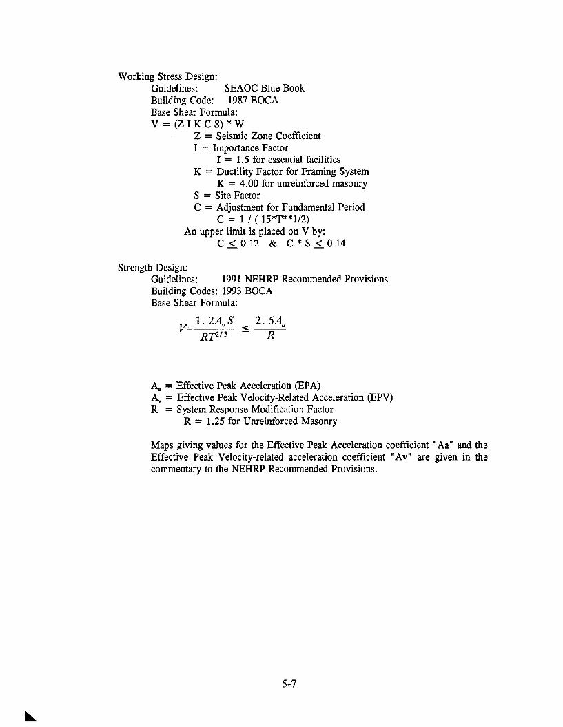
Working Stress Design:Guidelines: SEAOC Blue BookBuilding Code: 1987 BOCABase Shear Formula:V = (Z I K C S) * W
Z = Seismic Zone CoefficientI = Importance Factor
I = 1.5 for essential facilitiesK = Ductility Factor for Framing System
K = 4.00 for unreinforced masonryS = Site FactorC = Adjustment for Fundamental Period
C = 1 / ( 15*T**l/2)An upper limit is placed on V by:
C s.. 0.12 & C * S s.. 0.14
Strength Design:Guidelines: 1991 NEHRP Recommended ProvisionsBuilding Codes: 1993 BOCABase Shear Formula:
2.5Aa
R
Aa = Effective Peak Acceleration (EPA)Av = Effective Peak Velocity-Related Acceleration (EPV)R = System Response Modification Factor
R = 1.25 for Unreinforced Masonry
Maps giving values for the Effective Peak Acceleration coefficient "Aa" and theEffective Peak Velocity-related acceleration coefficient "Av" are given in thecommentary to the NEHRP Recommended Provisions.
5-7

~
Co
nto
ur
Map
for
Co
effi
cien
tA
a1
0%
Pro
ba
bili
tyo
fE
xce
ed
en
cein
50
Ye
ars
VI
I 00 Re
fere
nce
:N
EH
RP
Re
com
me
nd
ed
Pro
vis
ion
sfo
rth
eD
eve
lop
me
nt
of
Se
ism
icR
eg
ula
tio
ns
for
Ne
wB
uild
ing
s19
91E
dit
ion

",
Res
pons
eS
pect
rum
Com
pari
son
R=
1.25
K=
4.0
0S
=1
I1.
0I
.---
---..
--..-
19
87
BO
CA
Z=
0.3
75
1991
NE
HR
P,r---
Aa
=A
v=O
.13
19
87
BO
CA
Z=
1.0
1991
NEH
RP
,~-
Aa
=A
v=
0.4
0
--'
\., .....
---..
.......
.,
0.0
Iiii
til
IIi'
iIIii
iIIii
iii
I1
'1
II
II[I
II
iI
[iIii
iI
0.0
0.5
1.0
1.5
2.0
2.5
3.0
3.5
4.0
4.5
5.0
Per
iod
(se
con
ds)
cO.8
I•
o ......
«S L- a> a>0
.6o o « «S
0.4
L ...... o a> 0.. en0.
2
VI
I \0

EVALUATION
Guidelines for the evaluation of the seismic resistance of existing buildings are given in thedocument NEHRP Handbook for the Seismic Evaluation of Existing Buildings (FEMA 178),published by the Building Seismic Safety Council. This evaluation process consists of identifyingweak links in the building's lateral load resisting system, and methods for determining the strengthof existing structural elements. The following general procedure is given:
Data CollectionBuilding ClassificationAnalysisDesign ChecksEvaluation StatementsFollow-Up Field WorkMaterials TestingFinal Evaluation
DATA COLLECTIONData collection consists of examining available drawings, specifications, and soils reports from theoriginal construction. Site visits are imperative to verify that the existing construction matches thaton the drawings. It is not unusual for a building to have been substantially altered by subsequentwork.
BUILDING CLASSIFICATIONThe FEMA 178 document classifies buildings by construction and structural system. For eachclass of buildings there is a discussion of the lateral load path and the typical deficiencies.
ANALYSISThe FEMA 178 document allows design loads which are reduced from levels given in the NEHRPRecommended Provisions. For a given level of ground motion, the effect of this force reductioncan be explained as follows:
For a given exposure period, the probability of the ground motion is increased;For a given probability, the exposure period is reduced.
DESIGN CHECKSThe FEMA 178 document gives presumptive values for component strength and stiffness whichcan be used if test data are not available. The condition of the materials must be verified beforethese values are used. These presumptive values are based on a life-safety criteria, and assume thatthe building will be damaged during the design level earthquake. Examples of presumptive valuesin FEMA 178 are given in Appendix A.
EVALUATION STATEMENTSFEMA 178 contains detailed evaluation procedures for the lateral load resisting systems of differentstructural systems. These procedures are in the form of check lists with commentaries.
5-10

FOLLOW-UP FIELD WORKAdditional field visit are usually required during both the evaluation phase and the design phase.
MATERIALS TESTINGThe presumptive strength values given in FEMA 178 are lower than the values used for newconstruction. Higher values may be used if qualified testing is performed. For unreinforcedmasonry buildings, the most applicable test is the shove test for in-plane shear values. Since thepresumptive values for in-plane shear strength are very low, ranging from 6 - 12.5 psi, the in-planeshear test can have a large benefit-cost ratio. Examples of values from in-plane shear tests aregiven in Appendix B.
FINAL EVALUATIONThe end result of the evaluation process is a report on the capacity of the existing lateral loadresisting system for the required seismic risk and the desired performance objective.
TYPICAL UNREINFORCED MASONRY BUILDINGS
CONSTRUCTION
Unreinforced masonry bearing wall buildings in the Central United States are typically one to fivestories. The following outline summarizes the construction of these buildings:
WALLS:Single and Multiple Wythe Construction of concrete masonry clay, brick, clay tile:
Hollow Clay TileROOF DIAPHRAGMS:
Plywood or Wood Boards on Wood FramingSteel Deck on Steel JoistsConcrete Slab With Metal Deck on Steel JoistsWood Boards on Steel JoistsPanels (typically 2 ft. x 4 ft.) on Steel JoistsPoured Gypsum Over Fiberboard on Steel Joists
FLOOR DIAPHRAGMS:Straight or Diagonal Wood Boards on Wood FramingPlywood on Wood FramingConcrete Slab With Metal Deck on Steel Joists
FOUNDATIONS:Typically Narrow Strip Footings Under Walls
5-11

TYPICAL DEFICIENCIES
The typical deficiencies found in unreinforced masonry buildings in the Central United States canbe classified as follows:
Lack of continuity in the lateral load resisting system;Inadequate component strength;Inadequate component stiffness;Inadequate connections between components.
IN-PLANE SHEAR TESTS
The in-plane shear tests were performed in order to provide a quantitative determination of thestrength of the existing masonry walls, and to establish confidence levels for the analysis of theseexisting buildings, as well as for the design of the seismic retrofits.
The maximum shear values measured were approximately twice the average value, and theminimum were approximately 40 percent of the average. The range of the values underscore thevariability of masonry construction, yet the minimum values still provide for a lower bound withthe factor safety of four, which justifies the use of a higher allowable stress. This higher stressis no higher than that used for new masonry construction.
5-12

CASE mSTORIES
Southeast Missouri Telecommunications
• 24 One-Story URM Buildings• Aa = Av = 0.30• Performance Objective:
Continued Operation• Special Considerations:
No Work Inside BuildingNo Work on Roof
Southeast Missouri TelecommunicationsTypical Deficiencies
• Diaphragms InadequatePanel Roof SystemsWood Boards on Steel Joists
• Diaphragm-Wall Connections Inadequate• Walls Inadequate Out-Of-Plane• Short Walls Inadequate In-Plane
Southeast Missouri TelecommunicationsRetrofit Strategies
• All Work Done Outside Building• Horizontal Perimeter Truss or Beam Around Roof• Braced Frames at Inadequate Walls• New Foundation Elements
5-13

:10I ~l~I·~I
III
I
H'18x50 ...
II
~I~~il
II
IIII
QO
THEISS ENGIlEERS INC.Con.uIllng £ngln......__ ............R ......._
SOUTHEASTERN McrSSOURIBUILDING #4
5-14

(f)l/ r (Jr- P'-l4t11k
L-c;:;:;
J-/5 w/II/ln CIOO
1 1/2' £NSff)
1/2"~ AS iJlO'
1/8" ClOSUR£ PfAlE
NElY 1/8'" PLAT£
5-15
...."-.1....
........~....
SOUTHEASTERN MITSSOURIBUILDING 114.

0/-I ! !
EVII
o 1><1£ THBSS ENGIEERS INC.... ~ iI ConlulHng mgln......
~ ~ ':-=::'."::II..........
5-16
SOUTHEASTERN M[SSOURIBUILDING #2

tr-2"
SEcnON @
10.'..
1)<1E THEISS ENGIEEAS INC.Conlultlng £I'Ia1n..,..
5-17
SOUTHEASTERN ~SSOURI
BUll.DING #2

CASE mSTORIES
South Indiana Telecommunications
• 9 One-Story URM Buildings• Aa = Av = 0.20• Performance Objective
Continued Operation• Special Considerations
Dust and Vibration ControlWork Inside Building AllowedRoofing Replaced
South Indiana TelecommunicationsTypical Deficiencies
• Diaphragms InadequatePanel Roof SystemsStraight Sheathing Boards
• Walls Removed During Expansion• Diaphragm-Wall Connections Inadequate• Short Walls Inadequate for In-Plane Shear
South Indiana TelecommunicationsRetrofit Strategies
• Work Inside Building and on Roof Allowed• New Plywood Roof Diaphragms• New Diaphragm-Wall Connections• Steel Braced Frames Inside• Reinforced Masonry Shear Walls Outside• Use Existing URM Shear Walls if Possible
5-18

0'\ ...... I
lr)
1~ I I~ ~~
~C~~ ~~ Q g ~ ~i
ILl
"I!
g1'1
,52
'"4J
If]~
I!~
en~
-f8~
i!:
~~ '\:, ,I ~, ....
1'-6
"
I I___
_JA
~-a
@-
RlJ
IMEX
IST
®W
AlL
CE7tJ
NCTO
INSW
.J.BH
ACEI
Jfl
W/E
S,IJH
AGSl
iWT
Scf
srm
f'lA
TE:S
-RE
PLAC
EO
NrW
ALl
@-
PliV
VIIJ
£f-
1/2"
1W
E1lJE
OSl
lJIJ
SO
NST
EEl.
PW
FFO
RRI
TUR£
S"'
IXF
JJ'-
'f"r
16
'-8
"
NEW
STE
llPl
ATE
-@EC
LOW
ROO
FTR
USS
ESS
!SJ
(lYP)
-t---~'.:-
t--NE
Wsr
mPl
ATE
mO
W~
TmIS
!JI
NEW
IJHAG
Slli
'f/T
Imow
O/IE
RflW
IEL
~_
11'-2
"
1-
~'1; I
16
'-"
~ 10jvV
.<>T
.,.~
PH4S
E][
tPH
ASE
I..
flITl
/RE
MW
KCO
VPlE
TEf}
IWRK
ROO
FFR
AIJI
NC~
I
hi
r---
----
----
----
----
---
A~
~t~
!---------~--
g;;
~'~
~.
~~
__~,
OM
''"
'I~
I~
I'
EXIS
TW
12x2
2.,
'"-
A----
~
~I.~
~~
''a{>
\{f
~~ ~ ~
i4 ~~~~ !Ii
52'-<
f'
'ST
:sES
JJ'-
2'
2x1,
2xUE
¥ssE
S.i~
~ ~ '", ,. .1 ~
JI'I'
~~

o ! lloIlI: mass ENGIEERS INC.~ ~ eft CoMulIInO £noI"....
"li J t:'~_-:----5-20
SOU'I'HWESTERN INDIANABUILDING 111

/(1'-75/8'
r:-==========----
;r=:=~------~l,.U~~~" * i
I,I,!:"Ii":1
<::1 !~ THEISS ENGINEERS INC.:: i Ie r::: Conlulllng Engln.....
S ~f--- • _~ at.r-- )I ~
SEISMIC STRENGTHENINGSOUTHWESTERN INDIANA
BUILDING #2
5-21

~
('.l
('.l I
trl
~~ ~~~
~~~
~~~
fljoo§
uE= h
----
----
---
-4_
J.,"
N«.
SPAC
HQI
1IiO
iJlfS
51/
2-FR
4V1N
G-
NAIL
ING
OlT
AIL
MI
SCAL
E
,4"
N«
SPAC
HQ'
I1Ii
OlM
SI
J11
2"FR
AMIN
G-
NAili
NGOl
TAlL
MI
sr:A
l£
Ir
LA:
sr:R
E1
fI
+-+
-1
------
~I-------
--...
--+
----
---t
--4----
....
..:!
l--1
-----4
-----J.-
----_
-,
I
IS!
HaN
rJ,
~---l-----~---
..----
-!o
_'i
'-~
---±
L--f
i----
----
, !---
,-r---
I--------
,--
-l-i=
--J=
i----
.---
-I
-_+
-,-_
_~,-
-4
-----
'-~
----
i---
--t-
----
---
~
1,17
'AXJ
7RO
OS
DlfJ
£Om
rJC
DI£
STrJ
oe
:KlO
CAl
FTO
IIIS
SEX
IST.
fff1TI1l~c
(Wca
wIx
l
lfN
a:M
UV
N«
S2
IiO
fIS
,4"
ac'·1
..I
(ST
KX
D)
SEE
/W.J
'rf;
IJ£T
M.
~R~_~
.15J
AI'A
IUTl
lJS1
CAT1
IIHI:
1%4
,21
"or
:(N
EJ')
1\\III
I!'Ix
HLt
K:A
1Ml
(NEJ
')
PLnI
f}OO
INST
ALLA
llON
DIAG
RAM
lKllI
S;f.
INST
ilI.L
NF
l'1l
?EAT
flJ4
xfSl
I:E:P
ERS
I21
"tJ
ClJ
IREC
llY0I
fTi'
D1ST
.2"
C£I
I(S!V
D«K
.
2.SE
CtJ£
TM.
THIS
SH
lUfU
R~
lJl7
WlfN
.1lD
ES
RJ
0£f:K
.
Jsa
:~1.tM'
rmM
LlJ
I,f;~
I.IIS
1NJ.
In'
Nit
IUlB
JSH£A~
m;f
Iyf
$lE
£J'£
R$.
BlO
CK
All.
PANE
ll1J
I.7lS
MTH
Ixl.
6.SE
EIJ
£TM
.STH
ISSH
EET
flJIr
IlI1
ft'X
l?AV
S1N.
J.AlK
WAM
JIW
l..N
C.
!Elf
1'llf
ft::W
tJB
:1(
TTr£
AlBJ
I%
or(J
(J{)
(NC
r)I"
1.1
/1"D
IB£D
.,,
/HIl
nC
-l()
(}N
JIE
SM
CONN
ECTI
ONO
Tl.
OF
WOO
OSL
EEPE
RTO
EXIS
TING
CEYE
STO
OEC
KM
ISC
'AlE
~ BJ IIgil
,If
lifI~ r DR
AWIN
G
84

CASE mSTORIES
Southeast Missouri Utility
• 1 Two-Story Building• Aa = Av = 0.30• Performance Objective:
Life Safety• Special Conditions:
Dust and Vibration ControlNew Shear Walls Outside Building
Southeast Missouri UtilityTypical Deficiencies
• Perforated URM Shear Walls Inadequate• Panel Roof Diaphragm Inadequate• Diaphragm-Wall Connections Inadequate
Southeast Missouri UtilityRetrofit Strategies
• New Reinforced Concrete Shear Walls Outside Building• New Horizontal Steel Bracing Below Roof• New Chord Around Floor Diaphragm
5-23

--8
--8
--0
EV '~Ee, ~E>I ~ ~ I ~...: .-./ ,....'~ /'(1"'-
~ / '1-~ ./K ~ ~ r--
-®.... t;l :to.
V '" ""~ ~ ....--- ,"" ""
Q:J ~ iMi ~ •" ,I,. ... I n;r--. ~,"~ y "\ "'" FTI "'1 ---- ...-- ---1-----\
-"" "' I--'." O~/ ~ /. taD\~ -.....~ '\ .J/ ~:{ /~ ~.~...,
1~-/
><' \ ~~ 'J ~ r\. ,~""~~7 \ / ~
/---~-:~~l.L: - - " ..--~Pr ----- ---~CJ"A~~ T~
~
I~ '\ /l~0
:-4~r 1):\ k' ~J:l t:.
~nr....~t~::l taj
~ : \ ,/ 1.. / '\ ~~ l\./ : ( ~I " II v : I ,x, I
....~~1J7 .~~~ I I "I
,I
~1- ~~
--- --+~-- ~-- ~--- ~-,-1 ---~ -4- ---Qj
~C>- l\. /~~ ~ '\V ~~ ....
....~~I '\ ~
I ""!2l
~ / '\~ ,---- ---- ----- ,,) / "- JI
~ // " /
~5fVejt\ ~ \ /~ ~..../V~L/ ~ / '\~ ~
"" ~ ""J/ '\ / ~,
~~ ~~ ~I...-
~•~I
~VI
I
o 0011; THEISS ENGIEERS INC.~ ~ i I eonluIHng EnQln.....GJ) ~ i~ • _
. .a.. .......~...SOUTHEASTERN MISSOURI
sastdC S'T'Re¥ln-ENNQ Bun.DING #6
5-24

I~
II
<:> ~ THEISS ENGIEERS INC.~ ~!! - C4nlullln; ...;In.....(ft "" liB-.,. t5 ~ I-- • _
f--- ....-=.~.
"'~
SEISUC STRENQ1l-ENNQ
5-25
SOUTHEASTERN MISSOURIBUILDING #6

SCCT~
.....~
r DllSTOIIJ
SCCllON :§9_c
1~
""11: mass ENGINEERS INC.C4naultlnll £nl,1ln.-.
,---.........JI....~...
5-26
SOUTHEASTERN McrSSOURIBun.DING #6

CASE mSTORIES
Southeast Missouri School
• Two-Story Building• Aa = Av = 0.30• Performance Objective:
Life Safety• Special Conditions:
Retrofit Materials DonatedNew Bracing to Remain Exposed
Southeast Missouri SchoolTypical DeficienCies
• Perforated URM Shear Walls Inadequate• Diaphragm-Wall Connections Inadequate
Southeast Missouri SchoolRetrofit Strategies
• New Braced Frames Inside Building• Additional Wall-Diaphragm Connections
5-27

THEISS ENGIEERS INC.
--..........--...5-28
SEISMIC STRENGTHENINGSOUTHEASTERN MISSOURI
BUILDING #5

--@
~;:=::::;:**=====~:f*=~~==;rI---G---"'i'a"1 w~ti~i I ~~s~ ~ !~J\'-'A~ I .... lj>~.. .r I
~~.. i i ~~t~~ ~ i;~ I , ... ~h.. I I 4-'"-=~~~-i3~-----t.---- .... -!-_-=- -:_-_~~=tt!Ir I I I ~ I I
I I I
! i 1! ..JI I ~II I I
b::~HI-----+-----------_+-----(1 ..~--iii", "
I I II I'
::Jt!====;~~~===~r~-,~==~~:=:--:=:=-eW LU
I I
~I
I,Z?
I
I.I
~i,
--GQ;;
"...
'"-~
~ob
~
---e
THEISS ENGIEERS INC.
--.....-..~,.-SEISMIC STRENGTHENINGSOUTHEASTERN McrSSOURI
BUILDING '5
5-29

CASE mSTORIES
St. Louis Missouri Office Building
• 1 Six-Story Office Building• Aa = Av = 0.13• Performance Objective:
Life Safety• Special Considerations:
Adjacent Subway StationAdjacent Lower Building
St. Louis Missouri Office BuildingTypical Deficiencies
• Perforated URM Shear Walls Inadequate• Diaphragms With Large Openings• Dead Load Added During Renovation• Unsymmetrical Arrangement of Existing URM Walls
St. Louis Missouri Office BuildingRetrofit Strategies
• Steel Braced Frames Inside Building• Reinforce Edge of Diaphragm Openings• Non-Structural Retrofit
ParapetsSkylightsMechanical/ElectricalRaised Access Floor
5-30

5-31
~
'" i~f.I ;;;
~~ -~D ~
ST.LOUIS MISSOURIBUILDING #1

••I
--13
--13
-
II I I
III~
II
5-32
ST.LOUIS MISSOURIBUILDING 11

""')o'.----!f----11.
.~
.,
11IE1SS ENGIEERS INC.C4lMulllnQ [ntlftMra
--.......-5-33
ST.LOUIS MISSOURIBUIlDING Ii 1

APPENDIX APRESUMPTIVE VALVES FOR EXISTING CONSTRUCTION
Reference: FEMA 178
Presumptive Values for DiaphragmsStrength Values for Seismic Shear
Existing Construction Shear(pIt)
Roofs with Straight Sheathing 300Roofing Directly on Sheathing
Roofs with Diagonal Sheathing 750Roofing Directly on Sheathing
Floors with Straight Tongue-and Groove Sheathing 300
Floors with Diagonal Sheathing and Finish Wood Flooring 1800
Metal Deck with Minimal Welding 1800
Presumptive Values for In-Plane WallsStrength Values for Shear
Reference FEMA 178
Construction Allowable Shear Stress
Solid Brick Masonry 10 psi
Hollow Unit Masonry 6 psi
Grouted Concrete Masonry 12.5 psi
5-34

APPENDIXBRESULTS OF IN-PLANE SHEAR TEST
Results From 15 Buildings
CMU Brick Composite
Number 55 26 5
Average 411 370 413
High 605 724 605
Low 138 167 164
5-35

REFERENCES
BOCA National Building Code, 1993 EditionBuilding Officials & Code Administrators International, Inc.Country Club Hills, IL 1993
NEHRP Recommended Provisions for the Development of Seismic Regulations for New BuildingsPart 1 - Provisions and Part 2 - Commentary (FEMA 222 & FEMA 223)Building Seismic Safety CouncilWashington, D.C. 1991
NEHRP Handbook for the Seismic Evaluation of Existing Buildings (FEMA 178)Building Seismic Safety CouncilWashington, D.C. 1992
Uniform Building Code, 1991 EditionInternational Council of Building OfficialsWhittier, CA. 1991
Algermissen, S.T. and Hooper, M.G."Maps of Hypothetical Intensities for the Region"Estimation of Earthquake Effects Associated with Large Earthquakes in the New Madrid SeismicZone - Open File Report 85-457United States Geological SurveyDenver, CO. 1985
Ferritto, J.M."Economics of Seismic Design for New Buildings"Journal of Structural Engineering Vol 110, No. 12, Dec, 1984American Society of Civil EngineersNew York, NY.
Johnston, A.C. and Nava, S.J.Recurrence Rates and Probability Estimates for the New Madrid Seismic ZoneJournal of Geophysical ResearchVol. 90, No. 8B, July 10, 1985
Nuttli,O.W.The Nature of the Earthquake Threat in St. LouisPaper presented at the Building Seismic Safety Council in St. Louis, MO.Jan. 23, 1985
5-36

REHABILITATION OF URM BUILDINGS IN ITALY
C. Gavarini*
ABSTRACT
The problem concerning the rehabilitation of Unreinforced Masonry Buildings in Italy ispresented in its general dimension, a problem which deals with the definition of seismic hazard,the vision of seismic risk for the whole population of buildings present on the territory, therelated concept of seismic vulnerability, the basic problem of how to reduce the risk on thewhole population and on the single buildings, the particular questions which arise for historicaland monumental buildings, and for strategic buildings, and finally the problems regardingapplications: technical codes, specific laws and spreading of knowledge.
INTRODUCTION
The seismic protection of masonry buildings is considered in Italy as a serious problem withmany aspects to study and numerous fields of applications. We may mention at least thefollowing sectors:- the definition of the seismic hazard in every part of the country;- the assessment of the seismic risk concerning the huge population of existing masonrybuildings present on the territory;- related with the previous one, the problem of assessing the (seismic) vulnerability of thebuildings;- the problem of how to reduce the seismic risk;- related with the previous one, the problem of how to reinforce the single buildings, i.e. toreduce the vulnerability by means of appropriated techniques;- the problems related to the systematic application of the previous techniques, in terms ofgeneral policy, technical Codes, diffusion of the knowledge, and so on;- the particular problems related to the special parts of the population of buildings which presentthe specific aspect to be historical buildings and/or historical areas;- idem for the even more particular problems related to single monumental buildings;- idem for the existing masonry buildings which present, possibly together with the previoushistorical/monumental/artistical character, the property of being "strategic" from a functionalpoint of view.
All the problems mentioned above have been and are presently treated by the Italian NationalGroup for the Earthquake Loss Reduction. The experimental results which are being presentedhere in Pavia are an example of such an activity. Now I will give some information on the othersectors.
* Professor in Mechanics, Dpt. di Ingegneria Strutturale e Geotecnica, Univ. di Roma "LaSapienza" .
5-37

Seismic Hazard
Officially and practically, Seismic Hazard is presently defined in Italy by the Seismic Zonation,i.e. a map of the Country where every city or village, with all its territory, is assigned to aseismic zone, within 4 possible categories: I, II, III and no seismicity. A Design horizontalacceleration is assigned to every category: it is a conventional value which corresponds to anelastic design, and the four values are 0.10 g, 0.07 g, 0.04 g, zero. To give an idea on aninternational basis, we may say that such values correspond roughly to the PGA values indicatedwithin the EC8 activity, i.e. 0.35 g, 0.25 g, 0.15 g.
Such a zonation is the result of a very long process, and it presents defects and incoherences.Now, the results obtained on this subject by our National Group, after 14 years of activity,should allow a radical revision, based on a series of maps which give the expected groundmaximum seismic acceleration for given return periods. In particular one of the maps gives thePGA/475 years, as suggested by the EC8. Within the National Group, the discussion is nowactive on the meaning of such an indication from EC8; an indication which appears to concernessentially new ordinary constructions, while the problems related with existing buildings,historical areas and monumental buildings, and with strategic buildings, plants and lifelines maysuggest to consider more maps.
Seismic Risk
As it is well known, Seismic Risk depends mainly on three factors: hazard, vulnerability,exposure. Models may be proposed for the definition of each of these factors and theories for thedefinition of the Risk may be subsequently obtained. Such a task has been performed by ourGroup: there is a model for ordinary masonry· or reinforced concrete buildings proposed by V.Petrini, and this model has been very recently applied in particular to the whole population ofpublic buildings of Emilia Romagna (2676 buildings) with many results, the first being a listgiving the priority obtained for intervention, based on the expected damage (01, 02).
Seismic Vulnerability
As mentioned in the previous chapter, seismic risk is based, besides hazard, on vulnerability andon exposure. The question of how to obtain such information on a population of buildings hasbeen considered within the National Group since 1984, starting with masonry ordinary buildings(03) and reinforced concrete buildings (04) and dealing then with historical buildings (05),monumental buildings (06, 07), industrial buildings (Alessi and others: 01).
Vulnerability may be defined as the "weakness", versus assigned external actions, of structuresor systems. In the field we are concerned with, the actions are of mechanical nature, in particularthey are seismic actions.
The evaluation of vulnerability may be undertaken at different levels: we can consider as theirupper limit the full structural analysis of single constructions, as typically defined by the Codes:but this kind of approach is not regarded vulnerability assessment. Another limit may be fond ina very simple and quick approach, able to give an evaluation in a few minutes, typically on thebasis of an expert judgment.
A vulnerability survey is based on the collection of information on a number of parameters,which are considered important. This collection may be performed filling one or more forms oradopting an expert system implemented on a portable PC. The collected information may be
5-38

summarized in a vulnerability index to be utilized in a model of risk or it may be considered as aglobal input for a number of analyses: assessment of priorities, hypotheses of retrofitting, costsof retrofitting, costs-benefits analyses, optimal strategies for intervention on large scale, .....Such analyses may be performed defining suitable models; typically they deal with uncertaintiesand often they include the evaluation of data of very different nature: numbers in the commonengineering sense but also fuzzy sets, synthetic judgments, cultural values, drawings, photos,texts, historical data, social implications, .... As far as numbers only are considered, possiblyaffected by uncertainty defined on a probabilistic basis, the models may be numerical; but whenother kind of information must be introduced, other approaches have to be considered andsuitable informatic tools able to help in evaluation and decision making are to be developedand/or used, in particular expert systems i.e. systems able to deal with knowledge of generalnature, not only numerical.
The actual situation within the National Group is the following (01, 08, 09, 10, 11, 12, 13, 14,15):- there is a form, with two levels, for ordinary masonry buildings; there are models for thedefinition of a vulnerability index and the evaluation of retrofitting costs; there are dataconcerning thousands of buildings: some are both on vulnerability and on damage from recentearthquakes so that calibration studies are possible (and have been performed);- there is a form for reinforced concrete buildings, with an old version and a recent one, andthere are models for the vulnerability evaluation, both at level I and II;- there is a form and a model for industrial buildings;- there is a form for churches at level II (without model) and a form with a model at level I formonuments (churches and other);- there is a methodology for the assessment of vulnerability of bridges;- there are studies on the vulnerability assessment of buildings of special importance for their use("hazardous buildings");- there are studies in progress on models, new approaches, calibration, data bases, graphicalrestitution, fuzzy sets;- there are studies on lifelines, in particular electrical nets; - there is a form and an expert system(so called AMADEUS) for the evaluation of the usability of buildings after earthquakes.
Reduction of Seismic Risk
The reduction of seismic risk may be considered at a global level, i.e. looking at wholepopulations, or it may be considered at the level of single buildings. The first case involves ageneral policy aiming to reduce the global risk. In the second case the approach based on thereduction of the vulnerability seems generally the most appropriate. Of course the twoapproaches are related, in the sense that the results obtained for the second one are useful for thefirst, but not exclusively.
Seismic Reinforcement of Buildings
To reduce vulnerability of a building means to reinforce its structure: such a problem hastechnical aspects and then economical ones. The technical question is at the center of the studiespresented here in Pavia. But also the economical aspects are of paramount importance, if weconsider that in a seismic zone there can be thousands and more buildings to be improved fromthe point of view of vulnerability.
5-39

Historical and Monumental Buildings
If the buildings concerned present historical interest and importance, and in particular if they aremonuments, it isn't sufficient to think about the mere technical and economical aspects related tovulnerability and its reduction. The criteria based on optimization in the use of money, mayrepresent one aspect of the problem, but not always the only one. The whole approach has to bereconsidered .
And the problem must be discussed distinguishing between the two cases of historical buildingsand single monuments, because in the first case a population is to be considered while in thesecond case single objects are concerned.
More precisely appropriated definitions must be given to the terms Historical Building andMonument. Proposals have been given within EC8 in the following way:
- a MONUMENT is a building which has an important "cultural value", so high that it isnecessary to guarantee the PRESERVATION of the building, generally with its architectural,typological, material characters;
- an HISTORICAL BUILDING is a building of an URBAN AREA which, as a whole, has a"cultural value" (an Historical urban area), while the single building in question is not amonument. That means that the PRESERVATION concerns the general urbanistic character ofthe whole area and that History may give meaningful informations.
The principles concerning vulnerability and its reduction are still valid; but the newconcept of PRESERVATION may give rise to some problems both in the evaluation of thesituations and in the decisions on what to do to obtain a correct SEISMIC PROTECTION.
As to the definition of risk itself, we may mention another important question: the SeismicProtection of a Monument or an Historical Urban Area is something different from the seismicprotection of an ordinary building; generally seismic protection of a building means theprotection of people involved, mainly human lives, and (sometimes) the protection of somematerial value, a value which can be expressed in monetary terms. In the case of a monumentthere is the "cultural value" to protect, besides safeguarding people involved in the earthquake.So the demand of protection goes in two different directions that must be considered separately.As we see, dealing with monuments and historical buildings under seismic risk new concepts,definitions, methods must be necessarily introduced. An approach that takes in considerationsuch questions has been proposed as an Annex within the activity of EC8 Project Team 6, as acontribution to Part 1.4 of EC8: "REPAIR AND STRENGTHENING". The proposal ispresented in (16).
The mentioned EC8 proposal is only a very general approach, with few principles. To proceedfurther on we should establish for single situations, and in particular for single countries,specific documents related to the particular cases of buildings considered; the proposal is toprepare specific CODES OF PRACTICE. The task has received some answers in Italy: forHistorical Buildings from A. Giuffre' (05,17), and for Monuments from another National Body,the National Committee for the Seismic Protection of Monumental Buildings and Italian CulturalHeritage (18, 19).
5-40

Strategic Buildings
When STRATEGIC buildings in seismic zones are concerned, the question is rather simple if thebuildings are "ordinary", but it becomes difficult if the buildings are both strategic andmonumental, or at least historical; and such a situation is not rare in Italy. The argument is alsotreated in the EC8 proposal, which indicates the rather simple concept that the requirements of a"Strategic Seismic Safety" (to ensure the efficiency of the building after the earthquake) couldpossibly not agree with the "Monument Seismic Safety and Preservation": in such cases thesolution is often trivial: the building may remain or strategic or monumental and the officialBodies in charge for the decision must choose! If some possibilities of an "ecumenical" solutionseem to be at hand, a serious effort may be made by the Bodies, after a cost/benefit analysiswhere the benefit is an increase of safety and the cost is a loss of integrity.
Practical Problems: Codes, Knowledge, Applications
If one wants to solve the problem of reducing seismic risk for existing populations of buildings,both ordinary and monumental, according to the general concepts mentioned above, a veryimportant consideration has to be made: the problem is very difficult, and may becomeimpossible, if the technical Codes do not "help". Indeed the technical Codes are generally relatedto the questions concerning "new" buildings and not "existing" ones, and in such conditionsthere are many difficulties. Appropriated principles, as the ones mentioned before, have to beestablished by Law and implemented in technical Codes, and then in Codes of Practice. Theproposal within EC8 and the documents proposed in Italy are examples in the correct direction,as well as the international proposal Skopje 88 (20) and the Californian text State HistoricalBuilding Code (21).
Another question related to the real possibility to perform systematically the reduction of seismicrisk is the problem of spreading knowledge among Technicians, a task which is far from beingtrivial. In such a task, besides the usual tools like books and Courses, the more moderninformatic devices seem to be useful, like Softwares giving help in Design, Data Bases withinteresting Case Histories, presentation of Codes in form of Hypertexts and so on.
Finally, help to the task of retrofitting existing buildings in seismic zones, must come directly inthe field of applications, in form of Laws (think on Los Angeles, Ordinance 154807, Jan 71981), Insurances' contribution, organization of works on entire urban sectors. The Civilizationof working to correct the existing situation must take the place of creating everything new.
REFERENCES
01. CNR/GNDT, "Rischio sismico di edifici pubblici, parte I Aspetti metodologici", GNDT,Roma, 1993.
02. Colonna, E., C. Molina and V. Petrini, "Criteri di valutazione della vulnerabilita' sismicadel patrimonio edilizio esistente suI territorio nazionale", ingegneria sismica, anna Xl, n.1, gennaio-aprile 1994, pp. 16-24.
03. Benedetti, D. and V. Petrini, "Sulla vulnerabilita sismica di edifici in muratura: un metododi valutazione", L'Industria delle Costruzioni, 149, 66 - 74, 1984.
5-41

04. Gavarini, C. and P. Angeletti, "Assessing seismic vulnerability in view of developingcost/benefit ratios for existing R.C. buildings in Italy", Proc. 8th world Con! on Earthq.Eng., San Francisco, 1984.
05. Giuffre', A., M. Zampilli, V. Ceradini, F. Iacovoni and A. Pugliano, "Centri storici inzona sismica. Analisi tipologica della danneggiabilita' e tecniche di interventoconservativo", Universita' di Roma La Sapienza, Dipartimento di Ingegneria Strutturale eGeotecnica, 1988.
06. Corsanego, A. and C. Gavarini, "Vulnerabilita' e rischio sismico degli edifici monumentaliin Italia", Convegno internazionale "L'Ingegneria delle costruzioni nell 'Europa del 92",Roma, marzo 1990.
07. Doglioni, F., P. Angeletti, A. Bellina, A. Moretti and V. Petrini, "Scheda di rilevamentovulnerabilita' e danno delle chiese", Gruppo Nazionale per la Difesa dai Terremoti,Roma, 1989.
08. Braga, F., M. Dolce and D. Liberatore, "A statistical study on damaged buildings and anensuing review of the MSK-76 scale", Ita!. Geodyn. Project Pub!., n. 503, 1982.
09. Petrini, V. and P. Angeletti, "Vulnerability assessment - Case studies", US/Italy JointWorkshop on Seismic Hazard and Risk Analysis, Varenna, Italy 1985.
10. Corsanego, A., "A review of methodologies for seismic vulnerability assessment",Proceedings of the International Conference on Reconstruction, Restauration and UrbanPlanning of Towns and Regions in Seismic Prone Areas, Skopje, Yugoslavia, Nov. 1985.
11. Braga, F., M. Dolce, C. Fabrizi and D. Liberatore, "Evaluation of conventionally definedvulnerability of buildings based on surveyed damage data", Proc. 8th Eur. Conj. onEarthq. Eng., Lisbon, 1986.
12. Corsanego, A., A. Del Grosso and D. Stura, "Seismic vulnerability assessment forbuildings: a critical review of current methodologies", Proc. 8th Eur. Conj. on Earthq.Eng., Lisbon, 1986.
13. Gavarini, C., "An attempt for a new definition of seismic vulnerability of masonrybuildings", 9th World Conference on Earthquake Engineering, Tokyo-Kyoto, August1988.
14. Angeletti, P., A. Cherubini, C. Gavarini and V. Petrini, "Assessing seismic risk inhistorical towns", 9th European Conference on Earthquake Engineering, Moscow, sept1990.
15. Tazir, H., T. Pagnoni and C. Gavarini, "Knowledge Acquisition for PostearthquakeUsability Decisions", Chapter 8 in "Knowledge Acquisition in Civil Engineering", T.Arciszewski, L. Rossman (eds.), published by the American Society of Civil Engineers,1992.
16. Gavarini, C., "Monument Safety in Seismic Areas", Earthquake Spectra, Vol. 10, number 1,february 1994.
5-42

17. Giuffre', A. (coordinatore), "Sicurezza e Conservazione dei Centri Storici. II caso Ortigia",Editori Laterza, Roma-Bari, 1993.
18. Gavarini, C., B. Ballardini, S. D'Agostino, C. Viggiani, V. Petrini, A. Fralleone, F. Braga,A. Corsanego, P. Marconi, G. Miarelli-Mariani, F. Doglioni, E. Coccia and G. Di Geso,"Raccomandazioni relative agli interventi suI patrimonio monumentale a tipologiaspecialistica in zone sismiche", Documento approvato dal Comitato Nazionale per laprevenzione del patrimonio culturale dal rischio sismico, giugno 19861Atti del 1.Seminario di Studi: La protezione del patrimonio culturale, La questione sismica,Istituzioni e ricerca universitaria, Venezia, aprile 1987.
19. Ballardini, R. and C. Gavarini, con contributi di Baldi, Braga, Bucci Morichi, Corsanego,D'Agostino, Doglioni, Marconi, Miarelli, Monti, Pandolfino, Petrini, Rocchi, Viggiani,"Direttive per la redazione ed esecuzione di progetti di restauro comprendenti interventi di"miglioramento" antisismico e "manutenzione", nei complessi architettonici di valorestorico-artistico in zona sismica", Documento approvato dal Comitato Nazionale per laprevenzione del patrimonio culturale dal rischio sismico, luglio 1989/trasmesso agli ufficicentrali del Ministero dei Beni Culturali ed Ambientali e aIle Sovrintendenze con nota delDirettore Generale Sisinni 1841/12.03.91 1pubblicato su II Restauro Architettonico nellaRicostruzione del Friuli, 1991
20. "Recommendations - Skopje '88", Proceedings of the 1st International Seminar Modernprinciples in conservation and restoration of urban and rural cultural heritage in seismicprone regions, Skopje, Yugoslavia, october 1988.
21. State of California, "State historical building code, Title 24, Building Standards part 8" .
5-43


Section VI
Testing Methods for Evaluationof Insitu Material Properties
Measuring Masonry Material PropertiesLuigia Binda, Giulio Mirabella Roberti, Claudio Tiraboschi, andSilvia Abbaneo
In-Place Evaluation of Masonry MaterialsRichard H. Atkinson
Development and Use of a Mobile Laboratory for the Assessment of URMBuildings
Mauro Cadei, Paolo Panzeri, Alberto Peano, and Paolo Salvaneschi
6-1


MEASURING MASONRY MATERIAL PROPERTIES
Luigia Binda 1, Giulio Mirabella Roberti 2,
Claudia Tiraboschi 3 and Silvia Abbaneo 4
ABSTRACT
Results from comparative experimental studies on bricks and mortars used to build the full-scalemodel and on assemblages and small prisms of the same materials are presented. Compressive andflexural tests, shear and tensile bond strength tests are carried on with the aims of: (i) measuring themost important parameters to be used for modeling the material behaviour, (ii) correlating specimensize and dimension to the experimental results, (iii) comparing test methods proposed byinternational codes on testing masonry materials. During the research several problems werefocused, mainly concerning the difficulty of measuring the displacements on small specimens ofweak materials as the bricks and the mortars used for the full-scale model. Some of the problemshave already been solved by the careful calibration of the measurement methods and equipments.
INTRODUCTION
The materials to be tested were carefully controlled to be the same as the ones used for the full-scalemodel. The bricks were sent directly from Pavia to the D.I.S., Politecnico and mortars and prismswere prepared by the same masons who had built the two floor model in Pavia. Every time a newquantity of mortar was prepared, specimens were also sampled for laboratory tests.
Codified tests on the hydraulic lime and aggregates were performed so as tests on fresh mortars. Onbricks and hardened mortars chemical, optical and physical analyses were carried on, in order togain better knowledge on possible mutual influence of the materials on the masonry behaviour. Thechemical analysis of the lime confirn1ed that it is an hydraulic lime. Typical characteristic of themortar prepared by the masons was a high waterlbinder and a low binder/aggregate ratio, while thegrain size and distribution of the siliceous aggregate was varying within a quite narrow range, theseproperties indicating that the mortar would be a weak strength mortar. In fact this mortar wasintended to simulate, in the full-scale model, the weak joints usually found in existing buildings. Thesoft mud made bricks of the kind frequently used in practice for restoration, also simulate the solidbricks found in old and ancient masonries. These bricks are characterized by high water absorptionand capillary rise, rather low strength. Due to the mentioned properties of the materials a successfulbond between bricks and mortars is seldom realized and also the compressive and shear strength ofthe walls can be fairly low.
1 Professor, Dept. of Struct. Engrg., Politecnico di Milano, Italy2 Assistant Professor, Dept. of Struct. Engrg., Politecnico di Milano, Italy3 Technician, Dept. of Struct. Engrg., Politecnico di Milano, Italy4 Architect
6-3

Compression tests were performed on whole bricks, cubes and smal1 prisms cut out of bricks, cubesand prisms of mortars at different time curing. It was clear after the first tests were carried on, thegreat difficulty of obtaining reliable values for elasticity modulus and Poisson ratio due to theinfluence of the specimen dimension and of the low strength and stiffuess of the materials. Thereforedifferent types of machine constraints and measurement techniques for the specimen displacementswere adopted and comparison were made between the results in order to achieve the possible bestknowledge and give the right information to the researchers working on analytical models.
Shear bond tests (triplet tests) were also performed trying to measure at the best vertical andhorizontal absolute and differential displacements within the specimens, in order to control the realmeaning of the test for detecting shear bond and to calibrate some inelastic models.
Final1y the compressive tests on masonry prisms carried on under displacement control with anMTS servocontrol1ed machine (250 tons), allowed for the detection of post peak behaviour of themasonry and for a better understanding of the stress distribution in the specimens. Others, likecouplet tensile bond strength tests also gave some interesting infonnation.
OUTLINE OF THE EXPERIMENTAL WORK AND RESULTS
The results of the experimental work developed until now are reported in the following andcommented in order to give a first evaluation of the data to be used for mathematical models. Thetests were carried on according to several codes which are listed in Annex 1 of [I].
Specimen and test design
Whole bricks were submitted after surface grinding to compressive tests in the three principaldirection following the request of the Italian code [2]. Flexural tests were also performed on wholebricks; biaxial and uniaxial compressive tests will also be later carried on as shown in Fig. I.Cubes, 40 mm side and prisms (40x40x120 mm) were cut out of whole bricks; mortar prisms(40x40x160 mm and 40x40xl20 mm) were also prepared for the flexural and compressive tests atdifferent times of curing (Fig. 2). In Fig. 3 are shown the designed specimens for tensile and shearbond tests and for tests on masonry.
Chemical and optical tests on bricks and mortars
Mortar properties. The binder was defined by the producer (Legoplast) as hydraulic lime; in Table1 the results of the chemical analysis [3] is reported confirming a high content in soluble silica. Thesand is coming from the Ticino river near Pavia; in Fig. 4 its grain size and distribution isrepresented. This aggregate contains quartz, feldspar and flints (Annex 2 of [I D.Brick properties. The bricks have a soluble salt content of .36 % and a sulfate content of .015 %largely within the range al10wed by the Italian code [4]. Three slightly different colours weredetected for the bricks and the results of petrographical-mineralogical analyses on al1 three types(Annex 2 of [1Dare given in the following. They all are characterized by two distinct grain sizes,the first one with an average diameter below 0.1 mm, the second one between 0.1 and 1.0 mm. Thelithological composition is mainly given by quartz mono- and polycrystalline and minor quantities offeldspar and mica (Fig. 5).
Physical properties
As previously mentioned mortar specimens were prepared by the masons while working at theconstruction of masonry specimens (MIXl); these mortars were cured at 20°C and 90% R.H. formore than 28 days, then cured at 20°C and 50% R.H. until tested in order to simulate the air curing
6-4
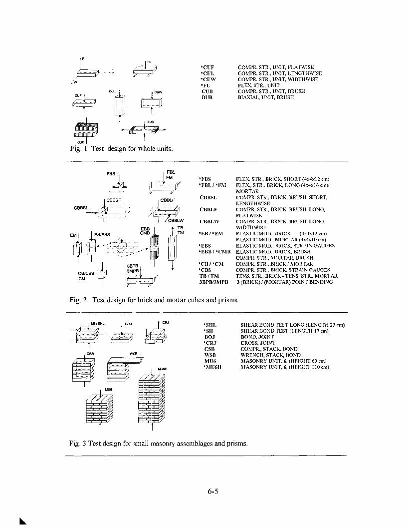
, L~--~
CUL
O91JoN
CUF ., .&:6 i L ...~ .""-
~ ~r"
"CUF"CUL"CUW"FUCUBBUB
COMPR. STR., UNIT, FLATWISECOMPR. STR., UNIT, LENGTHWISECOMPR. STR., UNIT, WIDTHWISEFLEX STR., UNITCOMPR. STR., UNIT, BRUSHBIA-'CIAL, UNIT, BRUSH
Fig. 1 Test design for whole units.
FLEX STR., BRICK, SHORT (4x4x12 em)FLEX, STR., BRICK. LONG (4x4x16 em)/MORTARCOMPR. STR., BRICK, BRUSH. SHORT,LENGTHWISECOMPR. STR., BRICK, BRUSH, LONG,FLATWISECOMPR. STR., BRICK. BRUSH. LONG,WIDTHWISEELASTIC MOD., BRICK (4x4x12 em)ELASTIC MOD., MORTAR (4x4xlO em)ELASTIC MOD., BRICK, STRAIN GAUGESELASTIC MOD., BRICK, BRUSHCOMPR. STR., MORTAR, BRUSHCOMPR. STR., BRICK / MORTARCOMPR. STR., BRICK, STRAIN GAUGESTENS. STR., BRICK - TENS. STR.. MORTAR3 (BRICK) / (MORTAR) POINT BENDING
CBBSL
CBBLW
CBBLF
"FBS"FBL/"FM
"EB/"EM
"EBS"EBB/"CMB
"CB/"CM"CBSTB/TM3BPB/3MPB
::?~)~LW
TBTM
FBS. L./
d52=
Fig. 2 Test design for brick and mortar cubes and prisms.
SH/SHL BOJ I /~RJ---E~ ~ ~"SHL"SHBOJ"CRJCSBWSBMU6"MU6H
SHEAR BOND TEST LONG (LENGTH 23 em)SHEAR BOND TEST (LENGTH 17 em)BOND, JOINTCROSS, JOINTCOMPR., STACK, BONDWRENCH, STACK, BONDMASONRY UNIT, 6, (HEIGHT 60 em)MASONRY UNIT, 6, (HEIGHT 110 em)
Fig. 3 Test design for small masonry assemblages and prisms.
6-5
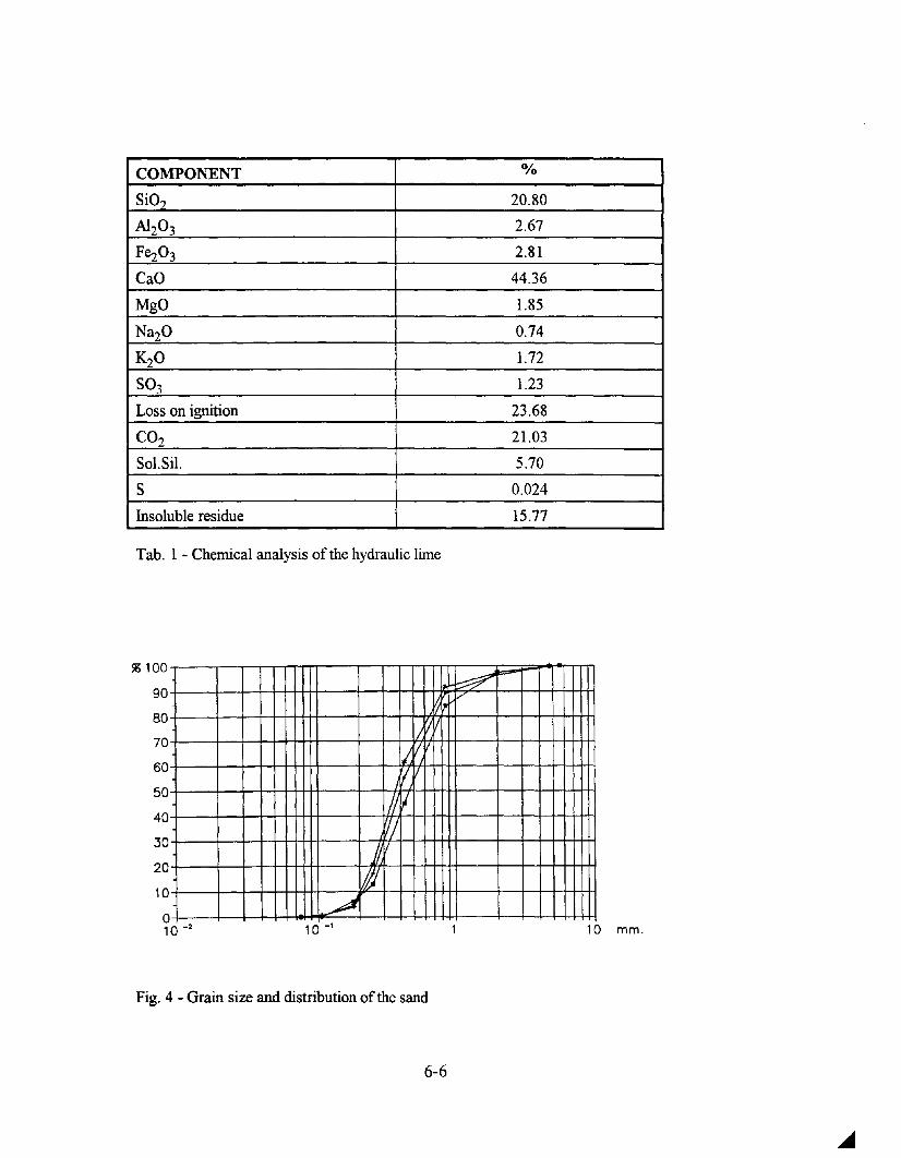
COMPONENT 0/0
SiO,? 20.80
Al20 3 2.67
Fe203 2.81
CaO 44.36
MgO 1.85
Na20 0.74
K20 1.72
S03 1.23
Loss on ignition 23.68
CO2 21.03
Sol.Sil. 5.70
S 0.024
Insoluble residue 15.77
Tab. 1 - Chemical analysis ofthe hydraulic lime
~t==-
;..---/,/
;'1Iiirl
UII'1/
j/,V!J
~
% 100
90
80
70
60
50
40
30
20
10
a10 -2 10-1 10 mm.
Fig. 4 - Grain size and distribution of the sand
6-6

of the full-scale model. In order to refer better to the usual preparation of laboratory specimens,another mix (MIX2) was prepared later on, having a lower ratio binder/aggregate (1/3) and also alower ratio waterlbinder (0.69 instead of 1.1). This second type of specimens is still being cured at20°C and 90% R.H. for the 180 days tests; therefore only results of tests after 28, 60 and 90 daysare here reported. The most important physical properties influencing the mechanical behaviour ofthe materials and the adhesion between mortars and bricks are the ones connected with theworkability, expansion and water retention of fresh mortars and the initial rate of suction of bricks.
Mortar properties. The physical tests on fresh mortar were perfonned following the Italian Code[3], [5], [6] or CEN prEN [7] as reported in the Annex I and the results on MIXI and MIX2 arereported in Table 2. The physical tests on hardened mortars [7], are presented in Table 3. For MIXIthe mean values for several preparations during the masonry specimen construction are reported. Infact there was practically a coincidence between the different preparations as it can be seen inAtmex 2. A reduction of the water absorption coefficient and a tendency to increase of the bulkdensity with the time of curing can be remarked for MIXl. MIX2, as expected due to itscomposition and to laboratory curing, has a lower bulk density, water absorption coefficient andwater absorption percentage with respect to MIX I .
Brick properties. The physical tests on bricks were perfonned following prEN draft proposals [8]and RILEM LUM 76 Recommendations [9]. The results are presented in Table 4, were the data aregiven separately for two different colours, defined red and braun found in the batches from whichthe specimens were sampled. Apparently the two types of bricks have the same properties, withslight differences, apart from the total absorption which seems to be the I I% lower for the braunbricks. In the following the two types of bricks will not be separated any more. Both types of bricksshow a weak tendency to efflorescence according to the Italian Code [4]. The two types of brickshave a rather low bulk density compared to other facing bricks and a high I.R.S.
If the physical properties of mortars and bricks are compared the following comments can be done:(i) the total absorption by immersion is practically the same for the two materials, therefore if salt orfrost-defrost actions affect their prfonnance, they will decay at the same time, (ii) the high initialrate of suction of the bricks can cause serious problems to the bond between brick and mortar joints,unless the bricks are not wetted prior to their use in the wall construction, (iii) the high porosity andlow bulk density of the bricks indicate that they will be low strength bricks. In Fig. 6 the averagecapillary rise diagram is presented for bricks and the two mortars,showing the much higher capillaryrise of bricks and the difference behveen MIXI and MIX2.
Mechanical tests
The aims of these tests were to detect as much as possible mechanical parameters useful for theanalitical modelization purpouses and furthennore to compare different test methods and proceduresrequired or suggested by national and intemational codes of standard and recommendations.Therefore the specimen shape, dimension and preparation and the testing procedure were verycarefully studied for every test. Tests on single materials (mortars and bricks), small assemblagesand wall prisms are being carried on, and special attention is paid to the equipment and procedureadopted for measuring loads and displacements.
Compression tests on bricks and mortars. The first problem to be solved concemed the specimendimension and preparation. In the case of solid bricks, testing of the whole unit can be chosen, as forother masonry units: nevertheless the height of the bricks is so small (no more than 40nun aftergrinding), that the inevitable friction between the steel platens of the machine and the brick contactsurfaces can heavely influence the value of the strength of the unit. Therefore cubes of 40mm side
6-7

Fig. 5 - Thin section of the brick; the two distinct grain size of the quartz areclearly visible
100water absorption
90 [kg/m2]
80BRICKS
70
60
50
40 MORTAR
30 MIXl - 180 days
20MIXl - 90 days
10 time [SI/2]MIX2 - 90 days
00 50 100 150 200 250 300
Fig. 6 - Capillary rise average plots for mortars and bricks
6-8

MORTAR LIME PASTE
COMPOSITION FLOW EXPANSION WATER INDEFOR- SETTING(by Weight) VALUE RETENTIVITY MABILITY TIME
(Le Chate!ier) (Vicat)
N. B. AG. wlb mm % % mm Start End
MlXl 1 4.4 1.1 192 -1.7 71.5 0.0 3h~ 7h20
MlX2 1 3 0.6 170 -0.7 77.9 0.0 3h~ 7h20
Tab. 2 - Test results on fresh mortar and lime
BULK DENSITY WATER ABSORPTION WATER ABSORPTIONCOEFFICIENT
(capillarv suction)
N. kg/m3 kg/(m2hY2) %
t.XJ days 180 days 360 days t.XJ d:~'S 180 days 360d:1)'S 90 d:1)'S 180~'S 360 d:1)'S
MlXl 1724 1755 1747 6.54 12.86 13.66 18.39 15 15.23
MlX2 1688 - - 4.79 - - 17.43 - -
Tab. 3 - Test results on hardened mortars
SOLUBLE ALKALINE EFFLORE BULK iRS. WATER WATERBRICK SALT SULPHATE -scENCE DENSITY ABSORPTION ~ORPTION
oowm ATTI11JDE COEFFICIENT(c.1pillary suction)
% % kg/mJ(kgIm)'
kg/(n"f min \12) %min
BROWN 0.36 O.oI5 veJyslight 1677 4.31 5.16 18.88
RED - - very slight 1687 4.49 - 16.29
Tab. 4 - Physical tests on bricks
6-9

are cut out of the whole brick and subsequently tested; the cutting scheme is given in Fig. 7, takinginto account the expected strength and stiffhess distribution within the brick itself, due to theproduction process .
In order to detect the elastic modulus and the Poisson ratio of the materials, prisms rather thancubes should be tested, but due to the low height of the solid bricks (55 mm) it is impossible to cutprisms normally to the flatwise direction. Therefore tests on cubes simply grinded, with brushesbetween the platens and on three alligned cubes as shown in Fig. 2 (EB/EBS) are being compared.When testing cubes the measure of the displacements in the vertical and horizontal directionbecomes very difficult due to the reduced space for applying instruments. LVDTs cannot be in factapplied directly on the specimen, but only between the two plates so that the measure of thedisplacement is influenced for low loads by the presence of the plates. Strain gauges were applied tothe specimens, but it could be detected that the stiffhess of the glue used for attaching the gauge tothe specimen can influence the results. Estensometers are also being used when dealing with smallspecimens.
Compressive strength and deformability ofwhole units. The tests were carried on according to Fig.1; 20 specimens were tested flatwise, 10 lengthwise and 10 widthwise and the average resultstogether with the standard deviation and the variation coefficient are given in Table 5 (Annex 3 of[1]). As expected the highest strength s given in the case of CUF specimens due to the low ratiobetween height and length and width; the lowest value is given by CULs due to instabilityphenomena. On the contrary the maximum defonnability seems to be obtained in the case of CUF.In Fig. 8 three stress- strain curves are presented as an example; it is clear the different behaviour ofthe bricks, particularly the strength nornlally to the flat\vise direction.
Compressive strength ofcubes and prisms. Specimens CB, EB, EBB, CM, EM, EMB were testedin order to compare and possibly correlate the results obtained on cubes and prisms for the strengthand defonnability. This research is being carried on, as already mentioned, due to the fact that onlycubes can be tested in the case of bricks used flatwise; a similar problem concerns the mortars, sincethe code requires the use of 40x40xl60 nun specimens. As mentioned above the difficulty concernsmore the calculation of elasticity modulus and Poisson ratio, which should be obtained from prisms.In the case of bricks the specimens EB were built with three cubes obtained as in Fig. 3 and theirdata were compared with CB and EBB, the second ones tested with steel brushes between two plates[10]. In Table 6 the mean values and variation coefficients of the peak stress fu , ultimate strain EUand secant elasticity modulus Es calculated between the 30 and 60 % of the peak'stress are given forCB, EB. As expected the highest value of fu is achieved by the CB specimens. In Table 7 the meanvalues and variation coefficient are given of compressive strength, ultimate strain and elasticitymodulus for mortar specimens (MIXI and MIX2) at different times of curing. In Fig. 9 the samevalues are plotted as a function of time for the two mixes. The strength at 28 days of curing is givenfor MIXI prepared in Pavia. The unexpected low strength of MIXI can be explained as dependenton the high ratio wlb and bls used for that mix, while the reduction of strength with time is probablydue to the type of curing adopted for MIX I. Curing dry can slightly reduce the strength in the caseof hydraulic mortars as shown in Fig. 10 [II].
As already mentioned, one of the difficulties to be faced was the right choice of measurementtechnique of horizontal and vertical displacements in the case of small specimens (EB, EM, CB,CM, EBB, EMB) when it was impossible to apply LVDTs directly on the specimen itself. In Fig.lla is shown the device used for the measurnlent of the displacements. Fig. IIb,c gives as anexample the plot of stress versus strain measured by vertical and horizontal strain gauges applied ontwo EBS and CBS specimens and vertical and horizontal displacements measured by LVDTs
6-10

Fig. 7 - Cutting scheme for bricks
35 6f u f u30
CUF 5
25 /,.--,
0'40 #fejejc: MIX1ll..~ 20 ll.. >0000< MIX2'--' ~
'--'Ul 3
:LUl 15 UlQ) CUW Ul.... Q)
PV.... ....(f) .... 210 (f)
5
evCuring (days)
05 10 15 20 25 30 0Strain [um/mm] 286090 180 360
Fig. 8 - Stress-strain curves for whole Fig. 9- Strength versus curing time forunits mortars (MIX 1, MIX2)
180
II I in aIr after: 2~ days ContlnuolJ5ly"moist-- - -II I / ~ 14 days --,I! if I~ 17days
II IV/ II ~
.:1oays
II'I Continuously in airt
l/
I1000• 03714 28 90
Age-days
Fig. 10 - Influence of moist and air curing on concrete strength
6,000
"cB- 000- 5.
.J::....OlC~ 4,000...Vl
~ 3,000.VjVl(l)
~2,OOOou
6-11

CUF CUW CUL
N.oftests 20 10 10fu[MPa] 26.50 11.05 10.70
y 10.52% 11.60% 14.92%
N.oftests - 10 108u10-3 - 6.60 4.32
y - 9.42% 6.88%
N.oftests 20 10 10ES(30-50%)[MPa] 2758 2020 2766
y 16.96% 8.76% 11.58%
where:fu =peak stressEU =peak strainEs =secant modulus between 30 and 50% offuy = coefficient ofvariation
Tab. 5 - Compressive test results for whole units
CB EB
N.oftests 25 23fu[MPa] 14.25 10.52
y 12.93% 20.28%
N.oftests 17 138u10-3 9.01 5.66
y 9.32% 10.77%
N.oftests 18 23ES(30-60%)[MPa] 2171 2156
y 13.71% 20.15%
Tab. 6 - Compressive test results for cubesand prisms from bricks
MIX1. MIX 2CM EM CM
Curing 28 days <.K)days 180 days 360 days 360 days 28 days 60 days <.K)daysN.oftests 12 8 8 10 10 20 20 20fu[MPa] 2.61 2.46 1.79 1.78 1.07 3.25 4.28 4.69
y 8.25% 11.88% 5.54% 6.Q9010 5.71% 6.05% 3.35% 3.94%
8u1O-3 - - - - 3.63 - - -y - - - - 18.22% - - -
Es(JO-60%)[MPa - - - - 533 - - -y - - - - 26.11% - - -
Tab. 7 - Compressive test results for cubes and prisms from mortar
FU FBL FBS FM (MIX 1) FM (MIX 2)
Curing 28 days <.K)days 28 days 60 days <.K)daysN.oftests 30 10 10 6 13 10 10 10
ftf [MPa] 2.44 3.28 3.04 1.08 0.61 1.39 1.80 2.02
y 25.90% 6.90% 8.58% 5% 19.9% 6.26% 3.33% 4.95%
Tab. 8 - Flexural strength test results for whole units, brick and mortar prisms
6-12

rizontal strain gauges
Vertical strain gauges
ii) - ~,
\ ...- Ho
~
.' ;~ .J '\\Vertical LVDTs
Horizontal LVDTs
Fig. IIa- Device for the measurement of the displacements
£v
-- LVDT--- - STRAIN GAUGES
2.5
15.0(J
12.5
,.......,({ 10.0:::2.......rn 7.5
'"Q)......... 5.0Vl
0·~12.5 -10.0 -7.5 -5.0 -2.5 0.0 2.5 5.0 7.5 10.0 12.5
Strain [p.m/mm]
Fig. 11 b - Stress-strain curves for specimen EBS
20.0 ...------------,r-------~--
17.5
(J-- LVDT----- STRAIN GAUGES
15.0
';f 12.5
:::2.......10.0
'"'"Q)
Z 7.5Vl
5.0
2.5
£v
0.0 -trTT"rn""T'TT'T'1n-T"TTT'T'1-rrTT"r-rI!.,rT"Tlrn-TT"n-r""T'T"""'""T'T"'-~-12.5 -10.0 -7.5 -5.0 -2.5 0.0 2.5 5.0 7.5 10.0 12.5
Strain [p.m/mm]
Fig. lIe - Stress-strain curves for specimen CBS
6-13

applied between the plates and in the middle of the specimen. While there is coincidence onhorizontal displacements, the vertical displacements measured with LVDTs are two times the onesmeasured with strain gauges. This difference cannot be accepted, therefore it is important tounderstand which measure of the two is really representing the specimen deformation. Fig. 12 givesthe stress-strain plot for the glue used to attach the strain gauges. The strength and stiffuess of thisglue (which was already chosen as one with the lowest stiffuess among the available glues forlaboratory purpouses), are much higher than those of the brick. In fact the vertical stiffuessmeasured on EBS and CBS by strain gauges is practically coincident with the one of the glue.
In order to detect the reliability of this conclusion, ESPI (Electronic Speckle Pattern Interferometry)was used to measure the vertical and horizontal displacements on a brick specimen on which straingauges were applied; the work was done in collaboration with M.Facchini a Phd student working atEuratom-Ispra in Varese (Italy). As shown in Fig. 13a the stiffness of the glue is so much influentthat interferometry fringes detect clearly the position of the gauge; Fig. 13b shows the samedifferences, as found in laboratory between strain gauges and LVDTs.
Finally the estensometers CPDT (Clamp in Point Displacement Transducer) shown in Fig. 14a, witha base of 20 mm, positioned in the center of the specimen, were used to measure verticaldisplacements and the results obtained were compared to the ones of LVDTs. In Fig. 14b is shownthe whole device for the measurement of the displacements. The curves plotted in Fig. 15 show thatthe LVDT curve in its linear part is parallel to the extensometer curve; therefore the secant modulusobtained by LVDTs between the 30 and 60 % of the peak stress can be accepted as a reliable valuefor the elasticity modulus.
Concerning Poisson ratio, the deforn1ation in the horizontal direction during the elastic phase is solow that the difference behvecn strain gauge and LVDT is minimum (Fig. II a, b); therefore theLVDT measurement, being the less expensive and most useful device also for detection of post-peakdeformations, could be recommended also for. codified tests. In order to calculate the elasticitymodulus, EB specimens should be preferred to CB specimens in the case of bricks; they also give avery low coefficient of variation, even if their preparation is much more difficult than the one of CBspecimens. EBB specimens should avoid this difficulty since the steel brushes could eliminate theplate influence [10]. Few tests were carried on with loading-unloading cycles in order to comparethe results with the ones given by EB specimens. Fig. 16 a, b gives two stress-strain plots as anexample. Nevertheless some more work must be done to adapt the stiffi1ess of the brushes to thebrick and mortar specimens; this work will be continued in the future research. When accomplishedthere will be an alternative to EB specimens in the case of bricks. The detailed complete results fromall the tests on brick and mortar specimens are given in Annex 3 of [I].
Flexural strength of}jJhole units and small prisms. Table 8 gives the mean value and the variationcoefficient of the flexural strength of whole units FU tested according to Fig. I and for specimensFBL, FBS, FM (MIX land MIX2) according to Fig. 2. High scattering in data result for FU due tothe specimen dimension amd FM for MIXI due probably to cracks developed by shrinkage. There isinstead a good behaviour of MIX2 with an increasing of flexural strength with time.
Tensile bond strength tests. These tests (CRJ in Fig. 3) were carried on following therecommendations[8] and using MIXI and MIX2. The results are given in Table 9 together with thedescription of the failure mechanisms. Once again a reduction of the strength with curing time canbe observed when MIX 1 was used, as it happened with all the tests on cubes and prisms and ahigher strength when MIX2 was used; nevertheless the scattering in the results is very high for bothmortars. This is unfortunately the characteristic of that type of test, \vhich otherwise could be veryinteresting for detecting the tensile bond strength; when the bond between mortar and bricks is very
6-14
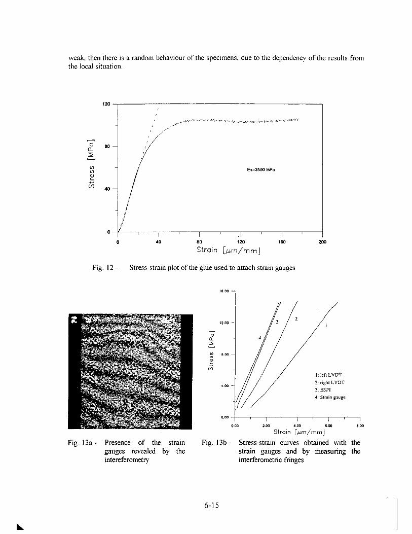
weak, then there is a random behaviour of the specimens, due to the dependency of the results fromthe local situation.
120 -,-----------------------------,
80
(J)(J)
QJ'-
-+-J(j)
O-f---,----,------,------,------,---,----,--------,---,---i
o 40 80 120
Strain [,um/mm]160 200
Fig. 12 - Stress-strain plot of the glue used to attach strain gauges
16.00
0.00 -t----,-----,----,-----,,--,----,---..,-'---,
0_ ~oo 4.00 e~
Strain [,um/mm]
Fig. 13b - Stress-stram curves obtained withstrain gauges and by measuringinterferometric fringes
8.00
thethe
,.: left LVDT
2: right LVDT
3: ESP!
4: Strain gauge
00...~
en e 00enQ)
.::;U1
~.oo
strainby the
Presence of thegauges revealedintereferometry
Fig. 13a-
6-15

--
Fig. 14a,b - The extensometers (CPDT, Clamp on Point DisplacementTransducer) used for measuring vertical displacements (a),together with the LVDTs (b)
\\
\ ,\
\\ ,
\\
\\ ,,
\\\ ,
\ ,
-- LVOT- - - - CPOT
0.0 2.5 5.0 7.5 10.0 12.5
[J.lm/mm]Stress-strain curves obtained from CPDT and LVDTmeasurements for EB
20.0a
17.5
15.0
0 12.50...:::;;:L-.J
10.0UJUJQJ"-
7.5-+-'(f)
5.0
2.5
l: ILVDr0.0
-12.5 -10.0 -7.5 -5.0 -2.5
Strain
Fig. 15 -
6-16

15.0a
12.5
,....,ci: 10.0~~
CIl7.5
CIlQ).....
-I-J 5.0(/)
2.5
0.0 --n-T"T""rT'"l--rT""""""-rT'"l--rT-r-T"".,.....-....-r-l
0.0 2.5 5.0 7.5 10.0 12.5
Strain [p,m/mm]
Fig. 16a - Stress-strain plot for EBunder cyclic vertical load
15.0a
12.5
,....,ci: 10.0~~
CIl7.5
CIlQ).....
-I-J 5.0(/)
2.5
0.0 +r",.,-,,,-r-r,,.....rT"1--rT-r-r,....,....M0.0 2.5 5.0 7.5 10.0 12.5
Strain [p,m/mm]
Fig. 16b - Stress-strain plot for EBBunder cyclic vertical load
MIX 1 MIX 2
/~ 90 days - 20°C, 180 days - 20°C, 90 days - 20°C,~~nded [ID-i//T'" U Unsanded 90% RH. 50%RH. 90% RH.• e side
Number of specimens 7 12 16
ft [MPaJ 0.085 0.039 0.069
y 30.20% 23.90% 27.38%
Failure mechanism
~ [][B @ Mixed detachment 1M OM OM
~ rr=EI @ Detachment from the1 US 4 US 9US• unsanded side
6j c:::EEJ CD Detachment from the• .. sanded side 5S 8S 7S
Tab. 9 - Tensile bond strength tests results
6-17

Shear bond (triplet) test. The specimens were built according to Fig. 3; the bottom and the topsurfaces were carefully controlled to be plane and parallel by capping with a gypsum thin layer andthe vertical faces were grinded to ensure a good contact with the testing device. Two different seriesof specimen were tested: the first one with a length of 170 mm, the second one with a length of 24mm (approximately a whole unit length), in order to detect the influence ofthe specimen dimensions.The tests were carried on following RILEM 127 MS draft [12]; constant vertical loads were appliedto the specimens, at different levels as follows: 0.12, 0.40, 0.80, 1.25 MPa, in order to calculate thefriction angle at the contact mortar joint-brick. The middle brick was loaded by an horizontal jackhaving the contrasts on the upper and lower brick. The horizontal displacements of the middle brickwere recorded as well as the differential displacements of the upper and lower brick; the totalvertical displacements were recorded as well (Fig. 17). Three triplets were tested for each level ofvertical load applied for the two series of specimens; the load-displacement curves are presented inFig. 18 for the different levels of vertical load.
The load-displacement plot for the second group of specimens (240 mm) show a quite low scatteringin the data compared to the first one, due to the greater length; this allows to draw a lineinterpolating the peak shear stress values (using the mean values cfthe peak shear loads) against thecorresponding mean normal stress. The results are given in Table 10 and shown in Fig. 19 in a 't-aplane. Even if these values are not representing the real local situation, the good correlation foundshows that a mean shear strength can be calculated once the normal stress is evaluated. Some usefulinformation can also be derived from the softening branch of the load-displacement curves,indicating that a residual strength is still available under large displacements, mainly due to thefriction contribution, when a normal load is applied. The detailed results can be found in Annex 3 of[1].
NAME AREA P [KN] T [KN] cry [MPa] 'tp [MPa]
SHL012A 283.2 3.40 17.354 0.12 0.31
SHL012B 285.6 3.43 15.636 0.12 0.27
SHL012C 284.4 3.41 13.014 0.12 0.23
SHL040A 284.4 11.38 26.173 0.40 0.46
SHL040B 285.6 11.42 26.654 0.40 0.47
SHL040C 288 11.52 30.004 0.40 0.52
SHL080A 285.6 22.85 42.082 0.80 0.74
SHL080B 285.6 22.85 38.059 0.80 0.67
SHL080C 286.8 22.94 41.714 0.80 0.73
SHL125A 283.2 35.4 52.523 1.25 0.93
SHL125B 282 35.25 53.736 1.25 0.95
SHL125C 284.4 35.55 50.954 1.25 0.9
SHLOOOA 285.6 0 1.818 0 0.032
Tab. 10 - Shear bond test
6-18

:•.•::.::H::~:.:.8:~.·:·:·:;:.::;;:;:;;::::::::::;;:;:;.; ..:.«.........:\/ .
~.
':=C', I\ .,~. 12
Fig. 17 - Design for displacement measurements on the triplet
60-::r----------------------,
50
L
oQ} 20
..c(f)
o SHL012D SHL0406 SHLOBOD SHL125
LVDT 3
o
A
D
3 5 a 10 13 15 1B 20 23
Horizontal displacement (mm)
Fig. 18-
25
Shear load-displacementcurve for the differentvalues of horizontal load
1.50 ..,----------------------,
r = 0.9771.25
rp = 30
1.00 T = 0.57 (J'y + 0.23
.--.o
a.. 0.75~~
t-Q. 0.50
0.25
'Fig. 19 - Interpolation of peak0.000.+00TTT'T'TTT"01'T.2"0'TTT"TTT'T0".4"T"10rT'TTTT"T"10."soTTT'T'TTT"0".a"0'TTT"TTT'T1".0'T"01'TTT'TTT1."2"0'TTT1'T1T'T1.40 shear stress and strain
(Jv [MPa]
6-19

Compressive tests on masonry prisms. The tests were carried on partially following the prEN [8]. Aservocontrolled MTS of 250 tons was used and the test was carried on under displacement control inorder to follow the post peak behaviour of the masonry prisms; vertical and horizontaldisplacements were measured following the scheme of Fig. 20. In Table 11 the strength, ultimatestrain and secant modulus of the tested prisms are presented. Fig. 21 a and 21 b show the stressstrain curves where both horizontal and vertical strains are reported. More details on these tests aregiven in Annex 3 of [1].
Comments on the results and future development of the research.
Some interesting results for the characterization of the full-scale model materials have beenachieved, having measured some of the most important parameters for modeling.The tests will berepeated in order to reach a statistically representative sample size. The interpretation of the resultsshould be discussed with the researchers implementing mathematical models. Some significantresults can nevertheless be anticipated: Fig 22 shows the variation of the compressive strengthcalculated on whole units, cubes and prisms; these can be three choises for the parameter strngth forthe model input. Fig. 23 shows the stress-strain plots for brick, mortar and masonry prisms, usefulfor eventual empirical fornmlae expressing the correlation between masonry and components.
Very interesting results were also achieved in the case of shear bond strength; they will be comparedin the future to the data obtained from shear-box tests on the same materials, which will be carriedon at Boulder University.
Several other tests have still to be carried on like biaxial tests for bricks, direct tensile tests onbricks and mortars. Bond wrench tests, three point bending test will be perforn1ed in the future tobetter characterize the materials, compressive tests on stack bond prisms, during which thedeformations in mortar joints and in bricks will be measured. Several problems have been solvedconcerning the difficulty of measuring displacements in small specimens; these difficulties seem tohave been overcome.
fu [MPa] E 10-3 Es [MPa] El/EV(AB) EI/EV(CD) EI/EV(ABCD)u
(30-60%) (30-60%) (30-60%) (30-60%)
MU6H01 5.75 6.4 1281 -.26 -.24 -.25
MU6H02 5.66 5.4 (2411) (-.14) (-.15) (-.14)
MU6H03 6.06 5.81 1255 -.19 -.10 -.14
MU6H04 6.01 6.22 1389 -.15 -.21 -.18
MU6H05 7.52 5.06 2040 -.14 -.14 -.14
mean value 6.2 5.79 1491 -.18 -.17 -.18
v 12% 10% 25% 29% 37% 29%
Tab. 11 - Mechanical parameters of the masonry prisms
6-20

1 MU6HI
.
IIf
, (8)j:)
9)
(
I !~
/-------'20cm
13T1,Ef)I = =
~ I i=
4T
=b==11 ~ \... I '-=,*==o:=j' CD
O'In! c-
.......1 E1 I ...
32cm/'--(---'
":11
:'. II
\
"i--:r-
I
lCj[IIl 11'9
Fig. 20 _Design for displacement measurements on the prisms, and crack pattern
6-21

15.0 ....--------------,----------------,
a12.5
~
~ 10.0
2'--'
enenQJL......
(f)
7.5
5.0
2.5
cl cv
7.5 10.0 12.50.0 -h-,-,--,-,--,-,--,-,-"'r-r-,-,-..,.,..,.,..,.,,..,,..,-rl;-'..,.,..,.,..,.,-,-;"l--o...,.--,...,.--,...,.--,--,-,--,-,--,-,-j
-12.5 -10.0 -7.5 -5.0 -2.5 0.0 2.5 5.0
Strain [,um/mm]
15.0 ....----------------,--------------,
EVAIlCO
dABElcoVOILVUT
cv
7.5 10.0 12.5
------
a
0.0 -h,..,,..,rr-,,..,r,-,,..,,..,,..,,..,,..,,..,.-12.5 -10.0 -7.5 -5.0 -2.5 0.0 2.5 5.0
Strain [,um/mm]
12.5
2.5
~
~ 10.0
2'--'
en 7.5enQJL
Vi 5.0
Fig. 21 a,b - Stress-strain curves for prisms MU6H.
6-22

12.510.0
~ EM
5.0 7.5Stra in
2.5
2.5
0.00.0
15.0
12.5 $ED
,-,
et 10.0 MU6H
2 /-
L...-I
(f)7.5
(f)(1)L
+-J 5.0(J)
Fig. 22 - Stress-strain plots for mortar, brick and masonry prisms
IIf
Ir
1.86~
11.00
-
I 0.74,...---
! ! ! I I I I I I I
0.80
0.40
1.20
0.00
fu / fUCB 2.00 11.60
CUF CB EB
$ ~ ~~ ...Fig. 23 - Brick specimens: strength ratio cube/whole units, cubes/prisms
6-23

References
[1] Tiraboschi C., Binda L., Mirabella Roberti G., Cucchi M., Antico M., Measuring MasonryMaterial Properties: detailed results from an exensive experimental research, D.I.S. Report,Politecnico di Milano, 1994, to appear
[2] November 20, 1987, Norme tecniche per la progettazione, esecuzione e collaudo degliedifici in muratura e per il loro consolidamento , Italian Code of Practice on MasonryStructures, Publ. in Gazzetta Ufficiale nOl03, Dec. 5, 1987, Rome
[3] July 31, 1972, Norme sui requisiti di accettazione e modalita di prova degli agglomeraticementizi e delle calci idrauliche, Italian Code of Standard for Hydrualic Binders, Publ. inGazzetta Ufficiale nO 287, Nov. 6, 1972, Rome
[4] R.D. 16, November 1939, nO 2233, Norme per l'accettazione dei materiali laterizi, Publ. inSuppl. Ord. Gazzetta Ufficiale n° 92, April 18, 1940, Rome
[5] UNI 8996-87, Malte cementizie espansive premiscelate per ancoraggi - Determinazionedell'espansione libera infase plastica, Italian Code, January 1987, Milan
[6] UNI 7044-72 Determinazione della consistenza delle malte cementizie mediante l'impiegodella tavola a scosse, 1972, Milan
[7] prEN 1015, CEN TC 125, WG4, TG3, Methods of test for mortar for masonry; February1993
[8] prEN 772, CEN TC 125, WG4, Methods oftest for masonry, June 1992
[9] LUM, RILEM, Category A: Tests ofunits and materials, 1990
[10] P. Guo, Investigation and Modeling ofthe Mechanical Properties ofMasonry, Ph.D. Thesis,Mc Master Univ., Hamilton (Ont.), Canada, February 1991
[11] A.M. Neville, Properties ofConcrete, Pitman Paperbacks, 1963
Acknowledgements
The authors wish to thank M. Antico, M. Cucchi, G. Ghilardi for their fine collaboration inpreparing measurement devices, M. Iscandri, V. Maccali, and P. Perolari for their assistance inlaboratory tests, and the students M. Armellin, G. Cardani, L. Ghirardelli and M. Tacchini for theircollaboration and assistance in experimental work and processing of the results. This research hasbeen supported by CNR-GNDT.
6-24

IN-PLACE EVALUATION OF MASONRY MATERIALS
R. H. Atkinson l
ABSTRACT
An important element in the seismic retrofit ofhistoric or older masonry buildings is the accurateassessment ofthe structural condition ofthe building. Quantitative data is needed for engineeringdetermination ofthe existing condition and for design of any necessary retrofits. Non-destructiveevaluation (NDE) methods adapted from concrete and rock technology or especially developed formasonry have been employed for condition assessment of existing brick masonry. Among thesemethods are ultrasonic and mechanical pulse tests, single and double flatjack tests and a bed-jointshear test. These NDE methods will be described and critiqued with respect to their application tohistoric masonry buildings. Examples of applications to historic and older masonry buildings willbe given.
INTRODUCTION
A large inventory of unreinforced masonry historic buildings exists, many ofwhich may bestructurally marginal or inadequate for their present or proposed use. Recent advances in seismichazard mapping as well as an increased recognition ofthe need to provide safety to the public haveresulted in more stringent performance requirements in many parts ofthe country.
A critical first step in any repair or seismic upgrading project is the need to assess the condition ofthe structure. This assessment is needed to establish the existing condition ofthe structure so as tofirst determine the need for repair or strengthening and then to determine the type and extent ofstructural repair or strengthening required. Means to assess the progress ofthe repair in real timeare required especially when techniques such as grouting are being used. Finally, an assessment ofthe final structure is required to assure that the repairs have provided the needed upgrade ofstructural capacity. A quantitative assessment ofthe final structural condition after any repair orupgrade can also provide a set ofbaseline measurements which would be used after any subsequentseismic loading to assess the building's condition.
A structural engineer faced with the task of determining the condition of an existing unreinforcedmasonry building would ideally like to have quantitative knowledge ofthe strength and deformation
1 Atkinson-Noland & Associates, Inc., Boulder, Colorado
6-25

stiflhess properties ofthe masonry and knowledge ofthe distribution ofthese values throughout thebuilding. In an existing building the masonry materials, method of construction and currentcondition may vary widely over the building's extent due to different stages of construction,environmental deterioration, loadings from past use, past repairs, settlements and seismic events,etc. The structural condition evaluation of an existing building requires a carefully plannedprogram of exploration and testing similar in many respects to that taken by a geotechnicalengineer surveying an unknown site.
REVIEW OF IN-PLACE EVALUATION METHODS
Visual
A general building survey should be the fist step in any structural condition assessment program.The visual survey identifies zones of different masonry quality and location and extent of structuralflaws. Items to be included in the survey are:
Definition ofthe geometry ofthe structure.Measurement of settlements, tilting and wall movements.Examination of connections (wall to roof and floors).Environmental deterioration.Corrosion of any metallic elements.
The results ofthe visual survey can be used to identify locations to conduct in-situ tests and toobtain destructive test specimens if allowed
Stress Wave Transmission Tests
Stress wave transmission tests provide a convenient, non-destructive means to assess in aqualitative manner the condition ofthe masonry. Both high and low frequency tests have beenused: the frequency ofthe transmitted wave determines the sensitivity of flaw location and theexpanse of masonry which can be evaluated with one placement of sensors. Most investigatorshave utilized the wave transmission velocity to characterize masonry quality due to the simplicityofmeasurement [8,11]. While the velocity can provide a good qualitative measure of masonryquality, experience with ultrasonic wave velocity measurements in concrete as well as masonryshows a poor quantitative correlation between velocity and compressive strength [6,13].Transformation ofthe received wave to the frequency domain using Fourier Transform methodshas been proposed as a means to obtain more information on the masonry material [6,9]. Workingin the frequency domain permits determination ofthe attenuation ofthe wave energy as a functionofwave frequency which may provide better correlation to the condition (strength) ofthe masonrystructure.
Ultrasonic Pulse Test
6-26

The application ofthe ultrasonic pulse velocity technique adopted from concrete has been acommon NDE method applied to masonry. It can be used to identify individual crack and flawlocations as well as develop a map ofwall velocities useful for comparative evaluation purposes.Figure 1 shows the rapid attenuation in the amplitude of a 54 kHz input signal in a masonry wallsimulating historic construction built using molded clay units and a 1:6: 18 (C:L:S) mortar giving aprism compressive strength of 705 psi [6]. Previous work [6,7,8,11] pointto several conclusionson the use of ultrasonic velocity. First, a generalized relation between velocity and strength is notpossible. Second, that ultrasonic waves can be useful in determining crack and flaw location,especially in modern masonry. And finally that parameters other than velocity need to be studied.
A series ofultrasonic velocity measurements can be used as the input data for a tomographicreconstruction program as discussed below.
Mechanical Pulse Test
Mechanical pulse tests are similar in concept to ultrasonic tests except that the input pulse has amuch lower frequency and a higher amplitude which results in increased travel distance comparedto a typical ultrasonic pulse [10,12]. The pulse is generated by a hammer blow or by use of acalibrated pendulum and is recorded some distance away by an accelerometer mounted on thestructure, Figure 2.
A series of mechanical pulse velocity tests is often used to develop a contour map ofpulse velocityover an area of interest. A single low reading may indicate a distinct void while a zone of lowreadings may indicate a region of low strength masonry or a region containing a system ofdistributed flaws (damaged zone). Interpretation of results is complicated if the wall is composedof good quality exterior masonry surrounding interior wythes ofpoor quality masonry since thewave travel path will favor the higher quality exterior wythes giving an incorrect interpretation ofoverall wall quality.
In-Situ Tests
In situ tests are semi-destructive tests to provide quantitative measures of engineering properties ofmasonry in units which are directly applicable for use in calculations necessary to evaluate thestability and strength of a structure under a given set of loads. They are termed semi-destructivebecause it is necessary to remove a small length of mortar bedjoint or a single unit in order to insertthe loading devices. If care is taken in conducting the test so as to avoid inducing new cracks intothe wall the damage associated with these tests can be easily repaired by replacing any removedunits and by replacing or repointing mortar joints.
By conducting the tests in situ, problems from specimen disturbance associated with cutting andtransportation to a laboratory for testing are avoided. Additionally, the severe disturbance to theappearance ofthe structure associated with removal of destructive specimens is also avoided.
6-27
""'----------------

Because in situ tests can be labor intensive a preliminary survey should be used to locate sites forthese tests. Sites should be selected to be representative ofthe major categories ofmasonry qualitydetermined by visual means or by using wave velocity methods. In addition, site selection may beinfluenced by accessibility and architectural considerations.
In-Situ Stress Measurement
The use offlatjacks to determine the in situ stress state was adapted from the field of rockmechanics by Rossi [14] who has applied this technique to many historic masonry structures inItaly.
Evaluation ofthe magnitude of in situ compressive stress in the vertical direction is a simpleprocess of stress-relief induced by the removal of a mortar bedjoint, followed by restoration oftheoriginal geometry by pressurizing a flatjack inserted into the empty bedjoint. A flatjack is a thinsteel envelope that is pressurized with a fluid to apply a uniform stress over the projected area ofthe flatjack By using a Whittemore gage or other deformation measurement device a baselinedistance is established on either side ofthe slot to be cut for the stress-relief. The pressure in theflatjack, with suitable calibration factors, at which the original dimension is reestablished is takenas the vertical stress in the wall at that point. This test is illustrated in Figure 3 and has beenadopted as ~n ASTM Standard Test Method, C-1196 [3].
Care in the interpretation of in situ stress data is required as the method measures stress only theouter layer ofmasonry. Since many older masonry walls consist ofgood quality exterior wythessurrounding poorer quality inner wythes, assummg a uniform stress field through the wall based onstress measurements in the outer wythe may erroneous.
In Situ Deformability Measurement
The deformation properties of masonry may be directly evaluated by inserting two parallelflatjacks, one directly above the other, separated by several courses ofmasonry, and pressurizingthem equally, thus imposing a compressive load on the intervening masonry. The deformation ofthe masonry between the flatjacks is then measured at several increments of flatjack pressure andused to construct the stress-strain curve ofthe masonry, Figure 4. This test provides a directmeasure ofmasonry deformability which is needed as input for stress analysis or deflectioncalculations. This test has been adopted as an ASTM Test Standard, C-1197 [4].
If the pressure in the flatjacks is increased until the stress-strain curve begins to flatten, asillustrated in Figure 4, a lower bound estimate ofmasonry compressive strength can be obtained.To obtain this type of information, however, requires pressure levels which will induceconsiderable cracking between and around the flatjacks which may be unacceptable for somestructures.
Deformability and strength information obtained from this test has the same limitation affecting thein-situ stress test since only the outer masonry wythe is loaded.
6-28

In-Place Shear (Shove) Test
The in-place shear test was designed to measure the in situ bedjoint shear strength of masonrywalls [1]; a parameter required for seismic hazard analysis. The test requires the removal of amasonry unit and a head joint on one or both sides ofthe test unit, Figure 5. The test unit is thendisplaced horizontally relative to the surrounding masonry using a hydraulic jack. The horizontalforce required to cause first movement ofthe test unit is recorded and used in a procedure toestimate the bedjoint shear resistance ofthe masonry [17].
A modification ofthe original procedure employs a small flatjack inserted into the headjoint spacenext to the test unit to apply the horizontal force to the unit, Figure 6. This procedure eliminatesstress concentration effects on the test unit resulting from the removal ofthe adjacent unit toaccomodate a hydraulic jack.
Bond Wrench Test
Out-of-plane flexural loads can result from seismic loading, from wind loads or from differentialbuilding movements. The flexural tensile bond strength can be determined in-situ using amodification ofthe laboratory bond wrench test method contained in ASTM C 1072 [2]. The testinvolves removing two adjacent units from the wall at the test location, Figure 7. The head jointsofthe two units thus exposed are removed as well as any mortar in the collar joint of a multiplewythe wall. A clamp is then attached to the test unit and a calibrated recording torque wrench isattached to the clamp, Figure 8. Manual pressure is applied to the torque until failure occurs onthe bedjoint under test. A simple calculation, accounting for the direction ofthe torque, the deadweight ofthe testing apparatus and the geometry ofthe test, is made to determine the flexuraltensile bond strength at failure.
STATISTICS
Adequate characterization ofmasonry material properties requires that a suitable number oftestsbe conducted such that the aggregate ofthe test data collected provides an acceptable determinationofthe property in question. The number oftests conducted will be influenced by the size ofthemasonry structure under evaluation, the expected variation ofproperties based on visualexamination, the desired accuracy with which the property value should be known and the inherentvariability ofthe test being used. Other factors such as access to the building, allowabledisturbance to the building appearance and cost can also be important factors.
The estimated coefficient ofvariation (COY) for a number of in-situ or NDE tests are given inTable X [16]. Also given for comparison is the COY value for prism test both on laboratory builtand field cut prisms.
Table XEstimated Coefficient ofVariation of Masonry Test Methods
6-29

Technique Lab Testing Field(Testing and Materials)
Prism Test 10% 20%
Flat Jack Test 10% 18%
In-Place Shear Test 23% 30%(Shove Test)
Bond Wrench 30% 36%
Ultrasonic Pulse Velocity
Direct 8% 20%
Indirect 12% 30%
TOMOGRAPHY
Ultrasonic pulse travel time data may be used in tomographic reconstruction programs to define amap ofpulse velocities on a two-dimensional slice. The internal distribution ofpulse velocities istaken as giving an indication ofthe masonry quality. The slice may be taken through the wall ormay lie with-in the plane ofthe wall. The technique requires that a large number oftravel timereadings be obtained. Ideally the readings should be made on all four sides ofthe area to beevaluated. In practical applications often only three or sometimes two sides ofthe area areavailable for making ultrasonic measurements. In these cases zones near a boundary not havingany measurement points will have poor definition.
Medical applications oftomography using X-rays as the information source are wide spread.Acoustic tomography was originally developed as a geophysical tool to characterize rockconditions over a large area. In contrast to X-rays, which travel in straight lines through a body,acoustic waves will bend, reflect and refract depending on the value ofthe acoustic impedance's ofadjacent materials. As a result the reconstruction algorithms required for acoustic tomography forapplications to civil structures ofmasonry or concrete are complex [5].
Acoustic tomography has been applied for the evaluation of injection grouting efficiency as arepair technique for unreinforced masonry piers and walls [15]. The first ultrasonic travel timemeasurement survey is taken with the wall or pier in the damaged, unrepaired state. Withextensively damaged walls obtaining meaningful travel time data may be difficult due to thepresence of extensive cracks. The tomographic reconstruction from the initial survey serves tolocate the position and magnitude of damaged zones within the masonry section .After the wall hasbeen repaired by injection grouting a duplicate travel time survey is conducted using the samepattern oftransducer locations as used on the first survey. A comparision ofthe two plots of
6-30

velocities maps provides an indication ofthe extent of grout filling of voids and cracks. Figure 9shows velocity plots from an unreinforced masonry pier before and after repair by injectiongrouting [15]
REFERENCES
1. ABK, A Joint Venture, "Methodology for Mitigation of Seismic Hazards in ExistingUnreinforced Masonry Buildings: Diaphragm Testing," Topical Report 03, Dec. 1981.
2. ASTM Standard Method for "Measurement of Masonry Flexural Bond Strength", ASTM C1072-86.
3. ASTM Standard Test Method for "In Situ Compressive Stress Within Solid Unit MasonryEstimated Using Flatjack Measurements", ASTM C-1196-91.
4. ASTM Standard Test Method for "In Situ Measurement of Masonry Deformability PropertiesUsing the Flatjack Method", ASTM C-1197-91.
5. Atkinson, R. H. and Schuller, M. P., "Characterization of Concrete Condition Using AcousticTomographic Imaging," prepared for U. S. Nuclear Regulatory Commission, April, 1994.
6. Atkinson-Noland & Associates, Inc., Final Report, NSF Grant ECE-8315924, "FurtherDevelopment and Field Verification of Methods for Non-Destructive Evaluation of MasonryStructures", Boulder, CO.
7. Berra, M. et. aI., "Ultrasonic Pulse Transmission: A Proposal to Evaluate the Efficiency ofMasonry Strengthening by Grouting", Proc. 2nd Joint USA-Italy Workshop on Evaluation andRetrofit of Masonry Structures, Aug. 1987.
8. Calvi, G.M., "Correlation between Ultrasonic and Load Tests on Old Masonry Specimens",Proc. 8th Int. Brick/Block Masonry Conf., Dublin, Sept. 1988.
9. Epperson, G., and Abrams, D., "Nondestructive Evaluation of Masonry Buildings", Universityof Illinois Advanced Construction Technology Center, Document No. 89-26-03, October 1989.
10. Forde, M.C. and Batchelor, A.1., "Low Frequency NDT Testing of Historic Structures", 3rdEuropean Conf. on NDT Testing, Florence, Italy 1984.
11. Hobbs, B., Wright, S.1., Ultrasonic Testing for Fault Detection in Brickwork and Blockwork",Proc. Int. Conf. on Struct. Faults and Repair, Y. 1, London, July 1987.
12. Kingsley, G.R., Noland, J.L., Atkinson, R.H., "Nondestructive Evaluation of MasonryStructures Using Sonic and Ultrasonic Pulse Velocity Techniques", Proc. 4th North Am. MasonryConf., Los Angeles, CA, August 1987.
13. Malhotra, Y.M., "Rebound Penetration Resistance and Pulse Velocity Methods for Testing InPlace," Concrete Construction Magazine, July 1981.
6-31

14. Rossi, P.P., "Flatjack Test for the Analysis of Mechanical Behavior of Brick MasonryStructures," Proc. 7th Int. Brick Masonry Conf., Melbourne, Vol. 1, 1985.
15. Schuller, M. P., Berra, M., Fatticioni, A., Atkinson, R. and Binda, L., "Use of Tomographyfor Diagnosis and Control of Masonry Repairs," 10th Int. Brick/Block Masonry Conference,Calgary, July 1994.
16. Suprenant, B. A. and Schuller, M. P., Nondestructive Evaluation and Testing of MasonryStructures, Aberdeen Press, in press.
17. Uniform Code for Building Conversation, "Seismic Strengthening Provisions for UnreinforcedMasonry Bearing Wall Buildings" Chapter 1, Appendix, , Int. Conf. of Building Officials,Whittier, CA 1991.
list of figuresFig. 1, nps #1, attenuation of ultrasonicFig. 2, nps #3, dwg ofmech pulse equipFig. 3, nps #4, in-situ stress dwg ofphotoFig. 4, nps#5, stress-strain curve from double flatjack testFig. 5, nps#6, shove test dwgFig. 6, new dwg of flatjack in head jointsFig. 7, unit removal for bond wrench testFig. 8, equip bond wrench testFig. 9, pier tomo resuhs from calgary paper.
6-32

Wall 4, Level 18, Indirect Transmission
15 ~-------------------------,
12010080604020
oL~~+-----'~~-+--~~----t----~-=~~==~===~---J
oHorizontal Path Length (em)
Figure 1Attenuation of lfltrasonic Wave Amplitude
MASONRY WALL
OMETER . ,-
POWER DIGITAL TRANSIENTUNIT RECORDER
HAMMER
Figure 2Mechanical Pulse Testing Equipment
6-33

Flatjack
Gage Point
RemovableDial Gage
In
~gStress
Hydraulic Hand Pump
Figure 3Determination of In-Situ Vertical Stress
400 ,..---------------------------, 2.8
320 2.2
Cycle 2
240 1.7Ul
..... n-Ul
...,.9-
(lJ
UlUl
UlUl
~IIIto. "U..., 160 1.1 ~Ul
0.6
0.00.150.130.03 0.05 0.08 0.10
Stra in (%l
Figure 4Stress-Strain CUIVe of Masonry Determined by Double Flatjack Test
80
6-34

CALIBRATED HYDRAULIC RAM
VERTICAL HEADJOINT REMOVED
Figure 5In-Place Bedjoint Shear Test Setup
CALIBRATED FLATJACK
VERTICAL HEADJOINT REMOVED
Figure 6In-Place Bedjoint Shear Test Using Headjoint Flatjack
6-35

UPPER TEST JOINT
(1) REMOVE UNITS ADJACENTTO TEST UNIT
k'if'==L_.,-~mt~;:::==:j;;;;;;;;;;;~~t-- (2) APPLY SMALL NORMAL LOADUSING HYDRAULIC JACK
(3) REMOVE HEAD JOINTSTO ISOLATE TEST JOINT
LOWER TEST JOINT
Figure 7Test Arrangement for In-Place Bond Wrench Test
INDICATOR DIAL
TORQUE WRENCH
TEST JOINT---..-t=======~ 1/16" NEOPRENEPAD
Figure 8In-Place Bond Wrench Test Equipment
6-36

v
v
2.79
2.53
2.27
2.00
1.74
1.47
1.21
0.95
0.68
2.79
2.57
2.34
2.12
1.89
1..66
1..44
1.21.
0.99
0.0
0.0
0.30.0 distance (II)
Figure 9Tomographic Reconstruction of the Velocity Distribution in One Course of a Masonry Pier.
Dimensions are in Meters; Vertical Velocity Scale Indicates Meters/Millisecond(a) As-Built Condition, with Voids in the Collar Joint and Interior Wythe
(b) Following Repair by Grout Injection
6-37


DEVELOPMENT AND USE OF A MOBILE LABORATORYFOR THE ASSESSMENT OF URM BUILDINGS
Mauro Cadei1, Paolo Panzeri2
, Alberto Peano3, Paolo Salvaneschi4
ABSTRACT
A mobile laboratory, provided with a knowledge based system, is presented whose objectives are tosupport the procedures leading to the seismic assessment of masonry buildings and the planning ofprecautionary operations on them. The architecture of the laboratory and its functions are describedwith emphasis on the main parts of it: the hardware part, consisting of a vehicle, a special container,experimental equipment and electronic devices; the software part with a knowledge-based system, inparticular, implementing models of the structure and possible seismic behaviours of buildings. Thetesting of one model is also presented through the comparison of its results with the seismicbehaviour of large scale masonry building prototypes tested on a shaking table.
INTRODUCTION: THE MOBILE LABORATORY
The importance of retrofitting existing buildings in order to obtain a uniform level of safety in caseof seismic events has been widely recognised as a major problem in civil engineering. Theprocedures required to establish a diagnosis and to suggest a therapy for a single building or forclasses of buildings are complex and heterogeneous. They require both theoretical knowledge andpractical experience because a building can be examined on the basis of direct observations, in situor laboratory tests and numerical analysis.
This strongly suggests the need for developing a facility to support this cognitive process in dataacquisition, storage and representation, in modelling, in simulation and evaluation, in decisionsabout retrofitting and in planning of activities.
A mobile laboratory supporting the seismic assessment and planning of retrofitting for masonrybuildings has been designed and implemented in ISMES. It is equipped with devices allowingexperimental tests to be performed for the acquisition of data related to the physical properties ofthe materials and to the structural features of the buildings. It is also provided with softwaresystems for data acquisition and management and, in particular, with a knowledge-based system forsupporting the evaluation and planning process.
1 SW Designer, ISMES, Bergamo, Italy2 R&D Directorate, ISMES, Bergamo, Italy3 R&D Director, ISMES, Bergamo, Italy4 Head of the SW Development Unit, ISMES, Bergamo, Italy
6-39

The whole research has been initially oriented towards masonry buildings, representing a large partof the historical heritage in most European countries. It has however produced a framework suitableto be extended to other different structural types.
STRATEGIES FOR USING THE MOBILE LABORATORY
In performing surveys for seismic assessment of buildings, three deepening levels can be identified.A first level allows the large scale localisation of the higher priority areas of a town or a city. Asecond level increments the knowledge needed about the structures and allows a more detailedevaluation. It is applied to smaller areas, localised in general by the first level, identifying higherpriority buildings. A third level allows deeper detail in the seismic assessment of single buildingsand their structural components.
The requirements in term of input data increases from the first to the third level as the first andsecond level require essentially visual inspection while experimental tests are necessary at the thirdlevel.
The general strategy driving the evaluation process should consist of applying the evaluation at onelevel generating results and limiting the target for the more detailed but more expensive levels.
THE ARCHITECTURE OF THE MOBILE LABORATORY
The main requirement for the design of the mobile laboratory was the integration of a knowledgebased decision support system with the test equipment generating input data. The mobile laboratoryconsists therefore of a vehicle provided with a special container divided into two parts:
• a laboratory allowing the execution of experimental tests on the materials and structuralcomponems (in situ and in the laboratory) and supplied with all the related equipment;
• an office provided with electronic devices such as data acquisition systems and a workstation,running the software systems, with related peripherals.
THE DATA ACQUISITION AND MANAGEMENT SYSTEM
The data acquisition and management system supports both static tests and dynamic tests (such asvibration test on floors or analysis of chains) for the mobile laboratory. It includes a set of tools forreading, processing and presentation of signals and it also offers data base facilities.
Processing functions include statistics, analysis in the time and frequency domains, fitting,smoothing and filtering.
THE KNOWLEDGE-BASED DECISION SUPPORT SYSTEM
From a technological point of view, the IGOR decision support system is a hybrid system, mixingknowledge-based systems technology and conventional technology (procedural languages, data
6-40

bases management techniques and man/machine interfaces). It is built on three main layers:
• models of the physical world, collecting knowledge related to a single building or to all thebuildings in a village (or a region);
• functions on the models, implementing possible operations related to them;
• man-machine interface, allowing the interaction between the system and the human expert at aproper conceptual level.
The relations between the models and the functions are:
• a model of a single building and its environment and a model of a set of buildings (e.g., a village)are related by a load/save function which can move data between them;
• an input function allows the input of values for the attributes of the models and modifying themwhen more data are available from new observations, measurements and experimental tests;
• an output function generates reports and graphical representations of the models;
• a generalisation function supports generalisation of some attribute value of a specific buildingover classes of homogeneous buildings;
• a simulation function allows the simulation of a seismic event on a single building modelgenerating an expected damage on it;
• an evaluation function produces a ranking of the expected damage;
• an explanation function produces an explanation of the expected damage processes withreference to the structural features of the building responsible for them;
• a retrofitting planner, after simulation and evaluation, supports the choice of the bestintervention techniques;
• a planner supports decision making on the use of different models, data acquisition, evaluationand generalisation of results.
Object oriented modelling is the base technique used in designing the software system implementedin C++ language and the shell Nexpert Object on a SUN workstation.
State of the art in modelling masonry buildings
From the modelling point of view, the development of finite-element methods have allowed theanalytical solution of complex civil engineering structures. Unfortunately, this is easily obtainedonly if a linear elastic behaviour of the structural elements is assumed. Moreover, computerprograms which can deal with simple non-linear behaviours, as needed in seismic modelling, doexist, but the difficulties in getting the correct constitutive parameters are great. The results aretherefore less reliable, more specialised users are required and, at the same time, the needed
6-41

computer resources and the possible numerical difficulties significantly increase.
Masonry buildings are particularly affected by such situation, since the description of theirgeometry is less complex than the constitutive equations of the structural elements and of theirinteractions. The modelling of masonry buildings through finite-clement analysis is therefore verycomplex or totally unsatisfactory.
The necessity of evaluating the seismic performance of large numbers of existing masonry buildingshas therefore given a strong impulse to the development of associationallempirical expert systems.These, however, only represent a part of the knowledge needed to solve this kind of problems. Infact, engineering reasoning takes advantage of both associationallempirical knowledge andknowledge coming from domain theories, expressed using numerical procedures. Moreover, theengineer's evaluation is based on two key elements:
• hierarchical reasoning: reasoning with hierarchical models of systems;
• causal mechanisms: empirical knowledge and domain theories and both qualitative andquantitative information are used in the context of causal mechanisms modelling the systembehaviour.
These different types ofknowlcdge have to be integrated (3).
The modelling technique
The formalisation of the models for a single building required the development of a specificmodelling technique.
A model of a physical system (a building) collects the knowledge related to:
• structure: describing its subsystems and relations (is-connected-to and is-part-of relations)between them;
• attributes: describing physical quantities and their values;
• behaviours: describing modifications of the structure and the values of attributes in time.
Each type of knowledge can be organised in a hierarchy, with different levels of abstraction, and acombination of one level from each hierarchy is a model (simple model) of the physical system. Anextended model is a set of (more then one of) these simple models with dependencies among thevalues of attributes related to them. In it, the modelled system is simultaneously represented atdifferent levels of abstraction allowing to deal with incomplete knowledge at one abstraction level.
In our modelling formalism, the structure is modelled by instances of subclasses derived from threeclasses (in the object oriented modelling sense):
• elements, representing subsystems (e.g., walls);
• connections, representing physical connections between subsystems;
6-42

• interfaces, representing contact parts, having their own attributes and behaviours, betweensubsystems (e.g., wall-floor interfaces).
Both elements and interfaces belong to the components super class and have attributes andbehaviours. Stimuli (e.g., a force) are a class of attributes which, at a definite time, can be markedby a token (a value is present) or not (no value), while properties (e.g., a friction coefficient) areattributes always having a value. It is possible to express dependencies between the values ofdifferent attributes, even belonging to different components and different simple models in the sameextended model, so that, changing one of them, the other is immediately modified too. That allowsthe description of physical laws and the representation of quantities at different levels of abstraction.
Behaviours are modelled so that each component expresses one or more processes (e.g., a processmodelling the shear sliding of a wall) which can be activated by stimuli and influenced byproperties. Each process is characterised by:
• a precondition on the existence of input stimuli;
• a precondition on the values of input attributes;
• a body.
When the preconditions are true (some cause is present and some threshold is overcome), theprocess can start, removing the tokens from input stimuli and executing the body. This is acomputation, expressed, in general, by a mix of associationaVempirical rules, procedures and callsto external programs, generating new stimuli and values of properties. In such a way,associationaVempirical and procedural knowledge can be mixed and quantitative and qualitativecomputations can be mixed as well.
A process can be graphically represented as a rectangle, while stimuli and properties are circlesconnected to them by oriented arcs representing input and output relations. The result of linkingdifferent processes is a net embedded in the components. Starting from a set of initial stimuli, the netcan be run simulating the system behaviour (from an earthquake to a damaged building).
The models of a single building
Three models of a single building, at different levels of abstraction, have been created. The first andsecond models respectively con'espond, as concerns input data, to the first and second vulnerabilityassessment forms by the Italian Gruppo Nazionale per la Difesa dai Terremoti (GNDT) (1).
In model 1, the building is modelled as one element and the description of both the seismic actionand the building attributes are totally qualitative. The seismic input is defined by the seismic zonecoefficient while the properties used to characterise the building response are the date ofconstruction (in relation with the date of enforcing a seismic design for the site of the building), thematerials and the construction type, the regularity of the geometry, and the existence of damagefrom previous earthquakes.
The expected damage is qualitative (low damage, medium damage, high damage) and evaluated onthe basis of associational/empirical rules.
6-43

In model 2, the seismic input is defined by a peak acceleration obtained from catalogue data and thebuilding is conceived as one element: a box-like behaviour is assumed and the total shear resistanceis compared with the expected horizontal force.
The ability of the building to act as a rigid body is also checked: any structural situation which isnot likely to allow a rigid body motion is considered to be a possible cause of unreliability of themodel.
Model 3 is an extended model so that the building is simultaneously modelled at three abstractionlevels. It provides a very detailed description of the non-linear mechanical behaviour of thestructural elements and the connections between them. That allows the analysis of damage processesinside single elements and the generation of a diagnosis in term of structural features and physicalproperties of the materials responsible for them.
At the first level, the building is modelled as one element and the associated behaviour assumes aone-degree-of-freedom model.
At the second level the building is modelled as composed by macro elements (one component for thefoundation, each wall, floor and the related interfaces).
At the third level each wall is described as composed by end-walls (between floors) (see 6 for moredetails).
The processes at level 2 and 3 model the transmission of motion and energy through the componentsand phenomena as amplification or attenuation of motion and energy dissipation (from the point ofview of the excitation or acting stimulus) and damage to structural elements (equivalent to energydissipation from the point of view of the building). Examples of damage processes are, related to thein-plane behaviour of a wall, flexural cracking, shear cracking, shear sliding and rocking.
The simulation is started by putting values into the earthquake attributes of the geological structureand these stimuli are propagated through the first abstraction level. The resulting effects related tothe building are inherited, through attributes dependencies, by the building components (level 2) andthe simulation goes on.
When some damage process is activated, according to the time ontology (event to event search), thesimulation is stopped and the resulting properties in the lower levels are summarised, throughdependencies, to the upper levels. For example, when a damage process is activated in a wall, thestiffness property of the building is changed too.
The simulation is run several times (each time starting from the previously generated status) and theend is reached when a steady state motion is reached, either because of the low level of the forcesdeveloped by the input acceleration or because of convergence between the input and the dissipatedenergy (see 6 for more details).The event to event search method has been applied. In this timeontology, when a simulation on the model is started, no time interval elapses until a significant event(a damage) is reached. The first event is not necessarily the first to happen in time, but rather theone which requires the lowest load multiplier (in a sense, it is the most probable).
6-44

EXPERIMENTAL EQUIPMENT AND TESTS
The key issues in selecting the experimental tests provided by the laboratory were:
• to generate all the input data required by the seismic assessment software, particularly model 3;
• to ensure reliable and really interesting information;
• to provide quick and low cost tests and analysis;
• to limit weight and volume of related devices;
• to limit electric power required;
• to allow execution of the tests on site, particularly on a building in an old urban nucleus.
Table I shows the list of the experimental tests provided by the mobile laboratory and their relationto the physical parameters directly or indirectly estimated.
Some data are generated by more than one test allowing different strategies to be employed in.different cases depending on the structural features of the building and the operating conditions.
Table 1. Experimental tests provided by the mobile laboratory.
test on the mortar compression strength of mortar layers
flat-jack test
shear test along the mortarla erscentred compression on a panel
com pression on a
endoscopy
removal of panels from the sitethen shear-compression test in alaborator
::!::pHY$J¢A~JMfiAMstga$.:W$IAQptURA(mggAtoRlt$@@::"::/:!m::::::!:!:!:
state of existing stress, longitudinal elastic modulus, Poisson ratio,com ressive stren thshear strength of mortar-masonry joint, friction angle, masonrycohesioncompressive strength of masonry, longitudinal elastic modulus,Poisson ratiotensile strength of masonry, shear modulus
in the
6-45

Sometimes, nevertheless, redundant tests will be needed in order to ensure maximum reliability ofdata.
TESTING OF MODEL 3 OF THE IGOR SUPPORT SYSTEM
A testing of model 3 of the IGOR decision support system has been based on the comparison of itsresults with the experimental behaviour of large scale physical models of unreinforced masonrybuildings evaluated by shaking table tests.
Three physical models of brick masonry buildings in 1:1.5 scale, differing as to the floor type, havebeen tested on a six-degree-of-freedom shaking table in ISMES.
I I t310 ,
DD
1"5 ; 80; ',5
D D
D~
t 80 ; 100 ; 80 ; 55
tr r f r370
~\~
0;'
0 IE~ ;'
0
"0 0
~ ;'
0
'"
-, )
\;;1 -~-.-----~,,-----~-----~--;
o;;;
1370
, , , ,r------------------------,
z
Fig. 1. Main geometrical features of the tested masonry building prototypes'(lengths in cm).
Table 2. Mechanical properties of the tested building prototypes.
WeiQht densityYounQ's modulusShear modulus
1.3 tlm3
21275 tlm 2
8510 Vm 2
Tensile strenath of the mortar-masonry ioint 10 tlm 2
Compressiye strenQth of the masonryTensile strenQth of the masonry
182 Vm 2
82 tlm 2
Shear strenath of the mortar-masonry ioint 0.9
6-46

The main geometrical features of ule mcxlcls are shown in figure 1 while tl1eir main mechanicalproperties, evaluated by laboratory tests, are reported in table 2.
The seismic response of tl1e masonry buildings has been measured by means of 16 accelerometersand 14 transducers of relative displacement (fig. 2).
Fig. 2. An in..strumenJed building prototype.
6-47

A test sequence was carried out applying the same time history with increasing levels ofamplification (from -12 dB up to 0 dB through 3 dB steps). The response spectra and the relevanttime history applied are shown in figure 3.
ru 15 0
"
10 0
5 0
o ~ !O-O-'-L-'--'----'--L-L~20;;-".0!;--'--'---L--'-L...L.-'-.1!-c;~0 -';;-~-'-1-'-'_L-.l..... __J..._l. _1 __ 1_-to·C
freauenla !,~~:
smorzamento· 2 _000 "
;;; :::IE
< oJ£
000
;> 00
n punt I· 4096
drltaT- 5000ms
val mal( • 5.118 m/5~2
Fig. 3. Response spectra and time history applied to the building prototypes(0 dB).
Table 3 gives, for· one of the tested buildings and for every step of the applied test sequence, theacceleration measured and numerically evaluated at the three reference levels of the structure:
• ground level (0 m);
• first floor level (2 m);
• second floor level (4 m).
Figure 4 shows the acceleration diagram of the final test N. 5.
6-48

Table 3. Acceleration values.
1 4.0 0.21 0.252.0 0.16 0.15
(-12 dB)
2
(-9 dB)
3
(-6 dB)
4
(-3 dB)
5
(0 dB)
0.0 0.09 0.134.0 0.40 0.372.0 0.20 0.230.0 0.18 0.184.0 0.51 0.522.0 0.29 0.320.0 0.24 0.264.0 0.54 0.692.0 0.42 0.430.0 0.37 0.374.0 0.75 0.972.0 0.56 0.610.0 0.51 0.52
Test N. 5
4,0 - - - - - - - - - - - - - - - - - - 0 - - - - -I
2,62,0
0+-----+-----UJ------+-----4o 0,1 0,2 0,3 0,4 0,5 0,6 0,7 0,8 0,9
I~SW Simulation· O· Experimental IFig. 4. Acceleration diagram for the test N. 5 (0 dB).
As to the experimentally observed damage, the tests N. 1, 2 and 3 caused only surface localisedcracks, while the higher excitation levels tests (N. 4 and 5) produced significant damages consistingof deep longitudinal cracks interesting the whole extension of the walls along the main direction ofthe seismic load. Figure 5 shows a sketch of the experimentally observed damage related to the finaltest N. 5 with 0 dB level of amplification.
Consistently with the experimental results, the outcomes of the simulation through the model 3implemented by the IGOR system did not forecast any damage for the simulation casescorresponding to the tests N. 1,2 and 3.
The IGOR simulation of the test N. 4 gave origin to significant flexural cracks interesting the twowalls along the main direction of the seismic load.
6-49

Tipo di fessurazlone <lmm >1mm .... >2mm -- >5mm
--
0-- ..- ~ ! .. .-.. - .'
IIIIIIII
'.I---~r·t"'"'
IIIIII
LAT!STRUMENTATI
.ri,~===~~"I
IIIIIIIII
tlrr:,====:;l".:
II
>KIIIII
=fI
x:rr;;=====Tl'\II
>KIf.: ,,~
~---------,---. _.-
-------·-------1
of
LATIDPPOSTI
-- -III
0- ..
I "IT: 'I
. ___ I-IIIIIIII
"'1"I II II II II I
Fig. 5. Sketch ofthe experimentally observed damage for the test N. 5 (0 dB).
Finally, a rocking compression failure, not clearly observed during the experimental test, wasgenerated by the simulation corresponding to the test N. 5.
The partial displacement between numerical and experimental results in the final test can beattributed to the fact that the seismic loads applied to the building in the software simulation arehigher than those experimentally exerted, as it is shown by the difference between the numerical andthe experimental values of acceleration related to the last two steps of the test sequence. Thisdifference between acceleration values is clearly to be connected with the ductile behaviour of thebuilding for strong levels of excitation, which would require to reduce the elastic reference response
6-50

spectra for the software analysis through the use of a "structural coefficient" according to theindications of Eurocode 8.
CONCLUSIONS, CURRENT AND FUTURE DEVELOPMENTS
The need of support to the seismic assessment and retrofitting of buildings is dictated by thecomplexity of the problem and by the heterogeneity of the involved knowledge. A mobile laboratorydeveloped for this purpose has been presented.
It integrates a knowledge-based decision support system with equipment for data acquisition aboutstructural features and properties of the materials. The modelling technique, the simulator, themodels and the user interface have been implemented, while other components of the system areunder development.
A PC version of the knowledge-based decision support system is under development in the MSWindows environment. It will integrate a relational data base management system and a geographicinformation system. It will also implement many more models of the seismic behaviour of masonrybuildings such as the GNDT model (1), Gavarini's model (4), the European Macroseismic Scale(up-dated MSK-scale) Methodology (5) and the PSI model (7).
The models 1 and 2 have been applied to about 1000 masonry buildings, comparing the results withthose generated by GNDT methods.
The model 3 has been tested through comparison with the behaviour of large scale physical modelsof masonry buildings on shaking tables in ISMES and is being evaluated using data coming fromtests performed on a real scale masonry building prototype in the University of Pavia.
A comparative assessment of the different models will be performed on data about buildings in oldurban nuclei (Lisbon, Rhodes, Naples) in the framework of an EC funded project in which ISMESand The Martin Centre of the Cambridge University Department of Architecture will collaborate.
The whole mobile laboratory has been used in the seismic assessment of three buildings in an oldItalian urban nucleus.
ACKNOWLEDGEMENTS
The present work is partially funded by:
• the Italian National Research Council (Progetto Finalizzato Edilizia);
• the European Community (Environment Program).
REFERENCES
1. Benedetti D., Benzoni G., Parisi M.A., "Seismic vulnerability and risk evaluation for old urbannuclei", Earthquake engineering and Structural Dynamics, Vol. 16, No.2, 1988, pp. 183-201.
6-51

2. CNR/GNDT, Istruzioni per La compilazione della scheda di rilevamento espOSlZlone evuLnerabilita sismica degli edifici, Regione Emilia Romagna / Regione Toscana, 1986.
3. Fenves S.J., "Expert Systems: Expectations versus Realities", Colloquium on Expert Systems inCivil Engineering of the International Association for Bridge and Structural Engineering,Bergamo, Italy, October 1989.
4. Gavarini C., "Ipotesi eli una nuova scala eli vulnerabilita sismica degli edifici in muratura",Proceedings ofConvegno NazionaLe "L'Ingegneria Sismica in Italia", Italy, 1987.
5. Griinthal G. (Ed.), European Macroseismic ScaLe 1992 (up-dated MSK-scaLe), EuropeanSeismological Commission, Luxembourg, 1993.
6. Salvaneschi P., Cadei M., Calvi G.M., Rossi P., "Towards a Knowledge-Based System forSeismic Assessment of Buildings", Microcomputers in Civil Engineering, Vol. 5 N. 2, 1990.
7. Spence R.J.S., Coburn A.W., Pomonis A., "Correlation of ground motion with building damage:The definition of a new damage-based seismic intensity scale", Tenth WorLd Conference onEarthquake Engineering, Madrid, Spain, July 1992.
6-52

Workshop Program
List of Participants
Appendix AConference Information
A-I


Workshop Program
US-Italian Workshop on:
Guidelines for Seismic Evaluation and Rehabilitation ofUnreinforced Masonry Buildings
University of Pavia, ItalyJune 22-24, 1994
sponsoredjointly byUs. National Center for Earthquake Engineering Research and
Gruppo Nazionale per la Difesa dai Terremoti
Wednesday, June 22
2:00pm
2:30pm
4:00pm
4:30pm
6:00pm
Introduction and WelcomeDaniel Abrams, University of Illinois and G. Michele Calvi, University of Pavia
Issues in Building Rehabilitation and PreservationChairmen: D. Abrams and G.M. Calvi
Architectural Issues in the Seismic Rehabilitation ofMasonry Buildings, RandolphLangenbach, Federal Emergency Management Agency, Washington DC
Actuality and Modeling ofHistorical Masonry, Antonino Giuffre', Caterina Carocci,Gianmarco de Felice, and Cesare Tocci, Terza University, Roma
Discussion
Break
Development of Guidelines for Seismic RehabilitationChairman: C. Gavarini
An European Codefor Rehabilitation and Strengthening, Giorgio Macchi, University ofPavia
Summary of the ATC-33 Project on Guidelines for Seismic Rehabilitation ofBuildings,Daniel P. Abrams, University of Illinois at Urbana-Champaign
Discussion
Adjourn
A-3

Thursday, June 23
9:00am
10:30am
11:00am
12:00noon
1:00pm
2:30pm
4:00pm
4:30pm
6:30pm
Research on Performance and Response of URM Building SystemsChainnan: G. BaIlio
Research on Unreinforced Masonry at the Joint Research Center ofthe EuropeanCommision, Annelle Anthoine, Ispra, Italy
Research on the Seismic Performance ofRepaired URM Walls, Sherwood Prawel andHsien Hua Lee, State University of New York at Buffalo
Dynamic Response Measurements for URM Building Systems, Daniel Abrams andAndrew Costley, University of Illinois
Break
Experimental Research on Response ofURM Building Systems, G. Michele Calvi, andGuido Magenes, University of Pavia
Discussion
Laboratory Demonstration
Real-Time Static Testing ofFull-Scale Masonry Building Prototype, G. MicheleCalvi,University of Pavia
Lunch
Analysis Methods for Evaluation of Rehabilitated BuildingsChainnan: R.H. Atkinson
Simplified Methods for Evaluation ofRehabilitated Buildings, Peter Gergely, CornellUniversity, Ithaca, New York, and Ronald Hamburger, EQE International Inc., SanFrancisco, California
Modeling Unreinforced Brick Masonry Walls, Luigi Gambarotta, and SergioLagomarsino, University of Genova
Failure Criterionfor Brick Masonry Under In-plane Load: A MicromechanicalApproach, Gianmarco de Felice, Third University of Roma
Discussion
Break
Case Studies of Building Preservation ProjectsChainnan: P. Gergely
Rehabilitation ofURM Buildings in the Eastern United States, John Theiss, TheissEngineers, St. Louis
Rehabilitation ofURM Buildings in Italy, Carlo Gavarini, University of Roma
Monitoring ofAncient Masonry Towers and Domes in Pavia, Giorgio Macchi, Universityof Pavia
Discussion
Adjourn
A-4

Friday, June 24
9:00am
11:00am
11:30am
Testing Methods for Evaluation of Insitu Material PropertiesChairman: G. Kingsley
Measuring Masonry Material Properties, Luigia Binda, Giulio Mirabella Roberti, ClaudioTiraboschi, and Silvia Abbaneo, Milan Politecnico University
In-Place Evaluation ofMasonry Materials, Richard H. Atkinson, Atkinson-Noland &Associates, Boulder, Colorado
Development and Use ofa Mobile Laboratory for the Assessment ofURMBuildings,Mauro Cadei, Paolo Panzeri, Alberto Peano, and Paolo Salvaneschi, ISMES, Bergamo
Discussion
Break
Workshop Summary and Formulation of Resolutions: D. Abrams
12:30pmClose and Lunch
1:30pm Optional Tour of Monitoring and Rehabilitation Projects in Pavia
Italian Seminar on Numerical Modeling ofURM BuildingsWednesday, June 22, 1994: 9:30 to 12:30pm
University of Pavia
Results of numerical models conceived by various investigators throughout Italy will be presented and discussedrelative to measured behavior of the full-scale, two-story structure tested at the University of Pavia. Measuredstrengths, force-deflection curves, deflected shapes and crack patterns of the two-story building structure willremain undisclosed until results of each analysis is presented.
A-5


US-Italian Workshop on:
Guidelines for Seismic Evaluation and Rehabilitation ofUnreinforced Masonry Buildings
Participants from United States of America
Daniel P. Abrams, US Chairman3148 Newmark Civil Engineering Laboratory205 N. Mathews, MC 250University of IllinoisUrbana, Illinois 61801
Richard H. AtkinsonAtkinson-Noland and Associates, Inc.Consulting Engineers2619 Spruce StreetBoulder, Colorado 80302
Peter GergelyDepartment of Civil EngineeringHollister HallCornell UniversityIthaca, New York 14853
Gregory KingsleyAtkinson-Noland and Associates, Inc.Consulting Engineers2619 Spruce StreetBoulder, Colorado 80302
Randolph LangenbachFEMA Public Assistance ProgramRoom 714, 500 C StreetWashington DC 20472
Sherwood PrawelDepartment of Civil EngineeringKetter HallState University of New York at BuffaloBuffalo, New York 14260
John TheissTheiss Engineers, Inc,1300 Convention PlazaS1. Louis, Missouri 63103
A-7


US-Italian Workshop on:
Guidelinesfor Seismic Evaluation and Rehabilitation ofUnreinforcedMasonry Buildings
Italian Participants
G. Michele Calvi, Italian ChairmanDipartimento di Meccanica StrutturaleUniversita degli Studi di PaviaVia Abbiategrasso, 21127100 Pavia
Silvia AbbaneoDipartimento di Ingegneria StrutturalePolitecnico di MilanoPiazza Leonardo da Vinci, 3220133 Milano
Roberto AlessioComune di Pavia - Ufficio TecnicoRipartizione Edilizia PrivataPiazza Municipio, 327100 Pavia
Armelle AnthoineJoint Research CentreSafety Tecnology InstituteApplied Mechanics Division21020 Ispra (Varese)
AnnaAnzaniDipartimento di Ingegneria StrutturalePolitecnico di MilanoPiazza Leonardo da Vinci, 3220133 Milano
Giulio BallioDipartimento di Ingegneria StrutturalePolitecnico di MilanoPiazza Leonardo da Vinci, 3220133 Milano
Giulia BaronioDipartimento di Ingegneria StrutturalePolitecnico di MilanoPiazza Leonardo da Vinci, 3220133 Milano
Alberto BiancardiGenio CivileVia Mentana, 5527100 Pavia
Luigia BindaDipartimento di Ingegneria StrutturalePolitecnico di MilanoPiazza Leonardo da Vinci, 3220133 Milano
Gianmario BenzoniDipartimento di Ingegneria StrutturalePolitecnico di MilanoPiazza Leonardo da Vinci, 3220133 Milano
Attilio Brognac/o CI - ELLE S.p.A.27045 Casteggio (PV)
Abdelaziz BoulahiaDip. di Ingegneria Strutturale e GeotecnicaUniversita di Roma (La Sapienza)Via Eudossiana, 1800184Roma
Aristide Latte BovioDitta Boviar SriVia G. Puccini, 12/a80026 Casoria (NA)
Mauro CadeiIstituto Sperimentale Modelli e Strutture - ISMESViale Giulio Cesere, 2924100 Bergamo
A-9

Alessandra CarrieroDip. di Ingegneria Strutturale e GeotecnicaUniversitA "La Sapienza" RomaVia Eudossiana, 1800100Roma
Adelino CremaROB ediliziaVia dell'Edilizia, 129010 Pontenure (PC)
Pietro Castellic/o Prescav S.p.A.27028 S. Martino Siccomario (PV)
Massimo CellittiCastelli S.p.A.Via Fieno, 320123 Milano
Luciano CicuttinPiazza N. Tommaseo 7/B34170 Gorizia (GO)
Rosario CrispinoIstituto Costruzioni di PontiUniversitA di Napoli "Federico II"Piazzale V. Tecchio, 8080125 Napoli
Maurizio CostantiniDipartimento di Ingegneria del TerritorioUniversita di Pavia27100 Pavia
Giuseppe CurcioVia San Paolo, 2527100 Pavia
A-IO
Giuliano CurtiViale Predabissi, 420077 Me1egnanoMilano
Dina D'AyalaDip. di Ingegneria Strutturale e GeotecnicaUniversitA di Roma (La Sapienza)Via Eudossiana, 1800184Roma
Gianmarco DeFeliceDip. di Ingegneria Strutturale e GeotecnicaFacolta di ArchitetturaVia A. Gramsci, 5300197Roma
Alessandro De StefanoPolitecnico di TorinoDipartimento di Ingegneria StrutturaleCorso Duca degli Abruzzi, 2410129 Torino
Antonio Fatticcionic/o ENEL-CRISVia Ornato 90/14'20162 Milano
Gennaro FiscinaIstituto di Tecnica delle CostruzioniUniversitA di Napoli "Federico II"Piazzale V. Tecchio, 8080125 Napoli
Alberto FerrarottiGenio CivileVia Mentana, 5527100 Pavia
Donatella FerrieriDipartimento di Ingegneria StrutturalePolitecnico di MilanoPiazza Leonardo da Vinci, 3220133 Milano

Domenico FontanaIstituto di Tecnica delle CostruzioniUniversita di Napoli "Federico II"Piazzale V. Tecchio, 8080125, Napoli
Antonino GiuffreFacolta' di ArchitturaDip. di Ingegneria Strutturale e GeotecnicaVia A. Gramsci, 5300197Roma
Luigi GambarottaIstituto di Scienza delle CostruzioniUniversita degli Studi di GenovaVia Montallegro, 116145 Genova
Giuseppe GazzolaRDB ediliziaVia dell'Edilizia, 129010 Pontenure (PC)
Carlo GavariniDipartimento di Ingegneria Strutturale eGootecnicaVia Eudossiana, 1800184 Roma
Mellak HachemiIstituto di Tecnica delle CostruzioniUniversita di Napoli "Federico II"Piazzale V. Tecchio, 8080125 Napoli
Boulbaba KoubaaDipartimento di Ingegneria StrutturalePolitecnico di MilanoPiazza Leonardo da Vinci, 3220133 Milano
Sergio LagomarsinoIstituto di Scienza delle CostruzioniUniversita degli Studi di GenovaVia Montallegro, 116145 Genova
Maria Pia LimongelliDipartimento di Ingegneria StrutturalePolitecnico di MilanoPiazza Leonardo Da Vinci, 3220133 Milano
Domenico LiberatoreDipartimento di Strutture GeologiaUniversita della BasilicataVia della Tecnica, 385100 Potenza
Nora LombardiniDipartimento di Ingegneria StrutturalePolitecnico di MilanoPiazza Leonardo da Vinci, 3220133 Milano
Mario LudiceIstituto di Tecnica delle CostruzioniUniversita di Napoli "Federico II"Piazzale V. Tecchio, 8080125 Napoli
Giorgio MacchiDipartimento di Meccanica StrutturaleUniversita degli Studi di PaviaVia Abbiategrasso, 21127100 Pavia
Guido MagenesDipartimento di Meccanica StrutturaleUniversita degli Studi di PaviaVia Abbiategrasso, 21127100 Pavia
Olimpia MazzarellaDipartimento scienza e tecnica del restauro1st. Univ. ArchitetturaVia Santa Croce, 19130125 Venezia
Mauro MerliVia L. Mazza, 20Varzi (PV)
Renata MorbiducciIstituto di Scienza delle CostruzioniUniversita degli Studi di GenovaVia Montallegro, 116145 Genova
Alfonso NappiFacolta di IngegneriaPiazzale Europa, 134127 Trieste
A-II

Enrico PapaDipartimento di Ingegneria StrutturalePolitecnico di MilanoPiazza Leonardo da Vinci, 3220133 Milano
Alberto PaveseDipartimento di Meccanica StrutturaleUniversitA degli Studi di PaviaVia Abbiategrasso, 21127100 Pavia
Vincenzo PetriniDipartimento di Ingegneria StrutturalePolitecnico di MilanoPiazza Leonardo da Vinci, 3220133 Milano
Gian Luigi PietraDipartimento di Ingegneria del territorioFacolta di IngegneriaUniversita di Pavia27100 Pavia
GiannaRivaDipartimento Scienza e Tecnica del RestauroIstituto Universitario di Architettura di VeneziaVia Tolentini,19130135 Venezia
Zohreh RezazadehVia Verdi 6-D20090 Pieve EmanueleMilano
Giulio Mirabella RobertiDipartimento di Ingegneria StrutturalePolitecnico di MilanoPiazza Leonardo da Vinci, 3220133 Milano
Caravalo RosarioPolitecnico di TorinoDipartimento di Ingegneria StrutturaleCorso Duca degli Abruzzi, 2410129 Torino
Mauro SassuIstituto di Scienza delle CostruzioniUniversita di PisaVia Diotisalvi, 256126 Pisa
Fabrizio ScardiRDB Terrecottevia dell'Edilizia, 129010 Pontenure (PC)
Lorena SguerriDip. di Ingegneria Strutturaie e GeotecnicaFacolta di ArchitetturaVia A. Gramsci, 5300197 Roma
Mario SovicoRDB, agenzia di PaviaVia A. Cazzola, ,40Pinarolo Po27040 Pavia
Cesare TocciDip. di Ingegneria Strutturale e GeotecnicaFacolta di ArchitetturaVia A. Gramsci, 5300197Roma
Gianfranco ValenteDipartimento di Ingegneria StrutturaleUniversita l'AquilaMonteluco di Roio67040 L'Aquila
Roberto Vencoc/o CI - ELLE S.p.A.Via Manzoni, 18427045 Casteggio (PV)
Andrea. VignoliUniversita degli Studi di FirenzeDipartimento di Ingegneria CivileVia S. Marta, 350139 Firenze
Roberto VinciICITE-CNRVia Lombardia, 4920098 S. GiulianoMilano
A-12

NATIONAL CENTER FOR EARTHQUAKE ENGINEERING RESEARCHLIST OF TECHNICAL REPORTS
The National Center for Earthquake Engineering Research (NCEER) publishes technical reports on a variety of subjects relatedto earthquake engineering written by authors funded through NCEER. These reports are available from both NCEER'sPublications Department and the National Technical Information Service (NTIS). Requests for reports should be directed tothe Publications Department, National Center for Earthquake Engineering Research, State University of New York at Buffalo,Red Jacket Quadrangle, Buffalo, New York 14261. Reports can also be requested through NTIS, 5285 Port Royal Road,Springfield, Virginia 22161. NTIS accession numbers are shown in parenthesis, if available.
NCEER-87-0001 "First-Year Program in Research, Education and Technology Transfer," 3/5/87, (PB88-134275).
NCEER-87-0002 "Experimental Evaluation ofInstantaneous Optimal Algorithms for Structural Control," by R.C. Lin, T.T.Soong and A.M. Reinhorn, 4/20/87, (PB88-134341).
NCEER-87-0003 "Experimentation Using the Earthquake Simulation Facilities at University at Buffalo," by A,M. Reinhornand R.L. Ketter, to be published.
NCEER-87-0004 "The System Characteristics and Performance of a Shaking Table," by J.S. Hwang, K.C. Chang and G.C.Lee, 6/1/87, (PB88-134259). This report is available only through NTIS (see address given above).
NCEER-87-0005 "A Finite Element Formulation for Nonlinear Viscoplastic Material Using a Q Model," by O. Gyebi andG. Dasgupta, 11/2/87, (PB88-213764).
NCEER-87-0006 "Symbolic Manipulation Program (SMP) - Algebraic Codes for Two and Three Dimensional FiniteElement Formulations," by X. Lee and G. Dasgupta, 11/9/87, (PB88-218522).
NCEER-87-0007 "Instantaneous Optimal Control Laws for Tall Buildings Under Seismic Excitations," by LN. Yang, A.Akbarpour and P. Ghaemmaghami, 6/10/87, (PB88-134333). This report is only available through NTIS(see address given above).
NCEER-87-0008 "IDARC: Inelastic Damage Analysis of Reinforced Concrete Frame - Shear-Wall Structures," by Y.J.Park, A.M. Reinhorn and S.K. Kunnath, 7/20/87, (PB88-134325).
NCEER-87-0009 "Liquefaction Potential for New York State: A Preliminary Report on Sites in Manhattan and Buffalo," byM. Budhu, V. Vijayakumar, R,F. Giese and L. Baumgras, 8/31/87, (PB88-163704). This report isavailable only through NTIS (see address given above).
NCEER-87-001O "Vertical and Torsional Vibration of Foundations in Inhomogeneous Media," by A.S. Veletsos and K.W.Dotson, 6/1/87, (PB88-134291).
NCEER-87-0011 "Seismic Probabilistic Risk Assessment and Seismic Margins Studies for Nuclear Power Plants," byHoward H.M. Hwang, 6/15/87, (PB88-134267).
NCEER-87-0012 "Parametric Studies of Frequency Response of Secondary Systems Under Ground-AccelerationExcitations," by Y. Yong and Y.K. Lin, 6/10/87, (PB88-134309).
NCEER-87-0013 "Frequency Response of Secondary Systems Under Seismic Excitation," by J.A. HoLung, J. Cai and Y.K.Lin, 7/31/87, (PB88-134317).
NCEER-87-0014 "Modelling Earthquake Ground Motions in Seismically Active Regions Using Parametric Time SeriesMethods," by G.W. Ellis and A.S. Cakmak, 8/25/87, (PB88-134283).
NCEER-87-0015 "Detection and Assessment of Seismic Structural Damage," by E. DiPasquale and A.S. Cakmak, 8/25/87,(PB88-163712).
B-1

NCEER-87-0016 "Pipeline Experiment at Parkfield, California," by 1. Isenberg and E. Richardson, 9/15/87, (PB88-163720).This report is available only through NTIS (see address given above).
NCEER-87-0017 "Digital Simulation of Seismic Ground Motion," by M. Shinozuka, G. Deodatis and T. Harada, 8/31/87,(PB88-155197). This report is available only through NTIS (see address given above).
NCEER-87-0018 "Practical Considerations for Structural Control: System Uncertainty, System Time Delay and Truncationof Small Control Forces," LN. Yang and A. Akbarpour, 8/10/87, (PB88-163738).
NCEER-87-0019 "Modal Analysis of Nonclassically Damped Structural Systems Using Canonical Transformation," by J.N.Yang, S. Sarkani and F.X. Long, 9/27/87, (PB88-187851).
NCEER-87-0020 "A Nonstationary Solution in Random Vibration Theory," by 1.R. Red-Horse and P.D. Spanos, 11/3/87,(PB88-163746).
NCEER-87-0021 "Horizontal Impedances for Radially Inhomogeneous Viscoelastic Soil Layers," by A.S. Veletsos andK.W. Dotson, 10/15/87, (PB88-150859).
NCEER-87-0022 "Seismic Damage Assessment of Reinforced Concrete Members," by Y.S. Chung, C. Meyer and M.Shinozuka, 10/9/87, (PB88-150867). This report is available only through NTIS (see address given above).
NCEER-87-0023 "Active Structural Control in Civil Engineering," by T.T. Soong, 11/11/87, (PB88-187778).
NCEER-87-0024 "Vertical and Torsional Impedances for Radially Inhomogeneous Viscoelastic Soil Layers," by K.W.Dotson and A.S. Veletsos, 12/87, (PB88-187786).
NCEER-87-0025 "Proceedings from the Symposium on Seismic Hazards, Ground Motions, Soil-Liquefaction andEngineering Practice in Eastern North America," October 20-22, 1987, edited by K.H. Jacob, 12/87,(PB88-188115).
NCEER-87-0026 "Report on the Whittier-Narrows, California, Earthquake of October 1, 1987," by J. Pantelic and A.Reinhorn, 11/87, (PB88c187752). This report is available only through NTIS (see address given above).
NCEER-87-0027 "Design of a Modular Program for Transient Nonlinear Analysis of Large 3-D Building Structures," by S.Srivastav and 1.F. Abel, 12/30/87, (PB88-187950).
NCEER-87-0028 "Second-Year Program in Research, Education and Technology Transfer," 3/8/88, (PB88-219480).
NCEER-88-0001 "Workshop on Seismic Computer Analysis and Design of Buildings With Interactive Graphics," by W.McGuire, J.F. Abel and C.H. Conley, 1/18/88, (PB88-187760).
NCEER-88-0002 "Optimal Control of Nonlinear Flexible Structures," by J.N. Yang, F.X. Long and D. Wong, 1/22/88,(PB88-213772).
NCEER-88-0003 "Substructuring Techniques in the Time Domain for Primary-Secondary Structural Systems," by G.D.Manolis and G. Juhn, 2/10/88, (PB88-213780).
NCEER-88-0004 "Iterative Seismic Analysis of Primary-Secondary Systems," by A. Singhal, L.D. Lutes and P.D. Spanos,2/23/88, (PB88-213798).
NCEER-88-0005 "Stochastic Finite Element Expansion for Random Media," by P.D. Spanos and R. Ghanem, 3/14/88,(PB88-213806).
NCEER-88-0006 "Combining Structural Optimization and Structural Control," by F.Y. Cheng and C.P. Pantelides, 1/10/88,(PB88-2138l4).
B-2

NCEER-88-0007 "Seismic Performance Assessment of Code-Designed Structures," by H.H-M. Hwang, J-W. Jaw and H-J.Shau, 3/20/88, (PB88-219423).
NCEER-88-0008 "Reliability Analysis of Code-Designed Structures Under Natural Hazards," by H.H-M. Hwang, H. Ushibaand M. Shinozuka, 2129/88, (PB88-229471).
NCEER-88-0009 "Seismic Fragility Analysis of Shear Wall Structures," by J-W Jaw and H.H-M. Hwang, 4/30/88, (PB89102867).
NCEER-88-001O "Base Isolation of a Multi-Story Building Under a Harmonic Ground Motion - A Comparison ofPerformances of Various Systems," by F-G Fan, G. Ahmadi and I.G. Tadjbakhsh, 5118/88, (PB89122238).
NCEER-88-0011 "Seismic Floor Response Spectra for a Combined System by Green's Functions," by F.M. Lavelle, L.A.Bergman and P.D. Spanos, 5/1188, (PB89-102875).
NCEER-88-0012 "A New Solution Technique for Randomly Excited Hysteretic Structures," by G.Q. Cai and Y.K. Lin,5/16/88, (PB89-102883).
NCEER-88-0013 "A Study of Radiation Damping and Soil-Structure Interaction Effects in the Centrifuge," by K. Weissman,supervised by LH. Prevost, 5/24/88, (PB89-l44703).
NCEER-88-00l4 "Parameter Identification and Implementation of a Kinematic Plasticity Model for Frictional Soils," by J.H.Prevost and D.V. Griffiths, to be published.
NCEER-88-0015 "Two- and Three- Dimensional Dynamic Finite Element Analyses of the Long Valley Dam," by D.V.Griffiths and J.H. Prevost, 6117/88, (PB89-l44711).
NCEER-88-00l6 "Damage Assessment of Reinforced Concrete Structures in Eastern United States," by A.M. Reinhorn,M.J. Seidel, S.K. Kunnath and Y.J. Park, 6115/88, (PB89-122220).
NCEER-88-00l7 "Dynamic Compliance of Vertically Loaded Strip Foundations in Multilayered Viscoelastic Soils," by S.Ahmad and A.S.M. Israil, 6117/88, (PB89-102891).
NCEER-88-0018 "An Experimental Study of Seismic Structural Response With Added Viscoelastic Dampers," by R.C. Lin,Z. Liang, T.T. Soong and R.H. Zhang, 6/30/88, (PB89-122212). This report is available only throughNTIS (see address given above).
NCEER-88-0019 "Experimental Investigation of Primary - Secondary System Interaction," by G.D. Manolis, G. Juhn andA.M. Reinhorn, 5/27/88, (PB89-122204).
NCEER-88-0020 "A Response Spectrum Approach For Analysis of Nonclassically Damped Structures," by LN. Yang, S.Sarkani and F.X. Long, 4122/88, (PB89-102909).
NCEER-88-0021 "Seismic Interaction of Structures and Soils: Stochastic Approach," by A.S. Veletsos and A.M. Prasad,7/21188, (PB89-122196).
NCEER-88-0022 "Identification of the Serviceability Limit State and Detection of Seismic Structural Damage," by E.DiPasquale and A.S. Cakmak, 6115/88, (PB89-122188). This report is available only through NTIS (seeaddress given above).
NCEER-88-0023 "Multi-Hazard Risk Analysis: Case of a Simple Offshore Structure," by B.K. Bhartia and E.H.Vanrnarcke, 7121188, (PB89-145213).
NCEER-88-0024 "Automated Seismic Design of Reinforced Concrete Buildings," by Y.S. Chung, C. Meyer and M.Shinozuka, 7/5/88, (PB89-122170). This report is available only through NTIS (see address given above).
B-3

NCEER-88-0025 "Experimental Study of Active Control of MDOF Structures Under Seismic Excitations," by L.L. Chung,R.C. Lin, T.T. Soong and A.M. Reinhorn, 7/10/88, (PB89-122600).
NCEER-88-0026 "Earthquake Simulation Tests of a Low-Rise Metal Structure," by J.S. Hwang, KC. Chang, G.C. Lee andR.L. Ketter, 8/1/88, (PB89-102917).
NCEER-88-0027 "Systems Study of Urban Response and Reconstruction Due to Catastrophic Earthquakes," by F. Kozin andH.K Zhou, 9/22/88, (PB90-162348).
NCEER-88-0028 "Seismic Fragility Analysis of Plane Frame Structures," by H.H-M. Hwang and Y.K. Low, 7/31/88,(PB89-131445).
NCEER-88-0029 "Response Analysis of Stochastic Structures," by A. Kardara, C. Bucher and M. Shinozuka, 9/22/88,(PB89-174429).
NCEER-88-0030 "Nonnormal Accelerations Due to Yielding in a Primary Structure," by D.C.K. Chen and L.D. Lutes,9/19/88, (PB89-131437).
NCEER-88-0031 "Design Approaches for Soil-Structure Interaction," by A.S. Veletsos, A.M. Prasad and Y. Tang,12/30/88, (PB89-174437). This report is available only through NTIS (see address given above).
NCEER-88-0032 "A Re-evaluation of Design Spectra for Seismic Damage Control," by C.J. Turkstra and A.G. Tallin,11/7/88, (PB89-145221).
NCEER-88-0033 "The Behavior and Design of Noncontact Lap Splices Subjected to Repeated Inelastic Tensile Loading," byV.E. Sagan, P. Gergely and R.N. White, 12/8/88, (PB89-163737).
NCEER-88-0034 "Seismic Response of Pile Foundations," by S.M. Mamoon, P.K. Banerjee and S. Ahmad, 11/1/88,(PB89-145239).
NCEER-88-0035 "Modeling of R/C Building Structures With Flexible Floor Diaphragms (IDARC2), " by A.M. Reinhorn,S.K Kunnath and N. Panahshahi, 9/7/88, (PB89-207153).
NCEER-88-0036 "Solution of the Dam-Reservoir Interaction Problem Using a Combination of FEM, BEM with ParticularIntegrals, Modal Analysis, and Substructuring," by C-S. Tsai, G.C. Lee and R.L. Ketter, 12/31/88,(PB89-207146).
NCEER-88-0037 "Optimal Placement of Actuators for Structural Control," by F.Y. Cheng and C.P. Pantelides, 8/15/88,(PB89-162846) .
NCEER-88-0038 "Teflon Bearings in Aseismic Base Isolation: Experimental Studies and Mathematical Modeling," by A.Mokha, M.C. Constantinou and A.M. Reinhorn, 12/5/88, (PB89-218457). This report is available onlythrough NTIS (see address given above).
NCEER-88-0039 "Seismic Behavior of Flat Slab High-Rise Buildings in the New York City Area," by P. Weidlinger and M.Ettouney, 10/15/88, (PB90-145681).
NCEER-88-0040 "Evaluation of the Earthquake Resistance of Existing Buildings in New York City," by P. Weidlinger andM. Ettouney, 10/15/88, to be published.
NCEER-88-0041 "Small-Scale Modeling Techniques for Reinforced Concrete Structures Subjected to Seismic Loads," by W.Kim, A. El-Attar and R.N. White, 11/22/88, (PB89-189625).
NCEER-88-0042 "Modeling Strong Ground Motion from Multiple Event Earthquakes," by G.W. Ellis and A.S. Cakmak,10/15/88, (PB89-174445).
B-4

NCEER-88-0043 "Nonstationary Models of Seismic Ground Acceleration," by M. Grigoriu, S.E. Ruiz and E. Rosenblueth,7/15/88, (PB89-189617).
NCEER-88-0044 "SARCF User's Guide: Seismic Analysis of Reinforced Concrete Frames," by Y.S. Chung, C. Meyer andM. Shinozuka, 11/9/88, (PB89-174452).
NCEER-88-0045 "First Expert Panel Meeting on Disaster Research and Planning," edited by J. Pantelic and J. Stoyle,9/15/88, (PB89-174460).
NCEER-88-0046 "Preliminary Studies of the Effect of Degrading Infill Walls on the Nonlinear Seismic Response of SteelFrames," by C.Z. Chrysostomou, P. Gergely and J.F. Abel, 12/19/88, (PB89-208383).
NCEER-88-0047 "Reinforced Concrete Frame Component Testing Facility - Design, Construction, Instrumentation andOperation," by S.P. Pessiki, C. Conley, T. Bond, P. Gergely and R.N. White, 12/16/88, (PB89-174478).
NCEER-89-0001 "Effects of Protective Cushion and Soil Compliancy on the Response of Equipment Within a SeismicallyExcited Building," by J.A. HoLung, 2/16/89, (PB89-207179).
NCEER-89-0002 "Statistical Evaluation of Response Modification Factors for Reinforced Concrete Structures," by H.H-M.Hwang and J-W. Jaw, 2/17/89, (PB89-207187).
NCEER-89-0003 "Hysteretic Columns Under Random Excitation," by G-Q. Cai and Y.K. Lin, 1/9/89, (PB89-196513).
NCEER-89-0004 "Experimental Study of 'Elephant Foot Bulge' Instability of Thin-Walled Metal Tanks," by Z-H. Jia andR.L. Ketter, 2/22/89, (PB89-207195).
NCEER-89-0005 "Experiment on Performance of Buried Pipelines Across San Andreas Fault," by J. Isenberg, E.Richardson and T.D. O'Rourke, 3/10/89, (PB89-218440). This report is available only through NTIS (seeaddress given above).
NCEER-89-0006 "A Knowledge-Based Approach to Structural Design of Earthquake-Resistant Buildings," by M.Subramani, P. Gergely, C.H. Conley, J.F. Abel and A.H. Zaghw, 1/15/89, (PB89-218465).
NCEER-89-0007 "Liquefaction Hazards and Their Effects on Buried Pipelines," by T.D. O'Rourke and P.A. Lane, 2/1/89,(PB89-218481).
NCEER-89-0008 "Fundamentals of System Identification in Structural Dynamics," by H. Imai, C-B. Yun, O. Maruyama andM. Shinozuka, 1/26/89, (PB89-207211).
NCEER-89-0009 "Effects of the 1985 Michoacan Earthquake on Water Systems and Other Buried Lifelines in Mexico," byA.G. Ayala and M.J. O'Rourke, 3/8/89, (PB89-207229).
NCEER-89-ROlO "NCEER Bibliography of Earthquake Education Materials," by K.E.K. Ross, Second Revision, 9/1/89,(PB90-125352) .
NCEER-89-0011 "Inelastic Three-Dimensional Response Analysis of Reinforced Concrete Building Structures (!DARC-3D),Part I - Modeling," by S.K. Kunnath and A.M. Reinhorn, 4/17/89, (PB90-114612).
NCEER-89-0012 "Recommended Modifications to ATC-14," by C.D. Poland and J.O. Malley, 4/12/89, (PB90-108648).
NCEER-89-0013 "Repair and Strengthening of Beam-to-Column Connections Subjected to Earthquake Loading," by M.Corazao and A.J. Durrani, 2/28/89, (PB90-109885).
NCEER-89-0014 "Program EXKAL2 for Identification of Structural Dynamic Systems," by O. Maruyama, C-B. Yun, M.Hoshiya and M. Shinozuka, 5/19/89, (PB90-109877).
B-5
...._------------

NCEER-89-0015 "Response of Frames With Bolted Semi-Rigid Connections, Part I - Experimental Study and AnalyticalPredictions," by P.J. DiCorso, A.M. Reinhorn, J.R. Dickerson, J.B. Radziminski and W.L. Harper,6/1/89, to be published.
NCEER-89-0016 "ARMA Monte Carlo Simulation in Probabilistic Structural Analysis," by P.D. Spanos and M.P.Mignolet, 7110/89, (PB90-109893).
NCEER-89-P017 "Preliminary Proceedings from the Conference on Disaster Preparedness - The Place of EarthquakeEducation in Our Schools," Edited by K.E.K. Ross, 6/23/89, (PB90-108606).
NCEER-89-0017 "Proceedings from the Conference on Disaster Preparedness - The Place of Earthquake Education in OurSchools," Edited by K.E.K. Ross, 12/31/89, (PB90-207895). This report is available only through NTIS(see address given above).
NCEER-89-0018 "Multidimensional Models of Hysteretic Material Behavior for Vibration Analysis of Shape MemoryEnergy Absorbing Devices, by E.J. Graesser and F.A. Cozzarelli, 6/7/89, (PB90-164146).
NCEER-89-0019 "Nonlinear Dynamic Analysis of Three-Dimensional Base Isolated Structures (3D-BASIS)," by S.Nagarajaiah, A.M. Reinhorn and M.C. Constantinou, 8/3/89, (PB90-161936). This report is availableonly through NTIS (see address given above).
NCEER-89-0020 "Structural Control Considering Time-Rate of Control Forces and Control Rate Constraints," by F.Y.Cheng and C.P. Pantelides, 8/3/89, (PB90-120445).
NCEER-89-0021 "Subsurface Conditions of Memphis and Shelby County," by K.W. Ng, T-S. Chang and H-H.M. Hwang,7/26/89, (PB90-120437).
NCEER-89-0022 "Seismic Wave Propagation Effects on Straight Jointed Buried Pipelines," by K. Elhmadi and M.LO'Rourke, 8/24/89, (PB90-162322).
NCEER-89-0023 "Workshop on Serviceability Analysis of Water Delivery Systems," edited by M. Grigoriu, 3/6/89, (PB90127424).
NCEER-89-0024 "Shaking Table Study of a 1/5 Scale Steel Frame Composed of Tapered Members," by K.C. Chang, J.S.Hwang and G.C. Lee, 9/18/89, (PB90-160169).
NCEER-89-0025 "DYNA1D: A Computer Program for Nonlinear Seismic Site Response Analysis - TechnicalDocumentation," by Jean H. Prevost, 9/14/89, (PB90-161944). This report is available only through NTIS(see address given above).
NCEER-89-0026 "1:4 Scale Model Studies of Active Tendon Systems and Active Mass Dampers for Aseismic Protection,"by A.M. Reinhorn, T.T. Soong, R.C. Lin, Y.P. Yang, Y. Fukao, H. Abe and M. Nakai, 9/15/89, (PB90173246).
NCEER-89-0027 "Scattering of Waves by Inclusions in a Nonhomogeneous Elastic Half Space Solved by Boundary ElementMethods," by P.K. Hadley, A. Askar and A.S. Cakmak, 6/15/89, (PB90-145699).
NCEER-89-0028 "Statistical Evaluation of Deflection Amplification Factors for Reinforced Concrete Structures," byH.H.M. Hwang, J-W. Jaw and A.L. Ch'ng, 8/31/89, (PB90-164633).
NCEER-89-0029 "Bedrock Accelerations in Memphis Area Due to Large New Madrid Earthquakes," by H.H.M. Hwang,C.H.S. Chen and G. Yu, 11/7/89, (PB90-162330).
NCEER-89-0030 "Seismic Behavior and Response Sensitivity of Secondary Structural Systems," by Y.Q. Chen and T.T.Soong, 10/23/89, (PB90-164658).
B-6

NCEER-89-0031 "Random Vibration and Reliability Analysis of Primary-Secondary Structural Systems," by Y. Ibrahim, M.Grigoriu and T.T. Soong, 11/10/89, (PB90-161951).
NCEER-89-0032 "Proceedings from the Second U.S. - Japan Workshop on Liquefaction, Large Ground Deformation andTheir Effects on Lifelines, September 26-29, 1989," Edited by T.D. O'Rourke and M. Hamada, 12/1/89,(PB90-209388).
NCEER-89-0033 "Deterministic Model for Seismic Damage Evaluation of Reinforced Concrete Structures," by J.M. Bracci,A.M. Reinhorn, J.B. Mander and S.K. Kunnath, 9/27/89.
NCEER-89-0034 "On the Relation Between Local and Global Damage Indices," by E. DiPasquale and A.S. Cakmak,8/15/89, (PB90-173865).
NCEER-89-0035 "Cyclic Undrained Behavior of Nonplastic and Low Plasticity Silts," by A.J. Walker and H.E. Stewart,7/26/89, (PB90-183518).
NCEER-89-0036 "Liquefaction Potential of Surficial Deposits in the City of Buffalo, New York," by M. Budhu, R. Gieseand L. Baumgrass, 1/17/89, (PB90-208455).
NCEER-89-0037 "A Deterministic Assessment of Effects of Ground Motion Incoherence," by A.S. Veletsos and Y. Tang,7/15/89, (PB90-164294).
NCEER-89-0038 "Workshop on Ground Motion Parameters for Seismic Hazard Mapping," July 17-18, 1989, edited by R.V.Whitman, 12/1/89, (PB90-173923).
NCEER-89-0039 "Seismic Effects on Elevated Transit Lines of the New York City Transit Authority," by C.L Costantino,C.A. Miller and E. Heymsfield, 12/26/89, (PB90-207887).
NCEER-89-0040 "Centrifugal Modeling of Dynamic Soil-Structure Interaction," by K. Weissman, Supervised by J.H.Prevost, 5/10/89, (PB90-207879).
NCEER-89-0041 "Linearized Identification of Buildings With Cores for Seismic Vulnerability Assessment," by I-K. Ho andA.E. Aktan, 11/1/89, (PB90-251943).
NCEER-90-0001 "Geotechnical and Lifeline Aspects of the October 17, 1989 Lorna Prieta Earthquake in San Francisco," byT.D. O'Rourke, H.E. Stewart, F.T. Blackburn and T.S. Dickerman, 1/90, (PB90-208596).
NCEER-90-0002 "Nonnormal Secondary Response Due to Yielding in a Primary Structure," by D.C.K. Chen and L.D.Lutes, 2/28/90, (PB90-251976).
NCEER-90-0003 "Earthquake Education Materials for Grades K-12," by K.E.K. Ross, 4/16/90, (PB91-251984).
NCEER-90-0004 "Catalog of Strong Motion Stations in Eastern North America," by R.W. Busby, 4/3/90, (PB90-251984).
NCEER-90-0005 "NCEER Strong-Motion Data Base: A User Manual for the GeoBase Release (Version 1.0 for the Sun3),"by P. Friberg and K. Jacob, 3/31/90 (PB90-258062).
NCEER-90-0006 "Seismic Hazard Along a Crude Oil Pipeline in the Event of an 1811-1812 Type New Madrid Earthquake,"by H.H.M. Hwang and C-H.S. Chen, 4/16/90(PB90-258054).
NCEER-90-0007 "Site-Specific Response Spectra for Memphis Sheahan Pumping Station," by H.H.M. Hwang and C.S.Lee, 5/15/90, (PB91-108811).
NCEER-90-0008 "Pilot Study on Seismic Vulnerability of Crude Oil Transmission Systems," by T. Ariman, R. Dobry, M.Grigoriu, F. Kozin, M. O'Rourke, T. O'Rourke and M. Shinozuka, 5/25/90, (PB91-108837).
B-7

NCEER-90-0009 "A Program to Generate Site Dependent Time Histories: EQGEN, " by G.W. Ellis, M. Srinivasan and A.S.Cakmak, 1/30/90, (PB91-108829).
NCEER-90-001O "Active Isolation for Seismic Protection of Operating Rooms," by M.E. Talbott, Supervised by M.Shinozuka, 6/8/9, (PB91-110205).
NCEER-90-0011 "Program LINEARID for Identification of Linear Structural Dynamic Systems," by C-B. Yun and M.Shinozuka, 6125/90, (PB91-110312).
NCEER-90-0012 "Two-Dimensional Two-Phase Elasto-Plastic Seismic Response of Earth Dams," by A.N. Yiagos,Supervised by LH. Prevost, 6120/90, (PB91-110197).
NCEER-90-0013 "Secondary Systems in Base-Isolated Structures: Experimental Investigation, Stochastic Response andStochastic Sensitivity," by G.D. Manolis, G. Juhn, M.C. Constantinou and A.M. Reinhorn, 7/1/90,(PB91-110320).
NCEER-90-0014 "Seismic Behavior of Lightly-Reinforced Concrete Column and Beam-Column Joint Details," by S.P.Pessiki, C.H. Conley, P. Gergely and R.N. White, 8/22/90, (PB91-108795).
NCEER-90-0015 "Two Hybrid Control Systems for Building Structures Under Strong Earthquakes," by J.N. Yang and A.Danielians, 6/29/90, (PB91-125393).
NCEER-90-0016 "Instantaneous Optimal Control with Acceleration and Velocity Feedback," by LN. Yang and Z. Li,6129/90, (PB9l-125401).
NCEER-90-0017 "Reconnaissance Report on the Northern Iran Earthquake of June 21, 1990," by M. Mehrain, 10/4/90,(PB91-125377).
NCEER-90-0018 "Evaluation of Liquefaction Potential in Memphis and Shelby County," by T.S. Chang, P.S. Tang, C.S.Lee and H. Hwang, 8/10/90, (PB91-125427).
NCEER-90-0019 "Experimental and Analytical Study of a Combined Sliding Disc Bearing and Helical Steel Spring IsolationSystem," by M.C. Constantinou, A.S. Mokha and A.M. Reinhorn, 10/4/90, (PB91-125385).
NCEER-90-0020 "Experimental Study and Analytical Prediction of Earthquake Response of a Sliding Isolation System with aSpherical Surface," by A.S. Mokha, M.C. Constantinou and A.M. Reinhorn, 10/11/90, (PB91-125419).
NCEER-90-0021 "Dynamic Interaction Factors for Floating Pile Groups," by G. Gazetas, K. Fan, A. Kaynia and E. Kausel,9/10/90, (PB91-170381).
NCEER-90-0022 "Evaluation of Seismic Damage Indices for Reinforced Concrete Structures," by S. Rodriguez-Gomez andA.S. Cakmak, 9/30/90, PB91-171322).
NCEER-90-0023 "Study of Site Response at a Selected Memphis Site," by H. Desai, S. Ahmad, E.S. Gazetas and M.R. Oh,10/11/90, (PB91-196857).
NCEER-90-0024 "A User's Guide to Strongmo: Version 1.0 of NCEER's Strong-Motion Data Access Tool for PCs andTerminals," by P.A. Friberg and C.A.T. Susch, 11/15/90, (PB91-171272).
NCEER-90-0025 "A Three-Dimensional Analytical Study of Spatial Variability of Seismic Ground Motions," by L-L. Hongand A.H.-S. Ang, 10/30/90, (PB91-170399).
NCEER-90-0026 "MUMOID User's Guide - A Program for the Identification of Modal Parameters," by S. RodriguezGomez and E. DiPasquale, 9/30/90, (PB91-171298).
NCEER-90-0027 "SARCF-II User's Guide - Seismic Analysis of Reinforced Concrete Frames," by S. Rodriguez-Gomez,Y.S. Chung and C. Meyer, 9/30/90, (PB91-171280).
B-8

NCEER-90-0028 "Viscous Dampers: Testing, Modeling and Application in Vibration and Seismic Isolation," by N. Makrisand M.C. Constantinou, 12/20/90 (PB91-190561).
NCEER-90-0029 "Soil Effects on Earthquake Ground Motions in the Memphis Area," by H. Hwang, C.S. Lee, K.W. Ngand T.S. Chang, 8/2/90, (PB91-190751).
NCEER-91-0001 "Proceedings from the Third Japan-U.S. Workshop on Earthquake Resistant Design of Lifeline Facilitiesand Countermeasures for Soil Liquefaction, December 17-19, 1990," edited by T.D. O'Rourke and M.Hamada, 2/1/91, (PB91-179259).
NCEER-91-0002 "Physical Space Solutions of Non-Proportionally Damped Systems," by M. Tong, Z. Liang and G.C. Lee,1/15/91, (PB91-179242).
NCEER-91-0003 "Seismic Response of Single Piles and Pile Groups," by K. Fan and G. Gazetas, 1/10/91, (PB92-174994).
NCEER-91-0004 "Damping of Structures: Part 1 - Theory of Complex Damping," by Z. Liang and G. Lee, 10/10/91,(PB92-197235).
NCEER-91-0005 "3D-BASIS - Nonlinear Dynamic Analysis of Three Dimensional Base Isolated Structures: Part II," by S.Nagarajaiah, A.M. Reinhorn and M.C. Constantinou, 2/28/91, (PB91-190553).
NCEER-91-0006 "A Multidimensional Hysteretic Model for Plasticity Deforming Metals in Energy Absorbing Devices," byE.J. Graesser and F.A. Cozzarelli, 4/9/91, (PB92-108364).
NCEER-91-0007 "A Framework for Customizable Knowledge-Based Expert Systems with an Application to a KBES forEvaluating the Seismic Resistance of Existing Buildings," by E.G. Ibarra-Anaya and S.J. Fenves, 4/9/91,(PB91-210930).
NCEER-91-0008 "Nonlinear Analysis of Steel Frames with Semi-Rigid Connections Using the Capacity Spectrum Method,"by G.G. Deier1ein, S-H. Hsieh, Y-J. Shen and J.F. Abel, 7/2/91, (PB92-113828).
NCEER-91-0009 "Earthquake Education Materials for Grades K-12," by K.E.K. Ross, 4/30/91, (PB91-212142).
NCEER-91-001O "Phase Wave Velocities and Displacement Phase Differences in a Harmonically Oscillating Pile," by N.Makris and G. Gazetas, 7/8/91, (PB92-108356).
NCEER-91-0011 "Dynamic Characteristics of a Full-Size Five-Story Steel Structure and a 2/5 Scale Model," by K.c.Chang, G.C. Yao, G.C. Lee, D.S. Hao and Y.c. Yeh," 7/2/91, (PB93-116648).
NCEER-91-0012 "Seismic Response of a 2/5 Scale Steel Structure with Added Viscoelastic Dampers," by K.C. Chang, T.T.Soong, S-T. Oh and M.L. Lai, 5/17/91, (PB92-110816).
NCEER-91-0013 "Earthquake Response of Retaining Walls; Full-Scale Testing and Computational Modeling," by S.Alampalli and A-W.M. Elgamal, 6/20/91, to be published.
NCEER-91-0014 "3D-BASIS-M: Nonlinear Dynamic Analysis of Multiple Building Base Isolated Structures," by P.C.Tsopelas, S. Nagarajaiah, M.C. Constantinou and A.M. Reinhorn, 5/28/91, (PB92-113885).
NCEER-91-0015 "Evaluation of SEAOC Design Requirements for Sliding Isolated Structures," by D. Theodossiou and M.C.Constantinou, 6/10/91, (PB92-114602).
NCEER-91-0016 "Closed-Loop Modal Testing of a 27-Story Reinforced Concrete Flat Plate-Core Building," by H.R.Somaprasad, T. Toksoy, H. Yoshiyuki and A.E. Aktan, 7/15/91, (PB92-129980).
NCEER-91-0017 "Shake Table Test of a 1/6 Scale Two-Story Lightly Reinforced Concrete Building," by A.G. EI-Attar,R.N. White and P. Gergely, 2/28/91, (PB92-222447).
B-9

NCEER-91-0018 "Shake Table Test of a 1/8 Scale Three-Story Lightly Reinforced Concrete Building," by A.G. E1-Attar,R.N. White and P. Gergely, 2/28/91, (PB93-116630).
NCEER-91-0019 "Transfer Functions for Rigid Rectangular Foundations," by A.S. Veletsos, A.M. Prasad and W.H. Wu,7/31/91.
NCEER-91-0020 "Hybrid Control of Seismic-Excited Nonlinear and Inelastic Structural Systems," by I.N. Yang, Z. Li andA. Danielians, 8/1/91, (PB92-143171).
NCEER-91-0021 "The NCEER-91 Earthquake Catalog: Improved Intensity-Based Magnitudes and Recurrence Relations forU.S. Earthquakes East of New Madrid," by L. Seeber and I.G. Armbruster, 8/28/91, (PB92-176742).
NCEER-91-0022 "Proceedings from the Implementation of Earthquake Planning and Education in Schools: The Need forChange - The Roles of the Changemakers," by K.E.K. Ross and F. Winslow, 7/23/91, (PB92-129998).
NCEER-91-0023 "A Study of Reliability-Based Criteria for Seismic Design of Reinforced Concrete Frame Buildings," byH.H.M. Hwang and H-M. Hsu, 8/10/91, (PB92-140235).
NCEER-91-0024 "Experimental Verification of a Number of Structural System Identification Algorithms," by R.G.Ghanem, H. Gavin and M. Shinozuka, 9/18/91, (PB92-176577).
NCEER-91-0025 "Probabilistic Evaluation of Liquefaction Potential," by H.H.M. Hwang and C.S. Lee," 11/25/91, (PB92143429).
NCEER-91-0026 "Instantaneous Optimal Control for Linear, Nonlinear and Hysteretic Structures - Stable Controllers," byJ.N. Yang and Z. Li, 11/15/91, (PB92-163807).
NCEER-91-0027 "Experimental and Theoretical Study of a Sliding Isolation System for Bridges," by M.e. Constantinou, A.Kartoum, A.M. Reinhorn and P. Bradford, 11/15/91, (PB92-176973).
NCEER-92-0001 "Case Studies of Liquefaction and Lifeline Performance During Past Earthquakes, Volume 1: JapaneseCase Studies," Edited by M. Hamada and T. O'Rourke, 2/17/92, (PB92-197243).
NCEER-92-0002 "Case Studies of Liquefaction and Lifeline Performance During Past Earthquakes, Volume 2: United StatesCase Studies," Edited by T. O'Rourke and M. Hamada, 2/17/92, (PB92-197250).
NCEER-92-0003 "Issues in Earthquake Education," Edited by K. Ross, 2/3/92, (PB92-222389).
NCEER-92-0004 "Proceedings from the First U.S. - Japan Workshop on Earthquake Protective Systems for Bridges," Editedby I.G. Buckle, 2/4/92, (PB94-142239, A99, MF-A06).
NCEER-92-0005 "Seismic Ground Motion from a Haskell-Type Source in a Multiple-Layered Half-Space," A.P. Theoharis,G. Deodatis and M. Shinozuka, 1/2/92, to be published.
NCEER-92-0006 "Proceedings from the Site Effects Workshop," Edited by R. Whitman, 2/29/92, (PB92-197201).
NCEER-92-0007 "Engineering Evaluation of Permanent Ground Deformations Due to Seismically-Induced Liquefaction," byM.H. Baziar, R. Dobry and A-W.M. Elgamal, 3/24/92, (PB92-222421).
NCEER-92-0008 "A Procedure for the Seismic Evaluation of Buildings in the Central and Eastern United States," by C.D.Poland and J.O. Malley, 4/2/92, (PB92-222439).
NCEER-92-0009 "Experimental and Analytical Study of a Hybrid Isolation System Using Friction Controllable SlidingBearings," by M.Q. Feng, S. Fujii and M. Shinozuka, 5/15/92, (PB93-150282).
NCEER-92-0010 "Seismic Resistance of Slab-Column Connections in Existing Non-Ductile Flat-Plate Buildings," by A.I.Durrani and Y. Du, 5/18/92.
B-lO

NCEER-92-0011 "The Hysteretic and Dynamic Behavior of Brick Masonry Walls Upgraded by Ferrocement Coatings UnderCyclic Loading and Strong Simulated Ground Motion," by H. Lee and S.P. Prawel, 5/11/92, to bepublished.
NCEER-92-0012 "Study of Wire Rope Systems for Seismic Protection of Equipment in Buildings," by G.F. Demetriades,M.C. Constantinou and A.M. Reinhorn, 5/20/92.
NCEER-92-0013 "Shape Memory Structural Dampers: Material Properties, Design and Seismic Testing," by P.R. Wittingand F.A. Cozzarelli, 5/26/92.
NCEER-92-0014 "Longitudinal Permanent Ground Deformation Effects on Buried Continuous Pipelines," by M.J.O'Rourke, and C. Nordberg, 6/15/92.
NCEER-92-0015 "A Simulation Method for Stationary Gaussian Random Functions Based on the Sampling Theorem," byM. Grigoriu and S. Balopoulou, 6/11/92, (PB93-127496).
NCEER-92-0016 "Gravity-Load-Designed Reinforced Concrete Buildings: Seismic Evaluation of Existing Construction andDetailing Strategies for Improved Seismic Resistance," by G.W. Hoffmann, S.K. Kunnath, A.M. Reinhornand l.B. Mander, 7/15/92, (PB94-142007, A08, MF-A02).
NCEER-92-0017 "Observations on Water System and Pipeline Performance in the Limon Area of Costa Rica Due to theApril 22, 1991 Earthquake," by M. O'Rourke and D. Ballantyne, 6/30/92, (PB93-126811).
NCEER-92-0018 "Fourth Edition of Earthquake Education Materials for Grades K-12," Edited by K.E.K. Ross, 8/10/92.
NCEER-92-0019 "Proceedings from the Fourth Japan-U.S. Workshop on Earthquake Resistant Design of Lifeline Facilitiesand Countermeasures for Soil Liquefaction," Edited by M. Hamada and T.D. O'Rourke, 8/12/92, (PB93163939).
NCEER-92-0020 "Active Bracing System: A Full Scale Implementation of Active Control," by A.M. Reinhorn, T.T. Soong,R.C. Lin, M.A. Riley, Y.P. Wang, S. Aizawa and M. Higashino, 8/14/92, (PB93-127512).
NCEER-92-0021 "Empirical Analysis of Horizontal Ground Displacement Generated by Liquefaction-Induced LateralSpreads," by S.F. Bartlett and T.L. Youd, 8/17/92, (PB93-188241).
NCEER-92-0022 "IDARC Version 3.0: Inelastic Damage Analysis of Reinforced Concrete Structures," by S.K. Kunnath,A.M. Reinhorn and R.F. Lobo, 8/31/92, (PB93-227502, A07, MF-A02).
NCEER-92-0023 "A Semi-Empirical Analysis of Strong-Motion Peaks in Terms of Seismic Source, Propagation Path andLocal Site Conditions, by M. Kamiyama, M.l. O'Rourke and R. Flores-Berrones, 9/9/92, (PB93-150266).
NCEER-92-0024 "Seismic Behavior of Reinforced Concrete Frame Structures with Nonductile Details, Part I: Summary ofExperimental Findings of Full Scale Beam-Column Joint Tests," by A. Beres, R.N. White and P. Gergely,9/30/92, (PB93-227783, A05, MF-A01).
NCEER-92-0025 "Experimental Results of Repaired and Retrofitted Beam-Column Joint Tests in Lightly ReinforcedConcrete Frame Buildings," by A. Beres, S. EI-Borgi, R.N. White and P. Gergely, 10129/92, (PB93227791, A05, MF-A01).
NCEER-92-0026 "A Generalization of Optimal Control Theory: Linear and Nonlinear Structures," by l.N. Yang, Z. Li andS. Vongchavalitkul, 1112/92, (PB93-188621).
NCEER-92-0027 "Seismic Resistance of Reinforced Concrete Frame Structures Designed Only for Gravity Loads: Part I Design and Properties of a One-Third Scale Model Structure," by l.M. Bracci, A.M. Reinhorn and J.B.Mander, 12/1/92, (PB94-104502, A08, MF-A02).
B-ll

NCEER-92-0028 "Seismic Resistance of Reinforced Concrete Frame Structures Designed Only for Gravity Loads: Part II Experimental Performance of Subassemblages," by L.E. Aycardi, I.B. Mander and A.M. Reinhorn,12/1/92, (PB94-10451O, A08, MF-A02).
NCEER-92-0029 "Seismic Resistance of Reinforced Concrete Frame Structures Designed Only for Gravity Loads: Part III Experimental Performance and Analytical Study of a Structural Model," by I.M. Bracci, A.M. Reinhornand I.E. Mander, 12/1/92, (PB93-227528, A09, MF-AOl).
NCEER-92-0030 "Evaluation of Seismic Retrofit of Reinforced Concrete Frame Structures: Part I - ExperimentalPerformance of Retrofitted Subassemblages," by D. Choudhuri, I.B. Mander and A.M. Reinhorn, 12/8/92,(PB93-198307, A07, MF-A02).
NCEER-92-0031 "Evaluation of Seismic Retrofit of Reinforced Concrete Frame Structures: Part II - ExperimentalPerformance and Analytical Study of a Retrofitted Structural Model," by I.M. Bracci, A.M. Reinhorn andI.E. Mander, 12/8/92, (PB93-198315, A09, MF-A03).
NCEER-92-0032 "Experimental and Analytical Investigation of Seismic Response of Structures with Supplemental FluidViscous Dampers," by M.C. Constantinou and M.D. Symans, 12/21/92, (PB93-191435).
NCEER-92-0033 "Reconnaissance Report on the Cairo, Egypt Earthquake of October 12, 1992," by M. Khater, 12/23/92,(PB93-188621).
NCEER-92-0034 "Low-Level Dynamic Characteristics of Four Tall Flat-Plate Buildings in New York City," by H. Gavin,S. Yuan, I. Grossman, E. Pekelis and K. Jacob, 12/28/92, (PB93-188217).
NCEER-93-0001 "An Experimental Study on the Seismic Performance of Brick-Infilled Steel Frames With and WithoutRetrofit," by I.B. Mander, B. Nair, K. Wojtkowski and I. Ma, 1/29/93, (PB93-22751O, A07, MF-A02).
NCEER-93-0002 "Social Accounting for Disaster Preparedness and Recovery Planning," by S. Cole, E. Pantoja and V.Razak, 2/22/93, (PB94-142114, A12, MF-A03).
NCEER-93-0003 "Assessment of 1991 NEHRP Provisions for Nonstructural Components and Recommended Revisions," byT.T. Soong, G. Chen, Z. Wu, R-H. Zhang and M. Grigoriu, 3/1/93, (PB93-188639).
NCEER-93-0004 "Evaluation of Static and Response Spectrum Analysis Procedures of SEAOCIUBC for Seismic IsolatedStructures," by C.W. Winters and M.C. Constantinou, 3/23/93, (PB93-198299).
NCEER-93-0005 "Earthquakes in the Northeast - Are We Ignoring the Hazard? A Workshop on Earthquake Science andSafety for Educators," edited by K.E.K. Ross, 4/2/93, (PB94-103066, A09, MF-A02).
NCEER-93-0006 "Inelastic Response of Reinforced Concrete Structures with Viscoelastic Braces," by R.F. Lobo, J.M.Bracci, K.L. Shen, A.M. Reinhorn and T.T. Soong, 4/5/93, (PB93-227486, A05, MF-A02).
NCEER-93-0007 "Seismic Testing of Installation Methods for Computers and Data Processing Equipment," by K. Kosar,T.T. Soong, K.L. Shen, J.A. HoLung and Y.K. Lin, 4/12/93, (PB93-198299).
NCEER-93-0008 "Retrofit of Reinforced Concrete Frames Using Added Dampers," by A. Reinhorn, M. Constantinou andC. Li, to be published.
NCEER-93-0009 "Seismic Behavior and Design Guidelines for Steel Frame Structures with Added Viscoelastic Dampers,"by K.C. Chang, M.L. Lai, T.T. Soong, D.S. Hao and Y.C. Yeh, 5/1/93, (PB94-141959, A07, MF-A02).
NCEER-93-0010 "Seismic Performance of Shear-Critical Reinforced Concrete Bridge Piers," by J.B. Mander, S.M.Waheed, M.T.A. Chaudhary and S.S. Chen, 5/12/93, (PB93-227494, A08, MF-A02).
B-12

NCEER-93-0011 "3D-BASIS-TABS: Computer Program for Nonlinear Dynamic Analysis of Three Dimensional BaseIsolated Structures," by S. Nagarajaiah, C. Li, A.M. Reinhorn and M.C. Constantinou, 8/2/93, (PB94141819, A09, MF-A02).
NCEER-93-0012 "Effects of Hydrocarbon Spills from an Oil Pipeline Break on Ground Water," by 0.1. Helweg andH.H.M. Hwang, 8/3/93, (PB94-141942, A06, MF-A02).
NCEER-93-0013 "Simplified Procedures for Seismic Design of Nonstructural Components and Assessment of Current CodeProvisions," by M.P. Singh, L.E. Suarez, E.E. Matheu and G.O. Maldonado, 8/4/93, (PB94-141827,A09, MF-A02).
NCEER-93-0014 "An Energy Approach to Seismic Analysis and Design of Secondary Systems," by G. Chen and T.T.Soong, 8/6/93, (PB94-142767, All, MF-A03).
NCEER-93-0015 "Proceedings from School Sites: Becoming Prepared for Earthquakes - Commemorating the ThirdAnniversary of the Lorna Prieta Earthquake," Edited by F.E. Winslow and K.E.K. Ross, 8/16/93.
NCEER-93-0016 "Reconnaissance Report of Damage to Historic Monuments in Cairo, Egypt Following the October 12,1992 Dahshur Earthquake," by D. Sykora, D. Look, G. Croci, E. Karaesmen and E. Karaesmen, 8/19/93,(PB94-142221, A08, MF-A02).
NCEER-93-0017 "The Island of Guam Earthquake of August 8, 1993," by S.W. Swan and S.K. Harris, 9/30/93, (PB94141843, A04, MF-AOl).
NCEER-93-0018 "Engineering Aspects of the October 12, 1992 Egyptian Earthquake," by A.W. Elgamal, M. Amer, K.Adalier and A. Abul-Fadl, 10/7/93, (PB94-141983, A05, MF-AOl).
NCEER-93-0019 "Development of an Earthquake Motion Simulator and its Application in Dynamic Centrifuge Testing," byI. Krstelj, Supervised by J.H. Prevost, 10/23/93, (PB94-181773, A-IO, MF-A03).
NCEER-93-0020 "NCEER-Taisei Corporation Research Program on Sliding Seismic Isolation Systems for Bridges:Experimental and Analytical Study of a Friction Pendulum System (FPS)," by M.C. Constantinou, P.Tsopelas, Y-S. Kim and S. Okamoto, 11/1/93, (PB94-142775, A08, MF-A02).
NCEER-93-0021 "Finite Element Modeling of Elastomeric Seismic Isolation Bearings," by L.J. Billings, Supervised by R.Shepherd, 11/8/93, to be published.
NCEER-93-0022 "Seismic Vulnerability of Equipment in Critical Facilities: Life-Safety and Operational Consequences," byK. Porter, G.S. Johnson, M.M. Zadeh, C. Scawthorn and S. Eder, 11/24/93, (PB94-181765, A16, MFA03).
NCEER-93-0023 "Hokkaido Nansei-oki, Japan Earthquake of July 12, 1993, by P.I. Yanev and C.R. Scawthorn, 12/23/93,(PB94-181500, A07, MF-AOl).
NCEER-94-0001 "An Evaluation of Seismic Serviceability of Water Supply Networks with Application to the San FranciscoAuxiliary Water Supply System," by I. Markov, Supervised by M. Grigoriu and T. O'Rourke, 1/21/94.
NCEER-94-0002 "NCEER-Taisei Corporation Research Program on Sliding Seismic Isolation Systems for Bridges:Experimental and Analytical Study of Systems Consisting of Sliding Bearings, Rubber Restoring ForceDevices and Fluid Dampers," Volumes I and II, by P. Tsopelas, S. Okamoto, M.C. Constantinou, D.Ozaki and S. Fujii, 2/4/94, (PB94-181740, A09, MF-A02 and PB94-181757, A12, MF-A03).
NCEER-94-0003 "A Markov Model for Local and Global Damage Indices in Seismic Analysis," by S. Rahman and M.Grigoriu, 2/18/94.
B-13

NCEER-94-0004 "Proceedings from the NCEER Workshop on Seismic Response of Masonry Infills," edited by D.P.Abrams, 3/1/94, (PB94-180783, A07, MF-A02).
NCEER-94-0005 "The Northridge, California Earthquake of January 17, 1994: General Reconnaissance Report," edited byJ.D. Goltz, 3/11/94.
NCEER-94-0006 "Seismic Energy Based Fatigue Damage Analysis of Bridge Columns: Part I - Evaluation of SeismicCapacity," by G.A. Chang and I.E. Mander, 3/14/94.
NCEER-94-0007 "Seismic Isolation of Multi-Story Frame Structures Using Spherical Sliding Isolation Systems," by T.M.Al-Hussaini, V.A. Zayas and M.C. Constantinou, 3/17/94.
NCEER-94-0008 "The Northridge, California Earthquake of January 17, 1994: Performance of Highway Bridges," edited byLG. Buckle, 3/24/94.
NCEER-94-0009 "Proceedings of the Third U.S.-Japan Workshop on Earthquake Protective Systems for Bridges," edited byLG. Buckle and L Friedland, 3/31/94.
NCEER-94-0010 "3D-BASIS-ME: Computer Program for Nonlinear Dynamic Analysis of Seismically Isolated Single andMultiple Structures and Liquid Storage Tanks," by P.C. Tsopelas, M.C. Constantinou and A.M. Reinhorn,4/12/94.
NCEER-94-0011 "The Northridge, California Earthquake of January 17, 1994: Performance of Gas Transmission Pipelines,"by T.D. O'Rourke and M.C. Palmer, 5/16/94.
NCEER-94-0012 "Feasibility Study of Replacement Procedures and Earthquake Performance Related to Gas TransmissionPipelines," by T.D. O'Rourke and M.C. Palmer, 5/25/94.
NCEER-94-0013 "Seismic Energy Based Fatigue Damage Analysis of Bridge Columns: Part II - Evaluation of SeismicDemand," by G.A. Chang and J.B. Mander', 6/1/94, to be published.
NCEER-94-0014 "NCEER-Taisei Corporation Research Program on Sliding Seismic Isolation Systems for Bridges:Experimental and Analytical Study of a System Consisting of Sliding Bearings and Fluid RestoringForcelDamping Devices," by P. Tsopelas and M.C. Constantinou, 6/13/94.
NCEER-94-0015 "Generation of Hazard-Consistent Fragility Curves for Seismic Loss Estimation Studies," by H. Hwangand J-R. Huo, 6/14/94.
NCEER-94-0016 "Seismic Study of Building Frames with Added Energy-Absorbing Devices," by W.S. Pong, C.S. Tsai andG.C. Lee, 6/20/94.
NCEER-94-0017 "Sliding Mode Control for Seismic-Excited Linear and Nonlinear Civil Engineering Structures," by I.Yang, I. Wu, A. Agrawal and Z. Li, 6/21/94.
NCEER-94-0018 "3D-BASIS-TABS: Computer Program for Nonlinear Dynamic Analysis of Three Diemnsional BaseIsolated Structures (Version 1.1)," by S. Nagarajaiah, C. Li, A.M. Reinhorn and M.C. Constantinou,6/22/94.
NCEER-94-0019 "Proceedings of the International Workshop on Civil Infrastructure Systems: Application of IntelligentSystems and Advanced Materials on Bridge Systems," Edited by G.C. Lee and K.C. Chang, 7/18/94, to bepublished.
NCEER-94-0020 "Study of Seismic Isolation Systems for Computer Floors," by V. Lambrou and M.C. Constantinou,7/19/94, to be published.
NCEER-94-0021 "Proceedings of the U.S.-Italian Workshop on Guidelines for Seismic Evaluation and Rehabilitation ofUnreinforced Masonry Buildings," Edited by D.P. Abrams and G.M. Calvi, 7/20/94.
B-14

Reproduced by NTISNational Technical Information ServiceU.S. Department of CommerceSpringfield, VA 22161
This report was printed sp~cifically for yourorder from our collection of more than 2 milliontechnical reports.
For economy and efficiency, NTIS does not maintain stock of its vastcollection of technical reports. Rather, most documents are printed foreach order. Your copy is the best possible reproduction available fromour master archive. If you have any questions concerning this documentor any order you placed with NTIS, please call our Customer ServicesDepartment at (703) 387-4660.
Always think of NTIS when you want:• Access to the technical, scientific, and engineering results generatedby the ongoing multibillion dollar R&D program of the U.S. Government.• R&D results from Japan, West Germany, Great Britain, and some 20other countries, most of it reported in English.
NTIS also operates two centers that can provide you with valuableinformation:• The Federal Computer Products Center - offers software anddatafiles produced by Federal agencies.• The Center for the Utilization of Federal Technology - gives youaccess to the best of Federal technologies and laboratory resources.
For more information about NTIS, send for our FREE NTIS Productsand Services Catalog which describes how you can access this U.S. and
foreign Government technology. Call (703) 487-4650 or send thissheet to NTIS, U.S. Department of Commerce, Springfield, VA 22161.Ask for catalog, PR-827.
Name, _Address, ----, _
Telephone, _
- Your Source to U.S. and Foreign GovernmentResearch and Technology


/:;~~ ~ .'~~I
U.S. DEPARTMENT OF COMMERCETechnology Administration
National Technical Information ServiceSpringfield, VA 22161 (703) 487-4650


![[HOUSE OF LORDS]](https://static.fdokumen.com/doc/165x107/6313ad96fc260b71020f33d4/house-of-lords.jpg)