
PATTERNS OF CHANGE IN PLANTATION - Defense ...
439
Contract No. DACW29-93-C-0089 U.S. Army Corps of Engineers New Orleans District PATTERNS OF CHANGE IN PLANTATION LIFE IN POINTE COUPEE PARISH, LOUISIANA: THE AMERICANIZATION OF NINA PLANTATION, 1820 -1890 September 1999 FINAL REPORT \/nT im/n? T m? TT DISTRIBUTION STATEMENT A VOLUME 1 O* II Approved for Public Release Chapters I - X and Appendix I Distribution Unlimited R. Christopher Goodwin & Associates, Inc. 5824 Plauche Street New Orleans, Louisiana 70123 PREPARED FOR: U,S. Army Corps of Engineers New Orleans District P.O. Box 60267 New Orleans, Louisiana 70160-0267 DTiG QUALITY IHürSÜÄ) 4 20010122 023
-
Upload
khangminh22 -
Category
Documents
-
view
3 -
download
0
Transcript of PATTERNS OF CHANGE IN PLANTATION - Defense ...
Contract No. DACW29-93-C-0089
U.S. Army Corps of Engineers New Orleans District
PATTERNS OF CHANGE IN PLANTATION LIFE IN POINTE COUPEE PARISH, LOUISIANA:
THE AMERICANIZATION OF NINA PLANTATION, 1820 -1890
September 1999
FINAL REPORT
\/nT im/n? T m? TT DISTRIBUTION STATEMENT A VOLUME 1 O* II Approved for Public Release Chapters I - X and Appendix I Distribution Unlimited
R. Christopher Goodwin & Associates, Inc. 5824 Plauche Street New Orleans, Louisiana 70123
PREPARED FOR:
U,S. Army Corps of Engineers New Orleans District P.O. Box 60267 New Orleans, Louisiana 70160-0267
DTiG QUALITY IHürSÜÄ) 4
20010122 023
CUR1TY CLASSIFICATION OF THIS PAGE
REPORT DOCUMENTATION PAGE
Form Approved
OMB No. 0704-0188
la. REPORT SECURITY CLASSIFICATION lb. RESTRICTIVE MARKINGS
>a. SECURITY CLASSIFICATION AUTHORITY 3. DISTRIBUTION/AVAILABILITY OF REPORT
2b. DECLASSIFICATION/DOWNGRADING SCHEDULE
t. PERFORMING ORGANIZATION REPORT NUMBER(S) 5. MONITORING ORGANIZATION REPORT NUMBER(S)
5a. NAME OF PERFORMING ORGANIZATION R. Christopher Goodwin & Associates, Inc.
6b. OFFICE SYMBOL (if applicable)
7a. NAME OF MONITORING ORGANIZATION
U.S. Army Corps of Engineers
New Orleans District
5c. ADDRESS (City. State, and ZIP Code) 5824 Plauche St., New Orleans. LA 70123
7b. ADDRESS (City. State, and ZIP Code)
P.O. Box 60267, New Orleans, Louisiana 70160-0267
3a. NAME OF FUNDING/SPONSORING ORGANIZATION U.S. Army Corps of Engineers New Orleans District
8b. OFFICE SYMBOL (if applicable) CELMN-PD-RN
9. PROCUREMENT INSTRUMENT IDENTIFICATION NUMBER
DACW29-93-C-0089
8c. ADDRESS (City. State and ZIP Code)
P.O. Box 60267
New Orleans, Louisiana 70160-0267
10. SOURCE OF FUNDING NUMBERS
PROGRAM
ELEMENT NO.
N/A
PROJECT NO.
Civil Works Funding
TASK NO. WORK UNIT
ACCESSION NO.
11. TITLE (Include Security Classification) PATTERNS OF CHANGE IN PLANTATION LIFE IN POINTE COUPEE PARISH, LOUISIANA: THE AMERICANIZATION OF NINA PLANTATION, 1820 -1890
12. PERSONAL AUTHOR(S) Ann Markell. R. Christopher Goodwin. Susan Barrett Smith, and Ralph Draughon with contributions by Frank Vento, Anthony Vega, Elizabeth Scott Michele Williams, Michael Hoover, Jeremy Pincoske, and Stephen Hinks
13a. TYPE OF REPORT Final
13b. TIME COVERED FROM 10/93 TO 9/94
14. DATE OF REPORT (Year,
Month. Day) 1999, September
15. PAGE COUNT
1061
16. SUPPLEMENTARY NOTATION
COSATI CODES
FIELD
05
GROUP
06
SUB-GROUP
18. SUBJECT TERMS (Continue on reverse if necessary and identify by block number) Historical archeology Slavery Plantation Vernacular Architecture Point Coupee Parish
19. ABSTRACT (Continue on reverse if necessary and identify by block number) This report presents the results of data recovery excavations at Nina Plantation (Site I6PC62}. a wcll-slratificd antebellum and postbcllum sugar and cotton plantation site; excavation of4.4 ac (17.8 ha) has provided a significant amount of dala relevant to understanding the
plantation as a social, cultural, economic, and political unit. This extensive historic site mitigation included an clhnobotanical survey, a magnetometer survey, the excavation of seventeen trenches, totaling 297 linear meters (974 linear It), and the removal of a total of 3.400 cubic meiere of twentieth century alluvial overburden, exposing the midden deposits and architectural remains from the nineteenth ccmury occupation of Nina Plantation. These remains included the nineteenth century plantation house and associated cisterns, a well, iwo domestic outbuildings, and the midden deposits associated with these plantation structures. The large main house had been raised on brick piers, bulthctwo associated outbuildings had been built using a variety of curly French colonial vernacular construction methods, pujutfic i-'i lern-
poteitux nur solle, mdpoleauxcii rare. One of these structures has been identified as a detached kitchen that also served as quarters for domestic slaves and laborers. The other outbuilding also was a residence for household labor The stratigraphy of the site was well preserved, and included two major occupational middens, separated by a thick deposit ofalluvium. attributed to a severe flood in 1851. This alluvium scaled the bulk of the antebellum cultural deposits, and acted as a temporal marker thai
extended across the entire site making it possible to differentiate between construction sequences at the main house and the associated outbuildings. While the construction sequence was not as clear on [he interior of the kilclicu outbuilding, correlation between the alluvial stratum outside of the building, and the interior strata associated with the construction of a brick chimney foundation, enhanced understanding of Ihc complex sequence of reconstruction events in the kitchen. Spatial and temporal pattern analysis has aided in recapturing the dynamic aspectsof the plantation's landscape.
Thisrcpon includes chapters detailing the gcomorphology and floral, fauna!, and climatic patterns of the site area, a contextual summary of the regional history, including a discussion of slavery and the plantation system in Louisiana, and a detailed review of land tenure and [he documentary history of the silc A review of previous archcological investigations at the site, atid at other related sites in the region is included, nie report contains detailed chapters on field and analytical methods, the research design, field results, analytical results, and the summary and interpretation of these dala Finally, detailed appendices include all lists of all artifacts Ihcir provenience, and their attributes
20. DISTRIBUTION/AVAILABILITY OF ABSTRACT _X_ UNCLASSIFIED/UNLIMITED SAME AS RPT.
DTIC USERS
21. ABSTRACT SECURITY CLASSIFICATION Unclassified
22a. NAME OF RESPONSIBLE INDIVIDUAL Joan Exnicios / Howard Bush
22b. TELEPHONE (Include Area Code) (504) 862-2550
22c. OFFICE SYMBOL CELMN-PD-RN
D Form 1473. JUN 86 Previous editions are obsolete SECURITY CLASSIFICATION OF THIS PAGE
PATTERNS OF CHANGE IN PLANTATION LIFE
IN POINTE COUPEE PARISH, LOUISIANA:
THE AMERICANIZATION OF NINA PLANTATION, 1820 -1890
FINAIj REPORT
Ann Markell, Ph.D., R. Christopher Goodwin, Ph.D., Susan Barrett Smith, B.A., and Ralph Draughon, Ph.D.
with contributions by
Frank Vento, Ph.D., Anthony Vega, Ph.D., Elizabeth Scott, Ph.D., Michele Williams, M.A., Michael Hoover, M.A., Jeremy Pincoske, B.A., and Stephen Hinks, M.A.
R. Christopher Goodwin & Associates, Inc. 5824 Plauche Street
New Orleans, LA 70123
September 1999
For
U.S. Army Corps of Engineers New Orleans District
P.O. Box 60267 New Orleans, LA 70160-0267
li
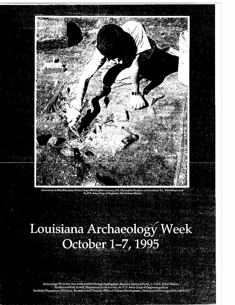
IacavaÜoiiMt'iWmaJTtatatien.'EointeCaupecfe '':';.;.■; : tteiüiS/^toyijEe^sioflEngineers.NcwSdcansiIBhliict
Louisiana Archaeology Week October 1-7,1995
Äiohaeology^Wci
DEDICATION
This report is dedicated to the memory of Mr. Richard Supple Glynn, proud twentieth century owner of Nina Plantation, and to all the former residents of Nina/Pecan Grove Plantation. At least in part, their untold stories now live on.
IV
ACKNOWLEDGEMENTS
R Christopher Goodwin & Associates, Inc., would like to thank Mrs. Catherine
.Glynn Olinde, the owner of Nina Planta- tion, for the opportunity to work at the plantation. Mr. Kenneth Jewell, Esq., has provided liaison between Goodwin & Associates, Inc., and Mrs. Olinde, and we also are grateful for his help.
We would like to thank the U.S. Army Corps of Engineers, New Orleans District, for funding these investigations; Mr. Howard R. Bush, Contracting Officer's Representative, and Ms. Joan M. Exnicios, Co-Contracting Officer's Representative, provided valuable advice throughout the course of these excavations. We would also like to acknowledge Dr. Tom Eubanks, State Archaeologist, Mr. Duke Rivet, Ms. Claudia Holland, and Ms. Nancy Hawkins, all of the Louisiana Division of Archaeology, for their help and guidance during this undertaking.
We would like to acknowledge the contribu- tions to research made by Dr. Jay Edwards of the Department of Anthropology at the University of Louisiana, who provided information and counsel on local vernacular architecture. James F. Sefcik, Director, Louisiana State Museum, graciously granted permission for the reproduction of the Jarreau family portraits. We also would like to thank the staffs of the Williams Research Center at the Historic New Orleans Collection, and of the Amistad Center for Research at Tulane Univer- sity, New Orleans. Mr. I.G. Olinde, Pointe Cou- pee Parish Clerk of Court, and his staff provided assistance with archival sources, as did Ms. Joan Caldwell and her staff at the Louisiana Collec- tion, Howard-Tilton Memorial Library, Tulane University, New Orleans. We also would like to acknowledge the contributions to research by the Library of Congress, Cartographic Branch, Washington, D.C.; the National Archives, Washington, D.C.; and the National Archives,
Records Administration, Cartographies Branch, College Park, Maryland. Mr. Kevin Hymel, M.A., Mr. Pat Giglio, M.A., and Ms. Martha Williams, M.A., M.Ed. provided archival and other research assistance during the course of the project.
Dr. R. Christopher Goodwin was the Princi- pal Investigator for the Nina Plantation project, and Dr. Ann Markell was the field director. Mr. William Athens, M.A., A.B.D. and Mr. Randall Primm, B.A provided much appreciated advice and assistance during the course of this project. Dr. Markell was assisted in the field by Co- Project Manager Stephen Hinks, M.A. and by supervisory personnel including Colby Child, B.A., Kathy Child, B.A., Johnna Thackston, M.A., Richard Wappenstein, B.S., Jeremy Pinco- ske, B.A., and Anna Norton, B.A. Archeological technicians included Dave Olney, B.A., Ben Fahy, B.A., Gary Gordon, B.A., Sonja Ingram, B.A., Katherine Woodcock, B.A., Alison Van Wagner, B.S., Catherine Boatner, B.F.A., Connie Darby, B.A., John Blackwelder, B.A., Michael Flynn, B.A., Derek Wingfield, B.A., Terrell Taylor, M.F.A., Bengt Hokanson, B.A., David Beard, M.A., Dan Warren, B.A., Ann Ballard, B.A., Kenny Wright, M.A., Tim Barton, M.A., and Paul Hughbanks, M.A.. The initial EDM sur- vey was conducted by Mr. David Harris, Regis- tered Land Surveyor, and later EDM measure- ments were taken by Stephen Hinks, M.A., David Olney, B.A., Jeremy Pincoske, B.A., and Ben Fahy, B.A.. Justine Woodward, B.A. conducted the ethnobotanical survey. The backhoe and the Cat 225 Excavator were operated skillfully by Mr. Bud Benton, of Pointe Coupee Parish. Mr. Benton also built the road into the project area, and helped to maintain it during the course of rains and floods, so that the project could con- tinue.
Laboratory analysis was conducted under the general supervision of Dr. Markell. Overall Lab supervision was provided by Mr Clifford Brown, M.A., A.B.D. Michael Hoover, B.A. and Anna Norton, B.A. acted as project-specific su- pervisors, and conducted the bulk of the primary analyses. Heather Appolonio, B.A., Allen Green, and Angele Montana, M.S. aided in some analy- ses. Tom Fenn, BA. conducted the analysis of tobacco pipes, and Michele Williams carried out he ethnobotanical analysis. Stephen Hinks and Michael Hoover analyzed the buttons, and Mi- chael Hoover conducted the bead analysis. Washing, labeling, and flotation were carried out by the permanent and part-time laboratory staff of R.Christopher Goodwin & Associates, Inc. As- sistance with the safe disposal of the Civil War hand-grenade recovered from the site, was pro- vided by Major Dexter Accardo, Commander of Special Operations, Melvin A. Rein, and Jose M. Colmenares, Bomb Technicians, Jefferson Parish Sheriff s office.
The production of graphics for this report was under the overall supervision of Ms. Shirley Rambeau, A.A. Mr. Dave Courington, B.A. and Mr. Lynn Berg, B.A. produced the many maps, plans and profiles for the report. In addition, Mr. Courington was responsible for the translation and mapping of the EDM data. Ms. Faith Leech, B.A. took the photographs, and assisted with graphics production. Dr. David Reiss of Elmwood Industrial Medicine, and Danita Pow- ers, X-ray Technician at Elmwood Industrial Medicine provided the x-ray of the handgun from Nina Plantation. Report production was carried out by Ms. Adele Bienvenu and Ms. Rebecca Riddle, B.A., under the general supervision of Ms. Christine Herman, B.A., Report Production Manager.
Finally, we would like to thank the occu- pants of Nina Plantation, and the residents of Point Coupee Parish, whose lives have enriched our own.
VI
TABLE OF CONTENTS
REPORT DOCUMENTATION PAGE i
TITLE PAGE ii
FRONTISPIECE iii
DEDICATION iv
ACKNOWLEDGEMENTS v
LIST OF FIGURES xiii
LIST OF TABLES xxiv
LIST OF CHARTS xxvii
I. INTRODUCTION 1 Site Description and Project Impacts 1 Research Objectives 3 Organization of the Report 5
H. NATURAL SETTING 6 Geological History 6
Wisconsinan Stage 6 Holocene Epoch 7
Specific Geology and Geomorphology 9 Stratigraphy 9 Sedimentary Processes 10 Geoarcheology 13 Structural Geology 13 Soils 14 Regional Climatology of Pointe Coupee Parish, Louisiana 14
Temperature 14 Precipitation 15 Water Budget Climatic Model 17 Flooding 17
Flora and Fauna 18 Flora 18 Fauna 20
DT. THE HISTORICAL CONTEXT 21 Introduction 21 Settlement between 1717 and 1900 21 The Social Milieu in Pointe Coupee Parish 24
The Slave Rebellion Conspiracy of 1795 25
vn
Labor Relations 25 Economic Development in Pointe Coupee 28 Flooding and Levee Construction 30
IV. THE LAND TENURE OF NINA PLANTATION 32 Bara Family Tenure: Late Eighteenth Century -1822 32 Jareau Family Tenure: 1822 -1857 34 Allen Family Tenure: 1857-1882 42
Nina Plantation during the Civil War 45 Late Nineteenth Century - Early Twentieth Century Tenure 50
Flooding and Levee Construction at Nina Plantation 58 Glynn Family Tenure: 1919 - Present 60 Summary 61
V. THE ARCHEOLOGICAL CONTEXT 63 Previous Investigations 63
NRHP Phase II Excavations at Nina Plantation 63 Previous Cultural Resources Surveys in the Vicinity of Site 16PC62 64
Plantation Sites in Louisiana 66 Rosehill Plantation (16WBR12) 66 Elmwood Plantation (16JE13 8) 66 Ashland - Belle Helene Plantation (16AN26) 67 Oakley Plantation (16WF34) 67
Plantation Sites in the Southeastern United States 68
VI. RESEARCH DESIGN 69 Introduction 69 Spatial Relationships 70 Comparison of Slave/Freedom and Planter Material Culture 70 Analysis of Diet at Nina Plantation 71 Summary 71
VH. FEELD METHODS, LABORATORY METHODS, AND TYPOLOGDIS 72 Introduction 72 Field Methods 73
Reconnaissance and Ethnobotanical Survey 73 Survey and Mapping Methods 73 Magnetometer Survey 74 Testing and Removal of Overburden 74 Hand Excavation 74
Laboratory Methods 75 Ceramics 76
Ceramic Type Descriptions 76 Creamware, Pearlware, and Whiteware 76 Yellowware 87 Ironstone 87 Porcelaneous Stoneware 87 Porcelain 87 Tin-glazed Earthenwares 89 Coarse Earthenwares 89 Redware 89
V1H
Refined Redware 89 Stoneware 91
Minimum Vessel Count 91 Glass 91
Color 93 Manufacturing Method 93
Nails 94 Beads 102
Buttons 104 Miscellaneous Artifacts 108
Coins 108 Dolls 108 Marbles 108 Tobacco Pipes 111 Firearms and Ammunition 111 Other Miscellaneous Items 119
Faunal Material ■ 119 Botanical Material 123
Hand Collected Botanical Specimens 123 Flotation 123
Flotation Botanical Specimens 124 Geomorphological Analysis .'. 124
Vm. RESULTS OF DATA RECOVERY EXCAVATIONS AT SITE 16PC62 126 Introduction 126 Cartographic Research 126 Magnetometer Survey 128 Mitigation Excavation Sequence 128 Site Stratigraphy 139
Anticipated Soils and Stratigraphy 139 Observed Stratigraphy 145 General Site Stratigraphy 145
Late Midden 145 1851 Alluvial Deposit (Cl/Bwb) 151 Early Midden 151
Site Taphonomy 151 Definition of Components at Site 16PC62 152
Architectural Components 152 The Main House Complex 152 The Outbuilding Complex 152
Unassociated Features 154 Unassociated Midden Deposits 154
The Main House Complex 154 The Core Features 154 Typical Stratigraphy near the Core 156
UnitE/50 156 UnitE/15 156 UnitE/14 163 UnitE/32 163 UnitE/24 163
The South Wing Features 166
ix
Typical Stratigraphy of the South Wing 166 UnitD/16 166 UnitD/9 170 UnitD/2 170 UnitD/6 170 UnitD/5 175
The North Wing Features 175 Typical Stratigraphy of the North Wing 175
UnitE/13 175 UnitE/9 180
The South Yard and the Cistern Features 180 Cisterns 180 South Sill Features 182
Unassociated Features 182 Feature 90 182 Feature 194 182
Summary of the Main House Complex 182 The Outbuilding Complex 182
Structure 1 Features 187 Sills and Structural Posts 187 Chimney Features 194 Plank Flooring Features 194 Miscellaneous Features 200
Summary of Structure 1 200 Structure 2 Features 200
Sills and Post Features 203 Firepit Features 208
Summary of Structure 2 208 Exterior Features 208
Feature 126 208 Feature 232 - 236 211 Features 1 -6 211
Unassociated Features 211 Summary of the Outbuilding Complex 216
BlockF 216 Features 43 and 143 216 Feature 130 218 Feature 52 218 Feature 53 218 Summary of BlockF 222
Trenches 222 Trench 1 222 Trench 6 222 Trench 8 222 Trench 9 226 Trench 16 and 17 226
Summary and Conclusions 226
DC ANALYTIC RESULTS 231 Introduction 231 Temporal and Spatial Analytical Units 231
Building a Whole Site Chronology 233 Flooding Deposits 234 Construction Periods 234 Occupational Sequences 236 Destruction Periods 236
Final Chronology 237 Combination of Periods 237
Ceramic Analysis 237 General Ceramic Distribution 237 Ceramic Types 242 Mean Ceramic Dating 247 Seriation 251 Economic Scaling 251 Ceramic Vessel Form 255
Functional Analyses 261 Glass Subassemblage 264
Faunal Analyses 272 Domestic and Wild Species 275 Chronological Patterns in Faunal Remains 280 Domesticated Animals 282 Wild Mammals 283 Wild Birds : 284 Reptiles and Amphibians 284 Fish 284 Eggshell 286 Butchering Evidence 286 Meat Cut Summary 287
Summary 287
X. SUMMARY AND INTERPRETATION 288 Introduction 288 The Architecture and Layout of Nina Plantation 288
The Main House Complex 288 The Outbuilding Complex 291 Discussion 293
The Material Assemblage of Nina Plantation 294 Distributional Patterns 296 Patterns of Ethnicity 296 Discussion 299
Summary 299
BIBLIOGRAPHY 302 References Cited 302
PROVENIENCE INFORMATION Appendixl
xi
VOLUME II
CERAMICS Appendix II
GLASS Appendix III
MISCELLANEOUS ARTIFACTS Appendix IV
NAILS Appendix V
REFERENCES USED IN APPENDICES Appendix VI
ANALYSIS OF FAUNAE REMAINS Appendix VII
ANALYSIS OF BOTANICAL REMAINS Appendix VIII
SCOPE OF SERVICES Appendix IX
UPDATED LOUISIANA STATE SITE FORMS Appendix X
xn
LIST OF FIGURES
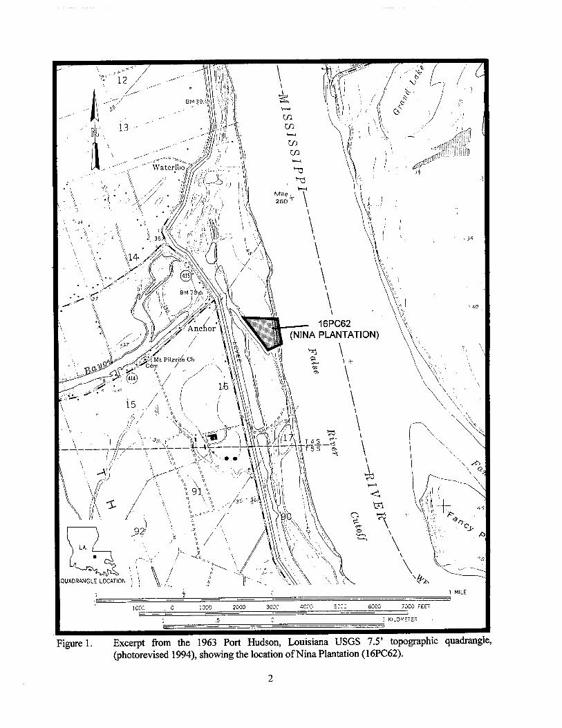
Figure 1. Excerpt from the 1963 Port Hudson, Louisiana USGS 7.5' topographic quadrangle, (photorevised 1994), showing the location of Nina Plantation (16PC62) 2
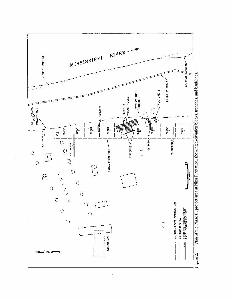
Figure 2. Plan of the Phase III project area at Nina Plantation, showing excavation blocks, trenches, and banklines 4
Figure 3. Mississippi River meander belts formed during the Holocene (adapted and redrawn from Autin et al. 1991; Kesel 1986) 8
Figure 4. A stratigraphic cross-section of the project area (adapted and redrawn from Saucier 1969) 11
Figure 5. Lateral migration, sedimentology, and site formational processes within a meandering river channel. From Heimich (1991) as modified from Gagliano and Van Beek (1970) 12
Figure 6. Excerpt from an unidentified map of Louisiana [ca. 1816], showing the location of the project area (on file in the National Archives) 22
Figure 7. Excerpt from Norman's Chart, Plantations on the Mississippi River from Natchez to New Orleans [1858], depicting C. Allen's Pecan Grove Plantation 23
Figure 8. Schematic representation of the general land tenure history of Section 16, T4S, Rl IE, of Nina Plantation, Pointe Coupee Parish 33
Figure 9. L'hermite's Plan et division en quatre lots d'unepropriete appartenant a Dame Vve. Durand [1820], depicting the subdivision of the Bara/ Durand property in Sections 15 and 16, T4S, Rl IE, and Sections 91 and 92, T5S, RUE (L'hermite 1818-1822, Survey No. 60). The project area is located within Lot No. 3 of the subdivision 35
Figure 10. Portrait of Jacques Jarreau, 1826 by Louis Antoine Collas (from the Collection of the Louisiana State Museum) 37
Figure 11. Portrait of Jean Ursin Jarreau, 1826, by Louis Antoine Collas (from the Collection of the Louisiana State Museum) 38
Figure 12. Portrait of Octavine LeBlanc, wife of Jean Ursin Jarreau, 1826, by Louis Antoine Collas (from the Collection of the Louisiana State Museum) 39
Figure 13. Conveyance amounts for Nina Plantation 1857 -1924 (Conveyance records, Pointe Coupee Parish Clerk of Court) 44
xm
Figure 14. Excerpt from the Mississippi River Commission's Survey of the Mississippi River, Chart No. 143 [1879-1883], depicting Nina Plantation structures and Cook's Landing 46
Figure 15. Excerpt from Banks' Department of the Gulf, Map No. 8: Atchafalaya Basin [1863], depicting Port Hudson and the False River country 47
Figure 16. Sholl''s Port Hudson and Its Defences [sic], Constructed and Engraved to llustrate "The War with the South" [ca. 1863] (vol. 3, 1862-1867, by Robert Tumes). Please note that the village of Waterloo and C. Favre's plantation erroneously have been placed below the Upper Chenal of False River; additionally, the C. Allen property and Pecan Grove were depicted as two separate plantations, rather than one 48
Figure 17. Excerpt from Tomlinson's New Map of Port Hudson. Showing the Scene of Gen. Banks Operations, Together with All of the Fortifications, Batteries, & c. [sic throughout][ca. 1863], depicting C. Allen's Paean [Pecan] Grove Plantation, Waterloo, and Hermitage Landing 49
Figure 18. Excerpt from the Mississippi River Commission's Survey of the Mississippi River, Chart No. 64 [1880-1881], depicting Nina Plantation and Waterloo, Anchor, and Cook's landings 51
Figure 19. Excerpt from the Mississippi River Commission surveyor's notebook, Topography near Waterloo, Hermitage, Point Manoir and Datum Point Clark, Transit Book No. 999 [1882-1883], depicting the riverfront survey of Nina Plantation (MRC 1882-1883b) 52
Figure 20. Excerpt from the Louisiana State Engineers' levee setback map [ca. 1890] depicting the proposed levee to be constructed behind Cook's Landing and through Nina Plantation. Please note that illegible notations and the words "NOT BUILT" appeared on the original copy of this map; however, the date(s), meaning, and relevance of this information could not be determined 57
Figure 21. Excerpt from the Mississippi River Commission's Map of the Lower Mississippi River from the Mouth of the Ohio River to the Head of the Passes, Sheet No. 24 [1907], depicting Nina Plantation and Waterloo, Anchor, and Cook's landings 59
Figure 22. Excerpt from the Mississippi River Commission's Survey of the Mississippi River, Chart No. 64 [1921], depicting the Glynn property [Nina Plantation] and Waterloo, Anchor, and Cook's landings 62
Figure 23. Reconstructed transfer-printed pearlware "Lions" pattern plates (FS 523, 530) 78
Figure 24. Portion of a transfer-printed pearlware "Washington" pattern bowl (FS 1210) 79
Figure 25. Selected transfer-printed whiteware "Asiatic Pheasant" pattern vessel fragments: (a, d, e) purple transfer-printed rim and body sherds (Vessel No. 148); (b, c, f) blue transfer-printed rim and body sherds (Vessel No. 179) 80
xiv
Figure 26. Partially reconstructed transfer-printed whiteware plates with patterns by Joseph Heath & Company (note maker's mark above each): (from left to right) "The Residence of the Late Richard Jordan, New Jersey" pattern (Vessel No. 502, 504); "Lombardy" pattern (Vessel No. 552) 82
Figure 27. Selected brown transfer-printed whiteware sherds with polychrome underglaze hand painting (Vessel No. 964) 84
Figure 28. Selected slip decorated whiteware vessel sherds: (a, b, d) polychrome finger painting with annular border (Vessel No. 1343, 710, 689); (c) white combed trailing (Vessel No. 687); (e, f) partially reconstructed bowl with variation of polychrome finger painting (Vessel No. 609); (g) white trailing (Vessel No. 176); (h) wide black and blue annular bands (Vessel No. 717); (i) blue and green annular bands with molded handle scar ( Vessel No. 715); (j) brown annular bands above a light blue field (Vessel No. 681); (k) dark brown and blue annular bands (Vessel No. 709) 85
Figure 29. Selected decorated ceramic vessel sherds: (a) blue cut-sponge stamped decoration on whiteware bowl (Vessel No. 742); (b) blue sponge stamped decoration with black underglaze hand painting on whiteware bowl (Vessel No. 719); (c) polychrome cut-sponge stamped decoration on whiteware bowl (Vessel No. 744); (d) blue "mocha" decoration on yellowware bowl (Vessel No. 695) 86
Figure 30. Partially reconstructed yellowware bowl with white and brown annular decoration (Vessel No. 11) 88
Figure 31. Partially reconstructed Albilsola Trailed redware bowl recovered from Site 16PC62 (Vessel No. 1893) 90
Figure 32. Selected stoneware ale bottles: (top) reconstructed bottle with down- tooled lip, v-shaped string rim and scooped shoulder (Vessel No. 298); (bottom, left to right) rounded or beaded three-ring lip (Vessel No. 47); tapered, rounded lip with small bead string rim (Vessel No. 46); rounded beveled lip with bead neck ring (Vessel No. 501); down-tooled lip with bead string rim (Vessel No. 44); down-tooled lip (Vessel No. 1388) 92
Figure 33. Selected perfume bottles and stoppers: (a) molded conical bottle with embossed decoration (FS 80); (b) blown-in-mold, waisted ovoid bottle (FS 1359); (c) rounded-square flat head stopper with ground shank (FS 1007); (d) molded cylindrical solarized amethyst glass bottle (FS 1124); (e) molded cylindrical bottle (FS 395); (f) disc stopper with ground shank (FS 443) 96
Figure 34. Selected pharmaceutical and ink bottles: (a) aqua, molded ink well (FS 1250); (b) aqua,molded cylindrical bottle (FS 269); (c) molded bottle (FS 255); (d) aqua, molded bottle (FS 1328); (e) molded bottle with two flat sides and two curved sides with molded fluting (note portion of cork still in bottle) (FS 1399) • 97
xv
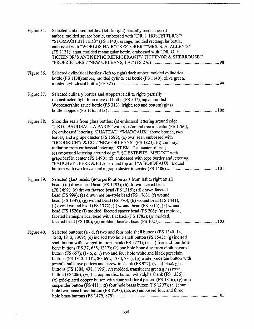
Figure 35. Selected embossed bottles: (left to right) partially reconstructed amber, molded square bottle, embossed with "DR. J. HOSTETTER'S"/ "STOMACH BITTERS" (FS 1140); orange, molded rectangular bottle, embossed with "WORLDS HAIR"/"RESTORER"/"MRS. S. A. ALLEN'S" (FS 1131); aqua, molded rectangular bottle, embossed with "DR. G. H. TICHENOR'S ANTISEPTIC REFRIGERANTT'TICHENOR & SHERROUSE'V "PROPRIETORS'VNEW ORLEANS, LA." (FS 276) 98
Figure 36. Selected cylindrical bottles: (left to right) dark amber, molded cylindrical bottle (FS 1138);amber, molded cylindrical bottle (FS 1140); olive green, molded cylindrical bottle (FS 325) 99
Figure 37. Selected culinary bottles and stoppers: (left to right) partially reconstructed light blue olive oil bottle (FS 507); aqua, molded Worcestershire sauce bottle (FS 313); (right, top and bottom) glass bottle stoppers (FS 1165, 313) 100
Figure 38. Shoulder seals from glass bottles: (a) embossed lettering around edge "...KD...BAUDEAU..A PARIS" with rooster and tree in center (FS 1760); (b) embossed lettering "CHATEAU'V'MARGAUX" above branch, two leaves, and a grape cluster (FS 1585); (c) oval seal, embossed with "GOODRICH"/"& CO'VNEW ORLEANS" (FS 1823); (d) thin rays radiating from embossed lettering "ST EM..." at center of seal; (e) embossed lettering around edge ". ST ESTEPHE . MEDOC" with grape leaf in center (FS 1490); (f) embossed with rope border and lettering "FAUCHEY. PERE & FILS" around top and "A BORDEAUX" around bottom with two leaves and a grape cluster in center (FS 1486) 101
Figure 39. Selected glass beads: (note perforation axis from left to right on all beads) (a) drawn seed bead (FS 1293); (b) drawn faceted bead (FS 1692); (c) drawn faceted bead (FS 1315); (d) drawn faceted bead (FS 999); (e) drawn melon-style bead (FS 1763); (f) wound bead (FS 1347); (g) wound bead (FS 770); (h) wound bead (FS 1441); (i) ovoid wound bead (FS 1372); (j) wound bead (FS 1515); (k) wound bead (FS 1526); (1) molded, faceted spacer bead (FS 206); (m) molded, faceted hemispherical bead with flat back (FS 1782); (n) molded, faceted bead (FS 180); (o) molded, faceted bead (FS 1027) 103
Figure 40. Selected buttons: (a - d, f) two and four hole shell buttons (FS 1340, 14, 1360, 1313,1309); (e) incised two hole shell button (FS 1543); (g) incised shell button with swaged-in loop shank (FS 1773); (h - j) five and four hole bone buttons (FS 37, 658, 1312); (k) one hole bone disc from cloth covered button (FS 657); (1 - o, q, r) two and four hole white and black porcelain buttons (FS 1312, 1312, 80, 692, 1334, 831); (p) white porcelain button with green's bulls-eye pattern and screw-in shank (FS 927); (s - u) black glass buttons (FS 1308,438, 1196); (v) molded, translucent green glass rose button (FS 206); (w) flat copper disc button with alpha shank (FS 1336); (x) gold-plated copper button with stamped floral pattern (FS 1816); (y) iron suspender button (FS 411); (z) four hole brass button (FS 1297); (aa) four hole two-piece brass button (FS 1297); (ab, ac) embossed four and three hole brass buttons (FS 1479, 879) 105
xvi
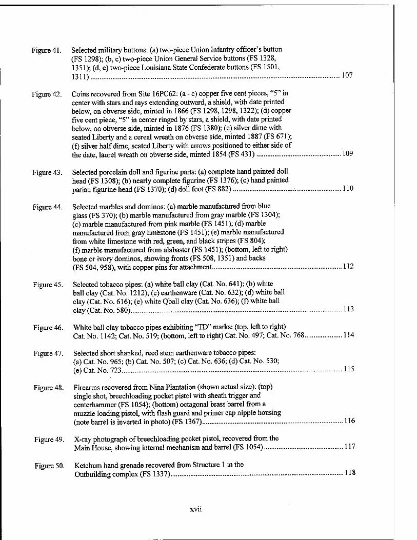
Figure 41. Selected military buttons: (a) two-piece Union Infantry officer's button (FS 1298); (b, c) two-piece Union General Service buttons (FS 1328, 1351); (d, e) two-piece Louisiana State Confederate buttons (FS 1501, 1311) 107
Figure 42. Coins recovered from Site 16PC62: (a - c) copper five cent pieces, "5" in center with stars and rays extending outward, a shield, with date printed below, on obverse side, minted in 1866 (FS 1298,1298,1322); (d) copper five cent piece, "5" in center ringed by stars, a shield, with date printed below, on obverse side, minted in 1876 (FS 1380); (e) silver dime with seated Liberty and a cereal wreath on obverse side, minted 1887 (FS 671); (f) silver half dime, seated Liberty with arrows positioned to either side of the date, laurel wreath on obverse side, minted 1854 (FS 431) 109
Figure 43. Selected porcelain doll and figurine parts: (a) complete hand painted doll head (FS 1308); (b) nearly complete figurine (FS 1376); (c) hand painted parian figurine head (FS 1370); (d) doll foot (FS 882) 110
Figure 44. Selected marbles and dominos: (a) marble manufactured from blue glass (FS 370); (b) marble manufactured from gray marble (FS 1304); (c) marble manufactured from pink marble (FS 1451); (d) marble manufactured from gray limestone (FS 1451); (e) marble manufactured from white limestone with red, green, and black stripes (FS 804); (f) marble manufactured from alabaster (FS 1451); (bottom, left to right) bone or ivory dominos, showing fronts (FS 508,1351) and backs (FS 504, 958), with copper pins for attachment 112
Figure 45. Selected tobacco pipes: (a) white ball clay (Cat. No. 641); (b) white ball clay (Cat. No. 1212); (c) earthenware (Cat. No. 632); (d) white ball clay (Cat. No. 616); (e) white Qball clay (Cat. No. 636); (f) white ball clay (Cat. No. 580) 113
Figure 46. White ball clay tobacco pipes exhibiting "TD" marks: (top, left to right) Cat. No. 1142; Cat. No. 519; (bottom, left to right) Cat. No. 497; Cat. No. 768 114
Figure 47. Selected short shanked, reed stem earthenware tobacco pipes: (a) Cat. No. 965; (b) Cat. No. 507; (c) Cat. No. 636; (d) Cat. No. 530; (e) Cat. No. 723 115
Figure 48. Firearms recovered from Nina Plantation (shown actual size): (top) single shot, breechloading pocket pistol with sheath trigger and centerhammer (FS 1054); (bottom) octagonal brass barrel from a muzzle loading pistol, with flash guard and primer cap nipple housing (note barrel is inverted in photo) (FS 1367) 116
Figure 49. X-ray photograph of breechloading pocket pistol, recovered from the Main House, showing internal mechanism and barrel (FS 1054) 117
Figure 50. Ketchum hand grenade recovered from Structure 1 in the Outbuilding complex (FS 1337) 118
xvii
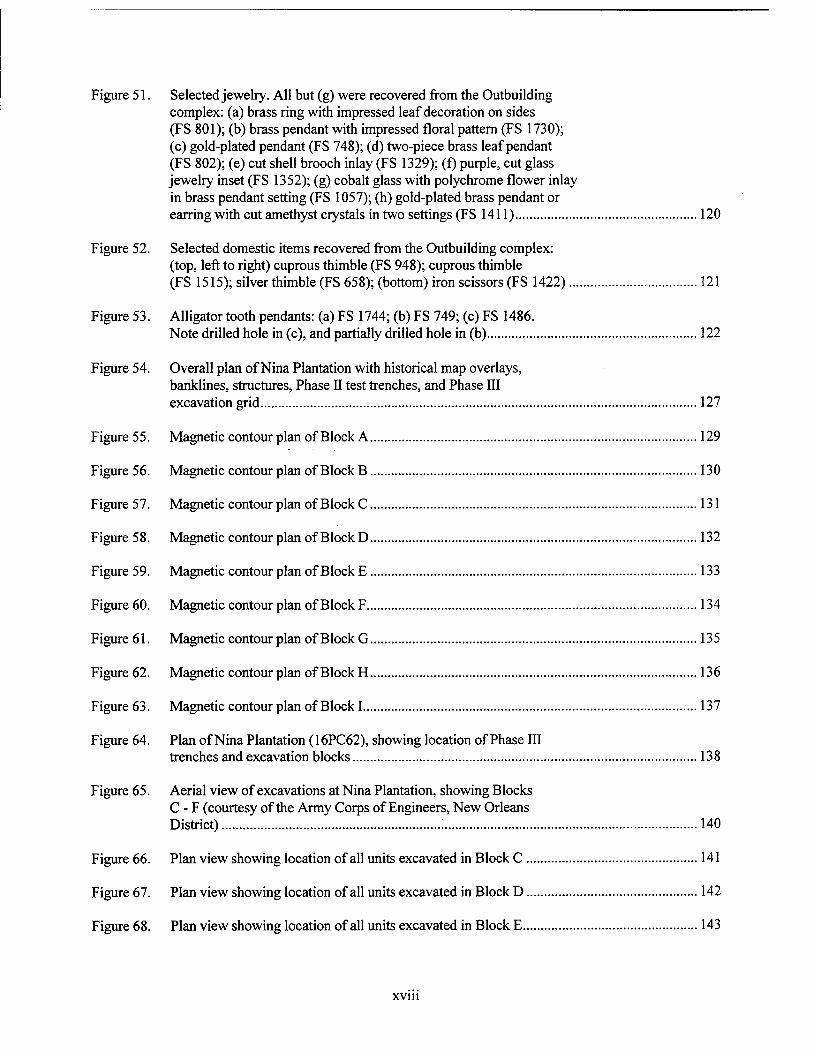
Figure 51. Selected jewelry. All but (g) were recovered from the Outbuilding complex: (a) brass ring with impressed leaf decoration on sides (FS 801); (b) brass pendant with impressed floral pattern (FS 1730); (c) gold-plated pendant (FS 748); (d) two-piece brass leaf pendant (FS 802); (e) cut shell brooch inlay (FS 1329); (f) purple, cut glass jewelry inset (FS 1352); (g) cobalt glass with polychrome flower inlay in brass pendant setting (FS 1057); (h) gold-plated brass pendant or earring with cut amethyst crystals in two settings (FS 1411) 120
Figure 52. Selected domestic items recovered from the Outbuilding complex: (top, left to right) cuprous thimble (FS 948); cuprous thimble (FS 1515); silver thimble (FS 658); (bottom) iron scissors (FS 1422) 121
Figure 53. Alligator tooth pendants: (a) FS 1744; (b) FS 749; (c) FS 1486. Note drilled hole in (c), and partially drilled hole in (b) 122
Figure 54. Overall plan of Nina Plantation with historical map overlays, banklines, structures, Phase II test trenches, and Phase III excavation grid 127
Figure 55. Magnetic contour plan of Block A 129
Figure 56. Magnetic contour plan of Block B 130
Figure 57. Magnetic contour plan of Block C 131
Figure 58. Magnetic contour plan of Block D 132
Figure 59. Magnetic contour plan of Block E 133
Figure 60. Magnetic contour plan of Block F 134
Figure 61. Magnetic contour plan of Block G 135
Figure 62. Magnetic contour plan of Block H 136
Figure 63. Magnetic contour plan of Block 1 137
Figure 64. Plan of Nina Plantation (16PC62), showing location of Phase III trenches and excavation blocks 138
Figure 65. Aerial view of excavations at Nina Plantation, showing Blocks C - F (courtesy of the Army Corps of Engineers, New Orleans District) 140
Figure 66. Plan view showing location of all units excavated in Block C 141
Figure 67. Plan view showing location of all units excavated in Block D 142
Figure 68. Plan view showing location of all units excavated in Block E 143
xvin
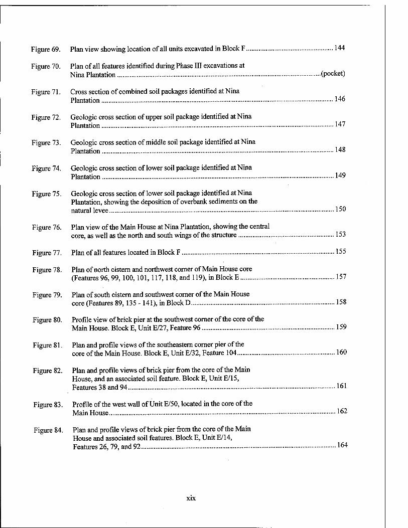
Figure 69. Plan view showing location of all units excavated in Block F 144
Figure 70. Plan of all features identified during Phase III excavations at Nina Plantation (pocket)
Figure 71. Cross section of combined soil packages identified at Nina Plantation 146
Figure 72. Geologic cross section of upper soil package identified at Nina Plantation 147
Figure 73. Geologic cross section of middle soil package identified at Nina Plantation 148
Figure 74. Geologic cross section of lower soil package identified at Nina Plantation 149
Figure 75. Geologic cross section of lower soil package identified at Nina Plantation, showing the deposition of overbank sediments on the natural levee 150
Figure 76. Plan view of the Main House at Nina Plantation, showing the central core, as well as the north and south wings of the structure 153
Figure 77. Plan of all features located in Block F 155
Figure 78. Plan of north cistern and northwest corner of Main House core (Features 96,99,100,101,117,118, and 119), in Block E 157
Figure 79. Plan of south cistern and southwest corner of the Main House core (Features 89, 135 -141), in Block D 158
Figure 80. Profile view of brick pier at the southwest corner of the core of the Main House. Block E, Unit E/27, Feature 96 159
Figure 81. Plan and profile views of the southeastern corner pier of the core of the Main House. Block E, Unit E/32, Feature 104 160
Figure 82. Plan and profile views of brick pier from the core of the Main House, and an associated soil feature. Block E, Unit E/15, Features 38 and 94 161
Figure 83. Profile of the west wall of Unit E/50, located in the core of the Main House 162
Figure 84. Plan and profile views of brick pier from the core of the Main House and associated soil features. Block E, Unit E/14, Features 26, 79, and 92 164
xix
Figure 85. Plan and profile views of a brick pier from the core of the Main House, a plan view of Feature 93, and a profile view of Feature 95. Block E, Units E/23 and E/24 165
Figure 86. Plan view of the south wing of the Main House 167
Figure 87. Typical profile of stratigraphic sequence at Nina Plantation. The 1851 flood event is evident in the thick alluvial stratum separating the two dark midden strata 168
Figure 88. Plan and profile views of a brick pier and postmold/posthole from the south wing of the Main House. Block D, Unit D/16, Features 231 and 238 169
Figure 89. Plan and profile views of a brick pier from the south wing of the Main House. Block D, Unit D/9, Feature 85 171
Figure 90. Plan and profile views of a brick pier at the southeastern corner of the south wing of the Main House. Block D, Unit D/2, Feature 65 172
Figure 91. Profile view showing midden and alluvial deposits associated with the south wing hearth. Block D, Unit D/6, Feature 84 173
Figure 92. Brick chimney foundation (Feature 84) in the south wing of the Main House. Block D, Unit D/6 174
Figure 93. Plan and profile views of piers connecting the core and the south wing of the Main House. Block D, Unit D/5, Features 115 A and 115 B 176
Figure 94. Plan view of the north wing of the Main House 177
Figure 95. Feature 30, in Block E, showing pier and brick rubble 178
Figure 96. Plan and profile views of piers connecting the core and the north wing of the Main House. Block E, Unit E/13, Feature 27 179
Figure 97. Profile and plan views of a brick pier from the north wing of the Main House. Block E, Unit E/9, Features 35 and 70 181
Figure 98. Plan view showing cedar beam and post features from the south wing of the Main House, and profile view showing elevation of beam. Block D, Units D/27, D/32, and D/33, Features 248,249,250, 252, and 254 183
Figure 99. Cedar sill and associated posts in Block D 184
Figure 100. Plan and profile views of Feature 90, in Block D 185
Figure 101. Plan and profile views of wood lined well (Feature 194), in Block E 186
xx
Figure 102. Conjectural configuration of Structure 1 in the Outbuilding complex 188
Figure 103. Plan of features attributed to the early period Structure 1 in Block C 189
Figure 104. Plan of features attributed to the late period Structure 1 in Block C 190
Figure 105. Plan and profile views of the southwestern corner of Structure 1 in the Outbuilding complex. Block C, Unit C/15 191
Figure 106. Plan and profile views of the northwestern corner of Structure 1 in the Outbuilding complex. Block C, Units C/23 and C/41, Features 146 and 147 192
Figure 107. Plan and profile of the south wall sill of Structure 1 (Feature 150), showing the stratigraphy of the interior and exterior of the structure. Block C, Units C/6, C/9, C/33, C/34, C/37 and C/38 193
Figure 108. Postholes associated with the wood and clay chimney in Structure 1 of the Outbuilding complex. Block C, Units C/13 and C/32, Features 197, 224, and 229 195
Figure 109. Brick chimney foundation in Structure 1 of the Outbuilding complex. Block C, Feature 116 196
Figure 110. Profiles of the balk that intersected the brick chimney foundation (Feature 116) in Structure 1 197
Figure 111. Various profile views of the brick chimney foundation (Feature 116) in Structure 1. Profile coordinates are shown in plan on Figure 112 198
Figure 112. Plan view of the H-shaped chimney foundation (Feature 116) in Structure 1 of the Outbuilding complex. Note the placement of the clay hearth (Feature 198), and posthole (Feature 197) associated with the previous wood and clay chimney 199
Figure 113. Plan and profile of features associated with the plank floor in Structure 1 In the Outbuilding complex. Block C, Unit C/37, Features 150, 195, and 208 201
Figure 114. Plan of features associated with Structure 2, in Block C 202
Figure 115. Stakeholes from the piquettes en terre partition wall in Structure 2 of the Outbuilding complex. Block C, Units C/56 and C/5 8, Features 168,181 -190 204
Figure 116. Plan view and profiles of sill features (Features 132 - 134) and corner construction at the northeastern corner of Structure 2. Block C, Unit C/47 205
xxi
Figure 117. Plan and profile of Units C/55 and C/59, showing the conjectural placement of sill Feature 157, in Structure 2, based on its position in profile 206
Figure 118. Plan of the south wall (Feature 228), and the piquette en terre partition wall (Features 168, 181 - 190) of Structure 2 in the Outbuilding complex. Block C, Units C/58 and C/65 207
Figure 119. Plan and profile views of Features 152 and 166 in Structure 2. Block C, Units E/52 and E/53 209
Figure 120. Plan and profile views of Feature 126, in Block C, Unit C/8 210
Figure 121. Profiles of the north and west walls of Unit C/63, showing Feature 239 212
Figure 122. Plan and profile views of Features 232,233, 234, 235, and 236, in Unit C/63 213
Figure 123. Plan of Features 1-6, in Block C, Units C/l - C/3 214
Figure 124. Profiles of Features 2 and 6, in Block C, Units C/l -C/3 215
Figure 125. Plan and profile views of Feature 43 and plan view of the southern portion of Feature 143, in Block F 217
Figure 126. Plan and profile views of Feature 130, Unit F/5, in Block F 219
Figure 127. Plan and profile views of Features 52 A and 52 B, in Block F 220
Figure 128. Plan and profile views of Feature 53, in Block F 221
Figure 129. Profile of north wall of Trench 1 in Block C 223
Figure 130. Profile of north wall of Trench 6 in Block H 224
Figure 131. Profile of south wall of Trench 8 in Block J 225
Figure 132. Profile of east wall of Trench 9 in Block H 227
Figure 133. Profile of east wall of Trench 16 in Block 1 228
Figure 134. Profile of south wall of Trench 17 in Block 1 229
Figure 135. Distribution of ceramics during the Early period in Blocks C, D, and E 241
Figure 136. Distribution of ceramics during the Late period in Blocks C, D, and E 241
Figure 137. Distribution of window glass in Blocks C, D, and E 273
XXI1
Figure 138. Distribution of analyzed faunal materials during the Early period in Blocks C, D, and E 276
Figure 139. Distribution of analyzed faunal materials during the late period in Blocks C, D, and E 277
Figure 140. John Latrobe's sketch of a raised plantation house, circa 1834. From John Latrobe, Southern Travels: Journal of John H.B. Latrobe, 1834, ed. Sam Wilson (New Orleans: Historic New Orleans Collection, 1986; cf. Edwards 1994) 290
Figure 141. Brass stencil bearing the legend, "PECAN GROVE / J U J" (FS1760) 292
Figure 142. Transverse view of the Amoreaux House, Ste. Genevieve Missouri, showing the limestone piers used to support the independent flooring (United States Department of the Interior, National Park Service, Historic American Buildings Survey, Survey no. M01113) 295
xxni
LIST OF TABLES
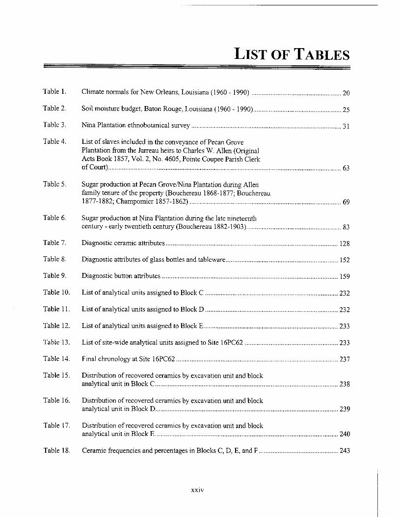
Table 1. Climate normals for New Orleans, Louisiana (1960 - 1990) 20
Table 2. Soil moisture budget, Baton Rouge, Louisiana (1960 - 1990) 25
Table 3. Nina Plantation ethnobotanical survey 31
Table 4. List of slaves included in the conveyance of Pecan Grove Plantation from the Jarreau heirs to Charles W. Allen (Original Acts Book 1857, Vol. 2, No. 4605, Pointe Coupee Parish Clerk of Court) 63
Table 5. Sugar production at Pecan Grove/Nina Plantation during Allen family tenure of the property (Bouchereau 1868-1877; Bouchereau 1877-1882; Champomier 1857-1862) 69
Table 6. Sugar production at Nina Plantation during the late nineteenth century - early twentieth century (Bouchereau 1882-1903) 83
Table 7. Diagnostic ceramic attributes 128
Table 8. Diagnostic attributes of glass bottles and tableware 152
Table 9. Diagnostic button attributes 159
Table 10. List of analytical units assigned to Block C 232
Table 11. List of analytical units assigned to Block D 232
Table 12. List of analytical units assigned to Block E 233
Table 13. List of site-wide analytical units assigned to Site 16PC62 233
Table 14. Final chronology at Site 16PC62 237
Table 15. Distribution of recovered ceramics by excavation unit and block analytical unit in Block C 238
Table 16. Distribution of recovered ceramics by excavation unit and block analytical unit in Block D 239
Table 17. Distribution of recovered ceramics by excavation unit and block analytical unit in Block E 240
Table 18. Ceramic frequencies and percentages in Blocks C, D, E, andF 243
xxiv
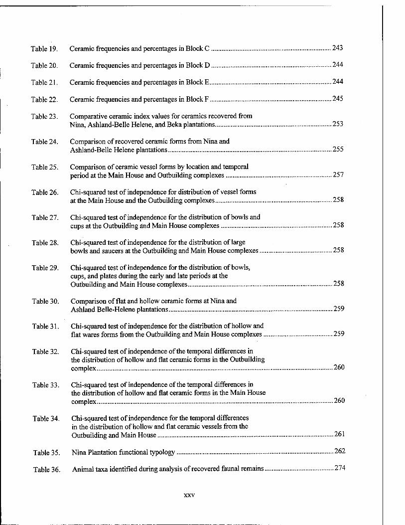
Table 19. Ceramic frequencies and percentages in Block C 243
Table 20. Ceramic frequencies and percentages in Block D 244
Table 21. Ceramic frequencies and percentages in Block E 244
Table 22. Ceramic frequencies and percentages in Block F 245
Table 23. Comparative ceramic index values for ceramics recovered from Nina, Ashland-Belle Helene, and Beka plantations 253
Table 24. Comparison of recovered ceramic forms from Nina and Ashland-Belle Helene plantations 255
Table 25. Comparison of ceramic vessel forms by location and temporal period at the Main House and Outbuilding complexes 257
Table 26. Chi-squared test of independence for distribution of vessel forms at the Main House and the Outbuilding complexes 258
Table 27. Chi-squared test of independence for the distribution of bowls and cups at the Outbuilding and Main House complexes .....258
Table 28. Chi-squared test of independence for the distribution of large bowls and saucers at the Outbuilding and Main House complexes 258
Table 29. Chi-squared test of independence for the distribution of bowls, cups, and plates during the early and late periods at the Outbuilding and Main House complexes 258
Table 30. Comparison of flat and hollow ceramic forms at Nina and Ashland Belle-Helene plantations 259
Table 31. Chi-squared test of independence for the distribution of hollow and flat wares forms from the Outbuilding and Main House complexes 259
Table 32. Chi-squared test of independence of the temporal differences in the distribution of hollow and flat ceramic forms in the Outbuilding complex 260
Table 33. Chi-squared test of independence of the temporal differences in the distribution of hollow and flat ceramic forms in the Main House complex 260
Table 34. Chi-squared test of independence for the temporal differences in the distribution of hollow and flat ceramic vessels from the Outbuilding and Main House 261
Table 35. Nina Plantation functional typology 262
Table 36. Animal taxa identified during analysis of recovered faunal remains 274
xxv
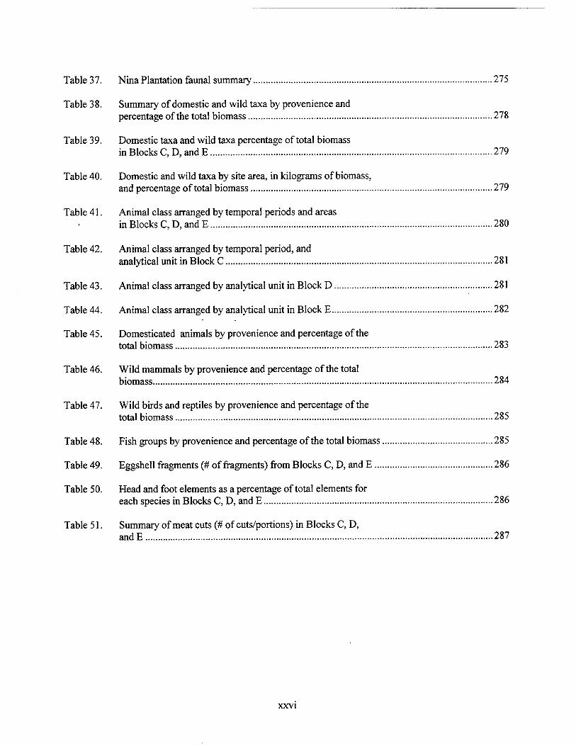
Table 37. Nina Plantation faunal summary 275
Table 38. Summary of domestic and wild taxa by provenience and percentage of the total biomass 278
Table 39. Domestic taxa and wild taxa percentage of total biomass in Blocks C, D, and E 279
Table 40. Domestic and wild taxa by site area, in kilograms of biomass, and percentage of total biomass 279
Table 41. Animal class arranged by temporal periods and areas in Blocks C, D, and E 280
Table 42. Animal class arranged by temporal period, and analytical unit in Block C 281
Table 43. Animal class arranged by analytical unit in Block D 281
Table 44. Animal class arranged by analytical unit in Block E 282
Table 45. Domesticated animals by provenience and percentage of the total biomass 283
Table 46. Wild mammals by provenience and percentage of the total biomass 284
Table 47. Wild birds and reptiles by provenience and percentage of the total biomass 285
Table 48. Fish groups by provenience and percentage of the total biomass 285
Table 49. Eggshell fragments (# of fragments) from Blocks C, D, and E 286
Table 50. Head and foot elements as a percentage of total elements for each species in Blocks C, D, and E 286
Table 51. Summary of meat cuts (# of cuts/portions) in Blocks C, D, andE 287
XXVI
LIST OF CHARTS
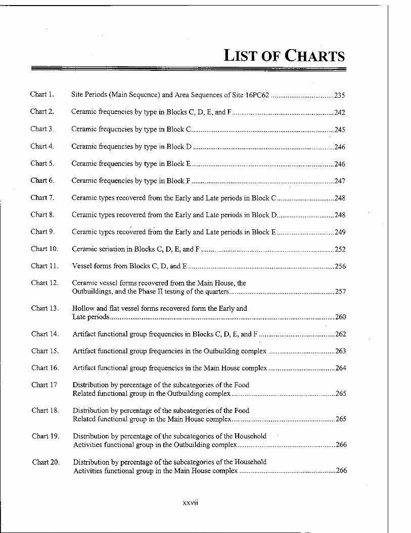
Chart 1. Site Periods (Main Sequence) and Area Sequences of Site 16PC62 235
Chart 2. Ceramic frequencies by type in Blocks C, D, E, and F 242
Chart 3. Ceramic frequencies by type in Block C 245
Chart 4. Ceramic frequencies by type in Block D 246
Chart 5. Ceramic frequencies by type in Block E 246
Chart 6. Ceramic frequencies by type in Block F 247
Chart 7. Ceramic types recovered from the Early and Late periods in Block C 248
Chart 8. Ceramic types recovered from the Early and Late periods in Block D 248
Chart 9. Ceramic types recovered from the Early and Late periods in Block E 249
Chart 10. Ceramic sedation in Blocks C, D, E, and F 252
Chart 11. Vessel forms from Blocks C, D, andE 256
Chart 12. Ceramic vessel forms recovered from the Main House, the Outbuildings, and the Phase II testing of the quarters 257
Chart 13. Hollow and flat vessel forms recovered form the Early and Late periods 260
Chart 14. Artifact functional group frequencies in Blocks C, D, E, and F 262
Chart 15. Artifact functional group frequencies in the Outbuilding complex 263
Chart 16. Artifact functional group frequencies in the Main House complex 264
Chart 17 Distribution by percentage of the subcategories of the Food Related functional group in the Outbuilding complex 265
Chart 18. Distribution by percentage of the subcategories of the Food Related functional group in the Main House complex 265
Chart 19. Distribution by percentage of the subcategories of the Household Activities functional group in the Outbuilding complex 266
Chart 20. Distribution by percentage of the subcategories of the Household Activities functional group in the Main House complex 266
xxvn
Chart 21.
Chart 22.
Chart 23.
Chart 24.
Chart 25.
Chart 26.
Chart 27.
Chart 28.
Chart 29.
Chart 30.
Chart 31.
Chart 32.
Chart 33.
Distribution by percentage of the subcategories of the Architectural functional group in the Outbuilding complex 267
Distribution by percentage of the subcategories of the Architectural functional group in the Main House complex 267
Distribution by percentage of subcategories of the Agricultural/Food Procurement functional group in the Outbuilding complex 268
Distribution by percentage of subcategories of the Agricultural/Food Procurement functional group in the Main House complex 268
Distribution by percentage of the subcategories of the Personal functional group in the Outbuilding complex 269
Distribution by percentage of the subcategories of the Personal functional group in the Main House complex 269
Distribution of artifacts by functional group for the Early period in the Outbuilding complex 270
Distribution of artifacts by functional group for the Late period in the Outbuilding complex 270
Distribution of artifacts by functional group for the Early period in the Main House complex 271
Distribution of Artifacts by functional group for the Late period in the Main House complex 271
Temporal distribution of glass by functional type in Blocks C, D, and E 272
Distribution of bottle glass during the Early period in Blocks C, D, and E 371
Distribution of bottle glass during the Late period in Blocks C, D, and E 371
XXVlll
CHAPTER I
INTRODUCTION
This report presents the results of Phase in data recovery excavations at Nina Planta- tion (16PC62), a nineteenth century his-
toric archeological site located on the west bank of the Mississippi River near New Roads, in Pointe Coupee Parish, Louisiana (Figure 1). R. Christopher Goodwin & Associates, Inc., con- ducted Phase III archeological mitigation at Nina Plantation between October 1993 and September 1994, on behalf of the Army Corps of Engineers, New Orleans District, under Contract DACW29- 93-R-0089. Data recovery was undertaken pursu- ant to and in accordance with procedures outlined in the National Historic Preservation Act of 1966, as amended; Executive Order 11593; the Ar- chaeological and Historic Preservation Act of 1974; The Archaeological Resources Protection Act of 1979, as amended; Title 36 of the Code of Federal Regulations, Parts 60-66 and 800, as ap- propriate; the Secretary of the Interior's Standards and Guidelines for Archeology and Historic Pres- ervation as published in the Federal Register of September 29, 1983; the Louisiana Division of Archaeology's Comprehensive Archaeological Plan of October 1, 1983; the Cultural Resources Code of Louisiana of June 1980; and the Advi- sory Council on Historic Preservation's Hand- book entitled "Treatment of Archeological Prop- erties" dated February 1981. Mitigation of planned impacts to the site was achieved by gath- ering a representative data sample from the site by addressing a variety of significant research questions, and by characterizing the cultural ac- tivity associated with nineteenth century occupa- tion of the site.
Dr. R. Christopher Goodwin served as Prin- cipal Investigator and supervised all aspects of
this study. Dr. Ann Markell and Stephen Hinks, M.A., served as Co-Project Managers; Dr. Markell also directed field investigations and the subsequent analysis of the recovered data, and she served as primary author of this report.
Site Description and Project Impacts The archeological Site 16PC62, Nina Plan-
tation, first was recorded in 1992 by Earth Search, Inc., during a cultural resources survey of the Grand Bay Revetment project right-of-way (Yakubik 1994). Subsequent to site identification, Site 16PC62 was tested and evaluated as eligible for inclusion in the National Register of Historic Places (Yakubik 1994:373). Testing and evalua- tion of the site consisted of the excavation of a series of judgmentally placed backhoe trenches designed to locate and identify a variety of intact cultural features. That investigation located both archeological features and deposits related to the main house complex, the slave/laborer's quarters, and the sugar mill. All but the sugar mill, which had been destroyed during twentieth century ex- cavation of nearby borrow pits, appeared to re- main intact beneath an alluvial deposit averaging 1 m (3.3 ft) in depth. Documentary research con- ducted by Yakubik (1994) suggested that the plantation dated from ca. 1820, and that it re- mained active in the same locale until the 1890s, when flooding and erosion forced the plantation owners to move the majority of the structures to the landward side of the newly constructed levee (Yakubik 1994).
Following a determination of eligibility for the National Register by the U.S. Army Corps of Engineers and the Louisiana State Historic Pres- ervation Office, level testing, data recovery exca-
QUADRANGLE LOCATION
1 MILE
1OC0 1000 2000 3000 4000 Ö0O0 7000 FEET
KILOMETER
Figure 1. Excerpt from the 1963 Port Hudson, Louisiana USGS 7.5' topographic quadrangle, (photorevised 1994), showing the location of Nina Plantation (16PC62).
vations subsequently were conducted at Nina Plantation (16PC62) by R Christopher Goodwin & Associates, Inc. Excavations, which began in October 1993, were undertaken in accordance with the modified Scope of Work agreed upon in February 1994 by Goodwin & Associates, Inc., and the New Orleans District. Modification of the original scope of work was intended to enable investigation of new and significant discoveries made by Goodwin & Associates, Inc., during the course of the 1993 data recovery efforts. During the final phase of data recovery, the main planta- tion house, comprised of an original core dwell- ing and two later wing additions, was delineated. In addition, investigations revealed the unex- pected presence of at least two temporally and stratigraphically distinct midden deposits. The lower deposit was sealed by alluvium from a se- vere, mid-nineteenth century flood, and it ap- peared to date from the antebellum period; the upper or later midden dated from the postbellum period. Two antebellum period,' earthfast out- buildings also were identified in the area south of the main house. Work under the modified con- tract was designed to address these important dis- coveries, and to recover data that would signifi- cantly enhance the interpretation of nineteenth century Nina Plantation.
These data recovery excavations success- fully exposed the remains of the main plantation house and associated cisterns, a well, and two domestic outbuildings. One of these smaller, earthfast structures was identified as a detached kitchen that also served as domestic quarters, probably for the cook and her family. The other outbuilding was interpreted as a residence, possi- bly for household labor. Both outbuildings em- ployed earthfast construction techniques. Mid- dens associated with the occupation of both out- buildings and with the main house were identified as a result of these excavations, and temporal and spatial distinctions between these midden depos- its allowed the current researchers to address a variety of diachronic and synchronic intra-site issues.
The Area of Potential Effect was defined in the Scope of Work (section C-2) as that portion of the Nina Plantation site located within 30 m (100 ft) of the top of the Mississippi River bankline. Those portions of the plantation that incorporated the slave/laborer quarters, and the industrial com-
plex, were not included in the current project area, although the data recovered from the quar- ters area during the Phase II assessment have been considered in this interpretation of the data collected during the current project. The site plan (Figure 2) illustrates the location of the current project area, the reported data recovery efforts, and the probable locations of the slave/laborer quarters and the industrial components identified during the Phase II testing effort completed pre- viously by Earth Search, Inc.
Research Objectives The Scope of Work provided by the U.S.
Army Corps of Engineers, New Orleans District, for data recovery at Nina Plantation defined three primary research issues. These issues included the examination of the material culture of planters and laborers living and working on a sugar and cotton plantation; a comparison of dietary resi- dues from areas occupied by planters and labor- ers; and an examination of the spatial layout of the plantation structures.
The proposal for data recovery submitted to the U.S. Army Corps of Engineers by R. Christo- pher Goodwin & Associates, Inc. (1993), ex- panded on these research themes, and added tem- poral analysis of identified features to the fist of research goals. The Phase II testing and evalua- tion conducted by Earth Search, Inc. (Yakubik 1994), suggested that there was little or no strati- graphic patterning at the site to allow for clear temporal differentiation of the associated compo- nents (Yakubik 1994:374). However, data recov- ery excavations provided evidence of clear strati- graphic patterning throughout most of the site area. For example, three distinct middens were associated with the main house and outbuildings, with the lower midden sealed or capped stratigraphically by a thick deposit of alluvium. Geomorphological and archival research, as well as subsequent artifact analyses, indicated that this alluvium was deposited by flood waters during the early 1850s. This alluvium sealed the bulk of the antebellum cultural deposits, and functioned as a temporal marker that extended across the entire site, making it possible to differentiate be- tween construction sequences associated with the main house and the related outbuildings. For ex- ample, brick support piers from the north wing of the main house were constructed on top of this
MIS SIS! ;IPP! R !VEB
z < CD :^~. t/i
o> o si
-.* a C8
X) "O
EC ~ ce UJ 3Z 3 (/) t- UJ t— 3 OI o o I3U 3 T CC 1- or
mi i—
y ..- w ■rf
S
O (P
O O o
O
0
o r O
-n
._J
5 o
■* ox O XU
ox 21- £5
CO
o O
c o
c
o 45
e o u
'§"
B a U
o c
E
alluvial stratum, while the bases of the piers of the original core of the main house were seated on sterile subsoil, well below this mid-nineteenth century alluvial deposit. While the construction sequence was not as clear during the excavation of the interior of the kitchen outbuilding, correla- tions between the alluvial stratum found outside of the building, and the interior strata associated with the construction of a brick chimney founda- tion, enhanced understanding of the complex se- quence of reconstruction events in the kitchen. Spatial and temporal pattern analysis also aided in "recapturing the dynamic aspects of the Nina Plantation's landscape" (Goodwin & Associates, Inc. 1993:13).
Nina Plantation is a well-stratified ante- bellum and postbellum sugar and cotton planta- tion site; excavation throughout selected portions of the site provided a phenomenal amount of data relevant to understanding the development of the plantation as a social, cultural, economic, and political unit. Evaluation of recovered artifact assemblages and distributional patterns, as well as documentary analysis, analysis of structural re- mains, ethnobotanical analysis, geomorphological studies, and faunal analyses were used to recon- struct and study past cultural activities and inter- actions within the site.
Organization of the Report The natural setting of Nina Plantation, a re-
view of the geomorphological development of the region, and a review of the floral, faunal, and cli-
matic patterns of the area, are contained in Chap- ter II. A summary of the regional history relevant to this project, and a discussion of slavery and the plantation system in Louisiana are contained in Chapter HI. Land tenure history, and documen- tary historical background specific to Nina Plan- tation, are chronicled in Chapter rv. A review of previous investigations at Nina Plantation, as well as a review of archeological investigations both at historic sites in the vicinity of the project area and at plantation sites in Louisiana, is contained in Chapter V. A review of the research design, as well as a review of theoretical and methodologi- cal approaches to plantation studies in the south- eastern United States, is contained in Chapter VI. The field and analytical methods employed in executing the project are described in Chapter VE. The results of data recovery at Nina Planta- tion are included in Chapters VIII and DC. A summary of results and interpretations associated with this data recovery effort is provided in Chapter X.
Provenience information, including tables describing features, units, and stratigraphic se- quences, is included in Appendix I. The associ- ated artifact inventories are contained in Appen- dices II, m, IV, V, and VI. The results of the fau- nal analysis are presented in Appendix VII, while the results of the botanical analysis are contained in Appendix VIII. The Scope of Work is included as Appendix IX, and an updated Louisiana State Site Form is provided in Appendix X.
CHAPTER II
NATURAL SETTING
Introduction This chapter presents the natural context of Nina Plantation. It provides information on
the natural setting that is essential to under- standing the context within which the plantation operated, and to understanding of the tapho- nomic events which followed its demise. Data on climate, flooding, botanical, and faünal re- sources in the region are important for study of the agricultural choices made, the architectural patterns, the refuse disposal patterns, and for analysis of faunal and botanical data. In addition to the general geomorphological study which was conducted, a survey of existing flora was conducted prior to excavation. This survey was intended to determine the presence of any rem- nant species which may have escaped cultiva- tion. This type of study is often fruitful in help- ing to determine early patterns of agriculture in a region.
Geological History The Mississippi Alluvial Valley is the prod-
uct of fluvial processes operating, at least, over the last 1.8 million years. Fluvial terraces associ- ated with the tributaries of the Mississippi River in the uplands of western Tennessee clearly dem- onstrate that the Mississippi Alluvial Valley and its tributaries were established by at least the Early Pleistocene. Since then, eustatic changes in sea level and periodic influxes of glacial meltwa- ter and sediments have caused the Mississippi River to entrench and aggrade repeatedly its allu- vial plain. Because the valley has shifted laterally in location with each period of entrenchment, the Mississippi Alluvial Valley has widened signifi- cantly over time. Also, with each period of en-
trenchment, the Mississippi River entrenched its valley deeper relative to the surrounding uplands (Autin et al. 1991:554-555). As a result, along most of its length, the valley is at its widest.
Wisconsinan Stage During the Wisconsinan Stage, 35,000 to
10,000 years ago, continental glaciation caused sea level to fluctuate by several tens of meters below modern levels. The lowest stand of sea level occurred between approximately 22,000 to 17,500 years ago, when sea level dropped as low as 100 m (330 ft) below modern mean sea level. This low stand of sea level caused the Mississippi River to entrench its valley at least as far north as the latitude of Baton Rouge, and near the project area (Saucier 1981:14-16; Saucier and Smith 1986:739; Schumm and Brakenridge 1987:236).
Available evidence indicates that the Wis- consinan alluvial plain within the Mississippi Alluvial Valley consisted of a series of extensive braidplains. Braided streams carrying large quan- tities of glacial meltwater flooded these braid- plains; however, during the fall and winter, there only were dry expanses of alluvium occupied by a few narrow streams (Saucier 1981:14-16; Sau- cier and Smith 1986:739; Schumm and Braken- ridge 1987:236).
Saucier (1981) and Saucier and Smith (1986) suggest that the Mississippi Alluvial Val- ley never was cleared completely of sediments during this low stand of glacial sea level, as dra- matically illustrated by Fisk (1944). Rather, it always was filled partially with a thick sequence of coarse-grained, fluvial sediments consisting mostly of sandy and gravelly glacial outwash. The erosional unconformity that forms the base of
the Mississippi Alluvial Valley originated not as the result of the formation of a dendritic stream network, but rather as the result of coalesced channel scouring and lateral planation by both braided and meandering fluvial systems (Schumm and Brakenridge 1987:236).
Saucier (1981) and Saucier and Smith (1986) imply that during the period from 12,000 to 7,000 radiocarbon years ago, the Mississippi River filled its alluvial valley and created a series of discrete flood plain surfaces that remained sta- ble for periods of hundreds of years. The surface of the alluvial plain dating from approximately 12,000 radiocarbon years ago would lie at shal- low depths beneath the surface of the modern alluvial plain. At the latitude of the project area, this surface would lie about 25 m (82 ft) below the modern alluvial plain. Because the presumed depth of this surface lies above the 30 to 35 m (98 to 115 ft) depth of cutbank erosion, later meander belt development would have destroyed any Wis- consinan fluvial, and definitely any Early and Middle Holocene deposits within the project area (Saucier 1981:10).
However, it is unlikely that the Mississippi River alluvial plain constantly aggraded between 15,000 years ago to present. The Mississippi River changed from a series of braided streams to a meandering river regime starting approximately 12,000 years ago at the latitude of Baton Rouge, Louisiana. The transition from braided streams to a meandering river may have involved alternating periods of fluvial erosion and deposition resulting in substantial degradation and aggradation of the valley floor (Autin et al. 1991:561).
As a result of the substantial degradation and aggradation of the valley floor during the Late Wisconsinan and the Early Holocene, significant destruction and burial of the terminal Wisconsi- nan and Early Holocene archeological record might have occurred. Detailed research concern- ing the subsurface stratigraphy and sedimentol- ogy of the alluvial fill within the Mississippi River valley will be needed before a clear picture of its Late Wisconsinan and Early Holocene his- tory can be reconstructed and predictions con- cerning the potential occurrence of archeological deposits can be made.
Holocene Epoch At the transition from braided to meandering
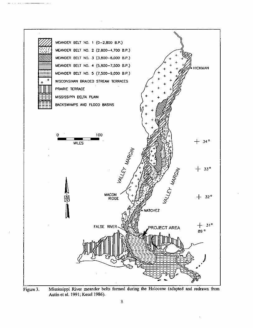
fluvial systems, the Mississippi River occupied at least five different meander belts during the Holocene Epoch (Figure 3). The project area lies within the youngest of these meander belts. As currently accepted, details concerning the chro- nology, river courses, and chronology of older meander belts are provided by Autin et al. (1991:562) and Saucier (1981:16). Saucier (1974, 1981:16) and Saucier and Snead (1989) depict the distribution of the remnants of each meander belt and their associated courses (Figure 3).
Prior to 2,800 years ago, the meander belts of the Mississippi River lay along the western wall of this stretch of the Mississippi Alluvial Valley (Figure 3) (Saucier 1981:16). At that time, the project area likely consisted of a poorly de- veloped drainage network and backswamp. Prior to 2,000 years ago, the backswamp had buried completely terminal Wisconsinan braidplains, and possibly an unnamed meander belt of un- known association. Saucier (1969) mapped frag- ments of such a buried meander belt adjacent to Meander Belt No. 1 within West Baton Rouge and Iberville parishes and adjacent to the project area (Saucier 1974, 1981).
By about 2,800 years ago, the Mississippi River established its present course and Meander Belt No. 1 by channel avulsion. After the channel avulsion, the newly created channel slowly ex- tended itself along the eastern valley wall of the Mississippi Alluvial Valley. This nonmeandering channel slowly incised its thalweg into the un- derlying backswamp deposits, building a low and relatively confining levee during the next few hundred years. As flow increasingly diverted into this course, the channel dug deeper into the un- derlying fluvial sediments, and continued to build the natural levee. Eventually, incipient meander loops developed along this course as small twists and turns in the channel. This was a period of rapid aggradation, because the flow was uncon- fined and levee overtopping was common as a result of its low elevation (Farrell 1989:159-164).
Soon after the diversion of the full flow of the Mississippi River into Meander Belt No. 1, its channel became fully developed and its natural
1 ^
111 min nimm llllllll
MEANDER BELT NO. 1 (0-2.800 B.P.)
MEANDER BELT NO. 2 (2,800-4.700 B.P.)
MEANDER BELT NO. 3 (3.800-6,000 B.P.)
MEANDER BELT NO. 4 (5.800-7.500 B.P.)
MEANDER BELT NO. 5 (7,500-9.000 B.P.)
WISCONSINAN BRAIDED STREAM TERRACES
PRAIRIE TERRACE
MISSISSIPPI DELTA PLAIN
BACKSWAMPS AND FLOOD BASINS
MILES
'• HICKMAN
Figure 3. Mississippi River meander belts formed during the Holocene (adapted and redrawn from Autin et al. 1991; Kesel 1986).
levees achieved their highest elevation. As the meander belt became wider and the natural levees became more confining, the deposition of sedi- ments on the natural levee became concentrated on the concave side of the meander loop. Also, the height of the levees prevented floodwaters from uniformly overflowing and submerging the entire levee. These high levees restricted the flow of flood waters across the natural levees to cre- vasses, resulting in the development of crevasse splays. As a result, most of the natural levee was high and dry during a typical annual flood (Far- rell 1989:164).
With the establishment of full flow within Meander Belt No. 1, the Mississippi River started to migrate back and forth. This back and forth lateral migration has completely reworked the upper 30 to 35 m (100 to 115 ft) of the alluvial plain within the project area. As the river course migrated, its cutbank removed the upper 30 to 35 m (100 to 115 ft) of the alluvial plain, while a point bar and natural levee deposits accumulated along its convex bank. As a result, backswamp, meandering river, and braided stream sediments older than 2,800 years have been removed com- pletely and backfilled with younger sediments to form the modern surface of Meander Belt No. 1.
Remnants of older meander belt surfaces and deposits may occur as isolated patches within Meander Belt No. 1. These small patches of older meander belt deposits and surfaces escaped de- struction because of the geometry of intersecting meander loops. As a result, rare patches of fluvial sediments and associated archeological deposits that predate Meander Belt No. 1 might occur within them (Whitney Autin, personal communi- cation 1991).
Specific Geology and Geomorphology Nina Plantation lies entirely within the mod-
ern meander belt of the Mississippi River, and along the eastern side of the Mississippi Alluvial Valley. This meander belt has been designated Meander Belt No. 1 by Autin et al. (1991). Me- ander Belt No. 1 is a constructional landform consisting of fluvial landforms created by active lateral channel migration and vertical accretion of the Mississippi River while occupying a single, set channel course (Saucier 1974:10-11). The general assemblage of constructional fluvial land- forms that characterized the surface of this and
other Mississippi River meander belts include point bars, natural levees, crevasses, and aban- doned meander loops (Saucier 1969).
The project area lies within the eastern por- tion of Meander Belt No. 1, along the natural levee of the Mississippi River. Meander Belt No. 1 attains a maximum width of 19 km (11.8 mi) and narrows to a minimum width of 3 km (1.9 mi). Meander Belt No. 1 contains the active channel of the Mississippi River, its associated point bar deposits, and a prehistoric, abandoned channel segment that contains the False River, Lake Clause, and their associated point bar de- posits. On the opposite bank of the river, point bar deposits occur proximal to the active river channel, while deposits of the Prairie terrace oc- cur immediately to the east. .
West of Meander Belt No. 1, backswamp sediments comprise the Mississippi Alluvial Plain. The backswamp, or flood basin, is that portion of the alluvial plain that consists of swamps, lakes, or a combination of both. Envi- ronments in the backswamp zone consist of in- frequently flooded forested bottomlands to per- manent lakes and swamps. The abandoned mean- der loops of the False River and Lake Clause are deeply entrenched into these backswamp depos- its. As noted by Saucier (1969; 1974:11-12), long, narrow natural levee systems of crevasse distributaries extend into the backswamp from the banks of both channel segments into the backs- wamp from the main natural levee of the meander belt.
The project area consists of a short linear strip of natural levee, situated along the west, or right descending bank of the Mississippi River. Currently, the site is bounded to the east by the Mississippi River and to the west by a man-made levee competed during the 1930s. Prior to 1890, a series of man-made levees were constructed be- tween Nina Plantation and the active river chan- nel. The natural levee lies at 9 m (30 ft) above mean sea level.
Stratigraphy As noted above, six distinct stages of mean-
der belt development are recognized within the Lower Mississippi River Valley. Meander Belt No.l, which occurs within the project area, is the youngest of the six identified meander belts. Me- ander Belt No.l formed when the Mississippi
River abandoned the eastern Stage 2 channel in the Yazoo Basin area, and full-flow was shifted to the western channel (Saucier 1994). This event at approximately 2800 yrs. B.P. essentially marks the beginning of the Stage I channel and initiation of the modern meander belt.
Meander Belt No. 1 represents the surface of an unnamed allostratigraphic unit created by the lateral migration of the Mississippi River. The North American Commission on Stratigraphic Nomenclature (1983) defines an allostratigraphic unit as "a mappable body of sedimentary rock or unconsolidated sediments that is defined and identified on the basis of bounding discontinui- ties." A meander belt is the surface of an al- lostratigraphic unit consisting of a basal bounding discontinuity, an upper bounding discontinuity, and a body of fluvial sediments that lies between the bounding discontinuities. Typically, the upper bounding discontinuity consists of either an ex- posed or buried meander belt. In the case of me- andering system, the fluvial sediments lying be- tween the unconformities consist of a lower part composed of point bar sands and gravels, overlain by finer grained and vertically accreted natural levee and overbank sediments. The basal bound- ing discontinuity is an erosional unconformity formed by the scour at the channel bottom, and at the edges, by cutbank erosion. Outside of the me- ander belt, natural levee deposits extend onto and interfinger with the adjacent backswamp sedi- ments (Fisk 1947).
Sedimentary Processes Within the Mississippi Alluvial Valley, the
formation and sedimentology of meander belt landforms and sedimentary facies that form them have been studied intensively. A comprehensive review of the sedimentologic and geomorpho- logic processes that form meander belts, backs- wamps, and the sedimentary deposits associated with them, can be in Galloway and Hobday (1984); Farrell (1989) clearly explains the fluvial processes important in the formation of meander belts and their associated sediments, e.g., chute and neck cut-offs, lateral accretion, and the for- mation of natural levees by the Mississippi River. Finally, Coleman (1966) and Farrell (1989) clearly describe the depositional processes, land
forms, and associated sediments common to typi- cal backswamps.
Within the project area, the lateral migration of the Mississippi River channel concurrent with point bar formation has been the dominant proc- ess responsible for the creation of the meander belt within which the project area lies. The active erosion of the concave bank, called the "cutbank" of the river channel, causes lateral migration to occur (Figures 4 and 5). This erosion causes the cutbank to become oversteepened and, eventu- ally, to cave into the river because of undercutting and scouring at the base cutbank and within the river channel. This caving of the cutbank results in the river channel shifting from its former posi- tion. As the cutbank periodically shifts, sand and silt are deposited contemporaneously on the op- posite convex bank, or "point bar," thereby caus- ing both banks of the river to shift simultane- ously. As lateral migration occurs, the bends of the channel enlarge and form a meander loop. This meander loop eventually will become "cut off' from the river as its upstream and down- stream arms migrate and coalesce at the neck of the loop (Fisk 1944,1947:10).
Once the surface of the point bar is formed, overbank sediments quickly bury it (Figures 4 and 5). Sediment-laden waters overflowing the banks of the Mississippi River during flood events deposit these sediments on the flood plain situated adjacent to the outside bank. Because these sediments accumulate on the flood plain outside, and hence "over" the banks of the Mis- sissippi River, they are termed "overbank" sedi- ments. Upon overflowing the banks of the Mis- sissippi River, the floodwaters spread out across the flood plain. Because the floodwaters are no longer confined by channel banks and perhaps, due to the baffling effect of flood plain vegeta- tion, their velocity abruptly decreases. As a result, the sediment suspended within the water rapidly settles out. The sand and silt settle near the chan- nel margin, and fine silt and clay settle further away between river channels within the backs- wamp. During a flood, the net result is the rapid accumulation of sediment along the channel mar- gin; this creates the stable ridge called the "natu- ral levee" and results in slow, periodic accumula- tion of fine-grained sediments within the back-
10
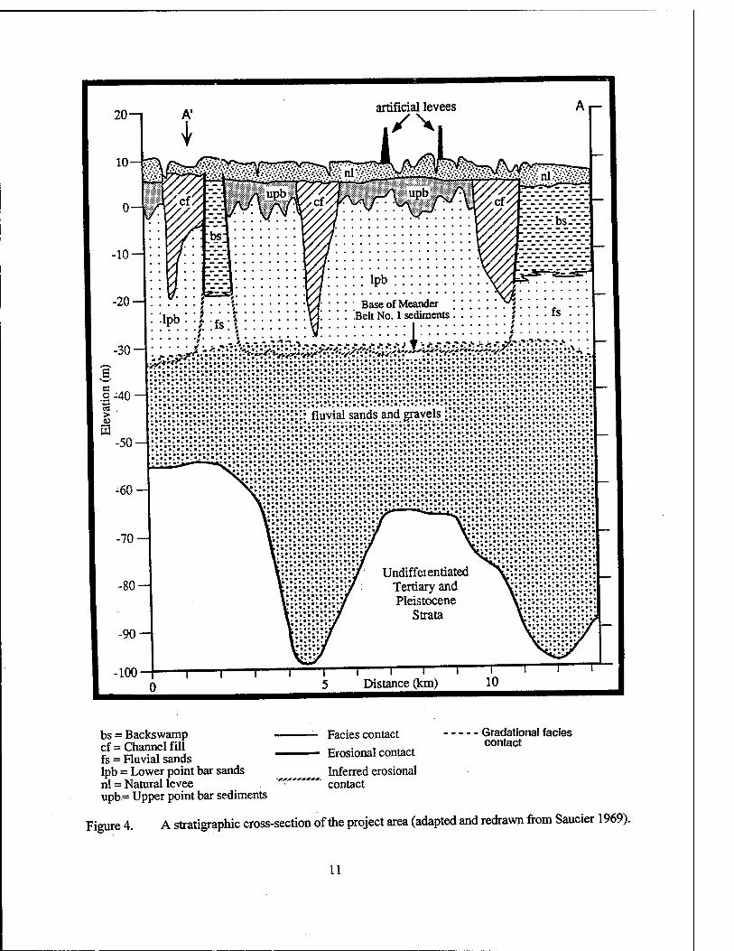
bs = Backswamp cf= Channel fill fs = Fluvial sands lpb = Lower point bar sands nl = Natural levee upb= Upper point bar sediments
Facies contact Erosional contact
Inferred erosional contact
Gradational facies contact
Figure 4. A stratigraphic cross-section of the project area (adapted and redrawn from Saucier 1969).
11
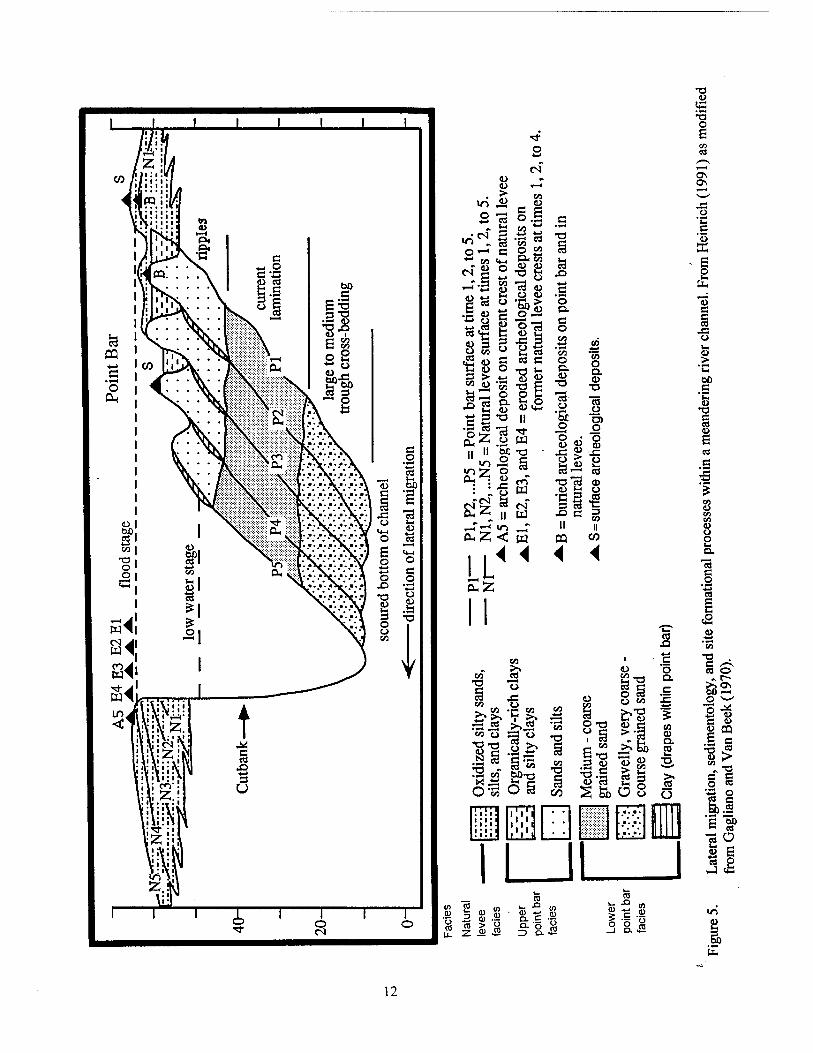
■ö .£
SP'g o U
^ 0) (1) .5! > y 0) jS
5a X)
.s o p. c o
'c/3 o D.
CO
"co o Q. CD
13 TR o
o
03 _ü O) o o CD
o co
lg T3*c3 ©
•C 3 45 D es t= X) C 3
II II « co
4 4
4J
O "O
li 3-i
O 53
'S 8
s&üi
co n c o Q.
CO CD Q. CO
ja o . *
ffi
co •- ja OT 0) *- fl>
6 ö co
'S o E
ü
K E £
"3
2 DO c u
C es
S
co
O o
es C o
co "O . e« O
&2 o •* 8 <u c «> 8 ffl
c es > 4>
o 53 "ü 2 &.I 's"!5
2° S E ts o
2
E
12
swamp of the adjacent floodplain (Galloway and Hobday 1983:53-53; Farrell 1989).
Geoarcheology Depositional environments associated with a
meandering river system affect the preservation of archeological deposits. The vertical accretion of sediments that aggrades natural levees and fills backswamp and abandoned channels works to preserve archeological deposits within these envi- ronments. Specifically, the lateral accretion of point bar deposits can preserve archeological de- posits, such as historic shipwrecks, since the lat- eral accretion of the point bar deposits occurs within a river channel (Goodwin et al. 1991).
However, the continually wet, swampy, and poorly drained nature of the backswamp and channel environments can minimize the accumu- lation of most types of archeological deposits. The active lateral migration of the Mississippi River significantly affects the preservation of ar- cheological deposits that predate the abandon- ment of an abandoned river channel or course segment within a meander belt. While active, a typical Mississippi River channel rapidly mi- grated back and forth across its meander belt. As the channel of a meandering river migrates, its cutbanks consume the fluvial deposits, especially the associated natural levee, to the depth of the channel (Figure 5). As the lateral migration con- sumes the natural levee, overbank sedimentation acts to rebuild the natural levee adjacent to the new cutbank. As a result, the natural levee on the side of a cutbank migrates with the cutbank and eventually destroys any archeological deposits that have accumulated on it. Thus, the meander- ing of an active river channel will destroy all of the archeological deposits that predate the forma- tion of the corresponding meander belt and the archeological deposits contemporaneous with it. At Nina Plantation, depositional processes also have been affected by the position of the various man-made levees over the last 150+ years.
Finally, an active meander belt will bury the contemporaneous archeological deposits not de- stroyed by lateral migration. As an active channel rapidly migrates away from the newly formed point bar, it covers the older portion ofthat point bar with natural levee deposits (Figure 4). Any archeological deposits on the point bar or adja-
cent natural levee also would be buried as the river migrated away from it. Similarly, pre- existing archeological deposits can be buried by natural levee deposits as the migration channel approaches them. By the time a cutbank migrates up to and stops at a preexisting archeological de- posit, that site probably would be buried beneath a stratum of natural levee deposits (Heinrich n.d., 1991).
Structural Geology The present Mississippi Embayment is a
wedge-shaped synclinal structure encompassing ca. 259,000 km2 (161,888 mi2) of the Gulf Coastal Plain. This syncline plunges to the south with its structural axis roughly corresponding to the present Mississippi River valley. The Missis- sippi Embayment extends well into the craton of North America, and intersects the continental margin at a high angle (Keller et al. 1983:401). Sedimentary rocks, ranging in age from Jurassic to Recent, fill the synclinal trough and uncon- formably rest upon Paleozoic rocks of Cambrian to Pennsylvanian age. Within the project area, sands and gravels ascribable to the Eutaw and Tuscaloosa formations (Cretaceous) nonconform- ably overlie crystalline rock.
Prior to the acceptance of the failed-arm rift model, briefly discussed below, most geologists working in the embayment had felt that the in- cipient subsidence of the embayment was related primarily to the late Paleozoic Appalachian orogeny. According to Crushing, Boswell, and Hosman (1964-.B22) subsidence of the embay- ment in the past as well as present is probably due to subcrustal movements, compaction, and over- loading of the deposits. However, in the early 1970s, Burke and Dewey (1973) proposed that the Mississippi Embayment's origin was the re- sult of an early Paleozoic failed-arm rift. In later models, the term Reelfoot Rift was applied to the breakup of Proto-North America during late Pre- cambrian/early Paleozoic time. This initiated the Wilson cycle, which formed the Appalachian- Ouachita system (Keller et al. 1983:402). The presence of Mesozoic intrusive rocks is clear evi- dence for reactivation of the Reelfoot Rift during the Mesozoic time.
Following the Mesozoic reactivation of the old Reelfoot Rift, structural highs such as the
13
Ouachita Mountain system, the Ozark Uplift, and the southern Appalachian Mountains were pres- ent as topographic highs and as a subsequent source of clastic sediments for the embayment. This influx of detrital sediments occurred con- comitant with subsidence and marine transgres- sion of the embayment. For a more detailed re- view of these sources and the aulagocen origin of the embayment, see Braile et al. (1982) and Kelleretal. (1983).
Soils The area of Nina Plantation is characterized
by Robinsonville and Commerce soils, both of which are occasionally flooded for brief to long periods of time. These soils also are subject to scouring and deposition. Robinsonville soils are nearly level to gently undulating, well-drained soils located in high to intermediate positions on natural levees along the Mississippi River (0 to 3 percent slopes). Robinsonville soils are located on the low, convex ridges between the river channel and the protection levees. The surface layer typi- cally consists of a dark grayish brown silty loam or fine sandy loam that measures 15.2 cm (6 in) in thickness. This is followed by an underlying deposit of stratified, brown and pale brown very fine sandy loam, loam, and loamy very fine sand that extends to a depth of 152.4 cm (60 in) below surface (Powell et al. 1982:21).
Commerce soils are somewhat poorly drained, and like Robinsonville soils, they are located in high to intermediate positions on the natural levees of the Mississippi River. They are located in the shallow swales in the narrow areas between the river channel and the protection lev- ees. Slopes are 0 to 3 percent. A typical surface layer consists of a dark grayish brown silt loam of silty clay loam that extends to a depth of ap- proximately 17.8 cm (7 in) below surface. This is followed by a subsoil that extends to a depth of 152.4 cm (60 in) below surface. The upper layer of this subsoil is a dark grayish brown silt loam, while the lower portion is a grayish brown silt loam. A grayish brown silty clay loam makes up the underlying material (Powell et al. 1982:21).
A complete description and discussion of soils specific to the project area can be found in Chapter VIII of this report.
Regional Climatology of Pointe Coupee Par- ish, Louisiana
The climate of Pointe Coupee Parish, Lou- isiana, may be categorized as Humid Subtropical (Cfa in the Koppen Climate Classification). The area is classified as having relatively mild winters and long, hot summers. Much of this is related to maritime influence upon the area by the Gulf of Mexico.
Temperature Average cold-month temperatures are typi-
cally between 4.4° - 15.6° C (40° - 60° F), but freezing temperatures are not uncommon. On average, the coldest month is January (approxi- mately 10.6° C [51° F] average), the time of most frequent Arctic outbreaks and freezes. In the South, two general conditions may produce freezing temperatures (Rohli and Rogers 1993; Rogers and Rohli 1991; Critchfield 1983). The first is associated with migratory cold airmasses or Arctic outbreaks; the second involves night- time radiational cooling. Both situations may re- sult from the same conditions following a cold front passage; indeed, radiational cooling may bring further surface cooling to an area already affected by the Arctic outbreak (Vega et al. 1994). This is particularly damaging to the fragile ecosystems that exist in the region. However, considerable warming of the Arctic airmass is typical as the airmass approaches the Gulf Coast. Therefore, extremely cold temperatures are rela- tively uncommon in this region. The lowest re- corded temperature for southeastern Louisiana was approximately -12.2° C (10° F), recorded on December 23, 1989 (Table 1). Because of the low frequency of extreme events, the mean first fall freeze date (0° C [32° F] temperature threshold; 50 percent probability level) is calculated to be November 22, while the mean last spring freeze (0° C [32° F]) temperature threshold; 50 percent probability level) typically occurs on March 4 (Vega et al. 1994). Due to the unavailability of data, New Orleans data are presented here. Dif- ferences to Pointe Coupee Parish or Baton Rouge, Louisiana are negligible.
Summer months are normally hot, with av- erage temperatures around 26.1° - 28.3° C (79° - 83° F). Not only is the air temperature high in
14
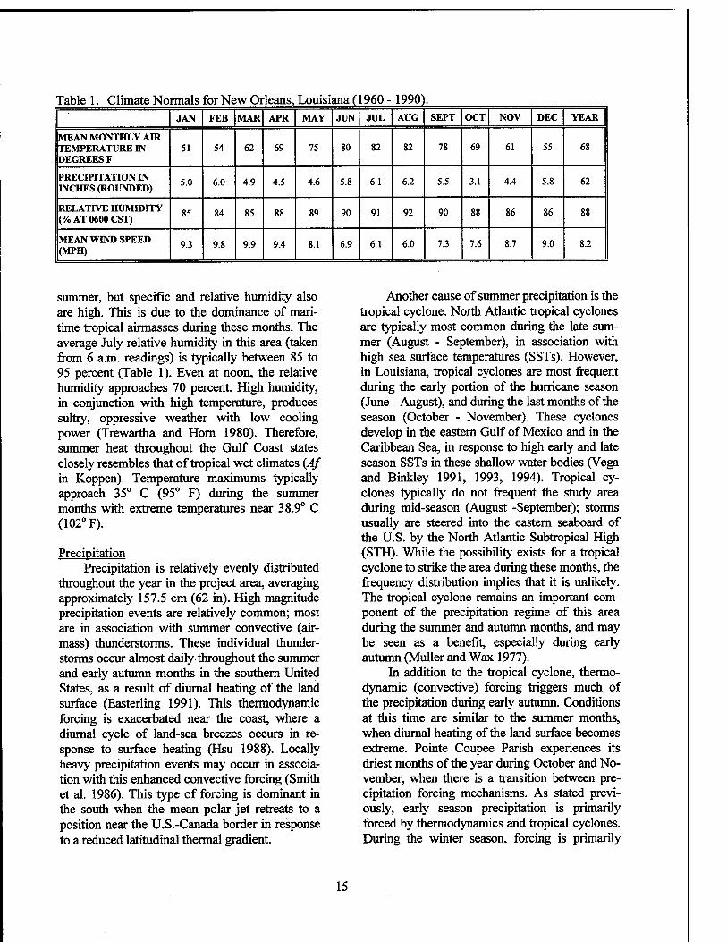
Table 1. Climate Normals for New Orleans, Louisiana ( 1960- 1990) . JAN FEB MAR APR MAY JUN JUL AUG SEPT OCT NOV DEC YEAR
MEAN MONTHLY AIR TEMPERATURE IN DEGREES F
51 54 62 69 75 80 82 82 78 69 61 55 68
PRECIPITATION IN INCHES (ROUNDED)
5.0 6.0 4.9 4.5 4.6 5.8 6.1 6.2 5.5 3.1 4.4 5.8 62
RELATIVE HUMIDITY (% AT 0600 CST)
85 84 85 88 89 90 91 92 90 88 86 86 88
MEAN WIND SPEED (MPH)
9.3 9.8 9.9 9.4 8.1 6.9 6.1 6.0 7.3 7.6 8.7 9.0 8.2
summer, but specific and relative humidity also are high. This is due to the dominance of mari- time tropical airmasses during these months. The average July relative humidity in this area (taken from 6 a.m. readings) is typically between 85 to 95 percent (Table 1). Even at noon, the relative humidity approaches 70 percent. High humidity, in conjunction with high temperature, produces sultry, oppressive weather with low cooling power (Trewartha and Horn 1980). Therefore, summer heat throughout the Gulf Coast states closely resembles that of tropical wet climates (Af in Koppen). Temperature maximums typically approach 35° C (95° F) during the summer months with extreme temperatures near 38.9° C (102° F).
Precipitation Precipitation is relatively evenly distributed
throughout the year in the project area, averaging approximately 157.5 cm (62 in). High magnitude precipitation events are relatively common; most are in association with summer convective (air- mass) thunderstorms. These individual thunder- storms occur almost daily throughout the summer and early autumn months in the southern United States, as a result of diurnal heating of the land surface (Easterling 1991). This thermodynamic forcing is exacerbated near the coast, where a diurnal cycle of land-sea breezes occurs in re- sponse to surface heating (Hsu 1988). Locally heavy precipitation events may occur in associa- tion with this enhanced convective forcing (Smith et al. 1986). This type of forcing is dominant in the south when the mean polar jet retreats to a position near the U.S.-Canada border in response to a reduced latitudinal thermal gradient.
Another cause of summer precipitation is the tropical cyclone. North Atlantic tropical cyclones are typically most common during the late sum- mer (August - September), in association with high sea surface temperatures (SSTs). However, in Louisiana, tropical cyclones are most frequent during the early portion of the hurricane season (June - August), and during the last months of the season (October - November). These cyclones develop in the eastern Gulf of Mexico and in the Caribbean Sea, in response to high early and late season SSTs in these shallow water bodies (Vega and Binkley 1991, 1993, 1994). Tropical cy- clones typically do not frequent the study area during mid-season (August -September); storms usually are steered into the eastern seaboard of the U.S. by the North Atlantic Subtropical High (STH). While the possibility exists for a tropical cyclone to strike the area during these months, the frequency distribution implies that it is unlikely. The tropical cyclone remains an important com- ponent of the precipitation regime of this area during the summer and autumn months, and may be seen as a benefit, especially during early autumn (Müller and Wax 1977).
In addition to the tropical cyclone, thermo- dynamic (convective) forcing triggers much of the precipitation during early autumn. Conditions at this time are similar to the summer months, when diurnal heating of the land surface becomes extreme. Pointe Coupee Parish experiences its driest months of the year during October and No- vember, when there is a transition between pre- cipitation forcing mechanisms. As stated previ- ously, early season precipitation is primarily forced by thermodynamics and tropical cyclones. During the winter season, forcing is primarily
15
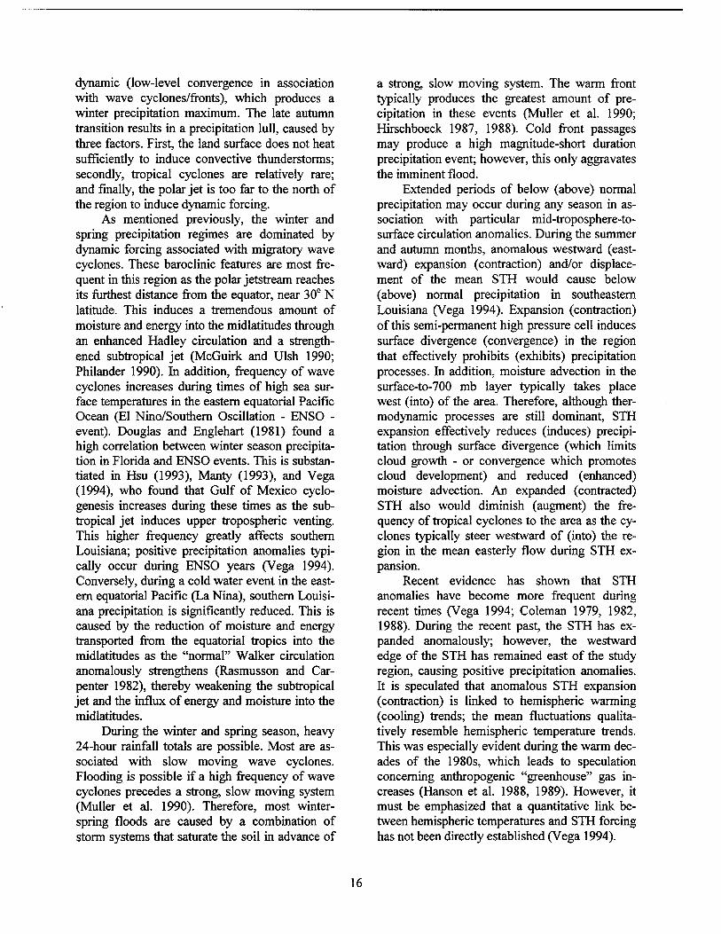
dynamic (low-level convergence in association with wave cyclones/fronts), which produces a winter precipitation maximum. The late autumn transition results in a precipitation lull, caused by three factors. First, the land surface does not heat sufficiently to induce convective thunderstorms; secondly, tropical cyclones are relatively rare; and finally, the polar jet is too far to the north of the region to induce dynamic forcing.
As mentioned previously, the winter and spring precipitation regimes are dominated by dynamic forcing associated with migratory wave cyclones. These baroclinic features are most fre- quent in this region as the polar Jetstream reaches its furthest distance from the equator, near 30° N latitude. This induces a tremendous amount of moisture and energy into the midlatitudes through an enhanced Hadley circulation and a strength- ened subtropical jet (McGuirk and Ulsh 1990; Philander 1990). In addition, frequency of wave cyclones increases during times of high sea sur- face temperatures in the eastern equatorial Pacific Ocean (El Nino/Southern Oscillation - ENSO - event). Douglas and Englehart (1981) found a high correlation between winter season precipita- tion in Florida and ENSO events. This is substan- tiated in Hsu (1993), Manty (1993), and Vega (1994), who found that Gulf of Mexico cyclo- genesis increases during these times as the sub- tropical jet induces upper tropospheric venting. This higher frequency greatly affects southern Louisiana; positive precipitation anomalies typi- cally occur during ENSO years (Vega 1994). Conversely, during a cold water event in the east- ern equatorial Pacific (La Nina), southern Louisi- ana precipitation is significantly reduced. This is caused by the reduction of moisture and energy transported from the equatorial tropics into the midlatitudes as the "normal" Walker circulation anomalously strengthens (Rasmusson and Car- penter 1982), thereby weakening the subtropical jet and the influx of energy and moisture into the midlatitudes.
During the winter and spring season, heavy 24-hour rainfall totals are possible. Most are as- sociated with slow moving wave cyclones. Flooding is possible if a high frequency of wave cyclones precedes a strong, slow moving system (Muller et al. 1990). Therefore, most winter- spring floods are caused by a combination of storm systems that saturate the soil in advance of
a strong, slow moving system. The warm front typically produces the greatest amount of pre- cipitation in these events (Muller et al. 1990; Hirschboeck 1987, 1988). Cold front passages may produce a high magnitude-short duration precipitation event; however, this only aggravates the imminent flood.
Extended periods of below (above) normal precipitation may occur during any season in as- sociation with particular mid-troposphere-to- surface circulation anomalies. During the summer and autumn months, anomalous westward (east- ward) expansion (contraction) and/or displace- ment of the mean STH would cause below (above) normal precipitation in southeastern Louisiana (Vega 1994). Expansion (contraction) of this semi-permanent high pressure cell induces surface divergence (convergence) in the region that effectively prohibits (exhibits) precipitation processes. In addition, moisture advection in the surface-to-700 mb layer typically takes place west (into) of the area. Therefore, although ther- modynamic processes are still dominant, STH expansion effectively reduces (induces) precipi- tation through surface divergence (which limits cloud growth - or convergence which promotes cloud development) and reduced (enhanced) moisture advection. An expanded (contracted) STH also would diminish (augment) the fre- quency of tropical cyclones to the area as the cy- clones typically steer westward of (into) the re- gion in the mean easterly flow during STH ex- pansion.
Recent evidence has shown that STH anomalies have become more frequent during recent times (Vega 1994; Coleman 1979, 1982, 1988). During the recent past, the STH has ex- panded anomalously; however, the westward edge of the STH has remained east of the study region, causing positive precipitation anomalies. It is speculated that anomalous STH expansion (contraction) is linked to hemispheric warming (cooling) trends; the mean fluctuations qualita- tively resemble hemispheric temperature trends. This was especially evident during the warm dec- ades of the 1980s, which leads to speculation concerning anthropogenic "greenhouse" gas in- creases (Hanson et al. 1988, 1989). However, it must be emphasized that a quantitative link be- tween hemispheric temperatures and STH forcing has not been directly established (Vega 1994).
16
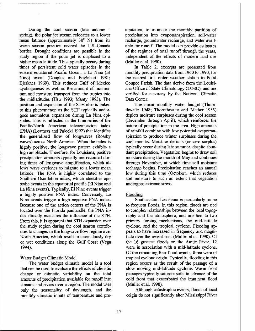
During the cool season (late autumn - spring), the polar jet stream relocates to a lower mean latitude (approximately 30° N) from its warm season position nearest the U.S.-Canada border. Drought conditions are possible in the study region if the polar jet is displaced to a higher mean latitude. This typically occurs during times of persistent cold water episodes in the eastern equatorial Pacific Ocean, a La Nina (El Nino) event (Douglas and Englehart 1981; Bjerknes 1969). This reduces Gulf of Mexico cycliogenesis as well as the amount of momen- tum and moisture transport from the tropics into the midlatitudes (Hsu 1993; Manty 1993). The position and expansion of the STH also is linked to this phenomenon as the STH typically under- goes anomalous expansion during La Nina epi- sodes. This is reflected in the time-series of the Pacific/North American teleconnection index (PNA) (Leathers and Palecki 1992) that identifies the generalized flow of longwaves (Rossby waves) across North America. When the index is highly positive, the longwave pattern exhibits a high amplitude. Therefore, for Louisiana, positive precipitation amounts typically are recorded dur- ing times of longwave amplification, which al- lows wave cyclones to migrate to a lower mean latitude. The PNA is highly correlated to the Southern Oscillation index, which identifies epi- sodic events in the equatorial pacific (El Nino and La Nina events). Typically, El Nino events trigger a highly positive PNA index. Conversely, La Nina events trigger a high negative PNA index. Because one of the action centers of the PNA is located over the Florida panhandle, the PNA in- dex directly measures the influence of the STH. From this, it is apparent that STH expansion over the study region during the cool season contrib- utes to changes in the longwave flow regime over North America, which result in anomalously dry or wet conditions along the Gulf Coast (Vega 1994).
Water Budget Climatic Model The water budget climatic model is a tool
that can be used to evaluate the effects of climatic change or climatic variability on the total amounts of precipitation available for runoff into streams and rivers over a region. The model uses only the seasonally of daylength, and the monthly climatic inputs of temperature and pre-
cipitation, to estimate the monthly partition of precipitation into evapotranspiration, soil-water recharge, groundwater recharge, and water avail- able for runoff. The model can provide estimates of the regimes of total runoff through the years, independent of the effects of modern land use (Muller et al. 1990).
In Table 2, excerpts are presented from monthly precipitation data from 1960 to 1990, for the nearest first order weather station to Point Coupee Parish. The data derive from the Louisi- ana Office of State Climatology (LOSC), and are verified for accuracy by the National Climatic Data Center.
The mean monthly water budget (Thorn- thwaite 1948; Thornthwaite and Mather 1955) depicts moisture surpluses during the cool season (December through April), which reinforces the nature of precipitation in the area. High amounts of rainfall combine with low potential evapotran- spiration to produce winter surpluses during the cool months. Moisture deficits (or zero surplus) typically occur during late summer, despite abun- dant precipitation. Vegetation begins to draw soil moisture during the month of May and continues through November, at which time soil moisture recharge begins. Precipitation reaches an annual low during this time (October), which reduces soil moisture to such an extent that vegetation undergoes extreme stress.
Flooding Southeastern Louisiana is particularly prone
to frequent floods. In this region, floods are tied to complex relationships between the local topog- raphy and the atmosphere, and are tied to two primary forcing mechanisms, the mid-latitude cyclone, and the tropical cyclone. Flooding ap- pears to have increased in frequency and magni- tude over the recent past (Muller et al. 1990). Of the 16 greatest floods on the Amite River, 12 were in association with a mid-latitude cyclone. Of the remaining four flood events, three were of tropical cyclone origin. Typically, flooding in this region occurs as the result of the passage of a slow moving mid-latitude cyclone. Warm front passages typically saturate soils in advance of the cold front that exacerbates' the imminent flood (Muller et al. 1990).
Although catastrophic events, floods of local origin do not significantly alter Mississippi River
17
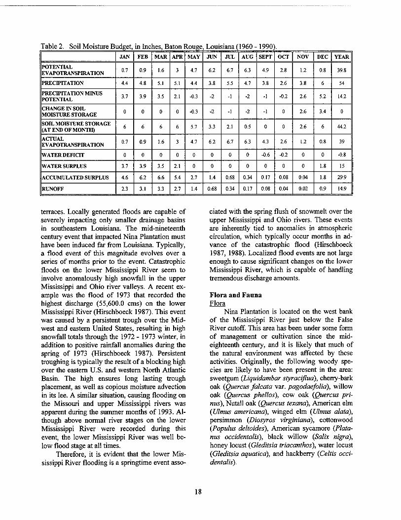
Table 2. Soil Moisture Budget, in Inches, Baton Rouge , Louisiana (1960 - 1990) . JAN FEB MAR APR MAY JUN JUL AUG SEPT OCT NOV DEC YEAR
POTENTIAL EVAPOTRANSPIRATION 0.7 0.9 1.6 3 4.7 6.2 6.7 6.3 4.9 2.8 1.2 0.8 39.8
PRECIPITATION 4.4 4.8 5.1 5.1 4.4 3.8 5.5 4.7 3.8 2.6 3.8 6 54
PRECIPITATION MINUS POTENTIAL
3.7 3.9 3.5 2.1 -0.3 -2 -1 -2 -1 -0.2 2.6 5.2 14.2
CHANGE IN SOIL MOISTURE STORAGE
0 0 0 0 -0.3 -2 -1 -2 -1 0 2.6 3.4 0
SOIL MOISTURE STORAGE (AT END OF MONTH) 6 6 6 6 5.7 3.3 2.1 0.5 0 0 2.6 6 44.2
ACTUAL EVAPOTRANSPIRATION 0.7 0.9 1.6 3 4.7 6.2 6.7 6.3 4.3 2.6 1.2 0.8 39
WATER DEFICIT 0 0 0 0 0 0 0 0 -0.6 -0.2 0 0 -0.8
WATER SURPLUS 3.7 3.9 3.5 2.1 0 0 0 0 0 0 0 1.8 15
ACCUMULATED SURPLUS 4.6 6.2 6.6 5.4 2.7 1.4 0.68 0.34 0.17 0.08 0.04 1.8 29.9
RUNOFF 2.3 3.1 3.3 2.7 1.4 0.68 0.34 0.17 0.08 0.04 0.02 0.9 14.9
terraces. Locally generated floods are capable of severely impacting only smaller drainage basins in southeastern Louisiana. The mid-nineteenth century event that impacted Nina Plantation must have been induced far from Louisiana. Typically, a flood event of this magnitude evolves over a series of months prior to the event. Catastrophic floods on the lower Mississippi River seem to involve anomalously high snowfall in the upper Mississippi and Ohio river valleys. A recent ex- ample was the flood of 1973 that recorded the highest discharge (55,600.0 cms) on the lower Mississippi River (Hirschboeck 1987). This event was caused by a persistent trough over the Mid- west and eastern United States, resulting in high snowfall totals through the 1972 - 1973 winter, in addition to positive rainfall anomalies during the spring of 1973 (Hirschboeck 1987). Persistent troughing is typically the result of a blocking high over the eastern U.S. and western North Atlantic Basin. The high ensures long lasting trough placement, as well as copious moisture advection in its lee. A similar situation, causing flooding on the Missouri and upper Mississippi rivers was apparent during the summer months of 1993. Al- though above normal river stages on the lower Mississippi River were recorded during this event, the lower Mississippi River was well be- low flood stage at all times.
Therefore, it is evident that the lower Mis- sissippi River flooding is a springtime event asso-
ciated with the spring flush of snowmelt over the upper Mississippi and Ohio rivers. These events are inherently tied to anomalies in atmospheric circulation, which typically occur months in ad- vance of the catastrophic flood (Hirschboeck 1987, 1988). Localized flood events are not large enough to cause significant changes on the lower Mississippi River, which is capable of handling tremendous discharge amounts.
Flora and Fauna Flora
Nina Plantation is located on the west bank of the Mississippi River just below the False River cutoff. This area has been under some form of management or cultivation since the mid- eighteenth century, and it is likely that much of the natural environment was affected by these activities. Originally, the following woody spe- cies are likely to have been present in the area: sweetgum {Liquidambar styraciflua), cherry-bark oak {Quercus falcata var. pagodaefolia), willow oak {Quercus phellos), cow oak {Quercus pri- nus), Nutall oak {Quercus texand), American elm {Ulmus americana), winged elm {Ulmus alatd), persimmon {Diosyros virginiana), cottonwood {Populus deltoides), American sycamore {Plata- nus occidentalis), black willow {Salix nigrd), honey locust {Gleditsia triacanthos), water locust {Gleditsia aquaticd), and hackberry {Celtis occi- dentalis).
18
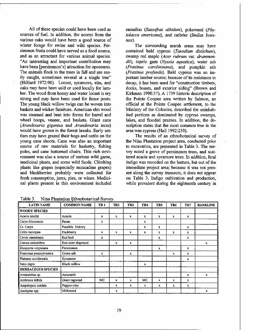
All of these species could have been used as sources of fuel. In addition, the acoms from the various oaks would have been a good source of winter forage for swine and wild species. Per- simmon fruits could have served as a food source, and as an attractant for various animal species. "An interesting and important contribution may have been [persimmon's] attraction for opossums. The animals flock to the trees in fall and are eas- ily caught, sometimes several at a single tree" (Hilliard 1972:90). Locust, sycamore, elm, and oaks may have been sold or used locally for lum- ber. The wood from honey and water locust is ery strong and may have been used for fence posts. The young black willow twigs can be woven into baskets and wicker furniture. American elm wood was steamed and bent into forms for barrel and wheel hoops, veneer, and baskets. Giant cane {Arundenaria gigantea and Arundenaria tectd) would have grown in the forest breaks. Early set- tlers may have grazed their hogs and cattle on the young cane shoots. Cane was also an important source of raw materials for basketry, fishing poles, and cane bottomed chairs. This rich envi- ronment was also a source of various wild game, medicinal plants, and some wild foods. Climbing plants like grapes (especially muscadine grapes) and blackberries probably were collected for fresh consumption, jams, pies, or wines. Medici- nal plants present in this environment included
sassafras {Sassafras albidum), pokeweed {Phy- tolacca americana), and catbrier {Smilax bonx- nox).
The surrounding marsh areas may have contained bald cypress (Taxodium distichum), swamp red maple {Acer rubrum var. drummon- dii), tupelo gum {Nyssia aquaticd), water ash {Fraxinns carolininand), and pumpkin ash {Fraxinus prqfundd). Bald cypress was an im- portant lumber source; because of its resistance to decay, it has been used for "construction timbers, docks, boasts, and exterior siding" (Brown and Kirkman 1990:57). A 1739 historic description of the Pointe Coupee area written by Salmon, an official at the Pointe Coupee settlement, to the Ministry of the Colonies, described the uninhab- ited portions as dominated by cypress swamps, lakes, and flooded prairies. In addition, the de- scription states that the most common tree in the area was cypress (Hall 1992:250).
The results of an ethnobotanical survey of the Nina Plantation project area, conducted prior to excavation, are presented in Table 3. The sur- vey noted a grove of persimmon trees, and scat- tered acacia and sycamore trees. In addition, feral indigo was recorded on the batture, but out of the immediate project area; because it was not pres- ent along the survey transects, it does not appear on Table 3. Indigo cultivation and production, while prevalent during the eighteenth century in
Table 3. Nina Plantation Ethnobotanical Survey. LATIN NAME COMMON NAME TR1 TR2 TR3 TR4 TR5 TR6 TR7 BANKLINE
WOODY SPECIES Acacia smallii Acacia X X X X X X X
Carya illinoiensis Pecan X X
Cs. Carya Possible hickory X X X
Celtis laevigata Hackberry X X X X X X X
Cercis canadensis Red bud X X X
Comus stolonifera Red osier dogwood X X X
Diospyros virginiana Persimmon X X
Franxinus pennsylvanica Green ash X X X X
Platanus occidentalis Sycamore X
Salix nigra Black willow X
HERBACEOUS SPECIES
Amaranthus sp. Amaranth X X
Ambrosia trifida Giant ragweed MC X X MC X X X
Ampelopsis cordata Pepper-vine X X X X X X
Asclepias spp. Milkweed X X
19
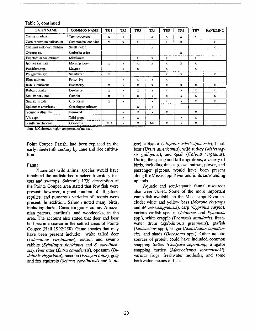
Table 3, continued
LATIN NAME COMMON NAME TR1 TR2 TR3 TR4 TR5 TR6 TR7 BANKLINE
Campsis radicans Trumpet-creeper X X X X X X
Cardiospermum haliaabum Common balloon vine X X X X X X
Cucumis melo var. dudiam Smell melon X X
Cyperas sp. Umbrella sedge X
Eupatorium coelestinum Mistflower X X X X
Ipomea sagittata Morning glory X X X X X X X
Passiflora spp. Maypop X X X X
Polygonum spp. Smartweed X X X X
Rhus radicans Poison ivy X X X X
Rubus louisianus Blackberry X X X X X X X X
Rubus trivialis Dewberry X X X X X X X X
Smilax bonx-nox Catbriar X X X X X X X X
Smilax hispida Greenbriar X X X X X X X
Spilanthes americana Creeping spotflower X X
Vernonia altissima Ironweed X X X X X
Vitis spp. Wild grape X X X X
Xanthium chinense Cocklebur MC X X MC X X X
Note: MC denotes major component of transect.
Point Coupee Parish, had been replaced in the early nineteenth century by cane and rice cultiva- tion.
Fauna Numerous wild animal species would have
inhabited the undisturbed nineteenth century for- ests and swamps. Salmon's 1739 description of the Pointe Coupee area stated that few fish were present; however, a great number of alligators, reptiles, and numerous varieties of insects were present. In addition, Salmon noted many birds, including ducks, Canadian geese, cranes, Amazo- nian parrots, cardinals, and woodcocks, in the area. The account also stated that deer and bear had become scarce in the settled areas of Pointe Coupee (Hall 1992:250). Game species that may have been present include: white tailed deer {Odocoileus virginianus), eastern and swamp rabbits (Sylvilagus floridanus and S. carolinen- sis), river otter (Lutra canadensis), opossum (Di- delphis virginiana), raccoon {Procyon lotor), gray and fox squirrels {Sciurus carolinensis and S. ni-
ger), alligator {Alligator mississippiensis), black bear {Ursus americanus), wild turkey (Melewag- ris gallopavo), and quail (Colinus virgianus). During the spring and fall migrations, a variety of birds, including ducks, geese, snipes, plover, and passenger pigeons, would have been present along the Mississippi River and in its surrounding uplands.
Aquatic and semi-aquatic faunal resources also were varied. Some of the more important game fish available in the Mississippi River in- clude: white and yellow bass {Morone chrysops and M. mississippiensis), carp (Cyprinus carpid), various catfish species (Jctalurus and Pylodistis spp.), white crappie (Promoxis annularis), fresh- water drum (Aplodinotus grunniens), garfish (Lepisosteus spp.), sauger (Stizostedoin canaden- sis), and shads (Dorosoma spp.). Other aquatic sources of protein could have included common snapping turtles (Chelydra sepentina), alligator snapping turtles (Macroclemys termmicncki), various frogs, freshwater mollusks, and some backwater species offish.
20
CHAPTER III
THE HISTORICAL CONTEXT
Introduction In 1682, the French explorer Robert Cave- lier, Sieur de La Salle, descended the Ohio
and Mississippi rivers from Canada to the Gulf of Mexico, claimed the entire Mississippi River Valley for King Louis XIV. He named the terri- tory "Louisiana" to honor the monarch (Neilson 1957:863). As the French began the colonization of Louisiana, Pierre Lemoyne, Sieur d'Iberville, recorded in his journal in 1699 the first mention of Pointe Coupee. When his expedition reached the 35.4 km (22 mi) curve in the Mississippi River, they chose instead to take a 6.4 km (4 mi) short cut through the channel that Iberville called Pointe Coupee, or the cut point. Eventually, the river changed course ca. 1722, flowed through the channel, and the ox-bow curve known today as la Fausse Riviere, or False River, was created (Rif- fel 1983:3). The project area lies within the inte- rior of the oxbow, i.e., in the area known locally as False River Island (Figures 6 and 7).
Pointe Coupee Parish enjoys a rich and var- ied heritage. The second oldest European settle- ment in Louisiana, the parish was subject to French, Spanish, and American colonial influ- ences. Its people were from diverse ethnic back- grounds; the influence of European, African, Caribbean, Native American, and American so- cieties can be discerned in the architecture, speech, foodways, and names of the Parish resi- dents. The cultural, social, and economic interac- tions of these groups, influenced at times by ex- tra-parish events, form the unique context within which the interpretation of the archeological re- mains at Nina Plantation (Site 16PC62) must take place. In this chapter, the general history of Pointe Coupee Parish is reviewed, with particular emphasis on the social milieu, labor relations,
economic development, and the history of floods and levee construction. A detailed history of the project area follows in Chapter IV.
Settlement between 1717 and 1900 The first formal French settlement at Pointe
Coupee was established in 1717 on the West Bank of the Mississippi River. By 1722, 10 French colonists and their families apparently resided at a Tunica village located just to the north of the French settlement. By 1726, the French population in the Tunica village had risen to 52, more than double the population of the Pointe Coupee settlement (21) (Riffel 1983:3-5; Hall 1992:243). Because of the strategic position of Pointe Coupee, the French established a mili- tary post there, which served as the defensive headquarters for the community after the Natchez rebellion in 1729 (Riffel 1983:6; Davis 1971:59). A continuing alliance between the French and the Tunica put both groups in danger from the Natchez Tribe, and attacks on the two settlements were common. In 1731, a massacre in the Tunica village resulted in the deaths of both French and Tunica, and sporadic raids by the Natchez and Chickasaw required constant vigilance (Hall 1992:246-248). Despite these recurrent attacks, the close relationship between the French and the Tunica continued into the eighteenth century (Hall 1992:244), even though the Tunica popula- tion had been reduced drastically by warfare, dis- ease, and westward migration (Davis 1971:24; Riffel 1983:19).
The Pointe Coupee community continued to grow; by 1745, the census reported that 260 whites, 391 blacks, 15 mulattos, and 23 Indians occupied the west bank of the river (Riffel 1983:4). The fort established at Pointe Coupee
21
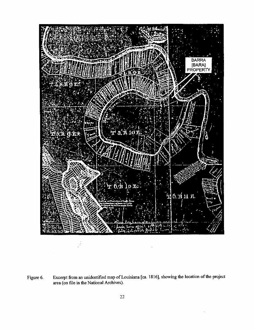
Figure 6. Excerpt from an unidentified map of Louisiana [ca. 1816], showing the location of the project area (on file in the National Archives).
22
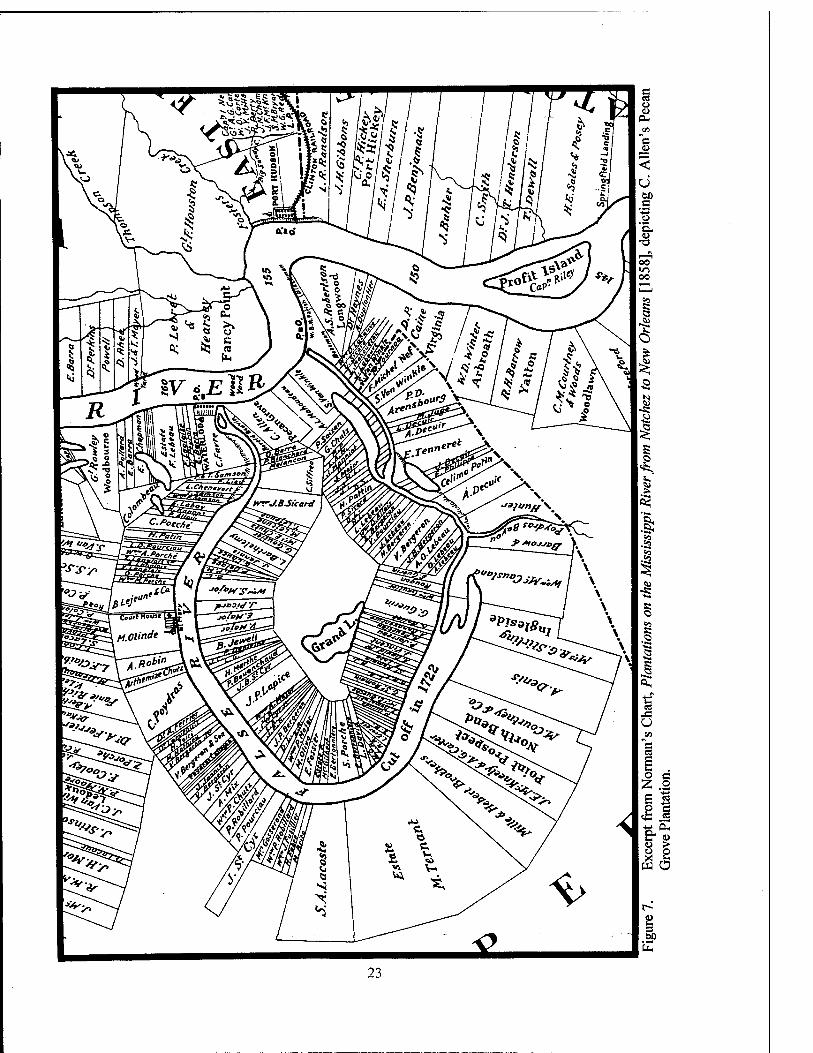
23
was enlarged and strengthened in 1760, in the midst of the French and Indian War, and a rebuilt Church of St. Francis was consecrated in 1760; it stood until floods and erosion destroyed it during the 1890s. Norman's map (1858) depicts both the new fort and the church near the present site of the St. Francisville Ferry, approximately 4.8 km (3 mi) upriver from the site of Nina Plantation. The original fort had been constructed approxi- mately 1.6 km (1 mi) above the site of the nine- teenth century town of Waterloo, even closer to the Nina Plantation site (Riffel 1983:40, 44, 62).
In 1763, at the conclusion of the French and Indian War, the British expelled France from North America. Under the terms of that peace treaty, the French ceded all of Louisiana west of the Mississippi River to Spain. The Spanish sub- sequently maintained a military presence at Point Coupee, and during the American Revolution, soldiers from the local garrison joined the Span- ish forces that seized Baton Rouge from the Brit- ish (Riffel 1983:13). While adjustments and compromises had to be made, both the fort and the settlement prospered under Spanish dominion, due in large measure to the reopening of trade after the end of the war (Davis 1971:133-134; Hall 1992:252).
The beginning of the nineteenth century brought more change to Pointe Coupee Parish. As part of an American Territory, and in 1812, as part of the state of Louisiana, Pointe Coupee was subjected to changes in legislation, trade, and immigration patterns. The industrial innovations of the late eighteenth and early nineteenth centu- ries - the cotton gin and steam power - brought increased trade and production. Legislative changes were felt in approaches to education, in levee and road construction, and in control of the slave labor force.
By the eve of the Civil War, Pointe Coupee Parish had become one of the more prosperous agricultural areas in the state. Despite the fact that the Parish suffered little direct damage during the war, the economic effects were widespread. The war destroyed the transportation network in the South, ruined its credit, and dislocated its market for cotton. Confederate defeat also fostered po- litical upheaval. The planter was disenfranchised, at least temporarily, and for a few years lost his predominant influence in local, state, and national government. During the era of Reconstruction,
from 1865-1877, Louisiana remained under Fed- eral military occupation; new political alliances attempted to govern the Pelican State and, inci- dentally, to protect the interests of the freed slaves. It was not until the last quarter of the nineteenth century that Pointe Coupee Parish re- adjusted to the sweeping changes in the labor supply, and again began to show solid signs of prosperity.
The Social Milieu in Pointe Coupee Parish From its inception in the early eighteenth
century, the community at Pointe Coupee was ethnically diverse. The colonists were of Euro- pean derivation, with the majority from France, French Canada, and the West Indies (Davis 1971:131). A 1732 report on the settlement re- ported 40 colonists, almost all of whom were Franco - Beige (Walloons) (Hall 1992:247). The colonists in Pointe Coupee imported African slaves to meet their labor needs, relying at first on slaves purchased from the West Indian colonies, and later, on those brought through direct trade between Africa and Louisiana, the latter being conducted by the Company of the West Indies (Taylor 1963:6-7). The 1731 census reported 95 whites, including 26 children; 70 black slaves, including seven children; and three Indian slaves (Hall 1992:247). By 1745, blacks outnumbered whites 391 to 260, and Pointe Coupee had the densest slave population of any location in Lou- isiana. By the close of the eighteenth century, approximately 2,000 blacks, 700-800 whites, and 60-80 free people of color lived in the Pointe Coupee community (Riffel 1983:15). In addition to these groups, the Native American population exerted strong influence during the formative years of the settlement.
During the earliest years of settlement at Pointe Coupee, inter-racial mixing was common. This has been explained at least partially as a re- sult of the frontier situation that prevailed (Hall 1992:240), although it also may attest to a less rigid racial classificatory system than was associ- ated with either the British or Spanish colonies (Davis 1971:84; Hall 1992:240). The small size of the slaveholdings in the early years also was more conducive to close interaction between the groups. In the Pointe Coupee community, there was frequently full acknowledgment of children born of such relationships. Often, children of
24
mixed race and their mothers were freed and counted as white in the censuses (Hall 1992:240). Throughout the eighteenth century, and probably into the nineteenth century, intermarriage be- tween Africans and Native Americans was rela- tively common. Native American women, even if they were not themselves enslaved, often lived in the quarters with their slave spouses (Hall 1992:335, 358); their offspring received the term grif, to distinguish their mixed ancestry (Hall 1992: 262).
Records from Pointe Coupee are detailed in their descriptions of age, gender, and ethnic af- filiation of the slaves (Hall 1992:282), and slave- owners of the area exhibited a general preference for laborers of African descent (Davis 1971:80). By 1782, more than 75 percent of all adult slaves on inventories from Pointe Coupee were African, as opposed to Creole (Louisiana born). Their named ethnic affiliations included Mina, Fon, Yoruba, Ado, Hausa, Mandinga, Bambara, Wolof, Fulbe, and Nard (Hall 1992:288). The estate of Bara dit Leblond, of which Site 16PC62 was once a part (see Chapter IV), had one of the most heavily Africanized slave populations in the area; a 1782 inventory indicates that 78.3 percent of the adult slaves at Bara's plantation were Afri- cans (Hall 1992:362). There also is evidence that at least Mina slaves organized socially, extending their community to include a group of Minas liv- ing in New Orleans. Owners frequently allowed, or at least tolerated, the development of African ethnic communities among the slaves, in the be- lief that the growth of ethnic division would help to discourage more broadly organized dissent (Hall 1992:318-319).
The picture that emerges of the Pointe Coupee community at the end of the eighteenth century is one of ethnic diversity, with a gradu- ally increasing social distance between landholder and labor. This distance was confirmed in the events of 1795.
The Slave Rebellion Conspiracy of 1795 In April 1795, the commandant of the Pointe
Coupee post, Guillaume Duparc, learned of a conspiracy by the slaves to murder their masters and seize freedom by force of arms. This plan apparently had been encouraged by accounts of the slave revolts in the French Antilles, the Revolution in France, and the 1794 abolition of
slavery in French colonies (Holmes 1970:343- 344). Antoine Sarrasin, a mulatto slave on the Pointe Coupee plantation of Julien Poydras, with the help of several other slaves, was accused of organizing the intrigue. Duparc immediately sent three patrols to arrest Sarrasin and other sus- pected insurrectionists. The activities and move- ments of all slaves were severely restricted, and systematic searches for firearms were made of the quarters (Holmes 1970:348). By May, the patrol had seized 60 persons accused of taking part in the conspiracy.
According to one recent scholarly account,
The trial began at Pointe Coupee on May 4, 1795. Fifty-seven slaves and three local whites were convicted. By June 2, twenty- three slaves were hung, their heads cut off and nailed on posts at several places along the Mississippi River from New Orleans to Pointe Coupee. Thirty-one slaves were sen- tenced to flogging, and to hard labor in Spanish fortresses in Mexico, Florida, Puerto Rico, and Cuba. All three whites were de- ported, and two of them were sentenced to six years of forced labor in Havana (Hall 1992:344).
The conspiracy at Pointe Coupee, discovered before the uprising began, nevertheless unsettled colonists. Slaveholders reacted with rigorous dis- cipline, curtailed privileges, and intensified pun- ishments for the men and women in bondage. According to Hall (1992:376), "The semi- egalitarian tradition among masters and slaves born out of the insecure frontier gave way to sys- tematic, preventative terror." Despite these pre- cautions, another plot for revolt was revealed in 1796 (Holmes 1970:358), and in 1811, an actual rebellion by approximately 500 slaves from the Pointe Coupee area resulted in the deaths of 66 rebels (Holmes 1970:359).
Labor Relations Prior to the events of 1795, Governor Miro
had warned the colonists of Pointe Coupee about the dangers of their lenience; under French rule, it had not been unusual for slaves to have arms, to enjoy free passage from plantation to plantation, and to enjoy similar small liberties (Davis 1971:80; Hall 1992:323; Holmes 1970:348). The testimony of Cesar, one of the slaves accused in the revolt, indicated that Pointe Coupee slaves
25
had been able to sell their pigs and chickens to purchase guns, powder, and balls (Hall 1992:329). Immediately after the aborted slave revolt of 1795, the new governor of the Spanish colony of Louisiana, Baron Francisco Luis Hector de Carondelet, issued a new police code that placed more detailed restrictions on the slaves. He also cautioned the colony's slavehold- ers to avoid:
... on the one hand ... too great indulgences, with which some treat their Slaves, rendering them insubordinate, and dangerously inso- lent, and on the other hand ... the severity and inhumanity of certain masters, who by their violence . . . [induce] their slaves, to form desperate designs (McGowan 1976:387, quoting Baron de Carondelet).
The decree also urged planters to allow free time for leisure and for slaves to attend to their own planting (Holmes 1970:355).
Despite these cautions, and even prior to the 1795 Rebellion, legal records of Pointe Coupee provide graphic evidence of incidences of severe cruelty towards slaves. Between 1782 and ca. 1821, Madame Bara/Durand (born Jeanne de Lattre) was the mistress of the plantation that in- cluded the current project area. In 1779, during her first husband's lifetime, the couple was in- vestigated by the post commandant at Pointe Coupee for mistreatment of two slave women. The surgeon who conducted the investigation found one of the female slaves covered with welts from head to toe as a result of whipping. The slave had been suspended by her feet upside down from a gallery post while her mistress ad- ministered the lash. As for Monsieur Bara, he tortured the slave Gennevieve so harshly that it left her crippled (Hall 1992:311; Yakubik 1994:1:142).
After her husband's death, Madame Bara and her son continued to abuse their slaves. In 1792, local officials conducted another investiga- tion into "les Traitements de la Dame Bara dit Le Blond en ses Eclaves;" the inquiry revealed that because the slave Perrine, a cook, would not mate with a slave on the plantation, Madame Bara kept her changed in the kitchen. In addition, her mis- tress choked Perrine and beat her often. Appar- ently Madame Bara also forced another female
slave, after working all day, to spend the night shucking corn for the turkeys. That slave was for- bidden to see her two children because Madame Bara claimed the slave was trying to poison her offspring (Hall 1992:312).
The surviving documents record no rebuke of the mistress for her cruelty, but the investiga- tion itself is indicative of broader community be- liefs about slave discipline. In this instance, pub- lic officials intervened twice on behalf of slaves to determine if they had been mistreated by an individual slaveholder. During the nineteenth century, as laws regulating the slaves grew more harsh, public intervention to protect the slaves virtually disappeared.
The harsh control that was exerted by Ma- dame Bara/Durand, did not deter rebellion among the slaves on her plantation. For example, one of her slaves, Alexis, was implicated in the abortive slave revolt in Pointe Coupee Parish in 1795. Alexis was spared execution and received a rela- tively light sentence: a severe flogging, deporta- tion, and five years of hard labor in one of the Spanish fortresses at Havana, Puerto Rico, Pensacola, or Vera Cruz (Andreu Ocariz 1977:154; Holmes 1970:332,361). Nevertheless, the facts do not support the suggestion in a previ- ous report (Yakubik 1994:142) that Madam Bara dit Le Blond herself administered punishment to her slave for his insubordination.
Another figure in Pointe Coupee history, Julien Poydras, was widely acknowledged to be a kind master. Indeed, according to the following eighteenth century account:
The colonist Poydras, whose fortune is be- yond contradiction the most considerable of Louisiana treats his slaves very humanely and mildly. Hence, all those men have as much veneration and respect for him as if he were their father. It would be well for all proprie- tors, who treat their slaves so cruelly, to serve an apprenticeship with him for some years before owning any. They would learn from him the successful method of getting them to work, of feeding them, and of encouraging them. Never is the swing of the lash heard on his plantation. Not one of his slaves bears the mark of it. At the time of the cotton picking, they know what they ought to gather, and they do it. All over and above that amount, their good master pays them for their accou-
26
trement. When they go to work, one would believe that all those cultivators are going to work their own fields, so cheerfully do they go . . . (Holmes 1970:347, quoting Paul Al- liot).
Nevertheless, no fewer than 15 of Poydras' slaves were convicted in the unsuccessful slave insur- rection of 1795. The conspiracy was devised on his plantation, and his slaves served as leaders of the plot (Hall 1992:364).
The slave regime could not have been maintained without concentrated discipline and strong restraints on the men and women in bond- age. In Pointe Coupee, the community reinforced the plantation rules. When whites feared another slave uprising in Pointe Coupee in 1805, the American territorial governor sent in troops to keep order in the parish (Dormon 1977:393; Holmes 1970:358). Increasingly harsh restrictions on slaves were enacted regularly in Louisiana during the antebellum period.
On a local level, a slave patrol attempted to ensure that the perceived mistakes and indul- gences of 1795 would never be repeated in the parish, and that slaves and free Negroes posed no threat to public order (Pointe Coupee Democrat, September 4, October 30, 1858, November 3, 1860). In addition, they had the responsibility of preventing runaways. In 1858, a correspondent of the local newspaper accused slaves in Pointe Coupee of stealing chickens from their masters and then selling the fowl to free Negro peddlers, who in turn sold the chickens to whites. The writer called on the newly reorganized slave pa- trol of the parish to crack down on the practice (Pointe Coupee Democrat, September 4,1858).
Deriving its authority from the Police Jury, the Pointe Coupee slave patrol had responsibility for keeping the slaves in subjugation. All of the white male population, from ages 16 to 50, were subject to patrol duty, but the captains of the pa- trol were required to be slaveholders or the sons of slaveholders. The patrollers rode around the parish to ensure that no slave was off his planta- tion without a pass, and that no disturbances arose in the slave quarters after dark. According to Ar- ticle 8 of the Pointe Coupee slave patrol code:
The patrol shall arrest and commit to prison all white persons or free persons of color
whom they may find, either in negro quarters or in company with slaves, and who may ap- pear to be suspicious or dangerous (Pointe Coupee Democrat, November 3,1860).
Any assembly of slaves outside the plantation was considered dangerous.
During the Civil War, Pointe Coupee Parish was spared the most severe conflict, but it felt the effects of the proximity of the siege at Port Hud- son. Some slaves labored at Port Hudson during the siege, and Federal troops commandeered the services of others for crevasse repair, road main- tenance, and additional tasks. Some slaves were sent out of areas of potential conflict by their owners, while others left of their own accord (Taylor 1967:28-29), and traveled either north or to other nearby states (Reid 1866:497). In addi- tion, more than 24,000 former slaves in Louisiana enlisted in the Federal army during the course of the war (Davis 1971:264).
After Emancipation, the slave's status was transformed, but the distrust that existed between the white employer and the black laborer gradu- ally increased. During the ensuing period of Fed- eral occupation, the Freedman's Bureau made educational opportunities available to some blacks (Davis 1971:276), and others were able to assume some political responsibility. However, for most former slaves, daily subsistence re- mained the priority. Many of those who fled dur- ing, or just after the war, returned to their original plantation homes as contracted laborers. One cited example, from a plantation south of Baton Rouge, indicated that approximately half of the former slaves had returned by the beginning of the 1866 planting season (Reid 1866:464). But some planters complained of a scarcity of good labor, claiming that they (former slaves) "seem to have disappeared" from the region (Reid 1866:497). A number of small, free black com- munities were established after the war, though these rarely were documented or identified as such.
By the end of the period of Federal occupa- tion, in 1877, new labor relationships were still in a fledgling state. Labor contracts varied widely, and labor disputes were not uncommon. By the 1880s, labor strikes affected many of the sugar parishes (Hair 1969:173-174). In 1887, a poor crop led to severely reduced wages; this, in turn,
27
spurred a violent strike which, in Terrebonne Parish, to the south led to a virtual massacre of striking laborers. According to Hair (1969:185), "the lot of the Louisiana Negro, although never good, was growing harder." Vigilantism was common; between 1882 and 1903, 232 lynchings were reported in Louisiana. But lynchings were not always reported, since, as one newspaper editorial stated, whites tended to regard such matters "not only with indifference, but with lev- ity" (Hair 1969: 187-188).
There had been increasing segregation in Louisiana from the 1870s to the 1890s; by the turn of the twentieth century, Jim Crow legisla- tion had been enacted, and blacks had been virtu- ally disenfranchised through education and prop- erty requirements (Dethloff and Jones 1968:316).
Economic Development in Pointe Coupee The fertile soils and advantageous location
on relatively high ground along the Mississippi River contributed to the success of Pointe Coupee as an agricultural community. The first settlers at Pointe Coupee cultivated tobacco and indigo as staple crops (Riffel 1983:4-5), and grew corn and other subsistence crops (Hall 1992:250). A 1775 report on indigo production stated that in that year, Pointe Coupee had produced 50,000 pounds of copper indigo, fully one-quarter of all indigo produced in Louisiana (Holmes 1967:340). By the end of the eighteenth century, however, in- digo blight, low market prices, and heavy compe- tition joined to exact a heavy toll on the producers (Holmes 1967:347). Cotton began to replace in- digo and tobacco as a market crop; this shift was accelerated by the introduction of the cotton gin in 1793. In addition, the advent of industrializa- tion caused a steadily increasing demand for cot- ton. While indigo, tobacco, and subsistence crops still were grown, cotton gradually rose in eco- nomic importance. In the New Orleans area, the reintroduction of sugar cane as a productive in- dustry began at the end of the eighteenth century (Le Gardeur, Jr. 1980:17-22). The difficulties with sugar cultivation in Louisiana arose primar- ily from the climate. Even with the introduction from the Philippine Islands of ribbon cane, which matured a month earlier than the West Indian va- riety, slaves on Louisiana sugar plantations worked 16 hours a day, seven days a week at har- vest time, to bring in the crop before freezing
weather destroyed it (McDonald 1993:14). In Pointe Coupee, at the northernmost margin of the sugar producing region, many difficulties were encountered in the attempt to grow cane and manufacture sugar (Goodspeed 1892:2:195). By 1828 and 1829, only 12 planters in Pointe Coupee Parish were cultivating sugar cane (Degelos 1892).
According to P.A. Champomier's Statement of Sugar Made in Louisiana in 1844, 10 new planters in Pointe Coupee Parish began the culti- vation of sugar in 1844 (Champomier 1845:1). Jean Ursin Jarreau, the owner of Pecan Grove Plantation (Nina Plantation) was included in that number (Champomier 1846:2). The shift to sugar production, even in a marginal climatic area such as Pointe Coupee, may have been spurred by the Panic of 1837 and the resultant severe depression in cotton prices that lasted through much of the 1840s. Cotton continued in production in the Parish, but in reduced amounts. In the 1850s, a cotton gin was maintained on Pecan Grove Plan- tation (Nina Plantation) (Point Coupee Parish, Clerk of Court, OAB 1857, Vol. 2, No. 4605, PCPCC); however, by 1855, Cohen's Directory does not list any cotton in production at the plan- tation (City Directory Series, Louisiana Collec- tion, Tulane). Cotton was shipped at the close of the Port Hudson siege, during the Civil War, and it was clear from the records that the planters had been stockpiling their harvested crops until nor- malcy returned to the waterways (French and American Claims Commission, Group 76, No. 17, July 1883).
Corn was grown mainly as a subsistence crop to supply the needs of the plantation. If the crop was particularly abundant, the surplus was sold locally, but little corn was exported from the Parish (McDonald 1993:54). Rice apparently did not play a major role in the economy of the Par- ish, and in fact is rarely mentioned in the records. One account from 1893 states only that "there will be but very little rice made in the Parish this year" {Louisiana Planter and Sugar Manufac- turer, April 22, 1893:20). This contrasts sharply with post bellum rice production in the river par- ishes between Baton Rouge and New Orleans (Goodwin et al. 1990).
Sugar, while labor intensive, was extremely profitable, and remained the major staple crop in the Parish through the nineteenth century. The
28
effect of the Civil War and emancipation on the local sugar industry was extreme. Approximately 60 planters had cultivated sugar in Pointe Coupee on the eve of the Civil War; only 17 planters in the parish attempted a sugar crop in 1869, four years after the close of the conflict. Alexander Allen was included among the 17. At Nina, 61 hogsheads of sugar were produced with free la- bor, as compared to the 549 hogsheads harvested with slave labor in 1862 (Bouchereau 1869:2). Until the end of Reconstruction in 1877, sugar production at Nina Plantation averaged less than 100 hogsheads annually (Bouchereau 1869- 1877).
While the Civil War did not create as much direct devastation in Pointe Coupee Parish as in other parts of Louisiana, the indirect economic effects of the war were harsh. According to a contemporary account; "Extravagant living left nearly every planter enormously in debt when the war came. Since then their affairs have gone from bad to worse" (Reid 1866:469). An uneasy period of readjustment in labor relations deterred eco- nomic recovery. The emancipation of the slaves not only severely disrupted the labor supply but also eliminated the millions of dollars Pointe Coupee planters had invested in human bondage. According to one authority, abolition swept away one-third of Louisiana's wealth (Winters 1963:428). The emancipation of the ca. 230 slaves the Aliens owned at Nina and Bayou For- doche in 1860 represented an estimated loss of close to a quarter of a million dollars. During the period of Reconstruction, from the war's end to 1877, prices for manufactured goods and other supplies were elevated, and agricultural produc- tion was hampered by labor and capital shortages (Davis 1971:275). As the end of the nineteenth century approached, resolution of these problems had been addressed through the increasingly common consolidation of farms into larger units. These larger farms often were corporately owned, and could provide the necessary capital for the adoption of technological advances.
Due to the nature of the crop, the labor on the sugar plantations usually was provided by individuals hired under contract, rather than through the sharecrop system popular in Missis- sippi (Hair 1969:171). One example of labor
costs, taken from a plantation positioned upriver from Pointe Coupee Parish, indicated an average wage of between $10 - $11 per month. In addi- tion, weekly rations of "mess pork", corn meal or flour, molasses, and salt were issued. Each family was allowed space for a garden, and was paid for Saturday afternoon, though no work was required (Reid 1866:490). By contrast, the 1887 strike had been provoked by wages that had dropped to an average of $6 or $7 per month, with no rations.
There is no suggestion in the records of the operation of manufacturing in the Pointe Coupee area, other than the processing of agricultural products, and the conduct of subsistence manu- facture and craft work. Secondary processing in- cluded the production of cotton oil, cypress lum- ber and staves, and refined sugar. Subsistence manufacture was aimed at supplying the needs of the plantation community for shoes, clothing, lumber, bricks, and other sundry items. Carpen- ters, cabinetmakers, stonecutters, and masons plied their trades, and also supplied coffins and markers. In 1860, a saddle and harness maker was in residence in Bayou Sarah, across the river from Pointe Coupee Parish (The Pointe Coupee Demo- crat, October 22, 1859, November 3,1860).
Most manufactured goods in the Parish were brought by river, and distributed either through numerous small general stores, or they were con- veyed directly to the planters through commission sales. New shipments of goods arriving at the stores and advertised in local newspapers in- cluded imported wines, liquors, foodstuffs, hard- ware, clothing, tools, medicines, "plantation" blankets, and other sundry household and planta- tion supplies (The Pointe Coupee Democrat, Oc- tober 22, 1859, November 3, I860). Stores gener- ally were located at the various river landings; major stores during the nineteenth century were at Cook's Landing, at Waterloo Landing, at the town of Anchor, and at Hermitage Landing (see Chapter PV). Additionally, by 1856, two stores were established inland, in the fledgling town of New Roads (Costello 1993:12). Most of these establishments also maintained warehouses at the landings, and acted as shipping agents for local agricultural products. During the latter part of the nineteenth century, some planters also acted as commodities brokers, purchasing cotton and
29
sugar from their neighbors and arranging for shipment to and sale in New Orleans (see Chapter IV).
In addition to the larger market economy, a smaller, but inter-related, economic system oper- ated amongst the slaves. Slaves usually were al- lowed to cultivate kitchen gardens, and to raise small livestock in the quarters areas. In addition, they often were given the use of more extensive allotments of land at the edges of the cultivable plantation fields. In these areas, the slaves grew a variety of vegetables, greens, corn, hay, pump- kins, and potatoes, and they raised chickens and pigs. Much of this was for their own consump- tion, but corn, hay, pumpkins, and potatoes raised in the larger allotments were earmarked for sale or trade (McDonald 1993:51-52). These goods usually were sold to the plantation, although sales also were made off of the estate (McDonald 1993:54). Wood, which was required in large quantities for steam-powered sugar mills, was cut or gathered by slaves in the swamps and sold to the planters. Odd jobs were performed by slaves on Sundays or during other free time; they either were paid by the job, or by the day (McDonald 1993:60). Another crop that was gathered and marketed was Spanish moss, which was shipped from local stores to St. Louis or New Orleans, with the slaves responsible for the shipping charges (McDonald 1993:63,66-67). Through these and other means, slaves were able to accu- mulate capital or credit, and to purchase a variety of goods for their own use.
Flooding and Levee Construction Although much of the settlement at Pointe
Coupee was built on the natural levee, flooding was a persistent problem. The first record of a severe flood was in 1827; work on the first sys- tem of man-made levees began in the following year. Construction was completed in 1829 (Riffel 1983:44). By law, each planter was responsible for building the levee that protected his plantation (Point Coupee Democrat, July 28, 1860), and also had responsibility for maintaining the levee. Ac- cording to an antebellum Pointe Coupee newspa- per, preventing floods required ". . . constant vigilance on the part of our planters, who reside on the river, and the withdrawal of a vast amount of labor [i.e., slaves] from their fields. . ." (Pointe Coupee Democrat August 28,1858).
Laws also required planters who lived along the Mississippi River not only to maintain the levee according to detailed specifications but also to establish a public road along the river. The regulations stated:
Every owner of land on the banks of any river ... are [sic] bound to give for public use a road of at least twenty-five feet between the ditches [i.e., in width], on the whole front of his property, and keep the same constantly in good order and repair, according'to the ex- isting ordinances, and such others as may hereinafter be passed by the Police Jury (Point Couple Democrat, July 28, 1860).
The landowner had the legal responsibility to es- tablish a public thoroughfare along the river. His slaves built and repaired the road just as they raised and maintained the levee.
There were a number of episodes of flooding during the first decades of the nineteenth century, but none seem to have been as severe as the flood of 1850-1851. According to Champomier's Statement of the Sugar Crop:
There have been in this Parish (Pointe Coupee) the past season (1850) no less than seven Crevasses or sliding of Levees, which destroyed about 1500 hhds Sugar, besides all the Corn and Cotton on False River Island (Champomier 1851:5).
Champomier, stated that while a number of prop- erties were "overflowed," the plantation of Mrs. J.U. Jarreau (Pecan Grove/Nina Plantation) was entirely overflowed. No sugar "was produced on the plantation for the following two years." The flood also destroyed the machinery of the sugar house; Mrs. Jarreau took the opportunity to con- vert from horse to steam power in 1851 (Cham- pomier 1852:5).
During the Civil War, the levee system suf- fered from neglect and from suspected sabotage; both Federal and Confederate troops were ac- cused. Crevasses occurred during the war, but all were downriver from the project area. A number of crevasses occurred in the later 1860s, caused by the weakened levees, and by the new lack of a ready labor force to repair them.
The next documented floods occurred in 1882 and 1884. In 1882, a flood broke the small protection levee that shielded the town of Water-
30
loo, approximately 1.6 km (1 mi) upriver from the project area (Riffel 1983;38). Although the waters devastated the community, they did less damage on False River Island, where planters salvaged a small but valuable sugar crop (Bouchereau 1882).
The flood of 1884, best known as the Mor- ganza Crevasse, had dire effects on Pointe Coupee Parish. A new levee had been constructed in 1883, but it could not hold the rising waters. The levee first broke at Morganza, at some dis- tance above the project area. Since slaves were no longer available for the dangerous work of stem- ming the crevasse, the state of Louisiana sent in convicts, but the prisoners could not contain the flow. Almost the entire levee line constructed in 1883 washed away (Goodspeed 1892:2:15-16).
The levee protecting Waterloo broke on March 28, 1884. When Evariste Chutz's house at Cook's Landing, at the mouth of False River, was swept away, his furniture ended up floating down False River until a practical local lady fished it out and dried it off. Waterloo, a small prosperous community before the flood, was destroyed, and only two houses were rebuilt (Riffel 1983:38). The flood also affected Nina Plantation and its neighbors. While Nina produced only 70 hogs
heads of sugar in 1884, other planters on False River Island produced no sugar at all (Bouchereau 1884:28-2).
Just six years later, in 1890, the floodwaters rose again, and the levee broke in 12 places. Nev- ertheless, False River Island fared better than the rest of the parish. According to a newspaper ac- count:
The crops on the island of False river ... are fine, but very grassy, not having been worked on account of the farmers being on the levees, most of the time for the past month (LPSM 1890:4:357).
By December 1890, state engineers were drawing up plans for a new levee, which would leave
... a large portion of the [Nina] plantation, including the sugar house, residence, etc., be- hind the levee. The citizens of that neighbor- hood have had a meeting, and ask[ed] the state engineers ... to strengthen the old levee instead of building a new one (LPSM 1891:6:441).
The neighborhood protested unsuccessfully; in 1891, construction of the relocated levee was be- gun.
31
CHAPTERIV
THE LAND TENURE
OF NINA PLANTATION
The tract of land that incorporated Nina Plantation is bounded by the Mississippi River to the east, by the Upper Chenal of
the False River to the north, by Grand Bay Plan- tation to the south, and by McClay Plantation to the west. Nina's acreage currently encompasses all or portions of Sections 15, 16, and 17, T4S, RUE, and Sections 90 and 91, T5S, RUE, in Pointe Coupee Parish. With the exception of Sec- tion 15, these boundaries have remained rela- tively constant since the early nineteenth century. This overview of land tenure focuses primarily on the current project area, in Section 16. A sche- matic representation of the land tenure history of Section 16, T4S, RUE is included below in Fig- ure 8.
Please note that certain terms used in this chapter refer to archaic or seldom used units of measure. Among these terms is the arpent, equivalent in length to 58.54 m, or 0.92 of a "lin- eal acre" (63.57 m), and equivalent in area to 0.8464 of a "superficial acre" (0.40 ha) (Waddill n.d.). Another measurement term used in this chapter is the hogshead. According to the nine- teenth century sugar crop records cited in this chapter, the antebellum hogshead held 1,000 lbs (454 kg) of sugar; after the Civil War, the hogs- head more commonly held between 1,100 and 1,200 lbs (499 and 544 kg) of sugar (Bouchereau 1868-1877, 1877-1890; Champomier 1844- 1846).
Bara Family Tenure: Late Eighteenth Cen- tury -1822
The American State Papers list Jean Baptiste Bara, "alias Le Blond," as the owner of Sections 16 and 91, Claim No. 21, prior to 1782 (Dickins and Forney 1860:6:681, 1861:8:921). Research conducted during the previous Phase II investiga- tions at Nina Plantation (Yakubik et al. 1994) indicated that Bara began accumulating his vari- ous Pointe Coupee properties ca. 1746. At the time of his death (April 8, 1782), Bara owned approximately 42 arpents frontage along the Mis- sissippi River, which included land on both sides of the upper channel of the False River. The Bara residence, "described as being in poor condition," was located on the uppermost tract, which also included a storehouse, slave cabins, and various outbuildings. Descriptions of the related struc- tures suggest that the plantation functioned as an indigo enterprise. The Bara plantation apparently served as an important river landing, since suc- cession provisions included a public easement along the False River and assurance that a struc- ture would be erected at the confluence of the False River channel and the Mississippi River to expedite import/export activities. This last stipu- lation probably marks the establishment of Cook's Landing and/or Anchor Landing, or pos- sibly the community later called Waterloo (Ya- kubik et al. 1994:139-141).
32
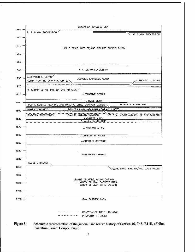
1990 —:
1980 —
1970
1960
1950 —
1940
1930
1920
1910
1900
1890
CATHERINE GLYNN OLINDE
R. S. GLYNN SUCCESSION V ■\TT" GLYNN SUCCESSION
LUCILLE PRICE, WIFE OF/AND RICHARD SUPPLE GLYNN
A. A. GLYNN SUCCESSION
7/ ALEXANDER A. GLYNN'
GLYNN PLANTING COMPANY, LIMITED- ALOYSIUS LAWRENCE GLYNN
■ALPH0NSE J. GLYNN
S. GUMBEL & CO. LTD. OF NEW ORLEANS "/ J. VILNEUVE DECUIR
F. OVIDE LIEUX
POINTE COUPEE PLANTING AND MANUFACTURING COMPANY LIMITED -\- ARTHUR V. ROBERTSON
MOSES SCHWARTZ / ' FARMERS LAND AND LOAN COMPANY LIMITED
SNOWDEN SUCCESSION -/ SAMUEL HAZARD SNOWDEN »V. & A. MEYER AND CO. OF NEW ORLEANS
1880 — MARGARET ALLEN A. ALLEN SUCCESSION
1870 — ALEXANDER ALLEN
1860
1850
1840
1830 —
CHARLES W. ALLEN
JARREAU SUCCESSION
JEAN URSIN JARREAU
AUGUSTE BRUNET X. 1820 —
1810
1800 —
1790 —
-N\ CELINE BARA, WIFE OF/AND LOUIS VIALES
JEANNE DELATTRE, WIDOW DURAND — WIDOW OF JEAN BAPTISTE BARA,
WIDOW OF JEAN MARIE DURAND
1780 JEAN BAPTISTE BARA
CONVEYANCE DATE UNKNOWN
PROPERTY INTEREST
Figure 8. Schematic representation of the general land tenure history of Section 16, T4S, Rl IE, of Nina Plantation, Pointe Coupee Parish.
33
Following the death of Jean Baptiste Bara, his property "passed into the possession of his widow," and then proceeded through "regular successive conveyances" to Jean Ursin Jarreau, whose claim to Sections 16 and 91 (Claim No. 21) was confirmed ca. 1833-1835 (Dickins and Forney 1860:6:681, 1861:8:380; Louisiana Sur- veyor General 1854, 1858). Records indicate, however, that the Bara arpentage may have passed into the hands of the widow of Jean Bap- tiste Barafils [son], rather than to the widow of Jean Baptiste Baiapere [father]. The Bara tracts were adjudicated on June 13, 1782 (two months after the death of Bara pere), to Jeanne Delattre, widow of Jean Baptiste Bara fils, dit Le Blond (Original Acts Book [OAB] 1819, No. 417, Pointe Coupee Parish Clerk of Court [PCPCC]; Yakubik et al. 1994:139-141). Although Jeanne Delattre Bara married a second time following her acquisition of the Bara property, she still was listed as "Widow LeBlond" in 1795 (Holmes 1970:361), and a contemporary parish survey (ca. 1816) recorded the property under the name Barra [sic]. By 1819, however, Jeanne Delattre was known as the widow of Jean Marie Durand (Figure 6). Following the death of her second husband, the Durand estate was inventoried on October 11, 1819. Among the listed properties was the 42-arpent by 40-arpent tract fronting the Mississippi River, bounded above by [Jean] Francois Porche and below by petit Bayou. In- cluded in the estate inventory was the "principal house," which consisted of three rooms, two cabinets (small rooms placed at the back corners of the house), and two galleries; also recorded were a storehouse, detached kitchen, and other outbuildings, in addition to corn and cotton crops and to 32 slaves (OAB 1819, No. 417, PCPCC; Yakubik et al. 1994:142-144).
The tracts belonging to Widow Durand were surveyed by Pierre Louis L'Hermite during the years 1820-1823. The property that later was designated Sections 15 and 16, T4S, RUE, and Sections 91 and 92, T5S, R11E, was surveyed October 30, 1820, and divided into four lots (Fig- ure 9). Neither the plat nor the survey text (Sur- vey No. 60) provide any indication as to whether or not structures were located on this property. It should be noted, though, that both L'Hermite Surveys No. 66 (1821) and No. 112 (1823) of the land above the Chenal superieur de la Fausse
Riviere depict the Maison and Magasin on the riverfront property formerly owned by the Widow Durand and later designated Section 14, T4S, RUE. More than likely, these structures are the house and storehouse listed in the 1819 Durand estate inventory (L'Hermite 1818-1822, Nos. 56, 57, 60, and 66; 1822-1827, No. 112).
On February 22, 1821, the Widow Durand donated Lots 1 and 2 (Sections 15 and 92) to her minor grandchildren, the four children of her de- ceased son Nicolas Bara. On the same date, she donated Lots 3 and 4 (Sections 16 and 91) to Ce- line Bara, wife of/and Louis Viales, "an male in law to said minors." Lots 3 and 4 extended front along the Mississippi River and were bounded by the land of the Nicolas Bara minors, the tract be- longing to parish judge Pierre Dormenon, the Francois Porche succession, and by le petit bayou. On August 27, 1822, Celine and Louis Viales sold Lots 3 and 4 to Auguste Brunet, the Marchand [dealer or tradesman] who had repre- sented the widow of Francois Porche (lower bounding party) when the Bara/Durand property was surveyed and subdivided in 1820. Three weeks later, Brunet sold the tract to Jean Ursin Jarreau (Figure 9) (L'Hermite 1818-1822, No. 60; OAB 1820-1821, Vol. 1, Nos. 751, 752, and 753; OAB 1822, Vol. 2, Nos. 1169 and 1178, PCPCC).
Jarreau Family Tenure: 1822 - 1857 Born March 23, 1800, Jean Ursin Jarreau
was the son of French merchantman navigator Jacques Jarreau, of Bordeaux, and Pointe Coupee native Marie Helene Tounoir. Jean Ursin Jarreau purchased the Durand Lots 3 and 4 on September 18,1822, as a young man of only 22 years of age. Nine months following his acquisition of the tract, on June 25, 1823, Jarreau married Octavine LeBlanc, a local girl who had just turned seven- teen, in a Catholic ceremony at the Church of St. Francis in Pointe Coupee. (Arthur and Kernion 1931:39; Bendernagel ca. 1966; Diocese of Baton Rouge ca. 1983:4:296).
Jean Ursin Jarreau's family expanded con- siderably after his marriage in 1823. Like other couples during the nineteenth century, the Jar- reaus had numerous children and paid a heavy toll in infant mortality. When their firstborn child died, they buried the baby on November 12, 1824, probably in the old cemetery, now lost to
34
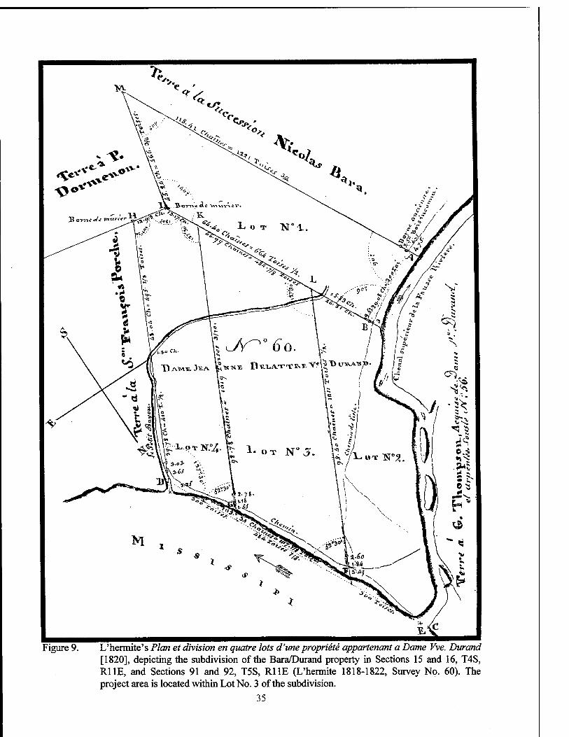
Figure 9. L'hermite's Plan et division en quatre lots d'ime propriete appartenant a Dame Vve. Durand [1820], depicting the subdivision of the Bara/Durand property in Sections 15 and 16, T4S, RUE, and Sections 91 and 92, T5S, RUE (L'hermite 1818-1822, Survey No. 60). The project area is located within Lot No. 3 of the subdivision.
35
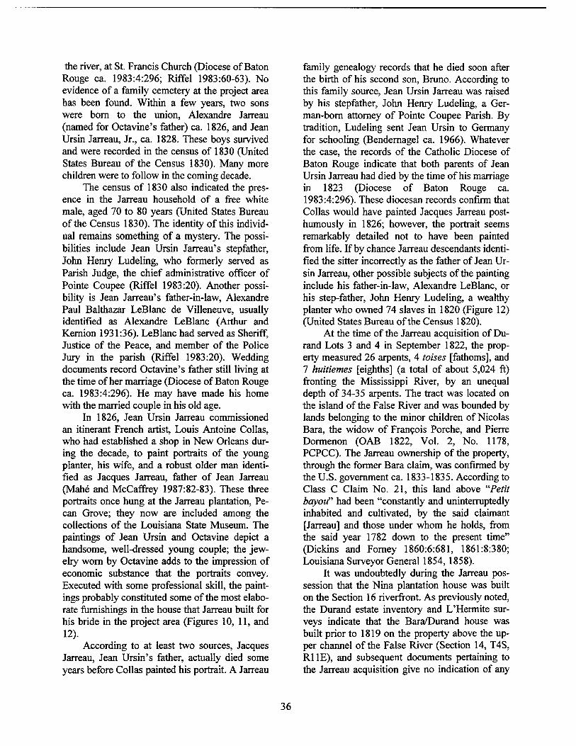
the river, at St. Francis Church (Diocese of Baton Rouge ca. 1983:4:296; Riffel 1983:60-63). No evidence of a family cemetery at the project area has been found. Within a few years, two sons were born to the union, Alexandre Jarreau (named for Octavine's father) ca. 1826, and Jean Ursin Jarreau, Jr., ca. 1828. These boys survived and were recorded in the census of 1830 (United States Bureau of the Census 1830). Many more children were to follow in the coming decade.
The census of 1830 also indicated the pres- ence in the Jarreau household of a free white male, aged 70 to 80 years (United States Bureau of the Census 1830). The identity of this individ- ual remains something of a mystery. The possi- bilities include Jean Ursin Jarreau's stepfather, John Henry Ludeling, who formerly served as Parish Judge, the chief administrative officer of Pointe Coupee (Riffel 1983:20). Another possi- bility is Jean Jarreau's father-in-law, Alexandre Paul Balthazar LeBlanc de Villeneuve, usually identified as Alexandre LeBlanc (Arthur and Kernion 1931:36). LeBlanc had served as Sheriff, Justice of the Peace, and member of the Police Jury in the parish (Riffel 1983:20). Wedding documents record Octavine's father still living at the time of her marriage (Diocese of Baton Rouge ca. 1983:4:296). He may have made his home with the married couple in his old age.
In 1826, Jean Ursin Jarreau commissioned an itinerant French artist, Louis Antoine Collas, who had established a shop in New Orleans dur- ing the decade, to paint portraits of the young planter, his wife, and a robust older man identi- fied as Jacques Jarreau, father of Jean Jarreau (Mahe and McCaffrey 1987:82-83). These three portraits once hung at the Jarreau plantation, Pe- can Grove; they now are included among the collections of the Louisiana State Museum. The paintings of Jean Ursin and Octavine depict a handsome, well-dressed young couple; the jew- elry worn by Octavine adds to the impression of economic substance that the portraits convey. Executed with some professional skill, the paint- ings probably constituted some of the most elabo- rate furnishings in the house that Jarreau built for his bride in the project area (Figures 10, 11, and 12).
According to at least two sources, Jacques Jarreau, Jean Ursin's father, actually died some years before Collas painted his portrait. A Jarreau
family genealogy records that he died soon after the birth of his second son, Bruno. According to this family source, Jean Ursin Jarreau was raised by his stepfather, John Henry Ludeling, a Ger- man-born attorney of Pointe Coupee Parish. By tradition, Ludeling sent Jean Ursin to Germany for schooling (Bendernagel ca. 1966). Whatever the case, the records of the Catholic Diocese of Baton Rouge indicate that both parents of Jean Ursin Jarreau had died by the time of his marriage in 1823 (Diocese of Baton Rouge ca. 1983:4:296). These diocesan records confirm that Collas would have painted Jacques Jarreau post- humously in 1826; however, the portrait seems remarkably detailed not to have been painted from life. If by chance Jarreau descendants identi- fied the sitter incorrectly as the father of Jean Ur- sin Jarreau, other possible subjects of the painting include his father-in-law, Alexandre LeBlanc, or his step-father, John Henry Ludeling, a wealthy planter who owned 74 slaves in 1820 (Figure 12) (United States Bureau of the Census 1820).
At the time of the Jarreau acquisition of Du- rand Lots 3 and 4 in September 1822, the prop- erty measured 26 arpents, 4 toises [fathoms], and 7 huitiemes [eighths] (a total of about 5,024 ft) fronting the Mississippi River, by an unequal depth of 34-35 arpents. The tract was located on the island of the False River and was bounded by lands belonging to the minor children of Nicolas Bara, the widow of Francois Porche, and Pierre Dormenon (OAB 1822, Vol. 2, No. 1178, PCPCC). The Jarreau ownership of the property, through the former Bara claim, was confirmed by the U.S. government ca. 1833-1835. According to Class C Claim No. 21, this land above "Petit bayou" had been "constantly and uninterruptedly inhabited and cultivated, by the said claimant [Jarreau] and those under whom he holds, from the said year 1782 down to the present time" (Dickins and Forney 1860:6:681, 1861:8:380; Louisiana Surveyor General 1854,1858).
It was undoubtedly during the Jarreau pos- session that the Nina plantation house was built on the Section 16 riverfront. As previously noted, the Durand estate inventory and L'Hermite sur- veys indicate that the Bara/Durand house was built prior to 1819 on the property above the up- per channel of the False River (Section 14, T4S, RUE), and subsequent documents pertaining to the Jarreau acquisition give no indication of any
36
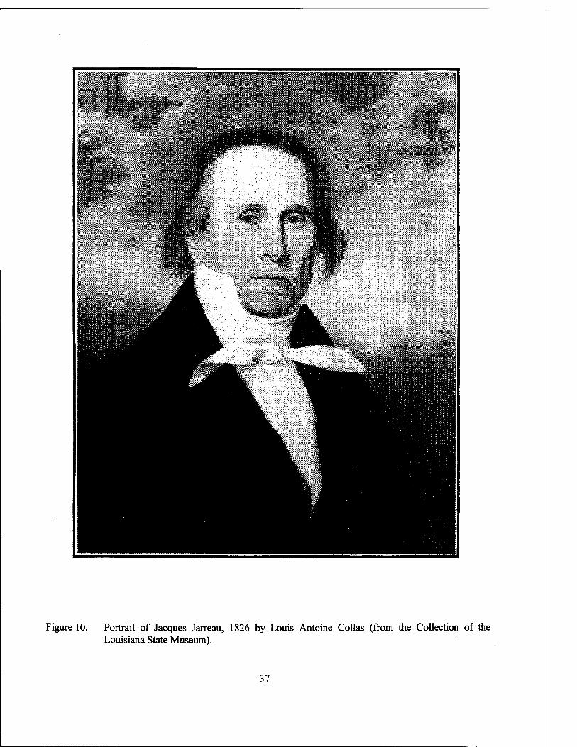
Figure 10. Portrait of Jacques Jarreau, 1826 by Louis Antoine Collas (from the Collection of the Louisiana State Museum).
37
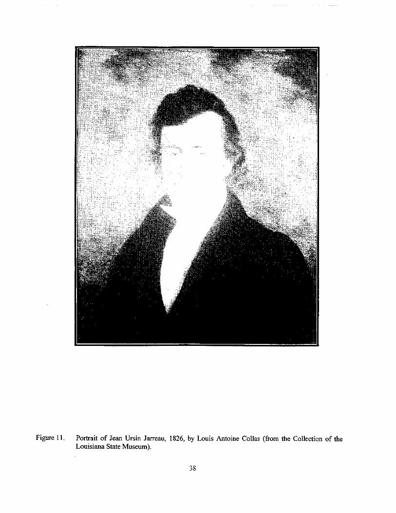
Figure 11. Portrait of Jean Ursin Jarreau, 1826, by Louis Antoine Collas (from the Collection of the Louisiana State Museum).
38
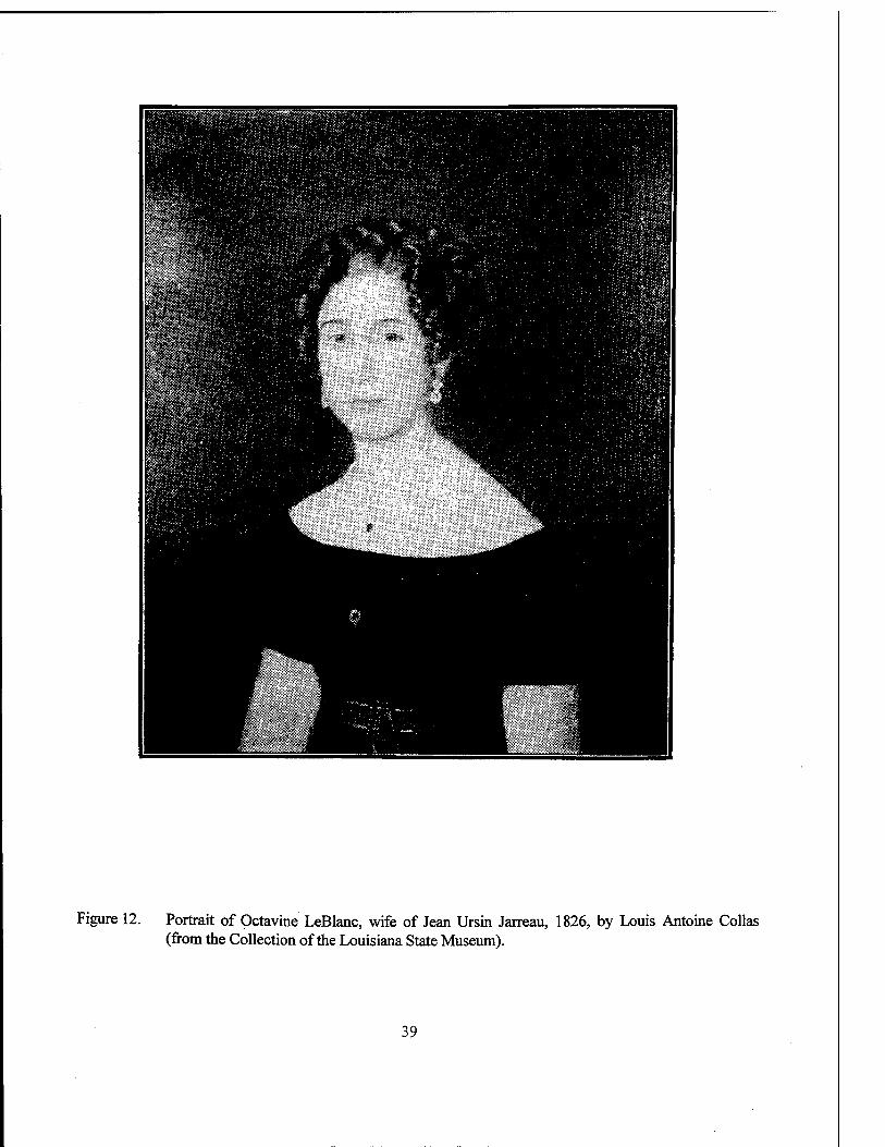
Figure 12. Portrait of Octavine LeBlanc, wife of Jean Ursin Jarreau, 1826, by Louis Antoine Collas (from the Collection of the Louisiana State Museum).
39
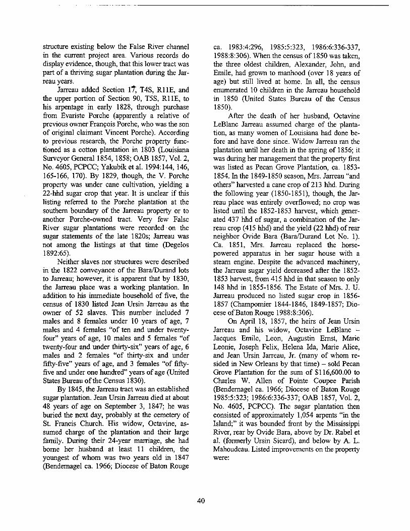
structure existing below the False River channel in the current project area. Various records do display evidence, though, that this lower tract was part of a thriving sugar plantation during the Jar- reau years.
Jarreau added Section it, T4S, RUE, and the upper portion of Section 90, T5S, Rl IE, to his arpentage in early 1828, through purchase from Evariste Porche (apparently a relative of previous owner Francois Porche, who was the son of original claimant Vincent Porche). According to previous research, the Porche property func- tioned as a cotton plantation in 1803 (Louisiana Surveyor General 1854,1858; OAB 1857, Vol. 2, No. 4605, PCPCC; Yakubik et al. 1994:144, 146, 165-166, 170). By 1829, though, the V. Porche property was under cane cultivation, yielding a 22-hhd sugar crop that year. It is unclear if this listing referred to the Porche plantation at the southern boundary of the Jarreau property or to another Porche-owned tract. Very few False River sugar plantations were recorded on the sugar statements of the late 1820s; Jarreau was not among the listings at that time (Degelos 1892:65).
Neither slaves nor structures were described in the 1822 conveyance of the Bara/Durand lots to Jarreau; however, it is apparent that by 1830, the Jarreau place was a working plantation. In addition to his immediate household of five, the census of 1830 listed Jean Ursin Jarreau as the owner of 52 slaves. This number included 7 males and 8 females under 10 years of age, 7 males and 4 females "of ten and under twenty- four" years of age, 10 males and 5 females "of twenty-four and under thirty-six" years of age, 6 males and 2 females "of thirty-six and under fifty-five" years of age, and 3 females "of fifty- five and under one hundred" years of age (United States Bureau of the Census 1830).
By 1845, the Jarreau tract was an established sugar plantation. Jean Ursin Jarreau died at about 48 years of age on September 3, 1847; he was buried the next day, probably at the cemetery of St. Francis Church. His widow, Octavine, as- sumed charge of the plantation and their large family. During their 24-year marriage, she had borne her husband at least 11 children, the youngest of whom was two years old in 1847 (Bendemagel ca. 1966; Diocese of Baton Rouge
ca. 1983:4:296, 1985:5:323, 1986:6:336-337, 1988:8:306). When the census of 1850 was taken, the three oldest children, Alexander, John, and Emile, had grown to manhood (over 18 years of age) but still lived at home. In all, the census enumerated 10 children in the Jarreau household in 1850 (United States Bureau of the Census 1850).
After the death of her husband, Octavine LeBlanc Jarreau assumed charge of the planta- tion, as many women of Louisiana had done be- fore and have done since. Widow Jarreau ran the plantation until her death in the spring of 1856; it was during her management that the property first was listed as Pecan Grove Plantation, ca. 1853- 1854. In the 1849-1850 season, Mrs. Jarreau "and others" harvested a cane crop of 213 hhd. During the following year (1850-1851), though, the Jar- reau place was entirely overflowed; no crop was listed until the 1852-1853 harvest, which gener- ated 437 hhd of sugar, a combination of the Jar- reau crop (415 hhd) and the yield (22 hhd) of rear neighbor Ovide Bara (Bara/Durand Lot No. 1). Ca. 1851, Mrs. Jarreau replaced the horse- powered apparatus in her sugar house with a steam engine. Despite the advanced machinery, the Jarreau sugar yield decreased after the 1852- 1853 harvest, from 415 hhd in that season to only 148 hhd in 1855-1856. The Estate of Mrs. J. U. Jarreau produced no listed sugar crop in 1856- 1857 (Champomier 1844-1846, 1849-1857; Dio- cese of Baton Rouge 1988:8:306).
On April 18, 1857, the heirs of Jean Ursin Jarreau and his widow, Octavine LeBlanc - Jacques Emile, Leon, Augustin Ernst, Marie Leonie, Joseph Felix, Helena Ida, Marie Alice, and Jean Ursin Jarreau, Jr. (many of whom re- sided in New Orleans by that time) - sold Pecan Grove Plantation for the sum of $116,600.00 to Charles W. Allen of Pointe Coupee Parish (Bendemagel ca. 1966; Diocese of Baton Rouge 1985:5:323; 1986:6:336-337; OAB 1857, Vol. 2, No. 4605, PCPCC). The sugar plantation then consisted of approximately 1,054 arpents "in the Island;" it was bounded front by the Mississippi River, rear by Ovide Bara, above by Dr. Rabel et al. (formerly Ursin Sicard), and below by A. L. Mahoudeau. Listed improvements on the property were:
40
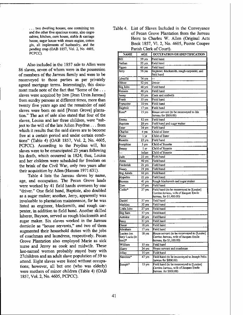
. . . two dwelling houses, one containing ten and the other five spacious rooms, also negro cabins, kitchen, com house, stable & carriage house, sugar house with steam engine, cotton gin, all implements of husbandry, and the pending crop (OAB 1857, Vol. 2, No. 4605, PCPCC).
Also included in the 1857 sale to Allen were 86 slaves, seven of whom were in the possession of members of the Jarreau family and were to be reconveyed to those parties as per privately agreed mortgage terms. Interestingly, this docu- ment made note of the fact that "Some of the . . . slaves were acquired by him [Jean Ursin Jarreau] from sundry persons at different times, more than twenty five years ago and the remainder of said slaves were born on said [Pecan Grove] planta- tion." The act of sale also stated that four of the slaves, Louisa and her three children, were "sub- ject to the will of the late Julien Poydras ... from which it results that the said slaves are to become free at a certain period and under certain condi- tions" (Table 4) (OAB 1857, Vol. 2, No. 4605, PCPCC). According to the Poydras will, his slaves were to be emancipated 25 years following his death, which occurred in 1824; thus, Louisa and her children were scheduled for freedom on the brink of the Civil War, only two years after their acquisition by Allen (Hansen 1971:631).
Table 4 lists the Jarreau slaves by name, age, and occupation. The Pecan Grove lands were worked by 41 field hands overseen by one "driver." One field hand, Baptiste, also doubled as a sugar maker; another, Jerry, apparently was invaluable to plantation maintenance, for he was listed as engineer, blacksmith, and rough car- penter, in addition to field hand. Another skilled laborer, Bayson, served as rough blacksmith and sugar maker. Six slaves worked in the Jarreau domicile as "house servants," and two of them augmented their household duties with the jobs of coachman and laundress, respectively. Pecan Grove Plantation also employed Marie as sick nurse and Jenny as cook and midwife. These last-named women probably stayed busy with 27children and an adult slave population of 59 to attend. Eight slaves were listed without occupa- tions; however, all but one (who was elderly) were mothers of minor children (Table 4) (OAB 1857, Vol. 2, No. 4605, PCPCC).
Table 4. List of Slaves Included in the Conveyance of Pecan Grove Plantation from the Jarreau Heirs to Charles W. Allen (Original Acts Book 1857, VI. 2, No. 4605, Pointe Coupee Parish Clerk of Court).
NAME | AGE | OCCUPATION OR IDENTIFICATION |
Bill 59 yrs Field hand Nathan 55 yrs Field hand Figaro 65 yrs rield hand Jerry 56 yrs ingineer, blacksmith, rough carpenter, and
ield hand Leveille 74 yrs — Oliver 52 yrs Driver Big John 48 yrs rield hand Henson 48 yrs Field hand Jenny 55 yrs Cook and midwife Frank 35 yrs Field hand Fran9oise 18 yrs Field hand Eugenie 17yrs -ield hand Rose* 15 yrs House servant (to be reconveyed to Ida
Jarreau for $800.00) Emma 12 yrs -ield hand Baptiste 28 yrs Field hand and sugar maker Ester 24 yrs rield hand Charles 4yrs Child of Ester Pierre lyr Child of Ester Rosette 23 yrs Field hand Josephine 3yrs Child of Rosette Renny lyr Child of Rosette — Infant Child of Rosette Jude 33 yrs Field hand Anna 40 yrs Field hand Frederick 21 yrs Field hand Henry 21 yrs Field hand Big Aimes 66 yrs Field hand Hypolite 21yrs Field hand Bayson 41 yrs Rough blacksmith and sugar maker Tom 37 yrs Field hand Codio* 37 yrs Field hand (to be reconveyed to [Louise]
Conine Jarreau, wife of Jacques Emile Jarreau, for $1,400.00)
Daniel 37 yrs Field hand Mathieu 32 yrs Field hand Little John 27 yrs Field hand Big Sam 37 yrs Field hand Antoine 28 yrs Field hand Jessy 21 yrs Field hand Oscar 18yrs Field hand Abraham 17yrs Field hand Lucien (on list)/ Lucia (in text)*
18yrs House servant (to be reconveyed to [Louise] Conine Jarreau, wife of Jacques Emile Jarreau, for$l,100.00)
William 15 yrs Field hand Harry 34 yrs House servant and coachman Allen 15 yrs Field hand Narcisse* 47 yrs Field hand (to be reconveyed to Joseph Felix
Jarreau for $800.00) Joseph* 15yrs Field hand (to be reconveyed to [Louise]
Conine Jarreau, wife of Jacques Emile Jarreau, for $800.00)
41
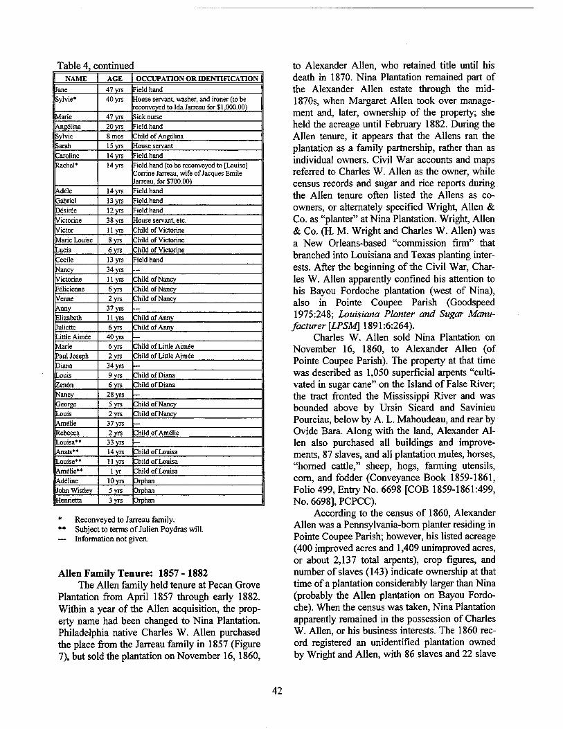
Table 4, continued NAME AGE OCCUPATION OR IDENTIFICATION
Jane 47yrs Field hand Sylvie* 40 yrs House servant, washer, and ironer (to be
reconveyed to Ida Jarreau for $1,000.00) Marie 47yrs Sick nurse Angelina 20yrs Field hand Sylvie 8mos Child of Angelina Sarah 15yrs House servant Caroline 14yrs Field hand Rachel* 14yrs Field hand (to be reconveyed to [Louise]
Conine Jarreau, wife of Jacques Emile Jarreau, for $700.00)
Adele 14yrs Field hand Gabriel 13yrs Field hand Decree 12yrs Field hand Victorine 38yrs House servant, etc. Victor 11 yrs Child of Victorine Marie Louise 8yrs Child of Victorine Lucia 6 yrs Child of Victorine Cecile 13yrs Field hand Nancy 34 yrs — Victorine 11 yrs Child of Nancy Felicienne 6 yrs Child of Nancy Venne 2 yrs Child of Nancy Anny 37 yrs — Elizabeth 11 yrs Child of Anny Juliette 6 yrs Child of Anny Little Aimee 40 yrs Marie 6yrs Child of Little Aimee Paul Joseph 2yrs Child of Little Aimee Diana 34 yrs Louis 9 yrs Child of Diana Zenön 6yrs Child of Diana Nancy 28 yrs George 5yrs Child of Nancy Louis 2yrs Child of Nancy Amelie 37 yrs Rebecca 2yrs Child of Amelie Louisa** 33 yrs Anals** 14yrs Child of Louisa Louise** 11 yrs Child of Louisa Amelie** lyr Child of Louisa Adeline lOyrs Orphan John Wistley 5yrs Orphan Henrietta 3yrs Orphan
Reconveyed to Jarreau family. Subject to terms of Julien Poydras will. Information not given.
Allen Family Tenure: 1857 - 1882 The Allen family held tenure at Pecan Grove
Plantation from April 1857 through early 1882. Within a year of the Allen acquisition, the prop- erty name had been changed to Nina Plantation. Philadelphia native Charles W. Allen purchased the place from the Jarreau family in 1857 (Figure 7), but sold the plantation on November 16,1860,
to Alexander Allen, who retained title until his death in 1870. Nina Plantation remained part of the Alexander Allen estate through the mid- 18705, when Margaret Allen took over manage- ment and, later, ownership of the property; she held the acreage until February 1882. During the Allen tenure, it appears that the Aliens ran the plantation as a family partnership, rather than as individual owners. Civil War accounts and maps referred to Charles W. Allen as the owner, while census records and sugar and rice reports during the Allen tenure often listed the Aliens as co- owners, or alternately specified Wright, Allen & Co. as "planter" at Nina Plantation. Wright, Allen & Co. (H. M. Wright and Charles W. Allen) was a New Orleans-based "commission firm" that branched into Louisiana and Texas planting inter- ests. After the beginning of the Civil War, Char- les W. Allen apparently confined his attention to his Bayou Fordoche plantation (west of Nina), also in Pointe Coupee Parish (Goodspeed 1975:248; Louisiana Planter and Sugar Manu-
facturer [LPSM\ 1891:6:264). Charles W. Allen sold Nina Plantation on
November 16, 1860, to Alexander Allen (of Pointe Coupee Parish). The property at that time was described as 1,050 superficial arpents "culti- vated in sugar cane" on the Island of False River; the tract fronted the Mississippi River and was bounded above by Ursin Sicard and Savinieu Pourciau, below by A. L. Mahoudeau, and rear by Ovide Bara. Along with the land, Alexander Al- len also purchased all buildings and improve- ments, 87 slaves, and all plantation mules, horses, "horned cattle," sheep, hogs, farming utensils, corn, and fodder (Conveyance Book 1859-1861, Folio 499, Entry No. 6698 [COB 1859-1861:499, No. 6698], PCPCC).
According to the census of 1860, Alexander Allen was a Pennsylvania-born planter residing in Pointe Coupee Parish; however, his listed acreage (400 improved acres and 1,409 unimproved acres, or about 2,137 total arpents), crop figures, and number of slaves (143) indicate ownership at that time of a plantation considerably larger than Nina (probably the Allen plantation on Bayou Fordo- che). When the census was taken, Nina Plantation apparently remained in the possession of Charles W. Allen, or his business interests. The 1860 rec- ord registered an unidentified plantation owned by Wright and Allen, with 86 slaves and 22 slave
42
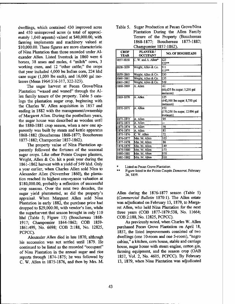
dwellings, which contained 430 improved acres and 450 unimproved acres (a total of approxi- mately 1,040 arpents) valued at $40,000.00, with farming implements and machinery valued at $10,000.00. These figures are more characteristic of Nina Plantation than those recorded under Al- exander Allen. Listed livestock in 1860 were 6 horses, 38 asses and mules, 4 "milch" cows, 3 working oxen, and 12 "other cattle;" the crops that year included 4,000 bu Indian corn, 224 hhd cane sugar (1,000 lbs each), and 16,000 gal mo- lasses (Menn 1964:316-317,322-323).
The sugar harvest at Pecan Grove/Nina Plantation "waxed and waned" through the Al- len family tenure of the property. Table 5 cata- logs the plantation sugar crop, beginning with the Charles W. Allen acquisition in 1857 and ending in 1882 with the management/ownership of Margaret Allen. During the postbellum years, the sugar house was described as wooden until the 1880-1881 crop season, when a new one ap- parently was built by steam and kettle apparatus 1868-1882 (Bouchereau 1868-1877; Bouchereau 1877-1882; Champomier 1857-1862).
The property value of Nina Plantation ap- parently followed the fortunes of the seasonal sugar crops. Like other Pointe Coupee planters, Wright, Allen & Co. hit a peak year during the 1861-1862 harvest with a yield of 549 hhd. Only a year earlier, when Charles Allen sold Nina to Alexander Allen (November 1860), the planta- tion reached its highest conveyance valuation at $180,000.00, probably a reflection of successful crop seasons. Over the next two decades, the sugar yield plummeted, as did the property's appraisal. When Margaret Allen sold Nina Plantation in early 1882, the purchase price had dropped to $29,000.00, with vendor's lien, while the sugarharvest that season brought in only 110 hhd (Table 5; Figure 13) (Bouchereau 1868- 1917; Champomier 1844-1862; COB 1859- 1861:499, No. 6698; COB 2:188, No. 12825, PCPCC).
Alexander Allen died in late 1870, although his succession was not settled until 1879. He continued to be listed as the recorded "occupant" of Nina Plantation in the annual sugar and rice reports through 1874-1875; he was followed by C. W. Allen in 1875-1876, and then by Mrs. M.
Table 5. Sugar Production at Pecan Grove/Nina Plantation During the Allen Family Tenure of the Property (Bouchereau 1868-1877; Bouchereau 1877-1882; Champomier 1857-1862).
CROP YEAR
PLANTER/ OCCUPANT
NO. OF HOGSHEADS
1857-1858 C.W. and A. Allen* 123 122**
1858-1859 Wright, Allen & Co. 511 515**
1859-1860 Wright, Allen & Co. 230 1860-1861 Wright, Allen & Co. 135 1861-1862 Wright, Allen & Co. 549 1868-1869 A. Allen 61
(68,625 lbs sugar; 5,250 gal molasses)
1869-1870 A Allen 125 (142,500 lbs sugar, 8,750 gal molasses)
1870-1871 A Allen 152 (170,250 lbs sugar, 12,096 gal molasses)
1871-1872 A. Allen 95 1872-1873 A. Allen — 1873-1874 A Allen 56 1874-1875 A Allen 83 1875-1876 C. W. Allen 72 1876-1877 Mis. M Allen 103 1877-1878 Mrs. M. Allen 86 1878-1879 Mrs. M. Allen 149 1879-1880 Mrs. M. Allen 173 1880-1881 Mrs. M. Allen 170 1881-1882 Mrs. M. Allen 110
* Listed as Pecan Grove Plantation. * * Figure listed in the Pointe Coupee Democrat, February
26,1859.
Allen during the 1876-1877 season (Table 5) (Commercial Bulletin 1870:1). The Allen estate was adjudicated on February 13, 1879, to Marga- ret Allen, who held Nina Plantation for the next three years (COB 1877-1879:538, No. 11664; COB 2:188, No. 12825, PCPCC).
As previously noted, when Charles W. Allen purchased Pecan Grove Plantation on April 18, 1857, the listed improvements consisted of two dwellings (one 10-room and one 5-room), "negro cabins," a kitchen, corn house, stable and carriage house, sugar house with steam engine, cotton gin, farming equipment, and the season crop (OAB 1857, Vol. 2, No. 4605, PCPCC). By February 13, 1879, when Nina Plantation was adjudicated
43
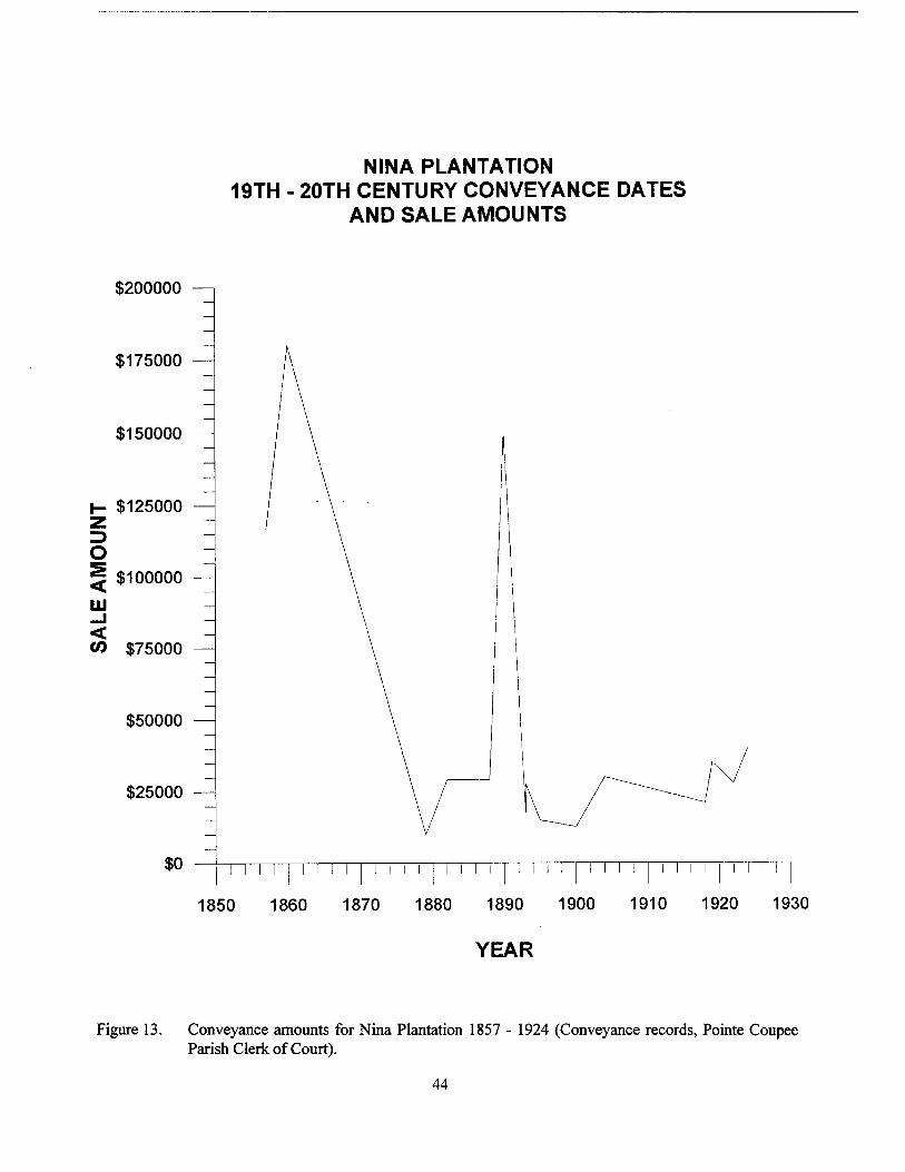
NINA PLANTATION 19TH - 20TH CENTURY CONVEYANCE DATES
AND SALE AMOUNTS
$200000
$175000
$150000
$125000
3 o < 111
$100000 —
< CO $75000
$50000
$25000
$0 II I I I I I I I I I i I i [ I I I i I I I I I I I I I i I I I i i I i I I I I
1850 1860 1870 1880 1890 1900 1910 1920 1930
YEAR
Figure 13. Conveyance amounts for Nina Plantation 1857 - 1924 (Conveyance records, Pointe Coupee Parish Clerk of Court).
44
to Margaret Allen, many of the same structures remained - "two dwelling houses, sugar house, stables, barns and cabins, etc.;" the Alexander Allen estate also included a number of "stock mules," farming utensils, four wagons, and one cart. The Nina property remained in the posses- sion of Margaret Allen for nearly three years, af- ter which she sold Nina Plantation (through her agent and brother, Charles William Allen, of New Orleans) to Samuel Hazard Snowden of Wilkin- son County, Mississippi (Figure 14) (COB 1877- 1879:538, No. 11664; COB 2:188, No. 12825, PCPCC).
Nina Plantation during the Civil War Although there were no major battles or
skirmishes in the project vicinity during the Civil War, the False River country figured prominently in scouting and foraging activities because of its location across the Mississippi River from Port Hudson, which fell to Union forces on July 8, 1863, following a six-week siege. Both the Wa- terloo and Hermitage landings were destination points for military movements through the region (Figure 15). Positioned between the two landings, Nina, or Pecan Grove, Plantation became part of the "tramping ground" for both Confederate and Federal troops (Edmonds 1984:127,156-157).
The spring of 1863 marked the first recorded military activity through Nina Plantation. In late March of that year, Captain James M. Magee of the Second Company, Massachusetts Unattached Cavalry, was ordered on a reconnaissance expe- dition through the eastern False River country. Magee bivouacked downriver at the Winter plantation (probably Arbroath), then with the di- rection of a "creole" prisoner who once lived in the area, he rode to Hermitage Landing and to the False River (Edmonds 1983:190-195; U.S. Sec- retary of War [OR] 1886:15:268). An excerpt from the Magee report of the scouting party, dated March 24,1863, reads as follows:
I... proceeded to the Hermitage Landing, a point at the head of the lower mouth of the False River, and nearly opposite Port Hud- son On discovering no enemy at the Point [Fausse, or False, Point, directly across the river from Port Hudson], where a consid- erable force was found two days before, I moved my command forward to the dike where the rebel steamer Hope, loaded with
600 barrels of molasses, lay, which ... I burned with its freight. I then left a portion of my men in the rear and proceeded with the balance to the junction of the False and Mis- sissippi Rivers (Hermitage Landing), where I found over 1,000 barrels of molasses, all of which I destroyed or rolled into the river (OR 1886:15:268) (Figures 16 and 17).
In reality, the "rebel steamer" belonged to French tradesman Charles Petitfils, whose vessels Faith and Hope carried on private transport with the False River planters. The Petitfils boats deliv- ered local plantation crops to the lower False River dike, from which point they were trans- ferred to larger riverboats for conveyance to downriver markets. Because of the upper and lower dike system, there was no water passage from False River to the Mississippi, making it impossible for the Hope to carry supplies to Port Hudson. On the other hand, Hermitage and Wa- terloo landings were considered important ship- ping connections between the Atchafalaya coun- try to the west and the Mississippi River; conse- quently, while the Federal motives were sound, the Magee attack was largely on an unoffending transport (Edmonds 1983:195-197; French and American Claims Commission [FACC] 1883, No. 292; OR 1896:48[2]: 1261-1262).
The Magee report of the expedition to Her- mitage and Waterloo landings continued:
At this point [Hermitage Landing] I found a rebel machine-shop, at present used as a repair-shop for guns. This was burned, with its contents, together with Government granary, containing 15,000 barrels of corn, intended for Port Hudson. After destroying all the property, including a drugstore, having a large assortment of valuable medicines, and some outbuildings, one the post-ofBce, I then proceeded to two or three different points on the Mississippi, where I had a full view of the river 4 or 5 miles above Waterloo. Neither the Hartford nor Albatross [Admiral Farra- gut's ships, previously sighted at Waterloo] were in sight, and no accurate information could be obtained from either whites or con- trabands of their whereabouts (OR 1886:15:252,268) (Figures 16 and 17).
En route upriver from Hermitage Landing, the Massachusetts troops crossed Pecan Grove Plantation (although called Nina by this time, apparently the plantation remained commonly
45
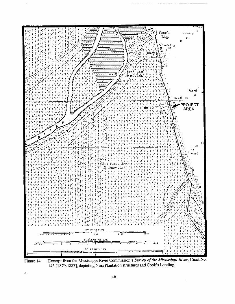
if:
<•
> ■
: .»■>'■ •>;:.<:>:-f
">';f
■ :-v':i' Ä > ■ ,r //.'.'.'/." "' /::::: :-7«VTT',','.',',I,.X
^w ~
=£=i (■.■.■.■.■■■.■.■.■■>W;.^y:^
Jv-V--; Cook's hard 59
54
':r.':r^:*il:t;{:;!tif!*^}ijs-:iv^:i:^:f: ; i i c ^ £\i y ■< *'\ ■*. ■ ■ * — ■ ' :\' . ^ - - - - - -
rri;*-i-*v;{:j:|;i*:;:v:>i>;fi,it:v.f:*>::?:<:-t: !T.' rrrv.' :i ■{■■ \:$J :>:<; ;.:>:- =- 4- * - ' *.
rrjrjrn ^■^.\\[^\.<l .i?;^"^-^-*- SCALK ('H FEIT
IOOOB ST t S-i 321 U
b UilU
SCALE OF METERS
s.« *.*rrrr. ,
,. . i t - * - - - - v\%
SCALE OF MILES "5 "v>' 3 "i' 0 ~ ' 2-'
Figure 14. Excerpt from the Mississippi River Commission's Survey of the Mississippi River, Chart No. 143 [1879-1883], depicting Nina Plantation structures and Cook's Landing.
46
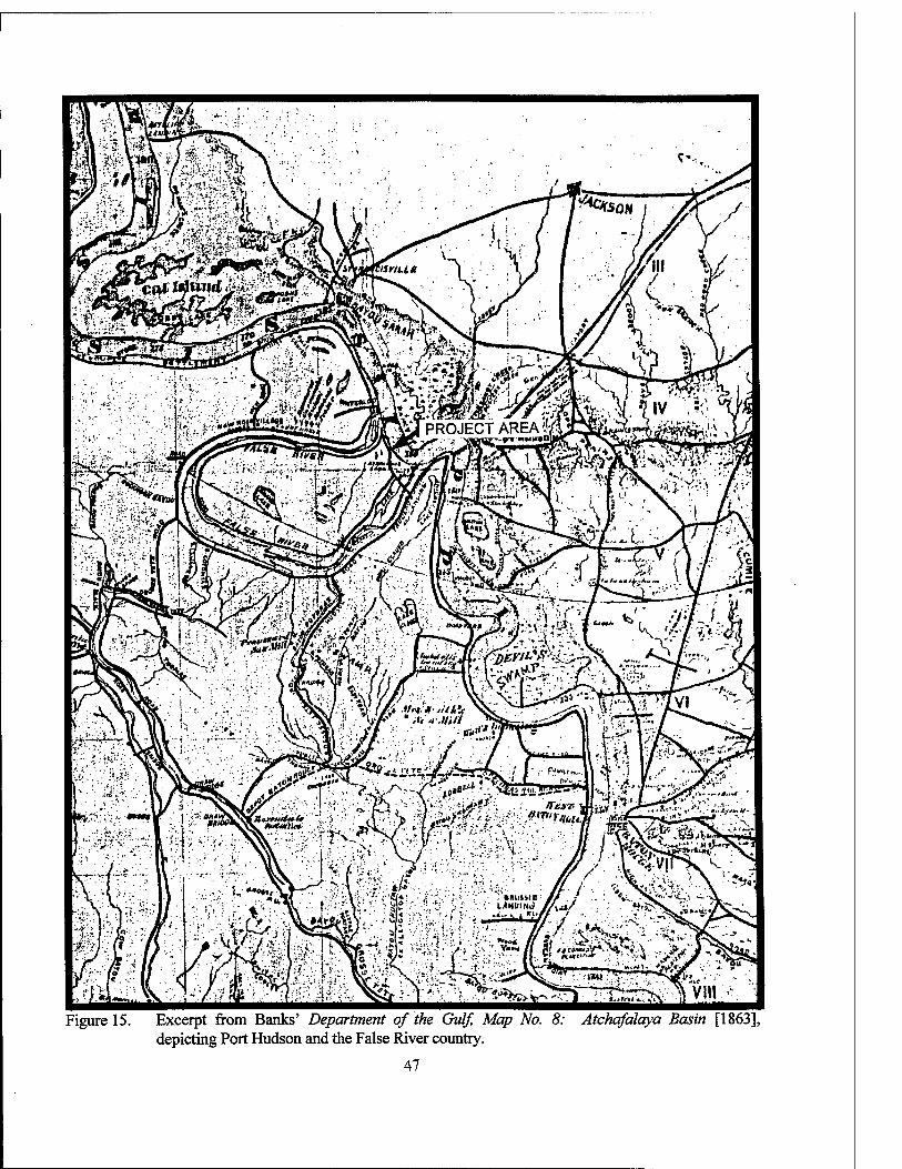
Figure 15. Excerpt from Banks' Department of the Gulf, Map No. 8: Atchafalaya Basin [1863], depicting Port Hudson and the False River country.
47
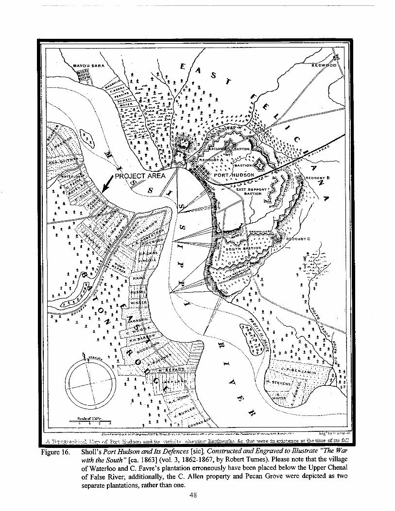
Scadterfriinr
r£*u tc «:r'fl*y>ukC'Jf7^^uX'-< tiVfÄJrir **"--* r*Ai rmliUtJltr. f-rKrtiUKtT-i £>*[
.h T<rpo? r.ajVhical "r.l.:
jbneJ by V." i-Jcm.J.
Port .HüdscTj. anditg -.iciailv site-win c £aztawofh.i. &c.-that "/7eie is.gristeace at th-etnae of its fen
Figure 16. SholPs Port Hudson and Its Defences [sic], Constructed and Engraved to Illustrate "The War with the South" [ca. 1863] (vol. 3, 1862-1867, by Robert Tumes). Please note that the village of Waterloo and C. Favre's plantation erroneously have been placed below the Upper Chenal of False River; additionally, the C. Allen property and Pecan Grove were depicted as two separate plantations, rather than one.
48
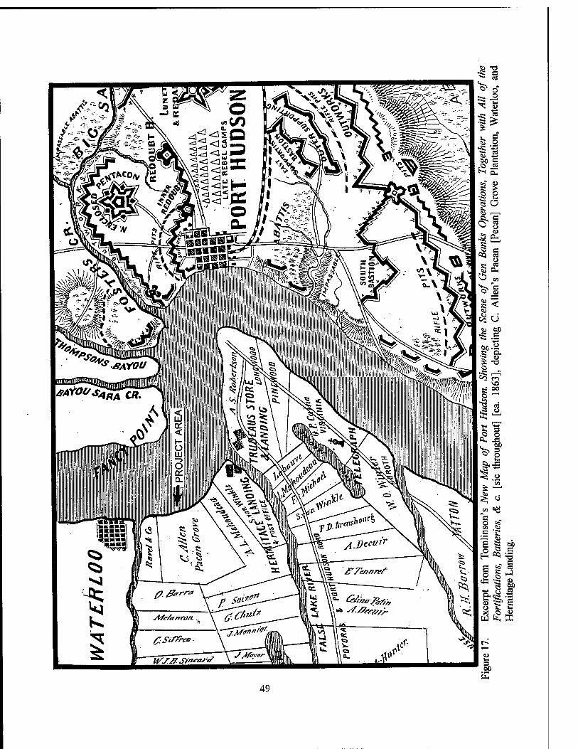
<o -ff E
ö k, DC
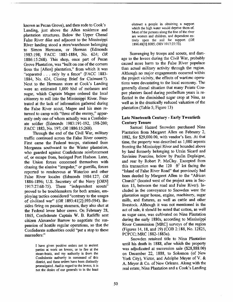
known as Pecan Grove), and then rode to Cook's Landing, just above the Allen residence and plantation structures. Below the Upper Chenal False River dike and adjacent to the Mississippi River landing stood a store/warehouse belonging to Simon Hermann, or Herman (Edmonds 1983:198; FACC 1883-1884, No. 624; OR 1886:15:268). This shop, once part of Pecan Grove Plantation, was "built on one of the corners from the [Allen] plantation," from which it was "separated . . . only by a fence" (FACC 1883- 1884, No. 624, Closing Brief for Claimant:7). Next to the Hermann store at Cook's Landing were an estimated 1,000 hhd of molasses and sugar, which Captain Magee ordered the local citizenry to roll into the Mississippi River. Frus- trated at the lack of information gathered during the False River scout, Magee and his men re- turned to camp with "three of the enemy," appar- ently only one of whom actually was a Confeder- ate soldier (Edmonds 1983:191-192, 198-200; FACC 1883, No. 197; OR 1886:15:268).
Through the end of the Civil War, military traffic continued across the False River country. First came the Federal troops, stationed from Morganza southward to the Winter plantation, who guarded against Confederate reinforcement of, or escape from, besieged Port Hudson. Later, the Union forces concerned themselves with chasing the elusive "irregular," or guerilla, forces reported to rendezvous at Waterloo and other False River locales (Edmonds 1984:127; OR 1886-1896; U.S. Secretary of the Navy [ORN] 1917:27:68-75). These "independent scouts" proved to be troublemakers for both armies, em- ploying tactics considered "contrary to the usages of civilized war" (OR 1893:41[2]:593-594). Be- sides firing on passing steamers, they also shot at the Federal levee labor crews. On February 28, 1865, Confederate Captain W. B. Ratliffe sent citizen Alexander Barrow to negotiate the sus- pension of hostile regular operations, so that the Confederate authorities could "put a stop to these marauders:"
I have given positive orders not to molest parties at work on levees, or to fire at the steam-boats, and my authority is from the Confederate authority in command of this district, and these orders have been distinctly promulgated. And in regard to the levees, it is not the desire of our generals to in the least
obstruct a people in obtaining a support which the high water would deprive them of. Most of the persons along the line of the river are women and children, and dependent en- tirely upon the soil for support (OR 1896:48[1]:1085; ORN 1917:27:73).
Scavenging by troops and scouts, and dam- age to the levees during the Civil War, probably caused more harm to the False River populace than actual military activity through the region. Although no major engagements occurred within the project vicinity, the effects of wartime opera- tions were devastating to the local economy. The generally dismal situation that many Pointe Cou- pee planters faced during postbellum years is re- flected in the diminished sugar crop at Nina, as well as in the drastically reduced valuation of the plantation (Table 5; Figure 13)
Late Nineteenth Century - Early Twentieth Century Tenure
Samuel Hazard Snowden purchased Nina Plantation from Margaret Allen on February 2, 1882, for $29,000.00, with vendor's lien. At that time, the property was described as 1,080 arpents fronting the Mississippi River and bounded above by land formerly belonging to Ursin Sicard and Savinieu Pourciau, below by Paulin Deplaigne, and rear by Robert P. McClay. Excepted from this transaction was the 120 ft2 lot facing the "Island of False River Road" that previously had been deeded by Margaret Allen to the "African Church" (located west of the project area in Sec- tion 15, between the road and False River). In- cluded in the conveyance to Snowden were the plantation sugar house, engine, machinery, sugar mills, and fixtures, as well as cattle and other livestock. Although it was not mentioned in the act of sale, it should be noted that cotton, as well as sugar cane, was cultivated on Nina Plantation during the early 1880s, according to Mississippi River Commission [MRC] surveys of the region (Figures 14, 18, and 19) (COB 2:188, No. 12825, PCPCQMRC 1882-1883a).
Snowden retained title to Nina Plantation until his death in 1888, after which the property was adjudicated at succession sale ($28,888.00) on December 22, 1888, to Solomon (of New York City), Victor, and Adolphe Meyer of V. & A. Meyer & Co. of New Orleans. Along with the real estate, Nina Plantation and a Cook's Landing
50
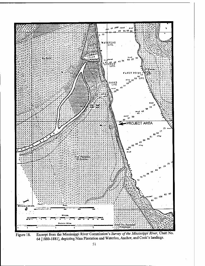
Figure 18. Excerpt from the Mississippi River Commission's Survey of the Mississippi River, Chart No. 64 [1880-1881], depicting Nina Plantation and Waterloo, Anchor, and Cook's landings.
51
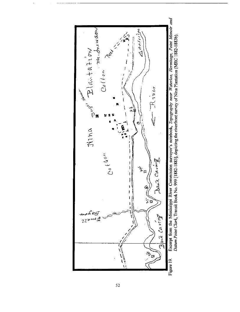
52
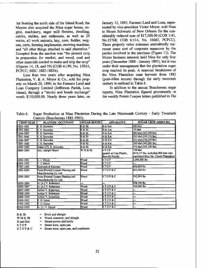
lot fronting the north side of the Island Road, the Meyers also acquired the Nina sugar house, en- gine, machinery, sugar mill fixtures, dwelling, cabins, stables, and outhouses, as well as 29 mules, all work animals, hay, corn, fodder, wag- ons, carts, farming implements, mowing machine, and "all other things attached to said plantation." Excepted from the auction was "the present crop in preparation for market, and wood, coal and other materials needed to make and ship the crop" (Figures 14, 18, and 19) (COB 4:199, No. 15014, PCPCC; MRC 1882-1883b).
Less than two years after acquiring Nina Plantation, V. & A. Meyer & Co., sold the prop- erty on March 20, 1890, to the Farmers Land and Loan Company Limited (Jefferson Parish, Lou- isiana), through a "stocks and bonds exchange" worth $150,000.00. Nearly three years later, on
January 12, 1893, Farmers Land and Loan, repre- sented by vice-president Victor Meyer, sold Nina to Moses Schwartz of New Orleans for the con- siderably reduced sum of $17,500.00 (COB 5:43, No.15768; COB 6:114, No. 16663, PCPCC). These property value extremes undoubtedly rep- resent some sort of corporate maneuver by the parties involved in the purchase (Figure 13). The Meyer business interests held Nina for only four years (December 1888 - January 1893), but it was under their management that the plantation sugar crop reached its peak. A seasonal breakdown of the Nina Plantation cane harvests from 1882 (post-Allen tenure) through the early twentieth century is outlined in Table 6.
In addition to the annual Bouchereau sugar reports, Nina Plantation figured prominently in the weekly Pointe Coupee letters published in The
Table 6. Sugar Production at Nina Plantation During the Late Nineteenth Century - Early Twentieth Century (Bouchereau 1882-1903).
CROP YEAR PLANTER / OCCUPANT SUGAR HOUSE | APPARATUS 1 SUGAR CROP (HHD/LBS)
1882-1883 S. H. Snowden B&Sh St & Ket 100 hhd 1883-1884 S. H. Snowden B&Sh St&Ket 70hhd 1884-1885 S. H. Snowden B&Sh St & Ket 280 hhd (322,000 lbs) 1885-1886 S. H. Snowden B&Sh St&Ket 305 hhd (350,750 lbs) 1886-1887 S. H. Snowden B&Sh St&Ket 221 hhd (276,250 lbs) 1887-1888 S. H. Snowden B&Sh St&Ket 300 hhd (345,000 lbs) 1888-1889 Estate ofS.H. Snowden B&Sh St&Ket 474 hhd (545,100 lbs) 1889-1890 Gen. Adolph Meyer WM&Sh STOP
(gran'd. at Cora Plant'n., [berville Parish)
728 hhd (918,157 lbs, including 800 tons cane purchased from Ste. Claude Plantation)
1890-1891 C. J. Meyer Wood STOP 1,004,000 lbs 1891-1892 C. J. Meyer Wood STOP 1892-1893 Seckbach & Eiseman Wood STOP 656,000 lbs 1893-1894 Point [Pointe] Coupee Planting and
Manufacturing Co. Ltd. Wood STOP&C 633,484 lbs
1894-1895 Point [Pointe] Coupee Planting and Manufacturing Co. Ltd.
Wood STOP&C 742,995 lbs
1895-1896 H. [A] V. Robertson — 448,500 lbs 1896-1897 H. \A.] V. Robertson Wood STOP&C 700,000 lbs 1897-1898 Arthur V. Robertson Wood STOP&C — 1898-1899 Arthur V. Robertson Wood STOP&C — 1899-1900 Arthur V. Robertson Wood STOP&C — 1900-1901 F. O. Lieux Wood STOP&C — 1901-1902 F. O. Lieux Wood STOP&C —
11902-1903 |A. [J.l V. Decuir Wood STOP&C —
B & Sh = Brick and shingle W M & Sh = Wood, masonry, and shingle St and Ket = Steam-power and kettle STOP = Steam tram, open pan S T O P &. C = Steam tram, open pan, and condenser
53
Louisiana Planter and Sugar Manufacturer. Fol- lowing are several excerpts printed during the years of Meyer management:
January 4, 1890 - One large double cabin on the Nina plantation caught fire on the 19th [of December 1889], and was reduced to ashes. Had it not been for the energetic efforts of those present, one or two other cabins, to- gether with the sugar house, would also have been destroyed (LPSM 1890:4:6). December 13, 1890 - The mill on the Nina plantation is still in full blast, harvesting the cane on that place into syrup, from whence it is taken to the Cora place (also Messrs. V. & A. Meyer's), in Iberville parish, and there made into white sugar. The crop on this place is exceptionally large, and the average yield is equal to that obtained on the surrounding places...
Mr. J. J. Trudeau . . . [of] Sweet Home plan- tation, on the island of False River, . . . has sold all his cane - except such quantity as will be required to plant his place next year - to Messrs. V. & A. Meyer of Nina plantation (LPSM 1890:5:452).
March 21, 1891 - Gen. Adolph Meyer, presi- dent of the Farmers' Land and Loan Co., has written to our local paper, endeavoring to ex- plain his reasons for taking out the injunction ... but, as far as your correspondent can per- ceive, he has failed to place himself in a bet- ter light with our people, who, without ex- ception, are unanimous in condemning him (LPSM 1891:6:209).
August 8, 1891 - Nina plantation, just above Grand Bay, also sustained considerable [cane] loss by the new levee [being built so far from the river]. The cane on this place, like that on all the other sugar plantations of this parish, is magnificent (LPSM 1891:7:4).
November 28, 1891 - The Nina mill is still in full blast. Only syrup is made at this place. This syrup is run through pipes into large tanks that are on board of a special tug boat in the river, and it is then taken down to the Cora plantation in Iberville parish, where it is turned into white sugar (LPSM 1891:7:300).
January 14, 1893 - It is rumored that the Nina plantation, near Cook's landing, is soon to change hands (LPSM 1893:10:20).
February 18, 1893 - The Nina sugar planta- tion has finally been sold by the Farmers' Land and Loan Company to Mr. Moses
Schwartz, of New Orleans (LPSM 1893:10:102).
Interestingly, both publications reported such items as sugar granulation at the Cora Plantation in Iberville Parish and the processing of cane cul- tivated at neighboring plantations.
Only ten weeks following his purchase of Nina Plantation in January 1893 (filed February 8, 1893), Moses Schwartz sold the property to the Pointe Coupee Planting and Manufacturing Com- pany Limited for $27,500.00, with a mortgage assumption. Along with the 1,080 arpents, the company purchased all appurtenances, including the sugar house, engine, machinery, sugar mills and fixtures, dwellings, cabins, stables, outbuild- ings, and farming implements. The earlier Schwartz acquisition had included a clause re- quiring him to honor a three-year property lease (through 1895) previously contracted with Seck- bach and Eiseman; however, that agreement lasted only until March 28, 1893, when Schwartz sold the plantation to the Pointe Coupee Planting and Manufacturing Company, which was a Schwartz/Seckbach/Eiseman company (Table 6) (COB 6:114, No. 16663; COB 6:196, No. 16726, PCPCC).
The Pointe Coupee Planting and Manufac- turing Company Limited was domiciled in Pointe Coupee Parish, but maintained an "office in New Orleans for the convenience of the meetings of the board of directors and for the purchase and sale of produce and necessary supplies" (LPSM 1893:10:212). Chartered in 1893, the original board of directors for the company consisted of Moses Schwartz, Adolphe Seckbach, Cassius M. Eiseman, John Overmeyer, and M. F. Flowers. Schwartz served as president, Seckbach was sec- retary-treasurer, and Eiseman acted both as vice- president and general manager (COB 6:196, No. 16726, PCPCC; LPSM 1893:10:212).
According to the Pointe Coupee letters re- ported in the LPSM of April 1893, the Pointe Coupee Planting and Manufacturing Company intended to construct a "central sugar factory" on Nina Plantation, not only for corporate use, but also for use by neighboring planters who wished either to purchase company stock or to sell their cane crops to the concern. By mid-November of 1893, the rumored central factory still had not been built at Nina; however, new sugar house
54
apparatus (steam tram, open pan, and condenser) was in place for the 1893-1894 crop season, and a large store managed by William Dalzell was in operation (Table 6) (LPSM 1893:10:212, 227, 244; 11:325). More than likely, the machinery was replaced after the sugar mill housing "gave away" that November, delaying the grinding pro- cess for several days (LPSM 1893:11:341).
Both sugar reports and news items of the day indicated that Nina Plantation thrived under cor- porate management. While leased to Seckbach and Eiseman, Nina produced a sugar crop of 656,000 lbs during the 1892-1893 harvest; two seasons later, the Pointe Coupee Planting and Manufacturing Company increased the yield to 742,995 lbs (Table 6). On April 1, 1893, the Pointe Coupee Parish letter to the LPSM reported that:
One passing on the Nina front would hardly recognize the place. Since the plantation has changed hands a beautiful residence and storehouse have been built, and the negro quarters which were left out by the new levee have been placed on the land side. The sugar house and one or two small houses are still on the river side of the levee, but it is expected that these, too, will be soon removed. The place now has a fine appearance, and when all improvements will have been completed it will be among the finest of the parish (LPSM 1893:10:197).
During the following year, Nina Plantation and her operating company took the lead in local cane harvesting, according to the LPSM issue of Sep- tember 22,1894:
It is reported that the cane cutting has already commenced on the Pointe Coupee Planting and Manufacturing Company's Nina planta- tion, and that grinding will begin on Monday next, the 24th. This, I believe, is the first start in Louisiana. It is also reported that until the 15th of next month, nothing but syrup will be made. The Nina mill is in good order and is one of the best equipped in the State (LPSM 1894:13:180).
Following the prosperous first years of the decade, disaster struck Nina Plantation during the winter of 1895. On January 19, 1895, the LPSM reported the destruction of the Nina sugar house:
On last Tuesday night the large refinery on the Pointe Coupee Planting and Manufactur- ing Company's Nina plantation near Anchor, in this parish, was totally destroyed by fire. I am informed that there was [sic] only a few barrels of sugar in the sugar house at the time. The origin of the fire is not known. It is sup- posed to have been the result of incendiarism. The mill was only partially insured and the loss of the company is quite a heavy one. I have not heard whether another mill would be built on Nina or not (LPSM 1895:14:37).
According to the annual sugar and rice reports, the sugar house was not replaced or repaired until the 1896-1897 cane season (Table 6).
On April 1, 1895, the Pointe Coupee Plant- ing and Manufacturing Company, represented by Cassius M. Eiseman, sold Nina Plantation for $15,000.00 (with mortgage assumption and ven- dor's lien) to Arthur V. Robertson of Pointe Cou- pee Parish. Robertson was general agent and manager of Nina prior to his purchase of the plantation (LPSM 1894:13:212, 1895:14:261). Included in the conveyance were the farming im- plements, 44 mules, 2 horses, "all cane or hay," and all plantation fixtures, as well as "the ma- chinery wreck of the fire on said plantation" (COB 7:1:224, No. 17232, PCPCC).
Despite the loss of the Nina sugar house, Robertson continued cane cultivation on one-half of the property; the crop then was taken to Grand Bay Plantation for grinding. The balance of the Nina acreage was turned over to corn and cotton in 1895 (LPSM 1895:14:261). After the 1896- 1897 season, no sugar crop was reported at Nina Plantation (Table 6). There had been foreshad- owings of diminished cane cultivation prior to that time. In November 1894, it was noted that the entire Nina cane crop would be ground, with none reserved for planting, an indication "that the culture of cane will be entirely stopped on that plantation" (LPSM 1894:13:309). The April 27, 1895, issue of the ZPWfurther reported:
. . . that the sugar mill, engine, bagasse burner, etc., of Nina plantation are advertised for sale. So it is decided that this . . . sugar place, one of the oldest in the parish, is to be transformed into a cotton place. This change will be sincerely felt by many small planters who cultivate cane to sell to the Nina mill (LPSM 1895:14:261).
55
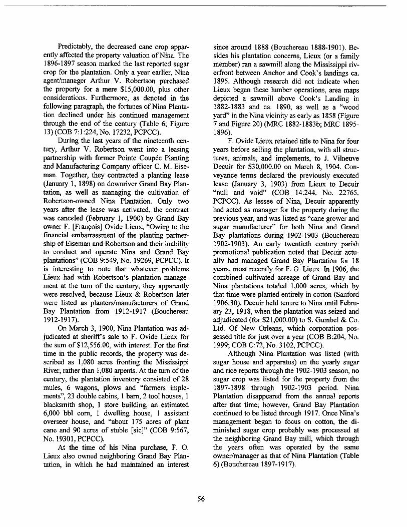
Predictably, the decreased cane crop appar- ently affected the property valuation of Nina. The 1896-1897 season marked the last reported sugar crop for the plantation. Only a year earlier, Nina agent/manager Arthur V. Robertson purchased the property for a mere $15,000.00, plus other considerations. Furthermore, as denoted in the following paragraph, the fortunes of Nina Planta- tion declined under his continued management through the end of the century (Table 6; Figure 13) (COB 7:1:224, No. 17232, PCPCC).
During the last years of the nineteenth cen- tury, Arthur V. Robertson went into a leasing partnership with former Pointe Coupee Planting and Manufacturing Company officer C. M. Eise- man. Together, they contracted a planting lease (January 1, 1898) on downriver Grand Bay Plan- tation, as well as managing the cultivation of Robertson-owned Nina Plantation. Only two years after the lease was activated, the contract was canceled (February 1, 1900) by Grand Bay owner F. [Francois] Ovide Lieux; "Owing to the financial embarrassment of the planting partner- ship of Eiseman and Robertson and their inability to conduct and operate Nina and Grand Bay plantations" (COB 9:549, No. 19269, PCPCC). It is interesting to note that whatever problems Lieux had with Robertson's plantation manage- ment at the turn of the century, they apparently were resolved, because Lieux & Robertson later were listed as planters/manufacturers of Grand Bay Plantation from 1912-1917 (Bouchereau 1912-1917).
On March 3, 1900, Nina Plantation was ad- judicated at sheriffs sale to F. Ovide Lieux for the sum of $12,556.00, with interest. For the first time in the public records, the property was de- scribed as 1,080 acres fronting the Mississippi River, rather than 1,080 arpents. At the turn of the century, the plantation inventory consisted of 28 mules, 6 wagons, plows and "farmers imple- ments", 23 double cabins, 1 barn, 2 tool houses, 1 blacksmith shop, 1 store building, an estimated 6,000 bbl corn, 1 dwelling house, 1 assistant overseer house, and "about 175 acres of plant cane and 90 acres of stuble [sic]" (COB 9:567, No. 19301, PCPCC).
At the time of his Nina purchase, F. O. Lieux also owned neighboring Grand Bay Plan- tation, in which he had maintained an interest
since around 1888 (Bouchereau 1888-1901). Be- sides his plantation concerns, Lieux (or a family member) ran a sawmill along the Mississippi riv- erfront between Anchor and Cook's landings ca. 1895. Although research did not indicate when Lieux began these lumber operations, area maps depicted a sawmill above Cook's Landing in 1882-1883 and ca. 1890, as well as a "wood yard" in the Nina vicinity as early as 1858 (Figure 7 and Figure 20) (MRC 1882-1883b; MRC 1895- 1896).
F. Ovide Lieux retained title to Nina for four years before selling the plantation, with all struc- tures, animals, and implements, to J. Vilneuve Decuir for $30,000.00 on March 8, 1904. Con- veyance terms declared the previously executed lease (January 3, 1903) from Lieux to Decuir "null and void" (COB 14:244, No. 22765, PCPCC). As lessee of Nina, Decuir apparently had acted as manager for the property during the previous year, and was listed as "cane grower and sugar manufacturer" for both Nina and Grand Bay plantations during 1902-1903 (Bouchereau 1902-1903). An early twentieth century parish promotional publication noted that Decuir actu- ally had managed Grand Bay Plantation for 18 years, most recently for F. O. Lieux. In 1906, the combined cultivated acreage of Grand Bay and Nina plantations totaled 1,000 acres, which by that time were planted entirely in cotton (Sanford 1906:30). Decuir held tenure to Nina until Febru- ary 23, 1918, when the plantation was seized and adjudicated (for $21,000.00) to S. Gumbel & Co. Ltd. Of New Orleans, which corporation pos- sessed title for just over a year (COB B:204, No. 1999; COB C:72, No. 3102, PCPCC).
Although Nina Plantation was listed (with sugar house and apparatus) on the yearly sugar and rice reports through the 1902-1903 season, no sugar crop was listed for the property from the 1897-1898 through 1902-1903 period. Nina Plantation disappeared from the annual reports after that time; however, Grand Bay Plantation continued to be listed through 1917. Once Nina's management began to focus on cotton, the di- minished sugar crop probably was processed at the neighboring Grand Bay mill, which through the years often was operated by the same owner/manager as that of Nina Plantation (Table 6) (Bouchereau 1897-1917).
56
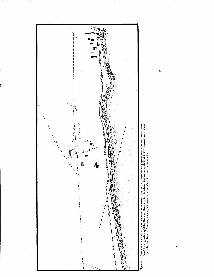
\
00 &
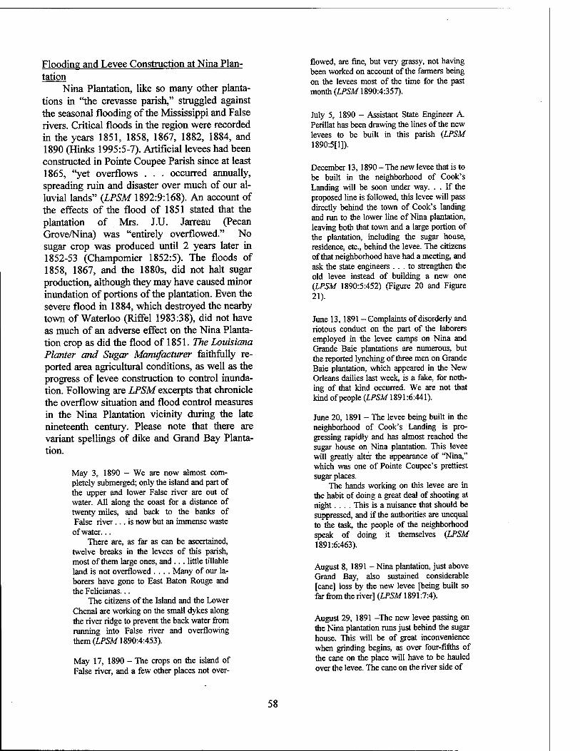
Flooding and Levee Construction at Nina Plan- tation
Nina Plantation, like so many other planta- tions in "the crevasse parish," struggled against the seasonal flooding of the Mississippi and False rivers. Critical floods in the region were recorded in the years 1851, 1858, 1867, 1882, 1884, and 1890 (Hinks 1995:5-7). Artificial levees had been constructed in Pointe Coupee Parish since at least 1865, "yet overflows . . . occurred annually, spreading ruin and disaster over much of our al- luvial lands" (LPSM 1892:9:168). An account of the effects of the flood of 1851 stated that the plantation of Mrs. J.U. Jarreau (Pecan Grove/Nina) was "entirely overflowed." No sugar crop was produced until 2 years later in 1852-53 (Champomier 1852:5). The floods of 1858, 1867, and the 1880s, did not halt sugar production, although they may have caused minor inundation of portions of the plantation. Even the severe flood in 1884, which destroyed the nearby town of Waterloo (Riffel 1983:38), did not have as much of an adverse effect on the Nina Planta- tion crop as did the flood of 1851. The Louisiana Planter and Sugar Manufacturer faithfully re- ported area agricultural conditions, as well as the progress of levee construction to control inunda- tion. Following are LPSM excerpts that chronicle the overflow situation and flood control measures in the Nina Plantation vicinity during the late nineteenth century. Please note that there are variant spellings of dike and Grand Bay Planta- tion.
May 3, 1890 - We are now almost com- pletely submerged; only the island and part of the upper and lower False river are out of water. All along the coast for a distance of twenty miles, and back to the banks of False river... is now but an immense waste of water...
There are, as far as can be ascertained, twelve breaks in the levees of this parish, most of them large ones, and ... little tillable land is not overflowed .... Many of our la- borers have gone to East Baton Rouge and the Felicianas...
The citizens of the Island and the Lower Chenal are working on the small dykes along the river ridge to prevent the back water from running into False river and overflowing them (LPSM 1890:4:453).
May 17, 1890 - The crops on the island of False river, and a few other places not over-
flowed, are fine, but very grassy, not having been worked on account of the farmers being on the levees most of the time for the past month (LPSM 1890:4:357).
July 5, 1890 - Assistant State Engineer A. Perillat has been drawing the lines of the new levees to be built in this parish (LPSM 1890:5[1]).
December 13,1890 - The new levee that is to be built in the neighborhood of Cook's Landing will be soon under way. . . If the proposed line is followed, this levee will pass directly behind the town of Cook's landing and run to the lower line of Nina plantation, leaving both that town and a large portion of the plantation, including the sugar house, residence, etc., behind the levee. The citizens ofthat neighborhood have had a meeting, and ask the state engineers ... to strengthen the old levee instead of building a new one (LPSM 1890:5:452) (Figure 20 and Figure 21).
June 13,1891 - Complaints of disorderly and riotous conduct on the part of the laborers employed in the levee camps on Nina and Grande Baie plantations are numerous, but the reported lynching of three men on Grande Baie plantation, which appeared in the New Orleans dailies last week, is a fake, for noth- ing of that kind occurred. We are not that kind of people (LPSM 1891:6:441).
June 20, 1891 - The levee being built in the neighborhood of Cook's Landing is pro- gressing rapidly and has almost reached the sugar house on Nina plantation. This levee will greatly alter the appearance of "Nina," which was one of Pointe Coupee's prettiest sugar places.
The hands working on this levee are in the habit of doing a great deal of shooting at night.... This is a nuisance that should be suppressed, and if the authorities are unequal to the task, the people of the neighborhood speak of doing it themselves (LPSM 1891:6:463).
August 8, 1891 - Nina plantation, just above Grand Bay, also sustained considerable [cane] loss by the new levee [being built so far from the river] (LPSM 1891:7:4).
August 29, 1891 -The new levee passing on the Nina plantation runs just behind the sugar house. This will be of great inconvenience when grinding begins, as over four-fifths of the cane on the place will have to be hauled over the levee. The cane on the river side of
58
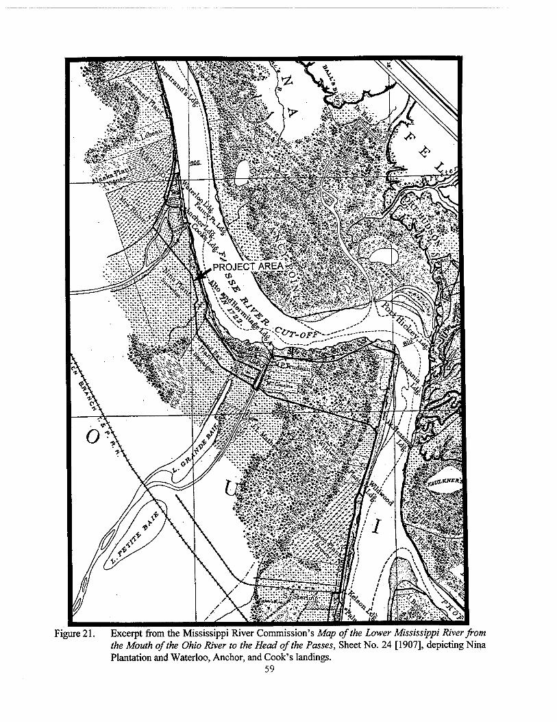
Figure 21. Excerpt from the Mississippi River Commission's Map of the Lower Mississippi River from the Mouth of the Ohio River to the Head of the Passes, Sheet No. 24 [1907], depicting Nina Plantation and Waterloo, Anchor, and Cook's landings.
59
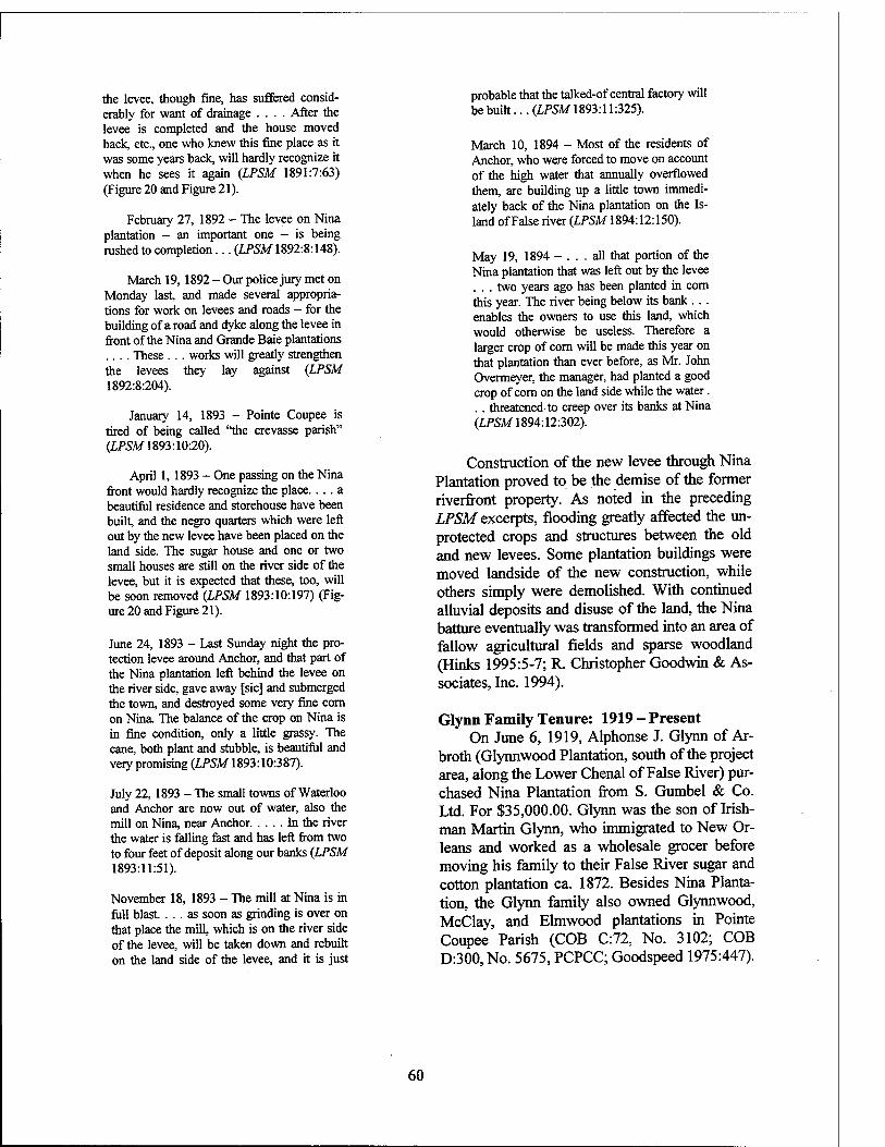
the levee, though fine, has suffered consid- erably for want of drainage .... After the levee is completed and the house moved back, etc., one who knew this fine place as it was some years back, will hardly recognize it when he sees it again (LPSM 1891:7:63) (Figure 20 and Figure 21).
February 27, 1892 - The levee on Nina plantation - an important one - is being rushed to completion... {LPSM 1892:8:148).
March 19,1892 - Our police jury met on Monday last, and made several appropria- tions for work on levees and roads - for the building of a road and dyke along the levee in front of the Nina and Grande Baie plantations .... These ... works will greatly strengthen the levees they lay against (LPSM 1892:8:204).
January 14, 1893 - Pointe Coupee is tired of being called "the crevasse parish" (LPSM 1893:10:20).
April 1, 1893 - One passing on the Nina front would hardly recognize the place.... a beautiful residence and storehouse have been built, and the negro quarters which were left out by the new levee have been placed on the land side. The sugar house and one or two small houses are still on the river side of the levee, but it is expected that these, too, will be soon removed (LPSM 1893:10:197) (Fig- ure 20 and Figure 21).
June 24, 1893 - Last Sunday night the pro- tection levee around Anchor, and that part of the Nina plantation left behind the levee on the river side, gave away [sic] and submerged the town, and destroyed some very fine com on Nina. The balance of the crop on Nina is in fine condition, only a little grassy. The cane, both plant and stubble, is beautiful and very promising (LPSM 1893:10:387).
July 22, 1893 - The small towns of Waterloo and Anchor are now out of water, also the mill on Nina, near Anchor In the river the water is falling fast and has left from two to four feet of deposit along our banks (LPSM 1893:11:51).
November 18, 1893 - The mill at Nina is in full blast. ... as soon as grinding is over on that place the mill, which is on the river side of the levee, will be taken down and rebuilt on the land side of the levee, and it is just
probable that the talked-of central factory will be built... (LPSM 1893:11:325).
March 10, 1894 - Most of the residents of Anchor, who were forced to move on account of the high water that annually overflowed them, are building up a little town immedi- ately back of the Nina plantation on the Is- land of False river (LPSM 1894:12:150).
May 19, 1894 - ... all that portion of the Nina plantation that was left out by the levee . . . two years ago has been planted in corn this year. The river being below its bank ... enables the owners to use this land, which would otherwise be useless. Therefore a larger crop of com will be made this year on that plantation than ever before, as Mr. John Overmeyer, the manager, had planted a good crop of com on the land side while the water. . . threatened to creep over its banks at Nina (LPSM 1894:12:302).
Construction of the new levee through Nina Plantation proved to be the demise of the former riverfront property. As noted in the preceding LPSM excerpts, flooding greatly affected the un- protected crops and structures between the old and new levees. Some plantation buildings were moved landside of the new construction, while others simply were demolished. With continued alluvial deposits and disuse of the land, the Nina batture eventually was transformed into an area of fallow agricultural fields and sparse woodland (Hinks 1995:5-7; R. Christopher Goodwin & As- sociates, Inc. 1994).
Glynn Family Tenure: 1919 - Present On June 6, 1919, Alphonse J. Glynn of Ar-
broth (Glynnwood Plantation, south of the project area, along the Lower Chenal of False River) pur- chased Nina Plantation from S. Gumbel & Co. Ltd. For $35,000.00. Glynn was the son of Irish- man Martin Glynn, who immigrated to New Or- leans and worked as a wholesale grocer before moving his family to their False River sugar and cotton plantation ca. 1872. Besides Nina Planta- tion, the Glynn family also owned Glynnwood, McClay, and Elmwood plantations in Pointe Coupee Parish (COB C:72, No. 3102; COB D:300,No. 5675, PCPCC; Goodspeed 1975:447).
60
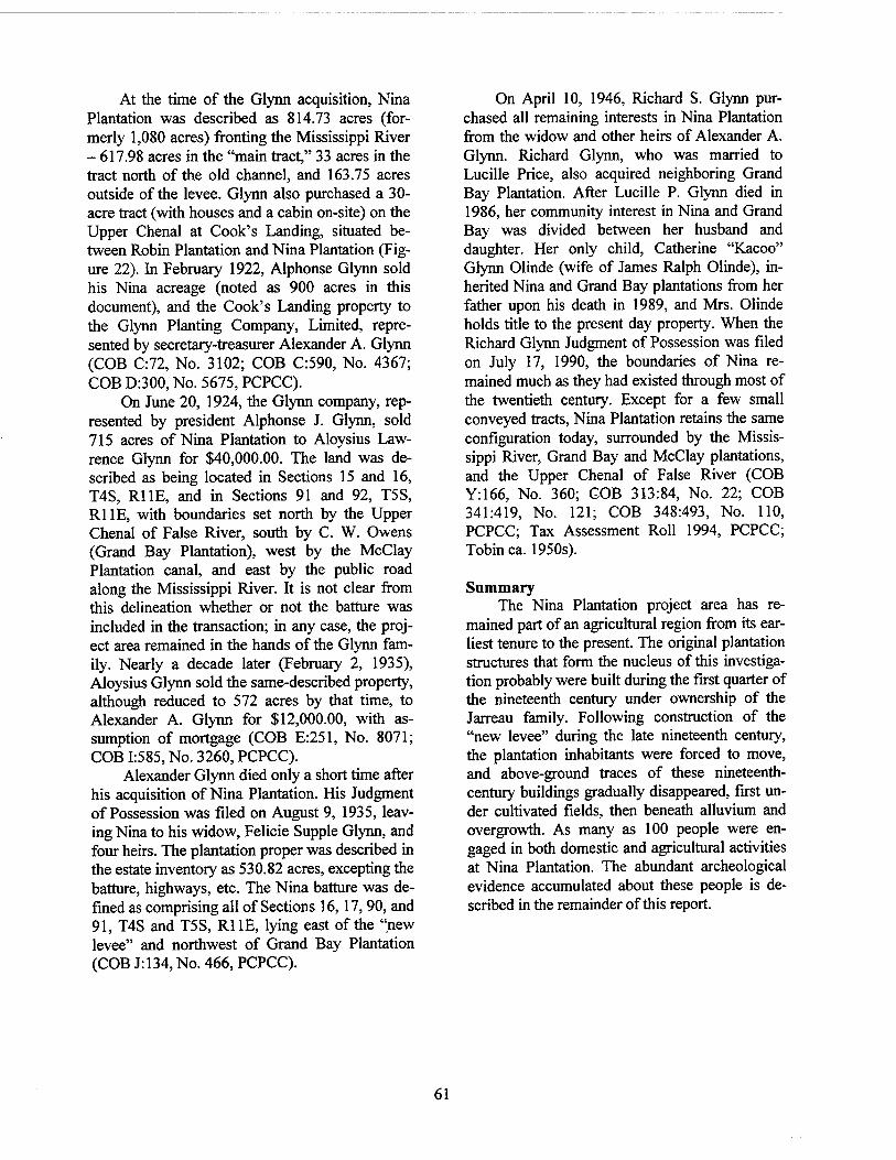
At the time of the Glynn acquisition, Nina Plantation was described as 814.73 acres (for- merly 1,080 acres) fronting the Mississippi River - 617.98 acres in the "main tract," 33 acres in the tract north of the old channel, and 163.75 acres outside of the levee. Glynn also purchased a 30- acre tract (with houses and a cabin on-site) on the Upper Chenal at Cook's Landing, situated be- tween Robin Plantation and Nina Plantation (Fig- ure 22). In February 1922, Alphonse Glynn sold his Nina acreage (noted as 900 acres in this document), and the Cook's Landing property to the Glynn Planting Company, Limited, repre- sented by secretary-treasurer Alexander A. Glynn (COB C:72, No. 3102; COB C:590, No. 4367; COB D:300, No. 5675, PCPCC).
On June 20, 1924, the Glynn company, rep- resented by president Alphonse J. Glynn, sold 715 acres of Nina Plantation to Aloysius Law- rence Glynn for $40,000.00. The land was de- scribed as being located in Sections 15 and 16, T4S, RUE, and in Sections 91 and 92, T5S, RUE, with boundaries set north by the Upper Chenal of False River, south by C. W. Owens (Grand Bay Plantation), west by the McClay Plantation canal, and east by the public road along the Mississippi River. It is not clear from this delineation whether or not the batture was included in the transaction; in any case, the proj- ect area remained in the hands of the Glynn fam- ily. Nearly a decade later (February 2, 1935), Aloysius Glynn sold the same-described property, although reduced to 572 acres by that time, to Alexander A. Glynn for $12,000.00, with as- sumption of mortgage (COB E:251, No. 8071; COB 1:585, No. 3260, PCPCC).
Alexander Glynn died only a short time after his acquisition of Nina Plantation. His Judgment of Possession was filed on August 9, 1935, leav- ing Nina to his widow, Felicie Supple Glynn, and four heirs. The plantation proper was described in the estate inventory as 530.82 acres, excepting the batture, highways, etc. The Nina batture was de- fined as comprising all of Sections 16,17, 90, and 91, T4S and T5S, RUE, lying east of the "new levee" and northwest of Grand Bay Plantation (COB J: 134, No. 466, PCPCC).
On April 10, 1946, Richard S. Glynn pur- chased all remaining interests in Nina Plantation from the widow and other heirs of Alexander A. Glynn. Richard Glynn, who was married to Lucille Price, also acquired neighboring Grand Bay Plantation. After Lucille P. Glynn died in 1986, her community interest in Nina and Grand Bay was divided between her husband and daughter. Her only child, Catherine "Kacoo" Glynn Olinde (wife of James Ralph Olinde), in- herited Nina and Grand Bay plantations from her father upon his death in 1989, and Mrs. Olinde holds title to the present day property. When the Richard Glynn Judgment of Possession was filed on July 17, 1990, the boundaries of Nina re- mained much as they had existed through most of the twentieth century. Except for a few small conveyed tracts, Nina Plantation retains the same configuration today, surrounded by the Missis- sippi River, Grand Bay and McClay plantations, and the Upper Chenal of False River (COB Y:166, No. 360; GOB 313:84, No. 22; COB 341:419, No. 121; COB 348:493, No. 110, PCPCC; Tax Assessment Roll 1994, PCPCC; Tobin ca. 1950s).
Summary The Nina Plantation project area has re-
mained part of an agricultural region from its ear- liest tenure to the present. The original plantation structures that form the nucleus of this investiga- tion probably were built during the first quarter of the nineteenth century under ownership of the Jarreau family. Following construction of the "new levee" during the late nineteenth century, the plantation inhabitants were forced to move, and above-ground traces of these nineteenth- century buildings gradually disappeared, first un- der cultivated fields, then beneath alluvium and overgrowth. As many as 100 people were en- gaged in both domestic and agricultural activities at Nina Plantation. The abundant archeological evidence accumulated about these people is de- scribed in the remainder of this report.
61
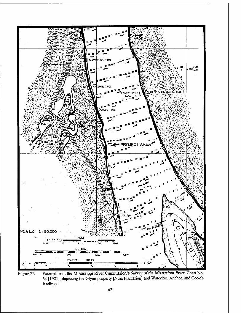
Figure 22. Excerpt from the Mississippi River Commission's Survey of the Mississippi River, Chart No. 64 [1921], depicting the Glynn property [Nina Plantation] and Waterloo, Anchor, and Cook's landings.
62
CHAPTER V
THE ARCHEOLOGICAL CONTEXT
Previous Investigations Interpretation of the results of archeologi- cal data recovery at Nina Plantation (Site
16PC62), must include an awareness of other lo- cal, or related, cultural resources investigations. Knowledge of the results of these previous stud- ies provides both comparative and contextual in- formation. This review of the archeological con- text of Nina Plantation includes a summary of the results of previous Phase II investigations at Nina Plantation (Yakubik et al. 1994), and a discussion of previous cultural resources investigations that have been conducted in the vicinity. Finally, studies at comparable plantation sites in Louisi- ana are reviewed.
NRHP Phase II Excavations at Nina Plantation The archeological site at Nina Plantation
(16PC62) first was identified and recorded in 1992, during a cultural resources survey con- ducted by Earth Search, Inc., for the U.S. Army Corps of Engineers, New Orleans District. As a result of analysis of historic cartographic infor- mation, the site was identified as Nina Plantation. Bankline survey resulted in the identification of five concentrations of historic debris, with manu- facture dates that spanned the nineteenth century. In addition, intensive survey in the area of the former sugar house revealed brick foundations that had been impacted by the removal of fill for levee construction. Because of the presence of intact cultural features, the site was judged capa- ble of producing data important to understanding of both regional and state history. The site was assessed as potentially eligible for inclusion on the National Register of Historic Places, and test
excavations to ascertain National Register eligi- bility, subsequently were conducted at the site (Yakubik et al. 1994:373).
Testing was conducted in both the "great house and quarters complexes," and in the "in- dustrial complex," where the sugar house was thought to have been located. The sugar house is not included in the current project area, since it is positioned more than 33 m (100 ft) from the bankline of the Mississippi River (Scope of Work). Testing in the domestic area of Site 16PC62 consisted of the excavation of 11 back- hoe trenches. These trenches ranged from 3 to 33 m (9.8 to 108.3 ft) in length; they were spaced approximately 50 m (164 ft) apart, and they were oriented perpendicular to the Mississippi River bankline. In addition, one trench was excavated parallel to the river. Trench depth varied but av- eraged 160 cmbs (63 inbs). A representative stra- tigraphic profile included an approximately 100 cm (39.4 in) layer of twentieth century alluvium, capping a culture-bearing stratum averaging ap- proximately 20 cm (7.9 in) in thickness. Only one cultural stratum was noted during the Phase II investigations, although Yakubik stated that cul- tural materials within this stratum appeared to be stratified chronologically (Yakubik et al. 1994:374).
Cultural materials were recovered from all trenches except Trenches 5 and 6. The highest densities of recovered artifacts were noted in Trenches 8 and 10, i.e., those trenches associated with the main house and detached kitchen, and in Trench 2, the area associated with the slave quarters of the plantation (Yakubik et al. 1994:384-388). These results coincided both with
63
bankline survey results and with the overall arti- fact distributions subsequently identified during data recovery trench and unit excavation.
During test excavations at Site 16PC62, 12 features were identified; 10 of these (Features 3 - lla-b) were positioned within the domestic por- tion of the site (Yakubik et al. 1994:384). Fea- tures 3-8 were located in Trench 2, which cut through the slave quarters area of the plantation, and they were outside both the impact area and the current project area. Features 9, 10, 11a, and lib were located in Trenches 8 and 10, both within the current project area, and situated within the main house/outbuilding complex.
Features 9 and 10 were identified in Trench 8, which ran through Block C of the current proj- ect area. These features were described as a "massive brick stepped footing" (Feature 9), and an associated lens of charcoal (Feature 10). Based on available cartographic evidence, and on the high artifact density associated with Trench 8, it appeared that Feature 9 represented a footing for the "great house" (Yakubik et al. 1994:413). Phase EH investigations, however, have shown that Feature 9 was in fact the foundation of a central brick chimney associated with the de- tached kitchen at Nina Plantation (Feature 116). This feature will be described and discussed in detail in Chapter VIE.
Features 11a and 1 lb were located in Trench 10, and were characterized as concentrations of brick and mortar (Feature 11a), and as a "floor" of crushed brick (Feature lib) located directly east of the brick and mortar concentration. A high density of pane glass and nails recovered from this trench suggested a structural association for the feature, while the presence of cast iron stove fragments suggested that the associated structure represented a kitchen dependency for the main house (Yakubik et al. 1994:422). The current Phase HI excavations were able to demonstrate that these features were associated with the main house, and not with a kitchen outbuilding. The main house structure will be discussed in depth in Chapters VEI and DC.
Trench 2, excavated In the vicinity of the slave quarters, contained six recorded features. These were identified as a concentration of char- coal, cinder, coal, and slag (Feature 3); concen- trations of brick and mortar (Features 4 and 6); two brick piers (Feature 5); the remnants of a wall
footing (Feature 7); and a trash pit (Feature 8). It is clear from the historical cartographic evidence examined as a part of the Phase HI archival re- search, that the features located in Trench 2 dur- ing the Phase II excavation were associated with the slave quarters of Nina Plantation. High con- centrations of ceramics, glass, metal, and faunal materials also were recovered during excavation in this area. In Chapter DC of this report, these subassemblages will be compared with the arti- facts recovered during data recovery at the main house and in the outbuilding complex.
Based on the results of the 1992 National Register testing at Nina Plantation, the site was assessed as eligible for inclusion in the National Register of Historic Places, and data recovery of Site 16PC62 was recommended (Yakubik et al. 1994:453-454). The final report, which docu- mented the results of testing at 16PC62, offered a number of potential research questions, as well as suggested data recovery methods (Yakubik et al. 1994:454-461). These questions were considered as part of the data recovery program conducted by R. Christopher Goodwin & Associates, Inc.; a more complete discussion of these issues is found below, in Chapter VI of this report.
Previous Cultural Resources Surveys in the Vi- cinity of Site 16PC62
For the purposes of this report, the vicinity of Site 16PC62 has been defined as the west (right descending) bank of the Mississippi River, between Pointe Coupee (River Mile 265) and Point Menoir (River Mile 255). In addition, sur- veys conducted within a distance of 3.2 km (2 mi) inland from the Mississippi River also are in- cluded in this summary. The majority of cultural resources surveys and assessments identified in the vicinity of Site 16PC62 have focused on the bankline and batture areas of the Mississippi River, and have been stimulated by levee revet- ment and construction work planned and carried out by the U.S. Army Corps of Engineers. An- other survey associated with the planned con- struction of an oil pipeline by Colonial Pipeline Company also resulted in an extensive examina- tion of the region.
The first survey and assessment completed in the vicinity of the current project area was conducted in 1976 by Coastal Environments, Inc. That survey, conducted in anticipation of the con-
64
struction of a 40 inch O.D. Colonial Pipeline Company products line, extended from East Fe- liciana Parish, Louisiana, to Orange County, Texas (Gagliano et al. 1976). Waterloo (Site 16PC31), Fancy Point, and Cook's Landing, all were recorded as a result of that survey. As noted above, Waterloo was an historic river town that dated from 1840 to 1910; both Fancy Point and Cook's Landing were associated with Waterloo. At the time of survey, the Waterloo portion of the site had been impacted by previous levee con- struction, and Fancy Point Landing had been im- pacted by an oil pipeline constructed during the 1960s (Gagliano et al. 1976:62). Testing at the site of Cook's Landing consisted of the excava- tion of a series of backhoe trenches oriented per- pendicular to the portion of the proposed pipeline; of the five trenches excavated, only one contained cultural materials (Gagliano et al. 1976:67-70). No features were encountered in the trenches, but subsequent bankline survey of the site produced evidence of brick piers and a brick foundation, as well as additional nineteenth century cultural material. The depth of the cultural deposits was estimated at between 1.5 to 1.8 m (4.9 to 5.9 ft), and Gagliano et al. (1976: 96-97) noted that this significant cultural resource represented an intact example of a nineteenth century Mississippi River town and landing. They also suggested steps to mitigate impacts to the site from the pro- posed pipeline construction, and subsequently five 1 x 1 m (3.3 x 3.3 ft) units were excavated at Cook's Landing by Castille and Morgan (n.d.). Extensive deposits of nineteenth century materi- als, interpreted as the remains of warehouses, were identified within 20 m (66 ft) of the bank- line (cf, Gagliano et al. 1978:1,18).
In 1978, Coastal Environments, Inc. revis- ited the vicinity of Site 16PC31 to conduct a cul- tural resources assessment of the site of a pro- posed borrow pit area located approximately 0.5 km (0.3 mi) west of the 16PC31 site area (Ga- gliano et al. 1978). Fieldwork included the exca- vation of 11 trenches, but cultural material only was recovered from two of those trenches. This material included brick, a single non-diagnostic ceramic sherd, a single piece of non-diagnostic glass, an iron spike, and various iron fragments. No midden deposits or evidence of cultural fea- tures were noted, and it was determined that there
would be no adverse impact as a result of borrow pit excavation (Gagliano et al. 1978:22,25,27).
A cultural resources survey of the proposed Pointe Coupee to Arbroth levee enlargement project area was conducted in 1983 by Stuart and Greene of the National Park Service. That survey extended from M-270 to 249.5-R, and included the entire bankline and batture area between Pointe Coupee and Point Menoir (Stuart and Greene 1983), and incorporating the not yet re- corded site, 16PC62 (Nina Plantation). In 16 ar- eas scheduled for impact, "100 percent" pedes- trian reconnaissance was conducted along linear transects spaced varying widths apart. In the re- mainder of the project area, an estimated 25 per- cent of the area was surveyed. No subsurface testing was conducted in conjunction with this project (Stuart and Greene 1983:8). While the previously recorded sites 16PC31 and 16PC33 were noted, no new cultural resources were re- corded (Stuart and Greene 1983:9).
In 1992, Earth Search, Inc. (Yakubik et al. 1994) conducted an extensive survey of a number of Mississippi River levee and revetment project areas scattered between River Miles 270.2 and 246.0-R. Survey included an assessment of the planned Grand Bay Revetment Item, i.e., the batture area between River Miles 259.5 and 255.0-R; the Arbroth Revetment Item, located on the batture between River Miles 251.4 and 246.0- R; and Pointe Coupee to Arbroth Seepage Con- trol Project, which included scattered areas both within the batture and landside of the levee be- tween River Miles 266.0 and 249.4-R. Fieldwork resulted in the recordation of eight sites within the various revetment items. Of these, Site 16PC62, Nina Plantation, located in the Grand Bay Re- vetment area, was the only site assessed as poten- tially eligible for inclusion in the National Regis- ter of Historic Places. Other historic sites re- corded during batture survey included 16PC56, a scatter of late nineteenth-early twentieth century structural and domestic debris; 16PC57, a series of exposed early nineteenth century artifact con- centrations positioned along the top of and river side of an abandoned levee; 16PC58, a deposit of slag, coal, iron, and structural materials scattered along the bankline; 16PC59, a scatter of coal, brick, iron, glass, and nineteenth century ceramics found eroding from the bankline; 16PC60, a low
65
density scatter of mid to late nineteenth century domestic artifacts also found eroding from the bankline; and 16PC61, a light scatter of nine- teenth century domestic material. Each of these sites, with the exception of 16PC61, was located in the vicinity of the Pointe Coupee Ferry, i.e., just upriver from the defined vicinity of Site 16PC62. Site 16PC61 is located east of the infe- rior Chenal of False River, or approximately 4.0 km (2.5 mi) downriver from Site 16PC62 (Nina Plantation). Subsequent Phase II testing at Nina Plantation (Yakubik et al. 1994) was discussed previously, and the archeological results of that effort are reviewed in more detail in subsequent chapters of this report.
Plantation Sites in Louisiana While no comparable plantation sites have
been identified in the immediate vicinity of Site 16PC62, a number of archeological investigations have been conducted on eighteenth and nine- teenth century plantations in other areas of the state. Because of their comparative value in re- searching a site such as Nina Plantation, these sites will be introduced briefly in this section; detailed comparisons are drawn to the results and conclusions of those efforts in Chapters VIII, DC, and X, below.
Rosehill Plantation (16WBR12) Located just downriver from Profit Island, at
Solitude Point, Rosehill Plantation (16WBR12) first was recorded in 1984 by the National Park Service (Shafer et al.1984). This reconnaissance survey, conducted under contract to the U.S. Army Corps of Engineers, New Orleans District, resulted in the identification of both brick foun- dation remains and domestic artifacts eroding from the river bank. In 1992, the site was revis- ited by Earth Search, Inc., and test excavations were conducted to assess the significance of the site applying the National Register of Historic Places criteria for evaluation (Yakubik et al. 1994). A total of seven backhoe trenches were excavated throughout the site areas, and they pro- duced the extensive remains of the plantation sugar house, as well as evidence of a small do- mestic component. Data recovery to examine and record the sugar house portion of the site was recommended (Yakubik et al. 1994:496-497).
More recently, several deeply buried cultural features that had not been identified previously were discovered during construction of the Ar- broth Revetment. These features were investi- gated by Coastal Environments, Inc. (Hahn 1994). While subsumed within the larger bounda- ries of Rosehill Plantation, these features were not part of the plantation, per se, but rather they were associated with a small free black community that had developed on the land of Theophile Mahier, a free person of color. Site 16WBR40 consisted of a group of brick foundations that probably were associated with a small sugar mill operated by Mahier, while Site 16WBR41 was a cemetery associated with the black community, which probably was in use between 1877 and 1930 (Hahn 1994:57). The features investigated by Coastal Environments, Inc., subsequently were destroyed during construction; no recommenda- tions were made for any remaining portions of these sites (Hahn 1994:59).
Elmwood Plantation f 16JE138) This site, located in East Jefferson Parish,
within the metropolitan New Orleans area, was investigated by R. Christopher Goodwin & Asso- ciates, Inc., in 1984; the project was funded jointly by the U.S. Department of the Interior, by Elmwood Plantation, Inc., and by the Jefferson Historical Society of Louisiana. Originally part of the Ste. Reyne concession, which was granted shortly after the founding of New Orleans, Elmwood remained a productive sugar and rice plantation through the end of the nineteenth cen- tury. Testing at Elmwood Plantation incorporated both archeological excavation and the use of a magnetometer to identify the location of a num- ber of subsurface features. Although it had burned in the 1960s, the ruins of the Great House built by Norbert Fortier still stood. Excavations at Elmwood succeeded in locating the remains of the detached kitchen associated with the house, and they were able to provide data regarding the architecture and use of the Great House and kitchen (Goodwin et al. 1984). While the occupa- tional span identified during excavations is somewhat earlier than that noted for Nina Planta- tion, the architectural details, the ceramic se- quence, and the faunal data derived from these excavations have proved invaluable for compara-
66
tive purposes. The investigations concluded that Elmwood Plantation, because of its potential to provide data important to an understanding of local, regional, and national history, was eligible for nomination to and inclusion in the National Register of Historic Places. In addition, the authors recommended that steps be taken to pre- serve and protect the site (Goodwin et al. 1984:259).
Ashland-Belle Helene Plantation (16AN26) Data recovery efforts at Ashland-Belle
Helene Plantation, located near Gonzales in As- cension Parish, were conducted by Earth Search, Inc. in 1992, under a Memorandum of Agreement between the Environmental Protection Agency, the Louisiana State Historic Preservation Officer, the Advisory Council on Historic Preservation, and by Shell Chemical Company. Excavations were funded by Shell Chemical Company, and while the Great House and yard of this nineteenth century sugar and cotton plantation already were listed on the National Register, the planned de- velopment of the remaining 68 ac (27.5 ha) parcel would have adversely affected the area of the slave quarters and the sugar mill. Extensive data recovery efforts in the area of the slave quarters provided valuable architectural data, and further allowed characterization of the material culture and diet of the occupants of these nineteenth century quarters (Yakubik et al. 1994). In Chap- ters DC of this report, a number of detailed com- parisons are made between ceramic and faunal data recovered from the Ashland-Belle Helene Plantation, and data collected from Nina Planta- tion.
Oaklev Plantation (16WF34) Oakley Plantation is located within the
Audubon State Commemorative Area, near St. Francisville, Louisiana. Its life as a cotton planta- tion spanned the nineteenth century, and even after its demise as a productive enterprise, tenants continued to occupy Oakley until 1949 (Wilkie and Farnsworth 1992:2). In 1980, 1984, 1985, 1989, and 1990, cultural resources surveys were conducted in portions of Oakley Plantation (Woodiel 1980, 1985; Holland and Orser 1984; Castille 1989, 1990). Subsequent to these inten- sive surveys (1991), more extensive testing for
National Register eligibility was conducted by Wilkie and Farnsworth of the Department of Ge- ography and Anthropology at Louisiana State University, in Baton Rouge. Fieldwork consisted of unit excavation, shovel testing, magnetometer survey, mechanical post-hole excavation, surface collection, and the gathering of oral histories. While many of the areas tested revealed a level of disturbance sufficient to deny inclusion on the National Register of Historic Places, other areas displayed evidence of features that possessed bom research potential and integrity (Wilkie and Farnsworth 1992:3). While no data recovery ef- forts have been undertaken at Oakley Plantation, the results of testing for National Register eligi- bility have provided artifactual and faunal data from what is believed to have been the residence of the Freeman family, who were employed as domestic servants at the plantation. While the Freemans were occupants of the identified struc- ture during the latter part of the nineteenth cen- tury, material recovered from the structure sug- gests an occupation spanning the entire nine- teenth century (Wilkie and Farnsworth 1992:193).
In addition to these plantation studies, lim- ited work has been conducted at a number of other plantation sites along the river. In 1982, limited testing for National Register eligibility was conducted by R. Christopher Goodwin & Associates, Inc., at Magnolia Plantation (16PL94). The area tested, however, did not con- tain significant features or cultural remains re- lated to the occupation of Magnolia Plantation (Goodwin and Yakubik 1982:111). Lakeland Plantation (16PC33), lies approximately 8 km (5 mi) upriver from Nina Plantation. Testing at this site was limited, and failed to identify any fea- tures associated with this nineteenth century sugar and cotton plantation (Hinks et al. 1983). Limited archeological investigations were con- ducted in 1993 at Destrehan Plantation (16SC18) (Yakubik et al. 1993), but did not contribute data useful for comparative purposes. Finally, cultural resources investigations were conducted in 1992 at Beka Plantation (16OR90), by Earth Search, Inc. (Yakubik and Franks 1992). While only one 1 x 1 m (3.3 x 3.3 ft) unit was excavated, the re- covered data provided information on ceramics and faunal remains that can help to elucidate
67
nineteenth century Louisiana plantation trade, consumption, and dietary patterns.
Plantation Sites in the Southeastern United States
While the most concise archeological com- parisons can be made with data derived from plantation studies within Louisiana, placing the current project within the wider context of the antebellum Deep South allows more accurate dis- crimination of local patterns of change. For ex- ample, studies conducted in coastal and lowland
Georgia (Otto 1984; Adams and Boling 1989), Florida (Fairbanks 1974), Texas (Gross et al. 1990), and South Carolina (Wheaton and Garrow 1985), have provided data essential for the inter- pretation of broader patterns of trade, social and labor relations, ethnic identity, plantation layout, and architecture. The theoretical and methodo- logical aspects of these and other regional inves- tigations into plantation society are discussed in Chapter VI, while specific archeological com- parisons are addressed in Chapters IX and X of this report.
68
CHAPTER VI
RESEARCH DESIGN
Introduction The Scope of Work (Appendix EX) for ar- cheological data recovery at Nina Plantation
(16PC62) defined three major research objec- tives. The first was examination of the material culture of planter and slaves/freedmen on a sugar and cotton plantation. The second issue was a comparison between dietary patterns identified for planter and slaves/freedmen. The final re- search issue specified in the Scope of Work was examination of the layout of buildings at Nina Plantation. Each of these themes was derived from prior research within Louisiana and within the broader universe of Southern agricultural sites; all were approached from the framework of past plantation studies.
The archeological investigation of planta- tions has developed from particularistic studies of architectural remains, first carried out in the 1930s (Cate 1930:34; Ford 1937) for purposes of reconstruction, to complex anthropological ex- aminations of the plantation as social, cultural, economic, and political units (Orser 1988a, 1988b, 1988c; Epperson 1987, 1990; Kelso 1984; Otto 1984). Charles Fairbanks, in his work at Kingsley Plantation in Florida (Fairbanks 1974), was one of the first to employ this more holistic approach. For perhaps the first time, the emphasis of plantation investigation was placed on slavery and African Americans, rather than on slave owners. This signaled the beginning of the con- sideration of the plantation as a milieu of com- plex and interdependent relationships, and almost a microcosm of Southern society (Otto 1984). It was the beginning of a recognition that "slaves and other agricultural laborers [were] essential components to understanding plantation life" (Singleton 1990:71).
Within this broad framework, theoretical approaches to the plantation system have varied considerably. The great majority of plantation studies have concentrated on the reconstruction of everyday life, with attention to examinations of facets of material life such as housing and diet. Efforts also have been made to define and to in- terpret the relationship of class, status, and race within plantation society. Recent works by Orser (1987, 1988a, 1988b, 1988c, 1989) have charac- terized plantations as systems based more on eco- nomics and relationships of power, rather than on race and status. There has been a gradual move- ment away from a focus on the descriptive and static products of social interaction - race and status - to the study of the process of "cultural interchange" (Singleton 1990:74), and to the pro- cess of creolization (Ferguson 1992; Sobel 1987). This new focus has permitted the study of the complexity of relationships, and of the dynamic processes of change within plantation society.
All of these studies have relied on the ability either to control a site's spatial components, in order to describe synchronic intrasite relation- ships, or to control the temporal components to describe diachronic change. Now, according to Howson, "what is needed is a contextual descrip- tion of material culture that is conscious of both plantation...relations and historical processes of culture change" (1990:90). The ideal site for a study of this type would be one at which patterns of social, economic, and material relationships could be defined spatially, and at which there is sufficient temporal control to permit confident description of change in these patterns. Research at Nina Plantation (16PC62) has demonstrated sufficient preservation of the main house and an- cillary structures, the detached kitchens, and the
69
nearby dwellings for household slaves/servants, to support the conduct of effective spatial analy- sis. Additionally, because of the mid-nineteenth century flood deposit that sealed and separated the antebellum middens from later cultural de- posits, the stratigraphic control vital to the study of change over time is available. Unfortunately, not all of the key elements of plantation society are represented in the Nina Plantation data. The quarters for field slaves were outside both the area of potential effects and the project area, and these areas were only cursorily examined during prior Phase II testing (Yakubik 1994). While these data have been incorporated to some extent in data analysis for this project, the primary com- parative effort focused on the relationships be- tween the planter and the slaves/servants em- ployed in a domestic capacity. These may have differed from more general planter - slave rela- tionships, not only because of the increased inter- action between diese groups in the work envi- ronment, but they also may have been affected by age and gender.
Spatial Relationships Contemporary scholarship regarding land-
scapes and their meanings holds that landscapes and the spatial arrangements of plantation sites in particular are the results of conscious efforts to "provide housing, accommodate the system of production, facilitate communication and trans- portation, mark social inequalities, and express aesthetics" (Rubertone 1989:50). Landscapes and spatial relationships in both rural and urban set- tings also are seen as fluid and dynamic (Stewart- Abernathy 1986; Rubertone 1989; Moir 1982; Rotenizer 1992), and as reflective of changing social perspectives. Given these theoretical con- structs, it would be expected that documented changes in economic fortunes, the size and nature of the work force, or changes in ownership would be reflected in a variety of temporally identifiable architectural features and artifact patterns at Nina Plantation.
The original proposal submitted for the data recovery at Nina Plantation suggested that inves- tigation of the pattern of structures, landscape features, and activity areas that defined the use of space at Nina Plantation should be based on a modified concept of farmstead proxemics posited by Moir (1982). The concept of farmstead
proxemics assumes that recovered archeological remains will reflect definite spheres of organiza- tion and activity. Originally applied to small farmsteads, farmstead proxemics is useful in pro- viding a theoretical paradigm for the analysis of the spatial organization of large agricultural com- plexes such as Nina Plantation. Moir's (1982) model defined two yard areas centered on the main farm residence. The immediate active yard was a relatively "clean" space surrounding the main dwelling, and it was characterized by a relative absence of sheet midden deposits and structural features. The "outer active yard," in which domestic and agricultural dependencies and activity areas were located, was characterized by relatively dense deposits of sheet midden ref- use, and by artifacts and features relating to those ancillary structures.
A comparative predictive model for struc- tures associated with specific Louisiana Planta- tion types was generated during study of the Willow Bend area conducted by R. Christopher Goodwin & Associates, Inc. (Goodwin et al. 1989). This model suggests that typical nine- teenth century sugar plantation complexes incor- porated two classes of structures: domestic and service structures, and industrial structures. The Nina Plantation study has focused on the domes- tic and service structures at the plantation. These typically included the Great House and its associ- ated dependencies, removed from the industrial areas and from the slave quarters; a manager's house, located in closer proximity to both slave dwellings and industrial buildings, and the slave/laborer cabin area, generally arranged line- arly and located closest to the industrial com- plexes. This arrangement appears to correspond closely to that depicted in the levee setback map of Nina Plantation in 1890.
Comparison of Slave/Freedman and Planter Material Culture
A number of recent plantation studies have described the difficulty of conducting compara- tive planter - slave analysis in the absence of ade- quate definitions of the contexts of production, distribution, use, and discard (Howson 1990:84). This difficulty has led to often facile conclusions about the similarity of the material remains pro- duced by these groups (Joseph 1989), or to par- ticularistic searches for "Africanisms" (Emerson
70
1988; Yakubik 1994b). The search for general patterns of material culture that would define the presence of planters, slave, overseers, or poor whites (Otto 1984), and the search for material correlates of status (Adams and Boling 1989), continue to drive much plantation archeology.
The descriptive elements of these studies, however, have proved extremely useful in char- acterizing the ceramic assemblages associated with planter and slave occupations. The synthesis of data from sites on the Georgia and South Carolina coast that was provided by Adams and Boling (1989) suggested discernible differences in the frequency and type of ceramics recovered from planter and slave sites; in the types and di- versity of vessel forms from each site; and, in the relative economic scale represented by the CC index values calculated for assemblages from each type of site. The CC index, devised by George Miller (1980, 1991), employs original price lists to establish a comparative scale of con- sumer ceramic costs. The judicious use of ana- lytical procedures such as this ceramic price scaling, the comparison of vessel forms, and the degree of intra-site matching of ceramic types and of other artifact classes, will aid in the detection of social interaction and differentiation between planter and slave groups.
However, nearly all recent researchers cau- tion against too facile an application of models produced by Adams and Boling's (1989) study. They note mat regional and temporal variation is likely, and that other variables, such as the eco- nomic status of the planter, or even the data re- covery strategies employed, all must be factored into the comparative equation (Adams and Boling 1989). Orser (1992) also suggests that artifact assemblages associated with tenant farming and other systems of postbellum labor will exhibit much different patterns of material culture.
Analysis of the material culture from the planter and slave/freedman domains at Nina Plantation should seek to generate an independent set of data comparable to the models established for the sites in Georgia and South Carolina, as well as from similar contexts in Louisiana. Com- parisons with these models then can be attempted, and the degree of correlation or deviation from them can be established. Issues of regionalism, ethnicity, temporal differences, and differential
access to distribution networks should be ad- dressed during analysis and interpretation of the data.
Analysis of Diet at Nina Plantation The inclusion of a systematic sampling strat-
egy and thorough analysis of the resultant ethno- botanical and faunal samples was included in the research design for archeological data recovery at Nina Plantation (16PC62). The combination of botanical and faunal analyses can establish die- tary resource patterns, and consumption patterns both between and within the socio-economic groups represented at the site.
Applicable faunal analyses should include assessment of the numbers and the taxa of the faunal remains present in the archeological re- mains at Nina Plantation. Comparative studies of faunal remains from slave and planter sites in coastal Georgia and South Carolina, and from the Elmwood Plantation study (Goodwin et al. 1984), have suggested that distinct quantitative differ- ences, both in the numbers of animals consumed and in the variety of taxa utilized for food pur- poses, was discernible on such sites (Reitz 1987). Analysis of faunal specimens for evidence of butchering practices, and to determine the units of acquisition and relative meat yields, also should provide insights into the type and adequacy of the diets enjoyed by planters, slaves, and postbellum laborers at Nina Plantation (Reitz 1987). Dietary comparisons between planters, slaves, and freed- men will be made, and these will be compared with patterns observed in other regions of the plantation South (Reitz et al. 1985; Otto 1984).
Summary The research design for the data recovery
excavations at Nina Plantation includes both spa- tial and temporal analyses in order to elucidate three major research issues. These include an in- vestigation of the settlement pattern at the planta- tion, diachronic and synchronic comparison of the material culture of planter and slave/freedmen occupations, and investigation of the dietary pat- terns of the planter, slave, and freedmen popula- tions. The results of these analyses are presented below in Chapters VIII and IX of this report; they are summarized in Chapter X.
71
CHAPTER VII
ARCHIVAL, FIELD, AND LABORATORY METHODS, AND TYPOLOGIES
Introduction The mitigation plan developed for Site 16PC62 required the design and implemen-
tation of a controlled, scientifically-executed ar- cheological data recovery program. The methods utilized during data recovery were carefully de- signed to address not only the specific research questions formulated for this project (See Chapter VI), but also ". . . to take into account the envi- ronmental and historical processes which have shaped the study area" (Plog 1974). In addition to archeological field and laboratory research, data recovery at Site 16PC62 (Nina Plantation) in- cluded archival, cartographical, geomorphologi- cal, paleoclimatological, historical, zooarche- ological, and ethnobotanical research. The inte- gration of these data sets provides a more thor- ough understanding of the nature of the nine- teenth century occupation of the site. This chapter describes the methods utilized in the field, and during subsequent analyses of recovered data.
Archival Research for a Study of Nina Plan- tation
The archival research for the Nina Plantation Project emphasized primary sources, including even the visual arts. Once hung in Pecan Grove Plantation, the portraits of Jean Ursin and Octa- vine Jarreau, painted in 1826 by Louis Antoine Collas, now are included in the collections of the Louisiana State Museum, New Orleans. To the informed observer the paintings provide indica- tions of the economic substance and the furnish- ings of the planter's household.
Manuscript collections also were examined. The Marcelle Jarreau Bendemagel Genealogical Records included a typescript, ca. 1966, relating to the Jarreau family. The Rosemonde E. and Emile Kuntz Collection included two acts of sale and a land claim relating to Jean Jarreau. The Bender- nagel and Kuntz collections are housed in the Manuscripts Division, Howard-Tilton Library, Tulane University, New Orleans, Louisiana.
Two claims in the French and American Claims Commission records, No. 197 and No. 292, were discovered to have relevance for the study of Nina Plantation. These records are housed in the National Archives, College Park, Maryland. Other records from the National Ar- chives, Washington, D.C., include Transit [Books] No. 996 and 999, surveyor's notebooks of the Waterloo vicinity. The Cartographic Division of the National Archives provided an important source of maps of the project area.
Other records of the Federal Government include the essential Census Population Schedules compiled every ten years. A secondary source, Menn's Large Slaveholders of Louisiana in 1860 (1964) conveniently presents in tabular form a compilation of the following schedules: Schedule No. 1, Free Inhabitants; Schedule No. 2, Slave Inhabitants; Schedule No. 4, Productions of Agri- culture; and Schedule No. 6, Social Statistics.
The records of Pointe Coupee Parish, pro- vided by the Clerk of Court, included Conveyance Books, Original Acts Books, and Tax Assessment Rolls. A two volume manuscript edition of early surveys and plats of Pointe Coupee Parish (1818-
72
1822; 1822-1827) also is house with the Clerk of Court.
The published multi-volume records of the Catholic Diocese of Baton Rouge detail the births, deaths, baptisms, and marriages of the occupants of the plantation house at Nina Plantation in the first half of the nineteenth century.
Contemporary periodicals examined included the Pointe Coupee Democrat on microfilm at the Howard-Tilton Library, Tulane. The Louisiana Planter and Sugar Master, Louisiana Collection, Howard-Tilton Library, also provided specific details of the plantation and its vicinity. The Obituary Index, an unpublished compilation of the Louisiana Division, New Orleans Public Library, comprises death notices from many Louisiana newspapers.
As always, the annual Statements of the Sugar Crop proved essential to research on a Louisiana sugar plantation. Pierre Degelos pro- vided the first listing of sugar planters in his "Statement of the Sugar Made in Louisiana in 1828 and 1829." Compiled from 1844 to 1862 by P. A. Champomier, the popular series was re- sumed after the Civil War by Louis Bouchereau (1867-1877) and Alcee Bouchereau (1877-1917). Frank M. Cayton's Landings (1881) provided an important contemporary parallel source, as well.
Field Methods Field techniques utilized during this investi-
gation were formulated to identify, record, de- scribe, and interpret cultural features located within the area of potential effect. Because the Mississippi River has deposited approximately 1 m (3.3 ft) of fluvial sediment on the site during the years since it was abandoned, heavy equip- ment was necessary to remove the overburden that covered occupational levels at the site. Me- chanical removal of overburden was followed by hand excavation in order to recover the archeo- logical data required to investigate thoroughly the historical occupation of Nina Plantation.
Reconnaissance and Ethnobotanical Survey Initially, and at the advent of Phase III
fieldwork, reconnaissance survey of the site was conducted prior to establishment of the perma- nent site grid. Exploratory trenches previously excavated by Earth Search, Inc. (Yakubik et al. 1994) were located and then flagged. In addition,
a series of east-west transects were established in anticipation of ethnobotanical survey, which was designed to elucidate the project area specific land use history and ecological succession. Eth- nobotanical survey was conducted along survey transects spaced 50 m (164 ft) apart; the vegeta- tion along these transects was identified, re- corded, and all of the plant species present ulti- mately were mapped. If field identification was not possible at the time of the survey, samples were collected for later identification in the labo- ratory. The results of this survey are discussed in Chapter II; Appendix VIII of this report reviews the results of the ethnobotanical survey in detail.
After both the archeological reconnaissance and ethnobotanical surveys were completed, all vegetation was removed from the area of poten- tial effect, and from a 20 m (66 ft) wide corridor located immediately west of this area. This corri- dor was used as a staging area, and for the dis- posal of the approximately 3,400 m3 (120,069 ft3) of alluvial overburden that was removed from the area under investigation.
Survey and Mapping Methods Following removal of the vegetation, a grid
was superimposed across the site area. The sur- vey was completed by a professional surveyor using a TOPCON GTS-303 5 Electronic Distance Meter (EDM), and a Hewlett-Packard 48SX Data Collector, with a Tripod Data Systems Surveying interface. A series of traverses were executed from a known datum located on the existing arti- ficial levee; this allowed the site to be fixed both in location and elevation. A permanent site datum then was established in the southwest corner of the project area; it was assigned grid coordinate N100 El00. Additional grid points were estab- lished at 30 m (98.4 ft) intervals, extending along a baseline situated north of the site datum, and at 15 m (49.2 ft) intervals in areas located east of the baseline. Contiguous 30 m (98.4 ft) squares were designated Blocks A - I (Figure 2). Use of the EDM and Data Collector permitted for subcenti- meter accuracy in both grid placement and in the collection of elevation data points. In addition to the placement of the site grid, all topographic features were noted and recorded, and each pre- viously located Phase II trench (Yakubik 1994) was re-recorded and tied both to the site grid and to the Louisiana State Plane coordinate system.
73
Magnetometer Survey Following establishment of the site grid, a
magnetometer survey was conducted within the area of potential effect using a Geometries 866 proton precession monitor. Magnetometer survey was conducted at 2 m (6.6 ft) intervals throughout Blocks A -1. The results of magnetometer survey refined identification of structural locations, and proved useful as an indicator of the presence of subsurface cultural features. The results of the magnetometer survey are discussed in Chapter Vm of this report.
Testing and Removal of Overburden After the ethnobotanical and magnetometer
surveys of the project area were completed, allu- vial overburden was removed from Blocks C, D, and E. These areas were selected based on a thor- ough review of the reported Phase II results, of all available historical cartographic data, of the re- sults of the magnetometer survey, and of the re- sults from reconnaissance of the eroding river bankline. A CAT 225 excavator, a bulldozer, and a rubber-tired backhoe were used to remove me- chanically the alluvial deposits from these three block areas. The work was monitored closely by professional archeologists experienced in the use of mechanical excavation. Approximately 3,400 m3 (120,069 ft3) was cleared to the level exposing debris associated with the final occupation of the site. The wide contiguous exposure achieved through the mechanical stripping of the alluvial overburden enabled the simultaneous exposure of numerous architectural and midden features, and led to enhanced intra-site interpretations regard- ing architectural patterning, the location of nu- merous activity areas, and/or yardscape proxe- mics.
A total of 17 backhoe trenches, with a com- bined total length of 297 m (974 ft), also were excavated in the project area (Figure 2). Each trench measured approximately 1.8 m (5.9 ft) in width; this greater width enabled a clearer view of the site stratigraphy, and of any features en- countered during excavation. The placement of the trenches was intended to help in the identifi- cation of activity areas within the site, to aid in the characterization of portions of the site lying outside of the major area of occupation, and to enable examination of deeper stratigraphic levels
of the site. All trenches were assigned sequential numbers (1-17), and they also were designated by their associated grid coordinates. A list of the trenches, their lengths and depths, and the rea- sons) for their excavation can be found in Ap- pendix I of this report. As noted above, trench excavation was monitored closely by archeolo- gists; all excavated soils were segregated by level, and were examined for artifacts by raking and troweling. Recovered artifacts were bagged by trench, section, stratum, and depth. Stratigraphic profiles then were prepared for representative sections of each trench, and soil colors were re- corded using Munsell Color Charts and standard soils nomenclature. The location and depth of each excavated trench was recorded using the EDM and Data Collector. Finally, all trenches were photographed prior to completion of the recordation process.
Hand Excavation Following mechanical removal of overbur-
den, all exposed features were recorded and pre- pared for hand excavation. Excavation units then were positioned to allow investigation of these features, or to allow for the characterization of the exposed midden. While the extent or boundaries of the most recent cultural midden was apparent after removal of the overburden, a number of units were positioned to corroborate the extent of the midden, and to provide a representative sam- ple of this midden deposit from different portions of the site. A total of 251 m2 (823 ft2) were hand excavated in 170 units during this phase of field- work; a list of all excavated units, and the ration- ale for their placement is included in Appendix I of this report.
Hand excavation was conducted in 1 x 1 m (3.3 x 3.3 ft) units, although some of the units were expanded to incorporate a number of subse- quently identified features. Each unit was desig- nated by block letter and then sequentially by the order in which it was excavated within the block. For example, the first unit excavated in Block C was designated Unit C/l, while the first unit ex- cavated within Block E was designated Unit E/l. All features identified during excavation were recorded and designated with a sequential nu- meral. To avoid confusion, these numerical des- ignations were not tied to the block system, but
74
were part of a site-wide system. All units, fea- tures, and trenches also were labeled with their respective grid coordinates.
To maintain vertical integrity after the re- moval of approximately 1 m (3.3 ft) of overbur- den from across the site, a datum was established in the southwestern corner of each unit. During the first stage of excavations, the elevation of each unit datum was reestablished relative to the site datum. All unit data points also were re- corded with the EDM. All elevational measure- ments recorded during excavation subsequently were converted to the National Geodetic Vertical Datum (NGVD) plane (Appendix I).
Each unit was excavated following the natu- ral stratigraphy of the site, with 10 cm (3.9 in) arbitrary levels maintained within strata. In units that displayed complex stratigraphy, levels were used to designate any segregated excavated soils. For example, in units that incorporated the out- side wall of a structure, separate levels were as- signed to soils from the interior and the exterior of the structure, despite the fact that these levels originated from the same horizontal plane. Loca- tional and elevational data then were recorded for each excavated level.
All excavated soils were screened through 0.64 cm (0.25 in) wire hardware mesh to ensure artifact recovery. The recovered cultural material was bagged by unit, stratum, level, and depth. All features were drawn in plan and profile, and then photographed; in the case of brick features, de- tailed drawings were made to illustrate the pattern of brickwork and the number of courses. In most cases, the units were placed to provide informa- tion about the relationship between features and the surrounding site stratigraphy. Soil features were drawn in plan, and then sectioned. A mini- mum of two liters of fill was retained from each excavated soil feature; if a feature contained less than two liters of soil, all of the excavated soil was retained for flotation and/or for specialized analysis. Detailed unit and feature plans were prepared at relevant stages during the unit and feature excavation process. Cross-sections of each excavated soil feature were drawn, and stra- tigraphic soil profiles were prepared of each ex- cavation unit; soil characteristics were recorded using Munsell Soil Color Charts and standard soils nomenclature. Detailed field notes were pre- pared that described each excavated level and all
associated features. All units and features were photographed prior to completion of the archeo- logical recordation process. After completion of excavation at Nina Plantation (16PC62), each block, unit, and trench was backfilled.
Laboratory Methods The laboratory methods and techniques em-
ployed during this project were based on both the research objectives (See Chapter VI) and on the nature of the recovered materials. More specifi- cally, laboratory methods were designed to pro- vide the data required to address the questions and test the hypotheses presented in both the re- search design and in the Scope of Work for this archeological data recovery project. An inventory and initial descriptive analysis included all classes of recovered cultural material. This inventory provided basic descriptive information fields about artifact morphology and typological place- ment. This information also was encoded into computerized artifact databases, created with Mi- crosoft Access 2.0. Basic information in each da- tabase entry included provenience data, material type, and functional categories.
To facilitate extra-site comparison, the analysis included functional categories originally devised by South (1977); also included was a set of more specific categories utilized during this analysis. While the classifications developed by South were useful for defining broad regional patterns of settlement in the Carolina Piedmont, they are of less utility in identifying more subtle intra-site activities and interactions. For example, South's classificatory system combines in a sin- gle category artifacts used for food consumption, food preparation, and food storage, thereby blur- ring any distinctions associated with these activi- ties within a site. The system also does not take into account the multiple functions some artifacts have, or the recycling of certain artifacts after discard.
The 20 functional categories used during the Nina Plantation analysis are listed in Appendix I, along with examples of the artifact types included in each category. This classificatory system shared similarities with those devised by Yakubik et al. (1994), and by Wilkie and Farnsworth (1992), but differed in its allowance for more than one function for each artifact. In general, the function of an artifact at the time of manufacture
75
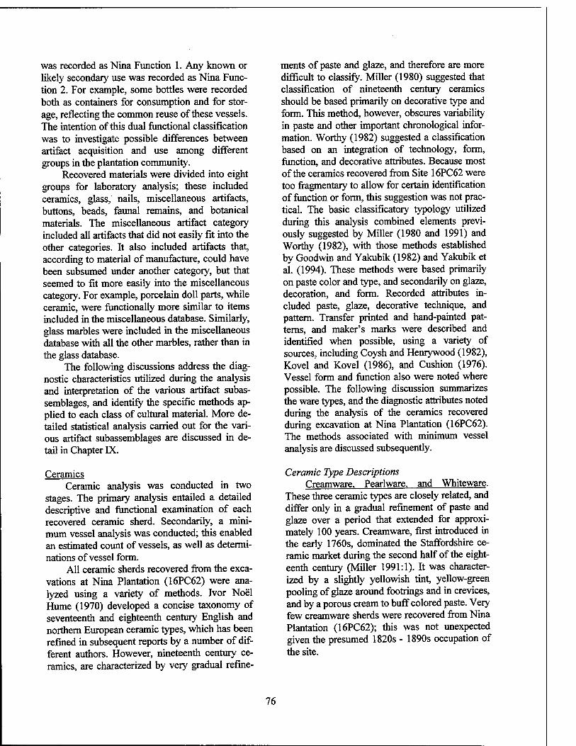
was recorded as Nina Function 1. Any known or likely secondary use was recorded as Nina Func- tion 2. For example, some bottles were recorded both as containers for consumption and for stor- age, reflecting the common reuse of these vessels. The intention of this dual functional classification was to investigate possible differences between artifact acquisition and use among different groups in the plantation community.
Recovered materials were divided into eight groups for laboratory analysis; these included ceramics, glass, nails, miscellaneous artifacts, buttons, beads, faunal remains, and botanical materials. The miscellaneous artifact category included all artifacts that did not easily fit into the other categories. It also included artifacts that, according to material of manufacture, could have been subsumed under another category, but that seemed to fit more easily into the miscellaneous category. For example, porcelain doll parts, while ceramic, were functionally more similar to items included in the miscellaneous database. Similarly, glass marbles were included in the miscellaneous database with all the other marbles, rather than in the glass database.
The following discussions address the diag- nostic characteristics utilized during the analysis and interpretation of the various artifact subas- semblages, and identify the specific methods ap- plied to each class of cultural material. More de- tailed statistical analysis carried out for the vari- ous artifact subassemblages are discussed in de- tail in Chapter IX.
Ceramics Ceramic analysis was conducted in two
stages. The primary analysis entailed a detailed descriptive and functional examination of each recovered ceramic sherd. Secondarily, a mini- mum vessel analysis was conducted; this enabled an estimated count of vessels, as well as determi- nations of vessel form.
All ceramic sherds recovered from the exca- vations at Nina Plantation (16PC62) were ana- lyzed using a variety of methods. Ivor Noel Hume (1970) developed a concise taxonomy of seventeenth and eighteenth century English and northern European ceramic types, which has been refined in subsequent reports by a number of dif- ferent authors. However, nineteenth century ce- ramics, are characterized by very gradual refine-
ments of paste and glaze, and therefore are more difficult to classify. Miller (1980) suggested that classification of nineteenth century ceramics should be based primarily on decorative type and form. This method, however, obscures variability in paste and other important chronological infor- mation. Worthy (1982) suggested a classification based on an integration of technology, form, function, and decorative attributes. Because most of the ceramics recovered from Site 16PC62 were too fragmentary to allow for certain identification of function or form, this suggestion was not prac- tical. The basic classificatory typology utilized during this analysis combined elements previ- ously suggested by Miller (1980 and 1991) and Worthy (1982), with those methods established by Goodwin and Yakubik (1982) and Yakubik et al. (1994). These methods were based primarily on paste color and type, and secondarily on glaze, decoration, and form. Recorded attributes in- cluded paste, glaze, decorative technique, and pattern. Transfer printed and hand-painted pat- terns, and maker's marks were described and identified when possible, using a variety of sources, including Coysh and Henrywood (1982), Kovel and Kovel (1986), and Cushion (1976). Vessel form and function also were noted where possible. The following discussion summarizes the ware types, and the diagnostic attributes noted during the analysis of the ceramics recovered during excavation at Nina Plantation (16PC62). The methods associated with minimum vessel analysis are discussed subsequently.
Ceramic Type Descriptions Creamware. Pearlware, and Whiteware.
These three ceramic types are closely related, and differ only in a gradual refinement of paste and glaze over a period that extended for approxi- mately 100 years. Creamware, first introduced in the early 1760s, dominated the Staffordshire ce- ramic market during the second half of the eight- eenth century (Miller 1991:1). It was character- ized by a slightly yellowish tint, yellow-green pooling of glaze around footrings and in crevices, and by a porous cream to buff colored paste. Very few creamware sherds were recovered from Nina Plantation (16PC62); this was not unexpected given the presumed 1820s - 1890s occupation of the site.
76
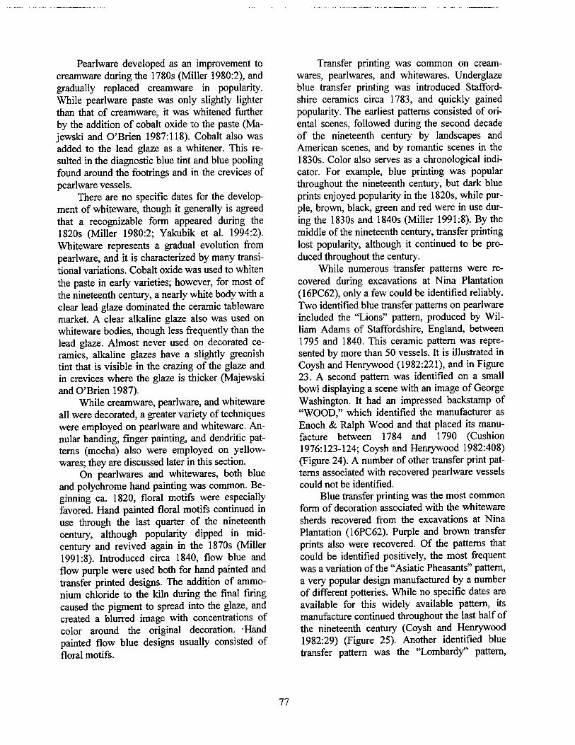
Pearlware developed as an improvement to creamware during the 1780s (Miller 1980:2), and gradually replaced creamware in popularity. While pearlware paste was only slightly lighter than that of creamware, it was whitened further by the addition of cobalt oxide to the paste (Ma- jewski and O'Brien 1987:118). Cobalt also was added to the lead glaze as a whitener. This re- sulted in the diagnostic blue tint and blue pooling found around the footrings and in the crevices of pearlware vessels.
There are no specific dates for the develop- ment of whiteware, though it generally is agreed that a recognizable form appeared during the 1820s (Miller 1980:2; Yakubik et al. 1994:2). Whiteware represents a gradual evolution from pearlware, and it is characterized by many transi- tional variations. Cobalt oxide was used to whiten the paste in early varieties; however, for most of the nineteenth century, a nearly white body with a clear lead glaze dominated the ceramic tableware market. A clear alkaline glaze also was used on whiteware bodies, though less frequently than the lead glaze. Almost never used on decorated ce- ramics, alkaline glazes have a slightly greenish tint that is visible in the crazing of the glaze and in crevices where the glaze is thicker (Majewski and O'Brien 1987).
While creamware, pearlware, and whiteware all were decorated, a greater variety of techniques were employed on pearlware and whiteware. An- nular banding, finger painting, and dendritic pat- terns (mocha) also were employed on yellow- wares; they are discussed later in this section.
On pearlwares and whitewares, both blue and polychrome hand painting was common. Be- ginning ca. 1820, floral motifs were especially favored. Hand painted floral motifs continued in use through the last quarter of the nineteenth century, although popularity dipped in mid- century and revived again in the 1870s (Miller 1991:8). Introduced circa 1840, flow blue and flow purple were used both for hand painted and transfer printed designs. The addition of ammo- nium chloride to the kiln during the final firing caused the pigment to spread into the glaze, and created a blurred image with concentrations of color around the original decoration. Hand painted flow blue designs usually consisted of floral motifs.
Transfer printing was common on cream- wares, pearlwares, and whitewares. Underglaze blue transfer printing was introduced Stafford- shire ceramics circa 1783, and quickly gained popularity. The earliest patterns consisted of ori- ental scenes, followed during the second decade of the nineteenth century by landscapes and American scenes, and by romantic scenes in the 1830s. Color also serves as a chronological indi- cator. For example, blue printing was popular throughout the nineteenth century, but dark blue prints enjoyed popularity in the 1820s, while pur- ple, brown, black, green and red were in use dur- ing the 1830s and 1840s (Miller 1991:8). By the middle of the nineteenth century, transfer printing lost popularity, although it continued to be pro- duced throughout the century.
While numerous transfer patterns were re- covered during excavations at Nina Plantation (16PC62), only a few could be identified reliably. Two identified blue transfer patterns on pearlware included the "Lions" pattern, produced by Wil- liam Adams of Staffordshire, England, between 1795 and 1840. This ceramic pattern was repre- sented by more than 50 vessels. It is illustrated in Coysh and Henrywood (1982:221), and in Figure 23. A second pattern was identified on a small bowl displaying a scene with an image of George Washington. It had an impressed backstamp of "WOOD," which identified the manufacturer as Enoch & Ralph Wood and that placed its manu- facture between 1784 and 1790 (Cushion 1976:123-124; Coysh and Henrywood 1982:408) (Figure 24). A number of other transfer print pat- terns associated with recovered pearlware vessels could not be identified.
Blue transfer printing was the most common form of decoration associated with the whiteware sherds recovered from the excavations at Nina Plantation (16PC62). Purple and brown transfer prints also were recovered. Of the patterns that could be identified positively, the most frequent was a variation of the "Asiatic Pheasants" pattern, a very popular design manufactured by a number of different potteries. While no specific dates are available for this widely available pattern, its manufacture continued throughout the last half of the nineteenth century (Coysh and Henrywood 1982:29) (Figure 25). Another identified blue transfer pattern was the "Lombardy" pattern,
77
o C1 m en CN v~> 00 tu
1 n. "to C o
»3
•a % 3
ti C o o
e 3 £P tu
78
o
00 w
"I o ja
o> S ex "c o to c
£
c8 u D.
o.
en c
o c o
'•5 o a.
79 3 00
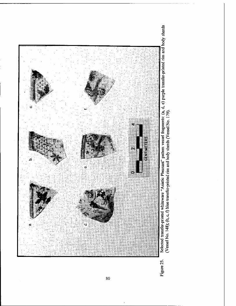
CO -a
<o -C
CO
■•£ O
•O
c
a.
1^
CM
m ,Ui:
03
O
CD
c o I Z
"S > Cfl ^-'
4) 13 > C - »
ö >> ea -a a, o „ js
g S
0 «
.2 -C < i
§ s | 2
1 °. "C JO
2 d
4) >
in
3
80
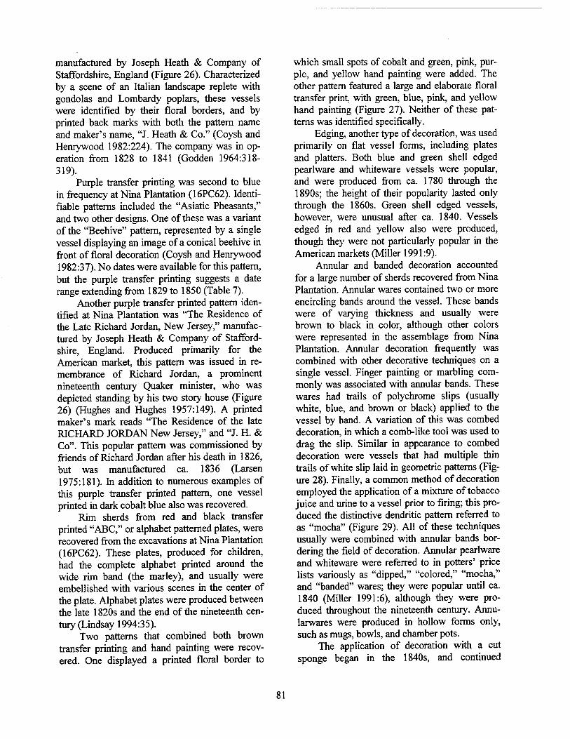
manufactured by Joseph Heath & Company of Staffordshire, England (Figure 26). Characterized by a scene of an Italian landscape replete with gondolas and Lombardy poplars, these vessels were identified by their floral borders, and by printed back marks with both the pattern name and maker's name, "J. Heath & Co." (Coysh and Henrywood 1982:224). The company was in op- eration from 1828 to 1841 (Godden 1964:318- 319).
Purple transfer printing was second to blue in frequency at Nina Plantation (16PC62). Identi- fiable patterns included the "Asiatic Pheasants," and two other designs. One of these was a variant of the "Beehive" pattern, represented by a single vessel displaying an image of a conical beehive in front of floral decoration (Coysh and Henrywood 1982:37). No dates were available for this pattern, but the purple transfer printing suggests a date range extending from 1829 to 1850 (Table 7).
Another purple transfer printed pattern iden- tified at Nina Plantation was "The Residence of the Late Richard Jordan, New Jersey," manufac- tured by Joseph Heath & Company of Stafford- shire, England. Produced primarily for the American market, this pattern was issued in re- membrance of Richard Jordan, a prominent nineteenth century Quaker minister, who was depicted standing by his two story house (Figure 26) (Hughes and Hughes 1957:149). A printed maker's mark reads "The Residence of the late RICHARD JORDAN New Jersey," and "J. H. & Co". This popular pattern was commissioned by friends of Richard Jordan after his death in 1826, but was manufactured ca. 1836 (Larsen 1975:181). In addition to numerous examples of this purple transfer printed pattern, one vessel printed in dark cobalt blue also was recovered.
Rim sherds from red and black transfer printed "ABC," or alphabet patterned plates, were recovered from the excavations at Nina Plantation (16PC62). These plates, produced for children, had the complete alphabet printed around the wide rim band (the marley), and usually were embellished with various scenes in the center of the plate. Alphabet plates were produced between the late 1820s and the end of the nineteenth cen- tury (Lindsay 1994:35).
Two patterns that combined both brown transfer printing and hand painting were recov- ered. One displayed a printed floral border to
which small spots of cobalt and green, pink, pur- ple, and yellow hand painting were added. The other pattern featured a large and elaborate floral transfer print, with green, blue, pink, and yellow hand painting (Figure 27). Neither of these pat- terns was identified specifically.
Edging, another type of decoration, was used primarily on flat vessel forms, including plates and platters. Both blue and green shell edged pearlware and whiteware vessels were popular, and were produced from ca. 1780 through the 1890s; the height of their popularity lasted only through the 1860s. Green shell edged vessels, however, were unusual after ca. 1840. Vessels edged in red and yellow also were produced, though they were not particularly popular in the American markets (Miller 1991:9).
Annular and banded decoration accounted for a large number of sherds recovered from Nina Plantation. Annular wares contained two or more encircling bands around the vessel. These bands were of varying thickness and usually were brown to black in color, although other colors were represented in the assemblage from Nina Plantation. Annular decoration frequently was combined with other decorative techniques on a single vessel. Finger painting or marbling com- monly was associated with annular bands. These wares had trails of polychrome slips (usually white, blue, and brown or black) applied to the vessel by hand. A variation of this was combed decoration, in which a comb-like tool was used to drag the slip. Similar in appearance to combed decoration were vessels that had multiple thin trails of white slip laid in geometric patterns (Fig- ure 28). Finally, a common method of decoration employed the application of a mixture of tobacco juice and urine to a vessel prior to firing; this pro- duced the distinctive dendritic pattern referred to as "mocha" (Figure 29). All of these techniques usually were combined with annular bands bor- dering the field of decoration. Annular pearlware and whiteware were referred to in potters' price lists variously as "dipped," "colored," "mocha," and "banded" wares; they were popular until ca. 1840 (Miller 1991:6), although they were pro- duced throughout the nineteenth century. Annu- larwares were produced in hollow forms only, such as mugs, bowls, and chamber pots.
The application of decoration with a cut sponge began in the 1840s, and continued
81
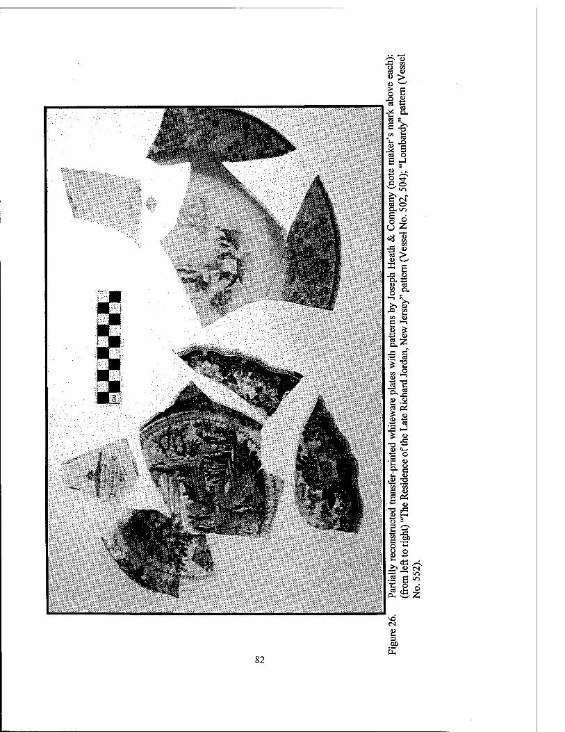
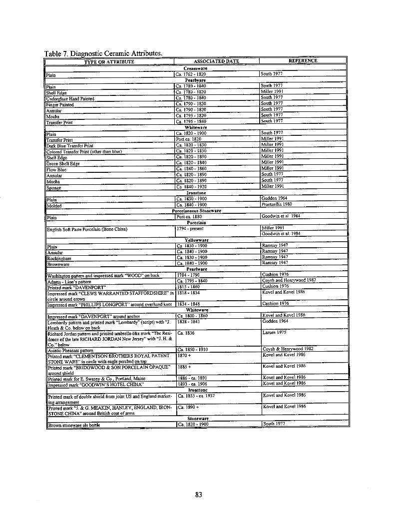
TYPE OR ATTRIBUTE 1 ASSOCIATED DATE I REFERENCE 1 Creamware
Plain 1 Ca. 1762-1820 I South 1977 Pearlware
Plain Ca. 1780-1840 South 1977
Shell Edge Ca. 1780-1820 Miller 1991
Underglaze Hand Painted Ca. 1780-1840 South 1977
Finger Painted Ca. 1790-1820 South 1977
Annular Ca. 1790-1820 South 1977
Mocha Ca. 1795 -1820 South 1977
Transfer Print Ca. 1795 - 1840 South 1977 Whiteware
Plain Ca. 1820-1900 South 1977
Transfer Print Postca. 1820 Miller 1991
Dark Blue Transfer Print Ca. 1820 -1830 Miller 1991
Colored Transfer Print (other than blue) Ca. 1829-1850 Miller 1991
Shell Edge Ca. 1820-1890 Miller 1991
Green Shell Edge Ca. 1820-1840 Miller 1991
Flow Blue Ca. 1840-1860 Miller 1991
Annular Ca. 1820-1890 South 1977
Mocha Ca. 1820-1890 South 1977
Snonee Ca. 1840 -1920 Miller 1991 Ironstone
Plain Ca. 1830-1900 Godden 1964
Molded Ca. 1840-1900 Praetzellis 1980 Porcelaneous Stoneware
Plain Postca. 1880 Goodwin et al 1984 Porcelain
English Soft Paste Porcelain (Bone China) 1794-present Miller 1991 Goodwin et al. 1984
Yellowware
Plain Ca. 1830-1900 Ramsay 1947
Annular Ca. 1840-1900 Ramsay 1947
Rockingham Ca. 1830-1900 Ramsay 1947
Brownware Ca. 1840-1900 Ramsay 1947 Peartware
Washington pattern and impressed mark "WOOD" on back 1784-1790 Cushion 1976
Adams - Lion's pattern Ca. 1795 -1840 Coysh and Henrywood 1982
Printed mark "DAVENPORT' 1815 -1860 Cushion 1976
Impressed mark "CLEWS WARRANTED STAFFORDSHIRE" in circle around crown
1818-1834 Kovel and Kovel 1986
ImDressed mark "PHILLIPS LONGPORT" around overhand knot 1834 - 1848 Cushion 1976 Whiteware
Impressed mark "DAVENPORT" around anchor Ca. 1800-1860 Kovel and Kovel 1986
Lombardy pattern and printed mark "Lombardy" (script) with "J. Heath & Co. below on back
1828-1841 Godden 1964
Richard Jordan pattern and printed umbrella-like mark "The Resi- dence of the late RICHARD JORDAN New Jersey" with "J. H. & Co." below
Ca. 1836 Larsen 1975
Asiatic Pheasant pattern Ca. 1850-1910 Covsh & Henrvwood 1982
Printed mark "CLEMENTSON BROTHERS ROYAL PATENT STONE WARE" in circle with eagle perched on top
1870 + Kovel and Kovel 1986
Printed mark "BRJDGWOOD & SON PORCELAIN OPAQUE" around shield
1885 + Kovel and Kovel 1986
Printed mark for E. Swasev & Co., Portland, Maine 1886-ca. 1891 Kovel and Kovel 1986
Impressed mark "GOODWIN'S HOTEL CHINA" 1893 - ca. 1906 Kovel and Kovel 1986 Ironstone
Printed mark of double shield from joint US and England market- ing arrangement
Ca. 1853-ca. 1937 Kovel and Kovel 1986
Printed mark "J. & G. MEAKIN, HANLEY, ENGLAND, IRON- STONE CHINA" around British coat of arms
Ca. 1890 + Kovel and Kovel 1986
Stoneware
Brown stoneware ale bottle |Ca. 1820-1900 | South 1977
83
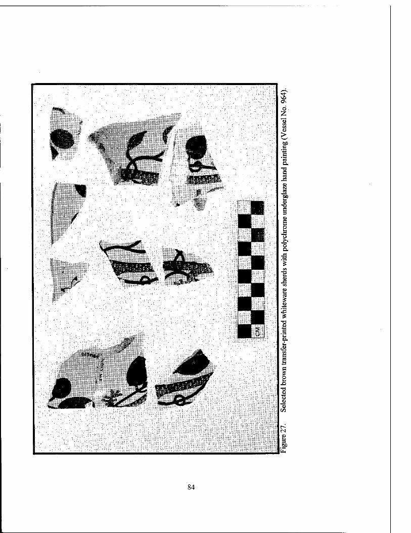
84
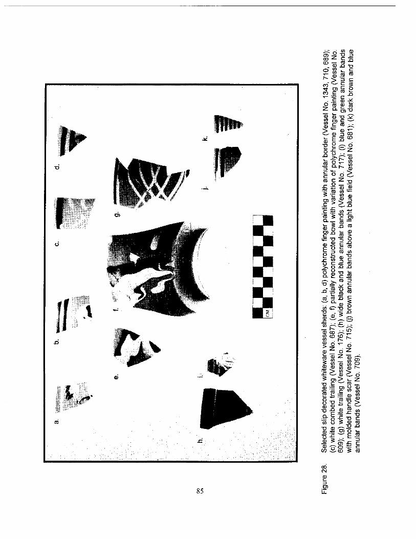
CD £ CO ^
<° ©
-^ CO """'
CO c
O 03 2 Q.
00 CU ■a 3 §5 x -o ro ro
1° 2 ro 0)"0
in c ro
■- E S ^ •o 2 ^ o o ■«= ""z
o <■> •_- _
-J Q. h- 00
(1) c O O > ro C <L Tl x o "53 (U
5 ro oo **— k. oo (11
TO c
CO > 2 3 X
c 00 x TO ro
a. 5 T3 c ro XI 0)
5 n ro TO X ro 0) >
■o -1 o (D E o
c c
X) ro
n ro 00 u i_ x CO c
CU 3
c ro
■>, o X X o D.
o CU T3 ro
x~ ro ro
ü ro
=3
ro m ro X c
oo OT3 2 T3 5 X 1— (1) .—.
00 *-~. _ r- cu oo 00 CD oo ^ d
CO
85
© _
I $ !> 5 TO a = ro 2 8^ cu a)
J-l 00 Ü XI CD CU .ti
•4—" #—
£2 co CN
CU
TO LL
_ o CU 00 ID
ao o
00 en r- 00 > o > L_ 7* *~^ ro n> ü a> t~ 00
CU ■a c
00 CU >
0) ro X 00
T3 TO r
■s CU ro T> X
TO O i_
"""^ F ro ^-^, 3 OO X. r o .— c CD S ro
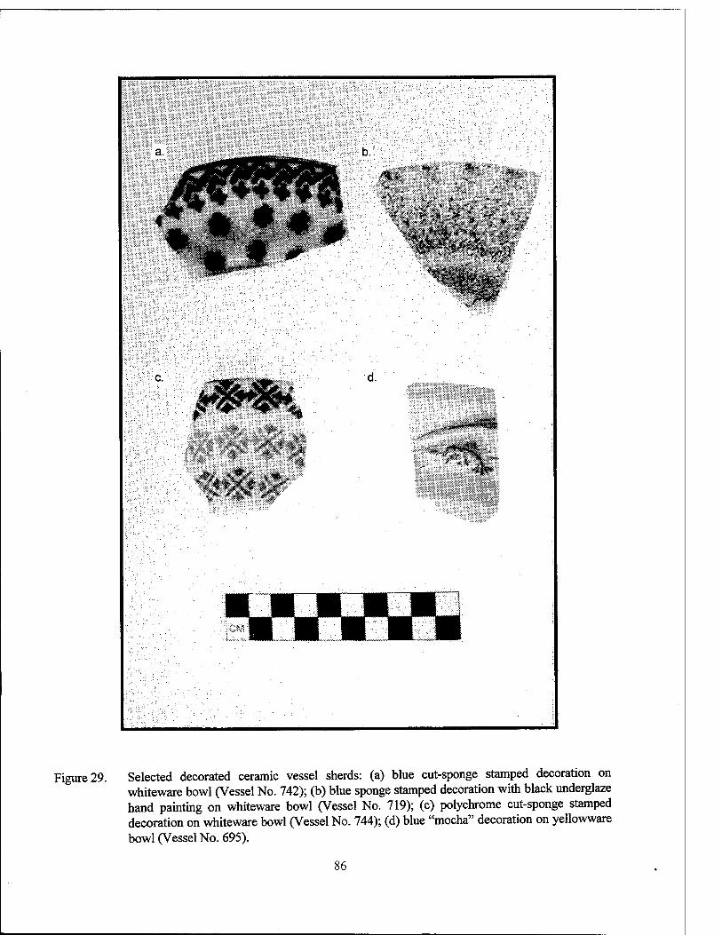
b.
c. d.
Figure 29. Selected decorated ceramic vessel sherds: (a) blue cut-sponge stamped decoration on whiteware bowl (Vessel No. 742); (b) blue sponge stamped decoration with black underglaze hand painting on whiteware bowl (Vessel No. 719); (c) polychrome cut-sponge stamped decoration on whiteware bowl (Vessel No. 744); (d) blue "mocha" decoration on yellowware bowl (Vessel No. 695).
86
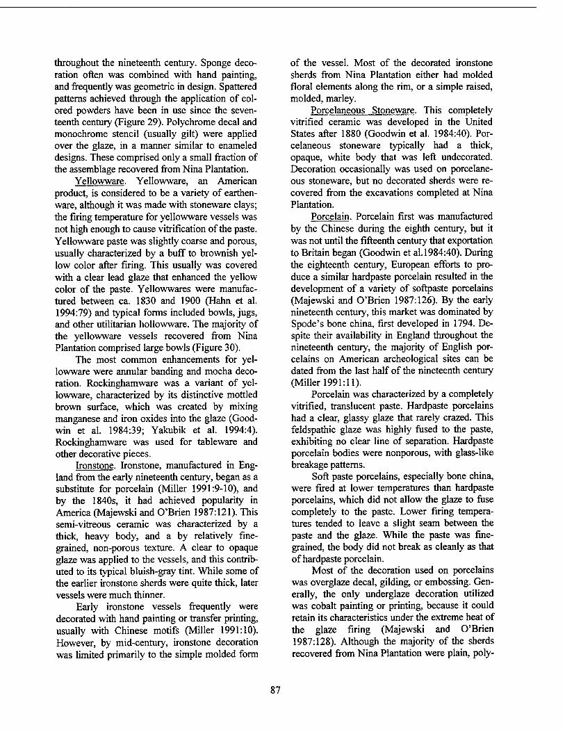
throughout the nineteenth century. Sponge deco- ration often was combined with hand painting, and frequently was geometric in design. Spattered patterns achieved through the application of col- ored powders have been in use since the seven- teenth century (Figure 29). Polychrome decal and monochrome stencil (usually gilt) were applied over the glaze, in a manner similar to enameled designs. These comprised only a small fraction of the assemblage recovered from Nina Plantation.
Yellowware. Yellowware, an American product, is considered to be a variety of earthen- ware, although it was made with stoneware clays; the firing temperature for yellowware vessels was not high enough to cause vitrification of the paste. Yellowware paste was slightly coarse and porous, usually characterized by a buff to brownish yel- low color after firing. This usually was covered with a clear lead glaze that enhanced the yellow color of the paste. Yellowwares were manufac- tured between ca. 1830 and 1900 (Hahn et al. 1994:79) and typical forms included bowls, jugs, and other utilitarian hollowware. The majority of the yellowware vessels recovered from Nina Plantation comprised large bowls (Figure 30).
The most common enhancements for yel- lowware were annular banding and mocha deco- ration. Rockinghamware was a variant of yel- lowware, characterized by its distinctive mottled brown surface, which was created by mixing manganese and iron oxides into the glaze (Good- win et al. 1984:39; Yakubik et al. 1994:4). Rockinghamware was used for tableware and other decorative pieces.
Ironstone. Ironstone, manufactured in Eng- land from the early nineteenth century, began as a substitute for porcelain (Miller 1991:9-10), and by the 1840s, it had achieved popularity in America (Majewski and O'Brien 1987:121). This semi-vitreous ceramic was characterized by a thick, heavy body, and a by relatively fine- grained, non-porous texture. A clear to opaque glaze was applied to the vessels, and this contrib- uted to its typical bluish-gray tint. While some of the earlier ironstone sherds were quite thick, later vessels were much thinner.
Early ironstone vessels frequently were decorated with hand painting or transfer printing, usually with Chinese motifs (Miller 1991:10). However, by mid-century, ironstone decoration was limited primarily to the simple molded form
of the vessel. Most of the decorated ironstone sherds from Nina Plantation either had molded floral elements along the rim, or a simple raised, molded, marley.
Porcelaneous Stoneware. This completely vitrified ceramic was developed in the United States after 1880 (Goodwin et al. 1984:40). Por- celaneous stoneware typically had a thick, opaque, white body that was left undecorated. Decoration occasionally was used on porcelane- ous stoneware, but no decorated sherds were re- covered from the excavations completed at Nina Plantation.
Porcelain. Porcelain first was manufactured by the Chinese during the eighth century, but it was not until the fifteenth century that exportation to Britain began (Goodwin et al. 1984:40). During the eighteenth century, European efforts to pro- duce a similar hardpaste porcelain resulted in the development of a variety of softpaste porcelains (Majewski and O'Brien 1987:126). By the early nineteenth century, this market was dominated by Spode's bone china, first developed in 1794. De- spite their availability in England throughout the nineteenth century, the majority of English por- celains on American archeological sites can be dated from the last half of the nineteenth century (Miller 1991:11).
Porcelain was characterized by a completely vitrified, translucent paste. Hardpaste porcelains had a clear, glassy glaze that rarely crazed. This feldspathic glaze was highly fused to the paste, exhibiting no clear line of separation. Hardpaste porcelain bodies were nonporous, with glass-like breakage patterns.
Soft paste porcelains, especially bone china, were fired at lower temperatures than hardpaste porcelains, which did not allow the glaze to fuse completely to the paste. Lower firing tempera- tures tended to leave a slight seam between the paste and the glaze. While the paste was fine- grained, the body did not break as cleanly as that of hardpaste porcelain.
Most of the decoration used on porcelains was overglaze decal, gilding, or embossing. Gen- erally, the only underglaze decoration utilized was cobalt painting or printing, because it could retain its characteristics under the extreme heat of the glaze firing (Majewski and O'Brien 1987:128). Although the majority of the sherds recovered from Nina Plantation were plain, poly-
87
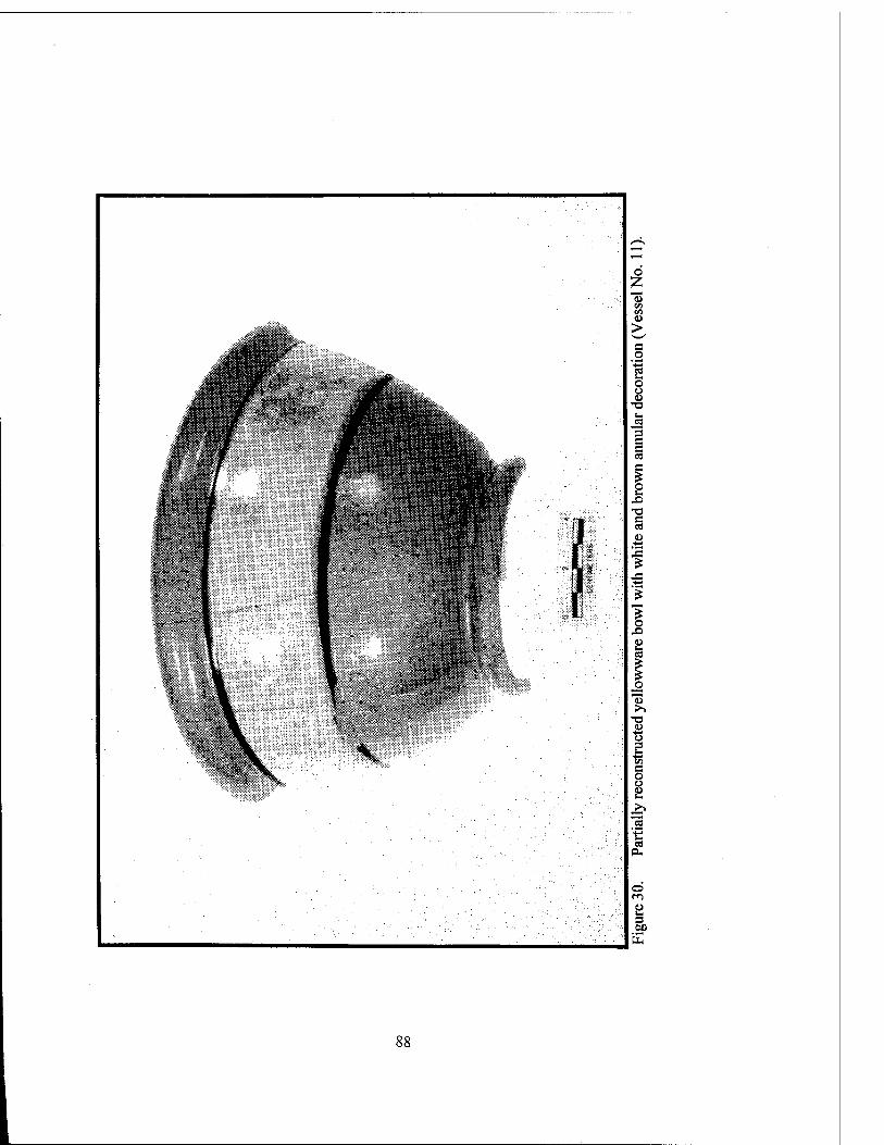
88
chrome floral overglaze decal and simple gilt banding around the rim were common at the site. Another prominent decorative motif recovered during excavation included underglaze cobalt handpainting around the rim, with a floral over- glaze gilt stencil pattern applied to a softpaste body.
Tin-glazed Earthenwares. Tin-glazed earth- enware vessels often are labeled as "delft" (Eng- lish and Dutch), "majolica" (Spanish and Italian), and "faience" (French), depending on the pre- sumed country of manufacture. During the analy- sis of materials from Nina Plantation (16PC62), the generic term was employed to avoid confu- sion and/or spurious attribution of origin.
Tin-glazed earthenwares were characterized by a relatively coarse, buff to light brown or pink, porous, and friable paste. The tin-oxide glaze was thick and opaque, with a tendency to separate cleanly from the body of the vessel. The vessels were glazed on both the interior and exterior, but it was characteristic for the footring to remain unglazed. The glaze often was colored by the ad- dition of various metal oxides, including cobalt, copper, and manganese. Typical vessel forms ranged from small jars or ointment pots to plates. The jars were characterized by short cylindrical bodies, everted lips, and by shallow concave inte- riors; they have been referred to elsewhere as ointment jars (Goodwin et al. 1984:35), rouge pots (Hahn et al. 1994:79), or cosmetic jars (Noel Hume 1969:204). The exterior of these vessels often was tinted, while the interior remained white.
Coarse Earthenwares. Low-fired, porous earthenware vessels were manufactured both in Europe and America throughout the Colonial pe- riod. Because of the porosity of the earthenware paste, a lead or alkaline glaze commonly was ap- plied to the interior, and sometimes to the exterior of the vessel, although some vessels were left unglazed. Most coarse earthenwares were utili- tarian in function, and were hollow in form. The ease of manufacture of coarse earthenwares con- tributed to their widespread distribution; as a re- sult, they are of little utility for chronological analysis, or for delimiting trade patterns.
Redware. Redware was one of the most prevalent types of coarse earthenware, with a typically red-brown, orange, or pink body, de- pending on the amount of iron oxide found in the
clay. Like most coarse earthenwares, their wide- spread geographic and temporal distribution pre- vents their use as diagnostic temporal indicators. Lead glazes, sometimes with the addition of metal oxides for color, were common. Slip glazes and slip decoration also were used in combination with lead glazes.
Sherds from two distinctive European red- ware vessels were recovered during excavations at Nina Plantation (16PC62). Two of these were fragments of large storage vessels that had coarse, pinkish bodies, with a high density of iron oxide inclusions. The interiors were glazed with a thick, pale yellow lead glaze. These vessels, often termed "Provence" jars, were manufactured in the region around Biot, France from at least the fif- teenth century; they have been found on Louisi- ana sites dating from the mid to late nineteenth century (Yakubik et al. 1994:7). The sherds re- covered from Nina Plantation had the typical thick, pink body, with remnants of the yellow glaze evident on the interior.
Another European redware type represented in the assemblage from 16PC62 was Albisola Trailed, a slip decorated redware produced in It- aly through the eighteenth century. The example recovered from Nina Plantation took the form of a small, shallow bowl; it had a compact, fine- grained, dark reddish-brown paste with a dark red or black, random trail of slip on the interior (Fig- ure 31). A lead glaze had been applied to the inte- rior of the vessel. According to Yakubik et al. (1994:6), Albisola Trailed was a product of Ital- ian Liguria, and commonly was found on eight- eenth and early nineteenth century French colo- nial sites.
Refined Redware. Refined redwares typi- cally were thinner, with a compact, fine-grained paste; the paste included more refractory clays that could withstand higher firing temperatures. These vessels were frequently covered with opaque slips before glazing. These also could be colored with a variety of metal oxides.
Most of the refined redware sherds from Nina Plantation contained a lead glaze that cov- ered an opaque slip of white, black, or poly- chrome annular bands. While one vessel had molded decoration, almost all of the refined red- ware vessels were simple, small bowls or hollow storage vessels.
89
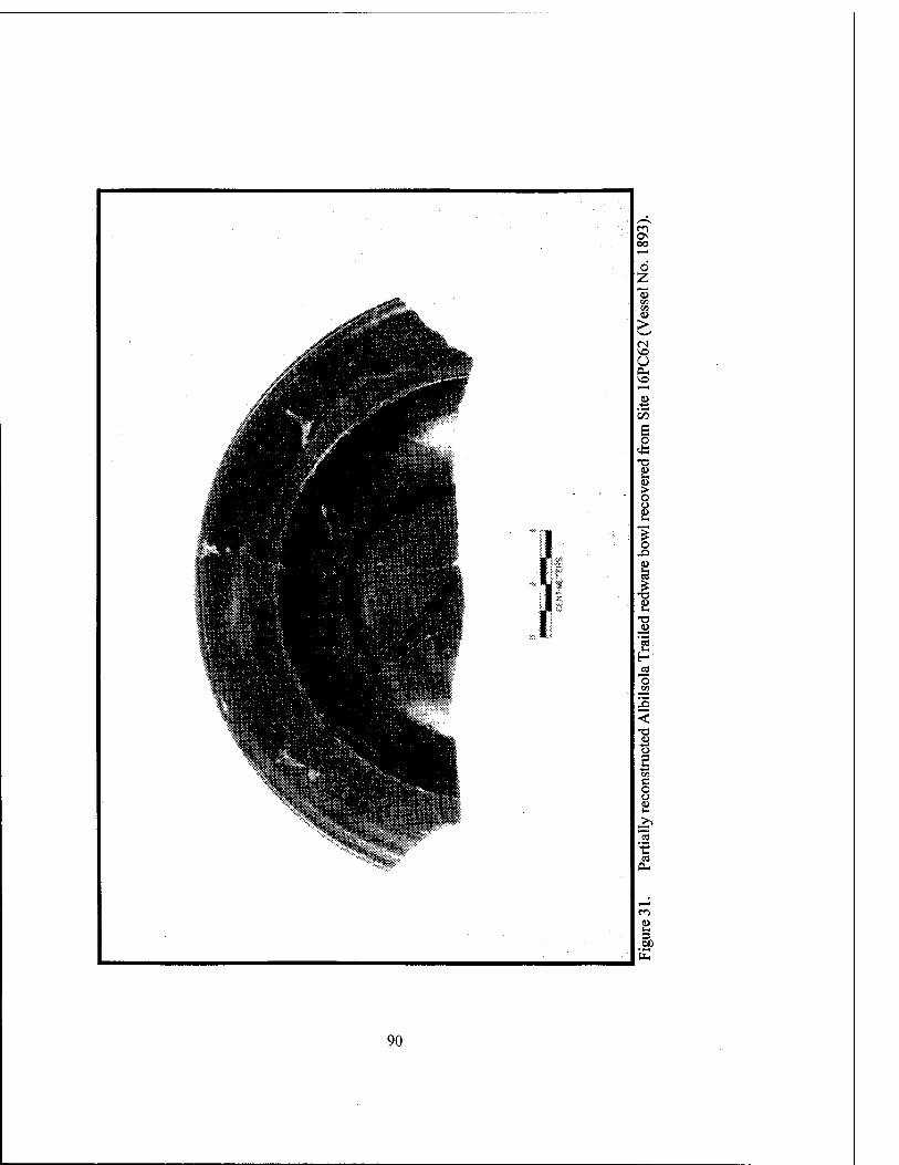
90
Stoneware. Stonewares are characterized by a vitrified paste with a smooth, stony texture. Colors of stoneware bodies range from gray to brown, depending on the kind and amount of im- purities in the clay. The brown stonewares ranged in color from a light buff to dark brown. Stone- wares first were produced in the United States ca. 1775 and became popular by the beginning of the nineteenth century (Goodwin et al. 1984:39). Stonewares were most commonly wheel-thrown utilitarian vessels that ranged in form from crocks to jars, jugs, and bottles.
Surface treatments included lead or alkaline and salt glazes. A salt glaze was created by add- ing salt to the kiln as the vessel was being fired; the vaporized salt adhered to the exterior of the body, giving it its characteristic orange peel tex- ture. Frequently, the interior of the vessel was glazed with a thick, dark matte brown Albany slip. The exteriors of some stoneware vessels were embellished with blue, hand-painted deco- ration.
Stoneware also was used for ale bottles; these were distinctive in paste and exterior treat- ment. The body was buff-colored, with a yellow glaze that extended from the lip to the shoulder of the vessel. In form, the bottles had conical necks and a variety of finished lips (Figure 32). Ale bottles were popular during the second half of the nineteenth century, and they are well represented in the assemblage from Nina Plantation.
Minimum Vessel Count In order to conduct analyses based on vessel
form, and to enable application of Miller's eco- nomic scaling (Miller 1980, 1991) to the ceramic subassemblage recovered from Nina Plantation, a minimum vessel count was compiled. Economic scaling and formal analyses will be discussed in Chapter IX of this report. The minimum vessel count was undertaken after the primary ceramic analysis was completed, and required the separa- tion of all rim sherds from the remaining ceramic subassemblage. After all rim sherds were iso- lated, they were sorted into categories based on the type of paste, glaze, decorative design, vessel shape, and curvature. Sherds were grouped as a single vessel either when there were direct cross- mends, or when the sherds met all of the follow- ing criteria. The sherds had to share a common
vessel form (e.g., bowl, plate, and bottle) and ex- hibit the same curvature in cross-section, the same thickness, granularity and color of paste, type and tone of glaze, and the same decorative pattern and color tone (e.g., variations in shades of purple). In a few cases, vessel numbers were assigned to non-rim sherds. In these cases, the sherds, while unique to the assemblage, were not represented by a rim sherd. To ensure that these vessels were represented in the minimum vessel count, each unique vessel was assigned a vessel number. Each identified vessel was assigned a sequential number in addition to the identifying catalog number of each sherd. Each vessel was entered into the ceramic database that included fields for vessel number, catalog number(s), paste type, glaze type, decorative type and pattern name, vessel form, rim diameter, and presumed function of the vessel. A compiled inventory of the recovered vessels can be found in Appendix II.
Glass Glass constituted a major portion of the arti-
fact assemblage recovered from Nina Plantation. Analysis included classification by manufacturing technique, form (including finish, base, and lip form), color, maker's marks, embossed lettering, decoration, and function. The chronology was derived from known dates of manufacture for techniques developed during the nineteenth cen- tury. Functional identification of the various glass forms was used to illuminate behavioral patterns, health concerns, and status, while the identifica- tion of maker's marks or embossers was infor- mative for the analysis of local and regional trade. A detailed inventory of the glass recovered from the site appears in Appendix III of this report.
An important source utilized during the identification and description of glass artifacts was The Parks Canada Glass Glossary (Jones and Sullivan 1989). The Bottle Book (Fike 1987) was consulted extensively during identification of both pharmaceutical and medicinal bottles. Bottle Makers and Their Marks (Toulouse 1971) was used to help identify and date the large number of maker's marks recovered from the site. In addi- tion, a number of secondary resources were refer- enced during the analysis.
91
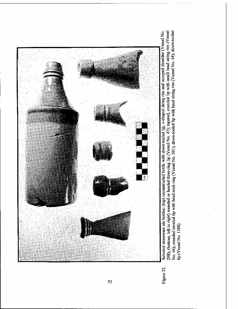
o <o u
75 Z VI co
> <o 2 CO
>*• c 0) > E •^-s T3 I* 01) Cl ri Z-"^
*o ■*
3 -4-* ■*
Ü T3 o
Z en HI
a. .£3
en o 03 <l> o ü E >
V] s—^
-o JS E c C3 £
.£" •4-»
hf) -a co 3 (Li
T3 es L> C CO 3 .o
T3 H .3 U
•a ■*--
£ J3 n. > d
£ ■*-- -a
o 3 •o
"o 2
ö Z
c o
i T1 c u £ CO >v o <L>
1
-a > 1—1 in
o Z
o i .O O
<L> T3 l- £ & 3 -o
■3 -T3 « « o JD u . 2 s 'S "8 ■it' c .. 3 en o 4) C
2 -a u 'C
"53 o
I* !> ~™
P o
CO U > 00 c
o u c
T3 cd u .0
13 .5
00 cs
.2- •a
73 ^
.£ oo
iz 2 73 . c «
Z =
92
m 8 3 OO
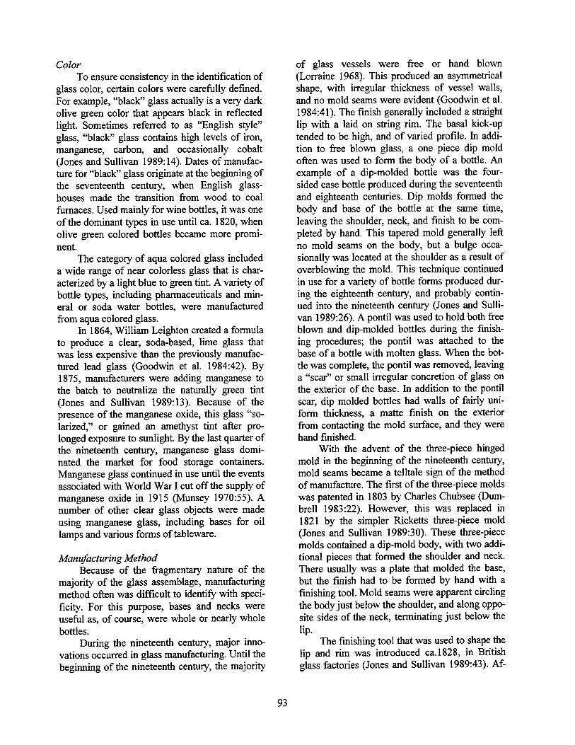
Color To ensure consistency in the identification of
glass color, certain colors were carefully defined. For example, "black" glass actually is a very dark olive green color that appears black in reflected light. Sometimes referred to as "English style" glass, "black" glass contains high levels of iron, manganese, carbon, and occasionally cobalt (Jones and Sullivan 1989:14). Dates of manufac- ture for "black" glass originate at the beginning of the seventeenth century, when English glass- houses made the transition from wood to coal furnaces. Used mainly for wine bottles, it was one of the dominant types in use until ca. 1820, when olive green colored bottles became more promi- nent.
The category of aqua colored glass included a wide range of near colorless glass that is char- acterized by a light blue to green tint. A variety of bottle types, including pharmaceuticals and min- eral or soda water bottles, were manufactured from aqua colored glass.
In 1864, William Leighton created a formula to produce a clear, soda-based, lime glass that was less expensive than the previously manufac- tured lead glass (Goodwin et al. 1984:42). By 1875, manufacturers were adding manganese to the batch to neutralize the naturally green tint (Jones and Sullivan 1989:13). Because of the presence of the manganese oxide, this glass "so- larized," or gained an amethyst tint after pro- longed exposure to sunlight. By the last quarter of the nineteenth century, manganese glass domi- nated the market for food storage containers. Manganese glass continued in use until the events associated with World War I cut off the supply of manganese oxide in 1915 (Munsey 1970:55). A number of other clear glass objects were made using manganese glass, including bases for oil lamps and various forms of tableware.
Manufacturing Method Because of the fragmentary nature of the
majority of the glass assemblage, manufacturing method often was difficult to identify with speci- ficity. For this purpose, bases and necks were useful as, of course, were whole or nearly whole bottles.
During the nineteenth century, major inno- vations occurred in glass manufacturing. Until the beginning of the nineteenth century, the majority
of glass vessels were free or hand blown (Lorraine 1968). This produced an asymmetrical shape, with irregular thickness of vessel walls, and no mold seams were evident (Goodwin et al. 1984:41). The finish generally included a straight lip with a laid on string rim. The basal kick-up tended to be high, and of varied profile. In addi- tion to free blown glass, a one piece dip mold often was used to form the body of a bottle. An example of a dip-molded bottle was the four- sided case bottle produced during the seventeenth and eighteenth centuries. Dip molds formed the body and base of the bottle at the same time, leaving the shoulder, neck, and finish to be com- pleted by hand. This tapered mold generally left no mold seams on the body, but a bulge occa- sionally was located at the shoulder as a result of overblowing the mold. This technique continued in use for a variety of bottle forms produced dur- ing the eighteenth century, and probably contin- ued into the nineteenth century (Jones and Sulli- van 1989:26). A pontil was used to hold both free blown and dip-molded bottles during the finish- ing procedures; the pontil was attached to the base of a bottle with molten glass. When the bot- tle was complete, the pontil was removed, leaving a "scar" or small irregular concretion of glass on the exterior of the base. In addition to the pontil scar, dip molded bottles had walls of fairly uni- form thickness, a matte finish on the exterior from contacting the mold surface, and they were hand finished.
With the advent of the three-piece hinged mold in the beginning of the nineteenth century, mold seams became a telltale sign of the method of manufacture. The first of the three-piece molds was patented in 1803 by Charles Chubsee (Dum- brell 1983:22). However, this was replaced in 1821 by the simpler Ricketts three-piece mold (Jones and Sullivan 1989:30). These three-piece molds contained a dip-mold body, with two addi- tional pieces that formed the shoulder and neck. There usually was a plate that molded the base, but the finish had to be formed by hand with a finishing tool. Mold seams were apparent circling the body just below the shoulder, and along oppo- site sides of the neck, terminating just below the lip.
The finishing tool that was used to shape the lip and rim was introduced ca.1828, in British glass factories (Jones and Sullivan 1989:43). Af-
93
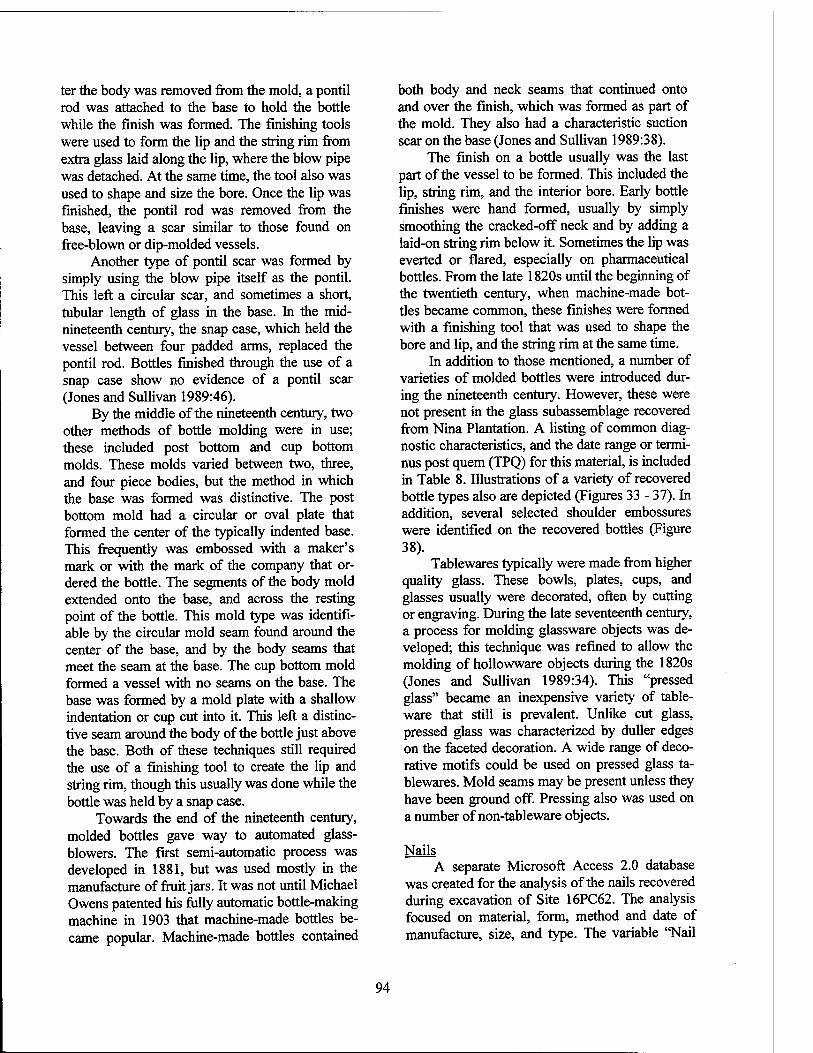
ter the body was removed from the mold, a pontil rod was attached to the base to hold the bottle while the finish was formed. The finishing tools were used to form the lip and the string rim from extra glass laid along the lip, where the blow pipe was detached. At the same time, the tool also was used to shape and size the bore. Once the lip was finished, the pontil rod was removed from the base, leaving a scar similar to those found on free-blown or dip-molded vessels.
Another type of pontil scar was formed by simply using the blow pipe itself as the pontil. This left a circular scar, and sometimes a short, tubular length of glass in the base. In the mid- nineteenth century, the snap case, which held the vessel between four padded arms, replaced the pontil rod. Bottles finished through the use of a snap case show no evidence of a pontil scar (Jones and Sullivan 1989:46).
By the middle of the nineteenth century, two other methods of bottle molding were in use; these included post bottom and cup bottom molds. These molds varied between two, three, and four piece bodies, but the method in which the base was formed was distinctive. The post bottom mold had a circular or oval plate that formed the center of the typically indented base. This frequently was embossed with a maker's mark or with the mark of the company that or- dered the bottle. The segments of the body mold extended onto the base, and across the resting point of the bottle. This mold type was identifi- able by the circular mold seam found around the center of the base, and by the body seams that meet the seam at the base. The cup bottom mold formed a vessel with no seams on the base. The base was formed by a mold plate with a shallow indentation or cup cut into it. This left a distinc- tive seam around the body of the bottle just above the base. Both of these techniques still required the use of a finishing tool to create the lip and string rim, though this usually was done while the bottle was held by a snap case.
Towards the end of the nineteenth century, molded bottles gave way to automated glass- blowers. The first semi-automatic process was developed in 1881, but was used mostly in the manufacture of fruit jars. It was not until Michael Owens patented his fully automatic bottle-making machine in 1903 that machine-made bottles be- came popular. Machine-made bottles contained
both body and neck seams that continued onto and over the finish, which was formed as part of the mold. They also had a characteristic suction scar on the base (Jones and Sullivan 1989:38).
The finish on a bottle usually was the last part of the vessel to be formed. This included the lip, string rim, and the interior bore. Early bottle finishes were hand formed, usually by simply smoothing the cracked-off neck and by adding a laid-on string rim below it. Sometimes the lip was everted or flared, especially on pharmaceutical bottles. From the late 1820s until the beginning of the twentieth century, when machine-made bot- tles became common, these finishes were formed with a finishing tool that was used to shape the bore and lip, and the string rim at the same time.
In addition to those mentioned, a number of varieties of molded bottles were introduced dur- ing the nineteenth century. However, these were not present in the glass subassemblage recovered from Nina Plantation. A listing of common diag- nostic characteristics, and the date range or termi- nus post quern (TPQ) for this material, is included in Table 8. Illustrations of a variety of recovered bottle types also are depicted (Figures 33 - 37). In addition, several selected shoulder embossures were identified on the recovered bottles (Figure 38).
Tablewares typically were made from higher quality glass. These bowls, plates, cups, and glasses usually were decorated, often by cutting or engraving. During the late seventeenth century, a process for molding glassware objects was de- veloped; this technique was refined to allow the molding of hollowware objects during the 1820s (Jones and Sullivan 1989:34). This "pressed glass" became an inexpensive variety of table- ware that still is prevalent. Unlike cut glass, pressed glass was characterized by duller edges on the faceted decoration. A wide range of deco- rative motifs could be used on pressed glass ta- blewares. Mold seams may be present unless they have been ground off. Pressing also was used on a number of non-tableware objects.
Nails A separate Microsoft Access 2.0 database
was created for the analysis of the nails recovered during excavation of Site 16PC62. The analysis focused on material, form, method and date of manufacture, size, and type. The variable "Nail
94
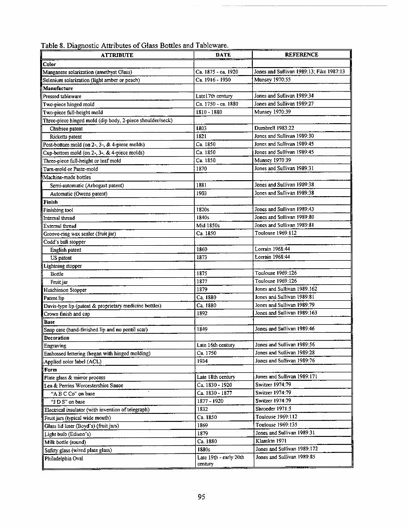
Table 8. Diagnostic Attributes of Glass Bottles and Tableware. ATTRIBUTE DATE REFERENCE
Color Manganese solarization (amethyst Glass) Ca. 1875 - ca. 1920 Jones and Sullivan 1989:13; Fike 1987:13
Selenium solarization (light amber or peach) Ca. 1916-1930 Munsey 1970:55
Manufacture
Pressed tableware Late 17th century Jones and Sullivan 1989:34
Two-piece hinged mold Ca. 1750-ca. 1880 Jones and Sullivan 1989:27
Two-piece full-height mold 1810-1880 Munsey 1970:39
Three-piece hinged mold (dip body, 2-piece shoulder/neck)
Chubsee patent 1803 Dumbrell 1983:22
Ricketts patent 1821 Jones and Sullivan 1989:30
Post-bottom mold (on 2-, 3-, & 4-piece molds) Ca. 1850 Jones and Sullivan 1989:45
Cup-bottom mold (on 2-, 3-, & 4-piece molds) Ca. 1850 Jones and Sullivan 1989:45
Three-piece full-height or leaf mold Ca. 1850 Munsey 1970:39
Turn-mold or Paste-mold 1870 Jones and Sullivan 1989:31
Machine-made bottles
Semi-automatic (Arbogast patent) 1881 Jones and Sullivan 1989:38
Automatic (Owens patent) 1903 Jones and Sullivan 1989:38
Finish
Finishing tool 1820s Jones and Sullivan 1989:43
Internal thread 1840s Jones and Sullivan 1989:80
External thread Mid 1850s Jones and Sullivan 1989:81
Groove-ring wax sealer (fruit jar) Ca. 1850 Toulouse 1969:112
Codd's ball stopper
English patent 1860 Lorrain 1968:44
US patent 1873 Lorrain 1968:44
Lightning stopper
Bottle 1875 Toulouse 1969:126
Fruit jar 1877 Toulouse 1969:126
Hutchinson Stopper 1879 Jones and Sullivan 1989:162
Patent lip Ca. 1880 Jones and Sullivan 1989:81
Davis-type lip (patent & proprietary medicine bottles) Ca. 1880 Jones and Sullivan 1989:79
Crown finish and cap 1892 Jones and Sullivan 1989:163
Base
Snap case (hand-finished lip and no pontil scar) 1849 Jones and Sullivan 1989:46
Decoration
Engraving Late 16th century Jones and Sullivan 1989:56
Embossed lettering (began with hinged molding) Ca. 1750 Jones and Sullivan 1989:28
Applied color label (ACL) 1934 Jones and Sullivan 1989:76
Form
Plate glass & mirror process Late 18th century Jones and Sullivan 1989:171
Lea & Perrins Worcestershire Sauce Ca. 1830-1920 Switzer 1974:79
"A B C Co" on base Ca. 1830-1877 Switzer 1974:79
"J D S" on base 1877-1920 Switzer 1974:79
Electrical insulator (with invention of telegraph) 1832 Shroeder 1971:5
Fruit jars (typical wide mouth) Ca. 1850 Toulouse 1969:112
Glass lid liner (Boyd's) (fruit jars) 1869 Toulouse 1969:135
Light bulb (Edison's) 1879 Jones and Sullivan 1989:31
Milk bottle (round) Ca. 1880 Klamkin 1971
Safety glass (wired plate glass) 1880s Jones and Sullivan 1989:172
Philadelphia Oval Late 19th -early 20th century
Jones and Sullivan 1989:85
95
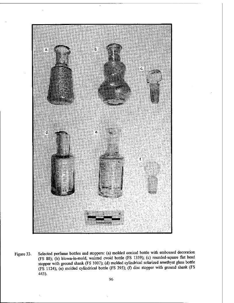
ia.i ,#**"**%;
■*#*
'W c.
§*#*?.& sia
d.
%'
CKKUMOTW
Figure 33. Selected perfume bottles and stoppers: (a) molded conical bottle with embossed decoration (FS 80); (b) blown-in-mold, waisted ovoid bottle (FS 1359); (c) rounded-square flat head stopper with ground shank (FS 1007); (d) molded cylindrical solarized amethyst glass bottle (FS 1124); (e) molded cylindrical bottle (FS 395); (f) disc stopper with ground shank (FS 443).
96
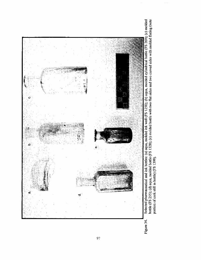
97
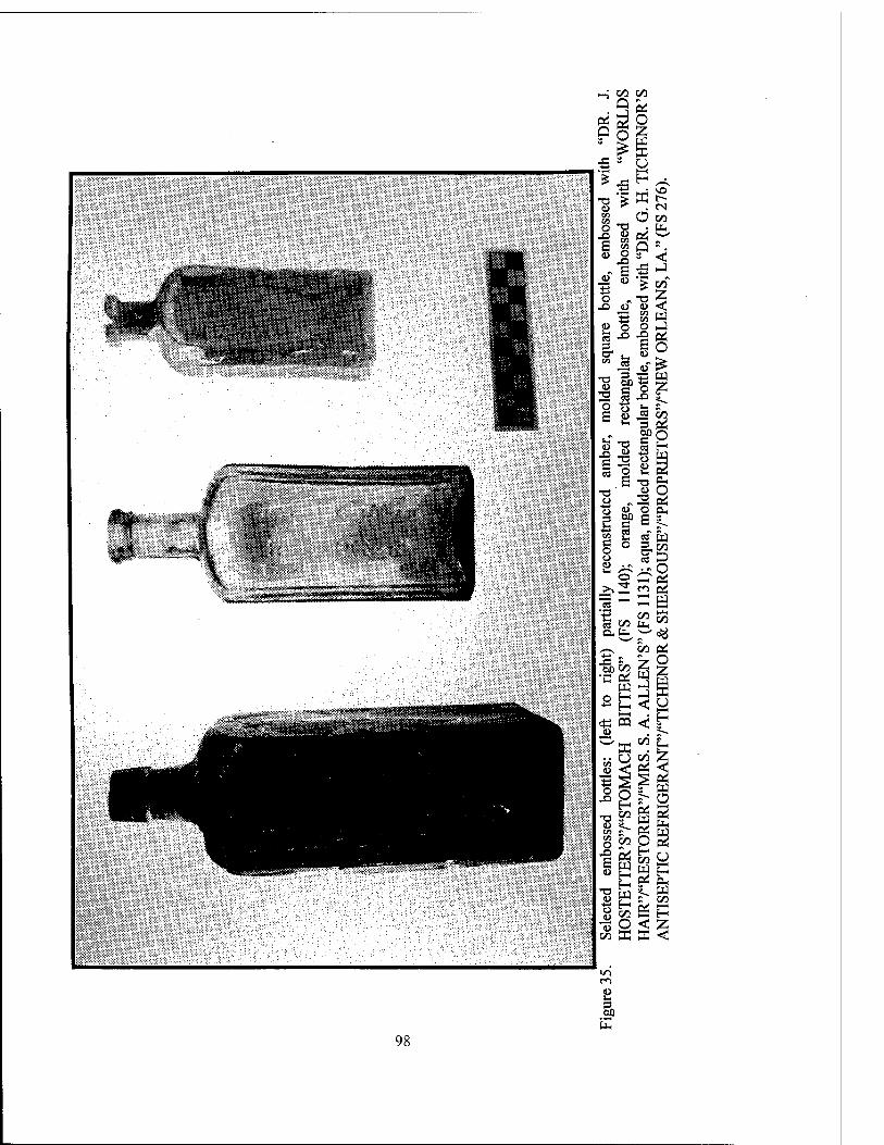
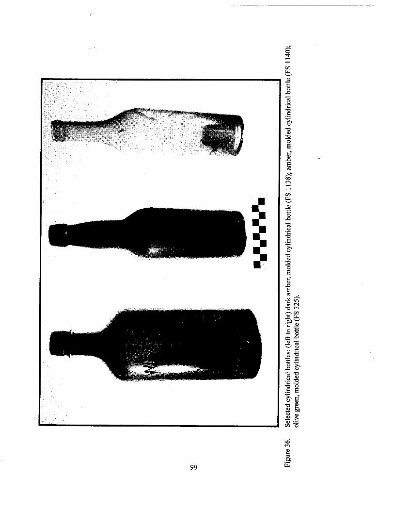
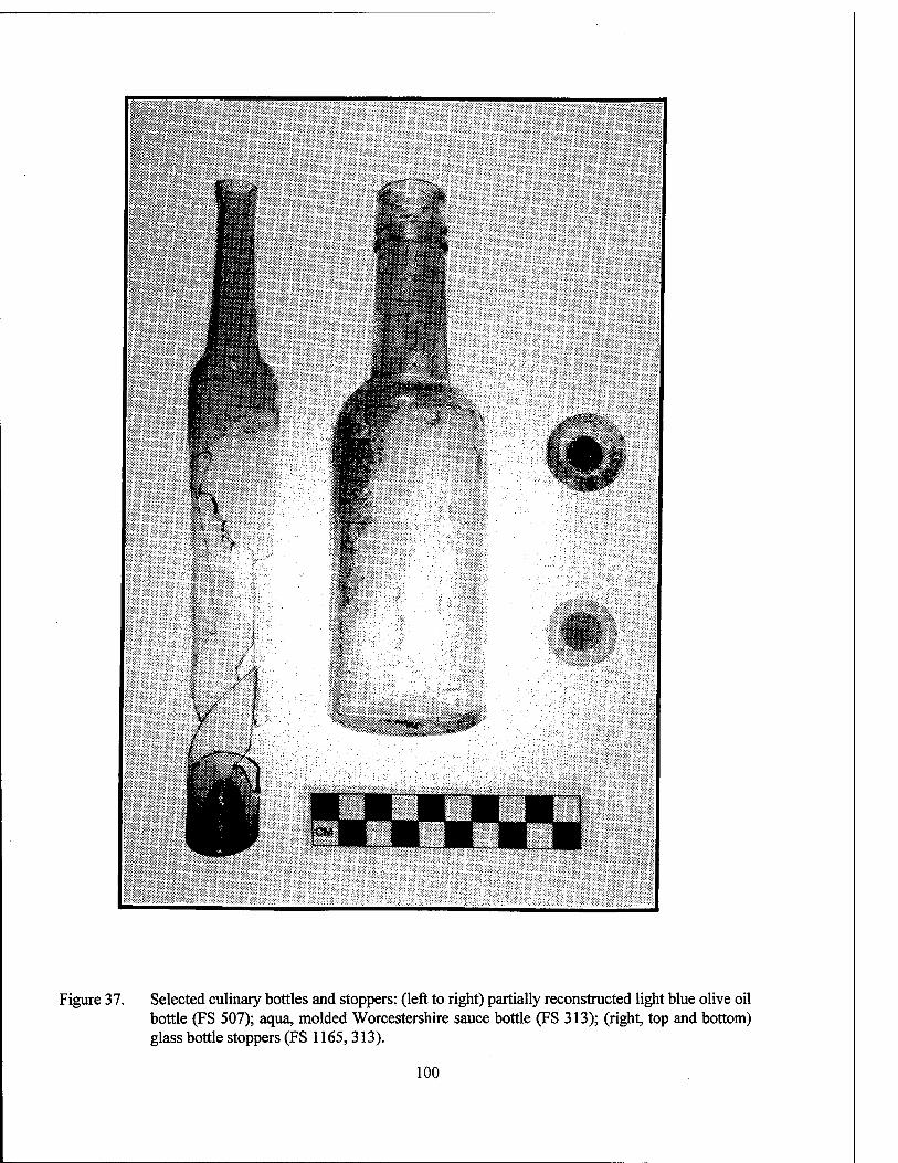
Figure 37. Selected culinary bottles and stoppers: (left to right) partially reconstructed light blue olive oil bottle (FS 507); aqua, molded Worcestershire sauce bottle (FS 313); (right, top and bottom) glass bottle stoppers (FS 1165, 313).
100
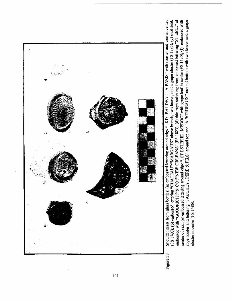
101
Type" was based on types defined previously in the volume Historic Louisiana Nails: Aids to the Dating of Old Buildings (Edwards and Wells 1993). Whole nails were defined as those with a head, or a finished end. These were separated from the nail fragments, and were sorted by size and manufacturing method. The majority of the nails were too badly fragmented or corroded to be diagnostic, but those that were well preserved were identified by type.
Typically, nails were made from steel or iron; however, they occasionally were fashioned from copper. Using Edwards and Wells' (1993) criteria, several nail forms were identified; these included sprigs, brads, common nails, and spikes. Sprigs were small, headless nails used for finish- ings on furniture or architecture. Brads, also gen- erally used for finishing, were headless or had a small L-shaped projection instead of a head. Both sprigs and brads were unusual at Nina Plantation. "Common" nails consisted of all other headed nails measuring less than 6 in (15.24 cm). Spikes were common; these headed nails measured greater than 6 in (15.24 cm) in length.
The size categories used in the analysis were 0 to 1 in (0 to 2.54 cm), 1 to 2 in (2.54 to 5.08 cm), 2 to 4 in (5.08 to 10.16 cm), 4 to 6 in (10.16 to 15.24 cm), and 6 to 10 in (15.24 to 25.4 cm). English measurement was used during the nail analysis to correlate better the analytical and manufactured sizes.
A potential correlation between length and function was drawn based on work previously completed at Ashland-Belle Helene Plantation (Orser et al. 1987:560-561; cf. Yakubik et al. 1994:69). There is some degree of overlap be- tween length and function (i.e., the nail used for a specific task was not always limited to one size). Nails 0 to 1 in (0 to 2.54 cm) in length may have been used for interior finishing and ornamenting. Nails 1 to 2 in (2.54 to 5.08 cm) in length were used for light framing and flooring, while 2 to 4 in (5.08 to 10.16 cm) long nails were used for boarding and heavy framing. Four to 6 in (10.16 to 15.24 cm) nails were for partition studding, rafters, and for heavy framing. However, function probably was not limited to the above mentioned tasks.
Manufacturing methods included forging, cutting, and drawing. Hand shaped forged or wrought nails were popular between the 1730s
and the 1820s (Edwards and Wells 1993:2, 45). The transition from wrought nails to cut nails took place between 1790 and 1830, though there was some overlap in popularity (Nelson 1968). Cut nails were produced in several varieties by cutting flat iron sheets into nail blanks. These nails were common during the late eighteenth through mid-nineteenth centuries. Wire nails, manufactured by drawing out an iron wire, were circular in form; they appeared after 1850, and by the end of the nineteenth century they had be- come more popular than cut nails.
Several diagnostic features were used to identify and date the few nails that were suitable for type analysis. These included surface texture; shape of the shaft (taper and cross-section); shape of the neck, head, and point; and morphology of the nail burr (a thin ridge running along one or several edges of the nail). The material from which the nail was manufactured, typically iron or steel, and other markings such as cold-shuts (creases or rifts in the metal) on hand-wrought nails, and cut-face cracking on cut nails, also were useful during identification (Edwards and Wells 1993:26-43).
Also noted in the analysis was whether or not the nail was clinched. A clinched nail was hammered through the wood and then bent over so that the point could be hammered back into the wood or bent over flat, preventing the nail from working loose. Clinching often was used when moveable parts, such as doors and shutters, were being attached. Wrought nails often were used in construction activities that required clinching, because the soft iron from which they were forged did not break when bent (Edwards and Wells 1993:3).
Beads Only 36 glass beads were recovered from
the excavations at Nina Plantation (Figure 39); they are itemized in Appendix IV of this report. Bead analysis relied on previously defined attrib- utes and classifications established for glass trade beads (Sprague 1991). Attributes included in the analysis were material, manufacturing method, style, shape, color, light (opacity), luster, and bead and bore dimensions. The primary distinc- tions between beads were the material and the method of manufacture. All of the beads recov- ered from Nina Plantation were made of glass,
102
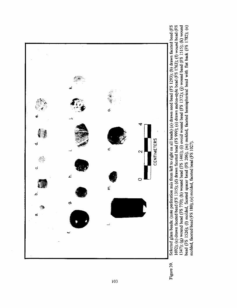
ON CO
fi 3 60
103
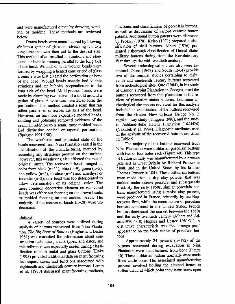
and were manufactured either by drawing, wind- ing, or molding. These methods are reviewed below.
Drawn beads were manufactured by blowing air into a gather of glass and stretching it into a long tube that was then cut to the desired size. This method often resulted in striations and elon- gated air bubbles running parallel to the long axis of the bead. Wound, or wire wound, beads were formed by wrapping a heated cane or rod of glass around a wire that created the perforation or bore of the bead. Wound beads usually had visible striations and air bubbles perpendicular to the long axis of the bead. Mold-pressed beads were made by clamping two halves of a mold around a gather of glass. A wire was inserted to form the perforation. This method created a seam that ran either parallel to or across the axis of the bead. However, on the more expensive molded beads, sanding and polishing removed evidence of the seam. In addition to a seam, most molded beads had distinctive conical or tapered perforations (Sprague 1991:150).
The weathered and patinated state of the beads recovered from Nina Plantation aided in the identification of the manufacturing method by accenting any striations present on the surface. However, this weathering also affected the beads' original luster. The recovered beads ranged in color from black (n=l 1), blue (n=9), green (n=5), and yellow (n=4), to clear (n=4) and amethyst or lavender (n=2); one bead was too deteriorated to allow determination of its original color. The most common decorative element on recovered beads was either cut faceting on the drawn beads, or molded faceting on the molded beads. The majority of the recovered beads (n=20) were mi- decorated.
Buttons A variety of sources were utilized during
analysis of buttons recovered from Nina Planta- tion. The Big Book of Buttons (Hughes and Lester 1981) was consulted for information about con- struction techniques, shank types, and dates, and this reference was especially useful during classi- fication of both metal and glass buttons. Hinks (1995) provided additional data on manufacturing techniques, dates, and functions associated with eighteenth and nineteenth century buttons. Lamm et al. (1970) discussed manufacturing methods,
functions, and classification of porcelain buttons, as well as discussions of various ceramic button patents. Additional button patents were discussed by Prosser (1970). Kelso (1971) prepared a clas- sification of shell buttons. Albert (1976) pre- sented a thorough classification of United States military buttons dating from the Revolutionary War through the mid-twentieth century.
Several archeological sources also were ex- amined. Olsen (1963) and South (1964) provide two of the seminal studies pertaining to eight- eenth and nineteenth century buttons recovered from archeological sites. Otto (1984), in his study of Cannon's Point Plantation in Georgia, used the buttons recovered from that plantation in his re- view of plantation status patterns. Louisiana ar- cheological site reports reviewed for this analysis included an examination of the buttons recovered from the Greater New Orleans Bridge No. 2 right-of-way study (Thigpen 1986), and the study of Ashland-Belle Helene Plantation (16AN26) (Yakubik et al. 1994). Diagnostic attributes used in the analysis of the recovered buttons are listed in Table 9.
The majority of the buttons recovered from Nina Plantation were utilitarian porcelain buttons with two or four holes each (Figure 40). This type of button initially was manufactured by a process patented in Great Britain by Richard Prosser in 1840, and in the United States by his brother Thomas Prosser in 1841. These utilitarian buttons were made from a dry clay powder that was molded under intense pressure, and subsequently fired. By the early 1850s, similar porcelain but- tons, manufactured using a moist clay process, were produced in France, primarily by the Bap- terosses firm; while the manufacture of porcelain buttons continued in the United States, French buttons dominated the market between the 1850s and the early twentieth century (Albert and Ad- ams 1970:4-10; Hughes and Lester 1981:31). A distinctive characteristic was the "orange peel" appearance on the back center of porcelain but- tons.
Approximately 24 percent (n=172) of the buttons recovered during excavation at Nina Plantation were manufactured from bone (Figure 40). These utilitarian buttons normally were made from cattle bone. The associated manufacturing process involved boiling the cleaned bones to soften them, at which point they were sawn open
104
105
o
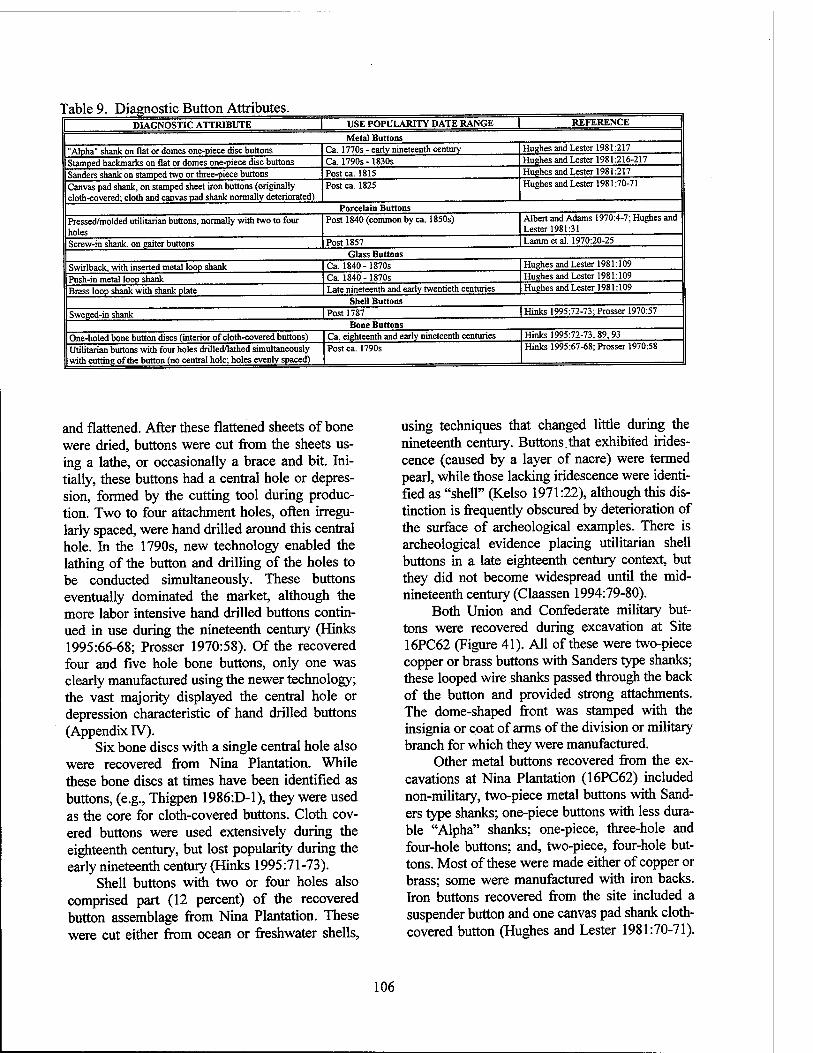
Table 9. Diagnostic Button Attributes. DIAGNOSTIC ATTRIBUTE USE POPULARITY DATE RANGE REFERENCE
Metal Buttons "Alpha" shank on flat or domes one-piece disc buttons Stamped backmarks on flat or domes one-piece disc buttons Sanders shank on stamped two or three-piece buttons Canvas pad shank, on stamped sheet iron buttons (originally cloth-covered; cloth and canvas pad shank normally deteriorated)
Ca. 1770s - early nineteenth century Ca. 1790s - 1830s Post ca. 1815 Post ca. 1825
Hughes and Lester 1981:217 Hughes and Lester 1981:216-217 Hughes and Lester 1981:217 Hughes and Lester 1981:70-71
Porcelain Buttons Pressed/molded utilitarian buttons, normally with two to four holes Screw-in shank, on gaiter buttons
Post 1840 (common by ca. 1850s)
Post 1857
Albert and Adams 1970:4-7; Hughes and Lester 1981:31 Lamm et al. 1970:20-25
Glass Buttons Swirlback, with inserted metal loop shank Push-in metal loop shank Brass loop shank with shank plate
Ca. 1840-1870s Ca. 1840 - 1870s Late nineteenth and early twentieth centuries
Hughes and Lester 1981:109 Hughes and Lester 1981:109 Hughes and Lester 1981:109
Sweged-in shank | Post 1787 Shell Buttons
Hinks 1995:72-73; Prosser 1970:57
Bone Buttons One-holed bone button discs (interior of cloth-covered buttons) Utilitarian buttons with four holes drilled/lathed simultaneously with cutting of the button (no central hole; holes evenly spaced)
Ca. eighteenth and early nineteenth centuries Postca. 1790s
Hinks 1995:72-73,89,93 Hinks 1995:67-68; Prosser 1970:58
and flattened. After these flattened sheets of bone were dried, buttons were cut from the sheets us- ing a lathe, or occasionally a brace and bit. Ini- tially, these buttons had a central hole or depres- sion, formed by the cutting tool during produc- tion. Two to four attachment holes, often irregu- larly spaced, were hand drilled around this central hole. In the 1790s, new technology enabled the lathing of the button and drilling of the holes to be conducted simultaneously. These buttons eventually dominated the market, although the more labor intensive hand drilled buttons contin- ued in use during the nineteenth century (Hinks 1995:66-68; Prosser 1970:58). Of the recovered four and five hole bone buttons, only one was clearly manufactured using the newer technology; the vast majority displayed the central hole or depression characteristic of hand drilled buttons (Appendix IV).
Six bone discs with a single central hole also were recovered from Nina Plantation. While these bone discs at times have been identified as buttons, (e.g., Thigpen 1986:D-1), they were used as the core for cloth-covered buttons. Cloth cov- ered buttons were used extensively during the eighteenth century, but lost popularity during the early nineteenth century (Hinks 1995:71-73).
Shell buttons with two or four holes also comprised part (12 percent) of the recovered button assemblage from Nina Plantation. These were cut either from ocean or freshwater shells,
using techniques that changed little during the nineteenth century. Buttons.that exhibited irides- cence (caused by a layer of nacre) were termed pearl, while those lacking iridescence were identi- fied as "shell" (Kelso 1971:22), although this dis- tinction is frequently obscured by deterioration of the surface of archeological examples. There is archeological evidence placing utilitarian shell buttons in a late eighteenth century context, but they did not become widespread until the mid- nineteenth century (Claassen 1994:79-80).
Both Union and Confederate military but- tons were recovered during excavation at Site 16PC62 (Figure 41). All of these were two-piece copper or brass buttons with Sanders type shanks; these looped wire shanks passed through the back of the button and provided strong attachments. The dome-shaped front was stamped with the insignia or coat of arms of the division or military branch for which they were manufactured.
Other metal buttons recovered from the ex- cavations at Nina Plantation (16PC62) included non-military, two-piece metal buttons with Sand- ers type shanks; one-piece buttons with less dura- ble "Alpha" shanks; one-piece, three-hole and four-hole buttons; and, two-piece, four-hole but- tons. Most of these were made either of copper or brass; some were manufactured with iron backs. Iron buttons recovered from the site included a suspender button and one canvas pad shank cloth- covered button (Hughes and Lester 1981:70-71).
106
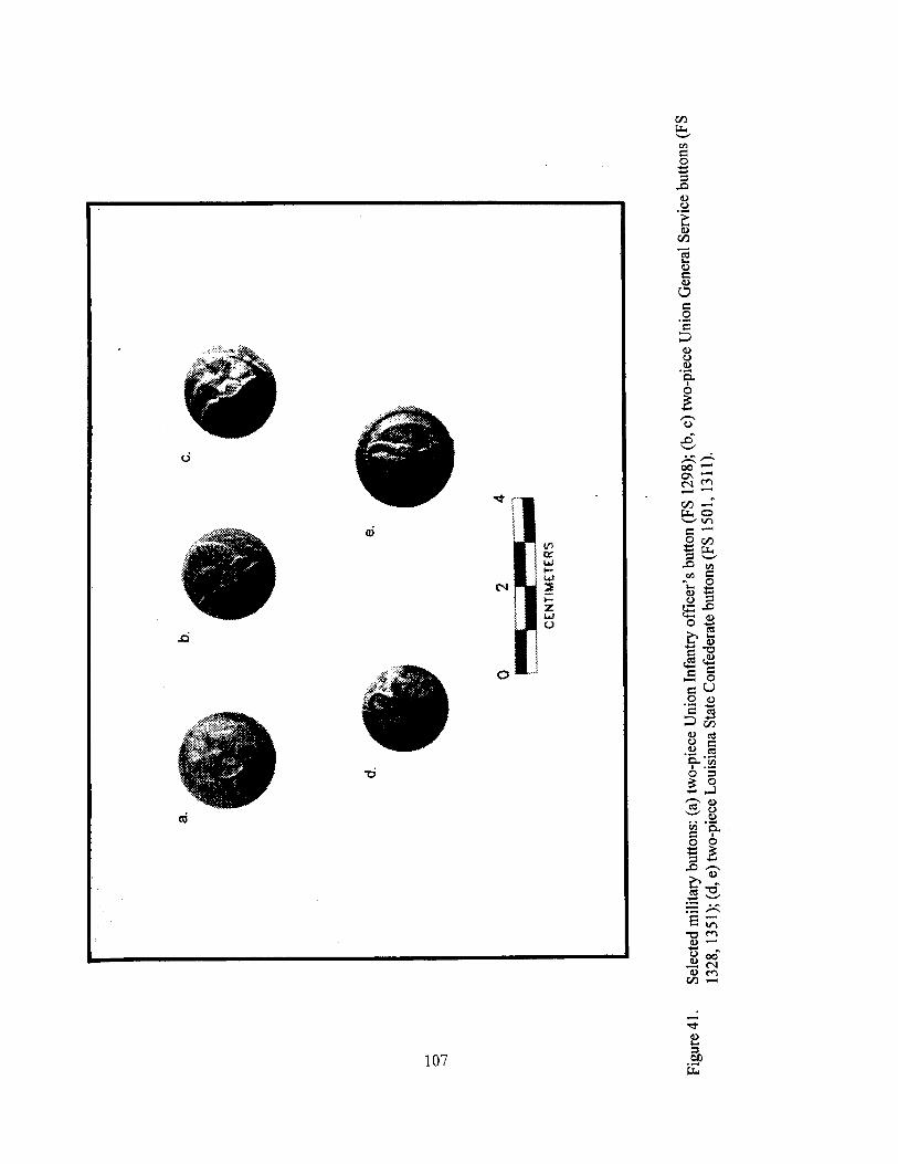
tu
e o 3
<D o
u c u Ü c g '2 D u o
§5 00 —" b o •^ in c —' ö b 3 w X) «
° S s -0
°-a fr Ö
C U O o C rt D 53 o cd
•- .1 Q. [en Ö '5 £3 c3 a
o u
11
<D —< ■4-» o u 00
oo —
107 b
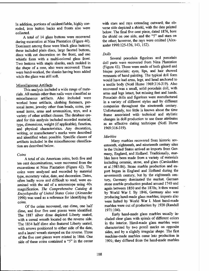
In addition, portions of unidentifiable, highly cor- roded, iron button backs and fronts also were collected.
A total of 14 glass buttons were recovered during excavation at Nina Plantation (Figure 40). Dominant among these were black glass buttons; these included plain discs, large faceted buttons, discs with cut decoration on the front, and one whistle form with a multi-colored glass front. Two buttons with staple shanks, each molded in the shape of a rose, also were recovered. These were hand-worked, the shanks having been added while the glass was still soft.
Miscellaneous Artifacts This analysis included a wide range of mate-
rials. All metals other than nails were classified as miscellaneous artifacts. Also included were worked bone artifacts, clothing fasteners, per- sonal items, jewelry other than beads, coins, per- sonal items, arms and ammunition, toys, and a variety of other artifact classes. The database cre- ated for this analysis included recorded material, type, dimensions, weight (if applicable), function, and physical characteristics. Any decoration, writing, or manufacturer's marks were described and identified when possible. Specific classes of artifacts included in the miscellaneous classifica- tion are described below.
Coins A total of six American coins, both five and
ten cent denominations, were recovered from the excavations at Nina Plantation (Figure 42). The coins were analyzed and recorded by material type, monetary value, date, and decoration. Dates, often badly worn and difficult to read, were ex- amined with the aid of a microscope using 40x magnification. The Comprehensive Catalog & Encyclopedia of United States Coins (Alexander 1990) was used as a reference for identifying the coins.
Of the coins recovered, one dime, one half dime, and four five cent pieces were identified. The 1887 silver dime depicted Liberty seated, with a cereal wreath located on the reverse side. The 1854 half dime also featured Liberty seated, with arrows positioned to either side of the date, and a laurel wreath stamped on the reverse. Three of the five cent pieces were minted in 1866. One side of these coins contained a "5" in the center
with stars and rays extending outward; the ob- verse side depicted a shield, with the date printed below. The final five cent piece, dated 1876, bore the shield on one side, and the "5" and stars on the other; however, the rays were omitted (Alex- ander 1990:125-126, 143,152).
Dolls Several porcelain figurines and porcelain
doll parts were recovered from Nina Plantation (Figure 43). These were made of both glazed and bisque porcelain; eyes, lips, and hair showed remnants of hand painting. The typical doll form would have had arms, legs, and head anchored to a textile body (Noel Hume 1969:316-319). Also recovered was a small, solid porcelain doll, with arms and legs intact, but missing feet and hands. Porcelain dolls and figurines were manufactured in a variety of different styles and by different companies throughout the nineteenth century. Unfortunately, too little is known about the time frame associated with technical and stylistic changes in doll production to use these attributes as an effective dating technique (Noel Hume 1969:316-319).
Marbles Many marbles recovered from historic sev-
enteenth, eighteenth, and nineteenth century sites in the United States arrived as imports from Ger- many, England, and Holland. Traditionally, mar- bles have been made from a variety of materials including ceramic, stone, and glass (Carskadden et al.l985:86). Stone marble production and ex- port began in England and Holland during the seventeenth century, but by the eighteenth cen- tury, Germany dominated the market. German stone marble production peaked around 1740 and again between 1850 and the 1870s; it then waned by World War I. By 1846, Germany also was producing hand-made glass marbles; imports also were halted by World War I. Most hand-made marbles were out of production by 1920 (Randall 1971:104).
Early hand-made glass marbles usually in- cluded clear glass with spirals of different colors in the interior. Hand-made glass marbles were characterized by two pontil marks on opposite sides, and by a slightly irregular shape. The first machine-made marbles came into production in 1901; they differed from the hand-made marbles
108
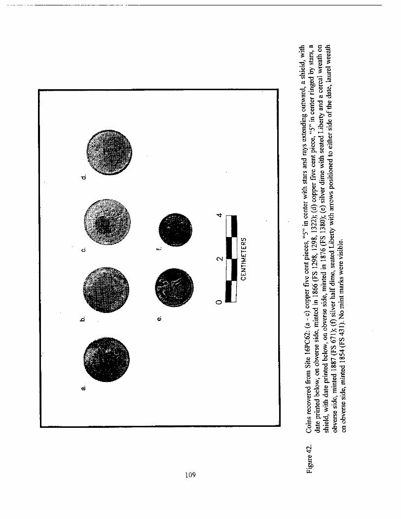
.ts - o -a * £^= §
-£ -° j_ 3
•2 CO
(L> 4)
13 ea *o 4> C J3
so " £> o
.5 :a
, 8 s£
S 8 *1
T3 C u H-»
u
i/-> ■"
fa ^ C +3 H-> "^-l .1-« "
J3
o 3;
o
4) O
l/J
o . . fc:
t- CN o ■> .5 «s oo >
8 oo co « « a fe ^ 4> CS w _) o — vo _ » «r- —1 *s I ~ aoooo « ■:;
3 > u 4)
.*. u. cs
' ON —• cs
° CO T3 Ö
*S vo -S ^ •- S E äs
8 !T °> 8 ^| g =
PH O £ CO
S c S o
C/3 SO
CO o
S «g -o fi >
.o r- 5* _ 00 H
o .5 T3 -£
O 4) -S 4) 15
X> 13 !2 5. "O JS
8 1-1 s r en
■I sis S
4) en t- 4> >
X) o
o o
109
4> 3 00
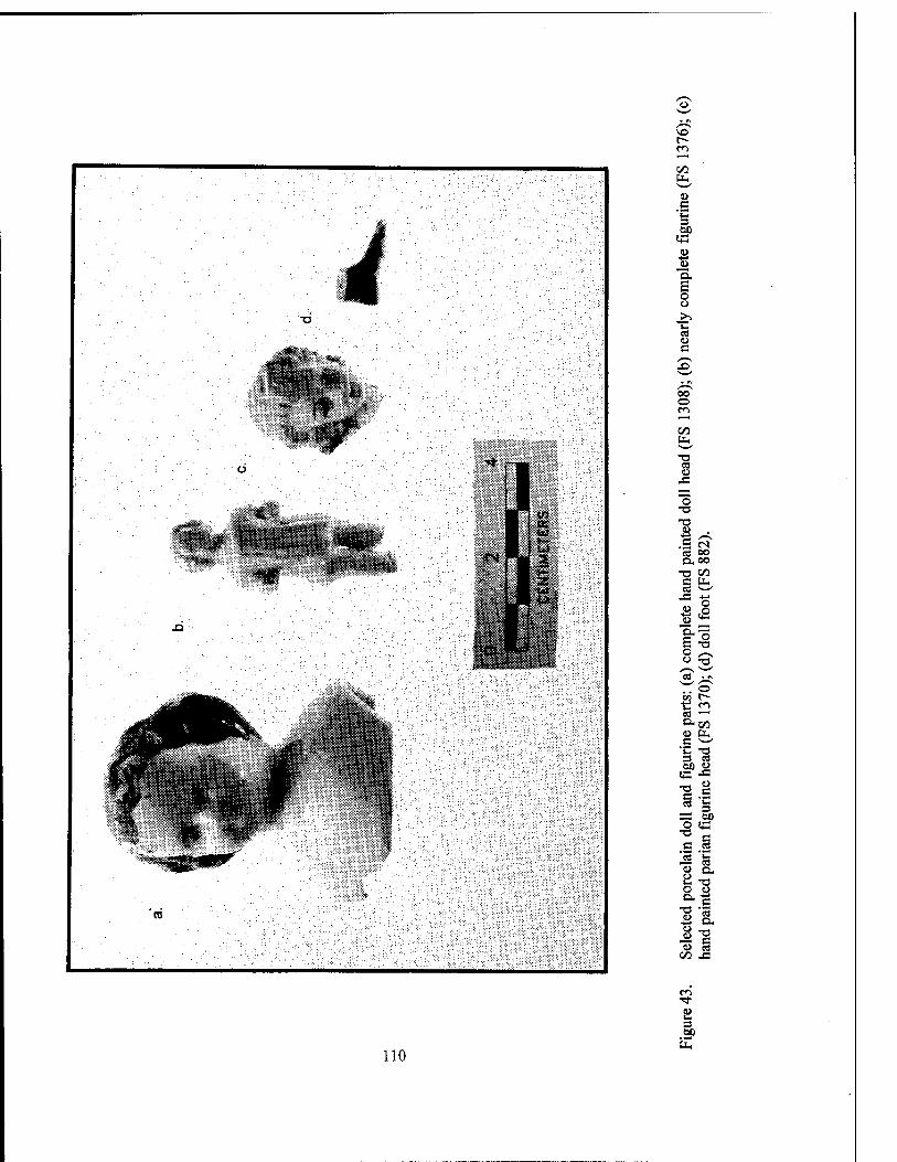
in w u .g
a £ o o
j>> "S es o c
00 o m '—" C/5 Ut, ^-^ •w
C8 <u
J3 ~— O
•o -a u ft U es <rt 00 n,oo
■n 00 c ÜH 03 ^-/
J3 +J
1i> Ü
a. S o
•a o o ■a ^»^ \—• «j < «\
o en 1^- t! m «J '—' O. ty> u UH c ** T3 3 S3 01) Cl
!+3 ■fi
c U 3
« 3
;—j 01) o «C
T3 S
C CO rrt 1-
K! 4> a. a •n o i> o. 3
T3 m ü a
T3 8 <u cfl
00 4=
r>~i ■*
u u 3 60
110
in that they usually were opaque, and contained a single pontil mark. By 1926, machine-made mar- ble production was fully developed; more regu- larly shaped marbles with no pontil marks, in a variety of colors and patterns, became the norm (Randall 1971:104-105; Carskadden et al. 1985:91-93).
Limestone marbles typically were white, gray, or brown, and they often were dyed bright colors during manufacture. Alabaster marbles, another popular European export, usually were white or pink. Due to the softness of the stone, these marbles tend to be poorly preserved in the archeological record. Other German stone mar- bles, made from a variety of semi-precious stones, are less common in the archeological rec- ord (Carskadden et al. 1985:91).
Attributes recorded during analysis in- cluded material and method of manufacture, di- ameter, color, and decoration. The majority of the 51 recovered specimens were made from earthenware, limestone, marble, glass, or porce- lain (Figure 44). A detailed listing of these mar- bles can be found in Appendix IV.
Tobacco Pipes A small collection of tobacco pipes was re-
covered during data recovery at Nina Plantation. For analytical purposes, these were divided into groups based on material and form. Two major groups were represented; the first included pipes with the bowl and stem both made from white ball clay (n=141) (Figures 45 and 46). Pipes in the other group (n=108) were manufactured from a variety of earthenware and stoneware clays, and had short stems into which a reed stem could be inserted (Figures 45 and 47). Five stem fragments manufactured of vulcanite, a type of hard rubber. These would have been used with brier pipes, although none were recovered. Other attributes noted in the analysis included glaze type, decora- tive elements, and mark type.
Identification and dating of the pipes was based on formal and decorative attributes, and on maker's marks, where present. Identified marks represented manufacturers in Holland, England, the United States, and France. Manufacturers of pipes were identified in England, France, Hol- land, and America. A statistical method for dating white ball clay pipe assemblages by measuring the diameter of the bore holes (Binford 1972)
works reasonably well only for dating sites occu- pied through the middle of the eighteenth century. Applying the Binford/Harrington formula on the tobacco pipe subassemblage recovered from Nina Plantation (16PC62) produced a mean date of 1734, while dates derived from formal analysis grouped in the first two thirds of the nineteenth century. Sources of great utility in identification and dating were Humphrey (1969), Walker (1971 and 1983), Alexander (1990), Duco (1982), and Hansen (1971). Details of the pipe analysis are presented in Appendix IV.
Firearms and Ammunition Only two firearms were recovered from the
site; one of these was a single shot, breechloading pocket pistol (Figures 48 and 49), and the other was a barrel from a muzzle loaded pistol (Figure 48). Ammunition represented at the site included lead shot, rim fire casings, center fire casings, percussion caps, and various bullets. The nine- teenth century was a period of rapid development for the firearm industry, and many of the patents approved during this period provided termini post quem for recovered artifacts.
For example, percussion caps first were pat- ented in 1822, and were used in both pistols and muzzle loading muskets (Coates and Thomas 1990:72). The Minie ball or bullet was adopted by the United States Army in 1855, and was used extensively during the Civil War (Lord 1982:15). Many of the casings recovered during excava- tions at Nina Plantation were .22 short rimfire cartridges, patented in 1860 by Smith and Wes- son, but first sold in 1857; however, they were in use by Federal forces by the end of the Civil War. By 1875, at least 30 manufacturers were produc- ing these cartridges (Klatt 1981:49).
In addition to firearms and ammunition, a Ketchum hand grenade (Figure 50), probably used during the Civil War, was recovered. Pat- ented in 1861, it was the most common grenade in use, and was furnished in one, two, three, and four pound weights (Lord 1982:117). The recov- ered grenade was intact, and because of its cor- roded condition, it was not possible to determine if it contained a charge of black powder. For safety reasons, the grenade was carefully re- corded, and subsequently turned over to bomb technicians from the Jefferson Parish Sheriffs Office, Jefferson Parish, Louisiana.
Ill
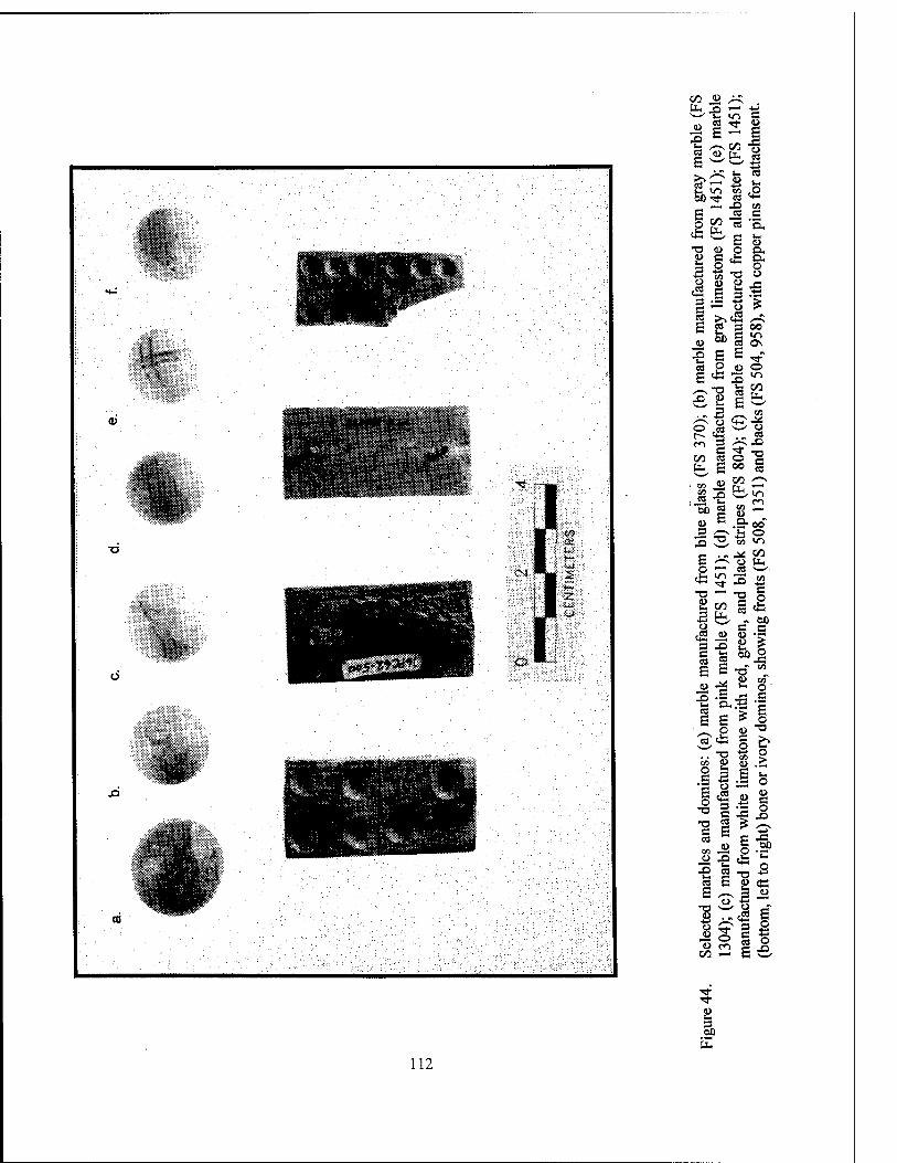
00 o
3 E x> 2 4> tu
So-* «
* ^ 13
3
5 5»
u u
£ p
eg 3 c « E
J£
el o r- CO 00
o <~ 4) p
u O. o o
in 05 0\
E^ u o 3 •" 2 UH
CO
1© o »03 ^^ »* *<-< . c 2
Co O S
— fa «, ^ B .&0O
5 -o. «
en CO es
<0 3
to «n
<4-l CO
S P
E o
X> T,
(50
T3 2 09
it ^ ■ -" - c«
CO p • e £ p
P
CO Z5
E E T, u J* 8
E * e?cfc S
«8 E
.. T, co <1>
§3 E " P
.08
e 03 oo
3
<u p
e
£ p •a
e3 E
IT, a
o° Si oo — £ w
112
8 3> E
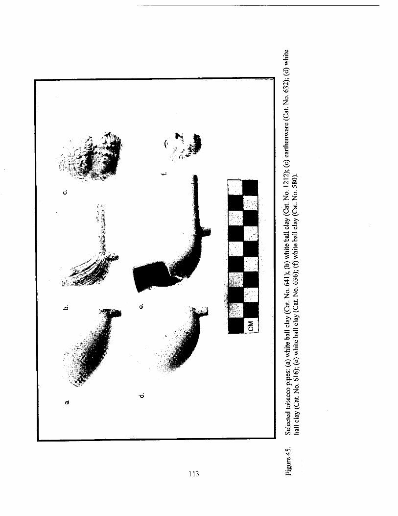
£ s~\ TJ
<N m VO
O Z -4-» W u o u. 03
* C 10
J3 ■c cs (D ,*""S o
•-N (N /-^ I—H o CM 00 *-" ir>
O o z z 03 03 o U ■"■^x s—^
>> >> 03 a o o
ea w .£> X) «> 4>
■*-»
j= -C £ * S1 s /"^ VO
VO
d Z
o z U
£ £ o o
03 03 X>
<u <u
u cd x^
en u a. a o u
Ü z o
o •4-» "s™^
•o >. <l> 03
o o tu , 1 V 03
t/3 -O
»n ■<*
9> u 3 ea.
113 IX
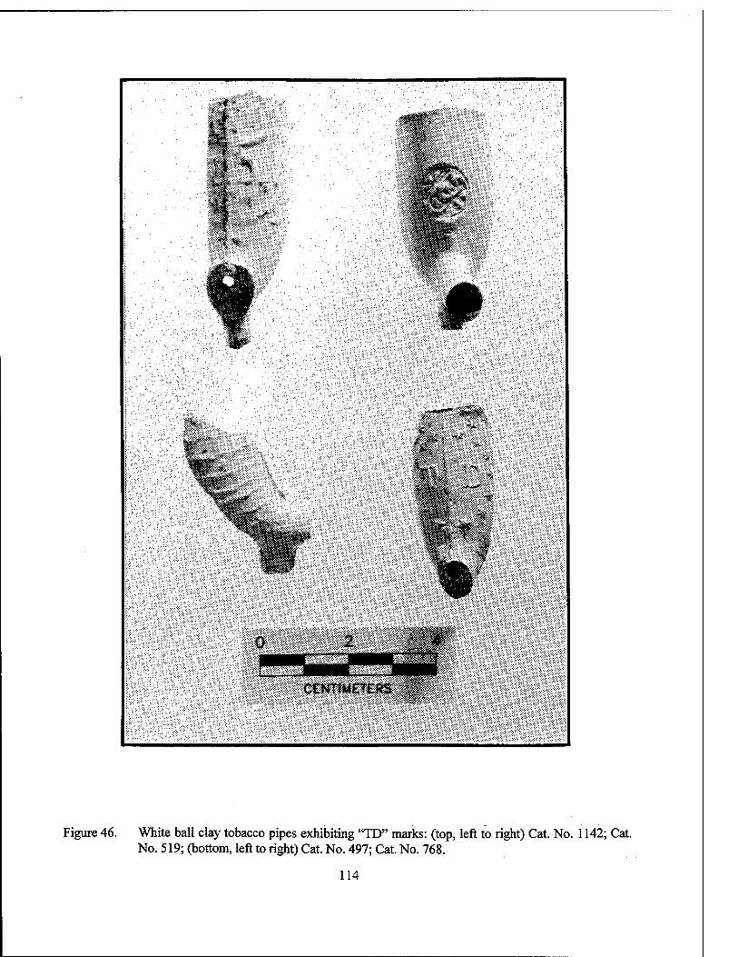
m
CENTIMETERS
Figure 46. White ball clay tobacco pipes exhibiting "TD" marks: (top, left to right) Cat. No. 1142; Cat. No. 519; (bottom, left to right) Cat. No. 497; Cat. No. 768.
114
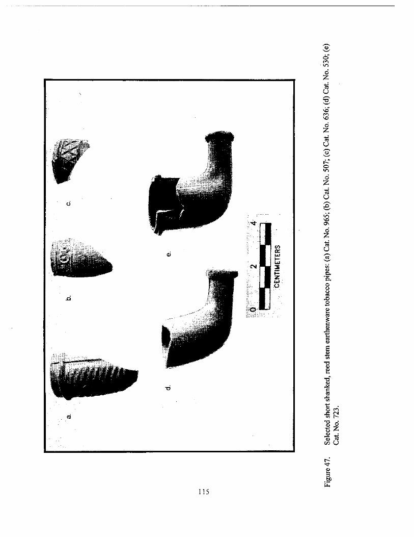
o CO in
ö Z ■a u ^5"
VO
Ö Z
r- o in Ö Z ■*-*
ca
in
Os
Ö Z 13 U
Q.
O o ä o
c
tS
£
T3 U 0>
u c
J3
o CO
■8i ts z
115
3)
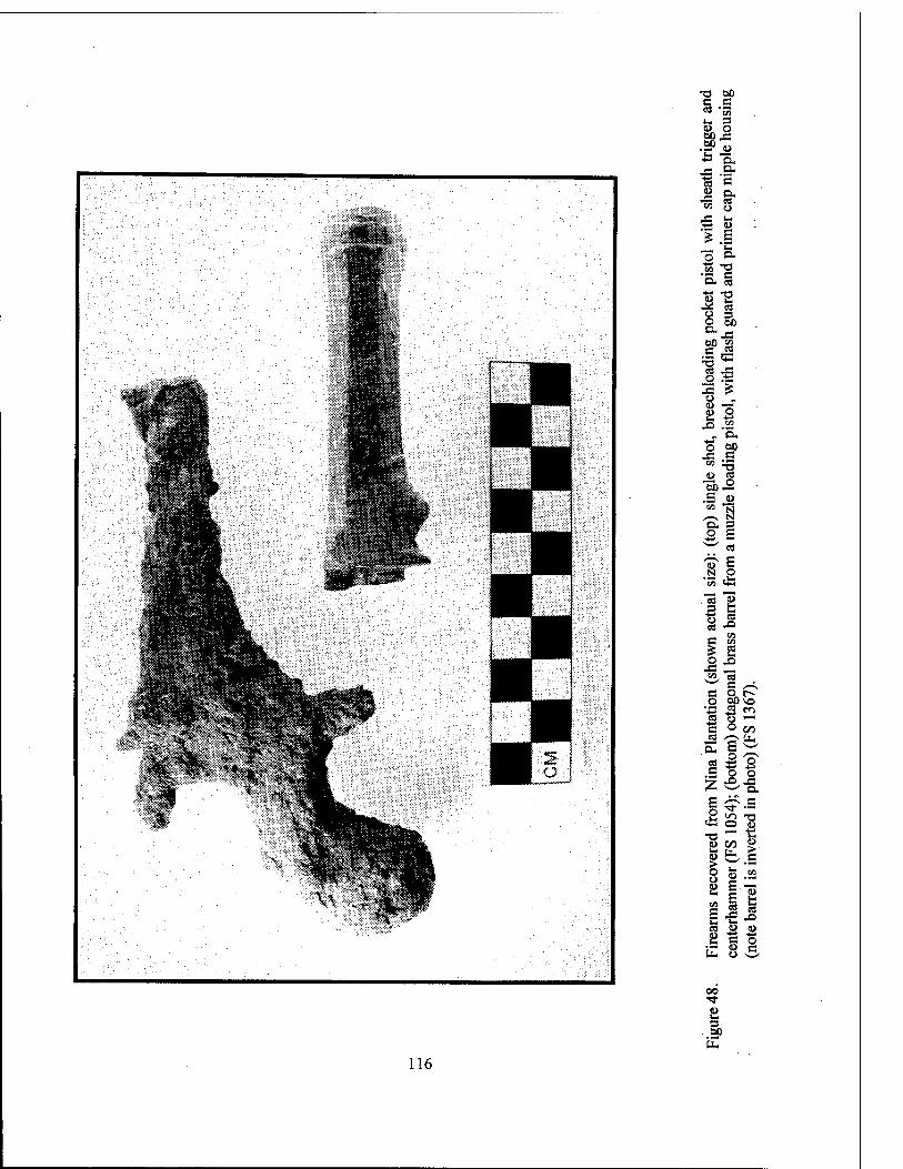
T3 60 C C
!-§ •f-s J3 .9- 3 c .S & «a g
_ *" o o-
■S5 "P °K c Cu «
!"§ o 5b 60 S3
•— 53 cd J3 O .tJ 3 &
2 -i « o.
o w> «3 S « =5 •a ^
§■1
s p
es
O MHO "5 -2 S2
Sfifi .S o 5
rfi Ä "° •o — t: p CO »
w
» .2
III b. c o
00 "3-
.3»
116
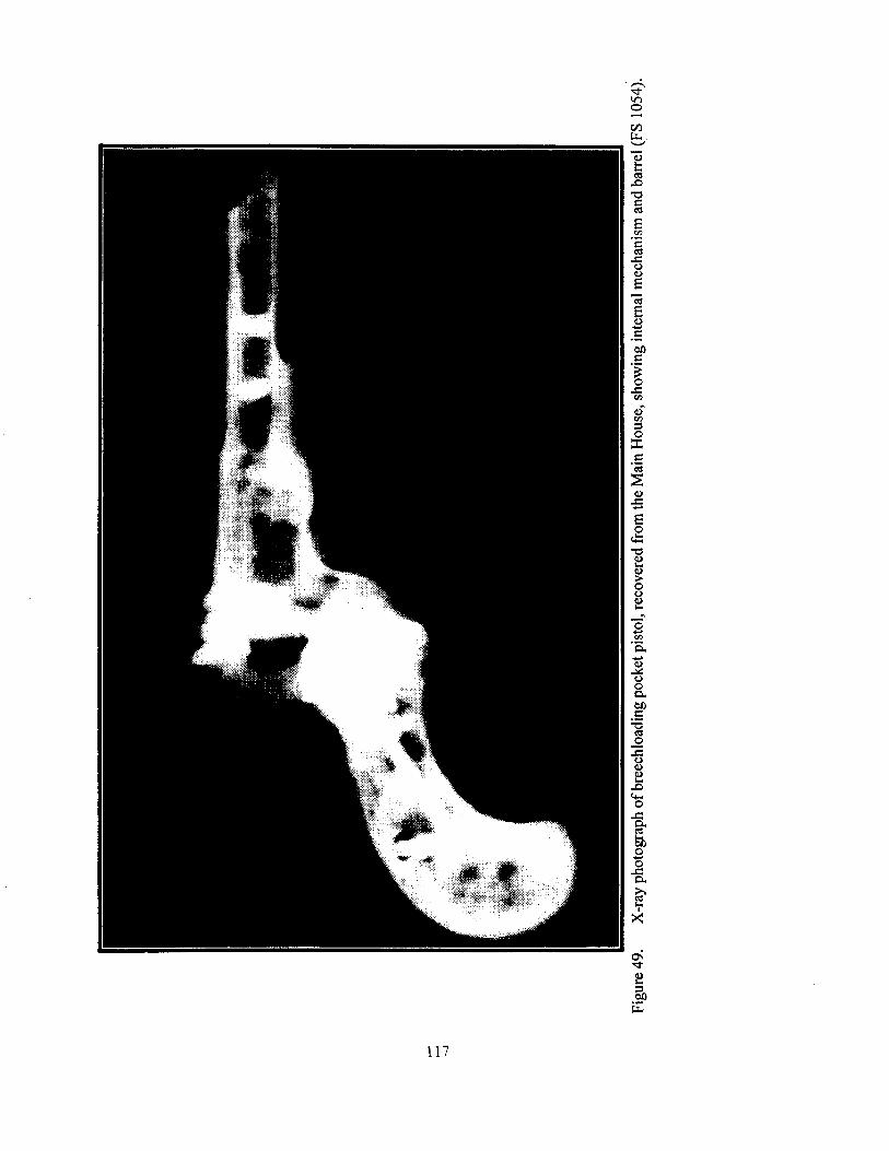
117
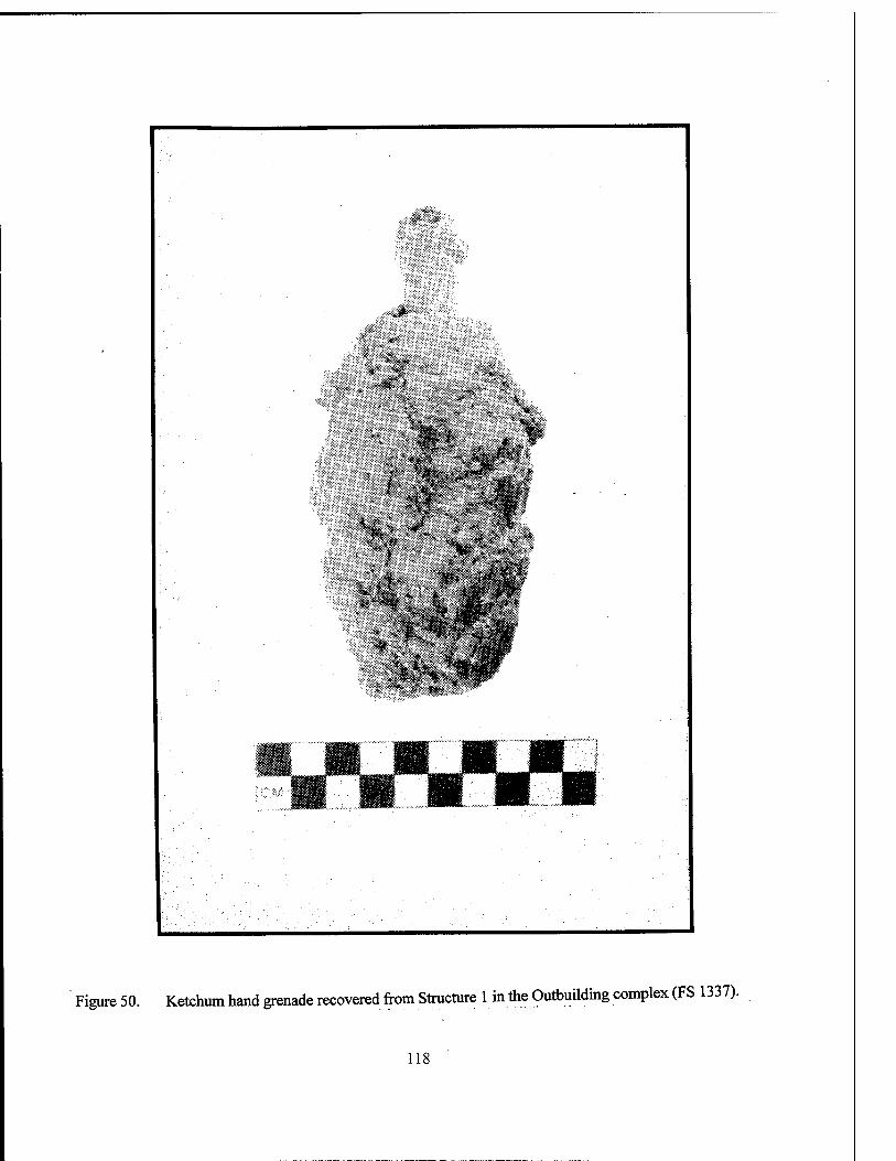
iܧ*:;
i*3
iWl
• * >
Figure 50. Ketchum hand grenade recovered from Structure 1 in the Outbuilding complex (FS 1337).
118
Other Miscellaneous Items A variety of personal items were identified
at Nina Plantation. Among these were toothbrush handles, shaving brush handles, and a straight razor handle, all manufactured from bone. Also recovered were fragments of hair combs made from bone and from vulcanite, a hard rubber in common use by the last half of the nineteenth century. Toothbrushes, initially imported from France and England during the nineteenth cen- tury, were considered luxury items until after the Civil War (Mattick 1993). Fewer than 20 percent of the American population used toothbrushes before the 1930s (Mattick 1993:168).
Other personal items included jewelry, some with amethyst settings (Figure 51), pocket watch parts, pocket knives, thimbles (Figure 52), eyeglass lenses, slate pencils, bone dominos (Figure 44), alligator tooth pendants (Figure 53), and a religious medallion. Sources useful for the identification of these items included reprints of the Bloomingdale's (1886), Sears, Roebuck & Company (1902 [1969 reprint]), and the 1922 Montgomery Ward (Cohen 1969) catalogs.
Faunal Material Approximately 16,000 faunal elements were
recovered during excavations at Nina Plantation; 7,089 of these elements underwent full analysis. Faunal elements recovered from disturbed, post- occupation, or surface contexts were not included in the analysis. The remaining materials, recov- ered from contexts possessing integrity and ana- lytic utility, were sorted by excavation block, by excavation unit, and by analytical unit (see Chapter DC and Appendix I of this report). The limited resources that could be devoted to faunal analysis necessitated a sampling strategy that was intended to provide a characterization of the types of species present and to provide some insight into their temporal and spatial distribu- tion. Because a complete data recovery and analysis of all specimens was not possible, the utility of the MNI counts and biomass measure- ments should be regarded as an aid to the char- acterization of the deposit, rather than as a sta- tistical tool.
To conform with the intent of a characteri- zation of the deposits, sampling methods were selected that would provide analytic access to as broad a sample as possible. Material from the
earliest midden deposits was sparse, an: each of the recovered elements was included in T :; analy- sis. Faunal remains from the late midder deposits were far more numerous. Provenier :s with fewer than 25 specimens were include in their entirety; those with more than 25 speci: ns were subjected to a 50 percent random samp! For this sampling procedure, tables of randon lumbers were computer-generated by the Lab director. Faunal bags from each analytic unit we- e placed on a numbered grid and were selected I accor- dance with the random number tab; . Some additional judgement was used in tb; final se- lection. For example, if material from the late midden deposits duplicated large and diverse samples from adjacent excavation units and identical analytic units, then an alternate choice was made. In addition, if a clearly unique specimen from a particular analytic unit was bypassed during the random number choice, it was later included in order to ensure that the species list was as complete.as possible.
This process resulted in a sample of faunal material from all areas and temporal periods of the site that was sufficient to characterize the as- semblage. The final sample selected for analysis approximated 44 percent of the total population; a list of all the included proveniences and analytic units is included in Appendix VII of this report.
A detailed analysis of the faunal assemblage was conducted by Dr. Elizabeth Scott (Appendix VET). Primary data collected consisted of raw fragment counts, fragment counts adjusted for fitted specimens, and weights to the nearest 0.1 gram. Identifications were carried out to the low- est taxon possible, following standard zoological classification and nomenclature. Also noted dur- ing the primary analysis were worked bone, butchering marks, burning and calcining, and gnaw marks.
Secondary data were derived from calcula- tions to determine the minimum number of indi- viduals (MNI) represented for each taxon, and the biomass (meat weight) represented by the bone weight for each taxon. MNI was calculated for each provenience or analytical unit, using the criteria of side, size, age, and sex (Wing and Brown 1979:123-126; Reitz and Scarry 1985:17). Biomass was estimated using the log-log regres- sion formula of skeletal mass allometry, based on bone weight (Wing and Brown 1979:127-129;
119
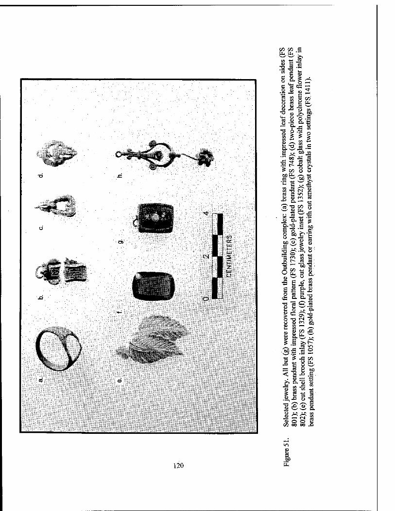
5? 4) S 50 c _ c » i
O 4)
cd en
O eö
u £> T3
o
'S, I o
53
s 1
s 8
05
C
o
•- ? •£ £</3 8
S3 'O CN
<u m X>
CO
4)
i CO 3
O ' 4> tii
><i .— -l-> "Ü 4) O, 4> >
—- i en ?*■ &2.S bo S o ^ £ § öß^fc „O o a
.S . r. S fc ;
— 2 « -a en co c C-» es eö ~ "5b IT 5° ts S' — ^ co
eS 3 — a. a-lj 13 g Jj ° >N ^ 53 o 32
-O tN o o m -- CO i—l
3
'S O a>
JS +-*
S eg •o 8 4>
S Ü U Ut
8 u
M
1) C/3 -C fc-M \w»' > »*
_ •"* rt »in
@-§ is 2
— a <!
. 4)
I 4)
a _4> £^ "S o c» 00
on IX, ^—' DO C
co
1= 'S 4) a«
iT CO
O u. 00 Xi
•O 4)
120
un
8 I
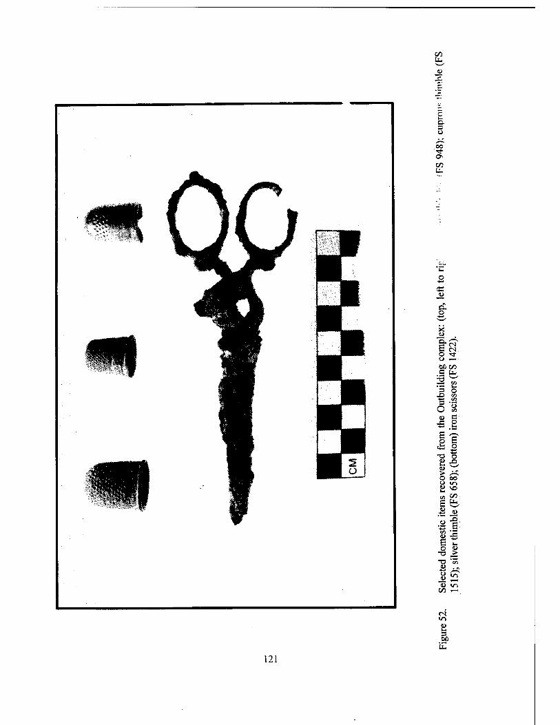
00
c c. o
00 ON
U.
<a w
^ D. o
X u
E o Tf o OCC/D c Ü-
T7
s o XI en *-» en s O o
en
«> C .E Ü
£ 's o
•o o y X) ID > /i-^ o 00 o »n a VO
C/3
E UU u <u
_o E
E J3
o u -o .*■
T3 en I) 13 a» <u in
C/D ,"H
<N in «> u. 3 M
121
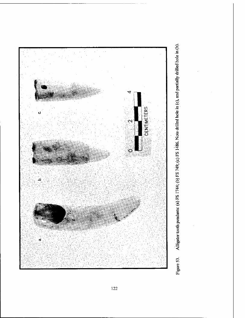
#g
~o JS T3 o
'C
"ea ■■5
<S D-
T3 e es
o
<L>
z • 00
tu
OS ■**
CO
CO
.. —-"%%*,>
CO
g c
o o
CO e8 60
J en in
3
122
Reitz and Scany 1985:18-19, 67; Reitz et al. 1987). This method predicted the amount of meat that would have been adhering to the actual re- covered bones; therefore, it provided a relatively conservative estimate of the amount of meat con- tributed by each species or taxon.
Botanical Material Botanical specimens recovered during data
recovery at Nina Plantation either were hand col- lected, or derived from flotation samples. The results of the botanical analyses are found in Chapter II and in Appendix VIII of this report.
Hand Collected Botanical Specimens The hand collected specimens usually in-
cluded those large enough to be recognized by archeologists during the excavation and screening processes. In the field, an attempt was made to ensure that the collected materials remained in the same condition as when they were found; most remains were moist, due to the prevalent soil conditions found at the site. These plant materials ranged in size from small peach pit fragments to large structural beams. A total of 28 hand col- lected samples were analyzed. The first step in the analysis was an examination to determine if they were wood or non-wood materials.
If found to be wood, identification of the species was attempted. Each wood fragment was broken to reveal a fresh transverse section. The resulting surface was examined with the aid of a low power (9-40 X) binocular microscope. Dis- tinguishing characteristics of the vessels/resin canals, rays, parenchyma, and late/early wood transition were noted for each specimen. Standard texts (e.g., Core et al. 1979; Hoadley 1990) and a study collection of pertinent wood species aided in the analysis.
Identification sometimes was limited by the level of decay exhibited by the wood and by the small sample size. For example, a cross-section of several growth rings is required for accurate identification of any wood fragments. Much of the wood recovered from the Nina excavations was quite decayed, thereby altering or destroying the cellular structure of the wood. As Hoadley (1990:190) has noted, "advanced decay produces drastic changes in many gross features. Useful characteristics such as color, evenness of grain, ray fleck and parenchyma arrangement may lose
their original macroscopic appearance." In addi- tion, the characteristic red cedar fragrance was affected by decay, although it was preserved in a few of the otherwise decayed specimens. The waterlogged nature of the Nina samples created another problem with identification; wood identi- fication guides describe characteristics only of non-waterlogged materials. Drying the specimens was not an option, since the process of drying destroys the cellular structure of non-carbonized botanical remains. During analysis, it was as- sumed that water-logged materials retained the basic characteristics of their species, but finer features such as the diameters of vessels and tra- cheids were altered by swelling.
This "swelling" problem was especialh acute for the differentiation of baldcypres5 (Taxodium distichum) and eastern redcedar (Ju- niperus virginiana). The longitudinal tracheids o: baldcypress are approximately 45-70 micrometer; wide, whereas the longitudinal tracheids of east ern redcedar are half that width (Hoadle\ 1990:17). As a result, two major characteristic for distinguishing these species, the characteristi scent of eastern redcedar and the larger trachei size of baldcypress, often were obscured in th materials recovered from Nina.
Flotation Water flotation is a recovery technique tte
takes advantage of the differences in the densit of organic and inorganic materials to separat organic matter from the soil matrix. This proce dure greatly enhances both the extent and quar tity of botanical remains that can be recovered from archeological contexts
Flotation processing employed standard an conventional techniques and equipment. Each so sample was measured volumetrically in liter prior to flotation. Volumes were measured i; quarter liter increments, since natural variation i the friability and texture of the soils would hav meant that measuring in smaller increment would not have increased the precision of th measurement. The flotation system was designe to allow water pressure fron- an ordinary plum! ing spigot to act as an agitat . to aid in the sep? ration of botanical materials ;rom the soil matrb Water overflowed from the flotation tank onto tightly woven nylon (tricot) fabric that, whil permeable to the water, captured any of th
123
floating organic or cultural debris. A stiff, sub- merged 1.5 mm (1/16 in or 0.0625 in) galvanized wire mesh screen, captured the heavy, non- buoyant material. Thus, the flotation process re- sulted in the recovery of both heavy and light fractions of material. Residual soil sediments that passed through the 1.5 mm (1/16 or 0.0625 in) wire mesh were discarded. All processed soil samples were air-dried prior to analysis. Flotation processing was used to recover both micro- archeological and archeobotanical specimens. After the flotation process was completed, the recovered material was examined and sorted for further analysis.
Flotation was conducted on soil samples from all soil features identified during excavation at Nina Plantation (16PC62), i.e., a total of 84 samples. In addition, 75 samples retained from midden contexts were floated; these represented a 50 percent sample of all midden proveniences. Sample size was standardized at two liters.
Flotation Botanical Specimens. Initial ex- amination of the material resulting from soil sam- ple flotation revealed little or no evidence of bo- tanical remains. Because of this it was decided that microscopic botanical analysis was justified only for samples originating from hearth features and from the densest midden deposits within the site, i.e., those areas considered to have the high- est probability for containing carbonized botani- cal remains. The light materials from each sample were weighed and then sifted through a series of geological sieves (2.00 mm, 1.70 mm, 1.00 mm, 0.71 mm, 0.355 mm). Wood, hickory nutshell, "other stem," and "unknowns" were removed only from the greater than 2.00 mm fractions. If those plant remains were not present in the greater than 2.00 mm fraction, they were re- moved from the smaller fractions, but not from the 0.355 mm fraction. Whole seeds and seed fragments were removed from all size fractions, and their identification was attempted.
Several special categories of plant remains were designed to describe the character of the remains. "Other stem (Monocot)" category de- scribes stem materials that were derived from an unidentified monocotyledonous plant. The Cheno-Am category describes small starch seeds that could either be Chenopodium sp. (goosefoot) or Amaranthus sp. (pigweed). Starchy materials were divided into categories depending on their
condition: remains with possible cortex were identified as "Starchy unknown (tuber?);" re- mains with no visible cortex were simply identi- fied as "Starchy unknown." Some seeds and seed fragments could be identified only to the genus or family level.
Identification of the plant remains was made with the aid of standard guides (e.g., Martin and Barkley 1961) and a reference collection of rele- vant species. The ubiquity (percent of total sam- ples in which a given material is present) of each category was calculated. Ubiquity is a good ana- lytical technique in paleoethnobotany, because it is "useful, within limitations, for showing general trends when one has little control over the sources of patterning in one's data" (Popper 1988:64).
Geomorphological Analysis Geoarcheological fieldwork and analysis
were conducted by Dr. Frank J. Vento (Geomor- phologist), Dr. Anthony Vega (Paleoclimatolo- gist), and Dr. Stephen J. Shulik (Paleomagnet- ist/Statistical Analyst). The study included a re- view of both general and specific references on the surficial geology and quaternary history of the project area. In addition, topographic and soil survey maps, and geologic and hydrologic charts were reviewed.
Field and laboratory investigations were ini- tiated on June 18,1995, and completed on August 8, 1995. Fieldwork included a pedestrian surface reconnaissance of the site area, and the inspection and mapping of soils in archeological units exca- vated at the site. In addition, a series of soil sam- ple columns were collected for granulometric, grain composition, SEM, and biogeochemical analyses. Collected from representative excava- tion units at the site, these 500 gm sediment sam- ples were taken from each cultural and non- cultural stratigraphic horizon, at 10 cm (3.94 in) intervals. If sediment composition changed within a 10 cm (3.94 in) interval, samples from each side of the change were taken. The sediment samples subsequently were divided into 50 gm fractions for analytical purposes, using a random sample splitter.
A standard granulometric sieve analysis was conducted on 50 gram fractions from each of the sediment columns. Wet sieving was performed to determine the distribution of grain sizes within each sample. Sieve size intervals included 4mm
124

(-2 phi), 2 mm (-1 phi), 1 mm (0 phi), 0.5 mm (1 phi), 0.250 mm (2 phi), 0.125 mm (3 phi), and 0.063 mm (4 phi) sizes. The percentage of each size class was determined by comparison of the weight of the dried sieve fraction to the initial weight of the dry sample. For sediments finer than 0.063 mm (4 phi), the resulting percentage was essentially equivalent to the weight lost from
the initial sample during wet sieving (Vento, Adovasio and Donahue et al. 1980). The dried and weighed fraction for each size class was saved and stored in a sealed vial for detrital grain composition analysis. Due to the small percentage of silt and clay-sized grains in the upper horizons of the site, no detailed hydrometer, pipette, or Coulter Counter analyses were performed.
125
CHAPTER Vin
RESULTS OF DATA RECOVERY
EXCAVATIONS AT SITE 16PC62
Introduction As described previously, Site 16PC62 (Nina Plantation), is a nineteenth century sugar and
cotton plantation, located adjacent to the Missis- sippi River near the town of New Roads, Louisi- ana. The site first was recorded in 1992, during cultural resources survey conducted by Earth Search Inc. (Yakubik et al. 1994). Phase Ü evaluatory testing subsequently carried out at the site resulted in a positive assessment of the site's eligibility for inclusion in the National Register of Historic Places, and Phase HI data recovery was recommended (Yakubik et al. 1994:453-454). Data recovery excavations were conducted by R. Christopher Goodwin & Associates, Inc. between October 1993 and September 1994, on behalf of the Army Corps of Engineers, New Orleans Dis- trict. This mitigation effort was undertaken in accordance with the Scope of Work dated 1993, and with the modified Scope of Work dated Feb- ruary 1994. Field methods were designed to ad- dress research questions outlined both in the Scope of Work (Appendix LX), and in the data recovery proposal prepared by R. Christopher Goodwin & Associates, Inc. These research questions were reviewed in Chapter VI of this report, and the field methods were described pre- viously in Chapter VII.
This chapter describes the results of mitiga- tion efforts at Site 16PC62 (Nina Plantation), and it reviews the excavation sequence, the site stra- tigraphy, the excavated trenches, and the archi- tectural and midden components. Analytical re-
sults, including a discussion of the analytical se- quence, is contained in Chapter DC.
Cartographic Research Prior to the initiation of excavations at the
site, archival and cartographic research was con- ducted. After compilation of historic maps and contemporary documents, a series of computer- aided, cartographic overlays were prepared (Fig- ure 54). Cartographic resources used in these overlays included modern hydrographic survey sheets from 1993 (Sheets 19 and 20), the 1963 (photorevised 1980) U.S. Geological Survey topographic quadrangle, the site plan from the Phase II excavations (Yakubik et al. 1994:375), and historic maps that depicted structures within the project area. Historic maps included the Mis- sissippi River Commission (MRC) charts from 1880-1881 (Chart 64), and 1880-1883 (Chart 143), a ca. 1890 map of the proposed levee set- back (Figure 20), and measured sketches of the project area from surveyors' notebooks dating from 1882-1883 (Figure 19).
By aligning known points on both modern and historic maps, a composite site plan was pro- duced that incorporated the modern and the his- toric banklines, the historic structures, Phase II excavation trenches, and the current project site grid. This plan later was modified to include ar- chitectural details revealed during excavation (Figure 54).
The results of cartographic research clearly revealed the extent of erosion that had occurred
126
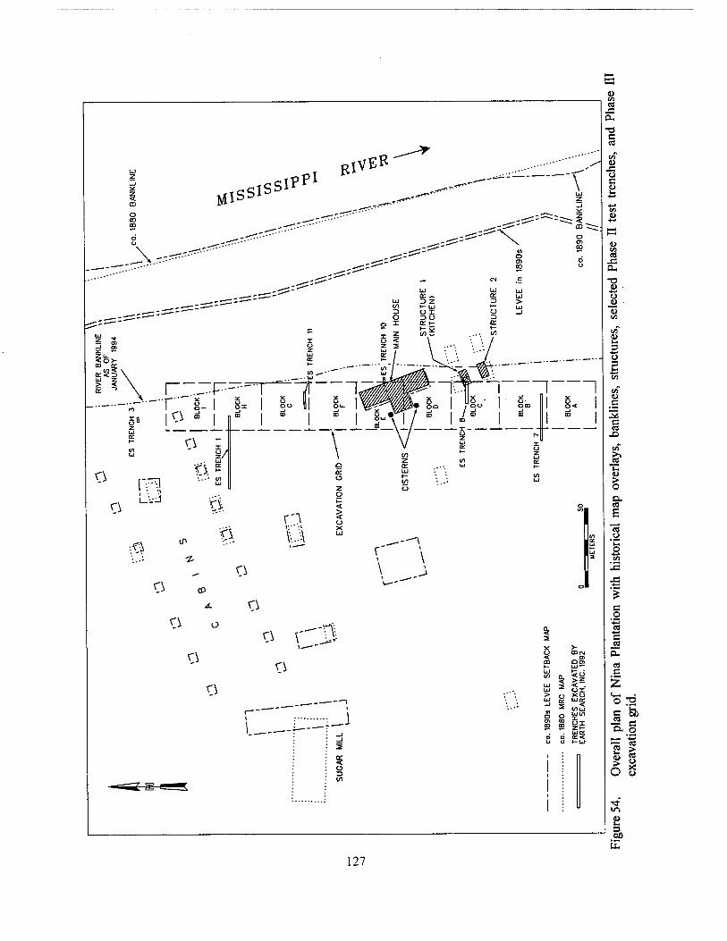
127
since the abandonment of the site at the end of the nineteenth century. The 1890 bankline had been located approximately 100 m (328 ft) from the main plantation house; in 1993, the river's edge was less than 1 m (3.28 ft) away. The carto- graphic overlay also indicated that two of four small structures depicted south of the main plan- tation house on the 1880-1881 MRC chart had succumbed to twentieth century erosion. The historic map overlay indicated that the main plantation house was located in the immediate vicinity of Phase II Trench 10 (Yakubik et al. 1994:375) (Figure 54); this trench had barely missed the structural features of the house. Fea- tures exposed during Phase II excavation of Trenches 8 and 9 were interpreted as structural remains from the main plantation house (Yakubik et al. 1994:413); the evidence from completed map overlays suggested that these features were related to a complex of four outbuildings, rather than to the plantation owner's dwelling.
Magnetometer Survey A magnetometer survey also was conducted
at Site 16PC62, prior to excavation. Intended to aid in the selection of excavation areas, the sur- vey incorporated those areas that had produced the highest concentration of cultural material during the Phase II excavations at the site. After the site grid was established, site Blocks A - I were surveyed at 2 m (6.56 ft) intervals. This grid was small enough to provide information on sig- nificant anomalous concentrations of a ferrous or magnetic nature. It was hoped that foundation pier locations could be determined, although brick normally displays a very low amplitude signal. The results of this survey are shown in Figures 55-63.
Blocks A and B showed no anomalies (Fig- ures 55 and 56), but in Blocks C, D, and E, the pattern of anomalies was significant (Figures 57, 58, and 59). Although oriented in the same direc- tion as the piers of the main house, the anomalies in Blocks D and E actually represented debris from the occupation and destruction of the build- ing. In Block C (Figure 57), the large anomaly in the northern portion of the block represented de- bris associated with Structure 1.
In Block F (Figure 60) anomalies were pres- ent, but later investigation indicated they were associated with either post-occupation activities,
or light concentrations of occupational debris. The plan of Block I (Figure 63) shows geologic anomalies caused by differential soil removal. Block I had suffered severe soil slumping and erosion, and a north-south rift was apparent at the surface.
Mitigation Excavation Sequence Phase II evaluatory testing at Nina Planta-
tion (16PC62), provided evidence of intact fea- tures associated with the owner's house, the slave quarters, and the sugar mill; artifacts corroborated dates of occupation between ca. 1820 and ca. 1890 (Yakubik et al. 1994). The results of the Phase II investigations also suggested that the site possessed significant research potential related to nineteenth century plantation life (Yakubik et al. 1994:453). Data recovery was designed to ad- dress research questions that focused on spatial relationships, patterns of material culture, and subsistence strategies, both in diachronic and synchronic perspectives.
The data classes necessary to address these issues included detailed information on plantation layout, in addition to stratigraphic information. The recovery of this type of database was best achieved through the use of wide area exposures. In the century since the abandonment of Nina Plantation, the Mississippi River had deposited a deep layer of fluvial sediment on the site; in order to expose wide areas of the site, a method was devised for stripping the approximately 1 m (3.28 ft) thick overburden from the site.
The areas designated for the removal of overburden were chosen after careful considera- tion of the results of the Phase II investigations, the cartographic and archival research, the mag- netometer survey, a bankline reconnaissance, and the excavation of Trenches 1-3. Based on this information, it was decided that structural fea- tures and concentrations of cultural material were most likely to be recovered from Blocks C, D, and E (Figure 64). The alluvial overburden from each of these 30 x 30 m (98.4 x 98.4 ft) areas was carefully removed with the aid of a CAT 225 ex- cavator, and a rubber-tired backhoe with a "clean- up" blade. The subsequent mechanical stripping of Block F was carried out after the excavation of Trenches 10 and 11 (Figure 64) revealed two features (Features 52 and 53), and a moderate density of artifactual material. A total of 3,400
128
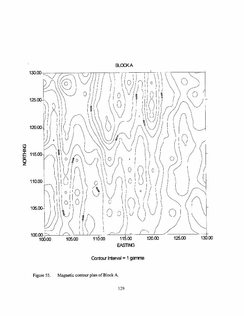
BLOCKA
130.00
100.00 100. .00 10^.00 110.00 rSöo
EASTING
12Ö00 12^.00 13O00
Contour Interval = 1 gamma
Figure 55. Magnetic contour plan of Block A.
129
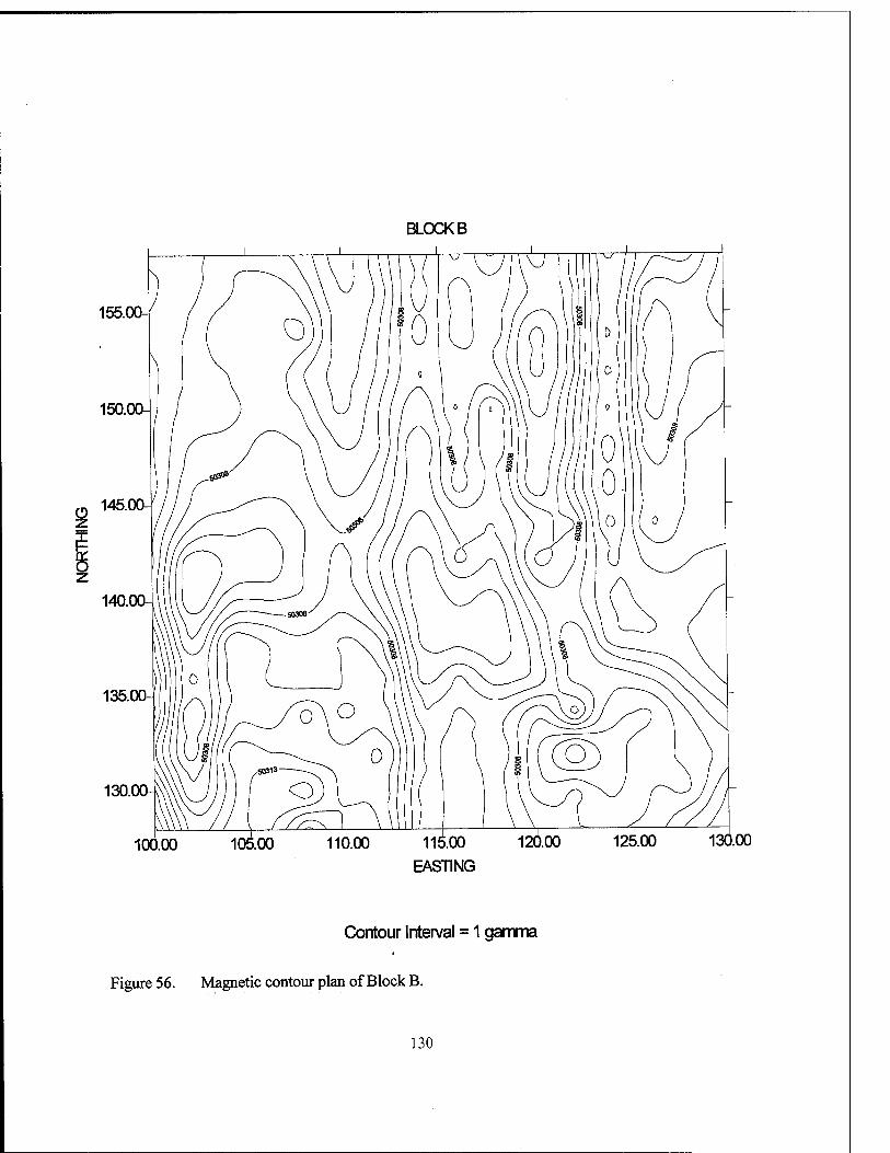
BLOCK B
155.00-
150.00-
145.00-
z 140.00-
135.00-
130.00-
100.00 105.00 110.00 11^.00 126.00 125.00 130.00 EASTING
Contour Interval = 1 gamma
Figure 56. Magnetic contour plan of Block B.
130
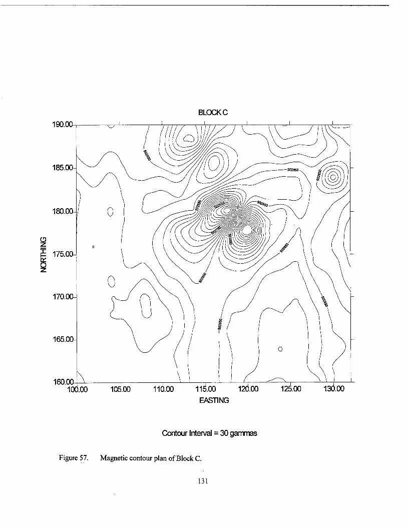
BLOCK C
190.0G
185.00-
180.00-
O
175.00-
170.00-
165.00-
160.00 10O00 10&00 11Ö.00 11^.00 120.00 125.00 130.00
EASTING
Contour Interval = 30 gammas
Figure 57. Magnetic contour plan of Block C.
131
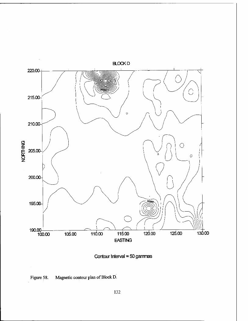
BLOCK D
220.00
190.00 100. .00 10^.00 I16.OO 11^.00 120.00
EASTING
12^.00 130.00
Contour Interval = 50 gammas
Figure 58. Magnetic contour plan of Block D.
132
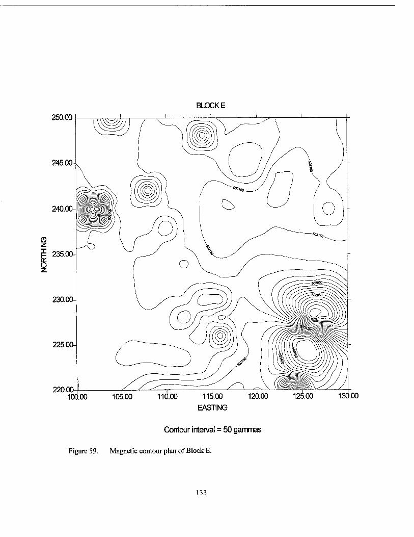
BLOCKE
250.00
245.
JE 235.
130.00
EASTING
Contour interval = 50 gammas
Figure 59. Magnetic contour plan of Block E.
133
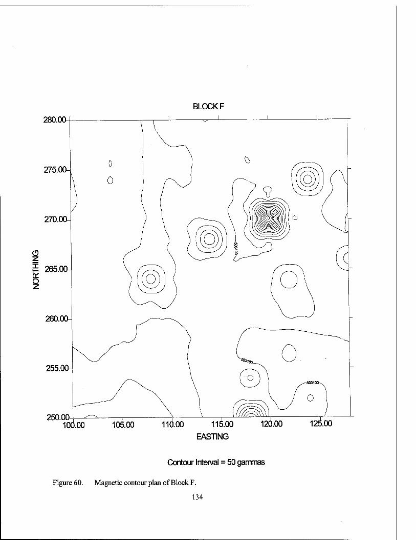
BLOCK F
280.00
250.00 100. 110.00 rüxöo
EASTING
Contour Interval = 50 gammas
Figure 60. Magnetic contour plan of Block F.
134
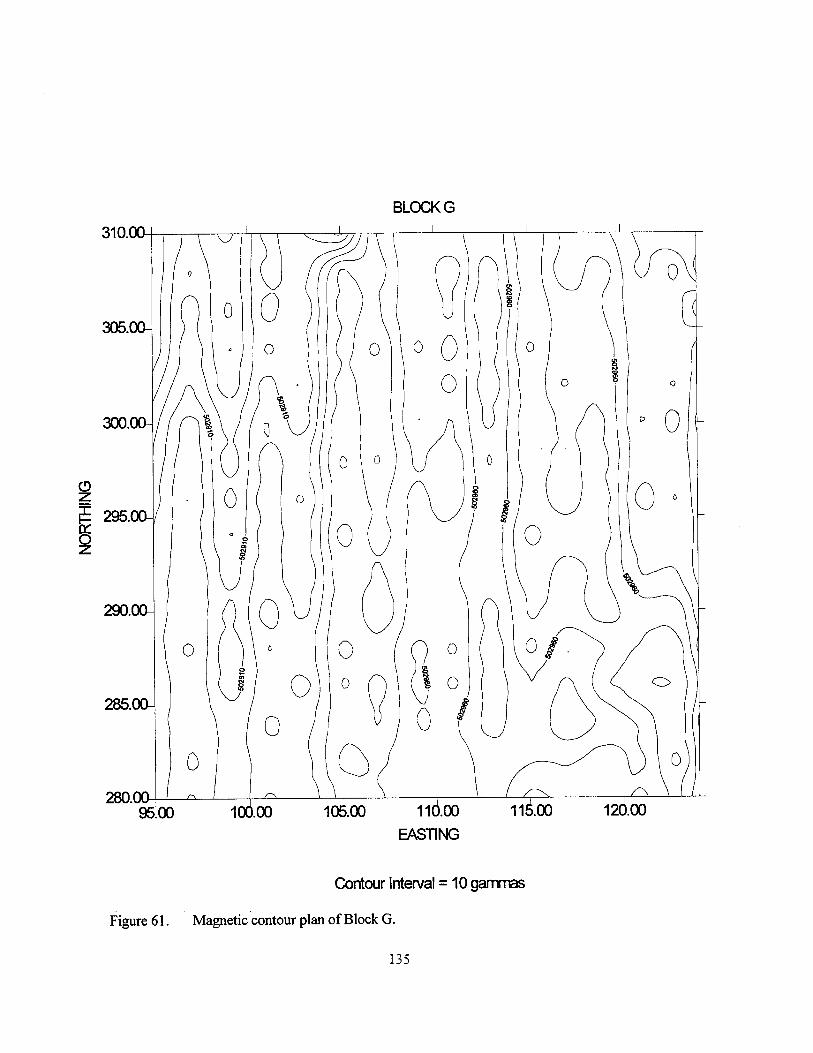
BLOCK G
310.00
305.00-
300.00-
f 295.00-
290.00-
285.00-
280.00 95.00 100.00 105^00 11Ö.00
EASTING
Contour Interval = 10 gammas
Figure 61. Magnetic contour plan of Block G.
135
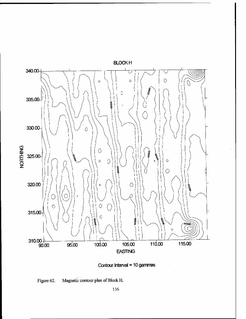
BLOCKH
340.00
335.
330.00-
CD z JE 325.0CH o z
320.00-
315.00-
310.00
EASTING
Contour Interval = 10 gammas
Figure 62. Magnetic contour plan of Block H.
136
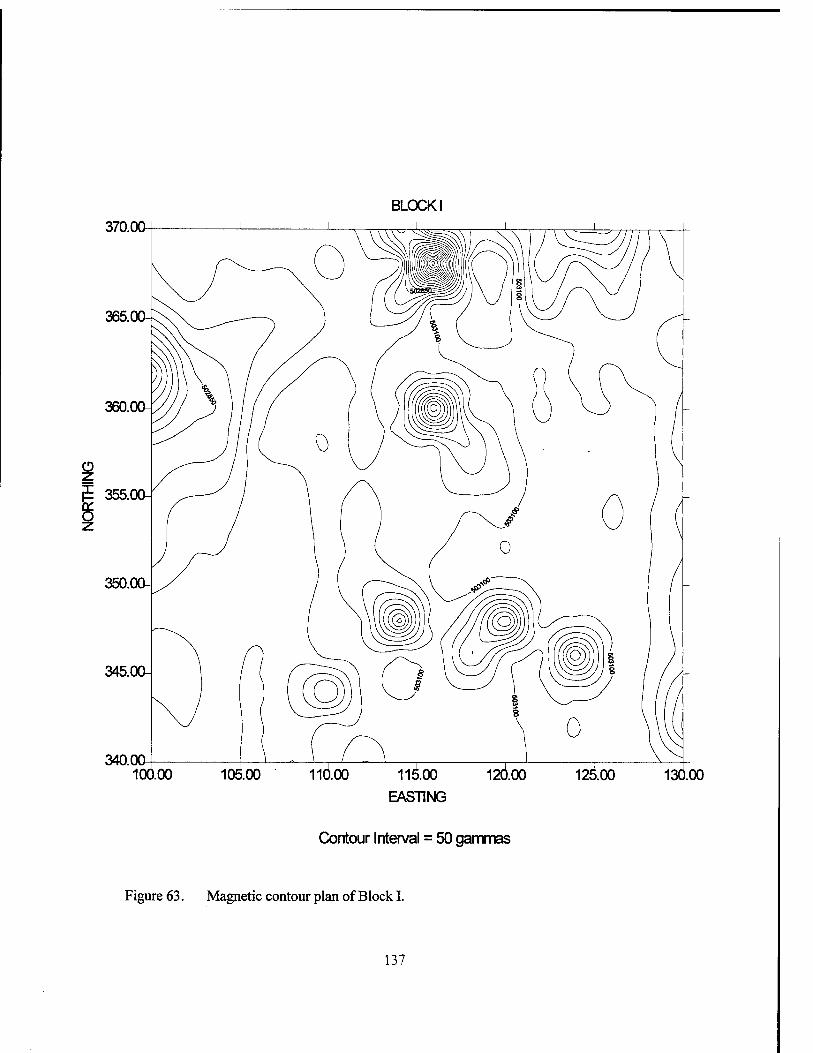
BLOCK I
370.0Q
340.0Q 100. 11^.00
EASTING
130.00
Contour Interval = 50 gammas
Figure 63. Magnetic contour plan of Block I.
137
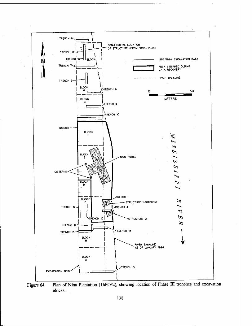
i I CONJECTURAL LOCATION * —: 'OF STRUCTURE (FROM 1890s PLAN)
- 1993/1994 EXCAVATION DATA
I AREA STRIPPED DURING DATA RECOVERY
-■ RIVER BANKLINE
50
METERS
MAIN HOUSE
.TRENCH 1
^jgji STRUCTURE 1 (KITCHEN)
INTRENCH 4
STRUCTURE 2
RIVER BANKLINE AS OF JANUARY 1994
X. Co Co
Co Co
Figure 64. Plan of Nina Plantation (16PC62), showing location of Phase ELI trenches and excavation blocks.
138
cubic meters (120,069 cubic feet) of alluvial overburden was removed from Blocks C, D, E, and F (Figure 65). Balks, each measuring 2 m (6.56 ft) in width, were left between excavation blocks, in order to maintain vertical control.
Mechanical stripping and unit excavation took place concurrently. Excavation units were established after the identification and initial rec- ordation of features exposed during the stripping operation. Excavation units were placed to enable the investigation of features, to sample midden deposits, and to characterize the various areas within and on the exterior of identified structures. A total of 251 m2 (823 ft2) was hand excavated in 170 units (Figures 66 - 69); the majority of these units measured lxl m (3.28 x 3.28 ft). If war- ranted, units were expanded beyond their original size in additional 1 x 1 m (3.28 x 3.28 ft), or 0.5 x 0.5 m (1.6 x 1.6 ft) increments. Twenty-six units measured 1 x 2 m (3.28 x 6.56 ft), ten measured 2 x 2 m (6.56 x 6.56 ft), two were 1.5 x 1.5 m (4.9 x 4.9 ft), six were 1.5 x 2 m (4.9 x 6.56 ft), two were 1.5 x 2.5 m (4.9 x 8.2 ft), and one was 3x3 m (9.8 x 9.8 ft). Larger units were designated with a single unit number, but were controlled in smaller 1 x 1 m (3.28 x 3.28 ft) segments. A list of all excavated units, including grid coordinates, size, and the rationale for excavation can be found in Appendix I.
A total of 216 features were investigated during data recovery at Nina Plantation (16PC62) (Figure 70 - pocket). Features were numbered consecutively from one to 256; 40 of these even- tually were re-classified as either non-cultural, or redundant. Redundant feature numbers were the result of the recordation of linear features in more than one unit; these redundant feature numbers were deleted when later investigation revealed separate exposures of a single feature. A list of all features is provided in Appendix I.
In addition, 17 trenches, totaling 297 linear m (974 linear ft) were excavated; the average width of these trenches measured 1.5 m (5 ft), providing a total area of 445.5 m (1461.6 ft) of exposure. The placement of these trenches was intended to allow investigation of the site stratig- raphy, to provide information about areas of the project area not included in the block excava- tions, and, in some cases, to allow investigation of large landscape features (Figure 64). A list of
all trenches, their lengths and coordinates, and the reasons for their excavation is contained in Ap- pendix I.
Site Stratigraphy Anticipated Soils and Stratigraphy
The soils in the area of Site 16PC62 are as- cribable to the Robinsonville series, as mapped by the United States Department of Agriculture, Soil Conservation Service (Powell et al. 1982). Robinsonville soils are mainly located on the batture side of the levee along both the Missis- sippi and the Atchafalaya rivers. They are among the youngest soils in the region, having developed in the most recent loamy and sandy alluvium. They are well drained, moderately permeable, and they often are associated with soils of the Commerce series. The A horizon has a hue of 10YR, and ranges in value between 3 and 5; chroma ranges between 2 and 4. The C horizons have a hue of 10YR, a value between 4 and 6, and a chroma of 2 to 4 (Powell et al. 1982).
A typical profile of Robinsonville silt loam consists of a 0 to 15.24 cm (0 to 6 in) dark gray- ish brown (10YR 4/2) silty loam Al horizon, overlying a dark brown (10YR 4/3) silt loam Cl horizon, extending to 30.48 cmbs (12 inbs). The C2 horizon is a brown (10YR 5/3), very fine sandy loam that extends to 55.88 cmbs (22 inbs); it commonly contains strong brown (7.5YR 5/6) stains along root channels. The C3 horizon con- sists of a pale brown (10YR 6/3), very fine sandy loam that extends to 93.98 cmbs (37 inbs). The C4 horizon, extending to 152.4 cmbs (60 inbs), is typically a pale brown (10YR 6/3) loamy, very fine sand, with a few fine, distinct yellowish brown mottles. All of these C horizons exhibit thin bedding planes, and clear, smooth bounda- ries. A buried A horizon may be present below 50.8 cmbs (20 inbs) (Powell et al. 1982:48).
Robinsonville soils are slightly acid to moderately alkaline, and they occasionally are flooded for brief to long periods of time between January and April. The high water table in these months ranges from 1.22 to 1.82 m (4.0 to 6.0 ft) below surface. These soils are well suited to pasture or short season crops and to hardwoods, but because of flooding, crops may sustain sea- sonal damage (Powell et al. 1982:21).
139
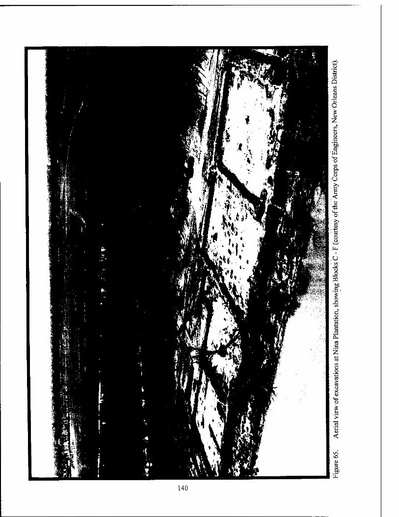
140
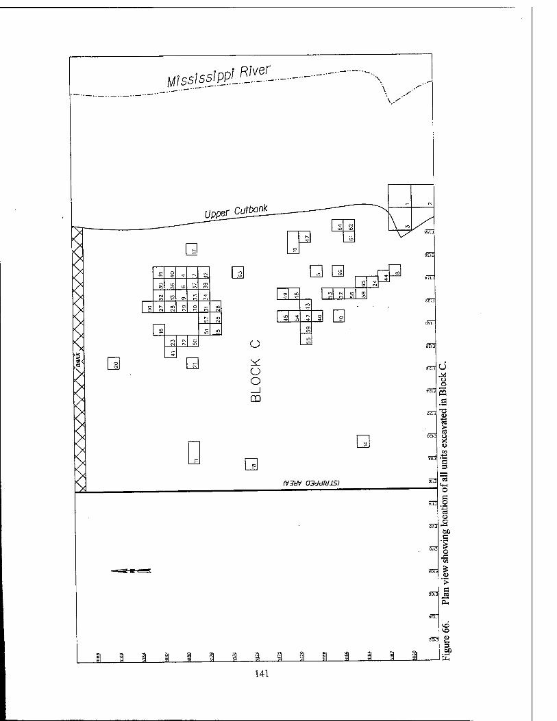
River MississipPL.^'-.---
\.-
UppeilCutbart
01 Kl
O ^ r» CN
Kl CD Kl CD n
CO Kl
Kl Kl Ol
Kl Kl
o CD CM
CO CM CM
O Kl Kl
CD CVJ
in in CM
CD in in
PO CM
CN o
5
CN o o _J m
n in <■
C0
m CD CN
CD 00 Kl CN in! in
CD m
CD in
Kl - in
in tl- CD o
Ol in
in m
<v3uv asddihus)
5Ü3
son
V o o 5 .g
5 o X
C 3
"3 o s o
■•§ u
tao c
o J3 m
I > C
00
141
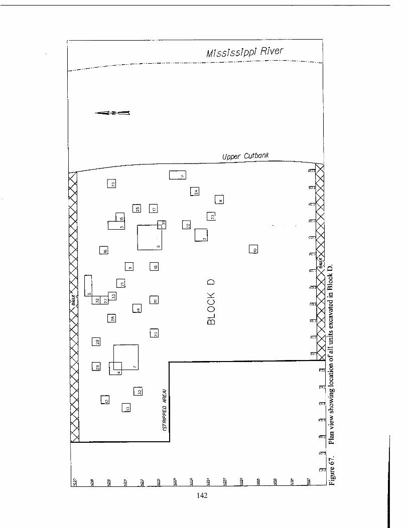
Mississippi River
Upper Cutbank
ID
m
n
ID
m a
=
* 00
a
"0/
[I CO
Q If)
CM P» o
2
CO CM
o
r-
O
(M
ro
O O _J CD
wn .a
J 1_ 142
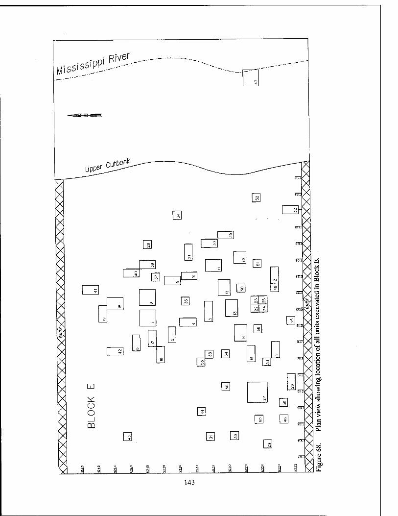
rqSfpp!^ve^
cutbanl<
o
en
□ oo
en
m r^
CO CM
£ oo
m
o o _J CD
PO ^2.
m
§Zft
CM in CM
CM CM
CO
sin
W
J i
0-
fc
143
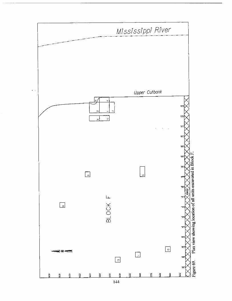
Mississippi River
Upper Cutbank
tr> o
Q
o o _J m
si i 1
Q
J i_
X -X
X mX
^x TO-X
X ^x x„
^X-g Xs
^x X
™x
X« ^x§
ST xl
TOX ? X-l
•5K1V/ C
V
» X M JL-M'tiH
IX,
-o u 'S ä u
cd o _o 60
144
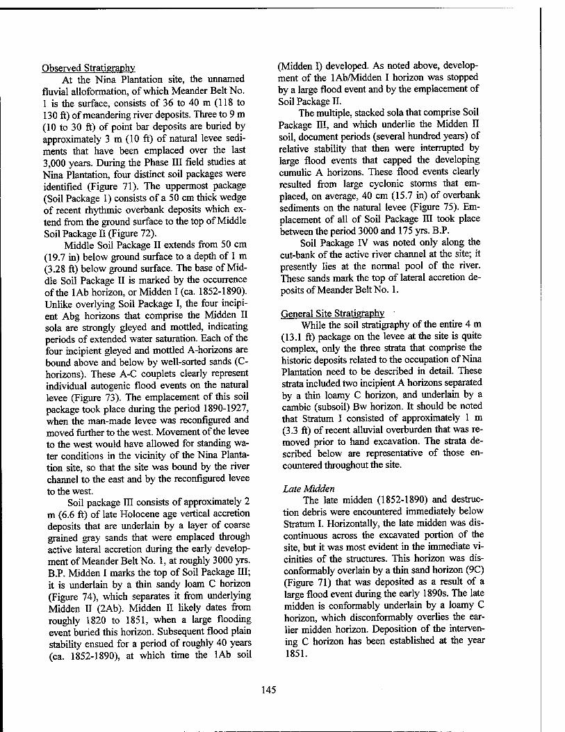
Observed Stratigraphy At the Nina Plantation site, the unnamed
fluvial alloformation, of which Meander Belt No. 1 is the surface, consists of 36 to 40 m (118 to 130 ft) of meandering river deposits. Three to 9 m (10 to 30 ft) of point bar deposits are buried by approximately 3 m (10 ft) of natural levee sedi- ments that have been emplaced over the last 3,000 years. During the Phase HI field studies at Nina Plantation, four distinct soil packages were identified (Figure 71). The uppermost package (Soil Package 1) consists of a 50 cm thick wedge of recent rhythmic overbank deposits which ex- tend from the ground surface to the top of Middle Soil Package II (Figure 72).
Middle Soil Package II extends from 50 cm (19.7 in) below ground surface to a depth of 1 m (3.28 ft) below ground surface. The base of Mid- dle Soil Package II is marked by the occurrence of the lAb horizon, or Midden I (ca. 1852-1890). Unlike overlying Soil Package I, the four incipi- ent Abg horizons that comprise the Midden II sola are strongly gleyed and mottled, indicating periods of extended water saturation. Each of the four incipient gleyed and mottled A-horizons are bound above and below by well-sorted sands (C- horizons). These A-C couplets clearly represent individual autogenic flood events on the natural levee (Figure 73). The emplacement of this soil package took place during the period 1890-1927, when the man-made levee was reconfigured and moved further to the west. Movement of the levee to the west would have allowed for standing wa- ter conditions in the vicinity of the Nina Planta- tion site, so that the site was bound by the river channel to the east and by the reconfigured levee to the west.
Soil package III consists of approximately 2 m (6.6 ft) of late Holocene age vertical accretion deposits that are underlain by a layer of coarse grained gray sands that were emplaced through active lateral accretion during the early develop- ment of Meander Belt No. 1, at roughly 3000 yrs. B.P. Midden I marks the top of Soil Package III; it is underlain by a thin sandy loam C horizon (Figure 74), which separates it from underlying Midden II (2Ab). Midden II likely dates from roughly 1820 to 1851, when a large flooding event buried this horizon. Subsequent flood plain stability ensued for a period of roughly 40 years (ca. 1852-1890), at which time the lAb soil
(Midden I) developed. As noted above, develop- ment of the lAb/Midden I horizon was stopped by a large flood event and by the emplacement of Soil Package II.
The multiple, stacked sola that comprise Soil Package III, and which underlie the Midden II soil, document periods (several hundred years) of relative stability that then were interrupted by large flood events that capped the developing cumulic A horizons. These flood events clearly resulted from large cyclonic storms that em- placed, on average, 40 cm (15.7 in) of overbank sediments on the natural levee (Figure 75). Em- placement of all of Soil Package III took place between the period 3000 and 175 yrs. B.P.
Soil Package rV was noted only along the cut-bank of the active river channel at the site; it presently lies at the normal pool of the river. These sands mark the top of lateral accretion de- posits of Meander Belt No. 1.
General Site Stratigraphy While the soil stratigraphy of the entire 4 m
(13.1 ft) package on the levee at the site is quite complex, only the three strata that comprise the historic deposits related to the occupation of Nina Plantation need to be described in detail. These strata included two incipient A horizons separated by a thin loamy C horizon, and underlain by a cambic (subsoil) Bw horizon. It should be noted that Stratum I consisted of approximately 1 m (3.3 ft) of recent alluvial overburden that was re- moved prior to hand excavation. The strata de- scribed below are representative of those en- countered throughout the site.
Late Midden The late midden (1852-1890) and destruc-
tion debris were encountered immediately below Stratum I. Horizontally, the late midden was dis- continuous across the excavated portion of the site, but it was most evident in the immediate vi- cinities of the structures. This horizon was dis- conformably overlain by a thin sand horizon (9C) (Figure 71) that was deposited as a result of a large flood event during the early 1890s. The late midden is conformably underlain by a loamy C horizon, which disconformably overlies the ear- lier midden horizon. Deposition of the interven- ing C horizon has been established at the year 1851.
145
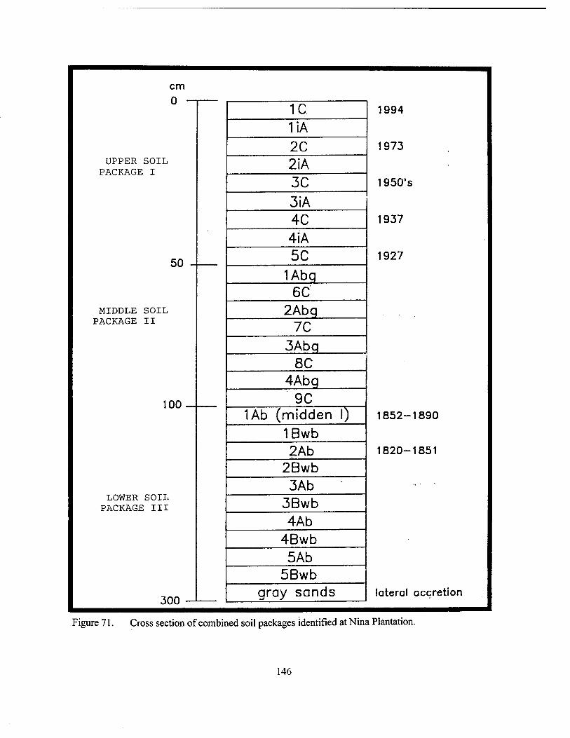
cm
1994
1973
1950's
1937
1927
1852-1890
1820-1851
lateral accretion
UPPER SOIL PACKAGE I
50 -
MIDDLE SOIL PACKAGE II
100
1C liA 2C 2iA 3C 3iA 4C 4iA 5C
1Abq 6C
2Abq 7C
3Abq 8C
4Abq 9C
LOWER SOIL PACKAGE III
1Ab (midden I) 1Bwb 2Ab
2Bwb 3Ab
3Bwb 4Ab
4Bwb 5Ab
5Bwb gray sands
Figure 71. Cross section of combined soil packages identified at Nina Plantation.
146
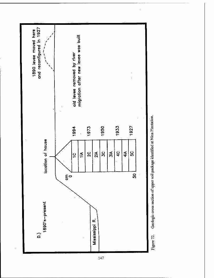
x: *-
©
O 0) 3 I
5 1 a) o — o o £ en 00 "Ü
3 A m a 9 l_
0) at > © V >
© >\ n
* TJ © 0) c > o E
L. V «1-
K o 0) 0)
c o
> «M © o u -o .S?
© © 3 O
JZ
** ro o ro r>- O) l^ m n CM en O) en en en
ü < ü CM < Ü
to < Ü < Ü m
o m
s o
c
a
4>
» cs
ex
l-l u n. O, 3 o c o
"■g u CO
2
00
o
r- £ 3 60 E
147
_ *~? c m v
-o Ol o> m na
JQ < t jy o °E < < eg ▼—
sam
be
gin
o '■§ c «8
CO c
■o 0) > o E
o x: a> >
a> u O
«♦- a>
b Oi oo
n b oo oo
o
T3 U s c <L>
12 <L> eo M
o es D.
•a
o c
_o o CJ I» en en
2 o o
'5b _o o u O
op
148
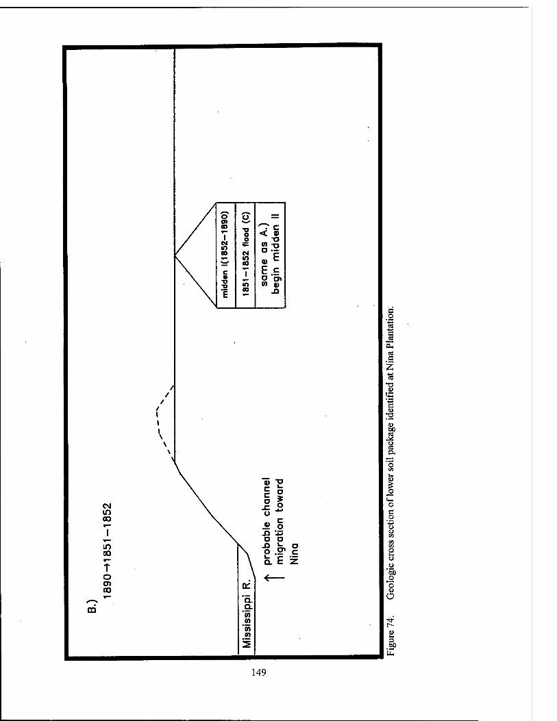
o C? — 0)
T T9 O < 0)
CM in 00 CM ^ in *m* oo 0) C •
■o ■D
T in sa
m
egin
1 oo xi
/
•
/ /
/ 1 1 I \ \ \ \
anne
l w
ard
CM \ -c .2 in \ o 00 \ ... c »— \ « o
1 \ .o *s o o
In oo
T o en CO
prob
m
igr
Nin
a
a: V
^^ *~ '51 m Q.
'm
to
a -S s a
a
1 rs o IP
a« 'o
CO
«4-1 o c o
"■§
u o
'Si ,2 "o u Ü
3)
149
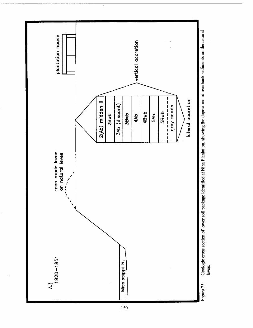
Q) to 3 c O o
JC 0) c ^
o o u
o o J-> c "5 o Q.
ü
'•XL 0) >
V c — /_s \ ° c 0) •a -o *E JO
-W m \ •*J
JO
m CM
c o o
•tn
T3 ^—' JO <
JO
CD
JO JO
00 JO <
JO
m in
o en
p
\ 2 \ °
/ / - K> / o eg /.-
leve
e le
vee
0) — "O P
2 / «= c / is/
V \ \ \
\
In . 1 oo a: r—
I Q. o o. CM "to oo <n
^-^ »— 'm < 0)
KS C
a> J3 ■*-
C o
c u E U en
c3 J3 u-
> o o c o tn O a, u
T3 V
60 C
o J3
a -a
"*3 C <o
o 00
ä
O en
O
B
o
o ÖX) o « o u <u > Ü cu
in t^ M u. 3 ÖJJ
b
150
The latest midden can be classified textur- ally as a silt loam; it displayed moderate biotur- bation, and it was weakly acidic. In addition, this stratum contained a moderate amount of organic materials. Grain size distributions displayed a primary mode in the <4 phi (0.063 mm) size class, while the mean grain size for late midden was 4.40 phi. Two weak secondary modes oc- curred at 4 phi (0.063 mm) and at -2 phi. The grains comprising the coarser sediments at -2 phi were primarily wood, carbon, small pieces of bone, and ceramic fragments associated with historic occupation of the site. The standard de- viation value for the latest midden is 3.66, indi- cating generally poor sorting under low energy conditions. The skewness value is -0.286, indi- cating a tail trending toward the coarser grain sizes.
1851 Alluvial Deposit (Cl/Bwb) The 1851 Alluvial Deposit was emplaced as
a result of a single flood event that was responsi- ble for capping the early midden deposits at the site. Horizontally, the alluvial deposit was rela- tively continuous across the excavated portion of Site 16PC62, although its depth varied in the im- mediate vicinity of the structures. The stratum lay disconformably above the early midden, and con- formably below the late midden.
The 1851 Alluvial Deposit can be classified texturally as a coarse silt loam; it displayed mod- erate bioturbation, and it was weakly acidic. In addition, the stratum displayed a minimal amount of organic materials. This alluvial deposition contained more than twice the amount of fine sand as the cultural bearing horizons at the site. The mean grain size for this alluvial deposit was 4.7 psi, and the skewness value was -0.266, indi- cating a slight tail trending toward the coarser grain sizes. The standard deviation value for the 1851 Alluvial Deposit is 0.833, indicating moder- ate sorting of the sediments during its emplace- ment by flood waters.
Early Midden The early midden (1820-1851) represents
the earliest historic occupation of the site. Hori- zontally, the early midden was discontinuous across the excavated portion of Site 16PC62, but it was most evident in the immediate vicinities of the structures. The early midden was disconform-
ably overlain by the 1851 Alluvial Deposit, and conformably underlain by the subsoil horizon (Stratum V) at the site.
Like the overlying latest midden, the early midden was an organic, rich silt loam horizon displaying a moderate amount of bioturbation; it was weakly acidic. The mean grain size for the earliest midden was 4.95 phi. The primary modal peak occurred at less than 4 phi, and the horizon was strongly unimodal with over 95 percent of the grains occurring in the silt and clay sized fraction. The standard deviation value for the early midden was 0.811, indicating moderate sorting. The skewness value was -0.65, indicating a tail trending toward the coarser grain sizes. The sediments that comprised both the late midden and the early midden indicate a leptokurtic char- acter for these strata.
Site Taphonomy The action of the Mississippi River has had a
profound effect on Site 16PC62 (Nina Planta- tion). Severe erosion along the Mississippi River batture during the twentieth century has seriously impacted the project area. Based on historic maps, as much as 100 m (328 ft) of the site has been claimed by the river; artifacts and other cultural debris were abundant along the cutbank in the project area. In areas of the site not yet af- fected by erosion, the impact of the river has been limited to the relatively rapid deposition of a thick, fluvial overburden during the twentieth century. While creating logistical problems for excavation, this approximately meter-thick de- posit minimized impact to the site from other po- tentially damaging activities.
There was little evident disturbance to cul- tural stratigraphy due to agricultural or logging activities. The bases of postmolds from post- occupation fencing were visible in the lowest lev- els of overburden in Block F, and plowscars were apparent in the alluvium removed from Block D. These post-occupation activities caused little or no impact to the nineteenth century soils. In Block C, excavation of drainage channels during the early twentieth century caused moderate dis- turbance to the most recent cultural stratum in Block C; this stratum consisted of sheet refuse distributed during and after the disman- tling/destruction of the buildings in that area of the site.
151
The low acidity of the soils aided preserva- tion of bone, molluscan, and other organic matter at the site. Rather than causing negative impact to the site, periodic episodes of flooding, coupled with moderate permeability of the soils, tended to preserve the cultural stratigraphy,
Definition of Components at Site 16PC62 Architectural Components
Data recovery excavation at 16PC62 re- vealed two major architectural components de- riving from the nineteenth century occupation of Nina Plantation. Features related to the owner's house were located in Blocks D and E; these are referred to herein as the Main House complex. Features associated with a small complex of out- buildings near the main house were located in Block C; these are referred to as the Outbuilding complex (Figure 70).
While the artifactual evidence indicated that both complexes were domestic in nature, and roughly contemporaneous, the two architectural components revealed major differences in archi- tectural materials, construction methods, and spa- tial layout. These differences are indicative of the relative social and economic positions of the oc- cupants within the plantation hierarchy. While no documentary evidence exists that specifically identifies the occupants of the two structural complexes, it is likely that the main house com- plex was constructed for the use of the plantation owners, beginning with Jean Jarreau ca. 1820, and including the Allen family who took posses- sion in 1857 (see Chapter IV). The Outbuilding complex included two structures, referred to as Structures 1 and 2. Structure 1 has been inter- preted as a detached kitchen and dwelling. While domestic artifacts recovered from Structure 2 suggest that it was used as a dwelling, any addi- tional functions remain unidentified. The occu- pants of these structures are likely to have been household servants assigned to tasks associated with the upkeep and maintenance of the main house and its occupants. In 1857, six slaves were assigned domestic duties; the kitchen (Structure I) probably was occupied by Jenny, listed in the Jarreau estate as a cook (see Chapter IV).
The Main House Complex For analytical purposes, the Main House
complex has been divided into five areas; these
include the core, the south wing, the north wing, and the north and south cisterns (Figure 76). The core refers to the central, rectangular section of the structure, constructed ca. 1820 by Jean Ursin Jarreau (see Chapter IV), the original owner of the plantation. The south wing appears to have been constructed during the same time period as the core, but it was attached as a wing at a later time. The north wing was an even later addition to the original core structure, probably postdating the sale of the estate to C.W. Allen in the 1850s. The Main House complex also included the north cistern, at the northwestern corner of the core, and the south cistern, located at the southwestern corner of the core (Figure 76). These large water storage tanks were of wooden construction, sup- ported on brick piers.
The configuration of the main house was defined by brick foundation piers (Figure 76) constructed on approximately 2.84 m (9.3 ft) centers. Based on the distribution of brick piers, the core of the main house measured 11.14 x 18.75 m (36.5 x 61.5 ft). The dimensions of the south wing (after attachment as a wing) were 8.06 x 14.77 m (26.4 x 48 ft), and the north wing measured 8.18 x 14.77 m (26.8 x 48 ft). Galleries on the river (eastern) sides of the south and the north wings measured 3.06 m (10 ft; south wing) and 2.95 m (9.69 ft; north wing) in width, and they ran the length of each wing. The core may have had galleries of a similar width on all sides. Each cistern foundation was approximately 1.81 m (5.96 ft) in diameter (Figures 70 and 76).
The Outbuilding Complex The Outbuilding complex was contained
within Block C of the excavated portion of the site (Figure 64). As noted above, the remains of two buildings included in the Outbuilding com- plex were designated Structures 1 and 2 (Figure 70). Structure 1 was marked by the remains of a substantial H-shaped chimney foundation (Fea- ture 116), which had been constructed on top of the remains of an earlier chimney and hearth made of wood and clay. Both outbuilding struc- tures were of earthfast construction, and they in- corporated both ground-laid sills and post-in- ground techniques. These structures appear on an 1883 MRC chart showing Nina Plantation as two of four small structures just south of the main house (Figure 54).
152
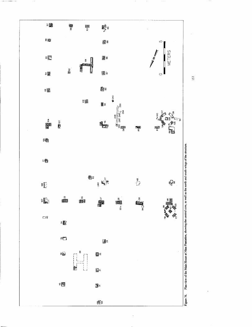
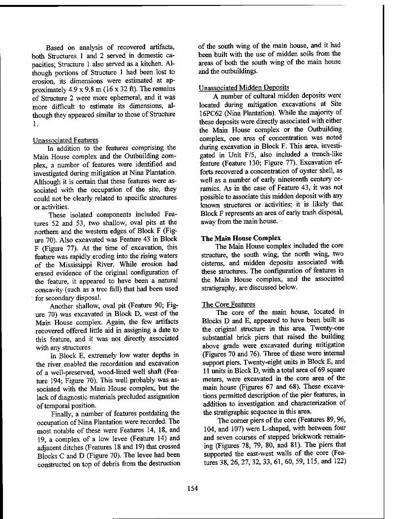
Based on analysis of recovered artifacts, both Structures 1 and 2 served in domestic ca- pacities; Structure 1 also served as a kitchen. Al- though portions of Structure 1 had been lost to erosion, its dimensions were estimated at ap- proximately 4.9 x 9.8 m (16 x 32 ft). The remains of Structure 2 were more ephemeral, and it was more difficult to estimate its dimensions, al- though they appeared similar to those of Structure 1.
Unassociated Features In addition to the features comprising the
Main House complex and the Outbuilding com- plex, a number of features were identified and investigated during mitigation at Nina Plantation. Although it is certain that these features were as- sociated with the occupation of the site, they could not be clearly related to specific structures or activities.
These isolated components included Fea- tures 52 and 53, two shallow, oval pits at the northern and the western edges of Block F (Fig- ure 70). Also excavated was Feature 43 in Block F (Figure 77). At the time of excavation, this feature was rapidly eroding into the rising waters of the Mississippi River. While erosion had erased evidence of the original configuration of the feature, it appeared to have been a natural concavity (such as a tree fall) that had been used for secondary disposal.
Another shallow, oval pit (Feature 90; Fig- ure 70) was excavated in Block D, west of the Main House complex. Again, the few artifacts recovered offered little aid in assigning a date to this feature, and it was not directly associated with any structures.
In Block E, extremely low water depths in the river enabled the recordation and excavation of a well-preserved, wood-lined well shaft (Fea- ture 194; Figure 70). This well probably was as- sociated with the Main House complex, but the lack of diagnostic materials precluded assignation of temporal position.
Finally, a number of features postdating the occupation of Nina Plantation were recorded. The most notable of these were Features 14, 18, and 19, a complex of a low levee (Feature 14) and adjacent ditches (Features 18 and 19) that crossed Blocks C and D (Figure 70). The levee had been constructed on top of debris from the destruction
of the south wing of the main house, and it had been built with the use of midden soils from the areas of both the south wing of the main house and the outbuildings.
Unassociated Midden Deposits A number of cultural midden deposits were
located during mitigation excavations at Site 16PC62 (Nina Plantation). While the majority of these deposits were directly associated with either the Main House complex or the Outbuilding complex, one area of concentration was noted during excavation in Block F. This area, investi- gated in Unit F/5, also included a trench-like feature (Feature 130; Figure 77). Excavation ef- forts recovered a concentration of oyster shell, as well as a number of early nineteenth century ce- ramics. As in the case of Feature 43, it was not possible to associate this midden deposit with any known structures or activities; it is likely that Block F represents an area of early trash disposal, away from the main house.
The Main House Complex The Main House complex included the core
structure, the south wing, the north wing, two cisterns, and midden deposits associated with these structures. The configuration of features in the Main House complex, and the associated stratigraphy, are discussed below.
The Core Features The core of the main house, located in
Blocks D and E, appeared to have been built as the original structure in this area. Twenty-one substantial brick piers that raised the building above grade were excavated during mitigation (Figures 70 and 76). Three of these were internal support piers. Twenty-eight units in Block E, and 11 units in Block D, with a total area of 69 square meters, were excavated in the core area of the main house (Figures 67 and 68). These excava- tions permitted description of the pier features, in addition to investigation and characterization of the stratigraphic sequence in this area.
The corner piers of the core (Features 89,96, 104, and 107) were L-shaped, with between four and seven courses of stepped brickwork remain- ing (Figures 78, 79, 80, and 81). The piers that supported the east-west walls of the core (Fea- tures 38, 26, 27, 32, 33, 61, 60, 59, 115, and 122)
154
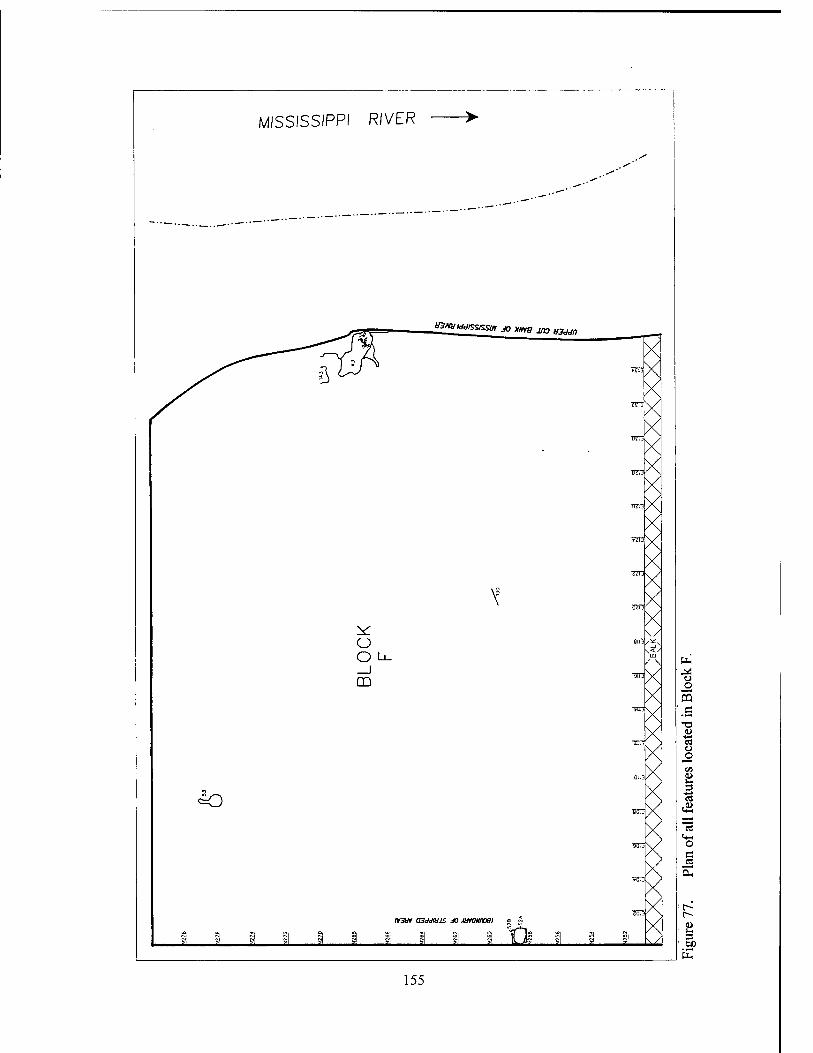
MISSISSIPPI RIVER
■ J—V
***—*■ «WSMSSSSW *> »W7 J« «^
?x X «3«
j%/H TTO X X
rtn X X X
BOT X X
um X X
TOT
X SSH X
t üjn X X
^ \/ CJ -sin '*,s
O Li. SS'
_J CD
-fin
Tin
X X X X X X
^o
»3tn ajddajs M wtawxsi • S
vsn
»on
X X X X X X X X 1 I i 9 1 i i i i i Yte i § sl
CJ O
5 .c T3
tu 15 ü o
i
o c ca
r-
155
were rectangular; they were spaced on approxi- mately 2.84 m (9.3 ft) centers. The piers meas- ured approximately 0.3 x 0.8 m (0.99 x 2.68 ft) on the upper course, and widened to 0.5 x 1.1 m (1.6 x 3.6 ft) at the base (Figure 82). The interior piers were less substantial, and their shapes re- flected the configuration of the beams of the structure, ranging from L-shaped (Feature 48), to T-shaped (Features 98 and 37), to square (Feature 112). The elevations of the tops of the piers ranged from 11.22 m NGVD (Feature 96) to 11.54 m NGVD (Feature 37). Assuming that grade was the upper limit of the cultural debris at the site, the piers had been removed to the top of grade, or just below, at the time of destruction. The bases of the piers were at depths ranging from 10.9 to 11.05 m NGVD, with the majority at approximately 10.95 m NGVD.
Typical Stratigraphy near the Core The stratigraphic sequence in the core area
of the main house approximated the general stra- tigraphic pattern at the site. In close proximity to the foundation piers, the natural stratigraphic se- quence had been disturbed at various times during occupation, but units located away from the structural features of the core exhibited a more uniform stratigraphic pattern.
UnitE/50 Figure 83 presents the west wall profile of
Unit E/50, located underneath the core structure, but not adjacent to a pier. This stratigraphic se- quence was typical of the area. Stratum I con- sisted of the alluvial overburden that had been deposited during flooding in 1993-1994. A lens of brick rubble and mortar was attributed to the destruction of the site at the end of the nineteenth century. In other areas of the Main House com- plex, destruction debris was far denser, and con- stituted a separate stratum rather than a lens. Stratum II was a layer of cultural debris (late midden). Material recovered from this deposit included nails, iron fragments, ceramics, glass, a tobacco pipestem, fish scales, and bone. Strata III and IV were attributed to the flood of 1851, and totaled 9 to 10 cm (3.5 to 3.9 in) in depth. The artifact density dropped dramatically in these lev- els, although some metal, glass, ceramic, and bone were recovered from the uppermost portions of this deposit. Unit E/50 was located in an area
that would have been underneath the house, pre- sumably affecting the intensity of flooding. Stra- tum V was a second cultural deposit, or midden. This stratum was characterized by the inclusion of brick dust and chips, giving the soil a reddish hue. Relative to the upper midden, artifact density was moderate; these levels produced metal, glass, ceramics, bone, and a single glass bead. Sterile soil underlay this deposit, at a depth of 11.09 m NGVD; the total depth of this unit was 43 cm (16.9 in).
UnitE/15 A profile of Unit E/15, incorporating Feature
38, a pier in the north wall of the core (Figures 76 and 82), displayed some deviation from the pre- vious stratigraphic pattern. In this unit, the profile was cut across the face of the feature, to illustrate the interaction between the pier and the sur- rounding soil strata. Stratum I was the post- occupation alluvium, and Stratum II represented the destruction debris. This brick and mortar rub- ble was denser than in Unit E/50, and was present across the entire unit. The rubble included nu- merous nails from the destruction of the building. Stratum III was the dense, artifact-rich upper midden deposit dating from the latter part of the nineteenth century. Ceramics, glass (including a perfume bottle), tin cans, nails, furniture hard- ware, tobacco pipe fragments, hair comb frag- ments, bone, fish scales, egg shell, scrap iron, and lead were recovered from Stratum III. The soil contained a high charcoal and ash content, in ad- dition to shell and other organic material; it was characterized as a 10YR 4/2 dark gray silty loam. Below this stratum was the alluvial deposit (Stratum IV), resulting from the flood of 1851. This deposit was present only on the west side of the pier, and where it approximately 6 cm (2.3 in) in thickness. A very low density of cultural mate- rial, probably originating in Stratum HI, charac- terized this sandy loam layer. Stratum V was an earlier midden deposit, which was characterized by a reddish hue caused by a high content of brick chips. This stratum contained ceramics, nails, glass, and charcoal in moderate density. Feature 94, a post-hole, was apparent at the top of Stratum VI (11.0 m NGVD; Figure 82). The fill in this feature was similar to that of Stratum V, and it contained similar cultural material, sug- gesting filling of the feature at the same time as
156
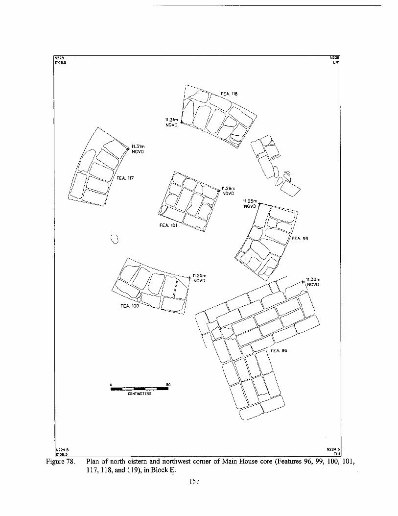
N228 E108.5
N228 E111
FEA. 118
Figure 78. Plan of north cistern and northwest corner of Main House core (Features 96, 99, 100, 101, 117,118, and 119), in Block E.
157
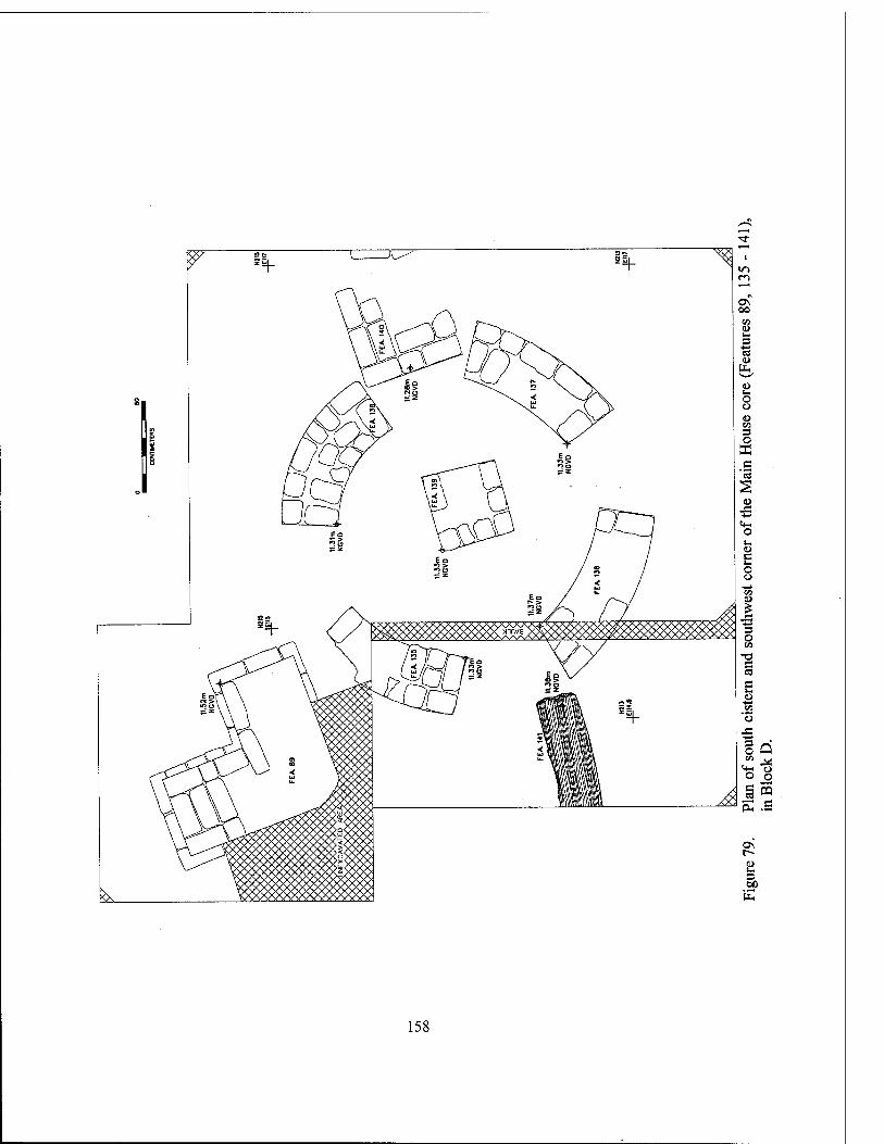
158
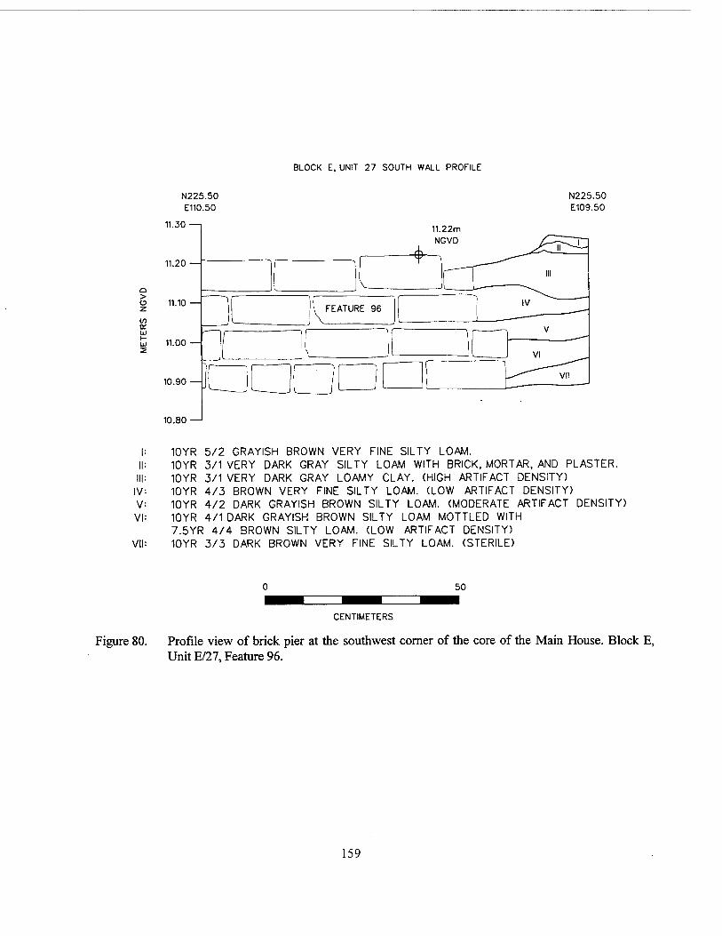
BLOCK E, UNIT 27 SOUTH WALL PROFILE
> o z V)
N225.50 E110.50
N225.50 E109.50
11.30
11.20 —
11.10
11.00
10.90 —
10.80 —'
|: 10YR 5/2 GRAYISH BROWN VERY FINE SILTY LOAM. II: 10YR 3/1 VERY DARK GRAY SILTY LOAM WITH BRICK, MORTAR, AND PLASTER.
Ill: 10YR 3/1 VERY DARK GRAY LOAMY CLAY. (HIGH ARTIFACT DENSITY) IV: 10YR 4/3 BROWN VERY FINE SILTY LOAM. (LOW ARTIFACT DENSITY) V: 10YR 4/2 DARK GRAYISH BROWN SILTY LOAM. (MODERATE ARTIFACT DENSITY) VI: 10YR 4/1 DARK GRAYISH BROWN SILTY LOAM MOTTLED WITH
7.5YR 4/4 BROWN SILTY LOAM. (LOW ARTIFACT DENSITY) VII: 10YR Z>/3 DARK BROWN VERY FINE SILTY LOAM. (STERILE)
50
CENTIMETERS
Figure 80. Profile view of brick pier at the southwest corner of the core of the Main House. Block E, Unit E/27, Feature 96.
159
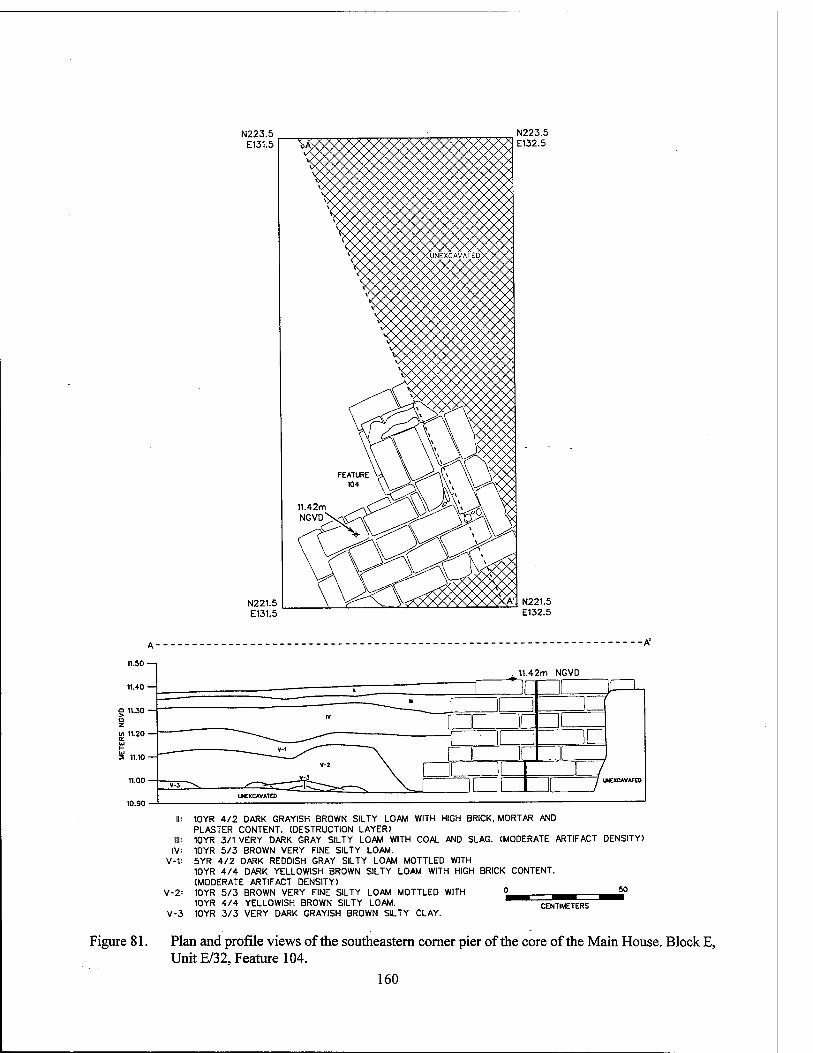
N223.5 E131.5
N221.5 E131.5
11.50 -
11.40 -
g 11.30 - o z in 11.20 - cr UJ i- UJ 2 11.10 -
11.00 -
10.90 -
Figure 81.
11.42m NGVD
urCXCAVATEO
IV v-t
V-2=
V-3
10YR 4/2 DARK GRAYISH BROWN SILTY LOAM WITH HIGH BRICK, MORTAR AND PLASTER CONTENT. (DESTRUCTION LAYER) 10YR 3/1 VERY DARK GRAY SILTY LOAM WITH COAL AND SLAG. (MODERATE ARTIFACT DENSITY) 10YR 5/3 BROWN VERY FINE SILTY LOAM. 5YR 4/2 DARK REDDISH GRAY SILTY LOAM MOTTLED WITH 10YR 4/4 DARK YELLOWISH BROWN SILTY LOAM WITH HIGH BRICK CONTENT. (MODERATE ARTIFACT DENSITY) 10YR 5/3 BROWN VERY FINE SILTY LOAM MOTTLED WITH <^ ^-^™° 10YR 4/4 YELLOWISH BROWN SILTY LOAM. ^^ CENTIMETERS 10YR 3/3 VERY DARK GRAYISH BROWN SILTY CLAY.
Plan and profile views of the southeastern corner pier of the core of the Main House. Block E, Unit E/32, Feature 104.
160
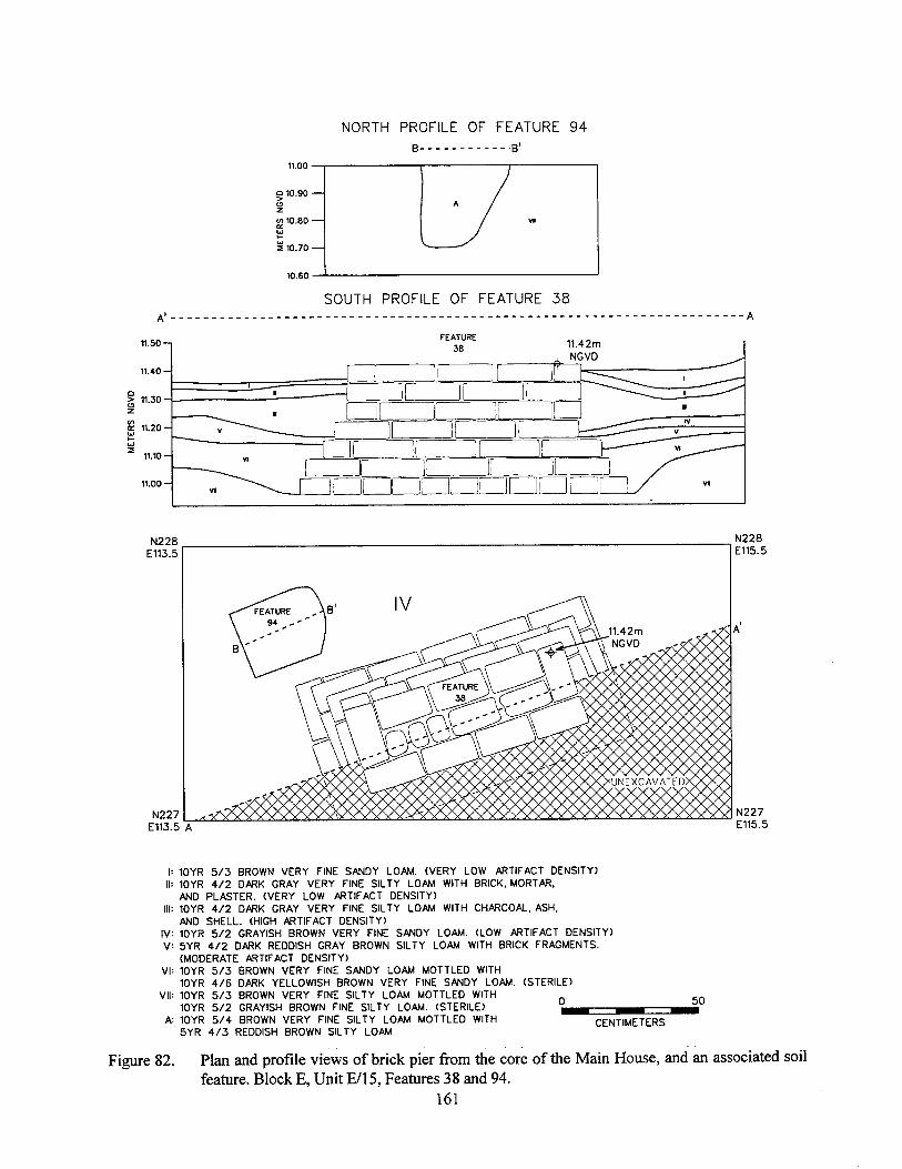
NORTH PROFILE OF FEATURE 94 B B'
11.00 ■
Q 10.90 o z 1/1 10.80 — a. I±J t- uj a 10.70
10.60 -
SOUTH PROFILE OF FEATURE 38
N228 E113.5
N227 E113.5 A
N228 E115.5
IV: V:
VI:
VII:
A:
Figure 82.
10YR 5/3 BROWN VERY FINE SANDY LOAM. (VERY LOW ARTIFACT DENSITY) 10YR 4/2 DARK GRAY VERY FINE SILTY LOAM WITH BRICK, MORTAR, AND PLASTER. (VERY LOW ARTIFACT DENSITY) 10YR 4/2 DARK GRAY VERY FINE SILTY LOAM WITH CHARCOAL, ASH. AND SHELL. (HIGH ARTIFACT DENSITY) 10YR 5/2 GRAYISH BROWN VERY FINE SANDY LOAM. (LOW ARTIFACT DENSITY) 5YR 4/2 DARK REDDISH GRAY BROWN SILTY LOAM WITH BRICK FRAGMENTS. (MODERATE ARTIFACT DENSITY) 10YR 5/3 BROWN VERY FINE SANDY LOAM MOTTLED WITH 10YR 4/6 DARK YELLOWISH BROWN VERY FINE SANDY LOAM. (STERILE) 10YR 5/3 BROWN VERY FINE SILTY LOAM MOTTLED WITH n
10YR 5/2 GRAYISH BROWN FINE SILTY LOAM. (STERILE) 10YR 5/4 BROWN VERY FINE SILTY LOAM MOTTLED WITH CENTIMETERS 5YR 4/3 REDDISH BROWN SILTY LOAM
Plan and profile views of brick pier from the core of the Main House, and an associated soil feature. Block E, Unit E/15, Features 38 and 94.
161
50
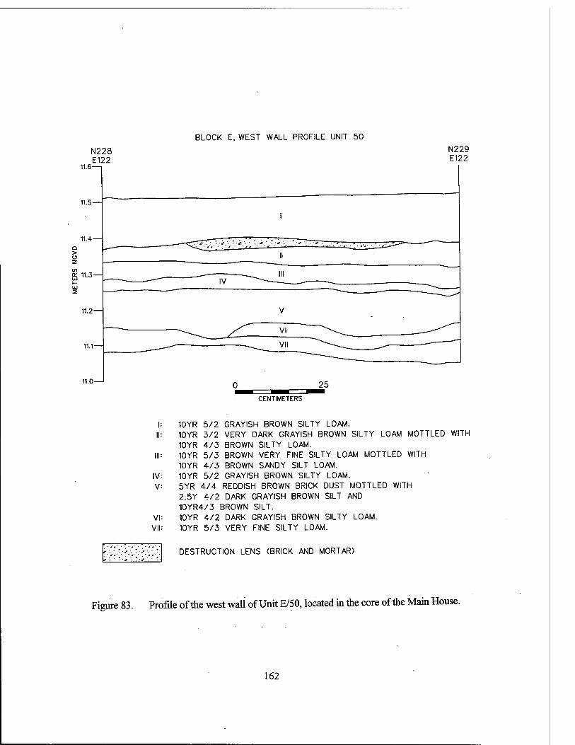
BLOCK E, WEST WALL PROFILE UNIT 50
11.6
N228 E122
N229 E122
CENTIMETERS
III:
IV: V:
VI: VII:
10YR 5/2 GRAYISH BROWN SILTY LOAM. 10YR 3/2 VERY DARK GRAYISH BROWN SILTY LOAM MOTTLED WITH 10YR 4/3 BROWN SILTY LOAM. 10YR 5/3 BROWN VERY FINE SILTY LOAM MOTTLED WITH 10YR 4/3 BROWN SANDY SILT LOAM. 10YR 5/2 GRAYISH BROWN SILTY LOAM. 5YR 4/4 REDDISH BROWN BRICK DUST MOTTLED WITH 2.5Y 4/2 DARK GRAYISH BROWN SILT AND 10YR4/3 BROWN SILT. 10YR 4/2 DARK GRAYISH BROWN SILTY LOAM. 10YR 5/3 VERY FINE SILTY LOAM.
■ • # ■ - J- . DESTRUCTION LENS (BRICK AND MORTAR)
Figure 83. Profile of the west wall of Unit E/50, located in the core of the Main House.
162
deposition of Stratum V. Stratum VI produced no artifactual material; it did not exhibit the same physical properties as the Stratum IV alluvium, and appeared to have been used as intentional fill for the depression surrounding Feature 38. The depression in Stratum VII, apparent on both the east and the west sides of Feature 38, may have been caused by the weight of the structure on the easily compacted subsoil.
UnitE/14 Feature 26, a pier located just east of Feature
38 (Figures 76 and 84), was surrounded by a much higher density of destruction debris and of the upper midden deposit than Feature 38. Stra- tum II included both the destruction debris and materials from the upper midden deposit; this stratum contained large quantities of brick, mor- tar, and Rangia shell, in addition to hundreds of artifacts including ceramic and glass sherds, to- bacco pipes, a tin can, a leather shoe sole, animal bone, iron sheeting, and nails. Stratum III, origi- nating at a depth of between 11.2 and 11.3 m NGVD, was the alluvial deposit from the mid- nineteenth century. Artifact density in Stratum III was a small fraction of that observed in Stratum II. The majority of the recovered material was attributed to drift and to post-flood disturbance. Below the flood deposit was the second, earlier midden (Stratum rV), which exhibited the same characteristics as observed in Units E/50 and E/15 (Stratum V). The elevations of the deposit were similar in both Unit E/15 and Unit E/14, with the base of the deposit at approximately 11.17 m NGVD. Artifact content in Stratum IV was lim- ited to moderate quantities of brick, glass, ce- ramics, nails, and charcoal.
Stratum V was a virtually sterile deposit that appeared to have been intentionally placed. This corresponded to Stratum VI in Unit E/15. Stratum V filled a concavity at the base of the pier (Fea- ture 26), which appeared to have been excavated intentionally, possibly at the time of original con- struction. Feature 79 (Figure 84) ran along the interior (south) side of Feature 26. Its trench-like configuration, and its sterile, silty fill suggested that it may have been excavated in order to effect repairs to the pier. This feature type was repeated frequently in different areas of the site, and at different elevations; most ran next to piers, but did not seem to possess characteristics of
builder's trenches. Rather, the piers had been constructed on grade, and fill had been brought in to level, or to raise, the surrounding yard area.
UnitE/32 The stratigraphic sequence associated with
Feature 104, the southeastern corner of the core of the main house (Figures 76 and 81), again was similar to the general pattern exhibited for this area of the site. Stratum II was the destruction layer, and contained dense deposits of charcoal, brick and mortar fragments, and small quantities of nails, ceramics, glass, and bone. Stratum HI, the upper midden deposit, contained quantities of coal, and small numbers of nails; one fragment of glass was recovered. While the midden soil in this unit was similar to that in the central areas of the core, the variance in artifact density reflected dif- ferential disposal patterns.
The flood layer was more pronounced in this area than in the central portion of the core. Stra- tum rV in this locale was 10 to 15 cm (3.9 to 5.9 in) in thickness, more than twice that of the cen- tral core units. It contained only a few small brick fragments, and some coal fragments. Stratum V, Level 1, was the earlier midden, characterized by the reddish hue imparted by the presence of quantities of small brick chips. Artifact content was low to moderate, with fewer than 50 glass, ceramic, bone, and iron fragments. Stratum V, Level 2 retained some qualities of the second midden, but a gradual transition to a 10YR 5/3 silty loam, similar to Stratum V in Unit E/14, be- came apparent by the bottom of the level at ap- proximately 11.0 m NGVD. A concavity, filled with the Stratum V, Level 1 soils, was apparent next to Feature 104. This may have resulted from activities similar to those that created Feature 79 in Unit E/14.
UnitE/24 Feature 37, an internal pier of the core
structure (Figures 76 and 85), served as a support for major cross-members that underpinned the house; it probably marked the division between gallery and interior. It was located approximately 2.9 m (9.5 ft) from Feature 27, the closest outside pier of the core. The upper course of the pier was at an elevation of 11.54 m NGVD, and the bot- tom of the seventh course of brick (base of pier) was at an elevation of 11.09 m NGVD.
163
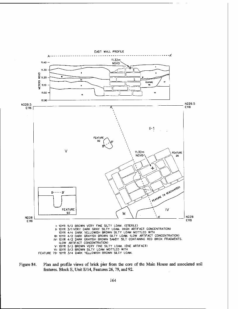
EAST WALL PROFILE
11.40 — 11.32m NGVD^\
11.30 -
■ I
^v^crx ̂
/ IV
> S 11 ->n r^ ir i
IV
V
\
—f ii Z2C3^=^ SÜ 11.10 - i ii
v FEATURE /
J 79 /_
2 II i I r 11.00 -
VI I ■ i m N229.5
E116
N228 E116
V
N229.5 E118
B B1
FEATURE 92
N228 E118
I: 10YR 5/3 BROWN VERY FINE SILTY LOAM. (STERILE) II: 10YR 3/1 VERY DARK GRAY SILTY LOAM. (HIGH ARTIFACT CONCENTRATION)
10YR 4/4 DARK YELLOWISH BROWN SILTY LOAM MOTTLED WITH III: 10YR 4/2 DARK GRAYISH BROWN SILTY LOAM. (LOW ARTIFACT CONCENTRATION) IV: 10YR 4/2 DARK GRAYISH BROWN SANDY SILT CONTAINING RED BRICK FRAGMENTS.
(LOW ARTIFACT CONCENTRATION) V VI
FEATURE 79
10YR 5/3 BROWN VERY FINE SILTY LOAM. (ONE ARTIFACT) 10YR 5/3 BROWN SILTY LOAM MOTTLED WITH 10YR 3/4 DARK YELLOWISH BROWN SILTY LOAM.
Figure 84. Plan and profile views of brick pier from the core of the Main House and associated soil features. Block E, Unit E/14, Features 26,79, and 92.
164
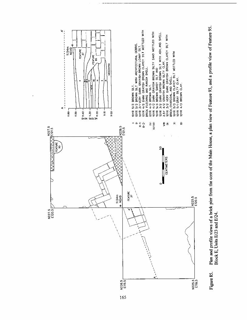
1 m SS s m ^ Z
bj u. 1) u
u IT
2"1 — i <•> ,^^ \ / "-/r \ °
\ / \ * i /A \ s
/1 \ *
1 >
- i
5 » * »
i QAON SH313n
»- i
o UJ n
_1 UJ I in
X
S _J h- t-
a: 5 s t- 3 _J
m -1 3 o UJ W > Q
>- _1 o < UJ t—
<!1« 3 X < * 3 ►- o t— X o
-J uj
o o _i
>- _J in n
_J
o
a:
o UJ _J t— )— o
m z UJ X
T £ 7 >_ co 2
Ü xS o H- S o
1— _1
in or <r rt- or "' V _i in
i 1- 5m o ID CD z < x >- s
a: o 3
T V T a in m >- _J _J
z z
_j in
z
>- < a:
3 in
7 a: o
oo oc
ID in 3U >-
t-
tn
< o z
=c % * * >- > £ o o £5 Z
O UJ
o ri- 5 Ü 5 < a:
a: UJ o o o or 5 u
or m CD UJ o al o CO o o > <$m
u UJ
K} fO «- CM n CM Kl CM CM CM T "1 «— ro -v \ -s. V u_ \ \ V V ^v ^ o ~^ V. in m »o ■* * •<t m K) m
a: K or K * n- o- or rr >■ or r^o: or cr >- >- >- >- >- >- V >- in >- gg >- >-
a o o o m o o o o <siy o o
V ^ > > = X X X
in
<U to o
E >
s a, «j
-o e
en ON <u IM
i u to «4-1 o
u ■>
c 'S, cä
<D" en 3 O X
u JS
t+H o (1) u. o u u
4= •4-»
E o «b u. u Q. ^ o 1- x> •* c« JN
«4- to o -o t/1 c ? CB
(U rn > f»
4) w «3 ■*-"
o c a D
T3 c w" es ^<S r: u rfl o
CU HI
vi oo « u 3 00
to
165
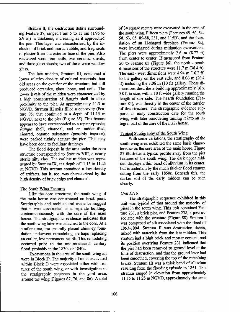
Stratum II, the destruction debris surround- ing Feature 37, ranged from 5 to 15 cm (1.96 to 5.9 in) in thickness, increasing as it approached the pier. This layer was characterized by the in- clusion of brick and mortar rubble, and fragments of plaster from the exterior face of the pier. Also recovered were four nails, two ceramic sherds, and three glass sherds; two of these were window glass.
The late midden, Stratum III, contained a lower relative density of cultural materials than did areas on the exterior of the structure, but still produced ceramics, glass, bone, and nails. The lower levels of the midden were characterized by a high concentration of Rangia shell in close proximity to the pier. At approximately 11.3 m NGVD, Stratum III soils filled a concavity (Fea- ture 95) that continued to a depth of 11.15 m NGVD, next to the pier (Figure 85). This feature appears to have corresponded to a repair episode; Rangia shell, charcoal, and an unidentified, charred, organic substance (possibly bagasse), were packed tightly against the pier. This may have been done to facilitate drainage.
The flood deposit in the area under the core structure corresponded to Stratum VDI, a nearly sterile silty clay. The earliest midden was repre- sented by Stratum IX, at a depth of 11.15 to 11.25 m NGVD. This stratum contained a low density of artifacts, but it, too, was characterized by the high density of brick chips and charcoal.
The South Wing Features Like the core structures, the south wing of
the main house was constructed on brick piers. Stratigraphic and architectural evidence suggest that it was constructed as a separate building, contemporaneously with the core of the main house. The stratigraphic evidence indicates that the south wing later was attached to the core. At a similar time, the centrally placed chimney foun- dation underwent remodeling, perhaps replacing an earlier, less permanent hearth. This remodeling occurred prior to the mid-nineteenth century flood, probably in the 1830s or 1840s.
Excavations in the area of the south wing all were in Block D. The majority of units excavated within Block D were associated either with fea- tures of the south wing, or with investigation of the stratigraphic sequence in the yard areas around the wing (Figures 67, 76, and 86). A total
of 34 square meters were excavated in the area of the south wing. Fifteen piers (Features 49, 50, 54- 58, 63, 65, 85-88, 231, and 115B), and the foun- dation of an H-shaped fireplace (Feature 84), were investigated during mitigation excavations. The piers were approximately 2.6 m (8.77 ft) from center to center. If measured from Feature 50 to Feature 65 (Figure 86), the north - south dimensions of the structure were 11.7 m (38.4 ft). The east - west dimensions were 4.94 m (16.2 ft) to the gallery on the east side, and 8.06 m (26.4 ft) including the 3.06 m (10 ft) gallery. These di- mensions describe a building approximately 16 x 38 ft in size, with a 10 ft wide gallery running the length of one side. The hearth foundation (Fea- ture 84), was directly in the center of the interior of this structure. The stratigraphic evidence sup- ports an early construction date for the south wing, with later remodeling turning it into an in- tegral part of the core of the main house.
Typical Stratigraphy of the South Wing With some variations, the stratigraphy of the
south wing area exhibited the same basic charac- teristics as the core area of the main house. Figure 87 illustrates a typical profile away from the pier features of the south wing. The dark upper mid- den displays a thin band of alluvium in its center, but is underlain by the much thicker flood stratum dating from the early 1850s. Beneath this, the darker soil of the early midden can be seen clearly.
UnitD/16 The stratigraphic sequence exhibited in this
unit was typical of that around the majority of piers in the south wing. This unit contained Fea- ture 231, a brick pier, and Feature 238, a post as- sociated with the structure (Figure 88). Stratum I was composed of silt associated with the flood of 1993-1994. Stratum II was destruction debris, mixed with materials from the late midden. This stratum had a high brick and mortar content, and its position overlying Feature 231 indicated that the pier had been removed to ground level at the time of destruction, and that the ground later had been smoothed, covering the top of the remaining bricks. Stratum III was a thick band of alluvium resulting from the flooding episode in 1851. This stratum ranged in elevation from approximately 11.15 to 11.25 m NGVD, approximately the same
166
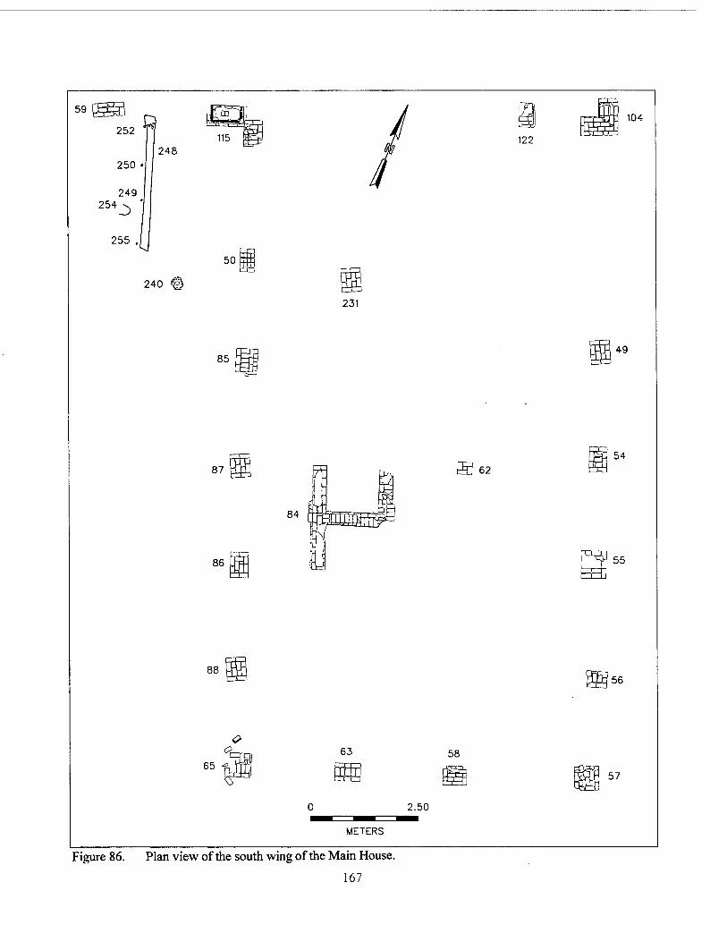
Figure 86. Plan view of the south wing of the Main House.
167
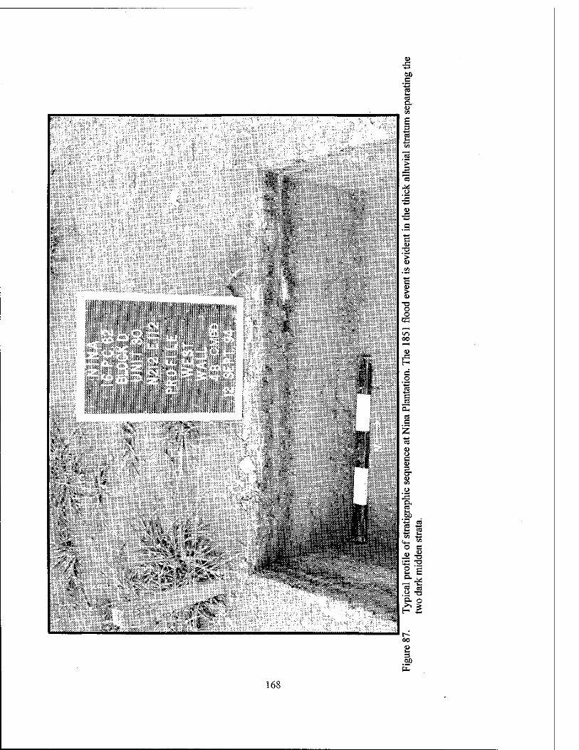
00 s
! CO
*
i'-Mfc
...pj
»mil
168
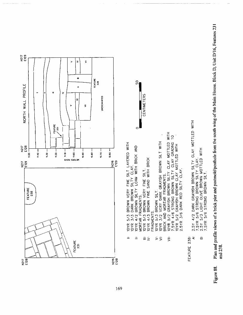
CM en
fct.
O Q-
<
o z
1 ' /
/
> > >
• UJ cc
1 < M
/ * . /
> > 1
>
o UJ t- < 5 CJ X IÜ
I 13
1 \ \ 1
I \ 1 \ o= \ \ ? 5 \ < w
\
t- <~~7 1 1 1 1 1 1 1 1
X to
X Q O z x
QA3N SH313H
Q bJ cc
5 .m
I_ "* •-
CO
ZjO Li- (/) -1
a: 5 i- bj g =J
zmz
o cc o oi < cc mom
\ \ \ inn * ce cc or
o o o
to
Z
o cc m x CO
>- < CC o
^* =! en to < ZQ
s >- o cc CC Ld m >
rO iO tT f) CN
o cc CD
(^ X _J t
LJQ
? z b. <
to
• Ld Z lO > b-
z z
o o CC 01 CO CD
< cc o
>- < o o
>- <
in >- I- >- , =!<d >- — to -> z to u ov
LÜ -, >- 2 Z > Z H-
to
go- mcoR o 01
01 01 >- >- o o
w m to 9 cc 01 01 >- >■ rr
o£* ai >- a: t- < < m oi o
e> <D ID \ CM -v.
in on oi >- oi >- in >- in
= > >>
UJ
d ^ V < Ld
O to CC CD Z
US >- CO < cc o
01 >- >- in m
\ m m
01 >- >- in in CM r-^
oo < to cs Ld 01 z> I— < LU
c D a" o o
CD
3 O
u JS, ■4-»
o (50 c %
"I—I 3 o I» ID
<g o
o
f o
o a. c cd u 9>
'EL J< _o
x> «
o
I >
e D.
p 00 m <N c "O c
Oi es
00 00 u u
S) tt,
169
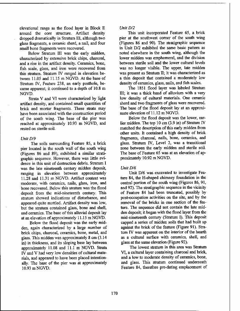
elevational range as the flood layer in Block E around the core structure. Artifact density dropped dramatically in Stratum III, although two glass fragments, a ceramic sherd, a nail, and four small bone fragments were recovered.
Below Stratum III was the early midden, characterized by extensive brick chips, charcoal, and a rise in the artifact density. Ceramics, bone, fish scale, glass, and iron were recovered from this stratum. Stratum IV ranged in elevation be- tween 11.05 and 11.15 m NGVD. At the base of Stratum IV, Feature 238, an early posthole, be- came apparent; it continued to a depth of 10.8 m NGVD.
Strata V and VI were characterized by light artifact density, and contained small quantities of brick and mortar fragments. These strata may have been associated with the construction period of the south wing. The base of the pier was reached at approximately 10.93 m NGVD, and rested on sterile soil.
UnitD/9 The soils surrounding Feature 85, a brick
pier located in the south wall of the south wing (Figures 86 and 89), exhibited a similar strati- graphic sequence. However, there was little evi- dence in this unit of destruction debris. Stratum I was the late nineteenth century midden deposit, ranging in elevation between approximately 11.28 and 11.31 m NGVD. Artifact content was moderate, with ceramics, nails, glass, iron, and bone recovered. Below this stratum was the flood deposit from the mid-nineteenth century. This stratum showed indications of disturbance, and appeared quite mottled. Artifact density was low, but the stratum contained glass, bone and shell, and ceramics. The base of this alluvial deposit lay at an elevation of approximately 11.15 m NGVD.
Below the flood deposit was the early mid- den, again characterized by a large number of brick chips, charcoal, ceramics, bone, metal, and glass. This midden was approximately 8 cm (3.14 in) in thickness, and its sloping base lay between approximately 11.08 and 11.1 m NGVD. Strata IV and V had very low densities of cultural mate- rials, and appeared to have been placed intention- ally. The base of the pier was at approximately 10.93 m NGVD.
UnitD/2 This unit incorporated Feature 65, a brick
pier at the southwest corner of the south wing (Figures 86 and 90). The stratigraphic sequence in Unit D/2 exhibited the same basic pattern as noted elsewhere in the south wing, although the lower midden was emphemeral, and the division between sterile soil and the lower cultural levels was no longer visible. The upper, late midden was present as Stratum II; it was characterized as a thin deposit that contained a moderately low density of ceramics, glass, nails, and fish scales.
The 1851 flood layer was labeled Stratum III; it was a thick band of alluvium with a very low density of cultural materials. One ceramic sherd and two fragments of glass were recovered. The base of the flood deposit lay at an approxi- mate elevation of 11.12 m NGVD.
Below the flood deposit was the lower, ear- lier midden. The top 10 cm (3.9 in) of Stratum IV matched the description of this early midden from other units. It contained a high density of brick fragments, charcoal, nails, bone, ceramics, and glass. Stratum IV, Level 2, was a transitional zone between the early midden and sterile soil. The base of Feature 65 was at an elevation of ap- proximately 10.92 m NGVD.
UnitD/6 Unit D/6 was excavated to investigate Fea-
ture 84, the H-shaped chimney foundation in the central portion of the south wing (Figures 86, 91, and 92). The stratigraphic sequence in the vicinity of Feature 84 had been truncated, possibly by post-occupation activities on the site, and by the removal of the bricks in one section of the fea- ture. The sequence did not contain the late mid- den deposit; it began with the flood layer from the mid-nineteenth century (Stratum I). This deposit capped a series of midden soils that had built up against the brick of the feature (Figure 91). Stra- tum IV was apparent on the interior of the hearth as a cultural surface with ceramics, shell, and glass at the same elevation (Figure 92).
The lowest stratum in this area was Stratum VI, a cultural layer containing charcoal and brick, and a low to moderate density of ceramics, bone, and glass. This stratum continued underneath Feature 84, therefore pre-dating emplacement of
170
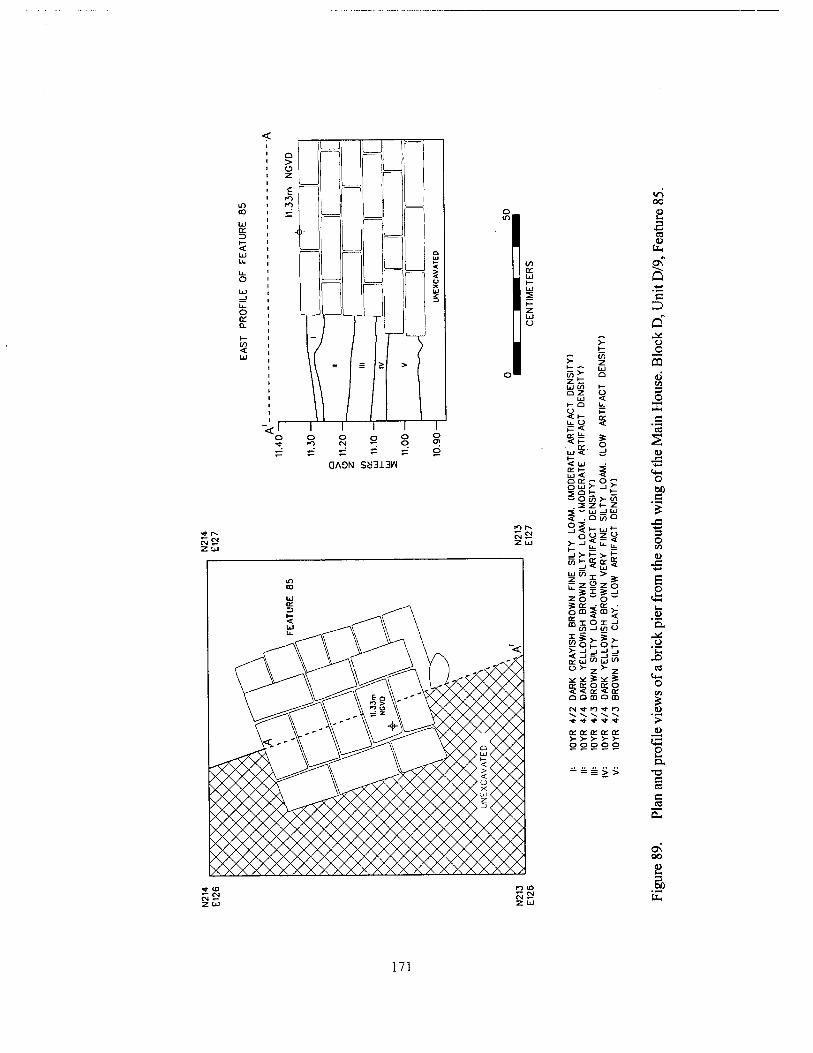
m m UJ
o L±J
o or a
CO <
I
,1
or
QA9N SH313W
S o
UJ CO O Z
UJ (- o o < H-
UJ < I— < UJ •
UJ < < o or r o c o UJ >- _J > 3 Q l- t ~ O CO >- CO
• 2 z •- z. ^ — UJ —' Cd 5 . D COO Sll-UJ»-
-I >- I- 3- fc
Ezi2| zoo" JEJ«: ■ o CD 5 m >- mioiJ
^ *
2 UJ co ÜJ w
SSEgSg O O 03 O CD oi *r to ■<*• to NNSS S
or oc or or a: o o o o o
00
1 ID
Q ■4-»
"5 D
o _o CQ
<L> « 3 O X c
"S
<D JS ■*-»
«4-1 o (30 c
J3 -4-*
3 O
E p
.22 "EL _o *c X) cd
«4- o CO
>
s a.
00
DC
E
171
ist
z L±J ü
X
O^OH
<
C/)
s I b
Q 'S
o o 5 3
S 'S
o c
3 O
an JS
ti—I o u
o
es u
3 O
J3
y s Ui
>- S> te <u h9h3 ° _i 2 -J < o . EX
FIN
E
S LO
AM
FI
NE
S
TY
LO
AM
AN
* P
AR
I
o
.O ^ -JOUJ eö
>>>-in-iiL U-> CK i- o; OL O U -1 lij LJ >- 3 > </l > Z 1- cn
ü. -Jz § Z Z Z (/>
S5S>,,u o o o o: y z > o; a: D; U ■& 5 aa on on > IL. Q <L>
to to tO CM fO y p ^ ~^ ^ ~- ^ rr in ■*- m -t •* O- o: o: o: or o: o
3 es o o o o o j£ c .5 s o
I
172
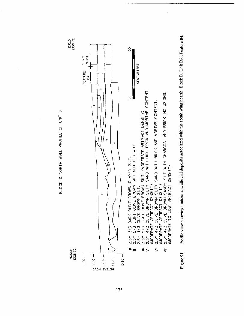
V2 o CN fO 2 .7,
CO
Z ID
O
O en Q.
o
o o _J CO
i? oo IN CN z ,T,
I
I
I CO
= >
00
4)
c3
Ü _o CQ 43° ts CO
z o o
t— Z Ld 1—
CO => _J Ü
60 C
> i— 01
IT < Z
o o
z JS +-» 3 O
z o CC o en
Ld 2 < en <L> Q 1— CD -4—1
(— Q Z o Q Ä
< < 2 Z
"< ' 'I 1—
Q Z
_1 < X 1— < m
< o o
.2
5 Q
t- Ld
Ld 1— <
X o X
o
m
< X o
o
=!^ Ld Q X X X '35
o D. Wh O t— i— t ^
. o 2 5 3 5 >- u ?-. 2 ^^ 1— ■o Ld Q O i— CO is I-- Z Z _J z
_J CO
< CO
< co 10 Ld
Q _3
Ü or £ m m
Ld tfJ
_J CO
2
3
z
o cc OD
LÜ
>- 1— _l
CO
z 5
> i— en z Lü Q
>- i— _i to
z 5
,-. >- >- Q l— Z
^Lo Ld z
1— O < Lu 1— en <
•a c es C
-a > > o > o 1— o I- o E
c ~i —i cc _J ce O ££ O Oi 5 o00oom<m<mo
b- Li_ _i
*X Ld >
1— X
Lü > 1—
a: Ld > DC 2* o "5 o
< O _J o _J < _l < -1 1— 43 O _l o _l o
Ld o o
Ld Ld CO
m m n m ro \— m h- ro h- \ \ — \ \ < \ < \ < '> m m ■* m ■* a: ■<*- 0C -t cc
Ld Ld Ld _« >- >- >- >- >- Q >• £^ Q s m in m in m O
2 tn o m O
2 o CN CN CN CN CN CNJ B CN OH
ON
u 3 DC
QA0N ScJ3i.3W
173
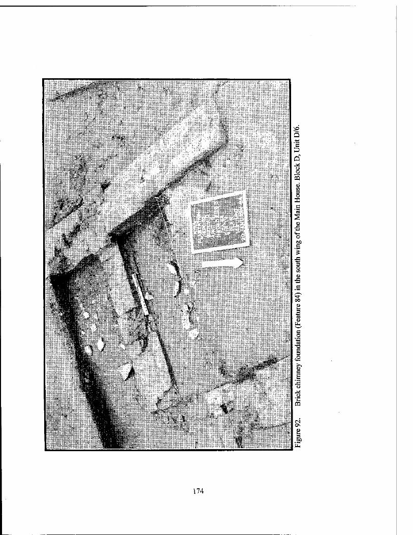
174
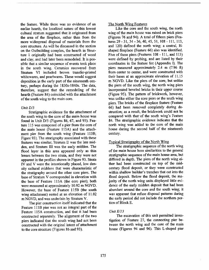
the feature. While there was no evidence of an earlier hearth, the localized nature of this lowest cultural stratum suggested that it originated from the area of the fireplace, rather than from the more widespread disposal of materials from the core structure. As will be discussed in the section on the Outbuilding complex, the hearth in Struc- ture 1 originally had been constructed of wood and clay, and had later been remodeled. It is pos- sible that a similar sequence of events took place in the south wing. Ceramics recovered from Stratum VI included brown transfer-printed whitewares, and pearlwares. These would suggest deposition in the early part of the nineteenth cen- tury, perhaps during the 1830s-1840s. The data, therefore, suggest that the remodeling of the hearth (Feature 84) coincided with the attachment of the south wing to the main core.
UnitD/5 Stratigraphic evidence for the attachment of
the south wing to the core of the main house was found in Unit D/5 (Figures 86, 67, and 93). Fea- ture 115 was composed of a pier from the core of the main house (Feature 115A) and the attach- ment pier from the south wing (Feature 115B; Figure 93). The stratigraphy associated with these features was similar; Stratum II was the late mid- den, and Stratum III was the early midden. The flood layer in this area appeared only as thin lenses between the two strata, and they were not apparent in the profiles shown in Figure 93. Strata IV and V were the intentionally placed, low den- sity cultural middens that were characteristic of the stratigraphy around the other core piers. The base of Stratum V corresponded in elevation with the base of Feature 115A (the core pier); both were measured at approximately 10.92 m NGVD. However, the base of Feature 115B (the south wing attachment) rested at an elevation of 11.02 m NGVD, and was underlain by Stratum V.
The pier construction itself indicated that the Feature 115B pier was not an integral part of the Feature 115A construction, and that it had been constructed separately. The alignment of the two piers indicated that the south wing had not been constructed with the original intent of attachment to the core structure (Figures 86 and 93).
The North Wing Features Like the core and the south wing, the north
wing of the main house was raised on brick piers (Figures 76 and 94). A total of fifteen piers (Fea- tures 29 - 31, 34 - 36, 40, 45, 51, 108-111,113, and 120) defined the north wing; a central, Hi- shaped fireplace (Feature 66) also was identified. Five of these piers (Features 108 - 111, and 113) were defined by probing, and are listed by their coordinates in the feature list (Appendix I). The piers measured approximately 2.4 m (7.96 ft) from center to center, and were constructed with their bases at an approximate elevation of 11.15 m NGVD. Like the piers of the core, but unlike the piers of the south wing, the north wing piers incorporated beveled bricks in their upper course (Figure 95). The pattern of brickwork, however, was unlike either the core piers or the south wing piers. The bricks of the fireplace feature (Feature 66) had been removed completely during de- struction; as a result, the brickwork could not be compared with that of the south wing's Feature 84. The stratigraphic evidence indicates that the north wing was added to the core of the main house during the second half of the nineteenth century.
Typical Stratigraphy of the North Wing The stratigraphic sequence of the north wing
of the main house bore similarities to the general stratigraphic sequence of the main house area, but differed in depth. The piers of the north wing ei- ther had been constructed on top of the mid- century flood deposit, or they were constructed within shallow builder's trenches that cut into the flood deposit. Below the flood deposit, the ma- jority of the north wing units displayed little evi- dence of the early midden deposit that had been abundant around the core and the south wing; it was apparent that refuse disposal patterns during the early period did not include the northern por- tion of Block E.
UnitE/13 The excavation of this unit permitted inves-
tigation of Feature 27, the connecting pier be- tween the north wing and the core of the main house (Figures 94 and 96). This L-shaped pier
175
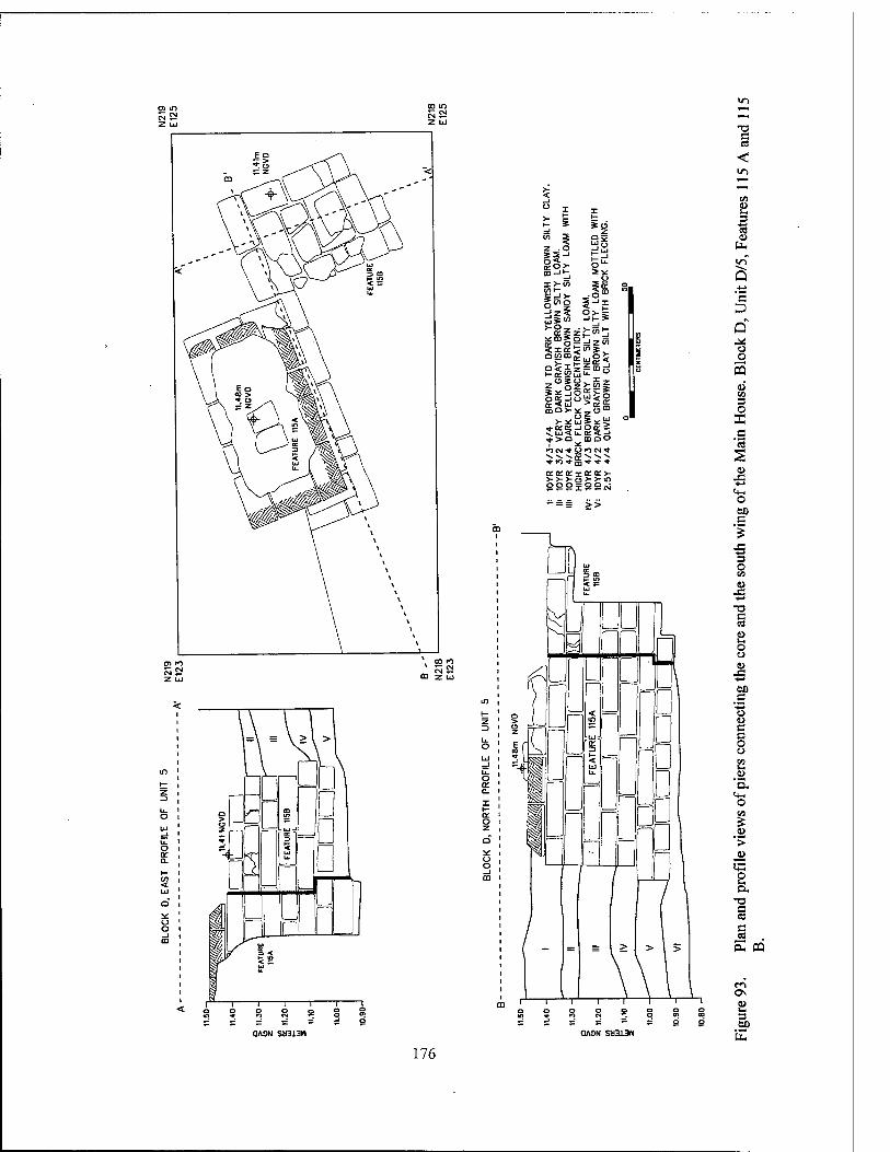
z .0 a* 0-
S3-1
go>- m-"-. =*
o x>- V) Ull- *s
>-o_
s£0DO z 0 _ < a:
z
□ VI 03
"2« _oSo ? oz >-5|
goo 05-lü CQO>-5I:
>-iu *«« _l
*>o moo Kioj ■* O»OCM ■*
\ >v ^ *-ro*- * * ■*■
KKO: KO: >- >>->- >>m 00c X °°«
"= >>
o _] m
T3 S 03
<
i
c
o o 5 3 o B
u
o 60 C
•S 3 o 03
u •4-»
c C3
u o o a> .e ■*^
M .C "■^ o u e c o o 1» s-
.0 'n. <+-
CO
■>
«5 S a.
•0 c « c
0A0N S!i313n QAON SM313W 3> E
176
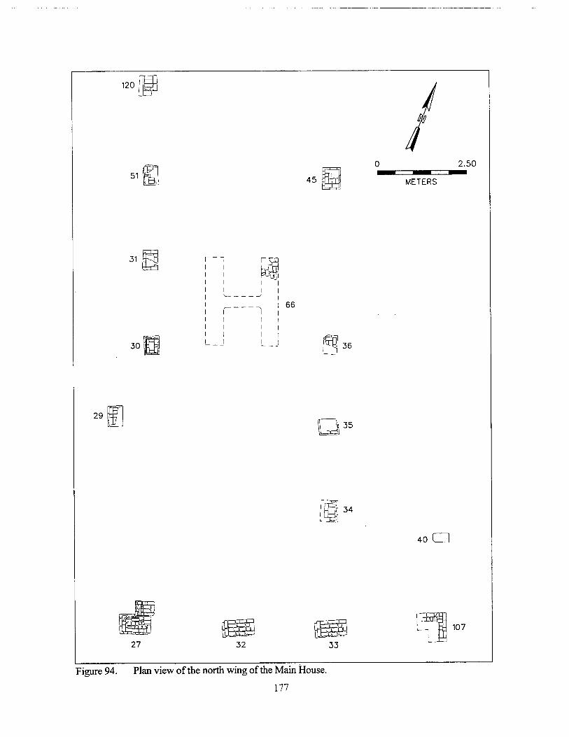
Figure 94. Plan view of the north wing of the Main House.
177
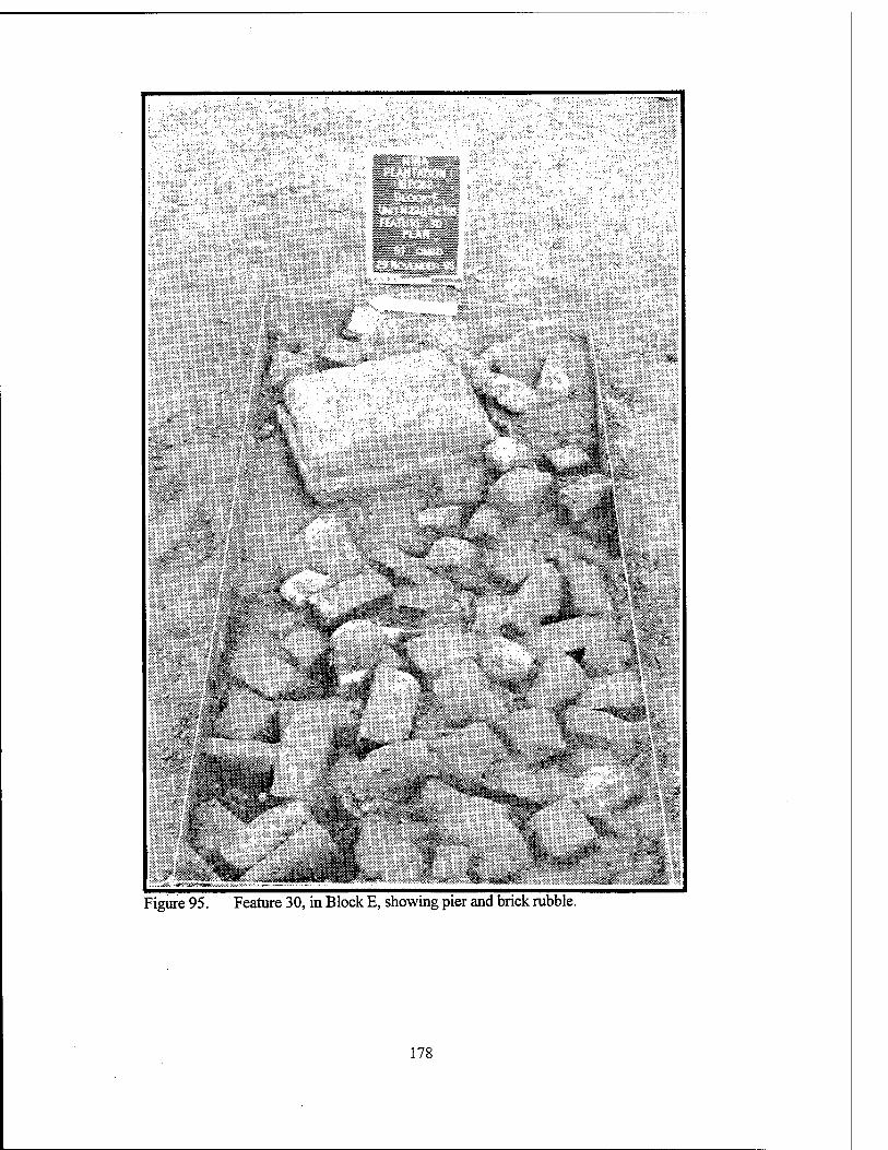
■70^ ^^W^S%:-V^:^^S,
l_ ' *s;flä
%SW-.MS^^^f^ff'W¥C'^fB- ^Bi^-ÄftS^B :SftÜi,L:;-Ä * ^% ^^^^S>*^ä^ä.''-^^^5
"*' §§ti§»L i£i^F^ ^^V^II
V >~ ' Vm ' ^ s
*. " W&to*^ S& ' ' * «*• I " V "^ '%& " V* Ji ^^^&«— * ^ ^f %?,-,, f ^
^%SS& ^5s - sÜ * *^*
. (lll^Bl(^BI^fcllBI ^Tl^^^B^^^^B^^^ÄE^-^.^^^MÖMRtt^^^^^ -t " "-' ^^$&ik ' ,- -«- ^ Lr^Sfe, ^111: &***'..-^ v-
' " * •' m --— ' -»^%i# jt*,^»» -JR«& ■ •^v ■■**..-.•?*■■■•
&s ; ■/ .- i/ *-* •'■ 4 - JF ■ # V^BiPHfc <•< £>< --1 ** r -- -. ' "-'ifltaif ,i, f*" - ■■" ^SI»fc,^BI' *: '.»S-•'"" ~ Vi '-•- '''°3r^*WmK - ^"~' '"^^SB". *? Jt£ ?\"-A' . " ■ y< ^ÄHr |f ' f^ |4^_ tJliif^c "
,- % > l||l^5 **' <-*"'**' '^ *w&JP^ ' ^^ *^ - ^r 'W^l^'**
lUP- ^^^üi^^*l^'^ " ^ÜÜk A' "v „*? ^llb&Sö.' W^,~ f-/
•am. !•■' ^Jr ^fe* 'üydV ^^ ~~ r"^ - «lÄ™%ifc -&^^^B- Air ill "'c^Hfw »,» - •••'•"■ -
vÄ* ,g|l * «..3 • IK i'Ä^^Ä - w' ^^^-f-^ ^,
11 * -■*.«& • {.:.
■ ,-•'.■
K*' ^P^ .Wm^iQ&mt' *&r ^'^ - '*. ■1 ■
* ^•^»Ä:v»mw.^,v.vW ., - ... '■■•■■'■■•■ *
Figure 95. Feature 30, in Block E, showing pier and brick rubble.
178
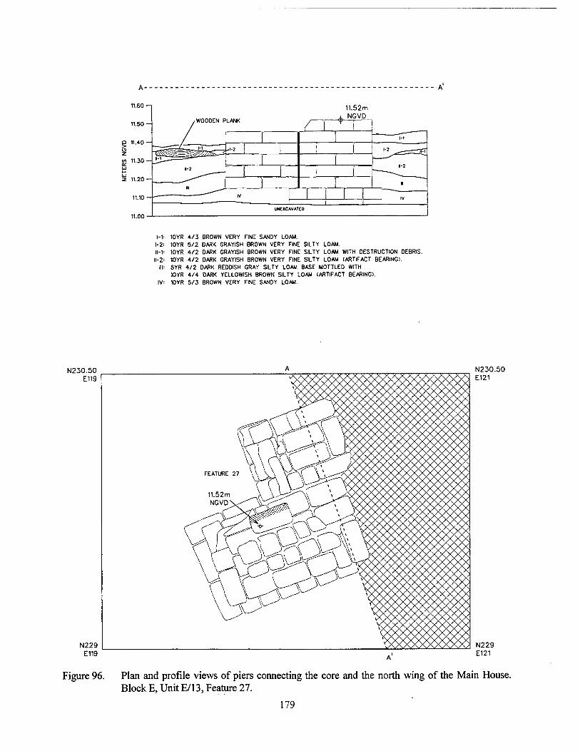
1-1: 1-2 ll-V
11-2 III:
10YR 4/3 BROWN VERY FINE SANDY LOAM. 10YR 5/2 DARK GRAYISH BROWN VERY FINE SILTY LOAM. 10YR 4/2 DARK GRAYISH 8R0WN VERY FINE SILTY LOAM WITH DESTRUCTION DEBRIS. 10YR 4/2 DARK GRAYISH BROWN VERY FINE SILTY LOAM (ARTIFACT BEARING). 5YR 4/2 DARK REDDISH GRAY SILTY LOAM BASE MOTTLED WITH 10YR 4/4 DARK YELLOWISH BROWN SILTY LOAM (ARTIFACT BEARING). 10YR 5/3 BROWN VERY FINE SANDY LOAM.
N230.50 E119
N229 E119
N230.50 E121
N229 E121
Figure 96. Plan and profile views of piers connecting the core and the north wing of the Main House. Block E, Unit E/13, Feature 27.
179
was composed of two parts; the north wing por- tion was not an integral part of the original core pier.
The nineteenth century stratigraphic se- quence began with a layer of destruction debris (Stratum II, Level 1) and late midden (Stratum II, Level 2). These had been mixed at the time of destruction; artifact density was high, and in- cluded brick and mortar fragments, nails, ceram- ics, glass, and bone. Below this stratum was a layer that incorporated brick, mortar, charcoal, coal, and a low density of ceramics, nails, glass, and bone (Stratum III).
Stratum IV was the alluvium deposited by the mid-century flood, and in this area of the site the flood deposit was completely sterile. The north wing portion of Feature 27 was constructed on top of this stratum, at an elevation of approxi- mately 11.15 m NGVD; the core portion of the feature continued to the base of this level (Figure 96), and rested at an elevation of approximately 11.05 m NGVD.
UnitE/9 Feature 35 was investigated in Unit E/9
(Figure 97). This north wing pier was located on the eastern wall of the structure. Only three courses in height, most of this brick pier had been removed at the time of destruction, and the sur- face of the pier was below grade. The destruction layer was Stratum II; it included brick fragments and a very high density of plaster. Stratum III was part of the late midden deposit, and contained a low density of iron, nails, bone, and ceramics. Stratum IV was a lens of coal and slag, which also contained ceramics, bottle and window glass, and nails; it was temporally similar to Stratum DI.
An apparent builder's trench, Feature 70, had been excavated into Stratum VI B, the flood deposit from mid-century (Figure 97). The pier was seated within Feature 70, which then was filled with soils designated Stratum VI A. These soils contained a low density of cultural materials, including ceramics, nails, and glass. The top of Stratum VIB was consistent with the elevation of the flood layer elsewhere on the site, at approxi- mately 11.20 to 11.25 m NGVD. The soils of this stratum contained only three small brick frag- ments and a mortar fragment.
The South Yard and the Cistern Features Cisterns
The cistern bases that flanked the core structure on its northwest and southwest corners both measured 1.8 m (5.9 ft) in diameter; each comprised six brick piers in circular configura- tions (Figures 76, 78, and 79). Slight differences in the spacing between the cistern bases and the core of the main house indicated that the cisterns may have been erected at different times, al- though the stratigraphic data indicate that they both were constructed prior to the mid-century flood, but after the core and south wing had been in use for a short period of time. The bricks of the cisterns were softer than the bricks of the piers, and crumbled more easily. Plaster recovered from the destruction layers, and in some cases still at- tached to the brick, indicated that the cistern piers had been protected by a coat of lime plaster, as were the piers of the north wing and the core.
The stratigraphic sequences associated with the cisterns were similar. The uppermost stratum was the destruction debris, which completely covered the cistern piers. Below this was Stratum III, a mixture of destruction debris and late mid- den; destruction activities and post-occupation disturbance (plowing in Block D) had spread the stratum across the pier area, covering most of the remains. A high density of cultural materials was recovered from the late midden, including bone, ceramics, glass, brass and lead objects, buttons, tobacco pipes, and other household debris. Stra- tum rv was the mid-century flood deposit, which ranged in base depth between 11.15 and 11.2 m NGVD, and that averaged 9 cm (3.5 in) in thick- ness. Directly below the flood layer was the early midden, Stratum V. This was characterized by concentrations of brick chips, charcoal, and coal, with moderate densities of ceramics, glass, bone, and other household debris. The cistern piers were constructed during the deposition of this midden, and some of the piers rested on top of early nineteenth century debris. The base eleva- tions of the piers varied slightly, but averaged approximately 11.10 m NGVD. The core piers (Features 89 and 96) adjacent to the cisterns had base elevations of 10.99 m NGVD (Feature 96), and 10.98 m NGVD.
180
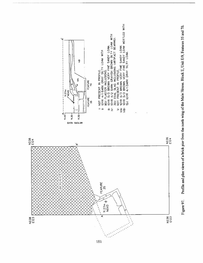
X 1—
s D
I Ul 1—
*G 1— T o
AM.
LOA
M
3EA
RI 2
1 1 O , o o -> >- h- ~' -1 3
s >—' < v >" o Q Q O ÜI/1L 2 < lli Ü 1 o CO CO > _l Lüg" Lü Lü -1 >- Z Z CO
, • 1— IJ- 5 u. u. H -" (/) I o > ;=! tTi z >- CO CO > >-< U. "' o
N V
ER
G
RA
YI
INC
LU
or or <£ ° V to o LU Ul o
3 _J 0. >>*
cc C) 2 2 £ t? z S x. o
O O ° < "*• ._ * o or < UJ u. £3 or or < ->
uj m o f1 z or or r CD m ^
CO Ul ^
CO < ??< CO UJ ^ ^ or v \ r-
? ■* _i m ■* o m m J: UJ Q_ n (j o or
5" X o
o: or .. o o 2
t- o
or or "~ >- >- X o o in
u_ z i=
— = = > > < DD > >
o
•a c
m m
03 (U
tin
Sf S3 -4-*
'2 D w o o 5
aJ CO
O DC c
u ■+-»
o
s
OAON SM313W o c
ES * "° CN CN 5-? Z UJ
10 CN
Z UÜ
i
\AAAAAAAA/^VVVVVNA \/\/\/\/\/\/\/\/\/\ t— /S/N/WVS/ "x>< l VWVYYVYY<SAA<VSAA K^XXV xYyYyVWV)><xxxxxy \/\/\ YVx)<Y\xW<x)(xXxx; KXXXXXXXX/U<XXXAXA XXX LU \AA/A\AA\A><A'VYVVY YVYi <* yV\/V\VVYSA z /v^s/Vxxx <XXX* =•
<xxx> < XXXXi w <XXX/, u.
XXX/!^ *
\A/Y\] \ *
m
+ \ \\ Eo W^\
CN o ( \ J --' z \ r\
"a.
S>
o> '> c
"o. T3 C ea
p
00
oo f> fO CN ^ r,
CO to to CN CN r~.
181
South Sill Features In Block D, a wooden sill (Feature 248) and
four flanking posts (Features 249, 250, 252, and 255) were located in the ell formed by the core and the south wing of the main house (Figures 76, 98, and 99). These features were part of an uni- dentified wooden construction that had been built using the same methods as those of Structure 1 in the Outbuilding complex. Feature 248 was a still intact cedar beam, measuring approximately 20 x 14 cm (7.87 x 5.5 in; Figure 99). The post fea- tures (Features 249, 250, 252, and 255) contained intact wood, subsequently identified as cypress. The associated stratigraphy indicated that the beam had been placed prior to the deposition of the flood deposits in 1851 (Stratum TV on Figure 98); it was seated in the soils of the earliest mid- den (Stratum V). The base of Stratum IV, and the probable level of grade at the time of the place- ment of Feature 248, was at an elevation of 11.05. The stratigraphic evidence indicated that the beam had been placed contemporaneously with the attachment of the south wing to the core. Al- though the intended function of these features is unknown, it is possible that Feature 248 formed the sill for a stairway to the newly attached south wing. It also may have been part of a shed struc- ture in the ell of the core and the south wing.
Unassociated Features Feature 90
An oval pit feature, measuring approxi- mately 2.5 m (8 ft) north to south, and 1.12 m (3.68 ft) east to west, was investigated during excavations in Block D (Figure 100). Strata I and II of the feature fill were post-occupational fill; Stratum HI corresponded to the late midden de- posit that surrounded the feature at the time of excavation. Stratum III contained a moderate density of ceramics, glass, nails, and shell; it was similar in character to the late midden in other areas of the site. Stratum TV contained a low den- sity of glass, ceramics, nails, brick, and bone, which appeared to have accumulated gradually. The base of the feature was at an elevation of ap- proximately 10.71 m NGVD. There were no clear indications of the function of Feature 90, and no specific date for its original excavation was as- certained. The stratigraphic evidence suggested that it had been open at the time of site abandon-
ment, and that it had been left open after site de- struction.
Feature 194 Feature 194 was a well-preserved, cypress
wood well shaft, located at low water on the banks of the Mississippi River, east of Block E (Figures 70 and 101). Despite its excellent pres- ervation, its location suggested that it had been displaced during bank erosion; Feature 194 did not maintain enough stratigraphic integrity to de- termine any temporal associations. The well shaft was approximately 1.4 m (4.59 ft) in depth, and it contained a very light density of nails, glass, ce- ramics, and brick fragments. Also recovered were the wooden staves, fiber bindings, and iron chains from two wooden buckets.
Summary of the Main House Complex The Main House complex comprised the
core structure, the south wing, the north wing, the north and south cisterns, and two unassociated features (Feature 90 and Feature 194). The strati- graphic associations of these structures allowed more construction of a relatively fine-grained temporal sequence for construction and occupa- tion in the main house area. The first two struc- tures to be built were the core of the main house, and the south wing. The core was a large struc- ture, raised on piers, that probably had galleries around all four sides. The south wing was con- structed as an independent building, and later at- tached to the core as a wing. This attachment took place in the 1830s or 1840s, contemporaneous with the construction of the two cisterns that flanked the core structure. The north wing was added after mid-century, and postdated the flood of 1851. Designed so that it provided symmetry to the main house, it is likely to have been the work of the Aliens, who purchased the plantation in the 1850s.
The Outbuilding Complex The Outbuilding complex, approximately 30
m (98 ft) south of the Main House complex, comprised two structures. Designated Structures 1 and 2, these buildings originally were part of a small group of four outbuildings depicted on the 1883 Mississippi River Commission Chart. Car- tographic overlays suggested that the other two
182
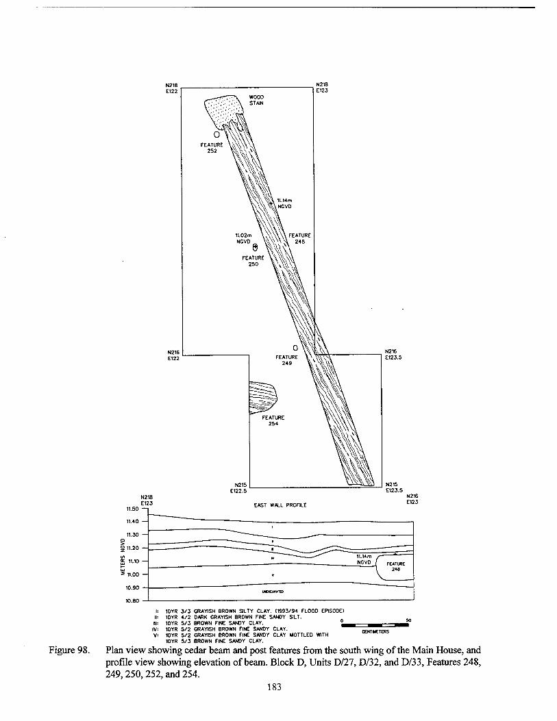
10YR 3/3 GRAYISH BROWN SILTY CLAY. (1993/94 FLOOD EPISODE) 10YR 4/2 DARK GRAYISH BROWN FINE SANDY SILT. 10YR 5/3 BROWN FINE SANDY CLAY. 10YR 5/2 GRAYISH BROWN FINE SANDY CLAY. 10YR 5/2 GRAYISH BROWN FINE SANDY CLAY MOTTLED WITH 10YR 5/3 BROWN FINE SANDY CLAY.
Figure 98. Plan view showing cedar beam and post features from the south wing of the Main House, and profile view showing elevation of beam. Block D, Units D/27, D/32, and D/33, Features 248, 249,250,252, and 254.
183
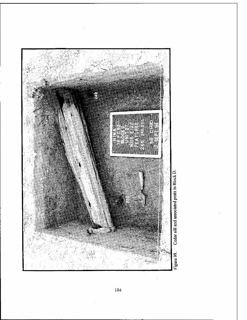
'"***«>£'.." ,/ • ■■■-.. .
o o 3 c
en O Q.
•a
o o CO «
OS
o O
OS ON
3 00
184
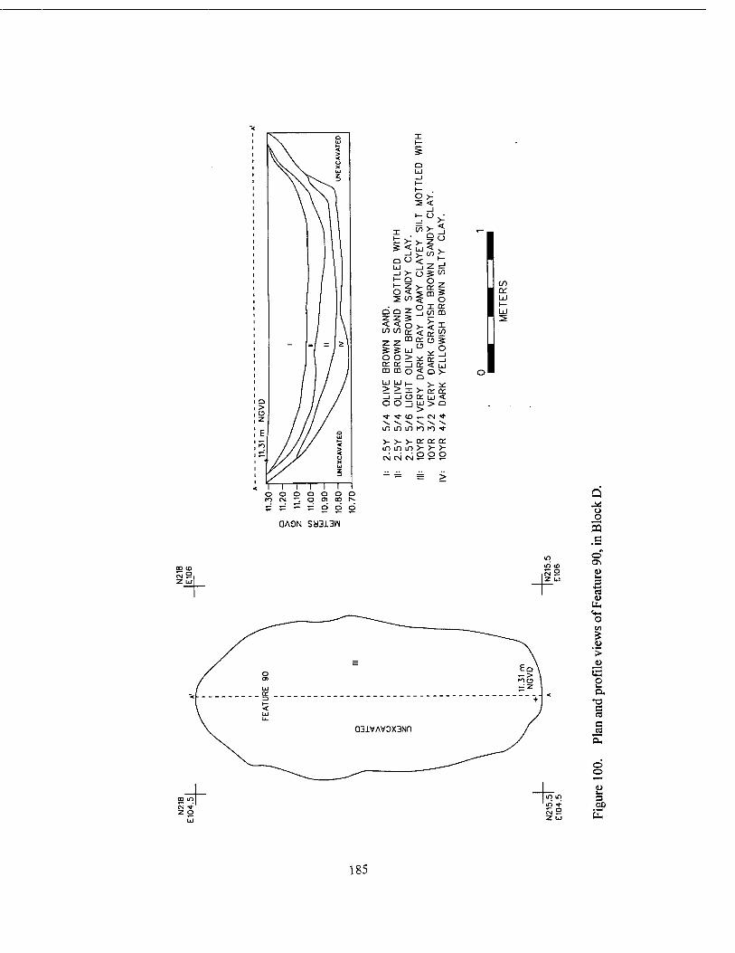
0 iii ... 1 1— i- O V > <
_i 1— () >-
X <s> >- Q 7
< _J
1— >- O * < < >- _i >- <
1
(/I D III
ü 2 _l
_J >- 0 ■S l/J 1- n O
O § < m 5
i Ü) O 0 T rr
O Q z. in m Z Z S < (/) <
to 0 0: < IV
1 10
T 7 tu
0 0 5
=£ % LÜ
IT
0 O O > Y D: a: 1 ir < CD m O <
0 O >
u ÜJ 1— V Y .> -> X >• rr Sr .,..,1 ..j <•) ir iii 0 Ü LÜ > 0 > ■* <■ (O ,_ (N ■* \ ^ ^» \ •v -x in m m ro f) ■*
V V V tr o: en i/i m m >- >- >-
I
I
I
1—1—1—1 1 r 0000000 rn CM 'I o 01 00 I** p ;= — :z o o o
QA3N Sy3i3W
CO ID S2,
Q ^s o o 5 o" ON u Ui 3
■s U-. (4-4 o
'>
O
c ca e CO
o o
3
185
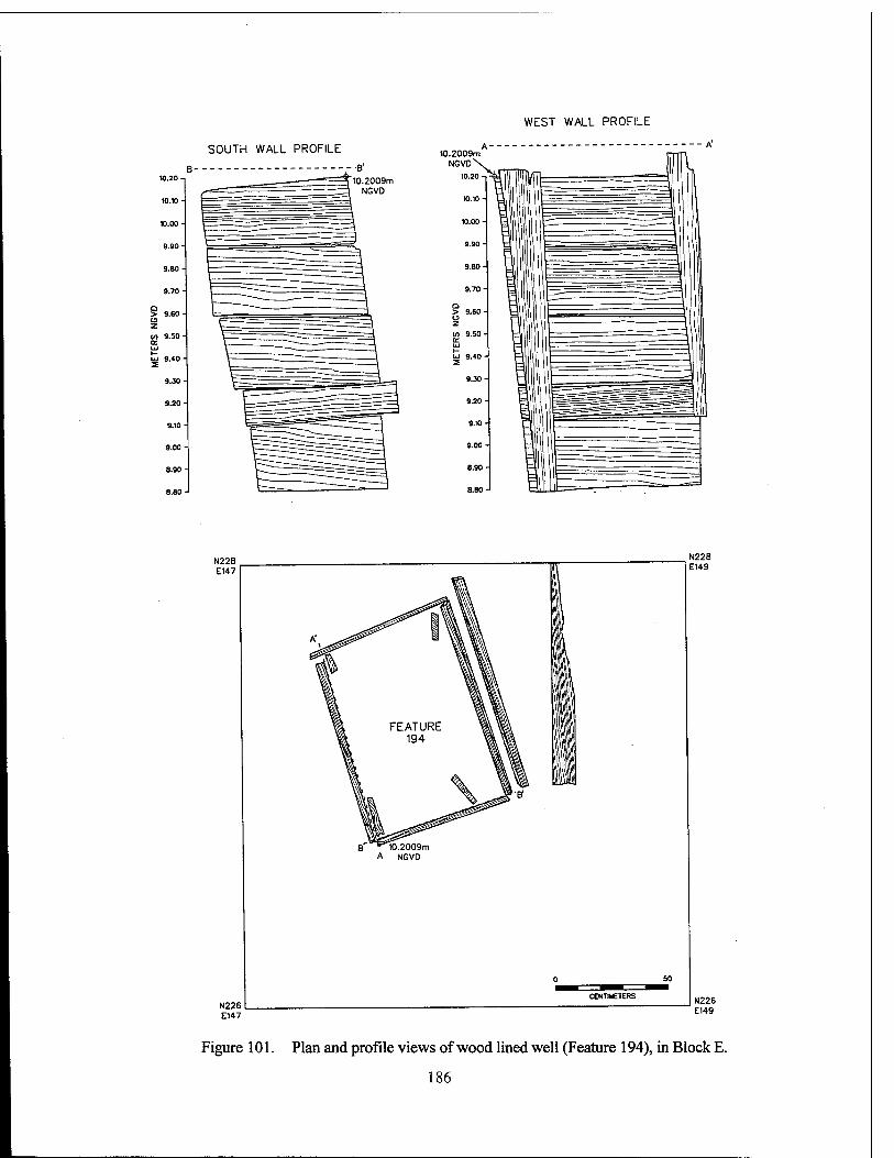
WEST WALL PROFILE
SOUTH WALL PROFILE
10.2009m NGVD
10.2009m NGVD\^
N228 E147
N226 E147
B^ ""M0.2009m A NGVD
N228 E149
N226 E149
Figure 101. Plan and profile views of wood lined well (Feature 194), in Block E.
186
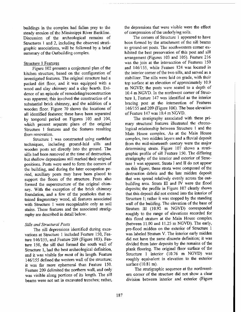
buildings in the complex had fallen prey to the steady erosion of the Mississippi River Bankline. Discussion of the archeological remains of Structures 1 and 2, including the observed strati- graphic associations, will be followed by a brief summary of the Outbuilding complex.
Structure 1 Features Figure 102 presents a conjectural plan of the
kitchen structure, based on the configuration of investigated features. The original structure had a packed dirt floor, and it was equipped with a wood and clay chimney and a clay hearth. Evi- dence of an episode of remodeling/reconstruction was apparent; this involved the construction of a substantial brick chimney, and the addition of a wooden floor. Figure 70 shows the locations of all identified features; these have been separated by temporal period on Figures 103 and 104, which present separate plans of the original Structure 1 features and the features resulting from renovation.
Structure 1 was constructed using earthfast techniques, including ground-laid sills and wooden posts set directly into the ground. The sills had been removed at the time of destruction, but shallow depressions still marked their original positions. Posts were used to form the corners of the building, and during the later occupation pe- riod, auxiliary posts may have been placed to support the floors of the structure. Posts also formed the superstructure of the original chim- ney. With the exception of the brick chimney foundation, and a few of the postholes that re- tained fragmentary wood, all features associated with Structure 1 were recognizable only as soil stains. These features and the associated stratig- raphy are described in detail below.
Sills and Structural Posts The sill depressions identified during exca-
vations at Structure 1 included Feature 150, Fea- ture 146/155, and Feature 209 (Figure 103). Fea- ture 150, the sill that formed the south wall of Structure 1, had the best archeological definition, and it was visible for most of its length. Feature 146/155 defined the western wall of the structure; it was far more ephemeral than Feature 150. Feature 209 delimited the northern wall, and only was visible along portions of its length. The sill beams were not set in excavated trenches; rather,
the depressions that were visible were the effect of compression of the underlying soils.
The corners of Structure 1 appeared to have been formed by the attachment of the sill beams to ground-set posts. The southwestern corner ex- hibited the best preservation of this post and sill arrangement (Figures 103 and 105). Feature 216 was the join at the intersection of Features 150 and 146/155, while Feature 124 was located in the interior corner of the two sills, and served as a stabilizer. The sills were laid on grade, with their top surface at an elevation of approximately 10.9 m NGVD; the posts were seated to a depth of 10.4 m NGVD. In the northwest corner of Struc- ture 1, Feature 147 was identified as the interior bracing post at the intersection of Features 146/155 and 209 (Figure 106). The base elevation of Feature 147 was 10.4 m NGVD.
The stratigraphy associated with these pri- mary structural features illustrated the chrono- logical relationship between Structure 1 and the Main House complex. As at the Main House complex, two midden layers and a fluvial deposit from the mid-nineteenth century were the major determining strata. Figure 107 shows a strati- graphic profile of sill Feature 150. The differing stratigraphy of the interior and exterior of Struc- ture 1 was apparent. Strata I and II do not appear on this figure; these strata were composed of the destruction debris and the late midden deposit that was spread relatively evenly across the out- building area. Strata III and IV were the flood deposits; the profile in Figure 107 clearly shows that this deposit did not extend into the interior of Structure 1; rather it was stopped by the standing wall of the building. The elevation of the base of Stratum III (10.92 m NGVD) corresponded roughly to the range of elevations recorded for this flood stratum at the Main House complex (between 11.00 and 11.25 m NGVD). The early, pre-flood midden on the exterior of Structure 1 was labeled Stratum V. The interior early midden did not have the same discrete definition; it was divided from later deposits by the remains of the plank flooring. The original floor surface of the Structure 1 interior (10.76 m NGVD) was roughly equivalent in elevation to the exterior surface (10.81m).
The stratigraphic sequence at the northwest- ern corner of the structure did not show a clear division between interior and exterior (Figure
187
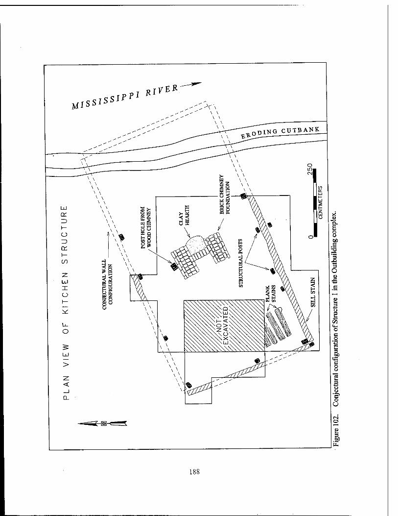
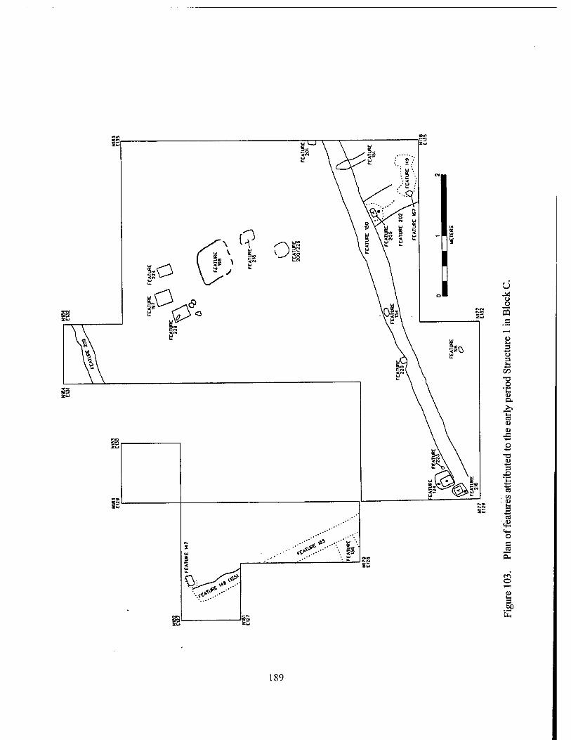
u Ü o 5 c
2 3 o E
■*-»
•o _o 'C o.
.>» W <u u
J3
u
S
c
o
3>
189
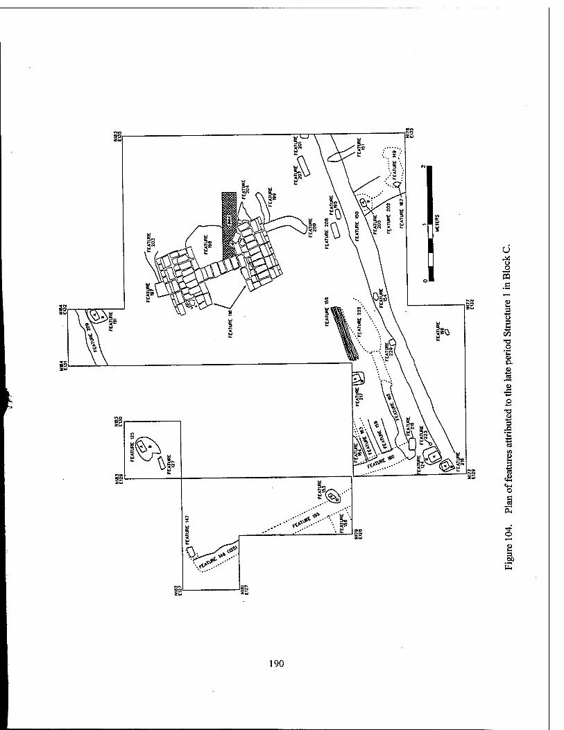
u o o s c
u u 3
■s s
.o u
■ J3
3
«t-C o g
o
3 00
190
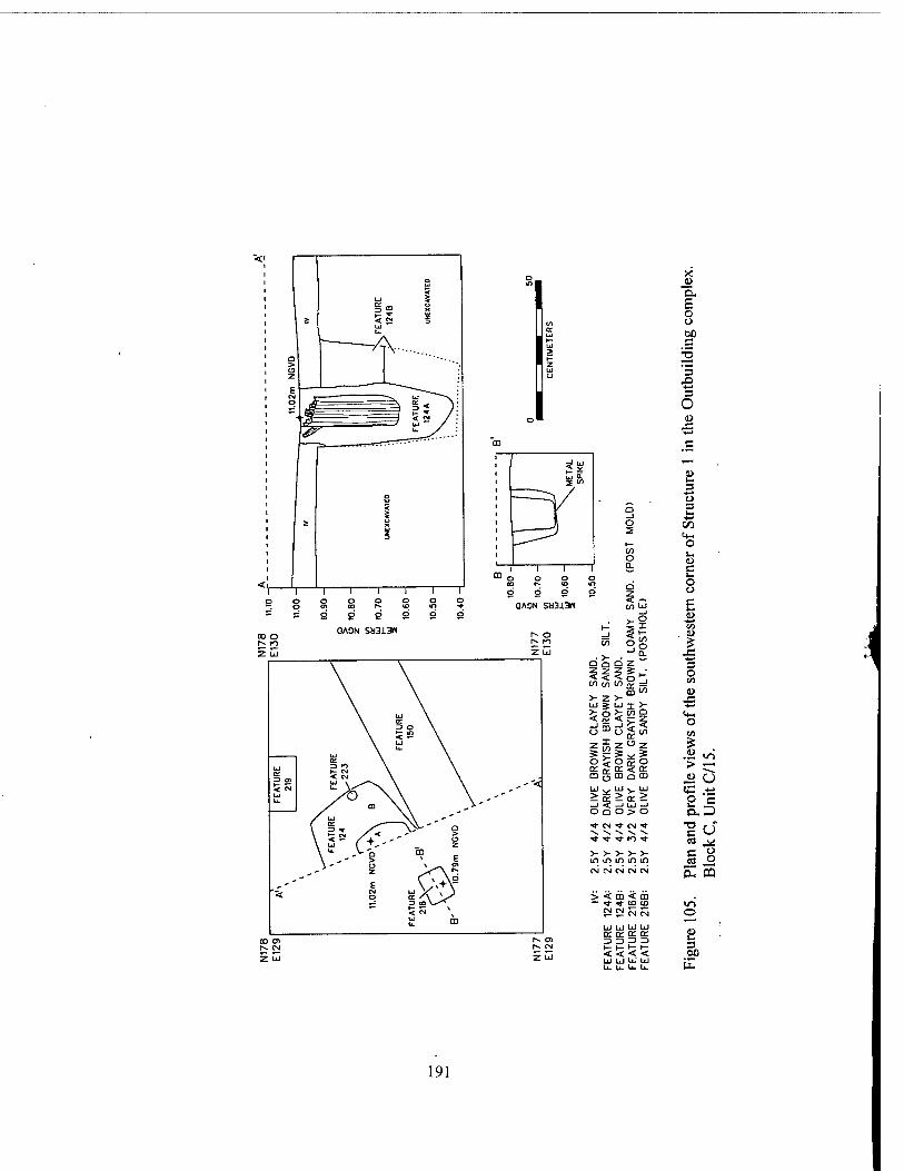
o 2
C/l O a.
</>UJ
1-^ _J en
• >- si O Q n z 3 2 < < 3 o^ (/) en i/>
SS >- z >- uj 5 UJ T > 5° >- in o <
o §3 s: Oz * o m Q UJ UJ > or 2
-i < _i UJ -J o o ü > <-> •«J- CM * CM •* \ -s *N >> ^ •* ■* I" t<") ■*
>- >- V >- >- in if) m if> in CM CM CM CM CM
> < m < m — i- ■* to to
CM CM CM CM
UJ h UJ UJ or ce or or Z) - 3 Z>
i- i- < < < < u li u. U. u. u.
5. £ o o 00 c
3
3 o u
42
s «4-1 o
s o o
u £
•e -*-* 3 O t«
« JE ■4-»
«4- o VI
? 0> ir> > ■—■
a> u «C •4-»
ü c D. D
T3 C O ca jji c o
o O* CQ
O
3 00
191
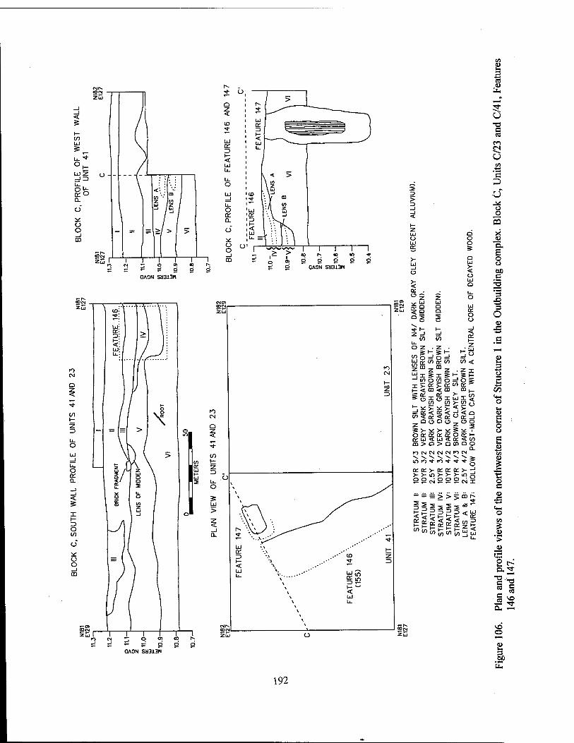
Q
< ID
Ul Crt Z> I— <
O LÜ
o Q.
O
5£ O o _1 CD
0A9N Sa3i3H
OASN Sa3i3N
>
o
o
SS gä g < 9 9 OS S
en L.
s a a>
ÜH r,
^—I 5 O T3 C tf
en JN u M
c D ̂ U ^ o o
03 o X o <u o a.
£ a o >- o < b0 o c uj Q ■o
o 3 J5
O 3 O o o
<! (/) (/)
o z . z
m co
-1 I/) o w
i_ < co <
^ * >- *
a o o S >- *: > o o: « o; o; ui < LJ m > a > fO CM CM CM ^ V. -V V IT) K3 •* IO
o: ce >- or > >- m > 99oi9
in V) <
z . Z x S"-, == t oJo» CD co ,_
luili} \n £ So v < > < rJ <Q or ° o: _i o -, o o :*: S :£ i
< a: 3 co aoQO
0- CM fO CM ^ ^ ^ 3?
en or >- -j >- >- <o o 99CMX
- = = >>5cnt^
w M « £ w S; I u
K) CM ""I O CD CO
s 5: ^ s: g S QAON SM3X3H "
■3 O 3 is 00
o
o
CO a)
i o c o
o en
I >
8 ^
■ J 5g
so o
2 3 60
PH
192
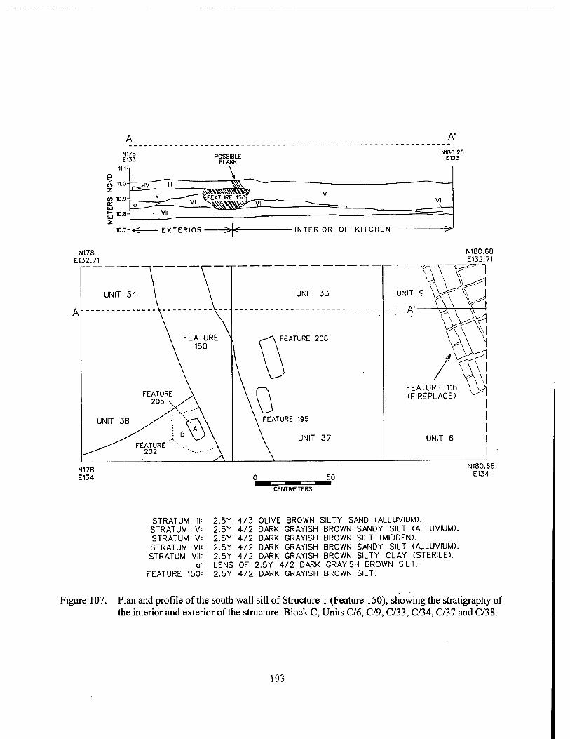
A'
N178 E132.71
N180.68 E132.71
N178 E134 0 50
CENTIMETERS
N180.68 E134
STRATUM III STRATUM IV STRATUM V STRATUM VI STRATUM VII
a FEATURE 150
2.5Y 4/3 OLIVE BROWN SILTY SAND (ALLUVIUM). 2.5Y 4/2 DARK GRAYISH BROWN SANDY SILT (ALLUVIUM). 2.5Y 4/2 DARK GRAYISH BROWN SILT (MIDDEN). 2.5Y 4/2 DARK GRAYISH BROWN SANDY SILT (ALLUVIUM). 2.5Y 4/2 DARK GRAYISH BROWN SILTY CLAY (STERILE). LENS OF 2.5Y 4/2 DARK GRAYISH BROWN SILT. 2.5Y 4/2 DARK GRAYISH BROWN SILT.
Figure 107. Plan and profile of the south wall sill of Structure 1 (Feature 150), showing the stratigraphy of the interior and exterior of the structure. Block C, Units C/6, C/9, C/33, C/34, C/37 and C/38.
193
106). The evidence of the east-west sill beam (Feature 146) was ephemeral, and the soils in the immediate vicinity showed some mixing, possi- bly during destruction, when the sill beams were removed. The flood deposit appeared as Stratum III, but it clearly had suffered disturbance during destruction. The depression from the structural sill (Feature 146) was clearest at elevations be- tween 10.85 and 11.0 m NGVD, within the nearly sterile Stratum VI.
Chimney Features Prior to the construction of the central brick
chimney foundation (Feature 116), Structure 1 had been equipped with a simple chimney and hearth constructed of wood and clay, with a clay hearth (Feature 198). Removal of the majority of Feature 116 revealed the configuration of the features associated with this early hearth and chimney (Figure 103). The five identified posts (Features 197, 224, 229, 218, and 234) that formed most of the framework of the early chim- ney measured approximately 19 x 23 cm (7.5 x 9 in), and were seated at an elevation of approxi- mately 10.45 m NGVD, or 28.6 cm (11.24 in) below the contemporary ground surface (Figure 108). It is likely that a third post was present on the south side of the hearth, corresponding to Feature 229. Centrally placed between these wooden uprights was a packed clay hearth (Fea- ture 198) that exhibited intensive fire-reddening, and that contained abundant charcoal inclusions (Figure 103). Burned and calcined bone, ceram- ics, and glass were recovered from the surface of this feature. The early chimney probably was constructed with clay infill; while few discrete fragments of this material were recovered during excavation, the fill of Feature 197 contained quantities of burned clay, and much of the central area of the Structure 1 was covered by a layer of deteriorated daub.
The brick chimney foundation (Feature 116) (Figures 104, 109, and 110) sat directly on top of the remains of the earlier hearth and chimney. Constructed of reused bricks, many broken and mismatched, the fireplace foundation measured approximately 2 m (6.56 ft) north to south, and each wing was 1.14 x 0.67 m (3.7 x 2.2 ft) in di- mension.
During excavation, the underlying hearth (Feature 198) and portions of an earlier posthole (Feature 197) were visible underneath Feature 116. The northern half of the brick foundation was removed systematically to expose the early chimney features. Four profiles of the northern part of Feature 116 were drawn prior to its re- moval (Figure 111). Additionally, profiles were drawn of the soil balk that ran through the central portion of Feature 116 (Figure 112). These illus- trated the stratigraphic relationships between the brick chimney and the surrounding soils.
Figure 111 clearly illustrates the nature of the brick used in the construction of Feature 116. Three to four courses of brick remained after de- struction, and all courses exhibited broken and mismatched construction materials. The brick foundation was constructed directly on top of the early hearth, Feature 198. Stratum III lay directly above the earliest occupation level; it consisted of the deteriorated clay infill of the early chimney. The surface of Stratum III, in areas where the weight of Feature 116 had not compacted it, was extremely uneven and undulating. This deposit contained small amounts of brick, mortar, and charcoal, and those areas directly above the hearth (Feature 198) contained bone, shell, glass, and a ceramic sherd.. Beneath this deposit, the surfaces of posthole Features 197, 224, and 229 were exposed.
Figure 110 shows the stratigraphic sequence, from construction to destruction, in the central chimney area of Structure 1. The late midden and destruction debris was designated as Stratum II, and demonstrated a great deal of mixing. The clay infill layer, Stratum III was located below this midden deposit, and below Feature 116; these soils also filled Feature 218, the posthole from the earlier wood and clay chimney. Stratum VII was a sterile, dark gray silty deposit that may have filled areas next to the post.
Plank Flooring Features Originally, the floor of Structure 1 was a
packed dirt or clay surface, visible only as a thin, discontinuous, 2 - 3 cm (0.78 - 1.18 in) thick lens, at a typical elevation ranging from 10.95 to 10.97 m NGVD (level 5 of Units 33 and 34). This lens had a high ash content; the small amount of de-
194
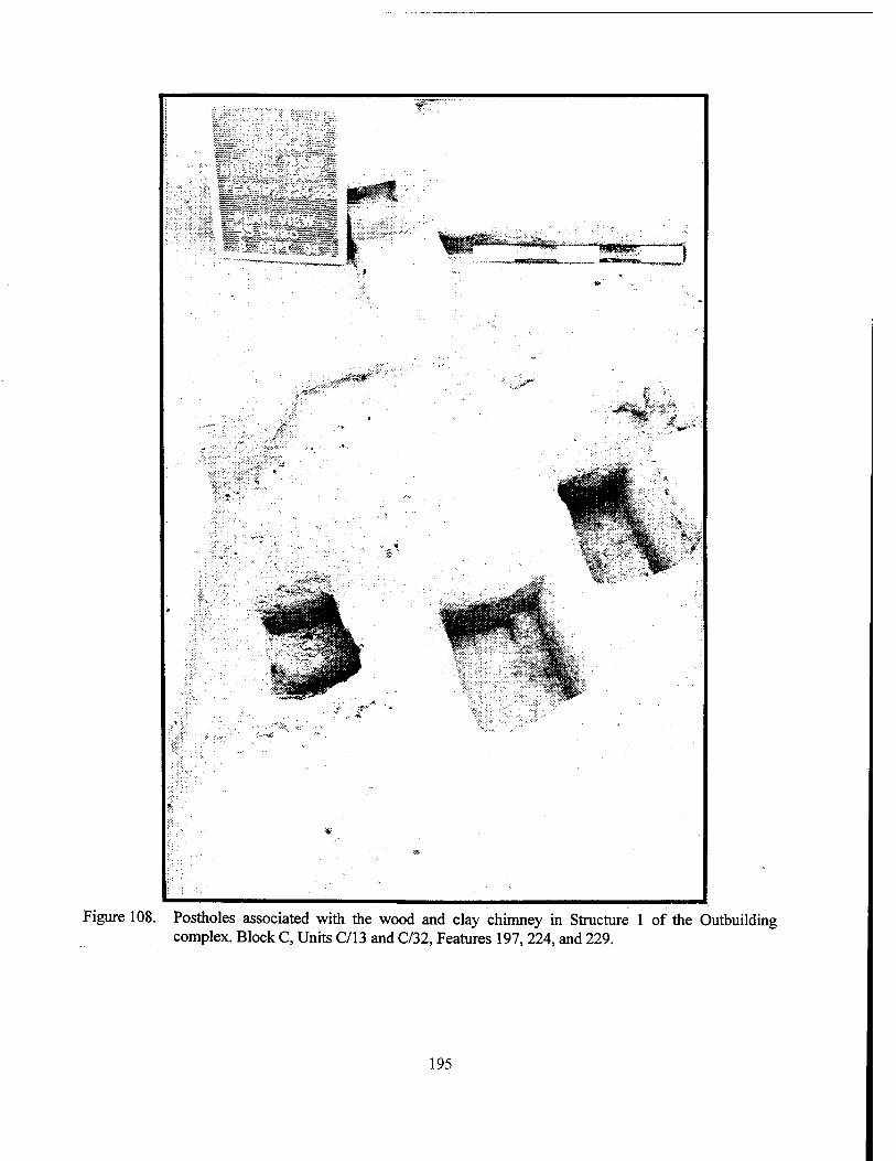
'. *
w
Figure 108. Postholes associated with the wood and clay chimney in Structure 1 of the Outbuilding complex. Block C, Units C/13 and C/32, Features 197,224, and 229.
195
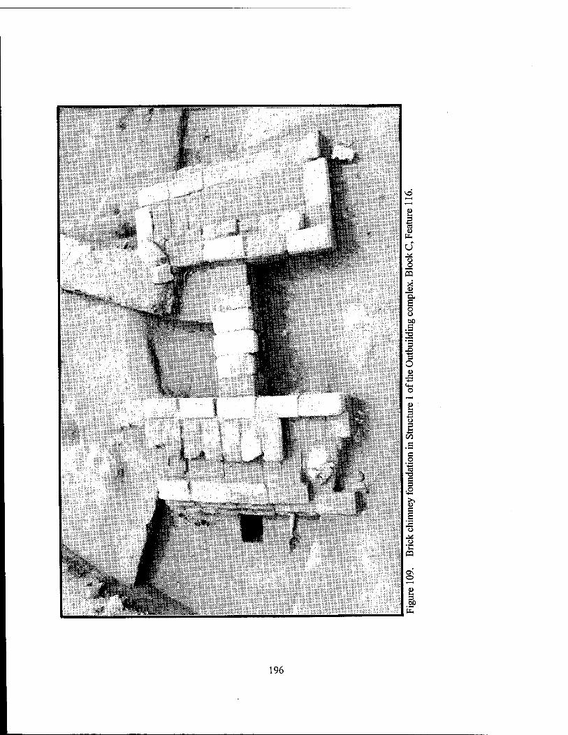
^o
i O u o s
o u M s
=S
S O o
o
<Z> .g c o
'■§ s 3
«s
'C 03
o
s
196
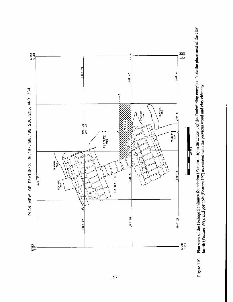
ä> 197
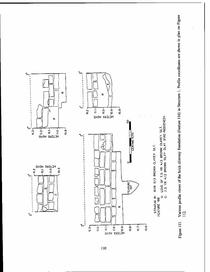
"Vg
QAON Sb313W
OAON Sb313W CM — O
.!_■. I up
fl£J Tsl
OAON SU313K
1 z . Q
t- Q _J UJ
m K >- o
2UJ
10 d
2 s 60
E s o c
"n. ,g c o
2 es CO
I c
o o
p
2 3 o
c
>o
O w S o
UJ
1 I-'
5~ ■5 a 3
UJ o
_J CO
o > tu H- CQ _i
£ >- UJ >- < _) o z
e £ u
s >- &■ o m X) 0£ in CD ": h-> o
r» v. .a
o Cfl
p
3 O
QAON SH313N
*2 > -
2 3 60
198
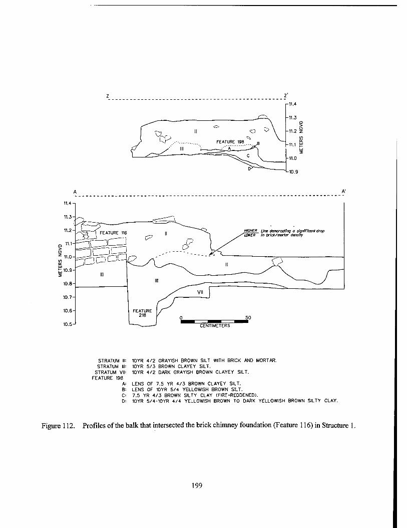
CENTIMETERS
STRATUM II STRATUM III
STRATUM VII FEATURE 198
A: B C D
10YR 4/2 GRAYISH BROWN SILT WITH BRICK AND MORTAR. 10YR 5/3 BROWN CLAYEY SILT. 10YR 4/2 DARK GRAYISH BROWN CLAYEY SILT.
LENS OF 7.5 YR 4/3 BROWN CLAYEY SILT. LENS OF 10YR 5/4 YELLOWISH BROWN SILT. 7.5 YR 4/3 BROWN SILTY CLAY (FIRE-REDDENED). 10YR 5/4-10YR 4/4 YELLOWISH BROWN TO DARK YELLOWISH BROWN SILTY CLAY.
Figure 112. Profiles of the balk that intersected the brick chimney foundation (Feature 116) in Structure
199
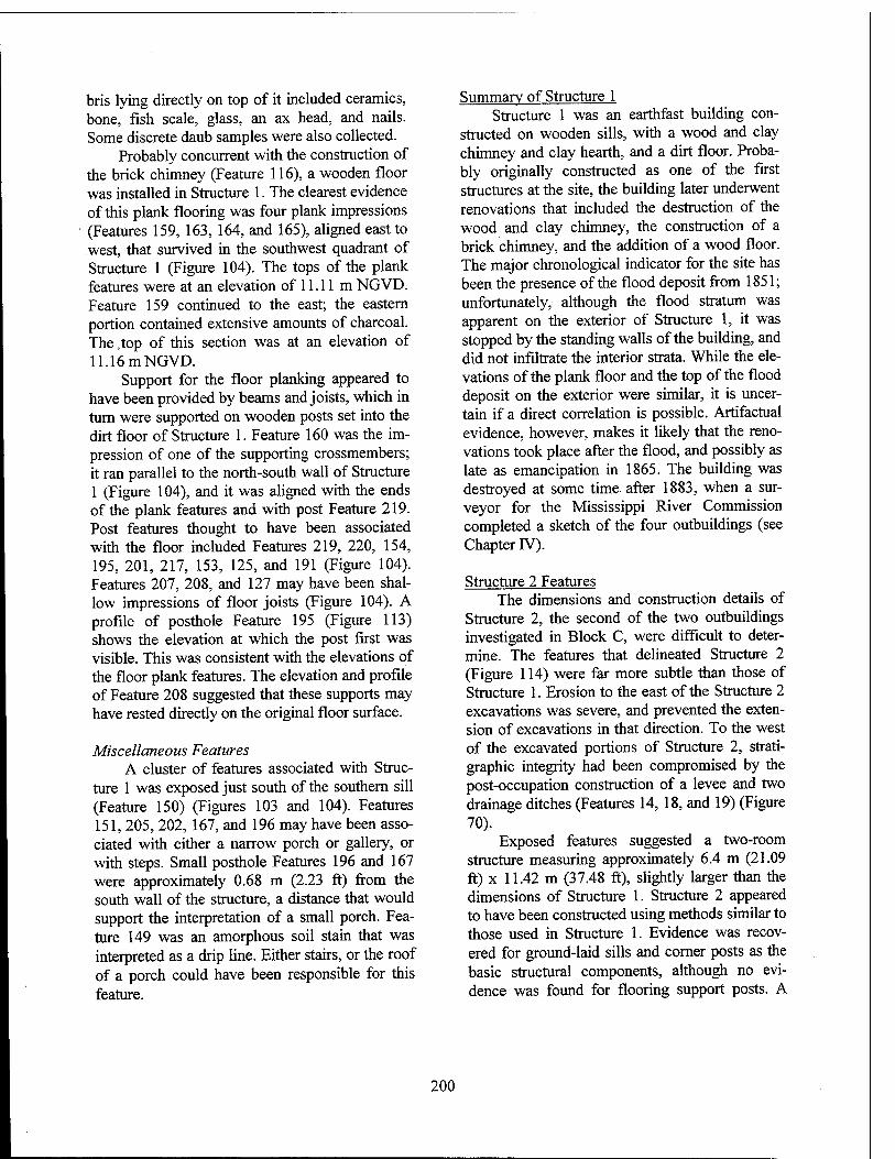
bris lying directly on top of it included ceramics, bone, fish scale, glass, an ax head, and nails. Some discrete daub samples were also collected.
Probably concurrent with the construction of the brick chimney (Feature 116), a wooden floor was installed in Structure 1. The clearest evidence of this plank flooring was four plank impressions (Features 159, 163, 164, and 165), aligned east to west, that survived in the southwest quadrant of Structure 1 (Figure 104). The tops of the plank features were at an elevation of 11.11 m NGVD. Feature 159 continued to the east; the eastern portion contained extensive amounts of charcoal. The .top of this section was at an elevation of 11.16 m NGVD.
Support for the floor planking appeared to have been provided by beams and joists, which in turn were supported on wooden posts set into the dirt floor of Structure 1. Feature 160 was the im- pression of one of the supporting crossmembers; it ran parallel to the north-south wall of Structure 1 (Figure 104), and it was aligned with the ends of the plank features and with post Feature 219. Post features thought to have been associated with the floor included Features 219, 220, 154, 195, 201, 217, 153, 125, and 191 (Figure 104). Features 207, 208, and 127 may have been shal- low impressions of floor joists (Figure 104). A profile of posthole Feature 195 (Figure 113) shows the elevation at which the post first was visible. This was consistent with the elevations of the floor plank features. The elevation and profile of Feature 208 suggested that these supports may have rested directly on the original floor surface.
Miscellaneous Features A cluster of features associated with Struc-
ture 1 was exposed just south of the southern sill (Feature 150) (Figures 103 and 104). Features 151, 205, 202, 167, and 196 may have been asso- ciated with either a narrow porch or gallery, or with steps. Small posthole Features 196 and 167 were approximately 0.68 m (2.23 ft) from the south wall of the structure, a distance that would support the interpretation of a small porch. Fea- ture 149 was an amorphous soil stain that was interpreted as a drip line. Either stairs, or the roof of a porch could have been responsible for this feature.
Summary of Structure 1 Structure 1 was an earthfast building con-
structed on wooden sills, with a wood and clay chimney and clay hearth, and a dirt floor. Proba- bly originally constructed as one of the first structures at the site, the building later underwent renovations that included the destruction of the wood and clay chimney, the construction of a brick chimney, and the addition of a wood floor. The major chronological indicator for the site has been the presence of the flood deposit from 1851; unfortunately, although the flood stratum was apparent on the exterior of Structure 1, it was stopped by the standing walls of the building, and did not infiltrate the interior strata. While the ele- vations of the plank floor and the top of the flood deposit on the exterior were similar, it is uncer- tain if a direct correlation is possible. Artifactual evidence, however, makes it likely that the reno- vations took place after the flood, and possibly as late as emancipation in 1865. The building was destroyed at some time- after 1883, when a sur- veyor for the Mississippi River Commission completed a sketch of the four outbuildings (see Chapter IV).
Structure 2 Features The dimensions and construction details of
Structure 2, the second of the two outbuildings investigated in Block C, were difficult to deter- mine. The features that delineated Structure 2 (Figure 114) were far more subtle than those of Structure 1. Erosion to the east of the Structure 2 excavations was severe, and prevented the exten- sion of excavations in that direction. To the west of the excavated portions of Structure 2, strati- graphic integrity had been compromised by the post-occupation construction of a levee and two drainage ditches (Features 14, 18, and 19) (Figure 70).
Exposed features suggested a two-room structure measuring approximately 6.4 m (21.09 ft) x 11.42 m (37.48 ft), slightly larger than the dimensions of Structure 1. Structure 2 appeared to have been constructed using methods similar to those used in Structure 1. Evidence was recov- ered for ground-laid sills and corner posts as the basic structural components, although no evi- dence was found for flooring support posts. A
200
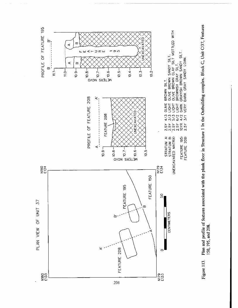
a: Z> I— < LÜ
O LÜ
o a.
00
no
' < )m V\X/00\/v) X/y UJ y \ /Vvi- v
L. uj < i— r> rr uj «- G) in LüAy /AX y/\
_^r\^iiJ X /
[< [-{888^ XX,DX/
1 II 1 1 1 i 1
>-
6 CO
Ö d ID d d d d
CM
d
QAON S8313IM
oo O CM
CC
< Ld
U- o Q_
xx; Q <X
o IX /< CN V-yX
XXX w XX 'v^ x x i- < X s/S/S/ < Yv /\/\/x> Xx
LiJ 1 )X QC*^\ Y X
\X\X\/< S/V 3 / fy yv/v/ x \/v < (7\/ \/\/\/z \/V iij rs/v X>\>\ 3 X> Ü. l/VX
1 1 1 1 1
Q UJ
CO =J I/)
>- Q > Z < < _) (/) o
. Z Z •"■ 5 S
=! O O W Q; or
mm 5 u UJ o>> rr _i _i moo LiJ I— I— I— v- s_ > i i i ce C O _i _i _j Q >
fo rn m (M IN «- "V V. ^ \ \ V •tn in IO ■* io
<r U) in >-
o V ^r < or
T
5 O
m
< in
>- < (/I
<n rr
Z o
# V V u < rr It rr < UJ o O
d cq d d
ID d
in d
OAON Scd313W
zuj
>- V V >- or >- m m m in >- m CN CM CM CM y CM
< CO X in oo CD o
2 Sh *"" CM 3 3 < UJ i , 1-1-2 < < *£ rr Q: Q
<< I- I- UJ in in |_ < > < o
O)* X r^ rn UJ zu z
3
p
ca
c D U
o o 5
"5. £ o o 00 c
3 JD ■*-»
3 o JS
_c i- o o
53
C JS "E. U
X!
u o
t*- o 00 (l> o
8 CN
c o. « TJ in C 0\ ea
c o" in
OH
ß 3) E
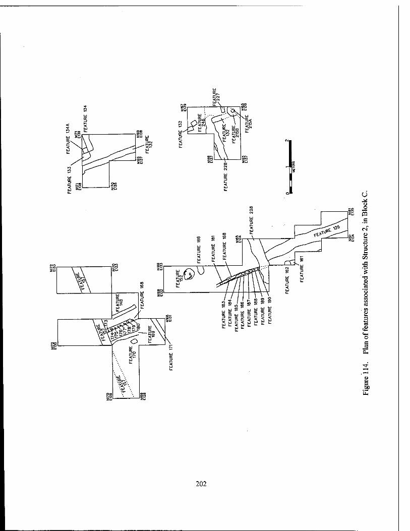
a o 5 .c ri '8 3 o s 00 J3
o o to i/i ce
. en 8 i o s w
2P
202
central, north - south partition wall was con- structed usingpiquette en terre construction. This consisted of a shallow trench, with small stakes driven directly into the ground within the trench (Features 168, and 174-190) (Figure 115). There was no evidence of a central chimney or hearth, although a small circular firepit (Feature 152) was identified near the presumed center of the struc- ture.
Sill and Post Features The five identified sill features (Features
157, 228, 132, 133, and 134) were similar to those in Structure 1, but in most cases they were not as well defined. Feature 132 showed the clearest definition (Figure 116). Running from north to south, Feature 132 defined the presumed eastern wall of Structure 2. Approximately 20 cm (7.87 in) in width, Feature 132 was an average of only 12 cm (4.72 in) in depth. Morphologically, Features 133 and 134 were similar to Feature 132, although their alignment is problematic. They may have been part of an unidentified addition to Structure 2. Unfortunately, erosion of the river bankline was so severe in this part of the site that all stratigraphic evidence to the east had been lost.
The stratigraphic sequence associated with Features 132, 133, and 134 is shown in Figure 116. Stratum I consisted of post-occupational riv- erine deposits, and Stratum II was the sheet mid- den deposit that covered much of the occupied portions of Block C. This deposit included a high density of cultural material from the destruction of the outbuildings, and from the late occupation period at the site. Stratum IE was the late midden deposit temporally associated with the second half of the nineteenth century; artifact density was moderate, with ceramics, nails, a tobacco pipe, and burned bone present in the deposit. Stratum rV was that the alluvial deposit representing the flood event of 1851; no artifacts were recovered from this deposit. Feature 132 was visible at the interface between Strata III and rV as a dark stain, with a mottling of alluvial silt. The elevation at this interface ranged between 10.95 m NGVD and 11.0 m NGVD. Stratum V was the early midden deposit, predating the flood event. Arti- fact density was moderate; nails, glass, ceramics, a large quantity of bone (n=50), and a glass bead
were recovered. Stratum VI was sterile soil, and represented the base of the occupational sequence
Feature 157, a sill feature defining the pre- sumed northern wall of Structure 2, was ex- tremely indistinct, and in many places it was ap- parent only in the profile of the excavation unit. Figure 117 shows the placement of Feature 157 within the stratigraphic sequence, and the con- jectural plan of this feature based on this data. This position was in alignment with the more visible portions of the feature further to the east (Figure 114). It also was consistent with the ele- vations of sill features in both Structure 1 and Structure 2 (10.95 m NGVD).
Feature 228 defined the southern boundary of Structure 2 (Figure 118). The area surrounding this sill feature sustained substantial disturbance when the sill was removed, although the depres- sion from the beam could be discerned. Feature 228 ran from west to east, connecting with Fea- ture 132 at the presumed southeastern corner of Structure 2 (Figure 114).. The sill depression ranged in elevation from 10.75 to 10.95 m NGVD. The associated stratigraphic sequence included a high density midden (Stratum II), overlying a stratum consisting of alluvium from the mid-century flood that had been churned and mixed with midden debris (Stratum III and Ilia). The sill depression was filled with a mixture of soils from both the flood layer and the preflood midden (Stratum IV). Stratum V was the transi- tional soil between the early midden and the ster- ile subsoil. The configuration and the fill of Fea- ture 228, in contrast to Features 132 -134, indi- cated that the sill beam from Feature 228 had been removed, while the Feature 132-134 beams remained in place after destruction.
Intersecting with Feature 228 was the piquette en terre partition wall (Features 168, and 173 - 190) (Figure 118). This very shallow, nar- row trench was approximately 14.8 cm (5.8 in) in width, and 12 cm (4.7 in) in depth. The stake holes within the trench were of varying sizes, but averaged 9 cm (3.5 in) in diameter. The surface of the feature was exposed at an elevation of 11.02 m NGVD within Stratum III, the layer most closely attributable to the mid-century flood. There was some mixing of midden soil with this stratum. The trench and post feature continued into Stratum TV, a more compact midden deposit
203
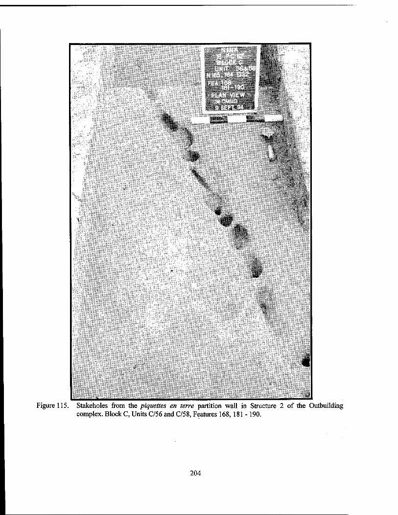
II
iiiitli
Figure 115. Stokeholes from the piquettes en terre partition wall in Structure 2 of the Outbuilding complex. Block C, Units C/56 and C/58, Features 168,181 -190.
204
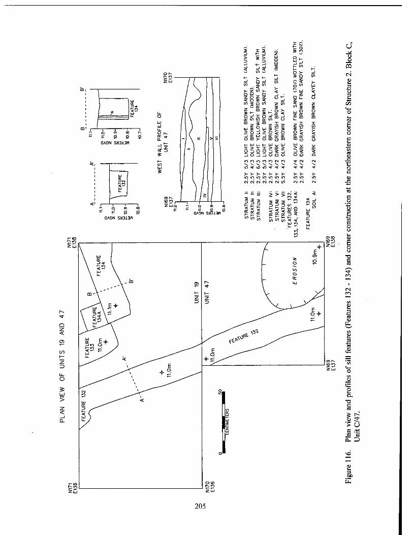
~ s" 9 9 QAON SM313W
2 12 ~ 3 1-13 Z > * > ^ -> I ' =
(/> 55 z c/>
1 Ü
>- <
z in
Sis* I|I OSO <z a. a: CD Q CD
Bi5 O O O
K) ro K) TO ro CM fO V >. V. N. V. v, s in •*■ to in •**■ ■* •*
in in in ir> in in io CNJ CN <N <N oi CNJ C/S
>- z w V O UJ o
i" 5 o f> z " m z
m z s m
> o d > _J ce uj _i O CD >- O
X > X X O _j O O _l O _i _i
X : t , S '
O V 3 O
lz UJ O
9 < or cc o
O O
>- >- m m
z S o
I
o
QAON Stf3i3n '
is. > > > <N < — ^ ro «*■
OAON SM313rN
S ? 2 "- M •* _J 2 ö
ID => 2 => </) i- t i- UJ Q < < < CtJ ct
0^ ? 3 < a.
3 t- t 1- r- - cn <" c/i < ■* <
UJ li-
UJ fO U- —
IO to "~ en
<r>
u o o 5
3 o S
■4-'
<+- O
O
es U
X! •c o c
c ,o o 2
■4-*
C o o i_ ID E o o
T3 C ca
i
eö
—. or-- iDro Zu o
en <D
IC O UH
D. -a c 03
> u c .ts « c
ft- D
3
205
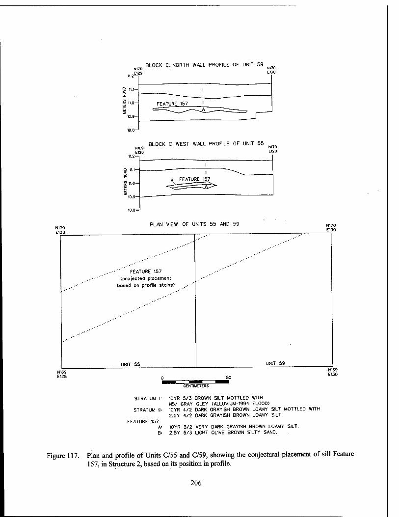
BLOCK C, NORTH WALL PROFILE OF UNIT 59 ki„n N170 N,7°
112E129 E'30
9 11.1—
BLOCK C, WEST WALL PROFILE OF UNIT 55 N169 N17° E128 E128
11.2—1
10.9-
I
B FEATURE 157
N170 E128
N169 E128
PLAN VIEW OF UNITS 55 AND 59 N170 E130
FEATURE 157
(projected placement
based on profile stains)
UNIT 55 UNIT 59
50
N169 E130
CENTIMETERS
STRATUM |:
STRATUM II:
FEATURE 157 A= B:
10YR 5/3 BROWN SILT MOTTLED WITH N5/ GRAY GLEY (ALLUVIUM-1994 FLOOD) 10YR 4/2 DARK GRAYISH BROWN LOAMY SILT MOTTLED WITH 2.5Y 4/2 DARK GRAYISH BROWN LOAMY SILT.
10YR 3/2 VERY DARK GRAYISH BROWN LOAMY SILT. 2.5Y 5/3 LIGHT OLIVE BROWN SILTY SAND.
Figure 117. Plan and profile of Units C/55 and C/59, showing the conjectural placement of sill Feature 157, in Structure 2, based on its position in profile.
206
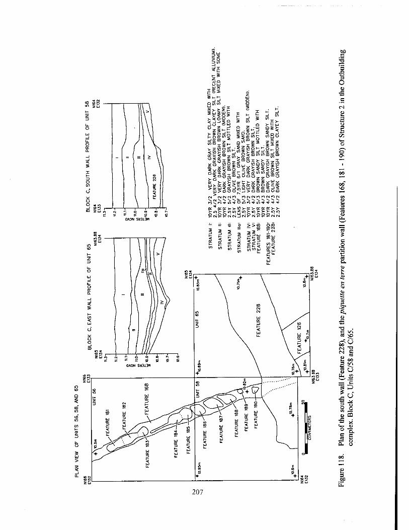
5° _) *z z UJ Q uu UJ X
0(/) in
£§g*| =!or CD •*
<in>:or ^ O < OT _ £
oor.<or_ >-D <2. or >-*:>-! UJ>- or or < >or u< a.
U>DO
CM CM CM CN S CM ^ ""* ^ ro ^ PO *■ in
or "* or or > >- in >- >- m
=! in in
x>- >-1 UJ SSV 3
a
si So o
SS
d" m So
.Jf-J
3 or ">£ Sm ° in Z2
»inoi-, o$mmwm=!
_i<ö:in
t>-*SS*
^ c\ -1
=Jor[]or
Ol/ltl/l ??*5
es53c S01 I? o Uu < or _j>ommaua KlCMCMKllOCMIOCM
CJAON SM31311
>-<5>-or>-orororw m z, in >-m >->■>-Kl in oiycM9cM°°ecsicv;
z 3
o s UJ
>
c
3 X) 3 o 4)
U
s
C/j
t«—I o
00 so
B C8 (L>
ÜH
« £ c o •i-t
•c C3 &, «i
O *t S K>2 S*.
z « c tu <u w S &< ö. <u
J3 ■*-»
■o C <0 C8 VO
00 _ CN 32
c oo B IC
oo 00 K)
2 u *o uj z — c
S D £ •> Js" "§ » 9 o u PQ
J3 *- X <+- <D
° a C3 S ;r o 0- u
3 00
h
207
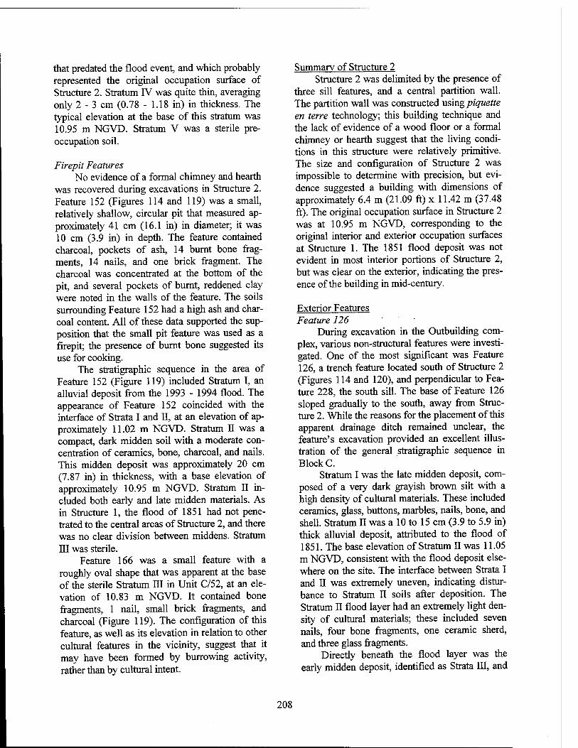
that predated the flood event, and which probably represented the original occupation surface of Structure 2. Stratum IV was quite thin, averaging only 2 - 3 cm (0.78 - 1.18 in) in thickness. The typical elevation at the base of this stratum was 10.95 m NGVD. Stratum V was a sterile pre- occupation soil.
Firepit Features No evidence of a formal chimney and hearth
was recovered during excavations in Structure 2. Feature 152 (Figures 114 and 119) was a small, relatively shallow, circular pit that measured ap- proximately 41 cm (16.1 in) in diameter; it was 10 cm (3.9 in) in depth. The feature contained charcoal, pockets of ash, 14 burnt bone frag- ments, 14 nails, and one brick fragment. The charcoal was concentrated at the bottom of the pit, and several pockets of burnt, reddened clay were noted in the walls of the feature. The soils surrounding Feature 152 had a high ash and char- coal content. All of these data supported the sup- position that the small pit feature was used as a firepit; the presence of burnt bone suggested its use for cooking.
The stratigraphic sequence in the area of Feature 152 (Figure 119) included Stratum I, an alluvial deposit from the 1993 - 1994 flood. The appearance of Feature 152 coincided with the interface of Strata I and II, at an elevation of ap- proximately 11.02 m NGVD. Stratum II was a compact, dark midden soil with a moderate con- centration of ceramics, bone, charcoal, and nails. This midden deposit was approximately 20 cm (7.87 in) in thickness, with a base elevation of approximately 10.95 m NGVD. Stratum II in- cluded both early and late midden materials. As in Structure 1, the flood of 1851 had not pene- trated to the central areas of Structure 2, and there was no clear division between middens. Stratum III was sterile.
Feature 166 was a small feature with a roughly oval shape that was apparent at the base of the sterile Stratum III in Unit C/52, at an ele- vation of 10.83 m NGVD. It contained bone fragments, 1 nail, small brick fragments, and charcoal (Figure 119). The configuration of this feature, as well as its elevation in relation to other cultural features in the vicinity, suggest that it may have been formed by burrowing activity, rather than by cultural intent.
Summary of Structure 2 Structure 2 was delimited by the presence of
three sill features, and a central partition wall. The partition wall was constructed using piquette en terre technology; this building technique and the lack of evidence of a wood floor or a formal chimney or hearth suggest that the living condi- tions in this structure were relatively primitive. The size and configuration of Structure 2 was impossible to determine with precision, but evi- dence suggested a building with dimensions of approximately 6.4 m (21.09 ft) x 11.42 m (37.48 ft). The original occupation surface in Structure 2 was at 10.95 m NGVD, corresponding to the original interior and exterior occupation surfaces at Structure 1. The 1851 flood deposit was not evident in most interior portions of Structure 2, but was clear on the exterior, indicating the pres- ence of the building in mid-century.
Exterior Features Feature 126
During excavation in the Outbuilding com- plex, various non-structural features were investi- gated. One of the most significant was Feature 126, a trench feature located south of Structure 2 (Figures 114 and 120), and perpendicular to Fea- ture 228, the south sill. The base of Feature 126 sloped gradually to the south, away from Struc- ture 2. While the reasons for the placement of this apparent drainage ditch remained unclear, the feature's excavation provided an excellent illus- tration of the general stratigraphic sequence in Block C.
Stratum I was the late midden deposit, com- posed of a very dark grayish brown silt with a high density of cultural materials. These included ceramics, glass, buttons, marbles, nails, bone, and shell. Stratum II was a 10 to 15 cm (3.9 to 5.9 in) thick alluvial deposit, attributed to the flood of 1851. The base elevation of Stratum II was 11.05 m NGVD, consistent with the flood deposit else- where on the site. The interface between Strata I and II was extremely uneven, indicating distur- bance to Stratum II soils after deposition. The Stratum II flood layer had an extremely light den- sity of cultural materials; these included seven nails, four bone fragments, one ceramic sherd, and three glass fragments.
Directly beneath the flood layer was the early midden deposit, identified as Strata III, and
208
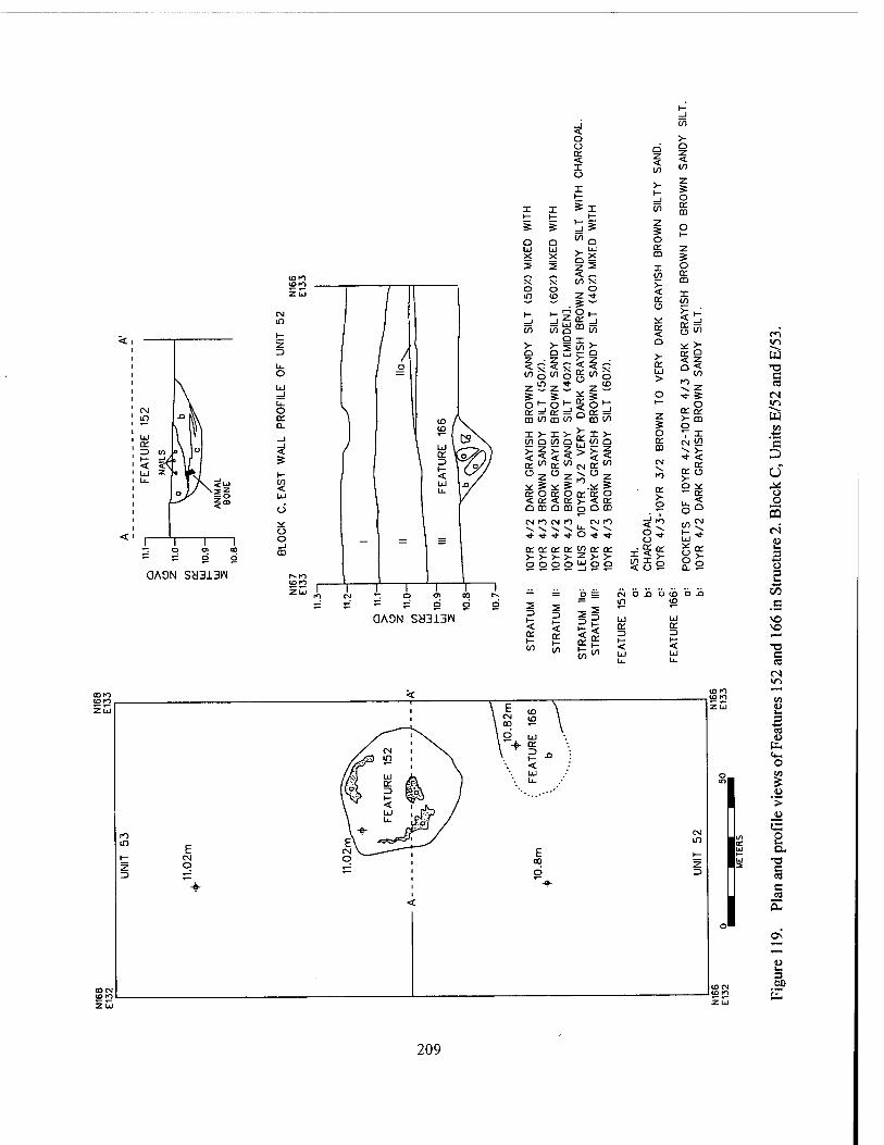
QAON saaiaw
QAON ScJ313N
31 CO
o >- c_> o * § I o CO CO
X >- z 5
1— _1 o I X *x (O or
CD 1— l- 1-
s s ^9 z 5 o
O
Q O "'n 1—
liJ LJ z X X 5 2 2 T i I o ^ ^ < — CO or X X CO X
5 cc o
o o o m ID z ■*
s " CO
SIL
T
SIL
T i—i
z Q
mcö C£ gK >- >- Qx V O * £
N
SA
ND
(5
0>
0.
N
SA
ND
X o
§1 a: co o .. 2
X o CO
>- ÜJ > CO
Cz s s ,f =e o •o- 5 o *-, o et =! a:
I— _) z erg
CD CO CD co (/) o I >- X V V o T I CO O CO
$5$ o Q cc
CO CN <2 X >- •* < £<"£ CO CM or CO
X EC o 2 o 2 x o z >- ^s^ Ä #
>- o
o * S£$ Ü
rv ?5 Ü re si o m a m OÜB
CM K) CM fl CM in <x> f- ii: x V.
■*•>!••>*■ ■o- u .* ■>*■ !„* ce ce ce tr co ce CC
35° g°= >->->- >- z >- >-
ooo o LJ o
Ö ==
o
— =r CM Di> U CO O .D m <o
ST
RA
TU
M
ST
RA
TU
M
II m"1
LU
\- < ÜJ
ce
< Ld
ro m E 1- CM z O =) TZ
E co b
J
c«-> in W ■a c
CB fN >/->
W en +-»
"5 P
o _o
CQ
c4 u i-i
3 u 5
4-» C/J
_c
vO
-O c CM »n
es
O
>
a a. c c3 c C8
OS
60
209
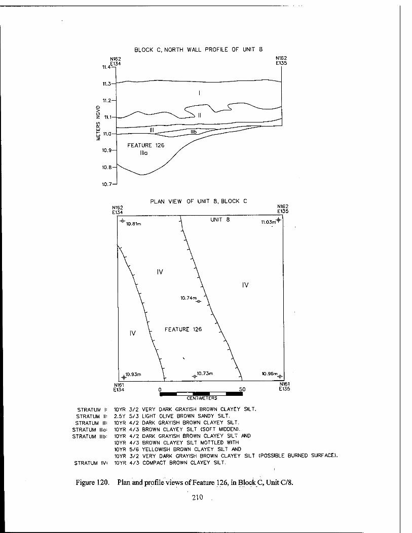
BLOCK C, NORTH WALL PROFILE OF UNIT 8
N162
11.Ä34
11.3--
11.2- o >
11.1
cc Ld
11.0-
10.9-
10.8
10.7-1
PLAN VIEW OF UNIT 8, BLOCK C N162 E134
N162 E135
10.81m UNIT 8
,10.93m
11.03ml
IV
10.74m
FEATURE 126
, 10.73m 10.96m ,
N161 E134
STRATUM I 10YR
STRATUM II 2.5Y
STRATUM III 10YR
STRATUM lllo 10YR
STRATUM lllb 10 YR 10 YR 10YR 10YR
STRATUM IV 10YR
50 N161 E135
CENTIMETERS
3/2 VERY DARK GRAYISH BROWN CLAYEY SILT. 5/3 LIGHT OLIVE BROWN SANDY SILT. 4/2 DARK GRAYISH BROWN CLAYEY SILT. 4/3 BROWN CLAYEY SILT (SOFT MIDDEN). 4/2 DARK GRAYISH BROWN CLAYEY SILT AND 4/3 BROWN CLAYEY SILT MOTTLED WITH 5/6 YELLOWISH BROWN CLAYEY SILT AND 3/2 VERY DARK GRAYISH BROWN CLAYEY SILT (POSSIBLE BURNED SURFACE). 4/3 COMPACT BROWN CLAYEY SILT.
Figure 120. Plan and profile views of Feature 126, in Block C, Unit C/8.
210 .
nib. The trench was apparent at 11 m NGVD; it was filled with early debris. This trench fill was designated Stratum Ilia. Stratum III contained a high density of artifacts, including ceramics, glass, large quantities of bone (n=165), fish scale, nails, small brick fragments, and charcoal. Stra- tum Mb covered the central and western portions of the unit, at an elevation of 11.0 m NGVD, di- rectly on top of the fill of Feature 126. Stratum Illb consisted of a level area of fire-reddened soil with ash and charcoal. Stratum Ilia, the fill of Feature 126, was indistinguishable from Stratum III soils, but was excavated separately. It con- tained a high density of cultural materials of the same nature as those recovered from Stratum III.
Features 232 -236 Unit C/63 was excavated midway between
Structures 1 and 2; its excavation was intended to aid in characterization of the soils between the two structures, and possibly to identify any activ- ity loci in what may have been a centralized yard area (Figures 70, 121, and 122). The stratigraphy in Unit C/63 corresponded to the general pattern observed elsewhere on the site. Two profiles are shown in Figure 121. In these, Stratum I was the 1993-1994 flood deposit, showing some distur- bance in the west wall. Stratum II was the late midden deposit, with a high density of cultural materials including nails, bone, glass, ceramics, buttons, and miscellaneous domestic items. Stra- tum III was the alluvium deposited during the 1851 flood; it displayed the same uneven inter- face with Stratum II as was seen in Unit C/8 (Feature 126). Strata IV and V were both early midden deposits, although there was a slight variation in soil color. The density in this deposit was low to moderate, with bone, ceramics, glass, nails, and a stoneware pipe bowl recovered. Be- low Stratum V, at an elevation of 10.9 to 10.95 m NGVD, was a hard-packed surface containing ash and charcoal This lens, labeled Feature 239, was discontinuous, although it covered approximately two thirds of the unit. The elevation and mor- phology of Feature 239 was consistent with the original occupation surface in the Outbuilding complex.
Four posthole or pit features and a linear feature (Features 232 - 236) were investigated in Unit C/63 (Figure 122). All of these were visible at the interface between Strata II and III, associ-
ating them with the later, post-1851 occupation period. All were filled with an olive brown silt soil similar to that of Stratum III, suggesting that they were filled at the time of the flood, or shortly after. Only Feature 233 contained artifacts; these consisted of a light density of ceramics, nails, bone, glass, and a button. The purpose of these postholes and other features was not readily ap- parent, but it was assumed that they were related to activities in the yard between the outbuildings.
Features 1-6 Cartographic evidence indicated that the
Outbuilding complex formerly comprised four structures, two of which had been lost to erosion of the Mississippi River bankline. During bank- line survey of Block C, a complex of six features was identified; these may have been either the remains of a third structure in the Outbuilding Complex, or the remains of a drainage system. Units C/l, C/2, and C/3 (Figures 66, 70, and 123) were established to investigate these features. Unfortunately, erosion was active in the area, and significant slumping of the deposits already had taken place. Features 1 and 3 (Figure 123) were composed of brick in course, although their origi- nal configuration could not be determined. These features flanked Feature 2, a wide, shallow ditch that measured approximately 0.8 m (2.62 ft) in width and 22 cm (8.66 in) in depth (Figure 124). The fill in Feature 2 was a gray midden soil that appeared to correspond to the early midden in the rest of the Outbuilding complex. Because of slumping in these units, the surrounding stratigra- phy and elevations could not be used to correlate this deposit. Cultural materials recovered from the midden deposit included ceramics, nails, glass, buttons, bone, eggshell, and brick and mortar fragments. Features 4 and 5 (Figure 123) were investigated and determined to be natural erosional channels.
Feature 6 was a small posthole, measuring approximately 25 cm (9.8 in) in diameter (Figures 123 and 124). Bisection of the feature revealed a core of decayed wood. The fill in the post was similar to the midden deposit located in Feature 2.
Unassociated Features Four post-occupational features also were
identified during excavations in Block C (Figure 70). Features 14, 18, and 19 were relics of a low
211
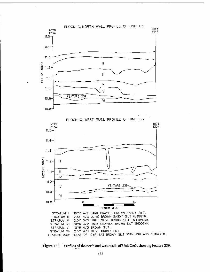
BLOCK C, NORTH WALL PROFILE OF UNIT 63 N176 E134
11.5
N176 E135
10.8
BLOCK C, WEST WALL PROFILE OF UNIT 63 N176 E134
STRATUM STRATUM II STRATUM III STRATUM IV STRATUM V STRATUM VI
FEATURE 239
CENTIMETERS
10YR 4/2 DARK GRAYISH BROWN SANDY SILT. 2.5Y 4/3 OLIVE BROWN SANDY SILT (MIDDEN). 2.5Y 5/3 LIGHT OLIVE BROWN SILT (ALLUVIUM). 10YR 4/2 DARK GRAYISH BROWN SILT (MIDDEN). 10YR 4/3 BROWN SILT. 2.5Y 4/3 OLIVE BROWN SILT. LENS OF 10YR 4/3 BROWN SILT WITH ASH AND CHARCOAL.
Figure 121. Profiles of the north and west walls of Unit C/63, showing Feature 239.
212
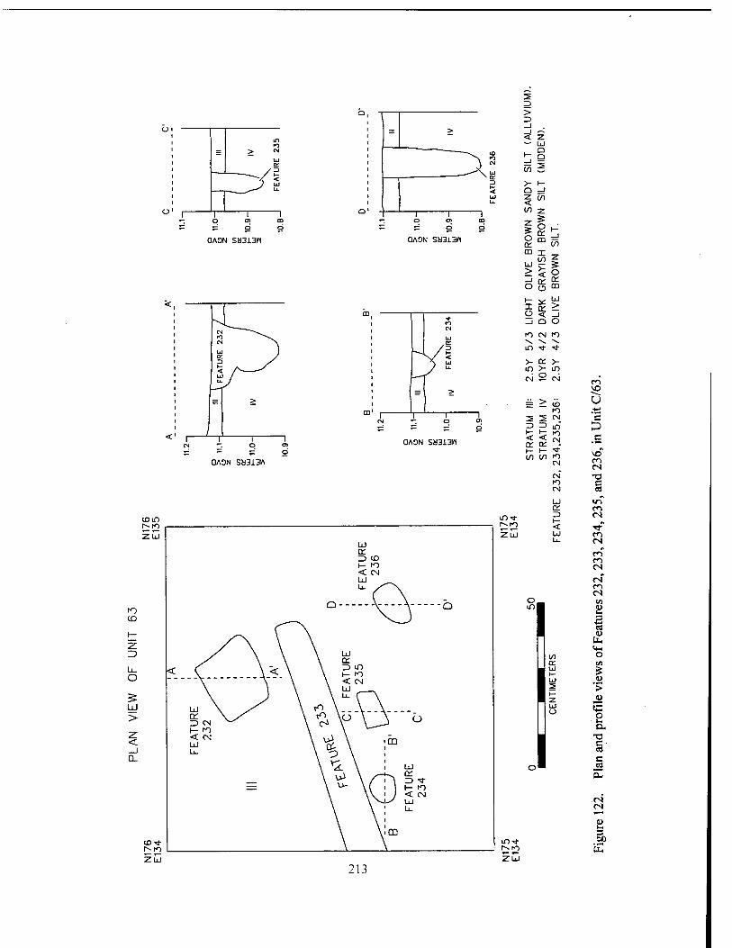
CJADN Sa313lt
Z5 _l
= > _l < z
A (0
CM
UJ
1— —1
Lü Q Q
2
3 >- h- < Q _l UJ Z in u. <
to Z i *- O Ol 00 Z
=s o or CD
•£■ 5= != O
OAON SH313H
o Ü or m _J
in
z UJ
< 5 > o
_i or o
or o m
i— i o or
UJ > i i < _J '
tn _J Q o CN
UJ to CM to V. v. V.
/=> in ■* ■*
^ / *Z \ UJ >- or >- / u. in >- in
CM ü CM co ; B > VO
: = > (J6 u to
r> ■=>
QAON SM313W
QA9N SM313W
< < CM or or -J- I- H- ■* (/) (/l to
CM
CM to CM
or Z3
1 I
I
' s p a
VO eo CN •o e es
v~t eo es
CO es CO CO es of CO es
CO
u
Cd o or cn UJ £ Ul 0> 2 > i— z d> Ul o p
a .T3 c- c i2
es es
3
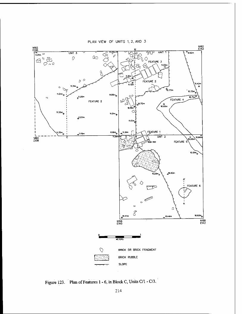
PLAN VIEW OF UNITS 1, 2, AND 3
N162 E138
UNIT 3
0
■C Ü n.Um-M
<3° V ÖO -a u FEATURE
^ BRICK OR BRICK FRAGMENT
~^ BRICK RUBBLE
SLOPE
Figure 123. Plan of Features 1 - 6, in Block C, Units C/l - C/3.
214
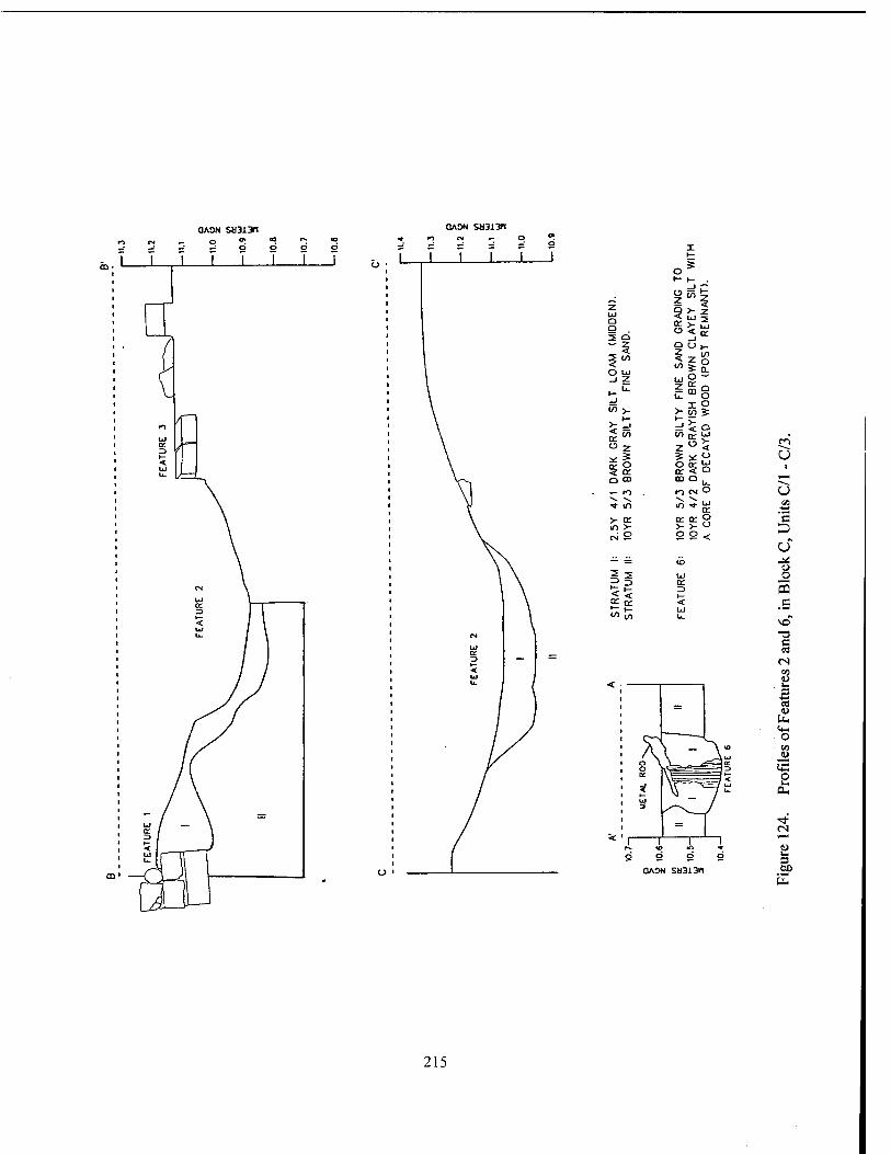
QAON SJJ313H
J I
O o
O u) _1 2
£ o O CD
< < 2 S
i
§5)5 9 >- z < LJ -5
<-> < Q;
< Z o
u. O I O
>-(/>£ S^o z " <
mo.
o= or p
Q: 3
o o o 5 so •o c 03
us
u fa o
o 3^ ^3 >~ P
UJ 2
^ - ff? Ul
PH
= 1 1 1 1 * P 9 g o O 3
QAOI A SH313M GO fa
215
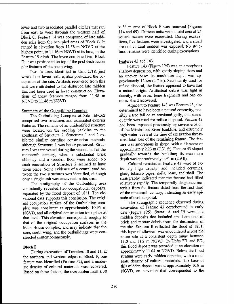
levee and two associated parallel ditches that ran from east to west through the western half of Block C. Feature 14 was composed of late mid- den soils from the occupied areas of Block C. It ranged in elevation from 11.58 m NGVD at the highest point, to 11.16 m NGVD at its base, in the Feature 19 ditch. The levee continued into Block D; it was positioned on top of the post-destruction pier features of the south wing.
Two features identified in Unit C/18, just west of the levee feature, also post-dated the oc- cupation of the site. Artifacts recovered from this unit were attributed to the disturbed late midden that had been used in levee construction. Eleva- tions of these features ranged from 11.58 m NGVD to 11.46 m NGVD.
Summary of the Outbuilding Complex The Outbuilding Complex at Site 16PC62
comprised two structures and associated exterior features. The remains of an unidentified structure were located on the eroding bankline to the southeast of Structure 2. Structures 1 and 2 ex- hibited similar earthfast construction methods, although Structure 1 was better preserved. Struc- ture 1 was renovated during the second half of the nineteenth century, when a substantial brick chimney and a wooden floor were added. No such renovation of Structure 2 seemed to have taken place. Some evidence of a central yard be- tween the two structures was identified, although only a single unit was excavated in this area.
The stratigraphy of the Outbuilding area consistently revealed two occupational deposits, separated by the flood deposit of 1851. The ele- vational data supports this conclusion. The origi- nal occupation surface of the Outbuilding com- plex was consistent at approximately 10.95 m NGVD, and all original construction took place at that level. This elevation corresponds roughly to that of the original occupation surfaces in the Main House complex, and may indicate that the core, south wing, and the outbuildings were con- structed contemporaneously.
Block F During excavation of Trenches 10 and 11, at
the northern and western edges of Block F, one feature was identified (Feature 52), and a moder- ate density of cultural materials was recovered. Based on these factors, the overburden from a 30
x 36 m area of Block F was removed (Figures 114 and 69). Thirteen units with a total area of 24 square meters were excavated. During excava- tions, five features were investigated, and a small area of cultural midden was exposed. No struc- tural remains were identified during excavations.
Features 43 and 143 Feature 143 (Figure 125) was an amorphous
shallow depression, with gently sloping sides and an uneven base; its maximum depth was ap- proximately 12 cm (4.7 in). Secondarily used for refuse disposal, the feature appeared to have had a natural origin. Artifactual debris was light in density, with seven bone fragments and one ce- ramic sherd recovered.
Adjacent to Feature 143 was Feature 43, also determined to have been a natural concavity, pos- sibly a tree fall or an erosional gully, that subse- quently was used for refuse disposal. Feature 43 had been impacted previously by severe erosion of the Mississippi River bankline, and extremely high water levels at the time of excavation threat- ened total loss of the remaining feature. The fea- ture was amorphous in shape, with a diameter of approximately 2.23 m (7.31 ft). Feature 43 sloped gradually towards the bankline; its maximum depth was approximately 0.91 m (2.9 ft).
Cultural remains in Feature 43 were of ex- tremely high density, and included ceramics, glass, tobacco pipes, nails, bone, and shell. The stratigraphy indicated that the feature had filled relatively rapidly. The temporally diagnostic ma- terials from the feature dated from the first third of the nineteenth century, indicating an early epi- sode of trash disposal.
The stratigraphic sequence observed during excavation of Feature 43 corroborated its early date (Figure 125). Strata IA and IB were late midden deposits that included small amounts of brick and mortar debris from the destruction of the site. Stratum II reflected the flood of 1851; this layer of alluvium was encountered across the entire site at a consistent depth range between 11.0 and 11.2 m NGVD. In Units F/l and F/2, this flood deposit was recorded at an elevation of approximately 11.04 m NGVD. Below the flood stratum were early midden deposits, with a mod- erate density of cultural materials. The base of this midden deposit was at approximately 10.9 m NGVD, an elevation that corresponded to the
216
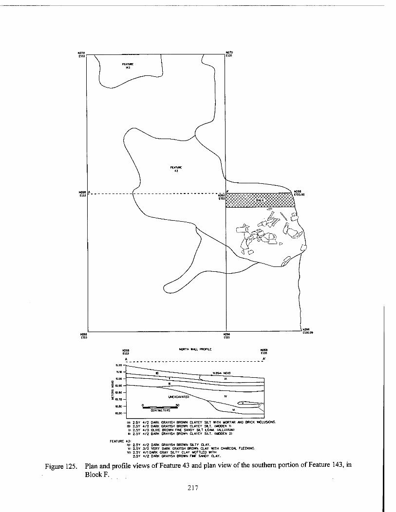
NORTH WALL PROFILE N260 EUS
I* 2.5Y 4/2 DARK GRAYISH BROWN CLAYEY SILT WITH MORTAR AND BRICK INCLUSIONS. IB" 2.5Y 4/2 DARK GRAYISH BROWN CLAYEY SIT. (UDOEN 1)
IM 2.5Y 4/3 OLIVE BROWN FINE SANDY SIT LOAM. (ALLUVIUM) ■: 2.5Y 4/2 DARK GRAYISH BROWN CLAYEY SILT. (MIDOEN 2)
FEATURE 43: IV: 2.5Y 4/2 DARK GRAYISH BROWN SILTY CLAY. V: 2.SY 3/2 VERY DARK GRAYISH BROWN CLAY WITH CHARCOAL FLECKING. VI: 2.5Y 4/1 DARK GRAY SILTY CLAY MOTTLED WITH
2.5Y 4/2 DARK GRAYISH BROWN Fl£ SANDY CLAY.
Figure 125. Plan and profile views of Feature 43 and plan view of the southern portion of Feature 143, in Block F.
217
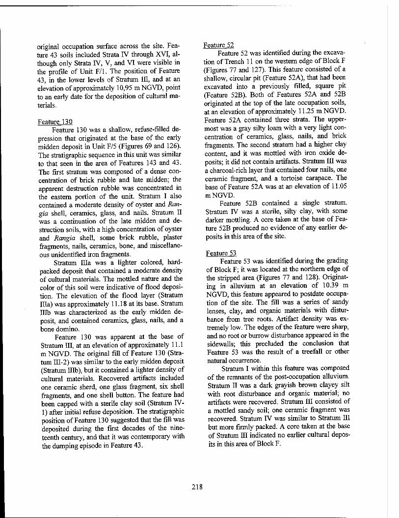
original occupation surface across the site. Fea- ture 43 soils included Strata IV through XVI, al- though only Strata IV, V, and VI were visible in the profile of Unit F/l. The position of Feature 43, in the lower levels of Stratum III, and at an elevation of approximately 10,95 m NGVD, point to an early date for the deposition of cultural ma- terials.
Feature 130 Feature 130 was a shallow, refuse-filled de-
pression that originated at the base of the early midden deposit in Unit F/5 (Figures 69 and 126). The stratigraphic sequence in this unit was similar to that seen in the area of Features 143 and 43. The first stratum was composed of a dense con- centration of brick rubble and late midden; the apparent destruction rubble was concentrated in the eastern portion of the unit. Stratum I also contained a moderate density of oyster and Ran- gia shell, ceramics, glass, and nails. Stratum II was a continuation of the late midden and de- struction soils, with a high concentration of oyster and Rangia shell, some brick rubble, plaster fragments, nails, ceramics, bone, and miscellane- ous unidentified iron fragments.
Stratum Ilia was a lighter colored, hard- packed deposit that contained a moderate density of cultural materials. The mottled nature and the color of this soil were indicative of flood deposi- tion. The elevation of the flood layer (Stratum Ilia) was approximately 11.18 at its base. Stratum Illb was characterized as the early midden de- posit, and contained ceramics, glass, nails, and a bone domino.
Feature 130 was apparent at the base of Stratum III, at an elevation of approximately 11.1 m NGVD. The original fill of Feature 130 (Stra- tum III-2) was similar to the early midden deposit (Stratum Illb), but it contained a lighter density of cultural materials. Recovered artifacts included one ceramic sherd, one glass fragment, six shell fragments, and one shell button. The feature had been capped with a sterile clay soil (Stratum IV- 1) after initial refuse deposition. The stratigraphic position of Feature 130 suggested that the fill was deposited during the first decades of the nine- teenth century, and that it was contemporary with the dumping episode in Feature 43.
Feature 52 Feature 52 was identified during the excava-
tion of Trench 11 on the western edge of Block F (Figures 77 and 127). This feature consisted of a shallow, circular pit (Feature 52A), that had been excavated into a previously filled, square pit (Feature 52B). Both of Features 52A and 52B originated at the top of the late occupation soils, at an elevation of approximately 11.25 m NGVD. Feature 52A contained three strata. The upper- most was a gray silty loam with a very light con- centration of ceramics, glass, nails, and brick fragments. The second stratum had a higher clay content, and it was mottled with iron oxide de- posits; it did not contain artifacts. Stratum III was a charcoal-rich layer that contained four nails, one ceramic fragment, and a tortoise carapace. The base of Feature 52A was at an elevation of 11.05 mNGVD.
Feature 52B contained a single stratum. Stratum IV was a sterile, silty clay, with some darker mottling. A core taken at the base of Fea- ture 52B produced no evidence of any earlier de- posits in this area of the site.
Feature 53 Feature 53 was identified during the grading
of Block F; it was located at the northern edge of the stripped area (Figures 77 and 128). Originat- ing in alluvium at an elevation of 10.39 m NGVD, this feature appeared to postdate occupa- tion of the site. The fill was a series of sandy lenses, clay, and organic materials with distur- bance from tree roots. Artifact density was ex- tremely low. The edges of the feature were sharp, and no root or burrow disturbance appeared in the sidewalls; this precluded the conclusion that Feature 53 was the result of a treefall or other natural occurrence.
Stratum I within this feature was composed of the remnants of the post-occupation alluvium. Stratum II was a dark grayish brown clayey silt with root disturbance and organic material; no artifacts were recovered. Stratum III consisted of a mottled sandy soil; one ceramic fragment was recovered. Stratum F/ was similar to Stratum III but more firmly packed. A core taken at the base of Stratum III indicated no earlier cultural depos- its in this area of Block F.
218
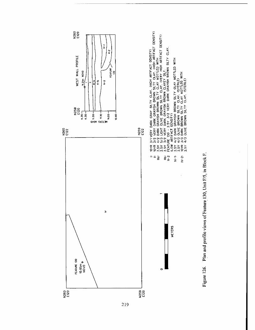
QAON SM313H
5 £ UJ !/> o z
•- ° v- ?< r, < tfe S d <" t u. ?,?iF >- I
FAC
T D
(H
IGH
LE
D
WIT
H
IGH
AR
T.
WN
SIL
T i- S Q UJ _J
1- v i- . JU 1- X DC < *- >~ Tjn K 5 Ü o cc "' m
1- 1-
UJ _ UJ O 2 w v. I > ?". I
üv>--^!2 >--S=> lK/<> < or ^J a: — _! -1 >- _j <
£0 O < o OC Ut-h1"
5 z v ° z .. (/) o ■"
TY
C
L B
RO
W
N
SIL
T S
ILT
Y
BR
OW
D
ARK
N
SIL
T C
LAY
. C
LAY
C
LAY
.
AY
S
IL
RA
YIS
H
BR
OW
R
OW
N
RA
YIS
H
2 V
ER
>
BR
OW
S
ILT
Y
SIL
TY
S
ILT
Y
DAR
K G
R
DA
RK
G
GR
AY
ISH
O
LIV
E
E D
AR
K
G
2.5
Y
3/
DE
NS
ITY
G
RA
YIS
H
BR
OW
N
BR
OW
N
BR
OW
N
1 V
ER
Y
2 V
ER
Y
2 D
AR
K
3 LI
GH
T 2
VE
RY
13
0 -
i-
AR
K
LIV
E
AR
K
LIV
E
1—
5 o o o o CM fO ro K)
-v ^ ^ V. ^ UJ \ \ v. v. K) K> ■«*- IT) ro cc * ■*■ IT*
or cc >- >- >- t? >->-ininifi,,l
s >■ >- <r > o m m >- m
S=: 5= CM CM CM L_ _i CM CM 9 CM
- = 6 B ? Y CM — — = > >
I
I
I
fa ü
_o CQ _c
in fa
'c D o
i fa O c/j
0»
'>
ta p
c c
M3
3 60
219
WEST WALL PROFILE
11.00
N259 E100
N259 E101
N257.75 E100
FEATURE 52A
N257.75 E101
|: 10YR 5/1 GRAY SILTY LOAM. (LOW ARTIFACT DENSITY) II: 10YR 5/6 YELLOWISH BROWN SILTY CLAY MOTTLED WITH
IRON OXIDE AND SOME BRICK FLECKING. Ill: 10YR 3/1 VERY DARK GRAY, CHARCOAL RICH, SILTY LOAM.
(MODERATE ARTIFACT DENSITY) FEATURE 52B
IV: 10YR 5/6 YELLOWISH BROWN SILTY CLAY. (STERILE)
Figure 127. Plan and profile views of Features 52 A and 52 B, in Block F.
220
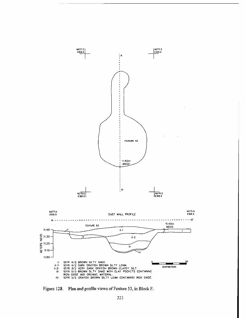
N277.5 E108.0
N277.5 E109.0
N275.5 EW8.0
N27S.5 E109.0
N277.5 E108.5 EAST WALL PROFILE
N275.5 E108.5
11.40 —i
11.00
11-1 II-2
10YR 4/3 BROWN SILTY SAND. 10YR 4/2 DARK GRAYISH BROWN SILTY LOAM. 10YR 3/2 VERY DARK GRAYISH BROWN CLAYEY SILT. 10YR 5/3 BROWN SILTY SAND WITH CLAY POCKETS CONTAINING IRON OXIDE AND ORGANIC MATERIAL. 10YR 5/2 GRAYISH BROWN SILTY LOAM CONTAINING IRON OXIDE.
11.40m NGVD
X
CENTIMETERS
Figure 128. Plan and profile views of Feature 53, in Block F.
221
Summary of Block F Features 43, 143, and 130 all represented
episodes of secondary refuse deposition during the first decades of occupation at Nina Plantation. Feature 52 appeared to date to the latest occupa- tion period at the site; its original purpose is un- known. Feature 53 was a post-occupation feature of an unidentified nature. No structural features were identified in Block F, and no extensive areas of midden were located. In general, Block F ap- peared to have been used only for secondary ref- use disposal during the earliest occupation peri- ods at the site.
Trenches In addition to block and feature excavations,
seventeen archeological trenches were excavated during Phase III investigations at Nina Plantation (Figure 64). These trenches were intended to permit characterization of cultural deposits in various areas of the site, and to investigate varia- tions in the stratigraphic sequence at Nina Planta- tion. Representative trench profiles are described below. Data pertinent to the trench excavations can be found in Appendix 1 of this report.
Trench 1 Trench 1, in Block C, was excavated on an
east-west line running perpendicular to the river (Figures 64 and 129). Because the post- occupational overburden had been removed prior to excavation of Trench 1, the stratigraphic se- quence started at approximately 11.25 m NGVD. The elevation at the base of the trench was 9.4 m NGVD.
Three cultural strata were visible in the pro- file of Trench 1. Stratum II was attributed to the late occupation sequence and to the final destruc- tion of the site. Artifact density, as in the rest of Block C, was high, and included ceramics, glass, nails, brick, and mortar fragments. Stratum III was composed of the sandy alluvial deposit from the flood of 1851. Stratum rV was the early mid- den deposit. The base of Stratum rV ranged in elevation from 10.85 to 10.95 mNGVD.
Post-occupational disturbance was evident in the eastern portion of the trench. Feature 12, a large intact post and posthole, intruded into the cultural levels at an elevation of 11.05 m NGVD. The stratigraphic position of this feature indicated
that it postdated the flood event, and while it may have originated in the late occupation stratum (Stratum II), its excellent preservation suggested a post-occupation origin. To the east of Feature 12, Strata VI, VII, and VIII were post-occupation disturbances; these may represent drainage chan- nels that later filled with alluvium. Strata below the cultural levels in Trench 1 have been de- scribed previously. They are part of a soil pack- age that consists of multiple stacked sola of late Holocene age, deposited during the development ofMeanderBeltNo. 1.
Trench 6 Trench 6, in Block H, was excavated on an
east-west line perpendicular to the bankline of the Mississippi River (Figures 64 and 130). Trench 6 began at 12.45 m NGVD, the top of the modern grade at Nina Plantation. Strata I - VI were post- occupational deposits (Soil Package II) that have been described previously. Stratum VII corre- sponded to the late period occupation deposits in other areas of the site, and exhibited similar color and texture. Stratum VIII combined alluvial de- posits with underlying gray silty clays; the base of this stratum was at 11.05 m NGVD. Both of these strata were sterile.
Trench 8 Trench 8 was the northernmost of the
trenches excavated during archeological mitiga- tion at Nina Plantation (Figures 64 and 131). The elevation of the top of Stratum I, in the profile of Trench 8, was reflective of the generally lower elevations in this area of the site, reflecting less deposition during the twentieth century. Stratum rV was the first cultural stratum; it had an eleva- tion of approximately 11.25 m NGVD. An ex- tremely light density deposit of cultural material was recovered from this stratum, including five sherds of whiteware, two unidentified iron frag- ments, and several brick fragments. No cultural materials were recovered from Strata V, VI, or VH. Stratum VIII included concentrations of coal and coal slag, but no other cultural materials. The presence of this deposit at an elevation of 10.6 m NGVD remained unexplained, although the pres- ence of a rodent burrow in this stratum suggested the possibility of bioturbation.
222
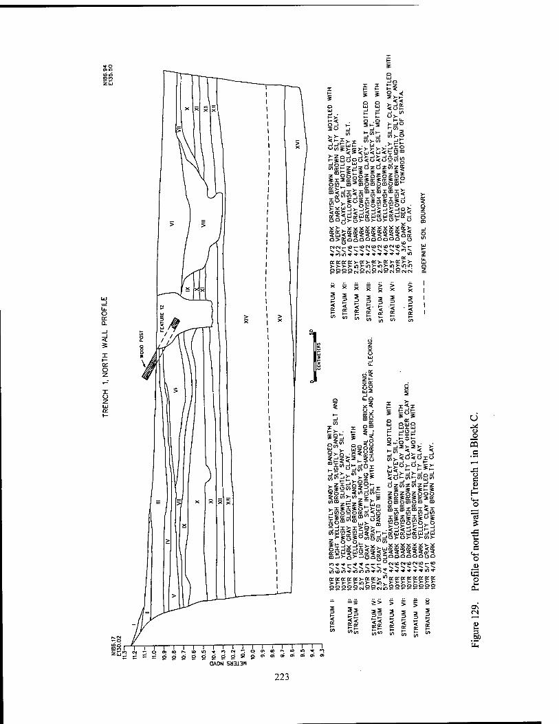
o Q.
< 5
a: o
x ü z LJ
O-i 30
o
V)
^Evx -J=J^I.I»_ "ins >-z
o .0 21-2
in>-w
2 * 2>-i- << <U|- -1 in o>-
5",2 m>-o
>->£>->: ^£8
-J0_j W _i _i -J £
o«n al■^alOCDOCDOII),^ KV1- ^ O: K IE >
T-- -~ (£ J£)<
Ill" " <T O <£ ^ £ (/)
K<<Üj3Cja:ujo:uio:ui(E_j uQ-|>!3>-u>-u>-ü>- o
O>KüOOOQQQQO "•
*» fo in -*•-*■♦■* *»- ■*'*'* ■* *>
cra:a:Q:>-o:>-a:va:>-o:>->- >->->->-in>-in>-(n>-tn>-tnin OOOÜp^LJ^ ?N2NN
? = = !?? I < £ t *- s- »- P-
£ e £ £
o'SE
UJ2
^"
tot
CIO ></>
zO-J. «
£1* 5OJ, iWjjcnt; Sn:in>-</> 2 S
Ui QUO _J UJXbJ h- JOJ
o ."-it THO O .
h-cn < < <
_» >—>>—" -> is >. < 0 < o x <-> >_£<->>-o>-~>- > 5 >■=!>-=! a =! So "-in»-enjoin
OT<Dz£**_üiQ 2tnoS5occ=g<o i-So:-;iKCDt',-'z
5° UJ>- CD
UZUIZMZKZ % S Si-S
2oS.o5.ooo O [DOCDOCD CD a _ "s ^ £ -r >; 1- ajxmxmx<x
in in injtf) I>I>I|u>
inüiS^0555>-i-KÜj5cjSd=JCj ,>-sgs°5os=!o>-ü)- u>-in>- z o 0^_ ^in
iniDinvmmin-a-in*-«-'»-»'«""--«-!"'« KiriEiEa:>-e:o:>-'nD:o:a:(EtEtt:o:p:
22222«22iNi£)22222222
H Win
>> > 2
K I—
2 2 2" ÖÄON" SM313M
T—1 1 1 to in * fo a> ai o* o>
O O
5 c
J3 O c (L>
(0
r o c O
«3 o
223
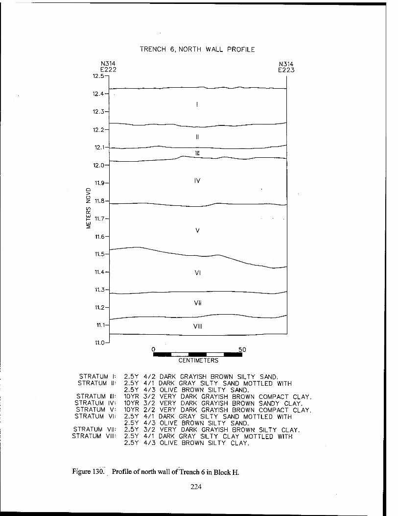
N3 E2
12.5-
12.4-
12.3-
12.2-
12.1-
12.0-
11.9- C_ > 2 11.8-
a_ £ 11.7- Lü
11.6-
11.5-
11.4-
11.3-
11.2-
11.1-
11.0-
TRENCH 6, NORTH WALL PROFILE
14 N3 22 E2
14 23
I
II
III
IV
V
"——
VI
VII
VIII
0 50 ^^^^^H ^H ^^^^^_
STRATUM STRATUM
STRATUM STRATUM STRATUM STRATUM
STRATUM \ STRATUM V
Figure 130.
I: II
III v- V VI
/ll III
p
CENTIMETERS
2.5Y 4/2 DARK GRAYISH BROWN SILTY SAND. 2.5Y 4/1 DARK GRAY SILTY SAND MOTTLED WITH 2.5Y 4/3 OLIVE BROWN SILTY SAND. 10YR 3/2 VERY DARK GRAYISH BROWN COMPACT CLAY. 10YR 3/2 VERY DARK GRAYISH BROWN SANDY CLAY. 10YR 2/2 VERY DARK GRAYISH BROWN COMPACT CLAY. 2.5Y 4/1 DARK GRAY SILTY SAND MOTTLED WITH 2.5Y 4/3 OLIVE BROWN SILTY SAND. 2.5Y 3/2 VERY DARK GRAYISH BROWN SILTY CLAY. 2.5Y 4/1 DARK GRAY SILTY CLAY MOTTLED WITH 2.5Y 4/3 OLIVE BROWN SILTY CLAY.
rofile of north wall of Trench 6 in Block H.
224
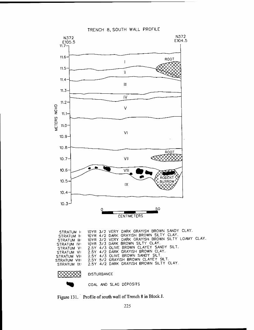
TRENCH 8, SOUTH WALL PROFILE
N372 E105.5
11.7-1
N372 E104.5
CENTIMETERS
STRATUM I STRATUM II STRATUM III
STRATUM IV STRATUM V STRATUM VI STRATUM VII STRATUM VIII STRATUM IX
10YR 3/2 VERY DARK GRAYISH BROWN SANDY CLAY. 10YR 4/2 DARK GRAYISH BROWN SILTY CLAY. 10YR 3/2 VERY DARK GRAYISH BROWN SILTY LOAMY CLAY. 10YR 3/3 DARK BROWN SILTY CLAY. 2 5Y 4/3 OLIVE BROWN CLAYEY SANDY SILT. 2 5Y 4/2 DARK GRAYISH BROWN CLAY. 2 5Y 4/3 OLIVE BROWN SANDY SILT. 2.5Y 5/2 GRAYISH BROWN CLAYEY SILT. 2.5Y 4/2 DARK GRAYISH BROWN SILTY CLAY.
DISTURBANCE
COAL AND SLAG DEPOSITS
Figure 131. Profile of south wall of Trench 8 in Block J.
225
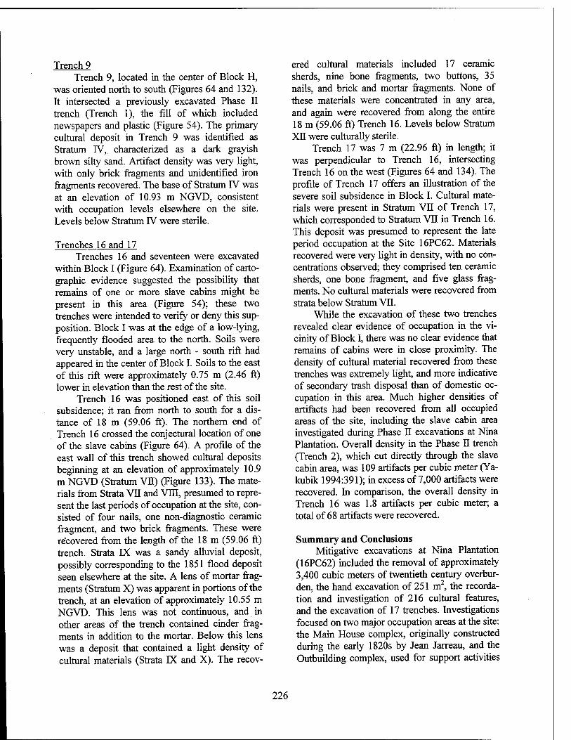
Trench 9 Trench 9, located in the center of Block H,
was oriented north to south (Figures 64 and 132). It intersected a previously excavated Phase II trench (Trench 1), the fill of which included newspapers and plastic (Figure 54). The primary cultural deposit in Trench 9 was identified as Stratum IV, characterized as a dark grayish brown silty sand. Artifact density was very light, with only brick fragments and unidentified iron fragments recovered. The base of Stratum TV was at an elevation of 10.93 m NGVD, consistent with occupation levels elsewhere on the site. Levels below Stratum rV were sterile.
Trenches 16 and 17 Trenches 16 and seventeen were excavated
within Block I (Figure 64). Examination of carto- graphic evidence suggested the possibility that remains of one or more slave cabins might be present in this area (Figure 54); these two trenches were intended to verify or deny this sup- position. Block I was at the edge of a low-lying, frequently flooded area to the north. Soils were very unstable, and a large north - south rift had appeared in the center of Block I. Soils to the east of this rift were approximately 0.75 m (2.46 ft) lower in elevation than the rest of the site.
Trench 16 was positioned east of this soil subsidence; it ran from north to south for a dis- tance of 18 m (59.06 ft). The northern end of Trench 16 crossed the conjectural location of one of the slave cabins (Figure 64). A profile of the east wall of this trench showed cultural deposits beginning at an elevation of approximately 10.9 m NGVD (Stratum VH) (Figure 133). The mate- rials from Strata VII and VIII, presumed to repre- sent the last periods of occupation at the site, con- sisted of four nails, one non-diagnostic ceramic fragment, and two brick fragments. These were recovered from the length of the 18 m (59.06 ft) trench. Strata EX was a sandy alluvial deposit, possibly corresponding to the 1851 flood deposit seen elsewhere at the site. A lens of mortar frag- ments (Stratum X) was apparent in portions of the trench, at an elevation of approximately 10.55 m NGVD. This lens was not continuous, and in other areas of the trench contained cinder frag- ments in addition to the mortar. Below this lens was a deposit that contained a light density of cultural materials (Strata DC and X). The recov-
ered cultural materials included 17 ceramic sherds, nine bone fragments, two buttons, 35 nails, and brick and mortar fragments. None of these materials were concentrated in any area, and again were recovered from along the entire 18 m (59.06 ft) Trench 16. Levels below Stratum XII were culturally sterile.
Trench 17 was 7 m (22.96 ft) in length; it was perpendicular to Trench 16, intersecting Trench 16 on the west (Figures 64 and 134). The profile of Trench 17 offers an illustration of the severe soil subsidence in Block I. Cultural mate- rials were present in Stratum VII of Trench 17, which corresponded to Stratum VH in Trench 16. This deposit was presumed to represent the late period occupation at the Site 16PC62. Materials recovered were very light in density, with no con- centrations observed; they comprised ten ceramic sherds, one bone fragment, and five glass frag- ments. No cultural materials were recovered from strata below Stratum VII.
While the excavation of these two trenches revealed clear evidence of occupation in the vi- cinity of Block I, there was no clear evidence that remains of cabins were in close proximity. The density of cultural material recovered from these trenches was extremely light, and more indicative of secondary trash disposal than of domestic oc- cupation in this area. Much higher densities of artifacts had been recovered from all occupied areas of the site, including the slave cabin area investigated during Phase II excavations at Nina Plantation. Overall density in the Phase II trench (Trench 2), which cut directly through the slave cabin area, was 109 artifacts per cubic meter (Ya- kubik 1994:391); in excess of 7,000 artifacts were recovered. In comparison, the overall density in Trench 16 was 1.8 artifacts per cubic meter; a total of 68 artifacts were recovered.
Summary and Conclusions Mitigative excavations at Nina Plantation
(16PC62) included the removal of approximately 3,400 cubic meters of twentieth century overbur- den, the hand excavation of 251 m2, the recorda- tion and investigation of 216 cultural features, and the excavation of 17 trenches. Investigations focused on two major occupation areas at the site: the Main House complex, originally constructed during the early 1820s by Jean Jarreau, and the Outbuilding complex, used for support activities
226
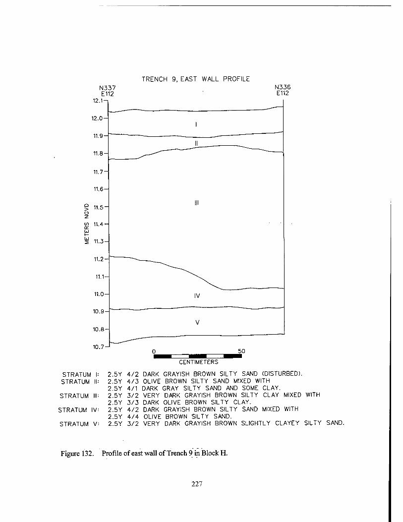
TRENCH 9, EAST WALL PROFILE N336 E112
CENTIMETERS
STRATUM I: 2.5Y 4/2 DARK GRAYISH BROWN SILTY SAND (DISTURBED). STRATUM II: 2.5Y 4/3 OLIVE BROWN SILTY SAND MIXED WITH
2.5Y 4/1 DARK GRAY SILTY SAND AND SOME CLAY. STRATUM III: 2.5Y 3/2 VERY DARK GRAYISH BROWN SILTY CLAY MIXED WITH
2.5Y 3/3 DARK OLIVE BROWN SILTY CLAY. STRATUM IV: 2.5Y 4/2 DARK GRAYISH BROWN SILTY SAND MIXED WITH
2.5Y 4/4 OLIVE BROWN SILTY SAND. STRATUM V: 2.5Y 3/2 VERY DARK GRAYISH BROWN SLIGHTLY CLAYEY SILTY SAND.
Figure 132. Profile of east wall of Trench 9 in Block H.
227
TRENCH 16, PARTIAL PROFILE OF EAST WALL
N363 N362 E111 E111
50
CENTIMETERS
STRATUM |: 2.5Y 2.5Y
STRATUM II: 2.5Y STRATUM III: 2.5Y
2.5Y STRATUM IV: 2.5Y STRATUM V: 2.5Y
2.5Y STRATUM VI: 2.5Y STRATUM VII: 2.5Y
2.5Y STRATUM VIII: 2.5Y
STRATUM IX: 2.5Y 2.5Y
STRATUM X: LENS STRATUM XI: 2.5Y STRATUM XII: 2.5Y STRATUM XIII: 2.5Y
STRATUM XIV: 2.5Y
5/2 GRAYISH BROWN SILTY SAND WITH BANDED 4/3 OLIVE BROWN SANDY LOAM. 3/2 VERY DARK GRAYISH BROWN SILTY CLAY. 3/2 VERY DARK GRAYISH BROWN SILTY CLAY MOTTLED WITH 7/3 PALE YELLOW SILT. 3/2 VERY DARK GRAYISH BROWN SILTY CLAY. 4/2 DARK GRAYISH BROWN CLAYEY SILT MOTTLED WITH 5/2 GRAYISH BROWN CLAYEY SILT. 3/2 VERY DARK GRAYISH BROWN LOAMY CLAY. 4/2 DARK GRAYISH BROWN CLAYEY SILT MOTTLED WITH 5/2 GRAYISH BROWN CLAYEY SILT. 3/2 VERY DARK GRAYISH BROWN LOAMY CLAY. 5/3 LIGHT OLIVE BROWN SILT MOTTLED WITH 5/1 GRAY SILTY CLAY. OF MORTAR FRAGMENTS. 4/1 DARK GRAY LOAMY SILT WITH BRICK AND MORTAR FRAGMENTS. 4/1 DARK GRAY LOAMY SILT. 5/3 LIGHT OLIVE BROWN SILT. 4/3 OLIVE BROWN SILTY CLAY.
Figure 133. Profile of east wall of Trench 16 in Block I.
228
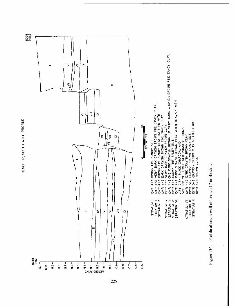
o o s
o c (U
■4-» 3 O <n
«♦-« O
_U £5 O
3
OAON Sä3i3N
229
for the main house, and occupied by slaves/servants employed in a domestic capacity.
The main house complex included the origi- nal core structure, the south wing, the north wing, and the north and south cisterns. Excellent strati- graphic integrity permitted the recordation of a temporal sequence of construction and occupa- tion in the main house area. The first two struc- tures to be built were the core of the main house, and the south wing. Evidence suggested that the south wing originally was an independent build- ing; during remodeling in the 1830s or 1840s, it was attached to the core as a wing. The two flanking cisterns were added at the same time. The north wing addition was constructed after mid-century, and post-dated the flood of 1851. Designed and built in a manner that added sym- metry to the main house, it is likely to have been the work of the Aliens, who purchased the plan- tation in the 1850s.
The Outbuilding complex included Struc- tures 1 and 2, both constructed using earthfast techniques. Evidence of mid nineteenth century renovation was recovered at Structure 1, where a substantial brick chimney replaced an earlier
wood and clay chimney, and a wooden floor was constructed over the original dirt surface. Struc- ture 2 was less well preserved, but provided am- ple evidence that there had been no central chim- ney, and that a dirt floor surface had been present throughout its occupation. Evidence was found in Structure 2 of a central partition wall built using simple piquette en terre construction methods.
The stratigraphy in these occupied areas of the site was consistent. The original occupation surface was at an elevation of approximately 10.95 m NGVD. A deposit of early occupational debris was observed in most areas of the site. A layer of alluvium deposited by a flood event in 1851 was present in almost all portions of the site; generally, the elevation of this deposit was between 11.15 and 11.25 m NGVD. Occupational debris post-dating the flood was present at eleva- tions above this, and was capped by debris from the destruction of the plantation structures circa 1890. This general stratigraphic sequence differed slightly only in the north and south wing areas, where occupational patterns created variation in the sequence.
230
CHAPTER IX
ANALYTICAL RESULTS
Introduction This archeological data recovery effort was designed to produce a synthetic characteriza-
tion of nineteenth century occupation at Nina Plantation. The recovered data permitted study of intra-site patterning, and temporal variation in that patterning; it also facilitated extra-site com- parative study. The data recovered from the exca- vations at Nina Plantation have been subjected to various types of analysis, to meet the specific re- search goals of the project. The analytical meth- ods employed during this study, and the results of these analyses, are reviewed in this chapter. A summary and interpretation of the field and ana- lytical results are included in Chapter X.
Temporal and Spatial Analytical Units Excavated areas of Site 16PC62 were as-
signed to both temporal and spatial analytical units, to facilitate examination of intra-site pat- terning and change. Questions about chronology, status differentiation, disparate access or use of material goods, and changes in plantation layout and activity areas required the division of the site into synchronic, spatial analytical units. Alterna- tively, temporal analysis required the division of the site into analytical units based on stratigraphic sequence and historiography; these temporal analytical units then could be compared across the entire site, and they also could be used to ex- amine changes within each spatial unit.
During analysis, the primary spatial divi- sions were the excavation blocks. As reviewed in Chapter VIII, the boundaries of these 30 x 30 m (98.4 x 98.4 ft) areas coincided rather neatly with the location of the architectural components of
the site (see Figure 54). Block C incorporated the Outbuilding complex, including both Structure 1 and Structure 2, in addition to associated midden deposits. Blocks D and E contained the Main House complex. Further separation of individual components of each block, for example the divi- sion of Block C by structures (e.g., Structures 1 and 2), permitted comparison within and between each structural complex.
Because of the number and complexity of components across the site, and the number of levels and strata represented in each component, intra-site interpretation required application of numerous discrete analytical units. Using these spatial and temporal analytical units, an interim site sequence was developed that provided uni- formity, and which permitted cross-site compari- sons. Specific lists of analytical units were devel- oped for excavations in Blocks C, D, and E. These analytical units derived from a combina- tion of observed stratigraphic relationships, spa- tial patterning, soils, elevation, material content, and other relevant characteristics of each block. Specific analytical units were assigned to each excavated level; lists of analytical units within each block are contained in Tables 10, 11, and 12, and in Appendix I. All provenience tables in Ap- pendix I include the analytical unit number as- signed to each excavated level. Because Block F contained no structural features or significant midden deposits that would have permitted cor- relation with the sequences in Blocks C, D, and E, materials recovered from Block F were not included in intra-site spatial analyses. However, materials recovered from Block F were included in site-wide analyses and chronologies.
231
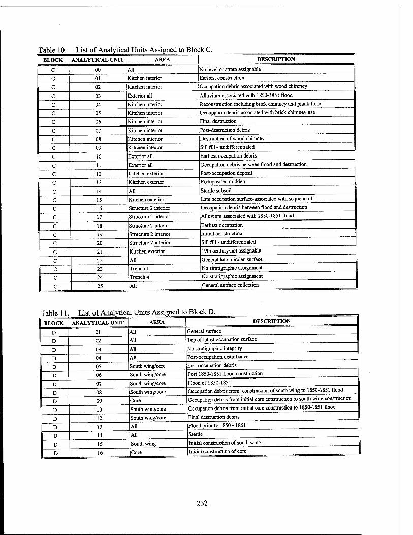
Table 10. List of Analytical Units Assigned to Block C. BLOCK ANALYTICAL UNIT AREA DESCRIPTION
C 00 All Mo level or strata assignable
c 01 Kitchen interior Earliest construction
c 02 Kitchen interior Occupation debris associated with wood chimney
c 03 Exterior all Alluvium associated with 1850-1851 flood
c 04 Kitchen interior Reconstruction including brick chimney and plank floor
c 05 Kitchen interior Occupation debris associated with brick chimney use
c 06 Kitchen interior Final destruction
c 07 Kitchen interior Post-destruction debris
c 08 Kitchen interior Destruction of wood chimney
c 09 Kitchen interior Sill fill - undifferentiated
c 10 Exterior all Earliest occupation debris
c 11 Exterior all Occupation debris between flood and destruction
c 12 Kitchen exterior Post-occupation deposit
c 13 Kitchen exterior Redeposited midden
c 14 All Sterile subsoil
c 15 Kitchen exterior Late occupation surface-associated with sequence 11
c 16 Structure 2 interior Occupation debris between flood and destruction
c 17 Structure 2 interior Alluvium associated with 1850-1851 flood
c 18 Structure 2 interior Earliest occupation
c 19 Structure 2 interior Initial construction
c 20 Structure 2 interior Sill fill - undifferentiated
c 21 Kitchen exterior 19th century/not assignable
c 22 All General late midden surface
c 23 Trench 1 No stratigraphic assignment
c 24 Trench 4 No stratigraphic assignment
c 25 |A11 General surface collection
Table 11. List of Analytical Units Assigned to Block D. BLOCK
D
D
D
ANALYTICAL UNIT
D
D
D
01
02
03
04
05
06
07
08
09
10
12
13
14
15
16
AREA
All
All
All
All
South wing/core
South wing/core
South wing/core
South wing/core
Core
South wing/core
South wing/core
All
All
South wing
Core
DESCRIPTION
General surface
Top of latest occupation surface
No stratigraphic integrity
Post-occupation disturbance
Last occupation debris
Post 1850-1851 flood construction
Flood of 1850-1851
Occupation debris from construction of south wing to 1850-1851 flood
Occupation debris from initial core construction to south wing construction
Occupation debris from initial core construction to 1850-1851 flood
Final destruction debris
Flood prior to 1850- 1851
Sterile
Initial construction of south wing
Initial construction of core
232
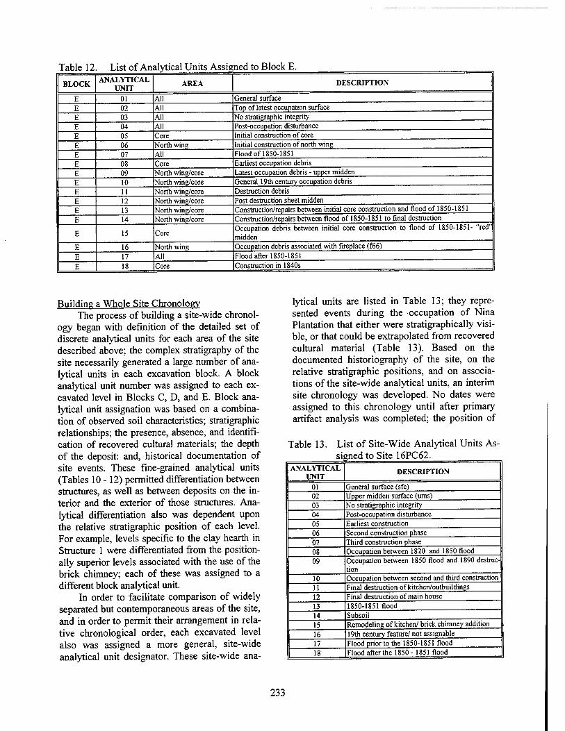
Table 12 List of Analytical Units Assigned to Block E.
BLOCK ANALYTICAL
UNIT AREA DESCRIPTION
E 01 All General surface
E 02 AH Top of latest occupation surface
E 03 All No stratigraphic integrity
E 04 All Post-occupation disturbance
E 05 Core Initial construction of core
E 06 North wing Initial construction of north wing
E 07 All Flood of 1850-1851
E 08 Core Earliest occupation debris
E 09 North wing/core Latest occupation debris - upper midden
E 10 North wing/core General 19th century occupation debris
E 11 North wing/core Destruction debris
E 12 North wing/core Post destruction sheet midden
E 13 North wing/core Construction/repairs between initial core construction and flood of 1850-1851
E 14 North wing/core Construction/repairs between flood of 1850-1851 to final destruction
E 15 Core Occupation debris between initial core construction to flood of 1850-1851- "red" midden
E 16 North wing Occupation debris associated with fireplace (f66)
E 17 All Flood after 1850-1851
E 18 Core Construction in 1840s
Building a Whole Site Chronology The process of building a site-wide chronol-
ogy began with definition of the detailed set of discrete analytical units for each area of the site described above; the complex stratigraphy of the site necessarily generated a large number of ana- lytical units in each excavation block. A block analytical unit number was assigned to each ex- cavated level in Blocks C, D, and E. Block ana- lytical unit assignation was based on a combina- tion of observed soil characteristics; stratigraphic relationships; the presence, absence, and identifi- cation of recovered cultural materials; the depth of the deposit: and, historical documentation of site events. These fine-grained analytical units (Tables 10-12) permitted differentiation between structures, as well as between deposits on the in- terior and the exterior of those structures. Ana- lytical differentiation also was dependent upon the relative stratigraphic position of each level. For example, levels specific to the clay hearth in Structure 1 were differentiated from the position- ally superior levels associated with the use of the brick chimney; each of these was assigned to a different block analytical unit.
In order to facilitate comparison of widely separated but contemporaneous areas of the site, and in order to permit their arrangement in rela- tive chronological order, each excavated level also was assigned a more general, site-wide analytical unit designator. These site-wide ana-
lytical units are listed in Table 13; they repre- sented events during the occupation of Nina Plantation that either were stratigraphically visi- ble, or that could be extrapolated from recovered cultural material (Table 13). Based on the documented historiography of the site, on the relative stratigraphic positions, and on associa- tions of the site-wide analytical units, an interim site chronology was developed. No dates were assigned to this chronology until after primary artifact analysis was completed; the position of
Table 13. List of Site-Wide Analytical Units As- signed to Site 16PC62.
ANALYTICAL UNIT
DESCRIPTION
01 General surface (sfc) 02 Upper midden surface (urns) 03 No stratigraphic integrity 04 Post-occupation disturbance 05 Earliest construction 06 Second construction phase 07 Third construction phase 08 Occupation between 1820 and 1850 flood 09 Occupation between 1850 flood and 1890 destruc-
tion 10 Occupation between second and third construction 11 Final destruction of kitchen/outbuildings
12 Final destruction of main house 13 1850-1851 flood 14 Subsoil 15 Remodeling of kitchen/ brick chimney addition
16 19th century feature/ not assignable 17 Flood prior to the 1850-1851 flood
| 18 iFlood after the 1850 -1851 flood
233
each analytical unit in the interim chronology indicated its relative chronological placement, rather than its correspondence to a specific date.
The following descriptions pertain to the major analytical units represented in the interim site chronology. These construction, occupation, flood, and destruction events were distinguished by stratigraphic position and association; in addi- tion, the material content of the excavated levels was frequently distinctive, and permitted confi- dent assignment of the level to an analytical unit.
Flooding Deposits The major episode of flooding and alluvial
deposition that was present across most of Site 16PC62 has been dated to ca. 1851 (see Chap- ters II, m, IV, and Vni of this report). This stratum provided stratigraphic clarity across most of the site, and it provided a key to the dif- ferentiation of occupation and construction peri- ods. While floods were recorded in the Pointe Coupee region in 1851, 1858, and 1867, only the 1851 flood was of such intensity that it pre- vented the production of a sugar crop both dur- ing the flood year and the year following; the 1858 and 1867 floods did not appear to impede production at all (Champomier 1858, 1867). Ac- cording to Champomier (1852:5), Pecan Grove (Nina) plantation was "entirely overflowed" during the 1851 event, while neighboring prop- erties were merely "overflowed."
Assigned to interim period 13 (Chart 1), levels with stratigraphic evidence of this major flood event were found in the majority of exca- vation units on the site; these levels sealed pre- 1851 deposits. Interim period 13 included block analytical units D-07, E-07, and C-03 (Chart 1). Minor flood deposits, limited in distribution and intensity, were encountered during excavation, but these did not possess the analytical utility of the clearly datable and ubiquitous interim period 13 flood deposits. These secondary flood epi- sodes are listed on Tables 10 - 12; they either pre-dated or postdated the 1851 event.
Construction Periods Three periods of construction were identified
at Nina Plantation; they represented in the interim chronology as Analytical Units 05, 06, 07, and 15 (Chart 1). The earliest of these construction stages, designated interim period 05, represents
the initial construction of the core of the main house, and of the outbuildings. The stratigraphic levels included in this interim period were block analytical units C-01, the kitchen interior; C-19, the structure 2 interior; D-16, the core of the main house; and E-05, also, the core of the main house. The stratigraphic position of these interim period 05 levels, directly above sterile soils, was key to their assignment to this interim period. Consid- ering historical documentation (see Chapter TV), a date range of ca. 1820-1830 was suggested for this period.
Those excavated stratigraphic levels clearly associated with a second stage of construction at the site were assigned to interim period 06. Evi- dence of second-stage construction included stra- tigraphic position above early occupation debris, and the presence of small amounts of construction materials such as brick fragments. This interim period correlated with the attachment of the south wing to the core of the main house in Block D (block analytical unit D-15), and with minor con- struction or reconstruction activities in Block E (block analytical unit E-18). No closely dateable, diagnostic materials were recovered from any of the Interim period 06 levels; the date range of recovered ceramics fell in the first half of the nineteenth century. Based on stratigraphic posi- tion, a date range of ca. 1840-1850 was assigned to interim period 06 construction.
The third construction period was designated interim period 07; it correlated with construction or repairs that took place after the flood of ca. 1851 (interim period 73). In Block E, this third construction phase included analytical units E-06 and E-14, representing the initial construction of the north wing of the main house, and construc- tion or repairs undertaken after 1851. In Block D, this interim period included levels assigned to analytical unit D-06, construction or repairs after 1851. Because of the specific nature of construc- tion and repairs undertaken in the outbuilding complex, the third phase of construction in Block C was assigned to interim period 15, rather than to interim period 07. Because both represent con- struction or repairs undertaken after the flood of 1851, the analytical units subsequently were combined into interim period 07/75 (Chart 1). In Block C, this interim period was represented by analytical unit C-04, corresponding to the con- struction of the brick chimney and hearth (Feature
234
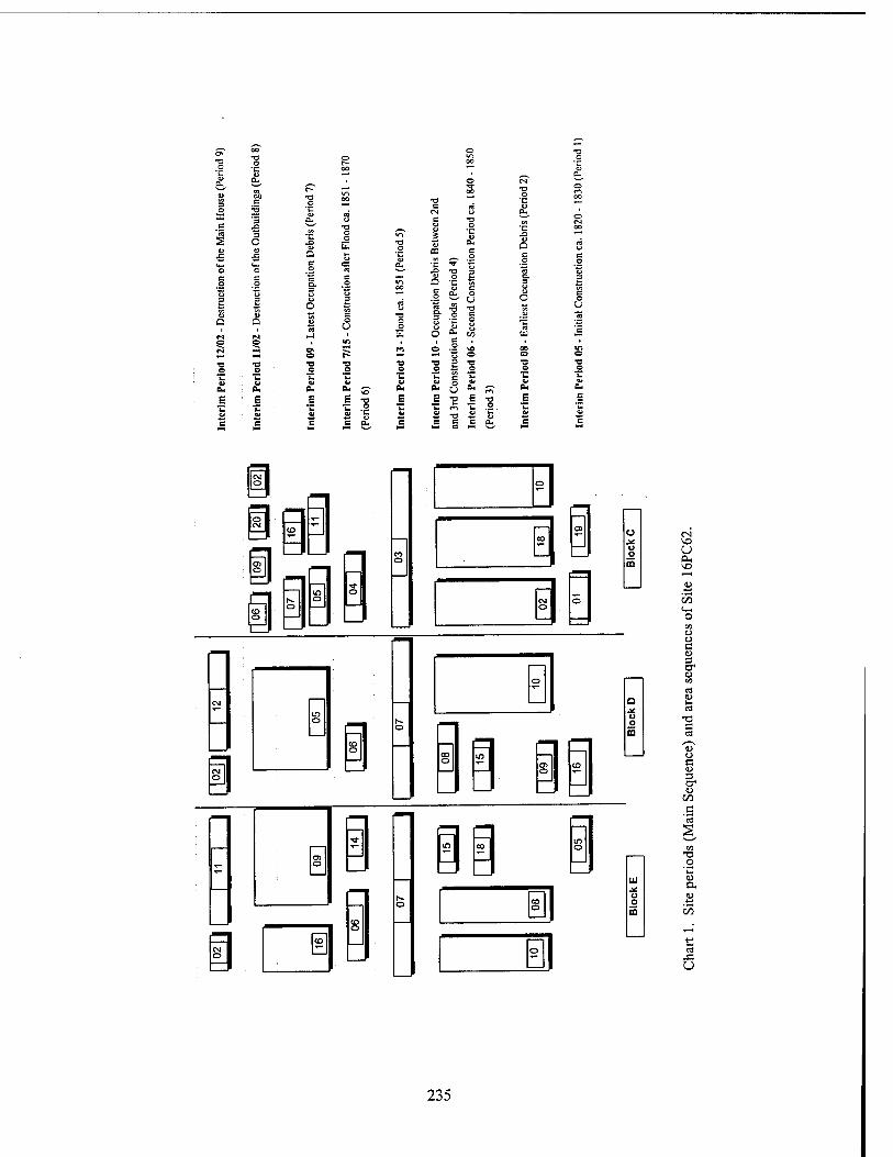
s, s.
3 o X
■c u a.
■° 7? B.
^ .n
s u Q
0. 6. a. c- a. U a. a. a. J s e •a o £ £ 'S e T3
O ■c
E jjj V V V V a» T3 Ci
e c C a* c c a.
o m
m o
o
a o CO
CO o
o
o m
VO a
u o a 3 cr
-a c ca
u o e u 3 cr
T3 O
u
oo
235
116) in Structure 1, and to the simultaneous de- struction of the earlier wood and clay chimney (Features 197, 204, 218, 224, 226, and 229). The stratigraphic position of the interim period 07 and 75 levels, above the 1851 flood deposits, allowed their relative dates to be fixed post 1851; no tem- porally diagnostic materials were recovered to permit more specific dating. However, economic constraints on the plantation economy during the Civil War make it likely that the north wing of the main house was built before the start of the War, and that remodeling of Structure 1 took place either at that time, or after emancipation.
Occupational Sequences The bulk of the data recovered from excava-
tions at Nina Plantation derived from levels cre- ated during the continued occupation of the site. The distribution and composition of this midden debris varied widely between blocks; in general, the occupational soils were characterized by a dark, organically rich soil, with charcoal inclu- sions. Material density varied from relatively light to extremely dense; changes in architecture and in activity areas were reflected in the volume and character of the deposited cultural debris. The spatial distribution and the temporal changes in patterns of distribution are examined in detail later in this chapter. As noted above, the interim relative chronology of occupation deposits and their corresponding analytical units are depicted on Chart 1.
The earliest occupation debris (interim pe- riod 08) was represented in Block C by analytical units C-02, C-18, and C-10. These corresponded to debris deposited on the interiors of Structures 1 and 2 (analytical units C-02 and C-18), and to midden deposits found in the yard areas of these outbuildings (analytical unit C-10). These levels post-dated the interim period 05 construction de- bris, but they were stratigraphically inferior to the 1851 flood deposit (interim period 13). In Block D, these earliest midden deposits were repre- sented by levels in analytical units D-09 and D- 10. Levels in analytical unit D-09 originated during the time between initial construction (in- terim period 05) and the construction of the south wing of the main house (interim period 06). Analytical unit D-10 levels were attributable only to the relative time span between interim period 05 and the 1851 flood (interim period 13). In
Block E, these early midden levels were less widespread, and were represented by analytical units E-08, and E-10. Interim period 08 was as- signed a date range from ca. 1820-1851.
Levels composed of occupational debris de- posited between the second construction phase and the circa 1851 flood (interim periods 06 and 13) in Blocks D and E (analytical units D-08 and E-15), were assigned to interim period 10. Levels from this interim period were not present in Block C. These levels were assigned a date range of circa 1840-1851, based on stratigraphic posi- tion relative to earlier deposits and to the 1851 flood stratum, and on the direct historical ap- proach
The final levels of occupational debris post- dated the mid-century flood, and contained mate- rials discarded until the time of site abandonment and destruction. These interim period 09 levels were found in Block C (analytical units C-05, C- 07, C-ll, and C-16), Block D (analytical unit D- 05), and in Block E (analytical units E-09 and E- 16). In the area of the main house complex, this interim period represents the longest time span of any of the analytical periods, from ca. 1851-1890. In Block C, the third construction episode may have taken place concurrently with the construc- tion of the north wing, between the 1851 flood and the start of the War, or it may have occurred after emancipation, as late as circa 1870. The fi- nal destruction date for the outbuildings is not known, and may have fallen between 1883, when they last were depicted on a Mississippi River Commission map, and 1890. A late third con- struction date, and an early destruction date, would significantly shorten the final period of deposition.
Destruction Periods The ' final destruction of the Outbuilding
complex has been assigned to interim periods 02 and 11, represented in Block C by analytical units C-02, C-06, C-09, and C-20. Interim period 02 materials were recovered during controlled sur- face collections that were conducted immediately after mechanical removal of the overburden in each block. No diagnostic materials recovered from the interim period 02 or interim period 11 levels provided temporal data with sufficient specification to date this episode within a time period narrower than that assigned - ca. 1884-
236
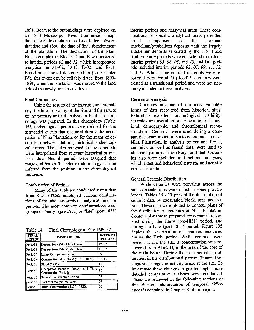
1891. Because the outbuildings were depicted on an 1883 Mississippi River Commission map, their date of destruction must have fallen between that date and 1890, the date of final abandonment of the plantation. The destruction of the Main House complex in Blocks D and E was assigned to interim periods 02 and 12, which incorporated analytical unitsD-02, D-12, E-02, and E-ll. Based on historical documentation (see Chapter IV), this event can be reliably dated from 1890- 1891, when the plantation was moved to the land side of the newly constructed levee.
Final Chronology Using the results of the interim site chronol-
ogy, the historiography of the site, and the results of the primary artifact analysis, a final site chro- nology was prepared. In this chronology (Table 14), archeological periods were defined for the sequential events that occurred during the occu- pation of Nina Plantation, or for the spans of oc- cupation between defining historical archeologi- cal events. The dates assigned to these periods were interpolated from relevant historical or ma- terial data. Not all periods were assigned date ranges, although the relative chronology can be inferred from the position in the chronological sequence.
Combination of Periods Many of the analyses conducted using data
from Site 16PC62 employed various combina- tions of the above-described analytical units or periods. The most common configurations were groups of "early" (pre 1851) or "late" (post 1851)
Table 14. Final Chronology at Site 16PC62. FINAL
PERIOD DESCRIPTION INTERIM PERIOD
Period 9 Destruction of the Main House 12,02
Period 8 Destruction of the Outbuildings 11,02
Period 7 Latest Occupation Debris 09
Period 6 Construction after Flood (1851 - 1870) 07,15
Period 5 Flood (1851) 13
Period 4 Occupation between Second and Third Construction Periods
10
Period 3 Second Construction Period 06
Period 2 Earliest Occupation Debris 08
Period 1 Initial Construction (1820 -1830) 05
interim periods and analytical units. These com- binations of specific analytical units permitted broad comparison of the terminal antebellum/postbellum deposits with the largely antebellum deposits separated by the 1851 flood stratum. Early periods were considered to include interim periods 05, 06, 08, and 10, and late peri- ods included interim periods 02, 07, 09, 11, 12, and 15. While some cultural materials were re- covered from Period 13 (flood) levels, they were treated as a transitional period and were not nor- mally included in these analyses.
Ceramics Analysis Ceramics are one of the most valuable
forms of data recovered from historical sites. Exhibiting excellent archeological visibility, ceramics are useful in socio-economic, behav- ioral, demographic, and chronological recon- structions. Ceramics were used during a com- parative examination of socio-economic status at Nina Plantation, in "analysis of ceramic forms; ceramics, as well as faunal data, were used to elucidate patterns in foodways and diet. Ceram- ics also were included in functional analyses, which examined behavioral patterns and activity areas at the site.
General Ceramic Distribution While ceramics were prevalent across the
site, concentrations were noted in some proven- iences. Tables 15-17 present the distribution of ceramic data by excavation block, unit, and pe- riod. These data were plotted as contour plans of the distribution of ceramics at Nina Plantation. Contour plans were prepared for ceramics recov- ered during the Early (pre-1851) period, and during the Late (post-1851) period. Figure 135 depicts the distribution of ceramics recovered during the Early period. While ceramics were present across the site, a concentration was re- covered from Block D, in the area of the core of the main house. During the Late period, an al- teration in the distributional pattern (Figure 136) suggests changes in activity areas at the site. To investigate these changes in greater depth, more detailed comparative analyses were conducted. These are reviewed in the following sections of this chapter. Interpretation of temporal differ- ences is contained in Chapter X of this report.
237
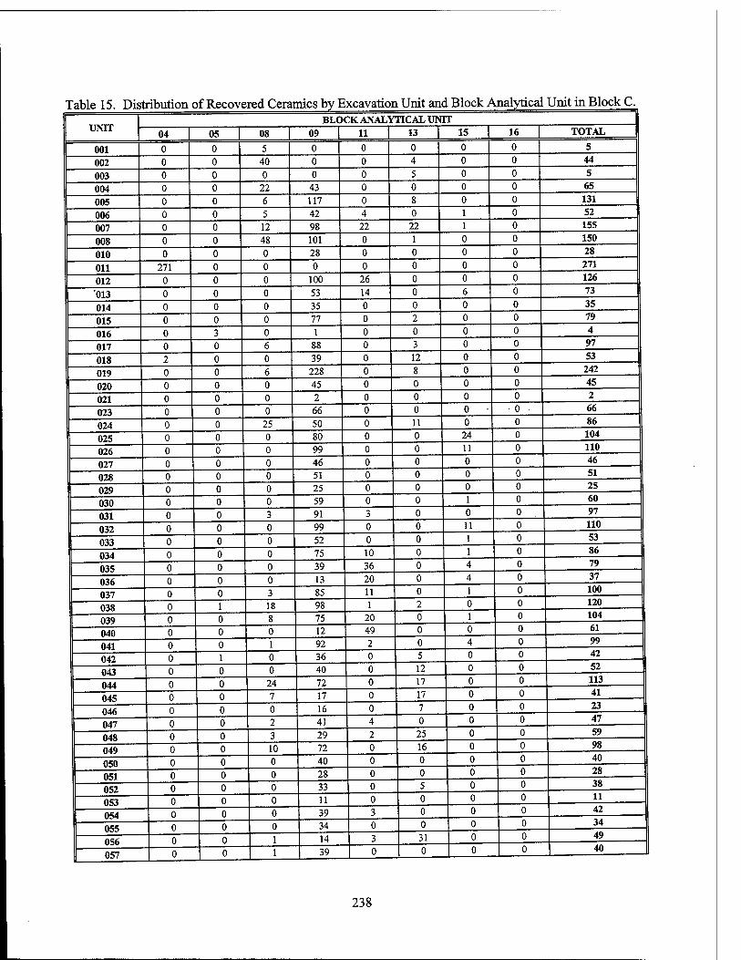
Table 15. Distribution of Recovered Ceramics by Excavation Unit and Block Analytical Unit in Block C. BLOCK ANALYTICAL UNIT
UNIT 04 | 05 | 08 | 09 | 11 | 13 | 15 | 16 I TOTAL
001 0 0 5 0 0 0 0 0 5
002 0 0 40 0 0 4 0 0 44
003 0 0 0 0 0 5 0 0 5
004 0 0 22 43 0 0 0 0 65
005 0 0 6 117 0 8 0 0 131
006 0 0 5 42 4 0 1 0 52
007 0 0 12 98 22 22 1 0 155
008 0 0 48 101 0 1 0 0 150
010 0 0 0 28 0 0 0 0 28
011 271 0 0 0 0 0 0 0 271
012 0 0 0 100 26 0 0 0 126
013 0 0 0 53 14 0 6 0 73
014 0 0 0 35 0 0 0 0 35
015 0 0 0 77 0 2 0 0 79
016 0 3 0 1 0 0 0 0 4
017 0 0 6 88 0 3 0 0 97
018 2 0 0 39 0 12 0 0 53
019 0 0 6 228 0 8 0 0 242
020 0 0 0 45 0 0 0 0 45
021 0 0 0 2 0 0 0 0 2
023 0 0 0 66 0 0 0 - 0 ■ 66
024 0 0 25 50 0 11 0 0 86
025 0 0 0 80 0 0 24 0 104
026 0 0 0 99 0 0 11 0 110
027 0 0 0 46 0 0 0 0 46
028 0 0 0 51 0 0 0 0 51
029 0 0 0 25 0 0 0 0 25
030 0 0 0 59 0 0 1 0 60
031 0 0 3 91 3 0 0 0 97
032 0 0 0 99 0 0 11 0 110
033 0 0 0 52 0 0 1 0 53
034 0 0 0 75 10 0 1 0 86
035 0 0 0 39 36 0 4 0 79
036 0 0 0 13 20 0 4 0 37
037 0 0 3 85 11 0 1 0 100
038 0 1 18 98 1 2 0 0 120
039 0 0 8 75 20 0 1 0 104
040 0 0 0 12 49 0 0 0 61
041 0 0 1 92 2 0 4 0 99
042 0 1 0 36 0 5 0 0 42
043 0 0 0 40 0 12 0 0 52
044 0 0 24 72 0 17 0 0 113
045 0 0 7 17 0 17 0 0 41
046 0 0 0 16 0 7 0 0 23
047 0 0 2 41 4 0 0 0 47
048 0 0 3 29 2 25 0 0 59
049 0 0 10 72 0 16 0 0 98
050 0 0 0 40 0 0 0 0 40
051 0 0 0 28 0 0 0 0 28
052 0 0 0 33 0 5 0 0 38
053 0 0 0 11 0 0 0 0 11
054 0 0 0 39 3 0 0 0 42
055 0 0 0 34 0 0 0 0 34
056 0 0 1 14 3 31 0 0 49
057 0 0 1 39 0 0 0 0 40
238
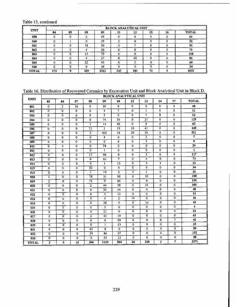
Table 15, continued
UNIT BLOCK ANALYTICAL UNIT
04 05 08 09 11 13 15 16 TOTAL 058 0 0 2 59 0 0 0 0 61
060 0 1 0 29 2 0 0 0 32 061 0 0 34 50 0 7 0 0 91 062 0 3 4 56 0 8 0 0 71 063 0 0 17 79 0 9 0 5 110 064 0 0 4 37 0 40 0 0 81 065 0 0 22 43 0 3 0 0 68 066 0 0 0 34 0 0 0 0 34
TOTAL 273 9 339 3312 242 280 72 5 4532
Table 16. Distribution of Recovered Ceramics by Excavation Unit and Block Analytical Unit in Block D.
UNIT BLOCK ANALYTICAL UNIT
03 04 07 08 09 10 12 13 14 17 TOTAL
001 0 2 16 0 50 0 0 0 0 0 68
002 0 0 0 0 3 7 0 1 0 0 11
003 0 0 0 0 5 0 0 7 0 0 12
004 0 0 0 0 74 34 0 21 0 0 129
005 0 0 0 2 13 48 0 0 0 0 63
006 0 0 0 73 2 19 10 41 0 0 145
007 0 0 0 2 402 14 39 54 0 • 0 511
008 0 0 0 0 4 0 0 3 0 0 7
009 0 0 0 0 0 6 0 3 0 0 9
010 0 3 0 0 24 2 0 0 0 0 29
011 0 0 0 0 1 0 0 0 0 0 1
012 0 0 0 17 98 0 0 2 0 0 117
013 0 0 0 0 63 7 0 3 0 0 73
014 0 0 0 0 1 15 0 5 1 0 22
015 0 0 0 30 0 4 0 0 0 0 34
016 0 0 0 1 19 2 3 1 0 0 26
018 1 0 0 78 31 96 0 32 0 0 238
019 2 0 0 71 0 86 0 0 0 0 159
020 0 0 0 2 44 38 0 21 0 0 105
021 0 0 0 0 34 14 0 0 0 0 48
022 0 0 0 0 3 12 0 0 0 0 15
023 0 0 0 9 1 2 14 0 0 0 26
024 0 0 0 0 28 5 0 10 0 0 43
025 0 0 0 0 5 0 0 0 0 0 5
026 0 0 0 0 21 0 0 0 0 0 21
027 0 0 0 2 42 19 0 0 0 0 63
028 0 0 0 6 0 29 0 0 0 7 42
029 0 0 0 0 1 13 0 9 0 0 23
031 0 0 0 42 8 0 0 0 0 0 50
032 0 0 0 29 86 37 0 0 0 0 152
033 0 0 0 0 25 13 0 0 0 0 38
TOTAL 3 5 16 366 1125 564 66 218 1 7 2371
239
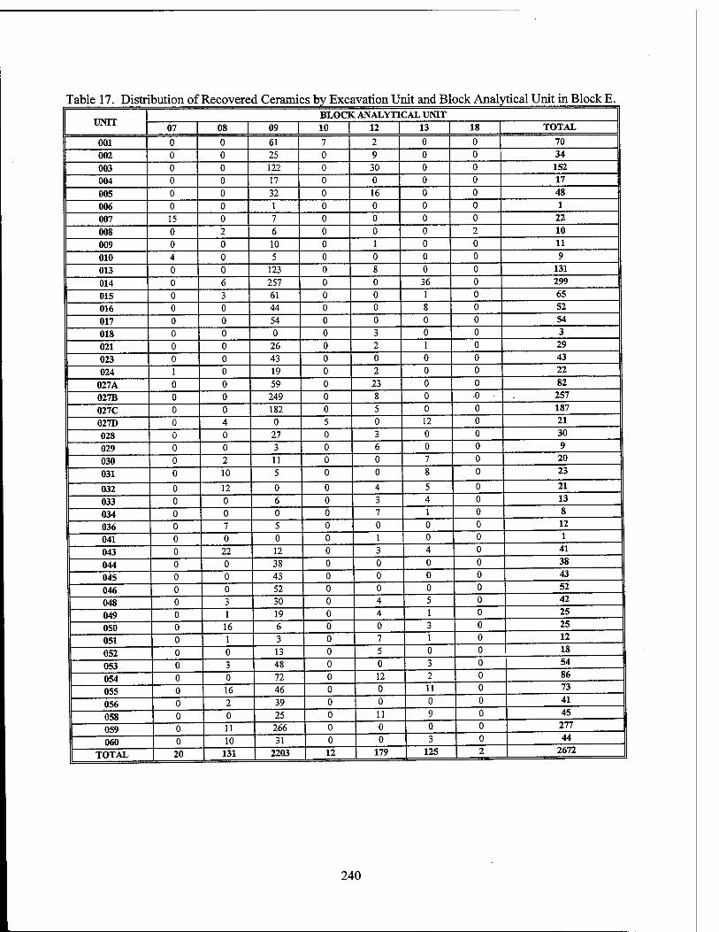
Table 17. Distribution of Recovered Ceramics by Excavation Unit and Block Analytical Unit in Block E.
UNIT BLOCK ANALYTICAL UNIT
07 08 | 09 | 10 | 12 13 | 18 | TOTAL
001 0 0 61 7 2 0 0 70
002 0 0 25 0 9 0 0 34
003 0 0 122 0 30 0 0 152
004 0 0 17 0 0 0 0 17
005 0 0 32 0 16 0 0 48
006 0 0 1 0 0 0 0 1
007 15 0 7 0 0 0 0 22
008 0 2 6 0 0 0 2 10
009 0 0 10 0 1 0 0 11
010 4 0 5 0 0 0 0 9
013 0 0 123 0 8 0 0 131
014 0 6 257 0 0 36 0 299
015 0 3 61 0 0 1 0 65
016 0 0 44 0 0 8 0 52
017 0 0 54 0 0 0 0 54
018 0 0 0 0 3 0 0 3
021 0 0 26 0 2 1 0 29
023 0 0 43 0 0 0 0 43
024 1 0 19 0 2 0 0 22
027A 0 0 59 0 23 0 0 82
027B 0 0 249 0 8 0 •0 257
027C 0 0 182 0 5 0 0 187
027D 0 4 0 5 0 12 0 21
028 0 0 27 0 3 0 0 30
029 0 0 3 0 6 0 0 9
030 0 2 11 0 0 7 0 20
031 0 10 5 0 0 8 0 23
032 0 12 0 0 4 5 0 21
033 0 0 6 0 3 4 0 13
034 0 0 0 0 7 1 0 8
036 0 7 5 0 0 0 0 12
041 0 0 0 0 1 0 0 1
043 0 22 12 0 3 4 0 41
044 0 0 38 0 0 0 0 38
045 0 0 43 0 0 0 0 43
046 0 0 52 0 0 0 0 52
048 0 3 30 0 4 5 0 42
049 0 1 19 0 4 1 0 25
050 0 16 6 0 0 3 0 25
051 0 1 3 0 7 1 0 12
052 0 0 13 0 5 0 0 18
053 0 3 48 0 0 3 0 54
054 0 0 72 0 12 2 0 86
055 0 16 46 0 0 11 0 73
056 0 2 39 0 0 0 0 41
058 0 0 25 0 11 9 0 45
059 0 11 266 0 0 0 0 277
060 0 10 31 0 0 3 0 44
TOTAL 1 20 131 2203 12 179 125 2 2672
240
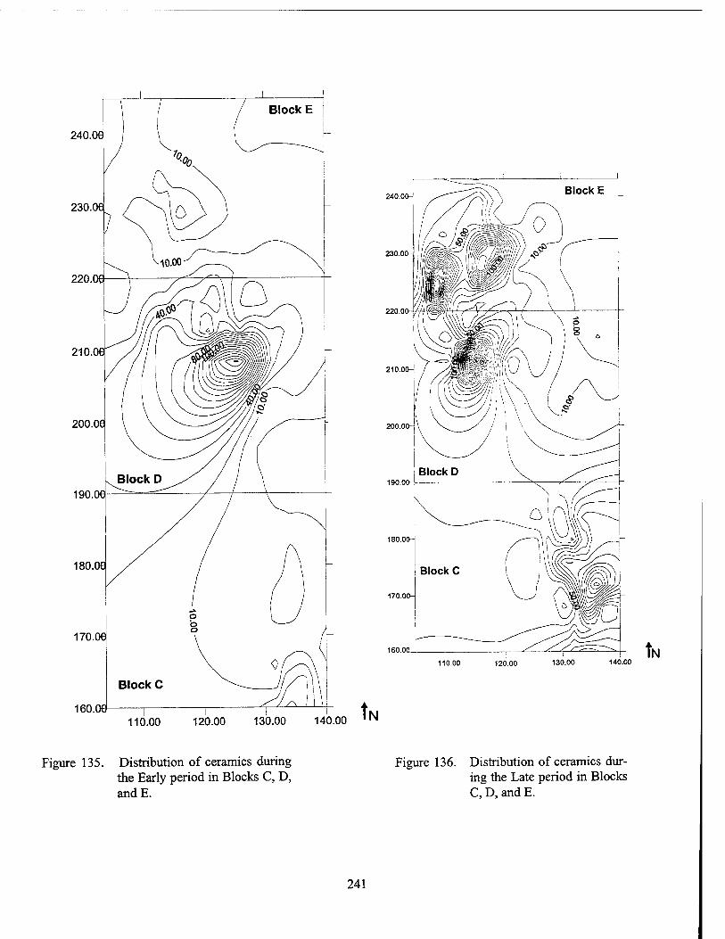
240.06
230.06
220.
210.
200.C
190.06
180.06
170.06
160.00
Block C
240.00^
230.00-j
220.00-
210.00-
190.00-J
180.00-
110.00 120.00 130.00 140.00 tl N
110.00 120.00 130.00 140.00 ,N tr
Figure 135. Distribution of ceramics during the Early period in Blocks C, D, andE.
Figure 136. Distribution of ceramics dur- ing the Late period in Blocks C, D, and E.
241
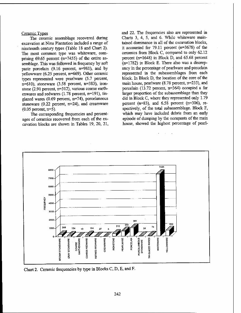
Ceramic Types The ceramic assemblage recovered during
excavation at Nina Plantation included a range of nineteenth century types (Table 18 and Chart 2). The most common type was whiteware, com- prising 69.65 percent (n=7455) of the entire as- semblage. This was followed in frequency by soft paste porcelain (9.16 percent, n=981), and by yellowware (6.25 percent, n=669). Other ceramic types represented were pearlware (5.7 percent, n=610), stoneware (3.58 percent, n=383), iron- stone (2.91 percent, n=312), various coarse earth- enwares and redwares (1.78 percent, n=191), tin- glazed wares (0.69 percent, n=74), porcelaneous stoneware (0.22 percent, n=24), and creamware (0.05 percent, n=5).
The corresponding frequencies and percent- ages of ceramics recovered from each of the ex- cavation blocks are shown in Tables 19, 20, 21,
and 22. The frequencies also are represented in Charts 3, 4, 5, and 6. While whiteware main- tained dominance in all of the excavation blocks, it accounted for 79.11 percent (n=3678) of the ceramics from Block C, compared to only 62.12 percent (n=1648) in Block D, and 65.68 percent (n=1782) in Block E. There also was a discrep- ancy in the percentage of pearlware and porcelain represented in the subassemblages from each block. In Block D, the location of the core of the main house, pearlware (8.78 percent, n=233), and porcelain (13.72 percent, n=364) occupied a far larger proportion of the subassemblage than they did in Block C, where they represented only 1.79 percent (n=83), and 6.58 percent (n=306), re- spectively, of the total subassemblage. Block F, which may have included debris from an early episode of dumping by the occupants of the main house, showed the highest percentage of pearl-
Chart 2. Ceramic frequencies by type in Blocks C, D, E, and F.
242
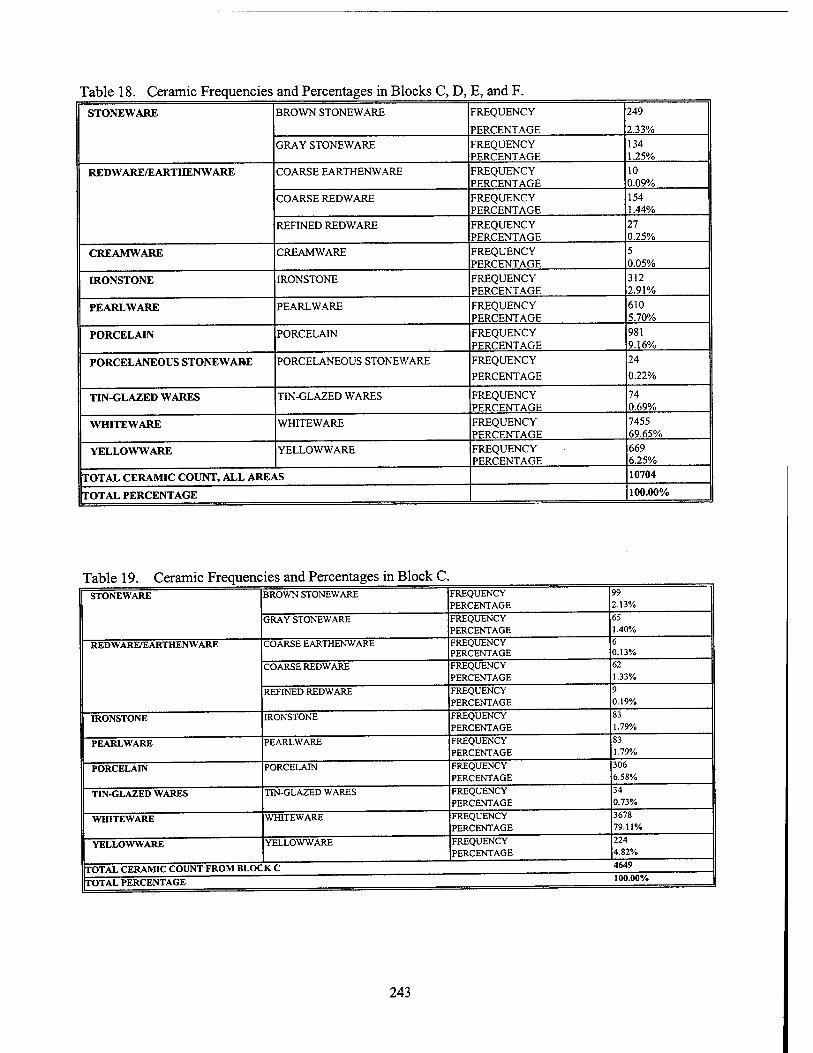
Table 18. Ceramic Frequencies and Percentages in Blocks C, D, E, and F. STONEWARE BROWN STONEWARE FREQUENCY
PERCENTAGE
249
2.33%
GRAY STONEWARE FREQUENCY PERCENTAGE
134 1.25%
REDWARE/EARTHENWARE COARSE EARTHENWARE FREQUENCY PERCENTAGE
10 0.09%
COARSE REDWARE FREQUENCY PERCENTAGE
154 1.44%
REFINED REDWARE FREQUENCY PERCENTAGE
27 0.25%
CREAMWARE CREAMWARE FREQUENCY PERCENTAGE
5 0.05%
IRONSTONE IRONSTONE FREQUENCY PERCENTAGE
312 2.91%
PEARLWARE PEARLWARE FREQUENCY PERCENTAGE
610 5.70%
PORCELAIN PORCELAIN FREQUENCY PERCENTAGE
981 9.16%
PORCELANEOUS STONEWARE PORCELANEOUS STONEWARE FREQUENCY
PERCENTAGE
24
0.22%
TIN-GLAZED WARES TIN-GLAZED WARES FREQUENCY PERCENTAGE
74 0.69%
WHITEWARE WHITEWARE FREQUENCY PERCENTAGE
7455 69.65%
YELLOWWARE YELLOWWARE FREQUENCY - PERCENTAGE
669 6.25%
TOTAL CERAMIC COUNT, ALL AREAS 10704
TOTAL PERCENTAGE 100.00%
Table 19. Ceramic Frequencies and Percentages in Block C. STONEWARE BROWN STONEWARE FREQUENCY
PERCENTAGE 99 2.13%
GRAY STONEWARE FREQUENCY PERCENTAGE
65 1.40%
REDWARE/EARTHENWARE COARSE EARTHENWARE FREQUENCY PERCENTAGE
6 0.13%
COARSE REDWARE FREQUENCY PERCENTAGE
62 1.33%
REFINED REDWARE FREQUENCY PERCENTAGE
9 0.19%
IRONSTONE IRONSTONE FREQUENCY PERCENTAGE
83 1.79%
PEARLWARE PEARLWARE FREQUENCY PERCENTAGE
83 1.79%
PORCELAIN PORCELAIN FREQUENCY PERCENTAGE
306 6.58%
TIN-GLAZED WARES TIN-GLAZED WARES FREQUENCY PERCENTAGE
34 0.73%
WHITEWARE WHITEWARE FREQUENCY PERCENTAGE
3678 79.11%
YELLOWWARE YELLOWWARE FREQUENCY PERCENTAGE
224 4.82%
TOTAL CERAMIC COUNT FROM BLOCK C 4649
TOTAL PERCENTAGE 100.00%
243
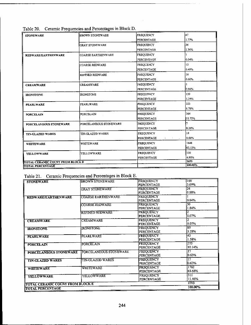
Table 20. Ceramic Frequencies and Percentages in Block D. STONEWARE BROWN STONEWARE FREQUENCY
PERCENTAGE
47
1.77%
GRAY STONEWARE FREQUENCY
PERCENTAGE
36
1.36%
REDWARE/EARTHENWARE COARSE EARTHENWARE FREQUENCY
PERCENTAGE
1
0.04%
COARSE REDWARE FREQUENCY
PERCENTAGE
13
0.49%
REFINED REDWARE FREQUENCY
PERCENTAGE
16
0.60%
CREAMWARE CREAMWARE FREQUENCY
PERCENTAGE
1
0.04%
IRONSTONE IRONSTONE FREQUENCY
PERCENTAGE
139
5.24%
PEARLWARE PEARLWARE FREQUENCY
PERCENTAGE
233
8.78%
PORCELAIN PORCELAIN FREQUENCY
PERCENTAGE
364
13.72%
PORCELANEOUS STONEWARE PORCELANEOUS STONEWARE FREQUENCY
PERCENTAGE
7
0.26%
TIN-GLAZED WARES TIN-GLAZED WARES FREQUENCY
PERCENTAGE
18
0.68%
WHITEWARE WHITEWARE FREQUENCY
PERCENTAGE
1648
62.12%
YELLOWWARE YELLOWWARE FREQUENCY
PERCENTAGE
130
4.90%
TOTAL CERAMIC COUNT FROM BLOCK D 2653
TOTAL PERCENTAGE 100.00%
Table 21. Ceramic Frequencies and Percentages in Block E. STONEWARE BROWN STONEWARE FREQUENCY
PERCENTAGE 100 3.69%
GRAY STONEWARE FREQUENCY PERCENTAGE
24 0.88%
REDWARE/EARTHENWARE COARSE EARTHENWARE FREQUENCY PERCENTAGE
1 0.04%
COARSE REDWARE FREQUENCY PERCENTAGE
50 1.84%
REFINED REDWARE FREQUENCY PERCENTAGE
2 0.07%
CREAMWARE CREAMWARE FREQUENCY PERCENTAGE
2 0.07%
IRONSTONE IRONSTONE FREQUENCY PERCENTAGE
89 3.28%
PEARLWARE PEARLWARE FREQUENCY PERCENTAGE
43 1.58%
PORCELAIN PORCELAIN FREQUENCY PERCENTAGE
275 10.14%
PORCELANEOUS STONEWARE PORCELANEOUS STONEWARE FREQUENCY PERCENTAGE
17 0.63%
TIN-GLAZED WARES TIN-GLAZED WARES FREQUENCY PERCENTAGE
17 0.63%
WHITEWARE WHITEWARE FREQUENCY PERCENTAGE
1782 65.68%
YELLOWWARE YELLOWWARE FREQUENCY PERCENTAGE
311 11.46%
TOTAL CERAMIC COUNT FROM BLOCK E 2713
TOTAL PERCENTAGE 100.00%
244
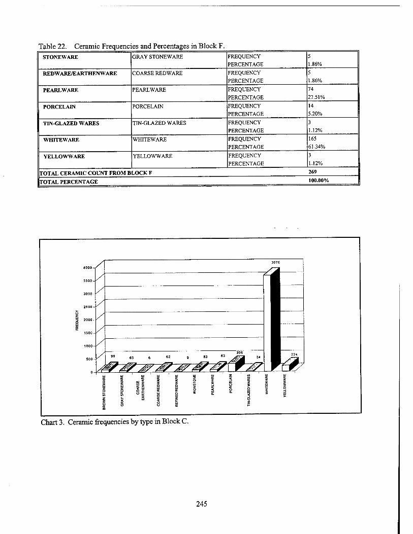
Table 22. Ceramic Frequencies and Percentages in Block F. STONEWARE GRAY STONEWARE FREQUENCY
PERCENTAGE
5
1.86%
REDWARE/EARTHENWARE COARSE RED WARE FREQUENCY
PERCENTAGE
5
1.86%
PEARLWARE PEARLWARE FREQUENCY
PERCENTAGE
74
27.51%
PORCELAIN PORCELAIN FREQUENCY
PERCENTAGE
14
5.20%
TIN-GLAZED WARES TIN-GLAZED WARES FREQUENCY
PERCENTAGE
3
1.12%
WHITEWARE WHITEWARE FREQUENCY
PERCENTAGE
165
61.34%
YELLOWWARE YELLOWWARE FREQUENCY
PERCENTAGE
3
1.12%
TOTAL CERAMIC COUNT FROM BLOCK F 269
TOTAL PERCENTAGE 100.00%
Chart 3. Ceramic frequencies by type in Block C.
245
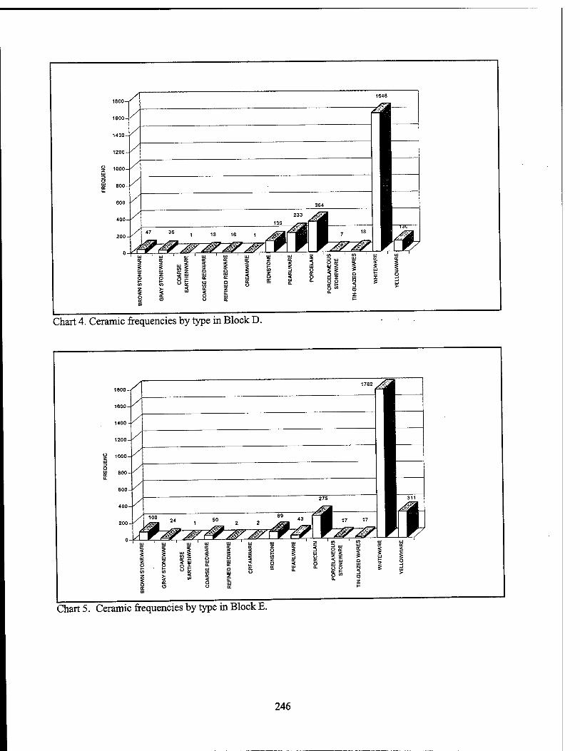
Chart 4. Ceramic frequencies by type in Block D.
Chart 5. Ceramic frequencies by type in Block E.
246
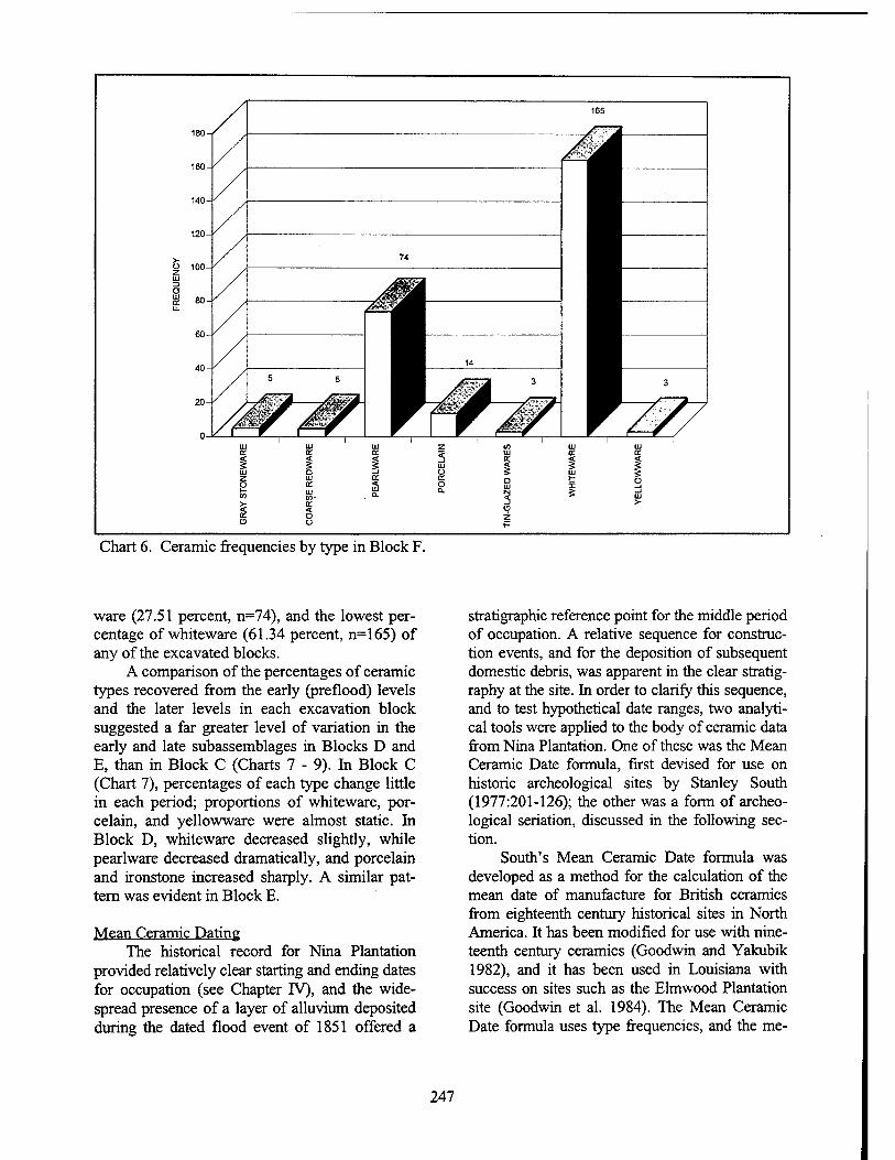
Chart 6. Ceramic frequencies by type in Block F.
ware (27.51 percent, n=74), and the lowest per- centage of whiteware (61.34 percent, n=165) of any of the excavated blocks.
A comparison of the percentages of ceramic types recovered from the early (preflood) levels and the later levels in each excavation block suggested a far greater level of variation in the early and late subassemblages in Blocks D and E, than in Block C (Charts 7 - 9). In Block C (Chart 7), percentages of each type change little in each period; proportions of whiteware, por- celain, and yellowware were almost static. In Block D, whiteware decreased slightly, while pearlware decreased dramatically, and porcelain and ironstone increased sharply. A similar pat- tern was evident in Block E.
Mean Ceramic Dating The historical record for Nina Plantation
provided relatively clear starting and ending dates for occupation (see Chapter IV), and the wide- spread presence of a layer of alluvium deposited during the dated flood event of 1851 offered a
stratigraphic reference point for the middle period of occupation. A relative sequence for construc- tion events, and for the deposition of subsequent domestic debris, was apparent in the clear stratig- raphy at the site. In order to clarify this sequence, and to test hypothetical date ranges, two analyti- cal tools were applied to the body of ceramic data from Nina Plantation. One of these was the Mean Ceramic Date formula, first devised for use on historic archeological sites by Stanley South (1977:201-126); the other was a form of archeo- logical seriation, discussed in the following sec- tion.
South's Mean Ceramic Date formula was developed as a method for the calculation of the mean date of manufacture for British ceramics from eighteenth century historical sites in North America. It has been modified for use with nine- teenth century ceramics (Goodwin and Yakubik 1982), and it has been used in Louisiana with success on sites such as the Elmwood Plantation site (Goodwin et al. 1984). The Mean Ceramic Date formula uses type frequencies, and the me-
247
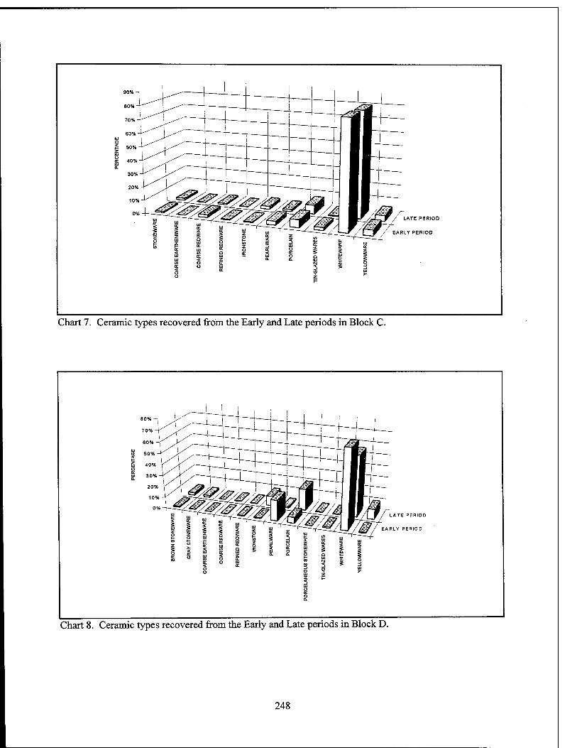
LATE PERIOD
EARLY PERIOD
Chart 7. Ceramic types recovered from the Early and Late periods in Block C.
LATE PERIOD
RLY PERIOD
Chart 8. Ceramic types recovered from the Early and Late periods in Block D.
248
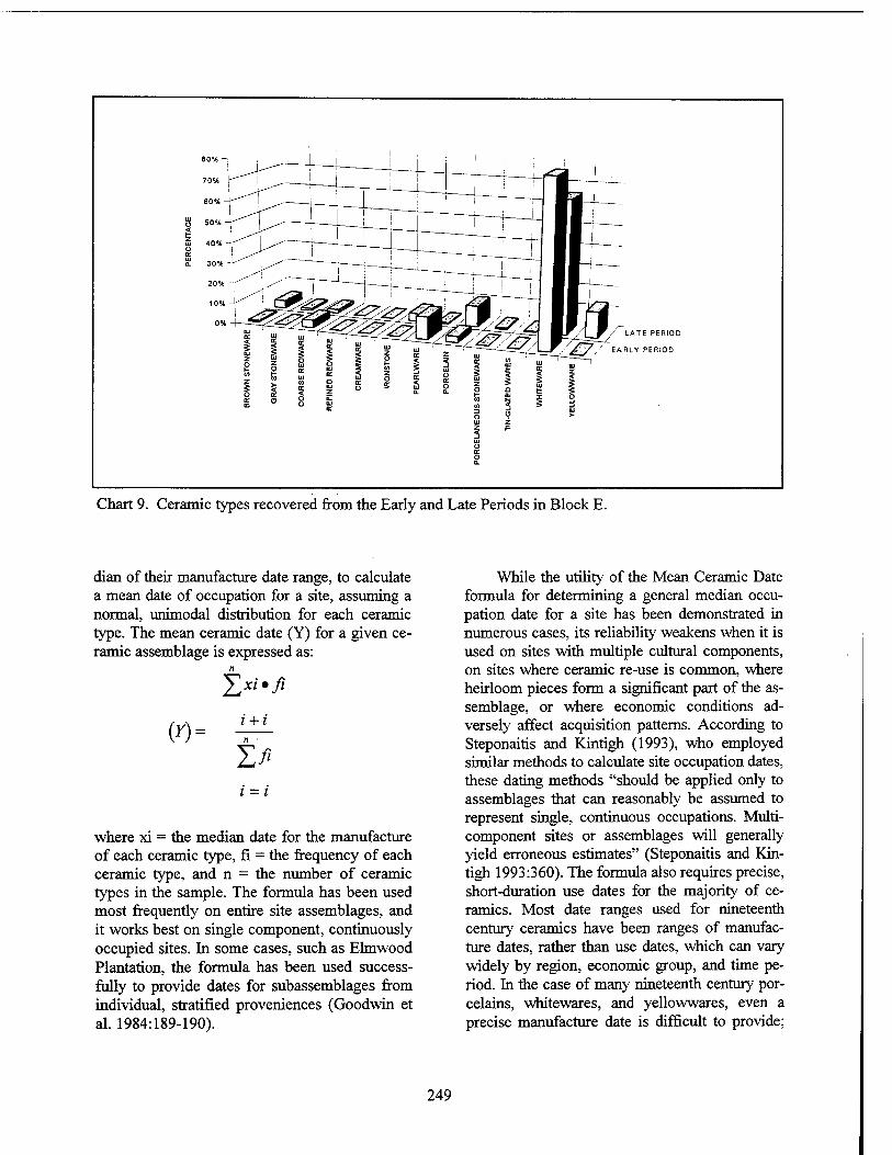
/ LATE PERIOD
EARLY PERIOD
Chart 9. Ceramic types recovered from the Early and Late Periods in Block E.
dian of their manufacture date range, to calculate a mean date of occupation for a site, assuming a normal, unimodal distribution for each ceramic type. The mean ceramic date (Y) for a given ce- ramic assemblage is expressed as:
Yjxi*fi
(*)- l + i
T,ß i = i
where xi = the median date for the manufacture of each ceramic type, fi = the frequency of each ceramic type, and n = the number of ceramic types in the sample. The formula has been used most frequently on entire site assemblages, and it works best on single component, continuously occupied sites. In some cases, such as Elmwood Plantation, the formula has been used success- fully to provide dates for subassemblages from individual, stratified proveniences (Goodwin et al. 1984:189-190).
While the utility of the Mean Ceramic Date formula for determining a general median occu- pation date for a site has been demonstrated in numerous cases, its reliability weakens when it is used on sites with multiple cultural components, on sites where ceramic re-use is common, where heirloom pieces form a significant part of the as- semblage, or where economic conditions ad- versely affect acquisition patterns. According to Steponaitis and Kintigh (1993), who employed similar methods to calculate site occupation dates, these dating methods "should be applied only to assemblages that can reasonably be assumed to represent single, continuous occupations. Multi- component sites or assemblages will generally yield erroneous estimates" (Steponaitis and Kin- tigh 1993:360). The formula also requires precise, short-duration use dates for the majority of ce- ramics. Most date ranges used for nineteenth century ceramics have been ranges of manufac- ture dates, rather than use dates, which can vary widely by region, economic group, and time pe- riod. In the case of many nineteenth century por- celains, whitewares, and yellowwares, even a precise manufacture date is difficult to provide;
249
many of these types have manufacture date ranges that span the nineteenth century.
Given these factors, the application of the Mean Ceramic Date formula to the data from Nina Plantation was not expected to yield ideal results. While the overall mean date for the site was within the expected range, the formula was unable to provide accurate mean dates for any of the substantially shorter temporal periods. The fact that the occupation of the site spanned the nineteenth century, as did the majority of the ce- ramic types, may explain the correspondence of the mean ceramic date to the actual mid-point of occupation.
The mean date for the entire site was calcu- lated at 1855.88 (n=9177, standard deviation = 15.89). Using the well documented end date of 1890, the mean date for the site would place the earliest date of occupation in 1821.76, which certainly is within the presumed historical range of 1820 - 1825. The overall calculated mean oc- cupation dates for the excavation blocks were 1854 (n=2456, standard deviation = 16.05) for Block D, 1857.2 (n=2588, standard deviation = 16.26) for Block E, and 1856 (n=4133, standard deviation = 13.93) for Block C. Using the end date of 1890, these mean dates would indicate the earliest occupation at the site in Block D (1818), first occupation of Block C in 1822, and occupa- tion of Block E in 1824. Blocks D and E both were associated with the main house, and evi- dence of continuous occupation was recovered from both areas. The difference in mean dates possibly reflects the construction in Block E of the north wing during the second half of the nineteenth century, and the later nineteenth cen- tury ceramic assemblage associated with its use. However, stratigraphic evidence clearly placed the construction of the north wing after the 1851 flood (see Chapter VET), a fact that is not re- flected in the calculated mean date for Block E.
When the formula was applied to ceramic subassemblages corresponding to early (antebellum) and late (largely postbellum) tempo- ral periods at the site, the results exhibited even less conformity with the historical and strati- graphic records. The mean date for the early pe- riod ceramic assemblage was 1851.23 (n=1392, standard deviation = 13.83), while the late period mean date was 1856.94 (n=7193, standard devia- tion = 16.2). Note that the total numbers of sherds
included in these calculations differed from those used in block calculations, because some tempo- ral periods, such as that of the flood, were not included in either the early or the late periods. In Block C, the early period had a mean date of 1856.73 (n=338, standard deviation = 14.27), and the late period's mean date was almost identical at 1856.74 (n=3234, standard deviation = 13.76). The identical mean dates and low standard devia- tions in Block C may be a reflection of a similar ceramic assemblage throughout the occupation span of the Outbuilding complex (see Chart 7).
Because the Main House complex was in both Blocks D and E, the data from these blocks were combined. The early period (antebellum) returned a mean date of 1851 (n=1037, standard deviation = 15.02), while the late period (largely postbellum) was dated at 1860.3 (n=3249, stan- dard deviation = 17.03). While the proper se- quential relationship is illustrated by these mean dates, they still do not correspond precisely with dates suggested by the larger body of site data. If a final date of 1890 were accepted as the end of the late period (site destruction), that would imply a beginning to the late period, represented by the flood deposition, in 1830. But if this were chronologically correct, then the mean date re- turned for the early period (1851) would clearly be incorrect.
Although the mean dates calculated using this method did not reflect actual occupation pe- riods, they did offer some qualitative information about the ceramic subassemblages from Nina Plantation. The mean dates for Blocks C, D, and E appeared to reflect the relative order of the con- struction sequence at the site, with the core of the main house in Block D producing the earliest date, and the north wing in Block E returning the most recent mean date. Additionally, the un- changed mean date for both early and late occu- pations in Block C, as well as the low standard deviation of the mean dates of ceramic types in this block, suggested a smaller variety of types with less temporal variation. This may be a re- flection of the lower economic status of the resi- dents of the Outbuilding complex, in contrast to the wealthier occupants of the Main House com- plex, who were able to purchase a greater variety of more popular ceramic types.
It is clear from these calculations that the Mean Ceramic Date formula is a less than ideal
250
chronological tool when applied to multicompo- nent sites like Nina Plantation. While the overall mean date returned from these calculations corre- sponded nicely with the estimate based on his- torical data, this may have resulted from the fact that the manufacturing dates for the majority of the recovered ceramics spanned the nineteenth century. As expected, the historical and strati- graphic data from Nina Plantation were able to provide a more reliable and fmer scaled chronol- ogy of site occupation than application of the Mean Ceramic Formula.
Seriation In addition to the Mean Ceramic Date for-
mula, another chronological tool applied to the ceramic data from Nina Plantation was seriation. In this method, relative frequencies of the major ceramic types from the excavated levels are ar- ranged to produce a relative chronological se- quence. The arrangement assumes a gradual rise, and then a decline in popularity for each ceramic type; the ideal popularity curve is "battleship- shaped," with the highest frequency at the height of the type's popularity (Ford 1962; Goodwin et al. 1984).
The seriation graph (Chart 10) then was compared to the chronological sequence sug- gested for the site by stratification, the direct his- torical approach, and by the known terminus post quern (tpq), i.e., the 1851 flood event (Chart 2). The results of this comparison indicated that the chronological sequence corroborated the relative chronology suggested by seriation. The most common ceramic type was whiteware, which re- mained constant throughout the occupation span of the site. This temporal persistence was not ex- hibited by any of the other types, which exhibited statistically normal changes in popularity and use through time.
Economic Scaling Economic scaling is being used with in-
creasing frequency with eighteenth and nine- teenth century historical data as an analytical tool that may aid in the determination of the relative social or economic status of an historical site's occupants. Relying on the late eighteenth and nineteenth century practice of price-fixing among potters in the English ceramic industry, economic scaling employs a "cc index," or compilation of
types and prices recognized by the English pot- tery industry (Miller 1980). "CC ware" was the industry's term for white-bodied, refined earth- enwares, including such wares as creamware, pearlware, and whiteware (Miller 1991:1). Through examination of wholesale price lists, price fixing lists, bills of lading, account books, and invoice statements, lists of index values for these different types of decorated ceramics have been developed (Miller 1980, 1991). During eco- nomic scaling analysis, a CC index value is cal- culated for a ceramic assemblages. The index value does not correspond to a fixed status level; there, it is a relative value that must be related to values from other sites and assemblages in the region. The use of this analytical tool allows "sites to be scaled in terms of their expenditure on ceramics" (Miller 1980:51), thereby determining the relative economic class of those purchasing the ceramics.
Economic scaling was conducted for ves- sels identified during rninimum vessel analysis. An index value was assigned to each vessel, based on its specific ware type, decorative treatment, form, and size; next, the values were averaged for each vessel form. The resulting ceramic index values then could be compared; in general, higher index values corresponded to higher purchase prices. Miller's index is based primarily on decorative type and form, rather than on ware type. According to Miller, the clas- sification of nineteenth century British ceramic assemblages by ware type provides only chronological information; however, classifica- tion of nineteenth century British-made ceramics by decorative treatment combines historical and archeological data, and provides consistency in identification and classification (Miller 1980:51).
During assignment of values, the 1859 index was used when possible (Miller 1991). This pro- vided a date as close as possible to the mean oc- cupation date of the site. If an index value for a specific ceramic type was not available for 1859, the next closest year index value was used. The ceramic index value for any dish in the collection less then 10 inches in diameter was calculated at the 10 inch size. All plates in the collection had their index values calculated at the 9 to 10 inch size, while saucers were defined as plates be- tween 5 to 7 inches in size. Any saucer with a
251
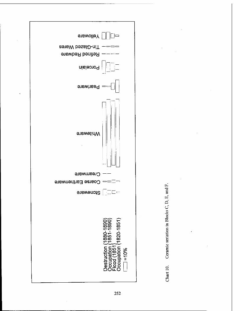
9JBM0||9A D sajBM pszBio-uii
ajB/wpsy peujpy
U!B|90J0d D
9JBM|JB9d ■D
9JBM9JI.11M
9JBMWB9JQ
9JBMU9U.JJB3 9SJE0Q =o
9JBM9U01S GO0'
OO T- 0505 LO 0000 00 T— T— T—
OT- O com CM coco 00 ^£Zv—J^
Des
truc
tion
Occ
upat
ion
Floo
d (1
851
Occ
upat
ion
O
T3
§
d ü
CO
O
5 c c o
CO
cS
o O
252
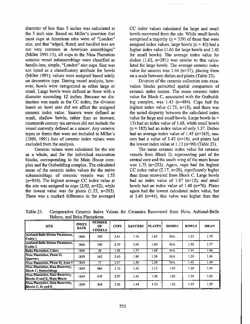
diameter of less than 5 inches was calculated at the 5 inch size. Based on Miller's assertion that most cups at American sites were of "London" size, and that "edged, fluted, and handled teas are not very common in American assemblages" (Miller 1991:15), all cups in the Nina Plantation ceramic vessel subassemblage were classified as handle-less, simple, "London" size cups. Size was not listed as a classificatory attribute for bowls (Miller 1991); values were assigned based solely on decorative type. During vessel analysis, how- ever, bowls were categorized as either large or small. Large bowls were defined as those with a diameter exceeding 12 inches. Because no dis- tinction was made in the CC index, the division based on bowl size did not affect the assigned ceramic index value. Saucers were defined as small, shallow bowls, rather than as teaware; nineteenth century tea services did not include the vessel currently defined as a saucer. Any ceramic types or forms that were not included in Miller's (1980, 1991) lists of ceramic index values were excluded from the analysis.
Ceramic values were calculated for the site as a whole, and for the individual excavation blocks, corresponding to the Main House com- plex and the Outbuilding complex. The calculated mean of the ceramic index values for the entire subassemblage of ceramic vessels was 1.55 (n=954). The highest average CC index value at the site was assigned to cups (2.02, n=52), while the lowest value was for plates (1.23, n=203). There was a marked difference in the averaged
CC index values calculated for large and small bowls recovered from the site. While small bowls comprised a majority (n = 339) of those that were assigned index values, large bowls (n = 42) had a higher index value (1.65 for large bowls and 1.41 for small bowls). The average index value for dishes (1.62, n=281) was similar to that calcu- lated for large bowls. The average ceramic index value for saucers was 1.44 (n=37), placing them on a scale between dishes and plates (Table 23).
Division of the ceramic collection into exca- vation blocks permitted spatial comparison of ceramic index means. The mean ceramic index value for Block C, associated with the Outbuild- ing complex, was 1.43 (n=484). Cups had the highest index value (1.75, n=18), and there was the noted disparity between the calculated index value for large and small bowls. Large bowls (n = 13) had an index value of 1.68, while small bowls (n = 182) had an index value of only 1.37. Dishes had an average index value of 1.45 (n=163), sau- cers had a value of 1.42 (n=18), and plates had the lowest index value at 1.13 (n=90) (Table 23).
The mean ceramic index value for ceramic vessels from Block D, representing part of the central core and the south wing of the main house was 1.75 (n=253). Again, cups had the highest CC index value (2.17, n=20), significantly higher than those recovered from Block C. Large bowls had an index value of 1.87 (n=12), and small bowls had an index value of 1.48 (n=76). Plates again had the lowest calculated index value, but at 1.45 (n=44), this valve was higher than that
Table 23. Comparative Ceramic Index Values for Ceramics Recovered from Nina, Ashland-Belle Helene, and Beka Plantations.
SITE INDEX DATE
NUMBER OF
VESSELS CUPS SAUCERS PLATES DISHES BOWLS MEAN
Ashland-Belle Helene Plantation, Cabin 1
1866 195 2.41 1.74 1.65 N/A 1.53 1.79
Ashland-Belle Helene Plantation, Cabin 2
1866 190 2.39 2.00 1.60 N/A 1.50 1.77
Beka Plantation, Cabin 1866 58 1.98 1.57 1.68 N/A 1.51 1.66 Nina Plantation, Phase II, Quarters
1859 162 2.40 1.80 1.58 N/A 1.29 1.56
Nina Plantation, Phase II, Area 1 1859 77 2.17 1.50 1.30 N/A 1.45 1.49 Nina Plantation, Data Recovery, Block C, Outbuildings
1859 484 1.75 1.42 1.13 1.45 1.39 1.43
Nina Plantation, Data Recovery, Blocks D and E, Main House
1859 470 2.07 1.45 1.28 1.82 1.54 1.63
Nina Plantation, Data Recovery, Blocks C, D, and E
1859 954 2.02 1.44 1.23 1.62 1.43 1.55
253
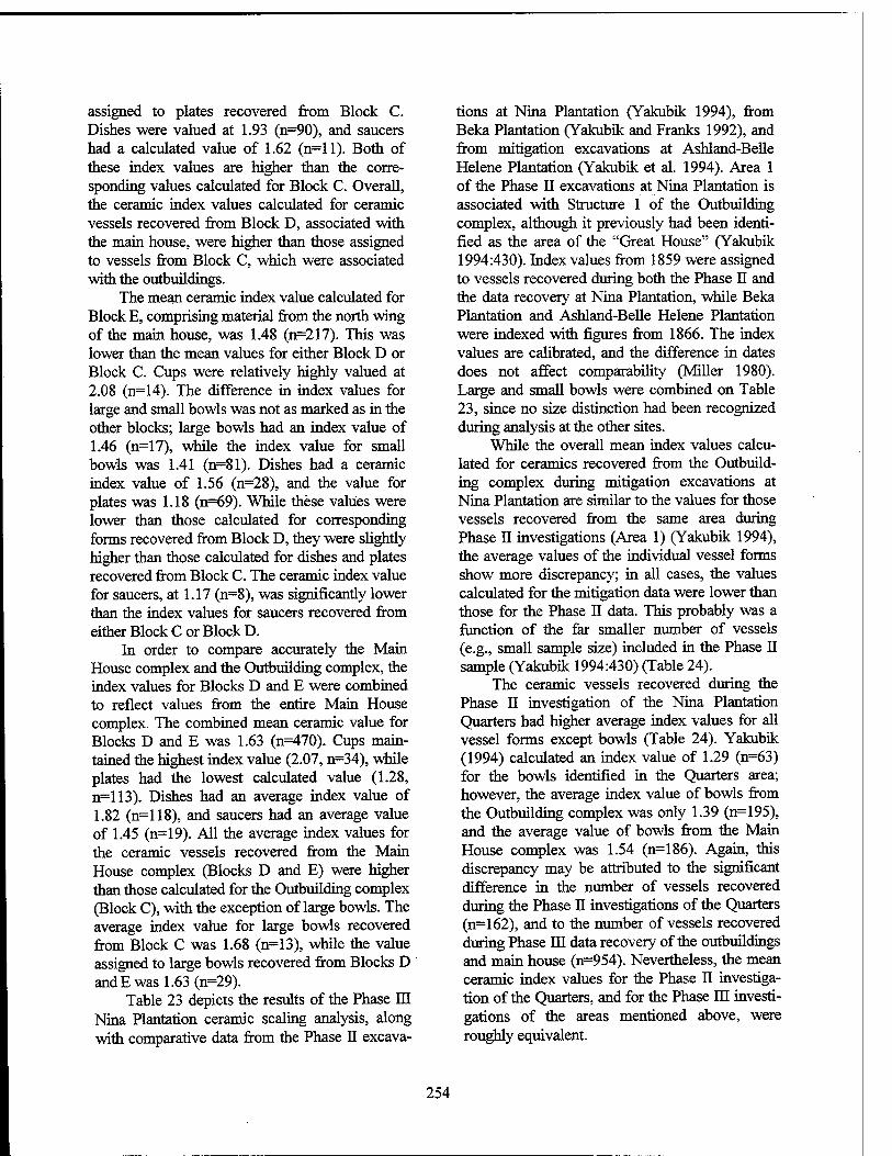
assigned to plates recovered from Block C. Dishes were valued at 1.93 (n=90), and saucers had a calculated value of 1.62 (n=ll). Both of these index values are higher than the corre- sponding values calculated for Block C. Overall, the ceramic index values calculated for ceramic vessels recovered from Block D, associated with the main house, were higher than those assigned to vessels from Block C, which were associated with the outbuildings.
The mean ceramic index value calculated for Block E, comprising material from the north wing of the main house, was 1.48 (n=217). This was lower than the mean values for either Block D or Block C. Cups were relatively highly valued at 2.08 (n=14). The difference in index values for large and small bowls was not as marked as in the other blocks; large bowls had an index value of 1.46 (n=17), while the index value for small bowls was 1.41 (n=81). Dishes had a ceramic index value of 1.56 (n=28), and the value for plates was 1.18 (n=69). While these values were lower than those calculated for corresponding forms recovered from Block D, they were slightly higher than those calculated for dishes and plates recovered from Block C. The ceramic index value for saucers, at 1.17 (n=8), was significantly lower than the index values for saucers recovered from either Block C or Block D.
In order to compare accurately the Main House complex and the Outbuilding complex, the index values for Blocks D and E were combined to reflect values from the entire Main House complex. The combined mean ceramic value for Blocks D and E was 1.63 (n=470). Cups main- tained the highest index value (2.07, n=34), while plates had the lowest calculated value (1.28, n=113). Dishes had an average index value of 1.82 (n=118), and saucers had an average value of 1.45 (n=19). All the average index values for the ceramic vessels recovered from the Main House complex (Blocks D and E) were higher than those calculated for the Outbuilding complex (Block C), with the exception of large bowls. The average index value for large bowls recovered from Block C was 1.68 (n=13), while the value assigned to large bowls recovered from Blocks D and E was 1.63 (n=29).
Table 23 depicts the results of the Phase El Nina Plantation ceramic scaling analysis, along with comparative data from the Phase II excava-
tions at Nina Plantation (Yakubik 1994), from Beka Plantation (Yakubik and Franks 1992), and from mitigation excavations at Ashland-Belle Helene Plantation (Yakubik et al. 1994). Area 1 of the Phase II excavations at Nina Plantation is associated with Structure 1 of the Outbuilding complex, although it previously had been identi- fied as the area of the "Great House" (Yakubik 1994:430). Index values from 1859 were assigned to vessels recovered during both the Phase II and the data recovery at Nina Plantation, while Beka Plantation and Ashland-Belle Helene Plantation were indexed with figures from 1866. The index values are calibrated, and the difference in dates does not affect comparability (Miller 1980). Large and small bowls were combined on Table 23, since no size distinction had been recognized during analysis at the other sites.
While the overall mean index values calcu- lated for ceramics recovered from the Outbuild- ing complex during mitigation excavations at Nina Plantation are similar to the values for those vessels recovered from the same area during Phase II investigations (Area 1) (Yakubik 1994), the average values of the individual vessel forms show more discrepancy; in all cases, the values calculated for the mitigation data were lower than those for the Phase II data. This probably was a function of the far smaller number of vessels (e.g., small sample size) included in the Phase II sample (Yakubik 1994:430) (Table 24).
The ceramic vessels recovered during the Phase II investigation of the Nina Plantation Quarters had higher average index values for all vessel forms except bowls (Table 24). Yakubik (1994) calculated an index value of 1.29 (n=63) for the bowls identified in the Quarters area; however, the average index value of bowls from the Outbuilding complex was only 1.39 (n=195), and the average value of bowls from the Main House complex was 1.54 (n=186). Again, this discrepancy may be attributed to the significant difference in the number of vessels recovered during the Phase II investigations of the Quarters (n=162), and to the number of vessels recovered during Phase HI data recovery of the outbuildings and main house (n=954). Nevertheless, the mean ceramic index values for the Phase II investiga- tion of the Quarters, and for the Phase m investi- gations of the areas mentioned above, were roughly equivalent.
254
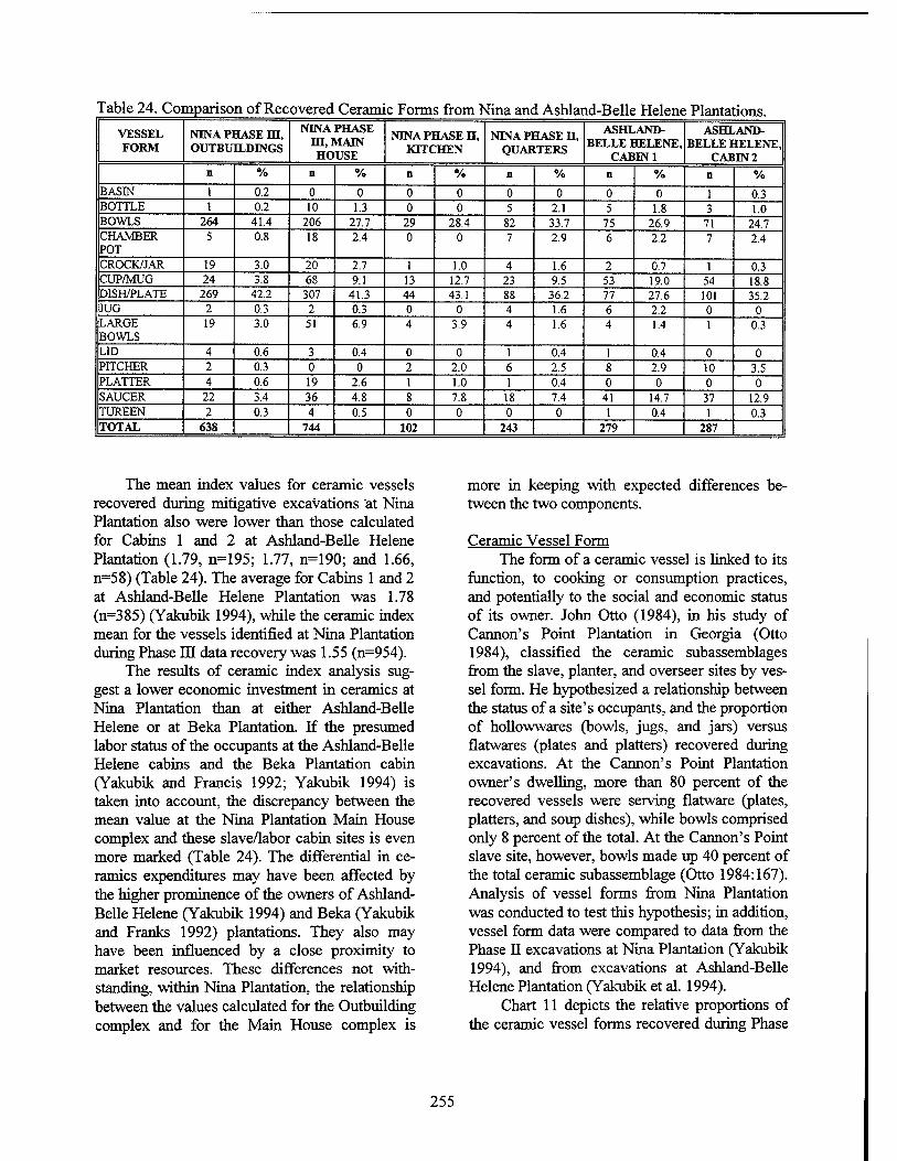
Table 24. Comparison of Recovered Ceramic Forms from Nina and Ashland-Belle Helene Plantations. VESSEL FORM
NINA PHASE m, OUTBUILDINGS
NINA PHASE m,MAIN HOUSE
NINA PHASE H, KITCHEN
NINA PHASE H, QUARTERS
ASHLAND- BELLE HELENE,
CABIN 1
ASHLAND- BELLE HELENE,
CABIN 2 n % n % D % n % n % D %
BASIN 1 0.2 0 0 0 0 0 0 0 0 1 0.3 BOTTLE 1 0.2 10 1.3 0 0 5 2.1 5 1.8 3 1.0 BOWLS 264 41.4 206 27.7 29 28.4 82 33.7 75 26.9 71 24.7 CHAMBER POT
5 0.8 18 2.4 0 0 7 2.9 6 2.2 7 2.4
CROCK/JAR 19 3.0 20 2.7 1 1.0 4 1.6 2 0.7 1 0.3 CUP/MUG 24 3.8 68 9.1 13 12.7 23 9.5 53 19.0 54 18.8 DISH/PLATE 269 42.2 307 41.3 44 43.1 88 36.2 77 27.6 101 35.2 JUG 2 0.3 2 0.3 0 0 4 1.6 6 2.2 0 0 LARGE BOWLS
19 3.0 51 6.9 4 3.9 4 1.6 4 1.4 1 0.3
LID 4 0.6 3 0.4 0 0 1 0.4 1 0.4 0 0 PITCHER 2 0.3 0 0 2 2.0 6 2.5 8 2.9 10 3.5 PLATTER 4 L 0.6 19 2.6 1 1.0 1 0.4 0 0 0 0 SAUCER 22 3.4 36 4.8 8 7.8 18 7.4 41 14.7 37 12.9 TUREEN 2 0.3 4 0.5 0 0 0 0 1 0.4 1 0.3 TOTAL 638 744 102 243 279 287
The mean index values for ceramic vessels recovered during mitigative excavations at Nina Plantation also were lower than those calculated for Cabins 1 and 2 at Ashland-Belle Helene Plantation (1.79, n=195; 1.77, n=190; and 1.66, n=58) (Table 24). The average for Cabins 1 and 2 at Ashland-Belle Helene Plantation was 1.78 (n=385) (Yakubik 1994), while the ceramic index mean for the vessels identified at Nina Plantation during Phase III data recovery was 1.55 (n=954).
The results of ceramic index analysis sug- gest a lower economic investment in ceramics at Nina Plantation than at either Ashland-Belle Helene or at Beka Plantation. If the presumed labor status of the occupants at the Ashland-Belle Helene cabins and the Beka Plantation cabin (Yakubik and Francis 1992; Yakubik 1994) is taken into account, the discrepancy between the mean value at the Nina Plantation Main House complex and these slave/labor cabin sites is even more marked (Table 24). The differential in ce- ramics expenditures may have been affected by the higher prominence of the owners of Ashland- Belle Helene (Yakubik 1994) and Beka (Yakubik and Franks 1992) plantations. They also may have been influenced by a close proximity to market resources. These differences not with- standing, within Nina Plantation, the relationship between the values calculated for the Outbuilding complex and for the Main House complex is
more in keeping with expected differences be- tween the two components.
Ceramic Vessel Form The form of a ceramic vessel is linked to its
function, to cooking or consumption practices, and potentially to the social and economic status of its owner. John Otto (1984), in his study of Cannon's Point Plantation in Georgia (Otto 1984), classified the ceramic subassemblages from the slave, planter, and overseer sites by ves- sel form. He hypothesized a relationship between the status of a site's occupants, and the proportion of hollowwares (bowls, jugs, and jars) versus flatwares (plates and platters) recovered during excavations. At the Cannon's Point Plantation owner's dwelling, more than 80 percent of the recovered vessels were serving flatware (plates, platters, and soup dishes), while bowls comprised only 8 percent of the total. At the Cannon's Point slave site, however, bowls made up 40 percent of the total ceramic subassemblage (Otto 1984:167). Analysis of vessel forms from Nina Plantation was conducted to test this hypothesis; in addition, vessel form data were compared to data from the Phase II excavations at Nina Plantation (Yakubik 1994), and from excavations at Ashland-Belle Helene Plantation (Yakubik et al. 1994).
Chart 11 depicts the relative proportions of the ceramic vessel forms recovered during Phase
255
Chart 11. Vessel forms from Blocks C, D, and E.
m data recovery at Nina Plantation. The category dishes/plates constituted 41.7 percent of the total vessel subassemblage, and bowls comprised 34 percent of the subassemblage. Combined, these consumption vessels accounted for 75.7 percent of the total of ceramic vessel subassemblage re- covered from Blocks C, D, and E. Cups/mugs and large bowls were the only two remaining vessel types that represented percentages greater than 5 percent (6.7 percent and 5.1 percent, respec- tively).
Table 24 inventories the ceramic vessel forms recovered from the Nina Plantation Out- building complex (Block C), and from the Main House complex (Blocks D and E). Vessel form data from Phase II testing of the kitchen and quarters of Nina Plantation (Yakubik et al. 1994), and from Cabins 1 and 2 at Ashland-Belle Helene Plantation (Yakubik 1994), are shown for com- parative purposes. Chart 12 offers a graphic com- parison of the proportionate relationships between vessel forms recovered from the Outbuilding complex, the Main House complex, and from the quarters area of Nina Plantation tested by Yaku- bik et al. (1994).
Arranged chronologically (Table 25), the proportions of the vessel forms recovered from
the Outbuilding complex and the Main House complex exhibited some diachronic changes. The percentage of bowls decreased in the late period in both the Outbuilding complex and the Main House complex, though the change was more pronounced in the outbuildings. While dishes/plates increased in relative proportion in the area of the outbuildings during the late period, they maintained consistency at the Main House complex. The proportions of cups also changed during the late period, decreasing at both the Out- building complex and the Main House complex.
To determine the statistical significance of the spatial and temporal distributions of these vessel forms, chi-squared tests of independence were conducted on various configurations of the vessel data. The results of these statistical calcu- lations are presented in (Tables 26 through 29). The first test included a variety of vessel forms (bowls, large bowls, plates, platters, saucers, and cups). The probability figure in Table 26 repre- sents the probability that the differences in the proportions of the vessel forms are due to chance or sampling. The result (p=0.0000000003171) indicates a very high probability that the observed distribution of these vessel forms is statistically significant, rather than random. Tables 27 - 28
256
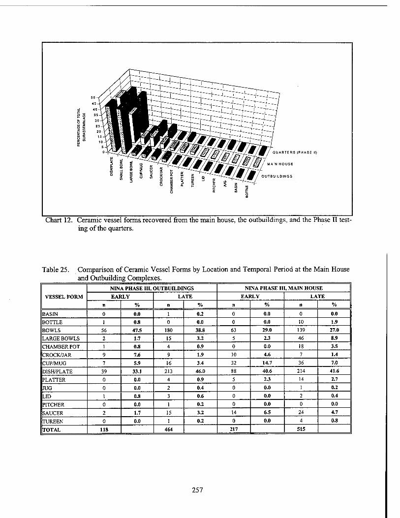
ft = Ui 2 <3 S
QUARTERS (PHASE II)
MAIN HOUSE
OUTBUILDINGS
Chart 12. Ceramic vessel forms recovered from the main house, the outbuildings, and the Phase II test- ing of the quarters.
Table 25. Comparison of Ceramic Vessel Forms by Location and Temporal Period at the Main House and Outbuilding Complexes.
VESSEL FORM
NINA PHASE III, OUTBUILDINGS NINA PHASE III, MAIN HOUSE
EARLY LATE EARLY LATE
n % n % n % n % BASIN 0 0.0 1 0.2 0 0.0 0 0.0
BOTTLE 1 0.8 0 0.0 0 0.0 10 1.9
BOWLS 56 47.5 180 38.8 63 29.0 139 27.0
LARGE BOWLS 2 1.7 15 3.2 5 23 46 8.9
CHAMBERPOT 1 0.8 4 0.9 0 0.0 18 3.5
CROCK/JAR 9 7.6 9 1.9 10 4.6 7 1.4
CUP/MUG 7 5.9 16 3.4 32 14.7 36 7.0
DISH/PLATE 39 33.1 213 46.0 88 40.6 214 41.6
PLATTER 0 0.0 4 0.9 5 23 14 2.7
JUG 0 0.0 2 0.4 0 0.0 1 0.2
LID 1 0.8 3 0.6 0 0.0 2 0.4
PITCHER 0 0.0 1 0.2 0 0.0 0 0.0
SAUCER 2 1.7 15 3.2 14 6.5 24 4.7
TUREEN 0 0.0 1 0.2 0 0.0 4 0.8
TOTAL 118 464 217 515
257
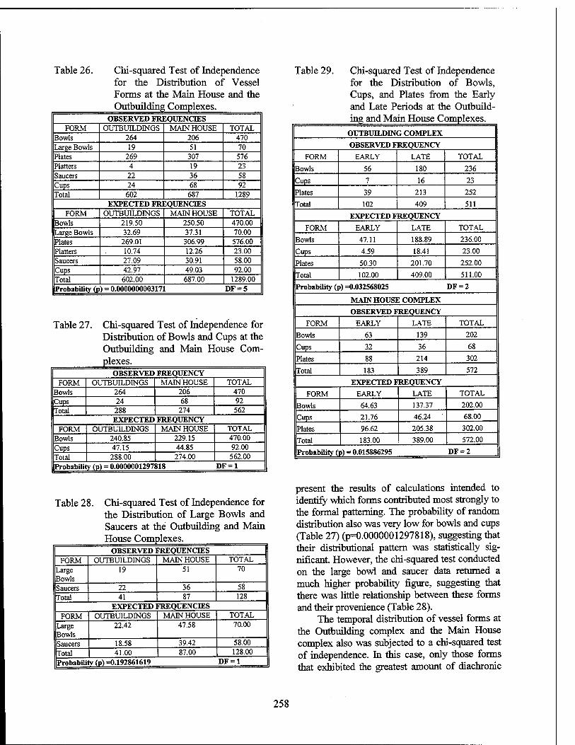
Table 26. Chi-squared Test of Independence for the Distribution of Vessel Forms at the Main House and the Outbuilding Complexes.
OBSERVED FREQUENCIES FORM OUTBUILDINGS MAIN HOUSE TOTAL
Bowls 264 206 470 Large Bowls 19 51 70 Plates 269 307 576 Platters 4 19 23 Saucers 22 36 58 Cups 24 68 92 Total 602 687 1289
EXPECTED FREQUENCIES FORM OUTBUILDINGS MAIN HOUSE TOTAL
Bowls 219.50 250.50 470.00 Large Bowls 32.69 37.31 70.00 Plates 269.01 306.99 576.00 Platters 10.74 12.26 23.00 Saucers 27.09 30.91 58.00 Cups 42.97 49.03 92.00 Total 602.00 687.00 1289.00 Probability (p ) = 0.0000000003171 DF = 5
Table 27. Chi-squared Test of Independence for Distribution of Bowls and Cups at the Outbuilding and Main House Com- plexes.
OBSERVED FREQUENCY FORM OUTBUILDINGS MAIN HOUSE TOTAL
Bowls 264 206 470 Cups 24 68 92 Total 288 274 562
EXPECTED FREQUENCY FORM OUTBUILDINGS MAIN HOUSE TOTAL
Bowls 240.85 229.15 470.00 Cups 47.15 44.85 92.00 Total 288.00 274.00 562.00 Probability (p) = 0.0000001297818 DF = 1
Table 28. Chi-squared Test of Independence for the Distribution of Large Bowls and Saucers at the Outbuilding and Main House Complexes.
OBSERVED FREQUENCIES FORM OUTBUILDINGS MAIN HOUSE TOTAL
Large Bowls
19 51 70
Saucers 22 36 58
Total 41 87 128 EXPECTED FREQUENCIES
FORM OUTBUILDINGS MAIN HOUSE TOTAL
Large Bowls
22.42 47.58 70.00
Saucers 18.58 39.42 58.00
Total 41.00 87.00 128.00
Probabili ly (p) =0.192861619 DF = 1
Table 29. Chi-squared Test of Independence for the Distribution of Bowls, Cups, and Plates from the Early and Late Periods at the Outbuild- ing and Main House Complexes.
OUTBUTJLDING COMPLEX
OBSERVED FREQUENCY
FORM EARLY LATE TOTAL
Bowls 56 180 236
Cups 7 16 23
Plates 39 213 252
Total 102 409 511
EXPECTED FREQUENCY
FORM EARLY LATE TOTAL
Bowls 47.11 188.89 236.00
Cups 4.59 18.41 23.00
Plates 50.30 201.70 252.00
Total 102.00 409.00 511.00
Probability (p) =0.032568025 DF = 2
MAIN HOUSE COMPLEX
OBSERVED FREQUENCY
FORM EARLY LATE TOTAL
Bowls 63 139 202
Cups 32 36 68
Plates 88 214 302
Total 183 389 572
EXPECTED FREQUENCY
FORM EARLY LATE TOTAL
Bowls 64.63 137.37 202.00
Cups 21.76 46.24 68.00
Plates 96.62 205.38 302.00
Total 183.00 389.00 572.00
Probability (] p) = 0.015886295 DF = 2
present the results of calculations intended to identify which forms contributed most strongly to the formal patterning. The probability of random distribution also was very low for bowls and cups (Table 27) (p=0.0000001297818), suggesting that their distributional pattern was statistically sig- nificant. However, the chi-squared test conducted on the large bowl and saucer data returned a much higher probability figure, suggesting that there was little relationship between these forms and their provenience (Table 28).
The temporal distribution of vessel forms at the Outbuilding complex and the Main House complex also was subjected to a chi-squared test of independence. In this case, only those forms that exhibited the greatest amount of diachronic
258
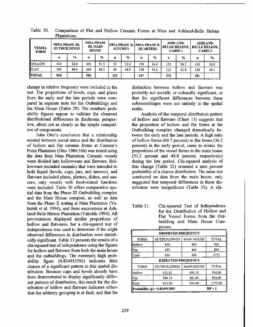
Table 30. Comparison of Flat and Hollow Ceramic Forms at Nina and Ashland-Belle Helene Plantations.
VESSEL FORM
NINA PHASE m, OUTBUILDINGS
NINA PHASE HI, MAIN HOUSE
NINA PHASE H, KITCHEN
NINA PHASE H, QUARTERS
ASHLAND- BELLE HELENE,
CABIN 1
ASHLAND- BELLE HELENE,
CABIN 2
n % ii % n % ii % n % n % HOLLOW 424 52.0 492 51.5 53 52.0 129 54.4 155 56.2 143 50.9
FLAT 392 48.0 464 48.5 49 48.0 108 45.6 121 43.8 138 49.1
TOTAL 816 956 102 237 276 281
change in relative frequency were included in the test. The proportions of bowls, cups, and plates from the early and the late periods were com- pared in separate tests for the Outbuildings and the Main House (Table 29). The resultant prob- ability figures appear to validate the observed distributional differences in diachronic perspec- tive, albeit not as clearly as the simple compari- son of components.
John Otto's conclusion that a relationship existed between social status and the distribution of hollow and flat ceramic forms at Cannon's Point Plantation (Otto 1984:166) was tested using the data from Nina Plantation. Ceramic vessels were divided into hollowware and flatware. Hol- lowware included ceramics that were intended to hold liquid (bowls, cups, jars, and tureens), and flatware included plates, platters, dishes, and sau- cers; only vessels with food-related functions were included. Table 30 offers comparative spa- tial data from the Phase El Outbuilding complex and the Main House complex, as well as data from the Phase II testing at Nina Plantation (Ya- kubik et al. 1994), and from excavations at Ash- land-Belle Helene Plantation (Yakubik 1994). All proveniences displayed similar proportions of hollow and flatwares, but a chi-squared test of independence was used to determine if the slight observed differences in distribution were statisti- cally significant. Table 31 presents the results of a chi-squared test of independence using the figures for hollow and flatware from both the main house and the outbuildings. The extremely high prob- ability figure (0.834912592) indicates little chance of a significant pattern in this spatial dis- tribution. Because cups and bowls already have been demonstrated to display significantly differ- ent patterns of distribution, this result for the dis- tribution of hollow and flatware indicates either- that the arbitrary grouping is at fault, and that the
distinction between hollow and flatware was probably not socially or culturally significant, or that the significant differences between these subassemblages were not entirely in the spatial realm.
Analysis of the temporal distribution pattern of hollow and flatware (Chart 13) suggests that the proportion of hollow and flat forms at the Outbuilding complex changed dramatically be- tween the early and the late periods. A high ratio of hollow forms (64.7 percent) to flat forms (36.2 percent) in the early period, came to mimic the proportions of the vessel forms in the main house (51.2 percent and 48.8 percent, respectively) during the late period. Chi-squared analysis of this change (Table 32) returned a zero percent probability of a chance distribution. The same test conducted on data from the main house, only suggested that temporal differences in these dis- tribution were insignificant (Table 33). A chi-
Table31. Chi-squared Test of Independence for the Distribution of Hollow and Flat Vessel Forms from the Out- building and Main House Com- plexes. OBSERVED FREQUENCY
FORM OUTBUILDINGS MAIN HOUSE TOTAL
Hollow 424 492 916
Flat 392 464 856
Total 816 956 1772
EXPECTED FREQUENCY
FORM OUTBUILDINGS MAIN HOUSE TOTAL
Hollow 421.81 494.19 916.00
Flat 394.19 461.81 856.00
Total 816.00 956.00 1772.00
Probability (p = 0.834912592 DF = 1
259
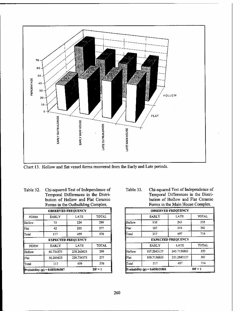
Chart 13. Hollow and flat vessel forms recovered from the Early and Late periods.
Table 32. Chi-squared Test of Independence of Temporal Differences in the Distri- bution of Hollow and Flat Ceramic Forms in the Outbuilding Complex.
OBSERVED FREQUENCY
FORM EARLY LATE TOTAL
Hollow 75 224 299
Flat 42 235 277
Total 117 459 576
EXPECTED FREQUENCY
FORM EARLY LATE TOTAL
Hollow 60.734375 238.265625 299
Flat 56.265625 220.734375 277
Total 117 459 576
Probability (p) = 0.003106587 DF = 1
Table 33. Chi-squared Test of Independence of Temporal Differences in the Distri- bution of Hollow and Flat Ceramic Forms in the Main House Complex.
OBSERVED FREQUENCY
EARLY LATE TOTAL
Hollow 110 243 353
Flat 107 254 361
Total 217 497 714
EXPECTED FREQUENCY
EARLY LATE TOTAL
Hollow 107.2843137 245.7156863 353
Flat 109.7156863 251.2843137 361
Total 217 497 714
Probability (p) = 0.658521881 DF = 1
260
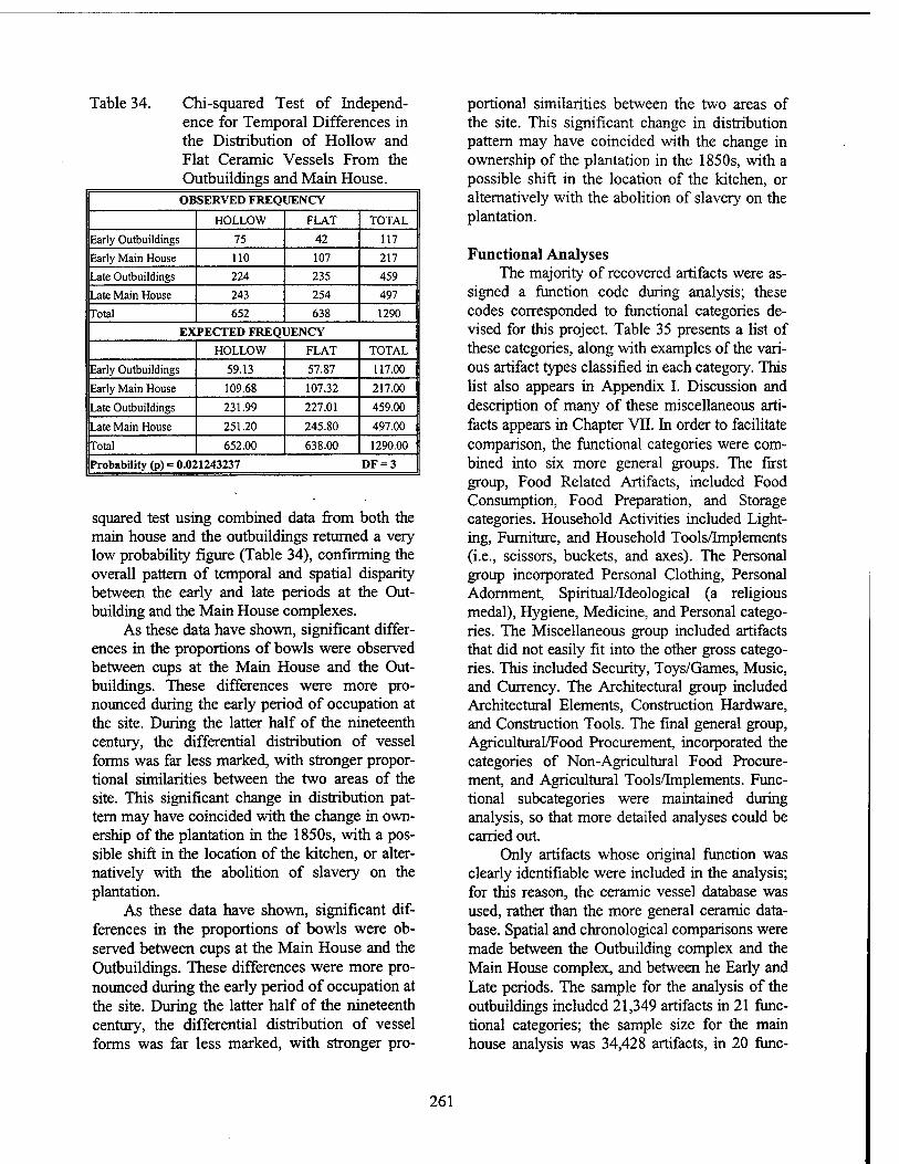
Table 34. Chi-squared Test of Independ- ence for Temporal Differences in the Distribution of Hollow and Flat Ceramic Vessels From the Outbuildings and Main House.
OBSERVED FREQUENCY
HOLLOW FLAT TOTAL
Early Outbuildings 75 42 117
Early Main House 110 107 217
Late Outbuildings 224 235 459
Late Main House 243 254 497
Total 652 638 1290
EXPECTED FREQUENCY
HOLLOW FLAT TOTAL
Early Outbuildings 59.13 57.87 117.00
Early Main House 109.68 107.32 217.00
Late Outbuildings 231.99 227.01 459.00
Late Main House 251.20 245.80 497.00
Total 652.00 638.00 1290.00
Probability (p) = 0.02 1243237 DF = 3
squared test using combined data from both the main house and the outbuildings returned a very low probability figure (Table 34), confirming the overall pattern of temporal and spatial disparity between the early and late periods at the Out- building and the Main House complexes.
As these data have shown, significant differ- ences in the proportions of bowls were observed between cups at the Main House and the Out- buildings. These differences were more pro- nounced during the early period of occupation at the site. During the latter half of the nineteenth century, the differential distribution of vessel forms was far less marked, with stronger propor- tional similarities between the two areas of the site. This significant change in distribution pat- tern may have coincided with the change in own- ership of the plantation in the 1850s, with a pos- sible shift in the location of the kitchen, or alter- natively with the abolition of slavery on the plantation.
As these data have shown, significant dif- ferences in the proportions of bowls were ob- served between cups at the Main House and the Outbuildings. These differences were more pro- nounced during the early period of occupation at the site. During the latter half of the nineteenth century, the differential distribution of vessel forms was far less marked, with stronger pro-
portional similarities between the two areas of the site. This significant change in distribution pattern may have coincided with the change in ownership of the plantation in the 1850s, with a possible shift in the location of the kitchen, or alternatively with the abolition of slavery on the plantation.
Functional Analyses The majority of recovered artifacts were as-
signed a function code during analysis; these codes corresponded to functional categories de- vised for this project. Table 35 presents a list of these categories, along with examples of the vari- ous artifact types classified in each category. This list also appears in Appendix I. Discussion and description of many of these miscellaneous arti- facts appears in Chapter VTI. In order to facilitate comparison, the functional categories were com- bined into six more general groups. The first group, Food Related Artifacts, included Food Consumption, Food Preparation, and Storage categories. Household Activities included Light- ing, Furniture, and Household Tools/Implements (i.e., scissors, buckets, and axes). The Personal group incorporated Personal Clothing, Personal Adornment, Spiritual/Ideological (a religious medal), Hygiene, Medicine, and Personal catego- ries. The Miscellaneous group included artifacts that did not easily fit into the other gross catego- ries. This included Security, Toys/Games, Music, and Currency. The Architectural group included Architectural Elements, Construction Hardware, and Construction Tools. The final general group, Agricultural/Food Procurement, incorporated the categories of Non-Agricultural Food Procure- ment, and Agricultural Tools/Implements. Func- tional subcategories were maintained during analysis, so that more detailed analyses could be carried out.
Only artifacts whose original function was clearly identifiable were included in the analysis; for this reason, the ceramic vessel database was used, rather than the more general ceramic data- base. Spatial and chronological comparisons were made between the Outbuilding complex and the Main House complex, and between he Early and Late periods. The sample for the analysis of the outbuildings included 21,349 artifacts in 21 func- tional categories; the sample size for the main house analysis was 34,428 artifacts, in 20 func-
261
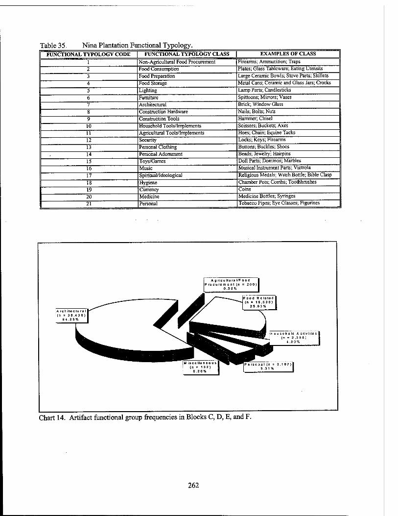
Table 3 5. Nina Plantation Functional Typology. FUNCTIONAL TYPOLOGY CODE | FUNCTIONAL TYPOLOGY CLASS EXAMPLES OF CLASS
1 Non-Agricultural Food Procurement Firearms; Ammunition; Traps
2 Food Consumption Plates; Glass Tableware; Eating Utensils
3 Food Preparation Large Ceramic Bowls; Stove Parts; Skillets
4 Food Storage Metal Cans; Ceramic and Glass Jars; Crocks
5 Lighting Lamp Parts; Candlesticks
6 Furniture Spittoons; Mirrors; Vases
7 Architectural Brick; Window Glass
8 Construction Hardware Nails; Bolts; Nuts
9 Construction Tools Hammer; Chisel
10 Household Tools/Implements Scissors; Buckets; Axes
11 Agricultural Tools/Implements Hoes; Chain; Equine Tacks
12 Security Locks; Keys; Firearms
13 Personal Clothing Buttons; Buckles; Shoes
14 Personal Adornment Beads; Jewelry; Hairpins
15 Toys/Games Doll Parts; Dominos; Marbles
16 Music Musical Instrument Parts; Victrola
17 Spiritual/Ideological Religious Medals; Witch Bottle; Bible Clasp
IS Hygiene Chamber Pots; Combs; Toothbrushes
19 Currency Coins
20 Medicine Medicine Bottles; Syringes
21 Personal Tobacco Pipes; Eye Glasses; Figurines
A g ricu Itu ra I/Food Procurement (n * 200)
0.30%
Food Re la ted (n = 1 5 .530)
2 5.9 3%
A rch ite ctu ra I (n = 38.438)
6 4 .2 6% X*LL^ W r^^m^-^- HB {Household Activities ^E_J (n = 2.3 88)
^ 4.00%
M isce Han e o us (n = 132)
0.20%
Ipersonal (n = 3.197)1 | 5.31% |
Chart 14. Artifact functional group frequencies in Blocks C, D, E, and F.
262
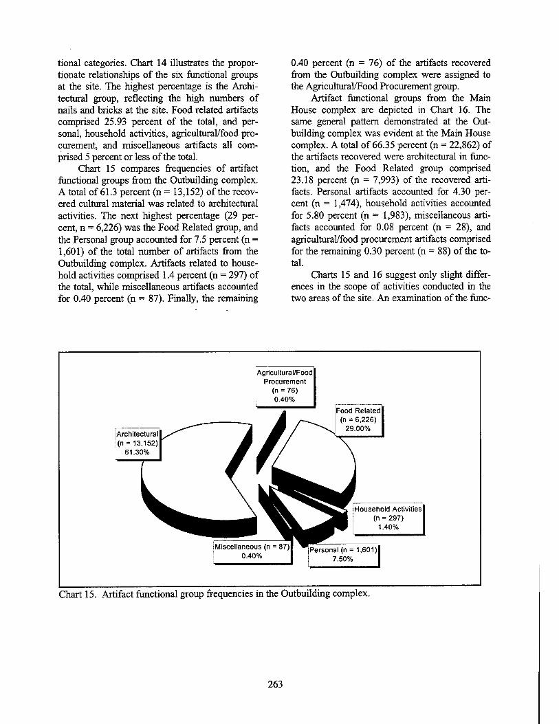
tional categories. Chart 14 illustrates the propor- tionate relationships of the six functional groups at the site. The highest percentage is the Archi- tectural group, reflecting the high numbers of nails and bricks at the site. Food related artifacts comprised 25.93 percent of the total, and per- sonal, household activities, agricultural/food pro- curement, and miscellaneous artifacts all com- prised 5 percent or less of the total.
Chart 15 compares frequencies of artifact functional groups from the Outbuilding complex. A total of 61.3 percent (n = 13,152) of the recov- ered cultural material was related to architectural activities. The next highest percentage (29 per- cent, n = 6,226) was the Food Related group, and the Personal group accounted for 7.5 percent (n = 1,601) of the total number of artifacts from the Outbuilding complex. Artifacts related to house- hold activities comprised 1.4 percent (n = 297) of the total, while miscellaneous artifacts accounted for 0.40 percent (n = 87). Finally, the remaining
0.40 percent (n = 76) of the artifacts recovered from the Outbuilding complex were assigned to the Agricultural/Food Procurement group.
Artifact functional groups from the Main House complex are depicted in Chart 16. The same general pattern demonstrated at the Out- building complex was evident at the Main House complex. A total of 66.35 percent (n = 22,862) of the artifacts recovered were architectural in func- tion, and the Food Related group comprised 23.18 percent (n = 7,993) of the recovered arti- facts. Personal artifacts accounted for 4.30 per- cent (n = 1,474), household activities accounted for 5.80 percent (n = 1,983), miscellaneous arti- facts accounted for 0.08 percent (n = 28), and agricultural/food procurement artifacts comprised for the remaining 0.30 percent (n = 88) of the to- tal.
Charts 15 and 16 suggest only slight differ- ences in the scope of activities conducted in the two areas of the site. An examination of the func-
Agricultural/Food Procurement
(n = 76) 0.40%
Architectural (n = 13,152)
61.30%
Food Related (n = 6,226)
29.00%
Household Activities (n = 297)
1.40%
Miscellaneous (n = 87)| 0.40%
Personal (n = 1,601) 7.50%
Chart 15. Artifact functional group frequencies in the Outbuilding complex.
263
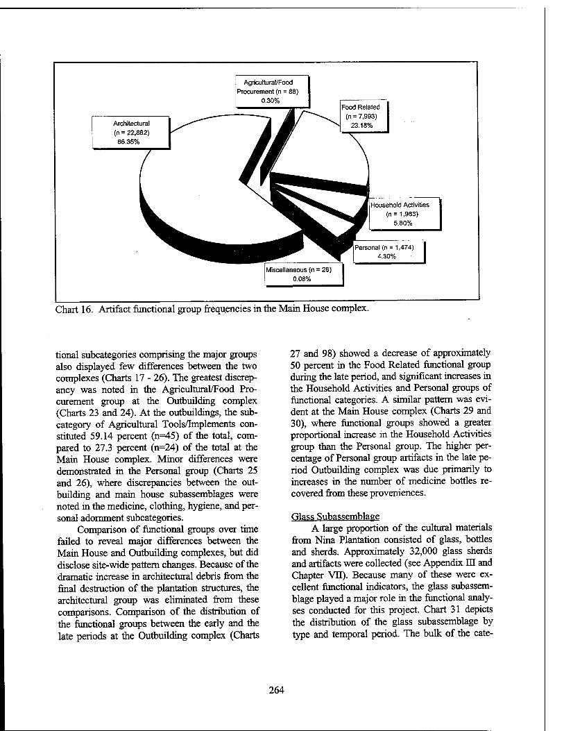
Agricultural/Food Procurement (n = 88)
0.30%
Architectural (n = 22,862) 66.35%
Food Related (n = 7,993)'
23.18%
Household Activities (n = 1,983)
5.80%
Personal (n = 1,474) 4.30%
Miscellaneous (n = 28) 0.08%
Chart 16. Artifact functional group frequencies in the Main House complex.
tional subcategories comprising the major groups also displayed few differences between the two complexes (Charts 17 - 26). The greatest discrep- ancy was noted in the Agricultural/Food Pro- curement group at the Outbuilding complex (Charts 23 and 24). At the outbuildings, the sub- category of Agricultural Tools/Implements con- stituted 59.14 percent (n=45) of the total, com- pared to 27.3 percent (n=24) of the total at the Main House complex. Minor differences were demonstrated in the Personal group (Charts 25 and 26), where discrepancies between the out- building and main house subassemblages were noted in the medicine, clothing, hygiene, and per- sonal adornment subcategories.
Comparison of functional groups over time failed to reveal major differences between the Main House and Outbuilding complexes, but did disclose site-wide pattern changes. Because of the dramatic increase in architectural debris from the final destruction of the plantation structures, the architectural group was eliminated from these comparisons. Comparison of the distribution of the functional groups between the early and the late periods at the Outbuilding complex (Charts
27 and 98) showed a decrease of approximately 50 percent in the Food Related functional group during the late period, and significant increases in the Household Activities and Personal groups of functional categories. A similar pattern was evi- dent at the Main House complex (Charts 29 and 30), where functional groups showed a greater proportional increase in the Household Activities group than the Personal group. The higher per- centage of Personal group artifacts in the late pe- riod Outbuilding complex was due primarily to increases in the number of medicine bottles re- covered from these proveniences.
Glass Subassemblage A large proportion of the cultural materials
from Nina Plantation consisted of glass, bottles and sherds. Approximately 32,000 glass sherds and artifacts were collected (see Appendix DI and Chapter VE). Because many of these were ex- cellent functional indicators, the glass subassem- blage played a major role in the functional analy- ses conducted for this project. Chart 31 depicts the distribution of the glass subassemblage by type and temporal period. The bulk of the cate-
264
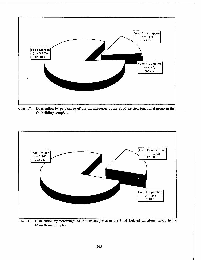
Food Storage (n = 5,253)
84.40%
Food Consumption (n = 947) 15.20%
)d Preparation (n = 26) 0.40%
Chart 17. Distribution by percentage of the subcategories of the Food Related functional group in the Outbuilding complex.
Food Storage (n = 6,263)
78.32%
Food Consumption (n = 1,702)
21.28%
Food Preparation (n = 28) 0.40%
Chart 18. Distribution by percentage of the subcategories of the Food Related functional group in the Main House complex.
265
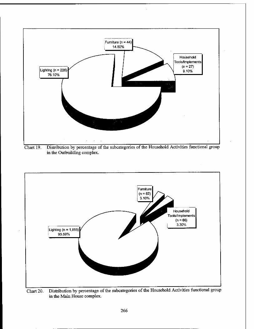
Furniture (n = 14.80%
Lighting (n = 226) 76.10%
Household Tools/Implements
(n = 27) 9.10%
Chart 19. Distribution by percentage of the subcategories of the Household Activities functional group in the Outbuilding complex.
[Lighting (n = 1,855) i 93.59%
Household Tools/Implements
(n = 66) 3.30%
Chart 20. Distribution by percentage of the subcategories of the Household Activities functional group in the Main House complex.
266
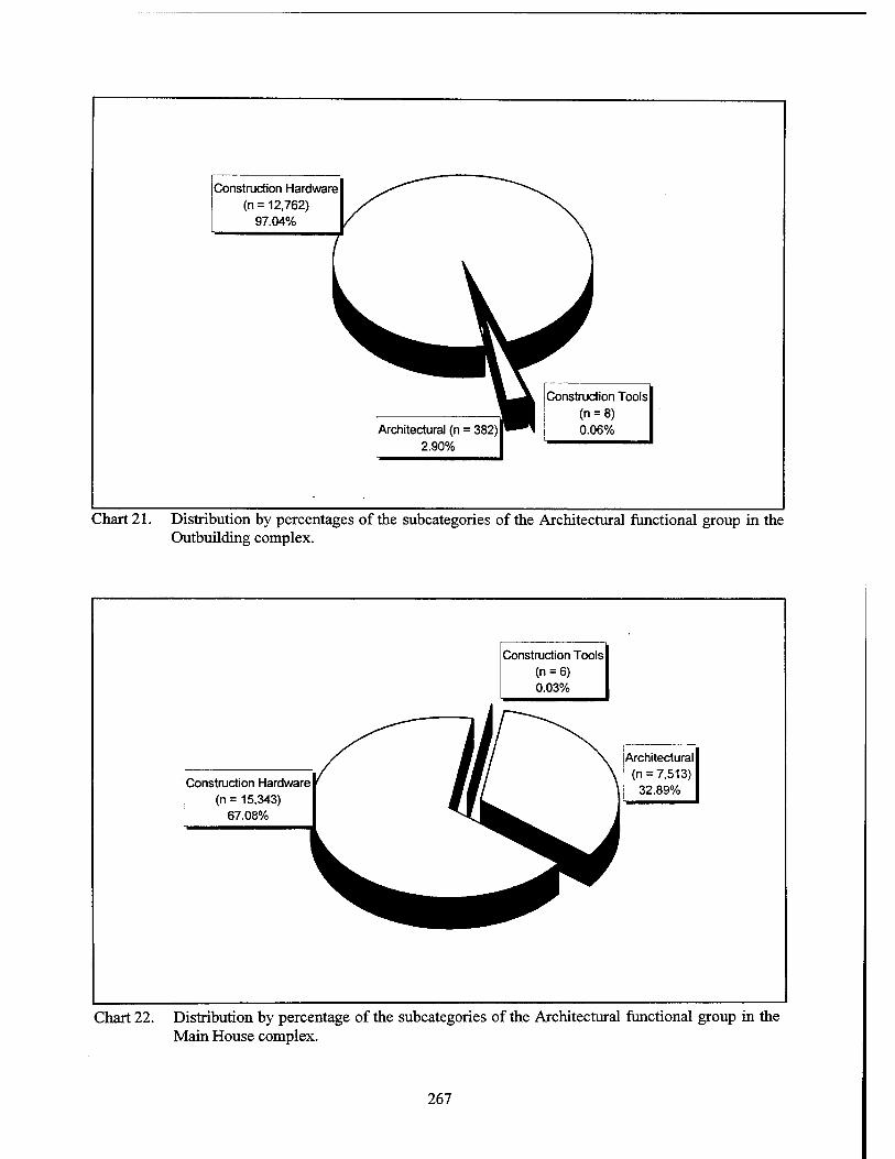
Construction Hardware (n= 12,762)
97.04%
Architectural (n = 382) 2.90%
Construction Tools (n = 8) 0.06%
Chart 21. Distribution by percentages of the subcategories of the Architectural functional group in the Outbuilding complex.
Construction Tools (n = 6) 0.03%
Construction Hardware (n = 15,343)
67.08%
Architectural (n =7,513)
32.89%
Chart 22. Distribution by percentage of the subcategories of the Architectural functional group in the Main House complex.
267
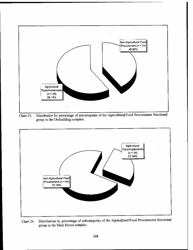
Non-Agricultural Food Procurement (n = 31)
40.86%
Agricultural Tools/Implements
(n = 45) 59.14%
Chart 23. Distribution by percentage of subcategories of the Agricultural/Food Procurement functional group in the Outbuilding complex.
Agricultural Tools/Implements
(n = 24) 27.30%
Non-Agricultural Food Procurement (n = 64)
72.70%
Chart 24. Distribution by percentage of subcategories of the Agricultural/Food Procurement functional group in the Main House complex.
268
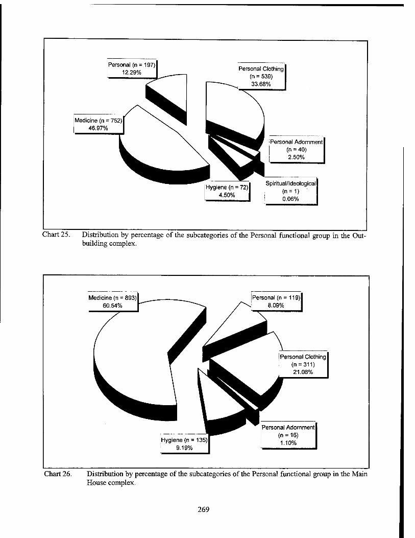
Personal (n = 197) 12.29%
Medicine (n = 752) 46.97%
Personal Clothing (n = 539) 33.68%
I Personal Adornment j (n = 40) f 2.50%
Hygiene (n = 72) 4.50%
Spiritual/Ideological j (n=1) ■ ! 0.06%
Chart 25. Distribution by percentage of the subcategories of the Personal functional group in the Out- building complex.
! Medicine (n = 893) 60.54%
Personal (n = 119) 8.09%
Personal Clothing (n = 311) 21.08%
Hygiene (n = 135) 9.19%
Personal Adornment (n = 16) 1.10%
Chart 26. Distribution by percentage of the subcategories of the Personal functional group in the Main House complex.
269
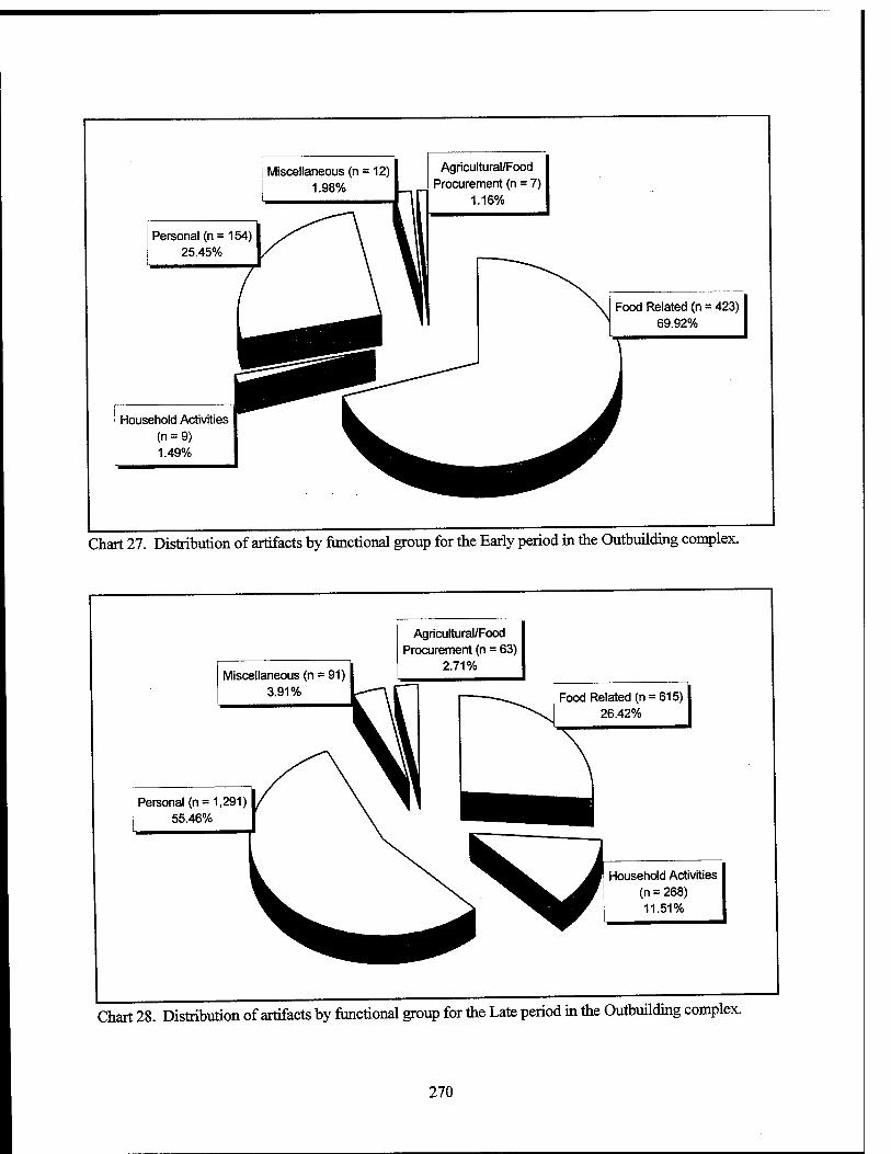
Miscellaneous (n = 12) | 1.98%
Personal (n = 154) 25.45%
Agricultural/Food Procurement (n = 7)
1.16%
Household Activities (n = 9) 1.49%
Food Related (n = 423) 69.92%
Chart 27. Distribution of artifacts by functional group for the Early period in the Outbuilding complex.
Miscellaneous (n = 91) 3.91%
Agricultural/Food Procurement (n = 63)
2.71%
Personal (n = 1,291) 55.46%
Food Related (n = 615) 26.42%
Household Activities (n = 268) 11.51%
Chart 28. Distribution of artifacts by functional group for the Late period in the Outbuilding complex.
270
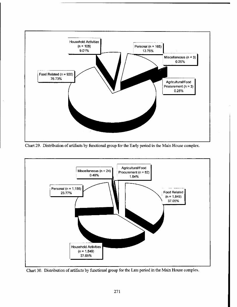
Household Activities (n = 108)
9.01% Personal (n = 165)
13.76%
Food Related (n = 920) 76.73%
Miscellaneous (n = 3) 0.25%
Agricultural/Food Procurement (n = 3)
0.25%
Chart 29. Distribution of artifacts by functional group for the Early period in the Main House complex.
i Agricultural/Food Miscellaneous (n = 24) I j procurement (n = 82)
0.48% 1.64%
Personal (n= 1,186) 23.77% Food Related
(n = 1,849) 37.05%
Household Activities (n= 1,849)
37.05%
Chart 30. Distribution of artifacts by functional group for the Late period in the Main House complex.
271
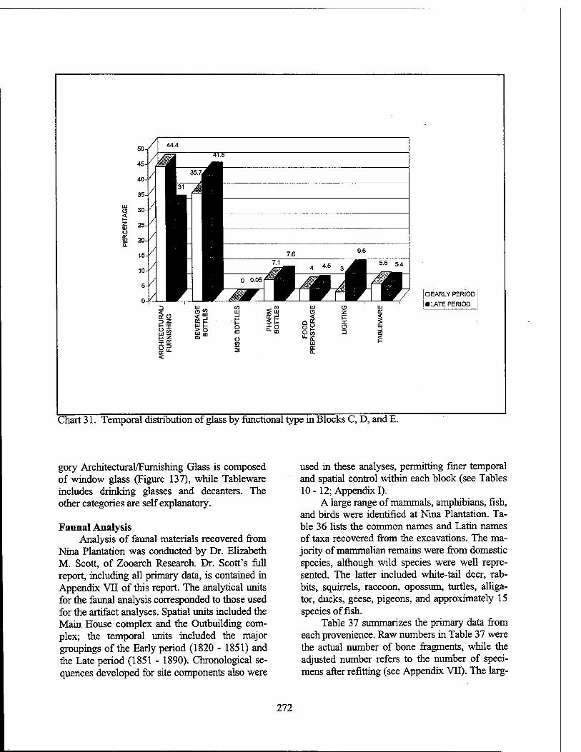
C5 < 111 o cc m a.
AAA
D EARLY PERIOD
■ LATE PERIOD
Chart 31. Temporal distribution of glass by functional type in Blocks C, D, and E.
gory Architectural/Furnishing Glass is composed of window glass (Figure 137), while Tableware includes drinking glasses and decanters. The other categories are self explanatory.
Faunal Analysis Analysis of faunal materials recovered from
Nina Plantation was conducted by Dr. Elizabeth M. Scott, of Zooarch Research. Dr. Scott's full report, including all primary data, is contained in Appendix VII of this report. The analytical units for the faunal analysis corresponded to those used for the artifact analyses. Spatial units included the Main House complex and the Outbuilding com- plex; the temporal units included the major groupings of the Early period (1820 - 1851) and the Late period (1851 - 1890). Chronological se- quences developed for site components also were
used in these analyses, permitting finer temporal and spatial control within each block (see Tables 10-12; Appendix I).
A large range of mammals, amphibians, fish, and birds were identified at Nina Plantation. Ta- ble 36 lists the common names and Latin names of taxa recovered from the excavations. The ma- jority of mammalian remains were from domestic species, although wild species were well repre- sented. The latter included white-tail deer, rab- bits, squirrels, raccoon, opossum, turtles, alliga- tor, ducks, geese, pigeons, and approximately 15 species offish.
Table 37 summarizes the primary data from each provenience. Raw numbers in Table 37 were the actual number of bone fragments, while the adjusted number refers to the number of speci- mens after refitting (see Appendix VII). The larg-
272
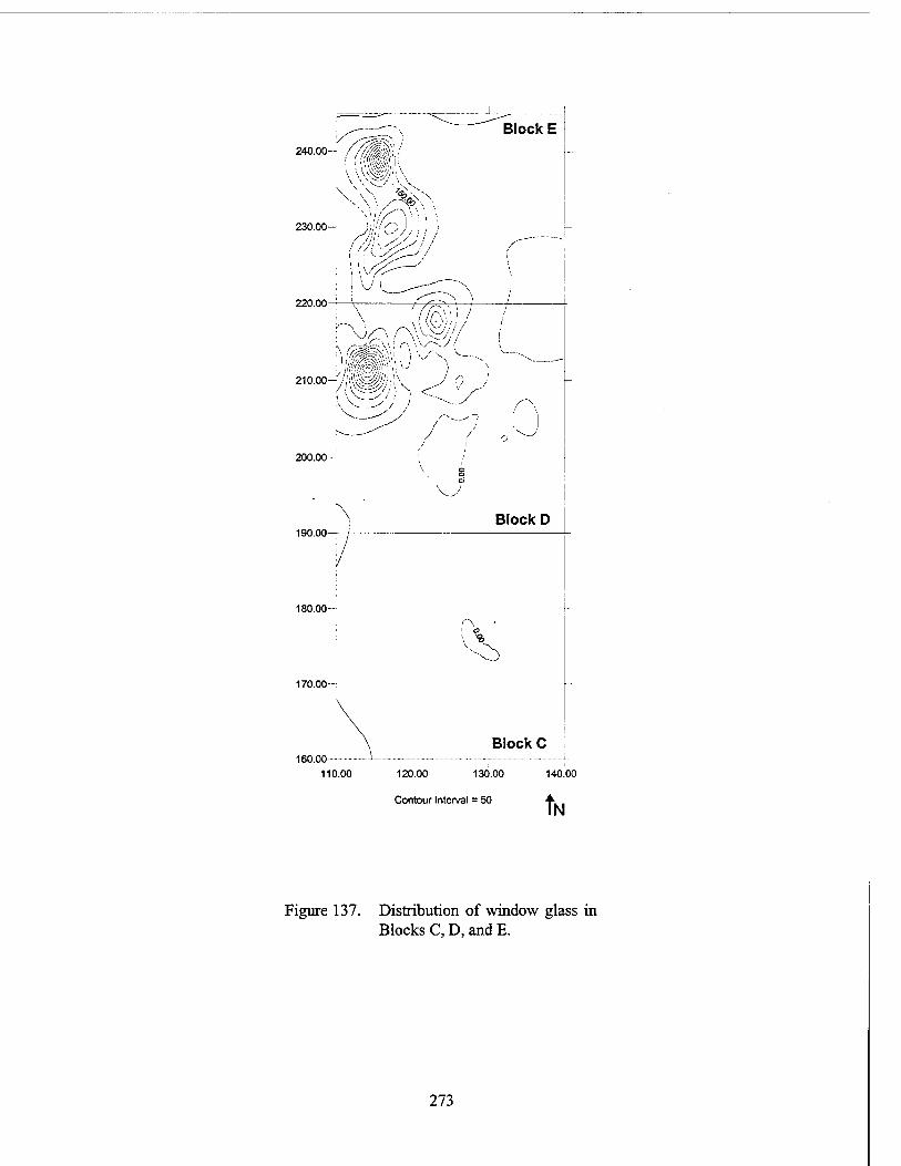
Block E / /WM-' 240.00-- //»;/
1 -\feV;
\ ^
230.00- )i!J'''o); ' < /
220.00-
w, IWi
\
200.00-
190.00-
180.00-
170.00
160.00- 110.00
V.„-
Block D
i o
Block C
120.00 130.00
Contour Interval = 50
140.00
tN
Figure 137. Distribution of window glass in Blocks C, D, and E.
273
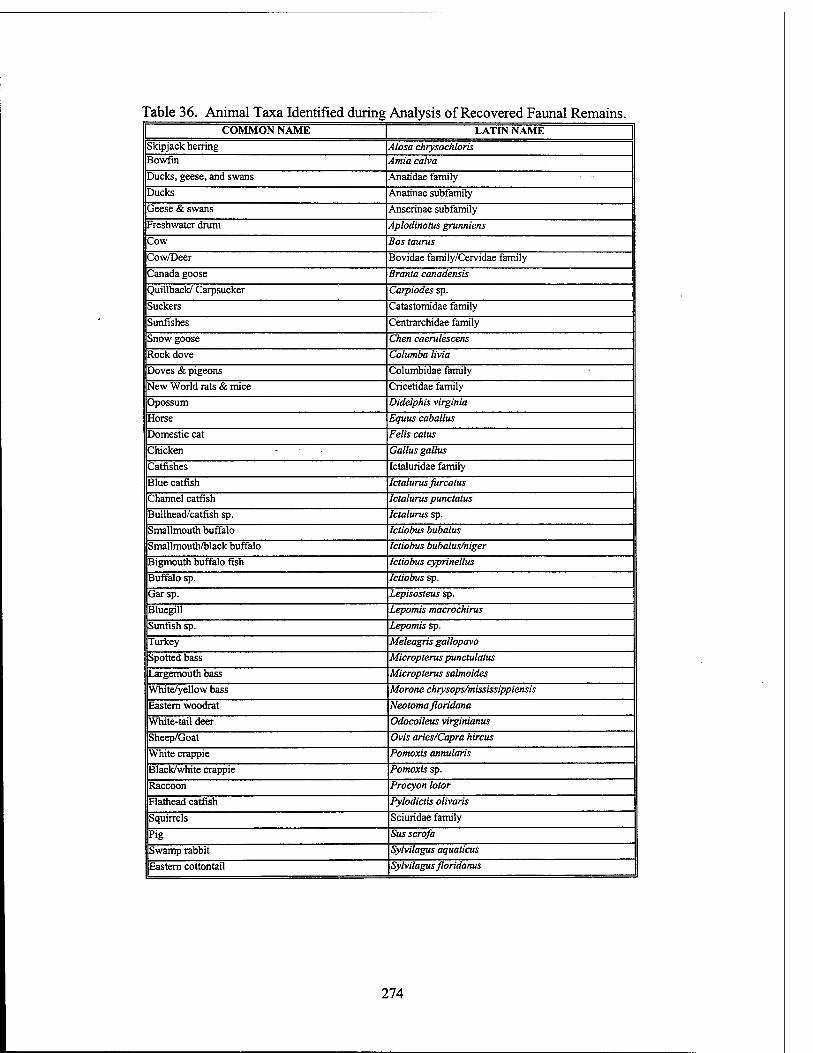
Table 36. Animal Taxa Identified during Analysis of Recovered Faunal Remains. COMMON NAME | LATIN NAME
Skipjack herring Alosa chrysochloris Bowfin Amia calva
Ducks, geese, and swans Anatidae family
Ducks Anatinae subfamily
Geese & swans Anserinae subfamily
Freshwater drum Aplodinotus grunniens
Cow Bos taunts
Cow/Deer Bovidae family/Cervidae family
Canada goose Branta canadensis
Quillback/ Carpsucker Carpiodes sp.
Suckers Catastomidae family
Sunfishes Centrarchidae family
Snow goose Chen caerulescens
Rock dove Columba livia
Doves & pigeons Columbidae family
New World rats & mice Cricetidae family
Opossum Didelphis Virginia
Horse Equus caballus
Domestic cat Felis catus
Chicken Gallus gallus
Catfishes Ictaluridae family
Blue catfish Ictalurus furcatus
Channel catfish Ictalurus punctatus
Bullhead/catfish sp. Ictalurus sp.
Smallmouth buffalo Ictiobus bubalus
Smallmouth/black buffalo Ictiobus bubalus/niger
Bigmouth buffalo fish Ictiobus cyprinellus
Buffalo sp. Ictiobus sp.
Garsp. Lepisosteus sp.
Bluegill Lepomis macrochirus
Sunfish sp. Lepomis sp.
Turkey Meleagris gallopavo
Spotted bass Micropterus punctulatus
Largemouth bass Micropterus salmoides
White/yellow bass Morone chrysops/mississippiensis
Eastern woodrat Neotoma floridana
White-tail deer Odocoileus virginianus
Sheep/Goat Ovis aries/Capra hircus
White crappie Pomoxis annularis
Black/white crappie Pomoxis sp.
Raccoon Procyon lotor
Flathead catfish Pylodictis olivaris
Squirrels Sciuridae family
Pig Sus scrofa
Swamp rabbit Sylvilagus aquaticus
Eastern cottontail Sylvilagus floridanus
274
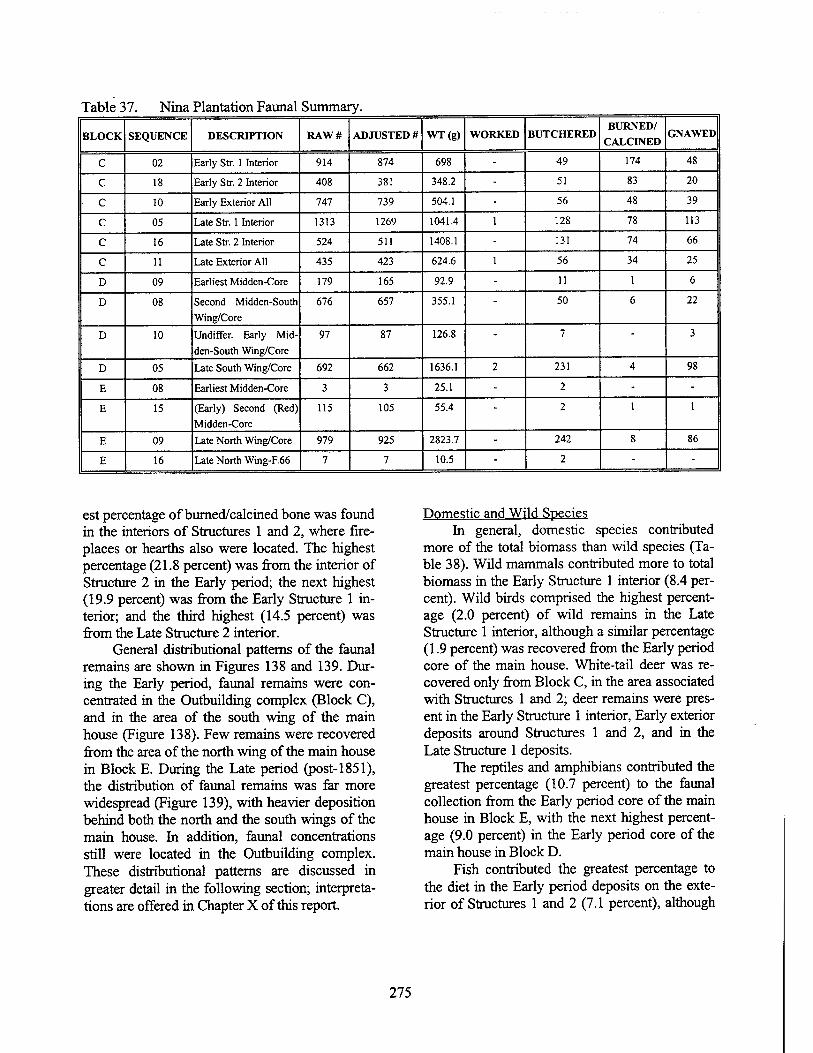
Table 37. Nina Plantation Faunal Summary.
BLOCK SEQUENCE DESCRIPTION RAW# ADJUSTED # WT(g) WORKED BUTCHERED BURNED/
CALCINED GNAWED
C 02 Early Str. 1 Interior 914 874 698 - 49 174 48
c 18 Early Str. 2 Interior 408 381 348.2 - 51 83 20
c 10 Early Exterior All 747 739 504.1 - 56 48 39
c 05 Late Str. 1 Interior 1313 1269 1041.4 1 128 78 113
c 16 Late Str. 2 Interior 524 511 1408.1 - 131 74 66
c 11 Late Exterior All 435 423 624.6 1 56 34 25
D 09 Earliest Midden-Core 179 165 92.9 - 11 1 6
D 08 Second Midden-South
Wing/Core
676 657 355.1 - 50 6 22
D 10 Undiffer. Early Mid-
den-South Wing/Core
97 87 126.8 - 7 - 3
D 05 Late South Wing/Core 692 662 1636.1 2 231 4 98
E 08 Earliest Midden-Core 3 3 25.1 - 2 - -
E 15 (Early) Second (Red)
Midden-Core
115 105 55.4 - 2 1 1
E 09 Late North Wing/Core 979 925 2823.7 - 242 8 86
E 16 Late North Wing-F.66 7 7 10.5 - 2 - -
est percentage of burned/calcined bone was found in the interiors of Structures 1 and 2, where fire- places or hearths also were located. The highest percentage (21.8 percent) was from the interior of Structure 2 in the Early period; the next highest (19.9 percent) was from the Early Structure 1 in- terior; and the third highest (14.5 percent) was from the Late Structure 2 interior.
General distributional patterns of the faunal remains are shown in Figures 138 and 139. Dur- ing the Early period, faunal remains were con- centrated in the Outbuilding complex (Block C), and in the area of the south wing of the main house (Figure 138). Few remains were recovered from the area of the north wing of the main house in Block E. During the Late period (post-1851), the distribution of faunal remains was far more widespread (Figure 139), with heavier deposition behind both the north and the south wings of the main house. In addition, faunal concentrations still were located in the Outbuilding complex. These distributional patterns are discussed in greater detail in the following section; interpreta- tions are offered in Chapter X of this report.
Domestic and Wild Species In general, domestic species contributed
more of the total biomass than wild species (Ta- ble 38). Wild mammals contributed more to total biomass in the Early Structure 1 interior (8.4 per- cent). Wild birds comprised the highest percent- age (2.0 percent) of wild remains in the Late Structure 1 interior, although a similar percentage (1.9 percent) was recovered from the Early period core of the main house. White-tail deer was re- covered only from Block C, in the area associated with Structures 1 and 2; deer remains were pres- ent in the Early Structure 1 interior, Early exterior deposits around Structures 1 and 2, and in the Late Structure 1 deposits.
The reptiles and amphibians contributed the greatest percentage (10.7 percent) to the faunal collection from the Early period core of the main house in Block E, with the next highest percent- age (9.0 percent) in the Early period core of the main house in Block D.
Fish contributed the greatest percentage to the diet in the Early period deposits on the exte- rior of Structures 1 and 2 (7.1 percent), although
275
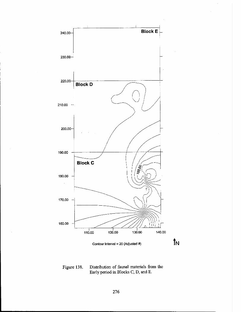
240.00-
230.00-
220.00
210.00
200.00
190.00
180.00 -
170.00 -
160.00 -
Contour Interval = 20 (Adjusted #) tl N
Figure 138. Distribution of faunal materials from the Early period in Blocks C, D, and E.
276
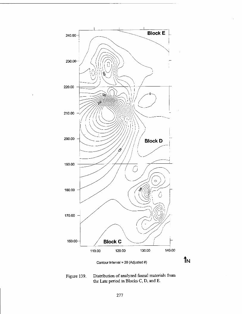
240.00-1
230.00-
220.00
210.00
200.00
190.00
180.00
170.00
160.00
110.00 120.00 130.00 140.00
Contour Interval = 20 (Adjusted #) tl N
Figure 139. Distribution of analyzed faunal materials from the Late period in Blocks C, D, and E.
277
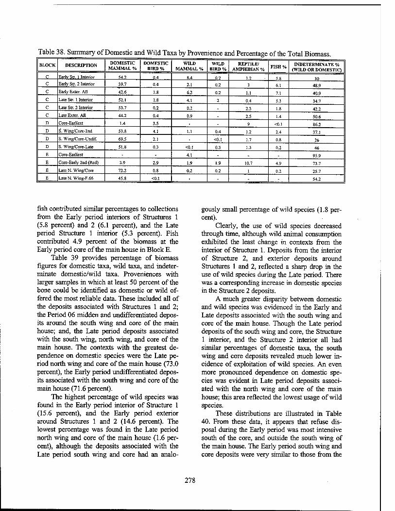
Table 38. Summary of Domestic and Wild Taxa by Provenience and Percentage of the Total Biomass. BLOCK DESCRIPTION DOMESTIC
MAMMAL % DOMESTIC
BIRD % WILD
MAMMAL % WILD
BIRD % REPTILE/
AMPHIBIAN % FISH % INDETERMINATE %
(WILD OR DOMESTIC)
c Earlv Str. 1 Interior 54.2 0.4 8.4 0.2 1.2 5.8 30 c Early Str. 2 Interior 39.7 0.4 2.1 0.2 3 6.1 48.9 c Early Exter. All 42.6 1.8 6.2 0.2 1.1 7.1 40.9 c Late Str. 1 Interior 52.1 1.8 4.1 2 0.4 5.3 34.7 c Late Str. 2 Interior 53.7 0.2 0.2 - 2.3 1.8 42.2 c Late Exter. All 44.2 0.4 0.9 - 2.5 1.4 50.6 D Core-Earliest 1.4 3.5 - - 9 <0.1 86.2
D S. Wing/Core-2nd 53.8 4.1 1.1 0.4 1.2 2.4 37.1
D S. Wing/Core-Undif. 69.5 2.1 - <0.1 1.7 0.8 26
D S. Wing/Core-Late 51.8 0.3 <0.1 0.3 1.3 0.2 46
E Core-Earliest - - 4.1 - - . 95.9
E Core-Early 2nd (Red) 3.9 2.9 1.9 1.9 10.7 4.9 73.7
E Late N. Wing/Core 72.2 0.8 0.2 0.2 1 0.2 25.7
E LateN. Wing-F.66 45.8 <0.1 - - - - ' 54.2
fish contributed similar percentages to collections from the Early period interiors of Structures 1 (5.8 percent) and 2 (6.1 percent), and the Late period Structure 1 interior (5.3 percent). Fish contributed 4.9 percent of the biomass at the Early period core of the main house in Block E.
Table 39 provides percentage of biomass figures for domestic taxa, wild taxa, and indeter- minate domestic/wild taxa. Proveniences with larger samples in which at least 50 percent of the bone could be identified as domestic or wild of- fered the most reliable data. These included all of the deposits associated with Structures 1 and 2; the Period 06 midden and undifferentiated depos- its around the south wing and core of the main house; and, the Late period deposits associated with the south wing, north wing, and core of the main house. The contexts with the greatest de- pendence on domestic species were the Late pe- riod north wing and core of the main house (73.0 percent), the Early period undifferentiated depos- its associated with the south wing and core of the main house (71.6 percent).
The highest percentage of wild species was found in the Early period interior of Structure 1 (15.6 percent), and the Early period exterior around Structures 1 and 2 (14.6 percent). The lowest percentage was found in the Late period north wing and core of the main house (1.6 per- cent), although the deposits associated with the Late period south wing and core had an analo-
gously small percentage of wild species (1.8 per- cent).
Clearly, the use of wild species decreased through time, although wild animal consumption exhibited the least change in contexts from the interior of Structure 1. Deposits from the interior of Structure 2, and exterior deposits around Structures 1 and 2, reflected a sharp drop in the use of wild species during the Late period. There was a corresponding increase in domestic species in the Structure 2 deposits.
A much greater disparity between domestic and wild species was evidenced in the Early and Late deposits associated with the south wing and core of the main house. Though the Late period deposits of the south wing and core, the Structure 1 interior, and the Structure 2 interior all had similar percentages of domestic taxa, the south wing and core deposits revealed much lower in- cidence of exploitation of wild species. An even more pronounced dependence on domestic spe- cies was evident in Late period deposits associ- ated with the north wing and core of the main house; this area reflected the lowest usage of wild species.
These distributions are illustrated in Table 40. From these data, it appears that refuse dis- posal during the Early period was most intensive south of the core, and outside the south wing of the main house. The Early period south wing and core deposits were very similar to those from the
278
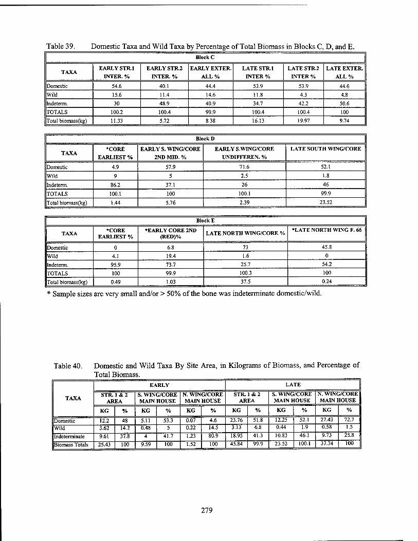
Table 39. Domestic Taxa and Wild Taxa by Percentage of Total Biomass in Blocks C, D, and E. Block C
TAXA EARLY STR.1
INTER. %
EARLY STR.2
INTER. %
EARLY EXTER.
ALL%
LATE STR.1
INTER %
LATE STR.2
INTER %
LATE EXTER.
ALL%
Domestic 54.6 40.1 44.4 53.9 53.9 44.6
Wild 15.6 11.4 14.6 11.8 4.3 4.8
Indeterm. 30 48.9 40.9 34.7 42.2 50.6
TOTALS 100.2 100.4 99.9 100.4 100.4 100
Total biomass(kg) 11.33 5.72 8.38 16.13 19.97 9.74
Block D
TAXA *CORE
EARLIEST %
EARLY S. WING/CORE
2ND MID. %
EARLY S.WING/CORE
UNDIFFEREN. %
LATE SOUTH WING/CORE
Domestic 4.9 57.9 71.6 52.1
Wild 9 5 2.5 1.8
Indeterm. 86.2 37.1 26 46
TOTALS 100.1 100 100.1 99.9
Total biomass(kg) 1.44 5.76 2.39 23.52
Block E
TAXA *CORE EARLIEST %
*EARLY CORE 2ND (RED)%
LATE NORTH WING/CORE % *LATE NORTH WING F. 66
Domestic 0 6.8 73 45.8
Wild 4.1 19.4 1.6 0
Indeterm. 95.9 73.7 25.7 54.2
TOTALS 100 99.9 100.3 100
Total biomass(kg) 0.49 1.03 37.5 0.24
* Sample sizes are very small and/or > 50% of the bone was indeterminate domestic/wild.
Table 40. Domestic and Wild Taxa By Site Area, in Kilograms of Biomass, and Percentage of Total Biomass.
TAXA
EARLY LATE
STR. 1 & 2 AREA
S. WING/CORE MAIN HOUSE
N. WING/CORE MAIN HOUSE
STR. 1 & 2 AREA
S. WING/CORE MAIN HOUSE
N. WING/CORE MAIN HOUSE
KG % KG % KG % KG % KG % KG %
Domestic 12.2 48 5.11 53.3 0.07 4.6 23.76 51.8 12.25 52.1 27.43 72.7
Wild 3.62 14.2 0.48 5 0.22 14.5 3.13 6.8 0.44 1.9 0.58 1.5
Indeterminate 9.61 37.8 4 41.7 1.23 80.9 18.95 41.3 10.83 46.1 9.73 25.8
Biomass Totals 25.43 100 9.59 100 1.52 100 45.84 99.9 23.52 100.1 37.74 100
279
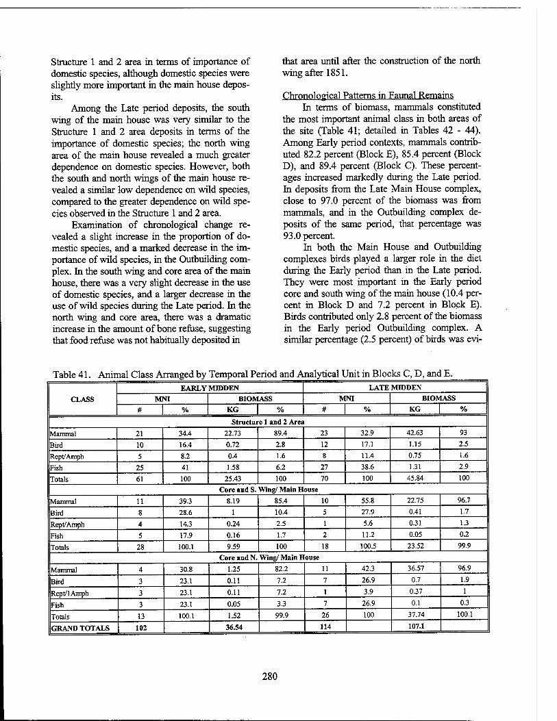
Structure 1 and 2 area in terms of importance of domestic species, although domestic species were slightly more important in the main house depos- its.
Among the Late period deposits, the south wing of the main house was very similar to the Structure 1 and 2 area deposits in terms of the importance of domestic species; the north wing area of the main house revealed a much greater dependence on domestic species. However, both the south and north wings of the main house re- vealed a similar low dependence on wild species, compared to the greater dependence on wild spe- cies observed in the Structure 1 and 2 area.
Examination of chronological change re- vealed a slight increase in the proportion of do- mestic species, and a marked decrease in the im- portance of wild species, in the Outbuilding com- plex. In the south wing and core area of the main house, there was a very slight decrease in the use of domestic species, and a larger decrease in the use of wild species during the Late period. In the north wing and core area, there was a dramatic increase in the amount of bone refuse, suggesting that food refuse was not habitually deposited in
that area until after the construction of the north wing after 1851.
Chronological Patterns in Faunal Remains In terms of biomass, mammals constituted
the most important animal class in both areas of the site (Table 41; detailed in Tables 42 - 44). Among Early period contexts, mammals contrib- uted 82.2 percent (Block E), 85.4 percent (Block D), and 89.4 percent (Block C). These percent- ages increased markedly during the Late period. In deposits from the Late Main House complex, close to 97.0 percent of the biomass was from mammals, and in the Outbuilding complex de- posits of the same period, that percentage was 93.0 percent.
In both the Main House and Outbuilding complexes birds played a larger role in the diet during the Early period than in the Late period. They were most important in the Early period core and south wing of the main house (10.4 per- cent in Block D and 7.2 percent in Block E). Birds contributed only 2.8 percent of the biomass in the Early period Outbuilding complex. A similar percentage (2.5 percent) of birds was evi-
Table 41. Animal Class Arranged by Temporal Period and Analytical Unit in Blocks C, D, and E.
CLASS
EARLY MIDDEN LATE MIDDEN
MNI BIOMASS MNI BIOMASS
# % KG % # % KG % Structure 1 and 2 Area
Mammal 21 34.4 22.73 89.4 23 32.9 42.63 93
Bird 10 16.4 0.72 2.8 12 17.1 1.15 2.5
Rept/Amph 5 8.2 0.4 1.6 8 11.4 0.75 1.6
Fish 25 41 1.58 6.2 27 38.6 1.31 2.9
Totals 61 100 25.43 100 70 100 45.84 100
Core and S. Wing/ Main House
Mammal 11 39.3 8.19 85.4 10 55.8 22.75 96.7
Bird 8 28.6 1 10.4 5 27.9 0.41 1.7
Rept/Amph 4 14.3 0.24 2.5 1 5.6 0.31 1.3
Fish 5 17.9 0.16 1.7 2 11.2 0.05 0.2
Totals 28 100.1 9.59 100 18 100.5 23.52 99.9
Core and N. Wing/ Main House
Mammal 4 30.8 1.25 82.2 11 42.3 36.57 96.9
Bird 3 23.1 0.11 7.2 7 26.9 0.7 1.9
Rept/lAmph 3 23.1 0.11 7.2 1 3.9 0.37 1
Fish 3 23.1 0.05 3.3 7 26.9 0.1 0.3
Totals 13 100.1 1.52 99.9 26 100 37.74 100.1
GRAND TOTALS 102 36.54 114 107.1
280
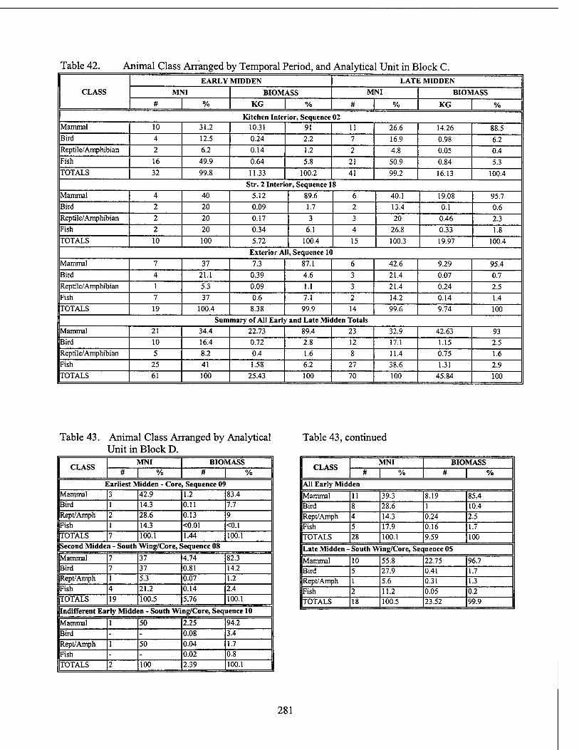
Table 42. Animal Class Arranged by Temporal Period, and Analytical Unit in Block C.
CLASS EARLY MIDDEN LATE MIDDEN
MNI BIOMASS MNI BIOMASS # % KG % # % KG %
Kitchen Interior, Sequence 02 Mammal 10 31.2 10.31 91 11 26.6 14.26 88.5 Bird 4 12.5 0.24 2.2 7 16.9 0.98 6.2 Reptile/Amphibian 2 6.2 0.14 1.2 2 4.8 0.05 0.4 Fish 16 49.9 0.64 5.8 21 50.9 0.84 5.3 TOTALS 32 99.8 11.33 100.2 41 99.2 16.13 100.4
Str. 2 Interior, Sequence 18
Mammal 4 40 5.12 89.6 6 40.1 19.08 95.7 Bird 2 20 0.09 1.7 2 13.4 0.1 0.6 Reptile/Amphibian 2 20 0.17 3 3 20 0.46 2.3 Fish 2 20 0.34 6.1 4 26.8 0.33 1.8 TOTALS 10 100 5.72 100.4 15 100.3 19.97 100.4
Exterior All, Sequence 10
Mammal 7 37 7.3 87.1 6 42.6 9.29 95.4
Bird 4 21.1 0.39 4.6 3 21.4 0.07 0.7
Rep tile/Amphibian 1 5.3 0.09 1.1 3 21.4 0.24 2.5
Fish 7 37 0.6 7.1 2 14.2 0.14 1.4
TOTALS 19 100.4 8.38 99.9 14 99.6 9.74 100
Summary of All Early and Late Midden Totals Mammal 21 34.4 22.73 89.4 23 32.9 42.63 93 Bird 10 16.4 0.72 2.8 12 17.1 1.15 2.5 Reptile/Amphibian 5 8.2 0.4 1.6 8 11.4 0.75 1.6 Fish 25 41 1.58 6.2 27 38.6 1.31 2.9
TOTALS 61 100 25.43 100 70 100 45.84 100
Table 43. Animal Class Arranged by Analytical Unit in Block D.
Table 43, continued
CLASS MNI BIOMASS
# | % # | % Earliest Midden - Core, Sequence 09
Mammal 3 42.9 1.2 83.4 Bird 1 14.3 0.11 7.7 Rept/Amph 2 28.6 0.13 9 Fish 1 14.3 <0.01 <0.1 TOTALS 7 100.1 1.44 100.1 Second Midden - South Wing/Core, Sequence 08
Mammal 7 37 4.74 82.3 Bird 7 37 0.81 14.2 Rept/Amph 1 5.3 0.07 1.2 Fish 4 21.2 0.14 2.4
TOTALS 19 100.5 5.76 100.1
Indifferent Early Midden - South Wing/Core, Sequence 10
Mammal 1 50 2.25 94.2
Bird - - 0.08 3.4
Rept/Amph 1 50 0.04 1.7
Fish - - 0.02 0.8
TOTALS 2 100 2.39 100.1
CLASS MNI BIOMASS
# | % # | % All Early Midden
Mammal 11 39.3 8.19 85.4 Bird 8 28.6 1 10.4 Rept/Amph 4 14.3 0.24 2.5 Fish 5 17.9 0.16 1.7 TOTALS 28 100.1 9.59 100
Late Midden - South Wing/Core, Sequence 05
Mammal 10 55.8 22.75 96.7 Bird 5 27.9 0.41 1.7 Rept/Amph 1 5.6 0.31 1.3 Fish 2 11.2 0.05 0.2 TOTALS 18 100.5 23.52 99.9
281
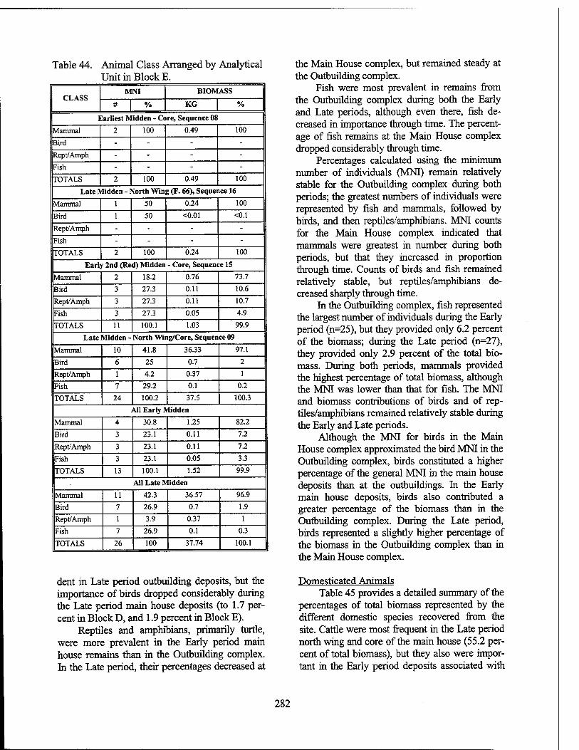
Table 44. Animal Class Arranged by Analytical Unit in Block E.
CLASS MNI BIOMASS
# % KG %
Earliest Midden - Core, Sequence 08
Mammal 2 100 0.49 100
Bird - - - - Rept/Amph - - - - Fish - - - - TOTALS 2 100 0.49 100
Late Midden - North Wing (F. 66), Sequence 16
Mamma] 1 50 0.24 100
Bird 1 50 <0.01 <0.1
Rept/Amph - - - - Fish - - - - TOTALS 2 100 0.24 100
Early 2nd (Red) Midden - Core, Sequence 15
Mammal 2 18.2 0.76 73.7
Bird 3 27.3 0.11 10.6
Rept/Amph 3 27.3 0.11 10.7
Fish 3 27.3 0.05 4.9
TOTALS 11 100.1 1.03 99.9
Late Midden - North Wing/Core, Sequence 09
Mammal 10 41.8 36.33 97.1
Bird 6 25 0.7 2
Rept/Amph 1 4.2 0.37 1
Fish 7 29.2 0.1 0.2
TOTALS 24 100.2 37.5 100.3
All Early Midden
Mammal 4 30.8 1.25 82.2
Bird 3 23.1 0.11 7.2
Rept/Amph 3 23.1 0.11 7.2
Fish 3 23.1 0.05 3.3
TOTALS 13 100.1 1.52 99.9
All Late Midden
Mammal 11 42.3 36.57 96.9
Bird 7 26.9 0.7 1.9
Rept/Amph 1 3.9 0.37 1
Fish 7 26.9 0.1 0.3
TOTALS 26 100 37.74 100.1
the Main House complex, but remained steady at the Outbuilding complex.
Fish were most prevalent in remains from the Outbuilding complex during both the Early and Late periods, although even there, fish de- creased in importance through time. The percent- age of fish remains at the Main House complex dropped considerably through time.
Percentages calculated using the minimum number of individuals (MNI) remain relatively stable for the Outbuilding complex during both periods; the greatest numbers of individuals were represented by fish and mammals, followed by birds, and then reptiles/amphibians. MNI counts for the Main House complex indicated that mammals were greatest in number during both periods, but that they increased in proportion through time. Counts of birds and fish remained relatively stable, but reptiles/amphibians de- creased sharply through time.
In the Outbuilding complex, fish represented the largest number of individuals during the Early period (n=25), but they provided only 6.2 percent of the biomass; during the Late period (n=27), they provided only 2.9 percent of the total bio- mass. During both periods, mammals provided the highest percentage of total biomass, although the MNI was lower than that for fish. The MNI and biomass contributions of birds and of rep- tiles/amphibians remained relatively stable during the Early and Late periods.
Although the MNI for birds in the Main House complex approximated the bird MNI in the Outbuilding complex, birds constituted a higher percentage of the general MNI in the main house deposits than at the outbuildings. In the Early main house deposits, birds also contributed a greater percentage of the biomass than in the Outbuilding complex. During the Late period, birds represented a slightly higher percentage of the biomass in the Outbuilding complex than in the Main House complex.
dent in Late period outbuilding deposits, but the importance of birds dropped considerably during the Late period main house deposits (to 1.7 per- cent in Block D, and 1.9 percent in Block E).
Reptiles and amphibians, primarily turtle, were more prevalent in the Early period main house remains than in the Outbuilding complex. In the Late period, their percentages decreased at
Domesticated Animals Table 45 provides a detailed summary of the
percentages of total biomass represented by the different domestic species recovered from the site. Cattle were most frequent in the Late period north wing and core of the main house (55.2 per- cent of total biomass), but they also were impor- tant in the Early period deposits associated with
282
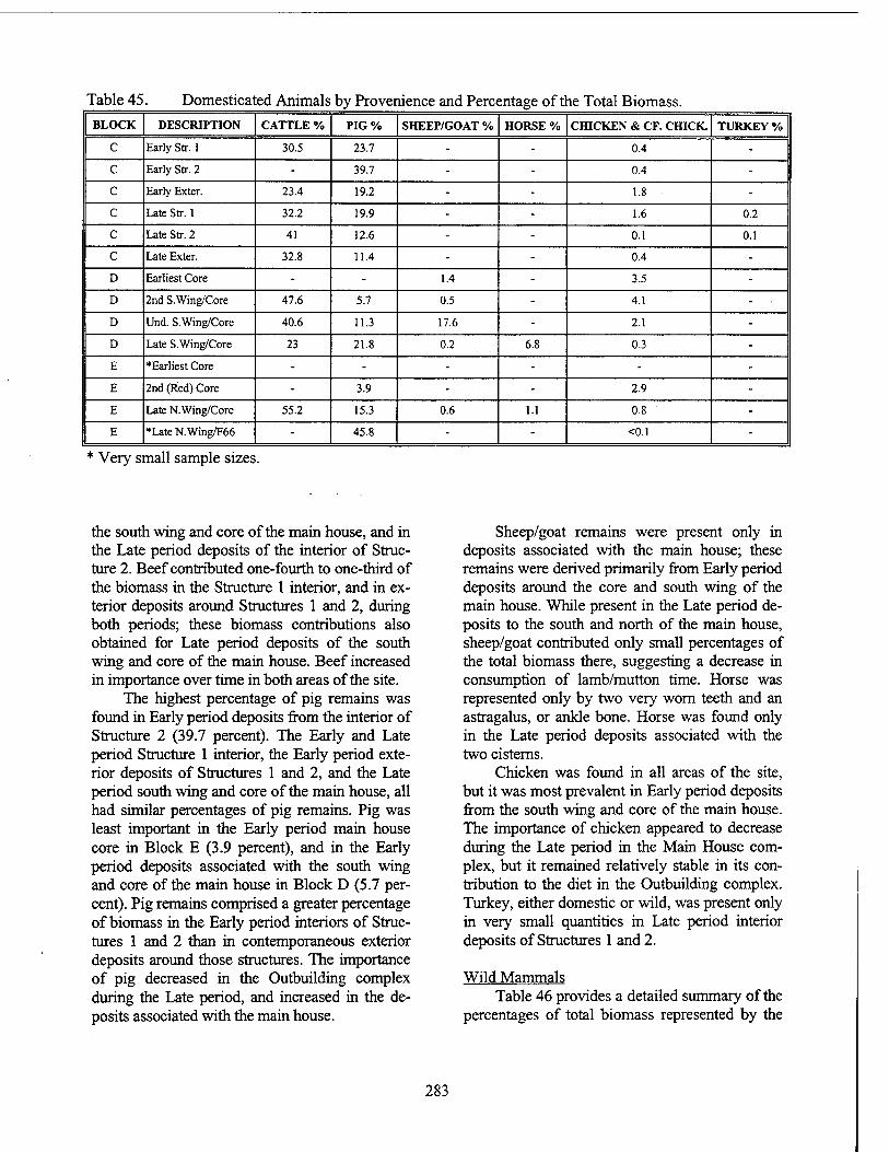
Table 45 Domesticated Animals by Provenience and Percentage of the Total Biomass. BLOCK DESCRIPTION CATTLE % PIG % SHEEP/GOAT % HORSE % CHICKEN & CF. CHICK TURKEY %
C Early Str. 1 30.5 23.7 - - 0.4 - c Early Str. 2 - 39.7 - - 0.4 - c Early Exter. 23.4 19.2 - - 1.8 - c Late Str. 1 32.2 19.9 - - 1.6 0.2
c Late Str. 2 41 12.6 - - 0.1 0.1
c Late Exter. 32.8 11.4 - - 0.4 - D Earliest Core - - 1.4 - 3.5 - D 2nd S.Wing/Core 47.6 5.7 0.5 - 4.1 - • D Und. S.Wing/Core 40.6 11.3 17.6 - 2.1 - D Ute S.Wing/Core 23 21.8 0.2 6.8 0.3 - E ♦Earliest Core - - - - - - E 2nd (Red) Core - 3.9 - - 2.9 - E Late N. Wing/Core 55.2 15.3 0.6 1.1 0.8 - E »Late N.Wing/F66 - 45.8 - - <0.1 -
Very small sample sizes.
the south wing and core of the main house, and in the Late period deposits of the interior of Struc- ture 2. Beef contributed one-fourth to one-third of the biomass in the Structure 1 interior, and in ex- terior deposits around Structures 1 and 2, during both periods; these biomass contributions also obtained for Late period deposits of the south wing and core of the main house. Beef increased in importance over time in both areas of the site.
The highest percentage of pig remains was found in Early period deposits from the interior of Structure 2 (39.7 percent). The Early and Late period Structure 1 interior, the Early period exte- rior deposits of Structures 1 and 2, and the Late period south wing and core of the main house, all had similar percentages of pig remains. Pig was least important in the Early period main house core in Block E (3.9 percent), and in the Early period deposits associated with the south wing and core of the main house in Block D (5.7 per- cent). Pig remains comprised a greater percentage of biomass in the Early period interiors of Struc- tures 1 and 2 than in contemporaneous exterior deposits around those structures. The importance of pig decreased in the Outbuilding complex during the Late period, and increased in the de- posits associated with the main house.
Sheep/goat remains were present only in deposits associated with the main house; these remains were derived primarily from Early period deposits around the core and south wing of the main house. While present in the Late period de- posits to the south and north of the main house, sheep/goat contributed only small percentages of the total biomass there, suggesting a decrease in consumption of lamb/mutton time. Horse was represented only by two very worn teeth and an astragalus, or ankle bone. Horse was found only in the Late period deposits associated with the two cisterns.
Chicken was found in all areas of the site, but it was most prevalent in Early period deposits from the south wing and core of the main house. The importance of chicken appeared to decrease during the Late period in the Main House com- plex, but it remained relatively stable in its con- tribution to the diet in the Outbuilding complex. Turkey, either domestic or wild, was present only in very small quantities in Late period interior deposits of Structures 1 and 2.
Wild Mammals Table 46 provides a detailed summary of the
percentages of total biomass represented by the
283
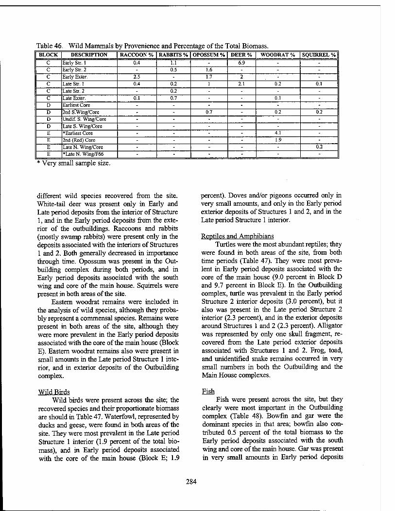
Table 46. Wild Mammals by Provenience and Percentage of the Total Biomass. BLOCK DESCRIPTION RACCOON % RABBITS % OPOSSUM % DEER % WOODRAT % SQUKREL %
C Early Str. 1 0.4 1.1 - 6.9 - - c Early Str. 2 - 0.5 1.6 - - - c Early Exter. 2.5 - 1.7 2 - - c Late Str. 1 0.4 0.2 1 2.1 0.2 0.1 c Late Str. 2 - 0.2 - - - - c Late Exter. 0.1 0.7 - - 0.1 - D Earliest Core - - - - - - D 2nd S.Wing/Core - - 0.7 - 0.2 0.2 D Undif. S. Wing/Core - - - - - - D Late S. Wing/Core - - - - - - E ♦Earliest Core - - - - 4.1 - E 2nd (Red) Core - - - - 1.9 - E Late N. Wing/Core - - - - - 0.2
E *LateN.Wing/F66 - - - - - -
* Very small sample size.
different wild species recovered from the site. White-tail deer was present only in Early and Late period deposits from the interior of Structure 1, and in the Early period deposits from the exte- rior of the outbuildings. Raccoons and rabbits (mostly swamp rabbits) were present only in the deposits associated with the interiors of Structures 1 and 2. Both generally decreased in importance through time. Opossum was present in the Out- building complex during both periods, and in Early period deposits associated with the south wing and core of the main house. Squirrels were present in both areas of the site.
Eastern woodrat remains were included in the analysis of wild species, although they proba- bly represent a commensal species. Remains were present in both areas of the site, although they were more prevalent in the Early period deposits associated with the core of the main house (Block E). Eastern woodrat remains also were present in small amounts in the Late period Structure 1 inte- rior, and in exterior deposits of the Outbuilding complex.
Wild Birds Wild birds were present across the site; the
recovered species and their proportionate biomass are should in Table 47. Waterfowl, represented by ducks and geese, were found in both areas of the site. They were most prevalent in the Late period Structure 1 interior (1.9 percent of the total bio- mass), and in Early period deposits associated with the core of the main house (Block E; 1.9
percent). Doves and/or pigeons occurred only in very small amounts, and only in the Early period exterior deposits of Structures 1 and 2, and in the Late period Structure 1 interior.
Reptiles and Amphibians Turtles were the most abundant reptiles; they
were found in both areas of the site, from both time periods (Table 47). They were most preva- lent in Early period deposits associated with the core of the main house (9.0 percent in Block D and 9.7 percent in Block E). In the Outbuilding complex, turtle was prevalent in the Early period Structure 2 interior deposits (3.0 percent), but it also was present in the Late period Structure 2 interior (2.3 percent), and in the exterior deposits around Structures 1 and 2 (2.3 percent). Alligator was represented by only one skull fragment, re- covered from the Late period exterior deposits associated with Structures 1 and 2. Frog, toad, and unidentified snake remains occurred in very small numbers in both the Outbuilding and the Main House complexes.
Fish Fish were present across the site, but they
clearly were most important in the Outbuilding complex (Table 48). Bowfm and gar were the dominant species in that area; bowfin also con- tributed 0.5 percent of the total biomass to the Early period deposits associated with the south wing and core of the main house. Gar was present in very small amounts in Early period deposits
284
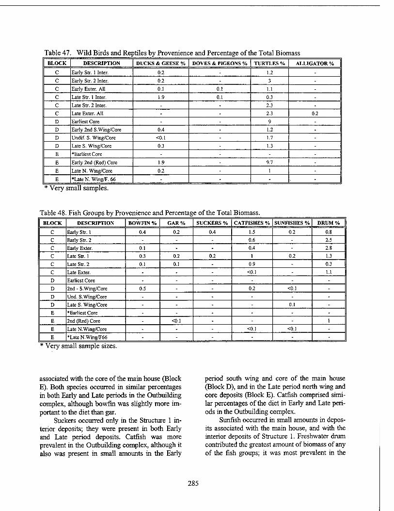
Table 47 Wild Birds and Reptiles by Provenience and Percentage of the Total Biomass BLOCK DESCRIPTION DUCKS & GEESE % DOVES & PIGEONS % TURTLES % ALLIGATOR %
C Early Str. 1 Inter. 0.2 - 1.2 - c Early Str. 2 Inter. 0.2 - 3 - c Early Exter. All 0.1 0.1 1.1 - c Late Str. 1 Inter. 1.9 0.1 0.3 - c Late Str. 2 Inter. - - 2.3 - c Late Exter. All - - 2.3 0.2
D Earliest Core - - 9 - D Early 2nd S.Wing/Core 0.4 - 1.2 - D Undif. S. Wing/Core <0.1 - 1.7 - D Late S. Wing/Core 0.3 - 1.3 - E ♦Earliest Core - - - - E Early 2nd (Red) Core 1.9 - 9.7 - E Late N. Wing/Core 0.2 - 1 - E »Late N. Wing/F. 66 - - - -
Very small samples.
Table 48 Fish Groups by Provenience and Percentage of the Total Biomass. BLOCK DESCRIPTION BOWFIN % GAR% SUCKERS % CATFISHES % SUNFISHES % DRUM %
C Early Str. 1 0.4 0.2 0.4 1.5 0.2 0.8
C Early Str. 2 - - - 0.6 - 2.5
c Early Exter. 0.1 - - 0.4 - 2.8
c Late Str. 1 0.3 0.2 0.2 1 0.2 1.3
c Late Str. 2 0.1 0.1 - 0.9 - 0.3
c Late Exter. - - - <0.1 - 1.1
D Earliest Core - - - - - - D 2nd - S.Wing/Core 0.5 - - 0.2 <0.1 - D Und. S.Wing/Core - - - - - - D Late S. Wing/Core - - - - 0.1 - E ♦Earliest Core - - - - - - E 2nd (Red) Core - <0.1 - - - 1
E Late N. Wing/Core - - - <0.1 <0.1 - E »Late N.Wing/F66 - - - - - -
* Very small sample sizes.
associated with the core of the main house (Block E). Both species occurred in similar percentages in both Early and Late periods in the Outbuilding complex, although bowfin was slightly more im- portant to the diet than gar.
Suckers occurred only in the Structure 1 in- terior deposits; they were present in both Early and Late period deposits. Catfish was more prevalent in the Outbuilding complex, although it also was present in small amounts in the Early
period south wing and core of the main house (Block D), and in the Late period north wing and core deposits (Block E). Catfish comprised simi- lar percentages of the diet in Early and Late peri- ods in the Outbuilding complex.
Sunfish occurred in small amounts in depos- its associated with the main house, and with the interior deposits of Structure 1. Freshwater drum contributed the greatest amount of biomass of any of the fish groups; it was most prevalent in the
285
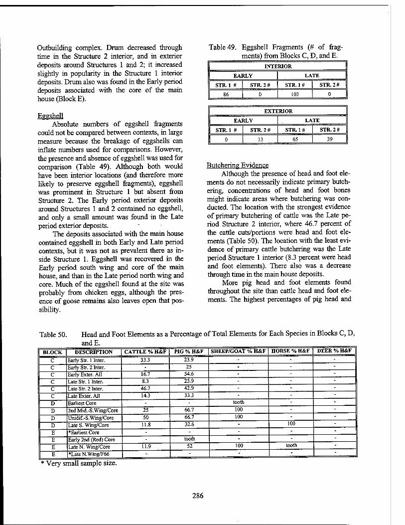
Outbuilding complex. Drum decreased through time in the Structure 2 interior, and in exterior deposits around Structures 1 and 2; it increased slightly in popularity in the Structure 1 interior deposits. Drum also was found in the Early period deposits associated with the core of the main house (Block E).
Eggshell Absolute numbers of eggshell fragments
could not be compared between contexts, in large measure because the breakage of eggshells can inflate numbers used for comparisons. However, the presence and absence of eggshell was used for comparison (Table 49). Although both would have been interior locations (and therefore more likely to preserve eggshell fragments), eggshell was prominent in Structure 1 but absent from Structure 2. The Early period exterior deposits around Structures 1 and 2 contained no eggshell, and only a small amount was found in the Late period exterior deposits.
The deposits associated with the main house contained eggshell in both Early and Late period contexts, but it was not as prevalent there as in- side Structure 1. Eggshell was recovered in the Early period south wing and core of the main house, and than in the Late period north wing and core. Much of the eggshell found at the site was probably from chicken eggs, although the pres- ence of goose remains also leaves open that pos- sibility.
Table 49. Eggshell Fragments (# of frag- ments) from Blocks C, D, and E.
INTERIOR
EARLY LATE
STR.1 # STR 2 # STR. 1 # STR.2#
86 0 103 0
EXTERIOR
EARLY LATE
STR.1 # STR. 2 # STR 1 # STR. 2 #
0 13 65 39
Butchering Evidence Although the presence of head and foot ele-
ments do not necessarily indicate primary butch- ering, concentrations of head and foot bones might indicate areas where butchering was con- ducted. The location with the strongest evidence of primary butchering of cattle was the Late pe- riod Structure 2 interior, where 46.7 percent of the cattle cuts/portions were head and foot ele- ments (Table 50). The location with the least evi- dence of primary cattle butchering was the Late period Structure 1 interior (8.3 percent were head and foot elements). There also was a decrease through time in the main house deposits.
More pig head and foot elements found throughout the site than cattle head and foot ele- ments. The highest percentages of pig head and
Table 50. Head and Foot Elements as a andE.
Percentage of Total Elements for Each Species in Blocks C, D,
BLOCK DESCRIPTION CATTLE % H&F PIG % H&F SHEEP/GOAT % H&F | HORSE % H&F DEER % H&F
C Early Str. 1 Inter. 33.3 23.9 - - - c Early Str. 2 Inter. - 25 - - - c Early Exter. All 16.7 54.6 - - - c Late Str. 1 Inter. 8.3 23.9 - - - c Late Str. 2 Inter. 46.7 42.9 - - - c Late Exter. All 14.3 33.3 - - - D Earliest Core - - tooth - - D 2nd Mid.-S.Wing/Core 25 66.7 100 - - D Unidif.-S.Wing/Core 50 66.7 100 - - D Late S. Wing/Core 11.8 32.6 - 100 - E ♦Earliest Core - - - - - E Early 2nd (Red) Core - tooth - - - E Late N. Wing/Core 11.9 52 100 tooth - E »Late N.Wing/F66 - - - - ~
Very small sample size.
286
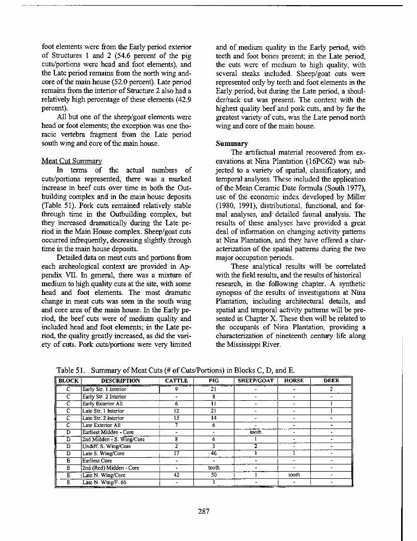
foot elements were from the Early period exterior of Structures 1 and 2 (54.6 percent of the pig cuts/portions were head and foot elements), and the Late period remains from the north wing and- core of the main house (52.0 percent). Late period remains from the interior of Structure 2 also had a relatively high percentage of these elements (42.9 percent).
All but one of the sheep/goat elements were head or foot elements; the exception was one tho- racic vertebra fragment from the Late period south wing and core of the main house.
Meat Cut Summary In terms of the actual numbers of
cuts/portions represented, there was a marked increase in beef cuts over time in both the Out- building complex and in the main house deposits (Table 51). Pork cuts remained relatively stable through time in the Outbuilding complex, but they increased dramatically during the Late pe- riod in the Main House complex. Sheep/goat cuts occurred infrequently, decreasing slightly through time in the main house deposits.
Detailed data on meat cuts and portions from each archeological context are provided in Ap- pendix VII. In general, there was a mixture of medium to high quality cuts at the site, with some head and foot elements. The most dramatic change in meat cuts was seen in the south wing and core area of the main house. In the Early pe- riod, the beef cuts were of medium quality and included head and foot elements; in the Late pe- riod, the quality greatly increased, as did the vari- ety of cuts. Pork cuts/portions were very limited
and of medium quality in the Early period, with teeth and foot bones present; in the Late period, the cuts were of medium to high quality, with several steaks included. Sheep/goat cuts were represented only by teeth and foot elements in the Early period, but during the Late period, a shoul- der/rack cut was present. The context with the highest quality beef and pork cuts, and by far the greatest variety of cuts, was the Late period north wing and core of the main house.
Summary The artifactual material recovered from ex-
cavations at Nina Plantation (16PC62) was sub- jected to a variety of spatial, classificatory, and temporal analyses. These included the application of the Mean Ceramic Date formula (South 1977), use of the economic index developed by Miller (1980, 1991), distributional, functional, and for- mal analyses, and detailed faunal analysis. The results of these analyses have provided a great deal of information on changing activity patterns at Nina Plantation, and they have offered a char- acterization of the spatial patterns during the two major occupation periods.
These analytical results will be correlated with the field results, and the results of historical research, in the following chapter. A synthetic synopsis of the results of investigations at Nina Plantation, including architectural details, and spatial and temporal activity patterns will be pre- sented in Chapter X. These then will be related to the occupants of Nina Plantation, providing a characterization of nineteenth century life along the Mississippi River.
Table 51. Summary of Meat Cuts (# of Cuts/Portions) in Blocks C, D, and E. BLOCK DESCRIPTION CATTLE PIG SHEEP/GOAT HORSE DEER
C Early Str. 1 Interior 9 21 - - 2 c Early Str. 2 Interior - 8 - - - c Early Exterior All 6 11 - - 1 c Late Str. 1 Interior 12 21 - - 1 c Late Str. 2 Interior 15 14 - - - c Late Exterior All 7 6 - - - D Earliest Midden - Core - - tooth - - D 2nd Midden - S. Wing/Core 8 6 1 - - D Undiff. S. Wing/Core 2 3 2 - - D Late S. Wing/Core 17 46 1 1 - E Earliest Core - - - - - E 2nd (Red) Midden - Core - tooth - - - E Late N. Wing/Core 42 50 1 tooth - E Late N. Wing/F. 66 - 1 - - -
287
CHAPTER X
SUMMARY AND INTERPRETATION
Introduction The preceding chapters of this report have described the results of archeological exca-
vations at Nina Plantation (16PC62), in Point Coupee Parish, Louisiana. These data recovery excavations and subsequent analyses were con- ducted in 1993 and 1994, on behalf of the U.S. Army Corps of Engineers, New Orleans District. This chapter summarizes the results of this exten- sive project, and offers an interpretation of the collected data, with reference to the research de- sign prepared for this project (Chapter VI).
The Architecture and Layout of Nina Planta- tion
Architectural data recovered from Nina Plantation have confirmed the use of documented vernacular styles and techniques, and illustrated the process of the adaptation of more general vernacular forms to the particularistic needs of the residents. Architectural changes and remod- eling at the Main House and the Outbuilding complexes during the nineteenth century, and changes in the orientation and facade of the main house during the second half of the nineteenth century were allied both with local and regional events, and with the social milieu and cultural background of the occupants.
The layout of the plantation followed a gen- eralized spatial pattern of Mississippi River sugar plantations (Goodwin et al. 1989), with the quar- ters for field slaves aligned in a double row at a distance from the Main House, with the industrial complex at a distance from the main house, but closer to the slave quarters, and with smaller service buildings (stables, smithy) located be-
tween the quarters and the main house. In addi- tion to these plantation components, smaller do- mestic and service structures were in close proximity to the main house. According to a de- scription of typical sugar plantation layout in die Caribbean, the big house was always accompa- nied by a detached kitchen, a "housekeeper's hut, and huts for servants" (Edwards 1994:179). It appears that this general pattern also prevailed at Nina Plantation.
While the plantation was a single social and economic entity, under the overall control of the plantation owner, that entity was shaped in large part by the varied social and cultural orientations of its occupants. These contributions to the ulti- mate form of the plantation can be discerned only by first considering the individual components.
The Main House Complex The original core structure of the Main
House at Nina Plantation was constructed in the 1820s by Jean Ursin Jarreau, a first generation Creole of French and local parentage. Jarreau was raised by his stepfather, a German by birth, and he was educated in Germany. He purchased the tract of land that was to become Nina Plantation in 1822, and married Octavine LeBlanc, a local Pointe Coupee woman, in 1823. At the time of purchase, there was no record of any extant structures on the land, and it is assumed that Jar- reau and his wife were responsible for the con- struction of the original plantation buildings.
The original house at Nina, then known as Pecan Grove Plantation, was a rectangular struc- ture measuring approximately 11.14 x 18.75 m (36.5 x 61.5 ft). It was raised on brick piers, and
288
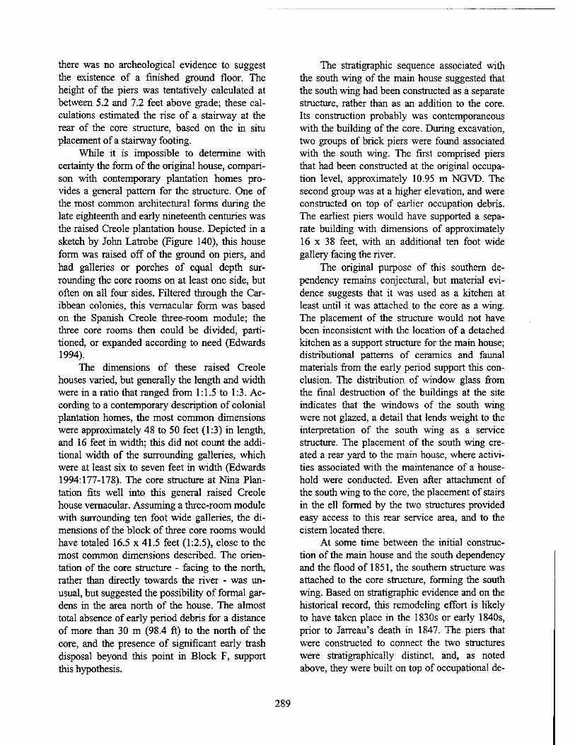
there was no archeological evidence to suggest the existence of a finished ground floor. The height of the piers was tentatively calculated at between 5.2 and 7.2 feet above grade; these cal- culations estimated the rise of a stairway at the rear of the core structure, based on the in situ placement of a stairway footing.
While it is impossible to determine with certainty the form of the original house, compari- son with contemporary plantation homes pro- vides a general pattern for the structure. One of the most common architectural forms during the late eighteenth and early nineteenth centuries was the raised Creole plantation house. Depicted in a sketch by John Latrobe (Figure 140), this house form was raised off of the ground on piers, and had galleries or porches of equal depth sur- rounding the core rooms on at least one side, but often on all four sides. Filtered through the Car- ibbean colonies, this vernacular form was based on the Spanish Creole three-room module; the three core rooms then could be divided, parti- tioned, or expanded according to need (Edwards 1994).
The dimensions of these raised Creole houses varied, but generally the length and width were in a ratio that ranged from 1:1.5 to 1:3. Ac- cording to a contemporary description of colonial plantation homes, the most common dimensions were approximately 48 to 50 feet (1:3) in length, and 16 feet in width; this did not count the addi- tional width of the surrounding galleries, which were at least six to seven feet in width (Edwards 1994:177-178). The core structure at Nina Plan- tation fits well into this general raised Creole house vernacular. Assuming a three-room module with surrounding ten foot wide galleries, the di- mensions of the block of three core rooms would have totaled 16.5 x 41.5 feet (1:2.5), close to the most common dimensions described. The orien- tation of the core structure - facing to the north, rather than directly towards the river - was un- usual, but suggested the possibility of formal gar- dens in the area north of the house. The almost total absence of early period debris for a distance of more than 30 m (98.4 ft) to the north of the core, and the presence of significant early trash disposal beyond this point in Block F, support this hypothesis.
The stratigraphic sequence associated with the south wing of the main house suggested that the south wing had been constructed as a separate structure, rather than as an addition to the core. Its construction probably was contemporaneous with the building of the core. During excavation, two groups of brick piers were found associated with the south wing. The first comprised piers that had been constructed at the original occupa- tion level, approximately 10.95 m NGVD. The second group was at a higher elevation, and were constructed on top of earlier occupation debris. The earliest piers would have supported a sepa- rate building with dimensions of approximately 16 x 38 feet, with an additional ten foot wide gallery facing the river.
The original purpose of this southern de- pendency remains conjectural, but material evi- dence suggests that it was used as a kitchen at least until it was attached to the core as a wing. The placement of the structure would not have been inconsistent with the location of a detached kitchen as a support structure for the main house; distributional patterns of ceramics and faunal materials from the early period support this con- clusion. The distribution of window glass from the final destruction of the buildings at the site indicates that the windows of the south wing were not glazed, a detail that lends weight to the interpretation of the south wing as a service structure. The placement of the south wing cre- ated a rear yard to the main house, where activi- ties associated with the maintenance of a house- hold were conducted. Even after attachment of the south wing to the core, the placement of stairs in the ell formed by the two structures provided easy access to this rear service area, and to the cistern located there.
At some time between the initial construc- tion of the main house and the south dependency and the flood of 1851, the southern structure was attached to the core structure, forming the south wing. Based on stratigraphic evidence and on the historical record, this remodeling effort is likely to have taken place in the 1830s or early 1840s, prior to Jarreau's death in 1847. The piers that were constructed to connect the two structures were stratigraphically distinct, and, as noted above, they were built on top of occupational de-
289
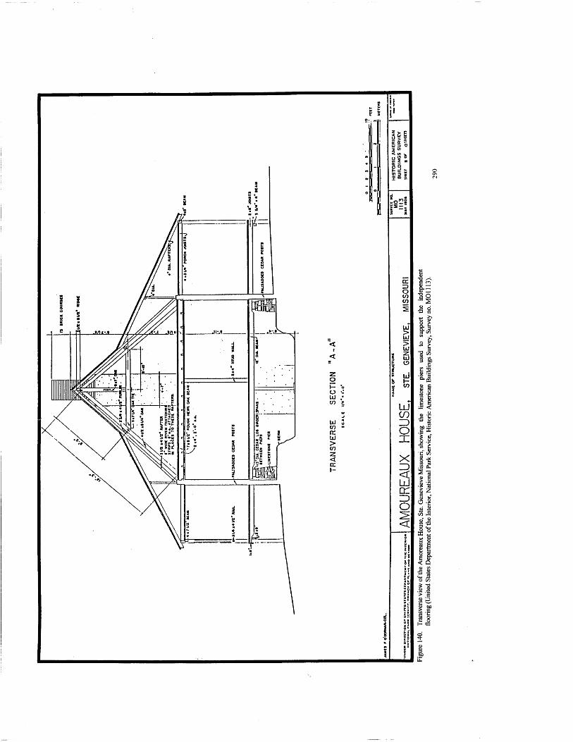
z o o *- UJ ,• to z
UJ lO (E LJ > to z < DC I-
11= si; 6 S3 8
UJ CO ID o X
X
< ÜJ cr o <
Is
5^
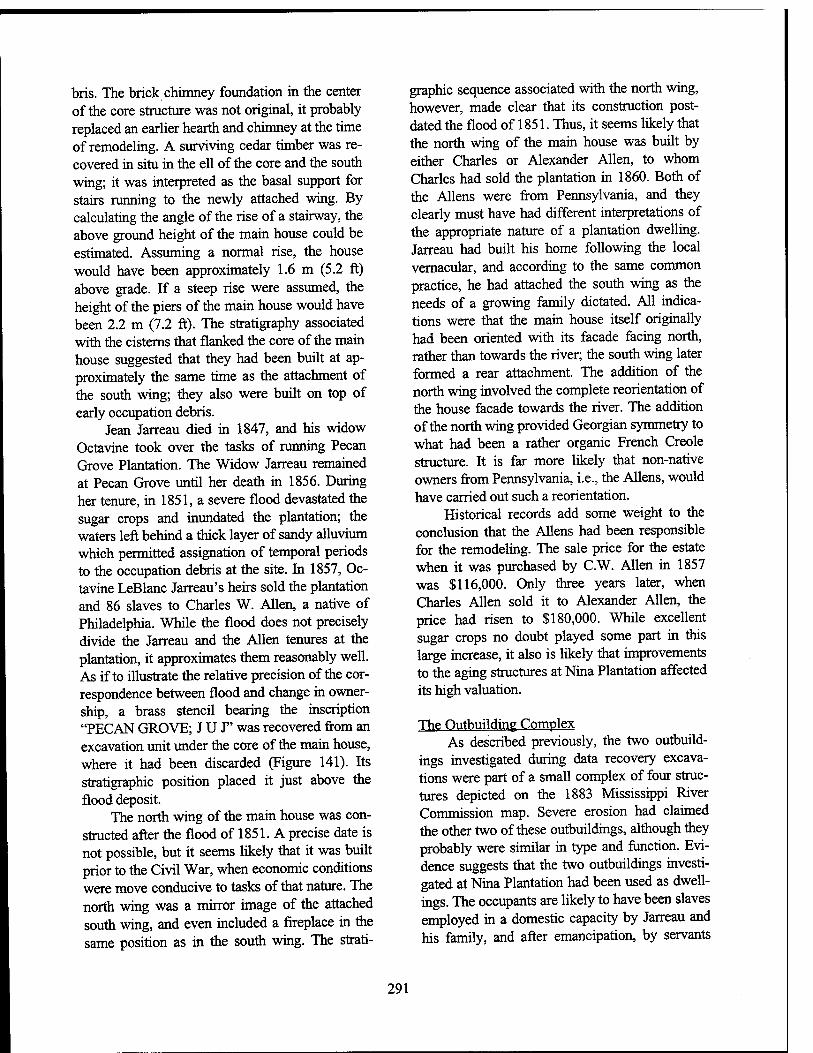
bris. The brick chimney foundation in the center of the core structure was not original, it probably replaced an earlier hearth and chimney at the time of remodeling. A surviving cedar timber was re- covered in situ in the ell of the core and the south wing; it was interpreted as the basal support for stairs running to the newly attached wing. By calculating the angle of the rise of a stairway, the above ground height of the main house could be estimated. Assuming a normal rise, the house would have been approximately 1.6 m (5.2 ft) above grade. If a steep rise were assumed, the height of the piers of the main house would have been 2.2 m (7.2 ft). The stratigraphy associated with the cisterns that flanked the core of the main house suggested that they had been built at ap- proximately the same time as the attachment of the south wing; they also were built on top of early occupation debris.
Jean Jarreau died in 1847, and his widow Octavine took over the tasks of running Pecan Grove Plantation. The Widow Jarreau remained at Pecan Grove until her death in 1856. During her tenure, in 1851, a severe flood devastated the sugar crops and inundated the plantation; the waters left behind a thick layer of sandy alluvium which permitted assignation of temporal periods to the occupation debris at the site. In 1857, Oc- tavine LeBlanc Jarreau's heirs sold the plantation and 86 slaves to Charles W. Allen, a native of Philadelphia. While the flood does not precisely divide the Jarreau and the Allen tenures at the plantation, it approximates them reasonably well. As if to illustrate the relative precision of the cor- respondence between flood and change in owner- ship, a brass stencil bearing the inscription "PECAN GROVE; JUT' was recovered from an excavation unit under the core of the main house, where it had been discarded (Figure 141). Its stratigraphic position placed it just above the flood deposit.
The north wing of the main house was con- structed after the flood of 1851. A precise date is not possible, but it seems likely that it was built prior to the Civil War, when economic conditions were move conducive to tasks ofthat nature. The north wing was a mirror image of the attached south wing, and even included a fireplace in the same position as in the south wing. The strati-
graphic sequence associated with the north wing, however, made clear that its construction post- dated the flood of 1851. Thus, it seems likely that the north wing of the main house was built by either Charles or Alexander Allen, to whom Charles had sold the plantation in 1860. Both of the Aliens were from Pennsylvania, and they clearly must have had different interpretations of the appropriate nature of a plantation dwelling. Jarreau had built his home following the local vernacular, and according to the same common practice, he had attached the south wing as the needs of a growing family dictated. All indica- tions were that the main house itself originally had been oriented with its facade facing north, rather than towards the river; the south wing later formed a rear attachment. The addition of the north wing involved the complete reorientation of the house facade towards the river. The addition of the north wing provided Georgian symmetry to what had been a rather organic French Creole structure. It is far more likely that non-native owners from Pennsylvania, i.e., the Aliens, would have carried out such a reorientation.
Historical records add some weight to the conclusion that the Aliens had been responsible for the remodeling. The sale price for the estate when it was purchased by C.W. Allen in 1857 was $116,000. Only three years later, when Charles Allen sold it to Alexander Allen, the price had risen to $180,000. While excellent sugar crops no doubt played some part in this large increase, it also is likely that improvements to the aging structures at Nina Plantation affected its high valuation.
The Outbuilding Complex As described previously, the two outbuild-
ings investigated during data recovery excava- tions were part of a small complex of four struc- tures depicted on the 1883 Mississippi River Commission map. Severe erosion had claimed the other two of these outbuildings, although they probably were similar in type and function. Evi- dence suggests that the two outbuildings investi- gated at Nina Plantation had been used as dwell- ings. The occupants are likely to have been slaves employed in a domestic capacity by Jarreau and his family, and after emancipation, by servants
291
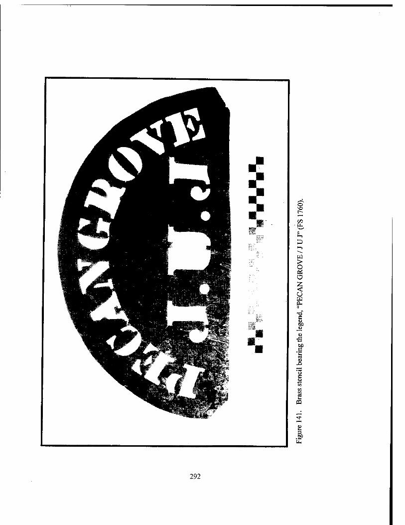
o r-
> O Pi o $ u w OH
XI c to eo
JD <u
J3 ■*-»
60 .C *w
CO U
-O
'5 c u
pa
292
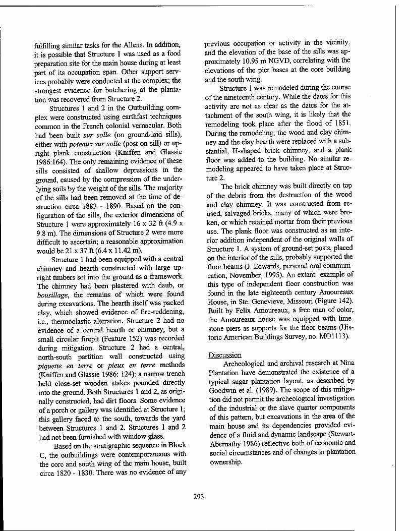
fulfilling similar tasks for the Aliens. In addition, it is possible that Structure 1 was used as a food preparation site for the main house during at least part of its occupation span. Other support serv- ices probably were conducted at the complex; the strongest evidence for butchering at the planta- tion was recovered from Structure 2.
Structures 1 and 2 in the Outbuilding com- plex were constructed using earthfast techniques common in the French colonial vernacular. Both had been built sur solle (on ground-laid sills), either with poteaux sur solle (post on sill) or up- right plank construction (Kniffen and Glassie 1986:164). The only remaining evidence of these sills consisted of shallow depressions in the ground, caused by the compression of the under- lying soils by the weight of the sills. The majority of the sills had been removed at the time of de- struction circa 1883 - 1890. Based on the con- figuration of the sills, the exterior dimensions of Structure 1 were approximately 16 x 32 ft (4.9 x 9.8 m). The dimensions of Structure 2 were more difficult to ascertain; a reasonable approximation would be 21 x 37 ft (6.4 x 11.42 m).
Structure 1 had been equipped with a central chimney and hearth constructed with large up- right timbers set into the ground as a framework. The chimney had been plastered with daub, or bousillage, the remains of which were found during excavations. The hearth itself was packed clay, which showed evidence of fire-reddening, i.e., thermoclastic alteration. Structure 2 had no evidence of a central hearth or chimney, but a small circular firepit (Feature 152) was recorded during mitigation. Structure 2 had a central, north-south partition wall constructed using piquette en terre or pieux en terre methods (Kniffen and Glassie 1986: 124); a narrow trench held close-set wooden stakes pounded directly into the ground. Both Structures 1 and 2, as origi- nally constructed, had dirt floors. Some evidence of a porch or gallery was identified at Structure 1; this gallery faced to the south, towards the yard between Structures 1 and 2. Structures 1 and 2 had not been furnished with window glass.
Based on the stratigraphic sequence in Block C, the outbuildings were contemporaneous with the core and south wing of the main house, built circa 1820 - 1830. There was no evidence of any
previous occupation or activity in the vicinity, and the elevation of the base of the sills was ap- proximately 10.95 m NGVD, correlating with the elevations of the pier bases at the core building and the south wing.
Structure 1 was remodeled during the course of the nineteenth century. While the dates for this activity are not as clear as the dates for the at- tachment of the south wing, it is likely that the remodeling took place after the flood of 1851. During the remodeling, the wood and clay chim- ney and the clay hearth were replaced with a sub- stantial, H-shaped brick chimney, and a plank floor was added to the building. No similar re- modeling appeared to have taken place at Struc- ture 2.
The brick chimney was built directly on top of the debris from the destruction of the wood and clay chimney. It was constructed from re- used, salvaged bricks, many of which were bro- ken, or which retained mortar from their previous use. The plank floor was constructed as an inte- rior addition independent of the original walls of Structure 1. A system of ground-set posts, placed on the interior of the sills, probably supported the floor beams (J. Edwards, personal oral communi- cation, November, 1995). An extant example of this type of independent floor construction was found in the late eighteenth century Amoureaux House, in Ste. Genevieve, Missouri (Figure 142). Built by Felix Amoureaux, a free man of color, the Amoureaux house was equipped with lime- stone piers as supports for the floor beams (His- toric American Buildings Survey, no. MOl 113).
Discussion Archeological and archival research at Nina
Plantation have demonstrated the existence of a typical sugar plantation layout, as described by Goodwin et al. (1989). The scope of this mitiga- tion did not permit the archeological investigation of the industrial or the slave quarter components of this pattern, but excavations in the area of the main house and its dependencies provided evi- dence of a fluid and dynamic landscape (Stewart- Abernathy 1986) reflective both of economic and social circumstances and of changes in plantation ownership.
293
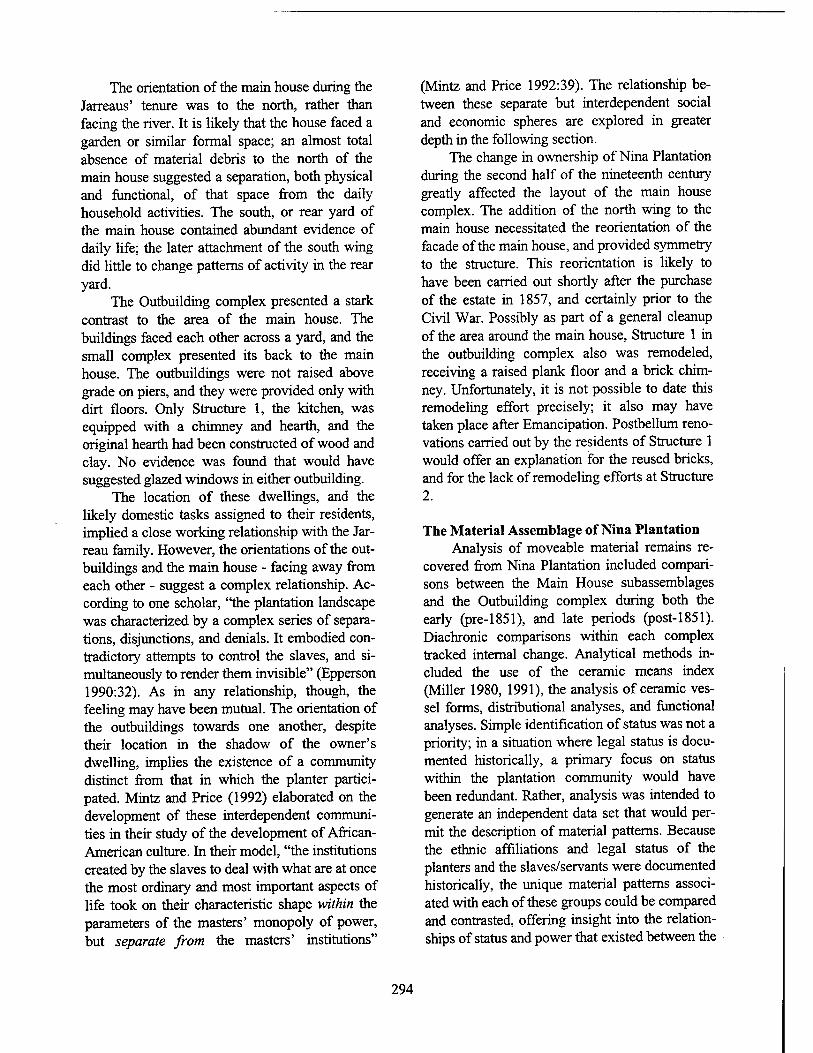
The orientation of the main house during the Jarreaus' tenure was to the north, rather than facing the river. It is likely that the house faced a garden or similar formal space; an almost total absence of material debris to the north of the main house suggested a separation, both physical and functional, of that space from the daily household activities. The south, or rear yard of the main house contained abundant evidence of daily life; the later attachment of the south wing did little to change patterns of activity in the rear yard.
The Outbuilding complex presented a stark contrast to the area of the main house. The buildings faced each other across a yard, and the small complex presented its back to the main house. The outbuildings were not raised above grade on piers, and they were provided only with dirt floors. Only Structure 1, the kitchen, was equipped with a chimney and hearth, and the original hearth had been constructed of wood and clay. No evidence was found that would have suggested glazed windows in either outbuilding.
The location of these dwellings, and the likely domestic tasks assigned to their residents, implied a close working relationship with the Jar- reau family. However, the orientations of the out- buildings and the main house - facing away from each other - suggest a complex relationship. Ac- cording to one scholar, "the plantation landscape was characterized by a complex series of separa- tions, disjunctions, and denials. It embodied con- tradictory attempts to control the slaves, and si- multaneously to render them invisible" (Epperson 1990:32). As in any relationship, though, the feeling may have been mutual. The orientation of the outbuildings towards one another, despite their location in the shadow of the owner's dwelling, implies the existence of a community distinct from that in which the planter partici- pated. Mintz and Price (1992) elaborated on the development of these interdependent communi- ties in their study of the development of African- American culture. In their model, "the institutions created by the slaves to deal with what are at once the most ordinary and most important aspects of life took on their characteristic shape within the parameters of the masters' monopoly of power, but separate from the masters' institutions"
(Mintz and Price 1992:39). The relationship be- tween these separate but interdependent social and economic spheres are explored in greater depth in the following section.
The change in ownership of Nina Plantation during the second half of the nineteenth century greatly affected the layout of the main house complex. The addition of the north wing to the main house necessitated the reorientation of the facade of the main house, and provided symmetry to the structure. This reorientation is likely to have been carried out shortly after the purchase of the estate in 1857, and certainly prior to the Civil War. Possibly as part of a general cleanup of the area around the main house, Structure 1 in the outbuilding complex also was remodeled, receiving a raised plank floor and a brick chim- ney. Unfortunately, it is not possible to date this remodeling effort precisely; it also may have taken place after Emancipation. Postbellum reno- vations carried out by the residents of Structure 1 would offer an explanation for the reused bricks, and for the lack of remodeling efforts at Structure 2.
The Material Assemblage of Nina Plantation Analysis of moveable material remains re-
covered from Nina Plantation included compari- sons between the Main House subassemblages and the Outbuilding complex during both the early (pre-1851), and late periods (post-1851). Diachronie comparisons within each complex tracked internal change. Analytical methods in- cluded the use of the ceramic means index (Miller 1980, 1991), the analysis of ceramic ves- sel forms, distributional analyses, and functional analyses. Simple identification of status was not a priority; in a situation where legal status is docu- mented historically, a primary focus on status within the plantation community would have been redundant. Rather, analysis was intended to generate an independent data set that would per- mit the description of material patterns. Because the ethnic affiliations and legal status of the planters and the slaves/servants were documented historically, the unique material patterns associ- ated with each of these groups could be compared and contrasted, offering insight into the relation- ships of status and power that existed between the
294
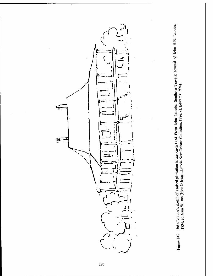
<L> XI o I«
■a
CO X a X o
a B =3 O
C ON O —i
X! co a o
00 cs
X ^ p <+J
Co _1
S 2
oo
OO ON
c
o
"o O
CO
C8
u u> 3 O X s o
O. ea -a J3 .22 O cö -^
CO O
o o <l>
CO £ CO
s X O
CS CO
i-
■s T3 J HJ
s en o oo
i
295
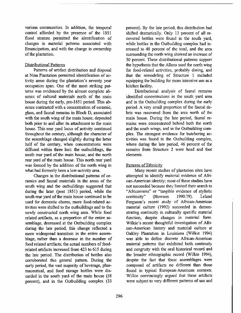
various communities. In addition, the temporal control afforded by the presence of the 1851 flood stratum permitted the identification of changes in material patterns associated with Emancipation, and with the change in ownership of the plantation.
Distributional Patterns Patterns of artifact distribution and disposal
at Nina Plantation permitted identification of ac- tivity areas during the plantation's seventy year occupation span. One of the most striking pat- terns was evidenced by the almost complete ab- sence of cultural materials north of the main house during the early, pre-1851 period. This ab- sence contrasted with a concentration of ceramic, glass, and faunal remains in Block D, associated with the south wing of the main house, deposited both prior to and after its attachment to the main house. This rear yard locus of activity continued throughout the century, although the character of the assemblage changed slightly during the latter half of the century, when concentrations were diffused within three loci: the outbuildings, the south rear yard of the main house, and the north rear yard of the main house. This north rear yard was formed by the addition of the north wing in what had formerly been a low-activity area.
Changes in the distributional patterns of ce- ramics and faunal materials in the areas of the south wing and the outbuildings suggested that during the later (post 1851) period, while the south rear yard of the main house continued to be used for domestic chores, more food-related ac- tivities were shifted to the outbuildings and to the newly constructed north wing area. While food related artifacts, as a proportion of the entire as- semblage, decreased at the Outbuilding complex during the late period, this change reflected a more widespread transition in the entire assem- blage, rather than a decrease in the number of food related artifacts; the actual numbers of food- related artifacts increased from 423 to 615 during the late period. The distribution of bottles also corroborated this general pattern. During the early period, the vast majority of beverage, phar- maceutical, and food storage bottles were dis- carded in the south yard of the main house (58 percent), and in the Outbuilding complex (33
percent). By the late period, this distribution had shifted dramatically. Only 13 percent of all re- covered bottles were found in the south yard, while bottles in the Outbuilding complex had in- creased to 48 percent of the total, and the area surrounding the north wing showed an increase of 30 percent. These distributional patterns support the hypothesis that the Aliens used the north wing for food-related activities, probably dining, and that the remodeling of Structure 1 included equipping the building for more intensive use as a kitchen facility.
Distributional analysis of faunal remains identified concentrations in the south yard area and in the Outbuilding complex during the early period. A very small proportion of the faunal de- bris was recovered from the area north of the main house. During the late period, faunal re- mains were concentrated behind both the north and the south wings, and in the Outbuilding com- plex. The strongest evidence for butchering ac- tivities was found in the Outbuilding complex, where during the late period, 46 percent of the remains from Structure 2 were head and foot elements.
Patterns of Ethnicity Many recent studies of plantation sites have
attempted to identify material evidence of Afri- can-American identity; most of these studies have not succeeded because they limited their search to "Africanisms" or "tangible evidence of stylistic continuity" (Howson 1990:79). Leland Ferguson's recent study of African-American material culture (1992) succeeded in demon- strating continuity in culturally specific material function, despite changes in material form. Wilkie's recent thoughtful investigation of Afri- can-American history and material culture at Oakley Plantation in Louisiana (Wilkie 1994) was able to define discrete African-American material patterns that exhibited both continuity and congruity with the oral historical record and the broader ethnographic record (Wilkie 1994), despite the fact that these assemblages were composed of artifacts no different than those found in typical European-American contexts. Wilkie convincingly argued that these artifacts were subject to very different patterns of use and
296
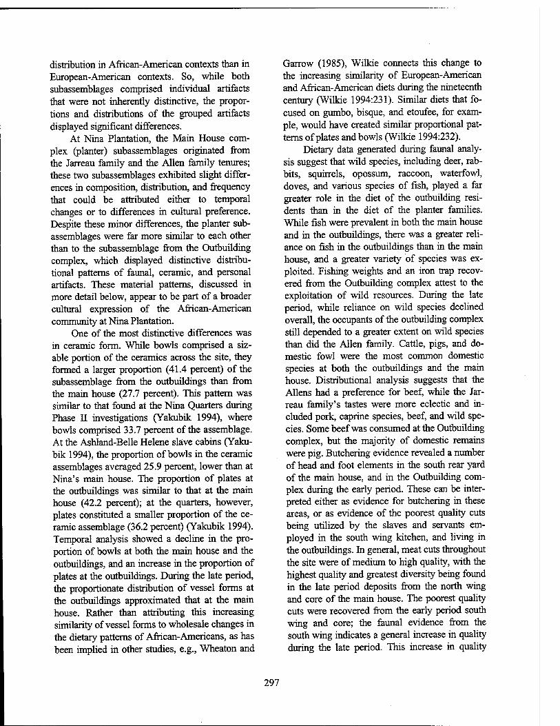
distribution in African-American contexts than in European-American contexts. So, while both subassemblages comprised individual artifacts that were not inherently distinctive, the propor- tions and distributions of the grouped artifacts displayed significant differences.
At Nina Plantation, the Main House com- plex (planter) subassemblages originated from the Jarreau family and the Allen family tenures; these two subassemblages exhibited slight differ- ences in composition, distribution, and frequency that could be attributed either to temporal changes or to differences in cultural preference. Despite these minor differences, the planter sub- assemblages were far more similar to each other than to the subassemblage from the Outbuilding complex, which displayed distinctive distribu- tional patterns of faunal, ceramic, and personal artifacts. These material patterns, discussed in more detail below, appear to be part of a broader cultural expression of the African-American community at Nina Plantation.
One of the most distinctive differences was in ceramic form. While bowls comprised a siz- able portion of the ceramics across the site, they formed a larger proportion (41.4 percent) of the subassemblage from the outbuildings than from the main house (27.7 percent). This pattern was similar to that found at the Nina Quarters during Phase II investigations (Yakubik 1994), where bowls comprised 33.7 percent of the assemblage. At the Ashland-Belle Helene slave cabins (Yaku- bik 1994), the proportion of bowls in the ceramic assemblages averaged 25.9 percent, lower than at Nina's main house. The proportion of plates at the outbuildings was similar to that at the main house (42.2 percent); at the quarters, however, plates constituted a smaller proportion of the ce- ramic assemblage (36.2 percent) (Yakubik 1994). Temporal analysis showed a decline in the pro- portion of bowls at both the main house and the outbuildings, and an increase in the proportion of plates at the outbuildings. During the late period, the proportionate distribution of vessel forms at the outbuildings approximated that at the main house. Rather than attributing this increasing similarity of vessel forms to wholesale changes in the dietary patterns of African-Americans, as has been implied in other studies, e.g., Wheaton and
Garrow (1985), Wilkie connects this change to the increasing similarity of European-American and African-American diets during the nineteenth century (Wilkie 1994:231). Similar diets that fo- cused on gumbo, bisque, and etoufee, for exam- ple, would have created similar proportional pat- terns of plates and bowls (Wilkie 1994:232).
Dietary data generated during faunal analy- sis suggest that wild species, including deer, rab- bits, squirrels, opossum, raccoon, waterfowl, doves, and various species of fish, played a far greater role in the diet of the outbuilding resi- dents than in the diet of the planter families. While fish were prevalent in both the main house and in the outbuildings, there was a greater reli- ance on fish in the outbuildings than in the main house, and a greater variety of species was ex- ploited. Fishing weights and an iron trap recov- ered from the Outbuilding complex attest to the exploitation of wild resources. During the late period, while reliance on wild species declined overall, the occupants of the outbuilding complex still depended to a greater extent on wild species than did the Allen family. Cattle, pigs, and do- mestic fowl were the most common domestic species at both the outbuildings and the main house. Distributional analysis suggests that the Aliens had a preference for beef, while the Jar- reau family's tastes were more eclectic and in- cluded pork, caprine species, beef, and wild spe- cies. Some beef was consumed at the Outbuilding complex, but the majority of domestic remains were pig. Butchering evidence revealed a number of head and foot elements in the south rear yard of the main house, and in the Outbuilding com- plex during the early period. These can be inter- preted either as evidence for butchering in these areas, or as evidence of the poorest quality cuts being utilized by the slaves and servants em- ployed in the south wing kitchen, and living in the outbuildings. In general, meat cuts throughout the site were of medium to high quality, with the highest quality and greatest diversity being found in the late period deposits from the north wing and core of the main house. The poorest quality cuts were recovered from the early period south wing and core; the faunal evidence from the south wing indicates a general increase in quality during the late period. This increase in quality
297
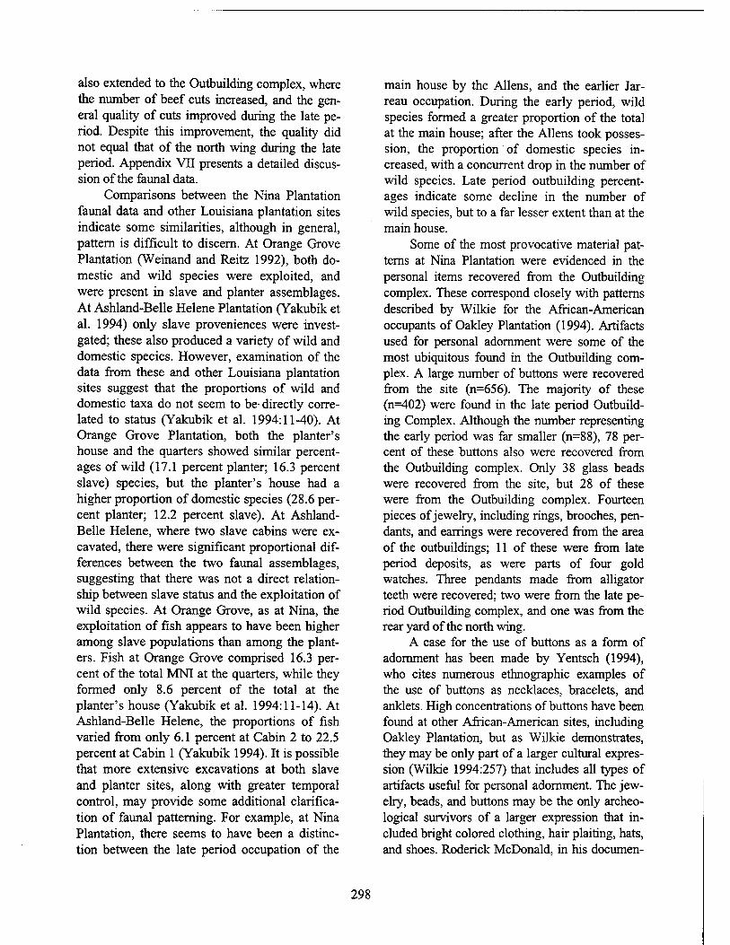
also extended to the Outbuilding complex, where the number of beef cuts increased, and the gen- eral quality of cuts improved during the late pe- riod. Despite this improvement, the quality did not equal that of the north wing during the late period. Appendix VII presents a detailed discus- sion of the faunal data.
Comparisons between the Nina Plantation faunal data and other Louisiana plantation sites indicate some similarities, although in general, pattern is difficult to discern. At Orange Grove Plantation (Weinand and Reitz 1992), both do- mestic and wild species were exploited, and were present in slave and planter assemblages. At Ashland-Belle Helene Plantation (Yakubik et al. 1994) only slave proveniences were invest- gated; these also produced a variety of wild and domestic species. However, examination of the data from these and other Louisiana plantation sites suggest that the proportions of wild and domestic taxa do not seem to be directly corre- lated to status (Yakubik et al. 1994:11-40). At Orange Grove Plantation, both the planter's house and the quarters showed similar percent- ages of wild (17.1 percent planter; 16.3 percent slave) species, but the planter's house had a higher proportion of domestic species (28.6 per- cent planter; 12.2 percent slave). At Ashland- Belle Helene, where two slave cabins were ex- cavated, there were significant proportional dif- ferences between the two faunal assemblages, suggesting that there was not a direct relation- ship between slave status and the exploitation of wild species. At Orange Grove, as at Nina, the exploitation of fish appears to have been higher among slave populations than among the plant- ers. Fish at Orange Grove comprised 16.3 per- cent of the total MNI at the quarters, while they formed only 8.6 percent of the total at the planter's house (Yakubik et al. 1994:11-14). At Ashland-Belle Helene, the proportions of fish varied from only 6.1 percent at Cabin 2 to 22.5 percent at Cabin 1 (Yakubik 1994). It is possible that more extensive excavations at both slave and planter sites, along with greater temporal control, may provide some additional clarifica- tion of faunal patterning. For example, at Nina Plantation, there seems to have been a distinc- tion between the late period occupation of the
main house by the Aliens, and the earlier Jar- reau occupation. During the early period, wild species formed a greater proportion of the total at the main house; after the Aliens took posses- sion, the proportion of domestic species in- creased, with a concurrent drop in the number of wild species. Late period outbuilding percent- ages indicate some decline in the number of wild species, but to a far lesser extent than at the main house.
Some of the most provocative material pat- terns at Nina Plantation were evidenced in the personal items recovered from the Outbuilding complex. These correspond closely with patterns described by Wilkie for the African-American occupants of Oakley Plantation (1994). Artifacts used for personal adornment were some of the most ubiquitous found in the Outbuilding com- plex. A large number of buttons were recovered from the site (n=656). The majority of these (n=402) were found in the late period Outbuild- ing Complex. Although the number representing the early period was far smaller (n=88), 78 per- cent of these buttons also were recovered from the Outbuilding complex. Only 38 glass beads were recovered from the site, but 28 of these were from the Outbuilding complex. Fourteen pieces of jewelry, including rings, brooches, pen- dants, and earrings were recovered from the area of the outbuildings; 11 of these were from late period deposits, as were parts of four gold watches. Three pendants made from alligator teeth were recovered; two were from the late pe- riod Outbuilding complex, and one was from the rear yard of the north wing.
A case for the use of buttons as a form of adornment has been made by Yentsch (1994), who cites numerous ethnographic examples of the use of buttons as necklaces, bracelets, and anklets. High concentrations of buttons have been found at other African-American sites, including Oakley Plantation, but as Wilkie demonstrates, they may be only part of a larger cultural expres- sion (Wilkie 1994:257) that includes all types of artifacts useful for personal adornment. The jew- elry, beads, and buttons may be the only archeo- logical survivors of a larger expression that in- cluded bright colored clothing, hair plaiting, hats, and shoes. Roderick McDonald, in his documen-
298
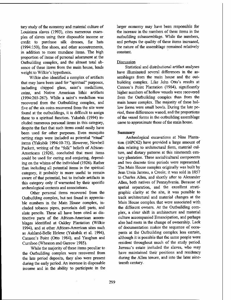
tary study of the economy and material culture of Louisiana slaves (1993), cites numerous exam- ples of slaves using their disposable income or credit to purchase silk dresses, fur hats (1994:150), fine shoes, and other accoutrements, in addition to more mundane items. The high proportion of items of personal adornment at the Outbuilding complex, and the almost total ab- sence of these items from the main house, lends weight to Wilkie's hypothesis.
Wilkie also identified a complex of artifacts that may have been used for "spiritual" purposes, including chipped glass, saint's medallions, coins, and Native American lithic artifacts (1994:265-267). While a saint's medallion was recovered from the Outbuilding complex, and five of the six coins recovered from the site were found at the outbuildings, it is difficult to assign these to a spiritual function. Yakubik (1994) in- cluded numerous personal items in this category, despite the fact that such items could easily have been used for other purposes. Even mosquito netting rings were included as potential "ritual" items (Yakubik 1994:10-75). However, Newbell Puckett, writing of the "folk" beliefs of African- Americans (1926), concluded that most items could be used for curing and conjuring, depend- ing on the whims of the individual (1926). Rather than including all potential items in the spiritual category, it probably is more useful to remain aware of that potential, but to include artifacts in this category only if warranted by their specific archeological contexts and associations.
Other personal items recovered from the Outbuilding complex, but not found in apprecia- ble numbers in the Main House complex, in- cluded tobacco pipes, porcelain doll parts, and slate pencils. These all have been cited as dis- tinctive parts of the African-American assem- blages identified at Oakley Plantation (Wilkie 1994), and at other African-American sites such as Ashland-Belle Helene (Yakubik et al. 1994), Cannon's Point (Otto 1984), and Yaughan and Curriboo (Wheaton and Garrow 1985).
While the majority of these items peculiar to the Outbuilding complex were recovered from the late period deposits, they also were present during the early period. An increase in disposable income and in the ability to participate in the
larger economy may have been responsible for the increase in the numbers of these items in the outbuilding subassemblage. While the numbers, and perhaps the quality of these items increased, the nature of the assemblage remained relatively constant.
Discussion Statistical and distributional artifact analyses
have illuminated several differences in the as- semblages from the main house and the out- building complex. Like John Otto's results at Cannon's Point Plantation (1984), significantly higher numbers of hollow vessels were recovered from the Outbuilding complex than from the main house complex. The majority of these hol- low forms were small bowls. During the late pe- riod, these differences waned, and the proportions of the vessel forms in the outbuilding assemblage came to approximate those of the main house.
Summary Archeological excavations at Nina Planta-
tion (16PC62) have provided a large amount of data relating to architectural form, material cul- ture, and dietary patterns at this nineteenth cen- tury plantation. Three social/cultural components and two discrete time periods were represented. The Main House complex originally was built by Jean Ursin Jarreau, a Creole; it was sold in 1857 to Charles Allen, and shortly after to Alexander Allen, both natives of Pennsylvania. Because of spatial separation, and the excellent strati- graphic clarity at the site, it was possible to track architectural and material changes at the Main House complex that were associated with the different owners. At the Outbuilding com- plex, a clear shift in architecture and material culture accompanied Emancipation, and perhaps also had roots in the change of ownership. Lack of documentation makes the sequence of occu- pants at the Outbuilding complex less certain, although it is possible that the same people were resident throughout much of the study period. Jarreau's estate included the slaves, who may have maintained their positions and residency during the Allen tenure, and into the later nine- teenth century.
299
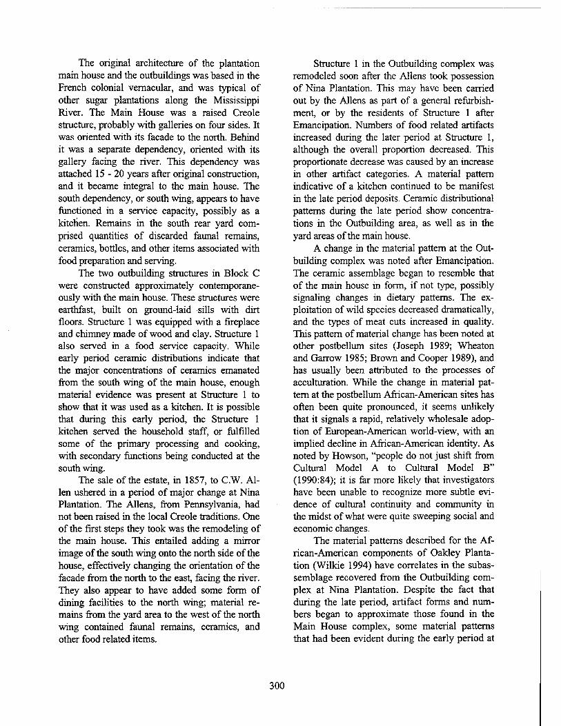
The original architecture of the plantation main house and the outbuildings was based in the French colonial vernacular, and was typical of other sugar plantations along the Mississippi River. The Main House was a raised Creole structure, probably with galleries on four sides. It was oriented with its facade to the north. Behind it was a separate dependency, oriented with its gallery facing the river. This dependency was attached 15-20 years after original construction, and it became integral to the main house. The south dependency, or south wing, appears to have functioned in a service capacity, possibly as a kitchen. Remains in the south rear yard com- prised quantities of discarded faunal remains, ceramics, bottles, and other items associated with food preparation and serving.
The two outbuilding structures in Block C were constructed approximately contemporane- ously with the main house. These structures were earthfast, built on ground-laid -sills with dirt floors. Structure 1 was equipped with a fireplace and chimney made of wood and clay. Structure 1 also served in a food service capacity. While early period ceramic distributions indicate that the major concentrations of ceramics emanated from the south wing of the main house, enough material evidence was present at Structure 1 to show that it was used as a kitchen. It is possible that during this early period, the Structure 1 kitchen served the household staff, or fulfilled some of the primary processing and cooking, with secondary functions being conducted at the south wing.
The sale of the estate, in 1857, to C.W. Al- len ushered in a period of major change at Nina Plantation. The Aliens, from Pennsylvania, had not been raised in the local Creole traditions. One of the first steps they took was the remodeling of the main house. This entailed adding a mirror image of the south wing onto the north side of the house, effectively changing the orientation of the facade from the north to the east, facing the river. They also appear to have added some form of dining facilities to the north wing; material re- mains from the yard area to the west of the north wing contained faunal remains, ceramics, and other food related items.
Structure 1 in the Outbuilding complex was remodeled soon after the Aliens took possession of Nina Plantation. This may have been carried out by the Aliens as part of a general refurbish- ment, or by the residents of Structure 1 after Emancipation. Numbers of food related artifacts increased during the later period at Structure 1, although the overall proportion decreased. This proportionate decrease was caused by an increase in other artifact categories. A material pattern indicative of a kitchen continued to be manifest in the late period deposits. Ceramic distributional patterns during the late period show concentra- tions in the Outbuilding area, as well as in the yard areas of the main house.
A change in the material pattern at the Out- building complex was noted after Emancipation. The ceramic assemblage began to resemble that of the main house in form, if not type, possibly signaling changes in dietary patterns. The ex- ploitation of wild species decreased dramatically, and the types of meat cuts increased in quality. This pattern of material change has been noted at other postbellum sites (Joseph 1989; Wheaton and Garrow 1985; Brown and Cooper 1989), and has usually been attributed to the processes of acculturation. While the change in material pat- tern at the postbellum African-American sites has often been quite pronounced, it seems unlikely that it signals a rapid, relatively wholesale adop- tion of European-American world-view, with an implied decline in African-American identity. As noted by Howson, "people do not just shift from Cultural Model A to Cultural Model B" (1990:84); it is far more likely that investigators have been unable to recognize more subtle evi- dence of cultural continuity and community in the midst of what were quite sweeping social and economic changes.
The material patterns described for the Af- rican-American components of Oakley Planta- tion (Wilkie 1994) have correlates in the subas- semblage recovered from the Outbuilding com- plex at Nina Plantation. Despite the fact that during the late period, artifact forms and num- bers began to approximate those found in the Main House complex, some material patterns that had been evident during the early period at
300
the Outbuilding complex actually intensified during the late, post-Emancipation period. This intensification was most visible in the higher numbers of personal goods. The post- Emancipation subassemblage was marked also by the presence of education-related artifacts such as slate pencils and eyeglasses. A change in dietary patterns after Emancipation was sug- gested by changes in the proportions of both vessel forms and faunal data; these categories suggested an increasing similarity between the dietary practices in use at the Main House and those at the Outbuilding complex.
The process of acculturation implies a uni- lateral, cultural adjustment; the data from Nina Plantation do not support such a hypothesis. Rather, they suggest a more dynamic process of creolization, in which there was multilateral movement towards new cultural configurations that included shared attributes; for example, the
increasing similarity of vessel forms and faunal remains at both the main house and the out- buildings suggests a growing commonality in foodways. The process of creolization, however, was additive, and did not negate unique cultural and ethnic traits. The increase in artifacts used for personal adornment, for example, was unique to the Outbuilding complex. This was not a new material pattern; it was an intensifi- cation of a pattern that had been present throughout the nineteenth century at the Nina Plantation outbuildings, and that was noted at numerous other nineteenth century African- American sites. The data from Nina Plantation suggest that after Emancipation, the African- American occupants enjoyed both a strength- ening of ethnic identity and a modicum of in- creased economic power and market access, as they continued to participate in the Americani- zation of Nina Plantation.
301
BIBLIOGRAPHY
References Cited
Adams, William and Sarah Boling 1989 Status and Ceramics for Planters and Slaves on Three Georgia Coast Plantations. Historical
Archaeology 23(l):69-96.
Albert, Alphaeus H. 1976 Record of American Uniform and Historical Buttons, Bicentennial Edition.
Albert, Lillian Smith, and Jane Ford Adams 1970 Essential Data Concerning China Buttons. In Guidelines for Collecting China Buttons, by
Ruth Lamm, Beatrice and Lester Lorah, and Helen W. Schüler. National Button Society of America. Boyertown Publishing Company, Boyertown, Pennsylvania.
Alexander, David T., ed. 1990 Comprehensive Catalog & Encyclopedia of United States Coins. Amos Press Inc, Sidney,
Ohio.
Alexander, L. T. 1983 Clay Tobacco Smoking Pipes from the Caleb Pusey House. In The Archaeology of the Clay
Tobacco Pipe VIII: America, edited by Peter Davey, pp. 195-233. BAR International Series 175, Oxford, England.
Allan, William 1886 The Life and Work of John McDonogh. Trustees of the McDonogh School. McDonogh,
Maryland.
Andreu Ocariz, Juan Jose 1977 Monumentos Rebeides de Los Esclavos Negros Dur ante el Dominio Espanol en Luisiana.
Zaragoza, Spain.
Arthur, Stanley Clisby, and George Campbell Huchet de Kernion 1931 Old Families of Louisiana. Harmanson, Publisher. New Orleans, Louisiana.
Autin, Whitney J., Scott F. Burns, Bobby J. Miller, Roger T. Saucier, and John I. Snead 1991 Quaternary Geology of the Lower Mississippi River Valley. In Quaternary Nonglacial
Geology, Conterminous U.S., edited by R. B. Morrison, pp. 20-56. The Geology of North America, vol. K-2. Geological Society of America, Boulder, Colorado.
Bannerman Catalogue of Military Goods 1927 DBI Books, Inc., Northfield, Illinois.
302
Batty, Bob H. 1978 A Complete Guide to Pressed Glass. Pelican Publishing Company, Gretna,
Bendernagel, Marcelle Jarreau ca. 1966 Bendernagel Genealogical Record. Typescript on file, Manuscript Section, Howafd-Tilton
Memorial Library, Tulane University, New Orleans.
Binford, Lewis R. 1972 The "Binford" Pipe Stem Formula: A Return from the Grave. The Conference on Historic
Sites Archaeology Papers Vol. 6, part 2, section 2:230-253.
Bloomingdale Brothers 1886 Bloomingdale's Illustrated 1886 Catalog: Fashions, Dry Goods and Housewares.
Boyertown Publishing Company, Boyertown, Pennsylvania.
Bjerknes, J. 1969 Atmospheric Teleconnections from the Equatorial Pacific, Monthly Weather Review,
97:3:163-172.
Bouchereau, Louis and Alcee 1868- Statement of the Sugar and Rice Crops Made in Louisiana. Pelican Steam Book and Job 1917 Printing, New Orleans.
Braile, L. W., G. R. Keller, W. J. Hinze, and E. G. Lidiak 1982 An Ancient Riß Complex and its Relation to Contemporary Seismicity in the New Madrid
Seismic Zone. Tectonics l(2):225-237.
Brown, Kenneth L., and Doreen C. Cooper 1989 Structural Continuity in an Afro-American Slave and Tenant Community. Paper presented
at Digging the Afro-American Past: Archaeology and the Black Experience Conference, University of Mississippi, Oxford.
Burke, K., and J.F. Dewey 1973 Plume Generated Triple Junctions: Key Indicators in Applying Plate Tectonics to Old
Rocks. Journal of Geology 81:406-433.
Carskadden, Jeff, Richard Gartley and Elizabeth Reeb 1985 Marble Making and Playing in Eastern Ohio: The Significance of Ceramic, Stone and Glass
Marbles in Historic Archaeology. Proceedings of the Symposium on Ohio Valley Urban and Historic Archaeology, 3:86-96.
Castille, George J., UJ 1989 A Magnetometer Survey of a Four-Acre Parcel in Audubon State Commemorative Area,
West Feliciana Parish, Louisiana. Submitted to the Louisiana Division of Archaeology, Department of Culture, Recreation and Tourism, Baton Rouge.
1990 A Magnetometer Survey of a Three-Acre Parcel in Audubon State Commemorative Area, West Feliciana Parish, Louisiana. Submitted to the Louisiana Division of Archaeology, Department of Culture, Recreation and Tourism, Baton Rouge.
303
Cate, Margaret Davis 1930 Our Todays and Yesterdays: A Story of Brunswick and the Coastal Islands. Glover
Brothers, Brunswick, Georgia.
Cayton, Frank M., compiler 1881 Landings on all the Western and Southern Rivers and Bayous showing Location, Post
Offices, Distances, &c. Woodward, Tiernan, and Hale. St. Louis, Missouri.
Champomier, P. A. 1858 Statement of the Sugar Crop Made in Louisiana in 1857-58, With an Appendix. Cook,
Young and Co., New Orleans.
1844- Statement of the Sugar Crop Made in Louisiana (1844-1866). Cook, Young and Company, 1866 New Orleans.
Chief of Engineers 1891 Annual Report of the Chief of Engineers, United States Army, to the Secretary of War, for
the Year 1891. Part 1. Government Printing Office. Washington, D.C.
City Directory Series 1850s Annual Directories of New Orleans, under Various Titles, in Louisiana Collection,
Howard-Tilton Library, Tulane University, New Orleans, Louisiana.
Claassen, Cheryl 1994 Washboards, Pigtoes, and Muckets: Historic Musseling in the Mississippi Watershed.
Historical Archaeology 28(2).
Coates, Earl J. and Dean S. Thomas 1990 An Introduction to Civil War Small Arms. Thomas Publications, Gettysburg,
Cohen, Hal L. (editor) 1969 7922 Montgomery Ward Catalogue. House of Collectibles Publishers, Inc. New York.
Coleman, James M. 1966 Ecological Changes in a Massive Fresh-Water Clay Sequence. Gulf Coast Association of
Geological Societies Transactions 16:159-174.
1979 Recent increased aridity in peninsular Florida, Quartemary Research, 13:5-79.
1982 Recent seasonal rainfall and temperature relationships in peninsular Florida, Quarternary Research, 18:144-151.
1988 Climatic warming and increased summer aridity in Florida, U.S.A., Climatic Change, 12:165-178.
Collins, Henry Hill, Jr. 1981 Complete Guide to North American Wildlife. Harper & Row, Publishers, New York.
Commercial Bulletin 1870 Obituary of Alexander Allen. Commercial Bulletin October 14:1.
304
Core, H. A., W. A. Cote, and A. C. Day 1979 Wood Structure and Identification. Syracuse University Press, Syracuse.
Costello, Brian 1993 New Roads: A Community in Retrospect.. Published by the city of New Roads, with
funding by Cajun Electric.
Coysh, A. W. and R. K. Henrywood 1982 The Dictionary of Blue and White Printed Pottery 1780-1880, Vol. I. Antique Collectors'
Club Ltd, Woodbridge, Suffolk, England.
Critchfield, H. J. 1983 General Climatology, 4th Ed. Prentice-Hall, Inc., 453pp.
Curtin, Philip D. 1969 The Atlantic Slave Trade: A Census. University of Wisconsin Press. Madison, Wisconsin.
Cushing, E. M, E. H. Bowell, and R. L. Hosman 1964 General Geology of the Mississippi Embayment. United States Geological Survey
Professional Paper, 448-B.
Cushion, J. P. 1976 Pocket Book of British Ceramic Marks. Faber and Faber, London.
Davis, Rex E. 1971 Soil Survey of George County, Mississippi. U.S. Department of Agriculture, Soil
Conservation Service, Jackson, Mississippi.
Degelos, Pierre A. 1892 Statement of Sugar Made in Louisiana in 1828 and 1829. The Louisiana Planter and Sugar
Manufacturer FX(4):65-68.
Dethloff, Henry C. and Robert R. Jones 1968 Race Relations in Louisiana, 1877-1898. Louisiana History DC(4):301-323.
De Ville, Winston, editor 1988 Slaves and Masters of Pointe Coupee: A Calendar of Civil Records. Polyanthos Press. New
Orleans, Louisiana.
Dickins, Asbury, and John W. Forney (editors) 1860- American State Papers, Class VIII, Public Lands, vols. VI and VIJX Gales & Seaton, 1861 Washington, D.C.
Diocese of Baton Rouge ca. 1983- Diocese of Baton Rouge Catholic Church Records, vols. 4, 5, 6, and 8. Department of
1988 Archives, Diocese of Baton Rouge, Baton Rouge, Louisiana.
Dormon, James H. 1977 The Persistent Specter: Slave Rebellion in Territorial Louisiana. Louisiana History.
18:389-404.
305
Douglas, A. V., and P. J. Englehart 1981 On a statistical relationship between autumn rainfall in the central equatorial Pacific and
subsequent winter precipitation in Florida, Monthly Weather Review, 190:2377-2382.
Duco, D. H. 1982 Merken van Goudse pijpenmakers 1660-1940. Poperinge, Lochern: Uitgeversmaatschappij
De Tijdstrom.
Dumbrell, Roger 1983 Understanding Antique Wine Bottles. Baron Publishing, Suffolk, England.
Easterling, D. R. 1991 Climatological patterns of thunderstorm activity in the south-east USA, Internal Journal
Climatology, 11:213-221.
Eaton, Clement 1975 A History of the Old South, 3rd ed. Macmillan Company. New York, New York.
Edmonds, David C. 1983 The Guns of Port Hudson, Volume One: The River Campaign. Acadiana Press, Lafayette,
Louisiana.
1984 The Guns of Port Hudson, Volume Two: The Investment, Siege and Reduction. Acadiana Press, Lafayette, Louisiana.
Edwards, Jay 1994 The Origins of Creole Architecture. In Winterthur Portfolio, 29(2-3): 155-189.
Edwards, Jay D. and Tom Wells 1993 Historic Louisiana Nails: Aids to the Dating of Old Buildings. Geoscience Publications,
Baton Rouge, LA.
Emerson, Matthew C. 1988 Decorated Clay Tobacco Pipes from the Chesapeake. Ph.D. dissertation, Department of
Anthropology, University of California, Berkley. University Microfilms, Ann Arbor.
Epperson, Terrence W. 1987 "Thus in the Beginning All the World Was America"; Class Formation and the Social
Construction of Race in the Chesapeake, 1675-1740. Research proposal for Afro-American Studies, University of Virginia, Charlottesville.
1990 Race and the Disciplines of the Plantation. Historical Archaeology 24(4):29-36.
Fairbanks, Charles H. 1974 The Kingsley Slave Cabins in Duval County, Florida, 1968. The Conference on Historic
Site Archaeology Papers 1972 7:62-93.
306
Farrell, Kathleen M. 1989 Stratigraphy and Sedimentology ofHolocene Overbank Deposits of the Mississippi River,
False River Region, Louisiana. Unpublished Ph.D. dissertation, Department of Geology and Geophysics, Louisiana State University, Baton Rouge.
Ferguson, Leland G. 1989 Archaeological Evidence for Early African-American Religion? Marks on Pottery from
Colonial Carolina. Paper presented at Digging the Afro-American Past: Archaeology and the Black Experience Conference, University of Mississippi, Oxford.
1992 Uncommon Ground: Archeology and Early African America, 1650-1800. Smithsonian Institute Press, Washington, D.C. and London.
Fike, Richard E. 1987 The Bottle Book: A Comprehensive Guide to Historic, Embossed Medicine Bottles. Gibbs
M. Smith, Inc., Salt Lake City.
Fisk, Harold N. 1944 Geological Investigation of the Alluvial Valley of the Lower Mississippi River. Mississippi
River Commission, U.S. Army Corps of Engineers. Vicksburg, Mississippi.
1947 Fine-Grained Alluvial Deposits and their Effects on Mississippi River Activity. Mississippi River Commission, U.S. Army Corps of Engineers, Vicksburg, Mississippi.
Ford, James A. 1937 An Archaeological Report on the Elizafield Ruins. In Georgia's Disputed Ruins, edited by
E. Coulter, pp. 191-225. University of North Carolina Press, Chapel Hill.
1962 A Quantative Method for Deriving Cultural Chronology. Technical Manual Number 1. Pan American Union, General Secretariat, Organization of American States Technical Publications and Documents, Department of Social Affairs, Washington, D.C.
French and American Claims Commission [FACC] 1883 Francois Bernard Manuel vs. The United States, No. 197. Claim documents on file,
National Archives, College Park, Maryland.
1883 Petitfils vs. The United States, No. 292. Claim documents on file, National Archives, College Park, Maryland.
1883- Claudius Maurin vs. The United States, No. 624. Claim documents on file, National 1884 Archives, College Park, Maryland.
Friedman, G. M. and J. E. Sanders 1978 Principles of Sedimentology. John Wiley and Sons, Ltd., New York.
Gagliano, Sherwood M., George Castille, and Susan Fulgham 1978 Cultural Resources Testing at a Proposed Borrow Pit Site near Waterloo, Pointe Coupee
Parish, Louisiana. Submitted by Coastal Environments, Inc. to the U.S. Army Corps of Engineers, New Orleans District.
307
Gagliano, Sherwood M., Richard S. Weinstein, and Eileen K. Burden 1976 Archaeological Survey: Colonial Pipe Line Company Forty-Inch Pipeline, East Feliciana
Parish, Louisiana to Orange County, Texas. Submitted by Coastal Environments, Inc. to the Division of Archaeology, Baton Rouge.
Galloway, W. E., and David K. Hobday 1984 Terrigenous Clastic Depositional Systems. Springer-Verlag, New York.
Godden, Geoffrey A. 1964 Encyclopedia of British Pottery and Porcelain Marks. Bonanza Books, New York.
Goodspeed Publishing Company 1892 Biographical and Historical Memoirs of Louisiana... 2 vols. Goodspeed Publishing
Company. Chicago, Illinois.
1975 Biographical and Historical Memoirs of Louisiana, vol. I. Reprinted. Claitor's Publishing Division, Baton Rouge. Originally published 1892, Goodspeed Publishing Company, Chicago.
Goodwin, R. Christopher & Associates, Inc. 1993 A Proposal for Archeological Data Recovery at Nina Plantation, Pointe Coupee Parish,
Louisiana. Requisition No. PD8000-3007-4004. Submitted to the U.S. Army Corps of Engineers, New Orleans District.
1994 The Archaeology of Nina Plantation, Pointe Coupee Parish, Louisiana. R. Christopher Goodwin & Associates, Inc., New Orleans.
Goodwin, R. Christopher, Stephen Hinks, Paul C. Armstrong, William P. Athens, and Jean Harris 1989 Archeological Data Recovery at Site 16SJB29, near Willow Bend, St. John the Baptist
Parish, Louisiana. Prepared by R. Christopher Goodwin & Associates, Inc. Submitted to the New Orleans District, U.S. Corps of Engineers, New Orleans.
Goodwin, R. Christopher and Jill-Karen Yakubik 1982 Report on the Level II Archeological Survey of Magnolia Plantation, Plaquemines Parish,
Louisiana. Submitted by R. Christopher Goodwin & Associates, Inc. to the U.S. Army Corps of Engineers, New Orleans District.
Goodwin, R. Christopher, Jill-Karen Yakubik, Cyd Heymann Goodwin, and Galloway Walker Selby 1982 Historic Archeology: Data Recovery at the New Orleans General Hospital Site, 160R69.
Research Report on File, Louisiana Division of Archeology, Department of Culture. Recreation, and Tourism, Baton Rouge, Louisiana.
Goodwin, R. Christopher, Jill-Karen Yakubik, and Cyd Heymann Goodwin 1984 Elmwood: The Historic Archeology of a Southeastern Louisiana Plantation. Prepared by R.
Christopher Goodwin & Associates, Inc. for the Jefferson Parish Historical Commission.
Goodwin, R. Christopher, James M. Wojtala, Lawrence Hewitt, and George W. Shannon, Jr. 1990 Archeology of the Vacherie Site (16SJ40), St. James Parish, Louisiana. Submitted to the
U.S. Army Corps of Engineers, New Orleans District.
308
Goodwin, R. C, Paul V. Heinrich, William P. Athens, and Stephen Hinks 1991 Overview, Inventory, and Assessment of Cultural Resources in the Louisiana Coastal Zone.
Submitted by R. Christopher Goodwin & Associates, Inc., for Contract SFP No. 25101-90- 09, Coastal Management Division, Department of Natural Resources, Baton Rouge.
Gross, W. Sue, Chris Kneupper, W. L. McClure, Johnney T. Pollan, Jr., and James L. Smith 1990 Archeological Excavations at the Overseer's House, the Eagle Island Plantation, Brazoria
County, Texas. Bulletin of the Texas Archeological Society 61:59-138.
Hahn, Thurston H. G, EQ 1994 Archaeological and Historical Investigations of the Price-Williams Cemetery and the
Mahier Building, Rosehill Plantation, West Baton Rouge Parish, Louisiana. Submitted by Coastal Environments, Inc. to the U.S. Army Corps of Engineers, New Orleans District.
Hahn, Thurston H. G., IE, Sammy Cranford, and Charles E. Pearson 1994 Historical and Archaeological Investigations of Doro Plantation, Bolivar County,
Mississippi: The Beulah Levee Project: Archaeology and History. Coastal Environments, Inc., Baton Rouge, Louisiana. Submitted to the U.S. Army Corps of Engineers, Vicksburg District. Contract No. DACW3 8-87-D-0008.
Hair, William Ivey 1969 Bourbonism and Agrarian Protest: Louisiana Politics, 1877-1900. Louisiana State
University Press, Baton Rouge.
Hall, Gwendolyn Midlo 1992 Africans in Colonial Louisiana: The Development of Afro-Creole Culture in the Eighteenth
Century. Louisiana State University Press. Baton Rouge.
Hammond, Dorothy 1994 Pictorial Price Guide to American Antiques and Objects Made for the American Market.
Viking Studio Books, Penguin Books USA, New York.
Hansen, Harry (editor) 1971 Louisiana: A Guide to the State. New revised edition. Hastings House. New York, New
York. (Originally published in the Federal Writers' Program, American Guide Series, 1941).
Hanson, K., I. Fung, A. Lacis, D. Rind, S. Lebedeff, R. Ruedy, and G. Rüssel 1988 Global climate changes as forecast by the Goddard Institute for Space Studies three
dimensional model, Journal of Geophysical Research, 93:9341-9364.
Hanson, K., G.A. Maul, and T.R. Karl 1989 "Are atmospheric "Greenhouse" effects apparent in the climate record of the contiguous
U.S. (1895-1987)?", Geophysical Research Letters, 16:1:49-52.
Heinrich, Paul V. 1991 A Sedimentological Explanation for the Distribution of Archaeological Sites in a Meander
Belt as Stated by the "Relict Channel Rule." Transactions of the Gulf Coast Association of Geological Societies 41:320.
309
Hillard, S.B. 1972 Hog Meat and Hoecake: Food Supply in the Old South, 1840-1860. Southern Illinois
University Press, Carbondale, Illinois.
Hinks, Stephen 1995 Nina Plantation: Flooding and Change along the Mississippi River. Paper presented at the
1995 Society for Historical Archaeology Conference on Historical and Underwater Archaeology, Washington, D.C.
Hinks, Stephen 1995 A Structural and Functional Analysis of Eighteenth Century Buttons. Volumes in Historical
Archaeology XXXII, edited by Stanley South. The South Carolina Institute of Archaeology and Anthropology, The University of South Carolina, Columbia.
Hinks, Stephen, Paul V. Heinrich, Ralph Draughon, Jr., and William P. Athens 1993 Supplemental Cultural Resources Investigations and Site Testing for the Pointe Coupee to
Arbroth Levee Enlargement and Seepage Control Project, West Baton Rouge Parish, Louisiana. Prepared for the U.S. Army Corps of Engineers, New Orleans District. R. Christopher Goodwin & Associates. New Orleans, Louisiana.
Hinks, Stephen, Paul V. Heinrich,.Ralph Draughon, Jr., Jennifer Cohen, and William P. Athens 1983 Supplemental Cultural Resources Investigations and Site Testing for the Pointe Coupee to
Arbroth Levee Enlargement and Seepage Control Project, West Baton Rouge Parish, Louisiana. Submitted by R. Christopher Goodwin & Associates, Inc. to the U.S. Army Corps of Engineers, New Orleans District.
Hirschboeck, K. K. 1987 Catastrophic flooding and atmospheric circulation anomalies, in Catastrophic Flooding,
Ed. L. Mayer and D. Nash, Allen and Unwin, London, pp 23 - 54.
1988 Flood Hydroclimatology, in Flood Geomorphology, Ed. V.R. Baker, R.C. Kocher, and P.C. Patton, John Wiley and Sons, Inc., pp 27-49.
Hoadley, R. B. 1990 Identifying Wood: Accurate Results with Simple Tools. Taunton Press, Newtown,
Connecticut
Holland, Claudia C. and Charles E. Orser, Jr. 1984 A Preliminary Archaeological Investigation of Oakley Plantation, Audubon State
Commemorative Area, West Feliciana Parish, Louisiana. Submitted to the Louisiana Division of Archaeology, Department of Culture, Recreation and Tourism, Baton Rouge.
Holmes, Jack D. L. 1970 The Abortive Slave Revolt at Pointe Coupee, Louisiana, 1795. Louisiana History. 11:341-
362.
Howson, Jean E. 1990 Social Relations and Material Culture: A Critique of the Archaeology of Plantation
Slavery. Historical Archaeology 24:78-91.
310
Hsu, S. A. 1988 Coastal Meteorology, Academic Press, Inc. San Diego, 260 pp.
1993 The Gulf of Mexico - A breeding ground for winter storms, Mariners Weather Log, Spring issue, pp 4-7, 10-11.
Hughes, Bernard and Therle Hughes 1957 The Collector's Encyclopedia of English Ceramics. The Macmillan Company, New York.
Hughes, Elizabeth and Marion Lester 1981 The Big Book of Buttons. Boyertown Publishing Company, Boyertown, Pennsylvania.
Humphrey, Richard V. 1969 Clay Pipes from Old Sacramento. Historical Archaeology 3:12-33.
Jones, Olive and Catherine Sullivan 1989 Parks Canada Glass Glossary. Canadian Parks Service.
Joseph, Joseph W. 1989 Pattern and Process in the Plantation Archaeology of the Lowcounty of Georgia and South
Carolina. Historical Archaeology 23(l):55-68.
Kauffman, Henry J. 1979 American Copper and Brass. Bonanza Books, New York.
Keller, G. R., E. G. Lidiak, W. J. Hinze, and L. W. Braile 1983 The Role of Rifling in the Tectonic Development of the Midcontinent of the United States.
Tectoonphysics 94:391 -412.
Kelso, Margaret F. 1971 A Classification of Pearl and Shell Buttons. National Button Society. Boyertown
Publishing Company, Boyertown, Pennsylvania.
Kelso, William M. 1984 Kingsmill Plantations, 1619-1800: Archaeology of Country Life in Colonial Virginia.
Academic Press, Orlando.
Ketchum, William C, Jr. 1975 A Treasury of American Bottles. Rutledge Books, New York.
1983 Pottery and Porcelain. Alfred A. Knopf, New York.
1987 American Country Pottery: Yellowware and Spongeware. Alfred A. Knopf, New York.
Klatt, Paul 1981 American Rimfire Cartridges, Parts I and U.. American Rifleman 129(5):48-51, 81 (May).
311
Kniffen, Fred B. and Henry Glassie 1986 Building in Wood in the Eastern United States: A Time-Place Perspective. In Common
Places: Readings in American Vernacular Architecture, edited by Dell Upton and John Michael Vlach. The University of Georgia Press, Athens.
Kovel, Ralph and Terry Kovel 1986 Kovels' New Dictionary of Marks. Crown Publishers, Inc., New York.
Lamm, Ruth, Beatrice Lorah, Lester Lorah, and Helen W. Schüler 1970 Guidelines for Collecting China Buttons. The National Button Society of America.
Boyertown Publishing Company, Boyertown, Pennsylvania.
Larsen, Ellouise Baker 1975 American Historical Views on Staffordshire China. Dover Publications, Inc., New York.
Leathers, D. J., and M. A. Palecki 1992 The Pacific/North American teleconnection pattern and United States Climate. Part II:
Temporal characteristics and index specification, Journal of Climate, 5:707-716.
Le Gardeur, Rene 1980 The Origins of the Sugar Industry in Louisiana. In Green Fields: Two Hundred Years of
Louisiana Sugar. The Center for Louisiana Studies, University of Southwestern Louisiana.
Lindsay, Ralph 1994 Letter Perfect. Country Accents Collectibles: Country and Americana 2(l):34-36, 38.
Lord, Francis A. 1982 Civ/7 War Collector's Encyclopedia. Castle, Book Sales, Inc., Secaucus, New Jersey.
Lorrain, Dessamae 1968 An Archaeologist's Guide to Nineteenth Century American Glass. Historical Archaeology
2:35-44.
Louisiana Planter and Sugar Manufacturer [LPSM] 1890- Pointe Coupee Letters. The Louisiana Planter and Sugar Manufacturer, vols. rV - XTV. 1895
Mahe, John A., II, and Rosanne McCaffrey, editors 1987 Encyclopedia of New Orleans Artists, 1718-1918. Historic New Orleans Collection. New
Orleans, Louisiana.
Majewski, Teresita and Michael O'Brien 1987 The Use and Misuse of Nineteenth-Century English and American Ceramics in
Archaeological Analysis. Advances in Archaeological Method and Theory. Schiffer, Michael B., ed. Academic Press, Inc., New York. 11:97-209.
Manty, R. E. 1993 Effect of the El Nino/Southern Oscillation on Gulf of Mexico, winter, frontal-wave
cyclones: 1960-89, unpublished PhD dissertation, Louisiana State University, 767pp.
312
Martin, A. C. and W. D. Barkley 1961 Seed Identification Manual. University of California, Berkley.
Mattick, Barbara E. 1993 "The History of Toothbrushes and Their Nature as Archaeological Artifacts." The Florida
Anthropologist 46(3):162-184.
McDonald, Roderick A. 1993 The Economy and Material Culture of Slaves: Goods and Chattels on the Sugar
Plantations of Jamaica and Louisiana. Louisiana State University Press. Baton Rouge, Louisiana.
McGowan, James Thomas 1976 Creation of a Slave Society: Louisiana Plantations in the Eighteenth Century. Unpublished
Dissertation. Department of History, University of Rochester. Rochester, New York.
McGuirk, J.P., and DJ. Ulsh 1990 Evolution of tropical plumes in VAS water vapor imagery, Monthly Weakly Review,
118:1758-1766.
McKearin, George S., and Helen McKearin 1989 American Glass. Bonanza Books, Crown, New York.
Menn, Joseph Karl 1964 The Large Slaveholders of Louisiana -1860. Pelican Publishing Company, New Orleans.
Miller, George L. 1980 Classification and Economic Scaling of 19th Century Ceramics. Historical Archaeology
14:1-40. Society for Historical Archaeology.
1991 A Revised Set of CC Index Values for Classification and Economic Scaling of Ceramics from 1787 to 1880. Historical Archaeology 25(1): 1-25.
Moir, Randall W. 1982 Sheet Refuse: An Indicator of Past Lifeways. In Settlement of the Prairie Margin:
Archaeology of the Richland Creek Reservoir, Navarro and Freestone Counties, Texas, 1980-1981: A Research Synopsis, edited by L. Mark Raab, pp. 139-152. Archaeology Research Program, Southern Methodist University, Dallas.
Müller, R A., and C. L. Wax 1977 "A comparative synoptic climatic baseline for coastal Louisiana", Geoscience and Man,
Louisiana State University, XVJJJ: 121-129.
Müller, R. A., and G. E. Faiers, Editors 1984 A climatic perspective of Louisiana Floods 1982-1983, Dept. of Geography and
Anthropology, Louisiana State University, 48pp.
Muller, R. A., J. M. Grymes, m, and B. D. Keim 1990 Climatic interpretation of long-term flooding in the Florida Parishes, Louisiana Office of
State Climatology Report No. 90-1, Louisiana State University, Baton Rouge, LA.
313
Munsey, Cecil 1970 The Illustrated Guide to Collecting Bottles. Hawthorn Books, Inc., Publishers, New York.
Neilson, William Alan, editor 1957 Webster's Biographical Dictionary. G & C Merriam. Springfield, Massachusetts.
Nelson, Lee H. 1968 Nail Chronology as an Aid to Dating Old Buildings. American Association for State and
Local History Technical Leaflet 48. History News 24(11).
Newton, Milton B., Jr. 1971 Louisiana House Types: A Field Guide. Melanges 2:1-18.
New Orleans Public Library, Louisiana Collection, Obituary Index.
Norman, Benjamin Moore 1858 Plantations Along the Mississippi River Between Natchez and New Orleans.
North American Commission on Stratigraphic Nomenclature 1983 North American Stratigraphic Code. American Association of Petroleum Geologists
Bulletin 67:841-87'5..
Noel Hume, Ivor 1969 A Guide to Artifacts of Colonial America. Alfred A. Knopf, NY.
1970 A Guide to Artifacts of Colonial America. Borzoi Books, Alfred A. Knopf, New York.
1974 All the Best Rubbish. Harper and Row, New York.
Olsen, Stanley J. 1963 Mammal Remains from Archaeological Sites: Parti, Southeastern and Southwestern
United States. Papers of the Peabody Museum of Archaeology and Ethnology, Vol. LVI, No. 1. Harvard University, Cambridge.
Orser, Charles E., Jr. 1987 Plantation Status and Consumer Choice: A Materialist Framework for Historical
Archaeology. In Consumer Choice in Historical Archaeology, edited by Suzanne Spencer- Wood, pp. 121-137. Plenum Press, New York.
1988a The Archaeological Analysis of Plantation Society: Replacing Status and Caste with Economics and Power. American Antiquity 53(4):735-751.
1988b The Material Basis of the Postbellum Tenant Plantation: Historical Archaeology in the South Carolina Piedmont. The University of Georgia Press, Athens.
1988c Toward a Theory of Power for Historical Archaeology: Plantations and Space. In The Recovery of Meaning in Historical Archaeology, edited by Mark P. Leone and Parker B. Potter, pp. 313-343. Smithsonian Institution Press, Washington, D.C.
314
1992 Beneath the material Surface of Things: Commodities, Artifacts, and Slave Plantations. Historical Archaeology 26(3)95-104.
Orser, Charles E., Jr., Annette M. Nekola, and James L. Roark 1987 Exploring the Rustic Life: Multidisciplinary Research at Millwood Plantation, a Large
Piedmont plantation in Abbeville County, South Carolina, and Elbert County, Georgia. Archaeological Services Branch, National Park Service, Atlanta.
Otto, John Solomon 1984 Cannon's Point Plantation, 1794 -1860: Living Conditions and Status Patterns in the Old
South. Academic Press. New York.
Philander, S.G. 1990 El Nino, La Nina, and the Southern Oscillation, Academic Press, Inc. San Diego, CA. 293
pp.
Phillips, Ulrich Bonnell 1966 American Negro Slavery. Foreword by Eugene D. Genovese. Louisiana State University
Press. Baton Rouge, Louisiana. (Originally published 1918, D. Appleton, Boston, Massachusetts).
Plog, Fred 1974 The Study of Prehistoric Change. Academic Press, New York.
Pointe Coupee Democrat, 1858- Microfilm copy, Howard-Tilton Library, Tulane University. New Orleans, Louisiana. 1860
Pointe Coupee Parish Clerk of Court, New Roads, Louisiana Conveyance Books [COB].
Original Acts Books [OAB].
1994 Tax Assessment Roll, Ward 5, Assessment Nos. 0300400, 0300410, 0300420, and 0300430.
Popper, V.S. 1988 Selecting Quantitative Measurements in Paleoethnobotany. In Current Paleoethnobotany,
edited by CA. Hastorf and V.S. Popper, pp. 53-71. University of Chicago Press, Chicago.
Postell, William D. 1951 The Health of Slaves on Southern Plantations. Louisiana State University Press. Baton
Rouge, Louisiana.
Powell, J. W., G. L. Bowden, D. L. Latiolais, and L. Morris 1982 Soil Survey of Pointe Coupee and West Baton Rouge Parishes, Louisiana. United States
Department of Agriculture, Soil Conservation Service.
315
Prosser, Richard B. 1970 Birmingham Inventors and Inventions, Being a Contribution to the Industrial History of
Birmingham. Reprinted. S. R. Publishers, n.p. Originally published 1881, Birmingham, Great Britain.
Puckett, Newbell Niles 1926 Folk Beliefs of the Southern Negro. University of North Carolina Press. Reprinted 1968.
Patterson Smith. Montclair, New Jersey.
Pullen, Edward J. (publisher) 1859 Pointe Coupee Democrat. February 26. Microfilm on file, Howard-Tilton Library, Tulane
University, New Orleans.
Randall, J. G., and David Donald 1969 The Civil War and Reconstruction. 2d ed., rev. D. C. Heath and Company. Lexington,
Massachusetts.
Randall, Mark E. 1971 "Early Marbles." Historical Archaeology. 5:102-105.
Rasmusson, E.M., and T.H. Carpenter 1982 Variations in tropical sea surface temperatures and surface wind fields associated with the
Southern Oscillation/El Nino, Monthly Weather Review, 110:354-384.
Reid, Whitelaw 1866 After the War: A Tour of the Southern States, 1865-1866. Moore, Wilstach, and Baldwin,
Cincinnati. Reprinted in 1965 by Harper and Row, New York.
Reitz, Elizabeth J. 1987 Vertebrae Fauna and Socioeconomic Status. In Consumer Choice in Historical
Archaeology, edited by Suzanne M. Spencer-Wood, pp. 101-119. Plenum Press, New York.
Reitz, Elizabeth J. and Margaret Scarry 1985 Reconstructing Historic Subsistence with an Example from Sixteenth-Century Spanish
Florida. Society for Historical Archaeology Special Publications Series, No. 3.
Reitz, Elizabeth J., Tyson Gibbs, and Ted Rathbun 1985 Archaeological Evidence of Subsistence on Coastal Plantations. In The Archaeology of
Slavery and Plantation Life, edited by Theresa A. Singleton, pp. 163-191. Academic Press, Orlando.
Reitz, E. J., I. R. Quitmyer, H. S. Hale, S. J. Scudder, and E. Wing 1987 Applications of Allometry to Zooarchaeology. American Antiquity 52(2):304-317.
Riffel, Judy, editor 1983 A History of Pointe Coupee Parish and Its Families. Le Comite des Archives de la
Louisiane. Baton Rouge, Louisiana.
316
Rolhi, R.V., and J.C. Rogers 1993 Atmospheric teleconnections and citrus freezes in the Southern United States, Physical
Geography, 14:1:1-15.
Rogers, J.C, and RV. Rohli 1991 Florida Citrus Freezes and Polar Anticyclones in the Great Plains, Journal of Climate
4:1103-1113.
Rose, James H. 1954 The Story of American Pressed Glass of the Lacy Period: 1825 - 1850. The Corning
Museum of Glass, Corning, New York.
Rotenizer, David E. 1992 In The Yard: An Examination of Spatial Organization and Subdivision of Activity Areas
on Rural Farmsteads of the Upland South. In Proceedings of the Tenth Symposium on Ohio Valley Urban and Historic Archaeology. Edited by Amy L. Young and Charles H. Faulkner. Tennessee Anthropological Association Miscellaneous Paper No. 16. Copy courtesy of the author.
Rubertone, Patricia E. 1989 Landscape as Artifact: Comments on "The Archeological use of Landscape Treatment in
Social, Economic, and Ideological Analysis." Historical Archaeology 23(l):50-55.
Russell and Erwin Illustrated Catalogue of American Hardware. 1980 An Unabridged Reprint of the 1865 Edition. The Association for Preservation Technology,
Pub Press, Inc., Baltimore.
Sanford, J. I. 1906 Beautiful Pointe Coupee and Her Prominent Citizens. Press of the American Printing Co.,
New Orleans.
Saucier, Roger T. 1969 Geological investigation of the Mississippi River Area Artonish to Donaldsonville,
Louisiana. Waterways Experimental Station Technical Report No. S-69-4, U.S. Army Corps of Engineers, Vicksburg, Mississippi.
1974 Quaternary Geology of the Lower Mississippi Valley. Arkansas Archeological Survey, Research Series No. 6, Fayetteville, Arkansas.
1981 Current Thinking on Riverine Processes and Geologic History as Related to Human Settlement in the Southeast. In Geoscience and Man 20:7-18. Traces of Prehistory: Papers in Honor of William G. Haag, edited by F. H. West and R. W. Neuman.
1987 Significance of Recent Developments in Lower Mississippi River Valley Chronostratigraphy. Lecture presented to the Baton Rouge Geological Society, May 11, 1987, Baton Rouge, Louisiana.
1994 Geomorphology and Quaternary Geologic History of the Lower Mississippi Valley. Prepared for the President of the Mississippi River Commission by the U.S. Army Corps of Engineer Waterways Experiment Station. Volumes I and U.
317
Saucier, Roger T., and John I. Snead 1989 Quaternary Geology of the Lower Mississippi River Valley, Scale 1:1,000,000, Louisiana
Geological Survey, Baton Rouge.
Saucier, Roger, and Lawson Smith 1986 Late Wisconsinan and Holocene Evolution of the Lower Mississippi Valley. Geological
Society of America Abstracts with Program 18:739.
Schumm, Stanley, and G. R. Brakenridge 1987 River Responses. In North America and Adjacent Oceans During the Last Deglaciation,
edited by W. F. Ruddiman and H. E. Wright, pp. 221-240. The Geology of North America, vol. K-3. Geological Society of America, Boulder, Colorado.
Sears, Roebuck Catalogue, The 1969 A Reprint of the 1902 Edition. Bounty Books, Crown Publishers, Inc., New York.
Sellari, Carlo and Dot Sellari 1970 Eastern Bottles Price Guide: Volume II. Area Printing Co., Dunedin, Florida.
1971 Eastern Bottles Price Guide: Volume III. Area Printing Co., Dunedin, Florida.
Shafer, Judy, A.B. Clemenson, and D. Rhodes 1984 An Archeological Survey of the Proposed Smithfield - Lobdell Levee Project (M-234 to
254-R) West Baton rouge Parish, Louisiana. Submitted by the National Park Service, Denver Service Center, to the U.S. Army Corps of Engineers, New Orleans District.
Singleton, Theresa A. (editor) 1990 The Archaeology of Slavery and Plantation Life. Academic Press, Orlando, Florida.
Smith, D. L., F. L. Zuckerberg, J. T. Schaefer, and G. E. Rasch 1986 Forecast Problems: The Meteorological and Operational Factors in Mesoscale Meteorology
and Forecasting, Ed. P. S. Ray, American Meteorological Society, pp 36-49.
Sobel, Mechal 1987 The World They Made together: Black and White Values in Eighteenth-Century Virginia.
Princeton University Press, Princeton, New Jersey.
South, Stanley 1964 Analysis of the Buttons from Brunswick Town and Fort Fisher. The Florida Anthropologist
17(2):67-74.
1977 Method and Theory in Historical Archeology. Academic Press, New York.
Spivey, Towana (ed.) 1979 A Historical Guide to Wagon Hardware & Blacksmith Supplies. Museum of the Great
Plains, Lawton, Oklahoma.
318
Sprague, Roderick 1991 Glass Trade Beads: A Progress Report. Approaches to Material Culture Research for
Historical Archaeologists. Compiled by Miller, George L., Olive R. Jones, Lester A. Ross, and Teresita Majewski. Society for Historical Archaeology, California University of Pennsylvania, California, Pennsylvania, pp.141-159.
Steponaitis, Vincas P. and Keith W. Kintigh 1993 Estimating Site Occupation Spans from Dated Artifact Types: Some New Approaches. In
Archaeology of Eastern North America Papers in Honor of Stephen Williams, edited by James B. Stoltman. Mississippi Department of Archives and History, Jackson.
Stewart-Abernathy, Leslie C. 1986 Urban Farmsteads: Household Responsibilities in the City. Historical Archaeology 20(2):5-
15.
Stuart, David R. and J.A. Greene 1983 An Archeological Survey of the Proposed Pointe Coupee - Arbroth Levee Enlargement (M-
270 to 249.5-R). Pointe Coupee and West Baton Rouge Parishes, Louisiana. Submitted by the National Park Service, Denver Service Center, to the U.S. Army Corps of Engineers, New Orleans District.
Switzer, Ronald R. 1974 The Bertrand Bottles: A Study of 19th-century Glass and Ceramic Containers. National
Park Service, Washington, DC.
Taylor, Joe Gray 1963 Negro Slavery in Louisiana. Negro Universities Press, New York.
1967 Slavery in Louisiana during the Civil War. Louisiana History VIJJ(l):27-33.
Thigpen, M. Melanie 1986 Button Analysis. Appendix D in Urban Archaeology in Old New Orleans: Historical and
Archaeological Investigations within the Greater New Orleans Bridge No. 2 Right-of-Way, by George J. Castille, Douglass D. Bryant, Joan M. Exnicios, William D. Reeves, and Susan D. deFrance. Volume III. Submitted by Coastal Environments, Inc., under contract with Daniel, Mann, Johnson and Mendenhall/Curtis and Davis, to the Louisiana Department of Transportation and Development, Baton Rouge.
Thornthwaite, C.W. 1948 An approach toward a rational classification of climate, Geologic Review, 38:55-94.
Thornthwaite, C.W., and J.R. Mather 1955 The water balance, Publication of Climatology, 8:9-86
Toulouse, Julian Harrison 1969 Fruit Jars. Thomas Nelson, Inc., Publishers, Nashville, Tennessee.
1971 Bottle Makers and Their Marks. Thomas Nelson, Inc., Camden, New Jersey.
319
Trewartha, G.T., and L.H. Horn 1980 An Introduction To Climate. 5th Ed. McGraw-Hill, Inc., 416pp.
United States Bureau of the Census 1820 Census Population Schedules, Pointe Coupee Parish. Microfilm copy. Howard-Tilton
Library, Tulane University. New Orleans, Louisiana.
1830 Census Population Schedules, Pointe Coupee Parish. Microfilm copy. Howard-Tilton Library, Tulane University. New Orleans, Louisiana.
1840 Census Population Schedules, Pointe Coupee Parish. Microfilm copy. Howard-Tilton Library, Tulane University. New Orleans, Louisiana.
1850 Census Population Schedules, Pointe Coupee Parish. Microfilm copy. Howard-Tilton Library, Tulane University. New Orleans, Louisiana.
1860 Census Population Schedules, Pointe Coupee Parish. Microfilm copy. Howard-Tilton Library, Tulane University. New Orleans, Louisiana.
U.S. Secretary of the Navy [ORNJ 1917 Official Records of the Union and Confederate Navies in the War of the Rebellion, series I,
vol. XXVEI. Superintendant Library and Naval Records, Washington, D.C.
U.S. Secretary of War [OR] 1886- The War of the Rebellion: A Compilation of the Official Records of the Union and 1896 Confederate Armies, vols. XV, XXVI(l), XXXTV(1, 2, 4), XLI(2, 4), and XLVIÜ(1, 2). Government Printing Office, Washington, D.C.
Vega, A. J. 1994 The Influence of Regional-Scale Circulation on Precipitation Variability in the Southern
United States, Ph.D. dissertation, Department of Archeology, Louisiana State University, Baton Rouge, Louisiana.
Vega, A.J., and M.S. Binkley 1991 "Temporal variation of tropical cyclones in the North Atlantic Basin", GeologicalJournal,
23:4:311-322.
1993 "Tropical cyclone formation in the North Atlantic Basin, 1960-1989", Climate Research, 3:3:221-232.
1994 "Tropical cyclone landfall in the United States 1960 - 1989", National Weather Digest, 19:1:14-26.
Vega, A.J., K.D. Robbins, and J.M. Grymes, 10 1994 Frost/Freeze Analysis in the Southern Climate Region, Southern Regional Climate Center
Technical Report No. 1., 93pp.
Vento, F.J., J.M. Adovasio, and J. Donahue 1980 Excavations at Dameron Rocksheiter (15Jo23A), Johnson County, Kentucky. Ethnology
Monograph 4.
320
Waddill, F. H. n.d. Memoranda from Parish of St. Mary, Louisiana, and Portions of Adjoining Parishes. Map excerpt on file, R. Christopher Goodwin & Associates, Inc.
Walker, Ian C. 1971 Nineteenth-Century Clay Tobacco Pipes in Canada. Ontario Archaeology 16:19-35.
1983 Nineteenth-Century Clay Tobacco-Pipes in Canada. In The Archaeology of the Clay Tobacco Pipe VIII: America, edited by Peter Davey, pp. 1-87. BAR International Series 175, Oxford, England.
Webster, Noah 1983 Webster's New Universal Unabridged Dictionary. Second Edition. Based upon the broad
foundations laid down by Noah Webster. Simon and Schuster. New York, New York.
Weinand, Daniel C. and Elizabeth J. Reitz 1992 Vertebrate Fauna from a Quarters Locale at Beka Plantation. In Archaeological
Investigations within the Freeport-McMoran Audubon Species Survival and Research Center and Wilderness Park, Orleans Parish, Louisiana, including Beka Plantation (16OR90), edited by Jill-Karen Yakubik and Herschel Franks, pp. 165-183. Submitted to the Division of Archaeology, Baton Rouge.
Wheaton, Thomas R, and Patrick W. Garrow 1985 Acculturation and the Archaeological Record in the Carolina Lowcountry. In The
Archaeology of Slavery and Plantation Life, edited by Theresa A. Singleton, pp. 239-259. Academic Press. New York.
Wilkie, Laurie A. 1994 Volumes in Historical Archaeology XXVI: Ethnicity, Community and Power: An
Archaeological Study of the African-American Experience at Oakley Plantation, Louisiana. The University of South Carolina, Columbia.
Wilkie, Laurie A. and Paul Farnsworth 1992 National Register Testing at Oakley Plantation (16WF34), West Feliciana Parish,
Louisiana, 1991. Department of Geography and Anthropology, Louisiana State University.
Wilson, Rex L. 1981 Bottles on the Western Frontier. University of Arizona Press, Tucson, Arizona.
Wing, Elizabeth S., and A. Brown 1971 Paleonutrition: Method and Theory in Prehistoric Foodways. Academic Press, New York.
Winters, John D. 1963 The Civil War in Louisiana. Louisiana State University Press. Baton Rouge, Louisiana.
Woodiel, Deborah 1980 Cultural Resources Survey of Proposed Sign Shop Area, Audubon State Commemorative
Area, West Feliciana Parish, Louisiana. Submitted to the Louisiana Division of Archaeology, Department of Culture, Recreation and Tourism, Baton Rouge.
321
1985 Cultural Resources Survey, Climate Control System, Audubon State Commemorative Area. Submitted to the Louisiana Division of Archaeology, Department of Culture, Recreation and Tourism, Baton Rouge.
Woodward, C. Vann 1971 Southern Slaves in the World of Thomas Malthus, pp. 78-106, in Southern Counterpoint:
Slavery and Racism in the North-South Dialogue. Boston, Massachusetts.
Worthy, Linda H. 1982 Classification and Interpretation of Late-Nineteenth Century and Early-Twentieth Century
Ceramics. Archaeology of Urban American: The Search for Pattern and Process, edited by Roy S. Dickens, Jr. Academic Press, New York.
Yakubik, Jill-Karen 1993 Archaeological Investigations at Destrehan Plantation (16SC18), St. Charles Parish,
Louisiana. With contributions by Benjamin Maygarden and Joel Dukes. Submitted by Earth Search, Inc. to Louisiana Division of Archaeology, Department of Culture, Recreation and Tourism, Baton Rouge.
1994 Cultural Resources Survey of Mississippi River Levee and Revetment Projects, M-270.2 to 246.0-R. 2 vols. With contributions by Howard Earnest, Jr., Kenneth R. Jones, and Benjamin Maygarden. Submitted by Earth Search, Inc. to the U.S. Army Corps of Engineers, New Orleans District.
Yakubik, Jill-Karen, and Herschel A. Franks 1992 Archaeological Investigations Within the Freeport-McMoran Audubon Species Survival
and Research Center and Wilderness Park, Orleans Parish, Louisiana, Including Beka Plantation (I6OR90). With contributions by Susan Enzweiler, Daniel C. Weinand, and Elizabeth J. Reitz. Submitted by Earth Search, Inc. to the Audubon Institute.
Yakubik, Jill-Karen, Carrie A. Leven, Kenneth R. Jones, Benjamin Maygarden, Shannon Dawdy, Donna K. Stone, James Cusick, Catheren Jones, Rosalinda Mendez, Herschel A. Franks, and Tara Bond
1994 Archaeological Data Recovery at Ashland-Belle Helene Plantation (16AN26) Ascension Parish, Louisiana. Earth Search, Inc. Submitted to Shell Chemical Company, Geismar, Louisiana.
Yakubic, Jill-Karen and Hershell A. Franks 1993 Significance Assessment of Site 16SC61, Luling Revetment, Mississippi River, M-116.7R.
Submitted to the U.S. Army Corps of Engineers, New Orleans District.
Yakubik, Jill-Karen, Howard Earnest, Jr., Kenneth R. Jones, Benjamin Maygarden, Andres Asian, T. R. Kidder, Herschel A. Franks, and Shannon Dawdy
1994 Cultural Resources Survey of Mississippi River Levee and Revetment Projects, M-270.2 to 246.0-R 2 vols. Submitted by Earth Search, Inc., to the U.S. Army Corps of Engineers, New Orleans District.
Yeutsch, Anne 1994 Chefateake Family and Their Slaves: A Study in Historical Archeology. Cambridge
University Press, New York.
322
Yount, John T. 1967 Bottle Collector's Handbook and Pricing Guide. Cleveland Supply, Texas.
Maps Cited
Banks, Maj. Gen. N. P. (commissioner) 1863 Department of the Gulf, Map No. 8: Atchafalaya Basin. Map on file, Civil Works Map
File, National Archives, Washington, D.C.
L'Hermite, Pierre Louis 1818- Early Surveys & Plats of Pointe Coupee Parish, 1818-1822. Volume 1 on file, Pointe 1822 Coupee Parish Clerk of Court, New Roads, Louisiana.
1822- Early Surveys & Plats of Pointe Coupee Parish, 1822-1827. Volume 2 on file, Pointe 1827 Coupee Parish Clerk of Court, New Roads, Louisiana.
Louisiana State Engineers ca. 1890 Levee setback map depicting proposed levee to be constructed behind Cook's Landing and
through Nina Plantation. Map on file, State Office of Public Works, Baton Rouge.
Louisiana Surveyor General 1854 Township survey of T5S, Rl IE, South Eastern District, Louisiana, west of the Mississippi
River. In U.S. Government Township Plats of Survey, Pointe Coupee Parish, Louisiana. Map book on file, Pointe Coupee Parish Clerk of Court, New Roads, Louisiana.
1858 Township survey of T3S and T4S, RUE, South Eastern District, Louisiana, west of the Mississippi River. In U.S. Government Township Plats of Survey, Pointe Coupee Parish, Louisiana. Map book on file, Pointe Coupee Parish Clerk of Court, New Roads, Louisiana.
Mississippi River Commission [MRC] 1879- Survey of the Mississippi River, Chart No. 143. Map on file, Manuscript Charts of 1883 Mississippi River, National Archives, Washington, D.C.
1880- Survey of the Mississippi River, Chart No. 64. Map on file, War Department Map 1881 Collection, National Archives, Washington, D.C.
1882- Topography near Waterloo, Pt. Memoir and Datum Point Clark, Transit [Book] No. 996. 1883a Surveyor's notebook on file, Records of the Mississippi River Commission, National
Archives, Washington, D.C.
1882- Topography near Waterloo, Hermitage, Point Memoir and Datum Point Clark, Transit 1883b Book No. 999. Surveyor's notebook on file, Records of the Mississippi River
Commission, National Archives, Washington, D.C.
1895- Mississippi River Low Water Survey, Vicksburg to Donaldsonville, Chart No. 28. Map on 1896 file, Cartographic Archives, National Archives, Washington, D.C.
323
1907 Map of the Lower Mississippi Riverfront the Mouth of the Ohio River to the Head of the Passes, Sheet No. 24. Originally published 1884, Mississippi River Commission. Map on file, U.S. Corps of Engineers, New Orleans District.
1921 Survey of the Mississippi River, Chart No. 64. Map on file, U.S. Corps of Engineers, New Orleans District.
Norman 1858 Plantations on the Mississippi River from Natchez to New Orleans. Reprint. Pelican
Publishing Company, Gretna, Louisiana.
Sholl, Charles ca. 1863 Port Hudson and Its Defences [sic], Constructed and Engraved to Illustrate "The War with
the South" (vol. 3, 1862-1867, by Robert Tumes). Illustration on file, Cartographic Branch, Library of Congress, Washington, D.C.
Tobin, Edgar ca. 1950s Aerial Survey of Pointe Coupee Parish, Louisiana. Map on file, Pointe Coupee Parish
Clerk of Court, New Roads, Louisiana.
Tomlinson, George W. ca. 1863 New Map of Port Hudson. Showing the Scene of Gen Banks Operations, Together with All
of the Fortifications, Batteries, & c. [sic throughout]. Map on file, Cartographic Branch, Library of Congress, Washington, D.C.
Unidentified surveyor ca. 1816 Untitled map of Louisiana. Map on file, National Archives, Washington, D.C.
U.S. Army Engineer District, New Orleans 1993 Mississippi River Hydrographie Survey, 1991 - 1992, Sheet Nos. 19 and 20. U.S. Army
Corps of Engineers, New Orleans District.
Personal Communications
Jay Edwards, 1995
Whitney Autin, 1991
324
APPENDIX I
PROVENIENCE INFORMATION
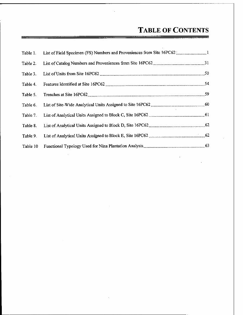
TABLE OF CONTENTS
Table 1. List of Field Specimen (FS) Numbers and Proveniences from Site 16PC62 1
Table 2. List of Catalog Numbers and Proveniences from Site 16PC62 31
Table 3. List of Units from Site 16PC62 50
Table 4. Features Identified at Site 16PC62 54
Table 5. Trenches at Site 16PC62 59
Table 6. List of Site-Wide Analytical Units Assigned to Site 16PC62 60
Table 7. List of Analytical Units Assigned to Block C, Site 16PC62 61
Table 8. List of Analytical Units Assigned to Block D, Site 16PC62 62
Table 9. List of Analytical Units Assigned to Block E, Site 16PC62 62
Table 10 Functional Typology Used for Nina Plantation Analysis 63
ABBREVIATIONS FOR APPENDIX I
FS — Field Specimen CAT# - Catelog Number SFC Surface UMS Upper Midden Surface TR Trench GB General Backdirt
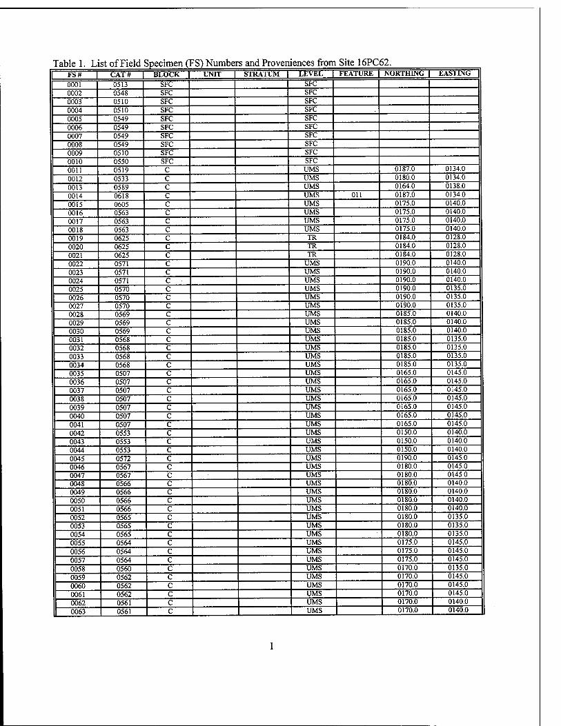
Table 1. List of Field Specimen (FS) Numbers and Proveniences from Site 16PC62. | FS# J CAT# | BLOCK | UNIT | STRATUM | LEVEL | FEATURE | NORTHING | EASTING |
0001 0513 SFC SFC 0002 0548 SFC SFC 0003 0510 SFC SFC 0004 0510 SFC SFC 0005 0549 SFC SFC 0006 0549 SFC SFC 0007 0549 SFC SFC 0008 0549 SFC SFC 0009 0510 SFC SFC 0010 0550 SFC SFC 0011 0519 C UMS 0187.0 0134.0 0012 0533 C UMS 0180.0 0134.0 0013 0589 C UMS 0164.0 0138.0 0014 0618 C UMS 011 0187.0 0134.0 0015 0605 C UMS 0175.0 0140.0 0016 0563 C UMS 0175.0 0140.0 0017 0563 C UMS 0175.0 0140.0 0018 0563 C UMS 0175.0 0140.0 0019 0625 c TR 0184.0 0128.0 0020 0625 c TR 0184.0 0128.0 0021 0625 c TR 0184.0 0128.0 0022 0571 c UMS 0190.0 0140.0 0023 0571 c UMS 0190.0 0140.0 0024 0571 c UMS 0190.0 0140.0 0025 0570 c UMS 0190.0 0135.0 0026 0570 c UMS 0190.0 0135.0 0027 0570 c UMS 0190.0 0135.0 0028 0569 c UMS 0185.0 0140.0 0029 0569 c UMS 0185.0 0140.0 0030 0569 c UMS 0185.0 0140.0 0031 0568 c UMS 0185.0 0135.0 0032 0568 c UMS 0185.0 0135.0 0033 0568 c UMS 0185.0 0135.0 0034 0568 c UMS 0185.0 0135.0 0035 0507 c UMS 0165.0 0145.0 0036 0507 c UMS 0165.0 0145.0 0037 0507 c UMS 0165.0 0145.0 0038 0507 c UMS 0165.0 0145.0 0039 0507 c UMS 0165.0 0145.0 0040 0507 c UMS 0165.0 0145.0 0041 0507 c UMS 0165.0 0145.0 0042 0553 c UMS 0150.0 0140.0 0043 0553 c UMS 0150.0 0140.0 0044 0553 c UMS 0150.0 0140.0 0045 0572 c UMS 0190.0 0145.0 0046 0567 c UMS 0180.0 0145.0 0047 0567 c UMS 0180.0 0145.0 0048 0566 c UMS 0180.0 0140.0 0049 0566 c UMS 0180.0 0140.0 0050 0566 c UMS 0180.0 0140.0 0051 0566 c UMS 0180.0 0140.0 0052 0565 c UMS 0180.0 0135.0 0053 0565 c UMS 0180.0 0135.0 0054 0565 c UMS 0180.0 0135.0 0055 0564 c UMS 0175.0 0145.0 0056 0564 c UMS 0175.0 0145.0 0057 0564 c UMS 0175.0 0145.0 0058 0560 c UMS 0170.0 0135.0 0059 0562 c UMS 0170.0 0145.0 0060 0562 c UMS 0170.0 0145.0 0061 0562 c UMS 0170.0 0145.0 0062 0561 c UMS 0170.0 0140.0
0063 0561 c I UMS 0170.0 0140.0
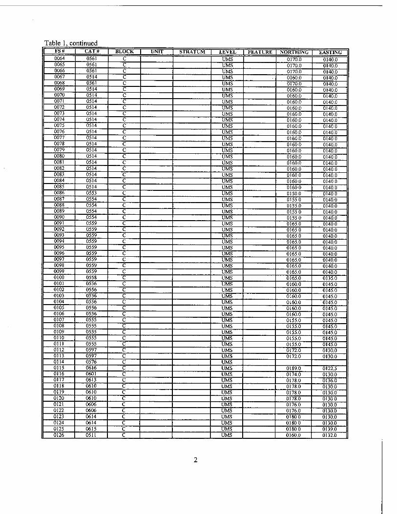
Table 1, continued FS# CAT# BLOCK UNIT STRATUM LEVEL FEATURE NORTHING EASTING 0064 0561 C UMS 0170.0 0140.0 0065 0561 c UMS 0170.0 0140.0 0066 0561 c UMS 0170.0 0140.0 0067 0514 c UMS 0160.0 0140.0 0068 0561 c UMS 0170.0 0140.0 0069 0514 c UMS 0160.0 0140.0 0070 0514 c UMS 0160.0 0140.0 0071 0514 c UMS 0160.0 0140.0 0072 0514 c UMS 0160.0 0140.0 0073 0514 c UMS 0160.0 0140.0 0074 0514 c UMS 0160.0 0140.0 0075 0514 c UMS 0160.0 0140.0 0076 0514 c UMS 0160.0 0140.0 0077 0514 c UMS 0160.0 0140.0 0078 0514 c UMS 0160.0 0140.0 0079 0514 c UMS 0160.0 0140.0 0080 0514 c UMS 0160.0 0140.0 0081 0514 c UMS 0160.0 0140.0 0082 0514 c UMS 0160.0 0140.0 0083 0514 c UMS 0160.0 0140.0 0084 0514 c UMS 0160.0 0140.0 0085 0514 c UMS 0160.0 0140.0 0086 0553 c UMS 0150.0 0140.0 0087 0554 c UMS 0155.0 0140.0 0088 0554 c UMS 0155.0 0140.0 0089 0554 c UMS 0155.0 0140.0 0090 0554 c UMS 0155.0 0140.0 0091 0559 c UMS 0165.0 0140.0 0092 0559 c UMS 0165.0 0140.0 0093 0559 c UMS 0165.0 0140.0 0094 0559 c UMS 0165.0 0140.0 0095 0559 c UMS 0165.0 0140.0 0096 0559 c UMS 0165.0 0140.0 0097 0559 c UMS 0165.0 0140.0 0098 0559 c UMS 0165.0 0140.0 0099 0559 c UMS 0165.0 0140.0 0100 0558 c UMS 0165.0 0135.0 0101 0556 c UMS 0160.0 0145.0 0102 0556 c UMS 0160.0 0145.0 0103 0556 c UMS 0160.0 0145.0 0104 0556 c UMS 0160.0 0145.0 0105 0556 c UMS 0160.0 0145.0 0106 0556 c UMS 0160.0 0145.0 0107 0555 c UMS 0155.0 0145.0 0108 0555 c UMS 0155.0 0145.0 0109 0555 c UMS 0155.0 0145.0 0110 0555 c UMS 0155.0 0145.0 0111 0555 c UMS 0155.0 0145.0 0112 0597 c UMS 0172.0 0130.0 0113 0597 c UMS 0172.0 0130.0 0114 0576 c UMS 0115 0616 c UMS 0189.0 0122.5 0116 0601 c UMS 0174.0 0130.0 0117 0613 c UMS 0178.0 0136.0 0118 0610 c UMS 0178.0 0130.0 0119 0610 c UMS 0178.0 0130.0 0120 0610 c UMS 0178.0 0130.0 0121 0606 c UMS 0176.0 0130.0 0122 0606 c UMS 0176.0 0130.0 0123 0614 c UMS 0180.0 0130.0 0124 0614 c UMS 0180.0 0130.0 0125 0615 c UMS 0180.0 0139.0 0126 0511 c UMS 0160.0 0132.0
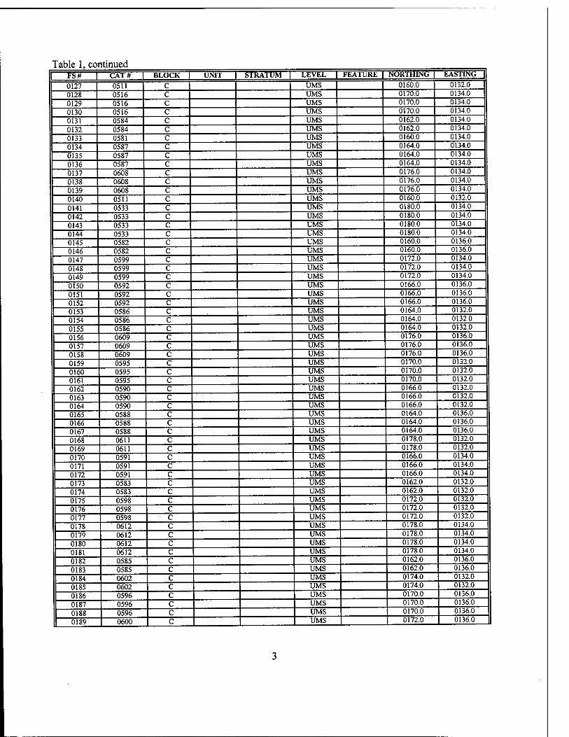
Table 1, continued I FS# | CAT# | BLOCK | UNIT | STRATUM | LEVEL | FEATURE | NORTHING | EASTING J
0127 0511 C UMS 0160.0 0132.0 0128 0516 c UMS 0170.0 0134.0 0129 0516 c UMS 0170.0 0134.0 0130 0516 c UMS 0170.0 0134.0 0131 0584 c UMS 0162.0 0134.0 0132 0584 c UMS 0162.0 0134.0
0133 0581 c UMS 0160.0 0134.0 0134 0587 c UMS 0164.0 0134.0
0135 0587 c UMS 0164.0 0134.0
0136 0587 c UMS 0164.0 0134.0
0137 0608 c UMS 0176.0 0134.0
0138 0608 c UMS 0176.0 0134.0
0139 0608 c UMS 0176.0 0134.0
0140 0511 c UMS 0160.0 0132.0
0141 0533 c UMS 0180.0 0134.0
0142 0533 c UMS 0180.0 0134.0
0143 0533 c UMS 0180.0 0134.0 0144 0533 c UMS 0180.0 0134.0
0145 0582 c UMS 0160.0 0136.0
0146 0582 c UMS 0160.0 0136.0
0147 0599 c UMS 0172.0 0134.0
0148 0599 c UMS 0172.0 0134.0
0149 0599 c UMS 0172.0 0134.0
0150 0592 c UMS 0166.0 0136.0
0151 0592 c UMS 0166.0 0136.0 0152 0592 c UMS 0166.0 0136.0
0153 0586 c UMS 0164.0 0132.0
0154 0586 c UMS 0164.0 0132.0
0155 0586 c UMS 0164.0 0132.0
0156 0609 c UMS 0176.0 0136.0
0157 0609 c UMS 0176.0 0136.0
0158 0609 c UMS 0176.0 0136.0
0159 0595 c UMS 0170.0 0132.0
0160 0595 c UMS 0170.0 0132.0
0161 0595 c UMS 0170.0 0132.0 0162 0590 c UMS 0166.0 0132.0
0163 0590 c UMS 0166.0 0132.0 0164 0590 c UMS 0166.0 0132.0 0165 0588 c UMS 0164.0 0136.0 0166 0588 c UMS 0164.0 0136.0 0167 0588 c UMS 0164.0 0136.0
0168 0611 c UMS 0178.0 0132.0
0169 0611 c UMS 0178.0 0132.0
0170 0591 c UMS 0166.0 0134.0 0171 0591 c UMS 0166.0 0134.0
0172 0591 c UMS 0166.0 0134.0
0173 0583 c UMS 0162.0 0132.0
0174 0583 c UMS 0162.0 0132.0
0175 0598 c UMS 0172.0 0132.0
0176 0598 c UMS 0172.0 0132.0
0177 0598 c UMS 0172.0 0132.0
0178 0612 c UMS 0178.0 0134.0
0179 0612 c UMS 0178.0 0134.0
0180 0612 c UMS 0178.0 0134.0
0181 0612 c UMS 0178.0 0134.0
0182 0585 c UMS 0162.0 0136.0
0183 0585 c UMS 0162.0 0136.0
0184 0602 c UMS 0174.0 0132.0
0185 0602 c UMS 0174.0 0132.0
0186 0596 c UMS 0170.0 0136.0
0187 0596 c UMS 0170.0 0136.0
0188 0596 c UMS 0170.0 0136.0
0189 0600 c UMS 0172.0 0136.0
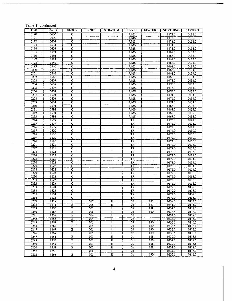
Table 1, continued FS# CAT# BLOCK UNIT STRATUM LEVEL FEATURE INORTH1NG EASTING 0190 0600 C UMS 0172.0 0136.0 0191 0600 c UMS 0172.0 0136.0 0192 0604 c UMS 0174.0 0136.0 0193 0604 c UMS 0174.0 0136.0 0194 0604 c UMS 0174.0 0136.0 0195 0593 c UMS 0168.0 0132.0 0196 0593 c UMS 0168.0 0132.0 0197 0593 c UMS 0168.0 0132.0 0198 0546 c UMS 0168.0 0134.0 0199 0546 c UMS 0168.0 0134.0 0200 0546 c UMS 0168.0 0134.0 0201 0546 c UMS 0168.0 0134.0 0202 0546 c UMS 0168.0 0134.0 0203 0607 c UMS 0176.0 0132.0 0204 0607 c UMS 0176.0 0132.0 0205 0607 c UMS 0176.0 0132.0 0206 0607 c UMS 0176.0 0132.0 0207 0603 c UMS 0174.0 0134.0 0208 0603 c UMS 0174.0 0134.0 0209 0603 c UMS 0174.0 0134.0 0210 0594 c UMS 0168.0 0136.0 0211 0594 c UMS 0168.0 0136.0 0212 0594 c UMS 0168.0 0136.0 0213 0594 c UMS 0168.0 0136.0 0214 0619 c TR 0172.0 0128.0 0215 0619 c TR 0172.0 0128.0 0216 0619 c TR 0172.0 0128.0 0217 0620 c TR 0172.0 0130.0 0218 0620 c TR 0172.0 0130.0 0219 0620 c TR 0172.0 0130.0 0220 0620 c TR 0172.0 0130.0 0221 0621 c TR 0172.0 0132.0 0222 0621 c TR 0172.0 0132.0 0223 0621 c TR 0172.0 0132.0 0224 0622 c TR 0172.0 0134.0 0225 0622 c TR 0172.0 0134.0 0226 0622 c TR 0172.0 0134.0 0227 0622 c TR 0172.0 0134.0 0228 0622 c TR 0172.0 0134.0 0229 0623 c TR 0172.0 0136.0 0230 0623 c TR 0172.0 0136.0 0231 0623 c TR 0172.0 0136.0 0232 0623 c TR 0172.0 0136.0 0233 0624 c TR 0172.0 0138.0 0234 0624 c TR 0172.0 0138.0 0235 0624 c TR 0172.0 0138.0 0236 0624 c TR 0172.0 0138.0 0237 1319 E 017 11 01 031 0239.0 0115.5 0238 1274 E 006 II 01 051 0241.0 0115.0 0239 1250 E 003 01 028 0232.0 0118.5 0240 1266 E 005 01 030 0236.5 0116.0 0241 1258 E 004 01 0234.0 0118.0 0242 1258 E 004 01 0234.0 0118.0 0243 1267 E 005 02 030 0236.5 0116.0 0244 1267 E 005 02 030 0236.5 0116.0 0245 1267 E 005 02 030 0236.5 0116.0 0246 1267 E 005 02 030 0236.5 0116.0 0247 1251 E 003 II 01 028 0232.0 0118.5 0248 1251 E 003 II 01 028 0232.0 0118.5 0249 1251 E 003 II 01 028 0232.0 0118.5 0250 1251 E 003 II 01 028 0232.0 0118.5 0251 1258 E 004 I 01 0234.0 0118.0 0252 1268 E 005 II 01 030 0236.5 0116.0
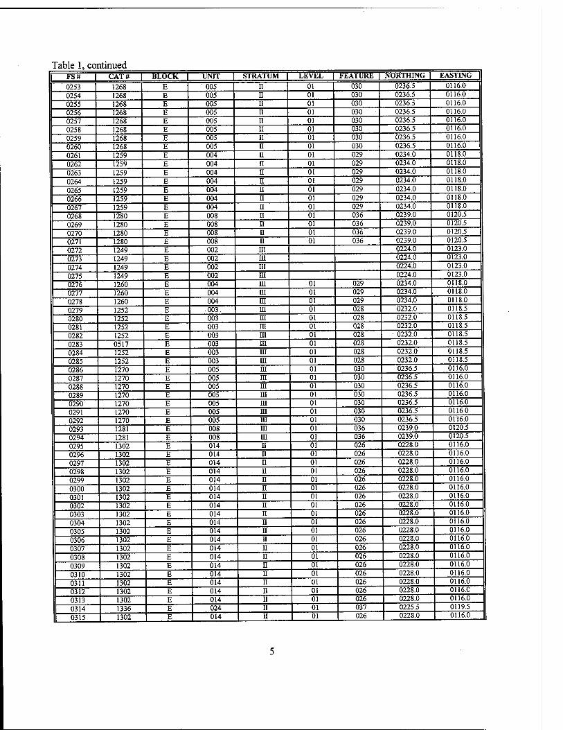
Table 1, continued FS# I CAT# | BLOCK L UNIT | STRATUM | LEVEL FEATURE | NORTHING | EASTING |
0253 1268 E 005 n 01 030 0236.5 0116.0
0254 1268 E 005 ii 01 030 0236.5 0116.0
0255 1268 E 005 n 01 030 0236.5 0116.0
0256 1268 E 005 n 01 030 - 0236.5 0116.0
0257 1268 E 005 n 01 030 0236.5 0116.0
0258 1268 E 005 II 01 030 0236.5 0116.0
0259 1268 E 005 II 01 030 0236.5 0116.0
0260 1268 E 005 n 01 030 0236.5 0116.0
0261 1259 E 004 II 01 029 0234.0 0118.0
0262 1259 E 004 n 01 029 0234.0 0118.0
0263 1259 E 004 n 01 029 0234.0 0118.0
0264 1259 E 004 n 01 029 0234.0 0118.0
0265 1259 E 004 u 01 029 0234.0 0118.0
0266 1259 E 004 II 01 029 0234.0 0118.0
0267 1259 E 004 n 01 029 0234.0 0118.0
0268 1280 E 008 II 01 036 0239.0 0120.5
0269 1280 E 008 n 01 036 0239.0 0120.5
0270 1280 E 008 II 01 036 0239.0 0120.5
0271 1280 E 008 II 01 036 0239.0 0120.5
0272 1249 E 002 in 0224.0 0123.0
0273 1249 E 002 ra 0224.0 0123.0
0274 1249 E 002 ni 0224.0 0123.0
0275 1249 E 002 ni 0224.0 0123.0
0276 1260 E 004 m 01 029 0234.0 0118.0
0277 1260 E 004 ni 01 029 0234.0 0118.0
0278 1260 E 004 HI 01 029 0234.0 0118.0
0279 1252 E 003. m 01 028 0232.0 0118.5
0280 1252 E 003 ni 01 028 0232.0 0118.5
0281 1252 E 003 m 01 028 0232.0 0118.5
0282 1252 E 003 in 01 028 0232.0 0118.5
0283 0517 E 003 HI 01 028 0232.0 0118.5
0284 1252 E 003 in 01 028 0232.0 0118.5
0285 1252 E 003 m 01 028 0232.0 0118.5
0286 1270 E 005 ra 01 030 0236.5 0116.0
0287 1270 E 005 ra 01 030 0236.5 0116.0
0288 1270 E 005 in 01 030 0236.5 0116.0
0289 1270 E 005 ra 01 030 0236.5 0116.0
0290 1270 E 005 ra 01 030 0236.5 0116.0
0291 1270 E 005 ra 01 030 0236.5 0116.0
0292 1270 E 005 in 01 030 0236.5 0116.0
0293 1281 E 008 ra 01 036 0239.0 0120.5
0294 1281 E 008 ra 01 036 0239.0 0120.5
0295 1302 E 014 n 01 026 0228.0 0116.0
0296 1302 E 014 n 01 026 0228.0 0116.0
0297 1302 E 014 n 01 026 0228.0 0116.0
0298 1302 E 014 n 01 026 0228.0 0116.0
0299 1302 E 014 n 01 026 0228.0 0116.0
0300 1302 E 014 ii 01 026 0228.0 0116.0
0301 1302 E 014 n 01 026 0228.0 0116.0
0302 1302 E 014 n 01 026 0228.0 0116.0
0303 1302 E 014 n 01 026 0228.0 0116.0
0304 1302 E 014 n 01 026 0228.0 0116.0
0305 1302 E 014 n 01 026 0228.0 0116.0
0306 1302 E 014 II 01 026 0228.0 0116.0
0307 1302 E 014 n 01 026 0228.0 0116.0
0308 1302 E 014 n 01 026 0228.0 0116.0
0309 1302 E 014 n 01 026 0228.0 0116.0
0310 1302 E 014 n 01 026 0228.0 0116.0
0311 1302 E 014 n 01 026 0228.0 0116.0
0312 1302 E 014 ii 01 026 0228.0 0116.0
0313 1302 E 014 ii 01 026 0228.0 0116.0
0314 1336 E 024 II 01 037 0225.5 0119.5
0315 1302 E 014 u 01 026 0228.0 0116.0
5
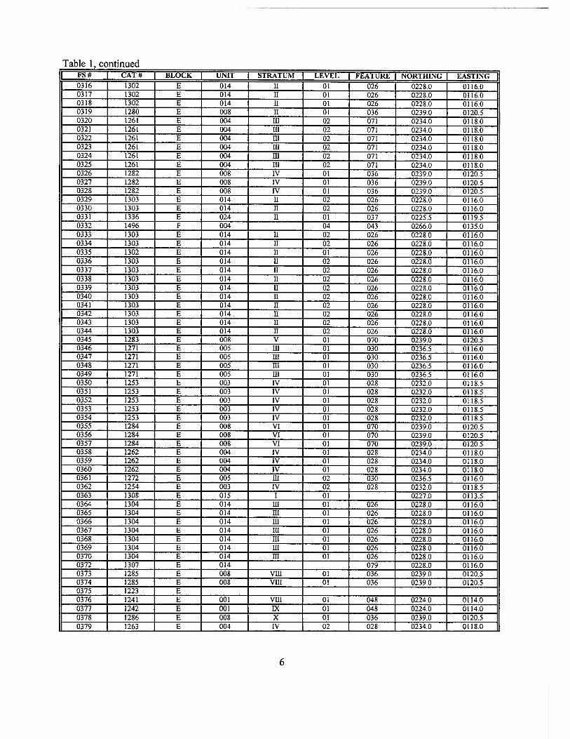
Table 1, continued FS# CAT# BLOCK UNIT STRATUM LEVEL FEATURE NORTHING EASTING 0316 1302 E 014 II 01 026 0228.0 0116.0 0317 1302 E 014 II 01 026 0228.0 0116.0 0318 1302 E 014 II 01 026 0228.0 0116.0 0319 1280 E 008 II 01 036 0239.0 0120.5 0320 1261 E 004 III 02 071 0234.0 0118.0 0321 1261 E 004 in 02 071 0234.0 0118.0 0322 1261 E 004 m 02 071 0234.0 0118.0 0323 1261 E 004 m 02 071 0234.0 0118.0 0324 1261 E 004 in 02 071 0234.0 0118.0 0325 1261 E 004 ni 02 071 0234.0 0118.0 0326 1282 E 008 IV 01 036 0239.0 0120.5 0327 1282 E 008 IV 01 036 0239.0 0120.5 0328 1282 E 008 IV 01 036 0239.0 0120.5 0329 1303 E 014 II 02 026 0228.0 0116.0 0330 1303 E 014 n 02 026 0228.0 0116.0 0331 1336 E 024 ii 01 037 0225.5 0119.5 0332 1496 F 004 04 043 0266.0 0135.0 0333 1303 E 014 ii 02 026 0228.0 0116.0 0334 1303 E 014 ii 02 026 0228.0 0116.0 0335 1302 E 014 ii 01 026 0228.0 0116.0 0336 1303 E 014 ii 02 026 0228.0 0116.0 0337 1303 E 014 n 02 026 0228.0 0116.0 0338 1303 E 014 ii 02 026 0228.0 0116.0 0339 1303 E 014 II 02 026 0228.0 0116.0 0340 1303 E 014 II 02 026 0228.0 0116.0 0341 1303 E 014 II 02 026 0228.0 0116.0 0342 1303 E 014. n 02 026 0228.0 0116.0 0343 1303 E 014 n 02 026 0228.0 0116.0 0344 1303 E 014 n 02 026 0228.0 0116.0 0345 1283 E 008 V 01 070 0239.0 0120.5 0346 1271 E 005 m 01 030 0236.5 0116.0 0347 1271 E 005 m 01 030 0236.5 0116.0 0348 1271 E 005 m 01 030 0236.5 0116.0 0349 1271 E 005 HI 01 030 0236.5 0116.0 0350 1253 E 003 IV 01 028 0232.0 0118.5 0351 1253 E 003 IV 01 028 0232.0 0118.5 0352 1253 E 003 IV 01 028 0232.0 0118.5 0353 1253 E 003 IV 01 028 0232.0 0118.5 0354 1253 E 003 IV 01 028 0232.0 0118.5 0355 1284 E 008 VI 01 070 0239.0 0120.5 0356 1284 E 008 VI 01 070 0239.0 0120.5 0357 1284 E 008 VI 01 070 0239.0 0120.5 0358 1262 E 004 IV 01 028 0234.0 0118.0 0359 1262 E 004 IV 01 028 0234.0 0118.0 0360 1262 E 004 IV 01 028 0234.0 0118.0 0361 1272 E 005 m 02 030 0236.5 0116.0 0362 1254 E 003 IV 02 028 0232.0 0118.5 0363 1308 E 015 i 01 0227.0 0113.5 0364 1304 E 014 m 01 026 0228.0 0116.0 0365 1304 E 014 HI 01 026 0228.0 0116.0 0366 1304 E 014 in 01 026 0228.0 0116.0 0367 1304 E 014 in 01 026 0228.0 0116.0 0368 1304 E 014 HI 01 026 0228.0 0116.0 0369 1304 E 014 m 01 026 0228.0 0116.0 0370 1304 E 014 ni 01 026 0228.0 0116.0 0372 1307 E 014 079 0228.0 0116.0 0373 1285 E 008 vm 01 036 0239.0 0120.5 0374 1285 E 008 VHI 01 036 0239.0 0120.5 0375 1223 E 0376 1241 E 001 vm 01 048 0224.0 0114.0 0377 1242 E 001 IX 01 048 0224.0 0114.0 0378 1286 E 008 X 01 036 0239.0 0120.5 0379 1263 E 004 IV 02 028 0234.0 0118.0
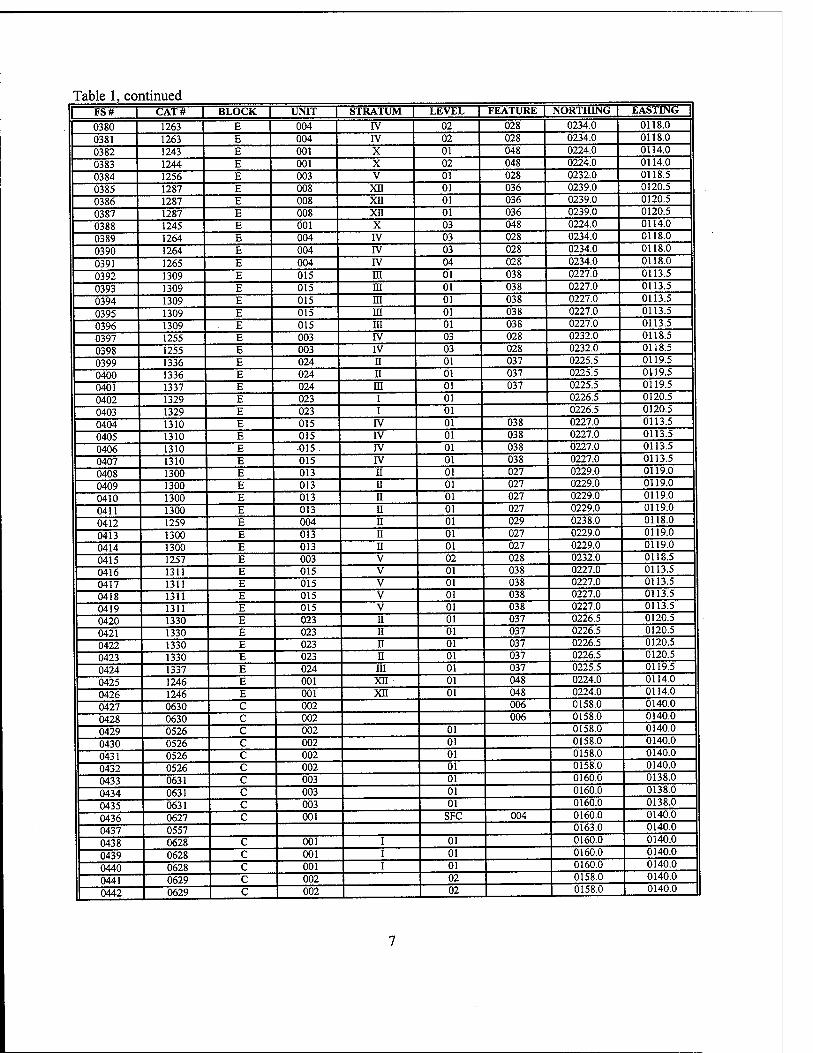
Table 1, continued I FS# | CAT# BLOCK | UNIT | STRATUM | LEVEL | FEATURE | NORTHING | EASTING |
0380 1263 E 004 rv 02 028 0234.0 0118.0
0381 1263 E 004 rv 02 028 0234.0 0118.0
0382 1243 E 001 X 01 048 0224.0 0114.0
0383 1244 E 001 X 02 048 0224.0 0114.0
0384 1256 E 003 V 01 028 0232.0 0118.5
0385 1287 E 008 xn 01 036 0239.0 0120.5
0386 1287 E 008 xn 01 036 0239.0 0120.5
0387 1287 E 008 xn 01 036 0239.0 0120.5
0388 1245 E 001 X 03 048 0224.0 0114.0
0389 1264 E 004 rv 03 028 0234.0 0118.0
0390 1264 E 004 IV 03 028 0234.0 0118.0
0391 1265 E 004 IV 04 028 0234.0 0118.0
0392 1309 E 015 in 01 038 0227.0 0113.5
0393 1309 E 015 in 01 038 0227.0 0113.5
0394 1309 E 015 m 01 038 0227.0 0113.5
0395 1309 E 015 m 01 038 0227.0 0113.5
0396 1309 E 015 in 01 038 0227.0 0113.5
0397 1255 E 003 rv 03 028 0232.0 0118.5
0398 1255 E 003 rv 03 028 0232.0 0118.5
0399 1336 E 024 n 01 037 0225.5 0119.5
0400 1336 E 024 ii 01 037 0225.5 0119.5
0401 1337 E 024 m 01 037 0225.5 0119.5
0402 1329 E 023 i 01 0226.5 0120.5
0403 1329 E 023 i 01 0226.5 0120.5
0404 1310 E 015 IV 01 038 0227.0 0113.5
0405 1310 E 015 IV 01 038 0227.0 0113.5
0406 1310 E 015 . IV 01 038 0227.0 0113.5
0407 1310 E 015 IV 01 038 0227.0 0113.5
0408 1300 E 013 n 01 027 0229.0 0119.0
0409 1300 E 013 n 01 027 0229.0 0119.0
0410 1300 E 013 II 01 027 0229.0 0119.0
0411 1300 E 013 n 01 027 0229.0 0119.0
0412 1259 E 004 n 01 029 0238.0 0118.0
0413 1300 E 013 n 01 027 0229.0 0119.0
0414 1300 E 013 n 01 027 0229.0 0119.0
0415 1257 E 003 V 02 028 0232.0 0118.5
0416 1311 E 015 V 01 038 0227.0 0113.5
0417 1311 E 015 V 01 038 0227.0 0113.5
0418 1311 E 015 V 01 038 0227.0 0113.5
0419 1311 E 015 V 01 038 0227.0 0113.5
0420 1330 E 023 11 01 037 0226.5 0120.5
0421 1330 E 023 II 01 037 0226.5 0120.5
0422 1330 E 023 n 01 037 0226.5 0120.5
0423 1330 E 023 n 01 037 0226.5 0120.5
0424 1337 E 024 m 01 037 0225.5 0119.5
0425 1246 E 001 xn 01 048 0224.0 0114.0
0426 1246 E 001 XII 01 048 0224.0 0114.0
0427 0630 C 002 006 0158.0 0140.0
0428 0630 C 002 006 0158.0 0140.0
0429 0526 C 002 01 0158.0 0140.0
0430 0526 C 002 01 0158.0 0140.0
0431 0526 c 002 01 0158.0 0140.0
0432 0526 c 002 01 0158.0 0140.0
0433 0631 c 003 01 0160.0 0138.0
0434 0631 c 003 01 0160.0 0138.0
0435 0631 c 003 01 0160.0 0138.0
0436 0627 c 001 SFC 004 0160.0 0140.0
0437 0557 0163.0 0140.0
0438 0628 c 001 i 01 0160.0 0140.0
0439 0628 c 001 i 01 0160.0 0140.0
0440 0628 c 001 i 01 0160.0 0140.0
0441 0629 c 002 02 0158.0 0140.0
0442 0629 C I 002 02 0158.0 0140.0
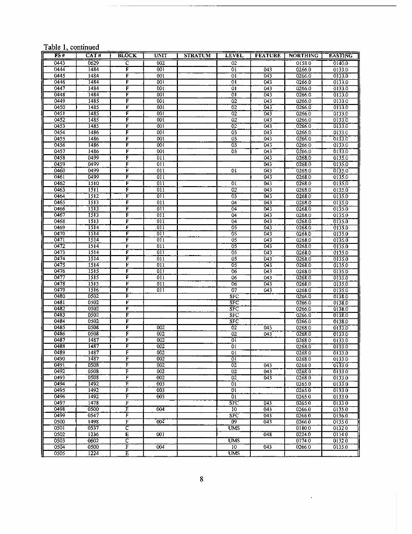
Table 1, continued FS# CAT# BLOCK UNIT STRATUM LEVEL FEATURE NORTHING EASTING
0443 0629 C 002 02 0158.0 0140.0 0444 1484 F 001 01 043 0266.0 0133.0 0445 1484 F 001 01 043 0266.0 0133.0 0446 1484 F 001 01 043 0266.0 0133.0 0447 1484 F 001 01 043 0266.0 0133.0 0448 1484 F 001 01 043 0266.0 0133.0 0449 1485 F 001 02 043 0266.0 0133.0 0450 1485 F 001 02 043 0266.0 0133.0 0451 1485 F 001 02 043 0266.0 0133.0 0452 1485 F 001 02 043 0266.0 0133.0 0453 1485 F 001 02 043 0266.0 0133.0 0454 1486 F 001 03 043 0266.0 0133.0 0455 1486 F 001 03 043 0266.0 0133.0 0456 1486 F 001 03 043 0266.0 0133.0 0457 1486 F 001 03 043 0266.0 0133.0 0458 0499 F on 043 0268.0 0135.0 0459 0499 F on 043 0268.0 0135.0 0460 0499 F on 01 043 0268.0 0135.0 0461 0499 F on 043 0268.0 0135.0 0462 1510 F on 01 043 0268.0 0135.0 0463 1511 F on 02 043 0268.0 0135.0 0464 1512 F on 03 043 0268.0 0135.0 0465 1513 F on 04 043 0268.0 0135.0 0466 1513 F on 04 043 0268.0 0135.0 0467 1513 F on 04 043 0268.0 0135.0 0468 1513 F Oil 04 043 0268.0 0135.0 0469 1514 F Oil 05 043 0268.0 0135.0 0470 1514 F Oil 05 043 0268.0 0135.0 0471 1514 F on 05 043 0268.0 0135.0 0472 1514 F on 05 043 0268.0 0135.0 0473 1514 F Oil 05 043 0268.0 0135.0 0474 1514 F on 05 043 0268.0 0135.0 0475 1514 F on 05 043 0268.0 0135.0 0476 1515 F on 06 043 0268.0 0135.0 0477 1515 F on 06 043 0268.0 0135.0 0478 1515 F on 06 043 0268.0 0135.0 0479 1516 F on 07 043 0268.0 0135.0 0480 0502 F SFC 0266.0 0138.0 0481 0502 F SFC 0266.0 0138.0 0482 0502 F SFC 0266.0 0138.0 0483 0502 F SFC 0266.0 0138.0 0484 0502 F SFC 0266.0 0138.0 0485 0508 F 002 02 043 0268.0 0133.0 0486 0508 F 002 02 043 0268.0 0133.0 0487 1487 F 002 01 0268.0 0133.0 0488 1487 F 002 01 0268.0 0133.0 0489 1487 F 002 01 0268.0 0133.0 0490 1487 F 002 01 0268.0 0133.0 0491 0508 F 002 02 043 0268.0 0133.0 0492 0508 F 002 02 043 0268.0 0133.0 0493 0508 F 002 02 043 0268.0 0133.0 0494 1492 F 003 01 0265.0 0133.0 0495 1492 F 003 01 0265.0 0133.0 0496 1492 F 003 01 0265.0 0133.0 0497 1478 F SFC 043 0265.0 0133.0 0498 0500 F 004 10 043 0266.0 0135.0 0499 0547 F SFC 043 0266.0 0136.0 0500 1498 F 004 09 043 0266.0 0135.0 0501 0537 C UMS 0180.0 0132.0 0502 1236 E 001 048 0224.0 0114.0 0503 0602 C UMS 0174.0 0132.0 0504 0500 F 004 10 043 0266.0 0135.0 0505 1224 E UMS
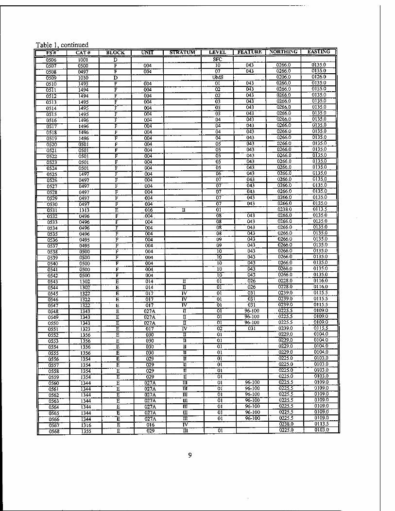
Table 1, continued FS# I CAT# | BLOCK | UNIT | STRATUM ± LEVEL L FEATURE | NORTHING | EASTING |
0506 1001 D SFC 0507 0500 F 004 10 043 0266.0 0135.0
0508 0497 F 004 07 043 0266.0 0135.0
0509 1030 D UMS 0206.0 0126.0
0510 1493 F 004 01 043 0266.0 0135.0
0511 1494 F 004 02 043 0266.0 0135.0
0512 1494 F 004 02 043 0266.0 0135.0
0513 1495 F 004 03 043 0266.0 0135.0
0514 1495 F 004 03 043 0266.0 0135.0
0515 1495 F 004 03 043 0266.0 0135.0
0516 1496 F 004 04 043 0266.0 0135.0
0517 1496 F 004 04 043 0266.0 0135.0
0518 1496 F 004 04 043 0266.0 0135.0
0519 1496 F 004 04 043 0266.0 0135.0
0520 0501 F 004 05 043 0266.0 0135.0
0521 0501 F 004 05 043 0266.0 0135.0
0522 0501 F 004 05 043 0266.0 0135.0
0523 0501 F 004 05 043 0266.0 0135.0
0524 0501 F 004 05 043 0266.0 0135.0
0525 1497 F 004 06 043 0266.0 0135.0
0526 0497 F 004 07 043 0266.0 0135.0
0527 0497 F 004 07 043 0266.0 0135.0
0528 0497 F 004 07 043 0266.0 0135.0
0529 0497 F 004 07 043 0266.0 0135.0
0530 0497 F 004 07 043 0266.0 0135.0
0531 1313 E 016 II 01 0238.0 0113.5
0532 0496 F .004. 08 043 0266.0 0135.0
0533 0496 F 004 08 043 0266.0 0135.0
0534 0496 F 004 08 043 0266.0 0135.0
0535 0496 F 004 08 043 0266.0 0135.0
0536 0495 F 004 09 043 0266.0 0135.0
0537 0495 F 004 09 043 0266.0 0135.0
0538 0500 F 004 10 043 0266.0 0135.0
0539 0500 F 004 10 043 0266.0 0135.0
0540 0500 F 004 10 043 0266.0 0135.0
0541 0500 F 004 10 043 0266.0 0135.0
0542 0500 F 004 10 043 0266.0 0135.0
0543 1302 E 014 n 01 026 0228.0 0116.0
0544 1302 E 014 n 01 026 0228.0 0116.0
0545 1322 E 017 rv 01 031 0239.0 0115.5
0546 1322 E 017 rv 01 031 0239.0 0115.5
0547 1322 E 017 IV 01 031 0239.0 0115.5
0548 1343 E 027A n 01 96-100 0225.5 0109.0
0549 1343 E 027A n 01 96-100 0225.5 0109.0
0550 1343 E 027A n 01 96-100 0225.5 0109.0
0551 1323 E 017 IV 02 031 0239.0 0115.5
0552 1356 E 030 n 01 0229.0 0104.0
0553 1356 E 030 ii 01 0229.0 0104.0
0554 1356 E 030 u 01 0229.0 0104.0
0555 1356 E 030 n 01 0229.0 0104.0
0556 1354 E 029 n 01 0225.0 0103.0
0557 1354 E 029 n 01 0225.0 0103.0
0558 1354 E 029 n 01 0225.0 0103.0
0559 1354 E 029 II 01 0225.0 0103.0
0560 1344 E 027A m 01 96-100 0225.5 0109.0
0561 1344 E 027A m 01 96-100 0225.5 0109.0
0562 1344 E 027A m 01 96-100 0225.5 0109.0
0563 1344 E 027A HI 01 96-100 0225.5 0109.0
0564 1344 E 027A m 01 96-100 0225.5 0109.0
0565 1344 E 027A m 01 96-100 0225.5 0109.0
0566 1344 E 027A m 01 96-100 0225.5 0109.0
0567 1316 E 016 IV 0238.0 0113.5
0568 1355 E 029 m 01 0225.0 0103.0
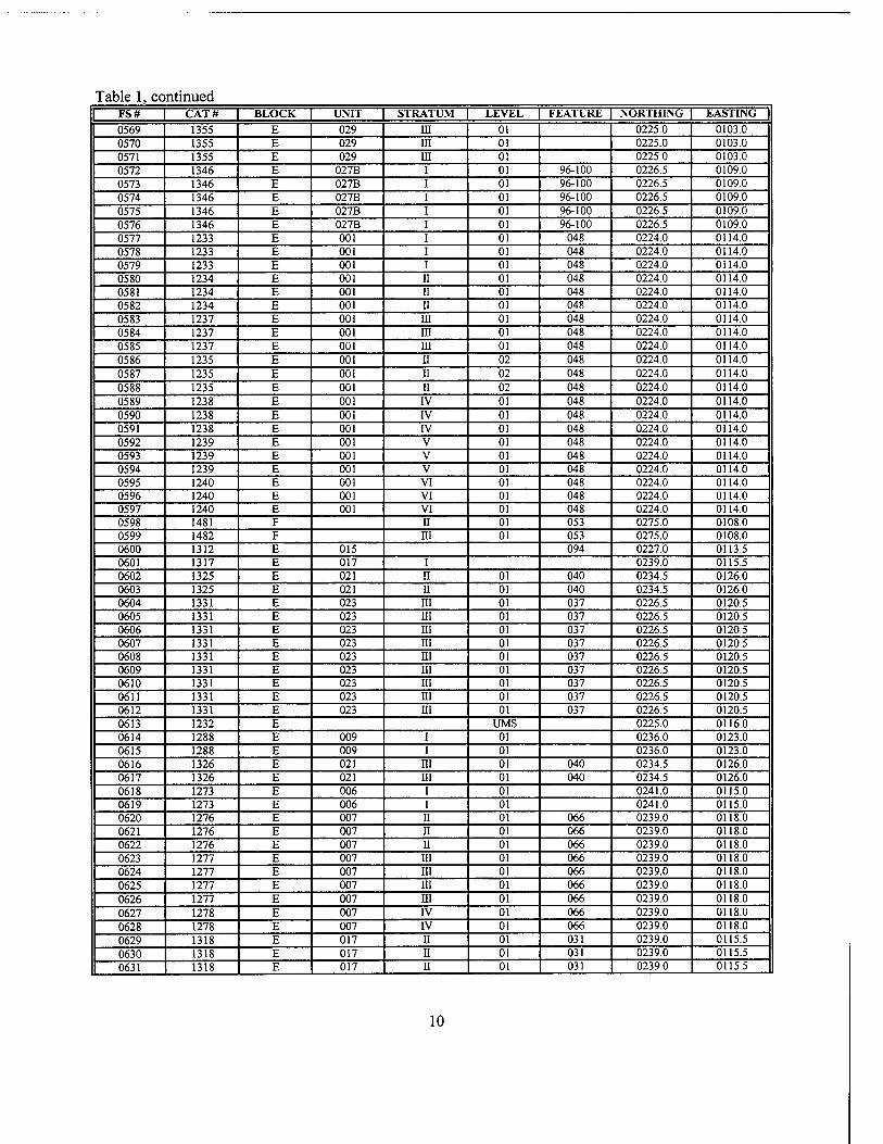
Table 1, continued FS# CAT# BLOCK UNIT STRATUM LEVEL FEATURE NORTHING EASTING
0569 1355 E 029 in 01 0225.0 0103.0 0570 1355 E 029 in 01 0225.0 0103.0 0571 1355 E 029 in 01 0225.0 0103.0 0572 1346 E 027B i 01 96-100 . 0226.5 0109.0 0573 1346 E 027B i 01 96-100 0226.5 0109.0 0574 1346 E 027B i 01 96-100 0226.5 0109.0 0575 1346 E 027B i 01 96-100 0226.5 0109.0 0576 1346 E 027B i 01 96-100 0226.5 0109.0 0577 1233 E 001 i 01 048 0224.0 0114.0 0578 1233 E 001 i 01 048 0224.0 0114.0 0579 1233 E 001 i 01 048 0224.0 0114.0 0580 1234 E 001 ii 01 048 0224.0 0114.0 0581 1234 E 001 ii 01 048 0224.0 0114.0 0582 1234 E 001 ii 01 048 0224.0 0114.0 0583 1237 E 001 in 01 048 0224.0 0114.0 0584 1237 E 001 m 01 048 0224.0 0114.0 0585 1237 E 001 in 01 048 0224.0 0114.0 0586 1235 E 001 n 02 048 0224.0 0114.0 0587 1235 E 001 II 02 048 0224.0 0114.0 0588 1235 E 001 u 02 048 0224.0 0114.0 0589 1238 E 001 IV 01 048 0224.0 0114.0 0590 1238 E 001 IV 01 048 0224.0 0114.0 0591 1238 E 001 IV 01 048 0224.0 0114.0 0592 1239 E 001 V 01 048 0224.0 0114.0 0593 1239 E 001 V 01 048 0224.0 0114.0 0594 1239 E 001 V 01 048 0224.0 0114.0 0595 1240 E 001 VI 01 048 0224.0 0114.0 0596 1240 E 001 VI 01 048 0224.0 0114.0 0597 1240 E 001 VI 01 048 0224.0 0114.0 0598 1481 F n 01 053 0275.0 0108.0 0599 1482 F in 01 053 0275.0 0108.0 0600 1312 E 015 094 0227.0 0113.5 0601 1317 E 017 i 0239.0 0115.5 0602 1325 E 021 n 01 040 0234.5 0126.0 0603 1325 E 021 n 01 040 0234.5 01260 0604 1331 E 023 ni 01 037 0226.5 0120.5 0605 1331 E 023 m 01 037 0226.5 0120.5 0606 1331 E 023 m 01 037 0226.5 0120.5 0607 1331 E 023 HI 01 037 0226.5 0120.5 0608 1331 E 023 m 01 037 0226.5 0120.5 0609 1331 E 023 in 01 037 0226.5 0120.5 0610 1331 E 023 ni 01 037 0226.5 0120.5 0611 1331 E 023 in 01 037 0226.5 0120.5 0612 1331 E 023 ni 01 037 0226.5 0120.5 0613 1232 E UMS 0225.0 0116.0 0614 1288 E 009 i 01 0236.0 0123.0 0615 1288 E 009 i 01 0236.0 0123.0 0616 1326 E 021 in 01 040 0234.5 0126.0 0617 1326 E 021 in 01 040 0234.5 0126.0 0618 1273 E 006 i 01 0241.0 0115.0 0619 1273 E 006 i 01 0241.0 0115.0 0620 1276 E 007 II 01 066 0239.0 0118.0 0621 1276 E 007 n 01 066 0239.0 0118.0 0622 1276 E 007 u 01 066 0239.0 0118.0 0623 1277 E 007 ni 01 066 0239.0 0118.0 0624 1277 E 007 in 01 066 0239.0 0118.0 0625 1277 E 007 in 01 066 0239.0 0118.0 0626 1277 E 007 in 01 066 0239.0 0118.0 0627 1278 E 007 rv 01 066 0239.0 0118.0 0628 1278 E 007 IV 01 066 0239.0 0118.0
0629 1318 E 017 n 01 031 0239.0 0115.5
0630 1318 E 017 ii 01 031 0239.0 0115.5
0631 1318 E 017 II 01 031 0239.0 0115.5
10
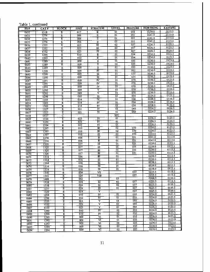
Table 1, continued I FS# | CAT# | BLOCK | UNIT | STRATUM | LEVEL | FEATURE L NORTHING | EASTING |
0632 1318 E 017 II 01 031 0239.0 0115.5
0633 1274 E 006 II 01 051 0241.0 0115.0
0634 1274 E 006 II 01 051 0241.0 _Q115.0
0635 1274 E 006 II 01 051 0241.0 0115.0
0636 1332 E 023 III 02 037 0226.5 „Q120.5
0637 1332 E 023 in 02 037 0226.5 0120.5
0638 1332 E 023 m 02 037 0226.5 0120.5
0639 1295 E 010 n 01 034 0234.0 0123.5
0640 1295 E 010 ii 01 034 0234.0 0123.5
0641 1289 E 009 n 01 035 0236.0 0123.0
0642 1289 E 009 ii 01 035 0236.0 0123.0
0643 1289 E 009 II 01 035 0236.0 0123.0
0644 1290 E 009 iii 01 035 0236.0 0123.0
0645 1290 E 009 in 01 035 0236.0 0123.0
0646 1290 E 009 in 01 035 0236.0 0123.0
0647 1291 E 009 IV 01 070. 0236.0 0123.0
0648 1291 E 009 IV 01 070 0236.0 0123.0
0649 1291 E 009 rv 01 070 0236.0 0123.0
0650 1292 E 009 V 01 070 0236.0 0123.0
0651 1292 E 009 V 01 070 0236.0 0123.0
0652 1296 E 010 HI 01 034 0234.0 0123.5
0653 1305 E 014 IV 01 026 0228.0 0116.0
0654 1305 E 014 IV 01 026 0228.0 0116.0
0655 1305 E 014 IV 01 026 0228.0 0116.0
0656 1327 E 021 IV 01 040 0234.5 0126.0
0657 1327 E 021 IV 01 040 0234.5 0126.0
0658 0527 C SFC 0659 1334 E 023 IV 01 0226.5 0120.5
0660 1334 E 023 rv 01 0226.5 0120.5
0661 1334 E 023 rv 01 0226.5 0120.5
0662 1297 E 010 in 02 070 0234.0 0123.5
0663 1297 E 010 m 02 070 0234.0 0123.5
0664 1297 E 010 HI 02 070 0234.0 0123.5
0665 1274 E 006 n 01 051 0241.0 0115.0
0666 1274 E 006 n 01 051 0241.0 0115.0
0667 1320 E 017 HI 01 031 0239.0 0115.5
0668 1320 E 017 m 01 031 0239.0 0115.5
0669 1320 E 017 HI 01 031 0239.0 0115.5
0670 1320 E 017 ni 01 031 0239.0 0115.5
0671 1314 E 016 m 01 0238.0 0113.5
0672 1314 E 016 HI 01 0238.0 0113.5
0673 1314 E 016 in 01 0238.0 0113.5
0674 1314 E 016 in 01 0238.0 0113.5
0675 1314 E 016 HI 01 0238.0 0113.5
0676 1340 E 024 vn 037 0225.5 0119.5
0677 1341 E 024 VHI 037 0225.5 0119.5
0678 1488 F 002 03 0268.0 0133.0
0679 1338 E 024 HI 02 037 0225.5 0119.5
0680 1338 E 024 m 02 037 0225.5 0119.5
0681 1337 E 024 HI 01 037 0225.5 0119.5
0682 1339 E 024 V 037 0225.5 0119.5
0683 1298 E 010 IV 01 035 0234.0 0123.5
0684 1298 E 010 IV 01 035 0234.0 0123.5
0685 1335 E 023 V 01 095 0226.5 0120.5
0686 1335 E 023 V 01 095 0226.5 0120.5
0687 1335 E 023 V 01 095 0226.5 0120.5
0688 1299 E 010 rv 02 035 0234.0 0123.5
0689 1299 E 010 IV 02 035 0234.0 0123.5
0690 1293 E 009 VI 01 035 0236.0 0123.0
0691 1293 E 009 VI 01 035 0236.0 0123.0
0692 1293 E 009 VI 01 035 0236.0 0123.0
0693 1294 E 009 VI 02 035 0236.0 0123.0
0694 1294 E 009 VI 02 035 0236.0 0123.0
11
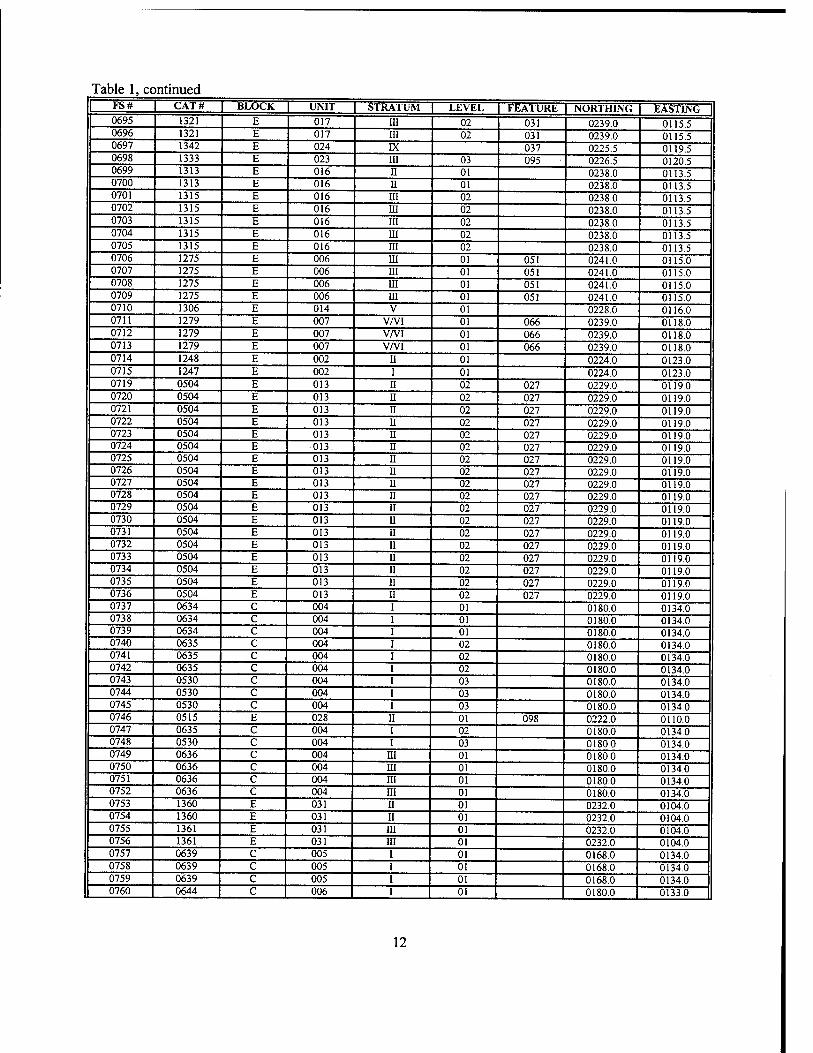
Table 1, continued 1 FS# | CAT# | BLOCK UNIT STRATUM LEVEL FEATURE | NORTHING EASTING
0695 1321 E 017 III 02 031 0239.0 0115.5 0696 1321 E 017 III 02 031 0239.0 0115.5 0697 1342 E 024 IX 037 0225.5 0119.5 0698 1333 E 023 III 03 095 0226.5 0120.5 0699 1313 E 016 II 01 0238.0 0113.5 0700 1313 E 016 II 01 0238.0 0113.5 0701 1315 E 016 in 02 0238.0 0113.5 0702 1315 E 016 m 02 0238.0 0113.5 0703 1315 E 016 m 02 0238.0 0113.5 0704 1315 E 016 m 02 0238.0 0113.5 0705 1315 E 016 m 02 0238.0 0113.5 0706 1275 E 006 iii 01 051 0241.0 0115.0 0707 1275 E 006 m 01 051 0241.0 0115.0 0708 1275 E 006 HI 01 051 0241.0 0115.0 0709 1275 E 006 HI 01 051 0241.0 0115.0 0710 1306 E 014 V 01 0228.0 0116.0 0711 1279 E 007 V/VI 01 066 0239.0 0118.0 0712 1279 E 007 V/VI 01 066 0239.0 0118.0 0713 1279 E 007 V/VI 01 066 0239.0 0118.0 0714 1248 E 002 11 01 0224.0 0123.0 0715 1247 E 002 1 01 0224.0 0123.0 0719 0504 E 013 H 02 027 0229.0 0119.0 0720 0504 E 013 H 02 027 0229.0 0119.0 0721 0504 E 013 H 02 027 0229.0 0119.0 0722 0504 E 013 U 02 027 0229.0 0119.0 0723 0504 E 013 H 02 027 0229.0 0119.0 0724 0504 E 013. U 02 027 0229.0 0119.0 0725 0504 E 013 II 02 027 0229.0 0119.0 0726 0504 E 013 II 02 027 0229.0 0119.0 0727 0504 E 013 II 02 027 0229.0 0119.0 0728 0504 E 013 II 02 027 0229.0 0119.0 0729 0504 E 013 H 02 027 0229.0 0119.0 0730 0504 E 013 H 02 027 0229.0 0119.0 0731 0504 E 013 H 02 027 0229.0 0119.0 0732 0504 E 013 II 02 027 0229.0 0119.0 0733 0504 E 013 H 02 027 0229.0 0119.0 0734 0504 E 013 II 02 027 0229.0 0119.0 0735 0504 E 013 II 02 027 0229.0 0119.0 0736 0504 E 013 U 02 027 0229.0 0119.0 0737 0634 C 004 I 01 0180.0 0134.0 0738 0634 C 004 I 01 0180.0 0134.0 0739 0634 C 004 I 01 0180.0 0134.0 0740 0635 C 004 I 02 0180.0 0134.0 0741 0635 C 004 I 02 0180.0 0134.0 0742 0635 C 004 I 02 0180.0 0134.0 0743 0530 C 004 I 03 0180.0 0134.0 0744 0530 C 004 I 03 0180.0 0134.0 0745 0530 C 004 I 03 0180.0 0134.0 0746 0515 E 028 II 01 098 0222.0 0110.0 0747 0635 C 004 I 02 0180.0 0134.0 0748 0530 C 004 I 03 0180.0 0134.0 0749 0636 C 004 III 01 0180.0 0134.0 0750 0636 C 004 IH 01 0180.0 0134.0 0751 0636 C 004 HI 01 0180.0 0134.0 0752 0636 C 004 III 01 0180.0 0134.0 0753 1360 E 031 II 01 0232.0 0104.0 0754 1360 E 031 II 01 0232.0 0104.0 0755 1361 E 031 III 01 0232.0 0104.0 0756 1361 E 031 III 01 0232.0 0104.0 0757 0639 C 005 I 01 0168.0 0134.0 0758 0639 C 005 I 01 0168.0 0134.0 0759 0639 C 005 I 01 0168.0 0134.0 0760 0644 C 006 I 01 0180.0 0133.0
12
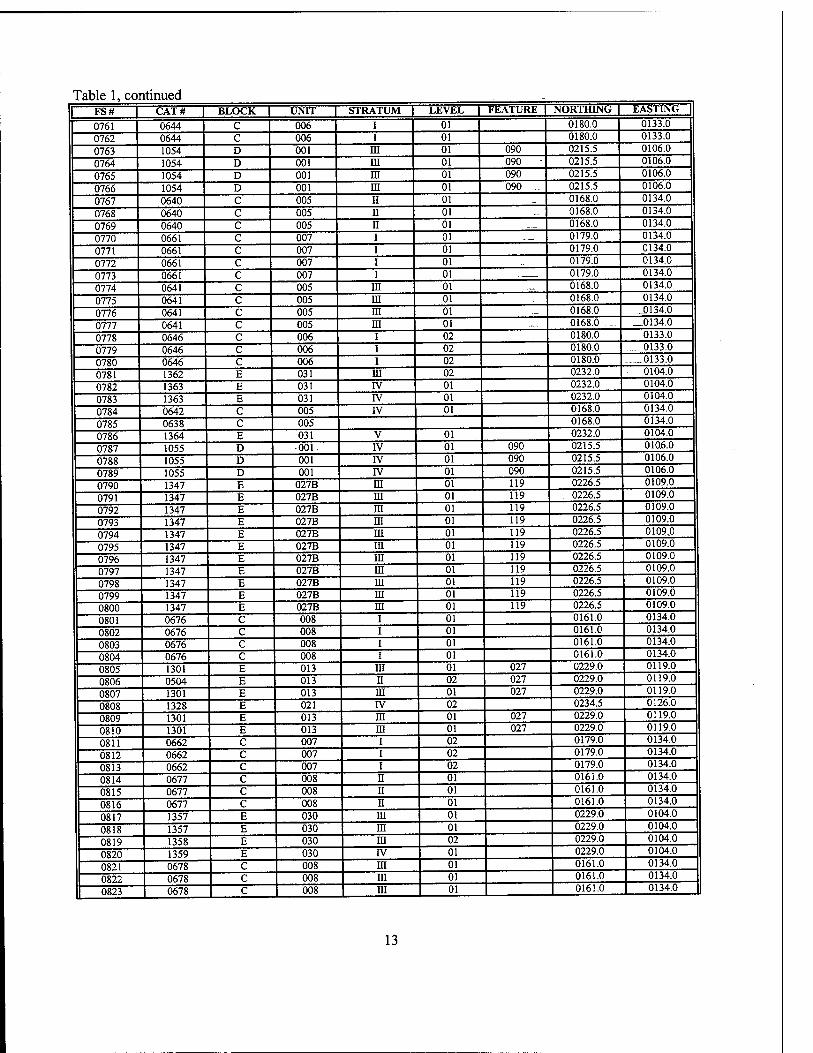
Table 1, continued - I FS# CAT# | BLOCK | UNIT | STRATUM | LEVEL | FEATURE | NORTHING | EASTING |
0761 0644 C 006 I 01 0180.0 0133.0
0762 0644 c 006 I 01 0180.0 0133.0
0763 1054 D 001 m 01 090 0215.5 0106.0
0764 1054 D 001 ni 01 090 0215.5 0106.0
0765 1054 D 001 ni 01 090 0215.5 0106.0
0766 1054 D 001 m 01 090 .. 0215.5 0106.0
0767 0640 C 005 ii 01 0168.0 0134.0
0768 0640 C 005 ii 01 0168.0 0134.0
0769 0640 C 005 II 01 -_ 0168.0 0134.0
0770 0661 C 007 i 01 — 0179.0 0134.0
0771 0661 C 007 i 01 0179.0 0134.0
0772 0661 C 007 i 01 0179.0 0134.0
0773 0661 C 007 i 01 ._— 0179.0 0134.0
0774 0641 C 005 ni 01 — 0168.0 0134.0
0775 0641 C 005 m 01 0168.0 0134.0
0776 0641 C 005 in 01 ._ 0168.0 J) 134.0
0777 0641 C 005 in 01 .._... 0168.0 ..... _0134.0
0778 0646 C 006 i 02 0180.0 0133.0
0779 0646 C 006 i 02 0180.0 .... 0133.0
0780 0646 C 006 i 02 0180.0 0133.0
0781 1362 E 031 in 02 0232.0 ■_ 0104.0
0782 1363 E 031 rv 01 0232.0 0104.0
0783 1363 E 031 IV 01 0232.0 0104.0
0784 0642 C 005 IV 01 0168.0 0134.0
0785 0638 C 005 0168.0 0134.0
0786 1364 E 031 V 01 0232.0 0104.0
0787 1055 D 001. IV 01 090 0215.5 0106.0
0788 1055 D 001 IV 01 090 0215.5 0106.0
0789 1055 D 001 rv 01 090 0215.5 0106.0
0790 1347 E 027B m 01 119 0226.5 0109.0
0791 1347 E 027B m 01 119 0226.5 0109.0
0792 1347 E 027B m 01 119 0226.5 0109.0
0793 1347 E 027B ni 01 119 0226.5 0109.0
0794 1347 E 027B m 01 119 0226.5 0109.0
0795 1347 E 027B m 01 119 0226.5 0109.0
0796 1347 E 027B in 01 119 0226.5 0109.0
0797 1347 E 027B HI 01 119 0226.5 0109.0
0798 1347 E 027B HI 01 119 0226.5 0109.0
0799 1347 E 027B HI 01 119 0226.5 0109.0
0800 1347 E 027B ra 01 119 0226.5 0109.0
0801 0676 C 008 i 01 0161.0 0134.0
0802 0676 C 008 i 01 0161.0 0134.0
0803 0676 c 008 i 01 0161.0 0134.0
0804 0676 c 008 i 01 0161.0 0134.0
0805 1301 E 013 HI 01 027 0229.0 0119.0
0806 0504 E 013 II 02 027 0229.0 0119.0
0807 1301 E 013 in 01 027 0229.0 0119.0
0808 1328 E 021 rv 02 0234.5 0126.0
0809 1301 E 013 HI 01 027 0229.0 0119.0
0810 1301 E 013 m 01 027 0229.0 0119.0
0811 0662 C 007 i 02 0179.0 0134.0
0812 0662 C 007 i 02 0179.0 0134.0
0813 0662 C 007 i 02 0179.0 0134.0
0814 0677 C 008 n 01 0161.0 0134.0
0815 0677 C 008 II 01 0161.0 0134.0
0816 0677 C 008 n 01 0161.0 0134.0
0817 1357 E 030 in 01 0229.0 0104.0
0818 1357 E 030 in 01 0229.0 0104.0
0819 1358 E 030 in 02 0229.0 0104.0
0820 1359 E 030 IV 01 0229.0 0104.0
0821 0678 C 008 in 01 0161.0 0134.0
0822 0678 C 008 ni 01 0161.0 0134.0
1 0823 0678 C 008 m 01 0161.0 0134.0
13
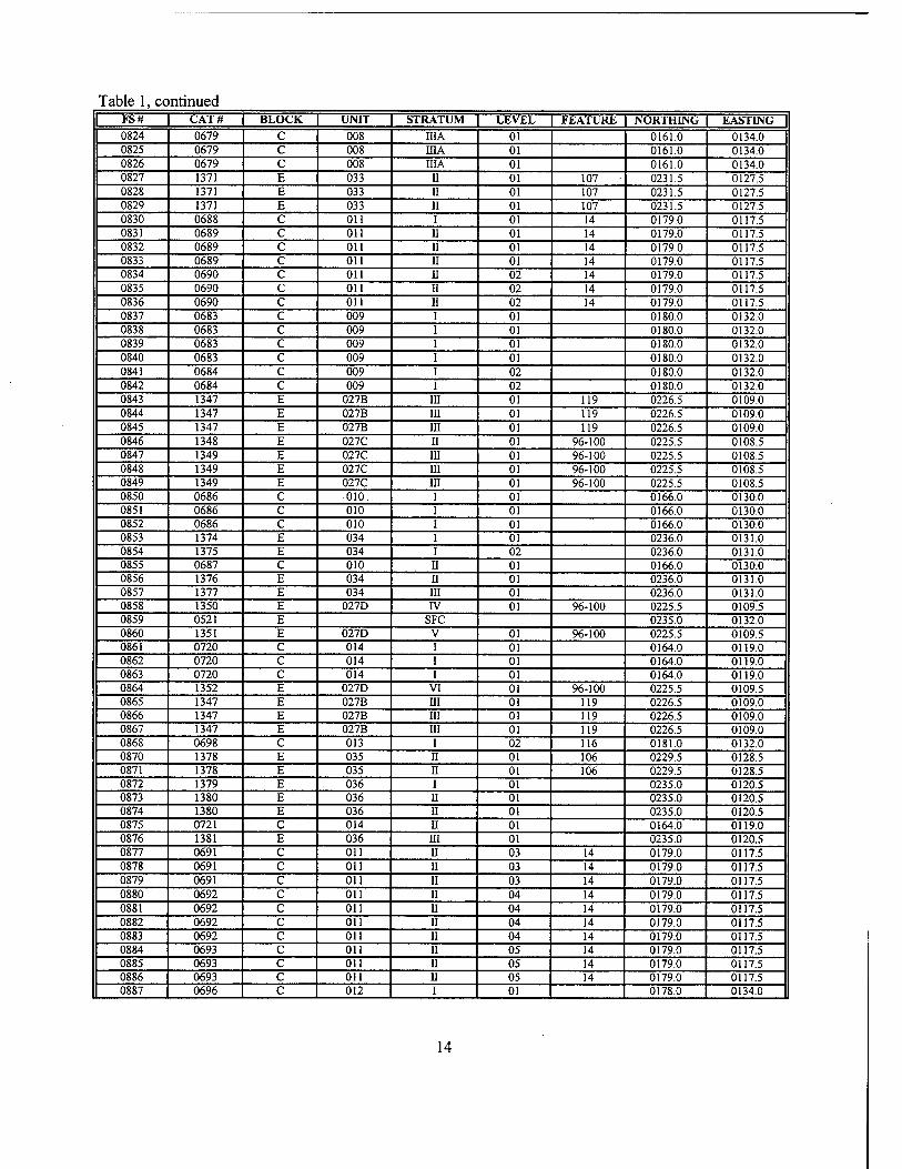
Table 1, continued FS# CAT# BLOCK UNIT STRATUM LEVEL FEATURE NORTHING EASTING 0824 0679 C 008 IIIA 01 0161.0 0134.0 0825 0679 c 008 mA 01 0161.0 0134.0 0826 0679 c 008 IIIA 01 0161.0 0134.0 0827 1371 E 033 II 01 107 0231.5 0127.5 0828 1371 E 033 II 01 107 0231.5 0127.5 0829 1371 E 033 II 01 107 0231.5 0127.5 0830 0688 C Oil I 01 14 0179.0 0117.5 0831 0689 c on II 01 14 0179.0 0117.5 0832 0689 c Oil n 01 14 0179.0 0117.5 0833 0689 c Oil ii 01 14 0179.0 0117.5 0834 0690 c Oil ii 02 14 0179.0 0117.5 0835 0690 c Oil II 02 14 0179.0 0117.5 0836 0690 c Oil II 02 14 0179.0 0117.5 0837 0683 c 009 i 01 0180.0 0132.0 0838 0683 c 009 i 01 0180.0 0132.0 0839 0683 c 009 i 01 0180.0 0132.0 0840 0683 c 009 i 01 0180.0 0132.0 0841 0684 c 009 i 02 0180.0 0132.0 0842 0684 c 009 i 02 0180.0 0132.0 0843 1347 E 027B m 01 119 0226.5 0109.0 0844 1347 E 027B HI 01 119 0226.5 0109.0 0845 1347 E 027B in 01 119 0226.5 0109.0 0846 1348 E 027C H 01 96-100 0225.5 0108.5 0847 1349 E 027C m 01 96-100 0225.5 0108.5 0848 1349 E 027C m 01 96-100 0225.5 0108.5 0849 1349 E 027C in 01 96-100 0225.5 0108.5 0850 0686 C 010. i 01 0166.0 0130.0 0851 0686 C 010 i 01 0166.0 0130.0 0852 0686 C 010 i 01 0166.0 0130.0 0853 1374 E 034 i 01 0236.0 0131.0 0854 1375 E 034 i 02 0236.0 0131.0 0855 0687 C 010 u 01 0166.0 0130.0 0856 1376 E 034 II 01 0236.0 0131.0 0857 1377 E 034 m 01 0236.0 0131.0 0858 1350 E 027D IV 01 96-100 0225.5 0109.5 0859 0521 E SFC 0235.0 0132.0 0860 1351 E 027D V 01 96-100 0225.5 0109.5 0861 0720 C 014 i 01 0164.0 0119.0 0862 0720 C 014 i 01 0164.0 0119.0 0863 0720 C 014 i 01 0164.0 0119.0 0864 1352 E 027D VI 01 96-100 0225.5 0109.5 0865 1347 E 027B HI 01 119 0226.5 0109.0 0866 1347 E 027B HI 01 119 0226.5 0109.0 0867 1347 E 027B HI 01 119 0226.5 0109.0 0868 0698 C 013 I 02 116 0181.0 0132.0 0870 1378 E 035 II 01 106 0229.5 0128.5 0871 1378 E 035 H 01 106 0229.5 0128.5 0872 1379 E 036 I 01 0235.0 0120.5 0873 1380 E 036 11 01 0235.0 0120.5 0874 1380 E 036 H 01 0235.0 0120.5 0875 0721 C 014 11 01 0164.0 0119.0 0876 1381 E 036 HI 01 0235.0 0120.5 0877 0691 C Oil II 03 14 0179.0 0117.5 0878 0691 C Oil H 03 14 0179.0 0117.5 0879 0691 C Oil U 03 14 0179.0 0117.5 0880 0692 C Oil II 04 14 0179.0 0117.5 0881 0692 c Oil U 04 14 0179.0 0117.5 0882 0692 c Oil II 04 14 0179.0 0117.5 0883 0692 c Oil II 04 14 0179.0 0117.5 0884 0693 c Oil H 05 14 0179.0 0117.5 0885 0693 c Oil U 05 14 0179.0 0117.5 0886 0693 c Oil H 05 14 0179.0 0117.5 0887 0696 c 012 I 01 0178.0 0134.0
14
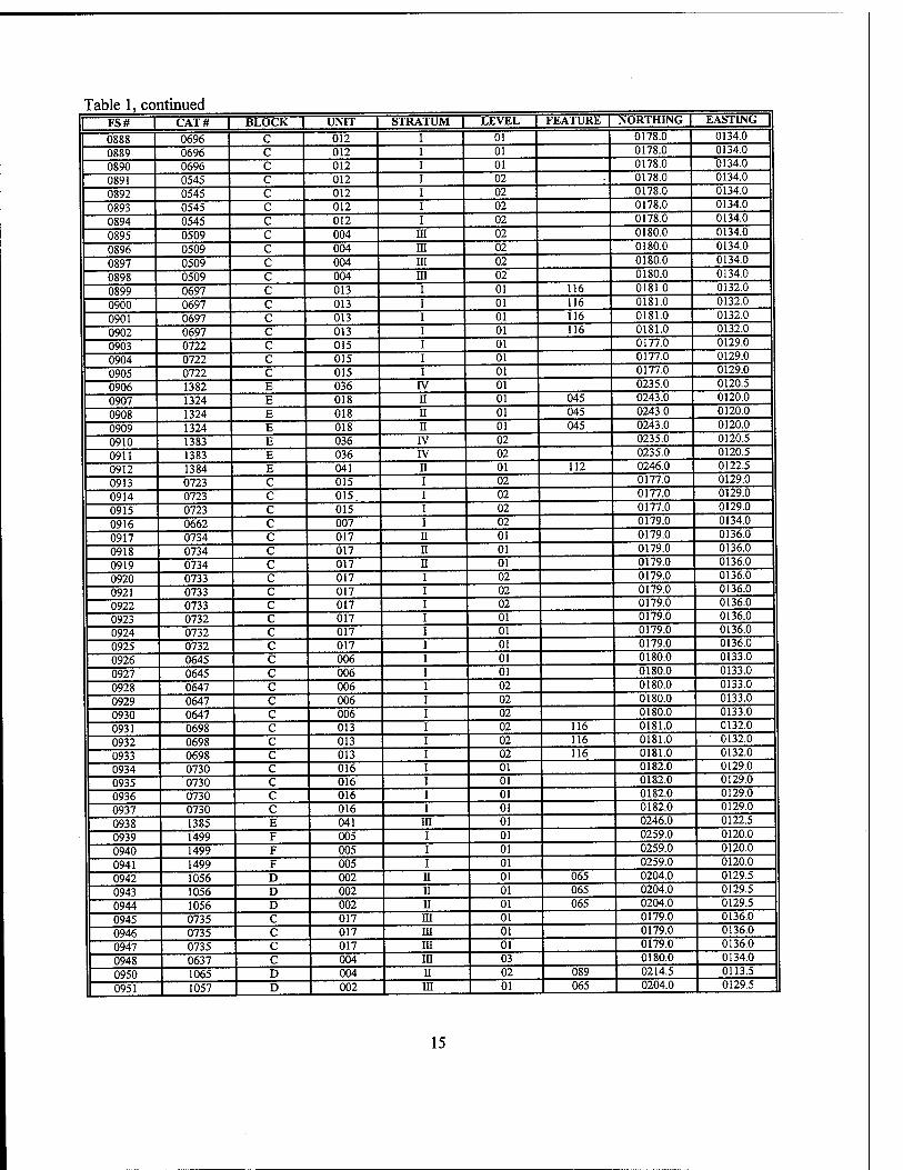
Table 1, continued FS# I CAT# | BLOCK | UNIT | STRATUM LEVEL FEATURE | NORTHING L EASTING J
0888 0696 C 012 01 0178.0 0134.0
0889 0696 c 012 01 0178.0 0134.0
0890 0696 c 012 01 0178.0 0134.0
0891 0545 c 012 02 0178.0 0134.0
0892 0545 c 012 02 0178.0 0134.0
0893 0545 c 012 02 0178.0 0134.0
0894 0545 c 012 02 0178.0 0134.0
0895 0509 c 004 ffl 02 0180.0 0134.0
0896 0509 c 004 ni 02 0180.0 0134.0
0897 0509 c 004 m 02 0180.0 0134.0
0898 0509 c 004 m 02 0180.0 0134.0
0899 0697 c 013 01 116 0181.0 0132.0
0900 0697 c 013 01 116 0181.0 0132.0
0901 0697 c 013 01 116 0181.0 0132.0
0902 0697 c 013 01 116 0181.0 0132.0
0903 0722 c 015 01 0177.0 0129.0
0904 0722 c 015 01 0177.0 0129.0
0905 0722 c 015 01 0177.0 0129.0
0906 1382 E 036 rv 01 0235.0 0120.5
0907 1324 E 018 n 01 045 0243.0 0120.0
0908 1324 E 018 ii 01 045 0243.0 0120.0
0909 1324 E 018 ii 01 045 0243.0 0120.0
0910 1383 E 036 rv 02 0235.0 0120.5
0911 1383 E 036 rv 02 0235.0 0120.5
0912 1384 E 041 n 01 112 0246.0 0122.5
0913 0723 C 015 i 02 0177.0 0129.0
0914 0723 C .015 i 02 0177.0 0129.0
0915 0723 c 015 i 02 0177.0 0129.0
0916 0662 c 007 i 02 0179.0 0134.0
0917 0734 c 017 n 01 0179.0 0136.0
0918 0734 c 017 n 01 0179.0 0136.0
0919 0734 c 017 n 01 0179.0 0136.0
0920 0733 c 017 02 0179.0 0136.0
0921 0733 c 017 02 0179.0 0136.0
0922 0733 c 017 02 0179.0 0136.0
0923 0732 c 017 01 0179.0 0136.0
0924 0732 c 017 01 0179.0 0136.0
0925 0732 c 017 01 0179.0 0136.0
0926 0645 c 006 01 0180.0 0133.0
0927 0645 c 006 01 0180.0 0133.0
0928 0647 c 006 02 0180.0 0133.0
0929 0647 c 006 02 0180.0 0133.0
0930 0647 c 006 02 0180.0 0133.0
0931 0698 c 013 02 116 0181.0 0132.0
0932 0698 c 013 02 116 0181.0 0132.0
0933 0698 c 013 02 116 0181.0 0132.0
0934 0730 c 016 01 0182.0 0129.0
0935 0730 c 016 01 0182.0 0129.0
0936 0730 c 016 01 0182.0 0129.0
0937 0730 c 016 01 0182.0 0129.0
0938 1385 E 041 in 01 0246.0 0122.5
0939 1499 F 005 01 0259.0 0120.0
0940 1499 F 005 01 0259.0 0120.0
0941 1499 F 005 01 0259.0 0120.0
0942 1056 D 002 ii 01 065 0204.0 0129.5
0943 1056 D 002 ii 01 065 0204.0 0129.5
0944 1056 D 002 II 01 065 0204.0 0129.5
0945 0735 C 017 in 01 0179.0 0136.0
0946 0735 C 017 in 01 0179.0 0136.0
0947 0735 C 017 in 01 0179.0 0136.0
0948 0637 C 004 in 03 0180.0 0134.0
0950 1065 D 004 n 02 089 0214.5 0113.5
0951 1057 D 002 in 01 065 0204.0 0129.5
15
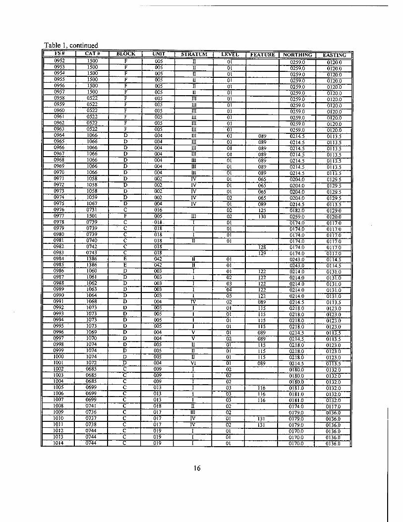
Table 1, continued FS# CAT# BLOCK UNIT STRATUM LEVEL FEATURE NORTHING EASTING 0952 1500 F 005 II 01 0259.0 0120.0 0953 1500 F 005 II 01 0259.0 0120.0 0954 1500 F 005 II 01 0259.0 0120.0 0955 1500 F 005 II 01 0259.0 0120.0 0956 1500 F 005 II 01 0259.0 0120.0 0957 1500 F 005 II 01 0259.0 0120.0 0958 0522 F 005 in 01 0259.0 0120.0 0959 0522 F 005 HI 01 0259.0 0120.0 0960 0522 F 005 iii 01 0259.0 0120.0 0961 0522 F 005 HI 01 0259.0 0120.0 0962 0522 F 005 m 01 0259.0 0120.0 0963 0522 F 005 ra 01 0259.0 0120.0 0964 1066 D 004 m 01 089 0214.5 0113.5 0965 1066 D 004 in 01 089 0214.5 0113.5 0966 1066 D 004 HI 01 089 0214.5 0113.5 0967 1066 D 004 in 01 089 0214.5 0113.5 0968 1066 D 004 in 01 089 0214.5 0113.5 0969 1066 D 004 m 01 089 0214.5 0113.5 0970 1066 D 004 HI 01 089 0214.5 0113.5 0971 1058 D 002 IV 01 065 0204.0 0129.5 0972 1058 D 002 rv 01 065 0204.0 0129.5 0973 1058 D 002 IV 01 065 0204.0 0129.5 0974 1059 D 002 IV 02 065 0204.0 0129.5 0975 1067 D 004 IV 01 089 0214.5 0113.5 0976 0731 C 016 02 125 0182.0 0129.0 0977 1501 F 005 m 02 130 0259.0 0120.0 0978 0739 C -018. i 01 0174.0 0117.0 0979 0739 C 018 i 01 0174.0 0117.0 0980 0739 C 018 i 01 0174.0 0117.0 0981 0740 C 018 ii 01 0174.0 0117.0 0982 0742 C 018 128 0174.0 0117.0 0983 0743 C 018 129 0174.0 0117.0 0984 1386 E 042 ii 01 0243.0 0114.5 0985 1386 E 042 n 01 0243.0 0114.5 0986 1060 D 003 i 01 122 0214.0 0131.0 0987 1061 D 003 i 02 122 0214.0 0131.0 0988 1062 D 003 i 03 122 0214.0 0131.0 0989 1063 D 003 i 04 122 0214.0 0131.0 0990 1064 D 003 i 05 122 0214.0 0131.0 0991 1068 D 004 rv 02 089 0214.5 0113.5 0992 1073 D 005 i 01 115 0218.0 0123.0 0993 1073 D 005 i 01 115 0218.0 0123.0 0994 1073 D 005 i 01 115 0218.0 0123.0 0995 ' 1073 D 005 i 01 115 0218.0 0123.0 0996 1069 D 004 V 01 089 0214.5 0113.5 0997 1070 D 004 V 02 089 0214.5 0113.5 0998 1074 D 005 u 01 115 0218.0 0123.0 0999 1074 D 005 II 01 115 0218.0 0123.0 1000 1074 D 005 n 01 115 0218.0 0123.0 1001 1072 D 004 VI 01 089 0214.5 0113.5 1002 0685 C 009 i 02 0180.0 0132.0 1003 0685 C 009 i 02 0180.0 0132.0 1004 0685 C 009 i 02 0180.0 0132.0 1005 0699 C 013 i 03 116 0181.0 0132.0 1006 0699 C 013 i 03 116 0181.0 0132.0 1007 0699 C 013 i 03 116 0181.0 0132.0 1008 0741 C 018 ii 02 0174.0 0117.0 1009 0736 C 017 m 02 0179.0 0136.0 1010 0737 C 017 IV 01 131 0179.0 0136.0 1011 0738 C 017 IV 02 131 0179.0 0136.0 1012 0744 C 019 i 01 0170.0 0136.0 1013 0744 C 019 I 01 0170.0 0136.0 1014 0744 C 019 i 01 0170.0 0136.0
16
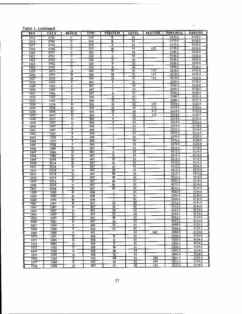
Table 1, continued | FS# | CAT# | BLOCK | UNIT | STRATUM 1 LEVEL I FEATURE | NORTHING | EASTING |
1015 0745 C 019 n 01 0170.0 0136.0
1016 0745 c 019 ii 01 0170.0 0136.0
1017 0745 c 019 n 01 0170.0 0136.0
1018 0746 c 019 in 01 132 0170.0 0136.0
1020 0751 c 020 n 01 0186.0 0126.0
1021 0751 c 020 n 01 0186.0 0126.0
1022 0752 c 020 II 02 0186.0 0126.0
1023 0752 c 020 n 02 0186.0 0126.0
1024 0752 c 020 n 02 0186.0 0126.0
1025 1075 D 005 m 01 115 0218.0 0123.0
1026 1075 D 005 ni 01 115 0218.0 0123.0
1027 1075 D 005 m 01 115 0218.0 0123.0
1028 1505 F 007 i 01 0260.0 0126.0
1029 1505 F 007 i 01 0260.0 0126.0
1030 1505 F 007 i 01 0260.0 0126.0
1031 1506 F 007 II 01 0260.0 0126.0
1032 1502 F 006 II 01 0268.0 0131.5
1033 1503 F 006 m 01 0268.0 0131.5
1034 1076 D 005 m 02 115 0218.0 0123.0
1035 1076 D 005 in 02 115 0218.0 0123.0
1036 1076 D 005 in 02 115 0218.0 0123.0
1037 1077 D 005 V 01 115 0218.0 0123.0
1038 1077 D 005 V 01 0218.0 0123.0
1039 1077 D 005 V 01 0218.0 0123.0
1040 1507 F 008 01 0275.0 0114.0
1041 1507 F 008 01 0275.0 0114.0
1042 1507 F -008- 01 0275.0 0114.0
1043 1508 F 009 01 0270.0 0120.0
1044 1507 F 009 01 0270.0 0120.0
1045 1508 F 009 01 0270.0 0120.0
1046 1086 D 007 n 01 0212.5 0114.0
1047 1086 D 007 n 01 0212.5 0114.0
1048 1086 D 007 n 01 0212.5 0114.0
1049 0518 D 007 in 01 0212.5 0114.0
1050 0518 D 007 m 01 0212.5 0114.0
1051 0518 D 007 in 01 0212.5 0114.0
1052 0518 D 007 in 01 0212.5 0114.0
1053 0518 D 007 in 01 0212.5 0114.0
1054 0518 D 007 m 01 0212.5 0114.0
1055 0518 D 007 m 01 0212.5 0114.0
1056 0518 D 007 in 01 0212.5 0114.0
1057 0518 D 007 in 01 0212.5 0114.0
1058 1090 D 008 i 01 0202.0 0134.0
1059 1090 D 008 i 01 0202.0 0134.0
1060 1090 D 008 i 01 0202.0 0134.0
1061 1087 D 007 m 02 0212.5 0114.0
1062 1087 D 007 m 02 0212.5 0114.0
1063 1087 D 007 in 02 0212.5 0114.0
1064 1087 D 007 m 02 0212.5 0114.0
1065 1087 D 007 m 02 0212.5 0114.0
1066 1087 D 007 m 02 0212.5 0114.0
1067 1504 F 006 rv 01 0268.0 0131.5
1068 1509 F 010 IV 01 0266.0 0131.5
1069 1486 F 001 03 043 0266.0 0133.0
1070 1091 D 008 ii 01 0202.0 0134.0
1071 1091 D 008 n 01 0202.0 0134.0
1072 1091 D 008 II 01 0202.0 0134.0
1073 1092 D 008 m 01 0202.0 0134.0
1074 1092 D 008 m 01 0202.0 0134.0
1075 1092 D 008 m 01 0202.0 0134.0
1076 1365 E 032 i/n 01 104 0221.5 0130.5
1077 1366 E 032 HI 01 104 0221.5 0130.5
1078 1088 D 007 IV 02 135 0212.5 0114.0
17
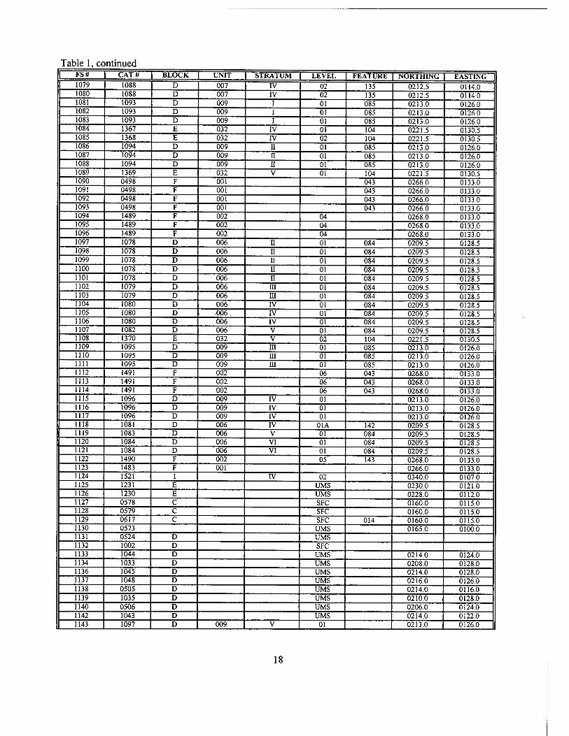
Table 1, continued FS# CAT# BLOCK UNIT STRATUM LEVEL FEATURE NORTHING EASTING 1079 1088 D 007 IV 02 135 0212.5 0114.0 1080 1088 D 007 IV 02 135 0212.5 0114.0 1081 1093 D 009 I 01 085 0213.0 0126.0 1082 1093 D 009 I 01 085 0213.0 0126.0 1083 1093 D 009 I 01 085 0213.0 0126.0 1084 1367 E 032 IV 01 104 0221.5 0130.5 1085 1368 E 032 IV 02 104 0221.5 0130.5 1086 1094 D 009 II 01 085 0213.0 0126.0 1087 1094 D 009 II 01 085 0213.0 0126.0 1088 1094 D 009 II 01 085 0213.0 0126.0 1089 1369 E 032 V 01 104 0221.5 0130.5 1090 0498 F 001 043 0266.0 0133.0 1091 0498 F 001 043 0266.0 0133.0 1092 J 0498 F 001 043 0266.0 0133.0 1093 0498 F 001 043 0266.0 0133.0 1094 1489 F 002 04 0268.0 0133.0 1095 1489 F 002 04 0268.0 0133.0 1096 1489 F 002 04 0268.0 0133.0 1097 1078 D 006 II 01 084 0209.5 0128.5 1098 1078 D 006 II 01 084 0209.5 0128.5 1099 1078 D 006 II 01 084 0209.5 0128.5 1100 1078 D 006 II 01 084 0209.5 0128.5 1101 1078 D 006 II 01 084 0209.5 0128.5 1102 1079 D 006 HI 01 084 0209.5 0128.5 1103 1079 D 006 III 01 084 0209.5 0128.5 1104 1080 D 006 IV 01 084 0209.5 0128.5 1105 1080 D 006. rv 01 084 0209.5 0128.5 1106 1080 D 006 IV 01 084 0209.5 0128.5 1107 1082 D 006 V 01 084 0209.5 0128.5 1108 1370 E 032 V 02 104 0221.5 0130.5 1109 1095 D 009 III 01 085 0213.0 0126.0 1110 1095 D 009 m 01 085 0213.0 0126.0 1111 1095 D 009 in 01 085 0213.0 0126.0 1112 1491 F 002 06 043 0268.0 0133.0 1113 1491 F 002 06 043 0268.0 0133.0 1114 1491 F 002 06 043 0268.0 0133.0 1115 1096 D 009 IV 01 0213.0 0126.0 1116 1096 D 009 IV 01 0213.0 0126.0 1117 1096 D 009 IV 01 0213.0 0126.0 1118 1081 D 006 IV 01A 142 0209.5 0128.5 1119 1083 D 006 V 01 084 0209.5 0128.5 1120 1084 D 006 VI 01 084 0209.5 0128.5 1121 1084 D 006 VI 01 084 0209.5 0128.5 1122 1490 F 002 05 143 0268.0 0133.0 1123 1483 F 001 0266.0 0133.0 1124 1521 I IV 02 0340.0 0107.0 1125 1231 E UMS 0230.0 0121.0 1126 1230 E UMS 0228.0 0112.0 1127 0578 C SFC 0160.0 0115.0 1128 0579 C SFC 0160.0 0115.0 1129 0617 C SFC 014 0160.0 0115.0 1130 0573 UMS 0165.0 0100.0 1131 0524 D UMS 1132 1002 D SFC 1133 1044 D UMS 0214.0 0124.0 1134 1033 D UMS 0208.0 0128.0 1136 1045 D UMS 0214.0 0128.0 1137 1048 D UMS 0216.0 0126.0 1138 0505 D UMS 0214.0 0116.0 1139 1035 D UMS 0210.0 0128.0 1140 0506 D UMS 0206.0 0124.0 1142 1043 D UMS 0214.0 0122.0 1143 1097 D 009 V 01 0213.0 0126.0
18
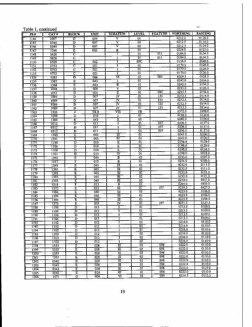
Table 1, continued
1 FS# | CAT# | BLOCK L UNIT L STRATUM | LEVEL L FEATURE | NORTHING | EASTING |
1144 1097 D 009 V 01 0213.0 -6126.0
1145 0544 D 007 V 01 0212.5 -0114.0
1146 0544 D 007 V 01 0212.5 _0114.0
1147 1248 E 002 n 01 0224.0 0123.0
1148 0626 C i 01 Oil 0184.0 0134.0
1149 0626 C i 01 Oil 0184.0 0134.0
1150 0529 C 002 i SFC 0158.0 0140.0
1151 0753 C 021 i 01 0179.0 0126.0
1152 0753 C 021 i 01 0179.0 0126.0
1153 0753 C 021 i 01 0179.0 0126.0
1154 1085 D 006 VI 02 084 0209.5 0128.5
1155 1387 E 043 i 01 0242.0 0104.0
1156 1388 E 043 n 01 0242.0 —0104.0
1157 1098 D 009 V 02 0213.0 0126.0
1158 1053 D 001 n 01 090 0215.5 - 0106.0
1159 1089 D 007 IV 01 135 0212.5 .0114.0
1160 1089 D 007 rv 01 135 0212.5 0114.0
1161 1089 D 007 IV 01 135 0212.5 0114.0
1162 1089 D 007 IV 01 135 0212.5 0114.0
1163 1526 J TR8 Vffl TR 0372.0 0100.0
1164 1099 D 010 i 01 0198.0 0128.0
1165 1389 E 043 n 02 0242.0 0104.0
1166 0512 D Oil i 01 057 0206.5 0137.0
1167 0512 D Oil i 01 057 0206.5 0137.0
1168 0512 D Oil i 01 057 0206.5 0137.0
1169 1390 E 043 in 01 0242.0 0104.0
1170 1391 E 043. IV 01 0242.0 0104.0
1171 1100 D 010 n 01 0198.0 0128.0
1172 1100 D 010 ii 01 0198.0 0128.0
1173 1100 D 010 n 01 0198.0 0128.0
1174 1101 D 010 IV 01 0198.0 0128.0
1175 1392 E 044 n 02 0233.0 0107.0
1176 1517 F 012 n 01 0254.0 0105.0
1177 1393 E 045 in 02 0232.0 0111.0
1178 1393 E 045 m 02 0232.0 on l.o 1179 1393 E 045 HI 02 0232.0 0111.0
1180 1393 E 045 m 02 0232.0 0111.0
1181 1393 E 045 m 02 0232.0 0111.0
1182 1518 F 013 n 01 0264.0 0103.0
1183 1372 E 033 m 01 107 0231.5 0127.5
1184 1394 E 046 in 01 0223.0 0106.0
1185 1394 E 046 in 01 0223.0 0106.0
1186 1394 E 046 m 01 0223.0 0106.0
1187 1373 E 033 rv 01 107 0231.5 0127.5
1188 1106 D 013 01 0213.5 0109.0
1189 1106 D 013 01 0213.5 0109.0
1190 1106 D 013 01 0213.5 0109.0
1191 1106 D 013 01 0213.5 0109.0
1192 1102 D 012 01 0216.0 0110.0
1193 1102 D 012 01 0216.0 0110.0
1194 1102 D 012 01 0216.0 0110.0
1195 1103 D 012 02 0216.0 0110.0
1196 1103 D 012 02 0216.0 0110.0
1197 1103 D 012 02 0216.0 0110.0
1198 1353 E 028 HI 02 098 0222.0 0110.0
1199 1353 E 028 ra 02 098 0222.0 0110.0
1200 1353 E 028 in 02 098 0222.0 0110.0
1201 1353 E 028 HI 02 098 0222.0 0110.0
1202 0542 E 028 in 01 098 0222.0 0110.0
1203 0542 E 028 in 01 098 0222.0 0110.0
1204 0542 E 028 in 01 098 0222.0 0110.0
1205 0542 E 028 in 01 098 0222.0 0110.0
1206 1071 D 004 VI 01 089 0214.5 0113.5
19
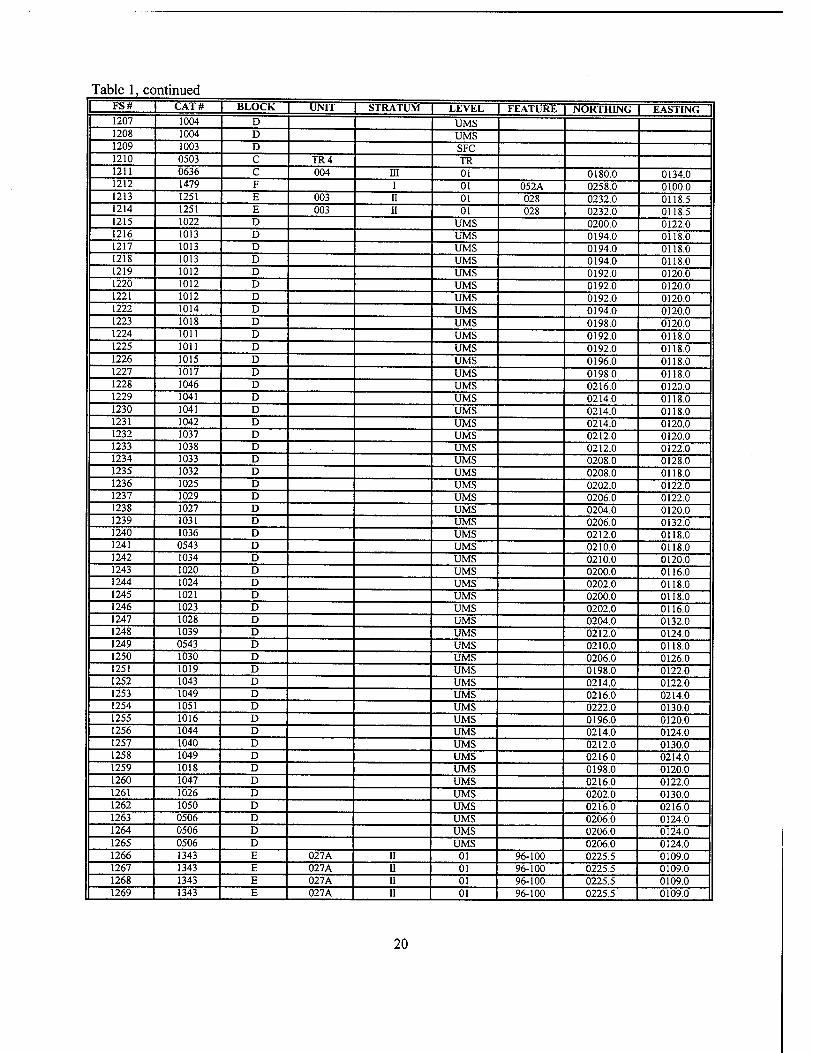
Table 1, continued FS# CAT# BLOCK UNIT STRATUM LEVEL | FEATURE NORTHING EASTING 1207 1004 D UMS 1208 1004 D UMS 1209 1003 D SFC 1210 0503 C TR4 TR 1211 0636 C 004 m 01 0180.0 0134.0 1212 1479 F i 01 052A 0258.0 0100.0 1213 1251 E 003 ii 01 028 0232.0 0118.5 1214 1251 E 003 ii 01 028 0232.0 0118.5 1215 1022 D UMS 0200.0 0122.0 1216 1013 D UMS 0194.0 0118.0 1217 1013 D UMS 0194.0 0118.0 1218 1013 D UMS 0194.0 0118.0 1219 1012 D UMS 0192.0 0120.0 1220 1012 D UMS 0192.0 0120.0 1221 1012 D UMS 0192.0 0120.0 1222 1014 D UMS 0194.0 0120.0 1223 1018 D UMS 0198.0 0120.0 1224 1011 D UMS 0192.0 0118.0 1225 1011 D UMS 0192.0 0118.0 1226 1015 D UMS 0196.0 0118.0 1227 1017 D UMS 0198.0 0118.0 1228 1046 D UMS 0216.0 0120.0 1229 1041 D UMS 0214.0 0118.0 1230 1041 D UMS 0214.0 0118.0 1231 1042 D UMS 0214.0 0120.0 1232 1037 D UMS 0212.0 0120.0 1233 1038 D UMS 0212.0 0122.0 1234 1033 D UMS 0208.0 0128.0 1235 1032 D UMS 0208.0 0118.0 1236 1025 D UMS 0202.0 0122.0 1237 1029 D UMS 0206.0 0122.0 1238 1027 D UMS 0204.0 0120.0 1239 1031 D UMS 0206.0 0132.0 1240 1036 D UMS 0212.0 0118.0 1241 0543 D UMS 0210.0 0118.0 1242 1034 D UMS 0210.0 0120.0 1243 1020 D UMS 0200.0 0116.0 1244 1024 D UMS 0202.0 0118.0 1245 1021 D UMS 0200.0 0118.0 1246 1023 D UMS 0202.0 0116.0 1247 1028 D UMS 0204.0 0132.0 1248 1039 D UMS 0212.0 0124.0 1249 0543 D UMS 0210.0 0118.0 1250 1030 D UMS 0206.0 0126.0 1251 1019 D UMS 0198.0 0122.0 1252 1043 D UMS 0214.0 0122.0 1253 1049 D UMS 0216.0 0214.0 1254 1051 D UMS 0222.0 0130.0 1255 1016 D UMS 0196.0 0120.0 1256 1044 D UMS 0214.0 0124.0 1257 1040 D UMS 0212.0 0130.0 1258 1049 D UMS 0216.0 0214.0 1259 1018 D UMS 0198.0 0120.0 1260 1047 D UMS 0216.0 0122.0 1261 1026 D UMS 0202.0 0130.0 1262 1050 D UMS 0216.0 0216.0 1263 0506 D UMS 0206.0 0124.0 1264 0506 D UMS 0206.0 0124.0 1265 0506 D UMS 0206.0 0124.0 1266 1343 E 027A ii 01 96-100 0225.5 0109.0 1267 1343 E 027A II 01 96-100 0225.5 0109.0 1268 1343 E 027A II 01 96-100 0225.5 0109.0 1269 1343 E 027A II 01 96-100 0225.5 0109.0
20
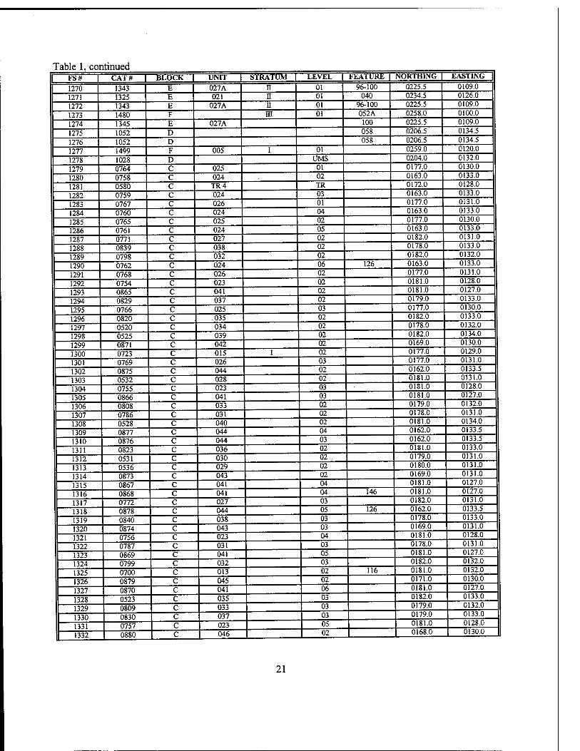
Table 1, continued 1 FS# I CAT# | BLOCK | UNIT | STRATUM | LEVEL I FEATURE | NORTHING | EASTING |
1270 1343 E 027A II 01 96-100 0225.5 0109.0
1271 1325 E 021 II 01 040 0234.5 0126.0
1272 1343 E 027A n 01 96-100 0225.5 0109.0
1273 1480 F HI 01 052A - 0258.0 0100.0
1274 1345 E 027A 100 0225.5 0109.0
1275 1052 D 058 0206.5 0134.5
1276 1052 D 058 0206.5 0134.5
1277 1499 F 005 I 01 0259.0 0120.0
1278 1028 D UMS 0204.0 0132.0
1279 0764 C 025 01 0177.0 0130.0
1280 0758 C 024 02 0163.0 0133.0
1281 0580 C TR4 TR 0172.0 0128.0
1282 0759 C 024 03 0163.0 0133.0
1283 0767 C 026 01 0177.0 0131.0
1284 0760 c 024 04 0163.0 0133.0
1285 0765 c 025 02 0177.0 0130.0
1286 0761 c 024 05 0163.0 0133.0
1287 0771 c 027 02 0182.0 0131.0
1288 0839 c 038 02 0178.0 0133.0
1289 0798 c 032 02 0182.0 0132.0
1290 0762 c 024 06 126 0163.0 0133.0
1291 0768 c 026 02 0177.0 0131.0
1292 0754 c 023 02 0181.0 0128.0
1293 0865 c 041 02 0181.0 0127.0
1294 0829 c 037 02 0179.0 0133.0
1295 0766 c 025 03 0177.0 0130.0
1296 0820 c .035 02 0182.0 0133.0
1297 0520 c 034 02 0178.0 0132.0
1298 0525 c 039 02 0182.0 0134.0
1299 0871 c 042 02 0169.0 0130.0
1300 0723 c 015 I 02 0177.0 0129.0
1301 0769 c 026 03 0177.0 0131.0
1302 0875 c 044 02 0162.0 0133.5
1303 0532 c 028 02 0181.0 0131.0
1304 0755 c 023 03 0181.0 0128.0
1305 0866 c 041 03 0181.0 0127.0
1306 0808 c 033 02 0179.0 0132.0
1307 0786 c 031 02 0178.0 0131.0
1308 0528 c 040 02 0181.0 0134.0
1309 0877 c 044 04 0162.0 0133.5
1310 0876 c 044 03 0162.0 0133.5
1311 0823 c 036 02 0181.0 0133.0
1312 0531 c 030 02 0179.0 0131.0
1313 0536 c 029 02 0180.0 0131.0
1314 0873 c 043 02 0169.0 0131.0
1315 0867 c 041 04 0181.0 0127.0
1316 0868 c 041 04 146 0181.0 0127.0
1317 0772 c 027 03 0182.0 0131.0
1318 0878 c 044 05 126 0162.0 0133.5
1319 0840 c 038 03 0178.0 0133.0
1320 0874 c 043 03 0169.0 0131.0
1321 0756 c 023 04 0181.0 0128.0
1322 0787 c 031 03 0178.0 0131.0
1323 0869 c 041 05 0181.0 0127.0
1324 0799 c 032 03 0182.0 0132.0
1325 0700 c 013 02 116 0181.0 0132.0
1326 0879 c 045 02 0171.0 0130.0
1327 0870 c 041 06 0181.0 0127.0
1328 0523 c 035 03 0182.0 0133.0
1329 0809 c 033 03 0179.0 0132.0
1330 0830 c 037 03 0179.0 0133.0
1331 0757 c 023 05 0181.0 0128.0
1 1332 1 0880 c 046 02 0168.0 0130.0
21
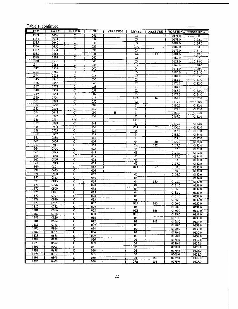
Table 1, continued I FS# | CAT# | BLOCK | UNIT | STRATUM | LEVEL | FEATURE NORTHING =EASTING |
1333 0538 C 045 03 0171.0 O130.0 1334 0541 C 034 03 0178.0 0132.0 1335 0540 C 039 03 0182.0 0134.0 1336 0856 C 039 03A 0182.0 0134.0 1337 0534 C 030 03 0179.0 0T31.0 1338 0864 C 041 06A 147 0181.0 6127.0 1339 0884 C 047 02 0169.0 0137.0 1340 0535 C 040 03 .._ 0181.0 . 0134.0 1341 0881 C 046 03 0168.0 0130.0 1342 0539 C 045 04 0171.0 01300 1343 0781 C 029 03 0180.0 0131.0 1344 0824 C 036 02 0181.0 0133.0 1345 0825 C 036 03 0181.0 0133.0 1346 0888 C 048 02 0170.0 —-0132.0 1347 0775 C 028 03 0181.0 0131.0 1348 0907 C 052 02 0166.0 0132.0 1349 0663 C 007 03 0179.0 0134.0 1350 0701 C 013 02A TT6 0181.0 " U 132.0 1351 0897 C 050 02 0179.0 0128.0 1352 0680 C 009 01 0180.0 —01-32.0 1353 0894 C 049 02 0171.0 0132.0 1354 0648 C 006 II 01 0180.0 0133.0 1355 0912 c 053 02 0167.0 0132.0 1356 0551 SFC SFC 1357 0889 C 048 03 0170.0 0132.0 1358 0904 C 052 03A 152 0166.0 —-0132.0 1359 0773 C .027 04 0182.0 - 0131.0 1360 0857 c 039 04 0182.0 0134.0 1361 0885 c 047 03 0169.0 0137.0 1362 0664 c 007 04 150 0179.0 0134.0 1363 0911 c 053 2A 152 0167.0 0132.0 1364 0774 c 027 05 * 0182.0 0131.0 1365 0895 c 049 03 0171.0 0132.0 1366 0858 c 039 05 0182.0 0134.0 1367 0800 c 032 04 0182.0 0132.0 1368 0913 c 053 03 0167.0 0132.0 1369 0891 c 048 04A 157 0170.0 0132.0 1370 0633 c 004 0180.0 0134.0 1371 0908 c 052 03 0166.0 0132.0 1372 0863 c 040 04 0181.0 0134.0 1373 0813 c 034 04 150 0178.0 0132.0 1374 0776 c 028 04 0181.0 0131.0 1375 0909 c 052 04 0166.0 0132.0 1376 0821 c 035 04 0182.0 0133.0 1377 0777 c 028 05 0181.0 0131.0 1378 0910 c 052 05 0166.0 0132.0 1379 0905 c 052 05A 166 0166.0 0132.0 1380 0782 c 029 04 0180.0 0131.0 1381 0906 c 052 05B 166 0166.0 0132.0 1382 0784 c 030 03B 0179.0 0131.0 1383 0826 c 036 04 0181.0 0133.0 1384 0694 c 012 03 149 0178.0 0134.0 1385 0783 c 029 05 0180.0 0131.0 1386 0914 c 054 02 0170.0 0130.0 1387 0915 c 054 03 0170.0 0130.0 1388 0681 c 009 02 0180.0 0132.0 1389 0920 c 056 02 0165.0 0132.0 1390 0682 c 009 03 0180.0 0132.0 1391 0903 c 051 02 0178.0 0129.0 1392 0898 c 050 02 0179.0 0128.0 1393 0917 c 055 02 0169.0 0128.0 1394 0899 c 050 03 153 0179.0 0128.0 1395 0900 c 050 03A 153 0179.0 0128.0
22
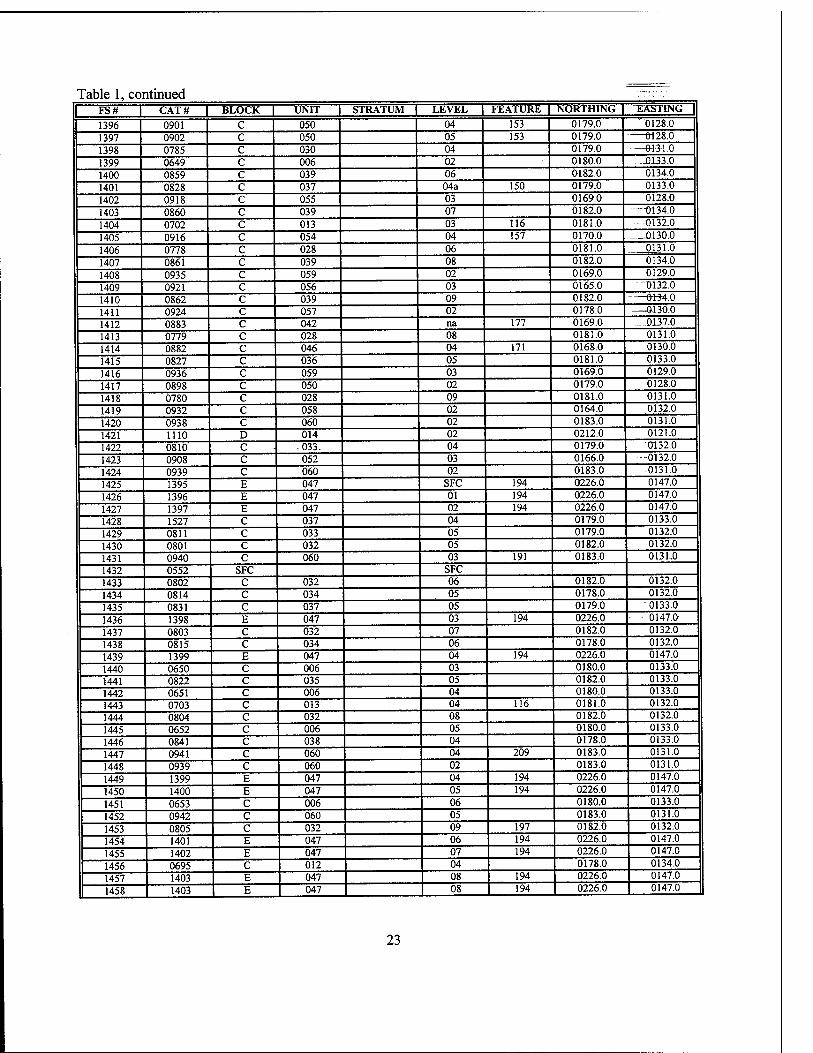
Table 1, continued ..'.TH'-V
FS# | CAT# | BLOCK | UNIT | STRATUM | LEVEL | FEATURE | NORTHING | EASTING |
1396 0901 C 050 04 153 0179.0 "0128.0
1397 0902 c 050 05 153 0179.0 0128.0
1398 0785 c 030 04 0179.0 —0-13-1.0
1399 0649 c 006 02 0180.0 ...JQ133.0
1400 0859 c 039 06 0182.0 0134.0
1401 0828 c 037 04a 150 0179.0 0133.0
1402 0918 c 055 03 0169.0 0128.0
1403 0860 c 039 07 0182.0 —0134.0
1404 0702 c 013 03 116 0181.0 - 0132.0
1405 0916 c 054 04 157 0170.0 0130.0
1406 0778 c 028 06 0181.0 0131.0
1407 0861 c 039 08 0182.0 0134.0
1408 0935 c 059 02 0169.0 0129.0
1409 0921 c 056 03 0165.0 0132.0
1410 0862 c 039 09 0182.0 OH4.0
1411 0924 c 057 02 0178.0 —01-30.0
1412 0883 c 042 na 177 0169.0 —0137.0
1413 0779 c 028 08 0181.0 0131.0
1414 0882 c 046 04 171 0168.0 0130.0
1415 0827 c 036 05 0181.0 0133.0
1416 0936 c 059 03 0169.0 0129.0
1417 0898 c 050 02 0179.0 0128.0
1418 0780 c 028 09 0181.0 0131.0
1419 0932 c 058 02 0164.0 0132.0
1420 0938 c 060 02 0183.0 0131.0
1421 1110 D 014 02 0212.0 0121.0
1422 0810 c • 033. 04 0179.0 "0132.0
1423 0908 c 052 03 0166.0 0132.0
1424 0939 c 060 02 0183.0 0131.0
1425 1395 E 047 SFC 194 0226.0 0147.0
1426 1396 E 047 01 194 0226.0 0147.0
1427 1397 E 047 02 194 0226.0 0147.0
1428 1527 C 037 04 0179.0 0133.0
1429 0811 c 033 05 0179.0 0132.0
1430 0801 c 032 05 0182.0 0132.0
1431 0940 c 060 03 191 0183.0 013L0
1432 0552 SFC SFC 1433 0802 C 032 06 0182.0 0132.0
1434 0814 c 034 05 0178.0 0132.0
1435 0831 c 037 05 0179.0 0133.0
1436 1398 E 047 03 194 0226.0 --- 0147.O
1437 0803 C 032 07 0182.0 0132.0
1438 0815 C 034 06 0178.0 0132.0
1439 1399 E 047 04 194 0226.0 0147.0
1440 0650 C 006 03 0180.0 0133.0
1441 0822 C 035 05 0182.0 0133.0
1442 0651 c 006 04 0180.0 0133.0
1443 0703 c 013 04 116 0181.0 0132.0
1444 0804 c 032 08 0182.0 0132.0
1445 0652 c 006 05 0180.0 0133.0
1446 0841 c 038 04 0178.0 0133.0
1447 0941 c 060 04 209 0183.0 0131.0
1448 0939 c 060 02 0183.0 0131.0
1449 1399 E 047 04 194 0226.0 0147.0
1450 1400 E 047 05 194 0226.0 0147.0
1451 0653 C 006 06 0180.0 0133.0
1452 0942 C 060 05 0183.0 0131.0
1453 0805 C 032 09 197 0182.0 0132.0
1454 1401 E 047 06 194 0226.0 0147.0
1455 1402 E 047 07 194 0226.0 0147.0
1456 0695 C 012 04 0178.0 0134.0
1457 1403 E 047 08 194 0226.0 0147.0
1458 1403 E 047 08 194 0226.0 0147.0
23
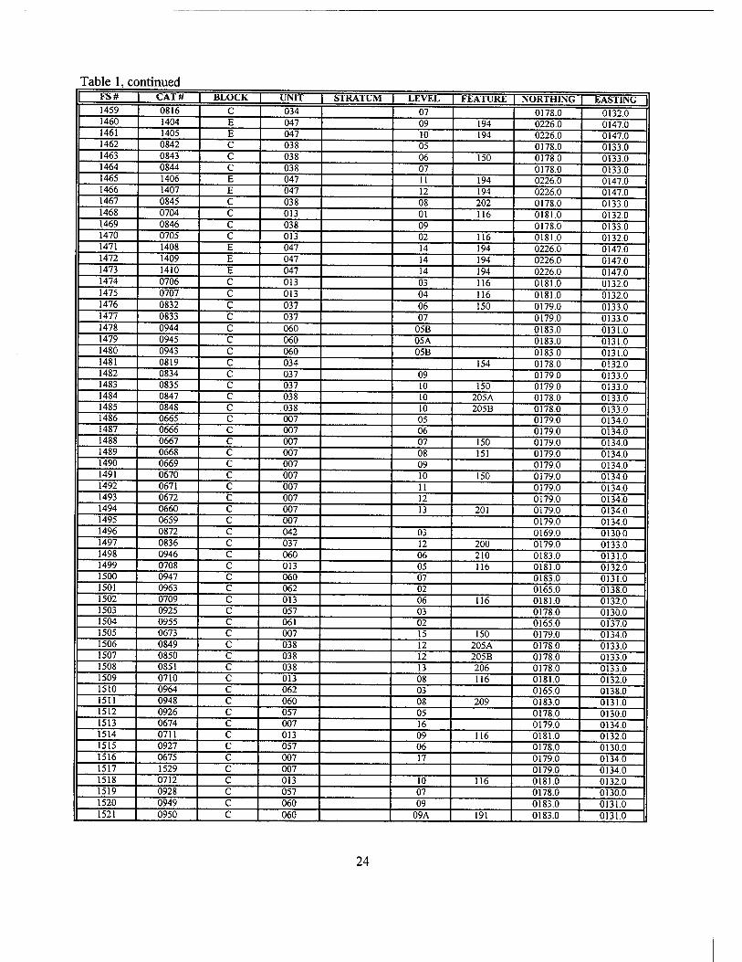
Table 1, continued | FS# CAT# BLOCK | UNIT STRATUM LEVEL FEATURE | NORTHING EASTING
1459 0816 C 034 07 0178.0 0132.0 1460 1404 E 047 09 194 0226.0 0147.0 1461 1405 E 047 10 194 0226.0 0147.0 1462 0842 C 038 05 0178.0 0133.0 1463 0843 C 038 06 150 0178.0 0133.0 1464 0844 C 038 07 0178.0 0133.0 1465 1406 E 047 11 194 0226.0 0147.0 1466 1407 E 047 12 194 0226.0 0147.0 1467 0845 C 038 08 202 0178.0 0133.0 1468 0704 C 013 01 116 0181.0 0132.0 1469 0846 C 038 09 0178.0 0133.0 1470 0705 C 013 02 116 0181.0 0132.0 1471 1408 E 047 14 194 0226.0 0147.0 1472 1409 E 047 14 194 0226.0 0147.0 1473 1410 E 047 14 194 0226.0 0147.0 1474 0706 C 013 03 116 0181.0 0132.0 1475 0707 C 013 04 116 0181.0 0132.0 1476 0832 C 037 06 150 0179.0 0133.0 1477 0833 C 037 07 0179.0 0133.0 1478 0944 C 060 05B 0183.0 0131.0 1479 0945 C 060 05A 0183.0 0131.0 1480 0943 C 060 05B 0183.0 0131.0 1481 0819 C 034 154 0178.0 0132.0 1482 0834 C 037 09 0179.0 0133.0 1483 0835 C 037 10 150 0179.0 0133.0 1484 0847 C 038 10 205A 0178.0 0133.0 1485 0848 C .038 10 205B 0178.0 0133.0 1486 0665 C 007 05 0179.0 0134.0 1487 0666 C 007 06 0179.0 0134.0 1488 0667 C 007 07 150 0179.0 0134.0 1489 0668 C 007 08 151 0179.0 0134.0 1490 0669 C 007 09 0179.0 0134.0 1491 0670 C 007 10 150 0179.0 0134.0 1492 0671 c 007 11 0179.0 0134.0 1493 0672 c 007 12 0179.0 0134.0 1494 0660 c 007 13 201 0179.0 0134.0 1495 0659 c 007 0179.0 0134.0 1496 0872 c 042 03 0169.0 0130.0 1497 0836 c 037 12 200 0179.0 0133.0 1498 0946 c 060 06 210 0183.0 0131.0 1499 0708 c 013 05 116 0181.0 0132.0 1500 0947 c 060 07 0183.0 0131.0 1501 0963 c 062 02 0165.0 0138.0 1502 0709 c 013 06 116 0181.0 0132.0 1503 0925 c 057 03 0178.0 0130.0 1504 0955 c 061 02 0165.0 0137.0 1505 0673 c 007 15 150 0179.0 0134.0 1506 0849 c 038 12 205A 0178.0 0133.0 1507 0850 c 038 12 205B 0178.0 0133.0 1508 0851 c 038 13 206 0178.0 0133.0 1509 0710 c 013 08 116 0181.0 0132.0 1510 0964 c 062 03 0165.0 0138.0 1511 0948 c 060 08 209 0183.0 0131.0 1512 0926 c 057 05 0178.0 0130.0 1513 0674 c 007 16 0179.0 0134.0 1514 0711 c 013 09 116 0181.0 0132.0 1515 0927 c 057 06 0178.0 0130.0 1516 0675 c 007 17 0179.0 0134.0 1517 1529 c 007 0179.0 0134.0 1518 0712 c 013 10 116 0181.0 0132.0 1519 0928 c 057 07 0178.0 0130.0 1520 0949 c 060 09 0183.0 0131.0 1521 0950 c 060 09A 191 0183.0 0131.0
24
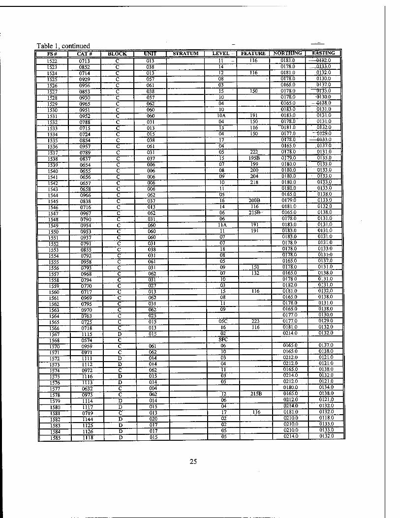
Table 1, continued I FS# | CAT# | BLOCK UNIT | STRATUM | LEVEL | FEATURE NORTHING 1 EASTING |
1522 0713 C 013 11 - 116 0181.0 0132.0
1523 0852 c 038 14 0178.0 0133.0
1524 0714 c 013 12 116 0181.0 0132.0
1525 0929 c 057 08 0178.0 0130.0
1526 0956 c 061 03 0165.0 0137.0
1527 0853 c 038 15 - 150 0178.0 —0133.0
1528 0930 c 057 10 0178.0 -0130.0
1529 0965 c 062 04 0165.0 —01-38.0
1530 0951 c 060 10 0183.0 0131.0
1531 0952 c 060 10A 191 0183.0 0131.0
1532 0788 c 031 04 150 0178.0 0131.0
1533 0715 c 013 13 116 "0181.0 "0132.0
1534 0724 c 015 04 150 0177.0 —0129.0
1535 0854 c 038 17 0178.0 0133 0
1536 0957 c 061 04 0165.0 -Q137.0
1537 0789 c 031 05 222 0178.0 0131.0
1538 0837 c 037 15 195B 0179.0 0133.0
1539 0654 c 006 07 199 0180.0 0133.0
1540 0655 c 006 08 200 0180.0 —0133.0
1541 0656 c 006 09 204 0180.0 - 0133.0
1542 0657 c 006 10 218 0180.0 0133.0
1543 0658 c 006 11 0180.0 0133.0
1544 0966 c 062 05 0165.0 0138.0
1545 0838 c 037 16 200B 0179.0 0133.0
1546 0716 c 013 14 116 0181.0 0132.0
1547 0967 c 062 06 215B- 0165.0 0138.0
1548 0790 c 031. 06 0178.0 0131.0
1549 0954 c 060 11A 191 0183.0 0131.0
1550 0953 c 060 11 191 0183.0 0131.0
1551 0937 c 060 07 0183.0 0131.0
1552 0791 c 031 07 0178.0 0131.0
1553 0855 c 038 18 0178.0 0133.0
1554 0792 c 031 08 0178.0 0131:0
1555 0958 c 061 05 0165.0 0137.0
1556 0793 c 031 09 150 0178.0 0131.0
1557 0968 c 062 07 132 0165.0 0138.0
1558 0794 c 031 10 0178.0 0131.0
1559 0770 c 027 03 0182.0 0131.0
1560 0717 c 013 15 116 0181.0 0132.0
1561 0969 c 062 08 0165.0 0138.0
1562 0795 c 031 11 0178.0 0131.0
1563 0970 c 062 09 0165.0 0138.0
1564 0763 c 025 0177.0 0130.0
1565 0725 c 015 05C 223 0177.0 0129.0
1566 0718 c 013 16 116 0181.0 0132.0
1567 1115 D 015 02 0214.0 0132.0
1568 0574 c SFC 1570 0959 c 061 06 0165.0 0137.0
1571 0971 c 062 10 0165.0 0138.0
1572 1111 D 014 03 0212.0 0121.0
1573 1112 D 014 04 0212.0 0121.0
1574 0972 c 062 11 0165.0 0138.0
1575 1116 D 015 03 0214.0 0132.0
1576 1113 D 014 05 0212.0 0121.0
1577 0632 c 004 0180.0 0134.0
1578 0973 c 062 12 215B 0165.0 0138.0
1579 1114 D 014 06 0212.0 0121.0
1580 1117 D 015 04 0214.0 0132.0
1581 0719 C 013 17 116 0181.0 0132.0
1582 1144 D 020 02 0210.0 0118.0
1583 1125 D 017 02 0210.0 0133.0
1584 1126 D 017 05 0210.0 0133.0
1585 1118 D 015 05 0214.0 0132.0
25
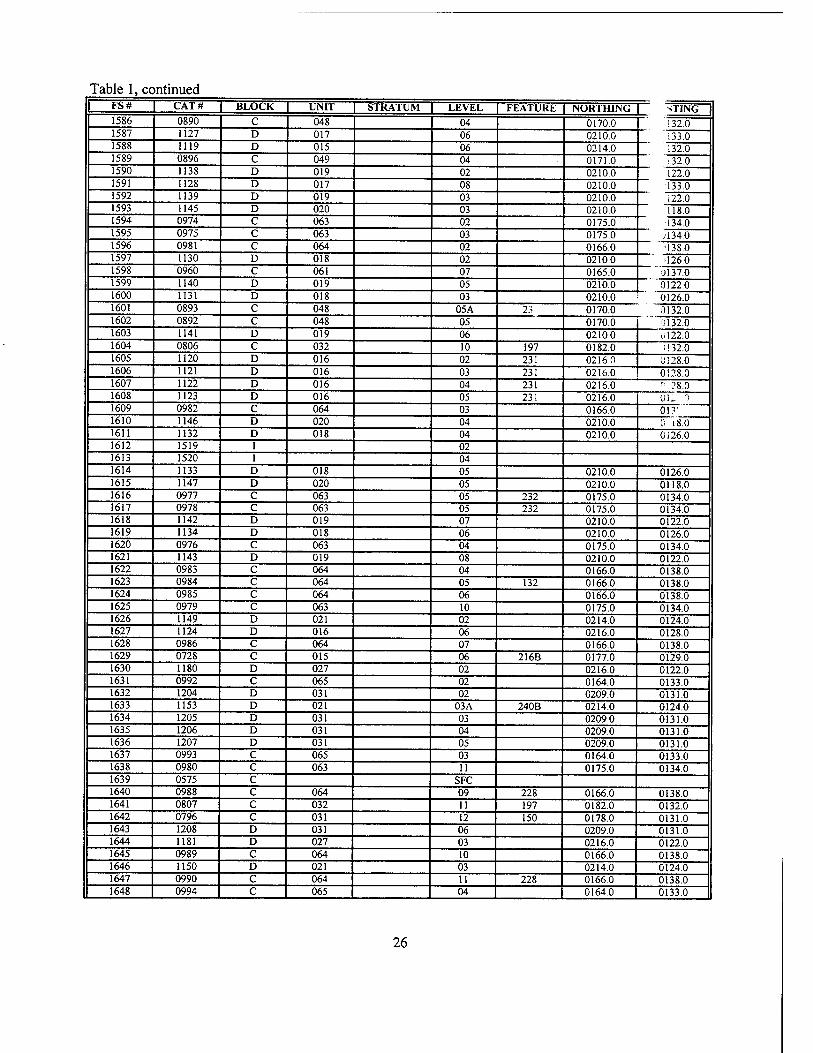
Table 1, continued I FS# CAT# BLOCK UNIT | STRATUM | LEVEL FEATURE NORTHING STING |
1586 0890 C 048 04 0170.0 132.0 1587 1127 D 017 06 0210.0 133.0 1588 1119 D 015 06 0214.0 132.0 1589 0896 C 049 04 0171.0 ;32.0 1590 1138 D 019 02 0210.0 122.0 1591 1128 D 017 08 0210.0 133.0 1592 1139 D 019 03 0210.0 122.0 1593 1145 D 020 03 0210.0 118.0 1594 0974 C 063 02 0175.0 134.0 1595 0975 C 063 03 0175.0 J134.0 1596 0981 C 064 02 0166.0 '138.0 1597 1130 D 018 02 0210.0 ,'126.0 1598 0960 C 061 07 0165.0 0137.0 1599 1140 D 019 05 0210.0 0122.0 1600 1131 D 018 03 0210.0 0126.0 1601 0893 C 048 05A 23. 0170.0 0132.0 1602 0892 C 048 05 0170.0 0132.0 1603 1141 D 019 06 0210.0 0122.0 1604 0806 C 032 10 197 0182.0 1132.0 1605 1120 D 016 02 231 0216.0 0128.0 1606 1121 D 016 03 231 0216.0 0128.0 1607 1122 D 016 04 231 0216.0 r.?8.0 1608 1123 D 016 05 231 0216.0 ÜU 0 1609 0982 C 064 03 0166.0 013' 1610 1146 D 020 04 0210.0 0 18.0 1611 1132 D 018 04 0210.0 0126.0 1612 1519 1 02 1613 1520 I 04 1614 1133 D 018 05 0210.0 0126.0 1615 1147 D 020 05 0210.0 0118.0 1616 0977 C 063 05 232 0175.0 0134.0 1617 0978 C 063 05 232 0175.0 0134.0 1618 1142 D 019 07 0210.0 0122.0 1619 1134 D 018 06 0210.0 0126.0 1620 0976 C 063 04 0175.0 0134.0 1621 1143 D 019 08 0210.0 0122.0 1622 0983 C 064 04 0166.0 0138.0 1623 0984 C 064 05 132 0166.0 0138.0 1624 0985 C 064 06 0166.0 0138.0 1625 0979 C 063 10 0175.0 0134.0 1626 1149 D 021 02 0214.0 0124.0 1627 1124 D 016 06 0216.0 0128.0 1628 0986 C 064 07 0166.0 0138.0 1629 0728 C 015 06 216B 0177.0 0129.0 1630 1180 D 027 02 0216.0 0122.0 1631 0992 C 065 02 0164.0 0133.0 1632 1204 D 031 02 0209.0 0131.0 1633 1153 D 021 03A 240B 0214.0 0124.0 1634 1205 D 031 03 0209.0 0131.0 1635 1206 D 031 04 0209.0 0131.0 1636 1207 D 031 05 0209.0 0131.0 1637 0993 C 065 03 0164.0 0133.0 1638 0980 C 063 11 0175.0 0134.0 1639 0575 C SFC 1640 0988 C 064 09 228 0166.0 0138.0 1641 0807 C 032 11 197 0182.0 0132.0 1642 0796 C 031 12 150 0178.0 0131.0 1643 1208 D 031 06 0209.0 0131.0 1644 1181 D 027 03 0216.0 0122.0 1645 0989 C 064 10 0166.0 0138.0 1646 1150 D 021 03 0214.0 0124.0 1647 0990 C 064 11 228 0166.0 0138.0 1648 0994 C 065 04 0164.0 0133.0
26
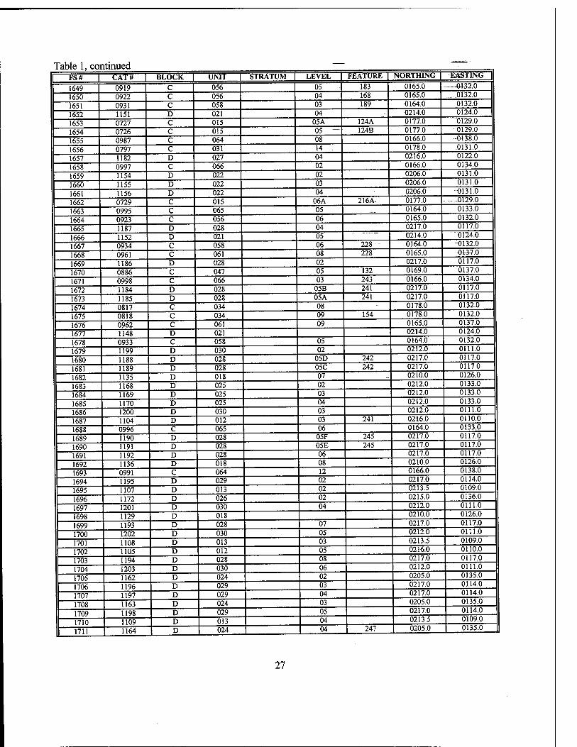
Table 1, continued FS# I CAT# | BLOCK L UNIT | STRATUM | LEVEL | FEATURE | NORTHING | EASTING |
1649 0919 C 056 05 183 0165.0 013'' 0
1650 0922 c 056 04 168 0165.0 0132.0
1651 0931 c 058 03 189 0164.0 0132.0
1652 1151 D 021 04 0214.0 0124.0
1653 0727 C 015 05A 124A 0177.0 "0129.0
1654 0726 C 015 05 — 124B 0177.0 0129.0
1655 0987 C 064 08 0166.0 -0138.0
1656 0797 C 031 14 . 0178.0 0131.0
1657 1182 D 027 04 0216.0 0122.0
1658 0997 C 066 02 0166.0 0134.0
1659 1154 D 022 02 0206.0 0131.0
1660 1155 D 022 03 0206.0 0131.0
1661 1156 D 022 04 0206.0 0131.0
1662 0729 C 015 06A 216A 0177.0 0129.0
1663 0995 C 065 05 0164.0 0133.0
1664 0923 C 056 06 0165.0 0132.0
1665 1187 D 028 04 0217.0 0117.0
1666 1152 D 021 05 0214.0 0124.0
1667 0934 C 058 06 228 0164.0 0132.0
1668 0961 C 061 08 228 0165.0 £«7.0
1669 1186 D 028 02 0217.0 0117.0
1670 0886 C 047 05 132 0169.0 0137.0
1671 0998 C 066 03 243 0166.0 0134.0
1672 1184 D 028 05B 241 0217.0 0117.0
1673 1185 D 028 05A 241 0217.0 0117.0
1674 0817 C 034 08 - 0178.0 0132.0
1675 0818 C .034 09 154 0178.0 0132.0
1676 0962 C 061 09 0165.0 0137.0
1677 1148 D 021 0214.0 0124.0
1678 0933 C 058 05 0164.0 0132.0
1679 1199 D 030 02 0212.0 0111.0
1680 1188 D 028 05D 242 0217.0 0117.0
1681 1189 D 028 05C 242 0217.0 0117.0
1682 1135 D 018 07 -. 0210.0 0126.0
1683 1168 D 025 02 0212.0 0133.0
1684 1169 D 025 03 0212.0 0133.0
1685 1170 D 025 04 0212.0 0133.0
1686 1200 D 030 03 0212.0 0111.0
1687 1104 D 012 03 241 0216.0 0110.0
1688 0996 C 065 06 0164.0 0133.0
1689 1190 D 028 05F 245 0217.0 0117.0
1690 1191 D 028 05E 245 0217.0 0117.0
1691 1192 D 028 06 0217.0 0117.0
1692 1136 D 018 08 0210.0 0126.0
1693 0991 C 064 12 0166.0 0138.0
1694 1195 D 029 02 0217.0 0114.0
1695 1107 D 013 02 0213.5 0109.0
1696 1172 D 026 02 0215.0 0136.0
1697 1201 D 030 04 0212.0 0111.0
1698 1129 D 018 0210.0 0126.0
1699 1193 D 028 07 0217.0 0117.0
1700 1202 D 030 05 0212.0 0111.0
1701 1108 D 013 03 0213.5 0109.0
1702 1105 D 012 05 0216.0 0110.0
1703 1194 D 028 08 0217.0 0117.0
1704 1203 D 030 06 0212.0 0111.0
1705 1162 D 024 02 0205.0 0135.0
1706 1196 D 029 03 0217.0 0114.0
1707 1197 D 029 04 0217.0 0114.0
1708 1163 D 024 03 0205.0 0135.0
1709 1198 D 029 05 0217.0 0114.0
1710 1109 D 013 04 0213.5 0109.0
1711 1164 D 024 | 04 247 0205.0 0135.0
27
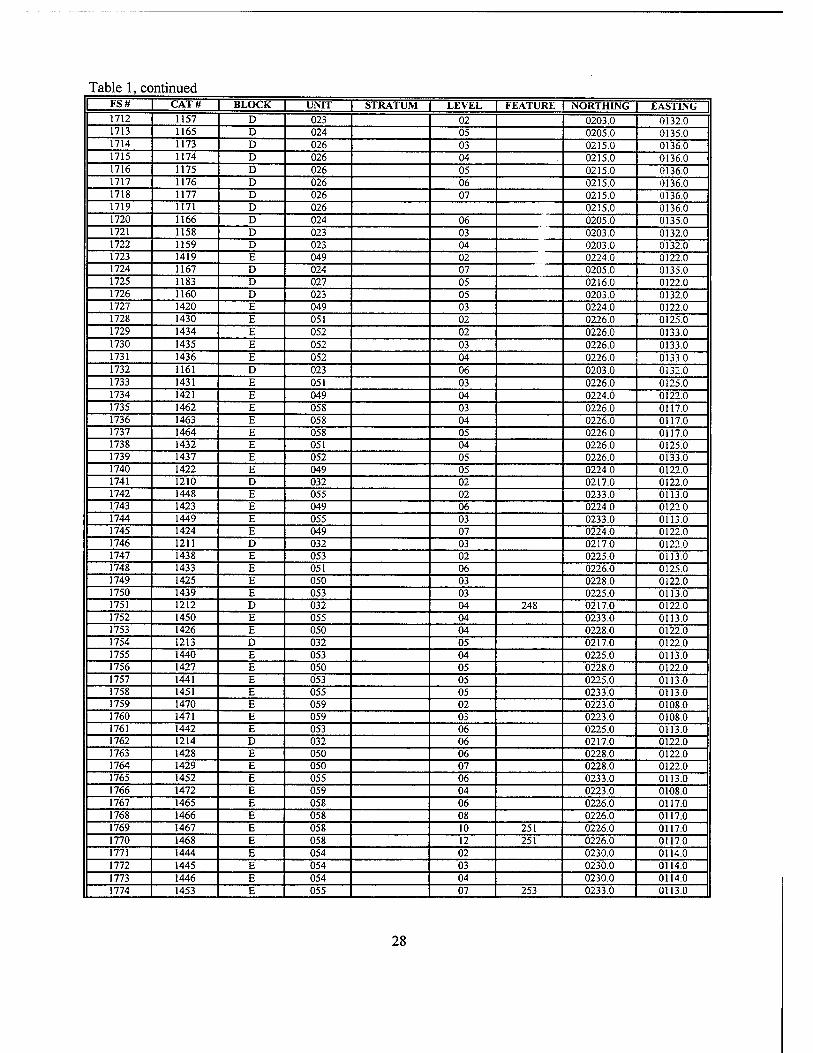
Table 1, continued FS# CAT# BLOCK UNIT STRATUM LEVEL FEATURE NORTHING EASTING 1712 1157 D 023 02 0203.0 0132.0 1713 1165 D 024 05 0205.0 0135.0 1714 1173 D 026 03 0215.0 0136.0 1715 1174 D 026 04 0215.0 0136.0 1716 1175 D 026 05 0215.0 0136.0 1717 1176 D 026 06 0215.0 0136.0 1718 1177 D 026 07 0215.0 0136.0 1719 1171 D 026 0215.0 0136.0 1720 1166 D 024 06 0205.0 0135.0 1721 1158 D 023 03 0203.0 0132.0 1722 1159 D 023 04 0203.0 0132.0 1723 1419 E 049 02 0224.0 0122.0 1724 1167 D 024 07 0205.0 0135.0 1725 1183 D 027 05 0216.0 0122.0 1726 1160 D 023 05 0203.0 0132.0 1727 1420 E 049 03 0224.0 0122.0 1728 1430 E 051 02 0226.0 0125.0 1729 1434 E 052 02 0226.0 0133.0 1730 1435 E 052 03 0226.0 0133.0 1731 1436 E 052 04 0226.0 01330 1732 1161 D 023 06 0203.0 0132.0 1733 1431 E 051 03 0226.0 0125.0 1734 1421 E 049 04 0224.0 0122.0 1735 1462 E 058 03 0226.0 0117.0 1736 1463 E 058 04 0226.0 0117.0 1737 1464 E 058 05 0226.0 0117.0 1738 1432 E 051 04 0226.0 0125.0 1739 1437 E 052 05 0226.0 0133.0 1740 1422 E 049 05 0224.0 0122.0 1741 1210 D 032 02 0217.0 0122.0 1742 1448 E 055 02 0233.0 0113.0 1743 1423 E 049 06 0224.0 01220 1744 1449 E 055 03 0233.0 0113.0 1745 1424 E 049 07 0224.0 01220 1746 1211 D 032 03 0217.0 0122.0 1747 1438 E 053 02 0225.0 0113.0 1748 1433 E 051 06 0226.0 0125.0 1749 1425 E 050 03 0228.0 0122.0 1750 1439 E 053 03 0225.0 0113.0 1751 1212 D 032 04 248 0217.0 0122.0 1752 1450 E 055 04 0233.0 0113.0 1753 1426 E 050 04 0228.0 0122.0 1754 1213 D 032 05 0217.0 0122.0 1755 1440 E 053 04 0225.0 0113.0 1756 1427 E 050 05 0228.0 0122.0 1757 1441 E 053 05 0225.0 0113.0 1758 1451 E 055 05 0233.0 0113.0 1759 1470 E 059 02 0223.0 0108.0 1760 1471 E 059 03 0223.0 0108.0 1761 1442 E 053 06 0225.0 0113.0 1762 1214 D 032 06 0217.0 0122.0 1763 1428 E 050 06 0228.0 0122.0 1764 1429 E 050 07 0228.0 0122.0 1765 1452 E 055 06 0233.0 0113.0 1766 1472 E 059 04 0223.0 0108.0 1767 1465 E 058 06 0226.0 0117.0 1768 1466 E 058 08 0226.0 0117.0 1769 1467 E 058 10 251 0226.0 0117.0 1770 1468 E 058 12 251 0226.0 0117.0 1771 1444 E 054 02 0230.0 0114.0 1772 1445 E 054 03 0230.0 0114.0 1773 1446 E 054 04 0230.0 0114.0 1774 1453 E 055 07 253 0233.0 0113.0
28
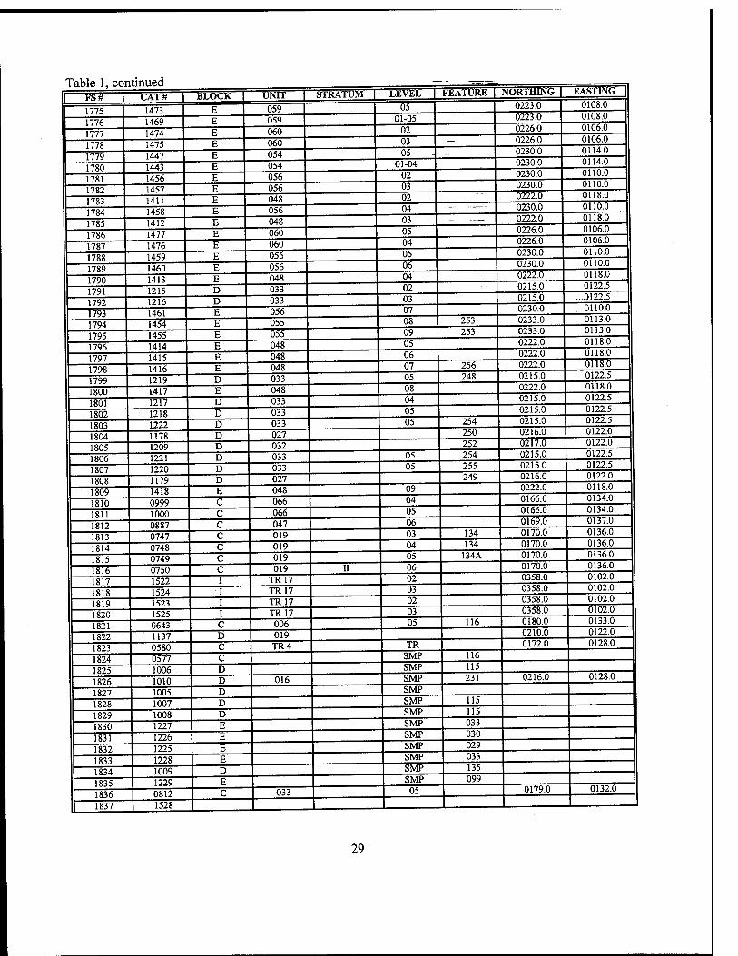
Table 1, continued LEVEL 1 FEATURE | NORTHING | EASTING |
1775
LAI » |
1473
BLOCK | E 059 05 0223.0 0108.0
1776 1469 E 059 01-05 0223.0 0108.0
1777 1474 E 060 02 03
0226.0 0226.0
0106.0 0106.0
1778 1779
1475 1447
fa E 054 05 ... 0230.0 0114.0
1780 1443 E 054 01-04 0230.0 0114.0
1781 1456 E 056 02 0230.0 0110.0
1782 1457 E 056 03 0230.0 0110.0
1783 1411 E 048 02 0222.0 0118.0
1784 1458 E 056 04 - — 0230.0 0110.0
1785 1412 E 048 03 — 0222.0 0118.0
1786 1477 E 060 05 0226.0 0106.0
1787 1476 E 060 04 0226.0 0230 0
0106.0 0110.0
1788 1789
1459 1460
E E
056 056 06 0230.0 0110.0
1790 1413 E 048 04 0222.0 0118.0
1791 1215 D 033 02 0215.0 0122.5
1792 1216 D 033 03 0215.0 - .-0122.5
1793 1461 E 056 07 0230.0 0110.0
1794 1454 E 055 08 253 0233.0 0113.0
1795 1455 E 055 09 253 0233.0 0113.0
1796 1414 E 048 05 0222.0 0118.0
1797 1415 E 048 06 0222.0 0118.0
1798 1416 E 048 07 256 0222.0 0118.0
1799 1219 D 033 05 248 0215.0 0122.5
1800 1417 E 048 08 0222.0 0118.0
1801 1217 D 033 04 0215.0 0122.5
1802 1218 D 033 05 0215.0 0122.5
1803 1222 D 033 05 254 0215.0 0122.5
1804 1178 D 027 250 0216.0 0122.0
1805 1209 D 032 252 0217.0 0122.0
1806 1221 D 033 05 254 0215.0 0122.5
1807 1220 D 033 05 255 0215.0 0122.5
1808 1179 D 027 249 0216.0 0122.0
1809 1418 E 048 09 0222.0 0118.0
1810 0999 C 066 04 0166.0 0134.0
1811 1000 C 066 05 0166.0 0134.0
1812 0887 C 047 06 0169.0 0137.0
1813 0747 C 019 03 134 0170.0 0136.0
1814 0748 C 019 04 134 0170.0 0136.0
1815 0749 C 019 05 134A 0170.0 0136.0
1816 0750 C 019 II 06 0170.0 0136.0
1817 1522 I TR17 02 0358.0 0102.0
1818 1524 I TR17 03 0358.0 0102.0
1819 1523 I TR17 02 0358.0 0102.0
1820 1525 I TR17 03 0358.0 0102.0
1821 0643 C 006 05 116 0180.0 0133.0
1822 1137 D 019 0210.0 0122.0
1823 0580 C TR4 TR 0172.0 0128.0
1824 0577 C SMP 116
1825 1006 D SMP 115
1826 1010 D 016 SMP 231 0216.0 0128.0
1827 1005 D SMP
1828 1007 D SMP 115
1829 1008 D SMP 115
1830 1227 E SMP 033
1831 1226 E SMP 030
1832 1225 E SMP 029 033 1833
1834 1228 1009
E D SMP 135
1835 1229 E SMP 099
1836 0812 C 033 05 0179.0 0132.0
1837 1528 . J_ u
29
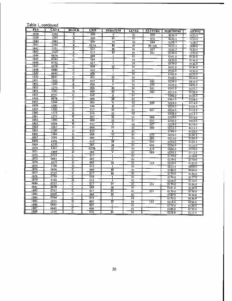
Table 1, continued FS# CAT# BLOCK UNIT | STRATUM LEVEL FEATURE NORTHING VSTING 1838 1292 E 009 V 01 070 0236.0 0123.0 1839 1291 E 009 IV 01 070 0236.0 0123.0 1840 1085 D 006 VI 02 084 0209.5 ai28.5 1841 1344 E 027A HI 01 96-100 0225.5 0109.0 1842 1331 E 023 in 01 037 0226.5 0120.5 1843 1320 E 017 HI 01 031 0239.0 1153.0 1844 0676 C 008 i 01 0161.0 0134.0 1845 0744 C 019 i 01 0120.0 0136.0 1846 0732 C 017 i 01 0179.0 0136.0 1847 0678 C 008 in 01 0161.0 0134.0 1848 0686 C 010 i 01 0166.0 0130.0 1849 0645 C 006 i 01 0180.0 0133.0 1850 0641 C 005 HI 01 0168.0 0134.0 1851 1302 E 014 ii 01 026 0228.0 0116.0 1852 1283 E 008 V 01 070 0239.0 0120.5 1853 1275 E 006 HI 01 051 0241.0 0115.1 1854 1095 D 009 HI 01 085 0213.0 0126.0 1855 0751 C 020 n 01 0186.0 0126.0 1856 0678 C 008 HI 01 0161.0 0134.0 1857 1244 E 001 X 02 048 0224.0 0114.0 1858 1380 E 036 Ü 01 0235.0 0120.5 1859 1320 E 017 HI 01 031 0239.0 0115.0 1860 1315 E 016 HI 02 0238.0 0113.5 1861 1277 E 007 III 01 066 0239.0 0118.0 1862 1290 E 009 HI 01 035 0236.0 0123.0 1863 0504 E 013 II 02 027 0229.0 0119.0 1864 1067 D .004 IV 01 089 0214.5 0113.5 1865 1100 D 010 II 01 0198.0 0128.0 1866 1284 E 008 VI 01 070 0239.0 0130.5 1867 1093 D 009 I 01 085 0213.0 0126.0 1868 1296 E 010 III 01 034 0234.0 0123.5 1869 1270 E 005 HI 01 030 0236.0 0116.0 1870 1347 E 027B HI 01 119 0226.0 0109.0 1871 1069 D 004 V 01 089 0214.5 0113.5 1872 0732 C 017 I 01 0179.0 0136.0 1873 0661 C 007 I 01 0179.0 0134.0 1874 1075 D 005 III 01 115 0218.0 0123.0 1875 1106 D 013 I 01 0213.5 0109.0 1876 0636 C 004 HI 01 0180.0 0134.0 1877 0735 C 017 HI 01 0179.0 0136.0 1878 0739 C 018 I 01 0174.0 0117.0 1879 1102 D 012 I 01 0216.0 0110.0 1880 0737 C 017 IV 01 131 0179.0 0136.0 1881 0678 C 008 HI 01 0161.0 0134.0 1882 0737 C 017 IV 01 131 0179.0 0136.0 1883 0509 C 004 HI 02 0180.0 0134.0 1884 0744 C 019 I 01 0170.0 0136.0 1885 1075 D 005 HI 01 115 0218.0 0126.0 1886 0661 C 007 I 01 0179.0 0134.0 1887 0645 C 006 I 01 0180.0 0133.0 1888 1314 C 016 HI 01 0238.0 0113.5
30
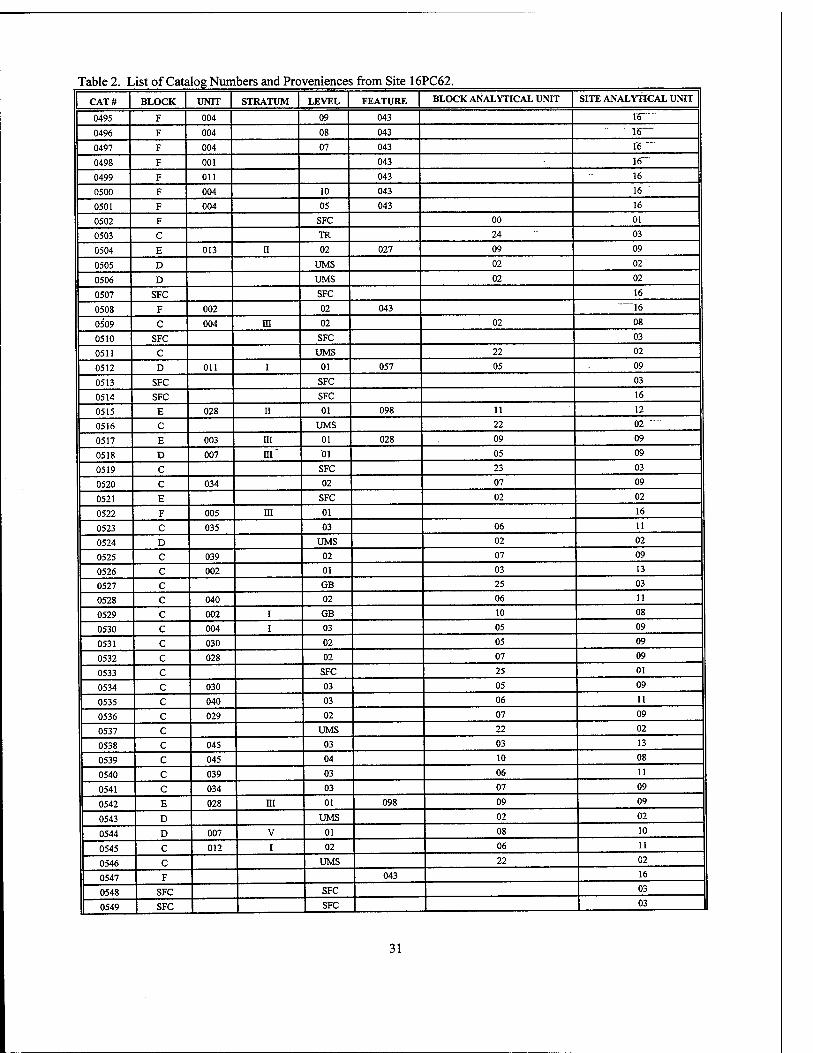
Table 2. List of Catalog Numbers and Proveniences from Site 16PC62.
CAT# BLOCK UNIT STRATUM LEVEL FEATURE BLOCK ANALYTICAL UNIT SITE ANALYTICAL UNIT
0495 F 004 09 043 re""™
0496 F 004 08 043 ~16—
0497 F 004 07 043 16"
0498 F 001 043 re 0499 F Oil 043 16"
0500 F 004 10 043 16
0501 F 004 05 043 16
0502 F SFC 00 01 "
0503 C TR 24 03
0504 E 013 n 02 027 09 09
0505 D UMS 02 02""
0506 D UMS 02 02
0507 SFC SFC 16
0508 F 002 02 043 16
0509 C 004 in 02 02 08
0510 SFC SFC 03
0511 C UMS 22 02
0512 D 011 i 01 057 05 09
0513 SFC SFC 03
0514 SFC SFC 16
0515 E 028 ii 01 098 11 12
0516 C UMS 22 02
0517 E 003 m 01 028 09 09
0518 D 007 m" 01 05 09
0519 C SFC 23 03
0520 C 034 02 07 09
0521 E SFC 02 02
0522 F 005 m 01 16
0523 C 035 03 06 11
0524 D UMS 02 02
0525 C 039 02 07 09
0526 C 002 01 03 13
0527 C GB 25 03
0528 C 040 02 06 11
0529 C 002 i GB 10 08
0530 C 004 i 03 05 09
0531 C 030 02 05 09
0532 C 028 02 07 09
0533 c SFC 25 01
0534 c 030 03 05 09
0535 c 040 03 06 11
0536 c 029 02 07 09
0537 c UMS 22 02
0538 c 045 03 03 13
0539 c 045 04 10 08
0540 c 039 03 06 11
0541 c 034 03 07 09
0542 E 028 in 01 098 09 09
0543 D UMS 02 02
0544 D 007 V 01 08 10
0545 C 012 i 02 06 11
0546 C UMS 22 02
0547 F 043 16
0548 SFC SFC 03
0549 SFC SFC 03
31
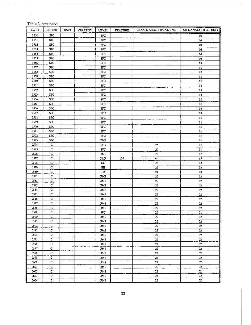
Table 2, continued
CAT# BLOCK UNIT STRATUM LEVEL FEATURE BLOCK ANALYTICAL UNIT SITE ANALYTICAL UNIT
0550 SFC SFC 03
0551 SFC SFC 01
0552 SFC SFC 01
0553 SFC SFC 01
0554 SFC SFC 01
0555 SFC SFC 01
0556 SFC SFC 01
0557 SFC SFC 01
0558 SFC SFC 01
0559 SFC SFC 01
0560 SFC SFC 01
0561 SFC SFC 01
0562 SFC SFC 01
0563 SFC SFC 01
0564 SFC SFC 01
0565 SFC SFC 01
0566 SFC SFC 01
0567 SFC SFC 01
0568 SFC SFC 01
0569 SFC SFC 01
0570 SFC SFC 01
0571 SFC SFC 01
0572 SFC SFC 01
0573 SFC UMS 01
0574 C SFC 25 01
0575 C SFC 25 01
0576 C UMS 22 02
0577 C SMP 116 04 15
0578 C GB 25 03
0579 C GB 25 03
0580 C TR 24 03
0581 C UMS 22 02
0582 C UMS 22 02
0583 C UMS 22 02
0584 C UMS 22 02
0585 C UMS 22 02
0586 C UMS 22 02
0587 C UMS 22 02
0588 C UMS 22 02
0589 C SFC 25 01
0590 c UMS 22 02
0591 c UMS 22 02
0592 c UMS 22 02
0593 c UMS 22 02
0594 c UMS 22 02
0595 c UMS 22 02
0596 c UMS 22 02
0597 c UMS 22 02
0598 c UMS 22 02
0599 c UMS 22 02
0600 c UMS 22 02
0601 c UMS 22 02
0602 c UMS 22 02
0603 c UMS 22 02
0604 c UMS 22 02
32
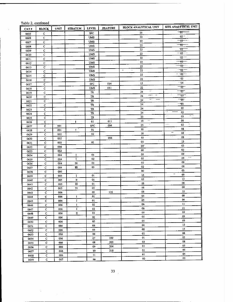
Table 2, cc »ntinued
CAT# BLOCK UNIT STRATUM LEVEL FEATURE BLOCK ANALYTICAL UNIT SITE ANALYTICAL UNIT
0605 C SFC 25 -=0T=
0606 c UMS 22 —02—
0607 c UMS 22 —02
0608 c UMS 22 —02
0609 c UMS 22 -02
0610 c UMS 22 —02
0611 c UMS 22 -02—
0612 c UMS 22 02—
0613 c UMS 22 02
0614 c UMS 22 —02—
0615 c UMS 22 "-02—
0616 c UMS 22 —02"
0617 c SFC 014 13 04
0618 c UMS Oil 22 —02—
0619 c TR 24 03"
0620 c TR 24 " 03
0621 c TR 24 - —03"
0622 c TR 24 —03
0623 c TR 24 03
0624 c TR 24 - — 03
0625 c TR 23 03
0626 c I 01 Oil 10 - 08
0627 c 001 SFC 004 25 02
0628 c 001 I 01 10 08
0629 c 002 02 10 ~ 08
0630 c 002 006 10 08
0631 c 003 01 03 13
0632 c 004 otr 03
0633 c 004 00 03
0634 c 004 I 01 05 09
0635 c 004 I 02 05 09 "
0636 c 004 m 01 02 08
0637 c 004 m 03 02 08
0638 c 005 00 03
0639 c 005 i 01 16 09
0640 c 005 n 01 03 13
0641 c 005 m 01 18 08
0642 c 005 IV 01 18 08
0643 c 006 05 116 08 15
0644 c 006 i 01 05 09
0645 c 006 i 01 05 09
0646 c 006 i 02 06 11
0647 c 006 i 02 06 11
0648 c 006 n 01 05 09
0649 c 006 02 05 09
0650 c 006 03 05 09
0651 c 006 04 04 15
0652 c 006 05 08 15
0653 c 006 06 02 08
0654 c 006 07 199 01 05
0655 c 006 08 200 02 08
0656 c 006 09 204 01 05
0657 c 006 10 218 01 05
0658 c 006 11 01 05
0659 c 007 na 00 03
33
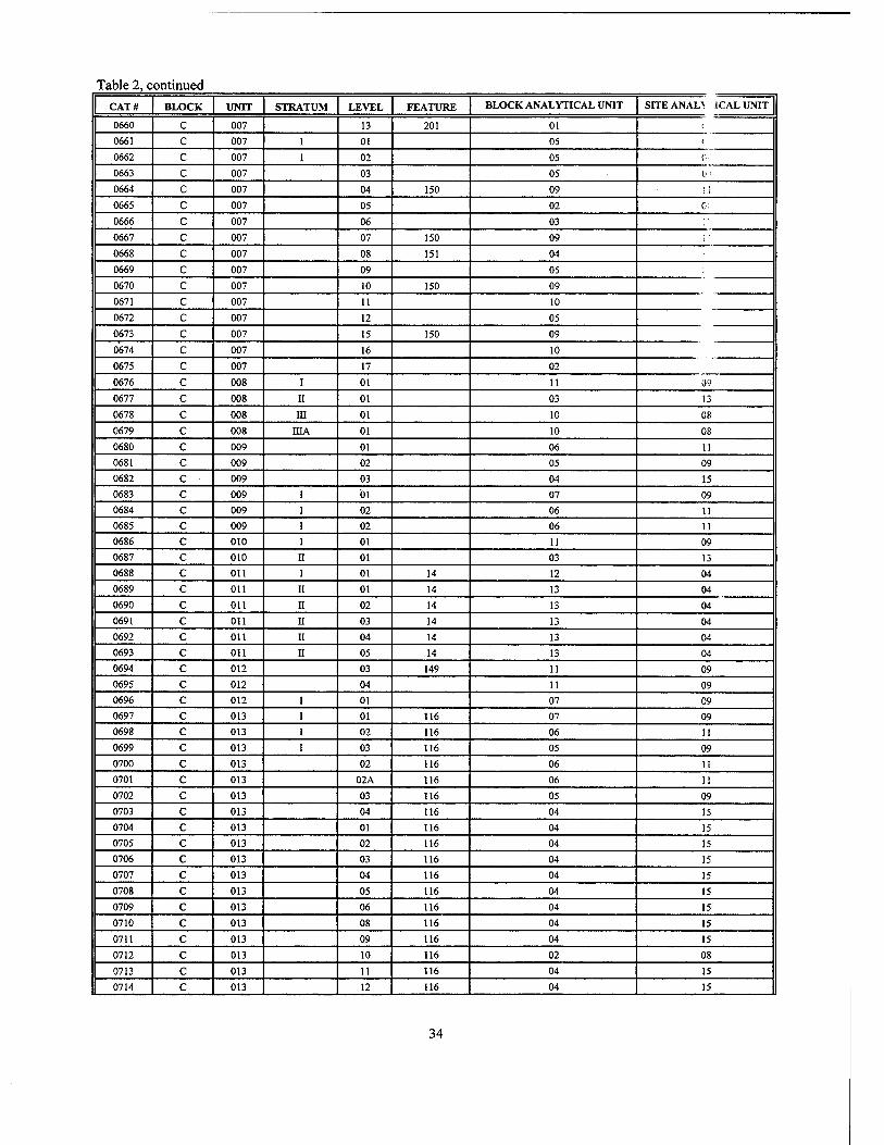
Table 2, continued
CATS BLOCK UNIT STRATUM LEVEL FEATURE BLOCK ANALYTICAL UNIT SITE ANAL1: IC AL UNIT
0660 C 007 13 201 01 {
0661 c 007 I 01 05 i
0662 c 007 I 02 05 ('■■
0663 c 007 03 05 0'
0664 c 007 04 150 09 i;
0665 c 007 05 02 C:
0666 c 007 06 03 ;■
0667 c 007 07 150 09
0668 c 007 08 151 04 ! 0669 c 007 09 05
0670 c 007 10 150 09
0671 c 007 11 10
0672 c 007 12 05
0673 c 007 15 150 09
0674 c 007 16 10
0675 c 007 17 02
0676 c 008 I 01 11 09
0677 c 008 II 01 03 13
0678 c 008 in 01 10 08
0679 c 008 niA 01 10 08
0680 c 009 01 06 11 0681 c 009 02 05 09
0682 c 009 03 04 15 0683 c 009 i 01 07 09 0684 c 009 i 02 06 11 0685 c 009 i 02 06 11 0686 c 010 i 01 11 09 0687 c 010 ii 01 03 13 0688 c Oil i 01 14 12 04
0689 c Oil II 01 14 13 04
0690 c Oil II 02 14 13 04
0691 c Oil II 03 14 13 04
0692 c Oil II 04 14 13 04
0693 c Oil II 05 14 13 04 0694 c 012 03 149 11 09 0695 c 012 04 11 09 0696 c 012 i 01 07 09 0697 c 013 i 01 116 07 09 0698 c 013 i 02 116 06 11
0699 c 013 i 03 116 05 09 0700 c 013 02 116 06 11 0701 c 013 02A 116 06 11
0702 c 013 03 116 05 09 0703 c 013 04 116 04 15 0704 c 013 01 116 04 15
0705 c 013 02 116 04 15
0706 c 013 03 116 04 15
0707 c 013 04 116 04 15
0708 c 013 05 116 04 15
0709 c 013 06 116 04 15
0710 c 013 08 116 04 15
0711 c 013 09 116 04 15
0712 c 013 10 116 02 08
0713 c 013 11 116 04 15
0714 c 013 12 116 04 15
34
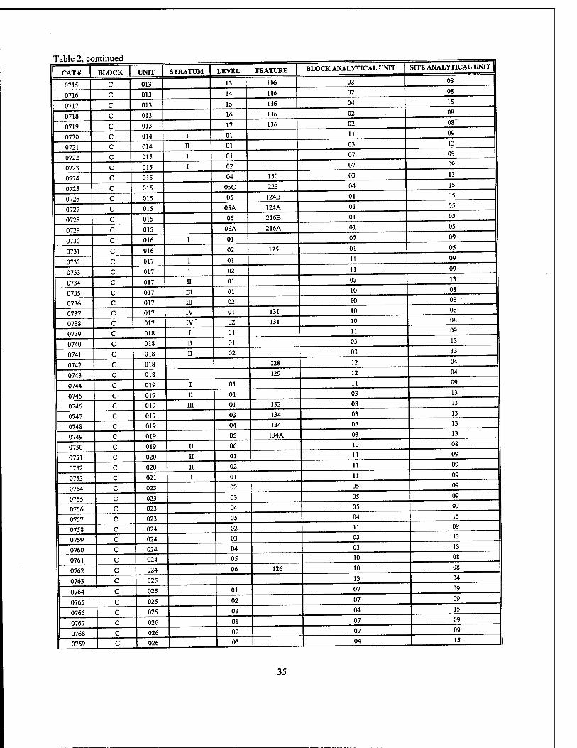
Table 2, continued
CAT# BLOCK UNIT STRATUM LEVEL FEATURE BLOCK ANALYTICAL UNIT SITE ANALYTICAL UNIT
0715 C 013 13 116 02 08
0716 c 013 14 116 02 08
0717 c 013 15 116 04 15
0718 c 013 16 116 02 08
0719 c 013 17 116 02 08
0720 c 014 I 01 11 09
0721 c 014 n 01 03 13
0722 c 015 i 01 07 09
0723 c 015 i 02 07 09
0724 c 015 04 150 03 13
0725 c 015 05C 223 04 15
0726 c 015 05 124B 01 05
0727 c 015 05A 124A 01 05
0728 c 015 06 216B 01 05
0729 c 015 06A 216A 01 05
0730 c 016 i 01 07 09
0731 c 016 02 125 01 05
0732 c 017 i 01 11 09
0733 c 017 i 02 11 09
0734 c 017 ii 01 03 13
0735 c 017 m 01 10 08
0736 c 017 ni 02 10 08
0737 c 017 IV 01 131 10 08
0738 c 017 IV" 02 131 10 08
0739 c 018 i 01 11 09
0740 c 018 ii 01 03 13
0741 c 018 ii 02 03 13
0742 c 018 128 12 04
0743 c 018 129 12 04
0744 c 019 i 01 11 09
0745 c 019 n 01 03 13
0746 c 019 in 01 132 03 13
0747 c 019 03 134 03 13
0748 c 019 04 134 03 13
0749 c 019 05 134A 03 13
0750 c 019 II 06 10 08
0751 c 020 II 01 11 09
0752 c 020 n 02 11 09
0753 c 021 i 01 11 09
0754 c 023 02 05 09
0755 c 023 03 05 09
0756 c 023 04 05 09
0757 c 023 05 04 15
0758 c 024 02 11 09
0759 c 024 03 03 13
0760 c 024 04 03 13
0761 c 024 05 10 08
0762 c 024 06 126 10 08
0763 c 025 13 04
0764 c 025 01 07 09
0765 c 025 02 07 09
0766 c 025 03 04 15
0767 c 026 01 07 09
0768 c 026 02 07 09
0769 c 026 03 04 15
35
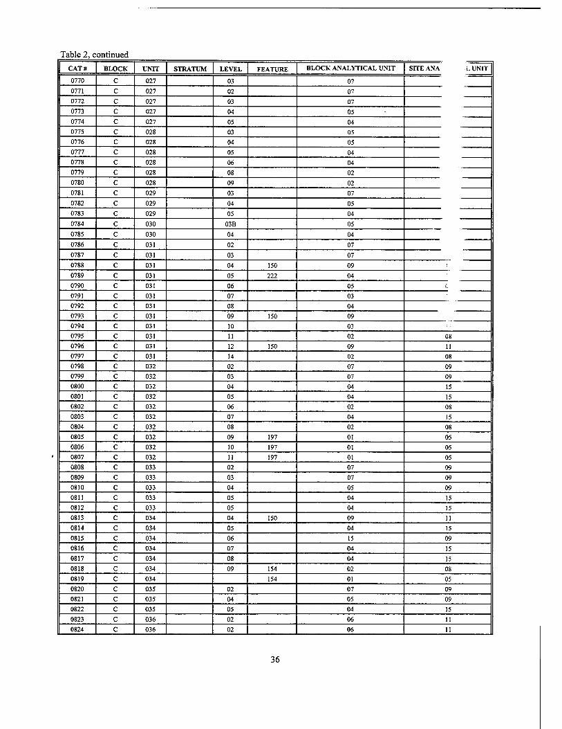
Table 2, continued
CATS BLOCK UNIT STRATUM LEVEL FEATURE BLOCK ANALYTICAL UNIT SITE ANA i.UNIT
0770 C 027 03 07 0771 c 027 02 07
0772 c 027 03 07 0773 c 027 04 05 0774 c 027 05 04 0775 c 028 03 05 0776 c 028 04 05 0777 c 028 05 04 0778 c 028 06 04 0779 c 028 08 02
0780 c 028 09 02
0781 c 029 03 07
0782 c 029 04 05
0783 c 029 05 04
0784 c 030 03B 05
0785 c 030 04 04
0786 c 031 02 07
0787 c 031 03 07
0788 c 031 04 150 09
0789 c 031 05 222 04
0790 c 031 06 05 0 0791 c 031 07 03
0792 c 031 08 04
0793 c 031 09 150 09 0794 c 031 10 03
0795 c 031 11 02 08
0796 c 031 12 150 09 11 0797 c 031 14 02 08 0798 c 032 02 07 09 0799 c 032 03 07 09 0800 c 032 04 04 15 0801 c 032 05 04 15 0802 c 032 06 02 08
0803 c 032 07 04 15 0804 c 032 08 02 08
0805 c 032 09 197 01 05
0806 c 032 10 197 01 05
0807 c 032 11 197 01 05 0808 c 033 02 07 09
0809 c 033 03 07 09
0810 c 033 04 05 09
0811 c 033 05 04 15
0812 c 033 05 04 15
0813 c 034 04 150 09 11
0814 c 034 05 04 15
0815 c 034 06 15 09 0816 c 034 07 04 15 0817 c 034 08 04 15
0818 c 034 09 154 02 08
0819 c 034 154 01 05
0820 c 035 02 07 09
0821 c 035 04 05 09
0822 c 035 05 04 15
0823 c 036 02 06 11
0824 c 036 02 06 11
36
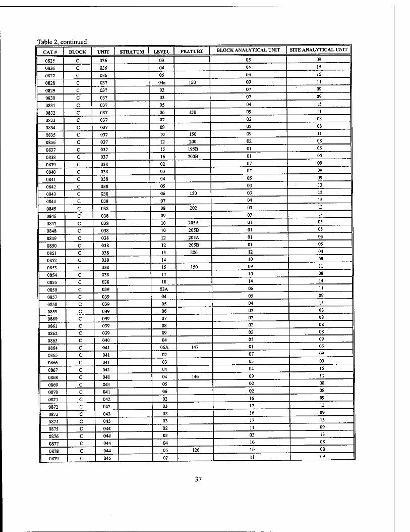
Table 2, continued
CAT# BLOCK UNIT STRATUM LEVEL FEATURE BLOCK ANALYTICAL UNIT SITE ANALYTICAL UNIT
0825 C 036 03 05 09
0826 c 036 04 04 15
0827 c 036 05 04 15
0828 c 037 04a 150 09 11
0829 c 037 02 07 09
0830 c 037 03 07 09
0831 c 037 05 04 15
0832 c 037 06 150 09 11
0833 c 037 07 02 08
0834 c 037 09 02 08
0835 c 037 10 150 09 11
0836 c 037 12 200 02 08
0837 c 037 15 195B 01 05
0838 c 037 16 200B 01 05
0839 c 038 02 07 09
0840 c 038 03 07 09
0841 c 038 04 05 09
0842 c 038 05 03 13
0843 c 038 06 150 03 13
0844 c 038 07 04 15
0845 c 038 08 202 03 13
0846 c 038 09 03 13
0847 c 038 10 205A 01 05
0848 c 038 10 205B 01 05
0849 c 038 12 205A 01 05
0850 c 038 12 205B 01 05
0851 c 038 13 206 12 04
0852 c 038 14 10 08
0853 c 038 15 150 09 11
0854 c 038 17 10 08
0855 c 038 18 14 14
0856 c 039 03A 06 11
0857 c 039 04 05 09
0858 c 039 05 04 15
0859 c 039 06 02 08
0860 c 039 07 02 08
0861 c 039 08 02 08
0862 c 039 09 02 08
0863 c 040 04 05 09
0864 c 041 06A 147 01 05
0865 c 041 02 07 09
0866 c 041 03 05 09
0867 c 041 04 04 15
0868 c 041 04 146 09 11
0869 c 041 05 02 08
0870 c 041 06 02 08
0871 c 042 02 16 09
0872 c 042 03 17 13
0873 c 043 02 16 09
0874 c 043 03 17 13
0875 c 044 02 11 09
0876 c 044 03 03 13
0877 c 044 04 10 08
0878 c 044 05 126 10 08
0879 c 045 02 11 09
37
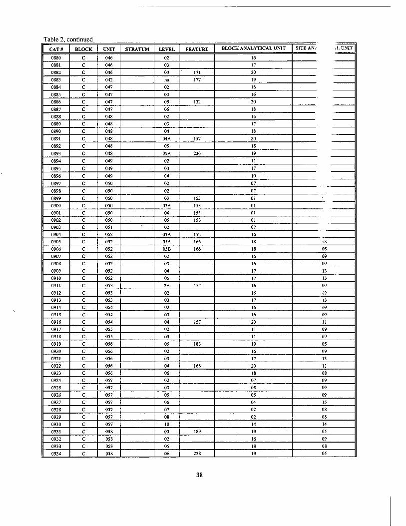
Table 2, continued
CAT# BLOCK UNIT STRATUM LEVEL FEATURE BLOCK ANALYTICAL UNIT SITE AN/ XUNIT
0880 C 046 02 16
0881 c 046 03 17
0882 c 046 04 171 20
0883 c 042 na 177 19
0884 c 047 02 16
0885 c 047 03 16
0886 c 047 05 132 20
0887 c 047 06 18
0888 c 048 02 16
0889 c 048 03 17
0890 c 048 04 18
0891 c 048 04A 157 20
0892 c 048 05 18
0893 c 048 05A 230 19
0894 c 049 02 11
0895 c 049 03 17
0896 c 049 04 10
0897 c 050 02 07
0898 c 050 02 07
0899 c 050 03 153 01 ! 0900 c 050 03A 153 01
0901 c 050 04 153 01
0902 c 050 05 153 01
0903 c 051 02 07
0904 c 052 03A 152 16
0905 c 052 05A 166 18 OS
0906 c 052 05B 166 18 08
0907 c 052 02 16 09
0908 c 052 03 16 09
0909 c 052 04 17 13
0910 c 052 05 17 13
0911 c 053 2A 152 16 09
0912 c 053 02 16 09
0913 c 053 03 17 13
0914 c 054 02 16 09
0915 c 054 03 16 09
0916 c 054 04 157 20 11
0917 c 055 02 11 09
0918 c 055 03 11 09
0919 c 056 05 183 19 05
0920 c 056 02 16 09
0921 c 056 03 17 13
0922 c 056 04 168 20 11
0923 c 056 06 18 08
0924 c 057 02 07 09
0925 c 057 03 05 09
0926 c 057 05 05 09
0927 c 057 06 04 15
0928 c 057 07 02 08
0929 c 057 08 02 08
0930 c 057 10 14 14
0931 c 058 03 189 19 05
0932 c 058 02 16 09
0933 c 058 05 18 08
0934 c 058 06 228 19 05
38
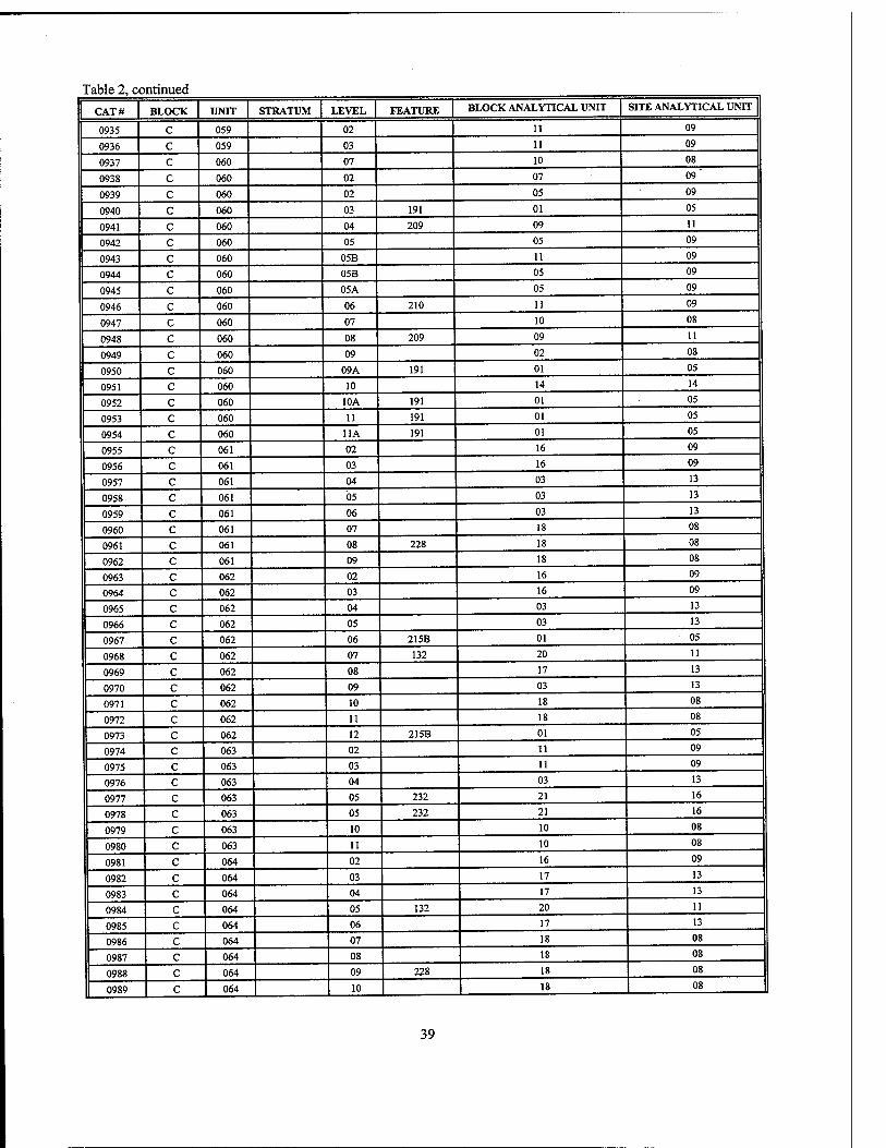
Table 2, continued
CAT# BLOCK UNIT STRATUM LEVEL FEATURE BLOCK ANALYTICAL UNIT SITE ANALYTICAL UNIT
0935 C 059 02 11 09
0936 c 059 03 11 09
0937 c 060 07 10 08
0938 c 060 02 07 09
0939 c 060 02 05 09
0940 c 060 03 191 01 05
0941 c 060 04 209 09 11
0942 c 060 05 05 09
0943 c 060 05B 11 09
0944 c 060 05B 05 09
0945 c 060 05A 05 09
0946 c 060 06 210 11 09
0947 c 060 07 10 08
0948 c 060 08 209 09 11
0949 c 060 09 02 08
0950 c 060 09A 191 01 05
0951 c 060 10 14 14
0952 c 060 10A 191 01 05
0953 c 060 11 191 01 05
0954 c 060 11A 191 01 05
0955 c 061 02 16 09
0956 c 061 03 16 09
0957 c 061 04 03 13
0958 c 061 05 03 13
0959 c 061 06 03 13
0960 c 061 07 18 08
0961 c 061 08 228 18 08
0962 c 061 09 18 08
0963 c 062 02 16 09
0964 c 062 03 16 09
0965 c 062 04 03 13
0966 c 062 05 03 13
0967 c 062 06 215B 01 05
0968 c 062 07 132 20 11
0969 c 062 08 17 13
0970 c 062 09 03 13
0971 c 062 10 18 08
0972 c 062 11 18 08
0973 c 062 12 215B 01 05
0974 c 063 02 11 09
0975 c 063 03 11 09
0976 c 063 04 03 13
0977 c 063 05 232 21 16
0978 c 063 05 232 21 16
0979 c 063 10 10 08
0980 c 063 11 10 08
0981 c 064 02 16 09
0982 c 064 03 17 13
0983 c 064 04 17 13
0984 c 064 05 132 20 11
0985 c 064 06 17 13
0986 c 064 07 18 08
0987 c 064 08 18 08
0988 c 064 09 228 18 08
0989 c 064 10 18 08
39
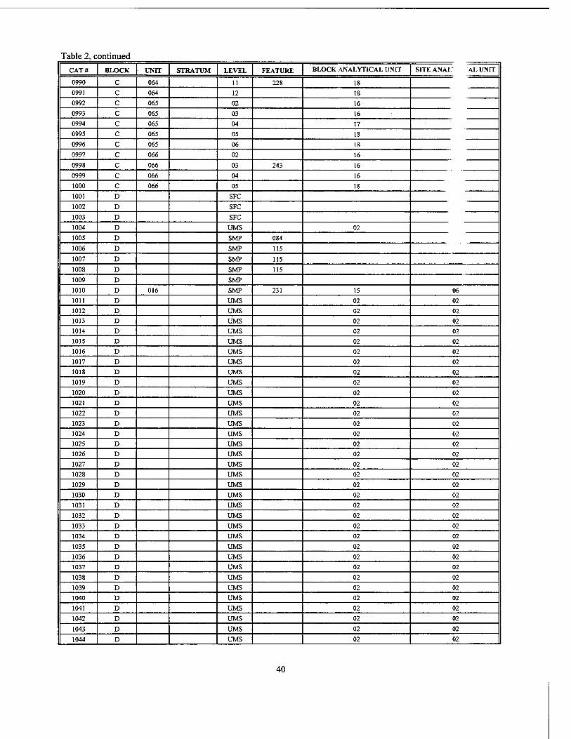
Table 2, continued CAT# BLOCK UNIT STRATUM LEVEL FEATURE BLOCK ANALYTICAL UNIT SITE ANAL' AL UNIT
0990 C 064 11 228 18
0991 c 064 12 18
0992 c 065 02 16
0993 c 065 03 16
0994 c 065 04 17
0995 c 065 05 18
0996 c 065 06 18
0997 c 066 02 16
0998 c 066 03 243 16
0999 c 066 04 16
1000 c 066 05 18
1001 D SFC
1002 D SFC
1003 D SFC
1004 D UMS 02
1005 D SMP 084
1006 D SMP 115
1007 D SMP 115
1008 D SMP 115
1009 D SMP
1010 D 016 SMP 231 15 06
1011 D UMS 02 02
1012 D UMS 02 02
1013 D UMS 02 02
1014 D UMS 02 02
1015 D UMS 02 02
1016 D UMS 02 02
1017 D UMS 02 02
1018 D UMS 02 02
1019 D UMS 02 02
1020 D UMS 02 02
1021 D UMS 02 02
1022 D UMS 02 02
1023 D UMS 02 02
1024 D UMS 02 02
1025 D UMS 02 02
1026 D UMS 02 02
1027 D UMS 02 02
1028 D UMS 02 02
1029 D UMS 02 02
1030 D UMS 02 02
1031 D UMS 02 02
1032 D UMS 02 02
1033 D UMS 02 02
1034 D UMS 02 02
1035 D UMS 02 02
1036 D UMS 02 02
1037 D UMS 02 02
1038 D UMS 02 02
1039 D UMS 02 02
1040 D UMS 02 02
1041 D UMS 02 02
1042 D UMS 02 02
1043 D UMS 02 02
1044 D UMS 02 02
40
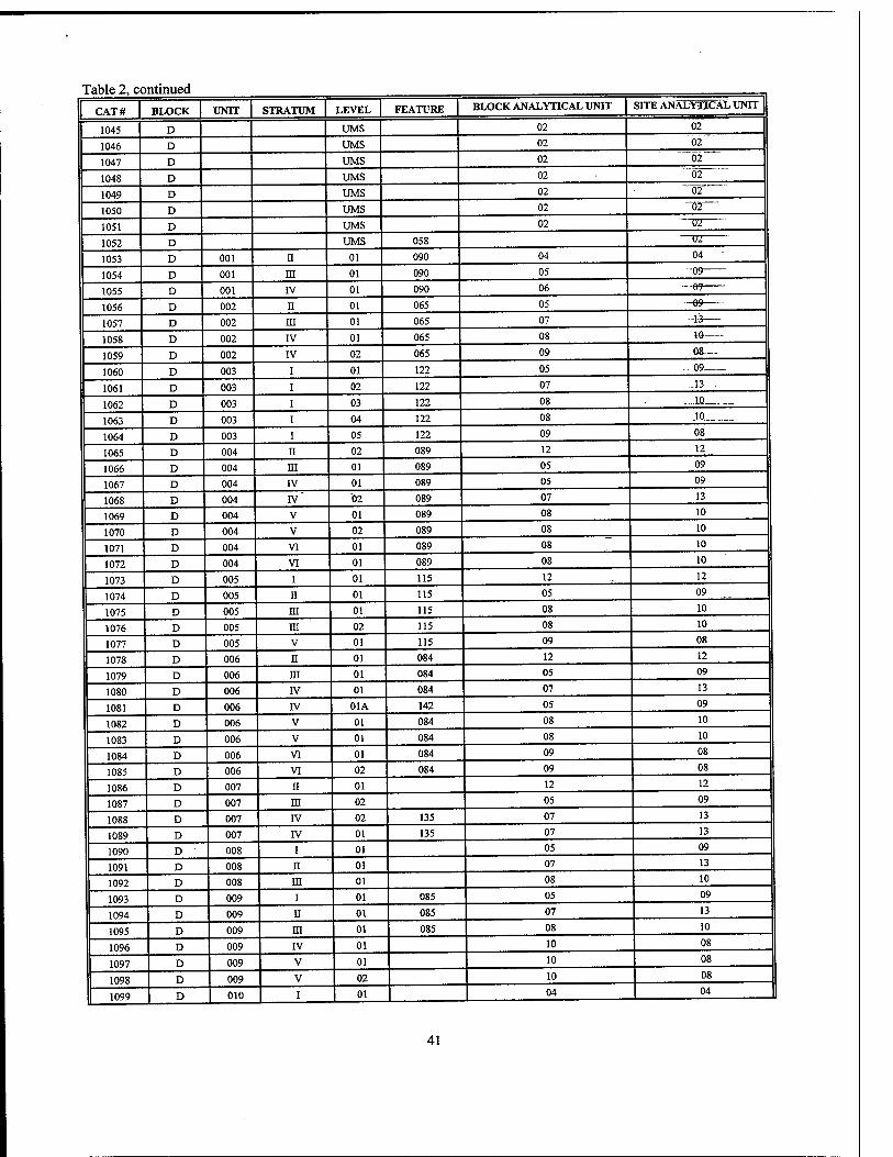
Table 2, continued
CAT# BLOCK UNIT STRATUM LEVEL FEATURE BLOCK ANALYTICAL UNIT SITE ANALYTICAL UNIT
1045 D UMS 02 02
1046 D UMS 02 02
1047 D UMS 02 02
1048 D UMS 02 02
1049 D UMS 02 02
1050 D UMS 02 ~G2
1051 D UMS 02 "ÖT
1052 D UMS 058 U2
1053 D 001 n 01 090 04 04
1054 D 001 ni 01 090 05 -09
1055 D 001 IV 01 090 06 —e?—
1056 D 002 n 01 065 05 -69—-
1057 D 002 ni 01 065 07 -1-3
1058 D 002 IV 01 065 08 10
1059 D 002 IV 02 065 09 08-—
1060 D 003 i 01 122 05 ... ...:09
1061 D 003 i 02 122 07 „J3„.
1062 D 003 i 03 122 08 . ,...10
1063 D 003 i 04 122 08 „10
1064 D 003 i 05 122 09 08_„
1065 D 004 ii 02 089 12 12
1066 D 004 HI 01 089 05 09
1067 D 004 IV 01 089 05 09
1068 D 004 IV 02 089 07 13
1069 D 004 V 01 089 08 10
1070 D 004 V 02 089 08 10
1071 D 004 VI 01 089 08 10
1072 D 004 VI 01 089 08 10
1073 D 005 I 01 115 12 12 ...
1074 D 005 II 01 115 05 09
1075 D 005 ni 01 115 08 10
1076 D 005 m 02 115 08 10
1077 D 005 V 01 115 09 08
1078 D 006 II 01 084 12 12
1079 D 006 m 01 084 05 09
1080 D 006 IV 01 084 07 13
1081 D 006 IV 01A 142 05 09
1082 D 006 V 01 084 08 10
1083 D 006 V 01 084 08 10
1084 D 006 VI 01 084 09 08
1085 D 006 VI 02 084 09 08
1086 D 007 II 01 12 12
1087 D 007 in 02 05 09
1088 D 007 IV 02 135 07 13
1089 D 007 IV 01 135 07 13
1090 D 008 i 01 05 09
1091 D 008 n 01 07 13
1092 D 008 in 01 08 10
1093 D 009 i 01 085 05 09
1094 D 009 n 01 085 07 13
1095 D 009 ni 01 085 08 10
1096 D 009 IV 01 10 08
1097 D 009 V 01 10 08
1098 D 009 V 02 10 08
1099 D 010 1 01 04 04 |
41
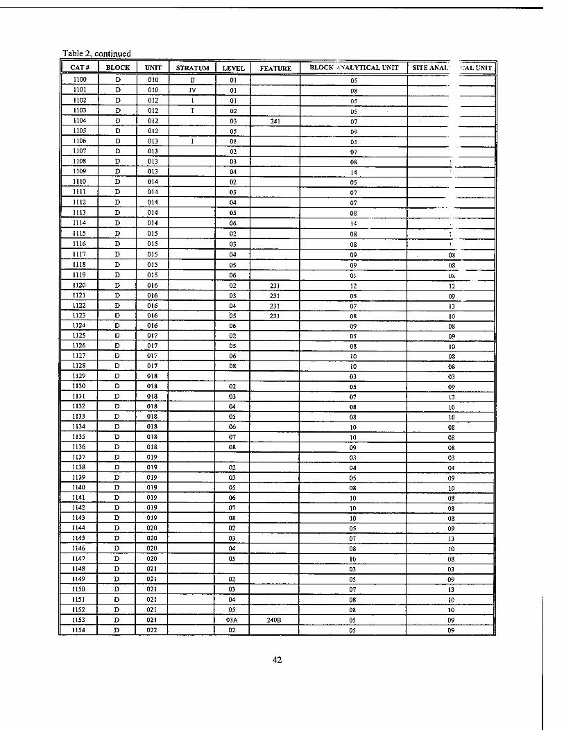
Table 2, continued
CATS BLOCK UNIT STRATUM LEVEL FEATURE BLOCK ANALYTICAL UNIT SITE ANAL CAL UNIT
1100 D 010 n 01 05 1101 D 010 IV 01 08 1102 D 012 i 01 05 1103 D 012 i 02 05 1104 D 012 03 241 07 1105 D 012 05 09 1106 D 013 i 01 05 1107 D 013 02 07 1108 D 013 03 08 1 1109 D 013 04 14 1110 D 014 02 05 1111 D 014 03 07 1112 D 014 04 07 1113 D 014 05 08 1114 D 014 06 14
1115 D 015 02 08 r 1116 D 015 03 08 1
1117 D 015 04 09 08 1118 D 015 05 09 08 1119 D 015 06 01'- 08 1120 D 016 02 231 12 12 1121 D 016 03 231 05 09 1122 D 016 04 231 07 13 1123 D 016 05 231 08 10 1124 D 016 06 09 08 1125 D 017 02 05 09 1126 D 017 05 08 10 1127 D 017 06 10 08 1128 D 017 08 10 08 1129 D 018 03 03 1130 D 018 02 05 09 1131 D 018 03 07 13 1132 D 018 04 08 10 1133 D 018 05 08 10 1134 D 018 06 10 08 1135 D 018 07 10 08 1136 D 018 08 09 08 1137 D 019 03 03 1138 D 019 02 04 04 1139 D 019 03 05 09 1140 D 019 05 08 10 1141 D 019 06 10 08 1142 D 019 07 10 08 1143 D 019 08 10 08 1144 D 020 02 05 09 1145 D 020 03 07 13 1146 D 020 04 08 10 1147 D 020 05 10 08 1148 D 021 03 03 1149 D 021 02 05 09 1150 D 021 03 07 13
1151 D 021 04 08 10
1152 D 021 05 08 10
1153 D 021 03A 240B 05 09
1154 D 022 02 05 09
42
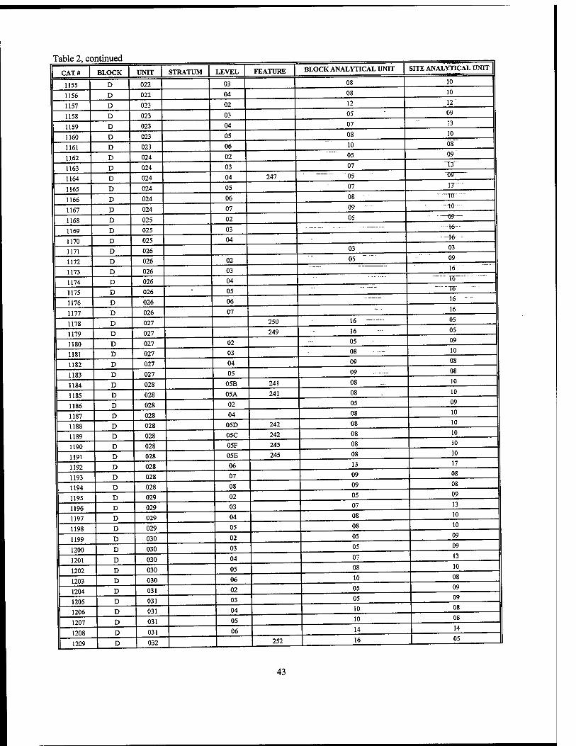
Table 2, co ntinued
CAT# BLOCK UNIT STRATUM LEVEL FEATURE BLOCK ANALYTICAL UNIT SITE ANALYTICAL UNIT
1155 D 022 03 08 10
1156 D 022 04 08 10
1157 D 023 02 12 12'
1158 D 023 03 05 09
1159 D 023 04 07 13
1160 D 023 05 08 10
1161 D 023 06 10 08
1162 D 024 02 05 09
1163 D 024 03 07 T3"
1164 D 024 04 247 " "05 TJ9
1165 D 024 05 07" nr-..-
1166 D 024 06 08 It)- -
1167 D 024 07 09 -to—
1168 D 025 02 05 —99—
1169 D 025 03 —16-
1170 D 025 04 -\(r
1171 D 026 03 03
1172 D 026 02 05 09
1173 D 026 03 16
1174 D 026 04 " 16 '
1175 D 026 • 05 --■ ■
T6
1176 D 026 06 16 - -
1177 D 026 07 - — 16
1178 D 027 250 16 05
1179 D 027 249 16 05
1180 D 027 02 05 09
1181 D 027 03 08 10
1182 D 027 04 09 - - • ■ 08
1183 D 027 05 09 08
1184 D 028 05B 241 08 10
1185 D 028 05A 241 08 10
1186 D 028 02 05 09
1187 D 028 04 08 10
1188 D 028 05D 242 08 10
1189 D 028 05C 242 08 10
1190 D 028 05F 245 08 10
1191 D 028 05E 245 08 10
1192 D 028 06 13 17
1193 D 028 07 09 08
1194 D 028 08 09 08
1195 D 029 02 05 09
1196 D 029 03 07 13
1197 D 029 04 08 10
1198 D 029 05 08 10
1199 D 030 02 05 09
1200 D 030 03 05 09
1201 D 030 04 07 13
1202 D 030 05 08 10
1203 D 030 06 10 08
1204 D 031 02 05 09
1205 D 031 03 05 09
1206 D 031 04 10 08
1207 D 031 05 10 08
1208 D 031 06 14 14
1209 D 032 252 16 05
43
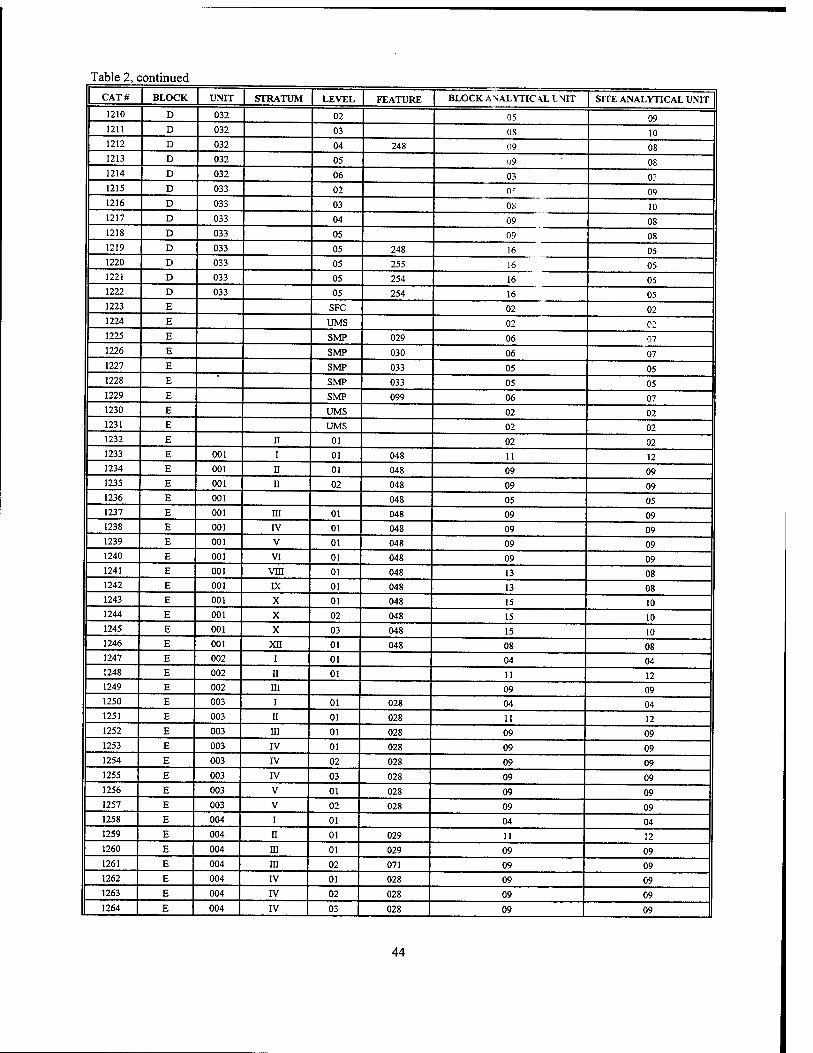
Table 2, continued CATS BLOCK UNIT STRATUM LEVEL FEATURE BLOCK ANALYTICAL I NTT SITE ANALYTICAL UNIT
1210 D 032 02 05 09 1211 D 032 03 OS 10 1212 D 032 04 248 09 08 1213 D 032 05 U9 08 1214 D 032 06 03 03 1215 D 033 02 0? 09 1216 D 033 03 OS 10 1217 D 033 04 09 08 1218 D 033 05 09 08 1219 D 033 05 248 16 05 1220 D 033 05 255 16 05 1221 D 033 05 254 16 05 1222 D 033 05 254 16 05 1223 E SFC 02 02 1224 E UMS 02 02 1225 E SMP 029 06 07 1226 E SMP 030 06 07 1227 E SMP 033 05 05 1228 E SMP 033 05 05 1229 E SMP 099 06 07 1230 E UMS 02 02 1231 E UMS 02 02 1232 E II . 01 02 02 1233 E 001 I 01 048 11 12 1234 E 001 II 01 048 09 09 1235 E 001 II 02 048 09 09 1236 E 001 048 05 05 1237 E 001 m 01 048 09 09 1238 E 001 IV 01 048 09 09 1239 E 001 V 01 048 09 09 1240 E 001 VI 01 048 09 09 1241 E 001 VIII 01 048 13 08 1242 E 001 IX 01 048 13 08 1243 E 001 X 01 048 15 10 1244 E 001 X 02 048 15 10 1245 E 001 X 03 048 15 10 1246 E 001 XII 01 048 08 08 1247 E 002 I 01 04 04 1248 E 002 II 01 11 12 1249 E 002 m 09 09 1250 E 003 i 01 028 04 04 1251 E 003 ii 01 028 11 12 1252 E 003 in 01 028 09 09 1253 E 003 IV 01 028 09 09 1254 E 003 IV 02 028 09 09 1255 E 003 IV 03 028 09 09 1256 E 003 V 01 028 09 09 1257 E 003 V 02 028 09 09 1258 E 004 I 01 04 04 1259 E 004 n 01 029 11 12 1260 E 004 in 01 029 09 09 1261 E 004 m 02 071 09 09 1262 E 004 IV 01 028 09 09 1263 E 004 IV 02 028 09 09 1264 E 004 IV 03 028 09 09
44
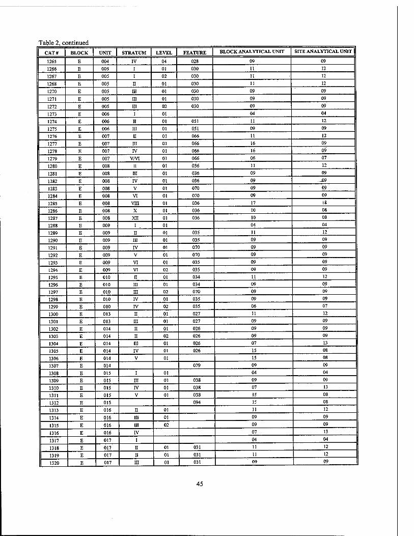
Table 2, continued
CAT# BLOCK UNIT STRATUM LEVEL FEATURE BLOCK ANALYTICAL UNIT SITE ANALYTICAL UNIT
1265 E 004 IV 04 028 09 09
1266 E 005 I 01 030 11 12
1267 E 005 I 02 030 11 12
1268 E 005 n 01 030 11 12
1270 E 005 m 01 030 09 09
1271 E 005 in 01 030 09 09
1272 E 005 in 02 030 09 09
1273 E 006 i 01 04 04
1274 E 006 n 01 051 11 12
1275 E 006 in 01 051 09 09
1276 E 007 H 01 066 11 12
1277 E 007 m 01 066 16 09
1278 E 007 IV 01 066 16 09
1279 E 007 V/VI 01 066 06 07
1280 E 008 ii 01 036 11 12
1281 E 008 m 01 036 09 09
1282 E 008 IV 01 036 09 „09
1283 E 008 V 01 070 09 09
1284 E 008 VI 01 070 09 09
1285 E 008 vni 01 036 17 18
1286 E 008 X 01 036 10 08
1287 E 008 xn 01 036 10 08
1288 E 009 i 01 04 04
1289 E 009 II 01 035 11 12
1290 E 009 in 01 035 09 09
1291 E 009 IV 01 070 09 09
1292 E 009 V 01 070 09 09
1293 E 009 VI 01 035 09 09
1294 E 009 VI 02 035 09 09
1295 E 010 n 01 034 11 12
1296 E 010 m 01 034 09 09
1297 E 010 in 02 070 09 09
1298 E 010 IV 01 035 09 09
1299 E 010 IV 02 035 06 07
1300 E 013 n 01 027 11 12
1301 E 013 m 01 027 09 09
1302 E 014 II 01 026 09 09
1303 E 014 n 02 026 09 09
1304 E 014 ra 01 026 07 13
1305 E 014 IV 01 026 15 08
1306 E 014 V 01 15 08
1307 E 014 079 09 09
1308 E 015 i 01 04 04
1309 E 015 ra 01 038 09 09
1310 E 015 IV 01 038 07 13
1311 E 015 V 01 038 15 08
1312 E 015 094 15 08
1313 E 016 n 01 11 12
1314 E 016 m 01 09 09
1315 E 016 in 02 09 09
1316 E 016 rv 07 13
1317 E 017 i 04 04
1318 E 017 n 01 031 11 12
1319 E 017 n 01 031 11 12
1320 E 017 ni 01 031 09 1 09
45
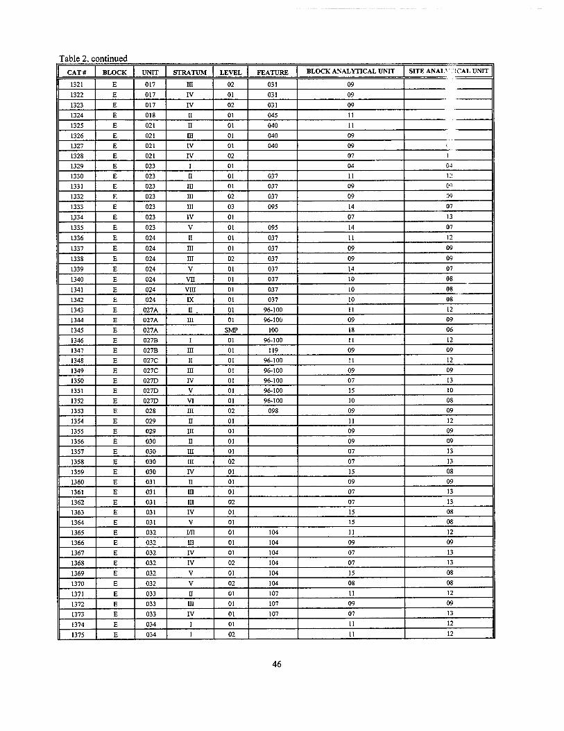
Table 2, continued
CAT# BLOCK UNIT STRATUM LEVEL FEATURE BLOCK ANALYTICAL UNIT SITE ANALV !CAL UNIT
1321 E 017 m 02 031 09
1322 E 017 IV 01 031 09
1323 E 017 IV 02 031 09
1324 E 018 H 01 045 11
1325 E 021 n 01 040 11
1326 E 021 m 01 040 09
1327 E 021 IV 01 040 09 ( 1328 E 021 IV 02 07 ]
1329 E 023 i 01 04 04
1330 E 023 n 01 037 11 12
1331 E 023 in 01 037 09 0'-)
1332 E 023 in 02 037 09 09
1333 E 023 in 03 095 14 07
1334 E 023 IV 01 07 13
1335 E 023 V 01 095 14 07
1336 E 024 n 01 037 11 12
1337 E 024 HI 01 037 09 09
1338 E 024 m 02 037 09 09
1339 E 024 V 01 037 14 07
1340 E 024 vn 01 037 10 08
1341 E 024 VIII 01 037 10 08
1342 E 024 K 01 037 10 08
1343 E 027A n . 01 96-100 11 12
1344 E 027A m 01 96-100 09 09
1345 E 027A SMP 100 18 06
1346 E 027B i 01 96-100 11 12
1347 E 027B in 01 119 09 09
1348 E 027C ii 01 96-100 11 12
1349 E 027C in 01 96-100 09 09
1350 E 027D IV 01 96-100 07 13
1351 E 027D V 01 96-100 15 10
1352 E 027D VI 01 96-100 10 08
1353 E 028 III 02 098 09 09
1354 E 029 n 01 11 12
1355 E 029 HI 01 09 09
1356 E 030 II 01 09 09
1357 E 030 in 01 07 13
1358 E 030 in 02 07 13
1359 E 030 IV 01 15 08
1360 E 031 n 01 09 09
1361 E 031 HI 01 07 13
1362 E 031 m 02 07 13
1363 E 031 IV 01 15 08
1364 E 031 V 01 15 08
1365 E 032 MI 01 104 11 12
1366 E 032 in 01 104 09 09
1367 E 032 IV 01 104 07 13
1368 E 032 IV 02 104 07 13
1369 E 032 V 01 104 15 08
1370 E 032 V 02 104 08 08
1371 E 033 u 01 107 11 12
1372 E 033 HI 01 107 09 09
1373 E 033 IV 01 107 07 13
1374 E 034 I 01 11 12
1375 E 034 I 02 11 12
46
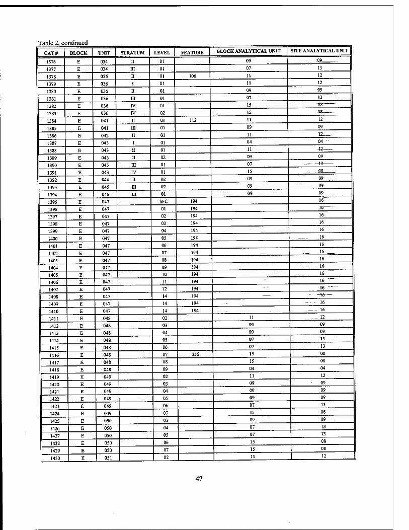
Table 2, continued
CAT# BLOCK UNIT STRATUM LEVEL FEATURE BLOCK ANALYTICAL UNIT SITE ANALYTICAL UNIT
1376 E 034 II 01 09 09—
1377 E 034 m 01 07 13
1378 E 035 n 01 106 11 12
1379 E 036 i 01 11 12
1380 E 036 n 01 09 09
1381 E 036 m 01 07 13
1382 E 036 IV 01 15 "08
1383 E 036 IV 02 15
1384 E 041 n 01 112 11 12
1385 E 041 in 01 09 09
1386 E 042 n 01 11 12
1387 E 043 i 01 04 04
1388 E 043 ii 01 11 .12
1389 E 043 ii 02 09 09
1390 E 043 m 01 07 1-3
1391 E 043 IV 01 15 08
1392 E 044 II 02 09 09
1393 E 045 m 02 09 09
1394 E 046 ni 01 09 09
1395 E 047 SFC 194 16
1396 E 047 01 194 16
1397 E 047 02 194 16
1398 E 047 03 194 16
1399 E 047 04 194 16
1400 E 047 05 194 . ..._16.. .
1401 E 047 06 194 16
1402 E 047 07 194 16 __.
1403 E 047 08 194 16
1404 E 047 09 194 16
1405 E 047 10 194 16
1406 E 047 11 194 16
1407 E 047 12 194 16
1408 E 047 14 194 -16-—
1409 E 047 14 194 —■
16
1410 E 047 14 194 ... 16
1411 E 048 02 11 .__ 12
1412 E 048 03 09 09
1413 E 048 04 09 09
1414 E 048 05 07 13
1415 E 048 06 07 13
1416 E 048 07 256 15 08
1417 E 048 08 15 08
1418 E 048 09 04 04
1419 E 049 02 11 12
1420 E 049 03 09 09
1421 E 049 04 09 09
1422 E 049 05 09 09
1423 E 049 06 07 13
1424 E 049 07 15 08
1425 E 050 03 09 09
1426 E 050 04 07 13
1427 E 050 05 07 13
1428 E 050 06 15 08
1429 E 050 07 15 08
1430 E 051 02 11 12
47
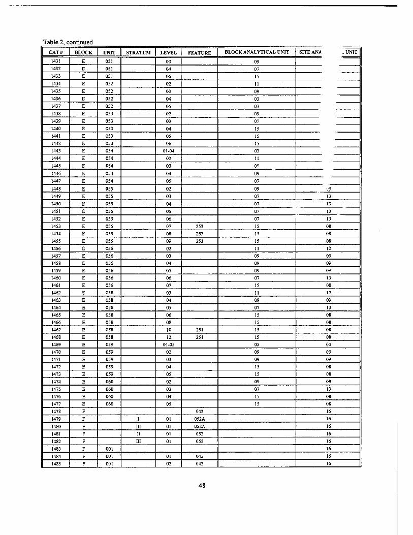
Table 2, continued
CAT« BLOCK UNIT STRATUM LEVEL FEATURE BLOCK ANALYTICAL UNIT SITE ANA :.. UNIT
1431 E 051 03 09 1432 E 051 04 07 1433 E 051 06 15 1434 E 052 02 11 1435 E 052 03 09
1436 E 052 04 03 1437 E 052 05 03
1438 E 053 02 09
1439 E 053 03 07
1440 E 053 04 15
1441 E 053 05 15
1442 E 053 06 15
1443 E 054 01-04 03
1444 E 054 02 11
1445 E 054 03 09
1446 E 054 04 09
1447 E 054 05 07
1448 E 055 02 09 •J9
1449 E 055 03 07 13
1450 E 055 04 07 13
1451 E 055 05 07 13
1452 E 055 06 07 13
1453 E 055 07 253 15 08
1454 E 055 08 253 15 08
1455 E 055 09 253 15 08
1456 E 056 02 11 12
1457 E 056 03 09 09
1458 E 056 04 09 09
1459 E 056 05 09 09
1460 E 056 06 07 13
1461 E 056 07 15 08
1462 E 058 03 11 12
1463 E 058 04 09 09
1464 E 058 05 07 13
1465 E 058 06 15 08
1466 E 058 08 15 08
1467 E 058 10 251 15 08
1468 E 058 12 251 15 08
1469 E 059 01-05 03 03
1470 E 059 02 09 09
1471 E 059 03 09 09
1472 E 059 04 15 08
1473 E 059 05 15 08
1474 E 060 02 09 09
1475 E 060 03 07 13
1476 E 060 04 15 08
1477 E 060 05 15 08
1478 F 043 16
1479 F I 01 052A 16
1480 F m 01 052A 16
1481 F ii 01 053 16
1482 F m 01 053 16
1483 F 001 16
1484 F 001 01 043 16
1485 F 001 02 043 16
48
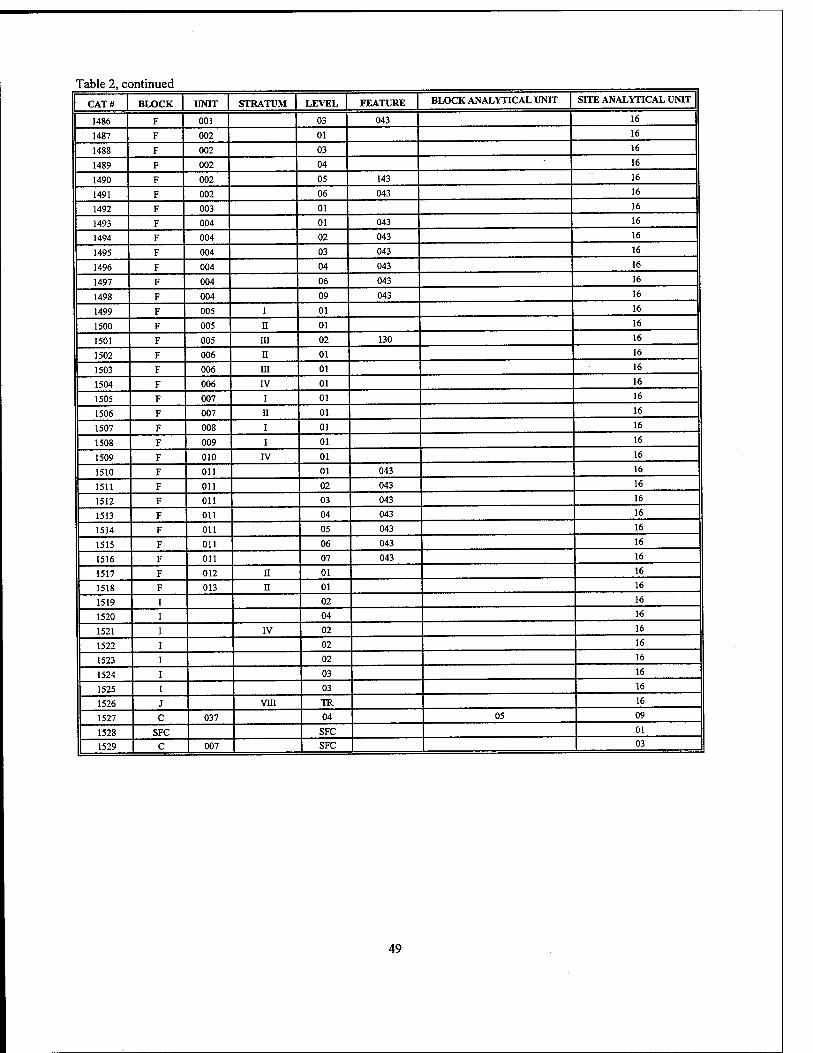
Table 2, continued
CAT# BLOCK UNIT STRATUM LEVEL FEATURE BLOCK ANALYTICAL UNIT SITE ANALYTICAL UNIT
I486 F 001 03 043 16
1487 F 002 01 16
1488 F 002 03 16
1489 F 002 04 16
1490 F 002 05 143 16
1491 F 002 06 043 16
1492 F 003 01 16
1493 F 004 01 043 16
1494 F 004 02 043 16
1495 F 004 03 043 16
1496 F 004 04 043 16
1497 F 004 06 043 16
1498 F 004 09 043 16
1499 F 005 I 01 16
1500 F 005 II 01 16
1501 F 005 in 02 130 16
1502 F 006 H 01 16
1503 F 006 ni 01 16
1504 F 006 IV 01 16
1505 F 007 i 01 16
1506 F 007 ii 01 16
1507 F 008 i 01 16
1508 F 009 i 01 16
1509 F 010 IV 01 16
1510 F Oil 01 043 16
1511 F Oil 02 043 16
1512 F Oil 03 043 16
1513 F Oil 04 043 16
1514 F Oil 05 043 16
1515 F Oil 06 043 16
1516 F Oil 07 043 16
1517 F 012 n 01 16
1518 F 013 n 01 16
1519 02 16
1520 04 16
1521 IV 02 16
1522 02 16
1523 02 16
1524 03 16
1525 03 16
1526 vm TR 16
1527 C 037 04 05 09
1528 SFC SFC 01
1529 | C 007 SFC 03
49
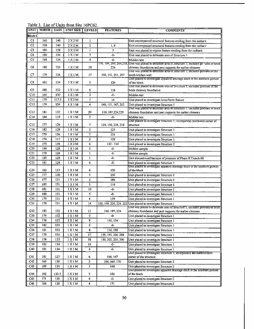
Table 3. List of Units from Site 16PC62 UNIT NORTH EAST UNIT SIZE LEVELS FEATURES COMMENTS
BlockC Cl 160 140 2X2M 1 Unit encompassed structural features eroding from the embark C2 158 140 2X2M 2 1,6 Unit encompassed structural features eroding from the cutbaiii: C3 160 138 2X2M 1 2 Unit was placed to expose feature eroding from the cutbank C4 180 134 1X1M 7 -0- Unit was placed to delineate area of Structure 1 C5 168 134 1X1M 4 -0- Midden test
C6 180 133 1X1M 19 i lb, iyy, <duu, Ai4,2is,
226 Unit was placed to delineate area ot Structure 1; includes po"ions ot brick chimney foundation and post supports for earlier chimney
C7 179 134 1X1M 17 150,151,201,207 Unit was placed to delineate area ot Structure 1; includes ponions ot the south kitchen wall
C8 161 134 1X1M 5 126 Unit placed to investigate apparent drainage ditch in the southern portion of the block
C9 180 132 1X1M 6 116 Unit was placed to delineate area ot Structure 1; includes portions ot the brick chimney foundation
CIO 166 130 1X1M 2 -0- Midden test Cll 179 117.5 1X2M 7 14 Unit placed to investigate levee/berm feature C12 178 134 1X1M 4 149,151,167,202 Unit placed to investigate Structure 1
C13 181 132 1X1M 29 116,197,224,229 Unit was placed to delineate area ot Structure l; includes portions ot bnck chimney foundation and post supports for earlier chimney
C14 164 119 1X1M 2 -0- Midden test
C15 177 129 1X1M 7 124,150,216,218 Unit placed to investigate Structure I; incorporates southwest corner ot structure
C16 182 129 1X1M 3 125 Unit placed to investigate Structure 1 C17 179 136 1X1M 7 131 Unit placed to investigate Structure 1 C18 174 • 117 1X1M 3 128 Unit placed to investigate Structure 1 C19 170 136 1X2M 6 132-134 Unit placed to investigate Structure 2 C20 186 126 1X1M 3 -0- Midden sample C21 179 126 1X1M 1 -0- Midden sample C22 180 128 1X1M 1 -0- Unit discontinued because of presence of Phase II Trench #8 C23 181 128 1X1M 6 -0- Unit placed to investigate Structure 1
C24 163 133 1X1M 6 126 Unit placed to investigate apparent drainage ditch in tne southern portion of the block
C25 177 130 1X1M 3 150 Unit placed to investigate Structure 1 C26 177 131 1X1M 3 196 Unit placed to investigate Structure 1 C27 182 131 1X1M 5 116 Unit placed to investigate Structure 1 C28 181 131 1X1M 10 -0- Unit placed to investigate Structure 1 C29 180 131 1X1M 5 -0- Unit placed to investigate Structure I C30 179 131 1X1M 4 159 Unit placed to investigate Structure 1 C31 178 131 1X1M 14 150,159,220,221,222 Unit placed to investigate Structure 1
C32 182 132 1X1M 11 116,197,224 Unit was placed to delineate area ot Structure 1; includes portions ot bnck chimney foundation and post supports for earlier chimney
C33 179 132 1X1M 5 -0- Unit placed to investigate Structure I C34 178 132 1X1M 9 150, 154 Unit placed to investigate Structure 1 C35 182 133 1X1M 5 -0- Unit placed to investigate Structure 1 C36 181 133 1X1M 8 116,198 Unit placed to investigate Structure 1 C37 179 133 1X1M 17 150,195,200,208 Unit placed to investigate Structure 1 C38 178 133 1X1M 18 150,202,205,206 Unit placed to investigate Structure 1 C39 182 134 1X1M 10 -0- Unit placed to investigate Structure 1 C40 181 134 1X1M 4 -0- Unit placed to investigate Structure 1
C41 181 127 1X1M 6 146, 147 Unit placed to investigate structure 1; incorporates the northwestern comer of the structure
C42 169 130 1X1M 3 168,169,170 Unit placed to investigate Structure 2 C43 169 131 1X1M 3 148 Unit placed to investigate Structure 2
C44 162 133.5 1X1M 5 126 Unit placed to investigate apparent drainage ditch in the southern portion of the block
C45 171 130 1X1M 4 -0- Unit placed to investigate Structure 2
C46 168 130 1X1M 4 171 Unit placed to investigate Structure 2
50
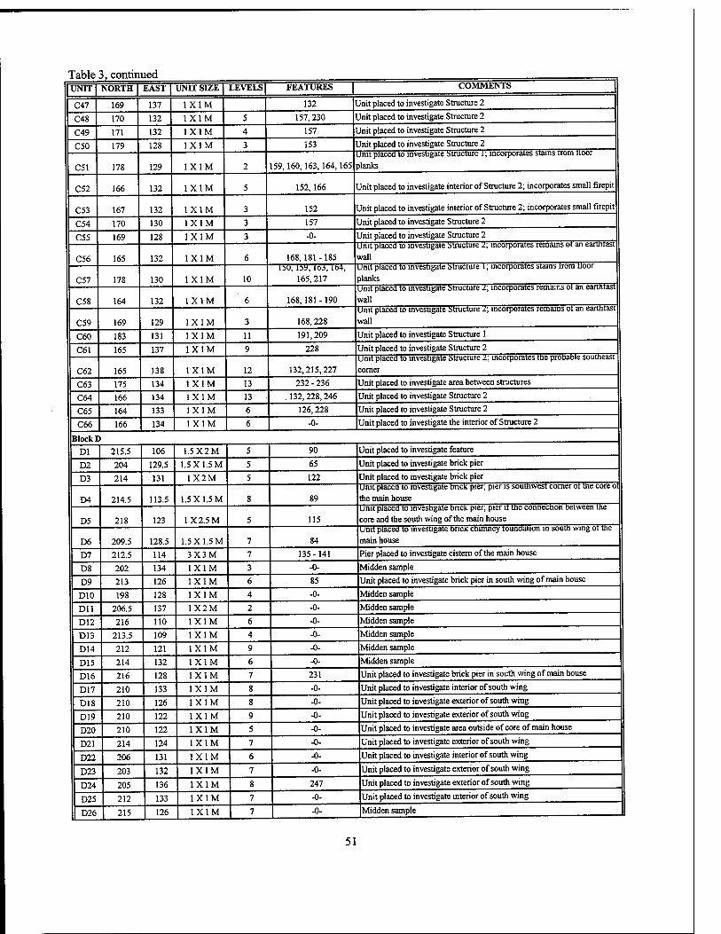
Table 3, continued UNIT] NORTH| EAST | UNIT SIZE | LEVELS | FEATURES | COMMENTS
C47 169 137 1X1M 132 Unit placed to investigate Structure 2
C48 170 132 1X1M 5 157,230 Unit placed to investigate Structure 2
C49 171 132 1X1M 4 157 1 Jnit placed to investigate Structure 2
C50 179 128 1X1M 3 153 1 Unit placed to investigate Structure 2
C51 178 129 1X1M 2 159,160,163,164,165 Unit placed to investigate structure 1; incorporates stains rrom tioor planks
C52 166 132 1X1M 5 152,166 Unit placed to investigate interior of Structure 2; incorporates small firepit
C53 167 132 1X1M 3 152 Unit placed to investigate interior of Structure 2; incorporates small firepit
C54 170 130 1X1M 3 157 Unit placed to investigate Structure 2
C55 169 128 1X1M 3 -0- Unit placed to investigate Structure 2
C56 165 132 1X1M 6 168,181-185 Unit placed to investigate structure 2; incorporates remains ot an eartntast wall
C57 178 130 1X1M 10 151), by, 163,164,
165,217 Unit placed to investigate structure l; incorporates stains trom tloor planks
C58 164 132 1X1M 6 168,181 -190 Unit placed to investigate structure l\ incorporates remains ot an eartntast wall
C59 169 129 1X1M 3 168,228 Unit placed to investigate structure 2; incorporates remains ot an eartntast wall
C60 183 131 1X1M 11 191,209 Unit placed to investigate Structure 1
C61 165 137 1X1M 9 228 Unit placed to investigate Structure 2
C62 165 138 1X1M 12 132,215,227 Unit placed to investigate structure z\ incorporates the prooaDie southeast corner
C63 175 134 1X1M 13 232 - 236 Unit placed to investigate area between structures
C64 166 134 1X1M 13 . 132,228,246 Unit placed to investigate Structure 2
C65 164 133 1X1M 6 126,228 Unit placed to investigate Structure 2
C66 166 134 1X1M 6 -0- Unit placed to investigate the interior of Structure 2
Block B Dl 215.5 106 1.5X2M 5 90 Unit placed to investigate feature
D2 204 129.5 1.5 X 1.5 M 5 65 Unit placed to investigate brick pier
D3 214 131 1X2M 5 122 Unit placed to investigate brick pier
D4 214.5 113.5 1.5 X 1.5 M 8 89 Unit placed to investigate DncK pier; pier is southwest corner ot the core ol the main house
D5 218 123 1X2.5 M 5 115 Unit placed to investigate bnclc pier; pier it the connection between the core and the south wing of the main house
D6 209.5 128.5 1.5 X 1.5 M 7 84 Unit placed to investigate brick chimney foundation m south wing ot the main house
D7 212.5 114 3X3M 7 135-141 Pier placed to investigate cistern of the main house
D8 202 134 1X1M 3 -0- Midden sample
D9 213 126 1X1M 6 85 Unit placed to investigate brick pier in south wing of main house
D10 198 128 1X1M 4 -0- Midden sample
Dll 206.5 137 1X2M 2 -0- Midden sample
D12 216 110 1X1M 6 -0- Midden sample
D13 213.5 109 1X1M 4 -0- Midden sample
D14 212 121 1X1M 9 -0- Midden sample
D15 214 132 1X1M 6 -0- Midden sample
D16 216 128 1X1M 7 231 Unit placed to investigate brick pier in south wing of main house
D17 210 133 1X1M 8 -0- Unit placed to investigate interior of south wing
D18 210 126 1X1M 8 -0- Unit placed to investigate exterior of south wing
D19 210 122 1X1M 9 -0- Unit placed to investigate exterior of south wing
D20 210 122 1X1M 5 -0- Unit placed to investigate area outside of core of main house
D21 214 124 1X1M 7 -0- Unit placed to investigate exterior of south wing
D22 206 131 1X1M 6 -0- Unit placed to investigate interior of south wing
D23 203 132 1X1M 7 -0- Unit placed to investigate exterior of south wing
D24 205 136 1X1M 8 247 Unit placed to investigate exterior of south wing
D25 212 133 1X1M 7 -0- Unit placed to investigate interior of south wing
D26 215 126 1X1M 7 -0- Midden sample
51
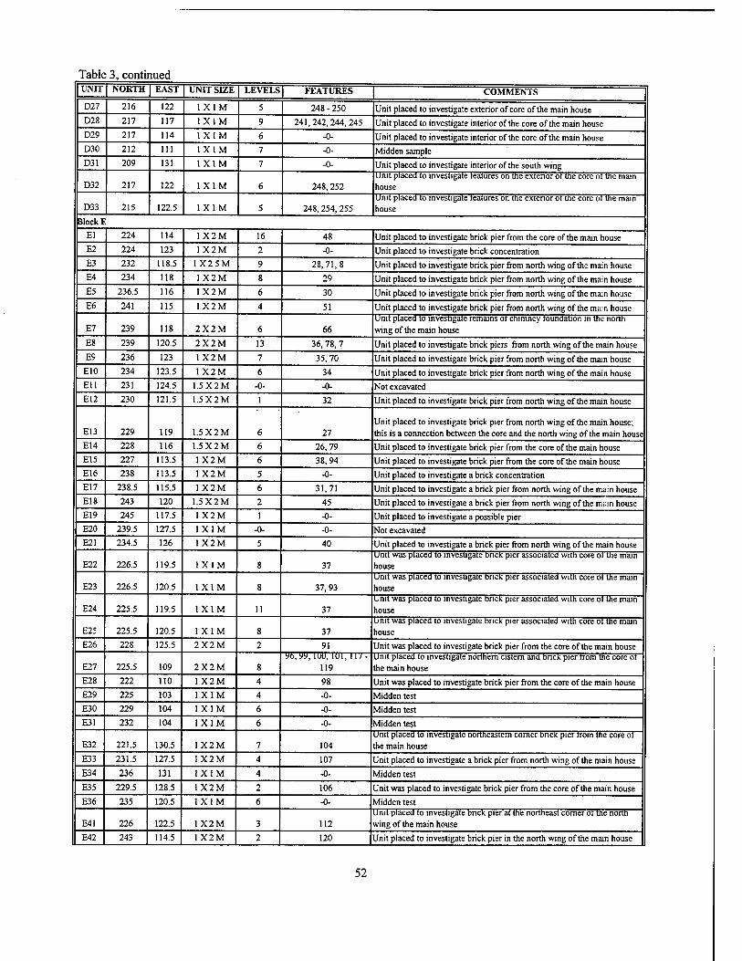
Table 3, continued UNIT NORTH EAST UNIT SIZE LEVELS FEATURES COMMENTS
D27 216 122 1X1M 5 248 - 250 Unit placed to investigate exterior of core of the main house D28 217 117 1X1M 9 241,242,244,245 Unit placed to investigate interior of the core of the main house D29 217 114 1X1M 6 -0- Unit placed to investigate interior of the core of the main house D30 212 111 1X1M 7 -0- Midden sample D31 209 131 1X1M 7 -0- Unit placed to investigate interior of the south wing
D32 217 122 1X1M 6 248,252 unit placed to investigate features on the exterior ot the core ot the main house
D33 215 122.5 1X1M 5 248,254,255 Unit placed to investigate features on the exterior ot the core ot the main house
Block E El 224 114 1X2M 16 48 Unit placed to investigate brick pier from the core of the main house E2 224 123 1X2M 2 -0- Unit placed to investigate brick concentration E3 232 118.5 1X2.5M 9 28,71,8 Unit placed to investigate brick pier from north wing of the main house E4 234 118 1X2M 8 29 Unit placed to investigate brick pier from north wing of the main house E5 236.5 116 1X2M 6 30 Unit placed to investigate brick pier from north wing of the main house E6 241 115 1X2M 4 51 Unit placed to investigate brick pier from north wing of the main house
E7 239 118 2X2M 6 66 Unit placed to investigate remains ot chimney toundation in the north wing of the main house
E8 239 120.5 2X2M 13 36, 78, 7 Unit placed to investigate brick piers from north wing of the main house E9 236 123 1X2M 7 35,70 Unit placed to investigate brick pier from north wing of the main house
E10 234 123.5 1X2M 6 34 Unit placed to investigate brick pier from north wing of the main house Ell 231 124.5 1.5X2M -0- -0- Not excavated E12 230 121.5 1.5X2M 1 32 Unit placed to investigate brick pier from north wing of the main house
E13 229 119 1.5X2M 6 27 Unit placed to investigate brick pier from north wing of the main house; this is a connection between the core and the north wing of the main house
E14 228 116 1.5X2M 6 26,79 Unit placed to investigate brick pier from the core of the main house E15 227 113.5 1X2M 6 38,94 Unit placed to investigate brick pier from the core of the main house E16 238 113.5 1X2M 5 -0- Unit placed to investigate a brick concentration E17 238.5 115.5 1X2M 6 31,71 Unit placed to investigate a brick pier from north wing of the main house E18 243 120 1.5X2M 2 45 Unit placed to investigate a brick pier from north wing of the main house E19 245 117.5 1 X2M 1 -0- Unit placed to investigate a possible pier E20 239.5 127.5 1X1M -0- -0- Not excavated E21 234.5 126 1X2M 5 40 Unit placed to investigate a brick pier from north wing of the main house
E22 226.5 119.5 1X1M 8 37 Unit was placed to investigate brick pier associated with core ot the main house
E23 226.5 120.5 1X1M 8 37,93 Unit was placed to investigate brick pier associated with core ot the mam house
E24 225.5 119.5 1X1M 11 37 Unit was placed to investigate bnck pier associated with core ot the main house
E25 225.5 120.5 1 X1M 8 37 Unit was placed to investigate brick pier associated with core ot the main house
E26 228 125.5 2X2M 2 91 Unit was placed to investigate brick pier from the core of the main house
E27 225.5 109 2X2M 8 %,yy, iuu, lui.iiv -
119 Unit placed to investigate northern cistern and bnck pier from the core ot the main house
E28 222 110 1X2M 4 98 Unit was placed to investigate brick pier from the core of the main house E29 225 103 1X1M 4 -0- Midden test E30 229 104 1X1M 6 -0- Midden test E31 232 104 1X1M 6 -0- Midden test
E32 221.5 130.5 1X2M 7 104 Unit placed to investigate northeastern corner bnck pier trom the core ot the main house
E33 231.5 127.5 1X2M 4 107 Unit placed to investigate a brick pier from north wing of the main house E34 236 131 1X1M 4 -0- Midden test E35 229.5 128.5 1X2M 2 106 Unit was placed to investigate brick pier from the core of the main house E36 235 120.5 1X1M 6 -0- Viidden test
E41 226 122.5 1X2M 3 112 Unit placed to investigate bnck pier at the northeast comer ot the north wing of the main house
E42 243 114.5 1X2M 2 120 Unit placed to investigate brick pier in the north wing of the main house
52
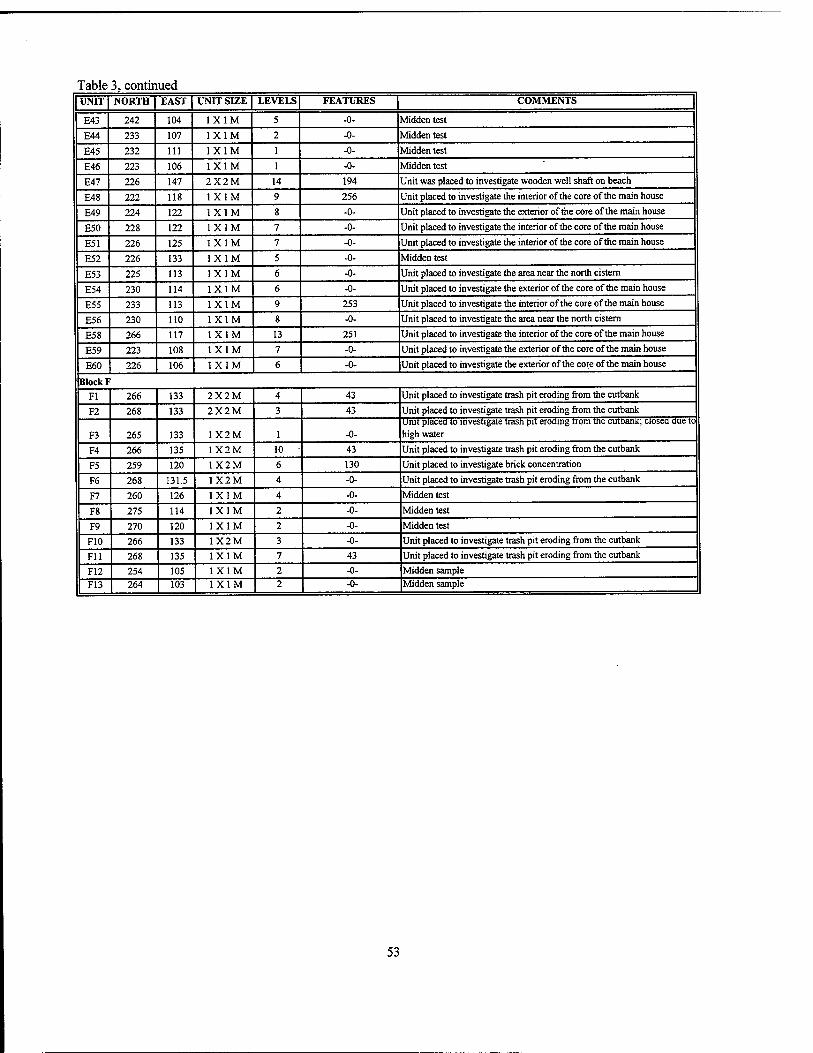
Table 3, continued UNIT NORTH EAST UNIT SIZE LEVELS | FEATURES COMMENTS |
E43 242 104 1X1M 5 -0- Midden test
E44 233 107 1X1M 2 -0- Midden test
E45 232 111 1X1M 1 -0- Midden test
E46 223 106 1X1M 1 -0- Midden test
E47 226 147 2X2M 14 194 Unit was placed to investigate wooden well shaft on beach
E48 222 118 1X1M 9 256 Unit placed to investigate the interior of the core of the main house
E49 224 122 1X1M 8 -0- Unit placed to investigate the exterior of the core of the main house
E50 228 122 1X1M 7 -0- Unit placed to investigate the interior of the core of the main house
E51 226 125 1X1M 7 -0- Unit placed to investigate the interior of the core of the main house
E52 226 133 1X1M 5 -0- Midden test
E53 225 113 1X1M 6 -0- Unit placed to investigate the area near the north cistern
E54 230 114 1X1M 6 -0- Unit placed to investigate the exterior of the core of the main house
E55 233 113 1X1M 9 253 Unit placed to investigate the interior of the core of the main house
E56 230 110 1X1M 8 -0- Unit placed to investigate the area near the north cistern
E58 266 117 1X1M 13 251 Unit placed to investigate the interior of the core of the main house
E59 223 108 1X1M 7 -0- Unit placed to investigate the exterior of the core of the main house
E60 226 106 1X1M 6 -0- Unit placed to investigate the exterior of the core of the main house
BlockF Fl 266 133 2X2M 4 43 Unit placed to investigate trash pit eroding from the cutbank
F2 268 133 2X2M 3 43 Unit placed to investigate trash pit eroding from the cutbank
F3 265 133 1X2M 1 -0- Unit placed to investigate trash pit eroding from the cutbank; closea due to high water
F4 266 135 1X2M 10 43 Unit placed to investigate trash pit eroding from the cutbank
F5 259 120 1X2M 6 130 Unit placed to investigate brick concentration
F6 268 131.5 1X2M 4 -0- Unit placed to investigate trash pit eroding from the cutbank
F7 260 126 1X1M 4 -0- Midden test
F8 275 114 1X1M 2 -0- Midden test
F9 270 120 1X1M 2 -0- Midden test
F10 266 133 1X2M 3 -0- Unit placed to investigate trash pit eroding from the cutbank
Fll 268 135 1X1M 7 43 Unit placed to investigate trash pit eroding from the cutbank
F12 254 105 1X1M 2 -0- Midden sample F13 264 103 1X1M 2 -0- Midden sample
53
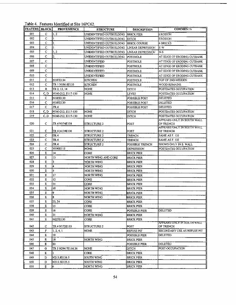
Table 4. Features Identified at Site 16PC62. FEATURE BLOCK PROVENIENCE STRUCTURE DESCRIPTION COMMENTS
001 C 1,2 UNIDENTIFIED OUTBUILDING BRICK PIER EROSION 002 c 1 UNIDENTIFIED OUTBUILDING DITCH EROSION 003 c 1 UNIDENTIFIED OUTBUILDING BRICK COURSE 6 BRICKS 004 c 1 UNIDENTIFIED OUTBUILDING LINEAR DEPRESSION E-W 005 c 1,2 UNIDENTIFIED OUTBUILDING LINEAR DEPRESSION N-S
006 c 2 UNIDENTIFIED OUTBUILDING POSTHOLE AT EDGE OF ERODING CUTBANK 007 c UNIDENTIFIED POSTHOLE AT EDGE OF ERODING CUTBANK 008 c UNIDENTIFIED POSTHOLE AT EDGE OF ERODING CUTBANK
009 c UNIDENTIFIED POSTHOLE AT EDGE OF ERODING CUTBANK
010 c UNIDENTIFIED POSTHOLE AT EDGE OF ERODING CUTBANK Oil c N187E134 KITCHEN POSTHOLE TOP OF 2ND MIDDEN 012 c TR1N186.8E133 KITCHEN POSTHOLE WOOD REMAINS 013 B TR2, 13, 14 NONE DrrCH POSTDATES OCCUPATION 014 C,D N160-212, El 17-130 NONE LEVEE POSTDATES OCCUPATION 015 C N185E130 POSSIBLE POST DELETED 016 C N185E130 POSSIBLE POST DELETED 017 C TR.4 POSSIBLE POST DELETED 018 C,D N160-212, El 17-130 NONE DITCH POSTDATES OCCUPATION 019 C,D N160-212, El 17-130 NONE DITCH POSTDATES OCCUPATION
020 C TR4N174E138 STRUCTURE 2 POST APPEARS ONLY IN SOUTH WALL OF TRENCH
021 C TR4N174E136 STRUCTURE 2 POST APPEARS ONLY IN SOUTH WALL OF TRENCH
022 C TR.4 STRUCTURE 2 TRENCH SAME ASF. 133 023 C TR.4 STRUCTURE 2 TRENCH SAME ASF. 132 024 C TR.4 STRUCTURE 2 POSSIBLE TRENCH SHOWS ONLY IN S. WALL 025 C N190E115 NONE DEPRESSION POSTDATES OCCUPATION 026 E 14 CORE BRICK PIER 027 E 13 NORTH WING AND CORE BRICK PEER 028 E 3 NORTH WING BRICK PIER 029 E 4 NORTH WING BRICK PIER 030 E 5 NORTH WING BRICK PIER 031 E 17 NORTH WING BRICK PER 032 E 12 CORE BRICK PER 033 E 11 CORE BRICK PER 034 E 10 NORTH WING BRICK PER 035 E 9 NORTH WING BRICK PER 036 E 8 NORTH WING BRICK PER 037 E 23,24 CORE BRICK PER 038 E 15 CORE BRICK PER 039 E 16 CORE POSSELEPER DELETED
040 E 21 NORTH WING BRICK PER 041 E N227E130 CORE BRICK PER
042 C TR4N172E133 STRUCTURE 2 POST APPEARS UNLV IN SOU l'H WALL OF TRENCH
043 F 1,2,4,1 NONE REFUSE PIT SECONDARY USE AS REFUSE PIT 044 E 19 POSSELE PER DELETED
045 E 18 NORTH WING BRICK PER 046 E 20 POSSELE PER DELETED
047 G TR5N294.7E116.36 NONE DITCH POST-OCCUPATION
048 E 1 CORE BRICK PER
049 D N213.8E136.5 SOUTH WING BRICK PER
050 D N215.5E125.5 SOUTH WING BRICK PER
051 E 6 NORTH WING BRICK PER
54
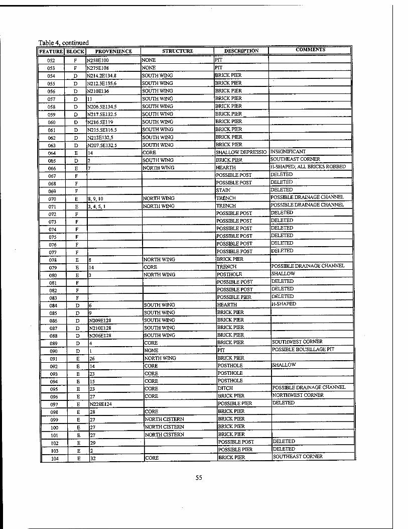
Table 4, continued FEATURE | BLOCK| PROVENIENCE | STRUCTURE | DESCRIPTION | COMMENTS |
052 F N258E100 NONE PIT
053 F N275E108 NONE PIT
054 D NE14.2E134.8 SOUTH WING BRICK PIER
055 D N212.3E135.6 SOUTH WING BRICK PIER
056 D N210E136 SOUTH WING BRICK PIER
057 D 11 SOUTH WING BRICK PIER
058 D N206.5E134.5 SOUTH WING BRICK PIER
059 D N217.5E132.5 SOUTH WING BRICK PIER
060 D N216.5E119 SOUTH WING BRICK PIER
061 D N215.5E116.5 SOUTH WING BRICK PER
062 D N213E132,5 SOUTH WING BRICK PEER
063 D N207.5E132.5 SOUTH WING BRICK PIER
064 E 14 CORE SHALLOW DEPRESSIO INSIGNIFICANT
065 D 2 SOUTH WING BRICK PIER SOUTHEAST CORNER
066 E 7 NORTH WING HEARTH H-SHAPED; ALL BRICKS ROBBED
067 F POSSIBLE POST DELETED
068 F POSSIBLE POST DELETED .
069 F STAIN DELETED
070 E 8,9,10 NORTH WING TRENCH POSSIBLE DRAINAGE CHANNEL
071 E 3,4,5,1 NORTH WING TRENCH POSSIBLE DRAINAGE CHANNEL
072 F POSSIBLE POST DELETED
073 F POSSIBLE POST DELETED
074 F POSSIBLE POST DELETED
075 F POSSIBLE POST DELETED
076 F POSSIBLE POST DELETED
077 F POSSIBLE POST DELETED
078 E 8 NORTH WING BRICK PIER
079 E 14 CORE TRENCH POSSIBLE DRAINAGE CHANNEL
080 E 3 NORTH WING POSTHOLE SHALLOW
081 F POSSIBLE POST DELETED
082 F POSSIBLE POST DELETED
083 F POSSIBLE PIER DELETED
084 D 6 SOUTH WING HEARTH H-SHAPED
085 D 9 SOUTH WING BRICK PIER
086 D N209E128 SOUTH WING BRICK PIER
087 D N210E128 SOUTH WING BRICK PIER
088 D N206E128 SOUTH WING BRICK PIER
089 D 4 CORE BRICK PIER SOUTHWEST CORNER
090 D 1 NONE PIT POSSIBLE BOUSEXAGE PIT
091 E 26 NORTH WING BRICK PIER
092 E 14 CORE POSTHOLE SHALLOW
093 E 23 CORE POSTHOLE
094 E 15 CORE POSTHOLE
095 E 23 CORE DITCH POSSIBLE DRAINAGE CHANNEL
096 E 27 CORE BRICK PIER NORTHWEST CORNER
097 E N228E124 POSSIBLE PIER DELETED
098 E 28 CORE BRICK PIER
099 E 27 NORTH CISTERN BRICK PIER
100 E 27 NORTH CISTERN BRICK PIER
101 E 27 NORTH CISTERN BRICK PIER
102 E 29 POSSIBLE POST DELETED
103 E 2 POSSIBLE PIER DELETED
104 E 32 CORE BRICK PIER SOUTHEAST CORNER
55
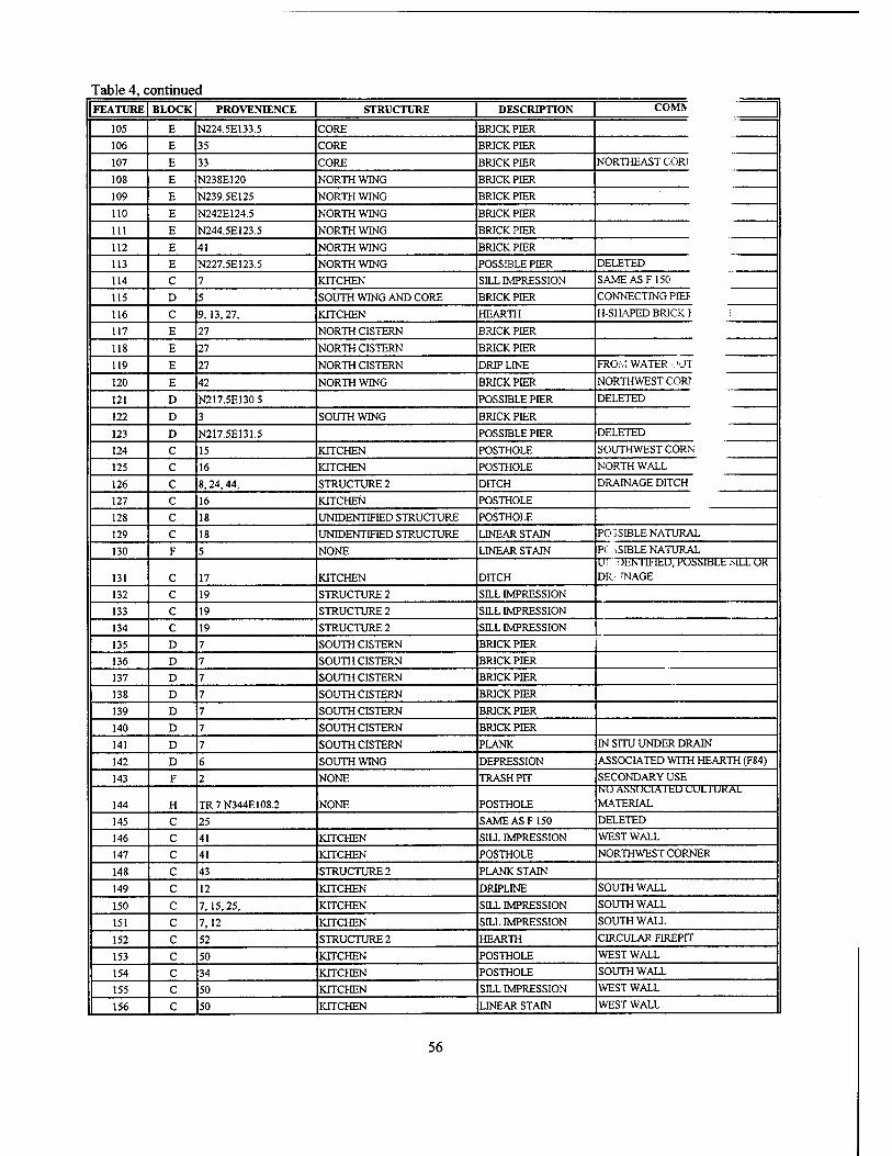
Table 4, continued FEATURE BLOCK PROVENIENCE STRUCTURE DESCRIPTION COMIV
105 E N224.5E133.5 CORE BRICK PER
106 E 35 CORE BRICK PEER
107 E 33 CORE BRICK PIER NORTHEAST COR1
108 E N238E120 NORTH WING BRICK PIER
109 E N239.5E125 NORTH WING BRICK PIER
no E N242E124.5 NORTH WING BRICK PIER
in E N244.5E123.5 NORTH WING BRICK PIER
112 E 41 NORTH WING BRICK PIER
113 E N227.5E123.5 NORTH WING POSSIBLE PIER DELETED
114 C 7 KITCHEN SHX IMPRESSION SAME ASF 150
115 D 5 SOUTH WING AND CORE BRICK PIER CONNECTING PEF
116 C 9,13,27, KITCHEN HEARTH H-SHAPED BRICK I i
117 E 27 NORTH CISTERN BRICK PIER
118 E 27 NORTH CISTERN BRICK PER
119 E 27 NORTH CISTERN DRIP LINE FROM WATER «.^UT
120 E 42 NORTH WING BRICK PER NORTHWEST COR)
121 D N217.5E130.5 POSSIBLE PER DELETED
122 D 3 SOUTH WING BRICK PER
123 D N217.5E131.5 POSSBLEPER DELETED
124 C 15 KITCHEN POSTHOLE SOUTHWEST CORN
125 C 16 KITCHEN POSTHOLE NORTH WALL
126 C 8,24,44, STRUCTURE 2 DITCH DRAINAGE DITCH
127 C 16 KITCHEN POSTHOLE
128 C 18 UNIDENTIFIED STRUCTURE POSTHOLE
129 C 18 UNIDENTIFIED STRUCTURE LINEAR STAIN POSSIBLE NATURAL
130 F 5 NONE LINEAR STAIN PC ..SELE NATURAL
131 C 17 KITCHEN DITCH U! i JENT1F1ED, POSSIBLE SILL UK DR--INAGE
132 C 19 STRUCTURE 2 SEX IMPRESSION
133 C 19 STRUCTURE 2 SILL IMPRESSION
134 C 19 STRUCTURE2 SELL IMPRESSION
135 D 7 SOUTH CISTERN BRICK PER
136 D 7 SOUTH CISTERN BRICK PER
137 D 7 SOUTH CISTERN BRICK PER
138 D 7 SOUTH CISTERN BRICK PER
139 D 7 SOUTH CISTERN BRICK PER
140 D 7 SOUTH CISTERN BRICK PER
141 D 7 SOUTH CISTERN PLANK IN SITU UNDER DRAIN
142 D 6 SOUTH WING DEPRESSION ASSOCIATED WITH HEARTH (F84)
143 F 2 NONE TRASH PIT SECONDARY USE
144 H TR 7 N344E108.2 NONE POSTHOLE NO ASSOClAltD CUL1UKAL MATERIAL
145 C 25 SAME ASF 150 DELETED
146 C 41 KITCHEN SILL IMPRESSION WEST WALL
147 C 41 KITCHEN POSTHOLE NORTHWEST CORNER
148 C 43 STRUCTURE2 PLANK STAIN
149 C 12 KITCHEN DRIPLINE SOUTH WALL
150 C 7,15,25, KITCHEN SILL IMPRESSION SOUTH WALL
151 C 7,12 KITCHEN SDLL IMPRESSION SOUTH WALL
152 C 52 STRUCTURE 2 HEARTH CIRCULAR FIREPIT
153 C 50 KITCHEN POSTHOLE WEST WALL
154 C 34 KITCHEN POSTHOLE SOUTH WALL
155 C 50 KITCHEN SILL IMPRESSION WEST WALL
156 C 50 KITCHEN LINEAR STAIN WEST WALL
56
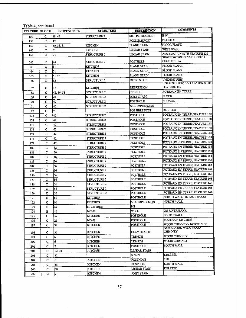
Table 4, continued FEATUREl BLOCK| PROVENIENCE STRUCTURE | DESCRIPTION COMMENTS |
157 C ♦8,49 STRUCTURE2 5ILL IMPRESSION E-W
158 c 49 POSSIBLE POST DELETED
159 c 30,31,51 KITCHEN PLANK STAIN FLOOR PLANK
160 c 51 KITCHEN LINEAR STAIN WEST WALL
161 c 24 STRUCTURE 2 LINEAR STAIN ASSOCIATED WITH FEATURE 126
162 c 24 STRUCTURE2 POSTHOLE
SHALLOW; ASSUUiAibD WUH
FEATURE 126
163 c 51 KITCHEN PLANK STAIN FLOOR PLANK
164 c 51 KITCHEN PLANK STAIN FLOOR PLANK
165 c 51,57 KITCHEN PLANK STAIN FLOOR PLANK
166 c 52 STRUCTURE 2 DEPRESSION UNIDENTIFIED
167 c 12 KITCHEN DEPRESSION
UNlDfcNIU-lfcD; ASSUClAltL) Wllht
FEATURE 149
168 c 42, 56, 58 STRUCTURE2 TRENCH POTEAUX EN TERRE
169 c 42 STRUCTURE2 JOIST STAIN FLOOR
170 c 42 STRUCTURE2 POSTHOLE SQUARE
171 c 46 STRUCTURE 2 SILL IMPRESSION
172 c 7 POSSIBLE POST DELETED .
173 c 42 STRUCTURE 2 POSTHOLE POTEAUX EN TERRE; FEATURE 168
174 c 42 STRUCTURE 2 POSTHOLE POTEAUX EN TERRE; FEATURE 168
175 c 42 STRUCTURE 2 POSTHOLE POTEAUX EN TERRE; FEATURE 168
176 c 42 STRUCTURE 2 POSTHOLE POTEAUX EN TERRE; FEATURE 168
177 c 42 STRUCTURE2 POSTHOLE POTEAUX EN TERRE; FEATURE 168
178 c 42 STRUCTURE 2 POSTHOLE POTEAUX EN TERRE; FEATURE 168
179 c 42 STRUCTURE2 POSTHOLE POTEAUX EN TERRE; FEATURE 168
180 c 42 STRUCTURE 2 POSTHOLE POTEAUX EN TERRE; FEATURE 168
181 c 56 STRUCTURE 2 POSTHOLE POTEAUX EN TERRE; FEATURE 168
182 c 56 STRUCTURE 2 POSTHOLE POTEAUX EN TERRE; FEATURE 168
183 c 56 STRUCTURE2 POSTHOLE POTEAUX EN TERRE; FEATURE 168
184 c 56 STRUCTURE 2 POSTHOLE POTEAUX EN TERRE; FEATURE 168
185 c 56 STRUCTURE 2 POSTHOLE POTEAUX EN TERRE; FEATURE 168
186 c 56 STRUCTURE2 POSTHOLE POTEAUX EN TERRE; FEATURE 168
187 c 56 STRUCTURE 2 POSTHOLE POTEAUX EN TERRE; FEATURE 168
188 c 56 STRUCTURE2 POSTHOLE POTEAUX EN TERRE; FEATURE 168
189 c 56 STRUCTURE2 POSTHOLE POTEAUX EN TERRE; FEATURE 168
190 c 56 STRUCTURE 2 POSTHOLE POTEAUX EN TERRE; FEATURE 168
191 c 60 KITCHEN POSTHOLE NORTH WALL; INTACT WOOD
192 c 60 KITCHEN SILL IMPRESSION NORTH WALL
193 E 27 N. CISTERN PIT
194 E 47 NONE WELL ON RIVER BANK
195 c 37 KITCHEN POSTHOLE SOUTH WALL
196 c 26 NONE POSTHOLE SOUTH OF KITCHEN
197 c 32 KITCHEN POSTHOLE WOOD CHIMNEY - NORTH SIDE
198 c 36 KITCHEN CLAY HEARTH ASSUCiAlbU Wllti WLKJD CHIMNEY
199 c 6 KITCHEN TRENCH WOOD CHIMNEY
200 c 6 KITCHEN TRENCH WOOD CHIMNEY
201 c 7 KITCHEN POSTHOLE SOUTH WALL
202 c 12,38 KITCHEN LINEAR STAIN
203 c 32 STAIN DELETED
204 c 6 KITCHEN POSTHOLE 218
205 c 38 KITCHEN POSTHOLE SOUTH WALL
206 c 38 KITCHEN LINEAR STAIN DELETED
207 c 7 KITCHEN JOIST STAIN
57
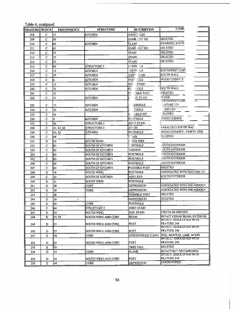
Table 4, continued FEATURE BLOCK PROVENIENCE | STRUCTURE | DESCRIPTION COMI*
208 C 37 KITCHEN JOIST STAIN
209 c 60 SAME ASF 192 DELETED
210 c 60 KITCHEN PLANK CHARRED; SOUT1
211 c 61 SAME ASF200 DELETED
212 c 37 STAIN DELETED
213 c 37 STAIN DELETED
214 c 37 STAIN DELETED
215 c 62 STRUCTURE 2 FOSTF vE
216 c 15 KITCHEN i'OSTI ■■ >LE SOUTHWEST CORl
217 c 57 KITCHEN JOIST TAIN SOUTH WALL
218 c 6 KITCHEN POS~ :OLE WOOD CHIMNEY
219 c 15 KITCHEN JO! STAIN
220 c 31 KITCHEN PC HOLE SOUTH WALL
221 c 31 P< -:iBLEPOST DELETED
222 c 31 KITCHEN F -fK STAIN
I JCEHOLE
1 THOLE
p .SIBLEPIT
TOOR
223 c 15 KITCHEN
iUU'1'HWkS'l CORi ;b "•'F.ATURE 124
224 c 32 KITCHEN OODCHK ::' -
225 c 61 >ELETED
WOOD CHJMNF; 226 c 6 KITCHEN POSTHOLE
227 c 62 STRUCTURE 2 JOIST STAIN !
228 c 61,62,64 STRUCTURE 2 DITCH PARALLELS SOUTH WAL.
229 c 13,32 KITCHEN POSTHOLE WOOD CHIMNEY - NORTH SIDE
230 c 48 S~AIN DELETED
231 D 16 SOUTH WING r :ICKPIER
f OSTHOLE 232 c 63 SOUTH OF KITCHEN SOUTH EXTERIOR
233 c 63 SOUTH OF KITCHEN TRENCH JOUTH EXTERIOR
234 c 63 SOUTH OF KITCHEN POSTHOLE :.OUTH EXTERIOR
235 c 63 SOUTH OF KITCHEN POSTHOLE SOUTH EXTERIOR
236 c 63 SOUTH OF KITCHEN POSTHOLE SOUTH EXTERIOR
237 c 63 SOUTH OF KITCHEN POSSIBLE POST DELETED
238 D 16 SOUTH WING POSTHOLE ASSOCIATED WITH FEATURE 231
239 c 63 SOUTH OF KITCHEN ASH LENS SOUTH EXTERIOR
240 D 21 SOUTH WING POSTHOLE
241 D 28 CORE DEPRESSION ASSOCIATED WITH 2ND MIDDEN
242 D 28 CORE DEPRESSION ASSOCIATED WITH 2ND MIDDEN
243 C 66 POSSIBLE POST DELETED
244 D 28 DEPRESSION DELETED
245 D 28 CORE POSTHOLE
246 C 64 STRUCTURE 2 JOIST STAIN
247 D 24 SOUTH WING SOIL STAIN CIRCULAR DEPOSIT
248 D 27,32 SOUTH WING AND CORE BEAM INTACT CEDAR BEAM; EXTERIOR
249 D 27 SOUTH WING AND CORE POST 1NJAL1; AüMJClAlbD Wim FEATURE 248
250 D 27 SOUTH WING AND CORE POST INIA(J 1; ASSUC1A1 bD WllH FEATURE 248
251 E 58 CORE UNTDENTIFIED CONST SOIL, MORTAR, LIME, WOOD
252 D 32 SOUTH WING AND CORE POST IN'1 AC 1; ASSUt'IA 1 Lb wn H FEATURE 248
253 E 55 TREE FALL DELETED
254 D 33 CORE PLANK INTACT BUT DECOMPOSED
255 D 33 SOUTH WING AND CORE POST IN 1 AC 1; ASSUU1A1 bD Wl 1 H
FEATURE 248
256 E 48 CORE DEPRESSION UNIDENTIFIED
58
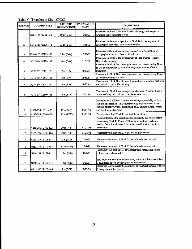
Table 5. Trenches at Site 16PC62.
TRENCH COORDINATES LENGTH/
ORIENTATION EXCAVATION
DATE DESCRD7TION
1 N184-186/E128-138 lOm(E-W) 10/28/93 Placement in Block C for investigation of stratigraphic sequence. Artifact density moderate to high.
2 N148-150/E100-115 15m(E-W) 10/28/93 Placement in the western portion of Block B for investigation of stratigraphic sequence. Low artifact density.
3 N100-102/El 15-140 25 m (E-W) 10/28/93 Placement at the southern edge of Block A for investigation of stratigraphic sequence. Low artifact density.
4 N172-174/E128-138 lOm(E-W) 11/2/93 Placement in Block C for investigation of stratigraphic sequence. High artifact density.
5 N295-297/El 11-128 17 m (E-W) 11/19/93
Placement in Block G to investigate areas not covered during Phase II. No cultural material, other than negligible number of brick fragments.
6 N312-314/E113-128 15 m (E-W) 11/19/93 Placement in Block H to investigate areas not covered during Phase II. No cultural material noted.
7 N342-344/E98-121 23 m (E-W) 11/22/93 Placement in Block H in alignment with a brick and mortar scatter in the cutbank. Low artifact density.
8 N372-374/E100-115 15 m (E-W) 11/23/93 Placement in Block J to investigate area between Trenches 3 and 7. A lense of slag and coal, but no artifacts were noted.
9 N322-335/E111-113 13m(N-S) 11/23/93
Placement east of Phase II trench to investigate possibility of slave cabin in this location. Phase II trench was encountered at N328. Artifact density very low, comprising small amount of brick rubble and few fragments of iron.
10 N283-285/E100-130 30 m (E-W) 11/23/93 Placement north of Block F. Artifact density low.
11 N255-28S/E100-102 30 m (N-S) 11/23/93
Placement intended to investigate the possibility of a line of cabins intersecting Block F. Feature 52 located in southern portion of trench. Ceramics, charcoal in association with feature. Artifact density low.
12 N165-195/E100-102 30 m (N-S) 11/23/93 Placement west of Block C. Very low artifact density.
13 N150-157/E115-117 7 m (N-S) 12/9/93 Placement southwest of Block C. No cultural materials noted.
14 N152-154/El 17-134 17 m (E-W) 12/9/93 Placement southwest of Block C. No cultural materials noted.
15 N166-181/E109-111 15 m (N-S) 12/9/93 Placement west of Block C. Brick fragments noted, but no other cultural materials recorded.
16 N350-368/E109-111 18 m (N-S) 8/31/94 Placement to investigate the possibility of structural features in Block I. Thin lense of coal and slag; low artifact density.
17 N358-360/E102-109 7 m (E-W) 9/23/94 Placement to investigate the possibility of structural features in Block I. Very low artifact density.
59
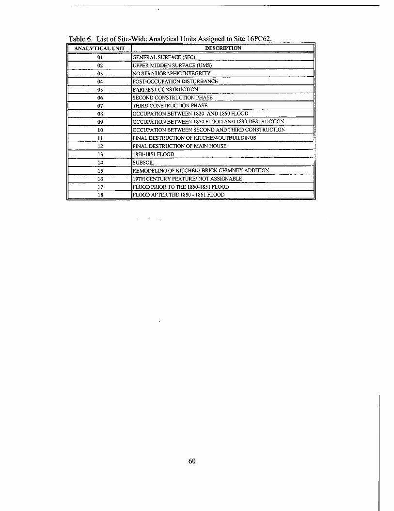
Table 6. ListofSite- Wide Analytical Units Assigned to Site 16PC62. ANALYTICAL UNIT DESCRIPTION
01 GENERAL SURFACE (SFC)
02 UPPER MIDDEN SURFACE (UMS)
03 NO STRATIGRAPHIC INTEGRITY
04 POST-OCCUPATION DISTURBANCE
05 EARLIEST CONSTRUCTION
06 SECOND CONSTRUCTION PHASE
07 THIRD CONSTRUCTION PHASE
08 OCCUPATION BETWEEN 1820 AND 1850 FLOOD
09 OCCUPATION BETWEEN 1850 FLOOD AND 1890 DESTRUCTION
10 OCCUPATION BETWEEN SECOND AND THIRD CONSTRUCTION
11 FINAL DESTRUCTION OF KITCHEN/OUTBUILDINGS j
12 FINAL DESTRUCTION OF MAIN HOUSE j
13 1850-1851 FLOOD i
14 SUBSOIL
15 REMODELING OF KITCHEN/ BRICK CHIMNEY ADDITION
16 19TH CENTURY FEATURE/ NOT ASSIGNABLE
17 FLOOD PRIOR TO THE 1850-1851 FLOOD
18 FLOOD AFTER THE 1850- 1851 FLOOD
60
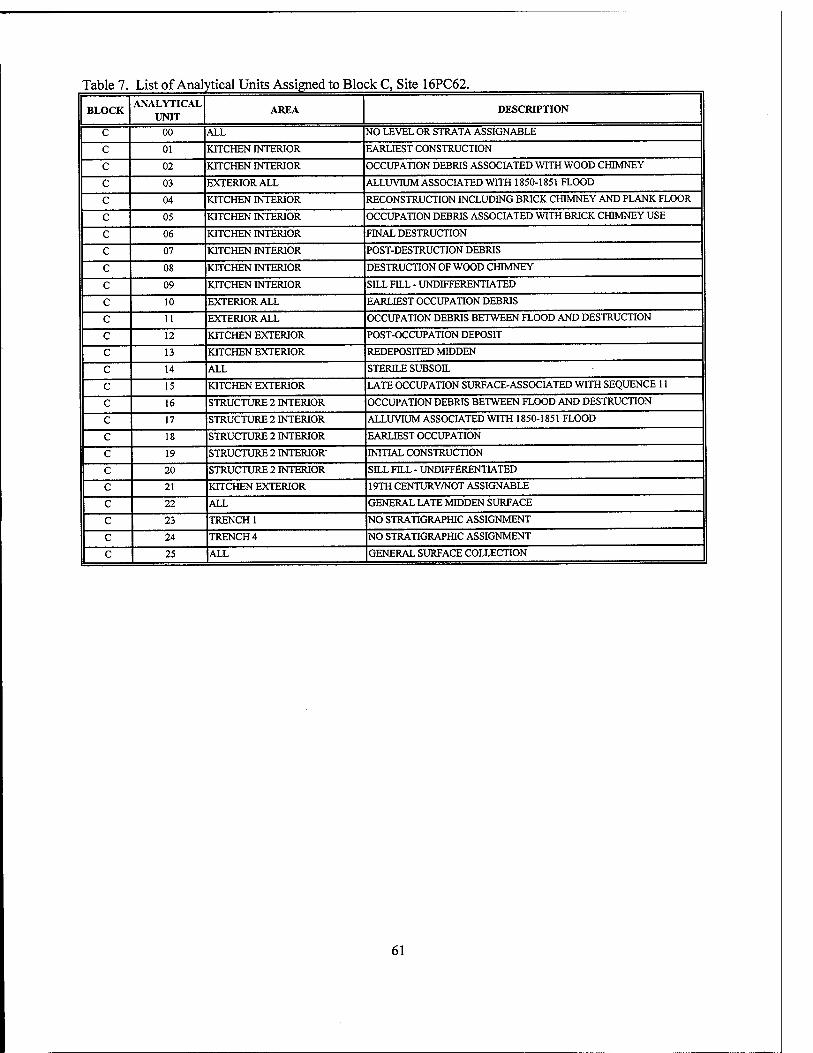
Table 7. List of Analytical Units Assigned to Block C, Site 16PC62.
BLOCK ANALYTICAL
UNIT AREA DESCRIPTION
C 00 ALL NO LEVEL OR STRATA ASSIGNABLE
c 01 KITCHEN INTERIOR EARLIEST CONSTRUCTION
c 02 KITCHEN INTERIOR OCCUPATION DEBRIS ASSOCIATED WITH WOOD CHIMNEY
c 03 EXTERIOR ALL ALLUVIUM ASSOCIATED WITH 1850-1851 FLOOD
c 04 KITCHEN INTERIOR RECONSTRUCTION INCLUDING BRICK CHIMNEY AND PLANK FLOOR
c 05 KITCHEN INTERIOR OCCUPATION DEBRIS ASSOCIATED WITH BRICK CHIMNEY USE
c 06 KITCHEN INTERIOR FINAL DESTRUCTION
c 07 KITCHEN INTERIOR POST-DESTRUCTION DEBRIS
c 08 KITCHEN INTERIOR DESTRUCTION OF WOOD CHIMNEY
c 09 KITCHEN INTERIOR SILL FILL - UNDIFFERENTIATED
c 10 EXTERIOR ALL EARLIEST OCCUPATION DEBRIS
c 11 EXTERIOR ALL OCCUPATION DEBRIS BETWEEN FLOOD AND DESTRUCTION
c 12 KITCHEN EXTERIOR POST-OCCUPATION DEPOSIT
c 13 KITCHEN EXTERIOR REDEPOSITED MIDDEN
c 14 ALL STERILE SUBSOIL
c 15 KITCHEN EXTERIOR LATE OCCUPATION SURFACE-ASSOCIATED WITH SEQUENCE 11
c 16 STRUCTURE 2 INTERIOR OCCUPATION DEBRIS BETWEEN FLOOD AND DESTRUCTION
c 17 STRUCTURE 2 INTERIOR ALLUVRJM ASSOCIATED WITH 1850-1851 FLOOD
c 18 STRUCTURE 2 INTERIOR EARLIEST OCCUPATION
c 19 STRUCTURE 2 INTERIOR- INITIAL CONSTRUCTION
c 20 STRUCTURE 2 INTERIOR SILL FILL - UNDIFFERENTIATED
c 21 KITCHEN EXTERIOR 19TH CENTURY/NOT ASSIGNABLE
c 22 ALL GENERAL LATE MIDDEN SURFACE
c 23 TRENCH 1 NO STRATIGRAPHIC ASSIGNMENT
c 24 TRENCH4 NO STRATIGRAPHIC ASSIGNMENT
c 25 |ALL GENERAL SURFACE COLLECTION
61

Table 8 List of Analytical Units Assigned to Block D, Site 16PC62.
BLOCK ANALYTICAL
UNITS AREA DESCRIPTION
D 01 ALL GENERAL SURFACE
D 02 ALL TOP OF LATEST OCCUPATION SURFACE
D 03 ALL NO STRATIGRAPHIC INTEGRITY
D 04 ALL POST-OCCUPATION DISTURBANCE
D 05 SOUTH WING/CORE LAST OCCUPATION DEBRIS
D 06 SOUTH WING/CORE POST 1850-1851 FLOOD CONSTRUCTION
D 07 SOUTH WING/CORE FLOOD OF 1850-1851
D 08 SOUTH WING/CORE OCCUPATION DEBRIS FROM CONSTRUCTION OF SOUTH WING ' FLOOD
D 09 CORE OCCUPATION DEBRIS FROM INITIAL CORE CONSTRUCTION TO i CONSTRUCTION
D 10 SOUTH WING/CORE OCCUPATION DEBRIS FROM INITIAL CORE CONSTRUCTION TO ' FLOOD
D 12 SOUTH WING/CORE FINAL DESTRUCTION DEBRIS
D 13 ALL FLOOD PRIOR TO 1850 - 1851
D 14 ALL STERILE
D 15 SOUTH WING INITIAL CONSTRUCTION OF SOUTH WING
D 16 CORE INITIAL CONSTRUCTION OF CORE
-1851
WING
;5i
Table 9 List of Analytical Units Assigned to Block E, Site 16PC62.
BLOCK ANALYTICAL
UNITS AREA DESCRIPTION
E 01 ALL GENERAL SURFACE
E 02 ALL TOP OF LATEST OCCUPATION SURFACE
E 03 ALL NO STRATIGRAPHIC INTEGRITY
E 04 ALL POST-OCCUPATION DISTURBANCE
E 05 CORE INITIAL CONSTRUCTION OF CORE
E 06 NORTH WING INITIAL CONSTRUCTION OF NORTH WING
E 07 ALL FLOOD OF 1850-1851
E 08 CORE EARLIEST OCCUPATION DEBRIS
E 09 NORTH WING/CORE LATEST OCCUPATION DEBRIS - UPPER MIDDEN
E 10 NORTH WING/CORE GENERAL 19TH CENTURY OCCUPATION DEBRIS
E 11 NORTH WING/CORE DESTRUCTION DEBRIS
E 12 NORTH WING/CORE POST DESTRUCTION SHEET MIDDEN
E 13 NORTH WING/CORE CONSTRUCTION/REPAIRS BETWEEN INITIAL CORE CONSTRUCTION AND FLOOD OF 1850-1851
E 14 NORTH WING/CORE CONSTRUCTION/REPAIRS BETWEEN FLOOD OF 1850-1851 TO FINAL DESTRUCTION
E 15 CORE OCCUPATION DEBRIS BETWEEN INITIAL CORE CONSTRUCTION TO FLOOD OF 1850-1851- "RED" MIDDEN
E 16 NORTH WING OCCUPATION DEBRIS ASSOCIATED WITH FIREPLACE (F66)
E 17 ALL FLOOD AFTER 1850-1851
E 18 CORE CONSTRUCTION IN 1840'S
62

Table 10. Functional Typology Used for Nina Plantation Analysis. FUNCTIONAL TYPOLOGY CODE FUNCTIONAL TYPOLOGY CLASS EXAMPLES OF CLASS
1 Non-Agricultural Food Procurement Firearms; Ammunition; Traps
2 Food Consumption Plates; Glass Tableware; Eating Utensils
3 Food Preparation Large Ceramic Bowls; Stove Parts; Skillets
4 Food Storage Metal Cans; Ceramic and Glass Jars; Crocks
5 Lighting Lamp Parts; Candlesticks
6 Furniture Spittoons; Mirrors; Vases
7 Architectural Brick; Window Glass
8 Construction Hardware Nails; Bolts; Nuts
9 Construction Tools Hammer; Chisel
10 Household Tools/Implements Scissors; Buckets; Axes
11 Agricultural Tools/Implements Hoes; Chain; Equine Tacks
12 Security Locks; Keys; Firearms
13 Personal Clothing Buttons; Buckles; Shoes
14 Personal Adornment Beads; Jewelry; Hairpins
15 Toys/Games Doll Parts; Dominos; Marbles
16 Music Musical Instrument Parts; Victrola
17 Spiritual/Ideological Religious Medals; Witch Bottle; Bible Clasp
IS Hygiene Chamber Pots; Combs; Toothbrushes
19 Currency Coins
20 Medicine Medicine Bottles; Syringes 21 Personal Tobacco Pipes; Eye Glasses; Figurines
63
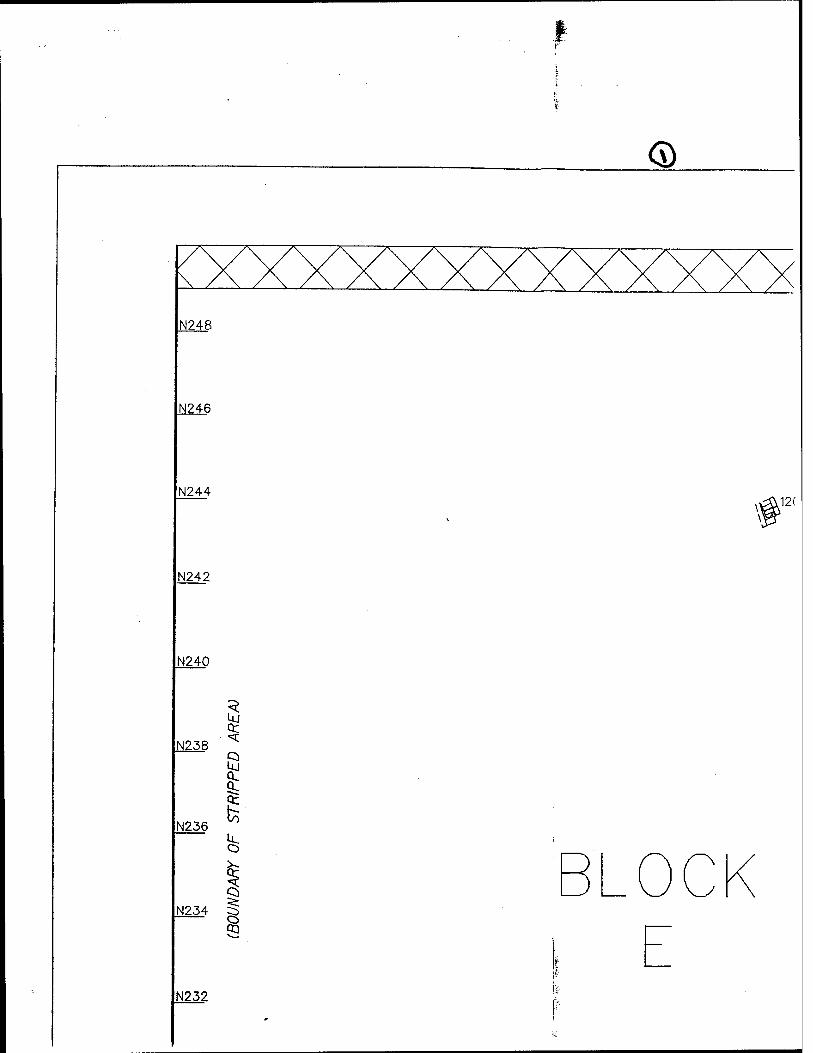
<D
N248
N246
N244 n12(
N242
N240
N238 et
I
5 IN234 ^
s
N236
N232
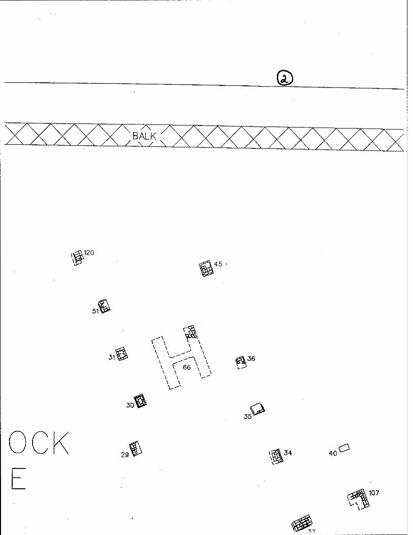
i120
5V
45
31'
30
\ \ 66 \ \
\ \
36
35
29 40 C3
107
V-\
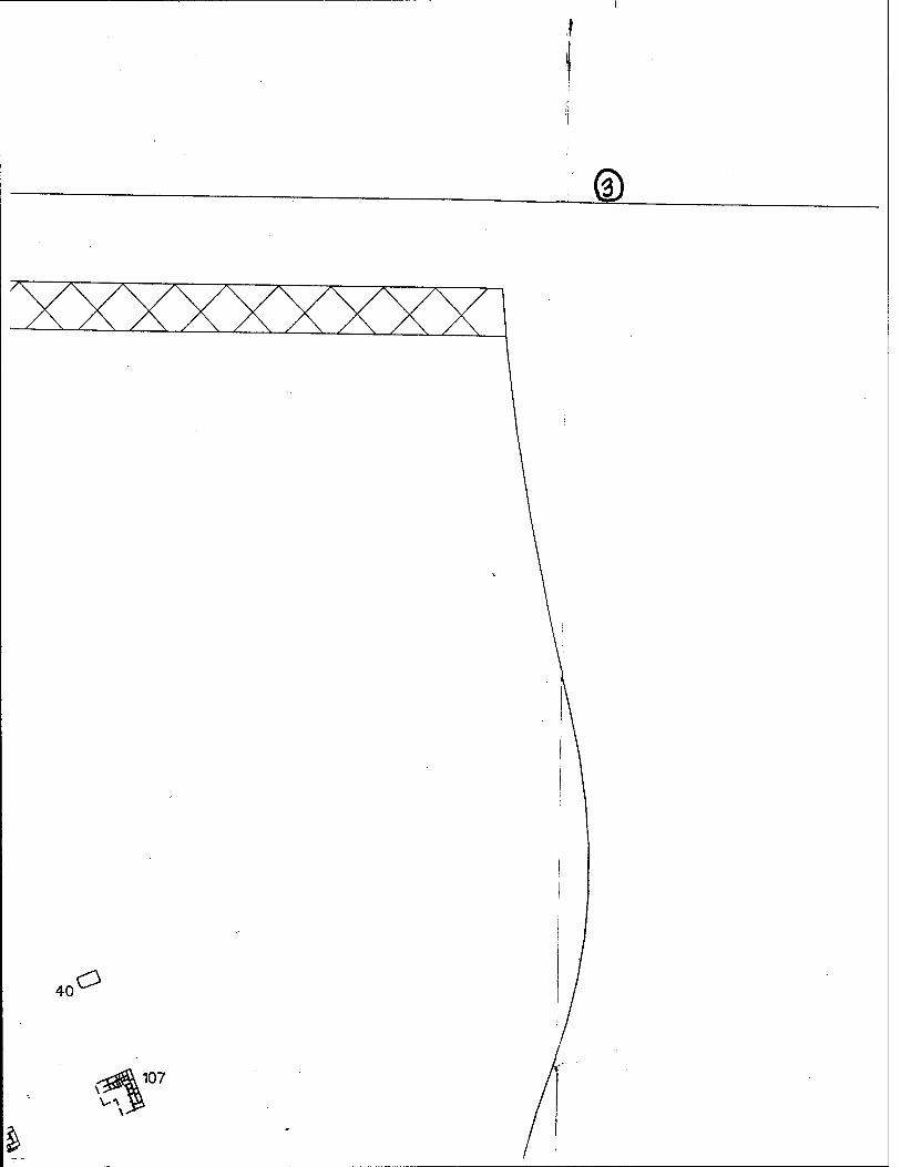
®
40 o
107
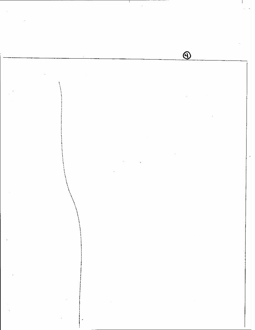
<3>
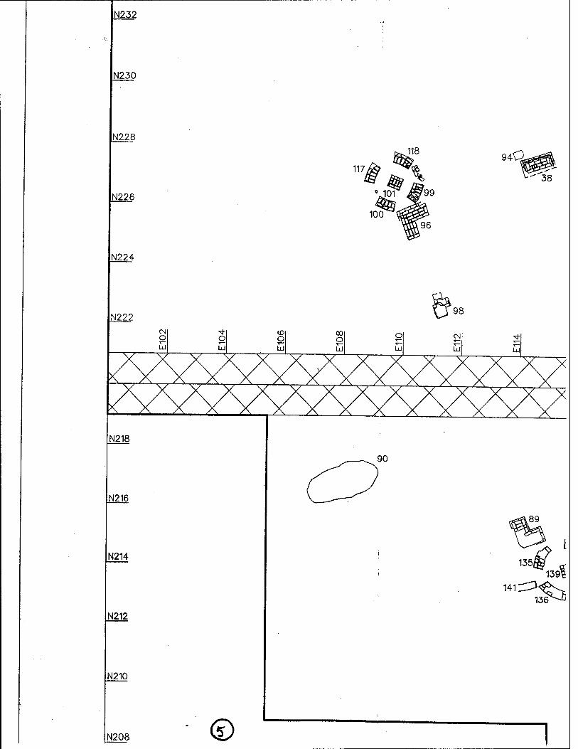
N232
N230
N228
N226
94Q
38
N224
N222
N218
N216
N214
N212
N210
N208 ' 0
90
98
89
135, 139
141 31$^
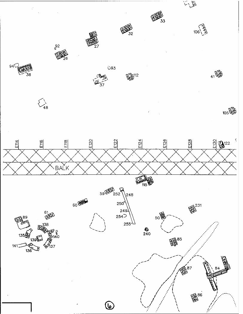
.92
94Q
38
27
Ü93
^ 37
32
,112
33
-^
106\
41
A ^48
1051
^ CO 00 O CM ■*■ CO 00 o < T— CM <N CM <N CM to ^X122 Ul UJ UI UJ Ul ÜJ UJ UJ UJ ^
141 ^<^g ^37 136
/-
/ I
//
/ / -' '
/ / / \
© \J
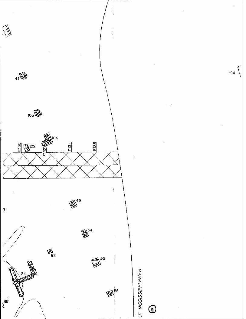
194
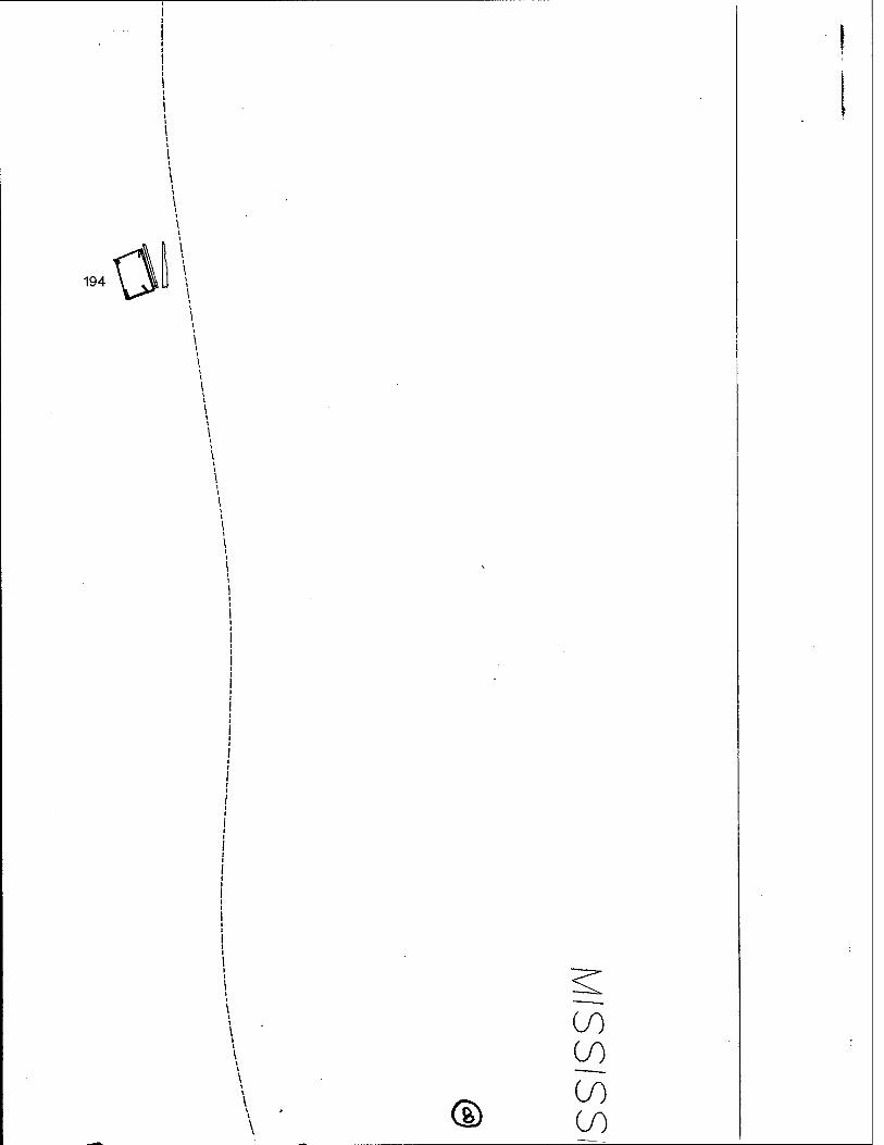
194
®
CO CO
CO CO
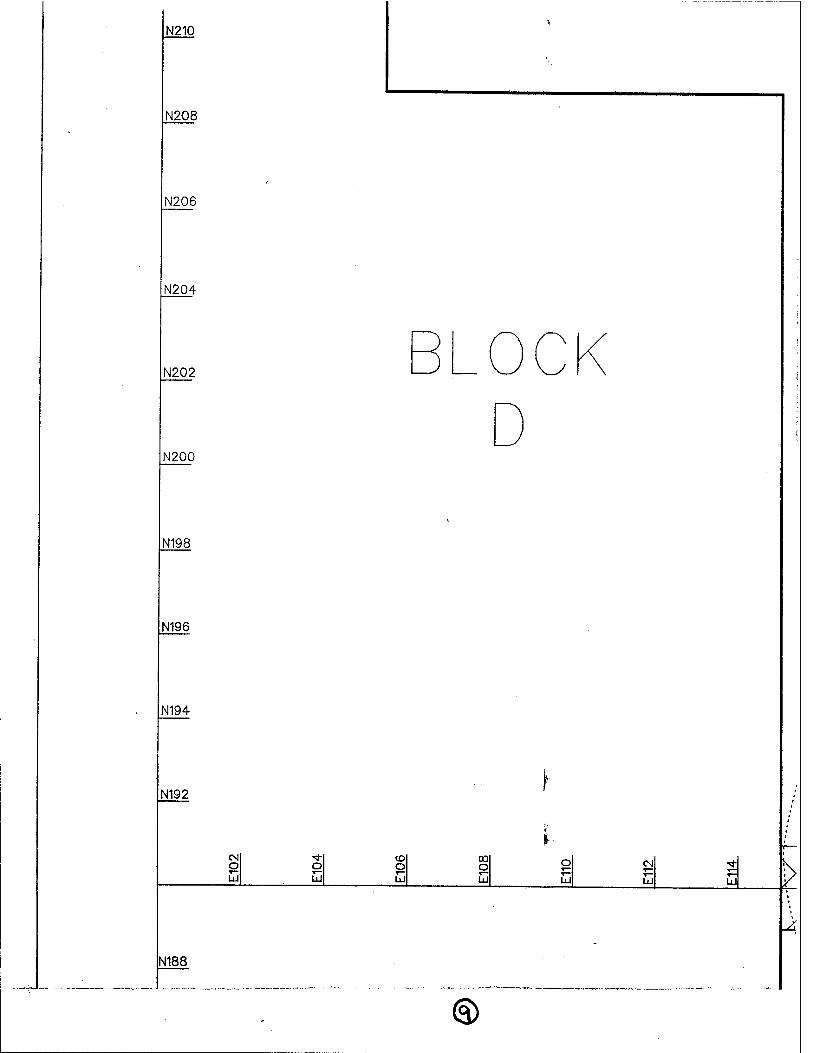
N210
N208
N206
N204
N202
N200
N198
N196
N194
N192
O EU
o o ui
oo o ^- UJ UJ 1x1 >
N188
JL
<§>
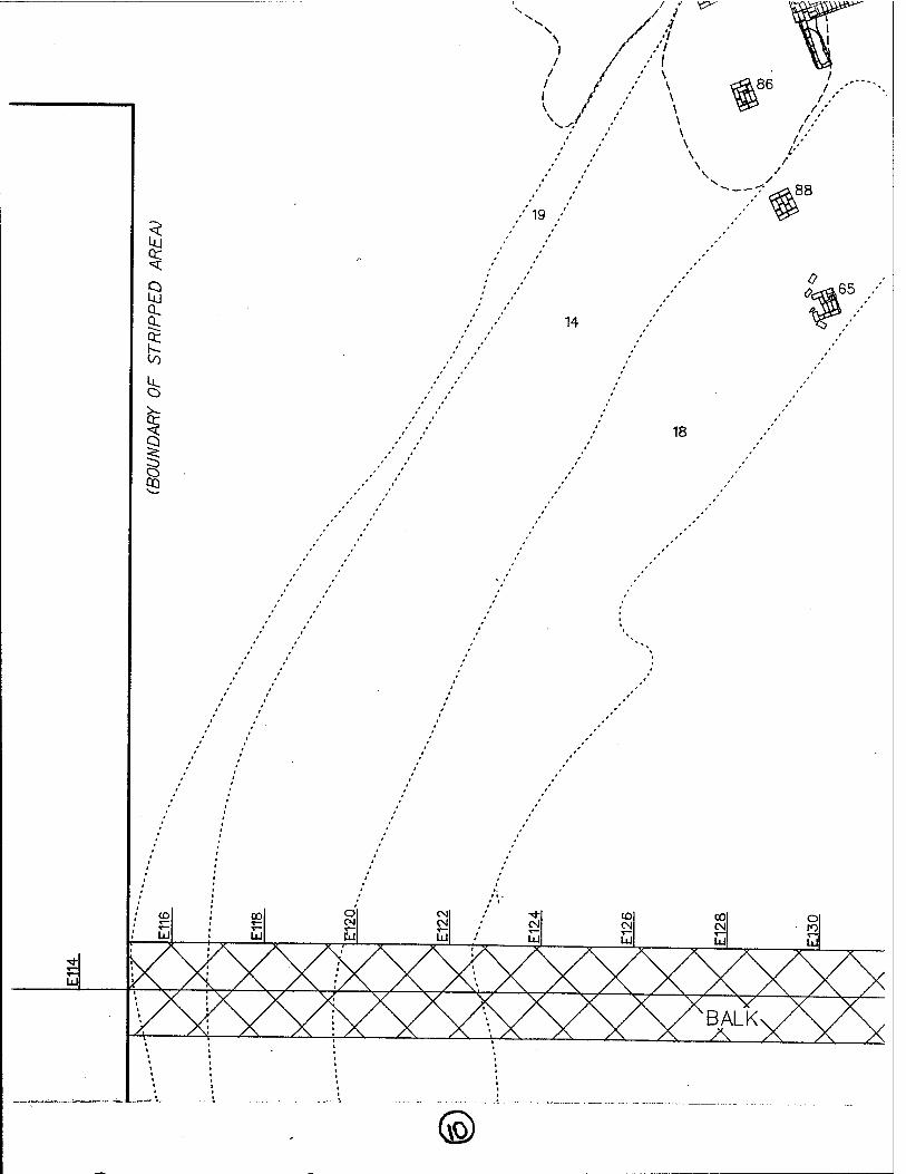
a
CO
o
1 14
18
<£x&65
to to
UJ
o 111
CN CN Ul
CN UJ
CO CN UJ
CO CN U
O ro UJ
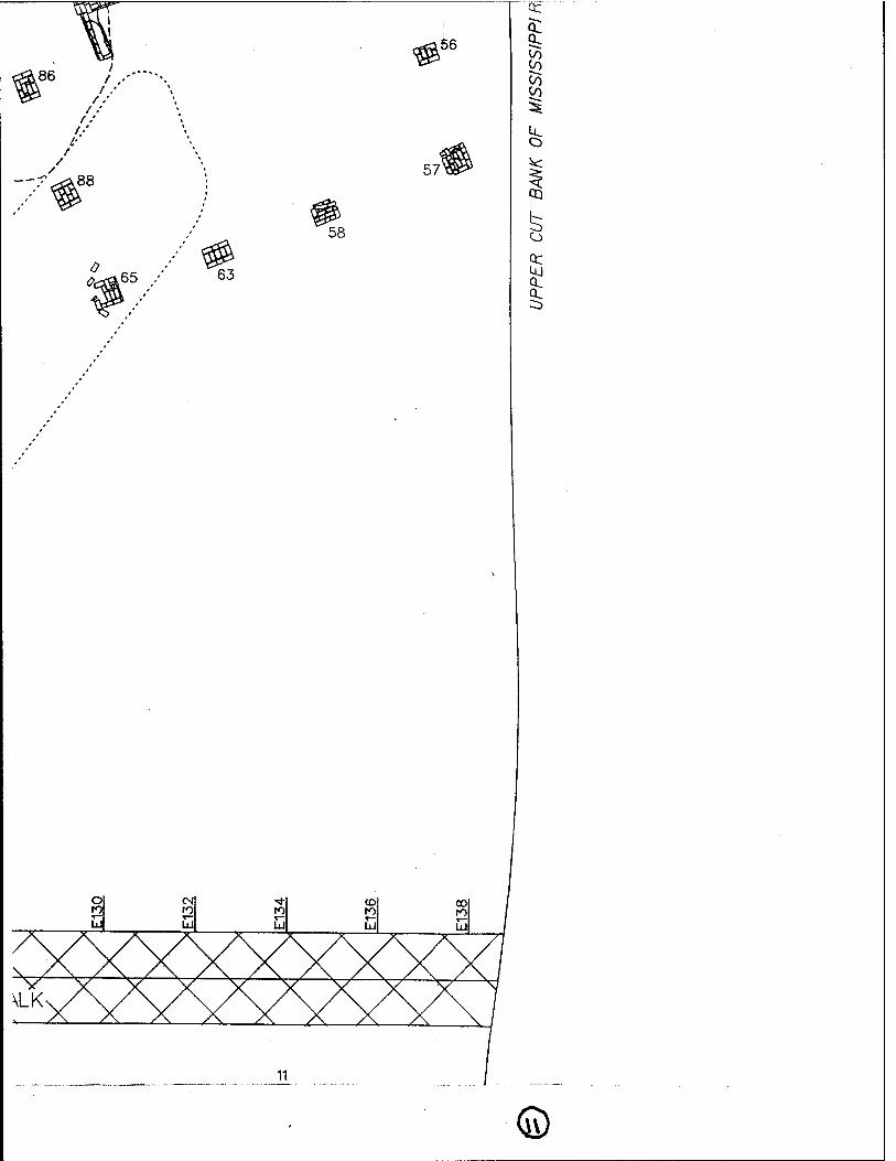
©
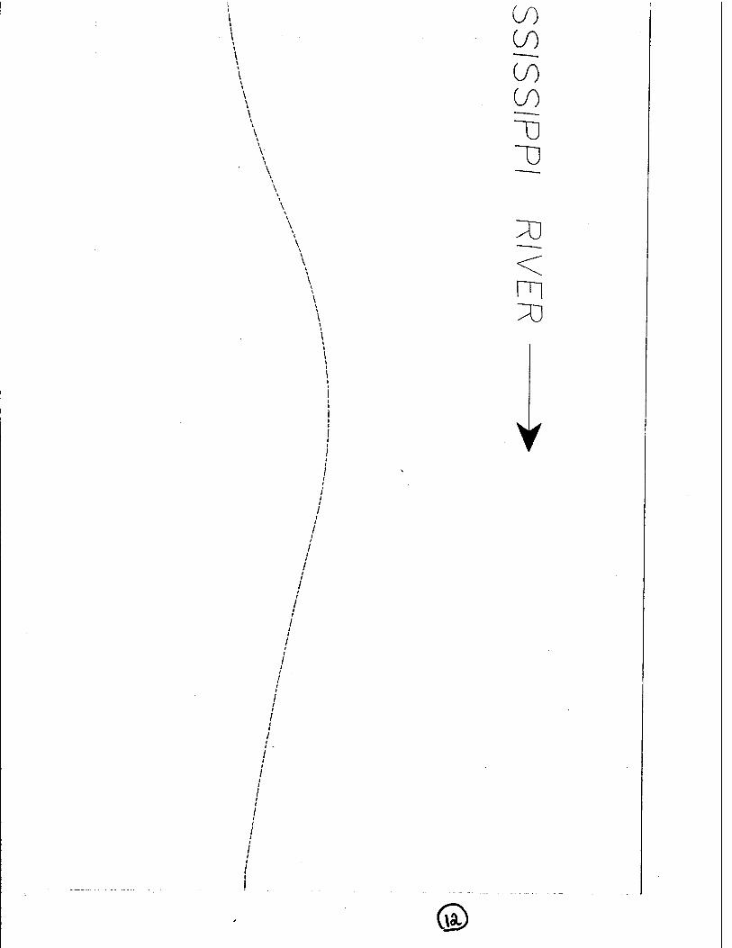
<s>
CO CO
CO CO
T)
2 <
m 33
Y
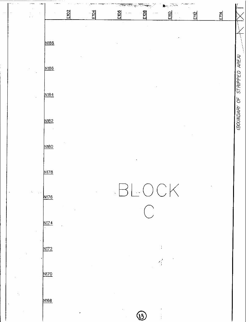
CM o UJ
O UJ
to 00 o o UJ uj
o T—
N188 -
N186
N184
N182
N180
N178
eg
uj
N176
N174
N172
N170
N168
©
ix
§ or
Q Uj
8:
I
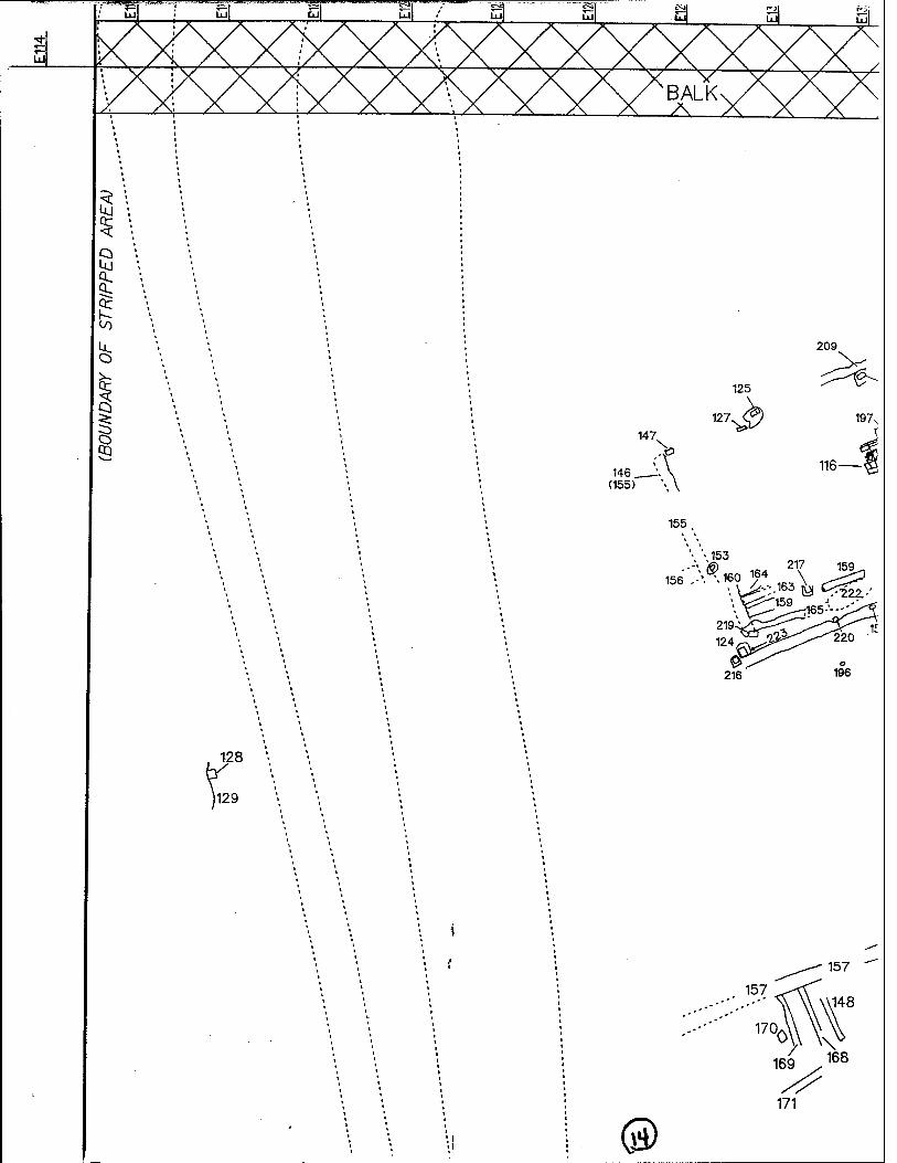
I
3 1 147,
>
146 _ (155)
125
127 V
209 N
197s
116 fi
128
\l29
155
> 153
»..^.»r 162
3\ J^
(3)
157
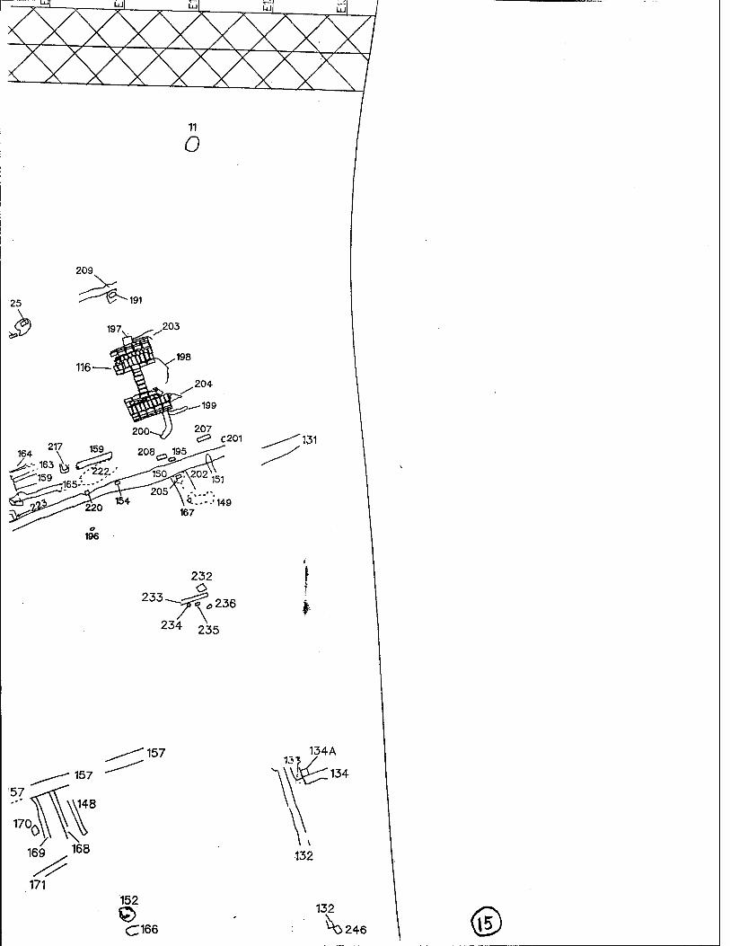
25
209
&^~ 191
203
217 164 \ JZ>2
^1^165-
207 <Z> C201
208 _ 195 '131
196
232
233 -^ 236
234 235
157 134A
152
C166
132
^0246 %
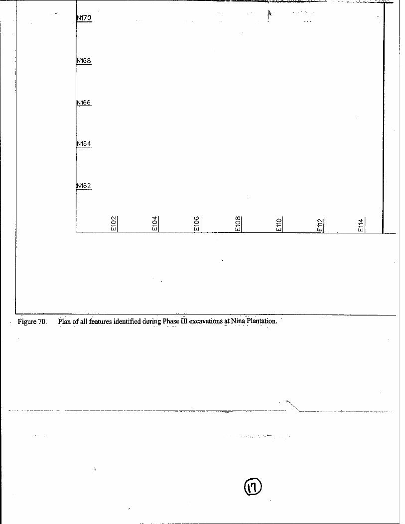
N170
N168
N166
N164
N162
o oo o UJ
M^-^s«5>a»»iTHi IWIIPII hi-jai :r t*A*
O
LJ v— ÜJ
Figure 70. Plan of all features identified during Phase HI excavations at Nina Plantation.
■■v
©
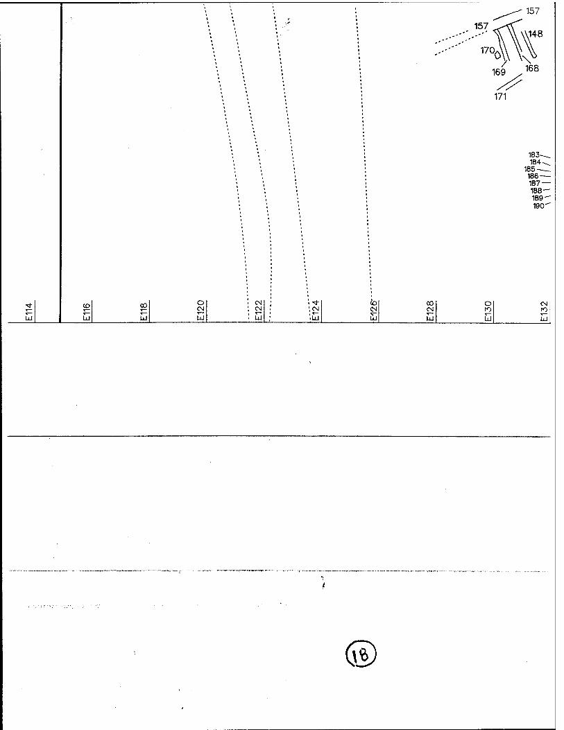
■ \ ^^^ 157
\ 1 '-i' 157 ^-cC
'"
169 .168
xy 1 ,
• 171
\ 183 ~^
' ', • 184-^. ' ', 185 > '( 186 — i \ 187 —
188 — 189^ 190"
T}- CD 00 o '• CN : '"*■ CO CO O CN
s— ^— ^— CN : cN ', CN CN CN to to T— V" ^—
LU 1 w lxl LU , LU ■UJ Ld LU LÜ UJ
~ —————-— —'—— r - • — „,. „.,„ r~~~~ „—,
/ \
H- — - -
-
®
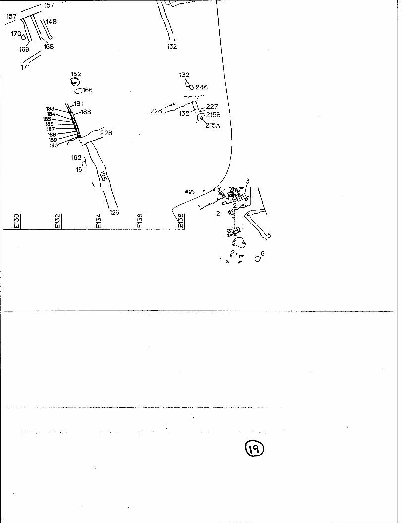
157
17Q 0. /
169 .
171
157
,148
V 168
^^"
o
228!
jo Hi
132
^246
ic:227 132"'-^215B
' 215A
©
SQ.