
Pattern-Oriented Application Frameworks for Domain Experts ...
190
Pattern-Oriented Application Frameworks for Domain Experts to Effectively Utilize Highly Parallel Manycore Microprocessors by Jike Chong A dissertation submitted in partial satisfaction of the requirements for the degree of Doctor of Philosophy in Engineering - Electrical Engineering and Computer Sciences in the Graduate Division of the University of California, Berkeley Committee in charge: Professor Kurt W. Keutzer, Chair Professor David A. Patterson Professor Nelson Morgan Professor Terrence Hendershott Fall 2010
-
Upload
khangminh22 -
Category
Documents
-
view
3 -
download
0
Transcript of Pattern-Oriented Application Frameworks for Domain Experts ...

Pattern-Oriented Application Frameworks for Domain Experts to Effectively UtilizeHighly Parallel Manycore Microprocessors
by
Jike Chong
A dissertation submitted in partial satisfaction of the
requirements for the degree of
Doctor of Philosophy
in
Engineering - Electrical Engineering and Computer Sciences
in the
Graduate Division
of the
University of California, Berkeley
Committee in charge:
Professor Kurt W. Keutzer, ChairProfessor David A. PattersonProfessor Nelson Morgan
Professor Terrence Hendershott
Fall 2010

Pattern-Oriented Application Frameworks for Domain Experts to Effectively UtilizeHighly Parallel Manycore Microprocessors
Copyright 2010by
Jike Chong

1
Abstract
Pattern-Oriented Application Frameworks for Domain Experts to Effectively UtilizeHighly Parallel Manycore Microprocessors
by
Jike Chong
Doctor of Philosophy in Engineering - Electrical Engineering and Computer Sciences
University of California, Berkeley
Professor Kurt W. Keutzer, Chair
Manycore microprocessors are powerful computing engines that are architected to em-brace the use of parallelism to extract computational throughput from the continued im-provements in the semiconductor manufacturing process. Yet the performance of the soft-ware applications running on these microprocessors is highly sensitive to factors such asdata layout, data placement, and synchronization. These factors are not usually part of anapplication domain experts daily concerns, as they look to utilize the powerful compute ca-pabilities of manycore microprocessors for their applications, but failure to carefully addressthese concerns could mean an order of magnitude of loss in application execution latencyand/or throughput. With the proliferation of manycore microprocessors from servers tolaptops and portable devices, there is increasing demand for the productive developmentof computationally efficient business and consumer applications in a wide range of usagescenarios. The sensitivity of execution speed to software architecture and programmingtechniques can impede the adoption of the manycore microprocessors and slow the momen-tum of the semiconductor industry.
This thesis discusses how we can empower application domain experts with pattern-oriented application frameworks, which can allow them to effectively utilize the capabilities ofhighly parallel manycore microprocessors and productively develop efficient parallel softwareapplications. Our pattern-oriented application framework includes an application context foroutlining application characteristics, a software architecture for describing the applicationconcurrency exploited in the framework, a reference implementation as a sample design, anda set of extension points for flexible customization.
We studied the process of accelerating applications in the fields of machine learning andcomputational finance, specifically looking at automatic speech recognition (ASR), financialmarket value-at-risk estimation (VaR), and financial potential future exposure (PFE). Wepresent a pattern-oriented application framework for ASR, as well as efficient reference im-plementations of VaR and PFE. For the ASR framework, we demonstrate its constructionand two separate deployments, one of which flexibly extends the ASR framework to enablelip-reading in high-noise recognition environments. The framework enabled a Matlab/Java

2
programmer to effectively utilize a manycore microprocessor to achieve a 20x speedup inrecognition throughput as compared to a sequential CPU implementation.
Our pattern-oriented application framework provides an approach for crystallizing andtransferring the often-tacit knowledge of effective parallel programming techniques whileallowing for flexible adaptation to various application usage scenarios. We believe that thepattern-oriented application framework will be an essential tool for the effective utilizationof manycore microprocessors for application domain experts.

i
To Yue, Xuetong, and Peiji,my wonderful wife and supportive parents.
To the application domain experts,who are bravely developing applications on the
highly parallel manycore microprocessors.

ii
Contents
List of Figures v
1 Introduction 11.1 Thesis Contributions . . . . . . . . . . . . . . . . . . . . . . . . . . . . . . . 31.2 Thesis Outline . . . . . . . . . . . . . . . . . . . . . . . . . . . . . . . . . . . 4
2 Background and Motivation 52.1 Computing Technology Trends . . . . . . . . . . . . . . . . . . . . . . . . . . 52.2 Software Application Trends . . . . . . . . . . . . . . . . . . . . . . . . . . . 82.3 Current Parallel Software Development Best Practices . . . . . . . . . . . . . 92.4 The Implementation Gap . . . . . . . . . . . . . . . . . . . . . . . . . . . . . 112.5 Summary . . . . . . . . . . . . . . . . . . . . . . . . . . . . . . . . . . . . . 12
3 Tools for Closing the Implementation Gap 133.1 Metrics for Evaluating Effectiveness . . . . . . . . . . . . . . . . . . . . . . . 133.2 Software Architecture Narrative . . . . . . . . . . . . . . . . . . . . . . . . . 14
3.2.1 Idioms . . . . . . . . . . . . . . . . . . . . . . . . . . . . . . . . . . . 153.2.2 Patterns and Pattern Languages . . . . . . . . . . . . . . . . . . . . . 16
3.3 Software Implementation Support . . . . . . . . . . . . . . . . . . . . . . . . 193.3.1 Libraries . . . . . . . . . . . . . . . . . . . . . . . . . . . . . . . . . . 203.3.2 Skeletons . . . . . . . . . . . . . . . . . . . . . . . . . . . . . . . . . 213.3.3 Frameworks . . . . . . . . . . . . . . . . . . . . . . . . . . . . . . . . 223.3.4 Pattern-oriented Application Frameworks . . . . . . . . . . . . . . . . 24
3.4 Parallel Software Implementation Tools . . . . . . . . . . . . . . . . . . . . . 253.5 Summary . . . . . . . . . . . . . . . . . . . . . . . . . . . . . . . . . . . . . 28
4 Pattern-Oriented Application Frameworks for Parallel Programming 304.1 The Four Components of an Application Framework . . . . . . . . . . . . . . 314.2 Design Philosophy . . . . . . . . . . . . . . . . . . . . . . . . . . . . . . . . 324.3 The Implications of Application Development Flow . . . . . . . . . . . . . . 334.4 Application Framework Component Details . . . . . . . . . . . . . . . . . . . 34
4.4.1 Application Context . . . . . . . . . . . . . . . . . . . . . . . . . . . 354.4.2 Software Architecture . . . . . . . . . . . . . . . . . . . . . . . . . . . 384.4.3 Reference Implementation . . . . . . . . . . . . . . . . . . . . . . . . 42

iii
4.4.4 Extension Points . . . . . . . . . . . . . . . . . . . . . . . . . . . . . 454.5 Discussion . . . . . . . . . . . . . . . . . . . . . . . . . . . . . . . . . . . . . 484.6 Summary . . . . . . . . . . . . . . . . . . . . . . . . . . . . . . . . . . . . . 50
5 The Construction of Pattern-Oriented Application Frameworks 515.1 Automatic Speech Recognition Application Framework . . . . . . . . . . . . 52
5.1.1 Implementation Efficiency Concerns . . . . . . . . . . . . . . . . . . . 555.1.2 Detailed Efficiency Optimizations . . . . . . . . . . . . . . . . . . . . 635.1.3 Application-Specific Algorithm Selection . . . . . . . . . . . . . . . . 735.1.4 Application-Specific Input Transformations . . . . . . . . . . . . . . . 785.1.5 Optimizations on Various Hardware Platforms . . . . . . . . . . . . . 845.1.6 Productivity Concerns . . . . . . . . . . . . . . . . . . . . . . . . . . 90
5.2 Risk Analytics Application Framework . . . . . . . . . . . . . . . . . . . . . 925.2.1 Market Risk Estimation . . . . . . . . . . . . . . . . . . . . . . . . . 925.2.2 Counterparty Exposure Estimation . . . . . . . . . . . . . . . . . . . 935.2.3 The Monte Carlo Method . . . . . . . . . . . . . . . . . . . . . . . . 945.2.4 Efficiency Concerns in Market Risk Estimation . . . . . . . . . . . . . 955.2.5 Productivity Concerns in Market Risk Estimation . . . . . . . . . . . 1095.2.6 Efficiency Concerns in Counterparty Exposure Estimation . . . . . . 1115.2.7 Productivity Concerns in Counterparty Exposure Estimation . . . . . 115
5.3 Summary . . . . . . . . . . . . . . . . . . . . . . . . . . . . . . . . . . . . . 117
6 The Deployment of a Pattern-Oriented Application Framework 1186.1 Automatic Speech Recognition Application Framework Deployment . . . . . 118
6.1.1 Application Framework Reference Implementation . . . . . . . . . . . 1196.1.2 Deployment for Usage in Meeting Transcription . . . . . . . . . . . . 1206.1.3 Deployment in Audio-Visual Speech Recognition Usage Scenario . . . 1216.1.4 Deployments to Industrial Usage Scenarios . . . . . . . . . . . . . . . 124
6.2 Risk Analytics Application Framework Deployment . . . . . . . . . . . . . . 1246.2.1 Value-at-Risk Application Framework Deployment . . . . . . . . . . . 1256.2.2 Potential Future Exposure Application Framework Deployment . . . 126
6.3 Summary . . . . . . . . . . . . . . . . . . . . . . . . . . . . . . . . . . . . . 127
7 An Ecosystem for Pattern-Oriented Application Frameworks 1287.1 Lead Users of Pattern-Oriented Application Framework . . . . . . . . . . . . 1297.2 Developers of the Pattern-Oriented Application Framework . . . . . . . . . . 1307.3 Building Blocks for Developing Pattern-Oriented Application Frameworks . . 1327.4 Components of a Thriving Ecosystem . . . . . . . . . . . . . . . . . . . . . . 1337.5 Summary . . . . . . . . . . . . . . . . . . . . . . . . . . . . . . . . . . . . . 137
8 Key Lessons 1398.1 Industry Landscape . . . . . . . . . . . . . . . . . . . . . . . . . . . . . . . . 1398.2 Implementation Gap . . . . . . . . . . . . . . . . . . . . . . . . . . . . . . . 1408.3 Pattern-Oriented Application Framework . . . . . . . . . . . . . . . . . . . . 141

iv
8.4 The Construction of Pattern-Oriented Application Frameworks . . . . . . . . 1428.5 Deployment of Pattern-Oriented Application Framework . . . . . . . . . . . 1438.6 The Ecosystem for Pattern-Oriented Application Framework . . . . . . . . . 1438.7 Summary . . . . . . . . . . . . . . . . . . . . . . . . . . . . . . . . . . . . . 144
Bibliography 146
A Sample Pattern: Monte Carlo Methods 159A.1 Name . . . . . . . . . . . . . . . . . . . . . . . . . . . . . . . . . . . . . . . 159A.2 Problem . . . . . . . . . . . . . . . . . . . . . . . . . . . . . . . . . . . . . . 160A.3 Context . . . . . . . . . . . . . . . . . . . . . . . . . . . . . . . . . . . . . . 160A.4 Forces . . . . . . . . . . . . . . . . . . . . . . . . . . . . . . . . . . . . . . . 161
A.4.1 Universal forces . . . . . . . . . . . . . . . . . . . . . . . . . . . . . . 161A.4.2 Implementation forces . . . . . . . . . . . . . . . . . . . . . . . . . . 161
A.5 Solution . . . . . . . . . . . . . . . . . . . . . . . . . . . . . . . . . . . . . . 162A.5.1 Solution Structure . . . . . . . . . . . . . . . . . . . . . . . . . . . . 162A.5.2 Solution Considerations . . . . . . . . . . . . . . . . . . . . . . . . . 163
A.6 Invariant . . . . . . . . . . . . . . . . . . . . . . . . . . . . . . . . . . . . . . 168A.7 Examples . . . . . . . . . . . . . . . . . . . . . . . . . . . . . . . . . . . . . 169
A.7.1 Example 1: π Estimation . . . . . . . . . . . . . . . . . . . . . . . . . 169A.7.2 Example 2: Financial Market Value-at-Risk Estimation . . . . . . . . 169A.7.3 Example 3: Option Pricing . . . . . . . . . . . . . . . . . . . . . . . . 171A.7.4 Example 4: Molecular Dynamics . . . . . . . . . . . . . . . . . . . . 173
A.8 Known Uses . . . . . . . . . . . . . . . . . . . . . . . . . . . . . . . . . . . . 174A.9 Related Patterns . . . . . . . . . . . . . . . . . . . . . . . . . . . . . . . . . 175A.10 Notes on: Random Number Generation . . . . . . . . . . . . . . . . . . . . . 176

v
List of Figures
2.1 Microprocessor specification trends over the past four decades (Prepared byHerb Sutter in [144]) . . . . . . . . . . . . . . . . . . . . . . . . . . . . . . . 6
2.2 The generic manycore architecture. . . . . . . . . . . . . . . . . . . . . . . . 82.3 The three-step process in a parallel applications development flow. . . . . . . 102.4 The parallel application Implementation Gap. . . . . . . . . . . . . . . . . . 10
3.1 Our Pattern Language. . . . . . . . . . . . . . . . . . . . . . . . . . . . . . . 19
4.1 The three-step process in an assisted parallel application development flow . 334.2 Overall parallel application development flow. . . . . . . . . . . . . . . . . . 354.3 Automatic Speech Recognition (ASR) extracts phonetically-relevant features
from a speech signal, estimates phone likelihoods, and infers word sequences. 354.4 Application characteristics: the inner-workings of the performance critical
Viterbi forward and backward pass steps . . . . . . . . . . . . . . . . . . . . 364.5 The software architecture of a large vocabulary continuous speech recognition
application. At the top level, the application can be seen as an instance of thePipe-and-filter pattern, with the speech feature extractor and the inferenceengine as filters, and the intermediate results between them on pipes. Insidethe inference engine, the iterations over each time step in the application isbased on the Iterative Refinement pattern, where each iteration handles oneinput feature vector corresponding to one time-step. Inside each iteration,phases 1 and 2 can be seen as filters in a Pipe-and-filter pattern. Within eachphase, the computations can be executed in parallel following the MapReducepattern. . . . . . . . . . . . . . . . . . . . . . . . . . . . . . . . . . . . . . . 41
4.6 A summary of the data structure access and control flow of the inferenceengine on the manycore platform . . . . . . . . . . . . . . . . . . . . . . . . 43
4.7 An application framework for automatic speech recognition with extensionpoints . . . . . . . . . . . . . . . . . . . . . . . . . . . . . . . . . . . . . . . 46
4.8 The observation probability computation extension point definition . . . . . 474.9 The pruning strategy extension point definition . . . . . . . . . . . . . . . . 484.10 The result output extension point definition . . . . . . . . . . . . . . . . . . 48
5.1 The construction of pattern-oriented application frameworks using the Lever-age step. . . . . . . . . . . . . . . . . . . . . . . . . . . . . . . . . . . . . . . 52

vi
5.2 The system architecture of a large vocabulary continuous speech recognitionapplication. . . . . . . . . . . . . . . . . . . . . . . . . . . . . . . . . . . . . 55
5.3 Application characteristics: the inner-workings of the performance criticalViterbi forward and backward pass steps. . . . . . . . . . . . . . . . . . . . . 56
5.4 Parallelization Opportunity 1: Applying MapReduce parallel programmingpattern over the input speech utterances. . . . . . . . . . . . . . . . . . . . . 58
5.5 Parallelization Opportunity 2: Applying the Pipe-and-Filter parallel pro-gramming pattern over a sequence of input speech utterances. . . . . . . . . 59
5.6 Parallelization Opportunity 3: Applying the Pipe-and-Filter parallel pro-gramming pattern over two phases of execution. . . . . . . . . . . . . . . . . 60
5.7 Alternative approaches for the implementation of Phase 1 and Phase 2 on aCPU-GPU hybrid system. . . . . . . . . . . . . . . . . . . . . . . . . . . . . 61
5.8 Parallelization Opportunity 4: Applying the MapReduce pattern over thefunctions that implement Phase 1 and Phase 2 in the Viterbi algorithm. . . . 62
5.9 Summary of the data structure access and control flow of the inference engineon the manycore platform . . . . . . . . . . . . . . . . . . . . . . . . . . . . 64
5.10 A demonstration of data-parallel data gathering routines . . . . . . . . . . . 655.11 Find unique function approaches . . . . . . . . . . . . . . . . . . . . . . . . 675.12 Pseudo code for traversal by propagation . . . . . . . . . . . . . . . . . . . . 685.13 The CUDA atomic operation with a logic operation . . . . . . . . . . . . . 695.14 Using the CUDA atomic operation with a logic operation . . . . . . . . . . 695.15 A global queue based implementation of active state list generation with
pruning . . . . . . . . . . . . . . . . . . . . . . . . . . . . . . . . . . . . . . 705.16 Comparison of the synchronization cost for global queue and hybrid global
and local queue implementations . . . . . . . . . . . . . . . . . . . . . . . . 715.17 A hybrid global/local queue based implementation of active state list gener-
ation with pruning . . . . . . . . . . . . . . . . . . . . . . . . . . . . . . . . 725.18 Structure of the recognition network for the LLM representation and WFST
representation. . . . . . . . . . . . . . . . . . . . . . . . . . . . . . . . . . . 745.19 Control flow for the CPU/GPU software implementation and associated data
structure access (R: read, W: write). . . . . . . . . . . . . . . . . . . . . . . 765.20 WER w.r.t. # of transitions evaluated (a), execution time in Real Time
Factor (b/c), and speed analysis at 8.90% WER (d). . . . . . . . . . . . . . 775.21 Network modification techniques for a data parallel inference engine. . . . . . 805.22 Parallel Speedup of the Inference Engine. . . . . . . . . . . . . . . . . . . . . 835.23 Communication Intensive Phase Run Time in the Inference Engine (normal-
ized to one second of speech). . . . . . . . . . . . . . . . . . . . . . . . . . . 835.24 The algorithmic level design space for graph traversal scalability analysis for
the inference engine. . . . . . . . . . . . . . . . . . . . . . . . . . . . . . . . 855.25 Scalability of the traversal process in terms of total synchronization time. . . 865.26 SIMD unit utilization in the active-state-based traversal. . . . . . . . . . . . 875.27 Ratio of computation intensive phase of the algorithm vs communication
intensive phase of the algorithm. . . . . . . . . . . . . . . . . . . . . . . . . . 88

vii
5.28 The solution structure for Monte Carlo based analysis . . . . . . . . . . . . . 955.29 The correlation of random variables is re-factored as a dense matrix-matrix
multiplication in order to use the existing well-parallelized cuBLAS library. . 985.30 Loss function evaluation is also re-factored as a dense matrix-vector multipli-
cation in order to use the existing well-parallelized cuBLAS library. . . . . . 995.31 The precomputation of q is factored as a dense matrix-vector multiplication. 995.32 The reformulated loss function evaluation is also factored as a dense matrix-
vector multiplication. . . . . . . . . . . . . . . . . . . . . . . . . . . . . . . . 1005.33 (Left) A comparison of the standard error (%) in the portfolio loss distribution
using Moro’s interpolation method and the Box-Muller method applied toSobol’ sequences. (Right) The corresponding error (%) in the simulated 1 dayportfolio delta VaR (c=95%) monotonically converges to the analytic deltaVaR (9.87%) with the number of scenarios. In single-precision arithmetic,approximately 1.5 × 10⁶ or 7.5 × 10⁵ scenarios is sufficient to estimate thedelta-VaR to within 0.1% when using Moro’s interpolation method or theBox-Muller method respectively. . . . . . . . . . . . . . . . . . . . . . . . . 104
5.34 The solution organization of Value-at-Risk on the GPU. . . . . . . . . . . . . 1055.35 The cube (three dimensional matrix) of Present Values (PVs), or Monte Carlo
simulation results, in a Potential Future Exposure (PFE) application. . . . . 1115.36 The task-centric perspective of a potential future exposure (PFE) estimation. 1125.37 The data-centric perspective of potential future exposure (PFE). . . . . . . . 1135.38 Three approaches to GPU-based PFE implementation. . . . . . . . . . . . . 115
6.1 The recognition speed shown as real time factor (RTF) demonstrated withthe Wall Street Journal corpus at 8.0% WER . . . . . . . . . . . . . . . . . 119
6.2 A coupled HMM consists of a matrix of interconnected states, which eachcorrespond to the pairing of one audio- and one video-HMM-state, qa and qv,respectively. . . . . . . . . . . . . . . . . . . . . . . . . . . . . . . . . . . . . 122
6.3 Runtime in ms per file of 3s length for M = 1, 2, . . . , 16 mixture componentsused in Eq. (6.4). The speedup factor S is given in parentheses. . . . . . . . 124
7.1 A screen shot of the Our Pattern Language (OPL) website . . . . . . . . . . 135
A.1 Monte Carlo Methods solution structures . . . . . . . . . . . . . . . . . . . . 163A.2 A sample implementation of the Box-Muller method . . . . . . . . . . . . . 166A.3 An example of mapping the original problem of generating vali values for
k experiments, using n coefficients a...m for m financial instruments and nrandom variables vi . . . . . . . . . . . . . . . . . . . . . . . . . . . . . . . . 167
A.4 π estimation problem . . . . . . . . . . . . . . . . . . . . . . . . . . . . . . . 169A.5 Solution Structure for the value at risk estimation application . . . . . . . . 170A.6 A Sequential Monte Carlo simulation of the Black-Scholes model . . . . . . 172A.7 Pseudo code fot the Metropolis Monte Carlo algorithm . . . . . . . . . . . . 174A.8 A general random number generation algorithm structure . . . . . . . . . . . 176A.9 A pseudo-random distribution . . . . . . . . . . . . . . . . . . . . . . . . . . 177

viii
A.10 A quasi-random distribution . . . . . . . . . . . . . . . . . . . . . . . . . . . 177

ix
Acknowledgments
I would like to thank all the people who have guided and supported me on this journey.In particular, I owe my deepest gratitude to my advisor, Kurt Keutzer, whose constantencouragement and unwavering support fill me with confidence even during the most difficulttimes. By following his guidance and observing him as a role model, I learned not only theprocess of conducting research, but also the process of sincerely engaging highly talentedpeople to work together in producing world-class contributions. This thesis also would nothave been possible without the inspirational leadership of Professor David Patterson, whospearheaded the establishment of the Parallel Computing Lab at University of California,Berkeley, which provided an environment for long term collaboration between applicationdomain experts and parallel programming experts. I am also grateful for Professor NelsonMorgan and Professor Terrence Hendershott, for their generous guidance and support.
It is an honor for me to have met and studied under professors Andrew Isaacs, HenryChesbrough, Steve Blank, Jihong Sanderson, and the late Dean Richard Newton, as theyinspired me to look beyond theories and algorithms, and to use the opportunities fromthe Mayfield Fellowship and perspectives from the Haas Business School to observe howtools and concepts get deployed in the real world. I would like to give special thanks toDr Pradeep Dubey, Dr Yen-Kuang Chen, Dr Mikhail Smelyanskiy, Dr Christopher Hughesat Intel Corporation, and Roger W., Dr Alejandro H., Colin W., and Brian C. in othercompanies for their guidance and support in shaping this research.
I am indebted to many of my colleagues including Dr Matthew Dixon and Dr DorotheaKolossa, whose support made possible the numerous real world case studies; Arlo Aria, DrNadathar Satish, Dr Youngmin Yi, Ekaterina Gonina, Dr Kisun You, Michael Anderson, DrAndreas Stolcke, Steffen Zeiler, Dr Gerald Friedland, Dr Adam Janin, and Fares Hedayatifor their generous support and close collaborations. They each made critical contributions tothe research presented here. I would also like to thank Bryan Catanzaro, Matt Moskewicz,Mark Murphy, Narayanan Sundarum, Bor-Ying Su, Chao-Yue Lai, David Sheffield, Dr WeiZheng, Dr Kelvin Lwin, Dr Abhjit Devare, Dr Qi Zhu and Dr Douglas Densmore for countlessstimulating discussions on research as well as on the meaning of life.
I am grateful to my uncle, Dr Xing Zhu, my father in-law, Dr Xiubao Chang, and mymentors, Dr Li Gong and Dr Prakash Hebalkar for their encouragement for me to pursue aPhD; to Dean Pradeep Khosla and Professor Andrjez Strojwas for their generous recommen-dations that enabled me to come to Berkeley. This research would not have been possiblewithout the sacrifice from my parents, Xuetong Zheng and Peiji Chong, and my grandpar-ents, Weimei Dong and the late Dechen Zheng, Yuhuan Li, and Yidong Chong, who madeevery effort to provide me with opportunities to receive the best education possible. Finally,I am forever indebted to my wife, Yue Cathy Chang, who has supported me intellectuallyand emotionally through a journey of six years during the process of this research.
This research was supported in part by an Intel Ph.D. Fellowship, a California Nano-Technology Research Fellowship, funding from the Gigascale Systems Research Center, theMicrosoft (Award #024263 ) and Intel (Award #024894) funding and by matching fundingby U.C. Discovery (Award #DIG07-10227).

1
Chapter 1
Introduction
The evolution of computing technology is at an inflection point where microprocessorsare forced by underlying physics to use parallelism to take advantage of the increasing scaleof silicon integration [17, 81]. Manycore microprocessors have emerged as powerful com-puting engines that can efficiently extract computational throughput from the continuedimprovements in the semiconductor manufacturing process. Manycore processors are archi-tected to embrace the use of parallelism by allowing software applications to utilize tensto hundreds of threads per core, and tens of cores per chip concurrently. This paradigmis in stark contrast to traditional threaded processing, where often only a few threads areused in an application. As a result, the inflection point in the hardware platform is caus-ing a disruption in the software development process, such that the traditional sequentialhardware abstraction is no longer sufficient for the development of performance-sensitiveend-user applications [18].
To further complicate the situation, the performance of the software applications run-ning on manycore microprocessors can be highly sensitive to factors such as data layout,data placement, and synchronization. Failure to carefully address these factors could resultin an order of magnitude of loss in application execution latency and/or throughput [26].At the same time, the types of applications that can take advantage of the manycore micro-processors are expanding. Significant application domain expertise is required to developnew application capabilities for new application usage scenarios1. We consider applicationdomain experts as professionals who are trained in specific domains such as machine learn-ing and computational finance. As application domain experts develop new applicationcapabilities on highly parallel manycore processors, they are usually not familiar with howto take care of concerns in data layout, data placement and synchronization, which makesit challenging to develop efficient implementations for new application usage scenarios.
Without an effective methodology to allow applications to quickly leverage the benefitsof the increasing scale of silicon integration, the adoption of manycore microprocessors canbe severely limited. Such a slow-down in new technology adoption can stunt the growth of
1Sections 5.1 and 6.1.3 illustrate that extensive application domain expertise that is required for thedevelopment of new application capabilities. The example in Section 6.1.3 involves the implementation ofan audio-visual speech recognition application that can perform lip-reading.

2
the entire semiconductor industry.This thesis assumes that the productive development of applications for an emerging
generation of highly parallel microprocessors is the preeminent programming challenge ofour time. We believe that the productive development of applications begins by empoweringapplication domain experts with tools that allow them to utilize the capabilities of thehighly parallel manycore microprocessors effectively and to develop efficient parallel softwareapplications productively.
With this perspective in mind, we have developed the pattern-oriented application frame-work to enable application domain experts to achieve application execution efficiency, devel-opment productivity, and the portability of development efforts. Our pattern-oriented appli-cation framework contains four components, which includes an application context outliningapplication characteristics and exposing application concurrency, a software architecture de-scribing the application concurrency exploited in the framework, a reference implementation,which a fully functional, efficient sample design, and a set of extension points for flexiblecustomization.
We demonstrate efficient reference implementations of applications in the fields of ma-chine learning and computational finance, specifically studying automatic speech recognition(ASR), financial market value-at-risk (VaR) estimation, and financial potential future ex-posure (PFE) estimation.
In the field of machine learning, we analyzed ASR in-depth and optimized it for executionefficiency. ASR allows multimedia content to be transcribed from acoustic signals to wordsequences. It is emerging as a critical component in data analytics for a wealth of multimediadata that is being generated on a daily basis. A pattern-oriented application framework wasdeveloped in order to assist application domain experts to productively utilize highly par-allel computing platforms to deploy ASR based applications. For the ASR pattern-orientedapplication framework, we demonstrate its construction and two separate deployment casestudies. Extensive optimizations were applied in the construction of the ASR referenceimplementation, including application algorithm selection, input speech model structuraltransformations, hardware platform feature sensitivity analysis, and implementation effi-ciency tuning. In one of the deployment case studies, the audio-only ASR framework wasextended to an audio-visual speech recognition application that takes in video informationand use lip-reading to improve recognition accuracy in noisy recognition environments. TheASR pattern-oriented application framework enabled a programmer with only prior expe-rience in Matlab/Java to effectively utilize a manycore microprocessor to achieve a 20xspeedup in recognition throughput as compared to a sequential CPU implementation.
In the field of computational finance, VaR and PFE are the two applications being ex-plored in this thesis. VaR is a measure of market risk for a financial portfolio and refers tothe maximum loss expected under normal market conditions over a period time at a givenconfidence level. It is the preferred risk metric recommended in the Basel II internationalbanking standard [5]. For the VaR implementation, we applied optimizations from multipleperspectives, including task-centric function refactoring to reduce necessary computation,numerical-centric module selection to accelerate algorithm convergence, and data-centricmodule merging to improve memory bandwidth utilization. The optimized implementation

3
achieved a speed up of 169x on the GPU when compared to a baseline GPU implementa-tion, making it an efficient reference implementation for the construction of an applicationframework. The implementation of this application framework is on-going research.
PFE is a measure of the financial default risk that quantifies the counterparty2 riskposed by future fluctuations in market prices during the lifetime of the transactions in abank’s portfolio. The exploration of an efficient PFE software architecture is based on theproduction code base of an industry partner that is a global financial information company.For the PFE application, we investigated multiple application programming interfaces tooffload batch of computation from a Central Processing Unit (CPU) to a manycore micro-processor based accelerator. When compared to a reference implementation on the CPU,the optimized implementation of the PFE application that is presented here achieved aspeed up of 750x on the GPU, making it an efficient reference design for the construction ofan application framework. The implementation of this application framework is also partof the ongoing research.
Our pattern-oriented application frameworks are tools that can be widely deployed inthe industry, allowing application domain experts to productively develop and deploy soft-ware applications for the new generations of highly parallel manycore microprocessors. Weanalyze an ecosystem for pattern-oriented application frameworks in terms of its lead users,developers, building blocks, and the ecosystem components to help the frameworks findinitial adoption and allow them to evolve to meet the needs of the industry.
1.1 Thesis Contributions
The contributions this research offers include:
1. Proposing four components that when used together can allow a pattern-oriented ap-plication framework to address the efficiency concerns of the application domain ex-perts and help them productively develop software applications for the highly parallelmanycore microprocessors3
2. Demonstrating that both application domain expertise and parallel programming ex-pertise are required to develop high-performance pattern-oriented application frame-work
3. Optimizing implementations of applications in machine learning for automatic speechrecognition and in computational finance for market value-at-risk estimation and fi-nancial potential future exposure estimation, achieving orders of magnitude speed upin execution time compared to sequential execution
2Counterparties are brokers, investment banks, and other securities dealers that serve as the contractingparty when completing an over-the-counter financial security transaction. The details are explained inSection 5.2.2.
3The pattern-oriented application framework concept proposed here is inspired by the framework conceptdiscussed in [18].
4
4. Demonstrating a pattern-oriented application framework for automatic speech recogni-tion with deployments in multiple usage scenarios, enabling application domain expertsto achieve 20x speedup on the highly parallel manycore microprocessors
5. Proposing an ecosystem in which pattern-oriented application frameworks can findadoption in industry and evolve to meet the needs of the application domain experts
1.2 Thesis Outline
The chapters in this thesis are presented as follows:
• Chapter 2 provides the background and motivation that highlights the implementationgap in parallel application development.
• Chapter 3 surveys the existing tools and environments for the productive develop-ment of parallel applications and introduces the concept of pattern-oriented applicationframeworks for domain experts.
• Chapter 4 illustrates the proposed pattern-oriented application frameworks for domainexperts to more effectively program manycore microprocessors.
• Chapter 5 presents the construction process for the pattern-oriented application frame-works.
• Chapter 6 demonstrates how pattern-oriented application frameworks can be deployedin the field.
• Chapter 7 proposes an ecosystem in which pattern-oriented application frameworkscan find adoption and evolve to meet the needs of the application domain experts.
• Chapter 8 provides a summary of key lessons learned in the process of developingpattern-oriented application frameworks for application domain experts.
The following chapter explains the industry trends in both hardware and applicationsoftware that are creating an implementation gap for the development of software applica-tions. It then goes on to propose a solution process that will be elaborated upon in theremainder of this thesis.

5
Chapter 2
Background and Motivation
The evolution of computing technology was recently at an inflection point where the in-dustry is transitioned from sequential computing platforms to parallel computing platforms.This inflection point in the hardware platform is causing a disruption in the software devel-opment process. The traditional sequential hardware abstraction is no longer sufficient forthe development of performance-sensitive end-user applications. This chapter explains theindustry trends, with respect to both hardware and application software, that are creatingan implementation gap for software application development. It then proposes a solutionprocess that will be elaborated upon in details in the remainder of this thesis.
2.1 Computing Technology Trends
For the past four decades, the computer industry has been driven by Moore’s Law, whichpredicted that the density of integrated circuits can double approximately every two years.Moore’s Law has become a synchronizing force for all levels of the semiconductor industry.This is most clearly seen in the microprocessor industry, where Moore’s Law has synchro-nized low-level research and development (R&D) efforts, such as the chemistry necessary forchip manufacturing steps, up to the high level R&D of the practically achievable end-userapplications performance on the microprocessors. Figure 2.1 illustrates the effect of Moore’sLaw on microprocessor designs over the past four decades [144]. The data points are basedon microprocessor specifications that are plotted according to their release dates. Startingat the top line, which shows the number of transistors that are integrated on-a-chip, it isclear that the industry is on track to increase the scale of integration approximately everytwo years. Since the early 1970s, the exponential growth during these three decades hasenabled more than one billion transistors to be integrated on one microprocessor.
At the application development level, software developers have depended on the as-sumption that exponential growth in transistor density will result in similar exponentialimprovement in the execution performance of a single stream of application code executingon one processor. In the last decade, however, the scaling process has reached physical limitsin microprocessor clock speed, power consumption, and performance per clock. We see inFigure 2.1 that many of these metrics have plateaued. Asanovic et al. in [17] has described

6
Figure 2.1: Microprocessor specification trends over the past four decades (Prepared byHerb Sutter in [144])
this effect as the aggregation of three performance scaling challenges:
1. “Power Wall”: Although power is a scarce resource for computation, transistors are“free” That is, we can put more transistors on a chip than we have the power to turnon.
2. “Memory Wall”: Load and store instructions are slow, but multiply is fast [155]. Mod-ern microprocessors can take 200 clocks to access Dynamic Random Access Memory(DRAM), but even floating-point multiplies may take only four clock cycles. Manyapplications are becoming bandwidth-limited.
3. “ILP Wall” : There are diminishing returns with respect to finding more instruction-level parallelism (ILP) via compilers and architecture innovations including branchprediction, out-of-order execution, speculation, and Very Long Instruction Word sys-tems [81].

7
The aggregate effect of these three “Walls” is that sequential processing performanceis becoming increasingly difficult to improve. While the total number of transistors thatone can integrate on a chip continues to increase, we are forced to respect the limitationsof physics and to organize microprocessor designs around the physical limitations of powerdissipation, memory device proximity, and the limited scope of implicit instruction levelparallelism in software implementation.
At the same time, a new breed of “manycore” microprocessor architectures has emerged.Such architecture sacrifices the performance of any single stream of instructions and usemany simpler and more power-efficient processor cores in parallel in order to achieve higheroverall throughput under any specific power budgets. The more power-efficient core architec-tures allow manycore processors to mitigate the “Power Wall”. The manycore architectureconcurrently maintains the context of numerous threads and allows low overhead contextswitches to occur between threads. This effectively hides long memory latencies by allowingstalled processor pipelines to switch to other ready threads so as to be able to continue,thus mitigating the effects of the “Memory Wall”. Lastly, special data-parallel languagesare proposed and used to expose and represent more parallelism in applications, therebymitigate the “ILP Wall”.
Having to adapt new applications to a new data-parallel language is not a preferred movein the industry. As summarized in [17], this move has been forced upon us by our desire tocontinue the scaling of microprocessor performance while respecting the laws of physics:
This shift toward increasing parallelism is not a triumphant stride forward basedon breakthroughs in novel software and architectures for parallelism; instead, thisplunge into parallelism is actually a retreat from even greater challenges thatthwart efficient silicon implementation of traditional uniprocessor architectures.– Berkeley View, December 2006
Many major microprocessor vendors have general-purpose manycore processors either inproduction or on the roadmap. For example, as of 2010, NVIDIA has brought to marketthe G80/GTX200/GTX400 general-purpose manycore processor architectures. AMD/ATIoffers the Radeon 4000/5000/6000 series manycore programmable processor architectures.And Intel is developing its many-integrated-core (MIC) processor architecture under thename Aubrey Isle [131], previously known as Larrabee [134].
Manycore Processor Architecture
Manycore processors are expected to be an increasingly important component in com-puting technologies. Current and emerging many-core platforms such as the GPUs fromNVIDIA and AMD/ATI, as well as the Intel MIC processor are built around an array ofprocessors each running many threads of execution in parallel. As shown in Figure 2.2, eachcore employs variations of the Single Instruction Multiple Data (SIMD) architecture, wherethe same instruction can operate on multiple pieces of data at the same time. Amortiz-ing the instruction-processing overhead among many data calculations is an effectively wayto reduce power consumption [98]. The cores are then connected together using levels of

8
! !"#$%&'#&("')*"'+,-)! .+#"'/0%+1)2'#&3")(+%&)4%,&$)
! .+#"'/0%+1)+(56'"0)37)#3"'0)8'"),%')
! .+#"'/0%+1)6/+,4%,&$)&3)39:#$%8)5'53";)
<3"')
<3"')
<3"')
</#$')
</#$')
</#$')
<3"')
<3"')
<3"')
</#$')</#$')
</#$')
5'5
)
5'5
)
5'5
)
5'5
)
5'5
)
5'5
)
5'5
)
5'5
)
=$/"',)>'53";)?(0)
Figure 2.2: The generic manycore architecture.
shared memory hierarchy, allowing synchronization to occur between the cores on a chip.The cores also share the same DRAM memory controller, thus enabling a shared memoryspace abstraction for ease of application development.
In this thesis, the highly parallel manycore microprocessors we use are the NVIDIAgraphics processing units (GPU), which are programmed using the Compute Unified DeviceArchitecture (CUDA) [122]. NVIDIA GPUs were chosen because they are representativeof an emerging generation of highly parallel microprocessors that have as many as 15-30 ofcores and 8-16 SIMD lanes in each core. At the same time, CUDA has a mature softwaredevelopment environment for the shared memory manycore on-a-chip architecture, whichallows large user applications to be effectively developed. Although the tools demonstratedin this thesis is based in CUDA, the concepts presented are not limited to CUDA and areapplicable to other development environments.
2.2 Software Application Trends
A software application is a solution that solves a problem when it is implemented in soft-ware and executed on a computer. The types of applications that could benefit from highlyparallel manycore platforms are expanding. In 2005, Pradeep Dubey put forth a vision thatby 2015, computing will be increasingly applied to a broad range of applications involvingRecognition, Mining, and Synthesis [64]. These applications are expected to demand andgain more utility from the increasing processing capabilities offered by manycore parallelarchitectures.
At the same time, the application software that is running on top of the highly parallelcomputation platforms is becoming increasingly complex. Many large projects often involvetens to hundreds of software developers at a time, making the design of succinct softwarearchitectures crucial for the success of the projects. With the growing maturity of opensource software available, many software projects are designed as a composition of existingoptimized software libraries and infrastructures in order to minimize the effort necessary toconstruct a new application from scratch.
The expanding variety of applications that can take advantage of parallel microproces-

9
sors and their increasing complexity are the two important points to keep in mind as wedevelop technologies to assist software developers to be able to better utilize highly parallelmicroprocessors.
2.3 Current Parallel Software Development Best Prac-tices
The development of a complex software application involves the coordinated efforts ofmultiple groups of people with diverse areas of expertise. To successfully construct theend application, they must have a coherent high-level view of a system’s structure andorganization. Through the process of developing efficient application implementations indiverse fields such as machine learning and computational finance, we found that a three-step process worked well in the construction of efficient parallel application. Figure 2.3illustrates this three-step process as: specify, architect, and implement.
1. In the specify step, the application characteristics are described in terms of the type,size, and requirements of the computation required, as well as performance goalsthat must be met or would be nice to meet. The parallelization opportunities in theapplication are also exposed, as well as the amount of parallelism that each opportunityentails.
2. In the architect step, the design space to be explored is defined. The design space is theset of alternative implementations of the solution that solves the end-user’s problem.It is associated with the parallel opportunities that are exposed in the specify step.In this step, the potential performance bottlenecks are also explored and prototyped.The end result is a set of data types and application programming interfaces (APIs).
3. In the implement step, the functions of the application are implemented by translatingthe high level descriptions of the application into a software code base, and unit testsare defined and deployed in order to verify functional correctness and to evaluateperformance requirements.
The purpose of specifying this three-step process is to partition the design process suchthat one set of activities should be completed before another set of activities begins. Theparallelism opportunities in the specify step should be explicitly enumerated before oneembarks on the exploration of the design space in the architect step. Failure to do socould result in a partially defined design space where better performing implementationalternatives may not be duly explored. All potential bottlenecks in the architect step shouldbe analyzed before one starts the detailed implementation in the Implement step. Failureto do so could result in late-stage performance or integration problems that prevent theon-time deployment of a software project from occurring.

10
Specify
Architect
Implement
• Evaluate legal transformations • Prototype potential bottlenecks • Specify data types and APIs
• Implement functions • Define and deploy unit tests • Verify performance goals
Artifacts
Application Domain Expert
Expert Parallel
Programmer
Application Domain Expert
Expert Parallel
Programmer
!"#$%&'()*++,-./01")
2/(/,,',)3145/(')
Development Process
• Specify application characteristics • Expose parallelization opportunities • Define invariants
Expertise Required
!"#"$$%$&'(($)*"+,-&.%/%$,(0%-1)
Figure 2.3: The three-step process in a parallel applications development flow.
!"!#$ASPA
!"#$%&'(#&#)*+,-)$.+'$
Target
Application End User
HW Platform
Hardware Architect
Application Domain
Expert
/''(01+,-)$2-&+0)$#3'#4*5$&+6#$
2#507)$*4+2#8-95$:0*"-;*$<;(($=0#:$-<$
'+4+((#($'#4<-4&+)1#$0&'(01+,-)5$
Expert Parallel
Programmer
>3'#4*$'+4+((#($'4-74+&$:0*"$
(0&0*#2$6)-:(#27#$-<$+''(01+,-)$
2#507)$*4+2#8-95$
Application$
Platform$
Imp
lem
en
tati
on
Ga
p$
Figure 2.4: The parallel application Implementation Gap.

11
2.4 The Implementation Gap
One can observe two groups of programmers for application development: the parallelprogramming experts and the application domain experts. The parallel programming ex-perts are often the staff programmers and IT professionals in an organization. They havea deep understanding of the parallel computing platforms. Application domain experts areoften the researchers and practitioners in diverse fields like automatic speech recognition,computer vision, and financial risk analytics. They understand application usage character-istics, algorithm variations, and legal transformations of data and control well enough to beable to derive various implementation alternatives to improve application performance.
To achieve an efficient implementation of an application on a highly parallel platform,applications must be designed taking into account the characteristics of the specific appli-cation, as well as the capabilities of the underlying computing platform.
Although application domain experts have an in-depth understanding of the applicationcharacteristics and requirements, they are often ill equipped to deal with application par-allelization challenges because they lack the computing platform insights to anticipate andavoid execution efficiency bottlenecks in various implementation alternatives. For example,Section 5.1.5 demonstrates the nuances in the multicore and manycore computing platformsthat a speech recognition domain expert must be aware of to achieve good performance.Specifically, being able to utilize hardware-supported atomic operations can provide a 3xperformance gain compared to relying on software-based synchronization mechanisms onthe GPU.
Although parallel programming experts have intimate knowledge of the implementationplatforms, they often lack the application level perspective to implement application leveltransformations that can result in significantly more efficient implementations for the ap-plication at hand. For example, Section 5.1.4 demonstrates that performing speech modeltransformations based on application domain expertise can provide up to 2x performanceimprovements on recognition network traversal speed, which translates to up to 40% im-provement in application-level recognition latency.
An application development team that is looking to adopt parallel processing technologymust have a collaboration between both application domain experts and parallel program-ming experts so as to reduce this implementation gap (Figure 2.4) in deploying parallelapplications.
The implementation gap represents a significant barrier to the successfully constructionof efficient implementations. There are very few developers who have expertise in both theapplication domain and the implementation platform to lead these projects. In order tomake parallel programming widely applicable, it is necessary to have a set of applicationdevelopment tools and the infrastructure required to bridge the implementation gap andmeet the needs of the end-users of software applications who are demanding an expandingvariety of ever more complex applications.
Referring back to Figure 2.3, in the current best practices for parallel software devel-opment, parallel programming experts are involved in the Architect and Implement stepof every application development project for each usage scenario. In the automatic speech

12
recognition related application, for example, parallel programming experts must be involvedin the development of usage scenarios of an in-car speech recognition system as well as ameeting transcription speech recognition system. While there are many application domainsthat can benefit from parallel implementations, the different application usage scenarios ineach application domain are even more numerous. If parallel programming experts haveto be involved in the development of every parallel application, the deployment of highlyparallel microprocessors will be severely limited.
2.5 Summary
The “Power Wall”, “Memory Wall” and “ILP Wall” are forcing microprocessor archi-tectures to go parallel. The observation here is that the future of computer architectureis heading in the direction of manycore microprocessors, with tens of cores on a chip, andtens of SIMD lanes concurrently executing on each core. This causes a disruption in thesoftware development process, where the traditional sequential hardware abstraction is nolonger sufficient for the development of performance-sensitive end-user applications.
Meanwhile, there is an expansion in the variety of recognition, mining, and synthesisbased end-user applications that can take advantage of the emerging manycore micropro-cessor architectures. However, the software is becoming increasingly complex to build.
To effectively implement the great variety of complex software applications with thehighly parallel manycore microprocessors, the current best practice is to follow the specify,architect, and implement three-step process. Yet, going through this process requires bothapplication domain expertise and parallel programming expertise, as having either one orthe other alone is not sufficient if one wants to develop efficient parallel software applications.This problematic situation is the parallel application Implementation Gap.
Unfortunately, building a team that has both areas of expertise so as to bridge the gapfor the development of every end-user application will be cost-prohibitive. At the same time,failure to enable the deployment of efficient end-user applications and demonstrate the valueof highly parallel microprocessors will severely stunt the growth of the entire semiconductorindustry.
To this end, the establishment of an alternative approach to productively develop effi-cient and highly parallel software applications is essential. Thus, the next chapter presentsa review of the existing work in this area that have attempted to solve this problem, andthe following chapters demonstrate a new effective solution toward the closing of the imple-mentation gap.

13
Chapter 3
Tools for Closing the ImplementationGap
A tremendous amount of work has been done in software engineering in order to allowlarger and more complex problems to be solved using software. This chapter focuses on thetechniques that can help resolve today’s challenge in closing the implementation gap andenabling “effective” implementation of software on highly parallel microprocessors. Firstly,the metrics for “effectiveness” are defined. Then, three sets of tools are surveyed so as toevaluate their effectiveness in closing the implementation gap. The three sets of tools are:software architecture narratives, software implementation support, and parallel softwareimplementation tools. Finally, a summary of the key lessons learned from prior work isgiven.
3.1 Metrics for Evaluating Effectiveness
The metrics for the effectiveness of the tools for closing the Implementation gap arepresented here from the perspective of an application domain expert who is looking toproductively implement efficient applications on highly parallel microprocessors.
Application domain experts are researchers and practitioners in diverse fields such asautomatic speech recognition, computer vision, and financial risk analytics. While theyhave a deep body of knowledge in the specific application domain, they may not have a clearsense of the relative efficiency of application architecture alternatives with respect to highlyparallel software implementations. In fact, there is often some notion of implementationoptimizations that was successful in sequential processing, but may no longer be effectivein parallel processing1.
A tool to effectively assist application domain experts to more productively implement
1One example of this is the technique of memoization, used to eliminate redundancies in computingidentical duplicate sub-problems in algorithms like dynamic programming and branch-and-bound. Herethe program maintains a hash table to keep track of the results that have been computed. In sequentialprocessing, this eliminates the need to do redundant work. In parallel processing, parallel threads may startworking on the same result at the same time, and still duplicate the work.

14
efficient applications on highly parallel microprocessors must provide: efficiency, productiv-ity, and portability.
To an application domain expert, efficiency measures the ability of the application de-veloped to obtain high performance using the available resources in a computing platform.It can be demonstrated in two ways:
1. Producing higher performance in an application-specific metric, such as higher accu-racy for speech recognition under some time constraints
2. Obtaining high degree of utilization of the underlying hardware platform
To an application domain expert, Productivity means a fast path to a functionally cor-rect solution that implements a feature or an application while meeting some performanceconstraint. One can categorize the metrics into the following classes:
1. The background required, which includes additional background knowledge such asapplication characteristics that are more amenable for parallelization, and efficientsoftware architectures for parallel implementations.
2. Lines of code (LOC), which is used to measures the LOC that must be comprehendedbefore one can utilize existing libraries or frameworks, as well as the LOC required toconstruct new features.
3. Potential for bugs, which includes errors due to misunderstanding the concept, anderrors from the inevitable process inherent to implementing the many lines of code.
To an application domain expert, Portability means how easy it is to get their code toexecute on another hardware platform. There are two aspects of portability:
1. Functional portability : Can the code execute correctly on an alternative platform?
2. Performance portability : Can the code leverage the available resources on the alter-native platform? This is also called “Parallel scalability” of an implementation [157].
With these metrics, the tools for software architecture narrative, software implementationsupport, and parallel software implementation infrastructures are analyzed.
3.2 Software Architecture Narrative
When software developers have a discussion about the architecture of a piece of software,they often use a set of vocabulary to assist them in describing the structure and organizationof that piece of software. There are many different types of narratives that can be used,including: idioms and patterns. While idioms are language-specific, patterns are language-agnostic. These software architecture narratives are described in details in this section.

15
3.2.1 Idioms
Idioms are small, language-specific coding techniques. They allow features that are notnative to a programming language to be expressed. Examples of these features include thememory management model, input and output (I/O), and object initialization. The usageof language extensions beyond the core language features becomes idiomatic.
This concept comes from idioms in natural languages, where idioms are expressionswhose meaning is unpredictable from the usual meanings of its constituent elements. Anexample of this is “to kick the bucket” which in English is often used to mean “to die”. Asearly as in 1989, Coplien used the concept of idioms in programming languages to teachC++ at AT&T Bell labs. To Coplien, idioms are fundamental building block of reuse in aspecific (programming) language. He writes in his 1992 book [50] (page vi):
In programming, as in natural language, important idioms underlie the suitabil-ity and expressiveness of linguistic constructs even in everyday situations. Goodidioms make the application programmer’s job easier, just as idioms in any lan-guage enrich communication. Programming idioms are reusable ”expressions” ofprogramming semantics... The idioms usually involve some intricacy and com-plexity, details that can be written once and stashed away. Once established,programming language idioms can be used with convenience and power.
A simple example of this is the technique of overloading of the << operators in C++in order to load data into an abstract data type. The operations invoked by << operatoris not defined in C++ natively. The resulting code generated according to the idiom wouldbe constructed by the software developer, and would only be relevant to the users of thespecific abstract data type.
A more complex example here is the technique of “reference counting,” which is used totrack the number of references to an object in an object oriented language. The techniquecan be used to assist in automated garbage-collection in order to free up unused mem-ory spaces during the execution of a program for languages that do not support garbage-collection natively. They exist in the context of a language property such as object-orientedlanguage, and are for particular purposes, such as automated garbage-collection. A detailedexample of this can be found in [50] (page 58).
Idioms are productivity tools that can help software developers in establishing the neces-sary background knowledge to effectively realize building blocks in the software architectureof an application. While the software developer still has to design the structure of the soft-ware, write all of the lines of the source code, and test the software for functional correctnessand performance characteristics, the potential for programmer errors is greatly reduced.
Although the proper usage of idioms can lead to more efficient code, this is not guar-anteed. More productive implementations may also be less efficient to execute, e.g. appli-cations that are implemented with automated garbage-collection incur additional overheadduring execution for counting references to objects, and applications with explicitly-managedmemory space can execute faster because they do not have to pay for the reference-countingoverhead.

16
3.2.2 Patterns and Pattern Languages
A design pattern is a generalizable solution to a class of recurring problems that occursin the design of software. A design pattern attaches a name to a well-analyzed solution thatencapsulates the way an expert in the field solves a problem. Compared to idioms, designpatterns are not language specific, and hence are more general than idioms2.
While design patterns describe point solutions to problems encountered in a design space,a pattern language is an organized way of navigating through a collection of design patterns.This helps a software developer solve a set of inter-related challenges in the process ofdeveloping a software application.
Patterns, as defined in the dictionary, refer to forms or models proposed for imitation.The concept of patterns in design has a long history that goes back to the early 1960s.In his seminal book on systems engineering [80], Hall relates patterns to the recurringcharacteristics of system processes that can be expressed in such a way as to facilitate theability of non-experts to learn how to improve system engineering. He writes:
Of all the possible ways of defining the systems engineering function, the mostsignificant and explicit is an operational one, which gives a description of thegeneral pattern of work from formulation of a program of projects to completionof a specific project. For it is the pattern, more than anything else, which givesthe function its essential structure and characteristics.
Christopher Alexander, a civil architect and Professor Emeritus of Architecture at theUniversity of California, Berkeley, used the concept of patterns in the design of civil archi-tecture [10]. For Alexander, patterns are knowledge written in a style that helps to lead adesigner from a recurring architectural design problem to a set of solutions for the designof buildings and towns. He writes:
A pattern is a careful description of a perennial solution to a recurring problemwithin a building context, describing one of the configurations which brings lifeto a building... Each pattern describes a problem which occurs over and overagain in our environment, and then describes the core of the solution to thatproblem, in such a way that you can use this solution a million times over,without ever doing it the same way twice.
Alexander organized his 253 patterns of civil architecture in a linear sequence (1) to(253) according to the scope the design patterns affect, from the largest scope in IndependentRegions (1), and The Distribution of Towns (2), to House for a Couple (77), to BathingRoom (144), to the smallest scope in Things from Your Life (253). At the same time, adesign pattern in this language relates to and helps complete selected larger patterns thatcomes before it, and relates to and is completed by selected smaller patterns that come after
2While the concept described by a common idiom such as integer increment can be implemented inmultiple languages: (InPascal : Inc(x)), (InC + + : x+ = 1; orx + +;) they are often considered to bedifferent idioms, as the implementation realization may be different.
17
it. Alexander envisions that a design process would involve the selection of a small subset ofthe patterns and the generation of a design around the solutions suggested in the patterns.
Inspired by these concepts, design patterns were applied to software development byKent Beck at Apple Computer, and Ward Cunningham at Tektronix in 1978 and publiclydiscussed at a panel discussion at the Object-Oriented Programming, Systems, Languages& Applications (OOPSLA) Conference in 1978 [25].
Design patterns in software engineering were popularized in 1994 by Gamma, Helm,Johnson and Vlissides in the book “Design Patterns: Elements of Reusable Object-OrientedSoftware” [68]. This book focuses on design patterns for object-oriented programming(OOP), and includes 23 patterns that are organized first by their purpose, which reflectswhat a pattern does, and then by their scope, which specifies whether the pattern appliesprimarily to classes or objects. The different purposes include: creational, structural, andbehavioral. Creational patterns help guide a user in techniques of object creation. Struc-tural patterns help guide a user in the composition of classes or objects. Behavioral patternshelp guide a user in the definition of class and object interactions. The different scopes hereinclude Class and Object, which distinguish between whether the patterns deal with rela-tionships between Classes that are static and fixed at compile time, or between Objects thatcan be dynamically changed at run-time.
At about the same time, Mary Shaw and David Garlan studied leading software in-dustry practices and crystallized a set of architectural styles in their 1996 book “SoftwareArchitecture: Perspectives on an Emerging Discipline”. For Garlan and Shaw, they definedan architectural style as “a family of systems in terms of a pattern of structural organiza-tion” [135].
Frank Buschmann et al [36] used concepts from Gamma et al and Shaw and Garlanto distinguish between two levels of patterns: 1) architectural patterns that describe theoverall structuring principle of viable software architectures; and 2) design patterns thatonly influence the architecture of a subsystem.
Timothy Mattson et al, in their 2004 book “Patterns for Parallel Programming” [110],focused on patterns used for parallel computing. They introduced 19 patterns and orga-nized them into a hierarchy of patterns for addressing three different levels of design space,including finding concurrency design space, algorithmic structure design space, supportingstructure design space.
The parallel programming design pattern used in this thesis is based on the paralleldesign pattern research hosted at the University of California, Berkeley [94]. The workingtitle for this set of patterns is OPL or “Our Pattern Language”. A pattern language is set ofinter-related design patterns that are organized to provide guidance to a software developerfor the process of solving a design problem.
Historically, patterns and pattern languages have been developed to serve the followingthree purposes:
1. Education: Patterns document effective solutions to recurring problems in order tohelp to more quickly transfer tacit expert knowledge in parallel computing to newparallel programmers.

18
2. Communication: Patterns provide a set of common vocabulary, and allow experts inparallel software design to use this vocabulary to further advance the field.
3. Design: Patterns and the pattern languages inform the design of frameworks thatsupport software developers to quickly construct software applications.
In order to help to illuminate problems and provide possible solutions, the OPL is struc-tured as five areas of concerns for a software developer, helping to illuminate problems andprovide possible solutions (Figure 3.1):
1. Area (a) contains the Structural Patterns and addresses concerns related to the highlevel structure of the application being developed. The patterns in this area are drawnfrom the architectural styles by Shaw et al. [135].
2. Area (b) contains the Computational Patterns, which addresses concerns related to theidentification of key computations; they are drawn largely from the thirteen motifs,which are the algorithm methods that capture patterns of computation and commu-nication originally described as “dwarfs” in [17].
3. Area (c) contains the Parallel Algorithm Strategy Patterns and addresses the con-cerns related to high-level strategies that describe how to exploit concurrency in aparallel computation. These patterns are drawn from the patterns in the “AlgorithmStructure” design space in [110].
4. Area (d) contains the Implementation Strategy Patterns and addresses concerns relatedto the realization of the source code to support (i) how the program itself is organizedand (ii) the common data structures specific to parallel programming. These patternsare a super-set of the patterns in the “Supporting Structures” design space in [110].
5. Area (e) contains the Concurrent Execution Patterns and addresses concerns relatedto the support of the execution of a parallel algorithm. This includes (i) strategies thatadvance a program counter and (ii) basic building blocks to support the coordinationof concurrent tasks.
In the context of this thesis, we focus on two areas of concerns of the software developer,which are described by the Structural Patterns and Computational Patterns. Figure 3.1shows these two areas of concerns at the top, where they are placed side by side with arrowsthat illustrate the tight coupling between them. These arrows demonstrate the iterativenature of the way that a software developer uses the Structural Patterns and ComputationalPatterns.
Software architecture is thus the hierarchical composition of these Structural and Com-putational Patterns, which can be subsequently refined using the design patterns in theother areas of concerns.
Each pattern in the OPL has a name that alludes to the problem or the solution of thepattern that can invoke familiarity for the reader. Each pattern also involves a narrativethat illustrates the problem that it solves, the context in which it is relevant, the forces that

19
Figure 3.1: Our Pattern Language.
act on the solution, and the solution to the problem. It also includes pedagogical examples,known uses, as well as a list of related patterns. An example is provided in Appendix A.
Parallel Programming Design Patterns are productivity tools that can help software de-velopers to establish the necessary background knowledge to effectively organize the softwarearchitecture of an application, as well as its mapping to hardware. Although the softwaredeveloper still has to implement the structure of the software, write all of the lines of thesource code, and test the software for functional correctness and performance characteristics,the potential for programmer errors is now greatly reduced.
Patterns are not efficiency tools, as they do not directly affect the efficiency of the endapplication. They can, however, help illuminate potential performance bottlenecks and helpsoftware developers avoid potentially inefficient architectures or implementations.
3.3 Software Implementation Support
In the era of manycore platforms, software programming patterns alone do not providesufficient assistance for the majority of domain experts to program manycore platforms.While software programming patterns describe the solutions, domain experts are still re-quired to arduously implement the application in their domains. In contrast, libraries, skele-

20
tons, and application frameworks provide assistance in implementing a solution. Hence, thissection examines each of these and how they can help bridge the implementation gap.
3.3.1 Libraries
A software library is a collection of sub-routines or classes used to develop software. Theycan be constructed for specific application domains, such as the OpenCV (Open SourceComputer Vision) library for computer vision [150], or for specific platforms, such as theCUDPP (CUDA Performance Primitives) library for the NVIDIA CUDA-enabled graphicsprocessing units (GPUs) [52], or for specific classes of algorithms, such as the BLAS (BasicLinear Algebra Subroutines) library for manipulating matrices [29].
A library enables software reuse: by implementing standard functions such as “sorting”once, they can be reused again and again in many usage scenarios. Given the amount ofreuse, significant effort can be put into making the standard functions as efficient as possible.A library subroutine is called through an interface, which is a list of the input and outputoperands necessary for a library to perform its functions. To effectively interact with asoftware library, one is only required to understand the library’s intended function and itsinterface. This allows significant complexity to be packaged into the libraries that providesefficient execution of the library functions, and at the same time it allows the library userto be highly productive.
An application can gain significant computational efficiency by using well-tuned librariessuch as the BLAS (Basic Linear Algebra Subroutines) library. Utilization levels of 60-97% of the peak achievable computational throughput have been reported for the BLASlibrary [148]. Such high levels of utilization are challenging to achieve on today’s highlycomplex computing platform, as an application’s performance may be limited by a numberof bottlenecks such as the memory bandwidth bottlenecks, workload imbalance, and multi-thread synchronization bottlenecks. Utilizing a library routine to implement an application’scompute-intensive sections is a fast way to improve the efficiency of the application.
Application developers can gain significant productivity by utilizing libraries from threemain perspectives: 1) They can achieve the intended functions without understanding allof the details of library implementation, and this saves time in regard to the obtainingof background knowledge to implement the require functions; 2) the library user is onlyrequired to use the library interface to instantiate the library functions, and this requiresmuch fewer lines of code to be written, reducing opportunities for bugs; 3) the librarysubroutines’ function has been extensively tested and verified by other users, increasingthe confidence for the correctness of its operations, allowing faster localization of bugs inmodules that are not library routines during debugging.
In terms of the portability of an application based on library routines, the availabilityof libraries with identical interfaces on multiple platforms allows applications using theseinterfaces to be functionally portable across platforms.
While libraries play an important part in providing implementation support for appli-cation developers, when faced with the implementation of an application, there is still thedecision of how to architect the application. Different applications architectures would call

21
for different subset of library routines. For example, an application that utilizes a breadth-first search on a graph could make use of a graph processing library, such as the BGL (BoostGraph Library) [136], or the adjacency matrix of the nodes in the graph could be representedusing sparse matrix and use the OSKI library (Optimized Sparse Kernel Interface) [149];or the adjacency matrix could be represented in a dense matrix format to make use of theBLAS library.
Decisions about how to transform an application or algorithm in order to make useof the specific optimized library can be handled with higher-level implementation supportinfrastructures like skeletons and frameworks, which we will examine in the next section.
3.3.2 Skeletons
A software skeleton resembles the outline of an algorithm. It was introduced in someearly works by Murray Cole on parallel-programming implementation-support at Universityof Glasgow, UK. He first introduced the concept of “algorithmic skeletons” in 1988 [48, 47],where “each such skeleton captures the essential computational structures of some familiarclass of algorithms”. The idea resonated within the software engineering community inEurope and several research groups started working in this direction.
Among the groups were Danelutto et al., from the University of Pisa, Italy, Darlingtonet al, from Imperial College, London, UK, and Kuchen et al. from Aachen University ofTechnology, Germany. Darlington et al. developed functional language embeddings of theskeletons in 1993 [58], and extended it to Fortran in 1995 [57]. In 1995, Danelutto et al de-signed P3L, Pisa Parallel Programming Language, which is a skeleton in parallel C [56], andthen latter extended it include dynamic run time support in 1999 [55]. Kuchen et al. firstpresented Skil, an imperative language enhanced with higher order functions and a poly-morphic type system in 1996 [31] and in 2002 produced a C++ Skeleton Library [99] withtwo classes of Data Parallel Skeletons: computation skeletons, such as the Map function,and communication skeletons, such as Permute functions, running on distributed data struc-tures. They also produced a class of Task Parallel Skeleton that offers the Farm functionfor splitting and joining task as well as parallel composition.
Such works adopted the algorithmic skeleton concept by Cole in [48, 47], where:
The user must describe a solution to a problem as an instance of the appropriateskeleton [a skeleton] is selected and fleshed out with appropriate procedure andtype definitions required to customize it to a particular problem.
Software skeletons provide the outline of an algorithm, where a piece of code has tobe inserted for compilation. They provide a partially functional system with high-levelstructures already designed and implemented. A typical example here is the elementaryalgorithm “MapReduce”, where a parallel programs can be constructed by inserting a side-effects-free, data-parallel “Map” function and an associative “Reduce” function.
The main advantage in using skeletons lies in their formal framework for algorithm com-position: a skeleton requires the “flesh” code to satisfy strict invariance in order to be fittedinto the skeleton; in exchange, the skeleton can perform a complex set of transformations

22
at compile time and run time to optimize the execution performance on a target computingplatform [55].
However, when an application developer is faced with the implementation of an appli-cation, and multiple algorithms are required for different phases of execution, there is littleguidance on how to compose different skeletons so as to obtain optimal efficiency at theapplication level.
3.3.3 Frameworks
The term “framework” is often considered overloaded. Ralph Johnson and Brian Foote [89]discussed the concept in as early as 1988. They viewed frameworks used in object-orientedprogramming as:
...a set of classes that embodies an abstract design for solutions to a family ofrelated problems, and supports reuses at a larger granularity than classes.
As classified in [65], there are generally three types of software frameworks for softwaredevelopment:
1. System infrastructure frameworks, which simplify the development of efficient systeminfrastructure in operating systems [37] or communication frameworks [132]
2. Middleware integration frameworks, which are used to integrate applications and com-ponents
3. Application frameworks, which directly address specific application domains.
In this thesis, we focus the discussion on application frameworks. To us, applicationframeworks are developed as a tool for propagating proven software designs and implemen-tations in order to reduce cost and improve the quality of the software. This concept hasbeen discussed since the 1980s [137] and early application frameworks were built with macroprocessors and conditional compilation techniques [23].
In the 1990s, as object-oriented programming enabled increasingly complex software tobe developed, software reuse though the use of application frameworks became popular. [66]provides a snap-shot of 24 application frameworks proposed in a variety of domains, such asBusiness and Artificial Intelligence. The concept also matured and was described by Fayadet al. in [65] as:
...a reusable design of a system that describes how the system is decomposedinto a set of interacting objects.
Application frameworks defined this way have four main benefits, as described by [65]:
1. Modularity : Application frameworks encapsulate the volatile implementation detailsbehind stable interfaces. The stable interfaces help localize the impact of designchanges and reduce the efforts required to understand and maintain existing software.

23
2. Reusability : The stable interfaces provided by the application framework allows plug-ins that are developed for one application to be used in another that is based onthe same application framework. This avoids re-creating and re-validating commonsolutions for recurring application requirements and software design challenges.
3. Extensibility : Application frameworks allow stable interfaces to be extended to ensurefor the timely customization of new application services and features.
4. Inversion of control : The application framework provides a software environmentwhere the overall program’s control flow is dictated, not by the caller of the framework,but by the framework itself. This allows the framework to apply transformations tothe execution in order to make it more efficient.
The four benefits of application frameworks for an object-oriented application frame-work are all targeted toward productivity enhancement. The efficiency enhancement of theapplication frameworks is less clear. While more efforts generally go into the optimizationof the components that can be reused, the fact that an application framework is used doesnot guarantee execution efficiency.
In contrast, the primary concern of application frameworks for parallel programming isthe applications’ execution efficiency. The application frameworks being developed in thisthesis strive to help application domain experts to more effectively program highly parallelmanycore platforms, where the primary motivation for domain experts is the platforms’execution performance potential.
Application frameworks for parallel programming have been proposed for scientific com-puting on large computing clusters. Examples include Cactus [75] for structured gridsbased applications, and CHARMS [77] for computational chemistry applications. Their de-velopment often involved multi-year efforts by a large team of developers. As multi-GPUworkstations today often pack the compute throughput that used to be common in com-puting centers a few years ago, the demand of application frameworks is shifting towardsdesktop applications in a more diverse set of application domains. As such, we are alreadyseeing frameworks emerging for GPU-based computing that target machine learning andcomputer vision applications [40, 13]. By providing reference implementations and definingthe extension points on top of the proven software designs, we hope to create light weightapplication frameworks that are easy to construct and easy to use. We expect this typeof application framework to become more important as more computer-literate applicationdomain experts develop applications for high performance workstations or even portabledevices.
In terms of successful application frameworks deployed in the industry, Hudson is anexemplar of an application framework that is used for software build-automation [93]. Hud-son provides a web interface for managing hundreds of third party tools used to performingfunctions such as automated self-testing, bug analysis, and documentation generation withan extension point interface. Hudson allows anyone to implement plug-ins for various third-party tools such that users can easily manage tools in one automated software productionapplication framework. Although Hudson is implemented in Java, many of the concepts like

24
narrow extension point interfaces are language agnostic and have influenced the design ofthe pattern-oriented application framework discussed in this thesis.
3.3.4 Pattern-oriented Application Frameworks
In this thesis, the application framework is developed in order to help application domainexperts more effectively program highly parallel manycore platforms. The development ofthe application framework is guided by the software architecture, which is the hierarchicalcomposition of the computational and structural patterns used in an application. A pattern-oriented application framework is defined as:
A software environment in which user customizations may only be in harmonywith the underlying software architecture, which is the hierarchical compositionof the computational and structural patterns, for a class of applications.
For example, if the application framework is based on pipe-and-filter, then customizationonly involves the modification of pipes and/or filters. As outlined in [14], an applicationdomain expert can be served by application frameworks in two ways: First, the applica-tion domain expert works within a familiar environment using concepts drawn from theapplication domain. Second, the application framework prevents the expression of manyannoying problems with respect to parallel programming such as race hazards3, deadlocks4,and starvation5.
An exemplar of a pattern-oriented application framework is the Ruby-on-Rail applicationframework for web application programming [19, 104]. Its development was based on theModel-View-Controller structural pattern, which was first referenced in the late 1970s withthe Smalltalk-80 user interface design [73].
In the Model-View-Controller structural pattern, the problem is expressed in terms ofthe challenge of designing a flexible user interface to allow the frequent adjustment of thepresentation, the safe manipulation of complex models, and a modular approach in theimplementation; the solution involves three interacting subsystems, including the model,the view, and the controller. This three-subsystem approach enforces the separation ofroles and restricted accesses, permits independent development, as well as the testing andmaintenance of each subsystem. In particular, the Model can only be modified by theController using specific routines; the View can only query the state of the model; and theView can only be selected by the Controller.
Ruby is a programming language that is dynamically typed, interpreted, and can bemodified at runtime. It originated in the mid-1990s and was first developed and designed
3Race hazards: a condition where the result of a parallel execution is dependent on the sequence ortiming of the program execution. A potentially wrong result can be generated through some ordering of theprogram execution. Bugs caused by race hazards are notoriously hard to reproduce, making them difficultto resolve.
4Deadlock: when two or more competing threads are each waiting for the other to finish5Starvation: the condition when one of the many threads is perpetually denied necessary resources, such
that the application cannot complete the necessary tasks.

25
by Yukihiro Matsumoto [105]. Rails is a “gem”, or a library in Ruby that was developedby David Heinemeier Hansson to assist in constructing web applications, providing classesfor saving to the database, handling URLs and displaying HTML. It was extracted fromDavid’s work on Basecamp, a project management tool by 37signals (a web applicationcompany) [76].
A developer defines the Model using Rails’ scaffolding mechanism, which creates a setof default Controller actions (i.e. URLs to visit) and a View (forms to fill out) to interactwith the specified model. The scaffolding approach is typical of an application framework,which put in place a reference design, such that the subsystems can then be customized bythe developer as the end-user application for the specific usage scenario is constructed.
Rails uses a specific directory structure with Models in app/models, Controllers inapp/controllers, and Views in app/views. These naming conventions let Rails applicationsfind its components without additional configuration. It also encourages the customizationsto the framework to be in harmony with the model-view-controller software programmingpattern. When a developer stays within the scope of the pattern, much of the complexityof interacting with a webserver and executing maintenance tasks is abstracted away.
The pattern-oriented application frameworks for parallel programming developed as partof this thesis were inspired by pattern-oriented application framework for web programmingtools like Ruby-on-Rail. However, some of the applications described in this thesis have amuch more complex software architecture that is hierarchically composed of multiple parallelprogramming patterns. An example of this is the pattern-oriented application frameworkfor automatic speech recognition. Its software architecture is discussed in details in Sec-tion 4.4.2.
3.4 Parallel Software Implementation Tools
In order to effectively utilize highly parallel computing platforms, the tools describedin the previous section for software implementation support can be implemented using avariety of languages and APIs. Some common infrastructures include: processes [147],threads [111], MPI [67], OpenMP [54], CUDA [122], and OpenCL.
A process is an instance of a computer program that is being executed. The concept firstappeared in computer control software in the early 1960s, when multiple programs running asseparate processes were able to share the scarce resources of a uniprocessor computer [147].In a modern operating system, the process retained its characteristic as an independentinstance with a separate memory address space, with considerable state information andresources include memory, file handles, sockets, device handles and windows. Such indepen-dence allows each process to accomplish a variety of functions. It also allows an operatingsystem to efficiently manage multiple processes to share the same hardware resources. On aparallel computing platform, computation can be separated into processes and mapped todifferent hardware computing resources. If processes need to coordinate actions, they cancommunicate through system-provided inter-process communication mechanisms. Whenmultiple processes share a computing resource, the operating system is able to preemptivelydetermine when to context-switch between processes.

26
Processes are used for parallelizing large applications at the scale of computing clus-ters, as the scope of a process nicely abstracts the resources on a computing cluster node.However, the challenge of using processes lies in the significant overhead of creating andmanaging a process, as each process carries a considerable amount of state information, andits resources must be allocated by the operating systems. A block of computation mustcontain millions instructions in order for it to be worthwhile to be parallelized by creatinganother process.
Threads are small units of execution within a process. The concept of sharing a singleexecution path among multiple threads of execution appeared as early as in the 1950s [138].Threads within a process share the states, memory and resources of the process. Thesharing of states and memory means that the threads within a process can communicatewith each other through the use of share variables at particular memory locations, whichis much more efficient than going through system-provided inter-process communicationmechanisms. With less states associated with each thread, the creation of a thread andcontext switching between threads involves much less overhead. An application can bepartitioned into finer-grained computation and constructed with threads in a process. Thesedifferent threads can then make use of the multiple computing resources that support theshared-memory-space abstraction, such as on a multicore microprocessor.
There are two main challenges in the use of threads for the deployment of programs onmanycore multiprocessors. First, writing shared-memory programs is an error-prone process,with many opportunities for race hazards, deadlocks, and starvation, even for simple setups.Second threads as implemented in POSIX threads still involve significant creation overheadthat require the computation granularity to be as large as 10,000 to 100,000 instructions toachieve compute efficiency.
To provide a more user-friendly abstractions to make parallel application programmingless error-prone, application programming interfaces (API), such as MPI and OpenMP, havebeen proposed to provide assistance to manage and partition computation, and instantiatecommon communication patterns. To reduce parallel thread management overhead, otherprogramming infrastructures such as CUDA and OpenCL, along with their associated hard-ware supports, were developed to allow much finer-grained application concurrency to beexploited.
MPI (Message Passing Interface) is an API specification that allows computers in a com-puter cluster to communicate and coordinate with each other. First presented in 1994 [67],it is the de facto standard in the scientific computing community as an abstraction for writ-ing parallel programs running on distributed memory systems. It uses the Single ProgramMultiple Data (SPMD) abstraction, which assigns each parallel process a unique process IDfor each process in order to identify itself and to coordinate actions among the processes.High performance communication functions, such as MPI Bcast (for broadcasting data fromone process to all processes) and MPI Reduce (for operations such as summing across allprocesses), are provided.
OpenMP (Open Multi-Processing) is an API specification introduced in 1997 that sup-ports parallel programming on shared memory platforms [54]. It uses pragmas6 to allow
6Pragma: a directive in a programming language communicating additional implementation-specific

27
portions of a sequential program to be marked as parallelizable, and automatically forks offthreads according to the available resources at runtime. The API also provides assistance fordescribing critical sections in data sharing among the parallel threads, as well as assistanceoperations that require global communication operations, such as reductions.
In programming manycore computing platforms, such as the GPU, the performancesensitivity to more nuances in the hardware architecture places additional demands on theprogramming infrastructure.
The GPU is programmed using the CUDA programming framework [122]. An appli-cation is organized into a sequential host program that is run on a CPU, and one ormore parallel kernels that run on a GPU, or on multi-core CPUs through tools such asMCUDA [143]).
A kernel executes a scalar sequential program across a set of parallel threads. Theprogrammer organizes these threads into thread blocks, where a thread within a thread blockcan efficiently coordinate actions with each other by means of barrier synchronization. Akernel consists of a grid of one or more blocks, as the size of each block is limited7. Thethreads in a thread block may also share a shared memory space private to that block. Theprogrammer must specify the number of blocks in the kernel and the number of threadswithin a block when launching the kernel. Each thread block is executed on one streamingmultiprocessor (SM). While synchronization within a block is possible using barriers in theshared memory, global synchronization across all of the blocks is possible either at kernelboundaries, or through the use of global atomic instructions. The SIMD structure of thehardware is exposed through thread warps. Each group of 32 threads within a threadblock executes in a SIMD fashion on the scalar processors within an SM, where the scalarprocessors share an instruction unit. Although the SM can handle the divergence of threadswithin a warp, it is important to keep such divergence to a minimum for best performance.
Each SM is equipped with an on-chip scratchpad memory that provides a private per-block shared memory space to CUDA kernels. This shared memory has very low accesslatency and a high bandwidth. Along with the SM’s lightweight barriers, this memory isan essential mechanism for efficient cooperation and communication amongst threads in ablock. In the most recent Fermi architecture from NVIDIA, part of the per-block sharedscratchpad memory can be configured as a hardware-controlled cache.
Threads in a warp can perform memory loads and stores from and to any address inmemory. However, when threads within a warp access consecutive memory locations, thehardware then can coalesce these accesses into an aggregate transaction for higher memorythroughput.
While CUDA is a vendor specific programming infrastructure, OpenCL (Open Comput-ing Language) is an open framework put in place by the Khronos Group in 2008 for writingCUDA-like parallel programs that execute across heterogeneous platforms such as CPUs,GPUs, and other processors [78].
In this thesis, as OpenCL was still being defined during the period of this research, we
information7Depending on the implementation hardware, there can be a maximum of 512 to 1024 threads within a
thread block

28
use CUDA as the development platform. It should be noted that the pattern-oriented ap-plication framework concepts discussed here are not limited to CUDA as an implementationplatform and can just as well be implemented in OpenCL.
3.5 Summary
This chapter surveyed existing tools that can help application domain experts moreeffectively program manycore microprocessors. We first defined “effectiveness” as achievingapplication execution efficiency, development productivity, and the portability of developerefforts.
Existing tools from three areas are explored in sections: software architecture narrativetools (Section 3.2), software implementation support (Section 3.3), and parallel softwareimplementation tools (Section 3.4).
Software architecture narrative tools help application domain experts grasp the back-ground knowledge necessary to understand the opportunities and challenges in developinga parallel application. These tools include idioms, patterns, and pattern languages. Whileassistance in understanding the background contributes to higher development productivityfor an application domain expert, using it alone is not enough to close the implementationgap: an application domain expert still needs significant expertise in the parallel hardwareplatform to implement the applications.
Software implementation support tools assist application domain experts with the im-plementation of the applications. These tools include libraries, skeletons, and frameworks.Libraries have concise APIs and are great abstractions for complex tasks. However, theyoften implement fixed functions and are relatively inflexible to adapting to new applicationrequirements. Skeletons provide the outline of an algorithm in a programming environment,and users can incorporate custom functions within the skeleton as “flesh” code. They aremore flexible than libraries, and target applications with a single dominant algorithm well.However, they provide little help with the composition of multiple levels of algorithms incomplex applications. The frameworks considered in this thesis are application frameworksthat often involve complex compositions of algorithms. They are tools for propagatingproven software designs and implementations in order to reduce the cost of developing sim-ilar solutions and to improve the quality of software. The pattern-oriented applicationframework imposes an additional constraint on the concept of application framework suchthat customizations of the framework may only be in harmony with the underlying softwarearchitecture. Ruby-on-Rails was presented as an exemplar application framework for webapplication development implementing the Model-View-Controller structural pattern. Suchprior work influenced the development of pattern-oriented application frameworks for highlyparallel computing platforms, where efficiency, productivity, and portability considerationsare addressed.
Parallel software implementation tools are used to construct tools for Software imple-mentation support. The common languages and APIs, such as processes, threads, MPI,OpenMP, CUDA and OpenCL have been discussed. Concepts from processes and threadsform the basis of parallel processing paradigms. MPI and OpenMP build on top of pro-

29
cesses and threads with SPMD, loop level, as well as task level parallelism abstractions toassist developer in utilizing cluster and multicore platforms. In order to target the level ofparallelism within a manycore microprocessor, CUDA and OpenCL provides the necessaryabstraction to effectively exploit fine-grained parallelism.
In this thesis, we focus on pattern-oriented application frameworks for domain expertsto effectively utilize highly parallel manycore microprocessors. Although the applicationframework are constructed with CUDA on NVIDIA GPUs, the techniques described hereare not limited to the CUDA environment or the GPUs, and are applicable to the broadchallenge of the effective utilization of highly parallel microprocessors and systems.

30
Chapter 4
Pattern-Oriented ApplicationFrameworks for Parallel Programming
In order to help application domain experts to more effectively utilize highly parallelmanycore microprocessors and productively implement efficient applications in a portableway, we see four types of assistance to be critical:
1. To provide assistance to better understand the landscape of parallelization opportu-nities or application concurrency
2. To provide assistance to better understand well-thought out techniques for exploitingthe application concurrency, as well as the trade-offs possible with the implementationtechniques, along with the common bottlenecks to avoid.
3. To provide a reference design to demonstrate how the techniques for exploiting appli-cation concurrency can be integrated together in order to achieve efficient execution.
4. To allow flexible customization of the reference design to implement a full class ofapplications so as to target different usage scenarios.
These types of assistance are precisely what a pattern-oriented application frameworkprovides for a domain expert. A pattern-oriented application framework for domain expertsis a software environment built around an underlying software architecture for a class ofapplications in a domain (such as Figure 4.5 on page 41) in which user customizations mayonly be applied in harmony with the software architecture. In our approach, the softwareenvironment includes the application context, the software architecture, a reference imple-mentation, and a set of extension points. Software architecture is defined as a hierarchicalcomposition of parallel programming patterns [94], which are solutions to the recurringproblems in parallel programming.
The application framework for parallel programming crystallizes in a reference implemen-tation the parallel programming optimizations that are applicable to a class of applicationsbased on their common software architecture. It also provides extension points to allow

31
flexible customizations of the reference implementation with plug-ins that target specificapplication usage scenarios.
This chapter introduces the four components of an application framework (Chapter 4.1),discusses the design philosophy behind the application framework (Chapter 4.2), illustratethe implications of the application framework in a parallel software development flow (Chap-ter 4.3), and gives a detailed explanation of each of the components (Chapter 4.4). Eachcomponent is illustrated with a sample pattern-oriented application framework for automaticspeech recognition (ASR).
4.1 The Four Components of an Application Frame-work
In our approach, there are four main components in the pattern-oriented applicationframework targeted for parallel programming, including the application context, the softwarearchitecture, the reference implementation, and a set of extension points.
The application context is a description of the characteristics and requirements for theclass of applications. This component exposes the parallelization opportunities of an applica-tion that are independent of the implementation platform. For application domain experts,it provides the context with which they can understand the motivation of parallelizationdecisions made in the software architecture of an application framework. Section 4.4.1 de-scribes the application context for an automatic speech recognition application.
The software architecture description is a set of concise documentations of the organiza-tion and structure of the class of applications that is described using the software parallelprogramming. This component presents a hierarchical composition of the parallel program-ming patterns that assist in the navigation of sample implementation. For applicationdomain experts, the description of the software architecture allows them to quickly gainan understanding of the opportunities and challenges in the implementation of an applica-tion. This helps the domain experts better organize their efforts around the fundamentallimitations and constraints of the implementation of the application with highly parallel mi-croprocessors. Section 4.4.2 describes a software architecture used for a speech recognitionapplication in great detail.
The reference implementation is a fully functional, efficiently implemented, sample par-allel design of the application. This component provides a concrete example of how eachcomponent in the application framework can be implemented, as well as how they can beintegrated. It is also a proof of the capability of a computing platform for the class of ap-plications that the application framework is designed for. For application domain experts,such implementation relieves the burden of constructing functionally correct baseline im-plementation before introducing new features. With the aid of the sample implementation,application domain experts can focus on the particular modules that have to be designedin order to meet the needs of specific end-user products. A detailed example of a referenceimplementation for ASR is described in Section 4.4.3.
The extension points are a set of interfaces that are defined to summarize the interactions

32
between the application framework and any potential new plug-in modules. They invitedevelopers to customize specific modules using pre-determined interfaces. They also allow forcustomizations that would not jeopardize the execution latency or any throughput sensitivefeatures in an application framework. For an application domain expert, the extensionpoints provide a flexible interface for the implementation of plug-ins while maintainingthe efficiency of the final implementation. Examples of extension points for the speechrecognition application framework are described in Section 4.4.4.
Section 4.3 offers some ways to utilize the application framework components in a par-allel application design flow. In brief, Figure 4.1 shows the application context and softwarearchitecture assist an application developer to specify the application and its concurrencyopportunities to be exploited. The reference implementation provides a functional designto help developers evaluate the performance potential on a computing platform, as wellas to match the end-user application to an application framework. The extension pointshelp abstract away the rest of the application and allow the developer to focus on cus-tomizing, which involves extending the functionality and implementing new features for anapplication.
4.2 Design Philosophy
Design philosophy clarifies the goals and their importance in the design process. Theapplication framework is developed to be part of a software development flow that is coherentwith the concept of “marginal utility,” which observes that people assess value only on the“margin,” where the benefit to them is new and uncommon. Informal conversations withapplication domain experts have shown that a tool for application development is usuallyconsidered worth trying when one can set it up and get initial results in one afternoon andbe able to use it effectively to implement new capabilities in one week.
The value of an application framework is therefore dependent on:
1. How quickly an application domain expert can use it to effectively start utilizing ahighly parallel manycore computing platform
2. How quickly an application domain expert can start developing new functions thatefficiently execute on these platforms
With the availability of reference implementation in the application framework, an ap-plication domain expert can immediately work with a functional and efficient starting pointto apply an application to an usage scenario. The application context description and thesoftware architecture in the framework can provide the necessary guidance to the applica-tion domain experts so they can utilize the relevant extension points to apply his/her owncustomizations. Each of the four main components of the application framework is essentialin maximizing “marginal utility” for an application domain expert looking to utilize highlyparallel microprocessors.

33
Specify
Match
Customize
• Select application frameworks • Check potential bottlenecks • Understand data types and APIs
• Implement isolated functions • Use unit tests to test correctness • Verify performance goals
Application Domain Expert
Application Domain Expert
!"#"$$%$&'()*"#%&
Development Process
• Specify application characteristics • Expose parallelization opportunities • Define invariants
Expertise Required
Application Domain Expert
+,-./0%#&122$34"5(,&
!""#"$%&'()*)++%+'!,,+#-)./0'1%2%+/,3%0$'4+/5'
Patterns: • Names • Contexts • Invariants
Patterns: • Forces • Solutions • Examples • Related Patterns
Architecture Narrative
Implementation Support
Frameworks: • Reference
Design
Frameworks: • Extension Points • Plug-in
examples
()*)++%+'()6%*0"')0&'4*)3%5/*7"'
Frameworks: • Pattern-based
framework documentation
Figure 4.1: The three-step process in an assisted parallel application development flow
4.3 The Implications of Application Development Flow
In order to solve the dichotomy of the increasing demand for parallel application andthe scarcity of developers with both application domain and parallel programming expertisewho can effectively develop parallel applications, we can provide tools to help developerstake care of their application development concerns.
For this thesis, we assume that application domain knowledge is essential for the imple-mentation of software applications. The assistance proposed here is in the form of parallelprogramming patterns and parallel application frameworks that allow a software developerto describe, define and implement the architecture of a piece of software.
Figure 4.1 shows that with the assistance provided by programming patterns and frame-works, an application domain expert can follow a new three-step development flow wherethe steps are to: Specify, Match, and Customize. The Specify step is where one describes ap-plication characteristics, exposes application concurrency (or parallelization opportunities),and defines the invariants. The Match Step is where one selects the application frameworkto use, checks for potential performance bottlenecks, and gets an understanding of the datatypes and APIs of the extension points to customize. The Customize step is where onedevelops the plug-in modules so as to obtain new functions for the end application.
By using the parallel programming patterns, an application domain expert is made awareof the hidden concerns that must be taken care of in developing parallel applications. Thereare two important benefits of using the parallel programming patterns. Firstly, it bringsforth potential implementation challenges that typically plague the solution of a pattern suchthat the engineering efforts can be coordinated to prototype the right bottlenecks to remove
34
implementation risks. We demonstrate this process in Section 4.4.2, where we evaluateparallelization opportunities in the ASR application with the known potential bottlenecks inthe corresponding parallel programming patterns. Secondly, parallel programming patternsallow the application domain expert to seek application-level transformation that reducesor even eliminates the limitations imposed by a particular style of implementation. Wedemonstrate this process in Section 5.1.4, where we applied a complex application-specificdata format transformation to trade-off the fixed overhead of data-parallel iterations withextra work per data-parallel iteration to improve overall application performance.
When an application framework is available, the application framework can take care ofthe hidden concerns, that is, as long as the application domain expert applies his/her cus-tomizations with respect to the provided extension points. A parallel programming expertis no longer required in the development process, opening up new opportunities for classesof applications to be developed by more application experts. This removes implementationplatform expertise from being a significant limiting factor in the demand for highly parallelcomputation platforms.
When an application framework is not available, it can be constructed from a referenceimplementation. Figure 4.2 shows how the Specify-Architect-Implement three-step processcan be extended with a fourth step: the leverage step. This step links the Specify-Architect-Implement process to the Specify-Match-Customize process by producing the parallel pro-gramming patterns and the application frameworks necessary to enable the Specify-Match-Customize process. The leverage step involves re-factoring the implementation structure,implementing the extension points such that additional plug-ins can be developed.
In terms of the prerequisites for the Leverage Step, the performance goals in the Imple-ment Step should have been verified before one starts building an application frameworkin the Leverage step. Failure to do so will lead to wasted effort in building an applicationframework for which there is no demand for reuse.
4.4 Application Framework Component Details
This section offers an overview of the features of the four components of applicationframework, how they function within a parallel application development flow, and howthese functions benefit application domain experts as they leverage highly parallel computingplatforms to produce end applications for users. The explanations here reference componentsfrom an ASR application framework as examples.
ASR is emerging as a critical component in data analytics for a wealth of multimediadata [153]. Speech recognition technology allows multimedia contents to be transcribedfrom acoustic waveforms into word sequences (Figure 4.3). Commercial usage scenarios forASR are now appearing in both data centers and portable devices1. We present the ASRapplication framework components in this section and demonstrate how a speech expert hasachieved a 20x speedup with the framework in recognition throughput as compared to thesequential CPU implementation in Section 6.1.
1iPhone applications such as Jibbigo provide speech recognition in the client device as part of a traveler’sspeech-to-speech translator

35
End-user Application
Specify
Match
Customize
Parallel Patterns
Architect
Implement
Parallel Frameworks
Parallel Software
Leverage
No Framework Framework
Artifacts Used or Produced
Design Flow Steps
Figure 4.2: Overall parallel application development flow.
Voice Input!
Recognize Speech!
r eh k ax g n ay z ‘ s p iy ch
A S R!
Recognition Output!
Figure 4.3: Automatic Speech Recognition (ASR) extracts phonetically-relevant featuresfrom a speech signal, estimates phone likelihoods, and infers word sequences.
4.4.1 Application Context
In this section, we discuss the application context, which is first of the four components ofa pattern-oriented application framework by presenting its features, functions, and benefitsto the application domain expert. We then use a component from an ASR applicationframework as an example.
Feature
The description of an application context contains an elaboration of the characteristicsof a class application. This includes the typical input and output data types, the typicalworking set sizes, the typical modules and their inter-dependence, as well as the constraintsthat must be met for the application to be viable for the end-user. The constraints couldbe defined in many areas such as in latency, throughput, power, and maintainability.

36
Obs 1 Obs 2 Obs 3 Obs 4 !
State 1!
State 2!
State 3!
State N!
Time!
…!
…!
…!
…!
…!
An Observation!A State!
P( xt|st ) P( st|st-1 ) m [t-1][st-1] m [t][st ]
Legends:!
Model size for a WFST language model!
A Pruned State!
1. Forward Pass!
2. Backward Pass!
# states: 4 million, # arcs: 10 million, # observations: 100/sec" Average # active states per time step: 10,000 – 20,000!
Observations!
Speech!
Model "
States!
Figure 4.4: Application characteristics: the inner-workings of the performance criticalViterbi forward and backward pass steps
Function
The goal of application context description is to expose the available concurrency in aclass of applications. Concurrency can also be described as parallelization opportunities.They are the state of a computation in which more than one task is active and able to makeprogress at one time. In a software application, concurrency allows the application to makeforward progress through executing multiple tasks at the same time.
Benefits
An application domain expert can examine the context in which the application frame-work is built and evaluate whether the application he/she would like to build is a variantof the class of applications that the application framework is designed for. Before investingmore time learning about the framework, a decision can be made about the relevance of theframework for the specific application usage scenario at hand.
Example
Application Characteristics: A Large Vocabulary Continuous Speech Recognition(LVCSR) application analyzes a human utterance from a sequence of input audio waveformsto interpret and distinguish the most likely words and sentences intended by the speaker (seeFigure 4.3). The analysis involves iteratively comparing a sequence of features extractedfrom the input audio waveform (as observations) to a speech model that has been trainedusing powerful statistical learning techniques. To adapt to different languages, acousticenvironments, and vocabulary domains, only the speech model needs to be replaced, withthe recognition process staying the same.
The process of recognizing speech is a type of temporal pattern recognition, which isa well-known application of the hidden Markov model (HMM) [129]. The states in theHMM for speech recognition are components of words in a vocabulary. They are hiddenbecause they can only be observed through interpreting features in an acoustic waveform.

37
The Viterbi algorithm [121], with a forward-pass and a backward-pass step, is often used toinfer the most likely sequence of words given the observations from the acoustic waveform.
Figure 4.4 shows that there are two main phases in the forward-pass of the inferencealgorithm. Phase 1 is shown in Figure 4.4 as dashed arrows between observations andstates. It evaluates the observation probability of the hidden state. This matches theinput information to the available acoustic model elements and only takes into accountthe instantaneous likelihood of a feature matching an acoustic model element. Phase 2is shown in Figure 4.4 as the solid arrows between states of consecutive time steps. Itreferences the historic information about what the most likely alternative interpretationsare in the utterance heard to that point; it computes the likelihood of incorporating thecurrent observation given the pronunciation and language models. The computation foreach state st at time t (with the diamond-shaped state as an example) records the statetransition from the prior time step t− 1 that produced the greatest probability m[t][st].
Inputs and Outputs: In a standard speech recognition application, the acoustic inputsare features that are extracted from acoustic waveforms, typically at 10ms time steps. Thenumber of features used varies among different information sources, languages and acousticenvironments in the recognition scenario. For example, when recognizing English with asingle microphone in meeting rooms, a common feature vector size is 39. The speech modelsused in this application framework contain information from acoustic models, pronunciationmodels, and language models. They are statically combined using weighted finite statetransducer (WFST) techniques into a monolithic graph structure [112]. Depending on thelanguage models, the speech model graphs often contain millions of states and tens ofmillions of arcs.
Working Set Size: When using the speech model during inference, one can achievegood accuracy by tracking a small percentage of the total number of states representing themost likely alternative interpretations of the utterances. In our experiments, we found thattracking more than 1% of the most likely alternative interpretations provides diminishinglysmall improvements in accuracy while requiring a linear increase in execution time. Thus,the working set of active states is kept below 1% of the total number of states in the speechmodel, which is, on average, 10,000 to 20,000 active states.
Concurrency: There are four main levels of concurrency in the inference process. Wehave provided an application description and have highlighted the amount of concurrencyavailable at each level. Detailed descriptions of these opportunities are treated in more depthin Section 5.1.1. The opportunities and challenges posed by these levels of concurrency inan implementation are explored in Section 4.4.2.
1. Different speech utterances can be distributed to different machines for batch-modeprocessing. A typical conversational utterance can be 5-30 seconds long, and a one-hour audio input can be distributed to hundreds of machines for processing. Eachinference process requires billions of instructions and can last seconds. This ap-proach uses the MapReduce structural pattern and is effective in improving recog-nition throughput. However, it will not improve recognition latency for single-useron-line applications such as live sub-title generation.
38
2. For a set of utterances, if the forward and backward passes in the Viterbi algorithmare handled by dedicated computing resources such as by different cores or differentprocessors, the two passes can be pipelined. When utterance A has completed theforward-pass and proceed to compute the backward pass, utterance B can initiateits forward-pass. This approach uses the Pipe-and-filter structural pattern, and canimprove both recognition throughput as well as latency.
3. In the forward-pass, if phases 1 and 2 are handled by dedicated computing resources,the two phases can be pipelined: i.e. Phase 2 of one time step can execute on onecomputing resource while Phase 1 of the next time step can execute on another com-puting resource. This approach uses the Pipe-and-filter structural pattern, and canimprove both recognition throughput as well as latency.
4. Within each of the functions in phases 1 and 2 of the forward pass, there are thousandsof observation probabilities and tens of thousands of alternative interpretations ofthe utterance to track. Each can be tracked independently with some amount ofsynchronization required after each function, with each unit of work usually beingno larger than tens to hundreds of instructions. This approach uses the MapReducestructural pattern, and can improve both recognition throughput as well as latency.
Performance Constraints: The primary goal of automatic speech recognition is totranscribe a sequence of utterances as fast as possible with as high an accuracy as possible.For commercial applications, there is usually an accuracy threshold that makes the usagescenario realistic and practical. For example, for in-car command and control applications,one may tolerate a 5% command error rate in the interpretation of non-essential commands.For data analytics, where one searches for the keywords in a recorded telephone conversation,a 50% word error rate (WER) may be tolerable and still yield useful results. In both usagescenarios, higher recognition accuracy will help reduce user frustration caused by recognitionerrors. Other goals such as more reliable automatic recognition confidence estimation forthe recognized results can allow human based back-off systems to be used to improve userexperience.
4.4.2 Software Architecture
In this section, we discuss the software architecture, which is second of the four com-ponents of a pattern-oriented application framework by presenting its features, functions,and benefits to the application domain expert. We then use a component from an ASRapplication framework as an example.
Feature
Software architecture is the organization of a software program expressed as the hierar-chical composition of structural and computational programming patterns.

39
This composition is often hierarchical: There can be one pattern matched for the top-level architecture, and more patterns matched for the sub-modules of the top-level architec-ture.
For example, the top-level architecture for a speech recognition application matches apipe-and-filter pattern that has two “filters,” or modules. The first module is the featureextractor, which transforms an input audio waveform into a stream of feature vector2. Thesecond module is the speech inference engine which analyzes the stream of feature vectorsand infer the most-likely word sequence present in the audio.
The first module can be further associated with a the pipe-and-filter pattern with aset of feature extraction techniques as “filters” and the various intermediate domain ofrepresentations such as amplitude, spectrum, and power spectrum as “pipes”. The secondmodule can be further associated with the bulk synchronous pattern, where each iterationintegrates the information presented by a feature vector in a particular time step with thestate derived from all of the preceding feature vectors. The sub-modules of the featureextractor and the speech inference engine can be further associated with other parallelprogramming pattern.
The composition may not be unique: there can be many ways to architect an appli-cation implementation and multiple sets of associations of application context to softwarearchitecture are possible. The software architecture for an application framework focuseson describing the structure and organization for the application framework.
The composition references parallel programming patterns: The parallel programmingpatterns are known, well-analyzed solutions to recurring problems in parallel programming.A set of such patterns is outlined in Section 3.2.2. Each pattern features a problem thatis often encountered in parallel programming, the context in which the problem is encoun-tered, the forces guiding the trade-offs in implementing a solution, the solutions that havepreviously been successfully used to solve the problem, and examples illustrating the solu-tion process. The set of patterns also form a pattern language where alternative patternsare referenced.
Function
The software architecture is used to introduce the structure and organization of theapplication framework and to convey the opportunities and challenges in parallelizing thisstructure and organization. The information is introduced and conveyed using parallelprogramming patterns in English (or any other natural language) prose. The goal here is toguide the application level design trade-offs to focus on the alleviation of critical performancebottlenecks.
Benefits
By identifying the parallel programming patterns that are used, a host of well-thoughtout solutions are brought forth for the application domain expert, as well as the impor-
2In this case, the feature vectors abstract information contained in the waveform that is relevant forspeech recognition.
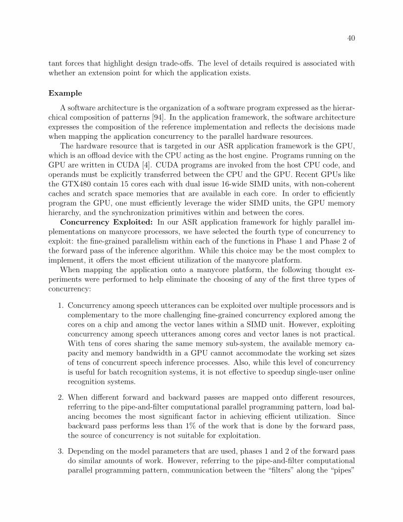
40
tant forces that highlight design trade-offs. The level of details required is associated withwhether an extension point for which the application exists.
Example
A software architecture is the organization of a software program expressed as the hierar-chical composition of patterns [94]. In the application framework, the software architectureexpresses the composition of the reference implementation and reflects the decisions madewhen mapping the application concurrency to the parallel hardware resources.
The hardware resource that is targeted in our ASR application framework is the GPU,which is an offload device with the CPU acting as the host engine. Programs running on theGPU are written in CUDA [4]. CUDA programs are invoked from the host CPU code, andoperands must be explicitly transferred between the CPU and the GPU. Recent GPUs likethe GTX480 contain 15 cores each with dual issue 16-wide SIMD units, with non-coherentcaches and scratch space memories that are available in each core. In order to efficientlyprogram the GPU, one must efficiently leverage the wider SIMD units, the GPU memoryhierarchy, and the synchronization primitives within and between the cores.
Concurrency Exploited: In our ASR application framework for highly parallel im-plementations on manycore processors, we have selected the fourth type of concurrency toexploit: the fine-grained parallelism within each of the functions in Phase 1 and Phase 2 ofthe forward pass of the inference algorithm. While this choice may be the most complex toimplement, it offers the most efficient utilization of the manycore platform.
When mapping the application onto a manycore platform, the following thought ex-periments were performed to help eliminate the choosing of any of the first three types ofconcurrency:
1. Concurrency among speech utterances can be exploited over multiple processors and iscomplementary to the more challenging fine-grained concurrency explored among thecores on a chip and among the vector lanes within a SIMD unit. However, exploitingconcurrency among speech utterances among cores and vector lanes is not practical.With tens of cores sharing the same memory sub-system, the available memory ca-pacity and memory bandwidth in a GPU cannot accommodate the working set sizesof tens of concurrent speech inference processes. Also, while this level of concurrencyis useful for batch recognition systems, it is not effective to speedup single-user onlinerecognition systems.
2. When different forward and backward passes are mapped onto different resources,referring to the pipe-and-filter computational parallel programming pattern, load bal-ancing becomes the most significant factor in achieving efficient utilization. Sincebackward pass performs less than 1% of the work that is done by the forward pass,the source of concurrency is not suitable for exploitation.
3. Depending on the model parameters that are used, phases 1 and 2 of the forward passdo similar amounts of work. However, referring to the pipe-and-filter computationalparallel programming pattern, communication between the “filters” along the “pipes”

41
Inference Engine: Beam Search with Graph Traversal!
Speech Feature Extractor!
Inference !Engine!
Voice Input!
Recognition Network!
SpeechFeatures!
Word Sequence!
!"
I think therefore I am
Acoustic Model!
Pronunciation Model!
Language Model!
Iterative Refinement!
Pipe-and-Filter!
MapReduce!
Iterative through inputsone time step at a time"
In each iteration, perform Viterbi algorithm steps"
In each step, consider alternative interpretations "
Figure 4.5: The software architecture of a large vocabulary continuous speech recognitionapplication. At the top level, the application can be seen as an instance of the Pipe-and-filter pattern, with the speech feature extractor and the inference engine as filters, and theintermediate results between them on pipes. Inside the inference engine, the iterationsover each time step in the application is based on the Iterative Refinement pattern, whereeach iteration handles one input feature vector corresponding to one time-step. Inside eachiteration, phases 1 and 2 can be seen as filters in a Pipe-and-filter pattern. Within eachphase, the computations can be executed in parallel following the MapReduce pattern.
may limit performance. In such a case, if phased 1 and 2 are implemented in the GPUand CPU, respectively, the amount of intermediate results that must be transferredbetween them can lead to a performance bottleneck. Indeed, this situation is observedin [63].
Architecture Representation: Figure 4.5 shows the software architecture for theASR application framework as a hierarchical composition of parallel programming patterns.The top level of the inference engine may be associated with the Iterative Refinement Struc-tural Pattern [94], where each iteration handles one input feature vector corresponding toone time-step. The computation for the entire iteration is mapped onto the GPU device,such that the computation throughput will not be bottlenecked by intermediate results thatwould be transferred between the CPU and the GPU. The work within each iteration canbe associated with the Pipe-and-filter Structural Pattern [94], where the phases can be con-sidered as filters. The computation in each of the two phases can be associated with theMapReduce Structural Pattern [94], where thousands of observation probabilities are com-

42
puted in parallel, and tens of thousands of alternative interpretations of a speech utteranceare tracked in parallel.
Challenges: While this software architecture maps well with respect to the many com-puting resources on the manycore GPU devices, it also presents significant challenges in re-gard to global synchronizations between different algorithm steps. For example, in Phase 2of the forward pass of the Viterbi algorithm, the inference process is based on parallel graphtraversal, a well-known and challenging problem in parallel computing [107], especially inthe context of speech recognition [86]. The parallel graph traversal operates on an irreg-ular subset of 10,000 states of the speech model representing the most likely alternativeinterpretations of the utterance; it frequently updates conflicting memory locations. Cor-rectly implementing such challenging tasks in parallel while optimizing for metrics suchas memory bandwidth are often beyond what most application domain experts would liketo undertake. Section 4.4.3 elaborates on how this challenge can be resolved by the useof application framework, which provides a reference implementation that encapsulates anefficient solution to these implementation challenges.
4.4.3 Reference Implementation
In this section, we discuss the reference implementation, which is third of the four com-ponents of a pattern-oriented application framework by presenting its features, functions,and benefits to the application domain expert. We then use a component from an ASRapplication framework as an example.
Feature
The Reference Implementation component of the pattern-oriented application frameworkis a fully functional, efficient sample parallel design of the application. It provides a descrip-tion of the data structures and application modules, an explanation of their implementationdecisions, and an illustration of how data structures and application modules are mappedonto the implementation platform.
Function
The reference implementation here allows the application framework to achieve fourobjectives. First, it demonstrates that the application concurrency can be exposed whilemaintaining functional correctness. Second, it demonstrates that an efficient software ar-chitecture can be designed to exploit specific levels of application concurrency. Third, itdemonstrates that an efficient software implementation can be constructed on a comput-ing platform. Lastly, it demonstrates that the computing platform is capable of efficientlydelivering the desired performance objectives.

43
Read Files!
Initialize data
structures!
CPU!Manycore GPU!
Backtrack!
Output Results!
Phase 0!
Phase 1!
Compute Observation
Probability!
Phase 2!
Graph Traversal!
Save !
Backtrack Log!W!
R"W!
R!
R!W!
Data!Control!Data! Control!
R!
RW!
R!
W! W!
RW!
R!
Collect "
Backtrack Info!
Prepare ActiveSet!
Iteration Control!
Figure 4.6: A summary of the data structure access and control flow of the inference engineon the manycore platform
Benefits
By providing the reference implementation, application domain experts can examine thespecific application concurrency that is exploited and how it fits in an efficient softwareimplementation. They can also experience the performance achievable on a hardware plat-form. Such information can allow domain experts to quickly evaluate the suitability of theapplication framework for their specific usage scenario. Moreover, all of this can be achievedwithout going through weeks of exercise learning about a hardware platform, and monthsof development and debugging on a proof-of-concept design.
Example
Figure 4.6 illustrates the reference implementation of the speech inference engine. Asspecified in the software architecture, the forward pass inference loop is implemented on theGPU accelerator, and the backward pass is implemented on the CPU.
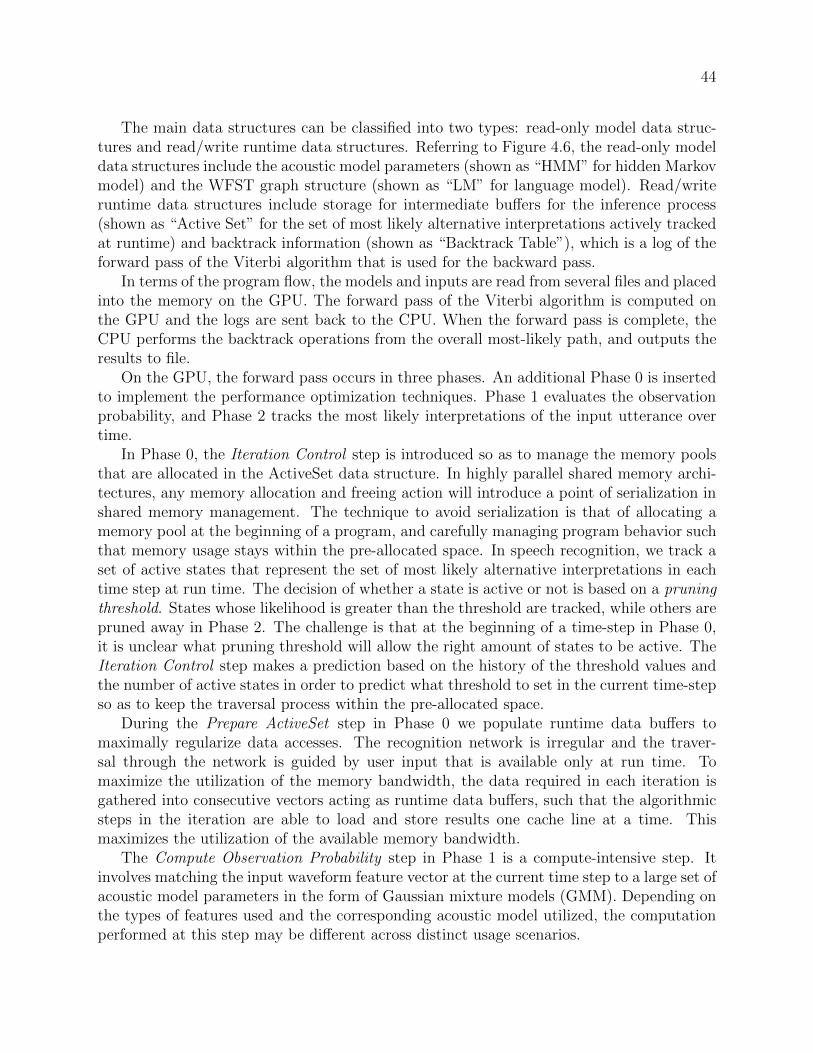
44
The main data structures can be classified into two types: read-only model data struc-tures and read/write runtime data structures. Referring to Figure 4.6, the read-only modeldata structures include the acoustic model parameters (shown as “HMM” for hidden Markovmodel) and the WFST graph structure (shown as “LM” for language model). Read/writeruntime data structures include storage for intermediate buffers for the inference process(shown as “Active Set” for the set of most likely alternative interpretations actively trackedat runtime) and backtrack information (shown as “Backtrack Table”), which is a log of theforward pass of the Viterbi algorithm that is used for the backward pass.
In terms of the program flow, the models and inputs are read from several files and placedinto the memory on the GPU. The forward pass of the Viterbi algorithm is computed onthe GPU and the logs are sent back to the CPU. When the forward pass is complete, theCPU performs the backtrack operations from the overall most-likely path, and outputs theresults to file.
On the GPU, the forward pass occurs in three phases. An additional Phase 0 is insertedto implement the performance optimization techniques. Phase 1 evaluates the observationprobability, and Phase 2 tracks the most likely interpretations of the input utterance overtime.
In Phase 0, the Iteration Control step is introduced so as to manage the memory poolsthat are allocated in the ActiveSet data structure. In highly parallel shared memory archi-tectures, any memory allocation and freeing action will introduce a point of serialization inshared memory management. The technique to avoid serialization is that of allocating amemory pool at the beginning of a program, and carefully managing program behavior suchthat memory usage stays within the pre-allocated space. In speech recognition, we track aset of active states that represent the set of most likely alternative interpretations in eachtime step at run time. The decision of whether a state is active or not is based on a pruningthreshold. States whose likelihood is greater than the threshold are tracked, while others arepruned away in Phase 2. The challenge is that at the beginning of a time-step in Phase 0,it is unclear what pruning threshold will allow the right amount of states to be active. TheIteration Control step makes a prediction based on the history of the threshold values andthe number of active states in order to predict what threshold to set in the current time-stepso as to keep the traversal process within the pre-allocated space.
During the Prepare ActiveSet step in Phase 0 we populate runtime data buffers tomaximally regularize data accesses. The recognition network is irregular and the traver-sal through the network is guided by user input that is available only at run time. Tomaximize the utilization of the memory bandwidth, the data required in each iteration isgathered into consecutive vectors acting as runtime data buffers, such that the algorithmicsteps in the iteration are able to load and store results one cache line at a time. Thismaximizes the utilization of the available memory bandwidth.
The Compute Observation Probability step in Phase 1 is a compute-intensive step. Itinvolves matching the input waveform feature vector at the current time step to a large set ofacoustic model parameters in the form of Gaussian mixture models (GMM). Depending onthe types of features used and the corresponding acoustic model utilized, the computationperformed at this step may be different across distinct usage scenarios.

45
Phase 2 is a performance critical phase. There are two steps in this phase, the GraphTraversal step and the Save Backtrack Log step. The Graph Traversal step involves data-parallel graph traversals of the irregular WFST graph structure, where the working set isguided by inputs known only at runtime. The graph traversal routines execute in parallelon different cores and frequently have to update the same memory locations. Such frequentwrite conflicts between cores must be resolved in an efficient manner. Four techniques wereemployed to optimize the graph traversal for speech inference on GPUs, and each of theseis discussed in details in Chapter 5:
1. Constructing efficient dynamic vector data structures to handle irregular graph traver-sals.
2. Implementing an efficient find-unique function to eliminate redundant work by lever-aging the GPU global memory write-conflict-resolution. policy
3. Implementing lock-free access to a shared-map leveraging advanced GPU atomic op-erations in order to enable conflict-free reduction.
4. Using hybrid local/global atomic operations and local buffers for the construction of aglobal queue to avoid sequential bottlenecks in accessing global queue control variables.
These techniques allow for the graph traversal step with irregular data access patternsand irregular task synchronization patterns to be implemented on a data parallel platform.This way the application will not be bottlenecked as a result of the sharing of intermediatedata between the CPU and the GPU in the inner loop of the speech inference algorithm ina hybrid GPU-CPU implementation. The implementation of these techniques also includesbasic capabilities for introspections on the dynamically changing data working set size thatis induced by the input data. The framework is able to automatically adapt the routines’runtime parameters by adjusting their task distribution parameter (the thread block size)based on the amount of work available.
The Save Backtrack Log step in Phase 2 transfers traversal data from the GPU tothe CPU. This step incurs a sequential overhead of 13% of the total execution time afterparallelization.
4.4.4 Extension Points
In this section, we discuss the extension points, which is last of the four components ofa pattern-oriented application framework by presenting its features, functions, and benefitsto the application domain expert. We then use a component from an ASR applicationframework as an example.
Feature
An extension point is an interface for creating families of functions that extend thecapability of the application framework for a specific application. It is implemented as an

46
Read Files!
Initialize data
structures!
CPU!
GPU!
Backtrack!
Output Results!
Phase 0!
Phase 1!
Compute Observation
Probability!
Phase 2!
Graph Traversal!
Save !
Backtrack Log!
Collect "
Backtrack Info!
Prepare ActiveSet!
Iteration Control!
File Input!
Pruning Strategy!
Observation Probability
Computation!
Result Output!
Fixed Beam Width!
Adaptive Beam Width!
HMM HTK GPU ObsProb!
HMM SRI GPU ObsProb!
CHMM GPU ObsProb!
HTK HResult format!
SRI Scoring format!
Framework! Plug-in!
HTK Format!
SRI Format!
Key:!
CHMM Format!
CHMM Scoring format!
Figure 4.7: An application framework for automatic speech recognition with extension points
instance of an Abstract Factory creational object-oriented programming pattern, as specifiedin [68]. This pattern involves an abstract class definition that specifies a set of methods withnames, as well as a list of parameters accompanying their data types.
Function
The extension points specify how a set of plug-ins should interact with the applicationframework. From the perspective of the framework, the extension points abstract the func-tions provided by the plug-in modules. From the perspective of the plug-ins, the extensionpoints abstract the framework’s requirements for the plug-in functions.
Benefits
For the application domain expert, the extension points provide an environment fromwhich to develop new functions on an application framework. One does not need to rewriteany of the generic modules associated with the infrastructure of an application, and canleverage the expertise crystallized within the performance critical portions of the referenceimplementation. The extension points allow the application domain experts to extend thefunction of the framework without jeopardizing its execution efficiency.

47
1 string getName ();
2 build_model( Runopt * options );
3 save_model ( *filename );
4 load_model ( Runopt * options );
5 free_model ();
6
7 observationProbComputation(
8 frame ,
9 Utterance *in,
10 *LabelFlagHash ,
11 *LabelProbHash );
Figure 4.8: The observation probability computation extension point definition
Example
Based on optimized reference implementation, we can construct extension points to allowthe implementation to be flexibly adapted to a variety of usage scenarios. The applicationframework with its extension points and many plug-ins is presented in Figure 4.7. Theextension points are illustrated as notches in the application framework. Their position isaligned with the functions in the program flow that they affect. The shapes of the extensionpoints, or the notches, correspond to the associated plug-ins that match them.
There are three extension points implemented in the ASR application framework: theObservation Probability Computation, the Pruning Strategy, and the Output File Format.
The Observation Probability Computation extension point is complex. It is usedto manage not only the computation of the observation probability, but the data structureof the acoustic model associated with the computation as well. As different acoustic modelsmay have different data representations, the data structure itself is not specified at theinterface. This is also the reason why the File Input extension point is part of this interface.The interface is specified in the following manner:
In the extension point interface for observation probability computation shown in Fig-ure 4.8, line 1 is a self-identifying function for the plug-in function. The build model interfaceon Line 2 reads a text format input file into the internal data format. The filename to read isspecified in the run options in the parameter. The save model interface on Line 3 dumps theinternal format to a binary file for fast loading in future runs. The load model interface onLine 4 loads previously dumped internal format from a binary file. The free model interfacefrees a model from the memory.
The observationProbComputation interface on line 7 is where Phase 1 of the inferenceengine takes place. It has four parameters. The frame parameter specifies what frame,or time step, the Phase 1 calculations target. The in parameter provides the input data.The LabelFlagHash parameter provides a vector of “0”s and non-“0”s as flags, where a “0”means the calculation should be skipped. The LableProbHash is a vector of output wherefor each non-“0” in the input flag vector, a valid observation probability is expected.

48
1 string getName ();
2 iteration_control(
3 frame ,
4 iControl *history ,
5 pruneThreshold );
Figure 4.9: The pruning strategy extension point definition
1 string getName ();
2 Result_Output(
3 FILE *outFile ,
4 gpu_History *hist ,
5 WordTable *Wordtable ,
6 SegmentList *segmentList );
Figure 4.10: The result output extension point definition
The Pruning Strategy extension point allows the customization of the algorithmfor specifying the pruning threshold to occur. The interface is as follows:
Figure 4.9 shows the In the extension point interface for the pruning strategy, line 1 isa self-identifying function for the plug-in function. The iteration control interface has threeparameters. The frame parameter specifies what frame, or time step, the plug-in is workingon. The history parameter provides the history of the past active state count and pruningthreshold used. The pruneThreshold is the predicted pruning threshold to be used for thecurrent frame.
The Result Output extension point allows the results of the inference process to bedisplayed in any format. The interface is as follows:
In the extension point interface for result output shown in Figure 4.10, line 1 is a self-identifying function for the plug-in function. The Result Output interface has four param-eters. The outFile parameter indicates the file pointer if the results are to be written to afile. The hist parameter provides the results of the backward pass in the Viterbi algorithm.The Wordtable parameter provides the word table to look up word IDs and print them outas words. The segmentList parameter provides the list of filenames being analyzed.
4.5 Discussion
The pattern-oriented application framework is best suited for applications with a rela-tively mature software architecture, where extension points can be clearly defined [59], asthe framework code must remain stable across many deployments to end-user usage scenar-ios for the cost of developing a framework to be effectively amortized. With this in mind,applications such as automatic speech recognition (ASR) are ideal candidates.
With respect to the “effectiveness” metrics specified in Section 3.1, the pattern-oriented

49
application framework, as discussed in this chapter, allows an application domain expert toconstruct an end-user application in a productive, efficient and portable manner.
Productivity
Productivity is achieved as the application framework allows an application domain ex-pert to follow a fast path to a functionally correct solution that implements the desiredfeature or application that can meet the performance constraints. We qualitatively describethe productivity benefits here.
The application context component of the pattern-oriented application framework pro-vides a more concise set of background information. The component quickly introduces anapplication domain expert to the sources of concurrency that are inherent to the applicationdomain. This saves him/her a significant amount of time that would other wise be spent onthe identification of sources of concurrency to exploit.
The software architecture component of the pattern-oriented application framework in-troduces an efficient software architecture for better implementation of the application, aswell as the potential performance bottlenecks to avoid. This saves the time necessary toarchitect an application from scratch and arduously perform software architecture designspace exploration to validate the software architecture.
Although some effort is required to understand an application framework well enough touse it, the pattern-oriented nature of the application framework provides a standard formatto expose and exploit application concurrency, greatly reducing the burden to studying theapplication context and the software architecture to get oriented to the reference implemen-tation and extension points.
The pattern oriented application framework includes a reference implementation withextension points that allow for the quick customization of the application framework in orderto target specific usage scenarios. This reduces the lines of code (LOC) that an applicationdomain expert has to write to the specific customizations of the extension points. As anexample, this reduces the efforts of implementing a speech recognition application from aten-thousand-line application to a few hundred lines of plug-in code.
The application context and the software architecture components of the pattern-orientedapplication framework carefully explains the sources of application concurrency and thetrade-offs in exploiting these sources. This greatly reduces errors in an implementationresulting from any misunderstandings of the parallelization concept.
With significant reduction in the lines of code required to be implemented, the probabilityof errors from the inevitable coding process is greatly reduced.
Efficiency
Efficiency is achieved through the rigorous process of developing reference implementa-tions that incorporates both application domain expertise as well as parallel programmingexpertise to take full advantage of the hardware resources. Section 5.1.4 demonstratesthe achievable efficiency of a reference implementation’ by presenting results that achieved

50
85-98% of peak execution efficiency on a GPU for the compute-intensive portion of an appli-cation. Section 6.1 demonstrates a 14-20x speed up on a GPU compared to the performanceof the sequential implementation on a CPU.
Portability
Portability for a pattern-oriented application framework is achieved through two means:functional portability and performance portability.
With respect to functional portability, the narrow interfaces defined by the extensionpoints naturally partition the application such that the plug-ins of the application frame-work can be used in other application frameworks. An extreme exemplar that illustratesthis portability is that of the observation probability computation plug-in presented in Sec-tion 6.1.3. It was originally designed for audio-video speech recognition, and was recentlyused in another application implementing audio-video speech model training.
With respect to performance portability, the pattern-oriented design allows the imple-mentation to achieve “Parallel scalability” [157], enabling an application to efficiently utilizean increasing number of processing elements on future generations of even more parallelplatforms.
It is also well known that performance portability across architecturally different micro-architectures is a challenging research topic. As demonstrated in Section 5.1.3 and Sec-tion 5.1.5, application framework must be tuned on different microprocessors to achievehigh efficiency. Such tuning process can be automated as described in [152]. The implemen-tation of the extension point can utilize programming frameworks such as Copperhead [39]to allow parallel computation to be implemented on architecturally diverse manycore mi-croprocessors.
4.6 Summary
Pattern-oriented application frameworks allow application domain experts to effectivelyleverage the capabilities of the highly parallel manycore microprocessors. The four maincomponents of a pattern-oriented application framework are: application context, softwarearchitecture, reference implementation, and extension points. The feature, function, andthe benefits of each component were discussed, and examples of each component from theautomatic speech recognition application framework were provided.
The four components of the application framework, when used together, allow an appli-cation domain expert to specify the needs of the application usage scenario, to match themto an application framework, and to customize the associated reference implementation inorder to construct the software for an end-user usage scenario – all without the presence ofa parallel programming expert.
Pattern-oriented application frameworks can greatly reduce the barriers for applicationdomain experts to more effectively utilize the manycore microprocessors, encouraging widerdeployment of highly parallel computing platforms.

51
Chapter 5
The Construction of Pattern-OrientedApplication Frameworks
When an application developer is faced with developing a parallel application, he/sheshould look for a pattern-oriented application framework for parallel programming to assistin the application development process. When an appropriate application framework exists,the application developer can customize it and apply it to the usage scenario at hand.However, when no appropriate application framework is available, how can he/she constructan efficient implementation, and re-factor it into an application framework for future use?
Constructing a pattern-oriented application framework for parallel programming requiresa four-step process, as illustrated in Figure 5.1. The first three steps: specify, architect,and implement, were addressed in Section 2.3. Once a functional and efficient referenceimplementation is available, one can leverage it to create the application framework. Theleverage process includes re-factoring the implementation, creating extension points, anddeveloping plug-in modules for the extension points.
This chapter addresses the two main concerns in the development of application frame-works: efficiency and productivity. Since the primary motivation for application developersto take up the challenge of using parallel platforms is the potential performance gains, theprimary concern to address during the construction of a pattern-oriented application frame-work is execution efficiency. Once an efficient implementation exists, we can go on to explorethe construction of the extension points in order to allow for better developer productivity.
This chapter presents the construction process of three pattern-oriented applicationframeworks in the respective fields of machine learning and computational finance.
1. The Automatic Speech Recognition (ASR) application framework provides speechrecognition application experts with an infrastructure to quickly deploy speech recog-nition application under different usage scenarios. An efficient ASR application hasbeen completely implemented and was re-factored to enable multiple extension pointsto be constructed. The completed application framework has been deployed in twousage scenarios, which are further described in Chapter 6.
2. The Value-at-Risk (VaR) application framework is being developed to allow risk man-agers in banks and hedge funds to quickly deploy VaR engines for their specific usage

52
Specify
Architect
Implement
Leverage
• Evaluate legal transformations • Prototype potential bottlenecks • Specify data types and APIs
• Implement functions • Define and deploy unit tests • Verify performance goals
• Refactor implementation • Create extension points • Develop plug-ins
Artifacts
Application Domain Expert
Expert Parallel
Programmer
Application Domain Expert
Expert Parallel
Programmer
Expert Parallel
Programmer
Application Domain Expert
!"#$%&'()*++,-./01")
2/(/,,',)3145/(')
2/(/,,',)2/6'("&)/"#))7(/8'51(9&)
Development Process
• Describe application characteristics • Expose parallelization opportunities • Define invariants
Expertise Required
!"#"$$%$&'(($)*"+,-&.%/%$,(0%-1&
Figure 5.1: The construction of pattern-oriented application frameworks using the Leveragestep.
scenarios. The configurations needed to achieve efficient execution are reported, andan efficient reference implementation has been developed. Research with respect tothe re-factoring and the development of the extension points in the reference imple-mentation is still on-going.
3. The Potential Future Exposure (PFE) application framework is being developed toallow an industrial-scale counterparty exposure estimation application (as describedin Section 5.2.2) to be effectively extended and maintained. The initial design spacehas been explored and the full reference implementation is still being constructed.
5.1 Automatic Speech Recognition Application Frame-work
Automatic speech recognition (ASR) allows multimedia content to be transcribed fromacoustic waveforms to word sequences. This technology is emerging as a critical componentin data analytics for the wealth of media data that is being generated everyday. Commercialusage scenarios have already begun to appear in industries, such as customer service callcenters for data analytics, where ASR is used to search recorded content, track servicequality, and to provide early detection of service issues. Fast and efficient ASR enableseconomic employment of text-based data analytics to multimedia contents to occur. Thisopens the door to an unlimited array of potential applications, such as automatic meetingdiarization, news broadcast transcription, and voice-activated multimedia systems in homeentertainment systems.

53
The goal of an automatic speech recognition application is to analyze a human utterancefrom a sequence of input audio waveforms in order to interpret and distinguish the wordsand sentences intended by the speaker. The mathematics behind statistical inference forprobabilistic functions of finite state Markov chains was developed by Baum in the late1960s [24]. The concept was used in a speech recognition system in 1975 by Baker [22],as well as in work conducted at IBM by Jelinek et al. [87]. The concept of beam search,which is a heuristic used to “focus” computation on the most-likely portion of a searchspace, was used by Lowerre in 1976 [106]. In the 1980s, HMM-based approaches wereinvestigated by labs at BBN [133] and Philips [32], as mentioned in [74]. By the mid-late1980s, HMMs became the dominant recognition paradigm, adopted by systems at SRI [116],MIT-Lincoln [126], and Carnegie Mellon University (CMU). The CMU system developedby Lee in 1988 [103] is representative of the types of systems developed at the time.
An HMM-based approach has since become the de facto approach used in major speechrecognition projects such as SPHINX, HTK, and Julius [103, 154, 102]. This approach gainedfurther popularity after the Rabiner published his extensive survey paper [129] on HMM forspeech recognition. Figure 5.2 shows the major components of such a system. This systemuses a recognition network that is compiled offline from a variety of knowledge sources usingpowerful statistical learning techniques. Spectral-based speech features are extracted byprocessing the input audio signal; the inference engine then computes the most likely wordsequence based on the extracted speech features and the recognition network.
Inference engine based LVCSR systems are modular and flexible. They are languageindependent and robust to various acoustic environments [154, 102]: by using differentrecognition networks and signal-processing kernels, they have been shown to be effectivefor Arabic, English, Japanese, and Mandarin, in a variety of situations, such as phoneconversations, lectures, and news broadcasts.
There is a large body of prior work in mapping LVCSR to parallel platforms, which canbe clustered into three categories of efforts:
• Data Parallel, shared memory implementations on multiprocessor clusters : These im-plementations are plagued by high communication overhead in the platform, high se-quential overhead in the software architecture, load imbalance among parallel tasks orexcessive memory bandwidth. They are limited in scalability as computing platformsbecome more parallel.
In 1993, Ravishankar [130] presented a parallel implementation of the HMM-basedinference engine with a beam search algorithm on a shared memory PLUS multi-processor cluster that was developed at Carnegie Mellon University. The implemen-tation statically mapped a carefully partitioned recognition network onto the multi-processors in order to minimize load imbalance. While achieving a 3.83x speedup overthe sequential implementation on five processors, static partitioning approaches willnot scale well to tens of cores due to load imbalance among the partitions at run time.
The parallel LVCSR system proposed by Phillips et al. [128] achieved a 4.6x to 6.23xspeedup on 16 processors. However, this implementation was limited by the sequentialcomponents in the recognizer and load imbalance among the processors. Their private
54
buffer-based synchronization imposes significant data structure overhead and is notscalable with the increasing number of cores.
You et al. [158] have recently proposed a parallel LVCSR implementation on a com-modity multicore system using OpenMP. The Viterbi search was parallelized by stat-ically partitioning a tree-lexical search network across cores. However, due to limitedmemory bandwidth, only 2x speedup was achieved on shared-memory Intel Core2quadcore processors.
• Task parallel implementation: the scaling of these implementations to more parallelplatforms requires extensive redesign efforts.
Ishikawa et al. [85] explored coarse-grained concurrency in LVCSR and implementeda pipeline of tasks on a cell phone-oriented multicore architecture. They achieved2.63x speedup over a sequential baseline version by distributing tasks among threeARM cores. However, due to the small amount of function-level concurrency in thealgorithm, it is difficult for this implementation to scale beyond three cores.
• Data Parallel implementation with manycore-based accelerators in CPU-based hostsystems :
Prior works such as [62, 38, 79] by Dixon et al., Cardinal et al., and Gupta et al. lever-aged manycore processors and focused on speeding up the compute-intensive phase(i.e., the observation probability computation) of LVCSR on manycore accelerators.Compared to CPU-based implementations, both [62] and [38] have shown approxi-mately 5x speedups in the compute-intensive phase. Both [62] and [38] have alsomapped the communication intensive phases (i.e., Viterbi search) onto the host CPUprocessor. This software architecture incurs significant penalty for copying intermedi-ate results between the host and the accelerator subsystem and does not expose themaximum potential of the performance capabilities of the platform.
The automatic speech recognition inference engine presented in this thesis is a collec-tion of multiple years of efforts in constructing an efficient and scalable application that isfully implemented on the GPU. The following sections illustrate in a host of optimizationsthat can be encapsulated in a pattern-oriented application framework for domain experts.Specifically:
• Sections 5.1.1 and 5.1.2: Apply parallel programming expertise to expose and exploitapplication concurrency to more efficiently implement ASR
• Section 5.1.3: Applies application domain expertise to explore multiple recognitionnetwork representations in order to more efficiently implement ASR
• Section 5.1.4: Applies application domain expertise to transform input recognitionnetwork structure so as to more efficiently implement ASR
• Section 5.1.5: Applies parallel programming expertise in order to experiment withmultiple HW implementation platforms to construct more efficient implementationsof ASR

55
SpeechFeatureExtractor
InferenceEngine
VoiceInput
SpeechFeatures
WordSequence
�…
I think therefore I am
AcousticModel
PronunciationModel
LanguageModel
Figure 5.2: The system architecture of a large vocabulary continuous speech recognitionapplication.
5.1.1 Implementation Efficiency Concerns
The recognition of human speech is a complex task, especially when you consider thesignificant variations in the voice quality, speed, and pronunciation among different speakers.Moreover, differences among languages and the speech recording environments pose furtherchallenges to an effective recognition system. After decades of scientific research, manyresearchers have converged on the hidden Markov model (HMM) extract and inferencesystem as a standard setup. In this setup, the acoustic signal is treated as the observedsequence of events and the sentences to be recognized are considered the hidden cause ofthe acoustic signal.
Figure 5.2 illustrates that ASR first extracts the representative features from an inputwaveform and then decodes the feature sequence to produce a word sequence. The featureextraction process involves a sequence of signal processing steps. It is done to minimize theinfluence of non-linguistic factors in the speech signal and preserving factors that are mostuseful in distinguishing word sequences. A feature vector is extracted per 10ms segment ofthe waveform (a time step). A sequence of feature vectors is used in an inference processby iteratively comparing each feature vector to a probabilistic speech model. The speechmodel contains an acoustic component, a pronunciation component, and a language com-ponent. The pronunciation component comes from a typical dictionary. Both the acousticand language components are trained off-line using a set of powerful statistical learningtechniques.
The acoustic model is often represented as a multi-component Gaussian mixture model,which is a more general model that uses a family of distributions to represent the featurespace of each phone label1. The pronunciation model describes each word as a sequence ofphones that make up its pronunciation. The language model relates words to phrases and is
1Phone: An abstract unit of sound

56
Obs 1 Obs 2 Obs 3 Obs 4 !
State 1!
State 2!
State 3!
State N!
Time!
…!
…!
…!
…!
…!
An Observation!A State!
P( xt|st ) P( st|st-1 ) m [t-1][st-1] m [t][st ]
Legends:!
Model size for a WFST language model!
A Pruned State!
1. Forward Pass!
2. Backward Pass!
# states: 4 million, # arcs: 10 million, # observations: 100/sec" Average # active states per time step: 10,000 – 20,000!
Observations!
Speech!
Model "
States!
Figure 5.3: Application characteristics: the inner-workings of the performance criticalViterbi forward and backward pass steps.
often represented by unigrams, bigrams, and trigrams, which are the common one/two/threeword phrases and their likelihood of appearance in a language. To recognize a different lan-guage in a distinct environment, only the speech model and the feature extractor need to bechanged. The inference engine remains unchanged producing the most-likely interpretationof the input sequence by traversing the speech model for the specified language.
The pronunciation model and language model can be seen as finite state machines withtransition probabilities on the arcs between states. One of the state-of-the-art optimiza-tion techniques in automatic speech recognition is the composition of the acoustic modelwith the language model off-line in order to produce a weighted finite state transducer(WFST) [112], where a single state machine can relate phone sequences to phrases directly.A typical WFST-based recognition network can have millions of states and arcs. The WFSTrepresentation could reduce redundancies in the number of state transitions traversal at runtime by 22x [44], and simplify the traversal process to reference only one state machine.
Figure 5.3 shows the inference process of ASR. The inference engine uses the Viterbidynamic programming algorithm [121]. It performs a forward-pass to track the more likelyinterpretations of the feature vector sequence through each increment in the time steps, anda backward-pass step to backtrack the path taken by the most likely outcome at the end ofa sequence.
The forward-pass has two main phases in the inference process. Figure 5.3 shows Phase 1as dashed arrows between observations and states. This phase evaluates the observationprobability of the hidden state, matches the input information to the available acousticmodel elements, and only takes into account the instantaneous likelihood of a feature match-ing acoustic model element. Figure 5.3 shows Phase 2 as the solid arrows between the statesof consecutive time steps. Phase 2 references the historic information in regards to what themost likely alternative interpretations of the utterance heard so far are. It also computes thelikelihood of incorporating the current observations given the pronunciation and languagemodels. The computation for each state st at time t (with the diamond shaped state asan example) records the state transition from the prior time step t − 1 that produced themaximum probability m[t][st].
57
In each time step of the algorithm, the data working set involves thousands of activestates that are used to keep track of the most likely alternative interpretations of the speechthat has been heard so far. We compute the next set of active states by using Phase 2of the algorithm, as described above. It is found that by tracking less than 1% of themost likely alternative interpretations and pruning away the rest, negligible differences inrecognition accuracy are perceived as compared to tracking all alternative interpretations.The process of pruning less likely interpretations is called the beam search technique asdescribed by [121], is called the beam search technique.
The recent development of the weight-finite state transducer (WFST) [112] has had afurther standardization effect in the inference engine. In the traditional HMM-based LVCSRinference engine, the recognition network has a regular structure where each word is trans-lated into a sequence of phone-states to be recognized, i.e. a linear-lexicon network. Manywords that have the same prefix have phone states that can be shared, leading to a tree-based structure for the recognition network, or a tree-lexicon network. The tree-lexiconnetwork has a greatly reduced memory footprint and saves computation time when the con-nectivity between words is not considered. Yet, as word-to-word bigram probabilities areused, a significant number of runtime state needs to be preserved with a tree replicationprocess, making the decoder cumbersome to design. Mohri’s work on WFST provides aLVCSR recognition network with features that are pre-compiled into the recognition net-work. Many of the recognition network optimization techniques are applied during networkcomposition, and the decoding process has a clean, and well-defined behavior.
Application Concurrency
As mentioned in the sample application context for speech recognition in Section 4.4.1,there are four main levels of concurrency in the inference process that can be exposedby examining the application’s characteristics. These levels of concurrency are exposedwith parallel programming patterns, where the patterns are used to illuminate potentialperformance bottlenecks that may be encountered while exploiting these parallelizationopportunities.
1. Concurrency among speech utterances:
Looking at the process of extracting acoustic features from the input waveform andconducting the inference on the feature stream with the speech inference engine, theinput waveform can be split up into numerous segments of speech that can be indepen-dently recognized2. A typical conversational utterance is usually no longer than 5 to 30seconds long and is separated by short silences. A one-hour long speech recording canbe quickly processed to detect pauses in the speech and can be split up into hundredsof utterances to be recognized in parallel. This can be done utilizing the MapReducepattern, where the Map function maps the independent utterances to be processed in
2One may argue that the topic of the words in one part of the input speech may help with recognitionof other parts of the input speech. While it is true that the knowledge of context may help improve theaccuracy of the speech, how context is best taken into account in speech recognition remains a topic ofresearch

58
!"#$%&'()*+,--"$#'.*/0&,'
!"#$%$"&$''(")*"$'
+,*&$'!"-./'
0-$$&1'2$3/.%$4'
1'
5,%6'0$7.$"&$'
I think therefore I am
8$&,)"*9,"':$/;,%<'
2+*0-3+'.*/,&'
()*$0$+"%3*$'.*/,&'
4%$#0%#,'.*/,&'
!"#$%&'()*+,--"$#'.*/0&,'
!"#$%&'()*+,--"$#'.*/0&,'
0-$$&1'2$3/.%$4'
1'
0-$$&1'2$3/.%$4'
1'
!"#$%$"&$''(")*"$'
!"#$%$"&$''(")*"$'
=>?' 8(@AB('
Figure 5.4: Parallelization Opportunity 1: Applying MapReduce parallel programming pat-tern over the input speech utterances.
parallel. The Reduce function then merges the resulting words according to their timestamps to produce a full transcription of the recording. Figure 5.4 illustrates the Mapand Reduce operations.
Figure 5.4 illustrates the concurrency over multiple input speech utterances. Whilethis level of concurrency can be exploited over multiple processors where it can be com-plementary to the exploitation of more fine-grained concurrency within the detailedalgorithm steps, it is not suitable for exploitation within vector lanes on a manycoreprocessor. The Map process in the MapReduce parallel programming pattern dupli-cates the data working set of the map process. While the read-only operands canbe shared, the data working set for an inference process contains tens of megabytesof variables. Duplicating the working set across a large number of mapped processeson the same manycore processor with a shared memory subsystem will create severememory bandwidth contention, leading to a performance bottleneck at the memoryinterface. Furthermore, this level of concurrency can not be exploited for latencysensitive applications such as single-user on-line applications,.
2. Concurrency among the forward and backward passes:
The forward and backward pass steps in the Viterbi algorithm can be seen as aninstance of the Pipe-and-Filter pattern, where the forward pass and backward passare filters, and the speech data passes through them and get transcribed into words.Applications that match the Pipe-and-Filter pattern can be pipelined, as independentdata flows through the application. In the first of the four application concurrencyopportunities, it was explained how a long speech recording can be segmented intoshort speech utterances. Figure 5.5 illustrates the parallelization opportunity existsto process forward and backward pass using a pipelined approach.

59
Obs 1 Obs 2 Obs 3 Obs 4 !
State 1!
State 2!
State 3!
State N!
Time!
…!
…!
…!
…!
…!
1. Forward Pass!
2. Backward Pass!
Observations!
Speech!
Model
States!
Speech Feature Extractor!
Inference !Engine!
Voice Input!
Recognition Network!
SpeechFeatures! Word
Sequence!
!"
I think therefore I am
Acoustic Model!
Pronunciation Model!
Language Model!
!" #!$ #!% #!& #!' #!(#####
#$"""""%$"
#$""""%$"
#$"""""%$"
#$""""%$"
Figure 5.5: Parallelization Opportunity 2: Applying the Pipe-and-Filter parallel program-ming pattern over a sequence of input speech utterances.
Figure 5.5 shows the progression of time across the page, and the independent speechutterances going down the page. The independent speech utterances can be pipelined,i.e. the backward pass of one utterance can be computed at the same time as theforward pass of the next utterance.
In order to exploit this level of concurrency with the pipelining technique in the Pipe-and-filter parallel programming pattern, the pipeline stages must be balanced. In theViterbi algorithm used in speech recognition, the backward pass performs less than1% of the work done by the forward pass. Thus, the source of concurrency is notsuitable for exploitation.
3. Parallelism among the computationally intensive and communication in-tensive phases:
The Viterbi algorithm iterates through the input one time step at a time. Within eachiteration, it performs two phases of computation. Phase 1 compares the input obser-vation at the current time step with the acoustic models in the recognition network.This provides an instantaneous match between the input and the acoustic model, andinvolves the computationally intensive Gaussian mixture model (GMM) based com-putation. Phase 2 then takes the historical information into account by consideringthe accumulated likelihood from the previous time steps along with the state-to-statetransition probabilities from the pronunciation and language models. Looking up theprevious likelihood and state-to-state transition likelihood is highly communication

60
Phase 2
Inference Engine: Beam Search with Graph Traversal!
Phase 1
Iterate through inputs one time step at a time
In each iteration, perform beam search algorithm steps
Phase 1: Computation Intensive
Phase 2: Communication Intensive
Speech Feature Extractor!
Inference !Engine!
Voice Input!
Recognition Network!
SpeechFeatures! Word
Sequence!
!"
I think therefore I am
Acoustic Model!
Pronunciation Model!
Language Model!
Obs 1 Obs 2 Obs 3 Obs 4 !
State 1!
State 2!
State 3!
State N!
Time!
…!
…!
…!
…!
…!
1. Forward Pass!
2. Backward Pass!
Observations!
Speech!
Model
States!
Figure 5.6: Parallelization Opportunity 3: Applying the Pipe-and-Filter parallel program-ming pattern over two phases of execution.
intensive.
The two phases can be seen as a Pipe-and-Filter parallel programming pattern, wherethe phases are the “filters”, and the data passes through the “pipes” between the“filters”. However, the two phases are encapsulated within an iterative-loop, withsequential dependencies between loop iterations. Such dependencies can be removedby the technique of speculation, where Phase 1 can speculatively process more workthan necessary in order to start the work load of the next iteration before the currentiteration has completed processing. Without these sequential dependencies betweenthe loop iterations, the two phases may be parallelized through the pipelining approachacross loop iterations.
To exploit this level of concurrency with the pipelining technique in the Pipe-and-filterparallel programming pattern, the pipeline stages must be balanced. While Phase 1can take 80-90% of the total sequential execution time, when it is parallelized on theGPU, its runtime can be comparable with Phase 2’s execution time running on theCPU. One issue with respect to partitioning Phase 1 and Phase 2 across the CPU andthe GPU is that there are thousands of operands that must be passed from Phase 1 toPhase 2 for each time step. Communication between the GPU and CPU can becomea performance bottleneck.
Figure 5.7 illustrates the alternative approaches for the implementation of phases 1and 2 on a CPU-GPU hybrid system. Approach 1 was implemented by Cardinal et al.in [38], where Phase 1 was mapped to the GPU and Phase 2 was mapped to the CPU.

61
Phase 0!
Read Files!
Initialize data structures!
CPU!GPU!
Backtrack!
Output Results!
Phase 1!
Compute Observation Probability!
Phase 2!
Graph Traversal!
Collect Backtrack Info!
Iteration Control!
Phase 0!
Read Files!
Initialize data structures!
CPU!GPU!
Backtrack!
Output Results!
Phase 1!
Compute Observation Probability!
Phase 2!
Graph Traversal!
Collect Backtrack Info!
Phase 1!Compute Observation Probability!
Iteration Control!
CPU!GPU!
Read Files!
Initialize data structures!
Backtrack!
Output Results!
Phase 0!
Phase 1!Compute Observation
Probability!
Phase 2!
Graph Traversal!
Save !Backtrack Log!
Collect Backtrack Info!
Prepare ActiveSet!
Iteration Control!
!""#$%&'()( !""#$%&'(*( !""#$%&'(+(
Figure 5.7: Alternative approaches for the implementation of Phase 1 and Phase 2 on aCPU-GPU hybrid system.
No pipelining was implemented. With the overhead coming from the transferring ofoperands and results back and forth, Phase 1 got a 5x speedup, and the applicationgot only 33% speed up. Approach 2 was implemented by Dixon et al. in [62], where thedependency between Phase 1 and Phase 2 was removed by speculatively computingmore results than necessary. Phase 1 was mapped to the GPU and Phase 2 stayed onthe CPU. When the two phases were pipelined, Phase 1 got a speedup of 2-4x, and theapplication got a 60-90% speed up. Approach 3 was implemented using the techniquesdescribed in this thesis, where both phases 1 and 2 of the inner loop got mapped tothe GPU. By eliminating the operand transfer overhead, Phase 1 got a 16-19x speedup and Phase 2 received a 3-4x speed up. Overall, more than a 10x speed up wasachieved for the application compared to an optimized sequential implementation onthe CPU.
4. Parallelism among the thousands of observation probabilities and tens ofthousands of alternative interpretations of the utterance being tracked:
Within each function in Phase 1, thousands of observation probabilities are beingcomputed at each time step; within each function in Phase 2, tens of thousands ofalternative interpretations of the input utterance are tracked. This is the ideal amountof parallelism that can be effectively utilized on a manycore computing platform.
In this case, the MapReduce parallel programming pattern can be used in this case.Each observation probability computation can be mapped to an independent thread

62
Inference Engine: Beam Search with Graph Traversal!
In each step, consider alternative interpretations "
Speech Feature Extractor!
Inference !Engine!
Voice Input"
Recognition Network"
SpeechFeatures" Word
Sequence"
!"
I think therefore I am
Acoustic Model!
Pronunciation Model!
Language Model!
Obs 1 Obs 2 Obs 3 Obs 4 "
State 1"
State 2"
State 3"
State N"
Time!
…"
…"
…"
…"
…"
1. Forward Pass"
2. Backward Pass"
Observations!
Speech!
Model
States!
Iterate through inputs one time step at a time
In each iteration, perform beam search algorithm
Figure 5.8: Parallelization Opportunity 4: Applying the MapReduce pattern over the func-tions that implement Phase 1 and Phase 2 in the Viterbi algorithm.
for computation, and the results can be reduced into a result array. Each alternativeinterpretation can be mapped to a thread responsible for tracking its likelihood overa time step, and the results are reduced to the destination of the tracking process.
While this software architecture maps well on to the many computing resources on themanycore GPU devices, it also presents significant challenges in regards to the imple-mentation of all algorithm steps with data-parallel functions. More specifically, thereare four main challenges that must be resolved with the following solution techniques:
(a) Challenge: Handling irregular graph structures with data parallel operations
Solution: Constructing efficient dynamic vector data structure to handle irreg-ular graph traversals
(b) Challenge: Eliminating redundant work that occurs when threads are accessingan unpredictable subset of data based on input
Solution: Implementing efficient find-unique function by leveraging the GPUglobal memory write-conflict-resolution policy
(c) Challenge: Performing Conflict-free reductions in graph traversal in order toimplement the Viterbi beam search algorithm
Solution: Implementing lock-free accesses of a shared map leveraging advancedGPU atomic operations with arithmetic operations so as to enable conflict-free reduction

63
(d) Challenge: Parallel construction of a global queue causes sequential bottleneckswhen atomically accessing queue control variables
Solution: Using hybrid local/global atomic operations and local buffers for theconstruction of a global queue to avoid sequential bottlenecks in accessingglobal queue control variables
5.1.2 Detailed Efficiency Optimizations
1. Constructing an efficient dynamic vector data structure to handle irregular graphtraversals
There exist extensive concurrency in the automatic speech recognition application. Asshown in Figure 4.5, there are 1,000s to 10,000s concurrent tasks that can be executedat the same time in both Phase 1 and Phase 2 of the recognition engine.
In a sequential implementation of the speech inference process, more than 80% ofexecution time is spent in Phase 1. The computation in Phase 1 is a Gaussian mixturemodel evaluation to determine the likelihood of an input feature matching specificacoustic symbols in the speech model. The structure of the computation resembles avector dot product evaluation, where careful structuring of the operand data structurescan achieve 16-20x speedup on the GPU. With Phase 1 accelerated on the GPU,Phase 2 dominates the execution time. Phase 2 performs a complex graph traversalover a large irregular graph with millions of states and arcs. The data working set istoo large to be cached and is determined by input available only at run time.
Implementing Phase 2 on the GPU is challenging [107], as operations on the GPU aremost efficient when performed over densely packed vectors of data. Accessing dataelements from irregular data structures can cause an order of magnitude performancedegradation. For this reason, many have attempted to use the CPU for this phase ofthe algorithm with limited success [62, 38]. The sub-optimal performance is mainlycaused by the significant overhead of communicating intermediate results betweenphases 1 and 2.
One can implement both phases of the inference engine on the GPU. This is achievedby using a technique for dynamically constructing efficient vector data structures atrun time. As illustrated in Figure 5.9, this technique allows the intermediate resultsto be efficiently handled within the GPU subsystem and eliminates unnecessary datatransfers between the CPU and the GPU.
Problem:
One often has to operate on large, irregular graph structures with unpredictable dataaccess patterns in machine learning algorithms. How does one implement the dataaccess patterns efficiently on the GPU?
Solution:
The solution involves dynamically constructing an efficient data structure at run time.Graph algorithms often operate on a subset of states at a time. Let this working set be

64
!"#!$ASPA
!"##$%&'#(#)#*$#&+,"-#,#*./01*&
%&'($)*+&,$
-.*/'+*0&$('1'$
,1234132&,$
234&534&
5'4612'46$
731831$%&,3+1,$
9:',&$;$
9:',&$#$
<=>831&$7?,&2@'/=.$
92=?'?*+*1A$
9:',&$B$
)=2$&'4:$'4/@&$'24C$
•!$<=>831&$'24$12'.,*/=.$$
$$$82=?'?*+*1A$
<=8A$2&,3+1,$?'46$1=$
<9D$E$
%$
E$
%$
%$E$
6/./&21*.)1-&6/./& 21*.)1-&
%$
%
E$
%$
E$ E$
%
E$
%$
<=++&41$5'4612'46$
-.F=$
92&8'2&$G4/@&H&1$
-1&2'/=.$<=.12=+$
Kisun You, Jike
Chong, Youngmin Yi, Ekaterina Gonina,
Christopher Hughes, Yen-Kuang Chen,
Wonyong Sung, Kurt
Keutzer, “Parallel Scalability in Speech
Recognition: Inference engine in
large vocabulary
continuous speech recognition”, IEEE
Signal Processing Magazine, vol. 26, no.
6, pp. 124-135,
November 2009.
Jike Chong, Ekaterina Gonina,
Kisun You, Kurt
Keutzer, “Scalable Parallelization of
Automatic Speech Recognition”, Invited
book chapter in
Scaling Up Machine Learning, an
upcoming 2010 Cambridge University
Press book.
Jike Chong,
Ekaterina Gonina, Youngmin Yi, Kurt
Keutzer, “A Fully Data Parallel
WFST-based Large
Vocabulary Continuous
Speech Recognition on a
Graphics
Processing Unit”, Proceeding of the
10th Annual Conference of the
International Speech
Communication Association
(InterSpeech), page 1183 – 1186,
September, 2009.
Figure 5.9: Summary of the data structure access and control flow of the inference engineon the manycore platform
the “active set”. This active set information is often accessed multiple times withina sequence of algorithmic steps. This is especially true for information about thestructure of the graph, such as the set of out-going arcs emerging from the activestates.
Active set information can be dynamically extracted from the overall graph and storedin a contiguous vector for efficient access. The cost of gathering the information isthen amortized over multiple uses of the same piece of information.
In automatic speech recognition, this technique is used during aggregation of stateand arc properties. As shown in Figure 5.9, the “Prepare ActiveSet” step gathersinformation from the speech model and dynamically populates a set of vectors sum-marizing the data working set. This way, the following operations can execute onpacked vectors of active states for the rest of the iteration.
The following code segment illustrates the usage of a dynamic runtime buffer:

65
1 // Gathering operands
2 curr_stateID = stateID[i];
3 state_property0[i] = SpeechModel_state_property0[curr_stateID ];
4 state_property1[i] = SpeechModel_state_property1[curr_stateID ];
5 ...
6 // Utilizing gathered operands
7 stepA(stateID , state_property0 );
8 stepB(stateID , state_property0 , state_property1 );
Figure 5.10: A demonstration of data-parallel data gathering routines
In Figure 5.10, there is a stateID array that stores a list of the active states. On lines3 and 4, the properties of an active state i are gathered from the graph data structureSpeechModel state property0 and SpeechModel state property1 into a consecutivevector of active state properties in the state property0 and state property1 arrays. Insubsequent algorithm steps on lines 7 and 8, one can use the dynamically constructeddata structure reusing the efficient data layout.
2. Implementing efficient find-unique function to eliminate redundant work
In Phase 1 of the inference process, the algorithm computes the likelihood of a matchbetween an input feature vector and elements in a database of known acoustic modelunits called “triphone states”. In the speech model we used, there is a total of 51,604unique triphone states making up the acoustic model. On average, only 20% of thesetriphone states are used for the observation probability computation in one time step.
In a sequential implementation, one can use memoization to avoid redundant work. Asthe active states are evaluated in Phase 1, one can check if a triphone state likelihoodhas already been computed in the current iteration. If so, the existing result will beused. Otherwise, the triphone state likelihood is computed and the result recorded forfuture reference.
In the parallel implementation, active states are evaluated in parallel and implement-ing memoization would require extensive synchronization among the parallel tasks.Table 5.1 shows three approaches that could be used to compute the observationprobability in each time step. One approach is to compute the triphone states as theyare encountered in the graph traversal process without memoization. This results ina 13× duplication in the amount of computation required. Even on a GTX280 plat-form, computing one second of speech would require 1.9 seconds of compute time. Aslight improvement to this approach is to compute the observation probability for alltriphone states, including the ones that may not be encountered in any particular timestep. This results in 4.9× redundancy in the necessary computation, which in turnresults in 0.709 second of computation for Phase 1 for each second of speech.
The more efficient approach is to remove duplicates in the list of encountered triphonestates and compute the observation probabilities for only the unique triphone states

66
encountered during the traversal. This approach requires a fast data parallel find-unique function.
Table 5.1: Comparison of three approaches to determine observation probabilities tocompute
Approaches Real Time Factor*1. Compute only encountered triphone
1.900with duplication and no memoization
2. Compute all triphone states once 0.709
3. Compute only encountered unique triphone states 0.146
* Real Time Factor:The number of seconds required to compute for one second worthof input data
Problem:
How does one efficiently find a set of unique elements among tens of thousands ofpossible elements to eliminate redundant work on the GPU?
Solution:
Traditionally, the find-unique function involves a process of “List sorting” and “duplication-removal”. As shown in the left half of Figure 5.11, the “sort” step clusters identicalelements together, and the “duplication-removal” process keeps one unique elementamong consecutive identical elements. On a data-parallel platform, Figure 5.11 illus-trates further how the “duplication-removal” process expands into cluster-boundaryidentification, unique-index prefix-scan, and unique list gathering steps. Specifically,the cluster-boundary identification step flags a “1” for the elements that are differentthan their prior neighbor in the sorted list, and leaves all other positions as “0”. Theunique-index prefix-scan step computes the index of the cluster-boundary elements inthe shortened unique list. The unique list gathering step transfers the flagged clusterboundary elements to the unique list. In this sequence of steps, sort is the dominantstep with 89% of the execution time of the find-unique function. The sort step alonewould take 0.310 seconds to process every second of input data.
An alternative approach is to generate a flag array based on the total number of uniquetriphone states in a speech model. This is illustrated in the right half of Figure 5.11.For the “Hash insertion” process, we leverage the semantics of conflicting writes fornon-atomic memory accesses. According to the CUDA Programming Guide [4], atleast one conflicting write to a device memory location is guaranteed to succeed. Forthe purpose of setting flags, the success of any one thread in write conflict situationscan achieve the desired result. For the “Duplicate Removal” process, the flag arrayproduced by the hash write step can be used directly for unique-index prefix-scan

67
Hash write (0.030)
Duplicate Removal
Unique-index
Prefix-scan (0.020)
Unique-list
Gathering (0.005)
Hash insertion
Alternative Approach
Sort (0.310)
Duplicate Removal
Cluster-boundary
Detection (0.007)
Unique-index
Prefix-scan (0.025)
Unique-list
Gathering (0.007)
List Sorting
Traditional Approach
Real Time Factor: 0.349 Real Time Factor: 0.055
Figure 5.11: Find unique function approaches
and unique-list gathering steps. This significantly simplifies the find unique function,providing an efficient way to eliminate redundant work with a small overhead.
3. Implementing lock-free accesses of a shared map to enable conflict-free reduction
Phase 2 of the automatic speech recognition algorithm performs a parallel graph traver-sal that is equivalent to a one level expansion during breadth-first search. Startingfrom a set of current active states, one follows the outgoing arcs to reach the nextset of active states. Each state represents an alternative interpretation of the wordsequence recognized so far.
The generation of the next set of active states is done in two steps: 1) evaluatingthe likelihood of a word sequence when an arc is traversed, 2) recording the maximumlikelihood of the traversed arc at the destination states (note that maximum likelihoodis equal to minimum absolute value in negative log spaces). The first step involvescomputing the likelihood of particular transitions and is trivially data parallel. Thesecond step involves a reduction over the likelihoods over all transitions ending in adestination state and recording only the transition that produced the most likely wordsequence. This is the more challenging step to describe in a data parallel executionenvironment.
One can organize the graph traversal in two ways: by propagation or by aggregation.During the graph traversal process, each arc has a source state and a destination state.Traversal by propagation organizes the traversal process at the source state. It evalu-ates the outgoing arcs of the active states and propagates the result to the destinationstates. As multiple arcs may be writing their result to the same destination state,this technique requires write conflict resolution support in the underlying platform.Traversal by aggregation organizes the traversal process around the destination state.

68
1 res = compute_result(tid);
2 stateID = get_stateID(tid);
3 Lock(stateID );
4 (res < stateProbValues[stateID ]) {
5 stateProbValues[stateID] = res;
6 }
7 Unlock(stateID );
Figure 5.12: Pseudo code for traversal by propagation
The destination states update their own information by performing a reduction on theevaluation results of their incoming arcs. This process explicitly manages the poten-tial write conflicts by using additional algorithmic steps such that no write conflictresolution support is required in the underlying platform.
There is significant overhead in performing the traversal by aggregation. Comparedto traversal by propagation, the process requires 3 more data parallel steps to collectdestination states, allocate result buffers for the incoming arcs, evaluate arcs to writeto designated result buffer index, and a final reduction over the destination state. Theimplementation of each step often requires multiple data parallel CUDA kernels toeliminate redundant elements and compact lists for more efficient execution.
For traversal by propagation, one can implement a direct-mapped table to store theresults of the traversal for all states, indexed by the state ID. Conflicting writes to adestination state would have to be resolved by locking the write location, checking ifthe new result is more likely than the existing result, and selectively writing into thedestination state. The approach is illustrated in the code segment below.
In the code snippet in Figure 5.12, each transition evaluation is assigned to a thread.The likelihood of the transition is computed by each thread (line 1). Then the stateIDof the destination state is obtained by each thread (line 2). The stateProbV alues arrayprovides a lookup table storing the most likely interpretation of the input waveformthat ends in a particular stateID. To conditionally update this lookup table, the mem-ory location in the stateProbV alues array is locked (line 3) to prevent write-conflictswhen multiple threads access the same state. The location then is updated if theprobability computed represents a more likely interpretation of the input waveforms(lines 4-6), which mathematically is a smaller magnitude in log-likelihood. Finally,after the update, the memory location for the state is unlocked (line 7).
This approach is not efficient, as recording a result involves two atomic operationsguarding a critical section and multiple dependent long-latency memory accesses. Insome platforms, because atomic and non-atomic memory accesses may execute out-of-order, the pseudo-code as shown may not even be functionally correct.
Problem: How does one efficiently leverage CUDA capabilities to implement conflict-free reductions when handling large graphs?

69
1 atomicMin( * myAddress , newVal );
Figure 5.13: The CUDA atomic operation with a logic operation
1 res = compute_result(tid);
2 stateID = StateID[tid];
3 valueAtState = atomicMin (&( destStateProb[stateID]), res);
Figure 5.14: Using the CUDA atomic operation with a logic operation
Solution: Instead of having a locking/unlocking process for each state update, wetake advantage of the atomicMin() operation in CUDA and implement a lock-freeversion of the traversal by propagation. The definition of atomicMin() is as follows:
From the CUDA manual [4]: The instruction reads the 32-bit word oldVal located atthe address myAddress in global or shared memory, computes the minimum of oldValand newVal, and stores the result back to memory at the same address. These threeoperations are performed in one atomic transaction. The function returns oldVal.
By using the atomicMin() instruction we implement a lock-free shared array update.Each thread obtains the stateID of the corresponding state and atomically updates thevalue at that location. The accumulation of the minimum probability is guaranteedby the atomicMin() semantics.
In the preceding code snippet, each thread computes the likelihood of the transi-tion ending at stateID (line 1) and obtains the stateID of the destination state forits assigned transition (line 2). Then, the destination state transition probabilityis atomically updated by keeping the smallest magnitude of log-likelihood using thethe atomicMin() operation. This technique efficiently resolves write-conflicts amongthreads (in the destStateProb array on line 3) and thus allows for lock-free updatesto a shared array, selecting the minimum value at each array location. The resultingreduction in the write-conflict contention is at least 2× since we only have one atomicoperation instead of two locks. The actual performance gain can be much greater, asthe multiple dependent long-latency accesses in the original critical section betweenthe locking and unlocking processes are also eliminated.
4. Using hybrid local/global atomic operations and local buffers for the construction of aglobal queue
During traversal of the recognition network in the speech inference engine, one needsto manage a set of active states that represent the most likely interpretation of theinput waveform. Algorithmically this is done by following arcs from the current set ofactive states and collecting the set of likely next active states. This process involvestwo steps: 1) computing the minimum transition probability and 2) collecting all newstates encountered into a list. Section 3 discusses efficient implementation of the first

70
1 res = compute_result(tid);
2 stateID = StateID[tid];
3 valueAtState = atomicMin (&( destStateProb[stateID]), res);
4 //first time seeing the state , push it onto the queue
5 (valueAtState == FLT_MAX) {
6 head = atomicAdd (&Q_head , 1);
7 myQ[head] = stateID;
8 }
Figure 5.15: A global queue based implementation of active state list generation withpruning
step on the GPU. If we implement this as a two-step process, after the first step, wewould have an array of states where some of the states are marked “active”. Thesize of this array equals the size of the recognition network, which is on the order ofmillions of states, and the number of states marked active is on the order of tens ofthousands. To efficiently handle graph traversal on the GPU, one needs to gather theset of active states into a dense array to guarantee efficient access of the state data inconsequent steps of the traversal process.
One way to gather the active states is to utilize part of the routine described inSubsection 2, by constructing an array of flags that has a “1” for an active stateand a “0” for a non-active state and then performing a “prefix-scan” and “gather” toreduce the size of the list. However, the prefix-scan operation on such large arraysis expensive, and the number of active states is less than 1% of the total number ofstates.
Instead, one can merge the two steps and actively create a global queue of states whileperforming the write-conflict resolution. Specifically, every time a thread evaluatesan arc transition and encounters a new state, it can atomically add the state to theglobal queue of next active states. The resulting code is as follows:
In Figure 5.15, each thread evaluates the likelihood of arriving at a state (line 1) andobtains the stateID of the destination state for its assigned transition (line 2). Eachentry of the destStateProb array is assumed to have been initialized to FLT MAX,the largest log-likelihood magnitude (representing the smallest possible likelihood). Inline 3, the value in the destStateProb array at the stateID position is conditionallyand atomically updated with the evaluated likelihood. If the thread is the first toencounter the state at stateID, the returned value from line 3 would be the initialvalue of FLT MAX. In that case, the new state is atomically added to the queue ofdestination states. This is done by atomically incrementing the queue pointer variableusing the atomicAdd operation on the Q head pointer (line 6). The value of theold queue head pointer is returned, and the actual stateID can be recorded at theappropriate location (line 7).
While the merged implementation is an efficient way to avoid instantiating numer-

71
!"#$"%&$$ "#'%($" ))
))*+,-./01.
'
'$$#"$
&2#3%
&32#3(
' %34#&(
& &4#!%
" &%%#4(
% "$#3"
2 '4#'"
4 '3'#4$
( "42#&&
$ 2#&4
! '(2#4"
'3 &4#&"
'' !%!#2(
'&
'" &((%#'&
'%
3*
3#2*
'*
'#2*
&*
*
"*
"#2*
3* &3* %3* 43* $3* '33*
!"#$%&'()*+,")-.$/")&0"1#&213*4&
56783,&"9&:,*1&'()*+,")-.3;&2<-%%-")1&"9&:,*14&
'()*+,")-.$/")&0"1#&-)&&
=)93,3)*3&>)?-)3&@,$A+&!,$B3,1$%&&
Global Queue
Hybrid Global+Local Queue
Figure 5.16: Comparison of the synchronization cost for global queue and hybrid global andlocal queue implementations
ous data parallel kernels for collecting active states in the two-step process, there isone sequentializing bottleneck that prevents this implementation from being scalable:when thousands of threads are executing this kernel concurrently, there are thousandsof threads atomically updating the Q head variable. As shown in Figure 5.16, the syn-chronization cost of a global queue implementation increases sharply as the numberof state transitions evaluated increases.
Problem: How does one efficiently construct a shared global queue?
Solution: In order to resolve the contention on the head pointer, one can use adistributed queue implementation. Each CUDA thread block creates its own localshared queue and populates it every time a thread encounters a new state. After eachblock constructs its local queue of states, each block then merges its local queue intothe global queue. The possible contention on the local queue head pointer is limitedto the number of threads in a thread block (usually 64 to 512), and the contentionon the global queue head pointer is thus reduced by 64× to 512×, greatly improvingperformance. Figure 5.16 shows that the hybrid implementation scales gracefully withan increasing number of arcs. The resulting code is shown below:
In Figure 5.17, lines 3-6 declare the shared memory variables: local queue myQ and lo-cal queue head myQ head index and the head index of the global queue, globalQ index.Thread 0 initializes the local queue head for each block in lines 8-10. The thread IDis computed and the bounds are checked in lines 13 and 15. Each thread obtains thedestination state for its transition and computes the transition probability in lines 16and 17 respectively. In lines 19-29, the probability for the destination state is updatedas described above and in Section 3. This time, however, the new states encountered

72
1 // Local Q: shared memory data structure
2 // -----------------------------------------
3 sh_mem []; // Q size , at most #threads
4 *myQ = ( *) sh_mem; // memory for local Q
5 myQ_head; // local Q head ptr
6 globalQ_index; // globalQ_index
7
8 ( ==0) {
9 myQ_head = 0;
10 }
11 __syncthreads ();
12
13 tid = * + ;
14
15 (tid <nStates) {
16 stateID = StateID[tid];
17 res = compute_result[tid];
18
19 (res > pruneThreshold) {
20 res = FLT_MAX;
21 } {
22 //if res is smaller than prune threshold
23 valueAtState = atomicMin (&( destStateProb[stateID]), res);
24 (valueAtState == FLT_MAX) {
25 //first time seeing the state , push into local queue
26 head = atomicAdd (&myQ_head , 1);
27 myQ[head] = stateID;
28 }
29 }
30
31 // Local Q -> Global Q transfer
32 // -----------------------------------------
33 __syncthreads ();
34
35 ( ==0) {
36 globalQ_index = atomicAdd(stateHeadPtr , myQ_head );
37 }
38 __syncthreads ();
39
40 ( < myQ_head)
41 destStateQ[globalQ_index+ ] = myQ[ ];
42
43 } // end if(tid <nStates)
Figure 5.17: A hybrid global/local queue based implementation of active state list generationwith pruning

73
by the threads in each block are stored locally in the local queue (line 26). Onceall threads in a thread block have completed their enqueuing operations to the localqueue, the thread block adds the content of the local queue to the global queue as ablock. Lines 35-37 update the global queue index, and line 41 copies the contents ofthe local queue to the global queue in parallel.
5.1.3 Application-Specific Algorithm Selection
A host of general optimization techniques have been described in Section 5.1.2. Thesetechniques are part of a parallel programming expert’s tool kit and are broadly applicablein a variety of highly parallel algorithms for implementing ASR.
A general approach for implementing ASR is the token-passing approach where a set ofactive tokens is maintained to represent all alternative interpretations being tracked in thespeech input. Significant research efforts have focused on optimizing the representation ofthe recognition network used during inference. The baseline representation is the LinearLexical Model (LLM), where each word is simply represented by a chain of phone states.Figure 5.18 shows the recognition network, which consists of a collection of chains with onechain representing each word in the vocabulary. The figure also shows that the word-to-wordtransitions are stored separately.
The Tree-Lexical Model (TLM) and WFST are the two widely adopted optimizationsof the LLM recognition network. Tree-organization of the pronunciation lexicon reducesthe number of states being traversed during recognition [120] by sharing pronunciationprefixes in a prefix tree structure in representing words in the pronunciation model. In TLM,language model look-ahead can be applied for efficient pruning [124]. More recently, theWFST representation has seen wide adoption [112] because of its application of powerfulfinite state machine transformations to remove redundant states and arcs during offlinenetwork compilation. As reported in [92], the WFST representation is faster than the tree-lexical representation as it explores even less search space. Both TLM and WFST showfaster recognition speed than conventional linear lexical search network on a sequentialprocessor.
Network Structure
The network structures for the LLM and the WFST representations differ significantly.Figure 5.18 illustrates the construction of the LLM representation, which involves a chainof triphone states for each pronunciation to be recognized. For example, a dictionary of5,000 word pronunciations would have 5,000 chains of triphone states in the recognitionnetwork. There are many duplicates as each pronunciation chain is constructed using aseparate copy of the triphone states for the chain’s phone sequence. The possibility of sharingcommon prefix is not considered in the LLM representation. The language model capturesthe likelihood of word-to-word transitions. It is used when the token-passing recognitionprocess reaches the end of a chain of triphones. Since a word can be followed by any word,one must evaluate the possibility of transitions from one word to all words in the vocabulary.

74
!"#$%&'("')"*"+$,-.$/"0,(,1$"21*1$"34*(#/5%$4"6$17'48"
9*(-5*-$":
'/$;"
!"#*<=;$"9,($*4"9$>,%*;":'/$;"6$17'48"
! arc
non ! arc
Active state
(contains a token)
Inactive state
(contains no token)
Language model
probability
States chain !"#$ !"%$ !"&$ '#$ '%$ '&$
!"#$ !"%$ !"&$ '#$ '%$ '&$ !"#$ !"%$ !"&$
'#$ '%$ '&$ !"#$ !"%$ !"&$
!"#!$
!"#%$
&'$
!"#$%&'("')"*"+$,-.$/"0,(,1$"21*1$"34*(#/5%$4"6$17'48"9*(-5*-$":
'/$;"
!"#*<=;$"9,($*4"9$>,%*;":'/$;"6$17'48"
! arc
non ! arc Active state
(contains a token)
Inactive state
(contains no token) Language model probability
Triphone states chain
!"('$ !")'$ !"#!$
!"#%$
&'$
!"('$ !")'(!"$ ')!"$
')!"$'(!"$
Figure 5.18: Structure of the recognition network for the LLM representation and WFSTrepresentation.
In contrast, the WFST representation of the recognition network is constructed by com-posing the pronunciation model and the language model using powerful finite state machine(FSM) composition techniques. Both within-word transitions and across-word transitionsare explicitly represented in the composed network. The sparsity structure of natural lan-guages and the minimization techniques employed in [112] allow the WFST representationto avoid the state explosion problem when composing the models. As reported in [112, 92],the WFST representation is a concise representation that encapsulates a large amount ofinformation with little redundancy. As we will show in our results, compared to the LLMrepresentation, many fewer tokens are required to be maintained for the WFST representa-tion during inference to achieve a target recognition accuracy.
The separate pronunciation and language models in the LLM representation allow forhighly optimized computation kernel design, compensating for the performance lost fromthe redundancies in the representation.
Traversal Implementation
The two inference engines are implemented on the GPU, with one using the LLM rep-resentation of the recognition network and the other using the WFST representation. Fig-ure 5.19 illustrates the application structure that was used for both inference engines. Inthis structure, both the observation probability computation and the token passing phasesare implemented on the GPU. This structure has been shown to provide the best recognitionspeed on GPUs for both types of recognition networks [45, 157]. The implementations aredesigned to utilize hardware support for atomic operations on the GPU. In Phase 1, eachGaussian Mixture Model (GMM) in the acoustic model is evaluated in a thread-block; inPhase 2, each arc in the recognition network is evaluated by a thread. Backtracking is per-formed on the CPU. We highlight the key differences between the graph traversal processon recognition networks using the LLM representation and the WFST representation.
The LLM representation: Efficient implementation of the graph traversal of a net-work with LLM representation depends on explicitly handling two types of transitions in theLLM representation: within-word transitions and across-word transitions. This distinctionwas originally used in a parallel implementation by [130], and is elaborated here to includethree specialized data structures for the GPU implementation. The three structures effi-

75
ciently represent the chains of triphone states as the first, middle and last state in a wordpronunciation. Within-word transition computation uses first and middle states as inputsand updates the middle and last state. Across-word transition computation uses last statesas inputs and updates the first states. The distinct memory access patterns for within-wordand across-word transitions can be efficiently implemented using specialized kernel routinesand data layouts. Specifically, the first triphone states are stored consecutively in memoryto optimize for across-word transitions and the middle and last states for each word arestored as a chain of consecutive states. These optimizations were originally proposed in[45] and have been re-implemented to take advantage of the new capabilities in the currentgeneration of GPUs.
The WFST representation: An inference engine using the WFST representationdoes not distinguish between within-word and across-word transitions, as the pronunciationand the language models are compiled into a monolithic weighted finite state transducer.However, the recognition network does distinguish between non-epsilon and epsilon arcs as aresult of state machine minimization during the network construction. The implementationoptimizations of the WFST inference engine are described in [157].
Both implementations have been optimized with fast hardware atomic operations as wellas using dynamically constructed efficient runtime buffers to gather operands that are dis-persed in memory. Figure 5.19 illustrates the operand gather step in Phase 0. While theLLM representation has a regular data structure that enables the utilization of specializeddata layout to achieve highly efficient implementations, such optimization is not possiblewith the WFST representation, as the WFST representation involves highly irregular datastructures. The across-word transitions are a significant computation bottleneck for theLLM representation, as a typical recognition process evaluates more than 20 million transi-tions each second. In our implementation, we represent these computation as dense matrixoperations that can be executed on the GPU extremely efficiently. For the WFST repre-sentation, the irregular graph structures require many of the operations to be handled assparse matrix operations.
Experimental Platform and Setup
We used both the NVIDIA GTX480 (Fermi) GPU and the NVIDIA GTX285 GPU witha Intel Core i7 920 based host platform. GTX480 has 15 cores each with dual issue 16-wayvector arithmetic units running at 1.40GHz. Its processor architecture allows a theoreticalmaximum of two single-precision floating point operations (SP FLOP) per cycle, resultingin a maximum of 1.35 TeraFLOP of peak performance per second. GTX285 has 30 coreswith 8-way vector arithmetic units running at 1.51GHz. The processor architecture allowsa theoretical maximum of three SP FLOP per cycle, resulting in a maximum of 1.087TeraFLOP of peak performance per second. For compilation, we used Visual Studio 2008with nvcc 3.0 and nvcc 2.2 respectively.
The acoustic model was trained by HTK [159] with the speaker independent trainingdata in the Wall Street Journal 1 corpus. The frontend uses 39 dimensional features thathave 13 dimensional MFCC, delta and acceleration coefficients. The trained acoustic modelconsists of 3,000 16-mixture Gaussians. Two language model sizes are used to illustrate the

76
Read Files!
Initialize data structures!
CPU!GPU!
Backtrack!
Output Results!
Phase 0!
Phase 1!
Compute Observation
Probability!
Phase 2!
For each active arc:!
•" Compute arc #
transition probability!
Copy results back
to CPU!W!
RW!
R!
R!W!
Data!Control!Data! Control!
R!
RW!
R!
W! W!
RW!
R!
Collect Backtrack Info!
Prepare ActiveSet!
Figure 5.19: Control flow for the CPU/GPU software implementation and associated datastructure access (R: read, W: write).
effect of a reduced language model size on the recognition performance. The language modelweight is set to 15. The WFST network is an H ◦C ◦L ◦G model compiled and optimizedoffline with the dmake tool described in [11]. The test set consists of 330 sentences totaling2,404 seconds from the Wall Street Journal test and evaluation set. The serial referenceimplementation using the LLM representation has a word error rate (WER) of 8.0% andruns with a 0.64 real time factor. The number of states and arcs representing the recognitionnetworks used are shown in Table 5.2. WFST representation explicitly stores all across-wordtransitions, and LLM representation skips many across-word transitions as they are impliedby the format. This leads to the differences in the actual number of arcs stored.
Table 5.2: Recognition network sizes used in experiments
LLM Pruned LLM WFST Pruned WFST# State 123,246 123,246 1,091,295 3,925,931# Arcs 537,608 1,596,884 2,955,145 11,394,956

77
4!
6!
8!
10!
12!
14!
16!
18!
20!
22!
24!
0.05! 0.10! 0.15! 0.20! 0.25!
WE
R (
%)!
Real Time Factor!
4!
6!
8!
10!
12!
14!
16!
18!
20!
22!
24!
1.E+03! 1.E+04! 1.E+05! 1.E+06! 1.E+07!
WE
R (
%)!
# Transitions (Alternative Interpretations) Evaluated!
4!
6!
8!
10!
12!
14!
16!
18!
20!
22!
24!
0.05! 0.10! 0.15! 0.20! 0.25!
WE
R (
%)!
Real Time Factor!
WFST!
WFST Pruned!
LLM!
LLM Pruned!
0.00!
0.02!
0.04!
0.06!
0.08!
0.10!
0.12!
0.14!
LLM! WFST! LLM! WFST!
Re
al
Tim
e F
ac
tor!
22x more transitions
evaluated for LLM compare
to WFST!
(a)! (b)! (c)!
8.23x ! 7.78x !
10.96x !
13.72x !
23%!26%!
16%!
45%!
12%!
13%!
47%!
14%!
10%!20%!
18%!
18%!
51%!
17%!
51%!
Execution speed measured at
8.90% WER!GTX480 Results !GTX285 Results !
Key:! !"#"$%"#&'()*+$ ,-.'(/"01*$2(1-$ %("3&$4("/'(."5$ 6'78'*0"5$,/'(&'"9$
18%!
!"#$%&&:".#'($#&"*$('"5$0;'$
GTX285 ! GTX480 !
(d)!
Figure 5.20: WER w.r.t. # of transitions evaluated (a), execution time in Real Time Factor(b/c), and speed analysis at 8.90% WER (d).
Computation Load, Accuracy, and Speed
We measured the number of transitions evaluated by an inference engine using both theLLM and the WFST representations of the recognition network. Figure 5.20(a) illustratesthe accuracy vs computation effort curves for both representations. Each curve representsa set of recognition accuracy results by adjusting the average number of states maintainedactive. A dynamic threshold prediction scheme is used for pruning. We chose an operatingpoint at 8.90% WER for the following comparison with an 11% relaxation (8.0% to 8.9%)in accuracy to gain almost a doubling in decoding speed (from 7.4× to 13.7× faster thanreal time for the WFST representation on GTX480).
At 8.90% WER, by using the LLM representation, an inference engine must evaluate22× more transitions compared to using the WFST representation. For a sequential imple-mentation where the execution is usually compute-bound, using the WFST representationcould provide a significant speed advantage over the LLM representation.
The speed and accuracy trade-off shifts significantly for implementations on highly par-allel platforms. Figure 5.20(b) illustrates the speed of the speech inference engine on theGTX285. The speed is shown as Real Time Factor, which is the number of seconds requiredto process one-second of speech input. The simplicity of the LLM representation allows theinference process to surpass the speed of the WFST representation for target WER of morethan 8.8%.
Figure 5.20(c) illustrates the speed of the speech inference engine on the GTX480. Goingfrom GTX285 to GTX480, the new processor micro architecture provided an average of 25%speed improvement for the LLM representation and 79% improvement for the WFST repre-sentation. On the GTX480, with the availability of data caches, the WFST representationbecomes the faster implementation. Its irregular Data Gathering phase and Graph Traversalphase enjoys a 74% boost to its performance, while the same phases in the LLM represen-tation only received a 27% performance improvement, which were already well parallelizedusing algorithm specific data structures.
In Figure 5.20(d), we see significant differences in the run time characteristics whenusing of the two representations of the recognition network across the two highly parallel
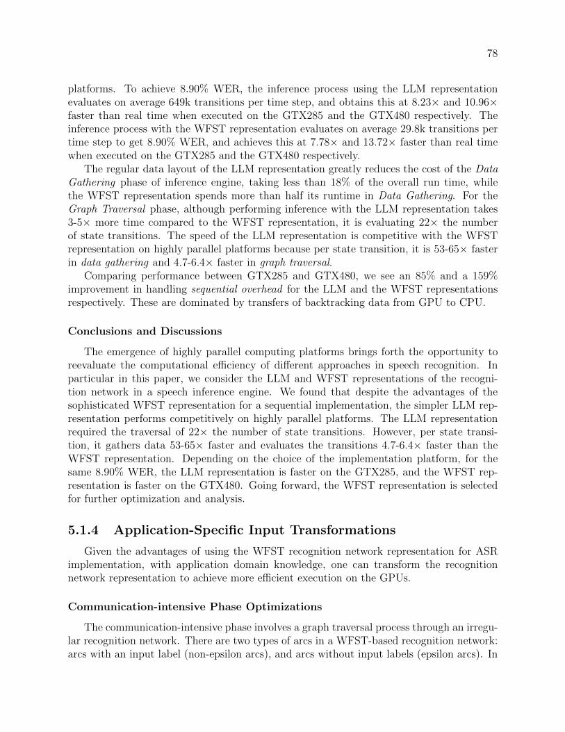
78
platforms. To achieve 8.90% WER, the inference process using the LLM representationevaluates on average 649k transitions per time step, and obtains this at 8.23× and 10.96×faster than real time when executed on the GTX285 and the GTX480 respectively. Theinference process with the WFST representation evaluates on average 29.8k transitions pertime step to get 8.90% WER, and achieves this at 7.78× and 13.72× faster than real timewhen executed on the GTX285 and the GTX480 respectively.
The regular data layout of the LLM representation greatly reduces the cost of the DataGathering phase of inference engine, taking less than 18% of the overall run time, whilethe WFST representation spends more than half its runtime in Data Gathering. For theGraph Traversal phase, although performing inference with the LLM representation takes3-5× more time compared to the WFST representation, it is evaluating 22× the numberof state transitions. The speed of the LLM representation is competitive with the WFSTrepresentation on highly parallel platforms because per state transition, it is 53-65× fasterin data gathering and 4.7-6.4× faster in graph traversal.
Comparing performance between GTX285 and GTX480, we see an 85% and a 159%improvement in handling sequential overhead for the LLM and the WFST representationsrespectively. These are dominated by transfers of backtracking data from GPU to CPU.
Conclusions and Discussions
The emergence of highly parallel computing platforms brings forth the opportunity toreevaluate the computational efficiency of different approaches in speech recognition. Inparticular in this paper, we consider the LLM and WFST representations of the recogni-tion network in a speech inference engine. We found that despite the advantages of thesophisticated WFST representation for a sequential implementation, the simpler LLM rep-resentation performs competitively on highly parallel platforms. The LLM representationrequired the traversal of 22× the number of state transitions. However, per state transi-tion, it gathers data 53-65× faster and evaluates the transitions 4.7-6.4× faster than theWFST representation. Depending on the choice of the implementation platform, for thesame 8.90% WER, the LLM representation is faster on the GTX285, and the WFST rep-resentation is faster on the GTX480. Going forward, the WFST representation is selectedfor further optimization and analysis.
5.1.4 Application-Specific Input Transformations
Given the advantages of using the WFST recognition network representation for ASRimplementation, with application domain knowledge, one can transform the recognitionnetwork representation to achieve more efficient execution on the GPUs.
Communication-intensive Phase Optimizations
The communication-intensive phase involves a graph traversal process through an irregu-lar recognition network. There are two types of arcs in a WFST-based recognition network:arcs with an input label (non-epsilon arcs), and arcs without input labels (epsilon arcs). In

79
order to compute the set of next states in a given time step, one must traverse both the non-epsilon and all the levels of epsilon arcs from the current set of active states. This multi-leveltraversal can impair performance significantly. The modification of flattening the recogni-tion network is explored to reduce the number of levels of arcs that need to be traversedand observe corresponding performance improvements. To illustrate this, Figure 5.21 showsa small section of a WFST-based recognition network. Each time step starts with a set ofcurrently active states representing the alternative interpretations of the input utterances.In Figure 5.21, the active states are represented by states (1) and (2). The traversal thenproceeds to evaluate all out-going non-epsilon arcs to reach a set of destination states, e.g.states (3) and (4). Next, the traversal extends through epsilon arcs to reach more states,e.g. state (5) for the next time step.
The traversal from state (1) and (2) to (3), (4) and (5) can be seen as a process of activestate wave-front expansion in a time step. The challenge for data parallel operations is thatthe expansion from (1) to (3) to (4) to (5) requires multiple level traversal: one non-epsilonlevel and two epsilon levels. The traversal incurs significant instruction stream divergenceand uncoalesced memory accesses if each thread expands through an arbitrary number oflevels. Instead, a data parallel traversal limits the expansion to one level at a time and therecognition network is augmented such that the expansion process can be achieved with afixed number of single level expansions. Figure 5.21 illustrates the necessary recognitionnetwork augmentations for Two-Level and One-Level setups.
Each step of expansion incurs some overhead, so to reduce the fixed cost of expansionwe want fewer number of steps in the traversal. However, depending on recognition networktopology, augmenting the recognition network may cause significant increase in the numberof arcs in the recognition network, thus increasing the variable cost of the traversal. Wedemonstrate this trade-off with a case study in the Results section.
Experimental Platform and Baseline Setup
We use the NVIDIA GTX280 GPU with a Intel Core2 Q9550 based host platform.GTX280 has 30 cores with 8-way vector arithmetic units running at 1.296GHz. The pro-cessor architecture allows a theoretical maximum of 3 floating point operations (FLOP)per cycle, resulting in a maximum of 933 GFLOP of peak performance per second. Thesequential results were measured on an Intel Core i7 920 based platform with 6GB of DDRmemory. The Core i7-based system is 30% faster than the Core2-based system becauseof its improved memory sub-system, providing a more conservative speedup comparison.The sequential implementation was compiled with icc 10.1.015 using all automatic vector-ization options. Kernels in the compute-intensive phase were hand optimized with SSEintrinsics [46]. Figure 5.22 shows that the sequential performance achieved was 3.23 secondsper one second of speech, with Phase 1 and 2 taking 2.70 and 0.53 seconds respectively.The parallel implementation was compiled with icc 10.1.015 and nvcc 2.2 using ComputeCapability v1.3.

80
!! "! #! $!
%!
!! "! #! $!
%!
!! "! #! $!
%!
&'()(*+,-./01-23456'7-
156-8393,-./01-23456'7- &*3-8393,-./01-23456'7-
Starting with (1) and (2)
(3), (4), and (5) reachable
in one time step
Starting with (1) and (2)
Add epsilon arc (3 ! 5)
(3), (4), and (5) reachable with
one non-epsilon arc expansion
and one epsilon arc expansion
Starting with (1) and (2)
Add non-epsilon arc (1 ! 4) (1 ! 5), and (2 ! 5)
(3), (4), and (5) reachable with
one non-epsilon arc expansion
Epsilon Arc
Non-epsilon Arc
Figure 5.21: Network modification techniques for a data parallel inference engine.
Speech Models and Test Sets
The speech models were taken from the SRI CALO realtime meeting recognition sys-tem [146]. The front-end uses 13d PLP features with 1st, 2nd, and 3rd order differences,VTL-normalized and projected to 39d using HLDA. The acoustic model was trained on con-versational telephone and meeting speech corpora, using the discriminative MPE criterion.The LM was trained on meeting transcripts, conversational telephone speech and web andbroadcast data [142]. The acoustic model includes 52K triphone states which are clusteredinto 2,613 mixtures of 128 Gaussian components. The recognition network is an H ◦C ◦L◦Gmodel compiled using WFST techniques [46].
The test set consisted of excerpts from NIST conference meetings taken from the “in-dividual head-mounted microphone” condition of the 2007 NIST Rich Transcription evalu-ation. The segmented audio files total 3.1 hours in length and comprise 35 speakers. Themeeting recognition task is very challenging due to the spontaneous nature of the speech3.The ambiguities in the sentences require larger number of active states to keep track ofalternative interpretations, which leads to slower recognition speed.
Our recognizer uses an adaptive heuristic to control the number of active states byadjusting the pruning threshold at run time. This allows all traversal data to fit within a
3A single-pass time-synchronous Viterbi decoder from SRI using lexical tree search achieves 37.9% WERon this test set

81
Table 5.3: Accuracy, word error rate (WER), for various beam sizes and decoding speed inreal-time factor (RTF)
Avg. # of Active States 32398 19306 9763 3390
WER 51.1 50.9 51.4 54.0Sequential CPU 4.36 3.17 2.29 1.20
RTF Parallel GPU 0.37 0.29 0.20 0.14Speedup 11.7 11.0 11.3 9.0
pre-allocated memory space. Table 5.3 shows the decoding accuracy, i.e., word error rate(WER) with varying thresholds and the corresponding decoding speed on various platforms.The recognition speed is represented by the real-time factor (RTF), which is computed asthe total decoding time divided by input speech duration.
As shown in Table 5.3, the GPU implementation can achieve order of magnitude morespeedup over the sequential implementation [46] for the same number of active states. Moreimportantly, one can trade-off speedup with accuracy. For example, one can achieve 54.0%WER traversing an average of 3390 states per time step with a sequential implementation,or one can achieve a 50.9% WER traversing an average of 19306 states per time step whilestill getting a 4.1× speedup, improving from an RTF of 1.20 to 0.29.
Compute-intensive Phase
The parallel implementation of the compute-intensive phase achieves close to peak per-formance on GTX280. As shown in Table 5.4, we found the GMM computation memory-bandwidth-limited and our implementation achieves 85% of peak memory bandwidth. Thelogarithmic mixture reduction is compute-limited and our implementation achieves 98% ofachievable peak compute performance given the instruction mix.
Table 5.4: Efficiency of the Computation Intensive Phase(GFLOP/s) Step 1 Step 2Theoretical Peak 933 933
Mem BW Limited Inst Mix LimitedPractical Peak 227 373Measured 194 367Utilization 85% 98%
Communication-intensive Phase
Parallelizing this phase on a quadcore CPU achieves a 2.85× performance gain [46] andincurs intermediate result transfer overhead. We achieved a 3.84× performance gain withan equivalent configuration on the GPU and avoided intermediate result transfer overhead.Despite the better speedup on the GPU, this phase became more dominant as shown inFig 5.22.

82
Tab
le5.5:
Perform
ance
withDifferentRecognitionNetworkAugm
entation
(Runtimes
Normalized
toon
eSecon
dof
Speech)
ActiveStates
OriginalW
FST
Network
Two-L
evelW
FST
Network
One-L
evelW
FST
Network
(%
ofstatespace)
0.1%
0.3%
0.5%
1.0%
0.1%
0.3%
0.5%
1.0%
0.1%
0.3%
0.5%
1.0%
TotalStates
4,114,507
4,114,672(+0.003%)
4,116,732(+0.05%)
TotalArcs
9,585,250
9,778,790(+2.0%)
12,670,194(+32.2%)
ArcsTraversed*
27,119
64,489
112,173
171,068
27,342
65,218
114,043
173,910
44,033
103,215
174,845
253,339
Arcsincrease(%)
--
--
+0.8%
+1.1%
+1.7%
+1.7%
+62%
+60%
+56%
+48%
Phase1(ms:%
)77:41%
112:43%
146:43%
177:41%
77:48%
112:50%
146:48%
178:45%
73:55%
110:55%
147:51%
177:48%
Phase2(ms:%
)97:52%
127:49%
171:50%
230:53%
74:46%
99:44%
138:45%
191:48%
52:39%
81:40%
125:43%
175:47%
Seq.Ovrhd(ms:%
)13:7%
20:8%
24:7%
28:6%
11:7%
14:6%
20:7%
25:6%
8:6%
10:5%
16:5%
21:6%
Total(ms)
187
258
341
436
161
225
304
393
134
202
289
373
Fasterthanrealtim
e5.3×
3.9×
2.9×
2.3×
6.2×
4.4×
3.3×
2.5×
7.5×
5.0×
3.5×
2.7×
*Average
numberofarcstraversed
pertimestep

83
!"!# !"$# %"!# %"$# &"!# &"$# '"!# '"$#
()*#
+)*#
,&"-.#(/01234#563467894##
%-"'.#(/00268:;</6#563467894##
$'"!.#(/01234#563467894##
=-"!.#(/00268:;</6#563467894##%%"!>#?4:/@86A#B804#14C#
D4:/6@#/E#D144:F##
G74:H#
Figure 5.22: Parallel Speedup of the Inference Engine.
!"!!#
!"!$#
!"%!#
!"%$#
!"&!#
!"&$#
!"'!#
!# $# %!# %$# &!# &$# '!#
!"##$%&'()"%*+%,-%.&/-*01(.-*2.-'3*
4$#5-6*"7*86'.*9:%'16"%&;-<*2=&>>&"%.*"7*86'.3*
!"##$%&'()"%*+%,-%.&/-*01(.-*?$%*@&#-*&%**
+%7-6-%'-*A%B&%-*C6(D1*@6(/-6.(>*D-6*9-'"%<*"7*9D--'1*
()*+*,-.#/0123)4#
5236.070.#/0123)4#
(,06.070.#/0123)4#
870)-+0#9#3:#8;<70#=1-10>#
->#?#3:#531-.#=1-10>#
!"%?#
!"'?#
!"$?#
%"!?#
!"#$%&'()$*+&,-%(
./#0"(10&2(30"4$02$*(
/0123)4##
@3A*B;-<3,#
5)-A063C>#
Figure 5.23: Communication Intensive Phase Run Time in the Inference Engine (normalizedto one second of speech).
Table 5.5 demonstrates the trade-offs of recognition network augmentation for efficientdata parallel traversal in our inference engine. The augmentation for Two-Level setupresulted in a 2.0% increase in arc count and the augmentation for One-Level setup resulteda 32.2% increase. The dynamic number of arcs evaluated increased marginally for the Two-Level setup. However for the One-Level solution it increased significantly by 48-62%, asstates with more arcs were visited more frequently.
Fig 5.23 shows the run time for various pruning thresholds. The network modificationsare described earlier in this section. Without network modifications, there is significant per-formance penalty, as multiple levels of epsilon arcs must be traversed with expensive globalsynchronization steps between levels. With minimal modifications to the network, we see a17-24% speedup for this phase. An additional 8-29% speedup can be achieved by eliminatingepsilon arcs completely, saving the fixed cost of one level of global synchronization routines,but this comes at the cost of traversing 48-62% more arcs.

84
Conclusion
A fully data parallel speech inference engine is presented with both observation probabil-ity computation and graph traversal implemented on an NVIDIA GTX280 GPU. The resultsshow that being able to leverage application domain expertise to make modifications to therecognition network is essential for efficient implementation of data parallel WFST-basedLVCSR algorithm on GPU. The implementation achieved up to 11.7× speedup comparedto highly optimized sequential implementation with 5-8% sequential overhead without sac-rificing accuracy. This software architecture enables performance improvement potentialson future platforms with more parallelism.
5.1.5 Optimizations on Various Hardware Platforms
This section demonstrates the implications of implementing the highly challenging graphtraversal operations on two highly parallel architectures: an Intel Core i7 multicore proces-sor and an NVIDIA GTX280 manycore processor. Multicore processors are considered asprocessors that devote significant transistor resources to complex features for acceleratingsingle thread performance, whereas manycore processors are considered as processors thatuse their transistor resources to maximize total instruction throughput at the expense ofsingle thread performance. It is shown that the best algorithm on one architecture mayperform poorly on another due to varying efficiencies of key parallel operations, and thatthe efficiency of the key parallel operations is more indicative of the performance of theapplication implementation.
Given the challenging and dynamic nature of the underlying graph-traversal routines inLVCSR, implementing it on parallel platforms presents two architectural challenges: efficientSIMD utilization and efficient core level synchronization. These challenges are key factorsin making the algorithms scalable to increasing number of cores and SIMD lanes. To find asolution to these challenges, two aspects of the algorithmic level design space were explored:the graph traversal technique and the arc transition evaluation granularity. Figure 5.24illustrates the design space under consideration.
Traversal Techniques: Aggregate or Propagate
The two graph traversal techniques are traversal by propagation and traversal by aggre-gation. During the graph traversal process, each arc has a source state and a destinationstate. Traversal by propagation organizes the traversal process at the source state. It evalu-ates the outgoing arcs of the active states and propagates the result to the destination states.As multiple arcs may be writing their result to the same destination state, this techniquerequires write conflict resolution support in the underlying platform. The programmer de-clares certain memory operations as atomic, and the implementation platform resolves thepotential write conflicts.
Traversal by aggregation organizes the traversal process around the destination state.The destination states update their own information by performing a reduction on theevaluation results of their incoming arcs. The programmer explicitly manages the potential

85
Graph Traversal Techniques
Addressing Core level Synchronization
Transition
Evaluation
Granularity
AddressingSIMD
Utilization
PropagationTraversal
organized at
source state
AggregationTraversal
organized at
destination state
State-basedAll out-going /
in-coming arcs
at a state
Arc-basedOne arc
at a time
Arc-‐based aggregationapproach
State-‐based aggregationapproach
Arc-‐based propagation approach
State-‐based propagation approach
Algorithm Styles in the Design Space
Figure 5.24: The algorithmic level design space for graph traversal scalability analysis forthe inference engine.
write conflicts by using additional algorithmic steps such that no write-conflict-resolutionsupport is required in the underlying platform.
The choice of the traversal technique has direct implications on the cost of core levelsynchronization. Efficient synchronization between cores reduces the management overheadof a parallel algorithm and allows the same problem to gain additional speedups as wescale to more cores. Figure 5.25 outlines the trade-offs in the total cost of synchronizationbetween the aggregation technique and the propagation technique. The qualitative graphshows increasing synchronization cost with increasing number of concurrent states or arcsevaluated.
The Y-intercept of line (a) in Figure 5.25 illustrates the fixed cost for the aggregationtechnique, which is higher than that of the propagation technique, as it requires a largerdata structure and a more complex set of software routines to manage potential write con-flicts. The relative gradient of the aggregation and propagation techniques depends onthe efficiency of the platform in resolving potential write conflicts. If efficient hardware-supported atomic operations are used, the variable cost for each additional access would besmall, and the propagation technique should scale as line (b) in Figure 5.25. If there is nohardware support for atomic operations, and sophisticated semaphores and more expensivesoftware-based locking routines are used, the propagation technique would scale as line (c).In addition, if the graph structure creates a scenario where many arcs are contenting towrite to a small set of next states, serialization bottleneck may appear and the propagationtechnique could scale as line (d).

86
(a) Propagation with HW
atomic memory ops
# of states/arcs handled
To
tal T
ime
fo
r S
yn
ch
ron
iza
tio
n (c) Propagation with atomic
memory ops causing contention
leading to access serialization
Figure 5.25: Scalability of the traversal process in terms of total synchronization time.
In order to minimize the synchronization cost for a given problem size, we need to choosethe approach corresponding to the lowest-lying line in Figure 5.25. For small number ofactive states or arcs, we should choose the propagation technique. For larger number ofarcs, however, the choice is highly dependent on the application graph structure and thewrite-conflict-resolution support in the underlying implementation platform.
Evaluation Granularity: Arc-Based or State-Based
We also explore two recognition network evaluation granularity: state-based evaluationand arc-based evaluation. In a parallel implementation we must define units of work (ortasks) that can be done concurrently. State-based evaluation defines a unit of work as theevaluation of all outgoing or incoming arcs associated with a state, with the majority ofstates having one or two outgoing or incoming arcs. Arc-based evaluation defines a unit ofwork as the evaluation of a single arc. The fine granularity of tasks allows the workloadto scale to increasingly parallel implementation platforms. Each fine-grained task, however,has little instruction-level parallelism and can not fully utilizing a growing number of SIMDlanes in a core. We must efficiently map tasks to SIMD lanes to gain higher SIMD utilization,such that the algorithm can scale to even wider SIMD units in future processors.
SIMD operations improve performance by executing the same operation on a set of dataelements packed into a contiguous vector. Thus, SIMD efficiency is highly dependent onthe ability of all lanes to synchronously execute useful instructions. When all lanes arefully utilized for an operation, we call the operation “coalesced”. When operations do notcoalesce, the SIMD unit becomes under-utilized.

87
!"#$%&&
'()(%*&
+),,%-&&
./(.&'0+1&
234%&
'0+1&
5#637)#./&
89(:)&;.:<&
!"#
$!"#
%!"#
&!"#
'!"#
(!"#
)!"#
*!"#
+!"#
,!"#
$!!"#
!#
$#
%#
&#
'#
(#
)#
*#
+#
,#
$!#
$# %# '# +# $)# &%#
'0+
1&5#637)#./&
',%%-=,&
'0+1&>3-(?&
',%%-=,&)/-&'0+1&8@"3%/"A&3/&&
'()(%&B)*%-&2:)$%:*)6&&
##-.//01.#23/4#
-/51/6789#:8;/#
##-<=>#?79@A87B6#
Figure 5.26: SIMD unit utilization in the active-state-based traversal.
For the state-based approach, we see on the left of Figure 5.26 that the control flowdiverges as some lanes are idle, while others are doing useful work. In our recognitionnetwork, the number of outgoing arcs of the active states ranges from 1 to 897. The barchart on the right of Figure 5.26 shows that the state-based evaluation granularity incurssignificant penalties with increasing SIMD width. A 32-wide SIMD achieves only 10%utilization and gets only a 3.3× speedup over a sequential version.
We can eliminate this kind of control flow divergence by using the arc-based approach,as each arc evaluation presents a constant amount of work. However, such fully coalescedcontrol flow requires extra storage overhead. In order for each arc evaluation to be anindependent task, the arc must have a reference to its source state. We must store thisinformation for every arc we evaluate. For a small SIMD width, this overhead may eliminateany gains from coalesced control flow.
Evaluation of the Inference Engine
We explore the traversal techniques and evaluation granulates on two hardware plat-forms: the Intel Core i7 920 multicore processor with 6GB memory and the NVIDIAGTX280 manycore processor with a Core2 Quad based host system with 8GB host memoryand a GTX280 graphics card with 1GB of device memory. The Core i7 was programmed us-ing the task queue abstraction [100], and the GTX280 was programmed using CUDA [122].The results are shown in Table 5.7.

88
!"!# $"!# %"!# &"!# '"!#
()*+),-./#
0+/-123)#
0.,4123)#
5%"67#829:+;)#<,;),=>?)##
$6"&7#8299+,>1.-2,#<,;),=>?)##
6@"$7#829:+;)#<,;),=>?)##
%!"@7#8299+,>1.-2,#<,;),=>?)##
'@"!7#829:+;)#<,;),=>?)##
A$"!7#8299+,>1.-2,#<,;),=>?)##
B)12C>,D#E>9)#:)3#()12,C#2F#(:))1G#H=)1I##
&"'J#
$!"AJ#
Figure 5.27: Ratio of computation intensive phase of the algorithm vs communication in-tensive phase of the algorithm.
Figure 5.27 highlights the growing importance of optimizing the communication intensivephases on parallel platforms. Over 80% of the time in the sequential implementation isspent in the compute intensive phases of the application. While the compute intensivephase achieved a 4-20× speedup in our highly parallel implementations, the communicationintensive phases incurred significant overhead in managing the parallelism. Even with arespectable 3× speedup, the communication intensive phases became proportionally moredominant, taking 49% of total runtime in the manycore implementation. This motivates theneed to examine in detail the parallelization issues in the communication intensive phasesof our inference engine. We mainly analyze its synchronization efficiency and effectivenessof using SIMD parallelism.
Table 5.6: Accuracy, word error rate (WER), for various beam sizes and correspondingdecoding speed in real-time factor (RTF).
Avg. # of Active States 32820 20000 10139 3518
WER 41.6 41.8 42.2 44.5Sequential 4.36 3.17 2.29 1.20
RTF Multicore 1.23 0.93 0.70 0.39Manycore 0.40 0.30 0.23 0.18
The speech models were taken from the SRI CALO realtime meeting recognition sys-tem [146], trained using the data and methodology developed for the SRI-ICSI NIST RT-07evaluation [142]. The acoustic model includes 128-component Gaussians. The pronuncia-tion model contains 59K words and 80K pronunciations. The recognition network contains4.1M states and 9.8M arcs and is composed using WFST techniques.
The test set consisted of 44 minutes of segmented audio from 10 speakers in NISTconference meetings. The recognition task is very challenging due to the spontaneous natureof the speech. The ambiguities in the sentences require a larger number of active states tokeep track of alternative interpretations, which leads to slower recognition speed.
As shown in Table 5.6, the multicore and manycore implementations can achieve signifi-cant speedup for the same number of active states. More importantly, for the same real time

89
Tab
le5.7:
Recognitionperform
ance
normalized
foron
esecondof
speech
fordifferentalgorithm
styles
withaverageof
20,000
active
states
each
iteration.Speedupreportedover
SIM
D-optimized
sequ
ential
version.Resultsexplained
arein
bold.
Corei7
Corei7
GTX280
Sequential
Prop.
Prop.
Aggr.
Prop.
Prop.
Aggr.
Aggr.
Seconds(%)
Prop.bystates
bystates
byarcs
bystates
bystates
byarcs
bystates
byarcs
Phase1
2.623(83%)
0.732(79%)
0.737(73%)
0.754(29%)
0.148(19%)
0.148(49%)
0.147(12%)
0.148(16%)
Phase2
0.474(15%)
0.157(17%)
0.242(24%)
1.356(52%)
0.512(66%)
0.103(34%)
0.770(64%)
0.469(51%)
Phase3
0.073(2%)
0.035(4%)
0.026(3%)
0.482(19%)
0.108(15%)
0.043(14%)
0.272(23%)
0.281(31%)
SequentialOverhead
-0.001
0.001
0.001
0.008(1.0%)
0.008(2
.5%
)0.014(1.2%)
0.014(1.6%)
Total
3.171
0.925
1.007
2.593
0.776
0.301
1.203
0.912
Speedup
13.43
3.15
1.22
4.08
10.53
2.64
3.48

90
factor (RTF), parallel implementations provide a higher recognition accuracy. For example,for an RTF of 0.4, accuracy improves from 44.5% to 41.6% WER going from a multicoreimplementation to manycore implementation.
Our implementations are structured to be scalable. As shown in Table 5.7 the sequentialoverhead in our implementations was measured to be less than 2.5% even for the fastestimplementation. Also seen in Table 5.7, the fastest algorithm style differed for each platform.Synchronization using the aggregation technique has an overwhelming overhead, despiteusing highly optimized software routines. The propagation technique, in comparison, hadstrictly better results. However, our first propagation implementation on GTX280 usingglobal atomic operations had severe atomic-memory-access conflicts and performed worsethan Core i7. The issue was resolved by using local atomics operations [4].
The GTX280 has a logical SIMD width of 32. The implementation on GTX280 benefitedsignificantly from evaluation by arc, re-gaining the lost efficiencies seen in Figure 5.26,making propagation by arc the fastest algorithm style. However, SIMD has not been appliedto the implementation on Core i7, since the overhead of coalescing control flow exceedsthe benefit comes from 4-wide SIMD. Thus, the fastest algorithmic style on Core i7 waspropagation by state.
5.1.6 Productivity Concerns
The ASR pattern-oriented application framework addresses many of the productivityconcerns of ASR domain experts. It provides extensive background information in two as-pects of the ASR application, the concurrency opportunities and the suitability of exploitingthem on a highly parallel manycore microprocessor. It also reduces the number of lines ofcode that are required to be written to deploy an ASR-based application, which reduces thenumber of potential bugs in the development process.
The extensive background information on concurrency opportunities in the ASR appli-cation is presented in the application context component of the pattern-oriented applicationframework. As demonstrated in Section 4.4.1, the application context exposes the applica-tion concurrency in ASR using the parallel programming patterns described in Section 3.2.2.Clarifying the concurrency opportunities with parallel programming patterns brings fortha set of background knowledge in the solution techniques and their trade-offs in imple-menting an ASR based application. This reduces the time needed to acquire the necessaryinformation to make design choices. For this reason, the application context improves theproductivity of the users of the ASR application framework.
The software architecture of the ASR application framework is described in Section 4.4.2.This section clarifies the structure of a parallel implementation of an ASR inference enginethat can effectively take advantage of the concurrency opportunities, and specifies the trade-offs and solution techniques on the GPU. This improves the productivity of the user of theapplication framework by providing assistance with navigating the software architecture ofthe ASR framework.
The pattern-oriented application framework for parallel programming incorporates allof the techniques that are described in sections 5.1.1, 5.1.3, 5.1.4, and 5.1.5 in a reference

91
implementation that is immediately available for ASR experts to use. For ASR experts,the speech inference process uses a standard HMM forward-backward implementation forinterpreting speech (as seen in Section 4.4.2). Adaptations to different usage scenariosinvolve the tuning of the acoustic features extraction techniques, as well as varying themethods with which acoustic models and language models are trained.
During the process of developing multiple ASR-based applications [44, 96], we observedthat the most frequently adapted module is the observation probability computation. Theobservation probability computation estimates the instantaneous match between the inputand the acoustic model at a point in time. For different usages scenarios, the variationsin the acoustic model affect the acoustic model file format and the observation probabilitycomputation routines. While the number of features in the feature vector extracted fromthe input may vary, the basic mechanism of one feature vector per time step is preserved.Based on this observation, a pattern-oriented application framework with an extension pointfor adapting the observation probability computation was constructed to allow ASR domainexperts to customize the observation probability computation without having to implementthe HMM forward-backward pass in the inference process (as described in Section 4.4.2).
The extension point component of the pattern-oriented application framework greatlyimproves the ASR domain expert’s productivity in two ways. Firstly, the extension pointfocuses the interactions between the plug-ins and the framework through clearly defined,narrow application programming interfaces (API). This provides a clean abstraction of theapplication framework for the developers of the plug-ins to target. The clearly defined,narrow APIs reduce the potential for bugs caused by mis-understanding of the interfaceand reduce the potential for problems to appear during the integration process. Secondly,the extension point reduces the number of lines ASR domain experts have to implementto produce an efficient ASR-based application. This reduction is significant: to arrive at aworking ASR-based application, using the pattern-oriented application framework reducesthe effort from developing a ten-thousand-line application for the entire speech recognitionengine to a few hundred lines of plug-in customization.
To further support the productive construction of ASR-based applications, the pattern-oriented application framework also provides other extension points, as listed below:
1. File input format: Data format for the different components of the Recognition Net-work, including the acoustic model, pronunciation model, and language model
2. Pruning Strategy: Fixed pruning threshold or adaptive pruning threshold
3. Observation Probability Computation: The instantaneous match between the inputand the acoustic model at a time step
4. Result output format: Data output format to target either the next step in processingor the accuracy checking script
The description of the extension point has been illustrated in more detail in Section 4.4.4.Chapter 6 will present their utilization in the deployment of different application usagescenarios.

92
5.2 Risk Analytics Application Framework
With the proliferation of algorithmic trading, derivative usage and highly leveraged hedgefunds, there is increasing need to monitor financial risk in order to measure the severity ofpotential portfolios losses in real time. As risk management is now obliged to keep pace withthe market, overnight runs of risk estimates no longer suffice. It is acknowledged that theability to compute intra-day risk metrics is a highly desirable capability in a risk analyticsengine [60].
There are many types of financial risks that a financial institution is exposed to, includ-ing:
• Market Risk: The market value of trading assets may fall
• Credit Risk: Debtors (including market counterparties, e.g. brokers, investmentbanks, and other securities dealers that serve as the contracting party when com-pleting financial securities transactions) may not be able to meet their obligations,causing a loss to the bank
• Operational risk: Loss of money due to a failure in the banks infrastructure or internalcontrols4.
• Liquidity risk: Banks may incur costs in raising cash to meet obligations that becomedue
• Business risk: A business may become less profitable because of changes in the marketfor the bank’s services
This work examines the challenges facing the construction of application frameworksestimating the first two types of risks: market risk and credit risk (related to counterparties,or counterparty risk). While the work presented here analyzes the configuration of the riskanalytics engine that are most sensitive in terms of execution efficiency, the integration ofsuch analysis into an application framework is an on-going task.
5.2.1 Market Risk Estimation
Financial institutions seek quantitative risk infrastructure that is able to provide ’ondemand’ reporting of global financial market risk using the Value-at-Risk (VaR) estimates.VaR refers to the maximum expected loss that will not be exceeded under normal marketconditions over a predetermined period at a given confidence level [91] (page xxii). Itemerged as a distinct concept in the 1980s and was likely triggered by the stock crashof 1987, when academically trained quantitative analysts were in high enough positions
4Risks arises from failures in a bank’s infrastructure could also have adverse effects on the market as awhole. Recent regulations banning “naked” market access is one move by the U.S. Securities and ExchangeCommission (SEC) to protect the market from the operational risks the market is exposed to as a result oftraders having “unfiltered” or “naked” access to exchanges or ATS [9].

93
to worry about firm-wide survival [91]. The metric became institutionalized in 1997, inresponse to the U.S. Securities and Exchange Commission ruling that public corporationsmust disclose quantitative information about their derivatives activity, when major banksstarted including VaR information in the notes to their financial statements. VaR wasselected as the preferred approach for measuring market risk in Basel II [5], an internationalstandard initially published in 2004 and revised in 2006, which banking regulators can usewhen creating regulations about how much capital banks need to put aside to guard againstthe types of financial and operational risks that such institutions may face.
While the use of VaR to measure market risk is standardized, the methodology forestimating it is not. One common approach for estimating VaR uses the Monte Carlomethod (Section 5.2.3).
Major banks model the joint probability distribution of hundreds, or even thousands, ofmarket risk factors, and consider hundreds of thousands of future market scenarios [160].Market risk factors are financial exchange quoted instruments, which could potentially de-value the portfolio. Common examples of market risk categories include interest rates,stocks, commodities, credit and foreign exchange. Hundreds of thousands of future marketscenarios must be computed to reduce the statistical error in the estimated VaR to below0.1%.
A faster implementation can improve the responsiveness of risk management systems,enable risk analysts to perform more comprehensive VaR estimates on an Ad hoc basis (e.g.pre-deal limit checking), and can give financial institutions a competitive edge in algorithmictrading. It will also allow institutions to effectively step up to the more pervasive systematicstress testing standards being imposed by market risk regulators.
The ability to closely monitor and control an institution’s market risk exposure is criticalto the performance of trading units, which rely on complex risk analysis in order to structureand execute trades. Yet, despite tightening legal requirements on market risk estimation, theindustry is still far from adopting a standardized and comprehensive framework for marketrisk analysis. In a recent survey conducted by the Global Association of Risk Professionalsin conjunction with SYBASE [6], only approximately 5% of the firms currently performcomplex risk analysis on their portfolios and global positions in real time while about 25%are able to perform real time analysis on individual trades. Over a third of these firmsindicated that the current risk infrastructure was not fast enough for the needs of thebusiness and that the gap between IT and business domain expertise is one of the majorsources of dislocation in the deployment of risk management systems. This calls for amore comprehensive approach to the design and deployment of complex risk analytics witha stronger emphasis on using financial domain knowledge and expertise to enhance thesoftware optimization process.
5.2.2 Counterparty Exposure Estimation
VaR is not the only risk metric being used in the banking industry. Large banks arealso using techniques such as potential future exposure (PFE) as a metric to quantify thecounterparty risk posed by fluctuations in market prices in the future during the lifetime

94
of the transactions in its portfolio. Counterparties are brokers, other investment banksand other securities dealers that serve as the contracting party when completing financialsecurities transactions such as over-the-counter (OTC) derivative contracts.
In an OTC contract, two parties agree on how a particular trade or agreement is to besettled in the future through signing a bilateral contract. It is usually from an investmentbank to its clients directly, without going through an exchange where a well-capitalizedfinancial institution could protect one side of a transaction when the other side defaults.In an OTC contract, both sides are exposed to the risk of their counterparty defaultingon the contract. According to the June 2010 statistics from the Bank for InternationalSettlements, the total outstanding notional amount of OTC derivative contracts is $583trillion [8], making OTC a significant source of counter party risk in the financial market.
PFE is a long-term credit risk metric that covers contracts with lifetimes that can be aslong as decades. As defined by Dean here:
PFE: the maximum credit exposures over a specified period of time calculated atsome level of confidence. This maximum is not to be confused with the maximumcredit exposure possible. Instead, the maximum credit exposure indicated bythe PFE analysis is an upper bound on a confidence interval for future creditexposure.
In a PFE calculation, the exposure is computed with respect to each counterparty con-tract individually in a Monte Carlo based estimation process. The approach here is signifi-cantly more complex as compared to the approach described in Section 5.2.1, where risk iscomputed for the entire portfolio at the same time. For large financial institutions, a port-folio could have as many as one million trades. Each traded asset requires the simulation of30-300 time steps over as many as 5000 market scenarios. Computing their exposure overlonger time horizons is a computationally expensive process. Such computations are usuallydone over-night on computing centers, requiring hours of computation on scores of servers.As the number of global positions held by the bank increases, there is increasing need toimprove computational efficiency and reduce the sprawling of computing centers.
5.2.3 The Monte Carlo Method
The Monte Carlo method is an approach where the solution to a problem is estimatedby statistically sampling its parameter space with thousands to millions of experimentsusing different parameter settings. The analysis method was made practical by the adventof computers and was pioneered by Stan Ulam, John Von Neuman, and Enrico Fermi,the physicists first used the approach for neutron diffusion calculations in the field of highenergy physics [15]. By statistically sampling a problem’s parameter space and simulatingthe outcome of an experiment, we gain valuable insights into complex problems that maybe impossible or impractical to solve analytically or iteratively using partial differentialequation based approaches. The ease and intuitiveness of setting up the experiments makesthe Monte Carlo method a popular approach [72].
The Monte Carlo method has the following properties that make it desirable for imple-mentation on a high performance parallel computing accelerator such as the GPU:

95
!"#$!"#"$
%&&'(')"*+,$
!%#$$-,'.+/($0",1+($$
23(45/$65,5/"*+,$
!&#$7"/"(5#5/$!'&#/'43*+,$
8/",&.+/("*+,$
!'#$9:;5/'(5,#$9<")3"*+,$
Figure 5.28: The solution structure for Monte Carlo based analysis
1. Experiments are independent and parallelizable: the approach assumes that exper-iments are independent and identically distributed (i.i.d.), such that the set of ex-periments provides a statistically valid sampling of the parameter space. This inde-pendence between experiments provides significant parallelization opportunities forGPU-based implementations.
2. Execution is computationally expensive: according to the law of large numbers, thestatistical error (standard error) in the solution is proportional to the inverse square-root of the experimental size, i.e. to achieve 10x more precision in the result, oneneeds to run 100x more experiments. The GPU-based implementation can providethe necessary speedup to allow many problems to become computationally feasible.
3. Input specifications and results are concise: the Monte Carlo method takes a smallset of experimental parameter inputs, generates thousands to millions of experiments,executes them, and assimilates the results as a single solution. There is a large amountof computation consumed with little input/output data transferred. This is ideal forGPU-based implementations, as input/output data has to be transferred between theCPU and the GPUs and all of the computation is performed on the GPU.
Figure 5.28 shows four key steps in a Monte Carlo based analysis. These steps can beoptimized from several different perspectives, as demonstrated in Section 5.2.4 and Sec-tion 5.2.6. Step 1 generates uniform random numbers; Step 2 converts the uniform randomnumbers into statistical distributions that model the parameters in the scenarios to be sim-ulated; step 3 evaluates the experiments; and step 4 assimilates the results. A typical MonteCarlo method based implementation executes one step at a time, with intermediate resultswritten out to memory.
5.2.4 Efficiency Concerns in Market Risk Estimation
Seven key implementation techniques were identified in the construction of Monte Carlobased applications by studying the implementation process from three different perspectives,as discussed in [61]. The three perspectives for achieving efficient execution are the task-centric, numerical-centric, and data-centric perspectives.

96
The task-centric perspective focuses on the tasks being executed (Section 5.2.4). Itinvolves applying two key optimization techniques. The first technique involves the mini-mization of the amount of necessary computation using task transformation and algorithmreformulation. The second technique involves the maximization of computational efficiencyby identifying opportunities to leverage existing high-performance library components.
These techniques are applied to MC-VaR as a reformulation of the loss aggregationmodule to avoid matrix-matrix computations, and an analysis of the relative performanceof various linear algebra routines to take advantage of more efficient types of cuBLAS (CUDABLAS) library components.
The numerical-centric perspective focuses on the numerical properties of modules andtheir influence on the application performance5 (Section 5.2.4). It involves three key opti-mization techniques. The first technique involves the selection of random sequences, whichprovide desirable convergence properties. The second technique involves the selection of ran-dom sequences that enable parallel generation of sequences. The third technique involvesthe selection of distribution conversion modules which preserve a uniformity property6 ofthe random sequences.
These techniques are applied in MC-VaR as the selection of Sobol’ quasi-random se-quences for its uniformity property in accelerating convergence, the usage of a Sobol’ gener-ator with skip-ahead capability to enable parallel generation of random sequences, and theselection of the Box-Muller algorithm for its ability to preserve property A, a measure ofuniformity, under distribution transformation proposed by Sobol’.
The data-centric perspective focuses on the data access properties of the algorithms andtheir influence on the application performance (Section 5.2.4). It involves two key optimiza-tion techniques. The first technique involves the elimination of redundant data transfersbetween small kernels. The second technique involves optimizations of the algorithm withrespect to the memory hierarchy.
These techniques are applied in MC-VaR, first as the merging of random number genera-tion and distribution conversion to eliminate redundant storage and transfer of intermediateresults and the identification of key data alignment needs between parameter generation andrisk estimation, second as the application of flexible data blocking strategies that maximallyleverage the shared memory resources (or local scratch-pad memory).
The seven optimization techniques discussed above are applied to a VaR estimationapplication based on delta-gamma (∆-Γ) approximation [61]. The Monte Carlo methodis used to simulate the correlated market risk factor log returns (value changes) over afixed time horizon. More precisely, each experiment k, where k = 1..M , is setup by firstgenerating uncorrelated Gaussian Random Variables, Xik, where i = 1..N . These are theuncorrelated Gaussian random perturbations away from the current market scenario, whichis defined by the current value of the risk factors Ri. The input to a Monte Carlo basedVaR estimation includes:
5Implementation techniques for efficient generation of Gaussian random numbers in CUDA are wellstudied, see for example [83].
6A uniformity property is a measure of how well sub-sequences of the random sequence cover the targetdistribution.

97
Statistical Parameters: the estimated means µi and Cholesky factor matrix Q of the co-variance matrix Σ = QT Q for the Gaussian distributed market risk factor log returnsd ln(Ri), where i = 1..N , j = 1..N , are obtained from historical time series;
Delta term: ∆i, where i = 1..N , is the sensitivity of the portfolio to a change in the log ofthe market risk factor Ri;
Gamma term: λi and Uij, where i = 1..N, j = 1..N , are the eigenvalues and orthogonalmatrix of column eigenvectors of the semi positive definite matrix
�ij Q
TmiΓijQjn, Γij
is the sensitivity of ∆i to a change in the log of market risk factor Rj. Γ is generallysparse and sometimes even diagonal, because the ∆s from simple models of instrumentprices typically only depend on one or a small number of risk factors.
Percentile for VaR evaluation: is typically either 1% or 5%; and
Time horizon: the duration of the simulation is typically at least a day and is measuredin units of years.
The execution of each experiment k outputs the change of value of the portfolio dPk
using the (rotated) delta-gamma (∆-Γ) approximation
dPk =�
i
∆iYik� �� �delta
+1
2λiX
2
ik� �� �gamma
, (5.1)
where Yik =�
j µi + QijXjk are the correlated Gaussian random variables obtained from
multiplying the (rotated) Cholesky matrix factor Q = QU with the i.i.d. standard Gaussianrandom variables Xik. Expressing the approximation in rotated random variables simplifiesthe expression in the gamma term 7.
By far the simplest model assumption is that portfolio losses are described by a jointnormal distribution. But normal loss distributions do not exhibit the fatter tails of theloss distribution implied from historical data, where extreme events occur more frequentlythan the normal distribution describes [72]. Consequently normal loss distributions tend toseverely underestimate potential losses. We relax this mathematically convenient assump-tion and present a VaR simulation approach, which generalizes to more realistic distributionfunctions. To this end, we also demonstrate the generation of student-t random variablesusing Bailey’s method in the data-centric perspective section.
Task-centric Perspective
Statistical sampling of the parameter space with the Monte Carlo method involves run-ning thousands to millions of independent experiments. With respect to the structure of animplementation of the Monte Carlo method, the experiment execution step often has the
7Readers more familiar with the approximation in original variables should refer to [72] for further details.The problem reformulation described in the next few pages relies on this rotated form of the approximationin which the rotated Cholesky matrix factor is now a full matrix and no longer upper triangular.

98
most amount of parallelism. For this reason, the evaluation of the delta term of the lossfunction (5.1) can be efficiently implemented as a dense matrix computation using existingwell-parallelized cuBLAS library routines. This is illustrated in two steps, with Figures 5.29showing the first step and Figure 5.30 showing the second step for the delta component ofthe loss function evaluation with N risk factors and M >> N experiments.
Figure 5.29: The correlation of random variables is re-factored as a dense matrix-matrixmultiplication in order to use the existing well-parallelized cuBLAS library.
Step 1 forms the correlated random N×M matrix Y using matrix-matrix multiplicationof the N×N (rotated) Cholesky factor matrix and the uncorrelated Gaussian random N×Mmatrix in 2N × N × M FLOPs. Step 2 computes the M vector of the delta componentof the portfolio losses dp∆ as a matrix-vector multiplication of Y and the N vector ∆ in afurther 2N ×M FLOPs.
Problem reformulation A key optimization reformulates the computation of the deltacomponent of the portfolio loss function. The reformulated computation is illustrated in twosteps. Firstly, the product of the (rotated) Cholesky matrix factor Q and the ∆ vector isstored in a vector q := ∆TQ using a call to the BLAS level 2 matrix-vector multiply functionSgemv. Figure 5.31 shows the pre-computation of q. Precomputation of q enables thebottleneck matrix-matrix computation to be replaced with a BLAS matrix-vector operation,reducing computation by O(N), where N is the number of risk factors. Figure 5.32 showsthe reformulated loss function evaluation.

99
Figure 5.30: Loss function evaluation is also re-factored as a dense matrix-vector multipli-cation in order to use the existing well-parallelized cuBLAS library.
Figure 5.31: The precomputation of q is factored as a dense matrix-vector multiplication.

100
Figure 5.32: The reformulated loss function evaluation is also factored as a dense matrix-vector multiplication.

101
The ∆-Γ approximation of the portfolio loss is thus obtained using the optimized form
dPk = dP∆
k + dP Γ
k =�
i
qiXik +1
2λiX
2
ik. (5.2)
By reformulating the computation, the deterministic component of the delta term, q, com-putes in 2N × N FLOPs and the delta component of the loss function computes in just2N ×M FLOPs (excluding terms independent of M). This reformulation achieves a factorof N + 1 reduction in computation resulting from replacing the BLAS single precision gen-eral matrix-matrix multiplication kernel Sgemm with the matrix-vector multiplication kernelSgemv.
The quadratic gamma term is evaluated by first scaling each row of Xik by λi using NSaxpy evaluations totaling N×M FLOPs. This step is followed by M BLAS single precisionvector-vector products (Sgemv evaluations), totaling 2N×M FLOPs. The evaluation of thegamma term totals 3N ×M FLOPs. Table 1 summarizes the FLOP count for ∆ and ∆-Γloss function approximations with and without optimization.
Standard Reformulated Speedup∆ 2N × (N + 1)×M 2N ×M N + 1
∆-Γ N × (2N + 5)×M 5N ×M (2N+5)
5
Table 5.8: A comparison of the number of FLOPs (excluding terms independent of M)required to compute the standard and reformulated∆ and∆-Γ loss function approximations.
Performance results Table 5.9 compares the performance of MC-VaR on an Intel Core i7processor and an NVIDIA GeForce GTX 480. Readers should refer to the later paragraphson experiment setup for further system configuration details. The estimate assumes a normaldistribution for the joint risk factor returns. Nb = 23 blocks of size Mb were generatedusing a portfolio of N = 4000 risk factors. With a maximum block size of Mb = 32768(for the available memory), this number of blocks ensures that approximately 7.5 × 10⁵
(753664) scenarios are generated to achieve 0.1% accuracy in the standard error of the lossdistribution. Table 5.9 further shows the comparative effect of the optimized Monte Carloalgorithm on the time taken to evaluate ∆-Γ VaR on the GPU and CPU. The numbers inparentheses are the loss estimation portions of the execution times without the QRNG anddistribution conversion steps.
Without problem reformulation, we see only a 7.76× speedup going from the base-line CPU to the baseline GPU implementation. By reformulating the problem, we see anadditional 108× speedup for the loss estimation from baseline GPU implementation to re-formulated GPU implementation. Reformulation enabled a 61.9× speedup for the ∆-Γ VaRestimation problem.

102
Timing (s) Standard Reformulated SpeedupCPU 457 (384) 73.9 (1.17) 6.18× (328×)GPU 58.9 (58.5) 0.951 (0.540) 61.9× (108×)Speedup 7.76×(6.56×) 77.7×(31.5×) 481×(711×)
Table 5.9: The comparative timings(s) of the standard and reformulated Monte Carlo al-gorithm for evaluating ∆-Γ VaR on a NVIDIA GeForce GTX480 and an Intel core i7 CPUusing the Box-Muller method with 7.5×10⁵ simulations. The parenthesized values representthe times and speedup factors in just the loss function evaluation step.
Overall, the reformulated algorithm performs 77.7× faster on the GPU than the reformulatedalgorithm on the CPU.
Numerical-centric Perspective
A critical feature of the Monte Carlo method is the type of random number generator(RNG) used to generate the random experiments [83] in the first step of the solution struc-ture illustrated in Figure 5.28. These generators must not only be extremely fast but alsogenerate high dimensional sequences, which lead to fast convergence in the VaR estimate.Quasi-random number generators (QRNG), also referred to as low discrepancy sequencegenerators, are used extensively in financial applications8 [71] and are the preferred choicefor generating high dimensional sequences of uniformly distributed variables with respectto a measure of uniformity [151]. Many of these generators use a ’skip-ahead’ method [140]to efficiently generate sequences on parallel architectures. As VaR estimation typically re-quires Gaussian random numbers, a distribution conversion function must also be used totransform the uniform random sequence to a Gaussian random sequence. This distributionstage should preserve the uniformity properties of the initial random sequence.
The Sobol’ QRNG has recently been shown by Joe and Kuo [88] to satisfy Sobol’smeasure of uniformity (property A) in upto N = 16900 dimensions. Broadly put, this meansa VaR estimate can be performed using up to N = 16900 market risk factors, providedthe distribution conversion stage preserves this uniformity property. The best choice ofdistribution conversion function isn’t always obvious and the decision should be approachedon a case-by-case basis.
Sobol’ Sequences The Sobol’ generator produces a sequence of M N -dimensional uni-formly distributed points of the form
Xi,k = 2−32mi,k (5.3)
where i is the dimension (risk factor) index, k is the experiment index, mi,k is a 32-bitunsigned integer and Xi,k is in the interval [0, 1). The CUDA implementation generates theinitial value of mi,k for each parallel thread based on Bratley and Foxs’ 659 algorithm
8Monte Carlo methods which use QRNGs are referred to as ’Quasi-Monte Carlo’ methods.

103
mi,k = g0vi,0 ∧ g1vi,1 ∧ . . . g31vi,31 (5.4)
where gj is the jth significant bit of the gray code g = k & (k-1) and vi,j is the jth elementof an unsigned integer direction vector for dimension (risk factor) i. If the number ofexperiments is M = 2n, then only the first n vectors are used for k < M . 232 is farmore experiments than necessary so typically n < 32. An important feature of the CUDAimplementation is that contiguous blocks of uniform distributed points are then generatedin p-way parallel using the recursion relation
mi,k+1 = mi,k ∧ vi,cg , (5.5)
to ’skip-ahead’ from element Xi,k in the sequence to element Xi,k+p in O(log p) operations9.Another important feature of the CUDA implementation is that it is able to generate
multiple blocks of random numbers, should N × M single precision variables saturate thedevice memory. This is achieved by starting each block from the last point in the previousblock.
Distribution conversion The CUDA SDK 3.1 demonstrates three Gaussian distributionconversion functions, the Box-Muller method [33], the Moro interpolation method [115]and the inverse complementary error function (inverse erfc). We just consider the firsttwo approaches here. The former takes a pair of uncorrelated uniform random numbers,from different dimensions of the Sobol’ sequence, in the product of closed unit intervals(0, 1)×(0, 1) and uses the polar coordinate transformation to generate a pair of uncorrelatedstandard Gaussian variables. The Moro interpolation method, takes a single uniform randomnumber in the open unit interval [0, 1] and draws a standard Gaussian variables using apolynomial interpolation of the inverse cumulative Gaussian distribution function.
The convergence rate in the standard error of the portfolio loss distribution can be usedas a metric for choosing the best distribution method. It is also advisable to compare thedelta-VaR estimate with the analytic estimate. In general, the∆-Γ VaR cannot be estimatedanalytically, of course, but having an understanding of how the standard error compareswith the delta VaR estimate error can provide some intuition into what tolerance to choosefor the standard error given a target VaR estimate error.
The results of the comparison between the two distribution functions are presented inFigure 5.33. For 4000 risk factors, approximately 1.5×10⁶ scenarios are required to estimatethe error in the simulated one-day portfolio delta VaR to be within 0.1% by using Moro’sinterpolation method. In contrast, by using the Box-Muller method, only half the numberof scenarios (7.5×10⁵ scenarios) is required when using to reach the same error bound. Thestudy of the comparative effect of using single versus double precision arithmetic on theconvergence rate is beyond the scope of this chapter.
9cg is the index of the least-significant zero bit in g.
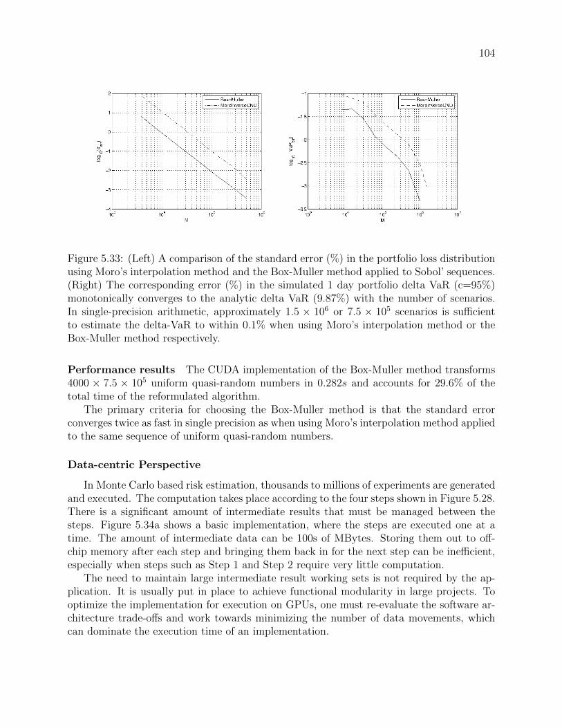
104
Figure 5.33: (Left) A comparison of the standard error (%) in the portfolio loss distributionusing Moro’s interpolation method and the Box-Muller method applied to Sobol’ sequences.(Right) The corresponding error (%) in the simulated 1 day portfolio delta VaR (c=95%)monotonically converges to the analytic delta VaR (9.87%) with the number of scenarios.In single-precision arithmetic, approximately 1.5 × 10⁶ or 7.5 × 10⁵ scenarios is sufficientto estimate the delta-VaR to within 0.1% when using Moro’s interpolation method or theBox-Muller method respectively.
Performance results The CUDA implementation of the Box-Muller method transforms4000 × 7.5 × 105 uniform quasi-random numbers in 0.282s and accounts for 29.6% of thetotal time of the reformulated algorithm.
The primary criteria for choosing the Box-Muller method is that the standard errorconverges twice as fast in single precision as when using Moro’s interpolation method appliedto the same sequence of uniform quasi-random numbers.
Data-centric Perspective
In Monte Carlo based risk estimation, thousands to millions of experiments are generatedand executed. The computation takes place according to the four steps shown in Figure 5.28.There is a significant amount of intermediate results that must be managed between thesteps. Figure 5.34a shows a basic implementation, where the steps are executed one at atime. The amount of intermediate data can be 100s of MBytes. Storing them out to off-chip memory after each step and bringing them back in for the next step can be inefficient,especially when steps such as Step 1 and Step 2 require very little computation.
The need to maintain large intermediate result working sets is not required by the ap-plication. It is usually put in place to achieve functional modularity in large projects. Tooptimize the implementation for execution on GPUs, one must re-evaluate the software ar-chitecture trade-offs and work towards minimizing the number of data movements, whichcan dominate the execution time of an implementation.

105
!"#$%&'()"*$+,-./$0"1*,$2(34*"5,-$!6#$+,-./$0"1*,$7(34*"5,-$,8$3"19/.$:";$$$
$$$$$$,'53(</=$8,1$>?@$1/7,41)/$A(/1"1)A&$
!B#$$$$$$$$$$$$$$$$$$$$$$$$$$$$$$$$$$C$C$C$
!D#$$$$$$$$$$$$$$$$$$$$$$$$$$$$$$$$$$C$C$C$
!E#$
!F#$$$$$$$$$$$$$$$$$$$$$$$$$$$$$$$$$$C$C$C$$
G436/1$,8$2)/-"1(,7$.,$2(34*"./$
!D#$
!E#$
!F#$
!B#$$
G436/1$,8$2)/-"1(,7$.,$2(34*"./$
Figure 5.34: The solution organization of Value-at-Risk on the GPU.
Timing (s) Standard Optimized Speedup(Separate) (Merged)
Box-Muller (step1) 0.128 0.156 2.63x(step2) 0.282
Bailey (step1) 0.128 0.441 1.16x(step2) 0.384
Table 5.10: The benefits of merging Step 1 (uniform random number generation) and Step 2(distribution conversion)
Kernel Merging In the case of the VaR implementation, merging the uniform randomsequence generation and the distribution conversion steps provided significant performanceboost. Figure 5.34b illustrates the case where the distribution conversion step executesin place as soon as the uniform random values are generated. By converting the uniformrandom values while they are still in the GPU’s register files on-chip, we save the executiontime associated with a set of round trip memory transfers as compared to writing out theresults to device memory and reading them back.
Performance results Table 5.10 illustrates the performance impact on a NVIDIA GeForceGTX 480 from applying kernel merging to two similar methods - the Box-Muller and Bai-ley’s methods10. A 2.63× speedup was achieved through merging steps 1 and 2 for theBox-Muller method. This optimization, however, can be sensitive to the amount of contexteach thread must maintain.
The optimization is found to be effective for the Box-Muller method, but not as effectivefor Bailey’s method, even though their functional form is very similar. The Bailey’s methodcontains two extra parameters for producing distributions with higher weights for less likely
10Bailey’s method [21] also makes use of a polar coordinate transformation of uniform random variables.Unlike the Box-Muller method, however, it produces student-t distributed random variables which give moreconservative VaR estimates [90]. Performance benchmarks using the Bailey’s method are based on our ownimplementation as is it not available in the CUDA SDK.

106
events (or “fatter tails” for the distribution). These extra parameters require more registersin the computation. Specifically, the merged Bailey’s method resulted in a modest 1.16×speed up over two separate steps. This indicates that register spilling is causing responsiblefor the reduction in performance improvements on the GPU architectures.
Data Blocking In Step 3, as explained in Section 5.2.4, we are leveraging the cuBLASlibrary for experiment execution. For VaR estimation, 7.5 × 10⁵ experiments are used.With thousands of risk factors being considered in each experiment, the experiments mustbe executed in batches to allow all operands and results of the cuBLAS routines to residein a GPU’s global memory. Sharing the 1GB GPU global memory with the Monte Carlobased VaR estimation engine, one can fit 214 experiments within one batch. The batchesof experiments are executed and the outcome of each experiment is saved for later use.Figure 5.34b illustrate the segmented Steps 1-3 that is used to block the batch processes foroptimized data reuse11.
Results After Addressing Efficiency Concerns
Our baseline GPU NVIDIA GeForce GTX480 graphics processing unit (GPU) imple-mentation of MC-VaR is a straightforward port from the CPU implementation and has a7.76x speed advantage over an eight-core Intel i7 Q920 central processing unit (CPU) basedimplementation. By reformulating the VaR estimate to reduce the amount of computation,we achieved a 61.9x speedup. Use of a Box-Muller algorithm to convert the distributiongives an additional 2x speedup over interpolating the inverse of the Gaussian distributionfunction. We merged data-parallel computational kernels to remove redundant load storeoperations leading to an additional 2.63x speedup. Overall, we have achieved a speedup of169x against the baseline GPU implementation, reducing the time of a VaR estimation witha standard error of 0.1% from minutes to less than one second.
Experiment Setup The benchmark results for the CPU implementation are measuredon an Intel i7 Q920 eight-core CPU, with 8MB L2 cache and 2.67GHz clock frequency. Theestimation engine is compiled with Intel ICC version 11.1 (072). We use the multi-threadedBLAS kernels implemented in the Intel Math Kernel Library (MKL) version 10.2.5 (update35).
The benchmark results for the GPU implementation are measured on an NVIDIAGeForce GTX 480 GPU with 1.5GB of global memory. The GTX480 has 15 multipro-cessors at 1.4GHz clock frequency, each with dual issue 16-way vector arithmetic units. TheCUDA programs are compiled with NVCC release 3.1 and use BLAS routines available inthe cuBLAS library version 3.1.
We have chosen algorithmically equivalent baseline CPU and GPU implementations,which provide negligible differences in the intermediate results and VaR estimates. In otherwords, the baseline implementations only provide a transparent reference point from which
11Step 4 does not need to be batched, because its data set comfortably fits in the GPU’s global memory.

107
to trace back any differences in output between the CPU and GPU after subsequent codemodifications. They are not fully optimized for performance.
The baseline CPU implementation first generates Sobol’ sequences using our own OpenMPparallel implementation of the Sobol’ QRNG adapted from a publicly available C++ codewritten by Joe and Kuo [88]. This implementation conveniently provided pre-computed di-rection vectors to dimensions beyond our requirements. Intel’s MKL provides an optimizedimplementation of the Sobol’ QRNG (with merged distribution transformations) based onBratley and Fox’s [34] algorithm 659. This implementation, however, is only pre-configuredto generate quasi-random numbers in dimensions of up to 40, although it does allow forprecomputed direction vectors in higher dimensions (e.g. from [88]) to be externally refer-enced.
Sobol’ sequences are transformed into normal random variables using a C implementa-tion of Moro’s Inverse Cumulative Distribution Function (ICDF) provided, for comparativereasons, in the NVIDIA CUDA SDK 3.1. The loss function is then evaluated with calls to theStreaming SIMD Extensions (SSE) enabled MKL cBLAS kernels cblasSgemm, cblasSgemvand cblasSaxpy, and the result is stored in a loss vector.
We observed that the baseline CPU implementation spends approximately half the timegenerating the random matrices (QRNG + distribution conversion), and half the time eval-uating the loss function. Finally, the moments of the loss distribution are estimated bysorting the loss vector of length M using qsort from cstdlib in O(MlogM) operations onaverage. This is a negligible step compared to the BLAS computations which are at leastO(MN).
The baseline GPU implementation first generates uniform quasi-random numbers withthe “embarrassingly parallel” Sobol’ QRNG provided in the NVIDIA SDK 3.1. The sequenceis transformed using our own optimized version of Moro’s ICDF which makes extensive useof computation blocking and shared constants in the on-chip shared memory. The lossfunction is then evaluated using cublasSgemm, cublasSgemv and cublasSaxpy kernels. Atthe final step, the loss vector is copied from device to CPU memory and sorted using qsort
from cstdlib.
Overall Performance Results The overall speedup from a three-stage optimization ofthe CUDA implementation of the ∆-Γ VaR model is presented in Table 5.11. The columnsin the table represent the three steps of execution in the VaR estimation and the tablecontent specifies the absolute and proportional timings of the steps.
The baseline GPU implementation is able to exploit the absence of cross thread com-munication in the Sobol’ QRNG and Moro’s ICDF by leveraging the faster native transcen-dental functions to significant effect. There is a 22.2× speedup for the Sobol’ quasi-randomnumber generation and a 25.8× speedup for Moro’s ICDF. With a 7.97× speedup, the lossfunction evaluation step also benefits from being mapped to the GPU, although it becomesthe performance bottleneck in the baseline GPU implementation.
We optimize the VaR computation on the GPU in three ways: using problem refor-mulation, module selection, and kernel merging. We briefly state the effect of these threeoptimizations here and explain them in detail in the next section:

108
Timing (s) QRNG Distribution LossConversion Evaluation
Baseline GPU 0.257 0.564 117(0.22%) (0.48%) (99.3%)
Problem - - 1.08Formulation (13.5%) (29.7%) (56.8%)(GPU)Module 0.129 0.282 0.540Selection (GPU) (13.6%) (29.6%) (56.8%)Kernel 0.156 -Merging (GPU) (22.4%) (77.6%)
Speedup 5.27x 217xTotal Speedup 169x
Table 5.11: The columns of the table illustrates the different steps in a Monte Carlo sim-ulation. The top half of the table shows the run time in seconds after each respectiveoptimizations. The percentages in parentheses on each row add up to 100%. They indicatethe proportions of the algorithm steps. The bottom half of the table illustrates the GPUspeedup for the ∆-Γ approximation with 4000 risk factors, simulated to achieve a standarderror in the normal loss distribution within 0.1%.
• Problem reformulation: By reformulating the algorithm using task-centric techniquesas described in the Numerical-centric Perspective section, we are able to obtain a 108×speedup in the loss function evaluation - the bottleneck in the baseline implementation.This amounts to an overall speedup in the VaR estimate of 61.9×.
• Module selection: Using the numerical-centric techniques to choose the Box-Mullermethod over Moro’s ICDF, as described in the Numerical-centric Perspective section,we selected the module that gives the faster numerical convergence rate in the standarderror. We were able to reach the same VaR estimation accuracy with nearly half thenumber of simulations. This provides another 2× speedup.
• Kernel merging: Using the data-centric techniques, we merge the Sobol’ and distribu-tion conversion steps, as described in the Data-centric Perspective section, to removea pair of redundant load and store operations from the computation of each distri-bution conversion. This reduces the QRNG generation and distribution conversionexecution time by 2.63×.
After these optimizations, we have enabled a 169× faster implementation compared to aGPU-based baseline solution, and 1311× faster implementation compared to a CPU-basedbaseline solution. This illustrates that using a GPU-based implementation may providesome speedup over a CPU-based implementation, but relying on the platform advantagealone would overlook significant acceleration opportunities.
109
5.2.5 Productivity Concerns in Market Risk Estimation
A Monte Carlo based VaR estimation is highly modular. Each of the four steps in theMonte Carlo method that was described in Section 5.2.3 can be replaced with functionalvariants to form new Monte Carlo based applications. While an application frameworkfor Monte Carlo based VaR estimation on the GPU remains a topic of on-going research,the efficient implementation described in Section 5.2.4 can serve as a reference implemen-tation. With this reference implementation, a framework user can immediately experiencethe performance achievable for VaR estimation on the GPU.
In terms of the other components of a VaR application framework, the application contextis outlined in Section 5.2.1. The concurrency in the VaR estimation application can bedescribed as an instance of the Monte Carlo Methods pattern (see Appendix A). Clarifyingthis association brings forth a set of background knowledge in the solution techniques andtheir trade-offs, which reduces the time needed to acquire the necessary information tomake design choices. For this reason, the application context improves the productivity ofthe users of the VaR application framework.
The software architecture of the VaR application framework is described in Section 5.2.3.By clarifying the structure of a parallel implementation of a Monte Carlo based estimationengine, a VaR application expert can effectively take advantage of the concurrency oppor-tunities in the VaR estimation problem, and learn about the suitability of the solutiontechniques to exploit the concurrency opportunities on the GPU. This improves the produc-tivity of the VaR application framework users by providing assistance with the navigationof the software architecture of a VaR application framework.
The extension points are described here in order to illustrate what an application devel-oper can expect from a Monte Carlo based VaR Application Framework.
1. The Random number generation (RNG) extension point : while we have found thatthe Sobol’ quasi-random number generator is well-suited for single time-step shorttime-horizon VaR computations, larger scale risk analytics approaches often use aMersenne twister [109] based pseudo RNG for its long periods. An extension point forRNG allows different generation approaches to be applied.
There are two requirements that a RNG implementation must satisfy to become aplug-in for this extension point: 1) It must support skip-ahead to allow a thread ofexecution to be able to fast forward to a particular element in the random sequence;2) It must be able to save and reload its internal states, i.e. the RNG step must beallowed to be swapped out of parallel contexts in a highly parallel implementationand restore the execution where it left off at a later time. For example, to satisfythe first requirement, an RNG routine interface should contain an index to which theimplementation will skip to for the next element to be generated; to satisfy the secondrequirement, a RNG routine interface should contain a set of internal states to beloaded for the next elements to be generated.
2. Parameter distribution transformation extension point : This is a crucial extensionpoint that is expected to be frequently customized in deployment. The appropri-ateness of parameter distribution is conditional on the type of financial instruments

110
for which the risk is being analyzed. In the reference implementation presented inSection 5.2.4, we have interchangeably used the Moro interpolation method and theBox-Muller method, which produce Gaussian distribution functions, as well as theBailey’s method, which produces the student t-distribution with more emphasis onthe occurrence of unlikely events (sometimes referred to as “fatter tails”).
There are some optimization opportunities in the merging of the plug-ins specifiedat the RNG extension point and the parameter distribution transformation extensionpoint, as demonstrated in the data-centric perspective shown in Section 5.2.4. Theapproach to exploit this opportunity is a topic of on-going research in programmingframeworks for parallel computing.
3. Experiment evaluation extension point : The experiments in the reference implementa-tion are evaluated using highly optimized dense matrix operations from the cuBLASlibrary, a BLAS library for CUDA. For estimating VaR on different portfolios of fi-nancial instruments, there are other variants besides the delta-gamma (∆-Γ) approxi-mation. For simpler cases, one could use the first-order delta (∆) approximation. Formore complex cases, one could use the third-order approximation. The decompositionof the evaluation into matrix routines may also change as new faster dense matrixlibraries emerge. The experiment evaluation extension point allows new plug-ins to bedeveloped without re-implementing the full VaR estimation infrastructure.
4. Data assimilation extension point : This extension point handles the analysis of theexperiment results. Different confidence intervals could be used for VaR estimates, anddifferent data output formats could be used given the needs of the overall application.
A VaR pattern-oriented application framework with the four extension points as de-scribed above highlights the key steps in a Monte Carlo based VaR estimation. With thesefour extension points, an application developer can adapt the framework to a variety of theVaR estimation usage scenarios by specifying only the plug-ins that differ from a standardimplementation. This significantly reduces the number of lines a VaR application experthave to implement to produce an efficient VaR estimation-based application. Specifically,using the pattern-oriented application framework reduces the effort from developing a ten-thousand-line application to implementing a few hundred lines of plug-in customization.
While the implementation of this application framework is on-going research, we seethat its implementation can help the VaR application framework users productively under-stand the application concurrency opportunities and the software architecture of referenceimplementation. It can greatly reduce the number of lines of code required to implement avariant of the VaR application, which will also reduce the number of potential for bugs inthe implementation process, resulting in improvements in productivity.

111
5.2.6 Efficiency Concerns in Counterparty Exposure Estimation
The challenges in the acceleration of Potential Future Exposure (PFE) calculations onthe GPU were explored12. Compared to the VaR implementation that was explored inSection 5.2.4, estimating PFE for a portfolio is significantly more computationally intensive.The computation can be seen as calculating Present Values (PV) of future gains/losses alongthree dimensions for a portfolio:
1. Over different trades: there can be as many as 5× 10⁵ to one million trade-able assetsin a portfolio, such as Bonds, Options, Swaps, Swaptions, etc.
2. Over different paths: each trade is simulated with as many as 5000 future marketscenarios or paths
3. Over different time steps: for each trade on each path, it is simulated for 30-300 timesteps into the future!"#$%&'$(&)*$+&,&--.-$/0(.)'01)'$
Trades x 4000+
Path x 5000
1+ Billion PV’s
Which Dimensions work best on GPU’s? Figure 5.35: The cube (three dimensional matrix) of Present Values (PVs), or Monte Carlosimulation results, in a Potential Future Exposure (PFE) application.
For any given time step of the market scenario, the value each of the trade is computed.To normalize the value of the trades to a present day value, the Present Value is computedby depreciating future value with the interest rate curves specified in the market scenario.Figure 5.35 represents these computations as a three-dimensional matrix (also known as thePV Cube). Even for a nominally sized PFE calculation with only 4000 trades, a billion
12These experiments were jointly conducted with an industry partner based on a production code basethat is currently in use. The industry partner is a large global financial information company

112!"#$%&'()*"&+,-.&,/#01"#(*&23%4&
&5#36")7&8(#9"7&&&:/7;%)&<%#%)(1"#&&=58:<>&
!"#$
&+()(7%$%)&&?3@$)3;/1"#&&A)(#@6")7(1"#&
!%#$
&B#@$)/7%#$&&+)303#C&
!&#$
&?($(&&D@@373*(1"#&
!'#$
for (1.. nPaths){!!for (1.. nTrades){!! !for (1..nTimeSteps){!
} // end nTimeSteps!!} // end nTrades!
} // end nPaths!
(3a) Calculate rate for each cashflow!(3b) Calculate each cashflow payment!(3c) Discount each cashflow payment (PV)!(3d) Sum each cashflow payment (NPV)!
(4) Aggregate NPVs for each scenario!
(1) Generate Uniform Random Values !
(2) Generate forward rate curves!
Interest Rate Swap Pricing Example!
&,3#(*&?($(&&D#(*E@3@&
!(#$Res
Figure 5.36: The task-centric perspective of a potential future exposure (PFE) estimation.
PV computations are required. Computing the PVs in this matrix consumes over 90% ofthe total execution time of a PFE application. The rest of the execution time is spent onloading market and trade data, as well as performing calibrations.
Task-centric Perspective
From the task-centric perspective, the 3D matrix of PVs is computed in a set of nestedfor loops. Among the for loops, all trades can be processed independently, and all pathscan be processed independently. However, at the time step level for certain trade types suchas options, it is more efficient to be computing the time steps in chronological order, as earlytermination of the computation may be possible depending on the market scenario.
Figure 5.36 illustrates the organization of the tasks. On the left is the triple nested loopfor computing the PVs in the 3D matrix of a computation. On the right is an example of aninterest rate swap (IRS) trade, where the computation for the specific trade type is listedand labeled with lines (1-4).
More specifically, for each path in each trade, a typical implementation of the MonteCarlo Engine creates a task that goes through each time step. The task first generatesuniform random values (line 1), and then creates a scenario going forward into the future(line 2). In the case of estimating PFE for an IRS, an interest rate scenario (i.e. forwardrate curves) is constructed according to the perturbations that the random values generated.Once the path scenario is generated, the trade’s behavior is simulated (lines 3a-3b). In thecase of the IRS, this involves calculation of the cash flow at each time step, as well as theassociated cash pay out. The value computed at each time step is normalized to the same

113
!"#$%&'()*"&+,-.&/($(&01%2&
Trades
Path
Phase 1: Generate
all potential time steps
Input: all trade types
and their parameters
Phase 2: Generate
market data for all time steps
Phase 3: Estimate value for all trades on reporting
time step
Path Path
Phase 4: Aggregating NPV from all trades
Phase 5: Find PFE
from all path
Figure 5.37: The data-centric perspective of potential future exposure (PFE).
point in time (line 3c). In this case, they are discounted to the present day, providing thepresent value (PV) (line 3d). The PV is then accumulated into the value of the trade givenits behavior in all of the time steps, thus providing the Net Present Value (NPV) for thetrade (line 4).
The parallelization techniques are explored in the result section. There are two caveatsto keep in mind:
1. In computing the PFE of a portfolio of trades, all trades may have slightly differentparameterization, meaning that their behavior is likely to differ across the time steps.
2. Path generation must be coordinated among the trades, as the same scenario should beapplied to all trades in order to arrive at the behavior for a portfolio for that scenario.
Data-centric Perspective
Taking the task-centric perspective into account, one can also analyze the PFE workloadfrom a data-centric perspective. Figure 5.37 illustrates the amount of results generatedacross different phases of execution (from left to right). It highlights that the majority ofthe work in the Monte Carlo-based PFE estimation is spent in Phase 3 working on pricingthe trade-able assets.
In Phase 1, a sequence of time stamps is generated based on trade types and parameters.These time stamps represent important reporting dates for the portfolio and its trades.Based on the time stamps of importance, the market data for the scenarios can be generatedin Phase 2. Note that not all scenarios have to be generated at the same time. In fact, theprocess illustrated in Figure 5.36 works with one path at a time, and it works through all
114
of the trades for that scenario before starting work on the next one. In Phase 3, the NPVsare computed for each trade in each path. In Phase 4, the NPVs are accumulated across allof the trades in order to summarize the value of the portfolio in each path over time. Thefinal step computes the PFE based on the NPVs over the thousands of simulated paths.
Results
The benchmark results for the CPU implementation are measured on an Intel Core2Q9300 quad-core CPU, with 6MB L2 cache and 2.50GHz clock frequency. Microsoft VisualStudio was used to compile the code. The benchmark results for the GPU implementationare measured on an NVIDIA GeForce GTX 260 GPU with 896MB of global memory. TheGTX260 has 12 multiprocessors running at 1.24GHz clock frequency, each with 8-way vectorarithmetic units. The CUDA programs are compiled with NVCC release 2.2 [4].
The production code for the industrial scale application contains more than 100k linesof C++ source code. The infrastructure has been developed over many years and wasoptimized for maintainability. A proof of concept (POC) Monte Carlo Engine of 5k linesof C++/CUDA was constructed based on the production code base in order to allow fastexploration of the software architecture design space to occur.
Using the POC Monte Carlo Engine, for a test set with 1000 interest rate swaps, 3000scenarios, and 50 time steps, a speed up of 750x was achieved. Figure 5.38 illustrates thedifferent approaches that were experimented with here.
On the left in Figure 5.38, the software architecture that was used in the serial CPUimplementation can be seen. Only the financial instrument (trade) pricing step was mappedto the GPU. In this case, the instrument pricing routine was parallelized over 50 time steps.This approach maximally preserves the Monte Carlo engine setup, but resulted in a slowdown in the execution time, as there was not enough concurrency or computation to speedup and compensate for the significant overhead in transferring the operands and results.
In the middle of Figure 5.38, the application is parallelized over the number of paths.At each time step, the paths (or market scenarios) are generated for all trades, and thePVs are computed one trade at a time across all paths. There is a 3000-way concurrencyover the paths, and the market scenario generated for each path only has to be transferredto the GPU once. We are able to observe a 25x speed up over the original C++ baselineperformance.
On the right in Figure 5.38, the application is parallelized over the number of paths andthe number of trades. At each time step, the paths (or market scenarios) are generatedfor all of the trades. The PV computations are blocked to maximally leverage the sharedmemory resources local to each streaming multiprocessors (SM) in the GPU. Specifically,each thread block works on a trade, and each thread within the thread block works on ascenario. Such mapping of workload to the GPU enables a 750x speed up over the originalC++ baseline performance.

115
!"#$%&'(!)*#+&(!!!,-(./'!0/#/'*1&#!!2"),03!
!"#$
!4*'*(/5/'!!6$75'$.-1&#!!8'*#7%&'(*1&#!
!%#$
!9#75'-(/#5!!4'$:$#;!
!&#$
!6*5*!!<77$($=*1&#!
!'#$
for (1..nTrades){!!for (1..nPaths){!! !for (1..nTimeSteps){!
} // end nTimeSteps!!} // end nPaths!
} // end nTrades!
!>$#*=!6*5*!!<#*=?7$7!
!(#$)/7!
)*+$$!$
?
8'*+/7!
4*5@!
!"#$%&'(!)*#+&(!!!,-(./'!0/#/'*1&#!!2"),03!
!"#$
!4*'*(/5/'!!6$75'$.-1&#!!8'*#7%&'(*1&#!
!%#$
!9#75'-(/#5!!4'$:$#;!
!&#$
!6*5*!!<77$($=*1&#!
!'#$
for (1..nTrades){!!for (1..nPaths){!
} // end nPaths!
for (1..nTimeSteps){!
} // end nTimeSteps!
for (1..nPaths){!
!} // end nPaths!} // end nTrades!
!>$#*=!6*5*!!<#*=?7$7!
!(#$)/7!
)*+$$!$
8'*+/7!
4*5@!
8'*+/7!
4*5@7!
8@'/*+7!24*5@3!
8@'/*+.=&:A7!28'*+/73!
04"!0'$+!B/'#/=!
,--./012$"$3-445$6-7$89'(:$
,--./012$%$3-445$6-7$%(:$
,--.9$&$3-445$6-7$$$$;(8:$
Figure 5.38: Three approaches to GPU-based PFE implementation.
5.2.7 Productivity Concerns in Counterparty Exposure Estima-tion
While a Monte Carlo based PFE pattern-oriented application framework using the GPUremains a topic of on-going research, the implementation demonstrated in Section 5.2.6can serve as a reference implementation. With this reference implementation, one canimmediately experience the performance achievable for the PFE application on the GPU.
The code base for counterparty exposure estimation contains domain knowledge fromthree domains of expertise in: 1) market models for scenario generation, 2) trade models andbusiness logic for simulating the trades under different market conditions, and 3) calibrationroutines to characterize model parameters. These three domains knowledge are encapsulatedin a code base of 100-thousand lines of code. The productivity concerns for a 100-thousand-line code base is focused on maintainability, as it is difficult for any one software developerto be aware of all of the parts of the code base at once. Maintainability here means that

116
the software architecture must be designed such that people with different domain expertisecan each have a module to implement functions in their domain without jeopardizing thecorrectness of the overall application. If this is achieved, one can consider the softwareinfrastructure maintainable.
In this spirit, the production code is already well architected with extension points avail-able for each commonly modified entity, such as time step management, forward rate con-struction, and a variety of internal and external libraries for instrument (or trade) pricing.The interface for pricing instruments has been kept at the finest grain of one time step, onepath, and one trade. While this is a very flexible interface, as was observed in the result inApproach 1 (left panel in Figure 5.38), it cannot be efficiently parallelized on a manycoreplatform.
The center panel in Figure 5.38 illustrates Approach 2, and the right panel in Figure 5.38illustrates Approach 3. The implication for Approach 2 is that the pricing library interfacemust be modified to allow the specification of a range of paths to be concurrently priced.Similarly, the implication for Approach 3 (right panel in Figure 5.38) is that the pricinglibrary interface must be modified to allow a set of paths as well as a list of trades to bepriced concurrently. While there is on-going research investigating how much the actualpricing routines must be modified to enable the alternative interface, approaches 2 and 3shows that the production Monte Carlo Engine must be modified to allow more flexiblepacked execution of the pricing engine calls to take place.
In terms of the components of a PFE pattern-oriented application framework, the ap-plication context is outlined in Section 5.2.2. The concurrency in the VaR estimation ap-plication can be described as an instance of the Monte Carlo Methods pattern (see Ap-pendix A). Clarifying this association brings forth a set of background knowledge in thesolution techniques and their trade-offs. This reduces the time needed to acquire the neces-sary information to make design choices. For this reason, the application context improvesthe productivity of the users of the PFE application framework.
The software architecture of the PFE application framework is described in Section 5.2.3.By clarifying the structure of a parallel implementation of a Monte Carlo based estimationengine, a PFE application expert can effectively take advantage of the concurrency oppor-tunities in the PFE estimation problem, and learn about the suitability of the solutiontechniques to exploit the concurrency opportunities on the GPU. This improves the produc-tivity of the PFE application framework users by providing assistance with the navigationof the software architecture of a PFE application framework.
While the implementation of this application framework is on-going research, we seethat its implementation can help the application framework users productively understandthe application concurrency opportunities and the application framework architecture. Thechallenge is in deploying such a large infrastructure in a real world scenario, with a sig-nificant change to an extension point interface. We focus on these challenges for PFE inSection 6.2.2.

117
5.3 Summary
This chapter demonstrates that a significant amount of optimizations can be incorpo-rated into an application framework, many of which require an intimate understanding ofthe underlying computing platform capabilities, as well as the knowledge of application im-plementation alternatives. Such optimizations cannot be achieved by application domainexperts using just a powerful compiler or parallel programming experts using just a samplesequential implementation. Both areas of expertise are required.
In the case of ASR implementation, the optimizations that have been explored include:
• Four parallel programming techniques for the acceleration of the irregular data accesspatterns in the inference process (Section 5.1.2)
• The selection of recognition network representation, where there is an intricate trade-off between the simpler, more regular, but highly redundant Linear Lexical Model(LLM) representation and the more advanced, highly irregular, and more terse WeightFinite State Transducer (WFST) representation (Section 5.1.3)
• The optimization of recognition network structure, where the network structure isoptimized to assist with more efficient data-parallel graph traversal on manycore microprocessors (Section 5.1.4)
• Implementation platform-specific optimizations, where we found that different graphtraversal techniques are optimal on different platforms, and that platform-specificalgorithm tuning and adaptation is required (Section 5.1.5)
In the case of VaR performance optimizations, attempts were made utilizing three per-spectives (Section 5.2.4), including:
• A task-centric perspective, where the application was architected to leverage existingefficient library routines, and the algorithm for computing VaR was transformed andreformulated to reduce the total number of operations
• A numerical-centric perspective, where the random numbers generator and statisticaldistribution conversion algorithms were selected based on their numerical propertiesin order to achieve fast numerical error convergence
• A data-centric perspective, where the implementation is optimized based on its dataaccess patterns
In the case of PFE performance optimization, the efforts focused on developing a softwarearchitecture where the capabilities of a manycore processor can be leveraged to deliverapplication performance (Section 5.2.6).
This chapter also highlighted the productivity concerns in developing extension pointsto allow the application framework to be flexibly reused in a variety of application usagescenarios. The challenge of deploying an application framework for the industry is the topicof the next chapter.

118
Chapter 6
The Deployment of aPattern-Oriented ApplicationFramework
Chapter 4 introduced an exemplar of a pattern-oriented application framework for adomain expert to effectively utilize manycore micro processors, and Chapter 5 offered adetailed explanation of the construction process of the pattern-oriented application frame-work, where the amount of application-level optimization that goes into an applicationframework is often beyond what an application domain expert can handle using a paralleliz-ing compiler. This chapter illustrates how pattern-oriented frameworks can be customizedfor various usage scenarios and deployed in the field.
The ASR application framework involves approximately ten thousand lines of code andcan be deployed as a stand-alone module. Section 6.1 demonstrates two deployments of theASR application framework, with one of them extending the ASR framework to incorporatevideo information to enable lip-reading in noisy recognition environments.
While the application frameworks for the risk analytics applications examined in thisthesis are still on-going research, based on our optimized reference implementations of theVaR and PFE applications, we have a grounded estimate of their expected scale of complex-ity. When completed, the VaR application framework involves approximately ten thousandlines of code, and can be deployed as a stand-alone module. The PFE application frame-work, when fully implemented, will involve a code base of more than one hundred thousandlines of code, with addition plug-ins implemented in external libraries. This poses significantchallenges in the deployment process, which is explored in Section 6.2.
6.1 Automatic Speech Recognition Application Frame-work Deployment
In this section, two case studies are presented that illustrate the flexibility of an appli-cation framework in regard to adapting it to different usage scenarios. The case studies
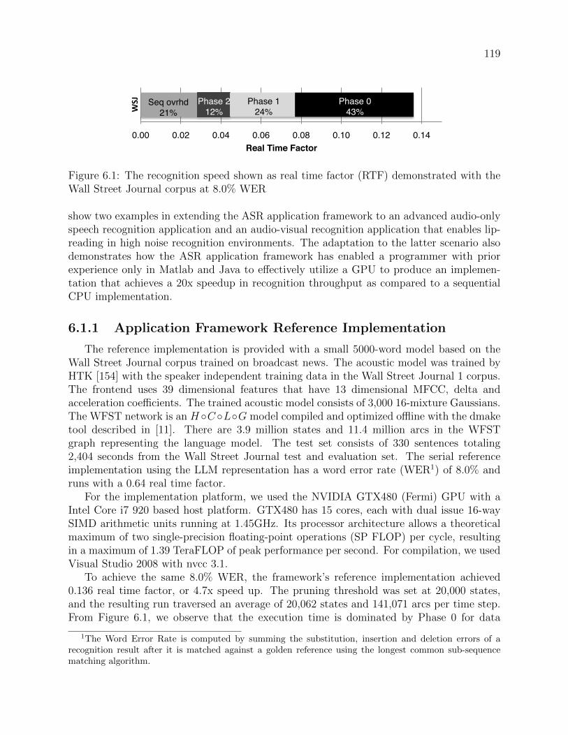
119
0.00! 0.02! 0.04! 0.06! 0.08! 0.10! 0.12! 0.14!
Real Time Factor!
!"#$
Phase 0!
43%!
Phase 2!
12%!
Phase 1!
24%!
Seq ovrhd!
21%!
Figure 6.1: The recognition speed shown as real time factor (RTF) demonstrated with theWall Street Journal corpus at 8.0% WER
show two examples in extending the ASR application framework to an advanced audio-onlyspeech recognition application and an audio-visual recognition application that enables lip-reading in high noise recognition environments. The adaptation to the latter scenario alsodemonstrates how the ASR application framework has enabled a programmer with priorexperience only in Matlab and Java to effectively utilize a GPU to produce an implemen-tation that achieves a 20x speedup in recognition throughput as compared to a sequentialCPU implementation.
6.1.1 Application Framework Reference Implementation
The reference implementation is provided with a small 5000-word model based on theWall Street Journal corpus trained on broadcast news. The acoustic model was trained byHTK [154] with the speaker independent training data in the Wall Street Journal 1 corpus.The frontend uses 39 dimensional features that have 13 dimensional MFCC, delta andacceleration coefficients. The trained acoustic model consists of 3,000 16-mixture Gaussians.The WFST network is an H ◦C ◦L◦G model compiled and optimized offline with the dmaketool described in [11]. There are 3.9 million states and 11.4 million arcs in the WFSTgraph representing the language model. The test set consists of 330 sentences totaling2,404 seconds from the Wall Street Journal test and evaluation set. The serial referenceimplementation using the LLM representation has a word error rate (WER1) of 8.0% andruns with a 0.64 real time factor.
For the implementation platform, we used the NVIDIA GTX480 (Fermi) GPU with aIntel Core i7 920 based host platform. GTX480 has 15 cores, each with dual issue 16-waySIMD arithmetic units running at 1.45GHz. Its processor architecture allows a theoreticalmaximum of two single-precision floating-point operations (SP FLOP) per cycle, resultingin a maximum of 1.39 TeraFLOP of peak performance per second. For compilation, we usedVisual Studio 2008 with nvcc 3.1.
To achieve the same 8.0% WER, the framework’s reference implementation achieved0.136 real time factor, or 4.7x speed up. The pruning threshold was set at 20,000 states,and the resulting run traversed an average of 20,062 states and 141,071 arcs per time step.From Figure 6.1, we observe that the execution time is dominated by Phase 0 for data
1The Word Error Rate is computed by summing the substitution, insertion and deletion errors of arecognition result after it is matched against a golden reference using the longest common sub-sequencematching algorithm.

120
gathering. Phase 0 is necessary to align operands for Phase 2, the graph traversal phase.For the sequential overhead, 65% is used for transferring the backtrack log from the GPUto the CPU and 35% is for backtrack, file input and output on the CPU.
6.1.2 Deployment for Usage in Meeting Transcription
The SRI speech models for meetings [146] are produced for the accurate automatictranscription of multi-party meetings. It aims to construct an interactive agent that providesonline and offline assistance to meeting participants.
We used the speech models from the SRI CALO realtime meeting recognition sys-tem [146]. It is produced with an advanced frontend that uses 13 dimensional perceptuallinear prediction (PLP) features with first, second, and third order differences, is vocal-track-length-normalized and is projected to 39 dimensions using heteroscedastic linear dis-criminant analysis (HLDA). The acoustic model is trained on conversational telephone andmeeting speech corpora, using the discriminative minimum-phone-error (MPE) criterion.The language model is trained on meeting transcripts, conversational telephone speech, andweb and broadcast data [142]. The acoustic model includes 52K triphone states which areclustered into 2,613 mixtures of 128 Gaussian components. This type of acoustic model usestied Gaussian Mixtures [142] and requires a more complex Phase 1 module for observationprobability computation.
To adapt the ASR application framework to the SRI Meeting Model, a new ObservationProbability Computation plug-in was developed to handle the tied Gaussian Mixture Modelwith a two-step computation. The first step computes the match between the input data andtied Gaussian mixtures related to active states. The second step applies mixture weightsspecific to each triphone state that is associated with active states. This extension alsoinvolved a new component to read in SRI’s model file format. A new Result Output plug-inwas developed to produce files for SRI’s accuracy scoring script. The Pruning Strategyplug-in was kept the same.
The test set consisted of excerpts from NIST conference meetings, taken from the “indi-vidual head-mounted microphone” condition of the 2007 NIST Rich Transcription evalua-tion. The segmented audio files total 44 minutes in length and comprise 10 speakers. For theexperiment, we assumed that the feature extraction is performed offline so that the inferenceengine can directly access the feature files. The meeting recognition task is very challengingdue to the spontaneous nature of speech. The ambiguities in the sentences require largernumber of active states to keep track of alternative interpretations, which leads to slowerrecognition speed.
Table 6.1 shows at various pruning thresholds the accuracy in WER, speed in real timefactor and speedup on the GTX480 GPU (compared to an optimized sequential versionimplemented on the CPU). By leveraging the optimizations in the ASR framework, we wereable to achieve up to 14.2x speedup GPU compared to a sequential version run on the CPU.
For data analytics, where one searches for the keywords in a recorded meeting conver-sation, the range of WER presented here is tolerable and still yield useful results.
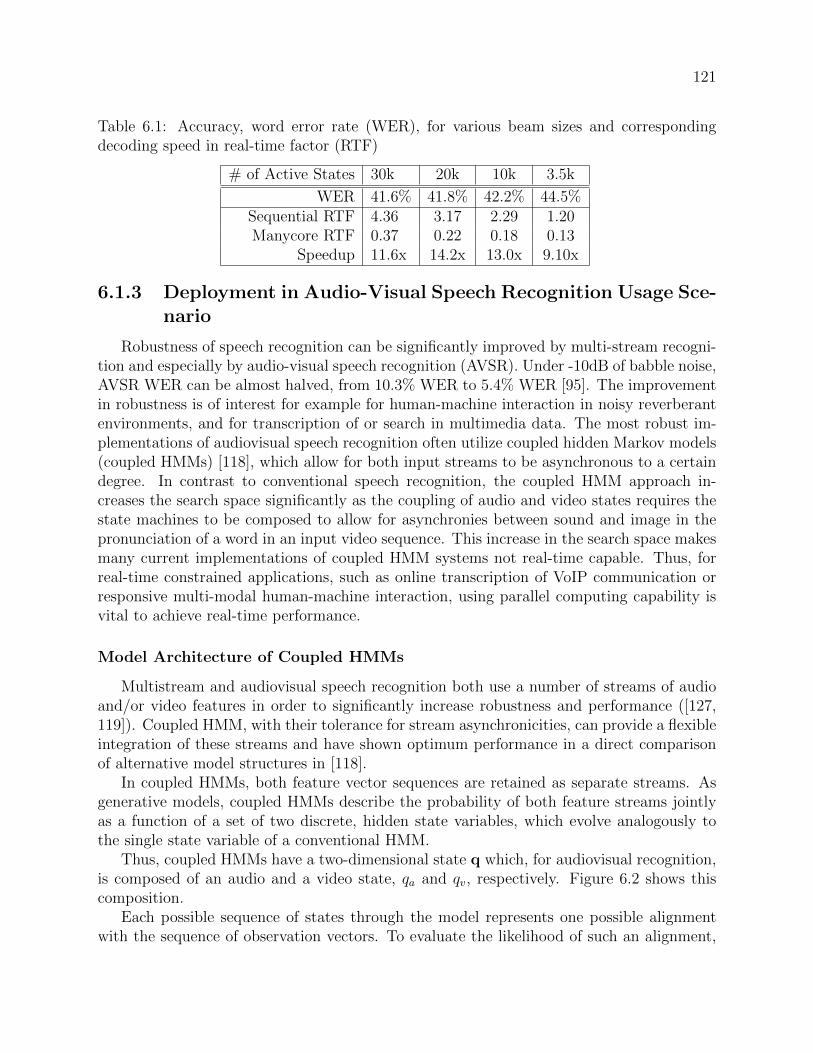
121
Table 6.1: Accuracy, word error rate (WER), for various beam sizes and correspondingdecoding speed in real-time factor (RTF)
# of Active States 30k 20k 10k 3.5k
WER 41.6% 41.8% 42.2% 44.5%Sequential RTF 4.36 3.17 2.29 1.20Manycore RTF 0.37 0.22 0.18 0.13
Speedup 11.6x 14.2x 13.0x 9.10x
6.1.3 Deployment in Audio-Visual Speech Recognition Usage Sce-nario
Robustness of speech recognition can be significantly improved by multi-stream recogni-tion and especially by audio-visual speech recognition (AVSR). Under -10dB of babble noise,AVSR WER can be almost halved, from 10.3% WER to 5.4% WER [95]. The improvementin robustness is of interest for example for human-machine interaction in noisy reverberantenvironments, and for transcription of or search in multimedia data. The most robust im-plementations of audiovisual speech recognition often utilize coupled hidden Markov models(coupled HMMs) [118], which allow for both input streams to be asynchronous to a certaindegree. In contrast to conventional speech recognition, the coupled HMM approach in-creases the search space significantly as the coupling of audio and video states requires thestate machines to be composed to allow for asynchronies between sound and image in thepronunciation of a word in an input video sequence. This increase in the search space makesmany current implementations of coupled HMM systems not real-time capable. Thus, forreal-time constrained applications, such as online transcription of VoIP communication orresponsive multi-modal human-machine interaction, using parallel computing capability isvital to achieve real-time performance.
Model Architecture of Coupled HMMs
Multistream and audiovisual speech recognition both use a number of streams of audioand/or video features in order to significantly increase robustness and performance ([127,119]). Coupled HMM, with their tolerance for stream asynchronicities, can provide a flexibleintegration of these streams and have shown optimum performance in a direct comparisonof alternative model structures in [118].
In coupled HMMs, both feature vector sequences are retained as separate streams. Asgenerative models, coupled HMMs describe the probability of both feature streams jointlyas a function of a set of two discrete, hidden state variables, which evolve analogously tothe single state variable of a conventional HMM.
Thus, coupled HMMs have a two-dimensional state q which, for audiovisual recognition,is composed of an audio and a video state, qa and qv, respectively. Figure 6.2 shows thiscomposition.
Each possible sequence of states through the model represents one possible alignmentwith the sequence of observation vectors. To evaluate the likelihood of such an alignment,

122
............
qv= 1
1 2 ... m
qv= n
Coupled HMM
...
...
...
...
...
...
...
......
...
...
...
...
...
...
............
.........HMM for Stream 2
HMM for Stream 1
............
............
............
qa=
Coupled HMM!
HMM for!Stream 2!
Figure 6.2: A coupled HMM consists of a matrix of interconnected states, which eachcorrespond to the pairing of one audio- and one video-HMM-state, qa and qv, respectively.
each state pairing is connected by a transition probability, and each state is associated withan observation probability distribution.
The transition probability and the observation probability can both be composed fromthe two marginal HMMs. Then, the coupled transition probability becomes
p�qa(t+ 1) = ja, qv(t+ 1) = jv|qa(t) = ia, qv(t) = iv
�
= aa(ia, ja) · av(iv, jv) (6.1)
where aa(ia, ja) and av(iv, jv) correspond to the transition probabilities of the two marginalHMMs, the audio-only and the video-only single-stream HMMs, respectively. This step ofthe computation, the so-called propagation step, is memory intensive due to the need fortransition probability lookup in a large and irregularly structured network.
For the observation probability, both marginal HMMs could be composed similarly, toform a joint output probability by
p(o|i) = ba(oa|ia) · bv(ov|iv), (6.2)
where ba(oa|ia) and bv(ov|iv) denote the output probability distributions for both singlestreams.
Such a formulation, however, does not take into account the different reliabilities of thetwo feature streams. Therefore, Eq. (6.2) is commonly modified by an additional streamweight γ as follows
p(o|i) = ba(oa|ia)γ· bv(ov|iv)
1−γ. (6.3)
Finally, computation of the marginal HMM state probabilities can be implemented in thesame way as for a standard single HMM system, e.g. as an M-component Gaussian mixture

123
model (GMM)
b(o|i) =M�
m=1
γmN (o | µi,m,Σi,m) . (6.4)
N (o|µ,Σ) stands for a multivariate Gaussian distribution evaluated for the vector-valuedobservation o with mean µ and covariance matrix Σ. The covariance matrix may be either afull or a diagonal covariance matrix, where the latter implies that feature vector componentsare either independent or that their dependencies may be neglected.
The steps given by (6.3) and (6.4) will be referred to as the likelihood combinationand the likelihood computation steps, respectively. These steps, especially the computation,have a much greater compute-to-memory-access ratio than the propagation step, due to thecomputational effort involved in GMM evaluation.
How was the framework used?
A coupled HMM can be compiled into a WFST that conforms to the required format intwo steps:
• First, the two-dimensional state index needs to be converted into one linear index foreach of the involved word models. These linearized word models can then be storedin an applicable format, in this case, the OpenFST [12] input format.
• Second, the word models need to be composed into the sentence level WFST. Thiscompilation, and a subsequent minimization, were carried out using OpenFST, whichresulted in an overall network size of 3167 states and 12751 arcs for the GRID gram-mar [49].
Once the WFST network is available, the only relevant change with respect to a ”regular”HMM is the observation probability computation according to Eq. (6.3). Therefore, thesignificant extension point for enabling coupled HMM-based audiovisual and multistreamASR was the observation probability computation step, which had to be adapted for coupledHMMs. For this purpose, CUDA kernels were implemented for Equations (6.3), the likelihoodcombination, and (6.4), the likelihood computation step.
The likelihood computation was optimized especially for the use with full covariancematrices, which can often result in substantial performance improvements; the relevantoptimizations are shown in some detail in [96]. For the likelihood combination step, asimple kernel was designed that is parallelized over all those coupled states that are in theactive set at the given time frame.
Performance results
The WFST decoder was used for multi-stream speech recognition in the following ex-periment. The two combined marginal HMMs were a 39-dimensional full-covariance Mel-frequency Cepstrum model and a 31-dimensional diagonal covariance RASTA-PLP model.The accuracy remained precisely the same for the C++ reference implementation and the
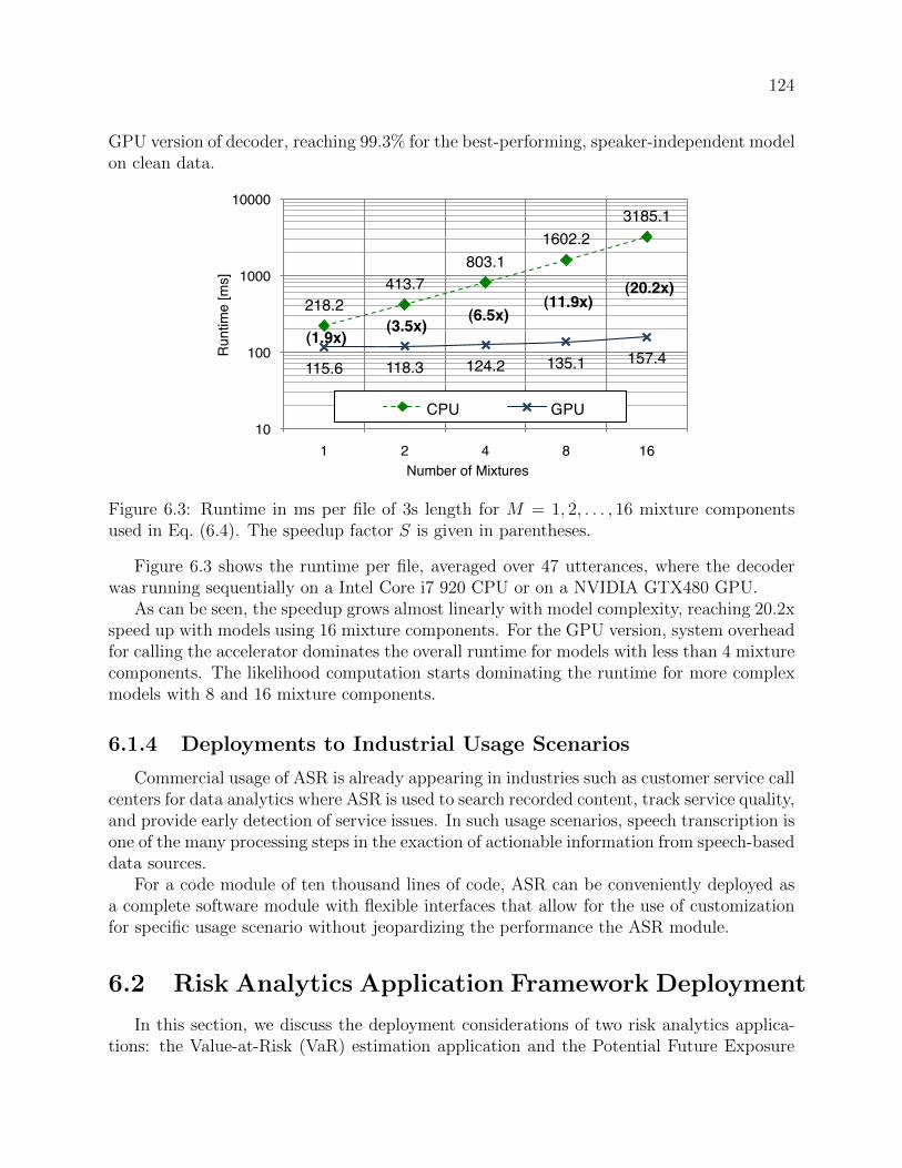
124
GPU version of decoder, reaching 99.3% for the best-performing, speaker-independent modelon clean data.
GPU 115.6 118.3 124.2 135.1
1.887543253 3.49704142 6.466183575 11.85936343
218.2!
413.7!
803.1!
1602.2!
3185.1!
115.6! 118.3! 124.2! 135.1! 157.4!
10!
100!
1000!
10000!
1! 2! 4! 8! 16!
Ru
ntim
e [
ms]!
Number of Mixtures!
CPU! GPU!
(1.9x)!(3.5x)!
(6.5x)!(11.9x)!
(20.2x)!
Figure 6.3: Runtime in ms per file of 3s length for M = 1, 2, . . . , 16 mixture componentsused in Eq. (6.4). The speedup factor S is given in parentheses.
Figure 6.3 shows the runtime per file, averaged over 47 utterances, where the decoderwas running sequentially on a Intel Core i7 920 CPU or on a NVIDIA GTX480 GPU.
As can be seen, the speedup grows almost linearly with model complexity, reaching 20.2xspeed up with models using 16 mixture components. For the GPU version, system overheadfor calling the accelerator dominates the overall runtime for models with less than 4 mixturecomponents. The likelihood computation starts dominating the runtime for more complexmodels with 8 and 16 mixture components.
6.1.4 Deployments to Industrial Usage Scenarios
Commercial usage of ASR is already appearing in industries such as customer service callcenters for data analytics where ASR is used to search recorded content, track service quality,and provide early detection of service issues. In such usage scenarios, speech transcription isone of the many processing steps in the exaction of actionable information from speech-baseddata sources.
For a code module of ten thousand lines of code, ASR can be conveniently deployed asa complete software module with flexible interfaces that allow for the use of customizationfor specific usage scenario without jeopardizing the performance the ASR module.
6.2 Risk Analytics Application Framework Deployment
In this section, we discuss the deployment considerations of two risk analytics applica-tions: the Value-at-Risk (VaR) estimation application and the Potential Future Exposure

125
(PFE) estimation application. As previously mentioned, the construction of the risk an-alytics application frameworks is a topic of on-going research. We estimate the expectedcomplexity of the code base using our optimized reference implementations as grounding,and discuss the anticipated challenges for the deployment of these application frameworksonce they are available.
We estimate that the VaR application framework can be built with ten thousand lines ofC++, and the PFE aplication framework will require one hundred thousand lines of C++.The deployment consideration is closely associated with the size of the framework beingdeployed. Using the widely used basic COCOMO model [30], a framework at the size of aVaR application framework takes an estimated 2.8 engineer-years to develop. A frameworksuch as a PFE application framework could take ten times as much efforts to develop. Whilein VaR, the market risk that a portfolio is exposed to is estimated for the portfolio, in PFE,different business logic is required for estimating the risk exposures between counterpartiesfor each contract. For example, the business logic for interest rate contracts, credit defaultswaps, foreign exchange contracts, commodity contracts, and equity contracts can varysignificantly. The variety in the business logic requires a much large code base to support.As the anticipated size of the two frameworks differs by an order of magnitude, we expectthem to require different deployment strategies. The next two sections explore the specificstrategies that can be used.
6.2.1 Value-at-Risk Application Framework Deployment
The VaR application framework produces risk metrics for risk managers in banks. Theapplication can be deployed in a variety of usage scenarios. In general, the inputs of a VaRapplication are financial data feeds and the outputs are the VaR estimation results enteredinto a database. The results can be used by analysts at quant desks for strategy validationor for risk assessment and stress testing.
To deploy the VaR application framework in these scenarios, an infrastructure must beavailable to calibrate the parameters used in the VaR estimation, where the parametersdescribe the sensitivity of a portfolio’s value to various risk factors over time. The infras-tructure for calibration and the infrastructure for risk estimation are linked by the parameterset. In practice, under the revised Basel II market risk framework, calibration is requiredat least once a month, where as the VaR metric can be computed on-demand or updatedregularly. From this perspective, a VaR application framework can be deployed as a softwaremodule in a larger risk assessment infrastructure, with customizable functions in plug-inswithout jeopardizing the execution efficiency of the VaR application framework. Potentialplug-ins include modules for various finanical data feed formats, modules utilizing differentrisk models and confidence intervals, and modules for outputing specific file formats.

126
6.2.2 Potential Future Exposure Application Framework Deploy-ment
PFE is a metric to quantify the counterparty risk of a financial portfolio posed byfluctuations in market prices in the future during the lifetime of the transactions, wherethe counterparties are brokers, investment banks, and other securities dealers that serveas the contracting party when completing financial securities transactions. Counterpartyrisk must be quantified on a transaction-by-transaction basis, where extensive business logicand modeling abstractions must be incorporated into the risk estimates for each type oftransactions. A PFE engine requires a code base that can be ten times larger than thatof a VaR engine. There is usually also a large set of legacy software routines in the formof a transaction-pricing library that is present as part of the infrastructure. Each legacypricing routine typically estimates the value of one transaction under one particular marketcondition at one specific point in time.
In Section 5.2.6, we showed that to efficiently utilize the GPU, the interface between theMonte Carlo engine and the pricing library must be modified. The Monte Carlo engine setsup the market scenarios for the PFE estimation and the pricing library computes the NetPresent Value (NPV) of each instrument under the market scenarios. The PFE pattern-oriented application framework for the GPU redefines the extension-point interface for thepricing library. The framework extension-point interface allows sets of transactions to bepriced on sets of scenarios at the same time (Section 5.2.7). This approach uses a moresuitable granularity of computations for highly parallel manycore computing platforms, andwas demonstrated to achieve orders of magnitude performance improvements on the GPU.With the new extension point interface, the infrastructure of a PFE framework can efficientlyexecute the pricing workload over the tens of cores on one manycore microprocessor withina computing cluster node. The infrastructure can also continue to distribute the pricingworkload to an entire cluster of computing nodes.
The redefinition of extension-points, however, requires the re-tooling of existing pricinglibraries to allow batch pricing of instruments. Such efforts can take years of engineeringeffort. Investing in such a large engineering effort is a non-trivial decision and companiesrarely have the resources to concurrently support the existing infrastructure and developa new GPU-based infrastructure. The resource-intensive nature of industrial deploymentof large new application frameworks is a significant challenge for the adoption of applica-tion frameworks, as the “inversion of control” property of application framework demandsthe application framework to completely take over the control of the existing executioninfrastructure [65].
One solution to resolve this challenge is to enable the incremental deployment of theapplication framework, such that the GPU-accelerated pricing engines can be developed overtime, and the benefits derived from the GPU-accelerated pricing engines can be leveragedbefore the infrastructure is fully replaced.
An incremental deployment of the application framework requires two capabilities to bein-place:
1. The Monte Carlo engine should be capable of initiating groups of transactions on

127
groups of scenarios.
2. The scenario generation routine should be able to replicate the generation of the samescenario for the simulation of different groups of transactions.
With these two properties, one can continue to utilize the legacy Monte Carlo enginein the PFE application to work on most types of transaction while allowing the GPU toaccelerate the specific ones that can be accelerated. In a deployment, the legacy Monte Carloengine can skip working on the GPU-accelerated transaction types, allowing the skippedtransactions to be executed later by the GPU-accelerated pricing library. In this way, therecan be a seamless deployment of the GPU-accelerated solution as the pricing library is slowlymigrated toward being completely GPU-accelerated over time.
6.3 Summary
In this chapter, we demonstrated the deployment of the application framework in end-user usage scenarios. The automatic speech recognition (ASR) application framework wassuccessfully deployed in the meeting transcription scenario with the acoustic models fromSRI, and it achieved a maximum of a 14.2x speed up on the GPU when compared to anoptimized sequential version implemented on the CPU. The ASR application frameworkwas also used to deploy an audio-visual speech recognition task that enables lip-reading. Byusing the application framework, a Matlab/Java programmer was able to achieve a 20.2xspeed up on the GPU as compared to a sequential version running on the CPU.
The industrial deployment of the applications enabled by the application frameworkshas also been discussed. There are some known challenges in deploying frameworks thatinvolve large software infrastructures of more than one hundred thousand lines of code, aslegacy and accelerated software infrastructures may have to co-exist as the infrastructureis being migrated. We proposed an incremental deployment of the application framework,where the application can be partitioned such that the legacy system can skip some compu-tation intentionally and have them completed by the manycore-accelerated implementationseparately.
The deployment examples for the ASR application framework as well as the deploy-ment discussions of the risk analysis application frameworks provide efficient and productiveimplementation paths from application to highly parallel software implementations on themanycore microprocessors. They demonstrate that pattern-oriented application frameworkscan effectively close the implementation gap (as described in Section 2.4) for domain expertslooking to utilize manycore microprocessors.

128
Chapter 7
An Ecosystem for Pattern-OrientedApplication Frameworks
We believe that pattern-oriented application frameworks are tools that can be widelydeployed in industry. Their adoption can close the parallel software application imple-mentation gap for application domain experts (Section 2.4), and allow application domainexperts to productively develop and deploy software applications for the new generationsof highly parallel manycore microprocessors. This chapter analyzes the ecosystem in whichpattern-oriented application frameworks can find initial adoption and evolve to meet indus-try needs.
The concept of an ecosystem for technology and businesses originated in the early 1990s,when James F. Moore described a new ecology of competition [113]. In his book [114],he elaborated on the strategic planning concept of a business ecosystem, and defined theconcept as an economic community supported by a foundation of interacting organizationsand individuals – the organisms of the business world. Moore writes:
In the new world...the new paradigm is about market creation. It is aboutenvisioning and helping to shape networks of contributions and processes inorder to weave rich new economic tapestries.
The driving force behind the ecosystem for pattern-oriented application framework isthe introduction of manycore microprocessors as a general-purpose computing platform.Today, the highly parallel manycore microprocessor has entered the center stage in the highperformance computing (HPC) community. The NVIDIA Tesla M2050 manycore GPUhelped put the Tianhe-1a supercomputing center at the number one position in the top-500 list of the World’s fastest supercomputers in November 2010 [7]. The GPU is beingrecognized as an economical approach to obtain world-class computing capabilities for manycompute-intensive workloads.
The capabilities of these highly parallel GPUs, as we have see in this thesis, are notrestricted to supercomputing applications in supercomputing facilities. Companies can buildinternal compute facility with GPU-based servers from top-tier hardware vendors such asDell and HP, or they can rent computing time on GPU-based servers from cloud computing

129
vendors such as Amazon EC2, PierOne, and Penguin Computing. For prototyping anapplication, a development system costs just a few hundred dollars. There is little hardwareacquisition barrier for companies to explore the benefits of a GPU-based parallel computingplatform.
The bottleneck limiting the increasing utilization of manycore microprocessor is theparallel software application implementation gap. To close the implementation gap withpattern-oriented application frameworks, we discuss four important questions regarding theadoption and evolution of the pattern-oriented application frameworks :
1. Who are the lead users of pattern-oriented application frameworks?
2. Who are developing pattern-oriented application frameworks?
3. What building blocks are used for developing pattern-oriented application frameworks?
4. What are the components of a thriving ecosystem for pattern-oriented applicationframeworks?
The answers to these questions sketch out the potential challenges of developing anecosystem for pattern-oriented application frameworks and lays down directions for futureresearch.
7.1 Lead Users of Pattern-Oriented Application Frame-work
Lead users, as defined by Hippel [82], are users who: 1) face needs that will be general ina marketplace, but face them months or years before the bulk of that marketplace encountersthem, and 2) are positioned to benefit significantly by obtaining a solution to those needs.
While many compute-intensive workloads used in industry are going to experience sig-nificant acceleration on GPU platforms, one group of companies that can see immediatebenefits to their operations are the software-as-a-service (SaaS) companies with their ownprivate computing infrastructure who are running compute-intensive workloads for theirbusiness.
The SaaS sector generates $8 billion a year, and is growing at 22% a year1. There existsa tight connection between the efficiency of the services SaaS companies provide and theprofit they realize, where an order of magnitude speed-up in their workload can result insignificant business value. From our interactions with SaaS companies, we found that thoseproviding compute-intensive hosted solutions represent an important group of lead users.These companies face the needs to increase services efficiency and are positioned to benefitfrom the reduced operations cost and improved profit margin by using more efficient softwareapplications.
1http://www.crmlandmark.com/saasmarket.htm, quoting a May 7, 2009 Gartner report titled MarketTrends: Software as a Service, Worldwide, 2009-2013

130
However, the deployment of efficient software applications on manycore microprocessorsis plagued with the implementation gap of highly parallel software applications (Section 2.4).To realize the full performance potential of the highly parallel manycore microprocessors, adevelopment team requires both application domain expertise, as well as parallel computingplatform expertise. Many SaaS companies do not have the resources to obtain both areasof expertise to develop the application they need.
With the concept of pattern-oriented application frameworks for domain experts, anapplication framework can be developed as a short-term project, with the exploration ofapplication algorithmic design space done by small teams of application domain expertsand parallel programming experts. Once the application framework is set up, it can bemaintained with just the application domain experts on staff.
While this lays out a group of lead users who can significantly benefit economicallyfrom pattern-oriented application frameworks, it naturally raises the question: Who aredeveloping these industrial-strength pattern-oriented application frameworks?
7.2 Developers of the Pattern-Oriented ApplicationFramework
We have shown in this thesis that the pattern-oriented application framework is animplementation assistant tool that allows domain experts to productively generate efficientparallel implementations for various application usage scenarios. We describe three groupsof people who are motivated to developing pattern-oriented application frameworks : teamswithin companies, academic researchers, and consultants.
Teams within Companies Software engineering teams within companies can create effi-cient pattern-oriented application frameworks to allow domain experts in different teams tocollaborate in a structured manner. For example, in the development of a PFE application,one team can be working on accelerating the infrastructure of the PFE Monte Carlo engine,while others can be developing plug-ins such as pricing library routines.
As both application domain expertise and parallel programming expertise are requiredto create an application framework, developing an application framework in-house for acompany consists of a multi-year commitments of maintaining a team of multiple experts.Such effort can easily cost millions of dollars, and is only affordable by institutions suchas government labs working on super computing centers [77, 75], or in highly lucrativeindustries such as hedge funds and trading firms2. There exist significant financial barriersfor small business entities to leverage the benefits of manycore microprocessors.
Companies that can afford to develop application frameworks keep their implementationsproprietary and consider them key competitive advantages of the company. The extensionpoints, or the narrow interfaces that are used for extending the capabilities of the frameworkcan be developed by the third-party. In other words, pattern-oriented application framework
2Although there are few sources to cite, infrastructure teams in hedge funds are known to build elaborateproprietary infrastructures similar to application frameworks for the quants and traders to use.

131
can find initial adoption within companies and evolve over time as more plug-ins either in-house or through third-party vendors.
Academic Researchers Academic researchers create efficient pattern-oriented applica-tion frameworks, such as our automatic speech recognition engine, as tools to assist re-searchers and practitioners implement applications in a field of study.
For the development of application frameworks in academia, multiple research groupsare required to work closely together for an extended period of time. The development of theASR application framework presented in this thesis is made possible by the collaborationbetween parallel programming researchers and speech recognition researchers in separateresearch groups over a period of more than two years. Depending on the structure of theacademic institution, this may be a significant commitment.
Application frameworks can find initial adoption among researchers and practitionersin a field, and then rely on the open source community to evolve over time. Applicationframeworks that can thrive in this environment must be in a domain that appeals to a broadcommunity of developers and users to survive and evolve over time.
Consultants Consultants create pattern-oriented application frameworks as tools to helpefficiently implement a variety of end-user applications that their clients care about. Apattern-oriented application framework can be optimized and deployed for multiple clientswith targeting different usage scenarios, lowering the cost for clients to develop highly par-allel software applications in-house.
A consulting firm with an interdisciplinary team can create application frameworks,improve the frameworks over time, and deploy the framework for their clients. The devel-opment cost of the application frameworks can be amortized over multiple clients, makingit economically feasible to invest in the extensive optimizations necessary in constructingefficient application frameworks.
Consulting firms fill an important gap in the economics of developing application frame-works. However, the process of sharing application framework development infrastructurealso raises questions regarding the intellectual property rights associated with the applica-tion framework.
A pattern-oriented application framework is a piece of intellectual property (IP) that canprovide business advantage of lower cost of application development and deployment. Onecan group pattern-oriented application frameworks into three categories3: core IP, importantIP, and other IP.
Core IP is essential for a company’s competitiveness in the market place and crucialfor the viability of the company. Therefore, they are often closely guarded. An example isthe trading infrastructure used in a high-frequency trading hedge fund, where a small one
3This categorization is used in the development of Nike’s open innovation initiative “GreenXchange”,where environmentally-friendly technologies are brought into a forum such that they can be licensed bythird parties [123].

132
millisecond advantage in trading latency can mean 100 million dollars of revenue a year4.Application frameworks that fit into this category are developed exclusively in-house.
Important IP for a company is strategic for the company’s success, but may be in ad-jacent industries that are not part of the company’s core competency. An example is theautomatic speech recognition technology for a call center data analytics company, whereit is important for the company’s business, but not part of the company’s core business.Application frameworks that fit into this category can be developed in collaboration withconsultants.
Other IP for a company is the technology necessary in the operation of the company. Anexample is the development of a billing system for an online retailer. Application frameworksthat fit into this category are usually development by third-parties and purchased as aproduct or service.
A pattern-oriented application framework developed by a consultant can find initial adop-tion with lead users in companies requiring the framework as important IP. As the frame-work evolves, it can be adapted to usage scenarios for a variety of fields, and be packagedinto a product or a service for other companies requiring it as other IP.
Given the groups of people in companies, academic institutions and consultancies whoare motivated to build application frameworks to leverage the capabilities of manycoremicroprocessors, what are the building blocks they need to construct a pattern-orientedapplication framework?
7.3 Building Blocks for Developing Pattern-OrientedApplication Frameworks
Our pattern-oriented application framework for parallel programming involves four maincomponents: application context, software architecture, reference implementation, and ex-tension points.
To describe the application context and present the software architecture, a system ofparallel programming patterns is required as the common language. In this thesis, we useOur Pattern Language (OPL) [94] as a foundation.
The parallel programming patterns, as well as the pattern language 5, forms a sourceknowledge with which software architectural design choices can be contemplated and designalternatives with sever bottlenecks can be eliminated. An example of this process is demon-strated in Section 5.1.1, where concurrency opportunities were evaluated with the parallelprogramming patterns.
In constructing the reference implementation, a plethora of building blocks can be used.The capabilities of the manycore microprocessors are exposed through vendor-provided soft-ware development kits (SDK) and application development languages such as CUDA and
4Philip A Davis quoting a Goldman Sachs estimate in Wall Street’s big bet on IT, Intel Circuit News,June 7, 2007.
5A pattern language is set of inter-related design patterns that are organized to provide guidance to asoftware developer for the process of solving a design problem.

133
OpenCL. Basic libraries are also provided by the microprocessor vendors. In the CUDA-based ecosystems, for example, standard libraries for many domains such as CUBLAS6 [51],CUFFT7 [51], and CUDPP8 [52] have been developed by the hardware manufactures. Formore specialized libraries, the ecosystem depend on third-party entities to produce librariesspecific for particular domains. For example, EM Photonics 9 provides the CULA (GPU-accelerated linear algebra library), which contains specialized routines such as variationsof eigensolvers; Cluster Technologies10 provides functions to generate random numbers andinterest rate paths in a financial application library.
To customize a pattern-oriented application framework, the application domain expertcan implement plug-ins that target the extension points provided by the application frame-work. There are a number of productivity tools that help application domain experts im-plement the plug-ins. We mention three examples here.
Thrust [145] is a standard template library (STL) interface for CUDA. It provides a moreproductive layer C++ based abstraction for programmers. GMAC [70] is a CUDA runtimeto unifying GPU and CPU memory space. It provides a shared memory abstraction tosimplify the coordination of data between CPU and GPUmemory spaces. Copperhead [39] isa data parallel subset of Python. It leverages the wealth of infrastructure that exists aroundPython and provides some automatic optimization capabilities by performing introspectionon the module developed in Copperhead.
These tools aim to provide abstractions to hide implementation details from the appli-cation domain experts, and can serve well to provide additional productivity to the applica-tion framework customization process. However, they are not designed to provide guidancein exploring application level design space, and cannot replace the combined expertise ofapplication domain experts and parallel programming experts in developing applicationframeworks.
7.4 Components of a Thriving Ecosystem
Creating a thriving ecosystem for using pattern-oriented application frameworks to closethe parallel programming implementation gap will be impossible without a community ofparticipants. When constructing one application framework can involve years of effort froman interdisciplinary team of experts, creating a thriving ecosystem cannot depend on anyone business, academic, or government entity alone. We see four components that if allowedto evolve over time, will help promote a thriving ecosystem for constructing and usingpattern-oriented application frameworks.
6CUBLAS: CUDA dense linear algebra routines7CUFFT: CUDA Fast Fourier Transforms8CUDPP: CUDA Performance Primitives – common data-parallel programming routines such as parallel
scan, parallel sort9EM Photonics is a privately held organization headquartered in Newark, Delaware that uses hardware
based platforms, such as FPGAs and GPUs, to accelerate applications for industries, such as scientificcomputing and image processing.
10Cluster Technologies Ltd is a Hong Kong based professional service company that specializes in theprovisioning of advanced computing technology solutions (http://www.clustertech.com/)

134
A Community for Parallel Programming Design PatternRecall that a design pattern is a generalizable solution to a class of recurring problem.
There has been a wealth of activity in the design pattern community on documenting soft-waredesign patterns online. One of the early efforts was the Portland Pattern Repository, arepository for computer programming design patterns. The web site was accompanied by acompanion website, WikiWikiWeb, which was the first wiki (a collection of reader-modifiableWeb pages), to help make exchange of ideas between programmers easier11.
Wiki is an ideal way to document patterns. As a good pattern write-up requires multipleareas of expertise, and new solutions appear as the underlying implementation technologyevolves over time. A pattern documented on a wiki can be easily updated to include newsolutions.
Each pattern is an extensive document that can have an elaborate structure. For exam-ple, each pattern in OPL [94] has a name that alludes to the problem or the solution of thepattern that can invoke familiarity for the reader, a narrative that illustrates the problemthat it solves, the context in which it is relevant, the forces that act on the solution, andthe solution to the problem. It also includes pedagogical examples, known uses, as wellas a list of related patterns. As more application frameworks are developed, new solutionsacting on the solution can come to light. For example, through our work in financial riskanalytics accelerating Value-at-Risk estimates (Section 5.2.4), we were able to introduce anew numerical-centric perspective in the solution section discussing to how the numericalproperties of random number generator can be used to accelerate convergence of the resultin the Monte Carlo Methods Computational Pattern (Appendix A). A wiki-based patternrepository can allow such insights to be mined and shared as soon as they are validated inpractice.
The wiki for a pattern language for parallel programming should be more structuredthan the Portland Pattern Repository, where the site has sprawled to more than 34,000pages as of 2010. We have developed a website (see Figure 7.1) with a top-level structureof five areas of patterns, where researchers from both industry and academia are collabo-rating on refining pattern for parallel programming. The researchers come from a varietyof academic institutions, including University of California, Berkeley, University of Illinois,Urbana-Champaign, University of Victoria Canada, as well as from industry, including Intel,Microsoft, National Instrument, and NEC. We have made significant progress in definingthe patterns for the benefit of the application development community and the parallelprogramming community.
In terms of the ecosystem for pattern-oriented application framework, a set of up-to-date patterns and the pattern language definitions is crucial to provide a consistent set ofvocabulary and background for the discussion of software architectures. The OPL wiki [2]aims to be a community-supported, up-to-date living website of documents to fulfill thispurpose.
11WikiWikiWeb was created by Ward Cunningham in 1994 and released in 1995

135
Figure 7.1: A screen shot of the Our Pattern Language (OPL) website
A Forum for Software Architecture DiscussionsAs parallel computing platforms become ubiquitous, we would like to expose and exploit
parallelism in an expanding variety of application to take advantage of the capabilities ofthese platforms. As shown in Section 5.1.1, an application often contains a hierarchy ofconcurrency opportunities. An analysis and discussion of these opportunities can bringforth bottleneck in potential implementations before significant effort is invested.
We envision an online forum, where discussions about software architecture decisionscan take place. For application framework developers, the process of concisely describingthe hierarchy of concurrency opportunities using the pattern language to others in a forumcan be a helpful exercise. With feedback from others about the software architecture ofapplications, cross-pollination of ideas can take place, where a hierarchical composition ofpatterns in one application domain may influence the design decisions in another domain.

136
A software architecture forum provides a space in the eco-system for pattern-orientedapplication framework to evolve over time, allowing efficient composition of patterns to beshared across application domains.
A Symbiotic Relationship between Libraries and FrameworksAs described in Section 7.3, there are a plethora of on-going efforts in developing accel-
erated modules for application framework developers to use. A good resource for CUDAbased development is the CUDA Community Showcase website [1]. As of November 2010,there are 1228 accelerated applications/libraries posted, with the work searchable by typesand domains.
Understanding the landscape of existing accelerated module is crucial for building pattern-oriented application frameworks. By using standard modules, such as ‘sort, scan or matrixmultiply, one is defining an extension point in the application framework where the plug-inis a standard model that is accelerated and maintained by third-parties. As the underlyingparallel platform architecture evolves over time, the application framework can stay efficientby choosing the most efficient implementation of the standard module.
In terms of the ecosystem for pattern-oriented application framework, the applicationframework and standard modules have a symbiotic relationship. The more applicationframeworks use a standard module as a building block, the more important a standardmodule becomes, and more resources will be spent on optimizing its performance. Thebetter the performance of a standard module, the more likely application frameworks willchoose to use it. To allow the ecosystem to thrive, pattern-oriented application frameworkdevelopers should choose to use existing standard building blocks where possible.
A Scalable Plug-in Development and Management SystemOne of the goals of the pattern-oriented application framework is to provide a software
environment where an efficient reference implementation can be productively customizedthrough the extension points with plug-in modules without jeopardizing execution efficiency.Depending on the interface of the extension point, the plug-ins could be in a standard off-the-shelf module, such as sort ; a domain-specific module, such as file-parsing module fora domain-specific file format; or an application-specific module, such as a heuristic fora particular algorithm step. Although the extension points are specified with particularinterface definitions in-mind, as the application framework and the plug-ins evolve over time,compatibility issues inevitably arise. As a pattern-oriented application framework evolves,the management of a large set of plug-ins for each pattern-oriented application frameworkbecomes an important challenge.
An enabling technology to manage this problem for the pattern-oriented applicationframework ecosystem is continuous integration. Continuous integration is a software devel-opment practice where members of a software development team frequently integrate theirchanges to a central repository. When changes are checked in, automatic build and test rou-tines are triggered to exercise the code with a test suite, and the results are automaticallyexamined for errors. In an environment where an update in the application framework mustbe tested with a portfolio of plug-ins, continuous integration is crucial for the stability of

137
the code base. One of the tools that assists with the practice of continuous integration isHudson [93]. The build and release management is implemented with a web interface, andthe build and test processes can be distributed to remote servers, allowing a large numberof plug-ins to be tested concurrently.
With tools like Hudson, we envision that flexible pattern-oriented application frameworkscan be developed to accommodate a variety of plug-ins that will allow application domainexperts to productively create efficiently end-user applications for highly parallel computingplatforms.
7.5 Summary
In this chapter we recognize that in order to develop and deploy pattern-oriented applica-tion frameworks in industry, an ecosystem must exist to support the application frameworkdevelopers and their users. We answer four important questions on the adoption and evolu-tion of pattern-oriented application framework regarding: the lead users, the developers, thebuilding blocks, and the ecosystem component of the pattern-oriented application framework.
We suggest that potential lead users of pattern-oriented application frameworks for paral-lel computing are SaaS companies who can obtain immediate economic benefits in increasedcompute-efficiency of applications on manycore microprocessors (Section 7.1).
The developers of pattern-oriented application frameworks can be teams within compa-nies, academic researchers, or consultants (Section 7.2). Building a team within a companyto develop pattern-oriented application framework can be an expensive undertaking: a teamof parallel programming and application domain experts working for a year could meanmillions of dollars in investment. The significant resource requirement puts parallel applica-tion development out-of-reach of many small companies. Building an application frameworkin academia requires a multi-year collaboration between multiple research groups. For theapplication framework to evolve, it must be in a domain that appeals to a broad communityof developers and users. Building an application framework in a consulting company canbe more practical, as there can be a stable group of experts working together to create anddeploy solutions that can be improved upon over time. The high-cost of development canbe amortized by deploying the framework for multiple usage scenarios for multiple clients.
The building blocks of pattern-oriented application frameworks include parallel program-ming patterns, libraries of accelerated modules, and programming tools (Section 7.3). Par-allel programming patterns provide the vocabulary and background for developers and usersin the application context and software architecture components of the pattern-oriented ap-plication frameworks. The libraries of accelerated modules assist in building the referenceimplementation. And the programming tools assist users to productively customize thepattern-oriented application frameworks and build plug-ins to target the extension points.
The components of a thriving ecosystem for pattern-oriented application frameworks in-clude: 1) a community for parallel programming design patterns, 2) a forum for softwarearchitecture discussions, 3) a symbiotic relationship between libraries and frameworks, and4) a scalable plug-in development and management system (Section 7.4). The communityfor parallel programming allows the patterns and pattern language definitions to evolve

138
over time and stay up-to-date with new solution techniques mined from application frame-work implementations. The forum for software architecture discussion provides feedbackto application framework developers in the process of exposing and exploiting applicationconcurrency. The symbiotic relationship between libraries and frameworks allows frame-works to be more portable when they utilize standard libraries modules, and allows librariesto gain value and importance as more frameworks depend on them. The scalable plug-indevelopment and management system based on continuous integration allows the complex-ity of frameworks, extension points, and plug-ins to be practically managed, enabling thepattern-oriented application framework to evolve over time.
By clarifying the lead users, developers, building blocks, and the components of theecosystem for pattern-oriented application frameworks, we observe that many ecosystemcomponents are already in place. At the same time, we recognize that some ecosystemcomponents that are still missing. Specifically, there are lead users and developers ready toadopt the pattern-oriented application framework concepts, and many building blocks suchas patterns, libraries, and programming tools are already available to assist applicationframework developers. On the other hand, continued effort is required to evolve the parallelprogramming patterns and the pattern language, discussion forums for software architecturedesign still need to be set up, and a sample implementation of a pattern-oriented applicationframework with plug-in management capabilities still needs to be demonstrated.
As the components of the ecosystem fall into place, with the wide adoption and de-ployment of pattern-oriented application framework, we believe the implementation gap ofparallel application development can be effectively closed, and application domain expertswill be able to productively develop efficient applications on manycore microprocessors.

139
Chapter 8
Key Lessons
In this chapter, we highlight the key lessons learned in the process of developing andutilizing pattern-oriented application frameworks. We first provide our observations as acontext behind each lesson and then provide the lessons learned.
8.1 Industry Landscape
We start with the examination of the broad industry landscape in both hardware andsoftware solutions from the perspective of the application domain expert.
With respect to the hardware landscape, the observation is that the “Power Wall”,“Memory Wall” and “ILP Wall” have forced microprocessor architectures to go parallel. Anew breed of manycore microprocessors has emerged to use many simpler and more power-efficient processor cores in parallel in order to achieve high compute throughput withinpractical power budgets. This has caused a disruption in the application development pro-cess, where significantly more parallelism must be exposed and exploited in the developmentof performance-sensitive end-user applications on manycore microprocessors.
The lesson learned is that data layout, data placement, and synchronization processesare increasingly important factors to consider when extracting performance from highlyparallel manycore microprocessors. Failure to carefully consider these factors could meanan order of magnitude of loss in application performance. Yet these factors are not usuallypart of an application domain expert’s daily concerns. Application domain experts need aneffective tool to productively utilize highly parallel manycore microprocessors to acceleratetheir applications.
With respect to the software landscape, the observation is that the expanding variety ofapplications and the applications’ increasing complexity motivate the need for applicationdomain expertise in the development of parallel applications that can take advantage ofparallel manycore microprocessors.
The lesson learned is that both application domain expertise and parallel programmingexpertise are required as having either one or the other area of expertise alone is not sufficientif one wants to develop efficient parallel software applications. This problematic situationis the parallel application Implementation Gap.

140
8.2 Implementation Gap
To address the Implementation Gap, we examined available tools that can help applica-tion domain experts effectively utilize manycore microprocessors. We assert that a tool toeffectively assist application domain experts to more productively implement efficient ap-plications on highly parallel microprocessors must provide application execution efficiency,application development productivity, and application domain expert effort portability.
Software architecture narrative tools
The observation is that software architecture narrative tools help application domainexperts grasp the background knowledge necessary to understand the opportunities andchallenges in developing a parallel application. These tools include idioms, patterns andpattern languages.
The lesson learned is that while assistance in understanding the background contributesto higher productivity in software development for an application domain expert, using italone is not enough to close the implementation gap. An application domain expert stillneeds significant expertise in the parallel hardware platform to implement the applications.
Software implementation support tools
The observation is that software implementation support tools assist application domainexperts with the implementation of the applications. These tools include libraries, skeletons,and application frameworks. While libraries have concise APIs and are great abstractionsfor complex tasks, they often implement fixed functions and are relatively inflexible toadapting to new application requirements. Skeletons provide the outline of an algorithm ina programming environment, and users can incorporate custom functions within the skeletonas “flesh” code. Skeletons are more flexible than libraries, and target applications with asingle dominant algorithm well. They provide little help, however, with the composition ofmultiple levels of algorithms in complex applications. The application framework, which isa type of software framework, involves complex compositions of algorithms to implementan application. However, there are often concerns about how easy it is to learn and use anapplication framework.
The lesson learned is that a software environment can be built to impose an additionalconstraint on the concept of application framework such that customizations of the frame-work may only be in harmony with the underlying software architecture. The constrainedcustomization capability allows application domain experts to flexibly leverage the efficientunderlying infrastructure involving a composition of algorithms while implementing newfunctions for particular usage scenarios by constructing custom plug-ins for specific frame-work extension points. In addition, by emphasizing the use of parallel programming patternsto illustrate our pattern-oriented application frameworks, we provide a rich resource to con-cisely describe complex software architectures, making it convenient to learn and use ourpattern-oriented application frameworks.

141
Software implementation support tools
The observation is that software implementation support tools must be constructed insome software implementation infrastructures. The common infrastructures, such as pro-cesses, threads, MPI, OpenMP, CUDA and OpenCL, have been discussed. Concepts fromprocesses and threads form the basis of parallel processing paradigms. MPI and OpenMPbuild on top of processes and threads with SPMD, loop level, as well as task level parallelismabstractions to assist developer in utilizing cluster and multicore platforms.
The lesson learned is that in order to target the level of parallelism within a manycoremicroprocessor, CUDA and OpenCL provide the necessary abstraction to effectively exploitfine-grained parallelism.
8.3 Pattern-Oriented Application Framework
We proposed pattern-oriented application frameworks for parallel programming as an ap-proach to help application domain experts to more effectively utilize highly parallel manycoremicroprocessors and productively implement efficient applications in a portable way.
The first observation is that application domain experts seek assistance to better un-derstand the concurrency inherent in an application to assess the application’s accelerationpotential.
The lesson learned is that by incorporating an elaboration of the characteristics of anapplication and exposing the application’s parallelization opportunities in the applicationcontext component of a pattern-oriented application framework, we can can provide theapplication domain experts with a better understanding of the application concurrency toassess the application’s acceleration potential.
The second observation is that application domain experts seek assistance to learn abouttechniques for exploiting the application concurrency, as well as assistance to understandthe trade-offs between alternative implementation techniques and the common bottlenecksto avoid.
The lesson learned is that by illustrating the organization of a software application as ahierarchical composition of structural and computational programming patterns, the Soft-ware Architecture component in a pattern-oriented application framework can provide theapplication domain experts with a better understanding of the trade-offs involved in exploit-ing application concurrency based on parallel programming patterns. The component canalso provide application domain experts with guidance to using the reference implementationcomponent.
The third observation is that application domain experts seek reference designs to demon-strate how the techniques for exploiting application concurrency can be integrated togetherin order to achieve efficient execution.
The lesson learned is that by providing a fully functional, efficiently constructed sampleparallel design of the application, the Reference Implementation component of the pattern-oriented application framework can allow application domain experts to experience the per-formance achievable on a hardware platform and examine the specific application concur-

142
rency that is exploited in an efficient software implementation.The fourth observation is that application domain experts seek assistance in flexible
customization of the reference design to implement a full class of applications so as to targetdifferent usage scenarios.
The lesson learned is that by creating interfaces for creating families of functions thatextend the capability of the application framework, the extension point component of thepattern-oriented application framework provides an environment with which an applicationdomain expert can quickly develop new capabilities for an application targeting differentusage scenarios.
The four components of the pattern-oriented application framework work together toallow application domain experts more productively develop efficient applications on many-core microprocessors.
8.4 The Construction of Pattern-Oriented ApplicationFrameworks
The observation is that many engineering-years of optimizations can be incorporated intoa pattern-oriented application framework. Many of these optimizations require an intimateunderstanding of the underlying computing platform capabilities, as well as knowledge ofthe application implementation alternatives.
Specifically, for the development of an efficient automatic speech recognition (ASR) ref-erence implementation, application domain expertise was applied in sections 5.1.3 and 5.1.4to explore multiple recognition network representations and to transform input recogni-tion network structure. Parallel programming expertise was applied in sections 5.1.1, 5.1.2,and 5.1.5 to expose and exploit application concurrency and to experiment with multipleHW implementation platforms.
For the development of our Value-at-Risk (VaR) reference implementation, applicationdomain expertise was applied to reformulate the algorithm and select algorithms with de-sirable numerical properties to achieve in faster simulation convergence. Parallel program-ming expertise was applied to organize the software architecture around efficient librarycomponents, eliminate redundant data transfers between small kernels, and introduce data-blocking strategies to take advantage of the processor memory hierarchy.
For the development of our Potential Future Exposure (PFE) reference implementation,application domain expertise was applied to the definition of alternative application pro-gramming interfaces (API) and develop pricing library components to simulate the behaviorof specific types of financial instrument; Parallel programming expertise was applied to re-factor the Monte Carlo simulation engine for execution speed on manycore multiprocessorsand enable the engine’s incremental deployment into the company’s infrastructure.
The lesson learned is that building a team that has multiple areas of expertise thedevelopment of every end-user application can be cost-prohibitive for many applications do-mains. At the same time, failure to enable the deployment of efficient end-user applicationson highly parallel microprocessors will severely stunt the growth of the entire semiconduc-

143
tor industry. Pattern-oriented application frameworks can amortize the cost of developingan efficient infrastructure across multiple end-user usage scenarios. It is an approach thatcan effectively bridge the Implementation Gap to productively construct efficient end-userapplications on highly parallel microprocessors.
8.5 Deployment of Pattern-Oriented Application Frame-work
We demonstrated the deployment of the application framework in end-user usage sce-narios. The automatic speech recognition (ASR) application framework was successfullydeployed in the meeting transcription scenario with the acoustic models from SRI, as wellas in an audio-visual speech recognition task that enables lip-reading. We also discussedthe challenges of deploying large-scale application frameworks of over 100,000 lines of codewith accesses to third party libraries, and proposed solutions for incremental deployment.
The observation is that in the deployment of the ASR application framework in anmeeting transcription scenario, we achieved a maximum of a 14.2x speed up on the GPUwhen compared to an optimized sequential version implemented on the CPU. In the deploy-ment of the ASR application framework in an audio-visual speech recognition applicationthat enables lip-reading, a programmer with only prior experience in Matlab/Java was ableto leverage the framework and achieve a 20.2x speed up on the GPU as compared to asequential version running on the CPU.
The lesson learned is that by utilizing the large number of performance optimizationsin a pattern-oriented application framework, application domain experts can effectively cus-tomize the frameworks to produce efficient end-user applications on highly parallel manycoremicroprocessors.
The observation is that depending on the scope of the deployment of an applicationframework, it may require years of engineering efforts to setup the associated libraries andperformance sensitive components or framework plug-ins to fully replace legacy systems.
The lesson learned is that an incremental deployment strategy can be used where theapplication can be partitioned such that the legacy system can skip some computationintentionally and have the skipped portions completed by the manycore-accelerated imple-mentation separately.
8.6 The Ecosystem for Pattern-Oriented ApplicationFramework
Finally, we discussed the ecosystem of development and deployment of application frame-works and how application frameworks can evolve and leverage each other over time.
The observation is that Moore’s concepts of ecosystem for technology and businessesmotivates an analysis of the lead users, developers, building blocks, and ecosystem com-ponents required to enable wide adoption and deployment of pattern-oriented application

144
frameworks.The lesson learned is that by clarifying the lead users, developers, building blocks, and the
ecosystem of the pattern-oriented application framework, we learned that many ecosystemcomponents, such as a community for parallel programming design patterns, are already inplace. We also recognize that other ecosystem components, such as a forum for softwarearchitecture discussions, are still missing. As the components of the ecosystem fall intoplace, with the wide adoption and deployment of pattern-oriented application framework, webelieve the implementation gap of parallel application development can be effectively closed,and application domain experts will be able to productively develop efficient applicationson manycore microprocessors.
8.7 Summary
The landscape in microprocessor design is shifting to embrace parallelism. This shift iscausing a disruption in the software development process. While the highly parallel many-core microprocessors can provide an order of magnitude more compute capability per chip,without careful considerations in data layout, data placement, and synchronization processesduring the application development process, orders of magnitude of application performancecould be lost. At the same time, the types of applications that take advantage of the many-core microprocessors are expanding. With the growing complexity in these applications,a parallel software application implementation gap appears between the application andthe implementation platform. Both application domain expertise and parallel programmingexpertise are required to close this implementation gap, and enable the development of ef-ficient parallel applications. The requirement of having both areas of expertise inflates thecost of adopting manycore microprocessors and slows the momentum of the semiconductorindustry.
To meet these challenges, we developed the pattern-oriented application framework asa tool to allow application domain experts to productively utilize highly parallel manycoremicroprocessors to accelerate their applications. A pattern-oriented application frameworkencapsulates a large number of performance optimizations and involves four components:1) the application context component outlines application characteristics using parallel pro-gramming patterns, 2) the software architecture component describes the application concur-rency exploited in the framework as a hierarchical composition of patterns, 3) the referenceimplementation component contains a fully functional, efficiently constructed sample designallowing the acceleration to be experienced first hand, and 4) extension point componentinvolves a set of interfaces and sample plug-ins for application domain experts to flexiblecustomize the application framework to target specific usage scenarios.
We demonstrated efficient reference implementations of applications in the fields of ma-chine learning and computational finance, specifically studying automatic speech recognition(ASR), financial market value-at-risk estimation, and financial potential future exposure es-timation. We presented a pattern-oriented application framework for ASR, and illustratedfour optimization efforts that went into the acceleration of the application including: 1) de-tailed efficiency optimizations resolving the challenges of implementing data-parallel speech

145
recognition, 2) optimization of the type of algorithm used in speech recognition in the con-text of manycore execution platform, 3) optimization of the input data format for moreefficient data-parallel operations, and 4) optimization the software architecture with respectto hardware implementation platform parameters. Using the pattern-oriented applicationframework we have developed for ASR, we conducted two separate deployment case stud-ies, one of which flexibly extends the ASR framework to incorporate video information toenable lip-reading in noisy recognition environments. The ASR application framework en-abled a programmer with only prior experience in Matlab/Java to productively customizethe framework with only a few hundred lines of code in selected plug-ins to produce anefficient end-user application. Running on a manycore GPU, the application achieved a 20xspeedup in recognition throughput as compared to a sequential CPU-based implementation.
We believe that the pattern-oriented application framework is a tool that has the poten-tial to be widely deployed in industry. Its adoption can close the parallel software applicationimplementation gap for application domain experts to effectively utilize the highly parallelmanycore microprocessors.

146
Bibliography
[1] CUDA community showcase. http://www.nvidia.com/object/cuda_showcase_
html.html.
[2] Our Pattern Language website. http://parlab.eecs.berkeley.edu/wiki/
patterns/patterns.
[3] Portland Pattern Repository: WikiWikiWeb. http://c2.com/cgi-bin/wiki?
PortlandPatternRepository.
[4] NVIDIA CUDA programming guide, April 2009. Version 2.2.
[5] Revisions to the Basel II Market Risk Framework. http://www.bis.org/publ/
bcbs148.html, January 2009. Basel Committee on Banking Supervision, Bank forInternational Settlements.
[6] Risk management systems in the aftermath of the financial crisis: Flaws, fixes andfuture plans. http://www.sybase.com/files/White_Papers/RiskReport_wp.pdf,2010. A GARP report prepared in association with SYBASE.
[7] Top500 Supercomputer List, November 2010. http://www.top500.org, November2010.
[8] Semiannual OTC derivatives statistics at end-June 2010. http://www.bis.org/
statistics/derstats.htm, June, 2010. Bank for International Settlements.
[9] SEC adopts new rule preventing unfiltered market access. http://sec.gov/news/
press/2010/2010-210.htm, November 3, 2010. U.S. Securities and Exchange Com-mission.
[10] C. Alexander, S. Ishikawa, and M. Silverstein. A Pattern Language: Towns, Buildings,Construction. Oxford University Press, New York, 1977.
[11] C. Allauzen, M. Mohri, M. Riley, and B. Roark. A generalized construction of inte-grated speech recognition transducers. In IEEE Intl. Conf. on Acoustics, Speech, andSignal Processing, pages 761–764, 2004.

147
[12] C. Allauzen, M. Riley, J. Schalkwyk, W. Skut, and M. Mohri. OpenFst: A general andefficient weighted finite-state transducer library. In Proceedings CIAA 2007, volume4783 of Lecture Notes in Computer Science, pages 11–23. Springer, 2007.
[13] Y. Allusse, P. Horain, A. Agarwal, and C. Saipriyadarshan. GpuCV: A GPU-Accelerated Framework for image processing and computer vision. Advances in VisualComputing, Lecture Notes in Computer Science, 5359:430–439, 2008.
[14] M. Anderson, B. Catanzaro, J. Chong, E. Gonina, K. Keutzer, C. Y. Lai,M. Moskewicz, M. Murphy, B. Y. Su, and N. Sundaram. PALLAS: Mapping Ap-plications onto Manycore. Multiprocessor System-On-Chip: Current Trends and theFuture, November 2010.
[15] C. Andrieu, N. de Freitas, A. Doucet, and M. I. Jordan. An introduction to MCMCfor machine learning. Machine Learning, 50(1-2):5–43, 2003.
[16] I.A. Antonov and V.M. Saleev. An economic method of computing LP-sequences. InU.S.S.R Comput. Maths. Math. Phys., page 252256, 1979.
[17] K. Asanovic, R. Bodik, B. C. Catanzaro, J. J. Gebis, P. Husbands, K. Keutzer, D. A.Patterson, W. L. Plishker, J. Shalf, S. W. Williams, and K. A. Yelick. The landscapeof parallel computing research: A View from Berkeley. Technical Report UCB/EECS-2006-183, EECS Department, University of California, Berkeley, Dec 2006.
[18] K. Asanovic, R. Bodik, J. Demmel, T. Keaveny, K. Keutzer, J. Kubiatowicz, N. Mor-gan, D. Patterson, K. Sen, J. Wawrzynek, D. Wessel, and K. Yelick. A View of theParallel Computing Landscape. Communications of the ACM, 52(10):56–67, 2009.
[19] M. Bachle and P. Kirchberg. Ruby on Rails. IEEE Software, 24:105–108, 2007.
[20] S. A. Baeurle. Multiscale modeling of polymer materials using field-theoretic method-ologies: a survey about recent developments. pages 363–426.
[21] R. W. Bailey. Polar generation of random variates with the t-distribution. Math.Comput., 62:779–781, April 1994.
[22] J. K. Baker. The DRAGON system – An overview. IEEE Transactions on Acoustics,Speech, and Signal Processing, ASSP-23(1):24–29, February 1975.
[23] D. S. Batory. Construction of file management systems from software components.Technical report, CS-TR-88-36, University of Texas at Austin, Austin, TX, USA,1988.
[24] L. E. Baum and T. Petrie. Statistical inference for probabilistic functions of FiniteState Markov Chains. Ann. Math. Statist., 37(6):1554–1563, 1966.

148
[25] K. Beck and W. Cunningham. Using pattern languages for object-oriented programs.In Workshop on Specification and Design, held in connection with Object-OrientedProgramming, Systems, Languages & Applications (OOPSLA), Orlando, Florida, Oc-tober 4-8, 1987. http://c2.com/doc/oopsla87.html.
[26] N. Bell and M. Garland. Implementing sparse matrix-vector multiplication onthroughput-oriented processors. In SC ’09: Proceedings of the Conference on HighPerformance Computing Networking, Storage and Analysis, pages 1–11, New York,NY, USA, 2009. ACM.
[27] D. Blaauw, K. Chopra, A. Srivastava, and L. Scheffer. Statistical timing analysis:From basic principles to state of the art. Computer-Aided Design of Integrated Circuitsand Systems, IEEE Transactions on, 27(4):589 –607, april 2008.
[28] F. Black and M. S. Scholes. The pricing of options and corporate liabilities. In Journalof Political Economy, pages 637–654, 1973.
[29] L. S. Blackford, J. Demmel, J. Dongarra, I. Duff, S. Hammarling, G. Henry, M. Her-oux, L. Kaufman, A. Lumsdaine, A. Petitet, R. Pozo, K. Remington, and R. C.Whaley. An Updated Set of Basic Linear Algebra Subprograms (BLAS). ACM Trans-actions on Mathematical Software, 28:135–151, 2001.
[30] B. W. Boehm, C. Abts, A. W. Brown, S. Chulani, B. K. Clark, E. Horowitz,R. Madachy, D. J. Reifer, and B. Steece. Software Cost Estimation with COCOMOII. Prentice Hall PTR, Upper Saddle River, NJ, 2000.
[31] G. H. Botorog and H. Kuchen. Skil: An imperative language with algorithmic skeletonsfor efficient distributed programming. pages 243–252, Los Alamitos, CA, USA, 6-9Aug 1996. IEEE Computer Society.
[32] H. Bourlard, Y. Kamp, H. Ney, and C. J. Wellekens. Speaker-dependent connectedspeech recognition via dynamic programming and statistical methods. In M. R.Schroeder, editor, Speech and Speaker Recognition, volume 12 of Bibliotheca Phonetica,pages 115–148. Karger, Basel, 1985.
[33] G. E. P. Box and M. E. Muller. A note on the generation of random normal deviates.Annals of Mathematical Statistics, 29:610–611, 1958.
[34] P. Bratley and B. L. Fox. Algorithm 659: Implementing Sobol’s quasirandom sequencegenerator. ACM Trans. Math. Softw., 14:88–100, March 1988.
[35] J. Brouillat, C. Bouville, B. Loos, C. D. Hansen, and K. Bouatouch. A Bayesian MonteCarlo approach to global illumination. Comput. Graph. Forum, 28(8):2315–2329, 2009.
[36] F. Buschmann, R. Meunier, H. Rohnert, P. Sommerlad, and M. Stal. Pattern-OrientedSoftware Architecture, Volume 1: A System of Patterns. Wiley, Chichester, UK, 1996.

149
[37] R. H. Campbell and N. Islam. A technique for documenting the framework of anobject-oriented system. Computing Systems, 6(4):363–389, 1993.
[38] P. Cardinal, P. Dumouchel, G. Boulianne, and M. Comeau. GPU accelerated acousticlikelihood computations. In Proceedings of the 9th Annual Conference of the Inter-national Speech Communication Association (Interspeech), pages 964–967, Brisbane,Australia, September 22-26, 2008.
[39] B. Catanzaro, M. Garland, and K. Keutzer. Copperhead: Compiling an embeddeddata parallel language. 16th ACM SIGPLAN Annual Symposium on Principles andPractices of Parallel Programming, February 2011.
[40] B. Catanzaro, N. Sundaram, and K. Keutzer. A MapReduce framework for program-ming graphics processors. In In Workshop on Software Tools for MultiCore Systems,April, 2008.
[41] J. Chong, G. Friedland, A. Janin, N. Morgan, and C. Oei. Opportunities and chal-lenges of parallelizing speech recognition. In 2nd USENIX Workshop on Hot Topicsin Parallelism (HotPar’10), 2010.
[42] J. Chong, E. Gonina, D. Kolossa, S. Zeiler, and K. Keutzer. A speech recognitionapplication framework for highly parallel implementations on the GPU. In Submittedto Principles and Practices of parallel Programming, 2011.
[43] J. Chong, E. Gonina, Y. Yi, and K. Keutzer. A fully data parallel WFST-basedlarge vocabulary continuous speech recog nition on a graphics processing unit. InProceedings of the 10th Annual Conference of the International Speech CommunicationAssociation (InterSpeech), page 11831186, Brighton, UK, September 2009.
[44] J. Chong, E. Gonina, K. You, and K. Keutzer. Exploring recognition network rep-resentations for efficient speech inference on highly parallel platforms. Proceedings ofthe 11th Annual Conference of the International Speech Communication Association,pages 1489–1492, 26-30 September 2010.
[45] J. Chong, Y. Yi, A. Faria, N. Satish, and K. Keutzer. Data-parallel large vocabularycontinuous speech recognition on graphics processors. In Proceedings of the 1st An-nual Workshop on Emerging Applications and Many Core Architecture, pages 23–35,Beijing, China, June 21, 2008.
[46] J. Chong, K. You, Y. Yi, E. Gonina, C. Hughes, W. Sung, and K. Keutzer. ScalableHMM-based inference engine in large vocabulary continuous speech recognition. InIEEE International Conference on Multimedia & Expo (ICME), pages 1797–1800, July2009.
[47] M. I. Cole. Algorithmic Skeletons: Structured Management of Parallel Computation.PhD thesis, University of Glasgow,, United Kingdom, 1989. http://homepages.inf.ed.ac.uk/mic/Pubs/skeletonbook.ps.gz.

150
[48] M. I. Cole. A skeletal approach to the exploitation of parallelism. In Proceedings of theconference on CONPAR 88, pages 667–675, New York, NY, USA, 1989. CambridgeUniversity Press.
[49] M. Cooke, J. Barker, S. Cunningham, and X. Shao. An audio-visual corpus for speechperception and automatic speech recognition. J. Acoust. Soc. Am., 120(5):2421–2424,2006.
[50] J. Coplien. Advanced C programming styles and idioms. Addison-Wesley Pub. Co.,1992.
[51] CUDA CUBLAS Library version 3.1. http://developer.download.nvidia.com/
compute/cuda/3_1/toolkit/docs/CUBLAS_Library_3.1.pdf, May, 2010.
[52] CUDPP: CUDA data parallel primitives library. http://www.gpgpu.org/developer/cudpp/.
[53] CUDA CUFFT Library. http://developer.download.nvidia.com/compute/cuda/3_1/toolkit/docs/CUFFT_Library_3.1.pdf, May, 2010.
[54] L. Dagum and R. Menon. OpenMP: an industry standard API for shared-memoryprogramming. Computational Science Engineering, IEEE, 5(1):46 –55, 1 1998.
[55] M. Danelutto. Dynamic run time support for skeletons. Technical report, Pisa, Italy,1999.
[56] M. Danelutto, R. Di Meglio, S. Orlando, S. Pelagatti, and M. Vanneschi. A method-ology for the development and the support of massively parallel programs. pages319–334, Los Alamitos, CA, USA, 1995. IEEE Computer Society Press.
[57] J. Darlington. Fortran-S: A uniform functional interface to parallel imperative lan-guages. In Proc. of 3rd Parallel Computing Workshop (PCW’94), pages P1–C–1 toP1–C–5. Fujitsu Laboratories Ltd., November, 1994. http://citeseerx.ist.psu.
edu/viewdoc/summary?doi=10.1.1.37.452.
[58] J. Darlington, A. J. Field, P. G. Harrison, P. H. J. Kelly, D. W. N. Sharp, andQ. Wu. Parallel programming using skeleton functions. In Proceedings of the 5thInternational PARLE Conference on Parallel Architectures and Languages Europe,PARLE ’93, pages 146–160, London, UK, 1993. Springer-Verlag.
[59] L.P. Deutsch. Design reuse and frameworks in the Smalltalk-80 system. SoftwareReusability, Volume II, Applications and Experiences, Biggerstaff and Perlis, editors.Addison-Wesley, pages 57–71, 1989.
[60] G. Dionne, P. Duchesne, and M. Pacurar. Intraday Value at Risk (IVaR) using tick-by-tick data with application to the Toronto Stock Exchange. Journal of EmpiricalFinance, 16(5):777 – 792, 2009.

151
[61] M. Dixon, J. Chong, and K. Keutzer. Acceleration of market Value-at-Risk estimation.pages 5:1–5:8, 2009.
[62] P. R. Dixon, T. Oonishi, and S. Furui. Fast acoustic computations using graphicsprocessors. In Proceedings of IEEE International Conference on Acoustics, Speech,and Signal Processing (ICASSP), pages 4321–4324, Taipei, Taiwan, 19-24 April 2009.
[63] P. R. Dixon, T. Oonishi, and S. Furui. Harnessing graphics processors for the fastcomputation of acoustic likelihoods in speech recognition. Comput. Speech Lang.,23(4):510–526, 2009.
[64] P. Dubey. A Platform 2015 Model: Recognition, Mining and Synthesis moves com-puters to the era of tera. Platform 2015 White Paper, February 2005.
[65] M. Fayad, D. Schmidt, and R. Johnson. Building Application Frameworks: Object-Oriented Foundations of Framework Design. Wiley Computer Publishing, New York,NY, 1999.
[66] M. Fayad, D. Schmidt, and Ralph Johnson. Implementing Application Frameworks:Object-Oriented Framework at Work. Wiley Computer Publishing, New York, NY,1999.
[67] Message Passing Forum. MPI: A Message-Passing Interface standard. Technical re-port, University of Tennessee, FUT-CS-94-230, Knoxville, TN, USA, April 21, 1994.http://www.netlib.org/tennessee/ut-cs-94-230.ps.
[68] E. Gamma, R. Helm, R. Johnson, and J. Vlissides. Design Patterns. Addison-Wesley,Boston, MA, 1995.
[69] P. N. Garner, J. Dines, T. Hain, A. El Hannani, M. Karafiat, D. Korchagin, M. Lin-coln, V. Wan, and L. Zhang. Realtime ASR from Meetings. Proceeding of the 10thAnnual Conference of the International Speech Communication Association (Inter-Speech), pages 2119–2122, September, 2009.
[70] I. Gelado, J. E. Stone, J. Cabezas, S. Patel, N. Navarro, andW.W. Hwu. An asymmet-ric distributed shared memory model for heterogeneous parallel systems. SIGARCHComput. Archit. News, 38:347–358, March 2010.
[71] M.B. Giles, F.Y. Kuo, I.H. Sloan, and B.J. Waterhouse. Quasi-Monte Carlo for financeapplications. In ANZIAM Journal, volume 50, pages 308–323, 2008.
[72] P. Glasserman. Monte Carlo Methods in Financial Engineering (Stochastic Modellingand Applied Probability). Springer, August 2003.
[73] A. Godberg. Smalltalk-80, The Interactive Programming Environment. Addison-Wesley, Reading, MA, 1984.

152
[74] B. Gold and N. Morgan. Speech and Audio Signal Processing: Processing and Percep-tion of Speech and Music. John Wiley & Sons, Inc., New York, NY, USA, 1st edition,1999.
[75] T. Goodale, G. Allen, G. Lanfermann, J. Masso, T. Radke, E. Seidel, and J. Shalf.The Cactus Framework and Toolkit: Design and applications. High PerformanceComputing for Computational Science - VECPAR 2002, Lecture Notes in ComputerScience, 2565:15–36, 2003.
[76] L. Grimmer. Interview with David Heinemeier Hansson from Ruby onRails, February, 2006. http://dev.mysql.com/tech-resources/interviews/
david-heinemeier-hansson-rails.html.
[77] E. Grinspun, P. Krysl, and P. Schroder. CHARMS: a simple framework for adaptivesimulation. ACM Trans. Graph., 21(3):281–290, 2002.
[78] Khronos Group. The Khronos Group releases OpenCL 1.0 specification, December8, 2008. http://www.khronos.org/news/press/releases/the\_khronos\_group\
_releases\_opencl\_1.0\_specification/.
[79] K. Gupta and J. D. Owens. Three-layer optimizations for fast GMM computationson GPU-like parallel processors. In Proceedings of the IEEE Workshop on AutomaticSpeech Recognition & Understanding, pages 146–151, December 2009.
[80] A. Hall. A Methodology for System Engineering. D. Van Nostrand Company, London,UK, 1962.
[81] J. Hennessy and D. Patterson. Computer Architecture: A Quantitative Approach.Morgan Kaufmann, 4th edition, 2007.
[82] E. Von Hippel. Lead Users: A source of novel product concepts. Management Science,32(7):pp. 791–805, 1986.
[83] L. Howes and D. Thomas. Efficient random number generation and application usingCUDA. In GPU Gems 3, Chapter 37, pages 805–830, 2007.
[84] Intel. Intel math kernel library. http://software.intel.com/en-us/intel-mkl/.
[85] S. Ishikawa, K. Yamabana, R. Isotani, and A. Okumura. Parallel LVCSR Algorithm forCellphone-Oriented Multicore Processors. In Acoustics, Speech and Signal Processing,2006. ICASSP 2006 Proceedings. 2006 IEEE International Conference on, pages I–177– I–180, 2006.
[86] A. Janin. Speech recognition on vector architectures. PhD thesis, University of Cali-fornia, Berkeley, Berkeley, CA, 2004.

153
[87] F. Jelinek, L. Bahl, and R. Mercer. Design of a linguistic statistical decoder forthe recognition of continuous speech. Information Theory, IEEE Transactions on,21(3):250 – 256, May 1975.
[88] S. Joe and F. Y. Kuo. Remark on algorithm 659: Implementing Sobol’s quasirandomsequence generator. ACM Trans. Math. Softw., 29:49–57, March 2003.
[89] R. E. Johnson and B. Foote. Designing reusable classes. Journal of Object-OrientedProgramming, 1(2):22–35, June/July 1988.
[90] E. Jondeau, S. H. Poon, and M. Rockinger. Financial modeling under non-Gaussiandistributions. Springer Finance. Springer, 2007.
[91] P. Jorion. Value at Risk: The New Benchmark for Managing Financial Risk. McGraw-Hill, 2000.
[92] S. Kanthak, H. Ney, M. Riley, and M. Mohri. A comparison of two LVR searchoptimization techniques. In Proc. Intl. Conf. on Spoken Language Processing (ICSLP),pages 1309–1312, Denver, Colorado, USA, 2002.
[93] K. Kawaguchi. Continuous Integration in the Cloud with Hudson, 2009. JavaOneConference 2009, http://wiki.hudson-ci.org/download/attachments/37323793/Hudson+J1+2009.ppt.
[94] K. Keutzer and T. Mattson. A design pattern language for engineering (parallel) soft-ware. Intel Technology Journal, Addressing the Challenges of Tera-scale Computing,13(4):6–19, 2009.
[95] D. Kolossa, R. F. Astudillo, S. Zeiler, A. Vorwerk, D. Lerch, J. Chong, and R. Or-glmeister. Missing feature audiovisual speech recognition under real-time constraints.In Proc. 9th ITG conference on Speech Communication, page paper 22, Bochum, Ger-many, October 6-8, 2010. VDE-Verlag Berlin.
[96] D. Kolossa, J. Chong, S. Zeiler, and K. Keutzer. Efficient manycore CHMM speechrecognition for audiovisual and multistream data. Proceedings of the 11th AnnualConference of the International Speech Communication Association, pages 2698–2701,26-30 September 2010.
[97] V. A. Korthikanti and G. Agha. Energy-performance trade-off analysis of parallelalgorithms. In USENIX Workshop on Hot Topics in Parallelism (HotPar), 2010.
[98] C. Kozyrakis. Scalable Vector Media-processors for Embedded Systems. PhD thesis,EECS Department, University of California, Berkeley, May 2002.
[99] H. Kuchen. A skeleton library. In Proceedings of the 8th International Euro-ParConference on Parallel Processing, Euro-Par ’02, pages 620–629, London, UK, 2002.Springer-Verlag.

154
[100] S. Kumar, C. J. Hughes, and A. D. Nguyen. Carbon: Architectural support for fine-grained parallelism on chip multiprocessors. In Proc. Intl. Symposium on ComputerArchitecture (ISCA), pages 162–173. ACM, 2007.
[101] P. L’Ecuyer. Random numbers for simulation. In Communications of the ACM, pages85–98, 1990.
[102] A. Lee, T. Kawahara, and K. Shikano. Julius - an open source real-time large vo-cabulary recognition engine. In EUROSPEECH 2001, pages 1691–1694, Aalborg,Denmark, September 3-7, 2001.
[103] K. F. Lee. Large Vocabulary Speaker-Independent Continuous Speech Recognition: TheSphinx System. PhD thesis, Carnegie Mellon University, Pittsburgh, PA, 1988.
[104] A. Leff and J. T. Rayfield. Web-application development using the Model/View/Con-troller design pattern. Enterprise Distributed Object Computing Conference, IEEEInternational, 0:0118, 2001.
[105] An Interview with the Creator of Ruby, November 29, 2001. http://www.
linuxdevcenter.com/pub/a/linux/2001/11/29/ruby.html.
[106] B. T. Lowerre. The Harpy Speech Recognition System. PhD thesis, Carnegie MellonUniversity, Pittsburgh, PA, 1976.
[107] A. Lumsdaine, D. Gregor, B. Hendrickson, and J. Berry. Challenges in parallel graphprocessing. Parallel Processing Letters, 2007.
[108] H. T. Macgillivray and R. J. Dodd. Monte-Carlo simulations of galaxy systems. pages331–337, 2004.
[109] M. Matsumoto and T. Nishimura. Mersenne twister: A 623-dimensionally equidis-tributed uniform pseudo-random number generator. In ACM Transactions on Model-ing and Computer Simulation, page 330, 1998.
[110] T. Mattson, B. Sanders, and B. Massingill. Patterns for Parallel Programming. Ad-dison Wesley, New York, NY, 2004.
[111] P. R. McJones and G. F. Swart. Evolving the UNIX system interface to supportmultithreaded programs. Technical report, HP Labs Technical Reports, SRC-RR-21,Palo Alto, California, USA, September 28, 1987.
[112] M. Mohri, F. Pereira, and M. Riley. Weighted finite state transducers in speechrecognition. Computer Speech and Lang., 16:69–88, 2002.
[113] J. F. Moore. Predators and Prey: A new ecology of competition. Harvard BusinessReview, 71(5-6):75–86, 1993.

155
[114] J. F Moore. The Death of Competition: Leadership & Strategy in the Age of BusinessEcosystems. HarperBusiness, 1996.
[115] B. Moro. The Full Monte. Risk Magazine, 8:57–58, February 1995.
[116] H. Murveit, M. Cohen, P. Price, G. Baldwin, M. Weintraub, and J. Bernstein. SRI’sDECIPHER system. In Proceedings of the workshop on Speech and Natural Language,HLT ’89, pages 238–242, Morristown, NJ, USA, 1989. Association for ComputationalLinguistics.
[117] K. V. Nagarajan, J. Fulcher, G. Awyzio, and P. J. Vial. Application of modelling andsimulation to understand customer satisfaction patterns for telecommunication serviceproviders, 2003. 4 pages, http://citeseerx.ist.psu.edu/viewdoc/summary?doi=10.1.1.95.933.
[118] A.V. Nefian, L. Liang, X. Pi, X. Liu, and K. Murphy. Dynamic bayesian networksfor audio-visual speech recognition. EURASIP Journal on Applied Signal Processing,11:1274–1288, 2002.
[119] C. Neti, G. Potamianos, J. Luettin, I. Matthews, H. Glotin, D. Vergyri, J. Sison,A. Mashari, and J. Zhou. Audio-visual speech recognition. Technical report, JohnsHopkins University, CLSP, 2000.
[120] H. Ney, R. Haeb-Umbach, B.-H. Tran, and MOerder. Improvements in beam search for10000-word continuous-speech recognition. In IEEE Intl. Conf. on Acoustics, Speech,and Signal Processing, pages 9–12, 1992.
[121] H. Ney and S. Ortmanns. Dynamic programming search for continuous speech recog-nition. IEEE Signal Processing Magazine, 16:64–83, 1999.
[122] J. Nickolls, I. Buck, M. Garland, and K. Skadron. Scalable parallel programming withCUDA. Queue, 6(2):40–53, 2008.
[123] Inc Nike. Corporate Responsibility Report FY07-09. Technical report, Nike, Inc,FY07-09. http://www.nikebiz.com/crreport/pdf/.
[124] S. Ortmanns, H. Ney, and A. Eiden. Language-model look-ahead for large vocabularyspeech recognition. In Proc. Int. Conf. on Spoken Language Processing, pages 2095–2098, 1996.
[125] UC Berkeley Parallel Computing Laboratory. http://parlab.eecs.berkeley.edu/.
[126] Douglas B. Paul. The Lincoln Continuous Speech Recognition system: recent devel-opments and results. In Proceedings of the workshop on Speech and Natural Language,HLT ’89, pages 160–166, Morristown, NJ, USA, 1989. Association for ComputationalLinguistics.

156
[127] E. Petajan, B. Bischoff, and D. Bodoff. An improved automatic lipreading system toenhance speech recognition. In Proc. SIGCHI Conf. on Human Factors in ComputingSystems, 1988.
[128] S. Phillips and A. Rogers. Parallel speech recognition. Intl. Journal of Parallel Pro-gramming, 27(4):257–288, 1999.
[129] L.R. Rabiner. A tutorial on hidden Markov models and selected applications in speechrecognition. Proceedings of the IEEE, 77(2):257–286, Feb 1989.
[130] M. Ravishankar. Parallel implementation of fast beam search for speaker-independentcontinuous speech recognition, 1993. Computer Science and Automation, IndianInstitute of Science, Bangalore, India. http://citeseerx.ist.psu.edu/viewdoc/download?doi=10.1.1.44.7596&rep=rep1&type=pdf.
[131] Intel News Release. Intel unveils new product plans for high-performance computing:Intel many integrated core chips to extend intel’s role in accelerating science anddiscovery. http://www.intel.com/pressroom/archive/releases/20100531comp.
htm, May 31, 2010.
[132] D. C. Schmidt. Applying design patterns and frameworks to develop object-orientedcommunication software. In Handbook of Programming Languages, Vol 1, New York,April, 1999. MacMillan Computer Publishing. Edited by Peter Salus.
[133] R. Schwartz, Y. Chow, O. Kimball, S. Roucos, M. Krasner, and J. Makhoul. Context-dependent modeling for acoustic-phonetic recognition of continuous speech. In Acous-tics, Speech, and Signal Processing, IEEE International Conference on ICASSP ’85.,volume 10, pages 1205 – 1208, April 1985.
[134] L. Seiler, D. Carmean, E. Sprangle, T. Forsyth, M. Abrash, P. Dubey, S. Junkins,A. Lake, J. Sugerman, R. Cavin, R. Espasa, E. Grochowski, T. Juan, and P. Hanrahan.Larrabee: a many-core x86 architecture for visual computing. ACM Trans. Graph.,27:18:1–18:15, August 2008.
[135] M. Shaw and D. Garland. Software Architecture: Perspectives on an Emerging Disci-pline. Prentice Hall, Upper Saddle River, NJ, 1996.
[136] J. Siek, L. Lee, and A. Lumsdaine. The Boost graph library: User guide and referencemanual. Addison-Wesley Professional, 2001.
[137] C. C. W. Smithson. A LEGO Approach to Financial Engineering: An introductionto forwards, futures, swaps and options. Midland Corporate Financial Journal., pages16–28, Winter, 1987.
[138] M. Smotherman. History of multithreading. http://www.cs.clemson.edu/~mark/
multithreading.html.

157
[139] I.M. Sobol’. Uniformly distributed sequences with an additional uniform property. InU.S.S.R Comput. Maths. Math. Phys., page 236242, 1976.
[140] A. Srinivasan. Parallel and distributed computing issues in pricing financial deriva-tives through quasi Monte Carlo. In Parallel and Distributed Processing Symposium.,Proceedings International, IPDPS 2002, Abstracts and CD-ROM, pages 14 –19, 2002.
[141] S. Srinivasan and J. Vergo. Object-oriented reuse: experience in developing a frame-work for speech recognition applications. In ICSE ’98: Proceedings of the 20th inter-national conference on Software engineering, pages 322–330, Washington, DC, USA,1998. IEEE Computer Society.
[142] A. Stolcke, X. Anguera, K. Boakye, O. Cetin, A. Janin, M. Magimai-Doss, C. Wooters,and J. Zheng. The SRI-ICSI Spring 2007 meeting and lecture recognition system.Lecture Notes in Computer Science, 4625(2):450–463, 2008.
[143] J. A. Stratton, S. S. Stone, and W. Hwu. M-CUDA: An efficient implementationof CUDA kernels on multi-cores. IMPACT Technical Report IMPACT-08-01, UIUC,February 2008.
[144] H. Sutter. The free lunch is over: A fundamental turn toward concurrency in software.Dr. Dobb’s Journal, 30(3), March 2005. (Intel CPU Introductions graph updated inAugust 2009, available at http://www.gotw.ca/publications/concurrency-ddj.
htm).
[145] Thrust: Code at the speed of light. http://thrust.googlecode.com/files/An\
Introduction\To\Thrust.pdf, Apr 28, 2010.
[146] G. Tur, A. Stolcke, L. Voss, J. Dowding, B. Favre, R. Fernandez, M. Frampton,M. Frandsen, C. Frederickson, M. Graciarena, D. Hakkani-Tr, D. Kintzing, K. Lev-eque, S. Mason, J. Niekrasz, S. Peters, M. Purver, K. Riedhammer, E. Shriberg,J. Tien, D. Vergyri, and F. Yang. The CALO meeting speech recognition and under-standing system. In Proc. IEEE Spoken Language Technology Workshop, pages 69–72,2008.
[147] U. Vahalia. UNIX Internals: The New Frontier. Prentice Hall, 1996.
[148] V. Volkov and J. W. Demmel. Benchmarking GPUs to tune dense linear algebra.In Proceedings of the 2008 ACM/IEEE conference on Supercomputing, SC ’08, pages1–11, Piscataway, NJ, USA, 2008. IEEE Press.
[149] R. Vuduc, J. W Demmel, and K. A Yelick. OSKI: A library of automatically tunedsparse matrix kernels. Journal of Physics: Conference Series, 16(1):521, 2005.
[150] Gregory V. W. Programmers tool chest: The OpenCV library. Dr. Dobbs Journal,November 1, 2000.

158
[151] X. Wang and I. H. Sloan. Low discrepancy sequences in high dimensions: How wellare their projections distributed. volume 213, pages 366 – 386, 2008.
[152] S. W. Williams. Auto-tuning Performance on Multicore Computers. PhD thesis, EECSDepartment, University of California, Berkeley, Dec 2008.
[153] Business Wire. Impact 360 speech analytics software from Verint Witness ActionableSolutions enhances performance and customer experiences at telefonica o2 ireland.Financial Tech Spotlight, July 19, 2010.
[154] P.C. Woodland, J.J. Odell, V. Valtchev, and S.J. Young. Large vocabulary continu-ous speech recognition using htk. In Acoustics, Speech, and Signal Processing, 1994.ICASSP-94., 1994 IEEE International Conference on, volume ii, pages II/125 –II/128vol.2, April 1994.
[155] Wm. A. Wulf and S. A. McKee. Hitting the memory wall: implications of the obvious.SIGARCH Comput. Archit. News, 23(1):20–24, 1995.
[156] Q. Xu, W. Wang, and S. Bao. A new computational way to Monte Carlo globalillumination. Int. J. Image Graphics, 6(1):23–34, 2006.
[157] K. You, J. Chong, Y. Yi, E. Gonina, C. Hughes, Y.K. Chen, W. Sung, and K. Keutzer.Parallel scalability in speech recognition: Inference engine in large vocabulary con-tinuous speech recognition. In IEEE Signal Processing Magazine, number 6, pages124–135, November 2009.
[158] K. You, Y. Lee, and W. Sung. OpenMP-based parallel implementation of a con-tinuous speech recognizer on a multi-core system. In Proceedings of the 2009 IEEEInternational Conference on Acoustics, Speech and Signal Processing, ICASSP ’09,pages 621–624, Washington, DC, USA, 2009. IEEE Computer Society.
[159] S. Young, G. Evermann, D. Kershaw, G. Moore, J. Odell, D. Ollason, V. Valtchev,and P. Woodland. The HTK Book Version 3.3. Cambridge University EngineeringDepartment, 2005.
[160] P. Youngman. Procyclicality and Value-at-Risk. Bank of Canada Financial SystemReview Report, pages 51–54, June, 2009.

159
Appendix A
Sample Pattern: Monte CarloMethods
Monte Carlo methods are an important set of algorithms in computer science. Theyinvolve estimating results by statistically sampling a parameter space with a thousands tomillions of experiments. The algorithm requires a small set of parameters as input, withwhich it generates a large amount of computation, and outputs a concise set of aggregatedresults. The large amount of computation has many independent component with obviousboundaries for parallelization. While the algorithm is well-suited for executing on a highlyparallel computing platform, there still exist many challenges such as: selecting a suitablerandom number generator with the appropriate statistical and computational properties,selecting a suitable distribution conversion method that preserves the statistical propertiesof the random sequences, leveraging the right abstraction for the computation in the experi-ments, and designing the an efficient data structures for a particular data working set. Thisappendix presents the Monte Carlo Methods software programming pattern and focuseson the numerical, task, and data perspectives to guide software developers in constructingefficient implementations of applications based on Monte Carlo methods.
The Monte Carlo Methods pattern is a computational pattern that resolves the recurringproblem of constructing efficient analysis involving estimating results by statistically sam-pling a parameter space with a large number of experiments. It is presented following thestandard format of the OPL patterns [94], with a name that alludes to the problem or thesolution of the pattern that can invoke familiarity for the reader (Section A.1), a problemdefinition (Section A.2), a context explaining the background in which the solution shouldbe used (Section A.3), a set of forces defining the design space (Section A.4), the solutionstructure and considerations (Section A.5), invariants that should be true in order to applythis pattern (Section A.6). It also include pedagogical examples (Section A.7), known uses(Section A.8), as well as a list of related patterns (Section A.9).
A.1 Name
Monte Carlo Methods

160
A.2 Problem
The results of some analysis can be best estimated by statistically sampling a parameterspace with thousands to millions of experiments using different parameter settings. Howdo we efficiently construct and execute this large number of experiments, and estimate theresult?
A.3 Context
How do you estimate the market risk your investment portfolio is exposed to? How doyou determine if a particular molecular dynamics system will reach equilibrium? Often, itis easy to solve a problem by setting up experiments to sample the parameter space andanalyze the distribution of the results, but hard to solve the problem analytically.
For example, in a volatile financial market, it is crucial to keep track of the downsiderisks for an investment portfolio. Given a set of market trends and volatility measures, wecan estimate the market Value-at-Risk (VaR) by simulating the effects of market trends onthe portfolio value through a set of experiments. Specifically, the inputs are sets of marketscenarios generated with certain statistical distribution, each experiment simulates the valueof the portfolio given one market scenario, and the result is an analysis of the set of portfoliovalues produced given the distribution of market scenarios.
Market VaR measures the probability that a portfolio would suffer a loss greater thansome threshold. For example, a VaR could be a 15% loss or more on the portfolio value witha probability of 1% over a day. Given changing market conditions, a portfolio’s exposure tomarket risk also changes. A portfolio manager must regularly modify the distribution of theinvestments to adapt to changes in market condition to meet the investors’ risk tolerance.
By statistically sampling a problem’s parameter space, we can gain valuable insightsinto a complex problem that would be impossible or impractical to solve analytically. Thequality of a solution estimated through sampling has several properties:
1. The experiments are independent and parallelizable: the approach assumesthat experiments are independent and identically distributed (i.i.d.), such that the setof experiments provides a statistically valid sampling of the parameter space
2. The process is computationally expensive: by the central limit theorem, thestatistical significance of solution, or more specifically, the statistical error (standarderror) in the solution is proportional to the inverse square-root of the experimentalsize, i.e. to achieve 10x more precision in the result, one needs to run 100x moreexperiments
3. The approach is flexible: Experiments can closely mimic business logic. It does notrequire significant simplifying assumptions as compared to many analytical solutions.This allows a more realistic model to be used, which reduces the risk of violating keyassumptions in using analytical solutions.

161
We call the process of sampling of the parameter space, simulating experiments, andaggregating the results, the Monte Carlo Method1. The ease and intuitiveness of setting upthe experiments makes the Monte Carlo Method a popular approach [72]. However, becauseof the large number of experiments required to achieve statistically significant solutions, itis extremely computationally intensive. Efficient setup and execution of the experimentscan make this method practical to a wide range of applications.
A.4 Forces
A.4.1 Universal forces
1. Complexity of parameter modelingWe want to use as simple a statistical model as possible to model the parameters.Simplicity leads to ease of understanding and programming, and allows for efficientcomputation. At the same time, the parameter model needs to be detailed and complexenough to properly represent the statistical variations in the input parameters.
2. Fast vs rigorous random number generationWe want to quickly generate many scenarios for experiments. At the same time, thescenarios generated must be independent and identically distributed based on suitablesequences of random numbers [101] to achieve the intended coverage of the parameterspace, requiring a more rigorous random number generation process than the typicalrandom number generator in a standard math library.
A.4.2 Implementation forces
1. Easy experiment mapping vs load balancingGiven the complete independence of the experiments, the easiest way to exploit thisconcurrency is to map each experiment to a unit of execution (UE). However, theexperiments vary in size, thus we need to consider task size to achieve a load balancedexecution. This requires for more complex experiment-to-UE mapping.
2. Experiment data working set sizeWe can allow a single experiment to use each UE to be sure to have data working setfit in cache, but execution is exposed to long memory latency. We can allow multipleexperiments to share a processor to hide long latency memory fetches, but the workingset may not fit in limited cache space.
3. Static vs. dynamic sample generationThe sampling process uses random number sequences. The sequence can be generatedbefore running any experiments, or it can be generated as part of the experiment.Generating it before running any experiment can save computation time if the same
1Due to Stan Ulam, John Von Neuman, and Enrico Fermi, who were Physicists who first used theapproach for neutron diffusion calculations in the field of high energy physics.[15]

162
sequence will be used multiple times, but it could take significant memory resourcesto store. Generating it as part of the experiment could be a more memory efficientapproach, but care must be taken as to how different threads share their randomnumber generation state.
A.5 Solution
The Monte Carlo method uses a simple solution structure where experiments are gen-erated, executed, and the experimental outputs are aggregated to estimate the result. Wedescribe the structure of the solution and illustrate the perspectives and considerations thatgo into the implementation of the solution. The solution is outlined here:
1. Solution Structure (A.5.1)
2. Solution Considerations (A.5.2)
(a) Numerical-centric perspective (A.5.2)
i. Random Number Generation (A.5.2.1)
ii. Parameter Distribution Conversion (A.5.2.2)
iii. Multi-parameter Correlation (A.5.2.3)
(b) Task-centric perspective (A.5.2)
(c) Data-centric perspective (A.5.2)
i. Experiment Generation - RNG step (A.5.2.1)
ii. Experiment Generation - Distribution conversion step (A.5.2.2)
iii. Experiment Execution Step (A.5.2.3)
iv. Result Aggregation (A.5.2.4)
A.5.1 Solution Structure
Solving a problem with the Monte Carlo method involves a sampling of the parameterspace with thousands to millions of experiments. The number of independent experimentsprovides significant opportunities for parallelization, which high performance computing(HPC) experts often call “embarrassingly parallel”. While this describes the ample paral-lelism opportunities, there are still many implementation decisions that need to be made toachieve efficient execution. Each experiment requires a three-step process:
1. Experiment generation: generating a random set of input parameters for an ex-periment
2. Experiment execution: executing the experiment with its input parameter
3. Result aggregation: aggregating the experimental results to into statistical relevantsolutions.

163
For (1..NumSimulations) do
Compute the expected results
according to some metric of all
the experiment outcomes
Setup experiments by
providing parameters
according to some stochastic model
Compute outcome of
the experiment
Experiment Generation
Experiment Execution
Result Aggregation
Compute the expected results
according to some metric of all
the experiment outcomes
Setup experiments by
providing parameters
according to some stochastic model
Compute outcome of
the experiment
Experiment Generation
Experiment Execution
Result Aggregation
For (1..NumSimulations) do
For (1..NumSimulations) do
(a) (b)
Figure A.1: Monte Carlo Methods solution structures
As there are millions of experiments to be computed, there are many valid orderingof these computations. Figure A.1 illustrates two types of ordering that enables static ordynamic generation of the random sequences: (a) illustrate the case with dynamic generationof random sequence, the values are generated per experiment and immediately consumed;(b) illustrate the case with a priori generation of random sequences, which could be generatedonce and stored for multiple uses.
At the top level, a Monte Carlo simulation may also involve not only one problem to besolved, but multiple very similar problems to be solved. For example, in Pi estimation, wehave the one value of Pi to be estimated, where as in option pricing, we often have a batchof thousands of options potentially to be priced in parallel. When there is more than oneproblem to solve, we have the multiple levels of parallelization opportunities to explore.
A.5.2 Solution Considerations
The goal of using the Monte Carlo method is to quickly converge on a solution thatis within a certain error bound. This motivates us to look at the numerical-centricperspective of the Monte Carlo method, which focuses on improving the convergence rate.The key is to select a parallelizable and scalable parameter generation technique that workswell with the parallelization requirements of the rest of the implementation.
Experiment execution has the most amount of concurrency available, but also has themost variation in problem size and computation requirements. This calls for the task-centric perspective, where the key is to be able to quickly re-factor the computation withpatterns to take advantage of existing libraries and frameworks.
The implementation of the Monte Carlo method is very data intensive. In the data-centric perspective, we focus on optimizing memory access patterns between differentstages of an implementation.

164
Numerical-centric perspective
There are many existing techniques for generating parameters for Monte Carlo experi-ments. The parameters are usually generated in two to three steps. The two required stepsare: Uniform Random Number Generation and Parameter Distribution Conversion. Thethird step is Multi-parameter Correlation, which may be performed separately, or combinedwith Experiment Execution.
Specifically, Uniform Random Number Generation produces an independent and identi-cally distributed sequence of values uniformly over a sampling domain, e.g. a real value from0.0 to 1.0. Parameter Distribution Conversion converts the sampled parameter to a distri-bution that matches the distribution of the real parameter, e.g. a normal distribution, or aPoisson distribution. Multi-parameter Correlation correlates the multiple parameters of anexperiment to produce scenarios that are coherent with the assumptions of the experimentinput parameters. We now go into each of the three steps that make up the experimentgeneration module in more detail.
1. Uniform Random Number Generation: Uniform number generators have beenstudied for several decades [139]. There are many existing RNG approaches andpackages available [83]. The types of RNGs and their properties are described inAppendix A. To choose a suitable RNG, one must be aware of several importantattributes of RNGs: a) random number type, b) state sizes, c) output value types.The detailed considerations for RNG selection are listed below.
a) Random number type: We distinguish between two types of random sequences:pseudo-random numbers and quasi-random numbers. Pseudo-random numbers aregenerated using an algorithm that deterministically produces sequences of randombits. Quasi-random number generators produce a special type of random sequencesthat satisfy the low-discrepancy criteria [139]. They allow a parameter space to bemore evenly covered with less experiments. Choosing quasi-random number genera-tion approaches can help improve the convergence rate of Monte Carlo methods (seeAppendix A). The important parallelization consideration is that the sequence mustsupport “skip-ahead”, which allows the generator to arbitrarily skip N-elements aheadin the quasi-random sequence such that a sequence can be deterministically generatedin parallel.
b) State-size: the ISO C standard specifies that the rand() function uses a state sizeof 32-bits, and provides a random sequence with a period of at most 232 (AppendixA illustrates how state is used in random number generation). This is often not largeenough for experiment generation in Monte Carlo methods. To solve an option-pricingproblem, for example, it may require 16 variables per time step, a simulation scopeof 1000 time steps, and the results of 1 million experiments to provide a result of thedesired accuracy. To obtain independent and identically distributed experiments, itwould require a sequence with a period of at least 234.
To resolve this issue, there are special pseudo random generators such as the MersenneTwister, which provides a period of (219937 - 1). The Mersenne Twister [109] is derived

165
from the fact that the period length is a Mersenne prime. The generator has aninternal state of 624 32-bit integers.
The state size is important to parallelization of random number generators as it deter-mines the data working set of each random number generation stream. For example,on some parallel processors, the 624 32-bit integer internal state required by Mersennetwister method may be too large to keep in L1 cache if we are using the vector unitto produce multiple sequences in parallel.
c) Output value type: Many uniform random sequences are generated in 32-bitunsigned integers through logical bit operations (Appendix A illustrates how a randomnumber generator outputs values). A typical usage model is to convert it into a 32-bitsingle precision floating-point (SP FP) value from 0.0 to 1.0. One should be awarethat there is a loss of precision in this conversion. A SP FP value only has 24-bitsof mantissa, and the number of values it can represent between 0.0-0.5 v.s. 0.5-1.0 isvery different. Some algorithms may be sensitive to this difference.
2. Parameter Distribution Conversion RNG produces uniformly distributed se-quences, where input of parameters of the experiments may require a variety of sta-tistical distributions. For example, the volatility of a stock in the market can bemodeled with a lognormal distribution in its price; the performance of a computer cir-cuit element affected by manufacturing process variation can be modeled by a normaldistribution in its delay.
In performing the distribution conversion, it is important to provide an array of valuesto be converted where possible, as many library routines are optimized to use vector in-structions to efficiently take advantage of instruction level parallelism in processing anarray of inputs. There are many off-the-shelf math libraries that are optimized for dis-tribution conversion. One such example is the Intel Math Kernel Library (MKL) [84].
For implementations that use quasi-random sequences with good uniformity proper-ties, it is also important for the distribution conversion model to preserve the unifor-mity of the quasi-random sequences. In [61], it was observed that practically, someconversion methods were better at conserving the uniformity properties and lead tobetter convergence rate than others.
The Box-Muller method [21] is based on a polar transformation and uses two of thecoordinates of each random point in the unit N hypercube to generate pairs of indepen-dent standard normal variates. This method can conserve the uniformity propertiesof a quasi-random number sequence.
Figure A.2 illustrates the Box-Muller method. The method takes in two FP values“u0” and “u1”, both between 0.0 and 1.0, and produces a pair of floating point valuesin the normal distribution. One should note that the uniformity property can onlybe inherited if “u0” and “u1” are produced by two independent random sequencesof quasi-random numbers. If they come from the same sequence of quasi-randomnumbers, the uniformity property will be destroyed.

166
1 float2 BoxMuller( u0, u1) {
2 r=sqrt(-2 log(u0));
3 theta =2*PI*u1;
4 make_float2(r*sin(theta), r*cos(theta ));
5 }
Figure A.2: A sample implementation of the Box-Muller method
Having to maintain two quasi-random sequences increases the complexity of paral-lelization. This complexity is manageable as the internal states of a quasi-randomnumber generators such as Sobol are only two 32-bit values (32-bit gray code repre-sentation of the index and a 32-bit state) [16].
3. Multi-parameter Correlation
The cross correlation between N parameters is usually handled by a N×N correlationmatrix. This operation can be efficiently handled by BLAS library [29] available onvarious platforms. Specific specialized handling of matrix operations can follow theDense Linear Algebra Pattern.
Task-centric perspective
Statistical sampling of the parameter space with the Monte Carlo method involves run-ning thousands to millions of independent experiments. With respect to the structure of animplementation of the Monte Carlo method, the experiment execution step often has themost amount of parallelism.
When there is an analytical equation being applied in each scenario, the experiment exe-cution step may be re-factored into a set of matrix operations using existing well-parallelizedBLAS library routines [148], or by referencing the Dense Linear Algebra Pattern. Fig-ure A.3 illustrates a sample problem reconfiguration into a dense linear algebra routine.The problem is to calculate the values of m financial instruments using k experiments, eachconsisting of n coefficients and n random variables. We can formulate this problem usingDense Linear Algebra and use the BLAS3 library to efficiently solve it.
For simple experiments, this step is often perceived as the “Map” part of a MapReduceStructural Pattern. The experiments can be trivially mapped onto separate executionunits using Task Parallelism Strategy Pattern. In this case the problem is expressedas a collection of explicitly defined tasks, and the the solution is composed of techniques tofarm out and load balance the task on a set of parallel resources. However, the operationsto determine value of an instrument in a given experiment might not be as simple as an“add” and “multiply”, and some non-linear “max” and “min” operations are required. Inthat case, it is hard to come up with a simple linear algebra formulation, and we need touse other parallelization strategies to improve performance of the application.

167
!
Val00
= a0v0
+ a1v1
+ ...+ anvn
Val01
= b0v0
+ b1v1
+ ...+ bnvn
.....
Val0m
= m0v0
+ m1v1
+ ...+ mnvn
!"#$#%&'()"*+',-( .,%/,(0#%,&"(1'$,+"&(2*"-3'&4*%(
!!"
!!"
!!" !!" !!" !!"
!!"
!!"
!!"
!!" !!" !!" !!"
!!"
!!"
!!"
!!" !!" !!" !!"
!!"
#" $"
%&'()*"+&%,"
"-'&'./&0"/',1%2*3'1,"
"-'&'./&0"/',1%2*3'1,"
3453%/*3'1,".)363'1," 3453%/*3'1,"
!
Valk0
= a0w0
+ a1w1
+ ...+ anwn
Valk1
= b0w0
+ b1w1
+ ...+ bnwn
.....
Valkm
= m0w0
+ m1w1
+ ...+ mnwn
7!!"
7!!"
!
a0
!
a1
!
an
!
b0
!
b1
!
bn
!
m0
!
m1
!
mn
!
v0
!
w0
!
z0
!
v1
!
w1
!
z1
!
vn
!
wn
!
zn
!
val10
!
val0m
!
val01
!
val11
!
val1m
!
val0m
!
val1m
!
valkm
!
val00
Figure A.3: An example of mapping the original problem of generating vali values for kexperiments, using n coefficients a...m for m financial instruments and n random variablesvi
Data-centric Perspective
A problem to be solved by the Monte Carlo Methods often requires a small set of pa-rameters, involves a large amount of simulation, and outputs a concise aggregation of theresults. In the data-centric perspective, we focus on optimizing the memory access patternsbetween RNG, distribution conversion step, experiment execution, and result analysis.
1. RNG step:
In the RNG step, one usually generate as many sequences of random numbers as thereare parameters,as different parameters often require random sequences that are inde-pendent and identically distributed. This is often achieved using the same algorithmfor random number generation, but using a different random seed for each parameter.This technique is ideal for parallelization using vector instructions with the SIMDPattern. In this case, each SIMD lane will be generating one sequence of randomnumbers and all lanes will be going through the state-transition function and outputfunction (as shown in Figure A.8) in a synchronized fashion.
When the experiments require hundreds to thousands of parameters to be generated,there is enough concurrency in the application to parallelize the RNG on a highlyparallel platform. However, when the experiments only require a few parameters,there needs to be a different set of parallelization strategies. With RNG that providesskip-ahead capability, state-transition functions can be constructed that transition theinternal state of the RNG n steps ahead. This allows multiple segments of the samerandom number sequence to be generated at the same time. The Sobol quasi-randomnumber generator allows skip-ahead to be implemented [139].
With no skip-ahead capability, the most efficient output data layout will be storingdifferent sequences into consecutive memory locations as they are produced. Withskip-ahead capability, output data can be produced with consecutive elements storing

168
data in the same sequence, or with consecutive elements storing data across differentsequences.
2. Distribution conversion step:
The distribution conversion step usually is a one input to one output operation wherean algorithm converts one value 0 < v ≤ 1 according to the cumulative probabilitydensity function of a particular statistical distribution. If this is the case, this step isvery flexible in terms of its data structure requirement.
However, with the Box-Muller method [21], each computation requires two indepen-dent input values from two independent random sequences and produces two indepen-dent normally distributed values. One approach to meet this special need is to alloweach thread process two random sequences at a time. The implication of this approachis that the working set of the algorithm will be doubled, which may increase memoryresource contention during execution.
3. The experiment execution step:
The experiment execution step is the most-compute intensive step. If there exist par-ticular high-performance libraries that can accelerate this step well, the data structureshould be based on the input requirement of the high-performance library routines.
When there does not exist high-performance library routines that can implement theexperiments efficiently, the experiments can mapped onto separate execution unit usingTask Parallelism Strategy Pattern. In this case, each experiment can be mappedto a SIMD lane on an execution unit, and it would be more efficient for the RNG tooutput random sequences from the same generator consecutively in memory.
4. Result analysis step: The results from all the experiments can be stored as a vectoror can be reduced as they are produced. If the results are stored as a vector, it canbe manipulated efficiently with a variety of data parallel operations.
In conclusion for the data-centric perspective, the most efficient data layout dependson the implementation strategy of the experiment execution step. In this case, Ge-ometric Decomposition Pattern can be used to block the computations betweenthe RNG step and the experiment execution step.
A.6 Invariant
Precondition: Experiments are independent and identically distributed to achieve sta-tistically valid sampling.
Invariant: Solution converges as more experiments are conducted.

169
r = 1
!
Circle Area = "
Square Area = 4
!
" = 4 #Circle Area
Square Area
(0,0)
Figure A.4: π estimation problem
A.7 Examples
We illustrate this pattern with four examples: the π estimation, the financial marketValue-at-Risk estimation, an option pricing application, and a molecular dynamics applica-tion. The first is a pedagogical example demonstrating the implementation structure of aMonte Carlo method. The later examples are real application example.
A.7.1 Example 1: π Estimation
Application Description
This is a simple example to illustrate basic principles of Monte Carlo Methods. Theproblem is to estimate π by throwing darts at a square inscribed with a circle. We approx-imate π by calculating percentage of the darts that fall in the circle. Figure A.4 illustratesthe problem setup.
We use the formulas: Area of square = (2r)2 = 4Area of circle = π ∗ r2 = π
Application Structure
1. Experiment generation: Uniformly choose x,y positions in a 2x2 square at random.The center of the square is co-located with the center of circle at x = 0, y = 0
2. Experiment execution: If x2 + y2 < 1, then point is inside circle
3. Result aggregation: π = 4∗# points inside# points total
A.7.2 Example 2: Financial Market Value-at-Risk Estimation
With the proliferation of algorithmic trading, derivative usage and highly leveraged hedgefunds, there is an increasing need to accelerate financial market Value-at-Risk (VaR) esti-mation to measure the severity of potential portfolios losses. VaR estimation of portfoliosuses the Monte Carlo method. It requires a small set of parameters to setup the estimationprocess, involves a large amount of computation, and outputs a concise set of risk profilesas the result. As shown in Figure A.5, there are four main steps in the application and the

170
!"#$%&'(!)*#+&(!!
!,-(./'!0/#/'*1&#!
!2"),03!!"#$
!4*'*(/5/'!
!6$75'$.-1&#!
!8'*#7%&'(*1&#!!%#$
!9&77!:-#;1&#!
!<=*>-*1&#!
!29$#/*'!?>@/.'*3!!&#$
!
f (x)
!6*5*!
!?77$($>*1&#!!'#$
2.3!8AB$;*>!C/!D*'>&!E$(->*1&#!
2;3!C/!D*'>&!7$(->*1&#!&%!(*'F/5!G*)!!!
!!!!!!&B1($H/+!%&'!04"!'/7&-';/!I$/'*';IA!
2*3!:&-'!75/B7!%&'!*!G*)!;&(B-5*1&#!!
!!!!!!.*7/+!&#!C/!D*'>&!7$(->*1&#!
2J3!!!!!!!!!!!!!!!!!!!!!!!!!!!!!!!!!!K!K!K!
2L3!!!!!!!!!!!!!!!!!!!!!!!!!!!!!!!!!!K!K!K!
2M3!
2N3!!!!!!!!!!!!!!!!!!!!!!!!!!!!!!!!!!K!K!K!!
,-(./'!&%!E;/#*'$&7!5&!E$(->*5/!
2L3!
2M3!
2N3!
2J3!!
Figure A.5: Solution Structure for the value at risk estimation application
parallelization involves many levels of optimization.
Application Description
The inputs to VaR are assumption about the market and the portfolio, which are en-coded in the distribution characteristics of the parameters generated and the coefficients (orinfluence) of the market risk factors. The outputs are the estimated portfolio prices whenthey are affected by hypothetical sets of market risk factors.
The application follows the three steps described in the solution section. Figure A.5aillustrates the steps and explicitly describe the experiment generation in two steps. Fig-ure A.5b illustrates the standard implementation, where each white circle represents thecomputation for each scenario at each algorithmic step. In the standard implementation,each step is performed separately, with the grouping shown with the dark boxes.
Mathematically, consider a portfolio whose valueP (R1, R2, . . . , RN) is a non-linear function in N correlated market risk factors Ri(t) at timet. Under a delta-gamma approximation, the portfolio incurs a change of value on the profitand loss (P&L) account due to market movements of the form
dP =�
i,j
∆idRi� �� �delta
+1
2dRiΓijdRj
� �� �gamma
, (A.1)
where the first and second derivatives in the portfolio value with respect to the riskfactors are denoted ∆i =
∂P∂Ri
and Γij = ∂2P∂Ri∂Rj
- i is the index for each risk factor whosechange in value dRi over a chosen time period is a log-normal random variable. In a typicalusage model on a global-scale portfolio, each experiment involves thousands of risk factorsdescribing market parameters such as interest rate trends over time in various currencies.

171
1. Experiment generation: From the numerical-centric perspective, the appli-cation uses the Sobol’ quasi-random low-discrepancy sequence that has been shownin [34] to satisfy property A for uniformity for dimensions up to 16900. Box-Mullermethod [21] is used to transform the uniform random variables to normally distributedrandom variables, while preserving the distribution uniformity property of the originalsequence. The correlation between risk factors is taken care of during the experimentexecution. From the data-centric perspective, the application requires enough ran-dom variables for each thread to be generating its own Sobol quasi-random sequences.The distribution conversion step using the Box-Muller method is merged into Sobolsequence generation step for reduced overhead. This optimization is illustrated inFigure A.5c, where the dark box over step 1 and 2 are merged.
2. Experiment execution: From the task-centric perspective, the application usesan analytical equation that is being applied in each experiment. The experimentexecution can successfully leverage the Dense Linear Algebra Pattern, and bere-factored into a sequence of calls to BLAS libraries to estimate the risk exposure.Further optimizations involving reformulating the portfolio loss function to use a pre-computed, deterministic part of the delta term. This precomputation enables thebottleneck matrix-matrix computation to be replaced with a matrix-vector operation,reducing computation by a factor of O(N), where N is the number of risk factors. Thecomputation can be further optimized with the Geometric Decomposition Pat-tern, where the problem can be broken down to blocks that fit into memory. This isillustrated in Figure A.5c, where the dark box over scenarios are separated into blocks.
3. Result aggregation: The results from the experiment with various market conditionsare sorted and the thresholds at 5 percentile or 1 percentile worst outcome are used toprovide the VaR estimate for the amount of 1-in-20 or 1-in-100 chance of portfolio loss.
A.7.3 Example 3: Option Pricing
We are trying to determine the present-day-value of a contract with this scenario:“In 3 months’ time a buyer will have the option to purchase Microsoft Corp. shares from aseller at a price of $25 per share.”
The key point is that the buyer has the option to buy the shares. Three months fromnow, the buyer may check the market price and decide whether or not to exercise the option.The buyer would exercise the option if and only if the market price were greater than $25,in which case the buyer could immediately re-sell for an instant profit.
This deal has no downside for the buyer once he/she pays the up-front cost of purchasingthe option. Three months from now the buyer will either make a profit or walks away.The seller, on the other hand, has no potential gain and an unlimited potential loss. Tocompensate, the cost for buyer to enter into the option contract must be carefully computed.The process in which we determine the cost of the up-front payment is the option-pricing

172
1 i = 0 to M 1
2 t := S * exp ((r - 0.5* sigma ^2)* T +
3 sigma * sqrt(T) * randomNumber ())
4 trials [ i ] := exp(-r * T ) max{t - E, 0}
5 end
6 mean := mean( trials )
7 stddev := stddev( trials , mean)
Figure A.6: A Sequential Monte Carlo simulation of the Black-Scholes model
problem2.Merton’s work expanded on that of two other researchers, Fischer Black and and Myron
Scholes, and the pricing model became known as the Black-Scholes model. The modeldepends on a constant (Sigma), representing how volatile the market is for the given asset,as well as the continuously compounded interest rate r.
The Monte Carlo Method approach takes M number of trials as input, where M couldbe 1,000 to 1,000,000 large depending on the accuracy required for the result. The pseudocode for one individual experiment is shown in Figure A.6, where: S is the asset valuefunction, E is the exercise price, r is the continuously compounded interest rate, Sigma isthe volatility of the asset, T is the expiry time, and M is the number of trials.
The pseudo code also uses several internal variables:
• trials : array of size M , each element of which is an independent trial (iteration ofthe Black-Scholes Monte Carlo method)
• mean: arithmetic mean of the M entries in the trials array
• randomNumber(), when called, returns successive(pseudo)random numbers chosen from a Gaussian distribution.
• mean(a) computes the arithmetic mean of the values in an array a
• stddev(a, mu) computes the standard deviation of the values in an array a whosearithmetic mean is mu.
• confwidth: width of confidence interval
• confmin: lower bound of confidence interval
• confmax: upper bound of confidence interval
The solution structure is:
2In 1973, Robert C. Merton published a paper [28] presenting a mathematical model, which can be usedto calculate a rational price for trading options. (He later won a Nobel prize for his work.) In that sameyear, options were first traded in the open market.

173
• Random Number GenerationIn a parallel implementation, the computation in line (2-3) can be computed by con-current threads of execution. The function randomNumber() must be generating un-correlated (pseudo)random number sequences using components such as MersenneTwister PRNG or SPRNG Ver4.0 for the concurrent threads of execution.
• Scenario SimulationThe execution can be implemented to target multiple levels of parallelism in modernhighly parallel execution.
• Result AggregationLine (5-6) in the algorithm aggregates the results of the trials and provide a summaryof the simulation results.
A.7.4 Example 4: Molecular Dynamics
In the field of molecular dynamics, Monte Carlo methods are used to statistically modelthe mechanics of the molecular system rather than explicitly reproducing the dynamics of thesystem. In this example, the Metropolis Monte Carlo simulation is a Markov Chain MonteCarlo method used to obtain a sequence of random samples from a probability distributionfor which direct sampling is very difficult. The method employs a Markov Chain procedurein order to determine a new state for a system from a previous one. According to itsstochastic nature, this new state is accepted at random. Metropolis Monte Carlo can beused to compute the set of canonical ensemble averages for the Ising model 3 in the field ofMolecular Dynamics.
More formally, the Metropolis Monte Carlo is a computational approach for generatinga set of N configurations of the system η1, η2, η3...ηN such that limN→+∞
Nη
N = P (η) whereP (η) is a given probability distribution (the Boltzman distribution) and Nη is the numberof configurations η (e.g. the number of configurations generated with particular spins S(η)of the Ising model).
The algorithm is shown in Figure A.7, and evolves any arbitrary distribution towardthe equilibrium distribution where Neta
N = P (η) . It is able to generate an ensemble ofconfigurations with the probability distribution P (η) by simply computing the probabilityratios. Thus, this is an efficient method for computing a sequence of configurations leadingto system equilibrium.
• Random Number GenerationRandom numbers are used to determine if the system takes on a new configuration inthe next simulation step.
3The Ising model is a mathematical model of ferromagnetism in statistical mechanics. The model consistsof discrete variables representing spins. The spins can be in one of two states and they are arranged in alattice or graph. If a molecular system reaches equilibrium by going through a series of configurations drawnrandomly from a probability distribution of the configurations. A canonical ensemble of a system is thestatistical ensemble used to represent probability distribution of microscopic states of the system.

174
Pick any configuration eta_n
For N where N is large
Pick a trial configuration eta_t
Compute ratio R=eta_n/eta_t
Generate Random number p (between 0 1)
If p<=R
eta_next = eta_t;
Else
eta_next = eta_n;
Figure A.7: Pseudo code fot the Metropolis Monte Carlo algorithm
• Scenario SimulationThe scenario being simulated in this case is randomly selecting the configuration ηof the system by sampling from the Boltzman probability distribution. The newconfiguration is then used at random, by comparing the ratio of the probabilities oftwo consecutive configurations to a random number.
• Result AggregationResult of this simulation is to determine if the system remains at an equilibrium goingthrough a sequence of configurations subject to the experiment constraints, i.e. if thelimit is satisfied.
A.8 Known Uses
1. Design and visuals
• Global illumination computationsMonte Carlo methods have also proven efficient in solving coupled integral dif-ferential equations of radiation fields and energy transport. These methods havebeen used in global illumination computations which produce photorealistic im-ages of virtual 3D models, with applications in video games, architecture, design,computer generated films, special effects in cinema [156, 35] .
2. Telecommunications
• Quality of Service SimulationsWireless network must be designed to handle a wide variety of scenarios depend-ing on the number of users, their locations and the services they want to use.The network performance is evaluated with a Monte Carlo engine generatinguser states. If service levels are not satisfactory, the network design goes throughan optimization process [117].

175
3. Physical Sciences
• Statistical PhysicsMonte Carlo methods are used in Molecular modeling as an alternative for molec-ular dynamics. It is also used to compute statistical field theories of particlemodels [108].
• Particle PhysicsMonte Carlo methods are used for designing detectors for understanding andcomparing experiment data to theoretical prediction in large galaxy modeling[20].
4. Circuit Design
• Statistical Timing AnalysisWith continued semiconductor device scaling, devices are becoming so small thattheir parameter variation, if not managed properly, are causing chip designs tofail. Monte Carlo Methods can be used where the random sequences are generatedto model device parameter variations and experiments are run to measure theexpected performance of the chip designs [27].
A.9 Related Patterns
Structural Patterns
• MapReduceTo manage experiment execution and result aggregation steps we can use the MapRe-duce pattern. Each experiment is mapped onto an execution unit and results arereduced to produce a global solution.
Computational Patterns
• Dense Linear AlgebraThe cross correlation between N parameters of the model are usually handled by aN×N correlation matrix. This operation can be efficiently handled by BLAS libraryavailable on various platforms. Specific specialized handling of matrix operations canfollow the Dense Linear Algebra Pattern.
Parallel Algorithm Strategy Patterns
• Task ParallelismThis pattern is used for managing experiment execution. Each experiment is a task.Tasks are independent and can be executed in parallel.

176
!"# !$# !%#
&"# &$# &%#
'# '# '#
(# (#
)*+,*+!#
)*+,*+!#
-*./01.#
(+23+#!+2+4#532.!601.#
-*./01.#
(*//4!!13
!+2+4!#
Figure A.8: A general random number generation algorithm structure
• Data ParallelismWe can view the experiment execution as the same operation being performed ondifferent pieces of data (the experiment parameters). This can be efficiently mappedto data-parallel platforms using the Data Parallel Algorithm Strategy Pattern.
Implementation Strategy Patterns
• SPMDWe can map each experiment to a set of instructions (single program), that executeson separate sets of data (multiple data).
Concurrent Execution Patterns
• SIMDThis pattern can be used for grouping experiment execution. We perform one experi-ment (one set of instructions) on multiple pieces of data.
A.10 Notes on: Random Number Generation
There are three types of Random Number Generators (RNG): true-random RNG, pseudo-random RNG, and quasi-random RNG. True-random RNG is based on some physical phe-nomenon that is expected to be random, and the sequence generated is believed to be trulyrandom and cannot be reproduced. Pseudo-random RNG and quasi-random RNG are basedon algorithms that use computational methods to produce long sequences of apparently ran-dom numbers, usually determined by an initial value (or seed). Given the same seed, thesesequences are reproducible. For computational problems, reproducibility is crucial for soft-ware development. We focus on pseudo-random RNG and quasi-random RNG.
Both pseudo-random RNG and quasi-random RNG are generated using state machineswith: a) a start state (or random seed), b) a state transition function, and c) an outputfunction, shown in Figure A.8. The difference between the two RNGs lie in the statetransition function induced the output sequence property. Figures A.9 and A.10 show the

177
output model of pseudo-random and quasi-random values. Quasi-random RNG such asthe Sobol sequence generates low-discrepancy sequences that conform to the uniformitycondition known as property A [139]. This means that they have a specific uniform coverageof the parameter domain, which if used, can lend to faster convergence rate for the MonteCarlo method. In a quasi-random generator such as the Sobol sequence, this is achievedin the state transition function by using a set of binary fraction states called directionnumbers. This function toggles the binary representation of a value in the sequence withvarying frequencies, to achieve the expected parameter space coverage.
Figure A.9: A pseudo-random distribution
Figure A.10: A quasi-random distribution