Passive Circuits for Active Learning Revisited
11
Paper ID #8418 Passive Circuits for Active Learning Revisited Dr. Scott L Post, Bradley University Scott Post received his Ph.D. in Mechanical Engineering from Purdue University. He is currently an Asso- ciate Professor at Bradley University in Peoria, IL. He has previously worked as an Assistant Professor at Michigan Technological University. He has also been a summer Faculty Fellow at NASA Dryden Flight Research Center, and a Visiting Erskine Fellow at the University of Canterbury in Christchurch, New Zealand. c American Society for Engineering Education, 2014
-
Upload
lincoln-nz -
Category
Documents
-
view
3 -
download
0
Transcript of Passive Circuits for Active Learning Revisited
Paper ID #8418
Passive Circuits for Active Learning Revisited
Dr. Scott L Post, Bradley University
Scott Post received his Ph.D. in Mechanical Engineering from Purdue University. He is currently an Asso-ciate Professor at Bradley University in Peoria, IL. He has previously worked as an Assistant Professor atMichigan Technological University. He has also been a summer Faculty Fellow at NASA Dryden FlightResearch Center, and a Visiting Erskine Fellow at the University of Canterbury in Christchurch, NewZealand.
c©American Society for Engineering Education, 2014
Passive Circuits for Active Learning Revisited Abstract The pedagogical literature has consistently and repeatedly shown that active learning is more effective than passive learning in teaching students fundamental engineering concepts, yet the lecture persists as the primary method of classroom organization for the vast majority of professors. Even among those professors who have read the literature and are willing to change their teaching methods, a barrier to adoption of active learning strategies is the time and effort required to develop the classroom activities for a particular course. This paper describes a series of experiments that can be done in class with low-cost equipment in an introductory circuits course. In each class period, a brief lecture at the beginning of the course went over the relative circuit theory, such as Ohm’s Law and Kirchoff’s laws. Then the instructor worked out a numerical example for a given circuit. Finally the students are instructed to build a circuit corresponding the example problem and make the necessary measurements to verify the theory. The class was divided into teams of four students each, and each team was given an equipment pack during the first week of class. The equipment packs included a budget digital multimeter (DMM), a number of resistors, a capacitor, LED, hobby-size DC motor, 9V battery, and lead wires with alligator clips for connecting the components. Students were instructed to bring the equipment packs to class every day, and they were also given homework assignments that required the use of the equipment packs. Though some breakage will occur and batteries may be accidentally discharged, the equipment packs can be re-used from year to year. Once the initial investment has been made, further upgrades with additional components can also be done in subsequent years. This paper contains a complete list of experiments that can easily be implemented by other instructors, and is also suitable for use in “flipped” classrooms. Introduction There is a large body of evidence that active learning is more effective than the passive learning of traditional lectures in teaching engineering science to undergraduate students. See for example the papers by Prince and others.1,2 While the literature on active learning is being increasingly disseminated and general workshops on active learning are being offered, still the lecture persists as the primary means of teaching in undergraduate engineering courses. The book by Wankat & Oreovicz3 is a good resource for new teachers with advice for organizing classes, but it does not provide any discipline-specific activities (Note: the authors acquired the copyright for the book and have made it available free online.) One major impediment to the implementation of active learning activities in engineering courses is the time and effort required for instructors to develop active learning activities for each of their courses. That is to say, in a given discipline-specific course, it is not easy for an instructor to find resources that provide easy-to-use active learning activities for their courses. While the author was on sabbatical at the University of Canterbury in New Zealand, he had the opportunity to teach a course in Electronics Technology for Mechanical Engineers. This course used laboratories in both the electrical and mechanical (mechatronics) engineering departments. The course was to cover basic analog circuit theory, an introduction to digital circuits, and instrumentation and measurements for mechanical engineering undergraduate students. This
paper presents active learning activities that were used in that course that could easily and cheaply be implemented in a basic circuits course either for majors or for non-majors. Literature Review In 2008 Niemi published the paper “In-Class Circuits: Using Passive Components to Create Active Learning,”4 which presented a description of some simple DC circuit experiments that were used during the lecture periods of a first-year course in DC electricity for engineering technology students. Niemi gave each individual student a set of equipment consisting of a few resistors, long jumper cables, and a battery. Each day during lecture he would have the students build a physical model of the circuit being described in class that day at their tables. The larger and more complex circuits required students to work together to build them. He brought multimeters to class to lend out to the students to make the necessary measurements. He found that the course drop rate declined from 38% to 7% and pass rate also increased, compared to previous offerings of the course that did not include the active-learning experiments. He reports that, “more than two-thirds of the class indicated that the in-class circuits significantly helped them to understand the circuit operation and analysis techniques that were being discussed on a given day.” While there were other papers found in the engineering education literature that described some good examples for semester-long building projects,5,6 as well as paper on curricular design for development of electric vehicles7, there were no other papers found besides that of Niemi for active learning activities that could be used in the regular daily lectures for an electronics course. Fisher et al.8 conducted a survey of the service courses that electrical engineering departments offer for students from other majors. They received responses from 26 schools. They found that in 19 of the 26 schools the electrical engineering department offered a separate course for non-majors, and the courses were typically targeted for juniors, with the standard 3-lectures per week format being common. A majority of the schools also had a laboratory experience integrated into the course. They also found the textbook by Rizzoni9 to be the most popular one selected for these courses. These service courses are not always popular among the students, though. On the ABET senior exit surveys used at Bradley University, graduating mechanical engineering seniors consistently rate their services courses from the electrical engineering department as among the least valuable of all their engineering courses. From the comments, much of the student dissatisfaction comes from the inability to relate the course material (electrical engineering) to their chosen field of study (mechanical engineering) and also perceived low teaching quality. Equipment Packs This paper expands upon the experiments described in Niemi’s paper4 by adding additional components and describing a larger number of experiments that should be sufficient to last for a semester. Most of the equipment was purchased from Jaycar in New Zealand, and components (resistors and capacitors) were also acquired from the University electronics shop, but all of these should be available from a local electronics store in most countries. For the active learning experiments implemented in the course at the University kits were put together for each team of 4 students, which included the following equipment:

• Digitech QM1500 budget multimeter. This is a low-cost (~ $5) multimeter with relatively low impedance (1 M), suitable for measuring voltage, current, and resistance in DC systems.
• 9V battery with battery cap with lead wires for each terminal • 3 sets of lead wires with alligator clips • Passive components including:
o Resistors at 10, 100, 1000, and 1M ohm, all the cheap 0.5 W rated type with 5% tolerance. Two of the 100 Ω were supplied. Given the low cost of resistors, more could easily be added.
o 33 µF capacitor (35 V rating) • A 5 mm red LED (5 mcd @ 10 mA) L53HD with 2.25 V voltage drop • 3V DC hobby motor (model #YM2706) – 12,000 RPM • Ziploc bag, including a separate bag specifically for the battery • $100 in “Canterbury Cash” The total cost was about $10 per kit. The 9V battery is kept in a small bag separate from the other components, and students are warned about the dangers of accidental shorting of the battery. A picture of the DMM used is in Figure 1 below. “Canterbury Cash” is a version of Monopoly money with department professors’ faces photo-shopped in. Students use the “Canterbury Cash” to pay for replacement batteries, resistors, etc. Students could use any leftover “Canterbury Cash” at the end of the semester to buy candy.
Figure 1: Picture of front face of the type of budget multimeter distributed to the students.
Available for the students to check out from the instructor was a plug-in AC Power Meter, of a type similar to the Kill-A-WattTM Electricity Usage Monitor available in the U.S., which measures voltage, current, and power factor of whatever AC device is plugged into it, and can also calculate kWh over a given time period. Also available was clamp-on ammeter with a custom extension cord for measuring the current through AC devices, so that the power draw could be calculated (assuming standard wall voltage of 240 V in New Zealand and 120 V in the United States). Students had to pay in “Canterbury Cash” to check out this equipment. Experiments Students are formed into teams of 4 students each on the second day of class and given their equipment packs. There were a couple of reasons for dividing the students into teams. First, given the large number of students in the course, it reduced the initial expense of buying the equipment by a factor of four. Second, there is a great deal of literature showing that students learn more effectively in teams than they learn on their own.10-12 At the end of the semester students were also allowed to evaluate their teammates to encourage accountability.13 Each team of four students is given one set of equipment, and instructed to bring it to class each day (the instructor would always bring a spare equipment pack to class in case one group forgot theirs or encountered a damaged component). The sets are used for in class demonstrations. Typically the instructor will lecture on a topic (say resistors in parallel), show/derive the equations, and work an example circuit problem with numerical component values. Then the students build the circuit from the example problem(s) and measure to verify the theory is correct. In-class experiments included the following: 1. Measure component values – students measure the resistances of all their resistors to verify
that they have all the resistors they are supposed to in their packs, and also measure the voltage of their batteries to make sure they are still good. Students seemed surprised to learn that a brand-new 9V battery typically had a voltage of 9.5-9.6 V rather than 9.0 V.
2. Ohm’s law – Students connect a 1k resistor in series with the 9V battery and measure voltage across the resistor. Then they measure the current through the resistor, and knowing the value of the resistor, use Ohm’s law to verify that the 3 values (V, i, R) are consistent with each other. Since they have to connect the multimeter in series with the resistor to measure current, this provides a good opportunity to talk about how multimeters work and the function of the shunt resistor.
3. Power dissipation in a resistor – Student calculate the power dissipated in a resistor in series with the 9V battery, and select the minimum “safe” size of a resistor to use with the 9V battery for the 0.5 W rated resistors. If the students connect the 10 Ω resistor by itself with the battery for more than a few seconds it will start to smolder.
4. Measurement uncertainty – Students repeat the previous experiment and calculate power three different ways across a resistor (P = Vi = i2R = V2/R) and verify that the three different calculations agree with each other within experiment uncertainty.
5. Variability in resistors – Students measure the values of all their resistors again and enter the values in a spreadsheet on the instructor’s computer. The spreadsheet is then used to calculate mean, standard deviation, maximum, and minimum resistance values for each class of resistor, and these are shared with the students to show the tolerances on the resistors.

6. Resistors in series – Students connect the two 100 Ω resistors in series to show that the total resistance is 200 Ω.
7. Resistors in parallel - Students connect the two 100 Ω resistors in parallel to show that the total resistance is 50 Ω.
8. Non-identical Resistors - Students connect the 100 Ω and 1k resistors in parallel to show that the equivalent resistance is approximately 91 Ω.
9. Significant digits – Students connect the 100 Ω resistor in series with the 1M resistor and measure the total resistance of the pair, and note that the smaller resistor does not affect the measured resistance due to the limited number of digits in the DMM display. This can be repeated with different sizes to find the limits of resolution.
10. Voltage divider circuit – Students build a voltage divider circuit to reduce the output voltage of the 9V battery to 4.5 V.
11. Multimeter Impedance – Students use two of the 1M resistors to create a voltage divider circuit and measure the voltage across one of the resistors. They will expect to measure 4.5 V but will actually measure around 3.0 V due to the small input impedance (~1M) of the cheap mutlimeters. The instructor could also bring in a higher-quality multimeter with ~10M impedance to show that it will give a more accurate reading.
12. Resistivity of aluminum foil – Knowing the resistivity of aluminum and the thickness of standard-grade kitchen aluminum foil, students measure the length and width of a strip of foil and use the definition of resistivity to calculate the resistance of the piece and compare to what they measure with their multimeter. This could also be done with aluminum or copper wire, but the wire needs to be very long and have very small diameter to generate enough resistance to be measured with cheap multimeters. The instructor could also bring in a more expensive DMM that will read smaller resistances.
13. Battery resistance – Students will typically try to measure the internal resistance of the battery by connecting the multimeter in series with the battery, with the DMM set to measure resistance. This does not work. This problem requires more thought on the part of the students, as they have to construct two different circuits and make two measurements to create a system of two equations and two unknowns to determine the internal resistance of the battery.
14. Batteries in series – Multiple teams will have to work together to connect their 9V batteries in series to verify that voltages add for batteries in series.
15. Batteries in parallel – Multiple teams will have to work together to connecter their 9V batteries in parallel. They will find the voltage does not change, but the current the batteries can supply increases.
16. Effects of lead wire resistance – If wire of sufficient resistance can be obtained (long length and small diameter) and connected to a small resistor (10 Ω or smaller) the students will find the lead wires increase the resistance above that of just the resistor itself by a non-negligible amount.
17. RC circuit charging/discharging – A simple RC circuit is constructed with the 1M resistor, a capacitor, and the battery in series. Students connect and disconnect one of the alligator clips to a battery terminal to work as a switch. The 33 µF capacitor was selected so that when used with the 1M resistor, it creates an RC circuit with a time constant of 33 s, which can be observed by the students in real time when they use the 9V battery to charge the circuit.
18. LED circuit – The students must select a resistor to put in series with the LED so that it receives rated current from the battery. Students learn that direction matters when connecting
a diode. Also, if they use an incorrectly sized resistor, they can see the brightness of the LED will vary with current.
19. Internal resistance of PM DC motor – By simply connecting the multimeter they can measure the resistance of the internal copper coils in a DC motor.
20. DC motor as a generator – Students turn the motor by hand and measure the output voltage. They will see the voltage increases with increasing speed. They should also turn the motor both clock-wise and counter-clockwise (or anti-clockwise as they say in the southern hemisphere).
The students are also assigned certain homework problems for which they will need to use the equipment packs to make measurements and conduct experiments. These are problems that either require equipment not available in class or that will take longer than the ~15 minutes usually given for the in-class experiments. Homework problems include: • Measure the speed of light in a microwave (demonstrating wave nature of electromagnetic
radiation). Most microwave ovens operate at a frequency of 2450 MHz. • Use a microphone and laptop to measure the speed of a car driving past (Doppler effect and
use of the FFT function). They can also use a microphone to measure the range of frequencies of the human voice.
• Take inventory of all the circuit breakers (or fuses) in their home, noting the current rating for each and what each is connected to, and then calculate the maximum power draw on each circuit.
• Take inventory of all the AC-DC power converters, and all the AC motors in the home. • Analyzing the electricity bill over the last 12 months, and estimate the cost to operate various
items, such as a computer, refrigerator, electric heater, and the lights. • Measure the resistance of incandescent light bulbs and verify the power rating is consistent
with the resistance and standard household voltage (240 V in N.Z., 120 V in U.S.) • Measure the voltage on all the batteries you can find in your home to determine the state of
charge of each. • Build a Wheatstone bridge using 100 Ω resistor with a variable resistors from 0-200 ohm
provided by the instructor. The students are first to balance the bridge, and then to measure the output voltage of the bridge when the 9V battery as the input when the value of the variable resistor is changed. Students are often surprised to find the output is not linear.
• Build an XX resistance from the provided 10, 100, and 1000 Ω parts, where XX is an odd number, such as 67, 75, or 90.
• Use a Thermistor (provided by the instructor) to measure temperature of an ice-water bath, room temperature, and temperature of a human hand.
• DC motor experiments: o Measure power - Use a pulley to pull a weight up o Measure speed - Use stroboscopic effect with LED and function generator, or attach
an encoder disk to the shaft, or use a stroboscope or a tachometer o Measure the friction torque of the DC motor
One limitation of the equipment set is that it is primarily suited for DC systems. Since the in-class and take-home experiments were mainly focused on DC circuits, the Laboratory portion of the course was organized to focus on AC circuits to compensate for the in-class experiments

emphasis on DC circuits. The laboratory portion of the course included the following experiments:
• Using a function generator to create AC signals and measuring it with an oscilloscope • Measuring the RF noise voltage from various AC sources using unshielded wire
connected to the oscilloscope (this was 50 Hz noise in New Zealand) • Using the function generator to create AC signals of various frequencies and observing
the output of high-pass and low-pass RC filters created from a resistor and capacitor. Circuits are built on a breadboard
• Using the function generator to create AC signals and sending through an inverting amplifier circuit created with an op-amp
• An AC induction motor performance lab • Using the simulate signal VI in LabView to create AC signals, which were used to excite
an impedance-based humidity sensor Other Resources At the University of Canterbury where the course was taught in New Zealand, many of the students could not afford to purchase the textbook,14 so a free online book15 was a valuable resource for those students. The day before each lecture a link to relevant material online was sent to the students to read or view. These resources included:
• Lessons in Electric Circuits,15 a free online-textbook that is complete enough it will likely cover all the material an instructor would want to cover in an introductory circuits course. It includes chapters on DC, AC, Semiconductors, and Digital circuits, along with an Appendix that outlines additional simple experiments
• Exploring Electrical Engineering16, lesson notes placed online by another professor. Includes sections on DC, AC, Sensors, and Digital circuits
• Khan Academy videos were used primarily in the first week of course for the very basic material (Electrostatics, Current resistance & voltage, resistors in series, resistors in parallel, equivalent resistances)
• Selections from Howstuffworks.com (Circuit breakers, AC-DC converters, DC-AC inverters, alternators, amplifiers, semiconductors and diodes, transistors, motors, electric vehicles)
• Selections from explainthatstuff.com (electricity, surge protectors and fuses, transformers, motors, sensors such as strain gages)
• Battery University – Different types of batteries and practical considerations when using batteries, including safety
• PHYSCLIPS17 – Animations showing how motors and generators work • CircuitLab – Some students chose to use this software for creating circuit diagrams for
their homework problems An emphasis was also placed on discussing the impact of engineering solutions in a global and societal context and contemporary issues (ABET outcomes h & j). At the time the course was conducted, the issue with thermal runaway of the LiCo batteries on the Boeing 787 was in the news, so this was discussed in class. Another topic of discussion was the New Zealand electricity grid, including the use of transformers, high voltage transmission lines (up to 220 kV AC), sources and uses of electricity, load-balancing, and New Zealand’s 350 kV DC link between the
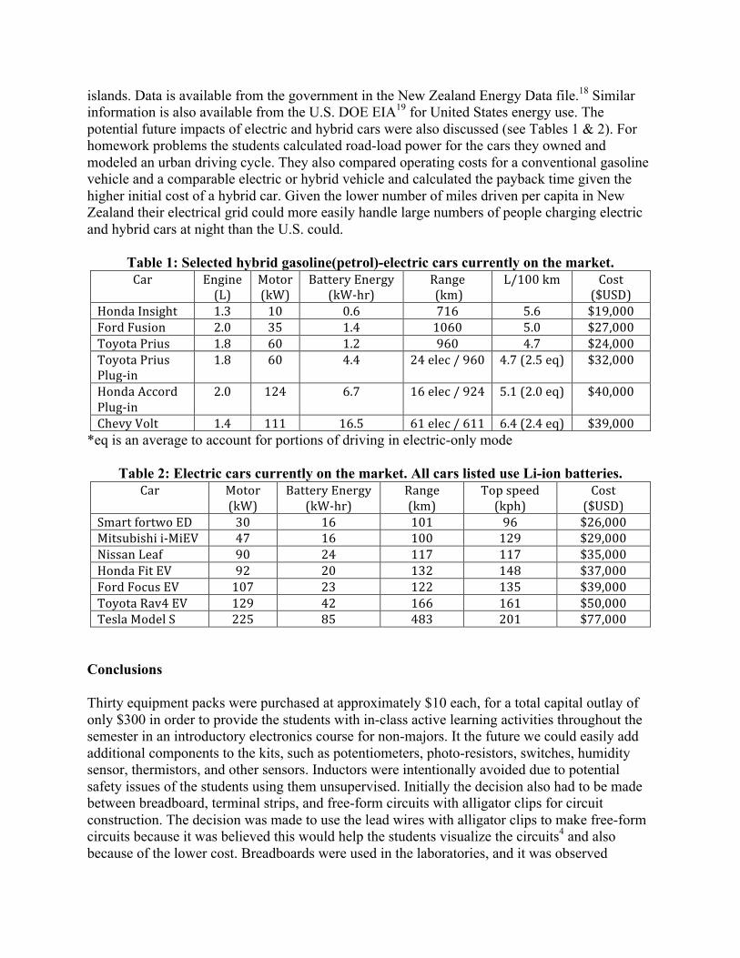
islands. Data is available from the government in the New Zealand Energy Data file.18 Similar information is also available from the U.S. DOE EIA19 for United States energy use. The potential future impacts of electric and hybrid cars were also discussed (see Tables 1 & 2). For homework problems the students calculated road-load power for the cars they owned and modeled an urban driving cycle. They also compared operating costs for a conventional gasoline vehicle and a comparable electric or hybrid vehicle and calculated the payback time given the higher initial cost of a hybrid car. Given the lower number of miles driven per capita in New Zealand their electrical grid could more easily handle large numbers of people charging electric and hybrid cars at night than the U.S. could.
Table 1: Selected hybrid gasoline(petrol)-electric cars currently on the market. Car Engine
(L) Motor (kW)
Battery Energy (kW-‐hr)
Range (km)
L/100 km Cost ($USD)
Honda Insight 1.3 10 0.6 716 5.6 $19,000 Ford Fusion 2.0 35 1.4 1060 5.0 $27,000 Toyota Prius 1.8 60 1.2 960 4.7 $24,000 Toyota Prius Plug-‐in
1.8 60 4.4 24 elec / 960 4.7 (2.5 eq) $32,000
Honda Accord Plug-‐in
2.0 124 6.7 16 elec / 924 5.1 (2.0 eq) $40,000
Chevy Volt 1.4 111 16.5 61 elec / 611 6.4 (2.4 eq) $39,000 *eq is an average to account for portions of driving in electric-only mode
Table 2: Electric cars currently on the market. All cars listed use Li-ion batteries. Car Motor
(kW) Battery Energy
(kW-‐hr) Range (km)
Top speed (kph)
Cost ($USD)
Smart fortwo ED 30 16 101 96 $26,000 Mitsubishi i-‐MiEV 47 16 100 129 $29,000 Nissan Leaf 90 24 117 117 $35,000 Honda Fit EV 92 20 132 148 $37,000 Ford Focus EV 107 23 122 135 $39,000 Toyota Rav4 EV 129 42 166 161 $50,000 Tesla Model S 225 85 483 201 $77,000
Conclusions Thirty equipment packs were purchased at approximately $10 each, for a total capital outlay of only $300 in order to provide the students with in-class active learning activities throughout the semester in an introductory electronics course for non-majors. It the future we could easily add additional components to the kits, such as potentiometers, photo-resistors, switches, humidity sensor, thermistors, and other sensors. Inductors were intentionally avoided due to potential safety issues of the students using them unsupervised. Initially the decision also had to be made between breadboard, terminal strips, and free-form circuits with alligator clips for circuit construction. The decision was made to use the lead wires with alligator clips to make free-form circuits because it was believed this would help the students visualize the circuits4 and also because of the lower cost. Breadboards were used in the laboratories, and it was observed
students had difficulty visualizing the physical connections in the breadboards. In the course evaluations students generally commented that the course was improved from what they had heard about the previous offerings with lectures without the active learning activities. Some of the more advanced students in the class complained that there were too many simple circuits that focused on Ohm’s law and they wanted to do some actual design of electronics. A design project would be a valuable addition to the class in the future. Since the instructor was on sabbatical and only taught the course once, there was not the opportunity to conduct assessments on student learning with the old and new versions of the course. Assessment of student learning outcomes would be a valuable addition to the literature. Acknowledgements Julian Murphy at the University of Canterbury in New Zealand helped with ordering the equipment and assembling the equipment packs, as well as with the scheduled laboratory portion of the course. Bibliography 1. Prince, M., (2004) “Does Active Learning Work? A Review of the Research,” Journal of Engineering Education, 93(3), 223-231. 2. Milks, A., (2002) “Modifying the Learning Environment to Improve Student Retention,” Proceedings of the 2002 American Society for Engineering Education Conference& Exposition, Montreal, Canada, June 2002. 3. Wankat, P.C. & Oreovicz, F.S. (1992) Teaching Engineering. McGraw-Hill. Available at: https://engineering.purdue.edu/ChE/AboutUs/Publications/TeachingEng/index.html 4. Niemi, A. (2008) In-Class Circuits: Using Passive Components to Create Active Learning. Proceedings of the 2008 ASEE Annual Conference. AC 2008-136 5. Becker, J.P., Plumb, C., & Revia, R.A. (2012) The Use of a Project Circuit in the Teaching of a Basic Electric Circuits Course. Proceedings of the 2012 ASEE Annual Conference. AC 2012-3217 6. Vasquez, H. & Gomez, C. (2009) Electric Generator for Wind or Human Power. Proceedings of the 2009 ASEE Annual Conference. AC 2009-1575. 7. McDonald, D. (2010) Engineering and Technology Education for Electric Vehicle Development. Proceedings of the 2010 ASEE Annual Conference. AC 2010-772. 8. Fisher, P.D., Fairweather, J.S., and Warmbier. E.A. (2001) The Impact of Benchmarking Peer Institutions in Curricular Reform. Proceedings of the 2001 ASEE Annual Conference. 9. Rizzoni, G. (2008) Fundamentals of Electrical Engineering. McGraw-Hill. 10. Felder, R.M., & Brent, R. (1994) “Cooperative Learning in Technical Courses: Procedures, Pitfalls, and Payoffs.” Report to the National Science Foundation. ERIC Document Reproduction Service No. ED 377 038. 11. Heller, P., and Hollabaugh, M. (1992) “Teaching problem solving through cooperative grouping. Part 2: Designing problems and structuring groups.” Am. J. Phys. 60(7), 637-644. 12. Johnson, D. W., Johnson, R. T., and Smith, K. A. (1991) Active learning: Cooperation in the college classroom. Edina, MN: Interaction Book Company. 13. Kaufman D. B. and Felder, R.M. (2000) Accounting for Individual Effort in Cooperative Learning Teams, Journal of Engineering Education, 89(2), 133–140. 14. Alciatore, D. & Histand, M. (2012) Introduction to Mechatronics and Measurement Systems. McGraw-Hill. Companion website with videos http://www.engr.colostate.edu/~dga/mechatronics/resources.html 15. Kuphaldt, T.R. (2013) Lessons in Electric Circuits. http://www.ibiblio.org/kuphaldt/electricCircuits/ 16. Mastascusa, E. (2013) Exploring Electrical Engineering. http://www.facstaff.bucknell.edu/mastascu/eLessonsHTML/EEIndex.html 17. Wolfe, J. (2013) PHYSCLIPS. School of Physics, University of New South Wales, Sydney, Australia, http://www.animations.physics.unsw.edu.au/jw/electricmotors.html 18. New Zealand Energy Data File (2012) Ministry of Business, Innovation, & Employment. 19. Monthly Energy Review (2013) U.S. Dept. of Energy, Energy Information Administration. http://www.eia.gov/totalenergy/data/monthly/
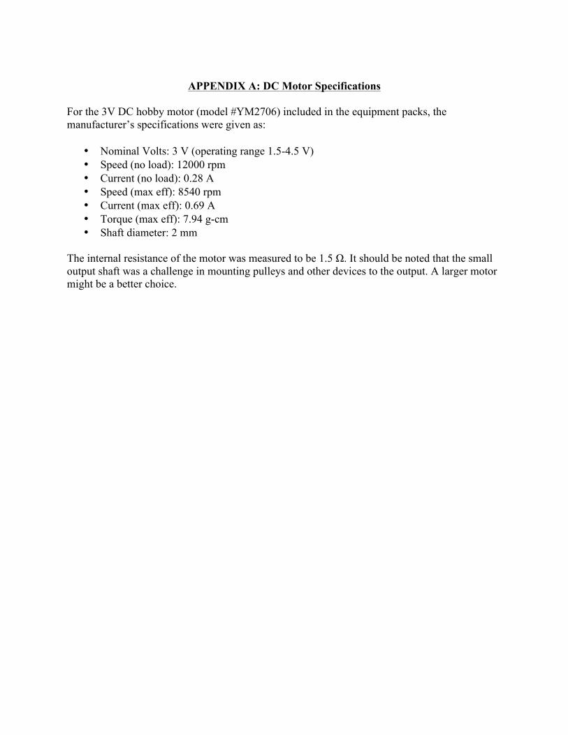
APPENDIX A: DC Motor Specifications
For the 3V DC hobby motor (model #YM2706) included in the equipment packs, the manufacturer’s specifications were given as:
• Nominal Volts: 3 V (operating range 1.5-4.5 V) • Speed (no load): 12000 rpm • Current (no load): 0.28 A • Speed (max eff): 8540 rpm • Current (max eff): 0.69 A • Torque (max eff): 7.94 g-cm • Shaft diameter: 2 mm
The internal resistance of the motor was measured to be 1.5 Ω. It should be noted that the small output shaft was a challenge in mounting pulleys and other devices to the output. A larger motor might be a better choice.