Particle-in-Cell Simulation of Stationary Plasma Thruster
23
Contributions to Plasma Physics CPP www.cpp-journal.org REPRINT Particle-in-Cell Simulation of Stationary Plasma Thruster F. Taccogna 1 , S. Longo 1 , M. Capitelli 1 , and R. Schneider 2 1 Dipartimento di Chimica, Universita’ degli Studi di Bari and Istituto di Metodologie Inorganiche e di Plasmi CNR, Sect. Bari, via Orabona 4, Bari, 70126, Italy 2 Max-Planck-Institut f¨ ur Plasmaphysik, EURATOM Association, Wendelsteinstrasse 1, D-17491, Greifswald, Germany Received 20 October 2007, accepted 5 November 2007 Published online 14 December 2007 Key words Particle-In-Cell method, Monte-Carlo method, Stationary Plasma Thruster, Secondary electron emission. PACS 52.65.Pp; 52.65.Rr; 52.75.Di A very good example for the application of PIC techniques for detailed studies of low-temperature plasmas is the Hall thrusters. Here, a variety of models with different complexities are needed to get better insight into the physics of these systems. Particular emphasis has been spent for the geometrical scaling, for the simulation of the plasma-wall interaction inside the acceleration channel and for ion-neutral collision into the plume emitted from the thruster. Results show the axial acceleration mechanism, the secondary electron emission instability, the azimuthal fluctuations into the channel and the ion backflow and electron trapping in the plume. Contrib. Plasma Phys. 47, No. 8–9, 635–656 (2007) / DOI 10.1002/ctpp.200710074
-
Upload
independent -
Category
Documents
-
view
0 -
download
0
Transcript of Particle-in-Cell Simulation of Stationary Plasma Thruster

ContributionstoPlasmaPhysicsCPP
www.cpp-journal.org
REPRINT
Particle-in-Cell Simulation of Stationary Plasma Thruster
F. Taccogna1, S. Longo1, M. Capitelli1, and R. Schneider2
1 Dipartimento di Chimica, Universita’ degli Studi di Bari and Istituto di Metodologie Inorganiche e di PlasmiCNR, Sect. Bari, via Orabona 4, Bari, 70126, Italy
2 Max-Planck-Institut fur Plasmaphysik, EURATOM Association, Wendelsteinstrasse 1, D-17491, Greifswald,Germany
Received 20 October 2007, accepted 5 November 2007Published online 14 December 2007
Key words Particle-In-Cell method, Monte-Carlo method, Stationary Plasma Thruster, Secondary electronemission.PACS 52.65.Pp; 52.65.Rr; 52.75.Di
A very good example for the application of PIC techniques for detailed studies of low-temperature plasmas isthe Hall thrusters. Here, a variety of models with different complexities are needed to get better insight into thephysics of these systems. Particular emphasis has been spent for the geometrical scaling, for the simulation ofthe plasma-wall interaction inside the acceleration channel and for ion-neutral collision into the plume emittedfrom the thruster. Results show the axial acceleration mechanism, the secondary electron emission instability,the azimuthal fluctuations into the channel and the ion backflow and electron trapping in the plume.
Contrib. Plasma Phys. 47, No. 8–9, 635–656 (2007) / DOI 10.1002/ctpp.200710074
Contrib. Plasma Phys. 47, No. 8-9, 635 – 656 (2007) / DOI 10.1002/ctpp.200710074
Particle-in-Cell Simulation of Stationary Plasma Thruster
F. Taccogna�1, S. Longo1, M. Capitelli1, and R. Schneider2
1 Dipartimento di Chimica, Universita’ degli Studi di Bari and Istituto di Metodologie Inorganiche e di PlasmiCNR, Sect. Bari, via Orabona 4, Bari, 70126, Italy
2 Max-Planck-Institut fur Plasmaphysik, EURATOM Association, Wendelsteinstrasse 1, D-17491, Greifswald,Germany
Received 20 October 2007, accepted 5 November 2007Published online 14 December 2007
Key words Particle-In-Cell method, Monte-Carlo method, Stationary Plasma Thruster, Secondary electronemission.PACS 52.65.Pp; 52.65.Rr; 52.75.Di
A very good example for the application of PIC techniques for detailed studies of low-temperature plasmas isthe Hall thrusters. Here, a variety of models with different complexities are needed to get better insight into thephysics of these systems. Particular emphasis has been spent for the geometrical scaling, for the simulation ofthe plasma-wall interaction inside the acceleration channel and for ion-neutral collision into the plume emittedfrom the thruster. Results show the axial acceleration mechanism, the secondary electron emission instability,the azimuthal fluctuations into the channel and the ion backflow and electron trapping in the plume.
c� 2007 WILEY-VCH Verlag GmbH & Co. KGaA, Weinheim
1 The Hall thruster
R.H. Goddart first suggested the use of electric propulsion in space in 1906. However, until now, many propulsivesystems have employed a solid, liquid or gaseous propellant and chemical propulsion to equip launcher space-crafts for interplanetary missions and satellites. Alternatively, many electric systems have been proposed forsatellite propulsion (microwave, arc-jet, stationary plasma thruster (SPT), pulsed plasma thruster (PPT), thrusterwith electric field (FEEP), gridded ion thruster, etc.) or for planetary missions (magneto-plasma-dynamic thruster(MPD)). Among these plasma sources, the Stationary Plasma Thruster (SPT) is one of the more promising de-vices for satellite station keeping, in particular due to the gain in mass (around 300 kg for a 3t-class satellite)and a long lifetime (up to 7000 h). Since 1970, almost 90 SPT thrusters have been tested on board Russiansatellites (Meteor, Galls) and nowadays, all space agencies recognize the usefulness of SPTs for North-South,East-West (NS-EW) station keeping or attitude control of geostationary telecommunication satellites. The SPTwas successfully used in the European lunar probe mission SMART1 and has been proposed for the future satel-lite constellations. In order to study and to manufacture Hall thrusters, a large effort is now being made in Europe,Russia, Japan and USA, while some other countries such as China, India and Israel are also interested in applyingelectric propulsion to spacecraft.
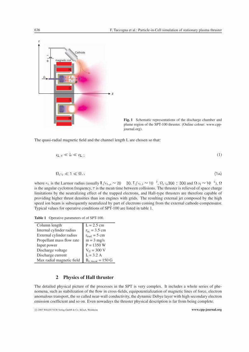
A SPT [1], also known as Hall effect thruster (HET) or thruster with closed electron drift, can be schemat-ically described (figure 1) as an anode-cathode system, with a dielectric annular chamber where the propellantionization and acceleration process occurs. This thruster works using a perpendicular electric and magnetic fieldsconfiguration. A magnetic circuit generates an axis-symmetric and quasi-radial magnetic field between the innerand outer poles. In operation, an electrical discharge is established between an anode (deep inside the channel),which is acting also as a gas distributor, and an external cathode, which is used also as an electron emitter. In thisconfiguration, cathode electrons are drawn to the positively charged anode, but the radial magnetic field createslarge impedance, trapping the electrons in cyclotron motion which follows a closed drift path inside the annularchamber. The trapped electrons act as a volumetric zone of ionization for neutral propellant atoms and as a virtualcathode to accelerate the ions which are not significantly affected by the magnetic field due to their larger Larmorradii. Generally, xenon is used as propellant due to its low ionization energy per unit mass and its inert nature.
�Corresponding author: e-mail: [email protected]
c� 2007 WILEY-VCH Verlag GmbH & Co. KGaA, Weinheim
636 F. Taccogna et al.: Particle-in-Cell simulation of stationary plasma thruster
r
z
Cathode
magnetic coil
N
N
S
S
m.
jE
B
Fig. 1 Schematic representations of the discharge chamber andplume region of the SPT-100 thruster. (Online colour: www.cpp-journal.org).
The quasi-radial magnetic field and the channel length L are chosen so that:
��� � � � � ��� � (1)
���� � � � ��� ����
where �� is the Larmor radius (usually ������ � ��� �� ������ � ����, �������� �� and ���� � ����), �is the angular cyclotron frequency, � is the mean time between collisions. The thruster is relieved of space chargelimitations by the neutralizing effect of the trapped electrons, and Hall-type thrusters are therefore capable ofproviding higher thrust densities than ion engines with grids. The resulting external jet composed by the highspeed ion beam is subsequently neutralized by part of electrons coming from the external cathode-compensator.Typical values for operative conditions of SPT-100 are listed in table 1.
Table 1 Operative parameters of of SPT-100.
Column length L = 2.5 cmInternal cylinder radius r�� = 3.5 cmExternal cylinder radius r��� = 5 cmPropellant mass flow rate m = 3 mg/sInput power P = 1350 WDischarge voltage V = 300 VDischarge current I= 3.2 AMax radial magnetic field B��� = 150 G
2 Physics of Hall thruster
The detailed physical picture of the processes in the SPT is very complex. It includes a whole series of phe-nomena, such as stabilization of the flow in cross-fields, equipotentialization of magnetic lines of force, electronanomalous transport, the so called near-wall conductivity, the dynamic Debye layer with high secondary electronemission coefficient and so on. Even nowadays the thruster physical description is far from being complete.
c� 2007 WILEY-VCH Verlag GmbH & Co. KGaA, Weinheim www.cpp-journal.org
Contrib. Plasma Phys. 47, No. 8-9 (2007) / www.cpp-journal.org 637
2.1 The thermalized potential concept and the acceleration mechanism
The magnetic field is the most important parameter in the design of a Hall thruster. In addition to the requirementon the plasma stability to have a peak at the exit plane of the channel with dB/dz � 0, there is also an effect ofthe curvature of magnetic force lines, based on the ”equipotentialization” of the magnetic force lines. Neglectingelectron inertia and Ohmic resistance, the momentum balance for the isothermal electrons takes the form:
���� � ��
� �
���
��� �
��� �� �� (2)
where � is the plasma potential, � the Boltzmann constant, ��, ne and ve the electron temperature, density andvelocity, respectively, and e the elementary charge. Equation (2) shows that the function inside square brackets,known as ”thermalized potential”, is constant along the magnetic field lines. Therefore, it follows also thatmagnetic field lines are plasma equipotentials with accuracy of the order of �����. This approximate relationbetween magnetic field and plasma equipotential lines is a valuable design tool for controlling plasma flow. Thegeometry of force lines (convex toward the anode) is chosen such that it provides repulsion of ions from thewalls thus reducing the channel erosion and focusing the ion beam. On the basis of the magnetic field topology,three regions can be distinguished inside the SPT channel: the near-anode region where the ionization is lowand the current is carried mostly by electrons or by an ion backflow; the ionization zone where the current ismaintained both by electrons going to the anode and ions going to the SPT outlet; the acceleration zone betweenthe ionization zone and the channel exit where the current is carried predominantly by ions.
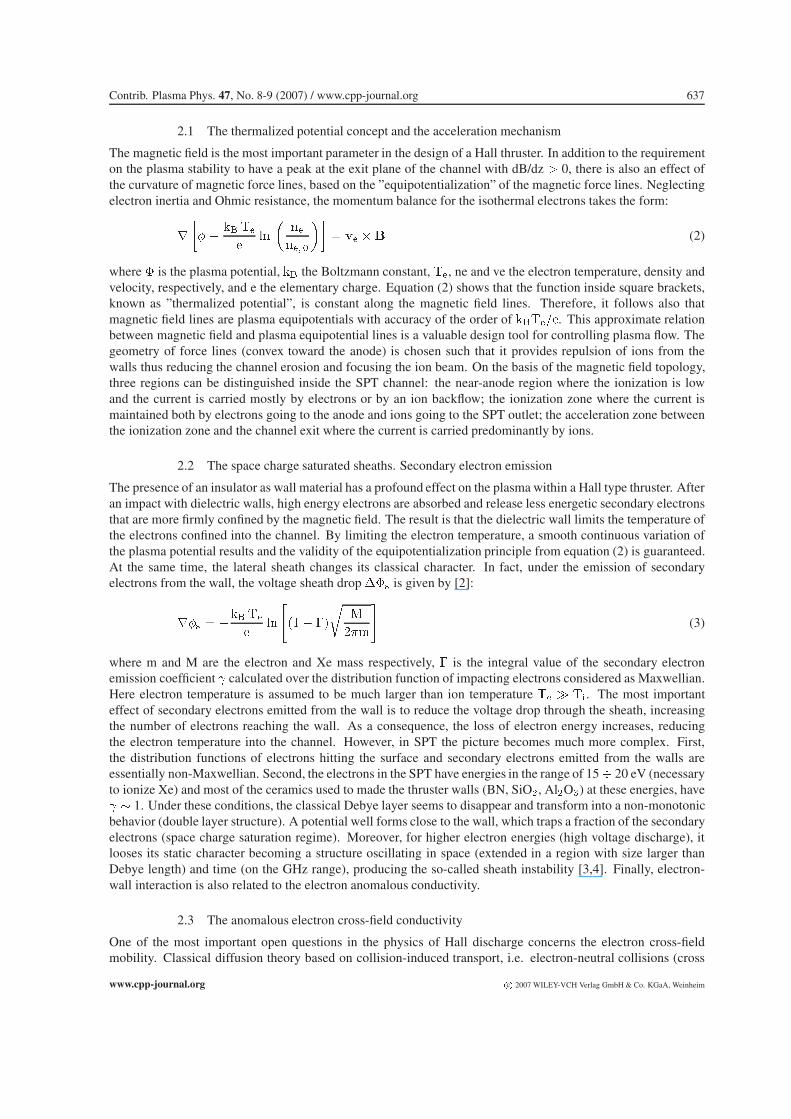
2.2 The space charge saturated sheaths. Secondary electron emission
The presence of an insulator as wall material has a profound effect on the plasma within a Hall type thruster. Afteran impact with dielectric walls, high energy electrons are absorbed and release less energetic secondary electronsthat are more firmly confined by the magnetic field. The result is that the dielectric wall limits the temperature ofthe electrons confined into the channel. By limiting the electron temperature, a smooth continuous variation ofthe plasma potential results and the validity of the equipotentialization principle from equation (2) is guaranteed.At the same time, the lateral sheath changes its classical character. In fact, under the emission of secondaryelectrons from the wall, the voltage sheath drop ��� is given by [2]:
��� � �� ��
� �
���� ��
��
���
�(3)
where m and M are the electron and Xe mass respectively, � is the integral value of the secondary electronemission coefficient � calculated over the distribution function of impacting electrons considered as Maxwellian.Here electron temperature is assumed to be much larger than ion temperature �� � ��. The most importanteffect of secondary electrons emitted from the wall is to reduce the voltage drop through the sheath, increasingthe number of electrons reaching the wall. As a consequence, the loss of electron energy increases, reducingthe electron temperature into the channel. However, in SPT the picture becomes much more complex. First,the distribution functions of electrons hitting the surface and secondary electrons emitted from the walls areessentially non-Maxwellian. Second, the electrons in the SPT have energies in the range of 15� 20 eV (necessaryto ionize Xe) and most of the ceramics used to made the thruster walls (BN, SiO�, Al�O�) at these energies, have� � 1. Under these conditions, the classical Debye layer seems to disappear and transform into a non-monotonicbehavior (double layer structure). A potential well forms close to the wall, which traps a fraction of the secondaryelectrons (space charge saturation regime). Moreover, for higher electron energies (high voltage discharge), itlooses its static character becoming a structure oscillating in space (extended in a region with size larger thanDebye length) and time (on the GHz range), producing the so-called sheath instability [3,4]. Finally, electron-wall interaction is also related to the electron anomalous conductivity.
2.3 The anomalous electron cross-field conductivity
One of the most important open questions in the physics of Hall discharge concerns the electron cross-fieldmobility. Classical diffusion theory based on collision-induced transport, i.e. electron-neutral collisions (cross
www.cpp-journal.org c� 2007 WILEY-VCH Verlag GmbH & Co. KGaA, Weinheim
638 F. Taccogna et al.: Particle-in-Cell simulation of stationary plasma thruster
mobility �� � ���) underestimates the cross-field transport, and numerical models of the discharge usuallyinvoke an adjustable diffusion coefficient to achieve acceptable results. Moreover, the comprehension of thisphenomenon is vital for the optimization of this device. The reason for this enhanced cross-field transport isnowadays a subject of considerable and continued debate. However, it is well accepted to attribute the anomalouselectron cross-field transport to three different sources.– fluctuation-induced transport (fit): this kind of diffusion can be divided into two classes which depend on thecharacter of the fluctuating azimuthal electric field E� [5]. Denoting the k�� Fourier space component of the elec-tric field by �� � �������������, in one case ���� is a statistical function of time and the anomalous diffusioncoefficient depends on the correlation time of the electric field fluctuations [6], while in the second case, the elec-tric field is made up of a superposition of coherent waves ���� � �� ��� and the anomalous diffusion arisesfrom a resonance of particles and waves which move along � with the same velocity ������ � � ����. Forthis reason, one is interested in high frequency (1�50 MHz) short wavelength oscillations in the plasma prop-erties, which have been already detected from experiments [7-11], numerical model [12,13] and linear stabilityanalysis [14-19]. The origin of these HF fluctuations is certain types of instabilities, among which the mostprobable candidates are:a) micro-instabilities (sheath [3,4], stream or anisotropy [20]);b) resistive instability [15] (electrostatic lower hybrid waves) due to the coupling with the electron drift flow inthe presence of electron collisions; c) axial gradient-driven instability [16], identified as a Rayleigh-type;d) electron drift instability [19] based on the resonance between �� and the cyclotron harmonics ��� inthe frequency range �� � � ��, occurring for very short wavelengths close to or even below the electrongyroradius ��.The anomalous axial electron current results from:
����� � �����
�(4)
which leads to a Bohm-type [21,22] anomalous conductivity �� � ���;- wall-induced transport (wit): the electron-wall interactions (the so called near-wall conductivity NWC [23,24])coming from a non-specular reflection or emission of electrons which leave the walls following another spiraltrajectory displaced toward the anode. This creates a classical conductivity varying like B��:
������ � ��
�
��
!
���
�
��
��
�
�� �(5)
where H=���� � ��� is the channel width (r��� and r�� are the outer and inner radius of the coaxial cylinderrespectively). In reality, the NWC is a more complex phenomenon including in nonlinear way numerous effects:a) secondary electron beam emitted from the wall and inducing secondaries on the opposite wall [24] ( is sub-stituted in equation (5) by an effective value ��� � ����� � ��� � �����, where is the electron penetrationcoefficient from one wall to the opposite;b) macroroughness on the surface [25];c) ion-wall recombination [26] leading to an additional correcting factor 2�������� in equation (5);d) photoelectron emission from the wall due to UV radiation [27];e) sheath oscillations as recently demonstrated by Monte Carlo calculations [28].–gradient-induced transport (git): non-local effect due to small length scale of gradients leading to a distortionof the gyro-motion, known as neoclassical conductivity. Recently [29] it has been suggested that the generalbelief that Bohm-like anomalous conductivity was dominant outside the thruster channel whereas electron-wallconductivity prevails inside the channel is not valid. It has been concluded that only the plasma azimuthal fluctua-tions are responsible for anomalous electron transport inside and outside the Hall thruster channel. Nevertheless,changing the wall material of Hall thrusters results in significant plasma parameters and electron axial currentchanges [30-32]. Then, there are strong arguments to conclude that the azimuthal fluctuations could be inducedby surface effects. Finally, concerning the neoclassical gradient-induced transport, it has been demonstrated tohave a negligible effect on the enhancement of the electron axial current inside the thruster channel [33].
c� 2007 WILEY-VCH Verlag GmbH & Co. KGaA, Weinheim www.cpp-journal.org
Contrib. Plasma Phys. 47, No. 8-9 (2007) / www.cpp-journal.org 639
2.4 Plasmadynamics of the plume. Near- and far-field regions
A major concern in the use of SPT-100 is the possible damage their plumes may cause to the host spacecraft andto communication interference of satellites. Indeed, SPT-100, in operation produces, besides high energy ions andelectrons emitted to neutralize the positive space charge, also neutral unionized propellant atoms and low energyions created by charge exchange (CX) collisions between ions and atoms in which electrons are transferred or byelectron impact ionization of neutral atoms. These particles are more influenced by the self-consistent electricfields that cause slow ions to propagate radially (reducing the efficiency) and to flow upstream, while gainingenergy. Finally, a very important region is the very near-field region of the plume (up to 10 cm from the exitplane). In fact, in this region, there are many new aspects to take in account as plasma-wall interaction, magneticfield effect, non isothermal electrons, electron-neutral collisions, cathode location, etc.
3 PIC-MCC models
The complexity, up to the kinetic level, of the physics of SPT, in addiction to the experimental difficulties in theinvestigation of such a small and surface-dominated plasma device and the ability to simulate a wider variety ofexternal ambient conditions, makes the use of numerical experiments [34,35] a fundamental tool in understandingand optimizing this thruster. Models of Hall thrusters have been developed using fluid [36-38] and hybrid fluid-particle approaches [39-42]. A question which cannot be resolved by these models, and which in fact stronglylimits the reliability of their results, is the strong departure from the Maxwellian distribution of electrons (due tolow collisionality), the electron transport, and the important role of electron-wall interaction. As a result, SPTperformance is affected by both the state of the wall surface and the properties of plasma structures on Debyeand electron-Larmor scales. The ideal numerical model would be a self-consistent particle model for all thespecies in three dimensions. Nowadays, such a model is unpractical because it would need too large considerableamount of computation time. In order to keep the fully kinetic character of the model, it is necessary to reducethe dimensionality of the system.
3.1 2D(r,z). General overview and the self-similarity principle
Nevertheless, additional tricks are necessary in order to speed up the execution of the code. Previous fully ki-netic PIC codes used an artificial electron to ion mass ratio [43] and/or an artificial vacuum permittivity constant[44]. The smaller heavy particle mass, for speeding up the neutrals and ions, decreases the number of iterationsnecessary to reach convergence, but at the same time it changes the ratio between electron and ion current, afundamental parameter for the anomalous electron transport and thruster efficiency, modifying completely thedischarge characteristics. The larger permittivity constant decreases the plasma frequency and increases the De-bye length, hence the computational time step and the required grid cell size increase. This trick changes dramat-ically the peculiar space and time scales of the plasma state making it impossible to recover the original system.Our proposal in the 2D(r,z) [45-50] model (axial-symmetry is considered neglecting all azimuthal gradients) isbased on the reduction of the geometrical dimension of the thruster preserving more rigorously the values of therelevant parameters governing the physics of the discharge. This creates a more self-similar copy of the originalsystem [51], invariant under the transformation. All the basic plasma characteristics in Hall discharge devicesrely heavily on the neutral ionization by electron impact and on the electron confinement, therefore during thechannel reduction the Knudsen and Hall parameters must remain unchanged:
���
�� "#�$� %
�
���� "#�$� %
����
�� "#�$� %
�
��� "#�$� � (6)
From these relations a number of scaling laws follows (summarized in table 2). The total simulation time (onthe order of neutral transit time T�) scales linearly with the length of the channel, while the time step te, asimposed by the stability criterion of the numerical method used to integrate the equations of motion, scales as theplasma oscillation period, that is with the inverse of the square root of the density. Therefore, reducing the lineardimension L of the discharge by a factor � �[0,1], it leads to a reduced number of PIC cycles N��� necessary toreach a steady state given by:
&�����
��� �
�� � ����&�
��� (7)
www.cpp-journal.org c� 2007 WILEY-VCH Verlag GmbH & Co. KGaA, Weinheim
640 F. Taccogna et al.: Particle-in-Cell simulation of stationary plasma thruster
where the asterisk is referred to the un-scaled system (the neutral velocity remains unchanged under scalingbecause neutrals are treated as a fixed background). The Debye parameter is conserved: ���� � �. This resultsin no reduction in the number of mesh cells necessary to cover the entire domain, and keep the physics ofplasmawall transition unchanged. Moreover, the ratio of plasma frequency to electron cyclotron frequency is alsoconserved. This is an important parameter for the plasma fluctuation dynamics in magnetic confinement systems.Its conservation guarantees a correct evaluation of UHF oscillations inside the channel and the related anomalouselectron transport.In addition to the reduction of the number of total PIC cycles, the number of real particles in the scaled system&���� � � �# � ��&���� is reduced, allowing a better statistics in the simulation. Nevertheless, limitationsin the geometrical reduction are necessary. First, the plasma parameter N�, the number of particles in a Debyesphere, is unavoidably reduced while PIC validity is based on the requirement that collective effects are dominantover the collisional one, that is:
&� � � % � &�
&�� � (8)
Furthermore, the ratio between surface and volume is unavoidably changed leading to the possible increasing ofthe surface effects (i.e. secondary electron emission) in the reduced system. Finally, gradient-driven instabilitiescould appear due to the fact that some plasma parameters scale differently from the size of the system.
Table 2 Scaling laws of self-similar system (un-scaled quantities are designed with asterisk).
Quantities Scaling LawsLength L = � ��
Particle density n = ��� ��
Electric potential V = � ��
Electric field E = ��
Magnetic field B = ����� ��
Mass flow rate '� = � '��
Velocity v = ���� ��
Current I = ���� (�
Temperature T = � ��
Before the simulation (domain reported in figure 2) begins, we fix all the parameters that remain constant dur-ing the execution. In particular, the magnetic field and the neutral distribution. Indeed, magnetic field variationsdue to plasma currents and changing electric fields are small compared to the field produced by the electromag-nets. For the radial component of the magnetostatic field profile we have chosen the bell-shaped expression:
���� )� � �����
����!"�����#� (9)
while the axial component has been neglected. Due to very different time scales of electrons and heavy particles,an explicit subcycling scheme [52] is used in which electrons equation of motion and Poissons equation aresolved every electron PIC cycle, while ions and neutrals are moved each ��� � *���. The electric field feltby the ions is filtered (a simple time average of the electric fields seen by the electrons works well). Since thesimulation starts from the scratch, we use, instead of a fixed time step, an adaptive time step: ��� � ��+��.Every electron PIC-cycle, cathode electrons are introduced at the free space right boundary (the cathode is notincluded in the simulation region) according to a cylindrical radial distribution in position and a half-Maxwelliandistribution with a temperature �� �15 eV (scaled according to the law reported in table 2) in velocity. Theamount of electrons to be introduced is determined through the steady-state current control method of electroninjection [44]:
�&� �(���
�,��&��� � �&��� (10)
where w is the macroparticle weight, �&��� and �&��� are the number of ions and electrons, respectively,passing the free space boundary each electron iteration. Verboncoeur interpolation method [53], which guarantees
c� 2007 WILEY-VCH Verlag GmbH & Co. KGaA, Weinheim www.cpp-journal.org
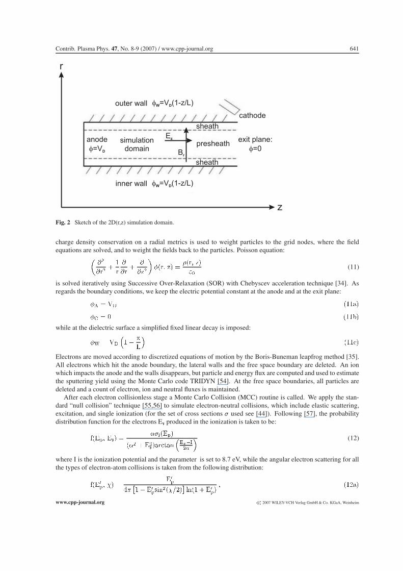
Contrib. Plasma Phys. 47, No. 8-9 (2007) / www.cpp-journal.org 641
r
z
cathode
outer wall
inner wall
simulationdomain
anode
=V� D
�W D=V (1-z/L)
�W D=V (1-z/L)
Ez
Br
sheath
presheath
sheath
exit plane:
=0�
Fig. 2 Sketch of the 2D(r,z) simulation domain.
charge density conservation on a radial metrics is used to weight particles to the grid nodes, where the fieldequations are solved, and to weight the fields back to the particles. Poisson equation:�
��
����
�
�
�
���
�
�)�
����� )� �
���� )�
��(11)
is solved iteratively using Successive Over-Relaxation (SOR) with Chebyscev acceleration technique [34]. Asregards the boundary conditions, we keep the electric potential constant at the anode and at the exit plane:
�$ � �� �����
�� � � ���-�
while at the dielectric surface a simplified fixed linear decay is imposed:
�% � ��
��� )
�
����"�
Electrons are moved according to discretized equations of motion by the Boris-Buneman leapfrog method [35].All electrons which hit the anode boundary, the lateral walls and the free space boundary are deleted. An ionwhich impacts the anode and the walls disappears, but particle and energy flux are computed and used to estimatethe sputtering yield using the Monte Carlo code TRIDYN [54]. At the free space boundaries, all particles aredeleted and a count of electron, ion and neutral fluxes is maintained.
After each electron collisionless stage a Monte Carlo Collision (MCC) routine is called. We apply the stan-dard “null collision” technique [55,56] to simulate electron-neutral collisions, which include elastic scattering,excitation, and single ionization (for the set of cross sections � used see [44]). Following [57], the probabilitydistribution function for the electrons E� produced in the ionization is taken to be:
.���� ��� � ������
� � � ��� ���"���
�����
��
� (12)
where I is the ionization potential and the parameter is set to 8.7 eV, while the angular electron scattering for allthe types of electron-atom collisions is taken from the following distribution:
.����� �� ����
/�� � ���$��������
��� � ����
� �����
www.cpp-journal.org c� 2007 WILEY-VCH Verlag GmbH & Co. KGaA, Weinheim

642 F. Taccogna et al.: Particle-in-Cell simulation of stationary plasma thruster
where ��� is the post-collisional energy of the primary electron. Electron energy loss associated with elasticelectron-atom collisions is neglected. For simplicity, only one excitation collision has been considered. Uponexcitation of a neutral Xe atom, the electron is assumed to lose energy of 8.32 eV. Anyway, the excited stateskinetics is not included, considering the quenching of excited states instantaneous.
3.2 1D(r) model of the acceleration region: secondary electron emission
In the previous model, a simplified boundary conditions for particle and field were implemented on the lateralwalls. In fact, condition (11.c) does not correspond to a floating wall and it represents a strong approximation.In order to take into account the important nature of secondary electron emission and floating potential conditionof the dielectric lateral wall a 1D(r) [58-62] model of the acceleration region of the discharge has been devel-oped. The simulation has been done per unit length in transverse direction for axial-symmetry. The ”local-fieldapproximation” is applied neglecting the effects of axial gradients based on the fact that in the acceleration partof the channel, the electron radial dynamics is much faster than the axial one due to the radial magnetic fieldimpedance. Concerning the ions, the situation is completely different, because their dynamics is mostly axial andradial. Ions are created by ionization and lost by wall recombination and axial upstream flow (toward the exitplane). Therefore, the total simulation time has to be limited to the ion residence time in the acceleration regionestimated to be T� *�$. In order to keep high the statistical quality of the simulation a non-uniform radialgrid is implemented. Due to cylindrical metrics, in order to have a constant volume, the radial cell size must beproportional to the radial position:
��� � ���
��
� ��
����� � �� � � � �& (13)
where ����� � !��
&. In this way, the average number of particles per cell varies between 5�100. Thetimestep is chosen such that ���=0.3.
The prescribed values used as input parameters, characteristic for the acceleration region, are: neutral den-sity �� � �� ���&��� (again neutral dynamics is not considered and neutrals are treated as a fixed back-ground); axial electric field E� � ��' V/m; radial magnetic field B���=150 Gauss (non-uniform, see equation(9)). The simulation starts with a uniform distribution of electrons and ions along the radial domain with adensity �� � ��+� ���(���. Velocities are sampled from a Maxwellian distribution with initial temperaturesT� � � eV and T� � ��� eV. The discharge is self-sustained with electrons created by bulk ionization and surfaceemission. The contribution from the cathode neutralizer is neglected due to the fact that in the acceleration regionthe current is carried mostly by ions. The Poisson equation in cylindrical radial coordinate r:�
��
����
�
�
�
��
����� � �����
��(14)
is discretized and solved directly using the Thomas tridiagonal algorithm [63]. For this purpose, a fixed Diricheletboundary condition ���=0 is used at the outer wall as reference potential, while the inner surface can floatelectrically with respect to the plasma such that the total current to the surface is zero (zero-current condition).The electric field (Neumann condition) at the wall is proportional to the net charge wi which has accumulated onthe surface (the possible surface conductivity of the dielectric is neglected):
��
��
������ � ���� � ����
��� ��/��
The same bulk collision methodology of the 2D(r,z) model is used, while concerning the boundary module, whenan electron strikes the dielectric wall, a Monte Carlo probabilistic model [64-68] is used which allows a detaileddependence of the secondary electron emission coefficient on the primary electron energy E�. It is distinguishedbetween three different type of secondary electrons (see figure 3): backscattered (high energy region), re-diffused(middle energy region) and true secondary electrons (low energy region). The fine structure of � is very importantat the energies typical of SPT operation (�30 eV). Theoretically, the backscattering coefficient � (red curve)should grow with the decrease of incident electron energy (� 0.8 at 0 eV) in competition with the stickingcoefficient, while the yield of re-diffused � and true secondary Æ electrons (green and blue curves) decreases and
c� 2007 WILEY-VCH Verlag GmbH & Co. KGaA, Weinheim www.cpp-journal.org
Contrib. Plasma Phys. 47, No. 8-9 (2007) / www.cpp-journal.org 643
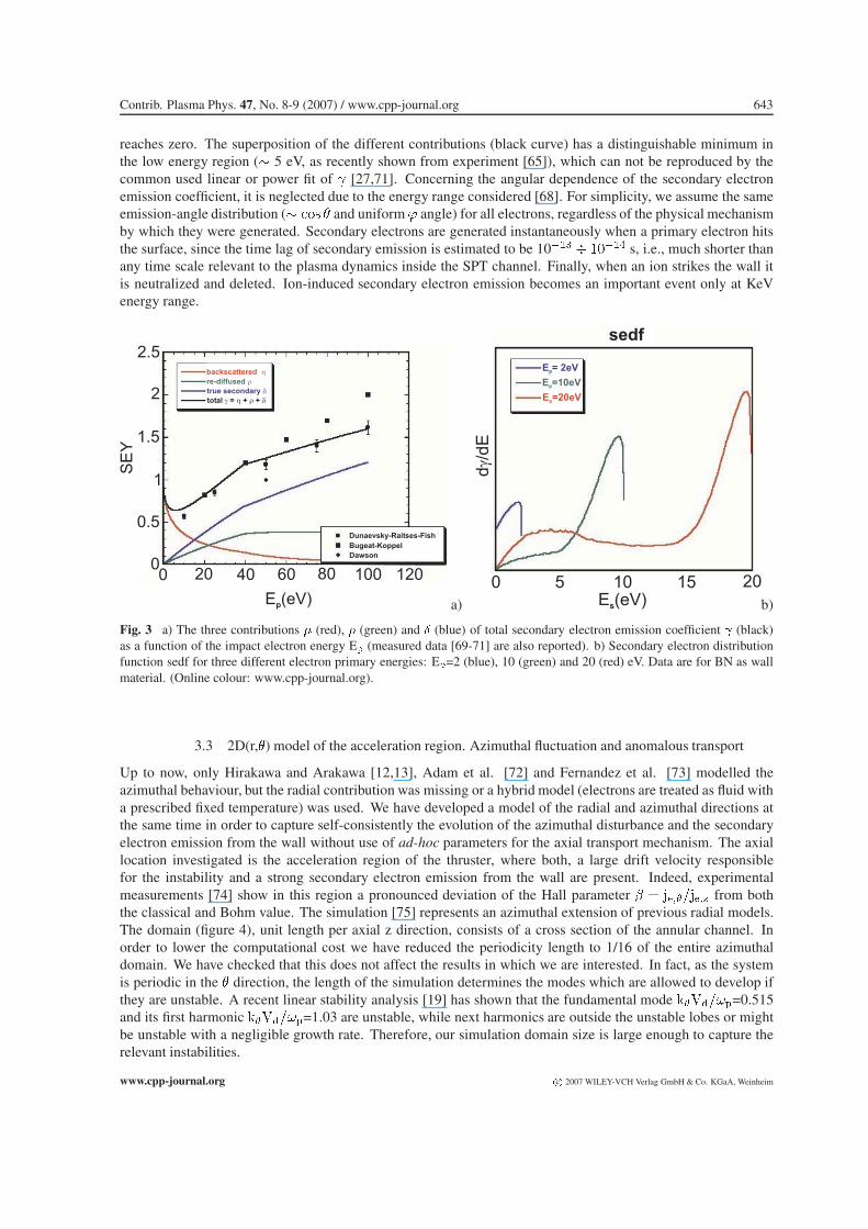
reaches zero. The superposition of the different contributions (black curve) has a distinguishable minimum inthe low energy region (� 5 eV, as recently shown from experiment [65]), which can not be reproduced by thecommon used linear or power fit of � [27,71]. Concerning the angular dependence of the secondary electronemission coefficient, it is neglected due to the energy range considered [68]. For simplicity, we assume the sameemission-angle distribution (� "#$ � and uniform � angle) for all electrons, regardless of the physical mechanismby which they were generated. Secondary electrons are generated instantaneously when a primary electron hitsthe surface, since the time lag of secondary emission is estimated to be 10��� � ����' s, i.e., much shorter thanany time scale relevant to the plasma dynamics inside the SPT channel. Finally, when an ion strikes the wall itis neutralized and deleted. Ion-induced secondary electron emission becomes an important event only at KeVenergy range.
0
0.5
1
1.5
2
2.5
0 20 40 60 80 100 120
backscattered �
re-diffused �
true secondary �
total = + +� � � �
Dunaevsky-Raitses-Fish
Bugeat-Koppel
Dawson
E (eV)p
SE
Y
a)
0 5 10 15 20E (eV)s
sedf
d/d
E�
E = 2eVp
E =10eVp
E =20eVp
b)
Fig. 3 a) The three contributions � (red), � (green) and Æ (blue) of total secondary electron emission coefficient � (black)as a function of the impact electron energy E� (measured data [69-71] are also reported). b) Secondary electron distributionfunction sedf for three different electron primary energies: E�=2 (blue), 10 (green) and 20 (red) eV. Data are for BN as wallmaterial. (Online colour: www.cpp-journal.org).
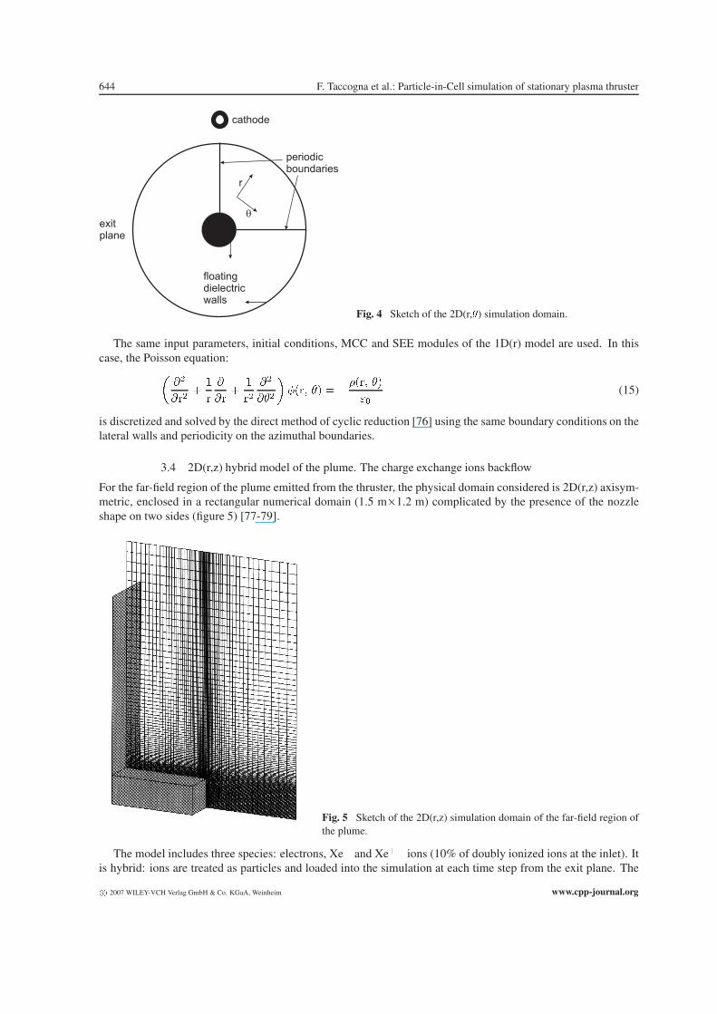
3.3 2D(r,�) model of the acceleration region. Azimuthal fluctuation and anomalous transport
Up to now, only Hirakawa and Arakawa [12,13], Adam et al. [72] and Fernandez et al. [73] modelled theazimuthal behaviour, but the radial contribution was missing or a hybrid model (electrons are treated as fluid witha prescribed fixed temperature) was used. We have developed a model of the radial and azimuthal directions atthe same time in order to capture self-consistently the evolution of the azimuthal disturbance and the secondaryelectron emission from the wall without use of ad-hoc parameters for the axial transport mechanism. The axiallocation investigated is the acceleration region of the thruster, where both, a large drift velocity responsiblefor the instability and a strong secondary electron emission from the wall are present. Indeed, experimentalmeasurements [74] show in this region a pronounced deviation of the Hall parameter � � ���� ��� from boththe classical and Bohm value. The simulation [75] represents an azimuthal extension of previous radial models.The domain (figure 4), unit length per axial z direction, consists of a cross section of the annular channel. Inorder to lower the computational cost we have reduced the periodicity length to 1/16 of the entire azimuthaldomain. We have checked that this does not affect the results in which we are interested. In fact, as the systemis periodic in the � direction, the length of the simulation determines the modes which are allowed to develop ifthey are unstable. A recent linear stability analysis [19] has shown that the fundamental mode ����=0.515and its first harmonic ����=1.03 are unstable, while next harmonics are outside the unstable lobes or mightbe unstable with a negligible growth rate. Therefore, our simulation domain size is large enough to capture therelevant instabilities.
www.cpp-journal.org c� 2007 WILEY-VCH Verlag GmbH & Co. KGaA, Weinheim
644 F. Taccogna et al.: Particle-in-Cell simulation of stationary plasma thruster
cathode
floatingdielectricwalls
exitplane
periodicboundaries
r
�
Fig. 4 Sketch of the 2D(r,�) simulation domain.
The same input parameters, initial conditions, MCC and SEE modules of the 1D(r) model are used. In thiscase, the Poisson equation:�
��
����
�
�
�
���
�
��
��
���
����� �� � ����� ��
��(15)
is discretized and solved by the direct method of cyclic reduction [76] using the same boundary conditions on thelateral walls and periodicity on the azimuthal boundaries.
3.4 2D(r,z) hybrid model of the plume. The charge exchange ions backflow
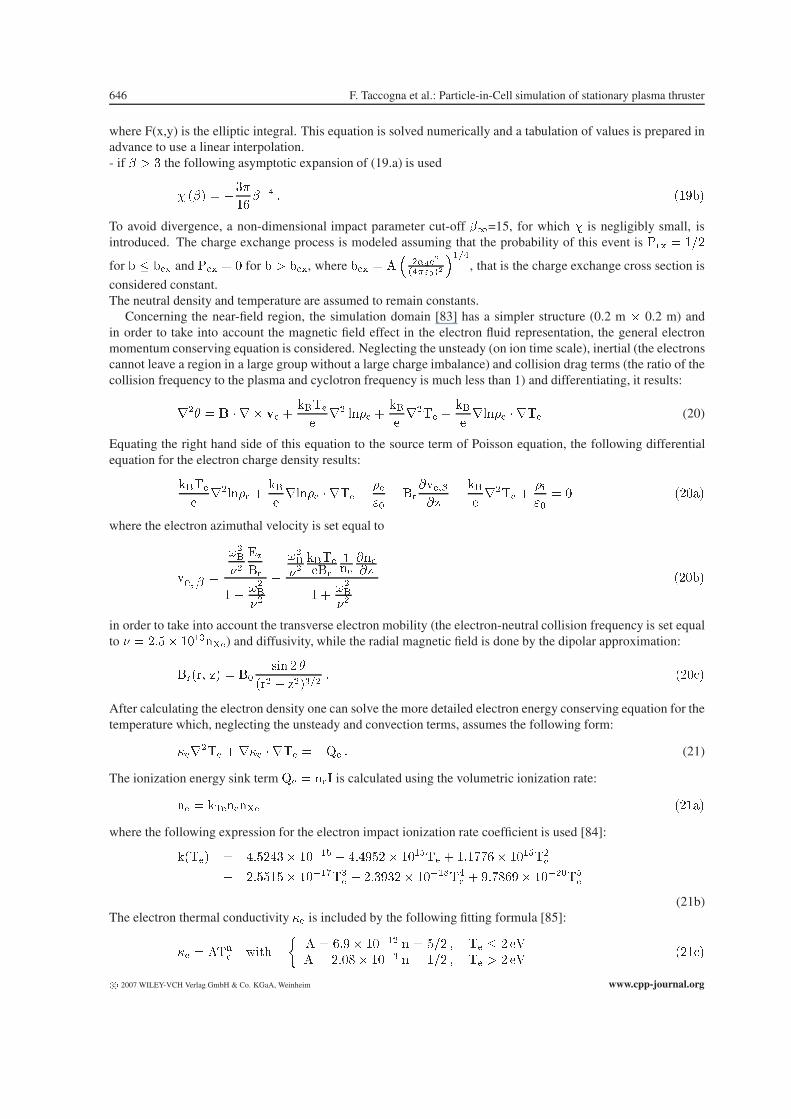
For the far-field region of the plume emitted from the thruster, the physical domain considered is 2D(r,z) axisym-metric, enclosed in a rectangular numerical domain (1.5 m�1.2 m) complicated by the presence of the nozzleshape on two sides (figure 5) [77-79].
Fig. 5 Sketch of the 2D(r,z) simulation domain of the far-field region ofthe plume.
The model includes three species: electrons, Xe) and Xe)) ions (10% of doubly ionized ions at the inlet). Itis hybrid: ions are treated as particles and loaded into the simulation at each time step from the exit plane. The
c� 2007 WILEY-VCH Verlag GmbH & Co. KGaA, Weinheim www.cpp-journal.org

Contrib. Plasma Phys. 47, No. 8-9 (2007) / www.cpp-journal.org 645
ion exit conditions (radial position and velocity components) are given on the basis of fitted experimental data[80]. Electrons are included by a quasi equilibrium ansatz assuming a fluid isothermal Boltzmann barometricrelation:
����� )� � ��* ���������� )�� �������� (16)
where the constants n�* is chosen to closely match the measurements [81]. The corresponding Poisson equationis highly nonlinear:
������ )� ������ )�
��� ��*
����� ������� )�� �������� � � (17)
and it is linearized with the Newton-Raphson method [34] and solved with SOR technique. The grid is nonuni-form in both r and z coordinates in order to adapt in a simple and straightforward way to the local plasma density.
The important ion-neutral collisional processes (momentum MX and charge exchange CX) are modeled usinga Test-Particle Monte Carlo method [55,82] which is based on an attractive polarization potential with a rigidcore between the neutral and ion parent particle:
0��� � � ��
��/�����
�
�'(18)
where is the Xe polarizability. This assumption corresponds to a dipole-induced dipole interaction. As a
consequence, there are two types of orbits (see figure 6a): for impact parameters - � -� ��
&����
"'��#�+ ,�
���'
(g
is the relative velocity), the orbit has a hyperbolic character, while for - � -�, the incoming particle is ”captured”and the orbit spirals into the core, leading to a large scattering angle.
� eq.(7b-c)hyperbolic trajectory
MT-CXprobability = 1/2
� eq.(7a)isotropic scattering
a)
-2
-1.5
-1
-0.5
0
0 1 2 3 4 5
isotropicscatteringeq. (19a)
eq. (19b) eq. (19c)
�
�(r
ad
)
b)
Fig. 6 (a) Langevin trajectories using the polarization potential in the ion-neutral interaction and b) deflection angle in theion-neutral scattering.
With the assumption of a rigid core size rc equal to the radius of the limiting circle �� � -���
�, the deflectionangle � is given by (see figure 6b):- if � � -�-� � � the scattering in the rigid core is considered isotropic, then:
"#$� � �� � ���1 % (19)
- if � � � � ,
���� � � �
+
� � ��
�� ���'2
��
�
�
��' � �����' � � � �
���3��
www.cpp-journal.org c� 2007 WILEY-VCH Verlag GmbH & Co. KGaA, Weinheim
646 F. Taccogna et al.: Particle-in-Cell simulation of stationary plasma thruster
where F(x,y) is the elliptic integral. This equation is solved numerically and a tabulation of values is prepared inadvance to use a linear interpolation.- if � � the following asymptotic expansion of (19.a) is used
� ��� � ��
�4��' � ��3-�
To avoid divergence, a non-dimensional impact parameter cut-off ��=15, for which � is negligibly small, isintroduced. The charge exchange process is modeled assuming that the probability of this event is 5- � ���
for - -- and 5- � � for - � -- , where -- � 6�
�����
"'��#�
���'
, that is the charge exchange cross section is
considered constant.The neutral density and temperature are assumed to remain constants.
Concerning the near-field region, the simulation domain [83] has a simpler structure (0.2 m � 0.2 m) andin order to take into account the magnetic field effect in the electron fluid representation, the general electronmomentum conserving equation is considered. Neglecting the unsteady (on ion time scale), inertial (the electronscannot leave a region in a large group without a large charge imbalance) and collision drag terms (the ratio of thecollision frequency to the plasma and cyclotron frequency is much less than 1) and differentiating, it results:
��� � � � � � �� ����
��� ��� �
�
����� �
�
�� ��� � ��� (20)
Equating the right hand side of this equation to the source term of Poisson equation, the following differentialequation for the electron charge density results:
���
��� ��� �
�
�� ��� � ��� � ��
��� �
����
�)�
�
����� �
��
��� � �����
where the electron azimuthal velocity is set equal to
��� � �
��
��
��
�
� ��
�
��
��
�
�������
���
����)
� ��
�
��
���-�
in order to take into account the transverse electron mobility (the electron-neutral collision frequency is set equalto � � ��*� �������) and diffusivity, while the radial magnetic field is done by the dipolar approximation:
���� )� � ��$�� � �
��� � )������ ���"�
After calculating the electron density one can solve the more detailed electron energy conserving equation for thetemperature which, neglecting the unsteady and convection terms, assumes the following form:
������ ���� � ��� � �7� � (21)
The ionization energy sink term 7� � ��( is calculated using the volumetric ionization rate:
�� � .������ �����
where the following expression for the electron impact ionization rate coefficient is used [84]:
���� � /�*�/� ����/ � /�/3*�� ���/�� � ���884� ���/���
� ��**�*� ����(��� � ��3�� ����&�'
� � 3�8+43� ������/�
(21b)The electron thermal conductivity �� is included by the following fitting formula [85]:
�� � 6��� ,��9
�6 � 4�3� ����� � � *�� � �� � ��6 � ���+� ���� � � ��� � �� � � ��
���"�
c� 2007 WILEY-VCH Verlag GmbH & Co. KGaA, Weinheim www.cpp-journal.org
Contrib. Plasma Phys. 47, No. 8-9 (2007) / www.cpp-journal.org 647
For electron temperatures below roughly 2 eV, electron-ion collision are dominant, and n=5/2 since �� � ������
and ��� � ������ . For electron temperatures above 2 eV, electron-neutral collisions are dominant:
since �� � ������ and ��� ��
��, one has n=1/2. Equations (20-21) are iterated until the whole convergenceis attained.
4 Results and Discussion
4.1 2D(r,z) discharge: acceleration mechanism and validation and limit of the scaling scheme
First of all, we have verified that the output data follow the theoretical scaling laws of the self-similar system re-ported in table 2. A series of simulations using different values of the scaling parameter � have been performed.The behaviour is in good agreement with the theoretical prevision until a scaling factor equal to 1/200. In fact,a small deviation from the theoretical scaling law is present for values smaller than 0.01, proofing that surface,turbulence and numerical effects become important. In particular, Figures 7 show the axial profiles of plasma po-tential, electron density and electron temperature for two different values of scaling parameter (0.01 in green and0.1 in red). As it is evident, the behaviour does not change. From figure 7a, also the little anode drop (� 40 V) isevident.
0 50 100 150 200 250
0
10
20
30
40
0
1
2
3
4
Axial Grid Points
Electric Potential (V)
= 0.1
= 0.01
a)0 50 100 150 200 250
0
1 1018 1 10
19
2 1019
2 1018
0
Axial Grid Points
Electron Density (m )-3
= 0.1
= 0.01
b)0 50 100 150 200 250
0
4
8
0.2
0.4
0.6
0.8
2
6
0
Axial Grid Points
Electron Temperature (eV)
= 0.1
= 0.01
c)
Fig. 7 Axial profile of a) plasma potential, b) electron density and c) electron temperature using two different scaling factor(0.01 in green and 0.1 in red). The values are scaled. (Online colour: www.cpp-journal.org).
The contour plots of figures 8 demonstrate the main features of the discharge. In particular, figures 8a and 8bshow, respectively, the space variation of the electric potential and ion density using a geometrical reducingfactor � = 1/50. As it can see in figure 8a, most of the potential drop occurs in the exhaust region, where themagnetic field is large. This decrease compensates the low electron conductivity in this region and ensurescurrent continuity. It is customary to allocate the acceleration region here. The large axial electric field resultingfrom this voltage drop is responsible for accelerating the ions from the ionization region to the exit plane and theelectron from the outlet to the anode. It can also be seen that equipotential lines are curved resulting from theequipotentialization of the magnetic field lines. However, the computed potential vanishes at the channel exit,while observations [86] indicate that only 1/2 to 1/3 of the potential drop takes place downstream of the thrusterexit. This difference is due imposing the zero potential boundary condition at the exit plane in the numericalsimulation (equation (11.b)), i.e., the full potential drop is forced to occur inside the channel. The space variationof the plasma density (figure 8b) shows that the plasma reaches its maximum in the centre of the channel and inthe ionization region, while it decreases in the acceleration region due to the increasing ion velocity.One of the most important quantities visualizing ion dynamics is the ion current. Figure 9a describes the ionstreamlines, whereas figure 9b shows the ion scatter plot in the velocity space (��� )). The division into threedistinct regions is evident. In the anode region, a backflow towards the anode exists due to the anode drop. Oftenthis region is also called diffusion region due to the very low magnetic field. It ends with the transition towards apositive ion velocity, where the ionization zone begins. Finally, the separation between ionization and accelerationregions is located at the sonic transition. From figure 9a the importance of the ion flow towards the walls can beunderstood. In the ionization region the ions hit almost normal to the surface, while in the acceleration region
www.cpp-journal.org c� 2007 WILEY-VCH Verlag GmbH & Co. KGaA, Weinheim

648 F. Taccogna et al.: Particle-in-Cell simulation of stationary plasma thruster
0 0.1 0.2 0.3 0.4 0.50.7
0.8
0.9
1.00
43.8
87.5
131.3
175.0
218.8
262.5
306.3
350.0
z(mm)
r(m
m)
a)0 0.1 0.2 0.3 0.4 0.5
0.7
0.8
0.9
1.0
0
z(mm)
r(m
m)
8.8 E18
1.8 E19
2.6 E19
3.5 E19
4.4 E19
5.3 E19
6.1 E19
7.0 E19
b)
Fig. 8 Colour plots of a) electric potential (V) and b) ion number density (m��) at steady-state. (Online colour: www.cpp-journal.org).
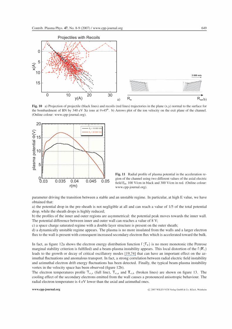
the mean angle � between ion velocity and surface normal increases up to a maximum value of 45Æ. This is dueto two concurrent effects: the reduction of the lateral sheath voltage in the acceleration region and the focusingeffect of the convex magnetic field lines. From the simulation results, the energy of ions impinging on the wallsmay be considered constant along the channel with a value of 340 eV. This information will be used as input datafor the TRIDYN analysis. In fact, when the steady state is reached, we collect all the information concerningthe ions impacting on the wall, that is the energy and the impact angle distributions. In figure 10a the projectionof trajectories (projectiles and recoils) in the plane (x,y) normal to the surface for bombardment at � = 45Æ isshown. These plots give a good impression of what the code is doing and how particles move. The trajectoriesof projectiles are represented in black, while those of recoils are in red. The distribution of the end points of thetrajectories give the depth profile, the lateral spread of the implanted particles and the sputtering yield. Finally,the code is able to calculate the ion distributions (radial position, energy and divergence angle) on the exit plane(figure 10b) which is an important information for analyzing the performance of the thruster and is used also asinput data for plume simulations.
z(mm)
50
45
40
350 5 10 15 20 25
r(m
m)
a)0 5 10 15 20 25
z(mm)
5
4
3
2
1
0
-1
-2
v/c
s
10 ions5
b)
Fig. 9 a) Ion current density vector plot and b) ion scatter plot in the phase space (v�,z). Ion velocity is normalized to the ionsonic speed c�.
4.2 1D(r) acceleration region: micro-instability
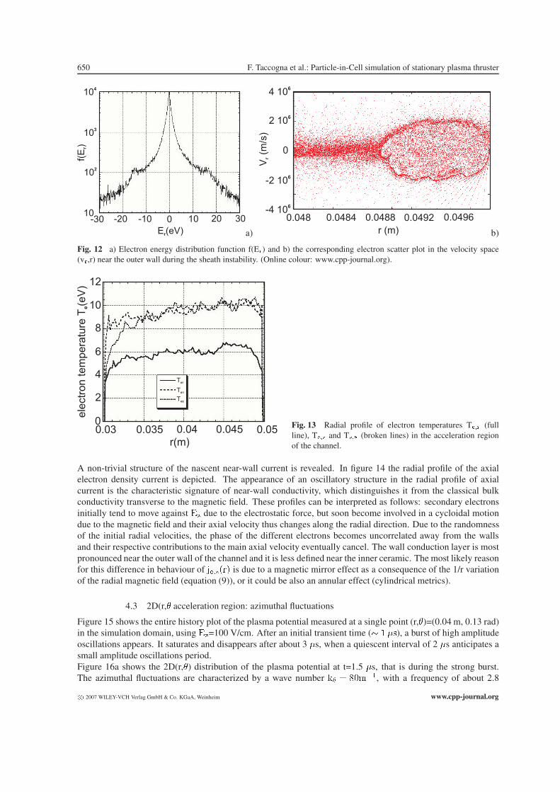
In figure 11, the radial profiles of the plasma potential is shown using two different value of axial electric fieldE�(100 V/cm in black and 300 V/cm in red), while BN is used as wall material. The E-field represents the order
c� 2007 WILEY-VCH Verlag GmbH & Co. KGaA, Weinheim www.cpp-journal.org
Contrib. Plasma Phys. 47, No. 8-9 (2007) / www.cpp-journal.org 649
0
5
10
15
y(A)0 10 20 30
x(A
)Projectiles with Recoils
a) Rin Rout
3 000 m/s
b)
Fig. 10 a) Projection of projectile (black lines) and recoils (red lines) trajectories in the plane (x,y) normal to the surface forthe bombardment of BN by 340 eV Xe ions at �=45Æ. b) Arrows plot of the ion velocity on the exit plane of the channel.(Online colour: www.cpp-journal.org).
0
5
10
15
20
0.03 0.04 0.050.035 0.045r(m)
pla
sm
ap
ote
ntia
l(V
)
E = 10 000 V/mS
E = 30 000 V/mS
Fig. 11 Radial profile of plasma potential in the acceleration re-gion of the channel using two different values of the axial electricfield E�, 100 V/cm in black and 300 V/cm in red. (Online colour:www.cpp-journal.org).
parameter driving the transition between a stable and an unstable regime. In particular, at high E value, we haveobtained that:a) the potential drop in the pre-sheath is not negligible at all and can reach a value of 1/5 of the total potentialdrop, while the sheath drops is highly reduced;b) the profiles of the inner and outer regions are asymmetrical: the potential peak moves towards the inner wall.The potential difference between inner and outer wall can reaches a value of 8 V;c) a space charge saturated regime with a double layer structure is present on the outer sheath;d) a dynamically unstable regime appears. The plasma is no more insulated from the walls and a larger electronflux to the wall is present with consequent increased secondary electron flux which is accelerated toward the bulk.
In fact, as figure 12a shows the electron energy distribution function . ��� is no more monotonic (the Penrosemarginal stability criterion is fulfilled) and a beam-plasma instability appears. This local distortion of the . ���leads to the growth or decay of critical oscillatory modes [19,74] that can have an important effect on the az-imuthal fluctuations and anomalous transport. In fact, a strong correlation between radial electric field instabilityand azimuthal electron drift energy fluctuations has been detected. Finally, the typical beam-plasma instabilityvortex in the velocity space has been observed (figure 12b).The electron temperatures profile ��� (full line), ���� and ���� (broken lines) are shown on figure 13. Thecooling effect of the secondary electrons emitted from the wall causes a pronounced anisotropic behaviour. Theradial electron temperature is 4 eV lower than the axial and azimuthal ones.
www.cpp-journal.org c� 2007 WILEY-VCH Verlag GmbH & Co. KGaA, Weinheim
650 F. Taccogna et al.: Particle-in-Cell simulation of stationary plasma thruster
-30 -20 -10 0 10 20 30
E (eV)r
f(E
) r
10
102
103
104
a)
4 106
2 106
-4 106
-2 106
0
0.048 0.0484 0.0488 0.0492 0.0496
r (m)
V(m
/s)
r
b)
Fig. 12 a) Electron energy distribution function f(E�) and b) the corresponding electron scatter plot in the velocity space(v�,r) near the outer wall during the sheath instability. (Online colour: www.cpp-journal.org).
Ter
Te�
Tez
r(m)
ele
ctr
on
tem
pera
ture
T(e
V)
e
0
2
4
6
8
10
12
0.03 0.035 0.04 0.045 0.05Fig. 13 Radial profile of electron temperatures T��� (fullline), T��� and T��� (broken lines) in the acceleration regionof the channel.
A non-trivial structure of the nascent near-wall current is revealed. In figure 14 the radial profile of the axialelectron density current is depicted. The appearance of an oscillatory structure in the radial profile of axialcurrent is the characteristic signature of near-wall conductivity, which distinguishes it from the classical bulkconductivity transverse to the magnetic field. These profiles can be interpreted as follows: secondary electronsinitially tend to move against �� due to the electrostatic force, but soon become involved in a cycloidal motiondue to the magnetic field and their axial velocity thus changes along the radial direction. Due to the randomnessof the initial radial velocities, the phase of the different electrons becomes uncorrelated away from the wallsand their respective contributions to the main axial velocity eventually cancel. The wall conduction layer is mostpronounced near the outer wall of the channel and it is less defined near the inner ceramic. The most likely reasonfor this difference in behaviour of ������ is due to a magnetic mirror effect as a consequence of the 1/r variationof the radial magnetic field (equation (9)), or it could be also an annular effect (cylindrical metrics).
4.3 2D(r,� acceleration region: azimuthal fluctuations
Figure 15 shows the entire history plot of the plasma potential measured at a single point (r,�)=(0.04 m, 0.13 rad)in the simulation domain, using ��=100 V/cm. After an initial transient time (� ��$), a burst of high amplitudeoscillations appears. It saturates and disappears after about 3 �s, when a quiescent interval of 2 �s anticipates asmall amplitude oscillations period.Figure 16a shows the 2D(r,�) distribution of the plasma potential at t=1.5 �s, that is during the strong burst.The azimuthal fluctuations are characterized by a wave number � � +����, with a frequency of about 2.8
c� 2007 WILEY-VCH Verlag GmbH & Co. KGaA, Weinheim www.cpp-journal.org

Contrib. Plasma Phys. 47, No. 8-9 (2007) / www.cpp-journal.org 651
r(m)
axia
lcurr
entdensity
J(A
/m)
ez
2
-2 104
-1 104
0
0.03 0.035 0.04 0.045 0.05 Fig. 14 Radial profile of electron axial density current in theacceleration region of the channel.
t ( s)�
pla
sm
apote
ntial
(V)
100
80
60
40
20
00 2 4 6 8 10 Fig. 15 Time evolution of the plasma potential measured at
a single point (r,�)=(0.04 m, 0.13 rad) with E�=100 V/cm.
0
0.5
1.0
1.5
3 4 5
r (cm)
(cm
)
a)
t(
s)
�
� (rad)
0.0
0.4
0.8
1.2
1.6
2.0
0 0.1 0.2 0.3 0.4
0
2.3
4.5
6.8
9.0
11.3
13.5
15.8
18.0
b)
Fig. 16 a) Distribution of plasma potential (V) in the r,� plane at t=1.5 �s. b) Time evolution of the azimuthal profile ofplasma potential (�10 V) calculated at r=0.04 m. (Online colour: www.cpp-journal.org).
MHz. The strong interaction with the walls is the most plausible candidate to excite this instability. Indeed,the sheath potential drop is azimuthally modulated, as the wall potential and the surface charge density. Infact, the combination of a reduced sheath (due to secondary electron emission) and a floating wall (non-linear
www.cpp-journal.org c� 2007 WILEY-VCH Verlag GmbH & Co. KGaA, Weinheim

652 F. Taccogna et al.: Particle-in-Cell simulation of stationary plasma thruster
coupling between current collected and wall potential equation (14b)) is the most important candidate to drive theazimuthal instability. The azimuthal fluctuation is not a standing wave, but it propagates with a phase velocity ofabout 5x10⁴ m/s, as shown in figure 16b. It represents the time evolution of the azimuthal profile of the plasmapotential calculated at the radial center of the coaxial channel (r=0.04 m). It can be seen that, after an initialtime of development, the plasma structure takes the shape of waves propagating with approximately constantphase velocity and with slightly increasing amplitude. Therefore, the spoke rotates at about ���������� whilethe electrons in the spoke move at ����. The resulting charge separation creates the azimuthal electric fieldwhich is correlated with the electron density. It has been speculated that the perturbation is driven from axialgradients [9] or from the out-of-axis cathode location [10]. In this work the azimuthal fluctuations exist even ifthese elements are absent in the simulation.
4.4 2D(r,z) near- and far-field region
In figure 17a a snapshot is reported of the position of a limited number of marker ions in the far-field region of theplume during the simulation. Note that ions exit the thruster channel as a narrow beam with a divergency angleof about 40Æ to the thruster axis and as a CX component out of the primary beam and propagating both upanddown-stream. Ions propagate under the effect of self-consistent electric field and collisions with neutrals untila stationary state is reached when the outflow balances the ion emission. Note that a significant component ofbackflow appears, as well as significant expansion in the radial direction. The effect of charge exchange collisionsis clearly detectable in figure 17b that plots the (� � ��) phase space at steady state. CX ions are visible as awing of low velocity ions. Although CX ions begin with relatively low speed, the plumes potential structure tendsto drive these ions sideways and backwards, towards the spacecraft rather than away from it.
z(m)
r(m
)
0
0.2
0.4
0.6
0.8
1.0
1.2
0.0 0.5 1.0 1.5
6.7 10 ions8
a)
ion
radia
lvelo
city
(m/s
)
ion axial velocity (m/s)
-3 104
-2 104
-2 104
-1 104
0
0
104
2 104
2 104
3 104
4 104
4 104
6 104 8 10
4
b)
Fig. 17 a) Phase space (r,z) and b) (v�, v�) plots of marker ions at the steady state.
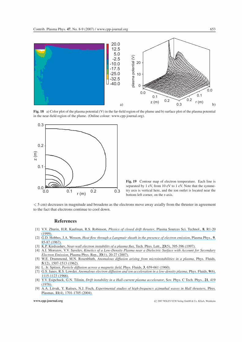
Figure 18a illustrates the electric potential at the steady state. We can note a fall of�50 V between the exit planeand the stagnation region, where a potential well develops spontaneously. The lobe structures seen directly onthe side of the thruster exit are produced by the charge exchange plasma.
Figure 18b shows the overall behaviour of the plasma potential in the near-field region of the plume. Onecan see that at r=0 mm the potential at first increases as a function of the axial positions because electrons aretrapped by the magnetic field effect and later decreases, since the value of magnetic field becomes relativelyweak. At r=20 mm the magnetic field is substantially lower and the plasma potential increase is less marked.While, the radial profiles of the plasma potential, that is potential distribution along the magnetic field, decreaseas the electron density according to the Boltzmann relation (16). Finally, figure 19 shows the contour map of theelectron temperature as calculated from eqs. (21), that is the violation of the isothermal hypothesis in the near-field region of the plume. The variation of the ion current density with axial distance from the thruster indicatesthat the ion flow begins as an annulus, and then merges into a single-body beam. Moreover on centreline (r=0)the ion current density increases with axial positions lower than z=10 cm and then begins to decrease. Thisbehaviour is attributed to the fact that the diverging annular ion beam overlaps at the centreline of the thrusterwith an angle of inner boundary of 16 degrees. The peak structure in front of the discharge channel (2.8 cm � r
c� 2007 WILEY-VCH Verlag GmbH & Co. KGaA, Weinheim www.cpp-journal.org
Contrib. Plasma Phys. 47, No. 8-9 (2007) / www.cpp-journal.org 653
20.012.55.0
-2.5-10.0-17.5-25.0-32.5-40.0
a)
pla
sm
ap
ote
ntia
l(V
)
0
10
20
0.0
0.20.1
0.3
0.0
0.1
0.2z (m) r (m)
b)
Fig. 18 a) Color plot of the plasma potential (V) in the far-field region of the plume and b) surface plot of the plasma potentialin the near-field region of the plume. (Online colour: www.cpp-journal.org).
r (m)
z(m
)
0.0 0.1 0.2 0.30.0
0.1
0.2
0.3
Fig. 19 Contour map of electron temperature. Each line isseparated by 1 eV, from 10 eV to 1 eV. Note that the symme-try axis is vertical here, and the ion outlet is located near thebottom left corner, on the r-axis.
� 5 cm) decreases in magnitude and broadens as the electrons move away axially from the thruster in agreementto the fact that electrons continue to cool down.
References
[1] V.V. Zhurin, H.R. Kaufman, R.S. Robinson, Physics of closed drift thruster, Plasma Sources Sci. Technol., 8, R1-20(1999).
[2] G.D. Hobbes, J.A. Wesson, Heat flow through a Langmuir sheath in the presence of electron emission, Plasma Phys., 9,85-87 (1967).
[3] K.P. Kirdyashev, Near-wall electron instability of a plasma flux, Tech. Phys. Lett., 23(5), 395-396 (1997).[4] A.I. Morozov, V.V. Savelev, Kinetics of a Low-Density Plasma near a Dielectric Surface with Account for Secondary
Electron Emission, Plasma Phys. Rep., 33(1), 20-27 (2007).[5] W.E. Drummond, M.N. Rosenbluth, Anomalous diffusion arising from microinstabilities in a plasma, Phys. Fluids,
5(12), 1507-1513 (1962).[6] L. Jr. Spitzer, Particle diffusion across a magnetic field, Phys. Fluids, 3, 659-661 (1960).[7] G.S. Janes, R.S. Lowder, Anomalous electron diffusion and ion acceleration in a low-density plasma, Phys. Fluids, 9(6),
1115-1123 (1966).[8] Y.V. Esipchuck, G.N. Tilinin, Drift instability in a Hall-current plasma accelerator, Sov. Phys. C Tech. Phys., 21, 419
(1976).[9] A.A. Litvak, Y. Raitses, N.J. Fisch, Experimental studies of high-frequency azimuthal waves in Hall thrusters, Phys.
Plasmas, 11(4), 1701-1705 (2004).
www.cpp-journal.org c� 2007 WILEY-VCH Verlag GmbH & Co. KGaA, Weinheim
654 F. Taccogna et al.: Particle-in-Cell simulation of stationary plasma thruster
[10] A. Lazurenko, L. Albarde, A. Bouchoule, Physical characterization of high-frequency instabilities in Hall thrusters,Phys. Plasmas, 13, 083503 (2006).
[11] A. Lazurenko, T. Dudok deWit, C. Cavoit, V. Krasnoselskikh, A. Bouchoule, M. Dudeck, Determination of the electronanomalous mobility through measurements of turbulent magnetic field in Hall thrusters, Phys. Plasmas, 14, 033504(2007).
[12] M. Hirakawa, Y. Arakawa, Particle simulation of plasma phenomena in Hall thrusters, Proceedings of the 24th Interna-tional Electric Propulsion Conference (Moscow), IEPC-95-164 (1995).
[13] M. Hirakawa, Y. Arakawa, Numerical simulation of plasma particle behavior in a Hall thruster, Proceedings of the32nd AIAA/ASME/SAE/ASEE Joint Propulsion Conference (Lake Buena Vista), AIAA-96-3195 (1996).
[14] E.Y. Choueiri, Plasma oscillations in Hall thrusters, Phys. Plasmas, 8(4), 1411-1426 (2001).[15] A.A. Litvak, N.J. Fisch, Resistive instability in Hall current plasma discharge, Phys. Plasmas, 8(2), 648-651 (2001).[16] A.A. Litvak, N.J. Fisch, Rayleigh instability in Hall thrusters, Phys. Plasmas, 11(4), 1379-1383 (2004).[17] J.M. Gallardo, E. Ahedo, On the anomalous diffusion mechanism in Hall-effect thrusters, Proceedings of the 29��
International Electric Propulsion Conference (Princeton), IEPC-2005-117 (2005).[18] C.A. Thomas, M.A. Cappelli, Fluctuation-induced transport in the Hall plasma accelerator, Proceedings of the 42�
AIAA/ASME/SAE/ASEE Joint Propulsion Conference (Sacramento), AIAA-2006-5168 (2006).[19] A. Ducrocq, J.C. Adam, A. Heron, G. Laval, High-frequency electron drift instability in the cross-field configuration of
Hall thrusters, Phys. Plasmas, 13, 102111 (2006).[20] D. Sydorenko, A. Smolyakov, I. Kaganovich, Y. Raitses, Effects of non-Maxwellian electron velocity distribution func-
tion on two-stream instability in low-pressure discharges, Phys. Plasmas, 14, 013508 (2007).[21] S. Yoshikawa, D. Rose, Anomalous diffusion of plasma across a magnetic field, Phys. Fluids, 5, 334-340 (1962).[22] D. Bohm, The characteristics of electrical discharges in magnetic fields, (McGraw-Hill, New York, 1949), p. 65.[23] A.I. Morozov, V.V. Savelyev, Reviews of Plasma Physics Vol. 21, ed. B.B. Kadomtsev and V.D. Shafranov (New York:
Consultants bureau, 2000), p. 277.[24] I.D. Kaganovich, Y. Raitses, D. Sydorenko, A. Smolyakov, Kinetic effects in a Hall thruster discharge, Phys. Plasmas,
14, 057104 (2007).[25] Z.-W. Wu, D.-R. Yu, X.-G. Wang, Effect of erosion surface on near wall conductivity (NWC) in the Halltype stationary
plasma thrusters, Vacuum, 80, 1376-1380 (2006).[26] A.A. Ivanov, A.A. Jr. Ivanov, M. Bacal, Effect of plasma-wall recombination on the conductivity in Hall thrusters,
Plasma Phys. Control. Fusion, 44, 1463-1470 (2002).[27] S. Barral, K. Makowski, Z. Peradzyski, N. Gascon, M. Dudeck, Wall material effects in stationary plasma thrusters. II.
Near-wall and in-wall conductivity, Phys. Plasmas, 10(10), 4137-4152 (2003).[28] D. Yu, H. Li, Z. Wu, W. Mao, Effect of oscillating sheath on near-wall conductivity in Hall thrusters, Phys. Plasmas,
14, 064505 (2007).[29] C. Boniface, L. Garrigues, G.J.M. Hagelaar, J.P. Boeuf, D. Gawron, S. Mazouffre, Anomalous cross field electron
transport in a Hall thruster, Appl. Phys. Lett., 89, 161503 (2006).[30] N. Gascon, M. Dudeck, S. Barral, Wall material effects in stationary plasma thrusters. I. Parametric studies of an
SPT-100, Phys. Plasmas, 10(10), 4123-4136 (2003).[31] Y. Raitses, A. Smirnov, D. Staack, N.J. Fisch, Measurements of secondary electron emission effects in the Hall thruster
discharge, Phys. Plasmas, 13, 014502 (2006).[32] H. Tahara, K. Imanaka, S. Yuge, Effects of channel wall material on thrust performance and plasma characteristics of
Hall-effect thrusters, Vacuum, 80, 1216-1222 (2006).[33] C.A. Thomas, Anomalous electron transport in the Hall-effect thruster, PhD Dissertation (Mechanical Engineering
Dept., Stanford University, Stanford, 2006).[34] J.W. Eastwood, R.W. Hockney, Computer Simulation using Particle (McGraw-Hill, New York, 1981).[35] C.K. Birdsall, A.B. Langdon, Plasma Physics via Computer Simulation (McGraw-Hill, New York, 1985).[36] M. Keidar, I.D. Boyd, I.I. Beilis, Plasma flow and plasma-wall transition in Hall thruster channel, Phys. Plasmas, 8(12),
5315-5322 (2001).[37] E.Y. Choueiri, Fundamental difference between the two Hall thruster variants, Phys. Plasmas, 8(11), 5025-5033 (2001).[38] L. Dorf, V. Semenov, Y. Raitses, Anode sheath in Hall thrusters, Appl. Phys. Lett., 83(13), 2551-2553 (2003).[39] K. Komurasaki, Y. Arakawa, Two-dimensional numerical model of plasma flow in a Hall thrusters, J. Prop. & Power,
11(6), 1317-1323 (1995).[40] L. Garrigues, Modelisation d’un propulseur a plasma stationnaire pour satellites, PhD Dissertation, (Universite Paul
Sabatier, Toulouse, 1998).[41] J.M. Fife, Hybrid-PIC modelling and electrostatic probe survey of Hall thrusters, PhD Dissertation, (Dept. of Aeronau-
tics and Astronautics, Massachusetts Institute of Technology, Boston, 1999).[42] J.W. Koo, I.D. Boyd, Computational modelling of stationary plasma thrusters, Proceedings of the 39��
AIAA/ASME/SAE/ASEE Joint Propulsion Conference and Exhibit (Huntsville) AIAA-2003-10113 (2003).[43] V. Latocha, Deux problmes en transport des particules charges intervenant dans la modlisation dun propulseur ionique,
PhD Dissertation, (Laboratoire Mathmatiques pour 1Industrie et la Physique, Universite Paul Sabatier, Toulouse, 2001).
c� 2007 WILEY-VCH Verlag GmbH & Co. KGaA, Weinheim www.cpp-journal.org
Contrib. Plasma Phys. 47, No. 8-9 (2007) / www.cpp-journal.org 655
[44] J.J. Jr. Szabo, Fully kinetic numerical modeling of a plasma thruster, PhD Dissertation, (Aeronautics and AstronauticsDept., Massachusetts Institute of Technology, Boston, 2001).
[45] F. Taccogna, Plasma-wall interaction inside a Hall thrusters, PhD Dissertation, (Chemistry Dept. University of Bari,2003).
[46] F. Taccogna, S. Longo, M. Capitelli, R. Schneider, Fully kinetic Particle-in-Cell simulation of a Hall thrusters, LectureNotes in Computer Science, 3039, 588-595 (2004).
[47] F. Taccogna, S. Longo, M. Capitelli, R. Schneider, Stationary plasma thruster simulation, Comp. Phys. Comm., 164,160-170 (2004).
[48] F. Taccogna, S. Longo, M. Capitelli, R. Schneider, Plasma flow in a Hall thrusters, Phys. Plasmas, 12, 43502 (2005).[49] F. Taccogna, S. Longo, M. Capitelli, R. Schneider, FMulti-scale simulation of Hall discharge, International Journal for
Multiscale Computational Engineering, 4(2), 243-254 (2006).[50] F. Taccogna, S. Longo, M. Capitelli, R. Schneider, Start-up transient in a Hall thrusters, Contr. Plasma Phys., 46(10),
781-786 (2006).[51] F. Taccogna, S. Longo, M. Capitelli, R. Schneider, Self-similarity in Hall plasma discharge. Application to particle
models, Phys. Plasmas, 12, 053502 (2005).[52] J.C. Adam, A. Gourdin Serveniere, A.B. Langdon, Electron sub-cycling in particle simulation of plasmas, J. Comp.
Phys., 47, 229-244 (1982).[53] J.P. Verboncoeur, Symmetric spline weighting for charge and current density in particle simulation, J. Comp. Phys., 174,
421-427 (2001).[54] W. Moller, W. Eckstein, TRYDIN-CBinary collision simulation of atomic collisions dynamic composition changes in
solids, Report nÆ IPP 9/64 (Max-Planck-Institute fur Plasmaphysik, Garching bei Munchen, 1988).[55] K. Nanbu, Probability theory of electron-molecule, ion-molecule, molecule-molecule, and coulomb collisions for parti-
cle modeling of materials processing plasmas and gases, IEEE Trans. Plasma Sci., 28(3), 971-990 (2000).[56] V. Vahedi, M. Surendra, A Monte Carlo collision model for particle-in-cell method: applications to argon and oxygen
discharges, Comp. Phys. Comm., 87, 179-198 (1995).[57] M. Surendra, D.B. Graves, I.J. Morey, Electron heating in low-pressure rf glow discharges, Appl. Phys. Lett., 5
¯6(11),
1022-1024 (1990).[58] F. Taccogna, S. Longo, M. Capitelli, Plasma-surface interaction model with secondary electron emission effects, Phys.
Plasmas, 11(3), 1-7 (2004).[59] F. Taccogna, S. Longo, M. Capitelli, Effect of secondary electron emission from a floating surface on the plasma sheath,
Vacuum, 73, 89-92 (2004).[60] F. Taccogna, S. Longo, M. Capitelli, Plasma sheaths in Hall discharge, Phys. Plasmas, 12, 093506 (2005).[61] F. Taccogna, S. Longo, M. Capitelli, Numerical Model of Plasma sheaths in Hall Thruster, Proceedings of the 29��
International Electric Propulsion Conference (Princeton), IEPC-2005-12 (2005).[62] F. Taccogna, R. Schneider, S. Longo, M. Capitelli, Effect of surface roughness on secondary electron emission in a Hall
discharge, Proceedings of the 42� AIAA/ASME/SAE/ASEE Joint Propulsion Conference (Sacramento), AIAA-2006-4662 (2006).
[63] W.H. Press, S.A. Teukolsky, W.T. Vetterling, B.P. Flannery, Numerical Recipes in Fortran 77: The Art of ScientificComputing (Cambridge University Press, New York, 2001). Available online, http://www.nr.com.
[64] M.A. Furman, M.T.F. Pivi, Probabilistic model for the simulation of secondary electron emission, Phys. Rev. SpecialTopicsCAccel. and Beams, 5, 124404 (2002).
[65] R. Cimino, I.R. Collins, M.A. Furman, M.T.F. Pivi, F. Ruggiero, G. Rumolo, F. Zimmermann, Can low-energy electronsaffect high-energy physics accelerators?, Phys. Rev. Lett., 93(1), 014801 (2004).
[66] J. R. Dennison, A. Sim, D. Thomson, Evolution of the electron yield curves of insulators as a function of impingingelectron fluence and energy, IEEE Trans. Plasma Sci., 34(5), 2204-2218 (2006).
[67] S. Clerc, J. R. Dennison, R. Hoffmann, J. Abbott, On the computation of secondary electron emission models, IEEETrans. Plasma Sci., 34(5), 2219-2225 (2006).
[68] A. Shih, C. Hor, Secondary emission properties as a function of the electron incidence angle, IEEE Trans. Electr. Dev.,40(4), 824-829 (1993).
[69] P.H. Dawson, Secondary electron emission yields of some ceramics, J. Appl. Phys., 37, 3644-3645 (1966).[70] J.P. Bugeat, C. Koppel, Development of a Second Generation of SPT, Proceedings of the 23� International Conference
on Electric Propulsion (Moscow), IEPC 95-35 (1995).[71] A. Dunaevsky, Y. Raitses, N.J. Fisch, Secondary electron emission from dielectric materials of a Hall thruster with
segmented electrodes, Phys. Plasmas, 10(6), 2574-2577 (2003).[72] J.C. Adam, A. Heron, G. Laval, Study of stationary plasma thrusters using two-dimensional fully kinetic simulations,
Phys. Plasmas, 11(1), 295-305 (2004).[73] E. Fernandez, A. Knoll, M.A. Cappelli, An axial-azimuthal hybrid simulation of coaxial Hall thrusters, Proceedings of
the 42� AIAA/ASME/SAE/ASEE Joint Propulsion Conference (Sacramento), AIAA-2006-4329 (2006).[74] N.B. Meezan, Electron transport in a coaxial Hall discharge, PhD Dissertation, (Mechanical Engineering Dept., Stan-
ford University, Stanford, 2002).
www.cpp-journal.org c� 2007 WILEY-VCH Verlag GmbH & Co. KGaA, Weinheim
656 F. Taccogna et al.: Particle-in-Cell simulation of stationary plasma thruster
[75] F. Taccogna, R. Schneider, S. Longo, M. Capitelli, Fully kinetic 2D(r,�) model of a Hall discharge, Proceedings of the43� AIAA/ASME/SAE/ASEE Joint Propulsion Conference (Cincinnati), AIAA-2006-5211 (2007).
[76] P.N. Swarztrauber, A direct method for the discrete solution of separable elliptic equations, SIAM J. Numer. Anal.,11(6), 1136-1150 (1974). See also http://www.cisl.ucar.edu/css/software/fishpack/.
[77] F. Taccogna, S. Longo, M. Capitelli, Particle in Cell/Monte Carlo model of the SPT-100 plume, Technical report No.WP 6.2 Advanced prediction methods for plume flows ESA/ESTEC contract n. 12736/97/NL/PA (2000).
[78] F. Taccogna, S. Longo, M. Capitelli, Particle in Cell/Monte Carlo Model of an electric thrusters, Proceedings of the31�� AIAA Plasmadynamics and Lasers Conference (Denver), AIAA-2000-2345 (2000).
[79] F. Taccogna, S. Longo, M. Capitelli, Particle-in-Cell with Test-Particle Monte Carlo (PIC/TPMC) Simulation of SPT-100 Exhaust Plumes, J. Spac. & Rock., 39(3), 409-419 (2002).
[80] L. Boccaletto, Electric thruster technologies SPT-100 ion inflow data, Technical report No. WP-3 ESA/ESTEC12736/97/NL/PA (1999).
[81] S.W. Kim, Experimental investigation of plasma parameters and species-dependent ion energy distribution in the plasmaexhaust plume of a Hall thruster, PhD Dissertation, (University of Michigan, Departement of Areospace Engineering,1999).
[82] K. Nanbu, Y. Kitatani, An ion-neutral species collision model for particle simulation of glow discharge, J. Phys. D:Appl. Phys., 28, 324-330 (1995).
[83] F. Taccogna, S. Longo, M. Capitelli, Very-near-field plume simulation of a stationary plasma thrusters, Europ. Phys. J.,Appl. Phys., 28, 113-122 (2004).
[84] G. Colonna, L.D. Pietanza, M. Capitelli, A collisional radiative model for Xe electrical thrusters, Proceedings of the31�� AIAA Plasmadynamics and Lasers Conference (Denver), AIAA-2000-2349 (2000).
[85] R.I. Samanta Roy, Numerical simulation of ion thruster plume backflow for spacecraft contamination assessment, PhDDissertation, (Aeronautics and Astronautics Dept., Massachusetts Institute of Technology, Boston, 1995).
c� 2007 WILEY-VCH Verlag GmbH & Co. KGaA, Weinheim www.cpp-journal.org