Part one: The Statistical Terminal Assisted Mobile Positioning methodology and architecture
12
Part one: The Statistical Terminal Assisted Mobile Positioning methodology and architecture C. Laoudias a, * , C.G. Panayiotou a , C. Desiniotis b , J.G. Markoulidakis b , J. Pajunen c , S. Nousiainen c a University of Cyprus, Department of Electrical and Computer Engineering, 75, Kallipoleos Street, P.O. Box 20537, 1678 Nicosia, Cyprus b Vodafone-Panafon (Greece), Technology Strategic Planning – R&D Department Tzavella 1-3, Halandri, 152 31 Athens, Greece c VTT Technical Research Center of Finland, VTT Information Technology, P.O. Box 1000, FIN-02044 VTT, Finland Available online 5 February 2008 Abstract Statistical Terminal Assisted Mobile Positioning (STAMP) is a methodology that improves the accuracy of existing positioning tech- niques by exploiting measurements collected at the terminal side. STAMP is setting a unified positioning framework, in which different types of raw network related measurements are employed by multiple positioning techniques in order to derive coarse position estimates. Subsequently, statistical processing is performed to further increase accuracy. STAMP is complementary to satellite positioning systems, while the proposed architecture is highly applicable to User Plane location architectures. Due to its open and modular architecture, new positioning algorithms and post processing techniques can be added in the localization chain, thus supporting effectively a wide variety of Location Based Services (LBS). The implementation of STAMP in a prototype focuses particularly on Quality of Position issues and compatibility with currently available and up-coming standards and communication protocols. Preliminary results using actual network measurements, in both Greece and Finland, reveal the efficiency of STAMP. Ó 2008 Elsevier B.V. All rights reserved. Keywords: Location Based Services; User Plane architecture; Mobile positioning; Statistical processing 1. Introduction Location Based Services (LBS) enable the provision of enhanced personalized services to the mobile user through the identification of the user’s current position. During the late 90s LBS did not get widely accepted for many reasons such as the lack of standards, low quality content, cus- tomer perception issues and inadequate positioning perfor- mance. However, nowadays most obstacles have been overcome and the market has become more mature to accept the advent of advanced location oriented applica- tions. This is also the result of the deployment of next gen- eration wireless networks and standardization activities carried out by the 3rd Generation Partnership Project (3GPP) and Open Mobile Alliance (OMA). A wide variety of positioning techniques has been pro- posed so far, each one presenting certain advantages, as well as drawbacks. There is a trade off between the accu- racy achieved and the initial investment required on the network side, while the support of legacy terminals is also an issue. Therefore, all positioning technology roadmaps begin with low cost and low accuracy techniques, e.g. Cell Identity based and evolve in the long term towards more advanced, accurate and reliable techniques, such as A- GPS. However, A-GPS terminals are still expensive, with limited market penetration and there will be a relatively long period of time for which commercial GSM or GSM/ UMTS devices will not be equipped with GPS receivers. Furthermore, many LBS may not even require the high accuracy provided by GPS. Even if GPS equipped 0140-3664/$ - see front matter Ó 2008 Elsevier B.V. All rights reserved. doi:10.1016/j.comcom.2008.01.052 * Corresponding author. Tel.: +357 22892298; fax: +357 22892260. E-mail addresses: [email protected] (C. Laoudias), [email protected] (C.G. Panayiotou), [email protected] (C. Desiniotis), Yan- [email protected] (J.G. Markoulidakis), Juuso.Pajunen@vtt.fi (J. Pajunen), Sami.Nousiainen@vtt.fi (S. Nousiainen). www.elsevier.com/locate/comcom Available online at www.sciencedirect.com Computer Communications 31 (2008) 1126–1137
Transcript of Part one: The Statistical Terminal Assisted Mobile Positioning methodology and architecture
Available online at www.sciencedirect.com
www.elsevier.com/locate/comcom
Computer Communications 31 (2008) 1126–1137
Part one: The Statistical Terminal Assisted MobilePositioning methodology and architecture
C. Laoudias a,*, C.G. Panayiotou a, C. Desiniotis b, J.G. Markoulidakis b,J. Pajunen c, S. Nousiainen c
a University of Cyprus, Department of Electrical and Computer Engineering, 75, Kallipoleos Street, P.O. Box 20537, 1678 Nicosia, Cyprusb Vodafone-Panafon (Greece), Technology Strategic Planning – R&D Department Tzavella 1-3, Halandri, 152 31 Athens, Greece
c VTT Technical Research Center of Finland, VTT Information Technology, P.O. Box 1000, FIN-02044 VTT, Finland
Available online 5 February 2008
Abstract
Statistical Terminal Assisted Mobile Positioning (STAMP) is a methodology that improves the accuracy of existing positioning tech-niques by exploiting measurements collected at the terminal side. STAMP is setting a unified positioning framework, in which differenttypes of raw network related measurements are employed by multiple positioning techniques in order to derive coarse position estimates.Subsequently, statistical processing is performed to further increase accuracy. STAMP is complementary to satellite positioning systems,while the proposed architecture is highly applicable to User Plane location architectures. Due to its open and modular architecture, newpositioning algorithms and post processing techniques can be added in the localization chain, thus supporting effectively a wide variety ofLocation Based Services (LBS). The implementation of STAMP in a prototype focuses particularly on Quality of Position issues andcompatibility with currently available and up-coming standards and communication protocols. Preliminary results using actual networkmeasurements, in both Greece and Finland, reveal the efficiency of STAMP.� 2008 Elsevier B.V. All rights reserved.
Keywords: Location Based Services; User Plane architecture; Mobile positioning; Statistical processing
1. Introduction
Location Based Services (LBS) enable the provision ofenhanced personalized services to the mobile user throughthe identification of the user’s current position. During thelate 90s LBS did not get widely accepted for many reasonssuch as the lack of standards, low quality content, cus-tomer perception issues and inadequate positioning perfor-mance. However, nowadays most obstacles have beenovercome and the market has become more mature toaccept the advent of advanced location oriented applica-tions. This is also the result of the deployment of next gen-
0140-3664/$ - see front matter � 2008 Elsevier B.V. All rights reserved.
doi:10.1016/j.comcom.2008.01.052
* Corresponding author. Tel.: +357 22892298; fax: +357 22892260.E-mail addresses: [email protected] (C. Laoudias), [email protected]
(C.G. Panayiotou), [email protected] (C. Desiniotis), [email protected] (J.G. Markoulidakis), [email protected](J. Pajunen), [email protected] (S. Nousiainen).
eration wireless networks and standardization activitiescarried out by the 3rd Generation Partnership Project(3GPP) and Open Mobile Alliance (OMA).
A wide variety of positioning techniques has been pro-posed so far, each one presenting certain advantages, aswell as drawbacks. There is a trade off between the accu-racy achieved and the initial investment required on thenetwork side, while the support of legacy terminals is alsoan issue. Therefore, all positioning technology roadmapsbegin with low cost and low accuracy techniques, e.g. CellIdentity based and evolve in the long term towards moreadvanced, accurate and reliable techniques, such as A-GPS. However, A-GPS terminals are still expensive, withlimited market penetration and there will be a relativelylong period of time for which commercial GSM or GSM/UMTS devices will not be equipped with GPS receivers.Furthermore, many LBS may not even require the highaccuracy provided by GPS. Even if GPS equipped
C. Laoudias et al. / Computer Communications 31 (2008) 1126–1137 1127
terminals proliferate in the near future, satellite based tech-niques will still suffer from time-to-first-fix delay, excessivebattery consumption and accuracy degradation related tosatellite visibility problems occurring indoors and in urbancanyon conditions. Therefore, other mobile positioningsolutions with high degree of applicability are in demandto complement satellite positioning systems. Such net-work-based-terminal-assisted positioning methods areoften considered as short term or fallback solutions inhybrid schemes based on A-GPS. The crucial requirementfor these methods refers to the ability of direct deploymentin commercial cellular networks, without the need fordevice replacement or hardware modifications at the net-work side.
STAMP is an advanced localization methodology that isgeneric and applicable to legacy cellular networks andBeyond 3G (B3G) heterogeneous radio access environ-ments [1], where multiple wireless technologies coexist(e.g. GSM/GPRS, UMTS, WLAN, WiMAX, etc.). Themain idea behind STAMP is the utilization of measure-ments from all available access networks that the MobileTerminal (MT) performs periodically while in idle mode[2]. An agent installed on the MT captures and stores loca-tion related information, such as Received Signal Strength(RSS) values and timing measurements from the primaryand all neighboring cells, available during normal opera-tion. At the LBS application initiation the list of measure-ments is uploaded to the Positioning Server and thenexploited through multiple positioning techniques, in orderto provide estimates of the history of the terminal’s motion.As a final step, statistical processing with the aid of Kal-man filtering provides a more accurate estimate of the cur-rent MT position. At the same time tracking capabilitiesand velocity estimation are also provided. Knowledge ofthe MT’s speed and direction enables the provision ofadvanced LBS. STAMP can be considered both as astand-alone solution or combined with A-GPS in a hybridscheme.
There are two architectural approaches for the deploy-ment of LBS, namely the Control and User Plane. ControlPlane architectures exploit the existing circuit-switched net-work infrastructure and signaling layer to support theexchange of position related information between the ter-minal and the network. These architectures were originallydesigned to enable the provision of voice-centric LBSapplications and to support emergency calls [3]. In thiscase, the positioning process is completely controlled bynetwork operators, who provide the location data to thirdparties through the central Gateway Mobile Location Cen-ter (GMLC), [4]. On the other hand, User Plane locationarchitectures, based on the emerging OMA Secure UserPlane Location (SUPL) standards [5], allow the transferof location related information (e.g. network measure-ments), through data packets over secure IP connections,independently of the underlying access technology and net-work infrastructure. Thus, the deployment of LBS by thirdparties is facilitated and the necessary network modifica-
tions to support positioning are minimized. However, anagent is required at the terminal side, that handles the com-munication exchange. Both architectures may be equallyapplicable depending on the application type, the profileof the end-user, the initiator of the positioning request (net-work or terminal) and the terminal capabilities [3,6]. Itshould be noted that the latest version of OMA User PlaneLocation Protocol (v.2.0), supports the transfer of multiplehistorical position related information, thus facilitating theuse of STAMP method as the positioning platform in UserPlane architectures.
The IST-MOTIVE project [7] provided the opportunityto gain more insight on the practical aspects of implement-ing STAMP, as part of the Ubiquitous Terminal AssistedPositioning (UTAP) system. The project aims to deliver apositioning system prototype that will serve as a completeplatform to enable LBS deployment. In this platform addi-tional positioning techniques can be easily integrated asseparate components, while Quality of Positioning (QoP)may be assured based on the application requirementsand the specific technique selected to perform localization.QoP is treated as a set of attributes, such as the positioningerror and the system response time, associated with arequest for the MT’s geographic position. Moreover, posi-tion and location management is provided by caching pastposition estimates, in order to avoid unnecessary calcula-tions. This article provides a detailed description ofSTAMP methodology as part of the UTAP system, pre-senting the proposed architecture, individual componentsand technical details of this positioning framework.
The remainder of this article is structured as follows.Section 2 outlines some well-known positioning algorithmsand state of the art localization techniques. In Section 3,the STAMP concept is introduced and some important fac-tors that affect the performance are highlighted. The plat-form requirements, followed by the proposed systemarchitecture, are detailed in Section 4. Prototype implemen-tation details are presented in Section 5, while Section 6demonstrates the application of STAMP in some indicativepositioning scenarios, based on actual network measure-ments. Finally, Section 7 provides some concludingremarks and discusses future work related to the UTAPprototype.
2. Overview of mobile positioning techniques
One way to categorize mobile positioning techniques isaccording to the measurements employed and the underly-ing processing algorithm. In the first category, localizationis achieved by the Angle of Arrival (AOA) of a signal fromthe terminal to several Base Stations (BS). This methodperforms best in rural areas, where Line-of-Sight (LOS)paths between the MT and the BSs are prevalent. Further-more, it requires the use of sophisticated antenna arraysand suffers from multipath propagation due to reflections[8]. The second category comprises techniques that relyon timing information, namely the Time of Arrival
Node B
BS
Node B
BS
BS
Node B
GSM NetworkUMTS Network
WLAN AP
t1 GSM: xxxx STAMP ListManagement
Terminal in idle mode
Store
Store Store
Retrieve STAMP List Data
Positioning ServerUploadData
LBS ApplicationInitiation
t1 GSM: xxxxt2 WLAN: xxxx
t1 GSM: xxxxt2 WLAN: xxxxt3 UMTS: xxxx
t1 GSM: xxxxt2 WLAN: xxxxt3 UMTS: xxxxt4 GSM: TA|xxxx
→→
→ →→→→
→→
→
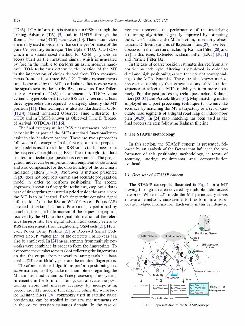
Fig. 1. Representation of the STAMP concept.
1128 C. Laoudias et al. / Computer Communications 31 (2008) 1126–1137
(TOA). TOA information is available in GSM through theTiming Advance (TA) [9] and in UMTS through theRound Trip Time (RTT) parameter [10]. These parametersare mainly used in order to enhance the performance of thepure Cell identity technique. The Uplink TOA (UL-TOA)which is a standardized method for GSM [11], uses anaccess burst as the measured signal, which is generatedby forcing the mobile to perform an asynchronous hand-over. TOA techniques determine the location of the MTas the intersection of circles derived from TOA measure-ments from at least three BSs [12]. Timing measurementscan also be used by the MT to calculate differences betweenthe signals sent by the nearby BSs, known as Time Differ-ence of Arrival (TDOA) measurements. A TDOA valuedefines a hyperbola with the two BSs as the foci and at leastthree hyperbolae are required to uniquely identify the MTposition [13]. This technique is also standardized in GSM[11,14] named Enhanced Observed Time Difference (E-OTD) and in UMTS known as Observed Time Differenceof Arrival (OTDOA) [15,16].
The final category utilizes RSS measurements, collectedperiodically as part of the MT’s standard functionality toassist in the handover process. There are two approachesfollowed in this category. In the first one, a proper propaga-tion model is used to translate RSS values to distances fromthe respective neighboring BSs. Then through standardtrilateration techniques position is determined. The propa-gation model can be empirical, semi-empirical or statisticaland also compensate for the directionality of the antenna’sradiation pattern [17–19]. Moreover, a method presentedin [20] does not require a known and accurate propagationmodel in order to perform positioning. The secondapproach, known as fingerprint technique, employs a data-base of fingerprints measured a priori inside the area wherethe MT is to be located. Each fingerprint contains signalinformation from the BSs or WLAN Access Points (AP)detected at certain locations. Positioning is performed bymatching the signal information of the request fingerprint,received by the MT, to the signal information of the refer-ence fingerprints. The signal information usually refers toRSS measurements from neighboring GSM cells [21]. How-ever, Power Delay Profiles [22] or Received Signal CodePower (RSCP) values [23] of the detected UMTS cells canalso be employed. In [24] measurements from multiple net-works were combined in order to form the fingerprints. Toovercome the cumbersome task of collecting the fingerprintson site, the output from network planning tools has beenused in [25] to artificially generate the required fingerprints.
The aforementioned algorithms perform positioning in astatic manner, i.e. they make no assumptions regarding theMT’s motion and dynamics. Time processing of noisy mea-surements, in the form of filtering, can alleviate the posi-tioning errors and increase accuracy by incorporatingproper mobility models. Filtering, including the well-stud-ied Kalman filters [26], commonly used in satellite basedpositioning, can be applied in the raw measurements orin the coarse position estimates domain. In the case of
raw measurements, the performance of the underlyingpositioning algorithm is greatly improved by estimatingthe system’s state, i.e. the MT’s motion, from noisy obser-vations. Different variants of Bayesian filters [27] have beendiscussed in the literature, including Kalman Filter [28] and[29] in this issue, Extended Kalman Filter (EKF) [30,31]and Particle Filter [32].
In the case of coarse position estimates derived from anypositioning technique, filtering is employed in order toeliminate high positioning errors that are not correspond-ing to the MT’s dynamics. These are also known as postprocessing techniques that generate a smoothed locationsequence to reflect the MT’s mobility pattern more accu-rately. Popular post processing techniques include Kalmanfilters [33–36] and Particle filters [37]. Map matching is alsoemployed as a post processing technique to increase theaccuracy by matching the MT’s trajectory to a set of can-didate road segments of a digital road map or indoor floorplan [38,39]. In [24] map matching has been used as thefinal processing step following Kalman filtering.
3. The STAMP methodology
In this section, the STAMP concept is presented, fol-lowed by an analysis of the factors that influence the per-formance of this positioning methodology, in terms ofaccuracy, storing requirements and communicationoverhead.
3.1. Overview of STAMP concept
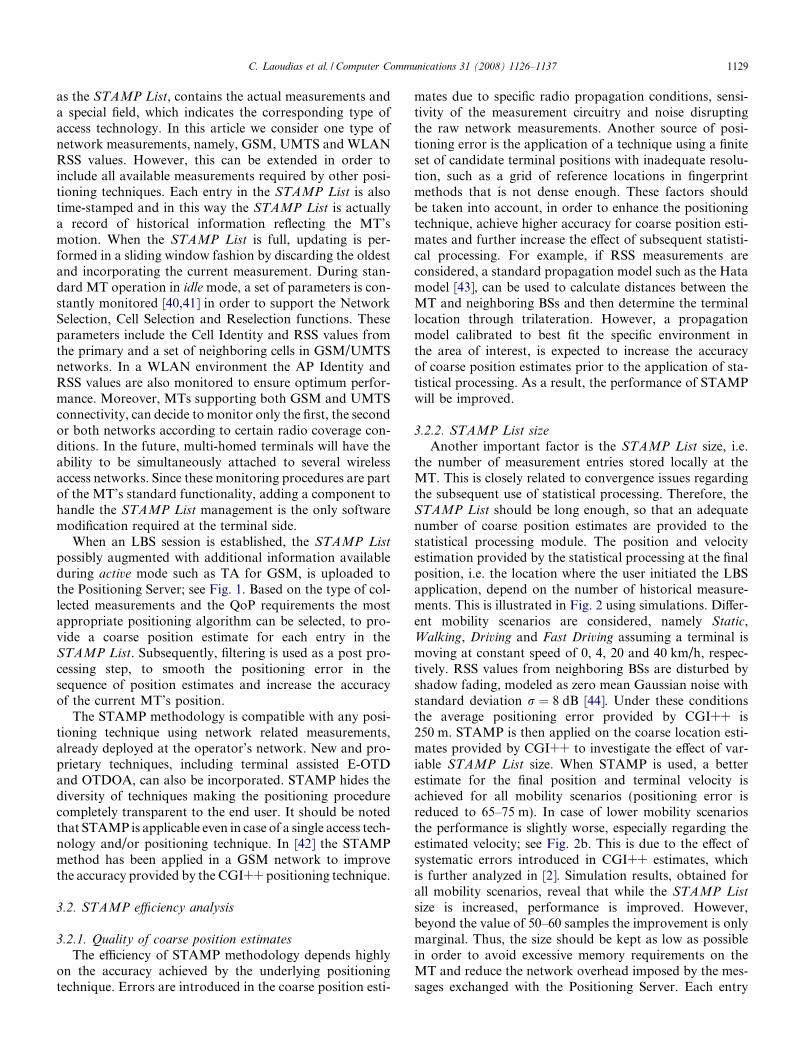
The STAMP concept is illustrated in Fig. 1 for a MTmoving through an area covered by multiple radio accessnetworks. While in idle mode the MT periodically storesall available network measurements, thus forming a list oflocation related information. Each entry in this list, denoted
C. Laoudias et al. / Computer Communications 31 (2008) 1126–1137 1129
as the STAMP List, contains the actual measurements anda special field, which indicates the corresponding type ofaccess technology. In this article we consider one type ofnetwork measurements, namely, GSM, UMTS and WLANRSS values. However, this can be extended in order toinclude all available measurements required by other posi-tioning techniques. Each entry in the STAMP List is alsotime-stamped and in this way the STAMP List is actuallya record of historical information reflecting the MT’smotion. When the STAMP List is full, updating is per-formed in a sliding window fashion by discarding the oldestand incorporating the current measurement. During stan-dard MT operation in idle mode, a set of parameters is con-stantly monitored [40,41] in order to support the NetworkSelection, Cell Selection and Reselection functions. Theseparameters include the Cell Identity and RSS values fromthe primary and a set of neighboring cells in GSM/UMTSnetworks. In a WLAN environment the AP Identity andRSS values are also monitored to ensure optimum perfor-mance. Moreover, MTs supporting both GSM and UMTSconnectivity, can decide to monitor only the first, the secondor both networks according to certain radio coverage con-ditions. In the future, multi-homed terminals will have theability to be simultaneously attached to several wirelessaccess networks. Since these monitoring procedures are partof the MT’s standard functionality, adding a component tohandle the STAMP List management is the only softwaremodification required at the terminal side.
When an LBS session is established, the STAMP List
possibly augmented with additional information availableduring active mode such as TA for GSM, is uploaded tothe Positioning Server; see Fig. 1. Based on the type of col-lected measurements and the QoP requirements the mostappropriate positioning algorithm can be selected, to pro-vide a coarse position estimate for each entry in theSTAMP List. Subsequently, filtering is used as a post pro-cessing step, to smooth the positioning error in thesequence of position estimates and increase the accuracyof the current MT’s position.
The STAMP methodology is compatible with any posi-tioning technique using network related measurements,already deployed at the operator’s network. New and pro-prietary techniques, including terminal assisted E-OTDand OTDOA, can also be incorporated. STAMP hides thediversity of techniques making the positioning procedurecompletely transparent to the end user. It should be notedthat STAMP is applicable even in case of a single access tech-nology and/or positioning technique. In [42] the STAMPmethod has been applied in a GSM network to improvethe accuracy provided by the CGI++ positioning technique.
3.2. STAMP efficiency analysis
3.2.1. Quality of coarse position estimates
The efficiency of STAMP methodology depends highlyon the accuracy achieved by the underlying positioningtechnique. Errors are introduced in the coarse position esti-
mates due to specific radio propagation conditions, sensi-tivity of the measurement circuitry and noise disruptingthe raw network measurements. Another source of posi-tioning error is the application of a technique using a finiteset of candidate terminal positions with inadequate resolu-tion, such as a grid of reference locations in fingerprintmethods that is not dense enough. These factors shouldbe taken into account, in order to enhance the positioningtechnique, achieve higher accuracy for coarse position esti-mates and further increase the effect of subsequent statisti-cal processing. For example, if RSS measurements areconsidered, a standard propagation model such as the Hatamodel [43], can be used to calculate distances between theMT and neighboring BSs and then determine the terminallocation through trilateration. However, a propagationmodel calibrated to best fit the specific environment inthe area of interest, is expected to increase the accuracyof coarse position estimates prior to the application of sta-tistical processing. As a result, the performance of STAMPwill be improved.
3.2.2. STAMP List size
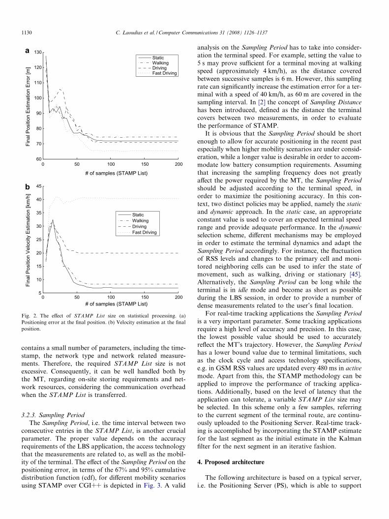
Another important factor is the STAMP List size, i.e.the number of measurement entries stored locally at theMT. This is closely related to convergence issues regardingthe subsequent use of statistical processing. Therefore, theSTAMP List should be long enough, so that an adequatenumber of coarse position estimates are provided to thestatistical processing module. The position and velocityestimation provided by the statistical processing at the finalposition, i.e. the location where the user initiated the LBSapplication, depend on the number of historical measure-ments. This is illustrated in Fig. 2 using simulations. Differ-ent mobility scenarios are considered, namely Static,Walking, Driving and Fast Driving assuming a terminal ismoving at constant speed of 0, 4, 20 and 40 km/h, respec-tively. RSS values from neighboring BSs are disturbed byshadow fading, modeled as zero mean Gaussian noise withstandard deviation r ¼ 8 dB [44]. Under these conditionsthe average positioning error provided by CGI++ is250 m. STAMP is then applied on the coarse location esti-mates provided by CGI++ to investigate the effect of var-iable STAMP List size. When STAMP is used, a betterestimate for the final position and terminal velocity isachieved for all mobility scenarios (positioning error isreduced to 65–75 m). In case of lower mobility scenariosthe performance is slightly worse, especially regarding theestimated velocity; see Fig. 2b. This is due to the effect ofsystematic errors introduced in CGI++ estimates, whichis further analyzed in [2]. Simulation results, obtained forall mobility scenarios, reveal that while the STAMP List
size is increased, performance is improved. However,beyond the value of 50–60 samples the improvement is onlymarginal. Thus, the size should be kept as low as possiblein order to avoid excessive memory requirements on theMT and reduce the network overhead imposed by the mes-sages exchanged with the Positioning Server. Each entry
0 50 100 150 20060
70
80
90
100
110
120
130
# of samples (STAMP List)
Fina
l Pos
ition
Est
imat
ion
Erro
r [m
]
StaticWalkingDrivingFast Driving
0 50 100 150 2005
10
15
20
25
30
35
40
45
# of samples (STAMP List)
Fina
l Pos
ition
Vel
ocity
Est
imat
ion
[km
/h]
StaticWalkingDrivingFast Driving
a
b
Fig. 2. The effect of STAMP List size on statistical processing. (a)Positioning error at the final position. (b) Velocity estimation at the finalposition.
1130 C. Laoudias et al. / Computer Communications 31 (2008) 1126–1137
contains a small number of parameters, including the time-stamp, the network type and network related measure-ments. Therefore, the required STAMP List size is notexcessive. Consequently, it can be well handled both bythe MT, regarding on-site storing requirements and net-work resources, considering the communication overheadwhen the STAMP List is transferred.
3.2.3. Sampling Period
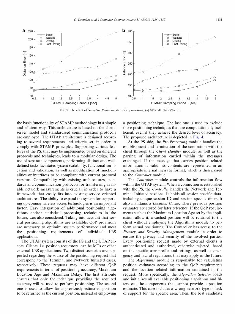
The Sampling Period, i.e. the time interval between twoconsecutive entries in the STAMP List, is another crucialparameter. The proper value depends on the accuracyrequirements of the LBS application, the access technologythat the measurements are related to, as well as the mobil-ity of the terminal. The effect of the Sampling Period on thepositioning error, in terms of the 67% and 95% cumulativedistribution function (cdf), for different mobility scenariosusing STAMP over CGI++ is depicted in Fig. 3. A valid
analysis on the Sampling Period has to take into consider-ation the terminal speed. For example, setting the value to5 s may prove sufficient for a terminal moving at walkingspeed (approximately 4 km/h), as the distance coveredbetween successive samples is 6 m. However, this samplingrate can significantly increase the estimation error for a ter-minal with a speed of 40 km/h, as 60 m are covered in thesampling interval. In [2] the concept of Sampling Distance
has been introduced, defined as the distance the terminalcovers between two measurements, in order to evaluatethe performance of STAMP.
It is obvious that the Sampling Period should be shortenough to allow for accurate positioning in the recent pastespecially when higher mobility scenarios are under consid-eration, while a longer value is desirable in order to accom-modate low battery consumption requirements. Assumingthat increasing the sampling frequency does not greatlyaffect the power required by the MT, the Sampling Period
should be adjusted according to the terminal speed, inorder to maximize the positioning accuracy. In this con-text, two distinct policies may be applied, namely the static
and dynamic approach. In the static case, an appropriateconstant value is used to cover an expected terminal speedrange and provide adequate performance. In the dynamic
selection scheme, different mechanisms may be employedin order to estimate the terminal dynamics and adapt theSampling Period accordingly. For instance, the fluctuationof RSS levels and changes to the primary cell and moni-tored neighboring cells can be used to infer the state ofmovement, such as walking, driving or stationary [45].Alternatively, the Sampling Period can be long while theterminal is in idle mode and become as short as possibleduring the LBS session, in order to provide a number ofdense measurements related to the user’s final location.
For real-time tracking applications the Sampling Period
is a very important parameter. Some tracking applicationsrequire a high level of accuracy and precision. In this case,the lowest possible value should be used to accuratelyreflect the MT’s trajectory. However, the Sampling Period
has a lower bound value due to terminal limitations, suchas the clock cycle and access technology specifications,e.g. in GSM RSS values are updated every 480 ms in active
mode. Apart from this, the STAMP methodology can beapplied to improve the performance of tracking applica-tions. Additionally, based on the level of latency that theapplication can tolerate, a variable STAMP List size maybe selected. In this scheme only a few samples, referringto the current segment of the terminal route, are continu-ously uploaded to the Positioning Server. Real-time track-ing is accomplished by incorporating the STAMP estimatefor the last segment as the initial estimate in the Kalmanfilter for the next segment in an iterative fashion.
4. Proposed architecture
The following architecture is based on a typical server,i.e. the Positioning Server (PS), which is able to support
0.5 1 1.5 2 2.5 3 3.5 4 4.5 560
80
100
120
140
160
180
200
220
STAMP Sampling Period T [sec]
Dis
tanc
e Er
ror [
m]
StaticWalkingDrivingFast Driving
0.5 1 1.5 2 2.5 3 3.5 4 4.5 5100
150
200
250
300
350
400
STAMP Sampling Period T [sec]
Dis
tanc
e Er
ror [
m]
StaticWalkingDrivingFast Driving
a b
Fig. 3. The effect of Sampling Period on statistical processing. (a) 67% cdf. (b) 95% cdf.
C. Laoudias et al. / Computer Communications 31 (2008) 1126–1137 1131
the basic functionality of STAMP methodology in a simpleand efficient way. This architecture is based on the client-server model and standardized communication protocolsare employed. The UTAP architecture is designed accord-ing to several requirements and criteria set, in order tocomply with STAMP principles. Supporting various fea-tures of the PS, that may be implemented based on differentprotocols and techniques, leads to a modular design. Theuse of separate components, performing distinct and well-defined tasks facilitates system scalability, functional verifi-cation and validation, as well as modification of function-alities or interfaces to be compliant with current protocolversions. Compatibility with existing architectures, stan-dards and communication protocols for transferring avail-able network measurements is crucial, in order to have aframework that easily fits into existing service orientedarchitectures. The ability to expand the system for support-ing up-coming wireless access technologies is an importantfactor. Easy integration of additional positioning algo-rithms and/or statistical processing techniques in thefuture, was also considered. Taking into account that sev-eral positioning algorithms are available, QoP provisionsare necessary to optimize system performance and meetthe positioning requirements of individual LBSapplications.
The UTAP system consists of the PS and the UTAP cli-ents. Clients, i.e. position requestors, can be MTs or otherexternal LBS applications. Two distinct scenarios are sup-ported regarding the source of the positioning request thatcorrespond to the Terminal and Network Initiated cases,respectively. These requests may have different QoPrequirements in terms of positioning accuracy, MaximumLocation Age and Maximum Delay. The first attributeensures that only the technique providing the requiredaccuracy will be used to perform positioning. The secondone is used to allow for a previously estimated positionto be returned as the current position, instead of employing
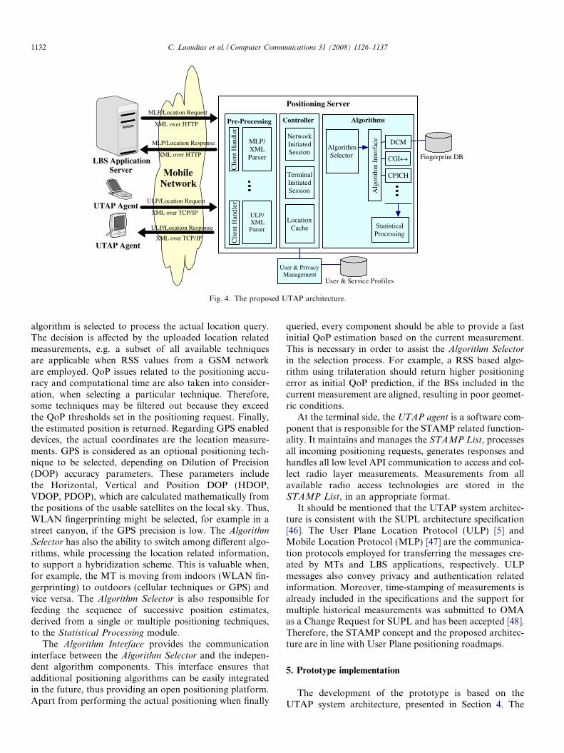
a positioning technique. The last one is used to excludethose positioning techniques that are computationally inef-ficient, even if they achieve the desired level of accuracy.The proposed architecture is depicted in Fig. 4.
At the PS side, the Pre-Processing module handles theestablishment and termination of the connection with theclient through the Client Handler module, as well as theparsing of information carried within the messagesexchanged. If the message that carries position relatedinformation is valid, its contents are represented in anappropriate internal message format, which is then passedto the Controller module.
The Controller module controls the information flowwithin the UTAP system. When a connection is establishedwith the PS, the Controller handles the Network and Ter-minal Initiated sessions. It holds all session specific data,including unique session ID and session specific timer. Italso maintains a Location Cache, where previous positionestimates are stored for later reference. If the QoP require-ments such as the Maximum Location Age set by the appli-cation allow it, a cached position will be returned to theclient without employing the Algorithms module to per-form actual positioning. The Controller has access to thePrivacy and Security Management module in order toensure the privacy and security of the involved parties.Every positioning request made by external clients isauthenticated and authorized, otherwise rejected, basedon the specific user profile and settings, as well as emer-gency and lawful regulations that may apply in the future.
The Algorithms module is responsible for calculatingposition estimates according to the QoP requirementsand the location related information contained in therequest. More specifically, the Algorithm Selector loadsand initializes all available positioning algorithms and fil-ters out the components that cannot provide a positionestimate. This case includes a wrong network type or lackof support for the specific area. Then, the best candidate
Pre-Processing Controller
MLP/XMLParser
ULP/XMLParser
Cli
ent H
andl
erC
lient
Han
dler
NetworkInitiatedSession
TerminalInitiatedSession
LocationCache
Algorithms
AlgorithmSelector
MLP/Location Response
ULP/Location Response
XML over HTTP
MLP/Location Request
XML over HTTP
ULP/Location Request
XML over TCP/IP
XML over TCP/IPUTAP Agent
LBS ApplicationServer
UTAP Agent
Positioning Server
User & PrivacyManagement
User & Service Profiles
CGI++ Fingerprint DB
Alg
orith
m I
nter
face
StatisticalProcessing
MobileNetwork
CPICH
DCM
Fig. 4. The proposed UTAP architecture.
1132 C. Laoudias et al. / Computer Communications 31 (2008) 1126–1137
algorithm is selected to process the actual location query.The decision is affected by the uploaded location relatedmeasurements, e.g. a subset of all available techniquesare applicable when RSS values from a GSM networkare employed. QoP issues related to the positioning accu-racy and computational time are also taken into consider-ation, when selecting a particular technique. Therefore,some techniques may be filtered out because they exceedthe QoP thresholds set in the positioning request. Finally,the estimated position is returned. Regarding GPS enableddevices, the actual coordinates are the location measure-ments. GPS is considered as an optional positioning tech-nique to be selected, depending on Dilution of Precision(DOP) accuracy parameters. These parameters includethe Horizontal, Vertical and Position DOP (HDOP,VDOP, PDOP), which are calculated mathematically fromthe positions of the usable satellites on the local sky. Thus,WLAN fingerprinting might be selected, for example in astreet canyon, if the GPS precision is low. The Algorithm
Selector has also the ability to switch among different algo-rithms, while processing the location related information,to support a hybridization scheme. This is valuable when,for example, the MT is moving from indoors (WLAN fin-gerprinting) to outdoors (cellular techniques or GPS) andvice versa. The Algorithm Selector is also responsible forfeeding the sequence of successive position estimates,derived from a single or multiple positioning techniques,to the Statistical Processing module.
The Algorithm Interface provides the communicationinterface between the Algorithm Selector and the indepen-dent algorithm components. This interface ensures thatadditional positioning algorithms can be easily integratedin the future, thus providing an open positioning platform.Apart from performing the actual positioning when finally
queried, every component should be able to provide a fastinitial QoP estimation based on the current measurement.This is necessary in order to assist the Algorithm Selector
in the selection process. For example, a RSS based algo-rithm using trilateration should return higher positioningerror as initial QoP prediction, if the BSs included in thecurrent measurement are aligned, resulting in poor geomet-ric conditions.
At the terminal side, the UTAP agent is a software com-ponent that is responsible for the STAMP related function-ality. It maintains and manages the STAMP List, processesall incoming positioning requests, generates responses andhandles all low level API communication to access and col-lect radio layer measurements. Measurements from allavailable radio access technologies are stored in theSTAMP List, in an appropriate format.
It should be mentioned that the UTAP system architec-ture is consistent with the SUPL architecture specification[46]. The User Plane Location Protocol (ULP) [5] andMobile Location Protocol (MLP) [47] are the communica-tion protocols employed for transferring the messages cre-ated by MTs and LBS applications, respectively. ULPmessages also convey privacy and authentication relatedinformation. Moreover, time-stamping of measurements isalready included in the specifications and the support formultiple historical measurements was submitted to OMAas a Change Request for SUPL and has been accepted [48].Therefore, the STAMP concept and the proposed architec-ture are in line with User Plane positioning roadmaps.
5. Prototype implementation
The development of the prototype is based on theUTAP system architecture, presented in Section 4. The
C. Laoudias et al. / Computer Communications 31 (2008) 1126–1137 1133
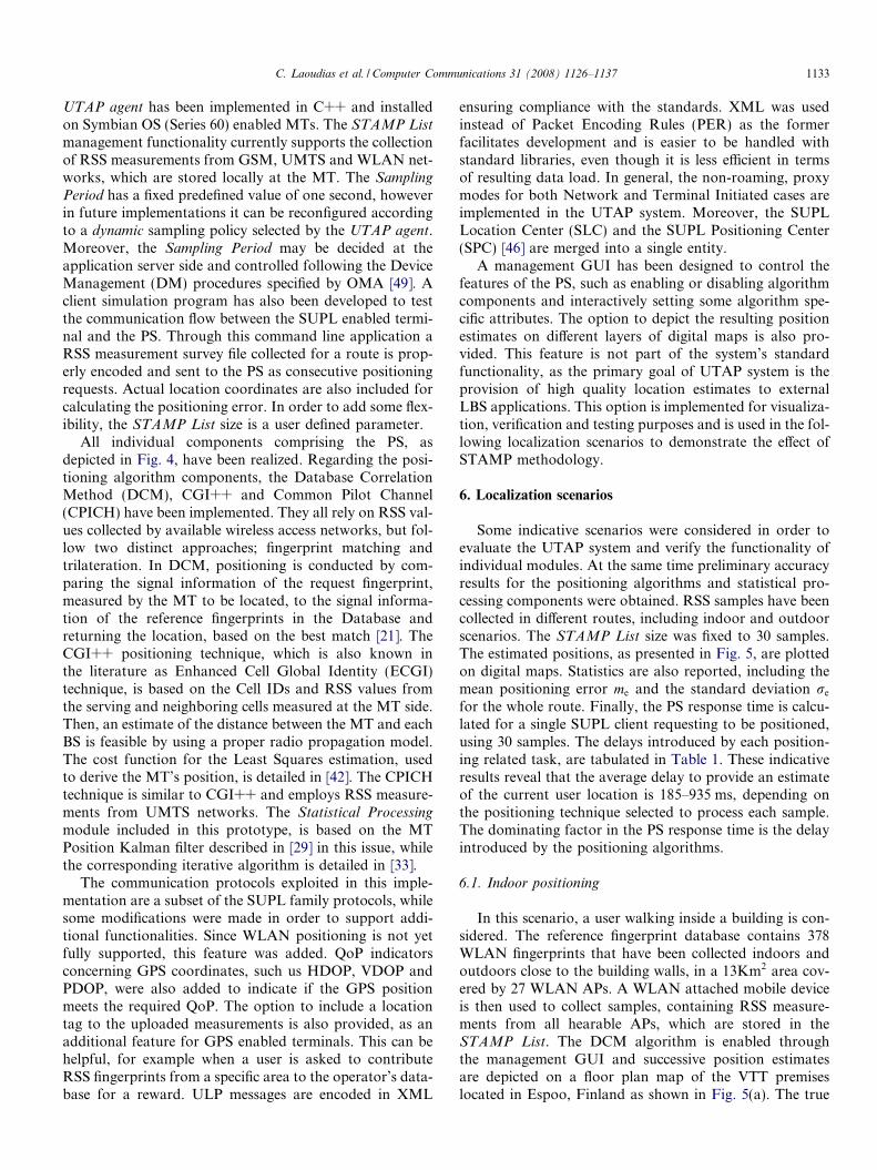
UTAP agent has been implemented in C++ and installedon Symbian OS (Series 60) enabled MTs. The STAMP List
management functionality currently supports the collectionof RSS measurements from GSM, UMTS and WLAN net-works, which are stored locally at the MT. The Sampling
Period has a fixed predefined value of one second, howeverin future implementations it can be reconfigured accordingto a dynamic sampling policy selected by the UTAP agent.Moreover, the Sampling Period may be decided at theapplication server side and controlled following the DeviceManagement (DM) procedures specified by OMA [49]. Aclient simulation program has also been developed to testthe communication flow between the SUPL enabled termi-nal and the PS. Through this command line application aRSS measurement survey file collected for a route is prop-erly encoded and sent to the PS as consecutive positioningrequests. Actual location coordinates are also included forcalculating the positioning error. In order to add some flex-ibility, the STAMP List size is a user defined parameter.
All individual components comprising the PS, asdepicted in Fig. 4, have been realized. Regarding the posi-tioning algorithm components, the Database CorrelationMethod (DCM), CGI++ and Common Pilot Channel(CPICH) have been implemented. They all rely on RSS val-ues collected by available wireless access networks, but fol-low two distinct approaches; fingerprint matching andtrilateration. In DCM, positioning is conducted by com-paring the signal information of the request fingerprint,measured by the MT to be located, to the signal informa-tion of the reference fingerprints in the Database andreturning the location, based on the best match [21]. TheCGI++ positioning technique, which is also known inthe literature as Enhanced Cell Global Identity (ECGI)technique, is based on the Cell IDs and RSS values fromthe serving and neighboring cells measured at the MT side.Then, an estimate of the distance between the MT and eachBS is feasible by using a proper radio propagation model.The cost function for the Least Squares estimation, usedto derive the MT’s position, is detailed in [42]. The CPICHtechnique is similar to CGI++ and employs RSS measure-ments from UMTS networks. The Statistical Processing
module included in this prototype, is based on the MTPosition Kalman filter described in [29] in this issue, whilethe corresponding iterative algorithm is detailed in [33].
The communication protocols exploited in this imple-mentation are a subset of the SUPL family protocols, whilesome modifications were made in order to support addi-tional functionalities. Since WLAN positioning is not yetfully supported, this feature was added. QoP indicatorsconcerning GPS coordinates, such us HDOP, VDOP andPDOP, were also added to indicate if the GPS positionmeets the required QoP. The option to include a locationtag to the uploaded measurements is also provided, as anadditional feature for GPS enabled terminals. This can behelpful, for example when a user is asked to contributeRSS fingerprints from a specific area to the operator’s data-base for a reward. ULP messages are encoded in XML
ensuring compliance with the standards. XML was usedinstead of Packet Encoding Rules (PER) as the formerfacilitates development and is easier to be handled withstandard libraries, even though it is less efficient in termsof resulting data load. In general, the non-roaming, proxymodes for both Network and Terminal Initiated cases areimplemented in the UTAP system. Moreover, the SUPLLocation Center (SLC) and the SUPL Positioning Center(SPC) [46] are merged into a single entity.
A management GUI has been designed to control thefeatures of the PS, such as enabling or disabling algorithmcomponents and interactively setting some algorithm spe-cific attributes. The option to depict the resulting positionestimates on different layers of digital maps is also pro-vided. This feature is not part of the system’s standardfunctionality, as the primary goal of UTAP system is theprovision of high quality location estimates to externalLBS applications. This option is implemented for visualiza-tion, verification and testing purposes and is used in the fol-lowing localization scenarios to demonstrate the effect ofSTAMP methodology.
6. Localization scenarios
Some indicative scenarios were considered in order toevaluate the UTAP system and verify the functionality ofindividual modules. At the same time preliminary accuracyresults for the positioning algorithms and statistical pro-cessing components were obtained. RSS samples have beencollected in different routes, including indoor and outdoorscenarios. The STAMP List size was fixed to 30 samples.The estimated positions, as presented in Fig. 5, are plottedon digital maps. Statistics are also reported, including themean positioning error me and the standard deviation re
for the whole route. Finally, the PS response time is calcu-lated for a single SUPL client requesting to be positioned,using 30 samples. The delays introduced by each position-ing related task, are tabulated in Table 1. These indicativeresults reveal that the average delay to provide an estimateof the current user location is 185–935 ms, depending onthe positioning technique selected to process each sample.The dominating factor in the PS response time is the delayintroduced by the positioning algorithms.
6.1. Indoor positioning
In this scenario, a user walking inside a building is con-sidered. The reference fingerprint database contains 378WLAN fingerprints that have been collected indoors andoutdoors close to the building walls, in a 13Km2 area cov-ered by 27 WLAN APs. A WLAN attached mobile deviceis then used to collect samples, containing RSS measure-ments from all hearable APs, which are stored in theSTAMP List. The DCM algorithm is enabled throughthe management GUI and successive position estimatesare depicted on a floor plan map of the VTT premiseslocated in Espoo, Finland as shown in Fig. 5(a). The true
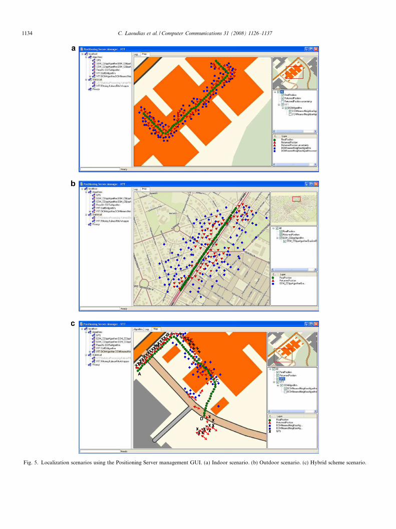
Fig. 5. Localization scenarios using the Positioning Server management GUI. (a) Indoor scenario. (b) Outdoor scenario. (c) Hybrid scheme scenario.
1134 C. Laoudias et al. / Computer Communications 31 (2008) 1126–1137
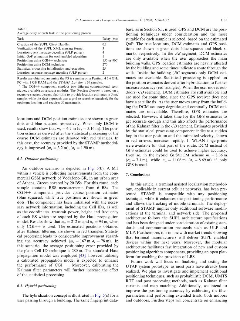
Table 1Average delay of each task in the positioning process
Task Delay (ms)
Creation of the SUPL Client Handler 0.1Verification of the SUPL XML message format 3Location query message decoding (ULP parser) 4Initial QoP estimation for each enabled algorithm 1Positioning using CGI++ technique 150 or 900a
Positioning using DCM technique 270Statistical processing initialization and execution 25Location response message encoding (ULP parser) 2
Results are obtained assuming the PS is running on a Pentium 4 3.6 GHzPC with 1 GB RAM and the STAMP List size is 30 samples.
a The CGI++ component employs two different computational tech-niques, available as separate modules. The Gradient Descent is based on arecursive steepest descent algorithm to provide location estimates in 5 ms/sample, while the Grid approach uses a grid to search exhaustively for theoptimum location and requires 30 ms/sample.
C. Laoudias et al. / Computer Communications 31 (2008) 1126–1137 1135
locations and DCM position estimates are shown in greendots and blue squares, respectively. When only DCM isused, results show that me ¼ 4:7 m ðre ¼ 3:16 mÞ. The posi-tion estimates derived after the statistical processing of thecoarse DCM estimates are denoted with red triangles. Inthis case, the accuracy provided by the STAMP methodol-ogy is improved ðme ¼ 3:2 mÞ; ðre ¼ 1:90 mÞ.
6.2. Outdoor positioning
An outdoor scenario is depicted in Fig. 5(b). A MTwithin a vehicle is collecting measurements from the com-mercial GSM network of Vodafone-GR, in an urban areaof Athens, Greece covered by 20 BSs. For this route, eachsample contains RSS measurements from 6 BSs. TheCGI++ component provides coarse position estimates(blue squares), while true positions are shown in greendots. The component has been initialized with the neces-sary network information, including the Cell IDs, as wellas the coordinates, transmit power, height and frequencyof each BS which are required by the Hata propagationmodel. Results show that me ¼ 212 m and re ¼ 94 m, whenonly CGI++ is used. The estimated positions obtainedafter Kalman filtering, are shown in red triangles. Statisti-cal processing leads to considerable improvement regard-ing the accuracy achieved ðme ¼ 167 m; re ¼ 78 mÞ. Inthis scenario, the average positioning error provided bythe plain Cell ID technique is 280 m. The standard Hatapropagation model was employed [43], however utilizinga calibrated propagation model is expected to enhancethe performance of CGI++. Moreover, calibrating theKalman filter parameters will further increase the effectof the statistical processing.
6.3. Hybrid positioning
The hybridization concept is illustrated in Fig. 5(c) for auser passing through a building. The same fingerprint data-
base, as in Section 6.1, is used. GPS and DCM are the posi-tioning techniques under consideration and the mostsuitable for each sample is selected, based on the estimatedQoP. The true locations, DCM estimates and GPS posi-tions are shown in green dots, blue squares and black x-marks, respectively. In the AB segment, DCM estimatesare only available when the user approaches the mainbuilding walls. GPS location estimates are heavily affectedby the building and some times indicate a route through thewalls. Inside the building (BC segment) only DCM esti-mates are available. Statistical processing is applied onthe position estimates derived after hybridization to furtherincrease accuracy (red triangles). When the user moves out-doors (CD segment), DCM estimates are still available andare used for some time, since the GPS receiver does nothave a satellite fix. As the user moves away from the build-ing the DCM accuracy degrades and eventually DCM esti-mates are unavailable. Therefore, GPS estimates areselected. However, it takes time for the GPS estimates toget accurate enough and this also affects the performanceof the Kalman filter in the CD segment. Estimates providedby the statistical processing component indicate a suddenhop in the user position and the estimated velocity, shownin red arrows, increases rapidly. If WLAN fingerprintswere available for that part of the route, DCM instead ofGPS estimates could be used to achieve higher accuracy.Even so, in the hybrid GPS/DCM scheme me ¼ 8:36 mðre ¼ 7:1 mÞ, while me ¼ 11:06 m ðre ¼ 8:69 mÞ if onlyGPS is used.
7. Conclusions
In this article, a terminal assisted localization methodol-ogy, applicable in current cellular networks, has been pre-sented. STAMP is compatible with any positioningtechnique, while it enhances the positioning performanceand allows the tracking of mobile terminals. The deploy-ment of STAMP implies only additional software modifi-cations at the terminal and network side. The proposedarchitecture follows the SUPL architecture specificationsand has been designed under consideration of existing stan-dards and communication protocols such as ULP andMLP. Furthermore, it is in line with market trends showingthat terminal manufacturers will deliver SUPL enableddevices within the next years. Moreover, the modulararchitecture facilitates fast integration of new and custompositioning algorithm components, providing an open plat-form for enabling the provision of LBS.
Future work will focus on finalizing and testing theUTAP system prototype, as most parts have already beenrealized. We plan to investigate and implement additionalpositioning techniques, such as probabilistic DCM, UMTSRTT and post processing methods, such as Kalman filtervariants and map matching. Additionally, we intend toimprove the positioning accuracy by calibrating the filterparameters and performing extended trials, both indoorsand outdoors. Further steps will concentrate on enhancing
1136 C. Laoudias et al. / Computer Communications 31 (2008) 1126–1137
the QoP provisions and providing uninterrupted position-ing, especially in hybrid schemes where different networkmeasurements and multiple positioning techniques areavailable.
Acknowledgements
This article introduces concepts and technologies de-ployed within the framework of the project MOTIVE [7],which is partially funded by the European Commission un-der the 6th framework of the IST program. This work ispartly supported by the Cyprus Research Promotion Foun-dation under contracts ENIRX=0506=59 andPKHPO=0603=06. The authors thank Reach-U(http://www.reach-u.com) for the provision of digitalmaps in the context of MOTIVE.
References
[1] J. Markoulidakis, C. Desiniotis, D. Nikitopoulos, Statistical terminalassisted mobile positioning in a beyond 3G environment, in: 15th ISTMobile and Wireless Summit, Myconos, Greece, 2006. Availablefrom: <http://www.cn.ntua.gr/ist-motive/public_doc.html>.
[2] J. Markoulidakis, C. Dessiniotis, Statistical terminal assisted mobilepositioning technique, IET Communications 1 (3) (2007) 325–332.
[3] J. Spinney, Wireless location uses in the user plane and control plane,Directions Magazine (Copyright 2005 ESRI), July 2005. Availablefrom: <http://www.directionsmag.com/article.php?article_id=897>.
[4] A. Kupper, Location-Based Services: Fundamentals and Operation,Wiley, 2005.
[5] Userplane Location Protocol, v1.0, Technical Specification, 2006.[6] J. Dyoub, B. Collins, Dueling architectures: control plane vs user
plane, which is right for you?, 2004.[7] FP6 IST-MOTIVE Project, Contract No:FP6-IST-27659. Available
from: <http://www.cn.ntua.gr/ist-motive/>.[8] J. Caffery, G. Stuber, Overview of radiolocation in CDMA cellular
systems, IEEE Communications Magazine 36 (4) (1998) 38–45.[9] M. Silventoinen, T. Rantalainen, Mobile station emergency locating
in GSM, in: IEEE International Conference on Personal WirelessCommunications, 1996, pp. 232–238.
[10] J. Borkowski, J. Niemela, J. Lempiainen, Enhanced performance ofCell ID+RTT by implementing forced soft handover algorithm, in:60th IEEE Vehicular Technology Conference (VTC2004-Fall), vol. 5,2004, pp. 3545–3549.
[11] ETSI TS 101 724: Location Services (LCS) (version 8.1.0), April 2001.[12] J. Caffery, A new approach to the geometry of TOA location, in: 52nd
IEEE Vehicular Technology Conference (VTC2000-Fall), vol. 4,2000, pp. 1943–1949.
[13] M. Spirito, On the accuracy of cellular mobile station locationestimation, IEEE Transactions on Vehicular Technology 50 (3) (2001)674–685.
[14] S. Fischer, A. Kangas, Time-of-arrival estimation for E-OTDlocation in GERAN, in: 12th IEEE International Symposium onPersonal, Indoor and Mobile Radio Communications, vol. 2, 2001,pp. F-121–F-125.
[15] Y. Zhao, Standardization of mobile phone positioning for 3Gsystems, IEEE Communications Magazine 40 (7) (2002) 108–116.
[16] D. Porcino, Performance of a OTDOA-IPDL positioning receiver for3GPP-FDD mode, in: Second International Conference on 3GMobile Communication Technologies (Conference Publication No.477), 2001, pp. 221–225.
[17] M. Aso, T. Saikawa, T. Hattori, Mobile station location estimationusing the maximum likelihood method in sector cell systems, in: 56th
IEEE Vehicular Technology Conference (VTC2002-Fall), vol. 2,2002, pp. 1192–1196.
[18] T. Roos, P. Myllymaki, H. Tirri, A statistical modeling approach tolocation estimation, IEEE Transactions on Mobile Computing 1 (1)(2002) 59–69.
[19] K. Chu, K. Leung, J.-Y. Ng, C.H. Li, Locating mobile stations withstatistical directional propagation model, in: 18th InternationalConference on Advanced Information Networking and Applications,vol. 1, 2004, pp. 230–235.
[20] D.-B. Lin, R.-T. Juang, Mobile location estimation based ondifferences of signal attenuations for GSM systems, IEEE Transac-tions on Vehicular Technology 54 (4) (2005) 1447–1454.
[21] H. Laitinen, J. Lahteenmaki, T. Nordstrom, Database correlationmethod for GSM location, in: 53rd IEEE Vehicular TechnologyConference (VTC2001-Spring), vol. 4, 2001, pp. 2504–2508.
[22] S. Ahonen, H. Laitinen, Database correlation method for UMTSlocation, in: 57th IEEE Semiannual Vehicular Technology Confer-ence (VTC2003-Spring), vol. 4, 2003, pp. 2696–2700.
[23] J. Borkowski, J. Lempiainen, Pilot correlation positioning method forurban UMTS networks, in: European Wireless Conference, vol. 2,2005, pp. 465–469.
[24] P. Kemppi, S. Nousiainen, Database correlation method for multi-system positioning, in: 63rd IEEE Vehicular Technology Conference(VTC2006-Spring), vol. 2, 2006, pp. 866–870.
[25] D. Zimmermann, J. Baumann, A. Layh, F. Landstorfer, R. Hoppe,G. Wolfle, Database correlation for positioning of mobile terminals incellular networks using wave propagation models, in: 60th IEEEVehicular Technology Conference (VTC2004-Fall), vol. 7, 2004, pp.4682–4686.
[26] R.G. Brown, P.Y.C. Hwang, Introduction to Random Signals andApplied Kalman Filtering, 3rd ed., John Wiley & Sons, 1997.
[27] V. Fox, J. Hightower, L. Liao, D. Schulz, G. Borriello, Bayesianfiltering for location estimation, IEEE Pervasive Computing 2 (3)(2003) 24–33.
[28] M. McGuire, K. Plataniotis, Dynamic model-based filtering formobile terminal location estimation, IEEE Transactions on VehicularTechnology 52 (4) (2003) 1012–1031.
[29] J. Markoulidakis, C. Dessiniotis, D. Nikolaidis, Part two: Kalmanfiltering options for error minimization in Statistical TerminalAssisted Mobile Positioning, Computer Communications 31 (6)(2008) 1138–1147.
[30] I. Papageorgiou, C. Charalambous, C. Panayiotou, An enhancedreceived signal level cellular location determination method viamaximum likelihood and Kalman filtering, in: IEEE WirelessCommunications and Networking Conference, vol. 4, 2005, pp.2524–2529.
[31] M. Najar, J. Vidal, Kalman tracking for mobile location inNLOS situations, in: 14th IEEE Proceedings on Personal,Indoor and Mobile Radio Communications, vol. 3, 2003, pp.2203–2207.
[32] M. Arulampalam, S. Maskell, N. Gordon, T. Clapp, A tutorial onparticle filters for online nonlinear/non-Gaussian Bayesian track-ing, IEEE Transactions on Signal Processing 50 (2) (2002) 174–188 (see also IEEE Transactions on Acoustics, Speech and SignalProcessing).
[33] M. Hellebrandt, R. Mathar, Location tracking of mobiles in cellularradio networks, IEEE Transactions on Vehicular Technology 48 (5)(1999) 1558–1562.
[34] D. Catrein, M. Hellebrandt, R. Mathar, M. Serrano, Locationtracking of mobiles: a smart filtering method and its use in practice,in: 59th IEEE Vehicular Technology Conference (VTC2004-Spring),vol. 5, 2004, pp. 2677–2681.
[35] Z. Zaidi, B. Mark, Real-time mobility tracking algorithms for cellularnetworks based on Kalman filtering, IEEE Transactions on MobileComputing 4 (2) (2005) 195–208.
[36] B.L. Le, K. Ahmed, H. Tsuji, Mobile location estimator with NLOSmitigation using Kalman filtering, in: IEEE Wireless Communica-tions and Networking, vol. 3, 2003, pp. 1969–1973.
C. Laoudias et al. / Computer Communications 31 (2008) 1126–1137 1137
[37] F. Evennou, F. Marx, E. Novakov, Map-aided indoor mobilepositioning system using particle filter, in: IEEE Wireless Com-munications and Networking Conference, vol. 4, 2005, pp. 2490–2494.
[38] D. Bernstein, A. Kornhauser, An introduction to map matching forpersonal navigation assistants, Technical Report, TIDE Center, NewJersey (1996).
[39] D. Yang, B. Cai, Y. Yuan, An improved map-matching algorithmused in vehicle navigation system, in: IEEE Intelligent TransportationSystems, vol. 2, 2003, pp. 1246–1250.
[40] TS 43.022 v.7.2.0: Functions related to Mobile Station (MS) in idlemode and group receive mode.
[41] TS 25.304 v.6.8.0: User Equipment procedures in idle mode andprocedures for cell reselection in connected mode.
[42] J. Markoulidakis, C. Desiniotis, K. Kypris, Method for improvingthe CGI++ mobile location technique by exploiting past measure-ments, in: IST Mobile Summit, Dresden, Germany, 2005.
[43] M. Hata, Empirical formula for propagation loss in land mobile radioservices, IEEE Transactions on Vehicular Technology 29 (3) (1980)317–325.
[44] H.L. Bertoni, Radio Propagation for Modern Wireless Systems,Prentice Hall Professional Technical Reference, 1999, pp. 16–23.
[45] I. Anderson, H. Muller, Practical activity recognition using GSMdata, Technical Report CSTR-06-016, Department of ComputerScience, University of Bristol (July 2006). Available from: <http://www.cs.bris.ac.uk/Publications/Papers/2000563.pdf>.
[46] Secure User Plane Location Architecture, v1.0, Technical Specifica-tion, March 2006.
[47] Mobile Location Protocol, v3.1, Technical Specification, September2006.
[48] OMA-LOC-2006-0070-CR-SUPL2.0-RD-Historical-Cell-Informa-tion, Change Request, March 2006.
[49] OMA-TS-DM-Protocol-V1-2-20070209-A, Technical Specification,February 2007.