Part 2 of 2, Rev. 00 to WCAP-15996-NP, Technical ...
168
Table G.A: Dictionary Listing Index Long Variable Name Input System System System Variable's Tyxe Dimen- Definition ." Units No._. Opuut Alt. 1 Alt. 2 Function slons 1144 RCSCONCPART Output RCS Solutes RE 50 RCS Node particulates concentrations. This parameter array is Microcure/lbm -Int both a CENTS calculated output and a USER adjusted Input. For instance, particulate conc. = 0.0 at initialization. After Initialization, RCS_CONCPART(I) = 0.0. Ifthe USER wanted to adjust the particulates in any or all nodes, then RCSCONCHYD (I) could be re-established at x mIcroC/lbm. CENTS would then calculate any changes to x as the given transient progressed, thus reverting RCSCONCPART to an output role affected by transport of the particulate and releases from the core damage model. Reference 1, Sections 4.15 and 5.8.2. 1145 RCSPCONCXEN Output! RCS Solutes RE 50 RCS Node xenon concentrations. This parameter array Is both a Microcune/Ibrn -Int CENTS calculated output and a USER adjusted input. For instance, Xenon conc. = 0.0 at initialization. After initialization, RCSCONCXEN(I) = 0.0. If the USER wanted to adjust the Xenon in any or all nodes, then RCS_CONCXEN(I) could be re established at x microClIbm. CENTS would then calculate any changes to x as the given transient progressed, thus reverting RCSCONCXEN to an output role affected by transport of the Xenon and releases from the core damage model. Reference 1, Sections 4.15 and 5.8 2. 1146 RCSRELESOLU Output RCS Solutes RE 50, 5 RCS Node solute accumulation rates. Reference 1, Sections 4.15 Composite -_-_and 5 8.2. 1 Units 1147 RCS-RELE.SOLU.CORE Partition RE 5 Core solute releases. 1-5 Bo,Hy,lo,Ce,Xe Composite _ - - -Units 1148 COREBORONREL Input RE Core boron release. This is a fictitious quantity. Must be set = 0 0 Composite Units 1149 COREHYDREL I/O CORE RCS Solutes RE Core hydrogen release. This input parameter is not required for Lbm/sec code initialization. If POWZRH20_NYZIR=True (User flag: Zr oxidation calculation is performed) then this variable is set to the calculated H2 release rate, POWZRH20_H2M. If POWZRH20_NYZIR=False, then this variable can be set by the USER to simulate different core clad failure analyses 1150 COREJIODREL Input CORE RCS Solutes RE Core Iodine release. This input parameter is not required for code Microcude/sec initialization. This Is a USER defined input parameter which simulates a certain amount of core damage. Once released into node 1, the iodine is then distributed & tracked through the system by CENTS. Reference 1. Sections 4.15, 7.1.3 & 7.2.7. 1151 COREPARTREL Input CORE RCS Solutes RE Core particulate (cesium) release. This input parameter is not Microcurie/sec required for code initialization. This Is a USER defined Input parameter which simulates a certain amount of core damage. Once released into node 1, the particulate Is then distributed & tracked through the system by CENTS. Reference 1, Sections 4.15, 7.1.3 & 17.2.7. G-100 WCAP-15996-NP, Revision 0
-
Upload
khangminh22 -
Category
Documents
-
view
0 -
download
0
Transcript of Part 2 of 2, Rev. 00 to WCAP-15996-NP, Technical ...

Table G.A: Dictionary Listing
Index Long Variable Name Input System System System Variable's Tyxe Dimen- Definition ." Units
No._. Opuut Alt. 1 Alt. 2 Function slons 1144 RCSCONCPART Output RCS Solutes RE 50 RCS Node particulates concentrations. This parameter array is Microcure/lbm
-Int both a CENTS calculated output and a USER adjusted Input. For instance, particulate conc. = 0.0 at initialization. After Initialization, RCS_CONCPART(I) = 0.0. If the USER wanted to adjust the particulates in any or all nodes, then RCSCONCHYD (I) could be re-established at x mIcroC/lbm. CENTS would then calculate any changes to x as the given transient progressed, thus reverting RCSCONCPART to an output role affected by transport of the particulate and releases from the core damage model. Reference 1, Sections 4.15 and 5.8.2.
1145 RCSPCONCXEN Output! RCS Solutes RE 50 RCS Node xenon concentrations. This parameter array Is both a Microcune/Ibrn
-Int CENTS calculated output and a USER adjusted input. For instance, Xenon conc. = 0.0 at initialization. After initialization, RCSCONCXEN(I) = 0.0. If the USER wanted to adjust the Xenon in any or all nodes, then RCS_CONCXEN(I) could be reestablished at x microClIbm. CENTS would then calculate any changes to x as the given transient progressed, thus reverting RCSCONCXEN to an output role affected by transport of the Xenon and releases from the core damage model. Reference 1, Sections 4.15 and 5.8 2.
1146 RCSRELESOLU Output RCS Solutes RE 50, 5 RCS Node solute accumulation rates. Reference 1, Sections 4.15 Composite -_-_and 5 8.2. 1 Units
1147 RCS-RELE.SOLU.CORE Partition RE 5 Core solute releases. 1-5 Bo,Hy,lo,Ce,Xe Composite _ - - -Units
1148 COREBORONREL Input RE Core boron release. This is a fictitious quantity. Must be set = 0 0 Composite Units
1149 COREHYDREL I/O CORE RCS Solutes RE Core hydrogen release. This input parameter is not required for Lbm/sec code initialization. If POWZRH20_NYZIR=True (User flag: Zr oxidation calculation is performed) then this variable is set to the calculated H2 release rate, POWZRH20_H2M. If POWZRH20_NYZIR=False, then this variable can be set by the USER to simulate different core clad failure analyses
1150 COREJIODREL Input CORE RCS Solutes RE Core Iodine release. This input parameter is not required for code Microcude/sec initialization. This Is a USER defined input parameter which simulates a certain amount of core damage. Once released into node 1, the iodine is then distributed & tracked through the system by CENTS. Reference 1. Sections 4.15, 7.1.3 & 7.2.7.
1151 COREPARTREL Input CORE RCS Solutes RE Core particulate (cesium) release. This input parameter is not Microcurie/sec required for code initialization. This Is a USER defined Input parameter which simulates a certain amount of core damage. Once released into node 1, the particulate Is then distributed & tracked through the system by CENTS. Reference 1, Sections 4.15, 7.1.3 &
17.2.7.
G-100WCAP-15996-NP, Revision 0

Table G.A: Dictionary Listing
Index Long Variable Name Inout/ System System System Variable's TVye Dimen- Definition " - Units , No. Output Alt. 1 Alt. 2 Function sions '
1152 CORE.XENREL Input CORE RCS Solutes RE Core xenon release. This input parameter Is not required for code Microcurie/sec initialization. This is a USER defined input parameter which simulates a certain amount of core damage. Once released into node 1, the Xenon is then distributed & tracked through the system by CENTS. Reference 1, Sections 4.15, 7.1 3 & 7.2.7.
1153 RCSDOSE VARIABLES Partition RE 20 Dose Model variables Partition 1154 RCSDOSE_INIT_IOD Input DOSE RCS Solutes RE Dose Model Initial RCS Iodine Conc. This input is scenario Microcune/Ibm
dependent, entered by the code USER. It defines the initial Iodine concentration In all the RCS nodes, collectively. Note that after initialization, the iodine concentration in all nodes will be RCSCONC_IOD(I) = RCSDOSEINITIOD. At that point individual node(x) concentration can be adjusted by USER modification of RCS_CONC_IOD(x). Reference 1, Section 5.8.2 and Appendix D.
1155 RCSDOSEFLASH Input DOSE RCS Solutes RE Dose model flashing factor flag. This USER defined input Dimensionless apportions the iodine entering the SG from the RCS during a tube leak, by allocating the fraction of iodine to the steam space of the SG, with the remainder going to the liquid in the SG secondary. RCS_DOSE_FLASH=O.O is best-estimate, 1.0 is conservative, and 2 0 is most conservative. Reference 1, Section 7.3.5.
1156 RCS_DOSE_BF Input DOSE RCS Plant Design RE Dose model breathing factor. This is a USER supplied input. Note FTW/sec that the units are normally in m3 /sec and require conversion to ft3
/sec. Reference 1, Section 7.3 5. 1157 RCS_DOSE_CF Input DOSE RCS Plant Design RE Dose model conversion factor. This a plant independent variable, Rem/Cune
which converts the units of iodine released to the atmosphere from curies to REM. Reference 1, Section 7 3 5.
1158 RCSDOSEXOQ2 Input DOSE RCS Plant Design RE Dose model 2Hr site dispersion factor. This is a plant dependent sec/FT' Input based upon the documented weather patterns at a given utility. It accounts for the iodine dispersion into the atmosphere from the release point to the site boundary, during the first 2 hrs after the release. It is used in determining 2 hr dose rates. Reference 1, Section 7 3 5.
1159 RCSDOSE_XO08 Input DOSE RCS Plant Design RE Dose model 8hr site dispersion factor. This is a plant dependent sec/FT'3
input based upon the documented weather pattems at a given utility. It accounts for the iodine dispersion into the atmosphere from the release point to the site boundary, during the first 2 hrs after the release. It is used in determining 2 hr dose rates. Reference 1, Section 7.3.5.
1160 RCS_DOSE_CONT_LEAK Input DOSE RCS Plant Design RE Dose Model Containment Leak Rate. This is a USER defined input. FracJday It is used by the code to calculate the iodine being released to the
I _atmosphere via the containment Reference 1, Section 7.3 5.
WCAP- 15996-NP, Revision 0 G-101
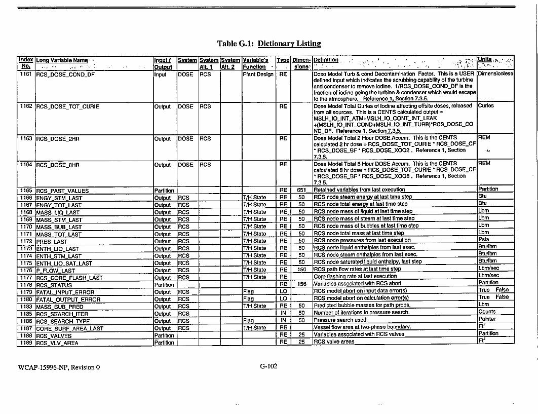
Table G.A: Dictionary Listine
Index Long Variable Name, Input/ System System System Variable's Type Dlmen- Definition, ,,,- ,, , UnI , v..,No. .. - Output Alt. 1 Alt. 2 Function - slons,
1161 RCSDOSECONDDF Input DOSE RCS Plant Design RE Dose Model Turb & cond Decontamination Factor. This Is a USER Dimensionless defined input which indicates the scrubbing capability of the turbine and condenser to remove Iodine. 1/RCSDOSECONDDF is the fraction of Iodine going the turbine & condenser which would escape to the atmosphere. Reference 1, Section 7.3.5.
1162 RCS.DOSETOTCURIE Output DOSE RCS RE Dose Model Total Curies of Iodine affecting offsite doses, released Curies
from all sources. This is a CENTS calculated output MSLHIOINTATM+MSLH_IO_CONT_INT_LEAK +(MSLH_10_INT_COND+MSLHI0_INTTURB)*RCSDOSECO _NDDF. Reference 1, Section 7.3.5.
1163 RCSDOSE 2HR Output DOSE RCS RE Dose Model Total 2 Hour DOSE Accum. This Is the CENTS REM calculated 2 hr dose = RCS..DOSE_TOT_CURIE * RCS_DOSECF * RCSDOSEBF - RCSDOSE_XO02. Reference 1, Section 7.3.5.
1164 RCSDOSE_8HR Output DOSE RCS RE Dose Model Total 8 Hour DOSE Accum. This is the CENTS REM calculated 8 hr dose = RCSDOSE_TOT_CURIE * RCSDOSECF * RCSDOSEBF- RCS.DOSE_X008. Reference 1, Section 7.35.
1165 RCSPASTVALUES Partition RE 651 Retained variables from last execution Partition
1166 ENGY STM LAST Output RCS T/H State RE 50 RCS node steam energy at last time step Btu
1167 ENGYTOTLAST Output RCS T/H State RE 50 RCS node total energy at last time step Btu
1168 MASSLIQLAST Output RCS T/H State RE 50 RCS node mass of liquid at last time step Lbm
1169 MASSSTM LAST Output RCS T/H State RE 50 RCS node mass of steam at last time step Lbm
1170 MASS BUB-LAST Output RCS T/H State RE 50 RCS node mass of bubbles at last time step Lbm
1171 MASS TOT LAST Output RCS T/H State RE 50 RCS node total mass at last time step Lbm
1172 PRES LAST Output RCS _ T/H State RE 50 RCS node pressures from last execution Psia
1173 ENTH LIQ LAST Output RCS T/H State RE 50 RCS node liquid enthalples from last exec. BtuAbm
1174 ENTH STMLAST Output RCS T/H State RE 50 RCS node steam enthalpIes from last exec. Btu/lbm
1175 ENTHLIOSATLAST Output RCS T/H State RE 50 RCS node saturated liquid enthalpy, last step BtuAbm
1176 PFLOWLAST Output RCS T/H State RE 150 RCS path flow rates at last time step Lbm/sec
1177 RCS-COREFLASHLAST Output RCS T/H State RE Core flashing rate at last execution Lbm/sec
1178 RCSSTATUS Partition RE 156 Variables associated with RCS abort Partition
1179 FATALINPUT ERROR Output RCS Flag LO RCS model abort on input data error(s) True False
1180 FATAL._OUTPUT ERROR Output RCS Flag LO RCS model abort on calculation error(s) True False
1183 MASS BUBSPRED Output RCS T/H State RE 50 Predicted bubble masses for path props. Lbm
1185 RCSSEARCHITER Output RCS IN 50 Number of iterations In pressure search. Counts
1186 RCSSEARCH TYPE Output RCS Flag IN 50 Pressure search used. Pointer
1187 CORESURFAREALAST Output R0CS T/H State RE Vessel flow area at two-phase boundary. Ft2
1188 RCS VALVES Partition RE 25 Variables associated with RCS valves Partition
1189 RCS.VLVLAREA Partition RE 25 RCS valve areas _Fte
WCAP-15996-NP, Revision 0 G-102

Table G.A: Dictionary Listing
Index Long Variable Name Input/ System System System Variable's Tvve Dlmen- Definition Units No. Output Alt. 1 Alt. 2 Function _ slons 1190 AREAVALVEUHEAD Output RCS Dimension RE 3 Array of upper head vent valve areas. This array Is a CENTS Ft2
calculated output. The 1st valve in the array is the vent to containment. The next two are the vent(s) to the OT. Related variables are vlv_uhead_cont & vlv._uheadqt, which are inputs setting the valves' fraction open. Other related vanables are pltvlvarea-uheadcont & pit vvarea-uhead-qt, which are the "full open" valve areas.
1191 AREA-VALVEPRZR Output PZR RCS Dimension RE 15 Array of presssurizer relief valve areas. This array is a CENTS Ft2 calculated output. The first 4 valves in the array are the PORVs, the next 4 valves are for PSVs, the third set of 4 are for PORV MOV block valves, next is the vent valve to containment and the last two are for vents to the OT. Related variables are vlv.przr.porv, vlvjprzr..safety, vlv...przr..mov, vlv_przrcont & vlv_przrqt, which are inputs setting the valves' fraction open for those valves without controllers(vents & MOVs) and outputs dictated by controller function for the PORVs and PSVs. Other related variables are pIt vlvarea.przr-porv, pl~tvlvarea_przr._safety, plt~vlvareaprzrmov, pltvlvarea-przr..cont & pltvlvarea_.przr._qt, which are the "full open" valve areas.
1192 AREAVALVE.SPRAY Output PZR RCS Dimension RE 2 Array of presssurizer main spray valves. This array is a CENTS Ft2 calculated output. Related variables are vlv-przrj.mspray, which are outputs dictated by controller action the valves' fraction open. Other related variables are plt...vlvarea_.przrnmspray, which are the "full open" valve areas and vlv..przr..mspraysig which are set by the controllers, if in auto, or by the USER, if the control system is In
_manual. 1193 AREAVALVEQT Output PZR RCS Dimension RE 3 Array of quench tank valve areas. This array is a CENTS calculated Ft2
output. The 1st valve in the array is the vent from the QT to GWS. the 2nd valve is the vent to containment and the last is the nitrogen supply valve. Related variables are vlvqtgws, viv._qLcont & vlv._uheadnsupply, which are inputs setting the valves' fraction open. Other related variables are pltyvlvarea.qLgws, plLvlvarea.qLcont & plt vivarea.qt-nsupply, which are the "full open" valve areas. Note that the OT model Is normally deactivated for safety analysis events by setting MODOFFQT = T or by zeroed inputs.
1194 RCSMALFUNCTION Partition RE 30 Malfunction flags and variables Partition 1198 P_AREALEAK Output RCS RE 17 Leak flow path areas. This is the CENTS calculated output array of Fet
leak flowpath areas generated from USER supplied input cues as to the size and source of the leaks. Reference 1, Section 7.5.1.
1199 RCS PRZRFLOW VALVES Partition T/H State RE 10 Pressurizer valves flow Partition 1200 RCSPFLOWPORV Output PZR RCS T/H State RE 4 PORVs mass flow rate. This plant independent output variable is Lbm/sec
always used, as long as RCSNUMPORVS > 0. Flow is based on system differential pressures across the valve, fluid conditions at the
I I_ _valve and valve opening.
WCAP- 15996-NP, Revision 0 G-103

Table G.I: Dictionary Listing
Index Long Variable Name InDut System System System Variable's T ype Dimen- Definition -2 - , .Units No. Output Alt. 1 Alt. 2 Function sions
1201 RCS_P_FLOW_SAFETY Output PZR RCS T/H State RE 4 Pressurizer safety valves mass flow rate. This plant Independent Lbm/sec output variable is always used. Flow is based on system differential pressures across the valve, fluid conditions at the valve and valve opening.
1202 PFLOWPRZRCONT Output PZR RCS T/H State RE Pressurizer to containment vent flow rate. This is a scenario Lbm/sec dependent output, based on system differential pressures across the valve, fluid conditions at the valve and valve opening.
1203 RCS_P_FLOWPRZROTi Output PZR RCS OT T/H State RE Pressurizer to quench tank vent flow rate. This Is a scenario Lbm/sec dependent output, based on system differential pressures across the valve, fluid conditions at the valve and valve opening. Note that the OT model must be "on' (MODOFFQT=F) for any flow to exit the pressurizer via these vents.
1204 RCPCOMMON Partition RE 100 Coolant pump model global common Partition
1205 RCP INTERNAL Partition RE 88 Pump model Internal variables Partition
1206 RCP_ELECTRIC Partition RE 28 Coolant pump motor electrical vanables Partition
1207 RCPVOLT Output RCP RCS Pump Prop. RE 4 Pump motor input voltages. This Output variable is set through Volts rcpivoltfrac * rated bus voltage. It is always used In determining pump motor parameters. Reference 1, Section 4.11
1208 RCPFREQ Output RCP RCS Pump Prop. RE 4 Pump motor electrical frequencies. This output mirrors the Input Hertz parameter rcp-jreqjrated. It is always used in determining pump motor parameters.
1211 RCPSLIP Output RCP RCS Pump Prop. RE 4 Coolant pump motor slip. Reference 1, Section 4.11 Fraction 1213 RCP_-MECHANICAL Partition RE 40 Coolant pump mechanical variables Partition
1214 RCPTJORQ_HYD Output RCP RCS Pump Prop. RE 4 Coolant pump hydraulic torques. This output parameter is always Ft-lbf used. Reference 1, Section 4.11
1215 RCP_TORQELEC Output RCP RCS Pump Prop. RE 4 Coolant pump electrical torques. This output parameter Is always Ft-lbf used. Reference 1, Section 4.11
1216 RCPTORQFRIC Output RCP RCS Pump Prop RE 4 Coolant pump friction torques. This output parameter is always Ft-lbf used. Reference 1, Section 4.11
1217 RCPHEAT Output RCP RCS T/H State RE 4 Coolant pump fluid heat rates. This output parameter is always Btu/sec used. Reference 1, Section 4.11
1218 RCPVIBR Output RCP RCS Pump Prop. RE 4 Coolant pump vibrations G's vibration
1219 RCPSPEEDPUMP Output RCP RCS Pump Prop. RE 4 Coolant pump impeller speed. This output parameter Is always Radians/seco I used. Reference 1, Section 4 11 nd
1220 RCPSPEED_MOTOR Output RCP RCS Pump Prop. RE 4 Coolant pump motor speed. This output parameter Is always used. Radians/seco Reference 1, Section 4.11 nd
1221 RCP VIBR AMP Output RCP RCS Pump Prop. RE 4 Pump vibration amplitude at rated speed G's vibration
1222 RCP_SPEED_DERIV Output RCP RCS Pump Prop. RE 4 Coolant pump speed derivatives Composite Units
1223 RCPMALFUNCTION Partition RE 12 Coolant pump malfunction variables Partition 1227 RCP RCS LEAK Partition RE 4 RCP seals leak partition Partiion
WCAP-15996-NP, Revision 0 G-104

Table G.1: Dictionary Listing
Index Lona Variable Name inoUt System System System Variable's Typ Dlmen-!! Definition Units-' No. Output Alt. 1 Alt. 2 Function slons -__
1228 RCPSEALS.LEAK Input RCP RCS T/H RE 4 RCP seals leakage rated cond. This variable Is set in the basedeck GaVmln Dimension for normal RCP seal leakage. Rcp-sealsileak is set to a nominal
value of x.x gpm/pump This is the difference between the nominal steady state charging and letdown. For accident conditions, it can be set by the USER to any desired leakrate. Reference 1, Table 7.25
1229 RCS OPTIMIZATION Partition RE 820 RCS optimization partition Partition
1230 RCS NSTEP CALCULATIONS Partition RE 160 Partition vars updated every n steps Partition
1231 RCSICOUNTMUKPRP Output RCS IN Counter mu-k-Pr calculations. CENTS counts the number of time Counts steps since the last recalculation of properties. This output indicates the number of time steps since the last recalculation.
1232 RCSNUM_MUKPRP Input RCS Model IN Number steps between each mu-k-Pr calculation. This Is the Counts Design maximum number of time steps that the RCS model may execute
before forcing a recalculation of the kinematic properties. This was introduced into CENTS in order to save execution time. If this is no longer a concern, then continuous recalculation of properties is
I__ II preferable (RCSNUMMUKPRP = 1).
1233 RCS_P_VISCOS Output RCS T/H State RE 100 RCS momentum path liquid viscosity. This kinematic parameter is Lbm/ft-sec calculated every RCSNUMMUKPR_P time steps, except every
_time step if the RCS pressure changes very rapidly.
1234 RCSPCONDUCT Output RCS T/H State RE 100 RCS momentum path liquid conductivity. This kinematic parameter Btu/sec-ftis calculated every RCS._NUMMUKPR_P time steps, except every degF time step if the RCS pressure changes very rapidly.
1235 RCSP_.PRANDTL Output RCS T/H State RE 100 RCS momentum path liquid Prandti number. This kinematic Dimensionless parameter is calculated every RCS_NUMMUKPRP time steps, except every time step if the RCS pressure changes very rapidly.
1236 RCSJCOUNTFLOWLIMP Output RCS Flag IN Counter for critical flow calculations. CENTS counts the number of Counts time steps since the last recalculation of cntical flows in the momentum paths. This output indicates the number of time steps since the last recalculation.
1237 RCS_.NUMFLOWLIMP Input RCS Model IN Number of time steps between each momentum paths cntical flow Counts Design calculation. Used when the input flag RCSCRIT_FLOWCHECK
is True. This is the maximum number of time steps that the RCS model may execute before forcing a recalculation of the critical flows for choking check in the RCS momentum paths.
1238 RCS MORE VARIABLES A Partition RE 153 RCS-more variables A Partition
1239 RCS MORE VARIABLESI Partition RE 20 RCS more variables partition I Partition
1242 RCSPRZlCONTIHEATMULT Input PZR RCS Multiplier RE Multiplier on wall heat transfer from the pressurizer to containmenL Dimensionless This is a scenario dependent input, available to the code USER to vary the heat loss from the pressunzer to containment. This multiplier would be applied to N HEATXFERCONT.
WCAP-15996-NP, Revision 0 G- 105

Table G.1: Dictionary Listing
Index Long Variable Name Input System System System Variable's Type Dimen- Definition Units. '7 No., Output Alt. 1 Alt. 2 Function slons "
1243 CHT_H_SUPER_MULT Input RCS Multiplier RE Supercritical heat transfer coefficient multiplier. Used always. Used Dimensionless in conjunction with CHT_PRESS_SUPERCRIT, which is the "supercdtical pressure" for the purpose of calculating heat flux. When vessel pressure exceeds this value (typically 2700 psla), CENTS does the following: (1) it forces the heat transfer mode to be in "forced convection", even if other conditions call for the "pool boiling" mode, and (2) it calculates the heat flux coefficient as CHT H SUPERMULT - CHTjHTCOF._SUB, where the latter is the calculated heat transfer coefficient to subcooled liquid. These parameters are independent of plant design.
1244 CHTHEATFRAC Output CORE RCS T/H State RE Total core heat transfer to coolant, as a fraction of the total power Fraction _rating.
1254 RCSPRZR_FLASH_TAU Input PZR RCS T/H RE Time constant for pressurizer flashing. It Is always used. Fraction Dimension It is a time constant for flashing In the pressurizer The flashing rate
is calculated when the pressure drops. Then, the flashing rate is lagged with a small time constant in order to assure stability In a process that will otherwise responds Instantaneously to pressure fluctuations.
This variable is independent of plant design.
1255 RCSUHEADCONTHEAT MULT Input RCS Multiplier RE _ Multiplier on upper head heat loss to containment. Dimensionless 1256 RCS_CRIT_MODEL Input RCS Flag IN LIq/2-phs choked flow model: O=HEM, 1 =HF. This plant Pointer
independent, scenario dependent flag Is normally set to Homogeneous Equilibrium Flow model. This choke flow correlation provides the best representation for steam or two phase flow from the PSVs. If a SBLOCA or SGTR is simulated the USER may consider switching to Henry-Fauske flow model for depicting sub_cooled critical flow.
1257 RCS MORE_VARIABLES II Partition PZR_ RE 28 RCS more variables partition ii -- Partition
1258 RCSSPRAYEFF Output PZR RCS RE Spray efficiency, calculated based on the local conditions. Fraction 1259 RCSSPRAY_EFFMULT Input PZR RCS Multiplier RE Spray efficiency multiplier. This plant independent variable is Dimensionless
normally set to 1.0 For testing or tuning purposes the user may wish to adjust this variable to achieve more or less rate of change in pressurizer pressure during spray flow situations.
1260 RCSLEFFSPR Input PZR RCS T/H RE 2 Levels for spray efficiency calculation. The absolute values for this Feet Dimension variable Is dependent upon the height of the spray nozzle head
within the pressurizer. By running sensitivity cases on various CE plant models, the spray efficiency varies from nil to full efficiency at levels approximately 0 0 to 5 0 ft below the spray nozzle.
_ Reference: Plant Basedeck Calculation, Hand Calc. #8.
1261 RCS"TSURGEfTAU Input PZR RCS T/H RE Time constant for surge line temperature. Always used, but only for Dimensionless Dimension calculating the simulator output TEMPPRZR.SURGE, which is not
referenced anywhere else in CENTS. Usually set to a small value [7_ _ _ 1_ _ (1 to 2 sec.), it Is Independent of plant design. I
WCAP-15996-NP, Revision 0 G-106


Table G.1: Dictionary Listing
Index Long Variable Name Input System Svstem System Variable's Type Dimen- Definition Units
No, -. IOutput Alt. 1 Alt 2 Function .. slons
1279 RCSSPRAYPRESDEG Input PZR T/H LO Sprays pressure dependent degradation. Used always, in True False
Dimension conjunction with RCSSPRAYPDEG_TERM & RCSSPRAY_DELHJERM, as long as the pressurizer is in thermal nonequilibrium and there Is pressurizer main spray flow. CENTS determines a spray condensation efficiency based on
steam height, steam pressure and subcooling of the liquid inventory.
CENTS calculates three efficiency factors for those three effects. The spray condensation rate is then given by the standard condensation formulation multiplied by all three factors. If
RCS_SPRAYPRESDEG is True, the efficiency factor due to pressure Is: RCSSPRAY_PDEG_TERM + (1. RCS_SPRAY_PDEGTERM) * PRESS(I)/1000. bounded by the range [0.05, 1.0]. If the flag is False, then there Is no low-pressure
induced degradation, I.e. the factor Is 1.0. The efficiency factor due to subcooling introduces degradation of the condensation due to spray when the pressurizer's liquid inventory Is close to saturation -L.e., within RCSSPRAY_DELHDEG (Btu/lbm) of the saturation line. The efficiency factor Is: (ENTH_SLIQAT(l) - ENTHLIO(l)) I RCS_SPRAYDELHDEG bounded by the range [0 0, 1.0]. If RCSSPRAYDELH-DEG is zero, then there is no degradation near the saturation curve. The flag RCSSPRAY_PRESDEG Is a
model flag, used to disable the calculation for testing purposes It is independent of plant design. This flag should always be True during realistic transients. RCSSPRAY_PDEG_TERM is a model constant which has been found to work best when set to 0 0. It Is independent of plant design. RCS_SPRAY_DELHDEG is a model constant which has been found to work best when set to 5.0
_ BtuAbm. It is Independent of plant design.
1280 RCSSPRAY.EFF2 Output PZR RE Spray efficiency term, calculated as a condensation degradation Fraction
term at low pressure.
1282 RCSQUALMINNE Input RCS T/H RE Minimum quality for non equilibrium calculation. Used always. To Fraction
Dimension be considered for thermal nonequilibrium, a node must contain both
liquid and steam. That Is, the quality must be less than 1.0 and greater than RCS_QUAL_MIN_NE. RCSQUALMINNE should
be set to a small number (1.E-3 to 1.E-2), but not zero. (A value of
0 0 may send the node into nonequilibrium with just a miniscule
amount steam present, and the condensation model may then condense more steam than is available, causing a pressure spike.). IRCSQUAL_MINNE is Independent of plant design.
WCAP-15996-NP, Revision 0 G-108

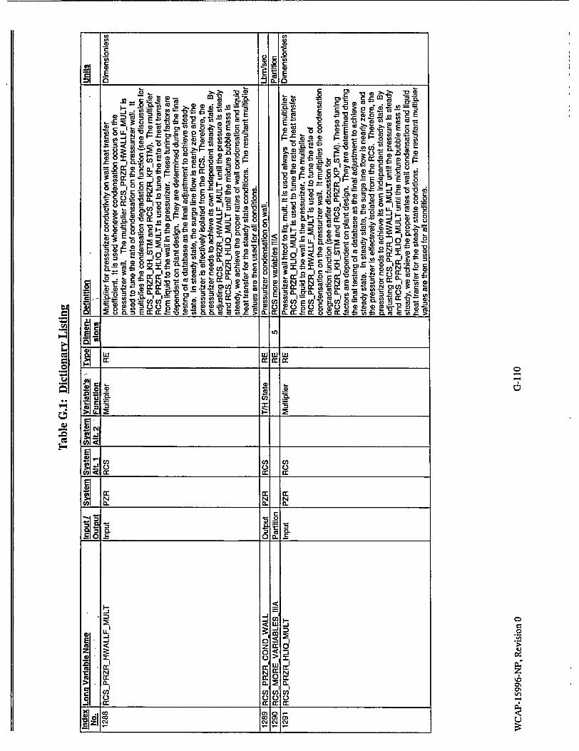

Table G.1: Dictionary Listing
Index Lona Variable Name Input System System System Variable's Typ~ Dimen- Definition Units No. Output Alt. 1 Alt. 2 Function slons
1293 RCS_PRZRJREFTAU Input PZR RCS T/H RE 2 Pressurizer reference leg time constants. Used to calculate a Seconds Dimension temperature that is used only in an instrument signal to the
simulator panels The temperature of the pressurizer's reference leg is dnven by the local containment temperature, by applying a lag function to the temperature, with the lag being RCS_PRZR_TREF_TAU(1) if the leg temperature is decreasing and RCS_PRZRTREFTAU(2) if it is increasing The temperature, TEMPPRZRREF, determines the enthalpy, density, liquid column head in the leg, and the instrument pressure difference. The latter is LEVLPRZR_DP. None of those quantities are used anywhere else in CENTS, but LEVLPRZR_DP is sent to a simulator instrument display. NOTE: The vanables for instrument-calculated measured level, CTL_PRZR_ILEVEL and CTLPRZR_LEVEL_INST are used by the CENTS control system, but are calculated in a separate algorithm. They are not affected by RCS PRZR TREF TAU
1295 RCS MORE VARIABLES IIIB Partition RE 4 RCS more variables IliA Partition
1297 RCS PRZR LEVEL Output PZR RCS T/H State RE RCS pressunzer level (inch from ref.leg bot) Inches
1298 RCS MORE VARIABLES-IV Partition RE 10 RCS more variables IV Partition
1300 RCS_PRZR_DT_SUBC Input PZR RCS T/H State RE Pressurizer delta-temperature for flashing Used in conjunction with Del-DegF RCS_PRZR_DT_SUBH, RCS_PRZR_LVLDT_SUBC(2), and RCS_PRZR_TAUDTSUB. See RCS PRZR DT SUBH for a full description.
1302 RCPDELSPEED_LOCKED Input RCP RCS Component RE RCP locked rotor delta speed (rad/sec). Used only during a Radians/seco Design "locked RCP rotor' malfunction transient, during the time that the nd
pump shaft speed decelerates to zero. This variables specifies the rate at which the pump speed decelerates, in rad/sec per time step. I e, at each time step, subprogram RCP does: RCP_SPEEDPUMP = AMAX1 (RCRPSPEEDPUMP RCP_DELSPEEDLOCKED, 0.0). Since the rate of pump shaft deceleration is impossible to predict in a locked-rotor situation, the value of RCPDELSPEEDLOCKED just needs to be reasonable. It is therefore independent of plant design
1303 RCPFRICCOEFF Input RCP RCS Component RE RCP windage and fnction coefficient. This variable is defined as the Composite Design (pump friction torque)/(motor speed [in radians/sec] 2 ) Units
1307 RCSITERDPL Input RCS RE Dp for convergence at low pressure(equilibrium). Used whenever Psig the system pressure is below 200 psia. This is a convergence critenon for the iterative pressure search. I.e , the solution converges when the pressure change from the last iteration is less than RCSITERDPL It is used whenever a node's pressure is below 200 psia AND the node is in equilibrium. (At higher pressures in equilibrium, the convergence dP Is RCSITERDP, and In nonequilibrium it is RCSJTER_DP_NE.). This parameter is numerical in nature, and is independent of plant design. Reference 1, Section 4.4
WCAP- 15996-NP, Revision 0 G-1Ill

Table G.I: Dictionary Listing
Index Long Variable Name - - n System System System Variablefs Type Dlmen- Definition', ' -. Units.
No. .,.Output Aft. 1 AIL 2 Function slons
1309 RCS MOREVARIABLESV Partition RE 8 RCS more variables V Partition
1313 RCS_PRZRMASSSTM Output PZR RCS RE Pressurizer steam mass Lbm
1314 RCSPRZRMASSAIR Output PZR RCS RE Pressurizer air mass Lbm
1315 RCS-MORE-VARIABLES-VI Partition I RE 14 RCS more variables VI Partition
1320 RCSWPRZRCONT Output PZR RCS RE Mass flow from pressunzer to containment. Lbm/sec
1321 RCSWPRZROT Output PZR RCS RE Mass flow from pressurizer to quench tank (valves). Lbm/sec
1322 RCS PRZRQUALRELIEF Output PZR RCS Initial Cond. RE Pressurizer relief valve flow quality. Fraction
1327 RCSPRZRFRACAIR Output PZR RCS Initial Cond. RE Air mass fraction in pressurizer. Fraction
1328 RCSPRZRKHSTM Input PZR RCS Initial Cond. RE K for enthalpy degradation of the heat transfer coefficient of steam. Dimensionless Used always, in conjunction with RCS-PRZRKP_STM. These are
parameters for the degradation function used in calculating steam condensation on the pressurizer wall. The condensation heat transfer Is calculated based on the various physical parameters (temperatures, steam height, air fraction, heat transfer coefficients),
and is then multiplied by a degradation: 1 - (1 - RCSPRZRKHSTM) * (2250 - PRESS) / (2250 RCSPRZRKPSTM), where PRESS is steam pressure, and the degradation is limited to (0,1]. Typical values for these parameters are KH--0.2 and KP--0.0, respectively, independently of plant design.
1329 RCSPRZRKPSTM Input PZR RCS Initial Cond. RE K for pressure degradation of the heat transfer coefficient for steam. Psia Used always, in conjunction with RCSPRZRKH_STM. These are parameters for the degradation function used in calculating steam condensation on the pressurizer wall. The condensation heat transfer is calculated based on the various physical parameters (temperatures, steam height, air fraction, heat transfer coefficients), and is then multiplied by a degradation: 1 - (1 - RCSPRZRKHSTM) * (2250 - PRESS) / (2250 RCSPRZR_KPSTM), where PRESS is steam pressure, and the degradation is limited to [0,1]. Typical values for these parameters are KH=0.2 and KP=0 0, respectively, independently of plant _design.
1330 RCSMoRE.VARIABLES 504_SR Partition RE 58 RCS more variables partition Partition
1332 RCS PRZRDTSUBBOIL Input PZR RCS T/H RE Pressurizer delta-temperature for boiling. Used always. Del-DegF
Dimension RCSPPRZR_DTSUBBOIL is the amount of subcooling (degF) above which all boiling/flashing ceases and below which the surface condensation stops, In the pressurizer. (See RCSPRZRDTSUBH, RCSPRZRDTSUBC).
1333 RCSRCPVOIDF Output RCP RCS T/H State RE 4 RCP void fraction Fraction
1337 RCS_PRZRCONDSURF Output PZR RCS T/H State RE Pressurizer steam condensation on liquid surface. Lbm/sec
1338 RCSPRZRLEVL LAST Output PZR RCS T/H State RE Pressurizer level last step Feet
1339 RCS PRZRTWALL Output PZR RCS T/H State RE 2 Pressurizer walls temp. 1:hiq, 2: stm Degree F
1340 RCSPRZR 0 CONT Output PZR RCS T/H State RE 2 Pressurizer walls heat to containment Btu/sec
G-112WCAP- 15996-NP, Revision 0

Table G.I: Dictionary Listingi
Index Lona Variable Name input System System System Variable's Type Dimen- Definition Units No. Output Alt. 1 Alt. 2 Function sions
1341 RCS_PRZRQAXWALL Output PZR RCS T/H State RE Pressurizer walls axial heat transfer. This output variable is the Btu/sec heat transferred from the wall region exposed to steam to that exposed to liquid (as determined by the water level at the last time step).
1342 RCS_PRZR_DT_SUBSS Output PZR RCS T/H State RE Pressurizer measure of subcooling to start boiling, in a steady-state Del-DegF mode
1343 RCSPORING Output RCS T/H State RE Inner 0-ring region pressure. If the o-ring has not failed, then Psia pressure is the minimum of the core node & upper head nodal pressures x rtrv._head seal_mult, set by the USER. If the 0-ring has failed (reached RCSORINGFAIL=T, where pressure at the oring is .ge. RCS_P_ORING_FAIL set by the USER), then RCSPORING is the maximum of the(failure pressure) and (the minimum pressure in the upper head and core nodes)
1344 RCSORING_FAIL Input RCS Flag LO Vessel O-nng failure flag. CENTS sets to true when pressure in True False both the core and upper head nodes are .ge. the USER set failure pressure, RCSP_ORING FAIL. Otherwise it is always False
1347 RCSRCP SVOL Output RCP RCS T/H State RE 4 Specific volume in the flow path going through each RCP. Ft3Abm 1354 RCSFAILURESTATUS Partition LO 3 RCS failure status partition Partition 1356 RCS_STEPJAILURE Output RCS Flag LO RCS step failure flag Indicates failure of the flow solution matrix True False
inversion 1358 RCS TIME CONTROL Partition RE 45 Time control partition Partition 1359 RCSTIME SCALE Output RE Time scale for RCS Dimensionless 1362 RCSDELTA T Output RE RCS integration delta t Seconds 1390 RCSMODOUTPUTS Partition RE 60 RCS model global common outputs Partition 1396 RCS MOD OUTPUTS CORE Partition RE 3 CS outputs to 1 -D core Partition 1397 CHTTCOOLAV Output CORE RCS T/H State RE Core coolant average temperature Degree F 1398 CHT SVOLCOOL AV Output CORE RCS T/H State RE Core coolant average specific volume Ft3 Abm 1399 RCS BORON CORE Output CORE RCS Solutes RE Core node boron concentration Parts/million 1400 RCS_MOD_OUTPUTSCHT Partition RE 53 RCS outputs to Core Heat Transfer. These are copies of the values Partition
I_ calculated in the RCS models 1401 RCSCHT PRESS Output CORE RCS T/H State RE Core node pressure Psia 1402 RCS CHT ENTHLIQ Output CORE RCS T/H State RE Core node liquid enthalpy Btu/lbm 1403 RCSCHT ENTHSTM Output CORE RCS T/H State RE Core node steam enthalpy BtuAbm 1404 RCSCHT QUAL Output CORE RCS T/H State RE Core node quality Fraction 1405 RCSCHT FLOWIN Output CORE RCS T/H State RE Core node inlet flow (total minus bypass) Lbm/sec 1406 RCSCHTENTHIN Output CORE RCS T/H State RE Core node inlet enthalpy Btu/Ibm 1407 RCSCHT QUALIN Output CORE RCS T/H State RE Core node Inlet quality Fraction 1408 RCS CHT LEVMIX Output CORE RCS T/H State RE _ Core node mixture height Feet 1409 RCS CHT LEVSAT Output CORE RCS T/H State RE Core node saturation line height Feet 1410 RCSCHTOWALL Output CORE RCS T/H State RE _Core node lower plenum wall heat Btu/sec 1411 RCSCHT TWALL Output CORE RCS _ T/H State RE _ Core node lower plenum wall temperature Degree F 1412 RCS CHT MASSLIQ Output CORE RCS T/H State RE _ Core node liquid mass Lbm
WCAP- 15996-NP, Revision 0 G-113

Table G.I: Dictionary Listing
Index Long Variable Name- ,, Input/ System System System Variable's, Type Dimen- Definition .. , Units_ No• . , • .'-.• "IOutput Alt. 1 Alt. 2 Function slons
1413 RCSCHTMASSBUB Output CORE RCS T/H State RE 22 RCS bubble mass in core (sections) Lbm 1414 RCS_MODINPUTS Partition RE 205 RCS modified inputs Partition
1415 RCSMODJNPUTSBOP Partition RE 50 RCS modified inputs from BOP systems Partition
1416 CHGS_RCSFLOW Output RCS CVCS T/H State RE 4 Charging system flows (RCS connections). This output parameter Lbmnsec from the charging system model supplies the flow from the charging system to the RCS. In the absence of a detailed CVCS model, this flow Is calculated by the Control System model.
1417 CHGS_RCS_ENTH Output RCS CVCS T/H State RE Charging system enthalpy (RCS connection). This output Btu/Ibm parameter from the charging system model supplies the enthalpy of flow from the charging system to the RCS. In the absence of a detailed CVCS model, this enthalpy is calculated by the Control System model.
1418 CHGSRCS-BORON Input / RCS CVCS Solutes RE Charging system boron concentration (RCS connection). In the Partstmillion Init absence of a detailed CVCS model, this parameter is set =RBINIT
dunng INITIALization, and then remains constant, unless changed by the USER during a transient.
1419 CHGSRCSHYD Input I RCS CVCS Solutes RE Charging system hydrogen concentration (RCS connection). In the Lbm/lbm Init absence of a detailed CVCS model, this parameter is set =0 0
during INITIALization, and then remains constant, unless changed by the USER during a transient.
1420 CHGS_RCS_IOD Input / RCS CVCS Solutes RE Charging system iodine conc (RCS connection). In the absence of Mlcrocurlellbm Init a detailed CVCS model, this parameter Is set =0.0 during
INITIALization, and then remains constant, unless changed by the I USER during a transient.
1421 CHGSRCSPART Input / RCS CVCS Solutes RE Charging sys particulate cone (RCS connection). In the absence of Mlcrocurle/Ibm Init a detailed CVCS model, this parameter is set =0 0 during
INITIALization, and then remains constant, unless changed by the USER during a transient.
1422 CHGSRCSXEN Input I RCS CVCS Solutes RE Charging system xenon conc (RCS connection). In the absence of Mlcrocurie/lbm Init a detailed CVCS model, this parameter Is set =0 0 during
INITIALIzation, and then remains constant, unless changed by the _USER during a transient.
1423 CHGS.ASPRAY-FLOW Output RCS CVCS TIH State RE Auxiliary spray flow rate. In the absence of a detailed CVCS model, Lbm/sec _this flow Is calculated by the Control System model.
1424 LDNSRCSFLOW Output RCS CVCS T/H State RE 4 Letdown system flow (RCS connections). This output parameter Lbm/sec from the CVCS model indicates the flow to the letdown line from the RCS. In the absence of a detailed CVCS model, this flow Is calculated by the Control System model.
1425 RCW_RCSFLOW Input RCS RCW TIH State RE 1 Drain flow to waste system (RCS connection). In the absence of a Lbm/sec RCW model, this parameter remains constant, unless changed by
_the USER during a transient. I
WCAP-15996-NP, Revision 0 G-114

Table G.A: Dictionary Listing
Index Long Variable Name Input/ System System System Variable's Type Dimen- Definition Units No Output Alt. 1 AIt. 2 Function slons 1426 SDCRCSFLOW Input / RCS T/H State RE 2 Shutdown cooling out-flow (RCS connection). In the absence of a Lbm/sec
Ind detailed SDC model, this parameter is set --0.0 during INITIALization, and then remains constant, unless changed by the USER during a transient
1427 SIS_RCSFLOW Output RCS SIS TiH State RE 8 SIS flows (RCS connections) This output parameter from the SIS Lbm/sec model indicates the flow from the SI lines to the RCS. This flow for each SI line is the combination of the HPSI, LPSI and SIT flow contributions.
1428 SIS_RCS_ENTH Output RCS SIS T/H State RE 8 SIS enthalpy (RCS connectons). This output parameter from the Btu/lbm SIS model indicates the enthalpy of flow from the SI lines to the RCS. This enthalpy is calculated from the inputs CTLHLPSI_H and CTLSISSITH, weighted by the flow rates from each source (HPSI, LPSI and SITs)
1429 SIS_RCSBORON Output RCS SIS Solutes RE 8 SIS boron concentration (RCS connection). This output parameter Parts/million from the SIS model indicates the boron concentration of flow from the Si lines to the RCS. This boron concentration is calculated from the inputs CTLHLPSI_BC and CTLSIS_SITfBC, weighted by the flow rates from each source (HPSI, LPSI and SITs).
1430 SITANKFLOW Output RCS SIS T/H State RE 4 Safety injection tank flow. This output parameter from the SIS Lbm/sec model indicates SIT flow based upon relative RCS and SIT pressures, flow area, k factors, etc. When added to HPSI and LPSI flow rates, this output becomes a part of SIS RCS FLOW
1431 RCSMODINPUTS VLVCONTR Partition RE 30 RCS mod inputs from valve controllers Partition 1432 VLV RCS_POS Partition Valves RE 24 RCS valve positions (fraction) Fraction 1433 VLVUHEADCONT Input UH RCS Valves Hardware RE Upper head to contain valve position. This input parameter is set by Fraction
Vent State the USER to vent the upper head of the RV to the containment This vent path may be used anytime, though its primary intent is for use during shutdown, cooled down conditions
1434 VLV_UHEAD_QT Input UH RCS Valves Hardware RE 2 Upper head to quench tank valve position. This Input parameter is Fraction Vent State set by the USER to vent the upper head of the RV to the quench
tank. This vent path may be used anytime, though its primary intent is for use during shutdown, cooled down conditions. It requires that the quench tank inputs be developed for a given plant basedeck and the OT model is "on' (MOD OFF QT=F).
1435 VLV_PRZR_PORV Output PZR RCS Valves Hardware RE 4 Pressunzer PORV position In Automatic mode, the position is Fraction State determined by the controller logic, which sets the valve signal as a
function of pressunzer pressure, and operates the valve. In Manual mode, the USER sets the PORV signal via VLVPRZRPORVSIG, and the model operates the PORV accordingly.
1436 VLVPRZRSAFETY Output PZR RCS Valves Hardware RE 4 Pressurizer safety valves position This parameter is determined Fraction State by the PSV controller for each safety valve as a function of the
I____ I__ I•_ I pressurizer pressure and the PSV setpoints. _
WCAP- 15996-NP, Revision 0 G-115
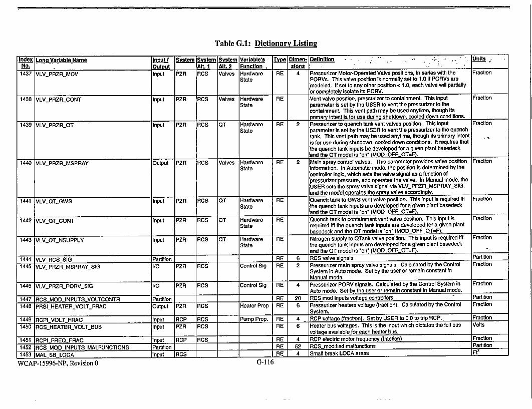
Table G.1: Dictionary Listing
Index Long Variable Name Input/ System System System Variable's ]Type Olmen. Definition , - . -, Units. No. Output Alt. 1 Alt. 2 Function ;slons __ ___
1437 VLVPRZRMOV Input PZR RCS Valves Hardware RE 4 Pressurizer Motor-Operated Valve positions, In series with the Fraction State PORVs. This valve position is normally set to 1.0 if PORVs are
modeled. If set to any other position < 1.0, each valve will partially or completely Isolate Its PORV.
1438 VLVPRZRCONT Input PZR RCS Valves Hardware RE Vent valve position, pressurizer to containment. This Input Fraction State parameter Is set by the USER to vent the pressurizer to the
containment. This vent path may be used anytime, though Its _pnmary intent is for use during shutdown, cooled down conditions.
1439 VLVPRZROQT Input PZR RCS OT Hardware RE 2 Pressurizer to quench tank vent valves position. This Input Fraction State parameter Is set by the USER to vent the pressurizer to the quench
tank. This vent path may be used anytime, though ts primary intent Is for use during shutdown, cooled down conditions. It requires that the quench tank inputs be developed for a given plant basedeck and the OT model Is "on" (MODOFFOT=F).
1440 VLV_PRZR_MSPRAY Output PZR RCS Valves Hardware RE 2 Main spray control valves. This parameter provides valve position Fraction State information. In Automatic mode, the position is determined by the
controller logic, which sets the valve signal as a function of pressurizer pressure, and operates the valve. In Manual mode, the USER sets the spray valve signal via VLVPRZRMSPRAY._SIG, and the model operates the spray valve accordingly.
1441 VLVQT_GWS Input PZR RCS OT Hardware RE Quench tank to GWS vent valve position. This Input is required iff Fraction State the quench tank inputs are developed for a given plant basedeck
and the OT model is *on" (MODOFF OT=F). 1442 VLVQT_CONT Input PZR RCS OT Hardware RE Quench tank to containment vent valve position. This Input Is Fraction
State required iff the quench tank Inputs are developed for a given plant I_ basedeck and the QT model is "on" (MODOFFQT=F).
1443 VLV_QTNSUPPLY Input PZR RCS OT Hardware RE Nitrogen supply to WTank valve position. This input is required iff Fraction State the quench tank inputs are developed for a given plant basedeck
land the QT model is "on" (MODOFFOT=F). %
1444 VLVRCSSIG Partition RE 6 RCS valve signals Partition
1445 VLV_PRZRMSPRAYSIG I/O PZR RCS Control Sig RE 2 Pressurizer main spray valve signals. Calculated by the Control Fraction System in Auto mode. Set by the user or remain constant in Manual mode.
1446 VLVPFRZR_PORVSIG I/O PZR RCS Control Sig RE 4 Pressurizer PORV signals. Calculated by the Control System In Fraction Auto mode. Set by the user or remain constant in Manual mode.
1447 RCSMODINPUTSVOLTCONTR Partition RE 20 RCS mod Inputs voltage controllers Partition
1448 PRSIHEATERVOLTFRAC Output PZR RCS Heater Prop RE 6 Pressurizer heaters voltage (fraction). Calculated by the Control Fraction System.
1449 RCPI-VOLT FRAC Input RCP RCS Pump Prop. RE 4 RCP voltage (fraction). Set by USER to 00 to trip RCP. Fraction
1450 RCSHEATERVOLT-BUS Input PZR RCS RE 6 Heater bus voltages. This is the Input which dictates the full bus Volts voltage available for each heater bus.
1451 RCPI_ FREQFRAC Input RCP RCS RE 4 RCP electric motor frequency (fraction) Fraction
1452 RCSMODINPUTS MALFUNCTIONS Partition RE 52 RCS modified malfunctions Partition
1453 MAL SB LOCA Input RCS RE 4 Small break LOCA areas Ft2
WCAP- 15996-NP, Revision 0 G-116
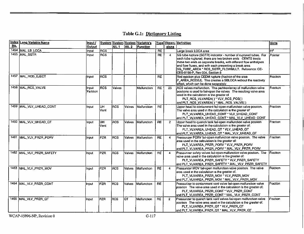
Table G.I: Dictionary Listing
Index Lona Variable Name Input/ System System System Variable's Type Dimen- Definition Units No. Output Alt. 1 Alt. 2 Function slons
1454 MAL LB LOCA Input RCS RE Large break LOCA area Ft2
1455 MALSGTR Input RCS RE 4 SG tube rupture (SGTR) indicator - number of ruptured tubes. For Pointer each tube ruptured, there are two broken ends CENTS treats these two ends as separate breaks, with different flow enthalpies and flow fluxes, and with each presenting a break area SG_TUBEAREA * RCS_SGTR_FLOWMULT. Reference: CECES-0198-P, Rev 004, Section 8
1457 MALROD_EJECT Input RCS RE Rod ejection plus CEDM rupture (fraction of the area Fraction P_AREARODEJ). This creates a SBLOCA without the reactivity effect, which can be done separately.
1458 MAL_RCS_VALVE Input RCS Valves Malfunction RE 25 RCS valves malfunction. This partition/array of malfunction valve Fraction Partition positions is used to fail-open the valves The resulting valve area
used in the calculation is the greater of PLT_RCS_VLVAREAO ) VLVRCS_POS()
and PLT RCSVLVAREA() * MAL RCS VALVE() 1459 MALVLVUHEADCONT Input UH RCS Valves Malfunction RE Upper head to containment fail-open malfunction valve position. Fraction
Vent The valve area used in the calculation is the greater of, PLT_VLVAREA_UHEADCONT * VLV_UHEAD_CONT
and PLT VLVAREA UHEAD CONT *MAL VLV UHEAD CONT 1460 MALVLVUHEADOT Input UH RCS Valves Malfunction RE 2 Upper head to quench tank fail-open malfunction valve position Fraction
Vent The valve area used in the calculation is the greater of: PLTVLVAREAUHEADQT * VLVUHEADQT
land PLT VLVAREA UHEADQT *MAL VLVUHEAD OT 1461 MAL_VLV_PRZR_PORV Input PZR RCS Valves Malfunction RE 4 Pressurizer PORV fail-open malfunction valve position. The valve Fraction
area used in the calculation is the greater of: PLT_VLVAREA_PRZR_PORV * VLV_PRZRPORV
and PLT_VLVAREA PRZR PORV *MAL VLV PRZR PORV 1462 MALVLVPRZRSAFETY Input PZR RCS Valves Malfunction RE 4 Pressunzer safety valves fail-open malfunction valve position. The Fraction
valve area used in the calculation is the greater of: PLT_VLVAREA_PRZR_SAFETY - VLV_PRZRSAFETY
and PLT VLVAREA PRZR SAFETY * MAL VLV PRZR SAFETY 1463 MAL_VLV_PRZR_MOV Input PZR RCS Valves Malfunction RE 4 Pressurizer MOV fail-open malfunction valve position. The valve Fraction
area used in the calculation is the greater of. PLT_VLVAREA_PRZR_MOV * VLVPRZRMOV
and PLT VLVAREA PRZR MOV* MAL VLV PRZR MOV 1464 MALVLVPRZRCONT Input PZR RCS Valves Malfunction RE Pressurizer to containment vent valve fail-open malfunction valve Fraction
position The valve area used in the calculation is the greater of: PLT_VLVAREAPRZR_CONT * VLVPRZRCONT
and PLT VLVAREA PRZR CONT * MAL VLV PRZRCONT 1465 MALVLV_PRZRQT Input PZR RCS OT Malfunction RE 2 Pressurizer to quench tank vent valves fail-open malfunction valve Fraction
position The valve area used in the calculation is the greater of. PLT_VLVAREAPRZR_QT * VLVPRZRQT
and PLTVLVAREAPRZR_QT * MAL VLV_PRZRQT
WCAP- 15996-NP, Revision 0 G-117

Table G.1: Dictionary Listing
Index Long Variable Name Input/ System System System Variable's , T Dlmen- Definition Units No.__=. : Outt, ut Alt. 1 Alt. 2 Function slons
1466 MAL_VLV_PRZRMSPRAY Input PZR RCS Valves Malfunction RE 2 Main spray control valves fail-open malfunction valve position. The Fraction valve area used in the calculation is the greater of:
PLTVLVAREAYPRZRMSPRAY - VLV_PRZR_MSPRAY and PLTYLVAREAPRZRMSPRAY 'MAL VLV PRZRMSPRAY
1467 MALVLV.QTGWS Input PZR RCS OT Malfunction RE Quench tank to GWS vent valve fail-open malfunction valve Fraction position. The valve area used in the calculation Is the greater of:
PLT_VLVAREA_QT_GWS * VLV_QTGWS and PLT_VLVAREA_QT_GWS * MAL_VLV_QTGWS
1468 MAL_VLV_QT_CONT Input PZR RCS QT Malfunction RE Quench tank to containment vent valve fail-open malfunction valve Fraction position. The valve area used in the calculation is the greater of:
PLTVLVAREAQTCONT - VLV-_QT_CONT -,
_and PLT-_VLVAREA-QT1CONT * MAL_VLVQTCONT 1469 MALVLVQT_NSUPPLY Input PZR RCS QT Malfunction RE Nitrogen supply to QTank valve fail-open malfunction valve position. Fraction
The valve area used in the calculation Is the greater of: PLTLVLVAREAQTNSUPPLY * VLV._QT._NSUPPLY
and PLTJVLVAREA-QTLNSUPPLY * MALVLV_QT_NSUPPLY
1470 MAL RCP SHAFTBREAK Input RCP RCS Malfunction LO 4 RCP shaft break malfunction True False
1471 MAL.RCPLOCKED Input RCP RCS Malfunction LO 4 RCP locked rotor malfunction True False
1474 RCSMOD INPUTS CONT Partition RE 2 RCS modified inputs from containment Partition 1475 CONT PRES Input RCS RE Containment pressure Psia
1476 QT MOD INPUTS Partition RE 5 Quench tank modified Inputs Partition
1477 DMW_QTFLOW Input PZR RCS RE Demineralized water flow to quench tank. This Input is used iff the Lbm/seoc quench tank inputs are developed for a given plant basedeck and the OT model is "on" (MODOFFQT=F).
1478 DMWOT_ENTH Input PZR RCS RE Demineralized water enthalpy. This Input is used iff the quench Btu/Ibm tank inputs are developed for a given plant basedeck and the OT model Is "on" (MOD_OFF QT=F).
1479 RCW_QT_FLOW Input PZR RCS RE Mass flow QT to RCW. This input Is used iff the quench tank Lbm/sec Inputs are developed for a given plant basedeck and the QT model is "on" (MODOFFQT=F).
1480 GWS_QT_PRES Input PZR RCS RE GWS pressure. This Input Is used iff the quench tank Inputs are Psia developed for a given plant basedeck and the OT model Is "on" (MODOFFQT=F).
1481 GWS_QTFLOW Input PZR RCS RE Gas flow quench tank to GWS. This input Is used iff the quench Lbm/sec tank inputs are developed for a given plant basedeck and the QT model is "on" (MODOFFQT=F). I
1482 RCSINPUTS PRZR RELIEF Partition RE 33 Pressurizer relief valves discharge model Partition
WCAP-15996-NP, Revision 0 G-1 18


Table G.1: Dictionary Listing
Index Lonq Variable Name - Input System Systen. System Variable's . Type Dimen- Definition -. Un.ts.. .
No. Output Ait. 1 Alt. 2 Function slons '2
1486 VLV_PRZR_FLOWTABLE Input PZR RCS Przr RE 15 Pressurizer relief valve flow table: dependent variable. Used when Undefined
Relief the relief flow quality > VLV_PRZRQUALDF and VLV\IPRZR_FLOWOPTION = 2 or 3:
2 - A Bemouli formulation for orifice type flow Is applied
independently of throat pressure. It Is multiplied by a discharge
coefficient Cd that is given by this table VLV_PRZR_FLOW_TABLE (Cd) vs. VLV_PRZR_PROPTABLE (subcooling, DegF). 3 - The flux is given directly by this table of VLVPRZRFLOWTABLE (flux, Ibmlsec-ft2) vs. VLV_PRZR_PROPTABLE (upstream pressure, Psla).
The table contains VLVPRZRNPOINTSTAB points.
1487 VLVPRZRPROPTABLE Input PZR RCS Przr RE 15 Pressunzer relief valve flow table: independent variable. Used Undefined
Relief when the relief flow quality > VLV_PRZR_QUALDF and VLVPRZRFLOWOPTION = 2 or 3
2 - A Bemouli formulation for orifice type flow is applied independently of throat pressure. It is multiplied by a discharge
coefficient Cd that Is given by the table VLVPRZR_FLOW_TABLE (Cd) vs. this table VLV_PRZRPROPTABLE (subcooling, DegF).
3 - The flux is given directly by the table of VLV_PRZR_FLOW_TABLE (flux, Ibm/sec-ft2) vs. this table VLV_PRZR_PROPTABLE (upstream pressure, Psla).
The table contains VLVPRZRNPOINTSTAB points.
1488 RCSINITIALCONDITIONS Partition I RE 15 RCS initial conditions Partition
1489 RPINIT Input RCS Initialization RE New initial pressunzer pressure (psla, in steam space). This Is a Psla
case dependent variable set by the USER to determine the initial conditions. CENTS uses this input as one of the required parameters to initialize the code. It Is used in conjunction with
RLINIT(pressurizer level), RWINIT(RCS total flow), RTCLIN(RCS cold leg temperature), RBINIT(RCS initial boron concentration), kfrain(initial power fraction), SLINIT(SG water level), CTL_FWS_.H(initial FW enthalpy). These variables dictate the initial
T/H conditions required by CENTS to calculate an overall plant heat
and flow balance. Reference 1, Appendix D.
1490 RLINIT Input RCS Initialization RE New Initial pressurizer level (feet, actual level). This Is a case Feet
dependent variable set by the USER to determine the initial
conditions. CENTS uses this input as one of the required parameters to Initialize the code. It Is used in conjunction with
RPINIT(pressurlzer pressure), RWINIT(RCS total flow), RTCLIN(RCS cold leg temperature), RBINIT(RCS Initial boron
concentration), kfrain(initial power fraction), SLINIT(SG water level),
CTL_FWS_H(initial FW enthalpy). These variables dictate the Initial T/H conditions required by CENTS to calculate an overall plant heat
I _ land flow balance. Reference 1, Appendix D. .... )_n
WCAP-1599o-iNI, Revision u U'L•U


Table G.A: Dictionary Listing
Index Long Variable Name Input System System System Variable's Tiype Dimen- Definition ., Units No. Output Alt. 1 Alt. 2 Function slons° - _ _ _ _ _ _ _
1499 RCS_SG_SECTDH Input RCS SG Model RE Tolerance for SG node saturation hysteresis. Typical value = 10.. BTU/LbM Design Used in switching logic for number of sections. In positive, single
phase flow, the requested number of sections from NUMSG-SECT is used. However, in two-phase or reverse flow, the code reduces the number of sections to 1 per node, since the sectioning scheme is not guaranteed to match the overall nodal state under those conditions. Thus, as an example, if each of 4 tube nodes had 10 sections in the sectioning scheme, the number of sections comprising the entire tube length of each SG can vary between 4 and 40. The actual (dynamic) number of sections employed in each node is stored In the array RCS_SG_NSECT. The switching logic Is that the number of sections collapses to one per node if that node reaches saturation enthalpy. It stays at one section unless the node becomes subcooled by at least the value of RCSSGSECT_DH. Usually the User will make this value sufficiently large to keep the node from erratic switching in the number of sections. Reference 1, Section 5.3.
1500 RCSSGSECT_DW Input RCS SG Model RE Tolerance for SG node flow hysteresis. Used In switching logic for Lbm/sec Design number of sections. Typical value = 2000. In positive, single-phase
flow, the requested number of sections from NUMSGSECT is used. However, in two-phase or reverse flow, the code reduces the number of sections to 1 per node, since the sectioning scheme is not guaranteed to match the overall nodal state under those conditions. Thus, as an example, if each of 4 tube nodes had 10 sections In the sectioning scheme, the number of sections comprising the entire tube length of each SG can vary between 4 and 40. The actual (dynamic) number of sections employed in each node is stored in the array RCSSGNSECT. The switching logic is that the number of sections collapses to one per node if that node's fluid flow reverses direction. It stays at one section unless the node flow Increases to the value of RCSSG_SECT_DW. Usually the User will make this value sufficiently large to keep the node from erratic switching in the number of sections. Reference 1, Section
15.3
1501 RCS_SG_SECTLH Output RCS SG T/H State LO 16 State of SG node saturation hysteresis. Used In switching logic for True False number of sections. Reference 1, Section 5.3.
1502 RCS_SGSECT_LW Output RCS SG T/H State LO 16 State of SG node flow hysteresis. Used in switching logic for True False number of sections. Reference 1, Section 5 3.
WCAP- 15996-NP, Revision 0 G-122
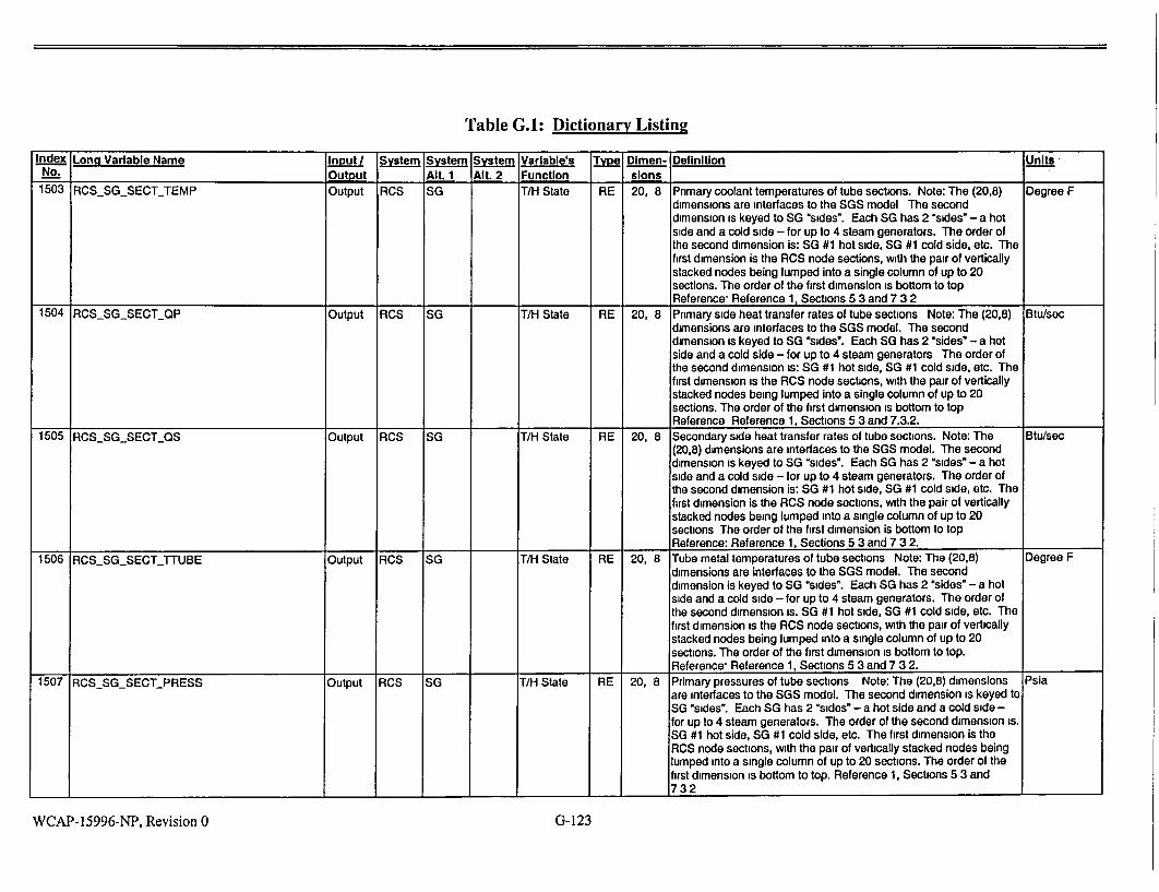
Table G.I: Dictionary Listing
Index Lona Variable Name Input System System System Variable's Type Dimen- Definition Units No. Output Alt. 1 Alt. 2 Function slons
1503 RCSSGSECTTEMP Output RCS SG T/H State RE 20, 8 Primary coolant temperatures of tube sections. Note: The (20,8) Degree F dimensions are interfaces to the SGS model The second dimension is keyed to SG "sides". Each SG has 2 "sides" - a hot side and a cold side - for up to 4 steam generators. The order of the second dimension is: SG #1 hot side, SG #1 cold side, etc. The first dimension is the RCS node sections, with the pair of vertically stacked nodes being lumped into a single column of up to 20 sections. The order of the first dimension is bottom to top Reference, Reference 1, Sections 5 3 and 7 3 2
1504 RCS_SGSECTQP Output RCS SG T/H State RE 20, 8 Primary side heat transfer rates of tube sections Note: The (20,8) Btu/sec dimensions are interfaces to the SGS model. The second dimension is keyed to SG "sides". Each SG has 2 "sides" - a hot side and a cold side - for up to 4 steam generators The order of the second dimension is: SG #1 hot side, SG #1 cold side, etc. The first dimension is the RCS node sections, with the pair of vertically stacked nodes being lumped into a single column of up to 20 sections. The order of the first dimension is bottom to top Reference Reference 1, Sections 5 3 and 7.3.2.
1505 RCS_SGSECTQS Output RCS SG T/H State RE 20, 8 Secondary side heat transfer rates of tube sections. Note: The Btu/sec (20,8) dimensions are interfaces to the SGS model. The second dimension is keyed to SG "sides". Each SG has 2 "sides" - a hot side and a cold side - for up to 4 steam generators. The order of the second dimension is: SG #1 hot side, SG #1 cold side, etc. The first dimension is the RCS node sections, with the pair of vertically stacked nodes being lumped into a single column of up to 20 sections The order of the first dimension is bottom to top Reference: Reference 1, Sections 5 3 and 7 3 2.
1506 RCSSGSECT_-TTUBE Output RCS SG T/H State RE 20, 8 Tube metal temperatures of tube sections Note: The (20.8) Degree F dimensions are interfaces to the SGS model. The second dimension is keyed to SG "sides". Each SG has 2 "sides" - a hot side and a cold side - for up to 4 steam generators. The order of the second dimension is. SG #1 hot side, SG #1 cold side, etc. The first dimension is the RCS node sections, with the pair of vertically stacked nodes being lumped into a single column of up to 20 sections. The order of the first dimension is bottom to top. Reference- Reference 1, Sections 5 3 and 7 3 2.
1507 RCSSGSECTPRESS Output RCS SG T/H State RE 20, 8 Primary pressures of tube sections Note: The (20,8) dimensions Psia are interfaces to the SGS model. The second dimension is keyed to SG "sides". Each SG has 2 "sides" - a hot side and a cold side for up to 4 steam generators. The order of the second dimension is. SG #1 hot side, SG #1 cold side, etc. The first dimension is the RCS node sections, with the pair of vertically stacked nodes being lumped into a single column of up to 20 sections. The order of the first dimension is bottom to top. Reference 1, Sections 5 3 and
1 1_732
WCAP-15996-NP, Revision 0 G-123

Table G.I: Dictionary Listing
Index Long Varable Name Input System System System Variable's Tyej DImen- Definition - Units
No. ___--______Output AIL t - Alt. 2 Function, sons
1508 SGSNSECT Output RCS SG T/H State IN 8 Number of sections in each SG side (I e. hot side & cold side). If Counts there are four tube nodes per SG, then the two hot side nodes' sections are added together and the two cold side nodes' sections
are added together for each SG. Reference 1, Section 5.3.
1509 RCSSGSECTTOPT Input RCS SG Model IN Optional primary temperature model for heat transfer. 0 => Exit Pointer
Design temp. 1 => LMTD-based temperature. The 0 option is included to allow the previous code model to be duplicated. Usually, the USER
will choose LMTD based temperature as the most realistic representation of the fluid temperature. For Option 1 (LMTD) TEMPI = TSEC + (Tim - Ti) / in [(Tim - TSEC) / (Ti - TSEC)], where,
TEMPI = Mean temperature of section i; TSEC = Temperature of the SG evaporator region; Tim = Temperature at bottom of section; "lTi = Temperature at top of section. Reference 1, Section 5.3.
1510 RCSSGSECTENTH Output RCS SG T/H State RE 11, 16 Section-bottom enthalples (section.node). Reference 1, Section 5.3. Btu/'bm
1511 SGTR DATA Partition RCS SG SGTR 28 Data for SGTR Model
1512 SGTR TUBELENGTH Input RCS SG SGTR RE 8 SGTR tube length. 2 values per generator. The first value is for the Feet hot side, the second for the cold side. Reference 1, Section 5.7 and 7.5.
1513 SGTRJTUBEENTRANCEK Input RCS SG SGTR RE 8 SGTR Entrance K factor. Normally set to 0.5. Provide 2 values per Dimensionless
steam generator. The first value is for the hot side, the second for the cold side. Reference 1, Section 5.7 and 7.5..
1514 SGTRBREAKELEV Input RCS SG SGTR RE 4 SGTR elevation above tube sheet. Provide 1 value per steam Feet
generator. Reference 1, Section 5.7 and 7.5.
1515 SGTR SLOTBREAKOPT Input RCS SG SGTR LO 4 SGTR Option to calculate SGTR break flow using a slot break flow Dimensionless model rather than double ended guillotine break. Reference 1,
Section 5.7 and 7.5.
1516 SGTRSLOTBREAK AREA Input RCS SG SGTR RE 4 SGTR Slot area per tube, used only when the flag FtA2
SGTRSLOTBREAKOPTION is true. Reference 1, Section 5.7
and 7.5.
1517 SB LOCAPIPEDATA Partition RCS SBLOCA RE 20 Data for SBLOCA pipe loss model Partition
1518 SBPIPEAREA Input RCS SBLOCA RE 4 SBLOCA pipe flow area between RCS and break. Reference 1, FtA2
Section 4.21.2 and 7.5.
1519 SBPIPELOD Input RCS SBLOCA RE 4 SBLOCA pipe length/diameter from RCS to break. Reference 1, Dimensionless
-__-_•_Section 4 21.2 and 7.5.
1520 SB1PIPE-KGEOM Input RCS SBLOCA RE 4 SBLOCA pipe geometric loss k-factor from RCS to break, excluding Dimensionless
entrance loss Reference 1, Section 4.21.2 and 7.5.
1521 SBYPIPE-KENT Input RCS SBLOCA RE 4 SBLOCA pipe entrance loss k-factor at the RCS connection. Dimensionless
Reference 1, Section 4.21.2 and 7.5.
1522 SBDELTAELEV Input RCS SBLOCA RE 4 SBLOCA break elevation above RCS connection Reference 1, Feet
-_ _Section 4.21.2 and 7.5.
1523 CVCSDATA Partition RCS CVCS Piping Def RE 50 CVCS model data Partition
1524 LDNPIPEDATA Partition RCS CVCS Piping Def RE 20 Input data for letdown line loss model. Reference 1, Section 4.21.1 Partition
and 7.5. 1_____
G-124WCAP-15996-NP, Revision 0

Table G.I: Dictionary Listing Index Long Variable Name Input System System System Variable's Type Dlmen- Definition Units
No. Output AIt. 1 Alt 2 Function sions 1525 LDN_PIPEAREA Input RCS CVCS Piping Def RE 2 Letdown line flow area FtA2
(1) = line from RCS to regenerative heat exchanger (RHX) (2) = line from RHX to the break, if any Reference 1, Section 4.21.1 and 7 5
1526 LDNPIPELOD Input RCS CVCS Piping Def RE 2 Letdown line length/diameter. Dimensionless
(1) = line from RCS to regenerative heat exchanger (RHX) (2) = line from RHX to the break, if any. Reference 1, Section 4.21.1 and 7 5
1527 LDN_PIPEKGEOM Input RCS CVCS Piping Def RE 2 Letdown line geometric loss factor, excluding entrance losses. Dimensionless
(1) = line from RCS to regenerative heat exchanger (RHX) (2) = line from RHX to the break, if any.
Reference 1, Section 4 21 1 and 7 5 1528 LDNPIPEKENT Input RCS CVCS Piping Def RE 2 Letdown line entrance loss k-factor. Dimensionless
(1) =at RCS connection (2) = at entrance to regenerative heat exchanger. Reference 1, Section 4 21 1 and 7.5.
1529 LDNPIPE_DELTAELEV Input RCS CVCS Piping Def RE 2 Letdown line elevation rise Feet (1) = line from RCS to regenerative heat exchanger (RHX) (2) = line from RHX to the break, if any Reference 1, Section 4 21 1 and 7 5
1530 MALLDNBREAK Input RCS CVCS Break RE Letdown line break area FtA2
When MALLDNBREAK > 0, the break is located in the letdown line downstream of the regenerative heat exchanger (RHX) When MALLDNBREAK < 0, the break is located in the first letdown line upstream of the RHX. (The number of active letdown lines from the RCS to the RHX is RCS NUMOUTLDNS < 4) Reference 1, Section 4 21 1 and 7 5
1531 CVCSRHXDATA Partition RCS CVCS State RE 30 CVCS model calculated data Partition 1532 CVCSRHXTLDN Output RCS CVCS State RE 2 Letdown temperature at regenerative heat exchanger (1) inlet DegreeF
1 1 _ (2) exit. 1533 CVCSRHXTCH Output RCS CVCS State RE 2 Charging temperature at regenerative heat exchanger (1) inlet DegreeF
(2) exit 1534 CVCS RHX HLDN Output RCS CVCS State RE 2 Letdown enthalpy at regenerative heat exchanger (1) inlet (2) exit BtuAbm 1535 CVCS RHX HCH Output RCS CVCS State RE 2 Charging enthalpy at regenerative heat exchanger (1) inlet (2) exit BtuA/bm 1536 CVCS RHX WLDN Output RCS CVCS State RE Letdown mass flow rate Lbrn/sec 1537 CVCS RHX WCH Output RCS CVCS State RE Charging mass flow rate Lbm/sec 1538 CVCSRHXHEAT Output RCS CVCS State RE Regenerative heat exchanger heat load Btu/sec 1539 LDNRCS ENTH Output RCS CVCS State RE 4 Enthalpy at letdown line RCS connections BtuAbm 1540 LDN_RCS_PRES Output RCS CVCS State RE 4 Pressure at letdown line RCS connections Psia 1541 SGSCOMMON Segment RE 1536 SG secondary global common variables Segment 1542 SGS INTERNAL Partition RE 400 SG secondary internal variables Partition 1543 SGS BOT P Output SG T/H State RE 4 Fluid pressure at SG tube sheet Psia
WCAP-15996-NP, Revision 0 G-125

Table G.A: Dictionary Listing
Index Long Variable Name, Input System System System Variable's Type Dlmen- Definition . ... ,Unts
,No.- . Output AIlt1 Alt. 2 Function slons
1544 SGS CON 101 Output SG Solutes RE 4 SG steam node Iodine concentration Microcude/Ibm 1545 SGS-CON 102 Output SG Solutes RE 4 SG evaporator and downcomer nodes iodine concentration Microcude/lbm 1546 SGSCONPT1 Output SG Solutes RE 4 SG steam node particulates concentration Microcurle/lbm 1547 SGS CON PT2 Output SG Solutes RE 4 SG evaporator and downcomer nodes particulates concentration Microcure/lbm 1548 SGSCON_XE1 Output SG Solutes RE 4 SG steam node xenon concentration Microcudeflbm 1549 SGS_CON XE2 Output SG Solutes RE 4 SG evaporator and downcomer nodes xenon concentration Microcudeflbm 1550 SGSCONBORONi Output SG Solutes RE 4 SG steam node boron concentration Parts/million 1551 SGSCONBORON2 Output SG Solutes RE 4 SG evaporator and downcomer nodes boron concentration Parts/million 1552 SGS_DELTV Input SG Model RE 4 Multiplier on steam velocity. This is an adjustment multiplier on the Dimensionless
Design calculated steam separation velocity in the steam generator evaporator. It Is a tuning factor available to tune for steady state, but is normally not used for this purpose. This Is an array of tuning factors, independent of plant design. SGS DELTV should normally be 1.0.
1553 SGSDP Output SG T/H State RE 3, 4 Level Instrum. delta press (refleg, sg) Psid
1554 SGSDVDP Output SG T/H State RE 4 Slope of volume(pressure) curve. Used always, and recalculated Feet3/ Psi always. This Is the slope of the volume-vs-pressure curve, used in the steam generator Iterative pressure solution. It is used as the initial guess for the slope, and is recalculated dynamically during the iterative solution. The Initial slope will have no effect on the
____solution, as long as it is *in the ballpark*. (Typical initial value: 20.)
1555 SGSENTHI Output SG T/H State RE 4 SG steam node average specific enthalpy Btu/lbm
1556 SGSENTH2 Output SG T/H State RE 4 SG evaporator node average sp. enthalpy BtuAbmr
1557 SGS ENTH3 Output SG T/H State RE 4 SG downcomer node average sp. enthalpy Btu/Ibm
1560 SGS El Output SG T/H State RE 4 SG steam dome node total energy. Btu
1561 SGS E2 Output SG T/H State RE 4 SG evaporator node total energy Btu
1562 SGS_E3 Output SG T/H State RE 4 SG downcomer node total energy Btu
1565 SGS HF Output SG T/H State RE 4 SG saturated liquid specific enthalpy Btu/Ibm
1566 SGS HG Output SG T/H State RE 4 SG saturated steam specific enthalpy Btu/lbm
1567 SGSHLEVEL Output SG T/H State RE 4 SG downcomer coolant level Feet
1568 SGSHT2 Output SG T/H State RE 4 SG evaporator coolant level. This is the 2-phase level calculated by Feet CENTS form the evaporators masses, specific volumes and volume to height dependency. Normally, until lower power levels (steaming rates), evaporator volume Is full of 2-phase flow to the separators.
1569 SGSHT3 Output SG T/H State RE 4 SG downcomer coolant level. This Is the actual 2-phase level in the Feet downcomer calculated by CENTS.
1570 SGS_HTI Output SG T/H State RE 4, 3 Instrument-measured water levels (SG,Ieg) This is calculated by Feet CENTS from the actual SG water level, and the known specific volumes and reference leg and calibration information for the instruments.
1571 SGSM1 Output SG T/State RE 4 SG steam node total mass Lbm
1572 SGSM2 Output SG I _ T/H State RE 4 SG evaporator node total mass ILbm
G-126WCAP- 15996-NP, Revision 0

Table G.I: Dictionary Listing
Index Lona Variable Name Input/ System System System Variable's Type Dimen- Definition Units No. Output Alt. 1 Alt. 2 Function slons 1573 SGS M3 Output SG T/H State RE 4 SG downcomer node total mass Lbm 1576 SGS P Output SG T/H State RE 4 SG steam node pressure Psia 1577 SGS RECIRC Output SG T/H State RE 4 SG evaporator to downcomer flow ratio Dimensionless 1578 SGS RHO1 Output SG T/H State RE 4 SG steam node density Lbml/ft 3
1579 SGS RHO2 Output SG T/H State RE 4 SG evaporator node density Lbm/ft3
1580 SGS RHO3 Output SG T/H State RE 4 SG downcomer node density Lbrm/ft 3
1583 SGS SV1 Output SG T/H State RE 4 SG steam node average specific volume Ft 3 /Ibm 1584 SGSSV2 Output SG T/H State RE 4 SG evaporator node average spec volume Ft3 Abm 1585 SGS SV3 Output SG T/H State RE 4 SG downcomer node average spec. volume Ft3 /Ibm 1588 SGS TREFLG Output SG T/H State RE 4 SG reference leg water temperature Degree F 1589 SGS TWALL Output SG T/H State RE 4 SG wall metal temperature Degree F 1590 SGS T1 Output SG T/H State RE 4 SG steam node temperature Degree F 1591 SGS T2 Output SG T/H State RE 4 SG evaporator node temperature Degree F 1592 SGS T3 Output SG T/H State RE 4 SG downcomer node temperature Degree F 1595 SGS USTM Output SG T/H State RE 4 Steam velocity leaving separators Ft/sec 1596 SGS VF Output SG T/H State RE 4 SG saturated liquid specific volume Ft3 /Abm 1597 SGS VF2 Output SG T/H State RE 4 SG evaporator node liquid spec. volume Ft3 Abm 1598 SGS VF3 Output SG T/H State RE 4 SG downcomer node liquid specific volume Ft3 /Abm 1601 SGS VG Output SG T/H State RE 4 SG saturated steam specific volume Ft3 /Abm 1602 SGS V1 Output SG T/H State RE 4 SG steam node total volume Ft3
1603 SGS V2 Output SG T/H State RE 4 SG evaporator node total volume Ft3
1604 SGS V3 Output SG T/H State RE 4 SG downcomer node total volume Ft 3
1607 SGS WF1 Output SG T/H State RE 4 SG steam node liquid mass Lbm 1608 SGS WF2 Output SG T/H State RE 4 SG evaporator node liquid mass Lbm 1609 SGS WF3 Output SG _T/H State RE 4 SG downcomer node liquid mass Lbm 1612 SGS WG1 Output SG T/H State RE 4 SG steam node steam mass Lbm 1613 SGS WG2 Output SG T/H State RE 4 SG evaporator node steam mass Lbm 1614 SGS WG3 Output SG T/H State RE 4 SG downcomer node steam mass Lbm 1617 SGS W13 Output SG T/H State RE 4 Steam node to downcomer flowrate Lbm/sec 1618 SGS W21 Output SG T/H State RE 4 SG evaporator to steam node flow rate Lbm/sec 1619 SGS W23 Output SG T/H State RE 4 Evaporator to downcomer circulation flow Lbm/sec 1620 SGS W31 Output SG I T/H State RE 4 Downcomer to steam node vaporization flow rate Lbmlsec 1621 SGS W32 Output SG T/H State RE 4 SG downcomer to evaporator flow rate Lbm/sec 1626 SGS WOUTSG Output SG T/H State RE 8 SG steam outlet nozzle flow Lbm/sec 1627 SGS_Xl Output SG T/H State RE 4 SG steam node quality Fraction 1628 SGS X2 Output SG T/H State RE 4 SG evaporator node quality Fraction 1629 SGS_X3 Output SG T/H State RE 4 SG downcomer node quality Fraction 1632 SGSFLOWCHOKED Output SG TiH State LO 8 Flag" steam flow choked at restrictor True False 1633 SGS HEAT Partition RE 60 SG heat transfer variables Partition 1634 SGT_RCSQHOT Output SG RCS T/H State RE 4 SG hot side RCS-to-tube heat transfer Btu/sec
G- 127WCAP- 15996-NP, Revision 0

Table G.1: Dictionary Listing
Index Long Variable Name - Input System System System Variable's Type Dlmen- Definition , Units •,< No. OutDut AIt. 1 Alt 2 Function sions ,.
1635 SGTSGQHOT Output SG T/H State RE 4 Hot side tube-to-secondary heat transfer Btu/sec
1636 SGT RCS_0COLD Output SG RCS T/H State RE 4 SG entire cold side RCS-to-tube heat tr. Btu/sec
1637 SGTSGOQCOLD Output SG T/H State RE 4 Entire cold side tube-to-secy heat trans Btulsec
1640 SGTTEMP HOT Output SG T/H State RE 4 SG hot side tube metal temperature Degree F
1641 SGTTEMPCOLD Output SG T/H State RE 4 SG cold side tube metal temp, evaporator Degree F
1643 SGSHEATLOAD Output SG T/H State RE Total secondary side heat load Btu/sec
1644 SGS_0_CONT Output SG T/H State RE 4 SG wall-to-containment heat rate Btulsec
1645 SGSOWALLI Output SG T/H State RE 4 SG steam node steam-to-wall heat rate Btu/sec
1646 SGS_Q0WALL3 Output SG T/H State RE 4 SG downcomer node lig-to-wall heat rate Btu/sec
1647 SGSSTEAMLINE Partition RE 390 SG steam line vanables Partition
1648 MSLHSTATE Partition RE 40 Steamllne header vanables Partition
1649 MALMSLBOUT Input MSL Malfunction IN Steamline break in MSLH flag: 0=>no 1-->yes. The break area is Flag:; MSLB •AREA. Reference 1, Section 7.5.2.
1650 MSLBOUTFLOW Output MSL RE Steamline break outside containment flow rate. Reference 1, Lbm/sec Section 7.5.2.
1651 MSLH CON_1O Output MSL Solutes RE MSLH node Iodine concentration. This variable refers to the Mlcrocurle/ibm concentration in the header (I e. the volume downstream of the MSIVs). Reference 1, Sections 5 6 and 7.3.3.
1652 MSLHCONPT Output MSL Solutes RE MSLH node particulates concentration. This variable refers to the Microcurle/ibm concentration in the header (I.e. the volume downstream of the MSIVs). Reference 1, Sections 5 6 and 7.3.3.
1653 MSLHCONXE Output MSL Solutes RE MSLH node xenon concentration. This variable refers to the Mlcrocurle/lbm concentration In the header (I.e. the volume downstream of the MSIVs). Reference 1, Sections 5.6 and 7.3.3.
1654 MSLH-DVDH Output MSL TMH State RE MSLH node partial derivative of sp. vol. with respect to enthalpy. Composite Reference 1, Sections 5.6 and 7.3 3. Units
1655 MSLHDVDP Output MSL T/H State RE MSLH node partial sp. vol. with pressure. This variable refers to the Composite parameter value in the header (I e. the volume downstream of the Units MSIVs). Reference 1, Sections 5.6 and 7.3.3.
1656 MSLHH Output MSL T/H State RE MSLH node enthalpy. This variable refers to the parameter value Btu/lbm In the header (I e. the volume downstream of the MSIVs). Reference 1, Sections 5 6 and 7.3.3.
1657 MSLH_HF Output MSL T/H State RE MSLH node saturated liquid enthalpy. This variable refers to the BtuAbm parameter value in the header (I e. the volume downstream of the MSIVs). Reference 1, Sections 5 6 and 7.3.3.
1658 MSLHHG Output MSL T/H State RE MSLH node saturated steam enthalpy. This variable refers to the Btu/lbm parameter value In the header (I e. the volume downstream of the MSIVs). Reference 1, Sections 5_6 and 7.3.3.
1659 MSLH_M Output MSL T/H State RE MSLH node mass. This variable refers to the parameter value in Ibm the header (I e. the volume downstream of the MSIVs). Reference
1 _1, Sections 5 6 and 7.3 3
WCAP- 15996-NP, Revision 0 G-128

Table G.1: Dictionary Listing!
Index Long Variable Name Input System System System Variable's TYie Dimen- Definition Units No. Output Alt. 1 Alt. 2 Function slons
1660 MSLHML Output MSL T/H State RE MSLH node liquid mass. This variable refers to the parameter Lbm value in the header (i.e. the volume downstream of the MSIVs). Reference 1, Sections 5.6 and 7 3 3
1661 MSLHP Output MSL T/H State RE MSLH node pressure. This variable refers to the parameter value Psia in the header (I e. the volume downstream of the MSIVs). Reference 1, Sections 5 6 and 7 3 3
1662 MSLHQ Output MSL T/H State RE MSLH coolant-to-wall heat rate. This variable refers to the Btu/sec parameter value in the header (I.e. the volume downstream of the
I_ MSIVs). Reference 1, Sections 5.6, 7 3 3 and 7.4 1663 MSLH_0_ATM Output MSL T/H State RE MSLH wall-to-atmosphere heat rate. This variable refers to the Btulsec
parameter value in the header (I.e. the volume downstream of the MSIVs) Reference 1, Sections 5.6, 7.3 3 and 7 4.
1664 MSLHSV Output MSL T/H State RE MSLH node specific volume. This variable refers to the parameter Ft3/Ibm value in the header (I.e. the volume downstream of the MSIVs) Reference 1, Sections 5 6 and 7 3 3
1665 MSLHSVF Output MSL T/H State RE MSLH node saturated liquid specific vol This variable refers to the FtA/bm parameter value in the header (I e. the volume downstream of the MSIVs) Reference 1, Sections 5 6 and 7.3.3.
1666 MSLH_SVG Output MSL T/H State RE MSLH node saturated steam specific vol. This variable refers to Ft3 Albm the parameter value in the header (I.e. the volume downstream of _the MSIVs) Reference 1, Sections 5 6 and 7 3 3
1667 MSLHT Output MSL T/H State RE MSLH node temperature This variable refers to the parameter Degree F value in the header (I e. the volume downstream of the MSIVs). Reference 1, Sections 5.6 and 7.3 3.
1668 MSLHTWALL Output MSL T/H State RE MSLH node pipe metal temperature. This variable refers to the Degree F parameter value in the header (I.e. the volume downstream of the MSIVs) Reference 1, Sections 5 6 and 7.3.3.
1669 MSLH WIN Output MSL T/H State RE 8 Steamline steam flow into the header Lbm/sec
1670 MSLHX Output MSL T/H State RE MSLH node quality. This variable refers to the parameter value in Fraction the header (I e. the volume downstream of the MSIVs)
1671 STEAMLINE STATE Partition RE 350 Steamlines & stmline ext. valves Partition 1672 MALMSLBIN Input MSL Malfunction IN 8 Steamline Break. The break area is MSLBAREA The precise Flag
break location along the steamline is determined by the K-factor MSLHFKBRK. For steam line i, MALMSLBINQ) = 0, No break = 1, Break before the MSIV, discharging to the containment. = 2, Break before the MSIV, discharging to the atmosphere. = 3, Break after the MSIV, before the MSLH-side flow restrictor and
the steamline check valve, discharging to the atmosphere. Reference 1 Section 7.5.2.
1673 MSLB-IN-FLOW Output MSL T/H State RE 8 Steamline break inside containment flowrate Reference 1, Section Lbrn/sec 1_ 1_ _752 1
WCAP-15996-NP, Revision 0 G-129

Table G.I: Dictionary Listing
Index Long Variable Name Inut/ System system system variable's Twye Dlmen- Definition Units No. Output Alt. I Alt. 2 Function slons
1674 MSLH_.HSL Output MSL T/H State RE 8 SG steamline enthalpy. This is the CENTS calculated parameter Btu/ibm value in the steam line section between the SG and the MSIV.
1675 MSLHPSL Output MSL T/H State RE 8 SG steamline pressure. This is the CENTS calculated parameter Psia value in the steam line section between the SG and the MSIV.
1676 MSLHTSL Output MSL T/H State RE 8 SG steamhine temperature. This Is the CENTS calculated Degree F parameter value in the steam line section between the SG and the __ MSIV.
1677 MSLH_ISL Output MSL Solutes RE 8 SG steamline iodine concentrations. This Is the CENTS calculated Microcude/lbm parameter value In the steam line section between the SG and the _ _MSIV.
1678 MSLHCSL Output MSL Solutes RE 8 SG steamline partic concentrations. This Is the CENTS calculated Microcurie/bm parameter value in the steam line section between the SG and the
__ MSIV. 1679 MSLHXSL Output MSL Solutes RE 8 SG steamline xenon concentrations This is the CENTS calculated Microcurle/Ibm
parameter value In the steam line section between the SG and the __MSIV.
1680 MSLHMSIV_POS Output MSL Hardware RE 8 MSIV fraction open. Fraction I _State
1681 MSLHMSIV_SIG I/O MSL Hardware RE 8 MSIV signal to the valve actuator. This is normally an output from Fraction State the valve controller, when MSIS is in automatic control. If MSIS Is
In manual, then the USER can shut the MSIV by setting the parameter value to 0.0. In this case it is an input. Usually, the Ivalue for this parameter Is 0 0 or 1.0.
1682 MSLHMSIVBYPASSPOS Input MSL Hardware RE 8 MSIV bypass fraction open. For safety analysis, this parameter is Fraction State set to zero. It should be used only for special testing scenarios of
plant warmup.
1683 MSLHVALVEPOS Output MSL Hardware RE 50 Steamline external valves fraction open. This output array Is Fraction State calculated by the CENTS valve actuator controllers. The array
includes the ADVs, MSSVs, SDBCS valves, etc.
1684 MSLHVALVESIG I/O MSL Hardware RE 50 Steamline external valves signal. This Is normally an output array of Fraction State valve signals calculated by the CENTS controllers, when their
associated control systems are in automatic. When a particular system (e g. SDBCS) is in manual, then the valve signals can be USER controlled input which drives the valve actuator controllers to
_vary valve position. 1685 SLP_FLOW Output MSL T/H State RE 50 Steamline external valves flow rates This output array Is calculated Lbm/sec
by CENTS using the appropriate flow correlation, which Is normally the CRITCO critical flow correlation when the plant Is hot and at power.
1686 MSLHAOUT Partition MSL Hardware RE 9, 4 Steamline external valves combined areas Partition I_ _ I_ _ I_ _ _ State I II
WCAP-15996-NP, Revision 0 G-130

Table G.1: Dictionary Listing!
Index Long Variable Name Input System System System Variable's Type DImen- Definition Units No. Output Alt. 1 Alt. 2 Function slons 1687 MSLHAOUTATM Output MSL Hardware RE 9 External valves flow area, steamlines to atmosphere. This array Ft2
State represents the combined open area of all valves discharging to atmosphere for each steam line, plus the last entry is for the SL header. (Note, the array allows for up to 4 SGs, each with 2 SUs and one header. For a 2 SG plant with one SL each, only the first three values in the array are used )
1688 MSLH_AOUTCOND Output MSL Hardware RE 9 External valves flow area, steamlines to condenser. This array Fte State represents the combined open area of all valves discharging to
condenser for each steam line, plus the last entry is for the SL header. (Note, the array allows for up to 4 SGs, each with 2 SL's and one header. For a 2 SG plant with one SL each, only the first
f _ three values in the array are used ) 1689 MSLHAOUTCONT Output MSL Hardware RE 9 External valves flow area, steamlines to containment This array Ft2
State represents the combined open area of all valves discharging to containment for each steam line, plus the last entry is for the SL header. (Note, the array allows for up to 4 SGs, each with 2 SL2s and one header. For a 2 SG plant with one SL each, only the first three values in the array are used )
1690 MSLH.AOUTTURB Output MSL Hardware RE 9 External valves flow area, steamlines to turbine. This array Fe State represents the combined open area of all valves discharging to
turbine for each steam line, plus the last entry is for the SL header. (Note, the array allows for up to 4 SGs, each with 2 SL's and one header. For a 2 SG plant with one SL each, only the first three values in the array are used )
1691 MSLH WOUT Partition T/H State RE 9, 4 Steamline ext valves combined flowrates Partition 1692 MSLHWOUTATM Output MSL T/H State RE 9 External valves flow rate, steamlines to atmosphere This array Lbrn/sec
represents the combined flow rate through all valves discharging to atmosphere, separately from each steam line and from the SL header. The array allows for up to 4 SGs, each with 2 SLs, plus one header. If 2 headers are modeled (NUMMSLH=2), then the flows from both header nodes are combined in one array element (E.g., For a 2 SG plant with one SL per SG, only the first 3 values in the array are used, regardless of the number of header nodes )
1693 MSLHWOUTCOND Output MSL T/H State RE 9 External valves flow rate, steamlines to condenser. This array Lbm/sec represents the combined flow rate through valves discharging to condenser, separately from each steam line and from the SL header. The array allows for up to 4 SGs, each with 2 SLs, plus one header. If 2 headers are modeled (NUMMSLH=2), then the flows from both header nodes are combined in one array element. (E g, For a 2 SG plant with one SL per SG, only the first 3 values in the array are used, regardless of the number of header nodes ) I___
WCAP- 15996-NP, Revision 0 G- 131

Table G.I: Dictionary Listing
Index Long Variable Name, Inut/ System System System Variable's Type Dlmen- Definition , Units No. , Output Alt.1 Alt. 2. Function slons _________
1694 MSLHWOUTCONT Output MSL T/H State RE 9 External valves flow rate, steamlines to containment. This array Lbm/sec represents the combined flow rate through all valves discharging to containment, separately from each steam line and from the SL header. The array allows for up to 4 SGs, each with 2 SLs, plus one header. If 2 headers are modeled (NUMMSLH=2), then the flows from both header nodes are combined In one array element. (E.g, For a 2 SG plant with one SL per SG, only the first 3 values in the array are used, regardless of the number of header nodes.)
1695 MSLHWOUTTURB Output MSL T/H State RE 9 External valves flow rate, steamlines to turbine. This array Lbm/sec represents the combined flow rate through all valves discharging to turbine, separately from each steam line and from the SL header. The array allows for up to 4 SGs, each with 2 SLs, plus one header. If 2 headers are modeled (NUMMSLH=2), then the flows from both header nodes are combined in one array element. (E.g, For a 2 SG plant with one SL per SG, only the first 3 values in the array are used, regardless of the number of header nodes.)
1696 MSLH OUTFLOW Partition T/H State RE 5, 4 Steamline outflow quantities, inc. break Partition 1697 MSLH_FLOW-ATM Output MSL T/H State RE Total flow rate, steamline to atmosphere. This parameter Is the Lbm/sec
combined flow from all steam line valves which exit to the atmosphere. Hence, it equals SUM(MSLH_ WOUTATM(I))
1698 MSLHENTHATM Output MSL T/H State RE Total flow enthalpy, steamline to atmosphere. This parameter Is the BtuAbm weighted average enthalpy of all the steam flow from the steam line valves which exit to the atmosphere.
1699 MSLHI0_ATM Output MSL Solutes RE Tot flow Iodine concentration, steamline to atmosphere. This Microcude/lbm parameter is the weighted average Iodine concentration of all the
_ steam flow from all steam line valves which exit to the atmosphere. 1700 MSLH_PTATM Output MSL Solutes RE Tot flow particulate concentration, steamline to atmosphere. This Microcurle/ibm
parameter is the weighted average particulate (cesium) concentration of all the steam flow from all steam line valves which exit to the atmosphere.
1701 MSLHXEATM Output MSL Solutes RE Total flow xenon concentration, steamline to atmosphere. This Microcurde/bm parameter Is the weighted average Xenon concentration of all the steam flow from all steam line valves which exit to the atmosphere.
1702 MSLHFLOW-COND Output MSL T/H State RE Total flow rate, steamline to condenser. This parameter Is the Lbm/sec combined flow from all steam line valves which exit to the condenser. Hence, It equals SUM(MSLHWOUTCOND(I))
1703 MSLHENTHCOND Output MSL T/H State RE Total flow enthalpy, steamline to condenser. This parameter Is the BtuA/bm weighted average enthalpy of all the steam flow from the steam line valves which exit to the condenser.
1704 MSLHIOCOND Output MSL Solutes RE Total flow iodine concentration, steamline to condenser. This Microcude/Ibm parameter Is the weighted average Iodine concentration of all the steam flow from all steam line valves which exit to the condenser. I
WCAP-15996-NP, Revision 0 G-132

Table G.1: Dictionary Listing
Index Long Variable Name Input I System System System Variable's Type Dimen- Definition Units No. Output Alt. 1 Alt. 2 Function slons
1705 MSLHPTCOND Output MSL Solutes RE Total flow particulate concentration, steamline to condenser. This Microcurie/lbm
parameter is the weighted average particulate (cesium) concentration of all the steam flow from all steam line valves which exit to the condenser.
1706 MSLHXECOND Output MSL Solutes RE Total flow xenon concentration, steamline to condenser. This Microcurie/lbm parameter is the weighted average Xenon concentration of all the steam flow from all steam line valves which exit to the condenser.
1707 MSLHFLOW_CONT Output MSL T/H State RE Total flow rate, steamline to containment. This parameter is the Lbm/sec
combined flow from all steam line valves which exit to the containment Hence, it equals SUM(MSLH WOUT CONT(l))
1708 MSLHENTHCONT Output MSL T/H State RE Total flow enthalpy, steamline to containment. This parameter is BtuAbm
the weighted average enthalpy of all the steam flow from the steam hline valves which exit to the containment.
1709 MSLHIOCONT Output MSL Solutes RE Total flow iodine concentration, steamline to containment. This Microcurie/Ibm parameter is the weighted average Iodine concentration of all the
_steam flow from all steam line valves which exit to the containment 1710 MSLHPTCONT Output MSL Solutes RE Total flow particulate concentration, steamline to containment This Microcurie/lbm
parameter is the weighted average particulate (cesium) concentration of all the steam flow from all steam line valves which exit to the containment.
1711 MSLH_XECONT Output MSL Solutes RE Total flow xenon concentration, steamline to containment. This MicrocurieAbm parameter is the weighted average Xenon concentration of all the
I_ isteam flow from all steam line valves which exit to the containment 1712 MSLHFLOWTURB Output MSL T/H State RE Total flow rate, steamline to turbine. This parameter is the Lbm/sec
combined flow from all steam line valves which exit to the containment. Hence, it equals SUM(MSLHWOUTTURB(I)) Usually this involves only the TAV.
1713 MSLHENTHTURB Output MSL T/H State RE Total flow enthalpy, steamline to turbine. This parameter is the BtuAbm weighted average enthalpy of all the steam flow from the steam line valves which exit to the turbine.
1714 MSLH_I10_TURB Output MSL Solutes RE Total flow iodine concentration, steamline to turbine. This Microcurie/Ibm parameter is the weighted average Iodine concentration of all the steam flow from all steam line valves which exit to the turbine
1715 MSLHPTTURB Output MSL Solutes RE Total flow particulate concentration, steamline to turbine. This Microcurie/bm parameter is the weighted average particulate (cesium) concentration of all the steam flow from all steam line valves which exit to the turbine
1716 MSLHXETURB Output MSL Solutes RE Total flow xenon concentration, steamline to turbine. This Microcurie/lbm parameter is the weighted average Xenon concentration of all the steam flow from all steam line valves which exit to the turbine.
1717 MSI-HIOINTFLOW Partition Solutes RE 10 Integrated iodine flows Partition 1718 MSLH 10 INT ATM Output MSL Solutes RE Integrated iodine flow to atmosphere Curie 1719 MSLH IO INT COND Output MSL Solutes RE _ Integrated iodine flow to cond (w/o DF) Curie 1720 MSLH 10 INT CONT Output MSL Salutes RE r_ IIntegrated iodine flow to containment Curie
G-133WCAP-15996-NP, Revision 0
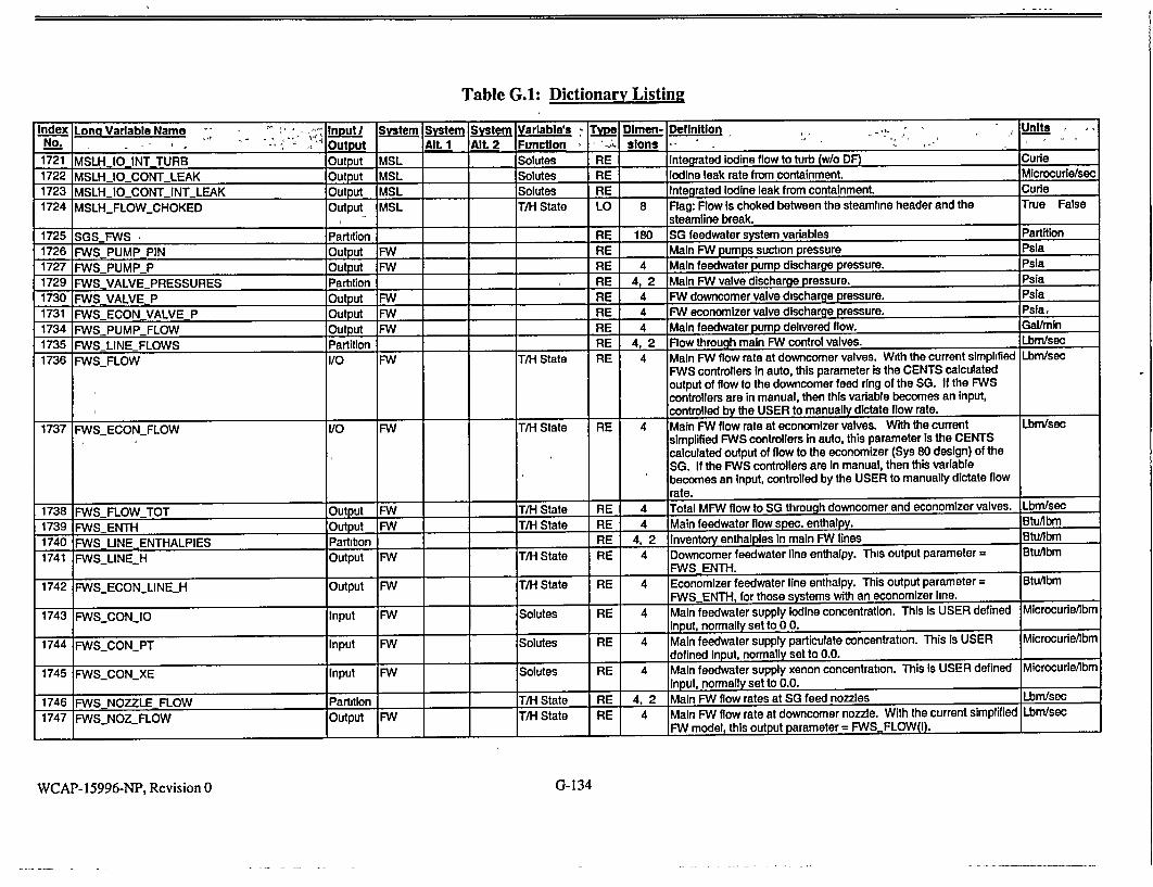
Table G.A: Dictionary Listin2
Index Long Variable Name in.. t I System System System Variable's Type Dimen- Definition - , Units No...... , ", " .•' Output Alt. I Alt 2 Function -., sions
1721 MSLH IOINT TURB Output MSL Solutes RE Integrated iodine flow to turb (w/o DF) Cune
1722 MSLHIOCONTLEAK Output MSL Solutes RE Iodine leak rate from containment. Microcurlelsec
1723 MSLH_10_CONTINTLEAK Output MSL Solutes RE Integrated iodine leak from containment. Curie 1724 MSLHFLOWCHOKED Output MSL T/H State LO 8 Flag: Flow Is choked between the steamline header and the True False
I_ __III steamline break.
1725 SGSFWS Partition RE 180 SG feedwater system variables Partition
1726 FWSPUMPPIN Output FW RE Main FW pumps suction pressure Psla
1727 FWSPUMPP P Output FW RE 4 Main feedwater pump discharge pressure. Psia
1729 FWSVALVEPRESSURES Partition RE 4, 2 Main FW valve discharge pressure. Psia
1730 FWSVALVEP Output FW RE 4 FW downcomer valve discharge pressure. Psia
1731 FWSECON VALVE P Output FW RE 4 FW economizer valve discharge pressure. Psia,
1734 FWSPUMP FLOW Output FW RE 4 Main feedwater pump delivered flow. Galmmn
1735 FWSLINE FLOWS Partition RE 4, 2 Flow through main FW control valves. Lbm/sec
1736 FWS_FLOW I/O FW T/H State RE 4 Main FW flow rate at downcomer valves. With the current simplified Lbm/sec FWS controllers In auto, this parameter is the CENTS calculated output of flow to the downcomer feed ring of the SG. If the FWS controllers are in manual, then this variable becomes an Input, controlled by the USER to manually dictate flow rate.
1737 FWSECONFLOW i/O FW T/H State RE 4 Main FW flow rate at economizer valves. With the current Lbm/sec simplified FWS controllers in auto, this parameter Is the CENTS calculated output of flow to the economizer (Sys 80 design) of the SG. If the FWS controllers are In manual, then this variable becomes an Input, controlled by the USER to manually dictate flow rate.
1738 FWSFLOWTOT Output NW I T/H State RE 4 Total MFW flow to SG through downcomer and economizer valves. Lbm/sec
1739 FWSENTH Output FW T/H State RE 4 Main feedwater flow spec. enthalpy. Btu/Ibm
1740 FWS LINEENTHALPIES Partition RE 4, 2 Inventory enthalples in main FW lines Btu/bmn
1741 FWS_LINEH Output FW T/H State RE 4 Downcomer feedwater line enthalpy. This output parameter = Btu/lbm FWS ENTH.
1742 FWSECONLINEH Output FW T/H State RE 4 Economizer feedwater line enthalpy. This output parameter = Btu/lbm FWS__ENTH, for those systems with an economizer line.
1743 FWS..CONJO Input MW Solutes RE 4 Main feedwater supply Iodine concentration. This Is USER defined Microcurle/lbm input, normally set to 0 0.
1744 FWS_CONPT Input FW Solutes RE 4 Main feedwater supply particulate concentration. This is USER Microcurie/bm defined Input, normally set to 0.0.
1745 FWS__CONXE Input FW Solutes RE 4 Main feedwater supply xenon concentration. This is USER defined Microcurde/bm input, normally set to 0.0.
1746 FWS NOZZLEFLOW Partition T/H State RE 4, 2 Main FW flow rates at SG feed nozzles Lbm/sec
1747 FWSNOZFLOW Output 'WN T/H State RE 4 Main FW flow rate at downcomer nozzle. With the current simplified Lbm/sec
I__ I_ _ _MFW model, this output parameter = FWSFLOW(I). 1_ 7_
WCAP- 15996-NP, Revision 0 G-134

Table G.I: Dictionary Listing
Index Long Variable Name Input System System System Variable's Type Dimen- Definition Units No. Output AIt. 1 AIt. 2 Function slons 1748 FWSECONNOZFLOW Output FW T/H State RE 4 Main FW flow rate at economizer nozzle With the current Lbm/sec
simplified FW model, this output parameter = FWSECONFLOW(l).
1749 FWS NOZZLE ENTHALPY Partition T/H State RE 4, 2 Main FW flow enthalpy at SG feed nozzles Btu/Ibm 1750 FWS NOZ ENTH Output FW T/H State RE 4 Main FW flow enthalpy at downcomer nozzles. Btu/lbm 1751 FWSECONNOZENTH Output FW T/H State RE 4 Main FW flow enthalpy at economizer nozzles Btu/lbm 1752 FWS NOZZLE QUALITY Partition _T/H State RE 4, 2 Main FW flow quality at SG feed nozzles Fraction 1753 FWSNOZQUAL Output FW _T/H State RE 4 Main FW flow quality at downcomer nozzle Fraction 1754 FWSECONNOZ QUAL Output FW T/H State RE 4 Main AN flow quality at economizer nozzle Fraction 1755 FWSNOZZLE TEMP Partition T/H State RE 4, 2 Main FW flow temp at SG feed nozzles Degree F 1756 FWS NOZ T Output FW T/H State RE 4 Main FA flow temp at downcomer nozzle Degree F 1757 FVSECONNOZ T Output FW T/H State RE 4 Main FW flow temp at economizer nozzle Degree F 1758 FWLBIN Partition T/H State RE 4, 2 Cues for feedline break inside chk valve Fraction 1759 MAL FNLB IN Input FW T/H State RE 4 Feedline break inside chk valve, DC line Fraction 1760 MALFWLBECONIN Input FW T/H State RE 4 Feedline break inside chk valve, EC line Fraction 1761 FWLB OUT Partition T/H State RE 4, 2 Cues for feedline brk outside chk valve Fraction 1762 MAL FWLB OUT Input FW T/H State RE 4 Feedline brk outside chk valve, DC line Fraction 1763 MAL FWLB ECON OUT Input FW T/H State RE 4 Feedline brk outside chk valve, EC line Fraction 1764 FWLB LOCATION Partition T/H State RE 4, 2 Feedline break locations, 0=valve 1 =nozz Fraction 1765 FWLB F Input I T/H State RE 4 Feedline break location, downcomer line Fraction 1766 AFNLB ECONF Input T/H State RE 4 Feedline break location, economizer line Fraction 1767 FALB W Partition T/H State RE 4, 2 Feedline break flow rates Lbm/sec 1768 FWLB FLOW Output FW T/H State RE 4 Downcomer feedline break flow rate Lbrn/sec 1769 FWLB ECONFLOW Output FW T/H State RE 4 Economizer feedline break flow rate. Lbm/sec 1770 FWLB H Partition T/H State RE 4, 2 Feedline break flow enthalpies Btu/lbm 1771 FWLB ENTH Output FW T/H State RE 4 Downcomer feedline break flow enthalpy BtuAbm 1772 FWLB ECON ENTH Output AFW I T/H State RE 4 Economizer feedline break flow enthalpy Btu/lbm 1773 FWLB QUALITY Partition T/H State RE 4, 2 Feedline break flow qualities Fraction 1774 FWLB-QUAL Output FW T/H State RE 4 Downcomer feedline break flow quality Fraction 1775 FWLB ECON QUAL Output AN T/H State RE 4 Economizer feedline break flow quality Fraction 1776 FWLB IODINE Partition Solutes RE 4, 2 Feedline break flow iodine concentrations Microcune/Ibm 1777 FWLB_10 Output FW Solutes RE 4 Downcomer feedline break flow iodine concentrations Microcurielbm 1778 FWLB ECONIO Output FW Solutes RE 4 Economizer feedline break flow iodine concentrations Microcurie/lbm 1779 FWLB PART Partition Solutes RE 4, 2 Feedline break flow particulate concentrations Microcurie/lbm 1780 FWLB PT Output FW Solutes RE 4 Downcomer feedline brk flow partic concentration Microcune/lbm 1781 FWLBECONPT Output FW Solutes RE 4 Economizer feedline brk flow partic concentration Microcurie/lbm 1782 FWLB XENON Partition _ _ Solutes RE 4, 2 Feedline break flow xenon concentration Microcurie/Ibm 1783 FWLB XE Output FW Solutes RE 4 Downcomer feedline brk flow xenon concentration Microcurieilbm 1784 FWLBECONXE Output FW _Solutes RE 4 Economizer feedline brk flow xenon concentration Microcune/lbm 1785 AFWS NOZ FLOW I/O FW AFW _ T/H State RE 4 Auxiliary feedwater flow rate to separate steam generator nozzle Lbm/sec
WCAP-15996-NP, Revision 0 G- 135

Table G.1: Dictionary Listing Index Long Variable Name- . Input-I Sytem System System Variable's -• 1 Dimen- Definition - -_ .:>- • , . ii, ,"
No.-, Output' - Alt. 1 Alt. 2i', Function ", - -slons. , . : ,%. V'... o. . - '.'
1786 AFWSENTH i/O FW AFW T/H State RE 4 Auxiliary feedwater flow spec. enthalpy. This input is set by the Btuflbm USER if the feedwater model is turned off, otherwise it is calculated. Often it is set to the FWS enthalpy until a sweep volume of hot FW
is "pushed' into the SG by the AFW system. Then, the AFW enthaipy is reduced to CWST enthalpy. This can be accomplished
I I using a CEER command WHEN statement.
1787 SGSSGBD Partition RE 100 SG blowdown system variables Partition
1788 SGBD-CON-1O Output SG SGBD Solutes RE SGBD tank Iodine concentration. This output is used IFF all the Microcudellbm blowdown system inputs have appropriate values and the blowdown
system Is activated by setting MOD_OFF_SGBD ^. F.
1789 SGBD_.CONPT Output SG SGBD Solutes RE SGBD tank particulates concentration. This output is used IFF all Microcurle/Ibm the blowdown system inputs have appropriate values and the
I blowdown system Is activated by setting MODOFF_SGBD =. F.
1790 SGBD_.CONXE Output SG SGBD Solutes RE SGBD tank xenon concentration. This output is used IFF all the MicrocurdeAbm
blowdown system Inputs have appropriate values and the blowdown system is activated by setting MODOFFSGBD =. F.
1791 SGBD_DVDH Output SG SGBD T/H State RE SGBD tank partial sp. vol with enthalpy. This output is used IFF all Composite
the blowdown system inputs have appropnate values and the Units _ _ _blowdown system is activated by setting MODOFFSGBD =. F.
1792 SGBDDVDP Output SG SGBD T/H State RE SGBD tank partial sp. vol. with pressure. This output is used IFF Composite - all the blowdown system inputs have appropriate values and the Units
_blowdown system Is activated by setting MODOFFSGBD =. F.
1793 SGBDH Output SG SGBD T/H State RE SGBD tank specific enthalpy. This output is used IFF all the ý Btu/Ibm blowdown system Inputs have appropriate values and the blowdown system is activated by setting MOD OFF SGBD =. F.
1794 SGBD.HF Output SG SGBD T/H State RE SGBD tank saturated liquid enthalpy. This output Is used IFF all Btu/lbm
the blowdown system inputs have appropriate values and the blowdown system is activated by setting MODOFF SGBD =. F.
1795 SGBDHG Output SG SGBD T/H State RE SGBD tank saturated steam enthalpy. This output is used IFF all Btu/lbm
the blowdown system Inputs have appropriate values and the
_blowdown system Is activated by setting MODOFFSGBD =. F.
1796 SGBDQL Output SG SGBD T/H State RE SGBD tank water level. This output is used IFF all the blowdown Feet
system Inputs have appropriate values and the blowdown system Is
activated by setting MODOFFSGBD =. F.
1797 SGBDM Output SG SGBD T/H State RE SGBD tank total mass. This output Is used IFF all the blowdown Lbm
system inputs have appropriate values and the blowdown system is
activated by setting MODOFFSGBD =. F.
1798 SGBDML Output SG SGBD T/H State RE SGBD tank liquid mass. This output Is used IFF all the blowdown Lbm
system Inputs have appropriate values and the blowdown system Is
activated by setting MODOFF._SGBD =. F.
1799 SGBDP Output SG SGBD TM State RE SGBD tank pressure. This output is used IFF all the blowdown Psia system Inputs have appropriate values and the blowdown system is
----------- activated by setting MODOFFSGBD =. F. I
WCAP-15996-NP, Revision 0 G-136
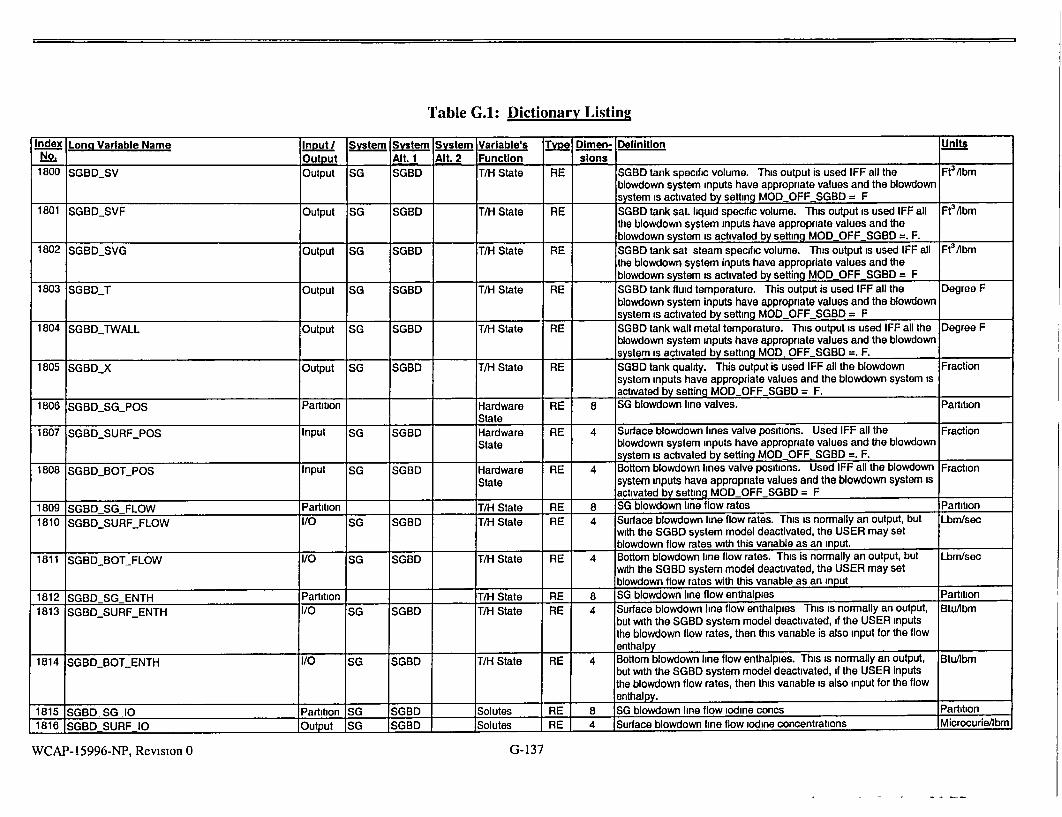
Table G.I: Dictionary Listing
Index Long Variable Name Input/ System System System Variable's Type Dimen- Definition Units No.. Output Alt. 1 Alt. 2 Function slons
1800 SGBDSV Output SG SGBD T/H State RE SGBD tank specific volume. This output is used IFF all the Ft3Abm blowdown system inputs have appropriate values and the blowdown system is activated by setting MODOFFSGBD = F
1801 SGBDSVF Output SG SGBD T/H State RE SGBD tank sat. liquid specific volume. This output is used IFF all FteAbm the blowdown system inputs have appropriate values and the blowdown system is activated by setting MOD OFF SGBD =. F.
1802 SGBDSVG Output SG SGBD T/H State RE SGBD tank sat steam specific volume. This output is used IFF all Ft3aIbm
the blowdown system inputs have appropriate values and the _blowdown system is activated by setting MOD OFF SGBD = F
1803 SGBDT Output SG SGBD T/H State RE SGBD tank fluid temperature. This output is used IFF all the Degree F blowdown system inputs have appropriate values and the blowdown system is activated by setting MOD OFF SGBD = F
1804 SGBDrWALL Output SG SGBD T/H State RE SGBD tank wall metal temperature. This output is used IFF all the Degree F blowdown system inputs have appropriate values and the blowdown
system is activated by setting MODOFFSGBD =. F. 1805 SGBDX Output SG SGBD T/H State RE SGBD tank quality. This output is used IFF all the blowdown Fraction
system inputs have appropriate values and the blowdown system is activated by setting MOD OFF SGBD = F.
1806 jSGBDSGPOS Partition Hardware RE 8 SG blowdown line valves. Partition State
1807 SGBDSURFPOS Input SG SGBD Hardware RE 4 Surface blowdown lines valve positions. Used IFF all the Fraction State blowdown system inputs have appropriate values and the blowdown
system is activated by setting MOD OFFSGBD =. F.
1808 SGBDBOTPOS Input SG SGBD Hardware RE 4 Bottom blowdown lines valve positions. Used IFF all the blowdown Fraction State system inputs have appropriate values and the blowdown system is
activated by setting MOD-OFFSGBD = F
1809 SGBD SG FLOW Partition _T/H State RE 8 SG blowdown line flow rates Partition
1810 SGBDSURFFLOW I/O SG SGBD T/H State RE 4 Surface blowdown line flow rates. This is normally an output, but Lbm/sec with the SGBD system model deactivated, the USER may set blowdown flow rates with this variable as an input.
1811 SGBD.BOT_FLOW I/O SG SGBD T/H State RE 4 Bottom blowdown line flow rates. This is normally an output, but Lbm/sec with the SGBD system model deactivated, the USER may set blowdown flow rates with this variable as an input
1812 SGBD SG ENTH Partition _T/H State RE 8 SG blowdown line flow enthalpies Partition
1813 SGBDSURFENTH i/O SG SGBD T/H State RE 4 Surface blowdown line flow enthalpies This is normally an output, BtuAbm but with the SGBD system model deactivated, if the USER inputs the blowdown flow rates, then this variable is also input for the flow enthalpy
_ 1814 SGBD_BOTENTH I/O SG SGBD T/H State RE 4 Bottom blowdown line flow enthalpies. This is normally an output, BtuAbm
but with the SGBD system model deactivated, if the USER inputs the blowdown flow rates, then this variable is also input for the flow enthalpy.
1815 SGBD-SG-10 Partition SG SGBD Solutes RE 8 SG blowdown line flow iodine concs Partition
1816 SGBD SURF 10 Output SG SGBD Solutes RE 4 Surface blowdown line flow iodine concentrations Microcurie/lbm
WCAP-15996-NP, Revision 0 G-137

Table G.1: Dictionary Listing
Index Lon Variable Name - Inut System System System Variable's Type Dimen- Definition Units
NO. . Output Aft. 1 Alt 2 Function slons "
1817 SGBD BOT 1O Output SG SGBD Solutes RE 4 Bottom blowdown line flow Iodine concentrations Microcure/lbm
1818 SGBDSGPT Partition SG SGBD Solutes RE 8 SG blowdown line flow partic concentrations Partition
1819 SGBDSURFPT Output SG SGBD Solutes RE 4 Surface blowdown line flow partic concentrations Microcurde/bm
1820 SGBDBOTPT Output SG SGBD Solutes RE 4 Bottom blowdown line flow partic concentrations Microcude/lbm
1821 SGBD_SGXE Partition SG SGBD I Solutes RE 8 SG blowdown line flow xenon concentrations Partition
1822 SGBDSURFXE Output SG SGBD Solutes RE 4 Surface blowdown line flow xenon concentrations Microcude/lbm
1823 SGBDBOTXE Output SG SGBD Solutes RE 4 Bottom blowdown line flow xenon concentrations Microcune/lbm
1824 SGBDSINKPOS Partition SG SGBD Hardware RE 3 SGBD tank discharge line valves Partition
State
1825 SGBDOUTPOS Input SG SGBD Hardware RE 2 SGBO tank outlet lines valve positions. Used 1FF all the blowdown Fraction
- State system inputs have appropriate values and the blowdown system Is
activated by setting MOD.OFFSGBD =. F.
1826 SGBD-RELIEFPOS Input SG SGBD Hardware RE SGBD tank relief line valve position. Used IFF all the blowdown Fraction
State system inputs have appropriate values and the blowdown system is
activated by setting MODOFFSGBD =. F.
1827 SGBDSINKFLOW Partibon T/H State RE 3 SGBD tank discharge line flow rates Partition
1828 SGBD. OUTFLOW Output SG SGBD T/H State RE 2 SGBD tank outlet lines flow rates. Used 1FF all the blowdown Lbm/sec system inputs have appropriate values and the blowdown system Is
activated by setting MODOFFSGBD =. F.
1829 SGBDORELIEFLFLOW Output SG SGBD T-I State RE SGBD tank relief line flow rate. Used IFF all the blowdown system Lbm/sec
inputs have appropriate values and the blowdown system Is
activated by setting MODOFF_SGBD =. F.
1830 SGBD SINKENTH Partition T/H State RE 3 SGBD tank discharge line flow enthalples Partition
1831 SGBD OUTENTH Output SG SGBD T/H State RE 2 SGBD tank outlet lines flow enthalpies. Used IFF all the blowdown Btu/bm
system inputs have appropriate values and the blowdown system Is
I activated by setting MODOFFSGBD =. F.
1832 SGBD-RELIEF..ENTH Output SG SGBD T/H State RE SGBD tank relief line flow enthalpy. Used IFF all the blowdown Btu/lbm system Inputs have appropriate values and the blowdown system is
activated by setting MODOFFSGBD =. F.
1833 SGBDSINK 10 Output SG SGBD Solutes RE 3 SGBD tank discharge line flow iodine concentrations Partition
1834 SGBDOUT_1O Output SG SGBD Solutes RE 2 SGBD tank outlet lines flow Iodine concentrations Microcure/lbm
1835 SGBDRELIEF 10 Output SG SGBD Solutes RE SGBD tank relief line flow Iodine concentration Microcurde/bm
1836 SGBDSINKPT Output SG SGBD Solutes RE 3 SGBD tank discharge line flow partic concentrations Parition
1837 SGBDOUTPT Output SG SGBD Solutes RE 2 SGBD tank outlet lines flow partic concentrations Microcude/ibm
1838 SGBDRELIEFPT Output SG SGBD Solutes RE SGBD tank relief line flow partic concentrations Mlcrocurie/bm
1839 SGBDSINKXE Output SG SGBD Solutes RE 3 SGBD tank discharge line flow xenon concentrations Partition
1840 SGBDOUT XE Output SG SGBD Solutes RE 2 SGBD tank outlet lines flow xenon concentrations Microcurle/lbm
1841 SGBDRELIEF.XE Output SG SGBD Solutes RE SGBD tank relief line flow xenon concentration Microcure/lbm
1842 SGBDSINKP Partition I - T/H State RE 3 SGBD tank disch. line dwnstrm pressures Partition
1843 SGBDOUT_P Input SG SGBD T/H State RE 2 SGBD tank outlet lines downstream pressures. Used IFF all the Psia
blowdown system Inputs have appropriate values and the blowdown
system is activated by setting MODOFFSGBD =. F.
G-138WCAP-15996-NP, Revision 0

Table G.I: Dictionary Listing
Index Long Variable Name Input/ System System System Variable's Type Dimen- Definition Units NO. "Output Alt. 1 AIt. 2 Function sions 1844 SGBDRELIEFP Input SG SGBD T/H State RE SGBD tank relief line downstream pressure. Used IFF all the Psia
blowdown system inputs have appropriate values and the blowdown system is activated by setting MODOFFSGBD = F 1845 MOD_OFFSGBD Input SG SGBD Model LO Turns off SGBD model, when set to True. True False
Desiqn 1846 SGS TUNE Partition RE 50 SG adjustable constants Partition 1847 CONTSG_TEMP Input SG RE 4 Containment temperature at SGS. This input parameter provides Degree F
the same function as a SG boundary condition as does CONT TEMP(I) for the RCS nodes. 1849 PCONDENSER Input MSL RE Condenser pressure. This input parameter is normally set to a Psia typical low sub-atmospheric value. It is normally not of major importance for safety analysis, but would be of interest during cooldowns of the SG to pressures/temperatures below atmospheric _conditions
1850 SGSASEPTUNE Input SG RE SGS steam separator area tuning factor. This is one of the major Dimensionless tuning factors used during initial setup of a plant basedeck to referenced conditions This parameter effects the bubble rise velocity or steam separation rate, which in turn, dictates the fluid density in the evaporator, and to a lesser extent, the SG recirculation ratio. Often, at the completion of the tuning, ASEPSG is adjusted so that ASEP SGTUNE can be set to a value of 1.0.
1852 SGS_FK3_TUNE Input SG RE SGS downcomer flow coeff tuning factor. This is one of the major Dimensionless tuning factors used during initial setup of a plant basedeck to referenced conditions. This parameter effects the SG recirculation ratio, and to a lesser extent, the fluid density in the evaporator. Often, at the completion of the tuning, ASEP_SG is adjusted so that I I_ ASEP SG TUNE can be set to a value of 1 0.
1855 SGSHASUBOPTION Input SG LO Option for calculating subcooled region in the SG evaporator. Used True False always This is a Logical flag to activate/disable the subcooled layer model in the steam generator heat transfer calculation. This flag should be True in all realistic calculations, to activate the model, independently of plant design
1856 SGS_PCNVRG Input SG RE Pressure convergence criterion. Used always These is a Psia convergence criterion for the iterative steam generator pressure search. This parameter is numerical in nature, independent of plant
I_ Idesign. 1857 SGSPMIN Input SG RE Minimum secondary-side pressure. Used always. This is the Psia
minimum pressure allowed in the steam generator, for model I_ I_ integrity. This parameter is independent of plant design
WCAP-15996-NP, Revision 0 G-139

Table G.1: Dictionary Listing
Index Long Variable Name lnrut I Sstem Syter Sytem Variable's Typ Dlmen- Definition . - Units No. Output Alt. 1 Alt 2 Function slons
1858 SGS_RECIRCDELVOL Input SG RE Delta volume for adjusting reclrc flow. Used always, In conjunction Ft3
with SGS_RECIRCMIN. CENTS uses these two parameters to dynamically calculate the steam generator recirculation ratio (RCR = SGSW23 / FWSFLOW100) as a function of the coolant volume In the evaporator. CENTS calculates a volume defect, which Is the difference between the current evaporator coolant volume and the maximum volume to reach the can deck. If the volume defect is less than SGS_RECIRCDELVOL, then RCR is calculated as a function of the volume defect. If the volume defect exceeds SGSRECIRCDELVOL, then a minimum RCR Is Imposed, RCR = SGSRECIRC.MIN. (The coolant level may be lower, if the volume defect exceeds 2 * SGSRECIRCDELVOL, then RCR = 0.5* SGSRECIRCMIN, and If the volume defect exceeds 4 SGSRECIRCDELVOL, then RCR = 0 0.). SGS_RECIRC_DELVOL Is dependent on plant design, within its definition In the RCR model. If sufficient dynamic data Is available, then SGSRECIRCDELVOL may be determined by tuning it along with the other steam generator model tuning factors. Otherwise, typical values are used, ranging from 120 to 200 Mt3. SGSRECIRCMIN Is a numerical minimum, Independent of plant
I_ I design.
1859 SGS_RECIRCMIN Input SG RE Minimum recirculation for crossflow. Used always, in conjunction Dimensionless with SGS_-RECIRC._DELVOL CENTS uses these two parameters to dynamically calculate the steam generator recirculation ratio (RCR = SGS_W23 / FWSFLOW100) as a function of the coolant volume In the evaporator. CENTS calculates a volume defect, which is the difference between the current evaporator coolant volume and the maximum volume to reach the can deck. If the volume defect is less than SGSRECIRCDELVOL, then RCR Is calculated as a function of the volume defect. If the volume defect exceeds SGSRECIRCDELVOL, then a minimum RCR is imposed, RCR = SGSRECIRCMIN. (The coolant level may be lower: if the volume defect exceeds 2 * SGS_RECIRCDELVOL, then RCR = 0.5 * SGSRECIRCMIN, and if the volume defect exceeds 4 * SGS_RECIRC_DELVOL, then RCR = 0 0.). SGS_RECIRCDELVOL Is dependent on plant design, within Its definition in the RCR model. If sufficient dynamic data is available, then SGS.RECIRCDELVOL may be determined by tuning it along with the other steam generator model tuning factors. Otherwise, typical values are used, ranging from 120 to 200 ff3. SGSRECIRC_MIN Is a numerical minimum, Independent of plant
I __design.
WCAP-15996-NP, Revision 0 G-140

Table G.I: Dictionary Listing
Index Long Variable Name Input/ System System System Variable's Tipe Dimen- Definition Units No. Output Alt. 1 Alt. 2 Function slons
1861 SGS_TAURCI_TUNE Input SG RE SG recirculation flow time constant tuning factor Used in Dimensionless conjunction with TAURC1. Used always. CENTS applies a time constant to the SG recirculation flow (SGSW23). TAURCI is the time constant, and SGSTAURC1JUNE is a multiplying tuning factor on that time constant The time constant formed by the product TAURC1 * SGSTAURCITUNE is dependent on plant data, within the definition of the overall model. Its best value is usually determined by tuning. This is usually done by comparing the SG downcomer level trace immediately following scram against available plant data, and tuning this and other parameter until a good match is obtained (The SGS model has more tuning factors that affect the circulation and recirculation flows than is necessary. Therefore, the usual practice is to tune SGS_TAURC1_TUNE and SGSFK3_TUNE together, and SGS_TAURC2_MAX to a lesser extent )
1862 SGSTAURC2_MAX Input SG RE SG downcomer flow, maximum time constant. Used always. This Seconds is an upper limit on the lag time constant that is applied to the SG circulation flow (SGSW32). This time constant is weakly dependent on plant data, within the definition of the overall model. That is, its typical value is between 0 5 and 5.0, and a best value is usually determined by tuning. This is usually done by comparing the SG downcomer level trace immediately following scram against available plant data, and tuning this and other parameter until a good match is obtained. Note, however, that the SGS model has more tuning factors that affect the circulation flow than is necessary, and the other parameters have a considerably more pronounced effect than SGS_TAURC2_MAX. Therefore, the usual practice is to select a mid-range value (2 0 to 3 0) and tune the other parameters (SGS TAURC1 TUNE and SGSFK3_TUNE).
1864 SGSUADROPPERIM Input SG RE Perimeter of the feedring. Note that this input parameter is the Feet perimeter of the feednng around the SG, not the feedring pipe cross
_sectional penmeter dimension. 1865 SGS_UADROP_WFDMIN Input SG RE Minimum feedflow below which condensation efficiency = 1. Used Lbm/sec
when the SG downcomer water height is below the main feedwater nozzle. This parameter is used to determine an efficiency of condensation of steam on the incoming cold feedwater, as the water falls through the steam space The parameter is the minimum feedwater flowrate, above which a condensation efficiency is calculated as a function of the feed flow rate and steam region height. Below this feed flow rate, the condensation efficiency is 1 0 (i.e., any feed water that is injected into the steam space condenses enough steam to become saturated by the time it reaches the water below). This is a model parameter that is independent of plant design. The value that is typically used was determined from engineering judgment to be between 0 and 100 Ibm/sec, and its effect on transient results is minimal within that range.
WCAP- 15996-NP, Revision 0 G-141

Table G.I: Dictionary Listing
Index Long Varable Name Input System System System Variable's Tvye Dlmen- Definition .. -Units
No.• Output Alt. 1 Alt. 2 Function slons _
1866 SGS-USTMMIN Input SG RE Minimum steam separation velocity. Used always. This is a Ft/sec minimum steam separation velocity Imposed on the Wilson correlation. The appropriate value for this parameter is dependent on the plant design, and Is determined by tuning the model to available plant data for shrink and swell in low power conditions. The value that Is typically used was determined from engineering judgment and from experience In tuning the model to be between 0 05 and 0.50 ft/sec.
1867 SGS_VCNVRG Input SG RE Volume convergence criterion. Used always. This Is a convergence Fraction criterion for the SG pressure search iterative solution. The iteration is converged when the change in SG volume from the last iteration (due to a change in pressure from the last iteration) is less than SGS_VCNVRG * VOLSGS. (VOLSGS is the total physical volume.) SGSVCNVRG Is also used the same way in SGFEED In the iterative solution for feedwater flow as a function of feedline junction pressure. Note, however, that SGFEED is called only if NUMFWSPUMPS > 0. SGS_VCNVRG Is strictly a numerical, dimensionless, convergence criterion, and is therefore Independent of plant design.
1868 SGS_WFMIN Input SG RE Region 2(evaporator) liquid mass for single-region switch. Used Lbm always. This Is the minimum liquid mass in the downcomer or the evaporator region that can be accommodated by the SGS model without instability. When downcomer liquid mass Is below SGSWFMIN/2, it Is immediately transferred to the evaporator region. When the evaporator region liquid mass Is below SGSWFMIN, the model combines all the regions into one and employs the one-region formulation. When the liquid mass exceeds 2*SGSWFMIN, the model reverts back to the multi-region formulation. This is a model-switch parameter whose appropriate value depends on the multi-region model's stability in low Inventory conditions, and is Independent of plant design in the range of typical
steam generator sizes.
1869 SGSX2_I Input SG RE Region 2 (evaporator) quality necessary to re-establish region 1 Fraction (steam dome). Used only when steam Is introduced into the steam generator after It filled solid with water. When the steam generator goes solid, region 1 (dome steam region) disappears. When steam reappears In the evaporator region, region 1 will be re-established. To prevent this from happening prematurely, possibly resulting in cycling or pressure spikes, CENTS waits until the evaporator region quality exceeds SGS_X2_1. Since It Is designed to prevent cycling or pressure spikes, this parameter Is numencal in nature.
I_ iTherefore, it is independent of plant design.
WCAP- 15996-NP, Revision 0 G-142


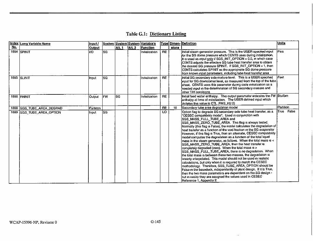
Table G.1: Dictionary Listing
Index Lona Variable Name ;InU. System System System Variable's Type Dimen- Definition Units
No. Output Alt. 1 Alt. 2 Function sions
1884 SPINIT I/O SG Initialization RE Initial steam generator pressure. This is the USER specified input Psia
for the SG dome pressure which CENTS uses during initialization. It is used as input only if SGSJNIT_OPTION = 0.0, in which case CENTS adjusts the effective SG tube heat transfer area to obtain the desired SG pressure SPINIT. If SGS_INIT_OPTION = 1, then CENTS calculates SPINIT as the appropnate SG dome pressure from known input parameters, including tube heat transfer area
1885 SLINIT Input SG Initialization RE Initial SG secondary side mixture level. This is a USER specified Feet input for SG downcomer level, as measured from the top of the tube sheet. CENTS uses this parameter during code initialization as a needed input in the determination of SG secondary masses and other T/H conditions
1886 FHINIT Output FW SG Initialization RE Initial feed water enthalpy. This output parameter indicates the FW BtuAbm enthalpy at time of initialization. The USER defined input which dictates this value is CTL_FWSH(I'2)
1888 SGS TUBE AREA DEGRAD Partition RE 10 Secondary tube area degradation model Partition
1889 SGSTUBEAREAOPTION Input SG LO Option flag to degrade SG secondary side tube heat transfer, as a True False "CESEC compatibility model". Used in conjunction with SGSMASSFULLJUBE-AREA and SGSMASSZERO_TUBEAREA. This flag is always tested. Normally (this flag is False), the model calculates the degradation of heat transfer as a function of the void fraction in the SG evaporator However, if this flag is True, then an alternate, CESEC compatibility model computes the degradation as a function of the total liquid mass in the steam generator, as follows. When the total mass is < SGSMASSZEROTUBEAREA, then the heat transfer is completely degraded (zero). When the total mass is > SGS_MASSFULL.TUBEAREA, there is no degradation. When the total mass is between these two masses, the degradation is linearly interpolated. This model should not be used in realistic calculations, but only when it is required to match the CESEC methodology. Therefore, SGS_TUBEAREAOPTION should be False in the basedeck, independently of plant design. If it is True, then the two mass parameters are dependent on the SG design but in reality they are assigned the values used in CESEC Reference 1, Appendix E
WCAP-15996-NP, Revision 0 G- 145

Table G.I: Dictionary Listing
Index Long Variable Name -, Input System System System Variable's, T±fe Dlmen- Definition , --. . No. Output Alt. 1 Alt. 2 Function _ slons - -. .,____
1890 SGS_MASSFULLTUBEAREA Input SO RE 4 Minimum mass for full SG secondary-side tube heat transfer. Used Lbm in conjunction SGS_MASS_ZERO_TUBE_AREA, but only if the flag
SGSTUBEAREA_OPTION is True. In that case, a "CESEC compatibility" model computes the degradation of SG heat transfer as a function of the total liquid mass in the steam generator, as follows. When the total mass is < SGS_MASS_ZERO_TUBEAREA, then the heat transfer Is completely degraded (zero). When the total mass Is > SGS_MASS_FULLTUBEAREA, there is no degradation. When the total mass is between these two masses, the degradation is linearly interpolated. This model should not be used in realistic calculations, but only when it Is required to match the CESEC methodology. Therefore, SGSTUBEAREAOPTION should be False in the basedeck, Independently of plant design. If it is True, then the two mass parameters are dependent on the SO design but In reality they are assigned the values used in CESEC. Reference 1, Appendix E.
1891 SGSMASSZERO_TUBEAREA Input SO RE 4 Mass for zero SO secondary-side tube heat transfer. Used In Lbm conjunction SGS_.MASSFULLTUBEAREA, but only If the flag SGSTUBE_AREAOPTION Is True. In that case, a "CESEC compatibility" model computes the degradation of SO heat transfer as a function of the total liquid mass In the steam generator, as follows. When the total mass Is < ' SGSMASSZEROTUBEAREA, then the heat transfer is completely degraded (zero). When the total mass Is > SGS_MASS_FULL_IUBE_AREA, there is no degradation. When the total mass is between these two masses, the degradation is linearly interpolated. This model should not be used In realistic calculations, but only when it is required to match the CESEC methodology. Therefore, SGSTUBE_AREAOPTION should be False In the basedeck, independently of plant design. If it Is True, then the two mass parameters are dependent on the SG design but in reality they are assigned the values used In CESEC. 1 Reference 1, Appendix E.
1892 FWS-ENTHTABLE Partition RE 50 Table of main feedwater enthalpy vs load Partition
1893 FWSHTABLEENTH Input SO FW RE 20 Table: MFW norm enthalpy, (h-H1)/(H2-H1), where H1 & H2 refer to Dimensionless CTL.FWSJ_H(1,2). Used for NUMFWSPUMPS--0 only. Reference 1, Section 6.7.3
1894 FWSHTABLELOAD Input SG FW RE 20 Table: turbine normalized load, WlWrated. Used In conjunction with Dimensionless FWSHTABLEENTH. Used for NUM_FWS_PUMPS=0 only. Reference 1, Section 6.7.3.
1895 FWS_HTABLENUM Input SO FW IN Table: number of entries for the FW enthalpy vs. load table. Used Counts
I__P ___for NUM FWSPUMPS--- only. Reference 1, Section 6.7.3. 1 1
1905 MSLH2 STATE Partition MSLH RE 40 Steamline Header, node 2, state output variables. Partition
WCAP-15996-NP, Revision 0 G-146
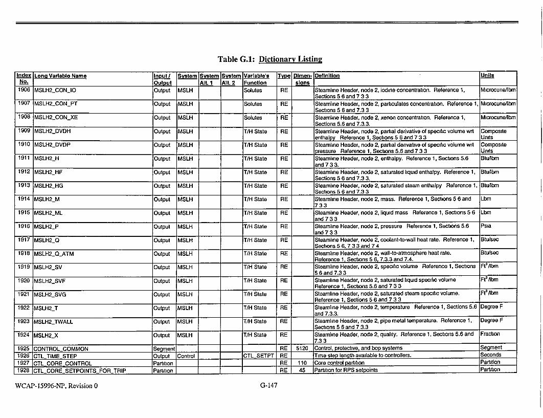
Table G.A: Dictionary Listing
index Long Variable Name Input System System System Variable's Type Dimen- Definition Units No. Output Alt. 1 Alt. 2 Function slons
1906 MSLH2_CONIO Output MSLH Solutes RE Steamline Header, node 2, Iodine concentration. Reference 1, Microcurie/bm Sections 5 6 and 7 3 3
1907 MSLH2_CONPT Output MSLH Solutes RE Steamline Header, node 2, particulates concentration. Reference 1, Microcune/libm I_ I Sections 5 6 and 7.3 3
1908 MSLH2_CONXE Output MSLH Solutes RE Steamline Header, node 2, xenon concentration. Reference 1, Microcune/Ibm Sections 5.6 and 7.3.3.
1909 MSLH2_DVDH Output MSLH T/H State RE Steamline Header, node 2, partial derivative of specific volume wrt Composite enthalpy Reference 1, Sections 5 6 and 7 3 3 Units
1910 MSLH2_DVDP Output MSLH T/H State RE Steamline Header, node 2, partial derivative of specific volume wrt Composite pressure Reference 1, Sections 5.6 and 7 3 3 Units
1911 MSLH2 H Output MSLH T/H State RE Steamline Header, node 2, enthalpy. Reference 1, Sections 5.6 BtuAbm and 7 3 3.
1912 MSLH2_HF Output MSLH T/H State RE Steamline Header, node 2, saturated liquid enthalpy. Reference 1, Btu/lbm Sections 5 6 and 7.3 3.
1913 MSLH2_HG Output MSLH T/H State RE Steamline Header, node 2, saturated steam enthalpy Reference 1, Btu/lbm ,Sections 5 6 and 7.3 3
1914 MSLH2_M Output MSLH TIH State RE Steamline Header, node 2, mass. Reference 1, Sections 5 6 and Lbm 733
1915 MSLH2_ML Output MSLH TIH State RE Steamline Header, node 2, liquid mass Reference 1, Sections 5 6 Lbm and 73 3
1916 MSLH2_P Output MSLH T/H State RE Steamline Header, node 2, pressure Reference 1, Sections 5.6 Psia and 7 3 3
1917 MSLH2_Q Output MSLH T/H State RE Steamline Header, node 2, coolant-to-wall heat rate. Reference 1, Btu/sec Sections 5 6, 7 3 3 and 7 4
1918 MSLH2_0_ATM Output MSLH T/H State RE Steamline Header, node 2, wall-to-atmosphere heat rate. Btu/sec Reference 1, Sections 5 6, 7.3.3 and 7.4.
1919 MSLH2_SV Output MSLH T/H State RE Steamline Header, node 2, specific volume Reference 1, Sections Ft3 Abm 1 ._ 5 6 and 7.3 3
1920 MSLH2_SVF Output MSLH T/H State RE Steamline Header, node 2, saturated liquid specific volume Ft3/Ibm Reference 1, Sections 5.6 and 7 3 3
1921 MSLH2SVG Output MSLH T/H State RE Steamline Header, node 2, saturated steam specific volume. Ft3 /bm Reference 1, Sections 5 6 and 7 3 3
1922 MSLH2_T Output MSLH T/H State RE Steamline Header, node 2, temperature Reference 1, Sections 5.6 Degree F and 7.3.3.
1923 MSLH2_TWALL Output MSLH T/H State RE Steamline Header, node 2, pipe metal temperature. Reference 1, Degree F
I__II Sections 5 6 and 7 3.3
1924 MSLH2YX Output MSLH T/H State RE Steamline Header, node 2, quality. Reference 1, Sections 5.6 and Fraction 7.3 3
1925 CONTROL COMMON Segment RE 5120 Control, protective, and bop systems Segment
1926 CTL TIME STEP Output Control CTL SETPT RE Time step length available to controllers. Seconds
1927 CTL CORE CONTROL Partition RE 110 Core control partition Partition 1928 CTL CORE SETPOINTS FORTRIP Partition , I RE 45 Partition for RPS setpoints Partition
WCAP-15996-NP, Revision 0 G- 147

Table G.A: Dictionary Listingi IVmInput Sytem System System Variable's ; Type Dlmen- Definitionunis : .- ,..
Index Long Variable Name,,...... Definition,!--,, • ... ,:'i
SNo. o , Output . AIt. 1 Alt. 2 Function .. slons
1929 CTLCOREHI_POWER_FRACTRIP Input Control RPS RE Hi power fraction scram setpoint. Reference 1, Section 6.1. Fraction CTLSETPT _
1930 CTLCORE-HI-POWERSURTRIP Input Control RPS RE High power SUR scram setpoint. Reference 1, Section 6.1. Decades/min
I CTLSETPT 1931 CTLCORELOWPRZRPRESTRIP Input Control RPS RE Low pressurizer pressure scram setpoint. Reference 1, Section 6.1. Psia
CTLSETPT 1932 CTLCORE_HI_PRZR_PRES_TRIP Input Control RPS RE High pressurizer pressure scram setpoint. Reference 1, Section 6.1. Psla
CTLSETPT 1933 CTLCORE_HI_PRZRLEVELL_TRIP Input Control RPS RE High pressurizer level scram setpoint. Reference 1, Section 6.1. Fraction
CTL.SETPT
1934 CTLCOREOVER_TEMPMRGNTRIP Input Control RPS RE Thermal margin setpts for over temp trip. Reference 1, Section 6.1. Del-degF CTLSETPT --_
1935 CTLCOREOVERPOWERMRGNTRIP Input Control RPS RE Thermal margin setpts for over pwr trip. Reference 1, Section 6.1. Del-degF CTLSETPT
1936 CTLCORERCSFLOW_FRACTRIP Input Control RPS RE Low loop flow scram setpoint. Reference 1, Section 6.1. Fraction CTLSETPT
1937 CTLCORESIAS_TRIP Input Control RPS RE Scram due to SIAS - general purpose setpolnt. Reference 1, Fraction I 1 _ _, _ _ , -__ 1 _ I CTLSETPT Section 6.1. 1, j
1938 CTLCORELOWSG_PRES_TRIP Input Control RPS RE Low SG pressure scram setpoint. Reference 1, Section 6.1. Psia CIL SETPT I11
1939 CTLCORELOWSGLEVELTRIP Input Control RPS RE Low SG level scram setpolnt. Reference 1, Section 6.1. Fraction CTLSETPT
1940 CTLCOREHISG_LEVELTRIP Input Control RPS RE High SG level scram setpoint. Reference 1, Section 6.1. Fraction
_CTLSETPT _
1941 CTL_STEAMFEEDMISMATCHTRIP Input Control RPS RE Steam-feed flow mismatch scram setpoint. Reference 1, Section Lbm/sec CTLSETPT 6.1.
1942 CTLCORE_TURB_TRIP..DELAY Input Control RPS RE Scram due to turb trip: time delay. Reference 1, Section 6.1. SecondsCTLSETPT
1943 CTLCOREHI_CONT_PRES_TRIP Input Control RPS RE High containment pressure scram setpoint. Reference 1, Section Psia
CTLSETPT _6.1.
1944 CTLCOREUSERFDEFINED_TRIP Input Control RPS RE 10 Space for other scram setpoints. Reference 1, Section 6.1. Undefined
CTL SETPT 1
1945 CTLRCP_.FLOWSTPOINT Output Control RPS RE 5 Low primary flow scram setpoints. These are calculated setpoints: Lbm/sec CTL.SETPT for each RCP, this is CTLCORE_RCSFLOW_FRAC_TRIP * rated
volumetric flow * rated density. The last value in this array (at NUMPUMPS+1) is the sum of the RCPs' flow setpotnts. Reference 1, Section 6.1.
1946 CTLCOREHIPOWER_..SURBYPS Input Control RPS RE 2 HI power SUR scram-inhibit setpoints. Reference 1, Section 6.1. Fraction
I__ I_ CTLSETPT 1
1947 CTLCOREPOWERRATIO Output Control RPS RE Logarithmic rate of power change. Independent of plant design. Dimensionless
CTL SETPT Reference 1, Section 6.1.
1948 CTLSTEAMFEED_MISMATCHBYPS Input Control RPS RE Scram on flow mismatch: Inhibit setpoint. Reference 1, Section 6.1. Fraction
I__ _CTLSETPT_
G-148WCAP-15996-NP, Revision 0

Table G.I: Dictionary Listing
Index Long Variable Name Input System System System Variable's Type Dimen- Definition Units., , No. Output Alt. I Alt. 2 Function sions
1949 CTLCORETURB_TRIPBYPS Input Control RPS RE Scram on turbine trip. inhibit setpoint. Reference 1, Section 6.1. Lbm/sec CTL SETPT
1950 CTLCOREUSERDEFINEDBYPS Input Control RPS RE 10 Space for other scram inhibit setpoints. Reference 1, Section 6.1. Undefined CTL SETPT
1951 CTLCORE TRIP OR Partition I RE 25 Partition for scram overrides Partition 1952 CTLCORE_HIPOWERFRACTRIPOR Input Control RPS RE Hi power fraction scram override. 0=Normal; 1 -Ovemde. User Overnde
CTL_SETPT determines based on trips desired to be active. Reference 1, Normal Section 6 1
1953 CTLCOREHI_POWERSURTRIPOR Input Control RPS RE High power SUR scram override. 0=Normal; I=Override. User Override CTL_SETPT determines based on trips desired to be active. Reference 1, Normal
Section 6.1. 1954 CTLCORELOW_PRZR_PRES_TRIPOR Input Control RPS RE Low pressunzer pressure scram override. O=Normal; 1=Override. Override
CTLSETPT User determines based on tnps desired to be active. Reference 1, Normal _Section 6 1.
1955 CTLCORE_HIPRZRPRESTRIPOR Input Control RPS RE High pressurizer pressure scram override. O=Normal; 1 =Override. Override CTLSETPT User determines based on trips desired to be active. Reference 1, Normal
I_ _Section 6.1. 1956 CTLCOREHIPRZRLEVELTRIPOR Input Control RPS RE High pressurizer level scram overrides. O=Normal, 1 =Override. Override
CTL_SETPT User determines based on trips desired to be active Reference 1, Normal I_ ISection 6 1
1957 CTLCOREOVER_TEMPMRGN-TRIPOR Input Control RPS RE Over-temp thermal margin scram override. O=Normal, 1=Override Override CTLSETPT User determines based on trips desired to be active. Reference 1, Normal
Section 6 1. 1958 CTLCOREOVERPOWERMRGNTRIPOR Input Control RPS RE Over-power thermal margin scram override. 0=Normal, Override
CTLSETPT I =Override. User determines based on trips desired to be active. Normal I Independent of plant design Reference 1, Section 6 1.
1959 CTL._CORERCSFLOW_FRACTRIPOR Input Control RPS RE Low loop flow scram override. 0=Normal, 1 =Override. User Override CTL_SETPT determines based on trips desired to be active. Independent of Normal
plant design Reference 1, Section 6.1 1960 CTL_CORE_SIASTRIPOR Input Control RPS RE Scram due to SIAS override 0=Normal; 1 =Override. User Override
CTLSETPT determines based on trips desired to be active. Independent of Normal I__ plant design. Reference 1, Section 6.1.
1961 CTLCORELOWSGPRESJRIPOR Input Control RPS RE Low SG pressure scram override. 0=Normal; 1=Override. User Override CTL_SETPT determines based on trips desired to be active. Independent of Normal
plant design Reference 1, Section 6 1. 1962 CTLCORELOWSGLEVELTRIPOR Input Control RPS RE Low SG level scram override O=Normal; I=Override. User Override
CTL_SETPT determines based on trips desired to be active. Independent of Normal plant design. Reference 1, Section 6.1.
1963 CTL_CORE_HI_SG_LEVEL_TRIP_OR Input Control RPS RE High SG level scram override. 0=Normal, 1=Override. User Override CTLSETPT determines based on trips desired to be active. Independent of Normal
I _plant design. Reference 1, Section 6.1. 1964 CTLSTEAM_FEEDMISMATCHTRIPOR Input Control RPS RE Steam-feed flow mismatch scram override. 0=Normal; 1 =Override. Override
CTLSETPT User determines based on trips desired to be active Independent Normal ____ I__ _of plant design. Reference 1, Section 6.1.
WCAP-15996-NP, Revision 0 G-149

Table G.I: Dictionary Listing
Index Long Variable Name , Input System System System Variable's. Tvlye Dimen- Definition Unlts-,:,"__ . ..... " Output Alt. 1 Alt. 2 Function sions
1965 CTLCORETURBTRIPDELAYOR Input Control RPS RE Scram due to turb trip: override. 0=Normal; 1 =Override. User Override CTLSETPT determines based on trips desired to be active. Independent of Normal
_ _plant design. Reference 1, Section 6.1.
1966 CTLCORE_HICONTPRESTRIP_OR Input Control RPS RE Hi cont. pressure scram override. O=Normal; 1=Override. User Override CTLSETPT determines based on trips desired to be active. Independent of Normal
plant design. Reference 1, Section 6.1.
1967 CTLCOREUSERDEFINEDTRIPOR Input Control RPS RE 10 Space for other scram overrides. O=Normal; 1=Override. User Override CTLSETPT determines based on trips desired to be active. Independent of Normal
plant design. Reference 1, Section 6.1.
1968 CTLTIMECORETRIP Output Control RPS RE Time elapsed after scram. Always used. Independent of plant Seconds CTLSETPT design.
1969 CTLCOREPOWER Output Control RPS RE Core power. Always used. Independent of plant design. Btu/sec CTLSETPT "___
1970 CTLQCORETRIP Output Control RPS RE Core power at time of trip. Always used. Independent of plant Btufsec _CTL SETPT design.
1971 CTLCOREPOWERFRACTION Output Control RPS RE Core power, fraction of rated. Always used. Independent of plant Fraction _CTLSETPT design.
1972 CTLCOREPOWER_FRACLAST Output Control RPS RE Core power fraction, at last time step. Always used. Independent Fraction CTLSETPT of plant design.
1973 CTLNUMRPS Input Control RPS IN Number of RPS channels. Always used. Independent of plant Counts CTLSETPT _ design. Reference 1, Section 6.1.
1974 CTLCORECONTROLAUTO Input Control RPS LO Flag: automatic control of core. This flag is set by the User. True Auto Manual CTLSETPT (Auto) indicates that the RPS controllers are actively set to provide
a trip, if a trip conditions develops. False (Manual) is used to override all RPS trip function controllers. Only a manual trip is available In that case (User sets CTLCORETRIP= T). Always used. Independent of plant design. Reference 1, Section 6.1.
1975 CTLCORETRIP I/O Control RPS LO Core tnpped flag. This flag Is set by the User or by CENTS. To Trip- Normal CTLSETPT simulate a manual trip the User can set CTLCOREJRIP= T via
the command tile or CENTS can set the flag to True if the RPS controllers indicate a trip condition. Always used. Independent of Ilant design. Reference 1, Section 6.1.
1976 CTL.CORETRIPSIG Output Control RPS LO 25 Scram signals. The scram channel that energizes first becomes Active CTLSETPT True in this array. All other scram channels are prevented from Inactive
becoming True, even if the channel energizing condition exists. Thus, the condition that caused the Scram can be interrogated at a later time. Reference 1, Section 6.1.
1977 CTL_CORE_PTRIP Output Control RPS LO Scram signal at last time step. True False CTLSETPT 1 1
1978 CTLCEACOMMON Partition RE 20 Control-element assembly model Partition
1979 CTLCEASETPOINTS Partition RE 6 Setpoints for reactor regulating system Partition
1980 CTLCEATREF._NO Input Control CEA RE Reference (avg) primary temp at no load. Reference 1, Section 6 8. Degree F
I____ ___CTL-SETPT I II
WCAP-15996-NP, Revision 0 G-150

Table G.A: Dictionary Listing
Index Lonq Variable Name Input / System System System Variable's Type Dimen- Definition Units No. output Alt. 1 Alt. 2 Function slons
1981 CTLCEATREFFULL Input Control CEA RE Reference (avg) primary temp, full load. Reference 1, Section 6.8. Degree F CTL SETPT
1982 CTLCEAGAINEXP Input Control CEA RE Exponent for nonlinear gain=demand'*exp Used always. In the Dimensionless
CTLSETPT Control Rod Regulating System of Westinghouse-designed plants, the temperature error logic contains a nonlinear gain term, CTLTURBDEMAND**CTL_CEA_GAINEXP, where the first factor is the current turbine power demand. The resultant value, CTLCEA_TURBLDGAIN, is used by the modeler via the Generic Control System. CTL_CEAGAIN EXP is dependent on the plant control system design, in many Westinghouse-designed plants. Reference 1, Section 6 8
1983 CTLCEATURBLD-GAIN Output Control CEA RE Nonlinear gain for Control Rod Regulating System of Dimensionless CTL_SETPT Westinghouse-designed plants. Used calculated The temperature
error logic of the CRRS contains a nonlinear gain term, CTLTURBDEMAND*CTL_CEA.GAINEXP, where the first factor is the current turbine power demand. The resultant value, CTLCEATURBLDGAIN, is used by the modeler via the Generic Control System Reference 1, Section 6.8
1984 CTLCEAPOSITIONFRAC Output Control CEA RE Fractional average rod position. 0.0=fully inserted, 1 0= fully Fraction CTL SETPT withdrawn. Always used Independent of plant design
1985 CTLCEALASTTIME Output Control CEA RE CEA motion time - the time at which the rods last moved Seconds CTL SETPT
1986 CTLCEAMAX Input Control CEA RE Maximum CEA withdrawal position. Steps CTL-SETPT
1987 CTL_CEA_MIN Input Control CEA RE Minimum CEA withdrawal position Steps CTL SETPT
1988 CTLCEAPOS Input Control CEA RE CEA withdrawal position Used always CTLCEAPOS is the Steps CTLSETPT current position of the "average" control rod, measured in steps with
zero at the fully inserted point (bottom). When the Reactor Regulating System is active, CTL_CEA_POS is calculated, based on rod speed signal received from the GCS controller. The power algorithm then determines the rod reactivity based on the current rod position CTL.CEAPOS. This variable is dynamic, independent of plant design
1989 CTLCEASPEED I/O Control CEA RE CEA motion speed and direction Reference 1, Section 6.8. Steps/min CTL SETPT
1990 CTLCEASTEP Input Control CEA RE Step size of control rod motion. Used always. This parameter is Inches CTL_SETPT the step size of control rod motion, in inches. This parameter is
dependent on plant design Reference 1, Section 6 8 1991 CTLCEAAUTO Input Control CEA LO Flag, Auto/Manual CEA (reactor regulating) control. If Auto, the True False
I I _CTL SETPT I _I __controller logic dnves the regulating rods. Reference 1, Section 6 8
WCAP- 15996-NP, Revision 0 G- 151

Table G.A: Dictionary Listing Index Lon. Variable Name, T S Sl ype Dimen- Definition Units
No. Output Alt. 1 Alt. 2 - Function , slons .. ,
1992 CTLCEAPERFECT Input Control CEA LO Flag: CEA perfect controller. If True, creates a fictional perfect CEA True False
CTLSETPT controller that continually positions the control rods where they will exactly match the other reactivity components, thus ensuring a
steady power state. Reference 1, Section 6.8.
1993 CTL,_CEAACCUM Output Control CEA RE CEA control accumulated signal. Reference 1. Section 6 8. Steps
CTLSETPT
1994 CTL_CEA.._SPEED._LAST Output Control CEA RE CEA speed and direction, last step. Steps/min
CTLSETPT
1995 CTL CVCSCOMMON Partition RE 85 Chemical & volume control system Partition
1996 CTLPRZRLEVEL.SETPOINTS Partition RE 9 Pressurizer level setpoints Partition
1997 CTLPRZRPLEVELTEMP Input Control CVCS RE 2 Pressurizer level-program temperature setpoints. These Degree F
CTL.SETPT parameters are dependent on plant design. Normally based upon RCS average temperature. These parameter values allow a variable program pressurizer level at different core power levels.
Reference 1, Section 6.2.
1998 CTLPRZR_PLEVEL Input Control CVCS RE 2 -Pressurizer level-program level setpoints. These plant dependent Fraction
CTLSETPT setpoints are determined in conjunction with CTLPRZRPLEVELTEMP. They allow the pressurizer level to vary with power (or average RCS temperature). The units are most often set to a fraction of level span, but that can vary depending on
how the level controller are established. Reference 1, Section 6.2.
1999 CTLPRZRLIQ0SPVOL REF Input Control CVCS RE Pressurizer Instrument reference liquid specific-volume. This plant FteAbm
CTLSETPT dependent variable is based on the pressurizer liquid temperature and pressure at the time of the level instrument calibration. Normally it is set to saturated conditions for normal operating pressure, since this is the most likely state during calibration. Reference 1, Section 6.2.
2000 CTLPRZRSTMSPVOLREF Input Control CVCS RE Pressurizer instrument reference steam specific-volume. This plant Ft3 /lbm
CTLSETPT dependent variable Is based on the pressurizer steam temperature
and pressure at the time of the level instrument calibration. Normally it is set to saturated conditions for normal operating
pressure, since this is the most likely state during calibration.
Reference 1, Section 6.2.
2001 CTLVLETDOWN.SETPOINTS Partition RE 6 Letdown control setpoints Partition
2002 CTLCVCSLDNZSPOINT Input Control CVCS RE 2 Letdown level control setpoints. These plant dependent setpoints Fraction
CTLSETPT are based upon a deviation from the pressurizer program level. The
units may be a fraction of span or In feet, Inches etc., depending on
how the controllers are established. Reference 1, Section 6.2.
2003 CTL.CVCSLDNW_GPM Input Control CVCS RE 2 Letdown flow setpoints. These plant dependent setpomnts are used GaVmin
CTL_SETPT in conjunction with CTLCVCSLDN_ZSPOINT, based upon a
deviation from the pressurizer program level. They set the letdown
flow rate based on the calculated pressurizer level error. Reference
-__ _ 1, Section 6.2.
2004 JCTLS.HARGING SETPOINTS Partition RE 15 Charging pump control setpoints Partition
G-152WCAP-15996-NP, Revision 0
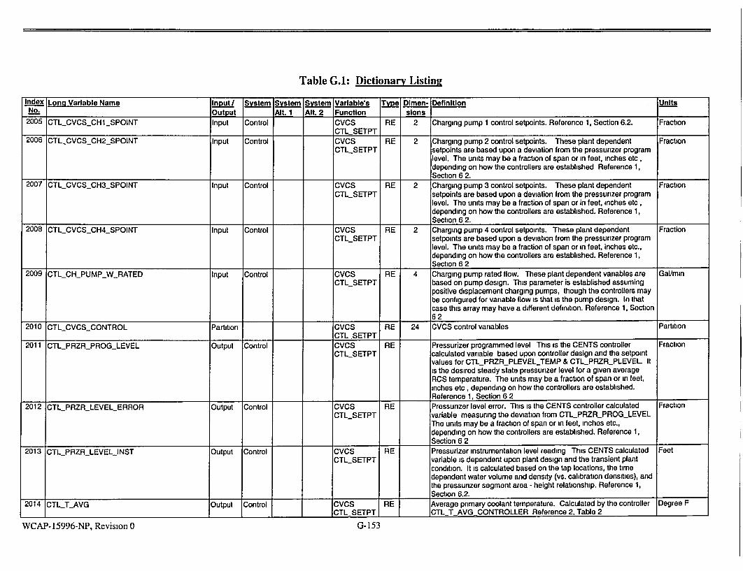
Table G.A: Dictionary Listing
Index Long Variable Name Input/ System System System Variable's Type. Dimen- Definition Units No. Output Alt. 1 Alt. 2 Function sions
2005 CTLCVCS_CHI_SPOINT Input Control CVCS RE 2 Charging pump 1 control setpoints. Reference 1, Section 6.2. Fraction
CTL SETPT 2006 CTLCVCSCH2_SPOINT Input Control CVCS RE 2 Charging pump 2 control setpoints. These plant dependent Fraction
CTLSETPT setpoints are based upon a deviation from the pressurizer program level. The units may be a fraction of span or in feet, inches etc, depending on how the controllers are established Reference 1, Section 6 2.
2007 CTLCVCSCH3_SPOINT Input Control CVCS RE 2 Charging pump 3 control setpoints. These plant dependent Fraction
CTL SETPT setpoints are based upon a deviation from the pressurizer program level. The units may be a fraction of span or in feet, inches etc, depending on how the controllers are established. Reference 1, Section 6 2.
2008 CTLCVCSCH4_SPOINT Input Control CVCS RE 2 Charging pump 4 control setpoints. These plant dependent Fraction CTLSETPT setpoints are based upon a deviation from the pressurizer program
level. The units may be a fraction of span or in feet, inches etc., depending on how the controllers are established. Reference 1, Section 6 2
2009 CTLCHPUMP_W_RATED Input Control CVCS RE 4 Charging pump rated flow. These plant dependent variables are Gal/mmn CTLSETPT based on pump design. This parameter is established assuming
positive displacement charging pumps, though the controllers may be configured for variable flow is that is the pump design. In that case this array may have a different definition. Reference 1, Section
162 2010 CTLCVCSCONTROL Partition CVCS RE 24 CVCS control vanables Partition
I _CTL SETPT 2011 CTLPRZRPROGLEVEL Output Control CVCS RE Pressurizer programmed level This is the CENTS controller Fraction
CTLSETPT calculated variable based upon controller design and the setpoint values for CTLPRZR_PLEVELTEMP & CTL_PRZR_PLEVEL It is the desired steady state pressurizer level for a given average RCS temperature. The units may be a fraction of span or in feet, inches etc , depending on how the controllers are established. Reference 1, Section 6 2
2012 CTLPRZRLEVELERROR Output Control CVCS RE Pressurizer level error. This is the CENTS controller calculated Fraction CTLSETPT variable measuring the deviation from CTLPRZRPROGLEVEL
The units may be a fraction of span or in feet, inches etc., depending on how the controllers are established. Reference 1, Section 6 2
2013 CTLPRZR_LEVELINST Output Control CVCS RE Pressurizer instrumentation level reading This CENTS calculated Feet CTLSETPT variable is dependent upon plant design and the transient plant
condition. It is calculated based on the tap locations, the time dependent water volume and density (vs. calibration densities), and the pressurizer segment area - height relationship. Reference 1, _Section 6.2.
2014 CTL_T_AVG Output Control CVCS RE Average primary coolant temperature. Calculated by the controller Degree F
_CTL SETPT CTL T AVG CONTROLLER Reference 2, Table 2
G-153WCAP- 15996-NP, Revision 0

Table G.1: Dictionary Listing
Inde.•3xi Long Variable Name Input System System System Variable's T jye Dlmen- Definition " . - Units No. _ _________________.__________ _ Output - Alt. 1 Alt. 2 Function sons
"2015 CTL.T_REF Output Control CVCS RE Demand reference temperature. Calculated by the controller Degree F CTLSETPT CTLTREFCONTROLLER. Reference 2, Table 2.
2016 CTLCH_PUMPFRAC I/O Control CVCS RE 4 Charging pump fractional flow. This variable Is set by the CENTS Fraction CTLSETPT controllers if the charging pumps are in automatic or by the code
User if the pumps are in manual control. Reference 1, Section 6.2; and Reference 2, Table 2.
2017 CTLCHPUMPAUTO Input Control CVCS LO 4 Flags: charging pumps automatic control. This variable array Is Auto Manual CTLSETPT independent of plant design. The code User may establish which of
the charging pumps are operated manually by user input and which pumps operate via the controller system. T = Auto; F = Manual. In manual, the user controls the pumps via CTLCHPUMPFRAC. The results are shown by CTLCH-FLOW. Reference 1, Section 6.2. -
2019 CTLLDNAUTO Input Control CVCS LO Flag: letdown automatic control. This variable Is Independent of Auto Manual CTLSETPT plant design. The code User may establish whether letdown is to
be operated manually by user input or operate via the controller system T = Auto; F = Manual. In manual, the User controls the letdown flow fraction via CTL_LDNFRAC. The results are shown in CTLLDNFLOW. Reference 1, Section 6.2.
2020 CTLCVCSRCSVALVES Partition RE 10 CVCS-RCS valve connections Partition
2021 CTLCHVFRAC Input Control CVCS RE 5 Fractional opening of charging valve. This plant Independent array Fraction CTLSETPT is established by the code User and used by CENTS, in conjunction
with CTL CHVFRAC, to determine where the charging flow enters the RCS. If all lines are of equal size, and the flow Is to be evenly split between the loops then the valve opening fractions would be set to equal fractions, totaling 1.0 Reference 1, Section 6.2.
2022 CTLCHV RAREA Input Control CVCS RE 5 Charging valve relative flow areas. This plant dependent array Is Dimensionless CTL._SETPT used by CENTS In conjunction with CTL_CHV_FRAC to determine
where the charging flow enters the RCS. The all lines are of equal _size then the array would all be set to 1.0 Reference 1, Section 6 2.
2023 CTLCVCSTH VARIABLES Partition RE 15 CVCS thermal-hydraulic variables Partition
2024 CTLHAREGHEATX Input Control CVCS RE Regen. heat exchanger overall ht coeff. This plant dependent heat Btu/sec-degF CTLSETPT transfer variable is calculated In the basedeck calculations. The
equation used is hA = 2*Wch*Cp*(Tchout - Tchin)/(TIdnln + Tidnout Tchout - Tchin). Reference: Individual Basedeck Calculations.
Reference 1, Section 6 2.
2025 CTL_LDN_FLOW Output Control CVCS RE Letdown mass flow rate. This is a CENTS calculated output based Lbm/sec CTLSETPT upon controller operation or User defined Input, if in manual control.
I__J__ Reference 1, Section 6.2.
2026 CTL LDNT Output Control CVCS RE 2 Letdown temperature at RHEX Inlet/exit. These two temperatures Degree F CTLSETPT are CENTS calculated output based upon charging flow, letdown
I_ I _ _ IIflow and CTLHAREGHEATX. Reference 1, Section 6.2.
WCAP-15996-NP, Revision 0 G-154

Table G.I: Dictionary Listing
Index Long Variable Name Input/ System System System Variable's Type Dimen- Definition Units NOutput Alt. 1 Alt. 2 Function slons
2027 CTL_LDN_H Output Control CVCS RE 2 Letdown enthalpy at RHEX inlet/exit These two enthalpies are Btu/lbm CTL_SETPT CENTS calculated output based upon CTLLDN_T and system
_ pressure Reference 1, Section 6 2. 2028 CTLLETDOWNFRAC I/O Control CVCS RE 4 Letdown flow fraction. This is a CENTS calculated output based Fraction
CTLSETPT upon controller operation or User defined input, if in manual control. Reference 1, Section 6 2; and Reference 2, Table 2
2029 CTL_CH_FLOW Output Control CVCS RE Total charging pumps delivery This is a CENTS calculated output Lbm/sec CTLSETPT based upon the number of pumps running due to controller
operation or User defined input, if in manual control. Note that this is the variable which is printed for charging flow in the standard output. However, this value is only correct if CTLCHV_RAREA & CTL_CHV_FRAC contain non-zero values Other charging flow variables are P_FLOW(105.108) or RCSCHGS FLOW. Reference 1, Section 6 2
2030 CTLCHT I/O Control CVCS RE 2 Charging temperature at RHEX inlet/exit. CTL.CH_T(1) is the input Degree F CTLSETPT temperature at the RHEX inlet. CTLCHT(2) is calculated by
CENTS based upon charging flow, letdown flow and CTL HA REG HEAT X Reference 1, Section 6 2.
2031 CTL_CH_H I/O Control CVCS RE 2 Charging enthalpy at RHEX inlet/exit. CTL_CH_.H1) is the input BtuAbm CTLSETPT enthalpy at the RHEX inlet CTLCHH(2) is calculated by CENTS
based upon CTLCHT(2) and system pressure. Reference 1, I Section 6 2
"2032 CTLHEATERSCONTROL Partition RE 18 Heaters control partition Partition 2033 CTL PRZR HEATER SETPOINTS Partition RE 10 Heater control setpoints Partition 2034 CTL PRZRBHLEVELSPOINT Input Control HTR RE 2 Pressurizer heaters high-level on/off setpoints. These plant Fraction
CTL SETPT dependent setpoints establish when pressurizer heaters come on and reset due to a high program level error condition The units may be a fraction of span or in feet, inches etc , depending on how the controllers are established. Reference 1, Section 6 3
2035 CTLLEVEL_HEATER_OFF Input Control HTR RE Heaters low-level cutoff setpoint. This plant dependent setpoint Fraction CTLSETPT establishes when pressurizer heaters come on and reset due to a
low level condition which could uncover the heaters The units may be a fraction of span or in feet, inches etc , depending on how the controllers are established. Reference 1, Section 6 3.
2036 CTLPRES_PHEATEROFF Input Control HTR RE Proportional heaters high pressure setpoint. This plant dependent Psia CTLSETPT pressure setpoint establishes when pressurizer proportional heaters
are totally off due to pressure above CTLPRZRREFPRES. Reference 1, Section 6 3
2037 CTL_PRES_PHEATERON Input Control HTR RE Proportional heaters low pressure setpoint. This plant dependent Psia CTLSETPT pressure setpoint establishes when pressurizer proportional heaters
are fully on due to pressure below CTLPRZRREFPRES. Reference 1, Section 6 3
WCAP-15996-NP, Revision 0 G- 155

Table G.I: Dictionary Listing
Index Long Variable Name, Input/ System System System Variable's Type Dlmen- Definition - Units
No. __ __ _ __ __ _Output Alt. 1 Alt 2 Function slons
2038 CTLPRES_BHEATER_OFF Input Control HTR RE Backup heaters high pressure setpoint. This plant dependent Psla
CTLSETPT pressure setpoint establishes when pressurizer backup heaters are off due to pressure above CTL_PRZRREF_PRES. Reference 1,
,__Section 6.3.
2039 CTLPRESBHEATERON Input Control HTR RE Backup heaters low pressure setpolnt. This plant dependent Psia CTLSETPT pressure setpolnt establishes when pressurizer backup heaters are
on due to pressure above CTL_PRZRREF_PRES. Reference 1, _,_ Section 6.3.
2040 CTLPRZRREFPRES Input Control HTR RE Reference pressure for pressurizer pressure control. This plant Psia
CTLSETPT dependent pressure Is the desired steady state reference pressurizer pressure. Heater and spray on/off setpolnts are all based upon pressure deviations from this reference. Reference 1,
I Section 6 3.
2041 CTLVOLTPROP I/O Control HTR RE Proportional heaters voltage. This is the CENTS calculated output Volts CTLSETPT which determines the extent to which the proportional heaters are
energized. If this voltage is compared to CTLPRZRHEATERSVOLT, then the fraction of full heater output can be determined. CENTS uses this voltage in conjunction with
- RESIHEATER to determine the power or heat being generated by the proportional heaters. Reference 1. Section 6.3.
2042 CTLVOLTBACK I/O Control HTR RE Backup heaters voltage. This is the CENTS calculated output Volts
CTL.SETPT which determines whether the backup heaters are energized. Since backup heaters are either full on or off, this voltage is either zero or equal to CTLPRZR_HEATERS_VOLT. CENTS uses this voltage in conjunction with RESIHEATER to determine the power or heat being generated by the backup heaters. Reference 1, Section 6 3
2043 CTLPRZRHEATERSVOLT Input Control HTR RE Pressurizer heaters rated voltage. This plant dependent voltage Is Volts
CTL.SETPT used as the reference voltage for fully energized heaters. Heater voltage and resistance are used by CENTS to calculate the heater power or heat input Into the system. Reference 1, Section 6.3
2044 CTLHEATERSCONTROLAUTO Input Control HTR LO Flag: automatic ctrl of pressurizer heaters. This Is a plant Auto Manual
CTLSETPT independent, User defined input. In T=Auto, the controller output dictates heater operation. In F=Manual, the User controls heater operation via setting CTLVOLT-PROP and CTLVOLTBACK. The results are shown by bank as HEAT_HEATER or as a total of all heaters In HEATPRZR. HEAT_ELEC Is the array which Indicates the electric heat being generated. Reference 1, Section
_____ _____6.3
2045 CTLPRZRSPRAYCONTROL Partition I RE 5 Pressurizer main spray controls Partition
2046 CTLJPRZR SPRAY SETPOINTS Partition RE 4 Pressurizer spray control setpoints Partition
WCAP-15996-NP, Revision 0 G-156

Table G.I: Dictionary Listing
Index Long Variable Name Input/ System System System Variable's Tye Dlmen- Definition Units No. Output Alt. 1 Alt. 2 Function slons
2047 CTLPRZRSPRAYPRESON Input Control SPRY RE Pressurizer spray control high-pressure on-setpoint. This plant Psia CTLSETPT dependent setpoint is based on a deviation from
CTLPRZRREFPRES. It may be used by the controllers as either the setpoint for full open spray valves or as a point where spray valves start to open The exact definition is based entirely on how the spray controller is designed Reference 1, Section 6 3.
2048 CTLPRZRSPRAYPRESOFF Input Control SPRY RE Pressurizer spray control low-pressure off-setpoint This plant Psia CTLSETPT dependent setpoint is based on a deviation from
CTIPRZRREFPRES. It may be used by the controllers as either the setpoint for fully shutting spray valves It may also be the setpoint where spray valves start to open The exact definition is based entirely on how the spray controller is designed Reference 1, Section 6 3
2049 CTLPRZRSPRAYCONTROLAUTO Input Control SPRY LO Flag automatic control of pressurizer spray. This is a plant Auto Manual CTLSETPT independent, User defined input. In T=Auto, the controller output
dictates pressurizer spray operation In F=Manual, the User controls spray operation via setting VLV_PRZR_MSPRAYSIG(J) The results are shown by PFLOW SPRAY Reference 1, Section 6 3
2050 CTL PRESSURIZER RELIEF Partition I RE 26 Pressurizer PORV and SV control variables Partition
2051 CTL PRZR RELIEF SETPOINTS Partition RE 20 Pressurizer relief and safety valve setpoints Partition
2052 CTLPORVPSET Input Control PZRRELIE RE 4 PORV opening pressure setpoints. This is the plant dependent Psia F_SETPT setpoint at which the PORVs just begin opening on an increasing
pressure scenario. Reference 1, Section 6 3 2053 CTLPSVPSETOPEN Input Control PZRRELIE RE 4 Pressunzer safeties full-open setpoints This is the plant dependent Psia
F_SETPT setpoint at which the PSVs are fully open on an increasing pressure scenario. This pressure is usually the opening setpoint plus accumulation pressure. Reference 1, Section 6 3
2054 CTL_PSVPSET_CLOSE Input Control PZR_RELIE RE 4 Pressurizer safeties opening setpoints This is the plant dependent Psia F_SETPT setpoint at which the PSVs just begin opening on an increasing
pressure scenario Reference 1, Section 6.3.
2055 CTLPSVPSETBLDN Input Control PZRRELIE RE 4 Pressurizer safeties re-closing setpoints. This Is the plant Psia F_SETPT dependent setpoint at which the PSVs are fully shut on a
decreasing pressure scenario This pressure is usually the opening pressure minus the amount of the valve blowdown. Reference 1, Section 6 3
2056 CTLPORVAUTO Input Control PZRRELIE LO 4 Flags: automatic control of PORVs This is a plant independent, Auto Manual
F_SETPT User defined input In T=Auto, the controller output dictates PORV operation In F=Manual, the User controls PORV operation via setting VLV_PRZRSIG(J). The results are shown by RCS_P_FLOW_PORV(J). Note that for plant with no PORVs, this variable is always set to F= Manual Reference 1, Section 6 3
2057 CTLSIS COMMON 1Partiton RE 200 Safety injection system Partition
2058 CTLSIASSETPOINTS Partition I II_ IRE 8 Safety injection syst setpoints Partition
WCAP-15996-NP, Revision 0 G-157

Table G.1: Dictionary Listing
Index Long Variable Name .. ""', Input/ SyS•tem Sstem System Variable's Typ Dimen- Definition ,Units , No. - - - 'Output Alt. 1 Alt. 2 Function slons
"2059 CTLSIASPRZRPRESLOW Input Control SIS RE Low pressure setpoint for SIAS. This Is the plant dependent Psla CTLSETPT pressurizer pressure setpoint which initiates a Safety Injection
Actuation Signal. Reference 1, Section 6 5. 2060 CTL_SIAS_SL_SHDP Input Control SIS RE Steamline flow trip setpoint. This plant dependent SIAS trip setpoint Psid
I II _CTLSETPT Is not used by any CE plant. Reference 1, Section 6.5.
2061 CTLSIASHICONTPRES Input Control SIS RE High containment press setpoint for SIAS. This is a plant Psia CTL_SETPT dependent setpoint. Note that CENTS does not model changes in
containment pressure, except as they are input by the user, possibly as a RAMP command In CEER. Reference 1, Section 6.5.
2062 CTLSIASLOWTAVG Input Control SIS RE Low temperature setpoint for SIAS. This plant dependent SIAS trip Degree F CTLSETPT setpoint Is not currently used by any CE plant. Reference 1, Section
6.5. 2063 CTLSIASLOWSLPRES Input Control SIS RE Low steamline pressure setpoint for SIAS. This plant dependent Psia
CTLSETPT SIAS trip setpoint is not currently used by any CE plant. Reference -1 Section 6 5.
2064 CTL SIS CONTROL Partition RE 150 Safety injection syst control variables Partition
2065 CTLHPSINPOINTS_TAB Input Control SiS IN No. of data points in the HPSI flow vs pressure table for each pump Counts CTLSETPT This number is dictated by the number of data points in a given
I___ I__ _lant's HPSI flow data. Maximum 15. Reference 1, Section 6 5. 1
WCAP-15996-NP, Revision 0 G-158

Table G.1: Dictionary Listin2
Index Lonq Variable Name Input System System System Variable's Type Dimen- Definition Units No.___._ Output AIt. 1 Alt. 2 Function -•ons
2066 CTLHPSIFLOWTABLE Input Control SIS RE 45 Flows for HPSI flow-vs-pressure table. This is the plant dependent Gal/min CTLSETPT array of flow delivery values corresponding to the RCS pressures
given in CTLHPSIPRES_TABLE. This array supports multiple sets of flow data points (maximum total 45), with CTLHPSINPOINTSJAB points per set, corresponding to the number of operating HPSI pumps, CTLHPSIPUMPNUM.
If 1 pump, then the HPSI delivery is given by the first set of CTLHPSINPOINTSJAB flow values from this array, versus the pressures from CTLHPSI_PRESTABLE. If 2 pumps, then CENTS uses the second set of flow values from this array, versus the same set of back pressures as for 1 pump However, if this array contains only 1 set of flow values, then CENTS uses this set and multiplies by 2.
In general, for N pumps, CENTS uses the N'th set of flow values from this array, versus the same set of back pressures as for 1 pump However, if this array contains M sets of flow values, where M < N, then CENTS uses the M'th set and multiplies it by N/M.
Each set of flow values must be monotonic in a direction that is opposite to that of CTL_HPSI_PRES_TABLE. This array gives the total flow delivered by the HPSI pump(s) to all the injection points. The actual delivery to the RCS is then determined by the array CTL HPSISPLIT Note that the array of flow values will require adjustment for minimum or maximum HPSI flow, depending upon which set of values has been used in the input Reference 1, Section 6 5
2067 CTLHPSI_PRESTABLE Input Control SIS RE 15 Back pressure for HPSI flow-vs-pressure table. This is the plant Psia CTL_SETPT dependent array of injection point pressure values corresponding to
the HPSI flows given in CTLHPSIFLOWTABLE. Note that this pressure array is used for each of the flow data sets in CTLHPSIFLOWTABLE, dependent on the number of operable HPSI pumps. The pressures in this array must be monotonically increasing or monotonically decreasing. Reference 1, Section 6 5
2068 CTLHPSIPUMPNUM Input Control SIS IN Number of operating HPSI pumps This variable is set by the user, Counts CTLSETPT for the number of HPSI pumps that are available in the scenario
The number of available pumps determines which set of flow variables is used in CTL_HPSIFLOW_TABLE. If set to 1, then the first set of flow variables is used; if set to 2, then the second set is used, etc. However, if set higher than the number of flow sets that exist in CTL_HPSIFLOW_TABLE, then see the discussion for CTLHPSIFLOWTABLE. If set to 0, then the HPSI flow is 00. Reference 1, Section 6 5
WCAP-15996-NP, Revision 0 G- 159

Table G.I: Dictionary Listing
Index Long Variable Name -A, Input System Sytem System Variable's Type Dimen- Definition ,.Units No. _ _ _ _ _ __Output Alt. 1 AIlt. 2 Function slons
2069 CTLHPSI_SPLIT Input Control SIS RE 8 HPSI flow split to injection points. This array, set by the user, Fraction CTLSETPT indicates what fraction of the total HPSI flow enters via each of the
SI connection to the RCS. Due to different line geometries and losses, the split fractions need not be equal. The total normally equals 1.0, but that Is not required. For example, If the total Is < 1.0, then the HPSI flow is correspondingly degraded. Reference 1,
___ Section 6.5.
2070 CTLLPSINPOINTSTAB Input Control SIS IN No of data points in the LPSI flow vs pressure table for each pump. Counts CTISETPT This number is dictated by the number of data points In a given
I plant's LPSI flow data. Maximum 15. Reference 1, Section 6 5.
2071 CTLLPSI_FLOW_TABLE Input Control SIS RE 45 Flows for LPSI flow-vs-pressure table. This is the plant dependent Gal/mln CTLSETPT array of flow delivery values corresponding to the RCS pressures
given in CTL_LPSIPRESTABLE. This array supports multiple sets of flow data points (maximum total 45), with CTL_LPSINPOINTSTAB points per set, corresponding to the number of operating LPSI pumps, CTLLPSI_PUMP_NUM:
If 1 pump, then the LPSI delivery Is given by the first set of "CTLLPSI_NPOINTSTAB flow values from this array, versus the pressures from CTL_LPSI_PRES_TABLE. If 2 pumps, then CENTS uses the second set of flow values from this array, versus the same set of back pressures as for 1 pump. However, if this array contains only 1 set of flow values, then CENTS uses this set and multiplies by 2. "In general, for N pumps, CENTS uses the N'th set of flow values from this array, versus the same set of back pressures as for 1 pump. However, if this array contains M sets of flow values, where M < N, then CENTS uses the M'th set and multiplies it by NIM.
Each set of flow values must be monotonic In a direction that is opposite to that of CTL_LPSIPRESTABLE. , This array gives the total flow delivered by the LPSI pump(s) to all the injection points. The actual delivery to the RCS is then determined by the array CTLLPSISPLIT. Note that the array of flow values will require adjustment for minimum or maximum LPSI flow, depending upon which set of values has been used in the
_input. Reference 1, Section 6.5.
2072 CTLLPSIPRESTABLE Input Control SIS RE 15 Back pressure for LPSI flow-vs-pressure table. This is the plant Psia CTLSETPT dependent array of injection point pressure values corresponding to
the LPSI flows given in CTLLPSI_FLOWTABLE. Note that this pressure array is used for each of the flow data sets in CTLLPSIFLOWTABLE, dependent on the number of operable LPSI pumps. The pressures in this array must be monotonically
-increasing or monotonically decreasing Reference 1, Section 6 5.
WCAP-15996-NP, Revision 0 G-160

Table G.I: Dictionary Listing
Index Long Variable Name Input/ System System System Variable's Type Dimen- Definition Units No. Output Alt. 1 Alt. 2 Function sions
2073 CTLLPSI_PUMPNUM Input Control SIS IN Number of operating LPSI pumps. This variable is set by the user, Counts CTLSETPT for the number of LPSI pumps that are available in the scenario.
The number of available pumps determines which set of flow variables is used in CTLLPSI_FLOW_TABLE. If set to 1, then the first set of flow variables is used, if set to 2, then the second set is used; etc. However, if set higher than the number of flow sets that exist in CTL_LPSI_FLOW_TABLE, then see the discussion for CTLLPSIFLOWJABLE. If set to 0, then the LPSI flow Is 0 0 Reference 1, Section 6.5.
2074 CTLLPSISPLIT Input Control SIS RE 8 LPSI flow split to injection points. This array, set by the user, Fraction
CTLSETPT indicates what fraction of the total LPSI flow enters via each of the Sl connection to the RCS. Due to different line geometnes and losses, the split fractions need not be equal. The total normally equals 1 0, but that is not required. For example, if the total is < 1 0, then the LPSI flow is correspondingly degraded Reference 1, Section 6 5
2075 CTLSIASTIME Output Control SIS RE Time elapsed since SIAS This variable is calculated by CENTS. Seconds CTL SETPT
2076 CTLSISDELAY Input Control SIS RE Sl pumps time delay after SIAS This plant dependent input Seconds CTLSETPT dictates the delay from time of SIAS until HPSVLPSI flow is
available. After this delay time has elapsed, then the flow is dictated by the pressure-flow tables. Reference 1, Section 6 5.
2077 CTLSIASCONTROLAUTO Input Control SIS LO Flag: automatic control of SIAS. This is a plant independent, User Auto Manual CTLSETPT defined input In T=Auto, the controller output dictates SIAS
operation In F=Manual, the User controls the SIAS by setting CTL SIAS TRIP. Reference 1, Section 6 5
2078 CTLSIASTRIP I/O Control SIS LO Safety injection actuation signal. This is a plant independent Active CTLSETPT variable This flag Is set by the User or by CENTS. To simulate a Inactive
manual SIAS actuation, the User can set CTLSIAS_TRIP= T via the command file. With SIAS control in Auto, CENTS can set the flag to True if the SIAS controller indicates a SIAS condition. Always used Reference 1, Section 6 5; and Reference 2, Table 2
2079 CTL_SIASPTRIP Output Control SIS LO SI signal at last time step. This plant independent flag variable is True False CTL SETPT set by CENTS. Always used.
2080 CTL SIS FLOW Partition RE 36 Safety injection system flow variables Partition 2081 CTL_SISHLPSIBC Input Control SIS RE HPSVLPSI flow boron concentration This is a plant dependent Parts/million
CTL SETPT input variable, set by the user. Often times set to 0.0 until a "sweep volume" of SI flow has entered the RCS See individual plant basedeck calculation. Reference 1, Section 6 5
2082 CTLSISHLPSIH Input Control SIS RE HPSVLPSI flow enthalpy. This is a plant dependent input variable, Btu/lbm CTLSETPT set by the user. Usually set to the enthalpy of the RWST water. Input _ _ I_ _ I_ _ I_ IReference 1, S ec tion 6 5.
WCAP-15996-NP, Revision 0 G-161


Table G.1: Dictionary Listing
Index Long Variable Name Input / System System System Variable's Type Dimen- Definition Units No. Output Alt. 1 Alt. 2 Function slons
2096 CTLSDCHMIN Input Control SDC SDC RE Shutdown Cooling minimum return enthalpy. When Shutdown Btu/Ibm CTLSETPT cooling is active, it is drawn from the hot leg(s), and returns cooler
to the cold legs via the SI lines The minimum return enthalpy is given by the input CTLSDC H MIN Reference 1, Section 6 5
2097 CTL_SDC_SPLIT Input Control SDC SDC RE 4 SDC flow split to injection points. When Shutdown cooling is active, Fraction CTLSETPT it is drawn from the hot leg(s), and returns cooler to the cold legs via
the SI lines. The SDC flow set by SDCRCSFLOW is returned, via each SI line multiplied by CTLSDCSPLIT0. The sum of the splits need not be 1. Reference 1, Section 6.5.
2098 CTL TURB CONTROL Partition RE 14 Turbine controls Partition
2099 CTL TURB SETPOINTS Partition RE 7 Turbine control setpoints Partition 2100 CTLTURBTRIPVALVETIME Input Control TURB RE TAV full-range closing time on turbine trip. This is a plant Seconds
CTLSETPT dependent input variable It usually represents the shutting time of the Turbine stop valves which are quick shutting valves in a trip condition. CENTS combines the operation of the TSV and TAV into one valve. Note that since the TAV may not be full open at the time of the trip, the closing time may not be equal to CTLTURBTRIPVALVETIME, unless the trip controller is designed specifically to account for this. Reference 1, Section 6 6
2101 CTLTURBAOUTTC Input Control TURB RE Turb admission valve time constant. This is a plant dependent Seconds CTLSETPT input variable, It represents the time for full open to shut or shut to
___ _open operation in a non-trip environment Reference 1, Section 6 6 2102 CTLTURBTRIPTIME Output Control TURB RE Time elapsed since turbine trip. This is a plant independent variable Seconds
CTL SETPT calculated by CENTS Always used
WCAP-15996-NP, Revision 0 G- 163

Table G.1: Dictionary Listin2
Index Long Variable Name Input/ System System System Variable's Typle 1men- Definition Units No. Output Alt. I Alt. 2 Function sions
2103 CTLTURB_DEMAND I/O Control TURB RE Turbine steam demand. This is a plant independent variable which Fraction
CTLSETPT represents a steam flow demand to the turbine as a fraction of CTL_TURRBSTEAMRATED. It is established by the CENTS code as an output IFF CTLJURB_CONTROLAUTO and CTL_TURB_CONTROL_LOAD are both T=Auto. In that case, CENTS causes turbine load to follow the heat generation rate of the RCS.
If CTL_TURBCONTROLAUTO = T and CTLTURB_CONTROLLOAD = F=Manual, then User must set CTL_TURBDEMAND to the load fraction required for the power level desired to be maintained. This is the mode of operation most
used In the plants, whereby TAV operation adjusts to maintain constant steam flow rate. However, even In this mode, CENTS Initializes CTL_TURBDEMAND during INITIALization, such that the secondary heat load equals the primary heat generation. Therefore, the User should set CTLJURB_DEMAND immediately after the INITIALization. See CE-CES-0198-p Rev. 004, Section 3 4, for discussion on the proper setting of CTLTURB.DEMAND for other than full power operation.
IFF CTLTURBCONTROLAUTO and CTLTURBCONTROLLOAD are both F=Manual, then the User sets the TAV position via MSLHVALVESIG(J), where J = the TAV In the array of main steam valves. In this last case CTLTURB_DEMAND Is inactive.
Reference 1, Section 6.6
2104 CTL._TURBSTEAM_RATED Input Control TURB RE Rated turbine steam flow. This is a plant dependent Input vanable. Lbm/sec
CTLSETPT It Is set by tuning the basedeck at full power with all the full power "RCS Initial conditions and FW enthalpy. The resulting steam flow to the turbine is then established as CTLTURB_STEAMRATED.
2105 CTL_TURB_CONTROL_AUTO Input Control TURB LO Flag- automatic turbine control This is a plant independent input Auto Manual
CTLSETPT variable set by User. In T=Auto, CENTS controllers calculate the TAV position, based upon CTL_TURBCONTROLLOAD. See CTLTURBDEMAND. Reference 1, Section 6 6.
2106 CTLTURBCONTROLLOAD Input Control TURB LO Flag to match st. demand with heat load. This is a plant Auto Manual CTL_SETPT Independent Input variable set by User. See CTL_TURBDDEMAND
for further discussion. Reference 1, Section 6 6.
2107 CTLTURB_TRIP I/O Control TURB LO Signal: turbine tripped. This Is a plant Independent variable. This Trip Normal
CTLSETPT flag is set by the User or by CENTS. To simulate a manual Turbine trip, the User can set CTLTURB_TRIP= T via the command file. With Turbine trip control in Auto, CENTS can set the flag to True if
the turbine trip controller indicates a trip condition. Reference 1, Section 6 6; and Reference 2, Table 2.
WCAP-15996-NP, Revision 0 G-164

Table G.1: Dictionary Listing
Index Long Variable Name Input/ System System System Variable's Type Dlmen- Definition Units No_ Output Alt. 1 AIt. 2 Function slons
2108 CTLTURBTRIPAUTO Input Control TURB LO Flag. automatic trip of turbine This is a plant independent, User Auto Manual CTLSETPT defined input. In T=Auto, the controller output dictates turbine trip
condition. In F=Manual, the User controls the turbine trip by setting CTL TURB TRIP = T=Trip. Reference 1, Section 6 6
2110 CTL MSIS CONTROL Partition RE 14 Main steam isolation signal controls Partition 2111 CTLMSIS SETPOINTS Partition RE 10 MSIS control setpoints Partition 2112 CTLMSISSGPRES_TRIP Input Control MSIS RE Low SG pressure MSIS trip setpoint. This plant dependent input Psia
CTLSETPT variable is used if CTLMSISCONTROLAUTO = T=Auto. In this case the CENTS controllers compare SG pressure to the trip setpoint to determine if CTLMSISTRIP = T = Active. Reference 1, Section 6 6.
2113 CTLMSISCONTPRESTRIP Input Control MSIS RE Containment pressure MSIS tnp setpoint. This is a plant dependent Psia CTLSETPT setpoint Note that CENTS does not model changes in containment
pressure, except as they are input by the user, possibly via a RAMP. Reference 1, Section 6 6
2114 CTLMSISSGSLFLOWTRIP Input Control MSIS RE 4 High steamline flow MSIS trip setpoint. This array of setpoints is Lbm/sec CTLSETPT plant dependent. It is used only if the plant controllers are designed
with a high steam flow MSIS Reference 1, Section 6 6 2115 CTLMSIS_CONTROLAUTO Input Control MSIS LO Flag: MSIS automatic control. This is a plant independent, User Auto Manual
CTLSETPT defined input. In T=Auto, the controller output dictates an MSIS condition In F=Manual, the User controls the MSIS condition by setting CTL MSIS TRIP = T=Trip Reference 1, Section 6 6
2116 CTLMSISTRIP I/O Control MSIS LO Main steam isolation signal This is a plant independent variable. Active CTLSETPT This flag Is set by the User or by CENTS. To simulate a manual Inactive
MSIS condition, the User can set CTL_MSIS_TRIP= T via the command file With MSIS control in Auto, CENTS can set the flag to True if the MSIS controller indicates a tnp condition. Always used Reference 1, Section 6 6; and Reference 2, Table 2.
2117 CTLATMDUMP CONTROL Partition RE 6 Atmospheric dump valves controls Partition 2118 CTLATMDUMPSETPOINTS Partition RE 4 SG ADVs setpoints Partition 2119 CTLATMDUMPSPOINT Input Control ADV RE 2 Atmospheric dump valves setpoints. These setpoint variables are Psia
CTLSETPT plant dependent Their use is dependent upon the controller design. Normally, the design is such that the valves open to maintain the setpoint pressure Reference 1, Section 6 6
2120 CTLATMDUMPCONTROLAUTO Input Control ADV LO Flag: automatic ctrt of atm-dump valves. This isa plant Auto Manual CTLSETPT independent, User defined input. In T=Auto, the controller output
dictates an ADV operation. In F=Manual, the User controls the ADV operation by setting MSLHVALVESIG(J) to the fraction open, where "J" is the appropriate valve number. Reference 1, Section 6.6.
2121 CTL TURB BYPASS CONTROL Partition I RE 11 Turbine bypass controls Partition 2122 CTL TUR-BYPASS SETPOINTS Partition I RE 10 Turbine bypass valves setpoints Partition
WCAP-15996-NP, Revision 0 G- 165
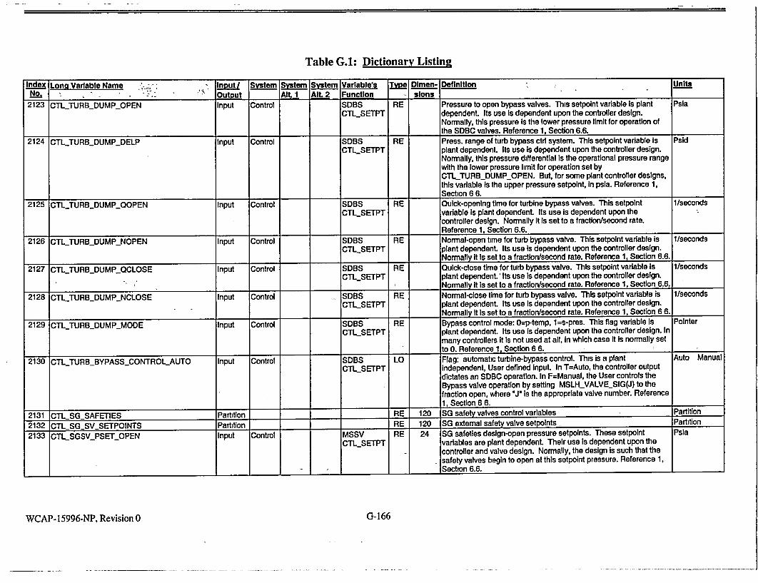
Table G.1: Dictionary Listing
Index Long Vaiable Name , Input/ System System System Variable's Type DImen- Definition Units
No. " • •' • Output Alt. I Alt. 2 Function slons
2123 CTL_TURB_DUMP_OPEN Input Control SDBS RE Pressure to open bypass valves. This setpoint variable Is plant Psla CTL_SETPT dependent. Its use Is dependent upon the controller design.
Normally, this pressure is the lower pressure limit for operation of the SDBC valves. Reference 1, Section 6.6.
2124 CTLTURB_DUMP_DELP Input Control SDBS RE Press. range of turb bypass ctd system. This setpoint variable is Psid
CTLSETPT plant dependent. Its use Is dependent upon the controller design. Normally, this pressure differential is the operational pressure range with the lower pressure limit for operation set by
CTLTURB_DUMP_OPEN. But, for some plant controller designs, this variable is the upper pressure setpoint, in psla. Reference 1,
Section 6 6.
2125 CTLTURB_DUMP_QOPEN Input Control SDBS RE Quick-opening time for turbine bypass valves. This setpoint 1/seconds CTLSETPT variable is plant dependent. Its use is dependent upon the
controller design. Normally it is set to a fraction/second rate. Reference 1, Section 6.6.
2126 CTITURBDUMPNOPEN Input Control SDBS RE Normal-open time for turb bypass valve. This setpoint variable is I/seconds CTLSETPT plant dependent. Its use Is dependent upon the controller design.
Normally It Is set to a fraction/second rate. Reference 1, Section 6.6.
2127 CTLTURBDUMP_QCLOSE Input Control SDBS RE Quick-close time for turb bypass valve. This setpoint variable is 1/seconds CTLSETPT plant dependent.' Its use Is dependent upon the controller design.
____I _Normally it is set to a fraction/second rate. Reference 1, Section 6.6.
2128 CTLJTURB_DUMP_NCLOSE Input Control SDBS RE Normal-close time for turb bypass valve. This setpoint variable is 1/seconds CTL_SETPT plant dependent. Its use is dependent upon the controller design.
I Normally It Is set to a fraction/second rate. Reference 1, Section 6 6.
2129 CTLTURBDUMPMODE Input Control SDBS RE Bypass control mode: O=p-temp, 1=s-pres. This flag variable Is Pointer
CTL.SETPT plant dependent. Its use Is dependent upon the controller design. In many controllers It is not used at all, In which case it is normally set to 0. Reference 1, Section 6 6.
2130 CTL_TURBBYPASS_CONTROLAUTO Input Control SDBS LO Flag: automatic turbine-bypass control. This is a plant Auto Manual
CTLSETPT independent, User defined Input. In T=Auto, the controller output dictates an SDBC operation. In F=Manual, the User controls the Bypass valve operation by setting MSLH_VALVESIG(J) to the fraction open, where VJ is the appropriate valve number. Reference 1, Section 6 6.
2131 CTLSGSAFETIES Partition RE 120 SG safety valves control variables Partition
2132 CTLSG_.SVSETPOINTS Partition RE 120 SG extemal safety valve setpoints Partition
2133 CTL_SGSV_PSET_OPEN Input Control MSSV RE 24 SG safeties design-open pressure setpoints. These setpoint Psla
CTLSETPT variables are plant dependent. Their use is dependent upon the controller and valve design. Normally, the design is such that the safety valves begin to open at this setpoint pressure. Reference 1, Section 6.6.
WCAP-15996-NP, Revision 0 G-166
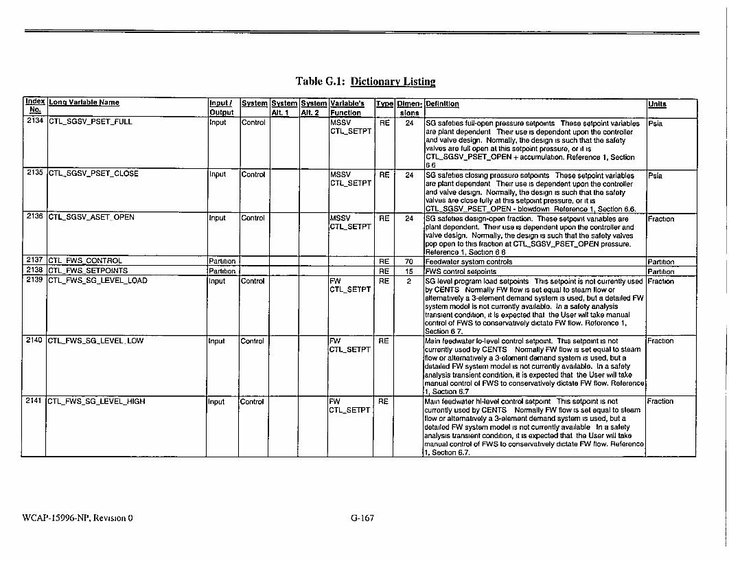
Table G.A: Dictionary Listing
Index Long Variable Name input/ System System System Variable's Type Dimen- Definition Units No. Output AIt. 1 Alt. 2 Function slons
2134 CTL_SGSV_PSET_FULL Input Control MSSV RE 24 SG safeties full-open pressure setpoints These setpoint variables Psia CTLSETPT are plant dependent Their use is dependent upon the controller
and valve design. Normally, the design is such that the safety valves are full open at this setpoint pressure, or it is CTLSGSVPSETOPEN + accumulation. Reference 1, Section 66
2135 CTL SGSVPSETCLOSE Input Control MSSV RE 24 SG safeties closing pressure setpoints These setpoint variables Psia CTLSETPT are plant dependent Their use is dependent upon the controller
and valve design. Normally, the design is such that the safety valves are close fully at this setpoint pressure, or it is CTL SGSV PSET OPEN - blowdown Reference 1, Section 6.6.
2136 CTLSGSVASET_OPEN Input Control MSSV RE 24 SG safeties design-open fraction. These setpoint variables are Fraction CTLSETPT plant dependent. Their use is dependent upon the controller and
valve design. Normally, the design is such that the safety valves pop open to this fraction at CTLSGSV_PSETOPEN pressure. Reference 1, Section 6 6
2137 CTL FWSCONTROL Partition RE 70 Feedwater system controls Partition 2138 CTLFWS SETPOINTS Partition RE 15 FWS control setpoints Partition 2139 CTLFWSSG LEVELLOAD Input Control FW RE 2 SG level program load setpoints This setpoint is not currently used Fraction
CTLSETPT by CENTS Normally FW flow is set equal to steam flow or altematively a 3-element demand system is used, but a detailed FW system model is not currently available. In a safety analysis transient condition, it is expected that the User will take manual control of FWS to conservatively dictate FW flow. Reference 1, Section 6 7.
2140 CTLFWSSGLEVELLOW Input Control FW RE Main feedwater o-level control setpoint. This setpoint is not Fraction CTLSETPT currently used by CENTS Normally FW flow is set equal to steam
flow or altematively a 3-element demand system is used, but a detailed FW system model is not currently available. In a safety analysis transient condition, it is expected that the User will take manual control of FWS to conservatively dictate FW flow. Reference 1, Section 6.7
2141 CTLFWSSGLEVELHIGH Input Control FW RE Main feedwater hi-level control setpoint This setpoint is not Fraction CTLSETPT currently used by CENTS Normally FW flow is set equal to steam
flow or alternatively a 3-element demand system is used, but a detailed FW system model is not currently available In a safety analysis transient condition, it is expected that the User will take manual control of FWS to conservatively dictate FW flow. Reference 1, Section 6.7.
WCAP-15996-NP, Revision 0 G-167
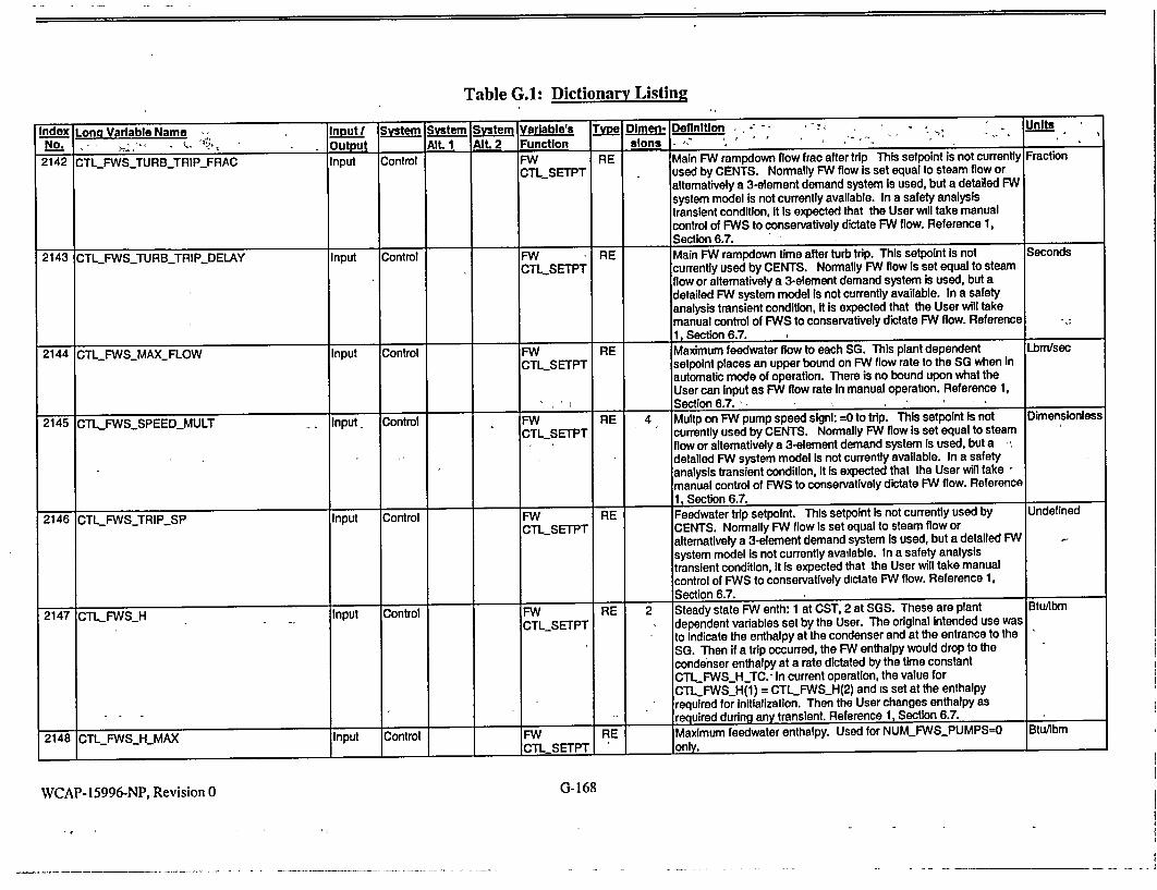
Table G.A: Dictionary Listing Index Long Variable Name Input System System System Variable's Type Dimen- Definition 2- - _ . Units
No-'. ,•"' • - Output - Alt.1, Alt. 2 Function" s__ lons I "-"•' "" •..
2142 CTLFWS_TURB_TRIP_FRAC Input Control FW RE Main FW rampdown flow frac after trip This setpoint is not currently Fraction CTLSETPT used by CENTS. Normally FW flow is set equal to steam flow or
alternatively a 3-element demand system is used, but a detailed FW system model is not currently available. In a safety analysis transient condition, It Is expected that the User will take manual control of FWS to conservatively dictate FW flow. Reference 1, Section 6.7.
2143 CTL_FWSTURB_TRIPDELAY Input Control FW RE Main FW rampdown time after turb trip. This setpoint is not Seconds CTLSETPT currently used by CENTS. Normally FW flow is set equal to steam
flow or alternatively a 3-element demand system is used, but a detailed FW system model is not currently available. In a safety analysis transient condition, it Is expected that the User will take manual control of FWS to conservatively dictate FW flow. Reference 1, Section 6.7.
2144 CTL_FWS_MAYFLOW Input Control FW RE Maximum feedwater flow to each SG. This plant dependent Lbm/sec CTL_SETPT setpoint places an upper bound on FW flow rate to the SG when In
automatic mode of operation. There is no bound upon what the User can input as FW flow rate In manual operation. Reference 1,
'_ __ _ _ Section 6.7. __III 1 1__
2145 CTLFWSSPEED_MULT Input Control FW RE 4 Multp on FW pump speed signi: -O to trip. This setpolnt is not Dimensionless CTL_SETPT currently used by CENTS. Normally FW flow is set equal to steam
flow or alternatively a 3-element demand system is used, but a , detailed FW system model Is not currently available. In a safety analysis transient condition, it Is expected that the User will take manual control of FWS to conservatively dictate FW flow. Reference
11, Section 6.7.
2146 CTL FWSfTRIPSP Input Control FW RE Feedwater trip setpoint. This setpoint Is not currently used by Undefined
CTL_SETPT CENTS. Normally FW flow Is set equal to steam flow or altematively a 3-element demand system Is used, but a detailed FW system model is not currently available. In a safety analysis transient condition, it Is expected that the User will take manual control of FWS to conservatively dictate FW flow. Reference 1, Section 6.7.
2147 CTLFWSH Input Control FW RE 2 Steady state FW enth: 1 at CST, 2 at SGS. These are plant BtuAbm
CTLSETPT dependent variables set by the User. The original Intended use was to indicate the enthalpy at the condenser and at the entrance to the SG. Then if a trip occurred, the FW enthalpy would drop to the condenser enthalpy at a rate dictated by the time constant CTL_FWS_H_TC. -In current operation, the value for CTLFWS_H(1) = CTLFWSH(2) and is set at the enthalpy required for Initialization. Then the User changes enthalpy as
required during any transient. Reference 1, Section 6.7.
2148 CTL_FWS_HMAX Input Control FWI RE Maximum feedwater enthalpy. Used for NUM_FWS_PUMPS--O Btu/ibm
I III _ CTL SETPT I only. ___
WCAP-15996-NP, Revision 0 G-168

Table G.A: Dictionary Listing
Index Long Variable Name Input System System System Variable's Type Dimen- Definition Units No_, Output Alt. 1 Alt. 2 Function slons
2149 CTLFWS_H_TC Input Control FW RE Feedwater enthalpy time constant. Used for NUMFWSPUMPS=0 Seconds CTL SETPT only. See CTL FWS H
2150 CTL_FWS_TRIP I/O Control FW LO FWS trip signal Reference 1, Section 6.7, and Reference 2, Table Active I CTL SETPT 2 Inactive
2151 CTLFWSAUTO Partition LO 14 Flags for automatic control of FW system Reference 1, Section 6.7. Partition 2152 CTLFWSCONTROLAUTO Input Control FW LO Master FW flag T=separate, F=all manual This is a plant Auto Manual
CTLSETPT independent, User defined input. In T=Auto, the controller output dictates a FW flow rate. In F=Manual, the User controls the FW flow by setting FWS FLOW(J) Reference 1, Section 6 7.
2153 CTLFWSVALVEAUTO Input Control FW LO 4 Flags: auto control of downcmr FW valves. This setpoint is not Auto Manual CTLSETPT currently used by CENTS. Normally FW flow is set equal to steam
flow or alternatively a 3-element demand system is used, but a detailed FW system model is not currently available In a safety analysis transient condition, it is expected that the User will take manual control of FWS to conservatively dictate FW flow AND enthalpy. Reference 1, Section 6.7.
2154 CTLFWS_ECONVALVEAUTO Input Control FW LO 4 Flags, auto control of econmzr FW valves. This setpoint is not Auto Manual CTLSETPT currently used by CENTS. If available, it would only be applicable
to System 80 design plants Reference 1, Section 6 7 2155 CTLFWSPUMPAUTO Input Control FW LO 4 Flags: auto control of main FW pumps This setpoint is not currently Auto Manual
CTLSETPT used by CENTS. Normally FW flow is set equal to steam flow or alternatively a 3-element demand system is used, but a detailed FW system model is not currently available. In a safety analysis transient condition, it is expected that the User will take manual control of FWS to conservatively dictate FW flow AND enthalpy. Reference 1, Section 6 7
2156 CTL_FWS_TRIPAUTO Input Control FW LO Flag. automatic main feedwater trip Reference 1, Section 6.7 Auto Manual CTL SETPT
2157 CTLFWS_VALVESIG Output RE 4, 2 Main FW valve demand signals Fraction Partition
2158 CTLFWS_SIG I/O Control FW RE 4 Main FW downcomer valve demand signal. This setpoint is not Fraction CTLSETPT currently used by CENTS. Normally FW flow is set equal to steam
flow or alternatively a 3-element demand system is used, but a detailed FW system model is not currently available. In a safety analysis transient condition, it is expected that the User will take manual control of FWS to conservatively dictate FW flow AND enthalpy Reference 1, Section 6 7; and Reference 2, Table 2.
2159 CTLFWSECONSIG I/O Control FW RE 4 Main FW economizer valve demand signal. This setpoint is not Fraction CTLSETPT currently used by CENTS If available, it would only be applicable
to System 80 design plants. Reference 1, Section 6 7; and Reference 2, Table 2.
2160 CTLFWSVALVE POS Output RE 4, 2 Main FW valve positions. Fraction _ __Partition I I I I
WCAP-15996-NP, Revision 0 G- 169

Table G.1: Dictionary Listing
Index Long Variable Name , lniut/ System SVstem System Varlable's, XType Dimen- Definition ., - -Units
No. . Output Alt. I Alt. 2 Function slons
2163 CTLFWSSPEEDSIG I/O Control FW RE 4 Main FW pumps speed demand signals. Reference 1, Section 6.7; Fraction CTLSETPT and Reference 2, Table 2.
2164 CTL._FWSSPEEDFRAC Output Control FW RE 4 Main FW pumps normalized speed, actual. This setpoint is not Fraction CTLSETPT currently used by CENTS. Normally FW flow is set equal to steam
flow or alternatively a 3-element demand system is used, but a detailed FW system model is not currently available. In a safety analysis transient condition, It Is expected that the User will take manual control of FWS to conservatively dictate FW flow AND enthalpy. Reference 1, Section 6.7.
2165 CTLFWSSPEED_MAX Input Control FW RE Main FW pumps reference speed. This setpoint is not currently Shaft RPM CTL_SETPT used by CENTS. Normally FW flow Is set equal to steam flow or'
altematively a 3-element demand system is used, but a detailed FW system model is not currently available. In a safety analysis transient condition, it Is expected that the User will take manual control of FWS to conservatively dictate FW flow AND enthalpy.
I__I __Reference 1, Section 6.7.
2166 CTLFWSISO_POS Output Control FW FW RE 4 Main FW isolation valve position. Reference 1, Section 6.7. Fraction CTLSETPT
2167 CTLFWSBYPSIG Output Control FW FW RE 4 Main FW bypass valve demand signal. Reference 1, Section 6.7. Fraction _CTLSETPT
2168 CTLAFWSCONTROL Partition RE 25 Aux feed system controls Partition
2169 CTLAFWSSETPOINTS Partition RE 20 AFWS control setpoints Partition
2170 CTL.AFWSSGLEVELLOW Input Control AFW RE 4 Low SG level setpoint for auxiliary feedwater. This setpoint Fraction CTL._SETPT variable is plant dependent. Its use is dependent upon the
controller design. Normally, at this level AFWS is actuated. This setpoint Is compared to either the actual downcomer water level calculated by CENTS, or it can be compared to the indicated water level which is based on the level indication model, complete with
_ calibration conditions, etc. Reference 1. Section 6.7.
2171 CTL AFWSSGLEVELHIGH Input Control AFW RE 4 High level setpoint for auxiliary feedwater. This setpoint variable is Fraction CTLSETPT plant dependent. Its use is dependent upon the controller design.
Normally, at this level AFWS flow Is terminated. This setpoint is compared to either the actual downcomer water level calculated by CENTS, or it can be compared to the Indicated water level which is based on the level Indication model, complete with calibration conditions, etc. Reference 1, Section 6.7.
2172 CTLAFWSTOTFLOW Input Control AFW RE Total aux-feed flow capacity, all SGs. This setpolnt variable is plant Lbm/sec CTLSETPT dependent. Its use Is dependent upon the controller design.
Normally, it Is not used because full flow rate is highly dependent upon SG pressure. Many CENTS control systems use an XTAB YTAB tables of pressure vs. flow with different SG and pump
_combinations included. Reference 1, Section 6.7.
WCAP-15996-NP, Revision 0 G- 170

Table G.I: Dictionary Listing
Index Long Variable Name Input System System System Variable's Type Dimen- Definition Units No. __._.Output Alt. 1 Alt. 2 Function slons
2173 CTLAFWSSGDPHIGH Input Control AFW RE SG differential pressure to cutout auxiliary feedwater to one SG. Psid CTLSETPT This setpoint variable is plant dependent Its use is dependent upon
the controller design. Normally, at this differential pressure flow is terminated to the SG with the lower pressure as a means of preventing flow to a ruptured SG Reference 1, Section 6.7.
2174 CTLAFWS DELAY Input Control AFW RE AFW time delay after trip. This setpoint vanable is plant dependent Seconds CTLSETPT Its use is dependent upon the controller design. Normally, this is
the delay from the time an actuation signal is activated until the AFW pumps and valves are operating and open providing flow to
.__ the SG Reference 1, Section 6 7 2175 CTLAFWSFLOWMULT Input Control AFW RE 4 Multiplier on auxiliary feedwater flow rate. This plant independent Dimensionless
CTLSETPT variable is set by the User. Normally it is set to 1 0 for realistic modeling of flow For special test purposes, the User may require some other value for this multiplier. Reference 1, Section 6 7
2176 CTLAFWSTURB_PUMP Input Control AFW RE AFWS turb-driven pump switch. 0=off, I=ok. This setpoint variable Pointer
CTLSETPT is plant dependent. Its use is dependent upon the controller and plant design. Normally, it is used to indicate a possible single failure of the turbine driven pump. Reference 1, Section 6 7.
2177 CTLAFWSMOTORPUMP Input Control AFW RE AFWS motor-drivn pump switch. 0=off,l=ok. This setpoint variable Pointer CTLSETPT is plant dependent Its use is dependent upon the controller and
plant design. Normally, it is used to indicate a possible single failure of the turbine driven pump Reference 1, Section 6 7.
2178 CTLAFWSCONTROLAUTO Input Control AFW LO Flag. automatic control of aux feed. This plant independent Auto Manual CTLSETPT variable is set by the User. In T=Auto, the controller output dictates
AFWS operation. In F=Manual, the User controls the AFWS flow by setting AFWS_.FLOW(J), "JV indicates the SG No Reference 1, Section 6.7.
2179 CTLAFWSSPEEDSIG I/O Control FW AFW AFW RE 4 AFW pumps speed demand signals. Reference 1, Section 6.7; and Fraction _CTL SETPT _ Reference 2, Table 2
2180 CTLRPCSCONTROL Partition RE 15 Reactor power cutback system Partition 2181 CTLRPCSSETPOINTS Partition RE 5 RPCS setpoints Partition 2182 CTLRPCSCONTROLAUTO Input Control RPCS LO Flag automatic RPCS control. Reference 1, Section 6 8. Auto Manual
CTL SETPT 2183 CTL_RPCS_TRIP I/O Control RPCS LO Signal. RPC engaged. Reference 1, Section 6 8, and Reference 2, Trip Normal
CTL SETPT Table 2 2184 CTLRPCSPTRIP Output Control RPCS LO RPC signal at last time step. Reference 1, Section 6.8. Trip Normal
CTL SETPT 2185 CTLRPCSTRIP_TIME Output Control RPCS RE Time elapsed since RP cutback engaged Reference 1, Section 6 8 Seconds
CTL SETPT 2186 CTLTURB SETBACK CONTROL Partition RE 20 Turbine setback and runback systems Partition 2187 CTL TURB SETBACK SETPOINTS Partition RE 10 Turb setback & runback system setpoints Partition 2188 CTLTURBSETBACKAUTO Input Control TURB LO Flag. automatic turbine setback control. Reference 1, Section 6 6. Auto Manual
SETBK SETPT
WCAP-15996-NP, Revision 0 G- 171

Table G.1: Dictionary Listing
Index Long Variable Name-_ . - Input/ System System System Variable's Type Dlmen- Definition ,- Units,' ,No...'•, -• - Output Alt. 1 AlL 2 , Function slone 2
2189 CTLTURB_RUNBACKAUTO Input Control TURB LO Flag: automatic turbine runback control. Reference 1, Section 6.6. Auto Manual SETBK SETPT
2190 CTL_TURBSETBACKTRIP I/O Control TURB LO Signal: turbine setback engaged. Reference 1, Section 6.6; and Trip Normal SETBK Reference 2, Table 2. SETPT
2191 CTLJURBRUNBACK I/O Control TURB LO Signal: turbine runback engaged. Reference 1, Section 6.6.; and True False SETBK Reference 2, Table 2. _SETPT ...
2192 CTLMISCSETPOINTS Partition ___RE 200 Miscellaneous user-defined setpoints Undefined 2193 CTLSETTEMP Input Control Model RE 20 Miscellaneous temperature setpoints. These setpoints, df used, are Degree F
Design totally dependent upon the design of the Individual plant CENTS controllers. Many controllers are unique and require constants which may not have a specifically defined setpoint variable. This array provides a place to record these values. Each basedeck
_calculation should define the use of each constant In this array. 2194 CTLSETDELTEMP Input Control Model RE 20 Miscellaneous delta-temp setpoints. These setpoints, if used, are Del-degF
Design totally dependent upon the design of the individual plant CENTS controllers. Many controllers are unique and require constants "which may not have a specifically defined setpoint variable. This array provides a place to record these values. Each basedeck calculation should define the use of each constant In this array.
2195 CTL SETDELTEMPD input Control Model RE 20 Miscellaneous per-delta-temp setpoints. These setpoints, if used, Per-degF Design are totally dependent upon the design of the Individual plant CENTS
controllers. Many controllers are unique and require constants which may not have a specifically defined setpolnt variable. This array provides a place to record these values. Each basedeck
_calculation should define the use of each constant in this array.
2196 CTLSETyPRES input Control Model RE 20 Miscellaneous pressure setpolnts. These setpoints, if used, are Psia Design totally dependent upon the design of the individual plant CENTS
controllers. Many controllers are unique and require constants which may not have a specifically defined setpoint variable. This array provides a place to record these values. Each basedeck calculation should define the use of each constant In this array.
2197 CTL._SET_PRESD Input Control Model RE 20 Miscellaneous per-pressure setpoints. These setpolnts, if used, are Per-psia Design totally dependent upon the design of the individual plant CENTS
controllers Many controllers are unique and require constants which may not have a specifically defined setpoint variable. This array provides a place to record these values. Each basedeck rcalculation should define the use of each constant In this array. I
WCAP-15996-NP, Revision 0 G-172

Table G.I: Dictionary Listing
Index Long Variable Name Inputl System System System Variable's Tlype Dimen- Definition Units No. Output Alt. 1 Alt. 2 Functlon slons
2198 CTLSETNODIM Input Control Model RE 60 Miscellaneous dimensionless setpoints These setpoints, if used, Dimensionless Design are totally dependent upon the design of the individual plant CENTS
controllers. Many controllers are unique and require constants which may not have a specifically defined setpoint variable This array provides a place to record these values. Each basedeck calculation should define the use of each constant in this array.
2199 CTLSETFLOW Input Control Model RE 10 Miscellaneous flowrate setpoints. These setpoints, if used, are Lbm/sec Design totally dependent upon the design of the individual plant CENTS
controllers. Many controllers are unique and require constants which may not have a specifically defined setpoint variable. This array provides a place to record these values Each basedeck
_calculation should define the use of each constant in this array 2200 CTLSETFLOWD Input Control Model RE 10 Miscellaneous per-flowrate setpoints. These setpoints, if used, are SecAbm
Design totally dependent upon the design of the individual plant CENTS controllers. Many controllers are unique and require constants which may not have a specifically defined setpoint variable This array provides a place to record these values. Each basedeck calculation should define the use of each constant in this array.
2201 CTLSETYPERTIME Input Control Model RE 20 Miscellaneous per-time setpoints. These setpoints, if used, are 1/seconds Design totally dependent upon the design of the individual plant CENTS
controllers. Many controllers are unique and require constants which may not have a specifically defined setpoint variable. This array provides a place to record these values. Each basedeck calculation should define the use of each constant in this array.
2202 CTLTIMECONSTANTS Input Control Model RE 150 Miscellan. user-defined time constants. These setpoints, if used, Seconds Design are totally dependent upon the design of the individual plant CENTS
controllers Many controllers are unique and require constants which may not have a specifically defined setpoint variable This array provides a place to record these values Each basedeck calculation should define the use of each constant in this array.
2203 CTLOUTPUT Partition RE 16 Output control partition Partition 2204 CTLOUTPUTINTERVAL Input Output IN Output frequency for line output CENTS produces a one-line Counts
output edit every CTLOUTPUTINTERVAL time steps. The user may change this to reduce the size of the output. Reference 1, Section 7 6 1
2205 CTLOUTPUTOPTION Input Output IN Line output option. CTLOUTPUT_OPTION modifies the one line Pointer output. If CTLOUTPUT_OPTION > 0.0. pressurizer 2-phase level is printed. Otherwise, indicated pressurizer level is printed
I_ I_ Reference 1, Section 7 6 1 2206 CTLOUTPUTCOUNT Input Output IN 4 Output counter- calls/ine/graph/title. CTLOUTPUT.COUNT is the Counts
total number of timesteps since the specified output was generated. The base deck requires initial values which are then updated during the run. Reference 1, Section 7.6.1.
WCAP-15996-NP, Revision 0 G-173

Table G.1: Dictionary Listing
Index Long Variable Name Input System System System Variable's Type Dlmn! Definition .. .. - , o , Units, . No., L . .. Output Alt 1 Alt. 2 Function slons
2207 CTL__OUTPUTNTITLE Input Output IN Une output title frequency. CTLOUTPUT._NTITLE specifies the Counts number of lines which are printed before a new title line Is printed. This should be set so that one title line Is printed on each page of output. The value depends on the printer being used, font size, etc. and must be adjusted by the user for his setup. Reference 1, Section 7.6.1.
2210 CTLOUTPUTLOOP Input Output IN 2 Select loops for the standard output. CTLOUTPUT"_LOOP Dimensionless specifies which 2 coolant loops (and associated steam generators) should be used for the standard output. For CE plants, the choice Is 1,2 because there are only two loops. Reference 1, Section 7.6.1.
2211 CTL_.OUTPUT__OPCL Input Output IN Determines which cold leg's temperature is displayed second in the Dimensionless standard output (Reference 1, Section 7.6.1.). That Is, display the temperatures of cold legs L and M, where: L = CTLOUTPUTLOOP(1)
I M = CTLOUTPUTLOOP(2) + CTL.OUTPUTOPCL 2214 CTL.TIMEBLOCK Partition RE 10 Time step control Information for CENTS Partition
2218 TIME I/O RE Simulation time. This variable is continually updated as CENTS Seconds Increments it by the value of TIME_SCALE. Since TIME is not used "anywhere in the CENTS calculational models, the User may reset or change TIME. However, some of the CEER background operations may be affected, such as SCREEN and RECORD.
2219 TIME-SCALE Input RE Global calculational time step length. Per unit
2220 TSTOP I/O RE Value of time at which to pause. Normally set by CENTS in Seconds accordance with the current TIME and the parameter of the GO command. Placing "TSTOP=0" In a WHEN command will cause the execution to pause when the WHEN Is activated.
2225 CTIINITIALCONDITIONS Partition RE 4 Flags for initial conditions Partition
2230 INITALL Output LO Internal flag set by CENTS when Initializing all the routines. True False
2231 INIT. OFF MODELS Partition LO 7 Off flags for initialization models True False
2232 INITOFFRCS Input LO Initialization of RCS: off flag. The INIT_OFFxxx flags are used to True False defeat the Initialization of each of the major models. These should set to False In the base deck.
2233 INIT_OFF._CHT Input LO Initialization of CHT: off flag. The INIT_OFFmxx flags are used to True False defeat the Initialization of each of the major models. These should
I__II set to False In the base deck.
2234 INITOFFPOW Input LO Initialization of POW: off flag. The INIT_OFFxxx flags are used to True False defeat the initialization of each of the major models. These should set to False in the base deck. _ _ _
2235 INITOFFSGS Input - LO Initialization of SGS: off flag. The INIT _OFF._xxx flags are used to True False defeat the Initialization of each of the major models. These should
-- ____set to False In the base deck. "
2236 INIT_OFFCON Input LO Initialization of CONT: off flag. The INITOFF._xxx flags are used True False to defeat the initialization of each of the major models. These _should set to False In the base deck.
G-174WCAP- 15996-NP, Revision 0

Table G.1: Dictionary Listing Inde.x Long Variable Name Input System System System Variable's Type Dimen- Definition Units
No._ Output Alt. 1 Alt. 2 Function slons 2236 INITITER Input IN Number of initialization passes. This is a plant independent variable Counts
set by the User to determine the number of code iterations on the steady state T/H solution Int-iter is the number of iterations during the initialization. Experience has shown that 30 iterations is sufficient. This value can be dependent on the controller setup The time steps assumed for the controllers during the initialization is 0.1 seconds so that the equivalent of 3 0 seconds pass - this is enough time to force the controllers to steady state so long as the time constants for lead/lags are less than 3 0 seconds Reference 1, Appendix D
2239 CTL ILEVEL Partition RE 15 instrument level readings for controls Fraction 2240 CTLSGILEVEL Output SG RE 4, 3 SG level readings. This output array is the CENTS calculated WA Fraction
and NR SG level indications The first index is the SG, and the second index is the reference leg as defined in the partition SG-REFLEGS This parameter is based on CENTS calculation of actual SG downcomer level and the fluid conditions with respect to the calibration conditions for the level indication system. These parameters are used in the controller system as input for controller actuation for such systems as RPS, AFW, FWCS, etc Reference 1, Sections 6 7 4 and 7 3 1
2241 CTL_PRZRILEVEL Output PZR RCS RE Pressurizer level reading This output is the CENTS calculated Fraction pressurizer level indication. This parameter is based on CENTS calculation of actual pressurizer level and the fluid conditions with respect to the calibration conditions for the level indication system. This parameter is used in the controller system as input for controller actuation for such systems as RPS, CVCS, Pressurizer heaters, etc. Reference 1, Section 6 2.2.
2243 CTL CONTROLLER Partition I RE 3000 Control module variables Partition 2244 ELLAST Output Control Model RE 1000 Saved 'last values" of control elements These "last values" are Undefined
Design needed as input by that particular element type in the next time step calculation See Reference 2. 2245 GROUT 1/O Control Model RE 1000 Control group output signals. This array of values represents the Undefined
Design final output from each controller at every time step. For any controller for which the malfunction MAL_CTL0 = T, the GROUT calculation is bypassed, and the User may input GROUT directly. See Reference 2
2246 MALCTL Input Control LO 1000 Control group malfunction cues See Reference 2 Malfunc Normal
2247 CTL_DELAYS Partition RE 50 Partition for control system delays. Note. Some delay variables Partition appear elsewhere: CTL_CORETURB_TRIPDELAY, CTL_SISDELAY, CTL_FWSTURB_TRIP_DELAY,
2248 _______________________ DELAYS _____tio ____CTL AFWS DELAY, SCRAM DELAY !Partitio 2248 OILCORETRIP DELAYS Partition ___RE 30 Partition for Scram channel delays Partition 2249 CTLCORE HIPOWER FRAC TRIPDL lnput Control I _ Delay RE I____High power fraction scram delay Seconds
WCAP-15996-NP, Revision 0 G- 175

Table G.1: Dictionary Listing
Index Long Variable Name - Input/ System Sstem System Variable's, Type Dimen- Definition Units No.....=. ' Output .. _Alt. 1 Alt 2 Function slons ____
2250 CTLCOREHIPOWERSURTRIPDL Input Control Delay RE High power SUR scram delay Seconds
2251 CTLCORELOWPRZRPRESTRIPDL Input Control Delay RE Low pressurizer pressure scram delay Seconds
2252 CTLCOREHIPRZRPRESTRIPDL Input Control Delay RE High pressurizer pressure scram delay Seconds
2253 CTLCOREHIPRZRLEVELTRIPDL Input Control Delay RE I High pressurizer level scram delays Seconds
2254 CTLCOREOVERTEMPMRGN_TRIPDL Input Control I Delay RE Over-temperature thermal margin scram delay Seconds
2255 CTLCOREOVERPOWERMRGNTRIPDL Input Control Delay RE Over-power thermal margin scram delay Seconds
2256 CTLCORERCSFLOWFRACTRIPDL Input Control Delay RE Low loop flow scram delay Seconds
2257 CTLCORE_SIASTRIPDL Input Control Delay RE Scram due to SIAS delay Seconds
2258 CTLCORELOWSGPRESTRIPDL Input Control 1 Delay RE Low SG pressure scram delay Seconds
2259 CTLCORELOWSGLEVELTRIPDL Input Control Delay RE Low SG level scram delay Seconds
2260 CTLCOREHISGLEVELTRIPDL Input Control Delay - RE High SG level scram delay Seconds
2261 CTL.STEAMFEED MISMATCHTRIPDL Input Control Delay RE Steam-feed flow mismatch scram delay Seconds
2262 CTLCOREHICONTPRESTRIPDL Input Control Delay RE High containment pressure scram delay Seconds
2263 CTLCOREUSERDEFINEDTRIPDL Input Control Delay RE 10 Space for other scram delays Seconds
2264 CTLMISCTRIPDELAYS Partition RE 20 Partition for miscellaneous control system delays Partition
2265 CTL TURB TRIP DELAY Input Control Delay RE Turbine trip signal delay I I Seconds
2266 CTL MSIS TRIP DELAY- Input Control Delay RE Main steamline Isolation signal delay Seconds
2267 CTLFWSTRIPDELAY Input Control Delay RE Main feedwater trip signal delay Seconds
2268 CTLRPCSTRIPDELAY Input Control Delay RE I Reactor Power Cutback signal delay Seconds
2269 CTLTURBSETBACK TRIPDELAY Input, Control Delay RE _ Turbine Setback signal delay Seconds
2270 CTL TURB RUNBACKDELAY Input Control Delay RE _ Turbine Runback delay Seconds
2271 CTL MISC DELAYS Input Control Delay RE 10 Space for other control system delays Seconds
2272 USER-COMMON Segment RE 1024 User global common variables Segment
2273 SCRAM.DELAY Input CORE RCS RE Total scram delay time after trip. This USER input is intended to be Seconds the delay time from the onset of a reactor trip signal until the scram breakers open. It may be different for each scenario, depending upon which trip function actuates. For safety analysis, it is usually set to the Tech Spec. max. time. Normally, it does not include the UV trip coil delay. This is usually Included In the scram reactivity vs. time table, which starts after SCRAMDELAY has elapsed. Note that some plant controller decks have lags established for the pressure, temperature, and level sensors. For these plants, it Is important for the USER to know how these lags figure into the overall calculation of the scram delay time so that the lags are not
"double counted" when entering a value for SCRAM-DELAY.
2274 MSLHNO.MOISTURECARRY Input MSL SG RE 1 => No moisture carryover. This Input variable = 1 forces CENTS Dimensionless to allow only steam to exit the SG outlet nozzle, regardless of the two-phase level in the SG. This allows compliance with regulatory guidelines for conservative estimations of SG blowdown during an MSLB event.
WCAP-15996-NP, Revision 0 G-176

Table G.A: Dictionary Listing
Index Long Variable Name !p System System System Variable's IYl! Dimen- Definition Units No. Output Alt. 1 Alt. 2 Function slons
2275 SGTINITOPTION Input SG RE 0 => Adjust area. 1 => Find SG press. During initialization of Dimensionless CENTS with a basedeck and set of initial conditions, two options are available for setting the SG steam dome pressure. If the USER knows exactly the desired pressure for the given scenario, then SGT_INITOPTION = 0 is chosen In this case, the code will adjust the tube heat transfer area to allow the proper RCS to SG heat balance necessary to attain the desired pressure Normally, the variable is set to 1, which allows CENTS to calculate the SG pressure which provides the best steady state heat balance for the given initial conditions. The SG tube heat transfer areas, in this case, remain at their base deck value
2276 INTERPOLATIONERROROPTION Input RE If 1 => Error stop after each interpolation out-of-table-range error, in Dimensionless order to avoid the danger of extrapolation If 0, => Extrapolation will proceed with no message
2277 SGSDEBUGSGSINI Input SG RE 1 => Debug print on in subroutine SGSINI. 0 => No debug print Dimensionless
2278 SGS DEBUG SGHEAT Input SG RE I => Debug print on in subroutine SGHEAT. 0 => No debug print Dimensionless
2279 CTLCOREPOWERA Output CORE RE Core power. This CENTS calculated output (in Mwt) is the Megawatts essentially equivalent to CTL_COREPOWER (in BTU/sec) or CTLCOREPOWERFRACTION (in fraction of POW USERPOWZ, which is design 100% power)
2280 SGSAREADOWNCOMER Input SG RE 4 Area of downcomer for bubble rise calculation This calculated Ft2
input is normally chosen to be an average area, or total volume/total height
2281 SGS ALPHA DOWNCOMER Output SG RE 4 Steam generator downcomer steam volume fractions Dimensionless
2282 SGSVEL31_MULT Input SG RE 4 Downcomer multiplier on Wilson velocity. Normally set to 1.0 Dimensionless except for special testing or tuning to known plant conditions or other codes
2283 SGS STEAM VEL31 Output SG RE 4 Steam velocity downcomer to steam dome Ft/sec
2284 RCS BALANCE Partition RCS RE 54 RCS mass and energy balance Partition
2285 RCS NODAL EXT FLOWS Output RCS RE 50 Sum of the external flows to each node. Reference 1, Section 7 6 3 Lbm/sec
2286 RCSNETEXTFLOW Output RCS RE Sum of all external RCS flows - includes PRZR. This output Lbm/sec parameter is the SUM(RCSNODALEXTFLOW(I)). Reference 1, Section 7 6 3
2287 RCS NET HEAT RATE Output RCS RE Sum of all heat flows to RCS Reference 1, Section 7 6 3 Btu/sec
2288 RCS_TOTALMASS Output RCS RE Sum of all RCS nodal fluid masses - inc PRZR. Reference 1, Lbm Section 7 6 3
2289 RCSTOTALENERGY Output RCS RE Sum of all RCS node total energy in the fluid system Reference 1, Btu I Section 7.6 3
2290 IODINE TOTALS PARTITION Partition RE 10 Variables to check iodine release model Partition
2291 RCS TOTAL IODINE Output RCS RE Total iodine in RCS nodes Curies
2292 SGS TOTAL IODINE Output RCS RE Total iodine in stm Generators & header Curies
2293 RCS IOD REL TOT Output RCS RE I Total of core release & external flows Cunes
2294 RCS IOD REL RATE Output RCS RE I__ Net rate of core release and ext flows Microcurie/sec
G3-177WCAP- 15996-NP, Revision 0

Table G.A: Dictionary Listing "Index Long Varable Name, , . 7input/ System System System Variable's,: Tp DImen- Definition,. . Unlts', ,
N , -... ,, Pi' •. Output - Alt1 Alt2. Function,:- slons : i.i.: -° - '
2295 CTLSUMMARY.DATA Partition RE 150 Case summary data Partition
2296 CTL MAXPOWERFRAC Output CORE RCS RE Maximum power fraction during run. Reference 1, Section 7.6.3. Fraction
2297 CTL_MAXPOWER TIME Output CORE RCS RE Time of maximum power during run. Reference 1, Section 7.6.3. Seconds
2298 CT _MAX HEATFLUX FRAC Output CORE RCS RE Maximum heat flux during run. Reference 1, Section 7.6.3. Fraction
2299 CTLMAXHEATFLUXTIME Output CORE RCS RE Time of maximum heat flux during run. Reference 1, Section 7.6.3. Seconds
2300 CTLMAXPRZR_PRESS Output PZR RCS RE Maximum Pressurizer Pressure during run. Reference 1, Section Psla
7.63.
2301 CTL_MAXPRZRPRESS_TIME Output PZR RCS RE Time of maximum Pressurizer Pressure during run. Reference 1, Seconds Section 7.6.3.
2302 CTLMINPRZRPRESS Output PZR RCS RE Minimum Pressurizer Pressure during run. Reference 1, Section Psia
- _1 -7.6.3.r
2303 CTLMINPRZRPRESS_TIME Output PZR RCS RE Time of minimum Pressunzer Pressure during run. Reference 1, Seconds
I ' Section 7.6.3. , ... .
2304 CTLMAX RCS PRESS Output RCS RE Maximum RCS Pressure during run. Reference 1, Section 7.6.3. Psia
2305 CTLMAXRCS_PRESS_TIME Output RCS RE Time of maximum RCS Press during run. Reference 1, Section Seconds
7.6.3.
2306 CTLMIN RCSPRESS Output RCS RE Minimum RCS Pressure during run. Reference 1, Section 7.6.3. Psla
2307 CTLMINRCSPRESSTIME Output RCS RE Time of Minimum RCS Press during run. Reference 1, Section Seconds 17.6.3.
2308 CTLMAXSG_PRESS Output SG RE 4 Maximum SG Pressure during run. Reference 1, Section 7.6.3. Psla
2309 CTLMAXSGPRESSTIME Output SG, RE 4 Time of maximum SG Press during run. Reference 1, Section Seconds
7.63.,
2310 CTL_MIN_SG_PRESS Output SG RE 4 Minimum SG Pressure during run. Reference 1, Section 7.6 3. Psia
2311 CTLMIN_SG_PRESSTIME Output SG RE 4 Time of minimum SG Press during run. Reference 1, Section 7.6.3. Seconds
2312 CTLINTEGPFLOWNONMOM Output RCS RE 50 Integrated flow though all leak paths. Reference 1, Section 7.6.3.- Ibm
2313 CTLINTEGSGSVALVES Output SG RE 50 Integrated flow though secondary paths. Reference 1, Section Lbm
- - __ 7.6.3. -
2314 CTLINTEGMSLBINFLOW Output MSL RE 8 Integrated flow MSLB Inside containment. Reference 1, Section Lbm
_. . .. __ 7.63.
2315 CTLJINTEG-MSLB-OUT.FLOW Output MSL RE Integrated flow MSLB outside containment Reference 1, Section Ibm
I . .. 7.6.3.
2316 CTLINITIAL COREFLOW Output CORE RCS RE Initial core flow. Reference 1, Section 7.6.3. Lbm/sec
2317 CTLCORE FLOWFRAC Output CORE RCS RE Normalized core flow - frac of initial. Reference 1, Section 7.6 3.- Fraction
2318 CTLHEATFLUXFRAC Output CORE RCS RE Core average heat flux fraction. Reference 1, Section 7.6.3. - Fraction
2319 CTL.CETOPMINDNBR Output RCS Core RE CETOP Minimum DNBR for the entire case run. Reference 1, Fraction
- I Section 7.6 3 and Appendix F.
2320 CTL CETOPMINDNBR_'IME Output RCS Core RE Time of CETOP Minimum DNBR. Reference 1, Section 7.6.3 and Seconds -- - - __ Appendix F.
2321 CETOPLINK . Partition RE 50 Partition to store CETOP link data. Referencel , Appendix F. Partition
2322 CETOP.OUT Partition RE 19 ICETOP standard output. Reference 1 , Appendix F. Partition
2323 CETOPOUTCASE Output RCS Core RE CETOP out: Case number. Reference 1 , Appendix F. Fraction
2324 jCETOPrOUT ODBL Output RCS Core RE CETOP out: Heat flux. Reference 1 , Appendix F. MegBtu/hr-f r. 1,7o
WCAP-15996-NP, Revision 0 U-I I0

Table G.I: Dictionary Listing
Index Lonfi Variable Name Input System System System Variable's Type Dimen- Definition Units No. Output Alt. 1 Alt. 2 Function slons
2325 CETOPOUTPOLR Output RCS Core RE CETOP out Power operating limit Reference 1 , Appendix F. Fraction 2326 CETOPOUT TIN Output RCS Core RE CETOP out: Inlet temperature Reference 1 , Appendix F. Degree F 2327 CETOPOUTPIN Output RCS Core RE CETOP out: Pressure Reference 1 , Appendix F. Psia 2328 CETOP OUT GAVG Output RCS Core RE CETOP out Core average mass velocity. Referencel , Appendix F 10e6 lb/hr-ft2 2329 CETOPOUT ASI Output RCS Core RE CETOP out, Axial shape index. Reference1, Appendix F Ratio 2330 CETOPOUTNRAD Output RCS Core RE CETOP out: Peripheral Axial shape index Referencel , Appendix Fraction
I_ F 2331 CETOP_OUTP1MAX Output RCS Core RE CETOP out: Max radial avg peaking factor Referencel , Appendix Fraction
F. 2332 CETOPOUT DNB-N Output RCS Core RE CETOP out: Min DNBR at final iteration. Referencel , Appendix F. Fraction 2333 CETOPOUT X-N Output RCS Core RE CETOP out, Quality at final iteration Referencel , Appendix F. Fraction 2334 CETOPOUT DNB-1 Output RCS Core RE CETOP out. Min DNBR at first iteration Referencel , Appendix F. Fraction 2335 CETOP OUT X-1 Output RCS Core RE CETOP out. Quality at first iteration Referencel , Appendix F. Fraction 2336 CETOPOUT QUIX Output RCS Core RE CETOP out' QUIX file case number. Referencel, Appendix F. Fraction 2337 CETOPOUTITER Output RCS Core RE CETOP out' Number of iterations. Referencel , Appendix F. Fraction 2338 CETOPOUTlEND Output RCS Core RE CETOP out: Iter code. 1 => DNBR converged. Referencel, Fraction
Appendix F. 2339 CETOPOUTATR Output RCS Core RE CETOP out. Average enthalpy transport coefficient Referencel, Composite
Appendix F. Units 2340 CETOPOUTHCH Output RCS Core RE CETOP out' Min DNBR hot channel number. Referencel, Pointer
Appendix F 2341 CETOPOUT MNOD Output RCS Core RE CETOP out: Min DNBR node location Referencel , Appendix F Pointer 2342 CETOP IN Partition RE 7 CETOP Inputs from CENTS Referencel , Appendix F Partition 2343 CETOP_IN_TIME Output RCS Core RE CETOP in: CENTS simulation time CETOPINJTIME is equal to Seconds
the CENTS variable TIME, and replaces CETOP vector #93. Referencel , Appendix F
2344 CETOPINFLOWFRAC Output RCS Core RE CETOP in: Normalized core flow. CETOPINFLOWFRAC is Fraction equal to the CENTS variable CTLCOREFLOWFRAC, which is defined as the ratio of the current core inlet mass flow to the initial core inlet mass flow. The CETOP mass flow specified by CETOP
I__II vector #1 is multiplied by this factor. Referencel , Appendix F. 2345 CETOPININLETTEMP Output RCS Core RE CETOP in' Core inlet temperature. CETOPjN_INLET_TEMP is Degree F
equal to the CENTS variable CHTTEMPCOOL(1) This value replaces CETOP vector #3 Referencel , Appendix F
2346 CETOPINCORE_PRESSURE Output RCS Core RE CETOP in' Core pressure CETOP IN COREPRESSURE is Psia equal to the CENTS variable PRESS(NODECORE). This value replaces CETOP input vector #4. Referencel , Appendix F.
2347 CETOP_IN_HEATFLUXFRAC Output RCS Core RE CETOP in: Heat flux fraction. CETOPIN_HEAT_FLUX_FRAC is Fraction equal to the CENTS variable CTLHEAT_FLUXFRAC, defined as the ratio of the current core average heat flux to the heat flux at full power The CETOP heat flux specified in CETOP vectors 2 and 102 are multiplied by this factor Referencel , Appendix F.
WCAP-15996-NP, Revision 0 G- 179

Table G.I: Dictionary Listing
Index Long Variable Name.,, -.Input System System System Variable's T DImen- Definition Un- tlt,.s No.-- Output Alt. 1- Alt. 2 Function slons - "
2348 CETOP_IN_FR_USER_MULT Input RCS Core RE CETOP In: User input Fr multiplier. CETOPJNN_FRUSERMULT Fraction is a user specified multiplier on the CETOP Fr given by CETOP input vector # 58. The base radial peak used by CETOP Is specified in the CETOP input file by the variable A(58). When the CETOP link Is active, this peak Is adjusted by two multiplicative factors. The first factor is CETOPIN_FR_USER_.MULT. The user sets this multiplier (possibly with the RAMP command) to account for radial effects such as the increase In Fr due to a dropped CEA. This variable should normally be set to 1.0. The second factor is CETOP_IN_FRTEMPMULT. Referencel , Appendix F.
2349 CETOPJN.FR.TEMP..MULT Output RCS Core RE CETOP In: FR temperature multiplier. Fraction CETOP_IN_FRTEMPMULT is one of two multipliers on the CETOP Fr given by CETOP input vector #58. This factor accounts for the increase in core peaking due to changes In core inlet temperature. The variable CETOPINFR TEMPMULT is calculated by CENTS based on current path temperatures by the formula
CETOPINFRTEMPMULT = 1.0 + CETOPFRDERIV ICETOPFRDELTEMPI
The other multiplier Is CETOP_IN_FR_USER_MULT: Referencel, _ _ _ _ _ _Appendix F.
2350 CETOPLINKCONTROL Partition RCS Core RE 7 CETOP link variables and options. Referencel , Appendix F. Partition
2351 CETOPPRESSOPT Input RCS Core LO CETOP link: Constant pressure option. CETOPPRESS_OPT Is a True False flag to use constant pressure in the DNBR calculation. The default is False, so that CETOP is passed the current value of core pressure. When CETOPPRESS_OPT is set to true, the data base variable CETOP_IN_CORE_PRESSURE must be set by the user. Referencel , Appendix F.
2352 CETOPFR-DERIV Input RCS Core RE CETOP link: User input derivative of Fr with respect to temperature. 1/Del-DegF See CETOPINFRTEMPMULT. The variable CETOPFRDERIV Is specified by the user. A typical value Is 0.005 /degF. To disable the Fr temperature correction, set CETOP_IN_FR_DERIV to 0 0 so that CETOPINFRTEMP._MULT will always be 1.0. Referencel, Appendix F.
2353 CETOPLFRPATH1 Input RCS Core IN CETOP link: Path number for CETOPYFR-TEMP1. Referencel, Pointer -_-_ _Appendix F.
2354 CETOPFRPATH2 Input RCS Core IN CETOP link: Path number for CETOP_FR_TEMP12. Reference1, Pointer Appendix F..
WCAP-15996-NP, Revision 0 G-180

Table G.1: Dictionary Listing
Index Long Variable Name Input System System System Variable's Type Dimen- Definition Units No.___ Output Alt. 1 Alt. 2 Function slons
2355 CETOP-FRJTEMP1 I/O RCS Core RE CETOP link. Templ for DT calculation. Degree F
If CETOP_FR_PATHt1 > 0. Temperature in that path, set be CENTS If CETOPFRPATH1 < 0 Constant temperature, assigned by user.
This enables the user to calculate the temperature correction based on the difference of a path temperature and a reference value.
See CETOPFRDEL_TEMP and CETOPINFRTEMPMULT. Referencel , Appendix F.
2356 CETOPFR_TEMP2 I/O RCS Core RE CETOP link. Temp2 for DT calculation. Degree F If CETOPjRPATH2 > 0. Temperature in that path, set be CENTS
If CETOP FRPATH2 <0. Constant temperature, assigned by user. This enables the user to calculate the temperature correction based on the difference of a path temperature and a reference value.
See CETOPFRDELTEMP and CETOPIN_FR_TEMPMULT. Referencel , Appendix F
2357 CETOPFR_DELTEMP Output RCS Core RE CETOP link: Temp Duff for Fr correction. The variable Degree F CETOPFRDEL.TEMP used in the Fr temperature correction is an inlet temperature difference which is calculated as the difference of CETOPFRTEMP1 and CETOP_FRTEMP2. The two temperatures are set by CENTS to the temperature of any CENTS paths based on the value of the pointers CETOPFR_PATH1 and CETOPFR.PATH2. If the value of one or both of the pointers is 0, the corresponding temperature is not updated by CENTS and must be set by the user. This enables the user to calculate the temperature correction based on the difference of a path temperature and a reference value. Referencel , Appendix F
2358 VATTENFALL-MISCELLANEOUS Partition RE 200 Partition for Vattenfall use Partition
2359 INITDEBUGOUTPUT Input RE 1 => Debug print on in the INITIALization routine. 0 => No debug Dimensionless print
2367 CDCONT COMMON Partition RE 50 Container array for Cooldown Controllers Partition
2368 DBG SGTR PARTITION Output RCS RE 36 SGTR Debug Variables Partition
2369 DBG SGTR FLOW1 Output RCS RE 4 Debug Variable SGTR Flow side 1 Lbm/sec
2370 DBGSGTR FLOW2 Output RCS RE 4 Debug Variable SGTR Flow side 2 Lbm/sec
2371 DBG SGTR FLOW SLOT Output RCS RE 4 Debug Variable SGTR Slot flow Lbm/sec
2372 DBG SGTR PRESS PRIl Output RCS RE 4 Debug Variable SGTR Primary pressure side 1 Psia
2373 DBG SGTR PRESS PRI2 Output RCS RE 4 Debug Variable SGTR Primary pressure side 2 Psia
2374 DBG SGTR PRESS SG Output RCS RE 4 Debug Vanable SGTR Secondary pressure Psia
2375 IDBG SGTR PRESS ITER Output RCS RE 4 Debug Variable SGTR Slot pressure Psia
2376 DBG SGTR SVOL TUBE1 Output RCS RE 4 Debug Variable SGTR Tube 1 specific volume ftA3/Ibm
2377 DBG SGTR SVOL TUBE2 Output RCS RE 4 Debug Variable SGTR Tube 2 specific volume ft^3/Abm
2378 FWS COMMON Segment FW RE 20000 Feedwater System model segment Segment
2379 FWS FDPATH Partition FW RE 1600 FWS model flow path partition Partition
WCAP-15996-NP, Revision 0 G-181

Table G.1: Dictionary Listing
Index Long Variable Name , Input/ Sstem System System Variable's Type Dlmen- Definition . Units
No.. - Output Alt. 1 AIL-2 Function sions
2380 FWS_DPEL Input FW Plant Design RE 50 FWS model flow path elevation gain, external path. Referencel, Feet Section 5.5, 6.7 and 7.3.4.
2381 FWS._CV Input FW Plant Design RE 50 FWS model flow path flow coefficient Referencel , Section 5.5, 6.7 Composite
I I and 7.3 4. 1 Units
2382 FWS_RESL Input/init FW Plant Design RE 50 FWS model flow path flow resistance. Referencel , Section 5 5, 6.7 Composite and 7.3 4. Units
2383 FWSRHOFD Output FW T/H State RE 50 FWS model flow path density. Referencel , Section 5.5, 6.7 and Lbm/FtA3 7.34. _
2384 FWSPEXT Output FW T/H State RE 50 FWS model flow path external pressure. Referencel , Section 5.5, PsIa I_ I_ I_16.7 and 7.3.4.
2385 FWSWMAS Output FW T/H State RE 50 FWS model flow path mass flow rate. Referencel , Section 5.5, 6.7 Lbm/sec , I I and 7.3.4. __-_ __-
2386 FWS_W0 Output FW T/H State RE FWS model flow path volumetric flow. Referencel , Section 5.5, 6.7 Gal/min and 7.3 4.
2387 FWSW Output FW T/H State RE 50 FWS model flow path volumetric flow. Referencel , Section 5.5, 6.7 Gal/min III_ and 7.3 4.
2388 FWSHPATH Output -W T/H State RE 50 FWS model flow path flow enthalpy. Referencel Section 5.5, 6.7, BtuA/bm _ I _ and 7.3.4. - ,
2389 FWSOCURR Output FW RE 50 FWS model flow path heat transfer. Referencel , Section 5.5, 6.7 Btulsec and 7.3 4. .
2390 FWSRESV Output FW RE 50 FWS model flow path valve flow resistance. Referencel , Section Composite - 5.5, 6.7 and 7.3 4. Units
2391 FWSRES Output FW RE 50 FWS model flow path total resistance. Referencel , Section 5.5, Composite
1 6.7 and 7.3 4. Units
2392 FWS_HEXT Output MW T/H State RE 50 FWS model flow path ext node enthalpy. Referencel , Section 5.5, BtuA/bm 6.7 and 7.3 4.
2393 FWSRHOEXT Output FW T/H State RE 50 FWS model flow path ext node density. Referencel , Section 5.5, Lbm/FtA3 .. 6.7 and 7.3 4.
2394 FWSRP Output FW RE 50 FWS model flow path pump resistance. Referencel , Section 5.5, Composite
-_6.7 and 7.3 4. Units
2395 FWSPS Output FW RE 50 FWS model flow path pump head. Referencel , Section 5.5, 6.7 PsId
and 7.3 4.
2396 FWS_SUMP Output -'W RE 50 -NS model flow path pressure error. Reference1 , Section 5 5, 6.7 Psid and 7.3 4. - . .
2397 FWS_GPMCOR Output FW RE 50 FWS model flow path density correction. Referencel , Section 5.5, Composite 6.7 and 7.3.4. Units
2398 FWS_NDIN Input MW Model IN 50 FWS model flow path Input node ID.- Referencel , Section 5.5,6.7 Pointer
- - _ _ __ Design and 7.3.4.._-_-
2399 FWSNDOUT - Input FW Model IN 50 FWS model flow path output node ID. Referencel , Section 5 5, 6.7 Pointer
R...... Design and 7.3 4. _ _ _ _ _
2400 FWS_NDEXT Input FW Model IN 50 FWS model flow path external node ID. Referencel , Section 5.5, Pointer
I _Design 1 6 7 and 7.3.4. _
WCAP-15996-NP, Revision 0 G-182

Table G.A: Dictionary Listing
Index Lonq Variable Name Input/ System System System Variable's Type Dimen- Definition Units No. Output Alt. 1 Alt. 2 Function slons
2401 FWSNCPUMP Input FW Model IN 50 FWS model flow path pump ID Referencel, Section 5.5, 6.7 and Pointer Design 7 3 4
2402 FWSICPUMP Output FW IN 50 FWS model flow path pump status. Referencel , Section 5 5, 6.7 Flag I and 7.3 4
2403 FWSICK Input FW Model IN 50 FWS model flow path check valve flag. Referencel , Section 5 5, Pointer Design 6.7 and 7 3 4
2404 FWS_IMF Output FW IN 50 FWS model flow path calculation flag. Referencel , Section 5 5, 6 7 Pointer and 7.3.4.
2405 FWS._POSISO I/O FW RE 50 FWS model path isolation valve position. Referencel , Section 5 5, Fraction 6 7 and 7.3 4.
2406 FWSCVAFLO Output / FW RE 50 FWS model path check valve flow area. Reference 1 , Section 5.5, Fraction lnit 6 7 and 7 3.4.
2407 FWSCVRESMN Input/Init FW RE 50 FWS model path check valve flow resistance. Referencel , Section Composite 5 5, 6 7 and 7 3 4 Units
2408 FWSCVDPMIN Input/init FW RE 50 FWS model path check valve minimum DP. Referencel , Section Psid 5 5, 6 7 and 7 3.4.
2409 FWSNFLO Input FW Model IN FWS model network number of paths. Reference1 , Section 5 5, Counts Design 6 7 and 7 3 4
2410 FWS_KEY Output FW IN FWS model any fw pumps on flag. Referencel , Section 5.5, 6.7 Flag and 7.3.4.
2411 FWS_FDNODE Partition FW RE 400 FWS model node partition Partition 2412 FWSPEXTN Input FW T/H State RE 20 FWS model external node pressure. Referencel , Section 5.5, 6.7 Psia
I_ and 7 3 4 2413 FWSHEXTN Input FW TiH State RE 20 FWS model external node enthalpy Referencel , Section 5 5, 6.7 Btu/lbm
I land 7 3.4. 2414 FWS_P0 Output FW T/H State RE FWS model node pressure. Referencel , Section 5.5, 6.7 and Psia
1734 2415 FWS_P Output / FW T/H State RE 30 FWS model node pressure Referencel , Section 5.5, 6.7 and Psia
Init 734 2416 FWSHNODE Output / FW T/H State RE 30 FWS model node enthalpy Referencel , Section 5 5, 6 7 and Btu/lbm
Init 734 2417 FWSRHONOD Output FW T/H State RE 30 FWS model node density. Referencel , Section 5 5, 6.7 and 7 3.4. Lbm/FtA3 2418 FWSWEXTF I/O FW T/H State RE 30 FWS model node ext flow. Positive out of node. Typically used to Lbm/sec
represent leakage flow out of system. Reference1, Section 5.5, 6.7 and 7 3 4
2419 FWSHEXTF I/O FW T/H State RE 30 FWS model node external flow enthalpy = node enthalpy for Btu/lbm leakage flow leaving a node.. Referencel , Section 5.5, 6.7 and 7.3.4.
2420 FWS_AEXTF Input FW T/H State RE 30 FWS model node extemal flow leakage area used to calculate the Ft2
leakage flow rate given node pressure and leakage flow path external node pressure below.. Referencel , Section 5.5, 6.7 and
1___ 1734 1
WCAP-I5996-NP, Revision 0 G-183

Table G.A: Dictionary Listing
Index Lona Variable Name - -, - Input I System System System Varlable'st, Type Dimen- Definition " .. Units
No. - Output Alt.,1- Alt. 2. Function slons ,
2421 FWS_PEXTF 1/0 FW T/H State RE 30 FWS model node external leakage flow back pressure used to Psia
calculate leakage flow.. Referencel , Section 5.5, 6.7 and 7.3.4.
2422 FWSWSUM Output FW RE 30 FWS model node flow error. Referencel , Section 5.5, 6.7 and Lbm/sec
1 7.34.
2423 FWSIMN Output FW IN 30 FWS model node network masking flag. Referencel, Section 5.5, Pointer 6.7 and 7.3 4.
2424 FWS._NNOD Input FW Model IN FWS model network number of nodes. Referencel, Section 5.5, Counts
Design 6.7 and 7.3.4. 1
2425 FWSNEXTN Input , FW Model IN FWS model network number of extnodes. Referencel , Section Counts
.I Design 5.5, 6.7 and 7.3 4.
2426 FWSNPSGMFW Input FW SG Model IN 4 FWS model SG main fw path ID. Reference1 , Section 5.5, 6.7 and Pointer
Design 7.3.4.
2427 FWSNPSGECO Input FW SG Model IN 4 FWS model SG economizer fw path ID. Referencel , Section 5.5, Pointer.
Design 6.7 and 7.3.4.
2428 FWSNPSGAFW Input FW SG AFW Model , IN 4 FWS model SG emergency/aux fw path ID. Referencel , Section Pointer
-_ _ Design 5.5, 6.7 and 7.3.4.
2429 FWS,_NPFWLB Input FW Model IN 4 FWS model MFWLB path ID. Referencel , Section 5 5, 6.7 and Pointer
-Design 7.34. 1 "
2430 FWS, AFWLB Output FW RE 4 FWS model MFWLB flow area (local) F•t2
2432 FWSNSG Output FW IN FWS model number of SG (local) Pointer
2433 FWS_FDVALV Partition FW __ RE 1000 FWS model valve partition Partition
2434 FWS STROKE I/O FW RE 30 FWS model valve demand (per cent) Percent
2435 FWSPOSIT Output FW RE 30 FWS model valve position. Referencel , Section 5 5, 6.7 and 7.3.4. Percent
2436 FWSVCW Output FW RE 30 FWS model valve flow coefficient. Referencel , Section 5.5, 6.7 Composite
and 7.3.4. Units
2437 FWS_TOPN Input FW Component RE 30 FWS model valve stroke open time. Referencel , Section 5.5, 6.7 Seconds
_Design and 7.3.4.
2438 FWSTCLOS Input FW Component RE 30 FWS model valve stroke close time. Referencel , Section 5.5, 6.7 Seconds
Design _ and 7.3.4.
2439 FWSTLAG Input FW - Component RE 30 FWS model valve actuator lag. Referencel , Section 5.5, 6.7 and Seconds Design 7.34.
2440 FWS CVP Input FW Component RE 200 FWS model valve CV vs Position. Referencel , Section 5 5, 6.7 Composite
-_Design and 7.3.4. Units
2441 FWSSTP Input FW Component RE 200 FWS model valve position vs CV. Referencel , Section 5.5, 6.7 Fraction
CD si n and 7.3.4.
2442 FWSNPATH Input FW Model IN 30 FWS model valve path location ID. Referencel , Section 5.5, 6.7 Pointer
Design and 7.3.4.
2443 FWSNTABLE Input, FW Model.- IN 30 FWS model valve CV table ID. Referencel , Section 5.5, 6.7 and Pointer
S .... . .... Design 7.3.4.
2444 FWSNPTV Input FW IN 10 FWS model valve CV table no of pts. Referencel , Section 5.5, 6.7 Counts
and 7.3.4.
2445 FWSINDEXF Output FW IN 30 FWS model valve CV table Index. Referencel , Section 5.5, 6.7 Pointer
and 7.3.4.
U_- 1154.WCAP-15996-NP, Revision 0
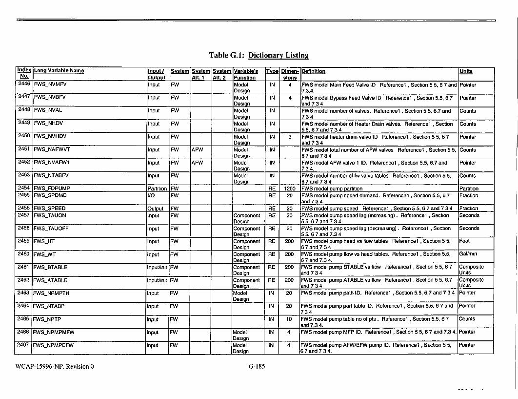
Table G.1: Dictionary Listing
Index Long Variable Name Input System System System Variable's Type Dimen- Definition Units No_. Output Alt. 1 Ait. 2 Function slons 2446 FWSNVMFV Input FW Model IN 4 FWS model Main Feed Valve ID Referencel , Section 5 5, 6 7 and Pointer
Design 7.3.4. 2447 FWSNVBFV Input FW Model IN 4 FWS model Bypass Feed Valve ID Reference1 , Section 5.5, 6 7 Pointer
Design and 7 3 4 2448 FWSNVAL Input FW Model IN FWS model number of valves. Referencel , Section 5.5, 6.7 and Counts
Design 73 4 2449 FWSNHDV Input FW Model IN FWS model number of Heater Drain valves. Referencel , Section Counts
Design 5 5, 6 7 and 7 3 4 2450 FWSNVHDV Input FW Model IN 3 FWS model heater drain valve ID Referencel , Section 5 5, 6 7 Pointer
Design and 7 3 4 2451 FWSNAFWVT Input FW AFW Model IN FWS model total number of AFW valves Referencel , Section 5 5, Counts
Design 6 7 and 7 3 4 2452 FWSNVAFW1 Input FW AFW Model IN FWS model AFW valve 1 ID. Referencel , Section 5.5, 6.7 and Pointer
I Design 7 3 4. 2453 FWSNTABFV Input FW Model IN FWS model number of fw valve tables Referencel, Section 5 5, Counts
Design 6 7 and 7 3 4 2454 FWS FDPUMP Partition FW RE 1200 FWS model pump partition Partition 2455 FWSSPDMD I/O FW RE 20 FWS model pump speed demand. Referencel , Section 5.5, 6.7 Fraction
and 734 2456 FWS SPEED Output FW RE 20 FWS model pump speed Referencel , Section 5 5, 6 7 and 7 3 4 Fraction 2457 FWSTAUON Input FW Component RE 20 FWS model pump speed lag (increasing). Reference1, Section Seconds
Design 55,6 7and734 2458 FWSTAUOFF Input FW Component RE 20 FWS model pump speed lag (decreasing). Referencel , Section Seconds
Design 5 5, 6 7 and 7.3 4 2459 FWSHT Input FW Component RE 200 FWS model pump head vs flow tables Reference 1 , Section 5 5, Feet
Design 6 7 and 7 3 4 2460 FWSWT Input FW Component RE 200 FWS model pump flow vs head tables. Referencel , Section 5.5, Gal/mmn
Design 6 7 and 7.3 4. 2461 FWSBTABLE Input/mit FW Component RE 200 FWS model pump BTABLE vs flow Referencel , Section 5 5, 6 7 Composite
I Design and 7 3 4 Units 2462 FWSATABLE Inputhmit FW Component RE 200 FWS model pump ATABLE vs flow Referencel , Section 5 5, 6.7 Composite
Design and 7 3 4 Units 2463 FWSNPMPTH Input FW Model IN 20 FWS model pump path ID. Referencel , Section 5.5, 6.7 and 7 3 4 Pointer
Design 2464 FWSNTABP Input FW IN 20 FWS model pump perf table ID. Referencel , Section 5.5, 6 7 and Pointer
734 2465 FWSNPTP Input FW IN 10 FWS model pump table no of pts. Referencel , Section 5.5, 6 7 Counts
and 7.3 4. 2466 FWSNPMPMFW Input FW Model IN 4 FWS model pump MFP ID. Referencel , Section 5 5, 6 7 and 7.3 4. Pointer
Design 2467 FWSNPMPEFW Input FW Model IN 4 FWS model pump AFW/EFW pump ID. Referencel , Section 5 5, Pointer
Design 6 7 and 7 3 4.
WCAP-15996-NP, Revision 0 G-185
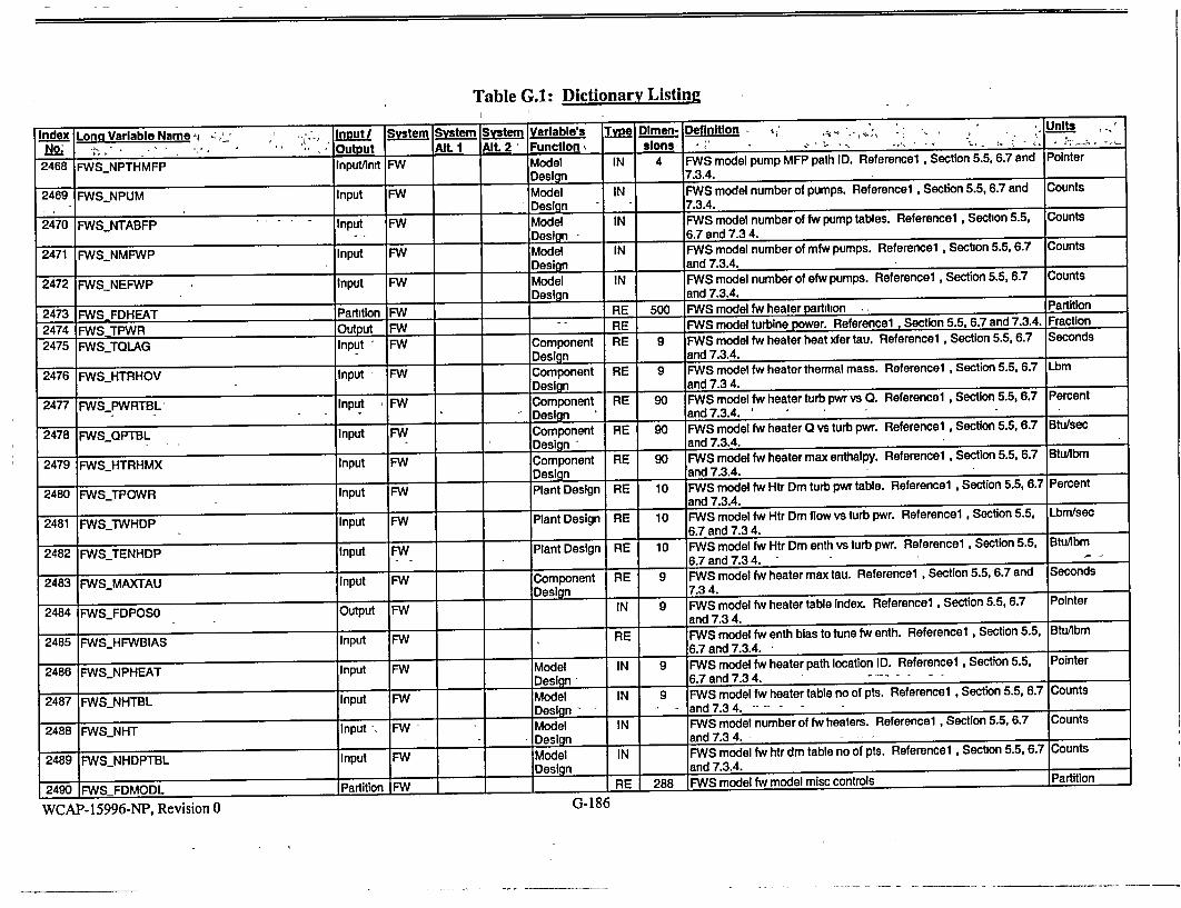
Table G.1: Dictionary Listing
Index Long Variable Name , Input I System System System Variable's Type Dimen- Definition • , - , - Units
No.. , -- Output Alt. 1 AlL 2 Function , slons, - , - .....
2468 FWSNPTHMFP Inputinit FW Model IN 4 FWS model pump MFP path ID. Referencel Section 5.5, 6.7 and Pointer
Design 7.3.4.
2469 FWS.NPUM Input FW Model IN FWS model number of pumps. Referencel , Section 5.5, 6.7 and Counts I . Design 7.3.4.
2470 FWS.NTABFP Input FW Model IN FWS model number of fw pump tables. Referencel , Section 5.5, Counts
- - Design 16.7 and 7.3 4.
2471 FWS_NMFWP Input FW Model IN FWS model number of mfw pumps. Referencel , Section 5.5, 6.7 Counts
Design and 7.3.4.
2472 FWSNEFWP Input FW Model IN FWS model number of efw pumps. Reference1 , Section 5.5, 6.7 Counts Design and 7.3.4.
2473 FWSFDHEAT Partition FW RE 500 FWS model fw heater partition - Partition
2474 FWSTPWR Output -FW "_ RE FWS model turbine power. Referencel , Section 5.5, 6.7 and 7.3.4. Fraction
2475 FWS_TQLAG Input FW Component RE 9 FWS model fw heater heat xfer tau. Referencel , Section 5.5, 6.7 Seconds
Design and 7.3.4.
2476 FWSHTRHOV Input FW Component RE 9 FWS model fw heater thermal mass. Referencel , Section 5.5, 6.7 Lbm
Design and 7.3 4.
2477 FWSPWRTBL Input FW Component RE 90 FWS model fw heater turb pwr vs 0. Referencel , Section 5.5, 6.7 Percent
Design -' and 7.3.4. _
2478 FWSQPTBL Input FW Component RE 90 FWS model fw heater 0 vs turb pwr. Referencel , Section 5.5, 6.7 Btu/sec
_ _ _Design - and 7.3.4. _
2479 FWS._HTRHMX Input FW Component RE 90 FWS model fw heater max enthalpy. Referencel , Section 5.5, 6.7 Btu/ibm
Design -and 7.3.4.....
2480 FWSTPOWR Input FW Plant Design RE 10 FWS model fw Htr Dm turb pwr table. Referencel , Section 5.5, 6.7 Percent and 7.3.4.
2481 FWS-TWHDP Input FW Plant Design RE 10 FWS model fw Htr Dm flow vs turb pwr. Referencel , Section 5.5, Lbm/sec - -6.7 and 7.3 4.
2482 -FWSTENHDP Input FW Plant Design RE 10 FWS model fw Htr Dm enth vs turb pwr. Referencel , Section 5.5, BtuAbmn 6.7 and 7.3 4.
2483 FWS..MAXTAU Input FW Component RE 9 FWS model fw heater max tau. Reference1 , Section 5.5, 6.7 and Seconds
Design 7.34.
2484 FWSjFDPOS0 Output FW IN 9 FWS model fw heater table index. Referencel , Section 5.5, 6.7 Pointer
and 7.3 4.
2485 FWSHFWBIAS Input FW RE FWS model fw enth bias to tune fw enth. Reference1 , Section 5.5, Btu/ibrn 6.7 and 7.3.4.
2486 FWSNPHEAT Input FW Model IN 9 FWS model fw heater path location ID. Referencel , Section 5.5. Pointer
Design - 6.7 and 7.3 4. - .
2487 FWSNHTBL Input FW Model IN 9 FWS model fw heater table no of pts. Reference1 , Section 5.5, 6.7 Counts
- _ - -Design - - and 7.3 4.
2488 FWSNHT Input FW - Model IN FWS model number of fw heaters. Referencel , Section 5.5, 6.7 Counts
Design and 7.3 4. - -_--___
2489 FWSNHDPTBL Input FW Model IN FWS model fw htr dm table no of pts. Referencel , Section 5.5, 6.7 Counts
2489-Design and 7.3.4.
2490 nFWSnFDMODL Partition FW - RE 288 FWS model fw model misc controls Partition
WCAP-15996-NP, Revision 0 U-Loo

Table G.1: Dictionary Listing Index Long Variable Name Inpout System System System Variable's Type Dlmen- Definition Units
N.Output Alt. 1 Alt. 2 Function slons 2491 FWSNRCIRC Input FW Model IN FWS model no of recirc flow cntds. Referencel , Section 5 5, 6.7 Counts
Design and 7 3 4 2492 FWSFWRCPB Input FW Controller RE 20 FWS model pump recirc control PB. Referencel , Section 5.5, 6 7 Percent Setpoint and 7.3 4 2493 FWSFWRCRE Input FW Controller RE 20 FWS model pump recirc control reset Referencel , Section 5.5, Seconds Setpoint 6.7 and 7 3 4 2494 FWSFWRCSP Input FW Controller RE 20 FWS model pump recirc control setpt Reference1 , Section 5 5, Gal/mm Setpoint 6 7 and 7.3 4. 2495 FWS_FWRCIR Input FW Controller RE 20 FWS model pump recirc cntrl instr range Referencel , Section 5.5, Gallons Setpoint 6 7 and 7 3 4. 2496 FWSFWRCOUT Output FW Controller RE 20 FWS model pump recirc control output Referencel, Section 55, Fraction State 6 7 and 7 3 4. 2497 FWS_FWRCINT Output FW Controller RE 20 FWS model pump recirc control integral Reference I, Section 5.5, Fraction State 6.7 and 7.3.4. 2498 FWSNPTHRC Input FW Model IN 20 FWS model pump recmrc cntrl path ID. Referencel , Section 5.5, 6.7 Pointer Design and 7 3 4 2499 FWSNVALRC Input FW Model IN 20 FWS model pump recirc cntd valve ID. Reference1 , Section 5.5, Pointer
__Desian 6 7 and 7.3 4. 2500 FWSNPMPRC Input FW Model IN 20 FWS model pump recirc cntrl pump ID. Referencel, Section 5 5, Pointer Design 6 7 and 7 3.4. 2501 FWS_IAUTORC Input/Init FW Flag IN 20 FWS model pump recirc cntd auto flag Referencel, Section 5 5, Pointer
.6 7 and 73 4 2505 FWSDCLMASS Output FW T/H State RE 4 FWS model downcomer line mass. Referencel , Section 5.5, 6.7 Lbm and 7.3 4
2506 FWSECLMASS Output FW T/H State RE 4 FWS model economizer line mass. Reference1 , Section 5 5, 6 7 Lbm and 7.3.4.
2507 AFWSFLOW I/O FW AFW T/H State RE 4 Auxiliary feedwater flow rate. Reference1 , Section 5 5, 6 7 and Lbm/sec 734 "2508 FWS_LINEMASSES Output FW T/H State RE 4, 2 FWS steady state feed line mass. Referencel , Section 5.5, 6 7 Lbm and 7 3 4. 2509 FWSFDSYST Partition MN RE 10000 FWS model fw system eqn partition Referencel , Section 5.5, 6.7 Partition and 7 3 4
2510 NONCONDCOMMON Segment RE 9000 Species and noncondensibles transport Segment 2511 RCSSPECIESCONSTANTS Partition RE 61 Species Constants Partition Partition 2512 NUMSOLUTES Input RCS IN Number of dissolved solute species exclusive of non- Counts
condensibles(NC), where Solutes (SO)+NC <= 20. This parameter sets the expected count for other partition variables. Reference
_ _ SOLUTS1, Sections 4 15, 5 8 1 1 2513 HALF_LIFE_SOLUTES Input RCS RE 20 Radioactive decay half lives of dissolved species For stables Seconds solutes, the value for this variable is set to 0 0 sec Nitrogen-16 carries a short half life which should be set for proper tracking of N
7 1 _ 1_ 16. Reference 1, Sections 4 15, 5 8
WCAP-15996-NP, Revision 0 G- 187

Table G.1: Dictionary Listing
Index Long Variable Name . Input System System System Varlable's•, Type Dlmen- Definition', Units' No. - Output _ Alt. I Alt. 2 Function slons - • '• ° '
2514 CONCRATIOSTMLIQ Input RCS RE 20 Measure of each solute's relative solubilities in liquid & steam. Fraction Concentration ratio stm,liq = Cstmmaxt(Cstmmax+Cliqmax) [0 0,1.01 Reference 1, Sections 4.15, 5 8.
2515 CONCMAX Input RCS RE 20 Maximum concentration of each species in solution Composite I_ I I _I (LBM/LBPPM,...) Reference 1, Sections 4.15, 5.8. Units
2516 IDTYPESPECIES Partition IN 20 Identifying pointers for the species. Partition
2517 IDTYPESOLUTE Partition IN 15 Identifying pointers for the solutes. Reference 1, Sections 4.15, Pointer 7.2.7.
2518 IDTYPEBORON Input RCS IN Identifying pointer for boron. Reference 1, Sections 4.15, 7.2.7. Pointer
2519 IDTYPEN16 Input RCS IN - Identifying pointer for N-16. Reference 1, Sections 4.15 7.2.7. Pointer
2520 IDTYPEIODINE Input RCS IN Identifying pointer for iodine. Reference 1, Sections 4.15, 7.2.7. Pointer
2521 IDTYPEXENON Input RCS IN Identifying pointer for xenon. Reference 1, Sections 4.15, 7.2.7. Pointer
2522 ID_TYPEPART Input RCS IN Identifying pointer for particulates. Reference 1, Sections 4.15, Pointer 7.2.7.
2523 IDTYPENONC Partition IN 5 Identifying pointers for the nonconds. Reference 1, Sections 4.15, Pointer 7.2.7.
2524 IDTYPEHYD Input RCS IN Identifying pointer for hydrogen. Reference 1, Sections 4.12, 7.2.7. Pointer
2525 IDTYPE-NIT Input RCS IN Identifying pointer for nitrogen. Reference 1, Sections 4.12, 7.2.7. Pointer
2526 IDTYPEAIR Input RCS IN Identifying pointer for air. Reference 1, Sections 4.12. 7.2.7. Pointer 2527 RCSNONCOND-CONSTANTS Partition RE 65 Noncondensibles constants Partition Partition
2528 NUMNONC Input RCS IN No. of non-condensible species, NC <= 5 Reference 1, Sections Counts 4.12, 7.2.7.
2529 NONC_K_DISSOLVE Input RCS RE 5 NC gas dissolution coefficient, for each species, Ilbsec-ft2-delconc. Composite If the concentration of the NC within the liquid In the node is less Units than saturated , then separated gas may dissolve. The rate of dissolution Is directly proportional the dissolution coefficient, stm-liq surface area, concentration of dissolved no and the specific volumes of the stm & lig. Reference 1, Sections 4.12, 4.15.
2530 NONC_MW Input RCS RE 5 Molecular weights of non-condensible. Reference 1, Section 4.12. Composite I I_ I Units
2531 COREN16_MULT Input RCS Core RE Production constant for N-16. The generation rate of N-16 = gC / POWUSER_QC (fission power fraction) * COREN16 MULT. power-fraction Reference 1, Sections 4.15, 5.8, 7.2.7.
2532 CONDLNONCFRAC Input RCS RE 2 Condensation efficiency In the presence of non-condensible gases. Fraction - When the node's gas fraction QUALNONCSEP_TOT Is at
COND_NONCFRAC(1) or below, condensation of steam can occur at full efficiency. When the node's gas fraction Is at
S - .... COND-NONCFRAC(2) or above, the condensation efficiency Is zero, and no steam condensation can occur. Between these points, the condensation efficiency is Interpolated. Reference 1, Section 4.12. _
2533 CONDNONODEGMULT Input RCS RE 50 Condensation degradation with non-condensibles. Reference 1, Dimensionless Section 4.12. 1
WCAP-15996-NP, Revision 0 G-188

Table G.1: Dictionary Listing
Index Long Variable Name Input/ System System System Variable's Type Dimeno Definition Units No. Output Alt. I Alt. 2 Function sions 2534 RCSPRZRSPRGASENTR Input RCS RE Constant for gas entrainment in pzr spray. The rate of entrainment Dimensionless
= rcs-przrspr.gasentr* pjlow.spray gas quality in the pzr stm space Reference 1, Section 4.12
2535 RCSSPECIESNODES Partition RE 2300 Node species state Partition 2536 MASSNONCDIS Output RCS RE 50, 5 Nodal mass of each dissolved non-condensibles Reference 1, Lbm
Section 4.12, 4.15, 7.2.7. 2537 MASSNONCDISTOT Output RCS RE 50 Nodal mass of Total dissolved non-condensibles. Reference 1, Lbm
Section 4 12, 4.15, 7.2.7. "2538 RCSCONCSOLUTE Output RCS RE 50, 20 Node concentrations of all dissolved solute species. Composite
Rcs.conc-solute(I) = solute (k) mass / mass tot(I) Reference 1, Units Section 4.15, 7.2.7.
2539 RCSCUMSOLU Output RCS RE 50, 20 Node solute accumulation rate: production+net flow+dissolution Composite rate Reference 1, Section 4.12, 4 15. Units
2540 RCS-NONCOND NODES Partition RE 1450 Node noncondensables state Partition 2541 MASSNONCSEP Output RCS RE 50, 5 Mass of each non-condensible in the steam/gas space of each Lbm
node Reference 1, Section 4.12, 7.2.7. 2542 MASSNONCSEP_TOT Output RCS RE 50 Total mass of all non-condensibles in the steam/gas space of each Lbm
node Reference 1, Section 4.12, 7 2.7 2543 QUALNONCSEP Output RCS RE 50, 5 Quality of each non-condensible in the nodal steam/gas space. Fraction
Xg(l,k) = mass-nonc-sep(l,k)/(mass-stm(l)+ mass-nonc-sep-tot(I)). Reference 1, Section 4.12
2544 QUALNONCSEPTOT Output RCS RE 50 Quality of all non-condensibles in nodal steam/gas space, or the Fraction I_ sum of all the qual-non-sep(l,k). Reference 1, Section 4.12.
2545 RCSCUMNONC Output RCS RE 50, 5 Per node, each non-condensible accumulation rate: net flow in + Lbm/sec separation of dissolved gas from the liquid to the steam space I Reference 1, Section 4.12, 4 15
2546 CONDNONC Output RCS RE 50 Node rates of non-condensible dissolution Reference 1, Section Lbrn/sec 4 12, 4,15
2547 PPRESNONC Output RCS RE 50, 5 Partial pressures of each non-condensible in each node. Psia Calculated using the ideal gas law: Ppres-nonc(k) = R*Mass-nonc-sep(k)/nonc.mw(k)
*(Temp-nonc+459.7)/Pvolnonc_tot. Reference 1, Section 4 12
2548 PPRESNONCTOT Output RCS RE 50 Sum of partial pressures of all the non-condensibles in the steam Psia space of each node (I.e. the sum of ppres.nonc). This variable is limited to a 10 psVsec rate of increase for numerical stability. Reference 1, Section 4.12
2549 PPRES STM Output RCS RE 50 Node steam partial pressures Reference 1, Section 4 12 Psia 2550 PVOLNONCTOT Output RCS RE 50 Total volume of separated non-condensible gas This equates to Ft3
the steam/nc or "free" space in each node. Reference 1, Section I_ I_ I_ 1_ _412. 1 1
WCAP- 15996-NP, Revision 0 G-189
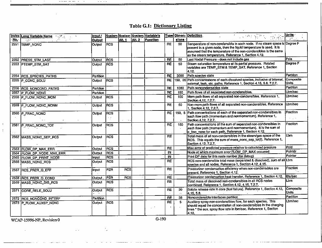
Table G.A: Dictionary Listing
Index Long Variable Name Input System System System Variable's Tvyp Dimen. Definition, Un,- - , NO.No:; ,', ;•' Output ,Alt 1 Alt. 2 Function slons
2551 TEMP_NONC Output PCS RE 50 Temperature of non-condensible In each node. If no steam space Is Degree F present in a given node, then the liquid temperature is used. It Is assumed that the temperature of the non-condensibles is the same
as the steam temperature. Reference 1, Section 4.12.
2552 PRESSSTM LAST Output RCS RE 50 Last Nodal Pressure -does not include gas Psia
2553 PTEMPSTM_SAT Output RCS RE 50 Steam saturation temperature at its partial pressure. Related Degree F variables are TEMPSTM & TEMP_SAT. Reference 1, Section 4.12.
2554 RCS SPECIES PATHS Partition RE 3000 Path species state Partition
2555 P_CONC_SOLU Output RCS RE 150, 20 Path concentrations of each dissolved species, inclusive of Intemal, Composite
I I I external, leak, etc. paths. Reference 1, Section 4.15, 5.8, 7.2.7. Units
2556 RCS NONCONDPATHS Partition RE 1080 Path noncondensables state Partition 2557 P FLOWNONC Partition RE 150 Path flows of all separated non-condensibles. Lbm/sec
2558 PFLOW_NONCMOM Output RCS RE 100 Mom path flows of all separated non-condensibles. Reference 1, Lbm/sec _ Section 4.12,7.2.7.
2559 P_FLOW_NONC_NONM Output RCS RE 50 Non-mom path flows of all separated non-condensibles. Reference Lbmfsec
1 1, Section 4.12, 7.2.7.
2560 P_FRAC_NONC Output RCS RE 150, 5 Path concentrations of each of the separated non-condensibles in Fraction j :each flow path (momentum and nonmomentum). Reference 1,
_ ___ Section 4.12, 7.2.7.
2561 P_FRAC_NONC_TOT Output RCS RE 150 Path concentrations of the sum of separated non-condensibles in Fraction each flow path (momentum and nonmomentum). It Is the sum of
____ p_jrac nonc for each path. Reference 1, Section 4.12.
2562 MASS_NONC_SEP_RCS Output RCS RE Total mass of all non-condensibles in the steam/gas space of the Lbm RCS. This equals the sum of mass._nonc_.sep.tot(l). Reference 1, Section 4.12, 7.2.7.
2563 FLOWDPMAXERR Output RCS RE Max error of predicted pressure relative to calculated pressure Psid
2564 FLOWDPNODEMAXERR Output RCS IN Node at which maximum error FLOWDPMAX occurred. Point6r
2565 FLOWDPPRINT NODE Input RCS IN Print DP data for this node number (for debug) Pointer
2566 MASSNONC_RCS Output RCS RE RCS non-condensible total mass (separated & dissolved), sum of all L:bm species and all nodes. Reference 1, Section 4.12,4.15.
2567 RCSPRZROEFF Input PZR RCS RE Pressurizer condensation efficiency when non-condensibles are Fraction present. Reference 1, Section 4.12.
2568 RCSPRZR 0 COND Output PZR RCS RE Pressurizer condensation heat transfer. Reference 1, Section 4.12. Btu/sec
2569 MASSNONC_DISRCS Output RCS RE Total mass of dissolved non-condensibles In all RCS nodes Lbm combined. Reference 1, Section 4.12,4.15,7.2.7.
2571 CORERELESOLU Output RCS RE 20 Solute release rate in core (fuel failure). Reference 1, Section 4.12, Composite - - _. 4.15, 5.8. Units
2572 RCS-NONCOND-INTERF Partition RE 38 Noncondensible interfaces partition Partition
2573 P_FLOW_AUXSP._NONC Output RCS RE 5- Auxiliary spray non-condensibles flow, for each species. This Lbm/sec should equal the concentration of non-condensibles in the charging lines "the aux. spray flow rate in Ibm/sec. Reference 1, Section 4.12. 1
G- 190WCAP- 15996-NP, Revision 0

Table G.I: Dictionary Listing
Index Long Variable Name Input / System System System Variable's Type Dlmen- Definition Units No. ... _Output Alt. 1 Alt. 2 Function slons
2574 SIS_RCS_NONC Input RE 6, 5 Noncondensables inflow via SI lines. Reference 1, Section 4 12, Lbm/sec Partition 7 2 7.
2575 SISIRCSNONC Input RCS RE 5 Each non-condensibles inflow via SI line, CL 1. Reference 1, Lbm/sec
I I _ I Section 4 12, 7 2 7. 2576 SIS2_RCS_NONC Input RCS RE 5 Each non-condensibles inflow via SI line, CL 2. Reference 1, Lbm/sec
Section 4.12, 7 2 7. 2577 SIS3_RCS_NONC Input RCS RE 5 Each non-condensibles inflow via SI line, CL 3. Reference 1, Lbm/sec
Section 4 12, 7 2 7 2578 SlS4_RCS_NONC Input RCS RE 5 Each non-condensibles inflow via SI line, CL 4. Reference 1, Lbm/sec
Section 4.12, 7.2.7.
2579 SIS5_RCSNONC Input RCS RE 5 Each non-condensibles inflow via SI line, HL 1 Reference 1, Lbm/sec Section 4.12, 7 2.7
2580 SIS6_RCSNONC Input RCS RE 5 Each non-condensibles inflow via SI line, HL 2. Reference 1, Lbm/sec Section 4 12, 7 2 7
2581 GSVESNONC Input RCS RE Non-condensibles inflow to vessel via Gas System. Reference 1, Lbm/sec
I _ Section 4.12, 7.2.7.
2582 GSPRZRNONC Input RCS RE Non-condensibles inflow to pressurizer via Gas System. Reference Lbm/sec
1 1, Section 4 12, 7 2 7
2583 GSSPECIES Input RCS IN Species of Gas System gas (from IDTYPESPECIES) that is Pointer entering the RCS via any of the inputs SISn_RCS_NONC, GSVESNONC or GSPRZRNONC. Reference 1, Section 4 12, 727
WCAP-15996-NP, Revision 0 G-191

Table G.2: Variables Dictionary in Tree Structure
index Vari able Name! No. Short Long
1 CHR CHMRCO!0ON 2 PLABEL PLANTDATALABEL 3 PFILE - PLANTrDATA.FILENAME 4 PTITLE PLANTDATA.TITLE 5 PTIME PLANTDATA.TIME 6 PDATE PLANTDATADATE 7 SLABEL SNAPSHOTLABEL 8 . . SFILE SNAPSHOTFILE.NAME 9 . STITLE SNAPSHOT-TITLE
10 . STIME SNAPSHOT-TIME 11 . SDATE SNAPSHOT-DATE
12 . CTLT CTLTITLE
13 PLT PLTDATA 14 PLTO1 UNUSED-VAR-PLT01 15 . DUMMY] CORERADOUTDUMMY 16 . TNMAXL CHT_NUM-LINPROP 17 . TNPROP CHTTIME.STPNUM 18 DRCS PLT-RCS 19 DRDESN PLT-RCS_.DESIGN 20 . NUMSG NUMSG
21 . . DRTYPE PLTRCSTYPE
22 DNPROP NUMPROPHEATERS 23 DNBACK NUMBACKHEATERS 24 . . DNCHGS NUM CHGSPUMPS
25 . . DNSPRA RCS_NUM_MSPRAYVLVS 26 . . DNPORV RCS_NUMPORVS
27 . . DNPRSV RCS_NUM_SAFETYVLVS 28 . . DMODIN MODINIT 29 . . DMDINV MOD0INITV
30 DNODE PLTRCSNODE 31 . NODENO PLT-1RCS-NODALIZATION 32 . . .. NODETO RCS_NODETOTALS
33 ....... .. NUMNOD NUMNODES 34 ....... .. NNODSE NUM_.NODESSEC 35 ....... .. NNODSG NUMSGNODES 36 ....... .. NNODHL NUXHLNODES 37 ....... .. NNODSL NUMSLNODES 38 ....... .. NNODCL NUMCL.NODES 39 . . . . NODENU RCSNODENUMBERS
40 ....... .. NODEHL RCS.NODEHL 41 .... ...... NHLI NODEHLl 42 ......... .. NHL2 NODEHL2 43 ......... .. NHL3 NODE_.L3 44 ......... .. NHL4 NODEHL4 45 ....... .. NODESG NODESG 46 ......... .. NSG1H NODESGIH 47 .......... .NSGIC NODE._SGIC 48 ......... .. NSG2H NODESG2H 49 ......... .. NSG2C NODE_SG2C 50 ......... .. NSG3H NODESG3H 51 ....... .. NSG3C NODESG3C 52 ........ .. NSG4H NODESG4H 53 ......... .. NSG4C NODESG4C 54 ....... .. NODECL NODE.CL ' 55 ......... .. NCL1 NODECL1 56 ......... .. NCL2 NODECL2 57 ......... .. NCL3 NODECL3 58 ......... .. NCL4 NODECL4 59 ........ NODESL RCSNODESL 60 .... ...... NSGIP NODESGIP 61 ......... .. NSG2P NODE_SG2P 62 ......... .. NSG3P NODESG3P 63 ......... .. NSG4P NODESG4P 64 ....... .. NODEOT RCS-NODEOTHERS 65 ......... .. NCORE NODECORE 66 ......... .. NPRZR NODEPRZR 67 ......... .. NUHEAD NODEUHEAD 68 ........... NANNUL NODE-ANNUL 69 ......... .. NCEASH NODE-CEASH 70 . . . NODGEO RCSNODEGEOMETRY
71 . . . . NODEA NODE-AREA 72 . . . . NZTOT NODEHEIGHT
73 . . . . NELBOT NBOT
DimenT sions Definition
CH 336 Character variables for snapshot ID CH Plant data title character variables CHM Plant data file description CH Plant data file title CH Plant data file time stamp CH Plant data file date stamp CH Snapshot file character variables CH Snapshot file description CH Snapshot file title CH Snapshot file time stamp CH Snapshot file date stamp CH 1000 Titles of controllers RE 25000 Restore-only plant data RE 15 Unused Partition RE 3 Unused Variable IN Unused Variable IN Unused Variable RE 2350 Restore-only RCS plant data IN 10 RCS design features IN Number of steam generators IN Unused Variable IN Number of proportional heaters IN Number of backup heaters IN -Number of charging pumps IN Number of przr main spray valves IN Number of przr PORVs IN -Number of przr safety valves LO Plant data initialization cue LO Plant data initialization cue - data
RE 900 Restore-only RCS plant node data IN 50 RCS nodalization data IN 6 RCS total number of nodes per group IN Total number of nodes (50 max) IN Number of sectionalized nodes (1 max) IN Number of SG nodes (2 per SO, 16 max) IN RCS number of hot leg nodes IN RCS number of suction leg nodes IN RCS number of cold leg nodes IN 30 -RCS node numbers IN 4 RCS hot leg nodes IN Hot leg 1 node number IN Hot leg 2 node number IN Hot leg 3 node number IN Hot leg 4 node number IN 16' Array of SG node numbers IN SG tube hot side node number~loop 1 IN SG tube cold side node number, loop 1 IN SG tube hot side node number, loop 2 IN SO tube cold side node number, loop 2 IN SG tube hot side node number,loop 3
-IN -SG tube cold side node number, loop 3 IN SO tube hot side node number, loop 4 IN SG tube cold side node number, loop 4 IN 4 Array of cold leg node numbers IN - Cold leg node number, loop 1 IN Cold leg node number, loop 2 IN Cold leg node number, loop 3 IN Cold leg node number, loop 4 IN 4 RCS suction leg node numbers IN SO outl plen. and suct. leg node loop IN SG outl plen. and suct. leg node loop IN SG outl plen. and suct. leg node loop IN - SG outl plen. and suct. leg node loop IN 10 RCS remaining nodes IN Core node number IN -- Pressurizer node number IN Upper head node number IN Annulus node number
IN CEA shroud node number RE 250 RCS node geometry variables RE 50 Node cross sectional area RE 50 Node height RE 50 Node bottom elevation
units
Segment Partition Character Character Character Character Partition Character Character Character Character Character Segment Dimensionless Dimensionless Dimensionless
,Dimensionless Partition Partition Counts Dimensionless Counts Counts Counts Counts Counts Counts True False True False Partition Partition Partition Counts Counts Counts Counts Counts Counts Partition Partition Pointer Pointer Pointer Pointer Pointer Pointer Pointer Pointer Pointer Pointer Pointer Pointer Pointer Pointer Pointer Pointer Pointer Pointer Partition
1 Pointer 2 Pointer 3 Pointer 4 Pointer
Partition "Pointer
,Pointer Pointer
'Pointer Pointer
,Partition Ft^2 Feet Feet
WCAP-15996-NP, Revision 0 G-192

Table G.2: Variables Dictionary in Tree Structure
Index No.
74 75 76 77 78 79 80 81 82 83 84 85 86 87 88 89 90 91 92 93 94 95 96 97 98 99
100 101 102 103 104 105 106 107 108 109 110 111 112 113 114 115 116 117 118 119 120 121 122 123 124 125 . 126 127 128 129 130 131 132 133 134 135 136 . 137 . 138 139 140 141 142 143 144 145 146 147 -
DimenTM sions
Variable Name: Short Long
. NGEOM N_GEOM . NOSECT NSECTIONS
NODETH RCS.NODETHVARS . NXLIQ N_HEAT_XFERLIQ
* - . NXSTM N_HEAT.XFERSTM . . . NXCON NHEAT_XFER_CONT - - - NXBOT N__JEATXFERBOT
NWLMXC N_HEATCAP NXBOIL NXFER_BOIL NXINJ N_XFER_INJ NXSPOF XFERSURFPOFF NXSPON XFERSURFPON NAMULT AREA_INJ_MULT
NSECT RCSNODESECTIONALIZED NUMSEG RCSPRZR_NSECT APZR RCSPRZRASECT HPZR RCSPRZR_HSECT NIJMANN RCSANNULNSECT AANN RCS_ANNULASECT
* . ZANN RCS4ANNUL_HSECT . - ASECVA N_AREASECT * . ZSECVA NHEIGHTSECT DPATH PLTRCS_PATH . PATHNO RCSPATHSNODALIZATION . . PATHTO RCSPATHSTOTALS
PNMOM NUMPATHSJ.MOM . . PNEXT NUMPATHS_EXT
PNLEAK NUM_PATHS_LEAK PNINT NUM_PATHS_INT PNPATH NUM_PATHS PNSB NUM_SMLBRK PNHL NUM_PATHS_HL PNCL NUM_PATHSCL PNNONM NUMPATHSNONM PNCHGS RCS_NUMINCHGS PNLET RCS_NUMOUT_LDNS PNDRN RCSNUMOUT_RCWDRAINS
* . PNSDC RCSNUMOUTSDC . . PNSIS RCSNUMINSIS . . PNRCP RCSNUIOAXRCP . - PNCHGM RCSNUMMAXMCHGSIN
* . PNLETM RCS_NUMMAXLDNSOUT PNDRNM RCS_NUMMAXDRAINSOUT PNSDCM RCS_NUMMAXSDCOUT PNSISM RCSNUMM.A_SISIN PNMOMM RCS_NUMMAX_MOM
PATHNU RCSPATHSJNUMBERS - PSURGE PATHSURGE
. PANCOR PATHANNULCORE
. PCORUH PATHCORE_UHEAD
. PSPRAY PATHSPRAY . . PLBLOC PATHLB-LOCA
PPUMP PATHPUMP PATHHL PATHHL PATHCL PATH_CL PATHSG PATHSG PUCEA PATHJUCEA
PATHG RCSPATHS_GEOMETRY PINLET P_NODE_INLET . PIMOM RCS_P_NODEINLETMOM
. . PINMOM RCS_P_NODE INLETNONM . . * PIEXT RCS_PATHEXTPNODEIN
PIRCP RCSRCPLEAXPNODEIN PICHGS RCSCHGSPNODEIN PILET RCSLDNS-PNODEIN PIDRN RCSRCWNPNODEIN PISDC RCS_SDC_PNODEIN
. PISIS RCSSISPNODEIN
- PIGAS RCS_GASPNODEIN . PILEAK RCSPATHLEAKPNODEIN
PISGTR RCSSGTRPNODEIN - - . PISB RCSSBLOCAPNODEIN
. . . PIRODE RCSRODEJ_PNODEIN
. . PIORIN RCSORING_PNODEIN
IN IN RE RE RE RE RE RE RE RE RE RE RE RE IN RE RE IN RE RE RE RE RE
IN IN IN IN IN IN IN IN IN IN IN IN IN IN IN IN IN IN IN IN IN IN IN IN IN IN IN IN IN IN IN IN IN IN RE IN IN IN IN IN IN IN IN IN IN IN IN IN IN IN IN
50 50 500 50 50 50 50 50 50 50 50 50 50 100
3 3
3 3 1,22 1,22 1400 60 25
35
4 8 8 4
1300 150 100 50 25 4 4 4 1 2 8 2 17 8 4
Definition
Node geometry indicator Sections in node (node I max 22, rest 1) RCS node thermo-hydraulic constants Node wall-to-liq overall heat tr coeffs Node wall-to-stm overall heat tr coeffs Node wall-to-cont overall heat tr coeffs Node bottom wall-to-fluid ht coef Node wall heat capacity Node boiling condensation coef Node liquid injection condensation mult Node surface condensation coef(pump off) Node surface condensation coef(pump on) Interfacial condensation area mult RCS sectionalized nodes variables Number of area sections in przr Przr cross-sectional areas Przr section heights Number of sections in annulus low plen Annulus cross-sectional areas Annulus section heights Cross sect area of section(node,section) Height of section (node.section) Restore-only flow path RCS plant data RCS paths nodalization variables RCS total paths Number of momentum paths Number of external flow paths (25 max) Number of leak flow paths (17 max) Number of internal flow paths (8 max) Total number of flow paths Number of SB leak flow paths (4 max) Number of hot leg flow paths (4 max) Number of cold leg flow paths (8 max) RCS number of non-momentum paths Number of RCS-CHGS connections Number of RCS-letdown connections Number of RCS-RCW drain connections Number of RCS-SDC connections (I max) Number of RCS-SIS connections Maximum number of RCP paths Max. number of CHGS conn to RCS Max. numb. of ldns connect to RCS Max. numb. of drains to RCW from RCS Max. numb. of SDC connect to RCS (out) Max. numb. of SIS connect to RCS (in) Maximum number of momentum paths RCS path numbers Surge line path number Annulus-to-inner vessel path number Upper head-to-inner vessel path number Pressurizer spray path number Large break LOCA path number (mal 038) RCP paths array (lla, llb, 12a, 12b) Inner vessel-to-hot leg path array Array of cold leg path nos.: lla,b.12a,b Top of SG tube bundle path number CEA to upper head path number RCS paths geometry variables Path inlet node number (all paths) Path inlet number (momentum) Path inlet number (non momentum) External paths inlet node RCP leak inlet node Charging inlet node RCS- letdown inlet node RCS RCW drains inlet node RCS shutdown cooling inlet node RCS safety injection inlet node RCS gas injection inlet node Leak paths inlet node RCS SG tube rupture inlet node RCS small break LOCA inlet node RCS rod ejection small break inlet node RCS o-ring seal inlet node
WCAP-15996-NP, Revision 0
Units
Pointer Counts Partition Btu/sec-degF Btu/sec-degF Btu/sec-degF Btu/secft^2degF Btu/degF Btu/sec-degF Dimensionless Btu/secft^2degF Btu/secft-2degF Dimensionless Partition Counts Ft^2 Feet Counts Ft^2 Feet Ft 2 Feet Partition Partition Partition Counts Counts Counts Counts Counts Counts Counts Counts Counts Counts Counts Counts Counts Counts Counts Counts Counts Counts Counts Counts Counts Partition Pointer Pointer Pointer Pointer Pointer Pointer Pointer Pointer Pointer Pointer Partition Pointer Pointer Pointer Pointer Pointer Pointer Pointer Pointer Pointer Pointer Pointer Pointer Pointer Pointer Pointer Pointer
G- 193

I, 11
Table G.2: Variables Dictionary in Tree Structure
Index V a r i a b l e N aim e: No. Short L MM
148 ........ PILB RCS_LBLOCAPNODEIN IN 149 ....... PINT RCSPATHINTPNODEIN IN 150 ... ....... .. PISPRA RCS_SPRAYPNODEIN IN 151 ... ....... .. PIBLED RCS_ESPRAYBLEEDPNODEIN IN 152 ... ....... .. PIPZRR RCS_PRZRRELIEFPNODEIN IN 153 ... ....... .. PIUHR RCSOUHEADRELIEF-PNODEIN IN 154 . ... PEXIT PNODEEXIT IN 155 . ... PEINIT P_ELEV_INLET RE 156 ....... .. PEMOM RCS_P_ELEVINLETYOM RE 157 ....... .. PENONM RCS_P_ELEVINLETNONM RE 15B ......... .. PEEXT -RCSPATHEXT.PELEVIN RE 159 ... ....... .. PERCP RCS_RCPLEAKPELEVIN RE 160 ... ....... .. PECHGS RCSCHGSPELEVIN RE 161 ... ....... .. PELET RCS_LDNS_PELEVIN RE 162 ... ....... .. PEDRN RCS_RCWPELEVIN RE 163 ... ....... .. PESDC RCSSDCPELEVIN RE 164 ... ....... .. PESIS ,RCS_SIS-PELEVIN RE 165 ... ....... .. PEGAS RCSGASPELEVIN RE 166 ......... .. PELEAK RCS_PATHLEAKPELEVIN RE 167 ... ....... .. PESGTR RCSSGTRPELEVIN RE 168 ... ....... .. PESB RCS_SBLOCAPELEVIN RE 169 ... ....... .. PERODE RCSRODEJPELEVIN RE 170 ... ....... .. PEORIN RCS_ORINGPELEVIN RE 171 ........... PELB RCSLBLOCAPELEVIN RE 172 ......... .. PEINT RCS_PATHINT_PELEVIN RE 173 ... ....... .. PESPRA RCSSPRAYPELEVIN RE 174 ... ....... .. PEBLED RCSSPRAYBLEEDPELEVIN RE 175 ... ....... .. PEPZRR RCSPRZR.RELIEFPELEVIN RE 176 ... ....... .. PEUHR RCS_UHEADnRELIEF._PELEVIN RE 177 . . .. PEEXIT PELEVEXIT RE 178 . . . . PGEOM PGEOM IN
179 . . . . PRADII PRADIUS RE 180 . . . . PTLOA PATHSTLOA RE 181 . . . . PKXPOS PATH_KLOSS_POS RE
182 . . . . PKXNEG PATH_KLOSSNEG RE 183 . . . . PAREA PAREA RE 184 . . . . PLDIAM PATH_.LENDIAM RE 185 . . . . PDIA PDIAMfHYD RE 186 DINVES PLT_RCS_VES RE 187 DUPMIN PRES_ATWSMIN RE 188 DUAMIN PAREA_ATWS_MIN RE 189 DUPMAX PRESEATWS_MAX RE 190 DUAMAX P.AREA_ATWSJAX RE 191 DUAROD PAREA_RODEJ RE 192 ZOUTUP NTOP_UPLEN RE 193 ZINUP N_BDTJUPLEN RE 194 XPOSUP KLOSSUPLEDPOS RE
195 XNEGUP KLOSSUPLEN_NEG RE 196 CORBOT COREBOT RE 197 CORTOP CORETOP RE
198 FLA AREA-CORE RE 199 DIHACE HA_CEASCORE RE 200 PUPCEA PATH_CEALOW IN 201 PCEAUH PATHSCEAUP IN
202 DINCEA NUMNCEAS IN 203 DIHCEA CEASDIST RE 204 DIEXBO EXCOREBOT RE 205 DIEXTO EXCORETOP RE 206 DIEXMP MAP_EXCORE IN
207 DIFBY RTRV_BYPASS RE 208 DIFTLT RCSKWEIGHTJHTILT RE 209 DIHAUI HAUHEADfCORE RE 210 DPRZR PLTRCS0PRZR RE 211 DHNUM NUM__EATERS IN 212 DHBURN BURNOUTJIEATER RE 213 DWABLD AREA_BLEED._MIN RE
214 DHHCAP HCAP_HEATER RE 215 DHHA XFER.HEATER RE
216 DHOHMS RESIHEATER RE 217 DHLTOP TOP_HEATERS RE
218 DHVMAX VOLTJHEATER.MAX RE 219 DPLRTD LEVLPRZRRTD RE 220 DPLRBO LEVLREFBOT RE
221 DPLRTO LEVL_REFTOP RE
Dimensions Definition
8
2
100 150 100 50 25 4 4 4 1 2 8 2 17 8 4
8
2
100 100 100 100 100 100 100 100 100 60
10
4,4
40
6
6 6 6
Units
-RCS large break LOCA inlet node Pointer RCS internal paths inlet node Pointer RCS przr spray inlet node Pointer RCS przr spray bleed inlet node Pointer Przr relief valves inlet node Pointer
-* Upper head relief valves inlet node Pointer Path exit node number (momentum paths) Pointer Path inlet elevation (at circle center) Feet Inlet elevation (mom. paths) Feet Path inlet elevation (non momentum) Feet External paths inlet elevation Feet RCP leak inlet elevation Feet Charging inlet elevation Feet RCS- letdown inlet elevation Feet RCS RCW drains inlet elevation Feet RCS shutdown cooling inlet elevation Feet RCS safety injection inlet elevation Feet RCS gas injection inlet elevation Feet Leak paths inlet elevation Feet RCS SG tube rupture inlet elevation Feet RCS small break LOCA inlet elevation Feet RCS rod ejection small break inlet eleva Feet RCS o-ring seal inlet elevation Feet RCS large break LOCA inlet elevation Feet RCS internal paths inlet elevation Feet RCS przr spray inlet elevation Feet RCS przr spray bleed inlet elevation Feet Przr relief valves inlet elevation Feet Upper head relief valves inlet elevation Feet Path exit elevation (at circle center) Feet Path end geom(0-3=ptcircu semi,l semi) Pointer Path radii at end(not related to parea) Feet Combined inertia length/area CdMom/dt) Composite Units Geometric forward k-factor Dimensionless Geometric reverse flow k-factor Dimensionless Path flow area Ft^2 Path length-to-diameter ratio Dimensionless Path hydraulic diameter Feet Restore-only inner vessel RCS plant data: Partition Atws min head seal leakage pressure Psia Atws min head seal leak area ýFt^2 Atws pressure for max head seal leak Psia Atws area at max head seal leak -Ft^2 CEA ejection leak area Ft^2 Top elev of UP part of inner vessel node Feet Bottom elev of UP part of IV node Feet UP geometric form loss coef, + flow Dimensionless UP geometric form loss coef, - flow Dimensionless Active core bot elev (rel to node bot) ý Feet Active core top elev (rel to node bot) Feet Active core flow area ,Ft^2 CEA to IV wall heat trans coef (hA) Btu/sec-degF Inlet path, UP to CEA guide tubes Pointer Exit path, CEA to UH Pointer Number of CEAs (65 max) Counts Traveling distance of CEAs Feet Excore detector elev, bottom (est) 'Feet Excore detector elev, top (est) - Feet Excore detector - RCS model mapping Pointer Fraction of vessel flow bypassing core Fraction Coeff. for cold leg to hot leg mixing Fraction Upper head to IV heat transfer coef (hA) Btu/sec-degF Restore-only pressurizer RCS plant data Partition Total number przr heater banks (6 max) Counts Heater burnout (set large remove limit) Btu Przr spray bleed line min area 'Ft^2 Heater gross heat capacity Btu/degF Heater overall heat transfer coef Btu/sec-degF Heater electrical resistance Ohms Top elev of przr heaters Feet Maximum przr heaters bus voltage Volts Level of przr rtd Feet Bottom level of przr reference leg Feet Top level of przr reference leg Feet
WCAP-15996-NP, Revision 0 G-194

Table G.2: Variables Dictionary in Tree Structure
Index V a r i a b l e N a m e: No. Short Long
222 DVLREL LEVLRELIEF 223 DVGPOR DESIGN_FLOW_PORV 224 DVGPS1 DESIGNFLOWSAFETYI 225 DVGPS2 DESIGNFLOW_SAFETY2 226 DQTANK PLTRCSQT 227 DQPN2 PRESN2 228 DOVOL VOLUtQT 229 DQHT HEIGHT_QT 230 DQMASS MASSQTMAX 231 DQPRUP QTRUPTURESPOINT 232 DRCP PLTRCSRCP 233 DRNUM NUMPUMPS 234 DRFRAC FRACTABL 235 BAN BAN 236 BVN BVN 237 BAD BAD 238 BVD BVD 239 BAT BAT 240 BVT BVT 241 BAR BAR 242 BVR BVR 243 HAN HAN 244 HVN HVN 245 HAD HAD 246 HVD HVD 247 HAT HAT 248 HVT HVT 249 HAR HAR 250 HVR HVR 251 HANC HANC 252 HVNC HVNC 253 HADC HADC 254 HVDC HVDC 255 HATC HATC 256 HVTC HVTC 257 HARC HARC 258 HVRC HVRC 259 HVOID FRAC_HD_TABL 260 HMUL HD_DEG_TABL 261 RRSPDR RATEDPUMPSPEED 262 RRVFLO RATEDVOL_FLOW 263 RRDD RATED_PUMFL_DENS 264 RRPHD RATED_PUMP_HD 265 RRPHT RATEDPUMPTORQ 266 RRSYNC RATEDPUMPSYNCH 267 DRNPOL. NUMIPOLES 268 TTWIFR WIND_TORQJULT 269 DRVBUS RATED_BUS_VOLT 270 DRTNUM NPTS_TAB 271 DRSLIP SLIPTAB 272 DRTORQ TORQTAB 273 DRDTDW DTDW_TAB 274 DRCURR CURRENTTAB 275 DRPLEK PRESSLDN 276 DRVRAT RCP-VOLTRATED 277 DRFRAT RCP_FREQRATED 278 DCONST RCSCONST 279 DPCONS RCSCONSTPRZR 280 DPWMUL PRZRSPRAY_MULT 281 DPHMUL PRZRJHEATERMULT
282 DPPMUL PRZRPORVMULT 283 DPSMUL PRZRSAFETY_MULT 284 DPVMUL PRZR_VENT_MULT 285 DPRTAU PRZRRELIEFRTDTAU 286 DPQMUL PRZR_QT_MULT 287 DPFMUL RCS_PRZRFLASH_MULT 288 DPFLSH RCS_DM_FLASH_PRZR 289 DPLSAT RCS_LEVL_SAT_PRZR 290 DPDMAX RCSDFLASHMAX_PRZR 291 DVKUP VLVPRZR_KLOSSUP 292 DVKDWN VLVPRZRKLOSSDOWN 293 DUCONS RCSCONSTUHEAD 294 - DUKCOR RTRVKLOSSCORE 295 DUVMUL RTRV_VENT._MULT
Dimenn-, sions
RE RE RE RE RE 10 RE RE RE RE RE RE 450 IN RE 11 RE 11 RE 11 RE 11 RE 11 RE 11 RE 11 RE 11 RE 11 RE 11 RE 11 RE 11 RE 11 RE 11 RE 11 RE 11 RE 11 RE 11 RE 11 RE 11 RE 11 RE 11 RE 11 RE 11 RE 11 RE 11 RE 11 RE 4 RE 4 RE 4 RE 4 RE 4 RE 4 IN RE RE IN RE 22 RE 22 RE 22 RE 22 RE RE RE RE 200 RE 15 RE RE RE RE RE RE RE RE RE RE RE RE RERE RE RE
10
Definition
Level of relief valve noz (rel to bot) PORV design flow rate Safety valve 1 design flow Safety valve 2 design flow Restore-only quench tank RCS plant data QT nitrogen supply pressure QT total volume QT height assuming con circ cross sect QT maximum mass of water Q T. rupture disk setpoint pressure Restore-only main coolant pump plant dat Number of main coolant pumps (4 max) Ind var inter for RCP homologous curves RCP torq homolog curve (normal +f,+s) RCP torq homolog curve (normal +f,+s) RCP torq homolog curve (eng diss -f,+s) RCP torq homolog curve (eng diss -f,+s) RCP torq homolog curve (turbine -f,-s) RCP torq homolog curve (turbine -f,-s) RCP torq homolog curve (abnormal +f,-s) RCP torq homolog curve (abnormal ÷f,-s) RCP head homolog curve (normal ÷f,+s) RCP head homolog curve (normal ÷f,+s) RCP head homolog curve (eng diss -f.+s) RCP head homolog curve (eng diss -f,+s) RCP head homolog curve (turbine -f,-s) RCP head homolog curve (turbine -f.-s) RCP head homolog curve (abnormal +f,-s) RCP head homolog curve (abnormal .f,-s) RCP diffr head homolog (normal *f,+s) RCP diffr head homolog (normal .f,+s) RCP diffr head homolog (eng diss -f,+s) RCP diffr head homolog (eng diss -f,+s) RCP diffr head homolog (turbine -f,-s) RCP diffr head homolog (turbine -f,-s) RCP diffr head homolog (abnormal +f,-s) RCP diffr head homolog (abnormal .f,-s) RCP head degradation void frac (ind var) RCP head degradation multiplier Rated pump speed Rated pump volumetric flow Rated pump density Rated pump head Rated pump torque Pump synch speed at rated frequency Number of poles per putmp Windage/friction torque constant Rated bus voltage (for input units conv) Number of points in motor tables Electrical slip Electrical torque multiplier Unused Variable Electrical current multiplier Letdown line pressure (for RCP leaks) RCP rated voltage RCP rated frequency RCS tunable constants RCS pressurizer tunable constants Mult on przr. spray (excluding aux.) Multiplier on total pressurizer heat Multiplier on PORV relief flow rates Multiplier on safety valve flow rates Multiplier on przr vent valve flows First order lag constant - relief RTDs Mult on control flow from QT to przr Multiplier for przr flashing calc Flashing rate przr sat region Pressurizer sat level (u bound) Max del flash in przr per step Loss coeff, przr to przr-relzef-valves Loss coeff, przr-relief-valves to Q.T RCS upper head tunable constants Core pressure drop factor for buoyancy Multiplier on head vent valve flows
Unite
Feet Lbm/sec Lbm/s ec Lbm/sec Partition Psia Ft^3 Feet Lbm Psia Partition Counts Dimensionless Dimensionless Dimensionless Dimensionless Dimensionless Dimensionless Dimensionless Dimensionless Dimensionless Dimensionless Dimensionless Dimensionless Dimensionless Dimensionless Dimensionless Dimensionless Dimensionless Dimensionless Dimensionless Dimensionless Dimensionless Dimensionless Dimensionless Dimensionless Dimensionless Dimensionless Dimensionless Shaft RPM Ft^3/sec Lbm/ft^3 Feet Ft-lbf Shaft RPM Counts Ft-lbf Volts Counts Dimensionless Dimensionless Dimensionless Dimensionless Psia Volts Hertz Partition Partition Dimensionless Dimensionless Dimensionless Dimensionless Dimensionless Seconds Dimensionless Dimensionless Lbm/sec Feet Lbm/sec Composite Units Composite Units Partition Dimensionless Dimensionless
WCAP-15996-NP, Revision 0 G- 195

Table G.2: Variables Dictionary in Tree Structure
index No.
296 297 298 299 300 301 302 303 304 305 306 307 308 309 310 311 312 313 314 315 316 317 318 319 320 321 322 323 324 325 326 327 328 329 330 331 332 333 334 335 336 337 338 339 340
DVAVWT DVAUH DVAPOI DVAPS1 DVAMOI DVAPC0 DVAPQT DVAMSP DVAQTG DVAQTC DVANC
341 DM504 342 DPSDE 343 DPSEQ 344 DPHDT 345 DPTDT 346 DPDGMC 347 DPLRIC 348 DULRIC 349 DUFRIC 350 DPFRIC 351 DPLBOI 352 DSDP 353 DSDPl2 354 DSDPW 355 DSDPWI 356 DPCRFI 357 DRCMUI 358 DRCMIN 359 DPTMSI 360 DPM034 361 DVTMA3 362 DRFRUI 363 DRTRUI 364 DPHAXI 365 DPLSB( 366 DUORFL 367 DRFREF 368 DRAREI 369 DRDAMJ
PLT_VLVAREAUHEAD_CONT PLTVLVAREAUHEADQT
Z PLTVLVAREAPRZRSPORV P PLTVLVAREA_PRZR_SAFETY V PLTVLVAREA_.PRZRMOV 0 PLTVLVAREAPRZRSCONT SPLTSVLVAREAPRZRQT
P PLTVLVAREA.PRZRMSPRAY PLTVLVAREAQT.GWS PLTVLVAREAQTCONT PLTVLVAREAQT._NSUPPLY
RCSMOREVARIABLES_504-RO RCSPRZRDHSPRAYEQ RCSPRZRISPRAYEQ RCSPRZRSDT.SUBH RCSPRZR_.TAUDTSUB
X RCSDWSOLIDSDC G RCSPRZRVENTRIG G RCSJUHEADI.VENTRIG G RCS-UHEAD-VENTRIG-FRAC G RCSPRZR.VENT-RIG-FRAC L RCSPRZRL..BOIL
RCSSGDP_.ADD 2RCSSG1112_DPADD
RCS_SG_DPWMULT I RCSSG1112_DPWMULT L RCSCRITFLOW_CHECK L RCPCAVITSGDPtMULT I RCP_CAVITSGDPFRAC_.MIN P RCSPRZRJMSPRAYTAU 4 RCSPRESCOARSEJMAL034 C RCS_PRZR.VLVHIMAZTAU B RCPFRSPRUBRATCH B RCPTORQ..RUBRATCH W RCSPRZR_HA&_WALL 0 RCS-PRZRLVLDTSUBC L RCSP-ORING-FAIL F RCPFLOWREF F RCP..ADMIFLOWCORRMULT P RCPDELAMPS
DimenTyp EsE!n Definition
RE RE RE RE RE RE RE RE RE RE RE RE RE RE RE RE RE RE RE RE RE RE RE
Units
Multiplier on head seal pressure Dimensionless Multiplier heat transfer CEA-core Dimensionless Multiplier uppper head ring seal area ' Dimensionless
2 Core-in mixg fctr: (l)lowflow, (2)high -Fraction 2 Core-out mixg fctr: (1)lowflow, (2)high Fraction
CEA in k factor multiplier Dimensionless 13 RCS coolant pump tunable constants Partition 4 Coolant pump rotor/flywheel interia 'Lbf*ft2
Coolant pump heat rate multiplier Dimensionless SFrac mom-inr to motor when sheared shaft Fraction
Unused Variable Dimensionless Unused Variable Dimensionless Unused Variable Dimensionless
-Unused Variable Dimensionless 4 Tunable constants for RCS loop varbl. Partition
--- Multiplier on cont. heat xfer rates 'Dimensionless SG tube rupt. flow multiplier Dimensionless
6 RCS quench tank addressable constants Partition Multiplier on nitrogen supply flow Dimensionless Multiplier on nitrogen flow to gws Dimensionless Multiplier on quench tank vent flow Dimensionless Fract. surge flow to QT to rupt. disk Fraction
133 General RCS addressable constants Partition
Variable Name: Short Long
DUPMUL RTRV_.EAD_SEAL_.MULT DURMUL RCSQ...CEA.CORE_.MULT DUAMUL RCS_UHEAD_RINGSEAL_MULT DIIMIX RTRVMIXINLET DIOMIX RTRV_MIX_OUTLET DUKCEA RCS_CEAIN_KTERM
DRCONS RCS_CONSTPUMPS PPINER RCPMOM_INERTIA DRQMUL RCP_HEATMULT DRISPL RCPMOMINERTIASPLIT DRVNOR RCPVIBERNORM
DRVMAX- RCPVIBRMAX DRVTIM RCPVIBR_.TIME DRVSPD RCPSPEEDDERIVSHAKE
DLOOPC RCSCONST_LOOP DCONMU- RCS_CONTHEATMULT DSGTRM RCS_SGTR_FLOWMULT
DQCONS RCS_CONSTQT DQNMUL QTN2_MULT DQGMUL QTGWS_.MULT DQVMUL QT_VENT.MULT DQSFRC QTFLOW_FFRAC
DGENC RCSCONST_.GENERAL DNIDPE RCSITER_DP DNIDPN RCSITERDPJNE DNIDHN RCS_ITERDHNE DNDMUL RCSDROPCONDMULT
DPKMUL RCS_KLOSS_MULT DNSMUL RCS_CONDSURFMULT DLCONS RCSCONST-LEAKS
DLSPMU RCSSUPERCRITFLOWMULT DLSBMU RCSSUBCRITFLOWJ4ULT DGPMA CONVGP&_AREA
DVAREA PLT_RCS_VLVAREA
Equil. pressure search convergence band Psia Non-eq pres search conv band on pressure Psia Non-eq pres search conv band on enthalpy Btu/lbm Multiplier droplet condensation (node 'Dimensionless Geometric losses multipliers Dimensionless Surface condensation multiplier Dimensionless Constants for leak tables and correla Partition Multiplier supercritical mass flux Dimensionless Multiplier leak tables (subcrit. cond Dimensionless Gal/mnm-to-area (nom cond). l-3=SLHL,PR 'Composite Units RCS valve areas ,Ft^2
Area of vent valve from u-head to cont Ft^2 Area vents valves u-head to q-tank Ft^2 Area przr PORVs Ft^2 Area przr safety valves Ft^2, Area przr movs (in series with PORVs) Ft^2 Area vent przr to containment Ft^2 Area vents przr to q-tank (in series) Ft^2 Area main spray control valves Ft^2 Quench tank to gws vent valve area Ft^2
- Quench tank to contain, vent vlv area Ft^2 Valve area nitrogen supply to contain FtA2 RCS more variables spin 413 to 504 RO Partition Przr spray del-enth for equil. Btu/lbm Przr spray del-enth equil flag True False Przr del-temp boil heaters on Del-DegF Przr time constant del-temp subc. Seconds Fast time max SDC del flow przr solid Lbm/sec Przr vent rig flag T=inF=out True False Uhead vent rig flag T=in,F=out True False Frac. nucl. uhead vent rig Fraction Frac. nucl. przr vent rig Fraction' Boiling degradation parameters -Feet Tuning add. inst. SG. delp Psig Tuning add. instrum. SG. delp ,Psig
Multiplier SG delp (coarse, 1 phase) Dimensionless Mult. SO delp (detail. 1 phase) Dimensionless Mom. paths-crit. flow check True 'False Unused Variable Dimensionless Unused Variable Dimensionless Main spray flow time constant Seconds Press. for switch to coarse nodalzn Psia
RE RE RE RE 50 RE 100 RE 50 RE 5 RE RE RE 3 RE 25 RE RE 2 RE 4 RE 4 RE 4 RE RE 2 RE 2 RE RE RE RE 41 RE LO RE RE RE LO LO RE RE RE 2 RE RE RE RE LO RE RE RE RE RE RE RE RE RE 2 RE RE RE RE
-Seconds Fraction Composite Units Btu/sec-degF Feet Psia Dimensionless Dimensionless Dimensionless
WCAP-15996-NP, Revision 0
Przr rel vlvs heat tran. max time cons "RCP frac speed pawls rub on ratchet RCP torque pawls rub on ratchet Przr walls axial overall htcoff. Przr level values for boil (subc.) Press. for vessel O-ring failure Unused Variable Unused Variable Unused Variable
G-196

Table G.2: Variables Dictionary in Tree Structure
Index No.
370 371 372 373 374 375 376 377 378 379 380 381 382 383 384 385 386 387 388 389 390 391 392 393 394 395 396 397 398 399 400 401 402 403 404 405 406 407 408 409 410 411 412 413 414 415 416 417 418 419 420 421 422 423 424 425 426 427 428 429 430 431 432 433 434 435 436 437 438 439 440 441 442 443
DimenTMM sions
Variable Name: Short Long
DUFAST RCSDHEATFASTT_UHEAD FRAC DRVMUL RCPCAVITVI BRHMULT DRLMUL RCP__CAVITLOAD_MULT DEDGDT RCSDWSTPSIT DPTREV RCS_PRZR_VLVREVH_TAU DPPHMU RCS_PHTR.RLDJMULT
. DPBHMU RCSBHTRRLDWMULT - DPVVMU RCSPRZRVLVLVIB_MULT - DLBCLC RCSKTEMPCLLOCA DSGS PLTh_SGS
DSCSIN PLT_SGS INTERNAL DSGDES SG_DESIGN ASPTBL ASPTBL
ASPTB1 ASP_TBLDSGN1 ASPTB2 ASPTBLDSGN2
HSPTBL HSPTBL HSPTBI HSPTBLDSGN1 HSPTB2 HSPTBLDSGN2
. VSTTBL VST_TBL VSTTB1 VST_TBL_DSGN1 VSTTB2 VSTTBLDSGN2
TBL2NU TBL2_NUM HT3TBL HT3_TBL - HT3TB1 HT3_TBL DSGNl * HT3TB2 HT3_TBLDSGN2
V3TBL V3_TBL * V3TBl V3_TBLDSGN1 . V3TB2 V3_TBL-DSGN2 TBL3NU TBL3_NUM ASEPSG ASEP SG EVAPSS EVAPSS.ALPHA SPACE SPACE PERIM PERIM SFCONI SFCONCIO SGU12 SG_U12 SGU23 SG_U23
- SGV2AC SG_V2_ACTIVE SGV4MX SGV4_MAX SGV5MX SGV5_MAX TAURCI TAURCI TAUIO TAU_10 TAUPT TAUPT TAUXE TAU_XE VOLSGS VOLSGS HT4MAX SG_HT4_MAX W32FLC W32-FLOW-COEFF DSREFL SGCREFLEGS
DSNREF SGREFNUM DSBREF SGREFBOT DSTREF SG-REF TOP DSTDN TAUREFLGCDN DSTUP TAUREFLGOUP
DSATUB SGCTUBEAREA DSETUS ELEVTUBESHEET DSECON SG_ECONOMIZER
DSHEAT PLTSGS_HEAT DSAFLO ATUBESMAXCS DSAHT ATUBES_MAX_HT QSG100 QSGIOG QSGTBL QSG_TBL TMPTBL, TMP_TBL RTUBES RTUBES SGMTCP SGMTCP DSDHYD SGT__HYDDIAM DSHWAL SGCHCONV DSRWAL SG_RWALL DSAWAL WALLAREA DSMCPW WALLMCP DSAEHT ATUBESMAXECJHT
DMSLH PLT SGS_MSLH ASLMAX ASL_MAX
- DMHAWI HAWALLIMSLH - DMEAWO HAWALLO_MSLH - DMMCPW MCPWALLJMSLH
RE RE RE RE RE RE RE RE RE RE RE IN RE RE RE RE RE RE RE RE RE IN RE RE RE RE RE RE IN RE RE RE RE RE RE RE RE RE RE RE RE RE RE RE RE RE RE IN RE RE RE RE RE RE LO RE RE RE RE RE RE RE RE RE RE RE RE RE RE RE RE RE RE RE
3 850 230 4 15,2 15 15 15,2 15 15 15,2 15 15 2 15,2 15 15 15.2 15 15 2 4 4 4 2
2 2 2
2 2 4 18 2 2,3 2,3 2 2 2 4
70 2 2 4 20 20 2 2 2
2 2 2 2 240 2,2
Definition
Frac const for uhead fastt heat Unused Variable Unused Variable SIT del flow per step (loop solid) Przr rel vlvs rev heat tr. time const Przr prop heater rld mult Przr backup heaters rld mult. Przr relief vlvs vabrat mult (slug flow LB LOCA CL2b temp constants Steam generator data constants SG data constants - SG internals Type of steam generator design (=1,2) Table c. s area of evaporator region Table CS area of evap region, design 1 Table CS area of evap region, design 2 Table height in evaporator region Table height in evap region, design 1 Table height in evap region, design 2 Table volume in evaporator region Table volume in evap region, design 1 Table volume in evap region, design 2 No of entries in evaporator geom table Table height in SG downcomer Table height in downcomer, design 1 Table height in downcomer, design 2 Table volume in SG downcomer Table volume in downcomer, design 1 Table volume in downcomer, design 2 No of entries in downcomer geom table Stm separation area at can deck, 100% ss SG evaporator void fraction at 100% s s Unused space Perimeter of tube shroud in lower SG Stripping factr for SG iodine nuc conc Heat trans coeff. between regions I & 2 H t. coeff regions 2 & 3; also 2/4, 3/4 Volume in region 2 to cover tubes Volume of SG economizer region Volume of quenching pool above can deck Time constant on recirculation flow W23 Decay const for iodine nuclide conc. Decay const for particulate nuclide conc Decay const for xenon nuclide conc. SG volume to rain steam isolation valve Height of SG economizer region Dcomer to tube bundle flow coeff, 100%ss SG level measurement taps Number of level instrum reference legs Lower tap ht abov tbsheet (design, leg#) Upper tap ht abov tbsheet (design, leg#) Time const , lvl instr ref leg cooldown Time const , lvl instr ref leg heat-up SG tube internal flow area, one tube Tubesheet elevation above cormmon refrnce SG economizer T=exist, F=none SG data constants - SG heat transfer Primary flow area through tubes SG tubes heat tsfr area, evaporator only Tube heat trans to each SG at 100% power Rosenow heat flux vs dT table, B/hr-ft2 Delta temp for Rosenow heat flux table Thermal resistance of SG tubes, 1/units Total heat capacity of tubes Hydraulic diam of SG tubes primary flow Convective htc outside SG wall Thermal resistance of SG wall, 1/units SG surface area for heat loss to cont. SG wall heat capacity SG tubes heat tsfr area, economizer only SG data constants - steamline & header Steamline flow area (design,line( Inside MSLH wall heat transfer hA Outside MSLH wall heat transfer hA Total heat cap of MSLH pipe wall
WCAP-15996-NP, Revision 0
Units
Fraction Dimensionless Dimensionless Lbm/sec Seconds Dimensionless Dimensionless Dimensionless Composite Units Partition Partition Pointer Ft^2 Ft^2 Ft^2 Feet Feet Feet Ft^3 Ft^3 Ft^3 Counts Feet Feet Feet Ft^3 Ft-3 Ft^3 Counts Ft^2 Fraction Unused Feet Dimensionless Btu/secft^2degF Btu/secft^2degF Ft-3 Ft-3 Ft^3 Seconds Seconds Seconds Seconds Ft^3 Feet Ft/s*SQRT(lbm) Partition Counts Feet Feet Seconds Seconds Ft^2 Feet True False Partition Ft^2 Ft^2 Btu/sec Composite Units Del-degF Secft^2degF/Btu Btu/degF Feet Btu/secft^2degF Secft-2degF/Btu Ft^2 Btu/degF Ft^2 Partition Ft^2 Btu/sec-degF Btu/sec-degF Btu/degF
G- 197

Table G.2: Variables Dictionary in Tree Structure
index V a r i a b I a N a m :s No. Short Long
444 445 446 447 448 449 450 451 452 453 454 455 456 457 458 459 460 461 462 463 464 465 466 467 468 469 470 471 472 473 474 475 476 477 478 479 480 481 482 483 484 485 486 487 488 489 490 491 492 493 494 495 496 497 498 499 500 501 502 503 504 505 506 507 508 509 510 511 512 513 514 515 516 517
DMSLIC SLIFLOWCOEFF DMSLOC SLOFLOWCOEFF DMSLC UNUSED_.FLOW_COEFF VELl00 VEL100 DMVOL VOLMSLH DMAREA MSLB_AREA DIAMAX MSLHMSIV.AMAX DMABY MSLHHMSIVBYPASS-AMAX DMVAMX MSLHVALVE-AMAX DMVIN HSLH.VALVEINLET DMVEX MSLHVALVE-EXIT DMVNUM KSLHVALVENUM DMPATM PATMOSPHERE DMTATM MSLHTATM DMCHKV SLICHECKVALVE DMDPIl SLIDPI00 DMDPOl SLODPI00 ASLMIN ASL_.MIN NUMSL NUMSL
DFWS PLTSGSFWS FWCDEF FWCOEFF DFC10O _FWSYFLOW100 WFW100 WFW1O0 DFAFWB FWLBAREA HTNOZF FWSNOZ.HEIGHT
* . HTNOZ HTNOZ HTNOZE HTNOZECON HTNOZA HTNOZEFW
* DFNPMP NUM_FWSPUMPS DFNJUN NUMFWS.JUNCTIONS DFPJUN FWSPUMP'JUNCTION DFLJUN FWS-LINEJUNCTION
DFJUN FWSJUNCTION DFEJUN FWSECONJUNCTION
DFGTAB FWSPUMPFLOWTABLE DFHTAB FWS-PUMP..HEAD_TABLE DFSTAB FWSPUMPSPEEDTABLE DFGNUM FWSPUMPFLOWNPOINTS DFSNUM FWSPUMPSPEEDNPOINTS DFCPMP FWSPUMPCOEFF DFCVAL FWSVALVECOEFFS
DFCVL FWSVALVECOEFF DFCEVL FWSECONVALVECOEFF
DFCLIN FWSLINECOEFFS DFCLN FWSLINECOEFF DFCELN FWSECONLINE-COEFF
DFVLIN FWSLINEVOLUMES DFVLN FWSVOL DFVELN FWSECONVOL
DFDLIN FWSLINEDIAMS DFDLN FWS-DIAM DFDELN FWSECON_DIAM
DANPMP NUM_AFWPUMPS DSGDB PLTSGSSGBD
DBATNK SGBDACROSS DBHAWI HAWALLISGBD DBHAWO HA-WALLOSGBD DBMCPW MCPWALL_SOBD
.- DBVTNK SGBD_VOL DBCOEF SGBDSGCOEFF
DBSCUR SGBD_SURF_COEFF DBCBOT SGBDBOTSCOEFF
DBHNOZ SGBDSGHTNOZ DBHSUR SGBDSURFHTNOZ DBHBOT SGBDBOTJHTNOZ
* DBHOUT SGBDOUTHTNOZ DBCOUT SGBDOUT-COEFF DBAMAX SGBDRELIEFAMAX
DM2SLH PLT_SGS_HSLH2 DM2SLO NUMMSLH DM2AFR HSLHAFRSL DM2FKB MSLHJFKBRX DM2ACI MSLH-ACROSS DM2AC2 MSLHACROSST
Dimen-. TMme sions Definition,
RE 8 Flow coeff, stm nozzle to MSIV, at 100% RE '8 Flow coeff, MSIV to header, at 100% RE 8 Unused array RE 8 "Steamline velocity at 100% flow RE Header and SL vol from MSIV to turb stop RE Standard area for main steamline breaks RE 2.2 MSIV full-open flow area (design,line) RE 2,2 MSIBV full-open flow area (design,line), RE '50 Steamline ext valves fullopen flow areas IN 50 Steamline ext valves upstream region IN 50 Steamline ext valves downstream regions IN # of stmline ext valvs <50-NUMSG*NUMSL RE Atmospheric pressure RE Atmospheric temperature at MSLH
-LO 2,2 Steamline check valve: Y/N (design,line) RE 8 Press drop, stm nozzle to MSIV, at 100% RE 8 Press drop, MSIV to header, at 100% RE 2,2 Stln restrictor mn area upst(dsgn,line) IN Number of steamlines per steam generator RE 225 SO data constants - main & aux feedwater RE 4 -•FW coeff at 100%. used for #pumps=0 only RE 4 Feedwater flow at 100% power, each SG RE Feedwater flow at 100% power, all SGs RE Standard area for feedwater line breaks RE 2,3 Feedwater nozzle heights RE 2 Height of downcomer'feedwater nozzle "RE 2 Height of economizer feedwater nozzle RE 2 Height of aux. feedwater nozzle IN -Number of feedwater pumps (max 4) IN No. of feedwater flow junctions (max 4) IN '4 ID# of junction feeding from Nth pump IN 4,2 ID #s of junctions feeding'FW lines IN 4 ID# of junction feeding to nth DCFW line IN 4 ID# of 3unction feeding to nth ECFW line RE 15 Flows for FW pump flow/head/speed tables RE 15,8 Heads for FW pump flow/head/speed tables RE 8 Speeds for FW pump flow/head/speed table IN No. of flow entries in FW pump tables IN No. of speed entries in FW pump tables RE 4 Flow coeff, pump discharge to 3unction RE 4,2 Flow coeffs, junction to valve discharge RE 4 Flow coeff,jct to dcomer valve discharge RE 4 Flow coeff,jct to econzr valve discharge RE 4,2 Flow coeffs, valve discharge to SO RE 4 Flow coeff, valve discharge to downcomer RE 4 Flow coeff, valve discharge to econmizer RE 4,2 FW line volumes downstream of valves RE 4 FW line volume after downcomer valve RE 4 'FW line volume after economizer valve RE 2,2 FW line diameters RE 2 FW line diameter after downcomer valve RE 2 FW line diameter after economizer valve IN Number of AFW pumps (max 4) RE, 30 SG data constants - SG blowdown system' RE Cross section area of SGBD tank RE Inside SGBD tank heat transfer hA RE Outside SGBD tank heat transfer hA RE Total heat cap of SGBD tank wall RE -SGBD tank volume "RE 8 Flow coeffs, blowdown nozzles to tank RE 4 -Flow coeffs, surface blowdown nozzles RE 4 Flow coeffs, bottom blowdown nozzles RE 4 Hts of SO blowdown nozzles above tubesht RE 2 Height of SG surface blowdown nozzle RE 2 Height of SG bottom blowdown nozzle RE 2 -Hts above bottom, 2 BD tank outlet nozls RE 2 Flow coeffs, 2 BD tank outlet nozzles ' RE Bd tank relief valve full-open flow area REý 40 -SG data constants - new header model IN Number of MSLH nodes (1 or 2) RE 8 _Stmln restrictor mmn flowarea dnstrm RE 8 Stmln K factor from SO to MSLB RE Stm header cross tie flowarea RE Stm header cross tie flowarea w turbine
WCAP-15996-NP, Revision 0
Units
Composite Units Composite Units Unused Ft/sec Ft^3 Ft^2 Ft^2 Ft^2 Ft^2 Pointer Pointer Counts Psia Degree F True False Psid Psid Ft-2 Counts Partition Composite Units Lbm/se6 Lbm/sec Ft'2 Partition Feet Feet Feet Counts Counts Pointer ,Pointer Pointer Pointer Gal/min Feet Shaft RPM ,Counts Counts Composite Units Composite Units Composite Units Composite Units Composite Units Composite Units Composite Units Ft^3 ýFt^3 Ft^3 Feet Feet Feet Counts Partition Ft^2 Btu/sec-degF Btu/sec-degF Btu/degF Ft-3 Partition Composite Units Composite Units
'Partition Feet
'Feet Feet Composite Units Ft'2 Partition Counts Ft^2 Composite Units Ft^2 Ft^2
G-198

Table G.2: Variables Dictionary in Tree Structure
Index Variabl e Name: No. Short Long
518 . . - DM2KC1 MSLH_FKCROSS 519 . . . DM2KC2 MSLHFKCROSST 520 DCTL PLTCTL 521 . DCNCON CTL_CONTROLLERNUMBERS 522 . . . DCACON CTLAFWSCONTROLLERS 523 . . . DCRCON CTLCEACONTROLLER 524 . . - DCCCON CTLCHGSCONTROLLERS 525 . . . DCFCON CTLFWSCONTROLLERS 526 . . . DCFECN CTL_FWSECOCN_CONTROLLERS 527 - - - DCFPMP CTL_FWS_PUMPCONTROLLERS 528 . . . DCFCOT CTLFWSTRIPCONTROLLER 529 . . DCHCON CTL_HEATER_CONTROLLERS 530 DCLCON CTLLETDOWNCONTROLLERS 531 DCICON CTLMSIV_CONTROLLERS 532 . DCICOT CTL_MSIS_TRIPCONTROLLER 533 . . . DCMCON CTLMSLHCONTROLLERS 534 DCVPOR CTL_PORVOCNTROLLERS 535 DCVPSV CTLPSVCONTROLLERS 536 DCTCON CTLRPS_CONTROLLERS 537 . . . DCECOT CTLSIASTRIPCONTROLLER 538 . . . DCWCON CTL_SPRAYCONTROLLERS 539 . . . DCTACO CTL_TAVGCONTROLLER 540 . . - DCTRCO CTLT_REF_CONTROLLER 541 . . . DCGCOT CTLTURBTRIPCONTROLLERS 542 . . . DCTCOT CTLCORE_TRIPCONTROLLER 543 . . . DCKCUT CTLPOWERCUTBACKCONTROLLER 544 . . . DCGSET CTLTURB_SETBACKICONTROLLER 545 . . . DCGRUN CTLTURBRUNBACKCONTROLLER 546 . . . DCPCOE CTL_PRZRLVLERRCONTROLLER
547 . - . DCPCOP CTLPRZRPROGLVLCONTROLLER 548 . . . DCFBCN CTLFWSBYPSCONTROLLERS 549 . . . DCFICN CTL_FWS_ISOL_CONTROLLERS 550 . DCAVCN CTLAFWSVALVECONTROLLERS 551 DCDNUM CTLATMDUMPNUM 552 DCDPAT CTLATLDUMPPATH 553 DCTANU CTLTAV_NUM 554 DCTAPA CTL_TAV__PATH 555 DCBNUM CTLTURBBYPASSNUM 556 DCBPAT CTLTURB_BYPASSPATH 557 DBADD DBADD 558 DBCOM DBCOM 559 ELEMS ELEMS 560 ELIN ELIN 561 ELTYPE ELTYPE 562 GROUPS GROUPS 563 NOTAB NOTAB 564 PTTAB PTTAB 565 SEQNCE SEQNCE 566 XTAB XTAB 567 YTAB YTAB 568 UNUSED UNUSED 569 DCINIT CTL_INIT 570 INPED INPED 571 INEDSQ INPEDSEQNCE 572 INEDPG INPEDPAGE 573 CTLDBG CTL_DBG 574 DCCONS CTL_CONSTS 575 DCZERO CTLZERO 576 DCHALF CTLHALF 577 DCONE CTLONE 578 DCMONE CTLMONE 579 DCLIMS CTLLIMITS 580 ELMAX ELMAX 581 LSTMAX LSTMAX 582 INMAX INMAX 583 GRPMAX GRPMAX 584 . CTLMAX CTLMAX 585 . TABMAX TABMAX 586 FCTMAX FCTMAX 587 DCWARN CTL_WARN 588 . INEDFL INPEDFILE 589 CHT CHTCOMMON 590 CHTINP CHT_INPUTS 591 . - DTNRAD CHTNREGIONSRAD
DimnenTa slons
RE RE RE IN IN IN IN IN IN IN IN IN IN IN IN IN IN IN IN IN IN IN IN IN IN IN IN IN IN IN IN IN IN IN IN IN IN IN IN IN IN IN RE
IN IN IN IN IN RE RE RE LO LO LO IN LO RE RE RE RE RE IN IN IN IN IN IN IN IN IN LO RE RE IN
Definition
Stm header cross tie flow resist Stm header cross tie flow resist w turb
20700 Control module variables 150 Controller numbers 4 AFWS flow controller number
Control rod reactivity controller number 4 Charging pump controller numbers 4 Main feedwater flow controller numbers 4 Economizer FW valve controller numbers 4 Main FW pumps speed controller numbers
Main feedwater trip controller number 2 PZr heater controller numbers propback 4 Letdown flow controller numbers 8 MSI valve controller numbers
MSI signal controller number 50 MSLH valve controller numbers 4 Pressurizer PORV controller numbers 4 Pressurizer safety valves controller #s 20 RPS channel controller numbers
SIAS trip controller number 2 Przr spray controller numbers
Controller number for loop avg temp Controller number for demand ref temp
2 Turb. trip controller nos. (trip/close) Core trip controller number Reactor power cutback controller number Turbine setback controller number Turbine runback controller number Przr level error calc. controller number Przr program level controller number
4 FWS Bypass valve controller number 4 FWS isol valve controller number 14 AFWS valve controller number
Number of MSLH atm. dump valves 10 Path number for MSLH atm. dump valve
Number of tubine admission valves 5 Path number for turbine admission valve
Number of turbine bypass valves 5 Path number for turbine bypass valve 100 Index of state variables in commson 100 Cue to commuon containing state variables 1000 No of elements per controller 10000 Inputs to controller elements 3000 Controller element type cues
Number of controllers 100 No. of entries in user function table 100 Pointer to start of user function table 1000 Order of exectuion of controllers 2000 Ind variable values for user function 2000 Dep variable values for user function
Unused Variable Control system initialization cue Control system structure display cue INPED display order T=seqnce, F=input Lines/page in inped output 0=no paging
1002 Controller debug edit cues 10 Useful constants
Floating point zero (0 0) Floating point one-half (0 5) Floating point one (1 0) Floating point minus-one (-1 0)
10 Dimensioned limits of the control system Maximum total number of elements Maximum total number of last-values Max total number of controller inputs Maximum number of controller groups Dimension of CTL_CONTROLLERNUMBERS Maximum number of user-defined functions Max tot no. of user-defined func entries Warnings display 0/l/2=none/once/always Inped output target T=file, F=console
1500 Core heat transfer segment 50 Core heat transfer model data constants
Number of radial regions in h t. mesh
Units
Composite Units Composite Units Partition Partition Pointer Pointer Pointer Pointer Pointer Pointer Pointer Pointer Pointer Pointer Pointer Pointer Pointer Pointer Pointer Pointer Pointer Pointer Pointer Pointer Pointer Pointer Pointer Pointer Pointer Pointer Pointer Pointer Pointer Counts Pointer Counts Pointer Counts Pointer Pointer Pointer Counts Pointer Pointer Counts Counts Pointer Pointer Undefined Undefined Dimensionless True False True False True False Counts True False Partition Dimensionless Dimensionless Dimensionless Dimensionless Partition Counts Counts Counts Counts Counts Counts Counts Pointer True False Segment Partition Counts
WCAP-15996-NP, Revision 0 G- 199
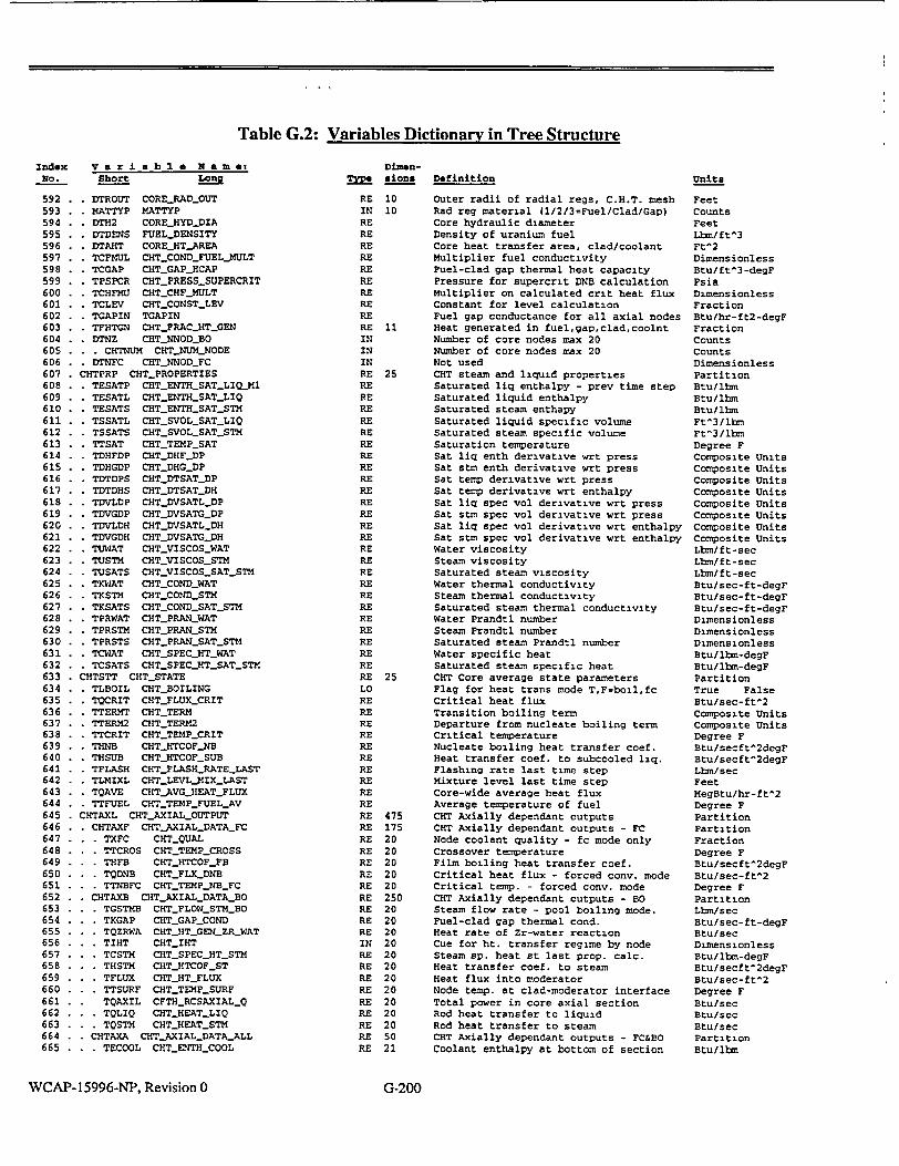
Table G.2: Variables Dictionary in Tree Structure
Index variable Name! No. Short Long
592 593 594 595 596 597 598 599 600 601 602 603 604 605 606 607 608 609 610 611 612 613 614 615 616 617 618 619 620 621 622 623 624 625 626 627 628 629 630 631 632 633 634 635 636 637 638 639 640 641 642 643 644 645 646 647 648 649 650 651 652 653 654 655 656 657 658 659 660 661 662 663 664 665
*DTROUT CORE.SADSOUT M4ATTYP MATTYP DTH2 COREJHYD-DIA DTDENS FUEL-DENSITY DTAHT COREJHTAREA TCFMUL CHTCONDSFUELJMULT TCGAP CHTSGAP_{CAP TPSPCR CHT-PRESSSUPERCRIT TCHFMU CHT_CHFMULT TCLEV CHT.CONST.LEV TGAPIN TGAPIN TFHTGN CHTFRACJHTGEN DTNZ CHTNNOD-BO * CHTNUM CHTJNUMNODE DTNFC CHT_.NNODFC
CHTPRP CHTPROPERTIES TESATP CHTrENTH_SATLIQ_M1 TESATL CHTSENTHSATLIQ TESATS CHT_ENTHSATSTM TSSATL CHTSVOLkSATLIQ TSSATS CHT-SVOLSATSTM TTSAT CHT_TEMP_SAT TDHFDP CHT.DHF..DP TDHGDP CHTDHGDP TDTDPS CHTDTSATDP TDTDHS CHT DTSATSDH TDVLDP CHTSDVSATLDP TDVGDP CHT DVSATGDP TDVLDH CHTDVSATLDH TDVGDH CHTDVSATGDH TUWAT CHT_VI SCOSWAT TUSTM CHT_VISCOSSTM TUSATS CHTVISCOSSAT-STM TKWAT CHT_COND_WAT TKSTM CHTSCOND-STM TKSATS CHTCONDSAT-STM TPRWAT CHTPRANWAT TPRSTM CHTPRANLSTM TPRSTS CHTPRANSATSTM TCWAT CHTSPECJHT.WAT TCSATS CHT-SPECHTSATSTM
CHTSTT CHTSTATE TLBOIL CHTDBOILING TOCRIT CUTFLUXCRIT TTERMT CHT-TERM TTERM2 CHT-TERM2 TTCRIT CHT_TEMP_CRIT THNB CHTJHTCOFJNB THSUB CHTHTCOFSUB TFLASH CHT_FLASHRATEJLAST TLMIXL CHT-LEVLMIXJLAST TQAVE CHT_AVGHEATFLUX TTFUEL CHT_TEMP_FUELAV
CHTAXL CHTAXIALOUTPUT CHTAXF CHT-AXIAL-DATAFC . TXFC CHTSQUAL T TTCROS CHTTEMPCROSS
* THFB CHTJHTCOFJFB * TQDNB CHT_FLXDNB * TTNBFC CHTTEMPNBFC
CHTAXB CHT_.AXIALDATA_BO TGSTMB CHT_FLOW_STIBO TKGAP CRT-GAPCOND TQZRWA CHT_HT_GEN_ZRWAT TIHT CHTJIHT TCSTM CHTSPECHTSTM THSTM CHTJHTCOFST TFLUX CHTHTFLUX TTSURF CHTTEMPSURF TQAXIL CFTH_RCSAXIAL_Q
* TQLIQ CHT.HEATLIQ • TQSTM CHTJHEATSTM CHTAXA CHTAXIAL.DATA&ALL * TECOOL CHTJENTHCOOL
DimenT sions
RE IN RE RE RE RE RE RE RE RE RE RE IN IN IN RE RE RE RE RE RE RE RE RE RE RE RE RE RE RE RE RE RE RE RE RE RE RE RE RE RE RE LO RE RE RE RE RE RE RE RE RE RE RE RE RE RE RE RE RE RE RE RE RE IN RE RE RE RE RE RE RE RE RE
10 10
11
25
25
475 175 20 20 20 20 20 250 20 20 20 20 20 20 20 20 20 20 20 50 21
Definition
Outer radii of radial regs, C.H.T. mesh Rad reg material (l/2/3=Fuel/Clad/Gap) Core hydraulic diameter Density of uranium fuel Core heat transfer area, clad/coolant Multiplier fuel conductivity Fuel-clad gap thermal heat capacity Pressure for supercrit DNB calculation Multiplier on calculated crit heat flux Constant for level calculation Fuel gap conductance for all axial nodes Heat generated in fuel,gap,clad,coolnt Number of core nodes max 20 Number of core nodes max 20 Not used CHT steam and liquid properties Saturated liq enthalpy - prev time step Saturated liquid enthalpy Saturated steam enthapy Saturated liquid specific volume Saturated steam specific volume Saturation temperature Sat liq enth derivative wrt press Sat stm enth derivative wrt press Sat temp derivative wrt press Sat temp derivative wrt enthalpy Sat liq spec vol derivative wrt press Sat stm spec vol derivative wrt press Sat liq spec vol derivative wrt enthalpy Sat stm spec vol derivative wrt enthalpy Water viscosity Steam viscosity Saturated steam viscosity Water thermal conductivity Steam thermal conductivity Saturated steam thermal conductivity Water Prandtl number Steam Prandtl number Saturated steam Prandtl number Water specific heat Saturated steam specific heat CHT Core average state parameters Flag for heat trans mode TF=boil,fc Critical heat flux Transition boiling term Departure from nucleate boiling term Critical temperature Nucleate boiling heat transfer coef. Heat transfer coef. to subcooled liq. Flashing rate last time step Mixture level last time step Core-wide average heat flux Average temperature of fuel CHT Axially dependant outputs CHT Axially dependant outputs - FC Node coolant quality - fc mode only Crossover temperature Film boiling heat transfer coef. Critical heat flux - forced conv. mode Critical temp. - forced conv. mode CHT Axially dependant outputs - BO Steam flow rate - pool boiling mode. Fuel-clad gap thermal cond. Heat rate of Zr-water reaction Cue for ht. transfer regime by node Steam sp. heat st last prop. calc. Heat transfer coef. to steam Heat flux into moderator Node temp. at clad-moderator interface Total power in core axial section Rod heat transfer to liquid Rod heat transfer to steam CHT Axially dependant outputs - FC&BO Coolant enthalpy at bottom of section
WCAP-15996-NP, Revision 0
Units
Feet Counts Feet Lbm/ft^3 Ft^2 Dimensionless Btu/ft^3-degF Psia Dimensionless Fraction Btu/hr-ft2-degF Fraction Counts Counts Dimensionless Partition Btu/Ibm Btu/lb•n Btu/ibm Ft^3/lbm Ft^3/lbm Degree F Composite Units Composite Units Composite Units Composite Units Composite Units Composite Units Composite Units Composite Units Lbmf/ft-sec Lbs/ft-sec Lbs/ft-sec Btu/sec-ft-degF Btu/sec-ft-degF Btu/sec-ft-degF Dimensionless Dimensionless Dimensionless Btu/lbm-degF Btu/Ibm-degF Partition True False Btu/sec-ft^2 Composite Units Composite Units Degree F Btu/secft^2degF Btu/secft^2degF Lbm/sec Feet MegBtu/hr-ft^2 Degree F Partition Partition Fraction Degree F Btu/secft^2degF Btu/sec-ft^2 Degree F Partition Lbm/sec Btu/sec-ft-degF Btu/sec Dimensionless Btu/Ibm-degF Btu/secft^2degF Btu/sec-ft^2 Degree F Btu/sec Btu/sec Btu/sec Partition Btu/lbm
G-200

Table G.2: Variables Dictionary in Tree Structure
Index Variabl a Name: No. Short Long
666 . . . TTCOOL CHTTEMPCOOL 667 TRADEX CHT_ROD_RADIAL 668 TTROD CHT_TEMP_-ROD 669 TKROD CHTCONDROD 670 TCROD CHTHTCAPROD 671 CHTSEO CHTSECTIONSOUTPUT 672 . . MCORES CHT_M_CORESECT 673 . . HCORE CHTHCORESECT 674 CTHHOP CHTUSE_-NEWENTMALPY_.OPTION 675 POW POWERCOMMON 676 KUSER POW_USER_COMMON 677 KUSERI POWUSERINP 678 . . POW01 UNUSED..VARPOW01 679 . KLUPOW POW..USERIFUPOW 680 . KWPOWZ POWUSER-POWZ 681 . KNPOWT POWUSER.NPOWT 682 KFPOWT POW_.USERPOWT 683 KTPOWT POW.USERTPOWT 684 KUSERS POWUSERSTATE 685 . . KFQC POWUSER.QC 686 . . KFQCD POW_USER_QCD 687 KKIN POW_KIN_COMMON 688 . KKINI POWKININP 689 . KALPHA POWKINALPHA 690 KDLAM POW_KINDLAM 691 . KBETA POW._KINBETA 692 . KPLAM POWKINPLAM 693 KBBAR POWKINBBAR 694 KBBARR POW._KINBBARR 695 KDKBOZ POWKIN_DKCONZ 696 . KDKMTZ POW_.KIN._DKCTMZ 697 KDKMDZ POWKINDKDENZ 698 KDKFTZ POW_.KIN._DKTMPZ 699 . KDKINZ POWKINDKINSZ 700 . . KLMOD POW_KINMODDK 701 . KNBO POWKINNDKCON 702 KNMT POWKIN._NDKCTM 703 KNMD POW_KINNDKDEN 704 KNFT POW.,KINNDKTMP 705 . KNQDK POWKIN._NQDK 706 KSIGD2 POWKINLSIGD2 707 KSTARL POWKINSTARL 708 KTSS POW_KINTSS 709 KDKBO POW_KIN_.DKCON 710 KTBO POW(_KIN_.TDKCON 711 . KDKMT POW_KINDKCTM 712 . . KTMT POWV_KINTDKCTM 713 KDKMD POWKINDKDEN 714 . KTMD POWKINTDKDEN 715 . . KDKFT POW_KIN..DKTMP 716 KTFT POWKNINTDKTMP 717 KQDK POW_.KIN._QDK 718 KTQDK POWKINý_TQDK 719 . KTFUEL POW_KINT 720 KDCORE POW_KIN_DENCOR 721 . . KDKIN POW_KINDKINS 722 . . KTDKIN POW_KINTDKINS 723 . KNDKIN POW_.KINNDKINS 724 . . KTUPOW POW_IFUPOWTIM 725 . KDKCT POWKIN_.CUTBACK 726 KTCT POW_KINTCUTBACK 727 KNCT POW_KIN.NCUTBACK 728 KDSRC POW_KINSOURCE 729 KDKSUB POW_KINDK3_INIT 730 KKINO POW_KINOUT 731 . KDKTOT POWKINDKT 732 . KDKUSR POWKIN_.DK 733 KDKBOR POW_.KINDKBOR 734 . . KDKMOD POW_.KINDKMOD 735 KDKDOP POWKINDKDOP 736 . KDKTMD POW_KINDKTMD 737 KDKROD POW_KIINDKROD 738 KDKSCR POW._KINDKSCRAM 739 KDKCUT POW_KINDKCUT
Dimen____ aion.
RE 21 RE 600 RE 10,20 RE 10,20 RE 10,20 RE 41 RE 20 RE 20 RE RE 1700 RE 80 RE 60 RE 12 LO RE IN RE 20 RE 20 RE 10 RE RE RE 630 RE 580 RE 11 RE 11 RE 6 RE 6 RE RE RE RE RE RE RE LO IN IN IN IN IN RE RE RE RE 30 RE 30 RE 30 RE 30 RE 30 RE 30 RE 30 RE 30 RE 30 RE 30 RE RE RE 100 RE 100 IN RE RE 10 RE 10 IN RE RE RE 10 RE RE RE RE RE RE RE RE RE
Definition
Coolant temperature at bottom of section Radial rod model variables Temperature. distribution in fuel rod Fuel rod thermal conductivity Fuel rod heat capacity CHT Axially Sections Mass and Enthalpy Mass in core sections: Steam+Liquid Average enthalpy in core sections 1.0 => Use new(Ver 02250) CHT Enth Calc Segment for core power variables Variables for user control of power User control input variables Unused Variable User option for using power table Initial steady-state power No. of pairs in power vs time table Power values for power vs time table Time values for power vs time table User power state variables Final kinetics fission power fraction Final decay power Power kinetics variables Kinetics input variables Fission products disintegration energies Decay constants for fission products Delayed neutron fractions Decay constants for delayed neutrons Total delayed neutrons fraction Delayed neutron effectiveness Reference boric acid reactivity Reference moderator temp reactivity Reference moderator density reactivity Reference Doppler reactivity Reference ctrl rod insertion reactivity Option: mod bor acid & temp reactivities No. pairs, react vs bor acid conc table No. pairs, react vs moder temp table No pairs, react vs moder density table No. pairs, Dopplr reac vs fueltemp table No pairs, reactivity vs time table Total fission (1.0 - sum POWKINALPHA) Prompt neutron lifetime Maximum kinetics time step Boric acid reacts, for bar vs conc table Concentration for bar vs conc table Mod temp react, for mtr vs temp table Temperature for mtr vs temp table Mod dens react. for mdr vs density table Mod dens. for mdr vs density table React. for dopplr react vs fuel temp tbl Fuel temp for Dop react vs fuel temp tbl Reactivity for react vs time table Time for react vs time table Average core fuel temperature Core average moderator density Reactivity for react vs CEA pos table Pos (steps) for react vs CEA pos table No. pairs in worth-vs position table Time elapsed since switch to user-power Reactivity for RPC react insertion table Times for RPC reactivity insertion table No. points in RPC react insertion table Kinetics source term - fraction of FP Initial subcriticality Kinetics output variables Total reactivity User-specified reactiv. (e.g. stuck rod) Boric acid reactivity Core moderator density reactivity Fuel temp Doppler reactivity Moderator temperature reactivity Control rods reactivity Scram rods reactivity Reactor power cutback reactivity
Units
Degree F Partition Degree F Btu/sec-ft-degF Btu/ft^3-degF Partition Lbm Btu/lbn Dimensionless Segment Partition Partition Dimensionless True False Megawatts Counts Fraction Seconds Partition Fraction Fraction Partition Partition Fraction 1/seconds Fraction 1/seconds Fraction Fraction Reactivity Reactivity Reactivity Reactivity Reactivity True False Counts Counts Counts Counts Counts Fraction Seconds Seconds Reactivity Parts/million Reactivity Degree F Reactivity Lbm/ft^3 Reactivity Degree F Reactivity Seconds Degree F Lbm/ft^3 Reactivity Counts Counts Seconds Reactivity Seconds Counts Fraction Reactivity Partition Reactivity Reactivity Reactivity Reactivity Reactivity Reactivity Reactivity Reactivity Reactivity
WCAP-15996-NP, Revision 0
I
G-201

Table G.2: Variables Dictionary in Tree Structure
Index Variabl e Name: No. Short Long
740 . ..KDKHER POWKINLDKHERMC 741 . KKINS POWKINSTATE 742 . KCHI2 POWKIN_CHI2 743 . . KEX2 POWKINEX2 744 . . KQD2 POWKIN_QD2 745 . . KQF2 POW_KIN_QF2 746 . KEN2 POW_KIN&EN2 747 . . KFTRIP POWCORE_TRIP_FRACTION 748 KDKHT POW_DKHTCOMMON 749 . KDKHTI POW_DKHT_INP 750 . . KTDHC POVWDKHTSTIMDHT 751 . KFDHC POW.DKHTANSDHC 752 . . KNDHC POVLDKHTNDHC 753 . . KFDHC0 POWDKHT_DHCBEG 754 . ..KFDHCM POW_DKHT_.DHCFCT 755 . KDKHTS POWDKIT_STATE 756 . KFLGDH POW_DKHTSIFDHC 757 . . KTIMDH POW.DKHTTIMDHC 758 . . KFQCDT POWJUSER_QCDLOOKUP 759 . KZRH2 POWVZRH20COMMON 760 . . KZRH21 POW-ZRH20-INP 761 . . ..KNYZIR POWZRH20NYZIR 762 . . .. KFZBJ POW_ZRH2O FZBJ 763 . . .. KZRH2S POW_ZRH20_STATE 764 ....... KH2M POW_ZRH2OJ2M 765 KINCON POW_INITIALCONDITIONS 766 . KFRAIN KFRAIN 767 KHER3D POW_KIN_HERMITE_INPUT 768 . KPRHER POWKIN_JERMITE.PARAM 769 . . . KTDHER POWSKIN_HERMTD 770 . . . KMLHER POW_KINHER'CHULT 771 . . . KTLTMN POW_KKINTEMP_TILT_MIN 772 . . . KPTWMN POWJKINPOWTOFLOWJMIN 773 . . . KWFRMN POWJKIN.FLOWFRACMIN 774 . . . KTLTMX POW_KIN_TEMP_TILTAX 775 . . KPTWIMX POWKIN_POWTOFLOWVMAX 776 . . KPHER POWKINJHERM_POWREF 777 . . KWHER POWJKINJIERMFLOWREF 778 . . . KNWFR POW_KIN_HERMCN_FLOWFR 779 . . . KWFHET POW_KINCOREWFRACTAB 780 . KRHER POWVKIN.CHEIM_CREDITTAB 781 KMHER POW_KIN_MIXINGINPUT 782 KCONSC POW.KIJNIIX_CON_COLD 783 KCONSH POW_KIN_MIXCON_HOT 784 KWEDGE POWKINEDGEJWEIGHT 785 KFDH POWJKINDHLFACTOR 786 KOPFB POWKINFEEDBACK.OPTIONS 787 KOPROD POWJKINSCRAM_RODOPTION 788 KOPREG POWJCINREGRODOPTION 789 KOPCUT POWKIN_CUT_RODOPTION 790 KOPDOP POW_KIN_DOPPLER_FB_OPTION 791 KOPBOR POWKINBORONFBOPTION 792 KOPMOD POWKINMODTEMPFBOPTION 793 KOPDEN POWSKINJMODDENSITYSFBSOPTION 794 KFLDEN POWJIN_MODDENSITYS_OPTION 795 KOPHER POWKINJHERMCREDIT_OPTION796 797 798 799 Soo 801 802 803 804 805 806 807 808 809 810 811 812 813
CORE3D POWIEXCORESOUT XDISP POWEXCOREDISP
XPOWRD EXCOREPOWERD XPOWER EXCOREPOWER XOFFST EXCOREOFFSET
XPWRAV EXCOREPOWERAV XOFFAV EXCORE-OFFSETAV XTCONS EXCORE-TAU
KXDISP POW_.EXCOREDATA KXPOWD POWEXCOREPOWERD KXPOWR POWEXCORE-POWER KXOFFS POWLEXCOREOFFSET
KXPWAV POWSEXCOREPOWERAV KXOFFA POWEXCOREOFFSET.AV KXTAU POW.EXCORE.TAU
KXCALB POW-EXCORESCALIB * . KXTUNE POWEXCORETUNE * . KXGAIN POWEXCOREGAIN
DimensionsRM
RE RE RE RE RE RE RE RE RE RE RE RE IN RE RE RE LO RE RE RE RE LO RE RE RE RE RE RE RE RE RE RE RE RE RE RE RE RE IN RE RE RE RE RE RE RE RE LO LO LO LO LO LO LO LO LO RE RE RE RE RE RE RE RE RE RE RE RE RE RE RE RE RE RE
Definition
Hermite 3-D credit reactivity 25 Kinetics state variables 11 Norm concentration for fission products 6 Norm concentration for delayed neutrons
Current kinetics decay heat fraction Current prompt power fraction Temporary prompt power fraction Core power fraction at time of trip
100 Partition for decay heat variables 85 Partition for decay heat inputs 40 Time for ans decay heat vs time table 40 Decay heat frac for decay ht vs time tbl
No. of pairs in decay heat vs time table Power fraction for switch to decay heat Multiplier on tabular decay heat
5 Partition for decay heat output Signal: switched to decay heat Time of switch to decay heat Decay power from table
8 Zirconium oxidation variables 5 Zr-H20 input variables
Option: calculate zirc-oxidation Multiplier on Baker-Just generated heat
1 Zr-H20 state variables Hydrogen release rate due to Zr-H20
20 Power initial conditions New initial core power fraction
380 Hermite-torq 3D fb reactivity input 30 Hermite-torq 3D fb reactivity param
Time delay for Hermite 3D feedback Fraction of Hermite 3D feedback taken Minimum temperature tilt Minimum power to flow ratio (3D fb) Minimum flow fraction (3D feedback) Maximum temperature tilt (3D feedback) Maximum power to flow ratio (3D fb) Power for normalization (3D feedback) Flow for normalization (3D feedback) Number of flow fractions (3D feedback)
8 Core frac flow for Hermite 3D feedback 350 Hermite react table trivariant (3D fb) 10 Hermite-torg 3D fb mixing input 4 Cold side mixing weight factors (3D fb) 4 Hot side mixing weight factors (3D fb)
Edge temperature geom weight (3D fb) Core enthalpy rise fraction (3D fb)
15 Core reactivity feedback options Scram control rod reactivity option Regulating rod reactivity option Cutback control rod reactivity option Doppler reactivity option Moderator boric acid reactivity option Moderator temp reactivity option Moderator density reactivity option Option flag - cold edge mod density fb Hermite 3D fb reactivity - option flag
74 Variables for excore detectors 25 Excore readings - used for display only 8 Tot excore power readings (display) 4 Tot excore power readings (display) 4 Excore axial offsets (display)
Average excore power (display) Average excore axial offset (display) Time const for excore response (display)
25 Excore readings. used by controls & RPS 8 Total excore power readings 4 Total excore power readings 4 Excore axial offsets
Average excore power Average excore axial offset Time const for excore response
10 Calibration constants for excores Calibration tuning constant for excores Decalibration gain for excores
WCAP-15996-NP, Revision 0
Units
Reactivity Partition Fraction Fraction Fraction Fraction Fraction Fraction Partition Partition Seconds Fraction Counts Fraction Dimensionless Partition True False Seconds Fraction Partition Partition True False Dimensionless Partition Lbm/sec Partition Fraction Partition Partition Seconds Fraction Degree F Dimensionless Fraction Degree F Dimensionless Megawatts Lbm/sec Counts Fraction Partition Partition Fraction Fraction Fraction Fraction Partition Active Inactive Active Inactive Active Inactive Active Inactive Active Inactive Active Inactive Active Inactive True False Active Inactive Partition Partition Fraction Fraction Dimensionless Fraction Dimensionless Seconds Partition Fraction Fraction Dimensionless Fraction Dimensionless Seconds Partition Dimensionless Lbm/ft^3
G-202

Table G.2: Variables Dictionary in Tree Structure
Index V a r i a b I e N a m e: NO. Short Long
814 . KXSVR POWEXCORESVR 815 POWAX POWAXIALDATA 816 KFAXIL POWUSER_QAXL 817 KIZX POWZRH20_IZX 818 KPCZR POWZRH2O0PCZR 819 KZX POWZRH20_ZX 820 KQZRH2 POWZRH20QZRH20 821 KSHPIN KSHAPIN 822 ZSHPIN ZSHAPIN 823 SHPOPT AXPDINPUTOPT 824 NUMSHP AXPDNUMPOINTS 825 PRISHP AXPDPRINTNORMALIZATION 826 RCS RCSCOMMON 827 RMODEL MODEL-OFF 828 RmORCP MOD_OFFRCP 829 RMOOIL M0DOFF_RCPOIL 830 RMOCHT MODOFFCHT 831 RMORCS MODOFFRCS 832 RMOQT MODOFFQT 833 RMOPOW MODOFFPOWER 834 RINTER RCS_INTERNAL 835 . RNODEV RCSNODEVARIABLES 836 . RPNODE RCSNODEPRESSURES 837 . RPRESP PRESPRED 838 RPRESS PRESS 839 RENNOD RCSNODEENERGIES 840 . RENTOT ENGYTOT 841 . RENSTM ENGYSTM 842 . RMNODE RCS.NODE_MASSES 843 . RMTOT MASSTOT 844 .... RMLIQ MASSLIQ 845 .... RMSTM MASS-STM 846 .... RMBUB MASS-BUB 847 . . . RENODE RCS_NODEENTHALPIES 848 .... RETOT ENTH_TOT 849 . ... RELIQ ENTH_LIQ 850 .... RESTM ENTHSTM 851 . . . REMIX ENTHMIX 852 .... RELIQS ENTH_LIQ..SAT 853 .... RESRMS ENTHSTM_SAT 854 . . . RSNODE RCS_NODE_SPEC_VOLUME 855 .... RSTOT SVOL.TOT 856 .... RSLIQ SVOLLIQ 857 . . . RSSTM SVOLSTM 858 .... RSLIQS SVOL_LIQSAT 859 . RSSTMS SVOLSTMSAT 860 RTNODE RCSNODE.TEMPERATURE 861 .... TRTOT TEMPTOT 862 .... RTLIQ TEMPLIQ 863 .... RTSTM TEMPSTM 864 . . . RTSAT TEMPSAT 865 . ... RTWALL TEMP_WALL 866 .... RTSUBC SUBCLIQ 867 . . . RTCONT TEMP_.CONT 868 . . . RQNODE RCS_NODE_HEATRATES 869 .... RQWALL HEAT_WALL 870 . . RQCONT HEAT_CONT 871 . . . RQEXT HEAT_EXT 872 .... RQTOT HEATTOT 873 . ... RQSTM HEATSTM 874 .... RQLIQ HEATLIQ 875 . RQCOND HEATCOND 876 RLNODE RCS._NODELEVELS 877 .... RLMIX LEVL MIX 878 .... RLLIQ LEVLLIQ 879 . . . RXNODE RCS_NODESTEAMFRAC 880 . . . RXTOT QUALTOT 881 . RXMIX QUAL_MIX 882 . ... RVOIDF VOID_FRAC 883 . . . RDNODE RCSNODEDERIVATIVES 884 . . RDPDMT DPDMTOT 885 .... RDPDML DPDMLIQ 886 . RDPDMS DPDMSTM 887 . . . RDPDUT DPDU_TOT
Dimen
MM! sions
RE RE RE LO RE RE RE RE RE IN IN IN RE LO LO LO LO LO LO LO RE RE RE RE RE RE RE RE RE RE RE RE RE RE RE RE RE RE RE RE RE RE RE RE RE RE RE RE RE RE RE RE RE RE RE RE RE RE RE RE RE RE RE RE RE RE RE RE RE RE RE RE RE RE
WCAP-15996-NP, Revision 0
250 20 20 20 20 20 50 50
12000 10
8400 3100 100 50 50 100 50 50 200 50 50 50 50 300 50 50 50 50 50 50 250 50 50 50 50 50 350 50 50 50 50 50 50 50 350 50 50 50 50 50 50 50 100 50 50 150 50 50 50 650 50 50 50 50
G-203
Definition
Reference downccmer spec-vol for excores Power calculation - core axial variables Axial power shape Indicator: non-reacted clad is present Percent zirconium reacted Thickness of reacted cladding Zr-H20 heat generation flux Initial power shape (normalized to one) Fraction of core height for KSHAPIN AXPD Input option: 0=node avg l=end node Number of points in AXPD (SHPOPT=I only) 1=> Debug print initial AXPD normalize RCS global cormmon variables Turns off models Turns off RCP model Turns off RCPOIL model Turns off CHT model Turns off RCS model Turns off QT model Turns off POWER model RCS internal variables Node variables Node pressure arrays Predicted node pressures Node pressures Node energy arrays Node total energies Node steam energies Node mass arrays Node total masses Node liquid masses Node steam masses Mass of entrained bubbles Node enthalpy arrays Node average enthalpies Node liquid enthalpies Node steam enthalpies Node two-phase mixture enthalpies Node saturated liquid enthalpies Node saturated steam enthalpies Node specific volume arrays Node average specific volumes Node liquid specific volumes Node steam specific volumes Node saturated liquid specific volumes Node saturated steam specific volumes Node temperature arrays Node average temperatures Node liquid temperatures Node steam temperatures Node saturation temperatures Node wall temperatures Node liquid subcooling Node containment temperatures Node heat rate arrays Node wall to coolant heat rates Node wall to containment heat rates Node external heat rates Node total heat rates Node wall-to-steam heat rates Node wall-to-liquid heat rates Node condensation heat rates Node coolant level arrays Node two-phase mixture levels Subcooled (or collapsed) liquid level Node steam fraction arrays Node steam mass fractions (qualities) Two-phase mix mass fractions (qualities) Node void fractions Derivative arrays Pressure derivatives, on total mass Pressure derivatives, on liquid mass Pressure derivatives, on steam mass Pressure derivatives, on total energy
Units
Ft^3/ibm Partition Dimensionless True False Percent Feet Btu/sec-ft^2 Fraction Fraction Dimensionless Dimensionless Dimensionless Segment Partition True False True False True False True False True False True False Partition Partition Partition Psia Psia Partition Btu Btu Partition Lbm Lbm Lbm Lbm Partition Btu/lbm Btu/lbm Btu/ibm Btu/ibm Btu/lbm Btu/ibm Partition Ft^3/lbm Ft^3/lbm Ft^3/lbmn Ft^3/lbm Ft^3/lbm Partition Degree F Degree F Degree F Degree F Degree F Del-DegF Degree F Partition Btu/sec Btu/sec Btu/sec Btu/sec Btu/sec Btu/sec Btu/sec Partition Feet Feet Partition Fraction Fraction Fraction Partition Composite Units Composite Units Composite Units Composite Units
I

Table G.2: Variables Dictionary in Tree Structure
Index No.
888 889 890 891 892 893 894 895 896 897 898 899 900 901 . 902 903 904 905 906 907 908 909 910 911 912 913 914 915 916 917 918 919 920 921 922 923 924 925 926 927 928 929 930 931 932 933 934 935 936 937 938 939 940 941 942 943 944 945 946 947 948 949 950 951 952 953 954 955 956 957 958 959 960 961
Dimen
r sionsVariable Name: Short Long
. . RDPDUS DPDUSTM * . RDHDU DHDU • . RDHDM DHDM
. . RDVDPT DVDPTOT • . RDVDHT DVDH TOT
* . RDHFDP DHF.DP
• . RDHGDP DHG_.DP * . RDVHDP DVF._.DP . . RDVGDP DVGDP * RBNODE RCS-NODEBUBBLES • . RBRELE RELEBUB
• . RBDRFT DRFTBUB
* RCNODE RCSNODECONDENSATION - RCTOT CONDTOT
• . RCBOIL CONDBOIL * . RCSURF COND.SURF
* . RCINJ CONDINJ
* . RCBUB CONDBUB
* RNENOD RCSNODESTATES . . RNECAN NECANDIDATE • . RNESTA NON.EQSTATE • . RHETRO NHETERO
• VOLMIX VOLMIX RSECT RCSSECT-NODE_VARIABLES
RIBUBM RCSMBUBSS RIDBUB RCSRELEPRIME RIVTOP RCSVOIDTOP RIVTRN RCS_VOID_TRAN RIBCOR RCSTRANSCORR RIXMIX QUALJMIXSECT RIMBUB MASSB BUB_SECT RISLIP SLIP-SECT
RPATHV RCS_PATHVARIABLES RGPATH RCS_PATHFLOWRATES
. . . RPFLOW PFLOW . . . RGMOM RCS _P _FLOW _.MOM
. . . . RGNONM RCS_P._FLOW_NONM
S ..... RGEXT RCSPATHEXTFLOW S ...... RGRCP RCSRCPLEAK_FLOW S ...... RGCHGS RCS_CHGSFLOW S ...... RGLET RCSLDNSFLOW S ...... RGDRN RCS_RCW_FLOW S . . . . .. RGSDC RCS _SDC _FLOW S ...... RGSIS RCS_SIS_FLOW . . . . RGLEAK RCSPATHLEAKFLOW S ...... RGSGTR RCSSGTRFLOW S ...... RGSB RCSSBLOCAFLOW S ...... RGRODE RCSRODEJFLOW S ...... RGORNG RCSORINGFLOW S ...... RGLB RCS_.LBLOCA_FLOW S ..... RGINT RCSPATHINTFLOW S ...... RGSPRA RCSSPRAYFLOW S ...... RGBLED RCS_S PRAYBLEEDFLOW
S.. . ... RGPZRR RCS _PRZR _RELIEF _FLOW S ..... RGR RCSS_UHEAD._RELIEF_FLOW . . . PFLOWC PFLOWCRIT • . REPATH RCSPATKLENTHALPIES . . . RPENTH P_.ENTH S .... REMOM RCS_PENTH_MOM . . . RENONM RCS_P.ENTHNONM S..... REEXT RCS_PATHEXT_ENTH
S ...... RERCP RCSRCPLEAK_ENTH S ...... RECHGS RCSCHGSENTH S ...... RELET RCSLDNSENTH
S..... REDRN RCSRCWENTH S ...... RESDC RCSSDC_ENTH S ...... RESIS RCSSIS_.ENTH S..... RELEAK RCS_PATHLEAKENTH
S ...... RESGTR RCSSGTRENTH S ...... RESB RCSSBLOCAENTH S ...... RERODE RCSRODEJ..ENTH S ...... REORNG RCS_ORING_ENTH S. . . ... RELB RCS _LBLOCA _ENTH S ..... REINT RCS_PATHINT_ENTH
Definition
RE RE RE RE RE RE RE RE RE RE RE RE RE RE RE RE RE RE RE IN IN LO RE RE RE RE RE RE RE RE RE RE RE RE RE RE RE RE RE RE RE RE RE RE RE RE RE RE RE RE RE RE RE RE RE RE RE RE RE RE RE RE RE RE RE RE RE RE RE RE RE RE RE RE
WCAP-15996-NP, Revision 0
50 Pressure derivative on steam 50 Enthalpy derivatives, on internal energy 50 Enthalpy derivatives, on total mass so Pressure derivative on total spec volume 50 Enthalpy derivative on total spec volume 50 Pres. derivative of sat. liquid enthalpy 50 Pres. derivative of sat. steam enthalpy 50 Pres. deriv, of sat. liquid spec. volume 50 Pres. deriv, of sat. steam spec. volume 100 Node bubble release arrays 50 Node bubble release rates 50 Node bubble drift velocities 250 Steam to liquid condensation variables 50 Total steam condensation rate in node
50 Condensation rate due to vaporization 50 Liquid-steam surface condensation rate 50 Condensation rate due to incoming liquid 50 Condensation rate of entrained bubbles 150 Non-equilibrium and heterogeneity flags 50 Non-equilibrium state possible in node 50 Non-equilibrium state now in existence 50 Flag indicating node is heterogeneous 50 Volume of two-phase mixture in node 71 RCS sectionalized node variables
SS bubble mass sect. node Deriv. of bub. release rate SS surf, void fraction Trans. surf, void fraction Transient bub. rel. correction
1,22 Array of section two-phase mix qualities 1,22 Array of section bubble masses 1,22 Array of section slip ratios 2750 Path variables 250 Path flow rate arrays 150 Path mass flow rates 100 Momentum paths mass flow rate 50 Non momentum paths mass flow rate 25 External paths mass flow rate 4 RCP leak mass flow 4 Charging mass flow 4 RCS- letdown mass flow 1 RCS RCW drains flow 2 RCS shutdown cooling flow 8 RCS safety injection flow 17 Leak paths mass flow rate 8 RCS SG tube rupture flow 4 RCS small break LOCA flow
RCS rod ejection small break flow RCS O-ring seal flow RCS large break LOCA flow
8 RCS internal paths mass flow rate RCS przr spray flow
2 RCS przr spray bleed flow Przr relief valves flow Upper head relief valves flow
100 Path critical flow rates 400 Path flow enthalpies 150 Path average enthalpies 100 Momentum paths enthalpy 50 Non momentum paths enthalpy 25 External paths enth 4 RCP leak enth 4 Charging enth 4 RCS- letdown enth 1 RCS RCW drains enth 2 RCS shutdown cooling enth 8 RCS safety injection enth 17 Leak paths enth 8 RCS SG tube rupture enth 4 RCS small break LOCA enth
RCS rod ejection small break enth RCS o-ring seal enth RCS large break LOCA enth
8 RCS internal paths enth
Units
Composite Units Composite Units Composite Units Composite Units Composite Units Composite Units Composite Units Composite Units Composite Units Partition Lbm/sec Feet Partition Lbm/sec Llxr/sec Lbm/sec Lbm/sec Lbm/sec Partition Pointer Pointer True False Ft^3 Partition Lbm Composite Units Fraction Fraction Dimensionless Fraction Lbm Fraction Partition Partition Lbm/sec Lbm/sec Lbm/sec Lbm/sec Lbm/sec Lbm/sec Lbm/sec Lbm/sec Lbm/sec Lbm/sec Lbm/sec Lbm/sec Lbm/sec Lbm/sec Lbm/sec Lbm/sec Lbm/sec Lbm/sec Lbm/sec Lbm/sec Lbm/sec Lbm/sec Partition Btu/lbm Btu/lhbn Btu/lbm Btu/lbm Btu/lbm Btu/lbm Btu/Ibm Btu/ibm Btu/lbm Btu/lbm Btu/ibm Btu/ibm Btu/lbm Btu/lbm Btu/lbm Btu/lbm Btu/lbm
G-204

Table G.2: Variables Dictionary in Tree Structure
DinanT) sions
Index Va r i a b l e N a m e: No. Short Long
962 963 964 965 966 967 968 969 970 971 972 973 974 975 976 977 978 979 980 981 982 983 984 985 986 987 988 989 990 991 992 993 994 995 996 997 998 999
1000 1001 1002 1003 1004 1005 1006 1007 1008 1009 1010 1011 1012 1013 1014 1015 1016 1017 1018 1019 1020 1021 1022 1023 1024 1025 1026 1027 1028 1029 1030 1031 1032 1033 1034 1035
S....... RESPRA RCS.SPRAYENTH S....... REBLED RCS.SPRAYBLEEDENTH S....... REPZRR RCSPRZR.RELIEF-ENTH S...... REUHR RCSUHEADRELIEFENTH . . . . RPLIQ PENTHILIQ . . . . RPSTM P.ENTHSTM * . . RPSVOL P-SVOL . . . RXPATH RCSPATHQUALITIES - . . . RPQUAL PQUAL
.... . RXMOM RCSPQUAL__O0 S..... RXNMOM RCS_-PQUAL-_NONM S.. ... RXEXT RCS_.PATHEXTQUAL
S. RXRCP RCSRCPLEAKXQUAL S ....... RXCHGS RCSCHGSQUAL S.. . ... RXLET RCSLDNSQUAL S....... RXDRN RCSRCWQUAL S....... RXSDC RCSSDC-QUAL S.. . ... RXSIS RCSSIS.SQUAL
S.... RXLEAK RCSPATHLEAKQUAL S...... RXSGTR RCSSGTRQUAL
S....... RXSB RCS-SBLOCAQUAL S....... RXRODE RCS-RODEJ QUAL S... ... RXORNG RCSORINGO QUAL
S. . ... RXLB RCSLBLOCA&QUAL ..... . RXINT RCS-PATHINT-QUAL
S....... RXSPRA RCSSSPRAYQUAL S ...... RXBLED RCSSPRAYBLEEDQUAL S...... RXPZRR RCSPRZR.RELIEFQUAL S...... RXUHR RCSUHEADRELIEFQUAL
S. ... RPVOID P _VOID S.... PSTMUP PSTILUP S..... RFMOM RCS-PSTMUPJ4OM
S..... RFNONM RCSSPSTMUPNONM S...... RFEXT RCS_PATHEXTSTM_UP
S...... RFRCP RCS-RCPLEAKXSTM-UP S.. ... RFCHGS RCSCHGMSSTMUP
S... ... RFLET RCSLDNS-STMUP S....... RFDRN RCSORCW STMIUP S... ... RFSDC RCSSDCSTMUP
. RFSIS RCSSISSTM-UP RFLEAK RCS.PATHLEAKXSTMUP
S...... RFSGTR RCS 0SGTRSTMUP RFSB RCSSBLOCA-STMCUP .RFRODE RCSRODEJ.STMUP
.. RFORNG RCS-ORINGSTMUP S.. . .. RFLB RCSLBLOCA&STM_UP
.... . RFINT RCSPATHINT_.STMUP
S...... RFSPRA RCSSPRAYSTMUP ... . RFBLED RCSSPRAYBLEEDSTMWUP
S... ... RFPZRR RCSPRZRRELIEFSTMLUP S... ... RFUHR RCSUHEADRELIEFSTMJUP
-. . RSTDN P5ST0_DOWN . . . RDPPAT RCS-PATHPRESSDROPS . . . RDPMOM DPMOM S.... RDPFRC DPSFRIC S .... RDPELE DPELEV S. ... RDPLOS DPLOSS S.... RDPHED DPHEAD S.... RDPEXT DP EXT S.... RDPTOT DPTOT S .... RDPACT DPACTUAL
S.... RDOCHK DPCHECK . . . RPDER RCS-PATH-DERIVATIVES S. ... RESUBK ESUBK S. ... RFSUBK FSUBK . . . RPUPDN RCSPATHMUPDOWN S.... PATHUP PNODEUP S.... PATHDN PiNODEDOWN
. . . RELUP PELEVUP S.... RELDN PELEVDOWN
RCSSG RCS-STEAMGENERATOR . HEATSG HEAT.SG RCSRCP RCSPUMPS
. . . RRSPED SPEED-PUMP
Definition
RE RE RE RE RE RE RE RE RE RE RE RE RE RE RE RE RE RE RE RE RE RE RE RE RE RE RE RE RE RE RE RE RE RE RE RE RE RE RE RE RE RE RE RE RE RE RE RE RE RE RE RE RE RE RE RE RE RE RE RE RE RE RE RE RE RE IN IN RE RE RE RE RE RE
RCS przr spray enth 2 RCS przr spray bleed enth
Przr relief valves enth Upper head relief valves enth
100 Path liquid enthalpies 100 Path steam enthalpies 100 Path average specific volumes 500 Path flow qualities 150 Path average steam fractions (quality) 100 Momentum paths quality 50 Non momentum paths quality 25 External paths quality 4 RCP leak quality 4 charging quality 4 RCS- letdown quality 1 RCS RCW drains qual 2 RCS shutdown cooling qual 8 RCS safety injection qual 17 Leak paths quality 8 RCS SG tube rupture qual 4 RCS small break LOCA qual
RCS rod ejection small break qual RCS O-ring seal qual RCS large break LOCA qual
8 RCS internal paths quality RCS przr spray qual
2 RCS przr spray bleed qual Przr relief valves qual Upper head relief valves qual
100 Path average steam void fractions 150 Frac of fluid from upstream steam region 100 Steam frac from steam region (mom path 50 Steam frac from steam reg. (non mom 25 External paths stm quality 4 RCP leak stm quali 4 Charging stm quali 4 RCS- letdown stm quali 1 RCS RCW drains stm quali 2 RCS shutdown cooling stm quali 8 RCS safety injection stm quali 17 Leak paths stm quali 8 RCS SG tube rupture stm quali 4 RCS small break LOCA stm quali
RCS rod ejection small break stm quali RCS o-ring seal stm quali RCS large break LOCA stm quali
8 RCS internal paths stm quali RCS przr spray stm quali
2 RCS przr spray bleed stm quali Przr relief valves stm quali Upper head relief valves stm quali
100 Frac of fluid to downstream steam region 900 Path flow pressure drops 100 Momentum pressure drop 100 Friction pressure drop 100 Elevation pressure drop 100 Form loss pressure drop 100 Head pressure drop 100 Externally driven pressure drop 100 Total pressure drop 100 Actual pressure drop (adjacent nodes) 100 Pressure drop check (DP._ACTUAL-DP._TOTAL) 200 Path momentum terms 100 Path momentum time derivative 100 Derivative of esubk by flow rate 400 Path flow direction dependent arrays 100 Node currently upstream of path 100 Node currently downstream of path 100 Elevation of currently upstream end 100 Elevation of currently downstream end 16 Steam generator variables 8 Steam generator heat transfer rates 20 Main coolant pump variables 4 Main coolant pump speeds
WCAP- 15996-NP, Revision 0
Units
Btu/lhm Btu/lbm Btu/lbm, Btu/lbm Btu/lbm Btu/lbm Ft^3lbn Partition Fraction Fraction Fraction Fraction Fraction Fraction Fraction Fraction Fraction Fraction Fraction Fraction Fraction Fraction Fraction Fraction Fraction Fraction Fraction Fraction Fraction Fraction Fraction Fraction Fraction Fraction Fraction Fraction Fraction Fraction Fraction Fraction Fraction Fraction Fraction Fraction Fraction Fraction Fraction Fraction Fraction Fraction Fraction Fraction Partition Psid Psid Psid Psid Psid Psid Psid Psid Psid Partition Composite Units Composite Units Partition Pointer Pointer Feet Feet Partition Btu/sec Partition Shaft RPM
G-205

Table G.2: Variables Dictionary in Tree Structure
1036 1037 1038 1039 1040 1041 1042 1043 1044 1045 1046 1047 1048 1049 1050 1051 1052 1053 1054 1055 1056 1057 1058 1059 1060 1061 1062 1063 1064 1065 1066 1067 1068 1069 1070 1071 1072 1073 1074 1075 1076 1077 1078 1079 1080 1081 1082 1083 1084 1085 1086 1087 1088 1089 1090 1091 1092 1093 1094 1095 1096 1097 1098 1099 1100 1101 1102 1103 1104 1105 1106 1107 1108 1109
index V a r i a b 1 N a m e: No. Short Long
. RRHEAT HEAT-PUMP * RRTORQ TORQPUMP * RRHEAD HEADPUMP * RRDP DPPUMP RCSCOR RCSCORE
RKQ HEAT-CORE RKGIN FLOW-COREIN RKBORN BORON-CORE RILLIQ LEVLLIQ.VESSEL RILMIX LEVLMIXVESSEL RKLMIX LEVLJMIXCORE RKSANN SVOL-DOWNCOMER RKBOUY BOUYANCY-CORE RKDPUH DPLOSSUPLEN RKQCEA RCSQ.CEA-CORE RKEDIS ENTH-QUADCORE RKETLT RCS-DELHHLTILT RKQUH RCSQUHEAD_CORE
RCSPZR RCSPRESSURI ZER RHVOLT VOLT-HEATER RHADMI ADMI-HEATER RHQELE HEATELEC RHENGY ENGY-HEATER RHTEMP TEMPHEATER RHQHTR HEATHEATER RHQPZR HEAT-PRZR RPDPLV LEVLPRZRDP RPTREF TEMFPPRZR REF RPTSRG TEMPPRZRSURGE RPTRTD TEMPPRZRRTD RWGPAT PFLOW-SPRAY RWEPAT PENTHSPRAY RWBPAT PBORON_SPRAY RWGAUX PFLOWAUXS PRAY RWEAUX P_ENTHAUXS PRAY RWBAUX P_BORON_AUX_SPRAY RWGBLD P_FLOW_BLEED RVGREL P_FLOWRELIEF RVEREL PENTHRELIEF RVSREL P_SVOL_RELIEF RVVRLE VIBRVALVERELIEF RVTREL TEMPVALVERELIEF RPNCON P-NONCPRZR.CONT RPNOT PNONCPRZRQT RPGSQT PFLOWPRZRQT RPGQT2 RCSPFLOW.PRZRQT2 RPPLOC RCSPRZR.PRES RWEBLD PENTHBLEED RVPUP VLVPRZRPRESUP RVPDN VLVPRZRPRESDOWN
RCSUH RCSUPPER.HEAD * RUGQT P_FLOW_UHEADQT * RUEQT PENTH_UHEADQT * RUGCON PFLOWUHEADCONT * RUECON PENTH_UHEADCONT
RUETOP ENTH-UHEAFDTOP * RUSTOP SVOLUHEAD_TOP * RUMNON MASSNONUHEAD
RUVNON VOLUNON-UHEAD RUPNON DPNON_UHEAD RUNDIL NONCDILU-RATE RUNCON P-NONCUHEADCONT RUNOT PNONCUHEADQT RUPLOC RCS-UHEADPRES RCKMUL RCSCEAMULT RCLCEA RCSCEAAV
RCSQT RCSQUENCHTANK RQPRES PRESQT RQENTH ENTHQT RQENGY ENGYQT RQLEVL LEVL.QT RQMWAT MASSS_WATQT RQMGAS MASS_GAS_QT ROTEMP TEMP_QT
Dimen
RE 4ions
RE 4 RE 4 RE 4 RE 4 RE 80 RE RE RE RE RE RE
RE 2,10 RE RE RE RE 4 RE 4 RE RE 80 RE 6 RE 6 RE 6 RE 6 RE 6 RE 6 RE RE RE RE RE RE RE RE RE RE RE RE 4 RE RE RE RE 4 RE 3 RE RE RE RE RE RE 4 RE RE RE 25 RE RE RE RE RE RE RE RE RE RE RE RE RE RE 2 RE RE 20 RE RE RE RE RE RE RE
WCAP-15996-NP, Revision 0
Definition
Main coolant pump heat rates Unused Variable Main coolant pump heads Main coolant pump pressure rises Reactor core variables Total core-to-coolant heat transfer rate Core inlet flow rate (totl minus bypass) Core average boron concentration Collapsed liquid level in vessel Two-phase mixture level in vessel Two-phase mixture level in core Downcomer sp. vols. at excore detectors Core coolant bouyancy ratio Pressure loss in vessel upper plennum Heat transfer rate CEA to core node Core inlet radial enthalpy distribution Hot leg inlet delta enthalpy tilt Heat transfer rate u-head to core node Pressurizer variables Pressurizer heater effective voltages Pressurizer heater admittances Przr. heater electrical heat rates Pressurizer heater stored heats Pressurizer heater temperature Pressurizer heater-to-coolant heat rates Total pressurizer heater heat rate Pressure drop for level instrument Pressurizer reference leg temperature Surge line temperature Pressurizer rtd temperature Pressuizer spray total flow rate Pressurizer spray enthalpy Pressurizer spray boron concentration Auxiliary spray flow rate Auxiliary spray flow enthalpy Auxiliary spray flow boron concentration Spray bleed flows from cold legs Total pressurizer relief flow rate Pressurizer relief flow enthalpy Pressurizer relief flow specific volume Array of relief valve vibration signals Array of relief valve exit temperatures Non-cond flow przr to cont Non-cond flow przr to quench tank Pressurizer surge to QT flow rate PORVs and safeties flow przr to Q.T. Pressurizer pressure (local variable) Spray bleed enthalpies from cold legs Upstream pressure at przr relief valves Downstream pressr at przr relief valves Reactor vessel upper head variables Upper head to quench tank flow rate Upper head to quench tank flow enthalpy Upper head to containment vent flow rate Upper head to containment vent enthalpy Enthalpy in top of upper head Specific volume at top of upper head Non-condensbl gas mass in upper head nu Non-condens gas volume in upper bead nu Upper head non-cond gas partial press Dilution of noncondensible u.h. bubble Non-cond flow from upper head to contmt Non-cond flow from upper head to quench Upper head pressure (local variable) CEA paths k factor multipliers CEA average position Quench tank variables Quench tank pressure Quench tank enthalpy Quench tank liquid energy Quench tank liquid level Mass of water in quench tank Mass of nitrogen in quench tank Quench tank temperature
Units
Btu/sec Dimensionless Feet Psid Partition Btu/sec Lbm/sec Parts/million Feet Feet Feet Ft^3/lbm Fraction Psid Btu/sec Btu/Ibm Btu/lbm Btu/sec Partition Volts Mho admittance Btu/sec Btu Degree F Btu/sec Btu/sec Feet Degree F Degree F Degree F Lbm/sec Btu/Ibm Parts/million Lbs/sec Btu/lbm Parts/million Lbm/sec Lbm/sec Btu/ibm Ft^3/llbs Volts Degree F Lbm/sec Lbm/sec Lbm/sec Lbm/sec Psia Btu/lbm Psia Psia Partition Lbm/sec Btu/lbm Lbs/sec Btu/i]bm Btu/lbm Ft^3/lbm Lbm Ft^3 Psia Lbm/sec Lbs/sec Lbms/ec Psia Dimensionless Feet Partition Psia Btu/Ibm Btu Feet Lbm Lbs Degree F
G-206

Table G.2: Variables Dictionary in Tree Structure
Index V a r i a b I e N a met No. Short Long
DimenTyM sion.
1110 1111 1112 1113 1114 1115 1116 1117 1118 1119 1120 1121 1122 1123 1124 1125 1126 1127 1128 1129 1130 1131 1132 1133 1134 1135 1136 1137 1138 1139 1140 1141 1142 1143 1144 1145 1146 1147 1148 1149 1150 1151 1152 1153 1154 1155 1156 1157 1158 1159 1160 1161 1162 1163 1164 1165 1166 1167 1168 1169 1170 1171 1172 1173 1174 1175 1176 1177 1178 1179 1180 1181 1182 1183
* RQTSUR TEMPQTSURGE . RQLRUP RUPTUREQT . RQSOLU CONCSOLU_QT • RQNCON PJNONCQTCONT
RCSGLO RCS-GLOBALAVERAGE RGPRES PRESGLOB RGMASS MASS-GLOB RGENTH ENTHGLOB RGENGY ENGYSGLOB RGSENG SENGSGLOB RGSVOL SVOL-GLOB RGQUAL QUAL-GLOB RGELQS ENTHLIQSAT._GLOB RGESTS ENTH_STMSATGLOB RGSLQS SVOLLIQ.SATGLOB RGSSTS SVOLSTM_SAT_GLOB RGTSAT TEMPSAT-GLOB RGDP DP_.GLOB
RCSSOL RCSSOLUTE • RPSOL RCS-PSOLU
RPBOR RCS_P..BORON • . . RPHYD RCSPSHYD * . . RPIOD RCS_P_IOD . . . RPPART RCSJPJPART * . . RPXEN RCS.PXEN
* RWAHYD RCSPJHYDAUXSPRAY . RWAIO RCS_P..IODAUXSPRAY
RWAPT RCSPPARTAUXSPRAY RWAXE RCS_P_XEN_AUX_SPRAY RNREL RCSRELEJNONC
• RNSOL RCSCONCSOLU * . . RNBOR RCSSCONC-BORON • . . RNHYD RCSCONCJHYD • . . RNIOD RCSSCONCJIOD • . . RNPART RCSCONCPART
. * RNXEN RCSCONCXEN * RSREL RCSSRELE_.SOLU . RKSREL RCSRELESOLUCORE . . RKBREL CORE_BORON_.REL
• . . RKHREL COREHYDREL . . . RKIREL COREIOD-REL . . . RKPREL COREPART.REL . . . RKXREL COREJXEN-REL * . RDSPAR RCSDOSEVARIABLES . . . RDMIIO RCSDOSEINITIOD . . . RDMFSH RCSJDOSEFLASH . . . RDMBF RCSDOSEBF . . . RDMCF RCSSDOSESCF • *. RDMXQ2 RCSDOSE_XOQ2 • . * RDMXQ8 RCSDOSE_XOQ8 • * RDMCLR RCSDOSECONT LEAK * . . RDMCDF RCSDOSECONDDF • . . RDMTCU RCSDOSETOT_CURIE • . . RDM2HR RCSDOSE_2HR
* RDM8HR RCSDOSE.8HR RPASTV RCSJPASTVALUES
RLENST ENGY.STM&LAST RLENTO ENGYTOTLAST RLMLIQ MASSLIQLAST RLMSTM MASS_STILAST RLMBUB MASSBUB-LAST RLMTOT MASSTOTLAST RLPRES PRESLAST RLELIQ ENTHfLIQLAST RLESTM ENTHSTMLAST RLELQS ENTH_LIQSATLAST RLFLOW PFLOWLAST RLKFLS RCSCOREFLASH_LAST
RCSSTA RCSSTATUS • RLIERR FATAL.INPUT_.ERROR
RLOERR FATAL-OUTPUTERROR * RLHOMO RCSHOMOGENEOUS * RLEQUI RCS-EQUILIBRIUM . RMBUBP MASSBUBPRED
RE 5 RE RE 18 RE RE RE RE RE RE RE RE RE RE RE RE RE RE 1030 RE 50,5 RE 50 RE 50 RE 50 RE 50 RE 50 RE RE RE RE RE RE 50,5 RE 50 RE 50 RE 50 RE 50 RE 50 RE 50.5 RE 5 RE RE RE RE RE RE 20 RE RE RE RE RE RE RE RE RE RE RE RE 651 RE 50 RE 50 RE 50 RE 50 RE 50 RE 50 RE 50 RE 50 RE 50 RE 50 RE 150 RE RE 156 LO LO LO LO RE 50
Definition
Quench tank in-surge temperature Rupture disk ruptured when *TRUE. Solute concs in Q.T.: B,H,ICsXe Quench tank to cont vent non-cond flow Global variables (excludes pressurizer) Global pressure Global mass (excludes pressurizer) Global specific enthalpy Global internal energy Global specific internal energy Global specific volume Global quality Global saturated liquid enthalpy Global saturated steam enthalpy Global saturated liquid spec volume Global saturated steam spec volume Global saturation temperature Change in global press. during last step Coolant solute variables Non mom. paths solute concentrations Non mom. paths boron concentration Non mom paths hydrogen Non mom. paths iodine Non mom. paths particulates Non mom. paths xenon Aux spray hydrogen concentr. Aux spray iodine concentr. Aux spray particulate concentr. Aux spray xenon concentr. Hydrogen release rate to u-head Node solution concentrations Node boron concentrations Node hydrogen concentrations Node iodine concentrations Node particulates concentrations Node xenon concentrations Node solute accumulation rates Core solute releases. 1-5:BoHylo,Ce,Xe Core boron release (=0.0: unused) Core hydrogen release Core iodine release Core particulate (cesium) release Core xenon release Dose Model variables Dose Model Initial RCS Iodine Conc. Dose model flashing factor flag Dose model breathing factor Dose model conversion factor Dose model 2Hr site dispersion factor Dose model 8hr site dispersion factor Dose Model Containment Leak Rate Dose Model Turb & cond Decon Factor Dose Model Total Curies Iodine Released Dose Model Total 2 Hour DOSE Accum. Dose Model Total 8 Hour DOSE Accum Retained variables from last execution Node steam energy at last time step Node total energy at last time step Node mass of liquid at last time step Node mass of steam at last time step Node mass of bubbles at last time step Node total mass at last time step Node pressures from last execution Node liquid enthalpies from last exec Node steam enthalpies from last exec Saturated liquid enthalpy, last step Path flow rates at last time step Core flashing rate at last execution Variables associated with RCS abort RCS model abort on input data error(s) RCS model abort on calculation error(s) Forces all nodes to be homogeneous Deactivates RCS non-equilibrium calc Predicted bubble masses for path props.
WCAP-15996-NP, Revision 0
Units
Degree F True False Composite Units Lbm/sec Partition Psia Lbm Btu/lbm Btu Btu/lbm Ft^3/lbm Fraction Btu/lbm Btu/Ibm Ft^3/lbm Ft^3/lbm Degree F Psid Partition Composite Units Parts/million Lbm/Ibm Microcurie/lbm Microcurie/Ibm Microcurae/ibm Lbm/Ibm Microcurie/Ibm Microcurie/lbm Microcurie/lbm Lbm//sec Composite Units Parts/million Lbm/ lbm Microcurie/lbm Microcurie/Ibm Microcurie/lbm Composite Units Composite Units Composite Units Lbm/sec Microcurie/sec Microcurie/sec Microcurie/sec Partition Microcurae/lbm Dimensionless FT^3/sec Rem/Curie sec/FT^3 sec/FT^3 Frac./day Dimensionless Curies REM REM Partition Btu Btu Lbm Lbm Lbm Lbm Psia Btu/lbm Btu/lbm Btu/ibm Lbm/sec Lbm/sec Partition True False True False True False True False Lbm
G-207

Table G.2: Variables Dictionary in Tree Structure
Index V a r i a b I e N a n ei NO. Short Long
LO IN IN RE RE RE RE RE RE RE RE LO LO LO RE RE RE RE RE RE
1184 1185 1186 1187 1188 1189 1190 1191 1192 1193 1194 1195 1196 1197 1198 1199 1200 1201 1202 1203 1204 1205 1206 1207 1208 1209 1210 1211 1212 1213 1214 1215 1216 1217 1218 1219 1220 1221 1222 1223 1224 1225 1226 1227 1228 1229 1230 1231 1232 1233 1234 1235 1236 1237 1238 1239 1240 1241 1242 1243 1244 1245 1246 1247 1248 1249 1250 1251 1252 1253 1254 1255 1256 1257
DisnM .ions
50 50
25 25 3 15 2 3 20
17 10 4 4
• RLLBMP RCSLOCA-MAPPING • RPITER RCSSEARCH-ITER * RPTYPE RCSSEARCHTYPE
. RKASUR CORE-SURF_.AREALAST RCSVLV RCSVALVES . RVAREA RCSVLV.AREA
. . . RUAVLV AREA.VALVE-UHEAD
. . . RPAVLV AREA.YALVEPRZR
. . . RWAVLV AREAVALVESPRAY
. . . RQAVLV AREAVALVE0QT RCSMAL RCSJMALFUNCTION * RLRODE FLAGRODEJ * RLLB FLAGLOCA * RLBLOW LOCA-BLOWDOWN * RALEAK PAREALEAK
RPVLV RCSPRZRFLOW.VALVES * RPGPOR RCS_P_FLOWPORV * RPGSAF RCSPFLOW_SAFETY * RPGCON PFLOWPRZRCONT * RPGQT1 RCSPFLOW_PRZRQT1 RCPCOM RCPCOMMON * RCPINT RCPINTERNAL
. . . RCPELE RCPELECTRIC . . . . RRVOLT RCPVOLT S . .. RRFREQ RCPFREQ . . . . RRADRE RCPADMI-RE . . . . RRADIM RCPADMIIM * . . . RRSLIP RCPSLIP . . . . RRPF RCPPF . . . RCPMEC RCP MECHANICAL . . . . RRTHYD RCPTORQHYD . . . . RRTELE RCPTORQ.ELEC
. . . . RRTFRI RCPTORQFRIC
. . . . RRQRCP RCPHEAT
. . . . RRVIBR RCPVIBR
. . . . RRSPMP RCPSPEEDPUMP
. . . . RRSMOT RCPSPEEDMOTOR
S .... RRAVIB RCPVIBRAMP . . . RRDSPD RCPSPEEDDERIV • . . RCPMAL RCP._ALFUNCTION
. . . . RRBREK RCPBREAK
. . . . RRHIVI RCPHIVIB
. . . . RRLOCK RCPLOCKED • . . RCPLEK RCPRCSLEAK . . . . RRLEAK RCPSEALSLEAK RCSOPT RCSOPTIMIZATION
RPNCAL RCSNSTEP-CALCULATIONS * RPITRP RCSICOUNT_MUKPRP * RPNTRP RCS_NUM_MUKPRP * RPVISC RCS_P_VISCOS RPCOND RCSPCONDUCT RPPRAN RCS-P-PRANDTL RPICRT RCS-ICOUNT-FLOWLIM-P RPNCRT RCSRNUMFLOWLIMP RMORA RCSMORE-VARIABLESA . RMORI RCSMORE_.ARIABLESI
• . . RPEMIN- RCSMIN-EXT-ENTH
. . RPEMAX RCS-MAXEXTENTH * . . RPQCMU RCSPRZR.CONT_HEATMULT . . . RTHSMU CHTH-SUPERJMULT
. . . RTFRAC CHTHEATFRAC • . . RLSPIK RCS-PSPIKEOUTPUT
. . RFLHET RCSFTIMEHEATER
. . . RHTIME RCSDELT-HEATER • . RTTMSC CHTTIME-SCALE • . . RTDEL CHTDELT • . . RTFDEL CHTFDELT • . RFLCHT CHTFTIME
. . . RTDELT CHTDELTAT
. . . RFLSPR RCSFTIMESPRAYS
. . . RPTFLS RCSPRZRFLASHTAU
. . . RUQCMU RCSUHEADCONT_HEAT_MULT
. . . RCRMOD RCSCRIT.MODEL
. . RMOR2 RCS.MOREVARIABLES-II
Definition
Enables LOCA super-node mapping each Number of iterations in pressure search Pressure search used Vessel flow area at two-phase boundary Variables associated with RCS valves RCS valve areas Array of upper head vent valve areas Array of presssurizer relief valve areas Array of presssurizer spray bleed valves Array of quench tank valve areas Malfunction flags and variables Rod ejection malfuntion in effect Large break LOCA in effect Blowdown part of LOCA in progress Leak flow path areas Pressurizer valves flow PORVs mass flow rate Przr safety valves mass flow rate Przr to containment vent flow rate Przr to quench tank vent flow rate Coolant pump model global common Pump model internal variables Coolant pump motor electrical variables Pump motor input voltages Pump motor electrical frequencies Unused Variable Unused Variable Coolant pump motor slip Unused Variable Coolant pump mechanical variables Coolant pump hydraulic torques Coolant pump electrical torques Coolant pump friction torques Coolant pump fluid heat rates Coolant pump vibrations Coolant pump impeller speed Coolant pump motor speed Pump vibration amplitude at rated speed Coolant pump speed derivatives Coolant pump malfunction variables Unused Variable Unused Variable Logical indicating pump shaft locked RCP seals leak partition RCP seals leakage rated cond. RCS optimization partition Partition vars updated every n steps Counter mu-k-Pr calculations Number steps for mu-k-Pr calc. Path liquid viscosity Path liquid conductivity Path liquid Prandtl number Counter for critical flow calculations Number steps for crit. flow calc. RCS_.more variables A RCS more variables partition I nu External paths min. enth. bound nu External paths max. enth. bound Mult. wall heat przr to cont. Supercrit. heat coeff. mult. Total core heat transfer to coolant nu Flag for press spike output message nu Heaters fast time control nu Heaters time step CHT time scale CHT standard time step nu CHT fast time delt CHT fast time flag CHT time step nu Sprays fast time flag Time constant for przr flashing Multiplr on uppr head heat loss to cont. Liq/2-phs choked flow model: 0=HEM, l=HF RCS more variables partition II
units
True False Counts Pointer Ft^2 Partition Ft^2 Ft^2 Ft^2 Ft^2 Ft 2 Partition True False True False True False Ft^2 Partition Lbm/sec Lbm/sec Lbm/sec Lbm/sec Partition Partition Partition Volts Hertz Dimensionless Dimensionless Fraction Dimensionless Partition Ft-lbf Ft-lbf Ft-lbf Btu/sec G's vibration Radians/second Radians/second G's vibration Composite Units Partition True False True False True False Partition Gal/min Partition Partition Counts Counts Lbm/ft-sec Btu/sec-ft-degF Dimensionless Counts Counts Partition Partition Btu/Ibm Btu/Ibm Dimensionless Dimensionless Fraction True False True False Seconds Dimensionless Seconds Seconds True False Seconds True False Fraction Dimensionless Pointer Partition
WCAP-15996-NP, Revision 0
RE 100 RE 88 RE 28 RE 4 RE 4 RE 4 RE 4 RE 4 RE 4 RE 40 RE 4 RE 4 RE 4 RE 4 RE 4 RE 4 RE 4 RE 4 RE 4 RE 12 LO 4 LO 4 LO 4 RE 4 RE 4 RE 820 RE 160 IN IN RE 100 RE 100 RE 100 IN IN RE 153 RE 20 RE RE RE RE RE LO LO RE RE RE RE LO RE LO RE RE IN RE 28
G-208

Table G.2: Variables Dictionary in Tree Structure
Index Variable Name: No. Short Long
DimenTM sions
1258 1259 1260 1261 1262 1263 1264 1265 1266 1267 1268 1269 1270 1271 1272 1273 1274 1275 1276 1277 1278 1279 1280 1281 1282 1283 1284 1285 1286 1287 1288 1289 1290 1291 1292 1293 1294 1295 1296 1297 1298 1299 1300 1301 1302 1303 1304 1305 1306 1307 1308 1309 1310 1311 1312 1313 1314 13151316 . . . REINIT RCSREINITIALIZE 1317 . . . . RPPINT RCSINIT_P 1318 . . . . RPLINT RCS_INIT._LEVEL_PRZR 1319 . . . . RPLAIR RCSINITAIR-PRZR 1320 . . . RPGVCN RCSWPRZRCONT 1321 . . . . RPGVQT RCSWfPRZR.QT 1322 . . . . RPXREL RCSPRZRQUALRELIEF 1323 * . . . RPTINT RCSINITT_PRZR 1324 . . . . RLTINT RCSINITT-LOOP 1325 .*. . . RSDCGF RCS_.DRAINSSDC 1326 . . . . RSDCGM RCS_MAX&DRAINSDC 1327 . . . RPFAIR RCS-PRZRJFRAC-AIR 1328 . . . . RKHSTM RCSPRZR_KH_STM 1329 . . . . RKPSTM RCSJPRZRIKPSTM 1330 . . . RM504 RCSMORE-VARIABLES_504_SR 1331 . . .*. RRFCAV RCPCAVIT_.SGDPFRAC
Definition
* RWEFF RCSSPRAYEFF RWEFFM RCSSPRAYEFFSMULT
* RWLEFF RCSJLEFFSPR * RTTSRG RCS-TSURGETAU • RELVLB RCS-MAL038 - REDTLB RCSDTFOPENLB • REFLB RCSFRACSIT-12B • REGLB RCSwj.SITCONT - REELB RCSHSITCONT - RTTMAX CHT.TERMMAX * RTESRG RCSJHLSURGESTAU * RFLSDC RCSJFTIMESDC - RCHGMX RCSJMAXMCHGS - RSITMX RCSJMAX.SIT * RLETMX RCSJMAXJLDNS • RDRNMX RCSMAX_WDRAIN - RSDCMX RCSJMAX.WSDC * REXBMX RCSJMAX.BC.EXT • RFLBUB RCSSFTIMEBUB - RWDELH RCSSPRAYDELH_DEG • RWEFFi RCSSPRAY _EFF1
• RWLPRS RCSSPRAYSPRESDEG • RWEFF2 RCSSPRAYEFF2 • RPLLOP RCS_PRZR_LOWPCONDLOG SRNEXM RCSQUALJMIN_NE * RPLCOF RCS_PRZRLCOND._OFF * RWPDEG RCSSPRAY-PDEGTERM
RMOR3 RCS.MORESVARIABLESIII * RPCORS RCS_HIGHP_COARSENODES * RSDPMU RCSSGDP_MULT * RPHWMU RCS-PRZR_HWALLFMULT * RPCWAL RCSPRZRCONDWALL
RMOR3A RCSMOREVARIABLESIIIA * RPHLMU RCSPRZRJHLIQJMULT * RFLPZR RCSSFTIME-PRZR * RPTAUR RCSSPRZRSTREFSTAU . RKHRMX RCSSCOREJHYDJREL_MAX
RMOR3B RCS.MORE-VARIABLESIIIB - RHVBSP RCSVOLTHTRBUS . RPLREF RCS.PRZRLLEVEL
RMOR4 RCSMORE3VARIABLESIV * RPDTBL RCS_PRZRDTBOIL * RPDTSB RCSPRZR.DTSUBC
RRADMU RCP_.ADMIMULT * RRDSLO RCPDELSPEEDLOCKED • RRCFRC RCP_FRIC_COEFF * RPPMOD RCSP_ELEV_MOD_SURGE * RDHFMN RCSDHF_MIN
RPDPMD RCSDPELEVSURGE * RITDPL RCSSITER&DPL * RELTST RCSSDCSITCONSISTTEST RMOR5 RCSJMOREVARIABLESV • RDWSDC RCSDW_SDC
RDWSTP RCSDWSTPSDC * RRSTAR RCPf_RCPSTART * RPMSTM RCSPRZR.MASSSTM * RPMAIR RCSPRZRMASSAIR RMOR6 RCSMOREVARIABLESVI
RE Spray efficiency RE Spray efficiency multiplier RE 2 Levels for spray effic. calc. RE Time constant surge temp. RE Local variable malf. 38 (LBLOCA) RE Delta t for full open of LBLOCA RE Fraction SIT CLl2b to RCS (LB only) RE CL 12b SIT flow to containm (LB only) RE CLI2b SIT enthalpy to contain (LB onl) RE Max. term for transition boiling RE Time constant surge line enth. LO Flag shutd. cool fast time contr. RE RCS bound on charging flow RE RCS bound on SIT flow RE RCS bound on letdown flow RE RCS bound on drain flows RE RCS bound on SDC flow RE RCS bound on ext. boron conc. LO nu Flag fast time bub. rel. RE Del enthalpy for spray degrad. RE Spray eff. term (flash red.) LO Sprays press dep. degrad RE Sprays press. dep eff. frac LO Przr low press. cond. logic RE Min quality for non eq. calc. RE Level cut-off przr. surf cond. RE Spray degrad. press. term RE 6 RCS more variables III post 406A. RE High press switch to coarse nodes(atws RE RCS SO del press mult.(coarse nodes) RE Mult for przr cond on wall hcoff RE Przr condensation on wall RE 5 RCS more variables IIIA RE Przr wall htcof to liq. mult. LO Przr fast time flag (condens.) RE 2 Przr ref. leg time constants RE Maximum core hyd. rel (single ph.) RE 4 RCS more variables IIIA RE 2 Voltage przr prop heater buses RE RCS przr level (inch from ref.leg bot. RE 10 RCS more variables IV RE Przr delt temp for boiling RE Przr. delt temp for flash. RE Unused Variable RE RCP locked rotor del-speed (rad/sec) RE RCP windage and fract. coeff. RE nu Press. for surge lin mod elev test. RE Subcooling del. enthalpy (low press.) RE nu Surge line modified dp RE Dp for converg. low press.(equil.) LO Flag to test SDC-SIT consist RE 8 RCS more variables V RE SDC- SIT delta flow RE Del flow / step SDC-SIT test RE 4 Unused Variable RE Przr steam mass RE Przr air mass RE 14 RCS more variables VI LO Control variable for reinitialization RE Przr pressure (reinitialization) RE Przr level reinitialization LO Remnit. with air in przr control RE Mass flow przr to contain RE Mass flow przr to quench tank (valves) RE Przr relief quality RE Przr liquid temp (reinitializ.) RE Loop temperature (reinitializ.) RE Drains from SDC line (fast time only) RE SDC drain flow bound (fast t RE Air mass fraction in przr. RE K for p degrad. of hcof stm. RE P for p degrad. of hcof stm. RE 58 RCS more variables spin 413 to 504 SR RE Unused Variable
WCAP-15996-NP, Revision 0
Units
Fraction Dimensionless Feet Dimensionless Percent Seconds Fraction Lbm/sec Btu/lbm Dimensionless Dimensionless True False Lbm/sec Lbs/sec Lbm/sec Lbs/sec Lbs/sec Parts/million True False Btu/lbm Fraction True False Fraction True False Fraction Feet Dimensionless Partition Psia Dimensionless Dimensionless Lbm/sec Partition Dimensionless True False Seconds Lbm/sec Partition Volts Inches Partition Del-DegF Del-DegF Dimensionless Radians/second Composite Units Psia Btu/lbm Psig Psig True False Partition Lhm/sec Lhb/sec Dimensionless Lbs Lbm Partition True False Psia Inches True False Lbs/sec Lhm/sec Fraction Degree F Degree F Lbs/sec Lbm/sec Fraction Dimensionless Psia Partition Dimensionless
G-209

Table G.2: Variables Dictionary in Tree Structure
Dimen
Tn sions
1332 1333 1334 1335 1336 1337 1338 1339 1340 1341 1342 1343 1344 1345 1346 1347 1348 1349 1350 1351 1352 1353 1354 1355 1356 1357 1358 1359 1360 1361 1362 1363 1364 1365 1366 1367 1368 1369 1370 1371 1372 1373 1374 1375 1376 1377 1378 1379 1380 1381 1382 1383 1384 1385 1386 1387 1388 1389 1390 1391 1392 1393 1394 1395 1396 1397 1398 1399 1400 1401 1402 1403 1404 1405
Definition
* . RPTSB RCSPRZR.DTSUB_.BOIL * . RRVOID RCSRCP.VOIDF * - RRDTTP RCPDT..LASTSTRIP * . RRSTOP RCPSTOPPED * . RRTRIP RCPTRIPPED * . RPCSUR RCSSPRZRSCOND.SURF * . RPLLAS RCS-PRZR._LEVLLAST * . RPTWAL RCSPRZRTWALL * . RPQCON RCS-PRZRSCONT * . RPQAXW RCS.PRZRQAXWALL * . RPDTSS RCSPRZR__DTSUBSS . . RUPORG RCSP-ORING * . RULORG - RCSORINGOFAIL * . RRADFC RCP_.ADMI-FLOWCORR • . RRAMPS RCPAMPS * * RRSVOL RCS-RCP.SVOL * . RRLCAV RCS.RCPSCAVITAT * . REGSIT RCSWLSIT * . REDGST RCSSDWSIT * . RTC12B RCS-TEMP-CL12B
. * RQPJ4 QT J4 _P * . RRLTHI RCPTBEARINGJ{IGH
RFAIL RCSJFAI LURESTATUS * RNEVER RCSJNEVERSTOP.AUTO * RSFAIL RCSSTEP.FAILURE * RSRECV RCSSTEP.RECOVERY
RTIMEC RCSTIMESCONTROL RTIMSC RCSTIMESCALE RDEL RCSDELT RFDELT RCSJFDELT RDELTA RCS-DELTAT RDELWL RCS-DELT-WALL RFLWAL RCSFTIMEWALL RFLCOL RCSFTIMEHEAT RFLNON RCSFTIMEPATHS RFQHT RCSJHEATJFASTT RFLCVC RCSSFTIMECVCS RFLSIT RCSJFTIMESIT RFDQHT RCSDHEATSFASTT RFDQMX RCSDHEATMAXFASTT RFSDQS RCSDHEATSTEPFASTT
RCSLB RCSLARGE.BREAK RLBEL PENTHILIQLB RLBES PENTHLSTMLB RLBVFR PVOID-LB RLBS PSVOLLB RLBALS RCSAREALBLAST RLBLDR RCS-LBSGDRAIN RLBDPL RCSDP.LEAKLASTLB RLBQMX RCSJHEATSGOJ(AXLB RLBLDP RCSSFLAGDPLEAKLB RLBDTS RCSDELTEMSG_.LB RSHAOV RCSJHAPRIM RSTPRE RCSTEMPSGPRE TSTLST RCS-TEMPSGLAST RLBCOS RCSJFLAG.COARSEJNODES RLBRCS RCSLB-LOCAFIRST RCSLBL RCS-RCSLBJFIRST
ROUTPT RCSMOD.OUTPUTS * ROPUMP RCSMODOUTPUTSINSTRUM • * RR1DP RCSL.PMPLDP * * RR2DP RCSLPMP2_DP
* . RR3DP RCSL.PMP3_DP * . RR4DP RCSLPMP4_DP * ROCORE RCSJMODOUTPUTSCORE * . RKTAV CHT.TCOOL-AV * . RKSAV CHTSVOLCOOLAV * . RRBORL RCS.BORON-CORE * ROCHT RCSJMODOUTPUTSSCHT * * RTPRES RCSSCHTSPRESS * * RTELIQ RCS-CHTENTHLIQ * . RTESTM RCSSCHTENTHSTM * . RTQUAL RCSSCHT.QUAL . . RTGIN RCS-CHT-FLOWIN
RE LO RE RE RE RE LO LO LO RE RE RE RE RE RE RE RE RE RE RE RE RE RE RE RE
4 4 4 4
Max SG heat rate (steam, large break) LB LOCA leak flag Delta temperature SG primary - tube SG overall heat trans. coeff (prim) SG predicted temperature Last step temp for SG heat transfer RCS coarse nodalization flag Flag first time coarse nodal (RCS) Flag first time coarse nodal (RCSLB)
60 RCS model global cormmon outputs 4 RCS model outputs for instruments
Main coolant pump 1A pressure rise Main coolant pump lB pressure rise Main coolant pump 2A pressure rise Main coolant pump 2B pressure rise
3 RCS outputs to 1-D core Core coolant average temperature Core coolant average spec vol. Core node boron concentration
53 RCS modified outputs to CHT RCS core pressure RCS core liquid enthalpy RCS core steam enthalpy RCS core quality RCS core inlet flow (total minus bypass)
Index V a r i a b l a N a m e No. Short Long
WCAP-15996-NP, Revision 0
RE Przr del-temp for boiling RE 4 RCP void fraction RE 4 Delt since RCP trip (0 RCP running) LO 4 Unused Variable LO 4 Unused Variable RE Przr cond. on liq. surface RE Przr. level last step RE 2 Przr walls temp. l.liq, 2- stm RE 2 Przr walls heat to containment RE Przr walls axial heat transf. RE Przr. ss subcooling to start boil. RE Inner O-ring region pressure LO Vessel O-ring failure flag RE 4 Unused Variable RE 4 Unused Variable RE 4 RCS RCP specific volume LO 4 Unused Variable RE 4 Safety injection tank flow RE 4 SIT delta flow RE CL2b temperature RE Quench tank press down of LO 4 Unused Variable LO 3 RCS failure status partition LO RCS never stop (bomb) control option LO RCS step failure flag LO RCS step recovery flag RE 45 Time control partition RE Time scale for RCS RE Master delt for RCS RE Fast time delt for RCS RE RCS integration delta t RE Walls integration delta t LO Walls fast time control LO Heat to coolant fast time control LO Non mom. paths fast time control RE 30 Fast time heat transfer LO CVCS paths fast time control LO SIT-shutd-cool fast time control RE Net delta heat fast time RE Max. net delt heat fast time RE Max del heat per step fast time RE 30 RCS large break variables RE Large break leak liquid enthalpy RE Large break leak steam enthalpy RE Large break leak void fraction RE Large break leak specific volume RE Large break last step break area LO Large break SG drain flag RE Last step leak delta press (large brk)
Units
Del-DegF Fraction Seconds True False True False Lbmfsec Feet Degree F Btu/sec Btu/sec Del-DegF Psia True False Dimensionless Dimensionless Ft^3/brn True False Lbm/sec Lbm/sec Degree F Psia True False Partition True False True False True False Partition Dimensionless Seconds Seconds Seconds Seconds True False True False True False Btu/sec True False True False Btu/sec Btu/sec Btu/sec Partition Btu/lbm Btu/l ibm Fraction Ft^3/lbm Ft-2 True False Psig Btu/sec True False Del-DegF Btu/sec-degF Degree F Degree F True False True False True False Partition Partition Psid Psid Psid Psid Partition Degree F Ft^3/lbm Parts/million Partition Psia Btu/lbm Btu/lbrn Fraction Lbm/sec
G-210

Table G.2: Variables Dictionary in Tree Structure
Index Vari able Name: DimenNO.- Short Long Type gions Definition
1406 1407 1408 1409 1410 1411 1412 1413 1414 1415 1416 1417 1418 1419 1420 1421 1422 1423 1424 1425 1426 1427 1428 1429 1430 1431 1432 1433 1434 1435 1436 1437 1438 1439 1440 1441 1442 1443 1444 1445 1446 1447 1448 1449 1450 1451 1452 1453 1454 1455 1456 1457 1458 1459 1460 1461 1462 1463 1464 1465 1466 1467 1468 1469 1470 1471 1472 1473 1474 1475 1476 1477 1478 1479
S .... RTEIN RCS.CHTENTHIN S .... RTXIN RCSCHTQUALIN . . RTLMIX RCSCHTLEVMIX S .... RTLSAT RCS.CHTLEVSAT .... RTQWAL RCSCHTQWALL S .... RTTWAL RCS-CHTTWALL S .... RTMLIQ RCS-CHT._MASSLIQ S .... RTMBUB RCS-CHTMASSBUB
RINPUT RCSMODINPUTS . RINBOP RCS-MOD-INPUTSBOP
S. RCFLOW CHGS-RCSFLOW . . RCENTH CHGSRCSENTH . . RCBORN CHGS-RCSBORON S. . RCHYD CHGSRCSHYD . . RCIOD CHGSRCSIOD
RCPART CHGSRCSPART S. .RCXEN CHGS.RCSXEN . . . RGASPR CHGSASPRAYFLOW . . . RLETG LDNSRCSFLOW . RDRNG RCWRCSFLOW . . RSDCG SDCRCSFLOW . . RSISG SISRCS-FLOW . . RSISE SISRCS-ENTH S. .RSISB SISRCSBORON
. RSITG SITANKFLOW * RIVLVC RCS.MODINPUTSVLVCONTR
. RVPOS VLVRCSPOS S .. . RVFUHC VLVUHEADCONT
S.. . RVFU`HQ VLVUHEADQT . . . RVFPOR VLVPRZR PORV
S . .. RVFSAF VLVPRZR_.SAFETY . . . . RVFMOV VLVPRZR_MOV
. . . RVFPC VLVPRZR CONT S .... RVFPQT VLVPRZRQT S .... RVFSPR VLVPRZRMSPRAY
S.... RVFQTG VLVQT GWS S.. . RVFQTC VLVQTCONT S .... RVFQTN VLVQTNSUPPLY • . . RVFSIG VLV_RCSSIG S .... RVSSPR VLV-PRZRMSPRAYSIG S .... RVSPOR VLVPRZRPORVSIG
* RIVOLT RCSMODINPUTSVOLTCONTR RHFVLT PRSIHEATERVOLT-FRAC
. . RRFVLT RCPIVOLT-FRAC • RHVBUS RCSHEATERVOLTBUS
RRFFRQ RCPIFREQFRAC RIMAL RCS_MOD_INPUTSJMALFUNCTIONS
RMSB MALSB LOCA RMLB MAL-LBLOCA
S. RMSGTR MALSGTR DUM001 DUMOOl RMRODE MALRODEJECT RMVALV MALRCSVALVE •RMVUHC MAL VLVUHEADCONT • RMVUHQ MALVLV_UHEADQT
S .... RMVPOR MALVLVPRZRPORV S .... RMVSAF MALVLVPRZRSAFETY S .... RMVMOV MALVLVPRZRMOV S.... RMVPCR MALVLVPRZRCONT
S .... RMVPQT MALVLVPRZRQT S .... RMVSPR XALVLVPRZRMSPRAY
. RMVQTG MALVLVQTGWS • RMVQTC MAL_VLVQTCONT
. . . RMVQTN MALVLVQTNSUPPLY RMRSHB MALRCPSHAFTBREAK RMRLOC MALRCP_.LOCKED
. RMRVIB MALRCPHIVIB . RMROD MALROD_CORE RICONT RCSMODINPUTSCONT . RPCONT CONTPRES
* RIQT QT_.MODINPUTS S.. RQGDMW DMWQTFLOW . . . RQEDMW DMWQTENTH S.. RQGRCW RCWQTFLOW
RE RE RE RE RE RE RE RE RE RE RE RE RE RE RE RE RE RE RE RE RE RE RE RE RE RE RE RE RE RE RE RE RE RE RE RE RE RE RE RE RE RE RE RE RE RE RE RE RE RE RE RE RE RE RE RE RE RE RE RE RE RE RE RE LO LO LO IN RE RE RE RE RE RE
22 205 50 4
4 1 2 8 8 8 4 30 24
2 4 4 4
2 2
6 2 4 20 6 4 6 4 52 4
4 4
25
2 4 4 4
2 2
4 4 4
2
5
RCS core inlet enthalpy RCS core inlet quality RCS core mixture level RCS core saturation level RCS lower plenum wall heat RCS lower plenum wall temperature RCS lower plenum liquid mass RCS bubble mass in core sections RCS modified inputs RCS modified inputs bop systems Charging system flows (RCS connections Charging system enthalpy (RCS connect. Charging system boron conc.(RCS connec Charging system hydrog. conc.(RCS conn Charging system iodine conc (RCS conn Charging sys particulate conc (RCS conn. Charging system xenon conc.(RCS connec Charging aux. spray flow Letdown system flow (RCS connections) Drain flow to waste syst (RCS connect. Shutdown cooling out flow (RCS connec. SIS flows (RCS connections) SIS enthalpy (RCS connections) SIS boron concentration (RCS connectio Safety injection tank flow RCS mod inputs from valve controllers RCS valve positions (fraction) Upper head to contain valve pos. Upper head to quench tank valve pos. Przr PORV position Przr safety valves position Przr mov position(in series with PORVs Vent valve przr to containment Przr to quench tank vent vlvs(in serie Main spray control valves Quench tank to gws vent vlv. position Quench tank to contain. vent vlv pos. Nitrogen supply to QTank valve pos. RCS valve signals Przr main spray valve signal Przr pressure relief valve signal RCS mod inputs voltage controllers Przr heaters voltage (fraction) RCP voltage (fraction) Heater bus voltages RCP electric motor frequency (frac.) RCSmodified malfunctions Small break LOCA areas Large break LOCA area SG tube rupture leaks (numb of tubes) Dummy variable Rod ejection plus CEDM rupture (fract) RCS valves malfunction Upper head to contain valve pos. (malf) Upper head to quench tank valve pos (ma Przr PORV pos. (malf) Przr safety valves pos (malf) Przr mov pos (malf) Vent valve przr to containment (malf) Przr to quench tank vent vlvs(malf) Main spray control valves (malf) Q tank to gws vent vlv. pos. (malf) Q tank to contain, vent vlv pos. (malf) Nitrogen supply to QTank valve pos. (mal RCP shaft break malfunction RCP locked rotor malfunction Unused Variable Rod number to eject (+) or drop C-) RCS modified inputs from containment Containment pressure Quench tank modified inputs Demineralized water flow to quench tan Demineralized water enthalpy Mass flow QT to RCW
WCAP-15996-NP, Revision 0
Unit.
Btu/lbm Fraction Feet Feet Btu/sec Degree F Lbm Lbm Partition Partition Lbm/sec Btu/Ibm Parts/million Lbm/I bm Microcurie/lbm Microcurie/lbm Microcurie/lbm Lbm/sec Lbm/sec Lbm/sec Lbm/sec Lbm/sec Btu/ibm Parts/million Lbm/sec Partition Fraction Fraction Fraction Fraction Fraction Fraction Fraction Fraction Fraction Fraction Fraction Fraction Partition Fraction Fraction Partition Fraction Fraction Volts Fraction Partition Ft^2 Ft^2 Pointer Unused Fraction Partition Fraction Fraction Fraction Fraction Fraction Fraction Fraction Fraction Fraction Fraction Fraction True False True False True False Pointer Partition Psia Partition Lbm/sec Btu/lbmn Lbm/sec
G-211

Table G.2: Variables Dictionary in Tree Structure
DimenTa aiona
Index V a r i a b I a N a m ei No. Short Long
1480 1481 1482 1483 1484 1485 1486 1487 1488 1489 1490 1491 1492 1493 1494 1495 1496 1497 1498 1499 1500 1501 1502 1503 1504 1505 1506 1507 1508 1509 1510 1511 1512 1513 1514 1515 1516 1517 1518 1519 1520 1521 1522 1523 1524 1525 1526 1527 1528 1529 1530 1531 1532 1533 1534 1535 1536 1537 1538 1539 1540 1541 1542 1543 1544 1545 1546 1547 1548 1549 1550 1551 1552 1553
. . . RQPGWS GWSQTPRES
. . . RQGGWS GWSQTFLOW
. . RIPZRR RCSINPUTSPRZRRELIEF S.. RVXPZR VLVPRZRQUALDF . . . RVOPZR VLVPRZRFLOWOPTION S.. RVNPZR VLVPRZRNPOINTSTAB . . . RVGPZR VLVPRZRFLOW_.TABLE . . RVPPZR VLVPRZRPROP-TABLE
RINCON RCSINITIALCONDITIONS RPINIT RPINIT RLINIT RLINIT RWINIT RWINIT RTCLIN RTCLIN RBINIT RBINIT RKPUMP RKPUMP RSINIT RSINIT
SGQPAR SGCTUBE-SECTIONS SGQNSE NUM_SGCSECT SGONNS RCSSGCNSECT SGODH RCSSGSECTDH SGODW RCS_SG_SECTDW SGQLH RCSSGSECTLH SGQLW RCSSGSECTLW SGQSET RCS_SGSECT-TEMP SGQQP RCS_SG_SECTQP SGQQS RCSSGSECT_QS SGQTTB RCSSGCSECTTTUBE SGQPR RCSSGSECT.PRESS SGQNSS SGSNSECT SGQOPT RCS_SGSECTTOPT SGQSEH RCSSGSECTEN'H
SGTRP SGTR DATA SCTLEN SGTR.TUBE-LENGTH SGTRK SGTRTUBE-ENTRANCEK SGTHT SGTRBREAKELEV SGTSLT SGTRSLOTBREAKOPT SGTSAR SGTRSLOT-BREAKAREA
SBPDAT SBLOCAPIPEDATA * SBPAR SBPIPEAREA . SBPLOD SBPIPELOD * SBPKG SBPIPEKGEOM * SBPKE SBPIPEKENT * SBPDZ SBDELTAELEV
CVDAT CVCSDATA . LDPDAT LDNPIPEDATA
. . . LDPAR LDNPIPEAREA LDPLOD LDNPIPELOD
. . . LDPKG LDNPIPE_KGEOM . . . LDPKE LDNPIPEKENT . . . LDPDZ LDNPIPEDELTAELEV . . . RMLDNB MALLDN_BREAK . . CVRHX CVCSREXDATA . . CVRHTL CVCS_RHX_TLDN . . . CVRHTC CVCSRHXTCH . . CVRHHL CVCSRHXHLDN * . CVRH•C CVCSRHXHCH . . . CVRHWL CVCSRHX WLDN . . . CVRHWC CVCSRHXWCH . . . CVRHQ CVCS_RMX_HEAT . . LDRCH LDNRCSENTH
LDRCP LDNRCSPRES SGS SGS_COMMON
SGSINT SGSINTERNAL SBOTP SGS-BOTP SCIOl SGS_CON_I01 SC102 SGSCON.IO2 SCPT1 SGS_CONPT1 SCPT2 SGSCON..PT2 SCXE1 SGS_CON_XEl SCEX2 SGS_CONXE2 SCBOR1 SCS-CON-BORON1 SCBOR2 SGS_CON_.BORON2 SDELTV SGS-DELTV SDP SGS_DP
WCAP-15996-NP, Revision 0
RE RE RE RE IN IN RE RE RE RE RE RE RE RE RE RE RE IN IN RE RE LO LO RE RE RE RE RE IN IN RE RE RE RE RE LO RE RE RE RE RE RE RE RE RE RE RE RE RE RE RE RE RE RE RE RE RE RE RE RE RE RE RE RE RE RE RE RE RE RE RE RE RE RE
33
15 15 15
4
1051 16 16
16 16 20,8 20,8 20,8 20,8 20.8 8
11.16 28 8 8 4 4 4 20 4 4 4 4 4 50 20 2 2 2 2 2
30 2 2 2 2
4 4 1536 400 4 4 4 4 4 4 4 4 4 4 3,4
G-212
Definition
GWS pressure Gas flow quench tank to GWS Przr relief valves discharge model Opt 2/3 below this quality only, above=l Opt 0-3: crit.crit/bernbern/cd(dt),f(p) No. of points in discharge table Discharge table: dependent variable Discharge table: independent variable RCS initial conditions New initial pressurizer pressure New initial pressurizer level New initial total loop flow rate New initial cold leg temperature New initial boron concentration Pump head multiplier Pump initial speed Partition for SG tube model Number of sections in SO node (request) Number of sections in SG node (dynamic) Tolerance for SC node satn hysteresis Tolerance for SO node flow hysteresis State of SG node saturation hysteresis State of SG node flow hysteresis Pri temperatures of tube sections Pri heat rates of tube sections Sec heat rates of tube sections Tube temperatures of tube sections Pri pressures of tube sections Number of sections in each SC side Tube section primary T. 0=Exit, l=LMTD Section-bottom enthalpies (sectionnode) Data for SGTR Model SGTR tube length. 2 values/SG SGTR Entrance K fact-use 0.5-2 values/SC SGTR Elev above tube sheet - 1 value/SG SGTR Calculate slot break flow SGTR Slot area for Slot break option Data for SBLOCA pipe loss model SBLOCA pipe flow area SBLOCA pipe length/diameter SB pipe geom k-factor, excl entrance SBLOCA pipe entrance loss k-factor SB break elev above RCS connection CVCS model data Input data for letdown line loss model Ldn line flow area (pre,post RHX) Ldn line length/diameter (prepost RHX) Ldn line Kg, excl entry (pre,post RHX) Ldn line entry loss k-factor (@RCS,RHX) Ldn line elevation rise (prepost RHX) Ldn line break area (<0:pre, >O.postRHX) CVCS model calculated data Letdown temperature at RHEX inlet/exit Charging temperature at RHEX inlet/exit Letdown enthalpy at RHEX inlet/exit Charging enthalpy at RHEX inlet/exit Letdown mass flow rate Charging mass flow rate Regenerative heat exchanger heat load Enthalpy at letdown line RCS connections Pressure at letdown line RCS connections SG secondary global conmmon variables SG secondary internal variables Fluid pressure at SC tube sheet SC steam node iodine concentration SC evaporator node iodine concentration SC steam node particulates concentration SC evaporator node partic. concentration SC steam node xenon concentration SC evaporator node xenon concentration SC steam node boron concentration SG evaporator node boron concentration Multiplier on steam velocity Level instrum. delta press (refleg, sg)
Units
Psia Lbm/sec Partition Fraction Pointer Counts Undefined Undefined Partition Psia Feet Lan/sec Degree F Parts/million Fraction Shaft RPM Partition Counts Counts Btu/lbm Lbm/sec True False True False Degree F Btu/sec Btu/sec Degree F Psia Counts Pointer Btu/lbm Partition Feet Dimensionless Feet True False Ft^2 Partition Ft^2 Dimensionless Dimensionless Dimensionless Feet Partition Partition Ft^2 Dimensionless Dimensionless Dimensionless Feet Ft-2 Partition Degree F Degree F Btu/lbm Btu/lbm Lbm/sec Lbm/sec Btu/sec Btu/lbh Psia Segment Partition Psia Microcurie/liss Microcurie/lbln Microcurie/Ibn Microcurie/lbn Microcurie/lbm Microcurie/lbm Parts/million Parts/million Dimensionless Psid

Table G.2: Variables Dictionary in Tree Structure
Index No.
1554 1555 1556 1557 1558 1559 1560 1561 1562 1563 1564 1565 1566 1567 1568 1569 1570 1571 1572 1573 1574 1575 1576 1577 1578 1579 1580 1581 1582 1583 1584 1585 1586 1587 1588 1589 1590 1591 1592 1593 1594 1595 1596 1597 1598 1599 1600 1601 1602 1603 1604 1605 1606 1607 1608 1609 1610 1611 1612 1613 1614 1615 1616 1617 1618 1619 1620 1621 1622 1623 1624 1625 1626 1627
DimenTXM sions
Variable Name: Short Long
SDVDP SGS_DVDP SENTHi SGSENTHI SENTH2 SCSENTH2 SENTH3 SGS_ENTH3 SENTH4 SGSENTH4 SENTH5 SGS_ENTH5 SOSEl SOSE1 SGSE2 SOSE2 SGSE3 SGSE3 SGSE4 SGSE4 SGSE5 SGSE5 SGSHF SGSHF SGSHG SGS.HG SHLEVL SGSJLEVEL SGSHT2 SGSHT2 SGSHT3 SGSHT3 SGSHT1 SGSHTI SGSMI1 SGS_.M SGSM2 SGS_M2 SGSM3 SGSM3 SGSM4 SGSM4 SGSM5 SGSM5 SGSP SGS_P SRECIR SGSRECIRC SRHO1 SGS-RHOI SRH02 SGSRH02 SRH03 SCS-RH03 SRHO4 SGS-RH04 SRH05 SGS_RH05 SGSSVI SGS_SVI SGSSV2 SGSSV2 SGSSV3 SGSSV3 SGSSV4 SGS_SV4 SGSSV5 SGSSV5 STREFL SGS_TREFLG STWALL SGS_TWALL SGST1 SGS_T1 SGST2 SGS_T2 SGST3 SGST3 SGST4 SGS_T4 SGST5 SGST5 SUSTM SGSUSTM SGSVF SGS_VF SGSVF2 SGS_VF2 SGSVF3 SGS_VF3 SGSVF4 SGS_VF4 SGSVF5 SGSVF5 SGSVG SGSVG SGSVI SGSV1 SGSV2 SGSV2 SGSV3 SGS_V3 SGSV4 SGSV4 SGSV5 SGS_V5 SGSWFI SGS_WF1 SGSWF2 SGSWF2 SGSWF3 SGS_WF3 SGSWF4 SGS_WF4 SGSWF5 SGSWF5 SGSWGI SGSWGI SGSWG2 SGSWG2 SGSWG3 SGS_WG3 SGSWG4 SGS_WG4 SGSWG5 SGS_WG5 SGSW13 SGS_W13 SGSW21 SGS_W21 SGSW23 SGS_W23 SGOSW31 SGSW31 SGSW32 SGS_W32 SGSW51 SGS_W51 SGSW25 SGS._W25 SCSW53 SGSW53 SGSW42 SGS_1W42 SWOUT SGS_WOUTSG SGSX1 SOSXI
RE RE RE RE RE RE RE RE RE RE RE RE RE RE RE RE RE RE RE RE RE RE RE RE RE RE RE RE RE RE RE RE RE RE RE RE RE RE RE RE RE RE RE RE RE RE RE RE RE RE RE RE RE RE RE RE RE RE RE RE RE RE RE RE RE RE RE RE RE RE RE RE RE RE
4 4 4 4 4 4 4 4 4 4 4 4 4 4 4 4 4.3 4 4 4 4 4 4 4 4 4 4 4 4 4 4 4 4 4 4 4 4 4 4 4 4 4 4 4 4 4 4 4 4 4 4 4 4 4 4 4 4 4 4 4 4 4 4 4 4 4 4 4 4 4 4 4 8 4
Definition
Slope of volume(pressure) curve SG steam node average specific enthalpy SG evaporator node average sp. enthalpy SG downcomer node average sp. enthalpy SG economizer node average sp. enthalpy SG quench-pool node average sp. enthalpy SG steam node total energy SG evaporator node total energy SG downcomer node total energy SG economizer node total energy SG quench-pool node total energy SO saturated liquid specific enthalpy SG saturated steam specific enthalpy SO coolant level SG evaporator coolant level SG downcomer coolant level Instrumnt-measured water levels (SG,1eg) SG steam node total mass SG evaporator node total mass SG downcomer node total mass SG economizer node total mass SG quench-pool node total mass SG steam node pressure SG evaporator to downcomer flow ratio SG steam node density SG evaporator node density SG downcomer node density SG economizer node density SG quench-pool node density SG steam node average specific volume SG evaporator node average spec volume SO downcomer node average spec. volume SG economizer node average spec volume SG quench-pool node average spec. volume SG reference leg water temperature SG wall metal temperature SG steam node temperature SG evaporator node temperature SG downcomer node temperature SG economizer node temperature SG quench-pool node temperature Steam velocity leaving separators SG saturated liquid specific volume SG evaporator node liquid spec. volume SG downcomer node liquid specific volume SG economizer node liq specific volume SG quench-pool node liq specific volume SG saturated steam specific volume SG steam node total volume SG evaporator node total volume SG downcomer node total volume SG economizer node total volume SG quench-pool node total volume SG steam node liquid mass SG evaporator node liquid mass SG downcomer node liquid mass SG economizer node liquid mass SG quench-pool node liquid mass SG steam node steam mass SG evaporator node steam mass SO downcomer node steam mass SG economizer node steam mass SG quench-pool node steam mass Stm node to dcomer condensation flowrate SG evaporator to steam node flow rate Evaporator to downcomer circulation flow Dcomer to steam node vapzation flow rate SG downcomer to evaporator flow rate Quench-pool to dome vaprzation flow rate Evap to quenchpool circulation flow rate Quench-pool to downcomer flow rate SG economizer to evaporator flow rate SG steam outlet nozzle flow SG steam node quality
WCAP-15996-NP, Revision 0
Unit.
Composite Units Btu/Ibm Btu/lbm Btu/lbm Btu/lbm Btu/Ibm Btu Btu Btu Btu Btu Btu/Ibm Btu/ibm Feet Feet Feet Feet Lbm Lbm Lbm Lbm Lbm Psia Dimensionless Lbm/ ft^3 Lbm/ft^3 Lbm/ft^3 Lbm/ft^3 Lbm/ft^3 Ft^3/Ibm Ft^3/lbm Ft^3/llxn Ft^3/lbm Ft^3/lbm Degree F Degree F Degree F Degree F Degree F Degree F Degree F Ft/sec Ft^3/lbm Ft^3 /lbn Ft^3/lbm Ft^3/1bm Ft^3/Ibm Ft^3/lbn Ft^3 Ft^3 Ft^3 Ft^3 Ft^3 Lbm Lbm Lbm Lbm Lbm Lbm Lbm Lbm Lbm Lbm Lbm/sec Lbm/sec Lbm/sec Lbm/sec Lbm/sec Lbm/sec Lbm/sec Lbm/sec Lbm/sec Lbm/sec Fraction
I
G-213

Table G.2: Variables Dictionary in Tree Structure
index Variabl a Name: No. Short Long
1628 1629 1630 1631 1632 1633 1634 1635 1636 1637 1638 1639 1640 1641 1642 1643 1644 1645 1646 1647 1648 1649 1650 1651 1652 1653 1654 1655 1656 1657 1658 1659 1660 1661 1662 1663 1664 1665 1666 1667 1668 1669 1670 1671 1672 1673 1674 1675 1676 1677 1678 1679 1680 1681 1682 1683 1684 1685 1686 1687 1688 1689 1690 1691 1692 1693 1694 1695 1696 1697 1698 1699 1700 1701
DimanMa siono
. SGSX2 SGSX2
. SGSX3 SGS_X3
. SGSX4 SGSX4 * SGSX5 SGSX5 . SGCHOK SGSFLOW_.CHOKED SHEAT SGSJHEAT
SQHOTR SGTRCSQHOT SQHOTS SGTSGOQHOT SQCLDR SGT RCSQCOLD SQCLDS SGTSGSQCOLD SQRECN SGTRCSQECON SQSECN SGT_SG_QECON STHOT SGTTEMPJHOT STCOLD SGTTEDPCOLD STECON SGTTEMP._ECON SQLOAD SGSHEATLOAD SQCONT SGSQCONT SQWALl SCS_._WALLI SQWAL3 S0S.Q..WALL3
MSLH SGS.STEAMLINE M.ODE MSLHKSTATE . MSLBO MAL.MSLBOUT
. . . MGSLBO MSLBOUTFLOW
. . . MCIO MSLKCONIO0 . . . MCPT MSLH.CONLPT
. . . MCXE MSLHCONXE
. . . MDVDH MSLHDVDH D . . M=P MSLHDVDP
. . . MSLHH MSLHH . . . HSLHHF MSLH_HF . . . MSLHHG MSLHHG . . . MSLHM MSLH_M . . MSLHML MSLHJL . . . MSLHP MSLHLP . . . MSLHQ MSLHQ . . . MQARM MSLHQ._ATM . - MSLHSV MSLEV . . . MSVF MSLH_SVF . . * MSVG MSLHiVG . . * MSLHT MSLH_T
. . . MTWALL MSLHLTWALL
. . . MWIN MSLHWIN S. . MSLHX MSLH_X - . MSLIN STEAMLINESTATE . . . MSLBI MALMSLBEIN - . . MGSLBI MSLBINJFLOW . . * MHSL MSLIHSL . . * MPSL MSLHJPSL . * . MTSL MSLHETSL . . . MISL MSLH-ISL . . . MCSL MSLHLCSL
MXSL MSLHXSL MIPOS MSLHIMSIVPOS MISIG MSLHMSIVSIG
. . MIBYPO MSLHLMSIV.BYPASSPOS
. . . MVPOS MSLIL/VALVESPOS
. * SMVSIG MSLHLVAL•/ESIG S* ESLPFLO SLPFLOW . . * MAOUT MSLHAOUT
S.*. . MAATM MSLHAOUTATM ..*. . MACOND MSLHAOUT_COND S.*. . MACONT MSLHIAOUTCONT . . . MATURB MSLHHAOUTTURB . . . MWOUT MSLH_WOUT
* . . MWATM MSLLWOUTATM * .*. . MWCOND MSLH_WOUT_COND . .-. . MWCONT MSLHMWOUTCONT
. . . MWTURB MSLHWOUTTURB . . . MGOUT MSLH0OUTFLOW S.. . MGATM MSLIFLOWLATM
. . . MEATM MSLILENTHATM
. . . MIATM MSLHIO.ATM
. . . MPATM MSLH_PTATM .. . . MXATM MSLHXEATM
RE RE RE RE LO RE RE RE RE RE RE RE RE RE RE RE RE RE RE RE RE IN RE RE RE RE RE RE RE RE RE RE RE RE RE RE RE RE RE RE RE RE RE RE IN RE RE RE RE RE RE RE RE RE RE RE RE RE RE RE RE RE RE RE RE RE RE RE RE RE RE RE RE RE
4 4 4 4 8 60 4 4 4 4 4 4 4 4 4
4 4 4 390 40
8
350 8 8 8 8 8 8 8 8 8 8 8 50 50 50 9,4 9 9 9 9 9,4 9 9 9 9 5,4
Definition
SG evaporator node quality SG downcomer node quality SG economizer node quality SG quench-pool node quality Flag: steam flow choked at restrictor SG heat transfer variables SG hot side RCS-to-tube heat transfer Hot side tube-to-secondary heat transfer SG entire cold side RCS-to-tube heat tr. Entire cold side tube-to-secy heat trans SG economizer RCS-to-tube heat transfer Economizer tube-to-secondary heat transf SG hot side tube metal temperature SG cold side tube metal temp, evaporator SG cold side tube metal temp, economizer Total secondary side heat load SG wall-to-containment heat rate SG steam node steam-to-wall heat rate SG downcomer node liq-to-wall heat rate SG steam line variables Steamline header variables Int:Stmline break in MSLH- 0=>no i=>yes Stmline break outside contment flowrate MSLH node iodine concentration MSLH node particulates concentration MSLH node xenon concentration MSLH node partial sp. vol with enthalpy MSLH node partial sp. vol. with pressure MSLH node enthalpy MSLH node saturated liquid enthalpy MSLH node saturated steam enthalpy MSLH node mass MSLH node liquid mass MSLH node pressure MSLH coolant-to-wall heat rate MSLH wall-to-atmosphere heat rate MSLH node specific volume MSLH node saturated liquid specific vol. MSLH node saturated steam specific vol. MSLH node temperature MSLH node pipe metal temperature Steamline steam flow into the header MSLH node quality Steamlines & stmline ext. valves SLB in stmln 0©No. l-3=various locations Steamline break inside contment flowrate SG steamline enthalpy SG steamline pressure SG steamline temperature SG steamline iodine concentrations SG steamline partic concentrations SG steamline xenon concentrations MSIV fraction open MSIV signal MSIV bypass fraction open Steamline external valves fraction open Steamline external valves signal Steamline external valves flow rates Steamline ext. valves combined areas Ext valves flow area, stmlines-atmospher Ext valves flow area, stmlines-condenser Ext valves flow area, stmlines-contnment Ext valves flow area, strnlines-turbine Steamline ext. valves combined flowrates Ext valves flow rate, stmlines-atmospher Ext valves flow rate, stmlines-condenser Ext valves flow rate, stmlines-contnment Ext valves flow rate, stmlines-turbine Steamline outflow quantities, inc. break Total flow rate, steamline to atmosph Total flow enthpy, steamline to atmosph Tot flow iodine conc, stmline to atmosph Tot flow partic conc, stmline to atmosph Tot flow xenon conc, stmline to atmosph
WCAP-15996-NP, Revision 0
Units
Fraction Fraction Fraction Fraction True False Partition Btu/sec Btu/sec Btu/sec Btu/sec Btu/sec Btu/seec Degree F Degree F Degree F Btu/sec Btu/sec Btu/sec Btu/sec Partition Partition Flag Lbm/sec microcurie/lbm Microcurie/lbm Microcurie/ibm Composite Units Composite Units Btu/Ibm Btu/ibm Btu/lbm Lbm Lbm Psia Btu/sec Btu/sec Ft^3/lbm Ft^3/ ibm Ft-3/ibm Degree F Degree F Lbm/sec Fraction Partition Pointer Lbm/sec Btu/lbm Psia Degree F Microcurie/lbm Microcurie/lbm Microcurae/Ibm Fraction Fraction Fraction Fraction Fraction Lbm/s ec Partition Ft^2 Ft^2 Ft^2 Ft-2 Partition Lbm/sec Lbm/sec Lbm/sec Lbm/sec Partition Lbm/sec Btu/ibm Microcurie/ ibm Microcurie/Ibm Microcurie/l bm
G-214

Table G.2: Variables DictionarV in Tree Structure
Index Variabl e Name: No. short Long
DimenT @ions
1702 1703 1704 1705 1706 1707 1708 1709 1710 1711 1712 1713 1714 1715 1716 1717 1718 1719 1720 1721 1722 1723 1724 1725 1726 1727 1728 1729 1730 1731 1732 1733 1734 1735 1736 1737 1738 1739 1740 1741 1742 1743 1744 1745 1746 1747 1748 1749 1750 1751 1752 1753 1754 1755 1756 1757 1758 1759 1760 1761 1762 1763 1764 1765 1766 1767 1768 1769 1770 1771 1772 1773 1774 1775
. . . MOCOND MSLCFLOW.CSOND S . .. MECOND MSLH.SNTFLCOND . . . . MICOND MSLHM10_COND . . . . MPCOND MSLILPTCOND * . . MXCOND MSLHXECOND S . MGCONT MSLHLFLOW..CONT .. . . MECONT MSLHENTHCONT . . . MICONT MSLHIOSCONT S .. . . MPCONT MSLTCPTCONT .. . . MXCONT MSLHLXECONT S.. . MGTUR MSLHFLOC..TURB . . . METUR MSLHENTHTURB * . . . MITUR MSLHIO..TURB S .*. . MPTUR MSLHPTKTURB . . . MXTUR MSLHMXETURB . . . NETIOU MSLHIOJINTFLOW .. . . ITOTAT MSHEM10_INT_ATM * . * ITOTCD MSLHIOINTCOND . * ITOTCT MSLILIOJINTCONT . . . ITOTTU MSLMIOINT_TURB . * . IOCTLK MSLHLIO-CONTLEAK * . . . IOCTL MSLIOCONTINT-LEAK
. * MSCHOK HSLHFLOWCHOKED • SGSFWS SGSOFWS * . FPPIN FWSPUMPPIN . * FPPMP FWSPUMPS
FPJUN FWtSJUNCTION-P * FPVALV FWSVALVE&PRESSURES . . . FPVAL FWSEVALVEP
.- FPEVAL FWSECONYVALVE-P * . FSPMP FWSPUMPSPEED
FHPMP FWSPUMP-HEAD FGPMP FWSSPUMPFLOW
* . FGLINE FWSLINEJFLOWS FGLIN FWSEFLOW
. - FGELIN FWS-ECONFLOW * . FGTOT FWSFLOWJTOT * FWSENT FWSENTH * . FELINE FWS-LINEENTHALPIES
FELIN FWSLINE&H * FEELIN FWSECONLINEJH FIOCO* FWSCON-1IO
* FPTCON FWSCON_PT * FXECON FWSCON_XE
FGNOZZ FWSNOZZLEFLOW . FGNOZ FWSNOZJFLOW
. . . FGENOZ FWSECONNOZFLOW FENOZZ FWSNOZZLEENTHALPY . FENOZ FWS.NOZENTH
. . . FEENOZ FWSECON..NOZENTH FXNOZZ FWSENOZZLEQUALITY * FXNOZ FWSNOZQUAL * FXENOZ FWSEECONJNOZQUAL FTNOZZ FWS.NOZZLE-TEMP
* . * FTNOZ FWSNOZT . . . FTENOZ FWSECON NOZT . . FWLBIN FWLEIN . * FLBIN MALFWLBEIN . . FLBEIN MALJFWLBEECONJIN - * FWLBOU FWLBEOUT
.. . FLBOU MALFWLBOUT . . * FLBEOU MALFWLBECONOUT . * FWLBLO FWLBLOCATION . . . FWLBF FWLBF . . . FWLBEF FWLBECONWF . * FWLBW FWLB_W * * FLBW FWLBEFLOW . . * FLBEW FWLBECONWFLOW * * FWLBH FWLBEH . . * FLBH FWLBENTH . . * FLBEH FWLBECONENTH
FWLBX FWLBEQUALITY . FLBX FWLBQUAL * FLBEX FWLBECON!QUAL
RE RE RE RE RE RE RE RE RE RE RE RE RE RE RE RE RE RE RE RE RE RE LO RE RE RE RE RE RE RE RE RE RE RE RE RE RE RE RE RE RE RE RE RE RE RE RE RE RE RE RE RE RE RE RE RE RE RE RE RE RE RE RE RE RE RE RE RE RE RE RE RE RE RE
Definition
Total flow rate. steamline to condnsr Total flow enthpy, steamline to condnsr Tot flow iodine conc, stmline to condnsr Tot flow partic conc, stmline to condnsr Tot flow xenon conc, stmline to condnsr Total flow rate, steamline to contmnt Total flow enthpy, steamline to contont Tot flow iodine conc, stmline to contmnt Tot flow partic conc, stmline to contrmnt Tot flow xenon conc, stmline to contnmt Total flow rate, steamline to turbine Total flow enthpy, steamline to turbine Tot flow iodine conc, stmline to turbine Tot flow partic conc, stmline to turbine Tot flow xenon conc, stmline to turbine Integrated iodine flows Integrated iodine flow to atmo Integrated iodine flow to cond (w/o DF) Integrated iodine flow to cont Integrated iodine flow to turb (w/o DF) Iodine leak rate from containment Integrated iodine leak from containment Flag: flow choked between header & MSLB SG feedwater system variables Main FW pumps suction pressure, constant Main feedwater pump discharge pressure Main FW piping junction pressure Main FW valve discharge pressure FW downcomer valve discharge pressure FW economizer valve discharge pressure Main feedwater pump speed Main feedwater pump head Main feedwater pump delivered flow Flow through main FW control valves Main FW flow rate at downcomer valves Main FW flow rate at economizer valves Total MFW flow to SG thru dc & ec valves Main feedwater flow spec. enthalpy Inventory enthalpies in main FW lines Downcomer feedwater line enthalpy Economizer feedwater line enthalpy Main feedwater supply iodine concent. Main feedwater supply partic concent. Main feedwater supply xenon concent. Main FW flow rates at SG feed nozzles Main FW flow rate at downcomer nozzle Main FW flow rate at economizer nozzle Main FW flow enthalpy at SG feed nozzles Main FW flow enthalpy at downcomer nozzl Main FW flow enthalpy at economiZr nozzl Main FW flow quality at SG feed nozzles Main FW flow quality at downcomer nozzle Main FW flow quality at economiZr nozzle Main FW flow temp at SG feed nozzles Main FW flow temp at downcomer nozzle Main FW flow temp at economizer nozzle Cues for feedline break inside chk valve Feedline break inside chk valve, DC line Feedline break inside chk valve, EC line Cues for feedline brk outside chk valve Feedline brk outside chk valve, DC line Feedline brk outside chk valve, EC line Feedline break locations- 0=valve l=nozz Feedline break location, downcomer line Feedline break location, economizer line Feedline break flow rates Downcomer feedline break flow rate Economizer feedline break flow rate Feedline break flow enthalpies Downcomer feedline break flow enthalpy Economizer feedline break flow enthalpy Feedline break flow qualities Downcomer feedline break flow quality Economizer feedline break flow quality
Units
Lbm/sec Btu/lbm Microcurie/lbm Microcurie/lbm Microcurie/Ibm Lbm/sec Btu/lbm Microcurie/lbm Microcurie/lbm Microcurie/lbm Lbm/sec Btu/lbm Mxcrocurie/lbm Mxcrocurie/ibm Microcurie/lbm Partition Curie Curie Curie Curie Microcurie/sec Curie True False Partition Psia Psia Psia Psia Psia Psia Shaft RPM Feet Gal/min Lbm/sec Lbm/sec Lbm/ sec Lbm/ sec Btu/lbm Btu/ibm Btu/Ibm Btu/ ibm Microcurie/lbm Microcurie/ibm Microcurie/lbm Lbm/sec Lbm/sec Lbm/sec Btu/lbm Btu/lbm Btu/lbm Fraction Fraction Fraction Degree F Degree F Degree F Fraction Fraction Fraction Fraction Fraction Fraction Fraction Fraction Fraction Lbm/sec Lbm/sec Lbm/sec Btu/Ibm Btu/lbm Btu/lbm Fraction Fraction Fraction
WCAP-15996-NP, Revision 0
10
8 180
4 4 4,2 4 4 4 4 4 4,2 4 4 4 4 4,2 4 4 4 4 4 4,2 4 4 4,2 4 4 4,2 4 4 4.2 4 4 4,2 4 4 4,2 4 4 4,2 4 4 4,2 4 4 4,2 4 4 4,2 4 4
G-215
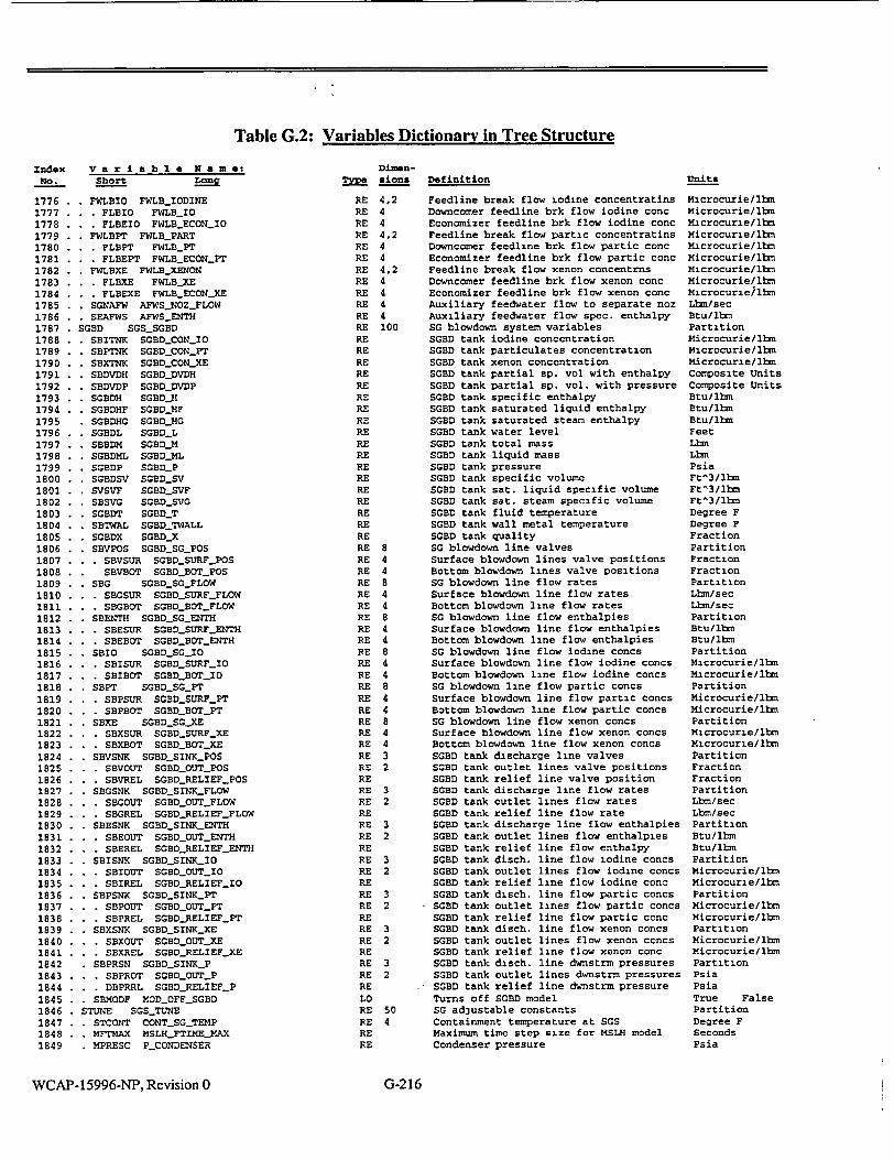
Table G.2: Variables Dictionary in Tree Structure
Dimenn sions
Var i a bl e Name: Short Long
Index NO.
1776 1777 1778 1779 1780 1781 1782 1783 1784 1785 1786 1787 1788 1789 1790 1791 1792 1793 1794 1795 1796 1797 1798 1799 1800 1801 1802 1803 1804 1805 1806 1807 1808 1809 1810 1811 1812 1813 1814 1815 1816 1817 1818 1819 1820 1821 1822 1823 1824 1825 1826 1827 1828 1829 1830 1831 1832 1833 1834 1835 1836 1837 1838 1839 1840 1841 1842 1843 1844 1845 1846 1847 1848 1849
FWLBIO FWLBJIODINE FLBIO FWLBIJO FLBEIO FWLBECON-JO
FWLBPT FWLB-PART . FLBPT FWLBPT . FLBEPT FWLBECONPT FWLBXE FWLBJXENON . FLBXE FWLBXE . FLBEXE FWLBSECONXE SGNAFW AFWSNOZJFLOW SEAFWS AFWSENTH
SGBD SGS0SGBD SBITNK SGBDCONSIO SBPTNK SGBDOCON..PT SBXTNK SGBDCONXE SBDVDH SGBDDVDH SBDVDP SGBDDVDP SGBDH SGBDOH SGBDHF SGBDOHF SGBDHG SGBD..EG SGBDL SGBD0L SBBDM SGBD_M SGBDML SGBDML SGBDP SGBD0 P SGBDSV SGBDOSV SVSVF SGBD0SVF SBSVG SGBDSVG SGBDT SGBDT SBTWAL SGBDTWALL SGBDX SGBDX SBVPOS SGBD_SGPOS . SBVSUR SGBD.SURF.POS
SBVBOT SGBDBOTPOS SBG SGBDSGtFLOW
* . . SBGSUR SGBDSURFSFLOW SBG.OT 0SGBDBOTFLOW
SBENTH SGBDSGENTH . . . SBESUR SGBDSURF.ENTH
. SBEBOT SGBD5BOTENTH SBIO SGBDOSGQ1O
SBISUR SGBDSURFIO SBIBOT SGBD0BOT.I0
SBPT SGBDSGPT . SBPSUR SGBDSURFPT . SBPBOT SGBDBOTPT SBXE SGBD.SGCXE . SBXSUR SGBDOSURFXE . SBXBOT SGBDBOOTCXE SBVSNK SGBDSINKSPOS . SBVOUT SGBDOUTPOS . SBVREL SGBDRELIEF-POS SBGSNK SGBDSINKFLOW . SBCOUT SGBDOUTSFLOW . SBGREL SGBDRELIEFFLOW
. SBESNK SGBDSINK-ENTH . SBEOUT SGBDOUTNTH . SBEREL SGBD5RELIEFENTH SBISNK SGBDOSINK-10
. . . SBIOUT SGBDOUTIO • SBIREL SGBD-RELIEF-10 SBPSNK SGBD0SINKPT
. . . SBPOUT SGBD_0OUT_PT . SBPREL SGBDRELIEFPT SBXSNK SGBDSINKXE . SBXOUT SGBD0_OUTXE . SBXREL SGBDRELIEFJXE SBPRSN SGBDSINKP
S.. SBPROT SGBD5OUTSP . DBPRRL SGBDCRELIEFP SBMODF MOD_OFF0SGBD
STUNE SGSTUNE STCONT CONTSGOTEMP MFTMAX MSLMFTIMEMAX
- MPRESC PCONDENSER
RE RE RE RE RE RE RE RE RE RE RE RE RE RE RE RE RE RE RE RE RE RE RE RE RE RE RE RE RE RE RE RE RE RE RE RE RE RE RE RE RE RE RE RE RE RE RE RE RE RE RE RE RE RE RE RE RE RE RE RE RE RE RE RE RE RE RE RE RELO RE 50 RE 4 RE RE
4,2 4 4 4.2 4 4 4,2 4 4 4 4 100
8 4 4 8 4 4 8 4 4 8 4 4 8 4 4 8 4 4 3 2
3 2
3 2
3 2
3 2
3 2
3 2
WCAP-15996-NP, Revision 0
Definition
Feedline break flow iodine concentratins Downcomer feedline brk flow iodine conc Economizer feedline brk flow iodine conc Feedline break flow partic concentratins Downcomer feedline brk flow partic conc Economizer feedline brk flow partic conc Feedline break flow xenon concentrns Downcomer feedline brk flow xenon conc Economizer feedline brk flow xenon conc Auxiliary feedwater flow to separate noz Auxiliary feedwater flow spec. enthalpy SG blowdown system variables SGBD tank iodine concentration SGBD tank particulates concentration SGBD tank xenon concentration SGBD tank partial sp. vol with enthalpy SGBD tank partial sp. vol. with pressure SGBD tank specific enthalpy SGBD tank saturated liquid enthalpy SGBD tank saturated steam enthalpy SGBD tank water level SGBD tank total mass SGBD tank liquid mass SGBD tank pressure SGBD tank specific volume SGBD tank sat. liquid specific volume SGBD tank sat. steam specific volume SGBD tank fluid temperature SGBD tank wall metal temperature SGBD tank quality SG blowdown line valves Surface blowdown lines valve positions Bottom blowdown lines valve positions SO blowdown line flow rates Surface blowdown line flow rates Bottom blowdown line flow rates SG blowdown line flow enthalpies Surface blowdown line flow enthalpies Bottom blowdown line flow enthalpies SG blowdown line flow iodine concs Surface blowdown line flow iodine concs Bottom blowdown line flow iodine concs SO blowdown line flow partic concs Surface blowdown line flow partic concs Bottom blowdown line flow partic concs SG blowdown line flow xenon concs Surface blowdown line flow xenon concs Bottom blowdown line flow xenon concs SGBD tank discharge line valves SGBD tank outlet lines valve positions SGBD tank relief line valve position SGBD tank discharge line flow rates SGBD tank outlet lines flow rates SGBD tank relief line flow rate SGBD tank discharge line flow enthalpies SGBD tank outlet lines flow enthalpies SGBD tank relief line flow enthalpy SGBD tank disch. line flow iodine concs SGBD tank outlet lines flow iodine concs SGBD tank relief line flow iodine conc SGBD tank disch. line flow partic concs SGBD tank outlet lines flow partic concs SGBD tank relief line flow partic conc SGBD tank disch. line flow xenon concs SGBD tank outlet lines flow xenon concs SGBD tank relief line flow xenon conc SGBD tank disch. line dwnstrm pressures SGBD tank outlet lines dwnstrm pressures SGBD tank relief line dwnstrm pressure Turns off SGBD model SG adjustable constants Containment temperature at SGS Maximum time step size for MSLH model Condenser pressure
Units
Microcurie/lbmn Microcurie/lbm Microcurie/lbm Microcurie/lbm Microcurie/lbm Microcurie/lbm Microcurie/lbn Microcurie/Ibm Microcurie/lbn Lbm/sec Btu/llbn Partition Microcurie/Ibm Microcurie/lbm Microcurie/lbm Composite Units Composite Units Btu/Ibm Btu/lbh Btu/lbm Feet Lbm Lbm Psia Ft'3/llm Ft^3/ lbm Ft'3/lbm Degree F Degree F Fraction Partition Fraction Fraction Partition Lbm/sec Lbm/sec Partition Btu/lbm Btullbm Partition Microcurie/lbm Microcurie/lbm Partition Microcurie/lbs Microcurie/lbm Partition Microcurie/lbm Microcurie/Ibm Partition Fraction Fraction Partition Lbm/sec Lbm/sec Partition Btu/lbm Btu/lbm Partition Microcurie/lbm Microcurie/lbn Partition Microcurie/lbm Microcurie/Ibm Partition Microcurie/lbm Microcurie/Ibm Partition Psia Psia True False Partition Degree F Seconds Psia
G-216

Table G.2: Variables Dictionary in Tree Structure
Index No.
1850 1851 1852 1853 1854 1855 1856 1857 1858 1859 1860 1861 1862 1863 1864 1865 1866 1867 1868 1869 1870 1871 1872 1873 1874 1875 1876 1877 1878 1879 1880 1881 1882 1883 1884 1885 1886 1887 1888 1889 1890 1891 1892 1893 1894 1895 1896 1897 1898 1899 1900 1901 1902 1903 1904 1905 1906 1907 1908 1909 1910 1911 1912 1913 1914 1915 1916 1917 1918 1919 1920 1921 1922 1923
M2CIO M2CPT M2CXE M2DVDH M2DVDP M2SLHH M2SLHF M2SLHG M2SLM M2SLML M2SLP M2SLQ M2QARM M2SLSV M2SVF M2SVG M2SLT M2TWAL
MSLH2_CON_I0 MSLH2_CONPT MSLH2_CONJXE MSLH2_DVDH MSLH2_DVDP MSLH2JH MSLH2MHF MSLH2_HG MSLH2_M MSLH2JML MSLH2_P MSLH2-0 MSLH2_Q__ATM MSLH2_SV MSLH2_SVF MSLH2_SVG MSLH2_T MSLH2JTWALL
Variable Name: Short Long
SASEPT SGS-ASEPTUNE SGSM SGSDELTVJAX SFK3T SGS_FK3_TUNE SFTIME SGSFTIME SFPMAX SGS_FTIMEPMAX SLHASB SGSJHASUBSOPTION SPCONV SGSPCNVRG SPMIN SGSPMIN SDVREC SGSRECIRCDELVOL SRECMN SGS_RECIRCJMIN SSEPMN SGSSEPSPHIN STRTUN SGSTAURC1-TUNE STRMAX SGS_TAURC2_MAX STGMAX SGSTAUJWOUTSG SPERIM SGSUADROP-PERIM SFDMIN SGSUADROPWFDMIN SUSTMN SGSUSTM_MIN SVCONV SGSVCNVRG SWFMIN SGS_WFMIN SX2RG1 SGSX2_1 SCOLDT SGTJHTCRTC SHOWT SGT_HTCRTH SH22SUB SGT_HTCSCW SH2STM SGTHTCSTM SQMULT SGTQJMULT MDPMIN MSLM_DPMILMULT SVFREF SGSSVF.REF SVGREF SGSVGREF SVLEGR SGS_VLEGOREF SGTAU SGSTAUFLOW SGXTAU SGSXTAU_FLOW SCRMOD SGS_CRIT_MODEL
SHORE SGS_MORE_VARIABLES SINCON SGS_INITIALCONDITIONS * SPINIT SPINIT
SLINIT SLINIT * FHINIT FHINIT * SKAMUL SKAMUL SADEG SGSSTUBE.AREASDEGRAD - SADGOP SGSTUBEAREAOPTION * SADFUL SGSJIASSFULLTUBE-AREA * SADZER SGS_MASS_ZEROTUBEAREA FHTBL FWS_ENTHLTABLE * FHENTH FWSITABLEENTH - FHLOAD FWSHTABLE_.LOAD * FHNUM FWSJHTABLEJNUM SECON SGS_ECONVARS
STPINE SGS_ECO1_TPIN STPOTE SGS-ECONTPOUT STFINE SGS_ECONTFIN STFOTE SGS_ECO?_TFOUT SASUBE SGSECONASUB STCAVE SGS_ECONTCAV SCNVRG SGS_ECONCNVRG SFLIME SGSECON_FLIM
MNODE2 MSLH2_STATE
DimenTM• sions
RE RE RE RE RE LO RE RE RE RE RE RE RE RE RE RE RE RE RE RE RE 4 RE 4 RE RE RE 4 RE RE RE RE RE 2 RE 2
IN RE 120 RE 15 RE RE RE RE 4 RE 10 LO RE 4 RE 4 RE 50 RE 20 RE 20 IN RE 40 RE 4 RE 4 RE 4 RE 4 RE 4 RE 4 RE RE RE 40 RE RE RE RE RE RE RE RE RE RE RE RE RE RE RE RE RE RE
MSLH2 MSLH2 MSLH2 MSLH2 MSLH2 MSLH2 MSLH2 MSLH2 MSLH2 MSLH2 MSLH2 MSLH2 MSLH2 MSLH2 MSLH2 MSLH2 MSLH2 MSLH2
node iodine concentration node particulates concentration node xenon concentration node partial sp. vol with enthalpy node partial sp. vol. w pressure node enthalpy node saturated liquid enthalpy node saturated steam enthalpy node mass node liquid mass node pressure coolant-to-wall heat rate wall-to-atmosphere heat rate node specific volume node saturated liquid spec. vol. node saturated steam specific vol. node temperature node pipe metal temperature
Definition
SGS steam separator area tuning factor Multiplier for maximum steam velocity SGS downcomer flow coeff. tuning factor SGS models fast-time step size Max pressure for fasttime w/ MSIV open Option for calculating subcooled region Pressure convergence criterion Minimum secondary-side pressure Delta volume for adjusting recirc flow Minimum recirculation for crossflow Minimum pressure for separation model SGS recirc flow time const tuning factor SGS downcomer flow max time constant Unused spare Perimeter of the feedring MHn feedflow below which condens eff = 1 Minimum steam separation velocity Volume convergence criterion Reg. 2 liq mass for single-region switch Reg. 2 quality to re-establist reg. 1 SG cold side heat transfer tuning factor SG hot side heat transfer tuning factor H.t. coeff if region 2 is subcooled H.t. coeff in region 2 if surface is ste Multiplier on SG tube heat transfer area Min del-P for flow coeff, frac of DP100 Liquid sp.vol for level instrum calibr Steam sp.vol for level instrum calibr Ref-leg spvol for level instrum calibr Steamflow time const @ lo/hi valve rates Fractional valve rates for SGStau_flow LiqI2-phs choked flow model: 0=HEM, l=HF SGS misc additional variables SGS initial conditions New initial steam generator pressure New init SG sec side mixture level New initial feed water enthalpy SG tube area multiplier Secondary tube area degradation model Option to degrade secondary tube area Min mass for full sec tube area Mass for zero secondary area Table of main feedwater enthalpy vs load Table: MFW norm enthalpy, (h-Hl)/(H2-HI) Table: turbine normalized load, W/Wrated Table: number of entries More vars for the SG economizer model Economizer primary inlet temperature Economizer primary outlet temperature Economizer feedwater inlet temperature Economizer feedwater outlet temperature Economizer area in subcooled heat trans SG cold side average primary temperature Converg criterion for econ ht iteration Min MFW flow to econ Below: model off Steamline header node 2 variables
WCAP- 15996-NP, Revision 0
Units
Dimensionless Dimensionless Dimensionless Seconds Psia True False Psia Psia Ft^3 Dimensionless Psia Dimensionless Seconds Unused Feet Lbm/sec Ft/sec Fraction Lb. Fraction Composite Units Composite Units Btu/secft^2degF Btu/secft^2degF Dimensionless Fraction Ft^3/lbm Ft^3llbm Ft^3/lbm Seconds Fraction Pointer Partition Partition Psia Feet Btu/lbm Fraction Partition True False Lbs Lbm Partition Dimensionless Dimensionless Counts Partition Degree F Degree F Degree F Degree F Ft^2 Degree F Dimensionless Lbm/sec Partition Microcurie/lbm Microcurie/lbm Microcurie/lbm Composite Units Composite Units Btu/lbm Btu/lbm Btu/lbm Lbm Lbm Psia Btu/sec Btu/sec Ft^3/lbm Ft^3/lbm Ft^3/lbs Degree F Degree F
I
G-217

Table G.2: Variables Dictionary in Tree Structure
index Va riable Name: No. Short Long
Dimen
im sions
1924 1925 1926 1927 1928 1929 1930 1931 1932 1933 1934 1935 1936 1937 1938 1939 1940 1941 1942 1943 1944 1945 1946 1947 1948 1949 1950 1951 1952 1953 1954 1955 1956 1957 1958 1959 1960 1961 1962 1963 1964 1965 1966 1967 1968 1969 1970 1971 1972 1973 1974 1975 1976 1977 1978 1979 1980 1981 1982 1983 1984 1985 1986 1987 1988 1989 1990 1991 1992 1993 1994 1995 1996 1997
. . M2SLX MSLH2_X RE CTL CONTROL-COMMON RE
CTIME CTLTIMESTEP RE CTCONT CTLSCORE-CONTROL RE . CTSET CTLCORESETPOINTSFOR.TRIP RE
. CTPOHI CTLCORE-HIIPOWERFRAC-TRIP RE
. CTSRHI CTLCORE_.HIPOWERSUR_.TRIP RE
. CTPPLO CTLCORELOW-PRZRPRESTRIP RE
. CTPPHI CTLCORE-HI-PRZRPRES-TRIP RE
. CTLPHI CTLCOREHIPRZRLEVELTRIP RE
. CTTMAR CTLCOREOVER_TEMP_MRGNTRIP RE
. CTWMAR CTLCOREOVER.POWER_4RGNTRIP RE
. CTGRCS CTLCORERCSFLOW-FRACTRI P RE
. CTSIAS CTLCORE-SIAS-TRIP RE
. CTPSGL CTLCORELOWSGPRESTRIP RE
. CTLSGL CTLCORELOWSGLEVELTRIP RE
. CTLSGH CTLCOREHISGLEVELTRIP RE
. CTGSGM CTLSTEAM-FEED-MI SMATCHTRI P RE
. CTDTUR CTLCORETURBTRIPDELAY RE
. CTPCHI CTLCOREHICONT-PRES.TRI P RE
. CTUSER CTL_COREUSERDEFINED_TRIP RE
. CTGKSP CTL RCPFLOWSTPOINT RE
. . CTSRBY CTLCORE-HI-POWER.SUR-BYPS RE CTPORA CTLCOREPOWER.RATIO RE CTGSBY CTLSTEAMFEED_-MISMATCIBYPS RE CTTUBY CTL_CORETURBTRIP_BYPS RE
. CTUSBY CTLCOREUSERDEFINEDBYPS RE * COVER CTLCORETRIPOR RE . . COPOHI CTLCOREHIPOWERFRACTRIP0OR RE - COSRHI CTLCORE-HIPOWERSUtRTRIP_OR RE . . COPPLO CTLCORELOW.PRZRPRES-TRIP-OR RE . COPPHI CTLCORE_HI_PRZRPRES_TRIP _OR RE . . COLPHI CTLCOREHI_PRZRLEVEL_TRIPPOR RE . COTMAR CTLCOREOVERTEMPRGN TRIPOR RE . COWMAR CTLCOREOVERPOWERMRGNTRIP-OR RE . COGRCS CTLCORE-RCSFLOW-FRACTRIP_OR RE . COSIAS CTLCORESIASTRIPOR RE . COPSGL CTLCORELOW_SG_PRES_TRIPOR RE . COLSGL CTLCORE-LOW-SGLEVEL-TRIP-OR RE . COLSGH CTL_CORE_HI_SGLEVELTRIP_OR RE . COGSGM CTLSTEAM-FEEDMISMATCHTRIPOR RE . CODTUR CTLCORE_TURB.TRI PDELAYOR RE . COPCHI CTLCOREHICONT-PRESTRIPOR RE . COUSER CTL_CORE_USERDEFINEDTRIPOR RE
CKTRPT CTLTIMECORETRIP RE COREQ CTLCOREPOWER RE COREOT CTL_QCORETRIP RE CPOWFR CTLCORE-POWER-FRACTION RE CPOWFL CTLCOREPOWERFRACLAST RE CNRPS CTLNUMRPS IN CKAUTO CTLSCORECONTROL.AUTO LO CKTRP CTLCORETRIP LO CKTRPS CTLCORETRIPSIG LO CKTRPP CTL CORE-PTRIP LO
CCEA CTL_CEACOMMON RE CRSET CTLCEA-SETPOINTS RE . CRTNO CTLCEATREF.NO RE
. . CRTFUL CTLCEA.TREF-FULL RE
. * CREXP CTLCEA&GAIN.EXP RE
. CRGAIN CTLCEA_TURBLDGAIN RE CRFPOS CTLCEAPOSITION..FRAC RE CRMOTL CTLCEA.LAST-TIME RE CRMAX CTLCEAMAX RE CRMIN CTLCEA-MIN RE CRPOS CTLCEAPOS RE CRSPD CTLCEASPEED RE CRSTEP CTLCEASTEP RE CAUTO CTLCEA-AUTO LO CRPERF CTLCEAPERFECT LO CRACCM CTLCEAACCUM RE CRSPDL CTLCEA.SPEEDLAST RE
CCVCS CTL_CVCSCOYXON RE . CPSET CTLPRZRLEVELSETPOINTS RE
.* CPTEM CTLPRZRPLEVELTEMP RE
5120
110 45
10 5 2
10 25
10
25
20 6
85 9 2
Definition
MSLH2 node quality Control, protective, and bop systems Time step delt available to controllers Core control partition Partition for RPS setpoints Hi power fraction scram setpoint High power SUR scram setpoint Low przr pressure scram setpoint High przr pressure scram setpoint High przr level scram setpoint Thermal margin setpts for over temp trip Thermal margin setpts for over pwr trip Low loop flow scram setpoint Scram due to SIAS Low SG pressure scram setpoint Low SQ level scram setpoint High SG level scram setpoint Steam-feed flow mismatch scram setpoint Scram due to turb trip. time delay Hi cont. pressure scram setpoint Space for other scram setpoints Low primary flow scram setpoints Hi power SUR scram-inhibit setpoints Logrithmic rate of power change Scram on flow mismatch, inhibit setpoint
-Scram on turbine trip: inhibit setptoint Space for other scram inhibit setpoints Partition for scram overrides Hi power fraction scram override High power SUR scram override Low przr pressure scram override High przr pressure scram override High przr level scram overrides Over-temp thermal margin scram override Over-power thermal margin scram override Low loop flow scram override Scram due to SIAS override Low SG pressure scram override Low SG level scram override High SG level scram override Steam-feed flow mismatch scram override Scram due to turb trip override Hi cont. pressure scram override Space for other scram overrides Time elapsed after scram Core power Core power at time of trip Core power, fraction of rated Core power fraction, last step Number of RPS channels Flag: automatic control of core Core tripped flag Scram signals Scram signal at last time step Control-element assembly model Setpoints for reactor regulating system Reference (avg) primary temp at no load Reference (avg) primary temp, full load Exponent for nonlinear gain=demand**exp Nonlinear gain for crr system Fractional average rod position CEA motion time Maximum CEA withdrawal position Minimum CEA withdrawal position CEA withdrawal position CEA motion speed and direction Step size of control rod motion Flag: auto/manual CEA control Flag: CEA perfect controller CEA control accumulated signal CEA speed and direction, last step Chemical & volume control system Przr level setpoints Przr level-program temperature setpoints
WCAP-15996-NP, Revision 0
Units
Fraction Segment Seconds Partition Partition Fraction Decades/mmn Psia Psia Fraction Del-degF Del-degF Fraction Fraction Psia Fraction Fraction Lbm/sec Seconds Psia Undefined Lbm/sec Fraction Dimensionless Fraction Lbm/sec Undefined Partition Override Normal Override Normal Override Normal Override Normal Override Normal Override Normal Override Normal Override Normal Override Normal Override Normal Override Normal Override Normal Override Normal Override Normal Override Normal Override Normal Seconds Btu/sec Btu/sec Fraction Fraction Counts Auto Manual Trip Normal Active Inactive True False Partition Partition Degree F Degree F Dimensionless Dimensionless Fraction Seconds Steps Steps Steps Steps/min Inches True False True False Steps Steps/min Partition Partition Degree F
G-218

Table G.2: Variables Dictionary in Tree Structure
Index V a ria b I e N a m e: No. short Long
1998 . . . CPLEV CTL_PRZRPLEVEL 1999 . . . CPSLIQ CTLPRZR_.LIQ_.SPVOLREF 2000 . . . CPSSTM CTLPRZR_.STMCSPVOLREF 2001 . CLSET CTLJLETDOWNSETPOINTS 2002 . CLLSP CTLCVCSLDNMZSPOINT 2003 . CLGSP CTLCVCS_LDN._.LGPM 2004 . CCSET CTL_CHARGING_SSETPOINTS 2005 - CCLSP1 CTL_.CVCSCHMSSPOINT 2006 . . CCLSP2 CTLCVCS.CH2_SPOINT 2007 . CCLSP3 CTLCVCSCH3_SSPOINT 2008 . CCLSP4 CTLSCVCSSCH4_SPOINT 2009 . . . CCGRAT CTLCHPUMPRWATED 2010 . CPPROG CTLCVCSCONTROL 2011 . . . CPLPRG CTLPRZRPROGLEVEL 2012 . . CPLERR CTLPRZRLEVELSERROR 2013 . . . CPLINS CTLPRZRLEVELINST 2014 . CTAVG CTL_T_AVG 2015 . . . CTREF CTLS...REF 2016 . . . CCFPMP CTL_CH_PUMP_FRAC 2017 . . CCAUTO CTLCHPUMPP_AUTO 2018 . . . CCPMPO CTL_CHPUMPON 2019 CLAUTO CTLLDNAUTO 2020 CCVALV CTLCVCSRCSVALVES 2021 . CCFVAL CTLSCHV.FRAC 2022 . . . CCAVAL CTLCHVRAREA 2023 . CXREG CTL_CVCSTHSVARIABLES 2024 . . . CXHA CTL_HA_REGJHEATX 2025 CLFLOW CTLLDNLFLOW 2026 CLTEMP CTLLDN_T
2027 . . . CLENTH CTL-LDNJH 2028 . . . CLFRAC CTLaLETDOWNFRAC 2029 . . . CCFLOW CTLCH_FLOW 2030 . . CCTEMP CTL_CH_T 2031 . . . CCENTH CTLCHJH 2032 CHEATR CTLHEATERSCONTROL 2033 . CHSET CTLPRZRRHEATERSETPOINTS 2034 . . . CHLBSP CTLPRZRBHLEVEL_SPOINT 2035 . . . CHLOFF CTLLEVELJHEATEROFF 2036 . . . CHPPOF CTL_.PRESPHEATER.OFF 2037 . . . CHPPON CTLPRESSPHEATER0ON 2038 . . . CHPBOF CTLPRESBHEATER_OFF 2039 . . . CMPBON CTLkPRES_BHEATER_ON 2040 . . CHPREF CTLPRZRREFPRES 2041 CHVPRP CTL3VOLT-PROP 2042 CHVBAK CTL.VOLTBACK 2043 CHVRAT CTLSPRZRHEATERSVOLT 2044 CHAUTO CTL_HEATERSCONTROLAUTO 2045 CSPRAY CTLPRZRSPRAY_CONTROL 2046 . CWSET CTLPRZR.SPRAY,_SETPOINTS 2047 . . . CWPON CTLPRZRSPRAY_PRES_ON 2048 . . CWPOFF CTLPRZRSPRAYPRESOFF 2049 . CWAUTO CTL3PRZRSPRAYCONTROLAUTO 2050 CVRELF CTL PRESSURIZER_RELIEF 2051 . CVSET CTLPRZRRELIEFSETPOINTS 2052 . . . CVPSET CTL PORVJPSET 2053 . . . CVOPEN CTLPSVPSETOPEN 2054 . . CVCLOS CTLPSV_PSETSCLOSE 2055 . . . CVBLDN CTLPSVPSET_BLDN
2056 . CVAUTO CTL&PORV.AUTO 2057 CECCS CTL.SISCOMMON 2058 . CESET CTLSIASSETPOINTS 2059 . CEPLO CTLSIAS-PRZR_.PRESLOW 2060 . CEDPSL CTL_SSIASSL_.SH_DP 2061 . . . CEPCHI CTL_.SIAS_HICONT_PRES 2062 . . CETAVL CTLSIAStLOWtTAVG 2063 CEPSLL CTLSIASLOW.SLPRES 2064 CESIS CTL SISCONTROL 2065 . . . CENHPS CTLHPSINPOINTS_TAB 2066 CEGHPS CTLJPSIFLOWtTABLE 2067 . . . CEPHPS CTL_HPSIPRESTABLE
2068 . . . CEHNUM CTLHPSIPUMP-NUM 2069 . . CESHPS CTLHPSI_SPLIT 2070 . . . CENLPS CTLLPSINPOINTS_TAB 2071 . . CEGLPS CTLLPSIFLOWTABLE
DimenT!U siona
RE 2 RE RE
Definition
Przr level-program level setpoints Przr instrum. ref. liquid specific-vol Przr instrum. ref steam specific-vol
6 Letdown control setpoints 2 Letdown level control setpoints 2 Letdown flow setpoints 15 Charging pump control setpoints 2 Charging pump 1 control setpoints 2 Charging pump 2 control setpoints 2 Charging pump 3 control setpoints 2 Charging pump 4 control setpoints 4 Charging pump rated flow 24 CVCS control variables
Pressurizer programnmed level Pressurizer level error Przr instrumentation level reading Average primary coolant temperature Demand reference temperature
4 Charging pump fractional flow 4 Flags' charging pumps automatic control 4 Charging pumps on-off indicator
Flag- letdown automatic control 10 CVCS-RCS valve connections 5 Fractional opening of charging valve 5 Charging valve relative flow areas 15 CVCS thermal-hydraulic variables
Regen. heat exchanger overall ht coeff. Letdown mass flow rate
2 Letdown temperature at RHEX inlet/exit 2 Letdown enthalpy at RHEX inlet/exit 4 Letdown flow fraction
Total charging pumps delivery 2 Charging temperature at RHEX inlet/exit 2 Charging enthalpy at RHEX inlet/exit 18 Heaters control partition 10 Heater control setpoLnts 2 Przr heaters hi-level on/off setpoints
Heaters low-level cutoff setpoint Prop heaters high pressure setpoint Prop heaters low pressure setpoint Backup heaters high pressure setpoint Backup heaters low pressure setpoint Reference p for przr pressure control Proportional heaters voltage Backup heaters voltage Przr heaters rated voltage Flag. automatic ctrl of przr heaters
5 Pressurizer main spray controls 4 Przr spray control setpoints
Przr spray ctrl high-press. on-setpoint Przr spray ctrl low-press off-setpoint Flag: automatic control of przr spray
26 Przr PORV and SV control variables 20 Przr relief and safety valve setpoints 4 PORV opening pressure setpoints 4 Przr safeties full-open setpoints 4 Przr safeties full-closed setpoints 4 Przr safeties re-closing setpoints 4 Flags: automatic control of PORVs 200 Safety injection system 8 Safety injection syst setpoints
Low pressure setpoint for SIAS Steamline flow trip setpoint High containment press setpoint for SIAS Low temperature setpoint for SIAS Low steamline pressure setpoint for SIAS
150 Safety injection syst control variables No. of pairs in HPSI flow vs press table
45 Flows for HPSI flow-vs-pressure table 15 Back press for HPSI flow-vs-press table
Number of operating HPSI pumps 8 HPSI flow split to injection points
No. of pairs in LPSI flow vs press table 45 Flows for LPSI flow-vs-pressure table
Units
Fraction Ft^3/lbm Ft^3/lbm Partition Fraction Gal/min Partition Fraction Fraction Fraction Fraction Gal/min Partition Fraction Fraction Feet Degree F Degree F Fraction Auto Manual Active Inactive Auto Manual Partition Fraction Dimensionless Partition Btu/sec-degF Lbm/sec Degree F Btu/lbm Fraction Lbm/sec Degree F Btu/ibm Partition Partition Fraction Fraction Psia Psia Psia Psia Psia Volts Volts Volts Auto Manual Partition Partition Psia Psia Auto Manual Partition Partition Psia Psia Psia Psia Auto Manual Partition Partition Psia Psid Psia Degree F Psia Partition Counts Gal/min Psia Counts Fraction Counts Gal/min
WCAP-15996-NP, Revision 0 G-219

Table G.2: Variables Dictionary in Tree Structure
index V a r i a b I N a m e: No. Short Long
2072 CEPLPS CTLLPSIIPRES_TABLE 2073 CELNUM CTLLPSI_PUMPNUM 2074 CESLPS CTL.LPSISPLIT 2075 CETRPT CTL_SIASTIME 2076 CEDEL CTL_SISDELAY 2077 CEAUTO CTLSIAS_CONTROL_AUTO 2078 CETRP CTLSIASTRIP 2079 . CETRPP CTL_SIASPTRIP 2080 . CEKISC CTLSISFLOW 2081 . CEBHLP CTLSISHLPSIBC 2082 . CEHHLP CTLSISHLPSIH 2083 . CEBSIT CTLSISSITBC 2084 . CEHSIT CTLSISSITH 2085 CENSIT CTLSITNUM 2086 . CEELEV CTL.SITELEV_PRES 2087 CEFLCO CTLS ITFLOWCOEFF 2088 CECGAS CTLSITGASCONST 2089 CEPSIT CTLSITGASPRES 2090 . CEVGAS CTL_SITGASVOLUME 2091 . CEIVAL CTL_SIT_ISOVALVE 2092 CESLIQ CTLSITLIQSPVOL 2093 CEVLIQ CTLSITLIQVOLUME 2094 CSDCCN CTLSDCCONTROL 2095 . CSDCDH CTLSDCDH 2096 . CSDCHM CTL_SDC_H_MIN 2097 . CSDCSP CTLSDCSPLIT 2098 CTURB CTL_TURB_CONTROL 2099 CGSET CTLTURBSETPOINTS 2100 . CGTCLS CTkLTURB.TRIP_VALVE_TIME 2101 . . CGVTC CTLTURBAOUT_TC 2102 . CGTRPT CTLTURBTRIPTIME 2103 . CGFDEM CTLTURBDEMAND 2104 . CGGRAT CTLTURBSTEAMRATED 2105 CGCAUT CTLTURB_CONTROLJAUTO 2106 CGLOAD CTL_TURB_CONTROLLOAD 2107 CGTRP CTLTURBTRIP 2108 CGTAUT CTL_TURBTRIPAUTO 2109 CGTRPP CTLTURB_PTRIP 2110 CMSIS CTLMSISCONTROL 2111 CISET CTLMSI S_SETPOINTS 2112 . CIPSLO CTL_MSIS_SGPRES_TRIP 2113 . CIPCHI CTLMSJIS_CONTPRESS_TRIP 2114 . CIGSLO CTLMSISSGSLFLOWTRIP 2115 CIAUTO CTL_MSIS_CONTROL_AUTO 2116 CITRP CTL._MSIS_TRIP 2117 CDUMP CTLATMDUMPSCONTROL 2118 . CDSET CTLATMDUMP-SETPOINTS 2119 . . CDTSP CTLATM-DUMPSPOINT 2120 . CDAUTO CTLATMDUMPCONTROLAUTO 2121 CBYPAS CTLTURBBYPASSCONTROL 2122 . CBSET CTLTURBBYPASSSETPOINTS 2123 . CBPOPN CTLTURB-DUMPOPEN 2124 CBDELP CTL_TURB_DUMP_.DELP 2125 CBQOPN CTLTURBDUMPQOPEN 2126 . CBNOPN CTLTURBDUMP._NOPEN 2127 . CBQCLS CTLTURB-DUMP-OCLOSE 2128 . CBNCLS CTLTURB_DUMPNCLOSE 2129 CBMODE CTL_TURBDUMP_.ODE 2130 . CBAUTO CTL_TURBBYPASSCONTROL..AUTO 2131 CSAFE CTL_SG_SAFETIES 2132 CSSET CTLSGSVSETPOINTS 2133 . CSOPEN CTL_SGSV_PSETOPEN 2134 . CSFULL CTL_SGSV.PSETFULL 2135 . CSCLOS CTLSGSVPSETCLOSE 2136 . CSAOPN CTLSGSVASETOPEN 2137 CFWS CTLFWS_CONTROL 2138 . CFSET CTLFWSSETPOINTS 2139 . CFLPRG CTL_FWS_SGLEVELLOAD 2140 . CFLLO CTL_FWSSG_LEVEL_LOW 2141 . CFLHI CTLFWSSG_LEVELHIGH 2142 . CFRAMP CTLFWSTURBTRIPFRAC 2143 . CFDELA CTLFWS_TURBTRIPDELAY 2144 . CFGMAX CTL_FWSMAX_FLOW 2145 . CFSMUL CTLFWSSPEEDMULT
DimenD sions
RE 15 IN RE 8 RE RE LO LO LO RE 36 RE RE RE RE IN RE 4 RE 4 RE RE 4 RE 4 LO 4 RE 4 RE 4 RE 6 RE RE RE 4 RE 14 RE 7 RE RE RE RE RE LO LO LO LO LO RE 14 RE 10 RE RE RE 4 LO LO RE 6 RE 4 RE 2 LO RE 11 RE 10 RE RE RE RE RE RE RE LO RE 120 RE 120 RE 24 RE 24 RE 24 RE 24 RE 70 RE 15 RE 2 RE RE RE RE RE RE 4
Definition Units
Back press for LPSI flow-vs-press table Psia Number of operating LPSI pumps Counts LPSI flow split to injection points Fraction Time elapsed since SIAS Seconds SI pumps time delay after SIAS Seconds Flag: automatic control of SIAS Auto Manual Safety injection actuation signal Active Inactive SI signal at last time step True False Safety injection system flow variables Partition HPSI/LPSI flow boron concentration Parts/million HPSI/LPSI flow enthalpy Btu/Ibm SI tank flow boron concentration Parts/million SI tank flow enthalpy Btu/lbm Number of SI tanks Counts
'SI tank elevation heads Psid SI tank flow coefficients Composite Units
-SI tank gas constant Dimensionless SI tank gas pressures Psia
,SI tank gas volumes Ft^3 SI tank isolation valves Open Closed SI tank liquid specific volumes Ft^3/lbm SI tank liquid volumes Ft^3 Shutdown Cooling control variables Partition Shutdown Cooling enthalpy drop Btu/lhm Shutdown Cooling min return enthalpy Btu/lbrn SDC flow split to injection points Fraction Turbine controls Partition Turbine control setpoints Partition TAV full-range closing time on turb trip Seconds Turb admission valve time constant Seconds Time elapsed since turbine trip Seconds Turbine steam demand Fraction Rated turbine steam flow Lbm/sec Flag: automatic turbine control Auto Manual Flag to match st. demand with heat load Auto Manual Signal. turbine tripped Trip Normal Flag: automatic trip of turbine Auto Manual Turbine trip signal at last time step True False Main steam isolation signal controls Partition MSIS control setpoints Partition Low SG pressure MSIS trip setpoint Psia Containment pressure MSIS trip setpoint Psia High steamline flow MSIS trip setpoint Lbm/sec Flag- MSIS automatic control Auto Manual Main steam isolation signal Active Inactive Atmospheric dump valves controls Partition Przr ADVs setpoints Partition Atm. dump valves temperature setpoints Psia Flag: automatic ctrl of atm-dump valves Auto Manual Turbine bypass controls Partition Turbine bypass valves setpoints Partition Pressure to open bypass valves Psia Press. range of turb bypass ctrl system Psid Quick-opening time for turb bypass valve I/seconds Normal-open time for turb bypass valve 1/seconds Quick-close time for turb bypass valve 1/seconds Normal-close time for turb bypass valve I/seconds Bypass control mode: 0=p-temp, 1=s-pres Pointer Flag: automatic turbine-bypass control Auto Manual SG safety valves control variables Partition SG external safety valve setpoints Partition SG safeties design-open press. setpoints Psia SG safeties full-open pressure setpoints Psia SG safeties closing pressure setpoints Psia SG safeties design-open fraction Fraction Feedwater system controls Partition FWS control setpoints Partition SG level program load setpoints Fraction Main feedwater lo-level control setpoint Fraction Main feedwater hi-level control setpoint Fraction Main FW rampdown flow frac after trip Fraction Main FW rampdown time after turb trip Seconds Max feedwater flow to each SG Lbm/sec Multp on FW pump speed signl: =0 to trip Dimensionless
WCAP-15996-NP, Revision 0 G-220

Table G.2: Variables Dictionary in Tree Structure
Index V a r i a b 1 e N a m e: No. Short Long
2146 . . CFTLO CTL_FWSTRIPSP 2147 . CFENTH CTL.FWS_H 2148 . CFEMAX CTLFWSJHMAX 2149 . CFETC CTLFWS_HTC 2150 . CFTRP CTLFWSTRIP 2151 CFAUT CTL_FWS_AUTO 2152 . . CFAUTO CT1_FWSCONTROLAUTO 2153 . . CFVAUT CTL.FWS-VALVEAUTO 2154 . . CFEAUT CTLFWS_ECON_VALVE.AUTO 2155 . . CFPAUT CTLFWSPUMPAUTO 2156 . . CFTAUT CTLFWSTRIPAUTO 2157 CFVSIG CTL FWSVALVELSIG 2158 . . CFVSI CTLFWSSIG 2159 . CFVESI CTL FWSECON-SIG 2160 CFVPOS CTLFWSVALVE._POS 2161 . CFVPO CTLFWSPOS 2162 . . . CFVEPO CTL_FWSECONrPOS 2163 CFSSIG CTLFWS_SPEED_SIG 2164 CFSFRC CTLFWS-SPEEDFRAC 2165 CFSMAX CTLFWSSPEED-MAX 2166 CFVISO CTLFWSIS0_POS 2167 CFVBYP CTLFWSBYPSIG 2168 CAFWS CTLAFWS_CONTROL 2169 . CASET CTLAFWS-SETPOINTS 2170 . . . CALLO CTLAFWSSGLEVELLOW 2171 . . . CALHI CTL AFWSSGLEVELJIIGH 2172 . CAGMAX CTLAFWSTOTFLOW 2173 CADPMI CTLAFWSSGDPJHIIGH 2174 . CADELA CTL.AFWSDELAY 2175 . CAFMUL CTL AFWSFLOW-MULT 2176 . CATURB CTLAFWSTURBPUMP 2177 . CAMOTR CTL._AFWSMOTOR-PUMP 2178 CAAUTO CTLAFWSCONTROLAUTO 2179 CASSIG CTLAFWSSPEEDSIG 2180 CRPCS CTLRPCSCONTROL 2181 . CQSET CTLRPCSSETPOINTS 2182 . CQAUTO CTLRPCS_CONTROL_AUTO 2183 . CQTRP CTLRPCSTRIP 2184 . CQTRPP CTLRPCSPTRIP 2185 . CQTRPT CTLRPCSTRIPTIME 2186 CGSCON CTLTURB.SETBACKCONTROL 2187 . CGSSET CTL_TURBSETBACKSETPOINTS 2188 . CGSAUT CTLTURB_.SETBACK_AUTO 2189 CGRAUT CTLTURBRUNBACKAUTO 2190 . CGSTRP CTLTURB_SETBACK_TRIP 2191 CGRTRP CTLTURB RUNBACK 2192 CSETPT CTLMISCSETPOINTS 2193 . SETT CTLSETTEMP 2194 . SETDT CTLSETDELTEMP 2195 SETDDT CTLSET_DELTEMPD 2196 SETP CTLSETPRES 2197 SETDP CTL_SET_PRESD 2198 . SETDM CTL_SETNODIM 2199 . SETW CTLSET_.FLOW 2200 . SETWD CTL_S ETFLOWD 2201 . SETRT CTLSETPERTIME 2202 CTIMCN CTLTIM-CONSTANTS 2203 COUT CTLOUTPUT 2204 COUTIN CTLOUTPUTINTERVAL 2205 COUTOP CTLOUTPUT-OPTION 2206 COUTCT CTLOUTPUTCOUNT 2207 COUTTI CTLOUTPUT_NTITLE 2208 COUTGR CTLGRAPHINTERVAL 2209 COUTFI CTLGRAPH_FILE 2210 COUTLO CTLOUTPUTLOOP 2211 COUTCL CTLOUTPUTOPCL 2212 COUT3D CTLOUTPUT.3DMAP 2213 CSPAR2 CTLSPARE2 2214 CBLOCK CTLTIMEBLOCK 2215 . DELT DELT 2216 . FDELT FDELT 2217 . TBASE TBASE 2218 . TIME TIME 2219 . . TSCALE TIME-SCALE
Di ci__
RE RE RE RE LO LO LO LO LO LO LO
RE RE RE RE RE RE RE RE RE RE RE RE RE RE RE RE RE RE RE RE RE LO RE RE RE RO RO RO RE RE RE RO LO LO RO RE RE RE RE RE RE RE RE RE RE RE RE IN IN IN IN IN
IN IN IN t0 RE RE RE RE RE RE RE
mn_ Lns Definition
Feedwater trip setpoint 2 Steady state FW enth: 1 at CST, 2 at SGS
Maximum feedwater enthalpy Feedwater enthalpy time constant FWS trip signal
14 Flags for automatic control of FW system Master FW flag: T=separate, F=all manual
4 Flags: auto control of downcmr FW valves 4 Flags: auto control of econmzr FW valves 4 Flags: auto control of main FW pumps
Flag: automatic main feedwater trip 4,2 Main FW valve demand signals 4 Main FW downcomer valve demand signal 4 Main FW economizer valve demand signal 4,2 Main FW valve positions 4 Main FW downcomer valve position 4 Main FW economizer valve position 4 Main FW pumps speed demand signals 4 Main FW pumps normalized speed, actual
Main FW pumps reference speed 4 Main FW isolation valve position 4 Main FW Bypass valve demand signal 25 Aux feed system controls 20 AFWS control setpoints 4 Low level setpoint for aux feed 4 High level setpoint for aux feed
Total aux-feed flow capacity, all SGs SO press.-difference to cutout aux. feed AFW time delay after trip
4 Multiplier on aux feedwater flow rate AFWS turb-driven pump switch: 0=off,l=ok AFWS motor-drivn pump switch: 0=offl=ok Flag: automatic control of aux feed
4 AFW pumps speed demand signals 15 Reactor power cutback system 5 RPCS setpoints
Flag: automatic RPCS control Signal. RPC engaged RPC signal at last time step Time elapsed since RP cutback engaged
20 Turbine setback and runback systems 10 Turb setback & runback system setpoints
Flag: automatic turbine setback control Flag: automatic turbine runback control Signal. turbine setback engaged Signal turbine runback engaged
200 Miscellaneous user-defined setpoints 20 Miscellaneous temperature setpoints 20 Miscellaneous delta-temp setpoints 20 Miscellaneous per-delta-temp setpoints 20 Miscellaneous pressure setpoints 20 Miscellaneous per-pressure setpoints 60 Miscellaneous dimensionless setpoints 10 Miscellaneous flowrate setpoints 10 Miscellaneous per-flowrate setpoints 20 Miscellaneous per-time setpoints 150 Miscellan. user-defined time constants 16 Output control partition
Output frequency for line output Line output option
4 Output counter: calls/line/graph/title Line output title frequency Output frequency for graphics output Suffix nn for graphics file graphnn dat
2 Select loops for std output & graphics Increment for 2nd cold leg in loop Flag to produce a 3-D power map
600 Not used 10 Time step control information for CENTS
Master time step variable Fast DELT used for scaled time operation Base time step (set to 1.0) Simulation time Time scaling ratio >1 is faster than rt
Units
Undefined Btu/lbm Btu/lbm Seconds Active Inactive Partition Auto Manual Auto Manual Auto Manual Auto Manual Auto Manual Fraction Fraction Fraction Fraction Fraction Fraction Fraction Fraction Shaft RPM Fraction Fraction Partition Partition Fraction Fraction Lbm/sec Paid Seconds Dimensionless Pointer Pointer Auto Manual Fraction Partition Partition Auto Manual Trip Normal Trip Normal Seconds Partition Undefined Auto Manual Auto Manual Trip Normal True False Undefined Degree F Del-degF Per-degF Psia Per-psia Dimensionless Lbm/sec Sec/Ibm 1/seconds Seconds Partition Counts Pointer Counts Counts Counts Pointer Dimensionless Dimensionless True False Unused Partition Seconds Seconds Seconds Seconds Per unit
WCAP-15996-NP, Revision 0 G-221

Table G.2: Variables Dictionary in Tree Structure
index V a r i a b I a N a = a: No. Short Lon
2220 TSTOP TSTOP 2221 MODELQ MODELQUEUE 2222 TIMQUE TIMQUE 2223 . MODQUE MODQUE 2224 . FLGQUE FLGQUE 2225 CINCON CTLINITIALCONDITIONS 2226 . CTLUN CTLUNUSED 2227 . CLCONT CLCONT 2228 CSPARE CTLSPARE 2229 INIFLG INIT_FLAG 2230 CEINIT INITALL 2231 MODOFF INITOFFMODELS 2232 . RCSOFF INITOFFRCS 2233 . CHTOFF INITOFF-CHT 2234 . POWOFF INITOFF_POW 2235 . SGSOFF INITOFFSGS 2236 . CONOFF INITOFF_CCN 2237 CORINI INITCORE 2238 NINIT INITITER 2239 CLEVEL CTLILEVEL 2240 CLEVSG CTL_SG_ILEVEL 2241 CLEVP CTLPRZR_ILEVEL 2242 MODERR MODELERROR 2243 CONT CTL_CONTROLLER 2244 ELLAST ELLAST 2245 GROUT GROUT 2246 MALCTL MAL_CTL 2247 CDELAY CTL_DELAYS 2248 CDTRIP CTLCORETRIPDELAYS 2249 . . . CDPOHI CTL_CORE_HIPOWERFRACTRIP_DL 2250 CDSRHI CTL_CORE_H1IPOWERSURTRIP_DL 2251 . . . CDPPLO CTLCORE-LOWPRZRPRES..TRI PDL 2252 . CDPPHI CTLCORE_H.I_PRZRPRES_TRIP_DL 2253 . . CDLPHI CTLCORE..HIYPRZR_.LEVELTRIP_DL 2254 . . CDTMAR CTLCOREOVER..TEMP_.MRGN-TRIP_DL 2255 . CDWMAR CTL.COREOVERPOWERMRGNTRIPDL 2256 CDGRCS CTL_CORERCSFLOW.FRACTRIPDL 2257 CDSIAS CTLCORESIASTRIP_DL 2258 CDPSGL CTLCORELOWSGPRESTRIPDL 2259 CDLSGL CTL_CORELOW_SGLEVELTRIPDL 2260 CDLSGH CTL_COREHISGLEVELTRIP DL 2261 . CDGSGM CTL_STEAKFEED.MISMATCH_TRI PDL 2262 . CDPCHI CTL_COREHI-CONTPRES_TRIPDL 2263 . CDUSER CTL_CORE_USERDEFINEDTRIP_DL 2264 CDMIST CTLMISC-TRIPDELAYS 2265 . CDGTRP CTLTURBTRIP..DELAY 2266 . CDITRP CTLMSIS_.TRI P_DELAY 2267 . CDFTRP CTL_FWS_TRIPDELAY 2268 . CDQTRP CTLRPCSTRIPDELAY 2269 . CDGSTR CTLTURB-SETBACKTRIP_DELAY 2270 . CDGRTR CTLTURBRUNBACKDELAY 2271 . CDMISC CTL_MISCDELAYS 2272 USR USER_COMMON 2273 SDELAY SCRAM_DELAY 2274 MOISTC MSLHNO.MOISTURECARRY 2275 SGTIOP SGTINITOPTION 2276 WARNOP INTERPOLATIONERROR_.OPTION 2277 DBGSGI SGSDEBUGSGSINI 2278 DBGSGH SGS-DEBUGSGHEAT 2279 COREQA CTLCOREPOWERA 2280 SAREA3 SGSAREADOWNCOMER 2281 ALPHA3 SGS_ALPHA_DOWNCOMER 2282 V3MULT SGS-VEL31-YMULT 2283 SVEL31 SGS-STEAMVEL31 2284 RBAL RCSBALANCE 2285 RNODFL RCS_NODAL.EXT.FLOWS 2286 RTOTFL RCS_NETEXT_FLOW 2287 RTOTHR RCSNET_HEAT.RATE 2288 RTOTM RCSTOTALMASS 2289 RTOTE RCS_TOTALENERGY 2290 ITOTP IODINETOTALSPARTITION 2291 RITOT RCSTOTALIODINE 2292 SITOT SGSTOTALIODINE 2293 RIRELT RCSIODRELTOT
Dimeon
To sions Definition
RE RE 60 RE 20 IN 20 LO 20 RE 4 RE LO RE 200 LO 10 LO LO 7 LO LO LO LO LO LO IN RE 15 RE 4,3 RE IN RE 3000 RE 1000 RE 1000 LO 1000 RE 50 RE 30 RE RE RE RE RE RE RE RE RE RE RE RE RE RE RE 10 RE 20 RE RE RE RE RE RE RE 10 RE 1024 RE RE RE RE RE RE RE RE 4 RE 4 RE 4 RE 4 RE 54 RE 50 RE RE RE RE RE 10 RE RE RE
Value of time at which to pause Model queue information Model queue - fraction of timestep Model queue - model number called Model queue - on/off flag Flags for initial conditions Not used Flag for including control routines Spare space Model initialization flag Initialization of all routines Off flags for initialization models Initialization of RCS: off flag Initialization of CHT: off flag Initialization of POW: off flag Initialization of SGS: off flag Initialization of CONT: off flag Flag to initialize the 3-D core model Number of initialization passes Instrument level readings for controls SG level readings (SG, refleg) Pressurizer level reading User-accessible flag for model errors Control module variables Saved "last values, of control elements Control group output signals Control group malfunction cues Partition for control system delays Scram channel delays Hi power fraction scram delay High power SUR scram delay Low przr pressure scram delay High przr pressure scram delay High przr level scram delays Over-temp thermal margin scram delay Over-power thermal margin scram delay Low loop flow scram delay Scram due to SIAS delay Low SG pressure scram delay Low SG level scram delay High SC level scram delay Steam-feed flow mismatch scram delay Hi containment pressure scram delay Space for other scram delays Miscellaneous control system delays Turbine trip signal delay Main steamline isolation signal delay Main feedwater trip signal delay Reactor Power Cutback signal delay Turbine Setback signal delay Turbine Runback delay Space for other control system delays User global common variables Total scram delay time after trip 1 => No moisture carryover 0 => Adjust area. I => Find SO press 1 => Warning after each interp error 1 => Debug print on-subroutine SGSINI 1 => Debug print on-subroutine SGHEAT 0 Core power Area of downcomer for bubble rise calc Downcomer steam volume fraction Downcomer multiplier on Wilson velocity Steam velocity downcomer to steam dome RCS mass and energy balance Sum of the external flows to each node Sum of all RCS flows - includes PRZR Sum of all heat flows to RCS Sum of all RCS nodal masses - inc PRZR Sum of all RCS node total energy Variables to check iodine release model Total iodine in RCS nodes Total iodine in stm Generators & header Total of core release & external flows
Units
Seconds Partition Fraction Dimensionless Active Inactive Partition Unused True False Unused Partition True False True False True False True False True False True False True False True False Counts Fraction Fraction Fraction Pointer Partition Undefined Undefined Malfunc Normal Partition Partition Seconds Seconds Seconds Seconds Seconds Seconds Seconds Seconds Seconds Seconds Seconds Seconds Seconds Seconds Seconds Partition Seconds Seconds Seconds Seconds Seconds Seconds Seconds Segment Seconds Dimensionless Dimensionless Dimensionless Dimensionless Dimensionless Megawatts Ft^2 Dimensionless Dimensionless Ft/sec Partition Lbm/sec Lbmf/sec Btu/sec Lbm Btu Partition Curies Curies Curies
WCAP- 15996-NP, Revision 0 G-222

Table G.2: Variables Dictionary in Tree Structure
Index V a r i a b l e N a m ei No. Short Long
2294 . RIRELR RCS_IOD_RELRATE 2295 MINMAX CTL_SUMMARYDATA 2296 MXPOW CTLMAXPOWER_FRAC 2297 MXPOWT CTLJ4AXPOWER_TIME 2298 MJOTFR CTLJMAXH.EATFLUX)FRAC 2299 . MHTT CTL_.MAX_HEATFLUX_TIME 2300 MXPPR CTLJMAXPRZR_PRESS 2301 MXPPRT CTLMAXPRZRPRESSS_TIME 2302 MNPPR CTL_MIN_PRZRPRESS 2303 MNPPRT CTLMINPRZRPRESSTIME 2304 MXRCSP CTLMAXRCSPRESS 2305 MXRPT CTLMAXRCSS_PRESSSTIME 2306 MNRCSP CTLJIN_RCSPRESS 2307 MNRPT CTL_MINIRCSSPRESS_TIME 2308 MXSGP CTLMAXSGPRESS 2309 MXSGPT CTLJAXSG_PRESS_TIME 2310 MNSGP CTL__MIN_SG_PRESS 2311 MNSGPT CTLMINSGPRESS_TIME 2312 INWRCS CTL_INTEG_PFLOWNONMOM 2313 INSGV CTL_INTEG_SGS_VALVES 2314 INSLBO CTL_JINTEGMSLB_INSFLOW 2315 INSLBI CTLINTEGCMSLBOUTFLOW 2316 CORWO CTL_INITIALCORE_FLOW 2317 CORWFR CTL_.CORE_FLOW_FRAC 2318 CORHFR CTL_HEATFLUXFRAC 2319 CTPMIN CTLCETOPMINDNBR 2320 CTPMNT CTLCETOP_MINDNBR_.TIME 2321 CETOPC CETOP..LINK 2322 . CTPOUT CETOP_OUT 2323 . . . CTP01 CETOPOUTCASE 2324 . . CTPO2 CETOPOUTQDBL 2325 . . CTP03 CETOP_OUT_POLR 2326 . . . CTP04 CETOPSOUTTIN 2327 . . . CTP05 CETOP_OUTPIN 2328 . . . CTPO6 CETOPOUT.GAVG 2329 . . . CTPO7 CETOPOUT._ASI 2330 . . . CTPO8 CETOP_OUTNRAD 2331 . . . CTPO9 CETOPOUT1_PMAX 2332 . . . CTPO0O CETOP_OUT.DNB-N 2333 . CTPO11 CETOP._OUT_X-N 2334 . . . CTPO12 CETOPOUTDNB-1 2335 CTP013 CETOP_OUT_X-1 2336 CTPO14 CETOPOUT_QUIX 2337 . . . CTPO15 CETOPOUT_ITER 2338 . . . CTPO16 CETOPOUT_IEND 2339 . . . CTPO17 CETOPOUTATR 2340 . . CTPO18 CETOCPOUTHCH 2341 . . . CTP019 CETOP_OUTMNOD 2342 CTPINP CETOP_.IN 2343 CTPI1 CETOP_IN_TIME 2344 CTPI2 CETOP_IN_FLOW_FRAC 2345 . . CTPI3 CETOP_IN_INLETTEMP 2346 . . CTPI4 CETOPI NCORE.PRESSURE 2347 . . . CTPI5 CETOP_IN._HEAT_FLUfFRAC 2348 . . . CTPI6 CETOP_IN_FR_USERULT 2349 . . . CTPI7 CETOP_INFR.TEMPJULT 2350 . . CTPLNK CETOPLINKICONTROL 2351 . . CTPC1 CETOP_.PRESS_OPT 2352 . CTPC2 CETOPJFRDERIV 2353 . CTPC3 CETOP_FR_PATH1 2354 . . . CTPC4 CETOP_FR_PATH2 2355 . CTPC5 CETOPJFRJTEMP1 2356 . . . CTPC6 CETOP_FR_TEMP2 2357 . . . CTPC7 CETOP_FRDEL_TEMP 2358 VBMISC VATTENFALL-MISCELLANEOUS 2359 INIOUT INIT_DEBUG_OUTPUT 2360 JUNKi JUNK1PARTITION 2361 . SLFLC SLFLOWCOEFF 2362 . DRATIO RATIO_CONCSOLU 2363 . RAUSER RCSLINPROP_USER 2364 RLNUP RCSJUCMLINPROP 2365 . RSSCON RCSSSSCONTROL 2366 . RSSUSE RCSSSUSER 2367 CDCONT CDCONTSCOMMON
Dimensions
150
4 4 4 4 50 50 8
TME
RE RE RE RE RE RE RE RE RE RE RE RE RE RE RE RE RE RE RE RE RE RE RE RE RE RE RE RE RE RE RE RE RE RE RE RE RE RE RE RE RE RE RE RE RE RE RE RE RE RE RE RE RE RE RE RE RE LO RE IN IN RE RE RE RE RE RE RE RE LO IN LO LO RE
Definition
Net rate of core release and ext flows Case summary data Maximum power fraction during run Time of maxLmum power during run Maximum heat flux during run Time of maximum heat flux during run Maximum Pressurizer Pressure during run Time of maximu= Przr Press during run Minimum Pressurizer Pressure during run Time of minimum Przr Press during run Maximum RCS Pressure during run Time of maximum RCS Press during run Minimum RCS Pressure during run Time of Minimum RCS Press during run Maximum SG Pressure during run Time of maximum SG Press during run Minimumm SG Pressure during run Time of minimum SG Press during run Integrated flow though all leak paths Integrated flow though secondary paths Integrated flow MSLB inside containment Integrated flow MSLB outside containment Initial core flow Normalized core flow - frac of initial Core average heat flux fraction CETOP Minimum DNBR Time of CETOP Minimum DNBR Partion to store CETOP link data
19 CETOP CETOP CETOP CETOP CETOP CETOP CETOP CETOP CETOP CETOP CETOP CETOP CETOP CETOP CETOP CETOP CETOP CETOP CETOP CETOP
7 CETOP CETOP CETOP CETOP CETOP CETOP CETOP CETOP
7 CETOP CETOP CETOP CETOP CETOP CETOP CETOP CETOP
200 Space
112 8 5
50
standard output out: Case number out: Heat flux out: Power operating limit out: Inlet temperature out: Pressure out: Core average mass velocity out: Axial shape index out: Peripheral Axial shape index out: Max radial avg peaking factor out: Min DNBR at final iteration out: Quality at final iteration out: Min DNBR at first iteration out: Quality at first iteration out: QUIX file case number out: Number of iterations out: Iter code: 1 => DNBR conv-d out: Avg enthalpy transport coeff out: Min DNBR hot channel number Out: Min DNBR node location Inputs from CENTS in: CENTS simulation time in: Normalized core flow in: Core inlet temperature in: Core pressure in- Heat flux fraction in: User input Fr multiplier in: FR temperature multiplier link variables and options link Constant pressure option link. Fr vs temperature derivative link: Path # for Templ link: Path # for Temp2 link: Templ for DT calc link: Temp2 for DT calc link: Temp Diff for Fr correction for Vattenfall use
I => Debug print on-subroutine INITIAL These variables are unused but in decks Unused Conc ratio - unused for vdict revl5 nu Linearization of props. user control nu Max steps to update lin. props. nu Flag t=RCSs called f= RCS called nu Control of RCSs or RCS (user) Container array for Cooldown Controllers
units
Microcurie/sec Partition Fraction Seconds Fraction Seconds PsLa Seconds Psia Seconds PsLa Seconds Psia Seconds Psia Seconds Psia Seconds Lhm Lbm Lbm Lhm
Lbm/sec Fraction Fraction Fraction Seconds Partition Partition Fraction MegBtu/hr- ft-2 Fraction Degree F PsLa 10e6 lb/hr-ft2 Ratio Fraction Fraction Fraction Fraction Fraction Fraction Fraction Fraction Fraction Composite Units Pointer Pointer Partition Seconds Fraction Degree F Psia Fraction Fraction Fraction Partition True False 1/Del-DegF Pointer Pointer Degree F Degree F Degree F Partition Dimensionless Unused Unused Dimensionless True False Counts True False True False Partition
WCAP-15996-NP, Revision 0
50
G-223

Table G.2: Variables Dictionary in Tree Structure
Xndex Va riable Name: NO. Short Long
2368 2369 2370 2371 2372 2373 2374 2375 2376 2377 2378 2379 2380 2381 2382 2383 2384 2385 2386 2387 2388 2389 2390 2391 2392 2393 2394 2395 2396 2397 2398 2399 2400 2401 2402 2403 2404 2405 2406 2407 2408 2409 2410 2411 2412 2413 2414 2415 2416 2417 2418 2419 2420 2421 2422 2423 2424 2425 2426 2427 2428 2429 2430 2431 2432 2433 2434 2435 2436 2437 2438 2439 2440 2441
Dimen
TU sion__
SGTDBP DBG_SGTRPARTITION SGTDBl DBGSGTRFLOW1 SGTDB2 DBGSGTRJFLOW2 SGTDB3 DBGSGTR&FLOW..SLOr SGTDB4 DBG SGTRPRESSPRI1 SGTDB5 DBGSGTR-PRESS-PRI2 SGTDB6 DBGCSGTRIPRESSSG SGTDB7 DBGCSGTR.PRESSITER SGTDB8 DBGSGTRSVOLkTUBEI SGTDB9 DBGCSGTR.SVOLSTUBE2
FWSCOM FWSCOMMON FDPATH FWSJFDPATH
FDPEL FWSSDPEL FCV FWSCV FRESL FWS-RESL FRHOFD FWSRHOFD FPEXT FWSPEXT FWMAS FWSMAS FWSWO FWSJWO FWSW FWSW FHPATH FWSJHPATH FQCURR FWSQCURR FRESV FWSRESV FRES FWSRES FHEXT FWSJHEXT FRHOEX FWSyRHOEXT FWSRP FWSRP FWSPS FWSPS FSUMP FWSSUMP FGPMCO FWSGPMCOR FNDIN FWSNDIN FNDOUT FWSJIDOUT FNDEXT FWSNDEXT FNCPMP FWSyNCPUMP FICPMP FWSICPUMP FWSICK FWSICK FWSIMF FWSIMF FPOISO FWSPOSISO FCVAFL FWSSCVAFLO FCVRES FWSCVRESMN FCVDPM FWSCVDPMIN FNFLO FWSNFLO FWSKEY FWSJCEY
FDNODE FWS-FDNODE FPEXTN FWSJPEXTN FHEXTN FWSJHEXTN FWSPO FWSPO FWSP FWSP FHNODE FWSJ1NODE FRHOND FWSRHONOD FWEXTF FWSWEXTF FHEXTF FWSJHEXTF FAEXTF FWS_AEXTF FPEXTF FWSPEXTF FWSUM FWS_WSUM FIMN FWS_IMN FNNOD FWSJNNOD FNEXTN FWSJNEXTN FNPSGM FWSJNPSGMFW FNPSGE FWS.NPSGECO FNPSGA FWSJJPSGAFW
* FNPFLB FWSSNPFWLB FWAFLB FWSAFWLB FNPPRV FWSSNPMFPRV
• FNSG FWSJNSG FDVALV FWSFDVALV
FSTROK FWSSTROKE FPOSIT FWSPOSIT FCVV FWSSCVV FTOPN FWSTOPN FTCLOS FWSJTCLOS FTLAG FWS.TLAG FCVP FWSCVP FSTP FWSSTP
RE RE RE RE RE RE RE RE RE RE RE RE RE RE RE RE RE RE RE RE RE RE RE RE RE RE RE RE RE RE IN IN IN IN IN IN IN RE RE RE RE IN IN RE RE RE RE RE RE RE RE RE RE RE RE IN IN IN IN IN IN IN RE IN IN RE RE RE RE RE RE RE RE RE
36 4 4 4 4 4 4 4 4 4 20000 1600 50 50 50 50 50 50
50 50 50 50 50 50 50 50 50 50 so 50 50 50 50 50 50 50 50 50 50 50
400 20 20
30 30 30 30 30 30 30 30 30
4 4 4 4 4 4
1000 30 30 30 30 30 30 200 200
Definition
SGTR Debug Variables Debug Var SGTR Flow side 1 Debug Var SGTR Flow side 2 Debug Var SGTR Slot Flow Debug Var SGTR Primary press side 1 Debug Var SGTR Primary press side 2 Debug Var SGTR Secondary press Debug Var SGTR Slot pressure Debug Var SGTR Tube 1 Specific Volume Debug Var SGTR Tube 2 Specific Volume Feedwater System model segment FWS model flow path partition FWS model flow path elev gain ext path FWS model flow path flow coeff. FWS model flow path flow resistnce FWS model flow path density FWS model flow path external pressure FWS model flow path mass flow rate FWS model flow path volumetric flow FWS model flow path volumetric flow FWS model flow path flow enthaly FWS model flow path heat transfer FWS model flow path valve flow resist FWS model flow path total resistance FWS model flow path ext node enthalpy FWS model flow path ext node density FWS model flow path pump resistance FWS model flow path pump head FWS model flow path pressure error FWS model flow path density correction FWS model flow path input node ID FWS model flow path output node ID FWS model flow path external node ID FWS model flow path pump ID FWS model flow path pump status FWS model flow path check valve flag FWS model flow path calculation flag FWS model path isolation valve pos FWS model path check valve flow area FWS model path chk val flow resist. FWS model path chk val minimum DP FWS model network number of paths FWS model any fw pumps on flag FWS model node partition FWS model external node pressure FWS model external node enthalpy FWS model node pressure FWS model node pressure FWS model node enthalpy FWS model node density FWS model node external leak flow out FWS model node ext leak flow enthalpy FWS model node ext leak flow area FWS model node ext leak flow back press. FWS model node flow error FWS model node network masking flag FWS model network number of nodes FWS model network number of ext. nodes FWS model SC main fw path ID FWS model SG economizer fw path ID FWS model SG emergency/aux fw path ID FWS model MFWLB path ID FWS model MFWLB flow area (local) FWS model (not used) FWS model number of SG (local) FWS model valve partition FWS model valve demand (per cent) FWS model valve position FWS model valve flow coefficient FWS model valve stroke open time FWS model valve stroke close time FWS model valve actuator lag FWS model valve CV vs Position FWS model valve position vs. CV
WCAP-15996-NP, Revision 0
Units
Partition Lbm/sec Lbm/sec Lbm/sec Psia Psia Psia Psia Ft^3/lbm Ft^3 /lbm Segment Partition Feet Composite Units Composite Units Lbm/Ft^3 Psia Lbs/sec Gal/min Gal/min Btu/lbm Btu/sec Composite Units Composite Units Btu/lbm Lbm/Ft^3 Composite Units Psid Psid Composite Units Pointer Pointer Pointer Pointer Pointer Pointer Pointer Fraction Fraction Composite Units Psid Counts Pointer Partition Psia Btu/lbm Psia Psia Btullbm Lbs/Ft^3 Lbm/sec Btu/ lbs Ft^2 Psia Lbm/sec Pointer Counts Counts Pointer Pointer Pointer Pointer Ft^2 Pointer Pointer Partition Percent Percent Composite Units Seconds Seconds Seconds Composite Units Fraction
G-224

Table G.2: Variables Dictionary in Tree Structure
Index V a r i a b I N a m e: No. Short Long
2442 FNPATH FWSNPATH 2443 FNTABL FWSJJTABLE 2444 FNPTV FWSNPTV 2445 FINDXF FWSINDEXF 2446 FNVMFV FWS_NVMFV 2447 FNVBFV FWSNVBFV 2448 FNVAL FWSVAL 2449 FNHDV FWSJNHDV 2450 FNVHDV FWSNVHDV
2451 FNAFVT FWStNAFWVT 2452 FNAFV1 FWSNVAFWl 2453 FNTAFV FWS_NTABFV 2454 FDPUMP FWSFDPUMP 2455 FSPDMD FWS_SPDMD 2456 FSPEED FWSSPEED 2457 FTAUON FWSTAUON 2458 FTAUOF FWSTAUOFF 2459 FWSHT FWS{HT 2460 FWSWT FWSWT 2461 FBTABL FWSBTABLE 2462 FATABL FWSATABLE 2463 FNPMTH FWSNPMPTH 2464 FNTABP FWS_NTABP 2465 FNPTP FWSNPTP 2466 FNPMPM FWSNPMPMFW 2467 FNPMPE FWSNPMPEFW 2468 FNPTMP FWSNPTHMFP 2469 FNPUM FWSNPUM 2470 FNTBFP FWS NTABFP 2471 FNMFWP FWS_NMFWP 2472 FNEFWP FWS-NEFWP 2473 FDHEAT FWS_FDHEAT 2474 . FTPWR FWSTPWR 2475 FTQLAG FWSTQLAG 2476 FHTRHV FWSHTRHOV 2477 FPWRTB FWSPWRTBL 2478 FQPTBL FWSQPTBL 2479 FHTHMX FWSHTRHMX 2480 FTPOWR FWS_TPOWR 2481 FTWHDP FWS_TWHDfP 2482 FTEMDP FWS_TENHDP 2483 FMAXTU FWS4MAXTAU 2484 FFDPSO FWSFDPOSO 2485 . FHFWBI FWSJHFWBIAS 2486 . FNPHET FWSNPHEAT 2487 . FNHTBL FWSNHTBL 2488 FWSNHT FWSJNHT 2489 . FNHDPT FWSNHDPTBL 2490 FDMODL FWSSFDMODL 2491 . FWSNRC FWSNRCIRC 2492 FWRCPB FWSFWRCPB 2493 . FWRCRE FWSJFWRCRE 2494 . FWRCSP FWS_FWRCSP 2495 FWRCIR FWSSFWRCIR 2496 FWRCOT FWSFWRCOUT 2497 FWRCIN FWSFWRCINT 2498 FNPTRC FWS_NPTHRC 2499 FNVLRC FWS_NVALRC 2500 FNPMRC FWSNPMPRC 2501 FIAURC FWS_IAUTORC 2502 FTIMET FWSSTIMET 2503 FITRIP FWSIFTRIP 2504 FITRPO FWSIFTRPO 2505 FDCLMS FWSDCLMASSES 2506 FECLMS FWSSECLJASSES 2507 SGAFWS AFWS_FLOW 2508 FWLMSS FWSLINEJASSES 2509 FDSYST FWSFDSYST 2510 NONC NONCOND_COMMON 2511 . NONC01 RCSSPECIESCONSTANTS 2512 . . NONC02 NUISOLUTES 2513 . . NONC03 HALF_LIFESOLUTES 2514 . . CRATIO CONCRATIOSTMLIQ 2515 . NONC05 CONCMAX
WCAP-15996-NP, Revision 0
Dimen
Type sions Definition
30 FWS model valve path location ID 30 FWS model valve CV table ID 10 FWS model valve CV table no. of pts. 30 FWS model valve CV table index 4 FWS model Main Feed Valve ID 4 FWS model Bypass Feed Valve ID
FWS model number of valves FWS model number of Htr Drn valves
3 FWS model heater drain valve ID FWS model total number of AFW valves FWS model AFW valve 1 ID FWS model number of fw valve tables
1200 FWS model pump partition 20 FWS model pump speed demand (frac) 20 FWS model pump speed (frac) 20 FWS model pump speed lag (increasing) 20 FWS model pump speed lag (decreasing) 200 FWS model pump head vs flow tables 200 FWS model pump flow vs head tables 200 FWS model pump BTABLE vs flow 200 FWS model pump ATABLE vs flow 20 FWS model pump path ID 20 FWS model pump perf. table ID 10 FWS model pump table no. of pts. 4 FWS model pump MFP ID 4 FWS model pump AFW/EFW pump ID 4 FWS model pump MFP path ID
FWS model number of pumps FWS model number of fw pump tables FWS model number of mfw pumps FWS model number of efw pumps
500 FWS model fw heater partition FWS model turbine power
9 FWS model fw heater heat xfer tau 9 FWS model fw heater thermal mass 90 FWS model fw heater turb pwr vs Q 90 FWS model fw heater Q vs turb pwr 90 FWS model fw heater max enthalpy 10 FWS model fw Htr Drn turb pwr table 10 FWS model fw Htr Drn flow vs turb pwr 10 FWS model fw Htr Drn enth vs turb pwr 9 FWS model fw heater max tau 9 FWS model fw heater table index
FWS model fw enth bias to tune fw enth 9 FWS model fw heater path location ID 9 FWS model fw heater table no. of pts.
FWS model number of fw heaters FWS model fw htr drn table no. of pts.
288 FWS model fw model misc controls FWS model no. of recirc flow cntrls
20 FWS model pump recirc control PB 20 FWS model pump recirc control reset 20 FWS model pump recirc control setpt 20 FWS model pump recirc cntrl instr range 20 FWS model pump recirc control output 20 FWS model pump recirc control integral 20 FWS model pump recirc cntrl path ID 20 FWS model pump recirc cntrl valve ID 20 FWS model pump recirc cntrl pump ID 20 FWS model pump recirc cntrl auto flag 20 FWS model pump trip timer 20 FWS model pump current trip state 20 FWS model pump previous trip state 4 FWS model downcomer line mass 4 FWS model economizer line mass 4 Auxiliary feedwater flow rate 4,2 FWS steady state feed line mass 10000 FWS model fw system eqn partition 9000 Species and noncondensibles transport 61 Species Constants Partition
# dissolved solutes excl nc, SO+NC <= 20 20 Decay half lives of dissolved species 20 Conc ratio st,liq: Cs/(Cs+Cl) [0.0,1.0] 20 Maximum conc of species (LBM/LBPPM....)
Units
Pointer Pointer Counts Pointer Pointer Pointer Counts Counts Pointer Counts Pointer Counts Partition Fraction Fraction Seconds Seconds Feet Gal/mran Composite Units Composite Units Pointer Pointer Counts Pointer Pointer Pointer Counts Counts Counts Counts Partition Fraction Seconds Lbm Percent Btu/sec Btu/ibm Percent Lbm/sec Btu/lbm Seconds Pointer Btu/lbm Pointer Counts Counts Counts Partition Counts Percent Seconds Gal/min Gallons Fraction Fraction Pointer Pointer Pointer Pointer Seconds Pointer Pointer Lbm Lbm Lhin/sec Lbm Partition Segment Partition Counts Seconds Fraction Composite Units
G-225
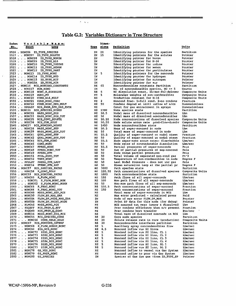
Table G.2: Variables Dictionary in Tree Structure
index V a r i a b I a N a m e: No. Short
DimenM sions
2516 2517 2518 2519 2520 2521 2522 2523 2524 2525 2526 2527 2528 2529 2530 2531 2532 2533 2534 2535 2536 2537 2538 2539 2540 2541 2542 2543 2544 2545 2546 2547 2548 2549 2550 2551 2552 2553 2554 2555 2556 2557 2558 2559 2560 2561 2562 2563 2564 2565 2566 2567 2568 2569 2570 2571 2572 2573 2574 2575 2576 2577 2578 2579 2580 2581 2582 2583
NONC06 IDTYPESPECIES . NONC07 IDTYPESOLUTE
. NONC08 ID-TYPE-BORON
. NONC09 ID_TYPEN16
. * NONCIO ID-TYPE-IODINE
. NONCI1 IDTYPEXENON NONC12 IDTYPEPART
NONC13 IDTYPENONC . NONC14 IDTYPEHYD . NONCI5 ID-TYPE-NIT . NON15A IDTYPEAIR
NONC16 RCSNONCONDCONSTANTS NONC17 NUMNONC NONC18 NONCKDISSOLVE NONCI9 NONC.MW NONC20 COREN16_KULT NONC21 COND-NONC-FRAC NONC22 CONDNONCDEG_MULT DPGASP RCSPRZRSPRGASENTR
NONC31 RCSSPECIESNODES * NONC32 MASS-NONCDIS * NONC33 MASS.NONCDISTOT
* NONC35 RCS-CONCSOLUTE * NONC36 RCS..CULMSOLU
NONC37 RCSNONCOND-NODES NONC38 MASSNONCSEP NONC39 MASS.NONC.SEPTOT NONC41 QUALNONCSEP NONC42 QUAL.NONC.SEP-TOT NONC45 RCSCUM-NONC NONC46 CONDNONC NONC47 PPRES-NONC NONC48 PPRESNONC.TOT NONC49 PPRES-STM NONC51 PVOL.NONCTOT NONC52 TEMPNONC PPSLST PRESSSTM-LAST NONC54 PTEMPSTMSAT
NONC57 RCSSPECIESPATHS . NONC58 PCONC.SOLU NONC59 RCSNONCONDPATHS . NONC60 PFLOWNONC
. NONC61 PFLOWNONCMOM
. NONC62 P_FLOW_NONCNONM NONC65 PFRACNONC NONC66 PFRACNONCTOT NONC40 MASS-NONC-SEPRCS NONC50 FLOWDPMAXERR NONSOA FLOW_DP_NODEMAX.ERR NON50B FLOWDPPRINTNODE RLMGAS MASSNONCRCS PZQEFF RCSPRZRQEFF PZQCND RCSPRZR.QCOND NONC34 MASS-NONC-DIS-RCS NONC55 RCS.SPECIESCORE
. NONC56 CORE.RELESOLU NONC67 RCSNONCONDINTERF
NONC68 PFLOWAUXSPNONC NONCSI SISRCSNONC . NONC72 SISILRCSNONC
.. . NONC73 SIS2_RCS_NONC . . NONC74 SIS3_RCSNONC . NONC75 SIS4_RCSNONC . NONC76 SIS5_RCS_NONC . NONC77 SIS6_RCSNONC
NONC78 GSVESNONC NONC79 GSPRZRNONC NONC8O GS-SPECIES
IN 20 IN 15 IN IN IN IN IN IN 5 IN IN IN RE 65 IN RE 5 RE 5 RE RE 2 RE 5( RE RE 2: RE 51 RE 5) RE 5( RE 5( RE 1 RE 5{ RE 5S RE 5{ RE 5S RE 5S RE 5' RE 5S RE 5S RE 5S RE 5S RE 5 RE 5 RE 5 RE 3 RE 1 RE 1 RE 1 RE I RE 5 RE 1 RE 1 RE RE IN IN RE RE RE RE RE 2 RE 2 RE 3 RE 5 RE 6 RE 5 RE 5 RE 5 RE 5 RE 5 RE 5 RE RE IN
0 0 8
,5
0 5
Definition
Identifying pointers for the species Identifying pointers for the solutes Identifying pointer for boron Identifying pointer for N-16 Identifying pointer for iodine Identifying pointer for xenon Identifying pointer for particulates Identifying pointers for the nonconds Identifying pointer for hydrogen Identifying pointer for nitrogen Identifying pointer for air Noncondensibles constants Partition No. of noncondensible species, NC -= 5 NC dissolution const, lb/sec-ft2-delconc Molecular weights of non-condensibles Production constant for N-16 Noncond frac: l=full cond, 2=no condens Condens degrad at initl inflow of n/cs Const for gas entrainment in sprays Node species state Nodal mass of dissolved noncondensibles Nodal mass of dissolved noncondensibles Node concentrations of dissolved species Node solute accum rate prod+flow+disslv Node noncondensibles state Mass of separ-noncond in node Total mass of separ-noncond in node Quality of separ-noncond in nodal steam Quality of separ-noncond in nodal steam Node separ-nonc accum rates: flow+bubble Node rates of noncondensble dissolution Partial pressures of separ-nonconds Sum of partial pressures of sep-noncond Node steam partial pressures Total volume of separated non-cond gas Temperature of non-condensibles in node Last Nodal Pressure - does not inc gas Steam saturation temp at the partial pr Path species state Path concentrations of dissolved species Path noncondensibles state Path flows of all separ-nonconds Mom path flows of all separ-nonconds Non-mom path flows of all sep-nonconds Path concentrations of separ-noncond Path concentrations of separ-noncond Total mass of separ-nonconds in RCS Max error predicted - calculated press Node of max error FLOW_DPMAX Print DP data for this node (for debug) RCS noncond tot mass (separ & dissolved) Przr condens efficiency when n/c present Przr condens heat transfer Total mass of dissolved nonconds in RCS Core node species Solute release rate in core (production) Noncondensible interfaces partition Auxiliary spray noncondensibles flow Noncond inflow via SI lines Noncond inflow via SI line, CL 1 Noncond inflow via SI line, CL 2 Noncond inflow via SI line, CL 3 Noncond inflow via SI line, CL 4 Noncond inflow via SI line, HL 1 Noncond inflow via SI line, HL 2 Noncond inflow to vessel via Gas System Noncond inflow to przr via Gas System Species of Gas Sys gas (from IDTYPESP
WCAP-15996-NP, Revision 0
0
300 0,5 0
0,20 0,20 450 015 0 0.5 0 0,5
0 005 0 0 0 0 0 0 000
50,20 080 so 00
0 50,5 50
Units
Partition Pointer Pointer Pointer Pointer Pointer Pointer Pointer Pointer Pointer Pointer Partition Counts Composite Units Composite Units Composite Units Fraction Dimensionless Dimensionless Partition Lbm Lbm Composite Units Composite Units Partition Lbm Lbm Fraction Fraction Lhnm/sec Lbm/sec Psia Psia Psia Ft^3 Degree F Psia Degree F Partition Composite Units Partition Lbm/sec Lbh/sec Lbsn/sec Fraction Fraction Lbm Psid Pointer Pointer LbM Fraction Btu/sec Lbm Partition Composite Units Partition Lbs/sec Lbm/sec Lbm/sec Lbm/sec Lbs/sec Lbm/sec Lbm/sec Lbm/sec Lbm/s ec Lbm/sec Pointer
G-226

Index
1056
1786
2507
1785
213
198
86
1191
1193
1192
1190
399
440
461
382
383
384
426
427
438
823
824
825
237
235
241
239
1043
1048
212
238
236
242
240
2367
203
2357
2352
2353
2354
2355
2356
2342
2346
2344
2349
2348
2347
Long Vari
ADMI_HEA
AFWS_ENTI
AFWS_FLO
AFWSNOZ
AREABLEE
AREACORI
AREA_INJ_
AREAVAL%
AREAVAL'
AREAVAL'
AREAVALU
ASEP._SG
ASL_MAX
ASIMIN
ASP_TBL
ASP.TBLDS
ASPTBL DS
ATUBES_M.
ATUBESM
ATUBES_MA
AXPDINPU
AXPDNUM
AXPDPRINI
BAD
BAN
BAR
BAT
BORONCOF
BOUYANCY_
BURNOUT_
BVD
BVN
BVR
BVT
CDCONTCO
CEASDIST
CETOP._FRD
CETOP._FRD
CETOP.FR_P
CETOP_FR_P
CETOP_FR_T
CETOP._FRT
CETOP_IN
CETOP..INC
CETOP_IN_Fl
CETOP_IN_Fl
CETOP_IN_F
CETOP._IN_H
Table G.3: Alphabetized Index of Lone Variable Names able Name Index Lone Variable I [ER 2345 CETOP_IN_INLET_ H 2343 CETOPIN_TIME W 2321 CETOP_LINK FLOW 2350 CETOPLINKCOI
ED_MIN 2322 CETOP._OUT E 2329 CETOP._OUTASI MULT 2339 CETOPOUTATR VE_PRZR 2323 CETOPOUTCASi VEQT 2334 CETOPOUTDNB VE_SPRAY 2332 CETOPOUTDNB VEUHEAD 2328 CETOPOUTIGAV
2340 CETOPOUTHCH
2338 CETOPJUTIEND
2337 CETOP_OUTJITER
2341 CETOPOUTMNO SGN 1 2330 CETOP_OUTNRA] SGN2 2331 CETOPOUTPIM, AXCS 2327 CETOP_OUTPIN AXHT 2325 CETOPOUTPOLI AXEC_HT 2324 CETOPOUT QDB] TOPT 2336 CETOPOULTQULD
POINTS 2326 CETOPOUT_TIN TNORMALIZATION 2335 CETOPOUT)_X-1
2333 CETOP..OUTX-N
2351 CETOP.PRESSOF
661 CFIiRCSAXIAL_
1423 CHGSASPRAY_F1 RE 1418 CHGSjRCSBOROI _CORE 1417 CHGSRCSENTH HEATER 1416 CHGS RCSFLOW
1419 CHGS RCSHYD
1420 CHGSRCSIOD
1421 CHGSRCSPART
1422 CHGSRCS-XEN 3MMON I CHR.COMMON
643 CHT_AVG_HEAT_ )EL_TEMP 664 CHT_AXIALDAT? )ERIV 652 CHTAXIALDATV 'ATHI 646 CHTAXIALDATA 'ATH2 645 CHTAXIALOUTF EMPI 634 CHTBOILING EMP2 600 CHTCHF_MULT
589 CHTCOMMON OREPRESSURE 597 CHTCONDFUEL LOWFRAC 669 CH-ITCONDROD
RTEMPMULT 627 CHTCONDLSAT_S RUSERMULT 626 CHT_CONDSTM EAT_FLUX_FRAC 625 CHTCONDWAT
WCAP-15996-NP, Revision 0
Name
TEMP
ITROL
E
-_
-N
G
D D
AX
L
r
-w N
FLUX
•_ALL
_BO
_FC UT
_MULT
TM
I
G-227

Table G.3: Alphabetized Index of Lon Variable Names
Index
601
1249
1252
614
615
617
616
621
619
620
618
665
609
608
610
1250
641
653
635
650
603
1251
654
598
673
1243
1244
662
663
670
659
655
649
639
658
640
656
590
642
672
604
606
591
16
605
630
629
628
Lom! Variable Name
CHT-CONSTý-LEV
CHT-DELT
CHTý-DELTA-T
CHTý-DHFý-DP
CHTýDHGLDP
CHTI-DTSAT-DH
CHTI-DTSAT-DP
CH-1ý-DVSATG-DH
CHT-DVSATG-DP
CHTI-DVSATI-DH
CHT-DVSATL-DP
CHTENTH-COOL
CHT-ENTýLSAT-LIQ
CHT-ENTH-SAT-LIQ-MI
CHTý-ENTH-SAT-STM
Cfrfý-FDELT
CHT-FLASH-RATIý-LAST
CHTý-FLOW-STM-BO
CHT-FLUXSRIT
CHTý-FIX-DNB
CHT-ýFRAC-HT-GEN
CHIý-FTIME
CHIIGAP-COND
CHT-GAP-HCAP
CHTý-H-CORE-SECT
CHT-H-SUPER.MULT
CHTI-HEATI-FRAC
CHT-HEAT-LIQ
CHT-HEAT-STM
CHT-HTSAP-ROD
CHTý-HT-FLUX
CHTý-HT-GEN-ZR-WAT
Cfflý-HTCOFý-FB
Cfflý-HTCOFý-NB
CHT-HTCOFý-ST
CHT-HTCOFý-SUB
CHT-HiT
CHT-INPUTS
CH-Iý-LEVIMIX-LAST
Cffrý-M-COREýSECT
CHT-ýNNOQ-BO
Cffý-NNODLFC
CHT-NREGIONS-RAD
CKII-NUM-LINPROP
CHT-NUM-NODE
CFrrý_PRAN-SA7j-STM
CHT2RAN-STM
GIT-PRAN-WAT
Index
599
607
647
667
671
632
657
631
633
611
612
1398
1397
666
638
648
644
651
668
613
660
636
1267
637
1248
17
674
624
623
622
2227
2515
2514
1112
902
905
904
2546
2533
2532
903
901
1475
1847
1925
328
1148
196
Lone Variable Name
CHTý-PRESS-SUPERCRIT
CWIý-PROPERTIES
CHT-QUAL
CHTý.ROP-RADIAL
CHTI-SECTIONS-OUTPUT
CHT-SPECý-HTý-SAT-STM
Cfflý-SPEC-HT-STM
CHT-SPEQ-HTýWAT
CMý-STATE
CK-SVOI-SAT-LIQ
CFM-SVOLSA'Iý.STM
CK-SVOLCOOLýAV
CHT-TCOOL-AV
CHTJEMPý-COOL
CHTý-TEMP-CRIT
CHTJEMPý-CROSS
CfIT-TEMPffLJELAV
CHT-TEW-NB-ýM
CHTffEW-ROD
Cfffý-TEMPý-SAT
CK-TEW-SURF
Cfrfý-TERM
CHT-TERM-MAX
CHTý-TERM2
CHTý-TIMEýSCALE
CHT-TIME-STP-NUM
CHT-USILNEWý-ENTHALPY-OPnON
CffZ-VISCOS-SAT-STM
CHT-VISCOS-STM
CtrZ-VISCOS-WAT
CLCONT
CONC-MAX
CONC-RATICLSTM-LIQ
CONC-SOLU-QT
COND-BOIL
COND-BUB
CONDJNJ
COND-NONC
COND-NONC-DEG-MULT
CONP-NONQ-FRAC
COND-SURF
CONDLTDT
CONT-PRES
CONT-SGffEMP
CONTROL-COMMON
CONV-GPM-AREA
COREýBORON-ýREL
CORE.BOT
WCAP-15996-NP, Revision 0 G-228

Table G.3: Alphabetized Index of Long Variable NamesIndex
596
594
1149
1150
2531
1151
592
15
2571
1187
197
1152
2168
2178
522
2174
2175
2177
2169
2171
2170
2173
2179
2172
2176
550
2117
2120
551
552
2118
2119
1993
1991
1978
523
1982
1985
1986
1987
1992
1988
1979
1989
1994
1990
1981
1980
Long Variable Name
CORE.Irrý-AREA CORE-HYD--DIA CORIý-HYDLREL
COREJODLREL COREýNMý-MULT CORE.PARTý-REL COREýRADý-OUT COREýRAD-OUT-DUMMY CORELRELEýSOLU COREýSURfý-AREA-LAST CORIý-TOP CORE-XEN-REL
MýAFWS-CONTROL Crl-AFWS-CONTROL-AUTO CrL.AFWS-CONTROLLERS CTL-AFWS-DELAY CTL-AFWSý-FLOW-MULT CTLýAFWS-MOTOR-PUMP CTIýAFWS-SETPOINTS CTI-AFWS-SQ-LEVEI-HIGH CrL-AFWS-SG-LEVEILOW CTIýAFWS-SGDPý-HIGH CTI-AFWS-SPEEDLSIG MýAFWS-TOTý-FLOW CrL.AMSý-TURB2UMP CR-AFWSý-VALVESONTROLLERS CrL-ATM-DUMFý-CONTROL CTI.ATM-DUMFý-CONTROL,-AUTU CTIýATM-DUMPý-NUM CTLý-ATM-DUMFý-PATH CTLýATM-DUMFý-SETPOINTS CrL-ATM-DUMFý-SPOINT
CM-CEA-ACCUM CrL,-CEA-AUTO CTIýCEA-COMMON CrL.CEA-CONTROLLER MýCEA-GAIN-EXP
CTLýCEA-LASIIJWE CTIýCEA-MAX CrL-CEA-MIN CTI.-CEA-PERFECr CTIýCEA-POS
CTL-CEA-SETPOINTS CTLýCEA-SPEED CM.CEA-SPEED-LAST CrL.CEA-STEP CTL-CEA-TREF-FULL
CT1ýCEA-TREfý-NO
Index
1983
1984
2319
2320
2029
2031
2017
2016
2018
2009
2030
2004
524
2021
2022
574
2243
521
1927
1974
2317
1943
2262
1966
1929
2249
1952
1946
1930
2250
1953
1933
2253
1956
1932
2252
1955
1940
2260
1963
1931
2251
1954
1939
2259
1962
1938
2258
Long Variable Name
CTIýCEA-TURBLQ-GAIN M.CEAPOSMON-FRAC
CTI,-CETOPý-MUq-DNBR CIICETOPý-MUq-DNBR-TIME CTI-CULFLOW CTIýCH-H CTIýCH-PUMFý-AUTO
C71ý07LPUW-FRAC CILSH-PUMFý-ON CTIýCH-PUW-W-RATED CTIýCH-T CTIýCHARGING-SETPOINTS CrLýCHGSSONTROLLERS CTI-CHV-FRAC CTL-CHV-RAREA CTIý.CONSTS CTI-CONTROLLER CTI-CONTROLLER-NUMBERS CTIýCORý-CONTROL CII-COREýCONTROL-AUTO CTICOREýFLOW-FRAC CTIý-CORE-HLCONT-PRES-TRIP Crl.-CORE.HLCONIý-PRES-TRTý-DL CTICORE-HLCONT - PRES-TRTý-OR CTLý-CORELHLPOWER-FRAC-TRIP C'rl.COREý-HLPOWER.FRACý-TRIPý-DL CTICOREýHL-POWER-FRAC-T-RIFý-OR Crl,-CORE.HLPOWER-SUR.BYPS CrlCORE.-HI-POWER-SUR-TRIP CrL.CORE.HLPOWER-SUR-TRUý-DL CrlýCORE-HL.POWER-SUR-TRTý-OR M1,CORIý-HURM-LEVE1ý7RIP CTIýCOREý-HLPRZR-LEVEI-TRIPý-DL CTL-CORIý-HLPRZR-LEVEITRIP-OR
CTL-CORE-HLPRZR-PRESffRIP CrI.CORE.HI-PRZR-PRES-7RWý-DL CTIýCORELHLPRZR-PRES-TRDý-OR CTIýCORELHLSG-LEVEIýTRIP Crl-COREýHLSQJEVELýTRIPý-DL CrL.CORE.HI-SO-LEVEI-TRIPý-OR CrIýCORE-LA)W-PRZRPRESý_TRjP MIýCOREJOW-MR-PRES-TRUý-DL CTL-CORE -LOW-PRZR-PRFS-TRIP-OR CTIýCORELLOW-SG-LEVEIýTRIP CrLCORE.LOW-SG-LEVEI.-TRIPý-DL CTL-CORE-LOW-SG-LEVEITRIFý-OR CrLýCOREJDWýSQ-PRES3RIP CIICOREýLOW.-SG-PRFS-TRff!-DL
WCAP-15996-NP, Revision 0 G-229

Table G.3: Alphabetized Index of Long Variable Names
iable Name Index Long Variable
LOW.-SG-PRES-TRIP-OR 2152 CTIýFWS-CONTR
-OVER-POWER-MRGN-TRIP 525 GIIýFWSSONTR
-OVER-POWER-MRGN-TRIP.-DL 526 CTL-MS-ECONý-, VER-POWER.MRGNffRIR-OR 2162 CTL-MS-ýECO VER-TEMP-MRGN-TRIP 2159 CTI.FWS-ECON-. VER-TEMP-ýM11GN-TIZIR-DI, 2154 CTIFWS-ECON-ý VER-TEMR-MRGN-TRIP-OR 2147 CT1,FWS-H
POWER 2148 CTIFWS-jj-MA)
-POWER-FRAC-LAST 2149 CTL.ýFWS-H-TC POWER.FRACTION 2166 CTL-FWS-ISQ-P0 POWER-RATIO 549 CT1,FWS-ISO POWERA 2144 CTL-IFWSý-MA)ý
YTRIP 2161 CTI.-FWS-POS RCSFLOW-FRAC-TRIP 2155 CTL-MSPUMR_ RCSFLOW-FRAC-TRIR-DL 527 CTL-ýFWS-ýPUMPRCSFLO)&ý-FRAQ-TRIR-OR 2138 CTLýFWS-SETPO
ETPOINTS-FOR-TRIP 2141 CTLýFWS-SQ-LE IAS-TRIP 2139 CTL.FWS-SQLE IAS-TRIRDL 2140 CTLýFWS-SG-LE IAS-TRIR-OR 2158 CTLýFWS-SIG
:rRIP 2164 CTLýFWS-SPEE :MIR-CONTROLLER 2165 CTL-IFWSýSPEER :MIR-DELAYS 2145 CTI-FWS-SPEE
-TRIR-OR 2163 CTI-,FWS-SPEE
-TRIP-SIG 2150 CTI.ýFWS21RIP
-TURB-TRIP-BYPS 2156 CTL-FWS-TRIP-A
-TURB-TRIR-DELAY 528 CTI-FWS-TRIPý-C
-TURB-TRIP-DELAY-ý011 2267 CT1-FWS-TRIR-E USER-DEFINEDý-BYPS 2146 CTLýFWS-TRIP-S
SER-DEFINErLTRIP 2143 CTLýFWS-TURB USER-DEFINEDLTRIP-131, 2142 CTL-FWS-TURB USER.DEFINEDLTRIR-OR 2153 CTI.-FWS-VALV
-CHI-SPOINT 2160 CTLýFWS-VALV
-CH2-SPOINT 2157 CTI.ýFWS-:VALV ýCI-13-SPOINT 2209 CTLýGRAPH-17111
-CH4-SPOINT 2208 CTL-GRAPH-M.
.COMMON 2024 CTL-HA-ýREG-HE 2CONTROL 576 CTL-HALF LDN-W-GPM 2318 CTI-HEATý-FLU LDN-ZSPOINT 529 CT1,HEATER-C0 RCSYALVES 2032 CTI-HEATERS-C :rH-VARIABLES 2044 MI-HEATERS-C
2066 CT1ýHPSLFLO 2065 CTIýUPSLNPO
kuTo 2067 CTL-HPSI-PRES YPý-SIG 2068 Cr1.HPSIPUM YPS-CONTROLLERS 2069 CT1,HPSLSPLrr ONTROL 2239 CTI-ILEVEL
Long Var
CTLCORR
CTLCOR
CTLCOR
CTL-COR
CTL-COR
CTL.COR
CrtCOR
CTL.COREý
C7rL.COR
CTL-COREý
CTI-CORE
CTLCOREý
CTL-COR
CTLýCOREý
CTLýCORE.
CTL-CORE
CTLCORE,
CTL.CORE,
CTLýCORE
CTLýCORE,
CTLCOR
CTL-COR
CT1,COR
CT1,COR
CTLCOR
CTL.COR
CTLSOR
CTL-COR
CTL-CORE,
CTL-COR
CTI-COREý
CTL-CORE.
Cnýcvcs
CTL-CVCS
miýcvcs
crL-CVCS
cTLCVCS
CTLCVCS
CTLýCVCs
CTLýCvcs_
CTLýCVCs
CT1,CVCS
CTL-VBG
CTLýDELA'
CT1-FWS
CTL,_FWSE
CTI.FWS.ýB
CTLýFWSJ
.'4ame
OL.AUTO
OLLERS
ONTROLLERS
POS
IG
ALVEý-AUTO
S
'ONTOLLERS
low
UTO
ONTROLLERS
INTS
VELHIGH
VELLOAD
VELLOW
ýFRAC
MAX
ýMULT
3IG
LITO
NTROLLER.
ELAY
P
TRIR-DELAY
TRIR-FRAC
_AUTO
-POS
,-SIG
RVAL
ATý-X
'FRAC
NTROLLERS
ONTROL
ONTROLAUTO
JABLE
TS-TAB
TABLE
YUM
Index
1961
1935
2255
1958
1934
2254
1957
1969
1972
1971
1947
2279
1977
1936
2256
1959
1929
1937
2257
1960
1975
542
2248
1951
1976
1949
1942
1965
1950
1944
2263
1967
2005
2006
2007
2008
1995
2010
2003
2002
2020
2023
573
2247
2151
2167
548
2137
WCAP-15996-NP, Revision 0 G-230

Table G.3: Alphabetized Index of Long Variable Names
able Name Index Long Variable
532 CTL.MSISTRIPý_C I.-CONDITIONS 2266 MýMSISMPj 1.CORE.FLOW 531 CrLMSIVCONTI
_MSLBINFLOW 533 Crl.MSLJiCON-r _MSLBOUTý_FLOW 1973 Cr1,NUMRPS _PFLOW-NONMOM 577 CTIONE _SGS-VALVES 2203 CTIOUTPUT UTO 2212 CTIý_OUTPUIý_31)
LOW 2206 CrL.OUTPUIjCO
2204 CT1,OU-IUTjN 2210 CTLOLrrPLTIý_LO
WN-CONTROLLERS 2207 Cr1,_OLJTPU-1ý_NT WN-FRAC 2211 Cr1.OU-IU-Iý_Op( WN-SETPOINTS 2205 CT1,OUrPU7ý_OP' ýHEATEROFF 2056 CTL,_PORVAUT0
534 CTLý_PORVCONT LOW-TABLE 2052 CTI-PORV-PSET POINTS-TAB 543 CTI-POWER-CUT RES-TABLE 2038 MýPRES3HEA1 UMPý_NUM 2039 CrLPRES3HE PLIT 2036 CTLPRESPHEA1 E 2037 C171ý-PRES-PHEA1 HEAT-FLUX-FRAC 2050 CTLPRESSURIZE HEA-1ý-FLUX-TIME 2034 Crt-PRZR-BHLE POWER-FRAC 2033 CTLPRZR_ýHEATI POWEKTIME 2043 CTL.PRZRHEAT1 PRZR-PRESS 2241 CTIPRZRILEVE PRZR-PRESS-TIME 2012 CTLPRZR-LEVE ICSý_PRESS 2013 CT1,PRZRLEVE CSý_PRESSTtME 1996 CTIý_PRZRLEVE G-PRESS 1999 CTIý_PRZRLIQS G-PRESS-TIME 546 CTLýPRZRLVL.E RZRPRFSS 1998 CrlPRZR-PLEVE RZRPRESSTIME 1997 CTIPRZRPLEVE CS-PRESS 2011 CT1ýPRZRPROQ CS-PRESS-TIME 547 CTIý_PRZRPROQ QPRESS 2040 Cr1.PRZRREIý_P G-PRESS-TIME 2051 CTI-PRZR-RELIE DELAYS 2045 CT1,PRZRSPRA SETPOINTS 2049 Crl,-PRZR-SPRA
11?ý_DELAYS 2048 CTLPRZRSPRA ONTý_PRESTRIP 2047 CT1,PRZRSPRA) ONTROL 2046 MýMR.SPRA. ONTRO1_Atrr0 2000 CTI-PRZR-STM-S ETPOINTS 535 MýPSVCONTR G-PRES-TRIP 2055 CnPSVPSETý_B G-SLFLOW.-TRIP 2054 CTL.PSVPSE-Iý_C
IP 2053 CTIPSVPSETý_O
Index
569
2225
2316
2314
2315
2312
2313
2019
2025
2027
2026
530
2028
2001
2035
579
2071
2070
2072
2073
2074
578
2298
2299
2296
2297
2300
2301
2304
2305
2308
2309
2302
2303
2306
2307
2310
2311
2271
2192
2264
2113
2110
2115
2111
2112
2114
2116
Long Vari
CTL.INrr
CTLINrrIA
CTI-INITIA
CT1,INTE
CTLINTEG
CTL-INTEG
CTI-INTEG
CTL-LDN-A
CTLLDN
CTILDK-H
CrL.LDNT
CTLLETDC
CTL.LETD0
CTLý_LETDO
CTILEVE
CTLLUAM
CTIýLPSI_
CTLLPSIN
CT1_LPSLP
CTLLPSIP
CT1_LPSLS
CT1,MON
CTI-MAX
CTL-MA)(
CT1_MAX_
CTL-MAX
CTI.-MAX
CTL.MAX
CTIý_MAX_
C'rLMAXI
CTL-MAX-S
CrL._MA.XS
CTLýMuqp
CTI-MIN-P
CTL-MIN-R
CT1.MINR
CTI1MINS
CTLýMuqs crl,_MIS(ý_
CTI.MISC
CTI.MISC-7,
CTLýMSISJ
cr1,_MSIS_(
CTLMSIS_(
CTLýMSISS
criýMSISS
CT1_MSISS
CTLýMSIS
lame,
ONTROLLER
ELAY
OLLERS
OLLERS
AAP
UNT
7ERVAL
OP
ITLE
L
ION
OLLERS
ACK-CONTROLLER
R-OFF
R-ON
R-OFF
R-ON
R RELIEF
IELýSPOINT
R-SETPOINTS
RS_ýVOLT
L
-ERROR
JNST
-SETPOINTS
PVOLý_REF
RR-CONTROLLER
L
L.TEMP
EVEL
VLýCONTROLLER
RES
F-SETPOINTS
r-CONTROL
r-CONTROI-AUTO
r-PRES-OFF
-PRES-ON
r-SETPOINTS
PVOL-REF
OLLERS
LDN
LOSE
PEN
WCAP- 15996-NP, Revision 0 G-231

Table G.3: Alphabetized Index of Long Variable Names
able Name Index Long Variable
EffRIP 2084 CTL-SIS-SI[j-H
LOW-STPOINT 2086 CTL-Srfý-ELEV-Pf
CONTROL 2087 CTI.Srlý-FLOW-C
CONTROL.AUTO 2088 CTL.Srlý-GAS-CO
PTRIP 2089 CTIýSIT-GAS-PR
ETPOINTS 2090 CTL-SIT-GAS-ýVO
IP 2091 CTL-Sný-ISQ-VA
TRIPý-DELAY 2092 CTL-SrIý-LIQ-SPV
TRIP-TIME 2093 CTL.SM-LIQ-VO
ONTROLLERS 2085 CTL-SrLNUM
ONTROL 2229 CTI-SPARE
H 2213 CTLýSPARE2
-MIN 538 CTLýSPRAY-CO
PLIT 1948 CTI.STEAM-ME
ELTEMP 1941 CT'L-STEAM-ME
ELTEMPD 2261 CTIýSTEAMJEE
LOW 1964 CTL.STEAM-ýFEE
LOWD 2295 CTLýSUMMARY
ODIM 2014 CTLýZýAVG
ERTIME 539 CTL.TýAVG-CO
RES 2015 CTLýT--REF
RESD 540 CTL:LREYý-CON'
EMP 553 CTL-TAV-NUM
VEL 554 CTLffAV-PATH
FETIES 2214 CTL-TIMEýBLOC
'-SETPOINTS 2202 CTL-TIME.CON
ASET-OPEN 1968 CrL.TIME-COR
PSETý.CLOSE 1926 CTL-TIMEýSTEP
PSET-FULL 12 CTL.TITLE
-PSET-OPEN 2101 CTIýTURB-AO
ONTROI.-AUTO 2121 CTI.,TURB-BYPA
HLCONT-PRES 2130 CTIýTURB-BYPA
LOVVý-SLýPRES 555 CTI.,TURB-BY
LOV%ý-TAVG 556 CTI.-TURB-BY
PRZR-PRES-LOW 2122 CTL-TURB-BY
PTRIP 2098 CTL-TURB--CO
ETPOINTS 2105 CTLZIURB-CO
SLSH-DP 2106 CTI-TURBSO
IME 2103 CTL-TURB-DEM
rRIP 2124 CTIýTURB-DUM
TRIPSONTROLLER 2129 CTL-TURB-ýDUM
MMON 2128 CTL-TURB.ýDUM
NTROL 2126 CTLýTURB-ýDUM
ELAY 2123 CTL-TURB-ýDUM
w 2127 CTL-TURB-ýDUM
LPSI-BC 2125 CTI.TURB-DUM
LPSI-H 2109 CTLýTURB-PTR
T-BC 2191 CTL-TURB-RUN
Index
1970
1945
2180
2182
2184
2181
2183
2268
2185
536
2094
2095
2096
2097
2194
2195
2199
2200
2198
2201
2196
2197
2193
2240
2131
2132
2136
2135
2134
2133
2077
2061
2063
2062
2059
2079
2058
2060
2075
2078
537
2057
2064
2076
2080
2081
2082
2083
LDng Vari
C7LQCOR
CTLýRCP
CTI.-RPCS
CTL-RPCS
CTL-RPCS
CTL-RPCS
CTLRPCS
CTL-RPC
CTL-RPCS
CTL-RPS-jC
CTLSDC-C
CTL-SDC-E
CTLSDC-H
CTLSDC-S
CTLSET ý13
CTLSETý-D
CTI-SETý
CTL-SETý
CTL.SET-N
CTL.SET-P
CTL-SET-P
CTI.-SET-P
CTL.SET-T
CTISG-IL1
CTLýSG-SA
CTI.,SGS
CTL.SGSV
CTL-SGSV
CTLSGSV_
CT1,SGSV
CTLýSIASJ
CTL-SIAS
CTL-SIAS
CTL-SIAS
CTL-SIAS
CTL-SIAS
CTL-SIASý'
CTI-SIAS
CTI-SIAS-'
CTL-SIAS
CTL-SIAS
CTLýSIS-0
CTL-SIS-0
CTLýSIS-D
CTL-SIS-m
CTLSISH
CTLýSIS-H
CTLýSIS-S
14ame
ES
OEFF
NST
ES
LUME
,VE
OL
LUME
TROLLERS
DLMISMATCH-BYPS
ELMISMATCH-TRIP
D-MISMATCH-TRIPý-DL
DLMISMATCH-TRM-OR
ATA
[TROLLER
OLLER
K
TANTS
-TRIP
r-TC SS-CONTROL
SS-CONTROL.AUTO
SS-NUM SS-PATH
SS.SETPOINTS
rROL
rROL-AUTO
rROI.-LjDAD
AND
Fý-DELP
P-MODE
Pý-NCLOSE
P-NOPEN
PLOPEN
P-QCLOSE
P-QOPEN
P
BACK
WCAP- 15996-NP, Revision 0 G-232

Index
2189
545
2270
2188
2186
544
2187
2190
2269
2099
2104
2107
2108
541
2265
2102
2100
2226
2042
2041
587
575
584
274
1523
1531
1535
1538
1534
1533
1532
1537
1536
557
558
2371
2369
2370
2368
2375
2372
2373
2374
2376
2377
2215
223
224
Long Vari
CTLTURB..
CTL_TURB
CTL TURB_
CTLTURB
CTL_TURB
CTITURB_
CTL_TURB_
CTL1TURB_
CTL_TURB
CTITURB_
CTL_TURB_
CTL_TURB..
CTLJTURB.
CTL_TURB "
CTLTURB
CTLTURB_"
CTL_TURB_.
CTLUNUSE
CTuVOLT_
CTLVOLT_
CTLWARN
CTLZERO
CTLMAX
CURRENTT
CVCS-DATA
CVCSRHX_
CVCS_RHX_.
CVCSRHX
CVCS RHX_
CVCS_RHX '
CVCS_RHX."
CVCSRHX_
CVCSRHX_
DBADD
DBCOM
DBGSGTR_
DBGSGTR_
DBG.SGTR_
DBGSGTR
DBG SGTR_
DBGSGTR_
DBGSGTR_
DBG_SGTR_.
DBG_SGTR_
DBGSGTR_
DELT
DESIGNFLC
DESIGN_FLC
Table G.3: Alphabetized Index of Long Variable Names able Name Index Long Variable r RUNBACKAUTO 225 DESIGNFLOW_SA RUNBACK CONTROLLER 890 DHDM RUNBACK DELAY 889 DHDU .SETBACKAUTO 893 DHF._DP _SETBACKCONTROL 894 DHGDP SETBACK-CONTROLLER 1478 DMWQT ENTH SETBACKSETPOINTS 1477 DMWQTFLOW SETBACK_TRIP 1022 DPACTUAL SETBACK.TRIPDELAY 1023 DPCHECK SETPOINTS 1017 DPELEV STEAMRATED 1020 DP_EXT
TRIP 1016 DPFRIC TRIPAUTO 1127 DP_GLOB TRIPCONTROLLERS 1019 DPHEAD TRIPDELAY 1018 DP_LOSS TRIP_TIME 1049 DP.WLOSSUPLEN
TRIP_VALVE_TIME 1015 DPMOM ED 1095 DP_NON_UHEAD BACK 1039 DPPUMP PROP 1021 DP_TOT
885 DPDMLIQ
886 DPDMSTM
884 DPDMTOT
*AB 888 DPDUSTM
887 DPDUOTOT DATA 899 DRFTBUB HCH 273 DTDW_TAB HEAT 1456 DUM001 HLDN 892 DVDHTOT J'CH 891 DVDPTOT "TLDN 895 DVF_DP WCH 896 DVG_DP WLDN 559 ELEMS
423 ELEVTUBESHEE
560 ELIN FLOWSLOT 2244 ELLAST FLOW1 580 ELMAX FLOW2 561 ELTYPE PARTITION 1118 ENGYGLOB
PRESS_ITER 1058 ENGY_HEATER PRESSPRII 1105 ENGY QT PRESSPRI2 841 ENGYSTM PRESS_SG 1166 ENGYSTM LAST SVOL_TUBEI 840 ENGYTOT SVOLTUBE2 1167 ENGYTOT_LAST
1117 ENTH-GLOB 1W_PORV 849 ENTIHLIQ 1W_SAFETY 1 1173 ENTHLIQLAST
WCAP-15996-NP, Revision 0
4ame
•FETY2
.T
I
G-233
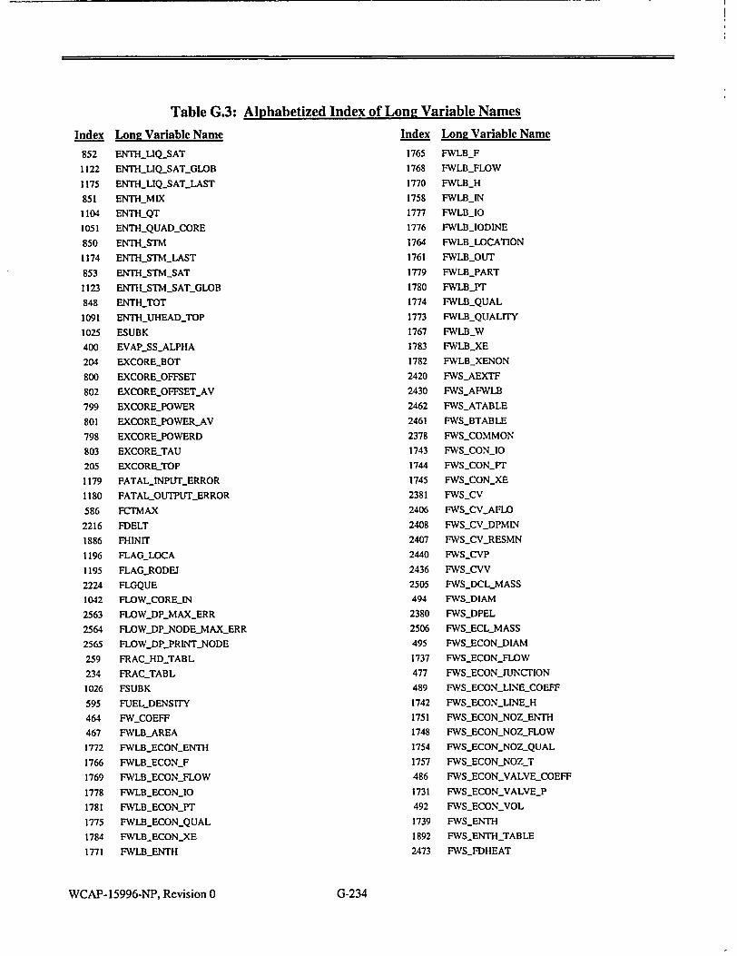
Index
852
1122
1175
851
1104
1051
850
1174
853
1123
848
1091
1025
400
204
800
802
799
801
798
803
205
1179
1180
586
2216
1886
1196
1195
2224
1042
2563
2564
2565
259
234
1026
595
464
467
1772
1766
1769
1778
1781
1775
1784
1771
Table G.3:
Long Variable Name
ENTHLIQSAT
ENTH LIQ.SATGLOB
ENTH_-LIQ..SATLAST
ENTHMIX
ENTHQT
ENTHQUADLCORE
ENTHSTM
ENT•-STM-LAST
ENTHSTMSAT
ENTH-STM-SAT-GLOB
ENTH-TOT
ENTH_UHEADTOP
ESUBK
EVAPSSALPHA
EXCOREBOT
EXCOREOFFSET
EXCOREOFFSETAV
EXCOREPOWER
EXCORE-POWER-AV
EXCOREPOWERD
EXCORETAU
EXCORETOP
FATALJNPUTERROR
FATAL-OUTPUTERROR
FCTMAX
FDELT
FHINIT
FLAG-LOCA
FLAG-RODEJ
FLGQUE
FLOWCOREIN
FLOWDP_MAXERR
FLOW_DPNODEMAXER
FLOW DP._PRINTNODE
FRAC_HDTABL
FRACTABL
FSUBK
FUEL-DENSITY
FW COEFF
FWLB.AREA
FWLB ECONENTH
FWLB_ECON_F
FWLB..ECONFLOW
FWLB-ECON_10
FWLB.ECON_PT
FWLB_ECON QUAL
FWLBECONXE
FWLB_ENTH
Alphabetized Index of Long Variable Names
Index Long Variable?
1765 FWLB_F
1768 FWLBFLOW
1770 FWLBH
1758 FWLB_IN
1777 FWLB_10
1776 FWLBIODINE
1764 FWLB_LOCATION
1761 FWLBOUT
1779 FWLB_PART
1780 FWLB_Pr
1774 FWLBQUAL
1773 FWLBQUALITY
1767 FWLB_W
1783 FWLBXE
1782 FWLBXENON
2420 FWSAEXTF
2430 FWSAFWLB
2462 FWSATABLE
2461 FWSBTABLE
2378 FWSCOMMON
1743 FWSCON_10
1744 FWSCON_PT
1745 FWSCONXE
2381 FWSCV
2406 FWSCVAFLO
2408 FWS_CV_DPMIN
2407 FWSCV_RESMN
2440 FWS_CVP
2436 FWS_CVV 2505 FWSDCLMASS
494 FWSDIAM
2380 FWSDPEL
R 2506 FWSECL_MASS
495 FWSECONDIA!•
1737 FWSECONFLO
477 FWSECONJUN(
489 FWSECONLINE
1742 FWSECONLINE
1751 FWSECON-NOZ
1748 FWSECONNOZ
1754 FWSECONNOZ
1757 FWSECONNOZ
486 FWS-ECON.VAL
1731 FWSECONVAL
492 FWS_ECONVOL
1739 FWSENTH
1892 FWSENTH_TAB
2473 FWSFDHEAT
WCAP-15996-NP, Revision 0
Name
4
MTION
,.COEFF
.H
.._ENTH .,_FLOW
_QUAL -,T YE_COEFF
YE_P
LE
G-234

Table G.3: Alphabetized Index of Long Variable Names
Index
2490
2411
2379
2484
2454
2509 2433
1736
1738
465
2497
2495
2496
2492
2493
2494
2397
2392
2419
2413
2485 2416
2388
2459
1893
1894
1895
2479
2476
2501
2403
2402
2503
2504
2404
2423
2445
476
1728
2410
488
487
493
1740
1735
1741
475
2508
Lon! Variable Name
FWSFDMODL
FWSFDNODE
FWSFDPATH
FWSFDPOSO
FWSFDPUMP
FWS_FDSYST
FWSFDVALV
FWSFLOW EWSFLOW-TQT FWSFLOWIOO
FWSFWRCINT
FWS_FWRCIR
FWSFWRCOUT
FWS_FWRCPB
FWS_FWRCRE
FWSFWRCSP
FWS-GPMCOR
FWSHEXT
FWS-HEXTF FWSHEXTN FWSHFWB lAS FWSHNODE FWSHPATH
FWS_HT
FWSHTABLEENTH
FWSHTABLE..LOAD
FWSHTABLEýNUM
FWS_HTHMX
FWS...TRHOV
FWS_1AUTORC FWSICK
FWSICPUMP
FWSIFrllIP
FWSJlFTRPO
FWS_M4F
FWSIMN
FWS_INDEXF
FWSJUNCTION
FWSJUNCTION_P
FWS_KEY
FWS_LINE.COEFF
FWSLINEýCOEFFS
FWS_LINE.DIAMS
FWSLINE..ENTHALPIES
FWS-L[NE-FLOWS
FWSLINE-H
FWSLINE-JUNCrION
FWSLTNE-MASSES
Index
490
2483
2451
2401
2400
2398
2399
2472
2425
2409
2489
2449
2488
2487
2471
2424
1750
1747
468
1753
1756
1749
1746
1752
1755
2442
2429
2486
2431
2467
2466
2500
2463
2428
2427
2426
2468
2498
2465
2444
2469
2491
2432
2470
2453
2443
2464
2452
WCAP-15996-NP, Revision 0G-3
Lon! Variable Name
FWS_-LINEVOLUMES
FWSMAXTAU
FWS_ýNAFWVT
FWS-NCPUMP
FWSNDEXT
FWS_NDIN
FWS-NDOUT
FWSNEFWP
FWS_NEXTN
FWS-NFLQ
FWSNHDPTBL
FWSNHDV
FWS.J4HT
FWS-NHTBL
FWS_NMFWP
FWS_ýNNOD
FWSNOZENTH
FWS_NOZ_FLOW
FWSNOZ_HEIGHT
FWSNOZQUAL
FW_ýNOZ_T
FWSNOZZLE_-ENTHALPY
FWS-NOZZLEFLOW
MSNOZZLEQUALITY FWS.NOZZLE_TEMP
FWSNPATH
FWSNPFWLB
FWSý_NPHEAT
FWSJJPMFPRV
FWSNPMPEFW
FWS_ýNPMPMFW
FWS..NPMPRC
FWS-NPMPTH
FWS-NPSGAFW
FWS-NPSGECO
FWSNPSGMFW
FWS-NPTHiMFP
FWS_ýNPTHRC
FWS-NMr
FWS_NPTV
FWSNPUM
FWSJ'4RCIRC
FWS_NSG
FWSNTABFP FWSNTABFV
FWSNTABLE FWS_NTABP FWS..NVAFWI
G-235

Index
2448
2499
2447
2450
2446
2415
2414
2384
2421
2412
2405
2435
2395
483
1734
481
478
1733
479
474
1727
1726
1732
482
480
2477
2389
2478
2391
2382
2390
2393
2383
2417
2394
2455
2456
2441
2434
2396
2458
2457
2438
2482
2502
2439
2437
2480
Long Vari
FWSNVAL
FWSNVALI
FWS NVBF'
FWS.NVHD
FWSNVMF
FWSP
FWS-P0
FWSPEXT
FWSPEXTF
FWSPEXTT
FWSPOSIS4
FWSPOSIT
FWSPS
FWS_PUMP_
FWS.PUMP.
FWSPUMPR
FWSPUMP
FWS_PUMP_
FWS.PUMP.
FWSPUMP_
FWSPUMP_
FWSJUMP_
FWSPUMP
FWSPUMP_
FWSPUMP.
FWSPWRT
FWSQCUR
FWS-QPTBL
FWSRES
FWSRESL
FWSRESV
FWSRHOE.
FWSRHOFI
FWSRHON
FWSRP
FWSSPDM]
FWSSPEED
FWSSTP
FWS-STROI
FWSSUMP
FWSTAUO
FWSTAUO:
FWS-TCLOS
FWS-TENHr
FWSTIMET
FWST1LAG
FWS.TOPN
FWS_TPOW
WCAP-15996-NP, Revision 0
Table G.3: Alphabetized Index of Long Variable Names
able Name Index Long Variable
2474 FWSTPWR
RC 2475 FWSTQLAG
2481 FWSTWHDP
V 485 FWS_VALVECOE
V 484 FWSVALVECOE
1730 FWSVALVEP
1729 FWSVALVEPRE
491 FWS_VOL
2387 FWS_W
2386 FWS_WO
0 2418 FWSWEXTF
2385 FWSWMAS
2422 FWS.WSUM
'-COEFF 2460 FWSWT
FLOW 562 GROUPS
*-FLOWJNPOINTS 2245 GROUT
_FLOWTABLE 583 GRPMAX
.HEAD 2582 GS-PRZRNONC
YEAD-TABLE 2583 GSSPECIES
JUNCTION 2581 GSYES-NONC
UP 1481 GWSQTFLOW
"PIN 1480 GWSQTPRES
-SPEED 199 HACEACORE
SPEEDNPOINTS 209 HAUHEADCORI
-SPEEDTABLE 441 HAWALLIMSLI
BL 499 HAWALLISGBD
R 442 HAWALLOMSL
L 500 HAWALLOSGBI
245 HAD
253 HADC
2513 HALF_LIFESOU
XT 243 HAN
251 HANC
OD 249 HAR
257 HARC
D 247 HAT
255 HATC
214 HCAP-HEATER
KE 260 HDDEGTABL
1038 HEADPUMP
FF 875 HEATCOND
N 870 HEAT.CONT
S 1041 HEATCORE
DP 1057 HEATELEC
871 HEATEXT
1060 HEATHEATER
874 HEATLIQ
R 1061 H EAT_PRZR
Name
FE
FFS
SSURES
E
,H
D
JTES
G-236

Index
1036
1033
873
872
869
229
385
386
387
392
393
394
469
470
471
246
254
244
252
250
258
248
256
2526
2518
2524
2520
2519
2525
2523
2522
2517
2516
2521
2230
2237
2359
2229
2238
2233
2236
2231
2234
2232
2235
582
570
588
Lone Vari
HEAT_PUM]
HEATSG
HEATSTM
HEATTOT
HEATWAL
HEIGHTQT
HSP_TBL
HSPJBL.D)
HSPTBL_D.D
HTI3TBL
HT3_TBL_D.
HT3_TBL_D
HTNOZ
HTNOZ_ECC
HTNOZ_EFV
HVD
HVDC
HVN
HVNC
HVR
HVRC
HVT
HVTC
IDJTYPE_Al
IDTYPE_BC
ID_TYPE_HY
IDTYPE_10]
IDTYPE_NI
ID_TYPE_NI
IDTYPE_NC
IDTYPEPA
IDTYPESO
IDTYPE SP
IDLTYPEXE
INITALL
INIT_CORE
INITDEBUG
INITFLAG
INITITER
INIT..OFFC
INIT_OFF CC
INITLOFF_MC
INILýOFFYPO
INITOFFRC
INITOFF_SG
INMAX
INPED
INPEDFILE
Table G.3: Alphabetized Index of Long Variable Names able Name Index Long Variable 1 P 572 INPEDPAGE
571 INPEDSEQNCE
2276 INTERPOLATION_
2290 IODINE._OTALS_ L 2360 JUNKPARTITION
766 KFRAIN
195 KLOSS_UPLEN_NI SGN I 194 KLOSSUPLENPC SGN2 821 KSHAPIN
1525 LDNPIPE AREA SGNI 1524 LDNPIPEDATA SGN2 1529 LDN_PIPE.DELTA
1528 LDNPIPEKENT )N 1527 LDN_PIPE._KGEON
1526 LDNPIPELOD
1539 LDNRCSENTH
1540 LDNRCSPRES
1424 LDNS RCS FLOW
878 LEVLLIQ
1044 LEVLLIQVESSEl
877 LEVL_MIX
1046 LEVLMIXCORE
1045 LEVL_MIXVESSE R 1062 LEVLPRZR_DP )RON 219 LEV LPRZRRTD YD 1106 LEVLQT
DINE 220 LEVL_REFBOT 6 221 LEVLREFTOP T 222 LEVLRELIEF )NC 1197 LOCABLOWDOW RT 581 LSTMAX LUTE 2246 MAL_CTL ECIES 1760 MAL FWLBECOI NON 1763 MALFWLBECOI
1759 MALFWLBIN
1762 MALFWLBOUT -OUTPUT 1454 MAL_LBLOCA
1530 MALLDNBREAK
1672 MALMSLBIN IT 1649 MALMSLB_OUT ON 1472 MAL_RCP_HIVIB
ODELS 1471 MAL_RCPLOCKE] 1W 1470 MAL_RCP_SHAFTI ZS 1458 MALRCSVALVE S 1473 MAL_RODCORE
1457 MALRODEJECT 1453 MAISBLOCA
1455 MALSGTR
WCAP-15996-NP, Revision 0
N4ame
ERROROPTION
PARTITION
EG
3S
_ELEV
L
L
IN
UN
LOUT
D
BREAK
I
G-237

Index
1464
1463
1466
1461
1465
1462
1468
1467
1469
1459
1460
206
846
1170
1183
918
1108
1116
844
1168
1093
2536
2569
2537
2566
2541
2562
2542
230
845
1169
843
1171
1107
593
443
501
28
29
830
833
832
828
829
831
1845
2242
827
Table G.3:
Long Variable Name
MALYLVPRZR_CONT
MALVLVPRZRMOV
MALVLVPRZRMSPRAY
MALVLVPRZRPORV
MALYLVPRZR QT
MALVLV-PRZRSAFETY
MALLVQTCONT
MAL3VLV.QTGWS
MALVLVQTNSUPPLY
MAL VLVUHEADCONT MALVLV UHEADQT
MAP-EXCORE
MASS-BUB
MASSBUBLAST
MASSBUB.PRED
MASSBUBSECT
MASSGASQT
MASSGLOB
MASS-LIQ
MASSLIQJLAST
MASS-NONUHEAD
MASS-NONCDIS
MASSNONC_DISRCS
MASS NONCDIS_TOT
MASSNONC-RCS
MASSNONC-SEP
MASSNONC_SEP_RCS
MASSNONCSEP_TOT
MASS.QTMAX
MASSSTM
MASSSTMLAST
MASSTOT
MASSTOT_LAST
MASS.WATQT
MATTYP
MCP_-WALL_MSLH
MCPWALLSGBD
MODINIT
MODINITV
MODOFFCHT
MODOFF-POWER
MODOFFQT
MODOFFRCP
MOD OFFRCPOIL
MODOFF_.RCS
MODOFFSGBD
MODELERROR
MODELOFF
WCAP-15996-NP, Revision 0
Alphabetized Index of Long Variable Names
Index Long Variable Name
2221 MODELQUEUE
2223 MODQUE
449 MSLBAREA
1673 MSLBINFLOW
1650 MSLBOUT_FLOW
516 MSLHACROSS
517 MSLHACROSST
514 MSLHAFRSL
1686 MSLH_AOUT
1687 MSLHAOUTATM
1688 MSLHAOUTCOND
1689 MSLHAOUTCONT
1690 MSLH_AOUTTURB
1651 MSLH_CON-10
1652 MSLHCONPT
1653 MSLH_CONXE
1678 MSLH_CSL
1875 MSLHDPMIN_MULT
1654 MSLHDVDH
1655 MSLHDVDP
1698 MSLH_-ENTHATM
1703 MSLHENTHCOND
1708 MSLHENTHCONT
1713 MSLHENTHTURB
515 MSLHFKBRK
518 MSLH_FKCROSS
519 MSLHFKCROSST
1697 MSLH_FLOWATM
1724 MSLH_FLOWCHOKED
1702 MSLH_FLOWCOND
1707 MSLH_FLOWCONT
1712 MSLH_FLOWTURB
1848 MSLH_FUIMEMAX
1656 MSLH_H
1657 MSLHHF
1658 MSLHHG
1674 MSLHHSL
1699 MSLH_10_ATM
1704 MSLH_10_COND
1709 MSLH_1OCONT
1723 MSLHIOCONTTNT_LEAK
1722 MSLH_10_CONTLEAK
1718 MSLH _IO _INT _ATM
1719 MSLH_10_INTCOND
1720 MSLHIOTNT_CONT
1717 MSLHI 0 NTFLOW
1721 MSLHJO _INT _TURB
1714 MSLH_10_TURB
G-238

Index
1677
1659
1660
450
451
1682
1680
1681
2274
1696
1661
1675
1700
1705
1710
1715
1662
1663
1648
1664
1665
1666
1667
457
1676
1668
452
454
453
455
1683
1684
1669
1691
1692
1693
1694
1695
1670
1701
1706
1711
1716
1679
1906
1907
1908
1909
Long Vari
MSLHISL
MSLH_M
MSLHML
MSLHMSIN
MSLHMSIV
MSLHMSIV
MSLHMSIN
MSLHMSIV
MSLHNO_,
MSLHOUT]
MSLH-_P
MSLHPSL
MSLH_PT1_A
MSLH_PT_C
MSLH_PT_C
MSLHPT_T
MSLHQ
MSLHQAT
MSLHSTAI
MSLHSV
MSLH_SVF
MSLH-_SVG
MSLH_T
MSLH_TAT1n
MSLH-TSL
MSLH_TWA
MSLHVALI
MSLHVALI
MSLHVALI
MSLHVAL•
MSLHVAL•
MSLHVALI
MSLHWIN
MSLH WOU
MSLHWOU
MSLHWOU
MSLH_WOU
MSLHWOU
MSLH_X
MSLHXE_A
MSLH_XE_C
MSLHXEC
MSLHXE_T
MSLHXSL
MSLH2_CON
MSLH2_CON
MSLH2_CON
MSLH2_DVD
WCAP-15996-NP, Revision 0 G-339
Table G.3: Alphabetized Index of Lon2 Variable Names able Name Index Long Variable I
1910 MSLH2_DVDP
1911 MSLH2_H
1912 MSLH2_HF _AMAX 1913 MSLH2_HG _BYPASSAMAX 1914 MSLH2_M
'BYPASSPOS 1915 MSLH2_ML _POS 1916 MSLH2_P
FSIG 1917 MSLH2_Q AOISTURECARRY 1918 MSLH2JQATM FLOW 1905 MSLH2_STATE
1919 MSLH2_SV
1920 MSLH2_SVF 1TM 1921 MSLH2_SVG
OND 1922 MSLH2_T
ONT 1923 MSLH2JTWALL "URB 1924 MSLH2_X
94 N.AREASECT
73 NBOT
193 NBOTUPLEN
74 NGEOM
81 NHEAT_CAP
80 NHEAT_XFER_B(
79 NHEATXFERC(
4 77 NHEATXFER_LI
78 N_HEAT_XFER_Si LL 95 NHEIGHTSECT
VEAMAX 909 NHETERO VEEXIT 75 NSECTIONS VE_INLET 192 NTOPUPLEN IE.NUM 82 NXFERBOIL IEPOS 83 NXFERINJ ESIG 907 NECANDIDATE
68 NODEANNUL T 71 NODEAREA T_ATM 69 NODECEASH
T_COND 54 NODECL T_CONT 55 NODECLI TTURB 56 NODE CL2
57 NODECL3 TM 58 NODE.CL4
OND 65 NODECORE ONT 72 NODEHEIGHT
URB 41 NODE_HLI
42 NODE HL2 LO 43 NODEHL3
rPT 44 NODEHL4 _XE 66 NODEPRZR
'H 45 NODESG
Name
OT
ONT
Q rM

Index
47
46
60
49
48
61
51
50
62
53
52
63
67
908
1096
2529
2530
2510
563
270
496
23
202
24
38
473
472
211
36
513
33
34
2528
103
106
100
105
102
101
99
107
267
22
233
20
35
1497
462
Long Vari
NODESGI(
NODESG! I
NODESGI i
NODESG2(
NODE.SG2
NODESG2I
NODESG3(
NODESG3I
NODESG31
NODESG4(
NODE_SG41
NODESG4I
NODEUHE
NONEQ_S
NONC.DILl
NONCJK(D
NONCMW
NONCOND_
NOTAB
NPTSTAB
NUMAFW.
NUMBACI
NUMCEAS
NUMCHGS
NUMCLN
NUM_FWS
NUMFWS
NUMHEA'
NUM_HLN
NUMMSLI
NUMNOD
NUM-NOD
NUMNON
NUM-PATI
NUM PATI
NUMPATI
NUMPATI
NUMPATI
NUMPAT)
NUM-PATI
NUMPATI
NUMPOLl
NUMPROI
NUMPUM
NUMSG
NUM_SGi_
NUM_SGS
NUMSL
WCAP-15996-NP, Revision 0
Table G.3: Alphabetized Index of Long Variable Names
able Name Index Long Variable l•
C 37 NUM_SL_NODES
H 104 NUM_SMLBRK
P 2512 NUMSOLUTES
C 183 PAREA
H 190 PAREA_ATWS_M
P 188 PAREA_ATWS_M
C 1198 PAREA_LEAK
H 191 P._AREA_RODEJ
P 456 PATMOSPHERE
C 1071 PBORON_AUX_S
H 1068 PBORON_SPRAY
P 2555 PCONCSOLU
AD 1849 PCONDENSER
TATE 185 PDIAM_1HYD
-RATE 1031 P..ELEV_DOWN
'ISSOLVE 177 P ELEV_EXIT
155 P_ELEV_INLET
-COMMON 1030 PELEVUP
945 P_.ENTH
1070 P-ENTHAUXSPi
PUMPS 1083 P.ENTH_BLEED
KHEATERS 966 PENTHLIQ
1374 PENTH_LIQ_LB
SPUMPS 1074 PENTH_RELIEF
JODES 1067 PENTH_SPRAY
JUNCTIONS 967 PENTH_STM
-PUMPS 1375 P.ENTHSTMLB
rERS 1090 P..ENTH_UHEAD_
NODES 1088 PENTHUHEAD
Fl 922 P.FLOW
ES 1069 PFLOWAUX_SP
ESSEC 2573 PFLOWAUXSP_
C 1072 PFLOWBLEED
HS 943 P_FLOWCRIT
HSCL 1176 PFLOW_LAST
HS_EXT 2557 PFLOWNONC
IS_HL 2558 PFLOW_NONCJ
S-INT 2559 P._FLOW_NONCI
S_LEAK 1202 P_FLOWPRZRC
SMOM 1080 PFLOWPRZR_(
HS_NONM 1073 P_FLOWRELIEF
3S 1066 P_FLOWSPRAY
PHEATERS 1089 PFLOWUHEAD
PS 1087 P_FLOW_UHEAD
2560 P_FRACNONC
NODES 2561 P_FRAC_NONC_1
SECT 178 P_GEOM
1029 PNODEDOWN
4ame
AX
IN
PRAY
RAY
CONT
_QT
RAY
NONC
MOM
NONM
"ONT IT
_CONT _QT
IOT
G-240

I
Table G.3: Index Long Variable Name
154 Pý-NODE-EXIT 132 Pý-NODEJNLET
1028 Pý-NODE.UP 1078 Pý-NONC-PRZR-CONT 1079 P-NONC-PRZR-QT 1113 Pý-NON(ý-QTý-CONT 1097 Pý-NONC-UHEADý-CONT 1098 Pý-NONCý-UHEAD-QT 970 P-QUAL 179 P-RADIUS
1013 Pý-STM-DOWN 992 P-STM-UP 968 Pý-SVOL 1377 P-SVOI-LB 1075 Pý-SVOIRELIEF 991 P-VOID 1376 Pý-VOIDý-LB 122 PATN-ANNUIý-CORE 200 PATH-CEA-LOW 201 PATH-CEA-UP
128 PATH-CL
123 PATHSOREýUHEAD 127 PATH-HL 182 PATN-KLOSS-NEG 181 PATHI-KLOSS-POS
125 PATH-LB-LOCA 194 PATli-LEN-DIAM 126 PATH-PUMP 129 PATH-SG
124 PAT14-SPRAY 121 PATH-SURGE 180 PATH-TLOA 130 PAT'H-UCEA 402 PERIM
6 PLANTý-DATADATE
3 PLANT-DATA-FILEýNAME 2 PLANT-DATA-LABEL 5 PLAYIý-DATA-TIME 4 PLANIý-DATA-TITLE 520 PLT-CTL 13 PLTDATA 18 PLTI-RCS 19 PLT-RCS-DESIGN 31 PLT-RCSýNODALIZATION 30 PLT - RCS-NODE 96 PLT-RCS-PATH 210 PUTý-RCS-PRZR 226 PLIý-RCS-QT
WCAP-15996-NP, Revision 0
Alphabetized Index of Long Variable Names
Index Long Variable Name
232 PLT-RCSý-RCP 21 PLT-RCSffYPE
186 PLTý-RCS-VES 329 PLTý-RCS-VLVAREA 379 PLTý-SGS 463 PLTý-SGSý-FWS 425 PLTý-SGS-HEAT 380 PLT-SGS-INTERNAL 439 PLTý-SGS-MSW 512 PLT-SGS-MSLH2 497 PLTý-SGS.SGBD 335 PLTý-VLVAREAPRZR-CONT 334 PLTI-VLVAREA-PRZR-MOV 337 PLIý-VLVAREA-PRZRMSPRAY 332 PLT-VLVAREA-PRZR-PORV 336 PLT-VLVAREA-PRZR-QT 333 PLIý-VLVAREA-PRZK-SAFETY 339 PLT-VLVAREA-QTý-CONT 338 PLT-VLVAREAýQ-Fý_GWS 340 PLT-VLVAREA-QTý_NSUPPLY 330 PLTý-VLVAREA-UHEAD-CONT 331 PL7ý-VLVAREA-UHEAIý-QT 815 POMý-AXIAIýDATA 747 POW-CORE-TRIF-FRACTION 751 POW-DKHT-ANSDHC 748 POW-DKHIý-COMMON 753 POW-DKHTý-DHCBEG 754 POW-DKH7ý-DHCFCT 756 POW-DKHTý-IFDHC 749 POIK-DKHTý-INP 752 POW-DKHTý-NDHC 755 POW-DKIJTý_STATE 757 POW-DKHIý-TIMDHC 750 POW-DKHT-TIMDHT 811 POW-EXCORECALIB 804 POW-EXCORE-DATA 797 POW-EXCORELDISP 813 POW-EXCORELGAIN 807 POW.-EXCOREýOFFSET 809 POW.-EXCORa-OFFSELAV 796 POW-EXCOREý-OUT 806 POW-EXCOREýPOWER 808 POW-EXCORE.POWER-AV 805 POW-EXCORELPOWERD 814 POW-EXCOREýSVR 810 POW-EXCORE-TAU 812 POW-EXCOREýTUNE 724 POW-IFUPOWTIM
G-241

Table G.3: Alphabetized Index of Loniz Variable Names
Long Variable Name
POW-INITIAL-CONDITIONS POWKIN-ALPHA POW-KIN-BBAR POW-KIN-BBARR POWK[N-BETA POWýKrN-BORONFBOFrrION POW-KINSH12 POW-KIN-COMMON POW-KIN-CORIý-W-FRACMB POW-KIN-CUT-ROD-OFTION POW-KIN-CUTBACK POWKIN-ýDENCOR POW-KIN.ýDH-FACTOR PW-KIN-DK POWý_KIN-DKjNrr POWKIN-ýDKBOR POW-KIN-DKCON POW-KIN-PKCONZ POAý-KIN-DKCTM POW-KIN-DKCTMZ POWKIN-DKCUT POWLKIN-DKDEN POW.-KIN-DKDENZ POW-KIN-DKDOP POWKIN-DKHERMC POW-KIN-DKINS POW-KIN-ýDKINSZ POW-KIN-DKMOD POW-K[N-DKROD POW-K[N-DKSCRAM POW-KIN-DKT POWLKIN-DKTMD POW-KIN-PKTMP POW-K[N-DKTMPZ POW-KIN-DLAM POMý-KIN-DOPPLER-FB-01710N POWLKIN-EDGEýWEIGHT POW-KIN-EN2 POW-KIN-EX2 POW-KIN-FEEDBACK-OPTIONS POW-KlNffWWFRAC.MIN POW-KIN-HERM-CREDR-OPTION POW-KIN-HERM-CREDnTAB POWýKIN-MERM-FLOW-REF POW.-KIN-HERM-MULT
POW-KIN-HERM.Y-FLOWR POWýKIN-HERM-POW-REF POW-KIN-HERM-TD
Index
767 768 688 782 783 781 793 794 792 700 727 701 702 703 723 704 705 730 692 775 772 744 717 745 788 787 706 728 707 741 719 726 710 712 714 722 716 774 771 719 708 676 679 677 681 682 680 816
Lom Variable Name
POW-KrNHERMrrE.INPLJT POW-KIKHERMrrE2ARAM POW.-K[NINP POVVý-KIN-MV(-CONSOLD POW-K[NMDCCONHOT POW.-K[NMDCING-INPUT POW-MMODý_DENSMYý-FB.OPTION POW-KrKMOD-DENSnYOPTION POW.-K[NMODLTEMP-FBQlynON POW.-KINMODDK POW-KIN_ýNCUTBACK POW-KINNDKCON POW-KINNDKCTM POW.-K[NNDKDEN POWý_KIN - NDKINS POW-K[NNDKTMP PO)K-K[NNQDK POWKINOUT POW-KIN-PLAM POW.-KIN-POWMFLOW-MAX POAý_KIN-POWrOFLOWMIN
POAý-KINQD2 POW-KIN-QDK POWKDLQF2 POWKINREG-ROD-OFYrION POWý-KIN-SCRAM-ýROD-OPTION
POIK-KIN-SIGD2 POIKK[N_$OURCE POINý-KINSTARL POW-KIN-STATE POWý-KrNff POW.-K[NWLFrBACK POW-KINTDKCON POW-K[NTDKC'rM POW-KrN-TDKDEN POW-KINTDKINS POW-KINTDKTMP POW.-M-TEMPffILIý-MAX POW.-KINTEMFý-TJLT-MIN POW-KINTQDK POW-KIN-TSS POW-USER-COMMON POWUSERIFUPOW POWUSERJNP POW-USER-NPOWr
POWUSERPOWr POWUSERPOWZ POW-USER-QAXL
Index
765 689 693 694 691 791 742 687 779 789 725 720 785 732 729 733 709 695 711 696 739 713 697 735 740 721 699 734 737 738 731 736 715 698 690 790 784 746 743 786 773 795 780 777 770 778 776 769
WCAP-15996-NP, Revision 0 G-242

Table G.3: Alphabetized Index of Long Variable NamesIndex
685
686
758
684
683
759
762
764
760
817
761
818
820
763
819
675
2547
2548
2549
189
187
1115
1172
227
837
1103
838
275
2552
1448
281
282
286
285
283
280
284
2553
564
2550
429
428
317
315
1352
1476
314
231
Long Variable Name
POWUSERQC
POWUSERQCD
POWUSERQCDLOOKUP
POWUSERSTATE
POWUSER.TPOWT
POWZRH2OCOMMON
POWZRH2OFZBJ
POWZRH20OH2M
POWZRH2O_INP
POW ZRH20_IZX
POWZRH20NYZIR
POWZRH2OPCZR
POWZRH20_QZRH2O
POWZRH20_STATE
POWZRH20_ZX
POWER-COMMON
PPRESNONC
PPRES-NONC TOT
PPRESSTM
PRESATWSMAX
PRESATWSMIN
PRESGLOB
PRESLAST
PRESN2
PRESPRED
PRES.QT
PRESS
PRESSLDN
PRESSSTMLAST
PRSIHEATERVOLT FRAC
PRZRHEATERMULT
PRZRPORV-MULT
PRZRQTMULT
PRZRRELIEFRTDTAU
PRZRSAFETYMULT
PRZRSPRAY MULT
PRZRVENT_ MULT
PTEMPSTM-SAT
MITAB
PVOLNONCTOT
QSGTBL
QSG100
QTFLOWFRAC
QTGWSM ULT
QTJ4_P
QTMODNPUTS
QTN2_MULT
QTRUPTURESPOINT
Index
316
1121
881
917
2543
2544
880
269
263
264
261
266
265
262
2362
1493
1345
368
1210
1301
1209
1346
1224
372
1331
358
357
371
1204
369
1302
1334
1206
367
362
1208
277
1303
1217
304
1225
1205
1226
1223
1213
303
305
1212
WCAP-15996-NP, Revision 0
Lone Variable Name
QTVENTMULT
QUALGLOB
QUAL MIX
QUALMIX SECT
QUALNONCSEP
QUALNONCSEPTOT
QUALTOT
RATEDBUSVOLT
RATED_PUMPDENS
RATEDPUMP HD
RATEDPUMPSPEED
RATEDPUMP.SYNCH
RATEDPUMP.TORQ
RATEDVOL FLOW
RATIOCONCSOLU
RBINIT
RCPADMIFLOWCORR
RCPADMI-FLOWCORR_MULT
RCPADMIIM
RCPADMIMULT
RCPADMIRE
RCPAMPS
RCPBREAK
RCPCAVITLOADMULT
RCP CAVITSGDPFRAC
RCPCAVITSGDPFRAC-MIN
RCPCAVITSGDPMULT
RCPCAVITVIBRMULT
RCP.COMMON
RCPDELAMPS
RCPDELSPEED LOCKED
RCPDTLASTTRIP
RCPELECTRIC
RCP_-FLOW REF
RCPFRSP..RUBRATCH
RCPFREQ
RCPFREQRATED
RCPFRICCOEFF
RCPHEAT
RCPHEAT MULT
RCPHIVIB
RCPINTERNAL
RCPLOCKED
RCPMALFUNCTION
RCP_.MECHANICAL
RCPMOMINERTIA
RCPMOMINERTIA_SPLIT
RCPPF
G-243

Index
1312
1227
1228
1211
1222
309
1220
1219
1335
1353
1215
1216
1214
363
1336
1218
1221
307
306
308
1207
276
1451
1449
92
93
91
1378
2284
376
1399
1101
1100
301
950
927
160
137
975
997
1406
1402
1403
1405
1408
1409
1413
1412
Long Vari
RCP_.RCPS'
RCP_RCS_U
RCPSEALS_
RCP_.SLIP
RCPSPEED
RCP._SPEED.
RCPSPEED
RCPSPEED
RCP._STOPP]
RCPTBEAR
RCPTORQ_
RCPTORQ_
RCPTORQ_
RCP TORQ.
RCPfTRIPPE
RCP VIBR
RCPVIBR-t
RCPVIBR_
RCP.YVIBR j
RCP_VIBR'
RCPVOLT
RCPYOLT_
RCPiFREQ.
RCPLVOLT
RCSANNU]
RCS.ANNU]
RCSANNU
RCSAREA_
RCSBALA!
RCS_BHTR
RCSBORO)
RCSCEAJ
RCSCEAJ
RCSCEAIN
RCSCHGS_
RCSCHGS_
RCSCHGS
RCS-CHGS
RCSCHGS.
RCSCHGS_
RCS-CHTE
RCSCHT_E
RCSCHT_E
RCSCHT_F
RCSCHTL
RCSCHTL
RCSCHTj
RCS_CHTI
Table G.3: Alphabetized Index of Long Variable Names
able Name Index Long Variable ?
TART 1401 RCS_CHTPRESS
EAK 1404 RCS-CHTQUAL
_LEAK 1407 RCSCHTQUALIN
1410 RCSCHTQWALL
DERWV 1411 RCSCHTTWALL
_DERIV_SHAKE 826 RCSCOMMON
MOTOR 1141 RCSCONC_BORO
PUMP 1142 RCSCONCHYD
ED 1143 RCSCONC_IOD
INGHIGH 1144 RCSCONCPART
ELEC 1140 RCSCONC_SOLU
FRIC 2538 RCSCONGSOLU
HYD 1145 RCS-CONC.XEN
_RUBRATCH 324 RCSCONDSURF
278 RCS_CONST
318 RCS_CONSTGEN
AMP 325 RCSCONSTLEA]
MAX 310 RCSCONSTLOO
NORM 279 RCSCONSTPRZI
.TPME 302 RCSCONSTPUM
313 RCSCONSTQT
RATED 293 RCSCONSTUHE
FRAC 311 RCS.CONT-HEAT
.FRAC 1040 RCSCORE
L_ASECT 1177 RCSCOREFLASI
L_HSECT 1294 RCS_COREHYD
L_NSECT 356 RCSCRIT_FLOW.
LBLAST 1256 RCSCRITMODE
NCE 2545 RCSCUMNONC
_RLD_MULT 2539 RCSCUMSOLU
NCORE 1052 RCSDELHHLTII
V 1360 RCSDELT
4ULT 1247 RCSDELT_-HEAT
_KTERM 1363 RCSDELTWALL
ENTH 1362 RCSDELTA_T
FLOW 1383 RCSDELTEM_SG
_PELEVIN 290 RCSDFLASH_MI
PNODEIN 1370 RCS_DHEATFAS
_QUAL 370 RCSDHEATFAS
_STM_UP 1371 RCSDHEATMA
NTHIN 1372 RCS_DHEATSTE
NTHLIQ 1305 RCSDHFMIN
NTHSTM 288 RCSDMFLASH
'LOWIN 1163 RCSDOSE_2HR
ýEVMIX 1164 RCSDOSE_8HR
LEVSAT 1156 RCSDOSEBF
AASSBUB 1157 RCSDOSECF
MASSLIQ 1161 RCS_DOSECON!
WCAP-15996-NP, Revision 0
lame
N
TE
MULT
ERAL
KS
P
PS
"AD -MULT
H-LAST
RELMAX
,CHECK
L
ER
-_LB
ýX_PRZR
TT TI'UHEADFRAC
KFASTT
P._FAS'T
PRZR
D -DF
G-244

Index
1160
1155
1154
1162
1153
1158
1159
1306
1380
1325
322
1263
1310
1350
346
1311
373
1182
1354
1361
1387
1382
1264
1276
1368
1365
1246
1366
1292
1269
1369
1253
1364
165
142
1114
1266
1268
1384
1367
1381
1450
1286
1181
1236
1231
1319
1318
Table G.3:
Lone Variable Name
RCSDOSECONTLEAK
RCSDOSEFLASH
RCS_DOSE_INIT_IOD
RCSDOSEfTOTCURIE
RCSDOSE._VARIABLES
RCSDOSEXOQ2
RCSDOSEXOQ8
RCSDP_ELEVSURGE
RCS_DP_LEAK_LASTLLB
RCSDRAINSSDC
RCSDROPCONDMULT
RCSDTFOPENLB
RCSDWSDC
RCSDW SIT
RCSDWSOLIDSDC
RCSDWSTPSDC
RCSDWSTPSIT
RCSEQUILIBRIUM
RCS_FAILURESTATUS
RCS_FDELT
RCS_FLAG_COARSE_NODES
RCSFLAG DPLEAKLB
RCSFRAC_SIT_12B
RCS_FrIME-BUB
RCS-FTIMECVCS
RCSFTIMEHEAT
RCS_FTIME_HEATER
RCS_FTIMEPATHS
RCSFTIMEPRZR
RCSFTIMESDC
RCSJFTIME.SIT
RCS _FTIMESPRAYS
RCS-FTIMEWALL
RCSGASPELEV[N
RCSGASPNODEIN
RCS GLOBAL_AVERAGE
RCS_HSITCONT
RCS_H_SURGE_TAU
RCS-HAPRIM
RCSHEATJFAS1T
RCSHEAT_SGMAXLB
RCSHEATER.VOLT_BUS
RCS_HIGHPCOARSENODE
RCSHOMOGENEOUS
RCSICOUNT-FLOWLIM_P
RCSICOUNTMUKPR_P
RCSINITAIRPRZR
RCS_INIT_LEVEL_PRZR
Alphabetized Index of Long Variable Names
Index Long Variable I 1317 RCS_INIT_P
1324 RCS_INIT_TLOOI
1323 RCS_[NIT_T_PRZS
1488 RCSJNrTIALCO1D
1482 RCSINPUTS_PRZ
834 RCSINTERNAL
2294 RCS_IOD_REL_RA
2293 RCS_IOD_RELJTO
321 RCS_ITERDH_NE
319 RCS_ITER_DP
320 RCS_ITER_DP_NE
1307 RCSITER_DPL
378 RCSK_TEMPCLI
323 RCS_KLOSSMUL
208 RCS-KWEIGHT_H
1260 RCS LEFFSPR
1373 RCSLARGEBRE.
1388 RCSLBLOCA_FI
1379 RCS_LB_SGDRAIV
960 RCSLBLOCA_EN
937 RCSLBLOCA_FL(
171 RCSLBLOCA_PE]
148 RCS_LBLOCA_PN'
985 RCS_LBLOCAQU
1007 RCSLBLOCA_STI
951 RCSLDNSENTH
928 RCSLDNSFLOW
161 RCSLDNSPELE\
138 RCS-LDNSPNOD
976 RCSLDNSQUAL
998 RCSLDNS_STM_I
289 RCSLEVLSAT_F
2363 RCS_LINPROP_US
1184 RCS_LOCAMAPP
1262 RCS-MAL038
1194 RCSMALFUNCTI
1275 RCS_MAX_BC_E¾
1270 RCSMAXCHGS
1326 RCSMAXDRAIN
1241 RCS_MAX_EXT_E
1272 RCSMAXLDNS
1271 RCSMAX_SIT
1273 RCS_MAX_WDRA
1274 RCSMAXWSDC
912 RCSMBUBSS
1240 RCS_MIN_EXT_Er 1414 RCS_MODINPUT
1415 RCSMODINPUT
WCAP-15996-NP, Revision 0
Name
NDITIONS
-RRELIEF
TE
T
LOCA
T
TILT
AK
RST
rTh
)W
LEVIN
ODEIN
AL
-_UP
IN
EIN
UP
?RZR
ER
ING
ON
LSDC :NTH
IN
NTH
"S "SBOP
I
G-245

Index
1474
1452
1431
1447
1390
1400
1396
1391
341
1330
1238
1239
1257
1285
1290
1295
1298
1309
1315
2286
2287
1355
2285
897
900
883
839
847
70
868
40
876
842
39
64
836
87
59
854
906
879
860
76
32
835
2527
2572
2540
Lone Var
RCSMOD_
RCS.MODI
RCSMOD_
RCSMODL
RCSMOD_
RCSMOD_
RCSMOD_
RCSMOD_
RCSMORE
RCSMORE
RCSMORE
RCSMORE
RCSMORE
RCSMORE
RCSMORE
RCS-MORE
RCSMORE
RCSMORE
RCSMORE
RCSNETI
RCSNETI
RCSNEVE
RCSNODA
RCSNODE
RCSNODE
RCSNODE
RCSNODE
RCSNODE
RCSNODE
RCSNODE
RCSNODE
RCSNODE
RCS-.NODE
RCSNODE
RCS-NODE
RCSNODE
RCSNODE
RCSNODE
RCSNODE
RCSNODE
RCSNODE
RCSNODE
RCSNODE
RCSNODE
RCSNODE
RCSNONC
RCSNONC
RCSNONC
WCAP-15996-NP, Revision 0
Table G.3: Alphabetized Index of Long Variable Names
iable Name Index Lone Variable 1•
INPUTS_CONT 2556 RCSNONCOND_P
INPUTS-MALFUNCTIONS 1230 RCS NSTEPCALC
INPUTSVLVCONTR 1237 RCSNUM_FLOW.
INPUTS3VOLTCONTR 2364 RCSNUMLINPR(
OUTPUTS 25 RCSNUMMSPRA
OUTPUTSCHT 1232 RCSNUMMUKPT
OUTPUTSCORE 26 RCSNUMPORVS
OUTPUTSINSTRUM 27 RCSNUMSAFET
YVARIABLES_504_RO 108 RCSNUM1NCHG
_VARIABLES_504_SR 112 RCSNUMINSIS
_VARIABLESA 114 RCSNUMMAX_C]
.VARIABLES_I 116 RCSNUMMAX_D
_VARIABLES_II 115 RCSNUMMAX_LI
.VARIABLES-11 119 RCSNUMMAX_M
_VARIABLESJIIA 113 RCS_NUMMAX_Ri
*_VARIABLESIIIB 117 RCSNUMMAX_SI
*_VARIABLES-IV 118 RCSNUMMAX_SI
YVARIABLESV 109 RCSNUMOUTL1
..YARIABLES_VI 110 RCSJNUMOUTR(
EXTFLOW 11 RCSNUMOUTSE
HEAT-RATE 1229 RCS_OPTIMIZATI
RSTOPAUTO 959 RCSORINGENTI
LEXTFLOWS 1344 RCS-ORINGFAIL
",-BUBBLES 936 RCSORINGFLO•
"-CONDENSATION 170 RCSORINGPELT
.DERIVATIVES 147 RCSORINGPNO]
,_ENERGIES 984 RCSORINGQUA
-ENTHALPIES 1006 RCSORINGSTM
.GEOMETRY 1130 RCSP_BORON
*_HEATRATES 1234 RCS_P_CONDUCT
*-HL 156 RCSPELEVJNL
LLEVELS 157 RCSP_ELEVINL
-MASSES 1304 RCS_P_ELEVMO
,NUMBERS 946 RCS_PENTH_MO
.-OTHERS 947 RCS_PENTHNO
'_PRESSURES 923 RCSP_FLOW_M(
..SECTIONALIZED 924 RCS_PFLOW_NC
-_SL 1200 RCS_P_FLOW_PO
-SPECVOLUME 1203 RCS_P_FLOW_PR
'.STATES 1081 RCS-PFLOWPI
-_STEAMFRAC 1201 RCS_P_FLOW_SA
-_TEMPERATURE 1131 RCSPHYD
.-TH_VARS 1135 RCSPHYDAU
,-TOTALS 1132 RCS_P_IOD
-.-VARIABLES 1136 RCS_P_IODAUX.
ONDCONSTANTS 133 RCS_P_NODEIN
.OND_[NTERF 134 RCS_P_NODE_INI
ONDNODES 1343 RCSP_ORING
game
ATHS
ULATIONS
IMP
VP
YVLVS L P
•VLVS
S
HGSIN
RAINSOUT
DNSOUT
OM
CP
DCOUT
[SIN
)NS
-WDRAINS
)C
ON
VIN
DEIN
L
_UP
ETMOM
ET_NONM
D_SURGE
NM )M NM DM
WNM
RV
ZRQT1
ZRQT2
FETY
ý_SPRAY
-SPRAY
LETMOM
LET_NONM
G-246

I
Table G.3: Alphabetized Index of Long Variable NamesIndex
366
1133
1137
1235
971
972
1129
1245
993
994
1233
1134
1138
1165
1024
944
921
1014
969
1027
920
948
925
158
135
973
995
961
938
172
149
986
1008
955
932
166
143
980
1002
131
97
120
98
375
360
1054
89
1337
,Long Variable Name
RCS-Pý-ORING-FAIL RCS-Pý-PART RCS-R-PARTý-AUX-SPRAY RCS-Pý-PRANDTL RCS-Pý-QUMMOM RCSJý-QUAINONM RCSJý-SOLU RCS-Pý-SPIKELOUTPUT RCS-Pý-STM-UP-MOM RCS-Pý-STM-UPLNONM RCS-Pý-VISCOS RCS-PLXEN RCS-PLXEN-AUX-SPRAY RCS-PAST-VALUES RCS-PATH-DERIVATIVES RCS-PATH-ENTHALPIES RCS-PATH-FLOW-RATES RCS-PATH-PRESS-DROPS RCS-PATH-QUALMES RCS-PATH-UPDOWN RCS-PATH-VARIABLES RCS-PATHEXTý-ENTH RCSý-PATHEXTý-FLOW RCS-PATHEXT-PELEWN RCS-PATHEXT-PNODEIN RCS-PATHEXIý-QUAL RCS-PATHEX7ý-STM-UP RCS-PATHINT-ENTH RCS-PATHINTý-FLOW RCS-PATHINTý-PELEVIN RCS-PATHIN7ý-PNODEIN RCS-PATHWIý-QUAL RCS-PATHINTý-STM-UP RCS-PATHLEAK-ENTH RCS-PATHLEAK-FLOW RCS-PATHLEAK-PELEVIN RCSLPATHLEAK-PNODEtN RCS-PATHLEAK-QUAL RCS-PATHLEAK-STM-UP RCS-PATHS-GEOMErRY RCS-PATHS-NODALIZATION RCS-PATHSLNUMBERS RCS-PATHS-TX)TALS RCS-PM-RLDý-MULT RCS-PRES-COARSEý-MAL034 RCSLPRESSURIZER RCSý-PRZR-ASECT RCSLPRZR-CONDLSURF
Index
1289
1242
342
1299
1332
1300
344
1342
287
1254
1199
1327
364
1291
90
1288
1328
1329
351
1283
1297
1338
1281
365
1314
1313
359
88
1082
2568
1340
2567
1341
1322
964
941
175
152
989
1011
2534
343
1339
345
1293
347
350
377
Long Variable Name
RCS-PRZR.CONDý-WALL
RCS-PRZR.CONTý-HEATý-MULT
RCS3RZILDHSPRAY-EQ
RCS-MR-D7ý-BOIL
RCS-MR.DrIý-SUB-BOIL
RCS-MR-DTý_SUBC
RCS-PRZR.DTý_SUBH
RCS-PRM-DTý-SUBSS
RCS-PRZR.FLASKMULT
RCS-PRZR-FLASH-TAU
RCS-PRZR-FLOW-VALVES
RCSý-PRZR.FRAQ-AIR
RCS2RZR-HAX-WALL
RCS-PRZRýHLIQ-MULT
RCS-PRZR-HSECr
RCSýPRZR-HWALLIý-MULT
RCS-PRZR-KHSTM
RCS-PRM-KPý-SIM
RCS-PRZR-IýBOIL
RCS-PRZRJýCONDLOFF
RCSýPRZR-LEVEL
RCS-PRZR-LEVL-LAST
RCS-PRZR-LOWPý-COND-LOG
RCSýMR.LVLDTý-SUBC
RCSýPRZR-MASS-AIR
RCS-PRZR-MASS-STM
RCS-PRZR-MSPRAYTAU
RCS-PRZR-NSEC'r
RCS-PRZR-PRES
RCS2RZR-Q-COND
RCS-PRZR-Q-CONT
RCS-PRZRQEFF
RCS-PRZP.-QAX-WALL
RCS-PRZR-QUAL-RELIEF
RCS-PRZR - RELIEFENni
RCS-PRZR - RELIEFý-FLOW
RCS-MR-RELIEF-PELEVIN
RCSý-PRZR.RELIEFý-PNODEIN
RCSý-PRZR-RELIEFý-QUAL
RCS-PRZR-RELIEFý-STM-UP
RCS-PRZR-SPR-GAS - ENTR RCS-PRZR-SPRAY-EQ
RCS-PRZR.C-WALL
RCS-PRZR-TALLDTSUB
RCSjRZR.TREFý-TAU
RCSý-PRZR-VEN'LRIG
RCS-PRZR.VENT-RIG-FRAC
RCSý-PRZR-VLV-LVIB-MULT
WCAP- 15996-NP, Revision 0 G-247

Table G.3: Alphabetized Index of L
LDng Variable Name
RCSJRZR-VLV-REVH-:rAU RCS-PRZR-VLVH-MAX-TAU RCS-PUMPS RCS-Q-CEA-CORE RCS-Q-CEA-COREýMULT RCS-Q-ýUHEAD-CORE RCS-QUALMIN-ýNE RCS-QUENCFLTANK RCS-ýRCPý-CAVITAT RCS-RCP-SVOL RCS-RCPYOIDF RCS-RCPLEAK-ENTH RCS-RCPLEAK-FLOW RCSRCPLEAK-PELEVIN RCS-ýRCPLEAK-PNODEIN RCS-RCPLEAK-QUAL RCS-RCPLEAK-STM-ýUP RCS-RCSLBfflRST RCS-RCW-ENTH RCS-RCW-ýýOW RCS-ýRCWJELEVIN RCS-ýRCW-PNODEIN RCS-ROVý-QUAL RCS-ROVý-STM-UP RCS-REINMALIZE RCSý-RELE-NONC RCS-ýRELIý-PRIME RCS-RELEýSOLU RCS-RELEýSOLUSORE RCS-RODEJ3NTH RCS-RODEJ-FLOW RCS-RODEJ-PELEVIN RCS-RODEJ-PNODEIN RCS-RODEI-QUAL RCS-RODEJ-STM-UP RCS-SBLOCA3NTH RCS-SBLOCA-FLOW RCSýSBLOCA-PELEVIN RCS-SBLOCA-PNODEIN RCS-SBLOCA-QUAL RCS-SBLOCA-STM-UP RCS.SDCý-ENTH RCS-SDCý-FLOW RCS-$DQ-PELEVIN RCS-SDC-PNODEIN RCS-SDQ-QUAL RCS-SDQ-STM-UP RCS-SDCSrr-CONSIS*r-TEST
riable Names
Long Variable Name
RCS-SEARCH-n-ER
RCS-SEARCILTYPE
RCS-SECTý-NODE.VARIABLES
RCS-SG-W-ADD
RCS-SGLDFý-MULT
RCS-SG-DPý-W-MULT
RCS-SG-NSECT
RCS-SCL-SEC71ý-DH
RCS.SG-SEC7r-DW
RCS-SG-SECr-ENTH
RCS-SG-SECT-ýý
RCS-SG-SECT-LW
RCS-SGLSECTYRESS
RCS-SQ-SECr-QP
RCS-SG-SECT-QS
RCS-$G-SEC7r-:rEMP
RCS-SG-SECr-TOP'r
RCS-SG-SECLTrUBE
RCS-SGI112-DPý-ADD
RCS-SG1112-DP-ýýMULT
RCS-SGTR3N-rH
RCS-SGTR-FLOW
RCS-SGTR-FLOWMULT
RCS-SGTR-PELEVIN
RCSýSGTR-PNODEIN
RCS-SGTR-QUAL
RCS-SGTR-STM-UP
RCS-SIS-ýENni
RCS-SIS-ýýOW
RCS-SIS-PELEVIN
RCS-SIS-YNODEIN
RCS-SIS-QUAL
RCS-SIS-STM-UP
RCS-SOLUTE
RCS-SPECtES-CONSTANTS
RCS-SPECIES-CORE
RCS-SPECIES-NODES
RCS-SPEC[ES3ATHS
RCS-SPRAY-DELH-ýDEG
RCS-SPRAYý-EFF
RCS-SPRAY-EFF-MULT
RCS-SPRAY-EFFI
RCS-SPRAY-EFF2
RCS-SPRAYý-ENTH
RCS-SPRAY-FLOW
RCS-SPRAY-PDEQ-TERM
RCS-SPRAY-PELEVIN
RCS-SPRAYý-PNODEIN
ong Va
Index
1185
1186
911
352
1287
354
1498
1499
1500
1510
1501
1502
1507
1504
1505
1503
1509
1506
353
355
956
933
312
167
144
981
1003
954
931
164
141
979
1001
1128
2511
2570
2535
2554
1277
1258
1259
1278
1280
962
939
1284
173
150
Index
374
361
1034
1050
297
1053
1282
1102
1348
1347
1333
949
926
159
136
974
996
1389
952
929
162
139
977
999
1316
1139
913
1146
1147
958
935
169
146
983
1005
957
934
168
145
982
1004
953
930
163
140
978
1000
1308
WCAP-15996-NP, Revision 0 G-248
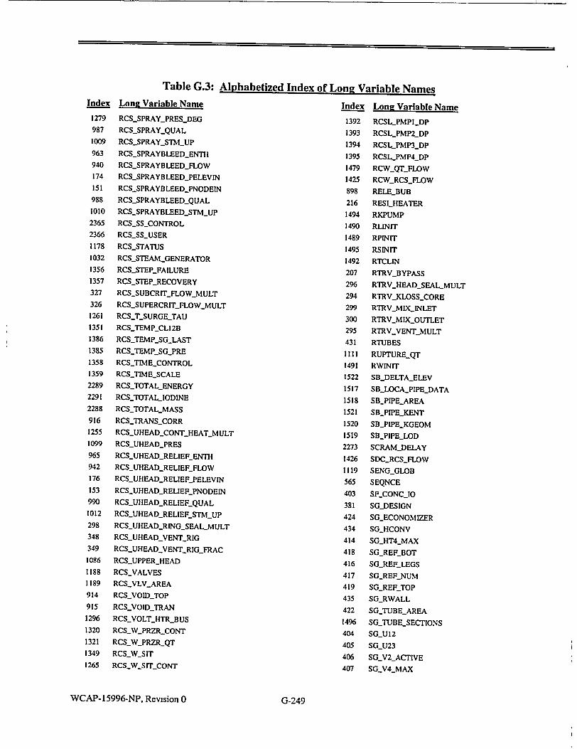
Index
1279
987
1009
963
940
174
151
988
1010
2365
2366
1178
1032
1356
1357
327
326
1261
1351
1386
1385
1358
1359
2289
2291
2288
916
1255
1099
965
942
176
153
990
1012
298
348
349
1086
1188
1189
914
915
1296
1320
1321
1349
1265
Long Vari
RCS_SPRAY
RCSSPRAY
RCS-SPRAY
RCSSPRAY
RCS._SPRAY
RCS_SPRAY
RCS-SPRAY
RCSSPRAY
RCSSPRAY
RCSSSCO
RCS_SSUSF
RCS_STATU
RCSSTEAM
RCSSTEPJ_
RCS_STEPR
RCS-SUBCR
RCSSUPERI
RCSSUR(
RCS._TEMNP..
RCSTEMP_.
RCSTEMP_
RCSTIME_C
RCSTIME_S
RCS_TOTAL
RCS_TOTAL_
RCSTOTAL_
RCS_TRANS
RCSUHEAD
RCSUHEAD
RCSUHEAD
RCSUHEAD
RCSUHEAD
RCSUHEAD
RCSUHEAD
RCSUHEAD
RCSUHEAD
RCSUHEAD
RCSUHEAD
RCSUPPER_
RCSVALVES
RCSVLV AR
RCSVOID_T(
RCSVOID Tj
RCSVOLT_H
RCS_WPRZR
RCS_WPRZR
RCS_WSIT
RCSW-SrITc
Table G.3: Alphabetized Index of Long Variable Names able Name Index Long Variable I '_PRESDEG 1392 RCSL_PMPI-DP '_QUAL 1393 RCSL_PMP2_DP ._STMUP 1394 RCSLPMP3_DP 'BLEEDENTH 1395 RCSLPMP4_DP BLEEDFLOW 1479 RCWQTFLOW BLEEDPELEVIN 1425 RCWRCSFLOW BLEED PNODEIN 898 RELEBUB BLEEDQUAL 216 RESILHEATER BLEEDSTMUP 1494 RKPUMP NTROL 1490 RLINIT ER 1489 RPINIT S 1495 RSINIT [LGENERATOR 1492 RTCLIN FAILURE 207 RTRV_BYPASS RECOVERY 296 RTRVHEADSEAI IT_FLOW MULT 294 RTRVJKLOSSCOF CRITFLOWMULT 299 RTRVMIXINLET GE_TAU 300 RTRVMIXOUTLI
L12B 295 RTRV.VENTMUL .GLAST 431 RTUBES SG-PRE IIII RUPTUREQT •ONTROL 1491 RWINIT CALE 1522 SBDELTA-ELEV ENERGY 1517 SBLOCAPIPE_DA
.IODINE 1518 SBPIPEAREA ,_MASS 1521 SBPIPE KENT _CORR 1520 SB_PIPE_KGEOM _CONTHEATMULT 1519 SBPIPELOD _PRES 2273 SCRAMDELAY _RELIEFENTH 1426 SDCRCSFLOW -RELIEFFLOW 1119 SENGGLOB .RELIEFPELEVIN 565 SEQNCE _RELIEFPNODEIN 403 SFCONC_10 .RELIEFQUAL 381 SGDESIGN RELIEFSTMUP 424 SGECONOMIZER RINGSEALMULT 434 SGHCONV VENTRIG 414 SGHT4_MAX VENTRIGFRAC 418 SGREFBOT
HEAD 416 SG REF LEGS
417 SG_REF._NUM •EA 419 SGREFTOP
P 435 SGRWALL RAN 422 SG_TUBEAREA TRBUS 1496 SG_TUBESECTION CONT 404 SG-U12
,-QT 405 SGLU23
406 SGV2_ACTIVE ONT 407 SG'V4_MAX
WCAP-15996-NP, Revision 0
Name
LMULT RE
IT
TA
4S
I
G-249

Table G.3: Alphabetized Index of Long Variable Names
Index Lone Variable Name Index Long Variable Name
408 SG.V5_.MAX 1827 SGBD_SINKFLOW
498 SGBDACROSS 1833 SGBDSINKIO
505 SGBD BOT-COEFF 1842 SGBDSINKP
1814 SGBDBOT.,ENTH 1824 SGBDSINKPOS
1811 SGBDBOTFLOW 1836 SGBD_SINKPT
508 SGBD BOT HTNOZ 1839 SGBD_SINKXE
1817 SGBD-BOT_1O 504 SGBDSURFCOEFF
1808 SGBDBOTPOS 1813 SGBDSURF_ENTH
1820 SGBDBOT_'T 1810 SGBD_SURFFLOW
1823 SGBDBOTXE 507 SGBDSURFHTNOZ
1788 SGBDCON-1O 1816 SGBDSURF_.10
1789 SGBDCONT 1807 SGBD_SURFPOS
1790 SGBDCON)XE 1819 SGBDUSURFPTf
1791 SGBDDVDH 1822 SGBD_SURF._XE
1792 SGBD DVDP 1800 SGBDSV
1793 SGBDJH 1801 SGBD_SVF
1794 SGBDHF 1802 SGBDSVG
1795 SGBDHG 1803 SGBD_T
1796 SGBDL 1804 SGBDTWALL
1797 SGBDM 502 SGBDYOL
1798 SGBD_-ML 1805 SGBDX
510 SGBDOUTCOEFF 432 SGMTCP
1831 SGBDOUTENTH 2281 SGSALPHADOWNCOMER
1828 SGBD.OUTFLOW 2280 SGSAREADOWNCOMER
509 SGBDOUTHTNOZ 1850 SGS_ASEPTUNE
1834 SGBDOUT.I0 1543 SGS_BOT_P
1843 SGBDOUTP 1541 SGSCOMMON
1825 SGBDOULTPOS 1550 SGS_CON_BORONI
1837 SGBDOUTPT 1551 SGSCONBORON2
1840 SGBQDOUTXE 1544 SGS_CON_101
1799 SGBDP 1545 SGSCON_102
511 SGBDRELIEFAMAX 1546 SGS_CONPTi
1832 SGBDRELIEF ENTH 1547 SGS_CONPI2
1829 SGBDRELIEFFLOW 1548 SGSCONXE1
1835 SGBDRELIEF_10 1549 SGSCONXE2
1844 SGBDRELIEF._P 1881 SGSCRIT_MODEL
1826 SGBDLRELIEFPOS 2278 SGS_DEBUG_SGHEAT
1838 SGBD RELIEF_-PT 2277 SGSDEBUG_SGSINI
1841 SGBDRELIEF._XE 1552 SGS DELTV
503 SGBDLSGCOEFF 1851 SGSDELTVMAX
1812 SGBDSGCENTH 1553 SGSDP
1809 SGBDSGFLOW 1554 SGS_DVDP
506 SGBDSGHTNOZ 1560 SGS_El
1815 SGBD_SG_10 1561 SGS_E2
1806 SGBDLSG yOS 1562 SGS.E3
1818 SGBDSGPT 1563 SGS_E4
1821 SGBDSGXE 1564 SGS_ES
1830 SGBD-SINKENTH 1901 SGS_ECONASUB
WCAP- 15996-NP, Revision 0 G-250

Index
1903
1904
1902
1899
1900
1897
1898
1896
1555
1556
1557
1558
1559
1852
1632
1853
1854
1725
1855
1633
1643
1565
1566
1567
1568
1569
1570
1883
1542
1571
1572
1573
1574
1575
1890
1891
1882
1508
1576
1856
1857
1644
1645
1646
1577
1858
1859
1578
Lone Vari
SGS_ECON_
SGS-ECON
SGS_ECON{
SGS_ECON
SGSECON
SGSECON
SGS_ECON
SGS_.ECON_'
SGS_ENTHI
SGS_ENTH2
SGS-ENTH3
SGSENTH4
SGSENTH5
SGS_FK3TJ1
SGS_FLOW_
SGS_FTIME
SGS_FTIME_
SGSFWS
SGSHASUB
SGSHEAT
SGSHEAT_
SGSHF
SGSHG
SGSHLEVE
SGS_HT2
SGS_HT3
SGS_HTI
SGS_INITIAl
SGSINTER!
SGS_Ml
SGS_M2
SGS_M3
SGSM4
SGSM5
SGS_MASS_
SGS_MASS_
SGS-MORE
SGS_NSECT
SGSP
SGS_PCNVR
SGS_PMIN
SGSQCON
SGS_QWAL
SGSQWAL
SGS_RECIRC
SGS_RECIRC
SGSRECIRC
SGS_RHOI
Table G.3: Alphabetized Index of Long Variable Names able Name Index Long Variable CNVRG 1579 SGS-RHO2 FLIM 1580 SGS-RHO3 TCAV 1581 SGS-RHO4
.TFIN 1582 SGSRHO5 *TFOUT 1860 SGS_SEP_PMIN :MIN 1787 SGS_SGBD TPOUT 2283 SGSSTEAM VEL3 YARS 1647 SGS-STEAMLINE
1583 SGSSVI
1584 SGSSV2
1585 SGS_SV3
1586 SGS_SV4
1587 SGS_SV5 UNE 1590 SGS_TI CHOKED 1591 SGST2
1592 SGST3 PMAX 1593 SGST4
1594 SGST5 -OPTION 1879 SGS_TAUFLOW
1863 SGS_TAU_WOUTS' LOAD 1861 SGS-TAURCITUIN
1862 SGS_TAURC2.MA2
2292 SGS_TOTAL1_IODl? L 1588 SGS_TREFLG
1888 SGS-TUBEAREA_
1889 SGS-TUBEAREA
1846 SGSTUNE LCONDITIONS 1589 SGS-TWALL NAL 1864 SGS_UADROP_PEIR
1865 SGS_UADROP..WF
1595 SGSUSTM
1866 SGSUSTMMIN
1602 SGS.V1
1603 SGSV2 FULLTUBEAREA 1604 SGS_V3 ZEROTUBEAREA 1605 SGS_V4
VARIABLES 1606 SGSV5
1867 SGSVCNVRG
2282 SGSVEL31-MULT G 1596 SGS_VF
1876 SGS_VYREF T 1597 SGS3VF2 LLI 1598 SGSVF3 U13 1599 SGS_VF4
1600 SGSVF5 DELVOL 1601 SGSVG
-MIN 1877 SGS_VGREF
1878 SGSVLEGREF
WCAP-15996-NP, Revision 0
4ame
G
lE
NE
DEGRAD
.OPTION
•IM
DMIN
I
G-251
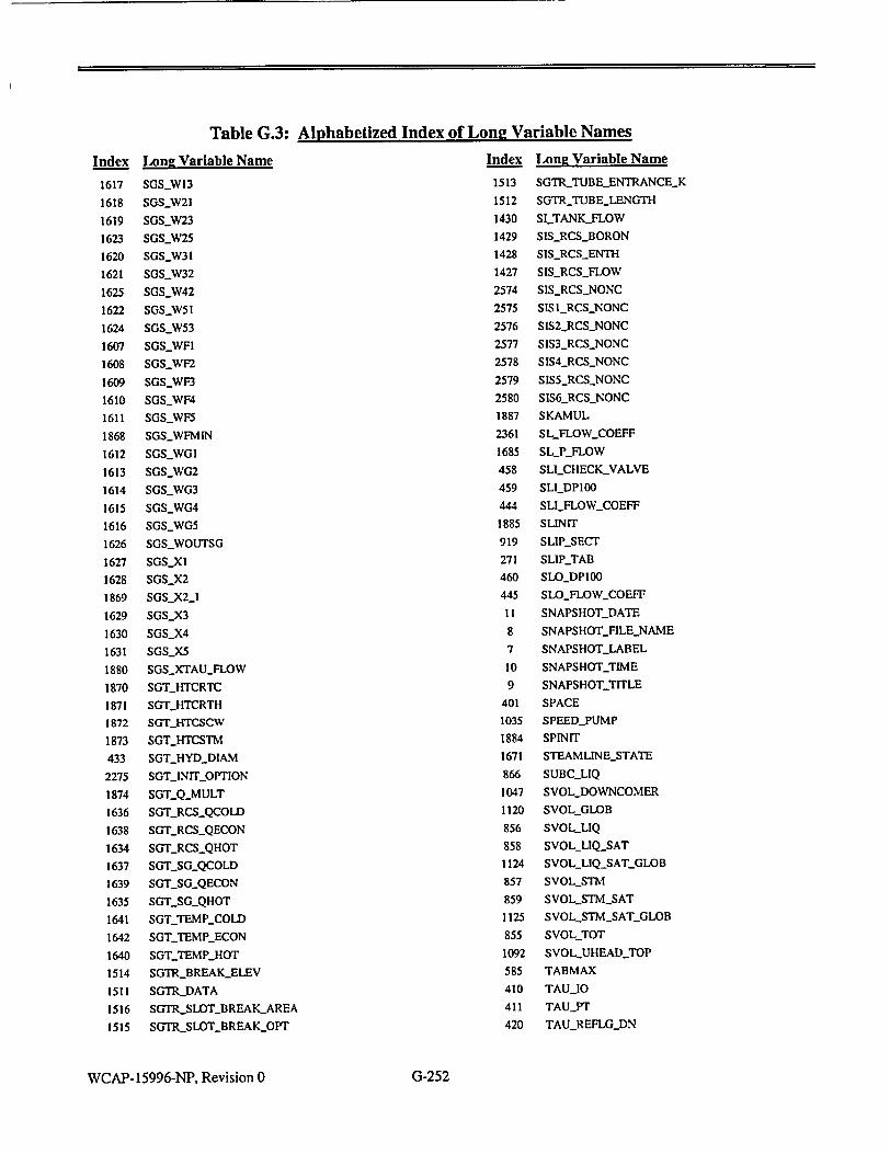
Index
1617
1618
1619
1623
1620
1621
1625
1622
1624
1607
1608
1609
1610
1611
1868
1612
1613
1614
1615
1616
1626
1627
1628
1869
1629
1630
1631
1880
1870
1871
1872
1873
433
2275
1874
1636
1638
1634
1637
1639
1635
1641
1642
1640
1514
1511
1516
1515
Long Vari
SGS-W13
SGSW21
SGS_.W23
SGSW25
SGSW31
SGSW32
SGS.W42
SGS-W51
SGS_.W53
SGSWFI
SGS.WF2
SGSWF3
SGS_WF4
SGSWF5
SGSWFMI?
SGSWGI
SGS_.WG2
SGSWG3
SGSWG4
SGS_)WG5
SGSW)OU
SGSXI
SGSX2
SGSX2_I
SGSX3
SGSX4
SGSX5
SGSXTAU
SGT_HTCR
SGT_..HTCR
SGT_.HTCS(
SGTHTCS'
SGTHYD_
SGTjNITJ_
SGTQMU
SGTRCS_
SGTRCS_
SGTRCSj
SGTSGQ
SGTSGQ
SGTSG=Q
SGT_.TEMP
SGTTEM.
SGT_,TEM.
SGTRBRE
SGTRDAT
SGTR.SLO
SGTRSLO
Table G.3: Alphabetized Index of Long Variable Names
able Name Index Long Variable N
1513 SGTRTUBE_ENTR
1512 SGTRTUBELENG
1430 SLTANKFLOW
1429 SISRCSBORON
1428 SISRCSENTH
1427 SISRCSFLOW
2574 SISRCSNONC
2575 SIS IRCSNONC
2576 SIS2_RCSNONC
2577 SIS3_RCSNONC
2578 S1S4_RCSNONC
2579 SIS5_RCSNONC
2580 SIS6_RCSNONC
1887 SKAMUL
2361 SLFLOWCOEFF
1685 SLP_FLOW
458 SLICHECKVALV
459 SLIDP100
444 SLI_FLOW_COEFF
1885 SLINIT
SG 919 SLIPSECT
271 SLIP_TAB
460 SLODPI00
445 SLOFLOWCOEFI
11 SNAPSHOT_-DATE
8 SNAPSHOTFILE_]
7 SNAPSHOT-LABE'
FLOW 10 SNAPSHOTIME
TC 9 SNAPSHOTTITLE
TH 401 SPACE
CW 1035 SPEEDPUMP
TM 1884 SPINIT
DIAM 1671 STEAMLINESTA
)PTION 866 SUBCLIQ
.LT 1047 SVOLDOWNCON
.COLD 1120 SVOLGLOB
?ECON 856 SVOLLIQ
QHOT 858 SVOLLIQSAT
COLD 1124 SVOLLIQ. SATC3
ECON 857 SVOLSTM
HOT 859 SVOLSTMSAT
'-COLD 1125 SVOLSTMSAT_
-_ECON 855 SVOLTOT
?_HOT 1092 SVOLUHEAD_TC
AKELEV 585 TABMAX
*A 410 TAU_10
)T_BREAKAREA 411 TAUPT
TBREAKOPT 420 TAUREFLGDN
WCAP-15996-NP, Revision 0
ame ANCE.K
TH
E
F
NAME ,L
rE
IER
3LOB
GLOB
DP
G-252

Table G.3: Alphabetized Index of Long Variable NamesIndex Long Variable Name
421 TAUREFLG_UP
412 TAUXE
409 TAURCI
2217 TBASE
391 TBL2_NUM
398 TBL3_NUM
867 TEMP._CONT
1059 TEMPHEATER
862 TEMPLIQ
2551 TEMP.NONC
1063 TEMPPRZRREF
1065 TEMP_PRZRRTD
1064 TEMPPRZR.SURGE
1109 TEMP_.QT
1110 TEMPQTSURGE
864 TEMPSAT
1126 TEMPSAT GLOB 863 TEMP_-STM
861 TEMPTOT
1077 TEMPVALVERELIEF
865 TEMPWALL
602 TGAPIN
2218 TIME
2219 TIME SCALE
2222 TIMQUE
430 TMP_TBL
217 TOPHEATERS
1037 TORQPUMP
272 TORQTAB
2220 TSTOP
568 UNUSED
446 UNUSEDFLOWCOEFF
14 UNUSEDyVARPLT01
678 UNUSEDVARPOWO1
2272 USERCOMMON
395 V3_TBL
396 V3_TBLDSGNI
397 V3JTBLDSGN2
2358 VATTENFALL_MISCELLANEOUS
447 VELIOO
1076 VIBRVALVERELIEF
1438 VLV_PRZRCONT
1484 VLV_PRZRFLOW_OPTION
1486 VLVPRZRFLOWTABLE
292 VLVPRZRKLOSSDOWN
291 VLVPRZRKLOSS_UP
1437 VLVPRZRMOV
1440 VLVPRZR-MSPRAY
Index
1445
1485
1435
1446
1085
1084
1487
1439
1483
1436
1442
1441
1443
1432
1444
1433
1434
882
910
448
413
1055
218
1094
228
388
389
390
415
436
437
466
268
215
84
85
566
567
822
Lone Variable Name
VLVPRZRMSPRAYSIG
VLVPRZRNPOINTS_TAB
VLV_.PRZRPORV
VLVPRZRPORV_SIG
VLVPRZRPRESDOWN
VLVPRZRPRES_UP
VLVPRZRPROPTABLE
VLVPRZRQT
VLVPRZRQUALDF
VLV PRZRSAFETY
VLVQTCONT
VLVQTGWS
VLVQTNSUPPLY
VLVRCS_POS
VLVRCSSIG
VLVJUHEADCONT
VLVUHEADQT
VOIDFRAC
VOL MIX
VOL MSLH
VOLSGS
VOLT HEATER
VOLTHEATERMAX
VOLUNONUHEAD
VOLUQT
VSTTBL
VST_TBLDSGNI
VST_TBL_DSGN2
W32-FLOWCOEFF
WALLAREA
WALL MCP
WFWIOO
WINDTORQMULT
XFERHEATER
XFERSURFPOFF
XFERSURF._PON
XTAB
YTAB
ZSHAPIN
WCAP-15996-NP, Revision 0 G-253

Table G.4: Alphabetized Index of Short Variable Names
Index Short Variable Name
92 AANN
2281 ALPHA3
89 APZR
94 ASECVA
399 ASEPSG
440 ASLMAX
461 ASLMIN
383 ASPTBI
384 ASPTB2
382 ASPTBL
237 BAD
235 BAN
241 BAR
239 BAT
238 BVD
236 BVN
242 BVR
240 BVT
2178 CAAUTO
2174 CADELA
2173 CADPHI
2175 CAFMUL
2168 CAFWS
2172 CAGMAX
2171 CALMI
2170 CALLO
2177 CAMOTR
2169 CASET
2179 CASSIG
2176 CATURB
1991 CAUTO
2130 CBAUTO
2124 CBDELP
2214 CBLOCK
2129 CBMODE
2128 CBNCLS
2126 CBNOPN
2123 CBPOPN
2127 CBQCLS
2125 CBQOPN
2122 CBSET
2121 CBYPAS
2017 CCAUTO
2022 CCAVAL
1978 CCEA
2031 CCENTH
2029 CCFLOW
2016 CCFPMP
Index Short Variable Name
2021 CCFVAL
2009 CCGRAT
2005 CCLSP1
2006 CCLSP2
2007 CCLSP3
2008 CCLSP4
2018 CCPMPO
2004 CCSET
2030 CCTEMP
2020 CCVALV
1995 CCVCS
2120 CDAUTO
2367 CDCONT
2247 CDELAY
2267 CDFrRP
2256 CDGRCS
2270 CDGRTR
2261 CDGSGM
2269 CDGSTR
2265 CDGTRP
2266 CDITRP
2253 CDLPHI
2260 CDLSGH
2259 CDLSGL
2271 CDMISC
2264 CDMIST
2262 CDPCHI
2249 CDPOHI
2252 CDPPHI
2251 CDPPLO
2258 CDPSGL
2268 CDQTRP
2118 CDSET
2257 CDSIAS
2250 CDSRHI
2254 CDTMAR
2248 CDTR[P
2119 CDTSP
2117 CDUMP
2263 CDUSER
2255 CDWMAR
2077 CEAUTO
2081 CEBHLP
2083 CEBSIT
2057 CECCS
2088 CECGAS
2076 CEDEL
2060 CEDPSL
Index Short Variable Name
2086 CEELEV
2087 CEFLCO
2066 CEGHPS
2071 CEGLPS
2082 CEHHLP
2068 CEHNUM
2084 CEHSIT
2230 CEINIT
2091 CEIVAL
2073 CELNUM
2080 CEMISC
2065 CENHPS
2070 CENLPS
2085 CENSIT
2061 CEPCHI
2067 CEPHPS
2059 CEPLO
2072 CEPLPS
2089 CEPSIT
2063 CEPSLL
2058 CESET
2069 CESHPS
2064 CESIS
2092 CESLIQ
2074 CESLPS
2062 CETAVL
2321 CETOPC
2078 CETRP
2079 CETRPP
2075 CETRPT
2090 CEVGAS
2093 CEVLIQ
2151 CFAUT
2152 CFAUTO
2143 CFDELA
2154 CFEAUT
2148 CFEMAX
2147 CFENTH
2149 CFETC
2144 CFGMAX
2141 CFLHI
2140 CFLLO
2139 CFLPRG
2155 CFPAUT
2142 CFRAMP
2138 CFSET
2164 CFSFRC
2165 CFSMAX
Index Short Variable Name
2145 CFSMUL
2163 CFSSIG
2156 CFrAUT
2146 CFrLO
2150 CFTRP
2153 CFVAUT
2167 CFVBYP
2162 CFVEPO
2159 CFVESI
2166 CFVISO
2161 CFVPO
2160 CFVPOS
2158 CFVSI
2157 CFVSIG
2137 CFWS
2105 CGCAUT
2103 CGFDEM
2104 CGGRAT
2106 CGLOAD
2189 CGRAUT
2191 CGRTRP
2188 CGSAUT
2186 CGSCON
2099 CGSET
2187 CGSSET
2190 CGSTRP
2108 CGTAUT
2100 CGTCLS
2107 CGTRP
2109 CGTRPP
2102 CGTRPT
2101 CGVTC
2044 CHAUTO
2032 CHEATR
2034 CHLBSP
2035 CHLOFF
2038 CHPBOF
2039 CHPBON
2036 CHPPOF
2037 CHPPON
2040 CHPREF
I CHR
2033 CHSET
589 CHT
664 CHTAXA
652 CHTAXB
671 CHTSEO
646 CHTAXF
WCAP-15996-NP, Revision 0 G-254
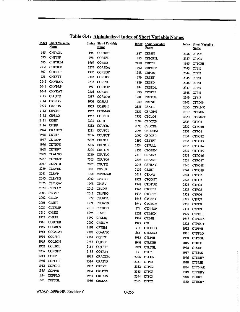
Table G.4: Alphabetized Index of Short Variable NamesIndex Short Variable
Name
645 CHTAXL
590 CHTINP
605 CHTNUM
2233 CHTOFF
607 CHTPRP
633 CHTSTr
2042 CHVBAK
2041 CHVPRP
2043 CHVRAT
2115 CIAUTO
2114 CIGSLO
2225 CINCON
2113 CIPCHI
2112 CIPSLO
2111 CISET
2116 CITRP
1974 CKAUTO
1975 CKTRP
1977 CKTRPP
1976 CKTRPS
1968 CKTRPT
2019 CLAUTO
2227 CLCONT
2027 CLENTH
2239 CLEVEL
2241 CLEVP
2240 CLEVSG
2025 CLFLOW
2028 CLFRAC
2003 CLGSP
2002 CLLSP
2001 CLSET
2026 CLTEMP
2110 CMSIS
1973 CNRPS
1965 CODTUR
1959 COGRCS
1964 COGSGM
1956 COLPHI
1963 COLSGH
1962 COLSGL
2236 CONOFF
2243 CONT
1966 COPCHI
1952 COPOHI
1955 COPPHI
1954 COPPLO
1961 COPSGL
Index Short Variable Name
196 CORBOT
796 CORE3D
1969 COREQ
2279 COREQA
1970 COREQT
2318 CORHFR
2237 CORINI
197 CORTOP
2316 CORWO
2317 CORWFR
1960 COSIAS
1953 COSRHI
1957 COTMAR
1967 COUSER
2203 COUT
2212 COUT3D
2211 COUTCL
2206 COUTCT
2209 COUTFI
2208 COUTGR
2204 COUTIN
2210 COUTLO
2205 COUTOP
2207 COUrT1
1951 COVER
1958 COWMAR
2012 CPLERR
1998 CPLEV
2013 CPLINS
2011 CPLPRG
1972 CPOWFL
1971 CPOWFR
2010 CPPROG
1996 CPSET
1999 CPSLIQ
2000 CPSSTM
1997 CPTEM
2182 CQAUTO
2181 CQSET
2183 CQTRP
2184 CQTRPP
2185 CQTRPT
1993 CRACCM
2514 CRATIO
1982 CREXP
1984 CRFPOS
1983 CRGAIN
1986 CRMAX
Index Short Variable Name
1987 CRMIN
1985 CRMOTL
2180 CRPCS
1992 CRPERF
1988 CRPOS
1979 CRSET
1989 CRSPD
1994 CRSPDL
1990 CRSTEP
1981 CRTFUL
1980 CRTNO
2131 CSAFE
2136 CSAOPN
2135 CSCLOS
2094 CSDCCN
2095 CSDCDH
2096 CSDCHM
2097 CSDCSP
2192 CSETPT
2134 CSFULL
2133 CSOPEN
2213 CSPAR2
2228 CSPARE
2045 CSPRAY
2132 CSSET
2014 CTAVG
1927 CTCONT
1942 CTDTUR
1945 CTGKSP
1936 CTGRCS
1948 CTGSBY
1941 CTGSGM
674 CTHHOP
2202 CTIMCN
1926 CTIME
1925 CTL
573 CTLDBG
584 CTLMAX
1933 CTLPHI
1940 CTLSGH
1939 CTLSGL
12 CTLT
2226 CTLUN
2351 CTPCI
2352 CTPC2
2353 CTPC3
2354 CTPC4
2355 CTPC5
Index Short Variable Name
2356 CTPC6
2357 CTPC7
1943 CTPCHI
2343 CTPI1
2344 CTPI2
2345 CTPI3
2346 CTPI4
2347 CTPI5
2348 CTrP16
2349 CTPI7
2342 CTPINP
2350 CTPLNK
2319 CTPMIN
2320 CTPMNT
2323 CTPOI
2332 CTPO10
2333 CTPOI I
2334 CTPOI2
2335 CTP13
2336 CTP014
2337 CTPO15
2338 CTr•O6
2339 CT?!O7
2340 CTPO18
2341 CTP019
2324 CTP02
2325 CTI03
2326 CTP04
2327 CTPO5
2328 CTTr06 2329 CTrP7
2330 CTrP8
2331 CTPO9
1929 CTOHI
1947 CTPORA
2322 CTPOUT
1932 C1PPHI
1931 CTPPLO
1938 CTPSGL
2015 CTREF
1928 CTSET
1937 CTSIAS
1946 CTSRBY
1930 CTSRHI
1934 CTrMAR
1949 CITUBY
2098 CTURB
1950 CTUSBY
WCAP-15996-NP, Revision 0
I
G-255
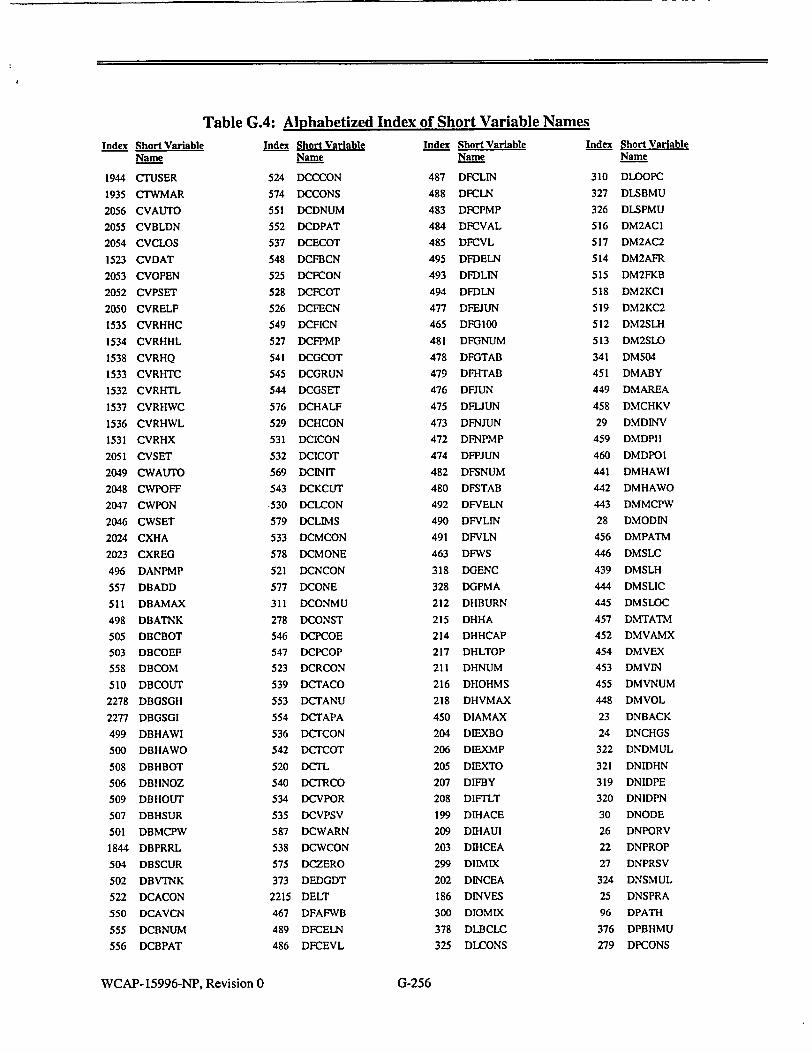
Table G.4: Alphabetized Index of Short Variable Names
Index Short Variable Name
1944 CTUSER
1935 CTWMAR
2056 CVAUTO
2055 CVBLDN
2054 CVCLOS
1523 CVDAT
2053 CVOPEN
2052 CVPSET
2050 CVRELF
1535 CVRHHC
1534 CVRHHL
1538 CVRHQ
1533 CVRHTC
1532 CVRHTL
1537 CVRHWC
1536 CVRHWL
1531 CVRHX
2051 CVSET
2049 CWAUTO
2048 CWPOFF
2047 CWPON
2046 CWSET
2024 CXHA
2023 CXREG
496 DANPMP
557 DBADD
511 DBAMAX
498 DBATNK
505 DBCBOT
503 DBCOEF
558 DBCOM
510 DBCOUT
2278 DBGSGH
2277 DBGSGI
499 DBHAWI
500 DBHAWO
508 DBHBOT
506 DBHNOZ
509 DBHOUT
507 DBHSUR
501 DBMCPW
1844 DBPRRL
504 DBSCUR
502 DBVTNK
522 DCACON
550 DCAVCN
555 DCBNUM
556 DCBPAT
Index Short Variable Name
524 DCCCON
574 DCCONS
551 DCDNUM
552 DCDPAT
537 DCECOT
548 DCFBCN
525 DCFCON
528 DCFCOT
526 DCFECN
549 DCFICN
527 DCFPMP
541 DCGCOT
545 DCGRUN
544 DCGSET
576 DCHALF
529 DCHCON
531 DCICON
532 DCICOT
569 DC1NIT
543 DCKCUT
,530 DCLCON
579 DCLIMS
533 DCMCON
578 DCMONE
521 DCNCON
577 DCONE
311 DCONMU
278 DCONST
546 DCPCOE
547 DCPCOP
523 DCRCON
539 DCTACO
553 DCTANU
554 DCTAPA
536 DCTCON
542 DCTCOT
520 DCTL
540 DCTRCO
534 DCVPOR
535 DCVPSV
587 DCWARN
538 DCWCON
575 DCZERO
373 DEDGDT
2215 DELT
467 DFAFWB
489 DFCELN
486 DFCEVL
Index Short Variable Name
487 DFCLIN
488 DFCLN
483 DFCPMP
484 DFCVAL
485 DFCVL
495 DFDELN
493 DFDLIN
494 DFDLN
477 DFEJUN
465 DFG100
481 DFGNUM
478 DFGTAB
479 DFHTAB
476 DFJUN
475 DFLJUN
473 DFNJUN
472 DFNPMP
474 DFPJUN
482 DFSNUM
480 DFSTAB
492 DFVELN
490 DFVLIN
491 DFVLN
463 DFWS
318 DGENC
328 DGPMA
212 DHBURN
215 DHHA
214 DHHCAP
217 DHLTOP
211 DHNUM
216 DHOHMS
218 DHVMAX
450 DIAMAX
204 DIEXBO
206 DIEXMP
205 DIEXTO
207 DIFBY
208 DIFrLT
199 DIHACE
209 DIHAUI
203 DIHCEA
299 DIIMIX
202 DINCEA
186 DINVES
300 DIOMIX
378 DLBCLC
325 DLCONS
Index Short Variable Name
310 DLOOPC
327 DLSBMU
326 DLSPMU
516 DM2ACI
517 DM2AC2
514 DM2AFR
515 DM2FKB
518 DM2KCI
519 DM2KC2
512 DM2SLH
513 DM2SLO
341 DM504
451 DMABY
449 DMAREA
458 DMCHKV
29 DMDINV
459 DMDPI1
460 DMDPOI
441 DMHAWI
442 DMHAWO
443 DMMCPW
28 DMODIN
456 DMPATM
446 DMSLC
439 DMSLH
444 DMSLIC
"445 DMSLOC
457 DMTATM
452 DMVAMX
454 DMVEX
453 DMVIN
455 DMVNUM
448 DMVOL
23 DNBACK
24 DNCHGS
322 DNDMUL
321 DNIDHN
319 DNIDPE
320 DNIDPN
30 DNODE
26 DNPORV
22 DNPROP
27 DNPRSV
324 DNSMUL
25 DNSPRA
96 DPATH
376 DPBHMU
279 DPCONS
WCAP- 15996-NP, Revision 0 G-256

Table G.4: Alphabetized Index of Short Variable NamesIndex Short Variable
Name
356 DPCRFL
346 DPDGMX
290 DPDMAX
288 DPFLSH
287 DPFMUL
350 DPFRIG
2534 DPGASP
364 DPHAXW
344 DPHDT
281 DPHMUL
323 DPKMUL
351 DPLBOL
220 DPLRBO
347 DPLRIG
219 DPLRTD
221 DPLRTO
289 DPLSAT
365 DPLSBO
360 DPM034
375 DPPHMU
282 DPPMUL
286 DPQMUL
285 DPRTAU
210 DPRZR
342 DPSDE
343 DPSEQ
283 DPSMUL
345 DMrDT
359 DPTMSP
374 DPTREV
284 DPVMUL
377 DPVVMU
280 DPWMUL
313 DQCONS
315 DQGMUL
229 DQHT
230 DQMASS
314 DQNMUL
227 DQPN2
231 DQPRUP
317 DQSFRC
226 DQTANK
316 DQVMUL
228 DQVOL
368 DRAREF
2362 DRATIO
358 DRCMIN
357 DRCMUL
WCAP-15996-NP, Revision 0
IndexIndex Short Variable Name
302 DRCONS
232 DRCP
18 DRCS
274 DRCURR
369 DRDAMP
19 DRDESN
273 DRDTDW
234 DRFRAC
277 DRFRAT
367 DRFREF
362 DRFRUB
305 DRISPL
372 DRLMUL
267 DRNPOL
233 DRNUM
275 DRPLEK
304 DRQMUL
271 DRSLIP
270 DRTNUM
272 DRTORQ
363 DRTRUB
21 DRTYPE
269 DRVBUS
307 DRVMAX
371 DRVMUL
306 DRVNOR
276 DRVRAT
309 DRVSPD
308 DRVTIM
438 DSAEHT
426 DSAFLO
427 DSAHT
422 DSATUB
436 DSAWAL
418 DSBREF
433 DSDHYD
352 DSDP
353 DSDPI2
354 DSDPW
355 DSDPW1
424 DSECON
423 DSETUS
497 DSGDB
381 DSGDES
379 DSGS
380 DSGSIN
312 DSGTRM
425 DSHEAT
Index Short Variable Name
434 DSHWAL
437 DSMCPW
417 DSNREF
416 DSREFL
435 DSRWAL
420 DSTDN
419 DSTREF
421 DSTUP
596 DTAHT
595 DTDENS
594 DTH2
606 DTNFC
591 DTNRAD
604 DTNZ
592 DTROUT
190 DUAMAX
188 DUAMIN
298 DUAMUL
191 DUAROD
293 DUCONS
370 DUFAST
349 DUFRIG
301 DUKCEA
294 DUKCOR
348 DULRIG
1456 DUMOOl
15 DUMMYI
366 DUORFL
189 DUPMAX
187 DUPMIN
296 DUPMUL
297 DURMUL
295 DUVMUL
334 DVAMOV
337 DVAMSP
340 DVANC
335 DVAPCO
332 DVAPOR
336 DVAPQT
333 DVAPSV
339 DVAQTC
338 DVAQTG
329 DVAREA
331 DVAUHQ
330 DVAVNT
223 DVGPOR
224 DVGPSI
225 DVGPS2
292
291
222
361
213
559
560
2244
580
561
400
2420
2462
2461
586
2381
2406
2408
2440
2407
2436
2505
2216
2473
2490
2411
2379
2380
2454
2509
2433
2506
1742
1751
1741
1740
1750
1749
2484
1737
1748
1736
1735
1747
1746
2397
1734
1738
Short Variable Name
DVKDWN
DVKUP
DVLREL
DVTMAX
DWABLD
ELEMS
ELIN
ELLAST
ELMAX
ELTYPE
EVAPSS
FAEXTF
FATABL
FBTABL
FCTMAX
FCV
FCVAFL
FCVDPM
FCVP
FCVRES
FCVV
FDCLMS
FDELT
FDHEAT
FDMODL
FDNODE
FDPATH
FDPEL
FDPUMP
FDSYST
FDVALV
FECLMS
FEELIN
FEENOZ
FELIN
FELINE
FENOZ
FENOZZ
FFDPSO
FGELIN
FGENOZ
FGLIN
FGLINE
FGNOZ
FGNOZZ
FGPMCO
FGPMP
FGTOT
G-257

Table G.4: Alphabetized Index of Short Variable Names
Index Short Variable Name
1893 FHENTH
2392 FHEXT
2419 FHEXTF
2413 FHEXTN
2485 FHFWBI
1886 FHINIT
1894 FHLOAD
2416 FHNODE
1895 FHNUM
2388 FHPATH
1733 FHPMP
1892 FHTBL
2479 FHTHMX
2476 FHTRHV
2501 FIAURC
2402 FICPMP
2423 FIMN
2445 FINDXF
1743 FIOCON
2503 FITRIP
2504 FITRPO
198 FLA
1772 FLBEH
1760 FLBEIN
1778 FLBEIO
1763 FLBEOU
1781 FLBEPT
1769 FLBEW
1775 FLBEX
1784 FLBEXE
1771 FLBH
1759 FLBIN
1777 FLBIO
1762 FLBOU
1780 FLBPT
1768 FLBW
1774 FLBX
1783 FLBXE
2224 FLGQUE
2483 FMAXTU
2452 FNAFVI
2451 FNAFVT
2401 FNCPMP
2400 FNDEXT
2398 FNDIN
2399 FNDOUT
2472 FNEFWP
2425 FNEXTN
Index Short Variable Name
2409 FNFLO
2489 FNHDPT
2449 FNHDV
2487 FNHTBL
2471 FNMFWP
2424 FNNOD
2442 FNPATH
2429 FNPFLB
2486 FNPHET
2467 FNPMPE
2466 FNPMPM
2500 FNPMRC
2463 FNPMTH
2431 FNPPRV
2428 FNPSGA
2427 FNPSGE
2426 FNPSGM
2468 FNPTMP
2465 FNPTP
2498 FNPTRC
2444 FNPTV
2469 FNPUM
2432 FNSG
2443 FNTABL
2464 FNTABP
2453 FNTAFV
2470 FNTBFP
2448 FNVAL
2447 FNVBFV
2450 FNVHDV
2499 FNVLRC
2446 FNVMFV
1731 FPEVAL
2384 FPEXT
2421 FPEXTF
2412 FPEXTN
1728 FPJUN
2405 FPOISO
2435 FPOSIT
1726 FPPIN
1727 FPPMP
1744 FPTCON
1730 FPVAL
1729 FPVALV
2477 FPWRTB
2389 FQCURR
2478 FQPTBL
2391 FRES
Index Short Variable Name
2382 FRESL
2390 FRESV
2393 FRHOEX
2383 FRHOFD
2417 FRHOND
2455 FSPDMD
2456 FSPEED
1732 FSPMP
2441 FSTP
2434 FSTROK
2396 FSUMP
2458 FTAUOF
2457 FTAUON
2438 FTCLOS
2482 FTEHDP
1757 FrENOZ
2502 FTIMET
2439 FTLAG
1756 FTNOZ
1755 FrNOZZ
2437 FTOPN
2480 FTPOWR
2474 FTPWR
2475 FTQLAG
2481 FTWHDP
2430 FWAFLB
464 FWCOEF
2418 FWEXTF
1766 FWLBEF
1765 FWLBF
1770 FWLBH
1758 FWLBIN
1776 FWLBJIO
1764 FWLBLO
1761 FWLBOU
1779 FWLBPT
1767 FWLBW
1773 FWLBX
1782 FWLBXE
2508 FWLMSS
2385 FWMAS
2497 FWRCIN
2495 FWRCIR
2496 FWRCOT
2492 FWRCPB
2493 FWRCRE
2494 FWRCSP
2378 FWSCOM
Index Short Variable Name
1739 FWSENT
2459 FWSHT
2403 FWSICK
2404 FWSIMF
2410 FWSKEY
2488 FWSNHT
2491 FWSNRC
2415 FWSP
2414 FWSPO
2395 FWSPS
2394 FWSRP
2422 FWSUM
2387 FWSW
2386 FWSWO
2460 FWSWT
1745 FXECON
1754 FXENOZ
1753 FXNOZ
1752 FXNOZZ
562 GROUPS
2245 GROUT
583 GRPMAX
245 HAD
253 HADC
243 HAN
251 HANC
249 HAR
257 HARC
247 HAT
255 HATC
673 HCORE
1033 HEATSG
260 HMUL
90 HPZR
1657 HSLHHF
386 HSPTB1
387 HSPTB2
385 HSPTBL
393 HT3TB1
394 HT3TB2
392 HT3TBL
414 HT4MAX
469 HTNOZ
471 HTNOZA
470 HTNOZE
468 HTNOZF
246 HVD
254 HVDC
WCAP-15996-NP, Revision 0 G-258
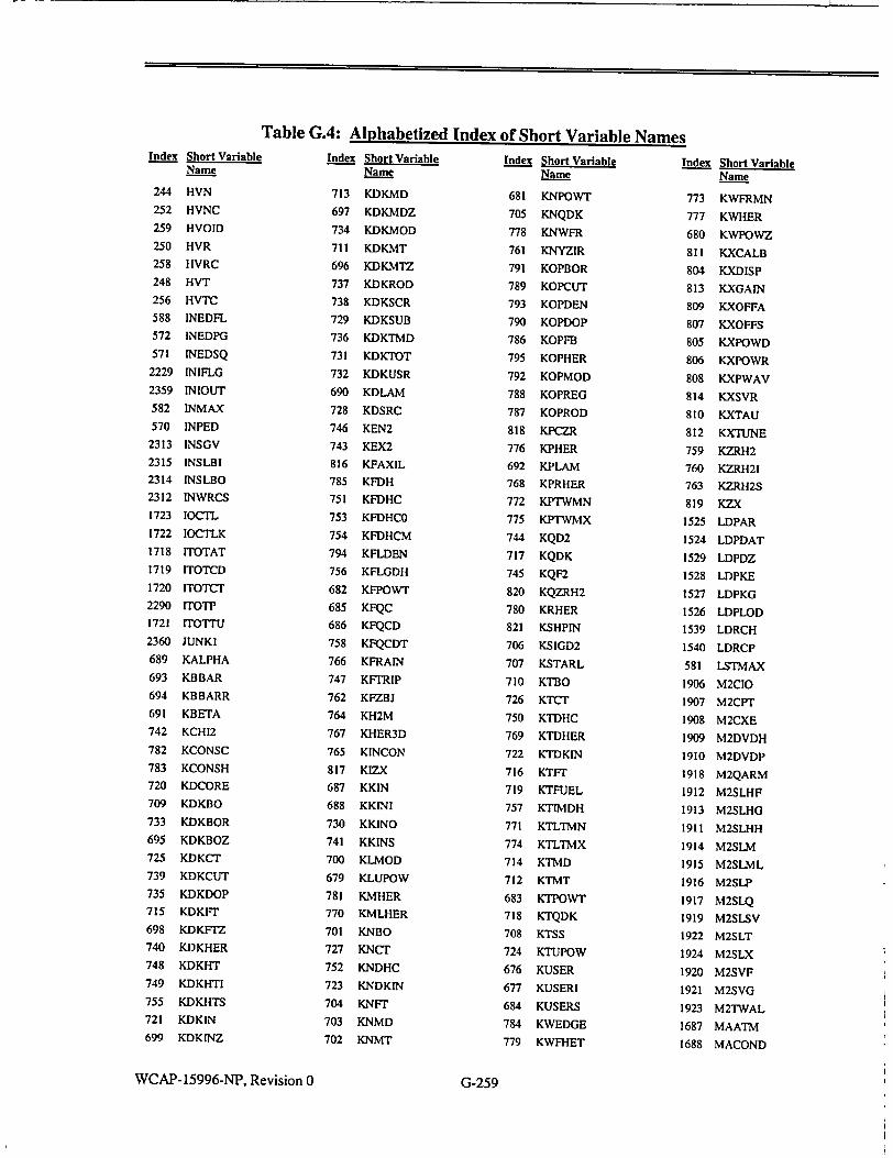
Table G.4: Alphabetized Index of Short Variable NamesIndex Short Variable
Name
244 HVN
252 HVNC
259 HVOID
250 HVR
258 HVRC
248 HVT
256 HVTC
588 INEDFL
572 INEDPG
571 INEDSQ
2229 INIFLG
2359 INIOUT
582 INMAX
570 INPED
2313 INSGV
2315 INSLBI
2314 INSLBO
2312 INWRCS
1723 IOCTL
1722 IOCTLK
1718 ITOTAT
1719 ITOTCD
1720 ITOTCT
2290 rrOTP 1721 ITOTTU
2360 JUNKI
689 KALPHA
693 KBBAR
694 KBBARR
691 KBETA
742 KCH12
782 KCONSC
783 KCONSH
720 KDCORE
709 KDKBO
733 KDKBOR
695 KDKBOZ
725 KDKCT
739 KDKCUT
735 KDKDOP
715 KDKFT
698 KDKFrZ
740 KDKHER
748 KDKHT
749 KDKHTI
755 KDKHTS
721 KDKIN
699 KDKINZ
Index Short Variable Name
713 KDKMD
697 KDKMDZ
734 KDKMOD
711 KDKMT
696 KDKMTZ
737 KDKROD
738 KDKSCR
729 KDKSUB
736 KDKTMD
731 KDKTOT
732 KDKUSR
690 KDLAM
728 KDSRC
746 KEN2
743 KEX2
816 KFAXIL
785 KFDH
751 KFDHC
753 KFDHCO
754 KFDHCM
794 KFLDEN
756 KFLGDH
682 KFPOWT
685 KFQC
686 KFQCD
758 KFQCDT
766 KFRAIN
747 KFTRIP
762 KFZBJ
764 KH2M
767 KHER3D
765 KINCON
817 KIZX
687 KKIN
688 KKINI
730 KKINO
741 KKINS
700 KLMOD
679 KLUPOW
781 KMHER
770 KMLHER
701 KNBO
727 KNCT
752 KNDHC
723 KNDKIN
704 KNFT
703 KNMD
702 KNMT
Index Short Variable Name
681 KNPOWT
705 KNQDK
778 KNWFR
761 KNYZIR
791 KOPBOR
789 KOPCUT
793 KOPDEN
790 KOPDOP
786 KOPFB
795 KOPHER
792 KOPMOD
788 KOPREG
787 KOPROD
818 KPCZR
776 KPHER
692 KPLAM
768 KPRHER
772 KPTWMN
775 KPTWMX
744 KQD2
717 KQDK
745 KQF2
820 KQZRH2
780 KRHER
821 KSHPIN
706 KSIGD2
707 KSTARL
710 KTBO
726 KTCT
750 KTDHC
769 KTDHER
722 KTDKIN
716 KTFT
719 KTFUEL
757 KTIMDH
771 KTLTMN
774 KTLTMX
714 KTMD
712 KTMT
683 KTPOWT
718 KTQDK
708 KTSS
724 KTUPOW
676 KUSER
677 KUSERI
684 KUSERS
784 KWEDGE
779 KWFHET
Index Short Variable Name
773 KWFRMN
777 KWHER
680 KWPOWZ
811 KXCALB
804 KXDISP
813 KXGAIN
809 KXOFFA
807 KXOFFS
805 KXPOWD
806 KXPOWR
808 KXPWAV
814 KXSVR
810 KXTAU
812 KXTUNE
759 KZRH2
760 KZRH2I
763 KZRH2S
819 KZX
1525 LDPAR
1524 LDPDAT
1529 LDPDZ
1528 LDPKE
1527 LDPKG
1526 LDPLOD
1539 LDRCH
1540 LDRCP
581 LSTMAX
1906 M2CIO
1907 M2CPT
1908 M2CXE
1909 M2DVDH
1910 M2DVDP
1918 M2QARM
1912 M2SLHF
1913 M2SLHG
1911 M2SLHH
1914 M2SLM
1915 M2SLML
1916 M2SLP
1917 M2SLQ
1919 M2SLSV
1922 M2SLT
1924 M2SLX
1920 M2SVF
1921 M2SVG
1923 M2TWAL
1687 MAATM
1688 MACOND
WCAP-15996-NP, Revision 0 G-259
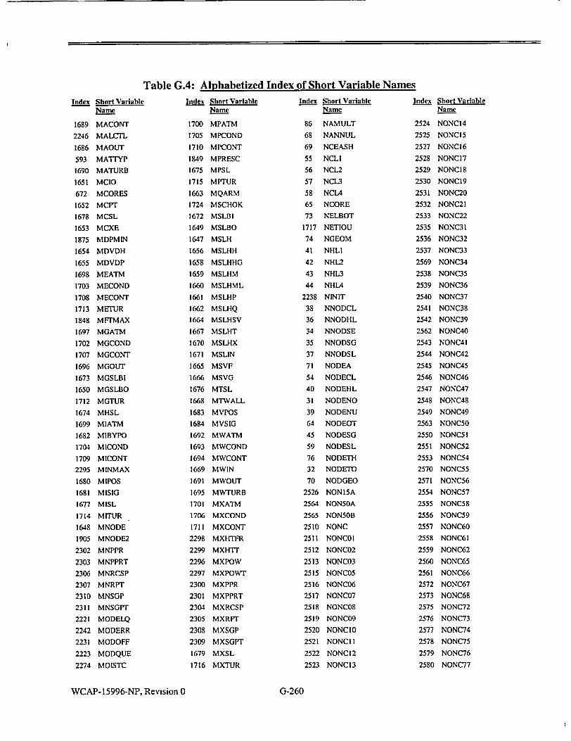
Table G.4: Alphabetized Index of Short Variable Names
Index Short Variable Name
1689 MACONT
2246 MALCTL
1686 MAOUT
593 MATrYP
1690 MATURB
1651 MCIO
672 MCORES
1652 MCV1
1678 MCSL
1653 MCXE
1875 MDPMIN
1654 MDVDH
1655 MDVDP
1698 MEATM
1703 MECOND
1708 MECONT
1713 METUR
1848 MFTMAX
1697 MGATM
1702 MGCOND
1707 MGCONT
1696 MGOUT
1673 MGSLBI
1650 MGSLBO
1712 MGTUR
1674 MHSL
1699 MIATM
1682 MIBYPO
1704 MICOND
1709 MICONT
2295 MINMAX
1680 MIPOS
1681 MISIG
1677 MISL
1714 MITUR
1648 MNODE
1905 MNODE2
2302 MNPPR
2303 MNPPRT
2306 MNRCSP
2307 MNRPT
2310 MNSGP
2311 MNSGPT
2221 MODELQ
2242 MODERR
2231 MODOFF
2223 MODQUE
2274 MOISTC
Index Short Variable Name
1700 MPATM
1705 MPCOND
1710 MPCONT
1849 MPRESC
1675 MPSL
1715 MPTUR
1663 MQARM
1724 MSCHOK
1672 MSLBI
1649 MSLBO
1647 MSLH
1656 MSLHH
1658 MSLHHG
1659 MSLHM
1660 MSLHML
1661 MSLHP
1662 MSLHQ
1664 MSLHSV
1667 MSLHT
1670 MSLHX
1671 MSLIN
1665 MSVF
1666 MSVG
1676 MTSL
1668 MTWALL
1683 MVPOS
1684 MVSIG
1692 MWATM
1693 MWCOND
1694 MWCONT
1669 MWIN
1691 MWOUT
1695 MWTURB
1701 MXATM
1706 MXCOND
1711 MXCONT
2298 MXHTFR
2299 MXHTr
2296 MXPOW
2297 MXPOWT
2300 MXPPR
2301 MXPPRT
2304 MXRCSP
2305 MXRPT
2308 MXSGP
2309 MXSGPT
1679 MXSL
1716 MXTUR
Index Short Variable Name
86 NAMULT
68 NANNUL
69 NCEASH
55 NCL1
56 NCL2
57 NCL3
58 NCLA
65 NCORE
73 NELBOT
1717 NETIOU
74 NGEOM
41 NHLI
42 NHL2
43 NHL3
44 NHL4
2238 NINIT
38 NNODCL
36 NNODHL
34 NNODSE
35 NNODSG
37 NNODSL
71 NODEA
54 NODECL
40 NODEHL
31 NODENO
39 NODENU
64 NODEOT
45 NODESG
59 NODESL
76 NODETH
32 NODETO
70 NODGEO
2526 NONI5A
2564 NON50A
2565 NONSOB
2510 NONC
2511 NONCOI
2512 NONC02
2513 NONC03
2515 NONC05
2516 NONC06
2517 NONC07
2518 NONC08
2519 NONC09
2520 NONCIO
2521 NONCII
2522 NONCI2
2523 NONC13
Index Short Variable Name
2524 NONCI4
2525 NONCI5
2527 NONCI6
2528 NONCI7
2529 NONC18
2530 NONC19
2531 NONC20
2532 NONC21
2533 NONC22
2535 NONC31
2536 NONC32
2537 NONC33
2569 NONC34
2538 NONC35
2539 NONC36
2540 NONC37
2541 NONC38
2542 NONC39
2562 NONC40
2543 NONC41
2544 NONC42
2545 NONC45
2546 NONC46
2547 NONC47
2548 NONC48
2549 NONC49
2563 NONCSO
2550 NONC5 1
2551 NONC52
2553 NONC54
2570 NONC55
2571 NONC56
2554 NONC57
2555 NONC58
2556 NONC59
2557 NONC60
2558 NONC61
2559 NONC62
2560 NONC65
2561 NONC66
2572 NONC67
2573 NONC68
2575 NONC72
2576 NONC73
2577 NONC74
2578 NONC75
2579 NONC76
2580 NONC77
WCAP-15996-NP, Revision 0 G-260

Table G.4: Alphabetized Index of Short Variable NamesIndex Short Variable
Name
2581 NONC78
2582 NONC79
2583 NONC80
2574 NONCSI
75 NOSECT
563 NOTAB
66 NPRZR
87 NSECT
47 NSGIC
46 NSGIH
60 NSGIP
49 NSG2C
48 NSG2H
61 NSG2P
51 NSG3C
50 NSG3H
62 NSG3P
53 NSG4C
52 NSG4H
63 NSG4P
67 NUHEAD
91 NUMANN
33 NUMNOD
88 NUMSEG
20 NUMSG
824 NUMSHP
462 NUMSL
81 NWLMXC
82 NXBOIL
80 NXBOT
79 NXCON
83 NXINJ
77 NXLIQ
84 NXSPOF
85 NXSPON
78 NXSTM
72 NZTOT
122 PANCOR
183 PAREA
128 PATHCL
1029 PATHDN
131 PATHG
127 PATHHL
97 PATHNO
120 PATHNU
129 PATHSG
98 PATHTO
1028 PATHUP
Index Short Variable Name
201 PCEAUH
123 PCORUH
6 PDATE
185 PDIA
174 PEBLED
160 PECHGS
162 PEDRN
177 PEEXIT
158 PEEXT
165 PEGAS
155 PEINIT
172 PEINT
171 PELB
166 PELEAK
161 PELET
156 PEMOM
157 PENONM
170 PEORIN
175 PEPZRR
159 PERCP
402 PER1M
169 PERODE
168 PESB
163 PESDC
167 PESGTR
164 PESIS
173 PESPRA
176 PEUHR
154 PEXIT
3 PFILE
943 PFLOWC
178 PGEOM
151 PIBLED
137 PICHGS
139 PIDRN
135 PIEXT
142 PIGAS
148 PILB
143 PILEAK
138 PILET
133 PIMOM
132 PINLET
134 PINMOM
149 PINT
147 PIORIN
152 PIPZRR
136 PIRCP
146 PIRODE
Index Short Variable Name
145 PISB
140 PISDC
144 PISGTR
141 PISIS
150 PISPRA
153 PIUHR
182 PKXNEG
181 PKXPOS
2 PLABEL
125 PLBLOC
184 PLDIAM
13 PLT
14 PLTO1
114 PNCHGM
108 PNCHGS
106 PNCL
110 PNDRN
116 PNDRNM
100 PNEXT
105 PNHL
102 PNINT
101 PNLEAK
109 PNLET
115 PNLETM
99 PNMOM
119 PNMOMM
107 PNNONM
103 PNPATH
113 PNRCP
104 PNSB
11 PNSDC
117 PNSDCM
112 PNSIS
118 PNSISM
675 POW
678 POW01
815 POWAX
2234 POWOFF
303 PPINER
2552 PPSLST
126 PPUMP
179 PRADII
825 PRISHP
124 PSPRAY
992 PSTMUP
121 PSURGE
5 PTIME
4 PTITLE
Index Short Variable Name
180 PTLOA
564 I'1TAB
130 PUCEA
200 PUPCEA
2568 PZQCND
2567 PZQEFF
428 QSGIOO
429 QSGTBL
1198 RALEAK
2363 RAUSER
2284 RBAL
899 RBDRFT
1493 RBINIT
897 RBNODE
898 RBRELE
902 RCBOIL
1418 RCBORN
905 RCBUB
1417 RCENTH
1416 RCFLOW
1270 RCHGMX
1419 RCHYD
904 RCINJ
1420 RCIOD
1100 RCKMUL
1101 RCLCEA
900 RCNODE
1421 RCPART
1204 RCPCOM
1206 RCPELE
1205 RCPINT
1227 RCPLEK
1223 RCPMAL
1213 RCPMEC
1256 RCRMOD
826 RCS
1040 RCSCOR
1114 RCSGLO
1373 RCSLB
1389 RCSLBL
1194 RCSMAL
2232 RCSOFF
1229 RCSOPT
1054 RCSPZR
1102 RCSQT
1034 RCSRCP
1032 RCSSG
1128 RCSSOL
WCAP-15996-NP, Revision 0 G-261

Table G.4: Alphabetized Index of Short Variable Names
Index Short Variable Name
1178 RCSSTA
1086 RCSUH
903 RCSURF
1188 RCSVLV
901 RCTOT
1422 RCXEN
1360 RDEL
1362 RDELTA
1363 RDELWL
890 RDHDM
889 RDHDU
893 RDHFDP
1305 RDHFMN
894 RDHGDP
1163 RDM2HR
1164 RDM8HR
1156 RDMBF
1161 RDMCDF
1157 RDMCF
1160 RDMCLR
1155 RDMFSH
1154 RDMIIO
1162 RDMTCU
1158 RDMXQ2
1159 RDMXQ8
883 RDNODE
1023 RDOCHK
1022 RDPACT
885 RDPDML
886 RDPDMS
884 RDPDMT
888 RDPDUS
887 RDPDUT
1017 RDPELE
1020 RDPEXT
1016 RDPFRC
1019 RDPHED
1018 RDPLOS
1015 RDPMOM
1014 RDPPAT
1021 RDPTOT
1425 RDRNG
1273 RDRNMX
1153 RDSPAR
892 RDVDHT
891 RDVDPT
896 RDVGDP
895 RDVHDP
Index Short Variable Name
1310 RDWSDC
1311 RDWSTP
963 REBLED
950 RECHGS
1350 REDGST
952 REDRN
1263 REDTLB
1266 REELB
948 REEXT
1264 REFLB
1265 REGLB
1349 REGSIT
1316 REINIT
961 REINT
960 RELB
1031 RELDN
955 RELEAK
951 RELET
849 RELIQ
852 RELIQS
1308 RELTST
1030 RELUP
1262 RELVLB
851 REMIX
946 REMOM
839 RENNOD
847 RENODE
947 RENONM
841 RENSTM
840 RENTOT
959 REORNG
944 REPATH
964 REPZRR
949 RERCP
958 RERODE
957 RESB
953 RESDC
956 RESGTR
954 RESIS
962 RESPRA
853 RESRMS
850 RESTM
1025 RESUBK
848 RETOT
965 REUHR
1275 REXBMX
1354 RFAIL
1010 RFBLED
Index Short Variable Name
997 RFCHGS
1361 RFDELT
1370 RFDQHT
1371 RFDQMX
999 RFDRN
995 RFEXT
1008 RFINT
1007 RFLB
1276 RFLBUB
1251 RFLCHT
1365 RFLCOL
1368 RFLCVC
1002 RFLEAK
998 RFLET
1246 RFLHET
1366 RFLNON
1292 RFLPZR
1269 RFLSDC
1369 RFLSIT
1253 RFLSPR
1364 RFLWAL
993 RFMOM
994 RFNONM
1006 RFORNG
1011 RFPZRR
1367 RFQHT
996 RFRCP
1005 RFRODE
1004 RFSB
1000 RFSDC
1372 RFSDQS
1003 RFSGTR
1001 RFSIS
1009 RFSPRA
1026 RFSUBK
1012 RFUHR
1423 RGASPR
940 RGBLED
927 RGCHGS
1127 RGDP
929 RGDRN
1122 RGELQS
1118 RGENGY
1117 RGENTH
1123 RGESTS
925 RGEXT
938 RGINT
937 RGLB
Index Short Variable Name
932 RGLEAK
928 RGLET
1116 RGMASS
923 RGMOM
924 RGNONM
936 RGORNG
921 RGPATH
1115 RGPRES
941 RGPZRR
1121 RGQUAL
926 RGRCP
935 RGRODE
934 RGSB
930 RGSDC
1119 RGSENG
933 RGSGTR
931 RGSIS
1124 RGSLQS
939 RGSPRA
1125 RGSSTS
1120 RGSVOL
1126 RGTSAT
942 RGUHR
1056 RHADMI
1058 RHENGY
909 RHETRO
1448 RHFVLT
1057 RHQELE
1060 RHQHTR
1061 RHQPZR
1059 RHTEMP
1247 RHTvIE
1296 RHVBSP
1450 RHVBUS
1055 RHVOLT
916 RIBCOR
912 RIBUBM
1474 RICONT
913 RIDBUB
1044 RILLIQ
1045 RILMIX
1452 RIMAL
918 RIMBUB
1415 RINBOP
1488 RINCON
1414 RINPUT
834 RINTER
1482 RIPZRR
WCAP-15996-NP, Revision 0 G-262
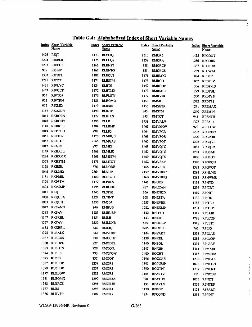
Table G.4: Alphabetized Index of Short Variable NamesIndex Short Variable
Name
1476 RIQT
2294 RIRELR
2293 RIRELT
919 RISLIP
1307 RITDPL
2291 RITOT
1431 RIVLVC
1447 RIVOLT
914 RIVTOP
915 RIVTRN
917 RIXMIX
1187 RKASUR
1043 RKBORN
1048 RKBOUY
1148 RKBREL
1049 RKDPUH
1051 RKEDIS
1052 RKETLT
1042 RKGIN
1149 RKHREL
1294 RKHRMX
1328 RKHSTM
1150 RKIREL
1046 RKLMIX
1151 RKPREL
1329 RKPSTM
1494 RKPUMP
1041 RKQ
1050 RKQCEA
1053 RKQUH
1047 RKSANN
1398 RKSAV
1147 RKSREL
1397 RKTAV
1152 RKXREL
1378 RLBALS
1387 RLBCOS
1380 RLBDPL
1383 RLBDTS
1374 RLBEL
1375 RLBES
1382 RLBLDP
1379 RLBLDR
1197 RLBLOW
1381 RLBQMX
1388 RLBRCS
1377 RLBS
1376 RLBVFR
Index Short Variable Name
1173 RLELIQ
1175 RLELQS
1166 RLENST
1167 RLENTO
1182 RLEQUI
1174 RLESTM
1424 RLETG
1272 RLETMX
1176 RLFLOW
1181 RLHOMO
1179 RLIERR
1490 RL1NIT
1177 RLKFLS
1196 RLLB
1184 RLLBMP
878 RLLIQ
1170 RLMBUB
2566 RLMGAS
877 RLMIX
1168 RLMLIQ
1169 RLMSTM
1171 RLMTOT
876 RLNODE
2364 RLNUP
1180 RLOERR
1172 RLPRES
1195 RLRODE
1245 RLSPIK
1324 RLTINT
1330 RM504
846 RMBUB
1183 RMBUBP
1454 RMLB
1530 RMLDNB
844 RMLIQ
842 RMNODE
830 RMOCHT
827 RMODEL
829 RMOOIL
833 RMOPOW
832 RMOQT
1239 RMORI
1257 RMOR2
1285 RMOR3
1290 RMOR3A
1295 RMOR3B
1298 RMOR4
1309 RMOR5
Index Short Variable Name
1315 RMOR6
1238 RMORA
828 RMORCP
831 RMORCS
1471 RMRLOC
1473 RMROD
1457 RMRODE
1470 RMRSHB
1472 RMRVIB
1453 RMSB
1455 RMSGTR
845 RMSTM
843 RMTOT
1458 RMVALV
1463 RMVMOV
1464 RMVPCR
1461 RMVPOR
1465 RMVPQT
1468 RMVQTC
1467 RMVQTG
1469 RMVQTN
1462 RMVSAF
1466 RMVSPR
1459 RMVUHC
1460 RMVUHQ
1141 RNBOR
907 RNECAN
906 RNENOD
908 RNESTA
1355 RNEVER
1282 RNEXMN
1142 RNHYD
1143 RNIOD
835 RNODEV
2285 RNODFL
1144 RNPART
1139 RNREL
1140 RNSOL
1145 RNXEN
1400 ROCHT
1396 ROCORE
1391 ROPUMP
1390 ROUTPT
1165 RPASTV
920 RPATHV
1191 RPAVLV
1130 RPBOR
1234 RPCOND
Index Short Variable Name
1475 RPCONT
1286 RPCORS
1337 RPCSUR
1289 RPCWAL
1024 RPDER
1062 RPDPLV
1306 RPDPMD
1299 RPDTBL
1300 RPDTSB
1342 RPDTSS
1241 RPEMAX
1240 RPEMIN
945 RPENTH
1327 RPFAIR
922 RPFLOW
1202 RPGCON
1200 RPGPOR
1203 RPGQTI
1081 RPGQT2
1201 RPGSAF
1080 RPGSQT
1320 RPGVCN
1321 RPGVQT
1291 RPHLMU
1288 RPHWMU
1131 RPHYD
1236 RPICRT
1489 RPINIT
1132 RPIOD
1185 RPITER
1231 RPITRP
1319 RPLAIR
1283 RPLCOF
1318 RPLINT
966 RPLIQ
1338 RPLLAS
1281 RPLLOP
1297 RPLREF
1314 RPMAIR
1313 RPMSTM
1230 RPNCAL
1078 RPNCON
1237 RPNCRT
836 RPNODE
1079 RPNQT
1232 RPNTRP
1133 RPPART
1317 RPPINT
WCAP- 15996-NP, Revision 0
I
G-263

Table GA: Alphabetized Index of Short Variable Names
Index Short Variable Name
1082 RPPLOC
1304 RPPMOD
1235 RPPRAN
1341 RPQAXW
1242 RPQCMU
1340 RPQCON
970 RPQUAL
837 RPRESP
838 RPRESS
1129 RPSOL
967 RPSTM
968 RPSVOL
1293 RPTAUR
1254 RPTFLS
1323 RPTINT
1063 RPTREF
1065 RPTRTD
1332 RPTSB
1064 RPTSRG
1339 RPTWAL
1186 RPTYPE
1027 RPUPDN
1233 RPVISC
1199 RPVLV
991 RPVOID
1134 RPXEN
1322 RPXREL
1193 RQAVLV
875 RQCOND
870 RQCONT
1478 RQEDMW
1105 RQENGY
1104 RQENTH
871 • RQEXT
1477 RQGDMW
1481 RQGGWS
1479 RQGRCW
1106 RQLEVL
874 RQLIQ
1111 RQLRUP
1108 RQMGAS
1107 RQMWAT
1113 RQNCON
868 RQNODE
1480 RQPGWS
1352 RQPJ4
1103 RQPRES
1112 RQSOLU
Index Short Variable Name
873 RQSTM
1109 RQTEMP
872 RQTOT
1110 RQTSUR
869 RQWALL
1392 RRIDP
1393 RR2DP
1394 RR3DP
1395 RR4DP
1345 RRADFC
1210 RRADIM
1301 RRADMU
1209 RRADRE
1346 RRAMPS
1221 RRAVIB
1399 RRBORL
1224 RRBREK
1303 RRCFRC
263 RRDD
1039 RRDP
1302 RRDSLO
1222 RRDSPD
1334 RRDTrP
1331 RRFCAV
1451 RRFFRQ
1208 RRFREQ
1449 RRFVLT
1038 RRHEAD
1036 RRHEAT
1225 RRHIVI
1348 RRLCAV
1228 RRLEAK
1226 RRLOCK
1353 RRLTHI
1212 RRPF
264 RRPHD
265 RRPHT
1217 RRQRCP
1211 RRSLIP
1220 RRSMOT
261 RRSPDR
1035 RRSPED
1219 RRSPMP
1312 RRSTAR
1335 RRSTOP
1347 RRSVOL
266 RRSYNC
1215 RRTELE
Index Short Variable Name
1216 RRTFRI
1214 RRTHYD
1037 RRTORQ
1336 RRTRIP
262 RRVFLO
1218 RRVIBR
1333 RRVOID
1207 RRVOLT
1426 RSDCG
1325 RSDCGF
1326 RSDCGM
1274 RSDCMX
1287 RSDPMU
911 RSECT
1356 RSFAIL
1384 RSHAOV
1495 RSINIT
1429 RSISB
1428 RSISE
1427 RSISG
1430 RSITG
1271 RS1TMX
856 RSLIQ
858 RSLIQS
854 RSNODE
1357 RSRECV
1146 RSREL
2365 RSSCON
857 RSSTM
859 RSSTMS
2366 RSSUSE
1013 RSTDN
855 RSTOT
1385 RSTPRE
1351 RTC12B
1492 RTCLIN
867 RTCONT
1249 RTDEL
1252 RTDELT
1406 RTEIN
1402 RTELIQ
1268 RTESRG
1403 RTESTM
1250 RTFDEL
1244 RTFRAC
1405 RTGIN
1243 RTHSMU
1358 RTIMEC
Index Short Variable Name
1359 RTIMSC
862 RTLIQ
1408 RTLMIX
1409 RTLSAT
1413 RTMBUB
1412 RTMLIQ
860 RTNODE
2289 RTOTE
2286 RTOTFL
2287 RTOTHR
2288 RTOTM
1401 RTPRES
1404 RTQUAL
1410 RTQWAL
864 RTSAT
863 RTSTM
866 RTSUBC
1267 RTrMAX
1248 RTTMSC
1261 RTISRG
1411 R"TWAL
431 RTUBES
865 RTWALL
1407 RTXIN
1190 RUAVLV
1090 RUECON
1088 RUEQT
1091 RUETOP
1089 RUGCON
1087 RUGQT
1344 RULORG
1093 RUMNON
1097 RUNCON
1096 RUNDIL
1098 RUNQT
1099 RUPLOC
1095 RUPNON
1343 RUPORG
1255 RUQCMU
1092 RUSTOP
1094 RUVNON
1189 RVAREA
1074 RVEREL
1437 RVFMOV
1438 RVFPC
1435 RVFPOR
1439 RVFPQT
1442 RVFQTC
WCAP-15996-NP, Revision 0 G-264
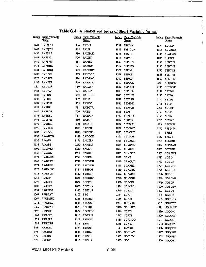
Table G.4: Alphabetized Index of Short Variable NamesIndex Short Variable
Name
1441 RVFQTG
1443 RVFQTN
1436 RVFSAF
1444 RVFSIG
1440 RVFSPR
1433 RVFUHC
1434 RVFUHQ
1486 RVGPZR
1073 RVGREL
1485 RVNPZR
882 RVOIDF
1484 RVOPZR
1085 RVPDN
1432 RVPOS
1487 RVPPZR
1084 RVPUP
1446 RVSPOR
1075 RVSREL
1445 RVSSPR
1077 RVTREL
1076 RVVRLE
1483 RVXPZR
1135 RWAHYD
1136 RWAIO
1137 RWAPT
1192 RWAVLV
1138 RWAXE
1071 RWBAUX
1068 RWBPAT
1277 RWDELH
1070 RWEAUX
1083 RWEBLD
1258 RWEFF
1278 RWEFFI
1280 RWEFF2
1259 RWEFFM
1067 RWEPAT
1069 RWGAUX
1072 RWGBLD
1066 RWGPAT
1491 RWlNIT
1260 RWLEFF
1279 RWLPRS
1284 RWPDEG
988 RXBLED
975 RXCHGS
977 RXDRN
973 RXEXT
Index Short Variable Name
986 RXINT
985 RXLB
980 RXLEAK
976 RXLET
881 RXMIX
971 RXMOM
972 RXNMOM
879 RXNODE
984 RXORNG
969 RXPATH
989 RXPZRR
974 RXRCP
983 RXRODE
982 RXSB
978 RXSDC
981 RXSGTR
979 RXSIS
987 RXSPRA
880 RXTOT
990 RXUHR
1888 SADEG
1890 SADFUL
1889 SADGOP
1891 SADZER
2280 SAREA3
1850 SASEPT
1901 SASUBE
1797 SBBDM
1791 SBDVDH
1792 SBDVDP
1814 SBEBOT
1812 SBENTH
1831 SBEOUT
1832 SBEREL
1830 SBESNK
1813 SBESUR
1809 SBG
1811 SBGBOT
1828 SBGOUT
1829 SBGREL
1827 SBGSNK
1810 SBGSUR
1817 SBIBOT
1815 SBIO
1834 SBIOUT
1835 SBIREL
1833 SBISNK
1816 SBISUR
Index Short Variable Name
1788 SBITNK
1845 SBMODF
1543 SBOTP
1518 SBPAR
1820 SBPBOT
1517 SBPDAT
1522 SBPDZ
1521 SBPKE
1520 SBPKG
1519 SBPLOD
1837 SBPOUT
1838 SBPREL
1843 SBPROT
1842 SBPRSN
1836 SBPSNK
1819 SBPSUR
1818 SBPT
1789 SBPTNK
1802 SBSVG
1804 SBTWAL
1808 SBVBOT
1825 SBVOUT
1806 SBVPOS
1826 SBVREL
1824 SBVSNK
1807 SBVSUR
1823 SBXBOT
1821 SBXE
1840 SBXOUT
1841 SBXREL
1839 SBXSNK
1822 SBXSUR
1790 SBXTNK
1550 SCBORI
1551 SCBOR2
1549 SCEX2
1544 SCIOI
1545 SCIO2
1903 SCNVRG
1870 SCOLDT
1546 SCPTI
1547 SCPT2
1881 SCRMOD
1548 SCXEI
11 SDATE
2273 SDELAY
1552 SDELTV
1553 SDP
Index Short Variable Name
1554 SDVDP
1858 SDVREC
1786 SEAFWS
1896 SECON
1555 SENTHI
1556 SENTH2
1557 SENTH3
1558 SENTH4
1559 SENTHS
565 SEQNCE
2195 SETDDT
2198 SETDM
2197 SETDP
2194 SETDT
2196 SETP
2201 SETRT
2193 SEMT
2199 SETW
2200 SETWD
403 SFCONI
1865 SFDMIN
8 SFILE
1852 SFK3T
1904 SFLUIE
1854 SFPMAX
1853 SFr1ME
2507 SGAFWS
1787 SGBD
1793 SGBDH
1794 SGBDHF
1795 SGBDHG
1796 SGBDL
1798 SGBDML
1799 SGBDP
1800 SGBDSV
1803 SGBDT
1805 SGBDX
1632 SGCHOK
432 SGMTCP
1785 SGNAFW
1499 SGQDH
1500 SGQDW
1501 SGQLH
1502 SGQLW
1498 SGQNNS
1497 SGQNSE
1508 SGQNSS
1509 SGQOPT
WCAP- 15996-NP, Revision 0
I
I
G-265
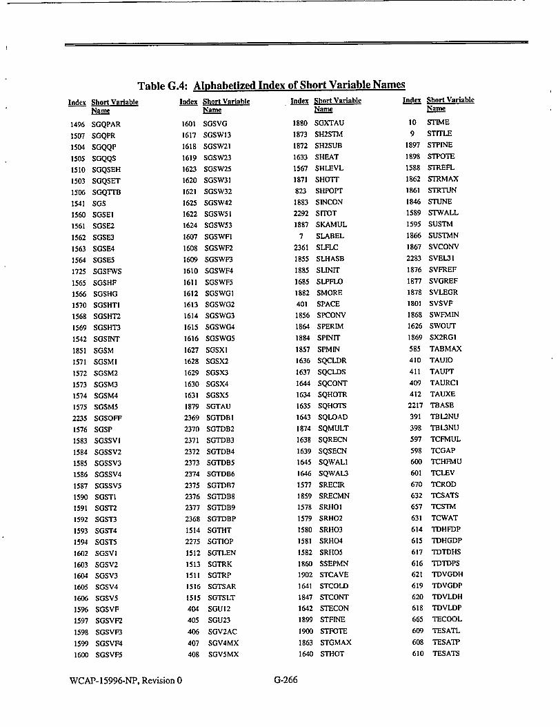
Table G.4: Alphabetized Index of Short Variable Names
Index Short Variable Name
1496 SGQPAR
1507 SGQPR
1504 SGQQP
1505 SGQQS
1510 SGQSEH
1503 SGQSET
1506 SGQTrB
1541 SGS
1560 SGSEI
1561 SGSE2
1562 SGSE3
1563 SGSE4
1564 SGSE5
1725 SGSFWS
1565 SGSHF
1566 SGSHG
1570 SGSHTI
1568 SGSHT2
1569 SGSHT3
1542 SGSINT
1851 SGSM
1571 SGSMI
1572 SGSM2
1573 SGSM3
1574 SGSM4
1575 SGSM5
2235 SGSOFF
1576 SGSP
1583 SGSSVI
1584 SGSSV2
1585 SGSSV3
1586 SGSSV4
1587 SGSSV5
1590 SGSTI
1591 SGST2
1592 SGST3
1593 SGST4
1594 SGST5
1602 SGSVI
1603 SGSV2
1604 SGSV3
1605 SGSV4
1606 SGSV5
1596 SGSVF
1597 SGSVF2
1598 SGSVF3
1599 SGSVF4
1600 SGSVF5
Index Short Variable Name
1601 SGSVG
1617 SGSWI3
1618 SGSW21
1619 SGSW23
1623 SGSW25
1620 SGSW31
1621 SGSW32
1625 SGSW42
1622 SGSW51
1624 SGSW53
1607 SGSWFI
1608 SGSWF2
1609 SGSWF3
1610 SGSWF4
1611 SGSWF5
1612 SGSWGI
1613 SGSWG2
1614 SGSWG3
1615 SGSWG4
1616 SGSWG5
1627 SGSXI
1628 SGSX2
1629 SGSX3
1630 SGSX4
1631 SGSX5
1879 SGTAU
2369 SGTDB1
2370 SGTDB2
2371 SGTDB3
2372 SGTDB4
2373 SGTDB5
2374 SGTDB6
2375 SGTDB7
2376 SGTDB8
2377 SGTDB9
2368 SGTDBP
1514 SGTHT
2275 SGTIOP
1512 SGTLEN
1513 SGTRK
1511 SGTRP
1516 SGTSAR
1515 SGTSLT
404 SGU12
405 SGU23
406 SGV2AC
407 SGV4MX
408 SGV5MX
Index Short Variable Name
1880 SGXTAU
1873 SH2STM
1872 SH2SUB
1633 SHEAT
1567 SHLEVL
1871 SHOTT
823 SHPOPT
1883 SINCON
2292 SITOT
1887 SKAMUL
7 SLABEL
2361 SLFLC
1855 SLHASB
1885 SLIN1T
1685 SLPFLO
1882 SMORE
401 SPACE
1856 SPCONV
1864 SPERIM
1884 SPINIT
1857 SPMIN
1636 SQCLDR
1637 SQCLDS
1644 SQCONT
1634 SQHOTR
1635 SQHOTS
1643 SQLOAD
1874 SQMULT
1638 SQRECN
1639 SQSECN
1645 SQWALI
1646 SQWAL3
1577 SRECIR
1859 SRECMN
1578 SRHOI
1579 SRHO2
1580 SRHO3
1581 SRHO4
1582 SRHO5
1860 SSEPMN
1902 STCAVE
1641 STCOLD
1847 STCONT
1642 STECON
1899 STFINE
1900 STFOTE
1863 STGMAX
1640 STHOT
Index Short Variable Name
10 STIME
9 STITLE
1897 STPINE
1898 STPOTE
1588 STREFL
1862 STRMAX
1861 STRTUN
1846 STUNE
1589 STWALL
1595 SUSTM
1866 SUSTMN
1867 SVCONV
2283 SVEL31
1876 SVFREF
1877 SVGREF
1878 SVLEGR
1801 SVSVF
1868 SWFMIN
1626 SWOUT
1869 SX2RGI
585 TABMAX
410 TAUIO
411 TAUPT
409 TAURCI
412 TAUXE
2217 TBASE
391 TBL2NU
398 TBL3NU
597 TCFMUL
598 TCGAP
600 TCHFMU
601 TCLEV
670 TCROD
632 TCSATS
657 TCSTM
631 TCWAT
614 TDHFDP
615 TDHGDP
617 TDTDHS
616 TDTDPS
621 TDVGDH
619 TDVGDP
620 TDVLDH
618 TDVLDP
665 TECOOL
609 TESATL
608 TESATP
610 TESATS
WCAP- 15996-NP, Revision 0 G-266

Table G.4: Alphabetized Index of Short Variable NamesIndex Short Variable
Name
603 TFHTGN
641 TFLASH
659 TFLUX
602 TGAPIN
653 TGSTMB
649 THFB
639 THNB
658 THSTM
640 THSUB
656 TIHT
2218 TIME
2222 TIMQUE
654 TKGAP
669 TKROD
627 TKSATS
626 TKSTM
625 TKWAT
634 TLBOIL
642 TLMIXL
430 TMPTBL
16 TNMAXL
17 TNPROP
629 TPRSTM
630 TPRSTS
628 TPRWAT
599 TPSPCR
643 TQAVE
661 TQAXIL
635 TQCRIT
650 TQDNB
662 TQLIQ
663 TQSTM
655 TQZRWA
667 TRADEX
861 TRTOT
2219 TSCALE
611 TSSATL
612 TSSATS
1386 TSTLST
2220 TSTOP
666 TrCOOL
638 TrCRIT
648 ITCROS
637 TTERM2
636 TFERMT
644 "TFUEL
651 TTNBFC
668 'ITROD
Index Short Variable Name
613 TISAT
660 TISURF
268 TrWIFR
624 TUSATS
623 TUSTM
622 TUWAT
647 TXFC
568 UNUSED
2272 USR
2282 V3MULT
396 V3TBI
397 V3TB2
395 V3TBL
2358 VBMISC
447 VELIOO
910 VOLMIX
413 VOLSGS
389 VS'I"BI
390 VSMTB2
388 VSTIBL
415 W32FLC
2276 WARNOP
466 WFWIOO
797 XDISP
195 XNEGUP
802 XOFFAV
800 XOFFST
194 XPOSUP
799 XPOWER
798 XPOWRD
801 XPWRAV
566 XTAB
803 XTCONS
567 YTAB
93 ZANN
193 ZINUP
192 ZOUTUP
95 ZSECVA
822 ZSHPIN
WCAP-15996-NP, Revision 0
I
I
G-267