PAPER SOLUTION - WordPress.com
14
PAPER SOLUTION SESSIONAL 2 Microprocessor & Microcontroller 2018-19 - Department of Electronics & Telecommunication Engineering ST. VINCENT PALLOTTI COLLEGE OF ENGINEERING & TECHNOLOGY
-
Upload
khangminh22 -
Category
Documents
-
view
5 -
download
0
Transcript of PAPER SOLUTION - WordPress.com
PAPER SOLUTION
SESSIONAL 2
Microprocessor & Microcontroller
2018-19-
Department of Electronics & Telecommunication EngineeringST. VINCENT PALLOTTI COLLEGE OF ENGINEERING & TECHNOLOGY
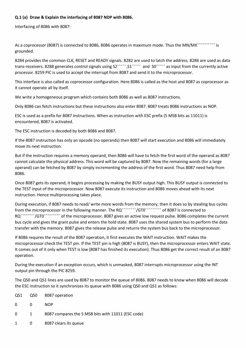
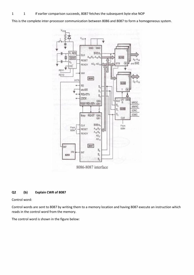
Q.1 (a) Draw & Explain the interfacing of 8087 NDP with 8086.
Interfacing of 8086 with 8087:
As a coprocessor (8087) is connected to 8086, 8086 operates in maximum mode. Thus the MN/MX¯¯¯¯¯¯¯¯¯¯ isgrounded.
8284 provides the common CLK, RESET and READY signals. 8282 are used to latch the address. 8286 are used as datatrans-receivers. 8288 generates control signals using S2¯¯¯¯¯,S1¯¯¯¯¯ and S0¯¯¯¯¯ as input from the currently activeprocessor. 8259 PIC is used to accept the interrupt from 8087 and send it to the microprocessor.
This interface is also called as coprocessor configuration. Here 8086 is called as the host and 8087 as coprocessor asit cannot operate all by itself.
We write a homogeneous program which contains both 8086 as well as 8087 instructions.
Only 8086 can fetch instructions but these instructions also enter 8087. 8087 treats 8086 instructions as NOP.
ESC is used as a prefix for 8087 instructions. When as instruction with ESC prefix (5 MSB bits as 11011) isencountered, 8087 is activated.
The ESC instruction is decoded by both 8086 and 8087.
If the 8087 instruction has only an opcode (no operands) then 8087 will start execution and 8086 will immediatelymove its next instruction.
But if the instruction requires a memory operand, then 8086 will have to fetch the first word of the operand as 8087cannot calculate the physical address. This word will be captured by 8087. Now the remaining words (for a largeoperand) can be fetched by 8087 by simply incrementing the address of the first word. Thus 8087 need help from8086.
Once 8087 gets its operand, it begins processing by making the BUSY output high. This BUSY output is connected tothe TEST input of the microprocessor. Now 8087 execute its instruction and 8086 moves ahead with its nextinstruction. Hence multiprocessing takes place.
During execution, if 8087 needs to read/ write more words from the memory, then it does so by stealing bus cyclesfrom the microprocessor in the following manner. The RQ¯¯¯¯¯¯¯¯/GT0¯¯¯¯¯¯¯¯¯ of 8087 is connected toRQ¯¯¯¯¯¯¯¯/GT0¯¯¯¯¯¯¯¯¯ of the microprocessor. 8087 gives an active low request pulse. 8086 completes the currentbus cycle and gives the grant pulse and enters the hold state. 8087 uses the shared system bus to perform the datatransfer with the memory. 8087 gives the release pulse and returns the system bus back to the microprocessor.
If 8086 requires the result of the 8087 operation, it first executes the WAIT instruction. WAIT makes themicroprocessor check the TEST pin. If the TEST pin is high (8087 is BUSY), then the microprocessor enters WAIT state.It comes out of it only when TEST is low (8087 has finished its execution). Thus 8086 get the correct result of an 8087operation.
During the execution if an exception occurs, which is unmasked, 8087 interrupts microprocessor using the INToutput pin through the PIC 8259.
The QS0 and QS1 lines are used by 8087 to monitor the queue of 8086. 8087 needs to know when 8086 will decodethe ESC instruction so it synchronizes its queue with 8086 using QS0 and QS1 as follows:
QS1 QS0 8087 operation
0 0 NOP
0 1 8087 compares the 5 MSB bits with 11011 (ESC code)
1 0 8087 clears its queue
1 1 If earlier comparison succeeds, 8087 fetches the subsequent byte else NOP
This is the complete inter-processor communication between 8086 and 8087 to form a homogeneous system.
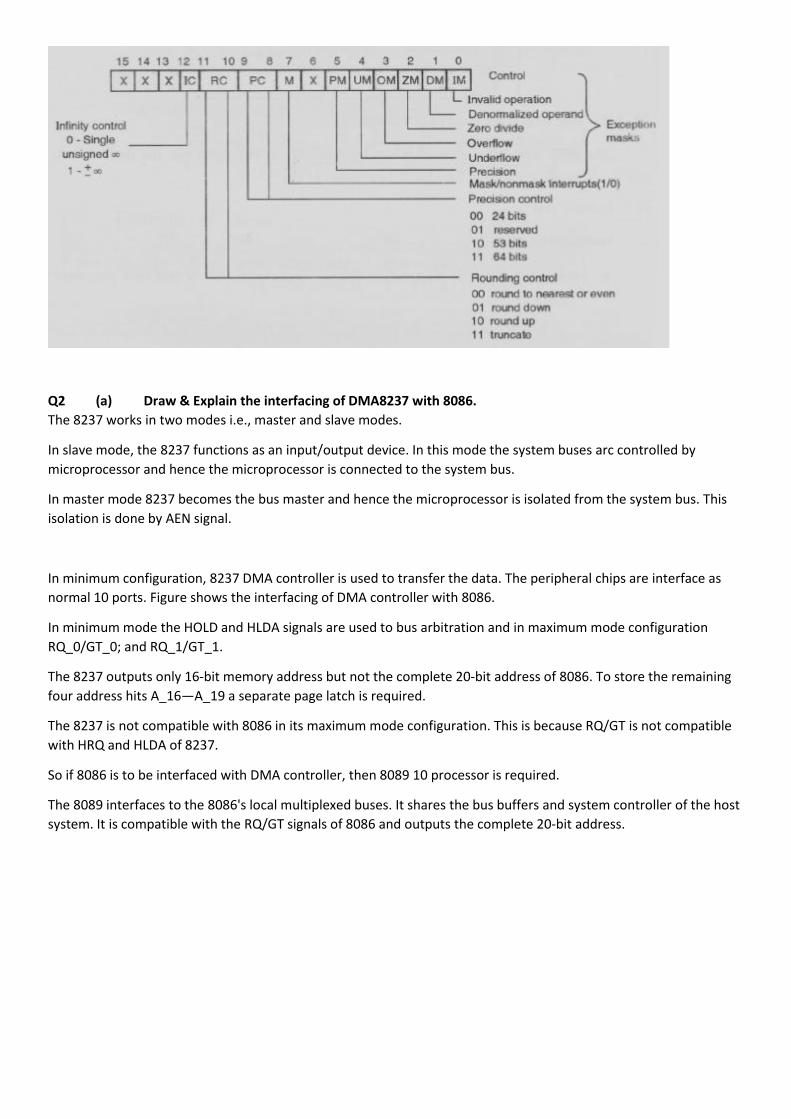
Q2 (b) Explain CWR of 8087
Control word:
Control words are sent to 8087 by writing them to a memory location and having 8087 execute an instruction whichreads in the control word from the memory.
The control word is shown in the figure below:
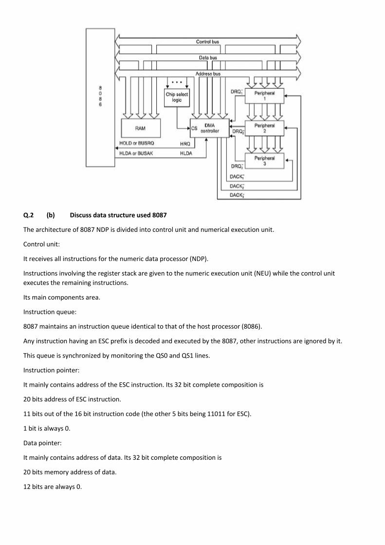
Q2 (a) Draw & Explain the interfacing of DMA8237 with 8086.The 8237 works in two modes i.e., master and slave modes.
In slave mode, the 8237 functions as an input/output device. In this mode the system buses arc controlled bymicroprocessor and hence the microprocessor is connected to the system bus.
In master mode 8237 becomes the bus master and hence the microprocessor is isolated from the system bus. Thisisolation is done by AEN signal.
In minimum configuration, 8237 DMA controller is used to transfer the data. The peripheral chips are interface asnormal 10 ports. Figure shows the interfacing of DMA controller with 8086.
In minimummode the HOLD and HLDA signals are used to bus arbitration and in maximum mode configurationRQ_0/GT_0; and RQ_1/GT_1.
The 8237 outputs only 16-bit memory address but not the complete 20-bit address of 8086. To store the remainingfour address hits A_16—A_19 a separate page latch is required.
The 8237 is not compatible with 8086 in its maximum mode configuration. This is because RQ/GT is not compatiblewith HRQ and HLDA of 8237.
So if 8086 is to be interfaced with DMA controller, then 8089 10 processor is required.
The 8089 interfaces to the 8086's local multiplexed buses. It shares the bus buffers and system controller of the hostsystem. It is compatible with the RQ/GT signals of 8086 and outputs the complete 20-bit address.
Q.2 (b) Discuss data structure used 8087
The architecture of 8087 NDP is divided into control unit and numerical execution unit.
Control unit:
It receives all instructions for the numeric data processor (NDP).
Instructions involving the register stack are given to the numeric execution unit (NEU) while the control unitexecutes the remaining instructions.
Its main components area.
Instruction queue:
8087 maintains an instruction queue identical to that of the host processor (8086).
Any instruction having an ESC prefix is decoded and executed by the 8087, other instructions are ignored by it.
This queue is synchronized by monitoring the QS0 and QS1 lines.
Instruction pointer:
It mainly contains address of the ESC instruction. Its 32 bit complete composition is
20 bits address of ESC instruction.
11 bits out of the 16 bit instruction code (the other 5 bits being 11011 for ESC).
1 bit is always 0.
Data pointer:
It mainly contains address of data. Its 32 bit complete composition is
20 bits memory address of data.
12 bits are always 0.
Q.3 (a) Explain any 3 special function register of 8051.
List of 8051 Microcontroller Special Function Registers
A or ACC
B
DPL
DPH
IE
IP
P0
P1
P2
P3
PCON
PSW
SCON
SBUF
SP
TMOD
TCON
TL0
TH0
TL1
TH1
A or Accumulator (ACC)
The Accumulator or Register A is the most important and most used 8051 Microcontroller SFRs. The Register A islocated at the address E0H in the SFR memory space. The Accumulator is used to hold the data for almost all the ALUOperations.
Some of the operations where the Accumulator is used are:
Arithmetic Operations like Addition, Subtraction, Multiplication etc.
Logical Operations like AND, OR, NOT etc.
Data Transfer Operations (between 8051 and External Memory)
The name “Accumulator” came from the fact this register is used to accumulate (or store) the result of all Arithmeticand most of the Logical Operations.
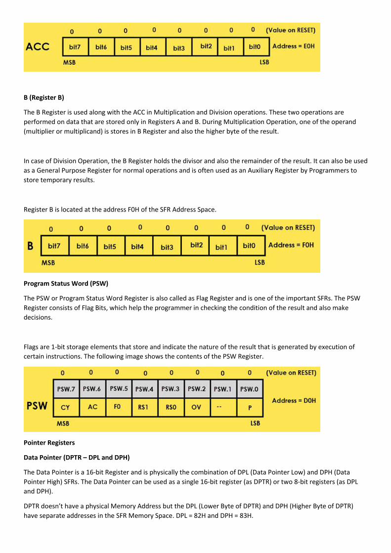
B (Register B)
The B Register is used along with the ACC in Multiplication and Division operations. These two operations areperformed on data that are stored only in Registers A and B. During Multiplication Operation, one of the operand(multiplier or multiplicand) is stores in B Register and also the higher byte of the result.
In case of Division Operation, the B Register holds the divisor and also the remainder of the result. It can also be usedas a General Purpose Register for normal operations and is often used as an Auxiliary Register by Programmers tostore temporary results.
Register B is located at the address F0H of the SFR Address Space.
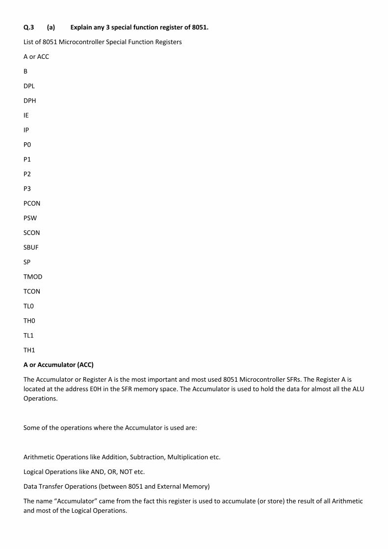
Program Status Word (PSW)
The PSW or Program Status Word Register is also called as Flag Register and is one of the important SFRs. The PSWRegister consists of Flag Bits, which help the programmer in checking the condition of the result and also makedecisions.
Flags are 1-bit storage elements that store and indicate the nature of the result that is generated by execution ofcertain instructions. The following image shows the contents of the PSW Register.
Pointer Registers
Data Pointer (DPTR – DPL and DPH)
The Data Pointer is a 16-bit Register and is physically the combination of DPL (Data Pointer Low) and DPH (DataPointer High) SFRs. The Data Pointer can be used as a single 16-bit register (as DPTR) or two 8-bit registers (as DPLand DPH).
DPTR doesn’t have a physical Memory Address but the DPL (Lower Byte of DPTR) and DPH (Higher Byte of DPTR)have separate addresses in the SFR Memory Space. DPL = 82H and DPH = 83H.
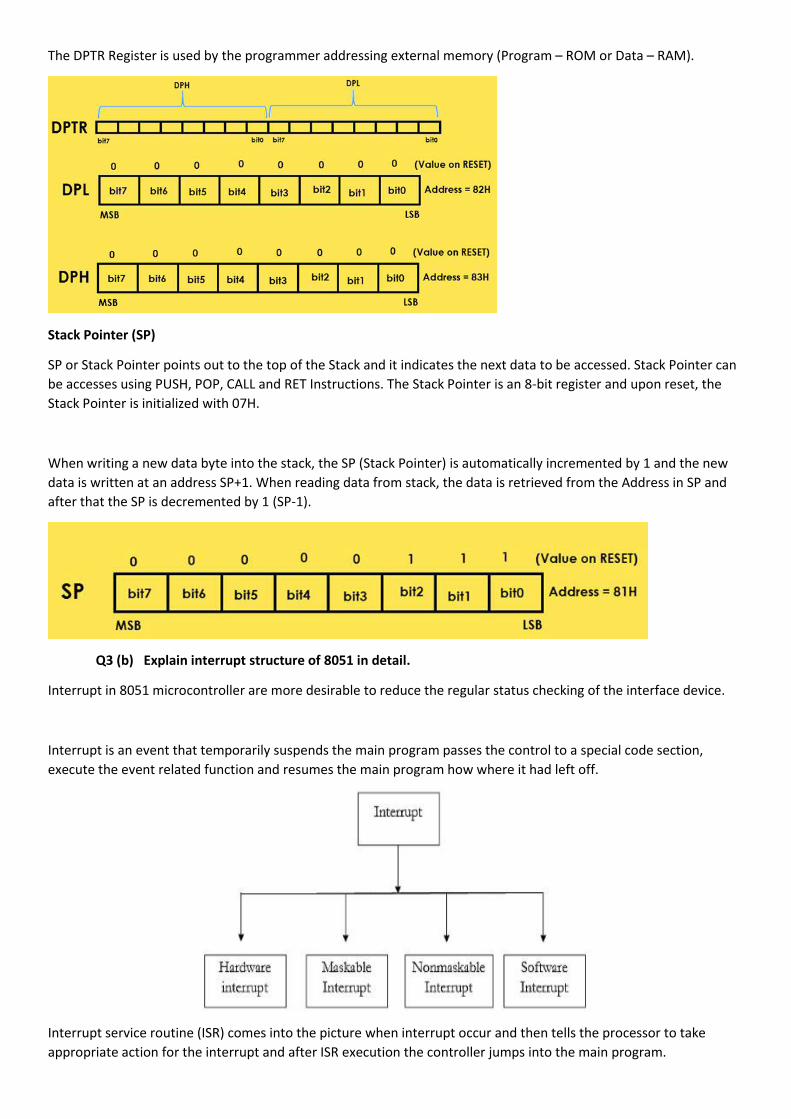
The DPTR Register is used by the programmer addressing external memory (Program – ROM or Data – RAM).
Stack Pointer (SP)
SP or Stack Pointer points out to the top of the Stack and it indicates the next data to be accessed. Stack Pointer canbe accesses using PUSH, POP, CALL and RET Instructions. The Stack Pointer is an 8-bit register and upon reset, theStack Pointer is initialized with 07H.
When writing a new data byte into the stack, the SP (Stack Pointer) is automatically incremented by 1 and the newdata is written at an address SP+1. When reading data from stack, the data is retrieved from the Address in SP andafter that the SP is decremented by 1 (SP-1).
Q3 (b) Explain interrupt structure of 8051 in detail.
Interrupt in 8051 microcontroller are more desirable to reduce the regular status checking of the interface device.
Interrupt is an event that temporarily suspends the main program passes the control to a special code section,execute the event related function and resumes the main program how where it had left off.
Interrupt service routine (ISR) comes into the picture when interrupt occur and then tells the processor to takeappropriate action for the interrupt and after ISR execution the controller jumps into the main program.
In 8051, five type of interrupt
Timer 0 overflow interrupt -> TF0
Timer 1 overflow interrupt -> TF1
External hardware interrupt -> INT0
External hardware interrupt -> INT1
Serial communication interrupt -> RI/TI
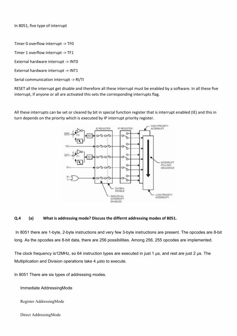
RESET all the interrupt get disable and therefore all these interrupt must be enabled by a software. In all these fiveinterrupt, if anyone or all are activated this sets the corresponding interrupts flag.
All these interrupts can be set or cleared by bit in special function register that is interrupt enabled (IE) and this inturn depends on the priority which is executed by IP interrupt priority register.
Q.4 (a) What is addressing mode? Discuss the differnt addressing modes of 8051.
In 8051 there are 1-byte, 2-byte instructions and very few 3-byte instructions are present. The opcodes are 8-bit
long. As the opcodes are 8-bit data, there are 256 possibilities. Among 256, 255 opcodes are implemented.
The clock frequency is12MHz, so 64 instruction types are executed in just 1 µs, and rest are just 2 µs. The
Multiplication and Division operations take 4 µsto to execute.
In 8051 There are six types of addressing modes.
Immediate AddressingMode
Register AddressingMode
Direct AddressingMode
Register IndirectAddressing Mode
Indexed AddressingMode
Implied AddressingMode
Immediate addressing mode
In this Immediate Addressing Mode, the data is provided in the instruction itself. The data is provided immediately after the
opcode. These are some examples of Immediate Addressing Mode.
MOVA, #0AFH;
MOVR3, #45H;
MOVDPTR, #FE00H;
In these instructions, the # symbol is used for immediate data. In the last instruction, there is DPTR. The DPTR stands for
Data Pointer. Using this, it points the external data memory location. In the first instruction, the immediate data is AFH, but
one 0 is added at the beginning. So when the data is starting with A to F, the data should be preceded by 0.
Register addressing mode
In the register addressing mode the source or destination data should be present in a register (R0 to R7). These are some
examples of RegisterAddressing Mode.
MOVA, R5;
MOVR2, #45H;
MOVR0, A;
In 8051, there is no instruction likeMOVR5, R7. But we can get the same result by using this instructionMOV R5, 07H,
or by usingMOV 05H, R7. But this two instruction will work when the selected register bank is RB0. To use another
register bank and to get the same effect, we have to add the starting address of that register bank with the register number.
For an example, if the RB2 is selected, and we want to access R5, then the address will be (10H + 05H = 15H), so the
instruction will look like thisMOV 15H, R7. Here 10H is the starting address of Register Bank 2.
Direct Addressing Mode
In the Direct Addressing Mode, the source or destination address is specified by using 8-bit data in the instruction. Only the
internal data memory can be used in this mode. Here some of the examples of direct Addressing Mode.
MOV80H, R6;
MOVR2, 45H;
MOVR0, 05H;
The first instruction will send the content of registerR6 to port P0 (Address of Port 0 is 80H). The second one is forgetting
content from 45H to R2. The third one is used to get data from Register R5 (When register bank RB0 is selected) to register
R5.
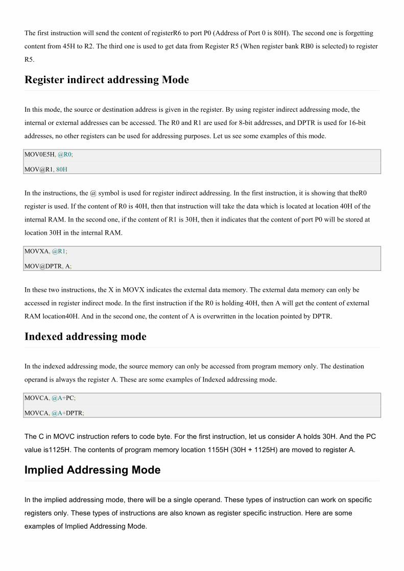
Register indirect addressing Mode
In this mode, the source or destination address is given in the register. By using register indirect addressing mode, the
internal or external addresses can be accessed. The R0 and R1 are used for 8-bit addresses, and DPTR is used for 16-bit
addresses, no other registers can be used for addressing purposes. Let us see some examples of this mode.
MOV0E5H, @R0;
MOV@R1, 80H
In the instructions, the @ symbol is used for register indirect addressing. In the first instruction, it is showing that theR0
register is used. If the content of R0 is 40H, then that instruction will take the data which is located at location 40H of the
internal RAM. In the second one, if the content of R1 is 30H, then it indicates that the content of port P0 will be stored at
location 30H in the internal RAM.
MOVXA, @R1;
MOV@DPTR, A;
In these two instructions, the X in MOVX indicates the external data memory. The external data memory can only be
accessed in register indirect mode. In the first instruction if the R0 is holding 40H, then A will get the content of external
RAM location40H. And in the second one, the content of A is overwritten in the location pointed by DPTR.
Indexed addressing mode
In the indexed addressing mode, the source memory can only be accessed from program memory only. The destination
operand is always the register A. These are some examples of Indexed addressing mode.
MOVCA, @A+PC;
MOVCA, @A+DPTR;
The C in MOVC instruction refers to code byte. For the first instruction, let us consider A holds 30H. And the PC
value is1125H. The contents of program memory location 1155H (30H + 1125H) are moved to register A.
Implied Addressing Mode
In the implied addressing mode, there will be a single operand. These types of instruction can work on specific
registers only. These types of instructions are also known as register specific instruction. Here are some
examples of Implied Addressing Mode.
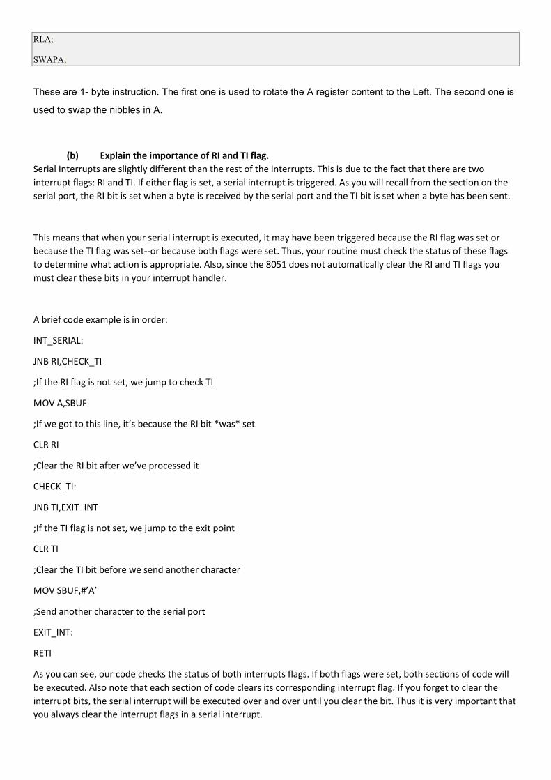
RLA;
SWAPA;
These are 1- byte instruction. The first one is used to rotate the A register content to the Left. The second one is
used to swap the nibbles in A.
(b) Explain the importance of RI and TI flag.Serial Interrupts are slightly different than the rest of the interrupts. This is due to the fact that there are twointerrupt flags: RI and TI. If either flag is set, a serial interrupt is triggered. As you will recall from the section on theserial port, the RI bit is set when a byte is received by the serial port and the TI bit is set when a byte has been sent.
This means that when your serial interrupt is executed, it may have been triggered because the RI flag was set orbecause the TI flag was set--or because both flags were set. Thus, your routine must check the status of these flagsto determine what action is appropriate. Also, since the 8051 does not automatically clear the RI and TI flags youmust clear these bits in your interrupt handler.
A brief code example is in order:
INT_SERIAL:
JNB RI,CHECK_TI
;If the RI flag is not set, we jump to check TI
MOV A,SBUF
;If we got to this line, it’s because the RI bit *was* set
CLR RI
;Clear the RI bit after we’ve processed it
CHECK_TI:
JNB TI,EXIT_INT
;If the TI flag is not set, we jump to the exit point
CLR TI
;Clear the TI bit before we send another character
MOV SBUF,#’A’
;Send another character to the serial port
EXIT_INT:
RETI
As you can see, our code checks the status of both interrupts flags. If both flags were set, both sections of code willbe executed. Also note that each section of code clears its corresponding interrupt flag. If you forget to clear theinterrupt bits, the serial interrupt will be executed over and over until you clear the bit. Thus it is very important thatyou always clear the interrupt flags in a serial interrupt.
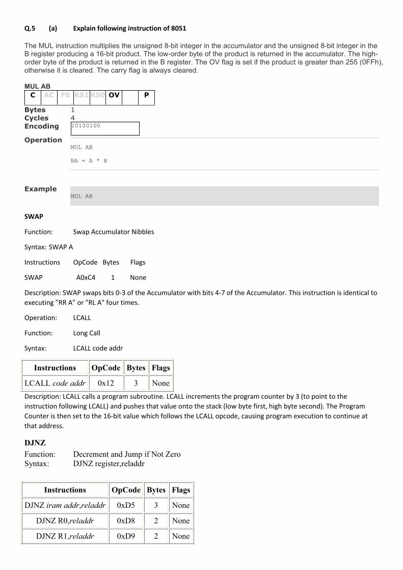
Q.5 (a) Explain following instruction of 8051
The MUL instruction multiplies the unsigned 8-bit integer in the accumulator and the unsigned 8-bit integer in theB register producing a 16-bit product. The low-order byte of the product is returned in the accumulator. The high-order byte of the product is returned in the B register. The OV flag is set if the product is greater than 255 (0FFh),otherwise it is cleared. The carry flag is always cleared.
MUL ABC AC F0 RS1RS0 OV P
Bytes 1Cycles 4Encoding 10100100
OperationMUL AB
BA = A * B
ExampleMUL AB
SWAP
Function: Swap Accumulator Nibbles
Syntax: SWAP A
Instructions OpCode Bytes Flags
SWAP A0xC4 1 None
Description: SWAP swaps bits 0-3 of the Accumulator with bits 4-7 of the Accumulator. This instruction is identical toexecuting "RR A" or "RL A" four times.
Operation: LCALL
Function: Long Call
Syntax: LCALL code addr
Instructions OpCode Bytes Flags
LCALL code addr 0x12 3 NoneDescription: LCALL calls a program subroutine. LCALL increments the program counter by 3 (to point to theinstruction following LCALL) and pushes that value onto the stack (low byte first, high byte second). The ProgramCounter is then set to the 16-bit value which follows the LCALL opcode, causing program execution to continue atthat address.
DJNZFunction: Decrement and Jump if Not ZeroSyntax: DJNZ register,reladdr
Instructions OpCode Bytes Flags
DJNZ iram addr,reladdr 0xD5 3 None
DJNZ R0,reladdr 0xD8 2 None
DJNZ R1,reladdr 0xD9 2 None
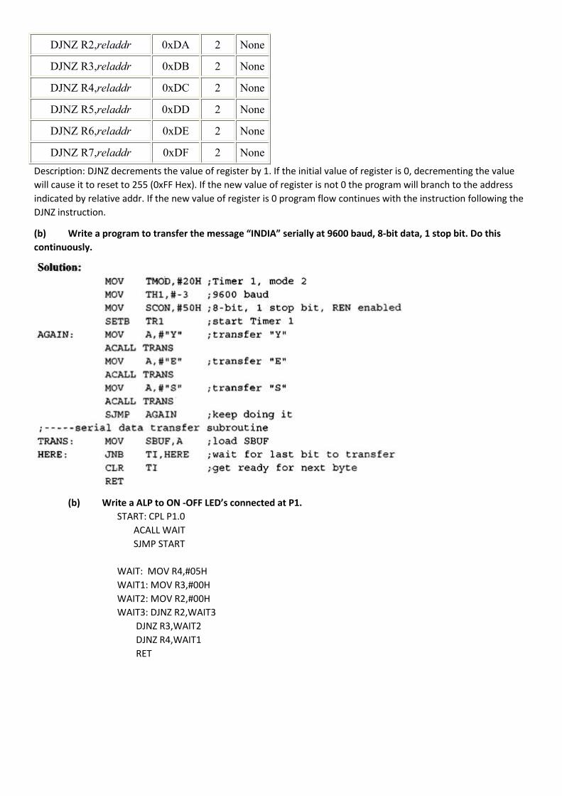
DJNZ R2,reladdr 0xDA 2 None
DJNZ R3,reladdr 0xDB 2 None
DJNZ R4,reladdr 0xDC 2 None
DJNZ R5,reladdr 0xDD 2 None
DJNZ R6,reladdr 0xDE 2 None
DJNZ R7,reladdr 0xDF 2 NoneDescription: DJNZ decrements the value of register by 1. If the initial value of register is 0, decrementing the valuewill cause it to reset to 255 (0xFF Hex). If the new value of register is not 0 the program will branch to the addressindicated by relative addr. If the new value of register is 0 program flow continues with the instruction following theDJNZ instruction.
(b) Write a program to transfer the message “INDIA” serially at 9600 baud, 8-bit data, 1 stop bit. Do thiscontinuously.
(b) Write a ALP to ON -OFF LED’s connected at P1.START: CPL P1.0
ACALL WAITSJMP START
WAIT: MOV R4,#05HWAIT1: MOV R3,#00HWAIT2: MOV R2,#00HWAIT3: DJNZ R2,WAIT3
DJNZ R3,WAIT2DJNZ R4,WAIT1RET