Paint Test Equipment - TEKNOCORR
64
Paint Test Equipment Paint Inspection Kit Data Sheet / Instructions
-
Upload
khangminh22 -
Category
Documents
-
view
1 -
download
0
Transcript of Paint Test Equipment - TEKNOCORR

Paint Test Equipment
Paint Inspection Kit
Data Sheet / Instructions

Information
The Paint Inspection Kit offers the industrial painter all the essential equipment needed for the testing of blast-cleaned steel prior to the protective coating application. When steel has been blast-cleaned to a surface preparation of Sa 2½, the inspection of the steel to ISO Standards is required. This ISO Standard compliance ensures that blast-cleaned steel is correctly prepared for the application of protective coatings.
Poor preparation of blast-cleaned steel could result in corrosion of the steel and poor adhesion of the protective coating, resulting in coating failure. Prevention of corrosion on steel is essential to ensure the long life and low maintenance of steel assets and the reduction of shutdown for expensive maintenance work. The Calibration Certificate with traceability to UKAS is an optional extra. The Certificate is supplied as hard copy and is available online through the Calibration Management Cloud (under Calibration) on our website.
Paint Inspection Kit

Paint Inspection Kit Specifications and Spares
Part No Metric/Imperial Cal Cert Part No
Conformance Cert Part No
K3001 Paint Inspection Kit Metric NK002
F2001 Spare Calibration Foils 0–1000µm (25, 50, 75, 125, 175, 250, 500, 750µm) NC002
Z1003 Spare Zero Disk Ferrous
R1002 Spare Testex Tape X Coarse (50 impressions) 40–115µm (1.5–4.5mils) NRC02
PS001 Spare Bresle Patches (pack of 50) Standard Adhesion NPC04
PS003 Spare Deionised Water (500ml)
PS004 Spare Syringes (pack of 3)
PS005 Spare Conductivity Meter Calibration Solution NP001
PS006 Spare Conductivity Meter Sensor
PS006 Spare 25ml Beaker
PS201 Spare Dust Test Tape 25mm (1”) 60m Roll NPC05
PS202 Spare Dust Test Comparator Charts (pack of 50) NPC06
HS301 Spare Humidity Sensor 0–100%rh/-10 to 70°C (14 to 160°F) NH101
HS302 Spare Surface Temperature Probe -20 to 80°C (-4 to 176°F) NH102
Paint Inspection Kit
The equipment supplied in the Paint Inspection Kit will enable on-site testing for all five stages of blast-cleaned steel and coating inspection in the following stages: Stage 1 (ISO 8503-5). Surface Profile measurement of the blasted profile. Stage 2 (ISO 8502-6, ISO 8502-9). Surface Cleanliness testing for water-soluble salts and corrosion products. Stage 3 (ISO 8502-3). Surface Cleanliness assessment for the quantity and size of dust particles. Stage 4 (ISO 8502-4). Climatic Conditions for the estimation of the probability of condensation. Stage 5 (ISO 2808, ISO 19840). Coating Thickness measurement to ensure the correct coating thickness has been applied.

Paint Inspection Kit
Stage 1 Surface Profile
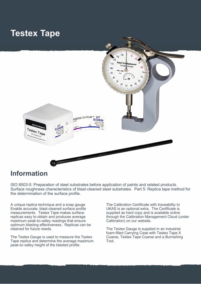
ISO 8503-5: Preparation of steel substrates before application of paints and related products. Surface roughness characteristics of blast-cleaned steel substrates. Part 5: Replica tape method for the determination of the surface profile.
Testex Tape (R1002) & Testex Gauge (R1004)
A unique replica technique produces accurate, blast-cleaned surface profile measurements that ensures optimum blasting effectiveness. Packing: Testex Tape X Coarse (50 impression roll), Testex Gauge and Burnishing Tool.

Paint Inspection Kit
Stage 2 Surface Cleanliness
ISO 8502-6: Preparation of steel substrates before application of paints and related products. Tests for the assessment of surface cleanliness. Part 6: Extraction of soluble contaminants for analysis. The Bresle method. ISO 8502-9: Preparation of steel substrates before application of paints and related products. Tests for the assessment of surface cleanliness. Part 9: Field method for the conductometric determination of water-soluble salts.
Bresle Test (P2005)
Blast-cleaned steel can be contaminated by water-soluble salts and corrosion products. If they are not removed prior to painting, chemical reactions can result in blister formation and accumulations of rust that destroy the adhesion between the substrate and the applied protective coating. Contents: Standard Bresle Patches (pack of 50 Standard Adhesion), Conductivity Meter, 500ml Deionised Water, 5ml Syringe, Calibration Solution, Moistening Solution and 25ml Beaker.

Paint Inspection Kit
Stage 3 Surface Cleanliness
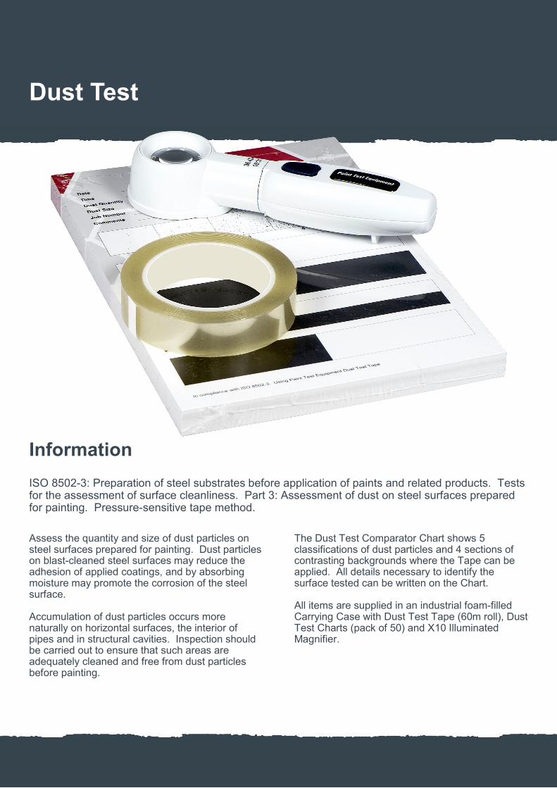
ISO 8502-3: Preparation of steel substrates before application of paints and related products. Tests for the assessment of surface cleanliness. Part 3: Assessment of dust on steel surfaces prepared for painting. Pressure-sensitive tape method.
Dust Test (P4001)
Assess the quantity and size of dust particles on steel surfaces prepared for painting. Dust particles on blast-cleaned steel surfaces may reduce the adhesion of applied coatings, and by absorbing moisture may promote the corrosion of the steel surface. Contents: Dust Test Tape (60m roll), Dust Test Charts (pack of 50) and X10 Illuminated Magnifier.
Paint Inspection Kit
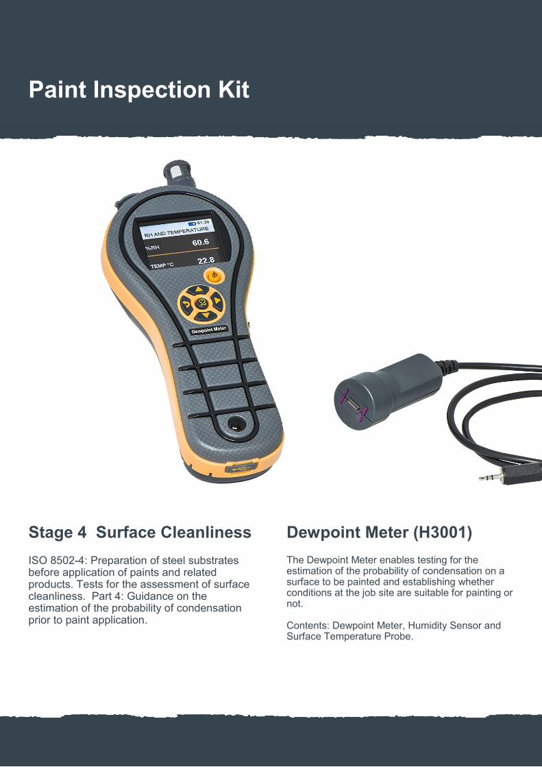
Stage 4 Surface Cleanliness
ISO 8502-4: Preparation of steel substrates before application of paints and related products. Tests for the assessment of surface cleanliness. Part 4: Guidance on the estimation of the probability of condensation prior to paint application.
Dewpoint Meter (H3001)
The Dewpoint Meter enables testing for the estimation of the probability of condensation on a surface to be painted and establishing whether conditions at the job site are suitable for painting or not. Contents: Dewpoint Meter, Humidity Sensor and Surface Temperature Probe.

Paint Inspection Kit
Stage 5 Wet Film Thickness
ISO 2808: Paints and varnishes. Determination of film thickness. .
Wet Film Gauge (W2001)
The Wet Film Gauge ensures the quality control of the paint thickness while the coating is still wet. Applying too much coating can be expensive.

Paint Inspection Kit
Stage 6 Coating Thickness
ISO 2808: Paints and varnishes. Determination of film thickness. ISO 19840: Corrosion protection of steel structures by protective paint systems. Measurement of, and acceptance criteria for, the thickness of dry films on rough surfaces.
Coating Thickness Meter (C5001)
Measures all coatings on steel and iron substrates using the magnetic induction principle, ensuring the correct coating thickness has been applied. Other models of the Coating Thickness Meter can be supplied for thick coatings or non-ferrous substrates. Contents: Coating Thickness Meter (C5001), Flexible Lead Probe, set of 8 Calibration Foils and Zero Disk.

Paint Test Equipment
Testex Tape
Data Sheet / Instructions
Information
ISO 8503-5: Preparation of steel substrates before application of paints and related products. Surface roughness characteristics of blast-cleaned steel substrates. Part 5: Replica tape method for the determination of the surface profile.
A unique replica technique and a snap gauge Enable accurate, blast-cleaned surface profile measurements. Testex Tape makes surface replicas easy to obtain and produces average maximum peak-to-valley readings that ensure optimum blasting effectiveness. Replicas can be retained for future needs. The Testex Gauge is used to measure the Testex Tape replica and determine the average maximum peak-to-valley height of the blasted profile.
The Calibration Certificate with traceability to UKAS is an optional extra. The Certificate is supplied as hard copy and is available online through the Calibration Management Cloud (under Calibration) on our website. The Testex Gauge is supplied in an industrial foam-filled Carrying Case with Testex Tape X Coarse, Testex Tape Coarse and a Burnishing Tool.
Testex Tape

Testex Tape Specifications
Part No Grade Range Metric
Range Imperial
Number of Tests Conformance Cert Part No
R1001 Coarse 20–64µm 0.8–2.5mils 50 NRC02
R1002 X Coarse 38–115µm 1.5–4.5mils 50 NRC02
R1004 Testex Gauge (metric) Includes Testex Coarse and X Coarse NR001
Testex Tape

Principle
The replica film in the Testex Tape consists of a layer of crushable plastic microfilm coated onto a polyester substrate of a highly uniform thickness 50µm (2mil). When compressed against a hard surface, the Microfoam collapses to about 25% of its original thickness.
During compression the foam acquires an impression of the surface against which it is burnished. The highest peaks on the test surface displace the fully compressed foam and come to rest against the polyester substrate. The deepest valleys on the test surface create the highest peaks on the replica. This method measures an average maximimum peak-to-valley profile. The anvils of the Testex Gauge flatten the replica profile slightly so that the reading equates to an average maximum value (this is not the same as mathematical average).
Taking Measurements
Locate a representative area of the surface for measurement and select the appropriate grade of Testex Tape based on your target profile (Coarse or X Coarse). For 20 to 64μm (0.8 to 2.5mil) profiles use Coarse grade. For 38 to 115μm (1.5 to 4.5mil) profiles use X Coarse grade. Prepare the Testex Gauge by cleaning the anvils and adjusting the dial to read zero on the red scale, the red scale is the thickness of the polyester substrate. The red scale automatically subtracts the thickness of the polyester substrate from all subsequent readings. Always ensure rust paper is placed between the anvils when the Test-ex Gauge is not in use. Remove a single piece of Testex Tape from its release paper. The replica material is the square, white plastic film in the centre. A bulls eye circle of paper should remain behind on the release paper (this is not used in the measurement). Apply the Testex Tape to the blast-cleaned surface and rub the Burnishing Tool over the replica film in the centre of the tape, using firm pressure. The circular cut-out will become darker as the surface is replicated. Make sure that the entire circular area has darkened uniformly.
Continued next page
White plastic film
Testex Tape Operation

Taking Measurements Continued
Remove the Testex Tape from the surface and place the replica between the anvils of the Testex Gauge, making sure that it is centred properly. Release the Testex Gauge anvil gently onto the replica and measure the profile. The gauge reading is the average maximum peak-to-valley height of the blast-cleaned surface. Testex Tape is able to produce accurate replicas on surface temperatures of -10 to +65°C.
Testex Tape is able to produce accurate replicas on surface temperatures of -10 to +65°C.
Averaging
If a measurement with either Coarse or X Coarse grade is between 38 to 64μm (1.5 to 2.5mil) take a second reading with the other grade of tape and average the reading. A graphic illustrating the ranges over which aver-aging should and should not be applied appears on each piece of tape.
General
Definitions of Roughness Testex Gauge measurements of Testex Tape give Rz results, which is the average maximum peak-to-valley height of the profile. This is the form of measurement most commonly used by the painting and coating industries. In some applications, Ra results are used, which are the arithmetic average roughness. In most cases Rz has a value approximately 4 times Ra for a given surface.
Sources of Error
One source of error is the presence of particles of dirt on either the replica or the Testex Gauge. Reasonable care should be taken to keep the Gauge anvils free of dirt. Another is a poor burnishing technique, including incomplete compression of the test film.
Shelf Life
The replica film on the Testex Tape has no expiry date. The only degeneration is the adhesive on the Tape if exposed to extremes of temperature. We would recommend that the Tape is used within a 12-month period from date of purchase.
Testex Tape Operation

Paint Test Equipment
Bresle Test
Data Sheet / Instructions

Information
ISO 8502-6: Preparation of steel substrates before application of paints and related products. Tests for the assessment of surface cleanliness. Part 6: Extraction of soluble contaminants for analysis. The Bresle method.
ISO 8502-9: Preparation of steel substrates before application of paints and related products. Tests for the assessment of surface cleanliness. Part 9: Field method for the conductometric determination of water-soluble salts.
The Bresle Test will measure water-soluble salts and corrosion products on blast-cleaned steel. These compounds are almost colourless and are localized at the lowest point of the rust pits. If they are not removed prior to painting, chemical reactions can result in blister formation and accumulations of rust that destroy the adhesion between the substrate and the applied protective coating.
Supplied in an industrial foam-filled Carrying Case with Bresle Patches (pack of 50 Standard Adhesion), Bresle Patches Plus (pack of 50 High Adhesion), Conductivity Meter, 500ml Deionised Water, 3 x 5ml Syringes, Calibration Solution, Moistening Solution and 25ml Beaker.
Bresle Test

Bresle Test Specifications and Spares
Part No Patches Supplied
Conductivity Meter Range
Conductivity Meter Resolution
Conductivity Meter Accuracy
Cond Solution Conformance Cert Part No
Bresle Patch Conformance Cert Part No
Conductivity Meter Cal Cert Part No
P2005 50 Standard Adhesion 50 High Adhesion
0–199µS/cm 0.20–1.99mS/cm
1µS/cm 0.01mS/cm
±2% NP001 NPC04 NP001
PS001 Spare Bresle Patches (pack of 50) Standard Adhesion NPC04
PS002 Spare Bresle Patches Plus (pack of 50) High Adhesion NPC04
PS003 Spare Deionised Water (500ml)
PS004 Spare Syringes (pack of 3)
PS005 Spare Conductivity Meter Calibration Solution NP001
PS006 Spare 25ml Beaker
PS007 Spare Conductivity Meter Sensor Measurment Head NP001
When high adhesion strength Patches are required for testing on very corroded or coarse-grade blasted steel, use the Bresle Patches Plus as an alternative to the Standard Bresle Patches.
Bresle Test

Conductivity Meter Cal
Place 3 to 4 droplets of the 1.41mS/cm Conductivity Solution into the Measuring Electrode, ensuring that the solution is in both sections of the Electrode with no air bubbles. Check the displayed reading which is shown when the smiley face comes on and if this is not 1.41 then calibrate as follows: Press and hold the Cal button until a CAL indicator and smiley face flashes – the Conductivity Meter will now auto calibrate. When the CAL indicator and smiley face stop flashing, calibration is complete. When you have finished calibrating the Conductivity Meter, the Measuring Electrode should be rinsed in tap water before taking any readings.
Safety
The needles on the Syringes in the Bresle Test are blunt. Care must still be taken when carrying out the test. When using the Syringes ensure the work area is well lit, be aware of people around you and assess any hazards. Ensure the protective cap is placed over the needle after use. If the Calibration Solution comes into contact with exposed skin, wash with water. If the Solution comes into contact with eyes, rinse the eye Immediately and seek medical advice.
Moistening Procedure
For first use on a new Conductivity Meter, moisten the Measuring Electrode with 3 to 4 droplets of the Moistening Solution and allow to sit for approximately 10 minutes, then the Measuring Electrode should be rinsed in tap water and dried. If the Measuring Electrode has not been used for a long period of time, or if the Electrode has been left extremely dry, then use this moistening procedure.
Measuring Electrode
Bresle Test Operation

Taking Measurements
Pour approximately 10ml of Deionized Water into the Beaker. Completely fill the Syringe with the Deionized Water from the Beaker, and then empty the Syringe back into the Beaker. Using the Syringe, withdraw approximately 1ml of Deionized Water from the Beaker and place 3 to 4 droplets into the Measuring Electrode on the Conductivity Meter, ensuring that the Deionized Water is in both sections of the Electrode with no air bubbles. Record the conductivity of the contaminated water displayed by the Meter when the smiley face appears. Take a Bresle Patch and remove the protective paper and the punched-out centre foam. Press the adhesive side of the patch against the test surface in such a way that the minimum amount of air is trapped in the circular test chamber. Fill the Syringe with 2.5ml of Deionized Water from the Beaker and insert the Syringe needle at an angle of about 30° to the test surface near the outer edge of the Patch so it passes through the adhesive foam body and into the circular test chamber. If the Patch is in a position which makes access to the Patch test chamber difficult, bend the Syringe needle as required. Inject the Syringe contents ensuring that it wets the entire test surface, then without removing the Syringe needle from the Patch, suck the contents of the Patch back into the Syringe. Repeat until at least 10 injection–sucking cycles have been completed.
At the end of the 10th cycle retrieve the contaminated water from the Patch with the Syringe and place 3 to 4 droplets into the Measuring Electrode on the Conductivity Meter, ensuring that the Deionized Water is in both sections of the Electrode with no air bubbles. Record the conductivity of the contaminated water displayed by the Meter when the smiley face appears.
Bresle Test Operation

Results
Subtract the initial Deionised Water conductivity reading from the contaminated water conductivity reading. The results are shown in µS/cm. For results in µg/cm2 multiply the µS/cm value by 0.1 or use the conversion table on the following page. If results in mg/m2 are required the µS/cm value is the same in mg/m2. The conversions listed are based on a test area of 1250mm2 and using a 2.5ml volume of water. Expression of results are based on section 7 of ISO 8502-9 Example. The Deionized Water measurement taken is 4µS/cm. The contaminated water measurement taken is 54µS/cm. The difference is therefore 50µS/cm which is equivalent to 50mg/m2. Multiply the difference (50µS/cm) by 0.1 and the result is 5.0µg/cm2. The Conductivity Meter will automatically take measurements when a solution is placed in the Measuring Electrode. If a further measurement is required press the Measure button and a MEAS indicator flashes. When the MEAS indicator stops flashing and a smiley face appears the measurement is complete.
General
Care
When you have finished using the Conductivity Meter, the Measuring Electrode should be rinsed in tap water and dried. Then place a small amount of Deionized Water in the Electrode and replace the sensor cap. Also ensure the Syringe is cleaned to remove any contamination.
Patch Shelf Life
The only degeneration on the Bresle Patches is the adhesive if exposed to extremes of temperature. It is recommended that the Patches are used within a 12-month period from date of purchase.
Replacing Batteries
To replace the batteries on the Conductivity Meter, slide off the sensor while lifting the catch located on the rear of the instrument. Replace with 2 lithium CR-2032 batteries, ensuring correct polarity.
Bresle Test Operation

Testing Abrasives
ISO 11127-6: Preparation of steel substrates before application of paints and related products. Test methods for non-metallic blast-cleaning abrasives. Part 6: Determination of water-soluble contaminants by conductivity measurement. The Bresle Test can also be used for testing non-metallic abrasives for water-soluble salts and corrosion products. Record the conductivity of the Deionized Water using the same procedure under the section Taking Measurements. Place 100gm of abrasive into a flask and add 100ml of the Deionized Water that you have recorded the conductivity of. Shake for 5 minutes and allow to stand for 1 hour. If the liquid does not clear, filter by any suitable method. Using the Syringe, withdraw approximately 1ml of contaminated water from the flask and place 3 to 4 droplets into the Measuring Electrode on the Conductivity Meter, ensuring that the contaminated water is in both sections of the Electrode with no air bubbles. Record the conductivity of the contaminated water displayed by the Meter when the smiley face ap-pears. Subtract the initial Deionized Water conductivity reading from the contaminated water conductivity reading. Record the results as shown in µS/cm.
Bresle Test Operation

Bresle Test Conversion Table
Results Conversion into µg/cm
2
Conversion into mg/m
2
Results Conversion into µg/cm
2
Conversion into mg/m
2
1µS/cm 0.1µg/cm2 1mg/m2 34µS/cm 3.4µg/cm2 34mg/m2
2µS/cm 0.2µg/cm2 2mg/m2 35µS/cm 3.5µg/cm2 35mg/m2
3µS/cm 0.3µg/cm2 3mg/m2 36µS/cm 3.6µg/cm2 36mg/m2
4µS/cm 0.4µg/cm2 4mg/m2 37µS/cm 3.7µg/cm2 37mg/m2
5µS/cm 0.5µg/cm2 5mg/m2 38µS/cm 3.8µg/cm2 38mg/m2
6µS/cm 0.6µg/cm2 6mg/m2 39µS/cm 3.9µg/cm2 39mg/m2
7µS/cm 0.7µg/cm2 7mg/m2 40µS/cm 4.0µg/cm2 40mg/m2
8µS/cm 0.8µg/cm2 8mg/m2 41µS/cm 4.1µg/cm2 41mg/m2
9µS/cm 0.9µg/cm2 9mg/m2 42µS/cm 4.2µg/cm2 42mg/m2
10µS/cm 1.0µg/cm2 10mg/m2 43µS/cm 4.3µg/cm2 43mg/m2
11µS/cm 1.1µg/cm2 11mg/m2 44µS/cm 4.4µg/cm2 44mg/m2
12µS/cm 1.2µg/cm2 12mg/m2 45µS/cm 4.5µg/cm2 45mg/m2
13µS/cm 1.3µg/cm2 13mg/m2 46µS/cm 4.6µg/cm2 46mg/m2
14µS/cm 1.4µg/cm2 14mg/m2 47µS/cm 4.7µg/cm2 47mg/m2
15µS/cm 1.5µg/cm2 15mg/m2 48µS/cm 4.8µg/cm2 48mg/m2
16µS/cm 1.6µg/cm2 16mg/m2 49µS/cm 4.9µg/cm2 49mg/m2
17µS/cm 1.7µg/cm2 17mg/m2 50µS/cm 5.0µg/cm2 50mg/m2
18µS/cm 1.8µg/cm2 18mg/m2 51µS/cm 5.1µg/cm2 51mg/m2
19µS/cm 1.9µg/cm2 19mg/m2 52µS/cm 5.2µg/cm2 52mg/m2
20µS/cm 2.0µg/cm2 20mg/m2 53µS/cm 5.3µg/cm2 53mg/m2
21µS/cm 2.1µg/cm2 21mg/m2 54µS/cm 5.4µg/cm2 54mg/m2
22µS/cm 2.2µg/cm2 22mg/m2 55µS/cm 5.5µg/cm2 55mg/m2
23µS/cm 2.3µg/cm2 23mg/m2 56µS/cm 5.6µg/cm2 56mg/m2
24µS/cm 2.4µg/cm2 24mg/m2 57µS/cm 5.7µg/cm2 57mg/m2
25µS/cm 2.5µg/cm2 25mg/m2 58µS/cm 5.8µg/cm2 58mg/m2
26µS/cm 2.6µg/cm2 26mg/m2 59µS/cm 5.9µg/cm2 59mg/m2
27µS/cm 2.7µg/cm2 27mg/m2 60µS/cm 6.0µg/cm2 60mg/m2
28µS/cm 2.8µg/cm2 28mg/m2 61µS/cm 6.1µg/cm2 61mg/m2
29µS/cm 2.9µg/cm2 29mg/m2 62µS/cm 6.2µg/cm2 62mg/m2
30µS/cm 3.0µg/cm2 30mg/m2 63µS/cm 6.3µg/cm2 63mg/m2
31µS/cm 3.1µg/cm2 31mg/m2 64µS/cm 6.4µg/cm2 64mg/m2
32µS/cm 3.2µg/cm2 32mg/m2 65µS/cm 6.5µg/cm2 65mg/m2
33µS/cm 3.3µg/cm2 33mg/m2 66µS/cm 6.6µg/cm2 66mg/m2
Bresle Test Operation

Bresle Test Conversion Table Continued
Results Conversion into µg/cm
2
Conversion into mg/m
2
Results Conversion into µg/cm
2
Conversion into mg/m
2
67µS/cm 6.7µg/cm2 67mg/m2 100µS/cm 10.0µg/cm2 100mg/m2
68µS/cm 6.8µg/cm2 68mg/m2 101µS/cm 10.1µg/cm2 101mg/m2
69µS/cm 6.9µg/cm2 69mg/m2 102µS/cm 10.2µg/cm2 102mg/m2
70µS/cm 7.0µg/cm2 70mg/m2 103µS/cm 10.3µg/cm2 103mg/m2
71µS/cm 7.1µg/cm2 71mg/m2 104µS/cm 10.4µg/cm2 104mg/m2
72µS/cm 7.2µg/cm2 72mg/m2 105µS/cm 10.5µg/cm2 105mg/m2
73µS/cm 7.3µg/cm2 73mg/m2 106µS/cm 10.6µg/cm2 106mg/m2
74µS/cm 7.4µg/cm2 74mg/m2 107µS/cm 10.7µg/cm2 107mg/m2
75µS/cm 7.5µg/cm2 75mg/m2 108µS/cm 10.8µg/cm2 108mg/m2
76µS/cm 7.6µg/cm2 76mg/m2 109µS/cm 10.9µg/cm2 109mg/m2
77µS/cm 7.7µg/cm2 77mg/m2 110µS/cm 11.0µg/cm2 110mg/m2
78µS/cm 7.8µg/cm2 78mg/m2 111µS/cm 11.1µg/cm2 111mg/m2
79µS/cm 7.9µg/cm2 79mg/m2 112µS/cm 11.2µg/cm2 112mg/m2
80µS/cm 8.0µg/cm2 80mg/m2 113µS/cm 11.3µg/cm2 113mg/m2
81µS/cm 8.1µg/cm2 81mg/m2 114µS/cm 11.4µg/cm2 114mg/m2
82µS/cm 8.2µg/cm2 82mg/m2 115µS/cm 11.5µg/cm2 115mg/m2
83µS/cm 8.3µg/cm2 83mg/m2 116µS/cm 11.6µg/cm2 116mg/m2
84µS/cm 8.4µg/cm2 84mg/m2 117µS/cm 11.7µg/cm2 117mg/m2
85µS/cm 8.5µg/cm2 85mg/m2 118µS/cm 11.8µg/cm2 118mg/m2
86µS/cm 8.6µg/cm2 86mg/m2 119µS/cm 11.9µg/cm2 119mg/m2
87µS/cm 8.7µg/cm2 87mg/m2 120µS/cm 12.0µg/cm2 120mg/m2
88µS/cm 8.8µg/cm2 88mg/m2 121µS/cm 12.1µg/cm2 121mg/m2
89µS/cm 8.9µg/cm2 89mg/m2 122µS/cm 12.2µg/cm2 122mg/m2
90µS/cm 9.0µg/cm2 90mg/m2 123µS/cm 12.3µg/cm2 123mg/m2
91µS/cm 9.1µg/cm2 91mg/m2 124µS/cm 12.4µg/cm2 124mg/m2
92µS/cm 9.2µg/cm2 92mg/m2 125µS/cm 12.5µg/cm2 125mg/m2
93µS/cm 9.3µg/cm2 93mg/m2 126µS/cm 12.6µg/cm2 126mg/m2
94µS/cm 9.4µg/cm2 94mg/m2 127µS/cm 12.7µg/cm2 127mg/m2
95µS/cm 9.5µg/cm2 95mg/m2 128µS/cm 12.8µg/cm2 128mg/m2
96µS/cm 9.6µg/cm2 96mg/m2 129µS/cm 12.9µg/cm2 129mg/m2
97µS/cm 9.7µg/cm2 97mg/m2 130µS/cm 13.0µg/cm2 130mg/m2
98µS/cm 9.8µg/cm2 98mg/m2 131µS/cm 13.1µg/cm2 131mg/m2
99µS/cm 9.9µg/cm2 99mg/m2 132µS/cm 13.2µg/cm2 132mg/m2
Bresle Test Operation

Bresle Test Conversion Table Continued
Results Conversion into µg/cm
2
Conversion into mg/m
2
Results Conversion into µg/cm
2
Conversion into mg/m
2
133µS/cm 13.3µg/cm2 133mg/m2 166µS/cm 16.6µg/cm2 166mg/m2
134µS/cm 13.4µg/cm2 134mg/m2 167µS/cm 16.7µg/cm2 167mg/m2
135µS/cm 13.5µg/cm2 135mg/m2 168µS/cm 16.8µg/cm2 168mg/m2
136µS/cm 13.6µg/cm2 136mg/m2 169µS/cm 16.9µg/cm2 169mg/m2
137µS/cm 13.7µg/cm2 137mg/m2 170µS/cm 17.0µg/cm2 170mg/m2
138µS/cm 13.8µg/cm2 138mg/m2 171µS/cm 17.1µg/cm2 171mg/m2
139µS/cm 13.9µg/cm2 139mg/m2 172µS/cm 17.2µg/cm2 172mg/m2
140µS/cm 14.0µg/cm2 140mg/m2 173µS/cm 17.3µg/cm2 173mg/m2
141µS/cm 14.1µg/cm2 141mg/m2 174µS/cm 17.4µg/cm2 174mg/m2
142µS/cm 14.2µg/cm2 142mg/m2 175µS/cm 17.5µg/cm2 175mg/m2
143µS/cm 14.3µg/cm2 143mg/m2 176µS/cm 17.6µg/cm2 176mg/m2
144µS/cm 14.4µg/cm2 144mg/m2 177µS/cm 17.7µg/cm2 177mg/m2
145µS/cm 14.5µg/cm2 145mg/m2 178µS/cm 17.8µg/cm2 178mg/m2
146µS/cm 14.6µg/cm2 146mg/m2 179µS/cm 17.9µg/cm2 179mg/m2
147µS/cm 14.7µg/cm2 147mg/m2 180µS/cm 18.0µg/cm2 180mg/m2
148µS/cm 14.8µg/cm2 148mg/m2 181µS/cm 18.1µg/cm2 181mg/m2
149µS/cm 14.9µg/cm2 149mg/m2 182µS/cm 18.2µg/cm2 182mg/m2
150µS/cm 15.0µg/cm2 150mg/m2 183µS/cm 18.3µg/cm2 183mg/m2
151µS/cm 15.1µg/cm2 151mg/m2 184µS/cm 18.4µg/cm2 184mg/m2
152µS/cm 15.2µg/cm2 152mg/m2 185µS/cm 18.5µg/cm2 185mg/m2
153µS/cm 15.3µg/cm2 153mg/m
2 186µS/cm 18.6µg/cm
2 186mg/m
2
154µS/cm 15.4µg/cm2 154mg/m2 187µS/cm 18.7µg/cm2 187mg/m2
155µS/cm 15.5µg/cm2 155mg/m2 188µS/cm 18.8µg/cm2 188mg/m2
156µS/cm 15.6µg/cm2 156mg/m2 189µS/cm 18.9µg/cm2 189mg/m2
157µS/cm 15.7µg/cm2 157mg/m2 190µS/cm 19.0µg/cm2 190mg/m2
158µS/cm 15.8µg/cm2 158mg/m2 191µS/cm 19.1µg/cm2 191mg/m2
159µS/cm 15.9µg/cm2 159mg/m2 192µS/cm 19.2µg/cm2 192mg/m2
160µS/cm 16.0µg/cm2 160mg/m2 193µS/cm 19.3µg/cm2 193mg/m2
161µS/cm 16.1µg/cm2 161mg/m2 194µS/cm 19.4µg/cm2 194mg/m2
162µS/cm 16.2µg/cm2 162mg/m2 195µS/cm 19.5µg/cm2 195mg/m2
163µS/cm 16.3µg/cm2 163mg/m2 196µS/cm 19.6µg/cm2 196mg/m2
164µS/cm 16.4µg/cm2 164mg/m2 197µS/cm 19.7µg/cm2 197mg/m2
165µS/cm 16.5µg/cm2 165mg/m2 198µS/cm 19.8µg/cm2 198mg/m2
Bresle Test Operation

Bresle Test Conversion Table Continued
Results Conversion into µg/cm
2
Conversion into mg/m
2
Results Conversion into µg/cm
2
Conversion into mg/m
2
199µS/cm 19.9µg/cm2 199mg/m2 0.52mS/cm 52µg/cm2 520mg/m2
0.20mS/cm 20µg/cm2 200mg/m2 0.53mS/cm 53µg/cm2 530mg/m2
0.21mS/cm 21µg/cm2 210mg/m2 0.54mS/cm 54µg/cm2 540mg/m2
0.22mS/cm 22µg/cm2 220mg/m2 0.55mS/cm 55µg/cm2 550mg/m2
0.23mS/cm 23µg/cm2 230mg/m2 0.56mS/cm 56µg/cm2 560mg/m2
0.24mS/cm 24µg/cm2 240mg/m2 0.57mS/cm 57µg/cm2 570mg/m2
0.25mS/cm 25µg/cm2 250mg/m2 0.58mS/cm 58µg/cm2 580mg/m2
0.26mS/cm 26µg/cm2 260mg/m2 0.59mS/cm 59µg/cm2 590mg/m2
0.27mS/cm 27µg/cm2 270mg/m2 0.60mS/cm 60µg/cm2 600mg/m2
0.28mS/cm 28µg/cm2 280mg/m2 0.61mS/cm 61µg/cm2 610mg/m2
0.29mS/cm 29µg/cm2 290mg/m2 0.62mS/cm 62µg/cm2 620mg/m2
0.30mS/cm 30µg/cm2 300mg/m2 0.63mS/cm 63µg/cm2 630mg/m2
0.31mS/cm 31µg/cm2 310mg/m2 0.64mS/cm 64µg/cm2 640mg/m2
0.32mS/cm 32µg/cm2 320mg/m2 0.65mS/cm 65µg/cm2 650mg/m2
0.33mS/cm 33µg/cm2 330mg/m2 0.66mS/cm 66µg/cm2 660mg/m2
0.34mS/cm 34µg/cm2 340mg/m2 0.67mS/cm 67µg/cm2 670mg/m2
0.35mS/cm 35µg/cm2 350mg/m2 0.68mS/cm 68µg/cm2 680mg/m2
0.36mS/cm 36µg/cm2 360mg/m2 0.69mS/cm 69µg/cm2 690mg/m2
0.37mS/cm 37µg/cm2 370mg/m2 0.70mS/cm 70µg/cm2 700mg/m2
0.38mS/cm 38µg/cm2 380mg/m2 0.71mS/cm 71µg/cm2 710mg/m2
0.39mS/cm 39µg/cm2 390mg/m2 0.72mS/cm 72µg/cm2 720mg/m2
0.40mS/cm 40µg/cm2 400mg/m2 0.73mS/cm 73µg/cm2 730mg/m2
0.41mS/cm 41µg/cm2 410mg/m2 0.74mS/cm 74µg/cm2 740mg/m2
0.42mS/cm 42µg/cm2 420mg/m2 0.75mS/cm 75µg/cm2 750mg/m2
0.43mS/cm 43µg/cm2 430mg/m2 0.76mS/cm 76µg/cm2 760mg/m2
0.44mS/cm 44µg/cm2 440mg/m2 0.77mS/cm 77µg/cm2 770mg/m2
0.45mS/cm 45µg/cm2 450mg/m2 0.78mS/cm 78µg/cm2 780mg/m2
0.46mS/cm 46µg/cm2 460mg/m2 0.79mS/cm 79µg/cm2 790mg/m2
0.47mS/cm 47µg/cm2 470mg/m2 0.80mS/cm 80µg/cm2 800mg/m2
0.48mS/cm 48µg/cm2 480mg/m2 0.81mS/cm 81µg/cm2 810mg/m2
0.49mS/cm 49µg/cm2 490mg/m2 0.82mS/cm 82µg/cm2 820mg/m2
0.50mS/cm 50µg/cm2 500mg/m2 0.83mS/cm 83µg/cm2 830mg/m2
0.51mS/cm 51µg/cm2 510mg/m2 0.84mS/cm 84µg/cm2 840mg/m2
Bresle Test Operation

Bresle Test Conversion Table Continued
Results Conversion into µg/cm
2
Conversion into mg/m
2
Results Conversion into µg/cm
2
Conversion into mg/m
2
0.85mS/cm 85µg/cm2 850mg/m2 1.18mS/cm 118µg/cm2 1180mg/m2
0.86mS/cm 86µg/cm2 860mg/m2 1.19mS/cm 119µg/cm2 1190mg/m2
0.87mS/cm 87µg/cm2 870mg/m2 1.20mS/cm 120µg/cm2 1200mg/m2
0.88mS/cm 88µg/cm2 880mg/m2 1.21mS/cm 121µg/cm2 1210mg/m2
0.89mS/cm 89µg/cm2 890mg/m2 1.22mS/cm 122µg/cm2 1220mg/m2
0.90mS/cm 90µg/cm2 900mg/m2 1.23mS/cm 123µg/cm2 1230mg/m2
0.91mS/cm 91µg/cm2 910mg/m2 1.24mS/cm 124µg/cm2 1240mg/m2
0.92mS/cm 92µg/cm2 920mg/m2 1.25mS/cm 125µg/cm2 1250mg/m2
0.93mS/cm 93µg/cm2 930mg/m2 1.26mS/cm 126µg/cm2 1260mg/m2
0.94mS/cm 94µg/cm2 940mg/m2 1.27mS/cm 127µg/cm2 1270mg/m2
0.95mS/cm 95µg/cm2 950mg/m2 1.28mS/cm 128µg/cm2 1280mg/m2
0.96mS/cm 96µg/cm2 960mg/m2 1.29mS/cm 129µg/cm2 1290mg/m2
0.97mS/cm 97µg/cm2 970mg/m2 1.30mS/cm 130µg/cm2 1300mg/m2
0.98mS/cm 98µg/cm2 980mg/m2 1.31mS/cm 131µg/cm2 1310mg/m2
0.99mS/cm 99µg/cm2 990mg/m2 1.32mS/cm 132µg/cm2 1320mg/m2
1.00mS/cm 100µg/cm2 1000mg/m2 1.33mS/cm 133µg/cm2 1330mg/m2
1.01mS/cm 101µg/cm2 1010mg/m2 1.34mS/cm 134µg/cm2 1340mg/m2
1.02mS/cm 102µg/cm2 1020mg/m2 1.35mS/cm 135µg/cm2 1350mg/m2
1.03mS/cm 103µg/cm2 1030mg/m2 1.36mS/cm 136µg/cm2 1360mg/m2
1.04mS/cm 104µg/cm2 1040mg/m2 1.37mS/cm 137µg/cm2 1370mg/m2
1.05mS/cm 105µg/cm2 1050mg/m2 1.38mS/cm 138µg/cm2 1380mg/m2
1.06mS/cm 106µg/cm2 1060mg/m2 1.39mS/cm 139µg/cm2 1390mg/m2
1.07mS/cm 107µg/cm2 1070mg/m2 1.40mS/cm 140µg/cm2 1400mg/m2
1.08mS/cm 108µg/cm2 1080mg/m2 1.41mS/cm 141µg/cm2 1410mg/m2
1.09mS/cm 109µg/cm2 1090mg/m2 1.42mS/cm 142µg/cm2 1420mg/m2
1.10mS/cm 110µg/cm2 1100mg/m2 1.43mS/cm 143µg/cm2 1430mg/m2
1.11mS/cm 111µg/cm2 1110mg/m2 1.44mS/cm 144µg/cm2 1440mg/m2
1.12mS/cm 112µg/cm2 1120mg/m2 1.45mS/cm 145µg/cm2 1450mg/m2
1.13mS/cm 113µg/cm2 1130mg/m2 1.46mS/cm 146µg/cm2 1460mg/m2
1.14mS/cm 114µg/cm2 1140mg/m2 1.47mS/cm 147µg/cm2 1470mg/m2
1.15mS/cm 115µg/cm2 1150mg/m2 1.48mS/cm 148µg/cm2 1480mg/m2
1.16mS/cm 116µg/cm2 1160mg/m2 1.49mS/cm 149µg/cm2 1490mg/m2
1.17mS/cm 117µg/cm2 1170mg/m2 1.50mS/cm 150µg/cm2 1500mg/m2
Bresle Test Operation

Bresle Test Conversion Table Continued
Results Conversion into µg/cm
2
Conversion into mg/m
2
Results Conversion into µg/cm
2
Conversion into mg/m
2
1.51mS/cm 151µg/cm2 1510mg/m2 1.84mS/cm 184µg/cm2 1840mg/m2
1.52mS/cm 152µg/cm2 1520mg/m2 1.85mS/cm 185µg/cm2 1850mg/m2
1.53mS/cm 153µg/cm2 1530mg/m2 1.86mS/cm 186µg/cm2 1860mg/m2
1.54mS/cm 154µg/cm2 1540mg/m2 1.87mS/cm 187µg/cm2 1870mg/m2
1.55mS/cm 155µg/cm2 1550mg/m2 1.88mS/cm 188µg/cm2 1880mg/m2
1.56mS/cm 156µg/cm2 1560mg/m2 1.89mS/cm 189µg/cm2 1890mg/m2
1.57mS/cm 157µg/cm2 1570mg/m2 1.90mS/cm 190µg/cm2 1900mg/m2
1.58mS/cm 158µg/cm2 1580mg/m2 1.91mS/cm 191µg/cm2 1910mg/m2
1.59mS/cm 159µg/cm2 1590mg/m2 1.92mS/cm 192µg/cm2 1920mg/m2
1.60mS/cm 160µg/cm2 1600mg/m2 1.93mS/cm 193µg/cm2 1930mg/m2
1.61mS/cm 161µg/cm2 1610mg/m2 1.94mS/cm 194µg/cm2 1940mg/m2
1.62mS/cm 162µg/cm2 1620mg/m2 1.95mS/cm 195µg/cm2 1950mg/m2
1.63mS/cm 163µg/cm2 1630mg/m2 1.96mS/cm 196µg/cm2 1960mg/m2
1.64mS/cm 164µg/cm2 1640mg/m2 1.97mS/cm 197µg/cm2 1970mg/m2
1.65mS/cm 165µg/cm2 1650mg/m2 1.98mS/cm 198µg/cm2 1980mg/m2
1.66mS/cm 166µg/cm2 1660mg/m2 1.99mS/cm 199µg/cm2 1990mg/m2
1.67mS/cm 167µg/cm2 1670mg/m2
1.68mS/cm 168µg/cm2 1680mg/m2
1.69mS/cm 169µg/cm2 1690mg/m2
1.70mS/cm 170µg/cm2 1700mg/m2
1.71mS/cm 171µg/cm2 1710mg/m2
1.72mS/cm 172µg/cm2 1720mg/m2
1.73mS/cm 173µg/cm2 1730mg/m2
1.74mS/cm 174µg/cm2 1740mg/m2
1.75mS/cm 175µg/cm2 1750mg/m2
1.76mS/cm 176µg/cm2 1760mg/m2
1.77mS/cm 177µg/cm2 1770mg/m2
1.78mS/cm 178µg/cm2 1780mg/m2
1.79mS/cm 179µg/cm2 1790mg/m2
1.80mS/cm 180µg/cm2 1800mg/m2
1.81mS/cm 181µg/cm2 1810mg/m2
1.82mS/cm 182µg/cm2 1820mg/m2
1.83mS/cm 183µg/cm2 1830mg/m2
Bresle Test Operation

Paint Test Equipment
Dust Test
Data Sheet / Instructions
Information
ISO 8502-3: Preparation of steel substrates before application of paints and related products. Tests for the assessment of surface cleanliness. Part 3: Assessment of dust on steel surfaces prepared for painting. Pressure-sensitive tape method.
Assess the quantity and size of dust particles on steel surfaces prepared for painting. Dust particles on blast-cleaned steel surfaces may reduce the adhesion of applied coatings, and by absorbing moisture may promote the corrosion of the steel surface. Accumulation of dust particles occurs more naturally on horizontal surfaces, the interior of pipes and in structural cavities. Inspection should be carried out to ensure that such areas are adequately cleaned and free from dust particles before painting.
The Dust Test Comparator Chart shows 5 classifications of dust particles and 4 sections of contrasting backgrounds where the Tape can be applied. All details necessary to identify the surface tested can be written on the Chart. All items are supplied in an industrial foam-filled Carrying Case with Dust Test Tape (60m roll), Dust Test Charts (pack of 50) and X10 Illuminated Magnifier.
Dust Test

Dust Test Specifications
Part No Product Tape Adhesive Strength
Tape Width Tape Length Dust Test Tape Conformance Cert Part No
Dust Charts Conformance Cert Part No
P4001 Dust Test 190nN/metre 25mm/1” 60 metres NPC05 NPC06
PS201 Spare Dust Test Tape
190nN/metre 25mm/1” 60 metres NPC05
PS202 Spare Dust Test Comparator Charts (pack 50) NPC06
Dust Test

Application
At the beginning of each series of tests, remove and discard the first three turns of the Dust Test Tape from the roll. Remove a piece of Tape about 250mm long. Holding the Tape only at the ends, press approximately 200mm of the freshly exposed Tape onto the blast-cleaned surface.
Place your thumb across one end of the Tape and move the thumb along the Tape whilst maintaining a firm pressure and constant speed along the Tape. Carry out this procedure three times in each direction. Remove the Tape from the blast-cleaned surface and place it on the Dust Test Comparator Chart in a section which contrasts to the colour of the dust (adhere the Tape with thumb pressure). Excess Tape can be folded around the back of the chart or cut off.
Assessment
Assess the quantity and size of dust particles on the Tape by visually comparing an area of the Tape with equivalent-sized areas of the pictorial references shown on the Chart. Record the rating corresponding to the reference that is the closest match. It is not unusual after carrying out the test to find that the Tape displays an overall discolouration, usually reddish-brown or black, sometimes with the presence of discrete visible particles, depending on the abrasive used. The discolouration is caused by microscopic dust particles from the blast-cleaned surface (particles less than 50µm) that can cause low paint adhesion. Report any overall discolouration as quantity rating 5, size class 1.
Report
Record on the Dust Test Chart the following information: All details necessary to identify the surface tested, with reference to specific features (ledges, beams, web or flange faces) and attitude of the test area (vertical, horizontal). The dust particle quantity rating and dust particle size class. Date and, if applicable, the time of each test. The Dust Test Chart can be kept as a permanent record for the inspection carried out.
Dust Test Operation

Dust Particle Size Classes
1. Particles not visible under X10 magnification.
2. Particles visible under X10 magnification but not with normal or corrected vision (usually particles less than 50µm in diameter).
3. Particles just visible with normal or corrected vision (usually particles between 50µm and 100µm in diameter).
4. Particles between 0.5mm and 2.5mm in diameter.
5. Particles larger than 2.5mm in diameter.
General
Practical Advice
The Dust Test is suitable for the assessment of dust particles retained after blast-cleaning on rust grades A, B and C. Because of the limited elasticity of the Tape, it is not possible to penetrate into the deep pits present on blast-cleaned steel rust grade D.
Tape Shelf Life
Do not expose the Adhesion Test Tape to any extremes of temperature or daylight. We would recommend that the Tape is used within a 12-month period from date of purchase.
Dust Test Operation

Paint Test Equipment
Dewpoint Meter
Data Sheet / Instructions

Information
ISO 8502-4: Preparation of steel substrates before application of paints and related products. Tests for the assessment of surface cleanliness. Part 4: Guidance on the estimation of the probability of condensation prior to paint application.
The Dewpoint Meter enables testing for the estimation of the probability of condensation on a surface to be painted and establishing whether conditions are suitable for painting or not. The steel surface temperature generally should be at least 3°C above the dew point when paints are applied. Below this temperature the Dewpoint Meter will sound an alarm and the display colour will change to warn you that the surface conditions are not suitable too paint. Measurements of relative humidity, dew point, air temperature are shown. Surface temperature and surface temperature proximity to dew point are shown when using the surface temperature sensor.
Interchangeable Humidity Sensor and Surface Temperature Probe allow the user to replace damaged or out-of-calibration-date Sensor and Probe. The Calibration Certificates with traceability to UKAS are an optional extra. The Certificates are supplied as hard copy and are available online through the Calibration Management Cloud (under Calibration) on our website. Supplied in an industrial foam-filled Carrying Case with a Humidity Sensor and Surface Temperature Probe.
Dewpoint Meter

Dewpoint Meter Specifications
Part No Range %rh
Range Temperature
Resolution %rh
Resolution Temp
Accuracy %rh/Temp
Accuracy Temp
Humidity Sensor Cal Cert Part No
Surface Temp Probe Cert Part No
H4001 1–100% Air -10–70°C (14–160°F) Surface -20–80°C (-4–176°F)
0.1% 0.1°C 0.2°F
10–90% ±2% 0–10/90–100% ±3%
±1% NH101 NH102
HS301 Spare Humidity Sensor 0–100%rh/-10 to 70°C (14 to 160°F) NH101
HS302 Spare Surface Temperature Probe -20 to 80°C (-4 to 176°F) NH102
Dewpoint Meter

Practical Advice
When using the Dewpoint Meter it is good practice to monitor the display for temperature stability. The Humidity Sensor should be given sufficient time to equilibrate with the environment to be measured. The larger the initial temperature difference between the Sensor and the environment to be measured, the more time temperature equilibration requires to provide a valid measurement.
Replacing Batteries
The battery status is shown at the top right of the display. Replace the batteries immediately when one bar is shown or the symbol is flashing. To replace, remove the screw then the cover located on the rear of the instrument. Replace with an alkaline PP3 battery, ensuring correct polarity.
General
Switch On/Off
Switch the Dewpoint Meter on by pressing the On button. To switch off, press and hold the button until the display shows DEVICE IS SWITCHING OFF. Alternatively, the instrument will switch itself off after a period that the Auto Off is set to under the Setting Menu Functions.
Infra Red Thermometer
The Dewpoint Meter has a built in infra red thermometer for measuring surface temperature. Remove the rubber cap from the infra red sensor and point at the substrate. Press the infra red temperature button (IRT) and the Surface Temperature Difference (difference between surface temperature and dewpoint), Surface Temperature and Air Dewpoint measurements will show on the display. If you press the infra red temperature button (IRT) twice the laser sight will activate. The infra red thermometer is not suitable for measuring on reflective substrates. This includes blast-cleaned steel. For blast-cleaned steel use the Surface Temperature Probe.
Pause Readings
Measurements on the display can be paused by pressing the right arrow button.
Dewpoint Meter Operation

Menu
All functions are accessed through a menu-driven display by pressing the left button. To scroll through the menus use the up and down arrow buttons and enter by briefly pressing the on button.
To exit from the menu, press the left Menu button again and the Dewpoint Meter will revert back to normal measurement mode.
Hygrometer Menu Function
The Hygrometer Menu Function shows the Relative Humidity and Air Temperature on the display.
Dewpoint Meter Operation

Enthalpy
Enthalpy, Relative Humidity and Air Temperature are shown on the display.
Vapour Pressure
Vapour Pressure, Relative Humidity and Air Temperature are shown on the display.
Custom
This Menu Function will allow you to display the customised measurements.
Psychometrics Menu Functions
Dew Point
Dew Point, Relative Humidity and Air Temperature are shown on the display.
Grams Per Kilogram
Grams Per Kilogram, Relative Humidity and Air Temperature are shown on the display.
Dewpoint Meter Operation
Surface Temperature Function
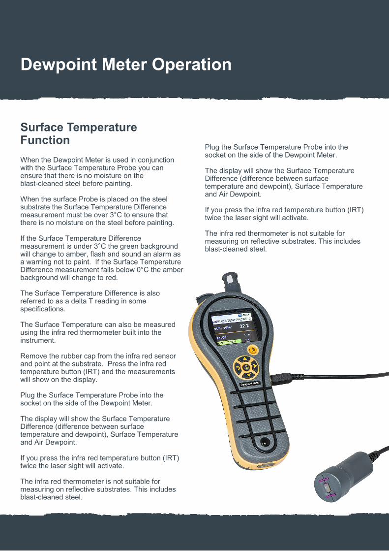
When the Dewpoint Meter is used in conjunction with the Surface Temperature Probe you can ensure that there is no moisture on the blast-cleaned steel before painting. When the surface Probe is placed on the steel substrate the Surface Temperature Difference measurement must be over 3°C to ensure that there is no moisture on the steel before painting. If the Surface Temperature Difference measurement is under 3°C the green background will change to amber, flash and sound an alarm as a warning not to paint. If the Surface Temperature Difference measurement falls below 0°C the amber background will change to red. The Surface Temperature Difference is also referred to as a delta T reading in some specifications. The Surface Temperature can also be measured using the infra red thermometer built into the instrument. Remove the rubber cap from the infra red sensor and point at the substrate. Press the infra red temperature button (IRT) and the measurements will show on the display. Plug the Surface Temperature Probe into the socket on the side of the Dewpoint Meter. The display will show the Surface Temperature Difference (difference between surface temperature and dewpoint), Surface Temperature and Air Dewpoint. If you press the infra red temperature button (IRT) twice the laser sight will activate. The infra red thermometer is not suitable for measuring on reflective substrates. This includes blast-cleaned steel.
Plug the Surface Temperature Probe into the socket on the side of the Dewpoint Meter. The display will show the Surface Temperature Difference (difference between surface temperature and dewpoint), Surface Temperature and Air Dewpoint. If you press the infra red temperature button (IRT) twice the laser sight will activate. The infra red thermometer is not suitable for measuring on reflective substrates. This includes blast-cleaned steel.
Dewpoint Meter Operation

Settings Menu Functions
Language
Language options of English, Norwegian, French, German, Swedish, Spanish, Italian and Dutch can be selected by using the up and down arrows. When selected press the On button to save.
Units
Metric or imperial measurements can be selected by using the up and down arrows. When selected press the On button to save.
Custom
Customise the display with up to four different measurement types by using the up and down arrows. When selected press the On button to save. When Custom is selected under the Psychometrics Menu Function the display will show the selected measurement types.
Date and Time
Set the Date and Time so when readings are stored for download to a PC the downloaded readings will show the date and time. Select the Date by using the up and down arrows to change numbers and the side arrows to move through the numbers, then press the On button and the display will allow you to set the Time using the same arrow buttons. When selected press the On button to save.
Auto Off
Select the number of minutes for the instrument to automatically switch off by using the up and down arrows. When selected press the On button to save.
Brightness
Select the display brightness by using the up and down Arrows. When selected press the On button to save.
Buzzer
Select the buzzer to be on or off. When selected press the On button to save.
Continued next page
Dewpoint Meter Operation

Settings Menu Functions Continued
Calibration
This function is for Paint Test Equipment use only.
Logging
The logging will allow you to set a logging period and a job number so that measurements can be stored for PC download. Select the Start and Stop by using the up and down arrows to change numbers and the side arrows to move through the numbers, then press the On button and the display will allow you to set the Log Interval and Job Number using the same arrow buttons. When selected press the On button to save. The memory can be cleared from all measurements by selecting Clear Data using the up and down arrows. When selected press the On button to clear.
USB Connection
Measurements can be stored in the memory by pressing the right arrow button for one second until RECORD SAVED appears. Select File Viewer by using the up and down arrows. When selected press the On button to save. All stored measurements can be download-ed to a computer directly into Excel. Connection is made using the optional USB PC Download Cable to the download socket on the Dewpoint Meter and the USB port on the computer. Ensure the Dewpoint Meter is switched off when connecting the cable.
Switch the Dewpoint Meter on and USB Connected will show on the display. Locate the HygroMaster storage device on the computer and view the files. When stored readings are in Excel using the Surface Temperature Probe Function the results are shown as follows: Measurement 1: Surface Temperature Measurement 2: Air Dewpoint Measurement 3: Surface Temperature Difference The memory can be cleared from all measurements by selecting Clear Data under the Logging Menu Feature.
Dewpoint Meter Operation

Paint Test Equipment
Wet Film Gauge
Data Sheet / Instructions

Information
ISO 2808: Paints and varnishes. Determination of film thickness.
The Wet Film Gauge ensures the quality control of the paint thickness while the coating is still wet. Applying too much coating can be expensive. Very useful on non-metallic substrates where the coating can only be measured destructively when dry. The stainless steel Wet Film Gauge is precision machined, ensuring that the highest accuracy of wet film thickness measurement is always achieved. The wide measurement range and high resolution of measurement ensures the stainless steel gauge caters for all of the wet film measurements the user requires. All gauges have metric values on the front side of the gauge and imperial values on the back.
The plastic disposable Wet Film Gauges are supplied in quantities of 200 and give the industrial painter a quick and efficient test of the wet film thickness. Manufactured in plastic, this disposable Wet Film Gauge has been designed for one-off use only, saving time on cleaning the teeth after use. They can also be left to dry and be kept as a permanent record of the paint thickness.
Wet Film Gauge

Wet Film Gauge Specifications
Part No Material Supply Quantity Range Metric Range Imperial Number of Teeth Conformance Cert Part No
W3001 Stainless Steel 1 25–900µm 1–36mils 24 NWC01
W2008 Plastic 200 50–900µm 2–36mils 18
Wet Film Gauge

Testing
Wet film thickness measurement should be taken as soon as possible after the coating application. Press the Wet Film Gauge onto the coated flat surface so it touches the substrate and the teeth are normal to the plane of the surface. Allow sufficient time for the coating to wet the teeth before removing the Gauge. If the surface is curved in a single plane, the Wet film Gauge should be placed parallel to the axis of the curvature. The coating thickness can now be observed by looking at the base of the teeth. The greatest gap reading of the tooth wetted by the coating is the wet film thickness. The stainless steel Wet Film Gauge shows the teeth values on every other tooth. The teeth with no identification is the middle value of the teeth either side.
Cleaning
The stainless steel Wet Film Gauges can be cleaned with solvents. Ensure all of the coating is removed from the teeth. Plastic Wet Film Gauges are designed for one-off use and are not suitable for cleaning with solvents.
Wet Film Gauge Operation
Teeth Ranges
All gauges have metric values on the front side of the gauge and imperial values on the back.
W3001 Stainless Steel
25, 50, 75, 100, 125, 150, 175, 200, 225, 250, 275, 300, 350, 400, 450, 500, 550, 600, 650, 700, 750, 800, 850, 900µm. 1, 2, 3, 4, 5, 6, 7, 8, 9, 10, 11, 12, 14, 16, 18, 20, 22, 24, 26, 28, 30, 32, 34, 36mils.
W2008 Plastic
50, 65, 75, 90, 100, 125, 150, 175, 200, 250, 300, 350, 400, 500, 600, 700, 800, 900µm. 2, 2.5, 3, 3.5, 4, 5, 6, 7, 8, 10, 12, 14, 16, 20, 24, 28, 32, 36mils.

Paint Test Equipment
Coating Thickness Meter
Data Sheet / Instructions

Information
The Paint Test Equipment Coating Thickness Meter easily measures all coatings on metallic Substrates using the magnetic induction or eddy-current principles, ensuring the correct coating thickness has been applied. It is one of the most advanced Coating Thickness Meters on the market, using up-to-date technology in a robust portable instrument and incorporating all the following user functions. Calibration. Calibrate on any blasted profile or any shape of substrate using the Calibration Foils supplied. Calibration Memories. The calibration settings for different substrates and shapes can be stored and recalled when required. Statistics. Continually shows Mean, Number of Readings, Max/Min, Coefficient of Variation and Standard Deviation.
Limits. Pass and fail with audible and visual alarm. Metric/Imperial. Select the measurement units that you require. Batching. Measurements that are taken can be stored into batches which incorporate batch number, unique job number, and date and time. You can also go back to previous batches and look at the statistics and add or cancel readings from previous batches. Download. Enables all measurements, statistics and out-of-limit readings to be downloaded to a computer either by batch number or job number into Microsoft Word or Excel. The Calibration Certificates with traceability to UKAS are an optional extra. The Certificates are supplied as hard copy and are available online through the Calibration Management Cloud (under Calibration) on our website.
Coating Thickness Meter

Coating Thickness Meter
ISO 2808: Paints and varnishes. Determination of film thickness.
ISO 19840: Corrosion protection of steel structures by protective paint systems. Measurement of, and acceptance criteria for, the thickness of dry films on rough surfaces.
ISO 2360: Non-conductive coatings on non-magnetic electrically conductive basis materials. Measurement of coating thickness. Amplitude-sensitive eddy-current method.
ISO 1461: Hot dip galvanized coatings on fabricated iron and steel articles. Specifications and test methods.
ISO 2063: Thermal spraying. Metallic and other inorganic coatings. Zinc, aluminium and their alloys.
All models are supplied in an industrial foam-filled Carrying Case with flexible lead Measuring Probe (Ferrous and Non-Ferrous instruments have two Measuring Probes), set of 8 Calibration Foils and Zero Disk (Ferrous and Non-Ferrous instruments have two Zero Disks and C5003 Model has 3 Foils). The USB PC Download Cable shown below is available as an optional extra.

Coating Thickness Meter Specifications
Part No Substrate Range Metric
Range Imperial
Resolution Metric
Resolution Imperial
Accuracy Cal Cert Part No
Foil Cert Part No
C5001 Ferrous 0–1000µm 0–40mils 1µm 0.1mil ±1 to 3% NC101 NC002
C5002 Ferrous 0–2000µm 0–5mm
0–80mils 0–200mils
1µm 0.01mm
0.1mil ±1 to 3% NC101 NC002
C5003 Ferrous 1–20mm 40–800mils 0.1mm 0.1mil ±1 to 3% NC101 NC002
C5004 Non-Ferrous 0–1000µm 0–40mils 1µm 0.1mil ±1 to 3% NC201 NC002
C5005 Non-Ferrous 0–2000µm 0–80mils 1µm 0.1mil ±1 to 3% NC201 NC002
C5006 Ferrous & Non-Ferrous
0–1000µm 0–40mils 1µm 0.1mil ±1 to 3% NC101 NC201
NC002
C5007 Ferrous & Non-Ferrous
F 0–2000µm F 0–5mm N 0–2000µm
0–80mils 0–200mils 0–80mils
1µm 0.01mm 1µm
0.1mil ±1 to 3% NC101 NC201
NC002
CA101 USB PC Download Cable
Ferrous models measure all non-ferromagnetic coatings on steel and iron. Non-Ferrous models measure all non-conductive, non-ferromagnetic coatings on conductive non-ferrous substrates.
Coating Thickness Meter

Spare Probes Specifications
Part No Cal Cert Part No
Product
CS301 Spare Ferrous Probe 0–1000µm (to fit Coating Thickness Meter C5001 & C5006) NC101
CS302 Spare Ferrous Probe 0–2000µm & 0–5mm (to fit Coating Thickness Meter C5002 & C5007) NC101
CS303 Spare Ferrous Probe 0–20mm (to fit Coating Thickness Meter C5003) NC101
CS304 Spare Non-Ferrous Probe 0–1000µm (to fit Coating Thickness Meter C5004 & C5006) NC201
CS305 Spare Non-Ferrous Probe 0–2000µm (to fit Coating Thickness Meter C5005 & C5007) NC201
CA201 Ferrous Right Angle Probe 0–1000µm (to fit Coating Thickness Meter C5001 & C5006) NC101
CA203 Non-Ferrous Right Angle Probe 0–1000µm (to fit Coating Thickness Meter C5004 & C5006) NC201
Coating Thickness Meter

Probe Sizes & Minimum radius’s / Sample Area
Probe Probe Diameter Working Headroom
Minimum Convex Radius
Minimum Concave Radius
Minimum Sample Area
Ferrous 0–1000µm 9mm (360mils) 75mm (3”) 4mm (160mils) 25mm (1”) 4mm (160mils)
Ferrous 0–2000µm/0–5mm 15mm (600mils) 75mm (3”) 10mm (400mils) 50mm (2”) 10mm (400mils)
Ferrous 1–20mm 50mm (2”) 150mm (6”) 100mm (4”) 500mm (20”) 100mm (4”)
Non-Ferrous 0–1000µm 10mm (400mils) 75mm (3”) 5mm (200mils) 25mm (1”) 5mm (200mils)
Non-Ferrous 0–2000µm 10mm (400mils) 75mm (3”) 5mm (200mils) 25mm (1”) 5mm (200mils)
Ferrous Right Angle 0–1000µm 9mm (360mils) 40mm (1.5”) 4mm (160mils) 25mm (1”) 4mm (160mils)
Non-Ferrous Right Angle 0–1000µm 10mm (400mils) 40mm (1.5”) 5mm (200mils) 25mm (1”) 5mm (200mils)
Coating Thickness Meter

Probe Selection for Substrates
Coating Substrate
Aluminium Brass Bronze Copper Magnesium Steel Stainless Titanium Zinc
Aluminium — — — — — Ferrous — — —
Anodizing Non-Ferrous — — — Non-Ferrous — — — —
Brass — — — — — Ferrous — — —
Bronze — — — — — Ferrous — — —
Cadmium — — — — — Ferrous — — —
Ceramic — — — — — Ferrous — — —
Chrome — — — — — Ferrous — — —
Copper — — — — — Ferrous — — —
Eloxal Non-Ferrous — — — — — — — —
Epoxy Non-Ferrous Non-Ferrous Non-Ferrous Non-Ferrous — Ferrous Non-Ferrous Non-Ferrous Non-Ferrous
Galvanizing — — — — — Ferrous — — —
Metal Spray — — — — — Ferrous — — —
Lacquer Non-Ferrous Non-Ferrous Non-Ferrous Non-Ferrous — Ferrous Non-Ferrous — Non-Ferrous
Paint Non-Ferrous Non-Ferrous Non-Ferrous Non-Ferrous Non-Ferrous Ferrous Non-Ferrous Non-Ferrous Non-Ferrous
Plastic Non-Ferrous Non-Ferrous Non-Ferrous Non-Ferrous Non-Ferrous Ferrous Non-Ferrous Non-Ferrous Non-Ferrous
Rubber Non-Ferrous — — — — Ferrous — — —
Tin — — — — — Ferrous — — —
Coating Thickness Meter

Information
Calibration Foils are required for the calibration of Coating Thickness Meters. Each individual Calibration Foil is measured in the centre and the value is printed on the attached label. Supplied in packs of eight in a protective Wallet. All values shown are nominal values.
Ferrous and Non-Ferrous Zero Disks (Plates) are also available. The Calibration Certificate with traceability to UKAS is an optional extra. The Certificate is supplied as hard copy and is available online through the Calibration Management Cloud (under Calibration) on our website.
Calibration Foils

Calibration Foils Specifications
Part No Range Values Accuracy Foil Cert Part No
F2001 0–1000µm 25, 50, 75, 125, 175, 250, 500, 750µm ±2% NC002
F2002 0–40mils 1, 2, 3, 5, 7, 10, 20, 30mils ±2% NC002
F2003 0–2000µm 50, 250, 500, 750, 1000, 1250, 1500, 2000µm ±2% NC002
F2004 0–80mils 2, 10, 20, 30, 40, 50, 60, 80mils ±2% NC002
F2005 0–5.00mm 50, 250, 500, 750, 1000, 1500, 2000, 3000µm ±2% NC002
F2006 0–200mils 2, 10, 20, 30, 40, 60, 80, 120mils ±2% NC002
F2007 1–20.0mm 5, 9.5, 15mm ±2% NC002
F2008 1–800mils 200, 360, 600mils ±2% NC002
FV001 Special Range Select 8 values
12, 25, 50, 75, 100, 125, 150, 175, 190, 200, 225, 250, 275, 300, 350, 375, 500, 625, 750, 1000, 1250, 1500, 2000, 3000µm (also available in mils on request)
±2% NC002
Z1003 Zero Disk Ferrous
Z1004 Zero Disk Non-Ferrous
Z1005 Zero Plate Ferrous (1–20mm Coating Thickness Meter)
Calibration Foils
Taking Readings
Ensure that the correct Probe for the substrate is selected. If you have a combined Ferrous and Non-Ferrous Coating Thickness Meter, the display will show if a Ferrous or Non-Ferrous Probe is connected. Place the Probe onto the surface to be measured – there will be a double beep and the reading will be displayed. This reading will be retained on the display until replaced by the next reading.
Replacing Batteries
When the batteries require replacement, Low Battery will flash on the display and the instrument will switch off. To replace, remove the cover located on the rear of the instrument. Replace with two alkaline AAA batteries, ensuring correct polarity.
General
Switch On/Off
To switch the Coating Thickness Meter on, press the on/off keypad for approximately 1 second. The display will show the last reading taken. The Coating Thickness Meter will automatically switch off after approximately 5 minutes if no readings have been taken. The instrument can also be switched off by pressing the on/off keypad again.
Connecting Probe
With the Coating Thickness Meter switched off, plug the Probe into the connector located on the bottom of the instrument. Take care to align the red dots before pushing the plug in. On combined Ferrous and Non-Ferrous instruments the display will show Setting up Probe when the Probes are changed. On the Non-Ferrous Probe the display will ask you to place the Probe on the Non-Ferrous Zero Disk. Hold the Probe on the Zero Disk until Zero Detected is shown. When changing Ferrous and Non-Ferrous Probes the display will ask you to enter a job number. This will enable the readings taken with the last Probe to be stored. If you do not require the readings to be stored, press Enter.
Coating Thickness Meter Operation

Menu
All functions are accessed through a menu-driven display. To scroll through the menus use the up and down arrows and enter where indicated.
To exit from the menu, press the Menu button again and the Coating Thickness Meter will revert back to normal measurement mode.
Coating Thickness Meter Operation

Calibration Menu Functions
Calibration of the Coating Thickness Meter can be checked at any time by using the Calibration Foils and Zero Disks supplied.
Zero and Calibration
This function will work from Factory Calibration (standard calibration) or Operator Calibration (special calibration). For the highest accuracy of measurement, the instrument has a variable calibration facility, enabling precise measurements to be obtained on virtually all substrate types.
The zero is carried out by placing the Probe onto an uncoated substrate or Zero Disk – this will set the zero value. The calibration is carried out by placing a Calibration Foil on the same uncoated substrate or Zero Disk (select the Calibration Foil value to be just above the coating thickness value to be measured). Place the Probe on this Calibration Foil and enter the Foil value into the instrument.
Factory Calibration
When selected this will reset the Coating Thickness Meter to a standard calibration. If you are using a combined Ferrous and Non-Ferrous instrument, the calibration is only reset to the Probe fitted. Calibration Foils are not required for this calibration. Calibrations stored in Calibration Memories are not affected. Limits, if selected, will be cleared.
Operator Calibration
This calibration enables the operator to access a special calibration curve that has been set up under Control in the menu. This will assist in overcoming inaccuracies due to slight probe wear. When selected, the operator can still use the other functions under Calibration. Factory Calibration will revert the instrument back to the standard calibration.
Continued next gage
Coating Thickness Meter Operation

Calibration Menu Functions Continued
Profile
This facility enables a special zero calibration that will assist in calibration on blast-cleaned surfaces and will also enable a top coat to be measured in a multiple-coating application – for example, if a coating of 25 microns has another coating of 50 microns applied then the profile feature will allow the operator to zero the Coating Thickness Meter on the 25 micron coat, and the instrument will measure the top coat only. To use this facility, the operator must first select Factory Calibration.
Calibration Memories
For specific calibrations that have to be retained on a temporary basis the Coating Thickness Meter has nine calibration memories which will retain any special calibrations. These can be recalled when required – for example, the current calibration can be stored under Calibration Memory 1, then the calibration can be changed for another job and saved under Calibration Memory 2. Then if required the first stored calibration can be recalled from Calibration Memory 1.
Clear Memory Menu Function
Clears the Coating Thickness Meter memory of all batches and stored readings. Does not affect calibration values and Calibration Memories.
Coating Thickness Meter Operation

Standard Deviation
Standard Deviation of readings taken.
Coefficient of Variation
Coefficient of Variation of readings taken (SDV/Mean)*100.
Maximum Reading
Maximum reading.
Minimum Reading
Minimum reading.
Statistics Off
Removes the displayed Statistics.
Statistics Menu Functions
At any time the appropriate statistics can be displayed on the lower line of the display. The statistics will be automatically updated when additional readings are taken.
Mean
Average of all readings.
Number Readings
Number of readings taken.
Coating Thickness Meter Operation

Batching Menu Functions
Multiple batches can be stored to a maximum of 10,000 readings.
Multiple batches can be stored to a maximum of 10,000 readings.
Batch Store
Readings taken can be stored in a batch and a job number allocated (up to 6 digits). Multiple batches can be stored with a maximum of 100 readings per batch. The 100th reading taken will automatically enter into a batch and you will be asked to enter the job number.
Batch Recall
Previous batches stored can be recalled either by batch number or by job number, so that further readings can be added, statistics viewed or job number changed.
Auto Batch
A batch quantity can be allocated and the Coating Thickness Meter will automatically enter the batch and you will be asked to enter the job number when this quantity of readings has been taken (the maximum batch limit is 99 readings).
Batching On/Off
Always ensure that batching is on if you need to store readings. When you do not need to store readings switch the batching off. This will enable you to take readings above 100 without automatically being stored into a batch. When changing Probes on combined Ferrous and Non-Ferrous instruments with batching on, your readings will automatically be entered into a batch and you will be asked to enter the job number.
Coating Thickness Meter Operation

Computor Download Menu Function
This enables the stored batches to be downloaded to a computer directly into Microsoft Word and Excel. Connection is made using the optional USB PC Download Cable to the download socket on the Coating Thickness Meter and the USB port on the computer. Ensure the Coating Thickness Meter is switched off when connecting the cable. Switch the Coating Thickness Meter on and USB Connected will show on the display. Locate the PteMeter storage device on the computer and view the files.
Coating Thickness Meter Operation

Control Menu Functions
Check Bat Life
Battery Life can be accessed to check the percentage of battery life available. Low Battery will appear on the display when the batteries require replacement. To replace, remove the cover located on the rear of the instrument. Replace with 2 alkaline AAA batteries, ensuring correct polarity. All readings and calibrations stored in the memory will not be affected by the battery change.
Set Limits
Limits can be set to establish a high and also a low pass/fail threshold. For out-of-limit readings an error display will be shown and the alarm will be sounded. The error amount will be shown as a percentage, which is the difference between the set high or low limit and the particular reading. To remove Limits press Clear Entry instead of Entering numbers when setting limits.
Set Date/Time
The date and time can be set. This will be recorded with every batch stored, and appear on all batches downloaded.
Operator Calibration Set
Enables the operator to create a special calibration curve by entering 8 Calibration Foil values. This will assist in overcoming inaccuracies in the calibration due to slight probe wear. The zero is carried out by placing the probe onto the Zero Disk – this will set the zero. The values of the 8 Calibration Foils can then be entered by placing the lowest value Calibration Foil onto the Zero Disk, place the Probe on this Calibration Foil and enter the Foil value into the instrument. Then enter the other Calibration Foils in order of value. The instrument will revert to normal measurement mode when the last Foil value has been entered. Once set up, the calibration curve can be accessed through Operator Calibration under Calibration in the menu.
Continued next page
Coating Thickness Meter Operation

Control Menu Functions Continued
Engineers Mode
This function is for Paint Test Equipment use only.
Micron/Thou
Enables the instrument to operate either in metric or imperial measurements.
Install Name
The Coating Thickness Meter can be personalised with your company, department or operator’s name. This will appear on every download and on the display when the instrument is switched on. By entering the following Ascii codes the name can be entered: A-65, B-66, C-67, D-68, E-69, F-70, G-71, H-72, I-73, J-74, K-75, L-76, M-77, N-78, O-79, P-80, Q-81, R-82, S-83, T-84, U-85, V-86, W-87, X-88, Y-89, Z-90. a-97, b-98, c-99, d-100, e-101, f-102, g-103, h-104, i-105, j-106, k-107, l-108, m-109, n-110, o-111, p-112, q-113, r-114, s-115, t-116, u-117, v-118, w-119, x-120, y-121, z-122. Space character is 32. When Enter is pressed without a character input, then the display will exit to normal measurement mode.
Select Probe
This function is only available on instruments with the ferrous range of 0–2000µm/0–5mm. On other models this function will not be shown. This gives the operator the option of selecting either a 0 to 2000µm measurement range with a display resolution of 1 micron, or a 0 to 5.00mm measurement range with a display resolution of 0.01mm.
Probe Speed
Select a fast or slow reading speed when the Probe is placed on the surface.
Coating Thickness Meter Operation

Paint Test Equipment reserves the right to alter specifications without prior notice. Copyright Paint Test Equipment 2018.
Paint Test Equipment is a global leader in the manufacture of specialist test equipment specifically for the industrial painting and coating industries for the protection of steel assets from corrosion, mainly in the oil, renewables and steel construction sectors. We have over 30 years experience and extensive knowledge in delivering practical solutions in supporting our customers with world class products for corrosion prevention. Prevention of corrosion on steel is essential to extend the asset lifetime, optimise performance and minimise downtime for expensive maintenance work. Using Paint Test Equipment products ensures that industrial coatings are applied to the highest achievable quality standards of ISO compliance. We supply small, medium and multinational companies with the full range of technologies and innovations in our unrivalled portfolio of products for our customers to grow their business and enhance profits through cost effective corrosion management equipment. Paint Test Equipment is committed to providing proactive and innovative solutions to meet customer requirements for the highest quality, user friendly inspection equipment. Paint Test Equipment is the partner of choice.
About Us
Paint Test Equipment
3–4 The Courtyard Greenfield Farm Estate Congleton, Cheshire CW12 4TR, England
www.paint-test-equipment.com Tel: +44 (0)1260 275614 e-mail: [email protected]