Page 1 of 19 Testing the Micrologic Trip Unit 2015/7/28 file://C ...
19
Testing the Micrologic Trip Unit At a glance Overview This chapter explains how to test the Micrologic trip units with the LTU software. What's in this Chapter? This chapter contains the following topics: Display Curves Manual Test Impact of Thermal Memory on Manual Tests Automatic Test Alarm Simulation Miscellaneous Test Report File Display Curves Introduction The Display curves function enables the user to display the tripping curves from the Micrologic trip unit current settings in online mode or in offline mode. Displaying Curves The following table describes the steps to follow to display the tripping curves: Step Step Step Step Action Action Action Action 1 In the File menu, click Display curves. 2 In Excel, enable Macros, if needed. Enabling Macros in Excel 2007 The Display Curves function uses Excel to display a graph of the current tripping curves. To display the curves in Windows Vista and Excel 2007, you need to enable Macros for all Excel files. The following table describes the steps to follow to enable Macros for all Excel files: Step Step Step Step Action Action Action Action 1 If Macros are not enabled in Excel 2007, the following security warning message is displayed: 2 Click Options... to display the following dialog box, then click Open the Trust Center link. Page 1 of 19 Testing the Micrologic Trip Unit 2015/7/28 file://C:\Users\sesa70662\AppData\Local\Temp\~hh5F30.htm
-
Upload
khangminh22 -
Category
Documents
-
view
4 -
download
0
Transcript of Page 1 of 19 Testing the Micrologic Trip Unit 2015/7/28 file://C ...
Testing the Micrologic Trip Unit
At a glance
Overview
This chapter explains how to test the Micrologic trip units with the LTU software.
What's in this Chapter?
This chapter contains the following topics:
Display Curves
Manual Test
Impact of Thermal Memory on Manual Tests
Automatic Test
Alarm Simulation
Miscellaneous
Test Report File
Display Curves
Introduction
The Display curves function enables the user to display the tripping curves from the Micrologic trip unit
current settings in online mode or in offline mode.
Displaying Curves
The following table describes the steps to follow to display the tripping curves:
StepStepStepStep ActionActionActionAction
1 In the File menu, click Display curves.
2 In Excel, enable Macros, if needed.
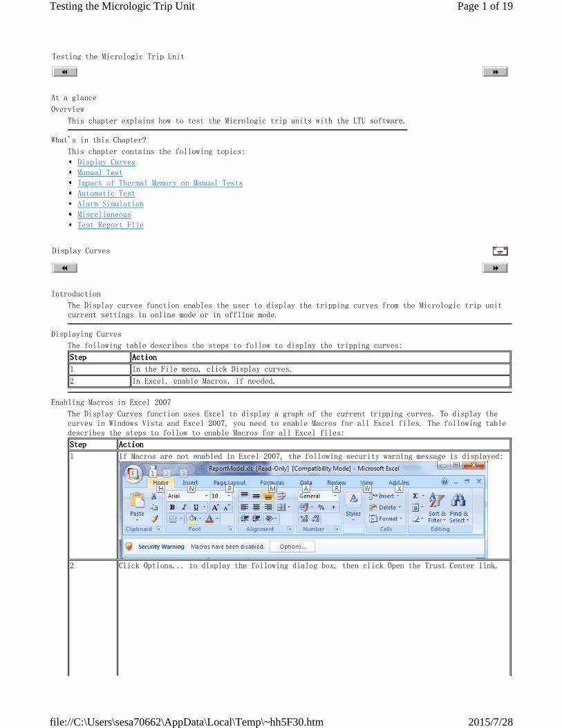
Enabling Macros in Excel 2007
The Display Curves function uses Excel to display a graph of the current tripping curves. To display the
curves in Windows Vista and Excel 2007, you need to enable Macros for all Excel files. The following table
describes the steps to follow to enable Macros for all Excel files:
StepStepStepStep ActionActionActionAction
1 If Macros are not enabled in Excel 2007, the following security warning message is displayed:
2 Click Options... to display the following dialog box, then click Open the Trust Center link.
Page 1 of 19Testing the Micrologic Trip Unit
2015/7/28file://C:\Users\sesa70662\AppData\Local\Temp\~hh5F30.htm
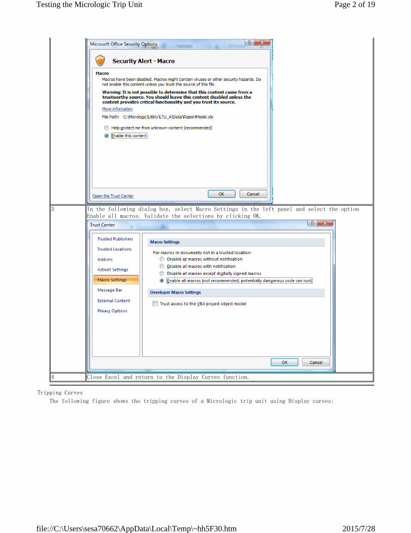
3 In the following dialog box, select Macro Settings in the left panel and select the option
Enable all macros. Validate the selections by clicking OK.
4 Close Excel and return to the Display Curves function.
Tripping Curves
The following figure shows the tripping curves of a Micrologic trip unit using Display curves:
Page 2 of 19Testing the Micrologic Trip Unit
2015/7/28file://C:\Users\sesa70662\AppData\Local\Temp\~hh5F30.htm

In this graph, we can distinguish 3 tripping areas from bottom to top:
1 Long time protection area
2 Short time protection area
3 Instantaneous protection area
Below the red curve: the circuit breaker will not trip.
In between the red and blue curves: the circuit breaker may or may not trip.
Above the blue curve: the circuit breaker will trip.
Manual Test
Introduction
The Manual TEST tab enables the user to:
Depending on the injected current, the following protections can trip:
simulate current injections on a Micrologic trip unit for a given time
check the tripping or the non-tripping of the tested Micrologic trip unit
all the distribution protections:
Long time
Short time
Instantaneous
Ground fault
some specific protections
The Jam protection can not trip during manual tests.
Unbalance
Long start
Under load
Manual TEST Tab Description
A caution message is displayed when the user selects the Manual TEST tab:
Page 3 of 19Testing the Micrologic Trip Unit
2015/7/28file://C:\Users\sesa70662\AppData\Local\Temp\~hh5F30.htm
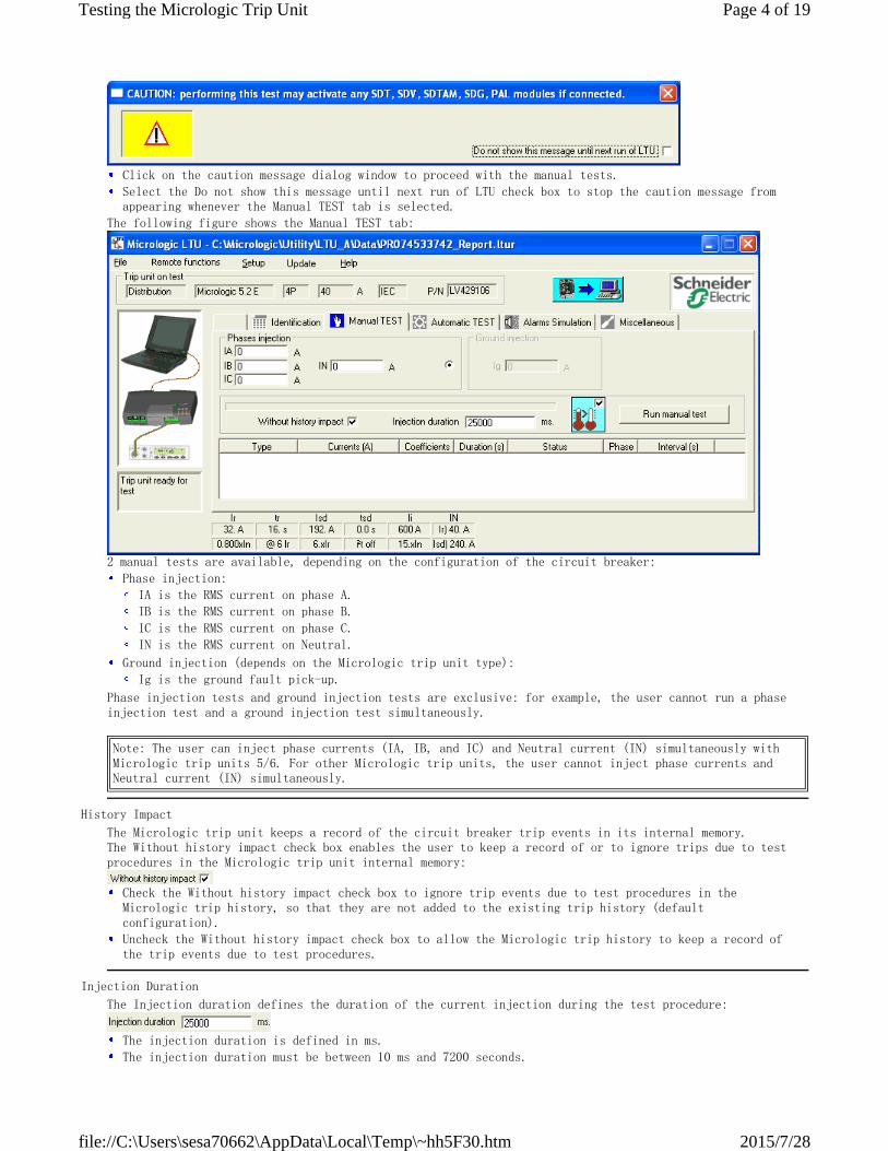
The following figure shows the Manual TEST tab:
2 manual tests are available, depending on the configuration of the circuit breaker:
Phase injection tests and ground injection tests are exclusive: for example, the user cannot run a phase
injection test and a ground injection test simultaneously.
Click on the caution message dialog window to proceed with the manual tests.
Select the Do not show this message until next run of LTU check box to stop the caution message from
appearing whenever the Manual TEST tab is selected.
Phase injection:
IA is the RMS current on phase A.
IB is the RMS current on phase B.
IC is the RMS current on phase C.
IN is the RMS current on Neutral.
Ground injection (depends on the Micrologic trip unit type):
Ig is the ground fault pick-up.
Note: The user can inject phase currents (IA, IB, and IC) and Neutral current (IN) simultaneously with
Micrologic trip units 5/6. For other Micrologic trip units, the user cannot inject phase currents and
Neutral current (IN) simultaneously.
History Impact
The Micrologic trip unit keeps a record of the circuit breaker trip events in its internal memory.
The Without history impact check box enables the user to keep a record of or to ignore trips due to test
procedures in the Micrologic trip unit internal memory:
Check the Without history impact check box to ignore trip events due to test procedures in the
Micrologic trip history, so that they are not added to the existing trip history (default
configuration).
Uncheck the Without history impact check box to allow the Micrologic trip history to keep a record of
the trip events due to test procedures.
Injection Duration
The Injection duration defines the duration of the current injection during the test procedure:
The injection duration is defined in ms.
The injection duration must be between 10 ms and 7200 seconds.
Page 4 of 19Testing the Micrologic Trip Unit
2015/7/28file://C:\Users\sesa70662\AppData\Local\Temp\~hh5F30.htm
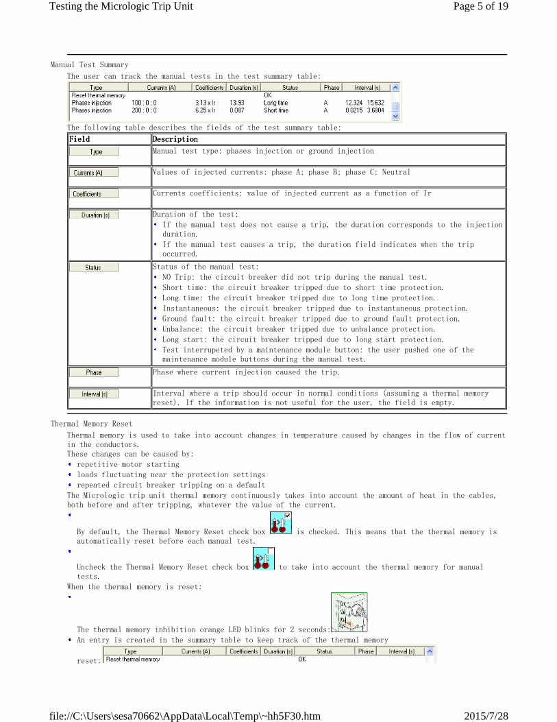
Manual Test Summary
The user can track the manual tests in the test summary table:
The following table describes the fields of the test summary table:
FieldFieldFieldField DescriptionDescriptionDescriptionDescription
Manual test type: phases injection or ground injection
Values of injected currents: phase A; phase B; phase C; Neutral
Currents coefficients: value of injected current as a function of Ir
Duration of the test:
If the manual test does not cause a trip, the duration corresponds to the injection
duration.
If the manual test causes a trip, the duration field indicates when the trip
occurred.
Status of the manual test:
NO Trip: the circuit breaker did not trip during the manual test.
Short time: the circuit breaker tripped due to short time protection.
Long time: the circuit breaker tripped due to long time protection.
Instantaneous: the circuit breaker tripped due to instantaneous protection.
Ground fault: the circuit breaker tripped due to ground fault protection.
Unbalance: the circuit breaker tripped due to unbalance protection.
Long start: the circuit breaker tripped due to long start protection.
Test interrupeted by a maintenance module button: the user pushed one of the
maintenance module buttons during the manual test.
Phase where current injection caused the trip.
Interval where a trip should occur in normal conditions (assuming a thermal memory
reset). If the information is not useful for the user, the field is empty.
Thermal Memory Reset
Thermal memory is used to take into account changes in temperature caused by changes in the flow of current
in the conductors.
These changes can be caused by:
The Micrologic trip unit thermal memory continuously takes into account the amount of heat in the cables,
both before and after tripping, whatever the value of the current.
When the thermal memory is reset:
repetitive motor starting
loads fluctuating near the protection settings
repeated circuit breaker tripping on a default
By default, the Thermal Memory Reset check box is checked. This means that the thermal memory is
automatically reset before each manual test.
Uncheck the Thermal Memory Reset check box to take into account the thermal memory for manual
tests.
The thermal memory inhibition orange LED blinks for 2 seconds:
An entry is created in the summary table to keep track of the thermal memory
reset:
Page 5 of 19Testing the Micrologic Trip Unit
2015/7/28file://C:\Users\sesa70662\AppData\Local\Temp\~hh5F30.htm
Run Manual Test
The following table describes the steps to follow when performing the manual tests:
StepStepStepStep ActionActionActionAction
1 Select the test type (phase injection or ground injection) and the corresponding current values.
2 Check/Uncheck the Without history impact check box (see History Impact).
3 Define the injection duration in the Injection duration box.
4 Check/Uncheck the Thermal Memory Reset check box (see Thermal Memory Reset).
5 Click Run manual test to start the manual test.
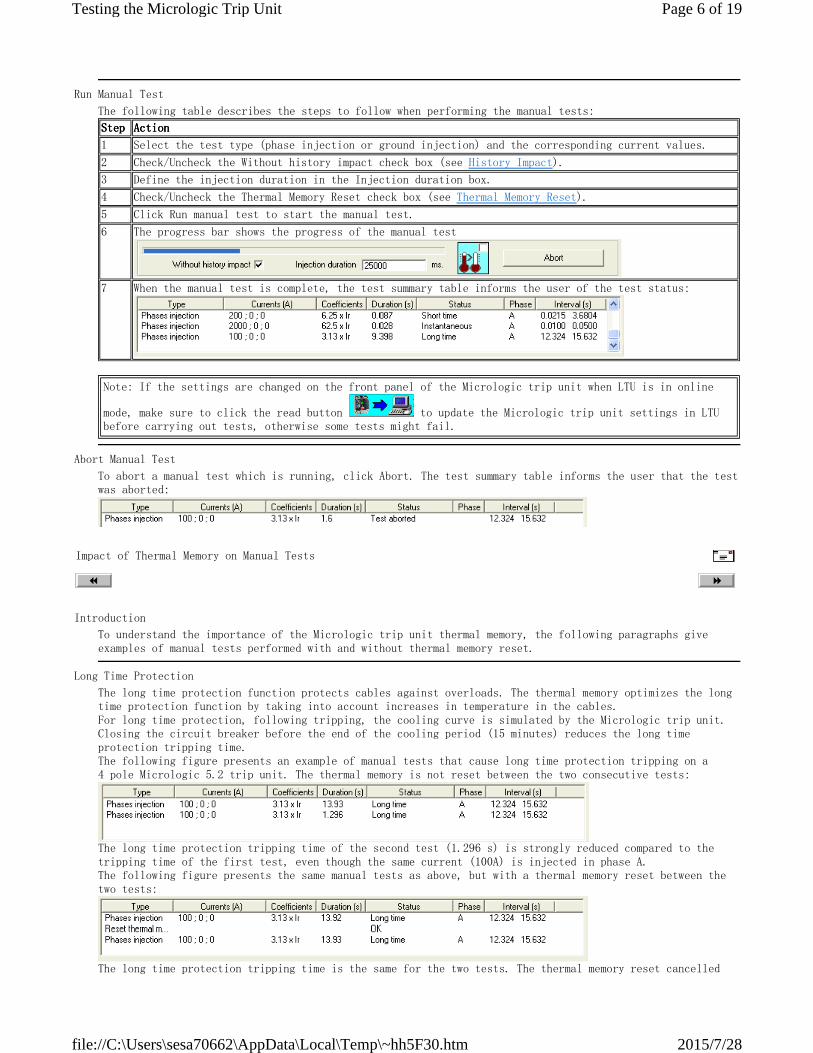
6 The progress bar shows the progress of the manual test
7 When the manual test is complete, the test summary table informs the user of the test status:
Note: If the settings are changed on the front panel of the Micrologic trip unit when LTU is in online
mode, make sure to click the read button to update the Micrologic trip unit settings in LTU
before carrying out tests, otherwise some tests might fail.
Abort Manual Test
To abort a manual test which is running, click Abort. The test summary table informs the user that the test
was aborted:
Impact of Thermal Memory on Manual Tests
Introduction
To understand the importance of the Micrologic trip unit thermal memory, the following paragraphs give
examples of manual tests performed with and without thermal memory reset.
Long Time Protection
The long time protection function protects cables against overloads. The thermal memory optimizes the long
time protection function by taking into account increases in temperature in the cables.
For long time protection, following tripping, the cooling curve is simulated by the Micrologic trip unit.
Closing the circuit breaker before the end of the cooling period (15 minutes) reduces the long time
protection tripping time.
The following figure presents an example of manual tests that cause long time protection tripping on a
4 pole Micrologic 5.2 trip unit. The thermal memory is not reset between the two consecutive tests:
The long time protection tripping time of the second test (1.296 s) is strongly reduced compared to the
tripping time of the first test, even though the same current (100A) is injected in phase A.
The following figure presents the same manual tests as above, but with a thermal memory reset between the
two tests:
The long time protection tripping time is the same for the two tests. The thermal memory reset cancelled
Page 6 of 19Testing the Micrologic Trip Unit
2015/7/28file://C:\Users\sesa70662\AppData\Local\Temp\~hh5F30.htm
out the temperature rise effect caused by the first test.
Short Time Protection
The short time protection function protects the distribution system against impedant short-circuits.
The short time tripping delay and the I
2
t ON/OFF function can be used to ensure discrimination with a
downstream circuit breaker:
Short time protection with I
2
t OFF
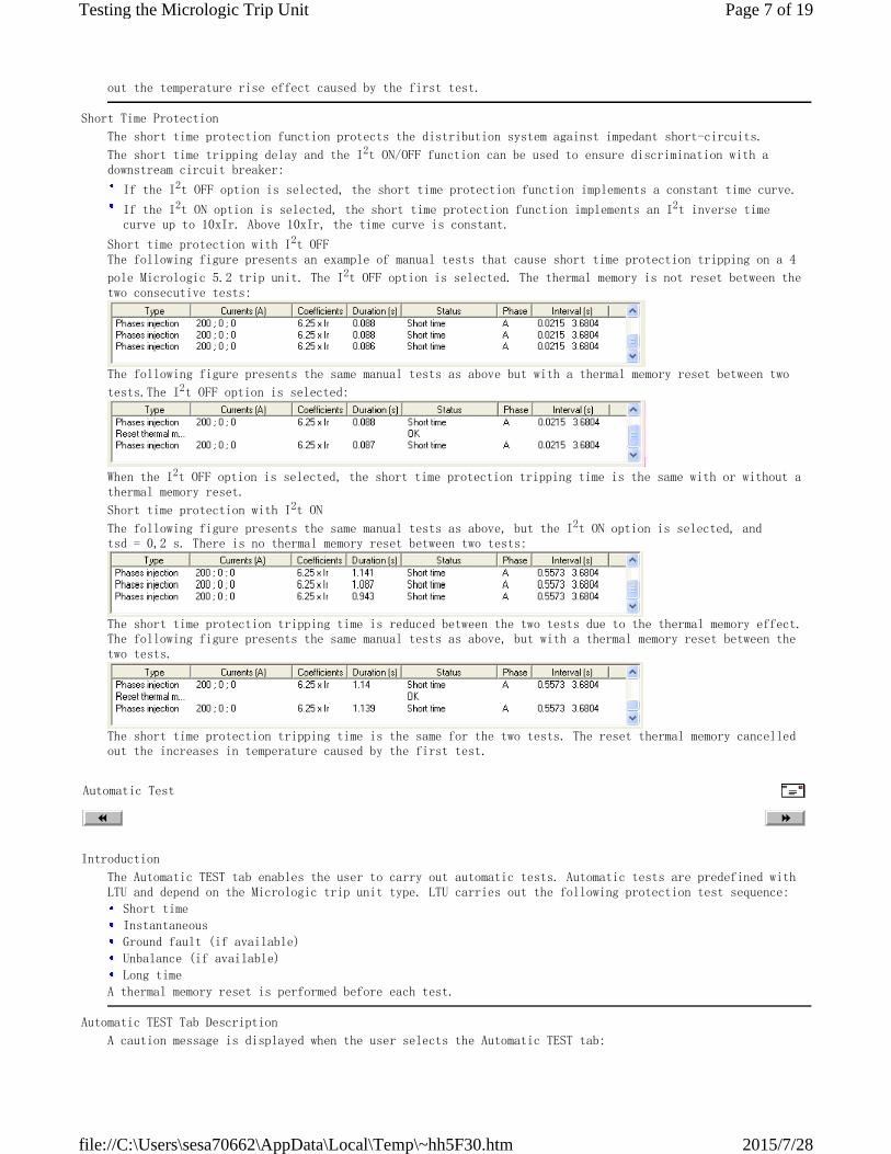
The following figure presents an example of manual tests that cause short time protection tripping on a 4
pole Micrologic 5.2 trip unit. The I
2
t OFF option is selected. The thermal memory is not reset between the
two consecutive tests:
The following figure presents the same manual tests as above but with a thermal memory reset between two
tests.The I
2
t OFF option is selected:
When the I
2
t OFF option is selected, the short time protection tripping time is the same with or without a
thermal memory reset.
Short time protection with I
2
t ON
The following figure presents the same manual tests as above, but the I
2
t ON option is selected, and
tsd = 0,2 s. There is no thermal memory reset between two tests:
The short time protection tripping time is reduced between the two tests due to the thermal memory effect.
The following figure presents the same manual tests as above, but with a thermal memory reset between the
two tests.
The short time protection tripping time is the same for the two tests. The reset thermal memory cancelled
out the increases in temperature caused by the first test.
If the I
2
t OFF option is selected, the short time protection function implements a constant time curve.
If the I
2
t ON option is selected, the short time protection function implements an I
2
t inverse time
curve up to 10xIr. Above 10xIr, the time curve is constant.
Automatic Test
Introduction
The Automatic TEST tab enables the user to carry out automatic tests. Automatic tests are predefined with
LTU and depend on the Micrologic trip unit type. LTU carries out the following protection test sequence:
A thermal memory reset is performed before each test.
Short time
Instantaneous
Ground fault (if available)
Unbalance (if available)
Long time
Automatic TEST Tab Description
A caution message is displayed when the user selects the Automatic TEST tab:
Page 7 of 19Testing the Micrologic Trip Unit
2015/7/28file://C:\Users\sesa70662\AppData\Local\Temp\~hh5F30.htm
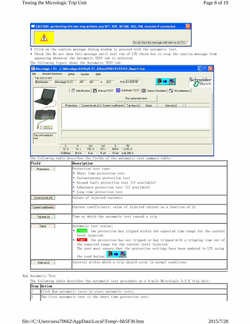
The following figure shows the Automatic TEST tab:
The following table describes the fields of the automatic test summary table:
Click on the caution message dialog window to proceed with the automatic test.
Check the Do not show this message until next run of LTU check box to stop the caution message from
appearing whenever the Automatic TEST tab is selected.
FieldFieldFieldField DescriptionDescriptionDescriptionDescription
Protection test type:
Short time protection test
Instantaneous protection test
Ground fault protection test (if available)
Unbalance protection test (if available)
Long time protection test
Values of injected currents
Current coefficients: value of injected current as a function of Ir
Time at which the automatic test caused a trip
Automatic test status:
: the protection has tripped within the expected time range for the current
level injected.
: the protection has not tripped or has tripped with a tripping time out of
the expected range for the current level injected.
The user must ensure that the protection settings have been updated in LTU using
the read button .
Interval within which a trip should occur in normal conditions
Run Automatic Test
The following table describes the automatic test procedure on a 4-pole Micrologic 5.2 E trip unit:
StepStepStepStep ActionActionActionAction
1 Click Run automatic tests to start automatic tests.
2 The first automatic test is the short time protection test:
Page 8 of 19Testing the Micrologic Trip Unit
2015/7/28file://C:\Users\sesa70662\AppData\Local\Temp\~hh5F30.htm
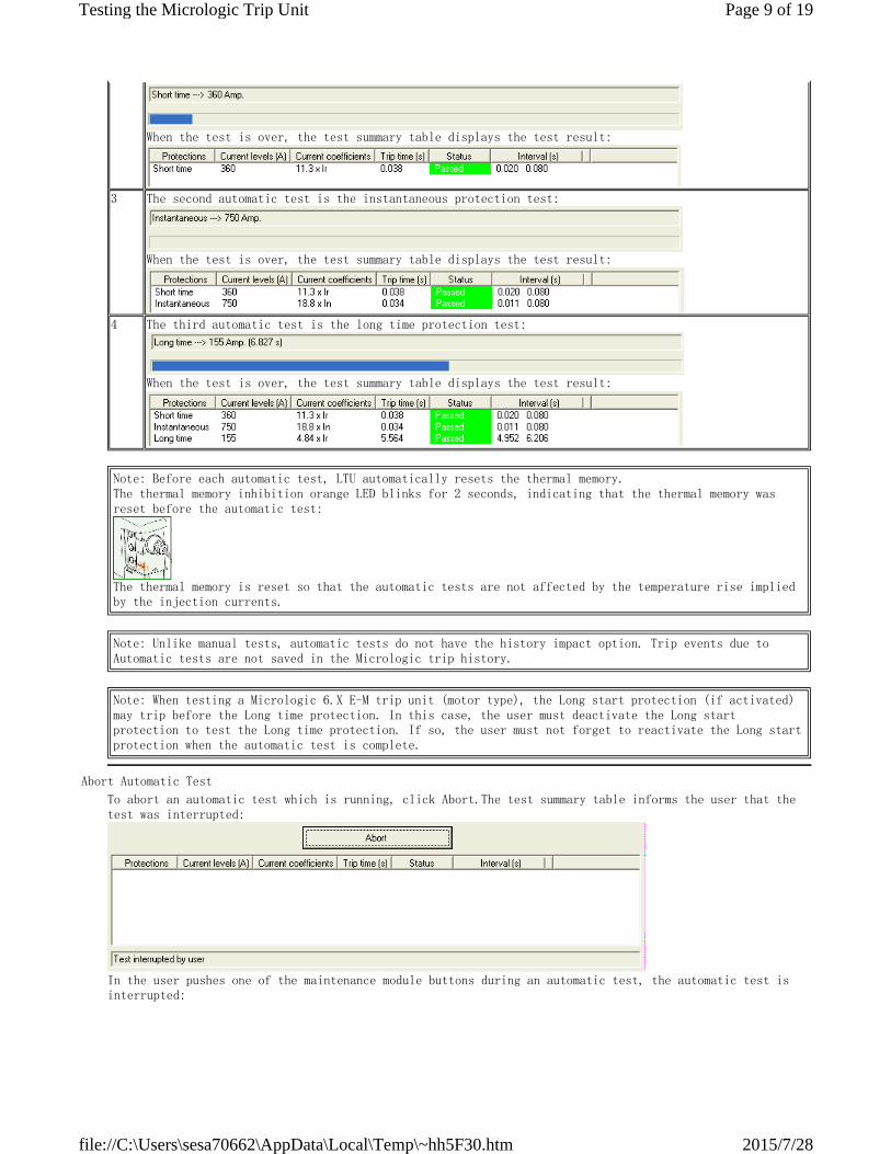
When the test is over, the test summary table displays the test result:
3 The second automatic test is the instantaneous protection test:
When the test is over, the test summary table displays the test result:
4 The third automatic test is the long time protection test:
When the test is over, the test summary table displays the test result:
Note: Before each automatic test, LTU automatically resets the thermal memory.
The thermal memory inhibition orange LED blinks for 2 seconds, indicating that the thermal memory was
reset before the automatic test:
The thermal memory is reset so that the automatic tests are not affected by the temperature rise implied
by the injection currents.
Note: Unlike manual tests, automatic tests do not have the history impact option. Trip events due to
Automatic tests are not saved in the Micrologic trip history.
Note: When testing a Micrologic 6.X E-M trip unit (motor type), the Long start protection (if activated)
may trip before the Long time protection. In this case, the user must deactivate the Long start
protection to test the Long time protection. If so, the user must not forget to reactivate the Long start
protection when the automatic test is complete.
Abort Automatic Test
To abort an automatic test which is running, click Abort.The test summary table informs the user that the
test was interrupted:
In the user pushes one of the maintenance module buttons during an automatic test, the automatic test is
interrupted:
Page 9 of 19Testing the Micrologic Trip Unit
2015/7/28file://C:\Users\sesa70662\AppData\Local\Temp\~hh5F30.htm
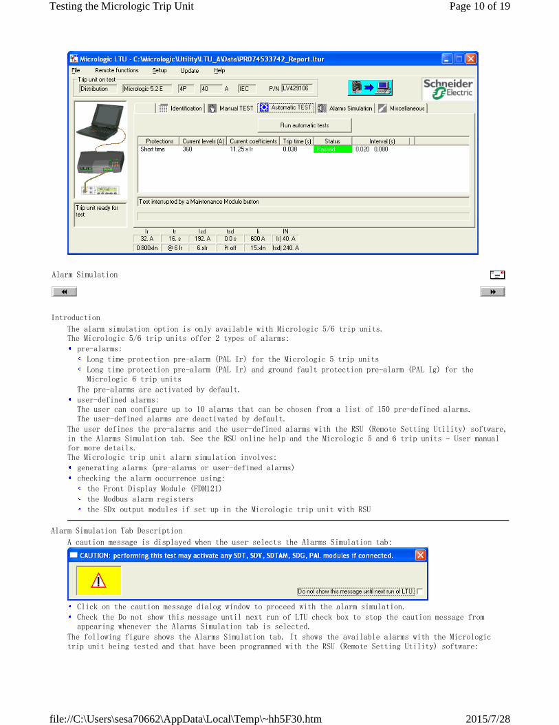
Alarm Simulation
Introduction
The alarm simulation option is only available with Micrologic 5/6 trip units.
The Micrologic 5/6 trip units offer 2 types of alarms:
The user defines the pre-alarms and the user-defined alarms with the RSU (Remote Setting Utility) software,
in the Alarms Simulation tab. See the RSU online help and the Micrologic 5 and 6 trip units - User manual
for more details.
The Micrologic trip unit alarm simulation involves:
pre-alarms:
The pre-alarms are activated by default.
Long time protection pre-alarm (PAL Ir) for the Micrologic 5 trip units
Long time protection pre-alarm (PAL Ir) and ground fault protection pre-alarm (PAL Ig) for the
Micrologic 6 trip units
user-defined alarms:
The user can configure up to 10 alarms that can be chosen from a list of 150 pre-defined alarms.
The user-defined alarms are deactivated by default.
generating alarms (pre-alarms or user-defined alarms)
checking the alarm occurrence using:
the Front Display Module (FDM121)
the Modbus alarm registers
the SDx output modules if set up in the Micrologic trip unit with RSU
Alarm Simulation Tab Description
A caution message is displayed when the user selects the Alarms Simulation tab:
The following figure shows the Alarms Simulation tab. It shows the available alarms with the Micrologic
trip unit being tested and that have been programmed with the RSU (Remote Setting Utility) software:
Click on the caution message dialog window to proceed with the alarm simulation.
Check the Do not show this message until next run of LTU check box to stop the caution message from
appearing whenever the Alarms Simulation tab is selected.
Page 10 of 19Testing the Micrologic Trip Unit
2015/7/28file://C:\Users\sesa70662\AppData\Local\Temp\~hh5F30.htm
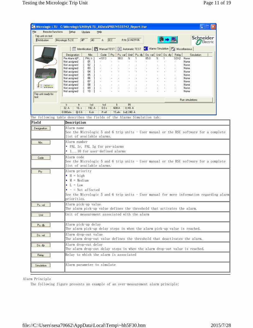
The following table describes the fields of the Alarms Simulation tab:
FieldFieldFieldField DescriptionDescriptionDescriptionDescription
Alarm name
See the Micrologic 5 and 6 trip units - User manual or the RSU software for a complete
list of available alarms.
Alarm number
PAL Ir, PAL Ig for pre-alarms
1...10 for user-defined alarms
Alarm code
See the Micrologic 5 and 6 trip units - User manual or the RSU software for a complete
list of available alarms.
Alarm priority
See the Micrologic 5 and 6 trip units - User manual for more information regarding alarm
priorities.
H = high
M = Medium
L = Low
- = Not affected
Alarm pick-up value
The alarm pick-up value defines the threshold that activates the alarm.
Unit of measurement associated with the alarm
Alarm pick-up delay
The alarm pick-up delay steps in when the alarm pick-up value is reached.
Alarm drop-out value
The alarm drop-out value defines the threshold that deactivates the alarm.
Alarm drop-out delay
The alarm drop-out delay steps in when the alarm drop-out value is reached.
Relay to which the alarm is associated
Alarm parameter to simulate
Alarm Principle
The following figure presents an example of an over-measurement alarm principle:
Page 11 of 19Testing the Micrologic Trip Unit
2015/7/28file://C:\Users\sesa70662\AppData\Local\Temp\~hh5F30.htm
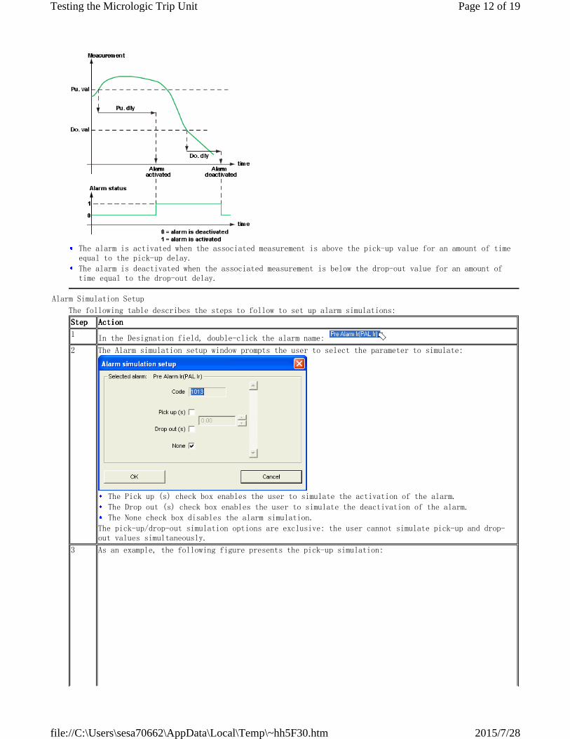
The alarm is activated when the associated measurement is above the pick-up value for an amount of time
equal to the pick-up delay.
The alarm is deactivated when the associated measurement is below the drop-out value for an amount of
time equal to the drop-out delay.
Alarm Simulation Setup
The following table describes the steps to follow to set up alarm simulations:
StepStepStepStep ActionActionActionAction
1
In the Designation field, double-click the alarm name:
2 The Alarm simulation setup window prompts the user to select the parameter to simulate:
The pick-up/drop-out simulation options are exclusive: the user cannot simulate pick-up and drop-
out values simultaneously.
The Pick up (s) check box enables the user to simulate the activation of the alarm.
The Drop out (s) check box enables the user to simulate the deactivation of the alarm.
The None check box disables the alarm simulation.
3 As an example, the following figure presents the pick-up simulation:
Page 12 of 19Testing the Micrologic Trip Unit
2015/7/28file://C:\Users\sesa70662\AppData\Local\Temp\~hh5F30.htm
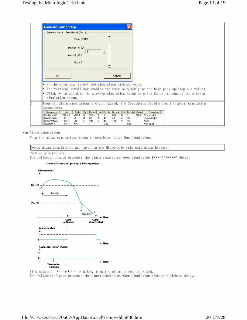
In the spin box, select the simulation pick-up value.
The vertical scroll bar enables the user to quickly select high pick-up/drop-out values.
Click OK to validate the pick-up simulation setup or click Cancel to cancel the pick-up
simulation setup.
4 When all alarm simulations are configured, the Simulation field shows the alarm simulation
parameters:
Run Alarm Simulations
When the alarm simulations setup is complete, click Run simulations.
Pick-up simulations
The following figure presents the alarm simulation when simulation delay:
If simulation delay, then the alarm is not activated.
The following figure presents the alarm simulation when simulation pick-up > pick-up delay:
Note: Alarm simulations are saved in the Micrologic trip unit alarm history.
Page 13 of 19Testing the Micrologic Trip Unit
2015/7/28file://C:\Users\sesa70662\AppData\Local\Temp\~hh5F30.htm
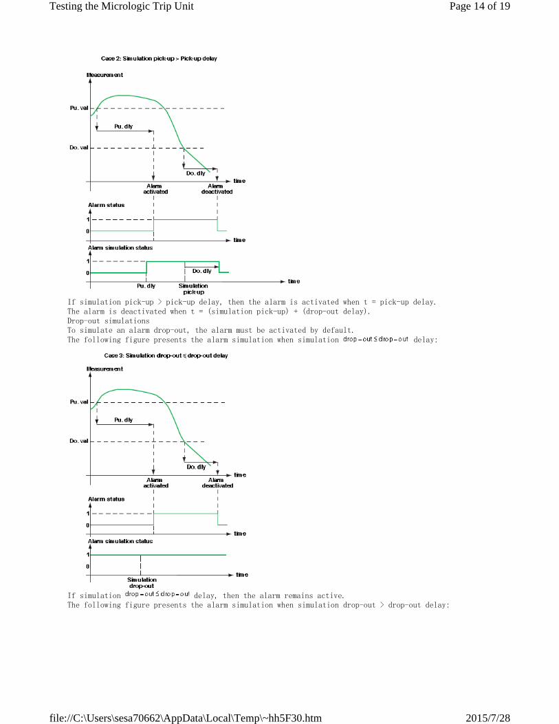
If simulation pick-up > pick-up delay, then the alarm is activated when t = pick-up delay.
The alarm is deactivated when t = (simulation pick-up) + (drop-out delay).
Drop-out simulations
To simulate an alarm drop-out, the alarm must be activated by default.
The following figure presents the alarm simulation when simulation delay:
If simulation delay, then the alarm remains active.
The following figure presents the alarm simulation when simulation drop-out > drop-out delay:
Page 14 of 19Testing the Micrologic Trip Unit
2015/7/28file://C:\Users\sesa70662\AppData\Local\Temp\~hh5F30.htm
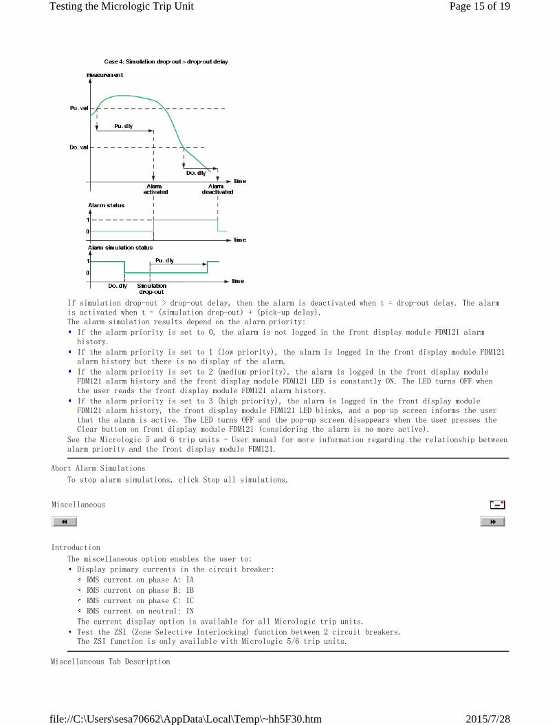
If simulation drop-out > drop-out delay, then the alarm is deactivated when t = drop-out delay. The alarm
is activated when t = (simulation drop-out) + (pick-up delay).
The alarm simulation results depend on the alarm priority:
See the Micrologic 5 and 6 trip units - User manual for more information regarding the relationship between
alarm priority and the front display module FDM121.
If the alarm priority is set to 0, the alarm is not logged in the front display module FDM121 alarm
history.
If the alarm priority is set to 1 (low priority), the alarm is logged in the front display module FDM121
alarm history but there is no display of the alarm.
If the alarm priority is set to 2 (medium priority), the alarm is logged in the front display module
FDM121 alarm history and the front display module FDM121 LED is constantly ON. The LED turns OFF when
the user reads the front display module FDM121 alarm history.
If the alarm priority is set to 3 (high priority), the alarm is logged in the front display module
FDM121 alarm history, the front display module FDM121 LED blinks, and a pop-up screen informs the user
that the alarm is active. The LED turns OFF and the pop-up screen disappears when the user presses the
Clear button on front display module FDM121 (considering the alarm is no more active).
Abort Alarm Simulations
To stop alarm simulations, click Stop all simulations.
Miscellaneous
Introduction
The miscellaneous option enables the user to:
Display primary currents in the circuit breaker:
The current display option is available for all Micrologic trip units.
RMS current on phase A: IA
RMS current on phase B: IB
RMS current on phase C: IC
RMS current on neutral: IN
Test the ZSI (Zone Selective Interlocking) function between 2 circuit breakers.
The ZSI function is only available with Micrologic 5/6 trip units.
Miscellaneous Tab Description
Page 15 of 19Testing the Micrologic Trip Unit
2015/7/28file://C:\Users\sesa70662\AppData\Local\Temp\~hh5F30.htm
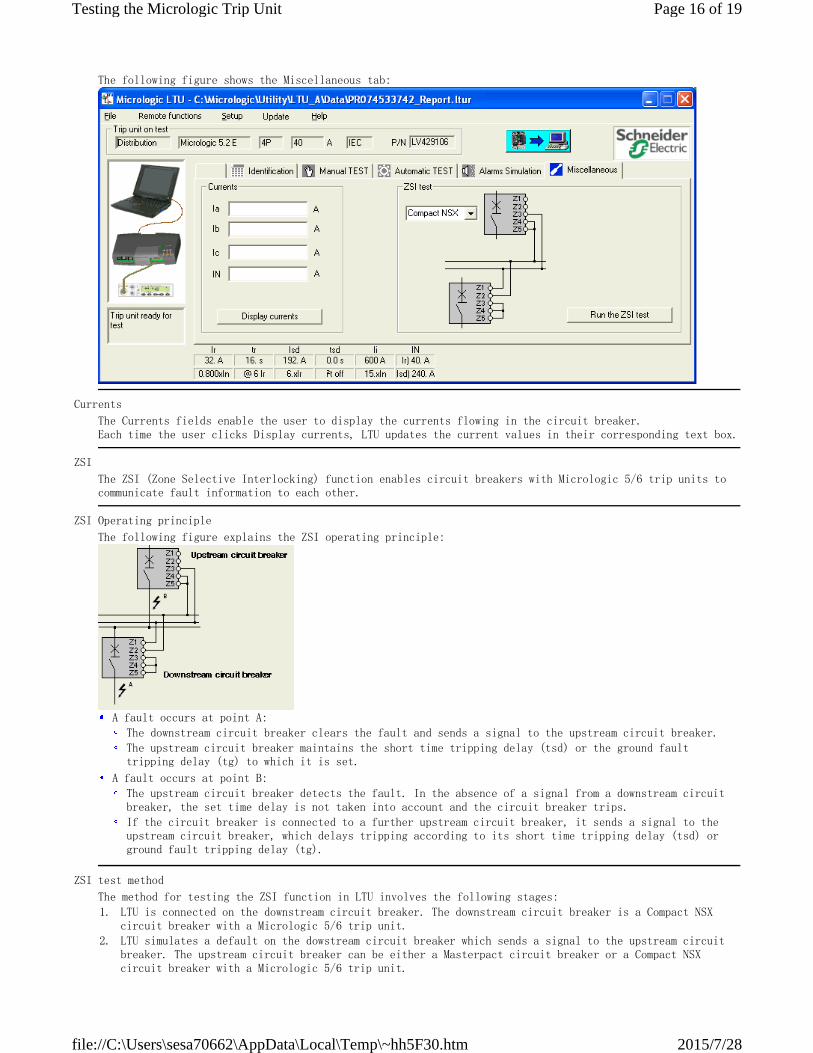
The following figure shows the Miscellaneous tab:
Currents
The Currents fields enable the user to display the currents flowing in the circuit breaker.
Each time the user clicks Display currents, LTU updates the current values in their corresponding text box.
ZSI
The ZSI (Zone Selective Interlocking) function enables circuit breakers with Micrologic 5/6 trip units to
communicate fault information to each other.
ZSI Operating principle
The following figure explains the ZSI operating principle:
A fault occurs at point A:
The downstream circuit breaker clears the fault and sends a signal to the upstream circuit breaker.
The upstream circuit breaker maintains the short time tripping delay (tsd) or the ground fault
tripping delay (tg) to which it is set.
A fault occurs at point B:
The upstream circuit breaker detects the fault. In the absence of a signal from a downstream circuit
breaker, the set time delay is not taken into account and the circuit breaker trips.
If the circuit breaker is connected to a further upstream circuit breaker, it sends a signal to the
upstream circuit breaker, which delays tripping according to its short time tripping delay (tsd) or
ground fault tripping delay (tg).
ZSI test method
The method for testing the ZSI function in LTU involves the following stages:
1.
LTU is connected on the downstream circuit breaker. The downstream circuit breaker is a Compact NSX
circuit breaker with a Micrologic 5/6 trip unit.
2.
LTU simulates a default on the dowstream circuit breaker which sends a signal to the upstream circuit
breaker. The upstream circuit breaker can be either a Masterpact circuit breaker or a Compact NSX
circuit breaker with a Micrologic 5/6 trip unit.
Page 16 of 19Testing the Micrologic Trip Unit
2015/7/28file://C:\Users\sesa70662\AppData\Local\Temp\~hh5F30.htm
3.
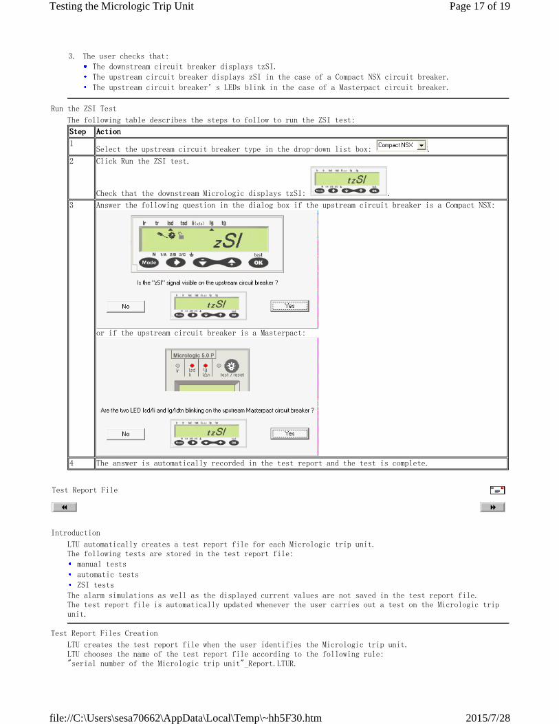
The user checks that:
The downstream circuit breaker displays tzSI.
The upstream circuit breaker displays zSI in the case of a Compact NSX circuit breaker.
The upstream circuit breaker’s LEDs blink in the case of a Masterpact circuit breaker.
Run the ZSI Test
The following table describes the steps to follow to run the ZSI test:
StepStepStepStep ActionActionActionAction
1
Select the upstream circuit breaker type in the drop-down list box: .
2 Click Run the ZSI test.
Check that the downstream Micrologic displays tzSI: .
3 Answer the following question in the dialog box if the upstream circuit breaker is a Compact NSX:
or if the upstream circuit breaker is a Masterpact:
4 The answer is automatically recorded in the test report and the test is complete.
Test Report File
Introduction
LTU automatically creates a test report file for each Micrologic trip unit.
The following tests are stored in the test report file:
The alarm simulations as well as the displayed current values are not saved in the test report file.
The test report file is automatically updated whenever the user carries out a test on the Micrologic trip
unit.
manual tests
automatic tests
ZSI tests
Test Report Files Creation
LTU creates the test report file when the user identifies the Micrologic trip unit.
LTU chooses the name of the test report file according to the following rule:
"serial number of the Micrologic trip unit"_Report.LTUR.
Page 17 of 19Testing the Micrologic Trip Unit
2015/7/28file://C:\Users\sesa70662\AppData\Local\Temp\~hh5F30.htm
This way, each Micrologic trip unit will have its own test report file.
Test Report Files Location
The test report files are stored in the following folder:
Software_path\Data
By default the software path is:
C:\Micrologic\Utility\LTU_A
Generating an Excel Test Report File
The user can display and print the test data by generating an Excel report file from the test report file.
The report language (French, English or Spanish) can be different from the test language. The test report
file generation is only available in offline mode. Once the tests are done, the user must close the
communication before generating an Excel test report file.
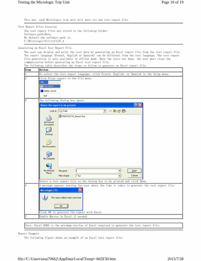
The following table describes the steps to follow to generate an Excel report file:
StepStepStepStep ActionActionActionAction
1 To select the test report language, click French, English, or Spanish in the Setup menu.
2 Click Print report in the file menu.
3 The following dialog box opens:
Select a test report file in the dialog box to be printed and click Open.
4 A message appears warning the user about the time it takes to generate the test report file:
Click OK to generate the report with Excel.
5 Enable Macros in Excel if needed.
Note: Excel 2003 is the minimum version of Excel required to generate the test report file.
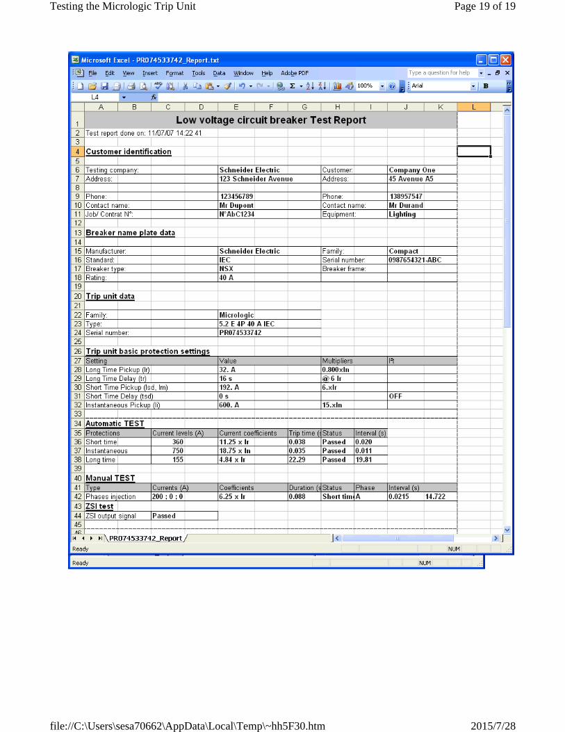
Report Example
The following figure shows an example of an Excel test report file:
Page 18 of 19Testing the Micrologic Trip Unit
2015/7/28file://C:\Users\sesa70662\AppData\Local\Temp\~hh5F30.htm
Page 19 of 19Testing the Micrologic Trip Unit
2015/7/28file://C:\Users\sesa70662\AppData\Local\Temp\~hh5F30.htm