P2 P3 P4 P5 P6 P7 C01 C02 C03 C04 C05 C10 Result - State ...
Upload
khangminh22Category
view
5download
0
1
P5/P2K Series
Connection Manual

2
Version Date Modification
V1.0.0 Janu 18,2015 First Draft
V1.0.1 MAR 7 2019 Increase Xinje
V1.0.2 MAR 15 2019 Increase Vigor
1. HMI Model Serial Information ....................................................................................................... 4
2. PLC Connection .............................................................................................................................. 7
2.1 FATEK Automation Corp. .................................................................................................... 7
FBs/B1/B1z/HB1 ..................................................................................................... 7
FBe........................................................................................................................ 11
FBs/B1/B1z/HB1 (TCP) ......................................................................................... 17
FBe (TCP) .............................................................................................................. 20
FBs/B1/B1z/HB1 (UDP) ........................................................................................ 22
2.1.6. Sflag series ........................................................................................................... 25
2.2 Mitsubishi ......................................................................................................................... 31
FX2N CPU ............................................................................................................. 31
FX2N-485BD ......................................................................................................... 34
FX3U CPU ............................................................................................................. 42
FX3U-485BD ......................................................................................................... 46
FX3U Ethernet ...................................................................................................... 53
FX5U-Serial ........................................................................................................... 59
FX5U Ethernet ...................................................................................................... 68
QSeries-Serial Communication(Link Port) ............................................................ 75
QSeries-Serial Communication(CPU Port) ........................................................... 83
Q/L Series-ENET ................................................................................................... 88
iQ-R Series-ENET .................................................................................................. 92
2.3 Omron .............................................................................................................................. 96
Omron SYSMAC CP Series .................................................................................... 96
Omron SYSMAC CP Series Ethernet ................................................................... 101
Omron SYSMAC CS/CJ Series ............................................................................. 104
Omron SYSMAC CS/CJ Series Ethernet .............................................................. 109
Omron SYSMAC CPM Series ............................................................................... 113
Omron SYSMAC NJ/NX Series(EtherNet/IP) ....................................................... 117
Omron Ethernet ................................................................................................. 120
Sysmac NJ Series (FINS/TCP) .............................................................................. 123
Sysmac NX/NJ Series (FINS/UDP) ....................................................................... 126

3
Omron SYSMAC CQM Series .............................................................................. 129
2.4 Siemens .......................................................................................................................... 134
Siemens S7-200 SMART ..................................................................................... 134
Siemens S7-200 SMART Ethernet ...................................................................... 140
Siemens S7-1200 Ethernet ................................................................................. 145
Siemens S7-200 .................................................................................................. 149
Siemens LOGO .................................................................................................... 156
2.5 Hitachi ............................................................................................................................ 159
EHV Series .......................................................................................................... 159
EHV Series ( Ethernet ) ....................................................................................... 162
2.6 Schneider ....................................................................................................................... 163
MODBUS RTU ..................................................................................................... 163
MODBUS TCP ..................................................................................................... 167
2.7 Allen-Bradley .................................................................................................................. 169
CompactLogix/ControlLogix/FlexLogix Tag Series .............................................. 169
SLC series (EtherNet/IP) ..................................................................................... 173
SLC Series ........................................................................................................... 177
MicroLogix Series (EtherNet/IP) ......................................................................... 182
MicroLogix Series ............................................................................................... 186
2.8 Taiwan Instrument & Control Co., Ltd. ........................................................................... 191
FY Series ............................................................................................................. 191
2.9 Delta ............................................................................................................................... 201
DVP Series .......................................................................................................... 201
AH500 Series ...................................................................................................... 204
2.10 Panasonic ....................................................................................................................... 211
FP Series ............................................................................................................. 211
FP Series (Ethernet) ............................................................................................ 215
2.11 YASKAWA ........................................................................................................................ 217
Extended MEMOBUS ......................................................................................... 217
MP Series Extension (Ethernet) ......................................................................... 220
2.12 Keyence .......................................................................................................................... 223
KV-3000/5000/5500/7500(Ethernet) ................................................................ 223
KV-L21V/3000/5000/5500 (host link) ................................................................ 228
KV-Nano (host link) ............................................................................................ 237
2.13 Beckhoff Automation ..................................................................................................... 241
Twincat(Ethernet) .............................................................................................. 241
2.14 Koyo ................................................................................................................................ 245
Direct .................................................................................................................. 245

4
2.15 Yudian ............................................................................................................................. 252
AI ........................................................................................................................ 252
2.16 Xinje ............................................................................................................................... 255
2.16.1 XC series ............................................................................................................... 255
2.16.2 XD series............................................................................................................... 259
2.17 Vigor ............................................................................................................................... 263
2.17.1 M/VB/VH Series ...................................................................................................... 263
2.17.2 VS series .................................................................................................................. 267
2.18 LS .................................................................................................................................... 272
2.18.1 LS XBC-cnet ........................................................................................................ 273
2.18.2 LS XEC-Cnet ........................................................................................................ 276
2.18.3 LS XBC-Fnet ........................................................................................................ 280
2.18.4 LS XEC-Fnet......................................................................................................... 283
1. HMI Model Serial Information
P5043S/P5043N/P5070VS/P5102VS
Serial Interface COM1(RS-232[TXD,RXD]), COM2(RS-422/485),
COM3(RS-485)
Serial Layout RS-
232/
RS-
422/
RS-
485
PIN# COM1 COM2
(RS-422)
COM2
(RS-485)
COM3
1 TX+ DATA+
2 RX
3 TX
4 RX+
5 GND GND GND GND
6 TX- DATA-
7 DATA+
8 DATA-
9 RX-

5
P5070S/ P5070N/ P5070N1/ P5102S/ P5102N/ P5102N1
Serial Interface COM1(RS-232[TXD,RXD,RTS,CTS]), COM3(RS-
422/485), COM4(RS-485)
Serial Layout RS-232
PIN# COM1
1
2 RX
3 TX
4
5 GND
6
7 RTS
8 CTS
9
RS-422/
485
Old Model
PIN# COM3
(RS-422)
COM3
(RS-485)
COM4
1 TX- DATA-
2 TX+ DATA+
3 RX-
4 RX+
5 ISO_GND
6
7 DATA-
8 DATA+
9

6
New Model
PIN# COM3
(RS-422)
COM3
(RS-485)
COM4
1 DATA+
2 DATA-
3 ISO_GND ISO_GND ISO_GND
4 RX+
5 RX-
6 TX+ DATA+
7 TX- DATA-
P2K SERIES
Serial Interface COM1(RS-232[TXD,RXD]), COM2(RS-422/485)
Serial Layout RS-
232/
RS-
422/
RS-485
PIN# COM1 COM2
(RS-422)
COM2
(RS-485)
1 TX+ DATA+
2 RX
3 TX
4 RX+
5 GND GND GND
6 TX- DATA-
7
8
9 RX-

7
2. PLC Connection
2.1 FATEK Automation Corp.
FBs/B1/B1z/HB1
2.1.1.1 Communication Setting
Item Default Setting Remark
Signal Level RS232
Baud Rate 9600
Data Length 7
Stop Bit 1
Parity Even
PLC Station No. 1 Must match PLC
port setting
Communication Method FATEK Communication
Protocol
2.1.1.2 Memory Resource Review
Device Data Bits Address
Format
Min. Max. Description
X 1 DDDD 0 255 Input Discrete
Y 1 DDDD 0 255 Output Relay
M 1 DDDD 0 2001 Internal Relay
S 1 DDDD 0 999 Step Relay
T 1 DDDD 0 255 Timer Discrete
C 1 DDDD 0 255 Counter Discrete
WX 16 DDDD 0 255 Input Discrete
WY 16 DDDD 0 255 Output Relay
WM 16 DDDD 0 2001 Input Relay
WS 16 DDDD 0 999 Step Relay
RT 16 DDDD 0 255 Timer Register
RC 16 DDDD 0 199 Counter Register
DRC 32 DDDD 200 255 Counter Register
R 16 DDDD 0 8071 Data Register
D 16 DDDD 0 4095 Data Register
F 16 DDDD 0 8191 File Register

8
2.1.1.3 Connecting to PLC
Configuring the PLC
Use the application WinProLadder (ver. 3.25) to configure the serial port of the PLC.
Connect the PLC to a computer. In the application, under the PLC tab, select the On-
Line option. In the dialog, select RS232 for the Connection Name and press ‘Edit’.
Within the edit dialog, select the port number the PLC is connected to. Press OK to
confirm the settings.
Under the PLC tab, select the Setting option and choose Port 0. Here, the Baud rate
and other parameters of the serial port can be configured.
Note: For more detailed information please refer to the PLC manual.

9
Connecting PLC to HMI
Within the Link configuration window in FvDesigner:
Under Interface Type select Serial
Under Manufacturer select FATEK Automation Corp
Under Product Series select FATEK FBs/B1/B1z/HB1
Under Port select COM1
Verify the other parameters are consistent with the settings on the PLC.
2.1.1.4 Wiring Diagrams
HMI COM1 Pinout
*Looking into COM1 Port
PIN# COM1 (RS232)
1

10
2 RX
3 TX
4
5 GND
6
7 RTS
8 CTS
9
PLC RS232 Pinout
*Looking into PLC
PIN# Signal
1
2 GND
3 RX
4 TX
All P5 and P2K Series
HMI COM1 PLC RS232 Port
2 RX 4 TX
3 TX 3 RX
5 GND 2 GND
Wiring Diagrams: All P5 and P2K Series

11
FBe
2.1.2.1 Communication Setting
Item Default Setting Remark
Signal Level RS232 / RS485
Baud Rate 9600
Data Length 7
Stop Bit 1
Parity Even
PLC Station No. 1 Must match PLC
port setting
Communication Method FATEK Communication
Protocol
2.1.2.2 Memory Resource Review
Device Data Bits Address
Format
Min. Max. Description
X 1 DDDD 0 255 Input Discrete
Y 1 DDDD 0 255 Output Relay
M 1 DDDD 0 2001 Internal Relay
S 1 DDDD 0 999 Step Relay
T 1 DDDD 0 255 Timer Discrete
C 1 DDDD 0 255 Counter Discrete

12
WX 16 DDDD 0 255 Input Discrete
WY 16 DDDD 0 255 Output Relay
WM 16 DDDD 0 2001 Input Relay
WS 16 DDDD 0 999 Step Relay
RT 16 DDDD 0 255 Timer Register
RC 16 DDDD 0 199 Counter Register
DRC 32 DDDD 200 255 Counter Register
R 16 DDDD 0 8071 Data Register
D 16 DDDD 0 4095 Data Register
2.1.2.3 Connecting to PLC
Configuring the PLC
Use the application WinProLadder (ver. 3.25) to configure the serial port of the PLC.
Connect the PLC to a computer. In the application, under the PLC tab, select the On-
Line option. In the dialog, select RS232 for the Connection Name and press ‘Edit’.
Within the edit dialog, select the port number the PLC is connected to. Press OK to
confirm the settings.
Under the PLC tab, select the Setting option and choose Port 0. Here, the Baud rate
and other parameters of the serial port can be configured.

13
Note: For more detailed information please refer to the PLC manual.
Connecting PLC to HMI
Within the Link configuration window in FvDesigner:

14
Under Interface Type select Serial
Under Manufacturer select FATEK Automation Corp.
Under Product Series select FATEK FBe
Under Port select the port corresponding to the connection to the PLC
Verify the other parameters are consistent with the settings on the PLC
2.1.2.4 Wiring Diagrams
Note: The connections were made between the HMI and the FB-DTBR-E module. The
module provides ports for each connection type.
PLC RS232 Pinout
*Looking into port0
PLC RS485 Pinout
PIN# Port 0 (RS-232) Port 2 (RS-485)
1 DATA+
2 TXD DATA-
3 RXD FG
4
5 GND
6
7
8
9
HMI COM1 Pinout
*Looking into COM1 Port

15
PIN# COM1 (RS232)
1
2 RX
3 TX
4
5 GND
6
7 RTS
8 CTS
9
HMI COM3 Pinout
*Looking into HMI Device
PIN# COM3
(RS-422/RS-485)
1
2
3 ISO_GND
4
5
6 DATA+
7 DATA-
All P5 and P2K Series
HMI COM1 PLC RS232 Port
2 RX 2 TXD
3 TX 3 RXD
5 GND 5 GND
Wiring Diagrams: All P5 and P2K Series

16
P5070S/ P5070N/ P5070N1/ P5102S/ P5102N/ P5102N1
HMI COM3 PLC RS485 Port
6 DATA+ DATA+
7 DATA- DATA-
Wiring Diagrams: P5070S/ P5070N/ P5070N1/ P5102S/ P5102N/ P5102N1
P5043S/P5043N/P5070VS/P5102VS/P2K SERIES
HMI COM2 PLC RS485 Port
1 DATA+ DATA+
6 DATA- DATA-

17
Wiring Diagrams:P5043S/P5043N/P5070VS/P5102VS/P2K SERIES
FBs/B1/B1z/HB1 (TCP)
2.1.3.1 Communication Setting
Item Default Setting Remark
Signal Level Ethernet
Internet Protocol 192.168.1.3
Port 500
PLC Station No. 0
Communication Method TCP
2.1.3.2 Memory Resource Review
Device Data Bits Address
Format
Min. Max. Description
X 1 DDDD 0 255 Input Discrete
Y 1 DDDD 0 255 Output Relay
M 1 DDDD 0 2001 Internal Relay
S 1 DDDD 0 999 Step Relay
T 1 DDDD 0 255 Timer Discrete
C 1 DDDD 0 255 Counter Discrete
WX 16 DDDD 0 255 Input Discrete
WY 16 DDDD 0 255 Output Relay

18
WM 16 DDDD 0 2001 Input Relay
WS 16 DDDD 0 999 Step Relay
RT 16 DDDD 0 255 Timer Register
RC 16 DDDD 0 199 Counter Register
DRC 32 DDDD 200 255 Counter Register
R 16 DDDD 0 8071 Data Register
D 16 DDDD 0 4095 Data Register
F 16 DDDD 0 8191 File Register
2.1.3.3 Connecting to HMI
Configuring IP Address on PLC
Use the application FATEK Ethernet Module Configuration Tool to configure the IP
address of the PLC. Connect an Ethernet cable to the PLC. Under Attached Media,
select LAN and press scan.
Select the PLC to connect to and right click or press Properties to change the IP.
Note: The default IP address for the PLC has 1 for its third octet. If the IP address of the
computer has a different number at that position, the PLC will not show up in the scan.
Configure network settings on the computer to be able to see the PLC in the local
network.
In the dialog window, the IP address and other parameters of the PLC can be
configured. In the Service Ports tab, the port number of the PLC can be changed.
19
Note: For more detailed information please refer to the PLC manual.
Connecting PLC to HMI
Within the Link configuration window in FvDesigner:
Under Interface Type select Ethernet
Under Manufacturer select FATEK Automation Corp
Under Product Series select FATEK FBs/B1/B1z/HB1 (TCP)

20
Use the IP address and port number assigned on the PLC
FBe (TCP)
2.1.4.1 Communication Setting
Item Default Setting Remark
Signal Level Ethernet
Internet Protocol 192.168.1.3
Port 500
PLC Station No. 0
Communication Method TCP
2.1.4.2 Memory Resource Review
Device Data Bits Address
Format
Min. Max. Description
X 1 DDDD 0 255 Input Discrete
Y 1 DDDD 0 255 Output Relay
M 1 DDDD 0 2001 Internal Relay
S 1 DDDD 0 999 Step Relay
T 1 DDDD 0 255 Timer Discrete
C 1 DDDD 0 255 Counter Discrete
WX 16 DDDD 0 255 Input Discrete
WY 16 DDDD 0 255 Output Relay
WM 16 DDDD 0 2001 Input Relay
WS 16 DDDD 0 999 Step Relay
RT 16 DDDD 0 255 Timer Register
RC 16 DDDD 0 199 Counter Register
DRC 32 DDDD 200 255 Counter Register
R 16 DDDD 0 8071 Data Register
D 16 DDDD 0 4095 Data Register
2.1.4.3 Connecting to HMI
Configuring IP Address on PLC
Use the application FATEK Ethernet Module Configuration Tool to configure the IP
address of the PLC. Connect an Ethernet cable to the PLC. Under Attached Media,
select LAN and press scan.

21
Select the PLC to connect to and right click or press Properties to change the IP.
Note: The default IP address for the PLC has 1 for its third octet. If the IP address of the
computer has a different number at that position, the PLC will not show up in the scan.
Configure network settings on the computer to be able to see the PLC in the local
network.
In the dialog window, the IP address and other parameters of the PLC can be
configured.
Note: For more detailed information please refer to the PLC manual.
Connecting PLC to HMI

22
Within the Link configuration window in FvDesigner:
Under Interface Type select Ethernet
Under Manufacturer select FATEK Automation Corp
Under Product Series select FATEK FBe (TCP)
Use the IP address assigned on the PLC
Leave the Port at the default value
FBs/B1/B1z/HB1 (UDP)
2.1.5.1 Communication Setting
Item Default Settings Remark
Signal Level Ethernet
Internet Protocol 192.168.1.100
Port 500
PLC Station No. 0
Communication
Method
UDP
2.1.5.2 Memory Resource Review

23
Device Data Bits Address
Format
Min. Max. Description
X 1 DDDD 0 255 Input Discrete
Y 1 DDDD 0 255 Output Relay
M 1 DDDD 0 2001 Internal Relay
S 1 DDDD 0 999 Step Relay
T 1 DDDD 0 255 Timer Discrete
C 1 DDDD 0 255 Counter Discrete
WX 16 DDDD 0 255 Input Discrete
WY 16 DDDD 0 255 Output Relay
WM 16 DDDD 0 2001 Input Relay
WS 16 DDDD 0 999 Step Relay
RT 16 DDDD 0 255 Timer Register
RC 16 DDDD 0 199 Counter Register
DRC 32 DDDD 200 255 Counter Register
R 16 DDDD 0 8071 Data Register
D 16 DDDD 0 4095 Data Register
F 16 DDDD 0 8191 File Register
2.1.5.3 Connecting to HMI
Configuring IP Address on PLC
Use the application FATEK Ethernet Module Configuration Tool to configure the IP
address of the PLC. Connect an Ethernet cable to the PLC. Under Attached Media,
select LAN and press scan.
In the dialog window, the IP address and other parameters of the PLC can be

24
configured.
Note: For more detailed information please refer to the PLC manual.
Connecting PLC to HMI

25
Within the Link configuration window in FvDesigner:
Under Interface Type select Ethernet
Under Manufacturer select FATEK Automation Corp
Under Product Series select FATEK FBe (UDP)
Use the IP address assigned on the PLC
Leave the Port at the default value
2.1.6. Sflag series
2.1.6.1. Communication Setting
ITEMS SPEC

26
Electrical specifications Asynchronous serial communication half
duplex
Baud rate 2400,4800,9600,19200,38400,57600bps
Data bit 8 bit
Parity bit None even odd
Stop bit 1bit 2bit
Check sum CRC16-CCITT
Data transfer 8 bit (binary)
Communication data length 32 bytes
2.1.6.2. Memory Resource Review
Bit/
Word
Device Name Register
symbol
Input
format
Start End Read/
Write
B Alarm Status A D 0 0 R
W Parameter P DDDD 0 1029 R/W
State S DDDD 0 1029 R
Multi-Turn Data MTD D 0 0 R
Alarm Status A D 0 0 R
DW Parameter DP DDDD 0 1029 R/W
State DS DDDD 0 1029 R
Single-Turn Data STD D 0 0 R
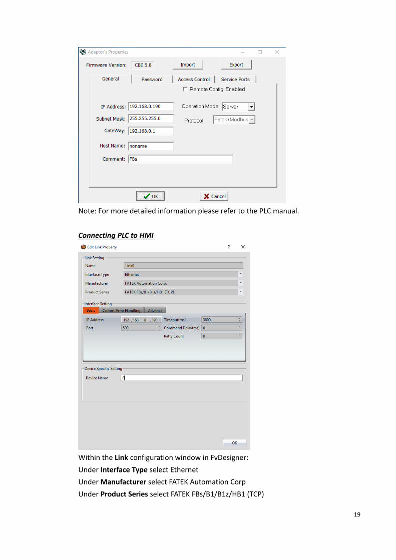
2.1.6.3. Connecting to HMI
Sankyo Servo Parameter configuration
With the upper control device specifications, set the drive communication address and
communication parameters.The following are the parameters that must be set for RS-485.
Parameter
No. parameter Setting value
4.0 RS-485 communication
address
1-32
Initial value 1。
6.0 RS-485 communication
Baud rate
0: 2,400bps
1: 4,800bps
2: 9,600bps
3:19,200bps
4:38,400bps
5:57,600bps (Initial value)

27
6.1 RS-485 communication
STOP bit
0:1 bit(Initial value)
1:2 bit
6.2 RS-485communication
parity
0:none(Initial value)
1:EVEN
2:ODD
8.0 RS-485 communication
ON/OFF
0:no use(Initial value)
1:use
11.0
RS-485 Communication
Minimum response
time
0-255
Initial value 3 [ms]。
2.1.6.4. Wiring Diagrams
Parameter setting method (alternatively set the following parameters):
參數設定方法
Use the drive front panel settings.
S-TUNE has been set for adjustment.
Software needs to be installed on the computer.
Method1:

28
Method2:
Open Sankyo S-TUNE and use the mini USB cable to connect to the computer USB port, it
will automatically connect

29
HMI 設定
30

31
2.2 Mitsubishi
FX2N CPU
2.2.1.1 Communication Setting
Item Default Setting Remark
Signal Level RS485 4W
Baud Rate 9600
Data Length 7
Stop Bit 1
Parity Even
PLC Station No. 0
Communication Method Programming Protocol
2.2.1.2 Memory Resource Review
Device Description Data bit Min. Max.
X Input Discrete 1 0 377
Y Output Relay 1 0 377
M Internal Relay 1 0 7999
SM Special Relay 1 8000 8255
S Step Relay 1 0 4095
TS Timer Discrete 1 0 255
CS Counter Discrete 1 0 255
WX Input Discrete 16 0 360
WY Output Relay 16 0 360
WM Internal Relay 16 0 7984
WS Step Relay 16 0 4080
TN Timer Memory 16 0 255
CN Counter Memory 16 0 199
D Data Register 16 0 7999
SD Special Data Register 16 8000 8255
DCN Counter Memory 32 200 255
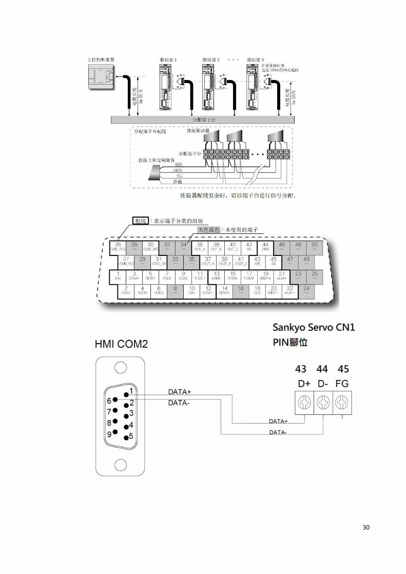
2.2.1.3 Connecting to HMI
Connecting PLC to HMI
32
Within the Link configuration window in FvDesigner:
Under Interface Type select Serial
Under Manufacturer select Mitsubishi Electric Corporation
Under Product Series select Mitsubishi FX2N
Under Port select COM3
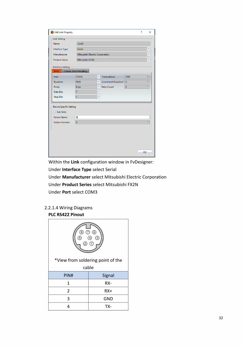
2.2.1.4 Wiring Diagrams
PLC RS422 Pinout
*View from soldering point of the
cable
PIN# Signal
1 RX-
2 RX+
3 GND
4 TX-

33
5
6
7 TX+
8
HMI COM3 Pinout
*Looking into HMI Device
PIN# COM3
(RS-422/RS-485)
1
2
3 ISO_GND
4 RX+
5 RX-
6 TX+
7 TX-
P5070S/P5070N/P5070N1/P5102N/P5102N1
HMI COM3 PLC RS422 Port
5 RX- 4 TX-
4 RX+ 7 TX+
7 TX- 1 RX-
6 TX+ 2 RX+
3 ISO_GND 3 GND
Wiring Diagrams: P5070S/P5070N/P5070N1/P5102N/P5102N1

34
P5043S/P5043N/P5070VS/P5102VS/P2K SERIES
HMI COM2 PLC RS422 Port
9 RX- 4 TX-
4 RX+ 7 TX+
6 TX- 1 RX-
1 TX+ 2 RX+
5 GND 3 GND
Wiring Diagrams: P5043S/P5043N/P5070VS/P5102VS/P2K SERIES
FX2N-485BD
2.2.2.1 Communication Setting

35
Item Default Setting Remark
Signal Level RS485
Baud Rate 19200
Data Length 7
Stop Bit 1
Parity Even
PLC Station No. 1
TX Control Form1 Without CR,LF
Checksum Yes
Communication Method Computer Link
2.2.2.2 Memory Resource Review
Device Description Data bit Min. Max.
X Input Discrete 1 0 377
Y Output Relay 1 0 377
M Internal Relay 1 0 3071
SM Special Relay 1 8000 8255
S Step Relay 1 0 999
TS Timer Discrete 1 0 255
CS Counter Discrete 1 0 199
WX Input Discrete 16 0 360
WY Output Relay 16 0 360
WM Internal Relay 16 0 3056
WS Step Relay 16 0 976
TN Timer Memory 16 0 255
CN Counter Memory 16 0 199
D Data Register 16 0 7999
SD Special Data Register 16 8000 8255
DCN Counter Memory 32 200 255
2.2.2.3 Connecting to HMI
Configuring the PLC
Use MELSOFT GX Works2 to configure the port of the PLC.
Under the Online menu option, select Read from PLC
Select the FXCPU PLC series.

36
Select Serial USB in the Transfer Setup Communication window.
Select the RS-232C radio button and select the COM Port that the PLC is connected at.
Click Connection Test to verify the connection and then press OK.

37
After confirming the Parameter option is checked, press Execute in the Online Data
Operation window.
Under the Project Sidebar, expand Parameter and select PLC Parameter.

38
Navigate to the PLC System(2) tab and configure it to the settings detailed below.
Check Operate Communication Setting to enable configuration
Set Protocol to Dedicated Protocol
Set Parity to Even

39
Set Transmission Speed to 19200
Set H/W Type to RS-485
Check the Sum Check checkbox
Verify the Station Number is consistent with the one set in FvDesigner.
Note: For more detailed information please refer to the PLC manual.
Connecting PLC to HMI
Within the Link configuration window in FvDesigner:
Under Interface Type select Serial
Under Manufacturer select Mitsubishi Electric Corporation
Under Product Series select Mitsubishi FX2N-485BD.
Under Port select COM3
2.2.2.4 Wiring Diagrams
PLC RS422 Pinout

40
HMI COM3 Pinout
*Looking into HMI Device
PIN# COM3
(RS-422/RS-485)
1
2
3 ISO_GND
4 RX+
5 RX-
6 TX+
7 TX-
P5070S/P5070N/P5070N1/P5102N/P5102N1
HMI COM3 PLC RS422 Port
5 RX- SDB
4 RX+ SDA
7 TX- RDB
6 TX+ RDA
3 ISO_GND SG
Wiring Diagrams: P5070S/P5070N/P5070N1/P5102N/P5102N1

41
P5043S/P5043N/P5070VS/P5102VS/P2K SERIES
HMI COM2 PLC RS422 Port
9 RX- SDB
4 RX+ SDA
6 TX- RDB
1 TX+ RDA
5 GND SG
Wiring Diagrams: P5043S/P5043N/P5070VS/P5102VS/P2K SERIES

42
FX3U CPU
2.2.3.1 Communication Setting
Item Default Setting Remark
Signal Level RS485 4W
Baud Rate 9600
Data Length 7
Stop Bit 1
Parity Even
PLC Station No. 0
Communication Method Programming Protocol
2.2.3.2 Memory Resource Review
Device Description Data bit Min. Max.
X Input Discrete 1 0 377
Y Output Relay 1 0 377
M Internal Relay 1 0 7999
SM Special Relay 1 8000 8511
S Step Relay 1 0 4095
TS Timer Discrete 1 0 511

43
CS Counter Discrete 1 0 199
WX Input Discrete 16 0 360
WY Output Relay 16 0 360
WM Internal Relay 16 0 7664
WS Step Relay 16 0 4080
TN Timer Memory 16 0 511
CN Counter Memory 16 0 199
D Data Register 16 0 7999
SD Special Data Register 16 8000 8511
R Extended Register 16 0 32767
DCN Counter Memory 32 200 255
2.2.3.3 Connecting to HMI
Connecting PLC to HMI
Within the Link configuration window in FvDesigner:
Under Interface Type select Serial
Under Manufacturer select Mitsubishi Electric Corporation
Under Product Series select Mitsubishi FX3U/3G
Under Port select COM3

44
2.2.3.4 Wiring Diagrams
PLC RS422 Pinout
*View from soldering point of the
cable
PIN# Signal
1 RX-
2 RX+
3 GND
4 TX-
5
6
7 TX+
8
HMI COM3 Pinout
*Looking into HMI Device
PIN# COM3
(RS-422/RS-485)
1
2
3 ISO_GND
4 RX+
5 RX-
6 TX+
7 TX-
P5070S/P5070N/P5070N1/P5102N/P5102N1

45
HMI COM3 PLC RS422 Port
5 RX- 4 TX-
4 RX+ 7 TX+
7 TX- 1 RX-
6 TX+ 2 RX+
3 ISO_GND 3 GND
Wiring Diagrams: P5070S/P5070N/P5070N1/P5102N/P5102N1
P5043S/P5043N/P5070VS/P5102VS/P2K SERIES
HMI COM2 PLC RS422 Port
9 RX- 4 TX-
4 RX+ 7 TX+
6 TX- 1 RX-
1 TX+ 2 RX+
5 GND 3 GND
Wiring Diagrams: P5043S/P5043N/P5070VS/P5102VS/P2K SERIES

46
FX3U-485BD
2.2.4.1 Communication Setting
Item Default Setting Remark
Signal Level RS485
Baud Rate 19200
Data Length 7
Stop Bit 1
Parity Even
PLC Station No. 1
TX Control Form1 Without CR,LF
Checksum Yes
Communication Method Computer Link
2.2.4.2 Memory Resource Review
Device Description Data bit Min. Max.
X Input Discrete 1 0 377
Y Output Relay 1 0 377
M Internal Relay 1 0 7679
SM Special Relay 1 8000 8511
S Step Relay 1 0 4095
TS Timer Discrete 1 0 511
CS Counter Discrete 1 0 199
WX Input Discrete 16 0 360
WY Output Relay 16 0 360

47
WM Internal Relay 16 0 7664
WS Step Relay 16 0 4080
TN Timer Memory 16 0 511
CN Counter Memory 16 0 199
D Data Register 16 0 7999
SD Special Data Register 16 8000 8511
R Extended Register 16 0 32767
DCN Counter Memory 32 200 255
2.2.4.3 Connecting to HMI
Configuring the PLC
Use MELSOFT GX Works2 to configure the port of the PLC.
Under the Online menu option, select Read from PLC
Select the FXCPU PLC series.
Select Serial USB in the Transfer Setup Communication window.

48
Select the RS-232C radio button and select the COM Port that the PLC is connected at.
Click Connection Test to verify the connection and then press OK.
After confirming the Parameter option is checked, press Execute in the Online Data
Operation window.

49
Under the Project Sidebar, expand Parameter and select PLC Parameter.
Navigate to the PLC System(2) tab and configure it to the settings detailed below.

50
Check Operate Communication Setting to enable configuration
Set Protocol to Dedicated Protocol
Set Parity to Even
Set Transmission Speed to 19200
Set H/W Type to RS-485
Check the Sum Check checkbox
Verify the Station Number is consistent with the one set in FvDesigner.
Note: For more detailed information please refer to the PLC manual.
Connecting PLC to HMI

51
Within the Link configuration window in FvDesigner:
Under Interface Type select Serial
Under Manufacturer select Mitsubishi Electric Corporation
Under Product Series select Mitsubishi FX3U/3G-485BD.
Under Port select COM3
2.2.4.4 Wiring Diagrams
PLC RS422 Pinout
HMI COM3 Pinout

52
*Looking into HMI Device
PIN# COM3
(RS-422/RS-485)
1
2
3 ISO_GND
4 RX+
5 RX-
6 TX+
7 TX-
P5070S/P5070N/P5070N1/P5102N/P5102N1
HMI COM3 PLC RS422 Port
5 RX- SDB
4 RX+ SDA
7 TX- RDB
6 TX+ RDA
3 ISO_GND SG
Wiring Diagrams: P5070S/P5070N/P5070N1/P5102N/P5102N1

53
P5043S/P5043N/P5070VS/P5102VS/P2K SERIES
HMI COM2 PLC RS422 Port
9 RX- SDB
4 RX+ SDA
6 TX- RDB
1 TX+ RDA
5 GND SG
Wiring Diagrams: P5043S/P5043N/P5070VS/P5102VS/P2K SERIES
FX3U Ethernet
2.2.5.1 Communication Setting
Item Default Setting Remark
Signal Level Ethernet
Internet Protocol 0.0.0.0
Port 5001
PLC Station No. 0
Communication Method MC protocol Binary/ASCII
2.2.5.2 Memory Resource Review

54
Device Description Data bit Min. Max.
X Input Discrete 1 0 377
Y Output Relay 1 0 377
M Internal Relay 1 0 7679
SM Special Relay 1 8000 8511
S Step Relay 1 0 4095
TS Timer Discrete 1 0 511
CS Counter Discrete 1 0 199
WX Input Discrete 16 0 360
WY Output Relay 16 0 360
WM Internal Relay 16 0 7664
WS Step Relay 16 0 4080
TN Timer Memory 16 0 511
CN Counter Memory 16 0 199
D Data Register 16 0 7999
SD Special Data Register 16 8000 8511
R Extended Register 16 0 32767
DCN Counter Memory 32 200 255
2.2.5.3 Connecting to HMI
Configuring IP Address on PLC
Use MELSOFT GX Works2 to configure the IP address of the PLC.
Under the Online menu option, select Read from PLC
Select the FXCPU PLC series.
Select Serial USB in the Transfer Setup Communication window.

55
Select the RS-232C radio button and select the COM Port that the PLC is connected at.
Click Connection Test to verify the connection and then press OK.
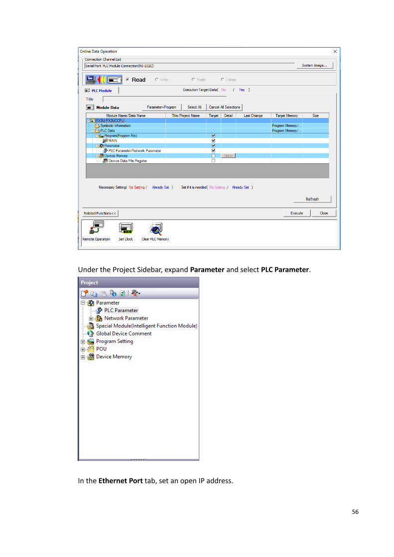
After confirming the Parameter option is checked, press Execute in the Online Data
Operation window.
56
Under the Project Sidebar, expand Parameter and select PLC Parameter.
In the Ethernet Port tab, set an open IP address.

57
Click Open Setting and set the entire Open System column to MC Protocol. For the
Host Station Port No., set row 1 to 5001, row 2 to 5002 and so on.
Under the Online menu option, select Write to PLC to save the settings to the PLC.
Press Execute in the Online Data Operation window.

58
Note: For more detailed information please refer to the PLC manual.
Connecting PLC to HMI

59
Within the Link configuration window in FvDesigner:
Under Interface Type select Ethernet
Under Manufacturer select Mitsubishi Electric Corporation
Under Product Series select one of the Mitsubishi FX3U-ENET-ADP options. The last
part of the series name (BINARY or ASCII) should be consistent with the Connection
Data Code set in the Ethernet Port for the PLC.
Enter the IP Address that was written into the PLC.
Enter 5001 for the Port.
FX5U-Serial
2.2.6.1 Communication Setting
Item Default Setting Remark
Signal Level RS485
Baud Rate 19200
Data Length 8
Stop Bit 1
Parity None
PLC Station No. 0

60
TX Control Form1 Without CR,LF
Checksum Yes
Communication Method MC Protocol 3C
2.2.6.2 Memory Resource Review
Device Description Data
bit
Input
Format
Min. Max.
X Input Relay 1 OOOO 0 1777
Y Output Relay 1 OOOO 0 1777
M Internal Relay 1 DDDDD 0 32767
B Link Relay 1 HHHH 0 7FFF
F Annunciator 1 DDDDD 0 32767
SB Link Special Relay 1 HHHH 0 7FFF
S Step Relay 1 DDDD 0 4095
TS Timer Contact 1 DDDD 0 1023
TC Timer Coil 1 DDDD 0 1023
SS Retentive Timer
Contact
1 DDDD 0 1023
SC Retentive Timer
Coil
1 DDDD 0 1023
CS Counter Contact 1 DDDD 0 1023
CC Counter Coil 1 DDDD 0 1023
LCS*1 Long Counter
Contact
1 DDDD 0 1023
LCC*1 Long Counter Coil 1 DDDD 0 1023
SM Special Relay 1 DDDD 0 9999
WX*2 Input Relay 16 OOOO 0 1760
WY*2 Output Relay 16 OOOO 0 1760
WM*3 Internal Relay 16 DDDDD 0 32752
B_Word*3 Link Relay 16 HHHH 0 7FF0
F_Word *3 Annunciator 16 DDDDD 0 32752
SB_Word *3 Link Special Relay 16 HHHH 0 7FF0
WS*3 Step Relay 16 DDDD 0 4080
TS_Word *3 Timer Contact 16 DDDD 0 1008
TC_Word *3 Timer Coil 16 DDDD 0 1008
SS_Word *3 Retentive Timer
Contact
16 DDDD 0 1008

61
SC_Word *3 Retentive Timer
Coil
16 DDDD 0 1008
CS_Word *3 Counter Contact 16 DDDD 0 1008
CC_Word *3 Counter Coil 16 DDDD 0 1008
SM_Word
*3
Special Relay 16 DDDD 0 9984
TN Timer Current
Value
16 DDDD 0 1023
SN Retentive Timer
Current Value
16 DDDD 0 1023
CN Counter Current
Value
16 DDDD 0 1023
D Data Register 16 DDDD 0 7999
W Link Register 16 HHHH 0 7FFF
SW Link special
Register
16 HHHH 0 7FFF
SD Special Register 16 DDDDD 0 11999
R File Register 16 DDDDD 0 32767
Z Index Register 16 DD 0 23
LCN*1 Long Counter
Current Value
32 DDDD 0 1023
LZ Long Index
Register
32 DD 0 11
*1 Binary mode support only *2 Address increased by 0, 20, 40, 60… *3 Address increased by 0, 20, 40, 60…
2.2.6.3 Connecting to HMI
Configuring the PLC
Connect the PLC using an Ethernet cable. The following setup uses an Ethernet Port
Direct Connection to configure the PLC.
Use MELSOFT GX Works3 to configure the port of the PLC.
Under the Online menu option, select Read from PLC.
Select the FX5CPU option for the Series.

62
In the connection window, select Ethernet Board. Click PLC Module and in the dialog
window, select the Ethernet Port Direct Connection radio button.

63
Click Connection Test to verify the connection and then press OK.
Click Select All in the Online Data Operation window and press Execute. Allow the read
to finish.

64
In the Project sidebar, expand Parameter, FX5UCPU, and Module Parameter and
select 485 Serial Port.
Under Basic Settings, change Communication Protocol Type to MC Protocol.
Under Fixed Setting, change Message Pattern to Pattern 1 and verify the station
number is consistent with the one set in FvDesigner.

65
Under the Online menu option, select Write to PLC to save the settings to the PLC.
Click Select All and press Execute in the Online Data Operation window.
Note: For more detailed information please refer to the PLC manual.
Connecting PLC to HMI
Within the Link configuration window in FvDesigner:
Under Interface Type select Serial
Under Manufacturer select Mitsubishi Electric Corporation
Under Product Series select Mitsubishi FX5U-SERIAL.
Verify the parameters match the window above.

66
2.2.6.4 Wiring Diagrams
PLC RS422 Pinout
HMI COM3 Pinout
*Looking into HMI Device
PIN# COM3
(RS-422/RS-485)
1
67
2
3 ISO_GND
4 RX+
5 RX-
6 TX+
7 TX-
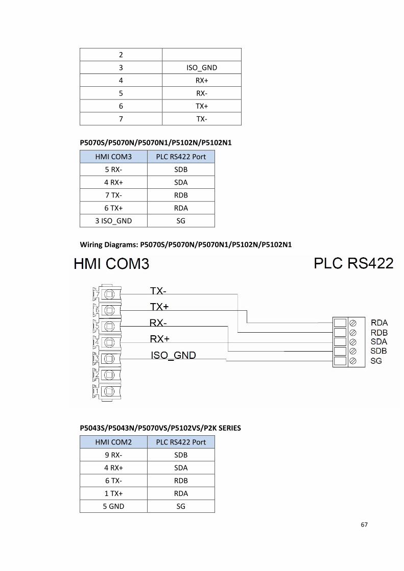
P5070S/P5070N/P5070N1/P5102N/P5102N1
HMI COM3 PLC RS422 Port
5 RX- SDB
4 RX+ SDA
7 TX- RDB
6 TX+ RDA
3 ISO_GND SG
Wiring Diagrams: P5070S/P5070N/P5070N1/P5102N/P5102N1
P5043S/P5043N/P5070VS/P5102VS/P2K SERIES
HMI COM2 PLC RS422 Port
9 RX- SDB
4 RX+ SDA
6 TX- RDB
1 TX+ RDA
5 GND SG

68
Wiring Diagrams: P5043S/P5043N/P5070VS/P5102VS/P2K SERIES
FX5U Ethernet
2.2.7.1 Communication Setting
Item Default Setting Remark
Signal Level Ethernet
Internet Protocol 0.0.0.0
Port 1025
PLC Station No. 0
Communication Method MC protocol 3E Binary/ASCII
2.2.7.2 Memory Resource Review
Device Description Data
bit
Input
Format
Min. Max.
X Input Relay 1 OOOO 0 1777
Y Output Relay 1 OOOO 0 1777
M Internal Relay 1 DDDDD 0 32767
B Link Relay 1 HHHH 0 7FFF
F Annunciator 1 DDDDD 0 32767

69
SB Link Special Relay 1 HHHH 0 7FFF
S Step Relay 1 DDDD 0 4095
TS Timer Contact 1 DDDD 0 1023
TC Timer Coil 1 DDDD 0 1023
SS Retentive Timer
Contact
1 DDDD 0 1023
SC Retentive Timer
Coil
1 DDDD 0 1023
CS Counter Contact 1 DDDD 0 1023
CC Counter Coil 1 DDDD 0 1023
LCS*1 Long Counter
Contact
1 DDDD 0 1023
LCC*1 Long Counter Coil 1 DDDD 0 1023
SM Special Relay 1 DDDD 0 9999
WX*2 Input Relay 16 OOOO 0 1760
WY*2 Output Relay 16 OOOO 0 1760
WM*3 Internal Relay 16 DDDDD 0 32752
B_Word *3 Link Relay 16 HHHH 0 7FF0
F_Word *3 Annunciator 16 DDDDD 0 32752
SB_Word *3 Link Special Relay 16 HHHH 0 7FF0
WS*3 Step Relay 16 DDDD 0 4080
TS_Word *3 Timer Contact 16 DDDD 0 1008
TC_Word *3 Timer Coil 16 DDDD 0 1008
SS_Word *3 Retentive Timer
Contact
16 DDDD 0 1008
SC_Word *3 Retentive Timer
Coil
16 DDDD 0 1008
CS_Word *3 Counter Contact 16 DDDD 0 1008
CC_Word *3 Counter Coil 16 DDDD 0 1008
SM_Word
*3
Special Relay 16 DDDD 0 9984
TN Timer Current
Value
16 DDDD 0 1023
SN Retentive Timer
Current Value
16 DDDD 0 1023
CN Counter Current
Value
16 DDDD 0 1023

70
D Data Register 16 DDDD 0 7999
W Link Register 16 HHHH 0 7FFF
SW Link special
Register
16 HHHH 0 7FFF
SD Special Register 16 DDDDD 0 11999
R File Register 16 DDDDD 0 32767
Z Index Register 16 DD 0 23
LCN*1 Long Counter
Current Value
32 DDDD 0 1023
LZ Long Index Register 32 DD 0 11 *1 Binary mode support only *2 Address increased by 0, 20, 40, 60… *3 Address increased by 0, 20, 40, 60…
2.2.7.3 Connecting to HMI
Configuring IP Address on PLC
Connect the PLC using an Ethernet cable. The following setup uses an Ethernet Port
Direct Connection to configure the PLC.
Use MELSOFT GX Works3 to configure the port of the PLC.
Under the Online menu option, select Read from PLC.
Select the FX5CPU option for the Series.
In the connection window, select Ethernet Board. Click PLC Module and in the dialog
window, select the Ethernet Port Direct Connection radio button.

71

72
Click Connection Test to verify the connection and then press OK.
Click Select All in the Online Data Operation window and press Execute. Allow the read
to finish.

73
In the Project sidebar, expand Parameter, FX5UCPU, and Module Parameter and
select Ethernet Port.
The IP Address of the PLC can be obtained here. Switch the Communication Data Code
to the mode needed (Binary or ASCII). Double click “<Detailed Setting>” under
External Device Configuration to get the port information. Verify the Protocol is TCP.

74
If the user needs to change the IP Address, edit the IP address under the Own Node
Settings. Then enter the Detailed Settings and press Close with Reflecting the Setting.
Under the Online menu option, select Write to PLC to save the settings to the PLC.
Click Select All and press Execute in the Online Data Operation window.
Note: For more detailed information please refer to the PLC manual.

75
Connecting PLC to HMI
Within the Link configuration window in FvDesigner:
Under Interface Type select Ethernet
Under Manufacturer select Mitsubishi Electric Corporation
Under Product Series select one of the Mitsubishi FX5U-ENET options. The last part of
the series name (BINARY or ASCII) should be consistent with the Connection Data Code
set in the Ethernet Port for the PLC.
Enter the IP Address that was written into the PLC.
Enter 1025 for the Port.
QSeries-Serial Communication(Link Port)
2.2.8.1 Communication Setting
Item Default Setting Remark
Signal Level RS232/RS422/RS485 QJ71C24N Module
Baud Rate 115200
Data Length 7
Stop Bit 1
Parity Odd
PLC Station No. 0

76
TX Control Procedure Form4 Without CR,LF
Sum Check Yes
Communication Method MC Protocol 3C
2.2.8.2 Memory Resource Review
Device Description Data bit Input
fromat
Max. Max.
X Input Relay 1 HHHH 0 1fff
Y Output Relay 1 HHHH 0 1fff
M Internal Relay 1 DDDDD 0 61439
L Latch Relay 1 DDDD 0 32767
B Link Relay 1 HHHH 0 efff
F Annunciator 1 DDDD 0 32767
V Edge Relay 1 DDDD 0 32767
SB Link Special Relay 1 HHH 0 7FFF
S Step Relay 1 DDDD 0 16383
TS Timer Contact 1 DDDD 0 32767
TC Timer Coil 1 DDDD 0 32767
SS Retentive Timer
Contact
1 DDDD 0 32767
SC Retentive Timer Coil 1 DDDD 0 32767
CS Counter Contact 1 DDDD 0 32767
CC Counter Coil 1 DDDD 0 32767
SM Special Relay 1 DDDD 0 2047
DX Direct Input 1 HHHH 0 1fff
DY Direct Output 1 HHHH 0 1fff
WX Input Relay 16 HHHH 0 1ff0
WY Output Relay 16 HHHH 0 1ff0
WM Internal Relay 16 DDDDD 0 61424
WL Link Relay 16 DDDD 32752
B_Word Link Relay 16 HHHH 0 eff0
F_Word Annunciator 16 DDDDD 0 32752
WV Edge relay 16 DDDDD 0 32752
SB_Word Link Special Relay 16 HHH 0 7ff0
WS Step Relay 16 DDDD 0 16368
TS_Word Timer Contact 16 DDDD 0 32752

77
TC_Word Timer Coil 16 DDDD 0 32752
SS_Word Retentive Timer
Contact
16 DDDD 0 32752
SC_Word Retentive Timer Coil 16 DDDD 0 32752
CS_Word Counter Contact 16 DDDD 0 32752
CC_Word Counter Coil 16 DDDD 0 32752
SM_Word Special Relay 16 DDDD 0 2032
TN Timer Current Value 16 DDDD 0 32752
SN Retentive Timer
Current Value
16 DDDD 0 32752
CN Counter Current
Value
16 DDDD 0 32752
D Data Register 16 DDDDD 0 39935
W Link Register 16 HHHH 0 9bff
SW Link special Register 16 HHH 0 7FFF
SD Special Register 16 DDDD 0 2047
R File Register 16 DDDDD 0 32767
Z Index Register 16 DD 0 19
ZR File Register 16 HHHHH 0 9fff
2.2.8.3 Connecting to HMI
Configuring the PLC
Use MELSOFT GX Works2 to configure the port of the QJ71C24N Module.
Under the Project Sidebar, expand Intelligent Function Module and select Switch
Setting.

78
Configure it to the settings detailed below.
Note: For more detailed information please refer to the PLC manual.
Connecting PLC to HMI

79
Within the Link configuration window in FvDesigner:
Under Interface Type select Serial
Under Manufacturer select Mitsubishi Electric Corporation
Under Product Series select Mitsubishi QSeries-Serial Communication(Link Port).
Verify the parameters match the window above.
The setting of Q series CPU setting if ‘’Use serial communication’’ is checked, please
use QSeries-Serial Communication (Link Port), and the transfer control program is set
to Form 5 (Binary mode).
2.2.8.4 Wiring Diagrams
QJ71C24N RS232 Pinout
* Looking into PLC Device
PIN# Signal
1 DCD

80
2 RXD
3 TXD
4 DTR
5 GND
6 DSR
7 RTS
8 CTS
QJ71C24N RS422/485 Pinout
HMI COM1 pinout
*Looking into COM1 Port
PIN# COM1 (RS232)
1
2 RX
3 TX
4
5 GND
6
7 RTS
8 CTS
9
81
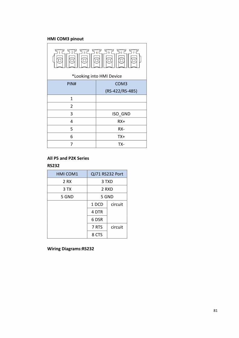
HMI COM3 pinout
*Looking into HMI Device
PIN# COM3
(RS-422/RS-485)
1
2
3 ISO_GND
4 RX+
5 RX-
6 TX+
7 TX-
All P5 and P2K Series
RS232
HMI COM1 QJ71 RS232 Port
2 RX 3 TXD
3 TX 2 RXD
5 GND 5 GND
1 DCD circuit
4 DTR
6 DSR
7 RTS circuit
8 CTS
Wiring Diagrams:RS232

82
RS422
HMI COM3 QJ71 RS422/485 Port
4 RX+ SDA
5 RX- SDB
6 TX+ RDA
7 TX- RDB
3 GND SG
Wiring Diagrams:RS422
RS485
HMI COM3 QJ71 RS422/485 Port
6 TX+ SDA
RDA
7 TX- SDB

83
RDB
3 GND SG
Wiring Diagrams: RS485
QSeries-Serial Communication(CPU Port)
2.2.9.1 Communication Setting
Item Default Setting Remark
Signal Level RS232
Baud Rate 19200
Data Length 8
Stop Bit 1
Parity Odd
PLC Station No. 0
2.2.9.2 Memory Resource Review
Device Description Data bit Input
format
Min. Max.
X Input Relay 1 HHHH 0 1fff
Y Output Relay 1 HHHH 0 1fff
M Internal Relay 1 DDDDD 0 61439
L Latch Relay 1 DDDDD 0 32767
B Link Relay 1 HHHH 0 Efff
F Annunciator 1 DDDDD 0 32767
V Edge Relay 1 DDDDD 0 32767
SB Link Special Relay 1 HHHH 0 7fff

84
S Step Relay 1 DDDDD 0 16383
TS Timer Contact 1 DDDDD 0 32767
TC Timer Coil 1 DDDDD 0 32767
SS Retentive Timer
Contact
1 DDDDD 0 32767
SC Retentive Timer Coil 1 DDDDD 0 32767
CS Counter Contact 1 DDDDD 0 32767
CC Counter Coil 1 DDDDD 0 32767
SM Special Relay 1 DDDD 0 2047
DX Direct Input 1 HHHH 0 1fff
DY Direct Output 1 HHHH 0 1fff
WX Input Relay 16 HHHH 0 1ff0
WY Output Relay 16 HHHH 0 1ff0
WM Internal Relay 16 DDDDD 0 61424
WL Latch Relay 16 DDDDD 0 32752
B_Word Link Relay 16 HHHH 0 Eff0
F_Word Annunciator 16 DDDDD 0 32752
WV Edge Relay 16 DDDDD 0 32752
SB_Word Link Special Relay 16 HHHH 0 7ff0
WS Step Relay 16 DDDDD 0 16368
TS_Word Timer Contact 16 DDDDD 0 32752
TC_Word Timer Coil 16 DDDDD 0 32752
SS_Word Retentive Timer
Contact
16 DDDDD 0 32752
SC_Word Retentive Timer Coil 16 DDDDD 0 32752
CS_Word Counter Contact 16 DDDDD 0 32752
CC_Word Counter Coil 16 DDDDD 0 32752
SM_Word Special Relay 16 DDDD 0 2032
TN Timer Current Value 16 DDDDD 0 32767
SN Retentive Timer
Current Value
16 DDDDD 0 32767
CN Counter Current Value 16 DDDDD 0 32767
D Data Register 16 DDDDD 0 39935
W Link Register 16 HHHH 0 9bff
SW Link Special Register 16 HHHH 0 7fff
SD Special Register 16 DDDD 0 2047

85
R File Register 16 DDDDD 0 32767
Z Index Register 16 DD 0 19
ZR File Register 16 HHHHH 0 9ffff
2.2.9.3 Connecting to HMI
Configuring IP Address on PLC
Use MELSOFT GX Works2 to configure the port of the PLC.
In the Project sidebar, expand Parameter and expand PLC Parameter.
The setting of Q series CPU setting if ‘’Use serial communication’’ is checked, please
use QSeries-Serial Communication (Link Port).
Note: For more detailed information please refer to the PLC manual.
Connect PLC to HMI

86
Within the Link configuration window in FvDesigner:
Under Interface Type select Direct Link(Serial)
Under Manufacturer select Mitsubishi Electric Corporation
Under Product Series select one of the Mitsubishi QSeries-Series Communication(CPU
Port).
Verify the parameters match the window above.
2.2.9.4 Wiring Diagrams
PLC RS232 Pinout
*View from soldering point of the
cable
PIN# Signal
1 TXD
2 RXD
3
4 GND
5 RTS
6 CTS

87
HMI COM1 Pinout
*Looking into COM1 Port
PIN# COM1 (RS232)
1
2 RX
3 TX
4
5 GND
6
7 RTS
8 CTS
9
All P5 and P2K Series
HMI COM1 PLC RS232 Port
2 RX 1 TXD
3 TX 2 RXD
5 GND 4 GND
5 RTS circuit
6 CTS
Wiring Diagrams: All P5 and P2K Series

88
Q/L Series-ENET
2.2.10.1 Communication Setting
Item Default Setting Remark
Signal Level Ethernet
Internet Protocol 0.0.0.0
Port 4999
PLC Station No. 0
Communication Method MC protocol 3E Binary/ASCII
2.2.10.2 Memory Resource Review
Device Description Data
bit
Input
Format
Min. Max.
X Input Relay 1 HHHH 0 1fff
Y Output Relay 1 HHHH 0 1fff
M Internal Relay 1 DDDDD 0 61439
L Latch Relay 1 DDDD 0 32767
B Link Relay 1 HHHH 0 efff
F Annunciator 1 DDDD 0 32767
V Edge Relay 1 DDDD 0 32767
SB Link Special Relay 1 HHH 0 7FFF
S Step Relay 1 DDDD 0 16383
TS Timer Contact 1 DDDD 0 32767
TC Timer Coil 1 DDDD 0 32767
SS Retentive Timer 1 DDDD 0 32767

89
Contact
SC Retentive Timer
Coil
1 DDDD 0 32767
CS Counter Contact 1 DDDD 0 32767
CC Counter Coil 1 DDDD 0 32767
SM Special Relay 1 DDDD 0 2047
DX Direct Input 1 HHHH 0 1fff
DY Direct Output 1 HHHH 0 1fff
WX*1 Input Relay 16 HHHH 0 1ff0
WY*1 Output Relay 16 HHHH 0 1ff0
WM*1 Internal Relay 16 DDDDD 0 61424
WL Link Relay 16 DDDD 32752
B_Word *1 Link Relay 16 HHHH 0 eff0
F_Word *1 Annunciator 16 DDDDD 0 32752
WV Edge relay 16 DDDDD 0 32752
SB_Word
*1
Link Special Relay 16 HHH 0 7ff0
WS*1 Step Relay 16 DDDD 0 16368
TS_Word
*1
Timer Contact 16 DDDD 0 32752
TC_Word
*1
Timer Coil 16 DDDD 0 32752
SS_Word
*1
Retentive Timer
Contact
16 DDDD 0 32752
SC_Word
*1
Retentive Timer
Coil
16 DDDD 0 32752
CS_Word
*1
Counter Contact 16 DDDD 0 32752
CC_Word
*1
Counter Coil 16 DDDD 0 32752
SM_Word
*1
Special Relay 16 DDDD 0 2032
TN Timer Current
Value
16 DDDD 0 32752
SN Retentive Timer
Current Value
16 DDDD 0 32752
CN Counter Current 16 DDDD 0 32752

90
Value
D Data Register 16 DDDDD 0 39935
W Link Register 16 HHHH 0 9bff
SW Link special
Register
16 HHH 0 7FFF
SD Special Register 16 DDDD 0 2047
R File Register 16 DDDDD 0 32767
Z Index Register 16 DD 0 19
ZR File Register 16 HHHHH 0 9fff *1 Address increased by 0, 20, 40, 60…
2.2.10.3 Connecting to HMI
Configuring IP Address on PLC
Use MELSOFT GX Works2 to configure the port of the PLC.
In the Project sidebar, expand Parameter and expand PLC Parameter.
Navigate to Built-in Ethernet Port Setting tab, the IP address and other parameters can
be set.

91
Click Open Setting and set the entire Open System column to MC Protocol. For the
Host Station Port No 4999.
Note: For more detailed information please refer to the PLC manual.
Connect PLC to HMI

92
Within the Link configuration window in FvDesigner:
Under Interface Type select Ethernet
Under Manufacturer select Mitsubishi Electric Corporation
Under Product Series select one of the Mitsubishi Q/L Series-ENET(BINARY 或 ASCII).
The last part of the series name (BINARY or ASCII) should be consistent with the
Connection Data Code set in the Ethernet Port for the PLC.
Enter the IP Address that was written into the PLC.
Verify the parameters match the window above.
iQ-R Series-ENET
2.2.11.1 Communication Setting
Item Default Setting Remark

93
Signal Level Ethernet
Internet Protocol 0.0.0.0
Port 4999
PLC Station No. 0
Communication Method MC protocol 3E Binary/ASCII
2.2.11.2 Memory Resource Review
類型 資料位元 說明 地址格式 最小 最大
X 1 Input HHHH 0 2fff
Y 1 Output HHHH 0 2fff
M 1 Internal Relay DDDDD 0 638975
SM 1 Special Relay DDDD 0 4095
B 1 Link Relay HHHHH 0 9bfff
SB 1 Link Special Relay HHHHH 0 9bfff
F 1 Annunciator DDDDD 0 32767
V 1 Edge Relay DDDDD 0 32767
TS 1 Timer Contact DDDDD 0 35487
TC 1 Timer Coil DDDDD 0 35487
LTS 1 Long Timer Contact DDDDD 0 35487
LTC 1 Long Timer Coil DDDDD 0 35487
STS 1 Retentive Timer
Contact
DDDDD 0
35487
STC 1 Retentive Timer Coil DDDDD 0 35487
LSTS 1 Long Retentive Timer
Contact
DDDDD 0 35487
LSTC 1 Long Retentive Timer
Coil
DDDDD 0 35487
CS 1 Counter Contact DDDDD 0 35487
CC 1 Counter Coil DDDDD 0 35487
LCS 1 Long Counter Contact DDDDD 0 35487
LCC 1 Long Counter Coil DDDDD 0 35487
L 1 Latch Relay DDDDD 0 32767
D 16 Data Register DDDDD 0 39935
SD 16 Special Register DDDD 0 4095
W 16 Link Register HHHH 0 9bff
SW 16 Link Special Register HHHH 0 9bff
TN 16 Timer Current Value DDDDD 0 35487
STN 16 Retentive Timer DDDDD 0 35487

94
Current Value
CN 16 Counter Current Value DDDDD 0 35487
Z 16 Index Register DD 0 23
LTN 16 Long Timer Current
Value
DDDDD 0 35487
LSTN 16 Long Retentive Timer
Current Value
DDDDD 0 35487
LCN 16 Long Counter Current
Value
DDDDD 0 35487
LZ 16 Long Index Register DD 0 11
2.2.11.3 Connecting to HMI
Configuring IP Address on PLC
Use MELSOFT GX Works2 to configure the port of the PLC.
In the Project sidebar, expand Parameter and expand PLC Parameter.
Navigate to Built-in Ethernet Port Setting tab, the IP address and other parameters can
be set.

95
Click Open Setting and set the entire Open System column to MC Protocol. For the
Host Station Port No 4999.
Note: For more detailed information please refer to the PLC manual.
Connect PLC to HMI

96
Within the Link configuration window in FvDesigner:
Under Interface Type select Ethernet
Under Manufacturer select Mitsubishi Electric Corporation
Under Product Series select one of the Mitsubishi iQ-R Series-ENET(BINARY 或 ASCII).
The last part of the series name (BINARY or ASCII) should be consistent with the
Connection Data Code set in the Ethernet Port for the PLC.
Enter the IP Address that was written into the PLC.
Verify the parameters match the window above.
2.3 Omron
Omron SYSMAC CP Series
2.3.1.1 Communication Setting
Item Default Setting Remark
Signal Level RS232
97
Baud Rate 9600
Data Length 7
Stop Bit 2
Parity Even
PLC Station No. 0
Communication Method FINS
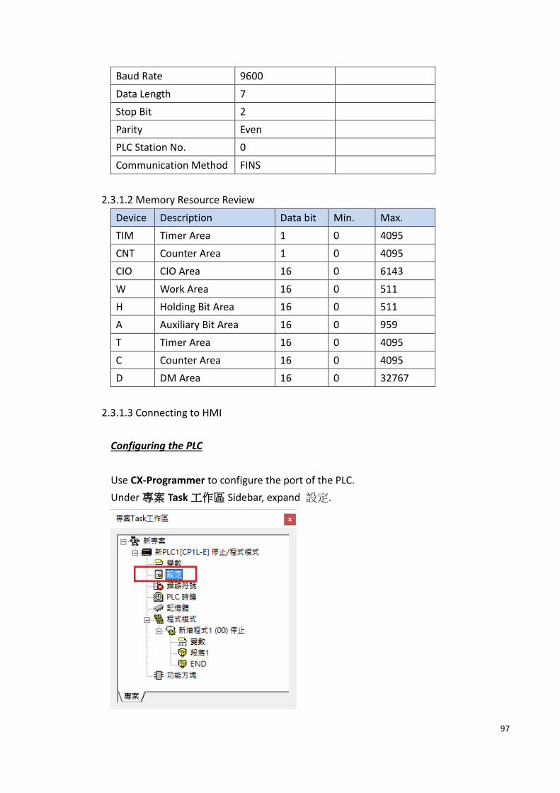
2.3.1.2 Memory Resource Review
Device Description Data bit Min. Max.
TIM Timer Area 1 0 4095
CNT Counter Area 1 0 4095
CIO CIO Area 16 0 6143
W Work Area 16 0 511
H Holding Bit Area 16 0 511
A Auxiliary Bit Area 16 0 959
T Timer Area 16 0 4095
C Counter Area 16 0 4095
D DM Area 16 0 32767
2.3.1.3 Connecting to HMI
Configuring the PLC
Use CX-Programmer to configure the port of the PLC.
Under 專案 Task 工作區 Sidebar, expand 設定.

98
Navigate to 序列埠 1 tab and configure it to the settings detailed below.
After click 傳輸到 PLC to write in PLC.
Note: For more detailed information please refer to the PLC manual.
Connecting PLC to HMI
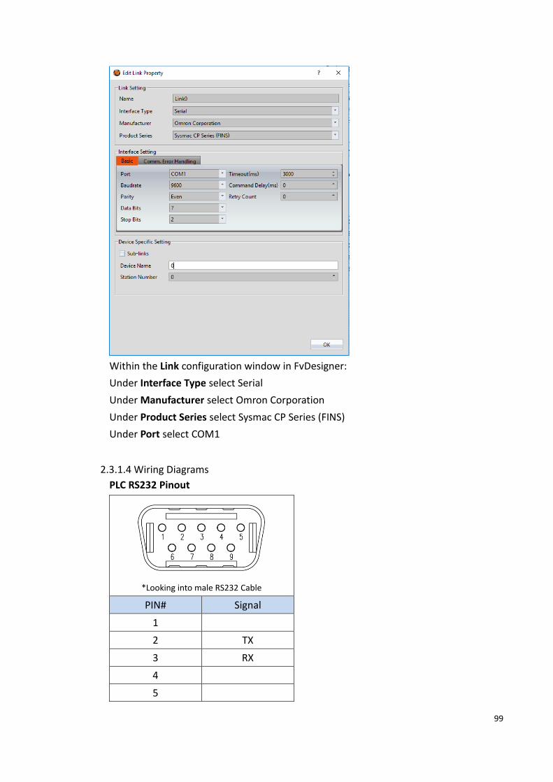
99
Within the Link configuration window in FvDesigner:
Under Interface Type select Serial
Under Manufacturer select Omron Corporation
Under Product Series select Sysmac CP Series (FINS)
Under Port select COM1
2.3.1.4 Wiring Diagrams
PLC RS232 Pinout
*Looking into male RS232 Cable
PIN# Signal
1
2 TX
3 RX
4
5

100
6
7
8
9 GND
HMI COM1 Pinout
*Looking into COM1 Port
PIN# COM1 (RS232)
1
2 RX
3 TX
4
5 GND
6
7 RTS
8 CTS
9
All P5 and P2K Series
HMI COM1 PLC RS232 Port
2 RX 2 TX
3 TX 3 RX
5 GND 9 GND
Wiring Diagrams: All P5 and P2K Series

101
Omron SYSMAC CP Series Ethernet
2.3.2.1 Communication Setting
Item Default Setting Remark
Signal Level Ethernet
Internet Protocol 0.0.0.0 To be configured
Port 9600
PLC Station No. 0
Communication Method FINS/TCP
2.3.2.2 Memory Resource Review
Device Description Data bit Min. Max.
TK Task Flag 1 0 31
TIM Timer Area 1 0 4095
CNT Counter Area 1 0 4095
CIO CIO Area 16 0 6143
W Work Area 16 0 511
H Holding Area 16 0 511
A Auxiliary Area 16 0 959
T Timer Area 16 0 4095
C Counter Area 16 0 4095
D Data Memory Area 16 0 32767
IR Index Register 32 0 15
DR Data Register 16 0 15

102
2.3.2.3 Connecting to HMI
Configuring IP Address on PLC
Use CX-Programmer to configure the IP of the PLC.
In the 專案 Task sidebar, expand 設定
Navigate to 內置乙太網路 tab, the IP address and other parameters can be set.
After click 傳輸到 PLC to write in PLC.

103
Note: For more detailed information please refer to the PLC manual.
HMI 設定

104
Within the Link configuration window in FvDesigner:
Under Interface Type select Ethernet
Under Manufacturer select Omron Corporation
Under Product Series select Sysmac CP Series (FINS/TCP)
Enter the IP Address that was written into the PLC
Enter 9600 for the Port
Omron SYSMAC CS/CJ Series
2.3.3.1 Communication Setting
Item Default Setting Remark
Signal Level RS232/RS422
Baud Rate 9600
Data Length 7
Stop Bit 2
Parity Even
PLC Station No. 0
Communication Method FINS
2.3.3.2 Memory Resource Review
Device Description Data bit Min. Max.
TK Task Flag 1 0 127
TIM Timer Area 1 0 4095
CNT Counter Area 1 0 4095
CIO CIO Area 16 0 6143
W Work Area 16 0 511
H Holding Bit Area 16 0 1535
A Auxiliary Bit Area 16 0 11535
T Timer Area 16 0 4095
C Counter Area 16 0 4095
D DM Area 16 0 32767
E0 EM Bank 0 16 0 32767
E1 EM Bank 1 16 0 32767
E2 EM Bank 2 16 0 32767
E3 EM Bank 3 16 0 32767
E4 EM Bank 4 16 0 32767

105
E5 EM Bank 5 16 0 32767
E6 EM Bank 6 16 0 32767
E7 EM Bank 7 16 0 32767
E8 EM Bank 8 16 0 32767
E9 EM Bank 9 16 0 32767
EA EM Bank 10 16 0 32767
EB EM Bank 11 16 0 32767
EC EM Bank 12 16 0 32767
EM Current EM Bank 16 0 32767
DR Data Register 16 0 15
IR Index Register 32 0 15
2.3.3.3 Connecting to HMI
Configuring the PLC
Use CX-Programmer to configure the port of the PLC.
Under 專案 Task 工作區 Sidebar, expand 設定.
After navigate to Serial Prot tab and configure it to the settings detailed below.
Note: For more detailed information please refer to the PLC manual.
Connecting PLC to HMI

106
Within the Link configuration window in FvDesigner:
Under Interface Type select Serial
Under Manufacturer select Omron Corporation
Under Product Series select Sysmac CS/CJ Series (FINS)
Under Port select COM3
2.3.3.4 PLC Message
When the first 4 error codes are 200A, it means that the last 4 error codes are created
by PLC.
Please refer to PLC manual https://www.automationdirect.com/microsites/c-
more/software-help/Content/476.htm
2.3.3.5 Wiring Diagrams
CJ1W-CIF11 (RS422/485)

107
HMI COM3 Pinout
*Looking into HMI Device
PIN# COM3
(RS-422/RS-485)
1
2
3 ISO_GND
4 RX+
5 RX-
6 TX+
7 TX-
P5070S/P5070N/P5070N1/P5102N/P5102N1
HMI COM3 PLC RS422 Port
5 RX- SDA-
4 RX+ SDB+
7 TX- RDA-
6 TX+ RDB+
3 ISO_GND FG
Wiring Diagrams: P5070S/P5070N/P5070N1/P5102N/P5102N1

108
P5043S/P5043N/P5070VS/P5102VS/P2K SERIES
HMI COM2 PLC RS422 Port
9 RX- SDA-
4 RX+ SDB+
6 TX- RDA-
1 TX+ RDB+
5 GND FG
Wiring Diagrams: P5043S/P5043N/P5070VS/P5102VS/P2K SERIES

109
Omron SYSMAC CS/CJ Series Ethernet
2.3.4.1 Communication Setting
Item Default Setting Remark
Signal Level Ethernet
Internet Protocol 0.0.0.0 To be configured
Port 9600
PLC Station No. 0
Communication Method FINS/TCP
2.3.4.2 Memory Resource Review
Device Description Data bit Min. Max.
TK Task Flag 1 0 127
TIM Timer Area 1 0 4095
CNT Counter Area 1 0 4095
CIO CIO Area 16 0 6143
W Work Area 16 0 511
H Holding Bit Area 16 0 1535
A Auxiliary Bit Area 16 0 11535
T Timer Area 16 0 4095
C Counter Area 16 0 4095
D DM Area 16 0 32767
E0 EM Bank 0 16 0 32767
E1 EM Bank 1 16 0 32767
E2 EM Bank 2 16 0 32767
E3 EM Bank 3 16 0 32767
E4 EM Bank 4 16 0 32767
E5 EM Bank 5 16 0 32767
E6 EM Bank 6 16 0 32767
E7 EM Bank 7 16 0 32767
E8 EM Bank 8 16 0 32767
E9 EM Bank 9 16 0 32767
EA EM Bank 10 16 0 32767
EB EM Bank 11 16 0 32767
EC EM Bank 12 16 0 32767
EM Current EM Bank 16 0 32767
DR Data Register 16 0 15

110
IR Index Register 32 0 15
2.3.4.3 Connecting to HMI
Configuring the PLC
Use CX-Programmer to configure the IP of the PLC.
In the 專案 Task 工具區 sidebar, expand IO 表及模組設定.
Expand 內建埠/嵌入板, and expand EtherNet/IP Port

111
IP address and other parameters can be set.
Note: For more detailed information please refer to the PLC manual.
Connect PLC to HMI

112
Within the Link configuration window in FvDesigner:
Under Interface Type select Ethernet
Under Manufacturer select Omron Corporation
Under Product Series select Sysmac CS/CJ Series (FINS/TCP)
Enter the IP Address that was written into the PLC
Enter 9600 for the Port

113
Omron SYSMAC CPM Series
2.3.5.1 Communication Setting
Item Default Setting Remark
Signal Level RS232
Baud Rate 9600
Data Length 7
Stop Bit 2
Parity Even
PLC Station No. 0
Communication Method HOSTLINK
2.3.5.2 Memory Resource Review
Device Description Data bit Min. Max.
TNB Timer Area 1 0 255
CNB Counter Area 1 0 255
IR IR area 16 0 227
HR HR area 16 0 19
AR AR area 16 0 23
LR LR area 16 0 15
TN Timer area 16 0 255
CN Counter area 16 0 255
DM DM area 16 0 6655
2.3.5.3 Connecting to HMI
Configuring the PLC
Use CX-Programmer to configure the port of the PLC.
Under 專案 Task 工作區 Sidebar, expand 設定.

114
Navigate to 序列埠 1 tab and configure it to the settings detailed below.
After click 傳輸到 PLC to write in PLC.

115
Note: For more detailed information please refer to the PLC manual.
Connecting PLC to HMI
Within the Link configuration window in FvDesigner:
Under Interface Type select Serial
Under Manufacturer select Omron Corporation
Under Product Series select Sysmac CPM Series (HOSTLINK)
Under Port select COM1
2.3.5.4 Wiring Diagrams

116
Omron PLC Pinout
*Looking into Omron PLC Cable
PIN# Signal
1
2
3
4 RX
5
6
7 GND
8 TX
9 RTS
10 CTS
HMI COM1 Pinout
*Looking into COM1 Port
PIN# COM1 (RS232)
1
2 RX
3 TX
4
5 GND
6
7 RTS
8 CTS
9
All P5 and P2K Series

117
HMI COM1 Omron PLC Port
2 RX 8 TX
3 TX 4 RX
5 GND 7 GND
Wiring Diagrams: All P5 and P2K Series
Omron SYSMAC NJ/NX Series(EtherNet/IP)
2.3.6.1 Communication Setting
Item Default Setting Remark
Signal Level Ethernet
Internet Protocol 192.168.250.1
Port 44818
PLC Station No. 1
Communication Method EtherNet/IP
2.3.6.2 Memory Resource Review
Device Data bit Description
BOOL --- 1 boolean value
BYTE --- 8 byte value
SINT --- 8 short integer value
USINT --- 8 unsigned short integer value
INT --- 16 integer value

118
UINT --- 16 unsigned integer value
WORD --- 16 word value
DINT --- 32 double integer value
DWORD --- 32 double word value
REAL --- 32 float value
UDINT --- 32 unsigned double integer value
BOOL[] BOOL 1*n array of Boolean value
BYTE[] BYTE 8*n array of byte value
SINT[] SINT 8*n array of short integer value
USINT[] USINT 8*n array of unsigned short integer value
INT[] INT 16*n array of integer value
UINT[] UINT 16*n array of unsigned integer value
WORD[] WORD 16*n array of word value
DINT[] DINT 32*n array of Double integer value
DWORD[] DWORD 32*n array of double word value
REAL[] REAL 32*n array of float value
UDINT[] UDINT 32*n array of unsigned double integer value
2.3.6.3 Connecting to HMI
Configuring the PLC
Use Sysmac Studio to configure the port of the PLC.
Under 專案多檢視瀏覽器 Sidebar, select 設定和安裝>控制器設定>內置
EtherNet/IP 通訊設定 and configure it to the settings detailed below.

119
Note: For more detailed information please refer to the PLC manual.
Connecting PLC to HMI

120
Within the Link configuration window in FvDesigner:
Under Interface Type select Ethernet
Under Manufacturer select Omron Corporation
Under Product Series select SYSMAC NJ/NX Series(EtherNet/IP)
Enter the IP Address that was written into the PLC
Enter 44818 for the Port
Omron Ethernet
2.3.7.1 Communication Setting
Item Default Setting Remark
Signal Level Ethernet
Internet Protocol 192.168.250.1
Port 9600
PLC Station No. 0
Communication Method FINS/UDP
2.3.7.2 Memory Resource Review
Device Description Data bit Min Max
TK Task Flag 1 0 127
TIM Timer Area 1 0 4095
CNT Counter Area 1 0 4095
CIO CIO Area 16 0 6143
W Work Area 16 0 511
H Holding Bit Area 16 0 1535

121
A Auxiliary Bit Area 16 0 11535
T Timer Area 16 0 4095
C Counter Area 16 0 4095
D DM Area 16 0 32767
E0_ EM Bank 0 16 0 32767
E1_ EM Bank 1 16 0 32767
E2_ EM Bank 2 16 0 32767
E3_ EM Bank 3 16 0 32767
E4_ EM Bank 4 16 0 32767
E5_ EM Bank 5 16 0 32767
E6_ EM Bank 6 16 0 32767
E7_ EM Bank 7 16 0 32767
E8_ EM Bank 8 16 0 32767
E9_ EM Bank 9 16 0 32767
EA_ EM Bank 10 16 0 32767
EB_ EM Bank 11 16 0 32767
EC_ EM Bank 12 16 0 32767
EM_ Current EM Bank 16 0 32767
DR Data Register 16 0 15
IR Index Register 32 0 15
2.3.7.3 Connecting to HMI
Configuring the PLC
Use Sysmac Studio to configure the port of the PLC.
Under 專案多檢視瀏覽器 Sidebar, select 設定和安裝>控制器設定>內置
EtherNet/IP 通訊設定 and configure it to the settings detailed below.

122
Note: For more detailed information please refer to the PLC manual.
Connecting PLC to HMI
123
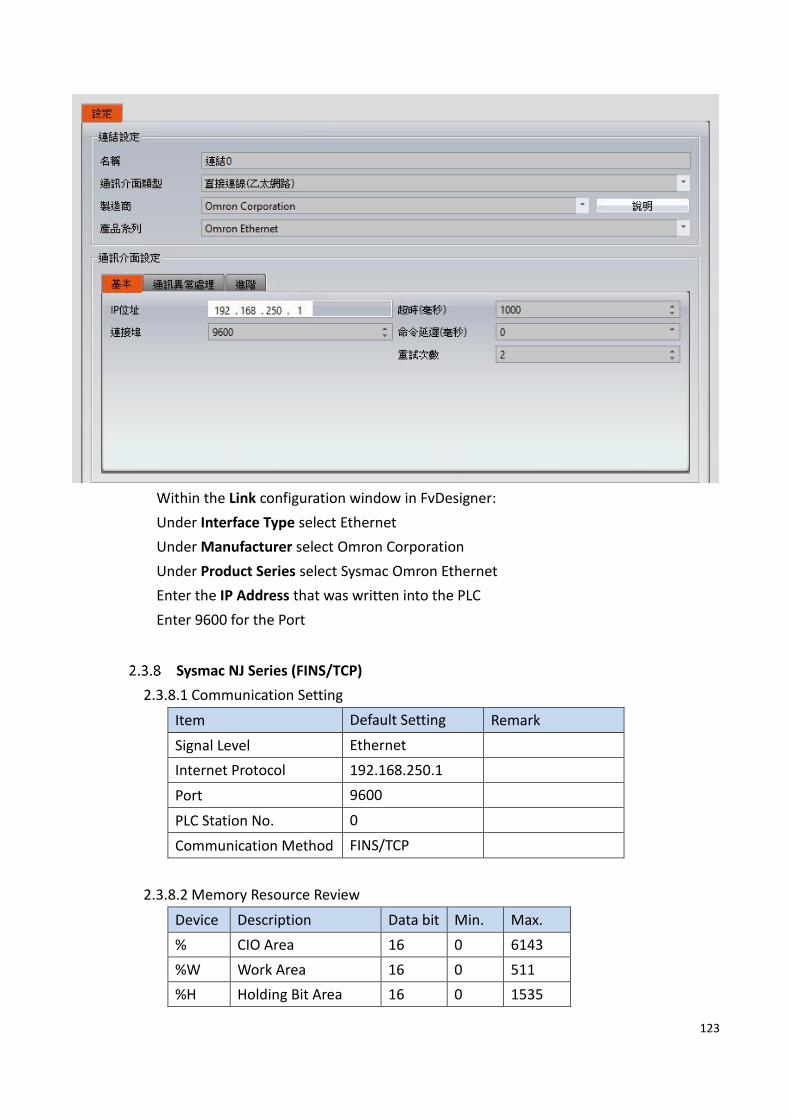
Within the Link configuration window in FvDesigner:
Under Interface Type select Ethernet
Under Manufacturer select Omron Corporation
Under Product Series select Sysmac Omron Ethernet
Enter the IP Address that was written into the PLC
Enter 9600 for the Port
Sysmac NJ Series (FINS/TCP)
2.3.8.1 Communication Setting
Item Default Setting Remark
Signal Level Ethernet
Internet Protocol 192.168.250.1
Port 9600
PLC Station No. 0
Communication Method FINS/TCP
2.3.8.2 Memory Resource Review
Device Description Data bit Min. Max.
% CIO Area 16 0 6143
%W Work Area 16 0 511
%H Holding Bit Area 16 0 1535

124
%D DM Area 16 0 32767
%E0_ EM Bank 0 16 0 32767
%E1_ EM Bank 1 16 0 32767
%E2_ EM Bank 2 16 0 32767
%E3_ EM Bank 3 16 0 32767
%E4_ EM Bank 4 16 0 32767
%E5_ EM Bank 5 16 0 32767
%E6_ EM Bank 6 16 0 32767
%E7_ EM Bank 7 16 0 32767
%E8_ EM Bank 8 16 0 32767
%E9_ EM Bank 9 16 0 32767
%EA_ EM Bank 10 16 0 32767
%EB_ EM Bank 11 16 0 32767
%EC_ EM Bank 12 16 0 32767
2.3.8.3 Connecting to HMI
Configuring the PLC
Use Sysmac Studio to configure the port of the PLC.
Under 專案多檢視瀏覽器 Sidebar, select 設定和安裝>控制器設定>內置
EtherNet/IP 通訊設定 and configure it to the settings detailed below
Note: For more detailed information please refer to the PLC manual.
Connecting PLC to HMI

125

126
Within the Link configuration window in FvDesigner:
Under Interface Type select Ethernet
Under Manufacturer select Omron Corporation
Under Product Series select Sysmac NJ Series (FINS/TCP)
Enter the IP Address that was written into the PLC
Enter 9600 for the Port
Sysmac NX/NJ Series (FINS/UDP)
2.3.9.1 Communication Setting
Item Default Setting Remark
Signal Level Ethernet
Internet Protocol 192.168.250.1
Port 9600
PLC Station No. 0
Communication Method FINS/UDP
2.3.9.2 Memory Resource Review
Device Description Data bit Min. Max.
% CIO Area 16 0 6143
%W Work Area 16 0 511
%H Holding Bit Area 16 0 1535

127
%D DM Area 16 0 32767
%E0_ EM Bank 0 16 0 32767
%E1_ EM Bank 1 16 0 32767
%E2_ EM Bank 2 16 0 32767
%E3_ EM Bank 3 16 0 32767
%E4_ EM Bank 4 16 0 32767
%E5_ EM Bank 5 16 0 32767
%E6_ EM Bank 6 16 0 32767
%E7_ EM Bank 7 16 0 32767
%E8_ EM Bank 8 16 0 32767
%E9_ EM Bank 9 16 0 32767
%EA_ EM Bank 10 16 0 32767
%EB_ EM Bank 11 16 0 32767
%EC_ EM Bank 12 16 0 32767
2.3.9.3 Connecting to HMI
Configuring the PLC
Use Sysmac Studio to configure the port of the PLC.
Under 專案多檢視瀏覽器 Sidebar, select 設定和安裝>控制器設定>內置
EtherNet/IP 通訊設定 and configure it to the settings detailed below.

128
Note: For more detailed information please refer to the PLC manual.
Connecting PLC to HMI

129
Within the Link configuration window in FvDesigner:
Under Interface Type select Ethernet
Under Manufacturer select Omron Corporation
Under Product Series select Sysmac NX/NJ Series (FINS/UDP)
Enter the IP Address that was written into the PLC
Enter 9600 for the Port
Omron SYSMAC CQM Series
2.3.10.1 Communication Setting
Item Default Setting Remark
Signal Level RS232
Baud Rate 9600
Data Length 7
Stop Bit 2
Parity Even
PLC Station No. 0
Communication Method HOSTLINK
2.3.10.2 Memory Resource Review

130
Device Description Data bit Min. Max.
TNB Timer Area 1 0 255
CNB Counter Area 1 0 255
IR IR area 16 0 227
HR HR area 16 0 19
AR AR area 16 0 23
LR LR area 16 0 15
TN Timer area 16 0 255
CN Counter area 16 0 255
DM DM area 16 0 6655
2.3.10.3 Connecting to HMI
Configuring the PLC
Use CX-Programmer to configure the port of the PLC.
Under 專案 Task 工作區 Sidebar, expand 設定.
Navigate to 序列埠 1 tab and configure it to the settings detailed below.

131
After click 傳輸到 PLC to write in PLC.
Note: For more detailed information please refer to the PLC manual.
Connecting PLC to HMI

132
Within the Link configuration window in FvDesigner:
Under Interface Type select Serial
Under Manufacturer select Omron Corporation
Under Product Series select Sysmac CQM Series (HOSTLINK)
Under Port select COM1
2.3.10.4 Wiring Diagrams
Omron PLC Pinout
*Looking into PLC Port
PIN# Signal
1
2 SD
3 RD
4 RS
5 CS

133
6
7
8
9 SG
HMI COM1 Pinout
*Looking into COM1 Port
PIN# COM1 (RS232)
1
2 RX
3 TX
4
5 GND
6
7
8
9
All P5 and P2K Series
HMI COM1 Omron PLC Port
2 RX 2 SD
3 TX 3 RD
5 GND 9 SG
4 RS circuit
5 CS
Wiring Diagrams: All P5 and P2K Series

134
2.4 Siemens
Siemens S7-200 SMART
2.4.1.1 Communication Setting
Item Default Setting Remark
Signal Level RS485 2W
Baud Rate 9600
Data Length 8
Stop Bit 1
Parity Even
PLC Station No. 2
Communication Method PPI
2.4.1.2 Memory Resource Review
Device Description Data bit Min. Max.
I Input 1 0 31
Q Output 1 0 31

135
M Bit Memory 1 0 31
V Variable Memory 1 0 20479
C Counter 1 0 255
T Timer 1 0 255
S Sequential Control Relays 1 0 31
SM Special Memory Bit 1 0 1535
IW Input 16 0 31
QW Output 16 0 31
TW Timer 16 0 255
CW Counter 16 0 255
MW Word Memory 16 0 31
SW SCR 16 0 31
VW V Memory 16 0 20479
SMW Special Memory 16 0 1535
AIW Analog Input 16 0 111
AQW Analog Output 16 0 111
2.4.1.3 Connecting to HMI
Configuring the PLC
Use Step7 microWIN smart to configure the port of the PLC.
Under the Project Sidebar, expand CPU model and configure it to the settings detailed
below.

136
Note: For more detailed information please refer to the PLC manual.
Connecting PLC to HMI
Within the Link configuration window in FvDesigner:

137
Under Interface Type select Serial
Under Manufacturer select Siemens Corporation
Under Product Series select S7-200 SMART PPI
Under Port select the port number that corresponds to the RS485 connection on the
HMI.
2.4.1.4 Wiring Diagrams
PLC RS485 Port
*Looking into male RS485 Cable
PIN# Signal
1
2
3 DATA+
4
5 GND
6
7
8 DATA-
9
HMI (ex.P5043N) COM2 Pinout
*Looking into HMI
PIN# COM2 (RS485)
1 DATA+
2
3
4

138
5 GND
6 DATA-
7
8
9
HMI (ex.P5070N1) COM3 Pinout
*Looking into HMI Device
PIN# COM3
(RS-422/RS-485)
1
2
3 ISO_GND
4
5
6 DATA+
7 DATA-
P5070S/P5070N/P5070N1/P5102N/P5102N1
HMI COM3 Port PLC RS485 Port
6 DATA+ 3 DATA+
7 DATA- 8 DATA-
5 GND 5 GND
Wiring Diagrams: P5070S/P5070N/P5070N1/P5102N/P5102N1

139
P5043S/P5043N/P5070VS/P5102VS/P2K SERIES
HMI COM3 Port PLC RS485 Port
1 DATA+ 3 DATA+
6 DATA- 8 DATA-
5 GND 5 GND
Wiring Diagrams: P5043S/P5043N/P5070VS/P5102VS/P2K SERIES

140
Siemens S7-200 SMART Ethernet
2.4.2.1 Communication Setting
Item Default Setting Remark
Signal Level Ethernet
Internet Protocol 0.0.0.0 To be configured
Port 102
PLC Station No. 0
Communication Method ISO TCP
2.4.2.2 Memory Resource Review
Device Description Data bit Min. Max.
I Input 1 0 31.7
Q Output 1 0 31.7
M Bit Memory 1 0 31.7
V Variable Memory 1 0 20479.7
C Counter 1 0 255
T Timer 1 0 255
S Sequential Control Relays 1 0 31.7
SM Special Memory Bit 1 0 1535.7
IW Input 16 0 31
QW Output 16 0 31
TW Timer 16 0 255

141
CW Counter 16 0 255
MW Word Memory 16 0 31
SW SCR 16 0 31
VW V Memory 16 0 20479
SMW Special Memory 16 0 1535
AIW Analog Input 16 0 111
AQW Analog Output 16 0 111
2.4.2.3 Connecting to HMI
Configuring IP Address on PLC
Use the application STEP 7-MicroWIN SMART to configure the IP address of the PLC.
Under the Project, press the Communications option to connect to the PLC over the
local network.

142
Under Network interface, select one of the options to scan the local network. The IP
address of the PLC will show up. The MAC address can be verified with the one on the
PLC.
Navigate to the PLC tab and select to upload the PLC program onto the computer.
On the sidebar, right click CPU CR40 and select the first option. A dialog window will
open up.

143
In the dialog window, the IP address can be changed. Press OK to confirm the setting.

144
In the PLC tab, select to download the settings onto the PLC.
Note: For more detailed information please refer to the PLC manual.
Connecting PLC to HMI
Within the Link configuration window in FvDesigner:
Under Interface Type select Ethernet
Under Manufacturer select Siemens Corporation
Under Product Series select S7-200 SMART ISO TCP
Enter the IP Address that was written into the PLC.
Enter the Port number that was set on the PLC. The default is 102.

145
Siemens S7-1200 Ethernet
2.4.3.1 Communication Setting
Item Default Setting Remark
Signal Level Ethernet
Internet Protocol 0.0.0.0 To be configured
Port 102
PLC Station No. 0
Communication Method ISO TCP
2.4.3.2 Memory Resource Review
Device Description Data bit Min. Max.
I Input 1 0 1022.7
Q Output 1 0 1022.7
M Bit Memory 1 0 1022.7
IW Input 16 0 1022
QW Output 16 0 1022
MW Word Memory 16 0 1022

146
2.4.3.3 Support Data block type
Data block type Size
Bool Bit
Byte 8-bit
SInt 8-bit
USInt 8-bit
Word 16-bit
Int 16-bit
UInt 16-bit
DWord 32-bit
DInt 32-bit
UDInt 32-bit
Real 32-bit
String Length = 254 byte
Please make sure that proper setting is in TIA:
(1) [DB Properties]→[Attributes]→[ Optimized block access] is unchecked
(2) [PLC program Properties]→[Protection]→[Permit access with PUT/GET
communication from remote partner (PLC,HMI,OPC,…] is checked.
2.4.3.4 Connecting to HMI
Configuring IP Address on PLC
Use the application TIA V13 Step Basic to configure the IP address on the PLC.
Open a new project and add the device to be configured.
In the Project tree sidebar, select the device and navigate to the Online menu option.
Under the Online menu option, select Extend Download to Device. Select the
appropriate network interfaces and check Show all accessible devices. The application
will scan the network for the device. When the device shows up, select it.

147
Under the device in the project tree, select Device configuration and click the Ethernet
port on the device image. Under the Ethernet addresses menu option, the IP address
can be configured.

148
Note: For more detailed information please refer to the PLC manual.
Connecting PLC to HMI
Within the Link configuration window in FvDesigner:
Under Interface Type select Ethernet
Under Manufacturer select Siemens Corporation
Under Product Series select S7-1200
Enter the IP Address that was written into the PLC.
Enter the Port number that was set on the PLC. The default is 102.

149
Siemens S7-200
2.4.4.1 Communication Setting
Item Default Setting Remark
Signal Level RS485 2W
Baud Rate 9600
Data Length 8
Stop Bit 1
Parity Even
PLC Station No. 2
Communication Method PPI
2.4.4.2 Memory Resource Review
Device Description Data Bit Min. Max.
I Input 1 0 15
Q Output 1 0 15
M Bit Memory 1 0 31
V Variable Memory 1 0 10239

150
C Counter 1 0 255
T Timer 1 0 255
S Sequential Control
Relays
1 0 31
SM Special Memory Bit 1 0 549
IW Input 16 0 14
QW Output 16 0 14
TW Timer 16 0 255
CW Counter 16 0 255
MW Word Memory 16 0 30
SW SCR 16 0 30
VW V Memory 16 0 10238
SMW Special Memory 16 0 548
AIW Analog Input 16 0 62
AQW Analog Output 16 0 62
ID Input 32 0 12
QD Output 32 0 12
MD Word Memory 32 0 28
SD SCR 32 0 28
VD V Memory 32 0 10236
SMD Special Memory 32 0 546
2.4.4.3 Connecting to HMI
Configuring the PLC
Use Step7 MicroWIN SP9 to configure the port of the PLC.
After choose the PLC type, click communication in the view field, then double click the
‘’double click to refresh’’ to connect.

151
Note: For more detailed information please refer to the PLC manual.
Connecting PLC to HMI

152
Within the Link configuration window in FvDesigner:
Under Interface Type select Serial
Under Manufacturer select Siemens Corporation
Under Product Series select S7-200
Under Port select the port number that corresponds to the RS485 connection on the
HMI.
2.4.4.4 Wiring Diagrams
PLC RS485 Port

153
*Looking into male RS485 Cable
PIN# Signal
1
2
3 DATA+
4
5 GND
6
7
8 DATA-
9
HMI (ex.P5043N) COM2 Pinout
*Looking into HMI
PIN# COM2 (RS485)
1 DATA+
2
3
4
5 GND
6 DATA-
7
8
9
HMI (ex.P5070N1) COM3 Pinout

154
*Looking into HMI Device
PIN# COM3
(RS-422/RS-485)
1
2
3 ISO_GND
4
5
6 DATA+
7 DATA-
P5070S/P5070N/P5070N1/P5102N/P5102N1
HMI COM3 Port PLC RS485 Port
6 DATA+ 3 DATA+
7 DATA- 8 DATA-
5 GND 5 GND
Wiring Diagrams: P5070S/P5070N/P5070N1/P5102N/P5102N1

155
P5043S/P5043N/P5070VS/P5102VS/P2K SERIES
HMI COM3 Port PLC RS485 Port
1 DATA+ 3 DATA+
6 DATA- 8 DATA-
5 GND 5 GND
Wiring Diagrams: P5043S/P5043N/P5070VS/P5102VS/P2K SERIES

156
Siemens LOGO
2.4.5.1 Communication Setting
Item Default Setting Remark
Signal Level Ethernet
Internet Protocol 0.0.0.0 To be configured
Port 102
PLC Station No. 0
Communication Method ISO TCP
Model 0BA8 0BA7/0BA8
Local TSAP 1000 HEX
Remote TSAP 2100 HEX
2.4.5.2 Memory Resource Review
Device Description Data bit Min. Max.
I Input 1 1 64
Q Output 1 1 64
M Bit Memory 1 1 112
V Variable Memory 1 0.0 1469.7
AI Analog Input 16 1 16
AQ Analog Ouput 16 1 16
AM Analog Memory 16 1 64
VW
16 0 1468

157
VD
32 0 1466
2.4.5.3 Connecting to HMI
Configuring IP Address on PLC
Use the application LOGO!Soft Comfort V8.1 to configure the IP address of the PLC.
Under the Online menu option, select Ethernet Connections.
Right chick Ethernet Connections and Add server connections.
Enable Accept all connection requests, And setting TSAP for
Remote Properties(Client)

158
Note: For more detailed information please refer to the PLC manual.
Connecting PLC to HMI
Within the Link configuration window in FvDesigner:
Under Interface Type select Ethernet
Under Manufacturer select Siemens Corporation
Under Product Series select LOGO
Enter the IP Address that was written into the PLC.
Enter the Port number that was set on the PLC. The default is 102.

159
2.5 Hitachi
EHV Series
2.5.1.1 Communication Setting
Item Default Setting Remark
Signal Level RS232C
Baud Rate 19200
Data Length 7
Stop Bit 1
Parity Even
PLC Station No. 0
Communication Method h protocol
2.5.1.2 Memory Resource Review
Device Description Data
bit
Input
format
Min. Max.
X Input bit 1 DDDDD 0 65535
Y Output bit 1 DDDDD 0 65535
M Memory bit 1 HHHH 0 FFFF
R Internaloutput bit 1 HHH 0 FFF
L Link bit 1 HHHH 0 3FFF
TD Timer 1 DDDD 0 2559
CU Counter 1 DDD 0 511
WX Input word 16 DDDD 0 9999
WY Output word 16 DDDD 0 9999
WM Memory word 16 HHH 0 FFF
WR Internaloutput word 16 HHHH 0 FFFF
WL Link word 16 HHH 0 3FF
TC Timer / Counter 16 DDDD 0 2559
2.5.1.3 Connecting to HMI
Connecting PLC to HMI
Within the Link configuration window in FvDesigner:
Under Interface Type select Serial
Under Manufacturer select Hitachi Ltd.
Under Product Series select EHV Series
Under Port select the port number that corresponds to the RS232 connection on the

160
HMI.
2.5.1.4 Wiring Diagrams
HMI COM1 Pinout
*Looking into COM1 Port
PIN# COM1 (RS232)
1
2 RX
3 TX
4
5 GND
6
7 RTS
8 CTS

161
9
PLC RS232 Pinout
*Looking into PLC
PIN# Signal
1 SG
2 VCC
3 ER
4
5 TxD
6 RxD
7
8 RTS
All P5 and P2K Series
HMI COM1 PLC RS232 Port
2 RX 5 TxD
3 TX 6 RxD
5 GND 1 SG
8 CTS 8 RTS
Wiring Diagrams: All P5 and P2K Series

162
EHV Series ( Ethernet )
2.5.2.1 Communication Setting
Item Default Setting Remark
Signal Level Ethernet
Internet Protocol 192.168.1.100
Port 3004
PLC Station No. 0
Communication Method h protocol ( Ethernet )
2.5.2.2 Memory Resource Review
Device Description Data
bit
Input
format
Min. Max.
X Input bit 1 DDDDD 0 65535
Y Output bit 1 DDDDD 0 65535
M Memory bit 1 HHHH 0 FFFF
R Internal output bit 1 HHH 0 FFF
L Link bit 1 HHHH 0 3FFF
TD Timer 1 DDDD 0 2559
CU Counter 1 DDD 0 511
WX Input word 16 DDDD 0 9999
WY Output word 16 DDDD 0 9999
WM Memory word 16 HHH 0 FFF
WR Internal output word 16 HHHH 0 FFFF

163
WL Link word 16 HHH 0 3FF
TC Timer / Counter 16 DDDD 0 2559
2.6 Schneider
MODBUS RTU
2.6.1.1 Communication Setting
Item Default Setting Remark
Signal Level RS485 2W
Baud Rate 19200
Data Length 8
Stop Bit 1
Parity None
PLC Station No. 0
Communication Method MODBUS RTU(Zero-based)
2.6.1.2 Memory Resource Review
Device Description Data bit Input
format
Min. Max.
%M Memory bit 1 DDDDD 0 65535
%MW Memory word 16 DDDDD 0 65535
2.6.1.3 Connecting to HMI
Configuring the PLC
Use TwidoSuite to configure the port of the PLC.,
expand Describe tab and creation Modbus setting,
Chick MY NETWORK and configure it to the settings detailed below.

164
Note: For more detailed information please refer to the PLC manual.
Connecting PLC to HMI
Within the Link configuration window in FvDesigner:
Under Interface Type select Serial

165
Under Manufacturer select Schneider
Under Product Series select MODBUS RTU
Enter the IP Address that was written into the PLC.
2.6.1.4 Wiring Diagrams
HMI (ex.P5043N) COM2 Pinout
*Looking into HMI
PIN# COM2 (RS485)
1 DATA+
2
3
4
5 GND
6 DATA-
7
8
9
HMI (ex.P5070N1) COM3 Pinout
*Looking into HMI Device
PIN# COM3
(RS-422/RS-485)
1
2
3 ISO_GND
4
5

166
6 DATA+
7 DATA-
PLC RS485 Pinout
*Looking into PLC
PIN# Signal
1 DATA+
2 DATA-
3
4
5
6
7 GND
8
P5070S/P5070N/P5070N1/P5102N/P5102N1
HMI COM3 Port PLC RS485 Port
6 DATA+ 1 DATA+
7 DATA- 2 DATA-
5 GND 5 GND
Wiring Diagrams: P5070S/P5070N/P5070N1/P5102N/P5102N1

167
P5043S/P5043N/P5070VS/P5102VS/P2K SERIES
HMI COM2 Port PLC RS485 Port
1 DATA+ 1 DATA+
6 DATA- 2 DATA-
5 GND 5 GND
Wiring Diagrams: P5043S/P5043N/P5070VS/P5102VS/P2K SERIES
MODBUS TCP
2.6.2.1 Communication Setting
Item Default Setting Remark
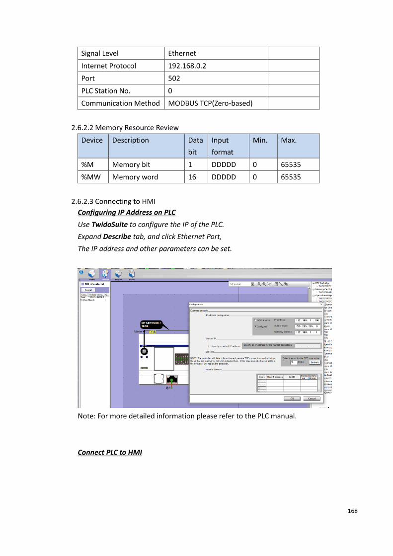
168
Signal Level Ethernet
Internet Protocol 192.168.0.2
Port 502
PLC Station No. 0
Communication Method MODBUS TCP(Zero-based)
2.6.2.2 Memory Resource Review
Device Description Data
bit
Input
format
Min. Max.
%M Memory bit 1 DDDDD 0 65535
%MW Memory word 16 DDDDD 0 65535
2.6.2.3 Connecting to HMI
Configuring IP Address on PLC
Use TwidoSuite to configure the IP of the PLC.
Expand Describe tab, and click Ethernet Port,
The IP address and other parameters can be set.
Note: For more detailed information please refer to the PLC manual.
Connect PLC to HMI

169
Within the Link configuration window in FvDesigner:
Under Interface Type select Ethernet
Under Manufacturer select Schneider Electric.
Under Product Series select Modbus TCP.
Enter the IP Address that was written into the PLC.
2.7 Allen-Bradley
CompactLogix/ControlLogix/FlexLogix Tag Series
2.7.1.1 Communication Setting
Item Default Setting Remark
Signal Level Ethernet
Internet Protocol 192.168.0.2
Port 44818
PLC Station No. 0
Communication Method EtherNet/IP
2.7.1.2 PLC Resource Review

170
DataType bits Description
BOOL --- 1 Boolean
SINT --- 8 Single integer
INT --- 16 Integer
DINT --- 32 Double integer
REAL --- 32 Float number
STRING LEN Length of string
DATA Character data of string
COUNTER PRE 32 Preset value
ACC 32 Accumulatedvalue
CU 1 Count up flag
CD 1 Count down flag
DN 1 Done flag
OV 1 Overflowflag
UN 1 Underflowflag
TIMER PRE 32 Preset value
ACC 32 Accumulatedvalue
EN 1 Enable flag
TT 1 Timing flag
DN 1 Done Flag
AB:1769_DI16:I:0 Fault 32
Data 16 Data of DI16
AB:1769_DI32:I:0 Fault 32
Data 32 Data of DI32
AB:1769_DO16:O:0 Data 16 Data of DO16
AB:1769_DO32:O:0 Data 32 Data of DO32
2.7.1.3 Connecting to HMI
Configuring IP Address on PLC
The application RSLinx Classic (ver. 3.51) was used to configure the IP address on the
device.
On the PLC device, make sure the switch on the main module is not set to the RUN
setting.
Open RSLinx Classic and connect to the PLC either with a USB-Serial cable or through
the local network. To connect to PLC via the local network, follow the steps below.
In the Communications menu tab, select Configure Drivers. Select EtherNet/IP Driver
and press ‘Add New’. Select “Your Network Interface Card” and press OK. Start the

171
Driver and close out of the dialog window.
Under the new Ethernet driver, the PLC connected to the local network should be
visible.
Right click the main module of the PLC and select Module Configuration.
Navigate to the Port Configuration tab. Here, the IP address and other parameters can
be set. Press OK to confirm the settings.

172
Note: For more detailed information please refer to the PLC manual.
Connect PLC to HMI
Within the Link configuration window in FvDesigner:
Under Interface Type select Ethernet
Under Manufacturer select Allen-Bradley.
Under Product Series select CompactLogix/ControlLogix/FlexLogix Taq.

173
Enter the IP Address that was written into the PLC.
To access variables in the program, tags will have to be imported. Tags are created in
the program RSLogix 5000.
Right click 控制器标签(controller tag) in the controller sidebar and select 导出
(Export) Tag.
Select which tags to export. The register tags can now be imported into the HMI
project.
SLC series (EtherNet/IP)
2.7.2.1 Communication Setting

174
Item Default Setting Remark
Signal Level Ethernet
Internet Protocol 192.168.0.1
Port 44818
Communication Method EtherNet/IP
2.7.2.2 PLC Resource Review
Device Description Data bit Input
format
Min. Max.
O Output File 1/16 O F:S.D O0:0.0 O0:30.255
I Intput File 1/16 I F:S.D I1:0.0 I1:30.255
S Status File 1/16 S F:E S2:0 S2:163
B Bit File 1/16 B F:E B3:0 B255:255
T Timer File 1/16 T F:E.D T4:0.0 T255:255.2
C Counter File 1/16 C F:E.D C5:0.0 C255:255.2
R Control File 1/16 R F:E.D R6:0.0 R255:255.2
N Integer File 1/16 N F:E N7:0 N255:255
F Floating File 32 F F:E F8:0 F255:255
A ASCII File 1/16 A F:E A9:0 A255:255
ST String File 1/16 ST F:E.D ST9:0.0 ST255:255.41
2.7.2.3 Connecting to HMI
The SLC series PLC can be configured using the same procedure as the Micrologix
series configuration. The figures refer to the Micrologix PLC but the procedure is the
same.
Configuring IP Address on PLC
If the IP address needs to be configured, follow the steps below.
Use the applications RSLinx Classic Lite and RSLogix 500 to configure the IP address of
the PLC.
First open RSLinx Classic Lite to set up a connection between the computer and PLC.
An Ethernet cable needs to be connected to the PLC and the computer must be online.
In the Communications menu tab, select Configure Drivers. Select EtherNet/IP Driver
and press ‘Add New’. Select “Your Network Interface Card” and press OK. Start the
Driver and close out of the dialog window.

175
Under the new Ethernet driver, the PLC connected to the local network should be
visible. If the status of the device is OK, open up RSLogix 500.
In RSLogix 500, under the Comms menu option, select Who Active go Online. In the
dialog window that appears, select the PLC device connected through RSLinx.
Press Create New File in the dialog window that appears after pressing OK.
On the left side of the program, double click Channel Configuration to access the PLC’s
Ethernet settings. Under the Channel 1 tab, the IP address can be changed.

176
Note: For more detailed information please refer to the PLC manual.
Connect PLC to HMI

177
Within the Link configuration window in FvDesigner:
Under Interface Type select Ethernet
Under Manufacturer select Allen-Bradley
Under Product Series select SLC (Ethernet/IP)
Enter the IP Address that was written into the PLC.
Keep the Port at the default setting.
SLC Series
2.7.3.1 Communication Setting
Item Default Setting Remark
Signal Level RS232
Baud Rate 19200
Data Length 8
Stop Bit 1
Parity None
PLC Station No. 1
TX Control CRC CRC/BCC

178
Communication Method DF1
2.7.3.2 PLC Resource Review
Device Description Data bit Input
format
Min. Max.
O Output File 1/16 O F:S.D O0:0.0 O0:30.255
I Intput File 1/16 I F:S.D I1:0.0 I1:30.255
S Status File 1/16 S F:E S2:0 S2:163
B Bit File 1/16 B F:E B3:0 B255:255
T Timer File 1/16 T F:E.D T4:0.0 T255:255.2
C Counter File 1/16 C F:E.D C5:0.0 C255:255.2
R Control File 1/16 R F:E.D R6:0.0 R255:255.2
N Integer File 1/16 N F:E N7:0 N255:255
F Floating File 32 F F:E F8:0 F255:255
A ASCII File 1/16 A F:E A9:0 A255:255
ST String File 1/16 ST F:E.D ST9:0.0 ST255:255.41
2.7.3.3 Connecting to HMI
Configuring the PLC
Use RSLinx Classic Lite and RSLogix 500 to configure the port of the PLC.
Under the Project Sidebar, expand Channel Configuration. And expand Channel 0 tab,
Configure it to the settings detailed below.

179
Note: For more detailed information please refer to the PLC manual.
Connecting PLC to HMI

180
Within the Link configuration window in FvDesigner:
Under Interface Type select Serial
Under Manufacturer select Allen-Bradley
Under Product Series select SLC.
Verify the parameters match the window above.
2.7.3.4 Wiring Diagrams
HMI COM1 Pinout
*Looking into COM1 Port
PIN# COM1 (RS232)
1
2 RX
3 TX
4

181
5 GND
6
7 RTS
8 CTS
9
PLC RS232 Pinout
*Looking into PLC
PIN# Signal
1
2 GND
3
4 RXD
5
6
7 TXD
8
All P5 and P2K Series
HMI COM1 PLC RS232 Port
2 RX 7 TXD
3 TX 4 RXD
5 GND 2 GND
Wiring Diagrams: All P5 and P2K Series

182
MicroLogix Series (EtherNet/IP)
2.7.4.1 Communication Setting
Item Default Setting Remark
Signal Level Ethernet
Internet Protocol 192.168.0.1
Port 44818
Communication Method EtherNet/IP
2.7.4.2 PLC Resource Review
Device Description Data bit Input
format
Min. Max.
O Output File 1/16 O F:S.D O0:0.0 O0:30.255
I Intput File 1/16 I F:S.D I1:0.0 I1:30.255
S Status File 1/16 S F:E S2:0 S2:163
B Bit File 1/16 B F:E B3:0 B255:255
T Timer File 1/16 T F:E.D T4:0.0 T255:255.2
C Counter File 1/16 C F:E.D C5:0.0 C255:255.2
R Control File 1/16 R F:E.D R6:0.0 R255:255.2
N Integer File 1/16 N F:E N7:0 N255:255
F Floating File 32 F F:E F8:0 F255:255
ST String File 1/16 ST F:E.D ST9:0.0 ST255:255.41
L Long word 32 L F:E L9:0 L255:255

183
File
2.7.4.3 Connecting to HMI
Configuring IP Address on PLC
If the IP address needs to be configured, follow the steps below.
Use the applications RSLinx Classic Lite and RSLogix 500 to configure the IP address of
the PLC.
First open RSLinx Classic Lite to set up a connection between the computer and PLC.
An Ethernet cable needs to be connected to the PLC and the computer must be online.
In the Communications menu tab, select Configure Drivers. Select EtherNet/IP Driver
and press ‘Add New’. Select “Your Network Interface Card” and press OK. Start the
Driver and close out of the dialog window.
Under the new Ethernet driver, the PLC connected to the local network should be
visible. If the status of the device is OK, open up RSLogix 500.
In RSLogix 500, under the Comms menu option, select Who Active go Online. In the
dialog window that appears, select the PLC device connected through RSLinx.

184
Press Create New File in the dialog window that appears after pressing OK.
On the left side of the program, double click Channel Configuration to access the PLC’s
Ethernet settings. Under the Channel 1 tab, the IP address can be changed.

185
Note: For more detailed information please refer to the PLC manual.
Connect PLC to HMI

186
Within the Link configuration window in FvDesigner:
Under Interface Type select Ethernet
Under Manufacturer select Allen-Bradley
Under Product Series select Micrologix (Ethernet/IP)
Enter the IP Address that was written into the PLC.
Keep the Port at the default setting.
MicroLogix Series
2.7.5.1 Communication Setting
Item Default Setting Remark
Signal Level RS232
Baud Rate 19200
Data Length 8
Stop Bit 1
Parity None
PLC Station No. 1
TX Control CRC CRC/BCC

187
Communication Method DF1 Protocol
2.7.5.2 PLC Resource Review
Device Description Data bit Input
format
Min. Max.
O Output File 1/16 O F:S.D O0:0.0 O0:30.255
I Intput File 1/16 I F:S.D I1:0.0 I1:30.255
S Status File 1/16 S F:E S2:0 S2:163
B Bit File 1/16 B F:E B3:0 B255:255
T Timer File 1/16 T F:E.D T4:0.0 T255:255.2
C Counter File 1/16 C F:E.D C5:0.0 C255:255.2
R Control File 1/16 R F:E.D R6:0.0 R255:255.2
N Integer File 1/16 N F:E N7:0 N255:255
F Floating File 32 F F:E F8:0 F255:255
ST String File 1/16 ST F:E.D ST9:0.0 ST255:255.41
L Long word
File
32 L F:E L9:0 L255:255
2.7.5.3 Connecting to HMI
Configuring the PLC
To connect the PLC to a computer, follow the same steps detailed in the previous
chapter. Configuring the serial connection of the PLC is the same as configuring the IP
address of the PLC.
Double click Channel Configuration and navigate to the Channel 0 tab. Here, the serial
connection settings can be adjusted if needed.

188
Note: For more detailed information please refer to the PLC manual.
Connecting PLC to HMI

189
Within the Link configuration window in FvDesigner:
Under Interface Type select Serial
Under Manufacturer select Allen-Bradley
Under Product Series select Micrologix
Under Port select COM1
Verify the other parameters are consistent with the ones set on the PLC.
2.7.5.4 Wiring Diagrams
HMI COM1 Pinout
*Looking into COM1 Port
PIN# COM1 (RS232)
1
2 RX
3 TX

190
4
5 GND
6
7 RTS
8 CTS
9
PLC RS232 Pinout
*Looking into PLC
PIN# Signal
1
2 GND
3
4 RXD
5
6
7 TXD
8
All P5 and P2K Series
HMI COM1 PLC RS232 Port
2 RX 7 TXD
3 TX 4 RXD
5 GND 2 GND
Wiring Diagrams: All P5 and P2K Series

191
2.8 Taiwan Instrument & Control Co., Ltd.
FY Series
2.8.1.1 Communication Setting
Item Default Setting Remark
Signal Level RS485 2W
Baud Rate 38400
Data Length 8
Stop Bit 1
Parity Odd
PLC Station No. 0
Communication Method MODBUS RTU
2.8.1.2 Memory Resource Review
Device Description Data
bit
Input
format
Min. Max.
SV Set Point 16 D 0 0
OUTL Output Limit 16 D 0 0
AT Auto Tuning 16 D 0 0
AL1 Alarm 1 set value 16 D 0 0
AL2 Alarm 2 set value 16 D 0 0
AL3 Alarm 3 set value 16 D 0 0
PTN Program Pattern 16 D 0 0

192
SEG Program Segment
Display
16 D 0 0
TIMR Program Countdown
Display
16 D 0 0
SV_1 Set Point of
Seg.1(Pattern 1)
16 D 0 0
TM_1 Run Time of
Seg.1(Pattern 1)
16 D 0 0
OUT1 Output Limit of
Seg.1(Pattern 1)
16 D 0 0
SV_2 Set Point of
Seg.2(Pattern 1)
16 D 0 0
TM_2 Run Time of
Seg.2(Pattern 1)
16 D 0 0
OUT2 Output Limit of
Seg.2(Pattern 1)
16 D 0 0
SV_3 Set Point of
Seg.3(Pattern 1)
16 D 0 0
TM_3 Run Time of
Seg.3(Pattern 1)
16 D 0 0
OUT3 Output Limit of
Seg.3(Pattern 1)
16 D 0 0
SV_4 Set Point of
Seg.4(Pattern 1)
16 D 0 0
TM_4 Run Time of
Seg.4(Pattern 1)
16 D 0 0
OUT4 Output Limit of
Seg.4(Pattern 1)
16 D 0 0
SV_5 Set Point of
Seg.5(Pattern 1)
16 D 0 0
TM_5 Run Time of
Seg.5(Pattern 1)
16 D 0 0
OUT5 Output Limit of
Seg.5(Pattern 1)
16 D 0 0
SV_6 Set Point of
Seg.6(Pattern 1)
16 D 0 0
TM_6 Run Time of 16 D 0 0

193
Seg.6(Pattern 1)
OUT6 Output Limit of
Seg.6(Pattern 1)
16 D 0 0
SV_7 Set Point of
Seg.7(Pattern 1)
16 D 0 0
TM_7 Run Time of
Seg.7(Pattern 1)
16 D 0 0
OUT7 Output Limit of
Seg.7(Pattern 1)
16 D 0 0
SV_8 Set Point of
Seg.8(Pattern 1)
16 D 0 0
TM_8 Run Time of
Seg.8(Pattern 1)
16 D 0 0
OUT8 Output Limit of
Seg.8(Pattern 1)
16 D 0 0
SV_12 Set Point of
Seg.1(Pattern 2)
16 D 0 0
TM_12 Run Time of
Seg.1(Pattern 2)
16 D 0 0
OUT12 Output Limit of
Seg.1(Pattern 2)
16 D 0 0
SV_22 Set Point of
Seg.2(Pattern 2)
16 D 0 0
TM_22 Run Time of
Seg.2(Pattern 2)
16 D 0 0
OUT22 Output Limit of
Seg.2(Pattern 2)
16 D 0 0
SV_32 Set Point of
Seg.3(Pattern 2)
16 D 0 0
TM_32 Run Time of
Seg.3(Pattern 2)
16 D 0 0
OUT32 Output Limit of
Seg.3(Pattern 2)
16 D 0 0
SV_42 Set Point of
Seg.4(Pattern 2)
16 D 0 0
TM_42 Run Time of
Seg.4(Pattern 2)
16 D 0 0

194
OUT42 Output Limit of
Seg.4(Pattern 2)
16 D 0 0
SV_52 Set Point of
Seg.5(Pattern 2)
16 D 0 0
TM_52 Run Time of
Seg.5(Pattern 2)
16 D 0 0
OUT52 Output Limit of
Seg.5(Pattern 2)
16 D 0 0
SV_62 Set Point of
Seg.6(Pattern 2)
16 D 0 0
TM_62 Run Time of
Seg.6(Pattern 2)
16 D 0 0
OUT62 Output Limit of
Seg.6(Pattern 2)
16 D 0 0
SV_72 Set Point of
Seg.7(Pattern 2)
16 D 0 0
TM_72 Run Time of
Seg.7(Pattern 2)
16 D 0 0
OUT72 Output Limit of
Seg.7(Pattern 2)
16 D 0 0
SV_82 Set Point of
Seg.8(Pattern 2)
16 D 0 0
TM_82 Run Time of
Seg.8(Pattern 2)
16 D 0 0
OUT82 Output Limit of
Seg.8(Pattern 2)
16 D 0 0
P1 OUT1 Proportional
Band
16 D 0 0
I1 OUT1 Integral Time 16 D 0 0
D1 OUT1 Derivative
Time
16 D 0 0
DB1 Dead-band Time 16 D 0 0
ATVL Auto Tuning Offset 16 D 0 0
CYT1 OUT1 Cycle Time 16 D 0 0
HYS1 OUT1 Hysteresis 16 D 0 0
P2 OUT2 Proportional
Band
16 D 0 0

195
I2 OUT2 Integral Time 16 D 0 0
D2 OUT2 Derivative
Time
16 D 0 0
CYT2 OUT2 Cycle Time 16 D 0 0
HYS2 OUT2 Hysteresis 16 D 0 0
GAP1 OUT1 Control Gap 16 D 0 0
GAP2 OUT2 Control Gap 16 D 0 0
LCK Function Lock 16 D 0 0
INP1 Input Type Selection 16 D 0 0
ANL1 Linear Input Zero
Calibration
16 D 0 0
ANH1 Linear Input Span
Calibration
16 D 0 0
DP Decimal Point
Position
16 D 0 0
LSPL Lower Set Point Limit 16 D 0 0
USPL Upper Set Point Limit 16 D 0 0
ANL2 Remote Input Zero
Calibration
16 D 0 0
ANH2 Linear Input Span
Calibration
16 D 0 0
ALD1 Alarm mode for AL1 16 D 0 0
ALT1 Alarm time for AL1 16 D 0 0
ALD2 Alarm mode for AL2 16 D 0 0
ALT2 Alarm time for AL2 16 D 0 0
ALD3 Alarm mode for AL3 16 D 0 0
ALT3 Alarm time for AL3 16 D 0 0
HYSA Hysteresis for all
Alarms
16 D 0 0
CLO1 OUT1 Lower
Calibration
16 D 0 0
CHO1 OUT1 Upper
Calibration
16 D 0 0
CLO2 OUT1 Lower
Calibration
16 D 0 0
CHO2 OUT1 Upper
Calibration
16 D 0 0

196
CLO3 TRS Lower
Calibration
16 D 0 0
CHO3 TRS Upper
Calibration
16 D 0 0
RUCY Full run time of
motor valve
16 D 0 0
WAIT Full run time of
proportional motor
valve
16 D 0 0
SETA 16 D 0 0
PSL Protocol Selection 16 D 0 0
BITS Communication Bits 16 D 0 0
IDNO ID Number 16 D 0 0
BAUD Baud rate 16 D 0 0
SVOS SV Compensation 16 D 0 0
PVOS PV Compensation 16 D 0 0
UNIT Unit of PV and SV 16 D 0 0
PVFT PV Filter 16 D 0 0
CASC 16 D 0 0
OUD Heating / Cooling
selection
16 D 0 0
OPAD Control Algorithm 16 D 0 0
HZ Power Frequency 16 D 0 0
SET1 Hide/ Display
parameter
16 D 0 0
SET2 Hide/ Display
parameter
16 D 0 0
SET3 Hide/ Display
parameter
16 D 0 0
SET4 Hide/ Display
parameter
16 D 0 0
SET5 Hide/ Display
parameter
16 D 0 0
SET6 Hide/ Display
parameter
16 D 0 0
SET7 Hide/ Display
parameter
16 D 0 0
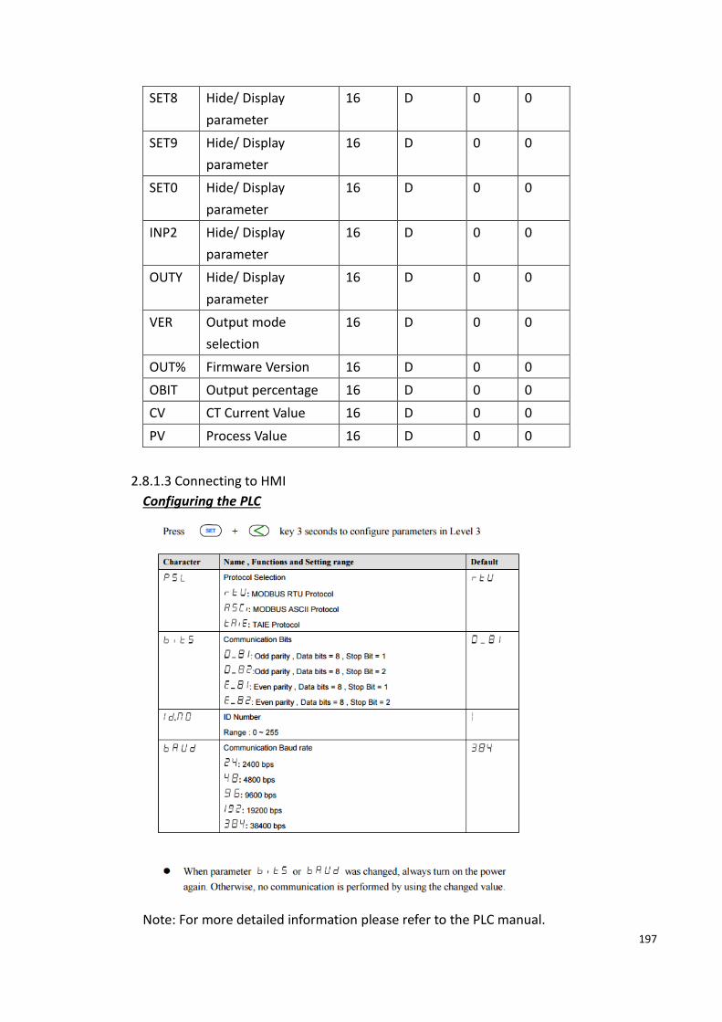
197
SET8 Hide/ Display
parameter
16 D 0 0
SET9 Hide/ Display
parameter
16 D 0 0
SET0 Hide/ Display
parameter
16 D 0 0
INP2 Hide/ Display
parameter
16 D 0 0
OUTY Hide/ Display
parameter
16 D 0 0
VER Output mode
selection
16 D 0 0
OUT% Firmware Version 16 D 0 0
OBIT Output percentage 16 D 0 0
CV CT Current Value 16 D 0 0
PV Process Value 16 D 0 0
2.8.1.3 Connecting to HMI
Configuring the PLC
Note: For more detailed information please refer to the PLC manual.

198
Connecting PLC to HMI
Within the Link configuration window in FvDesigner:
Under Interface Type select Serial
Under Manufacturer select Taiwan Instrument & Control Co.,Ltd.
Under Product Series select TAIE FY100/900 Series.
Verify the parameters match the window above.
2.8.1.4 Wiring diagrams
HMI (ex.P5043N) COM2 Pinout

199
*Looking into HMI
PIN# COM2 (RS485)
1 DATA+
2
3
4
5 GND
6 DATA-
7
8
9
HMI COM3 Pinout
*Looking into HMI Device
PIN# COM3
(RS-422/RS-485)
1
2
3 ISO_GND
4
5
6 DATA+
7 DATA-
P5070S/P5070N/P5070N1/P5102N/P5102N1
HMI COM3 Port PLC RS485 Port
6 DATA+ 12 DATA+
7 DATA- 11 DATA-

200
3 ISO_GND GND
Wiring Diagrams: P5070S/P5070N/P5070N1/P5102N/P5102N1
P5043S/P5043N/P5070VS/P5102VS/P2K SERIES
HMI COM2 Port PLC RS485 Port
1 DATA+ 12 DATA+
6 DATA- 11 DATA-
5 GND GND
Wiring Diagrams: P5043S/P5043N/P5070VS/P5102VS/P2K SERIES

201
2.9 Delta
DVP Series
2.9.1.1 Communication Setting
Item Default Setting Remark
Signal Level RS232C
Baud Rate 9600
Data Length 7
Stop Bit 1
Parity Even
PLC Station No. 0
Communication Method MODBUS ASCII
2.9.1.2 Memory Resource Review
Device Description Data
bit
Input
format
Min. Max.
X Input relay 1 OOO 0 377
Y Output relay 1 OOO 0 377
M Auxiliary relay 1 DDDD 0 4095
S Step 1 DDDD 0 1023
T Timer 1 DDD 0 255
C Counter 1 DDD 0 255
CV Counter memory 16 DDD 0 199
TV Timer memory 16 DDD 0 255
D Data register 16 DDDDD 0 11999
SCV Counter memory 32 DDD 200 255
2.9.1.3 Connecting to HMI
Configuring the PLC
Use ISPsoft to configure the port of the PLC.
But RS232 can’t change setting.
Note: For more detailed information please refer to the PLC manual.
Connecting PLC to HMI

202
Within the Link configuration window in FvDesigner:
Under Interface Type select Serial
Under Manufacturer select Delta Electronics, Inc
Under Product Series select DVP Series
Make sure the other parameters are set at the values in the figure.
2.9.1.4 Wiring Diagrams
HMI COM1 Pinout
*Looking into COM1 Port
PIN# COM1 (RS232)
1
2 RX
3 TX
4

203
5 GND
6
7 RTS
8 CTS
9
PLC RS232 Pinout
*Looking into PLC
PIN# Signal
1
2
3
4 RXD
5 TXD
6
7
8 GND
All P5 and P2K Series
HMI COM1 PLC RS232 Port
2 RX 5 TXD
3 TX 4 RXD
5 GND 8 GND
Wiring Diagrams: All P5 and P2K Series

204
AH500 Series
2.9.2.1 Communication Setting
Item Default Setting Remark
Signal Level RS232C
Baud Rate 9600
Data Length 7
Stop Bit 1
Parity Even
PLC Station No. 1
Communication Method MODBUS ASCII
2.9.2.2 Memory Resource Review
Device Description Data
bit
Input
format
Min. Max.
X Input relay 1 DDD.D 0.0 511.15
16 DDD 0 511
Y Output relay 1 DDD.D 0.0 511.15
16 DDD 0 511
D Data register 1 DDDDD.D 0 65535.15
16 DDDDD 0 65535
L Link register 1 DDDDD.D 0 65535.15
16 DDDDD 0 65535
M Auxiliary relay 1 DDDD 0 8191
SM Special Auxiliary 1 DDDD 0 2047

205
Relay
S Stepping Relay 1 DDDD 0 2047
T Timer 1 DDDD 0 2047
TV Timer memory 16 DDDD 0 2047
C Counter 1 DDDD 0 2047
CV Counter memory 16 DDDD 0 2047
HC 32-bit Counter 1 DD 0 63
HCV 32-bit Counter
memory
32 DD 0 63
SR Special data register 16 DDDD 0 2047
E Index register 16 DD 0 31
2.9.2.3 Connecting to HMI
Configuring the PLC
Use the application ISPSoft (Ver. 2.05) to configure the PLC. The application COMMGR
is used to establish the connection between the PLC and the computer.
Open COMMGR. The application opens in the system tray. Double click the icon to
open it.
In Device Manager, verify the port number the PLC is connected to. In COMMGR, press
Add and for Connection Setup, select RS232/422/485 for type. Select the port number
the PLC is connected to for the COM Port setting. Press Auto-detect and the
application will automatically adjust the rest of the parameters.

206
In ISPSoft, under the Tools menu option, select Communication Settings. Select the
name of the connection configured in COMMGR and press OK.
Under the PLC menu option, select Transfer and Upload. If there is a program on the
PLC, it will be uploaded and the system settings can be configured. If there is no
program present on the PLC one will have to be downloaded.

207
If program has to be downloaded onto the PLC, press open and select a program. In
the active folder, there are example programs. The device associated with the example
program may not be the same as the device connected. Under Tools, select PLC Type
and select the device currently used. Once a program is opened, the PLC settings can
be configured.
In the Project sidebar, double click HWCONFIG. Double click the CPU module and
navigate to the COM Port tab in the settings dialog. Adjust communication parameters
and press OK to confirm the settings.

208
Under the PLC menu option, the program and PLC configurations can be downloaded
onto the device.
Note: For more detailed information please refer to the PLC manual.
Connecting PLC to HMI

209
Within the Link configuration window in FvDesigner:
Under Interface Type select Serial
Under Manufacturer select Delta Electronics, Inc
Under Product Series select Delta AH500 Series
Select the appropriate Port to establish connection with the PLC.
Verify the other parameters are configured correctly.
2.9.2.4 Wiring Diagrams
HMI COM1 Pinout
*Looking into COM1 Port
PIN# COM1 (RS232)
1
2 RX
3 TX

210
4
5 GND
6
7 RTS
8 CTS
9
PLC COM1/COM2 Pinout
*Looking into PLC
PIN# Signal
1
2 RXD
3 TXD
4
5 GND
6
7
8
9
All P5 and P2K Series
HMI COM1 PLC RS232 Port
2 RX 3 TXD
3 TX 2 RXD
5 GND 5 GND
Wiring Diagrams: All P5 and P2K Series

211
2.10 Panasonic
FP Series
2.10.1.1 Communication Setting
Item Default Setting Remark
Signal Level RS232C
Baud Rate 9600
Data Length 8
Stop Bit 1
Parity Odd
PLC Station No. 1
Communication Method MEWTOCOL
(computer link)
2.10.1.2 Memory Resource Review
Device Description Data
bit
Input
format
Min. Max.
X External input relay 1 DDDD 0 8191
Y External output relay 1 DDDD 0 8191
R Internal relay 1 DDDDD 0 14191
L Link Relay 1 DDDDD 0 10239
T Timer 1 DDDD 0 3071
C Counter 1 DDDD 0 3071
WX External input relay 16 DDD 0 511
WY External output relay 16 DDD 0 511
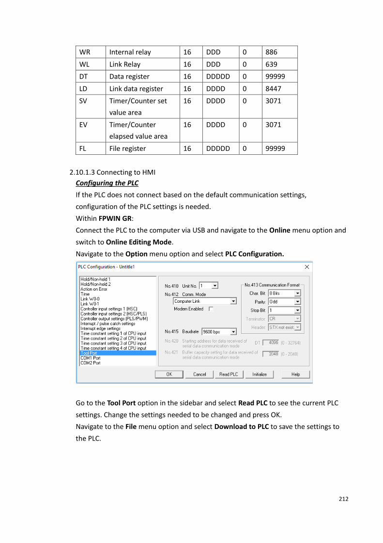
212
WR Internal relay 16 DDD 0 886
WL Link Relay 16 DDD 0 639
DT Data register 16 DDDDD 0 99999
LD Link data register 16 DDDD 0 8447
SV Timer/Counter set
value area
16 DDDD 0 3071
EV Timer/Counter
elapsed value area
16 DDDD 0 3071
FL File register 16 DDDDD 0 99999
2.10.1.3 Connecting to HMI
Configuring the PLC
If the PLC does not connect based on the default communication settings,
configuration of the PLC settings is needed.
Within FPWIN GR:
Connect the PLC to the computer via USB and navigate to the Online menu option and
switch to Online Editing Mode.
Navigate to the Option menu option and select PLC Configuration.
Go to the Tool Port option in the sidebar and select Read PLC to see the current PLC
settings. Change the settings needed to be changed and press OK.
Navigate to the File menu option and select Download to PLC to save the settings to
the PLC.

213
Note: For more detailed information please refer to the PLC manual.
Connecting PLC to HMI
Within the Link configuration window in FvDesigner:
Under Interface Type select Serial
Under Manufacturer select Panasonic Corporation
Under Product Series select FP Series
Select COM1 for the port
Select 1 for the station number
Verify the other settings are consistent with the settings on the PLC.

214
2.10.1.4 Wiring Diagrams
PLC RS232 Pinout
*View looking into PLC
PIN# Signal
1 GND
2 TXD
3 RXD
4
5
HMI COM1 Pinout
*Looking into COM1 Port
PIN# COM1 (RS232)
1
2 RX
3 TX
4
5 GND
6
7 RTS
8 CTS
9
All P5 and P2K Series
HMI COM1 PLC RS232 Port
2 RX 2 TXD
3 TX 3 RXD

215
5 GND 1 GND
Wiring Diagrams: All P5 and P2K Series
FP Series (Ethernet)
2.10.2.1 Communication Setting
Item Default Setting Remark
Signal Level Ethernet With AFPX-
COM5
Internet Protocol 192.168.1.100
Port 9094
PLC Station No. 1
Communication Method MEWTOCOL (computer
link)
2.10.2.2 Memory Resource Review
Device Description Data
bit
Input
format
Min. Max.
X External input relay 1 DDDD 0 8191
Y External output relay 1 DDDD 0 8191
R Internal relay 1 DDDDD 0 14191
L Link Relay 1 DDDDD 0 10239
T Timer 1 DDDD 0 3071

216
C Counter 1 DDDD 0 3071
WX External input relay 16 DDD 0 511
WY External output relay 16 DDD 0 511
WR Internal relay 16 DDD 0 886
WL Link Relay 16 DDD 0 639
DT Data register 16 DDDDD 0 99999
LD Link data register 16 DDDD 0 8447
SV Timer/Counter set
value area
16 DDDD 0 3071
EV Timer/Counter
elapsed value area
16 DDDD 0 3071
FL File register 16 DDDDD 0 99999
2.10.2.3 Connecting to HMI
Configuring IP Address on PLC
Use the application Configurator WD to view/change the IP address on the PLC.
Press the Search Unit to search for the PLC on the local network. Right click the PLC
and press Setting IP Address to change the IP address if needed.
Right click the PLC and press Communication Setting to change the port if necessary.
Note: For more detailed information please refer to the PLC manual.
Connecting PLC to HMI
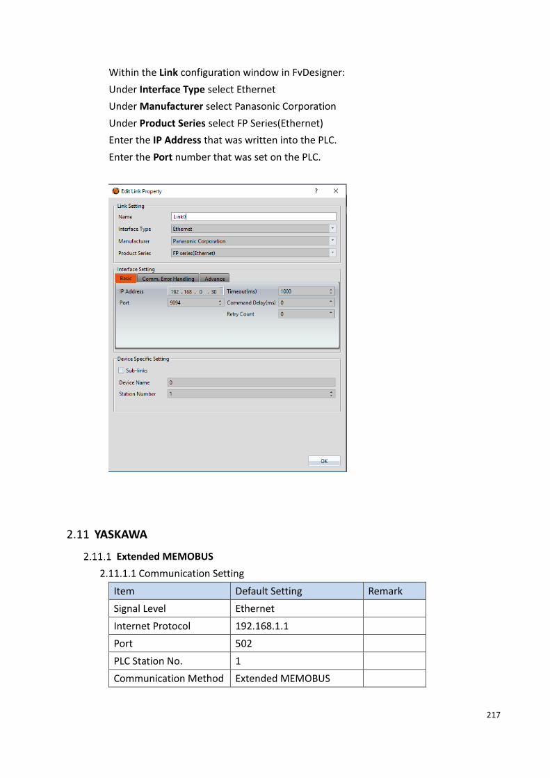
217
Within the Link configuration window in FvDesigner:
Under Interface Type select Ethernet
Under Manufacturer select Panasonic Corporation
Under Product Series select FP Series(Ethernet)
Enter the IP Address that was written into the PLC.
Enter the Port number that was set on the PLC.
2.11 YASKAWA
Extended MEMOBUS
2.11.1.1 Communication Setting
Item Default Setting Remark
Signal Level Ethernet
Internet Protocol 192.168.1.1
Port 502
PLC Station No. 1
Communication Method Extended MEMOBUS
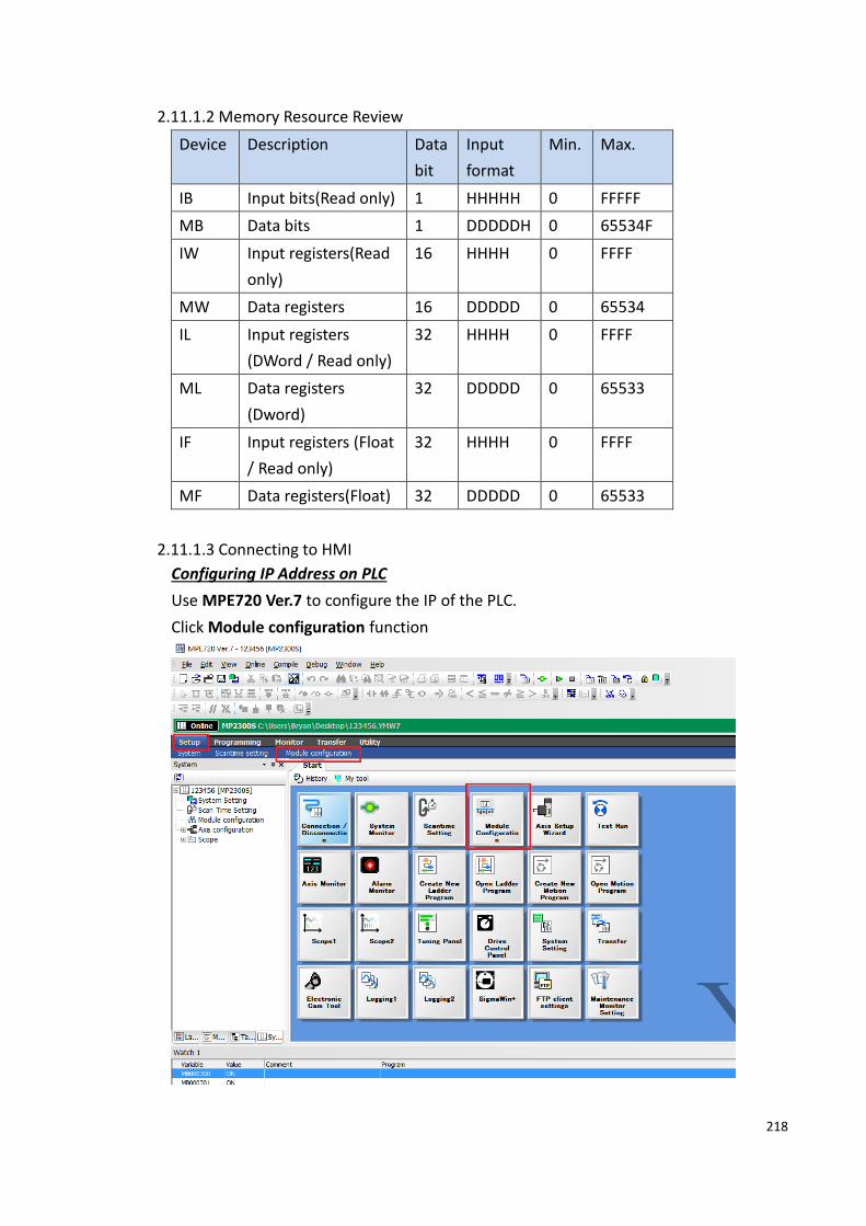
218
2.11.1.2 Memory Resource Review
Device Description Data
bit
Input
format
Min. Max.
IB Input bits(Read only) 1 HHHHH 0 FFFFF
MB Data bits 1 DDDDDH 0 65534F
IW Input registers(Read
only)
16 HHHH 0 FFFF
MW Data registers 16 DDDDD 0 65534
IL Input registers
(DWord / Read only)
32 HHHH 0 FFFF
ML Data registers
(Dword)
32 DDDDD 0 65533
IF Input registers (Float
/ Read only)
32 HHHH 0 FFFF
MF Data registers(Float) 32 DDDDD 0 65533
2.11.1.3 Connecting to HMI
Configuring IP Address on PLC
Use MPE720 Ver.7 to configure the IP of the PLC.
Click Module configuration function

219
Double click 218IFA, or chick 218IFA then chick Edit-Setting
the IP address and other parameters can be set.
Note: For more detailed information please refer to the PLC manual.
Connect PLC to HMI

220
Within the Link configuration window in FvDesigner:
Under Interface Type select Ethernet
Under Manufacturer select YASKAWA Electric Corporation.
Under Product Series select Extended MEMOBUS.
Enter the IP Address that was written into the PLC.
Verify the parameters match the window above.
MP Series Extension (Ethernet)
2.11.2.1 Communication Setting
Item Default Setting Remark
Signal Level Ethernet UDP
Internet Protocol 192.168.1.1
Port 10000
PLC Station No. 1
Communication Method MP Series Extension (Ethernet)
2.11.2.2 Memory Resource Review

221
Device Description Data
bit
Input
format
Min. Max.
SB System bits 1 DDDDH 0 8191F
MB Data bits 1 DDDDDH 0 65534F
IB Input bits 1 HHHHH 0 FFFFF
OB Output bits 1 HHHHH 0 FFFFF
SW System registers 16 DDDD 0 8191
MW Data registers 16 DDDDD 0 65534
IW Input registers 16 HHHH 0 FFFF
OW Output registers 16 HHHH 0 FFFF
ML Data registers(Dword) 32 DDDDD 0 65533
2.11.2.3 Connecting to HMI
Configuring IP Address on PLC
Use MPE720 Ver.7 to configure the IP of the PLC.
Click Module configuration function
Double click 218IFA, or chick 218IFA then chick Edit-Setting

222
the IP address and other parameters can be set.
Note: For more detailed information please refer to the PLC manual.
Connect PLC to HMI

223
Within the Link configuration window in FvDesigner:
Under Interface Type select Ethernet
Under Manufacturer select YASKAWA Electric Corporation.
Under Product Series select MP Series Extension (Ethernet).
Enter the IP Address that was written into the PLC.
Verify the parameters match the window above.
2.12 Keyence
KV-3000/5000/5500/7500(Ethernet)
2.12.1.1 Communication Setting
Item Default Setting Remark
Signal Level Ethernet
Internet Protocol 0.0.0.0
Port 8501
PLC Station No. 0
Communication Method HOST-LINK

224
COMMUNICATION
2.12.1.2 Memory Resource Review
Device Description Data
bit
Input
format
Min. Max.
R Relay 1 DDDdd 0 99915
B Link relay 1 HHHH 0 7FFF
MR Internal auxiliary
relay
1 DDDDdd 0 399915
LR Latch relay 1 DDDdd 0 99915
T Timer 1 DDDD 0 3999
C Counter 1 DDDD 0 3999
CTC_sts High-speed counter
comparator
(contact)
1 D 0 7
CR Control relay 1 DDdd 0 7915
VB Work relay 1 HHHH 0 F9FF
DM Data memory 16 DDDDD 0 65534
EM Extended data
memory
16 DDDDD 0 65534
FM File register 16 DDDDD 0 32767
ZF File register 16 DDDDDD 0 524287
W Link register 16 HHHH 0 7FFFF
TM Temporary data
memory
16 DDD 0 511
CM Control memory 16 DDDD 0 5999
VM Work memory 16 DDDDD 0 50999
Z Index register 32 D 1 12
TC Timer (current
value)
32 DDDD 0 3999
TS Timer (set value) 32 DDDD 0 3999
CC Counter (current
value)
32 DDDD 0 3999
CS Counter (set value) 32 DDDD 0 3999
CTH High-speed counter
(current value)
32 D 0 3
CTC High-speed counter 32 D 0 7

225
comparator (set
value)
TRM Digital trimmer 32 D 0 7
2.12.1.3 Connecting to HMI
Configuring IP address on PLC
Use the application KV Studio to configure the IP address of the PLC.
Select the connection between the PLC and the computer. A USB connection was used
in this case.
Under the Monitor/Simulator menu option, select Read from PLC and execute the
operation.
In the Workspace, right click the PLC model name and select Unit Editor.

226
On the right side of the dialog window, the IP address and Port can be changed. When
done, close out of the window and select ‘Yes’ to save the settings.
Under Monitor/Simulator, select Transfer to PLC to download the changes onto the
PLC. Confirm the execution of the operation

227
Note: For more detailed information please refer to the PLC manual.
Connecting PLC to HMI

228
Within the Link configuration window in FvDesigner:
Under Interface Type select Ethernet
Under Manufacturer select Keyence Corporation
Under Product Series select KV-3000/5000/5500/7500(Ethernet)
Set the IP address and Port to the values configured on the PLC.
KV-L21V/3000/5000/5500 (host link)
2.12.2.1 Communication Setting
Item Default Setting Remark
Signal Level RS232C
Baud Rate 115200
Data Length 8
Stop Bit 1
Parity Even
PLC Station No. 0
Communication Method HOST-LINK
COMMUNICATION

229
2.12.2.2 Memory Resource Review
Device Description Data
bit
Input
format
Min. Max.
R Relay 1 DDDdd 0 99915
B Link relay 1 HHHH 0 7FFF
MR Internal auxiliary
relay
1 DDDDdd 0 399915
LR Latch relay 1 DDDdd 0 99915
T Timer 1 DDDD 0 3999
C Counter 1 DDDD 0 3999
CTC_sts High-speed counter
comparator
(contact)
1 D 0 7
CR Control relay 1 DDdd 0 7915
VB Work relay 1 HHHH 0 F9FF
DM Data memory 16 DDDDD 0 65534
EM Extended data
memory
16 DDDDD 0 65534
FM File register 16 DDDDD 0 32767
ZF File register 16 DDDDDD 0 524287
W Link register 16 HHHH 0 7FFFF
TM Temporary data
memory
16 DDD 0 511
CM Control memory 16 DDDD 0 5999
VM Work memory 16 DDDDD 0 50999
Z Index register 32 D 1 12
TC Timer (current
value)
32 DDDD 0 3999
TS Timer (set value) 32 DDDD 0 3999
CC Counter (current
value)
32 DDDD 0 3999
CS Counter (set value) 32 DDDD 0 3999
CTH High-speed counter
(current value)
32 D 0 3
CTC High-speed counter
comparator (set
32 D 0 7

230
value)
TRM Digital trimmer 32 D 0 7
2.12.2.3 Connecting to HMI
Configuring the PLC
Use the application KV Studio to configure the serial connection of the PLC.
Select the connection between the PLC and the computer. A USB connection was used
in this case.
Under the Monitor/Simulator menu option, select Read from PLC and execute the
operation.
In the Workspace, right click the PLC model name and select Unit Editor.

231
On the right side of the dialog window, verify the baud rate is 115200bps. Close out of
the window and select ‘Yes’ to save the settings.
Under Monitor/Simulator, select Transfer to PLC to download the changes onto the
PLC. Confirm the execution of the operation

232
Note: Port 2 of the PLC can also be configured following the steps above. The
parameters for Port 2 are under the parameters for Port 1 in the dialog window.
Note: For more detailed information please refer to the PLC manual.
Connecting PLC to HMI

233
Within the Link configuration window in FvDesigner:
Under Interface Type select Serial
Under Manufacturer select Keyence Corporation
Under Product Series select KV-L21V/3000/5000/5500(host link)
Under Port select required COM port. Verify the baud rate is the same as the value set
on the PLC.
2.12.2.4 Wiring Diagrams
Using Port 1
PLC RS232 Port (PORT1)
*Looking into PLC
PIN# Signal
1
2 RXD

234
3 TXD
4
5 GND
6
7
8
9
HMI COM1 Pinout
*Looking into COM1 Port
PIN# COM1 (RS232)
1
2 RX
3 TX
4
5 GND
6
7 RTS
8 CTS
9
All P5 and P2K Series
HMI COM1 PLC RS232 Port
2 RX 3 TXD
3 TX 2 RXD
5 GND 5 GND
Wiring Diagrams: All P5 and P2K Series

235
Using Port 2
HMI COM3 Pinout
*Looking into HMI Device
PIN# COM3
(RS-422/RS-485)
1
2
3 ISO_GND
4 RX+
5 RX-
6 TX+
7 TX-
PLC RS485 Port (PORT2)
1
SG
3
SDA(-)
5
SDB(+)
2 4

236
RDA(-) RDB(+)
P5070S/P5070N/P5070N1/P5102N/P5102N1
HMI COM3 PLC RS485 Port
5 RX- 3 SDA(-)
4 RX+ 5 SDB(+)
7 TX- 2 RDA(-)
6 TX+ 4 RDA(+)
3 ISO_GND 1 SG
Wiring Diagrams:P5070S/P5070N/P5070N1/P5102N/P5102N1
P5043S/P5043N/P5070VS/P5102VS/P2K SERIES
HMI COM2 PLC RS485 Port
9 RX- 3 SDA(-)
4 RX+ 5 SDB(+)
6 TX- 2 RDA(-)
1 TX+ 4 RDA(+)
5 GND 1 SG
Wiring Diagrams:P5043S/P5043N/P5070VS/P5102VS/P2K SERIES

237
KV-Nano (host link)
2.12.3.1 Communication Setting
Item Default Setting Remark
Signal Level RS232C OP-26486
Baud Rate 115200
Data Length 8
Stop Bit 1
Parity Even
PLC Station No. 0
Communication Method HOST-LINK
COMMUNICATION
2.12.3.2 Memory Resource Review
Device Description Data
bit
Input
format
Min. Max.
R Relay 1 DDDdd 0 59915
B Link relay 1 HHHH 0 1FFF
MR Internal auxiliary
relay
1 DDDDdd 0 59915
LR Latch relay 1 DDDdd 0 19915

238
T Timer 1 DDDD 0 511
C Counter 1 DDDD 0 255
CTC_sts High-speed counter
comparator
(contact)
1 D 0 7
CR Control relay 1 DDdd 0 8915
VB Work relay 1 HHHH 0 1FFF
DM Data memory 16 DDDDD 0 32767
W Link register 16 HHHH 0 3FFF
TM Temporary data
memory
16 DDD 0 511
CM Control memory 16 DDDD 0 8999
VM Work memory 16 DDDDD 0 9999
Z Index register 32 D 1 12
TC Timer (current
value)
32 DDDD 0 511
TS Timer (set value) 32 DDDD 0 511
CC Counter (current
value)
32 DDDD 0 255
CS Counter (set value) 32 DDDD 0 255
CTH High-speed counter
(current value)
32 D 0 3
CTC High-speed counter
comparator (set
value)
32 D 0 7
2.12.3.3 Connecting to HMI
Configuring the PLC
Use the software KV Studio (ver. 9.02) to configure the PLC.
Right click the device in Unit configuration and select Unit Editor.

239
Choose KV mode (Host Link) and set the Baud rate to 115200.
Download the settings back onto the PLC and reset it.
Required register ranges

240
Note: For more detailed information please refer to the PLC manual.
Connecting PLC to HMI
Link settings screen to connect PLC to HMI

241
2.12.3.4 Wiring Diagrams
Port 1: RS232
HMI PLC
Serial
Interface
COM1 RS-232
9 pin D-SUB Female
RS232
6 pin
Looking into PLC
PIN# Signal PIN# Signal
2 RX 5 SD
3 TX 3 RD
5 GND 4 SG
Wiring Diagrams:Port 1: RS232
2.13 Beckhoff Automation
Twincat(Ethernet)
2.13.1.1 Communication Setting
Item Default Setting Remark
Signal Level Ethernet

242
IP 192.168.1.100
Port 801
PLC Station No. 1
Communication Method ADS
2.13.1.2 Memory Resource Review
Device Description Data Bits Address
Format
Min. Max.
IX Input 1 DDDDD.O 0.0 27484.7
QX Output 1 DDDDD.O 0.0 27484.7
MX Bit Memory 1 DDDDD.O 0.0 27484.7
IW
16 DDDDD 0 65534
QW
16 DDDDD 0 65534
MW
16 DDDDD 0 65534
ID
32 DDDDD 0 65532
QD
32 DDDDD 0 65532
MD
32 DDDDD 0 65532
2.13.1.3 Connecting to PLC
Configuring the PLC
1. Set IP-Address connected with PC.
Open TwinCAT System Control,setting IP-Address of plc in TwinCAT System
Properties
Open TwinCAT system manager build Route Table to ensure whether connecting
success, if reopen plc, need to execute these steps.
Note: when connecting success, display’’x’’

243
2. Use CERHOST to connect with plc, enter IP and Password of plc.
After connecting success with plc, click startcontrol panel

244
Click Network and Dial-up Connections, display information of plc, click plc to ensure
the IP.
Note: For more detailed information please refer to the PLC manual.
Connecting PLC to HMI

245
Within the Link configuration window in FvDesigner:
Under Interface Type select Serial
Under Manufacturer select FATEK Automation Corp.
Under Product Series select FATEK FBe
Under Port select the port corresponding to the connection to the PLC
Verify the other parameters are consistent with the settings on the PLC
2.14 Koyo
Direct
2.14.1.1 Communication Setting
Item Default Setting Remark
Signal Level RS232
Baud Rate 9600 or 19200,38400
Data Length 8

246
Stop Bit 1
Parity Odd or even, no
PLC Station No. 1 1-90 DirectNET, K
sequence
1-247 Modbus RTU
Communication Method K sequence (slave),
DirectNET
(master/slave),
Modbus
2.14.1.2 Memory Resource Review
Device Data bit Data format Max. Min. Description
GX 1 OOOO 3777 0 Global Input Bits
GY 1 OOOO 3777 0 Global Output Bits
X 1 OOOO 1777 0 Input Bits
Y 1 OOOO 1777 0 Output Bits
C 1 OOOO 3777 0 Control Relays
S 1 OOOO 1777 0 Stage Status Bits
T 1 OOO 377 0 Timer Status Bits
CT 1 OOO 777 0 Counter Status Bits
SP 1 OOOO 1777 0 System Status Bits
V 16 OOOOO 77777 0 V Memory
2.14.1.3 Connecting to HMI
Configuring the PLC
1. openDSLaunch 5, click ApplicationsDirectSOFT 5 Programming on the left side.

247
2. choose model and build project.
click PLC on the top, select ‘’connect’’ to connect.

248
connect success, as shown below.
HMI Setting

249
Within the Link configuration window in FvDesigner:
Under Interface Type select Serial
Under Manufacturer select Koyo Corporation
Under Product Series select Koyo Direct
Under Port select required COM port. Verify the baud rate is the same as the value set
on the PLC.
2.14.1.4 Wiring Diagrams
PLC RS232 Pinout

250
PIN# Signal
1 GND
2 Power+ 5V
3 Rx (RS-232C)
4 Tx (RS-232C)
5 Power+ 5V
6 GND
HMI COM1 Pinout
*Looking into COM1 Port
PIN# COM1 (RS232)
1
2 RX
3 TX
4
5 GND
6
7 RTS
8 CTS
9
All P5 and P2K Series
HMI COM1 PLC Port

251
2 RX 4 Tx (RS-232C)
3 TX 3 Rx (RS-232C)
5 GND 1 GND
Wiring Diagrams: All P5 and P2K Series

252
2.15 Yudian
AI
2.15.1.1 Communication Setting
Item Default Setting Remark
Signal Level RS232/RS485
Baud Rate 9600 or 4800,19200
Data Length 8
Stop Bit 1
Parity NONE
PLC Station No. 0
Communication Method Yudian Communication
Protocol
2.15.1.2 Memory Resource Review
Device Data bit Data format Min. Min. Description
Parm 16 HH 0 B4 Parameter
SV 16 D 0 B4 Pre-set Value
PV 16 D 0 0 Measuring Value
MV 16 D 0 0 Manual Output
Value
AL 16 D 0 0 Alarm Status
2.15.1.3 Connecting to HMI
Configuring the PLC
Press the control panel button on the device for 2 seconds, then let go of your finger
after the ‘’parameter settings’’ were displayed, the panel will display the parameters in
sequence, bAud: communication baud rate, Addr: communication address.
Other detailed settings can refer to Yudian official website
http://www.yudian.com/
HMI Setting

253
Within the Link configuration window in FvDesigner:
Under Interface Type select Serial
Under Manufacturer select Yudian Automation Technoloqy Co, Ltd.
Under Product Series select Yudian AI Series
Under Port select required COM port. Verify the baud rate is the same as the value set
on the PLC.
2.15.1.4 Wiring Diagrams
PLC RS485 Pinout
*Looking into PLC Port
PIN# Signal
21
22 A
23
24 B
HMI COM3 腳位

254
*Looking into HMI Device
PIN# COM3
(RS-422/RS-485)
1
2
3 ISO_GND
4
5
6 DATA+
7 DATA-
P5070S/P5070N/P5070N1/P5102N/P5102N1
HMI COM3 PLC RS485 Port
6 DTAT+ 22 A
7 DATA- 24 B
Wiring Diagrams:P5070S/P5070N/P5070N1/P5102N/P5102N1
P5043S/P5043N/P5070VS/P5102VS/P2K SERIES
HMI COM2 PLC RS485 Port
1 DATA+ 22 A
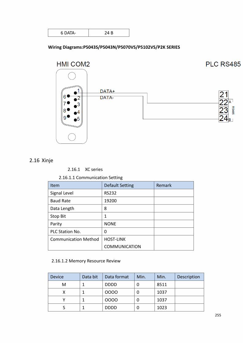
255
6 DATA- 24 B
Wiring Diagrams:P5043S/P5043N/P5070VS/P5102VS/P2K SERIES
2.16 Xinje
2.16.1 XC series
2.16.1.1 Communication Setting
Item Default Setting Remark
Signal Level RS232
Baud Rate 19200
Data Length 8
Stop Bit 1
Parity NONE
PLC Station No. 0
Communication Method HOST-LINK
COMMUNICATION
2.16.1.2 Memory Resource Review
Device Data bit Data format Min. Min. Description
M 1 DDDD 0 8511
X 1 OOOO 0 1037
Y 1 OOOO 0 1037
S 1 DDDD 0 1023

256
T 1 DDD 0 618
C 1 DDD 0 634
D 16 DDDD 0 8511
TD 16 DDD 0 618
CD 16 DDD 0 634
FD_1 16 DDDD 0 5000
FD_2 16 DDDD 8000 8511
2.16.1.3 Connecting to HMI
PLC Setting
Open XCPPro and use the official DVP cable to connect to the computer RS232
hole, the default will be use COM1 to connect automatically.
(Please do not modify the COME1 connection parameters, this will cause the PLC
to be unable to connect to the PC)
HMI Setting

257
Within the Link configuration window in FvDesigner:
Under Interface Type select Serial
Under Manufacturer select Xinje
Under Product Series select XinjeXC Series
Under Port select required COM port. Verify the baud rate is the same as the value set
on the PLC.
2.16.1.4 Wiring Diagrams
HMI COM1 Pinout
*Looking into COM1 Port
PIN# COM1 (RS232)
1
2 RX
3 TX
4

258
5 GND
6
7
8
9
PLC RS232 Pinout
*Looking into PLC
PIN# Signal
1
2 GND
3
4 RXD
5
6
7 TXD
8
All P5 and P2K Series
HMI COM1 PLC RS232 Port
2 RX 7 TXD
3 TX 4 RXD
5 GND 2 GND
Wiring Diagrams: All P5 and P2K Series
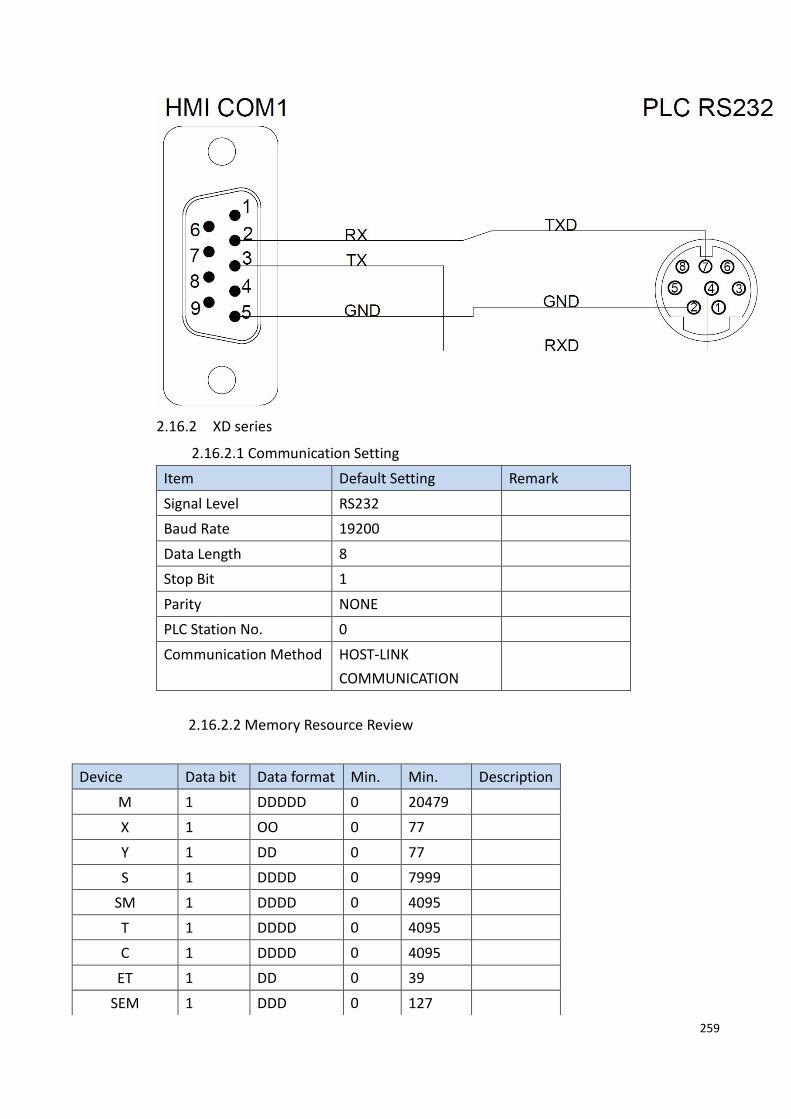
259
2.16.2 XD series
2.16.2.1 Communication Setting
Item Default Setting Remark
Signal Level RS232
Baud Rate 19200
Data Length 8
Stop Bit 1
Parity NONE
PLC Station No. 0
Communication Method HOST-LINK
COMMUNICATION
2.16.2.2 Memory Resource Review
Device Data bit Data format Min. Min. Description
M 1 DDDDD 0 20479
X 1 OO 0 77
Y 1 DD 0 77
S 1 DDDD 0 7999
SM 1 DDDD 0 4095
T 1 DDDD 0 4095
C 1 DDDD 0 4095
ET 1 DD 0 39
SEM 1 DDD 0 127

260
2.16.2.3 Connecting to HMI
PLC Setting
Open XDPPor and use the official DVP cable to connect to the computer RS232
hole, the default will be use COM1 to connect automatically.
(Please do not modify the COME1 connection parameters, this will cause the PLC
to be unable to connect to the PC)
HM 1 DDDD 0 6143
HS 1 DDD 0 999
HT 1 DDDD 0 1023
HC 1 DDDD 0 1023
HSC 1 DD 0 39
X_Extension 1 OOOOO 10000 11777
X_BD 1 OOOOO 20000 20100
Y_Extension 1 OOOOO 10000 11777
Y_BD 1 OOOOO 20000 20100
D 16 DDDDD 0 20479
ID 16 DD 0 99
QD 16 DD 0 99
SD 16 DDDD 0 4095
TD 16 DDDD 0 4095
CD 16 DDDD 0 4095
ETD 16 DD 0 39
HD 16 DDDD 0 6143
HSD 16 DDDD 0 1023
HTD 16 DDDD 0 1023
HCD 16 DDDD 0 1023
HSCD 16 DD 0 39
FD 16 DDDD 0 8191
SFD 16 DDDD 0 5999
FS 16 DD 0 49
ID_Extension 16 DDDDD 10000 11599
ID_BD 16 DDDDD 20000 20099
QD_Extension 16 DDDDD 10000 11599
QD_BD 16 DDDDD 20000 20099

261
HMI Setting
Within the Link configuration window in FvDesigner:
Under Interface Type select Serial
Under Manufacturer select Xinje
Under Product Series select XinjeXD Series
Under Port select required COM port. Verify the baud rate is the same as the value
set on the PLC.

262
2.16.2.4 Wiring Diagrams
HMI COM1 Pinout
*Looking into COM1 Port
PIN# COM1 (RS232)
1
2 RX
3 TX
4
5 GND
6
7
8
9
PLC RS232 Pinout
*Looking into PLC
PIN# Signal
1
2 GND
3
4 RXD
5
6
7 TXD
8
All P5 and P2K Series

263
HMI COM1 PLC RS232 Port
2 RX 7 TXD
3 TX 4 RXD
5 GND 2 GND
Wiring Diagrams: All P5 and P2K Series
2.17 Vigor
2.17.1 M/VB/VH Series
2.17.1.1 Communication Setting
Item Default Setting Remark
Signal Level RS485 2W
Baud Rate 19200
Data Length 8
Stop Bit 1
Parity Even
PLC Station No. 0
Communication Method Vigor M/VB/VH protocol
2.17.1.2 Memory Resource Review

264
Devic
e
Data bit Data format Min. Min. Description
X 1 OOO 0 777 External input relay
Y 1 OOO 0 777 External output relay
M 1 DDDD 0 7999 Internal relay
S 1 DDD 0 999 Step relay
SM 1 DDDD 9000 9255 Special relay
TC 1 DDD 0 255 Timer coil
CC 1 DDD 0 255 Counter coil
TS 1 DDD 0 255 Timer contact
CS 1 DDD 0 255 Counter contact
D 16 DDDD 0 8999 D data register
SD 16 DDD 9000 9255 Special data resgister
T 16 DDD 0 255 Timer
C 16 DDD 0 199 16 bits counter
CL 16 DDD 200 255 32 bits counter
2.17.1.3 Connecting to HMI
PLC Setting
Open Ladder Master and use the Vigor VBUSB-200 cable to connect to the
computer USB port, it will automatically connect.
HMI Setting

265
Within the Link configuration window in FvDesigner:
Under Interface Type select Serial
Under Manufacturer select Vigor Corporation
Under Product Series select VS Series
Under Port select required COM port. Verify the baud rate is the same as the value set
on the PLC.
2.17.1.4 Wiring Diagrams
HMI COM1 Pinout
*Looking into COM1 Port
PIN# COM1 (RS232)
1
2 RX
3 TX

266
4
5 GND
6
7
8
9
PLC USB Pinout
PIN# Signal
1
2 D-
3 D+
4 GND
All P5 and P2K Series
HMI COM1 PLC USB Port
2 RX 3 D+
3 TX 2 D-
5 GND 5 GND
Wiring Diagrams: All P5 and P2K Series

267
2.17.2 VS series
2.17.2.1 Communication Setting
Item Default Setting Remark
Signal Level RS232
Baud Rate 19200
Data Length 8
Stop Bit 1
Parity None
PLC Station No. 0
Communication Method HOST-LINK
COMMUNICATION
2.17.2.2 Memory Resource Review
Device Data bit Data format Min. Min. Description
X 1 OOO 0 377 External input relay
Y 1 OOO 0 377 External output relay
M 1 DDDD 0 8191 Internal relay
S 1 DDDD 0 4095 Step relay
SM 1 DDD 9000 9511 Special relay

268
2.17.2.3 Connecting to HMI
PLC Setting
Open Ladder Master and use the Vigor VBUSB-200 cable to connect to the
computer USB port, it will automatically connect.
(Note: Mini-USB cable is required for programming, RS-485 is required for
connection with human machine)
DB 1 DDDD.H 0.0 8999.f D data register bits
RB 1 DDDDD.H 0.0 25999.f R data register bits
TC 1 DDD 0 511 Timer coil
CC 1 DDD 0 255 Counter coil
TS 1 DDD 0 511 Timer contact
CS 1 DDD 0 255 Counter contact
D 16 DDDD 0 8999 D data register
SD 16 DDD 9000 9511 Special data resgister
R 16 DDDDD 0 25999 R data resgister
T 16 DDD 0 511 Timer
C 16 DDD 0 199 16 bits counter
WX 16 OOO 0 377 External input relay
WY 16 OOO 0 377 External output relay
WM 16 DDDD 0 8191 Internal relay
WS 16 DDDD 0 4095 Step relay
CL 32 DDD 200 255 32 bits counter

269
HMI Setting

270
Within the Link configuration window in FvDesigner:
Under Interface Type select Serial
Under Manufacturer select Vigor Corporation
Under Product Series select VS Series
Under Port select required COM port. Verify the baud rate is the same as the value set
on the PLC.
2.17.2.4 Wiring Diagrams
PLC RS485 Pinout
Signal
D-
D+
HMI COM3 Pinout: P5043S/P5043N/P5070VS/P5102VS/P2K

271
*Looking into COM3 Port
PIN# COM3
(RS-485)
1 DATA+
2
3
4
5 GND
6 DATA-
7
8
9
P5043S/P5043N/P5070VS/P5102VS/P2K
HMI COM3 PLC RS485 Port
1 DATA+ D+
6 DATA- D-
HMI COM3 Pinout:P5070S/ P5070N/ P5070N1/ P5102S/ P5102N/ P5102N1
*Looking into HMI Device
PIN# COM3
(RS-485)
1
2
3 ISO_GND
4
5
6 DATA+
7 DATA-

272
P5070S/ P5070N/ P5070N1/ P5102S/ P5102N/ P5102N1
HMI COM3 PLC RS485 Port
6 DATA+ DATA+
7 DATA- DATA-
Wiring Diagrams:P5043S/P5043N/P5070VS/P5102VS/P2K
Wiring Diagrams:P5070S/ P5070N/ P5070N1/ P5102S/ P5102N/ P5102N1
2.18 LS

273
2.18.1 LS XBC-cnet
2.18.1.1 Communication Setting
Item Default Setting Remark
Signal Level RS-232/RS-485
Baud Rate 115200
Data Length 8
Stop Bit 1
Parity None
PLC Station No. 0
Communication method Serial
2.18.1.2 Memory Resource Review
Bit/ Device Type Range XBC
Word
B
PX 0-2047F 0-1023F
MX 0-2047F 0-1023F
KX 0-2559F 0-2559F
FX 0-2047F 0-1023F
TX
0-2047 0-1023
CX 0-2047 0-1023
UX 0-3F.31F 0-A.31F
SX 0-12799 0-12799
L 0-4095 0-2047F
D 0-32767 0-10239
R 0-32767 0-2047
W
PW 0-2047 0-1023
MW 0-2047 0-1023
KW 0-2559 0-2559
FW 0-2047 0-1023
TW 0-2047 0-1023
CW 0-2047 0-1023
UW 0-3F.31 0-A.31
SW 0-12799 0-12799
ZW 0-127 0-127
LW 0-4095 0-2047F
DW 0-32767 0-10239

274
RW 0-32767 0-10239
2.18.1.3 Connecting to HMI
HMI setting
Within the Link configuration window in FvDesigner:
Under Interface Type select Serial
Under Manufacturer select LS Corporation
Under Product Series select LS XBC cnet
Under Port select COM1
2.18.1.4 Wiring Diagrams

275
XBC-Cnet Pinout
XBC-Cnet RS232Pinout
XBC-Cnet RS485 Pinout
RS-232 RS-485
SG DATA+(485+)
TX DATA- (485-)
RX
HMI COM1 Pinout
*Looking into COM1 Port
PIN COM1 (RS232)
1
2 RX
3 TX
4
5 GND
6

276
7 RTS
8 CTS
9
All P5 and P2K Series
HMI COM1 XBC-Cnet
RS232 Port
2 RX TX
3 TX RX
5 GND SG
Wiring Diagrams : All P5 and P2K Series
2.18.2 LS XEC-Cnet
2.18.2.1 Communication Setting
Item Default Setting Remark
Signal Level RS-232/RS-485
Baud Rate 115200
Data Length 8
Stop Bit 1
Parity None
PLC Station No. 0
Communication method Serial

277
2.18.2.2 Memory Resource Review
Bit/ Device Type Range XEC
Word
B
IX 0.0.0-15.15.63 0.0.0-15.15.63
QX 0.0.0-15.15.63 0.0.0-15.15.63
MX 0-262143 0-262143
LX 0-65535 0-65535
NX 0-163839 0-163839
KX 0-131071 0-131071
UX 0.0-11.511 0.0-11.511
RX 0-262143 0-262143
AX 0-524287 0-524287
WX 0-524287 0-524287
FX 0-32767 0-32767
W
I 0.0.0-15.15.3 0.0.0-15.15.3
QW 0.0.0-15.15.3 0.0.0-15.15.3
MW 0-16383 0-16383
LW 0-4095 0-4095
NW 0-10239 0-10239
KW 0-8191 0-8191
UW 0.0-11.31 0.0-11.31
RW 0-16383 0-16383
AW 0-32767 0-32767
WW 0-32767 0-32767
FW 0-2047 0-2047
2.18.2.3 Connecting to HMI
HMI setting

278
Within the Link configuration window in FvDesigner:
Under Interface Type select Serial
Under Manufacturer select LS Corporation
Under Product Series select LS XBC cnet
Under Port select COM1
2.18.2.4 Wiring Diagrams

279
XBC-Cnet Pinout
RS-232 RS-485
SG D- (485-)
TX D+(485+)
RX
HMI COM1 Pinout
*Looking into COM1 Port
PIN COM1 (RS232)
1
2 RX

280
3 TX
4
5 GND
6
7 RTS
8 CTS
9
All P5 and P2K Series
HMI COM1 XBC-Cnet
RS232 Port
2 RX TX
3 TX RX
5 GND SG
Wiring Diagrams : All P5 and P2K Series
2.18.3 LS XBC-Fnet
2.18.3.1 Communication Setting
Item Default Setting Remark
Signal Level Ethernet
Internet Protocol 192.168.0.61
Port 2004
PLC Station No. 1
Communication Method TCP

281
2.18.3.2 Memory Resource Review
類型 資料位元 地址格式 最小 最大 說明
PW 16 DDDD 0 2047 I/O relay
MW 16 DDDD 0 2047 Auxiliary relay
LW 16 DDDDD 0 4095 Link relay
KW 16 DDDD 0 2559 Keep relay
FW 16 DDDD 0 2047 Special relay
CW 16 DDDD 0 2047 Counter
TW 16 DDDD 0 2047 Timer
SW 16 DDD 0 12799 Step controller
DW 16 DDDDD 0 32767 Data register
UW 16 DH.DD 0 3F.31 Analog data register
RW 16 DDDDD 0 32767 File register
ZW 16 DDD 0 127 Index register
PX 1 DDDDH 0 2047F Auxiliary relay
MX 1 DDDDH 0 2047F Auxiliary relay
LX 1 DDDDDH 0 4095 Link relay
KX 1 DDDDH 0 2559F Keep relay
FX 1 DDDDH 0 2047F Special relay
DX 1 DDDDDH 0 32767 Data register
UX 1 DH.DD 0 3F.31F Analog data register
RX 1 DDDDDH 0 32767 File register
SX 1 DDDDD 0 12799 Step controller
TX 1 DDDD 0 2047 Timer
CX 1 DDDD 0 2047 Counter
2.18.3.3 Connecting to HMI
PLC setting
Open XG5000.exe and use mini-USB to connect the USB port of the computer, it will
connect automatically.

282
HMI setting

283
Within the Link configuration window in FvDesigner:
Under Interface Type select Ethernet
Under Manufacturer select LS Corporation
Under Product Series select LS XBC fnet
Please confirm that the HMI communication setting and the PLC setting are consistent
2.18.4 LS XEC-Fnet
2.18.4.1 Communication Setting
Item Default Setting Remark
Signal Level Ethernet
Internet Protocol 192.168.0.6
Port 2004
PLC Station No. 1
Communication Method TCP

284
2.18.4.2 Memory Resource Review
Bit/ Device Type Range XEC
Word
B
IX 0.0.0-15.15.63 0.0.0-15.15.63
QX 0.0.0-15.15.63 0.0.0-15.15.63
MX 0-262143 0-262143
LX 0-65535 0-65535
NX 0-163839 0-163839
KX 0-131071 0-131071
UX 0.0-11.511 0.0-11.511
RX 0-262143 0-262143
AX 0-524287 0-524287
WX 0-524287 0-524287
FX 0-32767 0-32767
W
I 0.0.0-15.15.3 0.0.0-15.15.3
QW 0.0.0-15.15.3 0.0.0-15.15.3
MW 0-16383 0-16383
LW 0-4095 0-4095
NW 0-10239 0-10239
KW 0-8191 0-8191
UW 0.0-11.31 0.0-11.31
RW 0-16383 0-16383
AW 0-32767 0-32767
WW 0-32767 0-32767
FW 0-2047 0-2047
2.18.4.3 Connecting to HMI
PLC setting
Open XG5000.exe and use mini-USB to connect the USB port of the computer, it will
connect automatically.

285
HMI setting

286
Within the Link configuration window in FvDesigner:
Under Interface Type select Ethernet
Under Manufacturer select LS Corporation
Under Product Series select LS XEC fnet
Please confirm that the HMI communication setting and the PLC setting are consistent
Copyright © 2022 FDOKUMEN