Oxymax H COS21D - Endress+Hauser
36
BA402C/07/en/12.07 71066660 Operating Instructions Oxymax H COS21D Digital dissolved oxygen sensor
-
Upload
khangminh22 -
Category
Documents
-
view
2 -
download
0
Transcript of Oxymax H COS21D - Endress+Hauser

BA402C/07/en/12.07
71066660
Operating Instructions
Oxymax H COS21DDigital dissolved oxygen sensor
Information for the use of this manual
Notes on safety icons and symbols
Cross reference symbols
#Warning!
This symbol alerts you to hazards. They can cause serious damage to the instrument
or to persons if ignored.
"Caution!
This symbol alerts you to possible faults which could arise from incorrect operation.
They could cause damage to the instrument if ignored.
! Note!
This symbol indicates important items of information.
È ä 1 This symbol indicates a cross reference to a defined page (e.g. p. 1).
È å 2 This symbol indicates a cross reference to a defined figure (e.g. fig. 2).
Endress+Hauser
Oxymax H COS21D
Table of contents
1 Safety instructions . . . . . . . . . . 4
1.1 Designated use . . . . . . . . . . . . . . . . . . . . . . 4
1.2 Installation, commissioning and operation . 4
1.3 Operational safety . . . . . . . . . . . . . . . . . . . 5
1.4 Safety Instructions for Ex versions . . . . . . . 5
1.5 Return . . . . . . . . . . . . . . . . . . . . . . . . . . . . 5
2 Identification . . . . . . . . . . . . . . 6
2.1 Product structure . . . . . . . . . . . . . . . . . . . . 6
2.2 Scope of delivery . . . . . . . . . . . . . . . . . . . . 6
2.3 Certificates and approvals . . . . . . . . . . . . . . 6
3 Installation . . . . . . . . . . . . . . . . 8
3.1 Incoming acceptance, transport, storage . . . 8
3.2 Installation conditions . . . . . . . . . . . . . . . . 8
3.3 Installation instructions . . . . . . . . . . . . . . . 9
3.4 Installation examples . . . . . . . . . . . . . . . . 11
3.5 Post-installation check . . . . . . . . . . . . . . . 12
4 Wiring . . . . . . . . . . . . . . . . . . 13
4.1 Sensor version for Ex applications . . . . . . . 14
4.2 Direct connection to Liquiline M . . . . . . . 15
4.3 Connection via junction box . . . . . . . . . . 16
4.4 Post-connection check . . . . . . . . . . . . . . . 16
5 Function . . . . . . . . . . . . . . . . . 17
5.1 Sensor design . . . . . . . . . . . . . . . . . . . . . . 17
5.2 Measuring principle . . . . . . . . . . . . . . . . . 17
5.3 Calibration . . . . . . . . . . . . . . . . . . . . . . . . 19
6 Commissioning. . . . . . . . . . . . 22
6.1 Function check . . . . . . . . . . . . . . . . . . . . 22
6.2 Polarization . . . . . . . . . . . . . . . . . . . . . . . 22
6.3 Calibration . . . . . . . . . . . . . . . . . . . . . . . . 23
7 Maintenance. . . . . . . . . . . . . . 23
7.1 Cleaning . . . . . . . . . . . . . . . . . . . . . . . . . 24
7.2 Replacing wear and tear materials . . . . . . 25
8 Accessories. . . . . . . . . . . . . . . 27
8.1 Connection accessories . . . . . . . . . . . . . . 27
8.2 Installation accessories . . . . . . . . . . . . . . . 27
8.3 Measurement . . . . . . . . . . . . . . . . . . . . . . 27
9 Trouble-shooting. . . . . . . . . . . 28
9.1 Trouble-shooting instructions . . . . . . . . . . 28
9.2 Spare parts and consumable material . . . . . 28
9.3 Return . . . . . . . . . . . . . . . . . . . . . . . . . . . 30
9.4 Disposal . . . . . . . . . . . . . . . . . . . . . . . . . . 30
10 Technical data. . . . . . . . . . . . . 30
10.1 Input . . . . . . . . . . . . . . . . . . . . . . . . . . . . 30
10.2 Environment . . . . . . . . . . . . . . . . . . . . . . 30
10.3 Process . . . . . . . . . . . . . . . . . . . . . . . . . . . 31
10.4 Performance characteristics . . . . . . . . . . . . 31
10.5 Mechanical construction . . . . . . . . . . . . . . 32
Index. . . . . . . . . . . . . . . . . . . . 33
Safety instructions Oxymax H COS21D
4 Endress+Hauser
1 Safety instructions
1.1 Designated use
The sensor is suitable for continuous measurement of dissolved oxygen in water.
The sensor version determines what the sensor is especially suitable for:
• COS21D-A (measuring range 0.01 to 20 mg/l)
– Measuring, monitoring and regulating the oxygen content in fermenters
– Monitoring the oxygen contents in biotechnological systems
• COS21D-B (trace measurement with high CO2 partial pressure, measuring range 0.001 to
20 mg/l, preferred operational range 0.001 to 2 mg/l)
– Monitoring inerting units in the food industry
– Monitoring the residual oxygen contents in carbonated media in the beverage industry
• COS21D-C (trace measurement, measuring range 0.001 to 20 mg/l, preferred operational
range 0.001 to 2 mg/l)
– Trace measurement in industrial applications such as inerting
– Monitoring residual oxygen contents in boiler feedwater
– Monitoring, measuring and regulating the oxygen contents in chemical processes
" Caution!
The sensor must not be used for measurement in hydrogen loaded media.
The COS21D sensor must be connected to the digital input of the Liquiline transmitter using the
CYK10 measuring cable for non-contact, digital data transfer.
Any other use than the one described here compromises the safety of persons and the entire
measuring system and is, therefore, not permitted.
The manufacturer is not liable for damage caused by improper or non-designated use.
1.2 Installation, commissioning and operation
Please note the following items:
• Installation, commissioning, operation and maintenance of the measuring system must only
be carried out by trained technical personnel.
The technical personnel must be authorized for the specified activities by the system operator.
• Electrical connection must only be carried out by a certified electrician.
• Technical personnel must have read and understood these Operating Instructions and must
adhere to them.
• Before commissioning the entire measuring point, check all the connections for
correctness. Ensure that electrical cables and hose connections are not damaged.
• Do not operate damaged products and secure them against unintentional
commissioning. Mark the damaged product as being defective.
• Measuring point faults may only be rectified by authorized and specially trained
personnel.
• If faults can not be rectified, the products must be taken out of service and secured against
unintentional commissioning.
Oxymax H COS21D Safety instructions
Endress+Hauser 5
• Repairs not described in these Operating Instructions may only be carried out at the
manufacturer’s or by the service organization.
1.3 Operational safety
The sensor has been designed and tested according to the state of the art and left the factory in
perfect functioning order.
Relevant regulations and European standards have been met.
As the user, you are responsible for complying with the following safety conditions:
• Installation instructions
• Local prevailing standards and regulations.
1.4 Safety Instructions for Ex versions
The inductive sensor-cable-plug-in system Memosens, consisting of
• oxygen sensor Oxymax H COS21D-*12*1 and
• measuring cable CYK10-G**1
is suitable for the use in explosion-hazardous areas acc. to the type-examination certificate
BVS 04 ATEX E 121 X . The corresponding EU declaration of conformity is part of this
document.
" Caution!
• The certified oxygen sensor Oxymax H COS21D-*12*1 in combination with the measuring
cable CYK10-G**1 may only be connected to certified, intrinsically-safe, digital sensor
circuits of the transmitter Liquiline M CM42-*G*********. The electrical connection must
be carried out in compliance with the wiring diagram.
• Oxygen sensors for use in Ex areas have a special, conductive O-ring. The metallic sensor shaft
is electrically connected to the conductive mounting location (e.g. a metallic assembly) by
means of the O-ring.
• You must take appropriate measures to connect the assembly or the mounting location to the
operational ground in accordance with Ex guidelines.
• The sensors must not be used under electrostatical critical process conditions. Strong vapour
or dust streams acting directly on the plug-in system are to be avoided.
• Ex versions of digital sensors with Memosens technology are marked with an orange-red ring
on the plug-in head.
• The maximum permissable cable length is 100 m (330 ft).
1.5 Return
If the sensor has to be repaired, please return it cleaned to the sales center responsible.
Please use the original packaging, if possible.
Please enclose the completed "Declaration of Hazardous Material and De-Contamination" (copy
the second last page of these Operating Instructions) with the packaging and the transportation
documents.
No repair without completed declaration!
Identification Oxymax H COS21D
6 Endress+Hauser
2 Identification
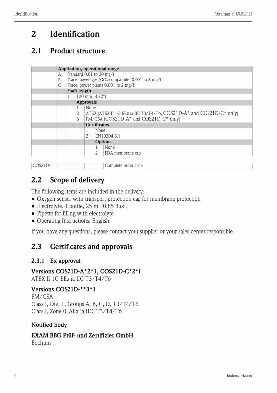
2.1 Product structure
2.2 Scope of delivery
The following items are included in the delivery:
• Oxygen sensor with transport protection cap for membrane protection
• Electrolyte, 1 bottle, 25 ml (0.85 fl.oz.)
• Pipette for filling with electrolyte
• Operating Instructions, English
If you have any questions, please contact your supplier or your sales center responsible.
2.3 Certificates and approvals
2.3.1 Ex approval
Versions COS21D-A*2*1, COS21D-C*2*1
ATEX II 1G EEx ia IIC T3/T4/T6
Versions COS21D-**3*1
FM/CSA
Class I, Div. 1, Groups A, B, C, D, T3/T4/T6
Class I, Zone 0, AEx ia IIC, T3/T4/T6
Notified body
EXAM BBG Prüf- und Zertifizier GmbH
Bochum
Application, operational range
A Standard 0.01 to 20 mg/l
B Trace, beverages (CO2 compatible) 0.001 to 2 mg/l
C Trace, power plants 0.001 to 2 mg/l
Shaft length
1 120 mm (4.72")
Approvals
1 None
2 ATEX (ATEX II 1G EEx ia IIC T3/T4/T6, COS21D-A* and COS21D-C* only)
3 FM/CSA (COS21D-A* and COS21D-C* only)
Certificates
1 None
2 EN10204 3.1
Options
1 None
2 FDA membrane cap
COS21D- Complete order code
Oxymax H COS21D Identification
Endress+Hauser 7
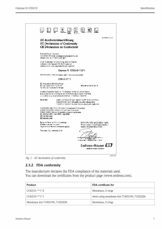
2.3.2 FDA conformity
The manufacturer declares the FDA compliance of the materials used.
You can download the certificates from the product page (www.endress.com).
a0007207
Fig. 1: EC declaration of conformity
Product FDA certificate for
COS21D-**1*2 Membrane, O-rings
COS21D-**1*1 when using membrane kits 71003199, 71023226
Membrane kits 71003199, 71023226 Membrane, O-rings

Installation Oxymax H COS21D
8 Endress+Hauser
3 Installation
3.1 Incoming acceptance, transport, storage
• Make sure the packaging is undamaged!
Inform the supplier about damage to the packaging. Keep the damaged packaging until the
matter has been settled.
• Make sure the contents are undamaged!
Inform the supplier about damage to the delivery contents. Keep the damaged products until
the matter has been settled.
• Check that the scope of delivery is complete and agrees with your order and the shipping
documents.
• The packaging material used to store or to transport the product must provide shock
protection and humidity protection. The original packaging offers the best protection. Also,
keep to the approved ambient conditions (see "Technical data").
• If you have any questions, please contact your supplier or your sales center responsible.
3.2 Installation conditions
3.2.1 Angle of installation
The sensor must be installed with an angle of inclination of at least 10 ° to the horizontal in an
assembly, support or a suitable process connection. Other angles are not permissible. Do not
install the sensor overhead.
! Note!
Make sure you comply with the instructions for installing sensors. You will find them in the
Operating Instructions for the assembly used.
a0005584-en
Fig. 2: Permitted angle of installation
10° 10° Not permissible!Not permissible!
Permissible angle of installation
Oxymax H COS21D Installation
Endress+Hauser 9
3.2.2 Mounting location
• Select the installation location so that there is easy access for later calibration.
• Make sure that upright posts and assemblies are secured safely and vibration-free.
• For immersed operation in an activated sludge basin, select an installation location which
produces a typical oxygen concentration.
3.3 Installation instructions
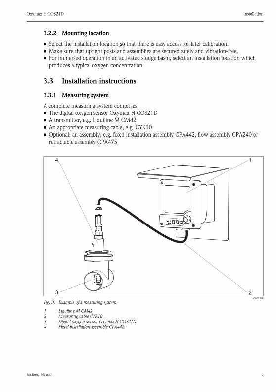
3.3.1 Measuring system
A complete measuring system comprises:
• The digital oxygen sensor Oxymax H COS21D
• A transmitter, e.g. Liquiline M CM42
• An appropriate measuring cable, e.g. CYK10
• Optional: an assembly, e.g. fixed installation assembly CPA442, flow assembly CPA240 or
retractable assembly CPA475
a0001398
Fig. 3: Example of a measuring system
1 Liquiline M CM42
2 Measuring cable CYK10
3 Digital oxygen sensor Oxymax H COS21D
4 Fixed installation assembly CPA442
1
23
4

Installation Oxymax H COS21D
10 Endress+Hauser
3.3.2 Installing a measuring point
For a complete installation of a measuring point, proceed as follows:
1. Install a retractable or a flow assembly (if used) into the process.
2. Connect the water supply to the rinse connections (if you use an assembly with cleaning
function).
3. Install and connect the oxygen sensor.
" Caution!
• Do not install the sensor suspended from the cable.
• Screw the sensor into the assembly so that the cable is not twisted.
• Mounting or dismounting the sensor: hold the sensor body, only turn the threaded plug-in
head while screwing the sensor in or out of the assembly. Otherwise you could unscrew the
sensor’s membrane cap. It will remain in the assembly resp. in the process then.
• Avoid exerting excessive tensile force on the cable (e.g. from jerky pulling).
• Select the installation location so that there is easy access for later calibration.
# Warning!
When using metallic assemblies and installation equipment, comply with national grounding
regulations.
Oxymax H COS21D Installation
Endress+Hauser 11
3.4 Installation examples
3.4.1 Fixed installation (CPA442)
The CPA442 fixed installation assembly allows a sensor to be easily adapted to almost any
process connections from Ingold nozzles to Varivent or Triclamp connections.
This type of installation is very suitable for tanks and larger pipes. The sensor achieves a defined
immersion depth in the medium in an easy manner → å 3.
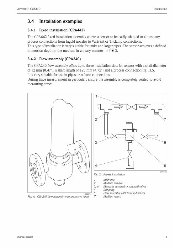
3.4.2 Flow assembly (CPA240)
The CPA240 flow assembly offers up to three installation slots for sensors with a shaft diameter
of 12 mm (0.47"), a shaft length of 120 mm (4.72") and a process connection Pg 13.5.
It is very suitable for use in pipes or at hose connections.
During trace measurement in particular, ensure the assembly is completely vented to avoid
measuring errors.
a0005720
Fig. 4: CPA240 flow assembly with protective hood
a0005721
Fig. 5: Bypass installation
1 Main line
2 Medium removal
3, 6 Manually actuated or solenoid valves
4 Sampling
5 Flow assembly with installed sensor
7 Medium return
Installation Oxymax H COS21D
12 Endress+Hauser
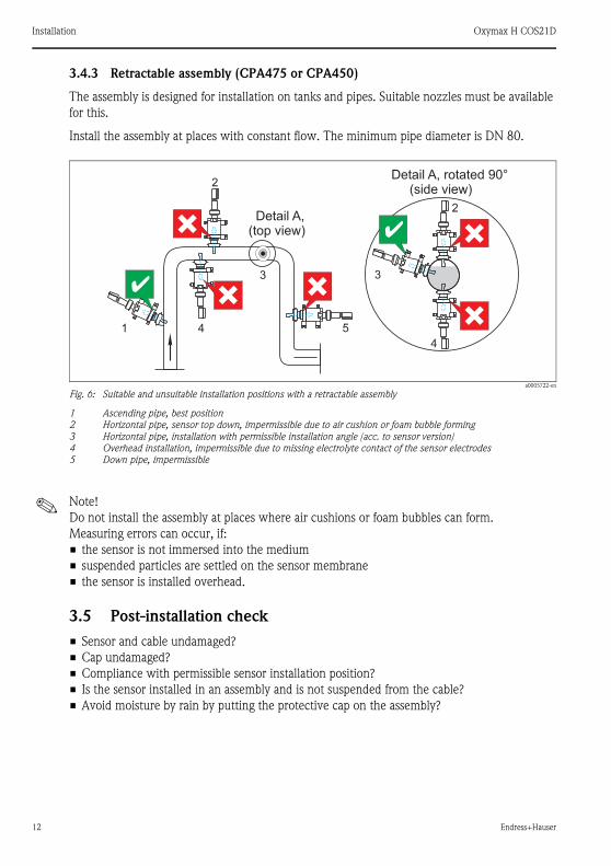
3.4.3 Retractable assembly (CPA475 or CPA450)
The assembly is designed for installation on tanks and pipes. Suitable nozzles must be available
for this.
Install the assembly at places with constant flow. The minimum pipe diameter is DN 80.
a0005722-en
Fig. 6: Suitable and unsuitable installation positions with a retractable assembly
1 Ascending pipe, best position
2 Horizontal pipe, sensor top down, impermissible due to air cushion or foam bubble forming
3 Horizontal pipe, installation with permissible installation angle (acc. to sensor version)
4 Overhead installation, impermissible due to missing electrolyte contact of the sensor electrodes
5 Down pipe, impermissible
! Note!
Do not install the assembly at places where air cushions or foam bubbles can form.
Measuring errors can occur, if:
• the sensor is not immersed into the medium
• suspended particles are settled on the sensor membrane
• the sensor is installed overhead.
3.5 Post-installation check
• Sensor and cable undamaged?
• Cap undamaged?
• Compliance with permissible sensor installation position?
• Is the sensor installed in an assembly and is not suspended from the cable?
• Avoid moisture by rain by putting the protective cap on the assembly?
5
3
41
2
3
4
2Detail A,
(top view)
Detail A, rotated(side view)
90°
Oxymax H COS21D Wiring
Endress+Hauser 13
4 Wiring
# Warning!
• The electrical connection must only be carried out by a certified electrician.
• Technical personnel must have read and understood the instructions in this manual and must
adhere to them.
• Ensure that there is no voltage at the power cable before beginning the connection work.

Wiring Oxymax H COS21D
14 Endress+Hauser
4.1 Sensor version for Ex applications
4.1.1 Quick wiring guide
a0006059
Fig. 7: Connection in the Ex area
Oxymax H COS21D Wiring
Endress+Hauser 15
4.1.2 Temperature classes
! Note!
If the ambient temperatures indicated are observed, no temperatures which are impermissible
for the temperature class in question will occur at the sensor.
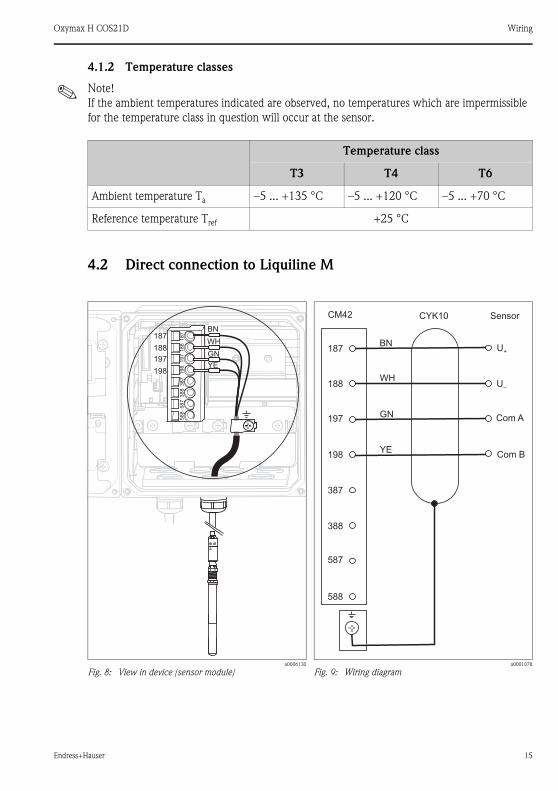
4.2 Direct connection to Liquiline M
Temperature class
T3 T4 T6
Ambient temperature Ta –5 ... +135 °C –5 ... +120 °C –5 ... +70 °C
Reference temperature Tref +25 °C
a0006130
Fig. 8: View in device (sensor module)a0001078
Fig. 9: Wiring diagram

Wiring Oxymax H COS21D
16 Endress+Hauser
4.3 Connection via junction box
To extend the sensor cable, the connection has to take place using a junction box RM (-->
Accessories). The extension to the transmitter is established by means of the CYK81 special
measuring cable.
The maximum permissible cable length is 100 m (328 ft).
4.4 Post-connection check
a0005724
Fig. 10: Wiring diagram with junction box RM
1 Sensor
2 Junction box
3 Extension cable
4 Transmitter
Instrument status and specifications Remarks
Are the sensor, assembly, junction box or cable damaged? Visual inspection
Electrical connection Remarks
Are the installed cables strain-relieved and not twisted ?
Long enough length of cable core stripped and correct in terminal? Check seating (pull slightly)
Are all the screws terminals properly tightened ? Tighten
Are all the cable entries installed, tightened and sealed ? For cable entries lateral: cable loops downwards
for water to be able to drip off.Are all the cable entries installed downwards or lateral ?
YE YE
BN
GN GN
YE
WH
187
188
197
198
1 2
3
4
GN
BN
WH
BN
WH
GY GY

Oxymax H COS21D Function
Endress+Hauser 17
5 Function
5.1 Sensor design
5.2 Measuring principle
5.2.1 Polarization
When the sensor is connected to the transmitter, a fixed external voltage is applied between the
cathode and anode. The resulting polarization current is indicated on the display of the
transmitter. The current starts high but then drops over time. The sensor can only be calibrated
when the display is stable.
a0005631
Fig. 11: Design
1 Threaded connection Pg 13.5
2 Anode
3 Membrane cap
4 Protective cap
5 Memosens plug-in head
6 Cathode
7 Membranea0005619
Fig. 12: Dimensions
1
2
3
4
5
6
7
Function Oxymax H COS21D
18 Endress+Hauser
Reference value for practically complete polarization of a sensor that was in storage for an
extended period beforehand:
• COS21D-A/C: 2 hours
• COS21D-B: 12 hours
After this time, measurements close to the determination limit make sense.
The polarization time needed is shorter for sensors which were in operation shortly beforehand.
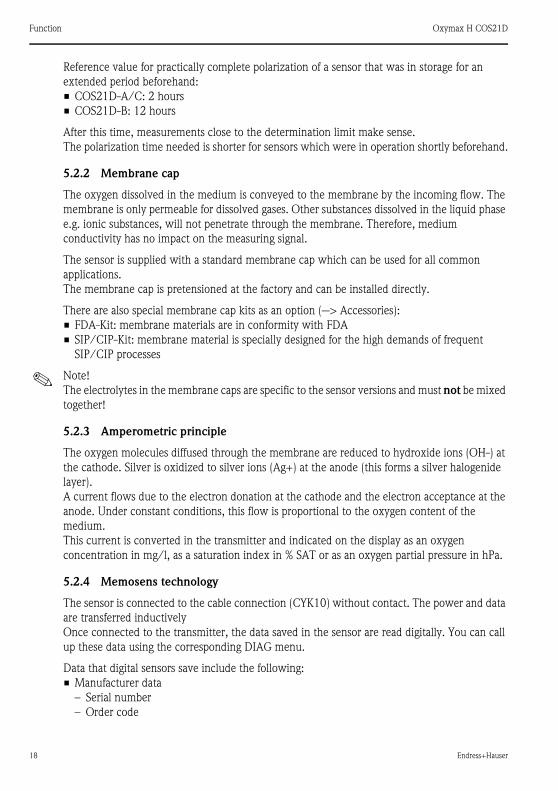
5.2.2 Membrane cap
The oxygen dissolved in the medium is conveyed to the membrane by the incoming flow. The
membrane is only permeable for dissolved gases. Other substances dissolved in the liquid phase
e.g. ionic substances, will not penetrate through the membrane. Therefore, medium
conductivity has no impact on the measuring signal.
The sensor is supplied with a standard membrane cap which can be used for all common
applications.
The membrane cap is pretensioned at the factory and can be installed directly.
There are also special membrane cap kits as an option (--> Accessories):
• FDA-Kit: membrane materials are in conformity with FDA
• SIP/CIP-Kit: membrane material is specially designed for the high demands of frequent
SIP/CIP processes
! Note!
The electrolytes in the membrane caps are specific to the sensor versions and must not be mixed
together!
5.2.3 Amperometric principle
The oxygen molecules diffused through the membrane are reduced to hydroxide ions (OH-) at
the cathode. Silver is oxidized to silver ions (Ag+) at the anode (this forms a silver halogenide
layer).
A current flows due to the electron donation at the cathode and the electron acceptance at the
anode. Under constant conditions, this flow is proportional to the oxygen content of the
medium.
This current is converted in the transmitter and indicated on the display as an oxygen
concentration in mg/l, as a saturation index in % SAT or as an oxygen partial pressure in hPa.
5.2.4 Memosens technology
The sensor is connected to the cable connection (CYK10) without contact. The power and data
are transferred inductively
Once connected to the transmitter, the data saved in the sensor are read digitally. You can call
up these data using the corresponding DIAG menu.
Data that digital sensors save include the following:
• Manufacturer data
– Serial number
– Order code
Oxymax H COS21D Function
Endress+Hauser 19
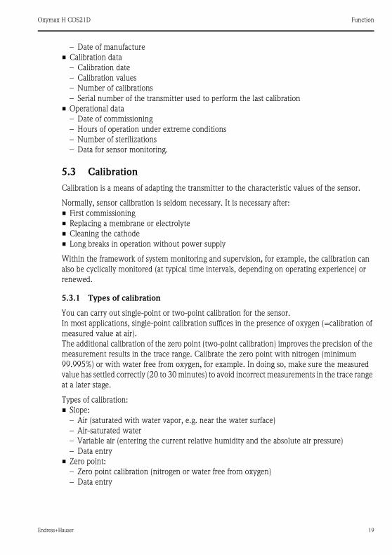
– Date of manufacture
• Calibration data
– Calibration date
– Calibration values
– Number of calibrations
– Serial number of the transmitter used to perform the last calibration
• Operational data
– Date of commissioning
– Hours of operation under extreme conditions
– Number of sterilizations
– Data for sensor monitoring.
5.3 Calibration
Calibration is a means of adapting the transmitter to the characteristic values of the sensor.
Normally, sensor calibration is seldom necessary. It is necessary after:
• First commissioning
• Replacing a membrane or electrolyte
• Cleaning the cathode
• Long breaks in operation without power supply
Within the framework of system monitoring and supervision, for example, the calibration can
also be cyclically monitored (at typical time intervals, depending on operating experience) or
renewed.
5.3.1 Types of calibration
You can carry out single-point or two-point calibration for the sensor.
In most applications, single-point calibration suffices in the presence of oxygen (=calibration of
measured value at air).
The additional calibration of the zero point (two-point calibration) improves the precision of the
measurement results in the trace range. Calibrate the zero point with nitrogen (minimum
99.995%) or with water free from oxygen, for example. In doing so, make sure the measured
value has settled correctly (20 to 30 minutes) to avoid incorrect measurements in the trace range
at a later stage.
Types of calibration:
• Slope:
– Air (saturated with water vapor, e.g. near the water surface)
– Air-saturated water
– Variable air (entering the current relative humidity and the absolute air pressure)
– Data entry
• Zero point:
– Zero point calibration (nitrogen or water free from oxygen)
– Data entry
Function Oxymax H COS21D
20 Endress+Hauser
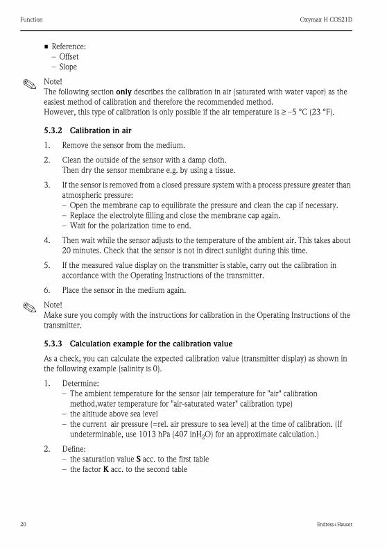
• Reference:
– Offset
– Slope
! Note!
The following section only describes the calibration in air (saturated with water vapor) as the
easiest method of calibration and therefore the recommended method.
However, this type of calibration is only possible if the air temperature is ≥ –5 °C (23 °F).
5.3.2 Calibration in air
1. Remove the sensor from the medium.
2. Clean the outside of the sensor with a damp cloth.
Then dry the sensor membrane e.g. by using a tissue.
3. If the sensor is removed from a closed pressure system with a process pressure greater than
atmospheric pressure:
– Open the membrane cap to equilibrate the pressure and clean the cap if necessary.
– Replace the electrolyte filling and close the membrane cap again.
– Wait for the polarization time to end.
4. Then wait while the sensor adjusts to the temperature of the ambient air. This takes about
20 minutes. Check that the sensor is not in direct sunlight during this time.
5. If the measured value display on the transmitter is stable, carry out the calibration in
accordance with the Operating Instructions of the transmitter.
6. Place the sensor in the medium again.
! Note!
Make sure you comply with the instructions for calibration in the Operating Instructions of the
transmitter.
5.3.3 Calculation example for the calibration value
As a check, you can calculate the expected calibration value (transmitter display) as shown in
the following example (salinity is 0).
1. Determine:
– The ambient temperature for the sensor (air temperature for "air" calibration
method,water temperature for "air-saturated water" calibration type)
– the altitude above sea level
– the current air pressure (=rel. air pressure to sea level) at the time of calibration. (If
undeterminable, use 1013 hPa (407 inH2O) for an approximate calculation.)
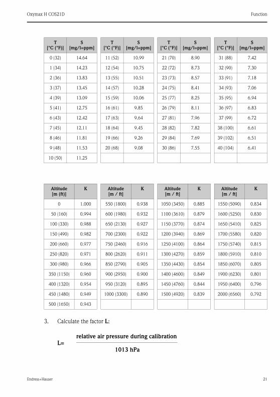
2. Define:
– the saturation value S acc. to the first table
– the factor K acc. to the second table
Oxymax H COS21D Function
Endress+Hauser 21
3. Calculate the factor L:
T
[°C (°F)]
S
[mg/l=ppm]
T
[°C (°F)]
S
[mg/l=ppm]
T
[°C (°F)]
S
[mg/l=ppm]
T
[°C (°F)]
S
[mg/l=ppm]
0 (32) 14.64 11 (52) 10.99 21 (70) 8.90 31 (88) 7.42
1 (34) 14.23 12 (54) 10.75 22 (72) 8.73 32 (90) 7.30
2 (36) 13.83 13 (55) 10.51 23 (73) 8.57 33 (91) 7.18
3 (37) 13.45 14 (57) 10.28 24 (75) 8.41 34 (93) 7.06
4 (39) 13.09 15 (59) 10.06 25 (77) 8.25 35 (95) 6.94
5 (41) 12.75 16 (61) 9.85 26 (79) 8.11 36 (97) 6.83
6 (43) 12.42 17 (63) 9.64 27 (81) 7.96 37 (99) 6.72
7 (45) 12.11 18 (64) 9.45 28 (82) 7.82 38 (100) 6.61
8 (46) 11.81 19 (66) 9.26 29 (84) 7.69 39 (102) 6.51
9 (48) 11.53 20 (68) 9.08 30 (86) 7.55 40 (104) 6.41
10 (50) 11.25
Altitude
[m (ft)]
K Altitude
[m / ft]
K Altitude
[m / ft]
K Altitude
[m / ft]
K
0 1.000 550 (1800) 0.938 1050 (3450) 0.885 1550 (5090) 0.834
50 (160) 0.994 600 (1980) 0.932 1100 (3610) 0.879 1600 (5250) 0.830
100 (330) 0.988 650 (2130) 0.927 1150 (3770) 0.874 1650 (5410) 0.825
150 (490) 0.982 700 (2300) 0.922 1200 (3940) 0.869 1700 (5580) 0.820
200 (660) 0.977 750 (2460) 0.916 1250 (4100) 0.864 1750 (5740) 0.815
250 (820) 0.971 800 (2620) 0.911 1300 (4270) 0.859 1800 (5910) 0.810
300 (980) 0.966 850 (2790) 0.905 1350 (4430) 0.854 1850 (6070) 0.805
350 (1150) 0.960 900 (2950) 0.900 1400 (4600) 0.849 1900 (6230) 0.801
400 (1320) 0.954 950 (3120) 0.895 1450 (4760) 0.844 1950 (6400) 0.796
450 (1480) 0.949 1000 (3300) 0.890 1500 (4920) 0.839 2000 (6560) 0.792
500 (1650) 0.943
L=relative air pressure during calibration-------------------------------------------------------------------------
1013 hPa

Commissioning Oxymax H COS21D
22 Endress+Hauser
4. Calculate the calibration value C:
C = S . K . L
Example
• Air calibration at 18°C (64 °F), altitude 500 m (1650 ft) above sea level, air pressure 1009 hPa
(405 inH2O)
• S = 9.45 mg/l, K = 0.943, L = 0.996
Calibration value C = 8.88 mg/l.
! Note!
You do not need factor K from the table if your device returns the absolute air pressure Labs
(location-dependent air pressure) as the measured value.
Thus, the formula for calculation is: C = S . Labs.
6 Commissioning
6.1 Function check
Before first commissioning, check if:
• the sensor is correctly installed
• the electrical connection is correct.
If using an assembly with automatic cleaning, check the correct water connection at the
assembly rinse connection.
# Warning!
Danger of medium leaking off
Before applying compressed air to an assembly with cleaning facility, make sure the connections
are correctly fitted. Otherwise, the assembly may not be insert into the process.
6.2 Polarization
The sensor was tested in the factory for perfect functionality and is supplied ready for operation.
To prepare for calibration, proceed as follows:
1. Remove the sensor protective cap.
2. Place the externally dry sensor in atmospheric air. The air should be saturated with water
vapour. Therefore, install the sensor as close to the water surface as possible. When
calibrating the sensor membrane, make sure the membrane remains dry. Therefore, avoid
any direct contact with the water surface.
Oxymax H COS21D Maintenance
Endress+Hauser 23
3. Connect the sensor to the transmitter and switch on the transmitter.
4. Switch-on the transmitter.
If you connect the sensor to the transmitter, polarization is automatically performed after
switching on the transmitter.
5. Wait for the polarization time to end.
" Caution!
• When you remove the sensor from the medium, protect the sensor from strong sunlight.
• Make sure you comply with the instructions for commissioning and calibration in the
Operating Instructions of the transmitter.
6.3 Calibration
Calibrate the sensor (air calibration) immediately after the polarization time has elapsed.
The calibration intervals depend heavily on:
• The application and
• The installation position of the sensor.
The following methods help you determine how long the calibration intervals should be:
1. Check the sensor one month after its being put into operation by taking it out of the fluid,
drying it and then measuring the oxygen saturation index at air after 10 minutes.
Decide using the results:
a. If the measured value is not at 100 ± 2 %SAT, you have to calibrate the sensor.
b. Otherwise, double the length of time to the next inspection.
2. Proceed as per Point 1 after two, four and/or eight months. In this way, you can determine
the optimum calibration interval for your sensor.
! Note!
Be sure to calibrate the sensor at least once a year.
7 Maintenance
Maintenance work must carried out at regular intervals. To ensure that it is carried out, we
recommend you enter the maintenance dates into an operations logbook or in an operations
calendar in advance.
The maintenance cycle primarily depends on:
• the system
• the installation conditions and
• the medium in which measurement is taking place.
The following activities must be carried out:
• Cleaning the sensor
Maintenance Oxymax H COS21D
24 Endress+Hauser
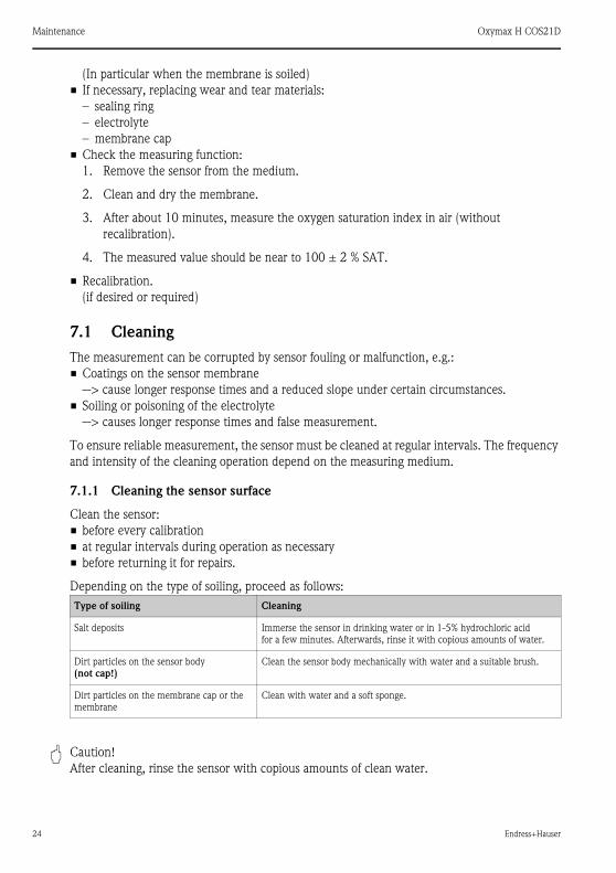
(In particular when the membrane is soiled)
• If necessary, replacing wear and tear materials:
– sealing ring
– electrolyte
– membrane cap
• Check the measuring function:
1. Remove the sensor from the medium.
2. Clean and dry the membrane.
3. After about 10 minutes, measure the oxygen saturation index in air (without
recalibration).
4. The measured value should be near to 100 ± 2 % SAT.
• Recalibration.
(if desired or required)
7.1 Cleaning
The measurement can be corrupted by sensor fouling or malfunction, e.g.:
• Coatings on the sensor membrane
--> cause longer response times and a reduced slope under certain circumstances.
• Soiling or poisoning of the electrolyte
--> causes longer response times and false measurement.
To ensure reliable measurement, the sensor must be cleaned at regular intervals. The frequency
and intensity of the cleaning operation depend on the measuring medium.
7.1.1 Cleaning the sensor surface
Clean the sensor:
• before every calibration
• at regular intervals during operation as necessary
• before returning it for repairs.
Depending on the type of soiling, proceed as follows:
" Caution!
After cleaning, rinse the sensor with copious amounts of clean water.
Type of soiling Cleaning
Salt deposits Immerse the sensor in drinking water or in 1-5% hydrochloric acid
for a few minutes. Afterwards, rinse it with copious amounts of water.
Dirt particles on the sensor body
(not cap!)
Clean the sensor body mechanically with water and a suitable brush.
Dirt particles on the membrane cap or the
membrane
Clean with water and a soft sponge.
Oxymax H COS21D Maintenance
Endress+Hauser 25
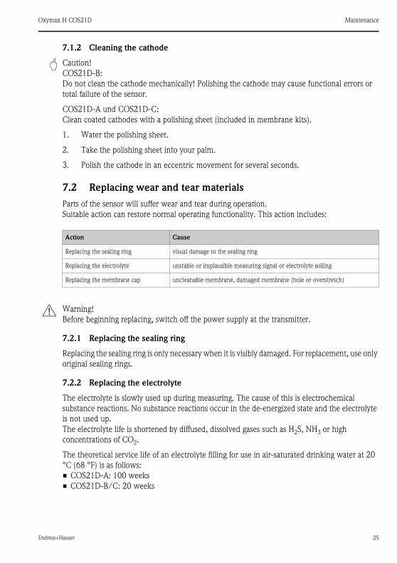
7.1.2 Cleaning the cathode
" Caution!
COS21D-B:
Do not clean the cathode mechanically! Polishing the cathode may cause functional errors or
total failure of the sensor.
COS21D-A und COS21D-C:
Clean coated cathodes with a polishing sheet (included in membrane kits).
1. Water the polishing sheet.
2. Take the polishing sheet into your palm.
3. Polish the cathode in an eccentric movement for several seconds.
7.2 Replacing wear and tear materials
Parts of the sensor will suffer wear and tear during operation.
Suitable action can restore normal operating functionality. This action includes:
# Warning!
Before beginning replacing, switch off the power supply at the transmitter.
7.2.1 Replacing the sealing ring
Replacing the sealing ring is only necessary when it is visibly damaged. For replacement, use only
original sealing rings.
7.2.2 Replacing the electrolyte
The electrolyte is slowly used up during measuring. The cause of this is electrochemical
substance reactions. No substance reactions occur in the de-energized state and the electrolyte
is not used up.
The electrolyte life is shortened by diffused, dissolved gases such as H2S, NH3 or high
concentrations of CO2.
The theoretical service life of an electrolyte filling for use in air-saturated drinking water at 20
°C (68 °F) is as follows:
• COS21D-A: 100 weeks
• COS21D-B/C: 20 weeks
Action Cause
Replacing the sealing ring visual damage to the sealing ring
Replacing the electrolyte unstable or implausible measuring signal or electrolyte soiling
Replacing the membrane cap uncleanable membrane, damaged membrane (hole or overstretch)
Maintenance Oxymax H COS21D
26 Endress+Hauser
# Warning!
Risk of acid burns!
The electrolyte is very caustic. You must follow the appropriate occupational safety regulations.
Always wear protective gloves and goggles with handling electrolytes.
To replace the electrolyte, proceed as follows:
1. Remove the membrane cap.
2. Replace the electrolyte and, if necessary, the membrane cap.
3. Place the membrane cap back on the sensor and screw the cap closed to the stop.
4. Reset the electrolyte replacement counter (Liquiline calibration menu, "Electrolyte
replacement").
7.2.3 Replacing the membrane cap
Removing the old membrane cap
1. Remove the sensor from the medium.
2. Clean the outside of the sensor.
3. Unscrew the membrane cap.
4. If necessary, clean the cathode or replace the sealing ring if it is damaged.
5. Rinse the electrode holder with drinking water.
Installing the new membrane cap
1. Make sure that there are no dirt particles on the sealing surface.
2. Using the pipette supplied, fill approx. 1.5 ml (0.05 fl.oz.) of electrolyte into the membrane
cap.
3. Hold the sensor body straight and carefully screw the membrane cap onto it until the
stop.
4. Reset the membrane cap counter and the electrolyte counter (Liquiline calibration menu,
"Cap replacement").
! Note!
After replacing the membrane cap, polarize and recalibrate the sensor. Then insert the sensor
into the medium and check that no alarm is displayed on the transmitter.

Oxymax H COS21D Accessories
Endress+Hauser 27
8 Accessories
8.1 Connection accessories
Junction box RM
• For cable extension (e.g. for Memosens sensors or CUS31/CUS41)
• 5 terminals
• Cable entries: 2 x Pg 13.5
• Material: PC
• Ingress protection: IP 65 (i NEMA 4X)
• Order no.: 51500832
CYK10 Memosens data cable
• For digital sensors with Memosens technology
• Ordering according to product structure, see Technical Information (TI376C/07/en)
CYK81 measuring cable
• Non-terminated measuring cable for extension of sensor cables of e.g. Memosens sensors,
CUS31/CUS41
• 2 wires, twisted pair with shield and PVC-sheath (2 x 2 x 0.5 mm2 + shield)
• Sold by the meter, order no. 51502543
8.2 Installation accessories
Flowfit P CPA240
• pH/redox flow assembly for processes with a high level of requirements
• Technical Information TI179C/07/en
Cleanfit H CPA475
• Retractable assembly for installation in tanks and pipework under sterile conditions
• Technical Information TI240C/07/en
Unifit H CPA442
• Installation assembly for food, biotechnology and pharmaceuticals, with EHEDG and
3A certificate
• Technical Information TI306C/07/en
Cleanfit W CPA450
• Manual retractable assembly for installing 120 mm sensors in tanks and pipework
• Technical Information TI183C/07/en
8.3 Measurement
Liquiline M CM42
• Modular two-wire transmitter for Ex and non-Ex areas
• Hart®, PROFIBUS or FOUNDATION Fieldbus available
• Ordering acc. to product structure, Technical Information TI381C/07/en
Trouble-shooting Oxymax H COS21D
28 Endress+Hauser
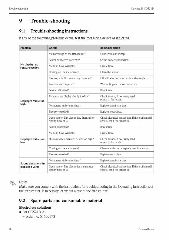
9 Trouble-shooting
9.1 Trouble-shooting instructions
If any of the following problems occur, test the measuring device as indicated.
! Note!
Make sure you comply with the instructions for troubleshooting in the Operating Instructions of
the transmitter. If necessary, carry out a test of the transmitter.
9.2 Spare parts and consumable material
Electrolyte solutions
• For COS21D-A:
– order no. 51505873
Problem Check Remedial action
No display, no
sensor reaction
Mains voltage to the transmitter? Connect mains voltage.
Sensor connected correctly? Set up correct connection.
Medium flow available? Create flow.
Coating on the membrane? Clean the sensor.
Electrolyte in the measuring chamber? Fill with electrolyte or replace electrolyte.
Displayed value too
high
Polarization complete? Wait until polarization time ends.
Sensor calibrated? Recalibrate
Temperature display clearly too low? Check sensor, if necessary send
sensor in for repair.
Membrane visibly stretched? Replace membrane cap.
Electrolyte soiled? Replace electrolyte.
Open sensor. Dry electrodes. Transmitter
display now at 0?
Check electrical connection. If the problem still
occurs, send the sensor in.
Displayed value too
low
Sensor calibrated? Recalibrate
Medium flow available? Create flow.
Displayesd temperature clearly too high? Check sensor, if necessary send
sensor in for repair.
Coating on the membrane? Clean membrane or replace membrane cap.
Electrolyte soiled? Replace electrolyte.
Strong deviations in
displayed value
Membrane visibly stretched? Replace membrane cap.
Open sensor. Dry electrodes transmitter
display now at 0?
Check electrical connection. If the problem still
occurs, send the sensor in.

Oxymax H COS21D Trouble-shooting
Endress+Hauser 29
• For COS21D-B:
– order no. 51518701
• For COS21D-C:
– order no. 51518703
Membrane kits
• Membrane kit Standard, COS21/COS21D:
– O-rings
– membrane: silicon rubber
– order no. 51505874
• Membrane kit Standard, COS21/COS21D, EN10204:
– O-rings
– membrane: silicon rubber
– order no. 51516339
• Membrane kit CIP, COS21/COS21D:
– O-rings: Viton®
– membrane: silicon rubber
– order no. 51518699
• Membrane kit CIP, COS21/COS21D, EN10204:
– O-rings: Viton®
– membrane: silicon rubber
– order no. 71023225
• Membrane kit FDA, COS21/COS21D:
– O-rings
– membrane: FDA certified material
– order no. 71003199
• Membrane kit FDA, COS21/COS21D, EN10204:
– O-rings
– membrane: FDA certified material
– order no. 71023226
Scope of delivery (all kits):
• 3 Membrane caps
• 1 O-ring (process seal, Viton®, none-Ex)
• 1 O-ring (sensor, EPDM)
! Note!
The electrolytes in the membrane caps are specific to the sensor versions and must not be mixed
together!
Process seal for Ex applications
• 3 pieces
• Viton® (not FDA conform)
• order no. 71023212

Technical data Oxymax H COS21D
30 Endress+Hauser
9.3 Return
If the sensor has to be repaired, please return it cleaned to the sales center
responsible.
Please use the original packaging, if possible.
Please enclose the completed "Declaration of Hazardous Material and
De-Contamination" (copy the second last page of these Operating
Instructions) with the packaging and the transportation documents.
No repair without completed declaration!
9.4 Disposal
The device contains electronic components and must therefore be
disposed of in accordance with regulations on the disposal of electronic
waste.
Please observe local regulations.
10 Technical data
10.1 Input
Measured variable Dissolved oxygen [mg/l, % SAT, hPa]
Temperature [° C, ° F]
Measuring range
10.2 Environment
Storage temperature –10 to +60 °C (10 to 140 °F) at 95% relative air humidity,
not condensing
Measuring range Recommended operational range
COS21D-A 0.01 to 20 mg/l
0 to 200 %SAT
0 to 400 hPa
0.01 to 20 mg/l
0 to 200 %SAT
0 to 400 hPa
COS21D-B 0.001 to 20 mg/l
0 to 200 %SAT
0 to 400 hPa
0.001 to 2 mg/l
0 to 20 %SAT
0 to 40 hPaCOS21D-C
" Caution!
Danger of drying out
Only store the sensor with the electrode protection cap (water filled).

Oxymax H COS21D Technical data
Endress+Hauser 31
Ambient temperature –5 to +135 °C (23 to 175 °F)
Ingress protection IP 68 (10 m (33 ft) water column at 25 °C (77 °F) during 45 days, 1 mol/l
KCl)
10.3 Process
Process temperature • COS21D-A and COS21D-C:
-5 to 135 °C (23 to 275 °F)
• COS21D-B:
-5 to 100 °C (23 to 212 °F)
Process pressure • COS21D-A:
0 to 4 bar (0 to 58 psi)
• COS21D-B and COS21D-C:
0 to 12 bar (0 to 174 psi)
10.4 Performance characteristics
Response time From air to nitrogen at 25 °C (77 °F)
• t90 : < 30 s
• t98 : < 60 s
Reference operating
conditions
Current value at air • COS21D-A:
60 nA (40 to 80 nA)
• COS21D-B and COS 21D-C:
300 nA (180 to 500 nA)
Zero current < 0.1 % of the current in air
Measured value
resolution
• COS21D-A:
10 μg/l (10 ppb)
• COS21D-B and COS21D-C:
1 μg/l (1 ppb)
Maximum measured
error
±1 % of measured value1)
Reference temperature: 25 °C (77 °F)
Reference pressure: 1013 hPa (15 psi)
Reference application: Municipal wastewater treatment
Technical data Oxymax H COS21D
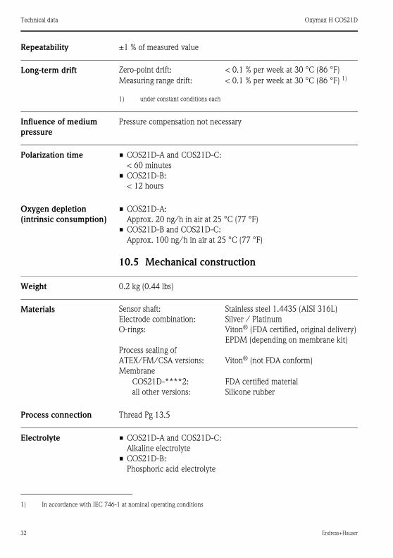
32 Endress+Hauser
Repeatability ±1 % of measured value
Long-term drift
Influence of medium
pressure
Pressure compensation not necessary
Polarization time • COS21D-A and COS21D-C:
< 60 minutes
• COS21D-B:
< 12 hours
Oxygen depletion
(intrinsic consumption)
• COS21D-A:
Approx. 20 ng/h in air at 25 °C (77 °F)
• COS21D-B and COS21D-C:
Approx. 100 ng/h in air at 25 °C (77 °F)
10.5 Mechanical construction
Weight 0.2 kg (0.44 lbs)
Materials
Process connection Thread Pg 13.5
Electrolyte • COS21D-A and COS21D-C:
Alkaline electrolyte
• COS21D-B:
Phosphoric acid electrolyte
1) In accordance with IEC 746-1 at nominal operating conditions
Zero-point drift: < 0.1 % per week at 30 °C (86 °F)
Measuring range drift: < 0.1 % per week at 30 °C (86 °F) 1)
1) under constant conditions each
Sensor shaft:
Electrode combination:
O-rings:
Process sealing of
ATEX/FM/CSA versions:
Membrane
Stainless steel 1.4435 (AISI 316L)
Silver / Platinum
Viton® (FDA certified, original delivery)
EPDM (depending on membrane kit)
Viton® (not FDA conform)
COS21D-****2:
all other versions:
FDA certified material
Silicone rubber
Endress+Hauser
Oxymax H COS21D
Index
AAccessories
Assemblies . . . . . . . . . . . . . . . . . . . . . . . . . . . 27
For connection . . . . . . . . . . . . . . . . . . . . . . . . 27
Measurement . . . . . . . . . . . . . . . . . . . . . . . . . 27
Ambient temperature range . . . . . . . . . . . . . . . . 31
Amperometric principle . . . . . . . . . . . . . . . . . . . 18
Angle of installation . . . . . . . . . . . . . . . . . . . . . . . 8
CCalibration . . . . . . . . . . . . . . . . . . . . . . . . . . . . . 23
Calculating the calibration value . . . . . . . . . . . 20
General . . . . . . . . . . . . . . . . . . . . . . . . . . . . . 19
In air . . . . . . . . . . . . . . . . . . . . . . . . . . . . . . . 20
Types of calibration . . . . . . . . . . . . . . . . . . . . 19
Checking
Connection . . . . . . . . . . . . . . . . . . . . . . . . . . 16
Function . . . . . . . . . . . . . . . . . . . . . . . . . . . . 22
Installation . . . . . . . . . . . . . . . . . . . . . . . . . . . 12
Cleaning
Cathode . . . . . . . . . . . . . . . . . . . . . . . . . . . . . 25
Sensor . . . . . . . . . . . . . . . . . . . . . . . . . . . . . . 24
Sensor surface . . . . . . . . . . . . . . . . . . . . . . . . 24
Commissioning. . . . . . . . . . . . . . . . . . . . . . . . 4, 22
Connection
Direct connection. . . . . . . . . . . . . . . . . . . . . . 15
Current value at air . . . . . . . . . . . . . . . . . . . . . . 31
DDesignated use . . . . . . . . . . . . . . . . . . . . . . . . . . . 4
Disposal . . . . . . . . . . . . . . . . . . . . . . . . . . . . . . . 30
EEC Declaration of conformity . . . . . . . . . . . . . . . . 6
Electrical connection
Via junction box . . . . . . . . . . . . . . . . . . . . . . . 16
Electrolyte . . . . . . . . . . . . . . . . . . . . . . . . . . . . . 32
Environment . . . . . . . . . . . . . . . . . . . . . . . . . . . 30
Errors. . . . . . . . . . . . . . . . . . . . . . . . . . . . . . . . . 28
Ex approval . . . . . . . . . . . . . . . . . . . . . . . . . . . . . 6
FFDA conformity . . . . . . . . . . . . . . . . . . . . . . . . . . 7
Flow operation . . . . . . . . . . . . . . . . . . . . . . . . . . 11
IIcons. . . . . . . . . . . . . . . . . . . . . . . . . . . . . . . . . . . 2
Immersion operation . . . . . . . . . . . . . . . . . . . . . . 11
Incoming acceptance. . . . . . . . . . . . . . . . . . . . . . . 8
Ingress protection . . . . . . . . . . . . . . . . . . . . . . . . 31
Input. . . . . . . . . . . . . . . . . . . . . . . . . . . . . . . . . . 30
Installation . . . . . . . . . . . . . . . . . . . . . . . . . . 4, 8–9
Angle of . . . . . . . . . . . . . . . . . . . . . . . . . . . . . . 8
Check . . . . . . . . . . . . . . . . . . . . . . . . . . . . . . . 12
Examples . . . . . . . . . . . . . . . . . . . . . . . . . . . . 11
Flow operation . . . . . . . . . . . . . . . . . . . . . . . . 11
Immersion operation . . . . . . . . . . . . . . . . . . . . 11
Location . . . . . . . . . . . . . . . . . . . . . . . . . . . . . . 9
Measuring point . . . . . . . . . . . . . . . . . . . . . . . 10
Retractable assembly . . . . . . . . . . . . . . . . . . . . 12
Intrinsic consumption . . . . . . . . . . . . . . . . . . . . . 32
LLong-term drift . . . . . . . . . . . . . . . . . . . . . . . . . . 32
MMaintenance . . . . . . . . . . . . . . . . . . . . . . . . . . . . 23
Materials. . . . . . . . . . . . . . . . . . . . . . . . . . . . . . . 32
Maximum measured error . . . . . . . . . . . . . . . . . . 31
Measured value resolution. . . . . . . . . . . . . . . . . . 31
Measuring point . . . . . . . . . . . . . . . . . . . . . . . . . 10
Measuring principle. . . . . . . . . . . . . . . . . . . . . . . 17
Measuring system . . . . . . . . . . . . . . . . . . . . . . . . . 9
Mechanical construction . . . . . . . . . . . . . . . . . . . 32
Medium pressure . . . . . . . . . . . . . . . . . . . . . . . . 32
Membrane cap . . . . . . . . . . . . . . . . . . . . . . . . . . 18
Memosens . . . . . . . . . . . . . . . . . . . . . . . . . . . . . 18
Mounting location. . . . . . . . . . . . . . . . . . . . . . . . . 9
NNotified body . . . . . . . . . . . . . . . . . . . . . . . . . . . . 6
OOperation . . . . . . . . . . . . . . . . . . . . . . . . . . . . . . . 4
Operational safety . . . . . . . . . . . . . . . . . . . . . . . . . 5
Ordering information. . . . . . . . . . . . . . . . . . . . . . . 6
Oxygen depletion . . . . . . . . . . . . . . . . . . . . . . . . 32
PPerformance characteristics . . . . . . . . . . . . . . . . . 31
Oxymax H COS21D
34
Polarization . . . . . . . . . . . . . . . . . . . . . . . . . 17, 22
Polarization time. . . . . . . . . . . . . . . . . . . . . . . . . 32
Process . . . . . . . . . . . . . . . . . . . . . . . . . . . . . . . . 31
Process connection . . . . . . . . . . . . . . . . . . . . . . . 32
Process pressure . . . . . . . . . . . . . . . . . . . . . . . . . 31
Process temperature . . . . . . . . . . . . . . . . . . . . . . 31
Product structure . . . . . . . . . . . . . . . . . . . . . . . . . 6
RReference operating conditions . . . . . . . . . . . . . . 31
Repeatability . . . . . . . . . . . . . . . . . . . . . . . . . . . . 32
Replacing
Electrolyte . . . . . . . . . . . . . . . . . . . . . . . . . . . 25
Membrane cap . . . . . . . . . . . . . . . . . . . . . . . . 26
Sealing ring. . . . . . . . . . . . . . . . . . . . . . . . . . . 25
Wear and tear materials . . . . . . . . . . . . . . . . . 25
Response time. . . . . . . . . . . . . . . . . . . . . . . . . . . 31
Retractable assembly . . . . . . . . . . . . . . . . . . . . . . 12
Return . . . . . . . . . . . . . . . . . . . . . . . . . . . . . . 5, 30
SSafety icons. . . . . . . . . . . . . . . . . . . . . . . . . . . . . . 2
Scope of delivery. . . . . . . . . . . . . . . . . . . . . . . . . . 6
Sealing ring. . . . . . . . . . . . . . . . . . . . . . . . . . . . . 25
Sensor
Measuring principle . . . . . . . . . . . . . . . . . . . . 17
Replacing wear and tear materials . . . . . . . . . . 25
Sensor design . . . . . . . . . . . . . . . . . . . . . . . . . . . 17
Spare parts . . . . . . . . . . . . . . . . . . . . . . . . . . . . . 28
Storage . . . . . . . . . . . . . . . . . . . . . . . . . . . . . . . . . 8
Storage temperature . . . . . . . . . . . . . . . . . . . . . . 30
Symbols . . . . . . . . . . . . . . . . . . . . . . . . . . . . . . . . 2
TTechnical data . . . . . . . . . . . . . . . . . . . . . . . . . . 30
Environment . . . . . . . . . . . . . . . . . . . . . . . . . 30
Input . . . . . . . . . . . . . . . . . . . . . . . . . . . . . . . 30
Mechanical construction . . . . . . . . . . . . . . . . . 32
Performance characteristics. . . . . . . . . . . . . . . 31
Process . . . . . . . . . . . . . . . . . . . . . . . . . . . . . . 31
Transport . . . . . . . . . . . . . . . . . . . . . . . . . . . . . . . 8
Types of calibration. . . . . . . . . . . . . . . . . . . . . . . 19
UUse. . . . . . . . . . . . . . . . . . . . . . . . . . . . . . . . . . . . 4
WWeight . . . . . . . . . . . . . . . . . . . . . . . . . . . . . . . . 32
ZZero current . . . . . . . . . . . . . . . . . . . . . . . . . . . 31

P/S
F/K
onta
XIV
RA No.
Declaration of Hazardous Material and De-Contamination
Please reference the Return Authorization Number (RA#), obtained from Endress+Hauser, on all paperwork andmark the RA# clearly on the outside of the box. If this procedure is not followed, it may result in the refusal of thepackage at our facility.
Because of legal regulations and for the safety of our employees and operating equipment, we need the "Declaration of Hazardous Materialand De-Contamination", with your signature, before your order can be handled. Please make absolutely sure to attach it to the outside of thepackaging.
Serial number ________________________Type of instrument / sensor ____________________________________________
Used as SIL device in a Safety Instrumented System
Process data Temperature _____ [°F] [°C]
Conductivity ________
_____
[µS/cm]
Pressure _____ [psi] [ Pa ]
Viscosity _____ [cp] [mm /s]
_____
_____
2
Medium and warnings
corrosive harmlessother *toxicIdentificationCAS No.
flammableharmful/irritantMedium /concentration
Processmedium
Medium forprocess cleaning
Returned partcleaned with
* explosive; oxidising; dangerous for the environment; biological risk; radioactivePlease tick should one of the above be applicable, include safety data sheet and, if necessary, special handling instructions.
Description of failure ________________________________________________________________________
______________________________________________________________________________________________________________
______________________________________________________________________________________________________________
Company data
Company ________________________________
_________________________________________________
Address
_________________________________________________
_________________________________________________
___ Phone number of contact person
____________________________________________
Fax / E-Mail ____________________________________________
Your order No. ____________________________
“We hereby certify that this declaration is filled out truthfully and completely to the best of our knowledge.We further certify that the returnedparts have been carefully cleaned. To the best of our knowledge they are free of any residues in dangerous quantities.”
(place, date) Name, dept. (please print) Signature

www.endress.com/worldwide
BA402C/07/en/12.07
Printed in Germany / FM+SGML 6.0 /
DT71066660