Owner's Manual IED1544AIO-D 4x4 Analog / Dante® I/O Module
16
AtlasIED.com – 1 – Specifications are subject to change without notice. 1601 Jack McKay Blvd. • Ennis, Texas 75119 U.S.A. Telephone: 800.876.3333 • Fax: 800.765.3435 Owner’s Manual IED1544AIO-D 4x4 Analog / Dante ® I/O Module IED1544AIO-D 4x4 Analog / Dante ® I/O Module
-
Upload
khangminh22 -
Category
Documents
-
view
1 -
download
0
Transcript of Owner's Manual IED1544AIO-D 4x4 Analog / Dante® I/O Module

AtlasIED.com – 1 –Specifications are subject to change without notice.
1601 Jack McKay Blvd. • Ennis, Texas 75119 U.S.A.Telephone: 800.876.3333 • Fax: 800.765.3435
Owner’s Manual IED1544AIO-D4x4 Analog / Dante® I/O Module
IED1544AIO-D4x4 Analog / Dante® I/O Module
AtlasIED.com – 2 –Specifications are subject to change without notice.
1601 Jack McKay Blvd. • Ennis, Texas 75119 U.S.A.Telephone: 800.876.3333 • Fax: 800.765.3435
Owner’s ManualIED1544AIO-D4x4 Analog / Dante® I/O Module
Table of Contents
Important Safety Instructions .................................................................................................3
Introduction .............................................................................................................................. 5
Key Features ............................................................................................................................. 5
Dante® Overview ......................................................................................................................6
Audio Applications ...................................................................................................................6
Front Panel Description ...........................................................................................................7
Rear Panel Description ............................................................................................................8
Matching Gain from an Analog Source In a Dante® Network .........................................9
Selecting the Router or Network Switch .............................................................................9
Dante® Items to Know or Think About ................................................................................10
Dante Controller™ ....................................................................................................................11
Dimensional Drawings ...........................................................................................................12
Specifications ..........................................................................................................................13
Warranty...................................................................................................................................16
AtlasIED.com – 3 –Specifications are subject to change without notice.
1601 Jack McKay Blvd. • Ennis, Texas 75119 U.S.A.Telephone: 800.876.3333 • Fax: 800.765.3435
Owner’s Manual IED1544AIO-D4x4 Analog / Dante® I/O Module
Important Safety Instructions
1. Read these instructions.2. Keep these instructions.3. Heed all warnings.4. Follow all instructions.5. Do not use this device near water.6. Clean only with dry cloth.7. Do not block any ventilation openings. Install in accordance with the manufacturer’s instructions.8. Do not install near any heat sources such as radiators, heat registers, stoves, or other device that produce heat. 9. Do not defeat the safety purpose of the polarized or grounding-type plug. A polarized plug has two blades with one wider than the other. A grounding type plug has two blades and a third grounding prong. The wide blade or the third prong are provided for your safety. If the provided plug does not fit into your outlet, consult an electrician for replacement of the obsolete outlet. 10. Protect the power cord from being walked on or pinched particularly at plugs, convenience receptacles, and the point where they exit from the device.11. Only use attachments/accessories specified by the manufacturer.12. Use only with the cart, stand, tripod, bracket, or table specified by the manufacturer, or sold with the device. When a cart is used, use caution when moving the cart / device combination to avoid injury from tip-over. 13. Unplug this device during lightning storms or when unused for long periods of time. 14. Refer all servicing to qualified service personnel. Servicing is required when the device has been damaged in any way, such as power-supply cord or plug is damaged, liquid has been spilled, or objects have fallen into the device, the device has been exposed to rain or moisture, does not operate normally, or has been dropped. 15. This product is equipped with a three-wire grounding-type plug, a plug having a third (grounding) pin. This plug will only fit into a grounding-type power outlet. This is a safety feature. If you are unable to insert the plug into the outlet, contact your electrician to replace your obsolete outlet. Do not defeat the safety purpose of the grounding-type plug.16. WARNING: To reduce the risk of fire or electric shock, this device should not be exposed to rain or moisture and objects filled with liquids, such as a vase, should not be placed on this device. 17. To completely disconnect this equipment from the mains, disconnect the power supply cord plug from the receptacle. 18. The mains plug of the power supply cord shall remain readily operable.19. Protective earthing terminal. The apparatus should be connected to a mains socket with a protective earthing connection.
The lightning flash with arrowhead symbol within an equilateral triangle, is intended to alert the user to the presence of uninsulated “dangerous voltage “ within the product’s enclosure that may be of sufficient magnitude to constitute a risk of electric shock to persons.
The exclamation point within an equilateral triangle is intended to alert the user to the presence of important operating and maintenance (servicing) instructions in the literature accompanying the product.
WARNING: SHOCK HAZARD - DO NOT OPENAVIS: RISQUE DE CHOC ELÉCTRIQUE - NE PAS OUVRIR
WARNING: TO REDUCE THE RISK OF FIRE OR ELECTRIC SHOCKDO NOT EXPOSE THIS EQUIPMENT TO RAIN OR MOISTURE
AVIS: NE PAS EXPOSER CE MATÉRIEL À LA PLUIE OU L’HUMIDITEAFIN DE REDUIRE LE RISQUE D’INFLAMMATION OU DE CHOC ELÉCTRIQUE

AtlasIED.com – 4 –Specifications are subject to change without notice.
1601 Jack McKay Blvd. • Ennis, Texas 75119 U.S.A.Telephone: 800.876.3333 • Fax: 800.765.3435
Owner’s ManualIED1544AIO-D4x4 Analog / Dante® I/O Module
WARNING - When The Device Is In Use
• WARNING: For the terminals marked with symbol of may be of sufficient magnitude to constitute a risk of electric shock. The external wiring connected to the terminals requires installation by an instructed person or the used of ready-made leads or cords.• WARNING: The apparatus shall not be exposed to dripping or splashing and that objects filled with liquids, such as vases, shall not be placed on apparatus. • WARNING: The mains plug is used as disconnect device, the disconnect device shall remain readily operable.• To prevent electric shock, do not remove the product cover as there are high voltage components inside. Refer all servicing to AtlasIED. • Should any of the following irregularities occur during use, immediately switch off the power, disconnect the power cord from the AC outlet and contact AtlasIED. Do not to attempt to continue operation with the product as this may cause fire or electric shock: • Smoke or strange smell coming from the unit. • If the product falls or the case is damaged. • If water or any metallic objects falls into the product. • If the power supply cord is damaged in any way. • If the unit is malfunctioning.• Do not insert or drop metallic objects or flammable materials into the ventilation holes of the product’s cover, as this may result in electric shock or fire.• Do not place any containers with liquid or metallic objects on the top of the product. If any liquid spills into the unit, fire or electric shock may result.• Never operate this product or touch the power supply cord during an electrical storm, electric shock may result.• Never exceed the power rating on the product when connecting equipment. Fire and/or property damage may result. • Operate the product only with the voltage specified on the unit. Fire and/or electric shock may result if a higher voltage is used. • Do not modify, kink, or cut the power cord. Do not place the power cord in close proximity to heaters and do not place heavy objects on the power cord, including the product itself, doing so may result in fire or electrical shock. • Ensure that the safety ground terminal is connected to a proper ground. Never connect the ground to a gas pipe as a catastrophic disaster may result. • Be sure the installation of the product is stable, avoid slanted surfaces as the product may fall and cause injury or property damage.

AtlasIED.com – 5 –Specifications are subject to change without notice.
1601 Jack McKay Blvd. • Ennis, Texas 75119 U.S.A.Telephone: 800.876.3333 • Fax: 800.765.3435
Owner’s Manual IED1544AIO-D4x4 Analog / Dante® I/O Module
CAUTION - When Installing The Product • Plugging in or unplugging the power cord with wet hands may result in electric shock. • Never move the unit with the power cord plugged into the wall, as damage to the power cord may result. • When unplugging the cord from the wall, grasp the plug, NOT the cord. • Never install this product in humid or dusty locations, nor in direct sunlight, near sources of heat, or in areas where sooty smoke or steam are present. Fire and electric shock may result.• Keep all sides of the unit at least 31⁄2" away from objects that may obstruct air flow to prevent the unit’s internal temperature rise.
CAUTION - When The Product Is In Use • Never place heavy objects on the product, causing it to fall and/or break, resulting in personal injury and property damage. In addition, the product itself may fall and cause injury and property damage. • Contact AtlasIED for instructions on cleaning the inside of the unit. Large accumulations of dust inside the unit may result in heat buildup and fire. • Ensure that the power supply plug is securely plugged into the wall outlet. Never allow dust to accumulate on the power plug or inside the wall outlet. • When cleaning the unit or the unit is not to be operated for an extended period, unplug the power cord from the wall.
IntroductionThe IED1544AIO-D is a 4-input x 4-output mic / line level analog pre-amplifier that converts analog audio signals to Dante® network audio. Multiple channels of Dante® network audio can be transported over standard IP networks. The IED1544AIO-D 4x4 Dante® I/O Module features four analog balanced mic or line inputs (selectable) and four balanced line outputs. The four analog inputs are converted into Dante® network audio and can be routed via Dante Controller™. The four outputs convert Dante® digital audio received over the LAN into analog audio. There are indicators for network connection, network audio traffic, and power. Each input can be selected to Line or Mic level. In Mic mode, each input has 3 gain selections with Phantom Power. The IED1544AIO-D requires no external power supply. It is powered via a network PoE port or a PoE injector.
Key Features• Dante® Digital Audio Platform• Analog Line or Mic Level Input• Convert Analog Mic / Line Audio to Dante® Network Audio• Convert Dante® Network Audio to Analog Audio Out• 48V Phantom Power• Input Signal & Peak LED Indicators• Independent Gain Selection on Each Input• Analog Balanced Line Output• Output Signal LED Indicators• PoE Powered
AtlasIED.com – 6 –Specifications are subject to change without notice.
1601 Jack McKay Blvd. • Ennis, Texas 75119 U.S.A.Telephone: 800.876.3333 • Fax: 800.765.3435
Owner’s ManualIED1544AIO-D4x4 Analog / Dante® I/O Module
Dante® OverviewAudinate® created Dante®, an uncompressed, multi-channel digital media networking technology, with near-zero latency and synchronization. Hundreds of Dante® enabled products are available from many manufacturers, enabling devices from multiple manufactures to be deployed in the same installation.
Dante® does away with heavy, expensive analog or multicore cabling, replacing it with low-cost, easily-available CAT5e, CAT6, or fiber optic cable for a simple, lightweight, and economical solution. Dante® integrates media and control for an entire system over a single, standard IP network.
Dante® systems can easily scale from a simple pairing of a console to a computer, to large capacity networks running thousands of audio channels. The network can be expanded and reconfigured at any time with just a few mouse clicks because Dante® uses logical routes instead of physical point-to-point connections.
Since the signal audio is transmitted digitally, common analog challenges like interference from other electrical equipment, crosstalk between cables, or signal degradation over long cable runs is not a problem. Setting up Dante® networks is easy, even the most complex networks can be set up and configured quickly and easily with Dante®, making system integration simple.
Signal routing and system configuration with Dante® is fast, simple, and incredibly flexible. Dante Controller™ is a powerful software application that manages devices on the network. Setting up a Dante® network is typically just a matter of plugging devices into an Ethernet switch and connecting a computer to the network. All Dante® devices are automatically discovered and displayed in Dante® Controller, so a system can be up and running in seconds.
Visit www.audioinate.com for details or to learn more on using Dante®. There are many Dante® guides available in the industry. AtlasIED offers one in the BlueBridge® DSP section of atlasied.com.
Audio Applications• Restaurants• Government Facilities• Schools• Industrial Facilities• House of Worship
AtlasIED.com – 7 –Specifications are subject to change without notice.
1601 Jack McKay Blvd. • Ennis, Texas 75119 U.S.A.Telephone: 800.876.3333 • Fax: 800.765.3435
Owner’s Manual IED1544AIO-D4x4 Analog / Dante® I/O Module
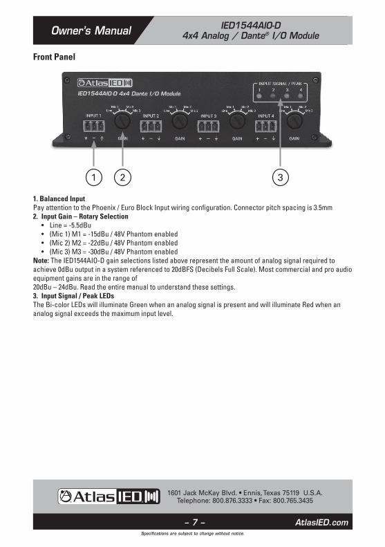
Front Panel
1. Balanced Input Pay attention to the Phoenix / Euro Block Input wiring configuration. Connector pitch spacing is 3.5mm2. Input Gain – Rotary Selection • Line = -5.5dBu • (Mic 1) M1 = -15dBu / 48V Phantom enabled • (Mic 2) M2 = -22dBu / 48V Phantom enabled • (Mic 3) M3 = -30dBu / 48V Phantom enabledNote: The IED1544AIO-D gain selections listed above represent the amount of analog signal required to achieve 0dBu output in a system referenced to 20dBFS (Decibels Full Scale). Most commercial and pro audio equipment gains are in the range of 20dBu – 24dBu. Read the entire manual to understand these settings.3. Input Signal / Peak LEDs The Bi-color LEDs will illuminate Green when an analog signal is present and will illuminate Red when an analog signal exceeds the maximum input level.
1 2 3

AtlasIED.com – 8 –Specifications are subject to change without notice.
1601 Jack McKay Blvd. • Ennis, Texas 75119 U.S.A.Telephone: 800.876.3333 • Fax: 800.765.3435
Owner’s ManualIED1544AIO-D4x4 Analog / Dante® I/O Module
Rear Panel
1. Balanced Output Pay attention to the Phoenix Input wiring configuration.2. Output Signal LEDs The LEDs will illuminate Green when an analog signal is present.3. Network LED The LED will illuminate Green when the unit is connected to a network.4. Network Audio LED The LED will illuminate Green when the unit is transmitting or receiving Dante® digital audio.5. Power LED The LED will illuminate Red when a CAT5 or CAT6 cable is plugged in and PoE is applied to the cable.6. Network Input RJ45, PoE required.
1 62 3 4 5

AtlasIED.com – 9 –Specifications are subject to change without notice.
1601 Jack McKay Blvd. • Ennis, Texas 75119 U.S.A.Telephone: 800.876.3333 • Fax: 800.765.3435
Owner’s Manual IED1544AIO-D4x4 Analog / Dante® I/O Module
Matching Gain from an Analog Source In a Dante® Network Understanding the gain structure is very important to avoid clipping the audio signal or amplifier output. There are three potential ways to clip the signal chain.1. Amplifier Input ClippingThis occurs when the applied input signal exceeds the maximum input level of the amplifier input stage. 2. Amplifier Output ClippingDriving the amplifier to maximum output level.3. Digital ClippingThis occurs when the 0dBFS levels are exceeded. This is very important to understand. Several examples are provided to help understand digital to analog gain structure. Note: AtlasIED recommends to always place a limiter set for 0dB in the signal path prior to the Network Output of the transmitting device.
Selecting the Router or Network Switch - IMPORTANT! It is extremely important to understand that when selecting a router or switch for the Dante® network, not all routers or switches are the same. The size of the Dante® network will influence which router or switch is needed to handle network traffic. There are three things to look for at a minimum or system dropouts may occur. Refer to Audinate® for products they recommend.1. Gigabit speed.2. If using a network switch, it must be a “managed switch” type.3. If using a router with a built-in switch, it should have DD-WRT firmware or Open Source firmware.

AtlasIED.com – 10 –Specifications are subject to change without notice.
1601 Jack McKay Blvd. • Ennis, Texas 75119 U.S.A.Telephone: 800.876.3333 • Fax: 800.765.3435
Owner’s ManualIED1544AIO-D4x4 Analog / Dante® I/O Module
Dante® Items to Know or Think About 1. Dante® Levels in Dante Controler™ Signal level cannot be added or reduced within Dante Controller™. It is strictly a signal router.2. What Does 0dBFS Mean dBFS is a unit of measurement for amplitude levels in digital systems. When referenced to a number such as 0dBFS or 20dBFS it is important to know that these are the maximum peak level before clipping in the digital domain. It is very important to know the source and receiver dBFS specification in order to set up the gain structure when signals are being converted from the digital to analog domain or vise-versa.3. Industry Standard At the time of this writing, there is no industry standard between companies for scaling 0dBFS gain levels in equipment. In a digital studio this is usually not an issue because most of the same brand is used or a limited number of products are interfaced. However, with live sound or commercial audio there can be multiple brands used in one job. Dante® can be great for connectivity between devices but be aware of gain structure matching.4. Interfacing Data with Different Manufactures Equipment To help understand scaling here are some examples: • Source device 0dBFS = 20dBu, transmits to a receiver with a 0dBFS = 20dBu reference, the output is 0dBu. This scenario is ideal when using an amplifier that has a 0dBu (775mV) input sensitivity.• Source device 0dBFS = 20dBu, transmits to a receiver with a 0dBFS = 10dBu reference, the output is -10dBu. To get full output of an amplifier that has a 0dBu (775mV) input sensitivity, increase the network output levels by 10dBu to get 0dBu into the amplifier’s input.• Source device 0dBFS = 10dBu, transmits to a receiver with a 0dBFS = 20dBu reference, the output is +10dBu. This combination will give too much signal into an amplifier that has a 0dBu (775mV) input sensitivity. Reduce the signal from the DSP Network output.• Source device 0dBFS = 10dBu, transmits to a receiver with a 0dBFS = 10dBu reference, the output is 0dBu.5. Understanding Digital Noise vs Headroom If headroom before clipping is a concern, the higher the ratio between 0dBFS and output level, the less likely clipping will be an issue. If the application is paging and background music then a lower number is ok because the headroom is not as critical. In live sound reinforcement applications such as a church band or a concert, more headroom and gain is needed for dynamics. The issue with higher gain in a product is the higher the gain the higher the noise output. To combat high gain output noise, use a Dante® Transmitter product with good signal to noise ratio specification, such as 100dB or better. For instance, AtlasIED BlueBridge® DSP has a signal to noise ratio of 110dB. The noise is very low before it is amplified, assuring low noise out of the DPA amplifier. Look at the input and output 0dBFS reference points and the noise floor specification. If they are not listed call the manufacturer.

AtlasIED.com – 11 –Specifications are subject to change without notice.
1601 Jack McKay Blvd. • Ennis, Texas 75119 U.S.A.Telephone: 800.876.3333 • Fax: 800.765.3435
Owner’s Manual IED1544AIO-D4x4 Analog / Dante® I/O Module
Dante® Controller Below is snapshot of the device information page listed in Dante Controller for the IED1544AIO-D.
Below is a snapshot of the Dante Controller™ routing page of IED1544AIO-D.

AtlasIED.com – 12 –Specifications are subject to change without notice.
1601 Jack McKay Blvd. • Ennis, Texas 75119 U.S.A.Telephone: 800.876.3333 • Fax: 800.765.3435
Owner’s ManualIED1544AIO-D4x4 Analog / Dante® I/O Module
Dimensional Drawings
5.91" (150mm)
1.63"(41.5mm)
1.75"(44.5mm)
FRONT
REAR
TOP
6.54" (166mm)
6.22" (158mm)
3.27"(83mm)
1.26"(32mm)
0.31"(8mm)
0.12"(3mm)

AtlasIED.com – 13 –Specifications are subject to change without notice.
1601 Jack McKay Blvd. • Ennis, Texas 75119 U.S.A.Telephone: 800.876.3333 • Fax: 800.765.3435
Owner’s Manual IED1544AIO-D4x4 Analog / Dante® I/O Module
System
Type 4x4 Analog / Dante IO Module
Network Connection Single RJ45, CAT5
Inputs
Input Quantity 4
Input Connectors Type 3 Position Phoenix Type, 3.5mm Pitch
Input Gain Selection (See Note 1)
Reference to 20dBFSLine = -5dBuM1 (Mic) = -15dBuM2 (Mic) = -22dBuM3 (Mic) = -30dBu
Phantom Power 48V DC When M1, M2, M3 is Selected
Outputs
Output Quantity 4
Output Connectors Type 3 Position Phoenix Type, 3.5mm Pitch
Status Indicators
Input Qty 4, Bi-Color LED, Signal = Green, Peak = Red
Output Qty 4, Green
Network Green
Network Audio Green
Power Red (Powered by PoE)
RJ45 Jack Indicator Industry Standard Network Status (Incorporated) Green / Yellow

AtlasIED.com – 14 –Specifications are subject to change without notice.
1601 Jack McKay Blvd. • Ennis, Texas 75119 U.S.A.Telephone: 800.876.3333 • Fax: 800.765.3435
Owner’s ManualIED1544AIO-D4x4 Analog / Dante® I/O Module
Electrical Specifications
Analog Input Impedance 2.2KΩ
Analog Output Impedance 600Ω
Input Signal LED On Threshold Line = 42mV M1 (Mic) = 15mVM2 (Mic) = 6mVM3 (Mic) = 2.8mV
Input Peak LED On Threshold Line = 14dBu (3.75V)M1 (Mic) = 4.5dBu (1.35V)M2 (Mic) = -2.7dBu (560mV)M3 (Mic) = -9.8dBu (250mV)
Output LED On Threshold 35mV
Maximum Input Level Line = 14dBu (3.75V)M1 (Mic) = 4.5dBu (1.35V)M2 (Mic) = -2.7dBu (560mV)M3 (Mic) = -9.8dBu (250mV)
Dante® Transmission Speed 100Mbps
Frequency Response 20Hz - 20KHz +/- 2dB
THD 0.06% @ 1KHz
Signal To Noise 110dB @ 1kHz
Dynamic Range 110dB
Power PoE
Power Consumption 5W
Mechanical
Dimensions 3.27" W x 1.75" H x 6.55" D (83mm x 44mm x 166mm)
Weight 1.2 lbs. (550g)
Color Black
Material Steel
Mounting 4 Holes, 0.12" (3mm) Diameter
Note 1: The IED1544AIO-D gain selections listed above is the amount of analog signal required to achieve 0dBu output in system reference to 20dBFS (Decibels Full Scale). Most commercial and pro audio equipment gains are in the range of 20dBu – 24dBu. Read the entire manual to understand these settings.

AtlasIED.com – 15 –Specifications are subject to change without notice.
1601 Jack McKay Blvd. • Ennis, Texas 75119 U.S.A.Telephone: 800.876.3333 • Fax: 800.765.3435
Owner’s Manual IED1544AIO-D4x4 Analog / Dante® I/O Module
Notes:

AtlasIED.com – 16 –Specifications are subject to change without notice.
1601 Jack McKay Blvd. • Ennis, Texas 75119 U.S.A.Telephone: 800.876.3333 • Fax: 800.765.3435
Owner’s ManualIED1544AIO-D4x4 Analog / Dante® I/O Module
Limited Warranty
All products manufactured by AtlasIED are warranted to the original dealer/installer, industrial or commercial purchaser to be free from defects in material and workmanship and to be in compliance with our published specifications, if any. This warranty shall extend from the date of purchase for a period of three years on all AtlasIED products, including SOUNDOLIER brand, INNOVATIVE ELECTRONIC DESIGNS brand, and AtlasIED brand products except as follows: one year on electronics and control systems; one year on replacement parts; and one year on Musician Series stands and related accessories. Additionally, fuses and lamps carry no warranty. AtlasIED will solely at its discretion, replace at no charge or repair free of charge defective parts or products when the product has been applied and used in accordance with our published operation and installation instructions. We will not be responsible for defects caused by improper storage, misuse (including failure to provide reasonable and necessary maintenance), accident, abnormal atmospheres, water immersion, lightning discharge, or malfunctions when products have been modified or operated in excess of rated power, altered, serviced or installed in other than a workman like manner. The original sales invoice should be retained as evidence of purchase under the terms of this warranty. All warranty returns must comply with our returns policy set forth below. When products returned to AtlasIED do not qualify for repair or replacement under our warranty, repairs may be performed at prevailing costs for material and labor unless there is included with the returned product(s) a written request for an estimate of repair costs before any non-warranty work is performed. In the event of replacement or upon completion of repairs, return shipment will be made with the transportation charges collect.
EXCEPT TO THE EXTENT THAT APPLICABLE LAW PREVENTS THE LIMITATION OF CONSEQUENTIAL DAMAGES FOR PERSONAL INJURY, ATLASIED SHALL NOT BE LIABLE IN TORT OR CONTRACT FOR ANY DIRECT, CONSEQUENTIAL OR INCIDENTAL LOSS OR DAMAGE ARISING OUT OF THE INSTALLATION, USE OR INABILITY TO USE THE PRODUCTS. THE ABOVE WARRANTY IS IN LIEU OF ALL OTHER WARRANTIES INCLUDING BUT NOT LIMITED TO WARRANTIES OF MERCHANTABILITY AND FITNESS FOR A PARTICULAR PURPOSE.
AtlasIED does not assume, or does it authorize any other person to assume or extend on its behalf, any other warranty, obligation, or liability. This warranty gives you specific legal rights and you may have other rights which vary from state to state.
Service
Should your IED1544AIO-D require service, please contact the AtlasIED warranty department at1-877-689-8055, ext. 277 or www.atlasied.com/support to obtain an RA number.
AtlasIED Tech Support can be reached at 1-800-876-3333 or www.atlasied.com/support
Visit our website at www.AtlasIED.com to see other AtlasIED products.
©2018 Atlas Sound L.P. The Atlas “Circle A”, Soundolier, and Atlas Sound are trademarks of Atlas Sound L.P. IED is a registered trademark of Innovative Electronic Designs LLC. All Rights Reserved. All other trademarks are the property of their respective
owners. All specs are subject to change without notice. ATS005685 RevC 1/18