OWL 640 S - Raptor Photonics
20
OWL 640 S/USER MANUAL/01-20/REV1.0 OWL 640 S Model: OWL-CL-640 USER MANUAL
-
Upload
khangminh22 -
Category
Documents
-
view
3 -
download
0
Transcript of OWL 640 S - Raptor Photonics
OWL 640 S/USER MANUAL/01-20/REV1.0
OWL 640 S Model: OWL-CL-640
USER MANUAL

OWL 640 S/USER MANUAL/01-20/REV1.0
CONTENTS
1. INTRODUCTION .............................................................................................................. 3
1.1 Scope .......................................................................................................................... 3
2. CAMERA CARE ............................................................................................................... 3
2.1 Cleaning the Sensor Window ....................................................................................... 3
3. SPECIFICATION .............................................................................................................. 4
3.1 Camera Overview ........................................................................................................ 4
3.2 Datasheet .................................................................................................................... 4
4. DESIGN OVERVIEW ........................................................................................................ 5
4.1 Mechanical Model ........................................................................................................ 5
4.2 Physical Interface ........................................................................................................ 6
4.3 Mounting to a Microscope ............................................................................................ 6
4.4 Mounting to a Tripod or Optical Table .......................................................................... 6
5. SOFTWARE COMPATIBILITY ......................................................................................... 7
5.1 XCAP Compatibility ..................................................................................................... 7
5.2 Custom Software Interfacing ........................................................................................ 7
6. CAMERA SETUP AND REQUIRMENTS .......................................................................... 8
6.1 Connecting the Camera to the Frame Grabber ............................................................ 8
6.1 Computer/Laptop System Requirements ..................................................................... 8
6.2 Frame Grabber Requirements ..................................................................................... 8
7. XCAP IMAGING SOFTWARE .......................................................................................... 9
7.1 Downloading XCAP ..................................................................................................... 9
7.2 Opening the Camera Configuration ............................................................................. 9
7.3 Acquiring a Live Image Sequence ............................................................................. 11
8. CONTROLLING THE CAMERA (XCAP) ........................................................................ 12
8.1 Exposure Time .......................................................................................................... 12
8.2 Gain Mode ................................................................................................................. 13
8.3 Frame Rate and Triggering Modes ............................................................................ 14
8.4 Non-Uniformity Correction (NUC) .............................................................................. 15
8.5 Thermoelectric Cooler (TEC) ..................................................................................... 16
8.6 Manufacturers Data ................................................................................................... 17
9. XCAP CONTROL FEATURES ....................................................................................... 18
9.1 Saving Preset Configuration Settings ........................................................................ 18
9.2 Contrast Modification (XCAP Std. Only) .................................................................... 19

OWL 640 S/USER MANUAL/01-20/REV1.0
1. INTRODUCTION This document provides detailed instructions for the operation of the Owl 640 S camera. Raptor Photonics Limited reserves the right to change this document at any time without notice and disclaims liability for editorial, pictorial or typographical errors.
1.1 Scope This manual covers the Owl 640 S digital camera and all applicable components. The Owl 640 S is a variant of the Owl 640 family that uses a different sensor offering a spectral response in the SWIR region only. Raptor recommends that this manual be used to optimize camera operation. Details of the camera’s mechanical and electrical interfaces are provided. Important precautions to be taken when using the camera are also stated. Detailed information is also provided on each of the cameras control parameters. Each camera control is discussed and explained with the use of XCAP Imaging software, which is the core plug and play software package that is offered with Raptor cameras. An image of the camera is shown in Figure 1.
2. CAMERA CARE 2.1 Cleaning the Sensor Window Raptor cameras require no regular maintenance except occasional external cleaning of the sensor window (the glass window between the camera sensor and the microscope or lens). Use optical grade isopropyl to clean this window. A cotton swab can be used, but may leave some fibres on the window, so be careful. To avoid this, you could also use a lens tissue or a cleaning swap such as a texwipe. Forced air can be applied to remove any loose particles. Should any other issues occur please contact your local agent.
CAUTION — The camera’s sensor and circuits are sensitive to static discharge. Ensure that you are using a static strap or completely grounded at all times to release any static energy before you clean the window.
CAUTION — Do not use acetone.
Figure 1: Complete Camera Module.

OWL 640 S/USER MANUAL/01-20/REV1.0
3. SPECIFICATION 3.1 Camera Overview The Owl 640 S is a variant of the Owl 640 family that can achieve faster frame rates (up to 300Hz) than the standard Owl 640 II. The camera has a response in the SWIR region from 0.9µm to 1.7µm.
The Owl 640 S is a compact, rugged and high sensitivity camera. With a typical readout noise of 30 electrons, the camera has a high intra-scene dynamic range for simultaneous capture of light and dark regions of a scene.
The Camera Link digital interface provides the most stable platform for data transfer and the camera will work on any Camera Link standard frame grabber.
3.2 Datasheet For the full specification of the Owl 640 S, the datasheet for the camera can be downloaded from the Raptor Photonics website using the link below:
https://www.raptorphotonics.com/products/owl-640-s/

OWL 640 S/USER MANUAL/01-20/REV1.0
4. DESIGN OVERVIEW 4.1 Mechanical Model
Units shown in mm and inches [in]
PDF of mechanical model available from our website: https://www.raptorphotonics.com/products/owl-640-s/

OWL 640 S/USER MANUAL/01-20/REV1.0
4.2 Physical Interface
4.3 Mounting to a Microscope The camera has a standard C-mount that should easily screw onto any microscope port.
4.4 Mounting to a Tripod or Optical Table The camera has a ¼-20 BSW (Whitworth), threaded hole to mount to a tripod or an optical table.
1. 3M CameraLink connector (TyOUT) Part #: 12226-1150-00FR
2. 3M CameraLink connector (TxOUT +comms) Part #: 12226-1150-00FR
3. SMA connector: Trigger Out. Single ended, source impedance = 51 Ω, capable of sinking and sourcing 32mA and will have an output voltage of 3.3v i.e. TTL compatible.
4. SMA connector: Trigger In. Single ended, termination impedance = 510 Ω, capacitive load = 200 pF, TTL compatible.
5. 4 Pin Hirose connector Part #: HR10A-7R-4PB(73)

OWL 640 S/USER MANUAL/01-20/REV1.0
5. SOFTWARE COMPATIBILITY This section outlines the options relating to software that are available for the Owl 640 S.
5.1 XCAP Compatibility Raptor works closely with EPIX who integrate all Raptor camera models into their XCAP Imaging Software package. XCAP is the core plug and play software package that is offered with the Owl 640 S.
5.2 Custom Software Interfacing Raptor works closely with EPIX Inc, who integrates all Raptor cameras into their software package, XCAP. The EPIX frame grabbers are the models that we offer with our cameras. We offer their Software Development Kit (SDK) for interfacing with custom software (XCLIB). If using a frame grabber from a different company, then you will have to obtain their SDK. Raptor can provide an ICD which includes a list of all serial commands to control the camera. This would be required along with the SDK from the frame grabber device to integrate the camera.

OWL 640 S/USER MANUAL/01-20/REV1.0
6. CAMERA SETUP AND REQUIRMENTS 6.1 Connecting the Camera to the Frame Grabber The Owl 640 S uses medium Camera Link configuration, so therefore requires a frame grabber that supports medium Camera Link. The camera has two shrunk SDR ports on the interface and requires two cables. The frame grabber that Raptor offer with this camera is the E8 model from EPIX. It is a minimum requirement to use this model or if not using the EPIX software or SDK, a frame grabber that matches the specification of the E8. When using this frame grabber, two MDR – SDR Camera Link cables are required to connect the camera to the frame grabber.
If demoing the camera with the Mini PC system that Raptor provides, you should connect the left port of the frame grabber to the SDR port closest to the power connector on the camera interface. Connect the other two ports using the other cable. The polarity of the port connection from the camera to the frame grabber will also be shown via A and B lettering (connect A to A and B to B).
6.1 Computer/Laptop System Requirements The basic system requirement is that the PCIe bus of the system must provide sufficient bandwidth to handle video rate transfers. The amount of bandwidth required depends on the camera in-hand. The Owl 640 S uses a Medium Camera Link interface which can be handled with a x8 PCIe bus and PIXCI E8 from EPIX, providing roughly 850MB/sec maximum bandwidth. Contact EPIX Inc. for further information regarding minimum computer/laptop specification requirements to run the XCAP Imaging Software.
6.2 Frame Grabber Requirements It is a minimum requirement to use the E8 frame grabber model if using EPIX. If using another frame grabber from a different company, the specification of this frame grabber must match that of the E8 model.

OWL 640 S/USER MANUAL/01-20/REV1.0
7. XCAP IMAGING SOFTWARE This section will discuss downloading an acquiring an image using XCAP.
7.1 Downloading XCAP The latest version of XCAP can be downloaded from the link below: http://www.epixinc.com/support/files.php
please select the appropriate version of XCAP for your computer. Ensure that you download from the section labelled “Pre-release version with support for the latest cameras and latest PIXCI® imaging boards”. Open the downloaded file when complete and follow the onscreen instructions in the installation wizard. If a pop-up message appears asking whether to install the PIXCI driver, ensure that you click yes.
7.2 Opening the Camera Configuration After opening XCAP, select “PIXCI Open/Close” from the “PIXCI” tab from the top menu bar in the main window. A PIXCI Open/Close pop-up box will open as shown in Figure 2.
Click on “Camera & Format” that is highlighted in Figure 2 and a “PIXCI Open Camera & Format” box will appear, as shown in Figure 3.
Figure 2: PIXCI Open/Close.
Figure 3: PIXCI Open Camera & Format.

OWL 640 S/USER MANUAL/01-20/REV1.0
Using the dropdown menu highlighted, search for “Owl 640 S”. You will see the configuration for “Raptor Photonics Owl 640 S”. Selecting “Open w. Default Video Setup” will open the control panel with all control parameters set to the default states. “Open w. Last used Video Setup” will open the control panel with all parameters set at the last known state. Once this option between the two has been selected, click “Ok”. To open the camera control panel and imaging window, click “Open” in the “PIXCI Open/Close” window (Figure 2).
Two windows will now open in XCAP, an imaging window and control panel, as shown in Figure 4.
Figure 4: Imaging Window and Control Panel.

OWL 640 S/USER MANUAL/01-20/REV1.0
7.3 Acquiring a Live Image Sequence There are two things to observe in the control panel that inform you that the camera is connected and ready to image.
The serial connect checkbox must be ticked in the control panel. This informs you that you have established a serial connection with the camera and can control the camera.
Secondly, the symbol near the bottom right of the control panel will have three moving dots. This indicates that you are obtaining video data from the camera. The imaging statistics displayed directly underneath the imaging window will also inform you if you are receiving a video feed from the camera.
Once you have established a serial connection with the camera and are receiving video data, you can now grab a live image feed. Clicking the “Live” button will grab a live image sequence which you will now see in the imaging window.
The symbols in the control app discussed above are displayed in Figure 5.
Figure 5: Checking Camera Connection and Acquiring a Live Image.

OWL 640 S/USER MANUAL/01-20/REV1.0
8. CONTROLLING THE CAMERA (XCAP) The sections below will give information on using each control of the Owl 640 S, giving a description on how to use each control parameter and their effect on the camera’s performance. The software used to illustrate the camera controls is XCAP.
8.1 Exposure Time The exposure time can be controlled under any tab in the XCAP GUI and remains constant on the GUI. There is an input box that allows the user to enter in an exposure time. By default, the ALC is disabled, enabling the user to set an exposure time using either the manual input box or the slider bar. The minimum and maximum limits set of the exposure time are dependent on the frame rate currently set. The maximum exposure time is a function of the frame period (1/frame rate) and the readout time. The relationship between these three parameters is shown below:
𝑀𝑀𝑀𝑀𝑀𝑀𝑀𝑀𝑀𝑀𝑀𝑀𝑀𝑀 𝐸𝐸𝑀𝑀𝐸𝐸𝐸𝐸𝐸𝐸𝑀𝑀𝐸𝐸𝐸𝐸 𝑇𝑇𝑀𝑀𝑀𝑀𝐸𝐸 = 𝐹𝐹𝐸𝐸𝑀𝑀𝑀𝑀𝐸𝐸 𝑃𝑃𝐸𝐸𝐸𝐸𝑀𝑀𝐸𝐸𝑃𝑃 − 𝑅𝑅𝐸𝐸𝑀𝑀𝑃𝑃𝐸𝐸𝑀𝑀𝑡𝑡 𝑇𝑇𝑀𝑀𝑀𝑀𝐸𝐸
The readout time for the Owl 640 S is fixed and remains the same for each gain mode (Low and High Gain):
Readout Time = ~3.3ms
Using an example of a frame rate of 25Hz, the maximum exposure time would be:
𝑀𝑀𝑀𝑀𝑀𝑀𝑀𝑀𝑀𝑀𝑀𝑀𝑀𝑀 𝐸𝐸𝑀𝑀𝐸𝐸𝐸𝐸𝐸𝐸𝑀𝑀𝐸𝐸𝐸𝐸 𝑇𝑇𝑀𝑀𝑀𝑀𝐸𝐸 = �1
25� − (3.3 × 10⁻³)
= 36.7𝑀𝑀𝐸𝐸
XCAP will automatically adjust the maximum exposure time the user can set depending on the frame rate selected. This upper limit will be adjusted on the slider bar with each frame rate adjustment.
In relation to the minimum exposure time, this value is still TBD and will be updated. XCAP currently has a lower limit of 0s, but note that the minimum exposure time of the camera is not yet defined.
If the ALC is enabled, the exposure time will be automatically adjusted.
The exposure time controls are highlighted in Figure 6.
Figure 6: ALC and Manual Exposure Time Controls.
OWL 640 S/USER MANUAL/01-20/REV1.0
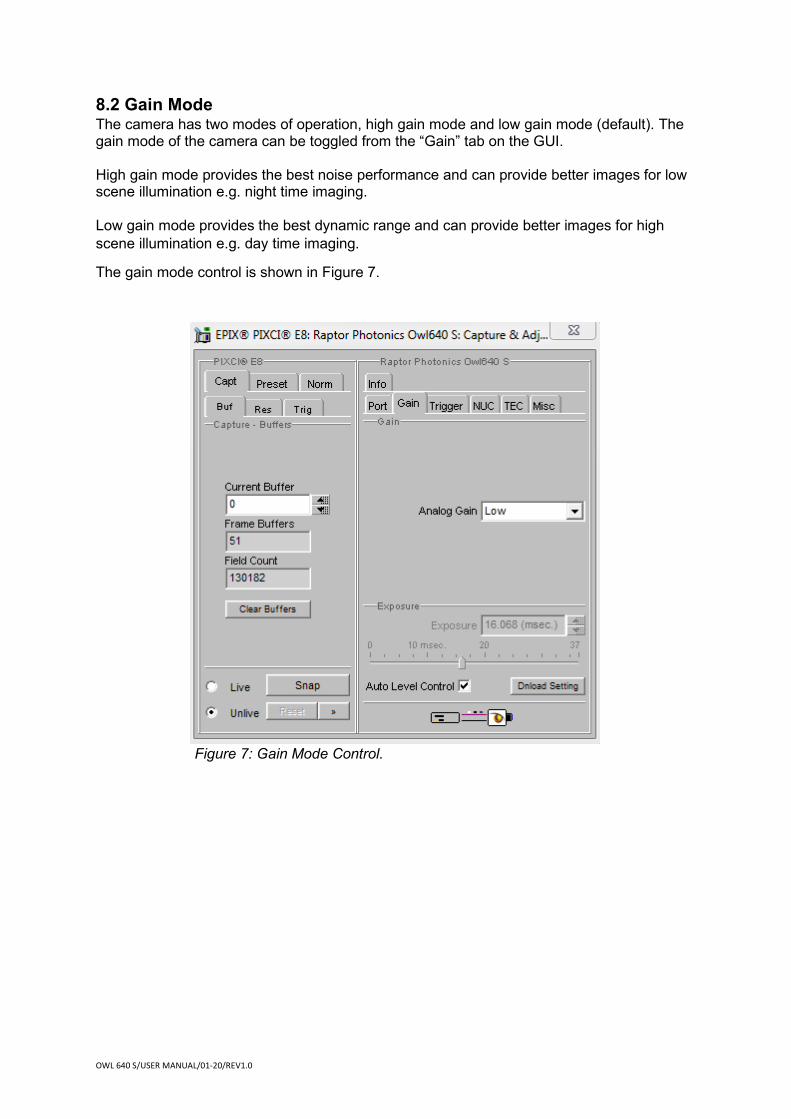
8.2 Gain Mode The camera has two modes of operation, high gain mode and low gain mode (default). The gain mode of the camera can be toggled from the “Gain” tab on the GUI. High gain mode provides the best noise performance and can provide better images for low scene illumination e.g. night time imaging. Low gain mode provides the best dynamic range and can provide better images for high scene illumination e.g. day time imaging.
The gain mode control is shown in Figure 7.
Figure 7: Gain Mode Control.

OWL 640 S/USER MANUAL/01-20/REV1.0
8.3 Frame Rate and Triggering Modes The frame rate and trigger mode of the camera can be controlled from the “Trigger” tab in the GUI, shown in Figure 8.
Frame rate: By default, the camera will be set to 25Hz. There are multiple discrete frame rate options available to select up to 300Hz.
Trigger: The trigger mode of the camera can be toggled from the “Readout Mode” dropdown box. By default, the camera will be set to internal trigger, integrate then read (ITR). This mode is indicated by the “Live” option in the dropdown box.
The camera can be switched to external trigger mode by selecting the “Ext. Triggered” option. When this mode is enabled, the “Trigger Polarity” (rising or falling edge) dropdown input box will become available. By default, the camera will run with a rising edge trigger polarity.
Figure 8: Frame Rate and Triggering Modes.

OWL 640 S/USER MANUAL/01-20/REV1.0
8.4 Non-Uniformity Correction (NUC) The NUC state of the camera can be controlled from the “NUC” tab of the GUI. The camera has a 3 point (offset, gain, dark) NUC performed live on board the FPGA of the camera, correcting for fixed pattern noise. There is also a bad pixel correction performed when the 3 point NUC is active. By default, the 3 point NUC and bad pixel correction will be enabled (3 Point NUC On).
If wanting to output the raw data from the camera, the 3 point NUC can be disabled (3 Point NUC Off – Raw Data).
The “Highlight Bad Pixel” control in the NUC tab shows the bad pixel map that the NUC is correcting for. This control does not show bad pixels that are not being corrected.
The NUC controls are shown in Figure 9.
Figure 9: 3 Point NUC Control.

OWL 640 S/USER MANUAL/01-20/REV1.0
8.5 Thermoelectric Cooler (TEC) The Owl 640 S, as with all Owl cameras, uses a TEC to stabilise the sensor temperature at 15 ͦC. The TEC status is shown in the “TEC” tab of the XCAP GUI, shown in Figure 10.
The TEC control can be enabled/disabled from this tab. By default, the TEC will be disabled. When enabling the TEC, the default set point on XCAP will be 15 ͦC. Raptor recommends keeping the set point at this temperature, as the camera is tested at this temperature under QC, and this is the specification TEC set point of the camera. The NUC is also performed at this temperature also so will not be optimal at other sensor temperatures.
There is roughly a 35 ͦC delta between the PCB and sensor temperature so the set point can possibly be varied depending on the ambient temperature and the level of heat sinking of the camera. As previously mentioned however, the NUC is not optimised at sensor temperatures outside of 15 ͦC.
The sensor temperature can also be read back from this tab. Clicking “Update Temp.” will read the current sensor temperature.
Figure 10: Thermoelectric Cooler (TEC) Control.

OWL 640 S/USER MANUAL/01-20/REV1.0
8.6 Manufacturers Data The “Info” tab displays the manufacturers data of the camera, such as the firmware version and serial number etc. The PCB and sensor temperature can be read back from this tab by clicking “Update Temp.” The “Info” tab is shown in Figure 11.
Figure 11: Manufacturers Data.

OWL 640 S/USER MANUAL/01-20/REV1.0
9. XCAP CONTROL FEATURES XCAP has many different control functions and analytical tools that can be used when imaging the camera. For the full XCAP user guide, please refer to the link below:
http://epixinc.com/manuals/pixci_e14el/index.htm
This section will discuss in detail a few features on XCAP that Raptor thinks would be of immediate use when using the camera.
9.1 Saving Preset Configuration Settings Different camera and frame grabber settings can be saved in the “Preset” tab under the “PIXCI E8” section of the GUI, as shown in Figure 12.
Up to three different presets can be saved per settings file. If the camera is set to a desired state outside of the default parameters, clicking “Save 1” will save all the current parameter states that have been set. This can be done a further two times. These camera states can be recalled at any time by using the recall buttons. The overall settings file can then be saved and loaded in this tab also. Three preset states are the maximum number that can be saved in a settings file.
Figure 12: Preset Configuration Settings.

OWL 640 S/USER MANUAL/01-20/REV1.0
9.2 Contrast Modification (XCAP Std. Only) The image contrast can be modified from the “Contrast Modification” section under the “Modify” tab in the XCAP imaging window. The location of this control feature is shown in Figure 13.
In the contrast modification box, that can be seen from Figure 14, select “Stretch Contrast, Histogram Percentile Endpoints” and click “preview”. The contrast modification will now be applied over the live image feed. The contrast can be adjusted using the low and high end percentile point controls. The default settings are usually adequate for most applications.
Figure 14: Contrast Modification.
Figure 13: Contrast Modification Location on Toolbar.

OWL 640 S/USER MANUAL/01-20/REV1.0
CORPORATE HEADQUARTERS Raptor Photonics LTD Willowbank Business Park Larne, Co Antrim BT40 2SF Northern Ireland PH: +44 2828 270141 www.raptorphotonics.com