osstem-implant-system-2013-bok.pdf - MaxFac Dental AS
466
-
Upload
khangminh22 -
Category
Documents
-
view
1 -
download
0
Transcript of osstem-implant-system-2013-bok.pdf - MaxFac Dental AS

(1~9페이지)CEO-목차(영문) 2013.05.09 1:9 PM 페이지1

1st
edition published at 1th April 2006
2nd
edition published at 14th
Feb 2013
Published by Choi, Kyoo-ok
Edited by Kim, Young-kyun, Kim, Ki-Seong, Kim, Se-woung, Park, Hwee-Woong
Oh, Young-Hak, Lee, Dae-Hee, CHO, Yong-Seok
Publisher : Osstem Implant Co., Ltd.
Registration No. 2005-5
Address : 8th floor, World Meridian 2, 426-5 Gasan-dong, Geumcheon-gu,
Seoul, Korea
Telephone : 82-2-2016-7000
Fax : 82-2-2016-7001
Web-site : http://www.osstem.com
E-mail : [email protected]
Manufactured by adfarm Communication
Printed by Grabic Co., Ltd. 031-901-2982
Price : 100,000 Won
All rights reserved Osstem Implant Co., Ltd. Reproducing,
using, and lifting excerpts from the content, figures, and photos
in this book are strictly prohibited and are punishable by law.
ⓒ
OSSTEM IMPLANT Co., Ltd.
(1~9페이지)CEO-목차(영문) 2013.05.09 1:9 PM 페이지2

CEO’s MESSAGE
OSSTEM IMPLANT CEO
Choi, Kyoo-Ok (DDS, Ph.D.)
Korea’s dental implant studies were introduced considerably later than in Europe or America.
However, thanks to Korea’s high standard of dentistry, dentists’academic fervor, and increase in the general public’s
interest for oral health has developed academics and industry, resulting in a rapid popularization of implants. Not only
do all universities perform implant operations, but also over 80% of private clinics. Korea’s implant clinic has been
growing and developing into a world-class level.
Osstem Implant has been spearheading such trend of growth and evolution, providing clinical operation methods and
clinical technical intelligence to AIC workshops, regional research societies, as well as various conferences. By
publishing general introduction to OSSTEM IMPLANT SYSTEM in 2005 and five general introductions to OSSTEM
IMPLANT SYSTEM in 2006, Osstem Implant has been contributing to the improvement of clinical operation methods
and the development of academics.
It has been 7 years since the publication of total five general introductions to OSSTEM IMPLANT SYSTEM, and Osstem
Implant has been striving for the clinical development of implants by continual research and development,
development of new technology, and provision of more convenient, safe, and durable products to both dentists and
patients for quality improvement.
Basing on years of cases with new concepts of operative methods applied, in addition to the release of such new
technology and products, a revised edition of OSSTEM IMPLANT SYSTEM has been published.
I am very happy to publish revised edition of
2013 OSSTEM IMPLANT SYSTEM.
(1~9페이지)CEO-목차(영문) 2013.05.09 1:9 PM 페이지3

This revision, published after 7 years, bear different significance from first edition of general introduction of 2005 and
from 5 particulars released in 2006 when implant was being popularized.
This revised edition is not a mere update from OSSTEM IMPLANT SYSTEM, but an upgrade revision, which exhibits
enhanced convenience in operation and long term clinical results by applying improved Osstem implant’s design and
new products with improved surface treatment. Moreover, it is a guideline organized to show operative methods of
experienced clinicians, so that clinicians can utilize state of the art surgical tools and equipment
The revised edition consists of “Variety, Design, and Surface Treatment of Osstem Implant”, “ Implant Operation”,
“ Implant Prosthesis”, “Surgical preparation and instrument management”, “Clinical cases”, “Related Articles”and
etcetera. Because it includes detailed accounts of real clinical application processes based on Osstem Implant’s
product’s technical understanding, it is expected to provide immediate and realistic clinical guidelines to private
clinicians.
To the hard work of those who helped greatly to publish this book with liberal clinical verifications and researches: Prof.
Kim young-Kyun, Dr. Oh Young-Hak, Dr. Cho Yong-Seok, Dr. Lee Dae-Hee, Dr. Kim Ki-Seong, Dr. Park Hwee-Woong,
Dr. Kim Se-Woung, I give special thanks. Moreover, I thank the AIC directors and the dentists in the country who have
provided valuable clinical cases and numerous feedbacks.
I give thanks to my fellow dentists and admire their passion and dedication that helped Osstem implant achieve global
excellence.
This book is a product of Osstem implant’s development, as well as a determination to lead the international dental
community as a representative of Korea. Through unrelenting effort and research, we promise to return with even
better products and technology.
Thank you.
(1~9페이지)CEO-목차(영문) 2013.05.09 1:9 PM 페이지4

Editor in Chief
Kim, Young-Kyun
Since Osstem’s first development of domestic implant in 1992, the first patent for
dental implant in Korea was obtained in 1995 through continuous research. It
was released as AVANA since 1997, and I began to cautiously use domestic
implants. However, I was hesitant as I had a vague sense of mistrust and
discomfort regarding domestic products. Nevertheless, after confirming the
excellent initial osseointegration and functional maintenance after prosthesis
treatment, I started to actively use domestic implants. Since then, the company
name changed to Osstem Implant, and surface treatment was continuously
developed and products of various designs were released. Moreover, numerous
scholars reported on the fundamental and clinical research results, and as both
domestic and international academic journals recently publish Osstem Implant
related journals, intermediate to long term stability has been confirmed.
General introduction to OSSTEM IMPLANT published in 2005 was acclaimed as
the first book in which a company has organized its implants. In 2006, revised
introduction in Korean, Taiwanese, and English was published, and itemized
discussions of operation, prosthesis, prosthetic lab-work, and esthetic implant
have also been published, providing valuable resources not only to the implant
community but also to the dentists.
The material published in 2013 records in detail the history of Osstem Implant,
types and characteristics of fixtures, surgical instruments and procedures, and
discusses in depth the concept of basic implant prothodontics, occlusion, and
impression taking. Successful clinical cases from domestic scholars who used
Osstem Implants are introduced, and Osstem Implant related international
academic articles have also been included. This teaching material, I believe, is
not merely limited to Osstem Implant system, but could aid in the fundamental
understanding of implantology as well as assist the clinicians who use the
products of other companies.
I sincerely thank the editors and Osstem Implant faculties who have spent a year
editing and collecting resources, as well as the dentists who have provided
numerous clinical data. Moreover, I thank the Adfarm Communication executives
and staff who have showed devoted support in providing this book.
Jan. 2013 Kim, Young-Kyun, Editor in Chief
Editor’s note
(1~9페이지)CEO-목차(영문) 2013.05.09 1:9 PM 페이지5

Editorial Board
Osstem Implant Co., Ltd.
CEO
Choi, Kyoo-Ok
Seoul National University Bundang Hospital
쪾1980 - 1986 Seoul National University, College of Dentistry. D.D.S.
쪾1986 - 1989 Intern, Resident, Depart of Oral and Maxillofacial Surgery,
Section of Dentistry, Seoul National University Hospital
쪾1989 - 1992 Military Dental Officer
쪾1987 - 1994 Seoul National University Graduate Course. MSD. PhD.
쪾1992 -1 997 Full-time Lecturer, Assistant Professor, Dept. of Oral and Maxillofacial Surgery,
College of Dentistry, Chosun University
쪾1997 - 2003 Chairman, Dept. of Oral and Maxillary Surgery, Section of Dentistry,
Bundang Jesaeng General Hospital
쪾2003 ~ Now Associate Professor, Chairman, Dept. of Oral and Maxillofacial Surgery,
Section of Dentistry, Seoul National University Bundang Hospital
Associate Professor, School of Dentistry, Seoul National University
쪾2011 ~ Now Editor-in-Chief, J Korean Assoc Oral Maxillofac Surg
쪾Published articles: 447 articles including "Development of a novel bone grafting material
using autogenous teeth" International articles <SCI(e)>: 51 articles including
"Development of a novel bone grafting material using autogenous teeth"
쪾Writing textbooks: publishing 54 books including "bone graft and implant vol. 1, 2, 3."
쪾DDS, College of Dentistry, Seoul National University, Seoul, Korea
쪾MS, Dankook University , Major: Orthodontics, Seoul, Korea
쪾Ph.D, College of Medicine, Korea University, Seoul, Korea
쪾CEO and President, Osstem Implant Co., Ltd., Seoul, Korea
쪾The Director of a Apsun Dental Clinic
쪾Adjunct Professor, Korea Medical University
쪾Vice President of Korea Venture Business Association.
쪾Director of Korea Medium Industries Association
쪾Director of Kosdaq Association
Kim, Young-Kyun
D.D.S., PhD
CEO
Editor in Chief
06
(1~9페이지)CEO-목차(영문) 2013.05.09 1:9 PM 페이지6

Namsang Dental Clinic
Educational and Professional Training쪾 1988 D.D.S. College of Dentistry, Seoul National University
쪾 1988 - 1991 Internship & Resident, Dept. of Prosthodontics, Seoul National University Dental Hospital
쪾 1991 M.S.D. Graduate School of Dentistry, Seoul National University
쪾 2010 Ph.D. Graduate School of Dentistry, Seoul National University
쪾 2008 - 2012 Clinical Professor, Dept. of Prosthodontics, College of Dentistry, Seoul National University
쪾 Present Director of Namsang Dental Clinic
OrganizationVice President, Korean Academy of Esthetic Dentistry (KAED)
Korean Academy of Prosthodontics
Academy of Osseointegration
Asian Academy of Osseointegration
Seoul Implant Research & Study Group
The Wise Dental Clinic
Educational and Professional Training쪾 Graduated from Kyung Hee University’s College of Dentistry
쪾 Interned at the Department of Prosthodontics of Gacheon University Gil Medical Center
쪾Dentist accredited by the Korean Association of Orthodontists
쪾 Served as general affairs director of the Korean Association of Oral and Maxillofacial Implant - Incheon Branch
쪾 Served as director of the Korea Academy of Aesthetic Dentistry
쪾 Served as clinical advisor on prosthetic dentistry at Gacheon University’s Dental Hygiene Department
쪾 Served as clinical advisor at the Department of Prosthodontic Dentistry, Graduate School of Health Science
Gacheon University
쪾 Director, OSSTEM AIC Society for Research
쪾 Currently serves as manager at the Department of Prosthesis at Gacheon University of Science and Medicine
쪾Director of The wise dental hospital
Director
Kim, Ki-Seong
Director
Kim, Se-Woung
Editors
07
쪾 Graduated in 1989 from the Dental Collage of Seoul National University, Korea
쪾 Trained at Dept. of Oral and maxillofacial Surgery, Seoul National University Hospital
쪾 Assistant professor at Chungbuk National University
쪾 Chairman of Dept. of Dentistry, Chungbuk National University Hospital
쪾 Diplomate, Korean board of Oral & maxillofacial Surgery
쪾 Diplomate, Korean Board of Maxillofacial Plastic and Reconstructive Surgery
쪾 Osstem Faculty and Course Director of AIC (Apsun Dental Implant Research and Education Center)
쪾 AO active member
쪾 EAO member
쪾 Ambulatory professor of Seoul National University Dental Collage
쪾 Director of Apsun Dental Hospital
Apsun Dental Hospital
CHO, Yong-Seok
DDS, MSD, PhD
(1~9페이지)CEO-목차(영문) 2013.05.09 1:9 PM 페이지7

All Dental Clinic
쪾 D.D.S/M.S.D from School of Dentistry, Seoul National University
쪾 Department of Prosthodontics, Seoul National University Dental Hospital
쪾 Adjunct Professor, College of Dentistry, Seoul National University
쪾 All Dental Clinic Director
Seoul Dental Clinic
쪾 Seoul National University Dental College & Graduate school D.D.S M.S Ph.D
쪾 Seoul National University Dental College Adjunct Professor
쪾 Inje University Sanggye Baik Hospital Adjunct Professor
쪾 F & I Implant Research Group Honorary President Osstem Implant AIC Director
쪾 Seoul Dental Clinic Director
Director
Oh, Young-Hak
Director
Lee, Dae-Hee
Editors
08
쪾 D.D.S/M.S.D from School of Dentistry, Seoul National University
쪾 Department of Prosthodontics, Seoul National University Dental Hospital
쪾 Adjunct Professor, College of Dentistry, Seoul National University
쪾 Seoul Ace Dental Clinic Director
Seoul Ace Dental Clinic
Director
Park, Hwee-Woong
(1~9페이지)CEO-목차(영문) 2013.05.09 1:9 PM 페이지8

Ⅰ
Kinds and design of Osstem implant system
Ⅱ Surface Treatment
Ⅲ Implant Surgery
1. Surgical guideline of Osstem implant systems
1) TSIII SA Implant System
2) MS Implant System
3) Ultra-Wide Implant System
2. Surgical kits for sinus bone graft
1) The CAS (Crestal Approach Sinus)-KIT
2) The LAS(Lateral Approach Sinus)-KIT
3. Guided Bone Regeneration Using the SMARTbuilder
4. AutoBone Collector ( A.B.C )
5. Drilling Sequence of Osstem Implant System
Ⅳ Implant Prosthodontics
1. Introduction
1) Introduction of implants in prosthodontics and its significance
2) Selection of implant
3) Types and selection of implant prosthesis
4) Types of Osstem implant abutment
5) Selection of implant abutment
2. Impression taking for implant superstructure
1) Basic concepts of impression taking for implants
2) Time for impression taking
3) Method for implant impression taking
4) Summary-impression taking in TS implant system.
3. Guideline for occlusion of implant prosthodontics
1) Occlusion, the never-ending challenge for dentists
2) Formation process of occlusion concept in implant
prosthodontics and current condition
3) Osseoperception
4) Occlusion=Force controll
5) Detailed occlusion patterns depending on number and positions
of teeth to rehabilitate
6) Summary
Ⅴ Surgical preparation and instrument management for implant
Ⅵ Clinical Cases of Osstem Implant System
Ⅶ Osstem Implant Related Paper
116991
92
104
112
120
141
147
155
160
177
178
180
182
184
223
235
238
241
299
302
302
305
306
314
324
327345431
CONTENTS
OSSTEM IMPLANT SYSTEM
09
(1~9페이지)CEO-목차(영문) 2013.05.09 1:9 PM 페이지9

2.변천사10- 90(영문) 2013.05.09 1:16 PM 페이지1

2.변천사10- 90(영문) 2013.05.09 1:16 PM 페이지2

It was named AVANA implant in 1995 after machined surface straight standard implant was first launched.
Self tapping implant that has been TiO2 blasting treated was then launched.. Company name changed to
Osstem Implant at the end of 1997, and one stage implant MT I and MT II were released in 1997~2001. At
the moment, two-stage implant with straight body was named US II. Since then, continuous R&D lead to
surface treated products as RBM, SA, HA, BA, CA, and products with various designs as USIII, SSI, SS II,
SSIII, GSII, GSIII, TSII, TSIII, TSIV, Ultra-Wide, MS system.
(Table1) (Fig1)
Table 1. History of the development of Osstem implant and related products
06 Development of TSIII CA Implant04 Development of TSIII BA Implant
2012
07 Development of CustomFit Abutment04 Development of LAS-KIT
2011
06 Development of TSIII HA ImplantDevelopment of CAS-KIT
04 Development of OSSTEM Guide03 Development of TSIII SA Implant
2010
06 Start domestic sale of HIOSSEN Implant (USA)05 Development of New SSIII Implant01 Developed and patented PEP7(strong osteoinductive material)
2009
06 Development of GSIII Implant200803 Development of MS Implant200705 Development of GSII Implant2005
Established AIC(Apsun Dental Implant Research & Education Center)2001Establishment of Osstem Implant Inc., trade name change (Osstem Implant)2000Mass production and sale of AVANA implant (SooMin general dental material)1997Self-development of implant successful and acquired license for industrial manufacture1995Promoted self-development of dental implant1992
11 Development of SSIII Implant07 Development of USIII Implant
2004
10 Development of SSII Implant08 Development of USII Implant01 Authorized Osstem Implant R & D Center
2002
Ⅰ Kinds and design of Osstem implant system
12
2.변천사10- 90(영문) 2013.05.09 1:16 PM 페이지3

OSSTEM IMPLANT SYSTEM
Fig.1 History of the development of Osstem Implant
13
2.변천사10- 90(영문) 2013.05.09 1:17 PM 페이지4

Fig. 2. USII RBM, USIII RBM, USII SA, USIII SA
USII RBM USIII RBM USII SA USIII SA
SSII RBM SSIII RBM SSII SA SSIII SA
Fig. 3. SSII RBM, SSIII RBM, SSII SA, SSIII SA
In the beginning, Osstem implant launched submerged type US(Universal Solution) series (USII, USIII) which has
external hexagon connection type, and non-submerged type SS(Success Solution) series (SSI, SSII, SSIII) which
has internal connection type. These implants are still being used today. Since 2005, tapered bodied GS (Gorgeous
solution) (GSII, GSIII) and TS(Transcendent Solution) (TSII, TSIII, TSIV) series which have tapered conical sealing
connection type and are capable of both submerged and non-submerged installation were launched. (Fig. 2-5)
Ⅰ Kinds and design of Osstem implant system
14
2.변천사10- 90(영문) 2013.05.09 1:17 PM 페이지5

GSII GSIII
TSII TSIII TSIV
Fig. 4. GSII, GSIII
Fig. 5. TSII, TSIII, TSIV
Depending on fixture body shape, it is divided into straight type and tapered type. Straight body has the
symbol “II”, whereas tapered body has the symbol “III”. Recommended insertion torque for all Osstem
implant is below 40Ncm.
OSSTEM IMPLANT SYSTEM
15
2.변천사10- 90(영문) 2013.05.09 1:17 PM 페이지6

Fig. 6. Hybrid RBM treated old USII system. It has 3mm machined surface from platform
1. US (Universal Solution) System
Hybrid RBM surfaces that are useful for plaque control were supplied in the early stages, (Fig. 6) but
from 2006, systems that have all their surfaces RBM treated as USII, III Plus system are supplied and
used. (Fig. 7) Recently, RBM, SLA surface treated products are both available.
Fig. 7. All surfaces RBM treated USII system
3mm
Fig. 8. Various US Implant System
Depending on surface treatment and design, RBM, USIII RBM, USII SA, USIII SA, USIV SA
are supplied. (Fig. 8)
Ⅰ Kinds and design of Osstem implant system
16
USII RBM USII RBM
(AII RBM)
USIII RBM USII SA USIII SA USIV SA
2.변천사10- 90(영문) 2013.05.09 1:17 PM 페이지7

Fig. 9. USII SA fixture
Sand-blasted Acid-etching
1) USII
(1) Characteristics (Fig. 9)USII RBM specifications are: 0.6pitch X 0.25~0.4depth X Single thread thread pitch 0.6mm, threaddepth 0.25-0.4mm, single thread (single rotation inserts single thread pitch)]. USII SAspecifications are: 0.8pitch X 0.4~0.5depth X Double thread [thread pitch 0.8mm, thread depth0.4-0.5mm, double thread (single rotation inserts two thread pitch)].
① External Hexagon Connection Method
Hexagon’s precision is +0.003/-0.005mm, fixture hex and superstructure’s tolerance is 7~15㎛, abutment’s
rotation tolerance is 0.4°~ 2°, and thus shows excellent precision fitness.
② Is a straight body structure, and is a submerged type implant that fundamentally needs two-stage
installation. However, one-stage surgery is possible depending on indication.
③ On the lower part of fixture, RBM specification has 4 cutting edges and SA specification has 3 cutting edges
which allows self-tapping. Slanted end of fixture also provides excellent initial entry when installing.
④ Screw thread consists of 0.6 pitch triangular screw.
⑤ Diameter of platform and size of hexagon are same and therefore compatible with upper material of
Branemark and BIOMET 3i Osseotite.
Corkscrew Thread쪾 0.8pitch x 0.5depth(0.35depth) x double thread쪾 Synchronized thread쪾 Optimized design for SA surface쪾 Powerful self threading쪾 High initial stability
Straight Body쪾 Implantation performance쪾 Easy surgical protocol쪾 Decrease sensitivity on drill size
Apical쪾 Good digging ability쪾 Good fixing ability at lower part
Cutting Edge쪾 Excellent Self Tapping ability
OSSTEM IMPLANT SYSTEM
17
2.변천사10- 90(영문) 2013.05.09 1:17 PM 페이지8

(2) SpecificationVarious fixture length of 6, 7, 8.5, 10, 11.5, 13, 15mm and diameter of 3.5, 4.0, 4.5, 5.0mm are available.(Table 2,
3) (Fig. 10-13). As shown in image, USII RBM and USII SA differ slightly in length. USII SA’s platform’s actual
diameter is 0.1mm larger than nominal diameter.(Fig. 14, 15) By applying a bigger platform than body
diameter, when installing, it adds a stopping function as well as a platform switching effect.(Fig. 16)
Table 2. Specification of USII SAConnection Mini Regular Wide PS Wide
Platform P3.5 P4.1 P5.0 P5.1
Hex 2.4 2.7 2.7 3.4
Diameter Ø3.5 Ø4.0 Ø4.5 Ø5.0 Ø5.0
- - - 6 6
- 7 7 7 7
8.5 8.5 8.5 8.5 8.5
10 10 10 10 10
11.5 11.5 11.5 11.5 11.5
13 13 13 13 13
Length
Table 3. Specification of USII RBMConnection Mini Regular Wide PS Wide
Platform P3.5 P4.1 P5.0 P5.1
Hex 2.4 2.7 2.7 3.4
Diameter Ø3.3 Ø3.75 Ø4.0 Ø4.5 Ø5.0 Ø5.5 Ø5.0 Ø5.5
- 7 7 7 7 7 7 7
8.5 8.5 8.5 8.5 8.5 8.5 8.5 8.5
10 10 10 10 10 10 10 10
11.5 11.5 11.5 11.5 11.5 11.5 11.5 11.5
13 13 13 13 13 13 13 13
15 15 15 15 15 15 15 15
Length
Ⅰ Kinds and design of Osstem implant system
18
2.변천사10- 90(영문) 2013.05.09 1:17 PM 페이지9

Fig. 10. USII SA Mini Fixtures
Fig. 11. USII SA Regular Fixtures
Fig. 12. USII SA Wide Fixtures
RM W Fixture Platform OSSTEM IMPLANT SYSTEM
19
2.변천사10- 90(영문) 2013.05.09 1:17 PM 페이지10

Fig. 13. Pre-mounted USII SA fixture
Fig. 14. USII 11.5mm implant specification. USII RBM and USII SA have slightly differentstructures.
Fig. 15. Comparison of USII RBM 15mm andUSII SA 13mm. It is recommended to installUSII RBM 0.75mm supracrestal, and USII SA0.2mm supracrestal. In such case, bonecontact area does not differ much. Hence, USII SA does not have specification with length of 15mm.
USII RBM
0.75 0.2
11.511.1
USII RBM15mm
USII SA13mm
SA 13mm vs RBM 15mm
USII SA
15mm is not available in USII SA
Ⅰ Kinds and design of Osstem implant system
20
Length 11.5mm as Standard
1. SA Surface is better than RBM2. Bone contact of SA 13mm is similar to RBM 15mm3. Demand of 15mm is low
2.변천사10- 90(영문) 2013.05.09 1:17 PM 페이지11

Fixture Platform is bigger than Body diameter (Fixture Ø3.5, Ø4.0)Fixture Platform is 0.1mm bigger than Abutment diameter
Platform
Fig. 16. Platform specification of USII SA. Actual diameter is 0.1mm bigger than nominal diameter. By applying a bigger platformthan body diameter, when installing, it adds a stopping function as well as a platform switching effect.
Fig. 17. Periapical radiograph of USII hybridsurface 74 months after installation.Marginal bone remains stable.
Platform Mini Regular Wide PS Wide
Nominal diameter P3.5 P4.1 P5.0 P5.1
Actual diameter Ø3.6 Ø4.2 Ø5.1 Ø5.2
쪾Stop function on fixtureinsertion
쪾Platform switching effect(prevent bacterial invasion)
쪾Secure long term stability (secure strength)
(3) Drilling and Implant installationGuideline from manufacturer should be followed. Recommended installation torque is below 40Ncm, and use
of fixture over 4.5mm diameter is suggested for single implant cases for posterior region. Install USII RBM via
supra-crestal method, and USII SA should be installed via equi-crestal method. One must drill additionally or
countersink when installing sub-crestally. Using hand ratchet and causing excessive torque near platform
where over-torque had occurred after implant installation.(Fig. 17)
OSSTEM IMPLANT SYSTEM
21
2.변천사10- 90(영문) 2013.05.09 1:17 PM 페이지12

Fig. 18. USIII SA fixture
2) USIII
(1) Characteristics (Fig. 18)USIII RBM specification is 0.8pitch X 0.35~0.5depth X Double thread, and USIII SA specification is0.8pitch X 0.35~0.5depth X Double thread.
① The old USIII had a straight & double tapered body form which could distribute stress, focused on cortical bone by bite force, to trabecular bone. However, the entire fixture has tapered body in the new USIII.
② High initial stability in weak bone quality can be achieved because of bony compression effect.③ Because of its tapered structure, initial entry is excellent and high early stability can be secured when final seating.④ Potential adjacent root damage is minimized because of its tapered lower part.⑤ Potential of perforation in buccal and labial concavity is minimized..⑥ Useful for immediate implant placement after extraction, as it is shaped similar to natural root.⑦ Triple taper & double thread
Double thread increases torque when installing, and provides high initial stability in weak bone quality. Decrease in operation time and increases operative convenience. Installation can be complete with only 2-3 rotations in D1-D2 bone quality.
⑧ Superb self-tapping ability due to triple cutting edge.⑨ Domed apex
Round apical part prevents membrane perforation when performing sinus membrane lift.⑩ Gap between fixture hex and upper part is 7~15㎛, rotational tolerance with abutment is 0.4°~ 2°.
Hence, exhibits excellent fitness.
Ⅰ Kinds and design of Osstem implant system
22
Corkscrew Thread쪾 0.8pitch x 0.5depth x double thread쪾 Synchronized thread쪾 Optimized design for SA surface쪾 Powerful self threading쪾 High initial stability
Helix Cutting Edge쪾 Good self tapping ability쪾 Good path correction ability
Apical쪾 Good penetraton ability쪾 Good fixing ability at lower part
USIII SA Fixture
Taper Body쪾Easy to get initial stability in soft bone
2.변천사10- 90(영문) 2013.05.09 1:17 PM 페이지13

(2) SpecificationFixture length of 7, 8.5, 10, 11.5, 13, 15mm and diameter of 3.5, 4.0, 4.5, 5.0mm are available. Platform of fixture is
larger than body diameter, and is designed to be 0.1mm bigger than abutment diameter. (Table 4, 5) (Fig. 19-22)
Table 4. USIII SAConnection Mini Regular Wide PS Wide
Platform P3.5 P4.1 P5.0 P5.1
Hex 2.4 2.7 2.7 3.4
Diameter Ø3.5 Ø4.0 Ø4.5 Ø5.0 Ø5.0
- - - 6 6
- 7 7 7 7
8.5 8.5 8.5 8.5 8.5
10 10 10 10 10
11.5 11.5 11.5 11.5 11.5
13 13 13 13 13
Length
Table 5. USIII RBMConnection Mini Regular Wide PS Wide
Platform P3.5 P4.1 P5.0 P5.1
Hex 2.4 2.7 2.7 3.4
Diameter Ø3.5 Ø4.0 Ø4.5 Ø5.0 Ø5.0
- - - 6 6
- 7 7 7 7
8.5 8.5 8.5 8.5 8.5
10 10 10 10 10
11.5 11.5 11.5 11.5 11.5
13 13 13 13 13
15 15 15 15 15
Length
OSSTEM IMPLANT SYSTEM
23
2.변천사10- 90(영문) 2013.05.09 1:17 PM 페이지14

Fig. 19. USIII SA Mini Fixtures
Fig. 20. USIII SA Regular Fixtures
Fig. 21. USIII SA Wide Fixtures, Short implant of 6mm are provided recently.
24
RM W Fixture Platform
2.변천사10- 90(영문) 2013.05.09 1:17 PM 페이지15

Fig. 22. Specification of pre-mounted USIII SA fixture
Fig. 23. Periapical radiograph of old design USIIIhybrid surface 50 months after installation. Marginal bone remains stable.
(3) Drilling and implant installationGuidelines from manufacturer should be followed. Recommended installation torque is below 40Ncm, and
use of fixture over 4.5mm diameter is suggested for single implant cases for posterior region. Using hand
ratchet and causing excessive torque near platform where over-torque had occurred after implant
installation. (Fig. 23)
OSSTEM IMPLANT SYSTEM
25
2.변천사10- 90(영문) 2013.05.09 1:17 PM 페이지16

2. SS (Success Solution) System
It is a typical one stage implant system. Depending on surface treatment and design, SSII RBM, SSIII RBM,
SSII SA, SSIII SA, SSIII HA are supplied. (Fig. 24)
Fig. 24. Various SS system
1) SSII
(1) Characteristics (Fig. 25)SSII RBM specification is 0.8pitch X 0.35~0.45depth X Single thread, and SSII SA specification is0.8pitch X 0.35~0.45depth X Double thread. Fixture with internal 8°Morse taper connection andstraight body, It is based on one stage operation.
Is a non-submerged type straight body fixture based on one stage operation. Has stableconnection structure of Internal Octa and 8°Morse Taper.
① Implant of Staumann corporation developed in Korean style
② Fixture thread is designed with triangular screw with 0.8 pitch, which secures high initial stability in
weak bone tissue, and distributes bite force.
③ Inclined end part grants excellent initial entry.
④ 4 bladed cutting edge allows enhanced self-tapping.
Ⅰ Kinds and design of Osstem implant system
26
2.변천사10- 90(영문) 2013.05.09 1:17 PM 페이지17

OSSTEM IMPLANT SYSTEM
⑤ Because internal octagon is located on the lower part of Morse taper (middle of Morse taper for Straumann ITI),
Morse taper contact area is larger than ITI. Hence, provides excellent stability in connection area. Connection with
superstructure is inside the fixture, removing micromobility and thus preventing bone resorption(Fig. 26)
Fig. 25. SSII SA fixture sturcture
Fig. 26. Connection type of Straumann ITI and SSII fixture.
27
Single Pitch Thread쪾 0.8pitch x 0.4depth x double thread쪾 Taper root쪾 Optimized design for SA surface쪾 Reinforce fixture strength
Machined + Etching쪾 Low supragingival plague
Straight Body쪾 Implantation performance쪾 Easy surgical protocol쪾 Decrease sensitivity on drill size
Apical 쪾 High performance self-tapping 쪾 High fixation
Corkscrew Thread쪾 0.8pitch x 0.5depth(0.4depth) x double thread쪾 Powerful self threading쪾 High initial stability
Octa 3.1 Octa 2.9
1.9 2.65
(Straumann Fixture) (SS Fixture)
2.변천사10- 90(영문) 2013.05.09 1:17 PM 페이지18

(2) Specification1.8mm, 2.0mm, and 2.8mm kinds of Collar height are provided. Collar has machined surfaceexcellent in tissue affinity and useful in plaque control. However, total heights of all three kinds aredifferent, and should be installed so that border between lower part of collar and surface treatedfixture is placed on level of alveolar bone crest. On the other hand, collar 1.8mm, 2.8mm of totalheight are same while SLA surface treatment heights are different. Hence, ITI implant with 2.88collar is installed by adjusting border between SLA surface to alveolar bone crest level. 1.8 mmcollar ITI implant should be installed by adjusting SLA border 1mm lower than alveolar bone crest.RBM surface and SLA surface(SSII SA) are provided. 7, 8.5, 10, 11.5, 13, 15mm length are prepared,and SSII SA also has 6mm. Fixture diameter for SSII SA are 4.0, 4.5, 5.0mm, and 3.3, 4.1, 4.8mm forSSII RBM.(Table 6, 7) (Fig. 27, 28, 29) 3.3mm SSII mini implant is external hexagon connection typeand has straight body, but surgical procedure is same as that of SSII. Material for superstructure issame for that of external connection USII and USIII. It was formerly named USIV.
Table 6. SSII SA FixtureConnection Regular Wide PS
Platform P4.8 P6.0
Diameter Ø4.0 Ø4.5 Ø4.5 Ø5.0
G/H 1.8 2.8 1.8 2.8 2.0 2.0
- - - - - 6
7 - 7 - 7 7
8.5 8.5 8.5 8.5 8.5 8.5
10 10 10 10 10 10
11.5 11.5 11.5 11.5 11.5 11.5
13 13 13 13 13 13
15 15 15 15 15 15
Length
Table 7. SSII RBMConnection Mini Regular Wide
Platform P3.5 P4.8 P6.0
Diameter Ø3.3 Ø4.1 Ø4.8 Ø4.8
G/H 1.8 2.8 1.8 2.8 1.8 2.8 2.0
- - 7 - 7 - 7
8.5 8.5 8.5 8.5 8.5 8.5 8.5
10 10 10 10 10 10 10
11.5 11.5 11.5 11.5 11.5 11.5 11.5
13 13 13 13 13 13 13
15 15 15 15 15 15 15
Length
Ⅰ Kinds and design of Osstem implant system
28
2.변천사10- 90(영문) 2013.05.09 1:17 PM 페이지19

OSSTEM IMPLANT SYSTEM
Fig. 27. SSII RBM Mini Fixtures
Fig. 28. SSII SA Regular Fixtures
Fig. 29. SSII SA Wide Fixtures
RM W Fixture Platform
29
2.변천사10- 90(영문) 2013.05.09 1:17 PM 페이지20

(3) Drilling and Implant installationGuideline from manufacturer should be followed. Recommended installation torque is below 40Ncm, anduse of fixture over 4.5mm diameter is suggested for single implant cases for posterior region. (Fig. 30)
2) SSIII
(1) Characteristics (Fig. 31)SSIII RBM specification is 0.8pitch X 0.35~0.5depth X Double thread, and SSIII SA specification is 0.8pitch X 0.35~0.5depth X Double thread.
Fig. 30. Periapical radiograph of 71 year old, female patient. 67 months after SSII installation. Marginal bone remains stable.
① Implant based on one stage operation.
② It has internal 8°Morse taper connection. The old SSII had a double tapered shape and triple tapered
thread which secure high initial stability in weak bone tissue and distribute stress due to bite force.
The entire fixture has tapered body in the new SSII.
③ Superb self-tapping ability due to corkscrew thread.
④ Structure of fixture and drilling procedure is same as those of USIII
Ⅰ Kinds and design of Osstem implant system
30
2.변천사10- 90(영문) 2013.05.09 1:17 PM 페이지21

OSSTEM IMPLANT SYSTEM
(2) Specification3 different surfaces of RBM, SLA, HA(Hybrid type with HA and RBM surface) are provided. Variousfixture length of 6, 7, 8.5, 10, 11.5, 13mm and diameter of 3.5, 4.0, 4.5, 5.0mm, and 4.8mm(regular),6.0mm(wide) from the platform are available.(Table 8, 9, 10) (Fig. 32, 33, 34)
Fig. 31. SSIII SA fixture
Table 8. SSIII RBMConnection Regular Wide PS
Platform P4.8 P6.0
Diameter Ø4.0 Ø4.5 Ø4.5 Ø5.0
G/H 1.8 2.8 1.8 2.8 2.0 2.0
- - - - - 6
7 - 7 - 7 7
8.5 8.5 8.5 8.5 8.5 8.5
10 10 10 10 10 10
11.5 11.5 11.5 11.5 11.5 11.5
13 13 13 13 13 13
15 15 15 15 15 15
Length
31
Corkscrew Thread쪾 0.8pitch x 0.5(0.35)depth x double thread쪾 Smooth insertion feeling쪾 Reduced insertion time
Helix Cutting Edge쪾 Good self tapping ability쪾 Good path correction ability
Open Thread쪾Prevent bone necrosis
Taper Body쪾Easy to get initial stability in soft bone
Apical쪾Good penetration ability 쪾Good fixing ability at lower part
Sand-blasted Acid-etching
SSIII SA Implant
2.변천사10- 90(영문) 2013.05.09 1:17 PM 페이지22

Table 9. SSIII SAConnection Regular Wide
Platform P4.8 P6.0
Diameter Ø3.5 Ø4.0 Ø4.5 Ø4.5 Ø5.0
G/H 1.8 2.8 1.8 2.8 1.8 2.8 2.0 2.0
- - - - - - - - 6
- - 7 - 7 - 7 7
8.5 8.5 8.5 8.5 8.5 8.5 8.5 8.5
10 10 10 10 10 10 10 10
11.5 11.5 11.5 11.5 11.5 11.5 11.5 11.5
13 13 13 13 13 13 13 13
Length
Table 10. SSIII HAConnection Regular Wide PS
Platform P4.8 P6.0
Diameter Ø4.0 Ø4.5 Ø4.5 Ø5.0
G/H 1.8 2.8 1.8 2.8 2.0 2.0
- - - - - 6
7 - 7 - 7 7
8.5 8.5 8.5 8.5 8.5 8.5
10 10 10 10 10 10
11.5 11.5 11.5 11.5 11.5 11.5
13 13 13 13 13 13
Length
Ⅰ Kinds and design of Osstem implant system
32
2.변천사10- 90(영문) 2013.05.09 1:17 PM 페이지23

OSSTEM IMPLANT SYSTEM
Fig. 32. SSIII HA Implant
2mmRBM surface
HA surface
Ra : 1.3㎛
Ra : 3.0㎛
Fig. 33. SSIII SA Regular Fixtures. Ø3.5 diameter Regular fixtures have been recently released. There is no specification for length 7mm.
Fig. 34. SSIII SA Wide Fixtures. Length of 6mm are provided for diameter Ø5mm SSII SA, HA.
R W Fixture Platform
33
2.변천사10- 90(영문) 2013.05.09 1:17 PM 페이지24

Fig. 35. Periapical radiograph after 67 monthsof SSII installation in left mandibular posteriorregion.
(3) Drilling and Implant installationBoth tapered drill kit and straight drill kit can be used. In soft bone regions (D3, D4), use only the standard
straight drill to install. In hard bone regions (D1, D2), use USIII exclusive shaping drill and tapered tap, drill
with SSIII Marking line until the lower marking line, and with USIII until upper marking line.(Fig. 35)
Fig. 36. GS Implant Series
GSII CellNest GSII RBM GSIII RBM
3. GS (Gorgeous Solution) System
GS fixture is a two stage operation based submerged type fixture. It possesses a stable Connection structure
with internal hex and conical seal of 11°taper. Straight formed GSII CellNest, GSII RBM, and tapered form
GSIII RBM were released between 2005 and 2008. (Fig. 36)
Ⅰ Kinds and design of Osstem implant system
34
2.변천사10- 90(영문) 2013.05.09 1:17 PM 페이지25

OSSTEM IMPLANT SYSTEM
GSIII fixture is a two stage operation based submerged type fixture. It possesses a stable Connection structurewith internal hex and conical seal of 11°taper. GSIII fixture minimizes bone resorption, and secures initialstability in poor bone quality. The easy depth control allows the fixture to be used in various bone qualities.
35
1) GSIII
(1) Characteristics (Fig. 37)
① By applying 0.4pitch X 0.25depth X fourfold thread microthread (4 edge screw) on upper part of implant,stress on crestal area could be distributed. Also, by amplifying contact with screw thread in thin corticalbones (D3, D4), secured stability.
② Corkscrew threadBy applying 0.8 pitch X 0.5depth X double thread, excellent self-tapping ability is achieved. Direction control is simple, and initial stability is increased even in poor bone quality
③ Is a tapered body with 1.5°degree taper.④ GSIII fixture is entirely taper, and its cutting edges in all of macrothread GSII RBM
allows reduction of resistance from the lateral side when modifying the insertion path.⑤ Even after shallow drilling, implant digs into bone tissue and fixates in the lower part. ⑥ Useful after drilling with small diameter.⑦ Rapid installation. 1.6mm is installed per rotation, and its taper structure enables pre-insertion
into the drilled hole which allows simple and rapid installation.
Fig. 37. GSIII Fixture Design
Micro Thread쪾0.4p x 0.25d x fourfold thread쪾Distribute stress on bone쪾Stimulate bone evenly쪾Increase cell response쪾Reinforce fixture strength
Corkscrew Thread쪾0.8p x 0.5d x double thread쪾Powerful self threading쪾Easy change path쪾Increase insertion torque at soft bone쪾Increase initial stability at soft bone쪾Decrease sensitivity on drill size
2.변천사10- 90(영문) 2013.05.09 1:17 PM 페이지26

Ⅰ Kinds and design of Osstem implant system
36
(2) SpecificationDiameter of 3.5, 4.0, 4.5, 5.0mm, and length of 7 (not for 3.5mm diameter), 8.5, 10, 11.5, 13, 15mm are equipped. (Fig. 38)
(3) Drilling and Implant installation (Fig. 39)Either use both straight drill and cortical drill or exclusive taper drill to install.
① Straight Drill KIT
Use only straight drill in soft bone, lower part of cortical drill in normal bone, and upper part of
cortical drill in hard bone.
② Taper Drill KIT
In weak bone quality, use drill with diameter 1 step smaller than that of fixture. In normal bone,
use corresponding diameter taper drill and install. In hard bone, use corresponding taper drill,
and then additionally use cortical drill to install.
Fig. 39. Periapical radiograph of GSIII 3 years after installation in right mandibular molar site. #37 distal side shows evidence of bone grafting.
Fig. 38. Pre-mounted GS III fixture
2.변천사10- 90(영문) 2013.05.09 1:18 PM 페이지27

OSSTEM IMPLANT SYSTEM
37
Fig. 41. Pre-Mounted and NoMount Fixture
Fig. 40. TSIII Fixture Connection
4. TS (Transcendent Solution) System
Submerged type implant with Internal Hex and conical seal connection of 11°taper. Depending on the
diameter of opening of Internal Hex and Morse Taper, it is divided into Mini Connection and Regular
Connection. No mount and pre-mounted fixture are provided.(Fig. 41) Depending on surface modification
method and design, TSII SA, TSIII SA, TSIII HA, TSIII BA, TSIII CA, TSIV SA are provided.(Fig. 42)
Pre-Mounted NoMount
Regular
2.변천사10- 90(영문) 2013.05.09 1:18 PM 페이지28

Ⅰ Kinds and design of Osstem implant system
38
Fig. 42. A variety of TS series.
TSII SA TSIII SA TSIII HA TSIII BA TSIII CA TSIV SA
1) TSII
(1) Characteristics (Fig. 43)
① Submerged type implant with Internal Hex and conical seal connection of 11°taper.
② Excellent installation performance as straight body. Enhanced insertion feeling as well as amplified
initial stability by adopting Macro Thread on entire fixture.
③ Small thread(0.8 pitch X 0.2 depth X double lead) on upper part reinforces the walk thickness and
minimizes bone loss. In addition, by adopting open thread on top part, pressure necrosis is minimized.
④ By applying single corkscrew thread (0.8 pitch X 0.5 depth(0.35 depth) X double lead) in middle part,
excellent self-tapping and initial stability is achieved.
⑤ By selecting sharp apex design for the lower part, self-tapping ability, initial stability, and direction
modification ability have all in enhanced.
Fig. 43. TSII SA Fixture Design.
2.변천사10- 90(영문) 2013.05.09 1:18 PM 페이지29

OSSTEM IMPLANT SYSTEM
39
Fig. 44. TSII SA Fixture
(2) SpecificationMini type with diameter of 3.5mm and Regular type with 4.0, 4.5, and 5.0mm are available. Length of 6, 7, 8.5,
10, 11.5, 13, 15mm are available. Total 24 types of no mount and pre-mounted type are provided. 6mm short
implant specification has been recently added. (Table 11) (Fig. 44-46)
Table 11. TSII ImplantConnection Mini Regular
Hex 2.1 2.5
Diameter Ø3.5 Ø4.0 Ø4.5 Ø5.0
- - - 6
- 7 7 7
8.5 8.5 8.5 8.5
10 10 10 10
11.5 11.5 11.5 11.5
13 13 13 13
15 15 15 15
6 TS2S5006S
7 TS2S4007S TS2S4507S TS2S5007S
8.5 TS2M3508S TS2S4008S TS2S4508S TS2S5008S
10 TS2M3510S TS2S4010S TS2S4510S TS2S5010S
11 TS2M3511S TS2S4011S TS2S4511S TS2S5011S
13 TS2M3513S TS2S4013S TS2S4513S TS2S5013S
15 TS2M3515S TS2S4015S TS2S4515S TS2S5015S
Length
Design
Product F3.5 F4.0 F4.5 F5.0
Actual diameter Ø3.5 Ø4.2 Ø4.4 Ø4.9
Connection Mini Regular
2.변천사10- 90(영문) 2013.05.09 1:18 PM 페이지30

40
Fig. 46. TSII Regular Fixtures
Fig. 45. TSII Mini Fixtures
RM Fixture Platform
2.변천사10- 90(영문) 2013.05.09 1:18 PM 페이지31

OSSTEM IMPLANT SYSTEM
41
Fig. 47. TSII drill kit uses the same surgical KIT used for standard GS system
(3) Drilling and implant installation.Use the same surgical KIT used for standard GS system.(Fig. 47)
Control implant depth considering gingival thickness, shape of alveolar bone, and surrounding conditions.
Generally it is recommended to place 0.5~1.0mm in sub-crestal position.
2) TSIII
(1) Characteristics (Fig. 48)
① Has 1.5°degree taper angle so that installation torque can increase adequately. Suitable for immediate or
early loading because of excellent initial stability.
② Submerged type implant with Internal Hex and conical seal connection structure of 11°taper.
③ Initial stability is easily gained in poor bone quality, and adoption of corckscrew thread
(0.8 pitch X 0.5 depth X double lead) allows powerful self-tapping ability and implant direction control.
④ An open thread was applied on the upper part of implant for bone necrosis prevention purposes.
⑤ Applying single pitch microthread(0.8 pitch X 0.25 depth X double lead) increased SA surface effect
and reinforced fixture strength.
⑥ Applying helix cutting edge provides excellent self-tapping ability and direction control.
⑦ Applying drilling blades on apex enhances drilling ability and stability of lower part.
⑧ Has dual thread screw with single macro thread of 0.8mm Pitch. Each rotation has 1.6mm of rapid
installation speed. (Fig. 49)
GS AbutmentKIT & Tool
GS KITGSII Mini KIT
Cortical drill 2
Hanaro
KITSimple
KIT
2.변천사10- 90(영문) 2013.05.09 1:18 PM 페이지32
42
Fig. 48. TIII Fixture Design
Ⅰ Kinds and design of Osstem implant system
1.5°
Double thread
1.6mm
GSIII Fixture Thread TSIII Fixture Thread
Fig. 49. TSIII fixture thread is a single macro thread. It is a dual thread structure in which each rotation installs two pitches (1.6mm).
2.변천사10- 90(영문) 2013.05.09 1:18 PM 페이지33

3.5 4.0 4.5 5.0
Fig. 50. TSIII fixture diameter. Actual diameter is bigger than labeled value.
OSSTEM IMPLANT SYSTEM
43
(2) SpecificationLength of 7, 8,5, 10, 11,5, 13, 15mm, diameter of 3.5(apex 2.5, top 3.7mm), 4.0(apex 2.8, top 4.2mm), 4.5(apex 3.1,
top 4.6mm), 5.0mm(apex 3.7, top 5.1mm) are provided.(Fig. 50) (Table 12). Recently, length 6mm for TSIII
fixture with diameter Ø5.0mm has been released and provided. All upper products from GS System are
compatible, and there are two types of abutment connection specifications. One is the Mini connection for
Fixture 3.5, and the other is the Regular connection for the rest of diameters. For Regular connection, in
fixtures with diameter over 4mm, same abutment regardless of diameter.(Fig. 51-54) SA surface TSIII SA, SA
surface with low crystalline thin film Nano-HA coated TSIII BA, and HA coated TSIII HA are supplied.
Table 12. Diameter and Length of TSIII FixtureConnection Mini Regular
Hex 2.1 2.5
Diameter Ø3.5 Ø4.0 Ø4.5 Ø5.0
- - - 6
- 7 7 7
8.5 8.5 8.5 8.5
10 10 10 10
11.5 11.5 11.5 11.5
13 13 13 13
15 15 15 15
Length
2.변천사10- 90(영문) 2013.05.09 1:18 PM 페이지34

Ⅰ Kinds and design of Osstem implant system
44
Fig. 51. Pre-mounted TSIII implant fixture
Fig. 52. TSIII Mini Fixtures
2.변천사10- 90(영문) 2013.05.09 1:18 PM 페이지35

OSSTEM IMPLANT SYSTEM
45
RM Fixture Platform
Fig. 53. TSIII regular system. Diameters of 4, 4.5, and 5mm are available.
Fig. 54. Periapical radiograph of TSIII SA short implant installed at #47 in 26 year old female patient. Short implant of 6mm has been recently released.
2.변천사10- 90(영문) 2013.05.09 1:18 PM 페이지36

Fig. 55. Purchasing individual cortical drill allows additional use with existing Osstem Kit.
Fig. 56. Tapered KIT. Mini specific and Regular specific are separately prepared.
(3) Drilling and Implant installationApply same surgical procedure and kit as GSIII system. An individual cortical drill 3 could be purchased for use
if one already has an Osstem surgical kit.(Fig. 55) A separate Tapered kit is prepared to make tapered implant
installation more easy.(Fig. 56) Recommended installation torque is 40Ncm or below. However, it is 35Ncm or
below for HA coated implant.
①Current Osstem kit Purchasing individual cortical drills
46
Ⅰ Kinds and design of Osstem implant system
2.변천사10- 90(영문) 2013.05.09 1:18 PM 페이지37

OSSTEM IMPLANT SYSTEM
47
Fig. 57. TSIV Fixture Design.
3) TSIV
(1) Characteristics (Fig. 57, 58, 59)
① Fixture thread consists of 0.8~1.2pitch X 0.45~0.65depth X Double thread
② Submerged type implant with Internal Hex and conical seal connection structure of 11°taper.
③ Implant specific to weak bone quality or where maxillary sinus bone grafting is required.
Insertion feeling and initial stability has been enhanced.
④ Helical cutting edge, corkscrew thread and sharp apex design applied allows installation with minimum
drilling (i.e. diameter of 2mm or 3mm in D4 bone quality) in poor bone quality.
⑤ Immediate installation after extraction provides high initial stability. It provides high initial stability
during Immediate implant placement after extraction.
⑥ High self-tapping ability allows precise direction control when installing.
⑦ There is no need to use osteotome in maxillary molar region, and recommended installation
torque is 40Ncm or below.
Sand-blasted Acid-etching- Increased osseointegration ability
Helical Cutting Edge- Improved insertion feeling
and initial stability
Sharp & Rounded Apex- Improved insertion feeling
and initial stability
30° Corkscrew Thread- Improved insertion feeling
and stability
Small Thread- Increased strength
0.45 /0.55 /0.65
0.81.01.2
30°
2.변천사10- 90(영문) 2013.05.09 1:18 PM 페이지38

Fig. 58. Insertion feeling and initial stability are excellent where maxillary sinus bone grafting is required.
Fig. 59. Comparison of TSIII and TSIV fixture.
Cortical bone
Cancellous bone
Cortical bone
쪾Body DesignIncreased stability by under drilling
쪾Thread DesignBig and sharp thread which enables good penetration
쪾Cutting EdgeHighly formed to improved insertion feeling and initial stability
쪾Sharp Apex DesignSharp Apex Design Good penetration ability
Ⅰ Kinds and design of Osstem implant system
48
2.변천사10- 90(영문) 2013.05.09 1:18 PM 페이지39

OSSTEM IMPLANT SYSTEM
49
Fig. 60. Pre-mounted TSIV Fixture.
(2) SpecificationThere are no mini-system and 15mm length for TSIV. 15 types of fixtures (lengths 7, 8.5, 10, 11.5, 13mm,
diameters 3.0, 3.5, 5.0mm) are supplied. Surface has been SA treated.(Table 13) (Fig. 60, 61)
Table 13. Diameter and length of TSIVConnection Regular
Hex 2.5
Diameter Ø4.0 Ø4.5 Ø5.0
Pitch 0.8 1.0 1.2
7 7 7
8.5 8.5 8.5
10 10 10
11.5 11.5 11.5
13 13 13
Length
2.변천사10- 90(영문) 2013.05.09 1:18 PM 페이지40

Fig. 61. TSIV Regular Fixtures. Actual diameter is bigger than labeled value.
R Fixture Platform
50
2.변천사10- 90(영문) 2013.05.09 1:18 PM 페이지41

OSSTEM IMPLANT SYSTEM
51
(3) Drilling and implant installation.
TSIV is an implant designed for maxillary sinus and weak bone quality, and is not recommended for normalor hard bone quality. Because its large pitch of thread rapidly installs the fixture, the installation speedshould be 15 rpm or below.(Fig. 62, 63)
Fig. 63. Periapical radiograph after 3 months of prosthesis function.Maxillary sinus bone grafting and two TSIV implants were installed in #16 and #17 regions
Fig. 62. TSIV fixture thread enables faster installation per one turn than GSIII or TSIII.
GSIII
Double thread Double thread Double thread
Ø5.0
1.6mm1.6mm 2.4mm
TSIII TSIV
2.변천사10- 90(영문) 2013.05.09 1:20 PM 페이지42

Fig. 64. Retrieve failed implant and replaced to Ultra-Wide fixture immediately
Fig. 65. Case in which implant was installed immediately after tooth extraction
5. Ultra-Wide Fixture
Allows selective usage: either to replace after removal of failed implant or to install immediately afterextraction in molar regions.(Fig. 64, 65)
Failed osseointegration of Ø5.0 fixture
Retrieve failed implant and immediately replaced
Ultra-Wide Ø6.0 Fixture
Fractured molar was planed to replace with implant
Immediate placement of Ultra-Wide Ø6.0 fixture
After extraction
Ⅰ Kinds and design of Osstem implant system
52
2.변천사10- 90(영문) 2013.05.09 1:21 PM 페이지43

OSSTEM IMPLANT SYSTEM
1) Straight body
Alveolar Canal or Sinus Membrane
Fig. 66. Ultra-Wide straight fixture is advantageous whenvertical height of alveolar bone lacks because of maxillary sinus or inferior alveolar nerve.
53
2) Tapered body
Fig. 67. Tapered body is more suitable if base of alveolar bone is narrow or has steep incline.
LingualBuccal
① Use either in narrow width of the alveolar bone, or has steep incline.(Fig. 67)
② When installing immediately after extraction, vertical height of alveolar bone must be sufficient to
secure initial stability.
③ Securing initial stability is easy in weak bone quality, whereas
difficulties will arise with depth control in hard bone quality.
① Is advantageous when vertical height of alveolar bone lacks because of maxillary sinus or
inferior alveolar nerve. (Fig. 66)
② Advantageous in securing initial stability when
installing immediately after tooth extraction.
③ Should be used with sufficient width of the alveolar bone.
2.변천사10- 90(영문) 2013.05.09 1:21 PM 페이지44

Fig. 68. USII Ultra-Wide
3) USII Ultra-Wide (Fig. 68)
① It is an external hex wide diameter fixture② Tolerance of Fixture Hex and Upper part is 7~15㎛, rotation tolerance is 0.4 ~̊2 .̊③ Platform switching effect minimizes bone resoprtion and amplifies soft tissue volume.④ Optimized apex design provides initial stability even in apical 3mm of extraction socket.⑤ Applied excellently biocompatible RBM surface.⑥ 4 bladed cutting edge provides excellent self-tapping ability.
4) SSII Ultra-Wide (Fig. 69)
Fig. 69. SSII Ultra-Wide
① A non-submerged wide diameter fixture with internal Octa connection.② Commonly uses SS wide abutment components.③ Excellent prevention of bone resorption because of the lack of micro-mobility due to connection
with upper part being inside the fixture.④ Applied collar (G/H 2.0) of machined surface that allows compatibility with gingival tissue and plaque control.⑤ Optimized apex design provides initial stability even in apical 3mm of extraction socket.⑥ Applied all RBM surface.
Ⅰ Kinds and design of Osstem implant system
54
2.변천사10- 90(영문) 2013.05.09 1:21 PM 페이지45

OSSTEM IMPLANT SYSTEM
Fig. 70. GSII Ultra-Wide
5) GSII Ultra- Wide (Fig. 70, 71)
① Submerged wide diameter fixture of internal connection type.
② Can commonly use GS Standard abutment components.
③ Optiized apex design provides initial stability even in apical 3mm of extraction socket.
④ Appled excellently biocompatible RBM surface.
⑤ Maintains stable connection with upper part in Rigid Motion.
⑥ 4 bladed cutting edge provides excellent self-tapping ability.
55
Fig. 71. GSII Ultra-Wide 6 x 6.0mm fixture was placedimmediately after extraction of #37. Periapicalradiograph after 2 years of prosthesis function.
2.변천사10- 90(영문) 2013.05.09 1:21 PM 페이지46

Fig. 72. TSIII Ultra-Wide
6) TSIII Ultra-Wide (Fig. 72, 73)
By selecting hybrid SA surface, fixture bevel area (0.5mm) surface roughness has been reduced for easy
plaque control and prevention of peri-implantitis.
Surface roughness of fixture bevel area wasreduced for easy plaque control and prevention of peri-implantitis
Fig. 73. Periapical radiograph of right mandibularmolar site after completion of implant prosthesis.TSIII Ultra-Wide(6D/6L) on #47, TSIII SA(#45:4D/7L,#46:5D/7L) on #45 and 46 have been installed.
Ⅰ Kinds and design of Osstem implant system
56
2.변천사10- 90(영문) 2013.05.09 1:21 PM 페이지47

OSSTEM IMPLANT SYSTEM
7) Specification
Diameter of 6mm and 7mm are provided. Depending on the system, length of 6, 7, 8.5, 10, 11.5, 13mm are provided.
(1) USII Ultra-WideSpecifications with diameter of 6, 7mm, length of 7, 8.5, 10, 11.5, 13mm are prepared.(Table 14) (Fig. 74)
Table 14. Diameter and length of USII Ultra-WideConnection Wide
Platform P5.1
Hex 3.4
Diameter Ø6.0 Ø7.0
6 6
7 7
8.5 8.5
10 10
11.5 11.5
13 13
Length
57
Fig. 74. Pre-mounted US Ultra-Wide system
2.변천사10- 90(영문) 2013.05.09 1:21 PM 페이지48

(2) SS Ultra-WideSpecifications with diameter of 6, 7mm, length of 7, 8.5, 10, 11.5, 13mm are prepared.(Table 15) (Fig. 75)
Table 15. Diameter and length of SSII Ultra-WideConnection Wide
Platform P6.0
Diameter Ø6.0 Ø7.0
G/H 2.0 2.0
7 7
8.5 8.5
10 10
11.5 11.5
13 13
Length
Fig. 75. Pre-mounted SS Ultra-Wide system
Ⅰ Kinds and design of Osstem implant system
58
2.변천사10- 90(영문) 2013.05.09 1:21 PM 페이지49

OSSTEM IMPLANT SYSTEM
(3) GS Ultra-WideSpecifications with diameter of 6, 7mm, length of 7, 8.5, 10, 11.5, 13mm are prepared.(Table 16) (Fig. 76)
Table 16. Diameter and length of GS Ultra-WideConnection Regular
Hex 2.5
Diameter Ø6.0 Ø7.0
6 6
7 7
8.5 8.5
10 10
11.5 11.5
13 13
Length
59
Fig. 78. GSII Ultra-Wide system
2.변천사10- 90(영문) 2013.05.09 1:21 PM 페이지50

(4) TSIII Ultra-Wide Specifications with diameter of 6, 7mm, length of 6, 7, 8.5, 10, 11.5, 13mm are prepared.(Table 17) (Fig. 77)
Table 17. Diameter and length of TSIII Ultra-WideConnection Regular
Hex 2.5
Diameter Ø6.0 Ø7.0
6 6
7 7
8.5 8.5
10 10
11.5 11.5
13 13
Length
Fig. 79. TSIII 7.0x10.0mm fixture was installed at #46 after extraction using trephine technique.Periaoical radiograph 1 year after crown delivery.
Ⅰ Kinds and design of Osstem implant system
60
2.변천사10- 90(영문) 2013.05.09 1:21 PM 페이지51

OSSTEM IMPLANT SYSTEM
Fig. 78. 4 types of MS Implants.
6. MS(Micro Solution) system
RBM
Provisional Narrow ridge denture Port Narrow ridge denture Port
SA
4 types of MS system are supplied. Depending on the type, various machined surface, RBM and SA surfacemodifications are applied. (Fig. 78)
61
1) Narrow Ridge TypeSA surface treated Narrow ridge MS implants consist of single macrothread. (0.8 pitch X 0.35 depth)
(1) Charcteristics (Fig. 79)
① Implant suitable for narrow space as mandibular anterior region.
② Fixture and abutment are one body to aptly resist masticatory force.
③ RBM surface was initially chosen, but has been replaced with SA surfaces for faster osseointegration.
④ Structure and size around abutment have been optimized for prosthetic procedure without preparation.
⑤ Fixture body, thread design and drill have been optimized to increase initial stability and bone
tapping ability.
2.변천사10- 90(영문) 2013.05.09 1:21 PM 페이지52

Fig. 79. Narrow Ridge Type MS SA Implant
5˚
7mm
2.5/4.0mm
Ø3mm
8.5/10/11.5/13 mm
(2) SpecificationFor MS RBM implant, length of 10, 11.5, 13, 15mm are provided. For MS SA implant, length of 8.5, 10, 11.5,
13mm are provided. 2.5mm and 3.0mm of diameter are ready. (Table 17), (Fig. 80)
SA Surface
Corkscrew thread
Apical
쪾0.8pitch x 0.35depth
쪾Smooth insertion feeling
Concave neck designfor soft tissue volume
Preperated abutment design
Flexible crown margin
for porcelain crown
쪾Good penetration ability
쪾Good fixing ability at lower part
Table 18. Diameter and length of MS SA implant narrow ridge typeDiameter Ø2.5 Ø3.0
G/H 2.5 4.0 2.5 4.0
8.5 8.5 8.5 8.5
10 10 10 10
11.5 11.5 11.5 11.5
13 13 13 13
Length
Ⅰ Kinds and design of Osstem implant system
62
2.변천사10- 90(영문) 2013.05.09 1:21 PM 페이지53

OSSTEM IMPLANT SYSTEM
Fig. 80. Specifications for MS SA implant (Narrow ridge)
63
(3) Drilling and implant installation (Fig. 81)All MS type implants undergo the same drilling operative procedure and installation torque less than
30Ncm is recommended.
Fig. 81. Periapical radiograph 2 years after installation of MS implant in #41.
2.변천사10- 90(영문) 2013.05.09 1:21 PM 페이지54

Fig. 82. MS Implant (provisional) installed to fabricate temporary prosthesis.
2) Provisional Type
(1) Characteristics (Fig. 82)
① Screw thread consists of 1.0pitch X 0.25depth X Single thread.
② Used when attaching immediate provisional restoration on complete or partial edentulous patients.
③ Because neck portion can bend, direction can be modified and maintain strength.
④ Can simply create temporary prosthesis using titanium provisional cap and lab Analog.
⑤ 4 edge structure is applied where driver is connected to lower part of neck.
⑥ Fixture body, thread design and drill have been optimized to increase initial stability and bone
penetration ability.
(2) SpecificationDiameters 1.8, 2.5mm, lengths 10, 13, 15mm are prepared.(Table 19) (Fig. 83)
Table 19. Diameter and length of provisional type MS ImplantDiameter Ø1.8 Ø2.5
G/H 4.0 4.0
10 10 10 10
13 13 13 13
15 15 15 15
Length
Ⅰ Kinds and design of Osstem implant system
64
2.변천사10- 90(영문) 2013.05.09 1:21 PM 페이지55

OSSTEM IMPLANT SYSTEM
Fig. 83. Provisional type MS implant.
65
3) Denture Type
(1) Characteristics (Fig. 84)
① Screw thread consists of 0.8pitch X 0.35depth X Single thread.
② It is implant for denture support in edentulous patients with narrow bone width, or in cases where
normal implant installation is difficult.
③ Possesses SA surface that provides excellent osseointegration.
④ Simple manufacture of denture using Retainer and Lab Analog.
⑤ Ball type structure was selected for connection of O-ring attachment.
⑥ Use 2 or 4mm depending on gingival height.
2.변천사10- 90(영문) 2013.05.09 1:21 PM 페이지56

Fig. 84. Denture type MS Implant
(2)SpecificationFor MS RBM implant, lengths of 10, 11.5, 13, 15mm are provided. For MS SA implant, lengths of 8.5, 10, 11.5,
13mm are provided. 2.5mm and 3.0mm of diameter are ready..(Table 20)
Table 20. Diameter and length of MS SA denture type implantsDiameter Ø2.5 Ø3.0
G/H 2.0 4.0 2.0 4.0
8.5 8.5 8.5 8.5
10 10 10 10
11.5 11.5 11.5 11.5
13 13 13 13
Length
Ⅰ Kinds and design of Osstem implant system
66
2.변천사10- 90(영문) 2013.05.09 1:21 PM 페이지57

OSSTEM IMPLANT SYSTEM
4) MS Port MS Port is an MS implant designed in the form of Locator Head to overcome limitations of using Locators
where mini diameter fixtures are difficult to use because of narrow ridges.
Port is a stable implant where denture can be safely attached.
(1) Characteristics (Fig. 85, 86)
① It is an implant for dentures with fixture body and locator abutment integrated.
② Is 100% compatible with Zest locator attachment.
③ Use in cases where implants with normal diameter Is difficult to install due to narrow bone width.
④ Use 2 or 4mm selectively depending on gingival height
⑤ Body and thread design was selected to provide optimal insertion feeling and installation torque
regardless of bone quality
Fig. 85. MS Port Design.
Corkscrew Thread
RBM/SA Surface
Locator
MS implant쪾0.8pitch x 0.35depth
쪾Smooth insertion feeling
Straight Body쪾Excellent Self Tapping Ability
쪾Good Path Correction Ability
2.0/4.0mm
1.5mm
67
2.변천사10- 90(영문) 2013.05.09 1:21 PM 페이지58

Fig. 86. Panorama 1 year after installation of MS port implant in 75 year old male patient with severe resorption of mandible.
(2) SpecificationDiameters of 2.5, 3.0, 3.5mm, lengths of 7, 8.5, 10, 11.5, 13mm are prepared.(Table 21)
Table 21. Diameter and length of MS Port implantDiameter Ø2.5 Ø3.0 Ø3.5
G/H 2.0 4.0 2.0 4.0 2.0 4.0
- - - - 7 7
8.5 8.5 8.5 8.5 8.5 8.5
10 10 10 10 10 10
11.5 11.5 11.5 11.5 11.5 11.5
13 13 13 13 13 13
Length
Ⅰ Kinds and design of Osstem implant system
68
2.변천사10- 90(영문) 2013.05.09 1:21 PM 페이지59

2.변천사10- 90(영문) 2013.05.09 1:21 PM 페이지60

It is no exaggeration to claim that the history of implant is the history of surface treatment. From the earlysmooth surface to various surface treatments, developments still occur repeatedly.
Non-modified titanium surface (henceforth smooth surface) is very reactive and forms a 2~17nm thickoxide layer to achieve chemical stability. It is known that appositional growth of regenerated bone occurs(distance osteogenesis) after installation on bone tissue, and leads to osseointegration. Such implants withsmooth surfaces are the 1st generation. They are bio-inert, as well as passively interact. Implant surfaceand methods of osseointegration is revolutionized from the 2nd generation. By adding maco ormicro-roughness on bio-inert smooth surfaces, surface areas could be increased.
Some typical methods are: additive methods (TPS (titanium plasma spray), sintering (Endopore)), andsubtractive methods (blasting, acid etching, sandblasted large-grit acid etching (SLA)). Withosteoconduction and bone formation guided by contact osteogenesis enabling osseointegration, thesesurface treatment methods have greatly affected operative procedures and timing of loading implants.For example, immediate installation after tooth extraction, nonsubmerged implants placement, andimmediate or early loading which were unthinkable in the first generation smooth surface implants. Theprotocol of implant installation had since significantly transformed.
Since 3rd generation, the focus has been shifted from the mechanical integration between bone andimplant due to increase in surface roughness, to integrating the bone’s calcium phosphate ions andtitanium implant surface’s ions. Such bonding osteogenesis methods (osseocoalescence) as HA(hydroxyapatite) coating, introduction of fluorine, anodizing, and inserting implant in NaCl solution withnitrogen preserved (SLActive), have been introduced to pursue chemical bonding. The implants havenow become bioactive because of the surface chemistry.
4th generation implant surface treatment methods are to incorporate signaling molecules as peptide orBMP2 (bone morphogenetic protein 2) on the implant surface. By applying such growth factors, theimplants will exhibit biomimetic effects in which implant surfaces possess both osteoconductivity andosteoinductivity. However, the methods of installation, storage, especially the prevention of degenerationduring distribution are still challenges to be tackled.
Early products of Osstem Implant all had machined surfaces with surface roughness of Ra 0.1-0.3㎛. TiO2
blasted products were released around 1997 and have been used clinically since. In early 2000, roughsurface implants have been widely used with the development of RBM surface treatment techniques. Withthe progress in surface treatment, anodized surface, SA surface, and HA coating surface products havebeen released.
Ⅱ Surface Treatment
70
2.변천사10- 90(영문) 2013.05.09 1:21 PM 페이지61

OSSTEM IMPLANT SYSTEM
1. RBM(Resorbable Blast Media)
Grit blasting is the method of increasing surface roughness by creating defects by applying sufficientpressure to metallic substrate of silica, resorbable bioceramic (e.g. HA), alumina, or titanium dioxide.Osstem RBM treatment is to blast with biocompatible hydroxyapatite<Ca10(PO4)6(OH)2> powder. Cleansingmethod regulated by ASTM F-86 is applied. 20% dilute HNO3 is used to remove hydroxyapatite remainingfrom surface treatment.Osstem’s RBM treatment has been adopted in US, SS, GS, and MS series, and has proven its efficiency andsafety with over 10 years of clinical usage. Generally, 12 weeks loading protocol is applied to RBM surfacetreated implant. Depending on the case, the loading duration is either decreased of extended. The mostobjective method is to refer the ISQ values from Osstell Mentor, etc.
Average surface roughness (Ra) for RBM is approximately 1.2-1.8㎛.(Fig. 2-1, 2-2) Hybrid surface(machined surface for upper 3mm, RBM surface for rest of lower part) was initially supplied. That is, it wasto bring advantage in controlling deposited plaque in case of crestal bone loss that results in exposure ofimplant surface. However, with further researches suggesting exposure of rough surfaces to be harmless,the entire surface became RBM treated.(Fig. 2-3)
Fig. 2-1. SEM photo of RBM surface.
Fig. 2-2. Implant roughness graph produced by surface roughness tester. The X axis represents measurementdistance, and Y axis represents unevenness. Distance between thread (above) and furrow (below) represents theroughness. Ra: Ra: average surface roughness. Rz: Average value of 5 biggest disparities between high thread and lowfurrow. Rt: distance from highest thread to lowest furrow.
Profile=R_ISO - Section=죂1죃
0.300mm/cm×33.3481.6000.400
-5.5
792.78
0um
/cm
,×35
96.620
0.06
5
죂mm죃2.800
죂㎛죃5
.710
Parameter Sum Table
Profile=R_ISO - Section=죂1죃 Average Vahie
Ra (㎛)
Rz (㎛)
Rt (㎛)
1.480
9.033
10.752
1.480
9.033
10.752
71
2.변천사10- 90(영문) 2013.05.09 1:21 PM 페이지62

Fig. 2-3. Hybrid RBM and all RBM surface USII implants.
2. Anodized Surface (CellNest)
Porosity favored by cells has been applied. Upper part’s roughness is 0.2-0.4㎛, and lower part’s roughnessis 0.8-1.2㎛. Titanium metal ion exposure has been completely prevented by applying a 2-3㎛ oxidized layer,and blood protein adsorptive power has been amplified by strengthening surface energy. This surfacetreatment was once applied to GSII system, but is now discontinued.(Fig. 2-4)
Cell prefer porosity (Cell Nest)Upper surface roughness: 0.2 ~ 0.4㎛Lower surface roughness : 0.8~1.2㎛
Increased oxidized Layer : 1~10㎛Completely prevent exposure of Titanium ion Reinforcedsurface energy Increased blood protein adsorption
①
②
③
①상단 2.0K
②중단 2.0K
③하단 2.0K
쮟
Gradiation
CellNest Surface of GSII
AFM Image
5㎛
Fig. 2-4. CellNest Surface of GSII
Ⅱ Surface Treatment
72
2.변천사10- 90(영문) 2013.05.09 1:21 PM 페이지63

OSSTEM IMPLANT SYSTEM
3. SA (Sandblasted with alumina and Acid etched) Surface
Machined
Surface
Materials
TitaniumGrade 4
Blasting
Blasting mediaAl2O3
Media size250~500㎛(Average 400㎛)
Acid-etching
Etching solutionUsed HCl, H2SO4
Remnant limit 20ea
- Solution temp- Etching time
SA
Etching solutionTSIII SA
2.5~3.0㎛(Average 2.8)
Macro
Topography
Macro
Topography
Specific
Morphology
The most difficult treatment method of 2nd generation surface treatments, Osstem blasts surface usinglarge particles (250~500㎛) of alumina (Al2O3) as Grit blasting media on grade 4 titanium, then etches usingstrong acids as HCl, H2SO4, and HNO3. Blasting is responsible for macroroughness, and etching isresponsible for microroughnesss. The treatments supplement each other. This method affects theresulting surface depending on the ratio of acid solution, temperature, time of etching, order, etc. Also,residue alumina from blasting are mostly removed from etching procedure, but may remain intact. Thisdecreases surface osteoconductivity.(Fig. 2-5) Osstem takes precision control so that there areapproximately 50 per unit area.
Consists of both Crater and micro-pit, Ra is 2.5 ~ 3.0㎛¸ and roughness is even.(Fig. 2-6, 7) Surface areahas been increased over 45% compared to RBM. Compared to RBM surface, it will show 20% higher earlycell response and early bone healing. Therefore, loading may be possible after 6 weeks of installation.(Fig.2-8, 9, 10) Surface chemical composition is Ti, O,C, and N. (Fig. 2-11) Osstem fixtures with SA surfaceinclude US, SS, and TS series. Fixtures with SA surfaces are advantageous than RBM for parts withrelatively poor bone quality, maxillary sinus bone grafting cases, or early loading and immediateinstallation after extraction cases. Their usage is increasing.
Fig. 2-5. Process of SA surface treatment
73
2.변천사10- 90(영문) 2013.05.09 1:21 PM 페이지64

Fig. 2-6. SEM image of SA surface. It showscompound shape of crater and micro-pit. Surface roughness is Ra 2.5~3.0㎛.
Fig. 2-7. Surface roughness is Ra 2.5~3.0㎛.
Fig. 2-8. Surface area has been increased over 45% compared to RBM.
Profile=R_ISO - Section=죂1죃
0.300mm/cm×33.2381.6000.400
-13.
299
6.33
9um
/cm
,×15
77.525
-0.5
14
죂mm죃2.800
죂㎛죃1
2.27
2
Parameter Sum Table
Profile=R_ISO - Section=죂1죃 Average Vahie
Ra (㎛)
Rz (㎛))
Rt (㎛)
2.794
20.810
24.354
2.794
20.810
24.354
RBM Surface Area : 120,402 ㎛2 SA Surface Area : 1179,751㎛2
Ⅱ Surface Treatment
74
2.변천사10- 90(영문) 2013.05.09 1:21 PM 페이지65

OSSTEM IMPLANT SYSTEM
Fig. 2-9. Surface area has been increased over 45% compared to RBM.Compared to RBM surface, it will show over 20% faster cell responseand bone healing.
Fig. 2-10. Compared to RBM surface, it will show 20% higher early cell response and early bone healing.
Osstem RBM Osstem SA
75
2.변천사10- 90(영문) 2013.05.09 1:21 PM 페이지66

Fig. 2-11. Surface chemical composition is Ti, O,C, and N
Element Content (at%)
C 34.85
O 49.15
Ti 12.75
N 3.25
4. HA Coating
The hybrid type method of having upper 2mm as RBM surface, and the rest as HA coated surface isselected. Hybrid type coating accelerates bone reaction in trabecular bone, limits bacteria deposition in theupper part, and minimizes marginal bone loss.(Fig. 2-12) Osstem HA coating is created by first plasmaspraying microsized HA powder on initial RBM surface, removing contaminants and unstable HA, TCPphase with a series of hydrothermal treatment, and finally refining pure HA phase.(Fig. 2-13, 14) Suchmethod of surface treatment has been known for its high failure rates and different success rates betweencompanies because of the exfoliation of HA coating layer during functioning. However, to solve such issueof exfoliation, Osstem has increased the degree of crystallinity to 98% to tackle the problem at its source.(Fig. 2-15) The Ca/P ratio is 1.69. Cell experiment results demonstrated, compared to RBM, over 20%increase in bone differentiation ability, and animal experiment results demonstrated over 50% increase inosseointegration ability and 300% increase in osseointegration force. Cell proliferation on HA surface, ALP(Alkaline phosphatase) activity, and mineralization has also observed to be higher than SA and RBM,BIC(bone implant contact), RTV(removal torque value) tested in animal experiments have demonstratedHA surface to be higher than those of SA, RBM surfaces. (Fig. 2-14~20) Loading after 4 weeks ofinstallation may be possible depending on the case. Thickness of HA coating is 20-70㎛, and bondingstrength is 78MPa. This secures long term security of the coating layer.(Fig. 2-21, 22) However, because ofpotential cracking on HA coating layer during installation, manufacturer guidelines must be followed, andinstallation torque should not exceed 35Ncm. HA surface selected on TSIII, SIII products are beingsupplied. TSIII HA has lengths (not for diameter 3.5mm), 8.5, 10, 11.5, 13, 15mm, and diameters 3.5, 4, 4.5,5mm prepared. (Fig. 2-23, 24) (Table 2-1, 2)
Ⅱ Surface Treatment
76
2.변천사10- 90(영문) 2013.05.09 1:21 PM 페이지67

OSSTEM IMPLANT SYSTEM
Fig. 2-12. Hybrid type with HA and RBM surface.
Plasma Gas + CurrentWater Cooled Nozzle
External Powder Injector
Electrode
Insulation
Coating
Substrate
Fig. 2-13. HA coating is created by spraying HA powder after melting the powder with high temperature plasma
2mmRBM surface
HA surface
77
Plasma Gun
Compressed Air
Control EquipmentGas Supply
PowerWater
Heat Exchanger Powder Feeder
2.변천사10- 90(영문) 2013.05.09 1:21 PM 페이지68

Fig. 2-14. SEM image of HA surface. Increasedsurface area by applying optimal shape androughness.
Fig. 2-15. Osstem HA surface secures long term stability because it has high degree of crystallinity which solve the exfoliation of HA coating layer
HA HA
Degree of crystallinity in Conventional HA coating layer : 78%
Degree of crystallinity in Osstem HA coating layer : 97%
Fig. 2-16. Cell test showed much enhanced bone differentiation ability and cell proliferation rate compare to RBM and SA.
Ⅱ Surface Treatment
78
2.변천사10- 90(영문) 2013.05.09 1:22 PM 페이지69

OSSTEM IMPLANT SYSTEM
Fig. 2-17. ALP(alkaline phosphotase) activity demonstrated higher than SA and RBM
79
Fig. 2-18. Mineralization at HA surface demonstrated higher than SA and RBM
2.변천사10- 90(영문) 2013.05.09 1:22 PM 페이지70

Fig. 2-20. BIC(bone implant contact), tested in animal experiments have demonstrated HA surface to be over 50% higher than those of RBM surfaces
Comparison of Bone formation ability RBM vs. HA [ BIC ]
Period of experiment Period of experiment
Comparison of Bone formation ability RBM vs. HA [ BA ]
Ⅱ Surface Treatment
80
Fig. 2-19. RTV(removal torque value) of 4 weeks, 8weeks and 12 weeks tested in 12 micropig tibia showed higherosseointegration ability in HA surface than those of SA, RBM surfaces.
2.변천사10- 90(영문) 2013.05.09 1:22 PM 페이지71

OSSTEM IMPLANT SYSTEM
Fig. 2-21. Compare to competitors, Osstem HA surface has uniform layer of HA surface with thickness of 20-70 in valley, slope, top area.
TSIII SA VS. Competitor
Thickness of
HA coating layer
Osstem TSIII HA
20~70
Company Z HA
Uniform layer of HA surface invalley, slope, top area.
20~150
Fig. 2-22. Bonding strength of 78MPa secures long term stability of bonding layer
81
Differentiated Osstem HA surface compared to conventional HA surface
Improved extended safety and extended stability of HA coating layer
by enlarging the tensile and shear strength of HA coated layer
2.변천사10- 90(영문) 2013.05.09 1:22 PM 페이지72

Fig. 2-23. Design of TSIII HA fixture is same as TSIII SA except surface treatment.
Table 2-1. Diameter and length of TSIII HA ImplantConnection Mini Regular
Hex 2.1 2.5
Diameter Ø3.5 Ø4.0 Ø4.5 Ø5.0
- 7 7 7
8.5 8.5 8.5 8.5
10 10 10 10
11.5 11.5 11.5 11.5
13 13 13 13
15 15 15 15
Length
Ⅱ Surface Treatment
82
2mm RBM area쪾 Suppress bacterial
accumulation 쪾 Improved marginal bone preservation
Corkscrew Thread쪾 0.8pitch x 0.5depth(0.35depth) x double thread쪾 Smooth insertion feeling쪾 Reduced insertion time
Helix Cutting Edge 쪾 Good Self Tapping Ability쪾 Good Path Correction Ability
Open Thread 쪾 Prevent Bone Necrosis
Taper Body쪾 Easy to get initial stability in soft bone
Apical쪾 Good penetration ability쪾 Good fixing ability at lower part
Osstem HA : POP 4 weeks loading is possible
2.변천사10- 90(영문) 2013.05.09 1:22 PM 페이지73

OSSTEM IMPLANT SYSTEM
Fig. 2-24. SSIII HA fixture has optimal HA surface and thread design while maintaining excellent insertion ability of SSIII RBM.
Table 2-2. Diameter and length of SSIII HA ImplantConnection Regular Wide PS
Platform P4.8 P6.0
Diameter Ø4.0 Ø4.5 Ø4.5 Ø5.0
G/H 1.8 2.8 1.8 2.8 2.0 2.0
- - - - - 6
7 - 7 - 7 7
8.5 8.5 8.5 8.5 8.5 8.5
10 10 10 10 10 10
11.5 11.5 11.5 11.5 11.5 11.5
13 13 13 13 13 13
Length
83
Hybrid type with HA and RBM surface
2mmRBM surface
HA surface
Ra : 1.3㎛
Ra : 3.0㎛
쫞
Active bone response in soft, and poor bone quality
쫞 Dual surface design which prevents plaque accumulation
at upper part to minimize inflammation
2.변천사10- 90(영문) 2013.05.09 1:22 PM 페이지74

5. BA (Bio-SA)
Maintained optimal physical surface topography of SA surfaces and materialized biologically active surfacethrough chemical treatment. Pure titanium’s bioactive properties have been amplified by preventingatmospheric carbon contamination. High surface energy provides excellent hydrophilicity as well as proteinadsorption followed by blood affinity. It shows increased osteoinductivity as chemical activity is increased by Caions. Exfoliation problem of HA coating layer is solved through ultra thin (under 10nm) HA which increaseosseointegration, and bioabsorption process of coating layer which participate in bone remodeling. Cellexperiment demonstrates bone differentiation ability to have increased over 15% in comparison to SA. Animalexperiment shows osseointegration abilities to have increased over 20% in comparison to SA(Fig. 2-25~27)
Fig. 2-25. TSIII BA surface SEM view.
Fig. 2-26. BIC and RTV of BA are significantly higher than those of SA.
(BIC in mandible of canine) (Removal torque in tibia of rabbit)
Ⅱ Surface Treatment
84
2.변천사10- 90(영문) 2013.05.09 1:22 PM 페이지75

OSSTEM IMPLANT SYSTEM
Fig. 2-27. Periapical radiogram after 1 yearfunctioning of prosthesis. Final crown wasdelivered 6 weeks after implantation.
Fig. 2-28. Evaluation of blood wettability of TSIII SA and TSIII CA fixture.
<Wettability Test>
6. CA (Calcium-SA)
The basic concept of Calcium implant is to have basal surface as SA, and to have the implant immersed inCaCl2 solution. Calcium implant is similar to Straumann’s SLActive, but the solution used is different.Instead of NaCl solution, using CaCl2 solution adds the bone formation and calcification abilities of Ca+2 ions.Calcium implants, unlike previous implants (RBM, TPS, SA, etc.), have its titanium surface activated,protects surface from carbon contamination, and has super-hydrophilicity. (Fig. 2-28) Such characteristicsinduce excellent blood affinity, and increase blood protein adsorption ability threefold. Such proteinincreases preosteoblast attachment ability, and accelerates differentiation to osteoblast. Moreover, itgreatly enhance bone formation ability by stimulating proliferation of differentiated osteoblast.(Fig. 2-29)
85
2.변천사10- 90(영문) 2013.05.09 1:22 PM 페이지76

Fig. 2-30. BIC (bone implant contact) of TSIII CA implant tested in micro-pig experiments has demonstratedto be significantly higher than that of SA implant
Ⅱ Surface Treatment
86
Fig. 2-29. Calcium implant significantlyenhanced protein adsorption ability.
2W 4W
Calcium implant’s (TSIII CA) excellent bone formation ability has been proven through various animalexperiments, over 30% compared to existing SA surfaces. Hence, early healing period is reduced more thantwice, and allows prosthetic loading after 4~6 weeks in normal bone quality.(Fig. 2-30~32) Supported by KoreanMinistry of Health and Welfare, dental hospital of Seoul national university is conducting “clinical researchcomparing TSIII CA and Straumann SLActive”. In addition, other multiple private hospitals and general hospitalsare conducting clinical evaluation and researches. Calcium implants are effective in all indications, and willprove exceptional when using in guided bone regeneration with Smart-Builder. The implant needs to be usedwithin 10 minutes of being taken out of the ampoule for maximum efficiency.(Fig. 2-33~40)
2.변천사10- 90(영문) 2013.05.09 1:22 PM 페이지77

Fig. 2-31. Removal torque test of TSIII CA implant has demonstrated to be significantly higher than that of SA implant.
Fig. 2-32. TSIII CA implant allows prosthetic loading after 4~6 weeks in normal bone.
OSSTEM IMPLANT SYSTEM
87
2.변천사10- 90(영문) 2013.05.09 1:22 PM 페이지78

Fig. 2-35. Panoramic view of three Osstem TSIII CA implants placed in left mandibular posterior region.
Fig. 2-33. TSIII CA fixture immersed in CaCl2 solution Fig. 2-34. TSIII CA implant needs to be used within 10minutes after being taken out from ampoule.
Ⅱ Surface Treatment
88
2.변천사10- 90(영문) 2013.05.09 1:22 PM 페이지79

Fig. 2-36. Implants are placed with flapless technique.
OSSTEM IMPLANT SYSTEM
Fig. 2-37. Just after implantation, ISQ value measured byOsstel Mento showed high as 70~75 ISQ
Fig. 2-38. Just after implantation, impression was taken usingimpression coping after connecting transfer abutment.
89
Fig. 2-39. Definite and provisional restoration weredelivered.
2.변천사10- 90(영문) 2013.05.09 1:23 PM 페이지80

Fig. 2-40. Radiogram after delivery of definite and provisional restoration.
Ⅱ Surface Treatment
90
2.변천사10- 90(영문) 2013.05.09 1:23 PM 페이지81

3.임플란트수술91-175(영문) 2013.05.09 1:29 PM 페이지2

1. Surgical Guideline of Osstem Implant Systems – By Dr. Cho, Yong-Seok
Surgical method using the TSIII SA Implant system can also follow general implant surgery protocol. It isimportant to select adequate diameter/width of fixture, drill with minimum damage to bone tissue, place inprecise location, direction, and depth. Moreover, acceptable stability needs to be present in implantsurgeries. TSIII SA implant system can be installed using straight drills in the Hanaro Kit and tapered drillsin the Taper Kit. The final drill is selected based on the bone quality when drilling. In installing TSIII SAfixture, the balance between drill and fixture design yields 30Ncm of torque. Use undersized drill in softbone density, and use the Cortical drill to grind enough cortical bone in hard bone density to avoidoverload. Initial stability less than 40Ncm is recommended when installing TSIII SA fixture.Although controversial, excessive insertion torque can lead to bone resorption and possiblely damage thesharp surface of TSIII SA fixture. Limit the surgical motor’s maximum torque to 40Ncm when implantation.If the implant is stuck at maximum torque without advancing, reverse the motor direction and remove theimplant. Then, enlarge with a wider drill and intstall again. However, when final torque exceeds 40Ncmwhen the implant is installed deeply to the end of the drill hole, not when the implant is stuck on the uppercortical bone, clinically it seems not so problematic. (Fig. 3-1, 2)
1) TSIII SA Implant System
Fig. 3-1. Surgical procedure of TSIII SA fixture using the straight drill system
Ⅲ Implant Surgery
92
3.임플란트수술91-175(영문) 2013.05.09 1:29 PM 페이지3

OSSTEM IMPLANT SYSTEM
Fig. 3-2. Surgical procedure of TSIII SA fixture using the tapered drill system
(1) Position of implant installationIn the past to leave 2~3mm between natural tooth and implant and to leave 3~4mm between interimplantshave been suggested when selecting the position of implant, but developments in inplant systems and surgicalmethods have rendered such standard no longer absolute. However, there is no argument against leavingsome space for maintenance and prosthetic purposes. The position of an implant should be the center of thefinal restorative crown. This avoids creation of unnecessary mesiodistal cantilever. Utilizing a surgical guidefabricated based on the diagnostic wax-up that predicts the shape and position of final prosthesis fromdiagnostic model is recommended. Although it may not be often used in real operations, fabricating a surgicalguide is strongly advised as it aids accurate diagnosis and establishment of proper treatment plans.
93
3.임플란트수술91-175(영문) 2013.05.09 1:29 PM 페이지4

Ⅲ Implant Surgery
94
Fig. 3-3. Let buccolingual path of implant points between the central fossa and the functional cusp.
(2) Path of the implantImplant is a structure corresponding the root part of natural tooth. Placing the implant in the direction ofnatural teeth is the basic pronciple. This avoids problems in relations with adjacent roots, and is mechanicallyadvantageous as the final prosthesis undertakes axial occlusal load.Carefully examine the direction of adjacent roots and determine the direction of implant. The buccolingual axisof natural teeth points the functional cusp of opposing tooth. The maxillary teeth are tilted bucally, themandibular teeth to lingually. When placing implants, watch the fixture mount and set it to point between thecentral fossa and the functional cusp. (Fig. 3-3)
When we consider mesiodistal axis, generally maxillary anterior teeth roots have slightly distal curvature,mandibular anterior teeth toots have vertical direction, and both posterior teeth roots have distal curvature.Roots of mandibular posteror teeth are especially curved distally, and require painstaking consideration fordirection of implant. (Fig. 3-4)
Fig. 3-4. Generally, axis of natural teeth is mesially inclined.
3.임플란트수술91-175(영문) 2013.05.09 1:29 PM 페이지5

95
Lots of experience is required in choosing the proper direction in real clinical situations, and beginners arelikely to make mistakes. The direction needs to be in consideration when drilling. The distal curvature of theroots must be in mind, and the drill should be slanted mesially.Such situation is common when placing implants close to natural teeth. Confusion caused by natural toothcrown slope, and interference caused by the handpiece may slant the drill direction distally. (Fig. 3-5)
Fig. 3-5. Poor implant path may arise damage of adjacent tooth root or risk or cantilevering in superstructure.
Fig. 3-6. When installing implants near natural teeth, actively use drill extensions to elongate drill.
To avoid such situations when installing implants near natural teeth, actively using Drill extensions andelongating the drill is recommended. Surgical guides do not help much in such situations and thereforeimproving sense of implant axis is advised. (Fig. 3-6)
3.임플란트수술91-175(영문) 2013.05.09 1:29 PM 페이지6

Fig. 3-7. Actual drilling depth is 12.0mm after using 10.0mm Stopper drill.
Drill depth Guideline
10mm stopper drill
Fixture is 10mm
(3) Depth control of TS Implant SystemDepth control is especially important for TS implant system with internal rigid connection that will be placedin bone level. Osstem implant system’s Stopper drill has its upper part and lower part 1.0mm longer thanlabelled, and thus creates a drill hole approximately 2.0mm deeper. (Fig. 3-7) The difference betweenlength of the fixture and depth of drill hole can be used to control depth of the fixture.
Ⅲ Implant Surgery
96
Biologic width needs to be considered depending on the clinical situation to select the proper depth offixture installation. Biologic width is the soft tissue thickness that protects the inside from outside invasion.It has been reported that minimum 3.0mm of healthy soft tissue is required around natural tooth andimpants. (Fig. 3-8)
3.임플란트수술91-175(영문) 2013.05.09 1:29 PM 페이지7

OSSTEM IMPLANT SYSTEM
97
Fig. 3-8. Biologic width around implant (Quote from Ericsson, 1994)
The depth of implant may be controlled depending on the type of fixture, as the location for formation ofbiologic width differ each fixture. For TS implant system, the biologic width is created above the borderbetween fixture and abutment. While installing an implant, the sum of soft and hard tissue above thefixture needs to be over 3.0mm, in real clinical situations, 4.0mm ±1.0mm is recommended. (Fig. 3-9)
Biologic Width around Implant
Gingival margin
Alveolar bone crest
Alveolar bone crest
Gingival margin
around Implant
Abutment - fixture Junction
Cementoenamel junction
Fig. 3-9. While installing an implant, the sum of soft and hard tissue above the fixtureneeds to be 4.0mm±1.0mm.
GS/TSIII Depth Guideline
Soft tissue + Hard tissue Thickness above the Fixture
3.0 4.0 5.0
4.0mm¾1.0mm
3.임플란트수술91-175(영문) 2013.05.09 1:29 PM 페이지8

Fig. 3-10. Implant depth can be controlled using healing abutment of 5.0mm height.
The Healing abutment can be a simple and usful guide for implant depth control. The method is toconnect a 5.0mm height Healing abutment, and to control the depth accordingly to the exposed heightabove the gingiva when suturing. If the 5.0mm Healing abutment is exposed over 3.0mm abovegingiva, the implant needs to be installed deeper. Exposure above 2.0mm is acceptable as theinstallation depth is 3.0mm. However, in actual clinical situations, 1.0mm~0.0mm exposure, i.e.4.0~5.0mm deep, is recommended.(Fig. 3-10)
To apply such standards, the depth of installation needs to depend on the patient’s gingival height. In thickgingiva cases, there is enough soft tissue to create biologic width. Therefore, there is no need to installdeep in the bone. Considering the natural bone resoprtion caused by trauma of flap elevation, installingbelow 0.5mm of bone is suggested. However, in thin gingiva cases, there is not enough soft tissue to createsufficient biologic width. Hence, it needs to be deeply installed to cause bone resorption that will convert tosoft tissue and form biologic width. (Fig. 3-11)
Ⅲ Implant Surgery
98
GS/TSIII Depth Guideline
with Healing Abutment
3.0mm2.0mm
1.0mm0.0mm
3.임플란트수술91-175(영문) 2013.05.09 1:29 PM 페이지9

Fig. 3-11. Implant depth will be controlled considering gingival thickness.
OSSTEM IMPLANT SYSTEM
99
GS/TSIII Depth Guideline with Healing Abutment
-Thick Gingiva -Thin Gingiva
Complete seating of healing abutment may not occur if the implant is placed too deep. Height of bone
interference in healing abutmentis related to implant diameter and abutment diameter and height. For
example, Height of bone interference is 1.7mm when 4.5mm TSIII SA fixture is installed with 5.0mm x 5.0mm
Healing abutment. If the implant is placed deeper, the upper bone needs to be cut away a little or instead use a
7.0mm healing abutment to avoid bone interference. (Fig. 3-12)
Fig. 3-12. Height of bone interference in healing abutment is related toimplant diameter and abutment diameter and height.
Healing Abutment Height by diameter (L)
Healing ABT. Fixture Diameter (D)Ø
Ø4
Ø5
Ø6
Ø7
3457
0.691.42
3.34
0.380.68
11.62
0.290.510.721.13
0.250.420.580.88
0.561.111.72.86
0.380.791.191.95
0.310.630.921.49
0.851.712.484.1
0.471.081.652.76
0.570.841.2720.9
3457
3457
3457
H Ø4 Ø4.5 Ø5
3.임플란트수술91-175(영문) 2013.05.09 1:29 PM 페이지10

(4) Selecting width of the TS Implant SystemWhile research suggests proportional increase in strength, great disparity is reported when the implant isfully submerged in bone or is partially exposed by bone resorption.Strength according to diameter is as follows: Ø3.5 <Ø4.0 <Ø4.5 <Ø5.0. Negligible difference is observedwithout bone resoprtion (average 7.5%), but significant difference is observed with bone resoprtion (average16.3%). Without bone resoprtion, greatest increase in strength is observed when increasing the diameterfrom Ø3.5 to Ø4.0 in mesiodistal load, and the latter increases yield minor strength changes (maximum9%). With bone resoprtion, most increase occurred in both buccolingual and mesiodistal as diameterincreased from Ø4.0 to Ø4.5 (maximum 24%, buccolingual). (Fig. 3-14)
The mandible generally possesses thinner gingiva than the maxilla, and often requires implants to be installed deeper.Implants with insufficient depth may lead to marginal bone resorption after deliver prosthesis.Depth control becomes easier when applying this principle, if performing flapless surgery or immediate implant afterextraction. Gingival scalloping of the maxillary anterior teeth makes it difficult to find a focal point. Hence, implants canbe installed deeper than other parts so installing 4.0~5.0mm below free gingival margin is recommended. (Fig. 3-13)
Some benefits of deeply placed implants are: prevented bone resorption and increase yield strength of implant,reduced potential for peri-implantitis, and favorable creation of emergence profile. A disadvantage is that the crownlength increases and becomes mechanically disadvantageous. Hence, the benefits need to be weighed accordingly.
Fig. 3-13. At maxillary anterior region,implant is positioned 4.0~5.0mm apically from the free gingival margin.
TSIII 4.0 x 11.5mm
Ⅲ Implant Surgery
100
3.임플란트수술91-175(영문) 2013.05.09 1:30 PM 페이지11

OSSTEM IMPLANT SYSTEM
101
Analysis of stress - Ø 3.5 Fixture
Analysis of stress - Ø 4.0 Fixture
3.임플란트수술91-175(영문) 2013.05.09 1:30 PM 페이지12

Ⅲ Implant Surgery
102
Fig. 3-14. Analysis of stress distribution depends on implant diameter using finite element method.
Analysis of stress - Ø 4.5 Fixture
Analysis of stress - Ø 5.0 Fixture
3.임플란트수술91-175(영문) 2013.05.09 1:30 PM 페이지13

OSSTEM IMPLANT SYSTEM
103
While the strength is proportional to diameter of implant, the size of implants are nevertheless limited by thebone width in real clinical circumstances. Hence, it is wise to install implants that are narrow but unlikely tofracture. Because Ø3.5 implants are weak, their usage should be limited to mandibular anterior teeth ormaxillary lateral incisor area where occlusal load is not heavy. MS implant is the optimal choice for mandibularanterior teeth. Ø4.0 implant is the first choice in maxillary anterior teeth or both premolar teeth area. Minimumsize of Ø4.5 implant is recommended if replacing both molar teeth. While placing Ø5.0 implant is possible inwide bones, primarily placing Ø4.5 implants in molar regions is suggested when considering surgicalconvinence or problem solving. (Fig. 3-15)
(5) Selecting length of the TS Implant SystemOpinions regarding length of Implant are quickly changing. Long implants over 10.0mm have been favoredin the past, but shorter implants are increasingly preferred. Evolution of implant surface, adoption of widediameter implants, changes in macro/micro designs in implants have significantly increased clinicalsuccess rates for short implant. The acceptable minimu length for an implant is unclear. Affecting factorsinclude: the patient’s bone quality, occlusion, bite force, the implant diameter, design, direction and locationof occlusal load, and number of splinting implants. There are plenty positive opinions regarding thecontroversy on the use of implants shorter than 6.0mm. Installing long implants if the remaining boneheight is sufficient is possible, but it is difficult to claim definite benefits for long implants over 10.0mm.Agreeing on such plausible benefits as production of initial stability, applying of early loading, increase insurface area due to increased length, improved crown-implant ratio, etc. is difficult. While long implantsover 11.5mm can be installed for initial stability if implant is placed immediately after extraction, commoncases do not require implants over 10.0mm. Because short implants of 8.5mm, 7.0mm and even 6.0mmdemonstrate similar clinical success rates to long implants, there is no reason to overextend the length.Especially for cases in which the mandibular posterior region where bone quality is good and nerve damageis likely, utilizing short implants can be a wise decision. The minimum implant approved by the KFDA (KoreaFood & Drug Administration) is 5.0 x 6.0mm, and experience suggests no difference in success rate withsuch short implants. (Fig. 3-16)
Fig. 3-15. Guideline of selecting implant diameter depends on implant position.
Recommended TS Fixture Diameter
■Mx:■CI, C, P1, P2:4.0~4.5mm
■LI :3.5~4.0mm
■MI, M2:4.5~5.0mm
■Mn:■CI, L1:3.5mm or MS
(2.5~3.0mm)
■PI , P2:4.0~4.5mm
■MI, M2:4.5~5.0mm
3.임플란트수술91-175(영문) 2013.05.09 1:30 PM 페이지14

Fig. 3-16. Available length of TSIII SA implant system. Recently, short implant is preferred.
Fig. 3-17. Mandibular anterior region is characterized as frequentcrowding, narrow bone width, and narrow interdental space.
The mandibular anterior teeth region possess narrow interdental space, narrow bone width, is prone to crowding, and frequently is involved in periodontal diseases (Fig. 3-17)
2) MS Implant System
Ⅲ Implant Surgery
104
3.임플란트수술91-175(영문) 2013.05.09 1:30 PM 페이지15

OSSTEM IMPLANT SYSTEM
105
Table 1. Average crown diameter of teeth.
Table 1.
The reported interdental spaces in the mandibular anterior region are as follows: mandibular central incisor5.0mm, mandibular lateral incisor 5.5mm. It is significantly narrower than those of mandibular premolar andmolar, and when placing implants, this causes great difficulty in maintaining adequate space between teethor adjacent implants.(Table 1)
Difficulties in operation and prosthetics often arise because the space between implants may be too narrowwhen not only placing 4.0mm implants of standard diameter but also 3.5mm implants of smallerdiameter.(Fig. 3-18)
Fig. 3-18. Placing implant with diameter of 3.5mm, or 4.0mm in madibular anterior incisors may arises prosthetic problems.
TSIII Ø4.0 mm
TSIII Ø3.5mm
3.임플란트수술91-175(영문) 2013.05.09 1:30 PM 페이지16

The labio-lingual bone width is also narrow and thin, ranging from 5.5mm to 6.8mm. Bone width may be resorbedup to 50% after tooth extraction. In actuality, patients lacking mandibular anterior teeth often have remaining bonewidth less than 4.0mm. (Fig. 3-19)
Comparison of mandibular anterior alveolar bone
thickness in different facial skeletal types
Kim YS et al. Korean JOrtod. 2010
Fig. 3-19. Usually, remaining alveolar bone width is 4.0mm or less after loss of mandibular anterior teeth.
Ⅲ Implant Surgery
106
Class I
6.00
6.60
5.90
Class II
6.45
6.86
6.42
Class III
5.72
5.76
5.44
3.임플란트수술91-175(영문) 2013.05.09 1:30 PM 페이지17

OSSTEM IMPLANT SYSTEM
Fig. 3-20. Drilling guideline of MS implant system.
(1) Surgical guideline of MS Implant System
107
Because the diameter is small, the MS Implant system can be place immediately after simple drilling. ForØ2.5mm fixture, after Lance drilling, useØ1.8mm, drill in soft & normal bone, and Ø2.3mm in hard bone as afinal drill. For Ø3.0mm fixture, after Lance drilling, useØ1.8mm, drill in soft & normal bone, and Ø2.3mm inhard bone as a final drill. (Fig. 3-20) After using the Lance drill, insert the parallel pin to examine thelabio-lingual and mesiodistal path. Determine accurate implant path at this stage because drill step is verysimple and less chance to correct it. The implant in mesiodistal path should be installed parallel to nearbytooth root axis. Commonly in mandibular anterior teeth, they are positioned upright.Basically labio-lingual path of the upper part should be same as natural tooth crown. However, characteristicsof the one-body implant and final prosthesis should be taken into consideration to meticulously choose thepath. In case of natural tooth, the crown axis and the root axis slightly differ. Because the MS fixture cannotbend its neck to modify directions, the difference needs to be carefully managed. Ideal path for abutment partof MS fixture, when taking into account esthetic factors for the final prosthesis, is slightly directed to the lingualside than to the incisal edge. This is because the labial side requires more space for the buildup of theporceline than the lingual side, when processing the final prosthesis to PFM. Increase in tolerance in cases ofdeep installations makes this easy, but caution is advised in shallow installations of the MS fixture. (Fig. 3-21)
3.임플란트수술91-175(영문) 2013.05.09 1:30 PM 페이지18

The axis of mandibular anterior alveolar bone also bends away from the labial side. Focusing on placing thefixture in the alveolar bone without exposure may result in imperfect path of the implant crown. Tiltinglingually should resolve this issue. The unideal labio-lingual path may be resolved prosthetically, butinstalling with proper path may simplify the prosthetic procedure and yields excellent aesthetic results.Hence, the path of the fixture should be carefully considered. In principle, the final drill’s depth should matchthe fixture’s length, but MS fixture’s excellent self-tapping ability allows installation without full depth drilling.Begin with low speed below 50rpm, connected to the MS fixture exclusive mount driver to install using motor,then connect the MS fixture exclusive mount extension and lastly manage the final depth by hand using theRatchet wrench. It is common to point the triangular marks on the MS fixture exclusive mount driver andmount extension to the labial surface, placing the MS fixture’s crown part where it can be viewed widely.However, if the mesodistal width is too narrow, the narrow crown part can point to the labial direction andobliquely positioned taking into account the arrangement of adjacent teeth. (Fig. 3-22)
Fig. 3-21. Path of MS fixture is slightly directed to the lingual side than to the incisal side.
Fig. 3-22. Direction of abutment in MS implant is controlled considering clinical situations.
Ⅲ Implant Surgery
108
3.임플란트수술91-175(영문) 2013.05.09 1:30 PM 페이지19

OSSTEM IMPLANT SYSTEM
The depth of the MS fixture is controlled considering the bone and gingival height. The rough surface rootpart of the MS fixture needs to be buried in bone. Control the fixture depth so that the gingiva is located atlower 3.0mm area of the abutment where the crown margin will be located. The MS fixture has two kinds ofneck height, 2.5mm and 4.0mm, which can be selected considering soft tissue thickness. (Fig. 3-23)
Fig. 3-23. Depth control of MS implant system considering gingival depth.
Crown marginarea (3.0mm)
Depth Control of MS Fixture
109
(2) Prosthetic procedure of MS implant systemThe standard prosthetics procedure for the MS implant system is as follows. Immediately afterinstallation, fabricate and deliver temporary crown using temporary cap. The self-retention of thetemporary cap is excellent, and requires no cementation when deliver the crown. Make the disclusion ofthe temporary crown and ask patient not to bite with anterior teeth. Usually about 2 months after healing,remove the temporary crown and connect impression cap and take pick-up impression.When this impression body is sent to the laboratory room, technician connects the lab analog andfabricates a master model. Then, through lab-work, fabricate the final crown. The final crown is commonlycemented with temporary cement, but may apply permanent cement depending on the circumstance.Using standard prosthetic procedure is the simplest way to utilize the MS implant system. Modifying theabutment part before final impression complicates standard protocol and lead to complex prostheticprocess. Until making and deliver the final prosthesis, try not to adjust or modify the crown part and followstandard methods to impression taking and prosthetic procedure. Then, if necessary, modify the abutmentpart of MS fixture in laboratory room to create final prosthesis. To allow identification of the modified part,let the technician fabricate a Jig. When deliver the prosthesis, connect the Jig to the abutment of the MSfixture in the actual patient and adjust the abutment as much as needed. Hence, the final prosthesis can beused as it is. (Fig. 3-24)
3.임플란트수술91-175(영문) 2013.05.09 1:30 PM 페이지20

Temporary Cap Impression Coping
Lab Analog
Fig. 3-25. Treatment planning of MS implantsystem in mandibular anterior missing site.
(3) Treatment PlanningIf missing a single tooth in the mandibular anterior, using one MS fixture is the standard protocol.However, when two mandibular anterior teeth are missing continuously, installing only one andcantilevering the adjacent with pontic is possible. If missing three of four teeth, install two MS fixtures andmake a bridge type prosthesis. The taperness of the MS fixture abutment is 5̊ degrees to the unilateralside, so install parallelly as possible.(Fig. 3-25, 26)
Fig. 3-24. Components for prosthetic procedure of MS implant system.
Ⅲ Implant Surgery
110
3.임플란트수술91-175(영문) 2013.05.09 1:30 PM 페이지21

OSSTEM IMPLANT SYSTEM
Fig. 3-26. The taper of MS fixture abutment is 5 degrees to the unilateralside, so in bridge case install MS fixtures parallel as possible
Maximum tolerance angle for bridge
Abutment taper degree
for path correction
111
In general, installing MS fixture immediately after extaction allows sufficient bone width for 3.0mm fixture.However, the alveolar bone width may decrease after some time of extraction, and may require Ø2.5mmfixtures to be placed. The MS implant system requires a superstructure immediately after installation of thefixture, and therefore initial stability is needed. Ø3.0mm fixture generally provides more stability thanØ2.5mm fixtures, but insufficient drilling and length of 13.0mm also provies acceptable stability. I personallyfavor Ø2.5mmx13.0mm fixture.MS implant system for Narrow ridge has been developed to manage mandibular anterior teeth deficiencies,but can be used in other situations. Limited use is possible in premolar areas where interdental space isextremely narrow, and also to support long bridges. It can also be used in maxillary lateral incisor missing site,where interdental space is also narrow. Determination of the MS implant path is difficult in maxillary lateralincisor because of different crown axis and root axis. So the path of the fixture is compromised between crownand root axis and the abutment part may be modified during the prosthetic procedure.(Fig. 3-27)
3.임플란트수술91-175(영문) 2013.05.09 1:30 PM 페이지22

Fig. 3-27. MS implant case replacing both maxillary lateral incisors.
Ultra-Wide implant can be placed with three kinds of methods. Implantation after conventional drilling andaddititionally using a drill with larger diameter, implantation after using trephine bur and additionally usinga drill with larger diameter, and implantation without drilling after removing a failed implant and selectingan implant with adequate diameter. The trephine bur technique can be used to remove the septal bone incase of immediate implant placement after extraction and to remove osseointegrated implant which isailing or failed. (Fig. 3-28~32)
3) Ultra-Wide Implant System
Ⅲ Implant Surgery
112
3.임플란트수술91-175(영문) 2013.05.09 1:31 PM 페이지23

OSSTEM IMPLANT SYSTEM
Conventional Drilling Sequence
Drilling Sequence with Trephine
Fig. 3-28. Conventional drilling procedure
Fig. 3-29. Drilling procedure using trephine bur
113
Ø4.6 Ø4.6 /Ø5.5
Ø4.2 /Ø5.0 Ø4.6 /Ø5.5 TapØ6.0 Ø6.0
Ø5.5 /Ø6.5
Ø5.2 /Ø6.0 Ø5.5 /Ø6.5 TapØ7.0 Ø7.0
TapØ7.0 Ø7.0
※When bone is especially hard like mandible (D1), you must use Surgical Tap finally.
TapØ6.0 Ø6.0
※When bone is especially hard like mandible (D1), you must use Surgical Tap finally.
3.임플란트수술91-175(영문) 2013.05.09 1:31 PM 페이지24

Fig. 3-30. Surgical procedure to place Ultra-Wide implant in hard bone case using trephine bur, wide drill, and tap.
Delayed Case ; Fixture Ø6.0×10mm
Immediate Case ; Fixture Ø6.0×10mm
Fig. 3-31. After extraction, septal bone is removed with trephine bur to place Ultra-Wide implant.
Ⅲ Implant Surgery
114
3.임플란트수술91-175(영문) 2013.05.09 1:31 PM 페이지25

OSSTEM IMPLANT SYSTEM
Failed Implant Case ; Fixture Ø6.0×10mm
Fig. 3-32. Ultra-Wide implant is placed after retrieval of failed implant with trephine bur. Use tap drill in case of hard bone density.
115
Indications of Ultra-Wide implant systemUltra-Wide Implant can be used to immediately install implants after extractin of the molar, toimmediately rescue a failed implant, and to increase the surface area when placing short implants becaseof insufficient remaining bone height.Because the diameter of upper part of extraction socket is as large as 7.0~10.mm after extraction in themolar region, placing implants with diameters of 4.5mm or 5.0mm leave space between fixture andextraction socket. Using Ultra-wide implant with a bigger diameter can reduce such space. (Fig. 3-33)
3.임플란트수술91-175(영문) 2013.05.09 1:31 PM 페이지26

For implant placed immediately after extraction to have enough stability, it needs to pass 3~5mm of thelower part of the extraction socket. However, if the remaining bone height up to the mandibular canal orthe maxiallary sinus floor is insufficient, it could be invasive. Because of its wide diameter, Ultra-Wideimplant provides opportunity to get stability without deep installation. (Fig. 3-34)
Fig. 3-33. Placing Ultra-Wide implant immediate after extraction ofmolar tooth can reduce gap between implant and extraction socket.
Shorter implant can be used
Fig. 3-34. Ultra-Wide implant can be a good choice to overcome insufficient alveolar bone height.
Ⅲ Implant Surgery
116
3.임플란트수술91-175(영문) 2013.05.09 1:31 PM 페이지27

OSSTEM IMPLANT SYSTEM
117
Fig. 3-35. Select proper diameter of implant depends on timing of re-installation during the rescue of failed implant to get primary stability.
Fig. 3-36. If the failed implant shows mobility, 1.5mm or more big sized and 1~1.5mm short Ultra-Wide implant to be replaced should be selected.
Failed Regular or Wide Diamter Implant
Tip for Immediate Rescue of Failed Implant
Ø4.5mm failure Rescue with Ø6.0mm or Ø7.0mm
Replace with one step shorter Iength fixture
Delayed rescue
Regular or Wide UltrawideRegular or Wide
with Inlay bone graft
Immediate rescue
Retrieval of implant because of peri-implntitis or failed osseointegration or prosthetic problems requiresswift and pertinent solutions to maintain proper relationship with the patient. After removal of standarddiameter or wide diameter implants, healing term of 3~6 months is needed depending on the circumstancesto install an implant with same diameter. To immediately replace an implant, performing inaly bone graft andsimultaneously placing an implant of same diameter is possible. However, utilizing Ultra-Wide implant cansimplify the process. (Fig. 3-35) Depending on the condition of the failed implant, a suitable diameter needsto be selected for Ultra-Wide implant. Generally, if the failed implant shows mobility, 1.5mm or biggersized Ultra-Wide implant to be replaced should be selected to get primary stability. Also, decreasing thelength a step (1~1.5mm shorter) avoids depth control issues. (Fig. 3-36)
3.임플란트수술91-175(영문) 2013.05.09 1:31 PM 페이지28

Surface area change accordung to chang Fixture(GSII) diameter & Length
Wider implants may be used to compensate for decreased surface area when placing short implantsbecause of insufficient remaining bone height. It has been reported that in cylindrical implants, change in3.0mm of length can lead to over 10% change in surface area. 0.25mm change in diameter leads to 5~8%change in surface area. The change in surface area according to diameter and length may differ bettwenimplant designs, but it is undoubtedly proportional.Osstem’s Ø6.0mm USII Ultra-Wide fixture of length 8.5mm has 1.6 times more surface area thanØ4.0mm USII regular fixture, and 1.3 times more surface area than Ø5.0mm USII wide fixture.Ultra-Wide Regular or Wide with Inlay bone graft Delayed rescueImmediate rescue Regular or Wide FailedRegular or Wide Diamter Implant Tip for Immediate Rescue of Failed Implant Ø4.5mm failure Rescue withØ6.0mm or Ø7.0mm Replace with one step shorter length fixture(Fig. 3-37) Optimal minimum length anddiameter of implant to withstand bite force and function long period is still controversial, but selectingwide diameters for short implants is regarded a relatively reasonable choice. However, it is important tocarefully weight the benefits when using wide implants to compensate for their short length, as theremaining bone width in the buccolingual side will decrease and require consideration of long termprognosis.
Ⅲ Implant Surgery
118
3.임플란트수술91-175(영문) 2013.05.09 1:31 PM 페이지29

OSSTEM IMPLANT SYSTEM
Fig. 3-37. The change in surface area according to diameter and length of implant is proportional.
Surface Area by Diameter
USII Fixture:8.5mm length
◆ Surface area of Ultra-Wide Ø6.0 Fixture
Diameter Ø3.3
111.5 128.1 138.2 178.5 224.4 269.6
Ø3.75 Ø4.0
Ø4.0
Ø5.0
X 1.6
X 1.3
=
Ø5.0 Ø6.0 Ø7.0
Surface area
(mm3)
119
3.임플란트수술91-175(영문) 2013.05.09 1:31 PM 페이지30

2. Surgical kits for sinus bone graft – By Dr. Cho, Yong-Seok
There are two most important considerations when placing implants in the maxillary posterior region. First isthe decrease of implants success rate due to the difficulty of achieving initial stability in poor bone quality.Second is the lack of remaining available bone height caused by the pneumatization of the maxillary sinus orresorption of the residual alveolar bone which requires such advanced surgical techniques as maxillary sinusbone grafting or guided bone regeneration to place adequately sized implants.The technique of maxillary sinus bone grafting to ensure sufficient bone height and placing enough long implanthas been developed for decades, and is considered a very predictable surgical method. The surgical method wasonce considered very difficult, but with the generalization of implant therapies dentists are increasingly learningand challenging themselves. Maxillary sinus bone grafting can be divided into two main techniques. One is thelateral window approach sinus bone graft technique, in which the maxillary sinus is approached laterallythrough opening a bone window, the sinus membrane elevated, and then the bone grafted. The other is thecrestal approach sinus bone graft technique, in which the maxillary sinus is approached through crest of theresidual alveolar bone and drilled, the sinus floor fractured, and then the bone grafted. (Fig. 3-38)
There are multiple variables in choosing which technique to use, but the residual alveolar bone height is themost common deciding factor. Generally, the crestal approach sinus bone graft technique is used forresidual alveolar bone heights of over 5.0mm, and lateral approach sinus bone graft technique for heightsless than 4.0mm. However, the operator’s surgical skills are significant in real clinical situations and othervariables as uncertainties in residual alveolar bone height, potential, risk of bleeding, and presences oflesions in the maxillary sinus may affect ones’s choice.General practitioners tend to avoid complex or risky surgical methods, and therefore favor crestal approachsinus bone graft technique over lateral window approach sinus bone graft tenchique. Crestal approachsinus bone graft technique using osteotome was introduced in 1994 by Summers, and has been widely usedas the most popular method. (Fig. 3-39)
1. The CAS (Crestal Approach Sinus)-KIT
Fig. 3-38. Generally, sinus bone graft can be performed via lateral or crestal approach technique depends on height of residual alveolar bone.
Ⅲ Implant Surgery
120
3.임플란트수술91-175(영문) 2013.05.09 1:31 PM 페이지31

OSSTEM IMPLANT SYSTEM
For this method to be successful, the sinus floor must be fractured without damaging the sinus membraneand sufficient amount of bone substitute must be inserted in the maxillary sinus and widly grafted. Althoughconventional crestal approach sinus bone graft using the osteotome has been progressed and regarded asrelatively simple and effective method it still has many limitations. Because it is basically a blind technique,checking progress during operation is difficult. Whether drilling to the sinus floor is precise, the sinus flooris fractured properly using the osteotome, and adequate amount of bone graft material has been grafted isdifficult to check during operation, and thus becomes stressful and time consuming.There are occasionswhen X-rays taken after the operation without any checkups during the procedure reveal unsatisfactoryresults. Such surgical method depends heavily on skill, experience, and senses of the operator, andtherefore lacks predictictablilty. The osteotome technique accurately measures the residual alveolar boneheight and allows drilling 1-2mm shorter before fracturing the sinus floor. However, it can be difficult tomeasure the residual alveolar bone height precisely in real clinical situations. We can use panoramic viewsor CT images to measure the available bone height, but actual drilling height may be significantly differentand depend on the location and direction of drilling. In result, the remaining bone may be too thick to alloweasy fracturing of the sinus floor, or the remaining bone may be too thin and the drill may penetrate thesinus floor directly, perforating the sinus membrane.Moreover, the osteotome technique uses malleting to fracture the sinus floor, and the patient may feeldiscomfort during the operation. Patients with of hard bone density or insufficient drilling depth, whichresults in excess bone between the sinus floor and the drilled hole, require heavy malletting. While itdepends on the sensitivity of the patient, the feeling has been reported to be very uncomfortable. Severemalletting during crestal approach sinus bone graft using osteotome, in rare cases, may result insymptoms of dizziness from benign paroxysmal positional vertigo.In the past, importance of sufficient membrane separation was neglected commonly during crestalapproach sinus bone graft technique using osteotome. Except for autogenic bone and some allogenic bonesubstitutes which have osteoinductivity, many bone materials grafted in the maxillary sinus generallyproduce new vital bone by osteoconduction. Therefore, it is important to increase contact of graft material
Fig. 3-39. Conventional crestal approach sinus bone graft technique using osteotome.
121
3.임플란트수술91-175(영문) 2013.05.09 1:31 PM 페이지32

with the original host bone. In sinus elevation, if the membrane is not separated enough and only the base isnarrowly elevated convexly, it is highly likely that the grafted bone substitute cannot performosteoconduction and new vital bone regenration is hindered. Widely separating the sinus membrane inosteotome technique is not predictable. Regardless of the surgical skill of the operator, separation of themembrane can be wide or narrow depending on the condition of the patient’s sinus membrane. The biggestdisadvantage to crestal approach sinus bone graft technique using the osteotome is the operator’s inabilityto control the separation of the membrane.Missing hidden infection sources are also a problem. While performing sinus bone graft using lateralwindow approach allows checking of the sinus membrane under direct vision and immediate adequatemanagement, infection sources cannot be seen when performing sinus bone graft using crestal approach.Panorama radiography makes it difficult to diagnose the conditions of the membrane, especially pathologicconditions. CT imaging allows more accurate diagnosis, but complete prehension of the membrane istroublesome. Failing to notice hidden infection sources increase the possibility of postoperative infection,and makes it difficult to identify the source of infection. Crestal approach sinus bone graft technique is alsoinefficient in its bone grafting procedure. Pushing in the bone substitute through a small drilled hole is timeconsuming, and loss of bone substitute occurs as some may be scattered or dropped. In addition, bonesubstitute that contacted adjacent teeth or contaminated by saliva may be inserted to the maxillary sinusand become a source of postoperative infection.To overcome such limitations of using the osteotome for crestal approach sinus bone graft technique, saferand highly predictable methods have started to develop. Many surgical tools with innovative designs andconcepts have been made in Korea and overseas and are being introduced in the market. Consequently,sinus bone grafting through crestal approach has now become safer and easier. (Fig. 3-40)
Fig. 3-40. Various crestal approach sinus grafting instruments made in Korea and overseas are available.
Ⅲ Implant Surgery
122
3.임플란트수술91-175(영문) 2013.05.09 1:31 PM 페이지33

OSSTEM IMPLANT SYSTEM
Fig. 3-41. Components of the CAS-KIT
Any tool can be said to be more advanced than conventional osteotome, but each tool possess advantagesand disadvantages, not to mention the costly nature. A clinician cannot help but have trouble deciding whichtool to purchase. An ideal crestal approach sinus lift kit must possess the following requirements:
It is difficult, even out of tens of different kits, to find a set of tools that fit the above criteria.Osstem’s CAS-KIT has been developed to meet all the requirements.
1. A tool fit for sinus bone graft via crestal approach must have special drills that could safely and easily
penetrate the sinus floor without damaging the sinus membrane.
2. A stopper system for easy force and depth control during drilling
3. A tool to safely and widely separate the sinus membrane after the sinus floor has been penetrated
4. In addition, the ability to collect autogenic bone and easily perform bone grafting is beneficial
5. The kit should be simple, easy to handle, durable, and affordable
CAS-KIT consists of specially designed CAS-drills, Stopper system, Hydraulic lift system, 2.0mm twist drill,Depth gauge, Bone spreader, Bone carrier, and Bone condenser. (Fig. 3-41)
1) Composition and functions of the CAS-KIT
123
3.임플란트수술91-175(영문) 2013.05.09 1:31 PM 페이지34

(1) The CAS-drillsThe CAS-drill has been designed to safely and rapidly penetrate the sinus floor. The end of the drill consistsof four special forms of blades. The excellent cutting efficiency allows rapid penetration of the cortical boneof the sinus floor, while its round edge decreases the potential of damaging the membrane high speeddrilling at 800rpm for bone cutting is possible, and safe, low speed drilling less than 100rpm still allowseasy penetration of the sinus floor. Also, the concave end of the drill creates a cornical bone lid during thepenetration of the sinus floor. The bone lid pushes the sinus membrane, preventing direct contact betweenthe drill and the membrane, as well as decreasing the risk of membrane perforation. (Fig. 3-42)
Fig. 3-42. Characteristics of the CAS-drillCAS-drill
Round end Conical bone lid for formation
Fig. 3-43. The CAS-drill can collect bone chip.
The CAS-drill is a straight type drill with connected upper and lower part, and thus vibration is little andstable. The deep grooves on the side of the drill aloows efficient ejection of bone particles during bonecutting. The bone chips gathered can later even be used for bone grafting. (Fig. 3-43)
Ⅲ Implant Surgery
124
3.임플란트수술91-175(영문) 2013.05.09 1:31 PM 페이지35

OSSTEM IMPLANT SYSTEM
GS/TSIII FØ4.0 GS/TSIII FØ4.5 GS/TSIII FØ5.0
soft normal soft normal soft normal
Ø2.8 Ø3.1 Ø3.3 Ø3.6 Ø3.8 Ø4.1
12
11
10
9
8
7
6
5
4
3
2
1
16
0.6
3
Tip
Fig. 3-44. Select final CAS-drill depends on implantdiameter to be placed and bone density.
Fig. 3-45. Features of 2.0mm twist drill.
There are six different diameters for CAS-drills: 2.8mm, 3.1mm, 3.3mm, 3.6mm, 3.8mm, and 4.1mm. The operator may choose the diameter of the final drill after considering the implant diameter and thebone quality. (Fig. 3-44)
① 2.0mm twist drillThe initial 2.0mm twist drill is designed to allow efficient bone cutting and advancing for initial drilling. Beingable to connect the stopper provides safety. (Fig. 3-45)
125
3.임플란트수술91-175(영문) 2013.05.09 1:32 PM 페이지36

Fig. 3-46. The CAS-KIT has 11 types of stoppers from 2.0mm to 12.0mm, with 1.0mm intervals.
Fig. 3-47. Hydraulic lift system in the CAS-KIT is very simple and effective.
②Stopper systemThe stoppers are an essential component for force and depth control during drilling. Depending on the length ofprotrusion of the lower part of the CAS-drill when the stopper is connected, there are 11 types from 2.0mm to12.0mm, with 1.0mm intervals. For distinction purposes, they have also been color coded. The stopper can beconnected not only to CAS-drill, but also to 2.0mm twist drill, to Depth gauage, to Bone spreader, and to Bonecondenser and support each tool. (Fig. 3-46)
③Hydraulic lift systemThis component uses hydraulic pressure to widely separate the sinus membrane and drastically increase contactarea between bone substitute and original host bone. CAS-Kit’s hydraulic lift system is simple in composition,easy to manipulate, and allow efficient separation of the membrane. The silicone Membrane lifter presses againstthe hole of the drill prevents leakage. The silicone tube connects the Membrane lifter and the disposable syringe,and allows sterilization with autoclave. A disposable syringe with capacity of 3.0cc is suitable. (Fig. 3-47)
Ⅲ Implant Surgery
126
3.임플란트수술91-175(영문) 2013.05.09 1:32 PM 페이지37

OSSTEM IMPLANT SYSTEM
Fig. 3-48. Depth gauge to check the penetration of the sinus floor
Fig. 3-49. Bone spreader to spread bone graft material.
④Depth gaugeThe Depth gauge is used to check the penetration of the sinus floor and the perforation of the membrane. Thestopper connected provides safety. The diameter of the lower part is slightly bigger, and can be caught in thesinus floor margin. Hence, whether the sinus floor has been penetrated becomes easy to check, and its roundtip decreases the risk of perforation even when directly contacting with the membrane. (Fig. 3-48)
⑤Bone spreaderThe bone spreader is used to widely spread the grafted bone substitute in the maxillary sinus. The rotation of the flagattached in the unilateral side spreads the bone substitute sideways. Connect the same stopper which was used topenetrate the sinus floor. Slow speed of 50~100rpm is recommended. The use of Bone spreader becomes optional ifthe hydraulic lift system successfully widely separates the membrane, because the bone substitute is likely to spreadsideways on its own. (Fig. 3-49)
127
Ø2.0 Ø3.0
2.5
13
13+2.5
=15.5
3.임플란트수술91-175(영문) 2013.05.09 1:32 PM 페이지38

⑥Bone carrier & Bone condenserThis tool inserts bone substitute to the maxillary sinus, and is located at the lower floor of the CAS-KIT. Thestopper used during the penetration of sinus floor should be connected for safe and effective bone grafting.(Fig. 3-50, 51)
Bone Carrier
Ø3.5 / Ø3.9
Bone Condenser
Ø2.3 / Ø3.3
The procedure requires the selection of order and diameter of final drill depending on patient’s bone qualityand diameter of implant to be placed. The Guide drill marks the implant position, and 2.0mm twist drill is usedfirst. In soft bone density, CAS-drills with diameters of 2.8mm, 3.3mm, and 3.8mm and in normal bone densityCAS-drills with diameters of 3.1mm, 3.6mm, and 4.1mm are used. Consequently, the final drill’s diameter is1.2mm smaller than that of the implant in soft bone, and 0.9mm smaller in normal bone. Suchrecommendations are to avoid complications during operating procedures and easily drill, and are not strictnecessities. The operator may adapt according to the type of implant and his/her judgment. (Fig. 3-52)
2) Surgical procedure using the CAS-KIT
Fig. 3-50. Bone carrier.
Fig. 3-51. Bone condenser.
Ⅲ Implant Surgery
128
3.임플란트수술91-175(영문) 2013.05.09 1:32 PM 페이지39

OSSTEM IMPLANT SYSTEM
Missing of left first molar Residual Bone Height of 7.0mm
The following is an example treatment of left maxillary first molar missing case:
3) Example of Crestal approach sinus bone graft using the CAS-KIT
Fig. 3-52. Surgical procedure requires the selection of order and diameter of the CAS-drill depending onpatient’s bone quality and implant diameter.
Soft Normal
Fig. 3-53. Missing of left first molar with residual alveolar bone height of 7.0mm
(1) Remaining bone height is determined via diagnosis with panoramic view or CT image. The bone heightwas 7.0mm in this example. It is better to be aware of the fact that the initial location and direction of thedrill may affect the depth of drilling. (Fig. 3-53)
129
TwistDrill
Fixture Selection
F(Ø)Bone
DensityØ2.0
▶
▶
▶
▶
▶
▶
▶
▶
▶
▶
▶
▶
▶
▶
▶
▶
Ø2.8 Ø3.1 Ø3.3 Ø3.6 Ø3.8 Ø4.1
Ø4.0
SoftØ4.5
Ø5.0
Ø4.0
NormalØ4.5
Ø5.0
CAS-Drill
3.임플란트수술91-175(영문) 2013.05.09 1:32 PM 페이지40

Ø2.0 Twist Drill with 5.0 Stopper Ø2.0 Twist Drill with 5.0 Stopper (800~1,500rpm)
Fig. 3-54. For safety, 5.0mm Stopper was connected to the Ø2.0mm Twist drill for initial drilling.
(2) Marking with the guide drill, an adequately sized stopper is attached to the Ø2.0mm twist drill. To ensuresafety, the stopper length is 2.0mm shorter than the residual alveolar bone height. Therefore, 5.0mm Stopperwas selected and connected to the Ø2.0mm Twist drill. The recommended drilling speed is 800 rpm. (Fig. 3-54)
Ø3.1 CAS-Drill with 5.0 stopper
(400~800rpm) (400~800rpm)
Ø3.6 CAS-Drill with 5.0 stopper
Fig. 3-55. Switch to Ø3.1mm CAS-drill and Ø3.6mm CAS-drill with 5.0mm Stopper to enlarge the drill hole.
(3) Switch to 3.1mm CAS-drill, and attach 5.0mm Stopper to increase the diameter of the drill hole. Drillingspeed of 800rpm is recommended. The suggested final drill diameter differs on the bone quality. Assumingnormal bone density for demonstration purposes, the final drill is the Ø3.6mm CAS-drill. Switch toØ3.6mm CAS-drill, connect 5.0mm Stopper, and enlarge the drill hole diameter. (Fig. 3-55)
Ⅲ Implant Surgery
130
3.임플란트수술91-175(영문) 2013.05.09 1:32 PM 페이지41

OSSTEM IMPLANT SYSTEM
Ø3.6 CAS-Drill with 6.0 Stopper Ø3.6 CAS-Drill with 7.0 Stopper
(400~800rpm) or (50~100rpm)
Fig. 3-56. After enlargement, change the stopper and advance the CAS-drill until penetrate the sinus floor.
Fig. 3-57. Use depth gauge with stopper to check penetration of the sinus floor during advancement.
(4) After enlargement using the final drill, the drill needs to be advanced to penetrate the sinus floor. 6.0mm Stopperis connected to the Ø3.6mm CAS-drill, and 1.0mm is advanced. Drill may be high speed of 400~800rpm, or low speedof 50~100 rpm. High speed is recommended for rapid operation or cases with hard bone density, and low speed isrecommended for securing safety and clearly feeling the penetration of sinus floor during operation. (Fig. 3-56)
(5) The operator should utilize Depth gauge during operation to ensure penetration of the sinus floor. Connectingthe stopper is highly recommended for safety when using the Depth gauge. For precise examination, the stoppershould be 1.0mm shorter than the one previously used for the CAS-drill. For example, if a 6.0mm Stopper was usedfor the CAS-drill, a 7.0mm Stopper for the Depth gauge is recommended. Advance the Ø3.6mm CAS-drill with theStopper increasing by 1.0mm untilthe sinus floor is penetrated.Experience suggests successfulpenetration with 8.0mm Stopperwhen radiographic imagingidentifies the remaining bone heightto be roughly 7.0mm. (Fig. 3-57)
131
3.임플란트수술91-175(영문) 2013.05.09 1:32 PM 페이지42

Fig. 3-58. Valsalva’s maneuver to test membrane perforation.
(6) When the sinus floor has been penetrated, check the sinus membrane for perforations. Valsalva’smaneuver is commonly used. Pinch the patient’s nose and ask the patient to blow his/her nose, and check if anyair leaks. Crestal approach sinus bone graft can only be successful without perforation of the sinus membrane.(Fig. 3-58)
Repeat Push & Pull Action
Fig. 3-59. Use the hydraulic lift system to separate the sinus membrane.
(7) If the sinus floor has been penetrated and there is no perforation, use the hydraulic lift system toseparate the sinus membrane. The sinus floor may be partially penetrated in inclined planes or septums, buthydraulic lifting is immediately performed regardless. A 3.0cc disposable syringe is filled with a moderateamount of normal saline or the patient’s blood, leaving no room for air. Using 1.0~2.0cc for cases with singletooth missing, and 3.0cc for cases with multiple teeth missing is recommended. (Fig. 3-59)
Ⅲ Implant Surgery
132
3.임플란트수술91-175(영문) 2013.05.09 1:32 PM 페이지43

OSSTEM IMPLANT SYSTEM
(8)
Insert bone substitute after hydraulic lifting without any membrane perforations. Using the Bone carrier,graft adequate amount of bone substitute into the drill hole. The Bone condenser is used to push in the bonesubstitute, and is crucial to use the last stopper to ensure safety. The final graft material’s height is decidednot by the amount of saline, but by the amount of bone substitute. The amount of bone grafting depends on thepatient’s size of the maxillary sinus and structure, but elevating 1.0mm of the sinus floor generally requires0.1~0.2cc of bone substitute. (Fig. 3-61)
Fig. 3-60. Reddish discoloration of the saline indicates successful hydraulic lifting of the membrane.
Push Pull
Fig. 3-61. Insert bone graft material in to the sinus.
Press the Membrane lifter against the drill hole tightly, and slowly inject 0.5cc of normal saline. Then ejectthe saline. If all goes well, the saline should mix with blood and turn reddish when retrieving.(Fig. 3-60)
If retrieval of saline fails, a leakage or a perforation in the sinus membrane can be suspected. Increase theamount to 1.0cc, slowly inject, and retrieve. Repeat the process increasing the amount of saline to slowlyseparate the sinus membrane. The membrane should be sufficiently elevated. Sometimes injecting too muchsaline can result in patients complaining pain, because the unanesthetized membrane may be elevated as well.
133
3.임플란트수술91-175(영문) 2013.05.09 1:34 PM 페이지44

Fig. 3-62. Bone spread can spread graft material widely.
(9) The bone spreader can be used to effectively spread the bone graft material. Connect the lastly usedstopper, insert inside the maxillary sinus, and rotate in low speed (50~100rpm). This procedure is not necessaryafter sufficient elevation of the membrane using hydraulic pressure, but can be used to assist. (Fig. 3-62)
Fig. 3-63. Install appropriate implant after sufficient bone grafting.
(10) Examine the amount of bone grafting. If lacking experience and confidence, take panoramic radiographyto check the height of grafting. If sufficient bone has been grafted, install an implant with adequate length anddiameter. I, the writer, personally favor TSIII SA 4.5x10.0mm at the molar region. Control the depth, connectthe cover screw or the healing abutment, and suture the flap to finish the operation. (Fig. 3-63)
Ⅲ Implant Surgery
134
3.임플란트수술91-175(영문) 2013.05.09 1:34 PM 페이지45

OSSTEM IMPLANT SYSTEM
Multiple Implants Case
There are several tricks needed to most efficiently place multiple implants using the CAS-KIT. The sinusfloor needs to be penetrated at a selected point using the CAS-KIT. After examining shape of the sinusfloor, choose the lowest or the middle point for effective hydraulic lifting. Use the standard method toenlarge and advance the CAS-drill until the sinus floor is penetrated. After penetration, check formembrane perforations and proceed to hydraulic lifting. When performing hydraulic lifting, use enoughsaline to elevate the nearby membranes where the implants will be placed. For two or more implantplacement, using over 3.0cc of normal saline is suggested. If the membrane has been sufficiently lifted,drill other implant placement sites. The CAS-drill, if possible, is a safe choice, and to speed things up, thesimplified drilling technique can be adopted to swap both CAS-drill and Stopper simultaneously. In theory,if the first hydraulic lifting separates all membranes, there is no need to hydraulic lift in nearby holes. Onecan still perform hydraulic lift in other holes for safety measures, still. Check for membrane perforations,graft the bone substitute, and place an implant with adequate length and diameter. (Fig. 3-64)
4) Using the CAS-KIT in multiple implant placement cases
135
3.임플란트수술91-175(영문) 2013.05.09 1:34 PM 페이지46

Ⅲ Implant Surgery
136
Initial drilling site can be positioned at the
center or lowest part of the sinus floor
Hydraulic lifting:inject sufficient volume of
normal saline (about 3.0cc) to separate
membrane of the sinus floor
3.임플란트수술91-175(영문) 2013.05.09 1:34 PM 페이지47

OSSTEM IMPLANT SYSTEM
137
Hydraulic lifting:inject sufficient volume of
normal saline (about 3.0cc) to separate
membrane of the sinus floor
Simplified drilling procedure can be applied
(Change a CAS-drill and a stopper simultaneously)
Following drilling sequencen can be safer and faster
3.임플란트수술91-175(영문) 2013.05.09 1:34 PM 페이지48

(1) The CAS-KIT, as a type of crestal approach sinus bone graft, should be used for remaining bone heightsof 4.0mm or over. Articles suggest decrease in success rates for crestal approach sinus bone graft withremaining bone heights less than 4.0mm. The CAS-KIT is expected to yield better results in crestalapproach sinus bone graft than osteotome technique, but a conservative disposition is nevertheless suggested until further research confirms so.
(2) Crestal approach sinus bone graft using the CAS-KIT is possible in common cases. Especially, hard sinus floors or inclined planes that make fracturing with osteotome difficult are goodindications for the CAS-KIT.
(3) Using the osteotome technique is difficult when the remaining bone height to the sinus floor is uncertainbecause it is difficult to decie the depth of drilling. Such cases lead to drill only shortly to avoid membraneperforations, and thus the sinus floor becomes difficult to fracture. The CAS-KIT, in such situations,allows trial and error method to advance in increments until the sinus floor is penetrated. Therefore, theCAS-KIT provides safety.
(4) The grooves in the sides of the CAS-drill collect autogenic bone when drilling. If collected well, it canalso be utilized as autogenic bone graft material.
(5) Althought the CAS-KIT was developed for safe and rapid crestal approach sinus bone grafting, it canalso be used in the mandible. When insufficient residual alveolar bone heights can potentially lead to nerve damage when placing implants in the mandible, the CAS-KIT can come in very handy. The Stopperallows perfect depth control, and the CAS-drill’s structure is unlikely to grind and damage the nerves,hence avoiding permanent nerve damage.(Fig. 3-65)
5) Indication of the CAS-KIT
Ⅲ Implant Surgery
138
Fig. 3-64. Sequences of the CAS-KIT handling in multiple case.
Bone graft and implantation
3.임플란트수술91-175(영문) 2013.05.09 1:34 PM 페이지49

OSSTEM IMPLANT SYSTEM
Fig. 3-65. The CAS-KIT can be applied in case of insufficientalveolar bone height in mandible to avoid nerve damage.
10mm Stopper drill
11
0.5
0.5
1.5
L=11
L=10
L=10
CAS-drill with 10.0mmStopper
In mandible with hard bone density, the drill speed is set to high speed of 1,500rpm and is used undercopious saline irrigation. Placing an implant at least 1.0mm shorter than the last stopper is advantageousfor depth control when using the CAS-drill to place implants in the mandible. (Fig. 3-66)
139
3.임플란트수술91-175(영문) 2013.05.09 1:34 PM 페이지50

Fig. 3-66. Place an implant at least 1.0mm shorter than the last stopper when using the CAS-drill in the mandible.
7.0mm 8.5mm 10.0mm
Ⅲ Implant Surgery
140
(1) The CAS-KIT rapidly and safely penetrates the sinus floor. It provides better cutting ability than othersimilar sinus surgery kits, allowing simple penetration of the sinus floor. Its grinding ability is superbeven in low speeds, and its unique structure decreases risks of membrane perforation even in high speeds.
(2) The stopper system provides impeccable depth and force control. Compared to kits of the competitors,the composition and identification of the stoppers is outstanding.
(3) The hydraulic lift system of the CAS-KIT is also excellent. Wide separation of the sinus membrane forcrestal approach sinus bone graft is necessary for safe and successful bone regeneration. This system allows simple yet efficacious means for such purpose.
(4) If desired, the CAS-drill can collect autogenic bone.
(5) The CAS-drill’s durability and outstanding cutting power is good enough to be used in the mandible. The ability to avoid nerve damage is an even greater benefit than making easy maxillary sinus bone grafting.
6) Advantages of the CAS-KIT
3.임플란트수술91-175(영문) 2013.05.09 1:34 PM 페이지51

OSSTEM IMPLANT SYSTEM
141
Despite the relative simplicity, easiness, and increase in development of fine tools for crestal approachsinus bone graft technique, clinicians nevertheless face cases that require them to perform lateral windowapproach sinus bone graft technique, in which they must approach laterally, open a bone window,approach the sinus membrane, elevate the sinus membrane and then bone graft. The lateral windowapproach sinus bone graft technique is a more predicatable surgical method when the remaining boneheight is less than 4.0mm, potential pathology may exist inside the sinus maxillary, or the structure of thesinus floor or the remaining bone is complex. (Fig. 3-67)
2. The LAS(Lateral Approach Sinus)-KIT
Fig. 3-67. Generally, lateral approach sinus bone graft technique is recommended for residual alveolar bone height less than 4.0mm.
It is not an easy surgery, as it requires more knowledge and surgical technqiues compared to the crestalapproach sinus bone graft technique, not to mention the greater number of variables that may complicatesituations. To be able to perform lateral window approach sinus bone grafting with ease, knowing relatedinformation about maxillary sinus bone grafting and attaining basic surgical skills is necessary. Freely usegood tools, material and observe and learn from experts. Know your own skill level, and accumulateexperience beginning from patients with simple cases. The lateral window approach sinus bone grafttechnique requires multiple steps of operation. Beginning with incision, the operator needs to elevate theflap, open a bone window, separate the sinus membrane, drill for implant placement, bone grafti in themaxillary sinus, place the implant, and finally suture the membrane. Each step requires related knowledge,proper tools, and specific surgical skills. Opening the sinus bone window safely is an important step.Depending on the operator’s preference, high speed handpiece with round diamond bur, straight low speedhandpiece with carbide bur, straight low speed handpiece with diamond bur, piezoelectric surgery, or othertools may be used. Grinding the sinus wall effectively while leaving the sinus membrane intact is important.Beginners of lateral approach sinus bone graft face the first challenge in this step. The CAS-KIT has beendeveloped for crestal approach sinus bone graft in cases with remaining bone heights of 5.0mm or over, and
3.임플란트수술91-175(영문) 2013.05.09 1:35 PM 페이지52

(1) A tool fit for sinus bone grafting via lateral window approach needs special drills structured so
that the sinus wall can be rapidly and easily penetrated without tearing the sinus membrane.
(2) A stopper system is needed for depth and force control during drilling.
(3) There needs to be a tool that can easily modify the bone window.
(4) The kit needs to be simple in composition, its surgical procedure simple, durable, and be affordable.
Ⅲ Implant Surgery
142
tools have also been developed to perform lateral window approach sinus bone graft in cases withremaining bone heights of 4.0mm or less. There are not many compared to kits developed for crestalapproach sinus bone graft, but some companies still develop such tools. Ideal requirements for such toolsare as follows:
Osstem’s LAS-KIT is an excellent tool for lateral window approach sinus bone graft that meets the abovecriteria. (Fig. 3-68)
1) LAS instrument
Fig. 3-68. The LAS-KIT.
3.임플란트수술91-175(영문) 2013.05.09 1:35 PM 페이지53

OSSTEM IMPLANT SYSTEM
143
LAS-KIT possesses two tools to open a bone wall. The Dome drill reveals the sinus membrane by grinding thebone wall, and the Core dril creates a round bone window in the sinus wall. (Fig. 3-69)
Fig. 3-69. The Dome drill reveals the sinus membrane by grinding the bone wall, and the Coredrill creates a round bone window in the sinus wall.
1) Dome / Wide dome drill 2) Core drill
There two types of the Dome drill, Ø5.5 and Ø7.0. An adequate length of Stopper is connected, and the sinus membraneis approached by grinding the sinus lateral wall at a high speed of 1,200~1,500rpm. Compared to similar tools of othercompanies, Osstem’s Dome drill provides excellent grinding ability and only little vibration and slipperiness whencontacting the bone wall. The Dome drill leaves a thin layer of bone without fully drilling the sinus wall, and this thin layerprevents direct contact with the sinus membrane and thus protects it from being ground as well. (Fig. 3-70)
Fig. 3-70. The Dome drill provides excellent grinding ability and little vibration and slipperiness when contacting the bone wall.
Dome drill
18
3
7
Ø5.5 &Ø7.0
3.임플란트수술91-175(영문) 2013.05.09 1:35 PM 페이지54

The Wide dome drill is used to enlarge the bone window opened by the Dome drill. Connecting the stopper, thedrill is pressed against the opened bone window and pushed to the direction enlargement is desired (Fig. 3-71)
Fig. 3-71. The Wide dome drill is used to enlarge the bone window
Ⅲ Implant Surgery
144
Wide Dome drill
Ø7.0
18
7
3
There are two types of the Core drill as well, Ø5.5 and Ø7.0. An adequate length of Stopper is connected, andthe sinus memebrane is approached by creating a round Core on the sinus wall at a high speed of1,200~1,500rpm. Osstem’s Core drill’s tip is round yet short, and provides superb cutting ability (Fig. 3-72)
Fig. 3-72. The Core drill approach to sinus membrane by creating a round core on the sinus wall.
18
73
Core drill
Ø5.5 &Ø7.0
3.임플란트수술91-175(영문) 2013.05.09 1:35 PM 페이지55

OSSTEM IMPLANT SYSTEM
145
In addition compared to tools of competitors, it shows less vibration when contacting the sinus wall andconnected stopper provides safety when penetrating the sinus wall. The Dome drill attaches a Stopper0.5mm~1.0mm shorter than the expected thinkness of the sinus wall and advances incrementally by 0.5mm.When the membrane is visible, an adequate tool is used to fracture outwards and reveal the membrane.The shortest Stopper connected to the Dome drill or the Core drill protrudes 0.5mm, and others increaseincrementally by 0.5mm until 3.0mm. It is color coded in repeating yellow, purple, and blue for easydistinction.(Fig. 3-73)
Fig. 3-73. The LAS-KIT stoppers.
Dome / Wide dome drill
0.5 / 1.0 / 1.5 / 2.0 / 2.5 / 3.0 0.5 / 1.0 / 1.5 / 2.0 / 2.5 / 3.0
Core drill
The Side wall drill is used to soften the bone window magin or enlarge the bone window after use of Domedrill. The CAS-KIT Stopper is also compatible (Fig. 3-74)
Fig. 3-74. Side wall drill.
Side wall drill
Ø3.0
9.7
1.8
3
Cutting Blade
3.임플란트수술91-175(영문) 2013.05.09 1:35 PM 페이지56

If the bone window is stuck to the Core drill after opening, the Bone separator can separate it (Fig. 3-75)
Fig. 3-75. Bone separator.
Ⅲ Implant Surgery
146
(1) Diagnosis is crucial in maxillary sinus bone grafting. If possible, take a CT to evaluate the thickness of the latera wall, position of the artery, and the conditions of the sinus membrane to plan the surgery.
(2) The LAS-KIT allows easier and safer creation of the bone winow. The Dome drill is superb in protectingthe membrane, and can be helpful to beginniners. Downfalls exist, however. It is time consuming togrind away the sinus wall, and the missing bone window needs to be repaired with substitutes.
(3) The Core drill preserves the bone window, and allows repositioning. To prevent membrane damage,only advancing until the membrane is visible and fracturing the bone window is recommended, notpenetrating the sinus wall completely.
(4) While experts may be able to operate with only one bone window opened with Core drill or Dome drill,beginners may feel uncomfortable working with only one bone window. In such cases, open anadditional bone window, or enlarge the bone window with the Wide dome drill.
2) Summary of utilizing the LAS-KIT:
3.임플란트수술91-175(영문) 2013.05.09 1:35 PM 페이지57

Its components are shown in the figure 3-76.. Connect the Height, a special attachment, to the fixture and
hang over the Smart membrane over it. Smart membrane can be fixed with healing abutment or cover cap
depending on non-submerged or submerged surgery. For example, you can perform non-submerged
surgery using connecting healing screw. However, connect cover cap and perform submerged surgery in
following cases: in 1 wall defect or vertical augmentation case which has wide or poor shape defect, in case
with excessive bone graft, when initial stability of fixture is weak, and when patient’ wearing temporary
denture.(Fig. 3-77)
1) Components and types of the SMARTbuilder
OSSTEM IMPLANT SYSTEM
147
Titanium is characterized with strong mechanical stability which enables space making, provides resistance
to external force as well as the ability to supply blood and nutrient through its multiple pores, allowing
penetration of nonosteoid tissue and dense connective tissue formation which can protect regenerated bone
when titanium mesh is exposed. Many senior scholars such as von Arx, Lozada, Schopper, Prossafaes, and
Roccuzo etc. have reported these advantages with numerous articles. However, titanium mesh is not
commonly used despite such advantages because it has many disadvantages: its multiple pored structure
enables soft tissue infiltration which decreases the function of GBR membrane, is difficult to bend because
of its stiffness, frequently exhibits dehiscence phenomenon of soft tissue after surgery, and requires wide
flap elevation to remove it. On the contrary, some clinicians continuously have been using titanium mesh
considering its strong space making advantage which ensures bone cell growth not from periosteum but
from bone marrow of the defect area which can suppress its disadvantage of delayed bone formation due to
infiltration of nonosseous tissue below the titanium mesh.
Company Osstem introduced Smartbuilder, a customized titanium mesh fit to individual bone defect type,
which has about 0.08~0.1mm thickness. It is invented for clinicians who desire to easily use the titanium
mesh for its space making advantage, while overcoming its several disadvantages. Usually, bending is not
necessary because it is already 3-dimensionally bent, and shows better adaptation because of wrinkle free
margin by controlling margin shape and pore size, and it is easy to remove after simple crestal incision.
3. Guided Bone Regeneration Using the Smartbuilder – By Dr. Lee, Dae-Hee
3.임플란트수술91-175(영문) 2013.05.09 1:35 PM 페이지58

Fig. 3-77. Depending on clinical situations or type of bone defect, non-submerged or submerged surgery can be done.
Ⅲ Implant Surgery
148
Constituents
Healing or Cap
SMARTbuilder
Height
Fixture
2 stage surgery : Cover cap 1 stage surgery : Healing
Fig. 3-76. Components of the SMARTbuilder
3.임플란트수술91-175(영문) 2013.05.09 1:35 PM 페이지59

OSSTEM IMPLANT SYSTEM
149
Depending on bone defect type to be repaired, Smart Builders are categorized into three types: type 1 for 1 wall
augmentation, type 2 for 2 wall augmentations, and type 3 for 3 wall augmentations. After determining basic type,
select subtype by measuring proximal width, buccal width, and buccal length of the defect (Fig. 3-78~84)
Fig. 3-78. Type 1 SMARTbuilder for 1-wall augmentation.
Fig. 3-79. Type 2 SMARTbuilder for 2-wall augmentation.
3.임플란트수술91-175(영문) 2013.05.09 1:35 PM 페이지60

Fig. 3-82. 6 subtypes for 2-wall augmentation.
Fig. 3-80. Type 3 SMARTbuilder for 3-wall augmentation.
Fig. 3-81. 3 subtypes for 1-wall augmentation.
SMARTbuilder
3D ImageP
4
4
4
7 9 7 5.5
7 9 9 5.5
10 12 7 5.5
10 12 9 5.5
12 12 7 5.5
12 12 9 5.5
8
10
10
7
7
9
5.5
5.5
5.5
BW BL BD
SMARTbuilder
3D Image
P BW BL BD
Ⅲ Implant Surgery
150
3.임플란트수술91-175(영문) 2013.05.09 1:36 PM 페이지61

OSSTEM IMPLANT SYSTEM
151
Fig. 3-83. 6 subtypes for 3-wall augmentation
7 9 7 5.5
7 9 9 5.5
10 12 7 5.5
10 12 9 5.5
12 12 7 5.5
12 12 9 5.5
SMARTbuilder
3D Image
P BW BL BD
Fig. 3-84. Dimension of defect is measured using a defect gauge in dentiform model.
# 46 Type 2
Proximal 7mm buccal width 9mm buccal length 9mm
SM2W7999SB
3.임플란트수술91-175(영문) 2013.05.09 1:36 PM 페이지62

Fig. 3-85. Initial Panoramic radiograph shows hopeless left mandibular 2nd premolar and 2nd molar.
Acceptable kinds of bone graft material such as autogenic bone, allogenic bone, xenogenic bone or,alloplastic bone can be selected according to operator’s preference. In hard bone defect, especially inmandible, it is better to perform cortical perforation to facilitate osteogenesis and angiogenesis before bonegrafting. The margin of Smart Builder should be positioned at least 1~1.5mm away from vertical incisionline and some distance from adjacent teeth. In type 2 and type 3 defect, which require much bone graft andcover proximal and lingual surface, titanium mesh may be exposed early. To prevent such an earlyexposure, do not use too much graft material and use additional fixation for the Smart Builder usinghorizontal sling suture. Removal timing of the Smart Builder is same as that of nonresorbable membrane inconventional GBR. To remove the Smart Builder, first, unscrew cover cap or healing abutment followed byinsertion of an explorer into the pore of Smart Builder under flap, mobilizing the Smart Builder, and thenremove the Height using a 1.2 hex screw driver. Then the Smart Builder will come out with the Height.However, type 3 Smart Build or in cases with wide buccal width and buccal length, give some stab incisionsat crest and remove it after dissection.
2) Handling of the SMARTbuilder and clinical case
This is a 50 years old male patient who is generally healthy. Abutment teeth of mandibular left 2nd premolar to
2nd molar bridge were extracted because of dental caries and periapical lesion 2 months ago and replaced
with two TSIII implants. At this moment, dehiscence defect occurred at buccal side of anterior implant and it
was managed with GBR using allogenic bone graft material and Smartbuilder system. 4 months later, I
removed the Smartbuilder and reflected flap to identify regenerated bone at dehiscence deft, and I could see
the regenerated bone covering the fixture at buccal defect. (Fig. 3-85~89)
A clinical case of the Smartbuilder.
Ⅲ Implant Surgery
152
3.임플란트수술91-175(영문) 2013.05.09 1:36 PM 페이지63

OSSTEM IMPLANT SYSTEM
153
Fig. 3-86. Panoramic radiograph 2 months after extraction of the left mandibular 2nd premolar and 2nd molar.
Fig. 3-87. After implant placement bone graft wad performed at buccal dehiscence defect.
3.임플란트수술91-175(영문) 2013.05.09 1:36 PM 페이지64

Fig. 3-88. A.
Connect the SMATbuilder and the healing cap.B. POP 4 months.C. Removed the healing screw. D. Can see the good bone regeneration at buccal dehiscence defect.
A B
C D
Fig. 3-89. Panoramic radiograph just after delivery of final bridge.
Ⅲ Implant Surgery
154
3.임플란트수술91-175(영문) 2013.05.09 1:36 PM 페이지65

OSSTEM IMPLANT SYSTEM
155
Although autogenic bone is considered as a gold standard of bone graft material because it is osteogenic,
osteoinductive, and osteoconductive, it has disadvantage of requiring additional surgery at other site to take
sufficient amount. Additionally, it is inconvenient to use bone mill or bone crusher to particulate collected bone
using instruments such as trephine drill, chisel, bur, or saw, and this procedure causes loss of some amount of
the bone. Recently, company Osstem developed an innovative product named Auto Bone Collector (ABC) which
can collect autogenic bone simply and particulate simultaneously. It is composed of bone collection drill and
titanium cage which function as stopper and container of collected bone. Its advantages: it can collect autogenic
bone just near the operation site through extension of the flap slightly, does not require bone mill or bone
crusher, and can minimize loss of collected bone.
Use the Auto Bone Collector lightly under slow drill speed of about 300~600 rpm, touching the bone without
excessive force. Otherwise, it can cause problem in handpiece cartridge and malfunction of stopper. Lightly
lock stopper at lower portion and start drilling, and then gradually the stopper will move towards upper portion,
saving collected bone in the stopper during bone grinding. There are three kinds of ABC drills: 5, 6, 7mm, as
well as different sized corresponding titanium cages (Stoppers). Usually we can collect 0.25~0.5cc autogenic
bone by single use and can simply and conveniently collect more bone using the drill continuously at adjacent
site. After autogenic bone collection, separate the titanium cage from the drill and collect autogenic bone on the
drill and inside the cage using the bone ejector. Save the bone in the bone well before use. (Fig. 3-90)
4. AutoBone Collector ( A.B.C ) – By Dr. Lee, Dae-Hee
Fig. 3-90. Structure of AutoBone Collector
AutoBone Collector
Design Concept - 2 stage locking structure - Stopper
U2 stage locking
U2 cutting blades
UBone chip storage flute
UPrevention of trembling
center point
UStopper
UBefore drilling UAfter drilling
4mm
3.임플란트수술91-175(영문) 2013.05.09 1:36 PM 페이지66

SEM image of autogenic bone collected with AutoBone Collector. ABC drill rotates and cuts bone, generating
bone curl pattern like fruit peels rather than bone chip. Hence, it will be resorbed faster than chip bone and
requires membrane coverage in open defect, which is not self-contained defect. (Fig. 3-91)
Fig. 3-91. SEM image of collected autogenic bone using the AutoBone Collector
Drill of Auto Bone Collector has excellent cutting ability and durability so it can be reused about 50~100 times. After use,clean the drill and stopper mechanically using a brush and an ultrasonic cleaner followed by dry, storage. Sterilize justbefore use. (Fig. 3-92)
Fig. 3-92. AutoBone Collector can be reused about 50 times.
About 50times can be used without great loss of cutting efficiency
Ⅲ Implant Surgery
156
3.임플란트수술91-175(영문) 2013.05.09 1:36 PM 페이지67

OSSTEM IMPLANT SYSTEM
157
668 years old female patient received 2 implants at right maxillary central & lateral incisor and was deliveredtemporary bridge. However one implant was retrieved and the other was in ailing condition because ofcontinuous bone resorption. After retrieval of ailing implant, ridge augmentation was performed usingtitanium mesh and allogenic bone mixed with autogenic bone collected by ABC. 6 months late, removed themesh and placed two TSIII SA implant. Now temporary restoration is delivered after second stage surgery.(Fig. 3-93~97)
A clinical case of AutoBone Collector
Fig. 3-93. Preoperative clinicalphotos and X-ray image.
Fig. 3-94. Retrieved existing implant after flap elevation and bone exposure.
3.임플란트수술91-175(영문) 2013.05.09 1:36 PM 페이지68

Fig. 3-95. Autogenic bone curls are collected using the AutoBone Collector.
Ⅲ Implant Surgery
158
Fig. 3-96. After 6 months, removed the titanium mesh and placed implants.
3.임플란트수술91-175(영문) 2013.05.09 1:36 PM 페이지69

OSSTEM IMPLANT SYSTEM
159
Fig. 3-97. Temporary restoration was delivered.
3.임플란트수술91-175(영문) 2013.05.09 1:36 PM 페이지70

160
3.임플란트수술91-175(영문) 2013.05.09 1:36 PM 페이지71

OSSTEM IMPLANT SYSTEM
161
3.임플란트수술91-175(영문) 2013.05.09 1:36 PM 페이지72

162
3.임플란트수술91-175(영문) 2013.05.09 1:37 PM 페이지73

OSSTEM IMPLANT SYSTEM
163
3.임플란트수술91-175(영문) 2013.05.09 1:37 PM 페이지74

164
3.임플란트수술91-175(영문) 2013.05.09 1:37 PM 페이지75

OSSTEM IMPLANT SYSTEM
165
3.임플란트수술91-175(영문) 2013.05.09 1:37 PM 페이지76

166
3.임플란트수술91-175(영문) 2013.05.09 1:37 PM 페이지77

OSSTEM IMPLANT SYSTEM
167
3.임플란트수술91-175(영문) 2013.05.09 1:37 PM 페이지78

168
3.임플란트수술91-175(영문) 2013.05.09 1:37 PM 페이지79

169
3.임플란트수술91-175(영문) 2013.05.09 1:37 PM 페이지80

170
3.임플란트수술91-175(영문) 2013.05.09 1:37 PM 페이지81

171
3.임플란트수술91-175(영문) 2013.05.09 1:37 PM 페이지82

172
3.임플란트수술91-175(영문) 2013.05.09 1:37 PM 페이지83

OSSTEM IMPLANT SYSTEM
173
3.임플란트수술91-175(영문) 2013.05.09 1:37 PM 페이지84

blood residue
174
3.임플란트수술91-175(영문) 2013.05.09 1:37 PM 페이지85

blood residue
175
3.임플란트수술91-175(영문) 2013.05.09 1:37 PM 페이지86

4.임플란트의보철176~325(영문) 2013.05.09 1:44 PM 페이지1

1. Introduction
1) Introduction of implants in prosthodontics and its significance
2) Selection of implant
3) Types and selection of implant prosthesis
4) Types of Osstem implant abutment
5) Selection of implant abutment
2. Impression taking for implant superstructure1) Basic concepts of impression taking for implants
2) Time for impression taking
3) Method for implant impression taking
4) Summary-impression taking in TS implant system.
3.Guideline for occlusion of implant prosthodontics1) Occlusion, the never-ending challenge for dentists
2) Formation process of occlusion concept in implant prosthodontics and current condition
3) Osseoperception
4) Occlusion=Force control
5) Detailed occlusion patterns depending on number and positions of teeth to rehabilitate
6) Summary
Implant prosthodontics : Table of contents
4.임플란트의보철176~325(영문) 2013.05.09 1:44 PM 페이지2

1. Introduction – By Dr. Kim, Ki-Seong
1) Introduction of implants in prosthodontics and its significance
As the goal of dental prosthesis or prosthodontics is the improvement of a patient’s oral function and
aesthetics, the introduction of implants in dentistry could be said to be the biggest revolution since the
introduction of casting technique in the early 1900s. While the only alternative was to extract unhealthy
teeth and deliver a removable denture, the casting technique provided a fixed prosthesis to continue
maintaining one’s teeth after treatment. Moreover, from the dentist’s perspective, it became a critical
tunning point that expanded interests previously limited to removable prosthesis that were close to
mechanical devices such as full dentures, to physiology and anatomy of natural teeth and maxillofacial
region. Since then, Dentistry and prosthodontics, accompanying other scientific fields, settled in as the
specialized study and technique which research and improve function and aesthetics of natural teeth and
oral and maxillofacial region. Introduction of modern implants proposed by P.I. Branemark in the late
1960s, was undoubtedly a milestone in not only dental prosthodontics or dentistry, but also in the entire
medical field. Dentists and dentistry alike now show more attention to and research more in bone
physiology and biology, and clinicians who only paid attention to intraoral or teeth treatment, now need to
obtain physiological understanding of the maxillofacial region including the maxillary sinus, maxillofacial
hard tissue (bone, teeth), and soft tissue, to perform minor operations and implant surgeries.
Especially, implant in prosthetic dentistry is no short of a milestone, its significance summarized as follows:
First, it is now possible to make fixed prosthesis for most cases. In mankind’s era of prolonged life, it
particularly implies that prosthodontics or dentists have strong means to increase the importance of teeth
and to satisfy patient’s convenience demands. With fixed prosthesis using implants, dentists, are now able
to dramatically improve patient function, aesthetics, comfort, and phonetics with more predictability. Also,
implant-supported prosthesis prevents disuse atrophy of the jaw bones by loading masticatory force into
the bone. Moreover, improvements have been made in facial appearance, normal secretion of saliva,
prevention of inflammatory changes in periodontal tissue caused by soft tissue-supported prosthesis, and
maintaining overall body health.
Second, even removable prosthesis using implants can gain increased stability. In cases of fully edentulous
patients, especially in the severely resorbed mandible, all clinicians are aware that the difference of patient
convenience between conventional full denture and implant overdenture using 2~4 implants is significant.
For such reasons, 15 international clinicians and dentists at the 2002 McGill Consensus, decided that
implant overdenture in the mandible be the first choice standard of care for edentulous patients.
Third, in perio-prosthodontics perspective, early extraction and replacement with implant appeared as an
reasonable method of treatment for hopeless teeth which continued bone loss despite treatment. When
the only alternative after extraction was to prepare the adjacent teeth or use removable prosthesis, it is no
Ⅳ Implant Prosthodontics
178
4.임플란트의보철176~325(영문) 2013.05.09 1:44 PM 페이지3

OSSTEM IMPLANT SYSTEM
exaggeration to say that the object of periodontology was solely focused on keeping natural teeth in the
mouth as long as possible. However, the introduction of implant that prevents bone resorption around
teeth that contracted progressive periodontitis confirms the long-term benefits in oral health from
extraction and early installation of implant. Nevins et al. have conveyed such idea with words as ‘paradigm
shift’, which has powerful sociological meaning.
For clinicians, implant prosthodontics is a new opportunity as well as a source of stress. Prosthetic
procedure related to implants is similar to prosthetic procedure for natural teeth, but nevertheless has
completely new ideas.
Similar parts include:
First, procedures of impression, lab-work, and delivery are similar
Second, fitness of prosthesis is an important issue caused by contraction-expansion in
impression/lab-work process.
Third, classic concepts such as occlusion and vertical dimension in prosthodontics are still important.
New ideas introduced in implant prosthodontics include:
First, the need to learn new concepts regarding implant superstructure(characteristics and types of
abutment, prosthesis).
Second, the need to learn new concepts of taking impressions of implant or abutment.
Third, the decision to either attach implant superstructure with cement or screw.
Fourth, increased need to consider the biomechanical reaction between forces applied to implant
prosthesis and implant and bone interface and its variables.
Fifth, more meticulous occlusal adjustment to control biomechanical load on implant than on natural teeth.
With such intents, this article demonstrates approaches to clinical guidelines that help clinicians to select
their own implant system. In addition, occlusion of the implant prosthesis will be discussed.
179
4.임플란트의보철176~325(영문) 2013.05.09 1:44 PM 페이지4

Since Prof. P.I. Branemark’s first adoption of osseointegrated implant in 1965, varieties of implant systems have
been developed and used. Various implants produced by Osstem implant corporations include: US(Universal
Solution), SS(Success Solution), TS(Transcendent Solution), MS(Micro Solution) system, etc.(Fig. 4-1)
Connection between implant and abutment is the critical factor in influencing the stability of implant, abutment, and
prosthesis. These connection systems are divided into two main, External connection and Internal connection. (Fig. 4-2)
Fig. 4-1. Osstem implant SA surface line-up
SA Surface Line Up
Straight body
TSII SSII USII TSIII TSIV SSIII USIII
Tapered body
Fig. 4-2. Types of Osstem implant connection
2) Selection of implant system.
Ⅳ Implant Prosthodontics
180
External Hex Internal Morse taper Internal conical seal
US SS TS
4.임플란트의보철176~325(영문) 2013.05.09 1:44 PM 페이지5

Osstem’s US system, early traditional external type implant is designed so that hex top in the height 0.7mm is
placed above implant platform, and an abutment is placed above that hex platform. US implant and abutment
are connected with an abutment screw that is tightened with a setting torque (20Ncm~30Ncm). In fact, External
connection is the prototype for modern implant. Most of the observed long-term data so far is External
connection, because it has been used widely since long ago for fully edentulous jaw. This system demonstrates
fairly good results in long-term observations in fully edentulous jaw. However, as clinical application of implant
expanded to recovery of a single tooth or partially edentulous jaw, implant and abutment had to be loaded more.
Because implant unit is more exposed to lateral bending moment, tipping or elongation when compared to
implants for fully edentulous jaw, more joint opening and screw loosening has been reported relatively. We can
also point out the shortcomings of difficulties in precisely locating Exernal hex clinically, especially in posterior
teeth. While many solutions (increasing Hex height from 0.7mm to 1.0mm, increasing the Hex width, etc) have
been proposed by several companies to solve the basic problems of External connection, no definite solution has
been discovered nor is it being used extensively in clinics. On the other hand, Osstem introduced SS system and
TS system, in which the lower part of abutment is located inside the implant platform. They are internal
connection systems in which friction is created between the tapered interfaces of implant and abutment, at the
same time clamping force is gained from the lower spiral helix. To supplement the shortcomings of External
connection, the internal interface distributes lateral load to inside of implant, protects abutment screw by
supporting with inner wall of implant, prevents disconnection by having more contact with long walls, completely
buffers micro-vibrations, and acts as a barrier against microorganisms from entering into the implant.
When selecting the clinically optimal implant from such variety of implant structures and connections, many
factors need to be considered.(Table 4-1)
In general, US system of External connection type is advantageous for prosthetic convenience and
retrievability, and SS system and TS system of Internal connection type is advantageous for stability of Joint
and prevention of both bone loss and screw loosening. Utilizing the advantages and supplementing the
disadvantages, any system can make clinically successful implant prosthesis. No specific implant system can
be definitely superior to others.
OSSTEM IMPLANT SYSTEM
Table 4-1. Considerations for optimal implant selection
181
Prosthetic considerations Surgical considerations
쪾Retrievability
쪾Limited interocclusal space
쪾Compatibility with other implant system
쪾Emergence profile
쪾Screw & Cement Retained Prostheses
쪾Screw loosening
쪾One-stage / Two-stage surgery
쪾Second surgery
쪾Guided Bone Regeneration(GBR)
쪾Marginal(crestal) bone maintenance
쪾Proximity to mandibular canal
쪾Initial stability
쪾Speed & quality of osseointegration
4.임플란트의보철176~325(영문) 2013.05.09 1:44 PM 페이지6

Implant prosthesis can be largely divided into two depending on the connection type of abutment to fixture.
Cement-retained type and screw-retained type both clinically have advantages and disadvantages. (Table 4-2)
Focusing on the biomechanical aspects, cement-retained type is relatively superior. Assuming perfect passive
fit of prosthesis is basically difficult, screw-retained prostheses, especially for long-span prostheses, cannot
avoid the misfit between fixtures and prostheses caused by errors in clinical and lab procedures. Thus, it
always has possibilities that can overload the bone surrounding the implant. In contrast, by filling the gap
between prosthesis and abutment with cement after fixture and abutment is passively connected,
cement-retained prosthesis reduces or removes preloading by misfit, and more uniformly distributes load on
implant than screw-retained type.
Recently, however, as the need for repair led by prosthetic complications such as mesial proximal contact
loosening or fracturing of porcelain rises, securing retrevability became vital necessity. Hence, SCRP(Screw &
Cement Retained Prostheses), which combines the advantages and reduces the disadvantages of both
cement-retained type and screw-retained type are being widely used (Fig. 4-3)
SCRP is most compatible with external connection, and requires caution when applying to internal connection
such as TS system, the most commonly used type in clinics today. Characteristically, internal connection has
wide, long, interface contact between fixture and abutment, which limits ‘Path of insertion’ and thereby causes
problems in attaching/removing the prosthesis. Moreover, it should also be considered that Settling or
Sinking-down phenomenon of internal abutment can act as a cause of the misfit
3) Kinds of implant prosthesis and its selection
Table 4-2. Advantages and disadvantages of cement-retained and screw-retained restoration
Ⅳ Implant Prosthodontics
182
Screw-retained Cement-retained
쪾Easy Retrievable
쪾Easy to solve prosthetic complications
쪾Difficult to obtain passive fit
쪾Compromised esthetics
쪾Compromised occlusal function
쪾Easier passive fit
쪾More esthetic
쪾Advantages in occlusal function & axial load
쪾Time efficient & lower costs
쪾Difficult to retrieve
쪾Problems due to residual cement
4.임플란트의보철176~325(영문) 2013.05.09 1:44 PM 페이지7

Fig. 4-3. SCRP(Screw & Cement Retained Prosthesis)
SCREW HOLE
CEMENT
PORCELAIN
ABUTMENT SCREW
METAL FRAMEWORK
ER ABUTMENT
References1. Misch CE. Dental Implant Prosthetics. Missouri: Mosby; 2005.2. Feine JS, Carlsson GE, Awad MA et al. The McGill consensus statement on overdentures.
Mandibular two-implant overdentures as first choice standard of care for edentulous patients. Montreal, Quebec, May 24-25, 2002. Int J Oral Maxillofac Implants 2002 17(4):601-2.
3. Nevins M., Mellonig JT. Implant Therapy. Carol Stream: Quintessence Publishing Co; 1998.4. Adell R, Eriksson B, Lekholm U, Branemark PI, Jemt T. Long-term follow-up study of osseointegrated
implants in the treatment of totally edentulous jaws. Int J Oral Maxillofac Implants 1990;5(4):347-59.5. Duncan JP, Nazarova E, Vogiatzi T, Taylor TD. Prosthodontic complications in a prospective clinical
trial of single-stage implants at 36 months. Int J Oral Maxillofac Implants 2003 18(4):561-5.6. Cho SC, Small PN, Elian N, Tarnow D. Screw loosening for standard and wide diameter implants in partially
edentulous cases: 3- to 7-year longitudinal data. Implant Dent 2004 13(3):245-50.7. Binon PP. Implants and components: entering the new millennium. Int J Oral Maxillofac Implants 2000 15(1):76-94.8. Heckmann SM, Karl M, Wichmann MG, Winter W, Graef F, Taylor TD. Cement fixation and screw
retention: parameters of passive fit. An in vitro study of three-unit implant-supported fixed partialdentures. Clin Oral Implants Res 2004 15(4):466-73.
9. Michalakis KX, Hirayama H, Garefis PD. Cement-retained versus screw-retained implant restorations: a critical review. Int J Oral Maxillofac Implants 2003 18(5):719-28.
10. Guichet DL, Caputo AA, Choi H, Sorensen JA. Passivity of fit and marginal opening in screw- orcement-retained implant fixed partial denture designs. Int J Oral Maxillofac Implants 2000 15(2):239-46.
11. Kim KS, Lim YJ, Kim MJ, Kwon HB, Yang JH, Lee JB, Yim SH. Variation in the total lengths ofabutment/implant assemblies generated with a function of applied tightening torque in external and internal implant-abutment connection. Clin Oral Implants Res 2011;22:834-839.
OSSTEM IMPLANT SYSTEM
183
。
4.임플란트의보철176~325(영문) 2013.05.09 1:44 PM 페이지8

4) Types of abutment of Osstem implant
(1) Abutment of External implant: US system
①Cement abutmentCemented abutment is used for cement-retained prosthesis, which is retained with dental cement. For aesthetics, theTiN coating is applied in the gingival area for gold coloring. The abutment is made of Ti-Grade 3 material. It featurestaper body design for easy prosthetic compatibility, anti-rotation surface to prevent rotation of single prosthesis, andchamfer margin for easy prosthesis fabrication. Dentists can prepare the abutment in the mouth, and dental techniciancan adjust the abutment in the model by milling. However, when repairing the prosthesis for reasons as abutment screwloosening or fracture and crown fracture, removal of prosthesis is difficult and thus decreases retrievability. And there isthe inconvenience of removing excess cement around the abutment collar when delivering prosthesis. Recently, SCRP(which is an prosthetic design that connects abutment and final crown with cement and connects again to implant bodywith screw) is commonly used. There are two types in cemented abutment depending on how it is connected with fixturehex: the hex type, in which fixture hex and hex counterpart of abutment are connected, and the non-hex type, in whichfixture hex and non-hex of abutment are connected. Specification of abutment is shown in Table. 4-3Depending on the material of abutment screw, there are Ti-screw and EbonyGold screw, and head hex size is 1.2mm.1.2 Hex hand driver is used for initial screw seating, but 1.2 hex torque driver must be used for final torque tightening.The tightening torque is 30Ncm for Ti-screw, and 20Ncm(mini), 30Ncm(regular and wide) for EbonyGold screw. Toprevent screw loosening and screw fracture, retightening with intervals (2~3 times) is recommended.
Table 4-3. Specification of Cemented abutment
Mini
Plat.(P)
Dia.(D)
Height(H)
G/H
Hex/Non-Hex
Di
Ds
Ø3.5
P : Platform diameter D : Abutment diameter H : Abutment height G / H : Gingival height Hex : Hex size Non-hex : Non-hex hole diameter Di : Abutment screw hole diameter Ds : Abutment screw hole neck diameter Hs : Distance from Platform to abutment screw head top dh : Abutment screw head diameter ds : Abutment screw thread diameter h : Abutment head length l : Abutment screw length
Ø4
7
2, 4
2.4 /Ø2.75
Ø2.4
Ø1.7
Ø4.1
Ø5/Ø6
4, 5.5, 7
1, 2, 3, 4
2.7 /Ø3.1
Ø2.6
Ø2.1
Ø5.1
Ø6/Ø7
4, 5.5, 7
1, 2, 3, 4
3.4 /Ø4.0
Ø3.0
Ø2.6
Ø5.0
Ø6
7
1, 2, 3, 4
2.7 /Ø3.1
Ø2.6
Ø2.1
Ø5.0
Ø6
4, 5.5, 7
-
Ø3.3
Ø3.3
Ø2.6
3.7
Ø2.3
Ø1.6
1.7
8.0
30Ncm
3.7
Ø2.5
Ø2.0
1.7
8.0
30Ncm
3.7
Ø2.9
Ø2.5
1.7
8.0
30Ncm
Ø7, 5.5only
3.7
Ø2.5
Ø2.0
1.7
8.0
30Ncm
4.2
Ø3.2
Ø2.5
2
8.2
30Ncm
only Hex
Hs
dh
ds
h
ℓ
TighteningTorque
Remarks
Regular Wide Wide-PS R-type Mini Regular Wide Wide-PS R-type
Ⅳ Implant Prosthodontics
184
4.임플란트의보철176~325(영문) 2013.05.09 1:44 PM 페이지9

② Angled abutment
Angled abutment is for cement-retained prosthesis, and is used to correct the path of fixture.For aesthetics, the surface of Angled abutment is yellow colored by TiN coating, and is made of Ti-Grade 3.Angled abutment has double hexagon in connection part, which provides 12 angles and 12 possible directions ofconnection with different 30 degrees when angled abutment is connected to fixture. Hence 12 repositioningpositions of abutment are possible for convenience in compensating misaligned implant path .Other characteristics are similar to those of cemented abutment. Depending on how tilted the abutment is, thereare 15°angled abutment and 25°angled abutment. Their specifications are shown in Table. 4-4The abutment screw is same as that for cement abutment, as well as the tightening torque which is 30Ncm for Ti-screw.
③ER abutmentER abutment is used for cement-retained prosthesis, has its unique connection structure which has advantagesof both Hex and Non-hex type. This is a specific abutment for combination type prosthesis(SCRP) which usescement and also has screw access hole. Passive fit between implant and prosthesis can easily be made by usingcement, thus minimizing complications of screw loosening and screw fracture by misfit in screw-retainedprosthesis. Also, the screw access hole allows application of the screw-retained concept, which providesretrievability for easy removal of prosthesis. Structures except the connection part are equal to those ofcemented abutment. Their specifications are shown in Table. 4-5 Abutment screws, depending on the materialare divided into Ti-screw and EbonyGold screw. The head hex size is 1.2mm. 1.2 hex hand driver is used for initialscrew tightening, but 1.2 hex torque driver must be used for final torque tightening. Tightening torque is 30Ncmfor Ti-screw, and 20Ncm(mini), 30Ncm(regular & wide) for EbonyGold screw. To prevent screw loosening andscrew fracture, retightening with intervals (2~3 times) is recommended.
OSSTEM IMPLANT SYSTEM
Table 4-4. Specification of Angled abutment
185
Mini
Plat.(P)
Dia.(D)
G/H
Angle(θ)
DoubleHex
Di
Ds
Ø3.5
Ø4
2, 4
15。/ 25。
2.4
Ø2.4
Ø1.7
Ø4.1
Ø5
2, 4
15。/ 25。
2.7
Ø2.6
Ø2.1
Ø5.1
Ø6
2, 4
15。/ 25。
3.4
Ø3.0
Ø2.6
Ø5.0
Ø6
2, 4
15。/ 25。
2.7
Ø2.6
Ø2.1
Ø5.0
Ø6
2, 4
15。/ 25。
3.3
Ø3.3
Ø2.6
3.7
Ø2.3
Ø1.6
1.7
8.0
30Ncm
3.7
Ø2.5
Ø2.0
1.7
8.0
30Ncm
3.7
Ø2.9
Ø2.5
1.7
8.0
30Ncm
All double hex
3.7
Ø2.5
Ø2.0
1.7
8.0
30Ncm
4.2
Ø3.2
Ø2.5
2
8.2
30Ncm
Hs
dh
ds
h
ℓ
TighteningTorque
Connection
Regular Wide Wide-PS R-type Mini Regular Wide Wide-PS R-type
4.임플란트의보철176~325(영문) 2013.05.09 1:44 PM 페이지10

Table 4-5. Specification of ER abutment
④ Safe abutment
Safe abutment is used for cement-retained prosthesis, and is often used in molar prosthetic cases where screw
loosening needs to be prevented. It consists of cylindrical abutment body with hex type connection, Ti-screw with
large, protruding head part, Carrier cap, and Protect cap. It is gold colored in the gingival area for aesthetics, and
is made of Ti-Grade 3. Safe abutment has only hex type connection in which two hexes are connected. Their
specifications are shown in Table. 4-6
Because final implant prosthesis holds abutment body and abutment screw simultaneously with cement, unless
the cement washes out, screw does not loosen, and therefore Safe abutment is useful for single implant
prosthesis in molar region. Permanent cement with strong adhesiveness is recommended, and lack of
retrievability after cementation of prosthesis is a disadvantage
Ⅳ Implant Prosthodontics
186
Mini
Plat.(P)
Dia.(D)
Height(H)
G/H
Hex &Non-Hex
Di
Ds
Ø3.5
Ø4
7
2, 4
2.4 /Ø2.8
Ø2.4
Ø1.7
Ø4.1
Ø5 /Ø6
4, 5.5, 7
1, 2, 3, 4
2.7 /Ø3.2
Ø2.6
Ø2.1
Ø5.1
Ø6/Ø7
4, 5.5, 7
1, 2, 3, 4
3.4 /Ø4.0
Ø3.0
Ø2.6
Ø5.0
Ø6
7
2, 4
2.7 /Ø3.2
Ø2.6
Ø2.1
3.7
Ø2.3
Ø1.6
1.7
8.0
30Ncm
3.7
Ø2.5
Ø2.0
1.7
8.0
30Ncm
3.7
Ø2.9
Ø2.5
1.7
8.0
30Ncm
Hex(upper) & Non-Hex(lower)
3.7
Ø2.5
Ø2.0
1.7
8.0
30Ncm
Hs
dh
ds
h
ℓ
TighteningTorque.
Connection
Regular Wide Wide-PS Mini Regular Wide Wide-PS
4.임플란트의보철176~325(영문) 2013.05.09 1:44 PM 페이지11

OSSTEM IMPLANT SYSTEM
Table 4-6. Specification of Safe abutment
⑤UCLA abutmentUCLA abutment is used for screw-retained type prosthesis. It is used when limitations in space and path makecement-retained type prosthesis difficult to fabricate and when aesthetics and precise customization arerequired. UCLA abutment allows flexible and easy customizing, and with gold casting, all three methods (Screw /Cement / SCRP type) are possible to make the prosthesis. Because screw-retained prosthesis is possible withUCLA abutment, it can permits prosthesis up to 4mm crown height space. It also has good retrievability becauseunscrewing allows removal of prosthesis. Making casting abutment allows convenient fabrication of prosthesisthat requires severe angle corrections. However, it has some disadvantages, for example, high cost and timeconsuming, as well as complexity in laboratory procedure. It is often used in the anterior region for aestheticprosthesis, and in the molar region for controlling angles of multiple implants.There are two types in UCLA abutment depending on how it is connected with fixture: the hex type, in which Hexand Hex are connected, and the non-hex type, in which Hex and cylinder are connected. Their specifications areshown in Table. 4-7Because abutment is made with fixture-level impression, prosthesis’ passive fit may decrease because of errorsin impression procedure. Hence, meticulous prosthetic procedure is necessary, and non-hex types should beused in multiple implant prosthesis to reduce errors. Abutment is made of either gold (melting point 1450~1500)with plastic, or only plastic. All plastic products reduce cost, but precision of connection part with fixture aftercasting also decreases. For easy distinction, hex type’s plastic is ivory and non-hex type’s plastic is white.UCLA abutment that has been customized with pattern resin or wax needs to be casted by casting method ofdental precious gold alloy. Use of gold alloy which has under 1200C melting range is recommended as thecasting metal. Non-precious alloys as porcelain metal of Ni-Cr may lead to transformation of cylinder anddiscoloration after casting, and should not be used. The screw tightening torque (Ti-screw 30Ncm) used is sameas that of cement abutment. Table 4-7. Specification of UCLA abutment
187
Plat.Dia.(P)
Dia.(D)
Height (H)
G/H
Hex
Ø4.1
Ø4.8
4, 5.5, 7
1, 2.5, 4
2.7
Ø5.1
Ø6.0
4, 5.5
1, 2.5, 4
3.4
Hs
Ds
ds
h
TighteningTorque
G/H + H, minimum 5mm
Ø2.1
Ø2.0
If Height(H) is 4.0, 2mm, if Height(H) is 5.5 or 7, 3.5mm
30Ncm
Ø2.6
Ø2.5
30Ncm
Regular Wide Regular Wide
4.임플란트의보철176~325(영문) 2013.05.09 1:44 PM 페이지12

Table 4-7. Specification of UCLA abutment
⑥US ZioCera abutment
ZioCera abutment is a body-screw detachable, two piece prosthetic abutment, either cement- or screw-retained
type prosthesis abutment, and is used for anterior aesthetic prosthesis.
ZioCera abutment demonstrates biocompatibility, is made of excellent strength Zirconia material, has ivory color
similar to that of natural teeth, and is possible to make screw retained type prosthesis through direct porcelain
Build-up. For increased operator convenience, straight and 17 angled types exist. All are hex type connection.
In maxillary anterior region where its anatomic morphology requires path control of abutment, utilizing angled
type ZioCera abutment can decrease work for abutment customizing, and increase applicability of screw
retained type prosthesis. If a satisfactory path is obtained, using straight type ZioCera abutment allows free
customization in various forms. Generally, the ZioCera abutment is used as abutment for all ceramic prosthesis
in cement retained type prosthesis.
1.2 Hex hand driver is used for initial screw seating, but 1.2 hex torque driver must be used for final torque
loading. The tightening torque is Ti-screw 30Ncm. To prevent loosen-fracturing of abutment screw, retightening
with intervals (2~3 times) is recommended.(Table. 4-8, 9)
Ⅳ Implant Prosthodontics
188
Mini
Plat.(P)
Dia.(D)
Height (H)
G / H
Hex/Non-Hex
Di
Ds
Ø3.5
Ø4.0
12
-
2.4 /Ø2.75
Ø2.4
Ø1.7
Ø4.1
Ø4.5
12
-
2.7 /Ø3.1
Ø2.6
Ø2.1
Ø5.1
Ø5.5
12
-
3.4 /Ø4.0
Ø3.0
Ø2.6
Ø5.0
Ø5.5
12
-
2.7 /Ø3.1
Ø2.6
Ø2.1
Ø5.0
Ø6.0
12
-
Ø3.3
Ø3.3
Ø2.6
3.7
Ø2.3
Ø1.6
1.7
8.0
30Ncm
3.7
Ø2.5
Ø2.0
1.7
8.0
30Ncm
3.7
Ø2.9
Ø2.5
1.7
8.0
30Ncm
3.7
Ø2.5
Ø2.0
1.7
8.0
30Ncm
4.2
Ø3.2
Ø2.5
2
8.2
30Ncm
Hs
dh
ds
h
ℓ
TighteningTorque.
Regular Wide Wide-PS R-type Mini Regular Wide Wide-PS R-type
4.임플란트의보철176~325(영문) 2013.05.09 1:44 PM 페이지13

OSSTEM IMPLANT SYSTEM
Table 4-8. Specification of ZioCera abutment
Table 4-9. Specification of ZioCera Angled abutment
189
Plat.Dia.(P)
Dia.(D)
Height(H)
G/H
Hex
Di
Ds
Ø3.5
Ø5.0
7.0
3.0, 5.0
2.4
Ø2.6
Ø1.7
Ø4.1
Ø5.0 /Ø6.0
7.0
3.0, 5.0
2.7
Ø2.6
Ø2.1
Hs
dh
ds
h
ℓ
Tightening Torque
Connection
Ø2.5
3.8
Ø1.6
1.7
8.0
30Ncm
Ø2.5
3.8
Ø2.0
1.7
8.0
30Ncm
Only Hex type
Mini Regular Mini Regular
Plat.Dia.(P)
Dia.(D)
Height(H)
G/H
Hex
Di
Ds
Ø5.5
9.0
3.0
Ø2.6
2.7
Ø2.1
Ø4.1
Ø6.5
9.0
4.0
Hs
dh
ds
h
ℓ
Tightening Torque
Connection
Ø2.5
3.8
Ø2.0
1.7
8.0
30Ncm
Only Hex type
Regular Regular
4.임플란트의보철176~325(영문) 2013.05.09 1:44 PM 페이지14

⑦Esthetic abutment
Esthetic abutment uses cylinder screws to fasten screw-retained type prosthesis.The conical area of abutment is slanted 15 degrees and allows adjustment of path up to 30 degrees, and its largecontact area between abutment and cylinder provides durability against lateral pressure. There are 1, 2, 3, 4mmcollar heights. Because the impression is taken in abutment level, accuracy of impression body is excellent inthick gingiva, and brings no inconvenience in attaching the prosthesis. The prosthesis is retained by screw soretrievability is also excellent. The abutment’s conical part’s height is 1.8mm despite it being screw retained type.Its gold cylinder height is 5.7mm, and cylinder screw exceeds slightly above. Hence, it can only be used when theocclusal clearance above fixture is minimum 7.3mm. Like UCLA abutment, an esthetically unpleasing screwhole on the crown occlusal surface exists. Depending on how abutment is connected with cylinder, there are hextypes and non-hex types. Depending on the material, there are gold cylinder made of both gold and plastic, andplastic cylinder made of only plastic., There are titanium and EbonyGold cylinder screws. Tightening torque is30Ncm for abutment screw, and 20Ncm for Ti cylinder screw. (Table. 4-10, 11)
Table 4-10. Specification of Esthetic abutment
Ⅳ Implant Prosthodontics
190
Plat.Dia.(P)
Dia.(D)
Height(H)
G/H
Hex
Di
Ds
Ø4.8
1.8
1 / 2 / 3 / 4
Ø2.6
2.7(only Hex type)
Ø2.3
Ø4.1 Hs
dh
ds
h
ℓ
Tightening Torque
Tightening driver
Ø3.0
G / H + 6.3
Ø2.0
2
G / H + 7.9
30Ncm
2.0 internal hex driver
Regular Regular
4.임플란트의보철176~325(영문) 2013.05.09 1:44 PM 페이지15

OSSTEM IMPLANT SYSTEM
⑧Esthetic-low abutment
Esthetic-low abutment uses cylinder screw to fasten screw-retained type prosthesis.
Height of conical part for esthetic low abutment is 1.0mm, and for gold cylinder is 3.5mm. Using G/H 1mm allows
prosthesis in minimum occlusal clearance of 5.4mm. Because conical part is slanted up to 24 degrees, path can
be adjusted up to 48 degrees. Other characteristic are same as those of esthetic abutment. Unlike esthetic
abutment, esthetic low abutment has Wide PS type which is compatible with wide and 3i wide fixture.
Cylinder screw uses the same screw as esthetic abutment. Tightening torque is 30Ncm for abutment screw, and
20Ncm for Ti cylinder screw. (Table. 4-12, 13)
Table 4-11. Specification of Esthetic cylinder
191
Dia.(D)
Height(H)
Hex / Non-Hex
Remarks
12
3.3 /Ø4.1
Cylinder Screw Tightening Torque 20Ncm
Ø4.8
Regular
4.임플란트의보철176~325(영문) 2013.05.09 1:44 PM 페이지16

Table 4-12. Specification of Esthetic-low abutment
Table 4 -13. Specification of Esthetic-low cylinder
Ⅳ Implant Prosthodontics
192
Plat.Dia.(P)
Dia.(D)
Height(H)
G/H
Hex
Di
Ds
Ø4.1
Ø4.8
1.0
1 / 2 / 3 / 4
2.7
Ø2.6
Ø2.3
Hs
dh
ds
h
ℓ
TighteningTorque
Tighteningdriver
2.0(Regular), 2.7(Wide) internal hex driver
Regular
Ø5.1
Ø5.5
1.0
1 / 2 / 3 / 4
3.4
Ø3.0
Ø2.9
Wide
Ø5.0
2.7
Ø3.0
Ø2.9
Wide-PS
G / H + 4.4
Ø3.0
Ø2.0
2
G / H + 6.8
30Ncm
Regular
G / H + 4.4
Ø3.6
Ø2.5
1.3
G / H + 6.8
30Ncm
Wide
Ø3.6
Ø2.0
1.3
G / H + 6.8
30Ncm
Wide-PS
Dia.(D)
Height(H)
Hex/Non-Hex
dh
ds
Remarks
Ø4.8
12
3.3 /Ø4.1
Ø2.5
Ø1.4
Regular
Ø5.5
12
3.7/Ø4.6
Ø2.9
Ø2.0
Cylinder Screw Tightening Torque 20Ncm
Wide Wide-PS
4.임플란트의보철176~325(영문) 2013.05.09 1:44 PM 페이지17

OSSTEM IMPLANT SYSTEM
Table 4-14. Specification of Standard abutment
⑨ Standard abutment
Standard abutment uses cylinder screw to fix screw-retained type prosthesis, and is specific to multiple bridge
often used in fully edentulous jaw. There is only regular fixture specification, so it must be considered when
installing fixture. There is only non-hex type cylinder. Because fixture and abutment is connected with hexagon
and abutment and cylinder is connected in 45 degrees tilting portion, it is convenient to correct unparallel path
between fixtures. Also, the range of abutment heights (3, 4, 5.5, 7, 8.5mm) provides a wide scope of application. In
addition, it has excellent retrievability because it is retained by screw. It is located 1~2mm higher than gingiva, so
it is unaesthetic yet advantageous in manipulation and maintaining of oral hygiene.
Takking impression in abutment level, and send the impression & gold cylinder to dental laboratory room.
Depending on the material, there are gold cylinder made of both gold and plastic, and plastic cylinder made of
only plastic. Torque for abutment tightening screw is 30Ncm, and 20Ncm for Ti cylinder. (Table. 4-14, 15)
193
Plat.Dia.(P)
Dia.(D)
Height (H)
Hex
Di
Ds
Ø4.5
3, 4, 5.5, 7, 8.5
2.7(only Hex type)
Ø3.6
Ø2.6
Ø4.1 Hs
dh
ds
h
Tightening Torque
Tightening driver
Ø3.5
G / H + 3.25
Ø2.0
2
30Ncm
2.0 internal hex driver
Regular Regular
4.임플란트의보철176~325(영문) 2013.05.09 1:45 PM 페이지18

Table 4 -15. Specification of Standard cylinder
⑩O-ring abutment
O-ring abutment is generally applied to prosthetic procedure for overdentures. Its O-ring attachment retained
abutment, connected to fixture, and then acts as the male counterpart. It is used best when jaw bone resorption
is severe, fixed type implant prosthesis is difficult, and full denture is deficient in retention and stability.
O-ring abutment is used along with retainer and O-ring. The retainer, in prosthetic procedure, is inserted inside
denture during denture curing, and fastens the O-ring inside denture. The O-ring inserted in the retainer acts as
the female counterpart. Black ring is used during lab procedure, and yellow ring(4N) and orange ring (6N) are
used when delivering final prosthesis. If retention diminishes during usage, replace with a new one.
Fixture and abutment is connected with non-hex, and impression is taken in abutment level. O-ring abutment is
only specific to regular and wide fixture. There are various collar heights depending on the gingival height.
Specific data are in Table 4-16.
Tightening torque is 30Ncm using exclusive 2.4 hex O-ring abutment driver.
Ⅳ Implant Prosthodontics
194
Dia.(D)
Height(H)
Non-Hex
Remarks
1.0, 2.0 (only Gold cylinder)
Ø4.1(only Non-Hex type)
Cylinder Screw Tightening Torque 20Ncm
Ø4.5
Regular
4.임플란트의보철176~325(영문) 2013.05.09 1:45 PM 페이지19

OSSTEM IMPLANT SYSTEM
Table 4-16. Specification of O-ring abutment
(2) Prosthetic abutment of internal implant: SS system
① Solid abutmentIn solid abutment, structure of fixture body and screw is an integral 1-piece. It is cement-retained typeabutment for internal connection type SS fixtures. Entire abutment is made of Ti-Grade 5 titanium alloy(To-6Al-4V), has an anti-rotation surface to prevent prosthesis rotation, has 8 degree Morse taper structure,and forms a stable connection with fixture. Because abutment and screw in solid abutment is a single piece,when attaching abutment, connection is made with rotation, not with hex. Hence, it is self-guiding andpositioning is easy. Moreover, abutment is entirely made of titanium alloy and therefore has high fracturestrength. Its connection mechanism which forms stable retention for abutment inside fixture, does not dependon screw’s length, but on friction caused between two adjacent 8 degree Morse taper inclined plane, such ascold welding mechanism that prevents screw loosening. However, abutment cannot be replaced in theoriginal circumferential direction after separation, because its single body rotates the anti-rotating surfaceafter connection. Therefore, solid abutment needs to stay fixed inside the mouth, its impression needs to betaken after repeated tightening with final torque, and should not be further tightened after impression. If thereare no modifications to abutment, take snap-on impressions using solid impression coping in abutment level.If abutment has been prepared, take direct impression by inserting retraction cord, or take direct impressionafter gingival sculpting by using solid retraction cap.
195
Plat.Dia.(P)
Dia.(D)
Height(H)
G / H
Non - Hex
Tightening Torque
Tightening driver
Ø4.1
Ø5.0
3.3
2, 3, 4, 5, 6
Ø3.1
30Ncm
Ø5.1
Ø5.6
3.3
2, 3, 4, 5, 6
Ø4.0
30Ncm
O-ring abutment driver
WideRegular
4.임플란트의보철176~325(영문) 2013.05.09 1:45 PM 페이지20

Solid abutment is a single bodied abutment for cement retained type prosthesis, and thus is easy andconvenient. However, removal of prosthesis is difficult and thus decreases retreivability, not to mention theinconvenience of removing cement that drips when attaching prosthesis. Regular specific abutment hasgroove for exclusive driver connection, wide specific abutment has 1.2 hex on top for connection.When connecting abutment, use conically processed abutment driver for platform 4.8 abutment, and 1.2 hexdriver for platform 6.0. The tightening torque is 30Ncm.(Table. 4-17, 18)
Table 4-17. Specification of Solid abutment
Table 4 -18. Specification of the Solid Protect Cap and Retraction Cap
Ⅳ Implant Prosthodontics
196
Regular Platform Ø4.8
Solid Protect Cap
Internal tolerance : 0.01~0.03mm
Retention force : 15NInternal tolerance : 0.04~0.06mm
Retention force : 15N
Solid Retraction Cap
Regular Platform Ø4.8
Plat.Dia.(P)
Dia.(D)
Height(H)
Tightening driver
Tightening Torque
Connection
Ø4.8
Ø3.5
4, 5.5, 7
Solid abutment driver
30Ncm
8°Morse taper contact
Ø6.0
Ø4.3
4, 5.5, 7
1.2 hex driver
30Ncm
WideRegular
4.임플란트의보철176~325(영문) 2013.05.09 1:45 PM 페이지21

OSSTEM IMPLANT SYSTEM
Table 4-19. Specification of Excellent Solid abutment
② Excellent Solid abutmentIn Excellent Solid abutment, fixture body and screw is an integral 1-piece structure. It is cement-retained typeabutment for internal connection type SS fixtures. The volume is 20~30% larger than that of solid abutment.Entire abutment is made of Ti-Grade 5 titanium alloy(To-6Al-4V), has an anti-rotation surface to preventprosthesis rotation, has 8 degree Morse taper structure, and has stable connection with fixture.Like Solid abutment, Excellent Solid abutment needs to be attached in the mouth and tightened with finaltorque before taking impression. Compared to Solid abutment, because of its large volume, relatively smallervolume is lost even after preparation for path correction and thus guarantees strength. In case of goldprosthesis, it is more economical because increased abutment volume can decrease amount of preciousmetal used, and has a larger cement surface area. In particular, this type of abutment prevents fracture ofplaster model when abutment is milled and direct impression is taken.Like Solid abutment, when connecting abutment, use conically processed excellent solid driver and 1.2 hexdriver for platform 4.8 abutment, and 1.2 hex driver for platform 6.0. If necessary, upper part can be reducedup to 2mm because of sufficient hex depth. Excellent solid abutment has a wing in its margin area. To makeconstant contact with Morse taper when seated in fixture, it is designed with a gap of 0.01~0.1mm at 45 degreeincline between wing and fixture. X-Rays will show a micro gap. Tightening torque is 30Ncm, retightening withintervals (2~3 times) is recommended to avoid abutment loosening.(Table. 4-19)
197
Plat.Dia.(P)
Dia.(D)
Heigh(H)
Tightening driver
Tightening Torque
Connection
Ø4.8
Ø4.3
4, 5.5, 7
Excellent Solid abutment driver or1.2 hex driver
30Ncm
Ø6.0
Ø5.3
4, 5.5, 7
1.2 hex driver
30Ncm
8°Morse taper contact
WideRegular
4.임플란트의보철176~325(영문) 2013.05.09 1:45 PM 페이지22

■ Excellent Solid Abutment Connection Design Concept
To avoid screw loosening and fracture, Excellent solid abutment, is designed so that the connection structure
provides constant contact with Morse taper. In case of Shoulder contact in which connection part’s gap is
contacted, Morse taper may not be contacted. This design concept is also applied to ComOcta abutment. (Fig. 4-4)
■ Implant prosthesis’ position of margin.
Cement retained type implant prosthesis, depending on form of implant fixture, i.e. depending on the location
of margin of superstructure, can be divided into “abutment margin system” and “implant (fixture) margin
system”. Abutment margin system is mainly applied to submerged implant systems as US, TS system, while
implant margin system is mainly applied to non-submerged implant system as SS system. Abutment margin
system refers to the superstructure’s margin being set up on the abutment. Most external connection system
and internal connection systems of TS system belong in this system.
Advantages include being able to adjust angle in subgingiva for making aesthetic superstructure and to
flexibly respond to different gingival shapes. In other words, selecting the margin position of superstructure
and expressing it on abutment by milling is its greatest advantage. While it is a disadvantage that processing
superstructure is more difficult than that of implant margin system, it provides more flexibility and is often
selected. In implant margin system, superstructure’s margin is placed above implant fixture, and thus
fabrication of superstructure becomes very simple. Also, superstructure’s “ferrule effect” can be expected
because margin is set on the implant fixture itself. Force applied on abutment screw is relatively less than on
abutment margin system. Hence more predictable superstructure due to lack of screw loosening, fatigue, and
fracture on single molar region under strong masticatory force can be made.
Typical examples are SS system’s Solid and Excellent Solid abutment. However, if implant margin system is
Fig. 4-4. Photos of connection fitness of Excellent Solid abutment
Connection fitness of Excellent Solid abutment
Sagittal cutting image
of connection
Enlarged A image Enlarged B image
Ⅳ Implant Prosthodontics
198
4.임플란트의보철176~325(영문) 2013.05.09 1:45 PM 페이지23

OSSTEM IMPLANT SYSTEM
chosen, the superstructure’s margin location is already set. Therefore for aesthetic region, depth, location,
and angle of insertion of implant fixture needs to be considered. If implant fixture is exposed in esthetic
region, fixture’s marginal area may need to be prepared, whereas if it is installed too deeply, risk of remaining
cement in case of cementation may increase. Thus, for such implant system, it is recommended that ideal
implant site development preceds implant fixture installation.(Fig. 4-5)
Fig. 4-5. Position of margins of implant prostheses in different implant systems
Position of margins of Implant Prostheses
US System TS System SS System
③ComOcta abutmentIn ComOcta abutment, fixture body and screw are separate 2-piece structure. It is cement-retained typeabutment for internal connection type SS fixtures. It is made of Ti-Grade 5 titanium alloy (To-6Al-4V), has ananti-rotation surface to prevent prosthesis rotation, has 8 degree Morse taper structure, and has stableconnection with fixture. Repositioning abutment is possible because abutment and screw are separate, andthis allows convenient laboratory work as abutment can be transferred to and fro mouth and dentallaboratory. Two repositionable octa and non-octa connection type are available on the bottom of abutment.Because ComOcta is also cement type abutment, it has low retreivability, not to mention the inconvenience ofremoving cement that drips when attaching prosthesis. It can be used as SCRP for single tooth , in whichabutment and crown is fixed with cement and finished prosthesis is connected to fixture with screw, but is notrecommended because the prosthetic margin is on fixture, not on abutment.ComOcta solid abutment has a wing in its margin area. To make constant contact with Morse taper whenseated in fixture, it is designed with a gap of 0.01~0.1mm at 45 degree incline between wing and fixture.X-Rays will show a micro gap. 1.2 Hex hand driver is used for initial screw seating, but 1.2 hex torque drivermust be used for final torque loading. Tightening torque is 30Ncm. Use same screws that are for UCLA screw.(Table. 4-20)
199
4.임플란트의보철176~325(영문) 2013.05.09 1:45 PM 페이지24

Table 4-20. Specification of ComOcta abutment
④ComOcta Plus abutment
In ComOcta Plus abutment, fixture body and screw are separate 2-piece structure. It is a cement-retained
type abutment for internal connection type SS fixtures. It is based on the ComOcta abutment, but is a
cement-retained type whose prosthesis margin is on the abutment.
It is made of Ti-Grade 5 titanium alloy (To-6Al-4V), has an anti-rotation surface to prevent prosthesis rotation,
and is TiN coated in Gold color for aesthetic purposes in the gingival area to minimize gray shade of gingival
and crown. ComOcta Plus abutment supplements the inconvenient disadvantage of ComOcta abutment which
were caused by prosthesis margin on the fixture. Hence, if the prosthesis margin is formed deep inside the
gingival after deep fixture installation, using ComOcta Plus abutment with collar height of 2mm and 4mm
makes high adjustment of prosthesis margin convenient. ComOcta Plus abutment has a wing, but unlike
ComOcta abutment, it is designed so that Morse taper part is always apart and 45 degree incline between
wing and fixture make constant contact. Hence, it makes Shoulder contact, not Morse taper contact. Gap
between fixture and abutment caused by prosthesis margin being on abutment may facilitate growth of
bacteria. To prevent this, the wing part is designed to make constant contact.
Only Octa speficification exists for implant connection, screws are same as ones used for ComOcta abutment,
and tightening torque is 30Ncm as well. (Table. 4-21)
Ⅳ Implant Prosthodontics
200
Plat.Dia.(P)
Dia.(D)
Height(H)
G/H
Octa / Non-Octa
Di
Ds
Connection
Ø4.8
Ø4.3
4, 5.5, 7
-
2.9 /Ø2.8
Ø2.6
Ø2.1
Ø6.0
Ø5.3
4, 5.5, 7
-
2.9 /Ø2.8
Ø2.6
Ø2.1
Hs
dh
ds
h
ℓ
Tightening Torque
Remarks
Ø2.5
2.65
Ø2.0
1.7
8.0
30Ncm
Ø2.5
2.3
Ø2.0
1.7
8.0
30Ncm
Octa / Non-Octa type
8°Morse taper contact
Regular Wide Regular Wide
4.임플란트의보철176~325(영문) 2013.05.09 1:45 PM 페이지25

OSSTEM IMPLANT SYSTEM
Table 4-21. Specification of ComOcta Plus abutment
⑤ComOcta Angled abutment
In ComOcta Angled abutment, fixture body and screw are separate 2-piece structure. It is a cement-retained
type abutment for internal connection type SS fixtures. It is an abutment used to adjust path of the fixture.
It is made of Ti-Grade 5 titanium alloy (To-6Al-4V), has 8 degree Morse taper structure, and has stable
connection with fixture. Just like ComOcta abutment, repositioning abutment is possible because abutment
and screw are separate, and this allows convenient laboratory work as abutment can be transferred to and fro
mouth and dental laboratory There is an Octagon on the lower part so that repositioning is possible.
Depending on the angle of incline, it can be divided into 15° Angled abutment and 20° Angled abutment. Other
features are equal to those of ComOcta abutment. Screw specific to Angled abutment is used, and tightening
torque is 30Ncm as well.(Table. 4-22)
201
Plat.Dia.(P)
Dia.(D)
Height(H)
G/H
Octa
Di
Ds
Connection
Ø4.8
Ø5.5
5.5
2 / 4
2.9
Ø2.6
Ø2.1
Ø6.0
Ø6.5
5.5
2 / 4
2.9
Ø2.6
Ø2.1
Hs
dh
ds
h
ℓ
Tightening Torque
Remarks
Ø2.5
2.65
Ø2.0
1.7
8.0
30Ncm
Ø2.5
2.3
Ø2.0
1.7
8.0
30Ncm
Only Octa type
Shoulder contact
Regular Wide Regular Wide
4.임플란트의보철176~325(영문) 2013.05.09 1:45 PM 페이지26

Plat.Dia.(P)
Dia.(D)
Height(H)
θ
Octa
Di
Ds
Connection
Ø4.8
Ø3.75
6.7
15°/ 20°
2.9
Ø2.6
Ø2.1
Ø6.0
Ø4.3
6.7
15°/ 20°
2.9
Ø2.6
Ø2.1
Hs
dh
ds
h
ℓ
Tightening Torque
Remarks
Ø2.5
1.4
Ø2.0
1.7
6.75
30Ncm
Ø2.5
1.05
Ø2.0
1.7
6.75
30Ncm
Only Octa type, exclusive Ti screw
8°Morse taper contact
Regular Wide Regular Wide
Table 4-22. Specification of ComOcta Angled abutment
⑥ComOcta Gold abutment
In ComOcta Gold abutment, fixture body and screw are separate 2-piece structure. It is a screw- orcement-retained type abutment for SS fixtures. It is designed so that it makes contact with fixture’s 45 degreeincline to make Shoulder contact rather than Morse taper contact.It is used when limitations in space and path make cement retained type prosthesis difficult to make andaesthetics and precise customization are required. ComOCta Gold abutment allows flexible and easycustomizing, and with gold casting, all three methods (Screw/Cement/SCRP type) are possible to make theprosthesis. Abutment is made of gold (Au, Pt, Pd Alloy, melting point 1450~1500) and plastic (POM). For easydistinction, Octa type’s plastic is ivory and Non-Octa type’s plastic is white.Prosthesis coping should be casted by dental technician after carving the abutment using pattern resin or waxon POM area. Dental technicians can personally manufacture custom abutment, and thus apply abutment tovariety of cases. There are Octa and Non-Octa type connections for ComOCta Gold abutment. Non-Octaspecification is suggested if path is severely misaligned on the bridge.ComOcta Gold abutment that has been customized with pattern resin or wax needs to be casted with dentalprecious gold alloy. Use of gold alloy whose casting metal’s melting range is under 1200C is recommended.Non-precious alloys as porcelain metal of Ni-Cr affiliation may cause transformation of cylinder anddiscoloration after casting, and thus should not be used.Use same screw for ComOcta abutment. Tightening torque is 30Ncm as well. (Table. 4-23)
Ⅳ Implant Prosthodontics
202
4.임플란트의보철176~325(영문) 2013.05.09 1:45 PM 페이지27

Plat.Dia.(P)
Dia.(D)
Height(H)
Octa /Non-Octa
Di
Ds
Hs
Connection
Ø4.8
Ø5.05
10.0
2.9 /Ø2.74
Ø2.6
Ø2.1
2.6
Ø6.0
Ø6.3
10.0
2.9 /Ø2.74
Ø2.6
Ø2.1
2.1
Hg
dh
ds
h
ℓ
Tightening Torque
Remarks
Ø2.5
3.35
Ø2.0
1.7
8.0
30Ncm
Ø2.5
3.0
Ø2.0
1.7
8.0
30Ncm
Octa / Non-Octa type
Shoulder contact
Regular Wide Regular Wide
OSSTEM IMPLANT SYSTEM
Table 4-23. Specification of ComOcta Gold abutment
⑦Hanaro abutment
Hanaro abutment is a cement-retained type prosthesis abutment designed based on ComOcta plus abutment.
It is a multifunctional abutment capable of being used as fixture mount and impression coping.
Mount exclusive screw is used when used as fixture mount, and head is composed of 3.5 Octa so that use of
simple mount driver is possible. Also, its body shape is designed to allow use for impression coping, and its
flat surface indicates direction when taking impression.
3mm of Octa part on the top can be reduced away, to be used as if it were ComOcta Plus abutment.
All features and directions of use are the same, except for its collar height which is 1.5mm.
Method of connection with fixture is also same as that of ComOcta plus. It makes constant shoulder contact in
45 degree incline, and Morse Taper part is always separate.
Use Hanaro abutment exclusive screw, and tightening torque is also 30Ncm. (Table. 4-24)
203
4.임플란트의보철176~325(영문) 2013.05.09 1:45 PM 페이지28

Table 4-24. Specification of Hanaro abutment
⑧Octa abutment
Octa abutment allows screw-retained prosthesis by switching internal connection fixture (SSII, SSIII) to
external connection fixture type and using gold cylinder above.
Internal connection fixture (SSII, SSIII) is developed based on cement-retained type prosthesis, and Octa
abutment is developed to allow screw retained type prosthesis like external connection. Hence, when
using Octa abutment, fixture and prosthesis is assembled with external connection, and is used to make
screw retained type prosthesis in bridge cases with misaligned path.
It requires minimum vertical clearance space of 4.5mm, and allows easy adjustment of prosthesis’
configuration and angle depending on oral conditions. Cylinder attached above Octa abutment, depending
on the material, can be divided into gold cylinder and plastic cylinder. Depending on the shape of part
connecting to the abutment, it can be divided into single specific Octa cylinder and bridge specific
Non-Octa cylinder. Use Octa driver to fasten Octa abutment with 30Ncm, and use 1.2 hex driver to fasten
cylinder screw with 20Ncm. (Table. 4-25~27)
Ⅳ Implant Prosthodontics
204
Plat.Dia.(P)
Dia.(D)
Height(H)
G / H
Octa
Di
Ds
Connection
Ø4.8
Ø5.5
5.5
1.5
2.9
Ø2.6
Ø2.1
Ø6.0
Ø6.5
5.5
1.5
2.9
Ø2.6
Ø2.1
Hs
dh
ds
h
ℓ
Tightening Torque
Remarks
Ø2.5
2.65
Ø2.0
2
7.65
30Ncm
Ø2.5
2.3
Ø2.0
2
7.65
30Ncm
Only Octa type, exclusive Ti screw
Shoulder contact
Regular Wide Regular Wide
4.임플란트의보철176~325(영문) 2013.05.09 1:46 PM 페이지29

OSSTEM IMPLANT SYSTEM
Table 4-25. Specification of Octa abutment
Table 4-26. Specification of Octa Combination & Temporary Cylinder
205
Special combined connection of Octa & Non-Octa type
Plat.Dia.(P)
Dia.(D)
Height(H)
Hs
Tightening Torque
Tightening driver
Connection
Ø4.8
Ø3.5
1.5
4.4
30Ncm
Octa Abutment driver
Ø6.0
Ø4.3
1.5
4.5
30Ncm
8°Morse taper contact
WideRegular
Plat.Dia.(P)
Dia.(D)
Heigh(H)
Combination cylinder
Temporary cylinder
Combination cylinder
Temporary cylinder
Hs
Octa / Non-Octa(ER structure)
Tightening Torque
Ø4.8
5.05
G/H 0:5.05 / G/H 2:5.5
8
G/H 0 :10 / G/H 2 : 9.5
4.4
3.0 / Ø3.1
Ø6.0
6.3
G/H 0 : 6.3 / G/H 2: 6.5
8
G/H 0 :10 / G/H 2 : 9.5
4.5
3.0 / Ø3.1
20Ncm
WideRegular
4.임플란트의보철176~325(영문) 2013.05.09 1:46 PM 페이지30

Table 4-27. Specification of the Octa Gold & Plastic Cylinder
⑨O-ring abutment
O-ring abutment is generally applied to prosthetic procedure that uses overdentures. The O-ring
attachment retained abutment, connected to fixture, acts as the male counterpart.
It is used best when jaw bone resorption is severe, fixed type implant prosthesis is difficult, and full denture
is deficient in retention and stability.
O-ring abutment is used along with retainer and O-ring. The retainer, in prosthetic procedure, is inserted
inside denture during denture curing, and fastens the O-ring from the inside. The O-ring inserted in the
retainer acts as the female counterpart. Black ring is used during prosthetic procedure, and yellow ring(4N)
and orange ring (6N) are used when attaching (intraoral) final prosthesis. If retention diminishes during
usage, replace with a new one. Fixture and abutment is connected with non-hex, and impression is taken in
abutment level. Only O-ring abutment for platform 4.8 exists, so caution is advised. Multiple collar heights
exist depending on gingival tissue height.
Tightening torque is 30Ncm, and use exclusive 2.4 hex O-ring abutment driver to tighten. (Table. 4-28)
Ⅳ Implant Prosthodontics
206
Plat.Dia.(P)
Dia.(D)
Height(H)Gold cylinder
Plastic cylinder
Hs
Octa / Non-Octa
Tightening Torque
Ø4.8
Ø5.05
12
10
4.4
3.0 / Ø3.22
Ø6.0
Ø6.3
12
10
4.5
3.0 / Ø3.22
20Ncm
WideRegular
4.임플란트의보철176~325(영문) 2013.05.09 1:46 PM 페이지31

OSSTEM IMPLANT SYSTEM
Table 4-28. Specification of O-ring abutment
①Rigid abutmentIn rigid abutment, fixture body and screw are one body. It is a 1-piece GS/TS exclusive cement-retained typeprosthesis abutment and has 11 taper conical seal structure with stable connection.For aesthetic purposes, Rigid abutment has area near Gingiva yellow colored through TiN coating. And it has 6degree tapered anti-rotation surface same to that of body, which prevents interference during connection ofprosthesis Because abutment and screw in solid abutment is a single piece, when attaching abutment,connection is made with rotation itself, not with hex. Hence, it is self-guiding and positioning is easy. Moreover,abutment is entirely made of Grade 5 titanium alloy and therefore has high fracture strength. Its connectionmechanism which forms stable retention for abutment inside fixture does not depend on screw’s length, but onfriction caused between two conical inclines such as cold welding mechanism that prevents screw loosening.However, abutment cannot be replaced in the original circumferential direction after separation, because itssingle body rotates the anti-rotating surface after connection. Therefore, Rigid abutment needs to stay fixedinside the mouth, its final impression be taken after repeated fastening with final torque, and should not befurther tightened after impression taking. If there are no modifications to abutment, take snap-on impressionsusing Rigid impression coping in abutment level. If abutment has been prepared, take direct impression byinserting retraction cord, or take direct impression after gingival sculpting using Rigid Retraction Cap., WhileRigid abutment provides simple and convenient connection as single body abutment for cement retained typeprosthesis, its retrievability is low when it needs to be removed. Moreover, because abutment and prosthesismay loosen counterclockwise if it is used as sole abutment in molar region where it is exposed to strong bitepressure, it should be used as abutment for 2 or more connected prosthesis in molar region.
(3) Prosthetic abutments of internal implant: GS/TS system
207
Plat.Dia.(P)
Dia.(D)
Height(H)
G / H
Tightening Torque
Tightening driver
Connection
Ø4.8
Ø3.5
3.3
0, 2, 4
30Ncm
2.4 hex O-ring abutment driver
8°Morse taper contact
Regular
4.임플란트의보철176~325(영문) 2013.05.09 1:46 PM 페이지32

Because of collar height, abutment diameter and height needs to be selected for Rigid abutment inside the mouth
directly. It is convenient to assort all specifications of abutment in treatment room.
Ø4.0/Ø4.5 specifications have same abutment diameter, but are divided into Mini/Regular applicable fixtures. One
must check whether the fixture specification is Mini or Regular, and choose the corresponding abutment
specification. For abutment diameter of 4mm, tighten with Rigid Outer driver, for Ø4.5, Ø5.0, Ø6.0, use either Rigid
outer driver or 1.2 hex driver, for Ø7.0, use 1.2 hex driver. Tightening torque is 30Ncm for all specifications. To
prevent loosening of abutment screw, retightening with intervals (2~3 times) is recommended. (Table. 4-29)
②Transfer abutment
In Transfer abutment, fixture body and screw are separate. It is the most often used abutment for 2-pieceGS/TS exclusive cement-retained type prosthesis and has 11° taper conical seal structure with stableconnection. For aesthetic purposes, Transfer abutment has area near gingiva yellow colored through TiNcoating. And it has 6 degree tapered anti-rotation surface same to that of body, which prevents interferenceduring connection of prosthesis. Because transfer abutment is two-pieced, attach abutment body first andthen connect abutment screw by rotating. There are Hex and Non-Hex type connection for abutment, and repositioning using Hex structure is possible(Non-hex can use transfer jig to reposition), so abutment can be transferred to and fro mouth and dentallaboratory for prosthetic procedure.
Ⅳ Implant Prosthodontics
208
Dia.(D)
Height(H)
G / H
Tightening Torque
Tightening driver
Remarks
Ø4.0, Ø4.5
4, 5.5, 7
1, 2, 3, 4, 5
30Ncm
Ø4.0, Ø4.5, Ø5.0, Ø6.0, Ø7.0
4, 5.5, 7
1, 2, 3, 4, 5
30Ncm
Ø7.0, only H 5.5 type
Ø4.0: Rigid Outer driver, Ø4.5, Ø5.0, Ø6.0: Rigid Outer driver or 1.2 hex driver
RegularMini
Table 4-29. Specification of Rigid abutment
4.임플란트의보철176~325(영문) 2013.05.09 1:46 PM 페이지33

OSSTEM IMPLANT SYSTEM
Because it is possible to choose and modify abutment on working model after impression taking in fixturelevel, it is not necessary to assort all specifications of abutment in treatment room.As the transfer abutment body’s upper part has the same configuration as that of Rigid abutment, it ispossible to take abutment level impression by using Rigid impression coping or Rigid Retraction cap.Connection mechanism of transfer abutment attaining stable retention inside fixture is maintained by heightof abutment screw, and therefore is relatively less stable in its connection part than Rigid abutment.However, Preload was increased to enhance stability of connection part by using Ebony Gold screw which is aWC/C (tungsten carbide/carbon)coated titanium alloy. In addition, resistance to fracture strength isreinforced by using Titanium Grade 5 titanium alloy for abutment body and all abutment screws.Because abutment misconnection may occur because of inaccurate seating of Hex and interruption by boneor adjacent tissue around fixture, connection area of fixture must be verified after abutment seating usingX-ray photography. If possible, use healing abutment to sculpt soft tissue and remodel bone tissue beforeabutment connection. Transfer abutment can be used for cement retained type prosthesis, but is moreconvenient in its repair/maintenance than single bodied Rigid abutment, because it is possible to loosenabutment screw and remove superstructure through a hole in the occlusal surface in case of food packing orporcelain fracture which necessitates removal of prosthesis.Moreover, for single rehabilitation cases, one can begin with SCRP. In other words, abutment andsuperstructure are connected with cement and such prosthesis can be fastened onto the fixture using screwhole in the middle. However when being used abutment for multiple connected prosthesis, the Hex may be alimiting factor for ‘Path of insertion’ of implant prosthesis in Hex-type abutment, and prohibit connection anddisconnection of prosthesis. Thus, Non-Hex must be used.If abutment diameter is 4.5mm, abutment has same diameter but needs distinction between Mini/Regularfixtures. It is necessary to confirm whether Mini or Regular specific fixtures were used, and use thecorresponding abutment and EbonyGold screw. Inner connection of TS system’s 3.5mm Mini Fixture iscomposed of conical seal, Hex structure, and two screw threads with different diameters.Upper screw thread with 2mm diameter is used to connect to Mini Fixture exclusive 1-piece abutment asRigid abutment, and lower screw thread with diameter 1.6mm is used to connect to 2-piece abutment asTransfer abutment. (Fig. 4-6) The total height for Mini Fixture’s connection is 8.0mm because of the dualdiameter thread structure. It is longer than 6.5mm of Regular Fixture, and Mini specific EbonyGold screw isalso longer than that of Regular Fixture. Thin and long Mini specific EbonyGold screw may over-elongate andfracture if it is connected with a torque of 30Ncm. Hence, final connection torque is limited to 20Ncm.1.2 Hex hand driver is used for initial screw seating, but 1.2 hex torque driver must be used for final torqueloading. The tightening torque is 20Ncm for Mini, and 30Ncm for Regular. To prevent loosen-fracturing ofabutment screw, retightening with intervals (2~3 times) is recommended.Unlike Us, SS system, abutment may settle down into fixture (approximately 50㎛) depending on force thattightens EbonyGold screw in GS/TS system which uses 11 degrees taper connection. Hence, to minimizetransformation of occlusion and misfit of prosthesis, abutment needs to be sufficiently slinked down byrepeatedly tightening with final torque and then processing final prosthesis via abutment levelimpression.(Table. 4-30, 31)
209
4.임플란트의보철176~325(영문) 2013.05.09 1:46 PM 페이지34

Table 4-30. Specification of Transfer abutment
Fig. 4-6. Connection of TS System Mini Ø3.5 Fixture and Abutment
Ⅳ Implant Prosthodontics
210
Rigid Abutment
Dual connectionstructure Connection with
Upper threadConnection with
Lower thread
Transfer Abutment
Dia.(D)
Height(H)
G / H
Hex/Non-Hex
Di
Ds
Hs
Tightening Torque
Remarks
Ø4.5
5.5, 7
1, 2, 3, 4, 5
2.1 / Ø2.0
Ø2.3
Ø1.7
3.1
20Ncm
No H4.0mm type
Ø4.5, Ø5.0, Ø6.0, Ø7.0
4, 5.5, 7
1, 2, 3, 4, 5
2.5 / Ø2.4
Ø2.4
Ø2.1
3.0
30Ncm
No Ø4.5 H4.0mm type
RegularMini
4.임플란트의보철176~325(영문) 2013.05.09 1:46 PM 페이지35

OSSTEM IMPLANT SYSTEM
Table 4-31. Specification of EbonyGold screw
③ Angled abutment
In Angled abutment, fixture body and screw are separate. It is a 2-piece GS/TS exclusive cement-retained type
prosthesis abutment and is used in cases that require path adjustment through its 17 degree Axial Angle.
For aesthetic purposes, the upper part of gingiva is yellow colored by TiN coating.
There are two types of connections in Hex type (Double Hex function) A and B, and only one in Non-Hex type
connection. In clinic or lab, choosing the optimal A/B Hex Type using Angled Abutment Selector before choosing
Angled Abutment can minimize preparation and thus allow rapid and precise prosthesis processing.
Angled abutment is useful in adjusting path in maxillary anterior region according to anatomic morphology, as
well as compensating for misaligned path in multiple implant restorations.
TS Angled abutment has 17 degree axial incline and 6 degree taper body structure, and allows path
compensation up to 23 degrees without abutment preparation. However, only using Angled abutment for Bridge
case in molar region may elicit over cantilever force and is thus prohibited.
1.2 Hex hand driver is used for initial screw seating, but 1.2 hex torque driver must be used for final torque
loading. The tightening torque is 20Ncm for Mini, and 30Ncm for Regular. To prevent loosen-fracturing of
abutment screw, retightening with intervals (2~3 times) is recommended. (Table. 4-32)
211
dh
ds
h1
h2
Tightening Torque
Ø2.2
Ø1.6
2.0
6.5
20Ncm
Ø2.3
Ø2.0
2.0
3.9
30Ncm
RegularMini
4.임플란트의보철176~325(영문) 2013.05.09 1:46 PM 페이지36

Table 4-32. Specification of Angled abutmen
④ ZioCera abutmentZioCera abutment is a body-screw detachable, two piece GS/TS exclusive prosthetic abutment, either cement-or screw-retained type prosthesis abutment, and is used for aesthetic prosthesis.ZioCera abutment demonstrates excellent biocompatibility, is made of superb strength Zirconia material, andhas ivory color similar to that of natural teeth. It is possible to make screw retained type prosthesis throughdirect porcelain Build-up. For increased operator’s convenience, straight and 17 angled types exist. Each hashex and non-hex type In maxillary anterior region where its anatomy requires path control of abutment, utilizingZioCera Angled abutment can decrease work for Abutment customizing, and increase applicability of screwretained type prosthesis. If an adequate path is obtained, using straight type ZioCera abutment allows freecustomization in various forms. ZioCera abutment is generally used as all ceramic prosthesis abutment forcement retained type prosthesis. The most aesthetically pleasing implant prosthesis can be manufactured bycustomizing abutment with bur for Zirconia in working model, fabricating adequate ceramic coping consideringthe patient’s case, and building up exclusive porcelain powder.Choosing adequate abutment specifications in ZioCera abutment which is harder to customize in comparison totitanium abutments is important as it can save time and reduce tool abrasion. Unlike titanium abutment,ZioCera abutment requires its own polishing tool for customization.When customizing, use soft/medium level bur, and irrigate or soak abutment in water to minimize thermalshock during preparation process. If interocclusal space is between 1 and 1.5 mm after customization, it can berehabilitated with screw retained type prosthesis using porcelain for zirconia. Being able to skip ceramic copingprocess unlike cement retained type prosthesis, allows economical and rapid prosthesis
Ⅳ Implant Prosthodontics
212
Dia.(D)
Angle(θ)
G/H
Hex(A, B)/Non-Hex
Di
Ds
Hs
Ø4.5
17°
2, 4
2.1 /Ø2.0
Ø2.3
Ø1.7
3.1
Ø5.0, Ø6.0
17°
2, 4
2.5 /Ø2.4
Ø2.4
Ø2.1
3.0
dh
ds
h
ℓ
Tightening Torque
Remarks
Ø1.6
Ø2.2
2.0
10.2
20Ncm
Ø2.0
Ø2.3
2.0
8.35
30Ncm
Mini Regular Mini Regular
4.임플란트의보철176~325(영문) 2013.05.09 1:46 PM 페이지37

OSSTEM IMPLANT SYSTEM
Table 4-33. Specification of ZioCera abutment
Table 4-34. Specification of ZioCera Angled abutment
If porcelain’s thickness exceeds 2mm it may lead to porcelain crack and one should make cement retained typeprosthesis instead. 1.2 Hex hand driver is used for initial screw seating, but 1.2 hex torque driver must be usedfor final torque loading. The tightening torque is 20Ncm for Mini, and 30Ncm for Regular. To preventloosen-fracturing of abutment screw, retightening with intervals (2~3 times) is recommended. (Table. 4-33, 34)
213
Dia.(D)
G / H
Hex / Non-Hex
Di
Ds
Hs
Ø4.5
3.5, 5.0
2.1 /Ø2.1
Ø2.3
Ø1.7
3.9
Ø4.5, Ø5.5, Ø6.5
3.5, 5.0
2.5 /Ø2.49
Ø2.6
Ø2.1
3.7
dh
ds
h
ℓ
Tightening Torque
Ø1.6
Ø2.2
2.5
10.7
20Ncm
Ø2.0
Ø2.5
2.5
8.85
30Ncm
Mini Regular Mini Regular
Dia.(D)
G / H
Hex / Non-Hex
Di
Ds
Hs
Ø5.5
3.0
Ø6.5
4.0
2.5 /Ø2.49
Ø2.6
Ø2.1
3.7
dh
ds
h
ℓ
Tightening Torque
Remarks
Ø2.0
Ø2.5
2.5
8.85
30Ncm
Only Regular type
Regular Regular
4.임플란트의보철176~325(영문) 2013.05.09 1:46 PM 페이지38

⑤ FreeForm ST abutmentIn FreeForm ST abutment, fixture body and screw are separate. It is a 2-piece GS/TS exclusivecement-retained type prosthesis abutment and has 11° taper conical seal structure with stable connection.For aesthetic purposes, the TiN coating is applied in the gingival area for yellow coloring.FreeForm ST abutment possess a straight margin area, and is useful for establishing or configuringprosthesis margin form and path adjustment because of its large volume. Because it is designed so that thelocation of margin can be flexibly set up according to the patient’s conditions, FreeForm ST abutment allowsfree customizing and securing of sufficient supporting area after preparation. Restriction of using Transferabutment/Angled abutment due to much reduction for path control can be overcome by using FreeForm STabutment, which can be used to configure the gingival scallop shape, control the misalignment of bridge,and make bigger sized single crown than normal after customizing. Ø4.0 diameter abutment, aftercustomizing, can be used in narrow interdental space, area such as the mandibular anterior region.Tightening torque is 20Ncm for mini, and 30Ncm for regular.(Table. 4-35)
Table 4-35. Specification of FreeForm ST abutment
Ⅳ Implant Prosthodontics
214
Dia.(D)
Height(H)
G / H
Hex/Non-Hex
Di
Ds
Hs
Ø4.0
10.5
1.5
9.0
3.0
2.1 /Ø2.0
Ø2.3
Ø1.7
3.1
Ø4.0, Ø5.0,Ø6.0,Ø7.0
8.0
1.5, 3.0
2.5 /Ø2.4
Ø2.4
Ø2.1
3.0
dh
ds
h
ℓ
Tightening Torque
Remarks
Ø1.6
Ø2.2
2.0
10.2
20Ncm
Straight type
Ø2.0
Ø2.3
2.0
8.35
30Ncm
Ø4.0 is straight type
Mini Regular Mini Regular
4.임플란트의보철176~325(영문) 2013.05.09 1:46 PM 페이지39

OSSTEM IMPLANT SYSTEM
⑥GoldCast abutmentIn GoldCast abutment, fixture body and screw are separate. It is a 2-piece GS/TS exclusive cement-retained typeprosthesis abutment and has 11 taper conical seal structure with stable connection.It is used when cement retained type prosthesis is difficult to make because of limitations in space and path, andrequirements of aesthetics and precise customization. GoldCast abutment allows flexible and easy customizing, andthrough gold casting, all three methods (Screw/Cement/SCRP type) are possible to make the prosthesis.Abutment is made of gold (Au, Pt, Pd Alloy, melting point 1450~1500) and plastic (POM). For easy distinction, Hex type’splastic is ivory and Non-Hex type’s plastic is white. Prosthesis coping should be casted by dental technician aftercarving or sculpting POM area using pattern resin or wax. Dental technicians can personally manufacture customabutment, and thus it is advantageous to apply this abutment to variety of cases.There are Hex and Non-Hex type conections for GoldCast abutment. Compared to SS/US system, passive fit isunfavorable for TS system of Internal submerged type. Using GoldCast abutment Hex in bridge cases with misalignedpath may cause passive fit to be impossible or lead to difficulties in prosthesis connection. Non-Hex specification shouldbe used in bridge, and passive fit must be confirmed via X-Ray.If path is off over 22 degrees, use of Convertible abutment is suggested. If applying cement retained type prosthesis isdifficult because of insufficient space between abutment and opposing tooth, screw retained type prosthesis needs tobe used. TS GoldCast abutment allows up to 4mm of space to make prosthesis. GoldCast abutment that has beencustomized with pattern resin or wax needs to be casted with dental precious gold alloy. It is recommended to use ofgold alloy of under 1200C melting range as casting metal. Non-precious alloys as porcelain metal of Ni-Cr may causetransformation of cylinder and discoloration after casting, and should not be used. Tightening torque is 20Ncm for mini,and 30Ncm for regular.(Table. 4-36)
Table 4-36. Specification of GoldCast abutment
215
Dia.(D)
Height(H)
G / H
Hex / Non-Hex
Di
Ds
Hs
Ø4.0
10
1.0, 3.0
2.1 /Ø2.0
Ø2.3
Ø1.7
3.1
Ø4.5
10
1.0, 3.0
2.5 /Ø2.4
Ø2.4
Ø2.1
3.0
dh
ds
h
ℓ
Tightening Torque
Remarks
Ø1.6
Ø2.2
2.0
10.2
20Ncm
Ø2.0
Ø2.3
2.0
8.35
30Ncm
Mini Regular Mini Regular
4.임플란트의보철176~325(영문) 2013.05.09 1:47 PM 페이지40

Dia.(D)
Height(H)
G / H
Hex / Non-Hex
Di
Ds
Hs
Ø4.0
10
1.0, 3.0
2.1 /Ø2.0
Ø2.3
Ø1.7
3.1
Ø4.5
10
1.0, 3.0
2.5 /Ø2.4
Ø2.4
Ø2.1
3.0
dh
ds
h
ℓ
Tightening Torque
Remarks
Ø1.6
Ø2.2
2.0
10.2
20Ncm
Ø2.0
Ø2.3
2.0
8.35
30Ncm
Mini Regular Mini Regular
⑦NP-Cast abutment
In NP-Cast abutment, fixture body and screw are separate. It is a 2-piece GS/TS exclusive cement-retained typeprosthesis abutment and has 11° taper conical seal structure with stable connection.It is used when limitations in space and path make cement retained type prosthesis difficult to make and aestheticsand precise customization are required. Abutment is made of Co-Cr-Mo alloy and plastic(POM). For easydistinction, Hex type’s plastic is ivory and Non-Hex type’s plastic is white. It possesses the same design, direction ofuse and advantages with basic GoldCast abutment. The difference is that NP-Cast, unlike GoldCast abutment, usesinexpensive dental non-precious alloy to cast and make prosthesis. Melting point of Co-Cr-Mo alloy isapproximately above 1500℃ (Cr 1800℃, Co 1492℃, Mo 2450℃), and allows casting of most porcelain and Crownmetal((Ni-Cr alloy m.p. 1250-1350℃) NP-Cast abutment is advantageous in that it allows PFM screw retained typeprosthesis, and that it can be used as abutment for framework of Bar type Overdenture. Thus, NP-Cast abutment isan inexpensive substitute for GoldCast Abutment. While making prosthesis, beware when removing oxide layerformed on conical interface of abutment. Do not blast with aluminum oxide or use grinding tools as rubber point orrubber wheel, but instead blast with glass bead (4~6bar pressure) and then polish with cotton wheel.Compared to GoldCast abutment, NP-Cast abutment is prone to misfit by casting shrinkage. In addition, if oxidelayer of connection interface is not properly treated, conical connection part of fixture may be damaged, leading todamage to overall prosthesis stability in long term. Because using Co-Cr Alloy as casting material may causeexcessive oxide layer formation and casting shrinkage, Ni-Cr Alloy is recommended.Tightening torque is 20Ncm for mini, and 30Ncm for regular.(Table. 4-37)
Table 4-37. Specification of NP-Cast abutment
Ⅳ Implant Prosthodontics
216
4.임플란트의보철176~325(영문) 2013.05.09 1:47 PM 페이지41

OSSTEM IMPLANT SYSTEM
⑧ SmartFit abutmentSmartFit abutment moves away from the traditional Wax-up & casting method using UCLA abutment, tomilling titanium using CAD/CAM application technology to make individualized abutment forcement-retained type prosthesis. (Fig. 4-7)It is used for cases with misplaced/misangled implant, with anterior region that requires aesthetic design,that require precise customization, with irregular gingival line, and with implant installed too deeply.While Gold UCLA type abutment has been the standard choice for customized abutment, factors such asincrease in gold price, in laboratory expenses and in abutment part price have made making individualizedabutment through direct wax up-casting process using GoldCast abutment difficult. In contrast, SmartFitabutment provides a more affordable CAD/CAM customized abutment of desired design.
Diagnostic wax up procedure is necessary if surpassing 4th bridge. If making abutment without diagnostic waxup, perspective difference in abutment designer and operator making final prosthesis may lead to additionalabutment modifications and preparations. The concept of making the SmartFit abutment using CAD/CAM is tomake a emergence profile similar to natural teeth by forming a margin similar to cross section of a naturaltooth cervical area. To accomplish this, adequate running room or transition zone is required. That is, thereneeds to be adequate thickness in gingiva from top of implant fixture to gingival line by controlling installationdepth, so that making cross sectional image of cervical area via soft tissue sculpting is possible. However,area where implant restoration is needed may have defect of hard tissue and soft tissue. Making an abutmentwith steep emergence angle solely based on design of abutment’s lower structure to imitate natural toothwithout considering such facts is inadequate. There are 3 types of emergence width to choose from,considering the patient’s oral conditions and surgical conditions. While wider emergence width allows morenatural crown, abutment connection may be difficult because of compression of the gingiva.
Advantages of SmartFit abutment are:1. Applicable when implant path or position is inadequate2. More esthetically pleasing prosthesis possible by forming optimized Emergence Profile that is similar
to natural tooth prosthesis.3. It is possible to make prosthesis with easy cement removal by forming scalloped gingival line and
level considering gingival shape.4. Overcomes limitations of readymade Stock abutment (collar length, abutment height, etc.)5. Large volume and parallel abutment appearance allows support and maintaining of prosthesis,
and prevention of porcelain fracture.6. Because it uses non-precious Titanium Alloy (Ti-6Al-4V) via CAD-Cam, it is more biocompatible
and affordable than traditional GoldCast UCLA abutment.7. Stable connection interface between fixture and abutment.
Order and fabrication method1. Send working model made from fixture level impression, opposing teeth, bite, order sheet to
Osstem Implant CAD/CAM Center.
2. 3D interactive abutment Design confirmation
3. Send Finished SmartFit abutment and transfer jig to dentistry.
4. Working time : 5~7days
217
4.임플란트의보철176~325(영문) 2013.05.09 1:47 PM 페이지42

Fig. 4-7. SmartFit abutment
⑨Convertible abutment
Convertible abutment allows screw-retained prosthesis with gold cylinder or titanium cylinder above by
switching internal connection fixture (GS/TS) to external connection fixture.
Internal connection fixture is developed based on cement retained type prosthesis, and Convertible
abutment is developed to allow screw retained type prosthesis like external connection.
Convertible abutment assembly consists of abutment, cylinder, and cylinder screw. Hence, fixture and
abutment are connected using internal friction fit connection method, and abutment and prosthesis are
connected using external slip fit connection method.
Tighten Convertible abutment for mini implant whose upper connection is Hex type with 2.4 O-ring
abutment driver, and tighten diameter 4.0 abutment for regular implant whose upper connection is hex
type with 2.4 O-ring abutment driver. Tighten diameters 5.0 and 6.0 abutment
whose upper connection is Octa type with Octa abutment driver in 30Ncm. Tighten Cylinder screw with 1.2
Hex driver in 20Ncm.
Cylinders that can be connected above Convertible abutment are: Combination / Angled Cylinder, GoldCast
Cylinder, Temporary Cylinder, and Plastic Cylinder.
In particular, Combination/Angled Cylinder’s connection is designed with a similar concept to that of ER
abutment, and is useful for making Combination prosthesis (SCRP). (Table. 4-38~40)
Ⅳ Implant Prosthodontics
218
4.임플란트의보철176~325(영문) 2013.05.09 1:47 PM 페이지43

OSSTEM IMPLANT SYSTEM
Table 4-38. Specification of Convertible abutment
Table 4-39. Specification of Convertible Combination / Angled Cylinder
219
Dia.(D)
Height(H)
G / H
Upper Connection
Tightening Torque
Tightening driver
Ø4.0
10
1, 2, 3, 4
Hex
30Ncm
Ø4.0
10
1, 2, 3, 4
Hex
30Ncm
Ø5.0, Ø6.0
1.2
1, 2, 3, 4, 5
Octa
30Ncm
Octa abutment driverO-ring abutment driver
Mini Regular
Connection
Dia.(D)
HCombination cylinder
Angled cylinder
Type
Tightening Torque
Ø4.8
Ø5.05
12
10
Ø4.0
7.0
8.0
Hex / Non-Hex
Ø5.0, Ø6.0
Octa & Non-Octa(ER structure)
20Ncm
RegularMini
4.임플란트의보철176~325(영문) 2013.05.09 1:47 PM 페이지44

Table 4-40. Specification of Convertible Cylinder
⑩ Stud abutmentStud abutment is generally applied to prosthetic procedure for overdentures. Stud attachment is an O-ringattachment retained abutment, connected to fixture, acts as the male counterpart. It is used best when jaw boneresorption is severe, fixed type implant prosthesis is difficult, and full denture is deficient in retention and stability.It is possible to choose not only O-ring but also CM Corporation’s Dalbo attachment depending on patient’scondition. Stud abutment consists of two types of Retainer and O-ring. In general, use easily detachable Retainercap. With limitations of vertical dimension, applying Retainer can decrease 1.5mm of dimension.If retention diminishes during usage, replace O-ring for easy retention recovery. Stud abutment can compensatepath up to 20 degrees. The more misaligned vertically, the shorter the interval of O-ring replacement becomes.Hence, one needs to pay close attention in path adjustment during fixture installation.Dalbo system is retained by precious metal lamella, and allows convenient adjustment of retention from 2 to 15 N.Retention recovery is also possible by rotating the driver clockwise in case of retention decrease. Dalbo systemallows path compensation up to 20 degrees, and may lead to lamella fracture if exceeding 20 degrees.Stud abutment is made of Titanium alloy (Ti-6Al-4V), and Dalbo attachment housing is made of Ti CP-Gr4. Dalboattachment lamella is made of Au-Pt alloy. Checking connection status between abutment and fixture via X-rayphotography is necessary because the confusion between Mini and Regular specification may lead to fixturemisconnection. Because the diameter of Stud abutment is 3.5mm, using exclusive slim Healing abutment isconvenient in prosthesis procedure. Fixture and abutment is connected with Non-Hex, and impression should betaken in abutment level. There are various heights of collar depending on the height of gingival tissue. Detailspecifications are in (Table. 4-41).Tightening torque is 30Ncm, and use exclusive Hex O-ring abutment driver to tighten.
Ⅳ Implant Prosthodontics
220
Connection
Dia.(D)
H
GoldCast cylinder
Temporary cylinder
Plastic cylinder
Type
Tightening Torque
Ø4.0
12.0
10.0
10.0
Hex / Non-Hex
Ø4.0
12.0
10.0
10.0
Ø5.0, Ø6.0
20Ncm
RegularMini
Hex / Non-Hex Octa & Non-octa(ER structure)
4.임플란트의보철176~325(영문) 2013.05.09 1:47 PM 페이지45

OSSTEM IMPLANT SYSTEM
Table 4-41. Specification of Stud abutment
⑪HG Locator abutment
HG Locator abutment is generally applied to prosthetic procedure of overdentures. Connected to fixture, itacts as a female counterpart. It is used best when jaw bone resorption is severe, fixed type implantprosthesis is difficult, and full denture is deficient in retention and stability.(Fig. 4-8) It consists of locatorabutment, denture cap, and replacement male that each has various retentions.
Connect Locator abutment with exclusive locator torque driver, and switch replacement male using locator core tool.Because the diameter of Locator abutment is 3.7mm, using slim healing abutment is convenient in prosthesisprocedure. Fixture and abutment is connected with non-hex, and impression should be taken in abutment level.There are various heights of collar depending on the height of gingival tissue. Abutment specification chosenshould be either same as thickness of gingival, or one step above. Use extended replacement male (red or green)if divergence angle between implants is 20~40 degrees, and use replacement male if angle is 0~20 degrees.There are 3 types of locator replacement male. Use blue male (retentive force 6N) with weakest retention initially.If lacking retention, use pink male (12N) or clear male (22N).Locator abutment is made of titanium alloy (Ti-6Al-4V), and its tightening torque is 30Ncm.(Table. 4-42)
Its advantages are:1. Obtaining stable denture retention by dual retention structure2. Replacement Males with various retentions3. Excellent Retention allows applications in cases with ridge absorption4. Compensation of path up to 40 degrees (2 implant standard in case of 2 implants)5. Expansion of indication due to low vertical dimension.
221
Dia.(D)
Height(H)
G / H
Tightening Torque
Tightening driver
Ø3.5
3.3
1, 2, 3, 4, 5, 6
30Ncm
Ø3.5
3.3
1, 2, 3, 4, 5, 6
30Ncm
O-ring abutment driver
RegularMini
4.임플란트의보철176~325(영문) 2013.05.09 1:47 PM 페이지46

Table 4-42. Specification of HG Locator abutment
Fig. 4-8. Clinical case of HG Locator abutment
Ⅳ Implant Prosthodontics
222
Dia.(D)
G / H
Tightening Torque
Tightening driver
Ø3.7
1, 2, 3, 4, 5
30Ncm
Ø3.7
1, 2, 3, 4, 5
30Ncm
Locator torque driver
RegularMini
4.임플란트의보철176~325(영문) 2013.05.09 1:47 PM 페이지47

OSSTEM IMPLANT SYSTEM
■ Abutment Screw Selection Guide
US System’s Cement abutment, ER abutment, UCLA abutment, Angled abutment and SS Syatem’s ComOcta
abutment, ComOcta plus abutment, ComOcta Gold abutment use same screws when diameter of fixture is
regular, but ComOcta Angled abutment and Hanaro abutment have their own exclusive screws.
Ebony Gold screw is the basic component for TS System abutments with the exception of ZioCera abutment
which uses its own exclusive EbonyGold Screw. Ti screw is provided for Temporary abutment. (Table. 4-43)
Table 4-43. Abutment Screw Selection Guide
Implant abutment is the transmucosal component that connects implant fixture and mouth. It promotes soft tissueand hard tissue recovery, as well as acts as an intermediate connector between fixture and final prosthesis.Healing abutment is the first abutment to be connected on top of fixture. It is used after installation for 1-stagesurgery, and is used temporarily from 2nd surgery until final prosthesis connection for 2-stage surgeryIn second stage of surgery, first connect Healing abutment, and select and connect final abutment after completionof soft tissue and hard tissue’s recovery. Or, take fixture level impression first, keep healing abutment connected,and remove Healing abutment right before final prosthesis connection. Healing abutment provides enough time toselect the final abutment, and allows easy connection of final abutment by sculpting soft and hard tissues around it.TS Healing abutment is divided into Fixture Mini specific and Regular specific, and are not compatible. For Mini,there are diameters of 4.0, 4.5 and heights of 3, 4, 5, 7mm. For regular, there are diameters of 4.0, 5.0, 6.0, 7.0, andheights of 3, 4, 5, 7mm. (Fig.4-9)
5) Selecting implant abutment (focused on TS system)
223
TS
ABT.
Transfer
Temporary
Angled
ZioCera
GoldCast
NP Cast
SmartFit
FreeForm ST
Cement USABSM
USABSM
ASM200
USABSM
USABSM
USABSM
USABSM
USABSM
ASR200
ASR200
ASR200
ASR200
ASR200
ASR200
ASR200
ASR200
ASW200
ASW200
-
ASW200
ASW200
ASW200
ASW200
ASW200
ASR200
ASR200
-
ASR200
ASR200
ASR200
ASR200
ASR200
RASW200
RASW200
-
RASW200
-
RASW200
RASW200
-
Angled
ZioCera
UCLA Gold
NP-CAST
UCLA Plastic
UCLA Temporary
ER
ABT. ABT.Screw Screw Screw
Mini
GSABSM
GSABSMT
GSABSM
GSASM
GSABSM
GSABSM
GSABSM
GSABSM
GSABSS
GSABSST
GSABSS
GSASR
GSABSS
GSABSS
GSABSS
GSABSS
ASR200
ASR200
SSHAS
ASS200
ASR200
ASR200
ASR200
ComOcta
ComOcta Plus
Hanaro
ComOctaAngled
ComOcta Gold
ComOcta NP-CAST
ComOctaTemporary
Mini Regular Wide Wide-PS R-typeRegular
SS US
4.임플란트의보철176~325(영문) 2013.05.09 1:47 PM 페이지48

Healing abutment should be selected after examining inter-occlusal space between opposing tooth. It should expose1~2mm above gingival, and should have similar diameter to that of abutment for final prosthesis. However, if implantis placed to deep or suturing of soft tissue is difficult, begin with products of smaller diameter (4.0,5.0) and laterexpand to Healing abutment that fits final abutment. (Fig.4-10)Using over 5mm height is recommended, because short healing abutment with large width may be stuck on bone orbe pressed by gingival, and thus improperly connect, invading biologic width and causing undesired bone resorptionand prei-mucositis.Moreover, if foreign body or blood remains inside fixture when connecting healing abutment, it may lead to lockingphenomenon. Therefore, clean thoroughly with saline, suction, and connect with Hex driver for hand (5~8Ncm).
Mini Ø4.0
H 3.0 H 4.0H 5.0
H 7.0
H 3.0H 4.0
H 5.0
H 7.0Mini Ø4.5
Regular Ø4.0
H 3.0 H 4.0H 5.0
H 7.0
H 3.0H 4.0 H 5.0
H 7.0Regular Ø5.0
Regular Ø6.0
H 3.0H 4.0
H 5.0H 7.0
H 3.0H 4.0
H 5.0H 7.0
Regular Ø7.0
Fig. 4-9. TS Healing abutments
Ⅳ Implant Prosthodontics
224
4.임플란트의보철176~325(영문) 2013.05.09 1:47 PM 페이지49

OSSTEM IMPLANT SYSTEM
There are various specifications of prosthesis abutment depending on implant systems.
Abutment can be classified in multiplr group: various stock, readymade, premade abutments from manufacturers,
and custom made abutments from dental technicians for CAD/CAM applications. Titanium, Gold alloy,
Non-precious metal alloy (Co-Cr-Mo), Ceramic, Zirconia, and Plastic are material for abutment. (Fig. 4-7)
Abutment type influences the function and aesthetics of prosthesis, and therefore should be carefully chosen considering
each patient’s case. The standard for abutment may differ depending on installed fixture’s type and diameter, mesiodistal
diameter of tooth that will be replaced, gingival height, interocclusal space, and crown height. (Table. 4-44)
Fig. 4-10. Selection guide for TS Healing abutment
Table 4-44. Considering factors for abutment selection
225
TSHA405R
Healing abutment Change from narrow diameter to wide diameter
TSHA605R
Considering Factors for Abutment Selection
쪾Single tooth, partial bridge, full fixed bridge
쪾Fixture position - upper or lower jaw
anterior or posterior
쪾Implant type, diameter, angulation
쪾Mesio-distal dimension
쪾Interocclusal space
쪾Soft tissue levels & thickness
쪾Marginal bone level
쪾Esthetic demands
쪾Cement retained or Screw retained
쪾Rigidity
쪾Screw loosening
4.임플란트의보철176~325(영문) 2013.05.09 1:47 PM 페이지50

Abutment height of cement-retained type prosthesis’ superstructure requires minimum 4mm for
increased cement-retention. For occlusal surface prosthesis, minimum sum of 1.5~2.0mm between metal
framework’s thickness and cement space is required. Gingival collar (cuff) must also not invade biologic
width, and thus 8~9mm of adequate vertical dimension is needed.
(Fig.4-11)
Fig. 4-11. Proper crown height space for implant prosthesis
Not considering treatment of opposing tooth in cases that show smaller interocclusal space,
screw-retained type prosthesis is preferred to cement-retained type prosthesis. Also, in cases with
excessive interocclusal space due to vertical resorption of alveolar bone, use UCLA abutment or SmartFit
abutment (CAD/CAM abutment) instead of readymade abutment to make a customized abutment that
carefully considers space depending on material of occlusal surface.
It is important to properly determine vertical position of implant installation to secure adequate vertical
dimension. To accomplish such goal, length of fixture’s mount can be used. If the end of mount does not
touch the opposing tooth after final installation in any of US, SS, TS System, space for restoration has been
secured.(Fig.4-12, 13)
Ⅳ Implant Prosthodontics
226
1.5mm
4.0mm
2.5mm
SS System TS System
8.0mm 9.0mm
2.0mm
4.0mm
3.0mm
4.임플란트의보철176~325(영문) 2013.05.09 1:52 PM 페이지51

OSSTEM IMPLANT SYSTEM
Fig. 4-12. SA Fixture Mount Height
Fig. 4-13. Implant must be installed where it can secure space for final prosthesis, notwhere it fits the given bone.
227
SA Fixture Mount Height
US Simple Mount SS Simple Mount TS Simple Mount
4.임플란트의보철176~325(영문) 2013.05.09 1:52 PM 페이지52

Abutment diameter may be different depending on installed fixture diameter. Choosing an abutment most
similar to cervical diameter of natural tooth reproduces emergence profile most harmonious with adjacent
teeth. However, implants installed are usually smaller in diameter than natural tooth, except for cases where
implants are immediately installed after extraction. Hence, abutment diameter has to decrease as well.
Abutment diameter depends on which implant system is being used. Superstructure’s cervical diameter in
gingival level implant systems as SS system is decided by implant shoulder’s diameter. Abutment is only
connected internally from the implant, and is not the final factor that decides diameter. Hence, with final
superstructure’s emergence profile in mind, implant installation depth and shoulder diameter (regular/wide
neck) needs to be considered. In bone level implants as TS System in which abutment is attached via conical
seal connection, one can use various collar diameter and abutment height depending on fixture diameter.
Thus, it is convenient in selecting an abutment fit to superstructure’s emergence profile.(Fig.4-14)
Fig. 4-14. Selection of TS System ready-made abutment
TS abutment selection
Abutment height4, 5.5, 7mm
Abutment diameter4, 4.5, 5, 6, 7mm
Platform diameterØ2.8, Ø3.35
Gingival Height (collar)
1, 2, 3, 4, 5mm
Ⅳ Implant Prosthodontics
228
4.임플란트의보철176~325(영문) 2013.05.09 1:52 PM 페이지53

OSSTEM IMPLANT SYSTEM
Abutment depending on gingival height is decided after selecting the location of prosthesis margin. In theposterior region where esthetic is relatively not important compared to anterior region, prosthetic marginwould be positioned on the level of supra-gingival height or equi-gingival height, while in the anterior regionwhere esthetics is highly demanded, it would be positioned on 1.0~1.5mm sub-gingival level consideringgingival recession after prosthetic delivery. Emergence profile of implant prosthetics is decided byemergence angle depending on diameter and collar height of finally used abutment. (Fig.4-15) Abutmentwith excessive diameter and short collar height may lead to peri-implantitis accompanying bone resorptionas by the same mechanism of healing abutment. When selecting abutment, considering reproduction ofnatural root apical shape and biologic width is very important. Abutment with 1mm collar height is notrecommended but rather control abutment installation depth to 3mm under gingival line of final prosthesisto 3mm collar height.
It is difficult to establish a uniform standard for implant, abutment, and selection of prosthetic option in all
cases. However, chartering criteria for wide range of cases is undoubtedly possible and is necessary for
everyday clinicians. In this article, the author has made efforts to organize such relative yet widely applicable
standards. The prosthetic flow diagrams for TS Systems are organized in fig. 16~19.
Fig. 4-15. Emergence angle of GS System ready-made abutment
Emergence angle in abutment collar
GSRA6410
56°35°
25°19°
15°
GSRA6420 GSRA6430
GSRA6440GSRA6450
229
4.임플란트의보철176~325(영문) 2013.05.09 1:52 PM 페이지54

Fig. 4-16
230
4.임플란트의보철176~325(영문) 2013.05.09 1:52 PM 페이지55

Fig. 4-17
231
4.임플란트의보철176~325(영문) 2013.05.09 1:52 PM 페이지56

Fig. 4-18
232
4.임플란트의보철176~325(영문) 2013.05.09 1:52 PM 페이지57

Fig. 4-19
233
4.임플란트의보철176~325(영문) 2013.05.09 1:52 PM 페이지58

Table 4-45. Clinical and laboratory procedures to fabricate an implant superstructure.
During prosthetic procedures
Clinical & laboratory procedures
Impression taking
Bite registration
Fabrication of superstructure
Delivery of superstructure
Maintenance procedure
2. Impression taking methods to fabricate an implant superstructure- By Dr. Kim, Se-Woung
An implant therapy involves several steps; a diagnosis and a treatment planning, a surgical procedure to
place the implant, a prosthetic procedure to fabricate an implant superstructure, and a maintenance
phase. Each of the steps is important for a long term success of the dental implant. Details of prosthetic
procedure are in Table. 4-45 Although there are prosthetic considerations during the diagnosis and
treatment panning procedure, clinically actual first step for a prosthetic procedure is exactly an
impression taking.
The fabrication of an implant superstructure is almost similar to that of a prosthetic procedure of thenatural teeth, but has several differences. A natural tooth permits some movement during the oral functionbecause of a periodontal ligament which buffers an occlusal load. However, a dental implant permits littlebut only a micro-movement by bone elasticity. Hence, it requires more accurate works than natural toothprostheses which can be made by routine prosthetic procedures. In case of natural tooth prosthesis,unavoidable errors from contraction or expansion of the dental materials during clinical and laboratoryprocedures can be compensated by cement space and tooth movement. Of course, a cement-retained typerestoration can compensate some errors with cement space. However, in case of multiple screw-retainedtype restorations or errors caused during an impression taking procedure result in the failure of a passivefit. An implant superstructure without passive fit affects a long term success of the implant by various kindsof negative effects. It is better to make an effort to minimize the error during the prosthetic procedures aspossible. Especially, the clinical importance of an accurate impression taking cannot be overemphasized
Ⅳ Implant prosthodontics
234
4.임플란트의보철176~325(영문) 2013.05.09 1:52 PM 페이지59

OSSTEM IMPLANT SYSTEM
Table 4-46. An illustration related to the connection method in a cement retained and a screw retained type prosthesis
because it is the first step among prosthetic procedures. There are several questions related to animpression taking when an implant superstructure is going to be made. When and how to take animpression, the best method of an impression taking depending on various clinical situations, the types oferrors during an impression taking and how to minimize them, as well as what kinds of impression materialshould be used for simple and accurate impression taking. In this chapter, impression taking methods foran implant superstructure and the types of errors during an impression taking will be discussed.
Grossly, the connection method of an implant superstructure can be classified as a cement retained type anda screw retained type. As shown in Table. 4-46 and Fig. 4-20, an abutment that will be selected in a cementretained and a screw retained type is usually connected by a screw(①), and depending on the type of aconnection between each abutment and final prosthesis, they are classified as a cement retained type, ascrew retained type, a SCRP type and so on. Generally, in a cement retained type, a final prosthesis iscemented(attached) over the abutment with a temporary or permanent dental cement(②), and in a screwretained type, a final prosthesis is fabricated using UCLA abutment (③) and fixed into the fixture by means ofan abutment screw(④). In other words, UCLA abutment and a final prosthesis will be one bodied by alaboratory work (a casting process) and fixed into the fixture. Although decreased in usage recently, there isanother method in a screw retained type prosthesis, in which a tran-mucosal abutment such as a convertibleabutment in TS/GS implant system is connected to a fixture, and then a screw retained type restoration thatwas fabricated using a gold or plastic cylinder in a laboratory side is fixed on this abutment with a specificcylinder screw. It will be mentioned later.
1) Basic concept of impression taking for implant
235
Cement-retained vs Screw-retained
Abutment + Crown
UCLA Abutment
AbutmentFixture Crown
Screw fixation
Almost 99%
Screw fixation
Cementation
or
Screw fixation
①
③
②
⑤
④
4.임플란트의보철176~325(영문) 2013.05.09 1:52 PM 페이지60

Fig. 4-20. Difference between a cement retained and a screw retained type prosthesis
①
②
③ ④
Cement retained superstructure
Screw retained superstructure SS implant system
After impression taking, screw retained final prosthesis was fabricated using an UCLA abutment
UCLA abutment
UCLA abutment and final prosthesis become one body by casting
Screw retained restoration is fixed on the fixture with abutment screw
Connect abutments on the fixtureswith screws
Cement final prosthesis on theabutments
To understand impression taking methods easily, at first, as shown in Fig. 4-21, a cement retained type
restoration can be related to post & core of a conventional prosthesis. That is to say, a fixture corresponds to
a root rest, an abutment to a core, and an abutment screw to a post. A cement retained type is same as a
conventional prosthesis in which a crown is cemented on the abutment. An impression taking is the prior
step for implant prosthesis and can be determined according to the connection method of an implant
superstructure or the kinds of abutment.
Ⅳ Implant prosthodontics
236
4.임플란트의보철176~325(영문) 2013.05.09 1:52 PM 페이지61

OSSTEM IMPLANT SYSTEM
Fig. 4-21. Comparison of a post & core and an implant superstructure
Fig. 4-22. Kinds of abutment for a cement retained type Fig. 4-23. Cement retained type superstructure
Roughly, an abutment for a cement retained type restoration can be classified as with or without a hexa
(octa) geometry (Fig, 4-22). An abutment with a hexa geometry is usually selected for a fixture level
impression, and an abutment without a hexa for an abutment level impression (Fig, 4-22, 23). It depends
on clinician’s preference, so only general methods will be mentioned in here.
237
Basic concept for implant prosthesis
cement-retained type
Basic concept for implant prosthesis
cement-retained type
Basic concept for implant prosthesis
cement-retained type
Shape of abutment for “cement-retained type” Shape of abutment for “cement-retained type”
Two piece type Two piece type
With Hex
Mainly use infixture level impression
Mainly use in abutment level impression
Cement retainedrestoration
Two piece type
Non Hex
CrownWith Hex쪹
쪹 쪹
Non Hex
Non Hex
One piece type
Post & Core Implant
Crown
Core
Post
Root rest
Fixture
Abutment
Abutment
screw
4.임플란트의보철176~325(영문) 2013.05.09 1:52 PM 페이지62

We can consider the timing of an impression taking as shown in Table 4-47. After an successful osseointegration,
an impression can be taken without a second stage surgery in 1 stage implant surgery, or with a second stage
surgery, wait gingival healing for 1~2 weeks and take an impression in 2 stage implant surgery. This type of an
impression can be applied in a posterior region where esthetics is not so important and a total treatment period
will be shortened (Fig. 4-24)
2) Timing of an impression taking
Table 4-47. Mimetic diagram of the timing of an impression taking
Ⅳ Implant prosthodontics
238
4.임플란트의보철176~325(영문) 2013.05.09 1:52 PM 페이지63

OSSTEM IMPLANT SYSTEM
However, a maxillary anterior region, where esthetics is very important, requires a gingival maturation process or
a gingival sculpting (remodeling or creeping method) (Fig. 4-25). A provisional restoration is required to evaluate
occlusal scheme or patient related factors in a full mouth fixed type restoration (Fig. 4-26) and to perform a
progressive loading in a sinus bone graft case (Fig. 4-27). After achieving some objectives, we take an impression
once more and fabricate a final prosthesis. Besides, an impression can be taken at the day of implantation to
perform an immediate loading or to deliver provisional restoration immediately after a second stage surgery
(using a surgical stent or an impression coping or a fixture mount) (Fig. 4-28).
Posterior unaesthetic area
Ossseointegrateion
Osseointegration Final impression taking Final restoration
Final impression taking Final restoration
Fig. 4-24. In a posterior region, except in special situations, a final prosthesis can be fabricated after taking animpression just once.
Anterior esthetic area
Implant surgery
Period of gingival maturation and sculpting Final impression taking Final restoration
Impression taking for provisional restoration after osseointegration
Fig. 4-25. Use a provisional restoration to mature or sculpt gingiva for a better esthetic result
239
4.임플란트의보철176~325(영문) 2013.05.09 1:52 PM 페이지64

Full mouth fixed type implant restoration
Impression taking for provisional restoration after osseointegration
Evaluation period with provisional restoration Final impression taking Fabrication of final restoration
Fabrication of provisional restoration
Fig. 4-26. Evaluation period using a provisional restoration is required in a full mouth rehabilitation or an extensive restoration case.
Sinus graft or other bone graft
Impression taking and fabrication of provisional restoration after osseointegration followed by 3 months evaluation period
Final impression taking Final restoration
Fig. 4-27. Provisional restoration for a progressive loading in a sinus bone graft case
Immediate loading
Implant installation Abutment connection Fabrication and delivery of provisional restoration within 24~48 hours after operation
Fig. 4-28. After an implant placement, an impression was taken at the same time and a provisional restorationwas fabricated and delivered for an immediate loading 1 day later.
Ⅳ Implant prosthodontics
240
4.임플란트의보철176~325(영문) 2013.05.09 1:52 PM 페이지65

OSSTEM IMPLANT SYSTEM
Fig. 4-29. Illustration about the Importance of an accurate impression taking
3) Impression taking methods for a dental implant
Accuracy of Impression Taking
Record shape and 3-dimentioanl position accurately
Fixture level impression
Abutment level impression
Lab. analogMaster model
Most of all, it is important that an impression taking should be as simple and accurate as possible like inconventional prosthetic treatment. In a conventional prosthetic therapy, duplicating the gingival margin of aprepared (reduced) tooth into a master model is the key of success in a final restoration. The significance ofan impression taking during implant prosthetic procedures is to accurately duplicate the 3-dimensionalshape and position of a fixture should be transferred into a master model in a fixture level impression. The3-dimensional shape of a fixture means an internal or an external geometry of an implant, like a hexa, anocta, a morse taper design and so on. The position of a fixture means a mesio-distal, a bucco-lingual and anapico-coronal position of an implant. Also, the angulation of a fixture should be included. In an abutmentlevel impression, the 3-dimensional shape and position of an abutment should be transferred into a mastermodel (Fig. 4-29) If the internal geometry (hexed or octa type) of a fixture, the shape of an abutment or its3-dimensional position is not accurately duplicated into a master model due to impression errors, and henceall the following prosthetic procedures would be highly stressful for clinicains.
Occasionally, a final restoration can be fabricated even when the internal geometry of a fixture is not accurately
duplicated due to just a rotational change of an impression coping. Maybe, it is possible to make a final restoration
by using a non-hexed type component (abutment). For example, if both horizontally and vertically 3-dimentional
position of a fixture or an abutment is going to be accurately duplicated into a master model, we can fabricate a
final prosthesis by selecting a non-hexed type UCLA abutment (Fig. 4-30) or a non-hexed type NP cast abutment
(Fig. 4-31) in TS/GS implant system when we are planning to make a splinted screw-retained prosthesis using
multiple implants or a bar type implant overdenture, although a little rotational impression error happened.
Some clinicians like to use non-hexed type impression coping from the beginning to avoid inconvenience and to
compensate minor error during an impression taking procedure. However, it is absolutely necessary to use a
transfer key (jig) or a repositioning jig in order to transfer an abutment in a master model into a mouth accurately
when a cement retained type restoration is made using a non-hexed type abutment (Fig. 4-32)
241
Position in the mouth
Fixture
External
Internal
Abutment
Position in the model
4.임플란트의보철176~325(영문) 2013.05.09 1:52 PM 페이지66

GS or TS implant systemGoldCast abutment(Non-hexed type)
Screw retained restoration using Non-hexed type UCLA abutment
Fig. 4-30. An example of a screw retained type restoration using non-hexed type GoldCast abutment
GS or TS implant systemNP Cast abutment(Non-hexed type)
Screw retained restoration Non-hexed type NP cast abutment
Fig. 4-31. An example of a screw retained type restoration using non-hexed type NP cast abutment
Transfer key or Repositioning jig
Fig. 4-32. It is necessary to use a transfer key so as to transfer an abutment into a mouth accurately when a cementretained type restoration is made using a non-hexed type abutment
Ⅳ Implant prosthodontics
242
4.임플란트의보철176~325(영문) 2013.05.09 1:53 PM 페이지67

OSSTEM IMPLANT SYSTEM
From my clinical experience point of view, I prefer a hexed-type impression coping in every cases when a fixturelevel impression is going to be taken, and in general I like to use a hexed type abutment in a single or multiplecement retained type and a single screw retained type restoration, but like to use a non-hexed type abutment incase of a splinted screw retained prosthesis using multiple implants. It is desirable there is no negotiation in animpression taking procedure regardless of fabricating a final prosthesis using any type of abutments. That isbecause you can experience certain limitation of making a final prosthesis if you will take an impression only byusing a non-hexed type impression coping. The impression method for a dental implant can be classified as afixture level impression and an abutment level impression depending on an impression level.
Literally, a fixture level impression means that an impression coping is directly connected to a fixture with a
retaining screw. A master model can be fabricated through this impression taking and there is a lab. analog
which indicates the shape and position of a fixture inside the master model (Fig. 4-33)
This impression method follows fabricating a master model, selecting an abutment and making a final
prosthesis in a dental laboratory room. For example, this impression method can be selected usually when
we are going to fabricate a cement retained type restoration using such as transfer abutment (Fig. 4-34) or a
screw retained restoration using GoldCast (UCLA) abutment in TS/GS implant system. (Fig. 4-35) A fixture
level impression is divided into two kinds of method according to an impression coping, which is a transfer
impression and a pick-up impression method.
(1) Fixture level impression
Fig. 4-33. Illustration of a fixture level impression
Impression taken after impression coping is directly connected to implant fixture
243
Fixture level impression
Master model
Implant fixture Impression coping Lab. analog
4.임플란트의보철176~325(영문) 2013.05.09 1:53 PM 페이지68

Fixture level impression -TS implant system-Cement retained type
Impression coping Fixture level impression
Fixture level impression Master model Transfer abutment
Abutment selection & Final restoration Cement-retained type Final restoration
Fig. 4-34. This case shows that a cement retained type was fabricated using transfer abutment after a fixture levelimpression in TS implant system
Fixture level impression-TS implant system-Screw retained type
Connect impression coping Fixture level impression
Master model GoldCast abutment Trimming & Wax-up
PFM screw-retained type Final restoration
Fig. 4-35. This case shows that a screw retained type was fabricated using GoldCast abutment after a fixture levelimpression in TS implant system
Ⅳ Implant prosthodontics
244
4.임플란트의보철176~325(영문) 2013.05.09 1:53 PM 페이지69

OSSTEM IMPLANT SYSTEM
Fig. 4-36. This case is an example of a transfer impression method in SS implant system
Fig. 4-37. This case is an example of a transfer impression method in TS implant system
① Transfer impression method
245
Transfer impression method - SS system
Retaining screwMaster model
Transfer impression coping Lab. analog
ⓐConnect transfer impression coping
ⓒLab. analog ⓓinsert into the impression body Master model
ⓑremove impression body
Transfer impression method - TS system
Retaining screwMaster model
Transfer impression coping Lab. analog
ⓐConnect transfer impression coping ⓓinsert into theimpression body
ⓑremove impressionbody
4.임플란트의보철176~325(영문) 2013.05.09 1:53 PM 페이지70

A transfer impression is a method of taking an impression after connecting a transfer impression coping toa fixture with a retaining screw (ⓐ). The transfer impression coping, which is connected to a fixture, stillremains in a patient’s mouth when the impression body is removed from a mouth after the setting of animpression material (ⓑ). And then, the transfer impression coping is removed from a fixture afterunscrewing a retaining screw and connected to a lab. analog (ⓒ), and inserted into the negative shape of animpression body(ⓓ). Hence, it is called “Transfer”. This method is named either an indirect method or aclosed tray technique because a stock or a metal tray is used. (Fig. 4-36, 37)There are two types of transfer impression coping, one-piece and two-piece type. One-piece type has onlynon-hexed type because an impression coping and a retaining screw is one body. Therefore, it can be usedfor a preliminary impression to fabricate an open tray or for a final prosthesis using a non-hexed typeabutment. Generally, we use two-piece, hexed type impression coping. (Fig. 4-38)
Fig. 4-38. Specification of a transfer impression coping
Ⅳ Implant prosthodontics
246
Connection
Diameter(D)
Height(H)
Type
Ø4.0
11 /14
H
H
D
D
Hex Non-Hex
Octa Non-Octa
Hex /Non-Hex
Ø4.0, Ø5.0, Ø6.0, Ø7.0
11 /14
Hex /Non-Hex
Mini Regular
Connection
Diameter(D)
Height(H)
Type
Ø4.8
9.5 /12.5
Octa/Non-Octa
Ø6.0
9.5 /12.5
Octa/Non-Octa
Regular Wide
Fixture level Impression coping - Transfer impression coping
UTS implant system
USS implant system
4.임플란트의보철176~325(영문) 2013.05.09 1:53 PM 페이지71

OSSTEM IMPLANT SYSTEM
Clinically, a transfer impression method is selected in following cases.
(1) When the path of fixtures are relatively parallel to each other - When the implants are not paralleling,if you choose a transfer impression method, it is very hard to remove an impression body from a mouthdue to the undercut area. And even when the impression body was removed from the mouth by your forcedhandling, the impression material got torn or deformed. This is one of a transfer impression error.
(2) When planning a cement retained type restoration using 1~3 implants - Some sort of a minor impressionerror can be compensated by cement space that is applied between a final prosthesis and an abutment.
(3) When planning a screw retained type restoration using 1~2 implants - It is desirable that the numberof implants should be limited to 1 or 2 in a screw retained type because there is no simple method tocompensate unavoidable errors during clinical and laboratory procedures.
(4) Preliminary impression for an open tray - A preliminary impression by means of a transfer impressiongives your dental laboratory technician some information of the path or position of a fixture to make moreaccurate open tray which saves clinical time for the modification of an open tray during a clinical procedure.
(5) When fabricating a provisional restoration - Minor errors during an impression taking can be correctedin a clinical side.
(6) When you are going to take an impression in a patient who has a limited mouth opening - A pick-upimpression is difficult in a patient with a mouth opening limitation because in general, the retaining screwof a pick-up impression coping is relatively long. Therefore, a short-sized transfer impression coping ismore effective in this this type of a situation.
(7) When fabricating a final restoration using a non-hexed type abutment - Some rotational error during
an impression taking is not so problematic if a non-hexed type abutment is going to be used.
In a transfer impression taking, please keep in mind following instructions to reduce an impression error.First, as shown in Fig. 4-39, all the whole negative shape of a transfer impression coping should beduplicated into an impression body. Two triangular surfaces (①) are designed to prevent a horizontal or arotational transfer impression error during repositioning a transfer impression coping into the impressionbody, and a lower cross sectional surface (②) is designed to prevent a vertical transfer impression error.These surfaces should be accurately duplicated into an impression body. Voids or air bubble were formeddue to the saliva or the impression material was not uniformly or evenly filled around the impressioncoping result in unstable repositioning of a transfer impression coping. Also, when the artificial gum isapplied or the master model is fabricated, the possibility of a distortion may be high. This is a reason whythe position of an impression coping can be changed during clinical and laboratory procedures. Hence, thewhole negative shape of these parts must be recorded in the impression body precisely. A lower crosssectional surface is related to both the length of a transfer impression coping and a gingival height, so itmay be recorded inaccurately in the impression body if it is positioned below the gingiva because of thedepth of an implant or the thickness of a gingiva. (Fig. 4-39)
247
4.임플란트의보철176~325(영문) 2013.05.09 1:53 PM 페이지72

Fig. 4-39. An impression method to reduce a transfer impression error.
①
②
Fig. 4-40. An impression method to reduce a transfer impression error.
Short << Long impression coping
Especially, TS Implant system tends to be placed slightly deep. Therefore, it is desirable to select the
proper length of a transfer impression coping considering a gingival height. It is difficult to have confidence
in the exact vertical position of a transfer impression coping if a lower cross sectional surface is not well
recorded in the impression body. In addition, there is a risk of deformation during the master model
fabrication, because the part of an impression body which holds an impression coping is short. (Fig. 4-40)
Ⅳ Implant prosthodontics
248
4.임플란트의보철176~325(영문) 2013.05.09 1:53 PM 페이지73

Fig. 4-41. An impression taking procedure will be unstable when using a relatively longer sized transfer impression copingthan that of adjacent teeth.
Fig. 4-42. It is important to select a suitable height of a transfer impression coping.
Consequently, It is better to use longer sized transfer impression coping or to select a pick-up impressioncoping when the lower part of a transfer impression coping is covered by a gingiva because of a deepimplant position or a thick gingiva. As shown in Fig. 4-38, the length of a transfer impression coping is 11and 14mm in TS implant system. Whereas, SS implant system has 9.5 and 12.5mm transfer impressioncoping. Second, if the height of a transfer impression coping much longer than that of neighboring teeth,which means there is too much height difference with adjacent teeth, when you insert the impression trayinto the mouth, the impression tray would be unstable during the setting time of a rubber impressionmaterial. Also, the impression body could be deformed or distorted, if a patient moves tongue or swallowssaliva. (Fig. 4-41) Hence, it is better to select a suitable transfer impression coping which does not make toomuch height difference with adjacent teeth. It is more likely to cause a transfer impression error. Especially,in case of a non-submerged type implant such as OSSTEM SS implant system. As you know well, SSimplant is a gingival level and one stage implant system, which means the top of a fixture could be locatedat a relatively high position compared with other implant system such as US or TS implant. (Fig. 4-42)
OSSTEM IMPLANT SYSTEM
249
4.임플란트의보철176~325(영문) 2013.05.09 1:53 PM 페이지74

Fig. 4-42 Fig. 4-43
Third, you should make sure that an impression coping doesn’t come in contact with an adjacent tooth orthe other impression coping due to the improper path or position of implants before the impression taking.This leads to an impression error. Generally, the retaining screw or an impression coping can be tightenedeven though the position of an impression coping is dislocated slightly in its place. If it is neglected beforethe impression taking, it can be noticed by evaluating an impression body. If there is no impression materialbetween an impression coping and an adjacent tooth in the proximal contact area, which means that animpression coping touches a neighboring tooth. Also, an impression material will be torn during theremoval of an impression body if an impression coping is in contact with an adjacent tooth. Therefore, whenit looks too close during connecting an impression coping to a fixture and when you are doubtful of anadjacent tooth interference, it is better to evaluate whether an impression coping touches a neighboringtooth or not with a dental floss silk (Fig. 4-41) and you should adjust the impression coping if it contacts. Fourth, we can consider the access hole of a retaining screw, which can cause a vertical impression error ina transfer impression taking. As you can see in Fig. 4-42, one access hole of a retaining screw was filled withCaviton짋 and the other was not. If you are looking into an impression body after a transfer impressiontaking, maybe, there can be the positive shape of an access hole like Fig. 4-42 (①). That’s because theimpression material flowed into an access hole during an impression taking. This could be one cause of avertical transfer error. Actually, whenever I insert a transfer impression coping into an impression body, Ifelt this positive shape of an access hole interferes with the position of a transfer impression coping in itsplace. Although all the part of an access hole is recorded in the impression body, the inner hex part of aretaining screw and the positive shape of an access hole will be mismatched because of a tolerancebetween a fixture and a lab. analog and/or a different force connecting a lab. analog to a fixture with aretaining screw. Additionally, the positive shape of an access will be recorded incompletely in theimpression body. As a result, the impression coping will push it outside during the transfer impressioncoping is inserted into the impression body (arrow in Fig. 4-43). Clinically, to prevent this type of an error, itis recommended that the access hole of a retaining screw is blocked up with a utility wax or it is better toremove the positive shape of an access hole inside an impression body using a spoon excavator before you’llinsert a transfer impression coping in its place. As shown in (Fig. 4-43), you can find the clear differencebetween before and after the removal of it.
By keeping above instructions, you can take a transfer impression more accurately because a transferimpression coping has asymmetrical structure in its design. And it is easier or more convenient than apick-up impression method that will be explained in next chapter.
Ⅳ Implant prosthodontics
250
Access hole of the retaining screw Access hole of the retaining screw
①
4.임플란트의보철176~325(영문) 2013.05.09 1:53 PM 페이지75

OSSTEM IMPLANT SYSTEM
②Pick-up impression methodA pick-up impression is a method of taking an impression after connecting a pick-up impression coping to afixture with a retaining screw(ⓐ). It is named so because an impression coping is picked-up together with animpression body(ⓑ) after the setting of an impression material. And then a lab. analog is connected to a pick-upimpression coping inside an impression body with a retaining screw again after the removal of an impressionbody(ⓒ). In order to unscrew the retaining screw of a pick-up impression coping before removing the impressionbody, the length of a retaining screw should be longer than that of a transfer impression coping to protrude overthe impression tray which must have a hole. For this reason, a pick-up impression is called as an open traytechnique or a direct method. (Fig. 4-44~46)
Fig. 4-44. This case is an example of a pick-up impression taking in SS implant system.
Fig. 4-45. This case is an example of a pick-up impression taking in TS implant system.
251
Pick-up impression method - SS system
Pick-up impression method - TS system
Retaining screw
Retaining screw
Master model
Master model
Pick-up impression coping Lab. analog
Pick-up impression coping Lab. analog
ⓐConnect pick-up impression coping ⓒConnectLab. analog
Master modelⓑRemove impression body
ⓐConnect pick-up impression coping ⓒConnect Lab. analog
Master modelⓑRemoveimpression body
4.임플란트의보철176~325(영문) 2013.05.09 1:53 PM 페이지76

Generally, a transfer impression coping has less curve or undercut to prevent an impression material from
getting torn when an impression body is removed from the mouth, while a pick-up impression coping is designed
with a hole and undercut structure to be removed with an impression body. (Fig. 4-46, 47)
Fig. 4-46. Difference of a pick-up impression coping and a transfer impression coping
Fig. 4-47. Specification of a pick-up impression coping
Ⅳ Implant prosthodontics
252
Classification by Impression Coping
U Pick up impression vs Transfer impression
U Open tray technique vs Closed tray technique
U Direct method vs Indirect method
Connection
Diameter(D)
Height(H)
Type
Ø4.0
11/15H
H
D
D
Hex Non-Hex
Octa Non-Octa
Hex/Non-Hex
Ø4.0, Ø5.0, Ø6.0, Ø7.0
11/15
Hex/Non-Hex
Mini Regular
Connection
Diameter(D)
Height(H)
Type
Ø4.8
10 /15 / 17
Octa/Non-Octa
Ø6.0
10 /15 / 17
Octa/Non-Octa
Regular Wide
Fixture level Impression coping-Pick-up impression coping
UTS implant system
USS implant system
4.임플란트의보철176~325(영문) 2013.05.09 1:54 PM 페이지77

OSSTEM IMPLANT SYSTEM
From a clinical point of view, a pick-up impression taking is slightly inconvenient than a transferimpression taking. But because it has no transferring process of impression coping and less chance oftransfer-related errors, it can be a good choice in case which requires more accurate prosthesis. Ofcourse, a recent transfer impression coping is well designed to minimize impression errors, if you keep inmind the aforementioned warnings, you can get clinically acceptable impression with only a transferimpression method. (Fig. 4-37) The pick-up impression taking is indicated as in the following cases.
(1) When the path of fixtures is not so paralleling.
(2) A cement retained type restoration using 4 or more implants.
(3) A screw retained type restoration using 3 or more implants.
(4) A full mouth fixed type implant restoration
(5) In case of a bar type implant overdenture
Fig. 4-48. Illustration of open tray fabrication process.
253
ⓐHealing abutments areconnected in the mouth
Alginate impression taking
Difficult to guess path offixture accurately
ⓓPath of fixtures in themouth
ⓔneed to adjust open tray
Waste time to adjust open trayand the hole will be enlarged
ⓑWorking model ⓒOpen tray
4.임플란트의보철176~325(영문) 2013.05.09 1:54 PM 페이지78

Fig. 4-49
Hole Window
Open tray
Ⅳ Implant prosthodontics
254
Possibility of positional change during connection of Lab. Analog
There are two kinds of method to make an open tray for a pick-up impression taking. First, we can take apreliminary impression with alginate or silicone rubber impression material to duplicate only the state of a healingabutment connection in the mouth (ⓐ, ⓑ). But, if the working model is fabricated in this way, this method does notinform a dental laboratory technician the path or angulation of implants or the dimension of pick-up impressioncopings that are going to be used for a final impression by a dentist in a clinical side, and hence a dental laboratorytechnician will make an open tray by guesswork (ⓒ). Therefore, it is clinically necessary to adjust the position of ahole on the open tray or the interference by impression copings inside the open tray (ⓓ, ⓔ) after connecting pick-upimpression copings to implants in the patient’s mouth. As a result, the chair time will increase and the hole sizebecomes bigger or larger. On the other hand, it is somewhat difficult that the impression material is not uniformly orevenly filled around pick-up impression copings, because enlarged hole leads to the loss of an impression materialto the outside of an open tray when a dental hygienist put an impression material into the open tray or during theimpression tray is inserted and positioned into the patient’s mouth. (Fig. 4-49) This is a reason why an impressionerror happens. In other words, the decreased stability of an impression coping elicits a little positional change of theimpression coping during the connection of a lab. analog and the fabrication of a master model. Hence, it will behelpful to block up the widened hole with a paraffin wax before an impression taking if the open tray was made in thisway.(Fig. 4-51)
Fig. 4-50. To prevent a positional change of an impression coping, do not hold an impression body during connecting andtightening of a lab. analog with a pick-up impression coping. Be careful especially when the impression material is notuniformly or evenly filled around pick-up impression copings.
4.임플란트의보철176~325(영문) 2013.05.09 1:54 PM 페이지79

OSSTEM IMPLANT SYSTEM
Consequently, it is better to fabricate such kind of open tray only when the path of implants is relatively parallel.
Meanwhile, some dentists can also use a special open tray for implant that was made of metal or a plastic
disposable open tray is available in the dental market. (Fig. 4-52)
Fig. 4-51
Fig. 4-52. A special implant tray for a pick-up impression taking
Inject impression material evenly
Ready made open tray
255
4.임플란트의보철176~325(영문) 2013.05.09 1:54 PM 페이지80

Second, I’d like to recommend the following method when the position or path of implants is not ideal or in
case of a multiple implant restoration. As shown in Fig. 4-53, you take a preliminary impression using a
transfer impression coping and give information of the accurate implant path and position to a dental
laboratory technician, so that he can make a favorable open tray which does not require modification or
adjustment in a clinic side. (Fig. 4-53) First, you connect transfer impression copings to implants and take
a transfer impression with alginate impression material (ⓐ). And then, you send pick-up impression
copings to the dental lab. side with an impression body, which are going to be used later in the clinic (ⓑ).
A laboratory dental technician will fabricate a working model and connect pick-up impression copings to
lab. analogs on this model after transfer impression copings are removed (ⓒ). After a suitable block-out
with paraffin wax considering the space for impression material and amount of retaining screw which will
be exposed outside of the open tray, fabricate an open tray using a self-curing or light curing resin (ⓓ).
This method enables you to make a more precise open tray considering 2 kinds of length and shape in
pick-up impression coping and the position and/or path of implants.
Recently, the design of a pick-up impression coping has been improved. As shown in Fig. 4-54, it has a wing
portion like an eccentric flag with a hole in the middle. It is designed to prevent the positional change of a
pick-up impression coping when connecting lab. analog and to solve the problem without modification of the
impression coping by changing direction when it contacts each other or adjacent tooth because of the path
or distance of implant. (Fig. 4-54) You can see the effectiveness of an open tray fabricated by this method in
case of Fig. 4-55.
Fig. 4-53
Ⅳ Implant prosthodontics
256
ⓐAlginate impression taking after connection of transfer impression coping
ⓑ ⓒConnect pick-up impression coping afterfabrication of working model
ⓓFabricate open tray after block-out
4.임플란트의보철176~325(영문) 2013.05.09 1:54 PM 페이지81

OSSTEM IMPLANT SYSTEM
Fig. 4-54
Shape of the Pick-up impression coping
A
US SS TS
B
Fig. 4-55. In case of poor implant position or path, it is better to fabricate an open tray by means of the second method.
③Opinion on a splinted pick-up impression taking
The idea that a splinted pick-up impression taking, which means pick-up impression copings are
connected one another with a self-curing resin like pattern resin or Duralay짋, is more accurate is
controversial. Articles which studied the accuracy of a pick-up impression depending on splinting or not
reported different results, some were on the positive side while others argued a splinted pick-up
impression is more inaccurate than a non-splinted one. However, here I don’t want to focus on the
splinting itself. From an actually clinical point of view, it is more important to keep the cautions in mind
about splinting pick-up impression copings one another by considering clinical problems that may occur
during an impression taking.
257
4.임플란트의보철176~325(영문) 2013.05.09 1:54 PM 페이지82

Without splinting, you should be careful not to cause a positional change of an impression coping duringconnecting a pick-up impression coping with a lab. analog. To achieve this, as mentioned before, theimpression material should be evenly or uniformly filled around a pick-up impression coping (Fig. 4-51),and please bear in mind that a retaining screw should be tightened firmly in this manner, Don’t grab theimpression body at the end of an applied tightening force. Just grab a lab. analog and a driver whenconnecting lab. analog. (Fig. 4-51) Especially, be careful when the rigidity of impression material isrelatively low. For this reason, some clinicians suggest it is better to choose high rigid impression materialafter setting. But, heavy body or polyether type impression material is too hard or rigid after setting;frequently, it is difficult to remove an impression body from the mouth and it is required to perform anadequate block-out at undercut area. This procedure is somewhat inconvenient. Aforementionedproblems can be solved if we splint impression copings and use combination of regular and light bodyimpression material which has a good elasticity recovery. (Fig. 4-56) However, the splitting of impressioncopings has another problem in current popular internal connection system when the path of implants isnot parallel. Like TS implant system which has a deep connection part, it is not easy to remove theimpression body when pick-up impression copings are splinted one another using a self-curing resin. (Fig.4-57) Additionally, even if the impression body is removed by force, the splinted portion is more apt to bebroken. This often leads to greater impression error because it is difficult that this broken portion would berepositioned in its place. (Fig. 4-58)
Fig. 4-56. Splinted pick-up impression taking
Fig. 4-57
Internal connection system
Ⅳ Implant prosthodontics
258
Splinting<<< Non-splinting
4.임플란트의보철176~325(영문) 2013.05.09 1:54 PM 페이지83

OSSTEM IMPLANT SYSTEM
Fig. 4-58
Fig. 4-59
For that reason, some clinicians claim or recommend that it would be better to apply a convertible abutment
for solving a path problem when the angulation of implants is not parallel one another in TS implant system
by changing it into an external connection structure. But this method causes a high productive cost,
therefore, you should make an effort to place implants as parallel as possible. (Fig. 4-59)
Application of Convertible abutment
Overcome poor implant path connecting Convertible abutment Preliminary impression taking
Fabricate open tray Splinted pick-up impression
259
4.임플란트의보철176~325(영문) 2013.05.09 1:54 PM 페이지84

Consequently, connecting pick-up impression copings for an accurate impression taking seems to behaving the opposite or negative effect. Because a current pick-up impression coping is designed tominimize an impression error during connecting a lab. analog with a pick-up impression coping inside animpression body (Fig. 4-60), it is better to not splint pick-up impression copings and choose impressionmaterial with a good elasticity recovery and above all things, you should pay attention to inject impressionmaterial evenly. (Fig. 4-60)
Fig. 4-60
Fig. 4-61
Improved shape of pick-up impression coping to reduce
impression error
Inject impression material evenly
In my clinic, I often choose a splinted pick-up impression method only when I°Øm going to make a plan animplant bar overdenture. Because I like a polysulfide impression material to make a border molding for asufficient working time, but this impression material tends to be unstable after setting. The rigidity of thisimpression material is very low, which means the possibility of a distortion may be high during clinical andlaboratory procedures because of its relatively poor elasticity recovery ability compared to otherimpression material. (Fig. 4-61)
Ⅳ Implant prosthodontics
260
4.임플란트의보철176~325(영문) 2013.05.09 1:54 PM 페이지85

OSSTEM IMPLANT SYSTEM
Fig. 4-62
④Hexed type vs Non-hexed typeWhether to choose a hexed type or a non-hexed type impression coping depends on the abutmentselection for an implant superstructure. It is desirable to select a hexed type impression coping toduplicate the hexagonal position of an implant into the master model precisely. Either a hexed or anon-hexed type is possible if you are going to make a final implant restoration by means of a non-hexedabutment. As I mentioned before, some clinicians prefer a non-hexed type component to avoid theinconvenience of an impression taking procedure or for easy abutment connection. However, for thediverse prosthetic design or option of a final restoration, using a hex type impression coping is moreadvantageous. Because you can select either a hexed or a non-hexed abutment according to variousclinical situation.
⑤When do you select a fixture level impression?Generally a fixture level impression is selected as the following situations.(1) On the anterior esthetic region - It is necessary to adjust an abutment in many ways for an estheticapproach such as the location of a gingival margin, the compensation of an improper path, an ideal emergenceprofile and so on. Hence, it is more effective to do work in a laboratory room after a fixture impression takingthan selecting an abutment and working in a patient’s mouth.(Fig. 4-62)
(2) On the posterior region - When the path or angulation of implants is not parallel one another and thedistance between implants or between an implant and a neighboring tooth is inappropriate or unfavorable,it is difficult to select and adjust an abutment in a patient’s mouth. Therefore, it is better to do work at alaboratory room after a fixture level impression. (Fig. 4-63)
261
4.임플란트의보철176~325(영문) 2013.05.09 1:54 PM 페이지86

(4) Full mouth fixed type implant restoration - It requires multiple steps in abutment selection and adjustmentprocedure for an ideal final restoration, hence an abutment level impression has many limitations andinsufficiencies. (Fig. 4-65)
(3) A screw retained type restoration should be fabricated in case of a limited vertical space - A screw retained
restoration is fabricated after a fixture level impression. (Fig. 4-64)
Fig. 4-63. CAD-CAM titanium customized abutments were used instead of ready-made abutments after a fixture levelimpression taking because of the improper distance and path of implants.
Fig. 4-64. A screw retained type restoration was fabricated using GoldCast(UCLA) abutment after a fixture level impression.
Fig. 4-65
Ⅳ Implant prosthodontics
262
4.임플란트의보철176~325(영문) 2013.05.09 1:54 PM 페이지87

OSSTEM IMPLANT SYSTEM
(5) Bar type implant overdenture - Generally a bar type overdenture is fabricated as a screw retained type. (Fig. 4-66)
Fig. 4-66
An abutment level impression is taking an impression after connecting an abutment to a fixture followed by
connection of an impression coping or a plastic impression cap for corresponding this abutment (Fig. 4-67), or
taking a direct impression like in a conventional prosthetic therapy. (Fig. 4-68)
(2) Abutment level impression
Fig. 4-67
263
Impression taken after impression coping is connected to abutment on top of implant
Abutment level impression
Master model
Connect abutment into implant
Impression copingPlastic impression cap
Lab. analog
4.임플란트의보철176~325(영문) 2013.05.09 1:55 PM 페이지88

The difference with a fixture level impression is: First, after an impression taking, the abutment which isconnected to the fixture with 20~30Ncm is not removed ever since. Second, a protection cap should beinserted in its place to protect the abutment and prevent a gingival over-growth around the abutment untilthe delivery of a final prosthesis. (Fig. 4-69) Third, a lab. analog that was used in an abutment levelimpression is different from that of a fixture level impression. That is to say, a lab. analog in a fixture levelimpression has same shape as a fixture, whereas a lab analog in an abutment level impression hasabutment shape that was connected to a fixture in the mouth. (Fig. 4-70) Consequently, if you are going tofabricate a master model after an abutment level impression using a plastic impression coping, sameshape as an abutment in the mouth is duplicated into the master model.
Fig. 4-68
Fig. 4-69
Ⅳ Implant prosthodontics
264
Direct impression taken after impression coping is connected to abutment same as in conventional prosthetic therapy
Abutment level impression
Protection cap
Connect abutment on fixture and prepared Conventional impression taking
Fabricate master model and final restoration Cement retained type
4.임플란트의보철176~325(영문) 2013.05.09 1:55 PM 페이지89

OSSTEM IMPLANT SYSTEM
An abutment level impression is selected for only a cement retained type restoration. Hence, a vertical spaceshould be sufficient considering the abutment height for the retention of a prosthesis and the material for anocclusal surface of the prosthesis, and the path of implants should be as parallel as possible. (Fig. 4-71) Anabutment level impression is divided into three methods: An original abutment level impression using aplastic impression coping, a similar impression method to a conventional prosthetic procedure with or withouta gingival retraction and a simple method using retraction cap.
Fig. 4-70
Fig. 4-71. A cement retained restoration through an abutment level impression
265
Difference of Lab. Analog
Fixture level impression
TS implant SS implant
Abutment level impression
TS SS TS SS
TS-Rigid abutment
SS-Solid abutment
Abutment level impression
In case of properimplant axis and
position
Sufficientvertical space
Cement-retained type
4.임플란트의보철176~325(영문) 2013.05.09 1:55 PM 페이지90

①Method using a plastic impression coping (TS implant system)
Briefly, an abutment level impression in TS implant system can be summarized as in the followings (an
illustration in Fig. 4-72 and figures in Fig. 4-73~76).
1) First, a suitable Rigid abutment is selected and connected to a fixture with 30Ncm tightening force
(20Ncm in mini Rigid abutment for D3.5mm fixture) and this Rigid abutment is not removed afterward.
(Fig. 4-72-㉮, 4-73-①)
2) And then a plastic impression coping(cap) corresponding to its Rigid abutment is inserted into a Rigid
abutment with a snap-on technique. (Fig. 4-72-㉯, ㉰, 4-73-②).
3) The plastic impression cap is picked-up into the impression body after taking an impression using a stock
tray and silicone rubber impression material. (Fig. 4-73-③)
4) A lab. analog corresponding to Rigid abutment is selected (Fig. 4-72-㉲, 4-74-④) , and is inserted into the
plastic impression cap in the impression body. (Fig. 4-74-⑤)
5) After taking an impression, a protection cap should be inserted in its place to protect Rigid abutment and
prevent a gingival over-growth around this abutment. (Fig. 4-72-㉱, 4-74-⑥)
6) A master model is fabricated after sending the impression body (Fig. 4-74-⑦) and followed by multiple
laboratory and clinical procedures, a cement retained final restoration is fabricated. (Fig. 4-76-⑮)
7) For the convenience of a laboratory work, a plastic cylinder for wax-up can be used (Fig. 4-75-⑧).
After casting, the “lip” part of a plastic cylinder at the bottom portion should be removed with Reamer짋
instrument (Fig. 4-75-⑨~⑫). In a laboratory room, to skip such inconvenient procedure, a cement retained
restoration is fabricated by direct wax-up as in a conventional prosthetic procedure instead of using a
plastic cylinder. (Fig. 4-71-⑭,⑮)
Ⅳ Implant prosthodontics
266
4.임플란트의보철176~325(영문) 2013.05.09 1:55 PM 페이지91

OSSTEM IMPLANT SYSTEM
Fig. 4-73
Fig. 4-72. Illustration of an abutment level impression procedure using Rigid abutment in TS implant system.
① Connect One-piece type “Rigid abutment”with 30Ncm
② Connect plastic impression coping on corresponding Rigid abutment ③ Impression taking
267
TS system
For single
For bridge
For single
Master model
Abutment level impression
Rigid abutment4.0/5.5/7.0mm
Protection cap
��
��
�
4.임플란트의보철176~325(영문) 2013.05.09 1:55 PM 페이지92

Fig. 4-74
Fig. 4-75
④ Lab. analog for Rigidabutment
⑤ Insert Lab. analog into the impression coping in impression body
⑥ Protection cap
⑧ Wax-up using plastic cylinder ⑨ Casting
⑩“LIP”area is not removed ⑪ Apply reamer ⑫ After reaming
⑦ Master model
Ⅳ Implant prosthodontics
268
4.임플란트의보철176~325(영문) 2013.05.09 1:55 PM 페이지93

OSSTEM IMPLANT SYSTEM
Fig. 4-76
⑬“LIP”area is removed ⑭ Cement retained type PFM
⑮ Cement retained type final restoration
From now on, I would like to describe in detail about clinical considerations related to an abutment level impression
using the Rigid abutment in TS implant system. TS implant is a submerged type or a bone level implant. Therefore, we
should select the most appropriate Rigid abutment considering the depth of implant, the gingival height around
implant and the emergence profile of a final prosthesis.
Fig. 4-77. Specification of Rigid abutment
269
Connection
Diameter(D)
Height(H)
G /H
Note
Ø4.0, Ø4.5
4, 5.5, 7
H
G/H
D
1, 2, 3, 4, 5
-
Ø4.0, Ø4.5, Ø5.0, Ø6.0, Ø7.0
4, 5.5, 7
1, 2, 3, 4, 5
Ø7.0 has H : 5.5 only
Mini Regular
Here, the worst part of an abutment level impression is that we should consider the dimension of Rigid abutment(Table 4-48, 49). As shown in Fig. 4-77, we should select the most suitable Rigid abutment according to various clinicalsituations such as abutment height (H), abutment collar diameter (D), and abutment collar height or gingival height(G/H) (Fig. 4-77) An abutment height so called H is related to the vertical space and the occlusal material of a finalrestoration like a gold crown or a full porcelain crown. Also, three kinds of abutment height are available in Rigidabutment: 4.0, 5.5 and 7.0mm. (Fig. 4-78) Clinically, it is important that the height of Rigid abutment shouldn’t beadjusted or modified less than 4.0mm for the retention of a final prosthesis, especially in a single implant restoration.
4.임플란트의보철176~325(영문) 2013.05.09 1:55 PM 페이지94

Fig. 4-78
An abutment collar diameter so called D is related to the emergence profile of a final prosthesis and equippedD4.0, 4.5, 6.0, 7.0mm. D7.0mm is available only with the abutment height of 5.5mm. (Table 4-48) Generally, theguidelines of selecting an abutment collar diameter are: personally considering the average diameter of anatural tooth at CEJ or cervical area, D5.0mm collar diameter is proper on a premolar region and D6.0mm ona molar region. (Fig. 4-79) Of course, according to the position of implants, a smaller or bigger one can beselected depending on the distance between implants or the mesio-distal distance between adjacent teeth.
Table 4-48
■Specifications-Rigid abutment
D쮡 Emergence profile
Table 4-49
Ⅳ Implant prosthodontics
270
Select abutment with proper collar height and collar diameter
D ? Emergence profile
H ? Vertical space / Occlusal materials of final prosthesis
G/H ? Position of Gingival margin (Supra-, Equi-, Sub-gingival margin)
D
H
4.임플란트의보철176~325(영문) 2013.05.09 1:55 PM 페이지95

OSSTEM IMPLANT SYSTEM
Fig. 4-79
Fig. 4-80. Generally, the interproximal papilla at a cervical area of an adjacent tooth is highly positioned.
A gingival height so called G/H is related to the position of a gingival margin. And five kinds of gingival heightare available: 1, 2, 3, 4 and 5mm. It depends on an equi-gingival margin, a supra-gingival margin, or asub-gingival margin of a final prosthesis. In a fixture level impression, a gingival margin can be located atsame depth from the interproximal papilla or the highest portion by means of the milling process. As a result,it may be effective to reduce or prevent the risk of excessive cement in a gingival sulcus. However, in anabutment level impression, because the location of a gingival margin is primarily based on a buccal or labialportion for an esthetic reason and Rigid abutment has just non-anatomic flat or round form, there can be arelatively deep gingival margin, especially at the interproximal area of an adjacent tooth. (Fig. 4-80)
271
5mm
6mm
4.임플란트의보철176~325(영문) 2013.05.09 1:55 PM 페이지96

Fig. 4-81
G / H
G/H - 4.0mmD - 5.0mm
Risk of cement remnant
G/H - 2.0mmD - 5.0mm
Fig. 4-82
This is a major cause in increasing the risk of excessive cement in a gingival sulcus, which is the disadvantage of
a cement retained type restoration. (Fig. 4-81) To avoid the risk of cement remnant, a screw retained type
restoration can be considered. However, the risk of cement remnant in a cement retained type restoration, which
comes from the difference of a gingival height and the position of a gingival margin, can be reduced by fabricating
the prosthesis that has a supra-gingival margin or by adjusting the color portion of an abutment like Transfer
abutment to be located at the same depth along the height of gingiva after a fixture level impression. (Fig. 4-82)
Ⅳ Implant prosthodontics
272
4.임플란트의보철176~325(영문) 2013.05.09 1:55 PM 페이지97

OSSTEM IMPLANT SYSTEM
Fig. 4-83. In general, a plastic impression cap for bridge is recommended in multiple or splinted implant restoration.
① ② ③
For bridge
For bridgeRigid Plastic coping
④
⑤ ⑥ ⑦ ⑧
⑨ ⑩ ⑪ ⑫
⑬ ⑬ ⑭ ⑮
273
A plastic impression cap for Rigid abutment are divided into a single exclusive (Fig. 4-72-㉯), and a bridgeexclusive. (Fig. 4-72-㉰) As shown in a Fig. 4-73-②, the plastic impression cap has an anti-rotational surfaceinside it to resist the rotation of a final prosthesis. It is designed correspondingly to that of a rigid abutment.And such a design enables you to transfer the anti-rotational surface of a rigid abutment into a lab. analog onthe master model. Also, the plastic impression cap has a prominent portion right above the anti-rotationalsurface to verify the exact position when inserting an impression cap into a rigid abutment by means of asnap-on mechanism. Consequently, a single exclusive plastic impression cap should be used in a singleimplant restoration because this anti-rotational surface should be recorded accurately into the master modelto prevent the rotation of a final restoration. On the other hand, a plastic impression cap for bridge or splintedprosthesis has no anti-rotational surface inside it. So, this is recommended for a multiple implant restoration.(Fig. 4-83) However, using a plastic impression cap for bridge (Fig. 4-83-③,④) results in mismatching theposition of anti-rotational surface in Rigid abutment at mouth and master model. It is certain that you can seethe anti-rotational surface of a lab. analog was located at different position in the master model. (Fig.4-83-⑩,⑪) Hence, it is inconvenient to use the Rigid plastic coping (or cylinder) for bridge during a wax-upstage in a laboratory side (Fig. 4-83-⑫~⑭) or to perform a block-out for removing that anti-rotational surfaceof a lab. analog. Furthermore, a dental laboratory technician must consider such point when fabricating a biteblock with pattern resin for a bite registration. Therefore, the author likes to use a single exclusive plasticimpression cap even in case of multiple implant cases to avoid these kinds of inconveniences. (Fig. 4-84~86)
4.임플란트의보철176~325(영문) 2013.05.09 1:55 PM 페이지98

Fig. 4-84. Single exclusive plastic impression caps were used even in multiple implant restoration.
Fig. 4-85. The position of anti-rotational surface can be transferred by means of a single exclusive plastic impression cap.
Ⅳ Implant prosthodontics
274
For single use
Abutment
Level
impression
For singleImpression cap
4.임플란트의보철176~325(영문) 2013.05.09 1:56 PM 페이지99

OSSTEM IMPLANT SYSTEM
Although an abutment level impression using a Rigid abutment enables us to take a relatively accurateimpression, there are several possible impression errors related to a plastic impression cap. As shown in aFig. 4-87, The impression material can be engaged or flowed between plastic impression cap and Rigidabutment when taking an impression without proper positioning of the plastic impression cap. (Fig. 4-87)
Fig. 4-86.If a single exclusive plastic impression cap would be selected even in case of multiple implant restoration, a cement retained type restoration can be fabricated by a conventional or routine method without using a Rigid plasticcoping(or cylinder) for bridge and there is no trouble in fabricating a bite block using pattern resin.
Fig. 4-87. This picture shows a plastic impression cap for different implant system. We can see the Impression materialwas engaged or flowed between plastic impression cap and Rigid abutment during the impression taking.
275
For singlePlastic impression cap
4.임플란트의보철176~325(영문) 2013.05.09 1:56 PM 페이지100

There are several reasons in this type of error.
First is the gingival interference during the connection of aplastic impression cap when surrounding gingival is firm or too thick (Fig. 4-88-ⓐ), especially in a mandibularretromolar pad area or a maxillary posterior area. Second, when the implant is placed deeply and there is analveolar bone overgrowth above the fixture, the plastic impression cap cannot be positioned in its placebecause it is possible that seating the impression cap can be interfered or interrupted. (Fig. 4-88-ⓑ) Third,the plastic impression cap is disposable. Recycling of this may result in loosening of the “lip” part anddislodgement of impression cap from the Rigid abutment during the impression taking. (Fig. 4-88-ⓒ)Especially, in patient with an abnormal bony outgrowth like a torus or exostosis which causes painful touchwith an impression tray, in this type of clinical situation, maybe you apply an excessive jiggling motion to avoidpatient’s discomfort during the positioning of tray with impression material. As a result, the plastic impressioncap can easily dislodge. To reduce such impression error, don’t use a plastic impression cap with loosened lippart and evaluate whether the gingival or alveolar bone interfere seating of a plastic impression cap. Inaddition that, limit the jiggling motion and position the tray in the mouth with a vertical movement.
Last consideration is related to maintenance-management problems when using the Rigid abutment. Variousmaintenance problems after the delivery of a final prosthesis are one of the biggest factors which canembarrass dentists in implant therapy. The Rigid abutment is one-piece type of an abutment and an abutmentscrew. In a single implant restoration, it is difficult to solve the problem when a patient complains the foodimpaction due to a contact loosening and the mobility of prosthesis due to a screw loosening. For example,how can we solve the problem when we cannot retrieve the prosthesis using an ejector because of a retentiveforce of “supertructure” or a screw loosening itself? In other words, we cannot apply an ejecting forceproperly because the crown is moving due to a screw loosening. In case of two-piece type Transfer abutment,we can retrieve it by opening a screw access hole on the occlusal surface and convert to SCRP structure.
Fig. 4-88. Clinical factors related to the positioning interference of a plastic impression cap.
Plastic impression cap - Connection error
Í
Gingival interference Î Alveolar bone interference ÏOld plastic impression coping
Ⅳ Implant prosthodontics
276
4.임플란트의보철176~325(영문) 2013.05.09 3:20 PM 페이지101

OSSTEM IMPLANT SYSTEM
Hence, we should consider the followings when using a Rigid abutment. First, as shown in a Fig. 4-90, various
etiologies of a screw loosening due to a settling down phenomenon should be taken into account. Here,
patient’s bite force and a fixture diameter are the most important etiologies. As you well know, the internal
connection part of a regular sized TS implant is same regardless of a fixture diameter. Consequently the
narrower the fixture diameter is, the thinner the fixture wall is. Namely, in case of a single molar restoration,
if a patient has a strong bite force and a 4.0mm diameter TS implant is placed, a “sinking down” phenomenon
can happen between a Rigid abutment and a fixture because of the enlargement of a fixture wall by a wedging
effect. That is to say, the Rigid abutment could be sank down when an occlusal force is loaded. This leads to
the decrease of preload and the screw loosening. Therefore, it is better to avoid placing D4.0mm TS fixture in
a molar region. You’d better choose more than D5.0mm TS implant.
However, it is impossible in Rigid abutment because it cannot be changed or converted to SCRP. Perhaps theprosthesis must be cut to solve this problem. It becomes a bigger problem when the number of implantpatient increases. Even when a cement retained type prosthesis is retrieved, the position of Rigid abutmentwill be changed after retightening the Rigid abutment because of the “settle down” phenomenon. (Fig. 4-89)As a result, an existing prosthesis can’t be seated and it is necessary to remove the anti-rotational surfaceinside the prosthesis for seating.
Fig. 4-89. A settling down phenomenon between a Rigid abutment and a fixture by patient’s bite force elicits loss ofpreload and this reads to a screw loosening. Even when we retrieve the prosthesis, an existing prosthesis cannot beseated after screw retightening because the position of anti-rotational surface is changed.
277
Settling phenomenon - Sinking down Settling phenomenon - Sinking down
Occlusal loading
One-piece abutment
Decrease “Preload”
Re-tightening
Re-tighteningRe-connect crown???
Abutment positionchanged
Screw loosening
4.임플란트의보철176~325(영문) 2013.05.09 3:20 PM 페이지102

Fig. 4-90. Factors related to a settling down phenomenon
Settling Embedment relaxation
Determined by...
Screw tightening force
Characteristics of abutment surface
Tolerance of taper
between abutment and fixture
Bite / Occlusal force
Fixture diameter
Second, we should consider factors which interfere with full seating of a Rigid abutment when we are going to
connect a Rigid abutment to a fixture. The internal portion of a fixture should be cleaned thoroughly. If not so,
a tightening torque of 30Ncm may not be applied properly because of the interference of surrounding gingiva
or alveolar bone over the fixture as explained in a plastic impression cap.
Among the etiologies of a screw loosening, “further tightening of screw and failures of retightening” is related
to this. In other words, the incidence of a screw loosening can increase because the inappropriate torque is
applied between a fixture and an abutment. Here, the inappropriate torque means that we get the resting
torque when subtracting a friction loss from the tightening torque of 30Ncm. To prevent this phenomenon,
clinically, it is recommended that instead of making a final restoration after applying 30Ncm tightening torque
to a Rigid abutment, a provisional restoration is delivered at first, and then retighten this Rigid abutment after
1 month of loading (Manufacturer’s recommendation) with a provisional restoration and fabricate a final
prosthesis.(Fig. 4-91, 92)
Ⅳ Implant prosthodontics
278
4.임플란트의보철176~325(영문) 2013.05.09 3:20 PM 페이지103

OSSTEM IMPLANT SYSTEM
Fig. 4-91. Clinical protocol to prevent a screw loosening due to a settling down phenomenon in Rigid abutment.
Fig. 4-92. It is better to fabricate a final prosthesis after 1 month of loading with a provisional restoration
279
ç è é
ê ë ì
í î ï
Rigid abutment connection Protection cap
Protection cap
Final restorationProvisional restoration
Retightening the abutment after 1 month
Provisional restoration Occlusion
4.임플란트의보철176~325(영문) 2013.05.09 3:20 PM 페이지104

Some dentists like to use Transfer abutment instead of Rigid abutment even if an abutment level
impression is going to be planned. This kind of clinical application enables us to convert a
cement-retained type restoration into a SCRP (Screw- and Cement-Retained Prosthesis). In case of a
screw loosening, we can reposition an existing crown after re-tightening the screw without a positional
change of abutment. In other words, after a Transfer abutment is connected to a fixture, an abutment
level impression can be taken using a plastic impression cap as same as in Rigid abutment. This
method makes maintenance problems to be solved easily. (Fig. 4-93)
Fig. 4-93
Abutment level impression using Transfer abutment
Conventional method
Used Transfer abutment instead of Rigid abutment
Ⅳ Implant prosthodontics
280
4.임플란트의보철176~325(영문) 2013.05.09 3:20 PM 페이지105

OSSTEM IMPLANT SYSTEM
②Method using a plastic impression coping (SS implant system)
An abutment level impression in SS implant system is easier than in TS implant system. As I mentioned
before, TS implant system is a submerged type and a bone level implant, so we should consider abutment
height (H), abutment collar diameter (D) and gingival height (G/H) during the abutment selection stage. But
SS implant system is a non-submerged type and a gingival level implant. For that reason, we only have to
consider abutment height depending on the dimension of SS implant when selecting solid or excellent solid
abutment. (Fig. 4-94)
SS system
Abutment level impression Master model
Protection cap
Solid or Excellent solid abutment4.0 /5.5 /7.0mm
Fig. 4-94. Illustration of an abutment level impression method in SS implant system
Fig. 4-95. Specification of Solid abutment
281
Solid abutment
Regular size
4.0mm 5.5mm 7.0mm 4.0mm 5.5mm 7.0mm
Wide platform(6.0mm)
4.임플란트의보철176~325(영문) 2013.05.09 3:20 PM 페이지106

Two types of solid abutment are available, one for D4.8mm regular platform, and the other for D6.0mm wide
platform. Each has 4.5, 5.5, 7.0mm of abutment height. (Fig. 4-95) Solid abutment is connected to a fixture
using exclusive screw driver and torque wrench with 30Ncm. (Fig. 4-96)
Connect solid abutment matching groove of Solid abutment and arrow mark of exclusive screw driver
Groove
At first, connect into the fixture with hand...
Tighten solid abutment using Torque wrench with 30Ncm
Fig. 4-96. Method of connecting solid abutment to a fixture
Fig. 4-97
Ⅳ Implant prosthodontics
282
Cost Effect by the saving of gold
Solid abutment Excellent solid abutment
Decrease of ‘Solidification shrinkage’during casting
Solid abutment exclusive screw driver4.0mm height
Torque wrench
4.임플란트의보철176~325(영문) 2013.05.09 3:21 PM 페이지107

OSSTEM IMPLANT SYSTEM
Excellent solid abutment increased its volume by 40% than solid abutment, so it enhances the retentive
force of a final prosthesis and a productive cost decreases when a final prosthesis is going to be made of
gold. Also, even if we are going to choose a PFM (porcelain fused to metal) crown instead of a gold crown
considering a productive cost or an esthetic result, it is advantageous in reducing a casting error which
comes from a “solidification shrinkage” during a bench cooling. Furthermore, the portion of excellent solid
abutment is more remained than solid abutment after modification. (Fig. 4-97) Same as solid abutment,
two types of excellent solid abutment are available, one for D4.8mm regular platform and the other for
D6.0mm wide platform. Each has 4.5, 5.5, 7.0mm of abutment height. Excellent solid abutment is
connected to a fixture using an exclusive screw driver and a torque wrench with 30Ncm. (Fig. 4-96) But, 1.2
hex driver is used in case of solid abutment and excellent solid abutment of D6.0mm wide platform. The
steps following an impression taking and laboratory procedures are same as those of Rigid abutment. (Fig.
4-98) Plastic impression caps are available according to abutment height: yellow for 4.0mm, gray for
5.5mm and blue for 7.0mm.(Fig. 4-99)
Fig. 4-98. A cement retained type restoration using excellent solid abutment in SS implant system
Installation of SS implant Connect Excellent solid abutment
Abutment level impression Connect Lab. analog
Cement retained final restoration Deliver final restoration
Fabricate master model
Plastic impression cap for 5.5mm height
Connect Plastic impression cap with snap-on technique
283
4.임플란트의보철176~325(영문) 2013.05.09 3:21 PM 페이지108

Fig. 4-99. Plastic impression caps are color-corded according to abutment height
Fig. 4-100
Ⅳ Implant prosthodontics
284
For4.0mm For 5.5mm For 7.0mm
Problems ???
Abutment collar height
Abutment collar diameter
Abutment height
Path of the implants
Occlusal plane
Inter-occlusal space
...
It is a little inconvenient for a clinician to select an appropriate abutment at chair-side in an abutment levelimpression using a Rigid abutment or a Solid abutment. In addition to that, it is more difficult to select asuitable abutment in cases of multiple or full mouth implant restoration, especially when we are going torestore upper and lower jaw immediately. That is because an opposing dentition doesn’t exist. At this time,there are many factors that should be considered such as occlusal plane, inter-occlusal clearance, abutmentheight, abutment collar height, abutment collar diameter, gingival height and path of implants and so on.Therefore, experiences of dentist are important to a certain degree in an abutment selection stage (Fig. 4-100)However, once we become familiar with this procedure, it has many advantages clinically and fortunatelyminor errors in an abutment selection stage can be solved by a “reverse technique” which will be explained inthe next chapter.
The advantages of an abutment level impression are as in the followings. First, after selecting and connectingan abutment to a fixture, there is no need to remove this abutment during the following clinical procedures andthe following prosthetic procedures will be same as conventional procedures. Namely, clinical and laboratoryprocedures are simple and easy. In a fixture level impression, it is inconvenient to repeat the connection and
4.임플란트의보철176~325(영문) 2013.05.09 3:21 PM 페이지109

OSSTEM IMPLANT SYSTEM
Fig. 4-101. Bite registration using protection cap
Apply pattern resin directly Apply Protection cap
Fig. 4-102. Fabrication of provisional restoration using protection cap
③Reverse techniqueHow can a clinician solve the problem if he/she received a call from a dental laboratory technician that it isimpossible to fabricate a final prosthesis because of insufficient occlusal clearance after an abutmentimpression taking? Clinically the occlusal clearance looked enough but was insufficient during the lab-work.Then should the clinician recall the patient and take an impression again after changing abutment or grind anopposing tooth? It is troublesome. “Reverse technique” is a solution for this trouble. After an abutment levelimpression using a plastic impression cap, if needed, the height or the path of an abutment can be adjusted ormodified in a lab. side. And a laboratory dental technician makes a final restoration as usual. And then alaboratory technician makes a “reduction cap or jig” that shows the amount of a lab. analog that was cut off in alab. side. (Fig. 4-103) A reduction jig can be made of pattern resin or non-precious metal. In a clinic side, aclinician relocates a reduction jig to an abutment in its place and adjusts the exposed portion above it with a highspeed bur to the same amount under abundant water supply. Finally, a final restoration is delivered.(Fig. 4-104)
285
Protection cap
disconnection of an abutment during clinical and laboratory procedures. Especially in a full mouth case, it is atime consuming procedure. But if a proper Rigid abutment in TS implant system is once selected, the frequencythat the abutment has to be connected or disconnected can decrease. Second, a MICP (Maximum Inter-CuspalPosition) or a bite can be registered easily by means of a protect cap짋. (Fig. 4-101) Third, sometimes aprovisional restoration can be simply fabricated using a protection cap짋. (Fig. 4-102) Consequently, it requiressome time for an abutment selection but total clinical time in an abutment level impression is shorter than in afixture level impression, particularly in multiple implant cases. Fourth, a dental laboratory cost would be lowerbecause of the elimination or omission of a milling process. This cannot be ignored as implant patients areincreasing. And finally, because Rigid abutments are stocked in our clinic, we can take good care of them easily.This has a significant meaning in regards to our dental management.
4.임플란트의보철176~325(영문) 2013.05.09 3:21 PM 페이지110

Mx.-Abutment level impression connecting Rigid abutment , Mn.-fixture level impression
Grind Rigid abutment after positioning of the reduction jig Delivery of final restoration Mx.-cement retained type, Mn.-screw retained type
Bite block
Bite registration Reduction jigFabricate final restoration after grinding of Lab. analog
Fig. 4-103. Reverse technique to solve the insufficient occlusal clearance
Abutment level impression
Grind Lab. analog Final restorationReduction jig
Bite block Bite registration Grind Lab. analogMounting
Fig. 4-104. Reverse technique to correct the path of implants
Ⅳ Implant prosthodontics
286
4.임플란트의보철176~325(영문) 2013.05.09 3:21 PM 페이지111

OSSTEM IMPLANT SYSTEM
④Method using a convertible abutment in TS implant systemTS convertible abutment is a kind of conical abutment which was used frequently in the past, and hasdecreased much in usage recently. However, if the path of TS implants is not parallel one another, it is noteasy to take an impression or to fabricate a final restoration because TS implant has a relatively deepconnection. Especially, when the path of implants is much slanted in case of a full mouth fixed type implantrestoration or an implant bar overdenture, this abutment can be used to solve this kind of problem.(Fig. 4-59)In other words, it enables easy prosthetic design by converting an internal connection type into an externalconnection type.
Fig. 4-105
Fig. 4-104. Reverse technique to correct the path of implants
Grind abutment after positioning of reduction jig
Deliver cement retained type final restoration
Final restoration
287
Trans-mucosal abutment -°Convertible abutment±
GH : 1.0 / 2.0 / 3.0 / 4.0 / 5.0mm
4.임플란트의보철176~325(영문) 2013.05.09 3:21 PM 페이지112

Select convertible abutment considering gingival depth
Do not disconnect Convertible abutment afterword
Connect lab analog for Convertible abutment Protection cap
ⓐ
Connect Convertible abutment
Impression taking-Abutment level / Pick-up impression
Impression method using Convertible abutment is an abutment level impression which divided in totransfer impression and pick-up impression.
After impression taking, connect protection cap as in rigid abutment or solid abutment (fig. ⓐ ).
Fig. 4-106. Working process using convertible abutment
Although I have not yet personally encountered such clinical situation, sometimes, I receive such aquestion: Although I have yet to personally encounter such situation, I sometimes receive such a question:“In maxilla, I placed TS implant too deep to get an initial stability. I heard that TS implant doesn’t causeproblems even when deeply placed, so I let it oseointegrated. But... in prosthetic procedures, it is too deep,an adequate impression coping is not available. And I cannot take a conventional impression afterconnecting an abutment because a ready-made abutment with enough length is not available. Whatshould I do?” Also, I have even experienced some dentist who made a phone call to me and asked that “Iplaced TS implant too deep on a maxillary posterior area, because I forgot to switch from a drilling motionof an engine into a torque motion. Oh, my god! Should I remove it? Or should I pull it out a little bit? I’mafraid of loosing the initial stability of a fixture. What shall I do for it?”A convertible abutment can be applied in this situation. When TS implant is placed deeply, a transferimpression coping of 14.0mm or a pick-up impression coping of 15.0mm is still too short to use. To solvethis problem, we can select an appropriate convertible abutment depending on the depth of implant. Aconvertible abutment has a gingival height of 1, 2, 3, 4, and 5mm. (Fig. 4-105) Following steps are same asthose for US implant system. In other words, an abutment level impression is taken using a correspondingtransfer impression coping or pick-up impression coping and a lab. analog. And a cement retained or ascrew retained type restoration is fabricated using a corresponding ready-made abutment in a laboratoryroom. A case in Fig. 4-106 is added to help the understanding of clinical and laboratory procedures of aconvertible abutment although it is not for the control of implant depth.
Ⅳ Implant prosthodontics
288
4.임플란트의보철176~325(영문) 2013.05.09 3:21 PM 페이지113

OSSTEM IMPLANT SYSTEM
Fig. 4-106. Working process using convertible abutment
⑤Conventional impression methodIt is almost same as taking an impression in natural teeth. As you well know, in natural teeth, it is the mostimportant to duplicate especially a gingival margin portion to a master model. That leads to a more preciseprosthesis and a long-term success. This kind of a conventional method can be applied to an implant also.For example, in TS implant system, an appropriate ready-made abutment is connected a fixture with arecommended torque value considering gingival height, abutment collar diameter, abutment collar height,abutment height and so on. The ready-made abutment used in here can be a two-piece type (Transferabutment) or one-piece type (Rigid abutment). And, if necessary, this abutment is adjusted taking intoaccount the path of implants, the location of a gingival margin and the occlusal clearance. The occlusalclearance is related with the kind of material that is applied to the occlusal surface of a final restoration.Here, it is very important that the abutment height should not be less than 4.0mm for a good retentive fore.And the following procedure is same as in a general prosthetic procedure. (see Fig. 4-68) If a gingivalmargin is located at a supra-or an equi-gingiva in non-esthetic area like a molar region, we can simplytake an impression without a gingival retraction. (Fig. 4-107-㉮) However, the margin area of ready-madeabutment is not of anatomical shape but of just flat and round shape. Hence, it is not easy to locate thegingival margin at the same depth, so long as the height of gingiva around a ready-made abutment is noteven. Especially, the gingival height of an interdental papilla is relatively higher than that of a buccal orlingual side, so a gingival retraction cord is mandatory in a deep gingival margin of ready-made abutmentexcept in case with complete supra-gingival margin. (see Fig. 4-80, 81) In this situation, a gingivalretraction is not easy because only circular fiber among the dento-gingival fiber group exists around theimplant. And even after gingival retraction, taking an accurate impression is not easy because of theexudates around implant. (Fig. 4-107-㉯, ㉰) Sometimes a local anesthesia is necessary to remove the painduring the gingival retraction.(Fig. 4-108)
Master model
Wax-up
Gold cylinder to fabricate screw retained type
Fabricate screw retained restoration
After abutment level impression , fabricate screw retained restoration using gold cylinder or plastic cylinder and fixed on the
convertible abutment with cylinder screw (fig. ⓑ).
Cement retained superstructure can be fabricated using convertible combination cylinder(straight type),
convertible angled cylinder(angled type)
289
ⓑ
4.임플란트의보철176~325(영문) 2013.05.09 3:21 PM 페이지114

Fig. 4-107. In case of a sub-gingival margin, an inconvenient gingival retraction is necessary and that is not easy work.
Equi- or Supra-gingival margin Sub-gingival margin ???
Sub-gingival margin ???
Fig. 4-108. A conventional impression was taken after applying gingival retraction cord under a local anesthesia.
Fig. 4-109. After a conventional impression taking, it is possible to evaluate and modify the gingival margin area throughthe try-in of a resin cap.
Hence, a conventional impression is recommended in a posterior region where a supra-gingival margin is
designed for a final prosthesis. If the quality of an impression is vague, please try a resin cap to get more
accurate margin before fabricating a final prosthesis (Fig. 4-109) we can modify minor short margin
intra-orally during the try-in of a resin cap and it is desirable to retake an impression when it looks too
short or deformed.
Ⅳ Implant prosthodontics
290
ⓐ ⓑ
ⓒ
4.임플란트의보철176~325(영문) 2013.05.09 3:21 PM 페이지115

OSSTEM IMPLANT SYSTEM
Fig. 4-110. A conventional impression was taken without a gingival retraction after a CAD-CAM titanium customizedabutment was fabricated first. This is because it is very difficult to obtain the passive fitness of a final restoration whenthere is a little mistake in a fixture level impression. This is a major reason why a CAD-CAM titanium customized abutment is relatively bulky in size as compared with a ready-made abutment.
Author fabricates both a CAD-CAM titanium customized abutment and a final prosthesis at the same timeafter a fixture level impression and delivery the final prosthesis if satisfied. If there is an impression erroror it requires some additional adjustment at the day of delivery, I take a conventional impression for a newfinal restoration, after a CAD-CAM titanium customized abutment is connected to a fixture with 30Ncmand adjusted the location of a gingival margin and the path a little bit. And then a bite registration isperformed to determine a rigid posterior bite stop with a pattern resin after retightening with 30Ncm.Generally, it is difficult to get the passive fit of a final prosthesis even in with a minor impression errorbecause the volume of a CAD-CAM titanium customized abutment is relatively big or bulky. Hence, aconventional impression method is useful in such a case.(Fig. 4-111)
We can apply a conventional impression method to a CAD-CAM titanium customized abutment which isincreasing in usage recently. Generally, it is possible to make an ideal emergence profile by using aCAD-CAM titanium customized abutment, even when a gingival margin of a final prosthesis is designed atan equi-gingiva or slightly supra-gingival margin. Therefore, it is convenient to take a conventionalimpression without a gingival retraction. Some clinicians prefer to design and fabricate a CAD-CAMtitanium customized abutment first after a fixture level impression and then fabricate a final prosthesisafter taking a conventional impression. (Fig. 4-110)
291
No gingival cord packing
Conventional impression
4.임플란트의보철176~325(영문) 2013.05.09 3:21 PM 페이지116

Fig. 4-111. During a try-in process, a fabricated CAD-CAM titanium customized abutment and a final prosthesis after afixture level impression revealed an impression error. So a new final prosthesis was fabricated again after a conventionalre-impression taking.
⑥Method using a Retraction cap
A retraction cap is introduced to take a simple and effective impression without using a gingival retraction
cord to expose a sub-gingival margin as explained in a conventional impression method. In the past, a
protection cap짋, that is used in Rigid or Solid abutment, has been tried personally for a conventional
impression before OSSTEM company rolls out this retraction cap.(Fig. 4-112)
Ⅳ Implant prosthodontics
292
4.임플란트의보철176~325(영문) 2013.05.09 3:22 PM 페이지117

OSSTEM IMPLANT SYSTEM
Fig. 4-112. A cement retained type prosthesis was fabricated after a conventional impression taking utilizing a protection cap.
Fig. 4-113. Shape of a retraction cap
However, a protection cap was used in limited cases depending on the gingival architecture orcharacteristics, the shape, and the depth of a gingival margin. A retraction cap supplemented its function.Because of its unique shape (Fig. 4-113), sometime after this retraction cap is inserted in its place, we canobtain an impression body with an accurate gingival margin without a gingival bleeding as in a gingivalretraction cord application. (Fig. 4-114~117)
293
Protection cap
Retraction Cap
4.임플란트의보철176~325(영문) 2013.05.09 3:22 PM 페이지118

Fig. 4-114. Illustration of a conventional impression and a final prosthetic procedure using a retraction cap
30Ncm
Sub marginRemove HealingAbutment After 1 week
Time to fabricateprosthesis
Select abutment tosub-margin and tighten
Re-connection of Retraction Cap Setting of prosthesis
Connect Retraction CapProvisional restoration
(option)
Remove Retraction andRetightening(30Ncm)
Direct impression taking
30Ncm
SS system -Application of Retraction cap
Application of retraction cap 5days later, removed retraction cap
Conventional impression taking
Fig. 4-115. Application of a retraction cap in SS implant system (Compare to a protection cap)
Ⅳ Implant prosthodontics
294
Protection cap
Retraction cap
4.임플란트의보철176~325(영문) 2013.05.09 3:22 PM 페이지119

OSSTEM IMPLANT SYSTEM
Fig. 4-116. We can verify the difference betweena protection cap and a retraction cap in terms ofthe amount and effectiveness of a gingivalretraction. A retraction cap is more effective.
Fig. 4-117. Application of a retraction cap in TS implant system-In a shallow gingival margin or a limited deep margin case, aretraction cap can be applied for several hours and this is enough (second molar distal site in this case). But it may requireseveral days in case of a deep gingival margin or a firm gingival architecture.
A retraction cap is applied to solid (Fig. 4-118) and excellent solid abutment (Fig. 4-119) in SS implant
system. And Rigid or Transfer abutment (used as same concept of Rigid abutment) in TS implant system.
(Fig. 4-120) A retraction cap can be applied in case of a modified ready-made abutment except in a gingival
margin area considering the path of implants or the occlusal clearance. (Fig. 4-121, 122) And it is easy to
make a provisional restoration using a retraction cap which reduces a screw loosening by retightening the
abutment again after a certain period (recommend about 1 month) (Fig. 4-91, 92)
295
GS or TS system - Application of Retraction cap
1 hour after retraction cap application
Gingival retraction effect
Using Protection cap Using Retraction cap
4.임플란트의보철176~325(영문) 2013.05.09 3:22 PM 페이지120

Fig. 4-118. A retraction cap for SS Solid abutment
▶ SS Product Line-up (Solid Abutment)
4mm5.5mm
7mm
PlatformØ4.8 PlatformØ6.0
4mm5.5mm
7mm
PlatformØ4.8 PlatformØ6.0
▶ SS Product Line-up (Excellent Solid Abutment)
Fig. 4-119. A retraction cap for SS Excellent solid abutment
Fig. 4-121. Illustration of applying a retraction cap in case of the modification of an abutment
Fig. 4-120. A retraction cap for TS Rigid or Transfer abutment.
ABTDiameter(D)
ABTHeight(H)
4, 5.5, 7
Ø4.0 Ø4.5 Ø5.0 Ø6.0 Ø7.0
Ⅳ Implant prosthodontics
296
Ø4.0
Abutmentconnection andpreparation
Retraction Capconnection
Direct impressiontaking
Fabricate stonemodel
Fabricateprosthesis
Remove provisionalrestoration in the mouth
Set prosthesis in the mouth
Ø4.5 Ø5.0 Ø6.0 Ø7.0
7mm
5.5mm
4mm
▶GS Product Line-up (Diameter)
▶GS Product Line-up (Height)
4.임플란트의보철176~325(영문) 2013.05.09 3:22 PM 페이지121

OSSTEM IMPLANT SYSTEM
Fig. 4-122. This case shows the application of a retraction cap in case of the modification of an abutment
Fig. 4-122. This case shows the application of a retraction cap in case of the modification of an abutment
Abutment preparation case - Application of Retraction cap
297
4.임플란트의보철176~325(영문) 2013.05.09 3:22 PM 페이지122

The clinical meaning of a retraction cap is that it allows getting an accurate margin relatively easily through
a conventional direct impression taking and adds the convenience of delivery of the prosthesis with less
gingival interference. Also, we can reduce the productive cost related to fabricating prosthesis and lab-work
compare to current conditions.
⑦ In case of selecting an abutment level impression
Generally, an abutment level impression is selected in following cases
(1) When a cement-retained type restoration is possible because of a sufficient vertical space
(2) Posterior region with the proper position and path of implants
Ⅳ Implant prosthodontics
298
4.임플란트의보철176~325(영문) 2013.05.09 3:22 PM 페이지123

OSSTEM IMPLANT SYSTEM
4) Summary-Impression taking in TS implant system
Methods of an impression taking and kinds of corresponding final prostheses are summarized at Fig.4-123, 124 and Table. 4-50, 4-51, and 4-52. This is not absolute protocol but Author’s personal clinicalprotocol. The author wants to give some guidelines. I hope to provide a more organized method of implantprosthesis treatment to those who read and master the aforementioned impression taking methods in thisbook with such a clinical guideline.
Fig. 4-123. A fixture level impression in TS implant system
Fig. 4-124. An abutment level impression in TS implant system
299
◆ Fixture level Impression
◆ Abutment level Impression
Impression coping
Rigid or TransferAbutment
Plasticimpression cap Protection cap
For 4.0/5.5/7.0mm
Retraction capFor 4.0/5.5/7.0mm
Lab. analogFor 4.0/5.5/7.0mm
4.0 5.5 7.0
Plastic coping
Lab.analog
TransferType
Pick-upType
Transfer Angled GoldCast NP cast Ziocera CAD-CAM
Kind of abutment for a cement- or screw-retained type
4.임플란트의보철176~325(영문) 2013.05.09 3:23 PM 페이지124

Table 4-50. Autho’s clinical protocol related to the impression taking method and the fabrication of a superstructure in anterior region
Ⅳ Implant prosthodontics
300
Table 4-51. Author’s clinical protocol related to the impression taking method and the fabrication of asuperstructure in posterior region (single case)
4.임플란트의보철176~325(영문) 2013.05.09 3:23 PM 페이지125

OSSTEM IMPLANT SYSTEM
Table 4-52. Author’s clinical protocol related to the impression taking method and the fabrication of asuperstructure in posterior region (multiple case)
An impression taking procedure is very important in a conventional prosthetic procedure also. That more
accurate impression taking is utmost important in an implant prosthetic procedure which requires
precision procedures. It cannot be more emphasized. I experienced many difficult problems in prosthetic
procedures that result from an impression error. When a certain mistake happens, please think about its
etiology and make improvements, so that we can reduce stress which comes from an impression taking
procedure. I hope you can make successful implant therapy through a good impression taking which is the
first step in an implant prosthetic procedure.
301
4.임플란트의보철176~325(영문) 2013.05.09 3:23 PM 페이지126

3. Guidelines for occlusion of implant-supported restorations- By Dr. Park, Hwee-Woong
1) Occlusion, the never-ending challenge for dentists
There is almost no field of dentistry than “Occlusion” in which dentists are left with boundless feelings.Seemingly obscure, vague characteristics of occlusion, the wistfulness of forming improper occlusion forthe patients, and the gap between ideal and clinical reality are enough to leave dentists frustrated.Moreover, such clinical varieties of occlusion as discovering poor restoration in the mouth to havefunctioned properly for a long time, receiving complaints rather than satisfactory remarks from patientswhose terrible dentures have been replaced with dentures made with utmost efforts following principleguidelines, or listening to patients describe incomprehensible descriptions of occlusal symptoms using thefive senses desperate the dentists beyond their commons senses.
2) The history of occlusal concept in implant prosthodontics and current condition
The history of occlusion started from complete denture and became extended to the field of the naturaldentition. Although many articles on occlusion exist, most of them are empirical, subjective and lackscientific evidence. Furthermore, introduction of dental implants changed the paradigm of restorativedentistry and added more confusion to the concept of occlusion.(Fig. 4-125)
Fig. 4-125. Most of the concept of occlusion in implant dentistry is derived from that of complete denture andnatural dentition. Consequenty, impant dentistry not only received benefits from acumulated expriences andtheories of conventional proshodontics but also succeeded dilemmas in conventional prothodontics.Exclusive concept of occlusion for implant prosthodontics has not been established until now.
Complete denture
Implant
Implant overdenture
Fixed restoration
Fixed restoration
Removable Partial Denture
Natural tooth
Occlusal concept
Ⅳ Implant prosthodontics
302
4.임플란트의보철176~325(영문) 2013.05.09 3:23 PM 페이지127

Dental implants show superior results in treatment of fully or partially edentulous and even in estheticcases. Clinical applications of dental implants are expanding continuously. But its occlusal concept isderived from that of complete denture and natural dentition. Traditional occlusal concept experiencedmuch confusion and changes, so the occlusal concept of dental implant also inherited the same dilemmas.It will need much time to establish an exclusive concept of occlusion for dental implants.But we should not be disappointed. In spite of the fact that the knowledge of occlusion is empirical,subjective, and lacks evidence until now, most of the restorative procedure performed by dentists aresuccessful. So the main stream of basic knowledge remains valuable and clinically effective.Consequently, it seems very valid to apply current concept of occlusion into implant prothodonticscarefully. In this chapter, the author summarized the clinical guidelines to the occlusion of implant–supported restoration.(Fig. 4-126)
These questions basically come from the concern of the ability of implants to withstand the occlusal force. It iswell known that dental implants are different from natural teeth in structure and physiologic ally, and can causevarious problems when overloaded.First of all, clinicians are concerned about osseointegration. Earlier studies of dental implant focused onosseointegration itself against occlusal load because maintenance of stable osseointegration was the mostimportant interest. For this reason, acrylic resin artificial teeth were used for occusal material to reduce impact
Clinicians come across the following questions about occlusion.
- Should the occlusal contact of dental implant be weaker than that of the natural dentition?
- Is it safe to make eccentric guidance in an implant-supported restoration?
- Should the single, multiple, full arch, and overdenture occlusion be same or different?
- What about long term changes of the occlusion of implant-supported restorations in a patient’s mouth?
OSSTEM IMPLANT SYSTEM
Fig. 4-126. Physiologic difference between implant and natural tooth comes from difference ofconnection structure with alveolar bone. Implant shows almost no mobility because peridontal ligament is absent and odontogenic proprioception and buffer action are decreased, so the reponse of implant to bite force is phsiologically quite different from that of natural tooth.
303
Tooth
Periodontal ligament
Shock absorbing
25~100㎛
Periodontalmechanoreceptor
Connection
Load bearing
Axial mobility
Proprioception
Osseointegration
Stress concentration at crestal bone
3~5㎛
Osseoperception
Implant
4.임플란트의보철176~325(영문) 2013.05.09 3:23 PM 페이지128

of occlusal force, and elastic polymer was used between an implant and an abutment to mimic the function ofthe periodontal ligament. However these materials elicited many problems such as frequent fracture andabrasion due to their poor mechanical properties to resist occlusal force.Some clinicians are concerned about overloading of osseointegration interface when metal or ceramic was usedfor material of occlusal surface. But it is well known that difference of occlusal surface material do notinfluences on the osseointegrtion. Now porcelain-fused-to-metal crown is commonly used as occlusal materialfor partially or fully edentulous patients. Recently, zirconia which has advantages in esthetics andbiocompatibility is successfully applied on superstructure and occlusal surface. Furthermore, evolution ofsurface treatment technology allows strong osseointegration in shorter period and enhanced long termsuccess, so we don’t need to worry too much about the harmful influence of occlusal load on theosseointegration itself anymore.Secondly, we are concerned about the fracture of implants. At early stages, fixtures with diameters of 4.0mm orless were used for single molar missing case and were frequently fractured. To prevent fracture, dentistsapplied occlusion type which has greatly reduced occlusal table and flat cusp even compromising masticatoryefficiency. Recently, however, mechanical problems such as fixture fracture or deformation are not seriousfactors because property of titanium alloy has been improved and various wide diameter implants are available.Third is related to prosthetic components and its connection interface. Among them, screw loosening andfracture are common problems. However, the function of a screw in a screw-retained implant prosthesis isdifferent from that of current cement retained implant prosthesis. In a screw retained implant prosthesis, thescrew was a structure for retrievability and, especially, the screw which fixes prosthesis on the abutmentfunctioned as a safety device by loosening first to prevent harmful effect on implant during overloaded situations.On the contrary, main function of screw in cement retained prosthesis is connecting abutment on the fixture.Hence, basically it shouldn’t be loosened after tightening by other factors except when operator intentionallyunscrews. Consequently, screw loosening should be minimized during functioning in cement retained implantprosthesis. Fortunately, screw loosening is rare during functioning in prosthesis which has a stabilized structuredue to several re-tightening with adequate tightening torque.As reviewed before, implant is considered as something “to be protected” which has very weak structure.Therefore, dentist commonly use concept of implant protected occlusion in partially edentulous case, whichmeans implant is protected by adjacent or contralateral natural teeth. Although implant is not stronger thansound natural tooth, it is not so weak to be protected by natural tooth. In some cases, depending on occlusionand condition of remaining tooth, an occlusion type which implant protects natural tooth should be applied.These two kinds of occlusion concepts are case specific and very vague, but, should be established in implantocclusion. (*There is a confusion of terminology. Currently, usually we use “implant- protected occlusion” and“implant-protective occlusion” without distinction and mainly they mean “occlusion to protect implants”.However, when we consider that ‘canine protected occlusion’ means a canine that protects posterior teeth ateccentric position in conventional prosthodontics, it is more reasonable that ‘implant-protected occlusion’means implant protects tooth not protected by natural tooth. Nevertheless, there is no clear differentiation interminology yet.)
Ⅳ Implant prosthodontics
304
4.임플란트의보철176~325(영문) 2013.05.09 3:23 PM 페이지129

OSSTEM IMPLANT SYSTEM
Fig. 4-127. Osseoperception means tactile sensitivity phenomenon of osseointegrated implant. Because extractedtooth loses sense of periodontal membrane, which is the most important odontogenic sense, mechanicalstimulation conducted to central nerve will be much decreased. It is thought that a certain compensationmechanism exists because dental implants which has no structure like periodontal membrane in natural tooth stillperforms masticatory function successfully although it is a big handicap.
3) Osseoperception
In functional aspect, the biggest difference between natural tooth and implant is the existence ofperiodontal membrane. Periodontal membrane in natural tooth buffers occlusal load and controlsmasticatory muscle function by feedback action of mechanical sensory receptor which exists in theperiodontal membrane. Because implant has no periodontal membrane, input of stimulation into centralnever system will be decreased, and actually many researchers report that sensory threshold of implantprosthesis load is higher than that of natural tooth. In other words, patient may not detect any problem inoverloaded implant. However, we can guess that osseointegrated dental implants have an unknowncompensation mechanism of p in spite of lack of periodontal ligament, because osseointegrated implantmerges to the stomatognatic system and successfully replaces function of tooth.(Especially, single implant shows almost similar level of proprioception as natural tooth assisted by thesensory function of adjacent and opposing teeth) Recently, researchers have suggested the concept ofosteoperception and have been reporting results of related researches. ‘Osseoperception’ means aphenomenon in which an implant detects mechanical stimulation (tactile sensitivity). It is thought thatimplant is merged to oral and maxillofacial system and functions well because of flexibility of central nervesystem and compensating sensory organs which exist in muscle and TMJ, in spite of decreasedproprioception in implant without periodontal ligament. Others suggest that nerve endings exist in thesurrounding bone of osseointegrated dental implant and detects mechanical stimulation.(Fig. 4-127)
305
Mechano-receptors
CNS
■ Periodontium(X)■ Direct innervation at peri-implant bone(?)■ Muscle■ Joint■ Mucosa■ Skin
(Cortical plasticity)Sensory input
Efferent
4.임플란트의보철176~325(영문) 2013.05.09 3:23 PM 페이지130

4) Occlusion equals force control
Defense mechanism of implant against occlusal overload may not be so sensitive because of relatively highsense threshold, lack of periodontal membrane, and pulp in implant. For a long time, many dentists havebeen aware of and studying such risk of overload.Typically, Isidor’s study reported that excessive non-axial force can destruct osseointegration completely.However, this study left room for doubt because conditions of overload were unrealistic and some implantswell maintained their osseointegration. On the contrary, Heitz-Mayfield and, Ogiso’s study reported that allimplants under overloading well maintained osseointegration.As above, studies on excessive occlusal load mainly handled problem of implant-bone interface. In reality,mechanical components caused more problems. Cell activities continuously remodel and repairimplant-bone interface and the strain of a certain range can stimulate to strengthen ossointegration.However, connection of mechanical component can elicit problems when repeated load is accumulated bytime passing, because it is a consumptive interface and cannot be repaired spontaneously. Activity ofmasticatory muscle makes all possible problems in implant-bone interface, mechanical components, andprosthesis. Consequently, Occlusion is an academic science which handles subjects of muscle energydistribution, control, and long term functioning to teeth
(1) Guidelines for occlusion of implant-supported restorationAvoidance and protection of risk factor is one of the basic principle of occlusion in implant supportedrestoration, and many articles mention following risk factors commonly.
It is known that dentists can prevent a large amount of implant failure by avoiding such risk factors in occlusion.
Among various theories of occlusion the most important common three factors are vertical dimension of
occlusion, solid posterior support for maintenance, and appropriate eccentric guidance.(Fig. 4-128)
Occlusal risk factors■ Large cantilever
■ Parafunctional habit
■ Excessive premature contact (>00-180μm)
■ Large occlusal table
■ Steep cusp
■ Poor bone density/quality
■ Inadequate number of implants
Ⅳ Implant prosthodontics
306
4.임플란트의보철176~325(영문) 2013.05.09 3:23 PM 페이지131

OSSTEM IMPLANT SYSTEM
Implant occlusion is divided into following three categories depending on implant or natural tooth which
functions dominantly in occlusion. In other words, this is a discussion of whether natural tooth protects implant
or implant protects natural tooth depending on the number of remaining tooth or implant.(Fig. 4-129)
Fig. 4-128. There are three kinds of important common factors among various theories in occlusion. First, propervertical dimension, second, solid posterior support for maintenance, third, choice of tooth in charge of eccentric guide.
Principal components of occlusion
Fig. 4-129. Occlusion of implant restoration is classified as three types; natural teeth dominant, implant dominant, and mixture of implants and natural teeth.
First, when few implant prostheses exist among many sound natural teeth, do not change current occlusion andharmonize with natural teeth.Second is a case when natural teeth and implants are mixed almost evenly. Sound natural teeth can share the occlusalforce evenly with implants, however, implant can be charged with more occlusal load instead of periodontally weakenednatural teeth.Third is a case of implant prosthesis with few natural teeth. Establish completely new occlusion replacing current oneand implant will be in charge of this function.
307
Mainly natural teeth
쪾No change of the pre-existing
occlusion
쪾In harmony with natural teeth
쪾Reconstruction of the pre-
existing occlusion
쪾Implants receive all the load
Mixed Mainly implants
4.임플란트의보철176~325(영문) 2013.05.09 3:23 PM 페이지132

(2) Mutually protected occlusion“Mutually protected occlusion” is the most simple and intuitive concept of applying these factors at actualpatient’s mouth. It is a principle that posterior teeth protect anterior teeth at maximal intercuspal position (MI)and vice versa during protrusive / lateral movement. We can apply this concept to occlusions in whichimplants and natural teeth are mixed. However there is an exception for this concept because of weakness ofimplant to lateral force. In other words, it is concerned with protection of the small numbers of implant overprevious dominant principle if implant can be overloaded. In this situation, implant restoration just keepsspace and does not serve any masticatory function. Based on mutually protected occlusion, let’s look at thedetails of occlusal scheme of occlusion in implant restoration.(Fig. 4-130)
(3) Occlusal relationship of each tooth.Above all, occusal surface of implant restoration must have a structure to prevent overload. It is safe to make roundcusps, low cusp angles, flat occlusal tables, and wide fossae, thereby giving horizontal freedom to opposing teeth.These shapes guide the occlusal load axially and prevent interferences.(Fig. 4-131)
Fig. 4-130. 4 factors for occlusion in fixed implant restoration1. Both posterior teeth should make contact simultaneously at maximal intercuspal position2. Distribute occlusal force to each tooth evenly3. Guide occlusal force to the implant long axis if possible.4. Anterior guidance should separate posterior teeth with gentle and smooth course.
Ⅳ Implant prosthodontics
308
1. Bilateral simultaneous contacts 2. Distributed occlusal contacts
3. Occlusal forces along the long-axis 4. Smooth anterior guidance
4.임플란트의보철176~325(영문) 2013.05.09 3:23 PM 페이지133

OSSTEM IMPLANT SYSTEM
Fig. 4-131. Generally, cusp tip-to fossa relationship is favorable in implant supported fixed restoration and can formlingualized occlusion in maxillary posterior teeth.
Fig. 4-132. This case requires lingualized occlusion. Theimplant in this premolar siteis placed too palatally. In thissituation, mechanical problem such as screw loosening can easily occur when the slope of buccal cusp occlude toopposing tooth. So the occlusal contacts should be placedaround the lingual cusp only.
In maxillary posterior region, because of buccal bone resorption, dentists may place implant at palatal positionaway from the center of tooth to replace. To restore buccal surface of maxillary prosthesis same as originalshape of natural tooth, dental technician will position buccal cusp away from the center of implant, which ismechanically disadvantageous. Concept of lingualized occlusion can be a safe occlusion type to apply in thissituation. The principle of lingualized occlusion in implant supported fixed restoration is basically same as thatof full denture.(Fig. 4-132) It prevents working interference by occluding maxillary palatal cusp on the concaveand wide mandibular fossa and forming maxillary buccal cusp low and flat. The only difference of lingualizedocclusion in full denture is that it requires bilateral balanced occlusion while in implant requiring separation ofnon-working posterior teeth during anterior and lateral movement. We can apply shape of buccal cross biteinstead of lingualized occlusion, but not only will it yield no advantages if it was not original natural toothocclusion but also unpreferred by patients.
309
Cusp-tip-to fossa
B L B LB
L
Lingualized occlusion Buccal crossbite
4.임플란트의보철176~325(영문) 2013.05.09 3:23 PM 페이지134

(4) Is compensation of the PDL space necessary? The vaguest problem in occlusion of natural tooth and adjacent implant restoration is how to control intensityof occlusal contact compared to adjacent teeth. Natural teeth can move vertically about several tens ofmicrometers on vertical occlusal load because of periodontal membrane, however, implant almost doesn’tmove vertically and can be overloaded. To prevent this, some clinicians recommend infra-occlusion of implantprosthesis than adjacent teeth. Such theory suggests that applying, about 30 micrometer space for discussionof implant restoration with opposing teeth in light occlusal load will elicit similar occusal intensity by sinkingdown tooth within the limit of periodontal ligament in heavy occlusal load.(Fig. 4-133)
Fig. 4-133. The theory that the occlusal contacts of implant-supported restorations should be weaker than that of natural teethat about 30 micrometer to compensate for thedifference of the vertical movement between implants and natural teeth. On a heavy occlusal force, finally, occusal contact intensity will be similar to that of adjacent natural teeth.
However, it is difficult to control this movement for practical reason. The author remains skeptical about theclinical meaning of such infra-occlusion. Rather it looks more favorable to occlude with same intensity inimplant and natural tooth prosthesis, and inhibit contact with opposing teeth during anterior or lateralguidance. The implants are vulnerable to lateral forces but very strong to bear axial forces. We can apply thisconcept especially in single molar implant.
Ⅳ Implant prosthodontics
310
PDL space
30㎛ clearance
at light-intensity force
Occlusal contact
at high-intensity force
4.임플란트의보철176~325(영문) 2013.05.09 3:23 PM 페이지135

OSSTEM IMPLANT SYSTEM
(5) Control of crown size
Fig. 4-135. Posterior prosthesis in left picture has too much reduced buccal surface which resuts in insufficient cheek supportand keeps buccal overjet difficult. Porcealin was added on buccal surface until the red dotted line to mofify the prosthesis as inright picture.
Fig. 4-134. It is adequate to make mesio-distal width of both molar prostheses in implant to be about 90% of that of naturalteeth. Length of dental arch will be reduced about 2~3mm if we make first molar size to 10mm, and second molar to 9mm.Place implant at center of the restorative tooth that will be rehabilitated.
Bucco-lingual and mesio-distal size of both anterior and premolar in implant prosthesis should be the sameas those of natural teeth to secure minimum distance of 2~3mm between implant as well as for estheticpurpose. On the contrary, it looks good to make mesio-distal width of molar prosthesis in posterior missingsite, which includes last molar, to be about 90% of that of natural teeth. Interdental space tends to be too bigunless medi-odistal width is slightly reduced because cervical diameter of implant prosthesis in molar is quitesmaller than that of natural molar, and has a weak emergence profile. And, it is better to reduce occusal tableof molar prosthesis because of risk of heavy bite force. Nevertheless, position of buccal surface in maxillaryposterior region should be same as that of natural tooth to support buccal cheek and keep buccal overjet inrelation to mandible.(Fig. 4-134, 135)
311
쪾Improper buccal contour
쪾Insufficient overjet
쪾Cheek support
쪾Proper overjet
B L B L
90%
10mm
10mm
9mm
9mm
90%
4.임플란트의보철176~325(영문) 2013.05.09 3:23 PM 페이지136

We cannot reduce mesio-diatal width of implant prosthesis if natural teeth exist mesiodistally like the firstmolar missing site which is a tooth-bound space. In this case, to decrease overload, it is better to makebucco-lingual width of crown same or slightly smaller than that of natural tooth and reduce occlusal tablewidth to 85~90% of natural teeth.(Fig. 4-136)
Fig. 4-136. A case of tooth-bound space (Kennedy Class III) in posterior region, especially in the first molar single implant, makebucco-lingual width of occlusal table 85~90% of natural tooth and decrease eccentric interference by reducing buccal cusp angle. At this moment, make maxillary buccal surface same as that of natural tooth.
Fatigue of dental implant materialIn material engineering term, fatigue means a phenomenon of structural damage in a material which isexposed to cyclic loading. Repeated load, even when small, can results in micro cracks at defect site or wherestress is concentrating, and if this crack reaches critical size, thefinal fracture will happen suddenly even atsmall force (catastrophic failure or spontaneous fracture).
Fig. 4-137. Fatigue fracture progresses in three steps. A crack started at small defect site propagates by repeated load and elicitsfinal fracture when it reaches a certain size.
stre
ss
time→
①
Crack initiation
②
Crack growth
③
Final fracture
Ⅳ Implant prosthodontics
312
Natural teeth Implants
Occlusal table
Occlusal table
B-L width
B-L width
Bucco-lingual width ofsingle molar implants
Reduced occlusal table
4.임플란트의보철176~325(영문) 2013.05.09 3:23 PM 페이지137

OSSTEM IMPLANT SYSTEM
We can see a unique structure named “fatigue striation” at cross section of material with fatigue fracture. It isknown that etiology of big catastrophic accidents such as succeeding crash of de Havilland comet airplane in1954, rollover of Norway oil prospecting ship in 1980, and crash of JAL 747 airplane in 1985, was fatiguefracture of main components.We interpret many of implant components fracture and prosthesis failures to have come from fatigue.Average number of masticatory movement is 1 million per year, and cyclic load causes fatigue phenomenon oftooth and prosthesis. Accumulation of fatigue for a certain period can elicit final fracture. It is difficult to selectsatisfactory material for intraoral structure which is limited in size yet have increased strength and haveconditions such as biocompatibility, corrosion resistance, and esthetics. To increase fatigue strength, usematerial with proper physical properties and design junction of the structure round not angled. Such are theresponsibilities of the implant manufacturer. Practically, dentists can use qualified product with sufficientstrength, distribute and prevent overload in prosthesis by forming adequate occlusion.
Fig. 4-138. Typical structure of fatigue striation in crosssection of fatigue fracture. Every striation corresponds to each load repeated.
Fig. 4-139. Fatigue test for endosseous dental implants.International Organization for Standardization regulate fatiguetest of implant at ISO 14801. It measures numbers of cyclicload and force which elicit fracture in implant which has beenplaced with 30 degree angulation. In fact, this test is a minimalrequirement because intra oral condition is usually poorer.
313
30。
4.임플란트의보철176~325(영문) 2013.05.09 3:23 PM 페이지138

Fig. 4-140. Mandibular first molar implant crown. To avoid contact with opposing teeth, the cusp angles are reduced theocclusal table is flat. Tidth of occlusal table was reduced to 90 % of a natural tooth.
Fig. 4-141. In maximal intercuspal position, the firstmolar should contact the opposing teeth with the sameintensity to those of adjacent teeth and be discludedduring the lateral and protrusive movement.
5)Detailed occlusion patterns depending on number and positions of teeth to rehabilitate
Molar area receives heavy bite force, and occlusal interferences frequently occur excessively. Especially, in
single molar implant restoration case, cyclic occlusal load tends to cause screw loosening, screw fracture,
and fixture fracture more frequently. Hence molar region requires protective occlusion to avoid occlusal
risk factors. (Fig. 4-140, 141)
Occlusion of single molar implant
Maximal intercuspal position Lateral movement Protrusive movement
(1) Occlusion of single molar implant restoration
MaximalIntercuspation
Lateral movement
Protrusivemovement
쪾Occlusal contact similar to natural teeth
쪾Occlusal contact the opposing teeth withsame intensity to that of adjacent teeth
쪾no contact(flat occlusal surface)쪾disclusion by natural teeth
쪾No contact쪾Disclusion by anterior teeth/premolars
쪾no contact(flat occlusal surface)쪾disclusion by natural teeth
쪾No contact쪾Disclusion by by anterior teeth
Ⅳ Implant prosthodontics
314
4.임플란트의보철176~325(영문) 2013.05.09 3:23 PM 페이지139

OSSTEM IMPLANT SYSTEM
Fig. 4-142. The abutment screw is fracture in an implant placed 1 year ago. The patient was referred to the author. The screw was removed after flap reflection because the access was difficult due to the hyperplastic soft tissue. Lingualposition of implant and shape of occlusal table shows high-risk factors of occlusion.
Single molar implant restoration should contact the opposing teeth with same intensity to those of adjacentteeth in maximal intercuspal position, and be opened during the other position. Fig. 4-142 is a case of abutmentfracture in mandibular first molar. We can see several risk factors such as lingually placed implant, high cusp,and regular diameter implant. Other possible factors are insufficient screw tightening or parafunctional habit ofthis patient.
(2) Occlusion of anterior single implant restoration
It is mechanically disadvantageous to maxillary anterior teeth, which mostly receive lateral force inocclusal relation to mandible. Labial alveolar bone of maxillary anterior teeth is very thin and easilyresorbed when it receives overload, resulting in gingival recession. Moreover, lateral force can be a majorcause of screw loosening or fracture of components. Hence, in maxillary single implant restoration, it issafe not to make contact with opposing teeth neither in maximal intercuspal position, in protrusivemovement, nor in lateral movement.(Fig. 4-140, 141)
Maximal intercuspalposition (MI)
Lateral movement
Protrusive movement
쪾no contact
쪾no contact
- lateral guidance by adjacent teeth
쪾no contact
- anterior guidance by adjacent teeth
315
4.임플란트의보철176~325(영문) 2013.05.09 3:23 PM 페이지140

Fig. 4-143. Sufficient overjet is given in maxillary anterior tooth. More freedom was given in this immediately placed and immediately restored implant with an immediate temporary crown.
Fig. 4-144. Occlusal relationship in single maxiallry anterior implant. a, b. Give sufficient freedom horizontally in maximalintercuspal position. It requires strong vertical support in posterior region. c, d. during mandibular movement, anterior andlateral guidance should work at adjacent teeth, and implant crown shouldn’t contact opposing teeth.
a b
c d
It is mechanically disadvantageous to maxillary anterior teeth, which mostly receive lateral force inocclusal relation to mandible. Labial alveolar bone of maxillary anterior teeth is very thin and easilyresorbed when it receives overload, resulting in gingival recession. Moreover, lateral force can be a majorcause of screw loosening or fracture of components. Hence, in maxillary single implant restoration, it issafe not to make contact with opposing teeth neither in maximal intercuspal position, in protrusivemovement, nor in lateral movement. (Fig. 4-143, 144)
Ⅳ Implant prosthodontics
316
4.임플란트의보철176~325(영문) 2013.05.09 3:23 PM 페이지141

OSSTEM IMPLANT SYSTEM
a b
There is no trouble in avoiding contact with opposing teeth if natural teeth are periodontally healthy and have nomobility. However, it requires more freedom if natural teeth are mobile. A case which cannot satisfy suchrequirement is contraindication for single maxillary anterior implant. For example, implant is in risk of overloadin following situations: When patient cannot maintain vertical occlusal clearance stably because of loss ofposterior teeth or mobility in periodontally affected molars, when natural teeth cannot be involve in anterior andlateral guidance because of severe mobility.(Fig. 4-145~148)
Fig. 4-146. Referred case which reveals screw loosening in single central incisor implant crown. Occulsal rests foranti-rotation positioned at both sides are ineffective.
Fig. 4-147. In a canine missing case, neither conventional prosthetic procedure nor implant restoration procedure is easy. The canine of this patient was extracted and restored with an implant-supported crown. Canine is out of occlusal load, andadjacent lateral incisor and premolar are involve in lateral guidance. Although it is unsatisfactory that Canine is not involved inlateral guidance, there is no alternative options to prevent overload.
317
Fig. 4-145. a. Single maxillary anterior implant without sufficient freedom at lingual side is exposed to the risk of continuouslateral force. b. Implant will receive overload if posterior support is not strong or if adjacent natural teeth are mobile.
4.임플란트의보철176~325(영문) 2013.05.09 3:24 PM 페이지142

Fig. 4-149. Kennedy classification used in partial denture restoration can be applied to implant prosthesis. Examples of Kennedy Class I, II, III from left side.
Fig. 4-148. Although direction of occlusal load is less unfavorable than maxillary anterior teeth, mandibular anterior teeth isnot easy to involve in occusion. Mobility of adjacent teeth will amplify the risk.
Maximal Intercuspation
Lateral movement
Protrusive movement
쪾 Even bilateral contact of posterior teeth쪾 Definite vertical support
쪾 no contact- disclusion by natural teeth
쪾 Eccentric guide by natural teeth- canine guidance or group function
쪾 Eccentric guide by implants- group function by splinted implants
Occlusion of posterior multiple implant restoration (Kennedy Class I, II, III)
Ⅳ Implant prosthodontics
318
4.임플란트의보철176~325(영문) 2013.05.09 3:24 PM 페이지143

OSSTEM IMPLANT SYSTEM
Fig. 4-150. Intentional infra-occlusion to avoid overloading in posterior multiple implant restoration may elicit overloading inanterior teeth. In this situation, implant is not to be protected by but to protect natural teeth.
Fig. 4-151. Illusttations of mutually protected occlusion of posterior multiple implant restorations. a. posterior implantsshould be actively involved in occlusion and keep vertical support at maximal intercuspal position. Anterior teeth will beexposed to risk of overloading during mastication if there is no definite vertical stop in posterior region. b. Posterior regionshould be discluded by anterior guidance of anterior region during protrusive movement.
One of the most important functions in posterior multiple implant restoration is rehabilitation of original functionof posterior teeth, a.k.a. vertical stop. As in mutually protected occlusion, implant restoration should contactopposing teeth to let posterior teeth protect anterior teeth at maximal intercuspal position. Intentionalinfra-occlusion to avoid overloading in posterior implant, or failure of fabrication of firm vertical stop because oferrors in clinical and laboratory procedure, results in loss of main function of posterior region.(Fig. 4-149~151)
a b
(X) (O)
319
a b
4.임플란트의보철176~325(영문) 2013.05.09 3:24 PM 페이지144

Fig. 4-152. a. In sound canine case, during lateral movement, use canine guidance and group function by splinted premolar inimplant restoration can assist. b. If canine is weak or restored with implant, use lateral guidance assisted by group function incanine and premolar.
Fig. 4-153. Implant-supported restorations in maxillary and mandibular partial edentulous case (Kennedy Classification I). In maximal intercuspal position, occusal contacts are expressed with black occusal paper in maxilla. Natural teeth are incharge of lateral and anterior guidance and are expressed with red occlusal paper. It is similar to class III malocclusion and2nd molar does not occlude with mandible
Clinicians can consider two kinds of lateral guidance in cases of posterior multiple implant restoration. First, ina case with sound canine and premolar, canine guidance of natural teeth or group function will disclude theposterior teeth. Second, implant-supported restoration can help the guide group function when natural teethare not sound or premolar, even replacing a canine with implant restoration.(Fig. 4-152, 153)
Ⅳ Implant prosthodontics
320
a b
4.임플란트의보철176~325(영문) 2013.05.09 3:24 PM 페이지145

OSSTEM IMPLANT SYSTEM
Fig. 4-154. Depending on missing range, Kennedy Class IV is classified as missing limited less than 4 teeth, until canineinvolved, and until premolar involved type. Existence of canine influences total treatment plan.
(4)Occlusion of anterior multiple implant restoration (Kennedy Class IV)
Anterior multiple implant restoration is classified into three depending on the number of missing teeth.First. In case of missing limited 2~3 teeth, adjacent natural teeth can perform anterior and lateral guidance,and if necessary, implant restoration can assist slightly.Second, in case of restoration which involves canines, we cannot avoid eccentric contact of implantprosthesis. In this situation, splint all implant prosthesis rigidly and make slope of anterior and lateralguidance gradually to form shallow guide. Third, in missing case including premolars, implant should be incharge of all the functions of existing natural teeth. If number of implant is sufficient, it is possible to makethe prosthesis with segment type, but if insufficient, it is safe to make cross-arch splinting. Just as in secondtype, anterior and lateral guide should be shallow.(Fig. 4-154)
Range of anterior restoration Mandibular position Pattern of occlusion
Including canines 5~6units
Including premolars 8~10 unit
incisor 2~3units Maximal intercuspalposition (MI)
Lateral movement
Protrusivemovement
No contact
No contact
No contact or weak guide
No contact
Group function of implant restoration and natural teeth
Anterior guidance by implant restoration
Vertical support at premolar
Group function by implant restoration
Anterior guidance by implant restoration
Maximal intercuspalposition (MI)
Lateral movement
Protrusivemovement
Maximal intercuspalposition (MI)
Lateral movement
Protrusivemovement
321
4.임플란트의보철176~325(영문) 2013.05.09 3:24 PM 페이지146

Fig. 4-155. Occlusion of implant supported fixed restoration in fully edentulous patient is very similar to that of completedenture. In maximal intercuspal position, posterior region contacts while anterior region does not. The occlusal table has wide fossae and low cusp angles to secure horizontal freedom. Avoid contacts of the anterior teeth byallowing sufficient overjet in maximal intercuspal position. Make group function with as many participating implants to avoidthe concentration of the load at a specific implant during the lateral movement. Distribute the load to many implants and gradually make shallow the anterior guidance during protrusive movement.
Occlusion of implant-supported fixed full arch restoration
(5) Occlusion of fully edentulous implant restoration
Occlusion of implant supported fixed restoration in fully edentulous patient without teeth cannot be expectedto exhibit proprioception from periodontal membrane and feedback control of masticatory force. In suchsituation, it seems that the mechanism of osseoperception controls mandibular position and masticatorymuscle force. And risk of overloading seems bigger than that of natural dentition. Hence, occlusion of implantsupported fixed restoration in fully edentulous patient should focus on prevention of risk factors. In maximalintercuspal position, even occlusal contact of right and left posterior region is needed, and occlusal tableshould secure horizontal freedom through wide fossae and low cusp angles. Provide sufficient horizontaloverjet at anterior region to avoid contacts at maximal intercuspal position. Make group function with manyparticipating implants to avoid concentration of load at one point during the lateral movement. Distribute theload to many implants and gradually make shallow the anterior guidance during protrusive movement. Thistype of occlusion looks very similar to the occlusion of a conventional complete denture except that implantsupported fixed restorations should not have bilateral balanced occlusion.(Fig. 4-155~157)
Ⅳ Implant prosthodontics
322
Maximal
Intercuspation
Lateral movement
Protrusive
movement
쪾Even contact of posterior teeth쪾No contact of anterior teeth쪾Horizontal freedom
= complete denture occlusion - bilateral balanced occlusion
쪾Group function쪾No non-working contact
쪾Shallow anterior guidance
4.임플란트의보철176~325(영문) 2013.05.09 3:24 PM 페이지147

OSSTEM IMPLANT SYSTEM
Fig. 4-156. Occlusion of mandibular complete edentulous restoration. Making points on maxillarypremolar and molar with black occusal paper is occlussal contacts in maximal intercuspalposition. Anterior guidance is expressed on central & lateral incisor with red occlusal paper.Making points on canine and premolar with red occusal paper shows group function duringlateral movement.
323
4.임플란트의보철176~325(영문) 2013.05.09 3:24 PM 페이지148

Fig. 4-157. we can see eccentric contact patterns of the previous case. Contralateral teeth are discluded during the rightlateral excursion(a),and the left lateral excursion(b). Posterior teeth are discluded by the anterior teeth during the protrusivemovement.
6) Summary
Principle of occlusion in implant restoration can summarized that it is succession of natural teeth occlusion
adding protective concept.
Exclusive theories and evidences for occlusion of implant-supported restoration is not established yet.
However, we hope to arrange the ideas and suggest more definite guidelines in the near future.
1) In maximal intercuspal position, distribute occlusal load to the bilateral posterior teeth to
make simultaneous contacts.
2) Guide the occlusal load to the long axis of the implants
3) Freedom in centric
- low cusp angle
- wide fossae
- narrow occlusal tables
4) Group function guidance
Ⅳ Implant prosthodontics
324
4.임플란트의보철176~325(영문) 2013.05.09 3:24 PM 페이지149

References
1. Kim Y, Oh T-J, Misch CE, Wang H-L. Occlusal considerations in implant therapy: clinical guidelines with
biomechanical rationale. Clin Oral Implants Res 2005 ;16:26–35.
2. Rilo B, da Silva JL, Mora MJ, Santana U. Guidelines for occlusion strategy in implant-borne prostheses.
A review. Int Dent J. 2008 Jun ;58:139-45..
3. Gross MD. Occlusion in implant dentistry. A review of the literature of prosthetic determinants and
current concepts. Aust Dent J. 2008 Jun ;53 Suppl 1:S60-8.
4. Sadowsky SJ. The role of complete denture principles in implant prosthodontics. J Calif Dent Assoc
2003 ;31:905-9.
5. Goodacre CJ, Bernal G, Rungcharassaeng K, Kan JY. Clinical complications in fixed prosthodontics.
J Prosthet Dent 2003 ;90:31-41
6. Isidor F. Histological evaluation of peri-implant bone at implants subjected to oclusal overload or plaque.
Clin Oral Implants Res 1997; 8: 1-9.
7. Isidor F. Influence of forces on peri-implant bone. Clin Oral Implants Res 2006;17(Suppl 2):8–18.
International Dental Journal (2008) 58, 139-145
8. Ogiso M, Tabata T, Kuo P, Borgese D. A histologic comparison of the functional loading capacity of an
occluded dense apatite implant and the natural dentition. J Prosthet Dent 1994 ;71:581-8.
9. Heitz-Mayfield LJ, Schmid B, Weigel C, Gerber S, Bosshardt DD, Jonsson J, et al. Does excessive
occlusal load affect osseointegration? An experimental study in the dog. Clin Oral Implants Res
2004 ;15:259-68.
10. Rilo B, da Silva JL, Mora MJ, Santana U. Guidelines for occlusion strategy in implant-borne prostheses.
A review. Int Dent J. 2008 Jun;58:139-45.
11. Gross MD. Occlusion in implant dentistry. A review of the literature of prosthetic determinants and
current concepts. Aust Dent J. 2008 Jun ;53 Suppl 1:S60-8.
12. Sadowsky SJ. The role of complete denture principles in implant prosthodontics.
J Calif Dent Assoc 2003 ;31:905-9.
13. Kim Y, Oh T-J, Misch CE, Wang H-L. Occlusal considerations in implant therapy: clinical guidelines with
biomechanical rationale. Clin Oral Implants Res 2005 ;16:26–35.
14. Goodacre CJ, Bernal G, Rungcharassaeng K, Kan JY. Clinical complications in fixed prosthodontics.
J Prosthet Dent 2003 ;90:31-41
15. Theoharidou A, Petridis HP, Tzannas K, Garefis P. Abutment screw loosening in single-implant
restorations: a systematic review. Int J Oral Maxillofac Implants. 2008 ;23:681-90.
16. Smith GC, Pell JP. Parachute use to prevent death and major trauma related to gravitational challenge:
systematic review of randomised controlled trials. BMJ. 2003 ;327:1459-61.
OSSTEM IMPLANT SYSTEM
325
4.임플란트의보철176~325(영문) 2013.05.09 3:24 PM 페이지150

5.수술준비(영문)326~344 2013.05.09 2:26 PM 페이지1

5.수술준비(영문)326~344 2013.05.09 2:26 PM 페이지2

1. Preoperative preparation
For patients who need implants, significantly reducing the number of intraoral bacteria is necessary to
diminish the potential for bacterial contamination or infection. (Fig. 5-1, 2)
Fig. 5-1. The patient needs implant placement in missing right mandibular first molar.Intraoral plaque accumulation is severe, and periodontal diseases as well as decayed toothexist. Meticulous plaque control, scaling, gum care, and decayed tooth treatment beforesurgery should significantly decrease the number of intraoral bacteria.
Ⅴ Surgical preparation and instrument management for implant
328
5.수술준비(영문)326~344 2013.05.09 2:26 PM 페이지3

OSSTEM IMPLANT SYSTEM
Fig. 5-2. Intraoral photo after scaling, oral hygiene instruction and plaque control suggestsnoticeable decrease in bacteria.
329
5.수술준비(영문)326~344 2013.05.09 2:26 PM 페이지4

Thorough plaque control instruction is desirable to decrease intraoral bacteria pre-operation. Depending onconditions of the patient’s gingival, calculus removal, root planning, and even gingival surgery may benecessary. Beforehand treatment of decayed tooth is also advised. Preoperative removal of periodontaldisease and operative treatment can significantly decrease the number of intraoral bacteria, and thusminimizes wound contamination. By calling or texting, notify the patient of surgery plans a day ahead.Emphasize preoperative medication and promote use of gargle solution. Smokers need to stop smoking for atleast a week before operation. Instruct to discourage make-ups and shaving. On surgery day, the operationchair needs to be sanitized using chemical disinfectant, or covered with disposable cover. When the patientarrives, send him/her to the bathroom, brush teeth for approximately 5 minutes, and intraoral sterilize usinggargle solutions as Listerine. Anesthetize sufficiently, and locate the patient so that the operator and thepatient may operate more efficiently and comfortably. Sterilize around the patient’s mouth, setup the lights,and cover around the patient’s mouth and the tools table with sterilized surgical cloth.(Fig. 5-3)
Surgical personnel must primarily wear clean hat, mask, and face shield. Hands should be sanitized usingantiseptic solution, and then dried with sterile towel. Wear sterile operating gown with the help of 2nd
assistant. The front is the aseptic area, and above neck and back is the clean area. These two areas need tobe strictly differentiated, and hands with sterile gloves should only make contact in the aseptic area, nevergoing to & fro both areas.First, 1st assistant wears sterile gloves using the aseptic technique, and then covers patient and surroundingsusing sterile surgical cloth. Place tools and machines for convenient access, and help operator wear sterilegloves in the aseptic area. The operator wears hat and mask, wash hands using antiseptic solution, and drywith sterile towel. Then the operator may wear sterile gloves with help from 1st assistant.(Fig. 5-4)
Fig. 5-3. Locate the patient so that the operator and the patient may operate more efficientlyand comfortably
Ⅴ Surgical preparation and instrument management for implant
330
5.수술준비(영문)326~344 2013.05.09 2:26 PM 페이지5

쪾 1st assistant wears cap and mask
쪾 1st assistant washes hands
쪾 1st assistant dries hands with sterilized hand towel
쪾 1st assistant wears sterilized surgical gown by assist of 2nd assistant
쪾 1st assistant wears surgical glove by herself with aseptic technique
쪾 Arrange sterilized kits and instruments of for
쪾Wear surgical cap and mask
쪾 Operator washes hands
쪾 Operator dries hands with sterilized hand towel
쪾 Operator wears sterilized surgical gown by assist of 2nd assistant
쪾 Operator wears surgical glove by assist of 1st assistant
OSSTEM IMPLANT SYSTEM
Fig. 5-4. Operator prepared for surgery needs to distinguish, beforecontacting, his/her aseptic area and clean area. Above chest and back is theclean area, where no hands with surgical gloves should touch.
Septic or
unsterile
field
Aseptic
or sterile
field
Sequence of preoperative preparation of
patient, 1st assistant, and operator
331
5.수술준비(영문)326~344 2013.05.09 2:26 PM 페이지6

2. Arrangement of the surgical instruments
Implant surgery requires many instruments. You will waste times to find necessary instrument if they arescattered. Make a rule and habitually put the instruments at original positions and let the 1st assist arrangethe instruments during the surgical assisting.Although there is no special rule of instrument arrangement, it is convenient to arrange instrument inusage order to avoid confusion between medical personnel. Arrange diagnostic tools such as mirror,pincette, explorer and probe at first, followed by flap incision and elevation tools such as blade, orbanknife, and, periosteal elevator. Next arrange various curettes for root planning or removing inflammatorytissue, chisels for osteoplasty, followed by suture instruments such as needle holder and scissor. Arrangeirrigation syringe and surgical micromotor at margin not to interrupt hand movement.(Fig. 5-5)
Fig. 5-5. Arrange the instruments in the following order; diagnostic tool, incision and flap elevation tool, instrument forinflammation removal, osteoplasty tool, and suture tool.
Suction system is very important for surgery. Connect sterilized rubber tube at suction line and connect suction linefor surgery at opposite side, and then position it in the surgical field.
Ⅴ Surgical preparation and instrument management for implant
332
5.수술준비(영문)326~344 2013.05.09 2:26 PM 페이지7

3. Infection control during implant surgery
In the past restorative therapy was the main field in dentistry, but, now surgical therapy is increasinglyperformed because implants have become popular. Dentist performs minor surgeries such as crownlengthening procedure, flap operation with osseous surgery, surgical extraction, apicoectomy,hemisection, root amputation, intentional replantation, autotransplantation, sinus graft, GBR, and implant.Every surgery requires infection control depending on specific surgical situations. During these kinds ofsurgeries, it is better to use surgical multiplying handpiece instead of high speed handpiece attached ondental unit chair to perform osteoplasty or tooth preparation easily. The high speed handpiece cannot keepadequate sterile condition for surgery. It cannot avoid contamination from water pipe, handling process,and compressed air. We offer several suggestions for better infection control.
1) Let’s try to reduce numbers of microorganisms in the mouth before surgery
Surgical activity temporarily destruct epithelial layer which protect our body from outside, so remember
that it is unavoidable to experience some level of infection during surgery. Hence, to decrease possible
infection, it is important to reduce much numbers of oral microorganisms preoperatively which can elicit
infection. To reduce oral microorganisms preoperatively, perform plaque control, scaling & root planning.
Oral gargle solution can reduce the microorganisms, but, it is more effective to use oral gargle with through
tooth brushing.
2) Let’s use surgical micromotor (Fig. 5-6)
In the past, high speed handpiece attached on dental unit chair or low speed handpiece (if dentists cared
more) was frequently used because surgical motor was not popular in dental clinics. However both of these
are not suitable to use in risky therapy which involves incision and flap elevation. As mentioned before, we
cannot keep sterile condition because of possible contamination from water tube, handling process, and
compressed air. In these days, most of dental clinics have implant motor, and using this motor we can
perform most minor surgeries under conditions with greatly reduced microorganisms. Surgical motor used
in implant surgery can rotate to 40,000~50,000 rpm and can be increased to 100,000 rpm if it is connected to
multiplying handpiece. This motor has same effect as highspeed handpiece rotating at 200,000~300,000 rpm
because it is an electrical motor which has high torque. Excellent foot control functions reduce surface
contamination that would result from using hands control. Surface care of micromotor part which connects
handpiece is easy because it can be sterilized or covered with sterilized vinyl.
Micro motor has various modes of action and most of them should be controlled by foot pedal to minimize
surface contamination during the surgery. Operator must be familiar with foot pedal control and habitually use it.
OSSTEM IMPLANT SYSTEM
333
5.수술준비(영문)326~344 2013.05.09 2:26 PM 페이지8

Fig. 5-6. Motor and handpiece fit for implant surgery.Surgical motor has various foot pedal function to minimizehand action. Handipece can be dissembled for internalcleaning.
Ⅴ Surgical preparation and instrument management for implant
334
5.수술준비(영문)326~344 2013.05.09 2:27 PM 페이지9

OSSTEM IMPLANT SYSTEM
3) Let’s use adequate handpiece
There are several factors for selecting handpiece; first, it needs to be able to be connected to irrigation tube, and
every part should be disassembled for easy internal cleansing. And, its head must have friction grip type
multiplying handpiece to use surgical bur. My 10 years experience revealed excellent durability of the handpiece.
Mechanical damage of the handpiece due to sterilization from autoclave is also not serious.(Fig. 5-6)
4) Let’s equip proper suction system for surgery
Powerful suction system is essential for surgery. Suction tubing attached to unit chair is difficult to maintain
surface care and inconvenient to use. However, it is convenient to use and keep sterilized condition if we connect
surgical suction tip to autoclavable rubber tube and fix the rubber tube at surgical field using towel clamp.
Additional light source will be helpful to brighten surgical field. Prepare various sizes of suction tips and don’t
forget a wire to break through the blocked suction tip.(Fig. 5-7)
Fig. 5-7. Suction system which attaches light source and various kinds of suction tips
335
5.수술준비(영문)326~344 2013.05.09 2:27 PM 페이지10

Fig. 5-8. Use a good metal syringe which is durable and can be sterilized. After use, disassemble, clean, dry, pack, and sterilize.
5) Aseptic irrigation syringe is useful
Securing a clear view is very important in surgery. Slight hesitation after bleeding can interfere with surgical view
even after attempts of suctioning. In this situation, suctioning after saline irrigation is helpful to secure surgical
view. Use disposable plastic suction syringe exclusive for surgery or metal irrigation syringe.(Fig. 5-8)
Ⅴ Surgical preparation and instrument management for implant
336
5.수술준비(영문)326~344 2013.05.09 2:27 PM 페이지11

OSSTEM IMPLANT SYSTEM
Fig. 5-9. Product to perform anesthesia with aseptic technique
6) Prepare to perform additional anesthesia aseptically during surgery
It is very embarrassing when patient complains pain during surgery. Additional anesthesia is not effective
because flap is already elevated. Aseptic anesthesia is not easy also. Anesthetic technique during the surgery
has some problems, but, a special system such as Safe Plus enables aseptic additional anesthesia and
preservation of anesthetic solution. Despite its cost, it is better to prepare as it is not frequently used.(Fig. 5-9)
337
5.수술준비(영문)326~344 2013.05.09 2:27 PM 페이지12

Fig. 5-10. You may waste time finding necessary instruments in such a disorder.
7) Let’s standardize every instruments and machines
Surgery requires many instruments. The more complex the surgery the more instruments required and you may
waste more time finding necessary instruments if they are not well arranged.(Fig. 5-10)
So, it is important to put instruments habitually at original position following a certain rule. Generally, it is useful
to arrange instruments in usage order; put diagnostic instruments first, followed by incision and flap retraction
instruments, curette instruments, bone surgery instruments, and suture instruments.
Ⅴ Surgical preparation and instrument management for implant
338
5.수술준비(영문)326~344 2013.05.09 2:27 PM 페이지13

OSSTEM IMPLANT SYSTEM
Fig. 5-11. Prepare aseptic X-ray taking system during surgery.
8) Divide septic and aseptic area during surgery
Even with perfectly prepared aseptic surgical condition, surgical field can be easily contaminated if you don’t
divide septic and aseptic area during the surgery. Machines and areas possibly involved in surgery should be
covered with sterilized vinyl and in unavoidable area ask help of 2nd assistant.
9) Prepare system to take X-ray aseptically during surgery
Sometimes it happens: urgent situations which require identification of the position of root rest or mandibular
canal during the surgery. Radiograph is greatly helpful in this situation. To take X-ray aseptically during the
surgery is not easy. First it is better to digitalize the X-ray system. Plate type sensor similar to old film seems
convenient for infection control. Linear type X-ray generator and tube is easy for surface care. It is urgent to
supply the Stands for X-ray generator because current X-ray tube is lighter than previous one. Activate the
switch attached to long line, and wireless remote controller is the best.(Fig. 5-11) Devices such as X-cp indicator
that stabilizes sensors at standardized positions in the mouth should be widely used.
339
5.수술준비(영문)326~344 2013.05.09 2:27 PM 페이지14

4. Postoperative patient management
Recall the patient for checking and dressing of the wound within 24 hours after surgery. Dental personnel
should carefully clean the surgical site and surrounding tissue because patient cannot perform normal
plaque control in surgical site easily. Let patient control plaque carefully and use oral gargle solution.
The interval and frequency of recall check depend on seriousness of the surgery. 1 week after the surgery,
remove stitches from the nearest point from the tissue using slightly lifting & cutting method to prevent
circulation of contaminated part.
5. Infection control during prosthetic procedure
Fixture level impression taking is common during the prosthetic procedure. Connection of impression coping
increases infection risk because it penetrates the transmucosla area. Use sterilized impression coping and
abutment which will be connected on the fixture. However during abutment level impression or crown
delivery procedures which have relatively low risk of infection, absolute sterilization is not recommended.
6. Management of small tools
Implant surgery needs many small tools. Although it is difficult, careful care and sterilization of these tool is
important to prevent cross infection during and after surgery. Every implant system has exclusive surgical
kit to standardize drilling procedure. Surgical tool has many small tools at certain positions. During the
surgery, select and use a tool from the kit and arrange used tool at extra bur stand for easy reuse.
Immerse used small tools into standby solution. Select a metal corrosion free chemical disinfectant for
standby solution. It is better to use a synthetic phenol type chemical disinfectant instead of gluta-aldehyde
or sodium hypochlorite type sterile solution which has strong metal corrosion characteristics. Standby
solution has some sterililization effect and makes easy cleaning the foreign material on the surface of
tools after immersing tools for a period of time. Moreover, the solution prevents air contamination.
Wash the tool immersed into the standby solution under running water and hand wash with brush which can
clean the detail area. It is important to remove foreign body on the surface of the tool for maximum sterilization
effect. Wear a long sleeve gown, mask, face shield, and durable rubber gloves during brush washing.
Ultrasonic cleaner has 5 times better foreign body removal efficiency than brush washing. Ultrasonic
cleaning is performed after putting small tools in a container with minute net not to touch the floor of
ultrasonic cleaner. Adding metal corrosion free disinfection solution with solution in the ultrasonic
cleaner will be helpful.
1)
Cycle process of small tools
2)
3)
Ⅴ Surgical preparation and instrument management for implant
340
5.수술준비(영문)326~344 2013.05.09 2:27 PM 페이지15

OSSTEM IMPLANT SYSTEM
After ultrasonic cleansing, wash the tools under running water and completely dry with towel or dryer. Much
residual moisture due to incomplete drying can be left after sterilization and accelerate corrosion of tools.
Arrange sufficiently dried tools in the surgical kit.
After packaging, insert sterilization indicator.
The most common sterilization method is to steam under pressure sterilization. Implant surgery requires
a lot of surgical cloths and instruments, so it is better to equip big sized sterilizer and B class sterilizer
which can penetrate inside the long tube. Especially, to sterilize packaged instruments, use sterilization
method which has good penetration ability. Unsaturated chemical steam sterilization method is not
recommended because of poor penetration ability.
Appoint a person in charge of sterilizer to care and check regularly. Sterilization means reducing numbers
of microorganism to less than 0.0001% of the population, and it is essential to select adequate sterile
method specific for each instrument.(Fig. 5-12, 13)
4)
5)
6)
7)
341
Fig. 5-12. Select sterilization method reducing number of microorganism to 0.0001%.
SAL 10-6
: Sterilizayion Assurance Level
Process must be powerful enough to ensure that the
chances for a micro-organism to survive is one in a million.
The acceptable SAL for a sterilized product is one in one million.
The achievement of the SAL depends on
the previous reduction of the bioburden.
IMPORTANT!!
TIME IN MIN AT
250OF(121
OC)
0
2
4
6
8
10
12
1.000.000
100.000
10.000
1.000
100
10
1
100%
10%
1%
0,1%
0,01%
0,001%
0,0001%
%POPULATION
SURVIVING
POPULATION OF
MICRO-ORGANISMS
5.수술준비(영문)326~344 2013.05.09 2:27 PM 페이지16

Fig. 5-13. Implant surgery requires many instruments, goods, and materials. Big sized B class pressuresteam sterilizer which has excellent micro penetration ability is most commonly used. This machineautomatically saves activation process and can print if necessary.
StorageStore sterilized instruments in the shelf which has door and sterile area less exposed to contamination by
outside air. Avoid long storage because permitted period of storage depends on packaging method. We
recommend sterilization of instruments the day before operation.
Management of handpiece and micro-motorUse a handpiece which has separable head for internal cleansing because blood can infiltrate the
handpiece. Immerse head of used handpiece in the distilled water and perform idling for 1 minute.
Then separate it from the micromotor and disassemble head & cover to clean under running water.
Following steps are drying, assembling, internal oiling, and removing of extra oil. Disassemble again
and package them. Handpiece and micromotor are dangerous machines which require sterilization.
Exposing them long time under high temperature is not good because the tools are precise and weak
against heat. Use a sterilizer with small chamber to expose them under high temperature for as short
time as possible. Small cassette type B class sterilizer such as Statim is recommended.(Fig. 5-14, 15)
8)
9)
Ⅴ Surgical preparation and instrument management for implant
342
5.수술준비(영문)326~344 2013.05.09 2:27 PM 페이지17

OSSTEM IMPLANT SYSTEM
Fig. 5-14. Separable handpiece is easy for internal cleaning.
343
5.수술준비(영문)326~344 2013.05.09 2:27 PM 페이지18

Fig. 5-15. A sterilizer with small chamber has short healing and cooling time. It can decreasesdamage of handpiece following sterilization because handpiece will be exposed to heat shortly.
Ⅴ Surgical preparation and instrument management for implant
344
5.수술준비(영문)326~344 2013.05.09 2:27 PM 페이지19

6.임상증례345~429(영문) 2013.05.09 2:31 PM 페이지2

Contents
1. Smart Builder (TSIII SA)
1) Nonsubmerged GBR Using Customized 3D Titanium Membrane (SMARTbuilder) 348
2) GBR on Premolar Defect Using the SMARTbuilder 350
2. TSIII SA1) Immediate Implant Placement and Immediate Loading with Simultaneous Guided Bone Regeneration 352
2) TSIII SA Immediate Implant Installation 354
3) Delayed Implantation of TSIII SA after Ridge Augmentation 356
4) Early loading three months after the TSIII SA installation, which was conducted four months
after a left maxillary sinus graft 358
5) Implant Placement into sites with periapical infections 360
6) A maxilla full-mouth implant-supported fixed prosthesis using TSIII SA 362
7) A clinical case of prosthetic treatment using TSIII SA after a bone graft in a region lacking vertical
and horizontal bone mass 364
8) An Implant installation accompanied with bone graft after extraction of maxillary anterior tooth 366
9) An overdenture case using TS III Implant Locator Abutment 368
3. CAD/CAM SmartFit Abutment (TSIII SA) 1) Milling CAD/CAM Titanium Abutment for Implant Prosthesis - Clinical Result 370
2) Maximizing Esthetic and Functional Outcomes through the Evolution in Implant Abutment Design:
Osstem CAD/CAM “SmartFit” Abutment 372
3) CAD/CAM Guided Flapless Implant Surgery and Immediate Loading Utilizing OsstemGuide 374
4) Restoration of the maxillary anterior region using the TSIII Implant and SmartFit Abutment 376
4. Ultra-Wide 1) Wide Diameter Implant Installation with Sinus Graft 378
2) Immediate Ultra-Wide USII implant placement after extraction of maxillary left 2nd molar 380
3) GSII Ultra-Wide in the mandibular posterior region 382
4) Short and Ultra-Wide implants (TSIII, GSII) were installed in the mandibular molar position on both sides 384
5) A case of a GSIII Ultra-Wide installation five months after a bone graft in the mandibular second molar
tooth by using an artificial bone graft 386
5. TSIV SA 1) My Favorite Immediate Implantation Technique Using Osstem Implant TSIV SA 388
2) Immediate Implant Placement of TSIV SA Fixtures after Extraction of Both Maxillary Central Incisors 390
3) Installation of TSIV SA implant at right maxillary molar tooth region 392
6. TSII SANon Submerged Placement of Osstem TSII SA Implant 394
Ⅵ OSSTEM Clinical Cases
346
Contents
6.임상증례345~429(영문) 2013.05.09 2:31 PM 페이지3

Contents
OSSTEM IMPLANT SYSTEM
7. SSII SA A clinical case of Osstem Implant placement with Maxillary Sinus Augmentation by Lateral
Window Technique 396
8. TSIII HA1) Immediate Loading Using TSIII HA Implants in Maxillary Posterior Area 398
2) Immediate loading was applied right after the implant installation, accompanied with a guided
bone regeneration in the maxillary molar region. 400
3) Case of reconstruction by using TSIII HA implants after vertical ridge augmentation in maxillary
right molar region. 402
4) Case of restoration TSIII HA implant installation accompanied with a sinus bone graft after
removal of a ailing implant 404
5) A case of reconstruction using a TSIII HA implant after the ridge augmentation with allogenic
bone block in the maxillary right molar region 406
9. CAS-KIT1) Sinus Lift Using the CAS-KIT and Implantation of the TSIII HA Fixtures at Lt. Maxillary Molars 408
2) Use of GSIII Short Implant Instead of Sinus Surgery 410
10. LAS-KIT1) Left maxillary sinus bone graft using LAS-KIT and simultaneous implant placement 412
2) Right sinus bone graft using LAS-KIT and simultaneous implant placement 414
11. MS1) Overdenture Treatment Using Two MS Port Implants in the Severely Atrophic Mandible 416
2) A case of an MS implant installed right after extracting the mandibular central incisors that
broken in an injury 418
3) MS implants were installed immediately after extracting both the lower central incisors
affected by periodontal disease 420
12. GS III1) Full-mouth reconstruction by using a GS III implant I 422
2) Full-mouth reconstruction by using a GS III implant II 424
13. HS IIDelayed installation of an implant after extraction of the lower molar teeth followed by a ramal
block bone graft in the mandibular posterior region 426
14. TS III SA and MSInstallation of a TS III SA in the upper anterior position and an MS implant in the lower anterior position 428
347
6.임상증례345~429(영문) 2013.05.09 2:31 PM 페이지4

Case
?
1. Smart B
uilder (TSIII SA)
Age:32, Sex:MImplant position: #24
Acro Dental Clinic
Director
Oh, Sang-Yoon
Nonsubmerged GBR Using
Customized 3D Titanium
Membrane(SMARTbuilder)
Fig. 1. A Preoperative intraoral view (postext. 4ms).Horizontal deficiency at labial side (#24).
Fig. 3~4. Preop CT (#24).Severe Labial bone resorption.
Fig. 5~6. Impalantation (TSIII SA) & sinus lifting.Labial bone deficiency.
Fig. 2. Initial panorama.
Ⅵ OSSTEM Clinical Cases
348
6.임상증례345~429(영문) 2013.05.09 2:31 PM 페이지5

OSSTEM IMPLANT SYSTEM
1. Smart B
uilder (TSIII SA)
Fig. 14. 2ms later.Good nonsubmerged healing of GBR.
Fig. 15~16. 2ms later 3D CT (#24). Incredible space maintenance.No loss of graft material in the SMARTbuilder.
Fig. 7. Bone Graft for labial augmentation.
Fig. 9. Nonsubmerged GBR using healing abutment.
Fig. 11~ 13. 2ms later postop. CT (#24).* Coronal section at mesial side.
* Coronal section at center area. * Coronal section at distal side.
Fig. 10. Postop CT (#24).Labial augmentation using bone graft & SMARTbuilder.
Fig. 8. Osstem SMARTbuilder (1wall augmentation).
349
6.임상증례345~429(영문) 2013.05.09 2:31 PM 페이지6

Case
?
1. Smart B
uilder (TSIII SA)
Age:59, Sex:FImplant position: #14
Apsun Dental Clinic
Director
Cho, Yong-Seok
GBR on Premolar Defect Using the
SMARTbuilder
Fig. 1~2. 59 years old female visited to place an implant at upper right 1st premolar missing site. She received implant 7 years ago and it wasretrieved 7 months ago due to the mobility of the implant which involved in severe peri-implantitis. Soft tissue was well healed but it showedinsufficient tissue volume.
Fig. 3. Panoramic view shows relatively radiolucent image of premolarmissing site
Fig. 4. Bone was exposed after mucoperiosteal flap elevation. Bonehealing was very poor even 7 months after the fixture removal.
Fig. 5. After site preparation TSIII SA Ø4.0x11.5mm fixture was installed. Fig. 6. Bone defect around the fixture was carefully examined to selecta SMARTbuilder. Buccal and proximal and slight palatal bone defectswere observed.
Ⅵ OSSTEM Clinical Cases
350
6.임상증례345~429(영문) 2013.05.09 2:31 PM 페이지7

OSSTEM IMPLANT SYSTEM
1. Smart B
uilder (TSIII SA)
Fig. 13. Flap was closed with 5-0 nylon.
Fig. 14. POP Standard X-ray shows well adapted SMARTbuilder over the fixture and height.
Fig. 7~8. Height of 1.0mm was selected and connected on the fixture.
Fig. 9. SMARTbuilder(3wall augmentation) was selected.
Fig. 11~12. The SMARTbuilder was fixed on the height using a healing abutment. The SMARTbuilder was directly applied without modification.
Fig. 10. An allogenic bone substitute (SureOss 0.25cc) was grafted to fill the bone defects.
351
6.임상증례345~429(영문) 2013.05.09 2:31 PM 페이지8

Case
?
2. TSIII SA
Age:75, Sex:MImplant position: #31, #42
Yena Dental Clinic
Director
Yang, Choon-Mo
Immediate Implant Placement and
Immediate Loading with Simultaneous
Guided Bone Regeneration
Fig. 1. A 75 year old male with failing fixed bridge at sites #32 to #42 due to advanced periodontal pathology.
Fig. 2. Following the extraction, sharp and irregular bony spines weretrimmed by chisel and collected for bone grafting.
Fig. 3. Final osteotomy in sites #31 and #42. Fig. 4. Osstem TSIII SA implants placed at site #31 with insertiontorque of 37Ncm and #42 with 27Ncm.
Fig. 5. Temporary abutments attached to the implants and mixture ofparticulated autogenous bone and FDBA(OsteOss) placed into defectivesocket. Barrier membrane was not used.
Fig. 6. Post-operative panoramic view before making provisional restoration.
Ⅵ OSSTEM Clinical Cases
352
6.임상증례345~429(영문) 2013.05.09 2:31 PM 페이지9

OSSTEM IMPLANT SYSTEM
2. TSIII SA
Fig. 13. Periapical radiograph at various remodeling period.
6 months 12 months 18 months
Fig. 7. Gingival protecting gel with nanoemulsion ingredients (NBF). Fig. 8. Chair-side provisional restoration was made by relining the prefabricated omni-vec shell with autopolymerizing resin (Bis-Acryl Protemp).
Fig. 9. Immediate post-operative periapical radiograph and retrievablescrew-retained provisional restoration.
Fig. 11. 6 months after immediate loading. Fig. 12. Definite fixed partial denture at 1 year of immediate loading.
Fig. 10. Soft tissue healing at 2 weeks after surgery.
353
6.임상증례345~429(영문) 2013.05.09 2:31 PM 페이지10

Case
?
2. TSIII SA
Age:49, Sex:FImplant position: #37
All Dental Clinic
Director
Oh, Young-Hak
TSIII SA
Immediate Implant Installation
Fig. 1~2. Pre-operative photo and radiograph (Root bifurcation lesion owing to improper post surgery).
Fig. 3. Hyperparakeratosis acanthosis, with mild epithelial dysplasia. Fig. 4. Bone graft(MBCP) with immediate implantation.
Fig. 5. One stage surgery (TSIII SA Ø5.0x10mm, MBCP 0.5g).
Fig. 6. Periapical radiograph after implantation (Good initial stability).
Ⅵ OSSTEM Clinical Cases
354
6.임상증례345~429(영문) 2013.05.09 2:31 PM 페이지11

OSSTEM IMPLANT SYSTEM
2. TSIII SA
Fig. 7~8. 2 months after implant placement, transfer abutment(temporary) was connected and repeatedly tightened to 30Ncm. The cusp angleformed was low so that the shape and the form of the temporary protheses are less exposed to masticatory pressure.
Fig. 9~10. Final prosthesis setting at 3 months after implant placement.
Fig. 11~12. 9 months after implant placement. Well-matured soft tissues are shown.
Fig. 13. Periapical radiograph at 18 months after implant placement.We accomplished functional need and stable bone response aroundimplants. The results were clinically satisfactory.
355
6.임상증례345~429(영문) 2013.05.09 2:31 PM 페이지12

Case
?
2. TSIII SA
Age:32, Sex:FImplant position: Multi.
Seoul Dental Clinic
Director
Lee, Dae-Hee
Delayed Implantation of TSIII SA after
Ridge Augmentation
Fig. 1. This(He was a referred case for severe atrophy of molar region and bone graft on the existing implant site.
Fig. 2. Previous fixtures were given the GBR through the verticalincision only.
Fig. 3. Vertical & horizontal ridge augmentation was performed in right upper side using titanium mesh.
Fig. 4. In left upper area, sinus graft and ridge augmentation was done and flap was secured with the aid of buccal fat pad.
Fig. 5~6. Lower area shows the ridge augmentation with allogenic block bone which area was covered with Ossix membrane.
Ⅵ OSSTEM Clinical Cases
356
6.임상증례345~429(영문) 2013.05.09 2:31 PM 페이지13

OSSTEM IMPLANT SYSTEM
2. TSIII SA
Fig. 9~10. Allogenic bone were combined well with host bone with a minor resorption. Excessive vertical bone was cut to the desirable amount.
Fig. 11~12. Lt. side also showed the desirable amount of new bone at that time. All the fixtures were submerged in this surgery. 2nd surgery wasprepared with APF & FGG in upper side and punch technique in lower side after 2 months.
Fig. 7. This panoramic view shows the ridge augmented appearance. Fig. 8. Titanium mesh was removed after 5 months and four TSIII SA fixtures were installed in upper area.
Fig. 13. The final restorations were engaged after passing through the periods of provisionalrestoration.
357
6.임상증례345~429(영문) 2013.05.09 2:31 PM 페이지14

Case
?
2. TSIII SA
Age:54, Sex:MImplant position: #26
Seoul National University
Bundang Hospital
Professor
Kim,Young-Kyun
Yi, Yang-Jin
Early loading three months after the TSIII SA
installation, which was conducted four
months after a left maxillary sinus graft
Fig. 1. Initial panoramic radiograph of a 54 year-old male patient. The radiograph was taken one month after extraction of tooth #26; theresidual bone mass was as little as 1 mm-level thick.
Fig. 2. Initial intraoral picture
Fig. 3. Sinus bone graft was performed via lateral approach. A mixture of autogenous tooth bone graft material using extracted tooth from thepatient and Bio-Oss was used for the bone graft. Vertical ridgeaugmentation was performed simultaneously.
Fig. 4. Panoramic radiograph after procedure. It can be observed thatthe vertical ridge augmentation was performed simultaneously with themaxillary sinus bone graft.
Fig. 5. Flap elevation performed four months after bone graft. The areawhere the vertical ridge augmentation was performed shows a fairlygood healing progress.
Fig. 6. After installation of the implant (TSIII SA, 4D/11.5L). The initialstability value was 56 ISQ, as measured with the OSSTELL Mentor
Ⅵ OSSTEM Clinical Cases
358
6.임상증례345~429(영문) 2013.05.09 2:31 PM 페이지15

OSSTEM IMPLANT SYSTEM
2. TSIII SA
Fig. 9. Periapical radiograph one month after the final prosthesis. The final prosthesis was installed three months after the implantinstallation.
Fig. 10. The periapical radiograph was 13 months after the final prosthesis
Fig. 7. Panoramic radiograph after the implant installation Fig. 8. Periapical radiograph after the second surgery. The second surgery was performed 2.5 months after the implantinstallation. Secondary stability value was 72 ISQ, re-measured byusing OSSTELL Mentor
359
6.임상증례345~429(영문) 2013.05.09 2:31 PM 페이지16

Case
?
2. TSIII SA
Age:64, Sex:FImplant position: #16, #17
Toba Dental Clinic
Director
Shuhei Toba
Implant placement into sites with
periapical infections
Fig. 1. Panoramic first diagnosis Observed shadows at end of UR 6&7 Fig. 2. at first diagnosis Patient felt pain when bit.
Fig. 3. CT at 1st daignosis Infection existed 7 to 7 of root, and it was 8mm diameter. The bone height from the extracted root to sinus was3mm. Sinus membrane was normal thickness.
Fig. 4. from occlusal plane, Carefully extracted so that soft tissue being not damaged. Completely cleaned up inside.
Fig. 5. Removed infected tissuePathologic test said granuloma of root
Fig. 6. Placed 6 septumPrimary stability was 25Ncm. Filled extracted sockets, with mixedgranule of HA,β-TCP, and DFDBA applying layering technique.Formed placement hole with Ossteotome and placed fixtures.
Ⅵ OSSTEM Clinical Cases
360
6.임상증례345~429(영문) 2013.05.09 2:31 PM 페이지17

OSSTEM IMPLANT SYSTEM
2. TSIII SA
Fig. 9. Occlusal view of upper structureUpper structure was set 6 months after the surgery. Buccal side ofmandible base is preserved.
Fig. 10. Labial view of upper structure Single structure for ease of cleaning
Fig. 11. Panoramic X-ray after prosthetic delivery Fixture TSIII SA 4.5mm×13mm
Fig. 12. Comment on CT Bone around GBR has yet to be formed enough, but functions enough.
Fig. 9. 3 years after operation, UR 6 , CTOver structure set after 6 months of placement. Bone was preserved both labial and buccal sides.
Fig.10. 3 years after operation, UR7 CT.
Filled HA,,β-TCP and surrounding bone was preserved. Bone-like tissue was observed around the fixture. No granuloma was observed.
Success factor was complete removal of infected area, GBR, and selection of fixtures.
Fig. 7. after placementFor UR7, primary stability was gained at 29 Ncm, and decided to one-stage operation with healing abutment. This was performed using 3.8 mm Ossteotome as placed 4.5 mm fixture.
Fig. 8. Used only DFDBA to fill the gap of the socket. Sutured so thatfilled the gap and not to lose bone graft materials.
361
6.임상증례345~429(영문) 2013.05.09 2:31 PM 페이지18

Case
?
2. TSIII SA
Age:50, Sex:FImplant location: multiple
Seoul Dental Clinic
Director
Lee, Dae-Hee
A maxillary full-mouth implant-supported
fixed prosthesis using TSIII SA
Fig. 1. Though the patient had dentures on the mandible andmaxilla, it was very urgent to extract the teeth due to severemobility caused by periodontitis. We decided to place a fixedprosthesis by using an implant after extracting the maxillary teethand allowing the soft tissue to recover. According to the patient'srequest, we decided to reconstruct the anterior part first.
Fig. 2. Bone graft was conducted on the buccal side while installing two TSIII implants in the right maxillary teeth.
Fig. 3. Bone graft was conducted by using synthetic bone and BMP-2in a dehiscence defect area that was generated while installing twoTSIII implants in the left maxillary teeth.
Fig. 4. Guided bone regeneration was performed by using resorbablemembrane, while protecting bone graft area by using DBM putty.
Fig. 5. A temporary implant was removed after about two months,which had been installed to protect the bone graft lesion duringsecond surgery.
Ⅵ OSSTEM Clinical Cases
362
6.임상증례345~429(영문) 2013.05.09 2:32 PM 페이지19

OSSTEM IMPLANT SYSTEM
2. TSIII SA
Fig. 8. A picture of the front part and panoramic radiograph taken after placing the final prostheses. Implant-supported, full-mouth prostheticreconstruction was completed by using 8 implants.
Fig. 6. A temporary prosthesis was placed in the maxillary anterior partand an implant was installed on both sides of the posterior region withaccompanied maxillary sinus lift and bone graft on the buccal side.
Fig. 7. Apically positioned flap and free gingival graft wereperformed in molar teeth part with deficient keratinized gingiva, and temporary prostheses were placed.
363
6.임상증례345~429(영문) 2013.05.09 2:32 PM 페이지20

Case
?
2. TSIII SA
Age:52, Sex:FImplant location: #16,17, 26,27,36,37,45,46,47
Seoul Dental Clinic
Director
Lee, Dae-Hee
A clinical case of prosthetic treatment using
TSIII SA after a bone graft in a region lacking
vertical and horizontal bone mass
Fig. 1.
The transferred patient had lots of missing teeth both in themaxillary and mandibular molar regions. The metal color of thefixture showed through the mucosal membrane in the anteriorregion where the implant was installed, so this is where the guidedbone regeneration was required.
Fig. 2. Guided bone regeneration was performed by using ridgeaugmentation with titanium mash in the right maxillary molarregion and a non-resorbable membrane after the maxillary sinus liftin maxillary left molar region.
Fig. 3. Horizontal bone augmentation was performed by using an allogeneic block bone on both sides of the mandibular molar region.
Fig. 4. Panoramic radiograph after bone graft procedure Fig. 5. TSIII implants were installed by using a submerged procedurein the maxillary right molar region after about five months.
Ⅵ OSSTEM Clinical Cases
364
6.임상증례345~429(영문) 2013.05.09 2:33 PM 페이지21

OSSTEM IMPLANT SYSTEM
2. TSIII SA
Fig. 7. TSIII implants were installed in the maxillary left molar region and the mandibular molar region as well.
Fig. 8. The second surgery was done using punch in the mandibleabout 2 months after the implant installation, and the apicallypositioned flap and free gingival graft were performed in the maxillato extend the width of the keratinized gingiva.
Fig. 9. The upper picture was taken after the first surgery while thebottom one shows a radiograph right after completion of the secondsurgery.
Fig. 6. An allogeneic bone block, grafted in the mandibular right molar region, was found well integrated without absorption. Two TSIII implants were installed after removing excessive bone.
Fig. 10. Final prosthesis was installed afterthree months of use of temporary prosthesis.
365
6.임상증례345~429(영문) 2013.05.09 2:34 PM 페이지22

Case
?
2. TSIII SA
Age:53, Sex:FImplant location: #11
Chungbuk National
University Hospital
Professor
Kim, Kyeong-won
An implant installation accompanied
with a bone graft after extraction of the
maxillary anterior tooth
Fig. 1. Initial panoramic radiograph. A central incisor with mostlyresorbed root, a lateral incisor, and a completely impacted caninewere observed.
Fig. 2. Initial intra oral findings. It was impossible to install twoimplants due to the linguoclination of the lateral incisor andcrowding.
Fig. 3. Extraction was done by smashing the completely impactedcanine into small pieces while preserving the alveolar bone in thelateral incisor position.
Fig. 4. Intraoral picture after installation of the implant (TSIII, 4.0 X13mm) in the position of the lateral incisor. Since the bone loss wassevere in the position of the completely impacted tooth, it was notpossible to obtain an initial fixation on the upper part of the TSIIIfixture. Therefore, the initial fixation was secured by installing about2~3mm of the fixture into the alveolar bone.
Fig. 5. Defect covered with resorbable collagen membrane afterallogeneic bone graft (SureOss) in the position with bone loss.
Fig. 6. Panoramic radiograph right after the procedure
Ⅵ OSSTEM Clinical Cases
366
6.임상증례345~429(영문) 2013.05.09 2:34 PM 페이지23

OSSTEM IMPLANT SYSTEM
2. TSIII SA
Fig. 9. Intra-oral view after 1 year and 9 months since the finalprosthetic placement
Fig. 10. Periapical radiography after 1 year and 9 months since thefinal prosthetic placement
Fig. 7. Intraoral picture after exposing implant by second surgery 4months after first surgery. It was observed that top of cover screwwas covered with bone tissue after flap elevation.
Fig. 8. Periapical radiographic view after second surgery
367
6.임상증례345~429(영문) 2013.05.09 2:34 PM 페이지24

Case
?
2. TSIII SA
Age:64, Sex : FLocation #33, 43
Director
Park, Hwee-Woong
An overdenture case using TSIII
Implant Locator Abutment
Fig. 1. An intra-oral view taken on the initial visit. Even thoughremaining teeth were fixed and connected from one to another; they showed severe mobility.
Fig. 2. Mandibular occlusal view
Fig. 3. Panoramic radiograph before the procedure Fig. 4. Two TSIII implants (diameter, 4mm; length, 10, 11.5mm) wereinstalled in the canine positions after extracting the remainingmandibular teeth.
Fig. 5. We decided to connect a Locator abutment ten days after theimplant installation to help support and hold the denture.
Fig. 6. The locator attachment is connected to the previousprosthesis after repairing. Early loading was attempted ten daysafter installation of the mandibular implant.
Ⅵ OSSTEM Clinical Cases
368
Full-teeth extraction from the maxilla and mandible
An implant installation in the mandibular canine region : TSIII SA 4D/10L, 4D/11.5L
Primary stability: Insertion torque 40-50 Ncm
Seoul Ace Dental Clinic
6.임상증례345~429(영문) 2013.05.09 2:34 PM 페이지25

OSSTEM IMPLANT SYSTEM
2. TSIII SA
Fig. 8. The completed immediate denture of the mandible and maxilla
Fig. 7. An arginate impression was taken from both the mandible and maxilla for a new immediate denture.
Fig. 11. Trial placement of the final prosthesis for the mandible and maxilla
Fig. 12. Panoramic radiograph after treatment completion
Fig. 9. The remaining teeth were all extracted from the mandibleand maxilla.
Fig. 10. The immediate denture was placed in the maxilla and theLocator attachment was connected to the implants in the mandible.
369
6.임상증례345~429(영문) 2013.05.09 2:34 PM 페이지26

Case
?
3. CAD/CAM Sm
artFit Abutment (TSIII SA)
Age:64, Sex:FImplant position: Multi.
A’ dent Dental Clinic
Director
Cho, Hyun-Ki
Milling CAD/CAM Titanium Abutment
for Implant Prosthesis-Clinical Result
Fig. 1~2. #16, 17, 46, 47 TSIIISA Implant placement. One-stage method (2010. 5. 31).
Fig. 3~8 #16, 17, 46, 47 final crown with custom abutment (2010. 8. 18).
Fig. 9. #23-27 crown and bridge removal.#24, 26, 37 implant placement one-stage method (2010. 8. 31).
Ⅵ OSSTEM Clinical Cases
370
6.임상증례345~429(영문) 2013.05.09 2:34 PM 페이지27

OSSTEM IMPLANT SYSTEM
3. CAD/CAM Sm
artFit Abutment (TSIII SA)
Fig. 16~18. Final prosthesis (2010. 12. 22).
Fig. 10. #23 mesial space, #11 labial position.Start of orthodontics treatment for labioversion and space recovery (2010. 9. 8).
Fig. 11. #11 finish of orthodontics treatment (2010. 12. 7).
Fig. 12~13. #24, 26 final crown with transfer abutment (2010. 12. 22).
Fig. 14~15. #37 final crown with transfer abutment (2010. 12. 22).
371
6.임상증례345~429(영문) 2013.05.09 2:34 PM 페이지28
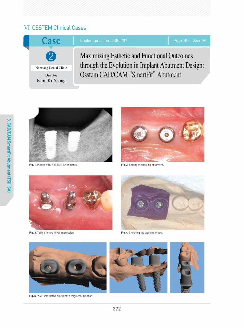
Case
?
3. CAD/CAM Sm
artFit Abutment (TSIII SA)
Age:49, Sex:MImplant position: #36, #37
Namsang Dental Clinic
Director
Kim, Ki-Seong
Maximizing Esthetic and Functional Outcomes
through the Evolution in Implant Abutment Design:
Osstem CAD/CAM “SmartFit”Abutment
Fig. 1. Placed #36, #37 TSIII SA implants. Fig. 2. Setting the healing abutment.
Fig. 3. Taking fixture-level impression. Fig. 4. Checking the working model.
Fig. 5~7. 3D interactive abutment design confirmation.
Ⅵ OSSTEM Clinical Cases
372
6.임상증례345~429(영문) 2013.05.09 2:34 PM 페이지29

OSSTEM IMPLANT SYSTEM
3. CAD/CAM Sm
artFit Abutment (TSIII SA)
Fig. 8~9. Cast-gold and milling abutment limitations were overcome with SmartFit abutment for Osstem implants to which CAD/CAM technology were applied. They were regarded as a good alternative to aesthetic and functional implant restoration.
Fig. 10~11. Abutment positioning. The abutment screw is retightened at least twice at 30Ncm with 10 minutes interval. The abutment margin is exposed using the retraction cord if necessary, and then abutment level impression is made.
Fig. 12~13. Removing the provisional restoration for final restoration delivery.
Fig. 14. Cementation with temporary cement. Fig. 15. Periapical radiograph for checking the residual excess cement.
373
6.임상증례345~429(영문) 2013.05.09 2:34 PM 페이지30

Case
?
3. CAD/CAM Sm
artFit Abutment (TSIII SA)
Age:70, Sex:FImplant position: #35, #36, #37
Yena Dental Clinic
Director
Yang, Choon-Mo
CAD/CAM Guided Flapless Implant
Surgery and Immediate Loading Utilizing
OsstemGuide
Fig. 1. A 70 year old female patient. 3 month healing after extraction of #35 tooth due to root decay.
Fig. 2. Minimal attached gingiva was observed and considerable horizontal alveolar bone resorption was estimated in lower left quadrant.
Fig. 3. 3D planning for OsstemGuide. Fig. 4. Implant replica placed into the sleeves of surgical guide for making working cast.
Fig. 5. Prefabrication of provisional restoration before implant surgery. Fig. 6. Anchored surgical guide in the mouth for flapless implant placement.
Ⅵ OSSTEM Clinical Cases
374
6.임상증례345~429(영문) 2013.05.09 2:34 PM 페이지31

OSSTEM IMPLANT SYSTEM
3. CAD/CAM Sm
artFit Abutment (TSIII SA)
Fig.7. Implants were placed into the computer-planned sites through sleeves of OsstemGuide.
Fig.8. Implants in ideal position and with optimized angulation
Fig. 9. Temporary abutments attached to the implants. Ready to load immediately.
Fig. 10. Immediately loaded screw-retained provisional prosthesis.
Fig. 11. Minimally invasive surgery and immediate loading by prefabricated provisional prosthesis.
Fig. 12. Definite prosthesis delivered after 5 months of loading byprovisional restoration.
Fig. 13. Immediate provisional resin restoration at the day of surgery. Fig. 14. Definite prosthesis after 1 and half year of loading. Noteincreased bone remodeling around implant fixtures.
375
6.임상증례345~429(영문) 2013.05.09 2:34 PM 페이지32

Case
?
3. CAD/CAM Sm
artFit Abutment (TSIII SA)
Age:27, Sex:FImplant position: #11
Seoul Ace Dental Clinic
Director
Park, Hwee-Woong
Restoration of the maxillary anterior
region using the TSIII Implant and
SmartFit Abutment
Fig. 1. Resorption and concavity of the labial side of alveolar ridge wasobserved in the first visit.
Fig. 2. According to the patient, this adhesion bridge had been used for17 years with repeating detachment and reattachment.
Fig. 3. Implant (TSIII SA 4D, 10L) was installed, and synthetic bone (BCP)was grafted in the region with a shortage of alveolar bone mass on thelabial side. Since primary stability was found to be as weak as insertiontorque of 30N cm, which was not enough for immediate restoration, shorthealing abutment was connected and the wound was sutured.
Fig. 4. The picture was taken after placing a fixed temporaryprosthesis by using proximal teeth on the day of its installation
Fig. 5. This picture was taken 3 months after the installation Fig. 6. A fixture-level impression was taken after the second surgeryand the CAD model was generated to produce SmartFit Abutment.
Ⅵ OSSTEM Clinical Cases
376
6.임상증례345~429(영문) 2013.05.09 2:34 PM 페이지33

OSSTEM IMPLANT SYSTEM
3. CAD/CAM Sm
artFit Abutment (TSIII SA)
Fig.7. Fabricated SmartFit Abutment and screw Fig.8. Finished SmartFit Abutment shows a similar shape to that ofnatural abutment teeth.
Fig. 9. A ceramic-veneered zirconia crown was made as a finalprosthesis.
Fig. 10. Soft tissue, which is more similar to natural teeth inanatomical structure and aesthetically better, can be obtained by usingSmartFit Abutment. Moreover, since the margin is formed withconstant depth along the gingiva, it is easy to remove residual cement.A screw hole was formed on the lingual to keep retreivability.
Fig. 11. After placement of the final prosthesis Fig. 12. Periapical radiograph after placement of final prosthesis
377
6.임상증례345~429(영문) 2013.05.09 2:35 PM 페이지34

Case
?
4. Ultra W
ide
Age:62, Sex:MImplant position: #16
All Dental Clinic
Director
Oh, Young-Hak
Wide Diameter Implant Installation
with Sinus Graft
Fig. 1. The patient visited the clinic chiefly complaining of masticationtroubles with food packing problem.
Fig. 2. Pre-operative radiograph of extraction.
Fig. 3. After the extraction. Fig. 4. Periapical radiograph after 3 months of the extraction.
Fig. 5. Photographics of the Intra-oral cavity after 3 months of theextraction. Well-matured soft tissues are shown.
Ⅵ OSSTEM Clinical Cases
378
6.임상증례345~429(영문) 2013.05.09 2:35 PM 페이지35

OSSTEM IMPLANT SYSTEM
4. Ultra W
ide
Fig. 6. Wide implant implantation with sinus graft & GBR (MBCP, Tutoplast & CYTOPLAST).
Fig. 7. 2.5 months after implant placement.
Fig. 8. 4 months after 2nd surgery.
Fig. 9~10. Impression and final prosthesis setting at 6 months after implant placement.
Fig. 11~12. Periapical radiograph at 7 months after implant placement. Well-matured soft tissues are shown.
379
6.임상증례345~429(영문) 2013.05.09 2:35 PM 페이지36
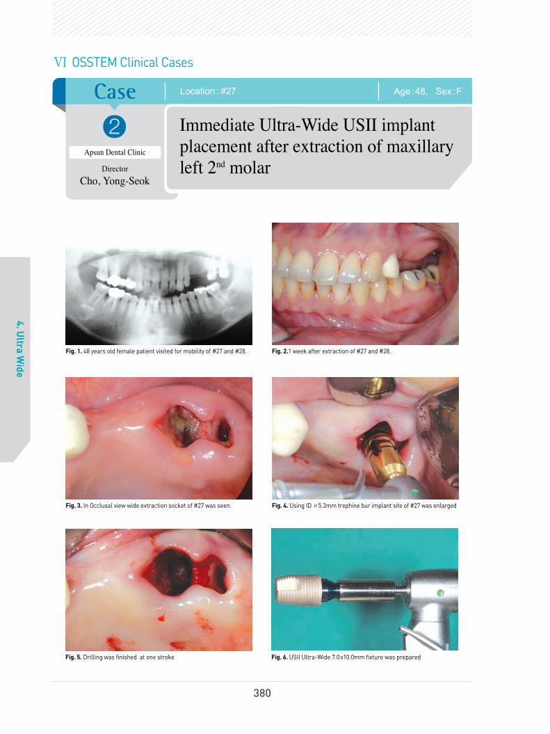
Case
?
4. Ultra W
ide
Age:48, Sex:FLocation : #27
Apsun Dental Clinic
Director
Cho, Yong-Seok
Immediate Ultra-Wide USII implant
placement after extraction of maxillary
left 2nd
molar
Fig. 1. 48 years old female patient visited for mobility of #27 and #28. Fig. 2.1 week after extraction of #27 and #28.
Fig. 3. In Occlusal view wide extraction socket of #27 was seen. Fig. 4. Using ID Ø5.3mm trephine bur implant site of #27 was enlarged
Fig. 5. Drilling was finished at one stroke Fig. 6. USII Ultra-Wide 7.0x10.0mm fixture was prepared
Ⅵ OSSTEM Clinical Cases
380
6.임상증례345~429(영문) 2013.05.09 2:35 PM 페이지37

OSSTEM IMPLANT SYSTEM
4. Ultra W
ide
Fig. 7. USII Ultra-Wide 7.0x10.0mm fixture was installed at #27 Fig. 8. GSII 4.0x11.5mm fixture was installed at #25 with flapless surgery
Fig. 9. After healing abutment connection flap was approximated with interrupted sutures
Fig. 10. POP Standard X-ray view showed well positioned implants
Fig. 11. Clinical photo of 4 years and 9 months after bridge delivery Fig. 12. Standard X-ray of 4 years and 9 months after bridge delivery
381
6.임상증례345~429(영문) 2013.05.09 2:35 PM 페이지38

Case
?
4. Ultra W
ide
Age:54, Sex:FLocation : #46, 47
Seoul National University
Bundang Hospital
Professor
Kim,Young-Kyun
Yi, Yang-Jin
GSII Ultra-Wide in the mandibular
posterior region
Fig. 1. Initial panoramic radiograph. one month after extraction of the teeth(#46, 47)
Fig. 2. Elevated flap
Fig. 3. Implant installed(GSII Ultra-Wide 6D/6L)
Fig. 4. Panoramic radiograph after the implant installation Fig. 5. Periapical radiograph 10 days after the implant installation
Ⅵ OSSTEM Clinical Cases
382
6.임상증례345~429(영문) 2013.05.09 2:35 PM 페이지39

OSSTEM IMPLANT SYSTEM
4. Ultra W
ide
Fig. 8. Periapical radiograph 14 months after the placement of final prosthesis
Fig. 6. Periapical radiograph after the second surgery. The secondsurgery was performed 3.5 months after the implant installation.
Fig. 7. Periapical radiograph three weeks after placement of the final prosthesis
383
6.임상증례345~429(영문) 2013.05.09 2:35 PM 페이지40

Case
?
4. Ultra W
ide
Age:58, Sex:FA case of a partial edentulous mandible : #36-37, 46-47
Seoul National University
Bundang Hospital
Professor
Kim,Young-Kyun
Yi, Yang-Jin
Short and Ultra-Wide implants (TSIII, GSII)
were installed in the mandibular molar
position on both sides
Fig. 1.
Initial panoramic radiograph Fig. 2. Implants were installed in positions #36 and 37 (#36 : TSIII SA4.5D/7L, #37: GSII Ultra-Wide 6D/6L). About 2mm of the thread wasexposed on buccal side.
Fig. 3. Bone graft was performed by using autologous tooth bone chips(AutoBT chips : Korea Tooth bank Co, Seoul, Korea) made from extractedteeth from the mandibular right posterior region.
Fig. 4. Panoramic radiograph after the implant installation
Fig. 5. Periapical radiograph after the second surgery. Fig. 6. Periapical radiograph one year after placing the final prosthesis
Ⅵ OSSTEM Clinical Cases
384
6.임상증례345~429(영문) 2013.05.09 2:36 PM 페이지41

OSSTEM IMPLANT SYSTEM
4. Ultra W
ide
Fig. 15. Periapical radiograph after the second surgery
Fig. 7. Flap elevation performed on positions #45 ~ 47for vertical ridge augmentation. Autogenous tooth bonegraft chips (AutoBT chips) were produced fromextracted teeth from positions #46, 47 and 48, sevenweeks ahead of the grafting surgery.
Fig. 8. Vertical ridge augmentation was performed byusing autogenous tooth bone graft chips, and the areawas covered with a resorbable collagen membrane(Ossix plus).
Fig. 9. A panoramic radiograph after a verticalridge augmentation in the mandibular right molar.
Fig. 10. A flap elevation was done six weeksafter the bone graft for the implant installation.The bone healing was observed in fairly goodcondition.
Fig. 11. Implants (#45 : TSIII SA, 4D/7L, #46 : TSIIISA 5D/7L, #47 : TSIII Ultra-Wide 6D/6L) wereinstalled.
Fig. 12. Bone graft chips (Bio-Oss) weresupplemented around the implant, and the areawas covered with a titanium mesh.
Fig. 16. Periapical radiograph six months after placing the final prosthesis
Fig. 13. Panoramic radiograph after implant installation Fig. 14. The flap elevation was done three months after the implantinstallation to expose the implant
385
6.임상증례345~429(영문) 2013.05.09 2:37 PM 페이지42

Case
?
4. Ultra W
ide
Age:67, Sex:MLocation : #47
Seoul Dental Clinic
Director
Lee, Dae-Hee
A case of a GSIII Ultra-Wide installation five
months after a bone graft in the mandibular second
molar tooth by using an artificial bone graft
Fig. 1. Since the bone was not regenerated even one year after the extraction in the mandibular second molar tooth, guided bone regeneration (GBR)was performed by using synthetic bone.
Ⅵ OSSTEM Clinical Cases
386
6.임상증례345~429(영문) 2013.05.09 2:37 PM 페이지43

OSSTEM IMPLANT SYSTEM
4. Ultra W
ide
Fig. 3. A final prosthesis was placed after using a temporary prosthesis for a certain amount of period.
Fig. 2. A GSIII Ultra-Wide implant was installed four months later, after confirming the newly generated bone tissue.
Fig. 4. A stable bone reaction was observed in this picture taken five years after the final prosthesis treatment.
387
6.임상증례345~429(영문) 2013.05.09 2:37 PM 페이지44

Case
?
5. TSIV SA
Age:28, Sex:FImplant position: #47
Acro Dental Clinic
Director
Oh, Sang -Yoon
My Favorite Immediate Implantation
Technique Using Osstem Implant
TSIV SA
Fig. 1. A preop. X-ray (CT Coronal section View). Fig. 2. Preoperative intraoral view (#47).
Fig. 3~4. Immediate implantation (TSIV Ø5.0 x 11.5mm). Easy to initial stabilization by abrupt tapered design.Excellent self tapping capacity by deep & sharp cutting edge. Minimum trauma to the lingual concavity & inferior alveolar canal by pointed apex design.
Fig. 5. Bone graft & healing abutment connection.PRF for Surgical isolation.
Fig. 6. Circular approximation.Good healing ; Fast biological secondary stability by TS SA surface.
TS IV
Ⅵ OSSTEM Clinical Cases
388
6.임상증례345~429(영문) 2013.05.09 2:37 PM 페이지45

OSSTEM IMPLANT SYSTEM
5. TSIV SA
Fig. 7. Postoperative panoramic view. Fig. 8. 4 months later.Tissue molding by healing abutment.
Fig. 9. Final prosthesis.Harmonious gingival line & profile.
Fig. 10. Panoramic view after final prosthesis.
Fig. 11. 6 months later.Maintain occlusal stability by no sinkdown.
Fig. 12. 6 months later.Natural gingival line & profile.
Fig. 13~14. 6 months later follow up CT (Coronal section view).
389
6.임상증례345~429(영문) 2013.05.09 2:37 PM 페이지46

Case
?
5. TSIV SA
Age:51, Sex:MImplant position: #11, #21
Apsun Dental Clinic
Director
Cho, Yong-Seok
Immediate Implant Placement of
TSIV SA Fixtures after Extraction of
Both Maxillary Central Incisores
Fig. 1. 51 years old female visited my clinic for the mobility andesthetic problem of both maxillary central incisors.
Fig. 2. In Standard X-ray view, both teeth received endodontic treatmentbefore and involved in periodontitis with severe bone destruction.Immediate implantation after extraction of the both teeth was planned.
Fig. 3~4. After extraction of the teeth throughout curettage was performed. Loss of the labial bone plate was observed.
Fig. 5~6. After drilling at patatal side of the extraction sockets TSIV SA Ø4.5x11.5mm were installed. Initial torque was over 40Ncm and ISQ value was 73/74 each.
Ⅵ OSSTEM Clinical Cases
390
6.임상증례345~429(영문) 2013.05.09 2:38 PM 페이지47

OSSTEM IMPLANT SYSTEM
5. TSIV SA
Fig. 7~9. Non functional immediate restoration was tried. Rigid abutments are connected on the fixtures with 30Ncm and allogenic bone graft material (SureOss 0.2cc+0.2cc) was grafts on labial bone defect. Temporary bridge was fabricated and delivered with out ofocclusion. POP Standard X-ray shows well positioned TSIV SA fixtures.
Fig. 10~11. 5 months after temporarization patient visited with good gingival health condition. After impression taking cementation type crowns are fabricated over customized abutments.
Fig. 12~13. Both crowns are delivered using a temporary cement. They showed harmonized crown and soft tissue.
Fig. 14. Final Standard X-ray shows good osseointegration of the fixtures. However coronal bone remodeling is not finished yet.
391
6.임상증례345~429(영문) 2013.05.09 2:38 PM 페이지48

Fig. 5. After the bone graft around the implants using autogenous toothbone chips. The wound was sutured after covering it with a resorbablecollagen membrane (collagide).
Fig. 6. Panoramic radiograph after implant installation
Case
?
5. TSIV SA
Age:40, Sex:MLocation : #16, 17
Seoul National University
Bundang Hospital
Professor
Kim,Young-Kyun
Yi, Yang-Jin
Installation of TSIV SA implant at right
maxillary molar tooth region
Fig. 1. Initial panoramic radiograph. Autogenous tooth bone graft chips(AutoBT chips) were produced from the extracted teeth from positions#16, 18 and 48, two months ahead of the grafting surgery.
Fig. 2. Initial CT scan image
Fig. 3. A flap elevation was performed. Severe bone loss was observedin the area where the implant was to be installed.
Fig. 4. After the implant installation (TSIV, #16 : 5D/11.5L, #17 : 5D/10L). A small amount of autogenous tooth bone chips were grafted during themaxillary sinus lift by using a crestal approach, and the implants wereinstalled simultaneously. Primary stability measured by the Osstell Mentor(Integration Diagn osticsAB, Goteberg, Sweden) were 59 ISQ for position #16and 62 ISQ for position #17, respectively.
Ⅵ OSSTEM Clinical Cases
392
6.임상증례345~429(영문) 2013.05.09 2:38 PM 페이지49

OSSTEM IMPLANT SYSTEM
5. TSIV SA
Fig. 9. Periapical panoramic radiograph after the second surgery Fig. 10. Periapical radiograph 6 months after the final placement of the prosthesis
Fig. 7. The implant was exposed by the flap elevation after 3.5 months.Peri-implant bone defect healed well, and the secondary stabilityvalues of the implants measured by the Osstell Mentor were 63 ISQ forposition #16 and 57 ISQ for position #17, respectively.
Fig. 8. Periapical radiograph after the second surgery
393
6.임상증례345~429(영문) 2013.05.09 2:38 PM 페이지50

Case
?
6. TSII SA
Age:41, Sex:MImplant position: #35, #37
Yena Dental Clinic
Director
Yang, Choon-Mo
Non Submerged Placement of
Osstem TSII SA Implant
Fig. 1. A 41 year old male patient. Panoramic view prior to implanttherapy in the lower left quadrant. Upper left premolar and molar teethwere extruded because of being free from occlusion for a long time.
Fig. 2. Oral view of soft and hard tissue before treatment.
Fig. 3. View of surgical site. Minimal attached gingiva was observed in the molar region.
Fig. 4. Finished osteotomy. The bone density was evaluated as normal.
Fig. 5. Implant insertion. Msio-distal and bucco-lingual angulation ofeach fixture(TSII SA Ø4.5X10mm) was evaluated.
Fig. 6. Platform of each implant was located subcrestally.
Ⅵ OSSTEM Clinical Cases
394
6.임상증례345~429(영문) 2013.05.09 2:38 PM 페이지51

OSSTEM IMPLANT SYSTEM
6. TSII SA
Fig. 7. The insertion-torque was 22Ncm to the site #35 and 18Ncm tothe site #37 fixture by machine. The transmucosal healing abutmentswere connected.
Fig. 8. Panoramic view of post-operative result.
Fig. 9. Intra-oral periapical radiograph after implant placement. Fig. 10. All-zirconia bridge (Prettau zirconia of zirkonzahn) supported by two implants.
Fig. 11~12. Cement-retained fixed partial denture was delivered at 10weeks after implantation.
Fig. 13. Follow-up radiograph at 3 months after functional loading.
395
6.임상증례345~429(영문) 2013.05.09 2:38 PM 페이지52

Case
?
7. SSII SA
Age:53, Sex:MImplant position: Multi.
Namsang Dental Clinic
Director
Kim, Ki-Seong
A Clinical Case of Osstem Implant
Placement with Maxillary Sinus Augmentation
by Lateral Window Technique
Fig. 1. Multiple teeth with deep caries and severe periodontitis were extracted.
Fig. 2. TSIII SA fixtures were placed in #15, #45, #46, #47 missingarea. Maxillary Sinus Graft procedure in Rt. & Lt. sides was done withlateral window technique.
Fig. 3~4. At Four months after sinus graft procedure, SSII SA fixtures were planned to be placed in #16 and #17 missing area.
Fig. 5. Sufficient bone volume was acquired in both sides of sinus cavity. Fig. 6. SSII SA fixtures were placed with minimal flap incision.
Ⅵ OSSTEM Clinical Cases
396
6.임상증례345~429(영문) 2013.05.09 2:38 PM 페이지53

OSSTEM IMPLANT SYSTEM
7. SSII SA
Fig. 7~8. Flap was sutured. Well-positioned SSII SA fixtures were shown in radiographic finding.
Fig. 9~10. Excellent solid abutments were connected with repeated 30Ncm tightening and an abutment level impression was made by using impression copings.
Fig. 11~12. Final treatment outcome at 8 months after the final crown placement.
Fig. 13. Panoramic view at 12 months after the final crown placement. Bone level around placed SA fixtures was maintained stably.
397
6.임상증례345~429(영문) 2013.05.09 2:38 PM 페이지54

Case
8. TS III HA
Age:46, Sex:FImplant position: #26,#27
Immediate Loading Using TSIII HA
Implants in Maxillary Posterior Area
Fig. 1. Initial panoramic radiograph of 46-year old female patient. Left maxillary 2nd premolar and 1st molar were lost.
Fig. 2. Preoperative intraoral occlusal view.
Fig. 3. Preoperative intraoral buccal view. Fig. 4. Two Osstem TSIII HA implants(#25:4.5D/10L, #26:5D/10L) were installed.
Fig. 5. Postoperative intraoral occlusal view. Fig. 6. Postoperative intraoral buccal view.
?Seoul National University
Bundang Hospital
Professor
Kim, Young-Kyun
Ⅵ OSSTEM Clinical Cases
398
6.임상증례345~429(영문) 2013.05.09 2:38 PM 페이지55

OSSTEM IMPLANT SYSTEM
8. TS III HA
Fig. 7. Postoperative panoramic radiograph. Fig. 8. Periapical radiograph 10 days after implant placement.Immediate loading was performed.
Fig. 9. Periapical radiograph 3 months after immediate loading. Fig. 9. Periapical radiograph 6 months after immediate loading. Final prosthesis was delivered.
Fig. 11. Periapical radiograph 9 months after immediate loading. Fig. 11. Periapical radiograph 12 months after immediate loading.Crestal bone level was stable.
399
6.임상증례345~429(영문) 2013.05.09 2:38 PM 페이지56

Case
8. TS III HA
Age:27, Sex:FLocation: #25, 26
Immediate loading was applied right after the
implant installation, accompanied with a guided
bone regeneration in the maxillary molar region.
Fig. 1. Initial panoramic radiograph. The picture was taken one monthafter extracting teeth #25 and 26.
Fig. 2. Intra-oral view one month after the teeth extraction
Fig. 3. After flap elevation Fig. 4. Implants (TSIII HA, #25 : 4.5D/10L, #26 : 5D/10L) were installedand connected with healing abutment.
Fig. 5. Autogenous tooth bone chips made from patient's ownextracted teeth were grafted in the perio-implant defects.
Fig. 6. The wound was sutured.
?Seoul National University
Bundang Hospital
Professor
Kim,Young-Kyun
Yi, Yang-Jin
Ⅵ OSSTEM Clinical Cases
400
6.임상증례345~429(영문) 2013.05.09 2:38 PM 페이지57

OSSTEM IMPLANT SYSTEM
8. TS III HA
Fig. 7. Panoramic radiograph after the implant installation Fig. 8. Periapical radiograph two weeks after the immediate loading
Fig. 9. Periapical radiograph one year after placing the final prosthesis,and 1 year and 6 months after immediate loading
401
6.임상증례345~429(영문) 2013.05.09 2:38 PM 페이지58

Case
?
8. TS III HA
Age:58, Sex:MImplant location: #16 TS III HA 5.0 x10 mm
Seoul Dental Clinic
Director
Lee, Dae-Hee
Case of reconstruction by using TSIII HA
implants after vertical ridge augmentation
in maxillary right molar region.
Fig. 1. A residual root was observed in the maxillary right first molar. Fig. 2. No new bone generation was observed in the extraction socketeven three months after removing the residual root.
Fig. 3. Especially, the palatal side showed worse bone regenerationcompared to other regions.
Fig. 4. The bone graft was performed using allogenic bone.
Fig. 5. Guided bone regeneration was performed by using Cytoplast membrane
Fig. 6. The wound was sutured without tension.
Ⅵ OSSTEM Clinical Cases
402
6.임상증례345~429(영문) 2013.05.09 2:38 PM 페이지59

OSSTEM IMPLANT SYSTEM
8. TS III HA
Fig. 9. Implant (TSIII HA 5.0x10mm) was installed after about four months. Fig. 10. The picture was taken after placing the final prosthesis.
Fig. 7. The membrane was exposed partially after about three weeks. Fig. 8. According to an open membrane technique, the wound wasstitched with a resorbable suture after removing the membrane.
403
6.임상증례345~429(영문) 2013.05.09 2:38 PM 페이지60

Case
?
8. TS III HA
Age:73, Sex:MLocation : # 26
Seoul Dental Clinic
Director
Lee, Dae-Hee
Case of restoration TSIII HA implant
installation accompanied with a sinus bone
graft after removal of a ailing implant
Fig. 1.
Initial panoramic radiograph. Prosthetic treatment wasperformed with three implants about six years ago.
Fig. 2. The patient was complaining about block mobility around thebridge on the first visit. After all three implants were confirmed ashaving failed, they were removed. Two implants were installed afterensuring that there was no perforation on the sinus membrane.
Fig. 3. Though a 3-init temporary bridge was applied by using twoimplants, it was removed due to the patient's complaint of soreness.
Fig. 4. A percussion test was performed in the suspicious area for amore definite diagnosis.
Fig. 5. The ailing fixture was removed and the lateral window wasperformed for the lateral approach.
Fig. 6. The sinus membrane was detached.
Ⅵ OSSTEM Clinical Cases
404
6.임상증례345~429(영문) 2013.05.09 2:40 PM 페이지61

OSSTEM IMPLANT SYSTEM
8. TS III HA
Fig. 9. The implant was installed using a single stage method, and thelateral window was closed with collagen membrane.
Fig. 12. This radiograph was taken right after placing the finalprosthesis about four months later.
Fig. 11. This radiograph was right after the TSIII HA implantinstallation and procedure on the sinus.
Fig. 7. A bone graft was performed in the lesion made by the detachedsinus membrane.
Fig. 8. TSIII HA 4.5x10mm implant was installed in position #26.
Fig. 10. A TSIII HA implant was installed, performing bone graft in themaxillary sinus widened buccolingually.
405
6.임상증례345~429(영문) 2013.05.09 2:40 PM 페이지62

Case
?
8. TS III HA
Age:65, Sex:MLocation : # 16
Seoul Dental Clinic
Director
Lee, Dae-Hee
A case of reconstruction using a TSIII HA implant
after the ridge augmentation with allogenic bone
block in the maxillary right molar region.
Fig. 1. This patient was transferred for a vertical bone graft in themaxillary right molar region.
Fig. 2. A bone graft was performed by using an allogenic bone block,but it was broken during the fixing procedure using a GBR screw dueto a thin cortical part.
Fig. 3. The grafted block was fixed with collagen membrane and GBRpin, and Bellafuse allogeneic bone was inserted on top of the graftbecause thin cortical bone layer could cause massive bone resorption.
Fig. 4. Radiograph after allogeneic block bone graft.
Fig. 5. The Bellafuse allogeneic bone was necrotized about 5 months later. Fig. 6. However, the allogenic bone block on the bottom was takenfairly well without any presence of bone absorption.
Ⅵ OSSTEM Clinical Cases
406
6.임상증례345~429(영문) 2013.05.09 2:40 PM 페이지63

OSSTEM IMPLANT SYSTEM
8. TS III HA
Fig. 9. The picture was taken after placing the final prosthesis aboutthree months later.
Fig. 7. TSIII HA implant (5.0x10mm) was installed in position #16. Fig. 8. The picture shows the installed implant by using a single stageprocedure.
407
6.임상증례345~429(영문) 2013.05.09 2:41 PM 페이지64

Case
?
9. CAS KIT
Age:64, Sex:FImplant position: #26, #27
Apsun Dental Clinic
Director
Cho, Yong-Seok
Sinus Lift Using the CAS-KIT and
Implantation of the TSIII HA Fixtures at
Lt Maxillary Molars
Fig. 1. 64 years old female visited my clinic to receive implants. Sheextracted #27 3 months ago for the mobility of the tooth after bridge cutting.Excessive occlusal clearance due to vertical bone loss was observed.
Fig. 2. In Panoramic view, resibual alveolar bone heights of #26, 27 are not clear and bone density seems very poor.
Fig. 3. In Conebeam CT view, it is difficult to measure the remaining bone height because of unclear alveolar bone crest. The sinusshows in healthy condition.
Fig. 4. Bone exposed after elevation of the mucoperiosteal flap. Bone healing of #27 site which involved in periodontitis looks very poor even 3months after extraction.
Fig. 5. The remaining bone height of #26 was sufficient and #27 was not.Sinus lift procedure was performed at #27 site using the CAS-KIT. Hydraulicmembrane lifting procedure was done after penetration of the sinus floor.
Fig. 6. Allogenic bone substitute (SureOss 0.5cc) was grafted.
Ⅵ OSSTEM Clinical Cases
408
6.임상증례345~429(영문) 2013.05.09 2:41 PM 페이지65

OSSTEM IMPLANT SYSTEM
9. CAS KIT
Fig. 14. Standard X-ray view after cementation of the final bridge. Fig. 15. The Panoramic view shows sinus floor remodeling of the #27i.
Fig. 7. After bone graft TSIII HA Ø4.5x10.0mm fixtures were installed.Because of poor bone quality insertion torques were under 10Ncm,and ISQ value was measured as 56/58 and 48/55 each.
Fig. 8. After minor autogenic bone graft around #27i bone defect 1-stage surgery was done by connecting healing abutments.
Fig. 9. POP Panoramic view shows well positioned #26i, 27i. Welldefined dome shaped bone grafting is seen at the apex of #27i.
Fig. 11~12. he rigid abutments are connected 6 months after operation and the temporary bridge was delivered.
Fig. 13. Final restoration was delivered 7 months after operation.
Fig. 10. POP CT shows successful sinus bone grafting of#27i using the CAS-KIT without membrane perforation.
409
6.임상증례345~429(영문) 2013.05.09 2:41 PM 페이지66

Case
?
9. CAS KIT
Age:66, Sex:MImplant position: #26
Seoul Dental Clinic
Director
Lee, Dae-Hee
Use of GSIII short implant instead of
sinus surgery
Fig. 1~2. This patient had suffered from cerebral stroke and its complications. His chief complaint was food packing under the pontic side of left upper implant-supported bridge area.
Fig. 3. Flapless surgery was done for the patient’s convenience. Fig. 4. CAS drill of Osstem was used to shaving the sinus floor for bi-cortical engagement of fixture.
Fig. 5. 6mm short GSIII fixture was installed. Fig. 6. Healing abutment was fastened and suture was not practiced.
Ⅵ OSSTEM Clinical Cases
410
6.임상증례345~429(영문) 2013.05.09 2:41 PM 페이지67

OSSTEM IMPLANT SYSTEM
9. CAS KIT
Fig. 7. Fixture was successfully engaged not to touch the thickened sinus membrane.
Fig. 8. After the period of provisional restoration.
Fig. 9. Gold bridgework was delivered. Plaque control was poor due to the hemiparalysis of right side from stroke.
Fig. 10. This picture shows the final appearance after bridgework.
411
6.임상증례345~429(영문) 2013.05.09 2:41 PM 페이지68

Case
?
10. LAS KIT
Age:56, Sex:MLocation: #24, 27
Apsun Dental Clinic
Director
Cho, Yong-Seok
Left maxillary sinus bone graft using
LAS-KIT and simultaneous
Implant placement
Fig. 1. 56 years old male patient visited to place the implant at missing site of #24, 25, 26, 27
Fig. 2. Preoperative panoramic view shows remaining bone height of the left maxillary sinus about 3.0 mm
Fig. 3. Preoperative CT view shows remaining bone height about 2.0 to 3.0mm and relatively thick lateral sinus wall.
Fig. 4. Lateral wall of the left maxillary sinus was exposed aftermucoperiosteal flap elevation
Fig. 5. Grind the lateral sinus wall using the Ø7.0mm LAS Core drill with 1.5mm stopper but sinus membrane was not exposed. After using Ø7.0mm Core drill with 2.0mm stopper sinus membrane was showed through.
Ø7.0mm Core drill with 1.5mm stopper
Ø7.0mm Core drill with 2.0mm stopper
Ⅵ OSSTEM Clinical Cases
412
6.임상증례345~429(영문) 2013.05.09 2:41 PM 페이지69

OSSTEM IMPLANT SYSTEM
10. LAS KIT
Fig. 11. Panoramic view after the bridge delivery
Fig. 6. Bone core was detached and sinus membrane was elevated using the membrane separator and elevator
Fig. 7. After bone graft TSIII SA 4.5x10.0mm and 4.5x10.0mm fixtures were installed
Fig. 9. POP CT view shows successful sinus bone graft Fig. 10. Bridge was delivered 6 months after the implant installation
Fig. 8. Bone core was repositioned
413
6.임상증례345~429(영문) 2013.05.09 2:41 PM 페이지70

Case
?
10. LAS KIT
Age:57, Sex:FLocation: #16, 17
Apsun Dental Clinic
Director
Cho, Yong-Seok
Right sinus bone graft using LAS-KIT
and simultaneous implant placement
Fig. 1. 57 years old female patient visited to place the implant at missing site of #16, 17
Fig. 2. Preoperative panoramic view shows remaining bone height of the right maxillary sinus about 2.0 mm
Fig. 3. Preoperative CT view shows remaining bone height about 1.0 to 20mm and thin lateral sinus wall.
Fig. 4. Lateral wall of the right maxillary sinus was exposed aftermucoperiosteal flap elevation
Fig. 5. Grind the lateral sinus wall using the Ø7.0mm LAS Core drill with 1.0mm stopper .
Fig. 6. After using Ø7.0mm Core drill with 1.0mm stopper sinusmembrane was showed through.
Ⅵ OSSTEM Clinical Cases
414
6.임상증례345~429(영문) 2013.05.09 2:42 PM 페이지71

OSSTEM IMPLANT SYSTEM
10. LAS KIT
Fig. 7. Bone core was detached and sinus membrane was elevatedusing the membrane separator and elevator
Fig. 8. After bone graft TSIII SA 4.5x10.0mm fixtures were installed
Fig. 9. POP Panoramic view shows successful sinus bone graft
Fig. 9. Panoramic view after the bridge delivery
Fig. 10. Bridge was delivered 8 months after the implant installation
415
6.임상증례345~429(영문) 2013.05.09 2:42 PM 페이지72

Case
11. MS
Age:72, Sex:MImplant position: #33, 43
Overdenture Treatment Using Two
MS Port Implants in the Severely
Atrophic Mandible
Fig. 1. Initial intra-oral view. Since long-term use of the completedenture caused repeated ulcerative lesions on the oral floor and thepatient was complaining of pressure pains on mental foramen on bothsides when wearing the denture, it was very hard to apply routinetreatment for the complete denture.
Fig. 2. Initial panoramic radiograph. Severe mandibular atrophy wasobserved and the mental foramen was located close to the alveolarcrest. Since there was a risk of a mandibular bone fracture during theimplant installation and the patient's general health condition waspoor, it was considered that guided bone regeneration or installation ofan implant with a common diameter size would not be appropriate inthis case. Therefore, we planned to apply an overdenture afterinstalling two mini implants in order to minimize complications.
Fig. 3. An MS port implant with diameter of 2.5mm and length of 8.5mm Fig. 4. Two MS port implants were installed by using the minimalinvasive approach.
Fig. 5. The wound was sutured after covering it with a cap. Fig. 6. Panoramic radiograph after the implant installation
?Seoul National University
Bundang Hospital
Professor
Kim,Young-Kyun
Yi, Yang-Jin
Ⅵ OSSTEM Clinical Cases
416
6.임상증례345~429(영문) 2013.05.09 2:42 PM 페이지73

OSSTEM IMPLANT SYSTEM
11. MS
Fig. 7. Periapical radiograph 2 weeks after the implant installation Fig. 8. Panoramic radiograph 2 months after the implant installation
Fig. 9. Intra-oral view after functional use of the overdenture for five months Fig. 10. Intraoral view of the overdenture 5 months of functional use.
Fig. 11. Lateral view before and after placing the overdenture
Fig. 12. Panoramic radiograph 1 year and 6 months after placing the overdenture
417
6.임상증례345~429(영문) 2013.05.09 2:42 PM 페이지74

Case
?
11. MS
Age:41, Sex:MLocation: #41
Apsun Dental Clinic
Director
Cho, Yong-Seok
A case of an MS implant installed right
after extracting the mandibular central
incisors that broken in an injury
Fig. 1. 41 years old male patient visited for mobility of #41 after trauma Fig. 2. Standard X-ray view showed fractured #41
Fig. 3. Extraction of #41 Fig. 4. Using Ø2.3 twist drill implant site was enlarged
Fig. 5. After drilling MS 3.0x13mm fixture was installed Fig. 6. Insertion torque was about 30 Ncm
Ⅵ OSSTEM Clinical Cases
418
6.임상증례345~429(영문) 2013.05.09 2:42 PM 페이지75

OSSTEM IMPLANT SYSTEM
11. MS
Fig. 7. In occlusal view abutment of the MS fixture was positionedobliquely considering crowding of adjacent teeth
Fig. 8. Immediate after implant installation temporary crownd wasfabricated using a temporary cap and delivered
Fig. 9. POP Standard X-ray view showed good position of MS implant
Fig. 11. Standard X-ray of 4 years after crown delivery
Fig. 10. Clinical photo of 4 years after crown delivery
419
6.임상증례345~429(영문) 2013.05.09 2:42 PM 페이지76

Case
?
11. MS
Age:51, Sex:FLocation: #41
Apsun Dental Clinic
Director
Cho, Yong-Seok
MS implants were installed immediately
after extracting both the lower central
incisors affected by periodontal disease
Fig. 1. 51 years old female patient visited for mobility and gingival recessionof #31. The degree of mobility were grade 3 in #31 and gerade 1 in #41
Fig. 2. In Occlusal view #31 was labially protruded
Fig. 3. Standard X-ray view showed severe alveolar bone reposition of#31.and moderate bone reposition of #41
Fig. 4. Both #31 and #41 were extracted. Using Ø1.8 twist drill #41 implant site was enlarged
Fig. 5. After drilling MS 2.5x13mm fixture was installed at #41 Fig. 6. Controlled depth of the fixture
Ⅵ OSSTEM Clinical Cases
420
6.임상증례345~429(영문) 2013.05.09 2:42 PM 페이지77
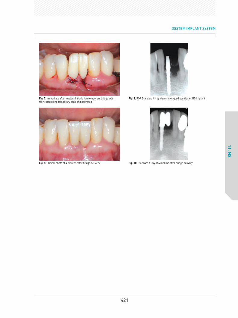
OSSTEM IMPLANT SYSTEM
11. MS
Fig. 7. Immediate after implant installation temporary bridge wasfabricated using temporary caps and delivered
Fig. 8. POP Standard X-ray view shows good position of MS implant
Fig. 9. Clinical photo of 4 months after bridge delivery Fig. 10. Standard X-ray of 4 months after bridge delivery
421
6.임상증례345~429(영문) 2013.05.09 2:42 PM 페이지78

Case
?
12. GS III
Age:54, Sex:MLocation : multiple, maxilla and mandible
Seoul Dental Clinic
Director
Lee, Dae-Hee
Full-mouth reconstruction by using a
GSIII implant I
Fig. 1. The patient with a completely edentulous maxilla and partially edentulous mandible asked for a fixed-type complete prosthesis supported by an implant.
Fig. 2. The GSIII implant was installed right after extracting the teeth and immediate loading was applied simultaneously.
Fig. 3. Full-mouth implant installation was performed in the mandible on the day of placing temporary fixed-type prosthesis in the maxilla.
Fig. 4. A sinus lift and overall bone graft were performed at the same time.
Ⅵ OSSTEM Clinical Cases
422
6.임상증례345~429(영문) 2013.05.09 2:43 PM 페이지79

OSSTEM IMPLANT SYSTEM
12. GS III
Fig. 5. This picture was taken after finishing the prosthetic treatment in the mandible and placing temporary teeth in the maxilla.
Fig. 7. After placing the final prosthesis
Fig. 6. One more implant was installed additionally in the right side ofthe maxilla while placing the temporary teeth.
423
6.임상증례345~429(영문) 2013.05.09 2:44 PM 페이지80

Case
?
12. GS III
Age:66, Sex : FLocation : multiple, maxilla and mandible
Seoul Ace Dental Clinic
Director
Park, Hwee-Woong
Full-mouth reconstruction by using a
GSIII implant II
Fig. 1. Initial condition. There was mobility in theposterior region of the maxilla and mandible aswell as severe resorption of the alveolar ridge inthe edentulous region.
Fig. 2. Initial panoramic radiograph Fig. 3. An intermaxillary jaw relation was takenfor mounting a diagnostic model of the maxillaand mandible.
Fig. 4. Mounted models of the maxilla andmandible showed severe vertical and horizontalbone resorption in the molar region.
Fig. 5. Implants were installed in the molar region afterextracting the premolar teeth showing poor prognosis.A sinus lift and bone graft were performed in themaxilla by using a crestal approach with simultaneousinstallation of GSIII implants, and healing abutmentwas connected using a single stage method after theimplant installation in the mandible. Periodontaltreatment and a root canal treatment were performedin the posterior resin of the mandible and maxilladuring the healing period for the osseointegration.
Fig. 6. Transfer abutment was connected to themandibular molar region two months after theimplant installation and a temporary prosthesiswas installed.
Fig. 7. Transfer abutment was connected to themaxillary molar region four months after theimplant installation and a temporary prosthesiswas installed.
Fig. 8. After placing the temporary fixedprosthesis in the maxilla and mandible, anocclusal balance was established.
Fig. 9. MS implants were installed immediatelyafter extracting the upper central incisors affectedby periodontal disease so that the installed implantscould support the temporary fixed prosthesis.
Ⅵ OSSTEM Clinical Cases
424
6.임상증례345~429(영문) 2013.05.09 2:44 PM 페이지81
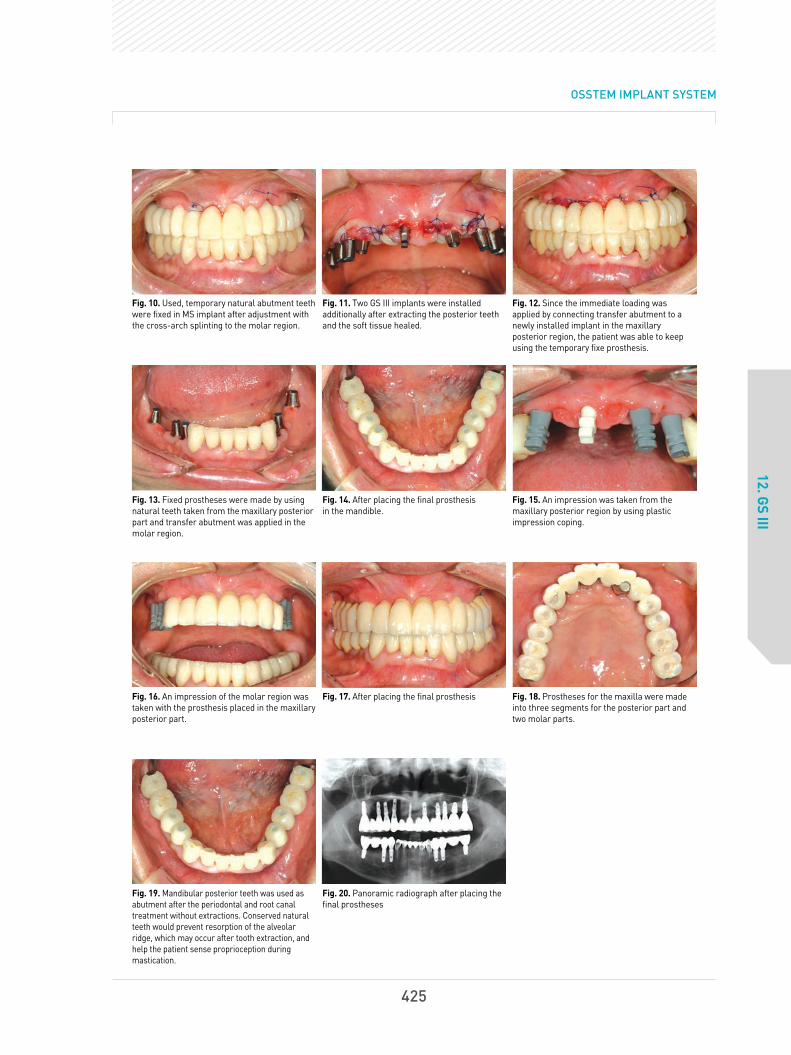
OSSTEM IMPLANT SYSTEM
12. GS III
Fig. 10. Used, temporary natural abutment teethwere fixed in MS implant after adjustment withthe cross-arch splinting to the molar region.
Fig. 11. Two GS III implants were installedadditionally after extracting the posterior teethand the soft tissue healed.
Fig. 12. Since the immediate loading wasapplied by connecting transfer abutment to anewly installed implant in the maxillaryposterior region, the patient was able to keepusing the temporary fixe prosthesis.
Fig. 13. Fixed prostheses were made by usingnatural teeth taken from the maxillary posteriorpart and transfer abutment was applied in themolar region.
Fig. 14. After placing the final prosthesis in the mandible.
Fig. 15. An impression was taken from themaxillary posterior region by using plasticimpression coping.
Fig. 16. An impression of the molar region wastaken with the prosthesis placed in the maxillaryposterior part.
Fig. 17. After placing the final prosthesis Fig. 18. Prostheses for the maxilla were madeinto three segments for the posterior part andtwo molar parts.
Fig. 19. Mandibular posterior teeth was used asabutment after the periodontal and root canaltreatment without extractions. Conserved naturalteeth would prevent resorption of the alveolarridge, which may occur after tooth extraction, andhelp the patient sense proprioception duringmastication.
Fig. 20. Panoramic radiograph after placing thefinal prostheses
425
6.임상증례345~429(영문) 2013.05.09 2:44 PM 페이지82

Case
?
13. HS II
Age:40, Sex:MLocation: #45, 46
Chungbuk National
University Hospital
Professor
Kim, Kyeong-won
Delayed installation of an implant after extraction
of the lower molar teeth followed by a ramal block
bone graft in the mandibular posterior region
Fig. 1. Initial panoramic radiograph. Severe bone loss was observed in position #47.
Fig. 2. Panoramic radiograph after extraction of tooth #47
Fig. 3. Taking ramal block bone Fig. 4. Ramal block bone applied to a bony defect area.
Fig. 5.β-TCP was grafted around the block bone. Fig. 6. After covering with resorbable collagen membrane (Lyoplant)
Ⅵ OSSTEM Clinical Cases
426
6.임상증례345~429(영문) 2013.05.09 2:45 PM 페이지83

OSSTEM IMPLANT SYSTEM
13. HS II
Fig. 9. A flap elevation was performed 5.5 months after a bone graft.Fairly good bone healing was observed.
Fig. 10. Panoramic radiograph after the implant installation. Two HSIIimplants with a size of 5.0x6mm and one with a size of 5.0x8.5mmwere installed.
Fig. 7. After suturing the wound Fig. 8. Panoramic radiograph 5.5 months after a bone graft
Fig. 11. Panoramic radiograph one year after placing the finalprostheses
427
6.임상증례345~429(영문) 2013.05.09 2:45 PM 페이지84

Case
?
14. TS III SA and MS
Age:32, Sex:FLocation: #11, 21, 33, 31, 42
Chungbuk National
University Hospital
Professor
Kim, Kyeong-won
Installation of a TSIII SA in the upper
anterior position and an MS implant
in the lower anterior position
Fig. 1. Initial panoramic radiograph Initial intra-oral view Fig. 2. Since the patient bite the oral airway too hard in the intensivecare unit under coma state, loss of anterior teeth was accompaniedwith severe destruction and resorption of the alveolar bone in themaxilla and mandible.
Fig. 3. Though TSIII implant(3.5x13mm) was installed, more than halfof the total length of the fixture was exposed due to severe alveolarbone resorption in the maxillary anterior part.
Fig. 4. Allogeneic bone graft was performed in the dehiscence defect,and bone particles were fixed by using fibrin glue (Beriplast).
Fig. 5. The bone graft area was covered with resorbable collagenmembrane in a double layer and fixed with a tissue adhesive(Beriplast).
Fig. 6. After suturing the lesion
Ⅵ OSSTEM Clinical Cases
428
6.임상증례345~429(영문) 2013.05.09 2:45 PM 페이지85

OSSTEM IMPLANT SYSTEM
14. TS III SA and MS
Fig. 15. Panoramic radiograph 13 months after placing the finalprosthesis in the maxilla and mandible
Fig. 16. Periapical radiograph 13 months after placing the finalprosthesis in the maxilla and mandible
Fig. 13. Panoramic radiograph after an implant installation in themaxilla and mandible
Fig. 14. Panoramic and periapical radiograph two months after theimplant installation
Fig. 7. The implant was exposed four monthsafter surgery. Bone regeneration around theimplant was observed to be fairly good.
Fig. 8. The wound was sutured after applying ahealing abutment.
Fig. 9. Intra-oral view seven months afterplacing the final prosthesis
Fig. 10. Initial intra-oral view of the mandible Fig. 11. Three MS implants (2.5D, 13L) wereinstalled due to the narrow bucco-lingual widthof the alveolar bone.
Fig. 12. After placing the temporary prosthesis
429
6.임상증례345~429(영문) 2013.05.09 2:45 PM 페이지86

7.논문430~466(영문) 2013.05.09 2:55 PM 페이지1

7.논문430~466(영문) 2013.05.09 2:55 PM 페이지2

Primary wound closure is difficult in the posterior mandible when insufficient soft tissue is available.
Primary wound closure using a buccinator musculomucosal flap after implant placement and guided bone
regeneration was performed in a patient with an atrophic alveolar ridge in the posterior mandible.
Implants were placed at the bone level of neighboring teeth to protect the inferior alveolar nerve, and
exposed threads were covered using guided bone regeneration. A posterior-based buccinator
musculomucosal flap was raised and placed over the alveolar crest, which resulted in a satisfactory
clinical outcome.
Kim YK, Yun PY. Use of a buccinator musculomucosal flap in implant surgery: a case report. Int J Periodontics Restorative Dent. 2012;32(6):699-703.
PURPOSE: To analyze the success and survival rates of the Osstem GSII (Osstem, Busan, Korea) implant in type IV bone.
MATERIALS: A prospective, multicenter (5 centers) study was conducted by examining the relationship between
implant success and survival rates, and several patient and surgical parameters. The implants were placed in 82
patients who visited several nationwide dental hospitals and clinics between 2007 and 2008, followed by clinical and
radiographic analyses.
RESULTS: In type IV bone, the implant success and survival rates were 93.23% and 95.83%, respectively. The
maxillary premolar and mandibular anterior tooth areas showed success rates of 100%. The most widely used
implant diameter and length was 5.0 and 13 mm, respectively, but the diameter and length had no effect on
success rates. However, success rates appeared to decrease with age.
CONCLUSIONS: The results indicated that the Osstem GSII implant is highly effective in poor-quality type IV bone.
Jeong MA, Kim SG, Kim YK, Oh HK, Cho YS, Kim WC, Oh JS. A multicenter prospective study in type IV bone of a single type of implant. Implant Dent. 2012;21(4):330-4.
(SCI and/or PubMed Registered Paper)
Ⅶ
Osstem Implant Related Paper
432
7.논문430~466(영문) 2013.05.09 2:55 PM 페이지3

OSSTEM IMPLANT SYSTEM
PURPOSE: The purpose of this prospective study was to evaluate the effect of early loading on survival rateor clinical parameter of anodic oxidized implants during the 12-month postloading period.
MATERIALS AND METHODS: Total 69 implants were placed in 42 patients. Anodic oxidized implants (GSII,Osstem Cor., Busan, Korea) placed on the posterior mandibles were divided into two groups, according totheir prosthetic loading times: test group (2 to 6 weeks), and control group (3 to 4 months). The implantsurvival rates were determined during one-year postloading period and analyzed by Kaplan-Meier method.The radiographic peri-implant bone loss and periodontal parameters were also evaluated and statisticallyanalyzed by unpaired t-test.
RESULTS: Total 69 implants were placed in 42 patients. The cumulative postloading implant survival rateswere 88.89% in test group, compared to 100% in control group (P<.05). Periimplant marginal bone loss (T:0.27±0.54 mm, C: 0.40±0.55 mm) and periodontal parameters showed no significant difference betweenthe groups (P>.05).
CONCLUSION: Within the limitation of the present study, implant survival was affected by early loading onthe anodic oxidized implants placed on posterior mandibles during one-year follow-up. Early implantloading did not influence peri-implant marginal bone loss, and periodontal parameters.
Kim SG, Yun PY, Park HS, Shim JS, Hwang JW, Kim YK. Effect of loading time on the survivalrate of anodic oxidized implants: prospective multicenter study. J Adv Prosthodont.2012;4(1):18-23.
OBJECTIVES : The purpose of this study was to evaluate the stability of tapered resorbable blasting mediasurface implants in the posterior maxilla.
STUDY DESIGN : From September 2008 through January 2010, 20 patients (9 men, 11 women) who weretreated with tapered GSIII implants at Seoul National University Bundang Hospital were identified.Thirty-eight implants (14 premolar and 24 molar) were placed in maxillary posterior areas.
RESULTS : The patients' mean age was 52.1 years, and the mean follow-up period was 12.6 months after finalprosthesis delivery. The implant length was 11.8±1.4 mm with a diameter of 4.6±0.5 mm. The 1-yearsurvival rate was 97.4%, and the success rate was 94.7%. The implant stability quotient value at implantplacement was 63.6 and 74.4 at the second surgery, which indicated a significant difference. There was nosignificant difference in crestal bone loss according to implant diameter or length or sinus bone graft.
CONCLUSIONS : This study showed the favorable clinical outcome of tapered implants that were placed in themaxillary posterior area.
Kim YK, Kim SG, Kim JH, Yi YJ, Yun PY. Prospective study of tapered resorbable blasting mediasurface implant stability in the maxillary posterior area. Oral Surg Oral Med Oral Pathol OralRadiol Endod. 2012 Feb 28. 2012;114(1):e19-24.
433
7.논문430~466(영문) 2013.05.09 2:55 PM 페이지4

OBJECTIVE : The objective of this study was to evaluate the early osseointegration of hydroxyapatite(HA)-coated implant.
STUDY DESIGN : Twelve adult male miniature pigs were used in this study. The removal torque of implantsplaced in the tibia of miniature pigs was measured. For implants placed in the mandible, histomorphometricevaluation was performed for the evaluation of the bone-implant contact (BIC) ratio.
RESULTS : After 4, 8, and 12 weeks, removal torque values were increased. Among the 3 groups, theHA-coated group showed the highest values (P < .05). At 4 and 8 weeks, the BIC ratio of HA was significantlyhigher than that of resorbable blast medium or sand blasted with alumina and acid etched (P < .05).
CONCLUSIONS : It was concluded that HA-coated implants are relatively favorable in early loading stages.
Eom TG, Jeon GR, Jeong CM, Kim YK, Kim SG, Cho IH, Cho YS, Oh JS. Experimental study of bone response to hydroxyapatite coating implants: Bone-implant contact and removal torque test.Oral Surg Oral Med Oral Pathol Oral Radiol. 2012; 114(4):411-8.
AIM : The aim of the study was to investigate the influence of cortical bone and increasing implant fixturelength on primary stability. Further investigation considered the correlation between the presence ofcortical bone at the marginal bone and implant stability measured by insertion torque (IT) and resonancefrequency analysis (RFA), as well as implant length, were determined.
MATERIALS AND METHODS : Two different types of polyurethane bone models were compared. (Group 1:with cortical and cancellous bone; Group 2: with cancellous bone only). A total of 60 external type implants(Ø4.1, OSSTEM짋 , US II) with different lengths (7, 10, and 13 mm) were used. IT was recorded automaticallyby a computer which was connected to the Implant fixture installation device during the placement. RFA wasconducted to quantify the primary implant stability quotient (ISQ). All two measurements were repeated 10times for each group.
RESULTS : All these differences were statistically significant between the two groups (P < 0.001) andintragroups (P < 0.001). Upon comparing the IT, cortical bone appears to have a greater influence on implantstability than implant lengths, whereas the RFA value strongly affects implant length rather than thepresence of the crestal cortical bone.
CONCLUSIONS : The quantitative biomechanical evaluations clearly demonstrated that primary implantstability seems to be influenced by the presence of a cortical plate and total surface area of the implantfixture appears to be the decisive determinant for ISQ value.
Hong J, Lim YJ, Park SO. Quantitative biomechanical analysis of the influence of the cortical bone and implant length on primary stability. Clin Oral Implants Res. 2011 Sep 29. doi: 10.1111/j.1600-0501.2011.02285.x.
Ⅶ Osstem Implant Related Paper
434
7.논문430~466(영문) 2013.05.09 2:55 PM 페이지5

OSSTEM IMPLANT SYSTEM
BACKGROUND : Despite several reports on the clinical outcomes of flapless implant surgery, limitedinformation exists regarding the clinical conditions after flapless implant surgery.
OBJECTIVE: The objective of this study was to evaluate the soft tissue conditions and marginal bonechanges around dental implants 1 year after flapless implant surgery.
STUDY DESIGN: For the study, 432 implants were placed in 241 patients by using a flapless 1-stageprocedure. In these patients, peri-implant soft tissue conditions and radiographic marginal bone changeswere evaluated 1 year after surgery.
RESULTS : Within the limitation of the present study, implant survival was affected by early loading on theanodic oxidNone of the implants were lost during follow-up, giving a success rate of 100%. The meanprobing depth was 2.1 mm (SD 0.7), and the average bleeding on probing index was 0.1 (SD 0.3). Theaverage gingival index score was 0.1 (SD 0.3), and the mean marginal bone loss was 0.3 mm (SD 0.4 mm;range 0.0-1.1 mm). Ten implants exhibited bone loss of > 1.0 mm, whereas 125 implants experienced nobone loss at all.
Jeong SM, Choi BH, Kim JH, Xuan F, Lee DH, Mo DY, Lee CU. A 1-year prospective clinical study of soft tissue conditions and marginal bone changes around dental implants after flapless implant surgery. Oral Surg Oral Med Oral Pathol Oral Radiol Endod 2011;111:41-46.
Kim YK, Kim SG, Park JY, Yi YJ, Bae JH. Comparison of clinical outcomes of sinus bone graft with simultaneous implant placement: 4-month and 6-month final prosthetic loading. Oral Surg Oral Med Oral Pathol Oral Radiol Endod. 2011;111(2):164-9.
CONCLUSION: The results of this study demonstrate that flapless implant surgery is a predictableprocedure. In addition, it is advantageous for preserving crestal bone and mucosal health surroundingdental implants.
OBJECTIVES : The aim of this study was to compare the survival rate and surrounding tissue condition ofsinus bone grafts with simultaneous implant placement between 4-month and 6-month occlusal loadingafter implantation.
STUDY DESIGN : Twenty-seven patients (61 implants) who were treated with sinus bone grafts (sinus lateralapproach) and simultaneous Osstem GSII implant placement from July 2007 to June 2008 were included inthis study. Of these patients, 14 (31 implants) were in the 4-month loading group, and 13 (30 implants) were inthe 6-month loading group. We investigated the implantation type (submerged or nonsubmerged), sinusmembrane perforation, type of prosthesis, opposed tooth type, primary and secondary stability of implants,and crestal bone loss around implant and surrounding tissue conditions.
435
7.논문430~466(영문) 2013.05.09 2:55 PM 페이지6

RESULTS: The amounts of crestal bone-loss at the final recall time (12.56±5.95 mo after loading) of the 4-monthand 6-month loading groups were 0.19±0.33 mm and 0.39±0.86 mm, respectively. However, the differencebetween groups was not statistically significant (P = .211). The width of keratinized mucosa, gingival index, plaqueindex, and pocket depth of the 4-month and 6-month loading groups were 2.50±1.69 mm and 1.73±1.40 mm (P =.081), 0.72±0.83 and 0.59±0.69 (P = .671), 1.11±0.96 and 0.76±0.79 (P = .226), 3.56±0.98 mm and 3.65±1.06 mm(P = .758), respectively. The primary stabilities of implants in the 4-month and 6-month loading groups were61.96±12.84 and 56.06±15.55 (P = .120), and the secondary stabilities were 71.85±6.80 and 66.51±11.28 (P =.026), respectively. The secondary stability of the 4-month group was significantly higher than that of the 6-monthgroup. There was no statistical difference (P > .05) between the 4-month and 6-month loading groups regardingthe implantation type (submerged or nonsubmerged), sinus membrane perforation, type of prosthesis, oropposed tooth type. In the 4-month and 6-month groups, all of the implants survived until the final recall time.
CONCLUSIONS: For the cases in which the residual bone was >3 mm and primary implant stability couldbe obtained, we conclude that loading is possible 4 months after the sinus bone graft and simultaneousimplant placement.
PURPOSE : The purpose of this study was to investigate the cellular activities of MG63 osteoblast-like cellson modified titanium surfaces.
MATERIALS AND METHODS : MG63 osteoblast-like cells were cultured on titanium disks (n = 20 in eachgroup) with turned, resorbable blast media (RBM)-treated, or anodized surfaces. The surfaces of commerciallyavailable implants of Osstem (Osstem Implant) were reproduced for the titanium disks. The morphology ofcells cultured on these disks was examined using scanning electron microscopy. X-ray photoelectronspectroscopy (XPS) was employed for the analysis of surface chemistry. Specimens were also evaluated withan initial cell adhesion assay to compare initial adhesion, with a methyl tetrazol sulfate (MTS) assay to comparethe proliferation ability, and with an alkaline phosphatase (ALP) assay to compare the differentiation ability.Statistical significance of the differences was determined using the Kruskal-Wallis test for the cell adhesionassay and analysis of variance for the MTS and ALP assays.
RESULTS : Attached cells with more defined lamellopodia and flattened morphology were observed on theanodized and RBM surfaces than on the turned surfaces. The titanium surfaces were all oxidized as titaniumoxide and polluted by carbon determinants, as determined by XPS. Anodized titanium surfaces exhibitedcalcium and phosphorus peaks. Initial cell attachment activity, cell proliferation activity, and ALP activitywere higher on the anodized surfaces than on the other surfaces. Cell differentiation on the anodizedsurfaces at culture day 10 was significantly higher (P < .05) than on the other surfaces.
Pae A, Kim SS, Kim HS, Woo YH. Osteoblast-like cell attachment and proliferation on turned, blasted, and anodized titanium surfaces. Int J Oral Maxillofac Implants. 2011;26(3):475-81.
Ⅶ Osstem Implant Related Paper
436
7.논문430~466(영문) 2013.05.09 2:55 PM 페이지7

OSSTEM IMPLANT SYSTEM
CONCLUSIONS : Surface treatment by anodization may improve initial attachment of cells, proliferationability, and differentiation activity, which play important roles in providing better osseointegration of implants.More rapid and stronger osseointegration of implants may make it possible to offer the best anchorage andshorten the healing time required prior to functional loading.
BACKGROUND: Flapless implant surgery has been suggested as a suitable treatment modality for the
preservation of soft tissue after implant placement.
PURPOSE: The purpose of this study was to determine the extent of soft tissue profile changes around implants after
flapless implant surgery. Materials and Methods: A total of 44 patients received 76 implants using a flapless implant
procedure. The marginal level of the peri-implant soft tissue was evaluated using dental casts 1 week, 1 month, and 4
months after implant placement.
RESULTS: The mean soft tissue levels around implants showed 0.7±0.3 mm of coronal growth 1 week after
surgery. At 1 month, the levels were 0.2±0.2 mm coronal growth and at 4 months, the values were 0.0±0.3 mm.
Soft tissue profiles assessed 4 months after flapless implant placement were similar to profiles assessed
immediately before implant placement.
CONCLUSION: Flapless implant surgery is advantageous for preserving mucosal form surrounding dental implants.
KEY WORDS: dental implant, flapless, minimal invasive, peri-implant tissue
Lee DH, Choi BH, DDS, Jeong SM, Xuan F, Kim HR. Effects of Flapless Implant Surgery on SoftTissue Profiles: A Prospective Clinical Study. Clin Implant Dent Relat Res 2011;13(4):324-9.
437
7.논문430~466(영문) 2013.05.09 2:55 PM 페이지8

OBJECTIVES : Given that the orientation of the transducer (mesiodistal or buccolingual) affects the dataobtained from a piezoelectric resonance frequency analysis (RFA), this study evaluated whether it isnecessary to use measurements taken in two different directions (mesiodistal and buccolingual) whenusing magnetic RFA to assess changes in the stiffness of dental implants.
MATERIALS AND METHODS : A prospective clinical trial was completed, in a total of 53 patients, on 71non-submerged dental implants that were inserted to replace the unilateral loss of mandibular molars. Allof the implants were of the same diameter (4.1 mm), length (10 mm), and collar height (2.8 mm). Theimplant stability quotient (ISQ) was measured during the surgical procedure, and at 4 and 10 weeks aftersurgery. Measurements were taken twice in each
DIRECYION : in the buccolingual direction from the buccal side and in the mesiodistal direction from themesial side. The average of two measurements in each direction was regarded as the representative ISQ ofthat direction. The higher and lower values of the two ISQs (buccolingual and mesiodistal) were alsoclassified separately. In addition, the variation in ISQ was quantified by subtracting the lower value from thehigher value, and the implants were classified into two groups according to this variation: one with ISQvariation of 3 or more and the other with a variation of < 3.
RESULTS : There were no differences between the two ISQs when measured from different directions, butthere were significant differences between the higher and lower values of the ISQs at each measurementpoint. A significant difference was also observed between the two ISQ variation groups in the pattern ofchange of the lower value for the period from immediately after surgery to 10 weeks after surgery.
Park JC, Kim HD, Kim SM, Kim MJ, Lee JH. A Comparison of Implant Stability Quotients Measured Using Magnetic Resonance Frequency Analysis from Two Directions: Prospective Clinical Study during the Initial Healing Period. ClinOral Implants Res. 2010;21(6): 591-7.
CONCLUSION : Acquisition of two directional measurements and classification of the higher and lowervalues of the two directional ISQs may allow clinicians to detect patterns of change in ISQ that would not beidentified if only one directional measurement were made.
KEY WORDS: implant stability quotient, Mentort, prospective clinical study, resonance frequency analysis
Ⅶ Osstem Implant Related Paper
438
7.논문430~466(영문) 2013.05.09 2:55 PM 페이지9

OSSTEM IMPLANT SYSTEM
Jo SH, Kim KI, Seo JM, Song KY, Park JM, Ahn SG. Effect of impression coping and implant angulation on the accuracy of implant impressions: an in vitro study. J Adv Prosthodont. 2010;2(4):128-33.
PURPOSE: The purpose of this study was to compare the accuracy of the implant master cast according to thetype (pick-up, transfer) and the length (long, short) of the impression copings.
MATERIALS AND METHODS : The metal master cast was fabricated with three internal connection typeimplant analogs (Osstem GSIII analog), embedded parallel and with 10°of mesial angulation to the centeranalog. Four types of impression coping were prepared with different combinations of types (transfer, pick-up)and lengths (long, short) of the coping. The impressions were made using vinyl polysiloxane (one step, heavy +light body) with an individual tray, and 10 impressions were made for each group. Eventually, 40 experimentalcasts were produced. Then, the difference in the distance between the master cast and the experimental castwere measured, and the error rate was determined. The analysis of variance was performed using the SPSS (v12.0) program (a = .05), and the statistical significance was set at P < .05.
RESULTS: The ANOVA showed that the pick-up type impression coping exhibited a significantly lower errorrate than the transfer type. However, no significant difference was observed with respect to the length of theimpression coping. Additionally, no significant difference was observed between the parallel and mesialangulated groups.
CONCLUSION : Within the limitations of this study, the pick-up type impression coping exhibited a moreaccurate implant master cast than the transfer type in parallel group. The accuracy of the implant master castdid not differ for different lengths of impression coping of at least 11 mm. Additionally, the accuracy of theimplant cast was not different for the parallel and 10。mesial angulated groups.
Bansal DJ, Kedige DS, Bansal DA, Anand DS. A Relaxed Implant Bed: Implants PlacedAfter Two Weeks of Osteotomy with Immediate Loading- A One Year Clinical Trial. J OralImplantol. 2010;38(2):155-64.
BACKGROUND : A waiting period of two weeks after osteotomy increases the surrounding tissue activity toits maximum level as collagen formation and neoangiogenesis represents a relaxed and acceptableimplant bed configuration.
PURPOSE : The aim of the present study was a clinical and radiological evaluation of early osteotomy withimplant placement delayed for two weeks with immediate loading in the anterior and premolar region withminimally invasive approach.
439
7.논문430~466(영문) 2013.05.09 2:55 PM 페이지10

MATERIALS AND METHODS: A total of seven GSII implants (Osstem) were placed in six patients. Osteotomywas done followed by flap closure without the placement of implant. After approximately waiting for a period oftwo weeks, implant placement was done which were loaded immediately with provisional crown in implantprotected occlusion. It was replaced by definitive restoration after 6-8 weeks which was considered asbaseline. Implant stability and marginal bone levels were assessed with clinical and radiological parameters atbaseline, 6th and 12th month intervals. Results: None of the implants were found mobile during the one yearperiod. The amount of average mean marginal bone loss was 0.4 mm over the one year follow up period.
CONCLUSION: In the present study, early osteotomy with delayed implant placement showed negligiblecrestal bone loss with no mobility.
Huang JS, Zhao JJ, Liu Q, Liu TT. Clinical research of immediate restoration with mini-implants in edentulous space. Hua Xi Kou Qiang Yi Xue Za Zhi. 2010;28(4):412-6.
OBJECTIVE: The purpose of this study was to investigate the clinical effective of immediate restoration withOsstem MS mini-implant in the edentulous space of 5-6 mm.
METHODS: The sample consisted of 36 consecutively treated partially edentulous patients who had a totalof 36 Osstem MS mini-implants, which were 2.5 mm or 3.0 mm in diameter and placed in 5-6 mm gap. Thechair-side-made or laboratory-made provisional crowns for implants were fabricated at the time offixtures placed. The final restorations were fabricated with gold alloy-fused-porcelain crown 3 to 5 monthslater. During the mean 21.3 months (12-37 months) follow-up time since fixtures placement, all implantswere examined clinically and radiologically.
RESULTS: No implant failed before restoration. One implant led an adjacent tooth pulp necrosis after theimplantation, but the natural tooth and implant were successfully retained by root canal therapy. 36implants in 36 patients who were followed-up were successful and their aesthetic results weresatisfactory.
CONCLUSION: Immediate loaded implant with Osstem MS mini-implant has good clinical prostheticeffects in the edentulous space of 5-6 mm.
Ⅶ Osstem Implant Related Paper
440
7.논문430~466(영문) 2013.05.09 2:55 PM 페이지11

OSSTEM IMPLANT SYSTEM
Park JC, Ha SR, Kim SM, Kim MJ, Lee JB, Lee JH. A randomized clinical 1-year trial comparing two types of non-submerged dental implants. Clin Oral Implants Res. 2010;21(2):228-36.
OBJECTIVES : This study compared the implant stability and clinical outcomes obtained with two types ofnon-submerged dental implants that have different thread designs and surface treatments.
MATERIALS AND METHODS : A randomized clinical trial with 1 year of follow-up was performed on 56participants with 75 implants (control group, 36 implants in 28 subjects; experimental group, 39 implants in 28subjects). The experimental group received the Osstem SSII Implant system; the control group received theStandard Straumann Dental Implant System. The diameter and length of the fixture were uniform at 4.1 mmand 10 mm and all the implants restored the unilateral loss of one or two molars from the mandible. Tocompare implant stability, the peak insertion torque, implant stability quotient (ISQ), and periotest value (PTV)were evaluated during surgery, and at 4 and 10 weeks after surgery. To compare marginal bone loss, standardperiapical radiographs were obtained during surgery, and at 10 weeks and 1 year after surgery.
RESULTS : This study showed statistically significant differences between the two groups in peak insertiontorque (P=0.009) and ISQ (P=0.003) but not in PTV (P=0.097) at surgery. In contrast, there was no statisticallysignificant difference in the pattern of change of ISQ during the 10 weeks after surgery (P=0.339). For marginalbone loss, no significant difference was observed between the control and the experimental groups beforefunctional loading (P=0.624), but after 1 year of follow-up, a borderline difference was observed (P=0.048).
CONCLUSION : The success rate after 1 year of follow-up was 100% for both implant system despite thepresence of a significant difference in implant stability during surgery. There was a borderline difference inmarginal bone loss after 1 year of follow-up.
AIM : Settling (embedment relaxation), which is the main cause for screw loosening, is developed bymicroroughness between implant and abutment metal surface. The objective of this study was to evaluateand compare the relationship between the level of applied torque and the settling of abutments into implantsin external and internal implant-abutment connection
Kim KS, Lim YJ, Kim MJ, Kwon HB, Yang JH, Lee JB, Yim SH. Variation in the total lengths of abutment/implant assemblies generated with a function of applied tightening torque in external and internal implant-abutment connection. Clin Oral Implants Res 2011;22:834-839.
441
7.논문430~466(영문) 2013.05.09 2:55 PM 페이지12

MATERIALS AND METHODS: Five different implant-abutment connections were used (Ext, External buttjoint+two-piece abutment; Int-H2, Internal hexagon+two-piece abutment; Int-H1, Internal hexagon+one-pieceabutment; Int-O2, Internal octagon+two-piece abutment; Int-O1, Internal octagon+one-piece abutment). Allabutments of each group were assembled and tightened with corresponding implants by a digital torquegauge. The total lengths of implant-abutment samples were measured at each torque (5, 10, 30Ncm andrepeated 30Ncm with 10-min interval) by an electronic digital micrometer. The settling values werecalculated by changes between the total lengths of implant-abutment samples.
RESULTS: All groups developed settling with repeated tightening. The Int-H2 group showed markedly highersettling for all instances of tightening torque and the Ext group was the lowest. Statistically significantdifferences were found in settling values between the groups and statistically significant increases wereobserved within each group at different tightening torques (P< 0.05). After the second tightening of 30Ncm,repeated tightening showed almost constant settling values.
CONCLUSIONS: Results from the present study suggested that to minimize the settling effect, abutmentscrews should be retightened at least twice at 30Ncm torque at a 10-min interval in all laboratory and clinicalprocedures.
KEY WORDS: dental implants, implant-abutment interface, repeated tightening, settling effect, tightening torque
Kim YK, Kim BS, Lee HJ, Hwang JW, Yun PY. Surgical repositioning of an unrestorable implant using a trephine bur: a case report. Int J Periodontics Restorative Dent 2010;30:181-5.
Implants are placed in the wrong position for various reasons. However, severely misplaced implantscannot be restored. To correct the misplacement of implants, surgical repositioning or removal of theimplants is necessary. In this study, a clinical case requiring surgical repositioning of an unrestorableimplant using a trephine bur is presented. This technique focuses on minimizing damage to theosseointegration and surrounding tissues of the implant.
Ⅶ Osstem Implant Related Paper
442
7.논문430~466(영문) 2013.05.09 2:55 PM 페이지13

OSSTEM IMPLANT SYSTEM
OBJECTIVE : The objective of this study was to evaluate the sinus bone graft resorption and marginal boneloss around the implants when allograft and xenograft are used.
STUDY DESIGN : Sinus bone grafting and implant placement (Osstem, Korea) were performed on 28 patientsfrom September 2003 to January 2006. In group I, a total of 49 implants were placed in 23 maxillary sinus areasof 16 patients together with bone graft using xenograft (Bio-Oss) and a minimal amount of autogenous bone. Ingroup II, 24 implants were placed in 13 maxillary sinus areas of 12 patients together with bone graft using aminimal amount of autogenous bone and equal amounts of allograft (Regenaform) and Bio-Oss in group II.
STATEMENT OF PROBLEM : Screw loosening has been a common complication and still reported frequently.
PURPOSE : The purpose of this study was to evaluate abrasion of the implant fixture and TiN coated abutment
screw after repeated delivery and removal with universal measuring microscope.
MATERIAL AND METHODS : Implant systems used for this study were Osstem and 3i. Seven pairs of implant
fixtures, abutments and abutment screws for each system were selected and all the fixtures were
perpendicularly mounted in liquid unsaturated polyesther with dental surveyor. After 20 times of repeated
closing and opening test, the evaluation for the change of inner surface of implant and TiN-coated abutment
screw, and weight loss were measured. Mann-Whitney test with SPSS statistical software for Window was
applied to analyze the measurement of weight loss.
RESULTS : TiN-coated abutment screws of Osstem and 3i showed lesser loss of weight than non-coated those
of Osstem and 3i (P < .05, Mann-Whitney test).
CONCLUSION : Conclusively, TiN coating of abutment screw showed better resistance to abrasion than titanium
abutment screw. It was concluded that TiN coating of abutment screw would reduce the loss of preload with
good abrasion resistance and low coefficient of friction, and help to maintain screw joint stability.
Jung SW, Son MK, Chung CH, Kim HJ. Abrasion of abutment screw coated with TiN. J Adv Prosthodont. 2009;1(2):102-6.
Kim YK, Yun PY, Kim SG, Kim BS, Ong JL. Evaluation of sinus bone resorption and marginal bone loss after sinus bone grafting and implant placement. Oral Surg Oral Med Oral Pathol Oral Radiol Endod. 2009;107(2):e21-8.
443
7.논문430~466(영문) 2013.05.09 2:55 PM 페이지14

RESULTS: Early osseointegration failures of 3 implants in 3 patients (group I: 1 patient, 1 implant; group II: 2patients, 2 implants) were observed, and revisions were performed for these 3 implant sites, followed bycomplete prosthodontic treatments. The average height of the remaining alveolar bone before the surgery,immediately after the surgery, and 1 year after the surgery was 4.9 mm, 19.0 mm, and 17.2 mm, respectively, ingroup I. In group II, the average height of the remaining alveolar bone was 4.0 mm, 19.2 mm, and 17.8 mmbefore the surgery, immediately after the surgery, and 1 year after the surgery, respectively. The averagemarginal bone loss 1 year after prosthodontic loading and after 20.8 months' follow-up was 0.6 mm and 0.7 mm,respectively, in group I. A 93.9% success rate was observed for group I, with 3 implants showing bone resorptionof >1.5 mm within 1 year of loading. For group II, the average marginal bone loss 1 year after prosthodonticloading and after 19.7 months' follow-up was 0.7 mm and 1.0 mm, respectively. An 83.3% success rate wasobserved for group II, with 4 implants showing bone resorption of >1.5 mm within 1 year of loading.
CONCLUSIONS : Based on the observations in this study, it was concluded that mixed grafting withdemineralized bone matrix for maxillary sinus bone grafting has no significant short-term merit regarding bonehealing and stability of implants compared with anorganic bovine bone alone.
Jeon WJ, Kim SG, Lim SC, Ong JL, Oh DS. Histomorphometric evaluation of immediately loaded SSII implants of different surface treatments in a dog model. J Biomed Mater Res A. 2009;90(2):396-400.
This study compared splint (experimental) and nonsplint (control) methods for immediately loadedimplants and examined the bone-implant contact rate for smooth, oxidized, and resorbable blast medium(RBM) surfaces. The first through fourth mandibular premolars were extracted from six young adult dogs.Twelve weeks after extraction, implantation was performed at the extraction sites. The SSII OSSTEMimplant had one of three surface treatments: smooth, oxidized, or RBM. Sixteen weeks after implantation,the dogs were euthanized; the hemimandibles were obtained and processed histologically to obtainnondecalcified sections. Longitudinal sections were made for each implant and analyzed using lightmicroscopy. Independent of the splinting method, a significantly higher bone-implant contact was observedfor implants with oxidized and RBM surfaces when compared with implants with smooth surfaces.Irrespective of the splinting method, immediately loaded implants with oxidized and RBM surfaces mayresult in higher bone-implant integration when compared with implants with smooth surfaces.
Ⅶ Osstem Implant Related Paper
444
7.논문430~466(영문) 2013.05.09 2:55 PM 페이지15

OSSTEM IMPLANT SYSTEM
OBJECTIVES : The purpose of this study was to evaluate the responses of peri-implant tissue in the presenceof keratinized mucosa.
STUDY DESIGN : A total of 276 implants were placed in 100 patients. From the time of implant placement, theaverage follow-up observation period was 13 months. The width of keratinized mucosa was compared andevaluated through the gingival inflammation index (GI), plaque index (PI), the pocket depth, mucosalrecession, and marginal bone resorption.
RESULTS : The GI, PI, and pocket depth in the presence or absence of the keratinized gingiva did not showstatistically significant differences. However, mucosal recession and marginal bone resorption experiencedstatistically significant increases in the group of deficient keratinized mucosa. Based on implant surfacetreatments, the width of keratinized gingiva and crestal bone loss did not show a significant difference.
CONCLUSION : In cases with insufficient keratinized gingiva in the vicinity of implants, the insufficiency doesnot necessarily mediate adverse effects on the hygiene management and soft tissue health condition.Nonetheless, the risk of the increase of gingival recession and the crestal bone loss is present. Therefore, it isthought that from the aspect of long-term maintenance and management, as well as for the area requiringesthetics, the presence of an appropriate amount of keratinized gingiva is required.
OBJECTIVES : The objective of this study was to evaluate the peri-implant's hard and soft tissue response
associated with the 1-stage, nonsubmerged, endosseous dental implant.
STUDY DESIGN : A multicenter retrospective clinical evaluation was performed on 339 nonsubmerged
implants placed in 108 patients at 5 clinical centers between January 2003 and December 2007.
RESULTS : After a mean follow-up period of 30 months, the mean crestal bone resorption in 339 implants was
0.43 mm. The survival and success rates were observed to be 99.1% and 95.1%, respectively. The mean
calculus, inflammatory, and plaque indices were 0.13, 0.37, and 0.73, respectively, and the mean width of
buccal keratinized mucosa was observed to be 2.43 mm.
CONCLUSION : The short- to intermediate-term evaluation of the 1-stage, nonsubmerged, endosseous
implant yields relatively high survival and success rates.
Kim BS, Kim YK, Yun PY, Yi YJ, Lee HJ, Kim SG, Son JS. Evaluation of peri-implant tissue response according to the presence of keratinized mucosa. Oral Surg Oral Med Oral Pathol Oral Radiol Endod. 2009;107(3):e24-8.
Kim YK, Kim SG, Oh HK, Choi YG, Cho YS, Oh YH, Son JS, Ong JL. Evaluation of peri-implant tissue in nonsubmerged dental implants: a multicenter retrospective study. Oral Surg Oral Med Oral Pathol Oral Radiol Endod.2009;108(2):189-95.
445
7.논문430~466(영문) 2013.05.09 2:55 PM 페이지16

OBJECTIVES : The purpose of this study was to examine the usefulness of Periotest and Osstell Mentor (aresonance frequency analysis) as nondestructive analytical tools for determining implant stability in clinics, toevaluate the precision of both instruments, and to determine the applicability of these measured values asclinically relevant indices.
STUDY DESIGN :Four adult mongrel dogs weighing about 12 to 15 kg were used in this study. Bilateralextractions of the first through the fourth mandibular and maxillary premolars were performed and a total of 48commercially pure titanium screw implants (USII Plus; OSTEM Implant, Seoul, Republic of Korea) were placedat 4 weeks after extraction. All implants (10 mm length and 3.3 mm diameter) were self-tapping andsurface-treated with resorbable blast media (RBM). Periotest values (PTVs) obtained from Periotest, andImplant Stability Quotient (ISQ) obtained from Osstell Mentor, were measured at the time of implantation, and 3and 6 weeks after implantation. At 3 and 6 weeks after implantation, 4 dogs were humanely killed andhistomorphometric analysis was performed. The new peri-implant bone formation rate (NBFR) was measured.
RESULTS: The PTV value was lower and ISQ value was higher at 6 weeks when compared with data collected at3 weeks after implantation. The PTVs of the maxilla were higher than the mandible and the ISQ values of themaxilla were lower than the mandible. Based on the NBFR, the 6-week group showed higher bone formationwhen compared to the 3-week group, correlating to the observed PTV and ISQ values. Additionally, the NBFRwas higher in the maxilla than the mandible. No significant difference between PTV and ISQ was also observedwhen PTV and ISQ were compared to NBFR.
CONCLUSION:The results indicated that the Periotest and Osstell Mentor, both noninvasive diagnostic devices,were useful and comparably reliable, showing a strong association with each other in assessing implant stability.
OBJECTIVES : The purpose of this study was to evaluate implant stability after short-term immediateloading in a canine model.
STUDY DESIGN : The control group used in this study was immediate nonfunctional loading and theexperimental group was immediate functional loading. Each group was measured for its periotest value(PTV) and bone-to-implant contact (BIC) ratio.
Lee JY, Kim SG, Moon SY, Lim SC, Ong JL, Lee KM. A short-term study on immediate functional loading and immediate nonfunctional loading implant in dogs:Histomorphometric evaluation of bone reaction. Oral Surg Oral Med Oral Pathol Oral Radiol Endod 2009;107:519-24.
Oh JS, Kim SG, Lim SC, Ong JL. A comparative study of two noninvasive techniques to evaluate implant stability: Periotest and Osstell Mentor. Oral Surg Oral Med Oral Pathol Oral Radiol Endod 2009;107:513-9.
Ⅶ Osstem Implant Related Paper
446
7.논문430~466(영문) 2013.05.09 2:55 PM 페이지17

OSSTEM IMPLANT SYSTEM
RESULTS : Statistically significant differences in PTV and BIC ratio were not observed between the controland the experimental groups.
CONCLUSION : It was concluded that implant stability can be achieved even with immediate loading.
OBJECTIVES : The vascularity of a peri-implant tissue is a very important parameter in the establishment andmaintenance of healthy tissue after dental implant insertion. The purpose of this study was to compare thevascularity of the periimplant mucosa between flap and flapless implant surgeries by using a caninemandible model.
STUDY DESIGN : In six mongrel dogs, bilateral, edentulated, and flat alveolar ridges were created in themandible. After 3 months of healing, 2 implants were placed in each side by either flap or flapless procedure.After another healing period of 3 months, biopsies were obtained, prepared for light microscopy, and exposedto morphometric measurements.
RESULTS : The supracrestal connective tissue lateral to the implant was found to be more richly vascularizedin the flapless group than in the flap group.
CONCLUSION : These results suggest that the flapless procedure may increase the vascularity of theperi-implant mucosa.
Kim JI, Choi BH, Li J, Xuan F, Jeong SM. Blood vessels of the peri-implant mucosa: a comparison between flap and flapless procedures. Oral Surg Oral Med Oral Pathol Oral Radiol Endod 2009;107:508-12.
OBJECTIVES : Although it has been shown that the exclusion of the mucoperiosteal flap can preventpostoperative bone resorption associated with flap elevation, there have been only a few studies on theperi-implant mucosa following flapless implant surgery. The purpose of this study was to compare themorphogenesis of the peri-implant mucosa between flap and flapless implant surgeries by using a caninemandible model.
You TM, Choi BH, Li J, Xuan F, Jeong SM, Jang SO. Morphogenesis of the peri-implant mucosa: a comparison between flap and flapless procedures in the canine mandible. Oral Surg Oral Med Oral Pathol Oral Radiol Endod2009;107:66-70.
447
7.논문430~466(영문) 2013.05.09 2:55 PM 페이지18

STUDY DESIGN: In six mongrel dogs, bilateral edentulated flat alveolar ridges were created in the mandible.After 3 months of healing, 2 implants were placed in each side by either the flap or the flapless procedure. Threemonths after implant insertion, the peri-implant mucosa was evaluated by using clinical, radiologic, andhistometric parameters, which included the gingival index, bleeding on probing, probing pocket depth, marginalbone loss, and the vertical dimension of the peri-implant tissues.
RESULTS: The height of the mucosa, length of the junctional epithelium, gingival index, bleeding on probing,probing depth, and marginal bone loss were all significantly greater in the dogs that had the flap procedure thanin those that had the flapless procedure (P < .05).
CONCLUSION: These results indicate that gingival inflammation, the height of junctional epithelium, and boneloss around nonsubmerged implants can be reduced when implants are placed without flap elevation.
PURPOSE : To examine the relationship between bone quality, as evaluated by cone-beam computerizedtomography (CBCT), and implant primary stability, as measured by resonance frequency analysis (RFA).
MATERIALS AND METHODS : A preliminary clinical study was conducted in which implant placementswere scheduled for 20 patients. The CT scan was obtained after initial drilling, and implant stability wasmeasured with the Osstell Mentor instrument before flap closure. With CBCT, CT numbers of surroundingbone were calculated and the thickness of compact bone was measured at the buccal, lingual, mesial, anddistal surfaces of each implant. The correlations between CT numbers and implant stability quotients(ISQs) and between compact bone thickness and ISQs were tested with the Pearson correlation coefficient.
RESULTS : Overall, 61 implants were examined in 20 patients. The statistics showed that the CT numbersand the thickness of compact bone had strong correlations to ISQs (P < .025).
CONCLUSION : CT scanning was suggested to be effective for evaluating bone quality and predicting initialimplant stability.
Song YD, Jun SH, Kwon JJ. Correlation Between Bone Quality Evaluated by Cone-Beam Computerized Tomography and Implant Primary Stability. Int J OralMaxillofac Implants 2009;24:59-64.
Ⅶ Osstem Implant Related Paper
448
7.논문430~466(영문) 2013.05.09 2:55 PM 페이지19

OSSTEM IMPLANT SYSTEM
PURPOSE : Excessive heat at the implant-bone interface may compromise osseointegration. This studyexamined the heat generated at the implant surface during preparation of a zirconia/alumina abutment in vitro.
MATERIALS AND METHODS : Sixty zirconia/alumina abutments were randomized into 12 experimentalgroups. The abutments were connected to implants and embedded in an acrylic resin block in a 37 degrees Cwater bath. The abutments were reduced by 1 mm in height over a period of 1 minute with a high-speedhandpiece and then polished for 30 seconds with a low-speed handpiece, both with and without an air/watercoolant. Temperatures were recorded via thermocouples at the cervical, middle, and apical part of theimplant surfaces. The Mann-Whitney rank-sum test was used to assess the statistical significance of thedifference in temperature between the abutment/implant complexes altered with and without coolant.
RESULTS : The 1-mm reduction with the high-speed handpiece without coolant resulted in a maximumtemperature of 41.22 degrees C at the cervical portion of the implant. Three of four temperatures above 40degrees C were observed at the cervical part of the implant following use of the high-speed handpiecewithout coolant. The temperature difference between "with coolant" and "without coolant" during bothlow-speed polishing and high-speed reduction was statistically significant at the cervical portion of theimplant (P = .009). In contrast, the temperature difference between "with coolant" and "without coolant"during both low-speed polishing and high-speed reduction was not statistically significant at the middle andapical parts of the implant (P > .05).
CONCLUSION : Preparation of a zirconia/alumina abutment caused an increase in temperature within theimplant, but this temperature increase did not reach the critical levels described in the implant literature.
Huh JB, Eckert SE, Ko SM, Choi YG. Heat Transfer to the Implant-Bone Interface during Preparation of a Zirconia/Alumina Abutment. Int J Oral Maxillofac Implants 2009;24:679-83.
Duncan WJ, Lee MH, Dovban AS, Hendra N, Ershadi S, Rumende H. Anodization increases early integration of Osstem implants in sheep femurs. Ann R Australas Coll Dent Surg. 2008;19:152-6.
BACKGROUND: Spark discharge anodic oxidation forms a porous TiO2 film on the surface of titanium oralimplants, increasing surface roughness and concentrations of calcium and phosphate ions. In this study,anodic-treated oral implants were placed in an animal model and analysed using clinical, micro-computerizedtomographic (micro-CT) and histometric techniques.
METHODS: Pairs of 3.5 mm x 8.5 mm long titanium implants (Osstem Implant Co., Ltd. Seoul, Korea), withblasted (control) or blasted and oxidized surfaces (test), were placed into the right femoral condyles of 10sheep. Animals were sacrificed after 1 month unloaded healing. Resonant frequency analysis (RFA) wasmeasured in implant stability quotient (ISQ) using the Mentor II device. Specimens were scanned usingmedium resolution micro-CT (Skyscan 1172). Mean percent bone-to-implant contact (%BIC) was calculated
449
7.논문430~466(영문) 2013.05.09 2:55 PM 페이지20

from two images per implant by three different operators, using Image J software. Inter- and intra-examinerdifferences were calculated. Specimens were then embedded in methacrylate and undemineralized groundsections were digitized. Mean %BIC was measured using Image J at x 20 magnification for the best-threeconsecutive threads from the most central section.
RESULTS: Mean micro-CT %BIC was similar for control and test (57.2 +/- 0.05% versus 56.4 +/- 0.03%, p =0.5). There was considerable inter-examiner variability (interclass correlation coefficient = 0.44). RFA showedno clinically-detectable difference between the two groups (control ISQ: 75.2 +/- 4.2; test ISQ: 76.3 +/- 1.7; p =0.48). However, histometric analysis found a marked and highly statistically-significant difference (%BIC Test72.5 +/- 8.6%, Control 46.2 +/- 12.1%, p = 0.01).
CONCLUSIONS : The novel anodic oxidation technique increased early ossointegration of rough-surfacedimplants by 157%. Neither clinical testing with resonant frequency analysis nor radiographic analysis usingmicro-CT had sufficient resolution to detect this improvement. Whether this gain in early bone-implant contactis clinically significant in the context of early occlusal loading is the subject of subsequent experiments.
New bone formation around USIII OSSTEM implants after early and immediate loading was evaluated in thisstudy. Three premolars and the first and second molars were first removed from the left mandible of fivedogs. At 3 weeks after extraction of the teeth in the left mandible, the corresponding teeth in the rightmandibles were removed. After 12 weeks of bone healing, five implants were placed in the left mandible. At3 weeks after placement of implants in the left mandible, another five were placed in the right mandible. Atthe time of placing implants in the right mandible, four implants on each side were restored using a fixedprovisional restoration. The anterior-most implant was not loaded and was used as controls. Periotestmeasurements performed immediately after implantation and after 16 weeks loading indicated implantstability for all groups tested. At 16 weeks after loading, the rate of peri-implant bone formation for the earlyloaded, immediately loaded (IL), and control implants were observed to be 75.00, 73.37, and 62.04%,respectively. It was thus concluded that early stability was achieved in early and IL implants using fixedprovisional restoration, thereby resulting in the high rate of peri-implant bone formation.
Moon SY, Kim SG, Lim SC, Ong JL. Histologic and histomorphometric evaluation of early and immediately loaded implants in the dog mandible. J Biomed Mater Res A. 2008;86(4):1122-7.
Ⅶ Osstem Implant Related Paper
450
7.논문430~466(영문) 2013.05.09 2:55 PM 페이지21

OSSTEM IMPLANT SYSTEM
The aim of this study was to investigate the early bone response to the titanium dental implants with differentsurface characteristics using the rabbit tibia model. Calcium metaphosphate coated, anodic oxidized,hydroxyapatite particle-blasted, and turned (control) surfaces were compared. Surface topography wasevaluated by field emission scanning electron microscope and optical interferometer. Eighteen rabbitsreceived 72 implants in the tibia. Resonance frequency was analyzed every week for 6 weeks. Removal torquevalues were measured 2 and 6 weeks after placement. The implant-bone interfaces were directly observed bylight microscope and bone-to-implant contact ratios were measured 2 and 6 weeks after insertion. All thesurface-modified implants showed superior initial bone responses to the control. No significant differenceswere found among the surface-modified groups. Data suggest that various surface modification methods canprovide favorable bone responses for early functioning and healing of dental implants. Keywords: surface modification; resonance frequency analysis; bone-to-implant contact; anodic oxidation;calcium metaphosphate coating
Yeo IS, Han JS, Yang JH. Biomechanical and Histomorphometric Study of Dental Implants With Different Surface Characteristics. J Biomed Mater Res Part B: Appl Biomater 2008;87B:303-11.
BACKGROUND: Findings from animal studies have indicated that the implant mucosal barrier consists of ajunctional epithelium;2mm long and a connective tissue compartment about 1 to 1.5 mm high. It may beargued that different features develop in the implant-mucosal barrier when it is placed within the alveolarbone with thick mucosa. The aim of this study was to examine the influence of a thick mucosa on peri-implanttissue healing around dental implants.
METHODS : The bilateral fourth mandibular premolars and all maxillary premolars were removed in sixmongrel dogs. On one side (test side) of the mandible, a standardized bone defect (8.0 mm in height) wascreated in the premolar region, whereas no defect was created on the other side (control side). After 3 monthsof healing, one implant was placed on each side of the mandible; a long abutment (12 mm in height) wasconnected to the fixture on the bone defect side, whereas a normal abutment was connected to the fixture onthe control side. After a healing period of 6 months, all dogs were sacrificed to evaluate peri-implant tissues.
RESULTS: The height of the mucosa, the length of the junctional epithelium, and the height of the zone ofconnective tissue integration were significantly greater in the thick mucosa than in the normal mucosa (P<0.05). No significant difference was found between the control and test sides in the marginal level ofbone-to-implant contact.
Jeong SM, Choi BH, Li J, Xuan F. The Effect of Thick Mucosa on Peri-Implant Tissues: An Experimental Study in Dogs. J Periodontol 2008;79:2151-5.
451
7.논문430~466(영문) 2013.05.09 2:55 PM 페이지22

CONCLUSION : The junctional epithelium extended more apically in the thick mucosa than in the normalmucosa. However, additional marginal bone resorption was not observed at the thick mucosa sites.
KEY WORDS: Dental implant; mucosa; osseointegration.
ABSTRACT: New bone formation around USIII OSSTEM implants after early and immediate loading wasevaluated in this study. Three premolars and the first and second molars were first removed from the leftmandible of five dogs. At 3 weeks after extraction of the teeth in the left mandible, the corresponding teethin the right mandibles were removed. After 12 weeks of bone healing, five implants were placed in the leftmandible. At 3 weeks after placement of implants in the left mandible, another five were placed in the rightmandible. At the time of placing implants in the right mandible, four implants on each side were restoredusing a fixed provisional restoration. The anterior-most implant was not loaded and was used as controls.Periotest measurements performed immediately after implantation and after 16 weeks loading indicatedimplant stability for all groups tested. At 16 weeks after loading, the rate of periimplant bone formation forthe early loaded, immediately loaded (IL), and control implants were observed to be 75.00, 73.37, and62.04%, respectively. It was thus concluded that early stability was achieved in early and IL implants usingfixed provisional restoration, thereby resulting in the high rate of peri-implant bone formation
KEY WORDS : early and immediately loaded implants; dog mandible
Moon SY, Kim SG, Lim SC, Ong JL. Histologic and histomorphometric evaluation of early and immediately loaded implants in the dog mandible. J Biomed Mater Res 20008;86A:1122-7.
BACKGROUND : Spontaneous early implant exposure is believed to be harmful, resulting in early crestal boneloss around submerged implants. The purpose of this studywas to examine the influence of abutmentconnections and plaque control on the initial healing of prematurely exposed implants in the canine mandible.
METHODS : Bilateral, edentulated, flat alveolar ridges were created in the mandible of 10 mongrel dogs.After 3 months of healing, two implants were placed on each side of the mandible following a commonlyused two-stage surgical protocol. Implants on each side were randomly assigned to one of two procedures:1) connection of a cover screw to the implant and removal of the gingiva to expose the cover screw; and 2)connection of a healing abutment to the implant so that the coronal portion of the abutment remainedexposed to the oral cavity. In five dogs (plaque control group), meticulous plaque control was performed. Inthe other five dogs (no plaque control group), plaque was allowed to accumulate. At 8 weeks
Jeong SM, Choi BH, Li J, Kim HS, K CY, Lee SH. Influence of Abutment Connections and Plaque Control on the Initial Healing of Prematurely Exposed Implants: An Experimental Study in Dogs. J Periodontol 2008;79:1070-4.
Ⅶ Osstem Implant Related Paper
452
7.논문430~466(영문) 2013.05.09 2:55 PM 페이지23

OSSTEM IMPLANT SYSTEM
post-implantation, microcomputed tomography was performed at the implantation site to measure boneheight in the peri-implant bone.
RESULTS : The plaque control group had greater vertical alveolar ridge height (9.7±0.5 mm) than the groupwithout plaque control (7.4±0.7 mm; P < 0.05). In the plaque control group, the average bone height wasgreater with the abutment-connected implant (10.1±0.5 mm) than with the partially exposed implant(9.3±0.5 mm; P < 0.05). In the group without plaque control, the average bone height was greater with thepartially exposed implant (8.2±0.6 mm) than with the abutment-connected implant (6.5±0.7 mm ; P < 0.05).
CONCLUSION : These results suggest that the placement of healing abutments and meticulous plaquecontrolmay limit bone loss around submerged implantswhen implants are partially exposed.
KEY WORDS : Dental abutment; dental implant; dental plaque; mucositis.
OBJECTIVES : Several studies have reported on spontaneous early exposure of submerged implants,suggesting that exposed implants have greater bone loss than nonexposed implants. The purpose of thisstudy was to compare the effects of implant-abutment connections and partial implant exposure on crestalbone loss around submerged implants.
STUDY DESIGN : Bilateral, edentulated, flat alveolar ridges were created in the mandible of 6 mongrel dogs.After 3 months of healing, 2 fixtures were placed on each side of the mandible following a commonlyaccepted 2-stage surgical protocol. The fixtures on each side were randomly assigned to 1 of 2 procedures. Inthe first, a cover screw was connected to the fixture, and the incised gingiva was partially removed to exposethe cover screw (partially exposed group). In the second, a healing abutment was connected to the fixture sothat the coronal portion of the abutment remained exposed to the oral cavity (abutment-connected group).After 8 weeks, micro-computed tomography (micro-CT) at the implantation site was performed to measurethe bone height in the peri-implant bone. Data were analyzed by Wilcoxon’s signed rank test.
RESULTS : The average bone height was greater for the abutment-connected fixture (9.8±0.5 mm) than forthe partially exposed fixture (9.3±0.5 mm; P < .05).
CONCLUSION : These results suggest that when implant exposure is detected, the placement of healingabutments may help limit bone loss around the submerged implants.
Yoo JH, Choi BH, Li J, Kim HS, Ko CY, Xuan F, Jeong SM. Influence of premature exposure of implants on early crestal bone loss: an experimental study in dogs. Oral Surg Oral Med Oral Pathol Oral Radiol Endod 2008;105:702-6.
453
7.논문430~466(영문) 2013.05.09 2:55 PM 페이지24

OBJECTIVES : The purpose of this study was to compare the bone healing around submerged andnonsubmerged implants installed in a canine mandible model using a flapless technique.
STUDY DESIGN : Bilateral, edentulated, flat alveolar ridges were created in the mandibles of 6 mongreldogs. After 3 months of healing, 2 implants were placed in 1 side by either miniflap submerged or flaplessnonsubmerged procedures. After healing for an additional 8 weeks, microcomputerized tomography at theimplantation site was performed. Osseointegration was calculated as the percent of the implant surface incontact with bone. Bone height was measured in the peri-implant bone.
RESULTS : The mean osseointegration was greater (64.7%) in miniflap submerged sites than in theflapless nonsubmerged sites (56.8%; P _ .05). The mean peri-implant bone height was greater (11.0 mm) inthe miniflap submerged sites than in the flapless nonsubmerged sites (10.1 mm; P _ .05).
CONCLUSION : This study demonstrated that the submerged procedure was more effective than thenonsubmerged procedure in improving implant anchorage in the early phase after implant placement.
Choi BH, Li J, Kim HS, Ko CY, Jeong SM, Xuan F. Comparison of submerged andnonsubmerged implants placed without flap reflection in the canine mandible. Oral Surg Oral Med Oral Pathol Oral Radiol Endod 2008;105:561-5.
BACKGROUND : Minimally invasive implant surgery allows clinicians to place implants in less time, withoutextensive flaps, and with less bleeding and postoperative discomfort. The purpose of this study was to evaluate anew surgical technique by which implants are inserted in a deficient alveolar ridge using a flapless techniquesimultaneously with a peri-implant defect correction that is performed using a subperiosteal tunneling procedure.
METHODS : Bilateral, horizontal defects of the alveolar ridge were created in the mandibles of five mongreldogs. After 3 months of healing, one implant was placed on each side of the mandible by a flaplessprocedure. The exposed threads of the implant on one side of the mandible were covered with a 1:1autogenous bone/xenograft mixture using a subperiosteal tunneling technique. Four months later, biopsiesof the implant sites were taken and prepared for ground sectioning and analysis.
RESULTS : All implants were well osseointegrated with the host bone. All of the peri-implant defects at thetest sites were covered with tissue that resembled bone. In all specimens, a mixture of bone, connectivetissue, and residual bone particles was observed in the graft area. In the control sites, where no graft wasused, none of the exposed threads on any implants were covered with new bone.
Jeong SM, Choi BH, Li J, Xuan F. Simultaneous Flapless Implant Placement andPeri-Implant Defect Correction: An Experimental Pilot Study in Dogs. J Periodontol 2008;79:876-80.
Ⅶ Osstem Implant Related Paper
454
7.논문430~466(영문) 2013.05.09 2:55 PM 페이지25

OSSTEM IMPLANT SYSTEM
OBJECTIVES : The aim of this study was to investigate the amount of augmented bone tissue formed in themaxillary sinus after sinus membrane elevation and the simultaneous insertion of titanium implants withoutadditional grafting material.
STUDY DESIGN : An implant was placed bilaterally in the maxillary sinus of 6 adult female mongrel dogs insuch a way that it protruded 4 mm or 8 mm into the maxillary sinus after sinus membrane elevation. Theimplants were left in place for 6 months.
RESULTS : The mean height of newly formed bone in the sinus was 3.3 mm on the side with the 4 mmprotruding implant and 3.2 mm on the side with the 8 mm protruding implant. There was no differencebetween the 2 sides regarding new bone height in the sinus (P > .05).
CONCLUSION : The results indicate that the length of implant protrusion into the sinus cavity after sinusmembrane elevation is not related to the height of new bone in the sinus.
CONCLUSION : This preliminary report indicates the potential use of a minimally invasive flaplesstechnique as a substitute for a more invasive implant placement and ridge augmentation procedure.
KEY WORDS : Animal studies; bone graft; bone regeneration; dental implants; surgery; xenograft.
Sul SH, Choi BH, Li J, Jeong SM, Xuan F. Effects of sinus membrane elevation on bone formation around implants placed in the maxillary sinus cavity: an experimental study. Oral Surg Oral Med Oral Pathol Oral Radiol Endod2008;105:684-7.
OBJECTIVES : The aim of this study was to evaluate the histologic changes in the maxillary sinus membrane aftersinus membrane elevation and the simultaneous insertion of dental implants without additional grafting material.
STUDY DESIGN : In 6 mongrel dogs, bilateral edentulated flat alveolar ridges were created in the maxilla.After 3 months of healing, an implant was unilaterally placed in the maxillary sinus in such a way that itprotruded 5 mm into the maxillary sinus after sinus membrane elevation. On the opposite side, the maxillarysinus was left untreated as a control site. The animals were killed 6 months after surgery. The maxillary sinusmucosa was examined using light microscopy and scanning and transmission electronic microscopy
Sul SH, Choi BH, Li J, Jeong SM, Xuan F. Histologic changes in the maxillary sinus membrane after sinus membrane elevation and the simultaneous insertion of dental implants without the use of grafting materials. Oral Surg Oral Med Oral Pathol Oral Radiol Endod 2008;105:e1-e5.
455
7.논문430~466(영문) 2013.05.09 2:55 PM 페이지26

RESULTS : There were no morphologic or ultrastructural differences in the sinus membrane between groups.
CONCLUSION : The results indicate that the surgical procedure by which implants are inserted into thesinus cavity by elevating the sinus membrane without adding any graft material appears to have littleinfluence on the histologic characteristics of the sinus membrane.
OBJECTIVES : The aim of this study was to compare the peri-implant bone reactions of implants subjectedto immediate loading with those subjected to delayed loading.
STUDY DESIGN : In 6 mongrel dogs, bilateral edentulated flat alveolar ridges were created in themandible. After 3 months of healing, 1 implant was placed in each side. On one side of the mandible, theimplant was loaded immediately with a force of 20 N that was applied at a 120。angle from the tooth’slongitudinal axis at the labial surface of the crown for 1800 cycles per day for 10 weeks. On the oppositeside, after a delay of 3 months to allow osseointegration to take place, the implant was loaded with thesame force used for the immediately loaded implant. Ten weeks after loading, microscopic computerizedtomography at the implantation site was performed. Osseointegration was calculated as the percentage ofimplant surface in contact with bone. Bone height was measured in the peri-implant bone.
RESULTS : The mean osseointegration was greater (65.5%) for the delayed-loading implants than for theimmediately loaded implants (60.9%; P < .05). The mean peri-implant bone height was greater (10.6 mm)for the delayed-loading implants than for the immediately loaded implants (9.6 mm; P < .05).
CONCLUSION : The results indicate that when implants are immediately loaded, the immediate loadingmay decrease both osseointegration of dental implants and bone height.
BACKGROUND : This study investigated the bone growth pattern in surgically created coronal defects withvarious depths around implants in dogs.
METHODS : Four mongrel dogs were used. All mandibular premolars were extracted under generalanesthesia and left to heal for 2 months. After ostectomy, bony defects were prepared in test sites, using astepped drill with a diameter of 6.3 mm and two depths: 2.5 mm (test sites 1 [T1]) and 5.0 mm (test sites 2[T2]). In the control sites, the implants were placed after ostectomy without any coronal defects. T1, T2,
Kim SH, Choi BH, Li J, Kim HS, Ko CY, Jeong SM, Xuan F, Lee SH. Peri-implant bonereactions at delayed and immediately loaded implants: an experimental study. Oral Surg Oral Med Oral Pathol Oral Radiol Endod 2008;105:144-8.
Yoon HC, Choi JY, Jung UW, Bae EK, Choi SH, Cho KS, Lee HY, Kim CK, Shim JS. Effects of different depths of gap on healing of surgically cerated coronal defects around implants in dogs: a pilot study. J Periodontol 2008l79(2):355-61.
Ⅶ Osstem Implant Related Paper
456
7.논문430~466(영문) 2013.05.09 2:55 PM 페이지27

OSSTEM IMPLANT SYSTEM
and control sites were prepared in the right and left sides of the mandible. Six implants, 3.3 mm indiameter and 10 mm in length, were placed in each dog; the implants were submerged completely. Twodogs were sacrificed 8 weeks after surgery, and the other two dogs were sacrificed 12 weeks after surgery.The stability of all implants was measured with a resonance frequency analyzer after placement and aftersacrifice. All sites were block-dissected for ground sectioning and histologic examination.
RESULTS : After 12 weeks of healing, only T2 were not filled fully with bone. At week 8, the meanbone-to-implant contact (BIC) was 47.7% for control, 43.6% for T1, and 22.2% for T2. At week 12, thecontrol BIC was 56.7% and the 2.5-mm defect had a greater BIC (58.8%). However, in the 5-mm defect, theBIC was 35.1%. At insertion, stability was reduced at sites with a greater defect depth. Similar stability wasnoted in all specimens after 8 and 12 weeks of healing.
CONCLUSION : Bone healing between an implant and marginal bone was compromised at sites with adeeper defect when the width of the bone defect was 1.5 mm.
OBJECTIVES : The aim of this study was to evaluate the combined use of autogenous bone andplatelet-enriched fibrin glue as grafting material for vertical alveolar ridge augmentation withsimultaneous implant placement in a canine alveolar ridge defect model.
STUDY DESIGN : In 6 mongrel dogs, bilateral vertical alveolar ridge defects were created in the mandible.After 3 months of healing, 2 dental implants were placed in each defect of the mandible, creating 6-mmsupra-alveolar peri-implant defects. The 2 implants per defect were subjected to surgical treatmentsinvolving either a combination of autogenous bone grafts and platelet-enriched fibrin glue, or aconventional flap procedure only (control). After a healing period of 6 months, the dogs were humanelykilled for histological and histometric analyses.
RESULTS : Implant placement alone produced limited vertical alveolar height (0.6 +/- 0.4 mm). However,alveolar augmentation including a combination of autogenous bone grafts and platelet-enriched fibrin gluewith simultaneous implant placement resulted in alveolar ridge augmentation amounting to 4.2 +/- 1.0mm, comprising 63% of the defect height. New bone-implant contact was 40.5% in the defects treated withcombined autogenous bone grafts and platelet-enriched fibrin glue, and was 48.4% in the resident bone;this difference was not statistically significant.
CONCLUSION: The present study demonstrates that vertical alveolar ridge augmentation usingautogenous bone grafts and platelet-enriched fibrin glue with simultaneous implant placement mighteffectively increase vertical alveolar ridge height and allow for an acceptable level of osseointegration.
Lee HJ, Choi BH, Jung JH, Zhu SJ, Lee SH, Huh JY, You TM, Li J. Vertical alveolar ridge augmentation using autogenous bone grafts and platelet-enriched fibrin glue with simultaneous implant placement. Oral Surg Oral Med Oral Pathol Oral Radiol Endod 2008;105:27-31.
457
7.논문430~466(영문) 2013.05.09 2:55 PM 페이지28

OBJECTIVES : The aim of this study was to examine the influence of platelet-rich plasma (PRP) used as anadjunct to Bio-Oss for the repair of bone defects adjacent to titanium dental implants.
STUDY DESIGN : In 6 mongrel dogs, 12 screw-shaped titanium dental implants were inserted into theosteotomy sites in the dogs' tibias. Before implantation, a standardized gap (2.0 mm) was created betweenthe implant surface and the surrounding bony walls. The gaps were filled with either Bio-Oss cancellousgranules alone or Bio-Oss cancellous granules mixed with PRP.
RESULTS : After 4 months, the Bio-Oss-treated defects revealed a significantly higher percentage ofbone-implant contact than the defects treated with Bio-Oss and PRP (60.1% vs. 30.8%; P < .05).
CONCLUSION : The results indicate that when PRP is used as an adjunct to Bio-Oss in the repair of bonedefects adjacent to titanium dental implants, PRP may decrease periimplant bone healing.
OBJECTIVE : The aim of this study was to compare 2 types of bone used for maxillary sinus flooraugmentation, corticocancellous block or particulate bone grafts, on bone healing around dental implantswhen installed simultaneously with the implant.
STUDY DESIGN : The mucous membranes of 12 sinuses in 6 dogs were elevated bilaterally. On one side ofthe maxillary sinus, autogenous corticocancellous block bone was grafted into the space between themembrane and sinus wall. On the opposite side, autogenous corticocancellous particulate bone wasgrafted. Simultaneously, 2 dental implants were inserted into the grafting material through the maxillarysinus floor. The animals were killed 6 months after surgical procedure.
RESULTS : The mean bone-implant contact was 56.7% on the block side and 32.1% on the particulate side(P < .05). The mean height of newly formed bone in the augmented area was 12.3 mm on the block side and9.7 mm on the particulate side (P < .05).
CONCLUSION : Our results show that maxillary sinus floor augmentation using corticocancellous blockbone grafts, when installed simultaneously with the implant, is superior to corticocancellous particulatebone grafts for bone healing around dental implants.
You TM, Choi BH, Li J, Jung JH, Lee HJ, Lee SH, Jeong SM. The effect of platelet-rich plasma on bone healing around implants placed in bone defects treated with Bio-Oss: a pilot study in the dog tibia. Oral Surg Oral Med Oral Pathol Oral Radiol Endod 2007;103:e8-12.
Lee SH, Choi BH, Li J, Jeong SM, Kim HS, Ko CY. Comparison of corticocancellous block and particulate bone grafts in maxillary sinus floor augmentation for bone healing around dental implants. Oral Surg Oral Med Oral Pathol Oral Radiol Endod. 2007 Sep;104(3):324-8.
Ⅶ Osstem Implant Related Paper
458
7.논문430~466(영문) 2013.05.09 2:55 PM 페이지29

OSSTEM IMPLANT SYSTEM
PURPOSE : The aim of this study was to compare the effects of platelet-enriched fibrin glue andplatelet-rich plasma (PRP) on the repair of bone defects adjacent to titanium dental implants.
MATERIALS AND METHODS : In 6 mongrel dogs, 3 screw-shaped titanium dental implants per dog wereplaced into the osteotomy sites in the tibia. Before implantation, a standardized gap (2.0 mm) was createdbetween the implant surface and the surrounding bone walls. Six gaps were left empty (control group), 6gaps were filled with autogenous particulate bone mixed with PRP (PRP group), and 6 gaps were filledwith autogenous particulate bone mixed with platelet-enriched fibrin glue (fibrin glue group).
RESULTS : After 6 weeks, the bone-implant contact was 59.7% in the fibrin glue group, 29.2% in the PRPgroup, and 10.2% in the control defects; this difference was statistically significant (P < .05).
DISCUSSION AND CONCLUSION : Greater bone-implant contact was achieved with platelet-enriched fibringlue than with PRP. The results indicate that platelet-enriched fibrin glue can induce a strongerperi-implant bone reaction than PRP in the treatment of bone defects adjacent to titanium dental implants.
OBJECTIVE : The purpose of this study was to evaluate the effects of autogenous bone grafts andplatelet-enriched fibrin glue in the treatment of peri-implantitis.
STUDY DESIGN : Thirty-six screw-type commercially pure titanium implants with rough acid-etchedsurfaces were inserted into 6 mongrel dogs 3 months after extraction of mandibular premolars. After 3months of healing, peri-implantitis was induced by placing gauze and wire around the implants. Onceperi-implantitis was created, surgical treatments involving a combination of autogenous bone grafts andplatelet-enriched fibrin glue, autogenous bone grafts alone, or a conventional flap procedure only (control)were carried out. Six months later, biopsies of the implant sites were taken and prepared for groundsectioning and analysis.
RESULTS : The amount of reosseointegration was significantly higher in peri-implantitis defects treatedwith combined autogenous bone grafts and platelet-enriched fibrin glue as compared with the other 2treatment procedures. A mean bone-to-implant contact of 50.1% was obtained in the peri-implantitislesions treated with combined autogenous bone grafts and platelet-enriched fibrin glue. The correspondingvalues for the autogenous bone grafts and control groups were 19.3% and 6.5%, respectively.
You TM, Choi BH, Zhu SJ, Jung JH, Lee SH, Huh JY, Lee HJ, Li J. Platelet-enriched fibrin glue and platelet-rich plasma in the repair of bone defectsadjacent to titanium dental implants. Int J Oral Maxillofac Implants. 2007;22(3):417-22.
You TM, Choi BH, Zhu SJ, Jung JH, Lee SH, Huh JY, Lee HJ, Li J. Treatment of experimental peri-implantitis using autogenous bone grafts and platelet-enriched fibrin glue in dogs. Oral Surg Oral Med Oral Pathol Oral Radiol Endod. 2007;103(1):34-7.
459
7.논문430~466(영문) 2013.05.09 2:55 PM 페이지30

CONCLUSION : The present study demonstrates that surgical treatment involving the combined use ofautogenous bone grafts and platelet-enriched fibrin glue might effectively promote reosseointegration inlesions resulting from peri-implantitis.
OBJECTIVE : The aim of this study was to evaluate the use of autogenous bone in combination withplatelet-enriched fibrin glue as a grafting material for maxillary sinus augmentation with simultaneousimplant placement in dogs.
STUDY DESIGN : The mucous membranes of 12 sinuses in 6 dogs were elevated bilaterally. In the rightsinus, autogenous bone mixed with platelet-enriched fibrin glue was grafted into the space between themembrane and the sinus wall. In the left sinus, autogenous bone alone was grafted as a control. At thesame time, 2 dental implants were inserted into the grafting material through the maxillary sinus floor.The animals were killed 6 months after surgery.
RESULTS : The mean bone-implant contact was 40.5% on the fibrin glue side and 32.3% on the control side(P < .05). The mean height of newly formed bone in the augmented area was 12.2 mm on the fibrin glueside and 10.7 mm on the control side (P < .05).
CONCLUSION : The results indicate that the use of autogenous bone mixed with platelet-enriched fibringlue can achieve results superior to those for grafts of autogenous bone alone. The specific improvementsof this technique include enhanced osseointegration of dental implants and increased height of new bone.
OBJECTIVE : The purpose of this study was to examine the effect of flapless implant surgery on crestalbone loss and osseointegration in a canine mandible model.
STUDY DESIGN : In 6 mongrel dogs, bilateral, edentulated, flat alveolar ridges were created in themandible. After 3 months of healing, 2 implants in each side were placed by either flap or flaplessprocedures. After a healing period of 8 weeks, microcomputerized tomography at the implantation site wasperformed. Osseointegration was calculated as percentage of implant surface in contact with bone.Additionally, bone height was measured in the peri-implant bone.
Lee HJ, Choi BH, Jung JH, Zhu SJ, Lee SH, Huh JY, You TM, Li J. Maxillary sinus floor augmentation using autogenous bone grafts and platelet-enriched fibrin glue with simultaneous implant placement. Oral Surg Oral Med Oral Pathol Oral Radiol Endod 2007;103:329-33.
Jeong SM, Choi BH, Li J, Kim HS, Ko CY, Jung JH, Lee HJ, Lee SH, Engelke W. Flapless implant surgery: an experimental study. Oral Surg Oral Med Oral Pathol Oral Radiol Endod 2007;104:24-8.
Ⅶ Osstem Implant Related Paper
460
7.논문430~466(영문) 2013.05.09 2:55 PM 페이지31

OSSTEM IMPLANT SYSTEM
RESULTS: The mean osseointegration was greater at flapless sites (70.4%) than at sites with flaps (59.5%)(P < .05). The mean peri-implant bone height was greater at flapless sites (10.1 mm) than at sites with flaps(9.0 mm) (P < .05).
CONCLUSION : Flapless surgery can achieve results superior to surgery with reflected flaps. The specificimprovements of this technique include enhanced osseointegration of dental implants and increased bone height.
OBJECTIVE: The purpose of this study was to evaluate the effects of autogenous bone grafts andplatelet-enriched fibrin glue in the treatment of peri-implantitis.
STUDY DESIGN: Thirty-six screw-type commercially pure titanium implants with rough acid-etchedsurfaces were inserted into 6 mongrel dogs 3 months after extraction of mandibular premolars. After 3months of healing, peri-implantitis was induced by placing gauze and wire around the implants. Onceperi-implantitis was created, surgical treatments involving a combination of autogenous bone grafts andplatelet-enriched fibrin glue, autogenous bone grafts alone, or a conventional flap procedure only (control)were carried out. Six months later, biopsies of the implant sites were taken and prepared for groundsectioning and analysis.
RESULTS: The amount of reosseointegration was significantly higher in peri-implantitis defects treatedwith combined autogenous bone grafts and platelet-enriched fibrin glue as compared with the other 2treatment procedures. A mean bone-to-implant contact of 50.1% was obtained in the peri-implantitislesions treated with combined autogenous bone grafts and platelet-enriched fibrin glue. The correspondingvalues for the autogenous bone grafts and control groups were 19.3% and 6.5%, respectively.
CONCLUSION: The present study demonstrates that surgical treatment involving the combined use ofautogenous bone grafts and platelet-enriched fibrin glue might effectively promote reosseointegration inlesions resulting from peri-implantitis.
You TM, Choi BH, Zhu SJ, Jung JH, Lee SH, Huh JY, Lee HJ, Li J. Treatment of experimental peri-implantitis using autogenous bone grafts andplatelet-enriched fibrin glue in dogs. Oral Surg Oral Med Oral Pathol Oral Radiol Endod 2007 ;103(1):34-7.
461
7.논문430~466(영문) 2013.05.09 2:55 PM 페이지32

OBJECTIVE : The aim of this study was to investigate whether dental implant exposure to the maxillarysinus cavity increases the risk of maxillary sinus complications.
STUDY DESIGN : An implant was placed bilaterally in the maxillary sinus of 8 adult female mongrel dogs ina way that it penetrated the bone and mucous membrane of the maxillary sinus floor to the extent of 2 mm,4 mm, or 8 mm. The implants were left in place for 6 months.
RESULTS : Radiographic and histologic examinations did not show any signs of pathologic findings in themaxillary sinus of the 8 dogs.
CONCLUSION : This study indicates that implant protrusion into the maxillary sinus cavity is not related tothe development of sinus complications in canines.
PURPOSE: To evaluate long-term follow-up clinical performance of dental implants in use in SouthKorean populations.
MATERIALS AND METHODS: A retrospective multicenter cohort study design was used to collectlong-term follow-up clinical data from dental records of 224 patients treated with 767 2-stage endosseousimplants at Ajou University Medical Center and Bundang Jesaeng Hospital in South Korea from June 1996through December 2003. Exposure variables such as gender, systemic disease, location, implant length,implant diameter, prosthesis type, opposing occlusion type, and date of implant placement were collected.Outcome variables such as date of implant failure were measured.
RESULTS: Patient ages ranged from 17 to 71.7 years old (mean age, 45.6 years old). Implants were morefrequently placed in men than in women (61% versus 39%, or 471 men versus 296 women). Systemicdisease was described by 9% of the patients. All implants had hydroxyapatite-blasted surfaces. Most of theimplants were 3.75 mm in diameter. Implant lengths 10 mm, 11.5 mm, 13 mm, and 15 mm were usedmost often. Differences of implant survival among different implant locations were observed. Implantswere used to support fixed partial dentures for the majority of the restorations. The opposing dentition wasnatural teeth for about 50% of the implants. A survival rate of 97.9% (751 of 767) was observed after 4.5years (mean, 1.95 +/- 1.2 years).
Ko SM, Lee JK, Eckert SE, Choi YG. Retrospective Multicenter Cohort Study of the Clinical Performance of 2-stage Implants in South Korean Populations. Int J ORAL & MAXILLOFAC IMPLANTS 2006;21:785-8.
Jung JH, Choi BH, Zhu SJ, Lee SH, Huh JY, You TM, Lee HJ, Li J. The effects of exposing dental implants to the maxillary sinus cavity on sinus complications. Oral Surg Oral Med Oral Pathol Oral Radiol Endod. 2006, 102(5):602-5.
Ⅶ Osstem Implant Related Paper
462
7.논문430~466(영문) 2013.05.09 2:55 PM 페이지33

OSSTEM IMPLANT SYSTEM
CONCLUSION: Clinical performance of 2-stage dental implants demonstrated a high level of predictability.The results achieved with a South Korean population did not differ from results achieved with diverseethnic groups.
STATEMENT OF PROBLEM: The mechanics of implant screw loosening or fracture are well understood inthe field of engineering. They have not been as widely explored in dentistry.
PURPOSE : This study investigated the effects of simulated mastication on implant components and usedwave analysis to document the basic mechanisms of screw loosening in a simulated oral environment.
MATERIAL AND METHODS: A pneumatic cylindrical cyclic loading device was fabricated to simulatemasticatory movement. Thirteen standard abutments were connected on external hexagonal implants withtitanium abutment screws tightened to 20 Newton centimeters (Ncm), and single crowns were retainedwith gold screws tightened to 10 Ncm on each abutment, respectively. Ten single-implant crowns wereloaded with the use of a cyclic loading device with 100 N of force at 30。angles to the long-axis for 0.2seconds of contact time with a frequency of 1 Hz. Three crowns were loaded vertically under the sameconditions to serve as the control group.The effects of up to 1 million cyclic loads and various tightening torque forces (2, 4, 6, 8, 10, and 12 Ncm) onscrew loosening were evaluated by wave analysis. A software program was written to record every wavemode and to stop the machine automatically if the amount of horizontal displacement of the crown wasmore than 0.5 mm, which was designated to represent perceptible loosened implant crown mobilityclinically. The general wave patterns and characteristics of loosened and stable screws and the effect ofvarious tightening torques were analyzed by comparing the differences in wave patterns.
RESULTS : The wave mode was divided into 4 stages for loosened gold screws: initial displacement, initialvibration, elastic deformation, and recovery stage. However, the initial displacement and initial vibrationstages were not discernible for stable gold screws. Of the 10 gold occlusal screws, 4 loosened before the 1million cyclic loads in the 10 single crowns tested. There was no screw loosening in the control group. Therewas no effect of screw loosening on the elastic deformation stage.
CONCLUSION : Within the limitations of this study, tightening torque had a significant effect on screwloosening. It would appear that more than 10 Ncm of tightening torque should be recommended for thegold screws in this external hexagon implant system.
Lee JS, Kim YS, Kim CW, Han JS. Wave analysis of implant screw loosening using an air cylindrical cyclic loading device. J Prosthet Dent 2002;88:402-8.
463
7.논문430~466(영문) 2013.05.09 2:55 PM 페이지34

PURPOSE : The purpose of this study was to assess the efficacy of demineralized bone powder (DBP) aloneor combined in a mixture with platelet-rich plasma (PRP) used to enhance osseointegration of dentalimplants in a dog model.
MATERIALS AND METHODS : Tissue integration was assessed using standard histomorphometricmethods at 6 and 12 weeks after surgery. A total of 30 Avana dental implants (SooMin Synthesis DentalMaterials Co, Busan, Korea) were inserted in the animals. They were self-tapping screw implants, 10 mmin length and 4 mm in diameter, made of commercially pure titanium. A titanium implant was then placedcentrally in each defect. In each dog, the defects were treated with 1 of the following 3 treatmentmodalities:1) no treatment (control), 2) grafting with DBP, or 3) grafting with DBP and PRP.
RESULTS : Histologic analysis showed that all of the bone defects surrounding the implants that weretreated with DBP, with and without PRP, were filled with new bone. The defects that were not treated(control) showed new bone formation only in the inferior threaded portion of the implants.Histomorphometric results revealed a higher percentage of bone contact with DBP and PRP comparedwith control and DBP.
CONCLUSION : These results suggested that bone defects around titanium implants can be treatedsuccessfully with DBP and that PRP may improve bone formation.
PURPOSE : To evaluate the effect of particulate dentin-plaster of Paris with and without platelet-richplasma (PRP) on bone healing and new bone formation around titanium dental implants in a caninemodel. Histologic sections and histomorphometric analysis of the defects were obtained at 6 and 12weeks after surgery.
MATERIALS AND METHODS : Three circular bone defects were surgically prepared in iliac crest sitesin each of 10 animals. A total of 30 Avana dental implants were placed in the animals. They wereself-tapping, screw-type implants, 10mm in length and 4mm in diameter, all made of commerciallypure titanium. A titanium implant was placed centrally in each defect. In each dog, the defects weretreated with 1 of the following 3 treatment modalities: (1) no treatment (control); (2) grafting withparticulate dentin-plaster of Paris; (3) grafting with particulate dentin-plaster of Paris and PRP.
Kim SG, Kim WK, Park JC, Kim HJ. A Comparative Study of Osseointegration of Avana Implants in a Demineralized Freeze-Dried Bone Alone or With Platelet-Rich Plasma. J Oral Maxillofac Surg 2002;60:1018-25.
You TM, Choi BH, Zhu SJ, Jung JH, Lee SH, Huh JY, Lee HJ, Li J. Treatment of experimental peri-implantitis using autogenous bone grafts andplatelet-enriched fibrin glue in dogs. Oral Surg Oral Med Oral Pathol Oral Radiol Endod 2007 ;103(1):34-7.
Ⅶ Osstem Implant Related Paper
464
7.논문430~466(영문) 2013.05.09 2:55 PM 페이지35

OSSTEM IMPLANT SYSTEM
RESULTS : Histologic analysis showed that all of the bone defects surrounding the implants that weretreated with particulate dentin-plaster of Paris, with and without PRP, were filled with new bone. Thedefects that were not treated (control) demonstrated new bone formation only in the inferior threadedportion of the implants.
DISCUSSION : Histomorphometric results revealed a higher percentage of bone contact with particulatedentin-plaster of Paris and PRP compared to the control and particulate dentin-plaster of Paris.
CONCLUSIONS : These results suggested that bone defects around titanium implants can be treatedsuccessfully with particulate dentin-plaster of Paris, and that the outcome can be improved if PRP isalso used.
465
7.논문430~466(영문) 2013.05.09 2:55 PM 페이지36

��(����������� ������������
�������
�������
7.논문430~466(영문) 2013.05.09 2:55 PM 페이지37