The environmentally benign synthesis of nanosized CoxZn1−xAl2O4 blue pigments
Upload
khangminh22Category
view
2download
0
ORGANIC CARBONATES AS BENIGN
REAGENTS FOR THE SYNTHESIS OF FINE CHEMICALS USING SOLID ACID/ BASE
CATALYSTS
ANANDKUMAR B. SHIVARKAR
HOMOGENEOUS CATALYSIS DIVISION
NATIONAL CHEMICAL LABORATORY
PUNE - 411 008, INDIA.
[MARCH 2007]

ORGANIC CARBONATES AS BENIGN REAGENTS FOR THE SYNTHESIS OF FINE
CHEMICALS USING SOLID ACID/ BASE CATALYSTS
A THESIS
SUBMITTED TO
THE UNIVERSITY OF PUNE
FOR THE DEGREE OF
DOCTOR OF PHILOSOPHY
IN
CHEMISTRY BY
ANANDKUMAR B. SHIVARKAR
AT
HOMOGENEOUS CATALYSIS DIVISION
NATIONAL CHEMICAL LABORATORY
PUNE-411 008
INDIA
MARCH 2007

CERTIFICATE
This is to certify that the work incorporated in the thesis, “Organic carbonates as
benign reagents for the synthesis of fine chemicals using solid acid/ base catalysts”
submitted by Mr. Anandkumar Balasaheb Shivarkar, for the Degree of Doctor of
Philosophy, was carried out by the candidate under my supervision in the Homogeneous
Catalysis Division, National Chemical Laboratory, Pune – 411 008, India. Such material
as has been obtained from other sources has been duly acknowledged in the thesis.
March, 2007 Dr. S. P. Gupte
Pune (Research Supervisor)

DECLARATION
I hereby declare that the thesis “Organic carbonates as benign reagents for the
synthesis of fine chemicals using solid acid/base catalysts” submitted for the degree of
Doctor of Philosophy to the University of Pune has not been submitted by me for a
degree to any other University.
March, 2007 Anandkumar B. Shivarkar
Pune

Dedicated to My Parents

ACKNOWLEDGEMENT
I wish to express my sincere gratitude to my research guide, Dr. S. P. Gupte, Scientist, Homogeneous Catalysis Division, National Chemical Laboratory (NCL), Pune, for his constant support and encouragement during the course of this work. I am grateful for his teaching and guidance. His enthusiastic attitude, innovative ideas and scientific knowledge have inspired me profoundly.
I would like to express my sincere gratitude and respect to Dr. R. V. Chaudhari, former Head, Homogeneous Catalysis Division, NCL, Pune, for his constant support, valuable help and suggestions during my research work. I truly feel privileged to have joined his research group.
I would also like to express my sincere gratitude and respect to Dr. B. D. Kulkarni, Deputy Director and Head, Homogeneous Catalysis Division, NCL, Pune, for his support and valuable help during my research work.
I am grateful to Council of Scientific and Industrial Research (CSIR), India for the research fellowship. I am thankful to former director Dr. Paul Ratnasamy and present director Dr. S. Sivaram, Director, NCL for allowing me to carry out research work and extending me all the possible infrastructural facilities.
I would like to gratefully acknowledge, Dr. Jaganathan and Dr. S. B. Umberkar for their guidance and encouragement during the course of this work.
I sincerely acknowledge, Dr. Deshpande, Dr. Kelkar, Dr. Rode, Dr. Grover, Dr. Ranade, Dr. Rane, Dr. Dongare, Dr. Hegde, Dr. Bhadbhade, Dr. Joshi, Dr. Bhide, Dr. Rajmohan, Dr. Sengupta, Dr. Kulkarni, Dr. Vaidya, Mr. Joshi, Mr. Jadkar, Mr. Ozarde, and Mr. Raheja for their valuable help and co-operation during my research stay in NCL. I would like to thank all other members of homogeneous catalysis division, for a healthy working atmosphere.
I also wish to thank my senior and more over my friends, Dr. Sunil D., Dr. Vinod, Dr. Suju, Dr. Seayad, Dr. Jayasree, Dr. Shrikant, Dr. Kausik, Dr. Yogesh, Dr. Sunil, Dr. Manisha, Dr. Tushar, Dr. Charu, Dr. Manisha K and Avinash M. I would like to express my deep-felt gratitude to my colleagues and friends Makarand, Dhanajay, Pandu, Dr. Debu, Bibhas, Poorva, Uma, Dr. Rashmi, Nitin, Abhishek, Kapil, Mahesh, Pipalad, Sunil, Anamika, Shashi, Ranjeet, Vikas, Jaypraksh, Amit, Nandu, Rajesh, Ruta, Ankush, Himadri, Kaushik, Sangeeta, Abhishek D., Rumana, Charu, Kalyani, N. Raju and Satya for their friendship and helping hands.
It is my immense pleasure to thank my friends, Lalita, Sofia, Savita, Baji and ShriRam for being my so nice friends. You all make my life full of fun and happiness.
I am also thankful to the Microanalysis and NMR analysis group, Library, administrative, stores, purchase and other supporting staff of NCL, for their co-operation. I wish to thank Mr. Borkar, Narawade, Dure, Wanjale, David, Radha, Subbu, Patane, Kamble, Kedari and Durai for their help in my research work in NCL.
No thanks can be enough to acknowledge the encouragement of my Papa, Aai, sisters, Manju, Anju and Anu and grand mother. They have been my constant source of strength. Needless to say it was because of the efforts of my family today I stand where I am.
March 2007 Anand Pune

LIST OF CONTENTS
Description Page No. List of Tables i
List of Figures iii
Abstract of the Thesis vi
Chapter 1 Introduction and Literature Survey
1.1. Introduction 1
1.2. Green Chemistry 2
1.2.1. Goal of green chemistry 3
1.2.2. Twelve Principles of Green Chemistry 4
1.3. Role of catalysis for the clean production of fine
chemicals
5
1.3.1. Solid-acid catalysis 7
1.3.2. Solid-base catalysis 9
1.4. Organic carbonate: an environmentally benign
building block for organic reactions
15
1.4.1. Various routes for synthesis of DMC 16
1.4.1.1. Non-phosgene processes for preparation of DMC 16
1.5. Carbamate 19
1.5.1. Synthesis of carbamate 20
1.5.2. Synthesis of carbamates via green chemistry 22
1.5.2.1. Carbonylation of nitro aromatics to carbamates 22
1.5.2.2. Oxidative carbonylation of amines to carbamates in
alcohol medium
23
1.5.2.3. Carbon dioxide mediated Carboxylation of amine
to carbamate
25
1.5.2.4. Carboxylation of amine to carbamate using organic
carbonate
26

1.5.2.4.1. Mechanisms for Carboxylation of amines by
organic carbonates to carbamate
27
1.5.2.4.1.1. Pb Catalysts 27
1.5.2.4.1.2. MCM-41-TBD catalysts 28
1.5.2.5. Alcoholysis of urea 31
1.6. N- alkylation 32
1.6.1. Synthesis of N,N-dimethyl anilines 32
1.6.1.1. Methanol as an alkylating agent 33
1.6.1.1.1. Mechanism of alkylation 35
1.6.1.1.1.1. Catalyst having only BrØnsted acid sites 35
1.6.1.1.1.2. Catalyst having only Lewis acid sites 37
1.6.1.1.1.3. Catalyst having both BrØnsted and Lewis acid sites 38
1.6.1.2. Dimethyl carbonate as an alkylating agent 39
1.6.2. Synthesis of β-amino alcohols 42
1.6.2.1. Synthesis of β-amino alcohols using alkylene oxide 42
1.6.2.1.1. Mechanism for synthesis of β-amino alcohol 43
1.6.2.2. Synthesis of β-amino alcohols from nitro paraffins 44
1.6.2.3. Synthesis of β-amino alcohols using alkylene
carbonate
45
1.7. Scope and Objectives of thesis 48
References 50
Chapter 2 Carbamate synthesis via transfunctionalization of substituted urea and organic carbonate
2.1. Introduction 56
2.2. Experimental section 58
2.2.1. Materials 58
2.2.1.1. General procedure for the preparation of
disubstituted ureas
58
2.2.1.2. Synthesis of dibutyl carbonate 59

2.2.1.3. Synthesis of methyl phenyl carbonate 61
2.2.1.4. Synthesis of Bu2Sn(OPh)2 61
2.2.1.5. Preparation of Mg-Al hydrotalcite (Mg/Al = 3) 61
2.2.2. General procedure for carbamate synthesis 62
2.2.3. Analytical methods 64
2.3. Results and Discussion 65
2.3.1. Carbamate synthesis using homogeneous catalyst 65
2.3.1.1. Preliminary experiments for catalyst screening 66
2.3.1.2. Reactivity of substituted urea and carbonate
towards carbamate formation
67
2.3.1.3. Synthesis of Methyl N-methyl Carbamate (MMC) 71
2.3.1.3.1. Effectiveness of DBTO as catalyst 72
2.3.1.3.2. Effect of DBTO concentration on MMC synthesis 74
2.3.1.3.3. Effect of DMU concentration on MMC synthesis 75
2.3.1.3.4. Effect of DMC concentration on MMC synthesis 76
2.3.1.3.5. Effect of solvent on MMC synthesis 77
2.3.1.3.6. Effect of temperature on MMC synthesis 78
2.3.1.4. Plausible reaction mechanism 79
2.3.2. Carbamate synthesis using heterogeneous catalyst 81
2.4. Conclusion 84
2.5. Identification of carbamates 85
References 88
Spectra 90
Chapter 3 Synthesis of N,N-dimethyl anilines from aromatic amines and dimethyl carbonate
3.1. Introduction 111
3.2. Experimental section 114
3.2.1. Materials 114
3.2.2. General procedure for synthesis of N,N-dimethyl
aniline derivatives
115
3.3.3. Analytical methods 115

3.3. Results and Discussion 117
3.3.1. Synthesis of N,N-dialkyl anilines using
homogeneous onium salts
118
3.3.1.1. Preliminary experiments for catalyst screening 118
3.3.1.2. Role of water 119
3.3.1.3. Screening of onium salts as catalyst 121
3.3.1.4. Effect of substrate 123
3.3.1.5. Effect of solvent 124
3.3.1.6. Efficiency of organic carbonate 126
3.3.1.7. Synthesis of N,N-dimethyl aniline (NNDMA) 127
3.3.1.7.1. Effect of catalyst loading 128
3.3.1.7.2. Effect of temperature 129
3.3.1.7.3. Catalyst recovery and recycling 130
3.3.1.8. Networking of N-alkylation reaction 131
3.3.1.9. Plausible reaction mechanism 133
3.3.2 Synthesis of N,N-dialkyl anilines using
immobilized quaternary salt and immobilized ionic
liquid
134
3.3.2.1 Synthesis of immobilized catalysts 134
3.3.2.1.1. Synthesis of ionic liquids immobilized on silica gel 134
3.3.2.1.1.1. Synthesis of immobilized 1-(tri-ethoxy-silyl
propyl)-3-methyl- imidazolium chloride on silica
support
134
3.3.2.1.1.2. Synthesis of immobilized 1-(tri-ethoxy-silyl
propyl)-3-methyl- pyridinium chloride on silica
support
137
3.3.2.1.2. Synthesis of quaternary salt immobilized on silica
gel
138
3.3.2.2. Activity of immobilized catalyst towards N-
alkylation reaction
140
3.3.2.3. Effect of catalyst loading 142

3.3.2.4. Effect of Substrate 143
3.3.2.5. Catalyst recycles study 144
3.4. Conclusion 145
References 147
Spectra 148
Chapter 4 Synthesis of β-amino alcohols from aromatic amines and alkylene carbonate
4.1. Introduction 154
4.2. Synthesis of β-amino alcohols from aromatic
amines and alkylene carbonate
156
4.2.1. Experimental Section 156
4.2.1.1. Materials 156
4.2.1.2. General procedure for β-amino alcohol synthesis 156
4.2.1.3. Analytical methods 157
4.2.2. Results and Discussion 158
4.2.2.1. Preliminary experiments for catalyst screening 159
4.2.2.2. Synthesis of β-amino alcohols using various amines
and ethylene carbonate
161
4.2.2.3. Synthesis of β-amino alcohols using various
alkylene carbonate
163
4.2.2.3.1. Synthesis of Chiral β-amino alcohols 165
4.2.2.4. Catalyst recycling 166
4.3. Tandem synthesis of β-amino alcohol from
aromatic amines, dialkyl carbonate and ethylene
glycol
167
4.3.1. Tandem synthesis of β-amino alcohol under high
pressure reaction condition
168
4.3.1.1. General experimental procedure for high-pressure
reaction
168
4.3.1.2. Preliminary experiments for catalyst screening 168

4.3.1.3. Effect of catalyst loading 171
4.3.1.4. Effect of temperature 172
4.3.1.5. Effect of dimethyl carbonate concentration 173
4.3.1.6. Effect of dialkyl carbonates 174
4.3.1.7. Effect of amines 175
4.3.2. Tandem synthesis of β-amino alcohol under pot
reaction condition
178
4.3.2.1. General experimental procedure 178
4.3.2.2. Catalyst Screening 179
4.3.2.3. Effect of dialkyl carbonates 184
4.3.2.4. Effect of aromatic amines 185
4.3.2.5. Catalyst recycles study 187
4.4. Conclusion 189
4.5. Identification of β-amino alcohols 190
References 195
Spectra 197
Chapter 5 Kinetic and mechanistic study of β-amino alcohol synthesis from aniline and ethylene carbonate using Na-Y zeolite as catalyst
Part I
5.1 Kinetic study of N-alkylation of aniline by
ethylene carbonate using Na-Y zeolite
227
5.1.1. Introduction 227
5.1.2. Experimental section 228
5.1.2.1. Materials 228
5.1.2.2. Reactor setup 228
5.1.2.3. Experimental procedure 229
5.1.2.4. Analysis 230
5.1.2. Results and Discussion 230

5.1.3.1. Preliminary experiments 230
5.1.3.1.1. Effect of solvent on NPEA yield 232
5.1.3.1.2. Effect of Na-Y zeolite pretreatment on its catalytic
activity
234
5.1.3.1.3. Effect of carbon dioxide atmosphere 235
5.1.3.1.4. Effect of concentration of NPEA 236
5.1.3.1.5. Catalyst recycles study 237
5.1.4. Analysis of initial rate data 238
5.1.4.1. Effect of concentration of aniline 238
5.1.4.2. Effect of concentration of ethylene carbonate 239
5.1.5. Analysis of mass transfer effects 241
5.1.5.1. Effect of agitation speed 244
5.1.5.2. Effect of catalyst loading 244
5.1.5.3. Intra-particle diffusion resistance 245
5.1.6. Kinetic model 247
5.1.7. Conclusion 254
Notations 255
Greek Letters 256
Part II
5.2. Synthesis of β-amino alcohols from aniline and
ethylene carbonate – mechanistic studies using
in situ FTIR technique
257
5.2.1. Introduction 257
5.2.2. Experimental 259
5.2.2.1. Experimental procedure for determination of nature
of acidity
260
5.2.2.2. Experimental procedure for in situ FTIR
spectroscopic studies
260
5.2.3. Results and Discussion 261
5.2.3.1. Determination of acidic sites on Na-Y zeolite 261
5.2.3.2. Adsorption of aniline on Na-Y catalyst 264

5.2.3.3. Sequential adsorption of aniline and ethylene
carbonate
266
5.2.3.4. Adsorption of ethylene carbonate on Na-Y catalyst 267
5.2.3.5. Adsorption of 1:1 mixture of aniline and ethylene
carbonate
270
5.2.3.6. Adsorption of aniline and ethylene carbonate on 4A
catalyst
270
5.2.3.7. Reaction mechanism 272
5.2.4. Conclusion 273
References 274
Publications and Symposia
275

LIST OF TABLES
No. Description Page No.
Table 1.1 Industrial processes using homogeneous catalysis 8
Table 1.2 Types of catalysts used in industrial processes 10
Table 1.3a Industrial processes using solid acid-base catalysts 10
Table 1.3b Industrial processes using solid acid-base catalyst 11
Table 1.4 Comparison between DMC and phosgene or DMS
based reactions
18
Table 1.5 Literature on carboxylation of amine using organic
carbonate
30
Table 1.6 Literature on N-alkylation reaction 41
Table 1.7 Literature on β-amino alcohol synthesis 47
Table 2.1 Synthesis of disubstituted urea 60
Table 2.2 Standard conditions for GC analysis 64
Table 2.3 Catalyst screening for synthesis of phenyl N-phenyl
carbamate 66
Table 2.4 Synthesis of carbamates using dibutyl tin oxide catalyst 70
Table 2.5 Effect of catalytic conditions on MMC synthesis 73
Table 2.6 Synthesis of carbamates using solid acid/base catalysts 82
Table 3.1 Standard conditions for GC analysis 116
Table 3.2 Screening of catalysts for N-alkylation of aniline 119
Table 3.3 Screening of onium salts for N-alkylation of aniline 123
Table 3.4 Synthesis of N,N-dimethyl anilines using TEAB
catalyst 124
Table 3.5 N-alkylation of substrates showing networking of
reaction scheme 132
Table 3.6 Characterization data of immobilized catalysts 140
Table 3.7 Screening of catalyst 141
Table 3.8 Synthesis of N, N- dialkyl anilines using Cat-1 catalyst 144
i

Table 4.1 Standard conditions for GC analysis 157
Table 4.2 Screening of catalysts for N-alkylation of aniline using
ethylene carbonate
160
Table 4.3 Synthesis of β-amino alcohols using ethylene carbonate 162
Table 4.4 Synthesis of β-amino alcohols using various alkylene
carbonate
164
Table 4.5 Screening of catalysts for the reaction of aniline, DMC
and EG
170
Table 4.6 Synthesis of β-amino alcohols from various amines
using DMC and EG
177
Table 4.7 Effect of organic carbonate on the synthesis β-amino
alcohols
185
Table 4.8 Effect of aromatic anilines on the synthesis β-amino
alcohols
187
Table 5.1 Range of experimental conditions 231
Table 5.2 Values of different parameters used in mass transfer
analysis
247
Table 5.3 Comparison of various models for N-alkylation of
aniline by ethylene carbonate to N-phenyl
ethanolamine using Na-Y zeolite as catalyst
250
ii

LIST OF FIGURES
No. Description Page No.
Figure 2.1 XRD pattern of Mg-Al Hydrotalcite 62
Figure 2.2 Parr autoclave 63
Figure 2.3 Concentration -Time profile of MMC synthesis 72
Figure 2.4 Effect of DBTO catalyst loading on MMC yield 75
Figure 2.5 Effect of DMU concentration on MMC yield 76
Figure 2.6 Effect of DMC concentration on MMC yield 77
Figure 2.7 Effect of solvent on MMC yield 78
Figure 2.8 Temperature dependence of initial rate of MMC 79
Figure 2.9 Catalyst recycles 83
Figure 3.1 Effect of water on NNDMA yield 121
Figure 3.2 Effect of solvent on NNDMA yield 126
Figure 3.3 Efficiency of organic carbonate as alkylating or
arylating agent 127
Figure 3.4 Effect of TEAB catalyst loading on NNDMA yield 129
Figure 3.5 Effect of temperature on NNDMA yield 130
Figure 3.6 TEAB catalyst recycles study 131
Figure 3.7 29Si MAS NMR Spectra of pure SiO2 136
Figure 3.8 29Si MAS NMR Spectra of (EtO)3-Si-propyl-
imidazolium chloride immobilized on SiO2137
Figure 3.9 DRIFT IR Spectra of (EtO)3-Si-propyl-imidazolium
chloride immobilized on SiO2137
Figure 3.10 29Si MAS NMR Spectra of (EtO)3-Si-propyl-
pyridinium chloride immobilized on SiO2138
Figure 3.11 DRIFT IR Spectra of (EtO)3-Si-propyl-pyridinium
chloride immobilized on SiO2138
Figure 3.12 DRIFT IR Spectra of immobilized quaternary
ammonium salt on SiO2140
iii

Figure 3.13 Effect of Cat-1 catalyst loading on NNDMA yield 142
Figure 3.14 Cat-1 catalyst recycles study 145
Figure 4.1 Na-Y catalyst recycles study 166
Figure 4.2 Progress profile of the pressure reaction with time 171
Figure 4.3 Effect of catalyst loading 172
Figure 4.4 Effect of temperature 173
Figure 4.5 Effect of DMC concentration 174
Figure 4.6 Effect of dialkyl carbonates 175
Figure 4.7 Experimental set up for pot reaction 179
Figure 4.8A Catalyst screening under pot reaction condition for
DMC as transesterification agent
181
Figure 4.8B Catalyst screening under pot reaction condition for
DEC as transesterification agent
182
Figure 4.9 Concentration-Time profile of the reaction of aniline,
DEC and ethylene glycol
183
Figure 4.10 Synthesis of N-phenyl diethanolamine (NPDEA) 184
Figure 4.11 Catalyst recycle study for the tandem reaction 188
Figure 5.1 Experimental set up for N-alkylation reaction 229
Figure 5.2 A typical concentration-time profile for N-alkyaltion
of aniline by EC
232
Figure 5.3 Effect of solvent on NPEA yield 234
Figure 5.4 Effect of Na-Y catalyst pretreatment on NPEA yield 235
Figure 5.5 Comparison of Na-Y catalyst activity under N2 and
CO2 atmosphere
236
Figure 5.6 Effect of concentration of NPEA on initial rate of N-
alkylation reaction
237
Figure 5.7 Effect of concentration of aniline on initial rate of
reaction
239
Figure 5.8 Effect of concentration of ethylene carbonate on
initial rate reaction
241
Figure 5.9 Schematic presentation of mass transfer steps 242
iv

involved in N-alkylation of aniline by ethylene
carbonate to N-phenyl ethanolamine
Figure 5.10 A catalytic cycle in zeolite catalysis 243
Figure 5.11 Effect of agitation speed on initial rate of reaction 244
Figure 5.12 Effect of Na-Y zeolite catalyst loading on initial rate
of reaction
245
Figure 5.13 Concentration-Time profile at 393 K 252
Figure 5.14 Concentration-Time profile at 413 K 252
Figure 5.15 Concentration-Time profile at 433 K 253
Figure 5.16 Temperature dependence of rate constant 254
Figure 5.17 Cross-sectional view of diffuse reflection cell 259
Figure 5.18 Structure of Na-Y zeolite 262
Figure 5.19 FTIR spectra of temperature programmed desorption
of Pyridine on Na-Y zeolite
263
Figure 5.20 A FTIR spectra of temperature programmed desorption
of aniline on Na-Y zeolite (4000-2700 cm-1)
265
Figure 5.20 B FTIR spectra of temperature programmed desorption
of aniline on Na-Y zeolite (2200-700 cm-1)
265
Figure 5.21 FTIR spectra of sequential adsorption of aniline and
ethylene carbonate on Na-Y
267
Figure 5.22 FTIR spectra of temperature programmed desorption
of ethylene carbonate on Na-Y zeolite
269
Figure 5.23 FTIR spectra of sequential adsorption of ethylene
carbonate, aniline and ethylene carbonate on Na-Y
269
Figure 5.24 Time-dependant FTIR spectra of adsorption of 1:1
mixture of aniline and ethylene carbonate on Na-Y
catalyst at 443 K
270
Figure 5.25 FTIR spectra of sequential adsorption of aniline,
ethylene carbonate and aniline on 4 A
271
v

ABSTRACT OF THE THESIS
The awareness for environmental protection has increased in the public, political
and economical world over the past two decades, as quality of life is strongly connected
to a clean environment.1 Thus, though much progress has already been made the need for
environmentally more friendly technology in the chemical industry is universally
acknowledged. Fine chemicals are synthesis products aimed at chemical uses as an
intermediates (or with the function of bulk chemicals), in the manufacture of various
chemical substances such as: pharmaceuticals, flavors, agro-chemicals, personal-care
chemicals and essences etc. Around 95% of all industrial heterogeneous catalysts are
used in the production of bulk chemicals and only 3-5% in the synthesis of fine
chemicals. In fine chemical industries, the low percentage use of heterogeneous catalyst
accounts for approximately 20% of the profit. With respect to fine and intermediate
chemicals manufacture, the profit margin seems to be much higher than in
petrochemicals or refinery processes. That underlines the economic importance and the
need of catalysis not only in the petrochemical industry but also in the specialty chemical
production.2
In the manufacturing processes for fine chemicals, often stoichiometric amount of
reagents, homogeneous acids and bases are still used to a great extent in the liquid phase
which produces a lot of unavoidable side products and inorganic salts that are
unacceptable from the environment aspects. In the development of cleaner technologies,
catalysis in particular can contribute to a large extent.3 Homogenous catalysis by soluble
metal complexes4 show high activity and selectivity at mild operating conditions and is
finding wide application in both bulk and fine chemicals for a number of processes
vi

involving carbonylation, hydroformylation, oligomerization, isomerization,
polymerization and oxidation. The main drawback of homogenous catalysis is the
separation of the catalyst and products. Subsequently, only 20% of the industrial catalytic
reactions involve homogenous catalysis, while 80% employing heterogeneous catalysis.2
In particular, the challenges in fine chemicals synthesis are in the replacement of
conventional catalysts and reagents based route which are corrosive, toxic, and produce
inorganic salts that causes environmental problems. Some examples of undesirable
reagents used for carboxylation and alkylation are phosgene, methyl halides and dimethyl
sulfate (DMS).
The main objective of this present work was to develop more efficient and more
selective catalyst systems and development of greener routes for the synthesis of fine
chemicals using organic carbonates as benign reagents. Organic carbonates such as
dialkyl carbonate (e.g. dimethyl carbonate)5 and alkylene carbonate (e.g. ethylene
carbonate, propylene carbonate)6 are non-toxic, biodegradable and produced
commercially via benign routes, replace potentially hazardous routes that uses phosgene
and DMS to produce fine chemicals such as carbamates, N,N-dialkyl anilines and β-
amino alcohols. These chemicals find wide range of applications in pharmaceuticals,
agriculture industry and polymer industries. It is also the aim of this investigation to
study chemical kinetic and mechanism of these reactions.
With these objectives, the following specific reactions have been studied.
• Carbamate synthesis via transfunctionalization of substituted ureas and carbonates
• Selective synthesis of N,N-dimethyl anilines from aromatic amines and dimethyl
carbonate
vii

• Synthesis of β-amino alcohols from aromatic amines and alkylene carbonates
• Tandem synthesis of β-amino alcohols from aromatic amines, dialkyl carbonates
and ethylene glycol
• Kinetic and mechanistic study of β-amino alcohol synthesis from aniline and
ethylene carbonate in presence of Na-Y zeolite as catalyst.
The thesis is presented in five chapters, a brief summery of which is outlined bellow.
CHAPTER 1. INTRODUCTION AND LITERATURE SURVEY
Chapter 1 presents a detailed literature survey along with objectives and scope of the
present work on following reactions
- Carbamate synthesis
- N-alkylation reaction for synthesis of N,N-dialkyl anilines
- N-alkylation reaction for synthesis of β-amino alcohols
CHAPTER 2. CARBAMATE SYNTHESIS VIA TRANSFUNCTIONALIZATION
OF SUBSTITUTED UREA AND ORGANIC CARBONATE
This chapter presents a detailed study on the synthesis of carbamates via
transfunctionalization of substituted ureas and organic carbonates using homogeneous as
well as heterogeneous catalysts which was demonstrated for the first time. This
methodology is simple, environmentally benign and highly efficient for carbamate
synthesis, and shows 100% atom economy. Excellent yield of carbamates were obtained
by using homogeneous dibutyl tin oxide (DBTO) as a catalyst. Heterogeneous reusable
silica gel catalyst was also found to be giving excellent yield of carbamates. Catalyst
recycles study showed that there was no loss in catalytic activity of silica gel even after
five recycles. The reactivity study of substituted ureas and organic carbonate was
viii

investigated and it was observed that aliphatic ureas showed higher reactivity compared
to aromatic ureas due to their basicity. Presence of various electron donating or electron
withdrawing substituents (e.g. CH3, Cl and NO2) on aromatic urea did not show any
significant effect on urea reactivity compared to non-substituted aromatic urea i.e.
diphenyl urea. The reactivity of alkyl carbonates towards ureas was found to decrease in
the order, dimethyl carbonate > diethyl carbonate > dibutyl carbonate as steric hindrance
increased from dimethyl carbonate to dibutyl carbonate. The effects of reaction
parameters on the synthesis of industrially important methyl N-methyl carbamate were
also investigated. The Arrhenius activation energy for the reaction between N,N’-
dimethyl urea and dimethyl carbonate was found to be 34.3 KJ/mol. A reaction
mechanism has been postulated explaining the role of DBTO in the synthesis of
carbamate from urea and carbonates. Synthesized carbamates were characterized by GC-
MS, IR, NMR and elemental analysis.
CHAPTER 3. SYNTHESIS OF N,N-DIMETHYL ANILINES FROM AROMATIC
AMINES AND DIMETHYL CARBONATE
In this chapter, selective N,N-dimethylation of aromatic amines with dimethyl
carbonate in presence of water using simple and efficient catalysts consisting of onium
salts and immobilized ionic liquid was demonstrated. It was observed that activity of
immobilized ionic liquid, Cat-1 (TOF; 0.2 -1h) is almost ten times less than homogeneous
TEAB catalyst (TOF; 2.25 -1h). Water played an important role in increasing the
selectivity of N,N-dialkylated products (~99%) by hydrolyzing the side product such as
carbamates to amines. Reactivity study of aromatic amines and organic carbonate was
investigated and excellent yield of dialkyl products were obtained in case of anilines
ix

having electron donating substituents on their ring and low yields for electron
withdrawing substituents on anilines. The activity of dialkyl carbonates as alkylating
agents towards aniline was found to decrease in the order, dimethyl carbonate > diethyl
carbonate > dibutyl carbonate as steric hindrance increases from dimethyl carbonate to
dibutyl carbonate. The effect of various process parameters on the synthesis of N,N-
dimethyl aniline from aniline and DMC was also investigated. The catalyst recycle
experiments showed that there was no loss in catalytic activity for both catalysts (TEAB
and Cat-1) even after several recycles. Even though, both the catalysts show good
recyclability, homogeneous TEAB catalyst suffers from energy intensive recovery
procedures.
CHAPTER 4. SYNTHESIS OF β-AMINO ALCOHOLS FROM AROMATIC
AMINES AND ALKYLENE CARBONATES This chapter presents a detailed study on the synthesis of β-amino alcohols from
aromatic amines and alkylene carbonates using solid acid/base catalysts. Excellent yields
of β-amino alcohols as well as chiral amino alcohols were obtained from alkylene
carbonates and chiral alkylene carbonates respectively by using highly efficient and
reusable Na-Y zeolite as catalyst. It has been also shown that alkylene carbonates have
excellent reactivity and at the same time they are non-toxic and safer to work with and
can effectively replace the use of epoxides in the synthesis of β-amino alcohols.
Reactivity of aromatic amines and alkylene carbonates was studied and it was observed
that electron-donating substituents enhance the nucleophilicity of aniline thus increasing
the reactivity as well as yield of β-amino alcohols, while electron-withdrawing
substituents on the aniline ring decrease the reactivity as well as yield. It was found that
x

ethylene carbonate showed highest reactivity and the order of reactivity obtained was
ethylene carbonate > 1,2 propylene carbonate > styrene carbonate > 1,3 propylene
carbonate.
In this work, tandem synthesis of β-amino alcohols from aniline, dialkyl
carbonate and ethylene glycol was also demonstrated for the first time. In this synthesis,
ethylene carbonate was generated in-situ by transesterification reaction of dialkyl
carbonate and ethylene glycol which reacted further with aniline to give β-amino alcohol.
This reaction system was investigated in high-pressure as well as in pot reaction
conditions. Various process parameters were investigated for the reaction of aniline,
dimethyl carbonate and ethylene glycol under high-pressure reaction condition, it was
observed that selectivity of mono β-amino alcohol i.e. N-phenyl ethanolamine was very
poor (55%). The selectivity of N-phenyl ethanolamine was decreased due to the
formation of N-methyl N-phenyl ethanolamine by N-methylation of N-phenyl
ethanolamine in presence of dimethyl carbonate under high pressure condition. The
selectivity of mono β-amino alcohol was improved drastically (91-99%) by carrying out
the reaction under pot reaction conditions using diethyl carbonate or dibutyl carbonate. It
was observed that Na-Y catalyst was highly effective in converting various anilines to β-
amino alcohols in high yield with good catalyst recyclability. Reactivity of various
aromatic anilines and dialkyl carbonates (as transesterification agent) was studied and it
was observed that aromatic amines were showing same reactivity pattern which was
observed in the reaction of anilines and alkylene carbonates. In case of screened dialkyl
carbonates, diethyl carbonate was found the most suitable transesterification agent for
tandem synthesis of β-amino alcohol as it was not a good N-alkylating agent, thus
xi

selectively β-amino alcohols were formed. Dimethyl carbonate was highly reactive which
gave more N-methylated products that decreased the selectivity of β-amino alcohol.
Dibutyl carbonate was less reactive for transesterification reaction that resulted in poor
yield of β-amino alcohol. Synthesized β-amino alcohols were characterized by IR, NMR
and GC-MS analysis.
CHAPTER 5. KINETIC AND MECHANISTIC STUDY OF β-AMINO ALCOHOL
SYNTHESIS FROM ANILINE AND ETHYLENE CARBONATE USING NA-Y ZEOLITE AS CATALYST
In this work, kinetics of N-alkylation of aniline by ethylene carbonate using a
Na-Y zeolite as catalyst was studied in a batch reactor in the temperature range of 393-
433 K. The reaction was found to be first order with respect to aniline concentration and
first order tending to zero order with respect to ethylene carbonate concentration. A rate
equation was derived using a catalytic cycle based on molecular level description of
elementary steps and assuming adsorption of ethylene carbonate on Na-Y zeolite catalyst
followed by reaction with aniline as the rate determining step. The kinetic parameters
were estimated using non-linear regression analysis and activation energy was evaluated
(83.1 KJ/mol).
This chapter also presents, detailed mechanistic studies of N-alkylation of aniline
using ethylene carbonate in presence of Na-Y catalyst to β-amino alcohols by in situ
FTIR spectroscopy (DRIFT technique).7 In this study, various insitu adsorption
experiments on Na-Y catalyst such as, pyridine adsorption, aniline adsorption, sequential
adsorption of aniline and ethylene carbonate, ethylene carbonate adsorption, sequential
adsorption of ethylene carbonate and aniline, adsorption of 1:1 mixture of aniline and
ethylene carbonate on Na-Y catalyst and adsorption of aniline and ethylene carbonate on
xii

4A catalyst were carried out. Based on these in situ experiments, reaction mechanism was
proposed in which aniline activation on Lewis acid sites of Na-Y i.e. Na+ was the first
step; however ethylene carbonate did not get activated on the catalyst. The activated
aniline acted as nucleophile and reacted instantaneously with ethylene carbonate
liberating CO2 to give product N-phenyl ethanolamine. This reaction was found to be
occurring in the pores of the catalyst and not on the surface, which was confirmed by
using 4A catalyst, which has only surface Lewis acidity and pore size which is smaller
than size of aniline molecule.
The results of kinetic studies and insitu FTIR mechanistic studies for N-alkylation
of aniline by ethylene carbonate indicate two different types of surface reactions that lead
to amino alcohol formation. This may be due to the fact that the reaction conditions
employed in kinetic studies and insitu FTIR mechanistic studies are completely different.
In kinetic studies, liquid phase reaction occurs between aniline and ethylene carbonate in
presence of triglyme as solvent using Na-Y catalyst, while in insitu FTIR mechanistic
studies, pure aniline and ethylene carbonate react in vapor phase with Na-Y catalyst.
Therefore, systems examined in kinetic studies and insitu FTIR mechanistic studies can
not be compared and it is difficult to arrive at a common conclusion.
xiii

REFERENCES
1. P.T Anastas and T.C. Williamson; “Green Chemistry”; Oxford, New York, (1998).
2. (a) W.F. Holderich; Stud. Surf. Sci Catal.; 75 (1993) 127. (b) W.F. Holderich;
Catalysis Today; 62 (2000) 115.
3. R.A. Sheldon and H. Van Bekkun, “Fine Chemicals through Heterogeneous
catalysis;” WILEY-VCH, Weinheim (2001).
4. B. Cornils and W.A. Hemann; “Applied Homogeneous Catalysis with organometallic
Compounds;” WILEY-VCH, Weinheim (1996).
5. (a) Y. Ono; Appl Catl. A: Gen; 155 (1997) 133; (b) J.P. Parrish; R. N. Salvatore and
K.W. Jung; Tetrahedron; 56 (2000) 8207; (c) P. Tundo; Pure Appl. Chem.; 73 (2001)
1117; (d) P. Tundo and M. Selva; Acc. Chem. Res; 35 (2002) 706.
6. J. H. Clements; Ind. Eng. Chem. Res., 42 (2003) 663. 7. (a) J. Ryczkowski, Catl. Today, 2001, 68, 263; (b) B. M. Weckuysen, In Situ
Spectroscopy of Catalysis, Amm. Sci. Publication, 2004.
xiv
Chapter 1
Introduction and Literature Survey

1.1. INTRODUCTION
The discovery and invention of new substances, which is the heart of chemistry,
have proven to be the keystone to the improved well-being of mankind in the twentieth
century. The discoveries of antibiotics, vaccines, and other modern medicines have
contributed not only to the extension of the human life span by twenty-five to thirty years
since the turn of the century, but also to the increase in the quality of human health. The
development of effective fertilizers and pesticides has allowed crops to be grown and
harvested in surplus quantities. Personal Quality of life has been improved enormously
through the development of pharmaceutical, personal care products, polymer products
and material science etc. At the center of these innovations, chemistry as well as catalysis
has been both directly and indirectly involved in most of the technical achievements that
characterize this century.1
Despite the enormous amount and type of technical advances in the twentieth
century, the manufacture, processing, use and disposal of many of the chemical products
on which society has grown to depend, have a negative impact on human health and
environment. The toll on human as well as on the many ecosystems of the world is
difficult if not impossible to assess in monetary terms. Although a monetary value can
never be assigned to human life, recent studies have estimated the worth of the world’s
ecosystems to be as high as 33 trillion dollars, which is almost double the combined gross
domestic product of the world's 194 nations.2 Given such estimation, the cost of damage
from chemical activity to the world's ecosystems clearly could be staggering.
A few notable environmental events that occurred in the past due to the
undesirable impact of chemical activity, which affected human health and environment,
1

are the reasons for the concerns over the use of hazardous chemicals and their risk to
human health and environment. Injudicious use of hazardous chemicals, pesticides
(DDT) have an irreparable impact on avian species and thus damages the ecosystem.3
Catastrophic events that took place in the past three decades such as, the chemical
accident in Bhopal (India) and rampant water and air pollution (Cuyahoga river) became
the subject of considerable public attention.
These environmental incidents over the past thirty years have shaped the public’s
opinion of chemicals and their effects on the environment and have also motivated the
public as a whole to take steps through legislation and regulation. Socially, it is
imperative that populace become aware of the innocuous and beneficial chemicals that
have been manufactured and used, and that chemicals can be designed to be both safe and
efficacious. Achieving these goals through the central science of chemistry is the primary
objective of green chemistry.
1.2. GREEN CHEMISTRY
Definition4- Green chemistry is “carry out chemical activities- including chemical
design, manufacture, use and disposal-such that hazardous substance will not be used
and generated.”
More broadly green chemistry is defined as the sustainable exercise of chemical
science and technology within the framework of good practice of industrial ecology such
that the use and handling of the hazardous substances are minimized and such substances
are never released to the environment. A key aspect of green chemistry is sustainability;
ideally, green chemistry is self-sustaining for several reason. Green chemistry is
sustainable in term of material because of its minimum and efficient use of raw material.
2

Green chemistry is sustainable in term of waste because it does not create hazardous
waste product. Green chemistry simply states that a central property or performance
criterion of any chemical activity must be that it is benign to human health and the
environment.
Of course, no chemical activity is ever completely innocuous or totally benign to
human health and environment. Many companies have adopted goals of ‘zero accidents’
or ‘zero defects’, it is recognized that any goal of perfection is not fully attainable. It is
also recognized that in setting goal, the value lies not in the actual goal but in the process
of striving toward that goal. Striving toward nothing less than perfection ensures that
improvement will always be sought in each step of the process.
1.2.1. GOAL OF GREEN CHEMISTRY4
The goal of green chemistry is to reduce the hazards associated with the product
and processes and also maintain the quality of life. Risk can be summarized in simple
term as the product of hazard of particular substance and the exposure to that substance.
Risk = Hazard × Exposure
Green chemistry seeks to reduce the risk associated with the activity by reducing the
hazard side of the risk if substance posses no significant hazard, there is no limit to the
exposure to substance. Hazard is not simply defined as toxicity but it includes acute-
chronic toxicity, carcinogenicity, flammability, direct ecological impact and atmospheric
damage.
Along with this, there are general areas of investigation in green chemistry called
as twelve principles of green chemistry, which can make ideal chemical synthesis.
3

1.2.2. TWELVE PRINCIPLES OF GREEN CHEMISTRY5
1. It is better to prevent waste than to treat or clean up waste after it is formed.
2. Synthetic methods should be designed to maximize incorporation of all materials
used in the process into the final product.
3. Wherever practicable, synthetic methodologies should be designed to use and
generate substances that possess little or no toxicity to human health and
environment.
4. Chemical products should be designed to preserve efficacy of function while reducing
toxicity.
5. Use of auxiliary substances (e.g. solvents, separation agents etc.) should be made
unnecessary wherever possible and, innocuous when used.
6. Energy requirements should be recognized for their environmental and economical
impacts and should be minimized. Synthetic methods should be conducted at ambient
temperature and pressure.
7. A raw material or feedstock should be renewable rather than depleting wherever
technically and economically practicable.
8. Unnecessary derivatization (blocking group, protection/deprotection, temporary
modification of physical/chemical process) should be avoided whenever possible.
9. Catalytic regents (as selective as possible) are superior to stoichiometric reagents.
10. Chemical products should be designed so that at the end of their function they do not
persist in the environment and break down into innocuous degradation products.
11. Analytical methodologies need to be developed further to allow for real-time in-
process monitoring and control prior to the formation of hazardous substances.
4

12. Substances and form of substance used in a chemical process should be chosen so as
to minimize the potential for chemical accidents, including releases, explosions and
fires.
Tang et al.6 have produced a simpler statement of the principles of green chemistry that is
understandable to wide range of audience. Principles of green chemistry = productively.
P- Prevent wastes
r- Renewable materials
o- Omit derivatization steps
d- Degradable chemical products
u- Use safe synthetic methods
c- Catalytic reagents
t- Temperature, pressure ambient
i- In-process monitoring
v- Very few auxiliary substances
e- E-factor, maximize feed in product
l- Low toxicity of chemical products
y- Yes, it is safe
1.3. ROLE OF CATALYSIS FOR THE CLEAN PRODUCTION OF FINE CHEMICALS
Fine chemicals are synthesis products aimed at chemical uses as intermediates (or
with the function of bulk chemicals), in the manufacture of various chemical substances
such as: pharmaceuticals, flavors, agro-chemicals, hair dye, essences and detergents, etc.
5

Around 95% of all industrial heterogeneous catalysts are used in the production of bulk
chemicals and only 3-5% in the synthesis of fine chemicals. In fine chemical industries,
the low percentage use of heterogeneous catalyst accounts for approximately 20% of the
profit. With respect to fine and intermediate chemicals manufacture, the profit seems to
be much higher than in petrochemicals or refinery processes. That underlines the
economic importance and the need of catalysis not only in the petrochemical industry but
also in the specialty chemical production.7
Traditionally, fine and specialty chemicals have been produced predominantly
using non-catalytic organic synthesis i.e. reagent based processes, which generate
copious quantities of inorganic salts which is unacceptable from the environment aspects.
Examples which readily come to minds are stoichiometric oxidations with permanganate,
manganese oxide, chromium (IV) reagents, stoichiometric reductions with metal hydrides
(NaBH4, LiAlH4, and variants thereof), reducing metals(Zn, Fe, Mg, Na) and a wide
variety of reactions that employ stoichiometric quantities of Lewis acids (AlCl3, BF3,
ZnCl2) or mineral acids (H2SO4, H3PO4, HF). All these processes produce a lot of waste
which causes the extra burden on the ecosystem.
In the drive towards cleaner technologies, the entire arsenal of catalytic
methodologies-homogeneous, heterogeneous and enzymatic catalysis-clubbed with
organic synthesis will help to achieve the goal. All these approaches have their
advantages and disadvantages. Homogenous catalysis by soluble metal complexes8 is
finding wide application in both bulk and fine chemicals for a number of processes
involving carbonylation, hydroformylation, oligomerization, isomerization,
polymerization and oxidation. These catalysts show high activity and selectivity at mild
6

operating conditions, ability to activate commercially available and cheaper substrates
such as CO, hydrogen, olefins and alcohols and plausible characterization of reactions at
a molecular level. There are several industrial processes based on homogenous catalysis
such as, hydroformylation technology, Wacker process, carbonylation of methanol to
acetic acid, ethylene polymerization by Zeigler-Natta catalysts and p-xylene oxidation to
terephthalic acid etc. The main drawback of homogenous catalysis is the separation of the
catalyst and products, which is often a tedious task involving precipitation of the catalyst
by adding non-polar solvents, high vacuum distillation or extraction of products into a
second phase, etc. subsequently, only 20% of the industrial catalytic reactions involve
homogenous catalysis (Table 1.1),while 80% employ heterogeneous catalysis.
Heterogeneous catalysts are mainly divided in two categories: solid-acid and solid
base catalyst.
1.3.1. SOLID-ACID CATALYSIS
Definition9: Solid-acid may be understood to be a solid on which the color of a basic
indicator changes or a solid on which a base is chemically adsorbed or a solid acid shows
a tendency to donate a proton or to accept an electron pair.
A wide variety of solid-acid catalysts are available: acidic clays, zeolites, silica-
occluded hetropoly acids, sulfonated polysiloxanes, Nafion and variety of hybrid
sulfonated mesoporous systems.
7

Table 1.1. Industrial processes using homogeneous catalysis
Sr. No Process Catalyst Company
1 Oxidation of ethylene to acetaldehyde PdCl2/CuCl2 Wacker-Werke 10
2 Oxidation of p-xylene to terephthalic acid/ester
Co/Mn-salts Imhausen
3 Polymerisation of ethylene to HDPE/LDPE Ni-complex Shell11
4 Hydrocyanation of butadiene to adipic acid Ni-complex Du Pont12
5 Asymmetric hydrogenation of acetamido cinnamicacid(3-methoxy -4-acetoxy derivative) (l-dopa process)
Rh(diene)(solvent)]+/DIPAMP NaCo(CO)4 HCo(CO)3PBu3
Monsanto13
BASF14 Shell15
6 Hydroformylation of propene to butyraldehyde
HRh(CO)(PPh3)3Rh/TPPTS
UnionCarbide16Ruhrchemie -Rhone-Poulenc17
7 Hydroformylation of diacetoxybutene to 1-methyl-4-acetoxy butanal (Vitamin A intermediate)
HRh(CO)(PPh3)3 Rh catalyst Rh/ Iodide
Hoffmann-La Roche18
BASF19 Monsanto20
8 Carbonylation of methanol to acetic acid
Co2(CO)8 Ir/Iodide Rh/MeI
BASF21
BPchemicals22 Halcon23
9 Carbonylation of methyl acetate to acetic anhydride
Rh/MeI Eastman Chemical24
10 Carbonylation of ethylene to propionic acid Ni(OCOC2H5)2 BASF25
11 Carbonylation of acetylene to acrylic acid Ni-salts or carbonyls
BASF26
12 Carbonylation of benzyl chloride to phenyl acetic acid
Co2(CO)8
Montedison27
13 Carbonylation of 1-(4-isobutylphenyl)ethanol to Ibuprofen
PdCl2(PPh3)2/HCl
Hoechst-Celanese28
14 Oxidative carbonylation of methanol to dimethyl carbonate
PdCl2-CuCl2 Assoreni 29
These catalysts are used for various types of acid catalyzed reactions such as,
electrophilic aromatic substitutions, e.g. nitration, halogenations, Friedel-Crafts
alkylations and acylations, and numerous rearrangement reactions such as Beckmann and
Fries rearrangements, and other reactions such as, cyclization and Diels-Alder reactions.
8
1.3.2. SOLID-BASE CATALYSIS
Definition9: Solid-base is defined as a solid on which the color of an acidic indicator
changes or a solid on which an acid is chemically adsorbed or a solid base shows a
tendency to accept a proton or to donate an electron pair.
The use of solid bases as catalysts in organic synthesis is less well-developed than
solid-acid catalysis but is becoming increasingly popular.30 For example, hydrotalcite
anionic clays31 alkali or alkaline earth metal occluded large pore zeolites and mesoporous
silicas modified by surface attachment of organic bases32 are effective catalysts for
isomerization, Aldol, Knoevengel and related condensations that are widely used in fine
chemical synthesis.
More than three hundreds of solid acids and bases have been developed in the
last 40 years. Their surface properties and the structures have been identified by newly
developed measurement methods using modern instruments and sophisticated techniques.
The characterized solid acid/bases have been applied as catalysts for various reactions,
and the role of their acid-base properties in catalytic activities and selectivities are being
studied extensively. Now, solid acid-base catalysis is one of the economically and
ecologically important fields in catalysis. They have many advantages over liquid
BrØnsted- and Lewis-acid and base catalyst. They are non-corrosive, easy to handle or
transport and environmentally benign, presenting fewer disposal problems. Their
repeated use and recovery from liquid products become much easier. Therefore, the
replacement of the homogeneous catalyst with heterogeneous catalyst is becoming even
more important in chemical and life science. Large numbers of industrial processes use
solid acid/base catalysts such as zeolites (40% of all collected processes), complex
9

oxides, ion-exchange resins, phosphates, clays immobilized enzymes, sulfates plus
carbonates and sulfonated polysiloxane (Table 1.2).
Table 1.2. Types of catalysts used in Industrial processes30
Sr.No. Catalyst No. of processes
1 Zeolites 74 2 Oxides, complex oxides 54 3 Ion-exchange resins 16 4 Solid acids (not specified) 7 5 Phosphates 16 6 Immobilized enzymes 3 7 Sulfate, carbonate 3 8 Clays 4 9 Sulfonated polysiloxanes 3
Based on above catalysts, industrial processes namely alkylation, isomerization,
dehydration and condensation, amination, cracking and etherification, and the smaller
ones for aromatization, hydration, hydrocracking, MTG/MTO, oligomerization,
polymerization and esterification are carried out (Table 1.3A and 1.3B).
Table 1.3A. Industrial processes using solid acid-base catalysts30
Sr.No. Type of reaction No. of processes
1 Dehydration and condensation 18 2 Isomerization 15 3 Alkylation 13 4 Etherification 10 5 Amination 9 6 Cracking 8 7 Aromatization 7 8 Hydration 7 9 Oligomerization & polymerization 6 10 MTG/MTO-processes 5 11 Hydrocracking 4 12 Hydrogenation 4 13 Esterification 3 14 Disproportionation 2 16 MTBE-iC4 1 17 Other 15 Total 127
10

Table 1.3B. Industrial processes using Solid acid-base catalyst30
Sr.No Process Catalyst Company
Alkylation reaction 1
+ C = C
H-ZSM-5
Mobil-Badger
2
+ C = C - C
High silica zeolite β-zeolite
Mobil-Badger /Raytheon Enichem
3 + C2H5OH
Pentasil zeolite Encilite 2
Hinduston Polymers
4 + C2H5OH
Pore size regulated ZSM-5
Paschim/IPCL
5
+
OH
CH3OHO
MgO
General Electric BASF AG
6
+
OH
CH3OHOH OH
+
Fe-V-O/SiO2
Asahi Chem.
7 + C = C
K/KOH/Al2O3
Sumitomo Chemical
8
+ C = C - C = C
C - C - C = C - C
Na/K2CO3 basic catalyst
AMOCO Chemical, Teijin
isomerization reaction 9 Xylene isomerization p-xylene
H-ZSM-5 Mobil Oil
10 X
+
Cl
X
Cl
High silica zeolite
Toray
11
H. ion-exchange resin
Exxon
12
Na/NaOH/g-Al2O3
Sumitomo Chemical
13 n-C4 i-C4 Fe/Mn/sulfated ZrO2 Zeolite Zeolite
Sun Zeolite BP-Chemicals, Huntsman Shell
11

Table 1.3B. Continued
Sr.No Process Catalyst Company 14 n-C'4 i-C'4
SiO2 modified Al2O3 Ferrierite BB2O3/Al2O3
IFP Shell SNAM
15 CH2 = C = CH2 CHCH3 - C
K2O/Al2O3 Shell
16 O allyl alcohol
Li3PO4 ARCO
17
O H
Ph -CH2 - C -CH3
O
Pentasil zeolite BASF AG
18 NOH N H
O
SAPO 11 High silicious Pentasil zeolite Ta-alkoxide/SiO2
UCC Sumitomo Chemical Mitsubishi chem..
19
Na/NaOH/Al2O3 Sumitomo Chemical
Dehydration and Condensation process 20
EtOH C2H4
- H2O
Al2O3 Petrobrass
21 t-BuOH i-C'4
- H2O
Sulfonic acid resin UOP
22
OH OHO- H2O
Ion exchange resin Davy-Mckee
23 OH - H2O
ZrO2-NaOH Sumitomo
24 C =C CHCHO
- H2O+ C =C - C =C
Nb2O5.nH2O Sumitomo
25 C - C - C- NH2
OH
- H2O C = C - C- NH2
ZrO2-KOH Koei Chem.
26
OH NH2
- H2O N H
Cs-Ba-P-O/SiO2 Nippon Shokubai
12

Table 1.3B. Continued
Sr.No Process
Catalyst Company
Amination process 27 2MeOH + NH3 Me2NH , MeNH2
RHO-ZK5 zeolite Du pont
28 O + NH3
(OHCH2 CH2)2 NH;OH CH2 CH2 NH2
Al-Si zeolite Berol/Nobel
29 OH
+ NH3
NH2
Mgo, B2O3, Al2O3 or TiO2/SiO2 or Al2O3
USS
30
+ NH3 C NH2
Pentasil zeolite BASF AG
Cracking process 31 FCC-processes Novel Y/ SiO2-
Al2O3
Cosmo
32 Heavy oil Mgo-Al2O3 -zeolite Nippon oil 33 Deep cracking of vacuum gas oil Pentasil zeolite China petro 34 Selective cracking of straight chain paraffins and
olefins to C3’ and c4’ H-ZSM-5 Mobil
35 Etherification processes 36 i-C'4; + MeOH MTBE
Ion exchange resin IFP, ACRO
37 i-C'4; + EtOH ETBE
Ion exchange resin SNAM
38 Olefinss + MeOH MTBE / TAME Ion exchange resin Erdoelchemi
39 OH
+ ROH
OH
OROH
Al-B-P-O Ube
40 O + n-BuOH ethyl ether of ethylene glycol
Pillared clay or smectite
BP
Aromatization process 41 C3’ C4’ to alkyl aromatics paraffins ZSM-5 Mobil 42 LPG (mainly C3, C4) to BTX Zeolite + promoter UOP 43 LPG to aromatics Metallosilicate Mitsubishi oil Hydrocracking process 44 Lub dewaxing; Wax+ H2 tolower mol.wt.
hydrocarbon ZSM-5 Mobil
45 Hydrocracking of gas oils; Wax+ H2 to gasoline ZSM-5 BASF
13

Table 1.3B. Continued
Sr.No Process Catalyst Company
Hydration process 46 C =C + H2O EtOH
Solid phosphoric acid
Shell, BP
47
H2ON
CN
N
NH2
O
MgO MnO2
Distillers Reynolds Tobaco
48 H2OC
H
O+
OHC
H
O
Acid base catalyst on TiO2/H3PO4
Degussa
49 H2O+ OH
Highly silicious H-ZSM-5
Ashi Chem.
Esterification process 50
+ EtOH O
O
O
CHCOOEt
CHCOOEt
Ion exchange resin
Davy-McKee
51 O
O
O + C8H17OH
O
O
O
O
C8H17
C8H17
Mercapto functionalized sulfonated polysiloxane
Degussa AG
Oligomerization & polymerization processes 52 i-C4 + butane to codimer High SiO2
mordenie Tonen
53 C3 to polypropylene TiO2 – MgO China Petro 54 C4 to linear octanes H3PO4 / SiO2 UOP Disproportionation process 55
2 +
Zeolite ZSM-5
UOP Mobil
56 Zeolite UOP C9 aromatics+
Hydrogenation process 57 CO + H2 to gasoline Zeolite BP 58
H2
COOH
+R
CHO
R
Mitsubishi chem..
ZrO3-Cr2O3Zeolite
Crossfield
14

The main objective of this thesis was to develop greener routes for the synthesis
of fine chemicals using organic carbonates as benign reagents. Fine chemicals such as,
carbamates, dialkyl anilines and β-amino alcohols were synthesized, which have wide
applications in pharmaceutical industries as drug intermediates, agriculture industries and
useful as intermediates in the synthesis of perfumes, hair dyes and photo developers. This
introduction chapter covers detailed literature survey on carbamate synthesis, dialkyl
aniline synthesis and β-amino alcohols synthesis.
1.4. ORGANIC CARBONATE: AN ENVIRONMENTALLY BENIGN
BUILDING BLOCK FOR ORGANIC REACTIONS
Organic carbonates stand on the verge of becoming extremely valuable tools to
the organic chemist.33 Organic carbonates are mainly used as carboxylating or alkylating
agent in organic synthesis and have applications in medicine and polymer chemistry. A
general overview regarding carbonate applications in organic synthesis is shown in
Scheme 1.1.33b
Scheme 1.1. Applications of organic carbonates in organic synthesis
RO OR
O
Useful Synthons
Functional Group manipulation
Enzyme Chemistry Photochemistry
Natural Products
Solid Phase Synthesis
15

Use of organic carbonate in organic synthesis has become popular as DMC was
produced in bulk quantity on commercial scale by benign routes.
1.4.1. VARIOUS ROUTES FOR SYNTHESIS OF DMC34
Conventionally DMC has been prepared by the reaction of methanol and
phosgene in the presence of a concentrated NaOH solution. This route suffers from sever
draw back of handling highly toxic and corrosive phosgene gas as well as environmental
problem of disposing by-products.
1.4.1.2. Non-phosgene processes for preparation of DMC
There are four non-phosgene routes for the production of DMC (Scheme 1.2)
1. Oxidative carbonylation of methanol is a non-phosgene route to DMC that is
practiced commercially by EniChem, a major DMC producer (180 bbl/day). The
process utilizes a copper chloride catalyst system. In the first step, copper is
oxidized from the cuprous to the cupric state with the formation of cupric
methoxy chloride intermediate. In the second step, the intermediate is reduced by
carbon monoxide to give DMC and restore the cuprous chloride.
2. Ube has commercialized an oxidative carbonylation route that employs the use of
nitric oxide as the redox agent. This route involves the formation of methyl nitrite
from methanol, nitric oxide, and oxygen. Methyl nitrite is subsequently reacted
with carbon monoxide to give DMC and releases nitric oxide for recycle. This
approach eliminates the handling of solids/slurries as in the Enichem process.
3. DMC is also formed by the transesterification reaction between ethylene
carbonate and methanol, giving ethylene glycol as a co-product. The DMC reactor
16

is assumed to be a boiling pot, operating at 423 K, surmounted by a trayed or
packed section from the top of which DMC is distilled as the methanol/DMC
azeotrope. Extractive distillation with water and a second column to remove water
from DMC provides a pure product.
4. DMC is also formed by transfunctionalization reaction of methanol with urea
using tin catalyst; however, yields are typically low because intermediate methyl
carbamate is prone to decompose to isocyanic acid or isocyanuric acid. Catalytic
Distillation Technologies has developed technology using high-boiling organic
electron donor solvents, such as triethylene glycol dimethyl ether and tin-based
catalysts, with continuous distillation of product dimethyl carbonate as it is
formed
Scheme 1.2. routes to prparation of Dimethyl carbonate
CH3O
O
OCH3 CH3ONO + COCu
-EG
-NO
CH3OH + NO
OO
OCH3OH
OCO2+
CH3OH
NH2 NH2
O
-NH3
Ethylene carbonate Urea
Methyl nitrile
COCl2 + CH3OHphosgene
-H2O 2NH3+ CO2
-2HCl
1/2O2CH3OH CO+ + -H2O
EG
-NH3
17

In particular, an underdeveloped area of chemistry is in the replacement of
reagents which are toxic, corrosive, dangerous, produced by eco-unfriendly processes and
which produce inorganic salts those are expensive to dispose. Emblematic examples of
undesired reagents used for methylation or carbonylation are methyl halide, dimethyl
sulfate and phosgene. Organic carbonate such as dimethyl carbonate (DMC) possess two
active reactive centers (alkyl and carbonyl carbon), whose reactivity can be tuned with
the temperature and nature of nucleophile. This dual reactivity makes DMC a versatile
intermediate for the replacement of dangerous chemicals such as phosgene for
carbonylation and dimethyl sulfate (DMS) or methyl halide for alkylation reactions.
Table 1.4 reports major environmental benefits of DMC-based procedures.35
Table 1.4. Comparison between DMC-and phosgene- or DMS- based reactions
Phosgene or DMS DMC
Dangerous reagent (toxic, corrosive) Harmless reagent (non-toxic, non-corrosive)
Use of solvent No solvent
Waste water treatment No waste water
Base consumption (e.g.NaOH) The base is catalytic
By-products: NaCl, Na2SO4 By-product: MeOH, CO2
Exothermic Slightly or not exothermic
In many aspects, DMC used as an environmentally benign building block for
organic reactions such as, carbamate synthesis, alkylation reaction such as, C- alkylation,
N-alkyaltion, O-alkylation and S-alkylation and transesterification reaction for the
synthesis of higher molecular alkyl carbonate and aromatic carbonates (Scheme 1.3).33
18

Scheme 1.3. DMC for environmentally benign organic reactions
OH
NHCOOCH3
NHCH3
NH2
SH
SCH3
OMe
NH2
CH2CNCHCNCH3
CH2COOCH3
CHCOOCH3CH3
R-OH; R: alkyl or aryl
RO
O
OR
CH3O
O
OCH 3
1.5. CARBAMATE
Carbamates are compounds of great interest because they exhibite some of the
characteristic properties of carboxylic esters and amides and have a wide range of
applications in chemical industry such as in the production of commodity chemicals like
polyurethane, herbicides and pesticides.36 On the other hand carbamates are required in
the low volumes but high cost segment for the production of drug intermediates in
pharmaceutical industry.37 Carbamates play a key role in organic synthesis as protecting
group38 and in understanding of DNA structures.39 ‘Rubisco’, a world’s most abundant
enzyme is a carbamate and plays an important part in fixation of CO2 by
photosynthesis.40 Recently due to the development of combinatorial techniques in the
19

field of drug discovery and due to their medicinal and biological properties, carbamates
have gained considerable importance in the preparation of small molecule libraries.41
1.5.1. SYNTHESIS OF CARBAMATE
The commercial production of carbamate is almost exclusively based on
conventional phosgene technology (Scheme 1.4).42 This process suffers from handling
highly toxic and corrosive phosgene gas which produces HCl as a side product.
Scheme 1.4
R-NH2 + ClCOCl
R-N = C = O + R'OH R-NHCOOR'
R-N = C = O + 2 HCl
In spite of the hazards involved in phosgenation process, the chemical industry
still uses about 2 × 10⁶ ton/year of phosgene worldwide43, as economy still favors the
phosgenation process. Although most of the use of phosgene is meant for captive
consumption it causes tremendous burden on ecosystem in terms of waste disposal (use
of 1 kg phosgene gives 1.17 kg of salt waste44) and air pollution. The preference for using
phosgene by industry is mainly driven by the fact that phosgene technology is cheaper,
simple and convenient hence seemingly overrides the danger of handling phosgene and
isocyanates, 45 which is unavoidable in phosgenation of amines.
Carbamates were also synthesized by using various types of reagent and
rearrangements (Scheme 1.5).46
20

Scheme 1.5. Various routes for carbamate preparation
R-N = C = O + R'OH R-NHCOOR'
R-NH2 + ClCOOR' R-NHCOOR'
ClCN + RCl + FeCl3 (RN = CCl2)n (FeCl3)m
(RN = CCl2)n (FeCl3)m+ R'OH R-NHCOOR'
RNHCOCl3 Na2CO3 R-N = C = O R-NHCOOR'
R'OH
1.
2.
3.
4.
6.
7.
8.
RCOOH + HN3 Schmidt
rearrangementH2SO4
R-N = C = O R-NHCOOR' R'OH
RCONH2 + NaOBr R-N = C = O R-NHCOOR' R'OHHoffman
rearrangement
5. RCON3 R-N = C = O R-NHCOOR' R'OHCurtious
rearrangementPyrolysis
RCONHOCOR Lossen
rearrangementBase
R-N = C = O R-NHCOOR' R'OH
The routes mentioned above for carbamate synthesis either deals with handling of
potentially hazardous chemicals or requires acid and bases in stoichiometric amount
which produces inorganic salts that ends up with aqueous effluent.
Several efforts have been made for the preparation of carbamates using non-toxic
reagents and for the development of novel environmentally friendly methodologies.
21

1.5.2. SYNTHESIS OF CARBAMATES VIA GREEN CHEMISTRY
Major routes for carbamate synthesis using green chemistry are shown below:
1. Carbonylation of nitro aromatics to carbamates
2. Oxidative carbonylation of amines to carbamates
3. Carboxylation of amines using CO2
4. Carboxylation of amine using organic carbonates
5. Alcoholysis of urea
1.5.2.1. Carbonylation of nitro aromatics to carbamates
Industrially, aromatic isocyanates represent very important intermediates.
Especially in polymer industries, poly isocyanates such as 2,4-toluene diisocyanate (TDI)
or methylene 4,4’-diphenyl diisocyanate (MDI) are the starting materials for the synthesis
of many polyurethanes.47a For aromatic isocyanate producers, the advantages of
carbonylation processes staring from nitro aromatics were foreseen quite a some time ago
and have attracted attention for more than 30 years.47b
The use of carbon monoxide (CO) for reduction of nitrogen-oxygen aromatic
bonds was initially reported in 1949 by Buckeley and Ray who converted nitrobenzene in
azo benzene.48 This discovery initiated the research on various reduction processes of the
nitroso aromatic linkage assisted by transition metal complexes using CO.49
Subsequently, in 1967, Hardy and Bennet reported the catalytic generation of isocyanates
from nitro compounds using rhodium, palladium or other metal salts in the presence of a
Lewis acid promoter.50 Catalytic systems comprising various transition metal salts were
then systematically studied. The catalyst system typically consists of a catalyst precursor
used in conjunction with various promoters such as ligands or co-catalyst (mostly Lewis
22
acid) or both. Thus, the selectivity and conversion of the carbonylation reaction is
dependant on the nature and properties of the precursors-ligands-promoters as well as on
the temperature and CO pressure applied during the reaction. Typical reaction
temperatures range between 393−493 K, whereas pressure usually lies between 4 to 20
MPa. For the synthesis of carbamates, various catalysts such as metals deposited on
various solid supports in the presence of ligands51 or system as (MXn / ligand / Lewis
acid) with RhCl3 or PdCl2 were active. New catalytic system with Ir or Pt complexes
were also effective and performed like PtCl2(PPh3)2/SnCl4 precursors.52
Polynuclear precursors like carbonyl clusters of rhodium or ruthenium constituted
much more active catalyst for carbonylation, especially when used with a co-catalyst like
NEt4Cl53. The presence of a co-catalyst was essential for the catalysis to proceed
efficiently and specifically, for instance diamine ligand was required with Pd catalyst.
Attempts to replace the diamine by diphosphine ligand or vice-versa in these systems
often resulted in lower selectivity and yield.54 Other new systems like ([Rh]/dppe)55,
([Rh]/phen)56 or ([Pd]phen/H+)57 have been thoroughly studied relative to the others.
Very impressive results were obtained when Bronsted acid co-catalyst was replaced by
Ce(IV) salt.58 Other recently discovered active catalysts are ruthenium complexes of
Schiff bases59 or Pd salts with Keggin-type heteropolyanions (PdCl2/HPA).60
1.5.2.2. Oxidative carbonylation of amines to carbamates in alcohol medium
Another notable environmentally benign synthesis pathway to carbamate is the
oxidative carbonylation of amines with alcohol (Scheme 1.6).
23

R-NH2 + CO + 1/2 O2RNHCOOR' + H2OR'OH
Catalyst
Scheme 1.6 Oxidative carbonylation of aromatic amines to carbamate is reported to be
effectively carried out using a variety of noble metal catalyst viz. Pd, Pt, Rh, Ir, Ru etc. in
presence of promoters such as iodide ion and α.-benzoinoxim etc. under severe
conditions of high pressure of CO:O2 gas mixture and high temperature.61 The selectivity
and conversion of the carbonylation reaction is dependant on the type of catalyst used,
concentration of amine, CO: O2 ratio and temperature. Typical reaction temperatures
range between 353 to 493 K, whereas pressure usually lies between 3 to 10 MPa. Se, Te
and Co catalysts have also been used for carbonylation of aliphatic and alicyclic amines,
but these catalysts show very low activity towards the carbonylation of aromatic
compounds.62 Alper and Hartstock63 described a homogeneous PdCl2-CuCl2 catalyst for
the carbonylation reaction at room temperature and atmospheric pressure. Wan et al.64
have shown that the polymer-supported bimetallic catalyst (PVP-PdCl2-MnCl2) exhibits
high activity and selectivity for the oxidative carbonylation of amines under atmospheric
pressure in presence of base. Shi and Deng have reported a gold complex [(Au(PPh3) Cl]
as an active catalyst for oxidative carbonylation reaction for the first time.65 These
researchers have also developed a relatively simple catalyst system consisting of PdCl2
and sulfated zirconia for the efficient synthesis of carbamates.66 Recently F. Shi et al.67
have developed an efficient catalyst system, Pd complex-ionic liquid, for the
carbonylation of amines and shown the reusability of catalyst with slight loss in catalytic
activity.
24

1.5.2.3. Carbon dioxide mediated carboxylation of amine to carbamate
The utilization of carbon dioxide in the synthesis of carbamates can represent an
attractive alternate route to conventional phosgene or isocyanate based routes. This new
procedure utilizes less noxious starting material such as CO2, which responds to
requirement of both environmental protection and utilization of CO2 as a source of carbon
(Equation 1.1).
RNH2 + CO2 + R'-X RNHCOOR' + H-X (1.1)
Chisholm and Extine in 1977 showed that transition metal complexes of N,N
dimethyl amide M(Me2N)n add onto CO2 giving metal carbamato derivatives.68 Later
Tsuda et al.69 reported the catalytic conversion of amines and carbon dioxide to
carbamates. Kojima et al.70 found that aluminum porphyrine is able to activate CO2 and
the catalytic system thus generated yields carbamate from amine and epoxide under
ambient condition with TON of ~ 35. Ruthenium catalyzed carboxylation of secondary
amines and terminal alkynes has been reported to give enol carbamates in good yields
with high regio and sterio selectivity.71 Higher yields of carbamates were realized when
alkyl halides and a suitable “host-guest” type of additives such as macrocyclic poly-
ethers72 or onium salts73 or strong organic bases with the ability to delocalize their charge
were employed as additives.
However, the disadvantage of this methodology was that it requires
stoichiometric amount of alkyl halide and produces equal amount of halide salts as a
waste.
25

1.5.2.4. Carboxylation of amine to carbamate using organic carbonate
Aminolysis of organic carbonates (Equation 1.2) has become a very attractive
synthetic route to carbamate, since non-phosgene routes to carbonic acid diesters are now
available.
RR'NH + R"OCOOR" RR'NHCOOR" + R"OH (1.2)
R, R' = H, alkyl or aryl; R" = alkyl or aryl
In fact, dimethyl carbonate (DMC) is currently produced on large scale by
oxidative carbonylation of methanol (Enichem- Ravenna, Italy). Organic carbonates of
high boiling alcohols74 or phenols75 can be obtained easily by trans-esterification of DMC
or diethyl carbonate.
The reagent chemistry of organic carbonate has been developed by Ono33a and
Tundo33c,d for synthesis of several important organic intermediates, establishing DMC as
a benign building block for organic synthesis. Alkyl carbonates e.g. DMC show two sites
for interacting with nucleophilic reagents: a) a methyl sp3 carbon atoms; b) the carbonylic
sp2 carbon. So, DMC and more generally, dialkyl carbonates are interesting examples of
ambident electrophilic substrates and the regioselectivity of the attack by nucleophiles is
an important feature of the chemistry of these compounds. Reaction of amine and organic
carbonate (Equation 1.2) usually needs a suitable catalyst to observe a good conversion
rate and selectivity. Literature on carboxylation of amine to carbamate using organic
carbonate is summarized in Table 1.5. Strong bases76 such as alkali metal alkoxides, or
Pb, Zn, Co, Sn, Al, Mn and Ti organometallic complexes andcompounds77 have been
widely used as catalyst in the carboxylation of anilines. More ever, Lewis acids, such as
AlCl3, SnCl2, ZnCl2, Zn(OAc)2, FeCl3 or metal (Rh, Ru) complexes have proved to be
26

effective catalysts.78 Synthesis of carbamate from dialkyl carbonate and amines in the
presence of γ-Al2O3,79 MCM-41-TBD,80 and Yb(OTf)3
81 has been also reported. Sima
and co-workers82 have demonstrated alkoxy carbonylation of primary and secondary
amines by DMC using ionic liquids (e.g. salts of substituted imidazolium). The ionic
liquids function both as catalyst as well as solvents. In addition use of ionic liquid
provides an efficient separation of products from catalyst components. Tundo et al. have
also reported, CO2 promoted Carboxylation of aliphatic amines to carbamate in excellent
yield under super critical conditions (90 bar CO2; 130 ºC).83 Extensive screening study
on micro porous and mesoporous zeolites and metal oxides catalysts has been reported
for synthesis of methyl N-phenyl carbamate from DMC and aniline.84
1.5.2.4.1. Mechanisms for Carboxylation of amines by organic carbonates to
carbamate 1.5.2.4.1.1. Pb Catalysts
Fu and Ono78b,c have reported the mechanism for amine carboxylation reaction
using Pb compounds. They proposed that Pb species serves as a Lewis acid to enhance
the polarization of the carbonyl group of DMC. The surface PbOH groups interact with
DMC to form PbOCOOMe groups, which in turn react with aniline to form carbamate
and regenerate the surface PbOH groups (Scheme 1.7).
27

Scheme 1.7. Proposed mechanism of carboxylation of amine using Pb catalyst
-PbOH
MeOH
O
MeO OMe
NH2
- Pb C OMe
O
O
OH
NH
OMe
O
C
O
OMe-PbO
N HH
O
OMe-PbO
1.5.2.4.1.2. MCM-41-TBD catalysts
Carloni et al.80 have reported the mechanism for amine carboxylation reactions
using MCM-41-TBD catalyst (A). They proposed that all the transformations may have
resulted from a catalytic cycle, depicted in Scheme 1.8. As strong base, supported 1,5,7-
triazabicyclo[4.4.0]dec-5-ene (TBD) is sufficiently nucleophilic to attack on the carbonyl
group of diethyl carbonate, giving the guanidinium salt (B). Subsequent attack of the
amine on the activated carbonyl group of (B) gives the carbamate and restores the
catalyst. This step is particularly favored since the positive charge, delocalized over the
three nitrogens, promotes the nucleophilic attack on the carbonyl, enhancing its
electrophilic character. Though the counter ion EtO- is an actually abase catalyst, the
authors proved that ethoxide is not the catalyst by carrying out the reaction with ethoxide.
28

No reaction was observed which confirmed that the real catalyst is TBD and not the
ethioxide.
O OSi
O
O
N
NN
O OSi
O
O
N
NN
OOEt
O
EtO OEt
+EtO -
N HPhH
NPhH
O
OEtEtOH +
(A)
Scheme 1.8. Hypothesized reaction mechanism for carboxylation of amine using MCM-41-TBD catalyst
(B)
29

Table1.5. Literature on carboxylation of amine using organic carbonate
Sr. No. Substrate Organic
carbonate Catalyst Time; h
Temp.0C
Amine Conv.
%
CarbamateYield, %
Reference
1 C6H5-NH2 DMC PbO (red) 1 160 98 97 Fu & Ono78b
2 C6H5-NH2 DMC Zn(OAc)2.H2O 1 160 93.3 91.3 Fu & Ono78b
3 n-C4H9-NH2 DEC NaH 1 25 - 70 Angeles et al.76d
4 m-Cl-C6H4-NH2 DEC NaH 1.5 25 - 93 Angeles et al 76d
5 C6H13-NH2 DMC Pb(NO3)2 2 120 99 99 Baba et al.78d
6 C3H7-NH2 DMC Pb(NO3)2 2 100 98 93 Baba et al.78d
7 C6H5-NH2 DMC γ-Al2O3 48 90 100 95 Vauthey et al.79
8 p-Cl-C6H4-NH2 DMC γ-Al2O3 48 90 100 85 Vauthey et al.79
9 C10H21-NH2 DMC scCO2 17 130 96 83 Tundo et al.83
10 C10H21-NH2 DEC scCO2 20 130 80 65 Tundo et al.83
11 n-C4H9-NH2 DMC Yb(OTf)3 8 80 - 93 Curini et al.81
12 C6H5-NH2 DMC Yb(OTf)3 8 80 - 96 Curini et al. 81
13 p-NO2-C6H4-NH2 DMC Yb(OTf)3 8 80 - 61 Curini et al. 81
14 C6H5-CH2-NH2 DEC MCM-41-TBD 24 125 99 98 Carloni et al.80
15 C6H11-NH2 DEC MCM-41-TBD 24 125 92 90 Carloni et al.80
16 C6H11-NH2 DMC BMImCl 1 170 100 83 Sima et al.82
17 C6H5-CH2-N(CH3)H
DMC BMImCl 1 Sima et al.82170 100 99
DMC: dimethyl carbonate; DEC: diethyl carbonate
30
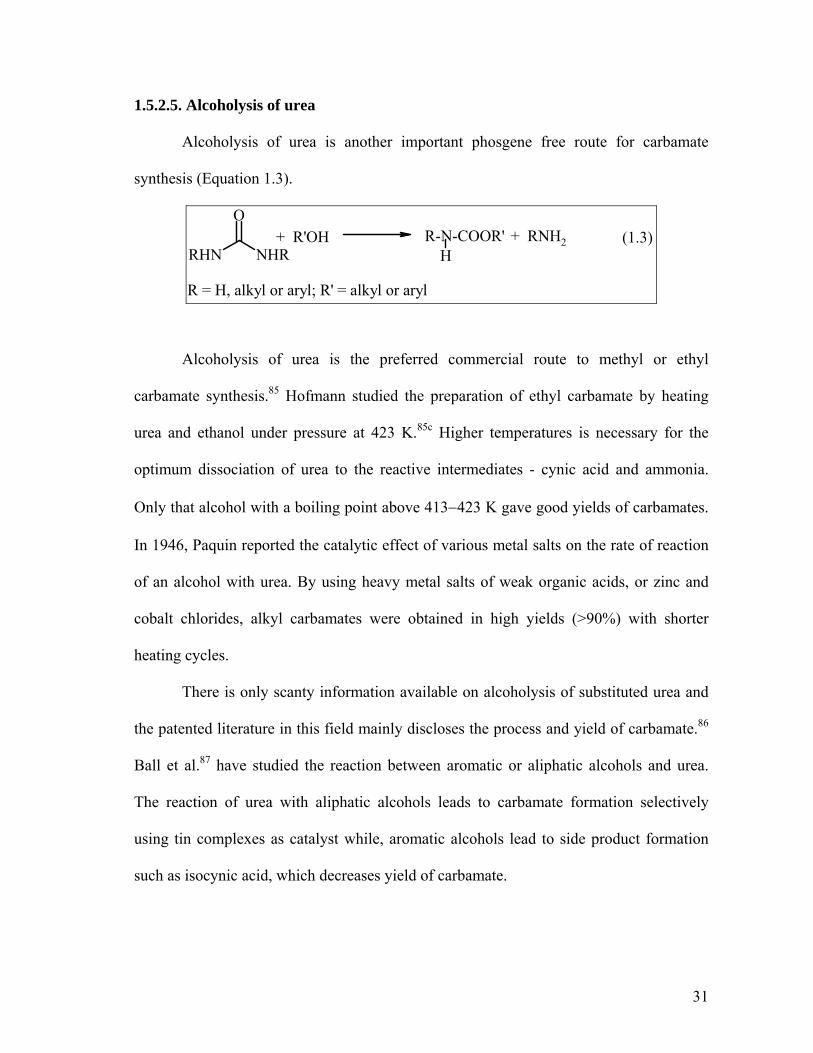
1.5.2.5. Alcoholysis of urea
Alcoholysis of urea is another important phosgene free route for carbamate
synthesis (Equation 1.3).
RHN NHR
O+ R'OH
R = H, alkyl or aryl; R' = alkyl or aryl
(1.3)R-N-COOR'H
+ RNH2
Alcoholysis of urea is the preferred commercial route to methyl or ethyl
carbamate synthesis.85 Hofmann studied the preparation of ethyl carbamate by heating
urea and ethanol under pressure at 423 K.85c Higher temperatures is necessary for the
optimum dissociation of urea to the reactive intermediates - cynic acid and ammonia.
Only that alcohol with a boiling point above 413−423 K gave good yields of carbamates.
In 1946, Paquin reported the catalytic effect of various metal salts on the rate of reaction
of an alcohol with urea. By using heavy metal salts of weak organic acids, or zinc and
cobalt chlorides, alkyl carbamates were obtained in high yields (>90%) with shorter
heating cycles.
There is only scanty information available on alcoholysis of substituted urea and
the patented literature in this field mainly discloses the process and yield of carbamate.86
Ball et al.87 have studied the reaction between aromatic or aliphatic alcohols and urea.
The reaction of urea with aliphatic alcohols leads to carbamate formation selectively
using tin complexes as catalyst while, aromatic alcohols lead to side product formation
such as isocynic acid, which decreases yield of carbamate.
31

1.6. N- ALKYLATION
Alkylations are among the most important reactions in organic chemistry.
N-alkylated derivatives of aromatic amines such as N-alkyl (e.g. N-methyl aniline) and
N,N-dialkyl (e.g. N,N-dimethyl aniline) derivatives are useful intermediates in the
manufacture of dyes, pharmaceuticals, agrochemicals, plastic and explosives.88
The most common methods of alkylation use dimethyl sulfate89 and alkyl
halides90 as the alkylating agents. There are, however, significant disadvantages in
carrying out alkylations with these reagents:
1. Dimethyl sulfate (DMS) and methyl halides are toxic and also corrosive.
Therefore, acid-resistant materials must be used for the construction of reactors.
2. Since the reactions proceed in the basic media, stoichiometric amounts of bases
are required to neutralize the acid that is formed. This results in the stoichiometric
formation of inorganic salts, which have to be disposed properly.
The first disadvantage may be overcome by using non-toxic alkylating agents such as
methanol and dimethyl carbonate (DMC), though these reagents are not so reactive. To
avoid second disadvantage mentioned above, the stoichiometric reactions must be
replaced by catalytic reactions.
1.6.1. SYNTHESIS OF N,N -DIMETHYL ANILINES
N,N-dimethyl anilines are valuable intermediates in the synthesis of
pharmaceuticals, agrochemicals and dyes as well as fine chemicals such as Vanillin,
Michler’s ketone etc. Various routes91 for the synthesis of N,N-dimethyl anilines have
been shown in Scheme 1.9.
32

NNDMA
N(CH3)2
NH2
NH2
NH2
DMS
CH3-X
X: halides
MeOH
DMC
NH2
NO2
HCOOCH3
Scheme 1.9. routes for synthesis of N,N- dimethyl aniline synthesis
1.6.1.1. Methanol as an alkylating agent
Conventionally, NNDMA was synthesized from the reaction of aniline and
methanol under pressure by using mineral acids92 (H2SO4) catalysts. (Scheme 1.10)
Scheme 1.10
C6H5NH2 + CH3OH C6H5NHCH3 + H2O
C6H5NHCH3 + CH3OH C6H5N(CH3)2 + H2O
This is a two-step process and a study of its kinetics shows that reaction rate is
proportional to the concentration of aniline in the first step and the concentration of N-
methyl aniline (NMA) in the second step. With 50% excess methanol, the reaction
equilibrium reaches to 99% N,N-dimethyl aniline (NNDMA) at 493 K. But at higher
33

temperature, ring alkylation and formation of formaldehyde from oxidation of methanol,
are observed. This traditional route of liquid phase alkylation using mineral acids and
AlCl3 as catalyst suffer from the disadvantages of high capital cost, reactor corrosion,
formation of by-products and the difficulties in handling and regeneration of catalysts.
With the increasing awareness of environmental issues, various solid acid
catalysts have been tested for their activity in alkylation reactions in place of traditional
Friedel-Crafts catalyst and mineral acids, the subject has been reviewed by Narayanamn
and Deshpande.93 Vapor-phase N-alkylation of aniline was initially studied by Hill et al
using Al2O3 as a catalyst.94 Later on, the gas-phase reaction involving aniline alkylation
with methanol was extensively studied using several different kinds of materials such as,
clays, zeolites, metal oxides, metal sulfates and aluminophosphates. Layered double
hydroxides (LDH) known as hydrotalcites (HT)95a and Zn-Co-Fe ternary spinel system95b
have also been studied for this reaction, wherein NMA formed selectively. In case of
ZSM-5 catalyst, the extent of conversion using this material increases with increasing
aluminum content.96 The vapor phase N-alkylation of amine reaction has also been
catalyzed by AlPO4-5, AlPO4-11, CoAPO-5, CoAPO-11, ZAPO-5 and ZAPO-11 with
the formation of NMA, NNDMA and N-methyl toluidine (NMT) where the product
distribution has been found to be influenced by the space velocity and the aniline to
methanol ratio.97 N-methylation products have been found to be as being predominant
over Al-HMS mesoporous molecular sieves,98 γ-alumina99 and metallosilicates.100 A
vapor-phase continuous process for the production of NNDMA from aniline and
methanol has been described using alumina based solid catalyst, wherein ~86% yield of
NNDMA has been claimed.101 Zeolites X and Y ion-exchanged with Li, Na, K, Rb and
34

Cs also have been used for this reaction. NNDMA is produced mainly over zeolite X and
NMA produced over zeolite Y.102 A mixture of N and C-alkylated products can be
obtained over the more acidic form of the zeolite. A rapid deactivation of zeolite-X has
been also reported. A review on the aniline alkylation over the solid acid catalyst also
appeared and the results suggests that the major factors influencing the activity and
selectivity of the gas phase alkylation of aniline are the acid-base properties and shape
selectivity of the solid catalyst.93 Grace et al.103 studied the alkylation of aniline with
methanol over cocrystalized zeolite RHO- zeolite X (FAU) and over zeolite Linde type L
(Sr, K-LTL) as catalysts. They observed that NNDMA was formed with (> 90%)
selectivity using cocrystalized zeolite RHO- zeolite X (FAU).
1.6.1.1.1. Mechanism of alkylation
Narayanan and Deshpande93 have proposed a mechanism for the N-alkylation
reaction under different conditions of the catalyst containing:
1. Only BrØnsted acid sites
2. Only Lewis acid sites
3. Both BrØnsted and Lewis acid sites.
1.6.1.1.1.1. Catalyst having only BrØnsted acid sites
Aniline alkylation on catalyst having only BrØnsted acid sites is a situation very
similar to that present on silica catalyst. Weak BrØnsted acidity of silica is responsible for
dehydration reaction of alcohol to give carbocation. On the other hand, aniline gets
protonated to give anilinium ion bringing down the rate of reaction (Scheme 1.11). This
may be reason for the comparatively low aniline alkylation activity of silica.
35

B B
O H
O CH2-CH3
H
O H
B B
O O H
O CH2-CH3
H
H
+
-H2O
B B
O H
CH2 CH3
O
+N
H
H
B B
O O H
+ NH
HC2H5 N
HC2H5
-H+
B
O HN
H
H
B
O
H NH
H
. .
B
ONH H
H+
+
B- bronsted sites
Scheme 1.11. Aniline alkylation involving only Bronsted sites
36

1.6.1.1.1.2. Catalyst having only Lewis acid sites
Aniline being a stronger base than ethanol gets absorbed preferentially on the
Lewis acid site. However, the presence of a large excess of alkylating agent, does not rule
out the possibility of ethanol getting absorbed on the acid sites as well. Having a catalyst
system with exclusively Lewis acid sites is rather unlikely under the reaction conditions
involving dehydration of alcohol. Even if the catalyst does not posses the BrØnsted
hydroxyls to start with, it may eventually develop them during the course of alkylation in
presence of H2O released in the course of reaction (Scheme 1.12)
-H
NH C2H5
+
L- Lewis acid sites
Scheme 1.12. Aniline alkylation involving only Lewis acid sites
L L+ +
NH H +
NHH
. .O CH2-CH3H. .
L L
O-CH2-CH3
H +
+N
HH
+
L L
+NH
O
CH2-CH3
:
L L
N CH2-CH3H
O
L L+
O
+
37

1.6.1.1.1.3. Catalyst having both BrØnsted and Lewis acid sites
Basic aniline preferentially gets absorbed on Lewis acid sites, while ethanol is
bound to the hydroxyl protons of BrØnsted acidic sites through the oxygen by hydrogen
bond. Protonation of alcohol, dehydration and subsequent formation of ether of the
released carbocation with conjugate base of BrØnsted acid site may follow. On the Lewis
acid site, the absorbed aniline loses a proton to balance the positive charge developed on
the nitrogen. The high electronegativity of oxygen in the ether linkage results in the
development of a partial positive charge on the alkyl side chain, initiating heterocyclic
cleavage of polar O-C bond and the shift of alkyl carbocation to nitrogen (Scheme 1.13).
L- Lewis acid sitesB-Bronsted acid sites
Scheme 1.13. Aniline alkylation involving both bronsted and Lewis acid sites
NH H +
NHH
L B+
O H
-H+
L
NHH
O
B
+H O-CH2-CH3
H+
L B
+N
HH
OH O-CH2-CH3
H
L
+NH
O
CH2-CH3
:
B
+
L
N CH2-CH3H
O
B
NH C2H5
L+
O
+ B
. .O CH2-CH3H. .
38

1.6.1.2. Dimethyl carbonate as an alkylating agent
Dimethyl carbonate has a versatile chemical property and has been used mainly as
a methylating and methoxycarbonylating agent. These reactions are very important in
organic synthesis. The use of DMC as a methylating agent has become popular as it is
produced commercially by environmentally benign routes. Tundo et al.104 have shown
that the attack of nucleophile on DMC (having two reactive centers; methyl sp3 carbon
atom and carbonylic sp2 carbon) is taking place by two different paths as shown in
Scheme 1.14.
RNH2RNHMe
DMC RNMe2
BAl2
Amine carboxylation via BAc2 mechanism
BAl2N- methylation via mechanism
O
O
O
CH3
CH3
BAc2RNH2
O
O
O
CH3
RNHCOOMe
CH3
Scheme 1.14. : Reaction path way for nucleophilic attack on DMC
39

The vapor phase N-alkylation of aniline using DMC as well as DEC as an
alkylating agent was extensively studied.105 It was shown that with faujasite as catalysts,
DMC as methylating agent was quite selective for N-alkylation of aniline. Ono et al.105a
have reported high yield of NMA with 92% selectivity using Na-X catalyst at 423 K,
while at 513 K temperature NNDMA was produced with > 95% selectivity. Zeolite K-
EMT and K-Y were also selective catalysts for formation of NMA (99.6% conversion
with 93.5% NMA selectivity), while alkaline X zeolites were the best catalysts for the
production of NNDMA (75% selectivity at 97% conversion).106 Barthomeuf et al. studied
this reaction over different zeolites having both acid and basic sites. They observed that
the C- alkylation with DMC may be favored on protonic sites, while N-methylation may
occur on other active centers such as basic or Lewis acid sites present in the alkaline
samples.106
Liquid-phase N-methylation of anilines have been studied by Tundo and
coworkers using faujasites X and Y catalysts.107 They reported that mono methyl anilines
were formed selectively (>95%) with only traces of dimethyl derivatives at 403−453 K
temperature. Romano et al.108 have reported excellent yield of NNDMA (85%) with 15%
yield of NMA at 421 K temperature using methyl iodide as catalyst. Shen and Jiang
showed that diphenylammonium triflate (DPAT) was an excellent catalyst for selective
synthesis of N,N-dimethyl anilines (> 99.6%).109 Recently Selva et al.110 showed selective
N,N-dimethylation of primary aromatic amines (90 to 96%) using unsymmetrical methyl
alkyl carbonate in presence of phosphonium salt (Ph3PEtI).
40

Table 1.6. Literature on N-alkylation reaction
Sr. No. Amine alkylating
agent Catalyst Time; h
Temp.0C
Amine Conv.%
(I) sel.;%
(II) sel.,% Reference
1 Indole MeI PEG methyl ether 5 20 60 60 - Davidson et al.90a
2 C6H5-NH2 EtBr Bu4NBr / NaOH 2 40 89 55 45 Dehmlow et al.90b
4 C6H5-NH2 BnBr [Bmim] [PF6] 0.01 60 60 30 70 Chiappe et al. 90c
5 C6H5-NO2 HCOOCH3 Ru3(CO)12 5 220 99.2 1 99 Jenner & Taleb91
6 C6H5-NH2 MeOH H2SO4 6 205 100 1 99 Shreve et al.92
7 C6H5-NH2 EtOH V2O5 - 400 35 70 20 Narayanan et al.93
8 C6H5-NH2 MeOH Mg-Al HTlc 6 425 68 100 0 T. Raja et al.95a
9 C6H5-NH2 MeOH Zn-Co-Fe(ZCF2) 1.2 350 74 94 6 Sreekumar et al.95b
10 C6H5-NH2 MeOH ZAPO-5 1.2 350 67 32.5 40 Elangovan et al.97
11 C6H5-NH2 MeOH γ-Al2O3 2 425 56 42 51 A-N Ko et al.99
12 C6H5-NH2 MeOH [Zr]ZSM-5 1 400 66.3 78.7 19.8 Park et al.100
13 C6H5-NH2 MeOH Alumina 1 200 96 8 92 Doraiswami et al.101
14 C6H5-NH2 MeOH RHO-zeolite X 1 400 100 10 90 Grace et al.103
15 C6H5-NH2 DMC KY NaX or KX - 180
240 99.6 100
93.5 4.4
6.5 95.6
Ono et al.105a
16 C6H5-NH2 DMC Mg-Al Htlc 2 275 91 87 13 Jyothi et al.105c
17 C6H5-NH2 DMC CF-5 1 250 60 61 22 Sreekumar et al.95a
18 C6H5-NH2 DEC Hβ 1 200 73.4 71.4 21.4 Yuvaraj et al. 105d
19 C6H5-NH2 DMC Na-X Na-EMT 6 300 91
85.4 36.6 58.5
62 41.5
Rao et al.106
20 C6H5-NH2 DMC Na-Y 2.5 90 100 99 1 Tundo et al.107
21 C6H5-NH2 DMC MeI 5 148 100 15 85 Romano et al.108
22 C6H5-NH2 DMC DPAT 2.6 180 99.9 0.3 99.6 Shen & Jiang109
23 C6H5-NH2 MeOCOOR Ph3PEtI 1 170 99 0 90 Selva et al.110
(I)= mono alkylated product; (II) = dialkylated product
41

1.6.2. SYNTHESIS OF β-AMINO ALCOHOLS
β-amino alcohols are an important class of organic compounds due to their
bifunctional nature having alcohol and amine functional groups in the same compound,
which allows them to react in wide variety of ways.111 These versatile compounds are
extensively used in the medicinal chemistry in the preparation of biologically active
natural and synthetic products, artificial amino acids, and chiral auxiliaries for
asymmetric synthesis.112 They are also useful as intermediates in the synthesis of
perfumes,113 dyes, photo developers,114and oxazolidones.115
1.6.2.1. Synthesis of β-amino alcohols using alkylene oxide
Conventionally β-amino alcohols are produced from alkylene oxide and amines116
(Equation 1.4).
R-NOH
H
R1
R2
(1.4)R-N
OH
H
R2
R1
+RNH2 + O
R1 R2
This classical approach, involving heating epoxides with amines works less well
with poorly nucleophilic amines such as anilines. Moreover, the lack of appreciable
regioselectivity, the requirement for the high temperature (which may pose problem for
sensitive epoxides), and the need for an excess of amine in the classical methods of β-
amino alcohol synthesis have led to the necessity for activation of the epoxides so as to
increase their susceptibility to nucleophilic attack by amines. The various methodologies
developed for this purpose include the use of alumina,117 metal amide,118 metal halides,119
42

metal alkoxides,120 metal triflates,121 alkali metal perchlorates,122 rare earth metal
halides,123 silica,124 clays125 and ionic liquids.126
1.6.2.1.1. Mechanism for synthesis of β-amino alcohol
Chakraborti and Kondaskar112b have proposed the catalytic mechanism for β-
amino alcohol synthesis by ZrCl4 catalyzed ring opening of epoxide with amine (Scheme
1.15). The coordination of Zr4+ with the epoxide oxygen (TS-I) renders the epoxide
susceptible to nucleophilic attack by amine leading to (TS-II/TS-IIa) followed by
protonylisis (via intramolecular proton transfer involving TS-II) to form the amino
alcohol. The liberation of the catalyst follows subsequently.
RNH2
O
R1 R2
ZrCl4
TS-I
TS-IIR1
NHRO
R2
CL4Zr H+
R1
R2O
NH2R
ZrCL4ZrCl4
O
R1 R2
TS-IIa
R1
R2OH
NH2R
Scheme 1.15. Catalytic cycle during the ZrCl4 -catalyzed opening of epoxide ring with amine
43

1.6.2.2. Synthesis of β-amino alcohols from nitro paraffins
β-amino alcohols are also synthesized from nitro alcohols by a two steps synthesis
(Equation 1.5).127 In the first step, nitro alcohols are obtained by the condensation of nitro
paraffins with aldehydes followed by their reduction to β-amino alcohols in the second
step.
(1.5)RCH2NO2 + CH2O RCHCH2OH
NO2
[H]RCHCH2OH
NH2
The condensation may occur one to three times, depending on the number of hydrogen
atoms on the α- carbon of nitro paraffins, giving rise to amino alcohols with one to three
hydroxyl groups.
The above mentioned classical routes based on epoxides for the synthesis of β-
amino alcohols suffer from the draw back of handling of hazardous epoxides, requires
stoichiometric amount of reagents, longer reaction time, high pressure (particularly for
ethylene oxide) and temperature conditions. β-amino alcohol synthesis based on nitro
paraffins is a multi step synthesis and adverse selectivity towards amino alcohol with one
hydroxyl group is the main issue in this route.
In contrast to these, a much safer and attractive synthesis of β-amino alcohol is
based on the use of a five-membered alkylene carbonate.
44

1.6.2.3. Synthesis of β-amino alcohols using alkylene carbonate
From the industrial point of view, alkylene carbonates are important precursors.
In particular, ethylene carbonate (EC) and propylene carbonate (PC) have been
commercially produced through benign routes and are available for over 45 years.128, 129
These compounds have significant physical properties such as high boiling and
flash point, low odor levels and evaporation rates, low toxicity and high solvency besides
being to biodegradabe. Being versatile, these compounds have found numerous
applications both as solvents and reactive intermediates (Scheme 1.16).33b
OO
O
ClOH
OHNH
OHO
OS
ON
O
H
BrOH
LiCl
NaBr
NaIKSCNNaOCN
anilinephenol
OHNC
Scheme 1.16. Applications of alkylene carbonate as useful synthons
NaCN
Among all these organic transformations using alkylene carbonates, synthesis of
β-amino alcohol is an important transformation. N-alkylation employing alkylene
carbonate is a simple reaction, easy to handle and does not require high pressure setup.
45

Though, it is a simple and useful reaction, it is not well investigated. Gulbins and
Hamann (1966) have reported the reaction of aromatic amine with alkylene carbonate in
presence of LiCl catalyst to give oxazolidones as major products, along with β-amino
alcohol.130 Kaye et al.131 reported the synthesis of N-methyl N-phenyl ethanolamine from
N-methyl aniline and ethylene carbonate using lithium amide catalyst. It has also been
reported that the reaction between aliphatic amines and alkylene carbonate gives
polymeric products possessing carbamate and carbonate functionality.132 A process for
the alkoxylation of an active hydrogen-containing compounds with an alkylene carbonate
in the presence of mixed metal oxide to give low yield of β-amino alcohol has been
patented by King.133
46

Table 1.7. Literature on β-amino alcohol synthesis
RNH2 + O
R1
RNOH
H
H
R1
RNOH
H
R1
H
+
(I) (II)
OO
O
R1EC: when R1 = H
+ RNH2
Sr. No. Amine alkylating
agent Catalyst Time; h
Temp.0C
Amine Conv.%
(I) sel.;%
(II) sel.,% Reference
1 C6H5-NH2 PO SO
ZrCl4 0.25 25 100 98
100 2
- 98
Chakraborti et al112b
2 C6H5-NH2 CyO Al2O3 0.16 40 69 100 Posner et al.117
3 C6H5-CH2NH2
CyO LiNH2 24 25 100 70 Kissel et al.118a
4 C6H5-NH2 CyO (Et)2AlNH2 2-3 25 52 100 Overmann et al. 118b
5 C6H5-NH2 SO CoCl2 3 25 98 5 95 Sundararajan119a
6 C6H5-NH2 CyO TaCl5-silica gel - 25 100 85 - Chandrashekhar et al.119c
7 C6H5-NH2 CyO Cu(OTf)2 Sn(OTf)2
20-30 25 100 100
95 94 - Sekar et al.119b
8 C6H5-NH2 C4H9-NH2
CyO PO
LiClO4
38 2 25 100
100 98 40
0 60
Chini et al.121
9 C4H9-N SO CyO
Montmorillonite 3 70 - 17.5 46 32.5 Mojtahedi et al.125
10 C6H5-NH2 SO CyO
[Bmim]BF4 5 6
25
- -
- 83
85 -
Yadav et al.126
11 C6H5-NH2 EC LiCl 5 176 100 18 Gulbins et al.130
12 C6H5-NH(Me) EC LiNH2 4 Kaye et al.131145-
190 53.5 53.5
PO: propylene oxide; SO: styrene oxide; CyO: cyclohexene oxide; EC: ethylene carbonate; *CyO & EC gave single product
47

1.7. SCOPE AND OBJECTIVES OF THESIS In the light of growing public and political awareness of chemical industry
polluting the environment, chemist have been contributing significantly to improve the
existing chemical routes and develop new routes that are less damaging to the ecosystem.
In the manufacturing processes of fine chemicals, stoichiometric amount of reagents and
homogeneous acid and bases of BrØnsted and Lewis catalysts are still applied to a great
extent in the liquid phase which produces a lot of unavoidable side products and
inorganic salts that causes a lot of burden on eco-system. In particular, an
underdeveloped area of fine chemicals is in the replacement of traditional catalysts and
reagents which are corrosive, toxic, produced by eco-unfriendly processes and which
produce inorganic salts that are expensive to dispose. Some of the examples of
undesirable reagents used for carboxylation and alkylation are phosgene, methyl halides
and dimethyl sulfate (DMS).
In this context the aim of present work was to develop more efficient and more
selective catalyst systems as well as the development and rationalization of new greener
routes for the synthesis of fine chemicals using organic carbonates as benign reagents.
Organic carbonates such as dimethyl carbonate, ethylene carbonate etc. are non-toxic,
biodegradable and produced commercially via benign routes. The use of carbonates thus
can replace potentially hazardous routes that uses phosgene and DMS to produce fine
chemicals such as carbamates, N,N-dialkyl anilines and β-amino alcohols which have
wide range of applications in pharmaceuticals, agriculture industry and polymer
industries.
With these objectives, the following specific reactions have been studied.
48

• Carbamate synthesis via transfunctionalization of substituted ureas and carbonates
• Selective synthesis of N,N-dimethyl anilines from aromatic amines and dimethyl
carbonate
• Synthesis of β-amino alcohols from aromatic amines and alkylene carbonates
• Selective tandem synthesis of β-amino alcohols from aromatic amines, dialkyl
carbonates and ethylene glycol
• Kinetic and mechanistic study of N-alkylation of aniline by ethylene carbonate to
β-amino alcohols in presence of Na-Y zeolite as catalyst
49

REFERENCES
1. R. Breslow; “Chemistry today and tomorrow” Ammerican Chemical Society, Washington, DC, 1997.
2. W. Rousch; Science, 1997, 276, 1029. 3. R. Carlson, Silent spring, Houghton Mifflin, New Yark, 1962. 4. P. T Anastas and T. C. Williamson; “Green Chemistry”, Oxford, New York, 1998. 5. P. T Anastas and J. C. Warner, “Green Chemistry: theory and practice”, Oxford
university press, New York, 1998. 6. S. L. Y. Tang, R. L. Smith and M. Poliakoff, Green Chem., 2005, 7, 761. 7. (a) W. F. Holderich, Stud. Surf. Sci Catal., 1993, 75, 127. (b) W. F. Hölderich,
Catalysis Today, 2000, 62, 115. 8. B. Cornils and W. A. Hemann; Applied Homogeneous Catalysis with
organometallic Compounds, VCH, Weinheim, 1996. 9. K. Tanabe; M. Misono, Y. Ono and H. Hattori; Stud. Surf. Sci Catal., 1989, 51, 1. 10. R Jira, Ethylene and its industrial derivatives, Miller S.A. (Ed.), Ernest Benn Ltd.
1969, 650. 11. E. F. Lutz, J. Chem. Educ., 1986, 63, 202. 12. V. D. Ludecke, Encyclopedia of chemical processing and design, J.J.Mcketta and
W.A.Cunningham (Eds.), Maedetl and Decker, 1976, 146. 13. W.A.Knowles, Acc. Chem. Res., 1983, 16, 106. 14. (a) BASF AG, Hydrocarbon Process, 1977, 11, 135. (b) BASF AG; Hydrocarbon
Process, 1977, 11, 172. 15. T. H. Johnson, (Shell Oil Co.), US 4584411, 1985. 16. Anon, Chem.Eng., 1977, 84, 110. 17. B. Cornils and E.Kuntz; J. Organomet. Chem., 1995, 502, 177. 18. P. Fitton and H. Moffet; US 4124619, 1978. 19. H. Pommer and A. Nuerrenbach; Pure. Appl. Chem., 1975, 43, 527. 20. J. F.Roth; J. H. Craddock; A. Hershmann and F. E. Paulik, CHEMTCH. 1971, 1,
600. 21. H. Hohenshutz, N.von Kutepow and W. Himmele, Hydrocarbon Process, 1966,
45, 141. 22. D. J Watson, Catalysis of Organic reactions,. F.E. Herkes, H. Heinemann., (Eds)
Marcell Decker Inc. 1998, 369. 23. H. W. Coover, R. C. Hart, Chem. Eng. Prog. 1982, 72. 24. V. H. Agreda, D. M. Pond and J. R. Zoeller, CHEMTCH, 1992, 172. 25. H. Hohenschutz, D. Franz, Bulow H. and G. Dinkhauser (BASF AG), DE 2133349,
1973. 26. B. Blumenberg., Nahr. Chem. Tech. Lab., 1984, 480. 27. (a) L. Casssar, Chem. Ind., 1985, 67, 256. (b) G. W. Parshall and W. A. Nugent,
CHEMTCH, 1988, 314. 28. V. Elango, M.A. Murphy, G. N Mott, E. G Zey, B. L Smith and G. L Moss, EP 400
892, 1990. 29. R. Ugo, T. Renato, M.M.Marcello and R. Plerluigi, Ind. Eng. Chem. Prod. Res.
Dev., 1980, 19, 396.
50

30. K. Tanabe and W. F. Holderich, App. Catl. A: Gen, 1999, 181, 399 and references cited therein.
31. (a) A. Vaccari, Catal. Today, 1998, 41, 53; (b) A. Vaccari, Appl. Clay Sci, 1999, 14, 161.
32. (a) D. Brunel, Microporous Mesoporous Mater., 1999, 27, 329; (b) D. J Macquarrie, Green Chem., 1999, 1, 195.
33. (a) Y. Ono, Appl Catl. A: Gen, 1997, 155, 133; (b) J. P. Parrish, R. N. Salvatore and K. W. Jung, Tetrahedron, 2000, 56, 8207; (c) P. Tundo, Pure Appl. Chem., 2001, 73, 1117; (d) P. Tundo and M. Selva, Acc. Chem. Res., 2002, 35, 706; (e) A. G. Shaikh and S. Sivaram; Chem.Rev., 1996, 96, 951.
34. M. A. Pacheco and C. L. Marshall, Energy & Fuels, 1997, 11, 2 and references cited therein.
35. F. Revetti, “Dimethyl carbonate: an answer to the need for safe chemicals”, in Green Chemistry: Challenging Perspectives, P. Tundo and P. Anastas(Eds), Oxford University press, 2000.
36. M. Aresta, A. Didenedetoo and E. Quarnta, Tetrahedron, 1998, 54, 14145. 37. P. Adames and F.A. Baron, Chem Rev., 1965, 65, 567. 38. T. Greene and P.G.M. Wuts; Protective Groups in Organic Synthesis; 2nd Edn;
Wiley, New York, 1991, 315. 39. M. Prhavc, E. A. Lesnik, V. Mohan and M. Manoharan, Tetrahedron Lett., 2001,
42, 8777. 40. W. W. Cleland, T. J. Andrews, S. Gutteridge, F. C. Hartman and G. H. Lorimer,
Chem.Rev., 1998, 98, 549. 41. R. Warrass, K. H. Weismuller and G. Jung, Tetrahedron Lett., 1998, 39, 2715. 42. R. G. Arnold, J. A. Nelsonand, J. J. Verbanc, Chem.Rev., 1956, 56, 47. 43. F. Bigi, R. Maggi and G. Sartori, Green Chem, 2000, 2, 140. 44. M. Aresta, A. Debenedetto and E. Quaranta, Green Chem., 1999, 1, 237. 45. B. Allen, Green Chem., 2000, 2, G56. 46. J. H Saunders and H. J Slocombe, Chem.Rev., 1948, 48, 203 and references cited
therein. 47. (a) K. C. Fritisch and D. Klempner, in: G. Allen and J. C. Benvington (Eds);
Comprehensive Ploymer Science, Pergamon, New York, 1989, 5, 413; (b) F. Paul, Coordination chem. Rev., 2000, 203, 269.
48. G. D. Buckley and N. H. Ray, J. Chem. Soc., 1949, 1154. 49. Patent FP 1379231, 1964. 50. W. B. Hardy and R. P. Bennett, Tetrahedron Lett., 1967, 11, 961. 51. (a)V. L. K. Vaali and H. Alper., J. Am. Chem. Soc., 1993, 115, 3778; (b) C. V.
Rode, S. P. Gupte, R. V. Chaudhari, C. Pirozhkov and A. L. Lapidus; J. Mol. Catl., 1994, 91, 195; (c) A. L. Lapidus, A. F. Lunin, S. D. Pirozhkov, N. B. Leonchik, P. Neittzel and K. Shvetlick, Bull. Accd. Sci., USSR Div. Chem Sci., 1982, 31, 1068. (d) B. M Chaudhari, K. K. Rao, S. D. Pirozhkov and A. L. Lapidus, J. Mol. Catl., 1994, 88, 23.
52. (a) Y. Watanabe, Y. Tsuji, R.Takeuchi and N. Suzuki; Bull. Chem. Soc. Jpn., 1983, 56, 3343; (b) Y. Watanabe, Y. Tsuji and N. Suzuki, Chem lett., 1982, 105.
51

53. (a) S. Cenini, C. Crotti, M. Pizzotti and F. Porta, J. Org.Chem., 1988, 53, 1243; (b) S. Cenini, C. Crotti, M. Pizzotti, F. Porta and G. La Monica, J. Chem. Soc. Chem. Commun., 1984, 1286.
54. N. P Reddy, A. M. Masudeu, B. E. Ali and H. Alper, J. Chem Soc. Chem. Commun., 1994, 863.
55. (a)J. D. Gargulak, A. J Berry, M. D. Noirot and W. L. Gladfelter, J. Am. Chem. Soc., 1992, 114, 8933; (b) S. J. Sherlock, D. C. Boyd, B. Moasser and W. L. Gladfelter, Inorg. Chem., 1991, 30, 3626; (c) S. J. Skoog, J. P. Campbell and W. L. Gladfelter, Organometallics, 1994, 13, 4137.
56. (a) F. Ragaini and S. Cenini, Organometallics, 1994, 13, 1178; (b) S. Cenini, F. Ragaini, M. Pizzotti, F. Porta and G. mesttroni, J. Mol. Catl., 1991, 64, 179.
57. (a) E. Alessio and G. Mestroni, J. Organomet. Chem., 1985, 291, 117; (b) E. Drent patent EP 231045, Shell international Research,1987; (c) E. Drent patent EP 86281, Shell international Research, 1981; (d) E. Alessio and G. Mestroni, J. Mol. Catal., 1984, 26, 237; (e) E. Alessio and G. Mestroni; EP 0169650, 1985.
58. F. Zhang, W. Wang, P. Xu and J. Xu, Fenzi Cuihua., 1991, 5, (Chem. Abs. 116: 128307).
59. M. M Taqui-Khan, S. B. Halligudi, S. Skula and Z. A. Shaik, J. Mol. Catal., 1990, 57, 301.
60. (a) Y. Izumi, Y. Satoh and K. Urabe, J. Mol. Catal., 1992, 72, 37; (b) Y. Izumi, Y. Satoh and K. Urabe, Chem. Lett., 1990, 795; (c) F. Ragaini, M. Macchi and S. Cenini, J. Mol. Catal. A: Chem., 1997, 127, 33.
61. (a) Asahi Chem. Ind.; JP 58146549, 1983; (b) S. Fukuoka and M. Chono, EP 83096, 1983; (c) S. Fukuoka and M. Chono, J. Chem. Soc. Chem. Commun., 1984 , 399 (d) S. Fukuoka and M. Chono, J. Org. Chem., 1984, 49,1460; (e) S. P. Gupte and R. V. Chaudhari, J. Catal., 1988, 114, 246; (f) A. A. Kelkar, D. S. Kolhe, S. Kanagasabaathy and R. V. Chaudhari, Ind.Eng. Chem. Res., 1992, 31, 172; (g) J. S. Oh, S. M Lee, J. K. Yeo, C. W. Lee and J. S. Lee, Ind.Eng. Chem. Res., 1991, 30, 1456; (h) K. T. Li and Y. J Peng; J. Catal., 1993, 143, 631.
62. (a) N. Sonoda, T. Yasuhara, K. Kondo, T. Ikeda and S. Tsutumi, J. Am. Chem. Soc., 1971, 93, 6344; (b) K. Kondo, S. Yokoyama, N. Myoshi, S. Murai and N. Sonoda, Angew. Chem. Int. Ed. Engl., 1979, 18, 692.
63. H. Alper and F. Hartstock, J. Chem. Soc. Chem. Commun.,, 1985, 1141. 64. B. Wan, S. Liao and D. Yu, App. Catal. A: Gen, 1999, 183, 81. 65. F. Shi and Y. Deng, Chem. Commun.; 2001, 443. 66. F. Shi, Y. Deng, T. Sima and H. Yang,J. Catal., 2001, 203, 525. 67. F. Shi, J. Peng and Y. Deng, J. Catal., 2003, 219, 372. 68. M. H. Chisholm and M. W. Extine, J. Am. Chem. Soc., 1977, 99, 792. 69. T. Tsuda, H. Washita, K. Watanabe, M. Miwa and T. Saegusa, J. Chem. Soc. Chem.
Commun., 1978, 815. 70. F. Kojima, T. Aida and S. Inoue, J. Am. Chem. Soc., 1986, 108, 391. 71. T. Mitsudo; Y. Hori; Y.Y Yamakawa and Y. Watanabe; Tetrahedron Lett., 1987,
28, 4417. 72. M. Aresta and E. Quaranta, Tetrahedron, 1992, 48, 1515. 73. (a) M. Yoshida, N. Hara and S. Okuyama, Chem. Commun., 2000, 151; (b) R. N.
Salvatore, S. Shin, A. S. Nagale and K.W. Jung, J. Org. Chem., 2001, 66, 1035.
52

74. P. Kock and U. Romano, Ital. Pt. Appl. 20264 A/82. 75. U. Ramano and R. Tesei, US 404564, 1977. 76. (a) Annon. Res. Discl., 1987, 275, 162; C.A., 1988, 108, 16742 g; (b) U. Romano,
G. Fornasari and S. Di Gioachino, DE 3202690, C.A. 1982, 97, 144607d; (c) T. Mukai, K. Suenobu and M. Mitsuru, C.A. 1977, 87, 52961e; (d) E. Angeles, A. Santillan, I. Martinez, A. Ramirez and E. Moreno, Synth. Commun., 1994, 24, 2441.
77. (a) F. F. Frulla, A. F. Stuber and J. P. Whitman, US 4550188, C.A. 1986, 104, 224725 u; (b) Gurgiolo, US 4268683, 1981, C.A. 1981, 95, 168832h; (c) Gurgiolo, US 4268684, C.A. 1981, 96, 97407k.
78. (a) F. Porta, S. Cenini, M. Pizzotti and C. Crotti, Gazz. Chim. Ital., 1985, 115, 275. (b) Z. Fu and Y. Ono, J. Mol. Catal., 1994, 91, 399; (c) Y. Fu, T. Baba and Y. Ono, J. Catal., 2001, 197, 91; (d) T. Baba, M. Fujiwara, A. Oosaku, A. Kobayashi, R. G Deleon and Y. Ono, Appl. Catal. A: Gen., 2002, 227, 1.
79. I. Vauthey, F. Valot, C. Gozzi, F. Fache and M. Lemaire, Tetrahedron Lett., 2000, 41, 6347.
80. S. Carloni, D. Vos, P.A. Jacobs, R. Maggi, G. Sartori and R. Sartorio, J. Catal., 2002, 205,199.
81. M. Curini, F. Epifano, F. Maltese and O. Rosati, Tetrahedron Lett., 2002, 43, 4895. 82. T. Sima, S. Guo, F. Shi and Y. Deng, Tetrahedron Lett., 2002, 43, 8145. 83. M. Selva, P. Tundo and A. Perosa, Tetrahedron Lett., 2002, 43, 1217. 84. N. Katada, H. Fujinaga, Y. Nakamura, K. Okumura, K. Nishigaki and M. Niwa,
Catl. Lett., 2002, 80, 47. 85. (a) S. Bunte, Ann., 1891, 151, 181; (b) A. Cahourrs, Compt. rend., 1873, 76, 1387;
(c) A. W. Hofmann, Chem. Ber., 1871, 4, 262. 86. (a) B. Gerhard; DE 19756768, 1999; (b) C. E. Brockway, US 2806051, 1957; (c) H.
G. Godman, US 3449406, 1969. 87. P. Ball, H. Fullmann, R. Schwalim and W. Heitz, C1 Mol. Chem., 1984, 1, 95. 88. Kirk-othmer Encyclopedia of Chemical Technology; Vol.2; 4th Edn. Wiely, New
York, 1992, 438. 89. A.W. Hoffmann, Philos. Trans., CXL, 1850, 93. 90. (a) R. S. Davidson., A. M. Patel, A Safdar and D. Thornthwaite, Tetrahedron Lett.,
1983, 24, 5907; (b) E. V. Dehmlow, R. Thieser, H. A. Zahaka and Y. Sasson, Tetrahedron Lett., 1985, 26, 297; (c) C. Chiappe, P. Piccioli and D. Pieraccini, Green Chem., 2006, 8, 277.
91. G. Jenner and A.B. Taleb, J. Mol. Catal., 1992, 77, 247. 92. N. R. Shreve, G. N. Vriens, D. A. Vogel, Ind. Eng. Chem., 1950, 42, 791. 93. S. Narayanamn and K. Deshpande, Appl. Catal. A: Gen., 2000, 199, 1. 94. A. G. Hill, J. H. Shipp and A. J. Hill, Ind. Eng. Chem., 1951, 43, 1579. 95. (a) J. Santhanalakshmi and T. Raja, Appl. Catal. A: Gen.; 1996, 147, 69; (b) K.
Sreekumar, T. Mathew, S. P. Mirajkar, S. Sugunan and B. S. Rao, Appl. Catal. A: Gen., 2000, 201, L1.
96. P. Y Chen, M. C. Chen, H. Y. Chu, N. S. Chang and T. K. Chuang, Stud. Surf. Sci. Catal., 1986, 28, 739.
97. S. P. Elangovan, C. Kannan, B. Arabindoo and V. Marugesan,Appl. Catal. A: Gen., 1998, 174, 213.
53

98. J. M. Campelo, A. Garcia, D. Luna, J. M. Marinas; A. A. Romero and J. J. Toledano, Stud. Surf. Sci. Catal., 2001, 135, 4137.
99. A-N. Ko, C-L Yang, W. D. Zhu and H-E. Lin, Appl. Catal. A: Gen., 1996, 134, 52. 100. Y. K. Park, K. Y. Park and S. I. Woo, Catal. Lett., 1994, 26, 169. 101. L. K. Doraiswami, G. R. W. Krishnan and S.P. Mukherjee, Chem. Eng., 1981, 13,
78. 102. B. L. Su and D. Barthomeuf, Appl. Catal. A: Gen.; 1995, 124, 73. 103. L. J. Graces, V. D. Makwana, B. Hincapie, A. Sacco and S. L. Suib, J. Catal., 2003,
217, 107. 104. (a) P. Tundo and M. Selva, ChemTech., 1995, 25(5), 31; (b) P. Tundo and M.
Selva; Acc. Chem. Res., 2002, 35, 706. 105. (a) F. Fu and Y. Ono, Catal. Lett., 1993, 18, 59; (b) F. Fu and Y. Ono, Catal. Lett.,
1993, 22, 277; (c) T. M. Jyothi, T. Raja, M. B. Talwar, K. Sreekumar, S. Sugunan and B. S. Rao, Synth. Commun., 2000, 30, 3929; (d) S. Yuvaraj, V. V. Balasubramanian and M. Palanichamy; Appl. Catal. A: Gen.; 1999, 176, 111.
106. P. R. Hari Prasad Rao, P. Massiani and D. Barthomeuf, Catal. Lett., 1995, 31, 115. 107. (a) F. Trotta, P. Tundo and G. Moraglio, J. Org. Chem., 1987, 52, 1300; (b) M.
Selva, A. Bomben and P. Tundo, J. Chem. Soc. Perkin Trans I, 1997, 1041; (c) M. Selva, P. Tundo and A. Perosa, J. Org. Chem., 2001, 66, 677; (d) M. Selva, P. Tundo and A. Perosa, J. Org. Chem., 2003, 68, 379; (e) M. Selva and P. Tundo, Tetrahedron Lett., 2003, 44, 8139; (f) M. Selva, P. Tundo and T. Foccardi, J. Org. Chem., 2005, 70, 2476.
108. U. Romano and G. Iori, US 4326079, 1982. 109. Z. L. Shen and X. Z. Jiang, J. Mol. Catl. A: Chem., 2004, 213, 193. 110. M. Selva, A. Perosa, P. Tundo and D. Brunelli, J. Org. Chem., 2006, 71, 5770. 111. Kirk-othmer Encyclopedia of Chemical Technology; Vol.2; 4th Edn. Wiely, New
York, 1992, 4. 112. (a) D. J. Ager, I. Prakash and D. R. Schaad, Chem. Rev., 1996, 96, 835; (b) A. K.
Chakaraborti and A. K. Kondaskar, Tetrahedron Lett., 2003, 44, 8315. 113. Y. Yang, D. Wahler and J. L. Reymond, Helv. Chim. Acta., 2003, 86, 2928. 114. T. Ibaya; T. Mizutani and T. Inagi; JP 02288850A2 (1990). 115. M. E. Dyen and D. Swern, Chem. Rev., 1967, 67, 197. 116. (a) R. E Lutz, J. A. Freek and R. S. Murphy, J. Am. Chem. Soc., 1948, 70, 2015; (b)
M. Mousseron, J. Jullien and Y. Jolchine, Bull. Soc.Chim. Fr., 1952, 757; (c) M. Freifelder and G.R. Stone, J. Org. Chem., 1961, 26, 1477; (d) P. A. Crooks and R. Szyudler, Chem. Ind. (London), 1973, 1111.
117. G. H. Posner and D. Z. Rogers, J. Am. Chem. Soc., 1977, 99, 8208. 118. (a) C. L. Kissel and B. Rickson; J. Org. Chem., 1972, 37, 2060; (b) L. E. Overman
and L. A. Flippin, Tetrahedron Lett., 1981, 22, 195. 119. (a) G. Sundararajan, K. Vijayakrishna and B. Verghese, Tetrahedron Lett., 2004,
45, 8253; (b) N. R. Swamy, T. V. Goud, S. M. Reddy, P. Krishnaiah and Y. Vekateswarlu, Synth. Commun., 2004, 34, 727; (c) S. Chandrashekar, T. Ramchandar and J. S. Prakash, Synthesis, 2000, 1817.
120. (a) S. Sagava, H. Abe, Y. Hase and T. Inaba, J.Org. Chem., 1999, 64, 4962; (b) S. Rampalli, S. S. Chaudhari and K. G. Akamanchi, Synthesis, 2000, 78.
54

121. (a) M. Fujiwara, M. Imada, A. Baba and H. Matsuda, Tetrahedron lett., 1989, 30, 739; (b) G. Sekar and V. K. Singh, J. Org. Chem., 1999, 64, 287.
122. M. Chini, P. Crotti and F. Machia, Tetrahedron Lett., 1990, 31, 4661. 123. (a) V. Weghe and J. Collin, Tetrahedron Lett., 1995, 36, 1649; (b) L. R. Reddy, M.
A. Reddy, N. Bhanumathi and K. R. Rao, Synthesis, 2001, 831. 124. H. Kotsuki, K. Hayashida, T. Shimanouchi and H. Nishizawa, J. Org. Chem., 1996
61, 984. 125. M. M. Mojtahedi, M. R. Saidi and M. Bolortchian, J. Chem. Res.(s), 1999, 128. 126. J. S. Yadav, B. V. Reddy, A. K. Basak and A. V. Narsaiah, Tetrahedron Lett., 2003
44, 1047. 127. H. B. Hass and E. F. Riley, Chem. Rev., 1943, 32, 373. 128. M. Lichtenwalter and J. Cooper, US Patent 2873282, 1959. 129. J. H. Clements, Ind. Eng. Chem. Res., 2003, 42, 663. 130. E. Gulbins and K. Hamann; Chem. Ber., 1966, 99, 55. 131. I. A. Kaye, H. Horn and M. Vouras, J. Org. Chem., 1953, 18, 664. 132. (a) M. Sepulchre, M. O. Sepulchre, M. A. Dourges and Neblai,M. Macromol,
Chem. Phys., 2000, 201, 1405; (b) N. Kihara, K. Makabe and T. Endo, J. Polym. Sci., Part A:Polym. Chem., 1996, 34, 1819; (c) H. Tomita, F. Sanda and T. Endo, J. Polym. Sci., Part A:Polym. Chem., 2001, 39, 162.
133. S. W. King, US Patent 5104987, 1992.
55

Chapter 2
Carbamate Synthesis via Transfunctionalization of Substituted
Urea and Organic Carbonate

2.1. INTRODUCTION
Carbamates are compounds of growing interest because of their wide applications
in agriculture industry as herbicides, fungicides and pesticides,1 in pharmaceutical
industries as drug intermediates and in polymer industries, in the synthesis of
polyurethanes.2 They are also useful as protecting groups in organic synthesis,
particularly, in peptide synthesis.3 The conventional production of carbamate is almost
exclusively based on phosgene technology.4 This process besides being highly energy
intensive uses highly corrosive and toxic phosgene gas and produces stoichiometric
quantities of hydrochloric acid as a side product and contamination of the remaining
chlorine anion to final product. Furthermore, HCl causes serious corrosion, and a
stoichiometric amount of NaOH is required to neutralize the HCl. Several efforts have
been made towards the development of environmentally friendly routes using non-toxic
reagents for preparation of carbamate such as, reductive carbonylation of nitro
aromatics,5 oxidative carbonylation of amines,6 carboxylation of amine using CO27or
organic carbonate8 and alcoholysis of urea.9 However, synthesis of carbamate by
reductive carbonylation of nitro compounds suffers from a lack of economic viability as
it utilizes only one-third of CO and there exist difficulty in separation of CO with CO2. In
oxidative carbonylation process, although CO can be utilized effectively, the formation of
water lowers the atom utility of the reactants. In addition, the operational safety resulting
from oxygen in combination with CO must be considered. These two processes required
severe reaction conditions such as high temperature and pressure, and a noble metal
catalyst such as Pd or Ru for the carbonylation reactions whose recycle and recovery is
difficult. Carbamate synthesis by amine carboxylation using clean and safe carboxylating
56

reagent such as CO2, which is an attractive route for research workers, but at present this
method is not attractive for bulk production because it utilizes stoichiometric amount of
alkyl halides and inorganic bases, that generates metal halides as a side products brings
about an increase in the E-factor. Synthesis of carbamate using organic carbonate or urea
as reagents results in poor atom economy and in each case alcohol or amine is produced
as a byproduct reducing the functional group efficiency of the reagent (for detail see
Section 1.5.2.4 and 1.5.2.5). Two useful measures of the environmental impact of
chemical process10 are the E-factor, defined by the mass ratio of waste to desired product,
and the atom-economy (atom utilization) calculated by dividing the molecular weight of
the desired product by the sum of the molecular weight of all substances produced in the
stoichiometric equation.
In view of this, objective of the present work was to develop a new
environmentally benign route for carbamate synthesis. This new route comprises of
transfunctionalization of substituted ureas and organic carbonates for carbamate
synthesis. In this chapter, experimental results on carbamate synthesis using
homogeneous as well as heterogeneous catalysts are presented. Various aspects such as,
catalytic activity, catalyst recycles, and reactivity of various substituted ureas and organic
carbonates have been studied. In the present work, the effect of process parameters on the
synthesis of methyl N-methyl carbamate (MMC) has been investigated. A reaction
mechanism has been postulated explaining the role of n-dibutyl tin oxide catalyst in the
carbamate synthesis. Various carbamates were synthesized by this route, and were
isolated and fully characterized by elemental analysis, 1H, 13C NMR, IR and GC-MS.
57

2.2. EXPERIMENTAL SECTION
2.2.1. MATERIALS
Substituted anilines, dimethyl carbonate (DMC), diethyl carbonate (DEC), FeCl3,
AlCl3, Mg(NO3)2, NaOH, NaHCO3 were purchased from S.D. fine chemical ltd. India,
and used as such. Diphenyl carbonate, catalyst precursors Ti(IV)(O)(acac)2, Cu(acac)2,
Al(NO3)3, PbZrO3, SnCl4(H2O)6, Bu2SnO (DBTO) and silica gel (davisil) were purchased
from Aldrich, USA and used as received. Silica gel was purchased from W.R. grace,
USA. Substituted ureas,11 n-dibutyl carbonate12 and unsymmetrical methyl phenyl
carbonate13 were synthesized by reported procedures and used after purification.
Bu2Sn(OPh)214 and Mg-Al Htlc15 were prepared according to literature procedure.
2.2.1.1. General procedure for the preparation of disubstituted ureas11
An aromatic amine (620 mmol) was mixed with urea (300 mmol) in a 100 ml
two-necked round bottom flask. A magnetic needle was placed in it for stirring the
reaction mixture. The flask was fitted with a refluxing water condenser. N2 gas was
purged through the reaction mixture to drive away ammonia formed; rate of purging was
approximately 1 ml/min. The reaction mixture was heated with constant stirring at 423 K
for 8–12 h. The reaction was monitored by ammonia evolution, which was checked by
litmus paper. The driving force for this reaction is efficient ammonia removal.
After completion of the reaction, the reaction mixture was cooled to room
temperature and filtered. Solid was first washed with excess of water to remove the
unreacted urea then with hot water to remove the mono substituted urea, which was
formed in the trace amount. Then this solid was washed with organic solvents like pet
58

ether, chloroform etc. to remove excess of unreacted amine. The recovered crystalline
solid material was recrystallized from water-ethanol. The yield of the product was more
than 98% for all the substituted ureas synthesized. The products were confirmed by
elemental microanalysis and I.R. spectroscopy (Table 2.1).
2.2.1.2. Synthesis of dibutyl carbonate12
The reaction was carried out in 100 ml two neck round bottom flask, equipped
with a dropping funnel and fractionating column. n-butanol (200 mmol) was added
followed by di-n-dibutyl tin oxide (2 mmol) and the mixture was heated to 393 K. When
the catalyst completely dissolved in butanol, dimethyl carbonate (230 mmol) was added
drop wise to the reaction mixture over the period of 0.5 h. The pot temperature was
between 383 and 393 K after complete addition of DMC. The occurrence of reaction was
indicated by attainment of temperature of 335-336 K at the top of the column, which
corresponds to the 70:30 constant boiling azeotrope of methanol and DMC. This
azeotrope was collected slowly in the receiver flask. The pot temperature was gradually
increased from 393-453 K. When the azeotrope had completely distilled out, the pot
temperature was raised to 493 K to enable removal of excess DMC. After completion of
the reaction, the product dibutyl carbonate (16 g) was isolated in pure form by distillation
under reduced pressure and was confirmed by GC-MS analysis.
59

Table 2.1. Synthesis of disubstituted urea
Sr. No.
Amine
Structure
νCO cm-1
(In KBr) Elemental analysis %
1
Aniline
N C
O
H
N
H N,N’- diphenyl urea
1648
C: 73.7 H: 5.84 N: 13.4
2
o- chloro aniline
N
Cl
C
O
N
HH
Cl N,N’-bis (2-Cl-phenyl) urea
C: 55.3 H: 3.97 N: 10.3 Cl: 25.1
3
m- chloro aniline
N C
O
H
N
H ClCl N,N’- bis (3-Cl-phenyl) urea
1635
C: 55.8 H: 3.92 N: 10.1 Cl: 25.6
4
p- chloro aniline
NCl C
O
H
N
H
Cl
N,N’- bis (4-Cl- phenyl) urea
C: 55.9 H: 3.94 N: 10.2 Cl: 25.3
5
p-Toludine
N C
O
H
N
H
CH3H3C
NN’ - bis (4-CH3 phenyl) urea
1640
C: 75.1 H: 6.45 N: 11.8
6
m- nitro aniline
N
O2N
C
O
H
N
H NO2 NN’- bis (3- NO2 phenyl) urea
1630
C: 51.5 H: 3.81 N: 18.2
60

2.2.1.3. Synthesis of methyl phenyl carbonate13
Methyl phenyl carbonate was prepared by disproportionating transesterification of
dimethyl carbonate and diphenyl carbonate. In a typical reaction, dimethyl carbonate
(0.12 mol), diphenyl carbonate (60 mmol) and n-dibutyl tin oxide (1 mmol) were charged
to the parr autoclave of 50 ml capacity. The contents were flushed with nitrogen and
autoclave was pressurized with nitrogen (3.4 MPa). Then reaction was carried out at 423
K for 5 h. After completion of the reaction, methyl phenyl carbonate (5.5 g) was isolated
by distillation under reduced pressure and was confirmed by GC-MS analysis.
2.2.1.4. Synthesis of Bu2Sn(OPh)2
14
Bu2SnO (10 mmol) and diphenyl carbonate (10 mmol) were charged in to a round
bottom flask equipped with magnetic stirrer and condenser. The reaction mixture was
heated at 353 K in preheated oil bath and the temperature was then raised in steps up to
413 K. At 413 K, a rapid evolution of CO2 began and after complete evolution of CO2,
reaction was stopped. A clear liquid of Bu2Sn(OPh)2 was obtained and which was
characterized by IR.
2.2.1.5. Preparation of Mg-Al hydrotalcite (Mg/Al = 3) 15
Solution-A containing aluminium nitrate nonahydrate (20 mmol) and magnesium
nitrate hexahydrate (60 mmol) dissolved in 100 ml of double distilled water and solution-
B containing sodium hydroxide (160 mmol) and sodium carbonate (16 mmol) dissolved
in 100 ml of double distilled water were prepared. Both the solutions were added
simultaneously dropwise into a 1000 ml beaker containing 100 ml of distilled water with
61

vigorous stirring for 0.5 − 0.75 h and pH of the solution was maintained in the range of 9
− 10. After completion of addition, the mixture was kept for ageing at 338 K for 18 h.
Then solid mass was filtered and more washings of distilled water were given unless it
was free from alkali. After that, white solid was dried at 393 K for 24 h. X-ray diffraction
analysis of the product showed the peaks corresponding to (003), (006), (110) and (113)
planes that were characteristic of clay mineral (hydrotalcite) having layered structure
(Figure2.1).15
0 2 0 4 0 6 0 8 0
0
1 0 0 0
2 0 0 0
3 0 0 0
4 0 0 0
5 0 0 0
6 0 0 0
(113
)
(110
)
(006
)
(003
)
Inte
nsity
(cps
)
2 θ ( d e g r e e s )
Figure 2.1. XRD pattern of Mg-Al Hydrotalcite
2.2.2. GENERAL PROCEDURE FOR CARBAMATE SYNTHESIS
In a typical experimental procedure, known quantities of substituted urea, organic
carbonate and catalyst were charged to a dried round bottom flask (50 ml) equipped with
temperature controller, a stirrer and reflux condenser. The contents were flushed few
times with nitrogen and heated to desired temperature into a preheated oil bath. The
reaction was continued for the specified time. After the reaction, reaction mixture was
62

cooled to room temperature and carbamate was separated by column chromatography
using silica gel as a solid stationary phase and ethyl acetate: chloroform mixture in
proportion 0.2:9.8 as eluent.
Carbamate synthesis reactions using low boiler dialkyl carbonates were carried
out in a 50 ml Parr Autoclave made of Hastelloy-C-276 having facilities for gas inlet,
outlet, intermediate sampling, temperature controlled heating and variable agitation speed
(Figure 2.2). As a safety precaution, a rupture disc (gold faced), which can withstand a
maximum of 14 MPa pressure, was also fitted in the reactor.
Figure 2.2. Parr autoclave
In a typical experiment, required amounts of the catalyst, substituted urea and
dialkyl carbonate were charged into the reactor. The reactor was purged with nitrogen
several times and then pressurized with nitrogen up to 3.4 MPa. Then the contents were
heated to the required temperature and the progress of the reaction was monitored by
63

withdrawing the intermediate samples which were quantitatively analyzed by GC for
reactants and products. The reaction was continued for specified time, the contents cooled
to room temperature and the gas vented off. Details of the liquid phase analysis are given
in the section 2.2.3. The products were further confirmed by GC-MS, NMR and IR
analysis. Spectral data of all the carbamates prepared are given in the section Spectra.
2.2.3. ANALYTICAL METHODS
IR spectra were obtained using a Perkin Elmer Spectrum-2000 in transmission
mode using KBr pellets. NMR was obtained from a Brucker-Av-200, Brucker-MSL-300
and Brucker-DRX-500 machines. Elemental analysis of the complexes was carried out on
a CHNS-O EA1108, Elemental analyzer of Carlo Erba Instruments, Italy. Liquid samples
were analyzed on a Hewlett Packard 6890 Series GC equipped with auto sampler
instrument, controlled by the HP Chemstation software, and using an HP-5 capillary
column (30 m x 320 μm x 0.25 μm film thickness, on a 5% phenyl methyl siloxane
stationary phase). GC-MS was carried out on Agilent 6890 instrument employing earlier
standardized GC method. The standard conditions for GC analysis are given in Table 2.2.
Table 2.2. Standard conditions for GC analysis
Parameters Conditions
Injector (split) temperature 523 K
Flame ionization detector (FID) temperature 573 K
Column temperature (HP-5 capillary column) 313 K–563 K (programmed)
Inlet Pressure (He) 20 psig
Carrier gas (He) flow rate 2 ml/min
Split ratio 25:1
64

2.3. RESULTS AND DISCUSSION
2.3.1. CARBAMATE SYNTHESIS USING HOMOGENEOUS CATALYST
In this work, reaction of substituted urea and organic carbonate for carbamate
synthesis has been investigated using homogeneous catalysts (Scheme 2.1). In this
reaction, aminolysis of organic carbonate and alcoholysis of urea is occurring in tandem
manner.
+catalyst
Scheme 2.1:
R2O CO OR2R1NH CO NHR1 R1NHCOOR22
carbonate aminolysis
urea alcoholysis
With this route, 100% atom economy was achieved where as amine carboxylation and
urea alcoholysis reactions showed poor atom economy by loss of alcohol and amine
functionality respectively (Scheme 2.2).
+catalyst
Scheme 2.2:
R1NH2
urea alcoholysisR1NH CONHR1
R2OCO OR2 R1NHCOOR2 + R2OH
+ R2OH catalyst
amine carboxylation
R1NHCOOR2 + R1NH2
65
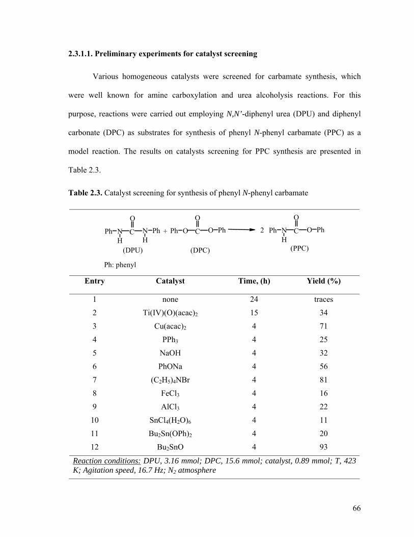
2.3.1.1. Preliminary experiments for catalyst screening
Various homogeneous catalysts were screened for carbamate synthesis, which
were well known for amine carboxylation and urea alcoholysis reactions. For this
purpose, reactions were carried out employing N,N’-diphenyl urea (DPU) and diphenyl
carbonate (DPC) as substrates for synthesis of phenyl N-phenyl carbamate (PPC) as a
model reaction. The results on catalysts screening for PPC synthesis are presented in
Table 2.3.
Table 2.3. Catalyst screening for synthesis of phenyl N-phenyl carbamate
(DPU)
C
O
+NH
Ph NH
Ph
(DPC)
C
O
OPh O Ph 2 C
O
(PPC)
NH
Ph O Ph
Ph: phenyl Entry Catalyst Time, (h) Yield (%)
1 none 24 traces
2 Ti(IV)(O)(acac)2 15 34
3 Cu(acac)2 4 71
4 PPh3 4 25
5 NaOH 4 32
6 PhONa 4 56
7 (C2H5)4NBr 4 81
8 FeCl3 4 16
9 AlCl3 4 22
10 SnCl4(H2O)6 4 11
11 Bu2Sn(OPh)2 4 20
12 Bu2SnO 4 93
Reaction conditions: DPU, 3.16 mmol; DPC, 15.6 mmol; catalyst, 0.89 mmol; T, 423 K; Agitation speed, 16.7 Hz; N2 atmosphere
66

From the catalyst screening it was observed that a non-catalytic reaction between
DPU and DPC produced only traces of PPC after 24 h indicating that catalyst was
essential for formation of PPC (Table 2.3, entry 1). Urea alcoholysis catalysts such as
titanium and copper acetyl acetonate complexes9d were also screened (see entry 2, 3) and
copper catalyst was found to be having good activity. Classical Lewis acid catalysts8e-h
such as FeCl3, AlCl3, SnCl4, (see entry 8-10) known for amine carboxylation reactions
showed poor activity compared to basic catalysts such NaOH, phenolate ion, onium salts
(see entry 5-7). Organotin complexes were also screened, which were known to be
excellent transesterification catalysts for carbonates and esters.12b Several organotin
complexes were employed for synthesis of carbamate from DPU and DPC in which
acidity of catalyst was varied to highly acidic to mild basic tin catalysts. The results of
these experiments showed that basic tin complexes such as dibutyl tin oxides (DBTO)
gave excellent carbamate yield (entry 12) compared to acidic tin compounds such as
SnCl4 (6H2O) (entry 10), while, Bu2Sn(OPh)2 having intermediate acidity showed
moderate yields of PPC (entry 11). Therefore, further reactions with various ureas and
carbonates were carried out using DBTO as a catalyst.
2.3.1.2. Reactivity of substituted urea and carbonate towards carbamate formation
The reaction between substituted urea and carbonate to form carbamate is a new
reaction and literature on the reactivity pattern of ureas and carbonate towards carbamate
formation is not available. However, considerable amount of work on ester aminolysis of
carbonates and alcoholysis of substituted ureas has been reported in literature (and
discussed later) which will be useful in understanding the reactivity behavior observed
for carbamate synthesis from urea and carbonate.
67

Ester aminolysis of substituted diphenyl carbonates to carbamate have been
investigated in detail.16 According to these investigators the reaction between organic
carbonate and amine is a function of basicity of amine. It is well known that in ester
aminolysis of substituted carbonates, the reaction depends upon the basicity of attacking
amine. It is generally belived that aminolysis proceeds smoothly when pKa values of
attacking amines are about 4-5 units higher than that of the leaving group (e.g. alkoxides
or aryloxide).17 The reactivity of carbonate depends upon the electrophilicity of carbonyl
carbon; the factors that help increase the electrophilicity of carbonyl carbon will increase
the rate of reaction. An electron withdrawing substituents on phenoxide or alkoxide will
facilitate nucleophilic attack (retarded by electron donating substituents).18 However, the
final reactivity will depend on the pKa of attacking amine as noted earlier. Similarly,
alcoholysis of substituted urea was accelerated by electron donating group on alcohol and
slowed by electron withdrawing groups, provided that hindrance factor was not coming
into play.9d On the other hand, electron-donating substituents on phenyl urea increased
the reactivity of urea, while the electron attracting substituents on aryl group decreased
reactivity of urea. 19
A few substituted ureas were reacted with diphenyl carbonate using DBTO as a
catalyst and these results are summarized in Table 2.4. It was observed that substituted
diphenyl urea having electron withdrawing (entry 2-5) or donating (entry 6) groups
presents on the aromatic ring did not show any prominent electronic effect on their
reactivity towards diphenyl carbonate and these ureas gave excellent yields of carbamate.
Except, that for sterically hindered N,N`-bis(2-chloro phenyl) urea which showed
substantially low carbamate yield (Table 2.4, entry 2). While carbonate reactivity towards
68

diphenyl urea seemed to be following the rule that carbonate reactivity increased with
leaving group ability of phenoxide and alkoxides (see entry 1 & 7), which was consistent
with the trend observed in aminolysis of carbonates.16a The reactivity of alkyl carbonates
towards ureas was found to decrease in the order, dimethyl carbonate> diethyl carbonate
> dibutyl carbonate (entry 7-11). This observed reactivity of carbonate suggested that
carbonyl carbon of dimethyl carbonate was most electrophilic center and that of dibutyl
carbonate was least in the three carbonates investigated. A similar kind of reactivity was
earlier observed for alcohols in transesterification of DMC and was attributed to the steric
factors rather than electronic effect of various alcohols. 12b,20
C
O
O MeOPh disproportionationC
O
O MeOMe + C
O
O PhOPh
(methyl phenyl carbonate) (dimethyl carbonate) (diphenyl carbonate)
Scheme 2.3
When unsymmetrical carbonate such as methyl phenyl carbonate was reacted with
DPU, phenyl N-phenyl carbamate and methyl N-phenyl carbamate (MPC) were formed in
62% and 10% yields respectively (Table 2.4, entry 12). However, as per the
stoichiometry of reaction (Scheme 2.3) equal amount of carbamates should have been
formed. It is well known that disproportionation of methyl phenyl carbonate to DPC and
DMC is likely to occur under the catalytic conditions (Scheme 2.3).21 Analysis of
reaction crude also confirmed the formation of symmetrical carbonates from methyl
phenyl carbonate. The symmetrical carbonates thus formed reacted independently with
DPU to form corresponding carbamates and yields of carbamates depended upon the
reactivity of carbonates viz, DPC and DMC. Higher yields of methyl N-phenyl carbamate
69

were obtained as DPC is more reactive than DMC. The reactivity pattern study showed a
general behavior in that excellent carbamate yields were obtained when an aromatic (or
aliphatic) urea was reacted with aromatic (or aliphatic) carbonate but poor yields were
envisaged when aromatic urea was reacted with aliphatic carbonate and vice versa.
Table 2.4. Synthesis of carbamates using dibutyl tin oxide catalyst
+R1NH CO NHR1 R2OCO OR2 R1NHCO OR22
Entry R1 (urea) R2 (carbonate) Time, (h) Product code
Isolated Yield (%)
1 C6H5 C6H5 4 1a 93
2 2-Cl-C6H4 C6H5 4 1b 75a
3 3-Cl-C6H4 C6H5 4 1c 92
4 4-Cl-C6H4 C6H5 4 1d 90
5 3-NO2C6H4 C6H5 4 1e 89
6 4-CH3-C6H5 C6H5 4 1f 90
7b C6H5 CH3 4 2a 77
8b C6H5 C2H5 4 2b 61
9b C6H5 C4H9 4 2c 50
10b CH3 CH3 4 3a 91
11b CH3 C2H5 4 3b 64
12c C6H5 - 15 - 72
Reaction conditions: substituted urea, 3.16 mmol; carbonate, 15.6 mmol; catalyst, 0.89 mmol; T, 423 K; Agitation speed, 16.7 Hz; N2 atmosphere; acarbamate are unstable breactions were carried out in a 50 ml autoclave using 17ml of carbonate and under nitrogen pressure of 3.4 MPa; creaction was carried out using methyl phenyl carbonate
70

2.3.1.3. Synthesis of methyl N-methyl carbamate (MMC)
Methyl N-methyl carbamate (MMC) an industrially important carbamate was
synthesized by reacting N,N’-dimethyl urea (DMU) with dimethyl carbonate (DMC).
Various process parameters such as, effects of DBTO concentration, DMU concentration,
DMC concentration and temperature were studied for MMC synthesis with the aim to
understand the kinetics and mechanism of the reaction. For this purpose, few initial
experiments were carried out to examine the material balance (for side product formation
etc.) as well as the contribution of non-catalytic reaction in the formation of methyl N-
methyl carbamate from N,N’-dimethyl urea and dimethyl carbonate. Figure 2.3 shows a
typical concentration-time profile in a high-pressure batch reactor. In this Figure since
DMC acted as a solvent as well as the reactants, DMU was considered as limiting
reactant. Hence, on the basis of moles of DMU reacted carbamate formation and DMC
consumed were tallied. Conversion of DMU was increased with respect to time and
correspondingly DMC was also consumed with concurrent formation of MMC,
indicating no side products formation and material balance was in complete agreement
with the stoichiometry. It was observed that there was 91% DMU conversion with 100%
selectivity for MMC formation at the end of six hours, this also showed that the reaction
was thermodynamically favorable under the experimental conditions. It may be noted that
Figure 2.3 shows an induction period of about 45 minutes at this temperature and
indicated the formation of an active catalytic species from catalyst precursor DBTO that
was responsible for the catalytic reaction. Fu and Ono have also reported similar
observation earlier for PbO catalyzed methoxy carbonylation of aniline with dimethyl
carbonate to carbamate.8f
71

0.0
0.3
0.6
0.9
1.2
1.5
1.8
0 60 120 180 240 300 360
Time, min
Con
cent
ratio
n of
MM
C o
r D
MU
, Km
ol/m
3
9.0
9.2
9.4
9.6
9.8
10.0
Con
cent
ratio
n of
DM
C,
Km
ol/m
3
MMC
DMU
DMC
Figure 2.3 Concentration -Time profile of MMC synthesis
Reaction conditions: DMU, 0.92 Kmol/m3; DMC, 9.95 Kmol/m3; DBTO, 0.06 Kmol/m3; T, 423 K; Time, 6 h; N2 pressure, 3.4 MPa; Agitation speed, 16.7 Hz; Total volume, 30 ml.
2.3.1.3.1. Effectiveness of DBTO as catalyst
Since, a base can effectively catalyze the reaction between urea and carbonate and
aliphatic ureas have mild basicity, we explored the possibility of a non-catalytic reaction
between and aliphatic carbonate. For this purpose, non-catalytic reaction between N,N-
dimethyl urea (DMU) and dimethyl carbonate (DMC) was investigated and these results
are presented in Table 2.5. The results of non catalytic reaction between urea and
carbonate showed that, basic urea such as N,N`-dimethyl urea activated carbonate, which
gave methyl N-methyl carbamate in good yields even in the absence of any catalyst
(37%; Table 2.5, entry 1).
72

Table 2.5. Effect of catalytic conditions on MMC synthesis
+ CH3OCO OCH3CH3NHCONHCH3 2 OCH3CH3NHCO
DMU DMC MMC
Entry Conditions Pressure, MPa Yieldsa of MMC, %
MMC yield due to DBTO, %
1 Non catalytic Autogenous 37 -
2 Non catalytic 3.4; N2 65 -
3 DBTO Autogenous 91 54 (91-37)
4 Non catalytic 3.4; CO2 9 -
5 DBTO 3.4; CO2 62 53 (62-9)
Reaction conditions: DMU, 15.34 mmol; DMC,169.2 mmol; DBTO, 1.81 mmol; T, 423 K; Time, 4 h; Agitation speed, 16.7 Hz; reaction volume, 17 ml; a GC yields.
On the other hand less basic urea like N,N’- diphenyl urea needs catalyst for carbamate
formation from diphenyl carbonate (Table 2.3, entry 1). Thus, catalysis is also dependent
on acidity and basicity of substrates as well as catalyst. In order to further confirm that
urea having basic property which catalyzes carbamate synthesis reaction of carbonate and
urea, an experiment was performed with carbon dioxide with the aim to neutralize the
basic sites of substituted urea resulting in lower activity. As expected, this experiment
gave very poor yields of MMC (9% yields, Table 2.5, entry 4). Thus, carbon dioxide
deactivated urea and thereby decreased its ability to activate dimethyl carbonate. This
confirmed our reasoning that DMU basicity was playing a key role in non-catalytic
reaction between DMU and DMC and that, DMU was acting as a both reactant as well as
a catalyst. However, the results obtained on the effect of pressure of inert gas such as
nitrogen on non-catalytic reaction between DMU and DMC was most unexpected. At 3.4
MPa pressure of nitrogen, the MMC yield increased to about 65% (entry 2).
73

Experiments were also undertaken to understand the effect of CO2 on DBTO
activity, and the results are also shown in Table 2.5. Since MMC was also formed via a
non-catalytic route (entry 1 and 2) activity due to DBTO alone could be calculated by
accounting for the contribution due to non-catalytic reaction. Entry 3 in Table 2.5.
showed that overall yield of MMC obtained under DBTO catalyzed reaction conditions
was 91%, which included 37% yield of MMC due to non-catalytic reaction (entry 1,
yields in absence of DBTO) and the rest 54% yields was thus due to DBTO. While, in the
presence of CO2, DBTO catalyzed reaction showed 62% of MMC yield (entry 5) and
under CO2 atmosphere only 9% MMC was formed due to non-catalytic reaction (entry 4).
It indicated that even in the presence of CO2, MMC yield due to DBTO was not affected
(compare entry 3, and 5 for MMC yields due to DBTO). Therefore, it was concluded that
most of catalytic activity of DBTO was retained even under CO2 atmosphere.
2.3.1.3.2. Effect of DBTO concentration on MMC synthesis
Effect of DBTO concentration on conversion and selectivity behaviors in MMC
synthesis was investigated in the range of 0.026 − 0.16 Kmol/m3. A plot of MMC yields
Vs catalyst concentration showed that with increased catalyst concentration, MMC yield
increased, showing first order dependence normally observed for catalyst concentration
effect. Except at high DBTO catalyst loading, the rates seemed to be tapering off with
catalyst loading (Figure 2.4). In the present case, both the reactants (urea and carbonate)
and catalyst were infinitely soluble in toluene under reaction conditions offering a
homogeneous liquid phase and therefore no liquid side mass transfer resistance was
expected. However, it may be noted that in absence of catalyst appreciable amount of
non-catalytic reaction was also contributing to MMC yield, indicating that contribution of
74
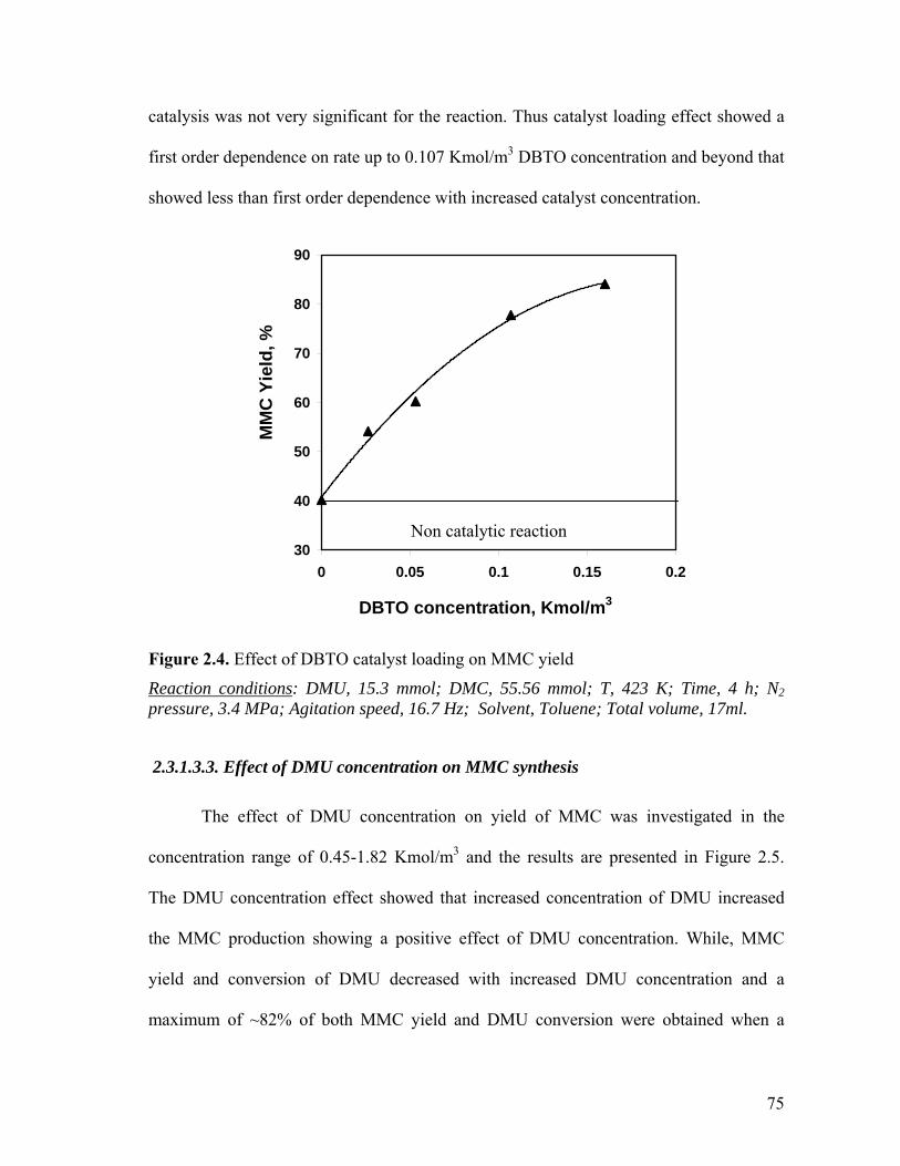
catalysis was not very significant for the reaction. Thus catalyst loading effect showed a
first order dependence on rate up to 0.107 Kmol/m3 DBTO concentration and beyond that
showed less than first order dependence with increased catalyst concentration.
30
40
50
60
70
80
90
0 0.05 0.1 0.15 0.2
DBTO concentration, Kmol/m3
MM
C Y
ield
, %
Non catalytic reaction
Figure 2.4. Effect of DBTO catalyst loading on MMC yield
Reaction conditions: DMU, 15.3 mmol; DMC, 55.56 mmol; T, 423 K; Time, 4 h; N2 pressure, 3.4 MPa; Agitation speed, 16.7 Hz; Solvent, Toluene; Total volume, 17ml.
2.3.1.3.3. Effect of DMU concentration on MMC synthesis
The effect of DMU concentration on yield of MMC was investigated in the
concentration range of 0.45-1.82 Kmol/m3 and the results are presented in Figure 2.5.
The DMU concentration effect showed that increased concentration of DMU increased
the MMC production showing a positive effect of DMU concentration. While, MMC
yield and conversion of DMU decreased with increased DMU concentration and a
maximum of ~82% of both MMC yield and DMU conversion were obtained when a
75

lower DMU concentration was employed (0.4.5 Kmol/m3). However, selectivity for
MMC was not affected with increase in DMU concentration. The decreased yield of
MMC was expected due to increased urea concentration as the ratio of urea to catalyst
increased (at constant catalyst concentration). Hence, under such conditions yields and
conversions were expected to decrease for a fix reaction time and was not due to
deactivation of catalyst.
0
20
40
60
80
100
0 0.5 1 1.5 2DMU concentration. Kmol/m3
MM
C c
once
ntra
tion,
K
mol
/m3
0
0.5
1
1.5
2
2.5
MM
C Y
ield
, %
MMC yieldMMC concentration
Fig. 2.5. Effect of DMU concentration on MMC yield
Reaction conditions: DBTO, 1.81mmol; DMC, 55.56 mmol; T, 423 K; Time, 4 h; N2 pressure, 3.4 MPa; Agitation speed, 16.7 Hz; Solvent, Toluene; Total volume, 17 ml.
2.3.1.3.4. Effect of DMC concentration on MMC synthesis
The effect of DMC concentration on MMC yield was investigated in
concentration range of 1.65-9.92 Kmol/m3, reactions were carried out at constant DMU
concentration the results are presented in Figure 2.6. The yield of MMC increased
76

sharply as DMC concentration was increased and in extreme case when pure DMC was
employed as reactant maximum yield of 91% of MMC was obtained.
0
20
40
60
80
100
0 2 4 6 8 10
DMC concentration, Kmol/m3
MM
C y
ield
, %
Fig. 2.6. Effect of DMC concentration on MMC yield
Reaction conditions: DBTO, 1.81mmol; DMU, 15.34 mmol; T, 423 K; Time, 4 h; PN2, 3.4 MPa; Agitation speed, 16.7 Hz; Solvent, Toluene; Total volume, 17 ml.
2.3.1.3.5. Effect of solvent on MMC synthesis
The effect of various solvents such as o-dichlorobenzene (ODCB), toluene,
dimethyl formamide (DMF), diphenyl ether (DPE) and DMC was investigated and the
results are presented in Figure 2.7. It can be seen from this figure that polar solvents such
as DMF, DMC and ODCB have no significant advantage over non-polar solvent like
toluene. The highest yield obtained was with DMC as a solvent and it was due to a
synergic effect of DMC acting as a reactant as well as solvent.
77

78
69
91
68 65
0
20
40
60
80
100
Toluene ODCB DMC DPE DMF
Solvent
MM
C y
ield
, %
Fig. 2.7. Effect of solvent on MMC yield
Reaction conditions: DBTO, 1.81mmol; DMU, 15.34 mmol; T, 423 K; Time, 4 h; N2 pressure, 3.4 MPa; Agitation speed, 16.7 Hz; Solvent, Toluene; Total volume, 17 ml.
2.3.1.3.6. Effect of temperature on MMC synthesis
The effect of temperature on MMC formation rate was investigated in the range
413- 433 K. For this purpose catalyst DBTO was pretreated at 423 K with DMC under
3.4 MPa of N2 for 1 h in a pressure reactor and a fix amount of this pretreated catalyst
solution (stored under N2) was later used for temperature effect study. The pretreatment
of catalyst avoided the complexities arising from the effect of temperature on induction
period and gave more consistent and realistic initial rates for temperature parameter
effect. Figure 2.8 shows that MMC yield increases with increase in temperature using
DBTO as catalyst. From this figure the apparent activation energy obtained from
Arrhenius law was found to be 34.3 KJ/mol. The low value of activation energy reflected
78

the secondary role played by catalyst DBTO, which was expected for the reaction as in
absence of catalyst appreciable yields of MMC was obtained (Section 2.3.1.3.1. on
effectiveness of DBTO catalyst).
-7.5
-7.3
-7.1
-6.9
0.0023 0.002325 0.00235 0.002375 0.0024 0.002425
1/T, K-1
ln R
MM
C (i
nitia
l rat
e), K
mol
/m3 /s
Fig. 2.8. Temperature dependence of initial rate of MMC
Reaction conditions: DBTO, 1.81mmol; DMU, 15.34 mmol; DMC, 169.2 mmol; T, 423 K; Time, 0.5 h; N2 pressure, 3.4 MPa; Agitation speed, 16.7 Hz; Total volume, 17 ml.
2.3.1.4. Plausible reaction mechanism
Basic tin complex such as DBTO is known to interact with organic carbonate14
indicating that interaction of carbonate with DBTO is more likely to be the first step
towards activation of substrates in our case. Sucia et al.23 have proposed the dialkyl tin
compounds (e.g. DBTO) catalyzed mechanism for the synthesis of dialkyl carbonate
from alkyl carbamates and alcohol. Based on their study, a plausible pathway for the
formation of N-substituted carbamates from substituted ureas and carbonates is depicted
79

in Scheme 2.4. The basic DBTO was believed to play a key role as a nucleophile
attacking carbonyl carbon of carbonate forming catalytically active species, dibutyl
alkoxy carbonato tin [I].12b Species [I] interacted with substituted urea to eliminate one
molecule of carbamate forming dibutyl alkoxy carbamato tin species [II].22 A further
reaction of species [II] with carbonate resulted in the formation of one more molecule of
carbamate with regeneration of active species [I]. The key step here was the formation of
species [I], which presumably does not get converted into Bu2Sn(OR)2 because of the
presence of urea. However, further work in this area is necessary to arrive at a definitive
mechanism for carbamate formation from substituted urea and carbonate catalyzed by tin
complexes.
[I]
Bu2SnO(RO)2CO
OCOORRNHCOOR
SnRNHCONHR
OR
OCONHRSn
OR RNHCOORROCOOR
[II]
Scheme 2.4: DBTO catalyzed proposed mechnism for carbamate synthesis from urea and carbonate
80

2.3.2. CARBAMATE SYNTHESIS USING HETEROGENEOUS CATALYST Though homogeneous catalyst DBTO is highly active for carbamate synthesis
from substituted urea and carbonate, the main drawback of this homogeneous catalyst is
the separation of catalyst from the product. Hence, various heterogeneous acid/base
catalysts were employed for the carbamate synthesis (Table 2.6). Catalyst screening was
carried out for the reaction of N,N’- diphenyl urea and diphenyl carbonate to phenyl N-
phenyl carbamate as model. From the catalyst screening it was observed that basic
catalyst showed excellent activity over acidic catalyst. Also, from the earlier literature, it
is known that basic catalysts are highly efficient for reactions involving carbonate e.g.
carboalkoxylation, trans- esterification and alkylation. Acidic Al2O3 was found inactive
for carbamate synthesis (Table 2.6, entry 3) while solid-base catalysts like, PbZrO3, Mg-
Al Htlc and Li-MgO were found to give excellent yields of carbamates (90-95% yield,
entry 5-7). From the catalyst screening, it was also found that silica gel (W.R. Grace) was
highly efficient catalyst for carbamate synthesis and its catalytic activity could be
attributed to the interactions of organic carbonate and urea with silanol groups.23 The
variation in activity of silica gel catalysts procured from two different sources viz. W.R
Grace and Davisil (entry1 and 2) is thought to be due to the difference in distribution of
silanol groups in these two silicas. Na-ZSM-5 catalyst with Si/Al ratio of 130 essentially
behaved like SiO2 since at these high ratio of Si/Al, contribution of Al atom in zeolite
framework was very less. The activity in this zeolite is likely to be due to basic sites
created by oxygen atom and not by Lewis sites due to Al atom.24
81

Table 2.6. Synthesis of carbamates using solid acid/base catalysts
+R1NH CO NHR1 R2OCO OR2 R1NHCO OR22
Entry R1 (urea) R2 (carbonate) Catalyst Time, (h) Yield (%)
1 C6H5 C6H5 Silica gela 3
8
81
96
2 C6H5 C6H5 Silica gelb 3 23
3 C6H5 C6H5 Al2O3 (acidic) 3 0
4 C6H5 C6H55% Pb on Silica gela 3 18
5 C6H5 C6H5 PbZrO3 3 92
6 C6H5 C6H5 Mg-Al Htlc 3 95
7 C6H5 C6H5 Li-MgOc 3 90
8 C6H5 C6H5Na-ZSM-5 (Si/Al=130) 3 79
9 2-Cl-C6H4 C6H5 Silica gela 8 73a
10 3-Cl-C6H4 C6H5 Silica gela 8 79 11 4-Cl-C6H4 C6H5 Silica gela 8 89
12 3-NO2C6H4 C6H5 Silica gela 8 89
13 4-CH3-C6H5 C6H5 Silica gela 8 91
14d C6H5 CH3 Silica gela 8 18
15d C6H5 C2H5 Silica gela 8 10
16d CH3 CH3 Silica gela 8 81
Reaction conditions: substituted urea, 3.16 mmol; carbonate, 15.6 mmol; catalyst,0.2 g; T, 423 K; Agitation speed, 16.7 Hz; N2 atmosphere; a Silica gel from W.R. Grace, USA ; b Silica gel davisil, Aldrich, USA reaction T, 373 K; c Prepared by wet impregnation of LiOAc on Mg(OAc)2 followed by calcination at 993 K (Li/Mg = 0.1); d reactions were carried out in a 50 ml autoclave using 17ml of carbonate and under N2 pressure of 3.4 MPa.
82

The most intriguing aspect of heterogeneous catalyst is catalyst recycle. Hence,
the reusability of silica gel and Na-ZSM-5 catalyst was studied and the results are shown
in Figure 2.9. Recycling of catalyst was carried out by filtration of catalyst from crude
reaction mixture in acetone followed by drying of catalyst and calcination at 773 K for 3
h. The catalyst recycle result showed excellent reusability of both catalysts for up to five
recycles without any loss in their catalytic activity.
0
20
40
60
80
100
0 1 2 3 4 5 6
Number of recycle
PPC
yie
ld, %
Silica gel (W.R. Grace) calcined at 773 K
ZSM-5 (Si/Al =130), calcined at 773 K
silica gel (W.R.Grace) dried at 373 K
Figure 2.9. Catalyst recycles
Reaction conditions: Catalyst, 0.2 g; DPU, 3.16 mmol; DPC,15.4 mmol; T, 423 K; Time, 8 h; N2 atmosphere; Agitation speed, 16.7 Hz; Total volume, 4 x 10 -6 m3.
83

2.4. CONCLUSION
An environmentally benign route for the synthesis of carbamates via
transfunctionalization of substituted ureas and organic carbonates using homogeneous as
well as heterogeneous catalysts was demonstrated for the first time. This methodology is
simple and highly efficient for carbamate synthesis, and shows 100% atom economy.
High yield of carbamates were obtained by using homogeneous dibutyl tin oxide (DBTO)
as well as heterogeneous silica gel catalyst, which was easily recycled. It was observed
that there was no loss in catalytic activity of silica gel even after five recycles. Reactivity
study of substituted ureas and organic carbonate was investigated and it was observed
that aliphatic ureas showed higher reactivity compared to aromatic ureas due to their
basicity. Various electron donating or electron withdrawing substituents (e.g. CH3, Cl and
NO2) on aromatic urea did not show any significant effect on urea reactivity compared to
non-substituted aromatic urea i.e. diphenyl urea. The reactivity of alkyl carbonates
towards ureas was found to decrease in the order, dimethyl carbonate> diethyl carbonate
> dibutyl carbonate as steric hindrance increased from dimethyl carbonate to dibutyl
carbonate. Reaction parameter effects on the synthesis of industrially important methyl
N-methyl carbamate were investigated. The Arrhenius activation energy for the reaction
between N,N’-dimethyl urea and dimethyl carbonate was found to be 34.3 KJ/mol. A
reaction mechanism has been also postulated explaining the role of DBTO in the
synthesis of carbamate from urea and carbonates.
84

2.5. IDENTIFICATION OF CARBAMATES
Carbamates were isolated in pure form and fully characterized by elemental
analysis, 1H NMR, 13CNMR, IR and GC-MS.
Phenyl N-Phenyl carbamate (1a): IR (KBr) υCO: 1717 cm-1. 1H NMR (200 MHz,
CDCl3): δ = 6.95δ (s, 1H, NH), 7.46-7.09 (m, 10H, Ar-CH);. 13C NMR (500 MHz,
CDCl3): δ = 118.84 (Ar-C), 121.61(Ar-C), 123.90 (Ar-C), 125.66 (Ar-C), 129.11 (Ar-C),
129.37 (Ar-C), 137.38 (Ar-C-N), 150.6 (C=O), 151.64(Ar-C-O). GC/MS (EI, 70 eV): 1a
thermally decomposes to Phenyl isocyanate and Phenol, therefore; it was indirectly
identified by its decomposition products. Phenyl isocyanate, (m/z): 119, 91, 64, 51 and
Phenol, (m/z): 94, 66, 39. Microanalysis for C13H11NO2, Calculated: 73.23% C, 5.16% H,
6.57% N; found: 72.85% C, 5.27% H, 6.35% N.
Phenyl N-(3-Cl-phenyl) carbamate (1c): IR (KBr) υCO: 1714 cm-1. 1H NMR (200 MHz,
CDCl3): δ = 6.97 (s, 1H, NH), 7.57-7.07 (m, 9H, Ar-CH);. 13C NMR (500 MHz, CDCl3):
δ = 118.96 (Ar-C), 120.85 (Ar-C), 121.52 (Ar-C), 125.8 (Ar-C), 126.27 (Ar-C), 129.54
(Ar-C), 130.01 (Ar-C), 134.77 (Ar-C-Cl), 138.62 (Ar-C-N), 150.43 (C=O), 151.51(Ar-C-
O). GC/MS (EI, 70 eV): 1c decomposes to N-(3-Cl-phenyl) isocyanate and Phenol. N-(3-
Cl-phenyl) isocyanate, (m/z): 153, 125, 90, 63, 50 and Phenol, (m/z): 94,66,39.
Microanalysis for C13H10NO2Cl, Calculated: 63.03% C, 4.04% H, 5.65% N, 14.34% Cl;
found: 63.4% C, 4.02% H, 5.56% N, 13.97% Cl.
Phenyl N-(4-Cl-phenyl) carbamate (1d): IR (KBr) υCO: 1716 cm-1. 1H NMR (200 MHz,
CDCl3): δ = 6.98 (brs, 1H, NH), 7.45-7.17 (m, 9H, Ar-CH). 13C NMR (500 MHz,
CDCl3): δ = 120.30 (Ar-C), 121.55 (Ar-C), 125.83 (Ar-C), 129.02 (Ar-C), 129.15 (Ar-C),
129.43 (Ar-C-Cl), 135.98 (Ar-C-N), 150.46 (C=O), 151.41 (Ar-C-O). GC/MS (EI, 70
eV): 1d decomposes to N-(4-Cl phenyl) isocyanate and Phenol. N-(4-Cl phenyl)
isocyanate, (m/z): 153, 125, 90, 63, 50 and Phenol, (m/z): 94, 66, 39. Microanalysis for
C13H10NO2Cl, Calculated: 63.03% C, 4.04% H, 5.65% N, 14.34%.
Phenyl N-(3-NO2 –phenyl) carbamate (1e): IR (KBr) υCO: 1712 cm-1. 1H NMR (200
MHz, CDCl3): δ = 7.16 (dd, J = 1.6 & 7.5 Hz, 2H, Ar-CH), 7.22 (dd, J = 1.6 & 7.5 Hz,
1H, Ar-CH), 7.3 (brs, 1H, NH), 7.37 (dd, J = 1.6 & 7.5 Hz, 2H, Ar-CH), 7.45 (t, J = 7.95
85

Hz, 1H, Ar-CHmeta to NO2), 7.7 (d, J = 7.95 Hz, 1H, Ar-CHpara to NO2), 7.92 (dd, J = 1.6 &
7.95 Hz, 1H, Ar-CHortho to NO2), 8.31 (t, J = 1.6 Hz, 1H, Ar-CHortho to NO2), 13C NMR (500
MHz, CDCl3): δ = 113.66 (Ar-C), 118.42 (Ar-C), 121.45 (Ar-C), 124.42 (Ar-C), 126.01
(Ar-C), 129.46 (Ar-C), 129.86 (Ar-C), 138.69 (Ar-C-N), 148.66 (Ar-C-NO2), 150.22
(C=O), 151.7 (Ar-C-O). GC/MS (EI, 70 eV): 1f decomposes to N-(3-NO2 phenyl)
isocyanate and Phenol. N-(3-NO2 phenyl) isocyanate, (m/z): 164, 118, 90, 63, 50. Phenol,
(m/z): 94, 66, 39. Microanalysis for C13H10N2O4, Calculated: 60.46% C, 3.87% H,
10.85% N; found: 61.45% C, 3.94% H, 10.52% N.
Phenyl N-(4-CH3 phenyl) carbamate (1f): IR (KBr) υCO: 1719 cm-1. 1H NMR (200
MHz, CDCl3): δ = 2.32 (s, 3H, Ar-CH3), 6.95 (brs, 1H, NH), 7.43-7.11 (m, 9H, Ar-CH).
13C NMR (500 MHz, CDCl3): δ = 20.69 (CH3), 118.88 (Ar-C), 121.67 (Ar-C), 125.55
(Ar-C), 126.25 (Ar-C), 129.32 (Ar-C), 129.6 (Ar-C), 134.79 (Ar-C-N), 150.68 (C=O),
151.7(Ar-C-O). GC/MS (EI, 70 eV): 1e decomposes to N-(4-CH3 phenyl) isocyanate and
phenol. N-(4-CH3 phenyl) isocyanate, (m/z): 133, 104, 91, 63, 51. Phenol, (m/z): 94, 66,
39. Microanalysis for C14H13NO2, Calculated: 74% C, 5.72% H, 6.16% N; found: 73.75%
C, 5.55% H, 6.38% N.
Methyl N-phenyl carbamate (2a): IR (KBr) υCO: 1708 cm-1. 1H NMR (200 MHz,
CDCl3): δ = 3.77 (s, 3H, O-CH3), 6.69 (brs, 1H, NH), 7.4-7.02 (m, 5H, Ar-CH). 13C
NMR (500 MHz, CDCl3): δ = 52.21 (O-CH3) , 118.74 (Ar-C), 123.38 (Ar-C), 128.94
(Ar-C), 137.84 (Ar-C-N), 154.11 (C=O). GC/MS: (m/z): 151, 135, 119, 106, 92, 77, 65,
51, 39. Microanalysis for C8H9NO2, Calculated: 63.57% C, 5.96% H, 9.27% N; found:
63.05% C, 5.71% H, 8.98% N.
Ethyl N-phenyl carbamate (2b): IR (KBr) υCO: 1703 cm-1; 1H NMR (200 MHz,
CDCl3): δ = 1.32 (t, 3H, J = 7.32 Hz, CH3-C), 4.22 (q, 2H, J = 7.32 Hz, O-CH2-C), 6.66
(brs, 1H, NH) 7.42-7.03 (m, 5H, Ar-CH). 13C NMR (500 MHz, CDCl3,): δ = 14.45 (CH3-
C), 61.1 (O-CH2), 118.71 (Ar-C), 123.25 (Ar-C), 128.91 (Ar-C), 137.99 (Ar-C-N), 153.7
(C=O). GC/MS: (m/z): 165, 137, 119, 93, 77, 65, 51, 39. Microanalysis for C8H9NO2,
Calculated: 65.45% C, 6.66% H, 8.48% N; found: 65.69% C, 6.73% H, 8.46% N.
Butyl N-phenyl carbamate (2c): IR (KBr) υCO: 1702 cm-1. 1H NMR (200 MHz, CDCl3):
δ = 0.97 (t, 3H, J = 7.33Hz, CH3-C), 1.45 (m, 2H, J = 6.84Hz & 7.33 Hz, -CH2-), 1.69
86

(qu, 2H, J =6.35Hz & 6.83Hz, -CH2-), 4.19 (t, 2H, J = 6.35Hz, -CH2-O), 6.67 (brs, 1H,
NH), 7.42-7.04 (m, 5H, Ar-CH);. 13C NMR (500 MHz, CDCl3,): δ = 13.66 (CH3-C),
19.03 (CH2-C), 30.95 (CH2-C), 65.08(O-CH2), 118.67 (Ar-C), 123.28 (Ar-C), 128.97
(Ar-C), 138.01 (Ar-C-N), 153.76 (C=O). GC/MS: (m/z): 193, 137, 119, 93, 77, 65, 41.
Microanalysis for C11H15NO2, Calculated: 68.39% C, 7.77% H, 7.72% N; found: 67.85 %
C, 7.78% H, 7.35% N.
Methyl N-methyl carbamate (3a): IR (KBr) υCO: 1711 cm-1. 1H NMR (200 MHz,
CDCl3): δ = 2.78 (d, 3H, J = 4.88 Hz, N-CH3), 4.93 (brs, 1H, NH); 3.67 (s, 3H, O-CH3).
13C NMR (500 MHz, CDCl3,): δ = 27.36 (N-CH3), 51.91 (O-CH3), 157.77 (C=O).
GC/MS (EI, 70 eV), (m/z): 89, 74, 58, 44.
Ethyl N-methyl carbamate (3b): IR (KBr) υCO: 1704 cm-1. 1H NMR (200 MHz,
CDCl3): δ = 1.16 (t, 3H, J = 7.32 Hz, CH3-C), 2.7 (d, 3H, N-CH3), 4.018 (q, 2H, J = 7.32
Hz, O-CH2), 4.95 (brs, 1H, NH). 13C NMR (500 MHz, CDCl3): δ = 14.42 (CH3), 27.17
(N-CH3), 60.47 (O-CH2), 157.33 (C=O). GC/MS (EI, 70 eV), (m/z): 103, 88, 74, 58, 44.
87

REFERENCES
1. M. Aresta, A. Didenedetoo and E. Quarnta, Tetrahedran, 1998, 54, 14145 and references cited therein.
2. P. Adames and F.A. Baron; Chem Rev., 1965, 65, 567. 3. T. Greene and P.G.M. Wuts; Protective Groups in Organic Synthesis; 2nd Edn; Wiley,
New York; 315 (1991). 4. (a) R. G. Arnold, J. A. Nelsonand and J. J. Verbanc, Chem.Rev.; 1956, 56, 47; (b) H.J.
Twitchett, Chem. Soc. Rev., 1974, 3, 209. 5. F. Paul; Coord. Chem. Rev., 2000, 203, 310. 6. (a) S. Fukuoka, M. Chono and M. Kohno, CHEMTECH, 1984, 670;(b) H. Alper and F.
Hartstock, J. Chem. Soc. Chem. Commun, 1985, 1141; (c) F. Shi, Y. Deng, T. Sima and H. Yang, J. Catal; 2001, 203, 525; (d) S.P. Gupte and R.V. Chaudhari, J. Catal, 1988,114, 246; (e) K. Kondo, S. Yokoyama, N. Myoshi, S. Murai and N. Sonoda, Angew. Chem. Int. Ed. Engl, 1979, 18, 692.
7. (a) T. Tsuda, H. Washita, K. Watanabe, M. Miwa and T. Saegusa, J. Chem. Soc. Chem. Commun, 1978, 815; (b) M. Aresta and E. Quaranta, Tetrahedran, 1992, 48 1515; (c) W. D. McGhee, Y. Pan and D.P. Riley, J. Chem. Soc. Chem. Commun, 1994, 699; (d) M. Abla, J. Choi and T. Sakakura, Chem.Comm. 2001, 2238.
8. (a) Annon. Res. Discl., 1987, 275, 162; C.A., 1988, 108, 16742 g; (b) U. Romano, G. Fornasari and S. Di Gioachino, DE 3,202,690, C.A., 1982, 97, 144607d; (c) T. Mukai, K. Suenobu and M. Mitsuru, C.A., 1977, 87, 52961e; (d) E. Angeles, A. Santillan, I. Martinez, A. Ramirez and E. Moreno, Synth. Commun, 1994, 24, 2441; (e) F. Porta, S. Cenini; M. Pizzotti and C. Crotti, Gazz. Chim. Ital, 1985, 115, 275. (f) Z. Fu and Y. Ono, J. Mol. Catal., 1994, 91, 399; (g) Y. Fu, T. Baba and Y. Ono, J. Catal, 2001, 197, 91; (h) T. Baba, M. Fujiwara, A. Oosaku, A. Kobayashi, R.G Deleon and Y. Ono, App. Catal. A: Gen, 2002, 227, 1.
9. (a) S. Bunte; Ann., 1891, 151, 181; (b) A. Cahourrs, Compt. rend., 1873, 76, 1387; (c) A. W. Hofmann, Chem. Ber., 1871, 4, 262; (d) P. Ball, H. Fullmann, R. Schwalim and W. Heitz, C1 Mol. Chem., 1984, 1, 95; (e) N. V. Kaminskaia and N. M. Kostic; Inorg.Chem., 1998, 37, 4302.
10. R. A. Sheldon; CHEMTECH, 1994, 38. 11. R. S. Sandler and K. Wolf, in A. T. Blomquist (Ed.), Organic functional group
preparations, Organic Chemistry, A series of Monographs- Volume II, Academic Press, New York and London, 1971, 135.
12. (a) A. A. G.Shaikh and S. Sivaram, Chem.Rev., 1996, 96, 951; (b) A. A. G.Shaikh and S. Sivaram, Ind. Eng. Chem. Res., 1992, 31,1167.
13. K. Hasegawa; T. Suzuki and M. Inaba, (Mitsubishi Chemical Industries Ltd., Japan). JP 10139736 A2 (1998).
14. H. R. Kricheldrof, N. Probst, D. Langanke and G. Schwarz, Macromol. Rapid Commun., 2001, 22, 750.
15. F. Cavani, F. Trifiro and A. Vaccari, Catal. Today, 1991, 11, 173. 16. (a) M. J. Gresser and W.P. Jencs, J.Am.Chem.Soc., 1977, 99, 6963; (b) E. A. Castro,
Chem.Rev., 1999, 99, 3505. 17. W. P. Jencks and M. Gilchrist, J. Am. Chem. Soc., 1968, 90, 2622. 18. M. J. Gresser and W. P. Jencks, J. Am. Chem. Soc.; 1977, 99, 6970. 19. R. Laudien and R. Mitzner,J. Chem.Soc.Perkin Trans.2;. 2001, 2226. 20. P. Tundo, F. Trotta, G. Moraglio and F. Ligorati, Ind. Eng. Chem. Res. 1988, 27, 1565. 21. J. L. R. Williams, D. D. Raynolds, K. R. Dunham and J. F. Tinker, J.Org.Chem., 1959, 24,
64.
88

22. E. N. Suciu, B. Kuhlmann, G. A. Knudsen and R. C. Michaelson, J. Organomet. Chem., 1998, 556, 41.
23. T. Suzuki, H. Tomon and M. Okazaki, Chem Lett., 1994, 2151. 24. (a) D. Barthomeuf, J. Phys. Chem., 1984, 88, 42; (b) M. Selva, P. Tundo and A. Perosa, J.
Org. Chem, 2001, 66, 677.
89

SPECTRA
90

8.0 7.5 7.0 6.5 6.0 5.5 5.0 4.5 4.0 3.5 3.0 2.5 2.0
0.883.036.25
6.957.
097.
117.
187.
217.34
7.367.
407.
437.
46
N OH
O
1H NMR Spectrum of compound 1a (CDCl3, 200 MHz)
152 144 136 128 120 112 104 96 88 80 72 64
Chloroform-d
151.
6415
0.60
137.
38
129.
3712
9.11
125.
6612
3.90
121.
6111
8.84
77.0
0
13C NMR Spectrum of compound 1a (CDCl3, 500 MHz)
150 145 140 135 130 125 120 115 110 105
118.
84
121.
70
123.
96
125.
74
129.
1812
9.45
DEPT Spectrum of compound 1a (CDCl3, 500 MHz)
91

4000 3500 3000 2500 2000 1500 1000 5000
20
40
60
80
100
120
1598
1443
1202
755
1224
1533
1717
3320
Tran
smitt
ance
(%)
Wavenumber(cm-1)
IR Spectrum of compound 1a (KBr)
35 40 45 50 55 60 65 70 75 80 85 90 95 1001051101151201250
10000
20000
30000
40000
50000
60000
70000
80000
90000
100000
110000
m/z-->
Abundance
Scan 660 (8.070 min): PPC.D119
91
64
51 5941 45 74 87
GC-MS Spectrum of Phenyl isocyanate (70 eV, EI)
92

7.5 7.0 6.5 6.0 5.5 5.0 4.5 4.0 3.5 3.0 2.5
0.949.03
7.03
7.117.
187.
217.
267.27
7.29
7.42
7.58
N OH
O
Cl
1H NMR Spectrum of compound 1c (CDCl3, 200 MHz)
13C NMR Spectrum of compound 1c (CDCl3, 500 MHz)
DEPT Spectrum of compound 1c (CDCl3, 500 MHz)
93

4000 3500 3000 2500 2000 1500 1000 5000
20
40
60
80
100
1597
1441
1205
751
15461714
3318
Tran
smitt
ance
(%)
Wavenumber(cm-1)
IR Spectrum of compound 1c (KBr)
40 50 60 70 80 90 100 110 120 130 140 150 1600
500
1000
1500
2000
2500
3000
3500
4000
4500
5000
5500
6000
6500
7000
7500
m/z-->
Abundance
Scan 1085 (10.318 min): 3CLCMB1.D153
12590
63
7550 9844
GC-MS Spectrum of N-(3-Cl phenyl) isocyanate (70 eV, EI)
94

8.5 8.0 7.5 7.0 6.5 6.0 5.5 5.0 4.5 4.0 3.5 3.0 2.5
6.98
7.17
7.21
7.277.
337.
397.
427.
447.
45
N OH
O
Cl
1H NMR Spectrum of compound 1d (CDCl3, 200 MHz)
152 144 136 128 120 112 104 96 88 80 72 64
Chloroform-d
77.0
0
120.
0312
1.55
125.
8312
9.02
129.
1512
9.43
135.
98
150.
4615
1.55
13C NMR Spectrum of compound 1d (CDCl3, 500 MHz)
160 150 140 130 120 110 100 90 80 70 60 50 40 30 20
120.
0312
1.53
125.
8112
9.13
129.
42
DEPT Spectrum of compound 1d (CDCl3, 500 MHz)
95

4000 3500 3000 2500 2000 1500 1000 500
0
20
40
60
80
100
120
828
688
1402
1716
1603
1227
3370
3312
1543
1493
Tran
smitt
ance
(%)
Wavenumber (cm-1)
IR Spectrum of compound 1d (KBr)
40 50 60 70 80 90 100 110 120 130 140 150 1600
5000
10000
15000
20000
25000
30000
35000
40000
45000
50000
55000
60000
65000
70000
m/z-->
Abundance
Scan 1109 (10.445 min): 4CLCMB.D153
125
90
63
7650 984484 111
GC-MS Spectrum of N-(4-Cl phenyl) isocyanate (70 eV, EI)
96

8.0 7.5 7.0 6.5 6.0
2.28 2.171.071.031.00
7.217.23
7.29
7.30
7.37
7.42
7.43
7.45
7.51
7.53
7.82
7.84
7.97
7.97
7.98
7.98
8.37
N OH
O
O2N
1H NMR Spectrum of compound 1e (CDCl3, 200 MHz)
160 150 140 130 120 110 100 90 80 70 60
Chloroform-d
77.0
0
113.
66
118.
4212
1.45
124.
4212
6.01
129.
4612
9.86
138.
69
148.
6615
0.22
151.
70
13C NMR Spectrum of compound 1e (CDCl3, 500 MHz)
180 170 160 150 140 130 120 110 100 90 80 70 60 50 40
129.
8912
9.50
126.
0612
4.46
121.
5111
8.45
113.
66
DEPT Spectrum of compound 1e(CDCl3, 500 MHz)
97

4000 3500 3000 2500 2000 1500 1000
0
20
40
60
80
100
3314
1349690
1029
1536
1594
1621
1712
Tran
smitt
ance
(%)
Wavenumber (cm-1)
IR Spectrum of compound 1e (KBr)
60 70 80 90 100 110 120 130 140 150 160 1700
100
200
300
400
500
600
700
800
900
1000
1100
1200
1300
m/z-->
Abundance
Scan 1439 (12.190 min): 3NO2CMB.D164
90
118
63
106
GC-MS Spectrum of N-(3-NO2 phenyl) isocyanate (70 eV, EI)
98

N OH
O
CH3
1H NMR Spectrum of compound 1f (CDCl3, 200 MHz)
13C NMR Spectrum of compound 1f (CDCl3, 500 MHz)
DEPT Spectrum of compound 1f (CDCl3, 500 MHz)
99

4000 3500 3000 2500 2000 1500 1000 500
0
20
40
60
80
100
1206
688
14941590
1719
3354
3315
1541
Tran
smitt
ance
(%)
Wavenumber (cm-1)
IR Spectrum of compound 1f (KBr)
45 50 55 60 65 70 75 80 85 90 95 1001051101151201251301351400
500
1000
1500
2000
2500
3000
3500
4000
m/z-->
Abundance
Scan 974 (9.731 min): 4CH3CMB.D133
104
7891
51
65
GC-MS Spectrum of N-(4-CH3 phenyl) isocyanate (70 eV, EI)
100

7.5 7.0 6.5 6.0 5.5 5.0 4.5 4.0 3.5 3.0 2.5 2.0
4.08 2.951.00 0.86
7.40
7.35 7.33
7.30
7.25
7.09 7.
067.
026.
69
3.77
N OH
O
CH3
1H NMR Spectrum of compound 2a (CDCl3, 200 MHz)
150 140 130 120 110 100 90 80 70 60 50 40 30
Chloroform-d
154.
11
137.
84
128.
94
123.
38
118.
74
77.0
0
52.2
1
13C NMR Spectrum of compound 2a (CDCl3, 500 MHz)
150 100 50
128.
93
123.
3711
8.73
52.2
1
DEPT Spectrum of compound 2a (CDCl3, 500 MHz)
101

4000 3500 3000 2500 2000 1500 1000 500
0
20
40
60
80
100
3302
1447
1546
1602
1708
691
1068
1243
3354Tran
smitt
ance
(%)
Wavenumber (cm-1)
IR Spectrum of compound 2a (KBr)
40 50 60 70 80 90 100 110 120 130 140 150 1600
5000
10000
15000
20000
25000
30000
35000
40000
45000
50000
55000
60000
65000
70000
m/z-->
Abundance
Scan 1407 (12.021 min): MPC.D151
106
119
6592
7759
5113540 45
GC-MS Spectrum of compound 2a (70 eV, EI)
102
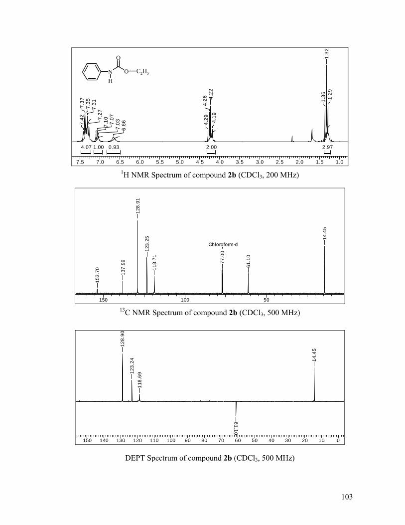
7.5 7.0 6.5 6.0 5.5 5.0 4.5 4.0 3.5 3.0 2.5 2.0 1.5 1.0
4.07 2.972.001.00 0.93
7.42
7.37
7.35
7.31
7.27
7.10 7.07
7.03
6.66 4.
294.
26 4.22
4.19
1.36
1.32
1.29
N OH
O
C2H5
1H NMR Spectrum of compound 2b (CDCl3, 200 MHz)
150 100 50
Chloroform-d
153.
70 137.
99
128.
91
123.
2511
8.71
77.0
0
61.1
0
14.4
5
13C NMR Spectrum of compound 2b (CDCl3, 500 MHz)
150 140 130 120 110 100 90 80 70 60 50 40 30 20 10 0
128.
90
123.
2411
8.69
61.10
14.4
5
DEPT Spectrum of compound 2b (CDCl3, 500 MHz)
103

4000 3500 3000 2500 2000 1500 1000 500
0
50
100
150
200
15401232
7521067
1597
2985
3330
1703
Tran
smita
nce
(%)
Wavenumber (cm-1)
IR Spectrum of compound 2b (KBr)
40 50 60 70 80 90 100 110 120 130 140 150 160 1700
5000
10000
15000
20000
25000
30000
35000
40000
m/z-->
Abundance
Scan 1491 (12.465 min): EPC.D93
165
106
65119
77
1375145
GC-MS Spectrum of compound 2b (70 eV, EI)
104

7.5 7.0 6.5 6.0 5.5 5.0 4.5 4.0 3.5 3.0 2.5 2.0 1.5 1.0 0.5 0.0
4.14 3.012.052.001.02 0.97
7.42
7.39
7.36 7.32
7.28
7.11 7.
077.
04 6.67
4.22
4.19
4.15
1.71
1.69
1.64
1.53
1.45
1.41
1.01
0.97
0.94
O
1H NMR Spectrum of compound 2c (CDCl3, 200 MHz)
150 100 50 0
Chloroform-d
153.
74
137.
98
128.
9912
3.29
118.
65
77.0
0
65.0
9
30.9
5
19.0
413
.68
13C NMR Spectrum of compound 2c (CDCl3, 500 MHz)
200 150 100 50 0
128.
9912
3.29
118.
63
65.08
30.94
19.04
13.6
8
DEPT Spectrum of compound 2c (CDCl3, 500 MHz)
N O C4H9
H
105

4000 3500 3000 2500 2000 1500 1000 500
0
20
40
60
80
100
120
1240
7521069
15501702
2872
32982960
1601
Tran
smitt
ance
(%)
Wavenumber (cm-1)
IR Spectrum of compound 2c (KBr)
40 50 60 70 80 90 100 110 120 130 140 150 160 170 180 190 2000
1000
2000
3000
4000
5000
6000
7000
8000
m/z-->
Abundance
Scan 1697 (13.555 min): BPC.D93
193
120
13741 57
65 77
106
GC-MS Spectrum of compound 2c (70 eV, EI)
106

5.0 4.5 4.0 3.5 3.0 2.5 2.0
3.183.021.00
4.93
3.67
2.80
2.78
CH3 N OH
O
CH3
1H NMR Spectrum of compound 3a (CDCl3, 200 MHz)
150 100 50 0
Chloroform-d
157.
77
77.0
0
51.9
1
27.3
6
13C NMR Spectrum of compound 3a (CDCl3, 200 MHz)
107

4000 3500 3000 2500 2000 1500 1000 50040
50
60
70
80
90
100
15701654
1338
3366
1175
1710
Tran
smita
nce
(%)
Wavenumber (cm-1)
IR Spectrum of compound 3a (film)
35 40 45 50 55 60 65 70 75 80 85 90 950
20000
40000
60000
80000
100000
120000
140000
160000
180000
200000
220000
240000
260000
280000
m/z-->
Abundance
Scan 401 (4.700 min): MMC.D58
89
74
44
5541 61 71
GC-MS Spectrum of compound 3a (70 eV, EI)
108

5.0 4.5 4.0 3.5 3.0 2.5 2.0 1.5 1.0 0.5 0.0
3.083.002.060.93
4.95
4.09
4.05
4.01
3.98
2.72
2.70
1.19
1.16
1.12
CH3 N OH
O
C2H5
1H NMR Spectrum of compound 3b (CDCl3, 200 MHz)
150 100 50
Chloroform-d
157.
33
77.0
0
60.4
7
27.1
7
14.4
2
13C NMR Spectrum of compound 3b (CDCl3, 500 MHz)
150 100 50 0
60.47
27.1
6
14.4
2
DEPT Spectrum of compound 3b (CDCl3, 500 MHz)
109
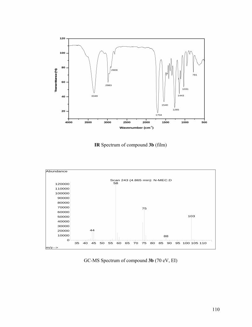
4000 3500 3000 2500 2000 1500 1000 500
20
40
60
80
100
120
781
1031
1540
2983
2909
1704
1265
14433349
Tran
smitt
ance
(%)
Wavenumber (cm-1)
IR Spectrum of compound 3b (film)
35 40 45 50 55 60 65 70 75 80 85 90 95 100 105 1100
10000
20000
30000
40000
50000
60000
70000
80000
90000
100000
110000
120000
m/z-->
Abundance
Scan 243 (4.865 min): N-MEC.D58
75
103
44
88
GC-MS Spectrum of compound 3b (70 eV, EI)
110

Chapter 3
Synthesis of N,N-dimethyl anilines from
Aromatic Amines and Dimethyl Carbonate

3.1. INTRODUCTION
N,N-dimethyl anilines are valuable intermediates in the synthesis of
pharmaceuticals, agrochemicals and dyestuffs as well as fine chemicals such Vanillin,
Michler’s ketone etc. They are also used as solvents and additives in the production of
synthetic rubber.1 N,N,N’N’-tetramethyl-1,4-phenylene diamine is used in the bio-
medical field as a reagent known as Wruster’s blue.2
The liquid phase alkylation processes for synthesis of N,N-dimethyl aniline
(NNDMA) was commercialized in 1866 in which aniline and methanol were heated in
presence of sulfuric acid at 478 K under pressure.3 In general practice, dimethyl sulfate
and methyl iodide are used as methylating agent in stoichiometric amount producing salts
in large quantities. These processes lead to problems like, corrosion, high toxicity and
cause pollution to environment due to neutralization of the acids and undesired by-
products. Although in the last decades attempts were made to develop alternative
processes based on environmentally acceptable starting materials such as methanol as the
alkylating agent and solid acid as recyclable catalysts.4 The process still requires high
temperatures typically in the range 573 to 623 K and the yield of dialkylated product is
very low (in the range of 12–40%).5 A vapor phase continuous process for the production
of NNDMA from aniline and methanol has been described using alumina based solid
acid catalyst, wherein ~ 86% yield of N,N-dimethyl aniline has been reported.6 Recently,
it has been shown that co-crystallized RHO-zeolite X (FAU) catalyst is highly active for
vapor phase N-alkylation of aniline by methanol and in this case a maximum yield of
~ 85% NNDMA is reported.7
111

In recent years, dimethyl carbonate (DMC) has emerged as a benign methylating
agent in organic synthesis.8 Although it is less reactive than methyl iodide and dimethyl
sulfate, it has the advantage of being much less toxic. DMC has been successfully used to
introduce a methyl group at the α-position of the aryl acetonitriles9 and methyl aryl
acetates.10 It has also been used for N-alkylation of aromatic amines and imidazoles.11
The vapor phase N-alkylation of aniline using DMC as alkylating agent was investigated
extensively.12 In particular Fu and Ono reported high yield of N-methyl aniline (NMA)
with selectivity ~ 92% using Faujasite Na-X as a catalyst at 423 K, while at 513 K
temperature N, N- dimethyl aniline was produced with selectivity > 95% with 100%
aniline conversion.12b Sreekumar et al. performed vapor phase alkylation of aniline using
DMC over hydrotalcite12c and Zn1-xCoxFe2O4 catalyst13 at 573 K however, selectivity for
NNDMA was very poor 22%. N-alkylation of aniline using organic carbonate in the
presence of metallosilicates, Faujasite, EMT and beta alkaline zeolite as catalysts was
also reported in which selectivity of NNDMA obtained was in the range of 50-75%.5c
Tundo and co-workers14 reported the liquid phase N-methylation of anilines using
DMC as an alkylating agent and Faujasite X or Y zeolite as a catalyst. Their results
indicated that at a temperature of 363-453 K, N- methyl aniline was produced selectively
in 96% yield with only traces of dimethyl derivative. While, Nagaraju and Kuriakose
reported the reaction of aniline and DMC over V-AlPO4 or Co-AlPO4 catalyst gave
biphenyl urea as a major products.15 A patent filed by Anic, S.P.A. described synthesis of
NNDMA from MeI and DMC under pressure at 421 K, with 85% yield of NNDMA.16
Shen and Jiang showed that diphenylammonium triflate as an excellent catalyst for
selective synthesis of N,N-dimethyl anilines.17 Recently Selva et al.18 showed selective
112

N,N-dimethylation of primary aromatic amines using unsymmetrical methyl alkyl
carbonate in presence of phosphonium salt. Jenner and Taleb19 investigated N-alkylation
of nitro arenes using methyl formate as a hydrogenating as well as alkylating agent. In
this case, Ru3(CO)12 acted as a hydrogenation catalyst while further N-alkylation of
reduced nitro derivative was achieved by the onium salts. A maximum of 97% yield of
dialkylated product was obtained at 493 K. Dehmlow et al.20 examined the N-alkylation
of anilines by alkyl halides under PTC conditions (onium salt and alkali hydroxide), but
the maximum yield of dialkylated product obtained was only 22%.
Thus, most of the previous reports on synthesis of N,N-dialkylated anilines suffer
from several techno-ecological problems. For example (a) Conventional alkylating agents
(MeI, DMS etc.) are corrosive, toxic and not good from environmental point of view, (b)
Alcohols as alkylating agents are effective only at higher temperatures (> 523 K) besides
the formation of side products such as toluidines due to ring alkylation, (c) The results on
N-alkylation of anilines with organic carbonates using solid catalyst indicate that, mono
alkylated products are formed selectively in the liquid phase reaction as compared to
dialkylated products. While, dialkylated products formed selectively under vapor phase
conditions and require very high temperature > 513 K. The N,N-dimethylation of
aromatic amines under batch condition is not extensively studied, (d) Due to the
closeness of the boiling points of aniline (457 K), N-methyl aniline (469 K) and N,N-
dimethyl aniline (466-465 K), it is extremely difficult to separate these compounds into
pure components by distillation. The normal method of separation is the acetylation of
crude product, which fixes aniline and NMA chemically. In this way, however, the
recovery of the by-products and purification of the NNDMA consumes substantial
113

amounts of energy and expensive chemicals. Therefore, it is most desirable to produce
selectively NNDMA in high yield.
In view of this, objective of the present work was to develop new catalytic system
for selective synthesis of N,N-dimethyl anilines by N-alkylation of primary aromatic
amines using dimethyl carbonate. In this chapter, experimental results on N-alkylation of
aromatic amines by dimethyl carbonate using various onium salts and heterogeneous
catalysts such as quaternary salt immobilized on silica gel and ionic liquid immobilized
on silica gel are demonstrated. Various aspects such as, process parameters and effect of
water on product selectivity and catalyst recycle have been studied.
3.2. EXPERIMENTAL SECTION
3.2.1. MATERIALS
Aniline, substituted aromatic amines, dimethyl carbonate (DMC) and diethyl
carbonate (DEC) were purchased from S.D. fine chemical ltd. India. Various quaternary
salts like; tetramethylammonium bromide (TMAB), tetraethylammonium bromide
(TEAB), tetraethylammonium iodide (TEAI), tetrapropylammonium bromide (TPAB),
tetrabutylammonium bromide (TBAB), tetrabutylphosphonium bromide (TBPB),
diphenyl carbonate and dibutyl tin oxide were purchased from Aldrich chemicals, USA.
Materials such as, Cs-Y, Cs-beta, Cs-MCM41, Cs-Na-X, Na-ZSM-5 and K-L already
synthesized and well characterized in our laboratory were used as such. n-dibutyl
carbonate and Mg-Al Htlc was prepared according to literature procedure (see Chapter
2.2.1.2 & 2.2.1.5). Amines were freshly distilled prior to use.
114

3.2.2. GENERAL PROCEDURE FOR SYNTHESIS OF N,N-DIMETHYL ANILINE DERIVATIVES
N-alkylation reactions were carried out in a 50 ml Parr Autoclave made of
Hastelloy-C-276. In a typical experiment, weighed quantities of the catalyst, amine,
dimethyl carbonate and water were charged into the autoclave. The autoclave was flushed
with nitrogen and then pressurized with nitrogen up to 3.4 MPa. Then the contents were
heated to the required temperature for 2 h under stirring at 13 Hz. After cooling the
reaction mixture to room temperature, the gases were vented off and liquid phase was
quantitatively analyzed using gas chromatography. A similar experimental procedure was
followed for testing the immobilized ionic liquids and quaternary salts. Details of the
liquid phase analysis are given in the section 3.2.3. The products were confirmed by GC-
MS analysis.
3.2.3. ANALYTICAL METHODS
Liquid samples were analyzed on a Hewlett Packard 6890 Series GC equipped
with auto sampler instrument, controlled by the HP Chemstation software, by using an
HP-5 capillary column (30 m x 320 μm x 0.25 μm film thickness, on a 5% phenyl methyl
siloxane stationary phase). GC-MS was carried out on Agilent 6890 instrument. Solid
state MAS-NMR measurement of the immobilized solid catalyst was carried out on
Bruker-AV 500 machine. Elemental analysis of the immobilized solid catalysts was
carried out on CHNS-O EA 1108, Elemental analyzer of Carlo Erba Instrument, Italy.
DRIFT IR of the immobilized solid catalysts was performed on Perkin Elmer, Spectrum
one, FT-IR spectrometer. BET surface area analysis was done on NOVA-2000 Version 8,
115

Instrument by nitrogen physisorption. The standard conditions for GC analysis are given
in Table 3.1.
Table 3.1. Standard conditions for GC analysis
Parameters Conditions
Injector (split) temperature 523 K
Flame ionization detector (FID) temperature 573 K
Column temperature (HP-5 capillary column) 318 K–563 K (programmed)
Inlet Pressure (He) 10 psig
Carrier gas (He) flow rate 2.2 ml/min
Split ratio 50:1
The conversion, selectivity, yield, turnover number (TON) and turnover frequency (TOF)
were calculated as follows.
% Selectivity of NNDMA =
No. of moles of NNDMA formed
No. of moles NNDMA expected based on aniline conversion X 100
% Conversion of aniline =
Initial moles of aniline Final moles of anilineInitial moles of aniline
X 100
% Yieldof NNDMA =
No. of moles of NNDMA formed
No. of moles of aniline chargedX 100
TON =No. of moles of NNDMA formed
No. of moles of catalyst charged
TOF, h-1 =No. of moles of NNDMA formed
No. of moles of catalyst charged X time in hours
116

3.3. RESULTS AND DISCUSSION
In this work, selective N,N-dimethylation of primary aromatic amines by dimethyl
carbonate as alkylating agent was investigated. Since carbonates posses two electrophilic
carbon (alkyl and carbonyl), they may act as both alkylating and carboxylating agents
(Scheme 3.1). This reactivity can be often differentiated by the temperature and by the
catalyst: below 363 K, carbonates react via BAC2 mechanism, whereas over 403 K, both
BBAC2 and BAl2 pathways may coexist. Thus, the complexities arising due to DMC in the
reaction for selective synthesis of N,N-dimethyl aniline were investigated by studying
process parameters.
alkylationcarboxylation
carboxylation
NCOOCH3CH3
DMC
NHCOOCH3
CH3OH+
DMC
alkylation
DMC
alkylation
NMA
NNDMA
MPC
MMPCNHCH3
CO2
+CH3OH
+
Scheme 3.1
NH2
+
CH3OH + CO2
N(CH3)2
+
OO
O
CH3
CH3
BAC2
BAl2
117

3.3.1. SYNTHESIS OF N,N-DIALKYL ANILINES USING HOMOGENEOUS ONIUM SALTS
3.3.1.1. Preliminary experiments for catalyst screening
Various homogeneous as well as heterogeneous catalysts were screened for the N-
alkylation reaction of aniline and dimethyl carbonate and results are presented in Table
3.2. It was observed that solid acid / base catalysts such as MgO, hydrotalcites, clays and
zeolites were not selective catalysts for synthesis of NNDMA (entry 1-10). Homogeneous
basic catalyst e.g. dibutyl tin oxide showed more activity towards carboxylation reaction
to give carbamate as major product rather than NNDMA (entry 11). Whereas, with
tetraethyl ammonium bromide (TEAB) as a catalyst, 76% yield of NNDMA was obtained
with 24% yield of carbamate (entry 12). On the other hand, N-alkylation under biphasic
(organic/aqueous) conditions with TEAB catalyst gave selectively only N-alkylated
amines, wherein carbamates were not detected (entry 13). Under biphasic conditions,
large amount of DMC was hydrolyzed resulting in a poor selectivity of NNDMA based
on DMC conversion. These results were however encouraging, since in the presence of
water, selectively to N-alkylated products were formed (yield of NMA 16% and
NNDMA 78%, entry 13). But under these conditions complete conversion of aniline was
not achieved. However, methyl N-phenyl carbamate (MPC) and methyl N-methyl-N-
phenyl carbamate (MMPC) were completely absent. This clearly showed that, water
played a key role in improving selectivity of N-alkylated products. Therefore the role of
water in N-alkylation of aniline was also investigated as this effect was thought to be vital
for the understanding of N-alkylation.
118

Table 3.2. Screening of catalysts for N-alkylation of aniline
Yielda, (%) Entry Catalyst (g)
Time,
(h)
Aniline
conversion, (%) MPC NMA NNDMA
1 MgO (0.25) 2 nil - - -
2 Mg-Al Htlc (0.25) 2 5 0 5 0
3 H-mordenite (1) 2 15 4 8 3 4 K+ silica (1) 2 7 3 4 0 5 K-L (1) 2 46 7 28 11 6 Na-ZSM-5 (1) 2 10 0 8 1 7 Cs-Na-X (1) 2 100 0 40 60 8 Cs-Y (1) 2 100 0 85 15 9 Cs-beta (1) 2 26 10 12 4 10 Cs-MCM-41 (1) 2 26 13 11 2 11 Bu2SnO (0.45) 2 50 43 2 5 12 (Et)4NBr (1.5) 2 100 8 (16)b - 76 13c (Et)4NBr (1.5) 2 94 0 16 78
Reaction conditions: aniline, 16.1mmol; DMC, 190 mmol; T., 423 K; N2 pressure, 3.4 MPa; Agitation speed, 13 Hz; reaction volume, 20 ml; a yields were determined by GC based on aniline conversion; bMMPC; cbiphasic conditions (DMC, 100 mmol; H2O, 560 mmol) and T., 443 K.
3.3.1.2. Role of water
The effect of water on conversion of aniline and yields of N-alkylated products
(NNDMA, NMA) and carbamate (MMPC) is shown in Figure 3.1. In absence of water
the yield of NNDMA obtained was 85% and appreciable amount of MMPC was formed
(15%). Addition of water to the system remarkably improved the yield of NNDMA to
almost 99.8% with traces of NMA (0.2%, yield) while MMPC was completely absent
(Figure. 3.1). At higher concentration of water, the biphasic conditions were approached
decreasing the yield of NNDMA (see also preliminary experiment for catalyst screening
section, 3.1.1.1). Thus, there exists an optimum quantity of water to be added to the
system in order to maximize the selectivity to N-alkylated products. Therefore,
experiments were carried out by adding precalculated water to the system. Water played a
119

key role in the selective synthesis of N,N-dimethyl aniline and in hydrolysis of
carbamates. For example hydrolysis of DMC, methyl N-phenyl carbamate (MPC) and
methyl N-methyl N-phenyl carbamate (MMPC) are known to give methanol, CO2, aniline
and N-methyl aniline (Scheme 3.2).
Scheme 3.2
NHCOOCH3
CH3OH
DMC
NMA
MPC
NHCH3
CO2
+CH3OH
+
NH2 O
CH3O OCH3+
CH3OH + CO2
NCOOCH3CH3
MMPC
CH3OH
H2O
H2O CH3OH + CO2
DMC
NNDMA
N(CH3)2
Cycle 1
Cycle 2
A blank experiment was carried out without aniline under standard reaction
conditions and it was observed that 50% of DMC was hydrolyzed to methanol and CO2.
Hydrolysis of DMC is an unwanted reaction as it reduces DMC based selectivity of
NNDMA. While, hydrolysis of both MPC and MMPC to aniline and to N-methyl aniline
respectively is a welcome reaction as it helps to increase the selectivity of N-alkylation
120

(Scheme 3.2, cycle 1 & 2). Particularly, hydrolysis of MMPC to NMA is important since
it was observed earlier that in the absence of water this carbamate decreased the
selectivity of N-alkylated products (also discussed later). Once N-methyl aniline was
produced, further alkylation by DMC gave NNDMA (Scheme 3.2).
-3
14
31
48
65
82
99
0 100 200 300 400 500 600
Water, mmol
Con
vers
ion
or Y
ield
, %
0
4
8
12
16
MM
PC y
ield
, %
Aniline conversionNMA yieldNNDMA yieldMMPC yield
Figure 3.1. Effect of water on NNDMA yield
Reaction conditions: aniline, 10.7 mmol; DMC, make-up to 20 ml; TEAB catalyst, 3.57 mmol; T., 443 K; N2 pressure, 3.4 MPa; Time, 2 h, Agitation speed, 13 Hz; Yields were determined by GC and are based on aniline conversion.
3.3.1.3. Screening of onium salts as catalyst
Several onium salts as catalysts were screened and the results are presented in
Table 3.3. It was observed that 100% aniline conversion was achieved in all the cases
with selectivity > 95% for the dialkylated products within 2 h. The variation in selectivity
with different onium salts as catalyst was only marginal, while tetra methyl and ethyl
ammonium bromides favored the most selective formation of NNDMA with selectivity
121

close to 100%, however tetra butyl ammonium chlorides was less active and showed poor
selectivity for NNDMA (50%, entry 5). Phosphonium salt showed marginal improvement
in the yields of NNDMA over ammonium salts (entry 4 & 8) and can be a substitute for
ammonium salts. It was further observed that hindered onium salt e.g. hexaethyl
gaunidinium bromide also showed excellent activity towards N-alkylation (entry 6). In
order to ascertain the activity trend in onium salts, conversion and yields were monitored
at shorter contact time (0.5 h). No particular trend was observed for screened onium salts
as catalyst and poor selectivity for NNDMA was obtained in the range of 40-50%. The
lower selectivity for NNDMA in the initial period was found to be due to interaction of
aniline with onium salt forming an activated intermediate of quaternized aniline and due
to formation of NMA. To check the possibility of formation of quaternized intermediate
of aniline an experiment was performed, in which aniline was treated with (Et)4NBr
without DMC in toluene solvent for 0.5 h under same reaction conditions similar to that
mentioned for Table 3.3. This experiment showed ~ 18% aniline conversion and no N-
alkylated products were detected (entry 9). A direct comparison of catalyst activities of
quaternary salts is difficult under experimental conditions due to the substrate interaction
with catalyst to form activated adduct in the initial period (0.5 h). In homologous series
of quaternary ammonium bromides, the formation of carbamate as a side product
increased from methyl to butyl (entry 1 to 4). This effect is probably due to the fact that
[(n-C4H9)4N]Br is more lipophilic than either methyl or ethyl quaternary ammonium
bromides21 and hence not as efficient in hydrolyzing carbamates (which essentially
proceeds in hydrophilic media) to amines, thus decreasing selectivity of N-alkylated
products.
122

Table 3.3. Screening of onium salts for N-alkylation of aniline
NNDMA (0.5 h) NMA (0.5 h)
Entry Onium salt Aniline
conversion,(0.5h), % Sel.,
% Yielda
, % Sel., %
Yielda
, %
Other b (0.5 h),
%
1 (Me)4NBr 100 (82)
98.8 (39.6)
98.8 (32.2)
1.2 (7.3)
1.2 (6)
Nil (nil)
2 (Et)4NBr 100 (97.1)
99.8 (53)
99.8 (51.4)
0.2 (5.5)
0.2 (5.3)
Nil (nil)
3 (n-Pr)4NBr 100 (98)
98 (55.5)
98 (54.2)
0.5 (3.9)
0.5 (3.8)
1.5 (nil)
4 (n-Bu)4NBr 100 (98.1)
96 (49.5)
96 (48.6)
0.2 (4)
0.2 (3.9)
3.8 (0.5)
5 (n-Bu)4NCl 88.12 (61)
50 (40.9)
44.13 (25)
17.24 (14.7)
15.2 (9)
3.5 (1)
6 HegBrc 100 (97.5)
96.8 (47.5)
96.8 (46.2)
0.2 (5.9)
0.2 (5.7)
3 (1.0)
7 (Et)4NI 100 (100)
98 (57.2)
98 (57.2)
0.2 (nil)
0.2 (nil)
1.8 (0.8)
8 (n-Bu)4PBr 100 (97.4)
97.8 (51.1)
97.8 (49.8)
0.3 (4.9)
0.3 (4.8)
1.9 (0.6)
9 (Et)4NBrd (18) 0 0 0 0 0 Reaction conditions: aniline, 16.1 mmol; DMC, 190 mmol; Catalyst, 3.57 mmol; H2O, 110 mmol; T., 443 K; N2 pressure, 3.4 MPa; Time, 2 h; Agitation speed, 13 Hz; reaction volume, 20 ml; a yields were determined by GC based on aniline conversion;
b MPC, MMPC; c Hexaethyl guanidinium bromide; d in absence of DMC
3.3.1.4. Effect of substrate
Several substituted anilines such as toluidine, chloro anilines, nitro aniline and
anisidine were investigated to see the reactivity of substrates towards N-alkylation by
DMC (Table 3.4). Excellent yields of dialkylated products were obtained in most of the
screened amines except p-nitro and o-chloro anilines (entry 5 & 7). Since the N-alkylated
products are formed by the nucleophilic substitution of anilines on DMC, electron
donating or withdrawing substituents on aniline are expected to increase or decrease the
nucleophilic character of aniline respectively. Although substituted anilines followed the
123

expected reactivity pattern that is based on the nucleophilicity of anilines, the effect was
not very pronounced for electron donating substituents but at the same time steric
hindrance of these substituents to NH2 group was dominating the reactivity of anilines.
For example o-chloro aniline showed lower conversion and poor selectivity to respective
dialkylated product (entry 5). In p-nitro aniline, -NO2 is very strong electron withdrawing
group and having ‘–R’ effect which decreases nucleophilic character of aniline, showing
poor conversion and selectivity to dialkylated product (entry 7). The alkylated product of
1,4 phenylene diamine (entry 8) has a special importance as a reagent and excellent yield
of N,N,N`,N`- tetramethyl 1,4 phenylene diamine was obtained.
Table 3.4. Synthesis of N,N-dimethyl anilines using TEAB catalyst
Entry Amine Dialkyl yielda, (%)
Monoalkyl yielda, (%)
Side productsb yielda, (%)
1 C6H5NH2 99.8 0.2 0 2 p-CH3-C6H4NH2 99.5 0 0.5 3 p-Cl-C6H4NH2 98.5 0.3 1.2 4 m-Cl-C6H4NH2 98.5 0.4 1.1 5 o-Cl-C6H4NH2 62.6 30.2 0.8 6 p-CH3O-C6H4NH2 99.6 0 0.4 7 p-NO2-C6H4NH2 35.9 27 7 8 p-NH2-C6H4NH2 98 0 2
Reaction conditions: aniline, 16.1 mmol; DMC, 190 mmol; TEAB, 3.57 mmol; H2O, 110 mmol; T., 443 K; N2 pressure, 3.4 MPa; Time, 2 h; Agitation speed, 13 Hz; reaction volume, 20 ml; a yields were determined by GC based on aniline conversion; b N-carbamates.
3.3.1.5. Effect of solvent
Five different solvents were screened with a wide range of variation in their
dielectric constants (ε) to see the effect of solvent on catalyst activity and selectivity to N-
alkylated products. These results are presented in Figure 3.2. The results on solvent
124

screening indicated that as dielectric constant (ε) of a solvent increased, conversion and
yield of NNDMA passed through an optimum value for ε. The bell shape of the graph
(for activity and yield) showed that a maximum of 78% yield of NNDMA was obtained
which corresponds to a value of dielectric constant (ε25) = 7.2 (using triglyme as solvent)
and at two extremes of this graph lie xylene having ε25 = 2.25 and methanol having
ε25 = 32.6 with NNDMA yield of 11.7 and 45 respectively and other solvents fell in
between these two extremes. It was observed that solvents such as p-xylene and toluene
form a biphasic system in the presence of water and TEAB catalyst was partitioned in
two phases decreasing the availability of catalyst in the organic phase. The depletion of
catalyst concentration in the organic phase lowered N-alkylation rates. The results
obtained for triglyme, as a solvent deserves some comments. The N-alkylation reaction
depends on the nucleophilicity of amines. Factors that increase the nucleophilicity of
amines e.g. electron donating groups attached to a ring or nucleophilic environment such
as that generated by solvents having basic groups or atoms such as N or O, help to
increase it’s reactivity.22 Triglyme has an open chain polyether structure with basic
oxygen atoms, and is a perfect solvent capable of inducing nucleophilic environment
around hydrogen of amine thus generating reactive (RNH-), which on further reaction
with DMC produces N-methylated products. This is a probable explanation, however,
similar effects have been observed earlier.22 The results clearly showed that the solvent
played an important role in activation (or deactivation) of substrates, but dielectric
constant alone did not explain this effect. The effect of DMC, as a solvent (ε25 = 3.1)
could not be compared, as DMC was also one of the reactants, however, DMC worked as
an excellent solvent and due to its benign nature was selected for further studies.
125

0
20
40
60
80
100
Xylene(2.25)
Solvent (dielectric constant)
Con
vers
ion
or y
ield
, %
Toluene(2.37)
Triglyme(7.2)
Acetone(20.7)
MeOH(32.6)
Aniline conversion
NMA yield
NNDMA yield
Figure 3.2. Effect of solvent on NNDMA yield
Reaction conditions: aniline, 10.7 mmol; DMC, 32.2 mmol; TEAB catalyst, 2.38 mmol; H2O, 111 mmol; solvent, 14 ml; T., 443 K; N2 pressure, 3.4 MPa; Time, 2 h, Agitation speed, 13 Hz; Total volume, 20 ml; Yields were determined by GC and are based on aniline conversion.
3.3.1.6. Efficiency of organic carbonate
The activity of carbonates as alkylating or arylating agents was examined for
aniline as a substrate (Figure 3.3). DMC as alkylating agent showed the highest activity
followed by ethyl and butyl carbonates, whereas diphenyl carbonate as an arylating agent
showed no activity. The results were in complete agreement with the steric hindrance
offered by reactive alkyl cation of the carbonate e.g. DMC having (H3C+
) as methylating
cation is the least bulkier as compared to other cations of dialkyl carbonates, and hence
shows the highest reactivity. Also from the view point of electronic effects, the expected
trend of carbonate reactivity was observed, the methyl cation being the most electrophilic
and showed the highest reactivity towards N-alkylation. In the reaction of aniline and
126

diphenyl carbonate, N-arylated products were not formed but only hydrolysis of DPC to
phenol and CO2were observed.
0
20
40
60
80
100
DMC DEC DBC DPC
Organic carbonate
Con
vers
ion
or Y
ield
, %Aniline conversion
Dialkyl aniline yield
Monoalkyl aniline yield
Figure 3.3. Efficiency of organic carbonate as alkylating or arylating agent
Reaction conditions: aniline, 16.1 mmol; organic carbonate, 190 mmol; TEAB catalyst, 3.57 mmol; H2O, 111 mmol; T., 443 K; N2 pressure, 3.4 MPa; Time, 2 h, Agitation speed, 13 Hz; Total volume, 20 ml; Yields were determined by GC and are based on aniline conversion.
3.3.1.7. Synthesis of N,N-dimethyl aniline (NNDMA)
The effect of reaction conditions was investigated on the most important
dialkylated amine, N,N-dimethyl aniline. For this purpose, N-alkylation of aniline was
considered as a model reaction for synthesis of NNDMA. Few experiments were carried
out to determine product distribution and material balance in the alkylation of aniline
with DMC. Since, DMC was acting as a solvent as well as alkylating agent, aniline was
considered as the limiting reactant and on the basis of moles of aniline reacted, NMA and
NNDMA formation and DMC consumed were tallied. A complete conversion of aniline
127

was achieved with concurrent formation of N-alkylated products and correspondingly
DMC was also consumed although in about 20% excess than the stoichiometric quantities
that were required based on aniline consumption, indicating that DMC based selectivity
was reduced due to formation of side products arising from hydrolysis of DMC. This is
evident from a typical experiment (Table 3.3, entry 2) in which, aniline conversion was
100% with 99.8% selectivity of NNDMA and 0.2% selectivity for NMA formation on the
basis of aniline converted and 83.6% selectivity of NNDMA and 0.16% selectivity for
NMA on basis of DMC converted was observed at the end of two hours of reaction time.
In the present case, both the reactants (amine and carbonate) were infinitely soluble under
reaction conditions offering a homogeneous liquid phase. However, experiments were
carried out at different agitation speed, which confirmed that beyond 8.3 Hz, conversion
of aniline remained unaffected indicating that mass transfer effects are unimportant.
Therefore all the experiments were carried out with agitation speed of 13 Hz.
The effect of different parameters on conversion, selectivity and yield are
discussed below:
3.3.1.7.1. Effect of catalyst loading
The effect of catalyst loading on conversion of aniline and selectivity of NMA
and NNDMA is shown in Figure3.4. Both conversion of aniline and yield of NNDMA
increased with increase in TEAB loading while the yield of intermediate NMA
decreased. It can be seen from this plot that higher catalyst concentration was required for
the selective formation of NNDMA, this however lowers the TON. In the present case,
the product NNDMA was formed via an intermediate NMA and the catalyst was
128

involved in both the steps and hence expected linear dependency of conversion with
catalyst loading was not observed.
0
20
40
60
80
100
0 1 2 3 4
TEAB catalyst, mmol
Con
vers
ion
or y
ield
, %
0
2
4
6
8
10
12
14
TON
(N-a
lkyl
ated
pro
duct
)
Aniline conversion
NMA yield
NNDMA yield
TON
Figure 3.4. Effect of TEAB catalyst loading on NNDMA yield
Reaction conditions: aniline, 16.1 mmol; DMC, 190 mmol; H2O, 111 mmol; T., 443 K; N2 pressure, 3.4 MPa; Time, 2 h, Agitation speed, 13 Hz; Total volume, 20 ml; Yields were determined by GC and are based on aniline conversion. 3.3.1.7.2. Effect of temperature
The temperature effect was investigated in the range of 393-443 K and the results
are shown in Figure 3.5 as a graph of aniline conversion and yield of alkylated products
at different temperatures. The conversion of aniline and NNDMA yield increased sharply
with increase in temperature, while NMA yield diminished with increase in temperature.
Temperature plays an important role in alkylation of amines when organic carbonates are
used as alkylating agents. Both carboxylation and alkylation of amine is possible
depending on the temperature of the reaction. Usually, temperature in the range of 423-
129

473 K was required for selective formation alkylated products.8a Side products arising
from bromination of aromatic ring or bromination of alkyl group were not detected even
at 443 K.
0
20
40
60
80
100
380 400 420 440 460
Temperature, K
Con
vers
ion
or y
ield
, %Aniline conversion
NMA yield
NNDMA yield
Figure 3.5. Effect of temperature on NNDMA yield
Reaction conditions: aniline, 16.1 mmol; DMC, 190 mmol; TEAB catalyst, 3.57 mmol; H2O, 111 mmol; T., 443 K; N2 pressure, 3.4 MPa; Time, 2 h, Agitation speed, 13 Hz; Total volume, 20 ml; Yields were determined by GC and are based on aniline conversion.
3.3.1.7.3. Catalyst recovery and recycling
The catalyst was recovered and recycled by diluting the concentrated reaction
crude (free from low boilers such as DMC and methanol) with chloroform and extracting
it three times in minimum amount of water (~ 10 ml). The combined aqueous phase was
then concentrated by evaporating water to recover TEAB and recycling it with the fresh
charge of aniline, DMC and water. The results on catalyst recycle experiments are
depicted in the Figure 3.6, which show excellent recycling ability of the catalyst while
retaining almost 98 % of its original activity for NNDMA synthesis even after fifth
130

recycle. The recycling efficiency of the catalyst also confirmed that catalyst degradation
arising from brominated products (brominated amines, alkyl bromides etc.) was absent.
0
20
40
60
80
100
0 1 2 3 4 5 6
Number of recycles
NN
DM
A Y
ield
, %
Figure 3.6. TEAB catalyst recycles study
Reaction conditions: aniline, 16.1 mmol; DMC, 190 mmol; TEAB catalyst 3.57 mmol; H2O, 111 mmol; T., 443 K; N2 pressure, 3.4 MPa; Time, 2 h, Agitation speed, 13 Hz; Total volume, 20 ml; Yields were determined by GC and are based on aniline conversion. 3.3.1.8. Networking of N- alkylation reaction
N-alkylation of aniline by DMC as an alkylating agent produces carbamates and
alkylated products depending on the reaction conditions (temperature and water).
Carbamates such as methyl N-phenyl carbamate (MPC) and methyl N-methyl N-phenyl
carbamate (MMPC) can form via two routes and their inter convertibility into amines via
hydrolysis is possible (Scheme 3.2). Moreover, possibility of formation of NMA and
DMC via hydrogen transfer reaction between MMPC and methanol (formed during
reaction) can not be ruled out under our experimental conditions (see Equation 3.1).14a
DMCPhNHCH3 + CH3OCOOCH3 (3.1)PhNCH3COOCH3 + CH3OH
MMPC NMA
131

To clarify these issues, diagnostic experiments were carried out and these results are
presented in Table 3.5. Reaction of MPC with DMC in absence of water produced only
MMPC ( entry 1), while in the presence of water, a similar experiment showed 50%
conversion of MPC to NNDMA (50% yield, entry 2), indicating that hydrolysis of
MMPC produced NNDMA via NMA alkylation (Scheme 3.2). In the absence of water,
MMPC accumulated in the system, as it did not have active hydrogen atom for further
reaction with DMC. Similar reactions were carried out either with NMA or aniline as a
substrate with DMC gave NNDMA and MMPC in the absence of water and the same
reaction in presence of water gave selectively only NNDMA (entry 3-6). Reaction of
aniline or MMPC with methanol under the experimental conditions did not give alkylated
anilines indicating that alkylation using methanol was not facile (entry 7 & 8). Similarly
reaction of MMPC and DMC did not give alkylated products (entry 9). These
experiments conclusively showed that MMPC hydrolysis to NMA was the key reaction in
increasing the selectivity of NNDMA in the present case.
Table 3.5. N-alkylation of substrates showing networking of reaction scheme
Product Yield, % Sr.No. Substrate Water Alkylating
agent Conv.
% MPC MMPC NMA NNDMA 1 MPC No DMC 90 0 90 0 0 2 MPC Yes DMC 50 0 0 0 50 3 NMA No DMC 100 0 18 0 82 4 NMA Yes DMC 100 0 0 0 99.8 5 Aniline No DMC 100 0 15 0 85 6 Aniline Yes DMC 100 0 0 0.2 99.8 7 Aniline Yes MeOH 0 0 0 0 0 8 MMPC No MeOH 0 0 0 0 0 9 MMPC No DMC 0 0 0 0 0
Reaction conditions: substrate, 16.1 mmol; alkylating agent, 190 mmol; TEAB catalyst, 3.57 mmol; H2O, 111 mmol; T., 443 K; N2 pressure, 3.4 MPa; Time, 2 h, Agitation speed, 13 Hz; Yields were determined by GC and are based on substrate conversion.
132

3.3.1.9. Plausible reaction mechanism
It is well known that ammonium quaternary salt would react with amine having
active hydrogen to form a complex17,20 (R4N+ –X….H….NHAr, Scheme 3.3, step I)
containing nucleophilic anion (PhHN–). This aniline nucleophile reacts with dimethyl
carbonate through BAl-2 mechanism (in which, nucleophile prefers to attacks on alkyl
group when an acyl carbon is also available by SN2 process) to generate N-methyl aniline
(step II) and recovers back ammonium quaternary salt (step III). N-methyl aniline further
undergoes N-alkylation reaction by DMC through similar catalytic cycle to give N,N-
dimethyl aniline.
Scheme 3.3: Plausible catalytic cycle for N-alkylation of aniline
DMC CO2+CH3OH+
NH2CH3OH + CO2
NNDMA
N(CH3)2
(Et)4NBr
N
CH3
H
CH3
O
O
O
CH3
Br N(Et)4NH
H+
NMA
(Et)4NBr
CH3
(Et)4N+ Br
H
O
O
O
+
Step l
Step ll
Step lll
BAl -2
133

3.3.2. SYNTHESIS OF N,N-DIALKYL ANILINES USING IMMOBILIZED QUATERNARY SALT AND IMMOBILIZED IONIC LIQUIDS
Immobilized ionic liquids and quaternary salts are active catalyst for various types
of reactions like: alkylation,23 Friedel-Craft acylations24 and C, O-alkylation25 and
nucleophilic substitution26 respectively. In the present chapter, N,N-dialkylation of
aromatic amines by dialkyl carbonate using immobilized ionic liquids and quaternary
salts was demonstrated. These immobilized catalysts have the advantages of facilitating
the separation of the catalyst from products, leading to uncontaminated product, can be
recycled several times and can be used in gas phase reactions. In quest to overcome the
separation of homogeneous catalyst like onium salts which involves energy intensive
steps, immobilized catalysts were examined for the purpose of studying the efficiency of
onium salts in heterogeneous form. Immobilized catalysts were synthesized as per
reported procedure and used for the N,N-dimethylation reaction for the first time. Various
aspects such as catalyst loading, reactivity of different aromatic amines and dialkyl
carbonates and catalyst recycle have been studied.
3.3.2.1. Synthesis of immobilized catalysts
3.3.2.1.1. Synthesis of ionic liquids immobilized on silica gel
Following immobilized ionic liquids were synthesized as per literature procedure
in two steps (Scheme 3.4). 27
3.3.2.1.1.1. Synthesis of immobilized 1-(tri-ethoxy-silyl-propyl)-3-methyl- imidazolium chloride on silica support
Step 1- Synthesis of 1-(tri-ethoxy-silyl-propyl)-3-methyl-imidazolium chloride
In a round bottom flask equipped with a reflux condenser, a mixture of 1-methyl
imidazole (20.53 g, 250 mmol) and 3-chloropropyl-tri-ethoxy-silane (60.2 g, 250 mmol)
134

were stirred at 383 K for 30 hrs under argon atmosphere. After completion of the
reaction, the dense yellowish product was extracted several times with diethyl ether and
dried under high vacuum at room temperature.
Cl
Toluene, reflux
30 h
2 EtOH
CH3
N
N
Si
OEt
OEt
EtO
3-chloro propyl triethoxy silane 1-methyl imidazole
+373 K
16 h
OH
OH
OH
+
O O
Si
+Cl
-N
N
CH3
+
Scheme 3.4
+
Cl- N N CH3
OEt
OEt
EtO Si
Si
OEt
OEt
EtO+
Cl- N N CH3
1-tri-ethoxy-silyl-propyl)-3-methyl-imidazolium chloride
Step-1
Step-2
silica support
OEt
Step 2- Immobilization of 1-(tri-ethoxy-silyl-propyl)-3-methyl-imidazolium chloride on
silica support
Chromatographic grade Silica gel (Spectrochem, India, 200-400 mesh, pore
diameter 60 Å, surface area ~ 400 m2/g) was dried under reduced pressure (10-2 torr) at
773 K for 3 h. This dried silica (6 g) was dispersed in anhydrous toluene in a distillation
apparatus. In that mixture, 1-(tri-ethoxy-silyl-propyl)-3-methyl-imidazolium chloride
(3.23 g) was added and stirred at reflux temperature for 16h. The toluene and ethanol
formed during grafting step were distilled off, solid catalyst was dried under high
vacuum. Solid material was then subjected to Soxhlet extraction in boiling
135

dichloromethane so as to remove unreacted 1-(tri-ethoxy-silyl-propyl)-3-methyl-
imidazolium chloride. After Soxhelt extraction treatment, solid material (Cat-1) was
dried under reduced pressure (10-2 torr). Cat-1 contains 35 wt% immobilized ionic liquid
and was well characterized by elemental analysis, DRIFT IR and 29Si MAS NMR
Spectroscopic technique.
The 29Si MAS NMR Spectra of pure silica showed that a signal at -102.8 ppm
corresponds to (SiO)3Si−OH group (Figure 3.7). While incase of Cat-1 (Figure 3.8), the
peaks appeared at -59.7 and -68.9 were assigned for Si−O−SiR−(OEt)2 and
(Si−O)2−SiR−OEt repectively.27,29 This showed that grafting of the organic cation on to
the silica surface had successfully taken place. The organic cations were bonded to the
surface either via one or two Si−O−Si bonds. The DRIFT IR (Figure 3.9) showed bands
at 3105 and 3157 cm-1 confirmed the presence characteristic interaction of stretching
frequency resulting from H-bonding interaction of C4/C5 hydrogen with Cl- and C2
hydrogen with Cl- respectively.28 The band between 1350-1482 cm-1 are attributed to
CH3-C-H asymmetric stretching vibrations of imidazole ring.
100 50 0 -50 -100 -150 -200
-102
.82
Si
OH
O SiO
Si
OSi
Figure 3.7. 29Si MAS NMR Spectra of pure SiO2
136

100 50 0 -50 -100 -150 -200
-59.
75 -68.
93
-102
.82
-112
.50
R
Figure 3.8. 29Si MAS NMR Spectra of (EtO)3-Si-propyl-imidazolium chloride immobilized on SiO2
4000 3500 3000 2500 2000 1500 1000 500
40
50
60
70
80
90
100
110
3105
799946
1462
1568
20191871
1634
1093
2838
2879
3157
Tran
smitt
ance
(%)
Wavenumber (cm-1)
Figure 3.9. DRIFT IR Spectra of (EtO)3-Si-propyl-imidazolium chloride immobilized on SiO2 3.3.2.1.1.2. Synthesis of immobilized 1-(tri-ethoxy-silyl-propyl)-pyridinium chloride on
silica support
1-(tri-ethoxy-silyl-propyl)-pyridinium chloride immobilized on silica (Cat-2) was
synthesized by replacing cationic part (1-methyl imidazole) by pyridine following the
above mentioned procedure. Cat-2 contains 35 wt% immobilized ionic liquid and was
characterized by elemental analysis, 29Si MAS NMR Spectroscopic technique (Figure
3.10) and DRIFT IR (Figure 3.11).
Si
OSi
O SiO
Si
OSi
Si
R
O EtOSi
OEt
SiEtO
OOSiSi
137

100 80 60 40 20 0 -20 -40 -60 -80 -100 -120 -140 -160 -180 -200
-102
.82
-68.
61-59.
76
Figure 3.10. 29Si MAS NMR Spectra of (EtO)3-Si-propyl- pyridinium chloride
immobilized on SiO2
4000 3500 3000 2500 2000 1500 1000 50020
40
60
80
100
120
140
160
791
1109
938
648
1642
1871
1486
2887
2019
2936
30583091
Tran
smitt
ance
(%)
Wavenumber (cm-1) Figure 3.11. DRIFT IR Spectra of (EtO)3-Si-propyl-pyridinium chloride immobilized on
SiO2 3.3.2.1.2. Synthesis of quaternary salt immobilized on silica gel 25
Immobilized quaternary salt was synthesized in two steps (Scheme 3.5).
Step1- Synthesis of 3-chloropropyl-functionalized silica gel
In a 250 ml round bottom flask equipped with a reflux condenser, a suspension of
3-chloropropyltriethoxysilane (3.63 g, 15 mmol) and activated silica gel30 (10g, activated
138

by refluxing it in conc. HCl for 4h), in 100 ml anhydrous toluene was refluxed with
stirring. After 3 h, toluene containing ethanol about 25 ml was removed by distillation
and reflux was continued. Again after 2h, 25 ml ethanol-containing toluene was removed
and reflux was continued for 2 h. The reaction mass was cooled at room temperature and
functionalized silica gel was filtered, washed several times with diethyl ether and
allowed it to dry at room temperature. Yield of functionalized silica gel was 11.5 g.
Step2- Synthesis of immobilized quaternary ammonium salt
The 3-chloropropyl-functionalized silica gel (5 g) in 25 ml tri-ethyl amine was
degassed under vacuum and refluxed at 361 K without stirring for 5 days. After cooling,
the reaction mass was filtered washed several times with diethyl ether and dried at room
temperature. Yield of immobilized ammonium quaternary salt (35 wt%, Cat-3) was 7.68
g and characterized by elemental analysis and DRIFT IR spectroscopy (Figure 3.12).
Toluene
3-chloropropyl triethoxysilane
OH
OH
OH
silica support
+ ClSi
OEt
OEt
EtOreflux
3-chloropropyl- functionalized silica gel
Step-1
Step-2
+ (Et)3Nreflux
O
O
O
Si NEt3Cl+O
O
O
Scheme 3.5:
Si Cl
O
O
O
+ EtOHSi Cl
139

4000 3500 3000 2500 2000 1500 1000 500
0
20
40
60
80
100
788
1046
1640
29382876
3412
1480
Tran
smita
nce (%
)
Wave number, (cm-1) Figure 3.12. DRIFT IR Spectra of immobilized quaternary ammonium salt on SiO2
Details of immobilized catalyst characterizations are presented in the Table 3.6.
Table 3.6. Characterization data of immobilized catalysts
Catalyst
(~35 wt% loading)
Surface
area, m2/g
C, H, N
analysis
Drift IR in
KBr, cm-1
29Si MAS
NMR, δ
O
OSi
+
ClN
N
CH3Cat-1
OEt
89
C, 11.05%; H, 2.0%; N, 3.56%
3157, 3105, 2879, 2838, 1871, 1568, 1462, 1093, 946, 799
-59.75, -68.93, -102.82, -112.5
O
OSi
+
ClN
Cat-2
OEt
69
C, 13.15%; H, 2.96%; N, 2%
3091, 3058, 2936, 2887, 1871, 1486, 1443, 1109, 938, 791
-59.76, -68.61 -102.82
Cat-3
+O
O
OSi NEt3Cl
102
C, 14.2%; H, 2.5%; N, 2.01%
2938, 2876, 1480, 1416, 1076, 788, 732
-
3.2.2.2. Activity of immobilized catalyst towards N-alkylation reaction
Following the same experimental procedure described in Section 3.2.2, various
immobilized catalysts were screened for the N-alkylation reaction of aniline and DMC in
140

absence of water (Table 3.7). From the catalyst screening it was observed that catalysts
like: Tixogel-VP (quaternary ammonium compound of bentonite, obtained from süd
chemie, Germany), Cat-2 and Cat-3 gave lower yield of NNDMA (entry 2, 4 and 5)
while, Cat-1 gave better yield of NNDMA (62%, entry 3). It was also observed that Cat-1
in comparison to the pure ionic liquid (C4MIMCl) gave more yield of N-alkylated
products while, C4MIMCl gave carboxylated compounds (carbamate) as major products
(entry 1). Hence, further N-alkylation reactions of various aromatic amines and dialkyl
carbonates were carried out using Cat-1 as catalyst.
Table 3.7. Screening of catalyst
Entry Catalyst Aniline
conversion, %
NMA yield, %
NNDMA yield, %
MMPC yield, %
MPC yield, %
1 C4MIM-Cl 97.5 3.4 31.9 51.6 10.5 2 Tixogel-VP 37.1 15.4 4.5 16 1.2 3 Cat-1 95.5 9.4 61.8 20.6 3.6 4 Cat-2 47.5 23.8 8.5 0.6 14.7 5 Cat-3 78.6 38.6 15.4 3.1 21.5
Reaction conditions: aniline, 5.4 mmol; dimethyl carbonate, 215 mmol; solid catalyst, 2 g (C4MIM-Cl, 3.5 mmol); T., 443 K; PN2, 3.4 MPa; Time, 4 h; Agitation speed, 13 Hz; reaction volume, 20 ml; a yields were determined by GC and are based on aniline conversion
Reaction of aniline and dimethyl carbonate in presence of Cat-1 gave 70% N-
alkylated products (NMA + NNDMA) and 25% carboxylated products (MMPC + MPC,
Table 3.7, entry 3). From the previous study, it was known that N-alkylation of anilines
by DMC in presence of water using TEAB catalyst gave high yields of N,N-dimethylated
anilines (> 99%). Therefore, same experimental procedure was followed for Cat-1
(Section 3.2.2.). It was observed that reaction of aniline with DMC in presence of water
at 443 K gave 32% yield of NMA and 30.4% yield of NNDMA in 4 h without any
141

formation of carboxylated products (Table 3.8, entry 1). Whereas, high selectivity and
yield of NNDMA (> 98%) was achieved by carrying out the reaction for longer run time
(Table 3.8, entry 2).
3.3.2.3. Effect of catalyst loading
Effect of catalyst loading on the conversion and selectivity of NMA and NNDMA
is shown in Figure 3.13. From the plot, it can be seen that both conversion of aniline and
yields of N-alkylated products increased with increase in Cat-1 loading. NNDMA was
formed via an intermediate NMA and thus catalyst was involved in both steps and hence
did not show expected linear dependency of aniline conversion with catalyst loading.
0
15
30
45
60
75
0 0.5 1 1.5 2 2.5
Cat-1, g
Con
vers
ion
or Y
ield
, %
aniline conv.
NMA yield
NNDMA yield
Figure 3.13. Effect of Cat-1 catalyst loading on NNDMA yield
Reaction conditions: aniline, 5.4 mmol; DMC, 215 mmol; H2O, 55 mmol; T., 443 K; N2 pressure, 3.4 MPa; Time, 4 h, Agitation speed, 13 Hz; Total volume, 20 ml; Yields were determined by GC and are based on aniline conversion.
142

3.3.2.4. Effect of Substrate
Various aromatic amines were screened to examine the wide applicability of the
Cat-1 catalyst and to study the reactivity of the substrates toward N,N-dimethylation
reaction. The results are summarized in Table 3.8. In most of the cases, N,N-
dimethylated products were obtained with excellent selectivity and yields (> 95%) except
o-chloro aniline and p-nitro aniline. Aromatic amines showed the similar reactivity
pattern, which was observed for TEAB catalyst for N,N–dimethylation reaction. The
presence of electron-donating groups (-CH3, -OCH3) on the benzene ring would increase
the activity of amines that increases the yield of N,N- dimethylated products (see entry 3,
4). While, electron-withdrawing groups (-Cl, -NO2) on the benzene ring would decrease
the activity of amines and yields of N, N- dimethylated products (entry 7, 8).
Activity of various dialkyl carbonates has been also examined for aniline
alkylation reaction. It was observed that activity of carbonates as alkylating agent
decreased in order of DMC > DEC > DBC in accordance with increase in steric
hindrance from DMC to DBC. High yield of N,N- dialkylated product was obtained in
case of DMC. Negligible yield of N,N- dialkylated product was obtained from DEC
while, DBC was inefficient for N,N- dialkylation reaction (entry 9, 10).
143

Table 3.8. Synthesis of N,N- dialkyl anilines using Cat-1 catalyst
Entry Amine Amine
conversion, %
Dialkyl yielda %
Mono alkyl yielda, %
Other productsb yielda, %
1c C6H5NH2 62.4 30.4 32 0 2 C6H5NH2 99.7 98.3 1.4 0 3 4-CH3-C6H4NH2 99.8 97.8 1.9 0.1 4 4-OCH3-C6H4NH2 99.5 97.8 1.7 0 5 4-Cl-C6H4NH2 99.2 96.7 2.0 0.5 6 3-Cl-C6H4NH2 98.7 96 2.1 0.6 7 2-Cl-C6H4NH2 52.2 7.7 43.9 0.6 8 4-NO2-C6H4NH2 44.2 13.8 25.5 4.9 9d C6H5NH2 15.7 2.8 11.9 1 10e C6H5NH2 8.9 0 8.9 0
Reaction conditions: amine, 5.4 mmol; DMC, 215 mmol; Cat-1 catalyst, 2 g; H2O, 55 mmol; T., 443 K; N2 pressure, 3.4 MPa; Time, 12 h; Agitation speed, 13 Hz; reaction volume, 20 ml; a yields were determined by GC and are based on aniline conversion; b N-carbamtes; c reaction time, 4h; d diethyl carbonate; e dibutyl carbonate
3.3.2.5. Catalyst recycles study
The most important feature of heterogeneous catalyst is its reusability. Therefore,
reusability of Cat-1 was studied for the reaction of aniline with DMC in presence of
water and the results are shown in Figure 3.14. Catalyst was separated from the reaction
mixture by simple filtration and washed several times with acetonitrile to remove any
adhered organic impurities and then dried at 373 K. This recovered catalyst was used for
new reaction. The recycle study showed the excellent reusability of Cat-1 catalyst
without any loss in its catalytic activity.
144

0
20
40
60
80
100
0 1 2 3
No. of catalyst recycles
Con
vers
ion
or Y
ield
, %
Aniline conv.NNDMA yieldNMA yield
Figure 3.14. Cat-1 catalyst recycles study
Reaction conditions: aniline, 5.4 mmol; DMC, 215 mmol; Cat-1 catalyst, 2 g; H2O, 55 mmol; T., 443 K; N2 pressure, 3.4 MPa; Time,12 h, Agitation speed, 13 Hz; Total volume, 20 ml; Yields were determined by GC and are based on aniline conversion. 3.4. CONCLUSION
Selective N,N-dimethylation of aromatic amines with dimethyl carbonate in
presence of water using simple and efficient catalysts consisting of onium salts and
immobilized ionic liquid was demonstrated for the first time. It was observed that activity
of immobilized ionic liquid, Cat-1 (TOF; 0.2 -1h) was almost ten times less than
homogeneous TEAB catalyst (TOF; 2.25 -1h). Water plays an important role in
increasing the selectivity of N,N-dialkylated products (~99%) by hydrolyzing the side
product such as carbamates to amines. Reactivity study of aromatic amines and organic
carbonate was investigated and it was observed that excellent yield of dialkyl products
145

were obtained in case of aromatic amines having electron donating substituents on their
ring and low yields for electron withdrawing substituents on ring. The activity of dialkyl
carbonates as alkylating agents towards aniline was found to decrease in the order of
dimethyl carbonate > diethyl carbonate > dibutyl carbonate as steric hindrance increases
from dimethyl carbonate to dibutyl carbonate. The catalyst recycle experiments showed
that there was no loss in catalytic activity for both catalysts (TEAB and Cat-1) even after
several recycles. Even though, both the catalysts showed good recyclability,
homogeneous TEAB catalyst suffered from energy intensive recovery procedures.
146

REFERENCES
1. Kirk-othmer Encyclopedia of Chemical Technology; Vol.2; 4th Edn. Wiely, New York (1992) 438.
2. W. Maret and B. L. Vallee, Proc. Natl. Acad. Sci. U.S.A, 1998, 95, 3478. 3. N. R. Shreve, G. N. Vriens, D. A. Vogel, Ind. Eng. Chem., 1950, 42, 791 and references
cited therein. 4. S. Narayanamn and K. Deshpande, App. Catal. A: Gen, 2000, 199, 1. 5. (a) S. P. Elangovan, C. Kannan, B. Arabindoo and V. Marugesan, App. Catal. A: Gen;
1998, 174, 213; (b) B. L. Su and D. Barthomeuf, App. Catal. A: Gen; 1995, 124, 73; (c) P.R. Hari Prasad Rao; P. Massiani and D. Barthomeuf; Catal. Lett., 1995, 31, 115.
6. L. K. Doraiswami, G. R. W. Krishnan and S. P. Mukherjee, Chem. Eng., 1981, 13, 78. 7. L.J. Graces, V.D. Makwana, B. Hincapie, A. Sacco and S.L. Suib, J. Catal. 2003, 217, 107. 8. (a) Y. Ono, Appl Catl. A: Gen, 1997, 155, 133; (b) J. P. Parrish, R. N. Salvatore and K.W.
Jung, Tetrahedron; 2000, 56, 8207; (c) P. Tundo; Pure Appl. Chem.; 2001, 73, 1117; (d) P. Tundo and M. Selva, Acc. Chem. Res, 2002, 35, 706.
9. P. Tundo, F. Trotta and G. Moraglio, J. Chem. Soc., Perkin Trans., 1989, 1070. 10. M. Selva, A. Marques and P. Tundo, J. Chem. Soc., Perkin Trans. 1, 1994, 1323. 11. M. Lissel, LiebigsAnn. Chem., 1987, 77. 12. (a) F. Fu and Y. Ono, Catal. Lett., 1993, 18, 59; (b) F. Fu and Y. Ono, Catal. Lett., 1993,
22, 277; (c) T. M. Jyothi, T. Raja, M. B. Talwar, K. Sreekumar, S. Sugunan and B. S. Rao; Synth. Commun., 2000, 30, 3929; (d) S. Yuvaraj, V. V. Balasubramanian and M. Palanichamy, App. Catal. A: Gen; 1999, 176, 111.
13. K. Sreekumar, T. M. Jyothi, T. Matthew, M. B. Talwar, S. Sugunan and B. S. Rao; J. Mol. Catl., 2000, 159, 327.
14. (a) F. Trotta, P. Tundo and G. Moraglio, J. Org. Chem., 1987, 52, 1300; (b) M. Selva, A. Bomben and P. Tundo, J.Chem. Soc. Perkin Trans I; 1997, 1041; (c) M. Selva, P. Tundo and A. Perosa; J. Org. Chem.; 66 (2001) 677; (d) M. Selva; P. Tundo and A. Perosa, J. Org. Chem., 2003, 68, 7374; (e) M. Selva and P. Tundo; Tetrahedran Lett., 2003, 44, 8139. (f) M. Selva, P. Tundo and T. Foccardi, J. Org. Chem., 2005, 70, 2476.
15. N. Nagaraju and G. Kuriakose, Green Chem., 2002, 4, 269. 16. U. Romano and G. Iori; US 4,326,079 (1982). 17. Z. L. Shen and X. Z. Jiang, J. Mol. Catl. A: Chem., 2004, 213, 193. 18. M. Selva, A. Perosa, P. Tundo and D. Brunelli, J. Org. Chem., 2006, 71, 5770. 19. G. Jenner and A. B. Taleb, J. Mol. Catal. 1992, 77, 247. 20. E. V. Dehmlow, R. Thieser, H. A. Zahaka and Y. Sasson, Tetrahedran Lett., 1985, 26, 297. 21. D. Landini and A. Maia, J.Mol.Catal., 2003, 204, 235. 22. (a) P. V. Gutmann, Coordination Chem. Rev. 1976, 18, 225; (b) C. L. Liotta and H P.
Harris, J. Amer. Chem. Soc., 1974, 96, 2250; (c) A. Perosa, M. Selva, P. Tundo and F. Zordan, Synlett, 2000, 272.
23. C. DeCastro, E. Sauvage, M. H. Valkenberg and W. F. Hölderich, J. Catl., 2000, 196, 86. 24. M. H. Valkenberg and W. F. Hölderich, App. Catl. A: Gen., 2001, 215, 185. 25. P. Tundo and P. Venturello, J. Am. Chem. Soc., 1979, 101, 6606. 26. P. Tundo, P. Venturello and E. Angeletti, J. Am. Chem. Soc., 1982, 104, 6551. 27. M. H. Valkenberg, C. DeCastro and W. F. Hölderich, Topics in Catl., 2001, 14, 139. 28. A. K. A. Sada, A. M. Greenway, P. B. Hitchcock, T. J. Mohammed, K. R. Seddon
and J. A Zora, Chem Comm, 1986, 1753. 29. G. E. Maciel and P. D. Ellis, NMR Tehcniques in Catalysis, Eds. A. T. Bell and A. Pines,
Dekker, New York, 1994, 231. 30. J. F. Fertz and J. N. King, Anal.Chem., 1976, 48, 570.
147

SPECTRA
148

40 50 60 70 80 90 100 110 120 130 140 150 1600
100000
200000
300000
400000
500000
600000
700000
800000
900000
1000000
m/z-->
Abundance
Scan 1397 (9.968 min): DMA.D120
77
104
519142 60
66 85
GC-MS Spectrum of N,N-dimethyl aniline (70 eV, EI)
35 40 45 50 55 60 65 70 75 80 85 90 951001051101151201251301351400
2000
4000
6000
8000
10000
12000
14000
16000
18000
20000
22000
24000
26000
28000
30000
32000
m/z-->
Abundance
Scan 1175 (10.294 min): DMA33.D134
91 118
65 771055142 8658
GC-MS Spectrum of compound N,N-dimethyl p-toluidine (70 eV, EI)
149

40 50 60 70 80 90 100 110 120 130 140 150 160 1700
200000
400000
600000
800000
1000000
1200000
1400000
1600000
1800000
2000000
m/z-->
Abundance
Scan 1356 (11.251 min): DMA34.D154
139
118111
7710442 63 9150 12569 85 9756
GC-MS Spectrum of compound N,N-dimethyl p-chloroaniline (70 eV, EI)
40 50 60 70 80 90 100 110 120 130 140 150 160 170 1800
50000
100000
150000
200000
250000
300000
350000
400000
450000
m/z-->
Abundance
Scan 1347 (11.204 min): DMA35.D154
118 1381117710442 63 9151 1258569 97
GC-MS Spectrum of compound N,N-dimethyl m-chloroaniline (70 eV, EI)
150

40 50 60 70 80 90 100 110 120 130 140 150 1600
100000
200000
300000
400000
500000
600000
700000
800000
900000
1000000
1100000
m/z-->
Abundance
Scan 1173 (10.283 min): DMA-36.D154
13977 118
111104915142 63 1258569 97
GC-MS Spectrum of compound N,N-dimethyl o-chloroaniline (70 eV, EI)
40 50 60 70 80 90 100 110 120 130 140 1500
10000
20000
30000
40000
50000
60000
70000
80000
90000
100000
110000
120000
130000
140000
150000
160000
m/z-->
Abundance
Scan 1355 (11.246 min): DMA38.D136
151
108
1206592
7742 518258 103
GC-MS Spectrum of compound N,N-dimethyl p-anisidine (70 eV, EI)
151

40 50 60 70 80 90 100 110 120 130 140 150 160 1700
10000
20000
30000
40000
50000
60000
70000
80000
90000
100000
110000
120000
130000
140000
150000
160000
170000
180000
m/z-->
Abundance
Scan 1797 (13.584 min): DMA-37.D166
119136
77 105
4291
6350150
6956
GC-MS Spectrum of compound N,N-dimethyl p-nitrroaniline (70 eV, EI)
40 50 60 70 80 90 100 110 120 130 140 150 160 1700
100000
200000
300000
400000
500000
600000
700000
800000
900000
1000000
1100000
1200000
1300000
1400000
m/z-->
Abundance
Scan 1616 (12.126 min): DMA-56.D164
149
81120
10773 133
42 65 9151 58 14399 155
GC-MS Spectrum of compound N,N,N’,N’-tetramethyl 1,4 phenylenediamine (70 eV, EI)
152

40 50 60 70 80 90 100 110 120 130 140 1500
5000
10000
15000
20000
25000
30000
35000
40000
45000
50000
55000
60000
65000
70000
75000
m/z-->
Abundance
Scan 1334 (10.635 min): DMA-57.D134
106149
77
12051 9144 65
GC-MS Spectrum of compound N,N- diethyl aniline (70 eV, EI)
40 50 60 70 80 90 100 110 120 130 140 1500
5000
10000
15000
20000
25000
30000
35000
40000
m/z-->
Abundance
Scan 1471 (11.359 min): DMA-58.D106
149
77
44 51 1189365 132
GC-MS Spectrum of compound N- butyl aniline (70 eV, EI)
153

Chapter 4 Synthesis of β-amino alcohols from
Aromatic amines and Alkylene Carbonate

4.1. INTRODUCTION
β-amino alcohols are an important class of organic compounds due to their high
occurrence in nature and their use as versatile intermediates in the synthesis of
pharmaceuticals and biological active natural products, synthetic amino acids and chiral
auxiliaries for asymmetric synthesis.1 They are also useful as intermediates in the
synthesis of perfumes,2 dyes,3 photo developers3 and oxazolidones.4
Conventionally β-amino alcohols are produced from the nucleophilic ring
opening of epoxides with an excess of amines at elevated temperature.3,5 This classical
approach, involving heating of alkylene oxides with amines works less well with poorly
nucleophilic amines such as anilines. Hence, various methodologies are developed to
overcome this problem include the use of variety of activators and promoters such as
metal triflates,6 metal halides,7 metal amides,8 alkali metal perchlorates,9 clays,10 silica11
and ionic liquids.12 However these routes suffer from the draw back of handling of
hazardous alkylene oxides, stoichiometric amount of reagents, longer reaction time, high
pressure and temperature conditions.
Whereas, synthesis of β-amino alcohols using alkylene carbonates is attractive
due non-hazardous nature of alkylene carbonate.13 Alkylene carbonates are easy to handle
and do not require high pressure reaction setup often necessary when working with
highly volatile epoxides (especially when working with ethylene oxide).
N-alkylation14 and alkoxy carbonylation15 of amines by dimethyl carbonate to N-
alkyl amine and carbamate respectively is known in the literature. However, the
extension of this methodology to the preparation of β-amino alcohols is not well
investigated.13 Gulbins and Hamann reported the reaction of aromatic amines with
154

alkylene carbonate in the presence of LiCl as a catalyst to give oxazolidones as the major
products, along with β-amino alcohols.16 Kaye et al.17 reported the synthesis of N-methyl
N-phenyl ethanolamine from N-methyl aniline and ethylene carbonate using corrosive
and flammable homogeneous lithium amide catalyst. It was also reported that reaction
between amine and alkylene carbonate gives polymeric products having carbamate and
carbonate functionality.18 Patented literature on this reaction revealed that the use of solid
base catalysts such as mixed metal oxides and hydrotalcite could be effective.19 However,
these catalysts showed poor activity and were not attractive from synthetic viewpoint.
Thus, there is a scope to develop an efficient method for β-amino alcohol synthesis since;
there is no detailed information in the literature on this simple but useful reaction.
In view of this, objective of the present work was to develop new catalytic system
as well as route for the synthesis of β-amino alcohol. In this chapter, experimental results
on N-alkylation of aromatic amines by alkylene carbonate to β-amino alcohols are
presented using Na-Y zeolite catalyst system. Effect of various parameters, reactivity of
aromatic amine and alkylene carbonate, and catalyst recycles have been studied. In this
work, tandem synthesis of β-amino alcohols from aniline, dialkyl carbonate and ethylene
glycol using Na-Y zeolite catalyst was also demonstrated for the first time. In this
synthesis, ethylene carbonate is generated in-situ by transesterification reaction of dialkyl
carbonate and ethylene glycol which reacts further with aniline to give β-amino alcohol.
Various process parameters such as substrate concentration, Na-Y catalyst loading and
temperature effect on conversion of aniline and selectivity of β-amino alcohol have been
studied. Synthesized β-amino alcohols were characterized by IR, NMR and GC-MS
analysis.
155

4.2. SYNTHESIS OF β-AMINO ALCOHOLS FROM AROMATIC AMINES AND ALKYLENE CARBONATE
4.2.1. EXPERIMENTAL SECTION
4.2.1.1. Materials
Cyclohexyl amine, benzyl amine, aniline, various substituted aromatic amines,
dimethyl carbonate (DMC), diethyl carbonate (DEC), ethylene glycol (EG), ZnO, MgO,
PbCO3, were purchased from M/s S. D. fine chemicals, India. Ethylene carbonate,
propylene carbonate, (R or S) propylene carbonate (98% ee), tri-ethylene glycol dimethyl
ether (triglyme), n-dibutyl tin oxide (DBTO), tetraethyl ammonium bromide (TEAB),
PbO, PbZrCO3 and Cs2CO3 were purchased from Aldrich chemicals, USA. Faujasites
Na-Y and Na-X were obtained from Süd-Chemie, India and Laporte-inorganic UK,
respectively and were characterized by XRD analysis (see Section on Spectra, page no.
226). Amines were freshly distilled or recrystallized prior to use.
4.2.1.2. General procedure for β-amino alcohol synthesis
In a typical experimental procedure, known quantities of amine, alkylene
carbonate, catalyst and solvent (triglyme) were charged to a dried round bottom flask (50
ml) equipped with temperature controller, a stirrer and reflux condenser. The contents
were flushed with nitrogen and heated to desired temperature into preheated oil bath.
After the reaction, reaction mixture was cooled to room temperature, filtered to separate
the catalyst and the liquid phase was quantitatively analyzed by GC.
Isolation of product: In the reaction crude, 15-20 ml water was added and then it was
extracted with diethyl ether (3 × 20 ml). The combined organic layer was dried over
Na2SO4, filtered and concentrated. The products were separated from concentrated
156

organic phase by flash chromatography on a 4 g normal phase silica RediSep column
employing n-hexane-ethyl acetate as the eluent with gradient programming. Liquid
chromatography was performed using CombiFlash Companion, supplied by Teledyne
ISCO, USA. Products were characterized by GC-MS, IR, 1H NMR and 13C NMR
spectroscopy. Spectral data of all synthesized β-amino alcohol is given in the section;
Spectra.
4.2.1.3. Analytical methods
IR spectra were obtained using a Perkin Elmer Spectrum-2000 in transmission
mode. NMR was obtained from a Brucker-Av-200 and Brucker-Av-400 machines.
Shimadzu HPLC with UV detector (λ, 254 nm) containing Chiralcel® OD-H column was
used for analysis of chiral amino alcohols. Liquid samples were analyzed on a Hewlett
Packard 6890 Series GC equipped with auto sampler instrument, controlled by the HP
Chemstation software, and using an HP-1 capillary column (30 m x 320 μm x 0.25 μm
film thickness, on 1% phenyl methyl siloxane stationary phase). Mass spectrometry was
performed on GC-MS (70eV, EI) instrument supplied by M/s. Agilent, USA, equipped
with auto-sampler employing earlier standardized GC method. The standard conditions
for GC analysis are given in Table 4.1
Table 4.1. Standard conditions for GC analysis
Parameters Conditions
Injector (split) temperature 523 K Flame ionization detector (FID) temperature 573 K Column temperature (HP-1 capillary column) 343 K–563 K (programmed) Inlet Pressure (He) 5 psig –10 psig (programmed) Carrier gas (He) flow rate 0.8 ml/min Split ratio 50:1
157

4.2.2. RESULTS AND DISCUSSION
The use of alkylene carbonates like ethylene carbonate (EC), propylene carbonate
(PC) has risen dramatically in the past few years and has grown to encompass several
additional areas of active research as they are biodegradable and have high boiling points,
flash points, high solvency, low odour levels and toxicities. Alkylene carbonate has two
types of electrophilic carbon, a hard carbonyl carbon (sp2 carbon) and a soft methylene
carbon (sp3 carbon). The possibility of amine nucleophile attacking on both electrophilic
carbons can be understood on the basis of HSAB theory.20 And according to HSAB
theory, aromatic amine being the softer nucleophile will preferably attack on soft
electrophile methylene carbon producing β-amino alcohol.21 While, aliphatic amines
(hard nucleophile) attack on carbonyl carbon (hard electrophile) giving rise to carbamates
(Scheme 4.1). These carbamates further undergo cyclization to give oxazolidones.4
Ar-NH2+
O
OO ArHN
OH + CO2
Interaction of soft nucleophile with soft electrophile
R-NH2 + OO
O
RHN O
O
OH
β-amino alcohol
Interaction of hard nucleophile with hard electrophile
carbamate
ON
O
R-H2O
oxazolidone
Scheme 4.1
ArNH
soft nucleophile
strong nucleophile
RNH
Soft electrophilic carbon *
**
Hard electrophilic carbon
158

4.2.2.1. Preliminary experiments for catalyst screening
Various homogeneous and heterogeneous catalysts were screened for the N-
alkylation reaction of aniline and ethylene carbonate and results are presented in Table
4.2. It was observed that a non-catalytic reaction between aniline and ethylene carbonate
gave less than 5% yield of N-phenyl ethanolamine (NPEA), indicating that the reaction
was quite slow and had no practical utility in the absence of any catalyst (Table 4.2,
entry1). Soluble catalyst, tetraethyl ammonium bromide (TEAB) was examined for the
catalytic performance and it was found that NPEA was not formed selectively. Further N-
alkylation of NPEA occurred to form appreciable quantity of N-phenyl diethanolamine,
which decreased NPEA selectivity (entry 2). Several catalytic materials consisting of
solid base catalysts such as metal oxides (MgO, PbO, ZnO,) and hydrotalcite reported
earlier in the patented literature were examined for their performance.19 Some other solid
base catalysts like carbonates (PbCO3, Cs2CO3, PbZrCO3) were also tested for this
reaction. It was clear from the results that these catalysts showed poor yields (2-18%) of
β-amino alcohols indicating that they were inefficient from practical point of view (entry
3-9). Solid base zeolites were also examined and it was noticed that except, alkali cation
exchanged zeolite X and Y, other zeolite-based materials viz. Na-ZSM5, KNO3 on KL,
4A and H-Y showed very poor yields (up to 30%; entry 11-14). Since zeolite X and Y,
showed a significant enhancement in yields (entry 15-16, yield >95%) over other
catalysts for N-alkylation of aniline by ethylene carbonate and also due to their benign
nature and excellent reusability further exploitation of the substrate effects were carried
out using Na-Y zeolite as catalyst. Na-Y zeolite is usually considered as amphoteric in
nature.22 The basicity of Na-Y zeolite is due to the framework of AlO4−, the excess
159

negative charge of which is compensated by Na+ cation. These extra-framework cations
play an important role in determining the adsorption, separation and catalytic properties
of zeolite. The positive charge of extra-frame work cations produces electrostatic field
within the zeolite pores, which can strongly influence adsorptive behavior and catalytic
properties in activating polar reactant molecule.23 Thus, mild acidic and basic nature of
Na-Y zeolite facilitates nucleophilic attack of amine on methylene carbon of alkylene
carbonate liberating CO2 to give β- amino alcohol.
Table 4.2. Screening of catalysts for N-alkylation of aniline using ethylene carbonate
CO2N OH
H+NH2
Catalyst
OH
N
OH
N-phenyl ethanolamine (NPEA)
N-phenyl diethanolamine (NPDEA)
+ +
2 3 4
OO
O
1
Entry Catalyst Time, (h) Aniline
conversion,a (%)
NPEA Yield,a (%)
NPDEA yield,a (%)
1 None 2 3.8 3.8 - 2 TEAB 2 82.5 68 14.5 3 PbO 2 10.7 10.7 - 4 ZnO 2 18.7 18.7 - 5 MgO 2 12.6 12.6 - 6 CsCO3 2 15.7 2 - 7 PbZrCO3 2 10.8 10.8 - 8 PbCO3 2 13.3 11.2 - 9 Mg-Al HTLC 2 10 10 - 10 K+ on Silica 2 19.3 7.9 - 11 Na-ZSM5 2 4.3 4.3 - 12 KNO3 on KL 2 19.2 7.8 - 13 4 Å MS 2 4.8 4.8 - 14 H-Y 2 28 28 - 15 Na-Y 0.5 100 100 - 16 Na-X 0.5
2 89.9 100
89.9 95.7
- 4.3
Reaction conditions: aniline, 10.7 mmol; ethylene carbonate, 13 mmol; triglyme (solvent), 15.5 mol; catalyst, 1.8 mmol (entries 2-8) or 0.25 g (entries 9-16); T, 433 K; N2 atmosphere; a conversion and yields were determined by GC analysis.
160

4.2.2.2. Synthesis of β-amino alcohols using various amines and ethylene carbonate
In order to increase the range of applicable substrates, the protocol was extended
to a range of amines with different functional groups and results are presented in Table
4.3. It was noticed that aliphatic amines gave predominantly carbamates (Table 4.3, entry
10) while aromatic amines gave selectively β-amino alcohols which could be explained
by HSAB theory.2 Tundo et al.24 also demonstrated this type of selectivity pattern for the
dimethyl carbonate aminolysis reaction. The results were generally in agreement with the
reactivity pattern expected for substituted anilines and most of screened anilines gave
high yield of β-amino alcohols (> 90%). Electron donating substituents such as -CH3, -
NH2 and -OCH3 enhanced the nucleophilicity of aniline thus increasing the reactivity as
well as yield of β-amino alcohols (entry 3-5), while electron withdrawing substituents
such as -Cl, -NO2 on aniline ring decreased the reactivity as well as the yield (entry 7-8).
It was observed that, bis amino alcohols were formed at the cost of decreased selectivity
of mono amino alcohol. The formation of bis derivative depended on concentrations of
alkylene carbonate and mono amino alcohol. It was also observed that in the case of p-
phenylene diamine and m-amino phenol, selectivity of mono amino alcohol decreased a
little due to the further N or O- alkylation of –NH2 and -OH groups present on aromatic
amines respectively (Table 4.3, entry 5, 6).
161

Table 4.3. Synthesis of β-amino alcohols using ethylene carbonate
Yield (%) aSr. No Amine
Time (h)
Amine conv. (%) N
OH
HR
N OHR
OH
Side-products yieldsa,b (%)
1 Aniline 0.5 100 100 (94), 3 - -
2c Aniline 0.5 2
100 100
93 72 (63)
7 28 (19), 4
3 p- toluidine 1.5 100 91(86), 3a 9, 4a -
4 p- anisidine 1 100 93 (88), 3b 7, 4b -
5 p- phenylene diamine
2
87
80 (70), 3c -
7, 8 H N
NH
OH
OH
6 m- amino phenol 2 100 93 (84), 3d
8, 9
O
N OH
OH
H
7 p- chloro
aniline 12 100 98 (91), 3e 2, 4e -
8 p- nitro aniline 12 61 40 (30), 3f - 21
9 Benzyl amine 2 100
40, 5
NOH
H
- 60
10d Cyclohexyl amine 2 100
2, 6
NOH
H
- 98
11 N-methyl aniline 6 100
100 (93), 7
NOH
CH3
- -
Reaction conditions: amine, 10.7 mmol; ethylene carbonate, 13 mmol; triglyme (solvent), 15.5 mol; Na-Y catalyst, 0.25 g (activated at 773 K for 6 h); T, 433 K; N2 atmosphere; a yields were determined by GC analysis based on amine conversion and isolated yields are indicated in brackets. bside-products include 3-(4-nitrophenyl) oxazoliin-2-one(entry 8), 2-hydroxyethyl benzyl carbamate and 3-benzyloxazolidin-2-one (entry 9, 46 % and 14% yield respectively) and 2-hydroxyethyl cyclohexyl carbamate (entry 10); All side products were confirmed by GC-MS analysis but were not isolated. c Ethylene carbonate was used as solvent; d Reaction carried out at 407 K.
162

4.2.2.3. Synthesis of β-amino alcohols using various alkylene carbonates
To further test the activity of the Na-Y catalyst and applicability of the method,
various alkylene carbonates were subjected to N-alkylation with aniline to furnish β-
amino alcohols and the results are presented in Table 4.4. Quantitative yields of
corresponding amino alcohols were obtained in the reaction of 1,2- propylene carbonate,
styrene carbonate and 1,3- propylene carbonate with aniline. Regioselective ring opening
reaction of unsymmetrical alkylene carbonates with amine by Na-Y catalyst was also
evaluated. The corresponding amino alcohols from unsymmetrical cyclic carbonates were
obtained in high yields but in case of 1,2 propylene carbonate, the regioisomers could not
be separated by column chromatography hence; the regioselectivity was determined by
GC and GC-MS analysis (Table 4.4, entry 1-5). As expected, an excellent regioselectivity
of 92:8 (10a:11a) in favor of nucleophilic attack at the sterically less hindered methylene
carbon of carbonate was observed affording 92% yield of 1-(phenyl amino)propan-2-ol
(10a) during the reaction with 1,2 propylene carbonate (entry 1). It was also observed that
the regioselectivity was slightly improved by lowering the reaction temperature (entry 2).
Two regioisomers viz. 1-(phenyl amino) propan-2-ol (10a) showed the characteristic ion
peak at m/z M+ -45 due to loss of CH3CHOH where as, 2-(phenyl amino) propan-1-ol
(11a) showed the ion peak at m/z M+ -31 due to loss of CH2OH in mass spectra.1b While,
in case of styrene carbonate, reverse regioselectivity was observed, in that the ratio of
isomers observed was 9:91 (10b:11b, Table 4.4, entry 6). Selective formation of the
regioisomeric product 2-phenyl amino-2-phenyl ethanol (11b) was observed due to the
preferred attack of aniline nucleophile on benzylic carbon of styrene carbonate which
163

being a more stable carbonium ion. The regioisomers in this case were isolated in pure
form using flash chromatography technique.
Excellent yield of 3-(phenylamino) propan-1-ol was realized from 1,3- propylene
carbonate (Table 4.4, entry 7). It was also observed from the screening of alkylene
carbonates that ethylene carbonate showed highest reactivity among the alkylene
carbonates screened and the order of reactivity obtained was R= H > CH3 > Ph which
was consistent with that reported earlier.13
Table 4.4. Synthesis of β-amino alcohols using various alkylene carbonate
CO2N OH
H R+NH2
Na-Y Zeolite + +
2 10 11
OO
O
R1
N OH
H
R
( )n
NH
OH12
R = CH3 (a) or Ph (b)
n=1;
n=2; R = H
Na-Y Zeolite
Entry Cyclic carbonate Time, (h)
Aniline conv. (%)a
(10:11)b Isolated Yield (%)
1 1,2-propylene carbonate 7 100 92:8 90 (10a+11a) 2 1,2-propylene carbonate 72 100 96:4 90 (10a+11a)
3b,c R (+) 1,2- propylene carbonate 72 100 96:4 92(13a+14a)
4b,c S (-) 1,2- propylene carbonate 72 100 96:4 91(13b+14b)
5b R (+) 1,2- propylene carbonate 7 100 92:8 91(13a+14a)
6 Styrene carbonate 8 100 9:91 3 (10b), 85 (11b)25
7 1,3- propylene carbonate 8 82 - 71 (12)
Reaction conditions: aniline, 10.7 mmol; alkylene carbonate, 13 mmol; triglyme (solvent), 15.5 mol; Na-Y catalyst, 0.25 g (activated at 773 K for 6 h); T, 433 K; N2 atmosphere; a conversion was determined by GC analysis. b ratio of regioisomers was determined by GLC. c reaction was carried out at 371 K in toluene solvent
164

4.2.2.3.1. Synthesis of Chiral β-amino alcohols
Chiral β-amino alcohols were also synthesized from chiral carbonates using the
same experimental procedure as mentioned in Section 4.2.1.2. Reaction of (R/S) 1,2-
propylene carbonate (98% ee) with aniline gave four possible chiral β-amino alcohol
products illustrated by reaction Scheme 4.2 as follows.
NH2
(R)
CH3
O
O O+ NH
OH
CH3H
CH3
NH
OH
H
(2R)- 1-anilinopropane-2-ol (2R)- 2-anilinopropane-1-ol
NH
OH
CH3H
H
NH
OH
CH3
O
O O
CH3
(S)
NH2 +
(2S)- 1-anilinopropane-2-ol (2S)- 2-anilinopropane-1-ol
1 2a
2b1
13a 14a
13b 14b
+
+
Scheme 4.2
Excellent yields of chiral β-amino alcohols were obtained from the reaction of aniline
and chiral 1,2-propylene carbonates using Na-Y catalyst (Table 4.4, entry 3-5). It was
observed that even at high temperature chiral amino alcohol can be synthesized using
stable chiral 1,2-propylene carbonates. Schultze et al.26 have also reported the use of
chiral propylene carbonate in drastic condition employing highly basic media and high
temperature. The four optical isomers (Scheme 4.2) were separated on chiral HPLC using
racemic mixture of two regioisomers: (±)-1-anilino propane 2-ol and (±)-2-anilino
propane 1-ol obtained from (±)-1,2-propylene carbonate as follows: chiral column: Dicel
165

chiral OD-H column; hexane:i-PrOH (97.5:2.5%, V/V), flow rate, 1 ml/min; t1= 42.2
min, 14a (minor); t2= 45.2 min, 13a (major); t3= 58.2 min, 13b (major); t4= 60.0 min, 14b
(minor); see Section on Spectra, page no. 218-220.
4.2.2.4. Catalyst recycling
The reusability of catalyst was studied. For that, reaction mixture was diluted with
acetonitrile and then it was filtered through sartorius 393-grade filter paper to separate the
catalyst. More washings of acetonitrile were given to it to remove adhered organic
impurities. Then catalyst was dried at 773 K for 6 h in air. This catalyst was used for new
reaction to study the catalyst recycle. The results on catalyst recycle experiments are
depicted in the Figure 4.1. It showed that the catalyst was reusable and there was no loss
in its catalytic activity at the end of fifth recycles.
0
20
40
60
80
100
0 1 2 3 4 5 6
Number of recycles
NPE
A Y
ield
, %
Figure 4.1. Na-Y catalyst recycles study
Reaction conditions: aniline, 10.7 mmol; ethylene carbonate, 13 mmol; triglyme (solvent), 15.5 mmol; Na-Y catalyst, 0.25 g; T, 433 K; Time, 0.5 h; N2 atmosphere; Yield was determined by GC analysis.
166

4.3. TANDEM SYNTHEASIS OF β-AMINO ALCOHOL FROM AROMATIC AMINE, DIALKYL CARBONATE AND ETHYLENE GLYCOL
Tandem reactions link several transformations together in a single step. Wherein,
an initial reaction produces an intermediate that undergoes further transformation with
strategically positioned reactive centers in the same molecule, with other compounds in
the reaction mixture, or with additional reagents introduced after the initial
transformation takes place.27 As the focus of chemical industry is to make specialty
chemicals via simple and clean technology is gaining importance, tandem reactions
would be one of the parts of clean processes. Because tandem reactions increase synthetic
efficiency by decreasing the number of laboratory operations, quantities of chemicals,
solvents, reagents and energy. Thus, these reactions would allow an environmentally and
economically favorable production.
In this present work, tandem synthesis of β-amino alcohol from aromatic amines,
dialkyl carbonate and ethylene glycol was demonstrated for the first time. In this
synthesis, transesterification of dialkyl carbonate by ethylene glycol to ethylene
carbonate and N-alkylation of aniline by ethylene carbonate to β-amino alcohol was
conducted in a single step (Scheme 4.3). In-situ generation of ethylene carbonate avoids
the isolation and purification steps involved in the synthesis of pure ethylene carbonate.
OH OHO
OO
R
ROO
ONH2
CO2
N
OH
OHROH
N OH
H
Transesterification N-alkylation
Scheme 4.3.
N-phenyl ethanolamine
+
+
N-phenyl diethanolamine
167

This reaction system was investigated in high-pressure as well as pot reaction conditions.
4.3.1. TANDEM SYNTHESIS OF β-AMINO ALCOHOL UNDER HIGH
PRESSURE REACTION CONDITION Various aspects such as catalyst screening, screening of dialkyl carbonates,
catalyst loading effect, dialkyl carbonate concentration effect and temperature effect were
studied to understand the effect of all these parameters on the conversion of amines and
selectivity pattern of amino alcohols. High-pressure reactions were carried out for the
synthesis of β-amino alcohols using following experimental procedure.
4.3.1.1. General experimental procedure for high-pressure reaction
High-pressure reactions were carried out in a parr autoclave (50 ml). In a typical
experiment, known quantities of amine, dialkyl carbonate, ethylene glycol and catalyst
were charged into the reactor. The reactor was flushed with nitrogen and then pressurized
with nitrogen up to 3.4 MPa. Then the contents were heated to the required temperature
and the progress of the reaction was monitored by withdrawing the intermediate samples
which were quantitatively analyzed by GC for reactants and products. The reaction was
continued for specified time, the contents were cooled to room temperature and gas
vented off. Liquid phase analysis was carried out using same GC programme given in
Section 4.1.2.3.
4.3.1.2. Preliminary experiments for catalyst screening
Transesterification28 and N-alkylation 14 reactions are well known in the literature.
Generally both acid and base catalysts are effective for transesterification; however base
catalysts are often employed for N-alkylation of amines as well as for
168

transesterification.29 Therefore, for the purpose of preliminary catalyst screening a few
basic catalysts were tested for the reactions of aniline, dimethyl carbonate (DMC) and
ethylene glycol (EG) and the results are shown in Table 4.5 and possibilities of reactions
are shown in Scheme 4.4. In the absence of a catalyst there was no reaction (Table 4.5,
entry 1). From the catalyst screening, it was observed that basic catalysts like, dibutyl tin
oxide (DBTO), tetraethyl ammonium bromide (TEAB), PbCO3 and ZnO showed activity
for the tandem reaction, giving rise to N-phenyl ethanolamine (NPEA) up to 20-50%
yield (entry 2-5). Zeolites, such as Na-Y and Na-X were also tested for this reaction and
it was found that both the catalysts gave good yield of NPEA (~ 50%, entry 6, 7) while
Na-Y gave better conversion than Na-X (~ 92%, 7). Soluble catalysts, TEAB was more
selective for methylated amino alcohol as well as bis-amino alcohol, while DBTO
showed preference for methylated anilines and amino alcohol (entry 2 and 3
respectively). Catalysts PbCO3 and ZnO showed good selectivity for NPEA (~ 70%,
entry 4, 5) but activity of these catalysts was poor compared to Na-Y zeolite. In order to
check the possibility of formation of β-amino alcohol from the condensation reaction of
aniline and ethylene glycol, an experiment was carried out in presence of Na-Y catalyst
without DMC, wherein β-amino alcohol was not formed (entry 8).
OH OHO
OO
CH3
CH3OO
O
NH2 +
+OHN
CH3
N- CH3H CO2+
+
+CH3OH
CO2
N OH
H
Scheme 4.4
CH3OH
DMC
DMC
N-phenyl diethanolamine
N
OH
OH
CO2
N- methyl N-phenyl ethanolamine
N-phenyl ethanolamine
N- methyl aniline
DMCN- CH3
CH3N,N- dimethyl aniline
NH2
++ CO2CH3OH+
EC
EC
EC
CO2
(NPEA)
(NMPEA) (NPDEA)(NMA)(NNDMA)
169

Table 4.5. Screening of catalysts for the reaction of aniline, DMC and EG
Yield,a,b (%) Sr. No. Catalyst
Aniline conv. (%) N OH
HPh
OHNCH3
Ph N
OH
OHPh N- CH3
HPh
N- CH3
CH3
Ph
1 none 0 0 0 0 0 0 2 DBTO 68.2 18.1 25.9 9.3 8.7 6.2 3 TEAB 95 24.9 36.9 24.1 1.12 3.44 4 PbCO3 74 49 12 10.4 2.6 0 5 ZnO 78 43.6 12.9 11.2 6.8 3.5 6 Na-X 86.5 49.7 23.3 5.4 5 3.1 7 Na-Y 92.3 51.1 26.5 8.6 2.8 3.3 8c Na-Y 0 0 0 0 0 0 Reaction conditions: aniline, 10.7 mmol; DMC, 33 mmol; ethylene glycol, 286 mmol; catalyst, 2.3 mmol (entry 2-5), 0.25 g (entry 6-8); T, 443 K; N2 pressure, 3.4 MPa; agitation speed, 13 Hz; Time, 2 h; reaction volume, 20 ml; a yields were determined by GC analysis and based on aniline conversion, b products were confirmed by GC-MS; c in absence of DMC
A typical progress profile of the reaction of aniline, dimethyl carbonate and
ethylene glycol for synthesis of β-amino alcohol using Na-Y zeolite catalyst is shown in
Figure 4.2 (Concentration profiles of DMC and EG is not shown for the sake of
convenience). Complete conversion of aniline was achieved at the end of 4h and
correspondingly DMC and EG was also consumed with concurrent formation of amino
alcohols and N-methylated anilines. Material balance was in complete agreement with the
products formed as shown in Scheme 4.4. The figure showed that N-phenyl ethanolamine
was rapidly formed (61%) in the beginning of the reaction. NPEA was formed from the
reaction of aniline and ethylene carbonate (generated in-situ by transesterification
reaction of DMC and ethylene glycol). Thereafter yield of NPEA decreased due to further
reaction of NPEA with EC and DMC to give N-phenyl diethanolamine (NPDEA) and N-
methyl N-phenyl ethanolamine (NMPEA) respectively (Scheme 4.4). Usually reaction of
170

aniline with dimethyl carbonate is known to give N-alkylated products (mono and
dimethyl anilines) at higher reaction temperature.14 However, in presence of ethylene
glycol, reaction pattern of aniline and dimethyl carbonate was altered and dimethyl
carbonate reacted more readily with ethylene glycol instead of aniline forming ethylene
carbonate. Hence, low yields of N-methyl aniline (NMA) and N,N-dimethyl aniline were
realized compared to amino alcohols.
0
20
40
60
80
100
0 60 120 180 240 300
Time, min
Con
vers
ion
or Y
ield
, %
Aniline conversionNPEA, yieldNMPEA, yieldNPDEA, yieldNMA, yieldNNDMA, yield
Figure 4.2. Progress profile of the pressure reaction with time
Reaction conditions: aniline, 10.7 mmol; DMC, 33 mmol; ethylene glycol, 286 mmol; Na-Y zeolite catalyst, 0.25 g; T, 443 K; N2 pressure, 3.4 MPa; agitation speed, 13 Hz; Time, 4 h; reaction volume, 20 ml. 4.3.1.3. Effect of catalyst loading
The effect of Na-Y zeolite catalyst loading on the yield of β-amino alcohols is
shown in Figure 4.3. The figure showed that catalyst loading had mild effect on
conversion and yields of amino alcohols in the loading range investigated. However, it
can be seen that initially yield of N-phenyl ethanolamine increased up to 51% and then it
171

decreased sharply as catalyst loading was increased with concurrent formation of
NPDEA and NMPEA. Usually linear dependency of conversion with catalyst loading
was expected, however in the present case, the tandem nature of reaction probably made
the catalyst loading effect more complex in nature (Scheme 4.4).
0
20
40
60
80
100
0.05 0.15 0.25 0.35 0.45
Na-Y Catalyst, g
Con
vers
ion
or Y
ield
, %
Aniline, conversionNPEA, yieldNMPEA, yieldNPDEA, yieldNMA, yieldNNDMA, yield
Figure 4.3. Effect of catalyst loading
Reaction conditions: aniline, 10.7 mmol; DMC, 33 mmol; ethylene glycol, 286m mol; Na-Y zeolite catalyst; T, 443 K; N2 pressure, 3.4 MPa; agitation speed, 13 Hz; Time, 2 h; reaction volume, 20 ml.
4.3.1.4. Effect of temperature
The temperature effect was investigated in the range of 423-453 K and the results
are shown in Figure 4.4. The figure showed that conversion of aniline and yields of
NMPEA and NPDEA increased with increase in temperature. While, yield of NPEA
passed through maximum due to it’s further conversion to NPDEA and NMPEA with
increase in temperature. Thus, higher temperature favors formation of NMPEA and
NPDEA.
172

0
20
40
60
80
100
420 430 440 450 460
Temperature, K
Con
vers
ion
or Y
ield
, %
Aniline, conversionNPEA, yieldNMPEA, yieldNPDEA, yieldNMA, yieldNNDMA, yield
Figure 4.4. Effect of temperature
Reaction conditions: aniline, 10.7 mmol; DMC,33 mmol; ethylene glycol, 286 mol; Na-Y zeolite catalyst, 0.25 g; N2 pressure, 3.4 MPa; agitation speed, 13 Hz; Time, 2 h; reaction volume, 20 ml.
4.3.1.5. Effect of dimethyl carbonate concentration
Dimethyl carbonate played a key role on yields of amino alcohol derivatives,
since DMC was involved in various reactions that took place under experimental
conditions investigated in this study (Scheme 4.4). The effect of DMC concentration on
the yield of mono β-amino alcohol was investigated in the range of 0.81−3.24 × 10⁻³
mol/cm3 (Figure 4.5). Figure showed that there was no much increase in NPEA yield as
DMC concentration increased from 0.81-1.62 × 10⁻³ mol/cm3. But as the DMC
concentration increased from 1.62 − 3.24 × 10⁻³ mol/cm3, there was sharp decrease in
NPEA yield. While, yield of N-methyl N-phenyl ethanolamine increased sharply as DMC
concentration was increased. Possibility of NMPEA formation can be realized via two
path ways (Scheme 4.4), in first path NPEA is further methylated by DMC and in second
173

case N-methyl aniline undergoes N-alkylation by EC giving rise to NMPEA. However,
from the figure it is clearly seen that major contribution of NMPEA formation is via N-
methylation of NPEA as yield profile of NPEA shows sharp decline with simultaneous
increase in NMPEA yield. Whereas NMA yield profile was not much changed during this
period. Therefore, high DMC concentration gave selective formation of NMPEA.
0
20
40
60
80
100
0 1 2 3 4
DMC concentration, mol/cm3 x103
Con
vers
ion
or Y
ield
, %
Aniline, conversionNPEA yieldNMPEA, yieldNPDEA, yieldNMA, yieldNNDMA, yield
Figure 4.5. Effect of DMC concentration
Reaction conditions: aniline, 10.7 mmol; DMC; ethylene glycol, 286 mmol; Na-Y zeolite catalyst, 0.25 g; T, 443 K; N2 pressure, 3.4 MPa; agitation speed, 13 Hz; Time, 2 h; reaction volume, 20 ml.
4.3.1.6. Effect of dialkyl carbonates
Various dialkyl carbonates viz. dimethyl carbonate (DMC), diethyl carbonate
(DEC) and dibutyl carbonate (DBC) were investigated for the tandem synthesis of β-
amino alcohol reaction to see their transesterification efficiency to form ethylene
carbonate as well as reactivity towards N-alkylation of anilines (Figure 4.6). Figure
showed that DMC was the most reactive among the screened dialkyl carbonate but least
174

selective for giving N-phenyl ethanolamine (because of its better methylating ability).
While, DEC and DBC gave selectively NPEA and highest selectivity was obtained with
DBC, however yield of NPEA was greater with DEC (Figure 4.6).
92.3
72.5
47.1
64.8
45
3.58.6 6.1 4.2 2.1
49.1
28.5
0
20
40
60
80
100
DMC DEC DBC
Con
vers
ion
or Y
ield
, %Aniline, conversion
NPEA, yield
N-alkyl NPEA, yield
NPDEA, yield
N-alkyl anilines, yield
Figure 4.6. Effect of dialkyl carbonates
Reaction conditions: aniline, 10.7 mmol; dialkyl carbonate, 33 mmol; ethylene glycol, 286 mmol; Na-Y zeolite catalyst, 0.25 g; T, 443 K; N2 pressure, 3.4 MPa; agitation speed, 13 Hz; Time, 2 h; reaction volume, 20 ml.
4.3.1.7. Effect of amines
Various amines were screened for tandem synthesis of β-amino alcohol from
DMC and EG using Na-Y zeolite catalysts and results are presented in Table 4.6. It was
observed that most of the amines showed higher conversions (> 92%) except p-chloro
aniline and p-nitro aniline (Entry 4 & 5). The results are generally in agreement with the
reactivity pattern expected for substituted aromatic amines. Electron-donating
substituents such as –CH3, –OCH3 enhance the nucleophilicity of aniline thus increasing
the reactivity as well as total yield of amino alcohols (total yield of amino alcohol
175

includes yield of mono β-amino alcohol, methylated amino alcohol and bis-amino
alcohol; Entry 2-3). While electron-withdrawing substituents such as –Cl, –NO2 on the
aniline ring decreases the reactivity as well as yield of amino alcohols (Entry 4 & 5). It
was observed that in most of the screened amines, mono β-amino alcohols were not
formed selectively wherein methylated amino alcohols and bis-amino alcohols were also
formed. In case of m-amino phenol, both N-alkylation as well as O-alkylation by ethylene
carbonate was observed (Entry 6). While in case of benzyl amine, oxazolidones and
carbamates were formed in substantial amounts along with amino alcohols (Entry 7).
Since, benzyl amine is a stronger nucleophile30 than anilines; benzyl amine can
effectively attack both the electrophilic carbons of ethylene carbonate, viz. carbonyl
carbon (which is hard) and methylene carbon (which is soft). Thus benzyl amine which
was neither too soft nor too hard in nature was able to react with both the reactive centers
of ethylene carbonate in accordance with HSAB theory. The reaction of benzyl amine
with soft electrophilic carbon gives rise to β-amino alcohols while reaction with hard
electrophilic carbon produced 2-hydroxyethyl benzyl carbamate and 3-benzyloxazolidin-
2-one (See Table 4.6, entry7, 12.3% and 36.7% respectively). It may however be noted
that, the explanation given here is qualitative in nature as applicability of nucleophilicity
is much more complicated than described here.31
176

Table 4.6. Synthesis of β-amino alcohols from various amines using DMC and EG
Yield,a,b (%) Sr. No. Amine
Amine conv.a
(%) N OH
HAr
OHNCH3
Ar N
OH
OHAr
N- CH3H
Ar
N- CH3
CH3
Ar
1 Aniline 92.3 51.1 26.5 8.6 2.8 3.3
2 p-toludine 99.8 27.5 45.5 17.3 1.3 8.2
3 p-anisidine 100 34.5 28 29.8 0 7.7
4 p-chloro aniline 69 40.6 14.5 0.3 9.9 3.7
5 p-nitro aniline 2 0 0 0 1.5 0
6 m-amino phenol 100 35.6 28.4
15.6
O
N OH
OH
H 3.9 9.2
7 Benzyl amine c 99 16 21 0 0 1.2
Reaction conditions: amine, 10.7 mmol; DMC, 33 mmol; EG, 286 mmol; Na-Y catalyst, 0.25 g; T, 443 K; N2 pressure, 3.4 MPa; agitation speed, 13 Hz; Time, 2 h; reaction volume, 20 ml; a conversion and yields were determined by GC analysis, b products were confirmed by GC-Ms; c2-hydroxyethyl benzyl carbamate (12.3%) & 3-benzyloxazolidin-2-one ( 36.7%) were formed as side product.
From the investigation of the tandem synthesis of β-amino alcohol from aniline,
dimethyl carbonate and ethylene glycol under high-pressure reaction conditions, it was
concluded that all three amino alcohols viz. N-phenyl ethanolamine; N-methyl-N-phenyl
ethanolamine and N-phenyl diethanolamine were formed simultaneously.
177

4.3.2. TANDEM SYNTHESIS OF β-AMINO ALCOHOL UNDER POT REACTION CONDITION
For the tandem synthesis of β-amino alcohols from amine, dialkyl carbonate and
ethylene glycol, following experimental procedure was used.
4.3.2.1. General experimental procedure
In a typical experimental procedure, known quantities of amine, diethyl carbonate
and ethylene glycol were charged to a dried three necked 100 ml round bottom flask
equipped with temperature controller, stirrer and fractional distillation assembly and this
experimental set up is shown in Figure 4.7. The contents were flushed with nitrogen and
heated at 399 K until the reflux of DEC commences, thereafter, the temperature was
slowly raised to 418 K in 3 h. During this period, transesterification of ethylene glycol to
ethylene carbonate occured due to the effective removal of ethanol (for DMC as
substrate, transesterification was carried out in the range of 363 K to 398 K for 6 h).
Excess of DEC was removed by increasing the temperature steadily from 418 K to 433 K
in 0.5 h. After the complete removal of DEC, the reaction was continued for 4 hours at
433 K. A similar reaction procedure was followed for DBC as a substrate in which DBC
being a high boiler (b.p. = 480 K) could not be distilled out. Reaction was monitored by
time sampling and liquid phase was quantitatively analyzed using a gas chromatography.
Isolation of products: After the completion of reaction, reaction mixture was cooled at
room temperature and filtered to separate the catalyst. Water was added to the filtrate and
it was extracted with diethyl ether (3 × 15 ml). The ether layer was dried over anhydrous
Na2SO4 and concentrated. The products were separated from concentrated organic phase
by flash chromatography on a 4 g normal phase silica RediSep column employing n-
178

hexane-ethyl acetate as an eluent with gradient programming. The products were
confirmed by GC-MS, IR, 1H & 13C NMR.
H2O
Temperature controller
Figure 4.7. Experimental set up for pot reaction
H2O
4.3.2.2. Catalyst Screening
The screening of catalysts under pot condition was performed using both DMC
and DEC as transesterification agent. This was thought necessary as DMC was more
efficient towards transesterification and N-methylation of aniline than DEC, while DEC
was more selective for NPEA formation (discussed in Section 4.3.1.6). Hence, it is
important to observe the efficiency of various catalysts for N- alkylated amino alcohols
formation (Scheme 4.4). Figure 4.8A and 4.8B showed the formation of amino alcohols
179

and N-alkylated anilines when DMC and DEC were used as transesterification agents
respectively. From the catalyst screening, it was observed that basic catalysts like, ZnO,
PbCO3, tetraethyl ammonium bromide and dibutyl tin oxide showed good activity for the
tandem reaction, giving rise to N-phenyl ethanolamine up to 30−60% yield (Figure 4.8A
& 4.8B).
Zeolites, such as Na-Y and Na-X were also tested for this reaction and it was
found that Na-X gave moderate yield of NPEA (Figure 4.8A & 4.8B, 55-70 %) while
Na-Y gave excellent yield of NPEA in presence of DEC (Figure 4.8B, yield ~ 91%). It
was also noticed that solid base zeolite catalysts were more selective towards NPEA
formation (Figure 4.8A & 4.8B) compared to TEAB and PbCO3. Formation of N-methyl
aniline was at its maximum with TEAB as catalyst and DMC as transesterification agent
(Figure 4.8A, ~19% yield of N-methyl aniline). On the other end, DEC as
transesterification agent was more selective for NPEA synthesis and negligible N-ethyl
aniline was seen with Na-Y as catalyst. When DMC was used as transesterification agent,
PbCO3 and DBTO gave rise to 12-14% yield of NPDEA, however, when DEC was used
as transesterification agent PbCO3 and TEAB were found to give rise to 7-9% yield of
NPDEA (Figure 4.8B). Thus, these results suggested that high yield of β-amino alcohol
was obtained using Na-Y catalyst and DEC was the best transesterification reagent for
tandem synthesis of β-amino alcohols from ethylene glycol and aniline.
180

Na
-Y
Na-X
ZnO
PbCO
3
TEAB
DBTO
NPEANMPEA
NPDEATotal Amino alcohol
NMA+NNDMA0
20
40
60
80
100
Yiel
d, %
NPEA
NMPEA
NPDEATotal Amino alcohol NMA+NNDMA
Figure 4.8A. Catalyst screening under pot reaction condition for DMC as
transesterification agent
Reaction conditions: aniline, 10.7 mmol; dimethyl carbonate, 33 mmol; ethylene glycol, 286 mmol; catalyst, 2.3 mmol (ZnO, PbCO3, TEAB, DBTO) or 0.25 g (Na-Y, Na-X zeolite); T, 363− 433 K; Time, 9.5 h; reaction volume, 20 ml.
181

Na-
Y
Na-
X
ZnO
PbC
O3
TEA
B
DB
TONPEA
NEPEANPDEA
Total Amino alcohol NEA
0
20
40
60
80
100Yi
eld,
%NPEANEPEANPDEATotal Amino alcohol NEA
Figure 4.8B. Catalyst screening under pot reaction condition for DEC as
transesterification agent
Reaction conditions: aniline, 10.7 mmol; diethyl carbonate, 33 mmol; ethylene glycol, 260 mmol; catalyst, 2.3 mmol (ZnO, PbCO3, TEAB, DBTO) or 0.25 g (Na-Y, Na-X zeolite); T, 399− 433 K; Time, 7.5 h; reaction volume, 20 ml.
A time concentration profile (Figure 4.9, in this figure, for the sake of
convenience, concentration profile of DEC and EG was not shown) of this reaction
showed that during transesterification step (399 K to 398 K in 3 h) along with ethylene
carbonate, N-phenyl ethanolamine was also formed to the extent of 37% yield along with
1.5% yield of N-ethyl aniline (NEA). At this stage excess of DEC was distilled out within
0.5 h, meanwhile the reaction temperature was raised from 398 K to 433 K, where upon
conversion of aniline and yield of NPEA increased with time. It was observed that as the
concentration of NPEA increased, it further reacted with EC to give N-phenyl
182

diethanolamine and simultaneously N-ethyl aniline reacted with EC to give N-ethyl N-
phenyl ethanolamine (NEPEA). In order to see, if the yields of bis-amino alcohol
(NPDEA) can be further increased, a fresh lot of DEC (0.016 mol) was injected slowly at
7.5h to reaction mixture via dosing pump and reaction continued further up to 12.5h. A
maximum yield of 92% NPDEA was realized (Figure 4.10).
-0.5
0.5
1.5
2.5
3.5
4.5
5.5
6.5
0 1 2 3 4 5 6 7 8
Time, h
Con
cent
ratio
n x
104 , m
ol/c
m3
aniline
EC
NPEA
NEPEA
NPDEA
NEA
Temperature, K
399 403 418 418 433 433 433
Figure 4.9. Concentration-Time profile of the reaction of aniline, DEC and ethylene
glycol
Reaction conditions: aniline, 10.7 mmol; diethyl carbonate, 33 mmol; ethylene glycol, 286 mmol; Na-Y zeolite catalyst, 0.25 g (activated at 773 K for 6 h); Time, 7.5 h; reaction volume, 20 ml.
183

0
20
40
60
80
100
3 6 9 12 15 18 21
Time, h
Con
vers
ion
or Y
ield
, %
Aniline, conversion
NPEA, yield
NEPEA, yieldFresh DEC introduced
NPDEA, yield
NEA
Figure 4.10. Synthesis of N-phenyl diethanolamine (NPDEA)
Reaction conditions: aniline, 10.7 mmol; diethyl carbonate, 33 mmol; ethylene glycol, 260 mmol; Na-Y zeolite catalyst, 0.25 g; After 7.5 h, 16 mmol diethyl carbonate was added and reaction was continued for 12.5 h.
4.3.2.3. Effect of dialkyl carbonates
Various organic carbonates such as dimethyl carbonate (DMC) and dibutyl
carbonate (DBC) were also examined for this tandem reaction (Table 4.7). It was
observed that, in case of dimethyl carbonate, 100% conversion of aniline was achieved
with 79.5% yield of NPEA (entry 1). However, during transesterification step N-
alkylation of aniline by DMC gave rise to N-methyl aniline in appreciable amounts which
further undergoes alkylation by EC to give N-methyl N-phenyl ethanolamine (entry 1,
12.6% yield). N-alkylation of NPEA by EC to form NPDEA was also observed (entry 1,
6.4% yield). Both these reactions decreased the yield of NPEA (entry 1, 79.5% yield).
When diethyl carbonate was used as a substrate, appreciably less amount of N-ethyl
184

aniline was formed during transesterification step because diethyl carbonate was not a
good N-alkylating agent as compared to dimethyl carbonate 32 and NPEA was formed in
high yields (91%, entry 2). While, dibutyl carbonate as transesterification agent gave
lower yield of NPEA in (56.5%, entry 3), however in this case N-butyl aniline and N-
butyl N-phenyl ethanolamine were not observed.
Table 4.7. Effect of organic carbonate on the synthesis β-amino alcohols
Yield,a (%) Sr. No.
Dialkyl carbonate
Aniline conversiona
(%) N OH
HPh
OHNR
Ph
N
OH
OHPh
N
H
Ph R
1b DMC 100 79.5 12.6; 7 6.4 0.9
2 DEC 100 91 1.5 7.5 0
3 DBC 57 56.5 0 0.5 0
Pot reaction conditions: aniline, 0.0107 mol; dialkyl carbonate, 0.033 mol; ethylene glycol, 0.286 mol; Na-Y catalyst, 0.25 g; T, 399-433 K; Time, 7.5 h; a conversion and yields were determined by GC analysis; b T, 363-433 K; Time, 9.5 h
4.3.2.4. Effect of aromatic amines
In order to exemplify the wider range of applicability of the route, different types
of amines were examined for β-amino alcohols synthesis from EG and DEC using Na-Y
zeolite catalyst and results are presented in Table 4.8. The different reactivities of
aromatic amines were dependent on substituents of the benzene ring. p-toluidine, p-
anisidine and p-phenylene diamine having electron donating groups present on benzene
ring facilitated the rate of reaction and β-amino alcohols were obtained in excellent yield
(entry 2-4). It was also observed in these anilines that continuing the reaction for longer
contact time, further N-alkylation of amino alcohol by ethylene carbonate was taking
185
place to give bis-amino alcohol (entry 1-3). While p- chloro aniline and p- nitro aniline
having electron withdrawing groups present on benzene ring decreased rate of reaction
and poor yield of β-amino alcohols were obtained (entry 6-7). In most of the screened
amines, N-ethylated amino alcohol and N-ethylated aniline were also formed in lower
yield and their combined yield was in the range of 1.5 to 3.7% (Table 4.9, last column,
entry 1-4). It was also observed that in the case of p-phenylene diamine and m-amino
phenol, the selectivity of mono-amino alcohol decreased due to further N- or O-
alkylation of –NH2 and –OH groups present on the aromatic amines (Entry 4 and 5). A
different selectivity pattern was observed when m-amino phenol was used as a substrate.
In this case, there is a possibility of N as well as O-alkylation by ethylene carbonate. But
it was observed that O-alkylated product viz. 2-(3-aminophenoxy)ethanol (17) prevailed
(56.8%, Table 4.9, entry 5) over N-alkylated product i.e 3-(2-hydroxyethylamino)phenol
(3d; 5.8%), while 2-{[3-(2-hydroxyethoxy) phenyl]amino}ethanol (16) was formed as a
result of both N and O-alkylation (27%).
186

Table 4.8. Effect of aromatic anilines on the synthesis β-amino alcohols
Yielda (%)
Sr.No. Amine Time
(h)
Amine conv.a
(%)
N OH
HAr
N
OH
OHAr
Side-product
Yielda, b (%)
1 Aniline 4 7.5
81.7 100
80.2; 3 91
0; 4 7.5
1.5 1.5
2 p-toluidine
3 3.5 5
85.8 89.4 100
84; 3a 76.5 68.8
0; 4a 11.1 29.4
1.8 1.8 1.8
3 p-anisidine
3 4
82.5 100
79.1; 3b 81.5
0; 4b 15.1
3.4 3.4
4 p-phenylene diamine
3 4
84.2 100
80.5; 3c 73.2
0; 15 23.1 H N
NH
OH
OH
3.7 3.7
5 m-amino phenol
3.5 4.5
74.5 89.6
11.7; 3d 5.8
19; 16 27
O
N OH
OH
H
43.8; 17 56.8
O
NH2
OH
6 p-chloro
aniline 6 9
64 88
64; 3e 82.8
0; 4e 5.2
0 0
7 p-nitro aniline
7.5 2 1.2; 3f 0 0
Pot reaction conditions: amine, 0.0107 mol; diethyl carbonate, 0.013 mol; ethylene glycol, 0.286 mol; Na-Y catalyst, 0.25 g; T, 399-433 K; a yields and conversions were determined by GC analysis, b side-products were confirmed by GC-MS, where side products corresponding to entry 1-4 are N-ethyl anilines and N-ethylated β-amino alcohols.
4.3.2.5. Catalyst recycles study
From the industrial point of view, one of the most intriguing aspects is the
reusability of catalyst. The results of the catalyst reusability studies are given in Figure
187

4.11. After completion of the experiment, Na-Y catalyst was separated by filtration
through Sartorius 393-grade filter paper. Separated catalyst was washed several times
with acetonitrile to remove adhered organic impurities. The catalyst was dried at 373 K
and then subjected to calcination at 773 K for 6 h in air and reused. The catalyst was
recycled five times and it was observed that there was no loss in its catalytic activity and
at the end of fifth recycle ~ 98% yield of amino alcohols were obtained (yield of NPEA ~
90%). There were losses during handling since the particles were fine (~600-750 nm) and
typically about 15-20% catalyst was lost during five recycles and these losses were
accounted for activity calculations.
0
20
40
60
80
100
Run 0 Run 1 Run 2 Run 3 Run 4 Run 5
Number of Na-Y catalyst recycles
Con
vers
ion
or Y
ield
, %
aniline, conversion NPEA, yieldNPDEA, yield NEPEA, yield
Figure 4.11. Na-Y zeolite catalyst recycles study for the tandem reaction
Reaction conditions: aniline, 0.0107 mol; diethyl carbonate, 0.033 mol; ethylene glycol, 0.286 mol; Na-Y zeolite catalyst, 0.25 g; Time, 7.5 h; reaction volume, 20 ml
188

4.4. CONCLUSION
A simple but efficient and environmentally benign methodology for synthesis of
β- amino alcohols from aromatic amines and alkylene carbonates using highly active and
reusable solid base Na-Y catalyst have been demonstrated. Excellent yields of chiral β-
amino alcohols were obtained (> 95%) from chiral alkylene carbonate by using this
methodology. It has also been shown that alkylene carbonates have excellent reactivity
and at the same time they are nontoxic and safer to work with and can effectively replace
the use of epoxides in synthesis β-amino alcohols.
In this work, tandem synthesis of β-amino alcohols from aniline, dialkyl
carbonate and ethylene glycol was also demonstrated for the first time. The route
comprises of tandem synthesis of β-amino alcohol involving in-situ transesterification
reaction of dialkyl carbonate by ethylene glycol to ethylene carbonate followed by N-
alkylation of aniline by ethylene carbonate. This reaction system was investigated in
high-pressure as well as in pot reaction conditions. Various process parameters were
investigated for the reaction of aniline, dimethyl carbonate and ethylene glycol under
high-pressure reaction condition, it was observed that selectivity of mono β-amino
alcohol i.e. N-phenyl ethanolamine was very poor (55%). The selectivity of N-phenyl
ethanolamine was decreased due to the more formation of N-methyl N-phenyl
ethanolamine by N-methylation of N-phenyl ethanolamine in presence of DMC under
high pressure condition. The selectivity of mono β-amino alcohol was improved
drastically (91-99%) by carrying out the reaction under pot reaction conditions using
diethyl carbonate or dibutyl carbonate. It was observed that Na-Y catalyst was highly
effective in converting various anilines to β-amino alcohols in high yield with good
189

catalyst recyclability. Reactivity of various aromatic anilines and organic carbonates was
studied and it was observed that electron-donating substituents enhanced the
nucleophilicity of aniline thus increasing the reactivity as well as yield of β-amino
alcohols, while electron-withdrawing substituents on the aniline ring decreased the
reactivity as well as yield of β-amino alcohol. Diethyl carbonate was found most suitable
transesterification agent for tandem synthesis of β-amino alcohol as it was not good N-
alkylating agent, thus selectively β-amino alcohols were formed. Dimethyl carbonate was
highly reactive which gave more N-methylated products that decreased the selectivity of
β-amino alcohol whereas dibutyl carbonate was less reactive for transesterification
reaction that resulted in poor yield of β-amino alcohol. It has also been shown that by
manipulating process parameters, it is possible to maximize the yield of either mono
amino alcohol or methylated amino alcohol or bis amino alcohols.
4.5. IDENTIFICATION OF β-AMINO ALCOHOLS
N-phenyl ethanolamine (3)33 1H NMR (200 MHz, CDCl3): δ = 2.86 (brs, 2H; NH & OH); 3.27 (t, J = 5.4 Hz, 2H; -
NCH2-); 3.80 (t, J = 5.4 Hz, 2H; -OCH2-); 6.63-6.77 (m, 3H; -CH, Ar); 7.14-7.22 (m, 2H;
-CH, Ar). 13C NMR (50 MHz, CDCl3): δ = 45.99 (-NCH2); 60.97 (-OCH2); 113.20 (-CH,
Ar); 117.84 (-CH, Ar); 129.21 (-CH, Ar); 148.00 (-C, Ar). IR (film): νmax = 3392 (OH,
NH), 2943 (CH), 1602 (C=C, Ar), 1506 (C=C, Ar), 1323 (C-N, Ar), 1058, 752 cm-1. GC-
MS (70 eV, EI): m/z (%): 137 (23) [M]+, 106 (100) [C6H5NH=CH2]+, 91 (2), 77 (23), 65
(3), 51 (8).
2-[(4-methylphenyl) amino] ethanol (3a) 1H NMR (200 MHz, CDCl3): δ = 2.24 (s, 3H; -CH3-Ar); 2.59 (brs, 2H; NH & OH); 3.27
(t, J = 5.4 Hz, 2H; -NCH2-); 3.80 (t, J = 5.4 Hz, 2H; -OCH2-); 6.57 (d, J = 8.5 Hz, 2H; -
CH, Ar); 6.98 (d, J = 8.5 Hz, 2H; -CH, Ar). 13C NMR (50 MHz, CDCl3): δ = 20.32 (-
190
CH3, Ar); 46.57 (-NCH2); 61.10 (-OCH2); 113.58 (-CH, Ar); 127.32 (-C, Ar); 129.73 (-
CH, Ar); 145.63 (-C, Ar). IR (film): νmax = 3382 (OH, NH), 2918 (CH), 1616 (C=C, Ar),
1519 (C=C, Ar), 1319 (C-N, Ar), 1062, 810 cm-1. GC-MS (70 eV, EI) m/z (%): 151 (24)
[M]+, 120 (100) [p-CH3-C6H4NH=CH2]+, 106 (3), 91 (17), 77 (6), 65 (7), 51 (2).
2-[(4-methoxylphenyl) amino] ethanol (3b) 1H NMR (200 MHz, CDCl3): δ = 3.04 (brs, 2H; NH & OH); 3.23 (t, J = 5.3 Hz, 2H; -
NCH2-); 3.73 (s, 3H; -OCH3-Ar); 3.80 (t, J = 5.3 Hz, 2H; -OCH2-); 6.64 (d, J = 9.1 Hz,
2H; -CH, Ar); 6.76 (d, J = 9.1 Hz, 2H; -CH, Ar). 13C NMR (50 MHz, CDCl3): δ = 47.84
(-NCH2); 55.64 (-OCH3, Ar); 60.53 (-OCH2); 114.81 (-CH, Ar); 115.61 (-CH, Ar);
140.83 (-C, Ar); 153.06 (-C, Ar). IR (film): νmax = 3421 (OH, NH), 2945 (CH), 1624
(C=C, Ar), 1514 (C=C, Ar), 1305 (C-N, Ar), 1076, 833 cm-1. GC-MS (70 eV, EI) m/z
(%): 167 (23) [M]+, 136 (100) [p-OCH3-C6H4NH=CH2]+, 121 (11), 108 (11), 93 (4), 77
(4), 65 (3).
2-[(4-aminophenyl) amino] ethanol (3c) 1H NMR (200 MHz, Acetone-d6): δ = 2.95 (brs, 4H; 3NH & OH); 3.19 (t, J = 5.6 Hz, 2H;
-NCH2-); 3.72 (t, J = 5.6 Hz, 2H; -OCH2-); 6.47 (d, J = 8.7 Hz, 2H; -CH, Ar); 6.60 (d, J =
8.7 Hz, 2H; -CH, Ar). 13C NMR (100 MHz, Acetone-d6): δ = 47.18 (-NCH2); 61.04 (-
OCH2); 113.72 (-CH, Ar); 121.64 (-CH, Ar); 142.07 (-C, Ar); 146.09 (-C, Ar). IR (film):
νmax = 3363 (OH, NH), 2945 (CH), 1614 (C=C, Ar), 1519 (C=C, Ar), 1325 (C-N, Ar),
1058, 827 cm-1. GC-MS (70 eV, EI) m/z (%): 152 (36) [M]+, 121 (100) [p-NH2-
C6H4NH=CH2]+, 107 (5), 93 (23), 77 (6), 65 (11), 52 (3).
3-[(2-hydroxyethyl) amino] phenol (3d) 1H NMR (200 MHz, Acetone-d6): δ = 2.96 (brs, 2H; NH & OH); 3.19 (t, J = 5.6 Hz, 2H;
-NCH2-); 3.72 (t, J = 5.6 Hz, 2H; -OCH2-); 4.77 (brs, 1H; OH,Ar); 6.08 - 6.17 (m, 3H; -
CH, Ar); 6.90 (dd, J = 7.8 & 8.5 Hz, 1H; -CH, Ar) 13C NMR (100 MHz, Acetone-d6): δ =
46.75 (-NCH2); 61.20 (-OCH2); 100.33 (-CH, Ar); 104.64 (-CH, Ar); 105.37 (-CH, Ar);
130.43 (-CH, Ar); 151.33 (-C, Ar); 159.17 (-C, Ar). IR (film): νmax = 3332 (OH, NH),
2947 (CH), 1606 (C=C, Ar), 1496 (C=C, Ar), 1338 (C-N, Ar), 1055, 767 cm-1. GC-MS
(70 eV, EI) m/z (%): 153 (34) [M]+, 122 (100) [m-OH-C6H4NH=CH2]+, 109 (3), 94 (13),
77 (5), 65 (9), 53 (2).
191

2-[(4-chlorophenyl) amino] ethanol (3e) 1H NMR (200 MHz, CDCl3): δ = 2.56 (brs, 2H; NH & OH); 3.27 (t, J = 5.3 Hz, 2H; -
NCH2-); 3.83 (t, J = 5.3 Hz, 2H; -OCH2-); 6.56 (d, J = 8.9 Hz, 2H; -CH, Ar); 7.1 (d, J =
8.9 Hz, 2H; -CH, Ar). 13C NMR (50 MHz, CDCl3): δ = 46.10 (-NCH2); 60.96 (-OCH2);
114.27 (-CH, Ar); 122.41 (-C, Ar); 129.04 (-CH, Ar); 146.55 (-C, Ar). IR (KBr): νmax =
3305 (OH), 3190 (NH), 2947 (CH), 1600 (C=C, Ar), 1499 (C=C, Ar), 1312 (C-N, Ar),
1063, 813 cm-1. GC-MS (70 eV, EI) m/z (%): 171 (26) [M]+, 140 (100) [p-Cl-
C6H4NH=CH2]+, 111 (8), 105 (9), 91 (2), 77 (10), 65 (2).
2-[(4-nitrophenyl) amino] ethanol (3f) 1H NMR (200 MHz, Acetone-d6): δ = 2.83 (brs, 2H; NH & OH); 3.38 (t, J = 5.4 Hz, 2H;
-NCH2-); 3.77 (t, J = 5.4 Hz, 2H; -OCH2-); 6.73 (d, J = 9.2 Hz, 2H; -CH, Ar); 8.01 (d, J =
9.2 Hz, 2H; -CH, Ar). 13C NMR (50 MHz, Acetone-d6): δ = 46.23 (-NCH2); 60.83 (-
OCH2); 111.76 (-CH, Ar); 126.79 (-CH, Ar); 137.82 (-C, Ar); 155.48 (-C, Ar). IR (KBr):
νmax = 3442 (OH), 3274 (NH), 2968 (CH), 1599 (C=C, Ar), 1503 (C=C, Ar), 1327 (C-N,
Ar), 1040, 753 cm-1. GC-MS (70 eV, EI) m/z (%): 182 (23) [M]+, 151 (100) [p-NO2-
C6H4NH=CH2]+, 135 (5), 105 (58), 93 (2), 76 (7), 65 (4), 50 (4).
N-phenyl diethanolamine (4) 1H NMR (200 MHz, CDCl3): δ = 3.49 (t, J = 4.9 Hz, 4H; -NCH2-); 3.75 (t, J = 4.9 Hz,
4H; -OCH2-); 6.63-6.75 (m, 3H; -CH, Ar); 7.17-7.25 (m, 2H; -CH, Ar). 13C NMR (50
MHz, CDCl3): δ = 55.21 (-NCH2); 60.48 (-OCH2); 112.41 (-CH, Ar); 116.75 (-CH, Ar);
129.20 (-CH, Ar); 147.62 (-C, Ar). IR (film): νmax = 3382 (OH, NH), 2952 (CH), 1598
(C=C, Ar), 1504 (C=C, Ar), 1355 (C-N, Ar), 1062, 750 cm-1. GC-MS (70 eV EI) m/z
(%): 181 (16) [M]+, 150 (100) [C6H5N(C2H4OH)=CH2]+, 106 (56) , 91 (7), 77 (16) , 65
(1), 52 (4), 45 (7).
N-methyl N-phenyl ethanolamine (7) 1H NMR (200 MHz, CDCl3): δ = 1.74 (brs, 1H; OH); 2.96 (s, 3H; -NCH3-); 3.47 (t, J =
5.6 Hz, 2H; -NCH2-); 3.81 (t, J = 5.6 Hz, 2H; -OCH2-); 6.72-6.83 (m, 3H; -CH, Ar);
7.21-7.29 (m, 2H; -CH, Ar). 13C NMR (100 MHz, CDCl3): δ = 38.68 (-NCH3); 55.32 (-
NCH2); 59.90 (-OCH2); 112.93 (-CH, Ar); 117.07 (-CH, Ar); 129.11 (-CH, Ar); 149.94 (-
C, Ar). IR (film): νmax = 3344 (OH, NH), 2906 (CH), 1596 (C=C, Ar), 1505 (C=C, Ar),
192

1340 (C-N, Ar), 1056, 746 Cm-1. GC-MS (70 eV, EI) m/z (%): 151 (17) [M]+,120 (100)
[C6H5N(CH3)=CH2]+, 105 (11), 91 (5), 77 (15) , 65 (1), 51 (5).
(2R)-1-(phenyl amino) propan-2-ol34 (13a, 96% pure containing 4% 14a) 1H NMR (200 MHz, CDCl3): δ = 1.25 (d, J = 6.3 Hz, 3H; -CH3); 2.64 (brs, 2H; NH &
OH); 2.98 (dd, J = 8.4 & 12.8 Hz, 1H; -NCH- ); 3.21 (dd, J = 3.4 & 12.8 Hz, 1H; -NCH);
3.95-4.09 (m, 1H; -OCH-); 6.64 - 6.67 (m, 3H; -CH, Ar); 7.15 – 7.25 (m, 2H; -CH, Ar). 13C NMR (50 MHz, CDCl3): δ = 20.74 (-CH3); 51.59 (-NCH2); 66.28 (-OCH2); 113.21 (-
CH, Ar); 117.83 (-CH, Ar); 129.23 (-CH, Ar); 148.12 (-C, Ar). IR (film): νmax = 3394
(OH, NH), 2970 (CH), 1602 (C=C, Ar), 1506 (C=C, Ar), 1319 (C-N, Ar), 1072, 750 cm-
1. GC-MS (70 eV, EI) m/z (%): 151 (21) [M]+, 106 (100) [C6H5NH=CH2]+, 93 (2), 77
(16), 65 (2), 51 (5). Chiral HPLC: (Dicel chiral OD-H column; hexane:i-PrOH
97.5:2.5%, V/V, flow rate, 1 ml/min); t1= 41.12 min; 14a(minor), t2= 44.62 min; 13a
(major); t4= 59.31 min; 14b.
(2S)-1-(phenyl amino) propan-2-ol34 (13b, 96% pure containing 4% 14b)
Chiral HPLC: (Dicel chiral OD-H column; hexane:i-PrOH 97.5:2.5%, V/V, flow rate,
1 ml/min); t1= 41.69 min; 14a(minor), t2= 44.72 min; 13a (minor); t3= 57.48 min; 13b
(major); Other spectral data is same as compound 13a.
2-phenylamino 1-phenyl ethanol (10b) 1H NMR (200 MHz, CDCl3): δ = 1.61 (brs, 2H; NH & OH); 3.32 (dd, J = 8.5 & 13.1
Hz,1H; -NCH2-); 3.48 (dd, J = 4.0 & 13.1 Hz, 1H; -NCH2); 4.96 (dd, J = 4.0 & 8.5 Hz,
1H; -OCH-); 6.68 (d, J = 7.6 Hz, 2H, CH, Ar); 6.76 (t, J = 7.3 Hz, 1H; -CH, Ar); 7.20 (t,
J = 7.5 Hz, 2H; -CH, Ar); 7.30-7.42 (m, 5H; -CH, Ar). IR (in CHCl3): νmax = 3610 (OH),
3433 (NH), 2927 (CH), 1604 (C=C, Ar), 1505 (C=C, Ar), 1316 (C-N, Ar), 1060, 790 cm-
1. GC-MS (70 eV, EI) m/z (%): 213 (8) [M]+, 194 (13), 182 (10), 165 (2), 106 (100)
[C6H5NH=CH2]+, 91 (7), 77 (33), 65 (3), 51 (9).
2-phenylamino-2-phenyl ethanol (11b)1b,25
1H NMR (200 MHz, CDCl3):δ = 2.71 (brs, 2H; NH & OH); 3.76 (dd, J = 7.0 & 11.1 Hz,
1H; -OCH2-); 3.96 (dd, J = 4.2 & 11.1 Hz, 1H; -OCH2-); 4.50 (dd, J = 4.2 & 7.0 Hz, 1H;
-NCH-) 6.55 (d, J = 7.5 Hz, 2H, -CH, Ar); 6.88 (t, J = 7.3 Hz, 1H; -CH, Ar); 7.11 (t, J =
7.4 Hz, 2H; -CH, Ar); 7.30-7.36 (m, 5H; -CH, Ar). 13C NMR (50 MHz, CDCl3): δ =
193

59.83 (-NCH); 67.33 (-OCH2); 113.82 (-CH, Ar); 117.86 (-CH, Ar); 126.70 (-CH, Ar);
127.58 (-CH, Ar); 128.80 (-CH, Ar); 129.13 (-CH, Ar); 140.10 (-C, Ar); 147.20 (-C, Ar).
IR (film): νmax = 3396 (OH, NH), 2927 (CH), 1602 (C=C, Ar), 1504 (C=C, Ar), 1317 (C-
N, Ar), 1066, 750 cm-1. GC-MS (70 eV, EI) m/z (%): 213 (7) [M]+, 182 (100)
[C6H5NH=CHPh]+, 104 (17), 91 (4), 77 (23), 65 (2), 51 (5).
3-(phenylamino) propan-1-ol (12) 1H NMR (200 MHz, CDCl3): δ = 1.87 (quint, J = 5.9 & 6.4 Hz, 2H,-CH2-); 2.79 (brs; 2H,
NH & OH); 3.27 (t, J = 6.4 Hz, 2H; -NCH2-); 3.80 (t, J = 5.9 Hz, 2H; -OCH2-); 6.62-6.76
(m, 3H; -CH, Ar); 7.14-7.22 (m, 2H; -CH, Ar). 13C NMR (50 MHz, CDCl3): δ = 31.85 (-
CH2); 41.89 (-NCH2); 61.55 (-OCH2); 113.10 (-CH, Ar); 117.63 (-CH, Ar); 129.22 (-CH,
Ar); 148.28 (-C, Ar). IR (film): νmax = 3381 (OH, NH), 2935 (CH), 1602 (C=C, Ar),
1506(C=C, Ar), 1321 (C-N, Ar), 1064, 752 cm-1. GC-MS (70 eV EI) m/z (%): 151 (27)
[M]+, 132 (1), 118 (2), 106 (100) [C6H5NH=CH2]+, 93 (5), 77 (15), 65 (4), 51 (4).
194

REFERENCES
1. (a) D. J. Ager, I Prakash and D. R. Schaad, Chem Rev., 1996, 96, 835; (b) A. K. Chakraborti , A. Kondaskar, Tetrahedron Lett., 2003, 44, 8315 and references cited there in.
2. Y. Yang, D. Wahler and J. L. Reymond, Helv. Chim. Acta., 2003, 86, 2928. 3. T. Ibaya and T. Mizutani, T. Inagi, JP Patent 02288850A2, 1990. 4. M. E. Dyen and D. Swern, Chem. Rev., 1967, 67, 197. 5. (a) Kirk-othhmer, in ‘Encyclopedia of Chemical Technology’, Wiley, New York, 4th
ed., vol. 2, 1992; (b) M. Ahmed, J. R. Nelson and C. A Gibson, US Patent 4,845,296, 1989.
6. (a) M. Fujiwara, M. Imada, A. Baba and H. Matsuda, Tetrhedron lett., 30 (1989) 739; b) G. Sekar, V. K. Singh, J. Org. Chem., 64 (1999) 287.
7. (a) G. Sundararajan, K. Vijayakrishna and B. Verghese, Tetrahedran Lett., 2004, 45, 8253; b) N. R. Swamy, T. V. Goud, S. M. Reddy, P. Krishnaiah and Y. Vekateswarlu, Synth. Commun., 2004, 34, 727; c) S. Chandrashekar, T. Ramchandar and J. S. Prakash, Synthesis, 2000, 1817.
8. (a) C. L. Kissel and B. Rickson, J. Org. Chem., 1972, 37, 2060; (b) L. E. Overman and L. A. Flippin, Tetrahedran Lett., 1981, 22, 195.
9. M. Chini, P. Crotti and F. Machia, Tetrahedran Lett., 1990, 31, 4661. 10. M. M. Mojtahedi, M. R. Saidi and M. Bolortchian, J. Chem. Res.(s), 1999, 128. 11. H. Kotsuki, K. Hayashida, T. Shimanouchi and H. Nishizawa, J.Org. Chem., 1996,
61, 984. 12. J. S. Yadav, B. V. Reddy, A. K. Basakv and A.V. Narsaiah, Tetrahedran Lett.,
2003, 44, 1047. 13. J. H. Clements, Ind. Eng. Chem. Res., 2003, 42, 663. 14. (a) Z. Fu and Y. Ono, Catal. Lett., 1993, 18, 59; (b) F. Trotta, P. Tundo and G.
Moraglio, J. Org. Chem., 1987, 52, 1300; (c) M. Selva, A. Bomben and P. Tundo, J. Chem. Soc. Perkin Trans I., 1997, 1041; (d) M. Selva, P. Tundo and A. Perosa, J. Org. Chem., 2001, 66, 677; (e) M. Selva and P. Tundo, Tetrahedron lett., 2003, 44, 8139.
15. (a) Z. Fu and Y. Ono, J. Mol. Catal., 1994, 91, 399; (b) I. Vauthey, F. Valot, C. Gozzi and F. Fache, M. Lemaire, Tetrahedron Lett., 2000, 41, 6347; (c) S. Carloni, D. Vos, P. A. Jacobs, R. Maggi, G. Sartori and R. Sartori, J. Catal., 2002, 205, 199; (d) M. Curini, F. Epifano, F. Maltese and O. Rosati, Tetrahedron Lett., 2002, 43, 4895.
16. E. Gulbins and K. Hamann, Chem. Ber., 1966, 99, 55. 17. I. A. Kaye, H. Horn and M. Vouras, J. Org. Chem., 1953, 18, 664. 18. (a) M. Sepulchre, M. O. Sepulchre, M. A. Dourges and M. Neblai, Macromol.
Chem. Phys., 2000, 201, 1405; (b) N. Kihara, K. Makabe and T. Endo, J. Polym. Sci. Part A: polym. Chem., 1996, 34, 1819; (c) H. Tomita, F. Sanda and T.Endo, J. Polym. Sci.: Part A:polym chem., 2001, 39, 162.
19. S. W. King, US Patent 5,104,987, 1992. 20. R. G. Pearson, J. Am. Chem. Soc., 1963, 85, 3533. 21. R. G. Pearson, J. Org. Chem., 1987, 52, 2131. 22. D. Barthomeuf, J. Phys. Chem., 1984, 88, 42.
195

23. (a) D. Barthomeuf; Cat. Rev. Sci. Eng., 1996, 38, 521, (b) J. Xie, M. Haung and S. Kaliaguine, Appl. Surf. Sci., 1997, 115, 157.
24. P.Tundo, L. Rossi and A. Loris, J. Org. Chem., 2005, 70, 2219. 25. (a) S. Rampalli, S. S. Chaudhari and G. Akamanchi, Synthesis, 2000, 78. (b) S. K.
De and R. A.Gibbs, Synth.Commun., 2005, 35, 2675 26. L. M. Schultze, H. H. Chapman, N. J. P. Dubree, R. J. Jones, k. M. Kent, T. T. Lee,
M. S. Louie, M. J. Postich, E. J. Prisbe, J. C. Rohloff and R. H. Yu, Tetrahedran Lett., 1998, 39, 195.
27. R. A. Bunce, Tetrahedran, 1995, 51, 195. 28. (a) A. A. G. Shaikh and S. Sivaram, Chem Rev., 1996, 96, 951; b) U. Meyer and W.
F. Hoelderich, Appl. Catal. A, 178 (1999) 159; c) B. Veldurthy, J. M. Clacens and F. Figueras, Eur. J. Org. Chem., (2005) 1972.
29. J. K. Knifton and R. G. Duranleau, J. Mol. Catal., 1991, 67, 389. 30. H. K. Oh, C. H. Shin and l. Lee; J. Chem. Soc. Perkin Trans. 2, 1993, 2411. 31. N. C. de Lucas, J. C. Netto-Ferreira, J. Andraos, and J. C. Scaiano, J. Org. Chem.,
2001, 66, 5016. 32. A. B. Shivarkar, S. P. Gupte and R. V. Chaudhari, J. Mol. Catal. A., 2005, 226, 49. 33. Z. Lu, R. J. Twieg, Tetrahedron Lett., 2005, 46, 2997. 34. E. J. Cabrita, C. A. M. Afonso and A. G. O Santos; Chem. Eur. J., 2001, 7, 1455.
196

SPECTRA
197

NOH
H
1H NMR Spectrum of compound 3 (CDCl3, 200 MHz)-NPEA
220 200 180 160 140 120 100 80 60 40 20 0 -20
Chloroform-d
45.9
9
60.9
7
77.0
0
113.
2011
7.84
129.
21
148.
00
13C NMR Spectrum of compound 3 (CDCl3, 50 MHz)
170 160 150 140 130 120 110 100 90 80 70 60 50 40 30 20 10
45.99
60.97
113.
22
117.
85
129.
23
DEPT Spectrum of compound 3 (CDCl3, 50 MHz)
198

4000 3500 3000 2500 2000 1500 1000 50020
40
60
80
100
120
1602
1506
2879
1058
2943
694
752
1323
3091
3392
Tran
smitt
ance
(%)
Wavenumber (cm-1)
IR Spectrum of compound 3 (film)
40 50 60 70 80 90 100 110 120 130 1400
50000
100000
150000
200000
250000
300000
350000
400000
450000
500000
550000
m/z-->
Abundance
Scan 1569 (12.378 min): PEA-94A.D106
13777
5165 93 11841 58 88
GC-MS Spectrum of compound 3 (70 eV, EI)
199

7.0 6.5 6.0 5.5 5.0 4.5 4.0 3.5 3.0 2.5 2.0 1.5 1.0 0.5 0
3.062.042.032.001.99
TMS
Chloroform-d
0.00
2.24
2.59
3.24
3.26
3.293.
773.80
3.836.
566.
60
6.97
7.02
7.25
NOH
HCH3
1H NMR Spectrum of compound 3a (CDCl3, 200 MHz)
220 200 180 160 140 120 100 80 60 40 20 0 -20
Chloroform-d
20.3
246.5
7
61.1
0
77.0
0
113.
58
127.
3212
9.73
145.
63
13C NMR Spectrum of compound 3a (CDCl3, 50 MHz)
200 150 100 50 0
20.3
2
46.55
61.07
113.
56
129.
73
DEPT Spectrum of compound 3a (CDCl3, 50 MHz)
200

4000 3500 3000 2500 2000 1500 1000 500
30
40
50
60
70
80
90
100
110
1319
1616
2866
1519
1062
810
2981
3389
Tran
smitt
ance
(%)
Wavenumber (cm-1)
IR Spectrum of compound 3a (film)
40 50 60 70 80 90 100 110 120 130 140 150 1600
100000
200000
300000
400000
500000
600000
700000
800000
m/z-->
Abundance
Scan 1661 (12.864 min): PEA-95.D120
151
91
65 7710651 13241 58 85
GC-MS Spectrum of compound 3a (70 eV, EI)
201

7.0 6.5 6.0 5.5 5.0 4.5 4.0 3.5 3.0 2.5 2.0 1.5 1.0 0.5 0
TMS
Choroform-d
0.003.05
3.24
3.27
3.75
3.81
3.84
6.65
6.706.77
6.82
7.26
NOH
HOMe
1H NMR Spectrum of compound 3b (CDCl3, 200 MHz)
170 160 150 140 130 120 110 100 90 80 70 60 50 40 30 20 10
Chloroform-d 47.8
455.6
4
60.5
3
77.0
0
114.
8111
5.61
140.
83
153.
06
13C NMR Spectrum of compound 3b (CDCl3, 50 MHz)
160 150 140 130 120 110 100 90 80 70 60 50 40 30 20 10
47.84
55.6
4
60.5111
4.79
115.
63
DEPT Spectrum of compound 3b (CDCl3, 50 MHz)
202

4000 3500 3000 2500 2000 1500 1000 500
20
30
40
50
60
70
80
90
100
8331305 10282839
3421
2945
2914
1624
1514
1255
Tran
smitt
ance
(%)
Wavenumer (cm-1)
IR Spectrum of compound 3b (film)
40 50 60 70 80 90 100 110 120 130 140 150 160 1700
50000
100000
150000
200000
250000
300000
350000
400000
450000
500000
550000
600000
m/z-->
Abundance
Scan 1803 (13.615 min): PEA-114.D136
167
121108
77 936552 15245 10258
GC-MS Spectrum of compound 3b (70 eV, EI)
203

7.0 6.5 6.0 5.5 5.0 4.5 4.0 3.5 3.0 2.5 2.0 1.5
1.952.062.06
Acetone-d6
2.07
3.16
3.19
3.223.
703.
733.
75
6.50
6.51
6.54
6.61
6.66
NOH
HNH2
1H NMR Spectrum of compound 3c (Acetone-d6, 200 MHz)
13C NMR Spectrum of compound 3c (Acetone-d6, 100 MHz)
DEPT Spectrum of compound 3c (Acetone-d6, 100 MHz)
204

4000 3500 3000 2500 2000 1500 1000 50030
40
50
60
70
80
90
100
82710581325
1614
2846
2881
2945
15193363
Tran
smitt
ance
(%)
Wavenumber (cm-1)
IR Spectrum of compound 3c (film)
40 50 60 70 80 90 100 110 120 130 140 150 1600
2000
4000
6000
8000
10000
12000
14000
16000
18000
20000
22000
24000
26000
m/z-->
Abundance
Scan 1854 (13.885 min): PEA139T2.D121
152
93
6577 10752 13441 59
GC-MS Spectrum of compound 3c (70 eV, EI)
205

7.5 7.0 6.5 6.0 5.5 5.0 4.5 4.0 3.5 3.0 2.5 2.0 1.5 1.0 0.5 0
2.032.072.092.00
TMS
Chloroform-d
0.00
2.57
3.25
3.28
3.303.
813.84
3.86
6.57
6.627.
117.
157.
26
NOH
HCl
1H NMR Spectrum of compound 3e (CDCl3, 200 MHz)
170 160 150 140 130 120 110 100 90 80 70 60 50 40 30 20
Chloroform-d
46.1
0
60.9
6
77.0
0
114.
27
122.
41
129.
04
146.
55
13C NMR Spectrum of compound 3e (CDCl3, 50 MHz)
150 100 50
46.10
60.96
114.
27
129.
04
DEPT Spectrum of compound 3e (CDCl3, 50 MHz)
206

4000 3500 3000 2500 2000 1500 1000 500
-10
0
10
20
30
40
50
60
70
80
813
1063
1312
3392
1600
1499
2877285329473190
3392
3305
Tran
smitt
ance
(%)
Wavenumber (cm-1)
IR Spectrum of compound 3e (KBr)
40 50 60 70 80 90 100 110 120 130 140 150 160 170 180 1900
20000
40000
60000
80000
100000
120000
140000
160000
180000
m/z-->
Abundance
Scan 1807 (13.636 min): PEA-55.D140
171
77 10511250 63 127907041 15311997
GC-MS Spectrum of compound 3e (70 eV, EI)
207

NOH
HO2N
1H NMR Spectrum of compound 3f (Acetone-d6, 200 MHz)
13C NMR Spectrum of compound 3f (Acetone-d6, 50 MHz)
DEPT Spectrum of compound 3f (Acetone-d6, 50 MHz)
208

4000 3500 3000 2500 2000 1500 1000 50010
20
30
40
50
60
70
80
90
100
834
34423274
1327
15991022
2889
30942968
2921
Tran
smitt
ance
(%)
Wavenumber (cm-1)
IR Spectrum of compound 3f (KBr)
40 50 60 70 80 90 100 110 120 130 140 150 160 170 180 190 2000
100
200
300
400
500
600
700
800
900
1000
1100
m/z-->
Abundance
Scan 2358 (16.550 min): PEA-87.D151
105
18244
GC-MS Spectrum of compound 3f (70 eV, EI)
209

NOH
HOH
1H NMR Spectrum of compound 3d (Acetone-d6, 200 MHz)
220 200 180 160 140 120 100 80 60 40 20 0 -20
Acetone-d6
29.8
0
46.7
5
61.2
0
100.
3310
4.64
105.
37
130.
43
151.
33
159.
17
206.
62
13C NMR Spectrum of compound 3d (Acetone-d6, 100 MHz)
150 100 50
46.75
61.20
100.
3210
4.63
105.
36
130.
43
DEPT Spectrum of compound 3d (Acetone-d6, 100 MHz)
210

4000 3500 3000 2500 2000 1500 1000 500
20
40
60
80
100
120
140
16063332
2881
2947
1338
7671055
1496
Tran
smitt
ance
(%)
Wavenumber (cm-1)
IR Spectrum of compound 3d (film)
40 50 60 70 80 90 100 110 120 130 140 1500
50000
100000
150000
200000
250000
300000
350000
400000
450000
m/z-->
Abundance
Average of 13.906 to 13.985 min.: PEA-85.D122
153
9465
7753 109 13440 1166046 10283 147
GC-MS Spectrum of compound 3d (70 eV, EI)
211

7.0 6.5 6.0 5.5 5.0 4.5 4.0 3.5 3.0 2.5 2.0 1.5 1.0 0.5 0
4.004.093.092.00
TMS
0.00
3.47
3.49
3.73
3.75
3.78
6.636.
676.
716.
757.
177.20
7.25
NOH
OH
1H NMR Spectrum of compound 4 (CDCl3, 200 MHz) (NPDEA)
170 160 150 140 130 120 110 100 90 80 70 60 50 40 30 20 10
Chloroform-d
55.2
1
60.4
8
77.0
0
112.
4111
6.75
129.
20
147.
62
13C NMR Spectrum of compound 4 (CDCl3, 50 MHz)
212

4000 3500 3000 2500 2000 1500 1000 500
20
40
60
80
100
120
750
1035
1062
1598
1504
2952
3382
2883
1355
Tran
smitt
ance
(%)
Wavenumber (cm-1)
IR Spectrum of compound 4 (film)
40 50 60 70 80 90 100 110 120 130 140 150 160 170 180 190 2000
50000
100000
150000
200000
250000
300000
350000
400000
450000
500000
550000
600000
m/z-->
Abundance
Scan 1906 (14.160 min): PEA-94B.D150
106
77 181
45 9112065 13252 16214384
GC-MS Spectrum of compound 4 (70 eV, EI)
213

7.5 7.0 6.5 6.0 5.5 5.0 4.5 4.0 3.5 3.0 2.5 2.0 1.5 1.0 0.5 0
3.002.042.003.002.04
TMS
0.00
1.74
2.96
3.44
3.47
3.50
3.79
3.81
3.84
6.79
6.83
7.217.24
7.29
NOH
CH3
1H NMR Spectrum of compound 7 (CDCl3, 200 MHz)
13C NMR Spectrum of compound 7 (CDCl3, 100 MHz)
180 170 160 150 140 130 120 110 100 90 80 70 60 50 40 30
38.6
8
55.32
59.91
112.
93
117.
07
129.
12
DEPT Spectrum of compound 7 (CDCl3, 100 MHz)
214

4000 3500 3000 2500 2000 1500 1000 500
40
60
80
100
120
1056
1596
1504
1340
746
28752906
3344
Tran
smitt
ance
(%)
Wavenumber (cm-1)
IR Spectrum of compound 7 (film)
40 50 60 70 80 90 100 110 120 130 140 1500
2000
4000
6000
8000
10000
12000
14000
16000
18000
m/z-->
Abundance
Scan 1485 (12.434 min): PEA61-B.D120
15177
105
915142 65 132
GC-MS Spectrum of compound 7 (70 eV, EI)
215

7.0 6.5 6.0 5.5 5.0 4.5 4.0 3.5 3.0 2.5 2.0 1.5 1.0 0.5 0
3.021.050.933.042.18
TMS
0.00
1.18
1.21
1.25
1.28
2.642.
942.
983.013.05
3.20
3.21
3.26
3.28
3.973.
984.
014.
024.
034.
044.
054.
09
6.646.
676.
746.
777.
157.18
7.19
7.23
3.2 3.1 3.0
1.051.00
3.28
3.26 3.
213.
20
3.05
3.01
2.98
2.94N
H
OH
CH3H
1H NMR Spectrum of compound 13a (96% purity; CDCl3, 200 MHz)
220 200 180 160 140 120 100 80 60 40 20 0 -20
Chloroform-d
20.7
4
51.5
9
66.2
8
77.0
0
113.
2111
7.83
129.
23
148.
12
13C NMR Spectrum of compound 13a (CDCl3, 50 MHz)
170 160 150 140 130 120 110 100 90 80 70 60 50 40 30 20 10 0 -10
20.7
4
51.59
66.2
8
113.
2111
7.83
129.
23
DEPT Spectrum of compound 13a (CDCl3, 50 MHz)
216

4000 3500 3000 2500 2000 1500 1000 500
0
20
40
60
80
100
120
3051
1319
1072
1506
2970
2929
1602
750
3394
Tran
smitt
ance
(%)
Wavenumber (cm-1)
IR Spectrum of compound 13a (film)
40 50 60 70 80 90 100 110 120 130 140 150 160 170 180 1900
5000
10000
15000
20000
25000
30000
35000
m/z-->
Abundance
Scan 1584 (12.457 min): PEA-117A.D106
15177
51 9365 118 13244
GC-MS Spectrum of compound 13a (70 eV, EI)
217

NOH
H CH3
(±) 1-anilinopropane-2-ol
Chiral HPLC Spectrum of compound (10a + 11a)
218

NH
OH
CH3H
(2R)- 1-anilinopropane-2-ol 13a
Chiral HPLC Spectrum of compound 13a
219

NH
OH
CH3H
(2S)- 1-anilinopropane-2-ol13b
Chiral HPLC Spectrum of compound 13b
220

7.5 7.0 6.5 6.0 5.5 5.0 4.5 4.0 3.5 3.0 2.5 2.0 1.5 1.0 0.5 0
1.061.001.962.00
TMS
0.00
2.71
3.713.74
3.763.
803.
913.93
3.984.
484.50
4.51
4.53
6.556.
596.
596.
686.
72
7.06
7.11
7.25
7.347.36
4 50 4 25 4 00 3 75
1.061.031.00
4.53 4.51
4.50
4.48
3.98
3.96
3.93
3.91 3.80
3.76
3.74
NOH
H
Ph
1H NMR Spectrum of compound 11b (CDCl3, 200 MHz)
152 144 136 128 120 112 104 96 88 80 72 64 56 48
Chloroform-d
59.8
367.3
3
77.0
0
113.
82
117.
86
126.
7012
7.58
128.
8012
9.13
140.
10
147.
20
13C NMR Spectrum of compound 11b (CDCl3, 50 MHz)
160 150 140 130 120 110 100 90 80 70 60 50 40 30
59.8
3
67.33
113.
83
117.
87
126.
7112
8.81
129.
14
DEPT Spectrum of compound 11b (CDCl3, 50 MHz)
221

4000 3500 3000 2500 2000 1500 1000 50020
40
60
80
100
120
140
1066
1504
1317
750
30532873
1602
2927
3396Tran
smitt
ance
(%)
Wavenumber (cm-1)
IR Spectrum of compound 11b (film)
40 50 60 70 80 90 1001101201301401501601701801902002102200
20000
40000
60000
80000
100000
120000
140000
160000
180000
200000
220000
240000
m/z-->
Abundance
Scan 2065 (15.501 min): PEA-153.D182
77
104
21351 9165 194152 167115 12741 139
GC-MS Spectrum of compound 11b (70 eV, EI)
222

3.5 3.4 3.3 3.2
1.120.99
3.50
3.48 3.
433.
41
3.36
3.32
3.29
3.25N
OH
H Ph
1H NMR Spectrum of compound 10b (CDCl3, 200 MHz)
4000 3500 3000 2500 2000 1500 1000 500
-14
-12
-10
-8
-6
-4
-2
0
2
4
6
790
1060
1604
1505
1316
2927
3443
30303056 28563610
Tran
smittan
ce (%
)
Wavenumber (cm-1)
IR Spectrum of compound 10b (in CHCl3)
40 50 60 70 80 90 100 110 120 130 140 150 160 170 180 190 200 2100
1000
2000
3000
4000
5000
6000
7000
8000
9000
10000
11000
12000
13000
14000
15000
16000
17000
m/z-->
Abundance
Scan 2149 (15.945 min): PEA-153.D106
77
19418251 213
91
65 165118
GC-MS Spectrum of compound x (70 eV, EI)
223

NH
OH
1H NMR Spectrum of compound 12 (CDCl3, 200 MHz)
220 200 180 160 140 120 100 80 60 40 20 0 -20
Chloroform-d
31.8
5
41.8
9
61.5
577.0
0
113.
1011
7.63
129.
22
148.
28
13C NMR Spectrum of compound 12 (CDCl3, 50 MHz)
220 200 180 160 140 120 100 80 60 40 20 0 -20
31.85
41.93
61.58
113.
1311
7.67
129.
25
DEPT Spectrum of compound 12 (CDCl3, 50 MHz)
224

4000 3500 3000 2500 2000 1500 1000 500
20
40
60
80
100
120
140
160
180
200
1064
1506 752
2935
1602
2875
13213381
Tran
smitt
ance
(%)
Wavenumber (cm-1)
IR Spectrum of compound 12 (film)
40 50 60 70 80 90 100 110 120 130 140 1500
20000
40000
60000
80000
100000
120000
140000
160000
180000
200000
220000
240000
260000
280000
300000
320000
340000
360000
380000
m/z-->
Abundance
Average of 12.978 to 12.994 min.: PEA-160.D106
151
77
936551118 13241 57
GC-MS Spectrum of compound 12 (70 eV, EI)
225

0 20 40 60
0
400
800
1200
1600
80
Inte
nsity
(cps
)
2 θ (deg.)
XRD Spectrum of Na-Y zeolite
0 20 40 60 80
0
500
1000
1500
2000
Inte
nsity
(cps
)
2 θ (deg.) XRD Spectrum of Na-X zeolite
226

Chapter 5
Kinetic and Mechanistic Study of β-amino alcohol Synthesis from
Aniline and Ethylene Carbonate Using Na-Y Zeolite as Catalyst

PART I
5.1. KINETIC STUDY OF N-ALKYLATION OF ANILINE BY ETHYLENE CARBONATE USING Na-Y ZEOLITE
5.1.1. INTRODUCTION
N-alkylation of anilines by alkylene carbonates is an important reaction for the
synthesis of β-amino alcohols. A majority of studies appeared in the literature for β-
amino alcohols synthesis on aminolysis of epoxides mainly focused on improving the
catalytic performance and product selectivity whereas N-alkylation of aromatic amines
using alkylene carbonate was not well investigated (Chapter 1, Table 1.10). A detailed
investigation on catalytic activity of Na-Y zeolite as catalyst and it’s reusability, effect of
substrates and product selectivity was discussed in Chapter 4. However, knowledge of the
reaction kinetics is also essential, as it describes the variation of reaction rate with
temperature and concentration of different species involved in the reaction. Analyzing the
influence of different reaction conditions on the reaction rate gives information about the
reaction mechanism and the transition state of a chemical reaction. Also, the kinetic data
are most essential in developing a rate equation that can be used for design and scale-up
purposes. Selva et al.1 have studied the kinetics of N-methylation of aromatic priamary
amines by alkyl methyl carbonate using Na-Y zeolite as catalyst. Their results showed
that a first order dependancy of aniline reaction rate at lower concentration of carbonate
and zero order dependancy of aniline reaction rate at higher concentration of carbonate.
Literature survey revels that there are no reports on kinetic study of N-alkylation of
aromatic amines using alkylene carbonates.
227

The aim of this work was to study the kinetics of N-alkylation of aniline by
ethylene carbonate using Na-Y zeolite. Various reaction parameters such as catalyst
loading effect, solvent effect and concentration of aniline and ethylene carbonate on the
rate of N-alkylation reaction were studied for a temperature range of 393 to 433 K.
Different empirical rate models were considered, out of which a suitable rate equation
was considered, which explained the experimental trends and the kinetic parameters were
also evaluated.
5.1.2. EXPERIMENTAL SECTION
5.1.2.1. Materials
Aniline was purchased from M/S S.D. fine-chem. ltd. India. Ethylene carbonate
and tri ethylene glycol dimethyl ether (triglyme) were purchased from Aldrich chemicals,
USA. Faujasites Na-Y was provided by Süd-Chemie, India. Aniline was distilled prior to
use. Fine powdered Na-Y zeolite was activated in air at 823 K for 6 h and then stored at
373 K in oven. The specification of Na-Y zeolite was as follows: Si/Al, 2.4; particle size,
6.5-7.5 × 10⁻⁷ m; surface area, 6 × 10⁵ m2/Kg; particle density, 2.5 × 10³ Kg/m3; porosity2
(ε), 0.3; tortuosity2 (τ), 3.
5.1.2.2. Reactor setup
A three-necked 30 ml flat bottom glass reactor of 3 cm internal diameter and
4.25 cm height equipped with 4 baffles and refluxing condenser was used for carrying out
the reactions. The reactor was placed into an electrically heated oil bath equipped with
digital temperature controller (HITECH, India). The desired speed of agitation was
228

achieved by controlling the speed of the magnetic stirrer having digital RPM display
(REMI, India). A schematic diagram of the experimental set up is shown in Figure 5.1.
Temperature controller
Baffles
Reaction mixture
Magnetic stirrer
Septum
800 rpm
id. 3 cm
4.25 cm
.
N2 Gas
Figure 5.1: Experimental set up for N-alkylation reaction
5.1.2.3. Experimental procedure
In a typical experiment, known quantities of substrates, Na-Y catalyst and
triglyme (solvent) were charged to reactor. The total volume of reaction charge was 10
ml. The reactor was purged with nitrogen and heated to desired temperature under
nitrogen atmosphere. A typical speed of agitation of 13.3 Hz was employed. The reaction
was continued for the specified time and intermediate liquid phase samples were
229

collected periodically. In each kinetic run all the liquid samples were analyzed by GC for
concentration of reactants and products.
5.1.2.4. Analysis
Quantitative analysis of the liquid samples was carried on a Hewlett Packard 6890
Series GC equipped with auto sampler instrument by using HP-1 capillary column (30 m
length × 0.32 mm i.d. × 0.25 μm film thickness, on 1% phenyl methyl siloxane stationary
phase). The standard conditions for GC analysis were similar to that given in chapter 4
(Section 4.2.1.3).
5.1.3. RESULTS AND DISCUSSION
5.1.3.1. Preliminary experiments
Some preliminary experiments on N-alkylation of aniline by ethylene carbonate
(EC) were carried out using the Na-Y zeolite as catalyst (Scheme 5.1) in order to select a
range of reaction conditions suitable for studying the reaction kinetics and establish the
product distribution, material balance etc. The range of reaction conditions under which
the present study was carried out is given in Table 5.1.
CO2N OH
H+NH2
Na-Y zeolite
OH
N
OH
N-phenyl ethanolamine (NPEA)
N-phenyl diethanolamine (NPDEA)
+ +
2 3 4
OO
O
1
Scheme 5.1
230
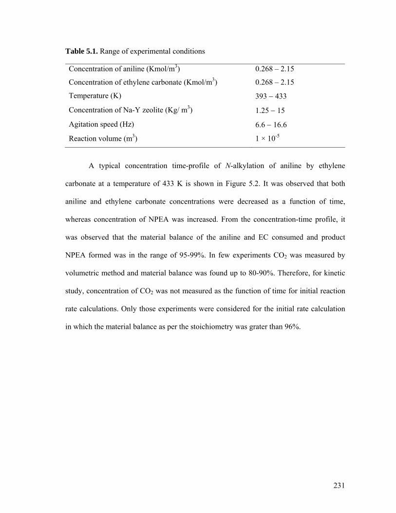
Table 5.1. Range of experimental conditions
Concentration of aniline (Kmol/m3) 0.268 – 2.15
Concentration of ethylene carbonate (Kmol/m3) 0.268 – 2.15
Temperature (K) 393 − 433
Concentration of Na-Y zeolite (Kg/ m3) 1.25 − 15
Agitation speed (Hz) 6.6 − 16.6
Reaction volume (m3) 1 × 10⁻⁵
A typical concentration time-profile of N-alkylation of aniline by ethylene
carbonate at a temperature of 433 K is shown in Figure 5.2. It was observed that both
aniline and ethylene carbonate concentrations were decreased as a function of time,
whereas concentration of NPEA was increased. From the concentration-time profile, it
was observed that the material balance of the aniline and EC consumed and product
NPEA formed was in the range of 95-99%. In few experiments CO2 was measured by
volumetric method and material balance was found up to 80-90%. Therefore, for kinetic
study, concentration of CO2 was not measured as the function of time for initial reaction
rate calculations. Only those experiments were considered for the initial rate calculation
in which the material balance as per the stoichiometry was grater than 96%.
231

0.0
0.2
0.4
0.6
0.8
1.0
1.2
0 30 60 90 120
Time, min
Con
cent
ratio
n, K
mol
/m3
Aniline
EC
NPEA
Figure 5.2. A typical concentration-time profile for N-alkyaltion of aniline by EC
Reaction conditions: aniline, 1.075 Kmol/m3; ethylene carbonate, 1.075 Kmol/m3; Na-Y catalyst, 10 Kg/m3; Solvent, triglyme; T, 433 K; N2 atmosphere; Time, 2h, Agitation speed, 13.3 Hz; Total volume, 10 ml.
Figure 5.2 shows that side-product N-phenyl diethanolamine (NPDEA) was not
formed under experimental conditions. Hence, the reaction Scheme 5.1 can be simplified
and shown as Scheme 5.2 from which NPDEA was excluded.
CO2N OH
H+NH2
Na-Y zeolite
N-phenyl ethanolamine (NPEA)
+
2 3
OO
O
1
Scheme 5.2
5.1.3.1.1. Effect of solvent on NPEA yield
Few solvents with wide range of variation in their dielectric constants (Є) viz.
triglyme (Є20 = 7.6), 1-methyl-2-pyrrolidone (NMP, Є20 = 32.4), ethylene glycol (EG, Є20
232

= 37), N,N- dimethyl formamide (DMF, Є20 = 38.2) and ethylene carbonate (EC, Є40 =
90.5) were screened to investigate the effect of solvent on catalyst activity towards
synthesis of β-amino alcohol (NPEA). These results are presented in Figure 5.3. The
results showed that in highly polar medium (NMP, DMF, EG) yield of N-phenyl
ethanolamine was poor (20−60%) as compared to less polar solvent, triglyme (100%).
The effect of ethylene carbonate as solvent could not be compared, as EC is one of
reactants. Though, EC worked as an excellent solvent, selectivity of NPEA (85% yield)
was less due to the formation of by-product, N-phenyl diethanolamine (15% yield). Polar
solvents such as DMF, NMP and EG interact strongly with the polar environment (i.e. a
silicoaluminate structure) of the inner cages of Na-Y zeolite and becomes one of the
major competitor of aniline for the active sites of the catalyst.1a Whereas, triglyme acts as
a suitable anion activating media to perform the alkylation reaction and which allows
operating the reaction at higher temperature in the range of 393 K − 453 K.3 Therefore,
for the kinetic study of N-alkylation reaction of aniline and ethylene carbonate, the
experiments were carried out using triglyme as a solvent.
233

0
20
40
60
80
100
Triglyme NMP EG DMF EC
Solvent
Con
vers
ion
or Y
ield
, %
aniline, conversion
NPEA, yield
NPDEA, yield
Figure 5.3. Effect of solvent on NPEA yield
Reaction conditions: aniline, 1.075 Kmol/m3; ethylene carbonate, 1.075 Kmol/m3; Na-Y catalyst, 15 Kg/m3; T, 433 K; N2 atmosphere; Time, 2 h, Agitation speed, 13.3 Hz; Total volume, 5 ml. 5.1.3.1.2. Effect of Na-Y zeolite pretreatment on its catalytic activity
The pretreatment of the catalyst can change its activity and selectivity in catalytic
reactions, which is well known in catalytic hydrogenation reactions. Therefore, some
experiments were carried out with the aim of understanding the effect of pretreatment of
Na-Y catalyst with aniline and ethylene carbonate (Figure 5.4). For this purpose, Na-Y
catalyst was treated first with any one of these substrates for 0.5 h at reaction temperature
(433 K) followed by the addition of another substrate and then reaction was carried out
for the specified time. The results indicated that the pretreated catalyst did not show any
effect on catalytic activity. It was also confirmed here that initial rate of reaction was
found to be unaffected by pretreatment. Therefore, for kinetic study, the experiments
were carried out using Na-Y zeolite without any pretreatment.
234

0
20
40
60
80
100
Na-Y without pretreatment
Na-Y pre treatedwith aniline
Na-Y pre treatedwith EC
NPE
A Y
ield
, %
Figure 5.4. Effect of Na-Y catalyst pretreatment on NPEA yield
Reaction conditions: aniline, 1.075 Kmol/m3; ethylene carbonate, 1.075 Kmol/m3; Na-Y catalyst, 15 Kg/m3; Solvent, triglyme; N2 atmosphere; Time, 2 h, Agitation speed, 13.3 Hz; Total volume, 5 ml. 5.1.3.1.3. Effect of carbon dioxide atmosphere
In the synthesis of β-amino alcohol from aniline and ethylene carbonate, carbon
dioxide was produced as a side product on the surface of Na-Y zeolite. It is assumed that
CO2 is evolved on the surface within the pores by chemical reaction and immediately
transported from liquid filled pores to gas phase under reaction conditions (T, > 393 K).
CO2 diffuses out into the bulk liquid and eventually desorbed into gas phase (i.e. inert N2)
prevailing at liquid-gas phase boundary. In order to confirm that the reaction was not in
mass transfer regime, two experiments were carried out to qualitatively show that CO2
concentration on surface is inhibiting reaction. Firstly an experiment was carried out in
CO2 atmosphere (instead of inert gas N2) and in the second experiment, nitrogen was
bubbled through the liquid phase continuously so as to purge gas and liquid phases, the
objective here was to drive away CO2 from liquid as well as gas phase and thereby to see
235

whether reaction is facilitated. The concentration–time profile of N-phenyl ethanolamine
is shown in Figure 5.5 (for the sake of convenience aniline and ethylene carbonate
concentration profiles are not shown) along with standard reaction carried out under N2
atmosphere. The data showed that under CO2 atmosphere and in N2 purge condition the
concentration-time profile was the same as that was observed in N2 atmosphere indicating
that CO2 had no effect on reaction rate. Therefore, further reactions were carried out in
nitrogen atmosphere without purging gas phase.
0.0
0.2
0.4
0.6
0.8
1.0
1.2
0 30 60 90 120
Time, min
NPE
A C
once
ntra
tion,
Km
ol/m
3
N2 atm
CO2 atmN2 purging
Figure 5.5. Comparison of Na-Y catalyst activity under N2 and CO2 atmosphere Reaction conditions: aniline, 1.075 Kmol/m3; ethylene carbonate, 1.075 Kmol/m3; Na-Y catalyst, 10 Kg/m3; Solvent, triglyme; T, 433 K; Time,2h, Agitation speed, 13.3 Hz; Total volume, 10 ml.
5.1.3.1.4. Effect of concentration of NPEA
The effect of concentration of product, N-phenyl ethanolamine (NPEA) was
studied at 433 K in the range of 0.27 – 1.075 Kmol/m3. In the experiments,
predetermined amount of NPEA was added along with the substrates at the start of the
236

reaction and results are presented in Figure 5.6. The results showed that initial rate of
reaction was not affected by concentration of NPEA indicating there was no reaction
inhibition due to the liquid product (NPEA) concentration during the run.
0.0
2.0
4.0
6.0
8.0
10.0
0 0.2 0.4 0.6 0.8 1 1.2
Concentration of NPEA, Kmol/m3
Initi
al ra
te, R
A x
104 K
mol
/m3 /s
393 K
433 K
Figure 5.6. Effect of concentration of NPEA on initial rate of reaction
Reaction conditions: aniline, 1.075 Kmol/m3; ethylene carbonate, 1.075 Kmol/m3; NPEA; Na-Y catalyst, 10 Kg/m3; Solvent, triglyme; N2 atmosphere; Agitation speed, 13.3 Hz; Total volume, 10 ml. 5.1.3.1.5. Catalyst recycle study It is important to ensure the consistent activity of the Na-Y catalyst through out a
reaction. Otherwise, if catalyst deactivates during the reaction, reactor performance will
be a function of catalyst deactivation rate and may give falsified kinetic parameters. The
recycle of catalyst indicated that there was no appreciable drop in catalyst activity. The
results showed that Na-Y zeolite was not deactivated due to the liquid-phase components
as well as due to the gas-phase components.
237

5.1.4. ANALYSIS OF INITIAL RATE DATA
The analysis of initial rate data is useful in understanding the dependence of the
reaction rate on individual reaction parameters and also in the evaluation of mass transfer
effects. The initial rates of the reaction were calculated from the concentration time data,
based on consumption of aniline concentration in the reaction. From these profiles the
initial rate of aniline reaction, RA, (Kmol.m-3.s-1) was calculated from the slope of
concentration Vs time plots in the time interval of ~ 15 minutes. Similar plots were also
made in few cases for ethylene carbonate and N-phenyl ethanol amine concentration and
calculated rates of EC and NPEA based on initial time intervals were found to agree as
per the stoichiometry depicted in scheme 5.2.
5.1.4.1. Effect of concentration of aniline
The effect of concentration of aniline on the rate of N-alkylation reaction was
studied in the range of 0.268 – 2.15 Kmol/m3 at 393, 413 and 433 K. The rate of reaction
showed linear dependence on aniline concentration in the range studied. The graphical
representation of the dependence of the reaction rate on aniline concentration is shown in
Figure 5.7. The aniline concentration dependency on initial rate of reaction can be
explained on the basis that either aniline is adsorbed on catalyst surface and has yet to
saturate catalyst surface so that EC has enough vacant sites remaining for adsorption
resulting in increase in reaction rates with increase in aniline concentration or is very
weakly adsorbed such that ethylene carbonate is able to displace it and bring about the
reaction. The third probability is that aniline is not adsorbed at all on catalyst and
adsorbed ethylene carbonate reacts with aniline present in the pores of zeolite (Eley-
238

Rideal mechanism). These possibilities will be explored when kinetic rate model is
evaluated in section 5.1.6.
0.0
5.0
10.0
15.0
20.0
0.0 0.5 1.0 1.5 2.0 2.5
Concentration of aniline, Kmol/m3
Initi
al ra
te, R
A x
104 , K
mol
/m3 /s
393 K
413 K
433 K
Figure 5.7. Effect of concentration of aniline on initial rate of reaction
Reaction conditions: aniline, 0.268 – 2.15 Kmol/m3; ethylene carbonate, 1.075 Kmol/m3; Na-Y catalyst, 10 Kg/m3; Solvent, triglyme; N2 atmosphere; Agitation speed, 13.3 Hz; Total volume, 10 ml. 5.1.4.2. Effect of concentration of ethylene carbonate
The effect of concentration of ethylene carbonate on the initial rate of N-
alkylation reaction was studied in the range of 0.268−2.15 Kmol/m3 at different
temperatures (393 – 433 K) and the results are presented in the Figure 5.8. The rate was
found to increase with increase in ethylene carbonate concentration up to 1.075 Kmol/m3
and was found to decrease slowly with further increase of ethylene carbonate
concentration. The rate behavior of ethylene carbonate concentration indicated that, with
the increase in the concentration of ethylene carbonate, concentration of adsorbed
ethylene carbonate increased resulting in increasing the rate of reaction. However, at
239

critical concentration of ethylene carbonate, catalyst surface got saturated with adsorbed
ethylene carbonate and further increase in the amount of ethylene carbonate can not
increase the rate. This effect was more prominent at higher temperature and less at lower
temperature wherein reaction rates were low and catalyst surface was not saturated with
ethylene carbonate. This trend supports the observation made in earlier section 5.1.4.1,
that aniline adsorption may be very weak. If one assumes that amino alcohol was formed
by reaction of adsorbed aniline and adsorbed ethylene carbonate, then in this case, at high
EC concentration, competitive adsorption of EC and aniline would decrease availability
of vacant site for aniline adsorption. And in this case reaction rate would decrease.
However rate was not decreased with increase in EC concentration but remained constant
indicating that assumption of aniline adsorption on catalyst surface was not correct. Selva
et al. had reported similar dependency on reaction rate with alkyl methyl carbonate
concentration for N-alkylation of aniline with Na-Y zeolite.1
240

0.0
2.0
4.0
6.0
8.0
10.0
12.0
14.0
0.0 0.5 1.0 1.5 2.0 2
Concentration of ethylene carbonate, Kmol/m3
Initi
al ra
te, R
A x
104 , K
mol
/m3 /s
.5
393 K
413 K
433 K
Figure 5.8. Effect of concentration of ethylene carbonate on initial rate reaction
Reaction conditions: aniline, 1.075 Kmol/m3; ethylene carbonate, 0.268 – 2.15 Kmol/m3; Na-Y catalyst, 10 Kg/m3; Solvent, triglyme; N2 atmosphere; Agitation speed, 13.3 Hz; Total volume, 10 ml. 5.1.5. ANALYSIS OF MASS TRANSFER EFFECTS
The chemical reaction in presence of a solid catalyst consists of physical as well
as chemical steps, generally reactants has to be transported from bulk reactant phase to
the active centers of the catalyst and product to be transported from catalyst surface to the
bulk solvent or gas phases (Figure 5.9). In order to ascertain that the reaction is in kinetic
regime, chemical reaction has to be slower compared to physical transport rates. A
description of physical mass transfer steps is made in the following section when solid
catalyst is used.
241

8o
A
o
A12
(g)
(lq)
CAn (lq)and CEC (lq)
CNPEA (lq)
(S)CCO2
CCO2
Solid
-liqu
id fi
lm
Bulk liquidG
as-li
quid
film
Gas phase
Pore of zeolite
CCO2
Figure5.9. Schematic presentation of mass transfer steps involved in N-alkylation of
aniline by ethylene carbonate to N-phenyl ethanolamine
In a chemical process involving zeolite as catalyst usually the feed stream is in the
gas or liquid phase, where adsorption on the zeolite surface and into the zeolite pores first
has to take place. In order to react, the molecules then have to be transported to the
reactive sites inside these pores. This transport process is called diffusion, which has two
components; bulk diffusion that involves diffusion of molecules in bulk liquid or gas
phase and pore diffusion that involves diffusion in catalyst pores. Diffusion in zeolites
differs from ordinary diffusion in the sense that the molecules have to move through
channels of molecular dimensions having electrostatic environment. As a result, there is a
constant interaction between the diffusing molecules and the zeolite framework (see
Figure 5.18 for Na-Y structure), and the molecular motion is thus also strongly
influenced by the exact size and shape of these channels instead of the temperature and
concentration only.
Once the reactants have reached the catalytically active sites, the necessary
chemical reactions can finally take place, and the conversion into products takes place. At
242

this stage products have to be transported away from the micro channels of zeolite
recreating free catalytic sites to facilitate the further reaction. As the conversion of
reactants can only occur when a significant amount of them are able to reach the active
sites, and the resulting products are removed sufficiently fast from these sites, one can
imagine that both adsorption and diffusion can significantly determine the catalytic
behavior of a system. These steps are schematically depicted in Figure 5.10.
Adsorption
Diffusion
Desorption
Diffusion
Occupied poreOccupied pore
Occupied reaction center
Empty pore
.
.
..
Figure 5.10. A catalytic cycle in zeolite catalysis4
In order to make sure that the chemical reaction is not limited by physical steps
such as diffusion of reactant to the active site of catalyst and desorption of products from
reaction centers to bulk phase, criteria available in literature to calculate the significance
of mass transfer rates were employed.5
For the purpose of kinetic study it is important to ensure that, the rate data
obtained are under kinetic regime and free from external liquid-solid mass transfer
resistance and intra-particle diffusion resistance. Therefore following studies were carried
out to analyze the significance of various mass transfer resistances in the range of
experimental conditions.
243

5.1.5.1. Effect of agitation speed
The effect of agitation speed was checked at highest catalyst loading and highest
temperature (used for kinetic study) to ascertain the liquid-solid mass transfer effect.
Figure 5.11 shows the effect of agitation speed on the initial rate of aniline. It was found
that stirrer speed has no effect on initial rate of aniline reaction indicating that reaction is
free from external mass transfer barrier. Hence, all experiments for the present study
were carried out at 13.3 Hz.
4.0
6.0
8.0
10.0
12.0
14.0
16.0
4.0 8.0 12.0 16.0 20.0
Agitation speed, Hz
Initi
al ra
te, R
A x
104 , K
mol
/m3 /s
Figure 5.11. Effect of agitation speed on initial rate of reaction
Reaction conditions: aniline, 1.075 Kmol/m3; ethylene carbonate, 1.075 Kmol/m3; Na-Y catalyst, 15 Kg/m3; Solvent, triglyme; T, 433 K; N2 atmosphere; Total volume, 10 ml. 5.1.5.2. Effect of catalyst loading
Effect of catalyst loading on initial rate of N-alkylation reaction of aniline and
ethylene carbonate was investigated in the range of 1.25 − 15 Kg/m3 at 433 K and the
results are presented in Figure 5.12. Initial rate of reaction showed linear dependence on
244

catalyst loading, indicating the absence of external liquid-solid mass transfer effects
under the conditions of present work.6
0.0
2.0
4.0
6.0
8.0
10.0
12.0
14.0
16.0
0.0 3.0 6.0 9.0 12.0 15.0 18.0
Catalyst concentration, Kg/m3
Initi
al ra
te, R
Ax1
04 , Km
ol/m
3 /s
Figure 5.12. Effect of Na-Y zeolite catalyst loading on initial rate of reaction
Reaction conditions: aniline, 1.075 Kmol/m3; ethylene carbonate, 1.075 Kmol/m3; Na-Y catalyst; Solvent, triglyme; T, 433 K; N2 atmosphere; Agitation speed, 13.3 Hz; Total volume, 10 ml. 5.1.5.3. Intra-particle diffusion resistance
Zeolites are crystalline three dimensional aluminosilicate materials having very
regular structure, with open channels or cages and acidic and basic properties. For the
zeolites, catalytically active sites are not directly accessible to the reacting molecules and
therefore, a number of different mass transfer steps are required in order to convert the
reactants into the desired products (Figure 5.9).
The fine powdered Na-Y zeolite, with average particle size 700 nm, was used
directly as catalyst in this kinetic study. Since it is difficult to vary the particle size of this
catalyst for determining the internal diffusion resistance, numerical calculations were
245

carried out using the Weisz-Prater criterion to asses the influence of intra-particle
diffusion resistances.7 According to the Weisz-Prater criterion, the dimensionless
parameter Cwp which represents the ratio of the intrinsic reaction rate to intra-particle
diffusion rate, can be evaluated from the observed rate of reaction, the particle radius
(Rp), effective diffusivity of limiting reactant (De) and concentration of reactant at the
external surface of the particle (CAS) that can be represented as:
][2
ASeppobswp CDRrC ρ−= (5.1)
If Cwp << 1, then the reaction is intrinsically kinetically controlled.
If Cwp >> 1, then the reaction is limited by severe internal diffusion resistance.
The Diffusivity values (D) were calculated by using the Wilke-Chang equations.8
Effective diffusivity, De was calculated from the following correlation,
τεM
eDD = (5.2)
where, ε and τ are the porosity and tortuosity of the Na-Y zeolite catalyst.
Molecular diffusivity, DM was calculated from the following correlation,
( )6.0
2/18104.7
Ml
WM
MTD
νμχ−×
= (5.3)
Where, χ, Mw, T, μ and νm are the association factor of the solvent, molecular weight of
solvent, temperature, viscosity of the liquid and molar volume of the solvent respectively.
The diffusivity values calculated are presented in Table 5.2.
246

Table 5.2. Values of different parameters used in mass transfer analysis
Temperature, K
Observed rate, robs × 105
DM × 107, *m2/S
Porosity, ε
Tortuosity, τ
De × 108, am2/S
393 8.6 1.43 0.3 3 1.43
413 20.6 1.7 0.3 3 1.7
433 40.6 2.14 0.3 3 2.14
*9.8 v/v % aniline, 7.2 v/v % EC and 83 v/v % triglyme, a These values of effective diffusivity obtained using the criterion is in similar range reported for liquid hydrocarbons in Na-Y zeolites.9
In the present case, the values of CWP were calculated for aniline at temperatures
393, 413 and 433 K are 1.44 × 10⁻⁶, 4.02 × 10⁻⁶ and 11.6 × 10⁻⁶ respectively, for the initial
observed rates, which are very much less than 1. Therefore, it was concluded that there
was no pore diffusion limitations in the Na-Y zeolite catalyst at the temperature range
393-433 K and the reaction was intrinsically kinetically controlled.
5.1.6. KINETIC MODEL
The analysis of initial rate data for N-alkylation of aniline by ethylene carbonate
using Na-Y zeolite in triglyme indicates linear variation with aniline concentration and
first order tending to zero order variation with ethylene carbonate concentration. Based
on these observed trends, three different forms of rate equations were evaluated. Several
basic assumption were made to develop the rate equations: (1) the rate of surface reaction
is the rate limiting step for the N-alkylation; (2) adsorption and desorption rates are
higher than the rate of surface reaction and (3) NPEA and CO2 desorbed very fast from
the catalyst surface keeping active sites free for the reaction. The following models were
considered:
247

Model 1. Interaction of adsorbed ethylene carbonate species with the liquid phase aniline
as rate limiting step (Eley-Rideal model).
The elementary steps for this Model can be written as follows;
(i)+ ECs An NPEA + CO2 s+ (ii)
EC + s ECs
KA
k1
Model 2. Both aniline and ethylene carbonate are adsorbed on Na-Y zeolite catalyst but
adsorbed aniline do not react and the rate of adsorbed ethylene carbonate
species with the liquid phase aniline is rate limiting step (Langmiur -Rideal
model).
The elementary steps for this Model can be written as follows;
(i)
An + s Ans
+ ECs An NPEA + CO2 s+
(ii)
(iii)
EC + s ECsKB
KA
k1
Model 3. Interaction of adsorbed ethylene carbonate species with adsorbed aniline
species as rate limiting step (Langmiur-Hinselwood-Hougel-Watson model).
The elementary steps for this Model can be written as follows;
(i)
An + s Ans
+ ECs Ans NPEA + CO2 2 s+
(ii)
(iii)
EC + s ECsKB
k1
KA
The rate equations were derived10 for these models and are presented in Table 5.3.
In order to check the applicability of the rate models derived under isothermal and
248

integral conditions, a semi batch reactor model was developed. Material balance of the
liquid phase components based on Model 2 is given bellow as an example:
ANBECA
ECANAn
CKCKCkwC
Rdt
dC++
−=−=11 (5.4)
ANBECA
ECANEC
CKCKCkwC
Rdt
dC++
−=−=11 (5.5)
ANBECA
ECANNPEA
CKCKCkwC
Rdt
dC++
==11 (5.6)
With the initial conditions:
0,,,0, 0,0, ==== NPEAECECAnAn CCCCCtat
Where, R1 is the reaction rate, Kmol/m3/s; CAN, CEC, and CNPEA are the
concentration of aniline, ethylene carbonate and N-phenyl ethanolamine respectively in
Kmol/m3; CAN, 0 and CEC, 0 are the initial concentration of aniline and ethylene carbonate
respectively in Kmol/m3; w, concentration of catalyst, Kg/m3; k , reaction rate constant,
m6/ Kg.Kmol.s, where, k = k1 × KA; k1, surface reaction rate constant, m3/Kg.s and KA,
KB are the adsorption constants for ethylene carbonate and aniline respectively in
m /Kmol.
B
3
In order to select an appropriate rate equation, a non-linear least square regression
analysis method was used for each rate equation to get the best-fit values of the
parameter. For this purpose an optimization programme based on Marquardt’s algorithm
combined with Runge-Kutta method was used. The optimization method involved an
objective function Фmin, the value of which minimized during the optimization and
defined as:
249

(5.7) ( )∑∑==
−=n
iiYiYi
1modexp
4
1minφ
where, Yiexp and Yimod represent experimental and predicted concentration of ith
species and n represents the number of samples. The mean average of relative residuals
(% RR) was also calculated based on the following expression:
100)(
%1 exp
modexp4
1×
−= ∑∑
==
n
ii YiYiYi
RR (5.8)
Table 5.3. Comparison of various models for N-alkylation of aniline by ethylene
carbonate to N-phenyl ethanolamine using Na-Y zeolite as catalyst
Model T, K k1×105 KA KB % RR Фmin
393 1.80 1.327 - ± 5.7 1.06×10⁻⁷
413 5.75 1.353 - ± 7.2 4.3×10⁻⁹ECA
ECANA CK
CkwCR
+=
1
(1) 433 19.4 1.129 - ± 7.5 3.24×10⁻¹²
393 1.84 1.424 0.30 ± 3.8 4.2×10⁻¹⁶
413 6.19 1.349 0.209 ± 2.4 1.94×10⁻¹⁸ANBECA
ECANA CKCK
CkwCR
++=
1
(2) 433 19.4 1.132 0.099 ± 6.3 3.2×10⁻¹⁶
393 2.69 0.964 0.1 ± 2.5 1.4×10⁻⁸
413 57.1 0.538 -0.22 ± 9.1 6.28×10-42
2
}1{ ANBECA
ECANA CKCK
CCkwR
++=
(3) 433 245 0.582 0.004 ± 17.7 4.3×10⁻³
The rate models were discriminated based on the Фmin and % RR values obtained
by regression analysis for each model. In addition, the thermodynamic criteria proposed
by Vannice et al.11 and Boudart12 were also considered for goodness of fit for the present
model. These criteria are; (i) rate constants and adsorption constants should be positive
(k > 0, K > 0) and (ii) activation energy should be positive (Ea > 0). The values of Фmin
250

and % RR along with the optimized rate and adsorption parameters are presented in Table
5.3. The main objective here was not only to discriminate models, but to show the
significance of aniline interaction with electrostatic environment in zeolites cage
(adsorption constants) for reaction occurring in zeolites cage.
Out of the three models, based on above criteria, Model-3 was rejected because it
gave negative values for the constant KB at 413 K. Among the remaining models,
Model- 2 has the lowest Ф
B
min and % RR. Hence, the model represents the kinetic of N-
alkylation of aniline by ethylene carbonate in the range of operating conditions
mentioned in Table 5.2. A few experimental and predicted concentration-time profiles are
shown in Figures 5.13 – 5.15 which showed a good agreement between the experimental
and theoretical data points and % RR values are in the range of ±2-6. This indicated the
stability of the model. It may be noted here that the value of KBB CAN is maximum 0.32,
which is not significantly affecting the denominator of Model 2. Hence, the denominator
value of Model 1 and Model 2 are not significantly different. Therefore, initial rates and
concentration - time profiles predicted by these models are almost similar. The advantage
of Model 2 is that it accounts for a weak interaction of aniline with zeolite in the pores.
251
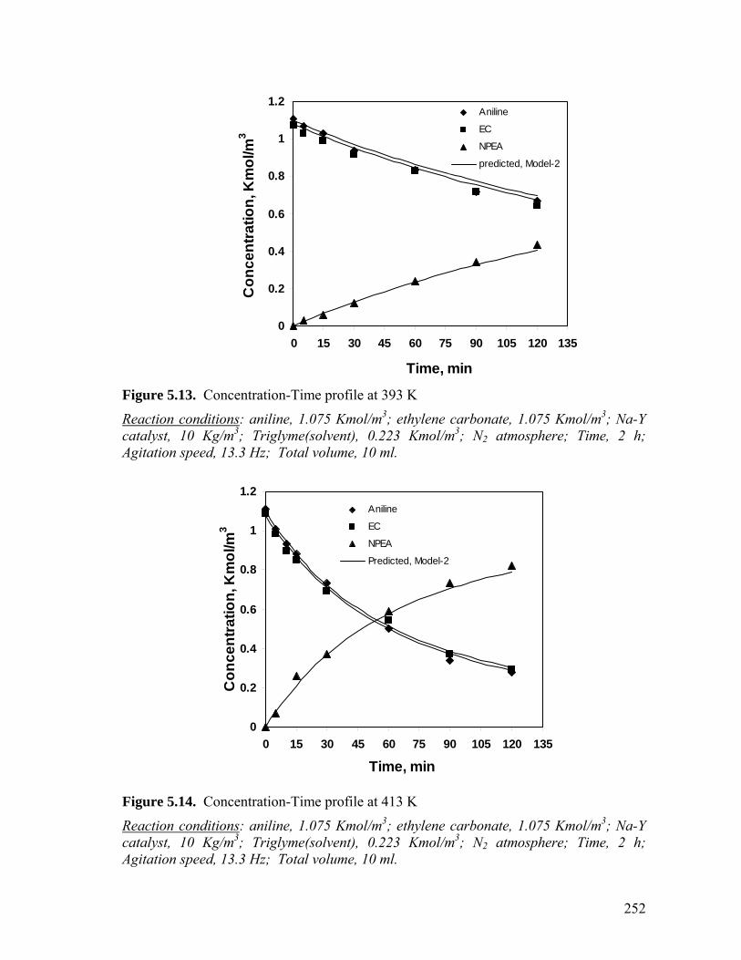
0
0.2
0.4
0.6
0.8
1
1.2
0 15 30 45 60 75 90 105 120 135
Time, min
Con
cent
ratio
n, K
mol
/m3
Aniline
EC
NPEA
predicted, Model-2
Figure 5.13. Concentration-Time profile at 393 K
Reaction conditions: aniline, 1.075 Kmol/m3; ethylene carbonate, 1.075 Kmol/m3; Na-Y catalyst, 10 Kg/m3; Triglyme(solvent), 0.223 Kmol/m3; N2 atmosphere; Time, 2 h; Agitation speed, 13.3 Hz; Total volume, 10 ml.
0
0.2
0.4
0.6
0.8
1
1.2
0 15 30 45 60 75 90 105 120 135
Time, min
Con
cent
ratio
n, K
mol
/m3
Aniline
EC
NPEA
Predicted, Model-2
Figure 5.14. Concentration-Time profile at 413 K
Reaction conditions: aniline, 1.075 Kmol/m3; ethylene carbonate, 1.075 Kmol/m3; Na-Y catalyst, 10 Kg/m3; Triglyme(solvent), 0.223 Kmol/m3; N2 atmosphere; Time, 2 h; Agitation speed, 13.3 Hz; Total volume, 10 ml.
252

0
0.2
0.4
0.6
0.8
1
1.2
0 15 30 45 60 75 90 105 120 135
Time, min
Con
cent
ratio
n, K
mol
/m3
Aniline
EC
NPEA
predicted, Model-2
Figure 5.15. Concentration-Time profile at 433 K
Reaction conditions: aniline, 1.075 Kmol/m3; ethylene carbonate, 1.075 Kmol/m3; Na-Y catalyst, 10 Kg/m3; Triglyme(solvent), 0.223 Kmol/m3; N2 atmosphere; Time, 2 h; Agitation speed, 13.3 Hz; Total volume, 10 ml.
From the temperature dependence of rate parameters (Figure 5.16) the activation
energy of the reaction was calculated to be 83.11 KJ/mol, which showed the reaction was
kinetically controlled and gave another proof of absence of intra-particle diffusion
resistance. Finally it may be noted that the model selected is representing the
experimental data adequately, however, since no attempts has been made here to
rigorously discriminate rival models, the possibility of other models representing the data
equally well can not be ruled out at this stage.
253

-11.5
-11
-10.5
-10
-9.5
-9
-8.5
-8
0.00225 0.00235 0.00245 0.00255
1/T, K-1
Ln k
Figure 5.16. Temperature dependence of rate constant 5.1.7. CONCLUSION
Kinetics of N-alkylation of aniline by ethylene carbonate using a Na-Y zeolite as
catalyst was studied in a batch reactor in the temperature range of 393-433 K. The
reaction was found to be first order with respect to aniline concentration and first order
tending to zero order with respect to ethylene carbonate concentration. A rate equation
was derived using a catalytic cycle based on molecular level description of elementary
steps and assuming adsorption of ethylene carbonate on Na-Y zeolite catalyst followed
by reaction with aniline as the rate determining step. The kinetic parameters were
estimated using non-linear regression analysis and activation energy was evaluated (83.1
KJ/mol).
254

Notations
An aniline
EC ethylene carbonate
NPEA N-phenyl ethanolamine
CAn concentration of aniline, Kmol/m3
CEC concentration of ethylene carbonate, Kmol/m3
CNPEA concentration of N-phenyl ethanolamine, Kmol/m3
Cwp Wiesz-Prater criterian
CAn, 0 initial concentration of aniline, Kmol/m3
CEC, 0 initial concentration of ethylene carbonate, Kmol/m3
De effective diffusivity, m2/s
DM molecular diffusivity, m2/s
dp particle diameter, m
k reaction rate constant,
m6/Kg.Kmol.s (defined by Model 1 and 2, where k = k1 × KA); m6/Kg.Kmol.s (defined by Model 3, where k = k1 × KA × KB) B
k1 Surface reaction rate constant,
m3/Kg.s (defined by Model 1 and 2)
Kmol.m3/Kg2.s (defined by Model 3)
KA adsorption constant for ethylene carbonate, m3/Kmol
KBB adsorption constant for aniline, m3/Kmol
RA initial rate of aniline, Kmol/m3/s
R1 rate of reaction, Kmol/m3/s
Rp particle, radius, m
s catalyst surface
T temperature, K
w catalyst loading, Kg/m3
255

Greek letters,
χ association factor of the solvent
ε porosity of catalyst
Є dielectric constant
Фmin Parameter defined by equation 5.7
μl viscosity of the liquid
νm molar volume of the solvent
τ tortuosity of the catalyst
ρp density of particle
256

PART II
5.2. SYNTHESIS OF β-AMINO ALCOHOLS FROM ANILINE AND ETHYLENE CARBONATE: MECHANISTIC STUDIES USING IN SITU FTIR TECHNIQUE
5.2.1. INTRODUCTION
β-amino alcohol is an important class of compound and its synthesis via
N-alkylation of anilines by alkylene carbonate is simple and useful reaction but it is not
investigated through mechanistic point of view. The conventional pre-and post-reaction
investigations through physico-chemical characterization contribute to some extent to
understanding of the reaction. However, most often they do not adequately reflect the
events that occur on the system under actual reaction conditions, like short-lived
intermediates, surface complexes and the reaction mechanism. The in situ
characterization techniques help to understand the interaction of adsorbed species with
catalyst surface and highlight the chemical and orientational changes of the adsorbate,
short-lived intermediates and surface complexes that are formed during the reaction,
which in turn provide information about the reaction mechanism. In addition, in situ
techniques throw light on how catalytic conversion and product selectivity depend on the
structural and electronic properties of the catalyst and the mode of catalyst deactivation.
Among the various techniques that are used to study catalytic process, infrared
spectroscopy (IR) plays an important role. This is primarily due to fact that IR provides
actual information on the structure, geometry and orientation of practically all molecules
that are present in a reaction mixture, irrespective of the physical state, temperature or
pressure. IR is, therefore, a feasible tool not only for the characterization of reactants and
257

products, but also of catalytically active sites, support materials, ligands, promoters and
intermediates of homogeneous and heterogeneous catalysts. A review on application of
IR spectroscopy in catalysis by Ryczkowski demonstrates the various important
applications of FTIR specially in understanding various catalytic processes.13
In the literature, various kind of interaction and the adsorption site of the
molecules like: benzene,14 pyridine,15 2,6-dimethyl pyridine,15 H2S,15 CO,16 N216 and
boric acid trimethyl ester (BATE)17 etc. in the zeolite Y were investigated using FTIR
spectroscopy to show that Na+ cations present only in SII position (Figure 5.18) are
accessible to the guest molecules for catalytic reactions as well as to determine the nature
and strength of acidity and basicity. Gomez and Anunziata have studied the aniline
adsorption on Na-Y18a and MCM-4118b using FTIR spectroscopy and they have
demonstrated that aniline binds strongly with Na-Y through unpaired electrons of amino
groups and Na+ of the zeolites whereas it interacts through π bonding of aromatic ring
with structural Si-OH groups of MCM-41. Sorption of anilines by montmorillonite
saturated with various cations was investigated by Yariv et al.19 to identify the various
interactions between aniline and adsorption sites in the interlayer space of the clays.
Singh et al.20 have also studied the interaction of aniline and N-methyl aniline with
zeolites (H-Beta and H-Y) by FTIR spectroscopy which revel that hydroxyl groups of
zeolites interacts with both π electrons of aromatic ring as well as lone pair of electrons
of amines. Vijayraj et al.21 have investigated the mechanism of N-methylation of aniline
with methanol on Cu1-ZnxFe2O4 catalyst using DRIFTS study.
Beutel22 and Bonino et al.23 have studied the interaction of dimethyl carbonate in
the pores of Na-X and Na-Y zeolite respectively using IR spectroscopy. From the
258

literature it is clear that there is no information on the interaction of ethylene carbonate
with any adsorbate as well as there are no previous reports on mechanistic studies of N-
alkylation of aniline by ethylene carbonate. In this work, a detailed vapor phase
interaction of aniline and ethylene carbonate on Na-Y for production of N-phenyl
ethanolamine using in situ FTIR technique (DRIFT) was investigated and based on these
results, reaction mechanism was proposed.
5.2.2. EXPERIMENTAL
Aniline was purchased from M/S S.D. fine chemicals, India and ethylene
carbonate (EC) from Aldrich chemicals, USA. Na-Y zeolite was provided by Süd-
Chemie, India and was characterized by XRD analysis (see Chapter 4, Section on
Spectra, page no. 226). In situ FTIR studies were carried out using Shimadzu FTIR
spectrometer (SSU8300) using diffuse reflectance infrared Fourier transform (DRIFT)
technique, equipped with MCT-A detector. A cross-sectional view of diffuse reflection
cell is shown in Figure 5.17.
Figure 5.17. Cross-sectional view of diffuse reflection cell
259

5.2.2.1. Experimental procedure for determination of nature of acidity
Nature of acidity of the Na-Y zeolite was determined by pyridine adsorption. The
fine powder of Na-Y catalyst was placed in the DRIFT cell and heated to 673 K in flow
of inert gas (N2) for 4 h. It was cooled to 373 K under inert atmosphere and then pyridine
was adsorbed on the catalyst in N2 flow. The physisorbed pyridine was removed by
flushing the cell with N2 for 45 min at the same temperature and the spectrum was
recorded. The temperature dependant desorption of pyridine was carried out at 373 K,
473 K and 673 K. The spectrum of the neat catalyst (before pyridine adsorption) at 373 K
was subtracted from all the spectra.
5.2.2.2. Experimental procedure for in situ FTIR spectroscopic studies
The catalyst Na-Y zeolite was freshly calcined in situ at 673 K for 4 h to remove
moisture adsorbed on the catalyst surface in the DRIFT sample holder under nitrogen
flow. The catalyst was cooled to 443 K and 10 μl of desired compound or reaction
mixture was introduced in the N2 flow and IR spectra were recorded at different
temperatures in the range 443 K to 523 K. In the first experiment, aniline was injected in
the beginning at 443 K in N2 stream. Physisorbed aniline was removed by flushing the
cell with N2 for 45 min. The chemisorbed aniline was analyzed and when there was no
further decrease in the intensity of aniline peaks, 10 μl ethylene carbonate was injected.
The spectra were recorded as function of time. In the second experiment, ethylene
carbonate was injected initially on freshly calcined catalyst at 443 K. After removing the
physisorbed ethylene carbonate by flushing the system with N2 for 1 h, aniline was
injected. The spectra were recorded as a function of time, again EC was injected and
spectra were recorded as a function of time. In third experiment a 1:1 mixture of aniline
260

and ethylene carbonate was injected on freshly calcined catalyst at 443 K and the spectra
were recorded as a function of time. In the fourth experiment 1:1 mixture of aniline and
ethylene carbonate was injected on freshly calcined 4A catalyst at 443 K and spectra
were recorded as a function of time. The spectrum of neat catalyst at 443 K was
subtracted from all the spectra. All the spectra presented here are as the difference spectra
between molecules absorbed on the Na-Y zeolite and virgin Na-Y zeolites at 443 K.
5.2.3. RESULTS AND DISCUSSION
In the present work, interaction of aniline and ethylene carbonate with Na-Y
zeolite to form β-amino alcohol was investigated in details by in situ IR spectroscopy
using DRIFT technique and based on the results the mechanism for the formation of
NPEA from aniline and ethylene carbonate on Na-Y is proposed.
The optical phenomenon known as diffuse reflectance is commonly used in UV-
Vis, NIR and MIR regions to obtain molecular spectroscopic information.24 When it is
applied in MIR area with a Fourier transform, it is known as diffuse reflectance infrared
Fourier transform spectroscopy (DRIFTS). It is usually used to obtain the spectra of
powders with minimum sample preparations. The collection and analysis of the surface-
reflected electromagnetic radiation as a function of frequency or wavelength obtain a
reflectance spectrum.
5.2.3.1. Determination of acidic sites on Na-Y zeolite
The Y faujasite has a cubic structure with space group Fd3m and it has 24.85 to
24.61 Å unit cell parameter.25 One unit cell contains eight sodalite cages (beta cage, 8 Å
of diameter) and eight super cages (alpha cages, 12.5 to 19 Å of diameter, depending on
261

if it is Na or H form respectively). Its pore system is relatively spacious and its super cages
of a diameter of 12.5 Å connected tetrahedrally with four neighboring cages through
windows with a diameter of 8 Å formed by 12 TO4 tetrahedra. Zeolite Y is therefore
classified to posses a three dimensional, a 12 membered-ring pore system. General formula
for Na-Y zeolites can be given as Na57(AlO2)57(SiO2)135 and structure of Na-Y zeolite is
shown in Figure 5.18. When Y zeolites are in the Na-Y form, the Na+ cations occupy SI,
SI’ and SII sites. The SI, SI’ sites are located in the hexagonal prisms and the sodalite cages
respectively where they are not accessible at low temperatures even for small molecules
such as N2 and CO.16 The only accessible Na+ cations are in SII positions in six ring
windows where they are coordinated to the three framework oxygen anions to form
regular triangle.
8 Å 12 Å
Figure5.18. Structure of Na-Y zeolite
262

Nature of acidity of the Na-Y zeolite was determined by pyridine adsorption. The
spectra of adsorbed pyridine on Na-Y (Figure 5.19) showed a band at 1442 cm-1
confirming presence of Lewis acid sites. Absence of band at 1540 cm-1 confirms the lack
of Bronsted acidity, which is in agreement with the lack of zeolitic –OH groups. Bands
at 1442 and 1593 cm-1 are specific of the ν19b and ν8a vibration mode (νCC(N)) of pyridine
interacting with weak Lewis acidity.26 The band at 1442 and 1577 cm-1 are due to the
combined C-C stretching and in plane C-H bending modes of pyridine. These
coordination sites are attributed to the Na+ centre. Pyridine adsorbed on base exchanged
aluminosilicates shows that base totally eliminates Brønsted acidity from aluminosilicates
which originally posses both Lewis as well as Brønsted acidity. It was also shown that
total amount of chemisorbed pyridine on base exchanged aluminosilicates was less than
aluminosilicate which was a proof for acidity poisoning effect of base metals.
1600 1550 1500 1450 1400
15771593
14881442
673 K
443 K
373 K
Abs
orba
nce,
a.u
.
wavenumber, cm-1
Figure 5.19. FTIR spectra of temperature programmed desorption of Pyridine on Na-Y
zeolite
263

5.2.3.2. Adsorption of aniline on Na-Y catalyst
To study the interaction of aniline with catalyst surface during the reaction,
aniline was adsorbed on freshly activated Na-Y zeolite. Aniline was adsorbed on catalyst
surface at temperature, 443 K and spectra were recorded at different temperatures as a
function of time. The spectra clearly show activation of aniline on Na-Y (Figure 5.20 A
and B). Large shift in the N-H asymmetric and symmetric stretching frequencies to
lower frequencies to 3367 and 3308 cm-1 respectively21 compared to 3450 and 3390 cm-1
in neat aniline27 indicate weakening of N-H bond to much greater extent (Figure 5.20 A).
Appearance of broad band at 3620 cm-1 indicates the formation of OH bond due to the
interaction of N-H proton with zeolite oxygen forming surface hydroxyl groups. This
clearly showed the activation of aniline on Lewis acid sites of the catalyst. A series of
low intensity bands at 1949, 1851, 1787 and 1722 cm-1 attributed to out of plane aromatic
C-H bending vibrations (νC-H) indicated less interaction of aromatic ring with Na-Y
zeolite (Figure 5.20 B).28 One band at 1625 cm-1 and two strong bands at 1597 and 1498
cm-1 are assigned to NH2 bending27 and C=C stretching vibration of phenyl ring27 (ν16a
and ν13a) respectively, which are not shifted to great extent compared much from the
pure aniline. The peaks for adsorbed aniline still existed at 523 K, which indicated that
aniline was strongly bonded to Na-Y zeolite. It is probable that most of the adsorbed
aniline interact with microporous material through lone pair of electrons of the amino
group and sodium cations (Na+).18a
264

4000 3800 3600 3400 3200 3000 2800
36203008
3033
33083367
443 K
523 KAbs
orba
nce, a.u
.
wavenumber, cm-1
Figure 5.20 A. FTIR spectra of temperature programmed desorption of aniline on Na-Y
zeolite (4000-2700 cm-1)
2200 2000 1800 1600 1400 1200 1000 800
1625
1722
1787
18511949
14981597
443 K
523 K
Abs
orba
nce,
a.u
.
wavenumber, cm-1
Figure 5.20 B. FTIR spectra of temperature programmed desorption of aniline on Na-Y zeolite (2200-700 cm-1)
265

5.2.3.3. Sequential adsorption of aniline and ethylene carbonate
The interaction of ethylene carbonate (EC) with activated aniline was studied.
Initially aniline was introduced on Na-Y at 443 K followed by injection of ethylene
carbonate (Figure 5.21). Immediately after the EC reached the catalyst surface,
instantaneous reaction of ethylene carbonate with activated aniline was observed with
liberation of CO2 at 2341 cm-1. Increase in the intensity of CO2 peak with time and
nonobservance of doublet at 1774 and 1800 cm-1 corresponding to ethylene carbonate
C=O clearly confirms the reaction of ethylene carbonate with activated aniline (Figure
5.22 A). The spectrum recorded after 10 minutes shows the peaks corresponding to
product N-phenyl ethanolamine. For reference, the spectrum of NPEA from Aldrich
FTIR database is given in the Figure 5.21.29 NPEA peaks, which are not interfering with
aniline or ethylene carbonate are seen at 3394 cm-1 corresponding to alcoholic –OH
group and a broad multiplet at 871 cm-1 corresponding to OH deformation. Peak at 2941
cm-1 can be assigned to aliphatic CH2 stretching bands of NPEA. Intensity of the NPEA
and CO2 peaks increases with time indicating formation of NPEA by reaction of ethylene
carbonate.
266

4000 3500 3000 2500 2000 1500 1000
NPEA
14988712341
159729413036
3394
(i)Aniline
EC on (i) 10 min
20 min
45 min A
bsor
banc
e, a
.u.
Wavenumber, cm-1
Figure 5.21. FTIR spectra of sequential adsorption of aniline and ethylene carbonate on
Na-Y
5.2.3.4. Adsorption of ethylene carbonate on Na-Y catalyst
When ethylene carbonate was injected on catalyst surface, it was observed that
there was no significant change in peaks position of adsorbed ethylene carbonate
compared to neat ethylene carbonate (Figure 5.22 A and B). The C=O stretching
vibration of adsorbed ethylene carbonate appears as doublet at 1800 and 1774 cm-1
compared to 1801 and 1774 cm-1 for liquid EC (Figure 5.22 A).30 The frequencies
corresponding to EC ring vibration and the ring breathing vibration are observed at 1146
cm-1 and 893 cm-1 respectively (Figure 5.22 B). Whereas, the corresponding bands for
liquid EC are reported at 1155 and 894 cm-1 respectively. This showed physisorption of
EC on Na-Y. When temperature programmed desorption of EC was monitored as a
function of time (Figure 5.22 A and B), it was clearly seen that with time and at higher
temperature (443 K at 30 min, and 523 K at 5 & 20 min) the intensity of all the ethylene
267

carbonate peaks decreased gradually. This gives clear evidence for physisorption of EC
on Na-Y. Before complete desorption of EC, aniline was injected to test if aniline reacts
with physisorbed EC, however no reaction between aniline and physisorbed EC was
observed on Na-Y (Figure 5.23). It proves that physisorbed EC and aniline do not interact
with each other for further reaction. This may be due to the adsorption of aniline on the
sites, which are isolated from physisorbed EC which did not allow reaction of aniline
with pre-adsorbed EC. However when again EC was injected followed by aniline,
formation of CO2 was observed (Figure 5.23) confirming the reaction of EC with
activated aniline. This may indicate that EC molecule reacts with activated aniline
without sitting on the catalyst surface. Beutel has studied the alkylation of phenol with
dimethyl carbonate (DMC) using Na-X zeolite by FTIR spectroscopy.22 Interaction of
DMC with Na-X22 and Na-Y23 shows two possible adsorption modes of DMC inside the
supercage of these zeolites. In first mode there is an interaction of carbonyl carbon with
Na+ ion. However this type of interaction is observed only at room temperature. At higher
temperature second type of interaction is observed where the formation of bidentate
complex in which ester oxygen atoms of DMC chelates one Na+ ion is observed. The
later bonding has led to alkyl cleavage of DMC at elevated temperature yielding
monomethyl carbonate and cleaved methyl group reacts with zeolitic oxygen forming
methoxy group. However it is not possible for ethylene carbonate to form bidentate
complex with Na+ in the supercage of Na-Y due to rigid ring structure of ethylene
carbonate. Because of which the activation of EC leading to liberation of CO2 in the
supercage of Na-Y is not possible.
268

3500 3000 2500 2000 1500
443 K, 30 min
523 K, 5 min
523 K, 20 min
2997
2932 1800 1774A
bsor
banc
e, a
.u.
Wavenumber, cm-1
(A)
1200 1100 1000 900 800 700
893
1146
Abs
orba
nce,
a.u
.
Wavenumber, cm-1
(B) Figure 5.22. FTIR spectra of temperature programmed desorption of ethylene carbonate
on Na-Y zeolite
3500 3000 2500 2000 1500
2341 (i)EC (ii)Aniline (iii)EC
(i)EC (ii)Aniline
EC
Abso
rban
ce, a
.u.
Wavenumber, cm-1
Figure 5.23. FTIR spectra of sequential adsorption of ethylene carbonate, aniline and
ethylene carbonate on Na-Y
269

5.2.3.5. Adsorption of 1:1 mixture of aniline and ethylene carbonate
To check the sequence of activation of both the reactants, 1:1 mixture of aniline
and ethylene carbonate was injected at 443 K. Instantaneous reaction of aniline with
ethylene carbonate was observed with liberation of CO2 (Figure 5.24). In the spectra,
peaks corresponding to activated aniline and NPEA formation were clearly seen and no
peaks corresponding to ethylene carbonate were observed.
3500 3000 2500 2000 1500 1000
NPEA,OH deformation
CO2NPEA,CH2
3394
NPEA,OH
8712341
3313 2941
3037
120min
35min
5min
Abs
orba
nce,
a.u
.
wavenumber, cm-1
Figure 5.24. Time-dependant FTIR spectra of adsorption of 1:1 mixture of aniline ethylene carbonate on Na-Y catalyst at 443 K
5.2.3.6. Adsorption of aniline and ethylene carbonate on 4A catalyst
To reconfirm that reaction takes place in the supercage of Na-Y and not on the
surface of the catalyst, reaction of aniline with EC was carried out using 4A as catalyst.
Zeolite 4A is known to have weak surface Lewis acidity31 and the pore size is 4 Å, which
is smaller than aniline (5.4 Å). Surface characteristics of 4A and Na-Y would be same
(aluminosilicate) as the cation in case of Na-Y is located only in the cages or pores of the
270

zeolite and hence there is no cation present on the surface of the Na-Y. If reaction of
aniline and EC would take place on the surface of Na-Y then it is expected that 4A also
catalyze the same reaction. The main source of acidity in case of Na-Y is the Na+ cation,
which is located in the cages of the zeolite and activates aniline that in turn causes the
reaction with EC to yield NPEA. To test if aniline and/or EC get activated on the surface
of 4A, aniline and EC were injected on the surface of catalyst 4A (Figure 5.25). In the
first experiment, aniline was injected and it was observed that there was no interaction of
aniline with 4A. In the second experiment, ethylene carbonate was injected after injection
of aniline and it was observed that no interaction of EC with 4A and no peaks
corresponding to NPEA indicating only physisorption of aniline and EC without
activation on the catalyst surface. This was reconfirmed in the third experiment where
mixture of aniline and EC was injected and still no formation of NPEA was observed in
FTIR spectrum. These experiments clearly showed that N-alkylation of aniline by
ethylene carbonate took place in the pores of Na-Y and not on the surface.
4000 3500 3000 2500 2000 1500 1000
1800
aniline + EC
(i)Aniline (ii) EC
aniline
2932
1774
Abs
orba
nce,
a.u
.
wavenumber, cm-1
Figure 5.25. FTIR spectra of sequential adsorption of aniline, ethylene carbonate and aniline on 4 A
271

5.2.3.7. Reaction mechanism
Based on the above in situ experiments, the following mechanism for the reaction of
aniline and ethylene carbonate using Na-Y catalyst was proposed (Scheme 5.3). In the
catalytic cycle, first aniline gets activated on the Lewis acid sites of Na-Y i.e. Na+
forming partial negative charge on nitrogen atom of aniline leading to the formation of
nucleophile species (ii). During this activation, N-H proton interacts with zeolitic oxygen
atom forming surface hydroxyl group species (iii). In the second step nucleophilic attack
of NH- on methylene carbon of ethylene carbonate results in liberation of CO2. In the
third step O- of the adsorbed product species (iv) abstracts the proton from the surface
hydroxyl group to give N-phenyl ethanolamine.
NH
NH O
NOH
H
CO2
NH
H
N-phenyl ethanolamine
Na-Y zeolite
Aniline
(i)
(ii)(iii)
O
O O
Ethylene carbonateO
OO
Na
NH
H
+ Oz
Na+ Oz
H
Na+ Oz
H
Na+ Oz
Scheme 5.3. Proposed catalytic cycle for β-amino alcohol synthesis .
.
(iv)
272

5.2.4. CONCLUSION
Mechanistic studies of N-alkylation of aniline by ethylene carbonate using Na-Y
catalyst was also studied by in situ FTIR technique. The insitu FTIR study showed that
aniline activation on cationic Lewis acid sites of Na-Y i.e. Na+ was the first step in this
reaction, however ethylene carbonate did not get activated on the catalyst. The activated
aniline acted as nucleophile and reacted instantaneously with ethylene carbonate
liberating CO2 to give product N-phenyl ethanolamine. This reaction was found to be
occurring in the pores of the catalyst and not on the surface, which was confirmed by
using 4A catalyst, which has only surface Lewis acidity and pore size which is smaller
than size of aniline molecule.
Conclusion of Part I and Part II indicate two different types of surface reactions
(reaction mechanisms) that lead to amino alcohol formation. This may be due to the fact
that the reaction conditions employed in Part I and II are completely different. In Part I,
liquid phase reaction occurs between aniline and ethylene carbonate in presence of
triglyme as solvent using Na-Y catalyst, while in Part II, pure aniline and ethylene
carbonate react in vapor phase with Na-Y catalyst.
Therefore, systems examined in Part I and Part II can not be compared and it is
difficult to arrive at a common conclusion. More work needs to be done in liquid as well
as vapor phase conditions to understand the interaction of aniline and ethylene carbonate
in presence of polar solvent such as triglyme with Na-Y catalyst to arrive at a definitive
conclusion.
273

REFERENCES 1. (a) M. Selva, P. Tundo and A Perosa, J. Org. Chem., 2002, 67, 9238; (b) M. Selva, P. Tundo
and T. Focardi, J. Org. Chem., 2005, 70, 2476. 2. J. F. M. Denayer and G. V. Baron, Adsorption, 1997, 3, 251. 3. A. Perosa, M. Selva, P. Tundo and F. Zordan, Synlett, 2000, 272. 4. D. Schuring, Diffusion in zeolites, Ph.D. th, esis, Eindhoven University of Technology, 2002. 5. P. M. Ramchandran and R. V. Chaudhari, Three Phase Catalytic Reactors. Goden and
Breach, New-York, USA, 1983. 6. C. V. Rode and R.V. Chaudhari, Ind. Eng. Chem. Res., 1994, 33, 1645. 7. (a) H. S. Fogler, Elements of Chemical Reaction Engineering, Prentice Hall, New Delhi,
1995; (b) G. D. Yadav, P. K. Goel and A. V. Joshi, Green Chem., 2001, 3, 92. 8. (a) C. R. Wilke and P. Chang, AIChE Journal, 1955, 1, 26; (b) R. C. Reid, M. J. Prausnitz
and T. K. Sherwood, The properties of Gases and Liquids, 3rd edn. McGraw Hill, New York 1977.
9. R. M. Moore and J. R. Katzer, AICHE Journal, 1972, 18, 816. 10. (a) G. F. Froment and K. B. Bischoff, ‘Reactor Analysis and Design’, Wiley, New York,
1974; (b) T. E. Corrigan, Chem. Eng., 1955, January, 199; (c) A. Corma, Chem. Rev., 1995, 95, 559.
11. M. A Vannice, S. H. Hyun, B. Kalpakci and W. C. Liauh, J. Catl., 1979, 56, 358. 12. M. Boudart, AIChE Journal,1972, 18, 465. 13. J. Ryczkowski, Catl. Today, 2001, 68, 263. 14. B. L. Su and V. Norberg, Colloids and surfaces A: Physicochem. Eng. Aspects, 2001, 187-
188, 297. 15. F. Mauge, A. Sahibed-Dine, M. Gaillard and M. Ziolek, J. Catl., 2002, 207, 353. 16. K. Hadjiivanov and H. Knözinger, Chem. Phy. Lett., 1999, 303, 513. 17. J. Liu, P. Ying Q. Xin and C. Li, Zeolites, 1997, 19, 197. 18. (a) M. B. Gόmez Costa and O. A. Anunziata, 2nd Mercosur Congress on Chemical
Engineering 4th Mercosur Congress on Process System Engineering, ENPROMER, 1; (b) G. A. Eimer, M. B. Gόmez Costa, L. B. Pierella and O. A. Anunziata, J. Colloid and interface Sci., 2003, 263, 400.
19. (a) S. Yariv, L. Heller and Z. Sofer, Isr. J. Chem., 1968, 6, 741; (b) S. Yariv, L. Heller and N. Kaufherr, Clays and Clay Minerals, 1969, 17, 301.
20. P. S. Singh, S. B. Umbarkar, S. G. Hegde and B. S. Rao, Bull. Catal. Soc. Ind, 2002, 1, 108. 21. M. Vijayraj, B. Murugan, S. Umbarkaer, S. G. Hegde and C. S. Gopinath, J. Mol. Catl., 2005,
231, 169. 22. T. Beutel, J. Chem. Soc. Farady Trans., 1998, 94, 985. 23. F. Bonino, A. Damin, S. Bordiga, M. Selva, P. Tundo and A. Zecchina, Angew. Chem. Int.
Ed., 2005, 44, 4774. 24. B. M. Weckuysen, In Situ Spectroscopy of Catalysis, Amm. Sci. Pub. 2004. 25. (a) F. Schwochow and L. Puppe, Angew. Chem. Int. Ed. Engl. 1975, 14, 620; (b) J. A. Kaduk
and J. Faber, The Rigaku Journal, 1995, 12, 14. 26. (a) E. P. Parry, J. Catl., 1963, 2, 371; (b) M. R. Basila, T. R. Kantner and K. H. Rhee, J. Phy.
Chem., 1964, 68, 3197. 27. J. C. Evans, Spectrochemica Acta, 1960, 16, 428. 28. (a) G. Busca and V. Lorenzelli, Mater. Chem., 1988, 5, 213; (b) D. R. Taylor, K. H. Ludlum,
J. Phys. Chem., 1972, 76, 2882. 29. The Aldrich Libray of FTIR Spectra, Vol. 2, II ed., P. 2029, 1997. 30. R. A. Nyquist and S. E. Settineri, Appl. Spectroscopy., 1991, 45, 1075. 31. J. Turkevich, F. Nozaki and D. N. Stamiras, Proc. Intern. Congr. Catl. 3rd, Amsterdam, 1964,
1, 586,(Wiely, New-York, 1965).
274

PUBLICATIONS AND SYMPOSIA
LIST OF PUBLICATIONS
1. Carbamate synthesis by solid-base catalyzed reaction of disubstituted ureas and
carbonates
Sunil P. Gupte, Anandkumar B. Shivarkar, Raghunath V. Chaudhari
Chem. Commun., 2001, 2620.
2. Carbamate synthesis via transfunctionalization of substituted ureas and carbonates
Anandkumar B. Shivarkar, Sunil P. Gupte, Raghunath V. Chaudhari
J. Mol. Catal. A: chem., 2004, 223, 85.
3. Selective synthesis of N,N-dimethyl aniline derivatives using dimethyl carbonate
as methylating agent and onium salt as a catalyst
Anandkumar B. Shivarkar, Sunil P. Gupte, Raghunath V. Chaudhari
J. Mol. Catal. A: chem., 226, 49 (2005).
4. Synthesis of β-amino alcohols from aromatic amines and alkylene carbonates
using Na-Y Zeolite catalysts
Anandkumar B. Shivarkar, Sunil P. Gupte, Raghunath V. Chaudhari
Synlett, 2006, 1374.
5. Highly active and selective Na-Y zeolite catalyzed-tandem synthesis of β-amino
alcohols from aniline, dialkyl carbonate and ethylene glycol
Anandkumar B. Shivarkar, Sunil P. Gupte, Raghunath V. Chaudhari
Communicated
6. N-alkylation of aniline to β-amino alcohol using ethylene carbonate over Na-Y
zeolites as a catalyst: mechanistic study by in-situ FTIR technique
Anandkumar B. Shivarkar, Sunil P. Gupte, Shubhangi B. Umbarkar, Raghunath
V. Chaudhari
To be communicated
275

7. Reaction kinetic of N-alkylation of aniline to β-amino alcohol using ethylene
carbonate in presence of Na-Y zeolite as catalyst
Anandkumar B. Shivarkar, Sunil P. Gupte, Raghunath V. Chaudhari
To be communicated
8. N,N-dimethylation of aromatic amines and O-methylation of phenols using
dimethyl carbonate over immobilized ionic liquids
Anandkumar B. Shivarkar, Lalita B. Kunde, Sunil P. Gupte, Raghunath V.
Chaudhari
To be communicated
LIST OF PATENTS
1. A process for the preparation of carbamates
Sunil P. Gupte, Raghunath V. Chaudhari, Anandkumar B. Shivarkar, Mulla
Shafeek A. Abdul
US Patent Pub. No. 2005-0222450
World patent Pub. No. 2005-063698
2. Method for synthesis of β-amino alcohols
Anandkumar B. Shivarkar, Sunil P. Gupte, Raghunath V. Chaudhari
Filed in India, Europe, US and World, NCL-3, 2006
LIST OF SYMPOSIA PARTICIPATION
1. One pot synthesis of urethanes from addition of ureas and carbonates using solid
base catalyzed reaction”
‘4th National symposium in chemistry’, 1-3 February, 2002, at NCL, Pune,
India.
Poster Presentation
276

2. Carbamate synthesis via transfunctionalization of substituted ureas and carbonates
‘16th National Symposium and 1st Indo-German Conference on catalysis’, 6-8
February, 2003, at IICT, Hyderabad, India.
Poster Presentation (Best poster presentation award)
3. Environment friendly carboxylating agent in carbamate synthesis: Molecular
structure of [Pb1.5I5]-2[(NMe3Ph)2]+2
‘XXXIIII National Seminar on Crystallography’ 6-8 January 2004, at NCL,
Pune, India.
Poster Presentation
4. N-alkylation of amines by alkylene carbonates to β-amino alcohols using Na-Y
and Na-X zeolite catalyst
‘17th National Symposium on Catalysis’, 18-20 January 2005, at CSMCRI,
Bhavnagar, India.
Oral Presentation (Best Oral presentation award)
5. ‘6th International Symposium on Catalysis in Multiphase Reactors (CAMURE-6)
and 5th International Symposium on Multifunctional Reactors (ISMR-5)’, 14-17
January 2007, at NCL, Pune, India.
Participation
6. Highly active and selective Na-Y zeolite catalyzed-tandem synthesis of β-amino
alcohols from aniline, dialkyl carbonate and ethylene glycol
Anandkumar B. Shivarkar, Sunil P. Gupte, Raghunath V. Chaudhari
‘18th National Symposium on Catalysis’, 16-18 April, 2007, at IIP, Dehradun,
India.
Accepted for Poster Presentation
277
Copyright © 2022 FDOKUMEN