Orange County Utilities Master Wastewater Pump Stations ...
495
ORANGE COUNTY UTILITIES MASTER WASTEWATER PUMP STATIONS HUGGINS PUMP STATION #3006 – REHABILITATION DOCUMENTS AND SPECIFICATIONS Bid Issue Prepared By: BLACK & VEATCH CORPORATION Orlando, FL 32801 B&V Project No. 147929 December 2011
-
Upload
khangminh22 -
Category
Documents
-
view
1 -
download
0
Transcript of Orange County Utilities Master Wastewater Pump Stations ...

ORANGE COUNTY UTILITIES MASTER WASTEWATER PUMP STATIONS
HUGGINS PUMP STATION #3006 – REHABILITATION
DOCUMENTS AND
SPECIFICATIONS
Bid Issue
Prepared By: BLACK & VEATCH CORPORATION
Orlando, FL 32801
B&V Project No. 147929 December 2011

This page was left blank intentionally

Orange County Utilities Master Wastewater Pump Stations
Huggins Pump Station #3006 – Rehabilitation
Table of Contents
Subject Pages
(Orange County Utilities) Bid Issue (Master Pump Station Improvements) TOC-1 October 2011 (Group 4A2)
SPECIFICATIONS DIVISION 1 – GENERAL REQUIREMENTS 01015 Project Requirements 1 : 9 01025 Measurement and Payment 1: 2 01060 Permits and Regulatory Requirements 1 : 2 01070 Abbreviations of Terms and Organizations 1 : 4 01300 Submittals 1 : 5 01310 Construction Scheduling 1 : 3 01320 Construction Progress Documentation 1 : 1 01380 Construction Photographs 1 : 1 01400 Quality Control 1 : 2 01500 Temporary Facilities 1 : 8 01516 Collection System Bypass 1 : 3 01610 General Equipment Stipulations 1 : 4 01612 Shipping 1 : 1 01614 Handling and Storage 1 : 2 01620 Equipment Schedule 1 : 1 01630 Pipeline Schedule 1 : 2 01650 Startup Requirements 1 : 3 01720 Project Record Documents & Samples 1 : 10 DIVISION 2 – SITEWORK 02050 Equipment, Piping & Materials Demolition 1 : 4 02200 Earthwork 1 : 12 02202 Trenching and Backfilling 1 : 13 02605 Sewer Manholes & Wetwells 1 : 6 02628 Polyvinyl Chloride (PVC) Sewer Pipe 1 : 2 02630 Polyvinyl Chloride (PVC) Pressure Pipe 1 : 4 02630- S01 Polyvinyl Chloride (PVC) Pressure Pipe Schedule 1 : 1 02631 Cured-In-Place Lining of Gravity Mains 1 : 11

Orange County Utilities Master Wastewater Pump Stations
Huggins Pump Station #3006 – Rehabilitation
Table of Contents
Subject Pages
(Orange County Utilities) Bid Issue (Master Pump Station Improvements) TOC-2 October 2011 (Group 4A2)
02675 Cleaning and Disinfection of Potable Water Lines 1 : 4 02702 Sewer Pipe Installation and Testing 1 : 4 02704 Pipeline Pressure and Leakage Testing 1 : 4 02810 Sodding 1 : 5 02825 Ornamental Swing Gates 1 : 3 DIVISION 3 – CONCRETE 03301 Concrete 1 : 9 03430 Structural Precast Concrete 1: 8 03600 Grout 1 : 2 03700 Concrete Repair 1 : 7 03710 Concrete Crack Repair 1 : 4 DIVISION 4 – MASONRY - Not Used DIVISION 5 – METALS 05550 Anchorage In Concrete and Masonry 1 : 5 DIVISION 6 – WOOD AND PLASTICS – Not Used DIVISION 7 – THERMAL AND MOISTURE PROTECTION 07600 Sheet Metal 1 : 3 07900 Caulking 1 : 3 DIVISION 8 – DOORS AND WINDOWS 08305 Access Hatches 1 : 2 DIVISION 9 – FINISHES 09940 Protective Coatings 1 : 15

Orange County Utilities Master Wastewater Pump Stations
Huggins Pump Station #3006 – Rehabilitation
Table of Contents
Subject Pages
(Orange County Utilities) Bid Issue (Master Pump Station Improvements) TOC-3 October 2011 (Group 4A2)
DIVISION 10 – SPECIALTIES 10990 Miscellaneous Specialties 1 : 2 DIVISION 11 – EQUIPMENT 11060 Equipment Installation 1 : 4 11150 Submersible Pumps 1 : 10 11910 Engine-Generators 1 : 15 11911 Removal of Existing Engine-Generator 1 : 1 DIVISION 12 – FURNISHINGS – Not Used DIVISION 13 – SPECIAL CONSTRUCTION 13214 Aboveground Fuel Storage Tanks 1 : 10 13500 Instrumentation and Control System 1 : 12 13500A Instrument Device Schedule 1 : 1 13500B Appendix PLC Input/Output Listing 1 : 2 13990 Removal of Aboveground and Underground Fuel
Storage Tanks 1 : 4
DIVISION 14 – CONVEYING SYSTEMS – Not Used DIVISION 15 – MECHANICAL 15010 Valve Installation 1 : 3 15020 Miscellaneous Piping and Accessories Installation 1 : 11 15050 Basic Mechanical Building Systems Materials and
Methods 1 : 6
15060 Miscellaneous Piping and Pipe Accessories 1 : 2 15061 Ductile Iron Pipe 1 : 15 15061- S01 Ductile Iron Pipe Schedule 1 : 1 15064 Stainless Steel Pipe, Tubing, and Accessories 1 : 4 15065 Miscellaneous Steel Pipe, Tubing, and Accessories 1 : 5

Orange County Utilities Master Wastewater Pump Stations
Huggins Pump Station #3006 – Rehabilitation
Table of Contents
Subject Pages
(Orange County Utilities) Bid Issue (Master Pump Station Improvements) TOC-4 October 2011 (Group 4A2)
15066 Fiberglass Reinforced Plastic Pipe (Air Service) 1 : 7 15067 Miscellaneous Plastic Pipe, Tubing, and
Accessories 1 : 3
15091 Miscellaneous Ball Valves 1 : 4 15093 Check Valves 1 : 4 15093- S01 Check Valves Schedule 1 : 1 15094 Backflow Preventers 1 : 3 15094- S01 Backflow Preventer Schedule 1 : 1 15102 Eccentric Plug Valves 1 : 5 15102- S01 Eccentric Plug Valves Schedule Manual Actuators 1 : 3 15104 Resilient-Seated Gate Valves 1 : 3 15108 Air Release Valves 1 : 2 15108- S01 Air Release Valves Schedule 1 : 2 15130 Pressure Gauges 1 : 2 15140 Pipe Supports 1 : 9 15180 Valve and Gate Actuators 1 : 10 15400 Plumbing 1 : 9 DIVISION 16 – ELECTRICAL 16050 Electrical 1 : 26 16100 Electrical Equipment Installation 1 : 2 16220 General Purpose Induction Motors 1 : 7 16491 Automatic Transfer Switch 1 : 7 16670 Lightning Protection Systems 1 : 3
(Orange County Utilities) Bid Issue (Master Pump Station Improvements) TOC-5 August 2011 (Group 4A2)
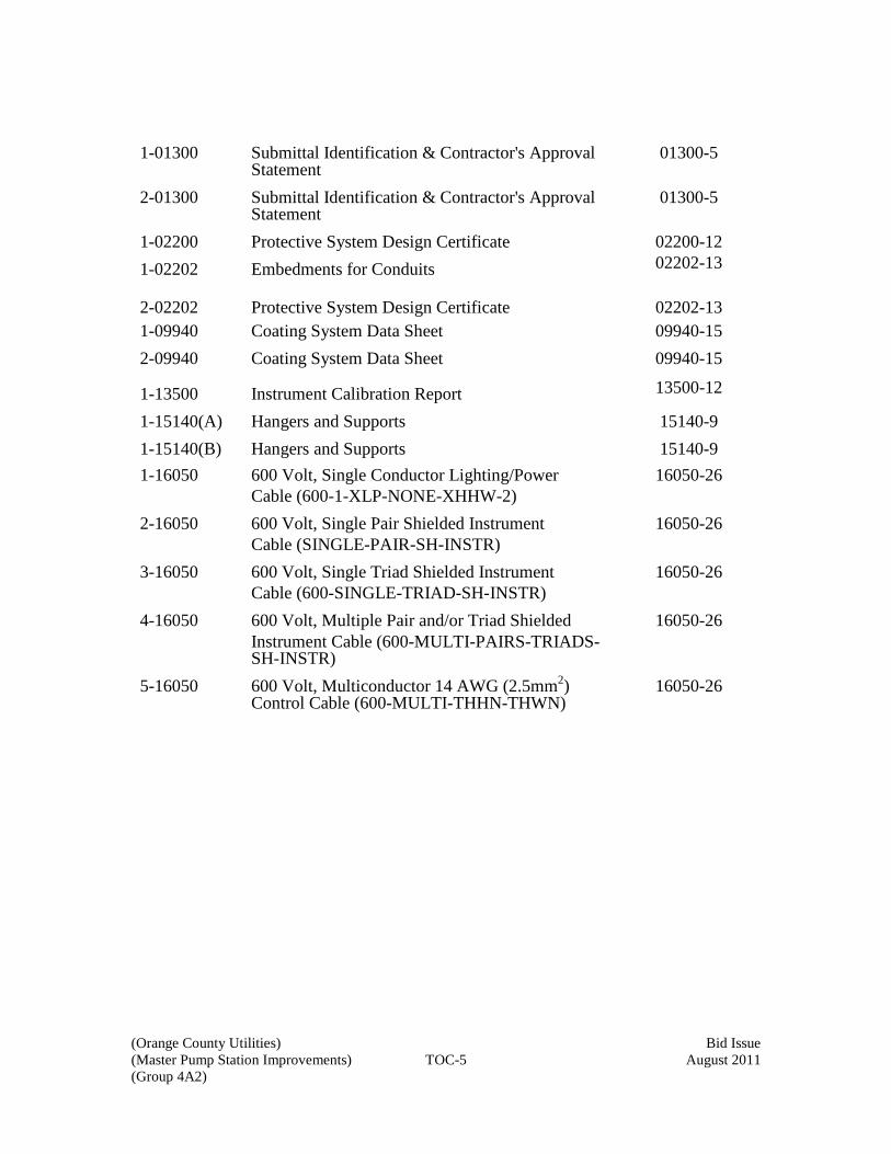
1-01300 Submittal Identification & Contractor's Approval Statement
01300-5
2-01300 Submittal Identification & Contractor's Approval Statement
01300-5
1-02200 Protective System Design Certificate 02200-12 1-02202 Embedments for Conduits 02202-13 2-02202
Protective System Design Certificate
02202-13
1-09940 Coating System Data Sheet 09940-15 2-09940 Coating System Data Sheet 09940-15
1-13500 Instrument Calibration Report 13500-12
1-15140(A) Hangers and Supports 15140-9 1-15140(B) Hangers and Supports 15140-9 1-16050 600 Volt, Single Conductor Lighting/Power
Cable (600-1-XLP-NONE-XHHW-2) 16050-26
2-16050 600 Volt, Single Pair Shielded Instrument Cable (SINGLE-PAIR-SH-INSTR)
16050-26
3-16050 600 Volt, Single Triad Shielded Instrument Cable (600-SINGLE-TRIAD-SH-INSTR)
16050-26
4-16050 600 Volt, Multiple Pair and/or Triad Shielded Instrument Cable (600-MULTI-PAIRS-TRIADS-SH-INSTR)
16050-26
5-16050 600 Volt, Multiconductor 14 AWG (2.5mm2) Control Cable (600-MULTI-THHN-THWN)
16050-26

This page was left blank intentionally

(Orange County Utilities) Bid Issue (Master Pump Station Improvements) 01015-A October 2011 (Group 4A2)
Section 01015
PROJECT REQUIREMENTS
Section 01015 - PROJECT REQUIREMENTS - LIST OF SUBJECTS
1. GENERAL DESCRIPTION OF WORK
2. UNITS OF MEASUREMENT
3. WORK BY PUBLIC UTILITIES
4. OFFSITE STORAGE
5. APPROVED PRODUCTS, SUBSTITUES AND “OR-EQUAL” ITEMS
6. PREPARATION FOR SHIPMENT
7. SALVAGE OF MATERIALS AND EQUIPMENT
8. LAND FOR CONSTRUCTION PURPOSES
9. EASEMENTS
9.01. On Private Property
9.02. Work Within Highway
10. OPERATION OF EXISTING FACILITIES
11. NOTICES TO OWNERS AND AUTHORITIES
12. LINES AND GRADES
13. CONNECTIONS TO EXISTING FACILITIES
14. UNFAVORABLE CONSTRUCTION CONDITIONS
15. CUTTING AND PATCHING
16. ASBESTOS REMOVAL
16.01. Subcontractor's Qualifications
16.02. Abatement Methods
17. CLEANING UP
18. APPLICABLE CODES
(Orange County Utilities) Bid Issue (Master Pump Station Improvements) 01015-B October 2011 (Group 4A2)
19. REFERENCE STANDARDS
20. PRECONSTRUCTION CONFERENCE
21. PROGRESS MEETINGS
22. SITE ADMINISTRATION

(Orange County Utilities) Bid Issue (Master Pump Station Improvements) 01015-1 October 2011 (Group 4A2)
Section 01015
PROJECT REQUIREMENTS
1. GENERAL DE SCRIPTION OF WORK. T he W ork t o be pe rformed unde r t hese Contract Documents is generally described as follows:
PS 3006 – Huggins
Demolish e xisting d ry pit p ump in stallation a nd r eplace w ith n ew s ubmersible pump t ype i nstallation. E xisting one -story s uperstructure a nd i ntermediate s lab will b e d emolished a nd d ry p it w ill b e f illed with s oil to g round level. N ew precast wetwell will be built on existing site. Specific improvements will include:
1. New submersible constant speed pumps in single wetwell 2. New influent and force main piping 3. Discharge valves and flowmeter located above grade 4. New engine generator and fuel tank for emergency power 5. New electrical power equipment 6. New instrumentation systems 7. New chain link fence and gate
2. UNITS OF MEASUREMENT. Both inch-pound (English) and SI (metric) uni ts of measurement are specified herein; the values expressed in inch-pound units shall govern. 3. WORK BY PUBLIC UTILITIES. 4. OFFSITE STORAGE. Offsite storage arrangements shall be approved by Owner for all materials and equipment not incorporated into the Work but included in Applications for Payment. Such offsite s torage arrangements shall be presented in writing and shall afford adequate and satisfactory security and protection. Offsite storage facilities shall be accessible to Owner and Engineer. 5. APPROVED PRODUCTS, SUBSTITUTES AND "OR-EQUAL" ITEMS. Approved product materials and eq uipment manufacturers h ave been identified in t he Specifications. If they are not l isted, approved products l isted i n t he O range C ounty Utilities S tandards a nd C onstruction S pecifications M anual s hall be us ed. W henever there i s a c onflict i n t he l ist of a pproved pr oducts l isted i n the S pecifications a nd t he current edition of O range C ounty U tilities S tandards a nd Construction S pecifications Manual, the more stringent of the two standards will apply. Whenever a m aterial o r ar ticle i s s pecified o r d escribed b y u sing t he n ame o f a proprietary product or the name of a particular manufacturer or vendor, the specified item

(Orange County Utilities) Bid Issue (Master Pump Station Improvements) 01015-2 October 2011 (Group 4A2)
shall be understood as establishing the type, function, and quality desired. R equests for review o f equivalency will n ot b e accepted from an yone ex cept Contractor, and s uch requests w ill not be c onsidered unt il a fter t he C ontract ha s be en awarded. O ther manufacturers' products may be accepted, provided sufficient information is submitted to allow Engineer to de termine t hat t he pr oducts p roposed a re e quivalent t o t hose na med and the product complies with Orange County List of Approved Products. Such items shall be submitted for review by the procedure set forth in the Submittals section. 6. PREPARATION F OR S HIPMENT. A ll materials s hall b e s uitably p ackaged to facilitate ha ndling a nd protect a gainst da mage dur ing t ransit a nd s torage. P ainted surfaces shall be protected against impact, abrasion, discoloration, and other damage. All painted surfaces which are damaged prior to acceptance of equipment shall be repainted to the satisfaction of Owner. Each item, package, or bundle of material shall be tagged or marked as identified in the delivery schedule or on the Shop Drawings. Complete packing lists and bills of material shall be included with each shipment. 7. SALVAGE O F MATERIALS AND E QUIPMENT. E xisting m aterials an d equipment r emoved and no t r eused a s a pa rt of t he W ork shall b ecome Contractor's property, except the items to be salvaged which shall remain Owner's property. Contractor shall carefully remove, i n a m anner t o p revent d amage, all m aterials and equipment specified or indicated to be salvaged and reused or to remain the property of Owner. Contractor shall s tore an d p rotect s alvaged i tems specified o r i ndicated t o b e reused in the Work. Salvaged i tems not t o b e r eused i n t he W ork, but to r emain Owner's pr operty s hall be delivered by Contractor in g ood c ondition t o Owner at location i ndicated on t he drawings. Any items specified or indicated to be salvaged which are damaged in removal, storage, or handling through carelessness or improper procedures shall be replaced by Contractor in kind or with new items. Contractor may furnish and install new items instead of those specified or indicated to be salvaged and r eused, i n w hich cas e s uch r emoved i tems w ill b ecome Contractor's property. Existing materials and equipment removed by Contractor shall not be reused in the Work, except where so specified or indicated. 8. LAND FOR C ONSTRUCTION P URPOSES. Contractor will b e p ermitted to u se available land belonging to Owner or identified as Temporary Construction Easement, on or near the Site, for construction purposes and for storage of materials and equipment.

(Orange County Utilities) Bid Issue (Master Pump Station Improvements) 01015-3 October 2011 (Group 4A2)
The locations and extent of the areas so used shall be as described in the legal description below. Contractor shall immediately move stored materials or equipment if any occasion arises, as determined b y Owner, r equiring access t o t he s torage area. M aterials o r equipment shall not be placed on the property of Owner until Owner has agreed to the location to be used for storage.
9. EASEMENTS. The easements, temporary construction easements as indicated on the drawings and rights-of-way for the pipelines will be provided by Owner. Contractor shall confine its c onstruction o perations w ithin th e limits indicated o n the D rawings. Contractor shall us e due c are i n pl acing c onstruction t ools, e quipment, e xcavated materials, and pipeline materials and supplies in order to avoid damage to property and interference with traffic. 9.01. On P rivate P roperty. E asements a cross pr ivate pr operty a re i ndicated on t he Drawings. Contractor shall set stakes to mark the boundaries of construction easements across private property. Contractor shall furnish, without charge, competent persons and

(Orange County Utilities) Bid Issue (Master Pump Station Improvements) 01015-4 October 2011 (Group 4A2)
such t ools, s takes, an d o ther m aterials as Engineer may r equire i n staking out t he boundaries of c onstruction e asements. Contractor will not be required to pr ovide a n instrument pe rson. The s takes s hall b e p rotected a nd m aintained unt il completion of construction and cleanup. Contractor shall not e nter a ny p rivate pr operty outside t he de signated c onstruction easement boundaries without written permission from the owner of the property. 9.02. Work Within Highway. Permits shall be obtained by Owner. All Work performed and a ll ope rations of Contractor, its employees, or S ubcontractors w ithin th e limits o f highway r ights-of-way s hall be i n c onformity with t he r equirements a nd be unde r t he control ( through Owner) of t he highway a uthority owning, o r ha ving j urisdiction ove r and control of, the right-of-way in each case. 10. OPERATION OF EXISTING FACILITIES. The existing facilities must be kept in continuous ope ration t hroughout t he c onstruction pe riod. N o i nterruption will b e permitted which adversely affects the degree of service provided. Provided permission is obtained from Owner in advance, portions of the existing facilities may be taken out of service for short periods corresponding with periods of minimum service demands. Contractor shall p rovide te mporary facilities a nd ma ke te mporary m odifications a s necessary to keep the existing facilities in operation during the construction period. Bypass pum ping pr ocedures s hall be i n a ccordance with S ection 1516 of t he Specifications an d with O range C ounty Utilities S tandard a nd C onstruction Specifications Manual “Section 3312” for Collection System Bypass. In case of conflict, the more stringent of the two standards shall apply. 11. NOTICES TO OW NERS AND A UTHORITIES. Contractor shall, as provided in the General Conditions, notify owners of adjacent property and utilities when prosecution of the Work may affect them. When it is necessary to temporarily deny access to property, or when any utility service connection must be interrupted, Contractor shall give not ices sufficiently in advance to enable t he a ffected pe rsons t o pr ovide f or t heir ne eds. N otices s hall c onform t o a ny applicable l ocal or dinance a nd, w hether de livered or ally or i n w riting, s hall i nclude appropriate i nformation c oncerning t he i nterruption a nd i nstructions o n how t o l imit inconvenience caused thereby. Utilities and other concerned agencies shall be notified at least 24 hou rs prior to cutting or c losing s treets or other t raffic a reas or excavating ne ar underground utilities or pole lines. 12. LINES AND GRADES. All Work shall be done to the lines, grades, and elevations indicated on the Drawings.

(Orange County Utilities) Bid Issue (Master Pump Station Improvements) 01015-5 October 2011 (Group 4A2)
Basic hor izontal a nd ve rtical c ontrol poi nts (benchmarks) ha ve be en d esignated on t he drawings to b e us ed a s da tums f or t he W ork. All a dditional s urvey, l ayout, a nd measurement work shall be performed by Contractor as a part of the Work. Contractor shall p rovide a n experienced i nstrument pe rson, c ompetent a ssistants, a nd such i nstruments, t ools, s takes, a nd ot her m aterials r equired to complete t he s urvey, layout, and measurement work. In addition, Contractor shall furnish competent persons and such tools, s takes, and other materials as required in establishing control points, in establishing c onstruction e asement bound aries, or i n checking s urvey, l ayout, and measurement work performed by Contractor. Contractor shall remove and reconstruct work which is improperly located. 13. CONNECTIONS TO E XISTING F ACILITIES. Unless ot herwise s pecified or indicated, Contractor shall make all necessary connections to existing facilities, including structures, drain lines, and utilities such as water, sewer, gas, telephone, and electric. In each case, Contractor shall receive permission from Owner or the owning utility prior to undertaking connections. Contractor shall protect facilities against deleterious substances and damage. Connections t o e xisting f acilities w hich a re i n service s hall be t horoughly pl anned i n advance, and all required equipment, materials, and labor shall be on hand at the time of undertaking t he c onnections. W ork s hall pr oceed c ontinuously ( around t he c lock) i f necessary to complete connections in the minimum t ime. O peration of valves or other appurtenances on e xisting ut ilities, w hen r equired, s hall be b y or unde r t he direct supervision of the owning utility. 14. UNFAVORABLE CONSTRUCTION CONDITIONS. During unfavorable weather, wet gr ound, or ot her u nsuitable c onstruction c onditions, Contractor shall c onfine its operations to work which will not be affected adversely by such conditions. No portion of t he W ork s hall be c onstructed unde r conditions w hich w ould a ffect a dversely t he quality or efficiency thereof, unless special means or precautions are taken by Contractor to perform the Work in a proper and satisfactory manner. 15. CUTTING AND PATCHING. As provided in General Conditions, Contractor shall perform a ll c utting a nd pa tching r equired f or t he W ork a nd a s m ay b e ne cessary i n connection with uncovering Work for inspection or for the correction of defective Work. Contractor shall perform all cutting and patching required for and in connection with the Work, including but not limited to the following:
Removal of improperly timed Work.
Removal of samples of installed materials for testing.
Alteration of existing facilities.

(Orange County Utilities) Bid Issue (Master Pump Station Improvements) 01015-6 October 2011 (Group 4A2)
Installation of new Work in existing facilities.
Contractor shall provide all shoring, bracing, supports, and protective devices necessary to s afeguard all W ork and existing f acilities during c utting, patching and ex cavating operations. Contractor shall not undertake any cutting or demolition which may affect the structural stability of the Work or existing facilities. Materials shall be cut and removed to the extent indicated on the Drawings or as required to complete the Work. Materials shall be removed in a careful manner, with no damage to a djacent f acilities o r materials. Materials w hich ar e n ot s alvable s hall b e r emoved from the site by Contractor. All Work and existing facilities affected by cutting operations shall be restored with new materials, o r w ith s alvaged ma terials a cceptable to Engineer, t o obt ain a f inished installation with the strength, appearance, and functional capacity required. If necessary, entire surfaces shall be patched and refinished. 16. ASBESTOS A BATEMENT. If, du ring the pr ogress of t he W ork, s uspected asbestos-containing pr oducts a re i dentified, Contractor shall s top w ork i n t he a ffected area an d en gage an as bestos ab atement S ubcontractor t o v erify t he m aterials an d, i f necessary, encapsulate, enclose, or remove and dispose of all asbestos in accordance with current regulations of the Environmental Protection Agency and the U. S. Department of Labor - Occupational S afety and H ealth A dministration, t he s tate asbestos r egulating agency, and a ny l ocal government a gency. Payment f or s uch w ork w ill be m ade b y Change Order. 16.01. Subcontractor's Qualifications. The Subcontractor for asbestos abatement shall be regularly engaged in this type of activity and shall be familiar with the regulations which govern this work. The Subcontractor shall demonstrate to the satisfaction of Owner that it h as s uccessfully co mpleted at l east t hree as bestos ab atement p rojects, t hat i t h as t he necessary staff and equipment to perform the work, and that i t has an approved site for disposal of the asbestos. Liability insurance covering the asbestos abatement work shall be provided as specified in the Supplementary Conditions. 16.02. Abatement Methods. The asbestos abatement Subcontractor shall submit a work plan of i ts pr oposed a batement pr ocedure t o Owner before b eginning work a nd s hall certify that the methods are in full compliance with the governing regulations. The work plan shall cover a ll aspects of the abatement, including health and safety of employees and b uilding o ccupants, h ygiene f acilities, em ployee cer tification, cl earance criteria, transportation a nd di sposal, e nclosure t echniques, a nd ot her t echniques appropriate f or the proposed work. 17. CLEANING UP . Contractor shall k eep th e p remises f ree a t all time s f rom accumulations of waste materials and rubbish. Contractor shall provide adequate t rash receptacles about the Site and shall promptly empty the containers when filled.

(Orange County Utilities) Bid Issue (Master Pump Station Improvements) 01015-7 October 2011 (Group 4A2)
Construction materials, such as concrete forms and scaffolding, shall be neatly stacked by Contractor when not i n us e. Contractor shall pr omptly r emove s plattered c oncrete, asphalt, oi l, p aint, c orrosive l iquids, a nd c leaning s olutions f rom s urfaces t o pr event marring or other damage. Volatile wastes shall be properly stored in covered metal containers and removed daily. Wastes shall not be buried or burned on the Site or disposed of into storm drains, sanitary sewers, streams, or waterways. A ll wastes shall be removed from the Site and disposed of in a manner complying with local ordinances and antipollution laws. Adequate c leanup w ill be a c ondition f or r ecommendation of pr ogress pa yment applications. 18. APPLICABLE CODES. References in the Contract Documents to local codes mean the following:
• Florida Building Code, latest version • All ordinances of Orange County, Florida • Florida Department of Environmental Protection • Southwest Florida Water Management District • Occupational Safety and Health Administration (OHSA) Standards
Manual Other standard codes which apply to the Work are designated in the Specifications. 19. REFERENCE S TANDARDS. R eference t o s tandards, s pecifications, manuals, or codes of any technical society, organization, or association, or to the laws or regulations of any governmental authority, whether such reference be specific or by implication, shall mean the latest s tandard specification, manual, code, or l aws or r egulations in ef fect at the time of opening of Bids (or on the effective date of the Contract or Agreement if there were no Bids), except as may be otherwise specifically stated in the Contract Documents. However, no provision of any referenced standard, specification, manual, or code, or any instruction of a S upplier, s hall be e ffective t o c hange t he dut ies or r esponsibilities of Owner, Contractor, or Engineer, or any of t heir subcontractors, consultants, a gents, o r employees from those set forth in the Contract Documents, nor shall any such provision or i nstruction be e ffective t o a ssign t o Owner, Engineer, or a ny o f Engineer's CONSULTANTS, agents, or employees, any duty or authority to supervise or direct the performance of the Work or any duty or authority to undertake responsibility inconsistent with the provisions of the Contract Documents. 20. PRECONSTRUCTION CONFERENCE. Prior to the commencement of Work at the Site, a preconstruction conference will be held at a mutually agreed time and place. The conference shall be attended by:

(Orange County Utilities) Bid Issue (Master Pump Station Improvements) 01015-8 October 2011 (Group 4A2)
Contractor and its superintendent.
Principal Subcontractors.
Representatives of principal Suppliers and manufacturers as appropriate.
Engineer Representative.
Representatives of Owner.
Government representatives as appropriate.
Others as requested by Contractor, Owner, or Engineer. Unless pr eviously s ubmitted t o Owner Contractor shall b ring t o t he co nference a preliminary schedule for each of the following:
Progress Schedule.
Procurement Schedule.
Schedule of Values for progress payment purposes.
Schedule of Shop Drawings and other submittals. The pur pose of t he c onference i s t o d esignate responsible pe rsonnel a nd e stablish a working r elationship. Matters r equiring c oordination w ill be d iscussed a nd pr ocedures for handling such matters established. The agenda will include:
Contractor's preliminary schedules.
Transmittal, review, and distribution of Contractor's submittals.
Processing Applications for Payment.
Maintaining record documents.
Critical Work sequencing.
Field decisions and Change Orders.
Use of premises, office and storage areas, security, housekeeping, and Owner's needs.
Major equipment deliveries and priorities.

(Orange County Utilities) Bid Issue (Master Pump Station Improvements) 01015-9 October 2011 (Group 4A2)
Contractor's assignments for safety and first aid. Engineer will p reside at t he co nference an d w ill ar range f or k eeping t he m inutes an d distributing the minutes to all persons in attendance. 21. PROGRESS M EETINGS. Contractor shall s chedule a nd hol d r egular pr ogress meetings at le ast mo nthly a nd at o ther time s a s r equested b y Owner, or r equired b y progress of t he W ork. Contractor, Engineer, and a ll S ubcontractors a ctive on t he S ite shall be represented at each meeting. Contractor may at its discretion request attendance by representatives of its Suppliers, manufacturers, and other Subcontractors. Contractor shall p reside a t th e me etings. M eeting min utes s hall be pr epared and distributed by Contractor. The purpose of the meetings will be to review the progress of the W ork, m aintain c oordination of e fforts, di scuss c hanges i n s cheduling, and r esolve other problems which may develop. 22. SITE ADMINISTRATION. Contractor shall be responsible for all areas of the Site used by i t and b y all Subcontractors in the performance of the Work. Contractor shall exert full control over the actions of all employees and other persons with respect to the use and preservation of property and existing facilities, except such controls as may be specifically reserved to Owner or others. Contractor shall have the right to exclude from the Site all persons who have no pur pose related to the Work or its inspection, and may require all pe rsons on t he S ite ( except Owner's em ployees) t o o bserve t he s ame regulations as Contractor requires of its employees.
End of Section

This page was left blank intentionally

(Orange County Utilities) Bid Issue (Master Pump Station Improvements) 01025-1 October 2011 (Group 4A2)
Section 01025
MEASUREMENT AND PAYMENT
1. GENERAL. The Contractor shall receive and accept the compensation provided in the Proposal and the Contract as full payment for furnishing all materials, labor, tools and equipment, for performing all operations necessary to complete the work under the Contract, and also in full payment for all loss or damages arising from the nature of work, or from any discrepancy between the actual quantities of work and quantities herein estimated by the Engineer, or from the action of the elements or from any unforeseen difficulties which may be encountered during the prosecution of the work until the final acceptance by the County.
The prices stated in the proposal include all costs and expenses for taxes, labor, equipment, materials, commissions, transportation charges and expenses, patent fees and royalties, labor for handling materials during inspection, together with any and all other costs and expenses for performing and completing the work as shown on the Drawings and specified herein. The basis of payment for an item at the unit price shown in the proposal shall be in accordance with the description of that item in this Section.
The Contractor’s attention is again called to the fact that the quotations for the various items of work are intended to establish a total price for completing the work in its entirety. Should the Contractor feel that the cost for any item of work has not been established by the Bid Form or Payment Items, he shall include the cost for that work in some other applicable bid item, so that his proposal for the project does reflect his total price for completing the work in its entirety.
2. MEASUREMENT. The quantities for payment under this Contract shall be determined by actual measurement of the completed items, in place, ready for service and accepted by the County, in accordance with the applicable method of measurement therefore contained herein.
3. PAYMENT ITEMS. Items are as enumerated on the bid form.
3.01. Item 1 – Huggins Pump Station #3006 Rehabilitation.
a. Payment for all the other work associated with the construction of the Huggins
Pump Station #3006 Rehabilitation will be made at the Contract lump sum price, based upon the approved schedule of values.
b. This item shall include all materials, equipment, labor, testing, permits,
appurtenances, and work required for the Huggins Pump Station #3006 Rehabilitation including all work and costs not listed elsewhere.
c. This item shall include costs for General Requirements, Mobilization, and
Demobilization. Measurement for various items covered under General Requirements, Mobilization and Demobilization will not be made for payment, and all items shall be included in the lump sum price.
(Orange County Utilities) Bid Issue (Master Pump Station Improvements) 01025-2 October 2011 (Group 4A2)
d. Payment for General Requirements shall include all Insurance requirement costs, the cost of bonds, and all Administrative costs. This item will be paid upon each payment request made by the Contractor. The Contractor shall attach with the pay request invoices to substantiate that appropriate insurance and bonds have been obtained by the Contractor.
e. Payment for Mobilization/Demobilization will be made at the Contract lump sum
price for the item, which price and payment shall be full compensation for the Work consisting of the preparatory Work and operations in mobilizing for beginning Work on the Contract, including, but not limited to, furnishing those supplies and incidentals to the project site, preparation of submittals, and for the establishment of temporary offices and buildings, safety equipment and first aid supplies, project signs, field surveys, sanitary and other facilities required by these specifications, and State and local laws and regulations. The costs of bonds and any required insurance and any other preconstruction expense necessary for the start of the work, excluding the cost of construction materials, shall also be included. This Work also consist of the general project management of the Work including, but not limited to, field supervision and office management, as well as other incidental cost for management of the Work during the duration of the Contract. This Work also includes maintenance of the field offices for the duration of the Contract. The Work specified in this item also consists of demobilization or the operations normally involved in ending Work on the project including, but not limited to, termination and removal of temporary utility service and field offices; demolition and removal of temporary structures and facilities; restoration of Contractor storage areas; disposal of trash and rubbish, and any other post-construction work necessary for the proper conclusion of the Work. This pay item may not exceed 5% of the Total Base Bid amount.
f. Payment for Indemnification: In consideration of the Contractor’s Indemnity Agreement as set out in the Contract Documents, County specifically agrees to give the Contractor $100.00 and other good and valuable consideration, receipt of which is acknowledged upon signing of the Agreement.
End of Section

(Orange County Utilities) Bid Issue
(Master Pump Station Improvements) 01060-1 October 2011
(Group 4A2)
Section 01060
PERMITS AND REGULATORY REQUIREMENTS
PART 1 - GENERAL
1.01 RELATED SECTIONS: N/A
1.02 REGULATORY AGENCIES:
A. General: The Contractor shall;
a. Obtain and pay for all permits and licenses as provided for in the General
Conditions, except as otherwise specified herein.
b. Schedule all inspections and obtain all written approvals of the agencies required
by the permits and licenses.
c. Comply with all conditions specified in each of the permits and licenses.
d. A copy of the permits obtained by the County will be furnished to the Contractor
upon request.
1.03 PERMITS OBTAINED BY THE COUNTY:
A. The County will apply for and pay for the following permits:
a. The initial Orange County Building Permit.
b. FDEP Wastewater Collection System for the on-site lift station.
c. FDEP Permit for fuel storage tank and generator.
1.04 PERMITS OBTAINED BY CONTRACTOR:
A. The Contractor shall be responsible for obtaining the following permits:
a. The Contractor shall be responsible for obtaining the Orange County Building
Permits, and shall pay for all permits subsequent to the initial Building Permit
as required for various building trades such as mechanical, electrical, plumbing,
roofing, etc.
b. The Contractor shall, within 14 days of the date of the Notice-to-Proceed,
prepare the application and pay fees associated with a Notice of Intent (NOI) to
Use Generic Permit for Stormwater Discharge from Large and Small

(Orange County Utilities) Bid Issue
(Master Pump Station Improvements) 01060-2 October 2011
(Group 4A2)
Construction Activities and the Stormwater Pollution Prevention Plan (SPPP)
for compliance with the USEPA’s General Permit for construction activities.
c. The Contractor shall apply and pay for the SFWMD Dewatering Permit.
d. The Contractor shall apply and pay for the permits required for the temporary
construction trailers.
e. All other permits required for Contractor's operations or required elsewhere in
Contract Documents and not included herein. Furnish three copies of permits
to the Owner prior to performance of work authorized by permits.
f. Contractor will be responsible for obtaining extensions to permits obtained by
the Owner if construction authorized by permits has not been completed by
expiration date noted on these permits.
g. Permits may require that a representative of permitting agency be present at site
during construction or prior to covering up of activity authorized by permit.
Contractor will be responsible for notifying permitting agency in compliance
with requirements of such permits.
h. Contractor shall include time to obtain permits in his construction schedule.
PART 2 – PRODUCTS: N/A
PART 3 - EXECUTION: N/A
End of Section

(Orange County Utilities) Bid Issue (Master Pump Station Improvements) 01070-1 October 2011 (Group 4A2)
Section 01070
ABBREVIATIONS OF TERMS AND ORGANIZATIONS 1. LIST OF ABBREVIATIONS. Abbreviations for standards and organizations used in the Contract Documents are defined as follows:
AA Aluminum Association AABC Associated Air Balance Council AAMA Architectural Aluminum Manufacturers Association AASHTO American Association of State Highway and Transportation
Officials ABMA American Boiler Manufacturers Association ACI American Concrete Institute ACPA American Concrete Pipe Association AEIC Association of Edison Illuminating Companies AFBMA Antifriction Bearing Manufacturers Association AFPA American Forest & Paper Association AGA American Gas Association AGMA American Gear Manufacturers Association AHA American Hardboard Association AISC American Institute of Steel Construction AISI American Iron and Steel Institute AITC American Institute of Timber Construction AMCA Air Moving and Conditioning Association ANSI American National Standards Institute APA American Plywood Association API American Petroleum Institute AREMA American Railway Engineers and Maintenance-of-Way
Association ARI American Refrigeration Institute ASAHC American Society of Architectural Hardware Consultants ASCE American Society of Civil Engineers ASHRAE American Society of Heating, Refrigerating, and Air-
Conditioning Engineers ASME American Society of Mechanical Engineers ASSE American Society of Sanitary Engineers ASTM American Society for Testing and Materials AVATI See RTI AWG American Wire Gage AWI Architectural Woodwork Institute AWPA American Wood-Preservers' Association AWPB American Wood Preservers Bureau AWS American Welding Society AWWA American Water Works Association BHMA Builders Hardware Manufacturers Association
(Orange County Utilities) Bid Issue (Master Pump Station Improvements) 01070-2 October 2011 (Group 4A2)
BIA Brick Institute of America (formerly SCPI) CDA Copper Development Association CISPI Cast Iron Soil Pipe Institute CMAA Crane Manufacturers Association of America CRA California Redwood Association CRSI Concrete Reinforcing Steel Institute CS Commercial Standard (U.S. Department of Commerce) DHI Door and Hardware Institute DIPRA Ductile Iron Pipe Research Association EEI Edison Electric Institute EJCDC Engineers' Joint Contract Documents Committee EPA Environmental Protection Agency FCC Federal Communications Commission FCI Fluid Controls Institute Fed Spec Federal Specification FGMA Flat Glass Marketing Association FHWA Federal Highway Administration FIA Factory Insurance Association FM Factory Mutual FSA Fluid Sealing Association FTI Facing Tile Institute HEI Heat Exchange Institute HMI Hoist Manufacturers Institute HPMA Hardwood Plywood Manufacturers Association HTI Hand Tools Institute I-B-R Institute of Boiler and Radiator Manufacturers IEEE Institute of Electrical and Electronics Engineers IBC International Building Code IES Illuminating Engineering Society IFI Industrial Fasteners Institute IPCEA Insulated Power Cable Engineers Association IRI Industrial Risk Insurers ISA Instrumentation, Systems, and Automation Society MHI Materials Handling Institute MIL Military Specification MMA Monorail Manufacturers Association MSS Manufacturers Standardization Society of Valve and Fitting Industry NAAMM National Association of Architectural Metals Manufacturers

(Orange County Utilities) Bid Issue (Master Pump Station Improvements) 01070-3 October 2011 (Group 4A2)
NACE NACE International NBHA National Builders Hardware Association NBBPVI National Board of Boiler and Pressure Vessel Inspectors NBS See NIST NCSPA National Corrugated Steel Pipe Association NEBB National Environmental Balancing Bureau NEC National Electrical Code NECA National Electrical Contractors Association NEMA National Electrical Manufacturers Association NEMI National Elevator Manufacturing Industry NFPA National Fire Protection Association NIST National Institute of Standards and Technology (formerly NBS) NLA National Lime Association NPC National Plumbing Code NPT National Pipe Thread NRMCA National Ready Mixed Concrete Association NSC National Safety Council NSF NSF International (formerly National Sanitation Foundation) NTMA National Terrazzo and Mosaic Association NWMA National Woodwork Manufacturers Association OSHA Occupational Safety and Health Administration PCA Portland Cement Association PCI Prestressed Concrete Institute PS Product Standard RIS Redwood Inspection Service RTI Resilient Tile Institute (formerly AVATI) SAE Society of Automotive Engineers SCPRF Structural Clay Products Research Foundation SDI Steel Door Institute SFPA Southern Forest Products Association SI Systéme International des Unités (International System of
Units) SIGMA Sealed Insulating Glass Manufacturers Association SJI Steel Joist Institute SMA Screen Manufacturers Association SMACNA Sheet Metal and Air Conditioning Contractors National
Association SPFA Steel Plate Fabricators Association SPI Society of the Plastics Industry SPTA Southern Pressure Treaters Association SSI Scaffolding and Shoring Institute SSPC SSPC: The Society for Protective Coatings UL Underwriters' Laboratories

(Orange County Utilities) Bid Issue (Master Pump Station Improvements) 01070-4 October 2011 (Group 4A2)
USBR U.S. Bureau of Reclamation WEF Water Environment Federation
End of Section

(Orange County Utilities) Bid Issue
(Master Pump Station Improvements) 01300-1 October 2011
(Group 4A2)
Section 01300
SUBMITTALS
1. SHOP DRAWINGS AND ENGINEERING DATA.
1.01. General. Shop Drawings and engineering data (submittals) covering all equipment and all
fabricated components and building materials which will become a permanent part of the Work
under this Contract shall be submitted to Engineer for review, as required. Submittals shall
verify compliance with the Contract Documents, and shall include drawings and descriptive
information in sufficient detail to show the kind, size, arrangement, and the operation of
component materials and devices; the external connections, anchorages, and supports required;
the performance characteristics; and dimensions needed for installation and correlation with
other materials and equipment.
Each submittal shall cover items from only one section of the specification unless the item
consists of components from several sources. Contractor shall submit a complete initial
submittal including all components. When an item consists of components from several sources,
Contractor's initial submittal shall be complete including all components.
All submittals, regardless of origin, shall be approved by Contractor and clearly identified with
the name and number of this Contract, Contractor's name, and references to applicable
specification paragraphs and Contract Drawings. Each copy of all submittals, regardless of
origin, shall be stamped or affixed with an approval statement of Contractor. Each submittal
shall indicate the intended use of the item in the Work. When catalog pages are submitted,
applicable items shall be clearly identified and inapplicable data crossed out. The current
revision, issue number, and date shall be indicated on all drawings and other descriptive data.
Contractor shall be solely responsible for the completeness of each submittal. Contractor's stamp
or affixed approval statement of a submittal, per Figure 01300-1, is a representation to Owner
and Engineer that Contractor accepts sole responsibility for determining and verifying all
quantities, dimensions, field construction criteria, materials, catalog numbers, and similar data,
and that Contractor has reviewed and coordinated each submittal with the requirements of the
Work and the Contract Documents. Submittals without Contractor’s approval statement will be
returned without review.
All deviations from the Contract Documents shall be identified as deviations on each submittal
and shall be tabulated in Contractor's letter of transmittal using Figure 01300-2. Such submittals
shall, as pertinent to the deviation, indicate essential details of all changes proposed by
Contractor (including modifications to other facilities that may be a result of the deviation) and
all required piping and wiring diagrams. The Contractor shall Mark his corrections in green ink.
For hard copy submittals six copies of each drawing and the necessary data shall be submitted to
Engineer. Engineer will return three marked copies (or one marked reproducible copy) to
Contractor. Facsimile (fax) or electronic copies will not be acceptable. Engineer will not accept
submittals from anyone but Contractor. Submittals shall be consecutively numbered in direct
sequence of submittal and without division by subcontracts or trades.

(Orange County Utilities) Bid Issue
(Master Pump Station Improvements) 01300-2 October 2011
(Group 4A2)
1.02. Engineer's Review of Submittals. Engineer's review of submittals covers only general
conformity to the Drawings and Specifications, external connections, and dimensions that affect
the layout; it does not indicate thorough review of all dimensions, quantities, and details of the
material, equipment, device, or item covered. Engineer's review shall not relieve Contractor of
sole responsibility for errors, omissions, or deviations in the drawings and data, nor of
Contractor's sole responsibility for compliance with the Contract Documents.
Engineer's submittal review period shall be 30 consecutive calendar days and shall commence on
the first calendar day following receipt of the submittal or resubmittal in Engineer's office. The
time required to mail the submittal or resubmittal back to Contractor shall not be considered a
part of the submittal review period.
When the drawings and data are returned with review status "NOT ACCEPTABLE" or
"RETURNED FOR CORRECTION", the corrections shall be made as instructed by Engineer.
Six corrected copies shall be resubmitted. Resubmittals by facsimile or e-mail will not be
accepted. When the drawings and data are returned with review status "EXCEPTIONS
NOTED", "NO EXCEPTIONS NOTED", or "RECORD COPY", no additional copies need be
furnished unless specifically requested by Engineer.
1.03. Resubmittal of Drawings and Data. Contractor shall accept full responsibility for the
completeness of each resubmittal. Contractor shall verify that all corrected data and additional
information previously requested by Engineer are provided on the resubmittal.
When corrected copies are resubmitted, Contractor shall direct specific attention to all revisions
in writing and shall list separately any revisions made other than those called for by Engineer on
previous submittals. Requirements specified for initial submittals shall also apply to
resubmittals. Resubmittals shall bear the number of the first submittal followed by a letter (A, B,
etc.) or a unique identification that indicates the initial submittal and correct sequence of each
resubmittal.
If more than one resubmittal is required because of failure of Contractor to provide all previously
requested corrected data or additional information, Contractor shall reimburse Owner for the
charges of Engineer for review of the additional resubmittals. This does not include initial
submittal data such as shop tests and field tests that are submitted after initial submittal.
Resubmittals shall be made within 60 days of the date of the letter returning the material to be
modified or corrected, unless within 30 days Contractor submits an acceptable request for an
extension of the stipulated time period, listing the reasons the resubmittal cannot be completed
within that time.
The need for more than one resubmittal, or any other delay in obtaining Engineer's review of
submittals, will not entitle Contractor to extension of the Contract Times unless delay of the
Work is the direct result of a change in the Work authorized by a Change Order or failure of
Engineer to review and return any submittal to Contractor within the specified review period.
1.04. Color Selection. Contractor shall submit samples of colors and finishes for all accepted
products before Engineer will coordinate the selection of colors and finishes with Owner.
Engineer will prepare a schedule of finishes that include the colors and finishes selected for both
manufactured products and for surfaces to be field painted or finished and will furnish this

(Orange County Utilities) Bid Issue
(Master Pump Station Improvements) 01300-3 October 2011
(Group 4A2)
schedule to Contractor within 60 days after the date of acceptance of the last color or finish
sample.
2. OPERATION AND MAINTENANCE DATA AND MANUALS. Adequate operation and
maintenance information shall be supplied for all equipment requiring maintenance or other
attention. The equipment Supplier shall prepare a project specific operation and maintenance
manual for each type of equipment indicated in the individual equipment sections or the
equipment schedule.
Parts lists and operating and maintenance instructions shall be furnished for other equipment not
listed in the individual equipment sections or the equipment schedule.
Operation and maintenance manuals shall include the following:
a. Table of Contents and Index.
b. Equipment function, normal operating characteristics, and limiting conditions.
c. Assembly, installation, alignment, adjustment, and checking instructions.
d. Operating instructions for startup, routine and normal operation, regulation and
control, shutdown, and emergency conditions.
e. Lubrication and maintenance instructions.
f. Guide to troubleshooting.
g. Parts lists and predicted life of parts subject to wear.
h. Outline, cross section, and assembly drawings; engineering data; and wiring
diagrams.
i. Test data and performance curves, where applicable.
The operation and maintenance manuals shall be in addition to any instructions or parts lists
packed with or attached to the equipment when delivered, or which may be required by
Contractor.
Three preliminary hard copies of each manual shall be submitted to Engineer prior to the date of
shipment of the equipment. When the O&M manuals are returned with the review status
"RETURNED FOR CORRECTION", the corrections shall be made as instructed by the
Engineer, and two copies of the corrected portion(s) and one complete corrected copy of the
O&M manual returned to the Engineer. After review by Engineer is complete five hard copies
and one electronic copy of each final operation and maintenance manual shall be prepared and
delivered to Engineer not later than 30 days prior to placing the equipment in operation. One
electronic copy of the final O&M Manual shall be submitted on CD-ROM. When corrections
are required, a corrected version of the five hard copies and one electronic copy shall be
resubmitted.

(Orange County Utilities) Bid Issue
(Master Pump Station Improvements) 01300-4 October 2011
(Group 4A2)
All material shall be marked with project identification, and inapplicable information shall be
marked out or deleted.
Shipment of equipment will not be considered complete until all required manuals and data have
been received.
2.01. Hard Copy Operation and Maintenance Manuals. Hard copies submitted for preliminary
review shall be temporarily bound in heavy paper covers bearing suitable identification. All
manuals and other data shall be printed on heavy, first quality 8-1/2 x 11 inch paper, with
standard three-hole punching. Drawings and diagrams shall be reduced to 8-1/2 x 11 inches or
11 x 17 inches. Where reduction is not practicable, larger drawings shall be folded separately
and placed in envelopes, which are bound into the manuals. Each envelope shall be suitably
identified on the outside. Each volume containing data for three or more items of equipment
shall include a table of contents and index tabs. The final hard copy of each manual shall be
prepared and delivered in substantial, permanent, three-ring or three-post binders with a table of
contents and suitable index tabs.
2.02. Electronic Operation and Maintenance Manuals. Electronic manuals shall be in Adobe
Acrobat’s Portable Document Format (PDF), and shall be prepared at a resolution of 300 dots
per inch (dpi) or greater, depending on document type. Optical Character Recognition (OCR)
capture shall be performed on these documents. OCR settings shall be performed with the
“original image with hidden text” option in Adobe Acrobat Exchange.
When multiple files are required the least number of files possible shall be created. File names
shall be in the format OMXXXXX-YYYZ-V.pdf, where XXXXX is the five digit number
corresponding to the specification section, YYY is a three digit O&M manual number, e.g. 001,
Z is the letter signifying a resubmittal, A, B, C, etc, and V is a number used only when more than
one file is required for an O&M manual.
Documents prepared in PDF format shall be processed as follows:
1. Pages shall be searchable (processed for optical character recognition) and indexed
when multiple files are required.
2. Pages shall be rotated for viewing in proper orientation.
3. A bookmark shall be provided in the navigation frame for each entry in the Table of
Contents.
4. Embedded thumbnails shall be generated for each completed PDF file.
5. The opening view for PDF files shall be as follows:
Initial View: Bookmarks and Page
Page Number: Title Page (usually Page 1)
Magnification: Set to Fit in Window
Page: Single Page
6. Where the bookmark structure is longer than one page the bookmarks shall be collapsed
to show the chapter headings only.
7. When multiple files are required the first file of the series (the parent file) shall list
every major topic in the Table of Contents. The parent file shall also include minor
headings bookmarked based on the Table of Contents. Major headings, whose content
is contained in subsequent files (children) shall be linked to be called from the parent to
the specific location in the child file. The child file shall contain bookmark entries for

(Orange County Utilities) Bid Issue
(Master Pump Station Improvements) 01300-5 October 2011
(Group 4A2)
both major and minor headings contained in the child file. The first bookmark of any
child file shall link back to the parent file and shall read as follows "Return to the
Equipment Name Table of Contents", e.g. Return to the Polymer Feed System Table of
Contents.
8. Drawings shall be bookmarked individually.
9. Files shall be delivered without security settings to permit editing, insertion and
deletion of material to update the manual provided by the manufacturer.
2.03. Labeling. As a minimum, the following information shall be included on all final O&M
manual materials, including CD-ROM disks, jewel cases, and hard copy manuals:
Equipment name and/or O&M title spelled out in complete words.
Project Name.
City Project/Contract Number.
Specification Section Number. Example: “Section 15500”
Manufacturer’s name.
File Name and Date.
For example:
Backwash Pump Operation and Maintenance Manual
Somewhere Plant Expansion
Project/Contract No. ____
Specification Section 11110
Manufacturer
OM11110-001.pdf, 5/05/07
End of Section

This page was left blank intentionally

FIGURE 1-01300
SUBMITTAL No. ________
SECTION ______________ Do not combine multiple sections together
unless required by specifications.
(Contractor's Letterhead)
SUBMITTAL IDENTIFICATION &
CONTRACTOR'S APPROVAL STATEMENT
DATE: ____________ COPIES ____________ DRAWING SHEET NO.__ _____
Description submittal contents: ___________________________________ _________
Location: _______________________________________________ _____________
Manufacturer_________________________________________ __________________
Subcontractor or Supplier (Optional) _________________________ _______________
REMARKS: ___________________________________________________ ________
______________________________________________________________________________
______________________________________________________________________________
_____________________________________________ _______________
CONTRACTOR'S APPROVAL
( Construction Company ) has reviewed and coordinated the submitted documentation
and verifies that the equipment and material meet the requirements of the Work and the Contract
Documents. We accept sole responsibility for determining and verifying all quantities,
dimensions, field construction criteria, materials, catalog numbers, and similar data contained in
the submittal as required by the Contract Documents.
Deviations: □ None □ Yes (See attached Figure 01300-2 for written description)
Approved By: ____________________ Date: ________________
This approval does not release subcontractor / vendor from the contractual responsibilities.


FIGURE 2-01300
SUBMITTAL No. ________
SECTION ______________ Do not combine multiple sections together
unless required by specifications.
(Contractor's Letterhead)
SUBMITTAL IDENTIFICATION &
CONTRACTOR'S APPROVAL STATEMENT
DATE: ____________ COPIES ____________ DRAWING SHEET NO.____ ___
Description submittal contents: ________________________ ____________________
Location: __________________________________________ __________________
Manufacturer__________________________________________________ _________
Subcontractor or Supplier (Optional) _________________________________ _______
DEVIATIONS ________________________________________________________________________
______________________________________________________________________________
______________________________________________________________________________
______________________________________________________________________________
______________________________________________________________________________
______________________________________________________________________________
______________________________________________________________________________
______________________________________________________________________________
______________________________________________________________________________
______________________________________________________________________________
______________________________________________________________________________
______________________________________________________________________________
______________________________________________________________________________
______________________________________________________________________________
______________________________________________________________________________
______________________________________________________________________________
______________________________________________________


(Orange County Utilities) Bid Issue
(Master Pump Station Improvements) 01310-1 October 2011
(Group 4A2)
Section 01310
CONSTRUCTION SCHEDULING
1. CRITICAL PATH PROGRESS SCHEDULE. A critical path Progress Schedule shall be
submitted by Contractor. The schedule shall consist of an arrow diagram and associated listings,
and shall cover all Work to be done on the Project. The critical path Progress Schedule shall be
submitted within 14 days after the Notice to Proceed. The firm or individual employed by
Contractor to prepare the critical path schedule shall be competent and experienced in critical
path scheduling.
1.01. Arrow Diagram. The arrow diagram shall be sufficiently detailed to indicate such
activities as shop drawing submittal and review, equipment manufacture and delivery,
installation of equipment, concrete pours, and Subcontractors' items of work. Construction
activities of less than 1 day's duration or more than 5 days' duration shall be kept to a minimum.
The arrow diagram shall be prepared so that the final diagram will fit on a drawing of
approximately 30 x 42 inches [750 x 1050 mm]. Each activity on the arrow diagram shall be
labeled with the following information: description, duration, scheduled start date, latest
completion date, and total float. The critical path of activities shall be indicated on the arrow
diagram by a heavy line.
1.02. Listings. Two chronological listings of the information in the arrow diagram shall be
prepared: one for scheduled start dates and one for latest completion dates. Each listing shall
show activity node numbers, description, scheduled start date, duration in workdays, latest
completion date, and total float for each item in the arrow diagram.
1.03. Submittal. The initial critical path schedule and subsequent revisions shall reflect the
actual progress of the Project to within 5 days prior to submittal. Contractor and its
representative who prepared the schedule shall meet with Engineer and Owner to review the
initial schedule and each subsequent revision. The meeting will be held in the office of Owner or
Engineer.
At least 6 copies of the arrow diagram and listings shall be submitted. A revised arrow diagram
and listing shall be prepared and submitted at a minimum frequency of 60 days.
If the initial schedule or any subsequent revision is not acceptable to Owner, the schedule shall
be revised and resubmitted as many times as necessary until the schedule is acceptable.
Acceptance of the schedule will not be unreasonably withheld.
1.04. Shop Drawings Schedule. At the time the initial critical path schedule is submitted, a
schedule shall be submitted of the items of materials and equipment for which Shop Drawings
are required by the Specifications. For each required Shop Drawing, the date shall be given for
intended submission of the drawing to Engineer for review and the date required for its return to
avoid delay in any activity beyond the scheduled start date. Sufficient time shall be allowed for
initial review, correction and resubmission, and final review of all Shop Drawings. In no case
will a schedule be acceptable which allows less than the number of calendar days specified in
Section 01300, Submittals, for Engineer's submittal review.

(Orange County Utilities) Bid Issue
(Master Pump Station Improvements) 01310-2 October 2011
(Group 4A2)
1.05. Progress Reports. At the end of each month, the node numbers of the activities that have
been completed, with their actual start and completion dates, and a list of the activities on which
Work is currently in progress and the number of working days required to complete each, shall
be submitted to Engineer.
If, at any time during the Project, any activity is not completed by its latest scheduled completion
date, Engineer shall be notified within 5 days of Contractor's plans to reorganize the workforce
to return to the schedule and prevent delays on any other activity. Owner may require
Contractor, at Contractor's expense, to add to its plant, equipment, or construction forces, as well
as increase the working hours, if operations fall behind schedule.
Any Work reported complete, but which is not readily apparent to Engineer, must be
substantiated with satisfactory evidence.
1.06. Sequence. The following information provides a suggested sequence for construction
operations that must be phased and items that shall be taken into consideration in preparing the
proposed schedule of construction operations. Other sequences proposed by Contractor will be
considered.
1. Demolish existing hydrogen peroxide feed system
2. Demolish existing fuel tank and provide portable fuel tank
3. Build new precast wetwell, discharge piping, and electrical/control panel; build new gravity
influent piping, construct new junction manhole
4. Connect new discharge piping to existing force main with hot tap connection
5. New pump station placed in service
6. Plug invert out pipe in existing junction manhole on Huggins St (west side of station) and
provide bypass pump to new wetwell
7. Plug invert out pipe in existing junction manhole (east side of station) and provide bypass
pump to new wetwell (bypass pump until new gravity piping to new wetwell installed)
8. Demolish existing wetwell top slab and gravity piping between existing junction manholes
and existing wetwell.
9. Install compacted fill in bottom of existing wetwell. Install new manholes in existing
wetwell. Connect existing junction manholes to new manhole.
10. Reline existing junction manholes (east side and west side)
11. Demolish superstructure/dry pit, generator, flow meter vault, discharge piping, and
electrical/control panels
12. Build odor control system, generator and fuel tank, and concrete drive
13. Demolish existing fence and build new block wall, as needed
14. Complete improvements
Contractor shall comply with the following during construction:
• Under no circumstances shall the transfer of wastewater flow in and out of this pump
station site be stopped.
• A generator, portable or permanent, shall be provided and connected at all times during
construction activities to provide back up electrical power. The Contractor shall make all
arrangements with the power company for relocating electrical service, pay all power
company charges and furnish all labor and material required for the electrical service.
• A temporary or permanent SCADA antenna shall be maintained in operation at all times.

(Orange County Utilities) Bid Issue
(Master Pump Station Improvements) 01310-3 October 2011
(Group 4A2)
• The new pump station shall operate continuously for 72 hours without fail. Bypass
pumping capabilities shall remain on-site until successful completion of the 72 hour test
period.
• After successful operation of the new pump station for 72 hours, all bypass pumping
equipment can be removed from the site.
End of Section


(Orange County Utilities) Bid Issue
(Master Pump Station Improvements) 01320-1 October 2011
(Group 4A2)
Section 01320
CONSTRUCTION PROGRESS DOCUMENTATION
1. GENERAL.
1.01. Units of Measurement. When both inch-pound (English) and SI (metric) units of
measurement are specified herein, the values expressed in inch-pound units shall govern.
2. SCHEDULE OF VALUES. After review of the preliminary schedule at the preconstruction
conference, and before submission of the first Application for Payment, Contractor shall prepare
and submit to Engineer a Schedule of Values covering each lump sum item. The Schedule of
Values, showing the value of each kind of work, shall be acceptable to Engineer before any
Application for Payment is prepared.
The sum of the items listed in the Schedule of Values shall equal the Contract Price. Such items
as Bond premium, temporary construction facilities, and plant may be listed separately in the
Schedule of Values, provided the amounts can be substantiated. Overhead and profit shall not be
listed as separate items.
The Schedule of Values shall have sufficient detail such that partial completion of separable
items of work can easily be calculated. The Schedule of Values shall have separate lines for
manufacturer's field services, O&M manuals, and performance testing for each item of
equipment requiring such services.
An unbalanced Schedule of Values providing for overpayment of Contractor on items of Work
which would be performed first will not be accepted. The Schedule of Values shall be revised
and resubmitted until acceptable to Engineer. Final acceptance by Engineer shall indicate only
consent to the Schedule of Values as a basis for preparation of applications for progress
payments, and shall not constitute an agreement as to the value of each indicated item.
3. SCHEDULE OF PAYMENTS. Within 30 days after award of contract, Contractor shall
furnish to Engineer a schedule of estimated monthly payments. The schedule shall be revised
and resubmitted each time an Application for Payment varies more than 10 percent from the
estimated payment schedule.
4. SURVEY DATA. All field books, notes, and other data developed by Contractor in
performing surveys required as part of the Work shall be available to Engineer for examination
throughout the construction period. All such data shall be submitted to Engineer with the other
documentation required for final acceptance of the Work.
5. LAYOUT DATA. Contractor shall keep neat and legible notes of measurements and
calculations made in connection with the layout of the Work. Copies of such data shall be
furnished to the Resident Project Representative for use in checking Contractor's layout as
provided in the project requirements section. All such data considered of value to Owner will be
transmitted to Owner by Engineer with other records upon completion of the Work.
End of Section

This page was left blank intentionally

(Orange County Utilities) 01380 Bid Issue
(Master Pump Station Improvements) -1- October 2011
(Group 4A2)
Section 01380
CONSTRUCTION PHOTOGRAPHS
1. CONSTRUCTION PHOTOGRAPHS BY CONTRACTOR. Contractor shall be responsible
for the production of construction photographs as provided herein. Engineer shall designate the
subject of each photograph.
Photographs of the entire site, and pertinent features thereof, shall be taken before the
commencement of Work and promptly submitted to Engineer. The same views shall be
rephotographed upon completion of all construction activities and submitted with Contractor's
application for final payment. Additional photographs shall be made each month throughout the
progress of the Work at such times as requested by Engineer, and submitted with Contractor's
application for progress payment.
All photographs shall be color digital, produced by a competent professional photographer.
Contractor shall submit the photographs electronically and two copies of 4 by 5 inch prints.
Digital images shall be compiled on CD and provided with a descriptive index of the images.
Prints shall be mounted on linen with flap for binding or enclosed in clear plastic binders, and
marked with the name and number of the Contract, name of Contractor, description and location
of view, and date photographed.
Engineer will transmit the digital files and one copy of the prints to Owner.
End of Section

This page was left blank intentionally

(Orange County Utilities) Bid Issue
(Master Pump Station Improvements) 01400-1 October 2011
(Group 4A2)
Section 01400
QUALITY CONTROL
1. TESTING SERVICES. All tests to determine compliance with the Contract Documents shall
be performed by an independent commercial testing firm acceptable to Owner. The testing
firm's laboratory shall be staffed with experienced technicians, properly equipped and fully
qualified to perform the tests in accordance with the specified standards.
Testing services provided by Owner are for the sole benefit of Owner; however, test results shall
be available to Contractor. Testing necessary to satisfy Contractor's internal quality control
procedures shall be the sole responsibility of Contractor.
1.01. Testing Services Provided by Contractor. Unless otherwise specified, Contractor shall
provide all testing services in connection with the following:
Concrete materials and design mixtures.
Masonry units and masonry grout and mortar materials and design mixtures.
Asphaltic concrete materials and design mixtures.
Embedment, fill, and backfill materials.
All other tests and engineering data required for Owner's review of materials
and equipment proposed to be used in the Work.
Contractor shall obtain Owner's acceptance of the testing firm before having services performed,
and shall pay all costs for these testing services.
1.02. Testing Services provided by Owner. Unless otherwise specified, Owner shall provide for
tests made on the following materials and equipment:
Concrete.
Tests of masonry prisms.
Field control test of masonry.
Asphaltic concrete.
Moisture-density and relative density tests on embedment, fill, and backfill
materials.
In-place field density tests on embedments, fills, and backfill .
Other materials and equipment at the discretion of Owner.

(Orange County Utilities) Bid Issue
(Master Pump Station Improvements) 01400-2 October 2011
(Group 4A2)
Testing, including sampling, will be performed by Owner or the testing firm's laboratory
personnel, in the general manner indicated in the Specifications. Engineer shall determine the
exact time, location, and number of tests, including samples.
Arrangements for delivery of samples and test specimens to the testing firm's laboratory will be
made by Owner. The testing firm's laboratory shall perform all laboratory tests within a
reasonable time consistent with the specified standards and shall furnish a written report of each
test.
Contractor shall furnish all sample materials and cooperate in the testing activities, including
sampling. Contractor shall interrupt the Work when necessary to allow testing, including
sampling, to be performed. Contractor shall have no Claim for an increase in Contract Price or
Contract Times due to such interruption. When testing activities, including sampling, are
performed in the field by Owner or laboratory personnel, Contractor shall furnish personnel and
facilities to assist in the activities.
1.03. Transmittal of Test Reports. Written reports of tests and engineering data furnished by
Contractor for Engineer's review of materials and equipment proposed to be used in the Work
shall be submitted as specified for Shop Drawings.
The laboratory retained by Owner will furnish copies of a written report of each test to the
Contractor and Engineer.
2. MANUFACTURER'S FIELD SERVICES. Manufacturer’s field services shall be as
specified herein except as specifically specified in the respective equipment sections.
2.01. Services Furnished Under This Contract. An experienced, competent, and authorized
representative of the manufacturer of each item of equipment for which field services are
indicated in the respective equipment section or in the equipment schedule section shall visit the
Site of the Work and inspect, check, adjust if necessary, and approve the equipment installation.
In each case, the manufacturer's representative shall be present when the equipment is placed in
operation. The manufacturer's representative shall revisit the jobsite as often as necessary until
all trouble is corrected and the equipment installation and operation are satisfactory in the
opinion of Engineer.
Each manufacturer's representative shall furnish to Owner, through Engineer, a written report
certifying that the equipment has been properly installed and lubricated; is in accurate alignment;
is free from any undue stress imposed by connecting piping or anchor bolts; and has been
operated under full load conditions and that it operated satisfactorily.
All costs for these services shall be included in the Contract Price.
End of Section

(Orange County Utilities) Bid Issue
(Master Pump Station Improvements) 01500-a October 2011
(Group 4A2)
Section 01500
TEMPORARY FACILITIES
Section 01500 – TEMPORARY FACILITIES - LIST OF SUBJECTS
1. UNITS OF MEASUREMENT
2. OFFICE AT SITE OF WORK
3. WATER
4. POWER
5. TELEPHONE SERVICE
6. SANITARY FACILITIES
7.
7.01.
7.02.
MAINTENANCE OF TRAFFIC
Temporary Bridges
Detours
8. BARRICADES AND LIGHTS
9. FENCES
10. PROTECTION OF PUBLIC AND PRIVATE PROPERTY
11. DAMAGE TO EXISTING PROPERTY
12. TREE AND PLANT PROTECTION
13. SECURITY
14. ACCESS ROADS
15. PARKING
16. NOISE CONTROL
17. DUST CONTROL
18. TEMPORARY DRAINAGE PROVISIONS
19. EROSION CONTROL
20. POLLUTION CONTROL

This page was left blank intentionally

(Orange County Utilities) Bid Issue
(Master Pump Station Improvements) 01500-1 October 2011
(Group 4A2)
Section 01500
TEMPORARY FACILITIES
1. UNITS OF MEASUREMENT. When both inch-pound (English) and SI (metric)
units of measurement are specified herein, the values expressed in inch-pound units shall
govern.
2. OFFICE AT SITE OF WORK. During the performance of this Contract, Contractor
shall maintain a suitable office at or near the Site which shall be the headquarters of its
representative authorized to receive drawings, instructions, or other communication or
articles. Any communication given to the said representative or delivered at Contractor's
office at the Site in the representative's absence shall be deemed to have been delivered to
Contractor.
Copies of the Drawings, Specifications, and other Contract Documents shall be kept at
Contractor's office at the Site and available for use at all times.
2.01. Owner’s Field Office Trailer. In addition to the Contractor’s field office,
Contractor shall provide a suitable field office for the Owner separate from the
Contractor’s office at the site for the exclusive use of the Owner throughout the period of
construction until final completion.
Furnish, Equip, and maintain an office trailer for the sole use of the Owner, with secure
entrance doors and one key per occupant. Provide entrance/exit steps at all exterior
doors. Provide parking areas for County vehicles. No Contractor employees or
equipment parking will be permitted on Owner parking areas. Contractor shall have
Owner’s field office fully functional prior to any construction activities.
Provide the following:
1. Area: 600 square feet minimum, with minimum dimensions 12 feet x 50 feet.
a. Divide trailer into two offices, one on each end, reception area, restroom, and
conference hall.
b. Obtain prior approval of Engineer of floor plan. Each room shall have doors
with integral locks, keyed alike.
2. Windows:
a. Minimum: 3, with a minimum total area of 10 percent of floor area.
b. Operable sash and insect screens.
c. Locate to provide view of construction areas.
d. Provide operable Venetian blinds for all Windows.
3. Flooring:

(Orange County Utilities) Bid Issue
(Master Pump Station Improvements) 01500-2 October 2011
(Group 4A2)
a. Provide VTC flooring throughout interior of trailer.
4. Furniture:
a. Two (2) conference tables 30 inches x 96 inches with conference chairs.
b. Two (2) standard size desks, 3-foot x 5-foot with four drawers.
c. Two (2) office chairs with armrest, high back, swivel and reclining.
d. Two (2) plan tables: 36 inches x 60 inches.
e. Two (2) plan table stools with cushion and high backs.
f. One (1) plan rack to hold a minimum of six sets of project drawings.
g. One (1) standard four-drawer legal size metal filing cabinet with lock and
keys (one key per occupant).
h. Two (2) wooden bookshelves with four shelves each.
i. Four (4) office chairs with armrest ( 2 per office).
j. Four (4) wastebaskets.
k. One (1) tack board, 30 inches x 48 inches.
l. One (1) dry erase board, 30 inches x 42 inches.
m. One (1) coat rack.
n. One (1) 5 cubic-foot refrigerator.
o. One (1) 1.5 cubic-foot microwave oven.
p. One (1) table for printer, copier, fax.
5. Office Equipment and Supplies:
a. Two (2) fire extinguishers (per code).
b. One (1) plain paper facsimile (fax) machine with independent phone line.
c. One (1) water cooler dispenser with hot and cold water valves, including
water service for the duration of the Project.
d. One (1) copier machine (sorter, double side copying, letter, legal and 11 x 17)
with software for O.C. computer to operate.
e. One (1) color printer Epson CX6600 or equal.
f. Provide paper for copies in all sizes for the duration of the Project.
g. Provide standard office supplies for the duration of the project.
h. One (1) first-aid kit.
6. Office Communications:
a. One (1) telephone system with minimum 3 rotary lines and 3 receivers, caller
ID.
b. One (1) telephone digital answering machine for 3 lines.
c. Three (3) high-speed internet connections, at a minimum DSL, Roadrunner,
etc., including e-mail service with connections in each office for the duration
of the Project.
d. Two (2) surge protector power strips.
e. The field office telephone numbers will not be published publicly.
7. Services (AOD):

(Orange County Utilities) Bid Issue
(Master Pump Station Improvements) 01500-3 October 2011
(Group 4A2)
a. Lighting: 50-foot-candles at desktop height.
b. Exterior lighting at entrance door.
c. Automatic heating and mechanical cooling equipment sufficient to maintain
comfort conditions.
d. Minimum of four 110-volt duplex electrical convenience outlets, at least one
on each wall.
e. Electric distribution panel: two circuits minimum, 110-volt, 60-hertz service.
f. Equip washroom with flush toilet, washbasin with two faucets, medicine
cabinet with supplies, toilet tissue holder, 10-gallon capacity automatic
electric water heater, and paper towel holder.
g. Provide potable water service to all trailer fixtures.
h. Provide a single waste discharge to sanitary disposal system.
i. Cleaning service for the duration of the Project (min. once per week).
j. Furnish, replace, and replenish light bulbs, fluorescent tubes, toilet paper,
paper towels, soap, etc.
3. WATER. All water required for and in connection with the Work to be performed
will be furnished by Owner in the vicinity of the Site without charge to Contractor,
provided:
a. Contractor shall procure such water in the location and in the manner
designated by Owner.
b. Contractor at its own expense shall make authorized connections and provide
means for delivering the water to the Site.
c. Contractor shall provide adequately against waste and needless use of water.
4. POWER. Contractor shall provide all powers for heating, lighting, operation of
Contractor’s plant or equipment, or for any other use by Contractor. Temporary heat and
lighting shall be maintained until the Work is accepted.
5. VOICE AND DATA SERVICES. Contractor shall make all necessary arrangements
and pay all installation charges for voice and data lines in its offices at the Site and for the
Owner’s field office.
6. SANITARY FACILITIES. Contractor shall furnish temporary sanitary facilities at
the Site, as provided herein, for the needs of all construction workers and others
performing work or furnishing services on the Project.
Sanitary facilities shall be of reasonable capacity, properly maintained throughout the
construction period, and obscured from public view to the greatest practical extent. If
toilets of the chemically treated type are used, at least one toilet will be furnished for each
20 persons. Contractor shall enforce the use of such sanitary facilities by all personnel at
the Site.
7. MAINTENANCE OF TRAFFIC. Contractor shall conduct its work to interfere as
little as possible with public travel, whether vehicular or pedestrian. If Contractor’s work
impacts any public travel, Contractor shall coordinate all maintenance of traffic needs
with Orange County Public Works and adhere to all local requirements for maintenance

(Orange County Utilities) Bid Issue
(Master Pump Station Improvements) 01500-4 October 2011
(Group 4A2)
of traffic. Whenever it is necessary to cross, obstruct, or close roads, driveways, and
walks, whether public or private, Contractor shall provide and maintain suitable and safe
bridges, detours, or other temporary expedients for the accommodation of public and
private travel, and shall give reasonable notice to owners of private drives before
interfering with them. Such maintenance of traffic will not be required when Contractor
has obtained permission from the owner and tenant of private property, or from the
authority having jurisdiction over public property involved, to obstruct traffic at the
designated point.
In making open-cut street crossings, Contractor shall not block more than one-half of the
street at a time. Whenever possible, Contractor shall widen the shoulder on the opposite
side to facilitate traffic flow. Temporary surfacing shall be provided as necessary on
shoulders.
7.01. Temporary Bridges. Contractor shall construct substantial bridges at all points
where it is necessary to maintain traffic across pipeline construction. Bridges in public
streets, roads, and highways shall be acceptable to the authority having jurisdiction
thereover. Bridges erected in private roads and driveways shall be adequate for the
service to which they will be subjected. Bridges shall be provided with substantial
guardrails and with suitably protected approaches. Foot bridges shall be at least 4 feet
wide, provided with handrails and uprights of dressed lumber. Bridges shall be
maintained in place as long as the conditions of the Work require their use for safety of
the public. When necessary for the proper prosecution of the Work in the immediate
vicinity of a bridge, the bridge may be relocated or temporarily removed for such period
as Engineer may permit.
7.02. Detours. Where required by the authority having jurisdiction thereover that traffic
be maintained over any construction work in a public street, road, or highway, and the
traffic cannot be maintained on the alignment of the original roadbed or pavement,
Contractor shall, at its own expense, construct and maintain a detour around the
construction work. Each detour shall include a bridge across the pipe trench and all
necessary barricades, guardrails, approaches, lights, signals, signs, and other devices and
precautions necessary for protection of the Work and safety of the public.
8. BARRICADES AND LIGHTS. All streets, roads, highways, and other public
thoroughfares which are closed to traffic shall be protected by effective barricades on
which shall be placed acceptable warning signs. Barricades shall be located at the nearest
intersecting public highway or street on each side of the blocked section.
All open trenches and other excavations shall have suitable barricades, signs, and lights
to provide adequate protection to the public. Obstructions, such as material piles and
equipment, shall be provided with similar warning signs and lights.
All barricades and obstructions shall be illuminated with warning lights from sunset to
sunrise. Material storage and conduct of the Work on or alongside public streets and
highways shall cause the minimum obstruction and inconvenience to the traveling public.
(Orange County Utilities) Bid Issue
(Master Pump Station Improvements) 01500-5 October 2011
(Group 4A2)
All barricades, signs, lights, and other protective devices shall be installed and
maintained in conformity with applicable statutory requirements and, where within
railroad and highway rights-of-way, as required by the authority having jurisdiction
thereover.
9. FENCES. All existing fences affected by the Work shall be maintained by Contractor
until completion of the Work. Fences which interfere with construction operations shall
not be relocated or dismantled until written permission is obtained from the owner of the
fence, and the period the fence may be left relocated or dismantled has been agreed upon.
Where fences must be maintained across the construction easement, adequate gates shall
be installed. Gates shall be kept closed and locked at all times when not in use.
On completion of the Work across any tract of land, Contractor shall restore all fences to
their original or to a better condition and to their original locations.
10 PROTECTION OF PUBLIC AND PRIVATE PROPERTY. Contractor shall protect,
shore, brace, support, and maintain all underground pipes, conduits, drains, and other
underground construction uncovered or otherwise affected by its construction operations.
All pavement, surfacing, driveways, curbs, walks, buildings, utility poles, guy wires,
fences, and other surface structures affected by construction operations, together with all
sod and shrubs in yards, parkways, and medians, shall be restored to their original
condition, whether within or outside the easement. All replacements shall be made with
new materials.
No trees shall be removed outside the permanent easement, except where authorized by
Engineer.
Contractor shall be responsible for all damage to streets, roads, highways, shoulders,
ditches, embankments, culverts, bridges, and other public or private property, regardless
of location or character, which may be caused by transporting equipment, materials, or
workers to or from the Work or any part or site thereof, whether by Contractor of its
Subcontractors. Contractor shall make satisfactory and acceptable arrangements with the
owner of, or the agency or authority having jurisdiction over, the damaged property
concerning its repair or replacement or payment of costs incurred in connection with the
damage.
All fire hydrants and water control valves shall be kept free from obstruction and
available for use at all times.
11. DAMAGE TO EXISTING PROPERTY. Contractor will be held responsible for any
damage to existing structures, Work, materials, or equipment because of his operations
and shall repair or replace any damaged structures, Work, materials, or equipment to the
satisfaction of, and at no additional cost to, Owner.
Contractor shall protect all existing structures and property from damage and shall
provide bracing, shoring, or other work necessary for such protection.
(Orange County Utilities) Bid Issue
(Master Pump Station Improvements) 01500-6 October 2011
(Group 4A2)
12. TREE AND PLANT PROTECTION. All trees and other vegetation which must be
removed to perform the Work shall be removed and disposed of by Contractor; however,
no trees or cultured plants shall be unnecessarily removed unless their removal is
indicated on the Drawings. All trees and plants not removed shall be protected against
injury from construction operations.
Trees considered by Engineer to have any significant effect on construction operations
are indicated on the Drawings and those which are to be preserved are so indicated.
Contractor shall take extra measures to protect trees designated to be preserved, such as
erecting barricades, trimming to prevent damage from construction equipment, and
installing pipe and other Work by means of hand excavation or tunneling methods. Such
trees shall not be endangered by stockpiling excavated material or storing equipment
against their trunks.
When injuring or removal of trees designated to be preserved cannot be avoided, or when
removal and replacement is indicated on the Drawings, each tree injured beyond repair or
removed shall be replaced with a similar tree of the nearest size possible.
All trimming, repair, and replacement of trees and plants shall be performed by qualified
nurserymen or horticulturists.
13. SECURITY. Contractor shall be responsible for protection of the Site, and all Work,
materials, equipment, and existing facilities thereon, against vandals and other
unauthorized persons.
No Claim shall be made against Owner by reason of any act of an employee or trespasser,
and Contractor shall make good all damage to Owner's property resulting from
Contractor's failure to provide security measures as specified.
Security measures shall be at least equal to those usually provided by Owner to protect
Owner's existing facilities during normal operation, but shall also include such additional
security fencing, barricades, lighting, watchman services, and other measures as required
to protect the Site.
14. ACCESS ROADS. Contractor shall establish and maintain temporary access roads
to various parts of the Site as required to complete the Project. Such roads shall be
available for the use of all others performing work or furnishing services in connection
with the Project.
15. PARKING. Contractor shall provide and maintain suitable parking areas for the use
of all workers and others performing work or furnishing services in connection with the
Project, as required to avoid any need for parking personal vehicles where they may
interfere with public traffic, Owner's operations, or construction activities.
16. NOISE CONTROL. Contractor shall take reasonable measures to avoid unnecessary
noise. Such measures shall be appropriate for the normal ambient sound levels in the
area during working hours. All construction machinery and vehicles shall be equipped

(Orange County Utilities) Bid Issue
(Master Pump Station Improvements) 01500-7 October 2011
(Group 4A2)
with practical sound-muffling devices, and operated in a manner to cause the least noise
consistent with efficient performance of the Work.
During construction activities on or adjacent to occupied buildings, and when
appropriate, Contractor shall erect screens or barriers effective in reducing noise in the
building and shall conduct its operations to avoid unnecessary noise which might
interfere with the activities of building occupants.
17. DUST CONTROL. Contractor shall take reasonable measures to prevent
unnecessary dust. Earth surfaces subject to dusting shall be kept moist with water or by
application of a chemical dust suppressant. When practicable, dusty materials in piles or
in transit shall be covered to prevent blowing dust.
Buildings or operating facilities which may be affected adversely by dust shall be
adequately protected from dust. Existing or new machinery, motors, instrument panels,
or similar equipment shall be protected by suitable dust screens. Proper ventilation shall
be included with dust screens.
18. TEMPORARY DRAINAGE PROVISIONS. Contractor shall provide for the
drainage of storm water and such water as may be applied or discharged on the Site in
performance of the Work. Drainage facilities shall be adequate to prevent damage to the
Work, the Site, and adjacent property.
Existing drainage channels and conduits shall be cleaned, enlarged, or supplemented as
necessary to carry all increased runoff attributable to Contractor's operations. Dikes shall
be constructed as necessary to divert increased runoff from entering adjacent property
(except in natural channels), to protect Owner's facilities and the Work, and to direct
water to drainage channels or conduits. Ponding shall be provided as necessary to
prevent downstream flooding.
19. EROSION CONTROL. Contractor shall prevent erosion of soil on the Site and
adjacent property resulting from its construction activities. Effective measures shall be
initiated prior to the commencement of clearing, grading, excavation, or other operation
that will disturb the natural protection.
Work shall be scheduled to expose areas subject to erosion for the shortest possible time,
and natural vegetation shall be preserved to the greatest extent practicable. Temporary
storage and construction buildings shall be located, and construction traffic routed, to
minimize erosion. Temporary fast-growing vegetation or other suitable ground cover
shall be provided as necessary to control runoff.

(Orange County Utilities) Bid Issue
(Master Pump Station Improvements) 01500-8 October 2011
(Group 4A2)
20. POLLUTION CONTROL. Contractor shall prevent the pollution of drains and
watercourses by sanitary wastes, sediment, debris, and other substances resulting from
construction activities. No sanitary wastes shall be permitted to enter any drain or
watercourse other than sanitary sewers. No sediment, debris, or other substance shall be
permitted to enter sanitary sewers, and reasonable measures shall be taken to prevent
such materials from entering any drain or watercourse.
End of Section

(Orange County Utilities) Bid Issue
(Master Pump Station Improvements) 01516-1 October 2011
(Group 4A2)
Section 01516
COLLECTION SYSTEM BYPASS
PART 1 – GENERAL
1.01 SCOPE OF WORK
A. The WORK covered by this section consists of providing all temporary bypassing to
perform all operations in connection with the flow of wastewater around pipe
segment(s) or pump stations. The purpose of bypassing is to prevent wastewater
overflows and provide continuous service to all wastewater customers. The
CONTRACTOR shall maintain wastewater flow in the construction area in order to
prevent backup and/or overflow and provide reliable wastewater service to the users
of the wastewater system at all times. Bypass flow design parameters shall be the
same as performance requirements listed in Section 11150 paragraph 2-2.
PART 2 – PRODUCTS
2.01 GENERAL
A. The CONTRACTOR shall provide and maintain adequate equipment, piping, tankers,
and other necessary appurtenances in order to maintain continuous and reliable
wastewater service in all wastewater lines as required for construction. The
CONTRACTOR shall have tankers, backup pump(s), piping, and appurtenances
ready to deploy immediately.
PART 3 – EXECUTION
3.01 GENERAL
A. The CONTRACTOR shall have all materials, equipment and labor necessary to
complete the repair, replacement, or rehabilitation on the job site prior to isolating the
gravity main segment, manhole, or pump station. The CONTRACTOR shall
demonstrate that the pumping system is in good working order and is sufficiently
sized to successfully handle flows by performing a test run for a period of 24 hours
prior to beginning the work.
3.02 TRAFFIC CONSIDERATIONS
A. The CONTRACTOR shall locate bypass pumping suction and discharge lines so as to
not cause undue interference with the use of streets, private driveways, and alleys to
include the possible temporary trenching of piping at critical intersections. Ingress
and egress to adjacent properties shall be maintained at all times. Ramps, steel plates
or others methods shall be deployed by the CONTRACTOR to facilitate traffic over
surface piping. High traffic commercial properties may require alternate methods.

(Orange County Utilities) Bid Issue
(Master Pump Station Improvements) 01516-2 October 2011
(Group 4A2)
3.03 BYPASS PLAN
A. The CONTRACTOR shall submit to the COUNTY a comprehensive written plan for
approval and acceptance that describes the intended bypass for the maintenance of
flows during construction. The CONTRACTOR shall also provide a sketch showing
the location of bypass pumping equipment for each pump station or line segment(s)
around which flows are being bypassed. The plan shall include any proposed
tanker(s), pump(s), bypass piping, backup plan and equipment, work schedule,
monitoring log for bypass pumping, monitoring plan of the bypass pumping
operation, and maintenance of traffic plan. The CONTRACTOR shall cease bypass
operations and return flows to the new and/or existing sewer when directed by the
COUNTY. All piping shall be designed to withstand at least twice the maximum
system pressure or a minimum of 50 psi whichever is greater. During bypassing, no
wastewater shall be leaked, dumped, or spilled in or onto, any area outside of the
existing wastewater system. When bypass operations are complete, all bypass piping
shall be drained into the wastewater system prior to disassembly.
3.04 BYPASS OPERATION
A. The COUNTY shall accept the bypass plan prior to implementation of the bypass.
The CONTRACTOR shall plug off and pump down the sewer manhole or line
segment in the immediate work area and shall maintain the wastewater system so that
surcharging does not occur.
B. Where work requires the line to be blocked beyond working hours and bypass
pumping is being utilized, the CONTRACTOR shall be responsible for monitoring
the bypass operation 24 hours per day, 7 days per week. If accepted in the bypass plan
by the COUNTY, any electronic monitoring in lieu of on-site monitoring must be
detailed in the comprehensive written plan and approved by the COUNTY.
C. The CONTRACTOR shall ensure that no damage will be caused to private property
as a result of bypass pumping operations. The CONTRACTOR shall complete the
work as quickly as possible and satisfactorily pass all tests, inspections and repair all
deficiencies prior to discontinuing bypassing operations and returning flow to the
sewer manhole or line segment.
D. The CONTRACTOR shall immediately notify the COUNTY should a sanitary sewer
overflow occur and take the necessary action to clean up and disinfect the spillage to
the satisfaction of the COUNTY or other governmental agency. If sewage is spilled
onto public or private property, the CONTRACTOR shall wash down, clean up and
disinfect the spillage to the satisfaction of the COUNTY. When bypassing a pump
station, one back-up pump equal to the primary unit shall be required. Bypass pumps
shall have a maximum rating of 55 decibels for sound attenuation.
3.05 CONTRACTOR LIABILITY
A. The CONTRACTOR shall be responsible for all required pumping, equipment,
piping, and appurtenances to accomplish the bypass and for any and all damage that
results directly or indirectly from the bypass pumping equipment, piping and/or

(Orange County Utilities) Bid Issue
(Master Pump Station Improvements) 01516-3 October 2011
(Group 4A2)
appurtenances. The CONTRACTOR shall also be liable for all COUNTY personnel
and equipment costs, penalties and fines resulting from sanitary sewer overflows. It
is the intent of these specifications to require the CONTRACTOR to establish
adequate bypass pumping as required regardless of the flow condition.
End of Section


(Orange County Utilities) Bid Issue
(Master Pump Station Improvements) 01610-1 October 2011
(Group 4A2)
Section 01610
GENERAL EQUIPMENT STIPULATIONS
1. SCOPE. When an equipment specification section in this Contract references this section, the
equipment shall conform to the general stipulations set forth in this section, except as otherwise
specified in other sections.
2. COORDINATION. Contractor shall coordinate all details of the equipment with other related
parts of the Work, including verification that all structures, piping, wiring, and equipment
components are compatible. Contractor shall be responsible for all structural and other alterations in
the Work required to accommodate equipment differing in dimensions or other characteristics from
that contemplated in the Contract Drawings or Specifications.
3. MANUFACTURER'S EXPERIENCE. Unless specifically named in the Specifications, a
manufacturer shall have furnished equipment of the type and size specified which has been in
successful operation for not less than the past 5 years.
4. WORKMANSHIP AND MATERIALS. Contractor shall guarantee all equipment against faulty
or inadequate design, improper assembly or erection, defective workmanship or materials, and
leakage, breakage, or other failure. Materials shall be suitable for service conditions.
All equipment shall be designed, fabricated, and assembled in accordance with recognized and
acceptable engineering and shop practice. Individual parts shall be manufactured to standard sizes
and thicknesses so that repair parts, furnished at any time, can be installed in the field. Like parts of
duplicate units shall be interchangeable. Equipment shall not have been in service at any time prior
to delivery, except as required by tests.
Except where otherwise specified, structural and miscellaneous fabricated steel used in equipment
shall conform to AISC standards. All structural members shall be designed for shock or vibratory
loads. Unless otherwise specified, all steel which will be submerged, all or in part, during normal
operation of the equipment shall be at least 1/4 inch [6.3 mm] thick. When dissimilar metal
components are used, consideration shall be given to prevention of galvanic corrosion.
5. LUBRICATION. Equipment shall be adequately lubricated by systems which require attention
no more frequently than weekly during continuous operation. Lubrication systems shall not require
attention during startup or shutdown and shall not waste lubricants.
Lubricants of the types recommended by the equipment manufacturer shall be provided in sufficient
quantities to fill all lubricant reservoirs and to replace all consumption during testing, startup, and
operation prior to acceptance of equipment by Owner.
Lubrication facilities shall be convenient and accessible. Oil drains and fill openings shall be easily
accessible from the normal operating area or platform. Drains shall allow for convenient collection
of waste oil in containers from the normal operating area or platform without removing the unit from
its normal installed position.

(Orange County Utilities) Bid Issue
(Master Pump Station Improvements) 01610-2 October 2011
(Group 4A2)
6. ELEVATION. The elevation of the site shall be as indicated in the respective equipment
specification sections. All equipment furnished shall be designed to meet stipulated conditions and
to operate satisfactorily at the specified elevation.
7. ELECTRIC MOTORS. Unless otherwise specified, motors furnished with equipment shall meet
the requirements specified in Section 16220 or specified in specific equipment sections.
8. DRIVE UNITS. The nominal input horsepower [kW] rating of each gear or speed reducer shall
be at least equal to the nameplate horsepower [kW] of the drive motor. Drive units shall be designed
for 24 hour continuous service.
8.01. Gearmotors. The use of gearmotors sharing an integral housing or cutgears into the motor
output shaft, or that require removal of lubricant from the gear reducer to change out the motor will
not be acceptable.
8.02. Gear Reducers. Each gear reducer shall be a totally enclosed unit with oil or grease lubricated,
rolling element, antifriction bearings throughout.
Unless superseded by individual specification requirements each helical, spiral bevel, combination
bevel-helical, and worm gear reducers shall have a service factor of at least 1.50 based on the
nameplate horsepower [kilowatts] of the drive motor. Cycloidal gear reducers shall have a service
factor of at least 2.0 based on the nameplate horsepower [kW] of the drive motor. Shaft-mounted
and flange-mounted gear reducers shall be rated AGMA Class III. Helical gear reducers shall have a
gear strength rating to catalog rating of 1.5. Each gear reducer shall be designed and manufactured in
compliance with applicable most current AGMA standards, except the L10 bearing life shall be
200,000 hours.
The thermal horsepower [kW] rating of each unit shall equal or exceed the nameplate horsepower
[kW] of the drive motor. During continuous operation, the maximum sump oil temperature shall not
rise more than 100°F [38°C] above the ambient air temperature in the vicinity of the unit and shall
not exceed 200°F [93°C].
Each grease lubricated bearing shall be installed in a bearing housing designed to facilitate periodic
regreasing of the bearing by means of a manually operated grease gun. Each bearing housing shall
be designed to evenly distribute new grease, to properly dispose of old grease, and to prevent
overgreasing of the bearing. The use of permanently sealed, grease lubricated bearings will not be
acceptable in large sized reducers. In small reducers, similar to basin equipment, permanently sealed
grease lubricated bearings rated L10 200,000 hour life may be provided at the manufacturer’s option.
An internal or external oil pump and appurtenances shall be provided if required to properly lubricate
oil lubricated bearings. A dipstick or a sight glass arranged to permit visual inspection of lubricant
level shall be provided on each unit.
Gear reducers which require the removal of parts or the periodic disassembly of the unit for cleaning
and manual regreasing of bearings will not be acceptable.

(Orange County Utilities) Bid Issue
(Master Pump Station Improvements) 01610-3 October 2011
(Group 4A2)
Certification shall be furnished by the gear reducer manufacturer indicating that the intended
application of each unit has been reviewed in detail by the manufacturer and that the unit provided is
fully compatible with the conditions of installation and service.
8.03. Adjustable Speed Drives. Each mechanical adjustable speed drive shall have a service factor
of at least 1.75 at maximum speed based on the nameplate horsepower [kilowatts] of the drive motor.
A spare belt shall be provided with each adjustable speed drive unit employing a belt for speed
change. Unless specifically permitted by the detailed equipment specifications, bracket type
mounting will not be acceptable for variable speed drives.
8.04. V-Belt Drives. Each V-belt drive shall include a sliding base or other suitable tension
adjustment. V-belt drives shall have a service factor of at least 1.75 at maximum speed based on the
nameplate horsepower [kilowatts] of the drive motor.
9. SAFETY GUARDS. All belt or chain drives, fan blades, couplings, and other moving or rotating
parts shall be covered on all sides by a safety guard. Safety guards shall be fabricated from 16 USS
gage [1.52 mm] thick or thicker galvanized, aluminum-clad sheet steel, or stainless sheet steel or
from 1/2 inch [12.7 mm] mesh galvanized expanded metal, or poltrusion molded UV resistant
materials. Each safety guard shall be reinforced or shaped to provide suitable strength to prevent
vibration and deflection and shall comply with OSHA. Each guard shall be designed for easy
installation and removal. All necessary supports and accessories shall be provided for each guard.
Supports and accessories, including bolts, shall be galvanized. All safety guards in outdoor locations
shall be designed to prevent the entrance of rain and dripping water.
10. ANCHOR BOLTS. Equipment suppliers shall furnish suitable anchor bolts for each item of
equipment. Anchor bolts, together with templates or setting drawings, shall be delivered sufficiently
early to permit setting the anchor bolts when the structural concrete is placed. Anchor bolts shall
comply with the Anchorage in Concrete and Masonry section and, unless otherwise specified, shall
be at least 3/4 inch [19 mm] in diameter.
Unless otherwise indicated or specified, anchor bolts for items of equipment mounted on baseplates
shall be long enough to permit 1-1/2 inches [38 mm] of grout beneath the baseplate and to provide
adequate anchorage into structural concrete.
11. EQUIPMENT BASES. Unless otherwise indicated or specified, all equipment shall be installed
on concrete bases at least 6 inches [150 mm] high. Cast iron or welded steel baseplates shall be
provided for pumps, compressors, and other equipment. Each unit and its drive assembly shall be
supported on a single baseplate of neat design. Baseplates shall have pads for anchoring all
components, and adequate grout holes. Baseplates for pumps shall have a means for collecting
leakage and a threaded drain connection. Baseplates shall be anchored to the concrete base with
suitable anchor bolts and the space beneath filled with grout as specified in the Grout section.
12. SPECIAL TOOLS AND ACCESSORIES. Equipment requiring periodic repair and adjustment
shall be furnished complete with all special tools, instruments, and accessories required for proper
maintenance. Equipment requiring special devices for lifting or handling shall be furnished complete
with those devices.

(Orange County Utilities) Bid Issue
(Master Pump Station Improvements) 01610-4 October 2011
(Group 4A2)
13. SHOP PAINTING. All iron and steel surfaces of the equipment shall be protected with suitable
protective coatings applied in the shop. Surfaces of the equipment that will be inaccessible after
assembly shall be protected for the life of the equipment. Coatings shall be suitable for the
environment where the equipment is installed. Exposed surfaces shall be finished, thoroughly
cleaned, and filled as necessary to provide a smooth, uniform base for painting. Electric motors,
speed reducers, starters, and other self-contained or enclosed components shall be shop primed or
finished with an epoxy or polyurethane enamel or universal type primer suitable for top coating in
the field with a universal primer and aliphatic polyurethane system.
Surfaces to be coated after installation shall be prepared for painting as recommended by the paint
manufacturer for the intended service, and then shop painted with one or more coats of a universal
primer.
Machined, polished, and nonferrous surfaces which are not to be painted shall be coated with
rust-preventive compound as recommended by the equipment manufacturer.
14. PREPARATION FOR SHIPMENT. Equipment shall be prepared for shipment as specified in
Section 01612 - Shipping.
15. STORAGE. Handling and storage of equipment shall be as specified in Section 01614 Handling
and Storage.
16. INSTALLATION AND OPERATION. Installation and operation shall be as specified in respective
equipment sections and Section 01650 Startup Requirements.
17. OBSERVATION OF PERFORMANCE TESTS. Where the Specifications require the presence
of Engineer, initial tests shall be observed or witnessed by Engineer. Owner shall be reimbursed by
Contractor for all costs of subsequent visits by Engineer to witness or observe incomplete tests,
retesting, or subsequent tests.
18. PROGRAMMING SOFTWARE. Programming software shall be provided for any equipment
which includes a programmable logic controller (PLC) or other digital controller that is user-
programmable. The software shall be suitable for loading and running on a laptop personal computer
operating with a Windows-based operating system. A copy of the manufacturer's original operating
logic program shall be provided for use in maintaining and troubleshooting the equipment. Where
multiple pieces of equipment, from the same or different vendors, use the same programming
software, only one copy of the software need be provided.
End of Section

(Orange County Utilities) Bid Issue
(Master Pump Station Improvements) 01612-1 October 2011
(Group 4A2)
Section 01612
SHIPPING
1. SCOPE. This section covers packaging and shipping of materials and equipment.
2. PREPARATION FOR SHIPMENT. All equipment shall be suitably packaged to facilitate
handling and to protect against damage during transit and storage. All equipment shall be boxed,
crated, or otherwise completely enclosed and protected during shipment, handling, and storage.
All equipment shall be protected from exposure to the elements and shall be kept dry at all times.
Painted and coated surfaces shall be protected against impact, abrasion, discoloration, and other
damage. Painted and coated surfaces which are damaged prior to acceptance of equipment shall
be repainted to the satisfaction of Engineer.
Grease and lubricating oil shall be applied to all bearings and similar items.
3. SHIPPING. Before shipping each item of equipment shall be tagged or marked as identified
in the delivery schedule or on the Shop Drawings. Complete packing lists and bills of material
shall be included with each shipment.
End of Section

This page was left blank intentionally

(Orange County Utilities) Bid Issue
(Master Pump Station Improvements) 01614-1 October 2011
(Group 4A2)
Section 01614
HANDLING AND STORAGE
1. SCOPE. This section covers delivery, storage, and handling of materials and equipment.
2. DELIVERY. Contractor shall bear the responsibility for delivery of equipment, spare parts,
special tools, and materials to the site and shall comply with the requirements specified herein
and shall provide required information concerning the shipment and delivery of the materials
specified in this Contract. These requirements also apply to any subsuppliers making direct
shipments to the jobsite.
Contractor shall, either directly or through contractual arrangements with others, accept
responsibility for the safe handling and protection of the equipment and materials furnished
under this Contract before and after receipt at the port of entry. Acceptance of the equipment
shall be made after it is installed, tested, placed in operation and found to comply with all the
specified requirements.
All items shall be checked against packing lists immediately on delivery to the site for damage
and for shortages. Damage and shortages shall be remedied with the minimum of delay.
Delivery of portions of the equipment in several individual shipments shall be subject to review
of Engineer before shipment. When permitted, all such partial shipments shall be plainly marked
to identify, to permit easy accumulation, and to facilitate eventual installation.
3. STORAGE. Upon delivery, all equipment and materials shall immediately be stored and
protected until installed in the Work.
Stacked items shall be suitably protected from damage by spacers or load distributing supports
that are safely arranged. No metalwork (miscellaneous steel shapes and reinforcing steel) shall
be stored directly on the ground. Masonry products shall be handled and stored in a manner to
hold breakage, chipping, cracking, and spalling to a minimum. Cement, lime, and similar
products shall be stored off the ground on pallets and shall be covered and kept completely dry at
all times. Pipe, fittings, and valves may be stored out of doors, but must be placed on wooden
blocking. PVC pipe, geomembranes, plastic liner, and other plastic materials shall be stored off
the ground on pallets and protected from direct sunlight.
Pumps, motors, electrical equipment, and all equipment with antifriction or sleeve bearings shall
be stored in weathertight structures maintained at a temperature above 60°F [16°C]. Electrical
equipment, controls, and insulation shall be protected against moisture and water damage. All
space heaters furnished in equipment shall be connected and operated continuously.
Equipment having moving parts, such as gears, bearings, and seals, shall be stored fully
lubricated with oil, grease, etc., unless otherwise instructed by the manufacturer. Manufacturer's
storage instructions shall be carefully followed by Contractor.
When required by the equipment manufacturer, moving parts shall be rotated a minimum of
twice a month to ensure proper lubrication and to avoid metal to metal "welding". Upon
(Orange County Utilities) Bid Issue
(Master Pump Station Improvements) 01614-2 October 2011
(Group 4A2)
installation of the equipment, Contractor shall, at the discretion of Engineer, start the equipment
at one-half load for an adequate period of time to ensure that the equipment does not deteriorate
from lack of use.
When required by the equipment manufacturer, lubricants shall be changed upon completion of
installation and as frequently as required thereafter during the period between installation and
acceptance. New lubricants shall be put into the equipment by Contractor at the time of
acceptance.
Equipment and materials shall not show any pitting, rust, decay, or other deleterious effects of
storage when installed in the Work.
In addition to the protection specified for prolonged storage, the packaging of spare units and
spare parts shall be for export packing and shall be suitable for long-term storage in a damp
location. Each spare item shall be packed separately and shall be completely identified on the
outside of the container.
4. HANDLING. Stored items shall be laid out to facilitate their retrieval for use in the Work.
Care shall be taken when removing the equipment for use to ensure the precise piece of
equipment is removed and that it is handled in a manner that does not damage the equipment.
End of Section

(Orange County Utilities) Bid Issue
(Master Pump Station Improvements) 01620-1 October 2011
(Group 4A2)
Section 01620
EQUIPMENT SCHEDULE
1. SCOPE. This section consists of an equipment schedule for items for which a basic level of
manufacturer's field services or operation and maintenance manuals are required, but not covered
in other sections. When other sections indicate that manufacturer’s field services and operation
and maintenance manuals are required, the requirements shall be as specified in the other
sections.
Specific requirements for manufacturer's field services are covered in the Quality Control
section and the equipment specifications.
Specific requirements for operation and maintenance manuals are covered in the Submittals
section and the equipment specifications.
2. SCHEDULE. Manufacturer's field services, including equipment installation checks and
training, and operation and maintenance manuals shall be provided for the items of equipment
indicated in the following schedule:
Spec
Section
Type of Equipment
Mfr's. Field
Services
O&M
Manual
11150 Submersible Pumps X X
11910 Engine Generator X X
13214 Aboveground Fuel Storage Tank X X
13500 Instrumentation and Control System X X
End of Section

This page was left blank intentionally

(Orange County Utilities) Bid Issue
(Master Pump Station Improvements) 01630-1 October 2011
(Group 4A2)
Section 01630
PIPELINE SCHEDULE
1. SCOPE. This section consists of a schedule of 4 inch [100 mm] and larger pipelines
indicating the type of pipe to be used. Pipe materials, installation, testing, and disinfection, when
specified, are covered in other sections.
Piping smaller than 4 inches [100 mm] is covered in the various miscellaneous piping sections.
Piping for plumbing, heating and air conditioning systems is covered in other sections. Piping to
be furnished with equipment is covered in the applicable equipment section.
2. ALTERNATIVE PIPE TYPES. Where more than one type of pipe is indicated in the
schedule, the type of pipe material to be installed may be selected by Contractor. The details on
the drawings cover only one type of pipe for each line. If a different material is selected by
Contractor, all details of connections, jointing, wall fittings, support, anchorage, and harnesses
shall be modified as necessary to produce an equivalent design acceptable to Engineer.
3. WALL FITTINGS. A wall pipe or sleeve will be required for all pipe passing through
concrete or masonry block walls. Wall fittings and sleeves shall be as indicated on the drawings
and as specified in the applicable piping section.
4. SCHEDULE INDEX. Pipe material abbreviations and their applicable specification section
number are as indicated:
Abbreviation Pipe Material Section No.
BR Brass 15060
CPVC CPVC 15067
CS Miscellaneous steel pipe 15065
CSG Galvanized steel pipe 15065
DIP Ductile iron pipe 15061
FRP FRP 15067
FRPA FRP air pipe 15066
HS Hose 15060
PE Polyethylene 15067
PP Polypropylene 15067

(Orange County Utilities) Bid Issue
(Master Pump Station Improvements) 01630-2 October 2011
(Group 4A2)
PVC PVC 15067
PVCPP PVC pressure pipe 02630
PVCSP PVC sewer pipe 02628
PVDF PVDF 15067
RPT Reinforced plastic tubing 15067
SS Stainless steel pipe 15064
TG Tempered glass 15060
5. SCHEDULE. Pipe materials shall conform to Schedule 01630-S01. All pipelines indicated
on the drawings and all pipelines required for proper operation of the equipment furnished shall
be provided whether listed in the schedule or not.
End of Section

(Orange County Utilities) Bid Issue
(Master Pump Station Improvements) 01650-1 October 2011
(Group 4A2)
Section 01650
STARTUP REQUIREMENTS
1. SCOPE. This section covers startup requirements for all items of equipment and systems
including mechanical equipment. Additional requirements may be specified in specific
equipment specifications. The requirements of this section shall be satisfactorily completed prior
to any field tests specified in the specific equipment sections.
2. GENERAL. Equipment shall not be operated except by, or with the guidance of, qualified
personnel having the knowledge and experience necessary to obtain proper results. All items of
equipment and systems shall be tested for proper operation, efficiency, and capacity. All
required adjustments, tests, operation checks, and other startup activity shall be provided by
qualified personnel. Contractor shall be responsible for planning, supervising, and executing the
installation of Work.
2.01. Coordination. Contractor shall coordinate all tests related to startup of equipment and
systems and shall report the results to Engineer in accordance with the submittals section.
Contractor shall accept the equipment and the test results related to starting of equipment and
systems before Engineer will accept the equipment and the test results.
When equipment is ready for a witness test, Contractor shall give written notice to Engineer at
least 14 days before any offsite witness testing is performed or any field witnessed performance
testing, unless otherwise specified.
3. EQUIPMENT TESTS.
3.01. Factory Tests. When specified in the specific equipment sections, the equipment will be
test run at the point of manufacture and the test results will be delivered to Engineer. Such
equipment will not be shipped until Engineer has reviewed the test results and advised the
Contractor, in writing, that the equipment is acceptable for shipment. Such acceptance, however,
will not be considered as final acceptance, which will only be made on the basis of the test results
of the equipment after installation.
3.02. Preliminary Field Tests. All items of mechanical equipment shall be given a preliminary
field test by Contractor after installation for proper operation, efficiency, and capacity. The
preliminary field test shall consist of the requirements listed herein, unless exceptions or
additions are indicated in the specific equipment sections.
Contractor's test operation of each piece of mechanical equipment shall continue for not less than
8 hours without interruption. All moving parts of equipment and machinery shall be carefully
tested for operation, and adjusted so all parts move freely and function to secure satisfactory
operation. All equipment shall be tested continuously under actual or simulated operating
conditions. All parts shall operate satisfactorily in all respects, under continuous full load and in
accordance with the specified requirements, for the full duration of the 8 hour test period. If any
part of a unit shows evidence of unsatisfactory or improper operation during the 8 hour test

(Orange County Utilities) Bid Issue
(Master Pump Station Improvements) 01650-2 October 2011
(Group 4A2)
period, correction or repairs shall be made and the full 8 hour test operation, as specified, shall be
completed after all parts operate satisfactorily.
Tests of all process and pumping equipment, drive motors, including auxiliaries shall be made in
accordance with the appropriate and approved test codes such as the American Society of
Mechanical Engineers, Hydraulic Institute Standards, and IEEE.
Tests shall be conducted after the Work is substantially complete so each item of equipment is
ready for integrated operation with other equipment at the plant. Testing, measuring, and
calibrating procedures shall be submitted to Engineer for review and acceptance prior to startup
and testing of equipment.
The equipment shall be properly filled, by Contractor, with oil and grease, and Contractor shall
furnish all power, personnel, water, chemicals, fuels, oil, grease, and auxiliaries necessary for
conducting the testing of the equipment for proper operation, efficiency, and capacity.
The period of inspection, initial startup operation, and field adjustment shall be as needed to
achieve satisfactory installation and operation of the items furnished. Any period required for
instruction of Owner's personnel shall be as specified in the Contract Documents.
When the specific equipment sections indicate that an installation check is required by the
equipment manufacturer, the manufacturer's representative will make all necessary field
adjustments and correct defects in materials or workmanship during this test period.
All equipment installed under this Contract, including that furnished by others, shall be placed
into successful operation according to the written instructions of the equipment manufacturer and
the instructions of the manufacturer's field representative.
3.03. Field System Operation Test. After all equipment is installed and the entire system is
ready to operate, Contractor shall conduct a field system operation test. The test shall consist of
the requirements listed herein, unless exceptions or additions are indicated in the specific
equipment sections.
The test period shall be at least 7 days, and each system shall operate under actual or simulated
operating conditions before a certificate of Substantial Completion of the Work is issued. All
defects of material, workmanship, or equipment which appear during this test period shall be
corrected by Contractor. After such corrections are made, the 7 day test shall be repeated before a
certificate of Substantial Completion of Work is issued, unless waived by Engineer.
Contractor shall supply all power, water, oil, grease, auxiliaries, and operating personnel required
for this operation test.
When necessary for certain items of equipment, the final adjustments and inspections will be
made by factory trained service personnel (other than sales representatives), rather than by
Contractor. The service personnel will also supervise the test operation. This requirement will
be stated under the detailed specification for the particular piece or pieces of equipment. The

(Orange County Utilities) Bid Issue
(Master Pump Station Improvements) 01650-3 October 2011
(Group 4A2)
manufacturer's service personnel will make adjustments and supervise testing by Contractor until
such tests have been accepted by Engineer.
4. ACCEPTANCE. When no other field tests for acceptance are specified in the equipment
sections, at the end of the field system operation testing, each system will be accepted if, in the
opinion of Engineer, it has operated satisfactorily without excessive power use, wear, or need for
lubrication, or requiring undue attention; and if all its rotating parts operate without excessive
vibration or noise at any operating condition.
When other field tests for acceptance are specified in the equipment sections, acceptance shall be
after all tests are satisfactorily conducted as specified in the appropriate equipment procurement
specification.
When a field performance test for baseline is specified in the equipment sections, acceptance
shall be after a completion of the baseline performance test that is conducted as specified in the
pumping unit field testing - baseline performance section.
Acceptance of Work in connection with the installation of equipment furnished by others will be
subject to approval of the manufacturer's field representative.
Acceptance by Owner or approval of the manufacturer's field representative will not relieve
Contractor of responsibility for defective Work.
End of Section

This page was left blank intentionally

(Orange County Utilities) Bid Issue
(Master Pump Station Improvements) 01720-1 October 2011
(Group 4A2)
Section 01720
PROJECT RECORD DOCUMENTS AND SAMPLES
PART 1-GENERAL
1.01 PURPOSE AND DESCRIPTION OF WORK
A. The purpose of the Project Record Documents is to provide the County with factual
information regarding all aspects of the Work, both concealed and visible, to enable
future location, identification and modification of the Work without lengthy and
expensive site measurement, investigation or examination.
B. Maintenance, certification and submittal of Record Documents and Samples.
1. Throughout progress of Work, maintain accurate records of progress and changes
of Contract Documents and in the Record Drawings.
2. Obtain the services of a Surveyor to certify the as-built asset attribute data for the
location of the Work and transfer the data to the Record Drawings.
3. Upon Surveyor certification of the location of completed work, transfer the
information from the as-built asset attribute data to electronic record documents.
4. Provide final record documents to the County.
1.02 DEFINITIONS
Except where specific definitions are used within a specific section, the following terms,
phrases, words and their derivation shall have the meaning given herein when consistent
with the context in which they are used. Words used in the present tense include the
future tense, words in the plural number include the singular number and words in the
singular number include the plural number. The word "shall" is mandatory, and the word
"may" is permissive.
A. As-Built Asset Attribute Data: Surveyor shall obtain field measurements of vertical
and horizontal dimensions of constructed improvements so that the constructed
facilities can be delineated in such a way that the location of the constructed
improvements may be compared with the construction drawings. A completed table
similar to the Table 01720-2 Asset Attribute Data Form Example in this Section shall
be provided and certified by the Surveyor.
B. As-Built Drawings: Drawings prepared by the Contractor’s Surveyor shall depict the
actual location of installed utilities for the completed WORK in a full size hard copy
and an electronic AutoCAD file (dwg) format.
C. Boundary Survey: Boundary survey, map and report certified by a Surveyor shall
be provided that meets the requirements of Chapter 61G17-6 ‘Minimum Technical
Standards’, FAC.
D. Electronic As-Built Asset Attribute Data: Shall mean documents that are signed
and sealed electronically by a Surveyor by creating a “signature” file and are
transmitted electronically following the procedures and definitions of Chapter 61G17-
7.0025, FAC.

(Orange County Utilities) Bid Issue
(Master Pump Station Improvements) 01720-2 October 2011
(Group 4A2)
E. Record Documents: Shall mean full size hard and electronic copies of Boundary
Surveys and As-Built Asset Attribute Data certified by a Surveyor, reports and other
documents presented in Article 2.01.
F. Surveyor: Contractor’s Surveyor that is licensed by the State of Florida as a
professional surveyor and mapper pursuant to Chapter 472, F.S.
E. Survey Map Report: As a minimum the Survey Map Report shall identify or
describe the locations where the pipe centerline was constructed within three feet of
the easement or right-of-way boundary, where the pipe was constructed outside the
easement or right-of-way boundary, any corners that had to be reset, measurements
and computations made, pump station boundary issues, and accuracies obtained.
1.03 RELATED REQUIREMENTS
A. All General Conditions, Supplements to the General Conditions, and any Addenda issued by
the County are a part of this Section in the same manner as if fully written herein, and shall
govern the Work of this Section, except where more stringent articles or requirements are
stipulated, then they shall govern this Section.
B. The Contract Documents are complementary and what is required by anyone shall be as
binding as if required by all.
C. Other requirements affecting Project Record Documents may appear in pertinent other
Sections of these specifications.
1.04 QUALITY ASSURANCE
A. Delegate the responsibility for maintenance of the Record Documents to one person on the
Contractor’s staff as approved by the County.
B. Thoroughly coordinate changes within the Record Documents, making adequate and
proper entries on each page of specifications and each sheet of drawings and other
documents where such entry is required to show progress and changes properly.
C. Make entries within 24-hours after receipt of information has occurred.
D. Survey documents shall comply with the minimum technical standards of Chapter 61G17-6
of the Florida Administrative Code (FAC) and Table 017201 Minimum Survey Accuracies
specified in, whichever are more stringent. Asset attribute data shall be signed, sealed and
dated by the Surveyor. All coordinates shall be geographically registered in the Florida State
Plan Coordinate System using the contract drawings control points for horizontal and
vertical controls.

(Orange County Utilities) Bid Issue
(Master Pump Station Improvements) 01720-3 October 2011
(Group 4A2)
Table 01720-1 Minimum Survey Accuracies
Asset/Location
Horizontal
Accuracy
(feet)
Elevation
Accuracy
(feet)
Location: horizontal center
and vertical top, unless
otherwise specified
Bench Marks N/A 0.01 Point
Horizontal Control 0.01 N/A Point
Easements and
Tracts * N/A Survey Monuments
Civil Site, Topo and
Foundation
Drawings
0.1 0.01 All
Hydrants 0.01 N/A Operating Nut
Blow off Valves 0.01 N/A Valve Enclosure
Air Release Valves 0.01 N/A Valve Enclosure
Master Meters 0.01 N/A Register
Meter Box 0.01 N/A Top of Meter Box
Clean-out 0.01 N/A Top of Clean-out
Pump Station 0.01 0.01 Top Center of Wet Well and
Pipe Inverts
Manholes 0.01 0.1 Top Center of Cover
Manhole N/A 0.01 Pipe Inverts
System Valves 0.01 0.1 Operating Nut and Valve
Body
Fittings 0.01 0.1 Top of Fitting and Ground
Piping at 100’ max
intervals
0.01 0.1 Top of Pipe and Ground
Restrained Pipe 0.01 N/A Limits
Connections 0.01 0.1 Pipe Invert
Bore & Jack Casing 0.01 0.1 Top of Casing at Limits of
Casing
Existing Utilities** 0.01 0.1 Conflicts
* Shall conform to the requirements of the “Chapter 61G17-6, ‘Minimum Technical Standards’, FAC”,
certified by a Surveyor.
** Existing utilities including but not limited to water, wastewater, reclaimed water, storm, fiber optic
cable, electric, gas and structures within the limits of construction.
1.05 SUBMITTALS

(Orange County Utilities) Bid Issue
(Master Pump Station Improvements) 01720-4 October 2011
(Group 4A2)
A. Comply with pertinent provisions of Section 01300 “Submittals” and other submittal
requirements in the different Articles of this Section and the rest of these specifications.
B. As a prerequisite for progress payments, the CONTRACTOR shall exhibit the currently
updated Record Documents for review by the COUNTY. Payment will be withheld at the
COUNTY’S discretion based on the status of the Record Documents or if they are not
properly maintained.
C. The Work will not be placed into operation until the asset attribute data (see Table 01720
Asset Attribute Data Form Example) certified by the Surveyor for the Record Drawings is
approved by the County.
D. Prior to submitting request for final payment or the County issuing a Certificate of
Completion for the Work, Contractor shall submit the final Record Documents to the
County for approval. Retainage funds will be withheld at the County’s discretion based on
the quality and accuracy of the final Record Documents.
E. Required Submittal Documents:
1. Full size, hard copy set of the Final Record Documents including but not limited to:
a. As-built asset attribute data added to the Record Drawings by the Contractor,
boundary surveys of pump stations, Surveys and Survey Report for the location
of constructed pipes within any easements and pump station site.
b. Other Final Record Documents.
2. Digital Set of the Final Record Documents including but not limited to:
a. Scanned digital copies of the Record Drawings updated to match the as- asset
attribute data table.
b. Electronic Survey documents electronically sealed by the Surveyor.
c. Final Record Documents information.
d. Digital Record Drawing in the Engineer’s current version of AutoCAD file
(dwg) format for the Contract Drawings, updated to match the final Record
Drawing information.

(Orange County Utilities) Bid Issue
(Master Pump Station Improvements) 01720-5 October 2011
(Group 4A2)

(Orange County Utilities) Bid Issue
(Master Pump Station Improvements) 01720-6 October 2011
(Group 4A2)
Restrained Water Main RSWM-1
1605631 450533.2
Limits of restraint
Restrained Force Main
RSFM-1 1605400 450765.8 Limits of restraint
Restrained Reclaimed Water Main RSRWM-1
Limits of restraint
1605024 450123.7 Water Main Connection WMC-1
1605626 450245.4
Force Main Connection RMC-1
1605030 450126.2
RW Main Connection RWMC-1 1605805 450057.3
Water B&J Casing WMBJC-
1 1605900 450883.9
Force Main B&J Casing FMBJC-1 1605647 450939.9
RW B&J Casing RWBJC-1 1605978 450490.1
Other Utility Line Conflicts CONFL-1
1605290 450130.2
I.D.
Number Asset Number 1605829 450035.9
Top Center
Infl. Pipe Invert
Wet Well Bottom
PS top center of wetwell PS-1
1605643 450370.8 87.04 73.25 68.20
I.D. Asset Asset Coordinates Top Invert Elevations
Number Number Northerly Easterly Elevation N S
Manhole MH-1 1605320 450196.7 88.19 73.50 73.60
Manhole MH-2 1605160 450726.7 87.48 75.35 75.45
1.06 RECORD DOCUMENTS AND SAMPLES AT SITE
A. Maintain at the site and always available for County’s use one record copy of:
1. Construction Contract, Drawings, Specifications, General Conditions, Supplemental
Conditions, Bid Proposal, Instruction to Bidders, Addenda, and all other Contract
Documents.
2. Change Orders, Verbal Orders, and other modifications to Contract.
3. Written instructions by the County as well as correspondence related to Requests for
Information (RFIs).
4. Accepted Shop Drawings, Samples, product data, substitution and “or-equal” requests.
5. Field test records, inspection certificates, manufacturer certificates and construction
photographs.
(Orange County Utilities) Bid Issue
(Master Pump Station Improvements) 01720-7 October 2011
(Group 4A2)
6. Partial Surveyor’s as-built assets attribute data, pipe deflection data, and gravity main
data.
B. Maintain the documents and samples in an organized, clean, dry, legible condition and
completely protected from deterioration and from loss and damage until completion of the
Work, transfer of all record data to the final Record Documents and for submittal to the
County.
PART 2-PRODUCTS
2.01 RECORD DOCUMENTS
A. As-Built Drawings: After obtaining one complete set of all documents comprising the
Contract and other Documents described in paragraph 1.06 Record Documents at site, the
Contractor shall maintain and create the As-Built Drawings including:
1. Pump station site boundary survey and map report: Provide the pump station site
boundary survey showing the real property boundaries and site improvements. The
boundary survey field work and survey map shall be performed after the Work at the site
has been completed and before the start-up inspection. Provide a survey map report in
addition to the boundary survey.
2. Survey Map Report for the As-Built Asset Attribute Data Table: As a minimum the
Survey Map Report shall identify or describe the locations where the pipe centerline was
constructed within three feet of the easement or right-of-way boundary, where the pipe
was constructed outside the easement or right-of-way boundary, any corners that had to
be reset, measurements and computations made, pump station boundary issues, and
accuracies obtained. Survey map report shall be dated after the Work within the right-
of-ways or easements have been completed.
3. Surveyor shall obtain field measurements of vertical and horizontal dimensions of
constructed improvements and certify a completed table similar to the Table 01720-2
Asset Attribute Data Form Example.
4. Surveyor shall prepare a certified table to include as a minimum the pipe lengths,
manhole inverts, and slopes for gravity mains.
5. Surveyor shall calculate and prepare a certified table for horizontal and vertical pipe
deflections of pipe that will include as a minimum the pipe lengths, coordinates of pipe
deflections, horizontal or vertical deflections, the manufacturer’s recommendations for
pipe deflections, and meets or exceeds the manufacturer’s recommendations.
B. Final Record Documents: Contractor shall provide final version of the Record Documents
both as paper copies and electronic format described below.
1. Construction Contract, Drawings, Specifications, General Conditions, Supplemental
Conditions, Bid Proposal, Instruction to Bidders, Addenda, and all other Contract
Documents.
2. Change orders, verbal orders, and other modifications to Contract.
3. Written instructions by the County as well as correspondence related to Requests for

(Orange County Utilities) Bid Issue
(Master Pump Station Improvements) 01720-8 October 2011
(Group 4A2)
Information (RFIs).
4. Accepted Shop Drawings, samples, product data, substitution and “or-equal” requests.
5. Field test records, inspection certificates, manufacturer certificates and construction
photographs.
6. As-Built Drawings described in paragraph A. above.
PART 3-EXECUTION
3.01 MAINTENANCE AND CREATION OF AS-BUIT SET
A. Promptly following the receipt of the County’s notice to proceed, secure from the County, at
no charge to the Contractor, one (1) complete electronic set of construction drawings.
Maintain the As-Built Drawings and create documents to add to it as described herein.
B. Construction Progress Meetings
1. Identify each paper document and sample with the title “RECORD DOCUMENTS”
using one inch high letters or higher.
2. Print a paper copy of the current draft electronic As-Built Drawings and As-Built Asset
Attribute Data Table (all partially constructed improvements).
3. Print a paper copy of the current table shall for pipe deflections (horizontal and vertical)
depicting if the deflections meet the manufacturer’s recommendations.
4. Print a paper copy of the current table of manhole elevations, pipe lengths, and slopes.
The table shall be updated before progress meetings when the wastewater pipes that
enter the manholes are backfilled.
C. Survey Documents: Contractor shall obtain the services of a Surveyor to acquire the As-
Built Assets Attribute Data, pump station Boundary Survey(s), and re-establish easement
corners with pins if destroyed by the Work.
1. Pump station site boundary survey and map report.
2. Survey Map Report for the As-Built Asset Attribute Data Table.
3. Complete a table similar to the Table 01720-2 Asset Attribute Data Form Example and
the final table shall be certified by the Surveyor.
4. Gravity main slope table prepared certified by Surveyor.
D. Electronic As-Built Drawing Entries:
1. Maintain the electronic As-Built Drawings to accurately record progress of Work and
change orders throughout the duration of the Contract.
2. Date all entries. Enter RFI No., Change Order No., etc. when applicable.
3. Call attention to the entry by highlighting with a “cloud” drawn around the area affected.
4. In the event of overlapping changes, use different colors for entries of the overlapping
changes.
5. Make entries in the pertinent other documents while coordinating with the Engineer and

(Orange County Utilities) Bid Issue
(Master Pump Station Improvements) 01720-9 October 2011
(Group 4A2)
the County for validity.
6. Entries shall consist of graphical representations, plan view and profiles, written
comments, dimensions, State Plane Coordinates, details and any other information as
required to document field and other changes of the actual Work completed. As a
minimum, make entries to also record:
a. Specifications and Addenda: Record manufacturer, trade name, catalog number and
supplier of each product and item of equipment actually installed as well as any
changes made by Field Order, Change Order or other.
b. Depths of various elements of foundation in relation to finish floor datum and State
Plane Coordinates and elevations.
c. Plan view and profile drawings, station and offset dimensions, State Plane
coordinates for all fittings, valves and appurtenances of underground piping in the
Work once lying uncovered in the trench. Show locations for equipment, facilities
and other Work relocated or changed in the field.
d. When manholes, boxes, or underground conduits and plumbing are involved as part
of the Work, record true elevations and locations, dimensions between manholes,
slope of gravity mains, invert and top elevations.
e. Actually installed pipe or other Work materials, class, pressure rating, diameter, size,
specifications, etc. Similar information for other encountered underground utilities,
not installed by Contractor, their owner and actual location if different than shown in
the Contract Documents.
f. Location of utilities, appurtenances and other Work concealed in the construction,
referenced to visible and accessible permanent improvements.
g. Details, not on original contract Drawings, as needed to show the actual location of
the Work completed in a manner that allows the County to find it in the future.
h. The Contractor shall mark all arrangements of conduits, circuits, piping, ducts and
similar items shown schematically on the construction documents and show on the
As-Built Drawings the actual horizontal and vertical alignments and locations.
i. Major architectural and structural changes including relocation of doors, windows,
etc. Architectural schedule changes according to contractor’s records and shop
drawings.
E. Storage and Preservation:
1. Store Record Documents and samples at a protected location in the project field office
apart from documents used for construction.
a. Provide files and racks for storage of documents
b. Provide locked cabinet or secure space for storage of samples.
2. File documents and samples in accordance with CSI format with section numbers
matching those in the Contract Documents.
3. In the event of loss of recorded data, use means necessary to again secure the data to the
County’s approval.
a. Such means shall include, if necessary in the opinion of the County, removal and
replacement of concealing materials.
b. In such cases, provide replacements of the concealing materials to the standards
originally required by the Contract Documents.

(Orange County Utilities) Bid Issue
(Master Pump Station Improvements) 01720-10 October 2011
(Group 4A2)
3.02 FINAL RECORD DOCUMENTS SUBMITTAL
A. Refer to Article 1.05 Submittals for relevant information regarding final submittal.
B. Refer to Article 2.01 for relevant information for Final Record Documents.
C. Scanned Documents: Scan the Survey Documents and other Record Documents reflecting
changes from the Bid Documents.
1. The scanned record drawing sets shall be complete and include the title sheet,
plan/profile sheets, cross-sections, and details. Each individual sheet contained in the
printed set of the As-Built Drawings shall be included in the electronic drawings, with
each sheet being converted into an individual tif (tagged image file). The plan sheets
shall be scanned in tif format Group 4 at 400 dpi resolution to maintain legibility of each
drawing. Then, the tif images shall be embedded into a single pdf (Adobe Acrobat) file
representing the complete plan set. Review all Record Documents to ensure a complete
record of the project.
D. Contractor’s Surveyor shall review and check for accuracy the As-Built Drawings and
ascertain that all data furnished and other documents are accurate and truly represent the
Work as actually installed.
E. As-Built Drawings: Provide an encompassing digital AutoCAD file that includes all the
information of the Drawings and any other graphical information in the As-Built Drawings.
It shall include the overall Work, utility system layout and associated parcel boundaries and
easements. Feature point, line and polygon information for new or altered Work and all
accompanying geodetic control and survey data shall be included. The surveyor’s certified
as-built asset attribute data shall be added to the As-Built Drawings and Surveyor shall
electronically seal the data in a comma-delineated ASCII format (txt).
F. Submit the Final Record Documents within 20 days after Substantial Completion.
G. Participate in review meetings as required.
H. Make required changes and promptly deliver the Final Record Documents to the Engineer
and County
3.04 CHANGES SUBSEQUENT TO ACCEPTANCE
A. The Contractor has no responsibility for recording changes in the Work after final
completion, except for changes resulting from work performed under guarantee.
END OF SECTION

(Orange County Utilities ) Bid Issue
(Master Pump Station Improvements) 02050-1 October 2011
(Group 4A2)
Section 02050
EQUIPMENT, PIPING, AND MATERIALS DEMOLITION
PART 1 - GENERAL
1-1. SCOPE
This section covers the demolition and removal of existing structures, equipment and
piping. Items to be demolished and removed or salvaged at the pump station sites shall
be as indicated on the drawings.
1-2. SUBMITTALS
Submit a removal and demolition plan to the Owner’s on-site representative at least 60
days prior to scheduled removal and demolition work. Submittal shall be in accordance
with Section 01300.
1-3. COORDINATION
Schedule a removal and demolition meeting with the Owner at least 30 days prior to
scheduled removal and demolition work to review the plan and coordinate activities.
Following the coordination meeting, the Contractor shall provide notice of any planned
demolition at least 14 days in advance of the planned commencement date. Notice shall
be through the use of a Construction Assistance Request (CAR) form with information
concerning the proposed commencement date and duration of the service outage. The
Owner will provide the Contractor with a standard form to be used for this purpose.
OWNER reserves the right to re-schedule any proposed demolition or service outage if it
can not be reasonably accommodated when requested. Work shall not begin until
approval is granted by OWNER.
1-4. PERMITS
The Contractor shall be responsible for obtaining all permits required for the demolition
and disposal work.
PART 2 – MATERIALS - Not used.
PART 3 - EXECUTION
3-1. GENERAL
All facilities and materials to be demolished and salvaged shall be removed from the site
unless otherwise noted on the drawings. Methods used in demolition and disposal of
materials shall be in accordance with all codes, ordinances, and requirements of all

(Orange County Utilities ) Bid Issue
(Master Pump Station Improvements) 02050-2 October 2011
(Group 4A2)
governing authorities; shall be acceptable to the Owner; and shall in all cases assure the
safety of persons and property.
Existing surfaces to receive new materials or finishes shall be prepared accordingly.
Surfaces exposed by demolition shall be finished to match adjacent surfaces if no
additional work is scheduled or indicated.
Salvaged equipment shall be cleaned and delivered to the Owner at the Orange County
Utilities Department Facility at Presidents Drive. Salvaged equipment shall be
transported and stored on wood pallets with tie down straps.
3-2. EXISTING PIPING AND ELECTRICAL UTILITIES
Shut off or disconnect utilities affecting demolition work. Schedule shutdowns with the
Owner; notify the Owner 14 working days in advance of any shutdown that is required to
perform the work. The Owner will open/close valves on piping required for the
shutdowns unless other arrangements are made during the coordination meeting.
3-3. ABANDONED AND UNUSED PIPING
All abandoned and unused piping both above grade and buried, shall be removed from
the site, unless otherwise indicated on the drawings.
3-4. REMOVAL OF ELECTRICAL MATERIALS AND EQUIPMENT
A. Unless otherwise noted, remove all abandoned and unused electrical conduit,
wiring, materials, and equipment from areas indicated for demolition. This
includes, but is not limited to, all unnecessary buried power and control circuits.
Disconnect circuits at their source. Remove exposed and buried conduits and
materials no longer used, including conduit supports, anchors, studs, and straps.
Remove or cut off concealed or embedded conduit, boxes, or other materials and
equipment to a point at least 3/4 inch below the final finished surface.
B. Repair affected surfaces to conform to the type, quality, and finish of the
surrounding surface.
3-5. BALLASTS
A. Electrical discharge lighting ballasts manufactured before 1974 that will be
removed under this contract contain polychlorinated biphenyls (PCBs).
B. Electrical discharge lighting ballasts manufactured after 1973 may contain PCBs.
C. It is the Contractor's responsibility to identify the presence of PCBs and to dispose
of them in compliance with all local, state, and federal laws, regulations, and
ordinances.

(Orange County Utilities ) Bid Issue
(Master Pump Station Improvements) 02050-3 October 2011
(Group 4A2)
3-6. TRANSFORMERS AND OTHER ELECTRICAL APPARATUS
Transformers, switches, capacitors, resistors, and/or other liquid-filled electrical
apparatus that will be removed under this contract may contain PCBs. It is the
Contractor's responsibility to identify the presence of PCBs and to dispose of them in
compliance with all local, state, and federal laws, regulations, and ordinances.
3-7. PATCHING
A. Patching shall mean the restoration of a surface or item to a condition as near as
practicable to match the existing adjoining surfaces unless otherwise noted,
detailed, or specified.
B. When patching involves painting, special coating, vinyl fabric, or other applied
finish, refinish the entire surface plane (i.e., wall or ceiling), unless complete
refinishing of the entire space is scheduled or specified.
C. Patching includes cleaning of soiled surfaces.
3-8. DEMOLITION
A. Existing buildings, structures, boxes, pipes, pavements, curbs, and other items are
to be removed and disposed of shall be as specified herein or as indicated on the
drawings. Remove and dispose of all portions of these items which interfere with
project construction.
B. Remove from the site all facilities, in their entirety, to be demolished including
belowground footings, foundations, and other associated appurtenances, as shown
on the drawings or as specified herein. Backfill and compact all site areas
disturbed by demolition work with earth backfill material in accordance with
Section 02200. Sod shall be established in all disturbed areas in accordance with
Section 02810.
C. Perform the work in a manner that will not damage adjacent structures or
facilities. If, in the opinion of the Owner, the method of demolition used may
endanger or damage parts of the structure or affect the satisfactory operation of
the facilities, Contractor must promptly change the method when so notified by
the Owner's Representative. No blasting will be permitted.
D. All equipment, material, and piping, except as specified to be salvaged for the
Owner, or removed by others, within the limits of the demolition, excavations,
and backfills, will become the property of the Contractor and shall be removed
from the project site. The salvage value of this equipment, materials, and piping
shall be reflected in the contract price of the demolition work.
E. Material salvaged from demolition work shall not be reused as part of the work,
except as specifically shown.

(Orange County Utilities ) Bid Issue
(Master Pump Station Improvements) 02050-4 October 2011
(Group 4A2)
3-9. SCHEDULE
Certain items cannot be removed, abandoned, or demolished until certain other work has
been accomplished. Contractor shall sequence work such that demolition will not have
any impact on the pump station operations.
End of Section

(Orange County Utilities) Bid Issue
(Master Pump Station Improvements) 02200-1 October 2011
(Group 4A2)
Section 02200
EARTHWORK
PART 1 - GENERAL
1-1. SCOPE. This section covers earthwork and shall include the necessary clearing, grubbing,
and preparation of the site; removal and disposal of all debris; excavation; handling, storage,
transportation, and disposal of all excavated material; all necessary sheeting, shoring, and
protection work; preparation of sub-grades; pumping and dewatering as necessary; protection of
adjacent property; backfilling; construction of fills and embankments; surfacing and grading; and
other appurtenant work.
1-2. GENERAL. With reference to the terms and conditions of the construction standards for
excavations set forth in OSHA "Safety and Health Regulations for Construction", Chapter XVII
of Title 29, CFR, Part 1926, Contractor shall employ a competent person and, when necessary
based on the regulations, a registered professional engineer, to act upon all pertinent matters of
the work of this section.
1-3. SUBMITTALS. Drawings, specifications, and data covering the proposed materials shall
be submitted in accordance with the Submittals section.
At least 30 days before starting construction on the sheeting and shoring, the sheeting and
shoring design engineer shall complete and submit to Engineer the Protection System Design
Certificate (Figure 1-02200) and the Contractor shall use the sheeting and shoring design. A
separate certificate shall be submitted for each unique design. The certificate shall be signed and
sealed by the registered professional engineer that designed the protection system. The
professional engineer shall be licensed or registered in the state where the protection system is
located.
1-3.01. Filter Fabric Data. Complete descriptive and engineering data for the fabric shall be
submitted in accordance with the Submittals section. Data submitted shall include:
A 12 inch [300 mm] square sample of fabric.
Manufacturer's descriptive product data.
Installation instructions.
1-4. BASIS FOR PAYMENT.
1-4.01. Sheeting for Excavation of Structures. No additional payment above the Contract Price
will be made for steel sheet piling left in place in excavations for structures.
1-5. INSURANCE. Professional Liability insurance shall be provided as specified in the
Supplementary Conditions.

(Orange County Utilities) Bid Issue
(Master Pump Station Improvements) 02200-2 October 2011
(Group 4A2)
PART 2 - PRODUCTS
2-1. MATERIALS.
2-1.01. Filter Fabric. Filter fabric shall be provided in rolls wrapped with covering for
protection from mud, dirt, dust, and debris.
2-1.01.01. Filter Fabric Type A. Filter Fabric Type A shall be provided for installation at
locations indicated on the drawings and as specified herein. Filter fabric Type A shall be a non-
woven fabric consisting of only continuous chains of polymeric filaments or yarns of polyester
formed into a stable network by needle punching. The fabric shall be inert to commonly
encountered chemicals; shall be resistant to mildew, rot, ultraviolet light, insects, and rodents;
and shall have the indicated properties:
Property Test Method Unit Min Roll Value*
Fabric Weight ASTM D3776 oz/yd2 [g/m2] 5.7 [193]
Grab Strength ASTM D4632 lb [N] 155 [689]
Grab Elongation ASTM D4632 percent 50
Mullen Burst Strength ASTM D3786 psi [MPa] 190 [1.3]
Apparent Opening
Size
CW-02215 U.S. Standard
Sieve Size
70 [212 µm]
*Minimum average roll value in weakest principal direction.
2-1.01.02. Filter Fabric Type B. Not used.
2-1.01.03. Filter Fabric Type C. Not used.
2-1.02. Polyethylene Film. Polyethylene film beneath concrete slabs or slab base course
material shall be Product Standard PS17, 6 mil minimum thickness.
2-1.03. General Fill and Embankment Materials. To the maximum extent available, excess
suitable material obtained from structure and trench excavation shall be used for the construction
of general fills and embankments. Additional material shall be provided from Contractor's off-
site source. No borrow pits shall be opened on site unless such pits are specifically indicated on
the drawings.
Fill material shall consist of non-plastic sand with less than 12 percent passing the No. 200 sieve.
Silty sands may be used as fill provided the material’s moisture content is adjusted to near
optimum to achieve the specified degree of compaction. All material placed in fills and
embankments shall be free from rocks or stones larger than the required size in their greatest
dimension, brush, stumps, logs, roots, debris, and other organic or deleterious materials. The
maximum size of stone in fills and embankment shall be 4 inches [100 mm]. No rocks or stones
shall be placed in the upper 18 inches [450 mm] of any fill or embankment. Rocks or stones
within the allowable size limit may be incorporated in the remainder of fills and embankments,
provided they are distributed so that they do not interfere with proper compaction.

(Orange County Utilities) Bid Issue
(Master Pump Station Improvements) 02200-3 October 2011
(Group 4A2)
2-1.04. Granular Fill. Granular fill material shall be crushed rock or gravel suitable for use as a
free draining sub-base beneath slabs and foundations. Granular fill shall be free from dust, clay,
and trash; hard, durable, non-friable; and shall be graded 3/4 inch to No. 4 [19 to 4.75 mm] as
defined in ASTM C33 for No. 67 coarse aggregate. Granular fill shall meet the quality
requirements for ASTM C33 coarse aggregate. Only crushed rock with angular particles shall be
used when the perimeter of the granular fill is not confined or otherwise subject to raveling, such
as on a slope.
2-1.05. Structure Backfill. Structure backfill shall be defined as the material placed around and
outside of structures. Structure backfill shall be as indicated herein.
2-1.05.01. General Fill Structure Backfill. General fill for structure backfill shall meet the
requirements of the previous paragraph entitled "General Fill and Embankment Materials".
2-1.05.02. Crushed Rock Structure Backfill. At Contractor’s discretion crushed rock as
specified herein may be used for structure backfill. Crushed rock for structure backfill shall meet
the following gradation requirements:
Size Percent Passing
1/2 inch [12.5 mm] 100
3/8 inch [9.5 mm] 90 – 100
No. 4 [4.75 mm] 30 – 60
No. 8 [2.36 mm] 0 – 10
No. 200 [75 µm] 0 - 5
2-1.05.03. Clean Sand Structure Backfill. Not used.
2-1.06. Select Fill. Select fill shall be defined as the material placed beneath the structure
foundations and slabs below any granular material layer or lean concrete slab indicated on the
drawings. Select fill shall be used to replace any unsuitable material below the structure
foundations and slabs and to raise the site grades below and within 5 feet of structural footprints
and at locations indicated on the drawings. Select fill shall be as indicated herein.
2-1.06.01. General Fill Select Fill. General fill for use as select fill shall meet the requirements
of the previous paragraph entitled “General Fill and Embankment Materials”.
2-1.06.02. Crushed Rock Select Fill. At Contractor’s discretion crushed rock as specified herein
may be used for select fill. Crushed rock for select fill shall meet the following gradation
requirements:
Size Percent Passing
1/2 inch [12.5 mm] 100
3/8 inch [9.5 mm] 90 - 100

(Orange County Utilities) Bid Issue
(Master Pump Station Improvements) 02200-4 October 2011
(Group 4A2)
Size Percent Passing
No. 4 [4.75 mm] 30 - 60
No. 8 [2.36 mm] 0 - 10
No. 200 [75 µm] 0 - 5
2-1.06.03. Clean Sand Select Fill. Not used.
2-1.07. Gravel Base Beneath Slabs. Not Used.
2-1.08. Controlled Low Strength Material (CLSM). Not used.
2-2. MATERIAL TESTING.
2-2.01. Preliminary Review of Materials. As stipulated in the Quality Control section, all tests
required for preliminary review of materials shall be made by an acceptable independent testing
laboratory at the expense of Contractor. Two initial gradation tests shall be made for each type
of general fill, designated fill, backfill, or other material, and one additional gradation test shall
be made for each additional 500 tons [450 Mg] of each material delivered to the jobsite. In
addition, one set of initial Atterberg Limits test shall be made for each fill material containing
more than 20 percent by weight pass the No. 200 sieve and for materials specified by Atterberg
Limits. One additional Atterberg Limits test shall be made for each additional 500 tons
[450 Mg] of each material delivered to the job site.
All material testing on CLSM shall be made by an independent testing laboratory at the expense
of Contractor.
2-2.02. Field Testing Expense. All moisture-density (Proctor) tests and relative density tests on
the materials, and all in-place field density tests, shall be made by an independent testing
laboratory at the expense of Contractor. Contractor shall provide access to the materials and
work area and shall assist the laboratory as needed in obtaining representative samples.
2-2.03. Required Field Tests. For planning purposes the following guidelines shall be used for
frequency of field tests. Additional tests shall be performed as necessary for job conditions and
number of failed tests. Test results shall be submitted as indicated in the Submittals section.
Two moisture-density (Proctor) tests in accordance with ASTM D698 (or, when
required, ASTM D1557), or two relative density tests in accordance with
ASTM D4253 and D4254 for each type of general fill, designated fill, backfill, or
other material proposed.
For area fills and embankments, an in-place field density and moisture test for each
1000 cubic yards [764 m3] of material placed.
One in-place field density and moisture test for every 100 to 200 cubic yards [76 to
153 m3] of structure backfill or select fill.

(Orange County Utilities) Bid Issue
(Master Pump Station Improvements) 02200-5 October 2011
(Group 4A2)
Around manholes stagger tests within three feet of the structure’s outside diameter.
Perform first test one foot above the structure base. Perform second test two feet
above the first test and perform subsequent tests every two feet up to finished grade.
One in-place density and moisture test whenever there is a suspicion of a change in
the quality of moisture control or effectiveness of compaction.
At least one test for every full shift of compaction operations on mass earthwork.
Additional gradation, proctor, and relative density tests whenever the source or
quality of materials changes.
Testing of CLSM shall be as follows.
Compressive Strength. For every 200 cubic yard [153 m3] of flowable fill
placed, fill four 6 by 12 inch [150 by 300 mm] plastic cylinder molds to
overflowing and then tap sides lightly. Cure cylinders in the molds covered
until time of testing, at least 14 days. Strip the cylinders carefully using a
knife to cut away the plastic mold. Cap the cylinders with high strength
gypsum plaster or other capping process that will not break these low strength
materials. Test cylinders in accordance with ASTM C39. Two cylinders
shall be tested at 7 days and the other two cylinders shall be tested at 56 days.
Flow of Fill. Once each day that flowable fill is placed, test the fill material
in accordance with ASTM C939 for the efflux time. Wet screening may be
required to remove coarse particles.
Unit Weight and Yield. Once each day that flowable fill is placed, determine
unit weight and yield in accordance with ASTM C138.
Air Content. Once each day that flowable fill is placed, determine air content
in accordance with ASTM C231.
Penetration Resistance. Once each day that flowable fill is placed, determine
early bearing strength in accordance with ASTM C403 penetration procedure.
PART 3 - EXECUTION
3-1. SITE PREPARATION. All sites to be occupied by permanent construction or
embankments shall be cleared of all logs, trees, stumps, weeds, roots, brush, tree trimmings,
rubbish, and other objectionable materials and debris. All stumps shall be grubbed. Grubbing
shall consist of the complete removal of all stumps, roots larger than 1-1/2 inches in diameter,
matted roots, brush, timber, logs and any other organic or metallic debris not suitable for
foundation purposes, resting on, under or protruding through the surface of the ground to a depth
of 18 inches below the subgrade or to a depth as designated by the Engineer. Subgrades for fills
and embankments and sites to be occupied by permanent construction shall be cleaned and
stripped of all surface vegetation, sod, and organic topsoil. All waste materials shall be removed
from the site and disposed of by and at the expense of Contractor.
3-2. EXCAVATION.

(Orange County Utilities) Bid Issue
(Master Pump Station Improvements) 02200-6 October 2011
(Group 4A2)
3-2.01. General. Excavations shall provide adequate working space and clearances for the work
to be performed therein and for installation and removal of concrete forms. In no case shall
excavation faces be undercut for extended footings.
Sub-grade surfaces shall be clean and free of loose material of any kind when concrete is placed
thereon.
Except where exterior surfaces are specified to be damp-proofed, monolithic concrete manholes
and other concrete structures or parts thereof, which do not have footings that extend beyond the
outside face of exterior walls, may be placed directly against excavation faces without the use of
outer forms, provided that such faces are stable and also provided that a layer of polyethylene
film is placed between the earth and the concrete.
Excavations for manholes and similar structures constructed of masonry units shall have such
horizontal dimensions that not less than 6 inches [150 mm] clearance is provided for outside
plastering.
3-2.02. Classification of Excavated Materials. No classification of excavated materials will be
made for payment purposes. Excavation and trenching work shall include the removal and
subsequent handling of all materials excavated or otherwise removed in performance of the
work, regardless of the type, character, composition, or condition thereof.
3-2.03. Preservation of Trees. No trees shall be removed outside excavated or filled areas,
unless their removal is authorized by Owner. Trees left standing shall be adequately protected
from permanent damage by construction operations.
For limits of tree removal along pipeline routes, see the Temporary Facilities section under
“Protection of Public and Private Property”.
3-2.04. Unauthorized Excavation. Except where otherwise authorized, indicated, or specified,
all materials excavated below the bottom of concrete walls, footings, slabs on grade, and
foundations shall be replaced with concrete or lean concrete at the expense of Contractor. If
structural concrete replacement is chosen, it shall be with concrete placed at the same time and
monolithic with the concrete foundation.
3-2.05. Blasting. Blasting or other use of explosives for excavation will not be permitted.
3-2.06. Dewatering. Dewatering equipment shall be provided to remove and dispose of all
surface water and groundwater entering excavations, trenches, or other parts of the work. Each
excavation shall be kept dry during subgrade preparation and continually thereafter until the
structure to be built, or the pipe to be installed therein, is completed to the extent that no damage
from hydrostatic pressure, flotation, or other cause will result.
All excavations for concrete structures or trenches which extend down to or below groundwater
shall be dewatered by lowering and keeping the groundwater level to the minimum depth of 24
inches [600 mm], beneath such excavations. The specified dewatering depth shall be maintained
below the prevailing bottom of excavation at all times.
(Orange County Utilities) Bid Issue
(Master Pump Station Improvements) 02200-7 October 2011
(Group 4A2)
Surface water shall be diverted or otherwise prevented from entering excavations or trenches to
the greatest extent possible without causing damage to adjacent property.
Contractor shall be responsible for the condition of any pipe or conduit used for drainage
purposes, and all such pipe or conduit shall be left clean and free of sediment.
3-2.07. Sheeting and Shoring. Except where banks are cut back on a stable slope, excavations
for structures and trenches shall be supported as necessary to prevent caving or sliding.
Steel sheet piling or other excavation support systems shall be furnished and installed as
necessary to limit the extent of excavations for the deeper structures and necessary backfill under
adjacent shallower structures, and to protect adjacent structures and facilities from damage due to
excavation and subsequent construction. Contractor shall assume complete responsibility for,
and install adequate protection systems for prevention of damage to existing facilities.
Excavation support systems and sheeting and shoring shall be all removed after completion of
work.shall be removed or left in place at Contractor's discretion.
The design of the excavation support system shall be such as to permit complete removal while
maintaining safety and stability in the excavation at all times.
Sheeting, shoring and excavation support systems shall be designed by a professional engineer
registered in the state where the project is located.
3-2.08. Stabilization. Sub-grades for concrete structures shall be firm, dense, and thoroughly
compacted and consolidated; shall be free from mud and muck; and shall be sufficiently stable to
remain firm and intact under the feet of the workers.
Sub-grades for concrete structures which are otherwise solid, but which become mucky on top
due to construction operations, shall be reinforced with crushed rock or gravel as specified for
granular fills. The stabilizing material shall be placed in such a manner that no voids remain in
the granular fill. All excess granular fill with unfilled void space shall be removed. The finished
elevation of stabilized sub-grades shall not be above sub-grade elevations indicated on the
drawings.
3-2.09. Ring-wall Excavation. Not used.
3-2.10. Roadway Excavation. Excavation for the roadways, drives, and parking areas shall
conform to the lines, grades, cross sections, and dimensions indicated on the drawings and shall
include the excavation of all unsuitable material from the subgrade. After shaping to line, grade,
and cross section, the subgrade shall be compacted to a depth of at least 12 inches [300 mm] and
shall meet the following:
Test method to determine maximum
density and moisture.
ASTM D1557.
Relative compaction . 95%.

(Orange County Utilities) Bid Issue
(Master Pump Station Improvements) 02200-8 October 2011
(Group 4A2)
Moisture content relative to the
optimum.
As required to achieve the specified
compaction
This operation shall include any reshaping and wetting or drying required to obtain proper
compaction. All soft or otherwise unsuitable material shall be removed and replaced with
suitable material.
3-3. GENERAL FILLS AND EMBANKMENTS. Fills and embankments not required or
indicated to be designated fills shall be constructed as general fills and embankments. All fills
and embankments shall be constructed to the lines and grades indicated on the drawings.
Backfill materials shall be deposited in layers not to exceed 8 inches [200 mm] in uncompacted
thickness. Unless otherwise specified herein, the following governing standards apply:
Test method to determine maximum
density and moisture.
ASTM D1557.
Relative compaction and moisture content
relative to the optimum.
95%.
Moisture content relative to the optimum. As required to achieve the
specified compaction
Backfilling and construction of fills and embankments during freezing weather shall not be done
except by permission of Engineer. No backfill, fill, or embankment materials shall be installed
on frozen surfaces, nor shall frozen materials, snow, or ice be placed in any backfill, fill, or
embankment.
3-3.01. Sub-grade Preparation. After preparation of the fill or embankment site, the sub-grade
shall be scarified and moisture conditioned to a minimum depth of 12 inches [300 mm], leveled
and rolled so that surface materials of the sub-grade will be at a moisture content and as compact
and well bonded with the first layer of the fill or embankment as specified for subsequent layers.
Unless otherwise directed by Engineer, the sub-grade shall be proof-rolled by a large vibratory
roller (Dynapac CA-25 or equivalent). Extreme caution shall be exercised when operating
vibratory equipment near existing structures to prevent damage to the structures. Provisions
shall be made to monitor the adjacent structures for damaging vibrations. Rollers shall be
operated in the static mode if excessive vibrations are experienced at the adjacent structures.
A minimum of 10 passes of the proof-rolling equipment shall be provided such that the last five
passes are made perpendicular to the first five passes.
All soft, yielding, or otherwise unsuitable material shall be removed and replaced with
compacted fill.
Proofrolling shall be continued until the soil at the depth of 12 inches below the compaction
surface has attained a minimum of 95% of the maximum dry density per ASTM D1557.
3-3.02. Placement and Compaction. All fill and embankment materials shall be placed in
approximately horizontal layers not to exceed 8 inches [200 mm] in un-compacted thickness.

(Orange County Utilities) Bid Issue
(Master Pump Station Improvements) 02200-9 October 2011
(Group 4A2)
Material deposited in piles or windrows by excavating and hauling equipment shall be spread
and leveled before compaction.
Each layer of material shall have the best practicable moisture content for satisfactory
compaction. The material in each layer shall be wetted or dried to achieve the moisture content
relative to optimum as specified above, and shall be thoroughly mixed to ensure uniform
moisture content and adequate compaction. Each layer shall be thoroughly compacted to the
required degree of compaction at the required moisture content. If the material fails to meet the
density specified, compaction methods shall be altered. The changes in compaction methods
shall include, but not be limited to, changes in compaction equipment, reduction in uncompacted
lift thickness, increase in number of passes, and better moisture control.
Wherever a trench is to pass through a fill or embankment, the fill or embankment material shall
be placed and compacted to an elevation not less than 12 inches [300 mm] above the top of pipe
elevation before the trench is excavated.
3-3.03. Borrow Pits. Borrow pits are not permitted at the project site.
3-4. DESIGNATED FILLS. Fills required or indicated to be designated fills shall be
constructed using the specific materials and placement requirements as specified herein. In
addition to the specific requirements specified herein, all requirements for general fills and
embankments shall apply. These requirements include, but are not limited to organic or
deleterious materials, subgrade preparation, lift thickness, and moisture conditioning
requirements. All designated fills shall be constructed to the lines and grades indicated on the
drawings. Backfilling and construction of fills during freezing weather shall not be done except
by permission of Engineer. No backfill, fill, or embankment materials shall be installed on
frozen surfaces, nor shall frozen materials, snow, or ice be placed in any backfill, fill, or
embankment.
3-4.01. Granular Fill. Granular fills shall be provided where indicated on the drawings.
Granular fills shall be placed on suitably prepared sub-grades in uncompacted lift thickness of
6 inches [150 mm] or less and compacted by vibration. Granular fills shall be compacted to not
less than 70 percent relative density as determined by ASTM D4253 and D4254.
Where granular fills are to be covered with concrete, the top surface shall be graded to the
required sub-grade elevation. The completed fill shall be covered by a vapor barrier.
3-4.02. Structure Backfill. Backfill materials shall be deposited in layers not to exceed 8 inches
[200 mm] in uncompacted thickness and shall meet the following requirements:
Test method to determine maximum
density and moisture.
ASTM D1557.
Relative compaction. 95%.
Moisture content relative to the optimum. As required to achieve the
specified compaction

(Orange County Utilities) Bid Issue
(Master Pump Station Improvements) 02200-10 October 2011
(Group 4A2)
Compaction of structure backfill shall be performed in such a manner that damage to the
structure is prevented. The compaction equipment used within 8 feet [2.4 m] of the walls and for
the top 8 feet [2.4 m] of backfill shall be the static type. Limit of equipment weight shall be 1
ton [907 kg]. Compaction of structure backfill by inundation with water will not be permitted.
No backfill shall be deposited or compacted in water.
Particular care shall be taken to compact structure backfill which will be beneath pipes, drives,
roads, parking areas, walks, curbs, gutters, or other surface construction or structures. In
addition, wherever a trench is to pass through structure backfill, the structure backfill shall be
placed and compacted to an elevation not less than 12 inches [300 mm] above the top of pipe
elevation before the trench is excavated. Compacted areas, in each case, shall be adequate to
support the item to be constructed or placed thereon.
3-4.03 Select Fill. Select fill shall be placed in nearly horizontal layers in uncompacted lift
thickness of 8 inches or less and shall meet the following requirements:
Test method to determine maximum
density and moisture.
ASTM D1557.
Relative compaction. 95%.
Moisture content relative to the
optimum.
As required to achieve the
specified compaction
3-4.04. Gravel Base Beneath Slabs. Not Used.
3-4.05. Controlled Low Strength Material (CLSM) Fill. Not used.
3-4.06. Ringwall Fill. Not used.
3-5. STRUCTURE FOUNDATION PREPARATION.
3-5.01. Excavation. Excavation below proposed foundations and slabs-on-grade shall consist of
removing all loose, soft or otherwise unsuitable material to the depths determined by Engineer.
Excavation shall be performed using methods and equipment that prevent disturbance of the
bearing materials. Should bearing materials become disturbed due to excavation operations, they
shall be recompacted, removed or stabilized to produce a firm, dense and thoroughly compacted
and consolidated subgrade to the satisfaction of Engineer.
3-5.02. Limits of Excavation. Excavations of unsuitable materials shall extend beyond the edge
of the footing a distance equal to the depth of overexcavation below the bottom of the footing or
3 feet, whichever is greater. In no case, however, shall proposed excavations undermine existing
foundations. Foundations and slabs of existing structures shall be positively supported by means
suitable to prevent damage to structures.
Damage to existing structures as a result of the Contractor's operations shall be corrected by the
Contractor to the satisfaction of Engineer at no additional cost to the Owner. The Contractor

(Orange County Utilities) Bid Issue
(Master Pump Station Improvements) 02200-11 October 2011
(Group 4A2)
shall adequately survey the condition of the structure in the work area and provide a written
report to Engineer prior to excavation.
3-5.03. Subgrade Preparation. Prior to placing fills below footings and slabs and any filter
fabric and granular fill or gravel as indicated on the drawings, the subgrade shall be tested for
soft, loose, or unsuitable soils.
Subgrades to a depth of 24 inches below footings and slabs shall be compacted to at least 95
percent of the maximum dry density as determined by ASTM D1557. This requirement does not
apply to the pump station structures designed to be constructed with a tremie concrete slab. For
these structures the subgrade shall be natural undisturbed soils. All loose, disturbed materials
shall be removed to the level of undisturbed materials.
Remove and replace the top 24 inches below the footings and slabs to meet the specified
compaction.
3-5.05. Replacement Materials. Materials used to replace existing unsuitable materials shall
meet the quality, classification and compaction requirements of select fill.
3-6. FINAL GRADING AND PLACEMENT OF TOPSOIL. After other outside work has been
finished, and backfilling and embankments completed and settled, all areas which are to be
graded shall be brought to grade at the indicated elevations, slopes, and contours. All cuts, fills,
embankments, and other areas which have been disturbed or damaged by construction operations
shall be surfaced with topsoil to a depth of 4 inches [100 mm]. Topsoil shall be of a quality at
least equal to the existing topsoil in adjacent areas, free from trash, stones, and debris, and well
suited to support plant growth.
Use of graders or other power equipment will be permitted for final grading and dressing of
slopes, provided the result is uniform and equivalent to manual methods. All surfaces shall be
graded to secure effective drainage. Unless otherwise indicated, a slope of at least 1 percent
shall be provided.
Final grades and surfaces shall be smooth, even, and free from clods and stones, weeds, brush,
and other debris.
3-7. DISPOSAL OF EXCAVATED MATERIALS. Suitable excavated materials may be used
in fills and embankments as needed. All excess excavated material shall be disposed of off site
at the expense of Contractor.
All debris, stones, logs, stumps, roots, and other unsuitable materials shall be removed from the
site and disposed of by, and at the expense of, Contractor.
3-8. RESODDING. All established lawn areas cut by the line of trench, by excavation, or
damaged during the work shall be resodded, after completion of construction, to the complete
satisfaction of the property owner and Owner. All sod used shall be the same type as removed or
damaged, shall be best quality, and, when placed, shall be live fresh growing grass with at least
1-1/2 inches [40 mm] of soil adhering to the roots.

(Orange County Utilities) Bid Issue
(Master Pump Station Improvements) 02200-12 October 2011
(Group 4A2)
All sod shall be procured from areas where soil is fertile and contains a high percentage of loamy
topsoil and from areas that have been grazed or mowed sufficiently to form a dense turf.
Sod shall be transplanted within 24 hours from the time it is harvested, unless stacked at its
destination in a suitable manner. All sod in stacks shall be kept moist and protected from
exposure to the sun and from freezing. In no event shall more than 1 week elapse between
cutting and planting.
Before placing sod, all shaping and dressing of the areas shall have been completed. After
shaping and dressing, commercial fertilizer of a type acceptable to Owner shall be applied
uniformly in the manner and amounts recommended by the manufacturer, and harrowed lightly.
Sodding shall follow immediately.
All sodding shall be done during the period from March 15 to October 1, unless written
permission is given by Owner to extend the planting season.
3-9. SETTLEMENT. Contractor shall be responsible for all settlement of backfill, fills, and
embankments which may occur within the correction period stipulated in the General
Conditions.
Contractor shall make, or cause to be made, all repairs or replacements made necessary by
settlement within 30 days after notice from Engineer or Owner.
End of Section

PROTECTIVE SYSTEM
DESIGN CERTIFICATE
I undersigned engineer, hereby certify that the protection system for
(structure name) has been designed by me and is in
compliance with the Contract Documents.
Name: State of Registration: ____________
Signature: P.E. Number
Date:
(Seal)
FIGURE 1-02200

This page was left blank intentionally

(Orange County Utilities) Bid Issue
(Master Pump Station Improvements) 02202-1 October 2011
(Group 4A2)
Section 02202
TRENCHING AND BACKFILLING
PART 1 - GENERAL
1-1. SCOPE. This section covers clearing, grubbing, and preparation of the site; removal and
disposal of all debris; excavation and trenching; tunneled (trenchless construction) crossings; the
handling, storage, transportation, and disposal of all excavated material; all necessary sheeting,
shoring, and protection work; preparation of subgrades; pumping and dewatering as necessary;
protection of adjacent property; backfilling; pipe embedment; surfacing and grading; and other
appurtenant work.
1-2. GENERAL. With reference to the terms and conditions of the construction standards for
excavations set forth in OSHA "Safety and Health Regulations for Construction", Chapter XVII
of Title 29, CFR, Part 1926, Contractor shall employ a competent person and, when necessary
based on the regulations, a registered professional engineer, to act upon all pertinent matters of
the work of this section.
1-3. SUBMITTALS. Drawings, specifications, and data covering the proposed materials shall
be submitted in accordance with the Submittals section.
At least 30 days before starting construction on the sheeting and shoring, the sheeting and
shoring design engineer shall complete and submit to Engineer the Protection System Design
Certificate (Figure 2-02202) and the Contractor shall use the sheeting and shoring design. A
separate certificate shall be submitted for each unique design. The certificate shall be signed and
sealed by the registered professional engineer that designed the protection system. The
professional engineer shall be licensed or registered in the state where the protection system is
located.
1-3.01. Filter Fabric Data. Complete descriptive and engineering data for the fabric shall be
submitted in accordance with the Submittals section. Data submitted shall include:
A 12 inch square [300 mm] sample of fabric.
Manufacturer's descriptive product data.
Installation instructions.
1-4. BASIS FOR PAYMENT.
1-4.01. Trench Sheeting. No additional payment above the Contract Price will be made for
trench sheeting left in place.
1-5. INSURANCE. Professional Liability insurance shall be provided as specified in the
Supplementary Conditions.

(Orange County Utilities) Bid Issue
(Master Pump Station Improvements) 02202-2 October 2011
(Group 4A2)
PART 2 - PRODUCTS
2-1. MATERIALS.
2-1.01. Filter Fabric. The fabric shall be provided in rolls wrapped with covering for protection
from mud, dirt, dust, and debris.
2-1.01.01. Filter Fabric Type A. Filter fabric Type A shall be provided for installation at
locations indicated on the drawings and as specified herein. Filter Fabric Type A shall be a
nonwoven fabric consisting of only continuous chains of polymeric filaments or yarns of
polyester formed into a stable network by needle punching. The fabric shall be inert to
commonly encountered chemicals; shall be resistant to mildew, rot, ultraviolet light, insects, and
rodents; and shall have the indicated properties:
Property Test Method Unit
Minimum Average
Roll Value *
Fabric Weight ASTM D3776 oz/yd2 [g/m2] 5.7 [193]
Grab Strength ASTM D4632 lb [N] 155 [689]
Grab Elongation ASTM D4632 percent 50
Mullen Burst Strength ASTM D3786 psi [MPa] 190 [1.3]
Apparent Opening Size CW-02215 U.S. Standard Sieve
Size
70 [212 µm]
* Minimum average roll value in weakest principal direction.
2-1.01.02. Filter Fabric Type B. Not used.
2-1.02. Polyethylene Film. Polyethylene film beneath concrete slabs or slab base course
material shall be Product Standard PS17, 6 mil [150 mm] minimum thickness.
2-1.03. Tunnel Liner Plates. Not used.
2-1.04. Smooth Steel Pipe. Not used.
2-1.05. Wood Skids. Not used.
2-1.06. Casing Insulators. Not used.
2-1.07. Stabilized Sand Backfill. Not used.Stabilized sand shall be mixed in the proportions of
at least 282 lbs of Portland cement to each cubic yard of sand [167 kg of Portland cement to each
cubic meter of sand]. Cement, sand (fine aggregate), and water shall be as specified for
cast-in-place concrete.
2-1.08. End Closure. Not used.

(Orange County Utilities) Bid Issue
(Master Pump Station Improvements) 02202-3 October 2011
(Group 4A2)
2-1.09. Inundated Sand Fill. Sand fill shall be clean, with not more than 25 percent retained on
a No. 4 [4.75 mm] sieve and not more than 7 percent passing a No. 200 [75 µm] sieve, and shall
have an effective size between 0.10 and 0.30 mm.
2-1.10. Graded Gravel Fill. Graded gravel for compacted trench backfill shall conform to the
following gradation:
Sieve Size Percent Passing by Weight
1 inch [25 mm] 100
3/4 inch [19 mm] 85 – 100
3/8 inch [9.5 mm] 50 – 80
No. 4 [4.75 mm] 35 – 60
No. 40 [425 µm] 15 – 30
No. 200 [75 µm] 5 – 10
The gravel mixture shall contain no clay lumps or organic matter. The fraction passing the No. 4
[4.75 mm] sieve shall have a liquid limit not greater than 25 and a plasticity index not greater
than 5.
2-1.11. Controlled Low Strength Material (CLSM) Fill. Not used.
2-1.12. Granular Fill. Granular fill material shall be crushed rock or gravel. Granular fill shall
be free from dust, clay, and trash; hard, durable, non-friable; and shall be graded 3/4 inch to
No. 4 [19 to 4.75 mm] as defined in ASTM C33 for No. 67 coarse aggregate. Granular fill shall
meet the quality requirements for ASTM C33 coarse aggregate.
2-2. MATERIALS TESTING.
2-2.01. Preliminary Review of Materials. As stipulated in the Quality Control section, all tests
required for preliminary review of materials shall be made by an acceptable independent testing
laboratory at the expense of Contractor. Two initial gradation tests shall be made for each type
of embedment, fill, backfill, or other material, and one additional gradation test shall be made for
each additional 500 tons [450 Mg] of each material delivered to the site. In addition, one set of
initial Atterberg Limits test shall be made for each fill materials containing more than 20 percent
by weight passing the No. 200 sieve [75 :m]. One additional Atterberg Limits test shall be made
for each additional 500 tons [450 Mg] of each material delivered to the site.
All material testing on CLSM shall be made by an independent testing laboratory at the expense
of Contractor.
2-2.02. Field Testing Expense. All moisture-density (Proctor) tests and relative density tests on
the materials, and all in-place field density tests, shall be made by an independent testing
laboratory at the expense of Contractor. Contractor shall provide access to the materials and
work area and shall assist the laboratory as needed in obtaining representative samples.

(Orange County Utilities) Bid Issue
(Master Pump Station Improvements) 02202-4 October 2011
(Group 4A2)
2-2.03. Required Tests. For planning purposes, the following guidelines shall be used for
frequency of field tests. Additional tests shall be performed as necessary for job conditions and
number of failed tests. Test results shall be submitted as indicated in the Submittals section.
a. Two moisture density (Proctor) tests in accordance with ASTM D698 (or,
when required, ASTM D1557), or two relative density tests in accordance
with ASTM D4253 and D4254 for each type of general fill, designated fill,
backfill, or other material proposed.
b. In-place field density and moisture tests at intervals of 300 feet [90 m]
maximum along the trench. Within the trench, perform one test at the pipe
springline, at least one test for each 12-inch layer of backfill within the pipe
zone for pipes 24 inches and larger, one test at an elevation of one foot
above the top of the pipe, and one test for each two feet of backfill placed
from one foot above the top of the pipe to finished grade elevation.
c. One in-place field density and moisture test for every 200 cubic yards
[153 m3] of backfill or one test for every 100 square feet of backfill,
whichever criteria provides a higher number of tests.
d. One in-place density and moisture test whenever there is a suspicion of a
change in the quality of moisture control or effectiveness of compaction.
e. At least one test for every full shift of compaction operations on mass
earthwork.
f. Provide additional field density and moisture testing prior to commencing
further construction if the testing reports and inspection indicate that the fill
that has been placed is below specified density. The Owner may require
additional tests to certify the installation depending on field conditions.
g. Additional gradation, Proctor, and relative density tests whenever the source
or quality of material changes.
PART 3 - EXECUTION
3-1. CLEARING. All clearing shall be performed as necessary for access, stringing of pipeline
materials, and construction of the pipeline and appurtenant structures.
3-2. EXCAVATION. Excavations shall provide adequate working space and clearances for the
work to be performed therein and for installation and removal of concrete forms. In no case shall
excavation faces be undercut for extended footings.
Subgrade surfaces shall be clean and free of loose material of any kind when concrete is placed
thereon.
Except where exterior surfaces are specified to be damp-proofed, monolithic concrete manholes
and other concrete structures or parts thereof, which do not have footings that extend beyond the
outside face of exterior walls, may be placed directly against excavation faces without the use of
outer forms, provided that such faces are stable and also provided that a layer of polyethylene
film is placed between the earth and the concrete.

(Orange County Utilities) Bid Issue
(Master Pump Station Improvements) 02202-5 October 2011
(Group 4A2)
Excavations for manholes and similar structures constructed of masonry units shall have such
horizontal dimensions that not less than 6 inches [150 mm] clearance is provided for outside
plastering.
3-2.01. Classification of Excavated Materials. No classification of excavated materials will be
made for payment purposes. Excavation and trenching work shall include the removal and
subsequent handling of all materials excavated or otherwise removed in performance of the
work, regardless of the type, character, composition, or condition thereof.
3-2.02. Preservation of Trees. No trees shall be removed outside excavated or filled areas,
unless their removal is authorized by Owner. Trees left standing shall be adequately protected
from permanent damage by construction operations.
For limits of tree removal along pipeline routes, see the Temporary Facilities section under
“Protection of Public and Private Property”.
3-2.03. Blasting. Blasting or other use of explosives for excavation will not be permitted.
3-2.04. Dewatering. Dewatering equipment shall be provided to remove and dispose of all
surface water and groundwater entering excavations, trenches, or other parts of the work. Each
excavation shall be kept dry during subgrade preparation and continually thereafter until the
structure to be built, or the pipe to be installed therein, is completed to the extent that no damage
from hydrostatic pressure, flotation, or other cause will result.
All excavations for concrete structures or trenches which extend down to or below groundwater
shall be dewatered by lowering and keeping the groundwater level to the minimum depth of 24
inches [600 mm], beneath such excavations. The specified dewatering depth shall be maintained
below the prevailing bottom of excavation at all times.
Surface water shall be diverted or otherwise prevented from entering excavations or trenches to
the greatest extent possible without causing damage to adjacent property.
Contractor shall be responsible for the condition of any pipe or conduit which he may use for
drainage purposes, and all such pipe or conduit shall be left clean and free of sediment.
Contractor shall obtain from the appropriate agencies and authorities, the dewatering and
stormwater discharge permits required to remove and dispose of groundwater, surface water, and
any other water used in Contractor's operations. The permits shall be obtained prior to start of
construction.
3-2.05. Sheeting and Shoring. Except where banks are cut back on a stable slope, excavations
for structures and trenches shall be supported with steel sheet piling and shoring as necessary to
prevent caving or sliding.
Sheet piling or other excavation support systems shall be installed as necessary to limit the extent
of excavations for deeper structures and to protect adjacent structures and facilities from damage
due to excavation and subsequent construction. Contractor shall assume complete responsibility
for, and shall install adequate protection systems for prevention of damage to existing facilities.

(Orange County Utilities) Bid Issue
(Master Pump Station Improvements) 02202-6 October 2011
(Group 4A2)
Sheeting, shoring and excavation support systems shall be designed by a professional engineer
registered in the state where the project is located.
Trench sheeting may be removed if the pipe strength is sufficient to carry trench loads based on
trench width to the back of sheeting. Trench sheeting shall not be pulled after backfilling.
Where trench sheeting is left in place, it shall not be braced against the pipe, but shall be
supported in a manner which will preclude concentrated loads or horizontal thrusts on the pipe.
Cross braces installed above the pipe to support sheeting may be removed after pipe embedment
has been completed. Trench sheeting shall be removed unless otherwise permitted by Engineer.
Trench sheeting will not be removed, if in the opinion of Engineer, removal of the sheeting will
cause damage to the facility it is protecting. If left in place, the sheeting shall cut off 12 inches
below finished grade. The design of the support system shall be such as to permit complete
removal while maintaining safety and stability at all times.
3-2.06. Stabilization. Sub-grades for concrete structures and trench bottoms shall be firm,
dense, and thoroughly compacted and consolidated; shall be free from mud and muck; and shall
be sufficiently stable to remain firm and intact under the feet of the workers.
Sub-grades for concrete structures or trench bottoms which are otherwise solid, but which
become mucky on top due to construction operations, shall be reinforced with crushed rock or
gravel as specified for granular fills. The stabilizing material shall be placed in a manner that no
voids remain in the granular fill. All excess granular fill with unfilled void space shall be
removed. The finished elevation of stabilized sub-grades shall not be above sub-grade elevations
indicated on the drawings.
3-3. TRENCH EXCAVATION. No more trench shall be opened in advance of pipe laying than
is necessary to expedite the work. One block or 400 feet [120 m], whichever is the shorter, shall
be the maximum length of open trench on any line under construction.
Except where tunneling is indicated on the drawings, is specified, or is permitted by Engineer, all
trench excavation shall be open cut from the surface.
3-3.01. Alignment, Grade, and Minimum Cover. The alignment and grade or elevation of each
pipeline shall be fixed and determined from offset stakes. Vertical and horizontal alignment of
pipes, and the maximum joint deflection used in connection therewith, shall be in conformity
with requirements of the section covering installation of pipe.
Where pipe grades or elevations are not definitely fixed by the contract drawings, trenches shall
be excavated to a depth sufficient to provide a minimum depth of backfill cover over the top of
the pipe of ___ inchesmm over pipes below paved and graded streets and, of ___ inchesmm over
pipes in other locations. Greater pipe cover depths may be necessary on vertical curves or to
provide adequate clearance beneath existing pipes, conduits, drains, drainage structures, or other
obstructions encountered at normal pipe grades. Measurement of pipe cover depth shall be made
vertically from the outside top of pipe to finished ground or pavement surface elevation, except
where future surface elevations are indicated on the drawings.
3-3.02. Maximum Trench Widths. Not used.

(Orange County Utilities) Bid Issue
(Master Pump Station Improvements) 02202-7 October 2011
(Group 4A2)
3-3.03. Minimum Trench Widths. Except when maximum trench width is required for certain
conduits, trenches shall be excavated to the minimum trench widths indicated in the following
table. Trenches shall be excavated to a width which will provide adequate working space and
sidewall clearances for proper pipe installation, jointing, and embedment.
Nominal Pipe Size Minimum Trench Width Clearance
Less than 27 in
[700 mm]
Pipe OD plus 24 in [600 mm] 12 in [300 mm]
27 in through 60 in
[700 mm through
1,500 mm]
Pipe OD plus nominal pipe size ID/2
Greater than 60 in [1,500
mm]
Pipe OD plus 70 in [1800 mm] 30 in [750 mm]
Clearance = Minimum sidewall clearance
OD = Outside diameter (or span) of conduit
ID = Inside diameter (or span) of conduit.
Specified minimum sidewall clearances are not minimum average clearances but are minimum
clear distances which will be required to the trench excavation or the trench protective system.
Cutting trench banks on slopes to reduce earth load to prevent sliding and caving shall be used
only in areas where the increased trench width will not interfere with surface features or
encroach on right-of-way limits.
3-3.04. Mechanical Excavation. The use of mechanical equipment will not be permitted in
locations where its operation would cause damage to trees, buildings, culverts, or other existing
property, utilities, or structures above or below ground. In all such locations, hand excavating
methods shall be used.
Mechanical equipment used for trench excavation shall be of a type, design, and construction,
and shall be so operated, that the rough trench excavation bottom elevation can be controlled,
and that trench alignment is such that pipe, when accurately laid to specified alignment, will be
centered in the trench with adequate sidewall clearance. Undercutting the trench sidewall to
obtain sidewall clearance will not be permitted.
In locations where maximum trench widths are required for designated rigid conduits,
mechanical equipment shall be operated so that uniform trench widths and vertical sidewalls are
obtained at least from an elevation 12 inches [300 mm] above the top of the installed pipe to the
bottom of the trench.
3-3.05. Cutting Concrete Surface Construction. Cuts in concrete pavement and concrete base
pavements shall be no larger than necessary to provide adequate working space for proper
installation of pipe and appurtenances. Cutting shall be started with a concrete saw in a manner
which will provide a clean groove at least 1-1/2 inches [40 mm] deep along each side of the
trench and along the perimeter of cuts for structures.

(Orange County Utilities) Bid Issue
(Master Pump Station Improvements) 02202-8 October 2011
(Group 4A2)
Concrete pavement and concrete base pavement over trenches excavated for pipelines shall be
removed so that a shoulder not less than 6 inches [150 mm] in width at any point is left between
the cut edge of the pavement and the top edge of the trench. Trench width at the bottom shall not
be greater than at the top and no undercutting will be permitted. Pavement cuts shall be made to
and between straight or accurately marked curved lines which, unless otherwise required, shall
be parallel to the center line of the trench.
Pavement removal for connections to existing lines or structures shall not exceed the extent
necessary for the installation.
Where the trench parallels the length of concrete walks, and the trench location is all or partially
under the walk, the entire walk shall be removed and replaced. Where the trench crosses drives,
walks, curbs, or other surface construction, the surface construction shall be removed and
subsequently replaced between existing joints or between saw cuts as specified for pavement.
3-3.06. Excavation Below Pipe Sub-grade. Except where otherwise required, pipe trenches shall
be excavated below the underside of the pipe, as indicated on Figure 1-02202, to provide for the
installation of granular embedment.
Bell holes shall provide adequate clearance for tools and methods used for installing pipe. No
part of any bell or coupling shall be in contact with the trench bottom, trench walls, or granular
embedment when the pipe is jointed.
3-3.07. Artificial Foundations in Trenches. Whenever unsuitable or unstable soil conditions are
encountered, trenches shall be excavated below grade and the trench bottom shall be brought to
grade with suitable material. In such cases, adjustments will be made in the Contract Price in
accordance with the provisions of the General Conditions.
3-4. PIPE EMBEDMENT. Embedment materials both below and above the bottom of the pipe,
classes of embedment to be used, and placement and compaction of embedment materials shall
conform to the requirements indicated on Figure 1-02202 and to the following supplementary
requirements.
Embedment material shall contain no cinders, clay lumps, or other material which may cause
pipe corrosion.
3-4.01. Embedment Classes.
a. Class A Arch Encasement. When arch encasement is indicated on the
drawings, Class A arch encasement shall be used at all locations so
indicated.
When arch encasement is not indicated on the drawings, Class A arch
encasement is not required unless improper trenching or unexpected trench
conditions require its use as determined by Engineer.
Concrete and reinforcing steel for Class A arch encasement shall conform to
the requirements of the Cast-in-Place Concrete section.
b. Class B Bedding. Class B bedding shall be used for all steel, ductile iron,
pretensioned concrete and vitrified clay pipelines, and for all other pipelines
not otherwise specified.

(Orange County Utilities) Bid Issue
(Master Pump Station Improvements) 02202-9 October 2011
(Group 4A2)
c. Class B Special Bedding. Class B special bedding shall be used for HDPE,
PVC, ABS, FRP, GRP, and when recommended by the pipe manufacturer.
d. Class C Bedding. Class C bedding shall be used for all reinforced concrete
and prestressed concrete pipelines.
3-4.02. Embedment for Ductile Iron, Steel, FRP, and PVC Pipelines. Granular embedment for
ductile iron, coal tar coated steel, FRP, and PVC pipelines shall be pea gravel or crushed rock
with rounded or subrounded particles; crushed rock with sharp edges which could cause
significant scratching or abrasion of the pipe or damage to the polyethylene tube protection shall
not be used. Inundated sand may be used for granular embedment in locations where the use of
water will cause no damage to adjacent property and where it can be placed and properly
compacted without damage to the pipe.
Inundated sand for granular embedment shall be deposited in, or placed simultaneously with the
application of water so that the sand is inundated during compaction. During placement, the
sand shall be compacted with a mechanical probe type vibrator. Water shall be allowed to
escape or shall be removed during vibration, and no ponding shall be allowed to take place.
Inundated sand shall be compacted to 70 percent relative density as determined by ASTM D4253
and D4254. If the required density cannot be achieved, placement and compaction methods shall
be altered.
3-4.03. Placement and Compaction. Granular embedment material shall be spread and the
surface graded to provide a uniform and continuous support beneath the pipe at all points
between bell holes or pipe joints. It will be permissible to slightly disturb the finished subgrade
surface by withdrawal of pipe slings or other lifting tackle.
After each pipe has been graded, aligned, and placed in final position on the bedding material,
and shoved home, sufficient pipe embedment material shall be deposited and compacted under
and around each side of the pipe and back of the bell or end thereof by shovel slicing or other
suitable methods to hold the pipe in proper position and alignment during subsequent pipe
jointing and embedment operations.
Embedment material shall be deposited and compacted uniformly and simultaneously on each
side of the pipe to prevent lateral displacement.
Class C embedment shall be compacted to the top of the pipe in all areas where compacted
backfill is specified and also around the restrained pipe sections.
Each lift of granular embedment material shall be vibrated with a mechanical probe type vibrator
or shovel sliced during placement to ensure that all spaces beneath the pipe are filled. Granular
embedment shall be placed in maximum lift thickness of 6 inches [150 mm] and compacted.
Each lift of embedment material shall be compacted with three passes (round trip) of a platform
type vibrating compactor.
Where indicated on the drawings, migration of soil into the embedment material shall be
prevented with filter fabric Type A or by use of inundated sand embedment. Filter fabric shall
be placed on the trench surfaces so that it completely surrounds the embedment material. Joints
shall be lapped 12 inches [300 mm].

(Orange County Utilities) Bid Issue
(Master Pump Station Improvements) 02202-10 October 2011
(Group 4A2)
3-4.04. Groundwater Barrier. Continuity of embedment material shall be interrupted by low
permeability groundwater barriers to impede passage of water through the embedment.
Groundwater barriers for sewer lines that contain manholes with cast-in-place bases shall be
compacted soil around each manhole, extending through any granular material beneath the
manhole, and meeting ASTM D2487 soil classification GC, SC, CL, or ML-CL and shall be
compacted to 92 percent of maximum density at near the optimum moisture content
(ASTM D1557). Material may be finely divided, suitable job excavated material, free from
stones, organic matter, and debris.
Groundwater barriers for sewer lines that contain manholes with precast (developed) bases and
for all other pipelines shall be soil plugs of 3 feet [1 m] in width, extending the full depth and
width of granular material, and spaced not more than 400 feet [120 m] apart. The soil plugs shall
be constructed from soil meeting ASTM D2487 classification GC, SC, CL, or ML, and
compacted to 92 percent of maximum density at near the optimum moisture content
(ASTM D1557).
3-5. TRENCH BACKFILL. All trench backfill above pipe embedment shall conform to the
following requirements.
A layer of backfill material not more than 8 inches [200 mm] deep may be placed over concrete
arch encasement or concrete reaction blocking after the concrete has reached its initial set, to aid
curing. No additional backfill shall be placed over arch encasement or blocking until the
concrete has been in place for at least 3 days.
3-5.01. Compacted Backfill. Compacted backfill will be required for the full depth of the trench
above the embedment in the following locations:
Where beneath pavements, surfacings, driveways, curbs, gutters, walks, or other
surface construction or structures.
Where in street, road, or highway shoulders.
In established lawn areas.
The top portion of backfill beneath established lawn areas shall be finished with at least
12 inches [300 mm] of topsoil corresponding to, or better than that which is underlying adjoining
lawn areas.
Trench backfill material shall be suitable job excavated materialinundated sandgraded gravel and
shall be as specified herein.
3-5.01.01. Job Excavated Material. Job excavated material may be used for compacted backfill
when the job excavated material is finely divided and free from debris, organic material, cinders,
any corrosive material, and stones larger than 3 inches [75 mm] in greatest dimension. Masses
of moist, stiff clay shall not be used. Job excavated materials shall be placed in uniform layers
not exceeding 8 inches [200 mm] in uncompacted thickness. Each layer of material shall have
the best possible moisture content for satisfactory compaction. The material in each layer shall
be wetted or dried as needed and thoroughly mixed to ensure uniform moisture content and
adequate compaction. Increased layer thickness may be permitted for noncohesive material if

(Orange County Utilities) Bid Issue
(Master Pump Station Improvements) 02202-11 October 2011
(Group 4A2)
Contractor demonstrates to the satisfaction of Engineer that the specified compacted density will
be obtained. The method of compaction and the equipment used shall be appropriate for the
material to be compacted and shall not transmit damaging shocks to the pipe. Job excavated
material shall be compacted to 95 percent of maximum density at a moisture content within 2
percent of the optimum moisture content, as determined by ASTM D1557 when that test is
appropriate, or to 70 percent relative density as determined by ASTM D4253 and D4254 when
those tests are appropriate.
3-5.01.02. Inundated Sand. Sand shall be deposited in, or placed simultaneously with the
application of, water so that the sand is inundated during compaction. During placement, the
sand shall be compacted with a mechanical probe type vibrator. Water shall be allowed to
escape or shall be removed during vibration and no ponding shall be allowed to take place.
Inundated sand shall be compacted to 70 percent relative density as determined by ASTM D4253
and D4254.
3-5.01.03. Graded Gravel. Gravel backfill shall be deposited in uniform layers not exceeding
12 inches [300 mm] in uncompacted thickness. The backfill shall be compacted with a suitable
vibratory roller or platform vibrator to at least 70 percent relative density as determined by
ASTM D4253 and D4254.
Groundwater barriers specified under pipe embedment shall extend to the top of the graded
gravel backfill.
3-5.02. Ordinary Backfill. Compaction of trench backfill above pipe embedment in locations
other than those specified will not be required except to the extent necessary to prevent future
settlement. Contractor shall be responsible for backfill settlement as specified.
Ordinary earth backfill material to be placed above embedments shall be free of brush, roots
more than 2 inches [50 mm] in diameter, debris, cinders, and any corrosive material, but may
contain rubble and detritus from rock excavation, stones, and boulders in certain portions of the
trench depth.
Backfill material above embedments shall be placed by methods which will not impose
excessive concentrated or unbalanced loads, shock, or impact on installed pipe, and which will
not result in displacement of the pipe.
Compact masses of stiff clay or other consolidated material more than 1 cubic foot [0.03 m3] in
volume shall not be permitted to fall more than 5 feet [1.5 m] into the trench, unless cushioned
by at least 2 feet [600 mm] of loose backfill above pipe embedment.
No trench backfill material containing rocks or rock excavation detritus shall be placed in the
upper 18 inches [450 mm] of the trench, nor shall any stone larger than 8 inches [200 mm] in its
greatest dimension be placed within 3 feet [900 mm] of the top of pipe. Large stones may be
placed in the remainder of the trench backfill only if well separated and so arranged that no
interference with backfill settlement will result.
3-5.03. Water-Settled Earth Backfill. Settlement or consolidation of trench backfill using water
jetting or ponding shall not be performed.

(Orange County Utilities) Bid Issue
(Master Pump Station Improvements) 02202-12 October 2011
(Group 4A2)
3-5.04. Structure Backfill. Backfill around manholes and small concrete vaults shall meet the
requirements specified for structure backfill specified in Section 02200.
3-5.05. Controlled Low Strength Material (CLSM). Not used.
3-6. TUNNEL EXCAVATION. Not used.
3-7. DRAINAGE MAINTENANCE. Trenches across roadways, driveways, walks, or other
trafficways adjacent to drainage ditches or watercourses shall not be backfilled prior to
completion of backfilling the trench on the upstream side of the trafficway, to prevent
impounding water after the pipe has been laid. Bridges and other temporary structures required
to maintain traffic across such unfilled trenches shall be constructed and maintained by
Contractor. Backfilling shall be done so that water will not accumulate in unfilled or partially
filled trenches. All material deposited in roadway ditches or other watercourses crossed by the
line of trench shall be removed immediately after backfilling is completed, and the original
section, grades, and contours of ditches or watercourses shall be restored. Surface drainage shall
not be obstructed longer than necessary.
3-8. PROTECTION OF TRENCH BACKFILL IN DRAINAGE COURSES. Not used.
3-9. FINAL GRADING AND PLACEMENT OF TOPSOIL. After other outside work has been
finished, and backfilling and embankments completed and settled, all areas which are to be
graded shall be brought to grade at the indicated elevations, slopes, and contours. All cuts, fills,
embankments, and other areas which have been disturbed or damaged by construction operations
shall be surfaced with topsoil to a depth of at least 4 inches [100 mm]. Topsoil shall be of a
quality at least equal to the existing topsoil in adjacent areas, free from trash, stones, and debris,
and well suited to support plant growth.
Use of graders or other power equipment will be permitted for final grading and dressing of
slopes, provided the result is uniform and equivalent to manual methods. All surfaces shall be
graded to secure effective drainage. Unless otherwise indicated, a slope of at least 1 percent
shall be provided.
Final grades and surfaces shall be smooth, even, and free from clods and stones, weeds, brush,
and other debris.
3-10. DISPOSAL OF EXCESS EXCAVATED MATERIALS. Disposal of excess material
from trench excavations on plant and major facility construction sites shall be accomplished as
indicated in the Earthwork section of the specifications for the major construction.
Disposal of excess material from other trench excavation sites shall be as follows. Except as
otherwise permitted, all excess excavated materials shall be disposed of away from the site.
Broken concrete and other debris resulting from pavement or sidewalk removal, excavated rock
in excess of the amount permitted to be installed in trench backfill, debris encountered in
excavation work, and other similar waste materials shall be disposed of away from the site.
Excess earth from excavations located in unimproved property may be distributed directly over
the pipe trench and within the pipeline right-of-way to a maximum depth of 6 inches [150 mm]

(Orange County Utilities) Bid Issue
(Master Pump Station Improvements) 02202-13 October 2011
(Group 4A2)
above the original ground surface elevation at and across the trench and sloping uniformly each
way. Material thus wasted shall be carefully finished with a drag, blade machine, or other
suitable tool to a smooth, uniform surface without obstructing drainage at any point. Wasting of
excess excavated material in the above manner will not be permitted where the line of trench
crosses or is within a railroad, public road, or highway right-of-way. The disposal of waste and
excess excavated materials, including hauling, handling, grading, and surfacing, shall be a
subsidiary obligation of Contractor and no separate payment will be made therefore.
3-11. RESODDING. All established lawn areas cut by the line of trench or damaged during the
work shall be re-sodded, after completion of construction, to the complete satisfaction of the
property owner and Owner. All sod used shall be the same type as removed or damaged, shall be
best quality, and, when placed, shall be live fresh growing grass with at least 1-1/2 inches
[40 mm] of soil adhering to the roots.
All sod shall be procured from areas where soil is fertile and contains a high percentage of loamy
topsoil and from areas that have been grazed or mowed sufficiently to form a dense turf.
Sod shall be transplanted within 24 hours from the time it is harvested, unless stacked at its
destination in a suitable manner. All sod in stacks shall be kept moist and protected from
exposure to the sun and from freezing. In no event shall more than 1 week elapse between
cutting and planting.
Before placing sod, all shaping and dressing of the areas shall have been completed. After
shaping and dressing, commercial fertilizer of a type acceptable to Owner shall be applied
uniformly in the manner and amounts recommended by the manufacturer, and harrowed lightly.
Sodding shall follow immediately.
All sodding shall be done during the period from March 15 to October 1, unless written
permission is given by Owner to extend the planting season.
3-12. SETTLEMENT. Contractor shall be responsible for all settlement of trench backfill
which may occur within the correction period stipulated in the General Conditions.
Contractor shall make, or cause to be made, all repairs or replacements made necessary by
settlement within 30 days after notice from Engineer or Owner.
End of Section

This page was left blank intentionally


PROTECTIVE SYSTEM
DESIGN CERTIFICATE
I undersigned engineer, hereby certify that the protection system for
(trench location) has been designed by me and is in
compliance with the Contract Documents.
Name: State of Registration: ____________
Signature: P.E. Number
Date:
(Seal)
FIGURE 2-02202

(Orange County Utilities) Bid Issue
(Master Pump Station Improvements) 02605-1 October 2011
(Group 4A2)
Section 02605
SEWER MANHOLES AND WETWELLS
PART 1 - GENERAL
1-1. SCOPE. This section covers the furnishing and installation of wetwells, and standard and
drop sewer manholes. Wetwells, and standard and drop manholes shall be constructed complete
with covers, fittings, and other appurtenances.
Where required, special manholes and wetwells shall be constructed in accordance with the
details indicated on the drawings.
Frames and covers for structures other than sewer manholes are covered in the other sections.
Access hatches for the wetwells are covered in Section 08305.
1-2. GENERAL. Standard and drop manholes shall be constructed with precast concrete
(developed) bases; unless otherwise indicated on the drawings.
Only manholes which are required to have outside pipe and fittings for dropping sewage into the
lower line will be designated as drop manholes. Inside drop manholes where the incoming line
discharges directly into the manhole and which do not require special fittings will be considered
standard manholes.
1-3. SUBMITTALS. Drawings and data covering precast concrete sections and castings shall
be submitted in accordance with the Submittals section.
When corrosion protection systems are specified, data submitted shall include corrosion
protection materials, method of application, maintenance requirements, and other pertinent data.
1-4. DELIVERY, STORAGE, AND HANDLING. Shipping shall be in accordance with the
Shipping section. Handling and storage shall be in accordance with the Handling and Storage
section.
Precast concrete sections shall not be delivered to the job until representative concrete control
cylinders have attained a strength of at least 80 percent of the specified minimum.
Precast concrete sections shall be handled carefully and shall not be bumped or dropped. Hooks
shall not be permitted to come in contact with joint surfaces.
PART 2 - PRODUCTS
2-1. MATERIALS.

(Orange County Utilities) Bid Issue
(Master Pump Station Improvements) 02605-2 October 2011
(Group 4A2)
Precast Concrete Manholes and
Wetwells and Reinforcement
ASTM C478, except as modified herein.
Cement
Concrete Admixtures
Cement type shall comply with ASTM
C150, Type II. Water-cementitious
materials ratio shall not exceed 0.40.
Alternative materials proposed by
Contractor that will provide equivalent
corrosion protection and durability may be
submitted subject to review and acceptance
by Engineer.
Water proofing admixtures shall be utilized
to prevent water intrusion in lieu of
external coatings. Concrete admixtures
shall be Xypex, Kryton, or approved equal.
Admixture dosage rate shall be in
accordance with the admixture supplier’s
recommendations based on the concrete’s
environmental exposure.
Riser and Precast Base Circular, uniform outside diameter.
Minimum Wall Thickness
for Manholes
Minimum Wall Thickness
for Wetwells (12 foot
diameter)
Minimum Base Thickness
for Manholes
1/12 of inside diameter, plus 1 inch.
1/12 of inside diameter
8 inches
Cone Shape shall be concentric or eccentric as
required; wall thickness as specified for
riser sections.
Adjusting Rings Circular, with shear keys.
Cast-in-Place Concrete Bases Materials, handling, forms, finishing,
curing, and other work as specified in the
cast-in-place concrete section.
Nonshrinking Grout Grace "Supreme", L&M "Crystex", Master
Builders "Masterflow 713 Grout" or "Set
Grout", Sauereisen Cements "F-100 Level
Fill Grout", UPCO "Upcon Super Flow", or
Five Star Products "Five Star Grout".
Resilient Manhole/Pipe Connectors ASTM 923, A-Lok "Manhole Pipe Seal",
Press-Seal "Manhole Connectors", or
approved equal.

(Orange County Utilities) Bid Issue
(Master Pump Station Improvements) 02605-3 October 2011
(Group 4A2)
Mastic Fill Butyl rubber compatible with resilient
connector material.
Gaskets
Mastic ASTM C990; Hamilton-Kent "Kent-Seal
No. 2", Sheller-Globe "Tac-Tite", or Henry
Company "Ram-Nek" or approved equal.
Cross-sectional area as recommended by
manhole manufacturer.
Rubber ASTM C361, Section 6.9.1, except gasket
shall be synthetic, with hardness of 40 ± 5
when measured by ASTM D2240, Type A
durometer. Natural rubber will not be
acceptable.
Rubber Joint Filler Synthetic.
Hardness 40 ± 5 when measured by ASTM D2240,
Type A durometer.
Tensile Strength 1,200 psi minimum.
Corrosion Protection System As specified herein.
Castings ASTM A48, Class 35B or better.
Manhole Rings and Covers US Foundry “USF 225-AS”, Vulcan, or
approved equal.
Manhole Top Encapsulation System ANSI/AWWA C216, Canusa
"WrapidSeal" Manhole Encapsulation
System.
2-2. MANUFACTURE. The first riser sections for use with cast-in-place bases shall be
provided with horseshoe-shaped boxouts for connecting piping to be grouted in, or with circular
openings with continuous, circular, resilient connectors cast into the riser wall. Boxouts for
grouting, if used, shall have surfaces grooved or roughened to improve grout bond.
Precast base sections shall be provided with circular openings, with continuous, circular, resilient
connectors cast into the wall.
Resilient connectors shall be installed in accordance with the manufacturer's recommendations,
except that connectors shall be positioned so that sealing or resealing operations may be
accomplished from inside the manhole.
Precast sections may be provided with lifting notches on the inside faces of walls to facilitate
handling. Lifting notches shall be not more than 3 inches deep; holes extending through the wall
will not be acceptable.

(Orange County Utilities) Bid Issue
(Master Pump Station Improvements) 02605-4 October 2011
(Group 4A2)
If precast concrete base sections are used, part of the concrete invert fill may be furnished with
the precast unit; however, a rough surface shall be provided to improve bond with the final invert
fill. At least the top 2 inches of the concrete invert fill shall be installed in the field.
2-3. INTERIOR CORROSION PROTECTION SYSTEM. A corrosion protection system shall
be applied to the interior surfaces of the manhole and wetwell. The corrosion protection system
shall adequately protect the concrete from corrosion caused by exposure to hydrogen sulfide
Information regarding the proposed corrosion protection system shall be submitted to Engineer
for review and acceptance. All new wetwells and manholes shall be lined. Any existing
wetwells and manholes shall be coated with approved interior surface coatings.
2-3.01. Manhole Interior.
Corrosion protection systems shall be as follows:
Surface Coatings - Interior
1. Sauereisen “210”
2. Aquata Poxy
3. Permite “PCA-9043 Type II”
4. Quadex “Alumina Liner”
5. THO ROC “HBS 100 Epoxy Liner System”
6. Lafarge Aluminates “Sewpercoat”
7. CCI Spectrum, Inc. “Spectrashield”
2-3.02. Wetwell Liners.
2-3.02.01 Fiberglass Liners.
Fiberglass reinforced polyester wetwell liner shall be manufactured from commercial
grade polyester resin or vinyl ester resin with fibreglass reinforcements. The resin
system shall be suitable for atmospheres containing hydrogen sulphide and dilute
sulphuric acid, as well as other gases associated with the wastewater collection
systems. The wetwell liner shall be a one-piece unit manufactured in accordance with
the requirements of ASTM D3753. All inserts and sleeves for piping shall be in
accordance with the liner manufacturer’s recommendations and shall result in
complete coverage of all pre-cast sections and be capable of passing a spark test.
2-3.02.02 HDPE Liner.
The HDPE embedment sheeting shall be mechanically bonded to the concrete by
integral studs. The liner shall be cast in place by the precast manufacturer and the
CONTRACTOR shall field weld the joints. Minimum thickness of liner is 80 mils.
All inserts and sleeves for piping shall be in accordance with the liner manufacturer’s
recommendations and shall result in complete coverage of all pre-cast sections and be
capable of passing a spark test.
2-3.02.03 Wetwell Lining Systems.
1. GU Liner – Reinforced Plastic Liner
2. AGRU Liner – HDPE Liner

(Orange County Utilities) Bid Issue
(Master Pump Station Improvements) 02605-5 October 2011
(Group 4A2)
3. Flowtite Liners – Fiberglass Liner
4. GSE Studliner – HDPE Liner
5. L&F Manufacturing – Fiberglass Liner
6. AFE – Fiberglass Liner
PART 3 - EXECUTION
3-1. INSPECTION. Precast concrete sections shall be inspected when delivered and all cracked
or otherwise visibly defective units shall be rejected.
3-2. CONSTRUCTION.
3-2.01. Bases. If cast-in-place concrete bases are used, concrete shall be placed on undisturbed
earth in accordance with applicable requirements of the Concrete section.
If precast concrete (developed) bases are used, the subgrade materials shall be excavated to
undisturbed earth and to a uniform elevation which will permit at least 4 inches of granular
embedment material, as specified in the Earthwork section, to be installed and compacted. The
surface of the granular material shall be carefully graded and the base section accurately set so
that connecting pipes will be on proper line and grade. The elevation of the granular material
shall be adjusted until proper grade and alignment of the base section has been attained.
No wedging or blocking under precast concrete bases will be permitted.
When resilient connectors are used with cast-in-place bases, the concrete fill under the
connecting pipe outside the manhole shall be deleted and shall be replaced with granular
embedment material to undisturbed earth.
In no case shall the invert section through a manhole be greater than that of the outgoing pipe.
The shape of the invert shall conform exactly to the lower half of the pipe it connects. Side
branches shall be connected with a radius of curve as large as practicable. All inverts shall be
towelled to a smooth, clean surface.
3-2.02. Riser and Cone Sections and Precast Concrete Adjusting Rings. Circular precast
sections and rings shall be provided with a rubber or mastic gasket to seal joints between sections
and rings. Mastic gaskets shall be used only at temperatures recommended by the manufacturer.
Lifting notches in manhole and wetwell walls shall be filled with nonshrinking grout.
3-2.03. Connecting Piping. The space between connecting pipes and the wall of precast sections
shall be completely filled with nonshrinking grout, except where resilient connectors are
provided.
When resilient connectors are used, the connecting pipe shall be carefully adjusted to proper line
and grade, and the bedding material shall be compacted under the haunches and to the spring line
of the pipe for a distance of at least 6 feet from the manhole wall and to at least the minimum
trench width. The pipe shall be installed in the resilient connector prior to backfilling outside the

(Orange County Utilities) Bid Issue
(Master Pump Station Improvements) 02605-6 October 2011
(Group 4A2)
manhole and shall be resealed after completion of the manhole and backfill. All visible leakage
shall be eliminated.
The connecting pipe for installation with resilient connectors shall be plain-end, square cut
spigots and shall not protrude more than 1 inch inside the manhole wall. A clear distance of at
least 1 inch from the end of each connecting pipe and around the pipe shall be provided when the
concrete invert fill is installed. After completion of the manhole, the boxout shall be filled with
mastic filler material, completely filling the space beneath the pipe and extending to at least the
spring line. The filler material shall provide a smooth, uniform surface between the inside
diameter of the pipe and the manhole invert.
At each special manhole, rubber joint filler shall be provided around connecting piping. The
filler shall be securely fastened in place with suitable wires or straps.
3-3. EXTERIOR COATING. Not Used
3-4. CASTING COATING. Not Used
3-5. STUBS. Not Used.
3-6. CONCRETE ADMIXTURES. Water proofing admixtures shall be utilized to prevent
water intrusion in lieu of external coatings. Concrete admixtures shall be Xypex, Kryton, or
approved equal. Admixture dosage rate shall be in accordance with the admixture supplier’s
recommendations based on the concrete’s environmental exposure.
End of Section

(Orange County Utilities) Bid Issue
(Master Pump Station Improvements) 02628-1 October 2011
(Group 4A2)
Section 02628
POLYVINYL CHLORIDE (PVC) SEWER PIPE
PART 1 - GENERAL
1-1. SCOPE. This section covers furnishing polyvinyl chloride (PVC) gravity sewer pipe and
fittings, complete with all jointing materials and appurtenances. Ribbed pipe or open profile pipe
will not be acceptable.
Pipe trenching, bedding, and backfilling are covered in the Trenching and Backfilling section.
1-2. SUBMITTALS. Drawings and data shall be submitted in accordance with the Submittals
section. Drawings and data shall include, but shall not be limited to, the following:
Details of joints.
Gasket material.
Pipe length.
Certification in accordance with ASTM D3034, Section 11; ASTM F679,
Section 10; ASTM F1803, Section 12.
1-3. DELIVERY, STORAGE AND HANDLING. Shipping shall be in accordance with the
Shipping section. Handling and storage shall be in accordance with the Handling and Storage
section.
Pipe, fittings, and accessories shall be handled in accordance with Chapter 6 of AWWA
Manual M23, to ensure installation in sound, undamaged condition. Pipe shall not be stored
uncovered in direct sunlight.
PART 2 - PRODUCTS
2-1. MATERIALS.
Pipe and Fittings.
Solid wall 4 through 15 inches. ASTM D3034, Cell Classification 12454.
SDR 35 for depth of cut greater than 4 ft
and less than 12 ft; SDR 26 for any depth.
18 through 60 inches. ASTM F1803, or ASTM F679, Wall T-1,
Cell Classification 12454. SDR 35 for
depth of cut greater than 4 ft and less than
12 ft; SDR 26 for any depth.
Jointing Materials.

(Orange County Utilities) Bid Issue
(Master Pump Station Improvements) 02628-2 October 2011
(Group 4A2)
Bell-and-Spigot Joints. ASTM D3212, integral bell push-on type
elastomeric gasket joints.
Gaskets. ASTM F477, synthetic rubber. Natural
rubber will not be acceptable.
Field-Cut Joints and
Connections to Other Piping
Materials.
Fernco "Flexible Couplings" or Mission
"Eastern Standard Band-Seal Couplings"
with stainless steel shear rings.
PART 3 - EXECUTION
3-1. INSTALLATION AND TESTING. Pipe will be installed and tested in accordance with
Section 02702.
End of Section

(Orange County Utilities) Bid Issue
(Master Pump Station Improvements) 02630-1 October 2011
(Group 4A2)
Section 02630
POLYVINYL CHLORIDE (PVC) PRESSURE PIPE
PART 1 - GENERAL
1-1. SCOPE. This section covers the furnishing and installation of 4 through 30 inch buried
polyvinyl chloride (PVC) pressure pipe for force mains. PVC pressure pipe shall be furnished
complete with all fittings, jointing materials, anchors, blocking, encasement, and other necessary
appurtenances.
Pressure and leakage tests, cleaning, and disinfection, are covered in other sections. Pipe
trenching, bedding, and backfill are covered in the Trenching and Backfilling section.
Pipe shall be furnished where indicated in the pipeline schedule or where indicated on the
drawings.
1-2. GOVERNING STANDARDS. Except as modified or supplemented herein, all PVC
pressure pipe shall conform to the applicable requirements of ANSI/AWWA C900 and C905.
The supplementary information required in the governing standards is as follows:
Affidavit of Compliance Required.
Plant Inspection Not required.
Special Markings Not required.
Special Preparation for Shipment Not required.
Certification Required.
1-3. SUBMITTALS. Drawings and data shall be submitted in accordance with the Submittals
section. Drawings and data shall include, but shall not be limited to, the following:
Gasket material.
Pipe length.
Affidavit of Compliance (ANSI/AWWA C900, Sec. 6.3).
Affidavit of Compliance (ANSI/AWWA C905, Sec. 6.3).
Certification (ANSI/AWWA C900, Sec. 4.2.3).
Certification (ANSI/AWWA C905, Sec. 4.2.3).
1-4. DELIVERY, STORAGE AND HANDLING. Shipping shall be in accordance with the
Shipping section. Handling and storage shall be in accordance with the Handling and Storage
section.

(Orange County Utilities) Bid Issue
(Master Pump Station Improvements) 02630-2 October 2011
(Group 4A2)
Pipe, fittings, and accessories shall be handled in accordance with Chapter 6 of AWWA
Manual M23, to ensure installation in sound, undamaged condition. Pipe shall not be stored
uncovered in direct sunlight.
PART 2 - PRODUCTS
2-1. DIMENSIONS. The dimension ratios (DRs: outside diameter to wall thickness) of PVC
pressure pipe shall be as indicated in the PVC Pressure Pipe Schedule 02630-S01.
2-2. MATERIALS.
Pipe ANSI/AWWA C900 or C905 minimum
100 psi working pressure rating; cast iron
pipe OD, dimension ratio as specified
herein.
Fittings Cast iron; ANSI/AWWA C110/A21.10,
250 psi pressure rating, except shorter
laying lengths will be acceptable.
Joints
PVC to PVC ANSI/AWWA C900 or C905, stab type,
with elastomeric synthetic rubber gaskets.
Gaskets of natural rubber will not be
acceptable.
PVC to Cast Iron ANSI/AWWA C111/A21.11, except
gaskets shall be synthetic rubber. Natural
rubber will not be acceptable.
Tapping Saddles Ductile iron, with galvanized steel straps
and synthetic rubber sealing gasket, 250 psi
pressure rating.
Restrained Joints ASTM F1674, EBAA Iron 2000 PV series
(4 inch through 24 inch), Star Pipe
Products “Stargrip” Series 4000, Ford
Uniflange Series 1500, or approved equal.
Tapping Sleeves Ductile iron, 250 psi pressure rating.
Manufacturing quality control shall be maintained by frequent, regularly scheduled sampling and
testing. Testing shall comply with the governing standards.
2-3. SHOP COATING AND LINING. The exterior surfaces of cast iron fittings shall be coated
with a bituminous coating. The interior surfaces of cast iron fittings shall be lined in accordance
with the Ductile Iron Pipe section.

(Orange County Utilities) Bid Issue
(Master Pump Station Improvements) 02630-3 October 2011
(Group 4A2)
PART 3 - EXECUTION
3-1. INSPECTION. Pipe and fittings shall be carefully examined for cracks and other defects
immediately before installation; spigot ends and bells shall be examined with particular care. All
defective pipe and fittings shall be removed from the site of the work.
3-2. LAYING PIPE. Pipe shall be protected from lateral displacement by pipe embedment
material installed as specified in the Trenching and Backfilling section. Pipe shall not be laid in
water or other unsuitable conditions.
Pipe shall be laid with bell ends facing the direction of laying, except when reverse laying is
specifically permitted by Engineer.
Foreign matter shall be prevented from entering the pipe during installation.
Whenever pipe laying is stopped, the open end of the line shall be sealed with a watertight plug.
All water shall be removed from the trench prior to removing the plug.
3-2.01. Cleaning. The interior of all pipe and fittings shall be thoroughly cleaned before
installation and shall be kept clean until the work has been accepted.
3-2.02. Alignment. Piping shall be laid to the lines and grades indicated on the drawings.
Pipelines or runs intended to be straight shall be laid straight. Deflections from a straight line or
grade shall not exceed the maximum deflections specified by the manufacturer.
Unless otherwise specified or indicated on the drawings, and subject to acceptance by Engineer,
either shorter pipe sections or fittings shall be installed as required to maintain the indicated
alignment or grade.
3-2.03. Locating Wire. Locating wire, for electronically locating pipe after it is buried, shall be
attached along the length of and installed with the pipe. This is applicable to all sizes and types
of pressure mains. The tracing wire is to be attached to the pipe with nylon wire tires, as shown
on the Drawings. The wire itself shall be 10-guage single strand solid core copper wire with
non-metallic insulation. The insulation shall be color coded for the type of pipe being installed.
Continuous continuity must be maintained in the wire along the entire length of the pipe run.
Permanent splices must be made in the length of the wire using wire connectors approved for
underground applications as listed in the uniform electric code handbook. The wire shall extend
to the surface and be connected to a test station box at valve locations in the manor, as shown on
the Drawings.
3-3. CUTTING PIPE. Cutting shall comply with the pipe manufacturer's recommendations and
with Chapter 7 of AWWA Manual M23. Cuts shall be smooth, straight, and at right angles to
the pipe axis. After cutting, the end of the pipe shall be dressed to remove all roughness and
sharp corners and shall be beveled in accordance with the manufacturer's instructions.
3-4. JOINTS. Joints shall be stab-type unless otherwise indicated on the drawings.

(Orange County Utilities) Bid Issue
(Master Pump Station Improvements) 02630-4 October 2011
(Group 4A2)
3-4.01. Stab Type Joints. Jointing shall conform to the instructions and recommendations of the
pipe manufacturer. All surfaces for gasketed joints shall be lubricated immediately before the
joint is completed. Gaskets and lubricants shall be supplied by the pipe manufacturer, shall be
suitable for use in potable water, shall be compatible with the pipe materials, shall be stored in
closed containers, and shall be kept clean. Each spigot shall be suitably beveled to facilitate
assembly.
3-4.02. Mechanical Joints. Mechanical joints shall be carefully assembled in accordance with
the manufacturer's recommendations. If effective sealing is not obtained, the joint shall be
disassembled, thoroughly cleaned, and reassembled. Over-tightening of bolts to compensate for
poor installation practice will not be permitted.
3-5. POLYETHYLENE ENCASEMENT. Not used.
3-6. CONNECTIONS WITH EXISTING PIPING. Connections with existing pipes shall be
made using fittings suitable for the conditions encountered. Each connection with an existing
pipe shall be made at a time and under conditions which will least interfere with service to
customers, and as authorized by Owner. Facilities shall be provided for proper dewatering and
for disposal of water removed from the dewatered lines and excavations without damage to
adjacent property.
3-7. SERVICE CONNECTIONS. Not used.
3-8. CONCRETE ENCASEMENT. Concrete encasement shall be installed as indicated on the
drawings. Concrete and reinforcing steel shall be as specified in the Cast-in-Place Concrete
section. All pipe to be encased shall be suitably supported and blocked in proper position and
shall be anchored against flotation.
3-9. RESTRAINED JOINTS. All bell-and-spigot or all-bell tees, Y-branches, bends deflecting
11-1/4 degrees or more, valves, and plugs which are installed in piping subjected to internal
hydrostatic heads in excess of 30 feet shall be provided with suitable restrained joints.
All steel clamps, rods, bolts, and other metal accessories used in tapping saddles or reaction
anchorages subject to submergence or in contact with earth or other fill material, and not encased
in concrete, shall be coated in accordance with the Protective Coatings section.
3-10. PRESSURE AND LEAKAGE TESTS. After installation, PVC piping shall be
hydrostatically tested for defective workmanship and materials as specified in the Pipeline
Pressure and Leakage Testing section.
3-11. LEAKAGE. All PVC piping shall be watertight and free from leaks. Each leak which is
discovered within the correction period stipulated in the General Conditions shall be repaired by
and at the expense of Contractor.
End of Section

(Orange County Utilities) Bid Issue
(Master Pump Station Improvements) 02630-S01--1 October 2011
(Group 4A2)
Schedule 02630-S01
Polyvinyl Chloride (PVC) Pressure Pipe Schedule
Size Dimension
Ratio
Location
in.
4 to12 18 Below grade force main piping
16 to 24 25 Below grade force main piping

This page was left blank intentionally
(Orange County Utilities) Bid Issue
(Master Pump Station Improvements) 02631-1 October 2011
(Group 4A2)
Section 02631
CURED-IN-PLACE LINING OF GRAVITY MAINS
PART 1 - GENERAL
1.01 SCOPE OF WORK
A. The WORK within this section consists of the installation and testing of cured-in-place
sewer pipe lining to rehabilitate deteriorated sections (manhole to manhole) of gravity
mains and sewer laterals.
B. The finished liner shall extend over the installation length in a continuous, tight
fitting, watertight pipe-within-a-pipe and shall be fabricated from materials which,
when installed, will be chemically resistant to withstand internal exposure to domestic
sewage. The CONTRACTOR shall confirm, through field measurements, the actual
length, diameter and depth of the sewer pipe to be rehabilitated prior to fabricating
the liner.
1.02 INSTALLER EXPERIENCE
A. The installer must have a minimum of three years of experience in the commercial
installation of the liner and must have installed a minimum of 200,000 lineal feet of
the liner in sewer collection pipes in the State of Florida. The inability to document
such experience may be grounds for rejecting the proposed installer.
B. Liner installer shall be an underground utilities CONTRACTOR licensed by the State
of Florida and certified by the liner system manufacturer for installation of the liner
system in the State of Florida.
1.03 CURED-IN-PLACE PIPE (CIPP) LINER
A. Cured-in-place pipe liner shall be as furnished by Insituform “CIP Liner”, National
“CIP Liner”, LMK Enterprises “Performance Liner”, Steven's Technologies “CIP
Liner 2 part 100% epoxy”, Inner Cure Technologies “Reichhold/DION CIP Liner”,
Lanzo Lining “Lanzo CIP Lining System”, Reynolds Inliner “Reichold/Intech”,
FirstLiner “FirstLiner CIP Lining System”, Premier Pipe “Premier Pipe CIP Lining
System” or approved equal.
PART 2 – PRODUCTS
2.01 LINER MATERIALS
A. The liner shall be polyester fiber felt tubing saturated with an epoxy, vinyl ester or
polyester resin prior to insertion. The liner and resin material shall be in accordance
with the requirements of ASTM F1216 and shall be fabricated to a size that when
installed will neatly fit the interior of the host pipe. Allowance shall be made for
circumferential stretching during inversion. The sewer service lateral liner shall be a
single piece liner that lines the lateral and be a contiguous part of the mainline.

(Orange County Utilities) Bid Issue
(Master Pump Station Improvements) 02631-2 October 2011
(Group 4A2)
B. The minimum tube length shall be that deemed necessary by the CONTRACTOR to
effectively span the distance between the access points, i.e. from manhole to manhole.
The installer shall verify the lengths in the field before impregnation.
C. Unless otherwise specified, the CONTRACTOR will use a polyester filter felt tube
and a resin and catalyst system compatible with the inversion process and having the
physical properties for the cured pipe identified in Table 3.45-1.
Table 3.45-1. Physical Properties.
Property Standard PSI
Tensile Strength ASTM D638 4,000
Flexural Strength ASTM D790 5,000
Flexural Modulus of Elasticity ASTM D790 400,000
Minimum Long Term (50 years)
Modulus of Elasticity
ASTM D2990 150,000
D. The lining manufacturer shall submit to the COUNTY for approval, complete design
calculations for the liner, signed and sealed by a Professional Engineer registered in
the State of Florida and certified by the manufacturer as to the compliance of his
materials to the values used in the calculations. It shall be assumed that a fully
deteriorated gravity sewer pipeline having no structural strength is to be rehabilitated.
E. The criteria for liner design shall provide for H-20 live traffic load, earth load at 120
pounds per cubic foot, the water table at the ground surface, the liner side support
shall be considered as if provided by soil pressure against the liner, the existing pipe
shall not be considered as providing any structural support and the liner shall have a
minimum expected lifetime of 50 years. The CONTRACTOR shall provide a tight fit
to the host pipe by properly sizing the liner. The liner shall be continuous, seamless,
and joint less from manhole to manhole.
F. The liner shall be designed for a safety factor of 2. An enhancement factor K of 7, a
minimum ovality of 3%, and a soil modulus of 700 psi shall be used in the design.
G. The liner shall be designed in accordance with ASTM F1216. In no case shall the
cured-in-place pipe liner finish wall thickness be less than 0.236 inches (6mm) for
pipe sizes 8-inch through 12-inch diameter.
H. As part of the design calculation submittal, the liner manufacturer shall submit a
tabulation of time versus temperature. This tabulation shall show the lengths of time
that exposed portions of the liner will endure without self-initiated cure or other
deterioration beginning. This tabulation shall be at five degree Fahrenheit increments
ranging from 70 to 100 degrees Fahrenheit. The manufacturer shall also submit his
analysis of the progressive effects of such “pre-cure” on the insertion and cured
properties of the liner. This information shall be submitted in a timely fashion prior
to construction. The minimum liner thickness is for materials with characteristics as
shown. Bidders with materials with other characteristics must supply complete
information in their bids of the values as listed for ascertaining minimum thickness.

(Orange County Utilities) Bid Issue
(Master Pump Station Improvements) 02631-3 October 2011
(Group 4A2)
I. No liner shall be installed until the COUNTY has approved the design calculations.
2.02 LATERAL LINING & SEALING SYSTEM
A. Top Hat Type Liner: Amerik Supplies, Inc. Top Hat or equal.
1. Extend at least 7 inches into lateral and create at least a 3 inch brim molded flat
against lined mainline pipe.
2. Tube thickness: Designed for fully deteriorated laterals.
B. T-Liner: LMK Enterprises Inc. T-liner or equal.
1. Provides an internal spot repair over connection at mainline and runs an attached
lateral liner up through cleanout.
C. Lateral Lining
1. Meet minimum chemical resistance and structural requirements of Section 2.01 of
this specification.
2. Shall be equal or better than the Mainline Liner.
2.03 GROUT MATERIAL
A. The grout shall be a "flowable fill" consisting of a mixture of Type 1 Portland
Cement, Type "F" Flyash (ASTM 618), sand and water.
B. The mixture shall contain a minimum of 50 pounds cement and minimum of 400
pounds flyash per cubic yard of grout.
2.04 GROUTING EQUIPMENT
A. All grout shall be mixed with a high shear, high-energy colloidal type mixer to
achieve the best uniform density.
B. The grout shall be pumped with a non-pulsating centrifugal or tri-plex pump.
C. The mixer shall be capable of continuous mixing. Batch mixing shall not be
permitted.
PART 3 – EXECUTION
3.01 PREPARATORY PROCEDURES
A. Before proceeding with the installation of the cured-in-place sewer pipe lining, the
CONTRACTOR shall complete all preparatory procedures including, but not limited
to, safety measures, traffic control, flow control, cleaning, television inspection, and
obstruction removal. The preparatory procedures shall be in accordance with the
applicable sections of these specifications and as follows.

(Orange County Utilities) Bid Issue
(Master Pump Station Improvements) 02631-4 October 2011
(Group 4A2)
1. Notification of Public or Customers:
Customers shall be notified by the CONTRACTOR with door hanger advising the
customers of when the WORK will begin, expected date of completion, the type
of WORK and contact person for any questions.
2. Safety:
The CONTRACTOR shall carry out his operation in strict accordance with all
applicable OSHA standards. Particular attention is drawn to those safety
requirements involving working with scaffolding and entering and working in
confined spaces.
3. Traffic Control:
The CONTRACTOR shall provide all traffic control measures required for the
safety of the public, workers and equipment during the WORK and in accordance
with FDOT and the COUNTY.
4. Flow Control:
a. Flow control shall be exercised as required to ensure that no flowing sewage
comes into contact with sections of the sewer under repair.
b. A sewer line plug shall be inserted into the sewer upstream from the section to
be repaired. The plug shall be so designed that all or any portion of the
sewage flows can be released. During the review, testing and installation
portion of the operation, flows shall be shut off in order to properly install the
cured-in-place pipe lining. The upstream manholes shall be constantly
monitored for degree of surcharging. After the installation is complete, flows
shall be restored to normal level.
c. Wherever lines are blocked off and the possibility of backing up the sewage
and causing harm to public and private property is foreseen, it shall be the
CONTRACTOR’s responsibility to bypass flow from manhole to manhole.
d. Bypassing shall be accomplished using sewer plugs with pump connections,
by pumping down surcharged manholes, or by other methods acceptable to the
COUNTY. All bypassed flow must be discharged to a sanitary sewer.
Bypassed flow shall not be allowed to enter any storm line, drainage ditch or
street gutter.
e. During a bypass operation, the pump shall be manned continuously; the
CONTRACTOR shall maintain the pump and bypass equipment; and shall be
responsible for any damages to public or private property due to the
malfunction of same.
5. Cleaning:
a. Preparation of the interior surface shall be accomplished by a thorough high
pressure water-jet cleaning. The pipe shall be left free of all loose sand, rock,
or other deleterious materials. Any roots in the pipe shall be either removed
or cut off flush with the interior.
b. If conditions such as broken pipe and major blockages are found that will
prevent proper cleaning or where additional damage would result if cleaning
is attempted or continued, the CONTRACTOR shall notify the COUNTY

(Orange County Utilities) Bid Issue
(Master Pump Station Improvements) 02631-5 October 2011
(Group 4A2)
immediately. The COUNTY will determine what course of action will be
taken to complete the project.
c. Precautions shall be taken by the CONTRACTOR to ensure that no damage or
flooding of public or private property is caused by the cleaning operation.
d. The COUNTY shall inspect the prepared pipe for cleanliness and smoothness
before the CONTRACTOR is authorized to proceed with pipe lining
operations.
6. Television Inspection:
Experienced personnel trained in locating breaks, obstacles and service
connections by closed-circuit television shall perform inspection of sewer line.
The interior of the pipeline shall be carefully inspected to determine the location
of any condition that shall prevent proper installation, such as roots, collapsed or
crushed pipe, significant line sags or deflected joints, and other protrusions with
sharp edges. These conditions shall be documented. A digital data video and a
suitable log shall be prepared by the CONTRACTOR during the WORK and
provided to the COUNTY.
7. Obstruction Removal:
The line shall be cleared of obstructions such as solids, roots, intruding service
connections or collapsed pipe that may prevent installation. If inspection reveals
an obstruction that cannot be removed by conventional sewer cleaning equipment,
then the Contractor shall immediately notify the COUNTY, and propose a plan
for removing the obstruction. The proposed plan shall be approved in writing by
the COUNTY’s representative prior to the commencement of the work and shall
be considered as a separate pay item.
3.02 LINER INSTALLATION PROCEDURES
A. The cured-in-place sewer pipe liner shall be installed in strict accordance with the
manufacturer’s written specifications and recommendations and these
SPECIFICATIONS. Should there be any difference between the requirements, the
more stringent shall govern. Prior to construction, the CONTRACTOR shall submit
to the COUNTY such written information which shall include, but not be limited to,
storage and handling of liner before installation, preparing liner for installation,
installing the liner in the sewer pipe, temperature and pressure requirements for
inverting and setting the liner, curing and cool down procedures, end seals and
opening of service connections. The CONTRACTOR shall also submit to the
COUNTY, a description of his methods for avoiding liner stoppage due to conflict
and friction at such locations as the manhole entrance and the bend into the pipe
entrance. He shall also present plans for dealing with a liner stopped by snagging
within the pipe.
B. Process Monitoring
1. Use sensors to monitor and maintain curing temperature and internal pressure
throughout length of liner following manufacturer’s recommendations.
2. Sensor Placement

(Orange County Utilities) Bid Issue
(Master Pump Station Improvements) 02631-6 October 2011
(Group 4A2)
a. The heat source shall be fitted with suitable monitors to gauge the
temperature of the incoming and outgoing heat exchanger circulating
water.
b. Another such gauge shall be placed between the tube and the host pipe in the downstream manhole at or near the bottom to determine the temperatures
during cure. c. Extra temperature gauges shall be placed inside the tube at the invert level of
each end. 3. Record pressure and temperature readings.
a. Electronically record continuous pressure and temperature reading on
printout.
b. Start time along with peak pressure and temperature.
c. Gradual build up to curing period along with maximum temperature
and pressure.
d. Start of gradual dropping of curing temperature.
e. Cool down duration along with relaxing temperature and pressure.
f. Start of gradual release of curing pressure.
g. Ending.
4. If electronic recording fails, record temperature and pressure readings on log
every 10 minutes starting before adding pressure to liner and ending 20
minutes after pressure is relieved.
5. The Contractor shall have on hand at all times, for use by his personnel and the
Engineer, a digital thermometer or other means of accurately and quickly checking
the temperature of exposed portions of the liner.
C. The CONTRACTOR shall immediately notify the COUNTY of any construction
delays taking place during the insertion operation. Such delays may require sampling
and testing by an independent laboratory of some portions of the cured liner at the
COUNTY’s discretion. The cost of such test shall be borne by the CONTRACTOR
and no extra compensation shall be allowed. Any failure of sampling and testing or a
lack of immediate notification of delay shall be automatic cause for rejection of that
part of the WORK at the COUNTY’s discretion.
D. The water circulating and heating system used for curing shall have the written
approval of the manufacturer. The system, together with the manufacturer’s
approval, shall be submitted to the COUNTY for review prior to lining operations.
Temperatures shall be monitored and recorded throughout the installation process to
ensure that each phase of the process is achieved at the manufacturer’s recommended
temperature levels. Copies of these records shall be given to the COUNTY at the
completion of each installation.
E. Curing and cool down procedures shall be as specified by the manufacturer. When
draining water, care shall be exercised not to create a vacuum in the line.
F. Top half of liner sections through manholes shall be removed after curing. Additional
portions may be removed to allow existing side connections to flow into the liner
pipe. CONTRACTOR shall apply a sealant compatible with the resin mixture used in
the liner and completely seal any cut surface of the liner to the manhole.

(Orange County Utilities) Bid Issue
(Master Pump Station Improvements) 02631-7 October 2011
(Group 4A2)
G. The CIPP liner shall be neatly and smoothly cut off at each manhole. The manhole
trough shall be raised to the invert of the liner to preclude snagging and shoaling of
debris.
H. The CONTRACTOR shall seal the liner at all manhole reconnections with an
approved product, compatible with the liner, to completely seal any annular space
present.
I. The finished product shall be continuous over the length of pipe constructed and be
free from dry spots, delamination and lifts. No visible leaks shall be present and the
CONTRACTOR shall be responsible for grouting to remove leaks or fill voids
between the host pipe and the liner.
J. After the liner has been installed, the CONTRACTOR shall reinstate the existing
service connections. This shall be done from the interior of the pipeline without
excavation. Where holes are cut through the liner, they shall be neat and smooth in
order to prevent blockage at the service connections. Cut-in service connections shall
be opened to 100 percent of the inside diameter of the service lateral. All coupons
shall be recovered at the downstream manhole and removed.
K. The CONTRACTOR shall seal the reinstated laterals by utilizing approved materials
as specified in Section 2.02 of this Specification. No visible leakage will be allowed.
L. If the lateral is indicated to be lined, the sealing of the lateral connection shall be
performed after or in conjunction with the lateral liner installation.
3.03 LATERAL LINING INSTALLATION PROCEDURES
A. Prior to construction, the CONTRACTOR shall submit to the COUNTY for review a
complete description of the methods he intends to use to reline the lateral and seal the
lateral to mainline connection.
B. The Contractor shall clean the lateral to be lined and the main line of all debris, roots and
other materials that would block proper installation of the liner and dispose of any
resulting material.
C. Each lateral to be lined shall be inspected from the mainline or cleanout pit,
showing the lateral ready for lining. The inspection shall be done by CCTV. The
mainline shall also be inspected for problems that will prevent setup at the
connection. The inspection of lateral and main line shall be performed by experienced
personnel trained in locating breaks, obstacles, and service connections using closed
circuit television (CCTV). The interior of each lateral shall be carefully inspected prior to
the day of installation of the liner to determine the location of any conditions that may
prevent proper installation of liner into the lateral. All such conditions shall be
documented. The Contractor shall keep a suitable log for reference and shall record all
CCTV inspections on DVD.
D. In the event that pre-installation inspection reveals an obstruction in the lateral that will
prevent a successful installation process, and that the obstruction can not be removed by
conventional sewer cleaning equipment, then the Contractor shall abandon the liner
installation process and seek the COUNTY’s approval to replace the lateral by open cut
which will be paid under a separate pay item.

(Orange County Utilities) Bid Issue
(Master Pump Station Improvements) 02631-8 October 2011
(Group 4A2)
E. In the event that the lateral has a less than 2 percent grade, has debris trapping
sags, has heavy grease build-up, or is crushed, it shall not be lined. Instead, the Contractor shall abandon the liner installation and seek the COUNTY’s approval to
replace the lateral by open cut which will be paid under a separate pay item.
F. In the event that the service connection of the lateral to be lined is protruding into the
sewer, it shall be cut or ground down so as to be flush with the pipe prior to liner
installation.
G. In the event that there is no cleanout present, the Contractor shall install a
cleanout just off the property line before lining the lateral.
H. The Contractor shall provide flow control and bypass pumping, if required, of sewage
flows around the section of pipe containing the lateral designated for rehabilitation. The
cost for maintaining sanitary sewer service for the property owners during construction
shall be included in the prices bid and no additional compensation will be allowed.
I. The Contractor shall make every effort to maintain sewer service usage throughout the
duration of the project. In the event that a connection will be out of service, the longest
period of no service shall be 8 hours.
J. When reinstating the sewer services, a suitable dam or weir shall be placed in the
downstream manhole to trap all cut out materials. Passing material from manhole section
to manhole section, which could cause line stoppages, accumulations of sand in wet
wells, or damage pumping equipment, shall not be permitted.
K. The Contractor shall furnish and install the liner in the lateral for the length as shown on
the Drawings. The installation of the liner shall be in complete accordance with the
applicable provisions herein and the manufacture's installation requirements.
1. The Contractor shall rough-up and prepare the main line for installation of liner.
2. Locate temperature sensing devices, such as thermocouples, between existing
pipe and lateral liner to ensure quality of cure of liner.
3. Prepare, install, and handle impregnated felt per manufacturer’s
recommendations.
4. Install the liner with no twist, cutting, kinks, gouging, overstressing, or double-
ups before commencing curing process.
5. Ensure resin and tubes are protected during placement.
6. Do not contaminate or dilute resin by exposure to dirt, debris or water during
placement.
7. Apply resin by vacuum following manufacturer’s recommendation and using
manufacturer’s factory proportioned mix.
8. Save piece of resin impregnated tube identified as Wick to provide verification of
curing.
9. Invert tube from process’s launcher by controlled means, assuring even feed of
tube into lateral and that installing pressures do not exceed 10 to 15 psi.
10. When curing is completed, gradually reduce pressure and remove inflation
bladder including any leftover pieces. Allow the liner to become fully relaxed and
cooled.

(Orange County Utilities) Bid Issue
(Master Pump Station Improvements) 02631-9 October 2011
(Group 4A2)
11. Open up cleanout access with smooth circular cut, able to pass easily a 4-inch
mini-camera.
12. Re-connect the stub-out to building side lateral using shear clamps.
13. Inspect lateral with internal CCTV equipment.
14. Inspect mainline with internal CCTV equipment.
15. Color copies of the DVD’s and the DVD’s made prior to the liner installation
shall be submitted to the COUNTY for approval.
16. Repair damaged or defective lateral liner to Engineer’s satisfaction and at no
additional cost to the COUNTY.
3.04 FINAL CLEANING AND TELEVISION INSPECTION
A. After the liner has been installed and the service connections reconnected, each
section (manhole to manhole) of lined sewer pipe shall be cleaned and the
CONTRACTOR, in the presence of the COUNTY, shall conduct a post-construction
television inspection. The liner shall be continuous and free of all visual and material
defects except those resulting from pre-lined conditions (such conditions shall be
brought to the attention of the COUNTY prior to lining). There shall be no damage,
deflection, holes, delaminating, uncured resin or other visual defects in the liner. The
liner surface shall be smooth and free of waviness throughout the pipe. No visible
leakage through the liner or at manhole or service lateral connections will be allowed.
Any defects located during the inspection shall be corrected by the CONTRACTOR
to conform to the requirements of the specifications and to the satisfaction of the
COUNTY. The CONTRACTOR shall not reactivate any section of lined sewer pipe
until authorized to do so by COUNTY.
3.05 GROUTING
A. Existing sewer pipes that are to be abandoned shall be filled with grout in
individually bulk-headed continuous segments of up to 300 linear feet.
B. Grout shall be placed in a maximum of three stages, with the initial stage volume
equal to or greater than 50% of the total volume for that section of pipe being
grouted. The maximum time wait between grouting stages shall be 24 hours.
C. For each stage, mix and pump the material in one continuous process so as to avoid
partial setting of some grout material during that stage, thus, eliminating voids and
possible subsequent surface damage due to "cave-ins".
D. Each section shall be grouted by injecting grout from the lowest point and allowing it
to flow toward the highest point to displace water from the annulus and assure
complete void-free coverage. Grout shall be placed through tubes installed in the
bulkheads at the insertion pits or manholes. Grout tubes shall be at least 2-inch
nominal diameter.
E. After the ends of each section of pipe are exposed, the entire space, not to exceed 300
linear feet end to end, shall be sealed by controlled pumping of grout until it flows

(Orange County Utilities) Bid Issue
(Master Pump Station Improvements) 02631-10 October 2011
(Group 4A2)
from the pipe at the opposite end of the grouting. Grouting shall be carried out until
the entire space is filled.
F. Grout pressure in the void space is not to exceed five (5) psi above maximum
hydrostatic groundwater level. An open ended, highpoint tap or equivalent vent must
be provided and monitored at the bulkhead opposite to the bulkhead through which
grout is injected. This bulkhead will be blocked closed as grout escapes to allow the
pressuring of the annular space.
3.06 FIELD QUALITY CONTROL FOR GROUTING
A. The quality of the grout, application of the equipment and installation techniques are
the responsibility of the Contractor. The review and acceptance or approval of
specific mix design, equipment or installation procedures shall in no way relieve the
Contractor of his obligation to provide the final product as specified herein.
3.07 FINAL ACCEPTANCE
A. In addition to any specific acceptance criteria specified in the contract, the following
standards shall be satisfied before final acceptance of the liner installation.
1. Finish:
The finished pipe shall be continuous over the length of a run between two
manholes and be free from defects. The CIPP lateral lining shall not inhibit the
CCTV post video inspection of the mainline or service lateral pipes.
2. Defects:
Any defects, which will affect the integrity of the installed pipe, shall be repaired
at the CONTRACTOR’s expense and as directed by the COUNTY.
3. Physical Properties:
Samples of the installed pipe shall have the minimum physical properties (flexural
stress, modulus of elasticity, and thickness) stated herein and as verified by
independent testing, if required.
4. Cut-Off:
a. The CIPP liner cut at the manhole wall interface shall be neat and smooth.
5. Manhole Channel:
a. The surface of the manhole trough shall smoothly transition between the
incoming and outgoing pipe liner to preclude snagging and shoaling of
debris.
6. Service Connections:
a. The CIPP lateral lining shall not inhibit the CCTV post video inspection of
the mainline or service lateral pipes.
b. The reinstatement of all building sewer connections shall be neat and
smooth.
c. Any missing clean outs at the road right-of-way installed.
7. Leakage:

(Orange County Utilities) Bid Issue
(Master Pump Station Improvements) 02631-11 October 2011
(Group 4A2)
a. No visible or evidence of leakage through the liner or at manhole or service
lateral connections will be allowed.
3.08. WARRANTY
A. The manufacturer for specified material properties for a particular job shall certify
the liner. The manufacturer shall warrant the liner to be free from defects in raw
materials for one year from the date of acceptance.
B. The COUNTY shall conduct the warranty television inspection within one year
after the date of acceptance. Any defective sections of liner located during the
inspection shall be promptly repaired or replaced by the CONTRACTOR as
directed by the COUNTY. In the event that a sewer liner or service connection is
found to be leaking during the inspection, the CONTRACTOR shall be required
to promptly replace it with a new section of pipe or liner or, if approved by the
COUNTY, to eliminate the leak(s) by other means of repair.
End of Section

This page was left blank intentionally

(Orange County Utilities) Bid Issue
(Master Pump Station Improvements) 02675-1 October 2011
(Group 4A2)
Section 02675
CLEANING AND DISINFECTION OF POTABLE WATER LINES
PART 1 - GENERAL
1-1. SCOPE. This section covers cleaning and disinfection of all potable water lines installed
under this contract.
1-2. GENERAL.
1-2.01. Coordination. Contractor shall coordinate flushing and disinfection work with adjacent
work as necessary to preclude work interferences or duplication of effort and to expedite the
overall progress of the work.
Contractor shall provide all necessary piping, piping connections, temporary valves, backflow
preventers, flowmeters, sampling taps, pumps, disinfectant, neutralization agents, chlorine
residual test apparatus, and all other items of equipment or facilities necessary to complete the
disinfection work.
Water for flushing and disinfection work will be provided as stipulated in the Temporary
Facilities section..
In all cases where it is necessary to interrupt service, permission of Owner shall be obtained at
least two days before the service will be interrupted.
Unless otherwise specified, final cleaning work shall not be performed until after hydrostatic
testing of the lines and any resulting repair work completed.
Contractor shall notify Orange County Utilities prior to the work to allow their representatives to
be present during cleaning and/or disinfection of the water lines.
1-2.02. Related Work. Other sections directly related to Work covered in this section are:
02704 – Pipeline Pressure and Leakage Testing
15067 - Miscellaneous Plastic Pipe, Tubing, and Accessories
1-2.03. Governing Standard. All disinfection work shall conform to the requirements of
ANSI/AWWA C651, and the requirements of Florida Department of Environmental Protection,
except as modified herein. If any state or local requirements conflict with the provisions of this
section, the state and local requirements shall govern.
1-3. SUBMITTALS.
1-3.01. Disinfection Plan. Prior to starting any disinfection work, Contractor shall submit to
Engineer a detailed disinfection plan. The plan shall cover the method and procedure proposed,
necessary coordination, qualification of personnel performing the disinfection, sequence of
operations, equipment to be used, manner of filling and flushing the lines, chlorine injection

(Orange County Utilities) Bid Issue
(Master Pump Station Improvements) 02675-2 October 2011
(Group 4A2)
points, sample points, testing schedule, potable water source, neutralization, and disposal of
wasted water. Personnel performing the disinfection shall demonstrate a minimum of 5 years
experience in the chlorination and dechlorination of similar pipelines.
1-3.02. Testing. Bacteriological testing shall be performed by Owner's staff.
The chlorine residual test shall be performed by Contractor. The test log shall be made available
to Owner or Engineer upon request and shall be provided to Engineer upon completion of all
chlorine residual testing.
1-4. QUALITY ASSURANCE.
1-4.01. Chlorine Residual Tests. Contractor shall provide the necessary apparatus for making
the chlorine residual tests by the drop dilution method as set forth in Appendix A of
ANSI/AWWA C651. Test results shall be recorded in a logbook that includes for each test: the
location, date, time, test results, and test kit manufacturer.
1-4.02. Bacteriological Tests. Sampling and testing of water in the lines shall be performed
after final flushing in accordance with Section 5 of ANSI/AWWA C651, including a standard
heterotrophic plate count for each sample.
1-4.03. Redisinfection. Should the bacteriological tests indicate the presence of coliform
organisms at any sampling point, the lines shall be reflushed, resampled and retested. If check
samples show the presence of coliform organisms, then the lines shall be rechlorinated until
acceptable results are obtained.
PART 2 - PRODUCTS
2-1. MATERIALS. All materials furnished by Contractor shall conform to the requirements of
ANSI/AWWA C651 and shall be clean and free of debris which could infer questionable test
results.
2-1.01. Liquid Chlorine. Liquid chlorine shall conform to AWWA B301.
2-1.02. Calcium Hypochlorite (Dry). Calcium hypochlorite shall conform to AWWA B300.
2-1.03. Sodium Hypochlorite (Solution). Sodium hypochlorite shall conform to AWWA B300.
2-1.04. Chlorine Residual Test Kit. Chlorine, residual concentration shall be measured using an
appropriate range, drop count, titration kit or an orthotolidine indicator comparator with wide
range color discs. The color disc range shall be selected to match chlorine concentration limits.
Test kits shall be maintained in good working order and available for immediate test of residuals
at point of sampling. Test kits manufactured by Hach Chemical or Hellige are acceptable.
(Orange County Utilities) Bid Issue
(Master Pump Station Improvements) 02675-3 October 2011
(Group 4A2)
PART 3 - EXECUTION
3-1. APPLICATION.
3-1.01. Disinfection Procedure. The new lines shall be disinfected by the tablet method,
continuous feed method, or slug method. Potable water shall be used in conjunction with the
chlorination agent.
For the continuous feed or slug method, the chlorination agent shall be injected into the line at
the supply end of each new line or valved section thereof.
Admission of disinfectant solution into or the flushing thereof through existing mains shall be
held to the minimum possible, and then only after adequate measures have been taken to prevent
any such solution of wastewater from entering branch service connections to water customers.
During disinfection, all valves and hydrants shall be operated to ensure that all appurtenances are
disinfected. Valves shall be operated such that the chlorine solution in the line being chlorinated
will not flow back into the supply line. Check valves shall be used if needed.
Existing mains which may become contaminated during work requiring connections to the new
water line, involving either tapping or cutting into operations, shall be flushed and disinfected in
accordance with Section 4 of ANSI/AWWA C651.
3-1.02. Final Flushing. Upon completion of chlorination, but before sampling and
bacteriological testing, all heavily chlorinated water shall be removed from the lines by flushing
with potable water until the chlorine residual in the lines is not higher than that generally
prevailing in the adjacent existing system.
Small pipelines shall be flushed with water at the maximum velocity which can be developed,
but not less than 2.5 feet per second [0.76 m/s], unless otherwise permitted by Engineer.
Flushing shall be accomplished through the installed valves or fittings, or through corporation
cocks in accordance with the details indicated on the drawings.
Pipelines may be flushed as specified, cleaned with a hose, or by other methods acceptable to
Engineer.
Booster pumps shall be used if needed to obtain the necessary volume or velocity of water.
Pumping equipment installed under this contract shall not be used for flushing, nor shall the
flushing water be passed through them; temporary bypass piping at each pump shall be provided
as needed.
3-1.03. Cleaning. The potable water mains installed under this contract, including all associated
valves and fittings, shall be flushed or cleaned to the satisfaction of Owner and Engineer.
All new piping shall be cleaned by flushing with water at the maximum velocity which can be
developed until the piping is free of dirt, debris, and other foreign materials. Cleaning shall
precede disinfection. Flushing shall be accomplished through the installed valves or fittings, or
through corporation cocks furnished and installed for that purpose.

(Orange County Utilities) Bid Issue
(Master Pump Station Improvements) 02675-4 October 2011
(Group 4A2)
3-1.04. Disposal of Chlorinated Wastewater. All chlorinated wastewater to be discharged shall
be neutralized by chemical treatment and disposed in accordance with the requirements of the
governing agency specified herein. Schedule and coordinate rates of flow and locations of
discharge of disinfection and flushing water with Engineer and cognizant state and local
regulatory agencies to ensure compliance with all applicable rules and regulations.
End of Section

(Orange County Utilities) Bid Issue
(Master Pump Station Improvements) 02702-1 October 2011
(Group 4A2)
Section 02702
SEWER PIPE INSTALLATION AND TESTING
PART 1 - GENERAL
1-1. SCOPE. This section covers the installation and testing of all sewer pipe furnished under
the following specification sections:
Section Description
02628 PVC Sewer Pipe
Pipe trenching, bedding, and backfill are covered in the Trenching and Backfilling section.
1-2. DELIVERY, STORAGE, AND HANDLING. Shipping shall be in accordance with the
Shipping section. Handling and storage shall be in accordance with the Handling and Storage
section.
Pipe, fittings, and appurtenances shall be transported, stored, and handled in a manner which
prevents damage. Hooks shall not be permitted to come into contact with joint surfaces. Plastic
pipe shall be shaded if necessary to prevent curvature due to thermal expansion. Damaged pipe
and fittings shall be removed from the site.
PART 2 - PRODUCTS
2-1. MATERIALS. Sewer pipe materials are specified in the pipe sections.
PART 3 - EXECUTION
3-1. ALIGNMENT. Piping shall be laid to the lines and grades indicated on the drawings.
Batter boards, laser beam equipment, or surveying instruments shall be used to maintain
alignment and grade. At least one elevation measurement shall be made on each length of pipe.
If batter boards are used to determine and check pipe subgrades, they shall be erected at intervals
of not more than 25 feet. At least three batter boards shall always be maintained in proper
position when trench grading is in progress.
If laser beam equipment is used, periodic elevation measurements shall be made with surveying
instruments to verify accuracy of grades. If such measurements indicate thermal deflection of
the laser beam due to differences between the ground temperature and the air temperature within
the pipe, precautions shall be taken to prevent or minimize further thermal deflections.
3-2. LAYING PIPE. Pipe shall be protected from lateral displacement by embedment material
installed as specified in the Earthwork section. Pipe shall not be laid in water or under unsuitable
weather or trench conditions.

(Orange County Utilities) Bid Issue
(Master Pump Station Improvements) 02702-2 October 2011
(Group 4A2)
Pipe laying shall begin at the lowest elevation with bell ends facing the direction of laying,
except when reverse laying is permitted by Engineer.
Foreign material shall be kept out of the pipe during installation. No debris, tools, clothing, or
other foreign objects shall be placed in the pipe.
Whenever pipe laying is stopped, the open end of the pipe shall be closed with a tight-fitting end
board to keep out soil. The end board shall have perforations near the center to admit water and
prevent flotation of the pipe in the event the trench becomes flooded.
3-3. JOINTING. All joint preparation and jointing procedures shall comply with the
instructions and recommendations of the manufacturer.
3-3.01. Rubber Gasketed Joints. Rubber gaskets shall be positioned on the joint in accordance
with the manufacturer’s recommendations. Immediately before joints are pushed together, all
joint surfaces shall be thoroughly cleaned and coated with the lubricant furnished with the pipe.
The gasket shall be lubricated and positioned in the spigot groove so that the gasket is distributed
uniformly around the pipe circumference. The position of the rubber gasket shall be checked
with a feeler gauge after each joint is completed. If the gasket is not in the proper position, the
joint shall be pulled apart, the gasket removed and discarded, and the joint re-assembled using a
new, properly lubricated gasket.
Joint lubricant shall be stored in closed containers and shall be kept clean. When installing pipe
in cold weather, the joint surfaces and gaskets shall be kept warm and the joint lubricant shall be
prevented from freezing.
For rubber and steel joints, each exterior joint recess shall be filled with joint grout. A diaper
shall be used to prevent foreign material from entering the joint recess before grouting and to
serve as a form for the grout. Each diaper shall be of sufficient length to encircle the pipe,
leaving enough space between the ends to allow the grout to be poured. Joint grout shall be
poured between the diaper and the pipe and shall be allowed to run down to the bottom of the
pipe. The grout shall be rodded while being poured, using a stiff wire curved to the approximate
shape of the pipe. Each joint recess shall be completely filled with grout for the full
circumference of the pipe.
Not less than two lengths of pipe shall be in final position in advance of exterior joint grouting.
If placing of pipe embedment is resumed before the grout has attained initial set, care shall be
taken to prevent damage to the grout while placing and compacting embedment material.
After trench backfilling has been completed, the inside joint recess of all pipe with rubber and
steel joints shall be filled with mortar. Joint surfaces shall be damp, but free from surface water,
when the mortar is placed. Mortar shall be thoroughly compacted to completely fill the recess
and shall be finished smooth. All excess mortar shall be removed from the pipe.
3-3.02. Flexible Sealant Joints. Joints made with flexible joint sealant shall be coated with the
recommended adhesive, and the joint sealant shall be positioned in accordance with the
manufacturer’s installation instructions. The pipe sections forming the joint shall be pulled

(Orange County Utilities) Bid Issue
(Master Pump Station Improvements) 02702-3 October 2011
(Group 4A2)
together with sufficient force to uniformly fill and seal the annular space in the joint. Joints shall
not be made when adverse weather conditions may prevent proper sealing, nor when the
temperature of the pipe and sealing materials is too low to achieve proper sealing.
3-3.03. Mastic Joints. Surfaces of pipe to be joined with mastic joints shall be primed, if
recommended by the mastic manufacturer. Immediately before joining the pipes, a uniform
layer of mastic shall be applied to the joint surfaces. After the pipes are in final position, the
mastic shall completely fill and seal the annular space in the joint. Joints shall not be made when
weather conditions may interfere with obtaining a satisfactory seal.
3-4. CONCRETE ENCASEMENT. Concrete encasement shall be installed where indicated on
the drawings. A pipe joint shall be provided within 12 inches of each end of the concrete
encasement. Concrete and reinforcing steel shall be as specified in the Cast-in-Place Concrete
section. All pipe which is to be encased shall be suitably supported and blocked in proper
position and shall be anchored against flotation.
3-5. ACCEPTANCE TESTS. Each reach of sewer shall meet the requirements of the following
acceptance tests. All defects shall be repaired to the satisfaction of Engineer.
3-5.01. Lamping. Unless otherwise indicated on the drawings, each section of sewer line
between manholes shall be straight and uniformly graded. Each section will be lamped by
Engineer. Contractor shall furnish suitable assistants to assist Engineer.
3-5.02. Exfiltration. An exfiltration test shall be conducted on each reach of sewer between
manholes. The first line between manholes shall be tested before backfilling and before any
additional sewer pipe is installed. Thereafter, exfiltration testing shall be done after backfilling,
and individual or multiple reaches may be tested at the option of Contractor.
Exfiltration tests shall be conducted by blocking off all manhole openings except those
connecting with the reach being tested, filling the line, and measuring the water required to
maintain a constant level in the manholes. Each manhole shall be subjected to at least one
exfiltration test.
During the exfiltration test, the water depth above the pipe invert at the lower end shall be at
least to the elevation of the ground surface, unless otherwise specified. The maximum depth of
the water at the lower end shall not exceed 25 feet, and the minimum depth of the water at the
upper end shall be at least 5 feet above the crown of the pipe or 5 feet above groundwater
elevation, whichever is higher.
The total exfiltration shall not exceed 25 gallons per inch of nominal diameter per mile [9 liters
per millimeter of nominal diameter per kilometer] of pipe per day for each reach tested. For
purposes of determining maximum allowable leakage, nominal diameter and depth of manholes
shall be included. The exfiltration tests shall be maintained on each reach for at least 2 hours and
shall be longer if necessary, in the opinion of Engineer, to locate all leaks.
Contractor shall provide, at his own expense, all necessary piping between the reach to be tested
and the source of water supply, and all labor, equipment, and materials required for the tests.
The methods used and the time of conducting exfiltration tests shall be acceptable to Engineer.

(Orange County Utilities) Bid Issue
(Master Pump Station Improvements) 02702-4 October 2011
(Group 4A2)
3-5.03. Low Pressure Air Testing. Low pressure air testing may be used in lieu of exfiltration
testing for 24 inch diameter and smaller pipe. Air testing shall not be used for manholes, or for
pipe larger than 24 inches in diameter.
Low pressure air testing shall comply with Uni-Bell PVC Pipe Association “Recommended
Practice for Low Pressure Air Testing of Installed Sewer Pipe”. The schedule of testing shall be
submitted to Engineer prior to starting the tests. The time of conducting the tests shall be
acceptable to Engineer.
The time elapsed for a 1 psi drop in air pressure shall be not less than, nor shall the air loss
exceed, the limits set forth in the governing standard.
If the length of sewer to be tested is fully or partially submerged in groundwater, the test pressure
shall be increased if necessary to overcome the actual static pressure exerted by the groundwater.
If a test pressure greater than 8 psi results, air testing shall not be used, and exfiltration testing
will be required.
Leaks shall be located by testing short sections of pipe. Leaks shall be repaired and the reach of
sewer retested.
3-5.04. Infiltration. If, at any time prior to expiration of the correction period stipulated in the
General Conditions, infiltration exceeds 100 gallons per inch of nominal diameter per mile
[9 L/mm of nominal diameter/km] of sewer per day, Contractor shall locate the leaks and make
repairs as necessary to control the infiltration.
3-5.05. Deflection. After backfilling is completed, and before acceptance of the work, each
reach of PVC and composite sewer pipe shall be checked for excessive deflection by pulling a
mandrel through the pipe, or by other methods acceptable to Engineer. Pipe with diametrical
deflection exceeding 5 percent of the inside diameter shall be uncovered, and the bedding and
backfill replaced to prevent excessive deflection. Repaired pipe shall be retested.
3-6. CLEANING. The interior of all pipe and fittings shall be thoroughly cleaned before
installation and shall be kept clean until the work has been accepted. All joint contact surfaces
shall be kept clean until the joint is completed.
End of Section

(Orange County Utilities) Bid Issue
(Master Pump Station Improvements) 02704-1 October 2011
(Group 4A2)
Section 02704
PIPELINE PRESSURE AND LEAKAGE TESTING
PART 1 - GENERAL
1-1. SCOPE. This section covers field hydrostatic pressure and leakage testing of piping. The
term "piping" shall be used in this section to refer to piping systems, pipelines, or sections
thereof.
Testing of other piping is covered in the Sewer Pipe Installation and Testing section and
Miscellaneous Piping and Accessories Installation section. Cleaning and disinfection of piping
is covered in another section if required.
1-2. GENERAL. Unless otherwise specified, testing of piping shall be completed prior to final
cleaning and disinfection.
Contractor shall notify federal, state, and local regulatory agencies to determine if any special
procedures or permits are required for disposal of water used for pressure and leakage testing and
to identify acceptable locations for disposal of the water. All requirements and costs associated
with notifications and obtaining any discharge permit or approvals shall be responsibility of
Contractor.
Engineer or Engineer's representative shall be present during testing and shall be notified of the
time and place of testing at least 3 days prior to commencement of the work. All work shall be
performed to the satisfaction of Engineer.
1-2.01. Testing Schedule and Procedure. A testing schedule and test procedure shall be
submitted to Engineer for review and acceptance not less than 21 days prior to commencement
of testing. The schedule shall indicate the proposed time and sequence of testing of the piping.
The testing procedure shall establish the limits of the piping to be tested, the positions of all
valves during testing, the locations of temporary bulkheads, and all procedures to be followed in
performing the testing.
1-2.02. Special Testing Requirements. Special testing requirements include the following:
The basic provisions of AWWA C600 shall be applicable.
1-2.03. Water. Water for testing shall be furnished as stipulated in the Temporary Facilities
section. As a conservation measure, the water shall be collected for reuse in subsequent testing.
Following completion of testing, the water shall be disposed of in a manner acceptable to
Engineer. Unless otherwise permitted, the water shall be kept out of the remainder of the piping.

(Orange County Utilities) Bid Issue
(Master Pump Station Improvements) 02704-2 October 2011
(Group 4A2)
PART 2 - PRODUCTS
2-1. TEST EQUIPMENT. All necessary connections between the piping to be tested and the
water source, together with pumping equipment, water meter, pressure gauges, and all other
equipment, materials, and facilities required to perform the specified tests, shall be provided. All
required flanges, valves, bulkheads, bracing, blocking, and other sectionalizing devices shall also
be provided. All temporary sectionalizing devices shall be removed upon completion of testing.
Vents shall be provided in test bulkheads where necessary to expel air from the piping to be
tested.
Test pressures shall be applied by means of a force pump sized to produce and maintain the
required pressure without interruption during the test.
Water meters and pressure gauges shall be accurately calibrated and shall be subject to review
and acceptance by Engineer.
Permanent gauge connections shall be installed at each location where test gauges are connected
to the piping during the required tests. Drilling and tapping of pipe walls will not be permitted.
Upon completion of testing, each gauge connection shall be fitted with a removable plug or cap
acceptable to Engineer.
PART 3 - EXECUTION
3-1. FILLING AND VENTING. Before filling the piping with water, care shall be taken to
ensure that all air release valves and other venting devices are properly installed and in the open
position. Hand-operated vent valves shall not be closed until an uninterrupted stream of water is
flowing from each valve. The rate of filling the piping with water must not exceed the venting
capacity of the installed air vent valves and devices.
3-2. BLOCKING AND BACKFILLING. Piping shall be adequately blocked, anchored, and
supported before the test pressure is applied.
3-3. PRESSURE TESTING. After the piping to be tested has been filled with water, the test
pressure shall be applied and maintained without interruption within plus or minus 5 psi of test
pressure for 2 hours plus any additional time required for Engineer to examine all piping being
tested and for Contractor to locate any defective joints and pipe materials. The test pressure shall
be in accordance with the requirements specified for pipeline or plant piping.
3-3.01. Pipeline Test Pressure. Piping shall be subjected to a hydrostatic test pressure of 100
psi.
The test pressure, expressed in feet of water, to be applied at any point in the piping shall be
equivalent to the arithmetic difference between the specified test pressure plane elevation and the
elevation of the horizontal center line of the piping at the selected location. The value obtained
shall be multiplied by 0.433 to obtain psi.
3-3.02. Plant Piping Test Pressure. Not used.

(Orange County Utilities) Bid Issue
(Master Pump Station Improvements) 02704-3 October 2011
(Group 4A2)
3-4. PLANT PIPING LEAKAGE. Not used.
3-5. PIPELINE LEAKAGE TESTING. Following completion of pressure testing and
acceptance by Engineer, the pipeline piping shall be subjected to a leakage test. The duration of
the leakage test shall be 2 hours plus the additional time required for Engineer to make an
accurate determination of leakage. If during test, the integrity of the tested line is in question, the
Owner may require a 6-hour pressure test.
3-5.01. Leakage Test Pressure. The hydrostatic pressure maintained during the leakage test
shall be at least 75 percent, but not more than 100 percent, of the pressure specified for pressure
testing of the piping and shall be maintained within plus or minus 5 psi [35 kPa] during the entire
time that leakage measurements are being performed.
3-5.02. Leakage Measurement. Measurement of leakage shall not be attempted until all trapped
air has been vented and a constant test pressure has been established. After the pressure has
stabilized, piping leakage shall be measured with a suitable water meter installed in the pressure
piping on the discharge side of the force pump.
3-5.03. Allowable Leakage. The term "leakage", as used herein, refers to the total amount of
water which must be introduced into the piping during the leakage test to maintain the test
pressure.
No piping will be accepted if and while it exhibits a leakage rate in excess of that determined by
the indicated formulas:
Q = DLN (using inch-pound units)
148,000
Where
Q = allowable leakage in gallons per hour
D = nominal diameter of pipe in inches
L = length of section tested in feet
N = square root of average test pressure in pounds per square inch
Whenever the piping to be tested contains pipe of different diameters, the allowable leakage shall
be calculated separately for each diameter and the corresponding length of piping. The resulting
allowable leakage rates shall be added to obtain the total allowable leakage for the entire piping.
All joints in piping shall be watertight and free from visible leaks during the leakage test. Each
leak which is discovered within the correction period stipulated in the General Conditions shall
be repaired by and at the expense of Contractor regardless of the amount that the total leakage
may have been below the specified allowable leakage rate during the leakage test.

(Orange County Utilities) Bid Issue
(Master Pump Station Improvements) 02704-4 October 2011
(Group 4A2)
If the leakage test indicates a higher than allowable leakage rate, Contractor shall locate and
repair leaking joints and other defective work to the extent necessary to reduce the leakage to an
acceptable value.
End of Section

(Orange County Utilities) Bid Issue
(Master Pump Station Improvements) 02810-1 October 2011
(Group 4A2)
Section 02810
SODDING PART 1 - GENERAL 1-1. DESCRIPTION
A. Provide all materials, water, equipment, transportation, tools, and labor, to establish grass plus all items called for or that can be reasonably inferred from the drawings, including sodding, grading, fertilizing, watering, mowing, replacing and maintaining the area for a complete job.
B. Sod all disturbed areas.
1-2 APPLICABLE PUBLICATIONS
Portions of the publications listed below form a part of this specification only to the extent referenced.
A. Florida Department of Transportation, "Standard Specifications for Road and Bridge
Construction" (Fla. DOT SPEC). B. Turfgrass Producers Association of Florida, "Standards of Sod Quality".
1-3 RECORDS
Submit written weekly records to the Owner of all grassed areas for use in determining the beginning and ending of the maintenance period for each area. The records shall indicate the date of grassing, fertilizing and mowing, the type of sod, quantity (sq. ft., sq. yds, or acres) and location of grassing.
1-4 SUBMITTALS
A. Submit Shop Drawings in accordance with the General Conditions. Submit certificates stating that the materials conform to the requirements of this specification as follows:
1. Certificate from sod producer stating that sod meets the requirements for
"Florida Standard Grade" as defined by the Turfgrass Producers Association of Florida, and set forth in paragraph "SOD" of this specification.
2. Fertilizer manufacturer's certificate of analysis including Nitrogen, Phosphorus
Potash and complete micro-nutrients in accordance with paragraph "Fertilizer" of this specification.
B. Submit a copy of the certificate(s) with each delivery.

(Orange County Utilities) Bid Issue
(Master Pump Station Improvements) 02810-2 October 2011
(Group 4A2)
PART 2 - PRODUCTS 2-1 SOD
A. Argentine Bahia with well matted roots. The sod shall be taken up in commercial-size rectangles, preferably 12-inch by 24-inch or larger, except where 6-inch strip sodding is called for.
B. The sod shall have no visible broadleaf weeds when viewed from a standing position
and the turf shall be visibly consistent with no obvious patches of foreign grasses. In no case may the total amount of foreign grasses or weeds exceed 2% of the total canopy. Florida Standard Grade sod shall be neatly mowed and mature enough that when grasped at one end it can be picked up and handled without damage. The sod shall be sufficiently thick to secure a dense stand of live grass. The sod shall be live, fresh and uninjured, at the time of planting. It shall have a soil mat of sufficient thickness adhering firmly to the roots to withstand all necessary handling.
2-2 FERTILIZER Commercial grade, controlled release, granular fertilizer consisting of blend of coated
prilled urea with iron included in a slowly soluble form, free flowing and uniform in composition conforming to Florida DOT Specification 982-1, and bearing the manufacturer's guaranteed statement of analysis by weight of 12 parts nitrogen, 8 parts phosphoric acid and 8 parts potash, plus complete micronutrient including magnesium, sulfur, zinc, manganese, copper and boron.
2-3 SOURCE REQUIREMENTS FOR SOD Comply with all current restrictions for transporting sod material from or through
quarantine areas for the white fringed beetle, witchweed, and West Indian sugar cane borer weevil, as issued by the Division of Plant Industry, Florida Department of Agriculture and the Animal and Plant Health Inspection Service, U.S. Department of Agriculture.
2-4 WATER FOR GRASSING Water shall be free of acid, alkali, or organic materials and shall have a pH of 7.0 to 8.5.
Provide all water needed for grassing. Provide permanent or temporary piping and valves, and temporary trucks to convey water from the source to the point of use. Provide any meters required and pay for water used if the water is taken from a public water system. Water shall be free of petroleum products, pesticides and any other deleterious constituents.
PART 3 - EXECUTION 3-1 COORDINATION OF WORK Coordinate all work activities to provide for establishment of grass cover at the earliest
possible time in the construction schedule to minimize erosion of topsoil.
3-2 CONSTRUCTION METHODS - GENERAL

(Orange County Utilities) Bid Issue
(Master Pump Station Improvements) 02810-3 October 2011
(Group 4A2)
A. Provide sod and establish grass in all areas designated on the drawings and that are disturbed during construction (except areas to be paved, landscaped or covered with structures).
B. Do not fertilize when wind velocities exceed 15 miles per hour. Sod only when the
soil is in proper condition to induce growth. C. When a length of roadway slopes or adjacent areas have been graded and made
ready, commence grassing in accordance with these specifications. Incorporate grass covering into the project at the earliest practical time in the life of the contract to reduce potential erosion.
D. Store fertilizer in dry locations away from contaminants. Sprinkle sod with water
and protect from exposure to wind and direct sunlight until planted. Provide covering that will allow air to circulate so that heating will not develop.
3-3 CONSTRUCTION METHODS FOR GRASSING
A. Sequence of Operations: The operations involved in the work shall proceed in the following sequence:
1. Preparation of the ground. 2. Sodding. 3. Watering and maintaining
3-4 PREPARATION OF AREA TO BE GRASSED
A. Prepare the areas to be grassed by disc-harrowing and thoroughly pulverizing them to a depth of at least 6 inches.
B. Bring all areas to be grassed to finished grades, remove weeds, surplus dirt and rock
debris over 1 inch in diameter, and rough grade the area. C. Test the soil for pH. If the soil is below a pH level of 5.5, spread lime to raise the pH
level to at least 5.5. D. Uniformly apply fertilizer at the rate of 400 to 500 pounds per acre. Immediately
after the fertilizer and/or lime is spread over the area, mix them into the soil to a depth of approximately 4 inches.
E. Float the area to a smooth uniform grade. Slope all areas to drain. Establish flow
lines as shown on the drawings. Finish areas to be grassed approximately 1 inch below top of adjoining curb or pathway.
3-5. SODDING
A. Incorporate sodding into the project at the earliest practical time in the life of the contract. Do not use sod which has been cut for more than 3 days. Stack any sod which is not planted within 24 hours after cutting and maintain properly moistened.
B. Place the sod on a prepared surface, with abutting joints. Fill any gaps or cracks
between sod blocks with sod. Roll with a minimum one-ton roller to obtain an even surface. Bring the sod edge in a neat, clean manner to the edge of all paving and shrub areas and project limits.

(Orange County Utilities) Bid Issue
(Master Pump Station Improvements) 02810-4 October 2011
(Group 4A2)
C. Where sodding is used in drainage ditches, stagger the setting of the pieces to avoid a continuous seam along the line of flow.
D. On areas where the sod may slide due to height and slope, peg the sod with pegs
driven through the sod blocks into firm earth at suitable intervals. Replace any pieces of sod which, after placing, show an appearance of extreme dryness.
3-6 MOWING
A. Mow first when the grass reaches a height of 3 to 4 inches. Mow a second time when the grass reaches a height of 6 inches and before a seedhead occurs. Subse-quent mowings should establish a uniform grass surface of 2-1/2 inches and be made before seedhead occurs. All mowings should be made with a cut height as low as possible to stop shading of the Bahia grass.
B. Mow sod to establish a uniform grass surface of 2-1/2 inches. C. Provide equipment for mowing that does not rut the soil surface. Fill any ruts that
are in excess of two (2) inches deep with native soil free from twigs and rocks larger than 1 inch in diameter. Temporarily suspend mowing operations when the soil is too wet to provide adequate support and traction for equipment.
3-7 WATERING
A. Maintain a balanced watering program until the acceptance of work. B. Apply water in sufficient quantities and as often as seasonal conditions require to
keep the grassed areas moist. C. Provide supplemental water and irrigate areas when the rainfall is not adequate to
maintain soil moisture necessary for germination and growth of the grass. It is Contractor's responsibility to determine the quantities of water required and when to irrigate. This obligation shall remain in full force and effect until final acceptance of the work by Owner and shall be provided at no additional cost to Owner.
D. Owner, at his discretion, may relieve Contractor of this obligation at such time as
Owner is able to provide irrigation. This action, however, does not relieve Contrac-tor of the provisions and guarantees set forth in the Contract Documents.
3-8 MAINTENANCE
A. Maintain all grassed areas for a period of 90 days after the date of substantial completion and guarantee against all defects and faults of material and workmanship.
B. Maintain grass areas by watering, fertilizing, and mowing to establish an even and
uniform grass surface of 2-1/2 inches, as specified above. C. In the event that the grass exhibits iron chlorosis symptoms during the establishment
period, apply liquid iron at manufacturer's recommended rates.
3-9 GUARANTEE
A. Guarantee all grasses areas to be alive and in satisfactory growth at the end of the maintenance period (90 days).

(Orange County Utilities) Bid Issue
(Master Pump Station Improvements) 02810-5 October 2011
(Group 4A2)
B. Replace any grass that is dead or not in satisfactory growth, as determined by the Owner or Owner's representative. Guarantee new sod for an additional 90 days.
C. The term "Satisfactory Growth" as used in this section is defined as even plant
growth in healthy conditions without bare spots. Bare spots in sodded areas shall be resodded. All sodded areas shall be maintained until satisfactory growth has been demonstrated. In the event that the subsequent stand of grass is found to be contaminated with weeds or other obnoxious or undesirable growth, effectively eliminate such undesirable growth, at the Contractor's expense.
D. Replace sod with the same variety as initially specified.
3-10 INSPECTION
A. Request inspection from the Owner and his representative at least 72 hours in advance of the time inspection is required.
B. Provide an authorized representative to be on-site during inspection.
End of Section

This page was left blank intentionally

(Orange County Utilities) Bid Issue
(Master Pump Station Improvements) 02825-1 October 2011
(Group 4A2)
Section 02825
ORNAMENTAL SWING GATES
PART 1 – GENERAL
1-1. SCOPE. Furnish all labor, materials, equipment and incidentals necessary and install the
ornamental aluminum swing gates for manual operation as shown on the Drawings and as
specified herein. Ornamental swing gates shall be provided at the pump stations surrounded by a
block wall.
1-2. SUBMITTALS.
A. Submit to the Engineer, in accordance with Section 01300, shop drawings
showing details and specifications on materials, layouts and details of
construction and erection of fence, gates, operator and accessories required.
B. Provide samples of specified finishes on proposed aluminum, stainless steel and
steel sections, hardware and sheet showing materials, finish and color for
approval.
PART 2 – PRODUCTS
2-1. MATERIALS.
A. Aluminum Extrusions - All components shall be 6063-T5 and 6105-T5 alloy
extrusions as approved, conforming to ASTM B221.
B. Fasteners — All screws shall be Type 410 stainless steel, self-drilling. Provide
masonry anchors and stainless steel machine screws for masonry connections as
approved. All screws shall be painted to match the finish of aluminum.
C. Accessories — Provide aluminum wall brackets and required stainless steel
hardware.
D. Bracing Cables — Stainless steel, Type 304 wire rope with stainless steel
hardware. Size to provide required bracing for gate rigidity in cross-brace
configuration and minimum visual impact.
E. Finish— The gate and components shall be factory coated with Specrail Poly-
Color or equal high- solids acrylic coating meeting AAMA 603.8. Application
shall be by electrostatic spray. Curing shall be at a temperature of 375EF to
400EF. Color shall be black.
F. Operator housing and base — Factory powder coated as approved. Color-black.

(Orange County Utilities) Bid Issue
(Master Pump Station Improvements) 02825-2 October 2011
(Group 4A2)
2-2. FABRICATION.
A. Horizontal rails, 1-5/8-in square, open extrusions, shall be punched to allow
pickets to pass through the top of the rail and into bottom rail.
B. Pickets, 1-in square, 0.065-in wall, tubes, integral spear point finial, shall be
fastened to stringers mechanically with stainless steel TEK screws on one side of
stringer only.
C. Vertical members, 2-1/2-in square, 0.075-in wall, tubes shall be prepunched to
allow horizontal rails to swing in and be attached with stainless steel TEK. Gate
posts, 4-in square, 0.125-in wall, tubes. Cast aluminum post caps shall be affixed
to all posts and verticals.
D. Provide in configurations shown and approved for rigidity and appearance. Cross
brace on inside with stainless steel cable, each panel shown making up the gate.
2-3. HARDWARE.
A. Gate Hangers, latches, brackets, guide assemblies and stops shall be aluminum, or
steel galvanized after fabrication.
B. Positive latch device shall be provided with provisions for padlocking.
PART 3 – EXECUTION
3-1. PREPARATION. Prepare the grade and remove surface irregularities, if any, which may
cause interference with the installation of gate and components.
3-2. INSTALLATION.
A. Set gate posts for gate opening as shown, providing support for gate in open and
closed positions.
B. Insert rail ends into pre-punched posts and fasten with TEK screws.
C. Center and align posts. Place concrete around posts and vibrate for consolidation.
Recheck vertical and top alignment of posts, and make necessary corrections.
Depth of post and full-depth concrete encasement shall be as required and
approved to provide rigidity under all operating and wind conditions.
D. Install gate plumb, level and secure for full opening without interference. Use
masonry anchor system specified below where required. Install operator on a
concrete pad, program as required and test to the satisfaction of the Engineer.
Clean cement paste from components before it dries.
E. Install fence sections between concrete block columns. Drill the precast for
expansion anchors and set to receive fence and gate post support hardware. Install

(Orange County Utilities) Bid Issue
(Master Pump Station Improvements) 02825-3 October 2011
(Group 4A2)
fence sections and required gate support appurtenances plumb, level and secure as
approved.
3-3. CLEANING, REPAIR AND REPLACEMENT.
A. Contractor shall clean jobsite of excess materials and excavated matter. Clean
aluminum with mild household detergent and clean water rinse thoroughly.
B. Adjust operator and all hardware for smooth operation of gate and test as ordered.
Repair or replace operator components as required and retest as ordered.
C. The Engineer will inspect all fence/gate components and finishes. Repair or
replace components and finishes as order. Cement paste not removed before it
dried shall be carefully removed and finish repaired or component replaced as
ordered.
End of Section

This page was left blank intentionally

(Orange County Utilities ) Bid Issue
(Master Pump Station Improvements ) 03301-1 October 2011
(Group 4A2)
Section 03301
CONCRETE
PART 1 - GENERAL
1-1. SCOPE. This section covers all cast-in-place concrete, including reinforcing steel, forms,
finishing, curing, and appurtenant work. All concrete shall be air-entrained.
Both inch-pound (English) and SI (metric) units of measurement are specified herein; the values
expressed in inch-pound units shall govern.
1-2. GENERAL. All cast-in-place concrete shall be accurately formed and properly placed and
finished as indicated on the drawings and as specified herein.
1-3. SUBMITTALS. All submittals of drawings and data shall be in accordance with the
submittals section.
1-4. STORAGE AND HANDLING. Cement shall be stored in suitable moisture proof
enclosures. Cement which has become caked or lumpy shall not be used.
Aggregates shall be stored so that segregation and the inclusion of foreign materials are
prevented. The bottom 6 inches [150 mm] of aggregate piles in contact with the ground shall not
be used.
Reinforcing steel shall be carefully handled and shall be stored on supports that will prevent the
steel from touching the ground.
PART 2 - PRODUCTS
2-1. LIMITING REQUIREMENTS. Unless otherwise specified, concrete shall be controlled
within the following limiting requirements.
2-1.01. Cement Content. The quantity of Portland cement in the concrete shall be not less than
that indicated in the following table:
Quantity of Cement (lb/yd3) [kg/m
3]
Coarse Aggregate Size
from No. 4 [4.75 mm] Sieve to
3/8 in. [9.5 mm] 1/2 in. [12 mm] 3/4 in. [19 mm] 1 in. [25 mm]
600 [355] 580 [344] 560 [333] 535 [318]

(Orange County Utilities ) Bid Issue
(Master Pump Station Improvements ) 03301-2 October 2011
(Group 4A2)
2-1.02. Maximum Water-Cementitious Ratio. The maximum water-cementitious ratio shall be
0.42 on a weight basis. If fly ash is used, the combined mass of cement plus fly ash shall be
used to determine the water-cementitious materials ratio.
2-1.03. Fly Ash Content. At the option of the Contractor, fly ash may be substituted for up to
25 percent of the portland cement, but not less than 15 percent, on the basis of 1.0 lbs [1.0 kg] of
fly ash added for each lb [kilogram] of cement reduction.
2-1.04. Coarse Aggregate. The maximum nominal coarse aggregate size shall be not larger than
1 inch [25 mm].
2-1.05. Slump. Concrete slump shall be kept as low as possible consistent with proper handling
and thorough compaction. Unless otherwise authorized by the Engineer, slump of concrete
without a superplasticizer shall not exceed 4 inches [100 mm]. Slump of concrete with a
superplasticizer, or a midrange water reducer, shall not exceed 8 inches.
2-1.06. Total Air Content. The total volumetric air content of concrete after placement shall be
6 percent ±1 percent.
2-1.07. Admixtures. The admixture content, batching method, and time of introduction to the
mix shall be in accordance with the manufacturer's recommendations. A water-reducing
admixture and an air-entraining admixture shall be included in all concrete. A midrange water
reducer or a superplasticizer may be used at the Contractor’s option. No calcium chloride or
admixture containing chloride from sources other than impurities in admixture ingredients will
be acceptable.
2-1.08. Strength. The minimum acceptable compressive strengths, as determined by
ASTM C39 with 6 inch [150 mm] diameter by 12 inch [300 mm] cylinders, shall be:
Age Minimum Compressive Strength
7 days 3,375 psi [23.5 MPa]
28 days 4,500 psi [31.5 MPa]
2-2. MATERIALS.
Cement ASTM C150, Type II or l/ll, low alkali.
Fly Ash ASTM C618, Class F, except loss on ignition shall
not exceed 4 percent.
Fine Aggregate Clean natural sand, ASTM C33. Artificial or
manufactured sand will not be acceptable.

(Orange County Utilities ) Bid Issue
(Master Pump Station Improvements ) 03301-3 October 2011
(Group 4A2)
Coarse Aggregate Non-reactive crushed rock, washed gravel, or other
inert granular material conforming to ASTM C33,
class 4S, except that clay and shale particles shall
not exceed 1 percent.
Water Potable.
Admixtures
Water-Reducing ASTM C494, Type A or D.
Air-Entraining ASTM C260.
Superplasticizing ASTM C494, Type F or G.
Reinforcing Steel
Bars ASTM A615, Grade 60, deformed.
Welded Wire Fabric ASTM A185 or A497.
Bar Supports CRSI Class 1, plastic protected; or Class 2,
stainless steel protected.
Mechanical Connector
(Couplers or Form
Savers)
Classified Type 2 per ACI 318-02 or per UBC-97.
Use only where indicated on the drawings.
Water stops
Metal, at construction
joints
Uncoated carbon steel, 12 gage, size as indicated on
the drawings.
PVC, at construction
joints
Extruded, virgin, elastomeric, polyvinyl chloride
(PVC), white (no pigment), flat, ribbed, 3/8 inch
[9.5 mm] thick. Reclaimed material will not be
acceptable. Provide hog rings or grommets spaced
at 12 inches [300 mm] on center entire length.
For concrete sections less
than 12 inches [300 mm]
in thickness
6 inches [150 mm] wide, 3/8 inch [9.5 mm] thick;
Greenstreak “679” or Vinylex “R6-38”
For concrete sections 12
inches [300 mm] or more
in thickness
9 inches [225 mm] wide, 3/8 inch [9.5 mm] thick;
Greenstreak “646” or Vinylex “R9-38”
Forms

(Orange County Utilities ) Bid Issue
(Master Pump Station Improvements ) 03301-4 October 2011
(Group 4A2)
Plywood Product Standard PS1, waterproof, resin-bonded, exterior
type, Douglas fir.
Lumber Straight, uniform width and thickness, and free
from knots, offsets, holes, dents, and other surface
defects.
Form Coating Nonstaining and nontoxic after 30 days, VOC-
compliant; Burke "Form Release (WB)", L&M
Chemical "E Z Strip", Nox-Crete "Form Coating",
or Symons "Thrift Kote E".
Pre-Cure Finishing Aid Burke "Finishing Aid Concentrate", Euclid
"Eucbar", L&M Chemical "E-Con", Master
Builders "Confilm", or Sika "Sikafilm".
Polyethylene Film Product Standard PS17 or ASTM D 4397, 6 mils
[150 µm] or thicker.
Vapor barrier and seam tape Polyolefin geomembrane, Stego Wrap, 15 mils
[0.38 mm] Vapor Barrier. Stego Wrap Red
polyethelene tape.
Membrane Curing Compound and
Floor Sealer
VOC – Compliant ASTM C1315, Type I, Class A, water based,
VOC-compliant acrylic, maximum VOC
2.9 lb/gal [350 g/L], minimum 30 percent
solids, nonyellowing, unit moisture loss 0.40
kg/m2
in 72 hours maximum.
Waterproofing Admixture See the EXTERIOR COATING paragraph in
Part 3 of this Section
2-3. SUBMITTALS. The source and quality of concrete materials and the concrete proportions
proposed for the work shall be submitted to the Engineer for review before concrete is placed.
2-3.01. Laboratory Shrinkage Limits Test. Based on the modified ASTM C157 test procedures
as specified herein, the shrinkage limits of concrete shall be the average drying shrinkage of each
set of three test specimens cast in the laboratory from a trial batch as measured at the 21 days
drying age, and shall not exceed the 0.036 percent, based on a 4 x4 x 11 inch specimen.
A drying shrinkage test shall be conducted on the preliminary trial batch, including admixtures,
that are proposed for the project. Three test specimens shall be prepared for each test. Drying
shrinkage specimens shall be 4 inch by 4 inch by 11 inch [100 by 100 by 275 mm] prisms with
an effective gauge length of 10 inches [250 mm], fabricated, cured, dried, and measured in
accordance with ASTM C157 except with the following modifications:

(Orange County Utilities ) Bid Issue
(Master Pump Station Improvements ) 03301-5 October 2011
(Group 4A2)
Specimens shall be removed from the molds at an age of 23 hours ±1 hour after trial batching,
shall be placed immediately in water at 73°F ±3°F [23°C ±2°C] for at least 30 minutes, and shall
be measured within 30 minutes thereafter to determine original length and then submerged in
lime-saturated water as specified in ASTM C157. Measurement to determine expansion
expressed as a percentage of original length shall be taken at age 7 days. The length at 7 days
shall be the base length for drying shrinkage calculations ("0" days drying age). Specimens then
shall be stored immediately in a humidity controlled room maintained at 73°F ±3°F [23°C ±2°C]
and 50 percent ±4 percent relative humidity for the remainder of the test. Measurements to
determine shrinkage expressed as a percentage of the base length shall be reported separately for
7, 14, and 21 days ±4 hours of drying from "0" days after 7 days of moist curing for a total of 28
days from the date of casting.
Drying shrinkage deformation for each specimen shall be computed as the difference between
the base length (at "0" days drying age) and the length after drying at each test age. Results of
the shrinkage test shall be reported to the nearest 0.001 percent. If drying shrinkage of any
specimen deviates from the average for that test age by more than 0.004 percent, the results for
that specimen shall be disregarded.
2-4. FORMS. Forms shall be designed to produce hardened concrete having the shape, lines,
and dimensions indicated on the drawings. Forms shall be substantial and sufficiently tight to
prevent leakage of mortar and shall be maintained in proper position and accurate alignment.
Forms for pavement, curbs, or gutters shall be made of steel and shall be supported on
thoroughly compacted earth. The top face of pavement forms shall not vary from a true plane
more than 1/4 inch in 10 feet [2 mm/m].
Forms shall be thoroughly cleaned and oiled before concrete is placed.
Where concrete is placed against gravel or crushed rock which does not contain at least 25
percent material passing a No. 4 [4.75 mm] sieve, such surfaces shall be covered with
polyethylene film to protect the concrete from loss of water. Joints in the film shall be lapped at
least 4 inches [100 mm].
2-4.01. Form Ties. Form ties shall be of the removable end, permanently embedded body type,
and shall have sufficient strength and rigidity to support and maintain the form in proper position
and alignment without the use of auxiliary spreaders.
2-4.02. Edges and Corners. Chamfer strips shall be placed in forms to bevel all salient edges
and corners, except the top edges of walls and slabs which are to be tooled and edges which are
to be buried. Unless otherwise noted, bevels shall be 3/4 inch [19 mm] wide.
2-4.03. Form Removal. Forms shall not be removed or disturbed until the concrete has attained
sufficient strength to safely support all dead, live, and construction loads. Care shall be taken in
form removal to avoid surface gouging, corner or edge breakage, and other damage to the
concrete.

(Orange County Utilities ) Bid Issue
(Master Pump Station Improvements ) 03301-6 October 2011
(Group 4A2)
2-5. REINFORCEMENT. Reinforcement shall be accurately formed and positioned and shall
be maintained in proper position while the concrete is being placed and compacted. Unless
otherwise indicated on the drawings, the details of fabrication shall conform to ACI 315 and 318.
In case of conflict, ACI 318 shall govern. Reinforcement shall be free from dirt, loose rust,
scale, and contaminants. Mechanical connections shall be used only as indicated on the
drawings.
2-6. BATCHING AND MIXING. Concrete shall conform to ASTM C94 and shall be furnished
by an acceptable ready-mixed concrete supplier.
2-6.01. Consistency. The consistency of concrete shall be suitable for the placement conditions.
Aggregates shall float uniformly throughout the mass, and the concrete shall flow sluggishly
when vibrated or spaded. The slump shall be kept uniform.
2-6.02. Delivery Tickets. A delivery ticket shall be prepared for each load of ready-mixed
concrete and a copy of the ticket shall be handed to the Engineer by the truck operator at the time
of delivery. Tickets shall indicate the name and location of the concrete supplier, the project
name, the mix identification, the quantity of concrete delivered, the quantity of each material in
the batch, the outdoor temperature in the shade, the time at which the cement was added, and the
numerical sequence of the delivery.
PART 3 - EXECUTION
3-1. PLACEMENT. The Contractor shall inform the Engineer at least 24 hours in advance of
the times and places at which he intends to place concrete.
Methods of conveying concrete to the point of final deposit and of placing shall prevent
segregation or loss of ingredients. During and immediately after placement, concrete shall be
thoroughly compacted and worked around all reinforcement and embedments and into the
corners of the forms. Concrete shall be compacted by immersion-type vibrators, vibrating
screeds, or other suitable mechanical compaction equipment. The use of "jitterbug" tampers to
compact concrete flatwork will not be permitted.
3-2. WATER STOPS. Each water stop shall be continuous throughout the length of the joint in
which it is installed. Water stops shall be clean, free from coatings, and shall be maintained in
proper position until surrounding concrete has been deposited and compacted.
Junctions between adjacent sections of metal water stops shall be lapped 5 inches [130 mm] and
securely bolted, screwed, or spot welded together.
Junctions between adjacent sections of elastomeric (PVC ) water stops shall be spliced in strict
conformity with the recommendations of the manufacturer. Directional changes and
intersections shall be factory fabricated by the water stop manufacturer prior to delivery to the
site of the work. Field splices will be acceptable only in straight sections.

(Orange County Utilities ) Bid Issue
(Master Pump Station Improvements ) 03301-7 October 2011
(Group 4A2)
3-3. FINISHING. Recesses from form ties shall be filled flush with mortar. Fins and other
surface projections shall be removed from all formed surfaces, except exterior surfaces that will
be in contact with earth backfill.
Unless otherwise specified, unformed surfaces shall be screeded and given an initial float finish
as soon as the concrete has stiffened sufficiently for proper working. Any piece of coarse
aggregate which is disturbed by the float or which causes a surface irregularity shall be removed
and replaced with mortar. Initial floating shall produce a surface of uniform texture and
appearance, with no unnecessary working of the surface.
Initial floating shall be followed by a second floating at the time of initial set. The second
floating shall produce a finish of uniform texture and color and the completed finish for
unformed surfaces unless indicated otherwise.
3-3.01. Troweling. Interior floor surfaces which will be exposed after construction is
completed; exposed top surfaces of equipment bases and interior curbs; and other surfaces
designated on the drawings shall be steel trowel finished. Troweling shall be performed after the
second floating when the surface has hardened sufficiently to prevent an excess of fines being
drawn to the surface. Troweling shall produce a dense, smooth, uniform surface free from
blemishes and trowel marks.
3-3.02. Application of Pre-Cure Finishing Aid. Concrete flatwork subject to rapid evaporation
due to hot weather, drying winds, and sunlight shall be protected with a pre-cure finishing aid.
The finishing aid shall form a monomolecular film on the surface of fresh, plastic concrete to
retard evaporation.
Immediately following screeding, pre-cure finishing aid shall be sprayed over the entire surface
of fresh, plastic concrete flatwork at a rate of not less than 200 square feet per gallon [4 m2/L], in
accordance with the manufacturer's recommendations. The spray equipment shall have sufficient
capacity to continuously spray finishing aid at approximately 40 psi [275 kPa] with a suitable
nozzle as recommended by the manufacturer.
The sprayable solution shall be prepared as recommended by the manufacturer.
Under severe drying conditions, additional applications of finishing aid may be required
following each floating or troweling, except the last finishing operation.
3-3.03. Pavement. Following placement and consolidation, and the disappearance of bleed
water, the concrete surface shall be broom finished with a broom acceptable to the Engineer.
The broom shall be not less than 18 inches [450 mm] wide and made from good quality bass or
bassine fibers not more than 5 inches [125 mm] long. The broom finishing shall produce regular
corrugations not over 1/8 inch [3 mm] deep. The broom shall be pulled square across the
surface, from edge to edge, with adjacent strokes slightly overlapped, and shall not tear the
concrete surface.
The surface of pavements shall not vary more than 1/8 inch [3 mm] under a 10 foot [3 m]
straightedge placed parallel to the center line.

(Orange County Utilities ) Bid Issue
(Master Pump Station Improvements ) 03301-8 October 2011
(Group 4A2)
3-3.04. Curb and Gutter. Curb and gutter shall be finished to the shape indicated on the
drawings. After the forms have been removed, all exposed edges shall be rounded, using an
edging tool with a 1/8 inch [3 mm] corner radius. Exposed surfaces shall be float finished and
given a light broom finish applied at right angles to the curb at the time of initial set, using a
horsehair broom.
3-3.05. Sidewalks. Concrete surfaces shall be screeded to the proper elevation and contour. All
aggregates shall be completely embedded in mortar. Screeded surfaces shall be given an initial
float finish as soon as the concrete has stiffened sufficiently for proper working. Any piece of
coarse aggregate which is disturbed by the float or which causes a surface irregularity shall be
removed and replaced with mortar. Initial floating shall produce a surface of uniform texture and
appearance, with no unnecessary working of the surface. Initial floating shall be followed by a
second floating at the time of initial set.
Floated surfaces shall be given a light broom finish, using a horsehair broom, to provide a
nonslip surface. Brooming shall be done at right angles to the length of the walk.
Sidewalks shall be edged using a 3 or 4 inch [75 or 100 mm] wide edging tool with a 1/8 inch
[3 mm] corner radius. Edger lap marks at corners of each slab shall be carefully removed. False
joints shall be provided at right angles to the length of the walk, using a grooving tool with
1/8 inch [3 mm] radius. The finished edge on each side of the joint shall be the same width as
the edging tool used. False joints shall divide each sidewalk into square sections.
The finished surface of all sidewalks shall be neat in appearance, shall be sloped to drain, and
shall not pond water.
3-4. CURING. Concrete shall be protected from loss of moisture by water saturation or by
membrane curing for at least 7 days after placement; however, when concrete is also being
protected from low temperatures, the period of curing by saturation shall be 1 day less than the
duration of the low temperature protection.
Water saturation shall be used on concrete which will be covered later with mortar or additional
concrete. Water saturation or membrane curing compound may be used on all other concrete
surfaces.
Water saturation of concrete surfaces shall begin as soon as possible after initial set. Unformed
surfaces shall be covered with polyethylene film, tarpaulins, or sand to retain the water. Water
shall be applied as often as necessary to keep the concrete saturated for the entire curing period.
Acceptable methods of water curing are described in ACI 308.
Membrane curing compound shall be sprayed at a coverage rate of not more than 300 square feet
per gallon [7 m²/L]. Unformed surfaces shall be covered with curing compound within 30
minutes after final finishing. If forms are removed before the end of the specified curing period,
curing compound shall be immediately applied to the formed surfaces. Curing compound shall
be suitably protected against abrasion during the curing period.
Concrete shall be protected against freezing for at least 8 days after placement.

(Orange County Utilities ) Bid Issue
(Master Pump Station Improvements ) 03301-9 October 2011
(Group 4A2)
3-5. EXTERIOR COATING Water proofing admixtures shall be utilized to prevent water
intrusion in lieu of external coatings. Concrete admixtures shall be Xypex, Kryton, or approved
equal. Admixture dosage rate shall be in accordance with the admixture supplier’s
recommendations based on the concrete’s environmental exposure.
3-6. REPAIRING DEFECTIVE CONCRETE. Defects in concrete surfaces shall be repaired to
the satisfaction of the Engineer. All concrete which is honeycombed or otherwise defective shall
be cut out and removed to sound concrete, with edges cut square to avoid feathering.
Concrete repair work shall conform to Article 5.3.7 of ACI 301 and shall be performed in a
manner that will not interfere with thorough curing of surrounding concrete. Repair work shall
be adequately cured.
3-7. FIELD CONTROL TESTING.
3-7.01. Air Content. An air content test shall be made on concrete from each batch of concrete
from which concrete compression test cylinders are made. The Contractor shall provide all
equipment and supplies necessary for the testing. Air content shall be determined in accordance
with ASTM C231.
3-7.02. Slump. A slump test shall be made on concrete from each batch of concrete from which
concrete compression test cylinders are made. Slump shall be determined in accordance with
ASTM C143.
3-7.03. Test Cylinders. Compression test specimens shall be made, cured, stored, and delivered
to the laboratory in accordance with ASTM C31 and C39. Compressive strength tests will be
evaluated in accordance with ACI 318 and as specified herein.
One set of 6 inch [150 mm] diameter by 12 inch [300 mm] concrete test cylinders shall be cast
for each concrete pour. A set of test cylinders shall consist of four cylinders, two to be broken
and to have compressive strengths averaged at 7 days, and two to be broken and to have
compressive strengths averaged at 28 days. All concrete required for testing shall be furnished
by, and at the expense of, the Contractor.
The cured cylinders shall be tested by an independent testing laboratory at the expense of the
Owner.
End of Section

This page was left blank intentionally

(Orange County Utilities ) Bid Issue
(Master Pump Station Improvements ) 03430-1 October 2011
(Group 4A2)
Section 03430
STRUCTURAL PRECAST CONCRETE
PART 1 - GENERAL
1-1. SCOPE. This section covers the design, fabrication, and erection of prestressed, precast
concrete members of hollow core construction for roof and floor applications. For precast
concrete wall panels refer to the Architectural Precast Concrete specification section.
1-2. GENERAL. Structural precast concrete members shall be furnished and installed complete
with all embedments, accessories, and special construction as specified and as indicated on the
drawings.
Layouts and details are based on members of the widths indicated on the drawings. Members
with a different standard width will be considered provided that complete layouts and details are
furnished to show all modifications necessary to accommodate the substitute product.
1-3. SUBMITTALS. Complete drawings and data covering fabrication, layout, and installation
shall be submitted in accordance with the submittals section. All drawings and calculations shall
bear the seal of a professional engineer registered in the state the members will be erected in. If
the laws of that state require a structural engineer to design the members, then the drawings and
calculations shall bear the seal of a structural engineer registered in the state the members will be
erected in.
Information to be submitted for review shall include:
Letter or certification from a registered engineer certifying that the product has
been designed and constructed in accordance with the Contract Documents.
Details of sections where concentrated loads are to be applied and where boxouts
are provided, including saddles, headers, and other special supports.
All dead and live loads used in the design of members as specified on the contract
drawings and in the specification.
Reports covering source and quality of concrete materials.
Test reports showing compressive strength of each design mix.
Test reports for required testing during production.
Certification of the Manufacturer by Prestressed Concrete Institute (PCI).
1-4. DELIVERY, STORAGE, AND HANDLING. Prestressed concrete members shall not be
damaged during handling and shall be kept from contact with adjacent concrete members.

(Orange County Utilities ) Bid Issue
(Master Pump Station Improvements ) 03430-2 October 2011
(Group 4A2)
Members shall be stored on timber skids and leveled to avoid twisting or other undesirable
stresses. Members shall not be moved from the Manufacturer's yard until completion of the
specified curing period. The open ends of cores shall be protected from the elements to prevent
trapping of moisture in the cores. Manufacturer will be responsible for the condition of
prestressed members until they are removed from the delivery vehicle at the site.
PART 2 - PRODUCTS
2-1. PERFORMANCE AND DESIGN REQUIREMENTS. Structural precast concrete shall be
suitable for the service conditions as specified and as indicated on the drawings. Members,
including embedments and accessories, shall be designed in accordance with the following
performance and design requirements.
2-1.01. Codes and Standards. Except as otherwise specified herein, design, fabrication, and
installation shall comply with all applicable provisions of the following:
2007 Florida Building Code
ACI 318, American Concrete Institute, "Building Code Requirements for
Structural Concrete".
PCI MNL-116, Prestressed Concrete Institute, "Manual for Quality Control for
Plants and Production of Precast Prestressed Concrete Products".
2-1.02. Fire Rating. Not used.
2-1.03. Performance and Design Requirements. The following requirements shall apply to the
prestressed concrete:
The maximum size of aggregate shall be 3/4 inch [19 mm].
The maximum size of prestressing strand shall be 1/2 inch [12.7 mm].
For all members, under dead load conditions (the dead load of the member plus
the required superimposed uniform dead load), there shall be no flexural tension in
the precompressed tensile zone.
For all members, the maximum flexural tension in the precompressed tensile zone
under applied dead load plus live load shall be:
6 x sqrt f'c, psi [1/2 x sqrt f'c, MPa]

(Orange County Utilities ) Bid Issue
(Master Pump Station Improvements ) 03430-3 October 2011
(Group 4A2)
Members shall be designed for the following loading:
Dead load – actual
Superimposed DL – 15 psf
Live load – 20 psf, unreduced
Installed camber shall exceed total deflection caused by superimposed dead load
and longtime effects of shrinkage and creep.
Adjacent members shall have approximately the same camber.
Immediate deflection of members due to live load shall not exceed span/480.
Members shall have embedments and additional reinforcing to satisfy support and
anchorage details.
Manufacturer shall design and detail connections in general accordance with the
configurations indicated on the drawings. Connection design shall satisfy all
applicable requirements of the building code.
2-2. MATERIALS. Materials for the prestressed members shall be new and free from defects,
and shall meet the following requirements unless indicated otherwise on the design drawings.
All materials shall be suitable for prestressed concrete construction.
Prestressing Strand ASTM A416.
Reinforcing Steel ASTM A615, Grade 60, deformed.
Welded Wire Fabric ASTM A185 or A497.
Deformed Bar Anchors (DBA) ASTM A496 with a minimum 70,000 psi
[482 MPa] yield strength and minimum
80,000 psi [551 MPa] tensile strength.
TRW/Nelson division or equal.
Headed Studs ASTM A108 with a minimum 50,000 psi
[344 MPa] yield strength and minimum
60,000 psi [413 MPa] tensile strength.
TRW/Nelson division or equal.
Steel Embedments and Accessories
Shapes and Plates ASTM A36, galvanized.
Bolts and Nuts

(Orange County Utilities ) Bid Issue
(Master Pump Station Improvements ) 03430-4 October 2011
(Group 4A2)
High Strength ASTM A325, Type 1; tested in accordance
with Article 9.2 thereof.
Unfinished ASTM A307.
Nuts, Self-Locking Prevailing torque type; IFI-100, Grade A.
Washers
Flat ASTM F844.
Flat, Hardened ASTM F436, Type 1.
Lock ANSI/ASME B18.21.1, helical spring type.
Beveled ASTM F436, Type 1.
Load Indicator ASTM F959, compressible-washer type
direct tension indicator as manufactured by
J&M Turner, Inc.; tested in accordance with
Article 10.2 of ASTM F959.
Galvanizing Hot dipped, G90, in accordance with ASTM
A123, A153, and A385.
Concrete Minimum compressive strength of 5,000 psi
[34 MPa] at 28 days.
Cement ASTM C150, Type I or Type III.
Aggregates ASTM C33 or C330.
Water Clean and free from deleterious substances.
Bearing Pads ANSI/AHA A135.4, Class 1, tempered
hardboard
Expansion Joint Filler ASTM D1752, Type I, preformed sponge
rubber, except when indicated otherwise on
the drawings.
Mortar (for grouting precast hollow
core concrete members)
Minimum compressive strength of 5,000 psi
[34 MPa] at 28 days, unless indicated
otherwise on the drawings.
Cement ASTM C150, Type I.
Sand ASTM C404, natural sharp sand.

(Orange County Utilities ) Bid Issue
(Master Pump Station Improvements ) 03430-5 October 2011
(Group 4A2)
Pea Gravel (If used) ASTM C404, coarse aggregate, 90 percent
passing a 3/8 inch [9.5 mm] sieve.
Leveling Mortar Sika "SikaSet Mortar", unless indicated
otherwise on the drawings.
Water Clean and free from deleterious substances.
2-3. MANUFACTURE.
2-3.01. Configuration. Members shall be rigid, adequately braced, and free from dents, gouges,
or other irregularities which would impair the quality, appearance, or performance of the
members.
The side edges of cored members shall have a continuous grout key. Side edges shall have a
rounded soffit edge unless otherwise approved by ENGINEER.
2-3.02. Release of Tension. The concrete shall attain a compressive strength of at least 3,500
psi [24 MPa] before the pretensioning stress in the prestressing strands is released.
2-3.03. Embedded Accessories. All plates, inserts, and other accessories which are required to
be embedded in the members shall be installed at the time of manufacture. All embedded items
shall be accurately positioned and shall be rigidly held in position during concrete placement. It
is essential that bearing plates be installed in exact and true position.
Prestressed members shall be provided with lifting loops or similar devices to facilitate handling
as needed.
2-3.04. Openings and Inserts. Openings for roof ventilators, skylights, roof drains, and other
items as indicated on the drawings shall be incorporated into the design and fabrication. The
drawings shall be carefully reviewed for the openings and inserts required by the work of all
trades, and all openings and inserts which are beyond the limitations of field modification shall
be provided by the manufacturer. Side edges of openings shall be formed or cut neatly and shall
have vertical surfaces. Saddles, headers, or other suitable supports shall be provided by the
manufacturer as necessary for the size and location of openings.
The manufacturer's submittals shall state the limitations for field cutting or modification.
2-3.05. Ends of Strands. Protruding ends of prestressing strands shall be cut off flush with the
concrete and coated or finished to prevent rusting.
2-3.06. Surface Finish. The top surface of horizontal members shall be given a smooth float
finish unless specifically indicated otherwise on the drawings.
Formed surfaces shall have a smooth uniform texture and color. All fins and other projections
shall be removed from formed surfaces, and all holes and other surface defects shall be repaired
to the satisfaction of ENGINEER.

(Orange County Utilities ) Bid Issue
(Master Pump Station Improvements ) 03430-6 October 2011
(Group 4A2)
2-3.07. Shop Markings. Each member shall have shop markings, painted or labeled at a place
not exposed to view after installation, to indicate location and position in the structure in
accordance with the manufacturer's layout drawings.
2-3.08. Bearing Pads. Bearing pads shall be used where indicated on the drawings or in
accordance with the manufacturer’s typical connections details as accepted by ENGINEER.
2-4. CEMENTITOUS MATERIALS FOR ERECTION.
2-4.01. Topping Slab Concrete. Not used.
2-4.02. Mortar (For Grouting Precast Hollow Core Members). Mortar for grouting precast
hollow core members shall be fine or shall be coarse concrete grout meeting the requirements of
ASTM C476 (UBC Standard 21-19). Only enough water shall be added to produce a mixture
which is flowable, but which will not show an excess of water when placed. Unless otherwise
specified, mortar shall have a slump ranging from 8 to 11 inches [200 to 275 mm].
2-5. CURING. Concrete shall be cured by continuous surface saturation or inundation,
exposure to steam or saturated air in a tightly closed room or chamber, or other method
acceptable to ENGINEER. Moist curing shall be maintained for at least 7 days when Type I
cement is used, or 48 hours when Type III cement is used. The steam curing period shall be as
needed to reach minimum compressive strength. Members shall be air cured in the fabricator's
yard until they attain an age of at least 30 days.
2-6. TOLERANCES. Tolerances for prestressed concrete members shall be as recommended by
PCI MNL-116, Division VI.
Prestressed members will be rejected for any of the following:
Length variation in excess of 1/2 inch [12.5 mm] (1/4 inch [6 mm] each end) of
adjacent units or 1 inch [25 mm] maximum between the longest and shortest
units.
Edges varying in excess of specified tolerance criteria.
Deviation from design camber, differential camber between adjacent members of
the same design, or warp or camber which cannot be controlled by the fastening
system between members.
Improperly placed accessories or boxouts.
Unsatisfactory surface finish.
Exposure of wire mesh, reinforcing steel, or prestressing strand, except where cut
off at the ends.
Honeycomb.

(Orange County Utilities ) Bid Issue
(Master Pump Station Improvements ) 03430-7 October 2011
(Group 4A2)
Fractures, cracks, chips, or spalls which cannot be repaired to the satisfaction of
ENGINEER.
Irregularities resulting from damaged forms.
2-7. TESTING. Six concrete compression test cylinders shall be cast each day of concreting
operations. An additional set of six cylinders shall be cast each time there is a change in the
concrete mixture during the day's operations. Control test specimens shall be tested as necessary
to determine when to transfer stress from the temporary end anchorage to the bond in the
concrete. At least two cylinders from each set shall be tested at an age of 28 days.
Each concrete mixture shall be tested at least once each week, minimum of one test, for water-
soluble chloride ion in accordance with ASTM C1218. Maximum water-soluble chloride ion
concentrations in prestressed, hardened concrete at an age of 28 days shall not exceed
0.06 percent expressed as a percentage of mass of cement.
PART 3 - EXECUTION
3-1. INSTALLATION. The Installer shall have been regularly engaged for at least three years
in the installation of precast structural concrete similar to the requirements of the project.
Prestressed concrete members shall be set in position in accordance with the manufacturer's
layout and the drawings. Bearing pads shall be installed as indicated on the design and
fabrication drawings. Members shall rest solidly upon the supports, without rocking.
3-1.01. Hollow Core Slabs. Members in final position shall be loaded as necessary so that
adjacent bottom edges are even, and the grout keys shall be filled with mortar. Mortar dams
shall be provided at openings and other locations as necessary to prevent mortar leakage.
Leveling loads shall be left in place until the mortar has attained sufficient strength to withstand
the shear loads. All mortar that seeps through the joint shall be removed before it hardens.
When all members have been placed, the joints filled with mortar, and the leveling loads
removed, the members shall be anchored to the supports as indicated on the drawings.
3-1.02. Double Tee Members. Not used.
3-1.03. Welding. If welded connections are required, welding shall be done by qualified
welders possessing valid certificates under the qualification procedures of AWS D1.1. Care
shall be exercised to avoid overheating and cracking the concrete adjacent to the anchorage
plates. All members damaged during welding shall be removed and replaced by the Installer
with new, undamaged members at no additional cost to OWNER.
3-1.04. Field Cutting. Openings, within the manufacturer's limitations and not requiring cutting
of prestressing strands, shall be cut in the field by the erector in accordance with the
manufacturer's standard recommendations. Openings requiring cutting of prestressing strands
shall be made during manufacture; prestressing strands shall not be cut in the field.

(Orange County Utilities ) Bid Issue
(Master Pump Station Improvements ) 03430-8 October 2011
(Group 4A2)
All cutting of concrete sections shall be done with suitable concrete saws or core drilling
equipment in a manner that will provide smooth, even cut surfaces. Side edges of openings shall
have vertical surfaces.
All lifting loops shall be cut off flush with the top surface of the member before any covering
materials are placed.
3-1.05. Joints. The soffit of all members shall present a neat and uniform appearance.
When installing hollow core members, cementitious mortar shall be firmly placed by methods
which will ensure complete, uniform, and permanent filling of the entire space without
disturbing or displacing the adjacent members. Mortar containing pea gravel shall be limited to
spaces having one dimension greater than 1-1/2 inches [38 mm].
When insulation is required to be installed directly on the roof slab, all joints shall be checked for
unevenness before roofing materials are placed over the prestressed members. Where the top
edges of adjacent members deviate more than 1/8 inch [3 mm] from a flush surface, leveling
mortar shall be placed along the edge to eliminate the sharp offset. The mortar shall slope
uniformly not steeper than 1/2 inch vertically to 12 inches horizontally [10 mm vertically to
240 mm horizontally] from the high edge to the surface of the adjacent member.
The underside of joints that will be permanently exposed to view after the work has been
completed shall be caulked. Caulking requirements, and the areas to be caulked, are covered in
the caulking section.
3-1.06. Topping Slabs. Not used.
3-1.07. Repairs After Erection. Surfaces damaged during handling or erection, and areas from
which fins and projections have been removed, will be repaired to a uniform finish that will
blend in with the rest of the member. All repairs shall be accomplished to the satisfaction of
ENGINEER.
End of Section

(Orange County Utilities ) Bid Issue
(Master Pump Station Improvements ) 03600-1 October 2011
(Group 4A2)
Section 03600
GROUT
PART 1 - GENERAL
1-1. SCOPE. This section covers procurement and installation of grout. Unless otherwise
specified, only nonshrinking grout shall be furnished.
Epoxy grouting of anchor bolts, threaded rod anchors, and reinforcing bars is covered in the
anchorage in concrete and masonry section. Grouting of masonry is covered in the building
masonry section.
1-2. SUBMITTALS. A letter of certification indicating the types of grout to be supplied and the
intended use of each type shall be submitted in accordance with the submittals section.
1-3. DELIVERY, STORAGE, AND HANDLING. Materials shall be handled, transported, and
delivered in a manner which will prevent damage of any kind. Materials shall be protected from
moisture.
PART 2 - PRODUCTS
2-1. MATERIALS.
Nonshrinking Grout Cementitious grout with demonstrated non-shrinking
properties; L&M "Crystex", Master Builders
"Masterflow 713" or "Set Grout", Sauereisen "F-100
Level Fill Grout", Sonneborn "Sonogrout 10K", Hilti
“CG 200 PC”, or Five Star Products "Five Star
Grout".
Water Clean and free from deleterious substances.
2-2. NONSHRINKING GROUT. Nonshrinking grout shall be furnished factory premixed so
that only water is added at the jobsite.
PART 3 - EXECUTION
3-1. PREPARATION. The concrete foundation to receive nonshrinking grout shall be saturated
with water for at least 12 hours preceding grouting unless additional time is required by the grout
manufacturer.
3-2. INSTALLATION.

(Orange County Utilities ) Bid Issue
(Master Pump Station Improvements ) 03600-2 October 2011
(Group 4A2)
3-2.01. Mixing. Grout shall be mixed in a mechanical mixer. No more water shall be used than
is necessary to produce a flowable grout.
3-2.02. Placement. Unless otherwise specified or indicated on the drawings, grout under
baseplates shall be 1-1/2 inches [38 mm] thick. Grout shall be placed in strict accordance with
the directions of the manufacturer so that all spaces and cavities below the baseplates are
completely filled without voids. Forms shall be provided where structural components of
baseplates will not confine the grout.
3-2.03. Edge Finishing. In all locations where the edge of the grout will be exposed to view, the
grout shall be finished smooth after it has reached its initial set. Except where shown to be
finished on a slope, the edges of grout shall be cut off flush at the baseplate.
3-2.04. Curing. Nonshrinking grout shall be protected against rapid loss of moisture by covering
with wet cloths or polyethylene sheets. After edge finishing is completed, the grout shall be wet
cured for at least 3 days and then an acceptable membrane curing compound shall be applied.
End of Section

(Orange County Utilities) Bid Issue
(Master Pump Station Improvements) 03700-1 October 2011
(Group 4A2)
Section 03700
CONCRETE REPAIR
PART 1 - GENERAL
1-1. SCOPE. This section covers the repair of concrete as indicated on the drawings, as
specified, or as required to complete the Work. This specification covers the furnishing of all
labor, equipment and materials required to repair, rehabilitate or reconstruct spalled, deteriorated,
or structurally damaged concrete surfaces. Depth of repairs shall be adequate to restore concrete
members to original dimensions.
The Work covered by this section includes, but is not limited to, the following locations:
Primary Sedimentation Basins, Plant No. 3 and 4
Sludge Thickeners, Plant No. 1 and 2
1-2. SUBMITTALS. Specifications and data covering physical properties, the mixes,
application procedures, and curing procedures of the materials proposed shall be submitted in
accordance with the Section 01340. Submittals shall include the approvals required from the
material manufacturer.
1-3. QUALITY ASSURANCE.
1-3.01. Manufacturer's Field Services. The material manufacturer shall provide engineering
field services to review the project and the material application prior to any preparation; to
approve the applicator, the material used, and the procedure to be used; to observe surface
preparation; to approve surface preparation; and to observe application and curing. The field
representative of the material manufacturer shall submit, in writing through the Contractor,
approvals of proposed materials, application procedures, applicator, and surface preparation. The
field representative shall instruct, as needed, to assure that handling, mixing, placing, finishing,
and curing of materials are in accordance with specifications and manufacturer’s requirements.
The field representative shall be an employee of the material manufacturer.
1-3.02. Materials. Material manufacturer’s shall be ISO 9001/9002 registered or provide proof
of documented quality assurance. The quality assurance system shall be independent auditing
registrar.
1-3.03. Applicator. The repair contractor shall have experience and proficiency specific to the
repair type and shall be acceptable to the Engineer and the material supplier. The applicator shall
submit, through the Contractor, a satisfactory experience record including references for previous
application of the specified materials to concrete structures of similar design and complexity.
1-3.04. Pre-construction Meeting. At least 30 days prior to concrete repairs, the contractor shall
conduct a meeting to review the detailed requirements for rehabilitation work. Site conditions,

(Orange County Utilities) Bid Issue
(Master Pump Station Improvements) 03700-2 October 2011
(Group 4A2)
surface preparation, proposed equipment, procedures, material mixing, placing and finishing
procedures, and curing methods shall be discussed and approved by the Engineer and by the
manufacturer’s field representative. The Contractor shall require the attendance of all involved
parties, including but not limited to the contractor’s superintendent, repair contractor,
manufacturer’s field representative and proposed equipment supplier representative. Minutes of
the meeting shall be recorded, typed and printed by the Contractor and distributed to all parties
within 5 days after the meeting.
1-3.05. Site Conditions. Job conditions shall be maintained at standards that allow material
placement within temperature and cleanliness requirements. Unusual conditions as uncovered
during the course of work shall be brought to the Engineer’s attention for analysis and
disposition. These conditions include but are not limited to poor quality base concrete, severely
corroded reinforcing steel, random cracks, and deep oil penetration.
1-4. PRE-BID INSPECTION. The Contractor shall visit the site prior to bid submittal to
determine the extent of the required repairs. Final bid shall include unit prices for each repair
type. Unit prices shall be utilized to adjust the final project cost based on quantities more than or
less than the engineering estimate.
1-5. DELIVERY, STORAGE, AND HANDLING. Shipping shall be in accordance with Section
1612; handling and storage shall be in accordance with Section 01614.
PART 2 - PRODUCTS
2-1. ACCEPTABLE PRODUCTS. Concrete repair and restoration products/ materials shall be
manufactured by the Euclid Chemical Company, BASF Construction Chemicals, Sika
Corporation, or equal as specified herein. Equivalent products of other manufacturers regularly
producing high quality concrete and restoration products/ materials, providing engineering field
services, and meeting the specified quality assurance requirements may be furnished subject to
acceptance by the Engineer.
2-2. MATERIALS. Unless otherwise specified or authorized, materials shall conform to the
requirements specified herein. Types of materials or concrete repair not specified herein shall be
as specified in other sections, as indicated on the drawings or, in the absence of any definite
requirement, as recommended by the manufacturer's field representative and acceptable to the
Engineer.
2-2.01. Leveling mortar or surface filler. Applied thickness less than one sixth inch. 1-
component or 2-component, polymer-modified, cementitious product.
Emaco R300 CI BASF
SikaTop 121 Plus Sika
Or equal
2-2.02 Horizontal repairs and overlays.

(Orange County Utilities) Bid Issue
(Master Pump Station Improvements) 03700-3 October 2011
(Group 4A2)
2-2.02.01 Overlay thickness less than one half inch. 1-component or 2-component, polymer-
modified, cementitious product.
Emaco R300 CI BASF
Thin-Top Supreme Euclid
SikaTop 122 Plus Sika
Or equal
2-2.02.02 Overlay thickness greater than one half inch and not exceeding one inch. 1-component
or 2-component, polymer-modified, cementitious product.
Emaco R310 CI BASF
Concrete-Top Supreme Euclid
SikaTop 122 Plus Sika
Or equal
2-2.02.03 Overlay thickness greater than one inch. 1-component, polymer-modified, silica-fume
enhanced, cementitious repair product.
Concrete-Top Supreme Euclid
MonoTop 615 Sika
Or equal
2-2.03 Vertical or Overhead (Non-sag) Repairs. 1-component or 2-component, polymer
modified, cementitious repair mortar.
Verticoat Supreme Euclid
SikaTop 123 Plus Sika
Or equal
2-2.04 Form and Pour. Thickness 6 inch and less. 1-component, silica-fume enhanced,
cementitious repair product; shrinkage compensated or polymer modified.
Emaco S66 CI BASF
MonoTop 611 Sika
Or equal
2-2.05 Shotcrete or Spray Mortar Repair. Thickness 6 inch and less. 1-component, silica-fume
enhanced, cementitious product; fiber reinforced or polymer modified.
Shotpatch 21F BASF
SikaCem 133 Sika
Or equal

(Orange County Utilities) Bid Issue
(Master Pump Station Improvements) 03700-4 October 2011
(Group 4A2)
2-2.06 Penetrating Sealer. Siloxane-based sealer with minimum 10 percent solids. Minimum
water repellency 85 percent by ASTM C 642. No scaling exhibited at 125 cycles by ASTM C
672.
Euco-Guard 100 Euclid
Sikagard 701W Sika
Or equal
2-2.07 Water. Clean and free from deleterious substances.
2-2.08 Accessory Products.
2-2.08.01 Bonding Agent. Bond repair material to exisiting concrete. Acrylic latex bonding
adhesive.
Flex-Con Euclid
SikaLatex Sika
Or equal
2-2.08.02 Bonding Agent. Protective coating for reinforcing steel and to bond repair material to
reinforcing steel. Water-based epoxy resin.
Corr-Bond Euclid
Armatec 110 EpoCem Sika
Or equal
PART 3 – EXECUTION
Unless otherwise specified, the Contractor shall apply all materials in strict accordance with the
manufacturer’s instructions which are made part of this specification.
3-1. INSPECTION. Prior to the placement of repair material, the surface to be repaired shall be
inspected by the material manufacturer’s field representative to assure the surface conditions are
correct for the type of repair and product/material is being used as specified.
3-2. PREPARATION.
3-2.01 Cleaning. The surface of existing concrete shall be clean and the pores free of any dirt or
material that will be detrimental to the bond of the repair material. All oil, dirt, debris, paint, and
unsound concrete shall be removed. Cleaning shall include complete removal of all dust, dirt,
and residue by high pressure washing.
3-2.02 Surface Preparation. All surfaces shall conform to the requirements of the material
manufacturer. All edges shall be square cut to avoid feather edges.

(Orange County Utilities) Bid Issue
(Master Pump Station Improvements) 03700-5 October 2011
(Group 4A2)
Concrete surfaces shall be clean and rough. As required, surfaces shall be prepared mechanically
using a scabbler, bushhammer, chipping hammer, shotblast, or scarifier which will give a surface
profile of a minimum one-eighth inch and expose the coarse aggregate of the concrete. For
overlays, the concrete surface shall be roughened to the profile (CSP-Concrete Surface Profile)
and thickness recommended by the International Concrete Repair Institute (ICRI) Publication
03732 .
3-2.03 Cracks. All cracks shall be repaired. See Section 03710.
3-2.04 Inspection and Replacement of Reinforcing Steel. Any exposed reinforcing steel shall be
excavated to the extent that a minimum of three-quarter inch of clear space is provided all around
the steel to allow placement of repair material.
Replace any reinforcing steel that has corroded to the extent that the cross-sectional area at any
point has been reduced more than 20 percent from the original cross-section.
3-3. APPLICATION. Concrete repair work shall be performed in accordance with the following
requirements.
3-3.01 Bonding and Priming. Bonding agent shall be applied per manufacturer’s
recommendations. The manufacturer’s coverage rate shall be followed. For rough surfaces, scrub
bonding agent into the surface with a stiff broom.
3-3.02 Treatment of Reinforcing Steel. All reinforcement which is loose, shall be secured in
it’s proper position by tying to other secured bars.
Place new reinforcing steel into repair cavity. Unless approved otherwise by the Engineer, new
reinforcing steel shall be lap spliced to existing reinforcing.
Reinforcing shall be treated with two coats of anti-corrosion bonding agent.
3-3.03 Forming. Where forms are required, water-tight forms shall be constructed with
sufficient rigidity to withstand head pressure and prevent excessive deflection during material
placement. For pumped applications without open top forms, provide a port connection of
sufficient diameter to allow pumping into the form.
Tolerances for formed work shall be as stipulated in ACI 117 for cast-in-place concrete, unless
otherwise indicated. Formed surfaces stipulated in Article 3.4 of ACI 347 shall be Class C.
3-3.04 Shotcrete Repairs. Shotcrete or spray mortar materials shall be applied per ACI 506.2 and
the recommendations of ACI 506. The material shall have a minimum thickness of one-half
inch.
3-3.05 Shoring and Support. When removal and patching of deteriorated concrete may cause
temporary weakness, excessive deflections, or structural instability, shoring or other suitable
supports shall be provided until completion and adequate curing of repairs.

(Orange County Utilities) Bid Issue
(Master Pump Station Improvements) 03700-6 October 2011
(Group 4A2)
3-4 FINISHING. All unformed surfaces shall receive a light broom finish.
3-5 CURING. Curing procedures are required to ensure the durability and quality of the repair.
The repair material shall be cured as recommended by the manufacturer before being placed in
service.
Unless specified otherwise, one or more of the following methods shall be used:
3-5.01 Water Curing. Keep concrete surfaces continuously wet with water during the curing
period by immersion, maintaining a continuous flow of water over the surface, continuous
spraying, continuous sprinkling, or a combination of these. The difference in temperature
between the water used for curing and the concrete shall not exceed 20 degrees F. The curing
period shall be a minimum of ten days.
3-5.02 Wet Coverings. Cover the surfaces with burlap, cotton mats, sand, earth, or other
suitable moisture retaining materials and keep these materials fully saturated during the curing
period. Lap all coverings at least 8 inches at all joints. Do not use any type covering which will
discolor the repair or the surrounding surfaces. The curing period shall be a minimum of ten
days.
3-5.03 Membrane Curing Compounds. Unless required by the material manufacturer,
membrane curing compounds shall not be used.
3-6. FIELD QUALITY CONTROL.
3-6.01 Material Storage and Handling. The material shall be delivered in original, unopened
containers. Containers shall be labeled with the manufacturer’s name, product name, and lot
number. Materials shall be stored at the job site under dry conditions and at temperatures
between 50 deg F and 90 deg F.
3-6.02. Environmental Conditions. Repair materials shall not be applied without protection in
temperature below 45 deg F nor when the temperature is expected to fall below 45 deg F during
the curing period, unless otherwise specified by the material manufacturer.
When ambient temperatures below 45 deg F are expected during the curing period, the repair
shall be maintained at 50 deg F for the full curing period. Sudden cooling shall not be permitted.
Gradual temperature drop shall be maintained at not more than 20 deg F in any 24 hour period.
Carbon dioxide or exhaust gases from combustion heaters shall not be allowed within enclosures
or allowed to contact the repair.
3-6.03. Protection. Repair areas shall be protected from other trades and weather for a minimum
of 10 days after material is placed.

(Orange County Utilities) Bid Issue
(Master Pump Station Improvements) 03700-7 October 2011
(Group 4A2)
3-6.04. Cleaning. Work areas are to be cleaned each day in accordance with Section 01710.
Upon completion of the final cleanup, the Contractor shall restore all areas affected by repair
procedures to their original condition, leaving no trace of material piles or other wasted
materials.
End of Section

This page was left blank itentionally

(Orange County Utilities) Bid Issue
(Master Pump Station Improvements) 03710-1 October 2011
(Group 4A2)
Section 03710
CONCRETE CRACK REPAIR
PART 1 - GENERAL
1-1. SCOPE. This section covers the repair of concrete and shotcrete cracks and joints.
The Work covered by this section includes, but is not limited to, the following:
a. Sealing of all cracks and crack networks that are wider than a minimum
thickness of 10 mils (0.01 inch) [250 µm].
b. Sealing of construction and movement joints that require repair.
c. If a liquid-containing structure fails the leakage test, CONTRACTOR
shall make repairs to the structure to stop all leaks. Repairs shall include
all repairs necessary to achieve an acceptable leakage test.
Both inch-pound (English) and SI (metric) units of measurement are specified herein; the values
expressed in inch-pound units shall govern.
1-2. SUBMITTALS. Specifications and data covering physical properties, mixtures, application
procedures, and curing procedures of the materials proposed shall be submitted in accordance
with the submittals section. Submittals shall include the approvals from the material
manufacturer.
1-3. QUALITY ASSURANCE.
1-3.01. Manufacturer's Field Services. The material manufacturer shall provide engineering
field services to review the project and the material application prior to any preparation; to
approve the applicator, the material used, and the procedure to be used; to observe surface
preparation; to approve surface preparation; and to observe application. The field representative
of the material manufacturer shall submit, in writing through CONTRACTOR, approvals of
proposed material, application procedures, applicator, and surface preparation. The field
representative shall be an employee of the material manufacturer.
1-3.02. Applicator. The applicator shall submit through CONTRACTOR a satisfactory
experience record including references from previous application of the specified materials to
structures of similar design and complexity.
1-4. DELIVERY, STORAGE, AND HANDLING. Shipping shall be in accordance with the
shipping section. Handling and storage shall be in accordance with the handling and storage
section.

(Orange County Utilities) Bid Issue
(Master Pump Station Improvements) 03710-2 October 2011
(Group 4A2)
PART 2 - PRODUCTS
2-1. PERFORMANCE AND DESIGN REQUIREMENTS. Unless otherwise specified or
authorized, repairs shall conform to the requirements specified herein. Types of repairs not
specified herein shall be as specified in other sections, as indicated on the drawings, or, in the
absence of any definite requirement, as recommended by the manufacturer's representative and
subject to acceptance by ENGINEER. The following types of repairs shall be performed as
required.
2-1.01. Pressure-Injected Epoxy Resin. Pressure-injected epoxy resin shall be used to seal
cracks, construction joints, and other repairs in concrete and shotcrete structures as required or as
directed by ENGINEER.
2-1.02. Pressure-Injected Foam Resin. Pressure-injected foam resin shall be used to seal joints
and cracks in concrete and shotcrete structures that will have movement as required or as
directed by ENGINEER.
2-1.03. Crack Sealant. Crack sealant shall be used to seal cracks in structures prior to pressure
injection of resin.
2-2. ACCEPTABLE PRODUCTS. Repair products/materials shall be manufactured by the
companies specified herein. Equivalent products of other manufacturers regularly producing
high quality concrete repair products/materials and providing engineering field services may be
furnished subject to review and acceptance by ENGINEER.
2-3. MATERIALS. All materials shall be as specified or as recommended by the manufacturer
for temperature and moisture conditions encountered.
Pressure-Injected Epoxy
Resin
ASTM C881, Type IV, moisture insensitive,
maximum viscosity 350 cps at 77°F [25°C]. Sika
"Sikadur 52", Master Builders "Concresive 1380",
PolySpec "RezRok 107", Prime Resins "Prime Rez
1000".
Pressure-Injected Foam Resin Prime Resins "Prime-Flex 900", DeNeef "HA
Sealfoam", or 3M "ScotchSeal 5600".
Foam Resin Accelerator As recommended by foam resin manufacturer.
Crack Sealant Master Builders "Concresive Paste LPL", Sika
"Sikadur Hi-Mod Gel", or PolySpec "TuffRez 106",
moisture insensitive.
Epoxy Bonding Agent Master Builders "Concresive Liquid LPL", Sika
"Sikadur Hi-Mod Adhesive", or PolySpec
"TuffRez 101", moisture insensitive.
Water Clean and free from deleterious substances.
PART 3 - EXECUTION

(Orange County Utilities) Bid Issue
(Master Pump Station Improvements) 03710-3 October 2011
(Group 4A2)
3-1. INSPECTION. Prior to the placement of the repair materials, the crack to be repaired shall
be inspected by the material manufacturer to assure that preparation and conditions are correct
for the type of repair and the product/material being used as specified herein.
3-2. PREPARATION. All cracks and surfaces around the cracks shall be free of objectionable
substances and shall conform to the requirements of the material manufacturer. Concrete and
shotcrete to be repaired shall be cleaned by methods acceptable to the material manufacturer so
that the cracks are free of dirt, oil, grease, laitance, and other foreign matter. All loose and
deteriorated existing concrete and shotcrete shall be removed down to sound materials. All
concrete and shotcrete surfaces shall be checked for delamination to ensure that all surfaces are
sound. All edges shall be square cut to avoid feather edges.
Any other preparation recommended by the material manufacturer shall be brought to
ENGINEER's attention and may be incorporated into the work if acceptable to ENGINEER.
Concrete and shotcrete surfaces in the area of a crack to be repaired shall be cleaned by wire
brushing, blasting, or other acceptable methods.
Wall surfaces shall be sandblasted clean to expose crack networks and construction joints. If
there is active water seepage in the repair area, the seepage shall be stopped as recommended by
the injection material manufacturer and as acceptable to ENGINEER. Injection ports shall be
installed, when recommended by the injection material manufacturer.
3-2.01. Injected Epoxy Resin. Preparation for injected epoxy resin shall include sealing the
surface at the crack on both sides, when possible, with crack sealant as recommended by the
material manufacturer and as acceptable to ENGINEER for the pressure injection work.
Injection ports for epoxy resin shall penetrate through the crack sealant into the cracks at
spacings recommended by the material manufacturer.
3-2.02. Injected Foam Resin. Preparation for injected foam resin shall include drilling offset
injection holes at an angle that will intersect the crack, joint, or crack network at approximately
one-half the thickness of the concrete or shotcrete up to a thickness of 36 inches [900 mm].
Spacing of injection ports shall be determined as recommended by the injection material
manufacturer and as acceptable to ENGINEER. When the injection material manufacturer
certifies, in writing, that spacing of injection ports and installation procedures are acceptable, the
injection ports may be installed directly into the crack, subject to review by ENGINEER.
3-3. APPLICATION. Concrete and shotcrete repair work shall be performed in accordance with
the following requirements.
3-3.01. Crack Sealant. Crack sealant shall be trowel-applied to a minimum dried thickness of
1/8 inch [3 mm]. The concrete surface where the sealant is applied shall be smooth, uniform,
and free from irregularities. Crack sealant shall be removed after the injection of resin is
completed whenever the sealant will be visible after completion of the work.

(Orange County Utilities) Bid Issue
(Master Pump Station Improvements) 03710-4 October 2011
(Group 4A2)
3-3.02. Pressure-Injected Resin. The injected areas shall be prepared as specified and as
recommended by the manufacturer. Pressure-injected resin shall be suitable for penetration of
joints, cracks, and crack networks 2 mils (0.002 inch) [50 µm] wide and larger.
After the joints and cracks are prepared and before the injection of the resin, the joints shall be
flushed with water. The water flush shall be terminated when the turbidity of the expelled water
is equal to that of the flush water.
The pumping equipment used for the pressure injection of resin shall have pressure metering.
Written procedures for use and quality control of the injection equipment shall be furnished to
ENGINEER for review and acceptance. The pump shall be electric. The material and process
used for the pressure injection of the resin shall have been in use a minimum of 5 years.
The joints and crack networks shall have a minimum of 90 percent penetration of resin into the
joint or crack network. Core samples may be taken at ENGINEER's discretion.
3-3.02.01. Epoxy Resin. Epoxy resin shall be injected into the structure in accordance with the
material manufacturer's recommendations and as acceptable to ENGINEER. Epoxy resin shall
be injected until the resin appears at the next port.
3-3.02.02. Foam Resin. Foam resin shall be premixed and injected into the structure in
accordance with the material manufacturer's recommendations and as acceptable to ENGINEER.
Foam resin shall be injected into the structure until the resin appears at the next injection port.
Surfaces of cracks and joints may need to be sealed with crack sealant.
3-3.03. Cold Weather. When ambient temperatures below 40°F [4°C] are expected during the
curing period, the repair materials shall be maintained at a temperature of at least 50°F [10°C]
for 14 days or 75°F [24°C] for 7 days after placement. Sudden cooling of the repair materials
shall not be permitted.
3-4. PROTECTION. Post-placement curing and protection shall be as specified herein and in
accordance with the manufacturer's recommendations.
3-5. CLEANING. Work areas shall be cleaned each day in accordance with the project
requirements section. Upon completion of the final cleanup, CONTRACTOR shall restore all
areas affected by the grouting procedures to their original condition, leaving no trace of material
piles or other wasted materials.
End of Section

(Orange County Utilities ) Bid Issue
(Master Pump Station Improvements ) 05550-1 October 2011
(Group 4A2)
Section 05550
ANCHORAGE IN CONCRETE AND MASONRY
PART 1 - GENERAL
1-1. SCOPE. This section covers the procurement and installation of anchors in concrete and
masonry. It includes cast-in-place anchor bolts, adhesive anchors, expansion anchors, undercut
anchors, and epoxy grouted anchor bolts and reinforcing bars to be installed in concrete and
masonry.
1-2. GENERAL. Unless otherwise specified or indicated on the drawings all anchors and anchor
bolts shall be cast-in-place anchor bolts with forged heads or embedded nuts and washers.
Unless otherwise indicated bolts in concrete shall have a diameter of at least 3/4 inch [19 mm],
and bolts in grouted masonry shall have a diameter of at least 1/2 inch [12.7 mm].
Unless otherwise indicated on the drawings, anchors and anchor bolts used in the following
locations and applications shall be of the indicated materials. Other anchors and anchor bolts
shall be as indicated on the drawings.
Cast-In-Place and Epoxy Grouted Anchor Bolts.
Submerged locations Stainless steel.
Locations subject to splashing Stainless steel.
Buried locations Stainless steel.
Anchorage of structural steel columns Stainless steel.
Other exterior locations Stainless steel.
Other interior locations Stainless steel.
Adhesive, Expansion, and Undercut Anchors.
Submerged locations Stainless steel.
Locations subject to splashing Stainless steel.
Buried locations Stainless steel.
Anchorage of structural steel columns Stainless steel.
Other exterior locations Stainless steel.
Other interior locations Stainless steel.

(Orange County Utilities ) Bid Issue
(Master Pump Station Improvements ) 05550-2 October 2011
(Group 4A2)
Adhesive, expansion, and undercut anchors may be used instead of cast-in-place anchors where
specifically indicated or permitted on the drawings or with the specific acceptance by
ENGINEER.
1-3. SUBMITTALS. Data and catalog cuts indicating the manufacturer and types of adhesive
anchors, expansion anchors, undercut anchors, and epoxy grouts to be supplied shall be
submitted in accordance with the submittals section.
1-4. DELIVERY, STORAGE, AND HANDLING. Materials shall be handled, transported, and
delivered in a manner which will prevent damage or corrosion. Damaged materials shall be
promptly replaced. Materials shall be shipped and stored in original manufacturer's packaging.
PART 2 - PRODUCTS
2-1. MATERIALS. Materials shall be as indicated below.
Anchor Bolts.
Carbon steel ASTM F1554, Grade 36 with compatible
nuts.
Galvanized steel ASTM F1554, Grade 36 with compatible
nuts; hot-dip galvanized, ASTM A153.
Stainless steel Bolts, ASTM F593, Alloy Group 2; nuts,
ASTM F594, Alloy Group 2.
Flat Washers ANSI B18.22.1; of the same material as
anchor bolts and nuts.
Reinforcing Bars ASTM A615, Grade 60, deformed.
Reinforcing Bars, weldable ASTM A706, Grade 60, deformed.
Epoxy Grout for Anchor Bolts and
Reinforcing Bars.
Adhesive
For Floors and Horizontal
Surfaces
Sika "Sikadur 35, Hi-Mod LV"; ChemRex
"Concresive Liquid LPL"; Sika "Sikadur 32
Hi-Mod".
For Vertical Surfaces and
Overhead Applications
Sika "Sikadur 31 Hi-Mod Gel".

(Orange County Utilities ) Bid Issue
(Master Pump Station Improvements ) 05550-3 October 2011
(Group 4A2)
Aggregate As recommended by the epoxy grout
manufacturer.
Water Clean and free from deleterious substances.
Expansion Anchors Hilti "Kwik-Bolt 3"; ITW Ramset/Red
Head "Trubolt Wedge Anchor"; Powers
Fasteners "Power-Stud Anchor"; Simpson
“Wedge-All”.
Undercut Anchors Hilti “HDA Self Setting Undercut Anchor”;
Drillco “Maxi-Bolt”.
Adhesive Anchors for Concrete and
Grout Filled Masonry.
Threaded Rods and Nuts As specified for Anchor Bolts and as
recommended by the adhesive
manufacturer.
Adhesive Hilti "HIT HY 150 MAX", “HIT-ICE”,
“HIT RE 500”, or “HVA” Systems; ITW
Ramset/Redhead "Red Head Epcon C6"
System; Powers Fasteners "Power Fast
Epoxy Injection Gel" System; Simpson
“SET Epoxy” or “Acrylic-Tie” Systems.
Adhesive Anchors for Hollow
Masonry System.
Threaded Rods and Nuts As specified for Anchor Bolts and as
recommended by the adhesive
manufacturer.
Adhesive Hilti "HIT HY 20" System; ITW
Ramset/Redhead "Epcon Ceramic 6"
System; Powers Fasteners "Power Fast
Epoxy Injection Gel" System; Simpson
“SET Epoxy” or “Acrylic-Tie” Systems.
Screen Tubes As recommended by the manufacturer.
2-2. ANCHORS.
2-2.01. Cast-in-Place Anchor Bolts. Cast-in-place anchor bolts shall be delivered in time to
permit setting before the structural concrete is placed. Unless installed in pipe sleeves, anchor
bolts shall be provided with sufficient threads to permit a nut to be installed on the concrete side
of the concrete form or the supporting template. Two nuts, a jam nut, and a washer shall be

(Orange County Utilities ) Bid Issue
(Master Pump Station Improvements ) 05550-4 October 2011
(Group 4A2)
furnished for cast-in-place anchor bolts indicated on the drawings to have locknuts; two nuts and
a washer shall be furnished for cast-in-place anchor bolts without locknuts.
2-2.02. Epoxy Grouted Anchor Bolts and Reinforcing. Epoxy grout for installing reinforcing
bars and anchor bolts not indicated to be adhesive anchors shall consist of a two-component
liquid epoxy adhesive of viscosity appropriate to the location and application, and an inert
aggregate filler component, if recommended by the adhesive manufacturer.
Anchor bolts and reinforcing bars shall be free of coatings that would weaken the bond with the
epoxy.
2-2.03. Adhesive, Expansion, and Undercut Anchors. When adhesive, expansion, or undercut
anchors are indicated on the drawings, only acceptable systems shall be used. Acceptable
systems shall include only those systems and products specified or specifically indicated by
product name on the drawings. Alternative anchoring systems may be used only when
specifically accepted by ENGINEER. An acceptable adhesive anchor system may be used as an
alternative in locations where epoxy grouted anchor bolts are specified or indicated.
Unless otherwise required, single nut and washer shall be furnished for adhesive anchors,
expansion anchors, and undercut anchors. Adhesive anchors shall be free of coatings that would
weaken the bond with the adhesive.
Adhesive anchors in hollow masonry shall utilize screen tubes as recommended by the
manufacturer.
PART 3 - EXECUTION
3-1. GENERAL. Anti-seize thread lubricant shall be liberally applied to projecting, threaded
portions of stainless steel anchors immediately before tightening of the nuts.
3-2. CAST-IN-PLACE ANCHOR BOLTS. Cast-in-place anchor bolts shall be carefully
positioned with templates and secured in the forms prior to placing concrete. CONTRACTOR
shall verify that anchorage devices are positioned in accordance with the design drawings and
with applicable equipment submittal drawings. Bolts shall be positioned sufficiently in advance
of the concrete placement so that an on-site representative of ENGINEER or OWNER will have
sufficient time to inspect the bolts prior to placing concrete. If Special Inspection of the anchor
bolts is required by the local building code, anchorage shall be placed in sufficient time and with
sufficient notification so that such inspection can take place without delaying progress of the
work.
Threads, bolts, and nuts spattered with concrete during placement shall be cleaned prior to final
installation of the bolts and nuts.
3-3. EPOXY GROUT. Epoxy grout components shall be packaged separately at the factory and
shall be mixed immediately before use. Proportioning and mixing of the components shall be
done in accordance with the manufacturer's recommendations.

(Orange County Utilities ) Bid Issue
(Master Pump Station Improvements ) 05550-5 October 2011
(Group 4A2)
3-3.01. Preparation. Where indicated on the drawings, anchor bolts and reinforcing bars shall be
epoxy grouted in holes drilled into hardened concrete. Diameters of holes shall be as follows:
Item Diameter of Hole
Anchor Bolts and Reinforcing Bars 1/8 inch [3 mm] larger than the outside
diameter of the bolt or bar.
The embedment depth for epoxy grouted anchor bolts and reinforcing bars shall be at least 15
bolt or bar diameters, unless otherwise indicated on the drawings.
Holes shall be prepared for grouting as recommended by the epoxy grout manufacturer.
3-3.02. Installation. Anchor bolts and reinforcing bars shall be clean, dry, and free of grease and
other foreign matter when installed. The bolts and bars shall be set and the epoxy grout shall be
placed in accordance with the recommendations of the grout manufacturer. Care shall be taken
to ensure that all spaces and cavities are filled with epoxy grout, without voids.
3-4. ADHESIVE ANCHORS. The embedment depth for adhesive anchors shall be at least
15 rod diameters unless otherwise indicated on the drawings.
Adhesive for adhesive anchors shall be statically mixed in the field during application. All
proportioning and mixing of the components shall be in accordance with the manufacturer's
recommendations.
Anchors shall be installed in holes drilled into hardened concrete or grout filled masonry.
Diameter of holes shall be 1/16 inch [1.5 mm] larger than the outside diameter of the rod unless
recommended otherwise by the anchor system manufacturer. Holes shall be prepared for
insertion of the anchors by removing all dust and debris using procedures recommended by the
adhesive manufacturer.
Adhesive anchors and holes shall be clean, dry, and free of grease and other foreign matter at the
time of installation. The adhesive shall be placed and the rods shall be set in accordance with the
recommendations of the material manufacturer. Care shall be taken to ensure that all spaces and
cavities are filled with adhesive, without voids.
3-5. EXPANSION AND UNDERCUT ANCHORS. Expansion and undercut anchors shall be
installed in accordance with the drawings, but in no case shall the embedment depth be less than
six bolt diameters. The minimum distance between the center of any anchor and an edge or
exterior corner of concrete shall be at least six times the diameter of the bolt. Unless otherwise
indicated on the drawings, the minimum distance between the centers of anchors shall be at least
12 times the diameter of the bolt.
End of Section

This page was left blank intentionally

(Orange County Utilities) Bid Issue
(Master Pump Station Improvements) 07600-1 October 2011
(Group 4A2)
Section 07600
SHEET METAL
PART 1 - GENERAL
1-1. SCOPE. This section covers sheet metal for flashings and moisture protection. The
following sheet metal items are covered in other sections:
Ductwork, louvers, and other sheet metal for the heating, ventilating, and air conditioning
system.
1-2. GENERAL. Installation of roof flashings shall be as indicated on the drawings and as
specified in the building masonry and roofing sections.
Flashing members to be built into masonry, concrete, or roofing shall be delivered at the proper
time for incorporation into the work.
When installing sheet metal items, care shall be taken to avoid marring and improper bending.
All components shall be stored in clean, dry storage areas. Contact with corrosive or staining
materials shall be prevented. All damaged sections shall be replaced and only undamaged units
shall be installed.
1-3. SUBMITTALS. Complete specifications, data, and catalog cuts or drawings covering the
items furnished under this section shall be submitted in accordance with the submittals section.
PART 2 - PRODUCTS
2-1. MATERIALS.
Stainless Steel ASTM A167, Type 302 or 304, AISI 2B finish
unless otherwise specified.
Sheet Aluminum ASTM B209, Allow 3003-H14
Solder ASTM B32, Alloy Grade 50A (50-50).
Soldering Flux
For Stainless Steel Zinc chloride type, Fed Spec 0-F-506, Type II.
For Other Metals Acid type, Fed Spec O-F-506, Type I, Form A.
Fasteners Same metal as sheet metal being fastened.

(Orange County Utilities) Bid Issue
(Master Pump Station Improvements) 07600-2 October 2011
(Group 4A2)
Acrylic Sealant Pecora "Unicrylic" or Tremco "Mono".
2-2. FLASHINGS. All exposed or contacting flashings shall be of the same material.
2-2.01. Types and Materials.
Miscellaneous Hidden Stainless steel, 26 gage.
Flashings
Scuppers Pre-finished .032 in. aluminum,
color and finish to be selected.
Collector Heads Pre-finished .032 in. aluminum,
color and finish to be selected.
Downspouts Pre-finished .032 in. aluminum,
color and finish to be selected.
Copings Pre-finished, pre-manufactured aluminum,
M&M model SLC-800, color and finish to be
selected.
2-3. CONFIGURATIONS.
2-3.01. Scuppers and Downspouts. The scupper conductor heads and downspouts shall be of the
type indicated on the drawings. Scupper conductor heads shall be installed as indicated on the
drawings and shall be coordinated with roofing and flashing installation. All hold-down clips,
anchors, and fasteners shall be provided for proper installation. The conductor heads and
downspouts shall be finished with a "Kynar 500" fluoropolymer over-baked coating conforming
to AAMA 2605.
2-3.02. Miscellaneous Metal Flashings. Metal flashings shall be provided for vents, sleeves, and
similar projections through the roof.
PART 3 - EXECUTION
3-1. WATERTIGHT JOINTS. Joints in sheet metal work shall be closed watertight unless slip
joints are specifically required. Watertight joints shall be mechanically interlocked and then
thoroughly soldered for metals other than aluminum. Joints in aluminum or between aluminum
and other metals shall be sealed with acrylic sealant.
All joints shall be wiped clean of flux after soldering. Acid flux shall be neutralized by washing
the joints with sodium bicarbonate.
3-2. SCUPPERS AND DOWNSPOUTS. The scupper conductor heads and downspouts shall
be as indicated on the drawings and specified herein. Sections of scupper conductor heads shall

(Orange County Utilities) Bid Issue
(Master Pump Station Improvements) 07600-3 October 2011
(Group 4A2)
be formed to the profiles indicated. All joints in conductor heads and downspouts shall be
watertight. Downspouts shall have bottom terminations canted outward away from the wall for
discharging onto splash blocks or other suitable wear surfacing.
All exposed fasteners shall have exposed portion colored to match the face color of the
connected pieces. All fasteners shall be a non-corroding type.
3-3. MISCELLANEOUS METAL FLASHINGS. Metal flashings shall be installed as specified
in the roofing section.
3-4. PROTECTION. Adequate protection shall be provided during shipment, site storage, and
installation, to prevent damage to materials or finished work.
Aluminum to be placed in contact with concrete, mortar, or dissimilar metals shall be given a
heavy coat of coal tar paint.
End of Section

This page was left blank intentionally

(Orange County Utilities) Bid Issue
(Master Pump Station Improvements) 07900-1 October 2011
(Group 4A2)
Section 07900
CAULKING
PART 1 - GENERAL
1-1. SCOPE. This section covers caulking and sealing.
1-2. GENERAL. The terms "caulking" and "sealing", as used on the drawings and in these
specifications, are synonymous. Both terms indicate the materials specified herein. Oil-base
caulking shall not be used on this project.
1-3. APPROVALS. All caulking shall meet the requirements of the standards specified herein. All
caulking and sealing to be used in contact with potable water shall meet the requirements of
ANSI/NSF Standard 61.
1-4. SUBMITTALS. Specifications and data covering the materials proposed for use, together
with samples or color cards showing the manufacturer's full line of sealant colors, shall be submitted
in accordance with the Submittals section.
PART 2 - PRODUCTS
2-1. MATERIALS.
Thiokol Sealants (polysulfides) Fed Spec TT-S-00227E, Class A or ASTM
920 Type M; polysulfide rubber, two
component.
Nonsag
Submerged Service,
Non potable water
Pecora "Synthacalk GC-2+"; Sonneborn
“Sonolastic Polysulfide Sealant”.
Nonsubmerged Service Pecora "Synthacalk GC-2+"; Sonneborn
"Sonolastic Polysulfide Sealant";
Polymeric Systems “PSI-350”.
Self-Leveling, nonsubmerged A. C. Horn "Hornflex Traffic Grade";
Polymeric Systems “PSI-350”.
Urethane Sealants (Polyurethanes) Fed Spec TT-S-00227E, Class A, Type 2
and ASTM C920, Type M, Grade NS, two
component.
Nonsag
Submerged Service

(Orange County Utilities) Bid Issue
(Master Pump Station Improvements) 07900-2 October 2011
(Group 4A2)
Potable Water Polymeric Systems “RC-270”; Sika
“Sikaflex-2cNS.
Nonpotable Water Pecora "Dynatred"; Polymeric Systems
“RC-270".
Nonsubmerged Service Bostik "Chem-Calk 500"; Tremco "Vulkem
227"; Pecora "Dynatrol II"; Tremco
"DYmeric 240"; Sika “Sikaflex-2cNS”.
Self-Leveling,
Nonsubmerged Service
Bostik "Chem-Calk 550"; Tremco
"Vulkem 245"; Pecora "Urexpan NR-200";
Polymeric Systems “ RC-2SL"; Tremco
"THC-900".
Acrylic Sealant Fed Spec TT-S-230; ASTM C834.
Bostik “Chem-Calk 600”; Pecora “ AC20”;
Tremco “Mono 555”.
Primer As recommended by the sealant
manufacturer.
Backup Material Polyethylene or polyurethane foam as
recommended by the sealant manufacturer;
Dow "Ethafoam SB" or Plateau "Denver
Foam".
Bondbreaker Tape Adhesive-backed polyethylene tape as
recommended by the sealant manufacturer.
2-2. COLORS. Colors of sealants shall be as selected by Engineer from the manufacturer's
standard line of colors. Different colors may be required for different locations.
2-3. LOCATIONS TO BE CAULKED.
2-3.01. With Thiokol or Urethane Sealant (Nonsag) - Submerged Service.
All joints requiring caulking in submerged locations.
2-3.02. With Thiokol or Urethane Sealant (Nonsag) - Nonsubmerged Service.
Entire perimeter of frames for exterior metal doors.
Control joints in masonry walls.
Joints on the underside of prestressed, precast roof members where exposed to view.
Joints between masonry and cast-in-place concrete, where indicated on the drawings.
Other locations where caulking is indicated on the drawings, specified in other sections, or
required for weatherproofing.

(Orange County Utilities) Bid Issue
(Master Pump Station Improvements) 07900-3 October 2011
(Group 4A2)
2-3.03. With Thiokol or Urethane Sealant (Self-Leveling).
Horizontal joints in walks or drives.
Horizontal joints in traffic-bearing decks and slabs.
2-3.04. With Acrylic Sealant.
Watertight joints in sheet metal work.
2-3.05. With Silicone Sealant. Not used.
PART 3 - EXECUTION
3-1. JOINT PREPARATION. All surfaces to receive sealant shall be clean, dry, and free from
dust, grease, oil, or wax. Concrete surfaces which have been contaminated by form oil, paint, or
other foreign matter which would impair the bond of the sealant to the substrate shall be cleaned by
sandblasting. All surfaces shall be wiped with a clean cloth saturated with xylol or other suitable
solvent, and shall be primed before the sealant is applied.
Unless otherwise recommended by the sealant manufacturer and permitted by the Engineer, the
depth of sealant in a joint shall be equal to the width of the joint, but not more than 1/2 inch.
Backup material shall be provided as necessary to control the depth of sealant and shall be of
suitable size so that, when compressed 25 to 50 percent, the space will be filled. Backup material
shall be rolled or pressed into place in accordance with the manufacturer's installation instructions,
avoiding puncturing and lengthwise stretching. If depth of the joint does not permit use of backup
material, bondbreaker tape shall be placed at the bottom of the joint to prevent three-sided adhesion.
3-2. SEALING. Sealing work shall be done before any field painting work is started. The air
temperature and the temperature of the sealed surfaces shall be above 50°F when sealing work is
performed.
Upon completion of the sealing work, each sealed joint shall have a smooth, even, tooled finish,
flush with the edges of the sealing recess, and all adjacent surfaces shall be clean. Sealant shall not
lap onto adjacent surfaces. Any sealant so applied as to prevent the painting of adjacent surfaces to
a clean line, or with an excess of material outside the joint and feathered onto surfaces, shall be
removed and the joint resealed.
End of Section

This page was left blank intentionally

(Orange County Utilities) Bid Issue
(Master Pump Station Improvements) 08305-1 October 2011
(Group 4A2)
Section 08305
ACCESS HATCHES
PART 1 - GENERAL
1-1. SCOPE. This section covers the fabrication and erection of cast-in-place, off-street, floor
access doors and hatches. Roof hatches are specified in the Roof Specialties and Accessories
section. Manhole frames and covers are specified in the Sewer Manhole section.
Fabricated items which are indicated on the drawings but not mentioned specifically herein shall
be fabricated in accordance with the applicable requirements of this section.
1-2. GENERAL. Equipment furnished under this section shall be fabricated and assembled in
full conformity with drawings, specifications, engineering data, instructions, and
recommendations of the equipment manufacturer, unless exceptions are noted by Engineer.
Equipment shall be furnished complete with all components and accessories required for proper
operation, and any additional materials or construction required by the manufacturer's design.
1-2.01. General Equipment Stipulations. The General Equipment Stipulations shall apply to all
equipment furnished under this section. If requirements in this specification differ from those in
the General Equipment Stipulations, the requirements specified herein shall take precedence.
1-3. SUBMITTALS.
1-3.01. Drawings and Data. Complete assembly and installation drawings, together with detailed
specifications, capacities, weight of each component, complete bill of materials, and accessories
forming a part of the equipment furnished, shall be submitted in accordance with the Submittals
section.
Verification that access hatches are properly sized to remove the pump equipment as intended by
pump manufacturer.
1-4. DELIVERY, STORAGE, AND HANDLING. Shipping shall be in accordance with the
Shipping section. Handling and storage shall be in accordance with the Handling and Storage
section.
1-5. WARRANTY. The manufacturer shall guarantee against defects in material or
workmanship for a warranty period of not less than 5 years.
PART 2 - PRODUCTS
2-1. GENERAL. Work on materials shall be fabricated in conformity with dimensions,
arrangements, sizes, and weights or thicknesses specified or indicated on the drawings.

(Orange County Utilities) Bid Issue
(Master Pump Station Improvements) 08305-2 October 2011
(Group 4A2)
All members and parts shall be free of warps, local deformations, and unauthorized bends. Holes
and other provisions for field connections shall be accurately located and shop checked so that
proper fit will result when the units are assembled in the field. All field connection materials
shall be furnished.
2-2. DESIGN REQUIREMENTS. Access hatches shall be of all-aluminum construction and
designed to withstand a live load of 300 psf, with a maximum deflection of 1/150th of the span.
Leaves shall pivot so that the cover does not protrude above the channel frame. The door leaves
shall be leaf type, constructed of structural shapes and reinforced diamond pattern checkered
plate. Structural shapes and plates shall have thickness of not less than ¼ inch. All hardware
shall be of stainless steel. The orientation of the access hatches shall be as indicated in the
drawings. The hatch opening size shown on the drawings shall be confirmed with the pump
equipment manufacturer to ensure the hatch is adequately sized to allow for pump equipment
removal. Access hatches shall be as manufactured by Bilco Company, Halliday Products, or US
Foundry, without exception.
Door and hatch frames shall be provided with anchorage devices into the concrete slab. Where
required for drainage, channel frames shall be 1/4 inch thick with a cross sectional area large
enough to allow adequate water drainage. A 1-1/2 inch drainage coupling shall be located in the
channel frame. The frame shall be designed to empty through the coupling. Frames shall have a
neoprene door cushion unless a specific door model without a cushion is specified. All
aluminum surfaces in contact with concrete or mortar shall be given a heavy coat of epoxy
enamel unless specified otherwise. Aluminum access doors and hatches shall be given a mill
finish.
Hatches shall be supplied with lifting operators and hold-open devices. All doors shall
automatically lock in the vertical position by means of a hold-open arm with release handle. A
snap lock with a gasketed cover plug and removable turn handle shall be provided. The
operators shall provide for smooth, easy and controlled door operation throughout the entire arc
of opening and closing. Operation shall not be affected by temperature.
Access hatches shall be etched with the words “Confined Space Empty” when located on
wetwells, manholes or other structures where access is confined.
PART 3 - EXECUTION
3-1. INSTALLATION. Materials shall be erected and installed in conformity with the
dimensions and arrangements specified or indicated on the drawings and as recommended by the
manufacturer. Product finishes damaged during erection shall be repaired as recommended by
the manufacturer. Hatch frames with drainage couplings shall be connected to the wetwell.
End of Section

(Orange County Utilities) Bid Issue
(Master Pump Station Improvements) 09940-1 October 2011
(Group 4A2)
Section 09940
PROTECTIVE COATINGS
PART 1 - GENERAL
1-1. SCOPE. This section covers field applied protective coatings, including surface
preparation, protection of surfaces, inspection, and other appurtenant work for equipment and
surfaces designated to be coated with heavy-duty maintenance coatings. Regardless of the
number of coats previously applied, at least two field coats in addition to any shop coats or field
prime coats shall be applied to all surfaces unless otherwise specified.
1-2. GENERAL. Cleaning, surface preparation, coating application, and thickness shall be as
specified herein and shall meet or exceed the coating manufacturer's recommendations. When
the manufacturer's minimum recommendations exceed the specified requirements, Contractor
shall comply with the manufacturer's minimum recommendations. When equivalent products
are acceptable to Engineer, Contractor shall comply with this specification and the coating
manufacturer's recommendations.
1-2.01. Governing Standards. All cleaning, surface preparation, coating application, thickness,
testing, and coating materials (where available) shall be in accordance with the referenced
standards of the following AWWA, ANSI, NACE, SSPC, NSF, and ASTM.
1-2.02. Delivery and Storage. All coating products shall be received and stored in accordance
with the coating manufacturer's recommendations.
1-2.03. Coatings, Painting, and Linings Covered in Other Sections. Not used.
1-3. SUBMITTALS. Contractor shall submit color cards for all coatings proposed for use,
together with complete descriptive specifications and the completed Coating System Data
Sheets, to Engineer for review and color selection. Requests for review submitted directly to
Engineer by coating suppliers will not be considered.
When the proposed products will be in contact with treated or raw water in potable water
treatment facilities, Contractor shall submit certifications that the proposed systems are in
compliance with ANSI/NSF 61.
Contractor shall submit a Coating System Data Sheet for each separately identified surface in the
Coating Schedule that will be used in the project, using the appropriate Coating System Data
Sheet forms (Figures 1-09940 and 2-09940) at the end of this section. Each field coating system
shall be acceptable to the coating material manufacturer. Each Coating System Data Sheet shall
include application temperature limits including recoat time requirements for the ambient
conditions at the site, including temperatures up to 130°F [54°C]. Temperature requirements
shall be specified by the coating manufacturer.
Each proposed coating system shall be assigned a unique number with a prefix letter based on
the following:

(Orange County Utilities) Bid Issue
(Master Pump Station Improvements) 09940-2 October 2011
(Group 4A2)
Prefix Surfaces Figure
A Iron and steel 2
C Concrete and concrete block 1
E Equipment - submerged
nonsubmerged
1
2
F Nonferrous metal 1
G Galvanized 1
H High temperature 1
P PVC and FRP 1
Each coating system that will be applied entirely in the field shall be assigned only a prefix letter
and no suffix letter. When appropriate under the indicated conditions, the following suffix shall
be added to the coating system numbers:
-F Each shop-applied coating system that includes a finish coat
applied in the field.
A separate Coating System Data Sheet shall be developed and submitted for each variation or
change in a coating system or surface to be coated.
1-4. QUALITY ASSURANCE.
1-4.01. Coating System Data Sheet Certifications. The coating applicator and coating
manufacturer shall review and approve in writing the coating manufacturer's written
recommendations for the coating system and the intended service. Any variations from the
specifications or the coating manufacturers published recommendations shall be submitted in
writing and approved by the coating manufacturer. The coating manufacturer shall observe the
surface preparation, mixing, and application of the coating systems and submit a written report of
his observations and any additional recommendations.
1-4.02. Special Interior Coating Systems. In addition to the requirements for all coating
systems, the coating applicator and coating manufacturer shall develop and submit, in writing,
the proposed detailed procedures for handling, storing, surface preparation, mixing, and
application to verify compliance with this specification and the coating manufacturer's written
recommendations. The procedures shall include copies of the coating manufacturer's published
recommendations and the proposed method for complying with these recommendations and
these specifications. Contractor, coating applicator, and coating manufacturer shall review and
approve, in writing, the proposed detail procedures before they are submitted for review.
Contractor and coating manufacturer shall inspect coating application of the appropriate
application methods.
(Orange County Utilities) Bid Issue
(Master Pump Station Improvements) 09940-3 October 2011
(Group 4A2)
PART 2 - PRODUCTS
2-1. ACCEPTABLE MANUFACTURERS.
2-1.01. Equivalent Coatings. Whenever a coating is specified by the name of a proprietary
product or of a particular manufacturer or vendor, it shall be understood as establishing the
desired type and quality of coating. Other manufacturers' coatings will be accepted, provided
that sufficient information is submitted to enable Engineer to determine that the proposed
coatings are equivalent to those named. Information on proposed coatings shall be submitted for
review in accordance with the Submittals section. Requests for review of equivalency will be
accepted only from Contractor, and will be considered only after the contract has been awarded.
2-2. MATERIALS. All coatings shall be delivered to the job in original, unopened containers,
with labels intact. Coatings shall be stored indoors and shall be protected against freezing. No
adulterant, unauthorized thinner, or other material not included in the coating formulation shall
be added to the coating for any purpose.
All coatings shall conform to the air quality regulations applicable at the location of use.
Coating materials that cannot be guaranteed by the manufacturer to conform, whether or not
specified by product designation, shall not be used.
Contractor shall be responsible for ensuring the compatibility of field coatings with each other or
with any previously applied coatings. Coatings used in successive field coats shall be produced
by the same manufacturer. The first field coat over shop coated or previously coated surfaces
shall cause no wrinkling, lifting, or other damage to underlying coats.
All coatings used on surfaces that will be in contact with potable or treated water shall be
certified as being in compliance with ANSI/NSF 61. Coatings that cannot be so certified,
whether or not specified by manufacturer and by product designation, shall not be used.
All intermediate and finish coating materials that will be in contact with wastewater atmosphere
shall be guaranteed by the manufacturer to be fumeproof and suitable for wastewater plant
atmosphere that contains hydrogen sulfide. Coatings that cannot be so guaranteed shall not be
used. Lead-free and mercury-free coatings shall be used if available, but in no case shall
coatings containing lead or mercury be used that become discolored when exposed to wastewater
plant atmosphere.
2-2.01 Primers.
Universal Primer Ameron "Amercoat 385 Epoxy", Carboline
"Rustbond", ICI Devoe "Devran 224HS",
Tnemec "Series 27 F.C. Typoxy", or
Sherwin-Williams "Macropoxy 646".
Epoxy Concrete Block Filler Ameron "Amerlock 400BF Epoxy Block
Filler", Carboline "Sanitile 600", ICI Devoe
"Blox Filler 4000", Tnemec "Series 54-660",
or Sherwin-Williams "Kem Cati-Coat HS".

(Orange County Utilities) Bid Issue
(Master Pump Station Improvements) 09940-4 October 2011
(Group 4A2)
Epoxy Concrete Filler and
Surfacer
Tnemec "Series 63-1500", Ameron NuKlad
114A, or Carboline "Carboguard 510".
2-2.02. Intermediate and Finish Coatings.
Epoxy Enamel (NSF certified
systems)
Ferrous Metal Surfaces and
Concrete Surfaces in Contact
with Treated or Raw Water in
Potable Water Facilities
Ameron "Amerlock 400 High-Solids Epoxy
Coating", Carboline "Carboguard 891", ICI
Devoe "Bar-Rust 233H" Tnemec "Series
N140 Pota-Pox Plus", or Sherwin-Williams
"Macropoxy 646NSF"; immersion service.
Epoxy Enamel
Concrete Floors Ameron "Amerlock 400", Carboline
"Carboguard 890", ICI Devoe "Devran
224HS", Tnemec "Series N69 Hi-Build
Epoxoline II”, or Sherwin-Williams
"Armorseal 1000HS"; nonskid.
Ferrous Metal Surfaces and
Masonry or Concrete Surfaces
Other Than Floors
Ameron "Amercoat 385 Epoxy", Carboline
"Carboguard 890", ICI Devoe Devran
"224HS", Tnemec "Series N69 Hi-Build
Epoxoline II", or Sherwin-Williams
"Macropoxy 646".
Aliphatic Polyurethane Ameron "Amercoat 450H", Carboline
"Carbothane 134HG", ICI Devoe "Devthane
379H" Tnemec "Series 1074 Endura-Shield
II", or Sherwin-Williams "Acrolon 218HS".
Coal Tar Epoxy High-build coal tar epoxy; Ameron
"Amercoat 78HB Coal Tar Epoxy", Carboline
"Bitumastic 300 M", Tnemec "46H-413
Hi-Build Tneme-Tar", or Sherwin-Williams
"Hi-Mil Sher-Tar Epoxy".
Medium Consistency Coal Tar Carboline "Bitumastic 50" or Tnemec
"46-465 H.B. Tnemecol".
Anti-Graffiti Paint American Building “Polyshield Restoration”,
Richard’s Paint “Professional Water Seal &
Graffiti”, or Environmental Products “Graffiti
Proof”.

(Orange County Utilities) Bid Issue
(Master Pump Station Improvements) 09940-5 October 2011
(Group 4A2)
PART 3 - EXECUTION
3-1. SURFACE PREPARATION. All surfaces to be coated shall be clean and dry and shall
meet the recommendations of the coating manufacturer for surface preparation. Freshly coated
surfaces shall be protected from dust and other contaminants. Oil and grease shall be completely
removed by use of solvents or detergents before mechanical cleaning is started. The gloss on
previously coated surfaces shall be dulled if necessary for proper adhesion of topcoats.
Surfaces shall be free of cracks, pits, projections, or other imperfections that would interfere with
the formation of a smooth, unbroken coating film, except for concrete block construction where a
rough surface is an inherent characteristic.
When applying touchup coating or repairing previously coated surfaces, the surfaces to be coated
shall be cleaned as recommended by the coating manufacturer, and the edges of the repaired area
shall be feathered by sanding or wire brushing to produce a smooth transition that will not be
noticeable after the coating is applied. All coatings made brittle or otherwise damaged by heat of
welding shall be completely removed.
3-1.01. Galvanized Surfaces. Galvanized surfaces shall be prepared for coating according to the
instructions of the manufacturer of the epoxy enamel. Any chemical treatment of galvanized
surfaces shall be followed by thorough rinsing with clean water.
3-1.02. Ferrous Metal Surfaces. Ungalvanized ferrous metal surfaces shall be prepared for
coating by using one or more of the following cleaning procedures as specified: solvents
(SSPC-SP1); blasting (SSPC-SP5, -SP6, -SP7, or -SP10); power tools (SSPC-SP3 or -SP11); or
hand tools (SSPC-SP2). Oil and grease shall be completely removed in accordance with
SSPC-SP1 before beginning any other cleaning method. Surfaces of welds shall be scraped and
ground as necessary to remove all slag and weld spatter. Tools which produce excessive
roughness shall not be used.
All components of equipment that can be properly prepared and coated after installation shall be
installed prior to surface preparation. Components that will be inaccessible after installation
shall have the surfaces prepared and coated before installation. Motors, drive trains, and
bearings shall be protected during surface preparation in accordance with the equipment
manufacturer's recommendations.
All cut or sheared edges shall be ground smooth to a 1/8 inch minimum radius for all material
1/4 inch thickness and larger. For material thickness less than 1/4 inch all cut or sheared edges
shall be ground smooth to a radius equal to 1/2 the material thickness. Grinding of rolled edges
on standard shapes with a minimum radius of the 1/16 inch will not be required.
All ferrous metal surfaces shall have all welds ground smooth and free of all defects in
accordance with NACE Standard RPO178, Appendix C, Designation C and sharp edges ground
smooth, if not previously prepared in the shop. Instead of blending of the weld with the base
metal as required by the NACE standard, it will be acceptable to furnish a welded joint that has a
smooth transition of the weld to the base metal. All welds shall be ground smooth to ensure
satisfactory adhesion of paint.

(Orange County Utilities) Bid Issue
(Master Pump Station Improvements) 09940-6 October 2011
(Group 4A2)
The cleaning methods and surface profiles specified herein are minimums, and if the
requirements printed in the coating manufacturer's data sheets exceed the limits specified, the
value printed on the data sheets shall become the minimum requirement.
3-1.02.01. Ferrous Metal Surfaces – Non-immersion Service. Ferrous metal surfaces, including
fabricated equipment, in non-immersion service shall be cleaned to the degree recommended by
the coating manufacturer for surfaces to be coated with coal tar epoxy, epoxy enamel, and
heat-resistant coatings, except galvanized surfaces. Blast cleaning to at least SSPC-SP6 shall be
used where recommended by the coating manufacturer, and may be used elsewhere at the option
of Contractor, provided that no dust is permitted to settle on adjacent wet coating. Surface
profile shall be as recommended by coating manufacturer, but not less than 2 mils [50 µm].
3-1.02.02. Ferrous Metal Surfaces - Immersion Service. Surface preparation of ferrous metal
surfaces in immersion service shall consist of blast cleaning to at least SSPC-SP10 and the first
application of coating shall be performed on the same day. If more surface area is prepared than
can be coated in one day, the uncoated area shall be blast cleaned again to the satisfaction of
Engineer. Surface profile shall be as recommended by coating manufacturer, but not less than 3.5
mils [88 µm]. Immersion service includes any material in wetwells or valve vaults, regardless of
whether material is below water level.
3-1.03. Concrete Surfaces. All concrete surfaces shall be free of objectionable substances and
shall meet the coating manufacturer's recommendations for surface preparation. Any other
surface preparation recommended by the coating material manufacturer shall be brought to
Engineer's attention and may be incorporated into the work if acceptable to Engineer.
All concrete surfaces shall be dry when coated and free from dirt, dust, sand, mud, oil, grease,
and other objectionable substances. Oil and grease shall be completely removed by use of
solvents or detergents before mechanical cleaning is started.
New concrete shall have cured for at least 4 weeks before coating is applied as recommended by
the material manufacturer. Concrete surfaces shall be tested for capillary moisture in accordance
with ASTM D4263. There shall be no capillary moisture when coatings are applied on concrete.
All surfaces to be coated shall be cleaned in accordance with ASTM D4258 and abraded in
accordance with ASTM D4259. Surface profile shall be at least 25 percent of the dry film
thickness specified for the coating system. Prior to application of the coating, the surfaces shall
be thoroughly washed or cleaned by air blasting to remove all dust and residue. Spalled areas,
voids, and cracks shall be repaired in accordance with the Concrete section and as acceptable to
the Engineer. Fins and other surface projections shall be removed to provide a flush surface
before application of coating.
Except where epoxy enamel is applied as damp-proofing, the concrete surfaces, including those
with bug holes less than 1 inch [25 mm] in any dimension, shall be prepared when required and
as recommended by the manufacturer, using an epoxy concrete filler and surfacer. Where coating
with a vinyl ester the concrete filler and surfacer shall be as recommended by the manufacturer
to be compatible with vinyl ester.

(Orange County Utilities) Bid Issue
(Master Pump Station Improvements) 09940-7 October 2011
(Group 4A2)
3-1.04. Concrete Block Surfaces. Voids and openings in concrete block surfaces shall be
painted. All exposed exterior surfaces and surfaces to be coated with epoxy enamel or anti-
graffiti paint, including the joints, shall be filled so that a continuous unbroken coating film is
obtained.
3-1.05. Copper Tubing. All flux residue shall be removed from joints in copper tubing.
Immediately before coating is started, tubing shall be wiped with a clean rag soaked in xylol.
3-1.06. Plastic Surfaces. All wax and oil shall be removed from plastic surfaces that are to be
coated, including PVC and FRP, by wiping with a solvent compatible with the specified coating.
3-1.07. Hardware. Hardware items such as bolts, screws, washers, springs, and grease fittings
need not be cleaned prior to coating if there is no evidence of dirt, corrosion, or foreign material.
3-1.08. Aluminum. When a coating system is required, remove all oil or deleterious substance
with neutral detergent or emulsion cleaner or blast lightly with fine abrasive.
3-1.09. Stainless Steel. When a coating system is required, surface preparation shall conform to
the coating manufacturer’s recommendations.
3-2. MIXING AND THINNING. Coating shall be thoroughly mixed each time any is
withdrawn from the container. Coating containers shall be kept tightly closed except while
coating is being withdrawn.
Coating shall be factory mixed to proper consistency and viscosity for hot weather application
without thinning. Thinning will be permitted only as necessary to obtain recommended coverage
at lower application temperatures. In no case shall the wet film thickness of applied coating be
reduced, by addition of coating thinner or otherwise, below the thickness recommended by the
coating manufacturer. Thinning shall be done in compliance with all applicable air quality
regulations.
3-3. APPLICATION. Coating shall be applied in a neat manner that will produce an even film
of uniform and proper thickness, with finished surfaces free of runs, sags, ridges, laps, and brush
marks. Each coat shall be thoroughly dry and hard before the next coat is applied. In no case
shall coating be applied at a rate of coverage greater than the maximum rate recommended by the
coating manufacturer.
Coating failures will not be accepted and shall be entirely removed down to the substrate and the
surface recoated. Failures include but are not limited to sags, checking, cracking, teardrops, fat
edges, fisheyes, or delamination.
3-3.01. Priming. Edges, corners, crevices, welds, and bolts shall be given a brush coat (stripe
coat) of primer before application of the primer coat. The stripe coat shall be applied by a brush
and worked in both directions. Special attention shall be given to filling all crevices with
coating.
Abraded and otherwise damaged portions of shop-applied coating shall be cleaned and recoated
as recommended by the manufacturer of the finish coating. Welded seams and other uncoated

(Orange County Utilities) Bid Issue
(Master Pump Station Improvements) 09940-8 October 2011
(Group 4A2)
surfaces, heads and nuts of field-installed bolts, and surfaces where coating has been damaged by
heat shall be given a brush coat of the specified primer. Before the specified spot or touchup
coating of metal surfaces, edges, corners, crevices, welds, and bolts in the area of the spot or
touchup coating shall be given a brush coat of primer. This patch, spot, or touchup coating shall
be completed, and the paint film shall be dry and hard, before additional coating is applied.
3-3.02. Epoxy Enamel. When used, epoxy enamel shall be applied in accordance with the
coating manufacturer's recommendations, including temperature limitations and protection from
sunlight until top-coated.
When concrete is to be coated, coatings shall not be applied to concrete surfaces in direct
sunlight or when the temperature of the concrete is rising. Preferably the coating shall be applied
when the temperature of the concrete is dropping.
When applying high build epoxy coatings with a roller or brush and where a dry film thickness
of at least 4-6 mils [100-150 µm] per coat is required, two or more coats shall be applied to
achieve the recommended dry film thickness equal to a spray applied coating.
3-3.03. Coal Tar Epoxy. When used, the application of coal tar epoxy, including time limits for
recoating, shall conform to the recommendations of the coating manufacturer.
When concrete is to be coated, coatings shall not be applied to concrete surfaces in direct
sunlight or when the temperature of the concrete is rising. Preferably the coating shall be applied
when the temperature of the concrete is dropping.
3-3.04. Film Thickness. The total coating film thickness including intermediate coats and finish
coat, shall be not less than the following:
Type of Coating Minimum Dry Film Thickness
Medium consistency coal tar 20 mils [500 µm].
Coal tar epoxy (two coats) 20 mils [500 µm].
Epoxy enamel
Floors 5 mils [125 µm].
Surfaces with first coat of epoxy
enamel and final coat of aliphatic
polyurethane
7 mils [175 µm] (5 mils [125 µm]
DFT for epoxy plus 2 mils [50 µm]
DFT for aliphatic polyurethane).
Surfaces with first and second coat
of epoxy enamel and final coat of
aliphatic polyurethane
12 mils [300 µm] (10 mils [250 µm]
DFT for epoxy plus 2 mils [50 µm]
DFT for aliphatic polyurethane).
Other surfaces (two coats) 10 mils [250 µm].
Immersion service (three coats) 15 mils [375 µm].
Other surfaces (one coat) 5 mils [125 µm].
Other surfaces (two coats) 10 mils [250 µm].
3-3.05. Weather Conditions. Coatings shall not be applied, except under shelter, during wet,
damp, or foggy weather, or when windblown dust, dirt, debris, or insects will collect on freshly
applied coating.

(Orange County Utilities) Bid Issue
(Master Pump Station Improvements) 09940-9 October 2011
(Group 4A2)
Coatings shall not be applied at temperatures lower than the minimum temperature
recommended by the coating manufacturer, or to metal surfaces such as tanks or pipe containing
cold water, regardless of the air temperature, when metal conditions are likely to cause
condensation. When necessary for proper application, a temporary enclosure shall be erected
and kept heated until the coating has fully cured.
Coatings shall not be applied at temperatures higher than the maximum temperature
recommended by the coating manufacturer. Where coatings are applied during periods of
elevated ambient temperatures, Contractor and the coatings manufacturer shall be jointly
responsible to ensure that proper application is performed including adherence to all re-coat
window requirements. Precautions shall be taken to reduce the temperature of the surface
application, especially for metal, at elevated temperatures above 100°F [38°C] including shading
application area from direct sunlight, applying coating in the evening or at night, and ventilating
the area to reduce the humidity and temperature.
3-4. REPAIRING FACTORY FINISHED SURFACES. Factory finished surfaces damaged
prior to acceptance by Owner shall be spot primed and recoated with materials equivalent to the
original coatings. If, in the opinion of Engineer, spot repair of the damaged area is not
satisfactory, the entire surface or item shall be recoated.
3-5. PROTECTION OF SURFACES. Throughout the work Contractor shall use drop cloths,
masking tape, and other suitable measures to protect adjacent surfaces. Contractor shall be
responsible for correcting and repairing any damage resulting from its or its subcontractors'
operations. Coatings spilled or spattered on adjacent surfaces which are not being coated at the
time shall be immediately removed. Exposed concrete or masonry not specified to be coated
which is damaged by coatings shall be either removed and rebuilt or, where authorized by
Owner, coated with two coats of masonry coating.
3-6. FIELD QUALITY CONTROL. The following inspection and testing shall be performed:
surface profile, visual inspection, and wet and dry film thickness testing. All inspection and
testing shall be witnessed by Engineer.
3-6.01. Surface Profile Testing. The surface profile for ferrous metal surfaces shall be measured
for compliance with the specified minimum profile. The surface profile for concrete shall comply
with SSPC 13/NACE 6 Table 1 for severe service.
3-6.02. Visual Inspection. The surface of the protective coatings shall be visually inspected.
3.6.03. Film Thickness. Coating film thickness shall be verified by measuring the film thickness
of each coat as it is applied and the dry film thickness of the entire system. Wet film thickness
shall be measured with a gauge that will measure the wet film thickness within an accuracy of
±0.5 mil [12.5 µm]. Dry film thickness shall be measured in accordance with SSPC-PA 2.
3-6.04. Spark Testing. Not required.
3-6.05. Adhesion Testing. Not required.

(Orange County Utilities) Bid Issue
(Master Pump Station Improvements) 09940-10 October 2011
(Group 4A2)
3-7. FIELD PRIMING SCHEDULE. In general, steel and cast iron surfaces of equipment are
specified to be shop primed. Any such surfaces which have not been shop primed shall be field
primed. Damaged or failed shop coatings which have been determined unsuitable by Engineer
shall be removed and the surfaces shall be field coated, including prime coat (if any).
Galvanized, aluminum, stainless steel, and insulated surfaces shall be field primed. Primers used
for field priming, unless otherwise required for repair of shop primers, shall be:
Surface To Be Primed Material
Equipment, surfaces to be coated with
Aliphatic polyurethane Universal primer.
Epoxy enamel Same as finish coats.
Coal tar coating Same as finish coats.
Steel and cast iron, surfaces to be coated with
Epoxy enamel Same as finish coats.
Coal tar coating Same as finish coats.
Aluminum Epoxy enamel.
Galvanized Epoxy enamel.
Copper Epoxy enamel.
Stainless steel Epoxy enamel.
Plastic surfaces, including PVC and FRP Same as finish coats.
Insulated piping As recommended by manufacturer
of finish coats.
Concrete, surfaces to be coated with epoxy enamel
For damp-proofing Epoxy enamel.
For all other surfaces Epoxy concrete filler and surfacer.
Concrete block exposed in exterior locations or to
be coated with anti-graffiti paint
Epoxy concrete block filler.
Concrete block to be coated with epoxy enamel Epoxy concrete block filler.
Unless otherwise recommended by the coating manufacturer or specified herein, priming will not
be required on concrete, or concrete block, nor on metal surfaces specified to be coated with
epoxy enamel, coal tar epoxy, and heat-resistant coatings. Concrete surfaces to be coated with
epoxy enamel shall be filled with epoxy concrete filler and surfacer so that a continuous film is
obtained, except where concrete is damp-proofed with epoxy enamel.
3-8. FINISH COATING SYSTEMS. The following schedule lists coatings systems and coating
system designations.

(Orange County Utilities) Bid Issue
(Master Pump Station Improvements) 09940-11 October 2011
(Group 4A2)
No. Finish Coating Systems Coating System
Designation
A C E F G H P
1. Epoxy enamel – One coat x x x
2. Epoxy enamel – Two coats x x x x x x
3. Epoxy enamel / NSF – Two coats x x
4. Epoxy enamel – Three coats x x x
5. Epoxy enamel / NSF – Three coats x x
6. Epoxy enamel – First coat
Aliphatic polyurethane – Finish coat x x x x x x
7. Epoxy enamel – First and second coat
Aliphatic polyurethane – Finish coat x x x
8. Universal primer – First coat
Aliphatic polyurethane – Finish coat x x
9. Medium consistency coal tar – Two coats x x x
10. Coal tar epoxy – Two coats x x x
11. Vinyl ester – Two coats x
12. Heat resistant – Two coats x
13. High heat resistant – Two coats x
14. Anti-Graffiti – Two coats x
3-8.01. Surfaces Not To Be Coated. Unless otherwise specified, the following surfaces shall be
left uncoated:
Exposed aluminum, except ductwork.
Polished or finished stainless steel. Unfinished stainless steel, except flashings
and counter flashings, shall be coated.
Nickel or chromium.
Galvanized surfaces, except piping, conduit, ductwork, and other items
specifically noted.
Rubber and plastics, except as specified.
Exterior concrete.
Surfaces specified to be factory finished.
3-8.02. Field Coating. Items to be field coated include the following. Field coating shall be in
accordance with the field priming schedule, the coating schedule, and the manufacturer's
recommendations.
(Orange County Utilities) Bid Issue
(Master Pump Station Improvements) 09940-12 October 2011
(Group 4A2)
a. Surfaces not indicated to be shop finished and surfaces where blast cleaning
can be performed in the field.
b. All interior ferrous metal surfaces.
c. Other items as otherwise specified.
3-9. METAL SURFACES COATING SCHEDULE.
Surface To Be Coated Finish Coating System
Non-galvanized and galvanized structural and
miscellaneous steel exposed to view or to the
elements in exterior locations.
A6, A7
Non-galvanized and galvanized structural and
miscellaneous steel exposed to view inside
buildings.
A2
Steel handrails, steel floor plates, doors, door
frames.
A8
Unless otherwise specified, pumps, motors,
speed reducers, and other machines and
equipment exposed to view.
E8
Actuator surfaces for sluice gates, slide
gates, control weirs, unless factory finished.
E7, E6
Metal curbs for skylights and power roof
ventilators.
A1
Heating and air conditioning units, convector
covers, electrical equipment cabinets, and
similar Items and equipment (unless factory
finished) exposed to view.
E8
Surfaces of cranes and hoists exposed to view
indoors.
E2
Surfaces of cranes and hoists exposed to the
elements outdoors.
E6, E7
Steel yard lighting poles exposed to view or to
the elements.
A8
Cast Iron and steel piping inside buildings,
including valves, fittings, flanges, bolts,
supports, and accessories, and galvanized
surfaces after proper priming.
A2

(Orange County Utilities) Bid Issue
(Master Pump Station Improvements) 09940-13 October 2011
(Group 4A2)
Surface To Be Coated Finish Coating System
Cast Iron and steel piping above grade exposed
to the elements and to view outdoors, including
valves, fittings, flanges, bolts, supports, and
accessories, and galvanized surfaces after proper
priming.
A6, A7
Copper pipe and tubing, including fittings and
valves.
F1, F2
Copper pipe and tubing, including fittings and
valves exposed to view in exterior locations.
F6, F7
All metal surfaces, unless otherwise specified,
which will be submerged or buried, all or in
part, including valves, and scum baffles, and
sluice gates, but excluding piping laid in the
ground.
E4 or A10E5
Miscellaneous castings, including manhole rings
and covers, and manhole steps. (One coat, if not
shop coated.)
E2 or A10E3
Cast iron and steel piping in manholes,
wetwells, and similar locations, including valves
fittings, flanges, bolts, supports, and accessories.
A4 or A10E5
All metal harness anchorage for buried piping. A10
All iron and steel parts that will be fully or
partially submerged, exposed to sewage gas, or
concealed inside; and digester mixing
equipment.
E10, E11
Supports and miscellaneous metal for
equipment handling corrosive chemicals.
Outdoor - A6
Outdoor - A7
Indoor - A2
Aluminum in contact with concrete. F1
Engine exhaust piping. H12
Aluminum and galvanized ductwork and
conduit indoors.
F1 or G1F2 or G2
Aluminum and galvanized ductwork and
conduit exposed to elements outdoors.
F6 or G6F7 or G7
Aluminum materials exposed to the elements
outdoors.
F6F7
3-10. CONCRETE AND MASONRY SURFACES COATING SCHEDULE.
Surface To Be Coated Finish Coating System

(Orange County Utilities) Bid Issue
(Master Pump Station Improvements) 09940-14 October 2011
(Group 4A2)
All concrete and concrete block (Except floors
and surfaces scheduled to receive other
coatings) which are exposed to view.
Indoor –C2
Outdoor –C7
PS3006/Huggins
Blockwall –C14
Where indicated on the drawings, walls, floors,
and curbed areas, adjacent to corrosive chemical
storage and feed equipment.
C2
Interior walls of filter boxes, full height above
underdrains and including edges of walkways.
C5
3-11. MISCELLANEOUS SURFACES COATING SCHEDULE.
Plastic Surfaces, including PVC and FRP. Outdoor - P6
Indoor - P2
Piping Insulation Outdoor - P6
Indoor - P2
3-12. PIPING IDENTIFICATION SCHEDULE. Exposed piping and piping in accessible
chases shall be identified with lettering or tags designating the service of each piping system,
marked with flow directional arrows, and color coded.
Piping scheduled to be color coded shall be completely coated with the indicated colors, except
surfaces specified to remain uncoated shall include sufficiently long segments of the specified
color to accommodate the lettering and arrows. All other piping shall be coated to match
adjacent surfaces, unless otherwise directed by Engineer.
3-12.01. Location. Lettering and flow direction arrows shall be provided on pipe near the
equipment served, adjacent to valves, on both sides of wall and floor penetrations, at each branch
or tee, and at least every 50 feet [15 m] in straight runs of pipe. If, in the opinion of Engineer,
this requirement will result in an excessive number of labels or arrows, the number required shall
be reduced as directed.
3-12.02. Metal Tags. Where the outside diameter of pipe or pipe covering is 5/8 inch [15 mm]
or smaller, aluminum or stainless steel tags shall be provided instead of lettering. Tags shall be
stamped as specified and shall be fastened to the pipe with suitable chains. Pipe identified with
tags shall be color coded as specified.
3-12.03. Lettering. Lettering shall be painted or stenciled on piping or shall be applied as
snap-on markers. Snap-on markers shall be plastic sleeves, Brady "Bradysnap-On B-915" or
Seton "Setmark". Letter size shall be as follows:
Outside Diameter of Pipe or Covering Minimum Height of Letters
5/8 inch and smaller Metal tags -1/4 inch

(Orange County Utilities) Bid Issue
(Master Pump Station Improvements) 09940-15 October 2011
(Group 4A2)
Outside Diameter of Pipe or Covering Minimum Height of Letters
3/4 to 4 inches 3/4 inch
5 inches and larger 2 inches
3-12.04. Color Coding and Lettering. All piping for the following services shall be color coded.
Bands shall be 6 inches [150 mm] wide spaced along the pipe at 5 foot [1.5 m] intervals. For
services not listed, the color coding and lettering shall be as directed by the Engineer.
Piping Identification
Service Color of Pipe Color of Letters
Fuel Oil Black White
Nonpotable or Raw Water Light blue with white bands Black
Odor Control Dark green with light brown bands White
Oil - Hydraulic Black with white bands White
Plumbing Vents Dark gray White
Potable Water (hot or cold) Light blue Black
Sewage Light gray Black
Electrical conduit shall be coated to match adjacent ceiling or wall surfaces as directed by
Engineer. Vent lines shall be coated to match surfaces they adjoin.
In addition, special coating of the following items will be required:
Item Color
Valve handwheels and levers Red
Hoist hooks and blocks Yellow and black stripes
Numerals at least 2 inches [50 mm] high shall be painted on or adjacent to all accessible valves,
pumps, flowmeters, and other items of equipment which are identified on the drawings or in the
specifications by number.
End of Section

This page was left blank intentionally

(Orange County Utilities) Bid Issue
(Master Pump Station Improvements) 09940-F1-1 October 2011
(Group 4A2)
SURFACE DESCRIPTION SYSTEM NO. -
SURFACE PREPARATION DESCRIPTION
Solvent SSPC-SP1 Ferrous Metal Nonimmersion SSPC-SP6 Ferrous Metal Immersion
SSPC-SP10 SSPC-SP-5 Other
COATING DFT
mils [µm] MANUFACTURER AND PRODUCT
First Coat
(Primer)
Second
Coat
Third
Coat
Total
System
Not less than minimum thickness specified.
Notes: (Attached if needed.)
Project:
Coatings Manufacturer: Initials ______
Painting Applicator: Initials ______
BLACK & VEATCH COATING SYSTEM
DATA SHEET
Fig 1-09940


(Orange County Utilities) Bid Issue
(Master Pump Station Improvements) 09940-F2-1 October 2011
(Group 4A2)
SURFACE DESCRIPTION SYSTEM NO. - -F
SURFACE PREPARATION DESCRIPTION
Solvent SSPC-SP1 Other:
COATING DFT
mils [µm] MANUFACTURER AND PRODUCT
Shop
(Primer)
(Identify Product/Type)
Touchup
Intermediate
Coat
Finish
Coat
Total
System
Not less than minimum thickness specified.
Notes: (Attached if needed.)
Project:
Coatings Manufacturer: Initials ______
Painting Applicator: Initials ______
BLACK & VEATCH COATING SYSTEM
DATA SHEET
Fig 2-09940


(Orange County Utilities) Bid Issue
(Master Pump Station Improvements) 10990-1 October 2011
(Group 4A2)
Section 10990
MISCELLANEOUS SPECIALTIES
PART 1 - GENERAL
1-1. SCOPE. This section covers the miscellaneous items of work not covered in other sections.
1-2. GENERAL. Miscellaneous specialties shall be furnished and installed as specified herein
and in accordance with the details, arrangements, and dimensions indicated on the drawings.
Where not specifically indicated or specified, fasteners, gaskets, and other accessories shall be
provided as required and as recommended by the manufacturer of the specific item.
1-3. SUBMITTALS. Complete specifications, detailed drawings, and setting or erection
drawings covering miscellaneous specialties shall be submitted in accordance with the submittals
section.
PART 2 - PRODUCTS
2-1. PRODUCTS.
2-1.01. Fire Extinguishers. Portable fire extinguishers of the all-purpose, nitrogen-pressured,
dry chemical type shall be provided as scheduled herein. The fire extinguishers shall be UL-
approved for Class A, B, and C fires and shall have a 10 pound capacity, such as Badger
"10ABC", Buckeye "10H-ABC", or Kidde "10TAS". Finish of shell shall be red with all metal
handle and valve.
Wall-mounted fire extinguishers shall be mounted on suitable wall brackets at the specific
locations designated by the Designer
The following fire extinguishers shall be provided:
Location Quantity Mounting
Rm 101 near D101 1 Surface
2-1.02. Splash Blocks. Precast reinforced concrete splash blocks shall be provided at the
locations indicated on the drawings. The blocks shall be approximately 16 inches wide by 30
inches long by 5 inches high, with curbs on three sides. The splash portion shall be sloped from
not less than 1 inch depth at the inlet end to not less than 2 inches at the outlet end. The block
shall be reinforced with not less than WWF4X4-W4XW4 welded wire fabric.

(Orange County Utilities) Bid Issue
(Master Pump Station Improvements) 10990-2 October 2011
(Group 4A2)
PART 3 - EXECUTION
3-1. INSTALLATION. All products herein shall be installed as recommended by the
manufacturer and as indicated on the drawings. All moving parts shall be properly lubricated and
adjusted as required for proper operation.
End of Section
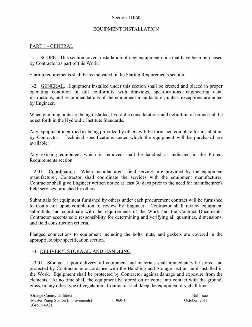
(Orange County Utilities) Bid Issue
(Master Pump Station Improvements) 11060-1 October 2011
(Group 4A2)
Section 11060
EQUIPMENT INSTALLATION
PART 1 - GENERAL
1-1. SCOPE. This section covers installation of new equipment units that have been purchased
by Contractor as part of this Work.
Startup requirements shall be as indicated in the Startup Requirements section.
1-2. GENERAL. Equipment installed under this section shall be erected and placed in proper
operating condition in full conformity with drawings, specifications, engineering data,
instructions, and recommendations of the equipment manufacturer, unless exceptions are noted
by Engineer.
When pumping units are being installed, hydraulic considerations and definition of terms shall be
as set forth in the Hydraulic Institute Standards.
Any equipment identified as being provided by others will be furnished complete for installation
by Contractor. Technical specifications under which the equipment will be purchased are
available.
Any existing equipment which is removed shall be handled as indicated in the Project
Requirements section.
1-2.01. Coordination. When manufacturer's field services are provided by the equipment
manufacturer, Contractor shall coordinate the services with the equipment manufacturer.
Contractor shall give Engineer written notice at least 30 days prior to the need for manufacturer's
field services furnished by others.
Submittals for equipment furnished by others under each procurement contract will be furnished
to Contractor upon completion of review by Engineer. Contractor shall review equipment
submittals and coordinate with the requirements of the Work and the Contract Documents.
Contractor accepts sole responsibility for determining and verifying all quantities, dimensions,
and field construction criteria.
Flanged connections to equipment including the bolts, nuts, and gaskets are covered in the
appropriate pipe specification section.
1-3. DELIVERY, STORAGE, AND HANDLING.
1-3.01. Storage. Upon delivery, all equipment and materials shall immediately be stored and
protected by Contractor in accordance with the Handling and Storage section until installed in
the Work. Equipment shall be protected by Contractor against damage and exposure from the
elements. At no time shall the equipment be stored on or come into contact with the ground,
grass, or any other type of vegetation. Contractor shall keep the equipment dry at all times.
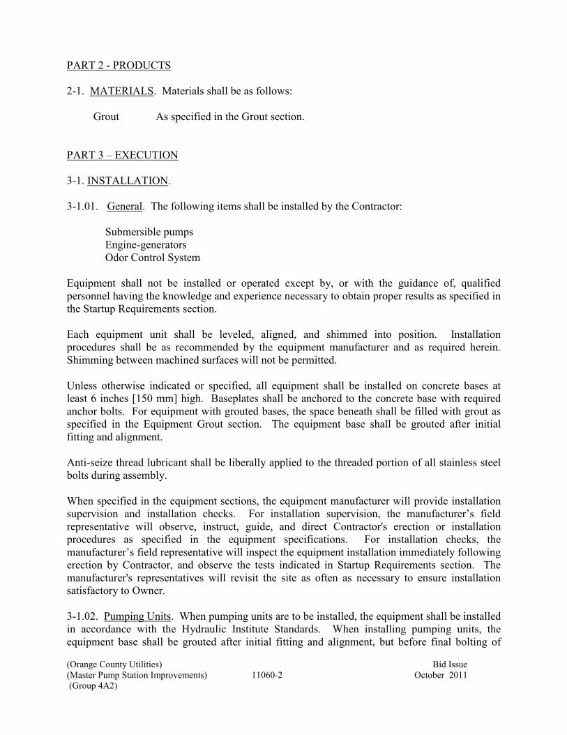
(Orange County Utilities) Bid Issue
(Master Pump Station Improvements) 11060-2 October 2011
(Group 4A2)
PART 2 - PRODUCTS
2-1. MATERIALS. Materials shall be as follows:
Grout As specified in the Grout section.
PART 3 – EXECUTION
3-1. INSTALLATION.
3-1.01. General. The following items shall be installed by the Contractor:
Submersible pumps
Engine-generators
Odor Control System
Equipment shall not be installed or operated except by, or with the guidance of, qualified
personnel having the knowledge and experience necessary to obtain proper results as specified in
the Startup Requirements section.
Each equipment unit shall be leveled, aligned, and shimmed into position. Installation
procedures shall be as recommended by the equipment manufacturer and as required herein.
Shimming between machined surfaces will not be permitted.
Unless otherwise indicated or specified, all equipment shall be installed on concrete bases at
least 6 inches [150 mm] high. Baseplates shall be anchored to the concrete base with required
anchor bolts. For equipment with grouted bases, the space beneath shall be filled with grout as
specified in the Equipment Grout section. The equipment base shall be grouted after initial
fitting and alignment.
Anti-seize thread lubricant shall be liberally applied to the threaded portion of all stainless steel
bolts during assembly.
When specified in the equipment sections, the equipment manufacturer will provide installation
supervision and installation checks. For installation supervision, the manufacturer’s field
representative will observe, instruct, guide, and direct Contractor's erection or installation
procedures as specified in the equipment specifications. For installation checks, the
manufacturer’s field representative will inspect the equipment installation immediately following
erection by Contractor, and observe the tests indicated in Startup Requirements section. The
manufacturer's representatives will revisit the site as often as necessary to ensure installation
satisfactory to Owner.
3-1.02. Pumping Units. When pumping units are to be installed, the equipment shall be installed
in accordance with the Hydraulic Institute Standards. When installing pumping units, the
equipment base shall be grouted after initial fitting and alignment, but before final bolting of
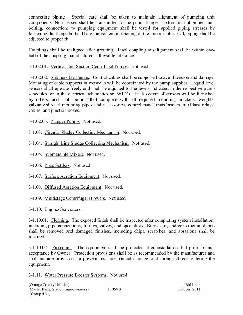
(Orange County Utilities) Bid Issue
(Master Pump Station Improvements) 11060-3 October 2011
(Group 4A2)
connecting piping. Special care shall be taken to maintain alignment of pumping unit
components. No stresses shall be transmitted to the pump flanges. After final alignment and
bolting, connections to pumping equipment shall be tested for applied piping stresses by
loosening the flange bolts. If any movement or opening of the joints is observed, piping shall be
adjusted to proper fit.
Couplings shall be realigned after grouting. Final coupling misalignment shall be within one-
half of the coupling manufacturer's allowable tolerance.
3-1.02.01. Vertical End Suction Centrifugal Pumps. Not used.
3-1.02.02. Submersible Pumps. Control cables shall be supported to avoid tension and damage.
Mounting of cable supports in wetwells will be coordinated by the pump supplier. Liquid level
sensors shall operate freely and shall be adjusted to the levels indicated in the respective pump
schedules, or in the electrical schematics or P&ID’s. Each system of sensors will be furnished
by others, and shall be installed complete with all required mounting brackets, weights,
galvanized steel mounting pipes and accessories, control panel transformers, auxiliary relays,
cables, and junction boxes.
3-1.02.03. Plunger Pumps. Not used.
3-1.03. Circular Sludge Collecting Mechanism. Not used.
3-1.04. Straight Line Sludge Collecting Mechanism. Not used.
3-1.05. Submersible Mixers. Not used.
3-1.06. Plate Settlers. Not used.
3-1.07. Surface Aeration Equipment. Not used.
3-1.08. Diffused Aeration Equipment. Not used.
3-1.09. Multistage Centrifugal Blowers. Not used.
3-1.10. Engine-Generators.
3-1.10.01. Cleaning. The exposed finish shall be inspected after completing system installation,
including pipe connections, fittings, valves, and specialties. Burrs, dirt, and construction debris
shall be removed and damaged finishes, including chips, scratches, and abrasions shall be
repaired.
3-1.10.02. Protection. The equipment shall be protected after installation, but prior to final
acceptance by Owner. Protection provisions shall be as recommended by the manufacturer and
shall include provisions to prevent rust, mechanical damage, and foreign objects entering the
equipment.
3-1.11. Water Pressure Booster Systems. Not used.

(Orange County Utilities) Bid Issue
(Master Pump Station Improvements) 11060-4 October 2011
(Group 4A2)
3-2. STARTUP AND TESTING. Startup requirements, and tests associated with startup shall
be as indicated in the Startup Requirements section. Other field tests shall be as indicated in the
specific equipment sections. Startup and tests required shall occur in the order listed in the
following paragraphs. Tests shall not begin until any installation supervision and installation
checks by the equipment manufacturer have been completed, except where noted below.
3-2.01. Preliminary Field Tests. Preliminary field tests shall be conducted on all equipment by
Contractor as indicated in the Startup Requirements section. When an installation check is
specified in the equipment sections, the equipment manufacturer's representative will participate
in these tests to the extent described in the Startup Requirements section and in the equipment
sections.
3-2.02. Field System Operation Tests. Field system operation tests shall be conducted on all
equipment by Contractor as indicated in the Startup Requirements section. When an installation
check is specified in the equipment sections, the equipment manufacturer's service personnel will
participate in these tests to the extent described in the Startup Requirements section and in the
equipment sections.
3-2.03. Field Demonstration Tests. Field demonstration tests will be conducted by the
equipment manufacturer on equipment as indicated and as specified in the equipment sections.
3-2.04. Field Performance Tests & Distribution Tests. Field performance tests or distribution
tests will be conducted by the equipment manufacturer on equipment as indicated and as
specified in the equipment sections.
3-2.05. Field Baseline Performance Tests. Field baseline performance tests shall be conducted
by Contractor on the equipment indicated in the equipment sections, and the tests shall be
performed as indicated. When indicated in the equipment sections, the equipment manufacturer
will participate in these tests. This test shall not be considered an acceptance test, but rather a
test to determine initial performance curves and efficiency just prior to the equipment entering
service.
End of Section

(Orange County Utilities) Bid Issue
(Master Pump Station Improvements) 11150-1 October 2011
(Group 4A2)
Section 11150
SUBMERSIBLE PUMPS
PART 1 - GENERAL
1-1. SCOPE. This section covers furnishing guiderail mounted, single-stage,
submersible, non-clog, end suction centrifugal pumping units and controls as indicated
herein or on the drawings.
Pump Station PS#3006
Pump Application Raw Sewage
Number of Pumps 3
Pump Tag Numbers PSM-3006-1, PSM-3006-2, PSM-3006-3
Location Wetwell
Each pumping unit shall be complete with a close-coupled, submersible electric motor,
and all other appurtenances specified, or otherwise required for proper operation.
Each pumping unit, including motor and all integral controls, shall be rated and labelled
for use in a Class 1, Division 1, Group D area as defined by the National Electric Code.
1-2. GENERAL. Equipment furnished under this section shall be fabricated and
assembled in full conformity with drawings, specifications, engineering data,
instructions, and recommendations of the equipment manufacturer, unless exceptions are
noted by Engineer. Hydraulic considerations and definition of terms shall be as set forth
in the Hydraulic Institute Standards.
Pumping units shall be manufactured by Flygt, or ABS without exception.
1-2.01. General Equipment Stipulations. The General Equipment Stipulations shall
apply to all equipment furnished under this section. If requirements in this specification
differ from those in the General Equipment Stipulations, the requirements specified
herein shall take precedence.
1-2.02. Tagging. Each item of equipment and each part shipped separately shall be
tagged and identified with indelible markings for the intended service. Tag numbers shall
be clearly marked on all shipping labels and on the outside of all containers.
1-2.03. Power Supply. Unless otherwise indicated, power supply to the equipment shall
be 480 volts, 60 Hz, 3 phase.

(Orange County Utilities) Bid Issue
(Master Pump Station Improvements) 11150-2 October 2011
(Group 4A2)
1-3. SUBMITTALS.
1-3.01. Drawings and Data. Complete fabrication and assembly drawings, together with
detailed specifications and data covering materials, parts, devices, and accessories
forming a part of the equipment furnished, shall be submitted in accordance with the
Submittals section. The data and specifications for each unit shall include, but shall not
be limited to, the following:
Pumps
Name of manufacturer.
Type and model.
Tag number.
Pump designation.
Pump location.
Rotative speed.
Size of discharge nozzle.
Net weight of pump and motor only.
Complete performance curves showing capacity versus head, NPSH
required, pump efficiency, wire-to-water efficiency, and pump input
power.
Data on shop painting.
Motors
Name of manufacturer.
Type and model.
Type of bearings and method of lubrication.
Rated size of motor, hp, and service factor.
Insulation class and temperature rise.
Full load rotative speed.
Efficiency at full load and rated pump condition.
Full load current.
Locked rotor current.
Nameplate data as stipulated by NEMA MG-1.
Moisture Detection System
Name of manufacturer.
Type and model.
Enclosure rating and layout if an enclosure is specified.
Electrical schematics and wiring diagram.
Published descriptive data on each item of equipment and all accessories,
indicating all specific characteristics and options.
Control Components
Type and manufacturer.
Model.
Enclosure rating.

(Orange County Utilities) Bid Issue
(Master Pump Station Improvements) 11150-3 October 2011
(Group 4A2)
Published descriptive data on all components, indicating all specific
characteristics and options.
Where liquid level sensors are provided, provide mounting details.
1-3.02. Operation and Maintenance Data and Manuals. Adequate operation and
maintenance information shall be supplied as required in the Submittals section.
Operation and maintenance manuals shall be submitted in accordance with the Submittals
section. The operation and maintenance manuals shall be in addition to any instructions
or parts lists packed with or attached to the equipment when delivered.
1-4. QUALITY ASSURANCE.
1-4.01. Balance. All rotating parts shall be accurately machined and shall be in as nearly
perfect rotational balance as practicable. Excessive vibration shall be sufficient cause for
rejection of the equipment. The mass of the unit and its distribution shall be such that
resonance at normal operating speeds is avoided. In any case, the unfiltered vibration
velocity, as measured at any point on the machine including top of motor, shall not
exceed the maximum velocity as indicated for vertical, end suction, solids handling
pumps in Figure 9.6.4.10 of the governing standard.
At any operating speed, the ratio of rotative speed to the critical speed of a unit or its
components shall be less than 0.8 or more than 1.3.
1-5. DELIVERY, STORAGE, AND HANDLING. Shipping shall be in accordance with
the Shipping section. Handling and storage shall be in accordance with the Handling and
Storage section.
1-6. SPARE PARTS. One set of all special tolls required for normal operation and
maintenance shall be provided. All such tools shall be furnished in a suitable steel chest
complete with lock and duplicate keys.
One set of spare parts for each pump station (3) shall be provided. Each set of spare parts
shall include:
1 – Upper bearings
1 – Lower bearings
1 – Set of upper and lower shaft seals
1 – Set of o-rings or gaskets required for replacement of bearings and seals
1 – Set impeller wear ring
1 – Shaft sleeve (if applicable); and
1 – Cable cap for each pump (if applicable)
Spare parts shall be suitably packaged with labels indicating the contents of each
package. Spare parts shall be delivered to Owner as directed.
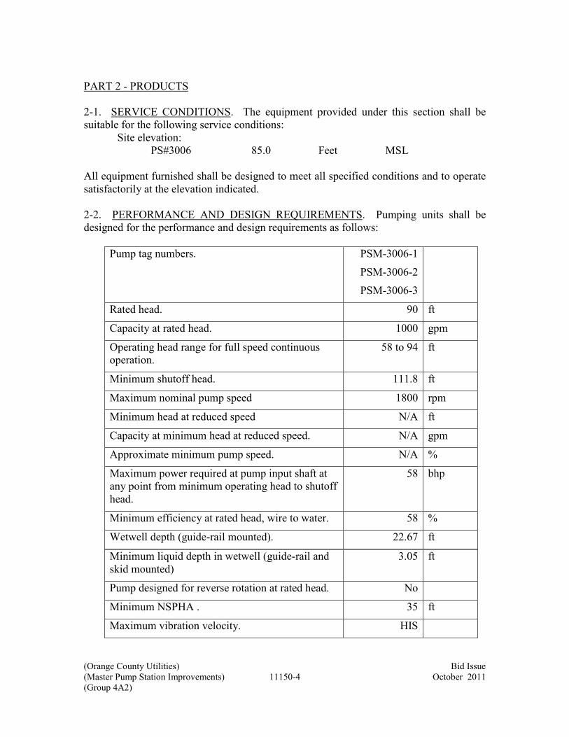
(Orange County Utilities) Bid Issue
(Master Pump Station Improvements) 11150-4 October 2011
(Group 4A2)
PART 2 - PRODUCTS
2-1. SERVICE CONDITIONS. The equipment provided under this section shall be
suitable for the following service conditions:
Site elevation:
PS#3006 85.0 Feet MSL
All equipment furnished shall be designed to meet all specified conditions and to operate
satisfactorily at the elevation indicated.
2-2. PERFORMANCE AND DESIGN REQUIREMENTS. Pumping units shall be
designed for the performance and design requirements as follows:
Pump tag numbers. PSM-3006-1
PSM-3006-2
PSM-3006-3
Rated head. 90 ft
Capacity at rated head. 1000 gpm
Operating head range for full speed continuous
operation.
58 to 94 ft
Minimum shutoff head. 111.8 ft
Maximum nominal pump speed 1800 rpm
Minimum head at reduced speed N/A ft
Capacity at minimum head at reduced speed. N/A gpm
Approximate minimum pump speed. N/A %
Maximum power required at pump input shaft at
any point from minimum operating head to shutoff
head.
58 bhp
Minimum efficiency at rated head, wire to water. 58 %
Wetwell depth (guide-rail mounted). 22.67 ft
Minimum liquid depth in wetwell (guide-rail and
skid mounted)
3.05 ft
Pump designed for reverse rotation at rated head. No
Minimum NSPHA . 35 ft
Maximum vibration velocity. HIS

(Orange County Utilities) Bid Issue
(Master Pump Station Improvements) 11150-5 October 2011
(Group 4A2)
Minimum pump discharge nozzle/elbow size. 6 in
Minimum test sphere diameter. 3 in
All specified conditions shall be at rated speed unless otherwise indicated.
Overall (wire-to-water) efficiency shall include losses in the pump and motor.
The minimum hydrostatic test pressure shall be 1.5 times shutoff head plus max suction
pressure.
Pump performance shall be stable and free from cavitation and noise throughout the
specified operating head range at minimum suction submergences. The design running
clearance between the impeller inlet and the casing wearing ring (if provided) shall be not
less than 0.01 inch or 1 mil per inch of casing wearing ring diameter, whichever is
greater.
2-3. MATERIALS.
Stator Housing, Oil Chamber Housing,
Impeller Casing, and Impeller
Cast iron, ASTM A48, Class 30.
Casing Wearing Ring Martensitic stainless steel,
Brinell 300+.
Impeller Wearing Ring Martensitic stainless steel, Brinell 200-
250.
Shaft Alloy steel, hard chrome plated; or
martensitic stainless steel, AISI
Type 416 or 420.
Mechanical Seals 2 tandem single type, oil lubricated
with silicon or tungsten carbide seal
rings at all points, except the upper
rotating seal, which shall be carbon.
Discharge Base Cast iron or fabricated steel.
Guiderails Stainless steel pipe, ASTM A312,
Schedule 40S.
Upper guiderail bracket, cable hooks,
and chain hooks
AISI Type 304 stainless steel.
2-4. PUMP CONSTRUCTION.

(Orange County Utilities) Bid Issue
(Master Pump Station Improvements) 11150-6 October 2011
(Group 4A2)
2-4.01. Impeller Casing. The impeller casing shall have well-rounded water passages
and smooth interior surfaces free from cracks, porosity, blowholes, or other irregularities.
The discharge nozzle shall be flanged and sufficiently rigid to support the pumping unit
under all operating conditions.
2-4.02. Impeller. The impeller shall be an enclosed one-piece casting with not more than
two nonclog passages. The interior water passages shall have uniform sections and
smooth surfaces and shall be free from cracks and porosity. The impeller shall be
dynamically balanced and securely locked to the shaft by means of a key and self-locking
bolt or nut.
2-4.03. Wearing Rings. Renewable wearing rings shall be provided in the casing and on
the impeller. The rings shall be positively locked in place.
2-4.04. Oil Chamber Housing. The oil chamber shall contain a drain plug and a vent
plug.
2-4.05. Mechanical Seals. Each pump shall be provided with two mechanical rotating
shaft seals arranged in tandem and running in an oil chamber. Each interface shall be
held in contact by an independent spring system designed to withstand maximum suction
submergence. The seals shall require neither maintenance nor adjustment and shall be
readily accessible for inspection and replacement.
Shaft seals lacking positively driven rotating members or conventional double
mechanical seals which utilize a common single or double spring acting between the
upper and lower units and requiring a pressure differential to offset external pressure and
effect sealing, will not be acceptable. The seals shall not rely upon the pumped media for
lubrication and shall not be damaged if the pumps are run unsubmerged for extended
periods while pumping under load.
2-4.06. Sealing of Mating Surfaces. All mating surfaces of major components shall be.
The use of O-rings, gaskets, or seals to obtain and maintain compression and
watertightness will not be acceptable. The use of secondary sealing compounds, gasket
cement, grease, or other devices to obtain watertight joints will not be acceptable.
2-4.07. Guiderail Mounted Base. A discharge base and discharge elbow shall be
furnished by the pump manufacturer. The base shall be sufficiently rigid to firmly
support the guiderails, discharge piping, and pumping unit under all operating conditions.
The base shall be provided with one or more integral support legs or pads suitable for
bolting to the floor of the wetwell. The face of the discharge elbow inlet flange shall be
perpendicular to the floor and shall make contact with the face of the pump discharge
nozzle flange. The diameter and drilling of the elbow outlet flange shall conform to
ANSI B16.1, Class 125.

(Orange County Utilities) Bid Issue
(Master Pump Station Improvements) 11150-7 October 2011
(Group 4A2)
The pump and motor assembly shall be automatically connected to and supported by the
discharge base and guiderails so that the unit can be removed from the wetwell and
replaced without the need for operating personnel to enter the wetwell.
2-4.07.01. Sliding Bracket. Each guiderail mounted pumping unit shall be provided with
an integral, self-aligning guiderail sliding bracket. The bracket shall be designed to
obtain a wedging action between flange faces as final alignment of the pump occurs in
the connected position. The bracket shall maintain proper contact and a suitably sealed
connection between flange faces under all operating conditions. The sliding bracket shall
be nonsparking where the pump is installed in a hazardous area.
2-4.07.02. Guiderails. Each guide rail mounted pumping unit shall be equipped with one
or more guiderails. Guiderails shall be sized to fit the discharge base and the sliding
bracket and shall extend upwards from the discharge base to the location indicated on the
drawings. An upper guiderail bracket shall be provided at the pump access opening.
2-4.07.03. Lifting Chain. Each guide rail mounted pumping unit shall be provided with
a chain and cable suitable for removing and installing. Each pump shall be fitted with 6
feet of Type 316 stainless steel, ¾” chain attached to the lifting mechanism and aircraft
rated ¼” stainless steel cable provided between the cable holder and the chain. A suitable
chain hook shall be provided at the top of the wetwell.
2-4.08. Pedestal Mounted Base. Not used.
2-4.09. Skid Mounted Base. Not used.
2-4.10. Access Hatch Cover. Access hatch covers are specified in the Access Hatches
section.
2-4.11. Shop Painting. All iron and steel parts which will be in contact with pumped
liquid or submerged after installation, including the inside of the casing, the impeller, and
the discharge elbow, shall be shop cleaned in accordance with the coating manufacturer's
recommendations and painted with the epoxy coating system specified. The coating shall
have a dry film thickness of at least 10 mils [250 µm] and shall consist of a prime (first)
coat and one or more finish coats. At least 1 quart [1 L] of the finish coat material shall
be furnished with each pump for field touch-up.
The shop painting of other surfaces shall be in accordance with the shop painting
requirements in the General Equipment Stipulations.
2-4.12. Hoist Assembly. Not used.
2-5. ELECTRIC MOTORS. Each pump shall be driven by an air-filled, totally
submersible electric motor provided by the pump manufacturer. Motor nameplate rating
shall exceed the maximum power required by the pump in the operating head range.

(Orange County Utilities) Bid Issue
(Master Pump Station Improvements) 11150-8 October 2011
(Group 4A2)
Each motor shall be rated for the power supply provided to the pump, and shall have a
service factor of 1.15. The stator housing shall be an air-filled, watertight casing. A
cooling jacket shall encase the motor housing for each pump where needed to maintain
adequate cooling. The cooling jacket shall require no external source of cooling water.
Motor insulation shall be moisture resistant, Class F, 155°C. Each motor shall be NEMA
Design B for continuous duty at 40°C ambient temperature, and designed for at least 10
starts per hour.
The motor bearings shall be antifriction, permanently lubricated type. The lower bearing
shall be fixed to carry the pump thrust and the upper bearing free to move axially. The
bearings shall have a calculated AFBMA L10 Life Rating of 40,000 hours when operating
at maximum operating head. Maximum shaft runout at the mechanical seals shall not
exceed 2 mils [50 µm] at any point in the operating head range.
Each motor installed in a wetpit shall be capable of continuous operation in air
(unsubmerged) for at least 24 hours under pump full load conditions, without exceeding
the temperature rise limits for the motor insulation system.
Each pump shall be equipped with one or more multiconductor cable assemblies for
power and control. Each multiconductor assembly containing power cables shall be
provided with a separate grounding conductor. Each cable assembly shall bear a
permanently embossed code or legend indicating the cable is suitable for submerged use.
Cable sizing shall conform to NEC requirements.
Cables for wetwell mounted pumps shall be of sufficient length to terminate in a junction
box outside the wetwell as indicated on the drawings, with 10 feet of slack which will be
coiled on a cable hook at the top of the wetwell. Each cable shall be supported by AISI
Series 300 corrosion-resistant stainless steel Kellems or woven grips to prevent damage
to the cable insulation. Mounting of cable supports in the wetwell shall be coordinated
by Contractor to prevent damage to the cable.
The cable entry water seal shall include a strain relief and a grommet type seal designed
so that a specific fastener torque is not required to ensure a watertight, submersible seal.
The cable entry junction box and motor shall be separated by a stator lead sealing gland
or a terminal board. The junction box shall isolate the motor interior from moisture
gaining access through the top of the stator housing.
Motors shall be specifically selected for service with an adjustable frequency type speed
controller when indicated on the drawings and shall be derated to compensate for
harmonic heating effects and reduced self-cooling capability at low speed operation so
that the motor does not exceed Class B temperature rise when operating in the installed
condition at load with power received from the adjustable frequency drive. Motors
driven by adjustable frequency drives shall be supplied with full phase insulation on the
end turns and shall meet the requirements of NEMA MG 1, Part 31. In addition to the

(Orange County Utilities) Bid Issue
(Master Pump Station Improvements) 11150-9 October 2011
(Group 4A2)
requirements of NEMA MG 1, Part 31, motors shall be designed to be continually pulsed
at the motor terminals with a voltage of 1600 volts ac.
2-5.01. Adjustable Frequency Drives. Not used.
2-6. CONTROLS.
2-6.01. Liquid Level Sensors. Sensors shall be in accordance with the pressure and level
instruments section.
2-6.02. Pump Controls. Each motor shall be protected by one motor temperature switch
embedded in each phase winding. Each switch shall be designed to operate at 140°C
(± 5°C). Each switch shall be normally closed automatic reset type rated 5 amps at
120 volts ac. The switches shall be wired in series with end leads wired to terminals
within the motor housing.
2-7. SHOP TESTS. Each pump shall be tested at the factory for capacity, power
requirements, and efficiency at specified rated head, shutoff head, operating head
extremes, and at as many other points as necessary for accurate performance curve
plotting. All tests and test reports shall conform to the requirements and
recommendations of the Hydraulic Institute Standards. Acceptance testing shall be Level
A, with no minus tolerance or margin allowed.
Five certified copies of a report covering each test shall be prepared by the pump
manufacturer and delivered to Engineer not less than 10 days prior to the shipment of the
equipment from the factory. The report shall include data and test information as
stipulated in the Hydraulic Institute Standards, copies of the test log originals, test
reading to curve conversion equations, and certified performance curves. The curves
shall include head, bhp [brake kW], pump efficiency, and shop test NPSH available,
plotted against capacity. The curves shall be easily read and plotted to scales consistent
with performance requirements. All test points shall be clearly shown.
PART 3 - EXECUTION
3-1. INSTALLATION. Each pumping unit will be installed in accordance with the
Equipment Installation section.

(Orange County Utilities) Bid Issue
(Master Pump Station Improvements) 11150-10 October 2011
(Group 4A2)
3-2. FIELD QUALITY CONTROL.
3-2.01. Installation Check. An experienced, competent, and authorized representative of
the manufacturer shall visit the site of the Work and inspect, check, adjust if necessary,
and approve the equipment installation. The representative shall be present when the
equipment is placed in operation in accordance with Section 01650, Startup
Requirements, and shall revisit the job site as often as necessary until all trouble is
corrected and the equipment installation and operation are satisfactory in the opinion of
Engineer.
The manufacturer's representative shall furnish a written report certifying that the
equipment has been properly installed and lubricated; is in accurate alignment; is free
from any undue stress imposed by connecting piping or anchor bolts; and has been
operated under full load conditions and that it operated satisfactorily.
All costs for these services shall be included in the contract price.
3-2.02. Installation Supervision. Installation supervision by the manufacturer is not
required.
End of Section

(Orange County Utilities) Bid Issue
(Master Pump Station Improvements) 11910-1 October 2011
(Group 4A2)
Section 11910
ENGINE-GENERATORS
PART 1 - GENERAL
1-1. SCOPE. This section covers the furnishing of diesel fuel engine-driven electric generator
units. Each engine-generator shall be located outdoors in a weatherproof enclosure.
Each engine-generator shall be a skid-mounted package unit consisting of an engine, an
alternator, auxiliary systems, controls, and accessories as specified, all mounted in a
weatherproof enclosure, and as required for a complete operating system.
1-2. GENERAL. Equipment furnished under this section shall be assembled in full conformity
with drawings, specifications, engineering data, instructions, and recommendations of the
equipment manufacturer unless exceptions are noted by Engineer.
Requirements of the engine-generator specified herein shall be coordinated with the electrical
section, plant control system section, miscellaneous piping section, the miscellaneous valves
section, and the aboveground fuel storage tank section.
The contractor shall properly coordinate the work between the suppliers of the equipment to be
used with or connected to the engine-generator to ensure that all required provisions for
mounting the accessories are included.
1-2.01. General Equipment Stipulations. The General Equipment Stipulations shall apply to all
equipment furnished under this section. If requirements in this specification differ from those in
the General Equipment Stipulations, the requirements specified herein shall take precedence.
1-2.02. Coordination. All equipment specified in this section shall be furnished through a single
engine-generator manufacturer who shall be responsible for the design, manufacture,
coordination, and proper installation and operation of the entire system.
Each engine-generator unit shall be a standard product of the manufacturer and shall be a
packaged type unit, fully shop assembled, wired and tested, requiring no field assembly of
critical moving parts.
Contractor shall verify that each component of the system is compatible with all other parts of
the system; that all piping, materials, and motor sizes are appropriate; and that all devices
necessary for properly functioning system have been provided.
The engine-generator manufacturer shall coordinate requirements between the automatic transfer
switch and the engine-generator.
Contractor shall, at his own expense, arrange for and obtain all necessary permits, inspections,
and approval by the proper authorities in local jurisdiction of such work.

(Orange County Utilities) Bid Issue
(Master Pump Station Improvements) 11910-2 October 2011
(Group 4A2)
1-2.03. Governing Standards. Except where modified or supplemented by these specifications,
all equipment and materials shall be designed and constructed in accordance with the latest
applicable requirements of the standard specifications and codes of ANSI, ASTM, NEMA,
IEEE, EEI, HEI, ISO, NFPA, SAE, and other such regularly published and accepted standards as
well as state and local codes.
1-2.04. Power Supply. Site power supply provided will be 240 volts, 60 Hz, single phase for
operation of the equipment and accessories. Each engine-generator shall be provided with a
power panel sized to power the required loads inside the enclosure as specified herein. The
engine (starting and controls) will operate from batteries specified herein. When needed, a
control power transformer shall be provided for voltages other than the supply power voltage.
1-3. SUBMITTALS.
1-3.01. Drawings and Data. Complete assembly and installation drawings, together with
detailed specifications and data covering materials, drive unit, parts, devices and accessories
forming a part of the equipment furnished, shall be submitted in accordance with the submittals
section. The data and specifications for each unit shall include, but shall not be limited to, the
following:
Manufacturer, model, and type:
Engine.
Alternator.
Enclosure.
Battery charger and battery.
Fuel oil cooler (if required by engine design).
Silencer.
Engine output horsepower and efficiency curves at rated capacity.
Fuel consumption at rated capacity.
Ratings at specified conditions:
Engine (net horsepower).
Engine (maximum performance horsepower bare engine).
Generator kW at specified power factor.
Volts.
Amperes.
Overall dimensions and weight:
Length.
Width.
Height.
Net weight.
Wiring diagrams and schematics, including the engine control panel and
generator line circuit breaker.
Alternator insulation class and temperature ratings.
Alternator winding pitch.
Calculations or test results showing compliance with specified motor
starting and voltage dip requirements.
Generator line circuit breaker rating.

(Orange County Utilities) Bid Issue
(Master Pump Station Improvements) 11910-3 October 2011
(Group 4A2)
Control panel layout, identifying location of all instrumentation being
supplied.
Engine drawing to include location of all piping connections.
Operation instructions.
Letter from the engine-generator manufacturer confirming that the unit will
provide the specified minimum kW rating at the specified design conditions and
time duration.
Maximum output short circuit kvA available.
Exhaust gas emission data, maximum values at loads of 1/2, 3/4, and full:
Carbon Monoxide (CO), lb/hr
Nitrogen Oxides (NOx), lb/hr
Sulfur Dioxide (SO2), lb/hr
Particular Matter (PM), lb/hr
Temperature, F
Flow, acfm
Letter from the engine-generator manufacturer confirming that the unit is in full
compliance with Federal EPA, State of Florida, and local emissions requirements.
Equipment skid drawing including material list.
Conformation confirming that the exhaust through the exhaust silencer
does not exceed the specified maximum pressure loss at the specified power
outage capacity of the unit and that the exhaust silencer provides sound
attenuation equal to or greater at the specified frequencies.
Letter from the engine-generator manufacturer confirming that the
enclosure is suitable for the specified wind velocity and is designed as specified
for rain penetration when the unit is operating.
Name, address, and phone number of manufacturer’s repair facility.
Color chart showing available options for the enclosure color. The color of
the enclosure shall be as directed by Owner during shop drawing review.
Drawings showing engine-generator inside the enclosure that shows
location of all enclosure mounted and engine-generator mounted equipment.
Drawings to indicate maintenance access clearances for electrical and mechanical
equipment. Drawing to show location of all enclosures bracing and location of
doors and removable panels.
Certificate of compliance.
1-3.02. Operation and Maintenance Manuals. Adequate operation and maintenance information
shall be supplied as required in the Submittals section. Operation and maintenance manuals shall
be submitted in accordance with the Submittals section. The operation and maintenance manuals
shall be in addition to any instructions or parts lists packed with or attached to the equipment
when delivered.
1-4. DELIVERY, STORAGE, AND HANDLING. Shipping shall be in accordance with the
Shipping section. Handling and storage shall be in accordance with the Handling and Storage
section.
1-5. SPARE PARTS. The following spare parts and accessories shall be furnished for each
engine-generator in substantial wooden boxes with identifying labels and delivered to the
vicinity of the project site or the Owner as directed:

(Orange County Utilities) Bid Issue
(Master Pump Station Improvements) 11910-4 October 2011
(Group 4A2)
Spare Parts Quantity
Air filters. 2 sets
Oil filters. 4 sets
Fuel filters. 12 sets
V-belts. 1 sets
1-5.01. Padlocks and Keys. Two stainless steel padlocks and four sets of keys for each door shall
be provided. All keys and padlocks are to be keyed to Orange County standard maintenance key
numbers. Contractor shall coordinate with the Owner accordingly.
PART 2 - PRODUCTS
2-1. SERVICE CONDITIONS. Each engine-generator unit shall be designed to operate under
the following service conditions:
Ambient air temperature range 20 to 110 °F
Design wind speed 120 mph
Site elevations
3006 Huggins 85 ft
Each engine-generator unit will be used as a power unit for selected electrical loads when the
utility supplied power fails.
Each engine-generator shall automatically start and connect to the electrical load when initiated
from the automatic transfer controls.
Fuel for each engine-generator will be furnished from an aboveground tank specified in section
13214, Aboveground Fuel Storage Tanks.
The engine-generator supplier shall provide the correct amount and grade of crankcase oil,
coolant, and other fluids (except fuel) necessary for initial testing and operation.
2-2. PERFORMANCE AND DESIGN REQUIREMENTS. Each engine-generator unit shall be
designed for the operating conditions and requirements as follows:
Pump Station Location 3006
Generator
Minimum power rating capacity with
accessories, for generator voltage output and
service conditions specified herein.
145 kW

(Orange County Utilities) Bid Issue
(Master Pump Station Improvements) 11910-5 October 2011
(Group 4A2)
Output frequency. 60 Hz
Output voltage. 480Y/277V VAC
Output power factor. 0.8
Maximum voltage dip. [SEE
PERFORMANC
E TABLE]
Engine
Fuel supply. No. 2 diesel
Maximum speed. 1,800 rpm
Minimum piston displacement. 400 in3
Black start required. Yes
Guaranteed Emissions Tier 3
Maximum engine-generator length, including
radiator discharge plenum.
17’-0”
Maximum engine-generator width, including air
intake plenums.
14’-0”
Each engine-generator shall be designed to operated during a power outage for a minimum of 64
continuous hours and a maximum of 200 hours per year.
Engine-generators submitted with ratings in excess of current published data will not be
acceptable.
The engine-generator shall at a minimum meet the required Environmental Protection Agency
New Source Performance Standards emission regulation. The engine-generator supplier shall
coordinate with the local air quality management authority to ensure the equipment meets all
current local air emissions requirements.
Engine-generator supplier shall guarantee the equipment supplied meets all local air emissions
requirements in place at the time of startup. Field testing of actual emissions will be required per
section 3-3 to determine compliance with the emissions requirements.
Each engine-generator unit furnished, including any air intake or discharge plenums, shall be of a
design that can be accommodated in the space as indicated on the drawings and as specified
herein. Maximum outside dimensions of the engine-generator enclosure including any plenums
shall be as specified.
Any special fittings or piping required for connection to fuel piping shall be furnished and
installed.

(Orange County Utilities) Bid Issue
(Master Pump Station Improvements) 11910-6 October 2011
(Group 4A2)
2-2.01 Performance Table Each engine-generator shall satisfactorily start the following loads,
while meeting the indicated voltage dip.
Location: 3006
2-3. ACCEPTABLE MANUFACTURERS. Each engine-generator shall be a current
production model and from the same manufacturer. The engine-generator shall be manufactured
by the supplier Caterpillar or Cummins without exception.
The manufacturer of the engine-generator unit shall have a full-time, fully factory trained
technical staff and an equipped 24 hour service facility having all personnel and all equipment
required to maintain, repair, or overhaul the engine-generator unit and associated equipment.
2-4. ENGINE-GENERATOR UNIT.
2-4.01. Engine. Each engine shall be 4-stroke cycle type and shall be equipped with the
following:
Electronic governor for isochronous regulation of engine speed from no
load to full load alternator output.
Dry type air cleaner with replaceable elements.
2-4.02. Alternator. Each engine-generator alternator shall be a 4 pole, revolving field design
with temperature compensated solid state voltage regulator, brushless rotating rectifier exciter
system, and drip-proof construction with amortisseur windings. The alternator shall be directly
connected to the engine flywheel housing, and the rotor shall be driven through a semi-flexible
driving flange to ensure permanent alignment.
Frequency regulation shall be isochronous ±0.15 Hz from no load to rated load. Voltage
regulation shall be within ±2 percent of rated voltage, steady state, from no load to full load. The
momentary voltage drop shall not exceed the specified percent without starter coils dropping out
or stalling the engine at any time when applying or starting the specified loads. Recovery to
stable operation shall occur within 2 seconds.
The alternator shall have Class F insulation as defined by NEMA MG1-1.65 and temperature rise
shall be within NEMA MG1-22.40 definition at rated condition.
Harmonic filters shall be provided where determined by the supplier for proper operation when
powering solid-state motor starters.
Load Description Rating
Maximum
Voltage
Dip (%)
Time
Delay
(sec)
Comments
Step 1 Static Load (Total) 40KVA 15 0
Pump Motor 1 60 Hp 15 0 Reduced Voltage Starter
Step 2 Pump Motor 2 60Hp 15 20 Reduced Voltage Starter

(Orange County Utilities) Bid Issue
(Master Pump Station Improvements) 11910-7 October 2011
(Group 4A2)
An alternator winding heater shall be furnished as an integral part of the engine-generator unit.
Alternator winding heater shall be rated 120 volts, single phase. The alternator winding heater
control system shall include an interlock with the engine-generator unit so that the heaters are de-
energized at all times that the generator field is energized. The supplier shall provide all internal
alternator winding heater wiring and used branch circuit protection.
2-4.02.01. Surge Protection. Each engine-generator shall be provided with a voltage surge
protection system installed in the generator terminal box or in a separate enclosure near the
generator terminal box.
2-4.03. Fuel System. A remote aboveground fuel storage tank, as specified in Section 13214,
will be the source of the diesel fuel. Each engine-generator unit shall be furnished with a
complete fuel system including engine-driven fuel pump, engine supply and return line, and with
all accessories as required for proper operation. All items shall be suitable for the specified fuel
and located inside the enclosure and serviceable from inside the enclosure. The engine driven
fuel pump shall transfer the fuel from the remote aboveground fuel storage tank to the engine-
generator.
The fuel system shall be furnished with any equipment required for the engine to supply or return
any unused portion of fuel back to the fuel storage tank with any level in the tank, as indicated on
the Drawings.
All stainless steel flexible connectors shall be provided for the fuel supply and return lines.
A manual shutoff valve shall be located in the fuel supply piping outside the enclosure. The
shutoff valves shall be of firesafe design and shall utilize secondary metal seating surfaces to
ensure shutoff if the primary seats are destroyed by fire. Valves shall be manually operated and
shall be of three-piece design ball valves with carbon steel body and end caps, stainless steel or
hard chrome plated ball and stem, reinforced teflon seats and seals, and socket welding ends.
Firesafe ball valves shall be Contomatics “C-1122-BB-FS” or Jamesbury “4C2236XT-1”.
A fire valve shall be installed in the diesel fuel piping just inside the enclosure. The valve shall
have a spring loaded handle mechanism to provide for automatic closure of the normally open
ball valve. The fire valve shall be FM approved and shall be Jamesbury Figure “1075”.
The combination fuel filter/separator shall be located inside the enclosure and upstream from the
flexible connectors. The combination fuel filter/separator shall be a manifold unit with shutoff
valves and shall permit servicing the filter/separator without engine shutdown. Filter/separator
shall be manufactured by Racor or equal.
The diesel fuel valve train for the engine shall include an electrically operated solenoid valve for
shutoff of the fuel supply on engine shutdown. The valve shall be DC powered and located
upstream from the flexible connection in the fuel line and shall open when the engine start in
initiated.

(Orange County Utilities) Bid Issue
(Master Pump Station Improvements) 11910-8 October 2011
(Group 4A2)
A suitable check valve shall be located in the fuel return line inside the enclosure. The check
valve shall be suitable for the specified fuel and shall prevent the flow of the fuel back towards
the engine.
Fuel oil coolers shall be provided if the engine fuel system absorbs heat from the unit injectors
and surrounding jacket water. The fuel cooler shall be a radiator mounted, air cooled unit that
uses the air flow from the radiator for the cooling air flow. To prevent over heating of the fuel in
the day tank, the fuel oil cooler shall be adequately sized to cool the return fuel from the engine
to the required fuel usage inlet temperature.
A siphon-break, normally open, solenoid valve shall be provided at the highest point of the fuel
supply line. The anti-siphon valve shall be piped back to the above fuel storage tank vent line
riser pipe to prevent moisture from entering the valve as indicated on the drawings. The valve
shall be used to break siphon when open and to make siphon when closed. It shall be connected
to the day tank level controller to energize (close) whenever fuel is required.
A tamper switch shall be added to the fuel tank to prevent fuel theft.
2-4.04. Exhaust System. Each engine-generator unit shall be furnished with a complete exhaust
system including an exhaust silencer, exhaust piping, stainless steel bellows expansion joints,
and accessories required for a complete operating system.
The silencer shall be chamber type, all welded AISI Type 304L stainless steel construction.
Exhaust piping shall be Schedule 10S, AISI Type 304L stainless steel with buttwelded fittings.
The exhaust silencer shall be furnished with suitable stainless steel bracket supports for
horizontal mounting on top of the enclosure. The silencer shall be sized so that the back pressure
at rated capacity of the engine does not exceed one half the manufacturer's maximum allowable
back pressure. The exhaust from the engine shall enter either the bottom or side. Silencers shall
be Maxim “M51”, Nelson “400” or equal.
Minimum silencer attenuation for the following mid band frequencies shall be as follows:
63 Hz 19 dB
125 Hz 29 dB
250 Hz 35 dB
500 Hz 33 dB
1,000 Hz 29 dB
2,000 Hz 28 dB
4,000 Hz 28 dB
8,000 Hz 28 dB
The exhaust shall discharge horizontally at the silencer outlet. The exhaust shall be directed per
Owner’s preference and end of the pipe shall be cut at 45 degree angle such that rain will not
enter the exhaust pipe. Expanded 0.5 inch stainless bird screen shall be installed over the end to
prevent birds from entering.

(Orange County Utilities) Bid Issue
(Master Pump Station Improvements) 11910-9 October 2011
(Group 4A2)
Exhaust emission test ports shall be provided in the exhaust piping after the silencer. Ports shall
be threaded and shall be provided with stainless steel threaded caps.
2-4.05. Starting System and Control Power. Each engine-generator unit shall be furnished with
a complete electric motor start system including starting motors, battery pack with rack, cables,
and battery charger.
The batteries shall be of the high rate, nickel-cadmium type and have a 12 volt output. The
battery shall be electrically sized for the engine furnished to maintain minimum cell voltages of
0.65 volt per cell during initial starting, and 0.85 volt per cell throughout the cranking time for
five consecutive starting attempts of 10 seconds each. Battery voltages shall be maintained
under the conditions specified herein.
The battery charger shall be suitable for the nickel-cadmium battery pack. The charger shall have
a DC output suitable to supply power for all continuous loads and to recharge the batteries from
a fully discharged state to normal operating voltage within 8 hours. The battery charger shall be
provided with a NEMA 2 corrosion resistant enclosure. The battery charger shall be provided
with the following: on/off switch, DC ammeter, DC voltmeter, AC input and DC output circuit
breakers or fuses, floating voltage equalization, equalizing timer, and relays with form c contacts
for remote annunciation of loss of AC power, low battery voltage, and high battery voltage.
The batteries, battery rack, and battery charger shall be located inside a separate vented enclosure
inside the engine-generator enclosure. The battery rack frame shall be constructed of corrosion
resistant material.
The engine-generator shall automatically supply power to the remote bus that powers the battery
charger when it is operating and when utility power is not available.
2-4.06. Cooling System. Each engine-generator unit shall be cooled with unit-mounted radiator
cooling system complete with radiator, expansion tank, water pump, belt-driven fan, fan guard,
thermostatic temperature control, high-water temperature cutout, electric jacket water heater and
all accessories required for proper operation. The radiator shall be sized with sufficient capacity
for cooling of the engine and all other accessories required for proper operation. The core shall
be epoxy coated for ocean spray and the fan shall draw air over the engine and discharge through
the radiator.
The cooling system shall be filled with a permanent antifreeze mixture of the ethylene glycol
type with rust inhibitor.
The electric jacket water heater shall be furnished to maintain jacket water at 90°F with a winter
ambient temperature as specified herein. The jacket water heater shall be thermostatically
controlled.
2-4.07. Engine-Generator Enclosure. Each engine-generator unit, including its control panel,
battery rack, battery charger, power panel, and other ancillary equipment, shall be housed in an

(Orange County Utilities) Bid Issue
(Master Pump Station Improvements) 11910-10 October 2011
(Group 4A2)
aluminum weatherproof enclosure, of the non-walk-in type. The enclosure shall be shop
mounted on the engine generator skid or field erected.
Aluminum enclosure shall be Marine Grade formed sheet aluminum construction, made of
modular panels and louvers. Posts, rails, channels, and roof bows shall be 6061-T6 extruded
aluminum. The panels shall be 0.040 inches thick minimum.
The enclosure shall consist of two side walls, two end walls, and roof. The roof shall be braced
as necessary to support the exhaust silencer. The enclosure shall be designed to withstand the
specified wind velocity without damage. All bracing and reinforcing members shall be integral
to the enclosure. Roof penetrations for the installation of the silencer shall be gasketed to
prevent the entrance of rain.
Doors shall be provided and located for easy access to the engine-generator, controls,
accessories, radiator fill, and to provide easy accessibility for maintenance. Doors shall be
lockable and suitable for use with all stainless steel padlocks. The padlocks shall be suitable for
re-keying.
Engine oil and coolant drains shall be piped to outside of enclosure, with lockable shutoff valves
and caps. All enclosure penetrations shall be gasketed or sealed to prevent the entry of rodents.
The enclosure shall be provided with intake and exhaust louvers with dampers to open on engine
start. Louvers and dampers shall be sized for 120 percent of the cooling air requirements.
Louvers shall be AC powered closed and spring open on unit start. The louvers shall be screened
from the inside to prevent the entry of birds.
The enclosure shall be rain tight type and shall be designed to prevent the entrance of rain at the
specified wind velocity when the unit is operating and the wind direction at 90 degrees to the
intake louvers. "Rain Resistant" louvers, vertical air turning plenums, or a combination of the
two shall be provided.
AC/DC operated maintenance lights, controlled with a 1 hour, wind-up timer switch shall also be
provided inside the enclosure. A duplex receptacle rated 20 amp, 125 volts with a weatherproof
enclosure shall be mounted inside and near the middle of the enclosure.
The enclosure shall be pre-wired, requiring only external connection to the power panel and the
control panel outputs.
The enclosure shall be provided with vertical air turning plenums for cooling air intake. The air
inlet turning plenums shall be located on each side of the enclosure.
The enclosure shall be provided with vertical air tuning plenums for radiator discharge air. The
radiator discharge plenum shall direct the air and mechanical noise upwards away from the unit,
and shall be supplied with a bottom sump area, with a one inch drain and shutoff valve to remove
any moisture.
The entire enclosure, except for the louvered openings, shall be provided with noise suppression
insulation and be designed to limit mechanical noise to not more than 75 dB(A) at 25 feet from

(Orange County Utilities) Bid Issue
(Master Pump Station Improvements) 11910-11 October 2011
(Group 4A2)
any point of the enclosure when operating . Field sound level tests shall be performed on each
unit as specified in the installation section of this specification.
The enclosure shall be thoroughly cleaned after assembly and etched to allow both the interior
and exterior surfaces to be shop painted. The interior finish shall consist of at least one coat of
paint as selected by the Owner.
The enclosure shall be as manufactured by Pritchard-Brown or equal.
2-4.08. Control Panel. Each engine-generator unit shall have a control panel mounted inside the
enclosure with panel mounted controls accessible when the enclosure doors are open. The panel
shall be provided with vibration isolators to prevent damage to the instruments from engine-
generator vibration.
The control panel shall be automatic and safety type and shall, at a minimum, include all items
required by NFPA 110, Level 1.
The control panel shall be provided with a four-position selector switch with the following
positions: “MANUAL-OFF/RESET-STOP-AUTO”. In the “MANUAL” position, the engine
starting sequence shall be initiated providing local control for maintenance, in the “AUTO”
position, the engine-generator will be remotely started and stopped by a run contract from the
automatic transfer switch as described in specification 16491. Isolated contacts for when the unit
is in the “AUTO” position shall be provided for remote indication.
Adequate clearance shall be provided between the panel and the engine to allow engine
maintenance without moving the control panel. The control panel shall be provided with the
following instruments and control devices in addition to those required by NFPA 110, Level 1.:
The Metering equipment shall include 3-1/2-inch diameter meters.
Tachometer.
Non-resetable hour meter.
2% accuracy AC voltmeter, AC ammeter, voltmeter/ammeter selector
switch with “off” position.
Two normally open dry contacts which close when the engine is running
and open with it is stopped.
Dry contact that closes for remote common alarm.
Dry contact that closes when the control selector switch is in “auto” mode.
Frequency Meter
Engine water temperature
Lube Oil Pressure
Fault Indicators for the following:
Individual press-to-test fault indicator lights for low oil pressure
High water temperature
Low water level
Over speed
Over crank

(Orange County Utilities) Bid Issue
(Master Pump Station Improvements) 11910-12 October 2011
(Group 4A2)
2-4.09. Crankcase Vent Blow-By Absorber. Suitable crankcase ventilation shall be provided by
the engine manufacturer to meet the applicable Tier level emission requirements.
2-4.10. Power Panel. Each engine-generator unit shall have a 12 minimum circuit 120/240-volt
load center with main and feeder breakers, rated as needed. The load center shall be mounted
inside the enclosure and isolated from generator vibration. The load center shall be pre-wired to
all engine generator accessories as needed. The power panel shall supply power to the
following:
Engine-generator starting system battery charger.
Enclosure lights and receptacles.
Day tank fuel system.
Enclosure intake and exhaust louvers/dampers.
Engine jacket water heater.
Alternator windings heater.
2-4.11. Generator Line and Generator Component Overcurrent Protection. A generator line
circuit breaker rated for the generator output voltage, having the trip rating as needed , shall be
provided on the output terminals. The line circuit breaker shall be pre-wired to the generator
output terminals, and shall be provided within the generator enclosure in outdoor applications or
shall be furnished in a skid mounted NEMA 1 enclosure for indoor applications.
Overcurrent protection devices shall be provided as needed by the system design to protect
generator rotor and excitation system components.
2-4.12. Limiting Dimensions. Each engine-generator unit furnished shall be of a design that can
be accommodated in the space available as specified herein and as shown on the drawings.
2-5. SHOP PAINTING. All steel and iron surfaces shall be protected by suitable coatings
applied in the shop. Surfaces which will be inaccessible after assembly shall be protected for the
life of the equipment. Coatings shall be suitable for the environment where the equipment is
installed. Exposed surfaces shall be finished, thoroughly cleaned, and filled as necessary to
provide a smooth, uniform base for painting. Electric motors, engine, alternator, enclosure,
piping, and valves shall be shop primed and finish painted prior to shipment to the site.
Stainless steel, nonferrous, and nonmetallic surfaces shall not be painted.
2-6. SHOP TESTS. The manufacturer shall shop test each engine-generator set with its control
panel and unit mounted radiator to demonstrate that the equipment conforms to specified
requirements for load capacity.
All items included on the control panel shall be assembled, wired, and tested in the
manufacturer's shop.
(Orange County Utilities) Bid Issue
(Master Pump Station Improvements) 11910-13 October 2011
(Group 4A2)
The tests shall consist of repeated starts and stops, operation under a load bank at specified
capacity frequency, voltage, phase, and power factor for a minimum of 1 continuous hour, and
tests to demonstrate that each safety shutdown device is working properly. Contractor shall
submit certified copies of the shop test results prior to shipping the unit.
2-7. OPERATION INSTRUCTION. Step-by-step instructions shall be furnished by each engine
manufacturer for each unit. The instructions shall include, but not be limited to, the following
procedures or information:
Startup of the unit.
Normal shutdown of the unit.
Emergency shutdown of the unit.
Normal operation of the unit, typical temperatures, pressures, speed, etc.,
for gauges and instruments which are displayed on the panel.
The operation instructions shall be submitted for review in accordance with the submittals
section. When the review is complete, the instruction sheets shall be printed on heavy paper or
cardboard stock and laminated with clear plastic. Two copies of the laminated instructions shall
be furnished with the unit. One copy shall be located or displayed at the control panel for the
unit. The reserve copy shall be delivered to Owner. The instructions specified here are in
addition to the operation and maintenance manuals required by the submittals section.
2-8. AIR EMISSIONS PERMIT. Contractor shall be responsible for preparing and submitting
air emission permit application on behalf of the Owner to the local air quality authority for the
unit being supplied based on the maximum number of operating hours specified herein and
guaranteed emissions.
Permit to include provisions for the Owner to contact the local air quality authority for
permission to operate the unit in the event the permit hours may be exceeded due to unforeseen
conditions.
PART 3 - EXECUTION
3-1. INSTALLATION. Each engine-generator will be installed in accordance with the
Equipment Installation section.
3-2. FIELD QUALITY CONTROL.
3-2.01. Installation Check. When required, an experienced, competent, and authorized
representative of the manufacturer shall visit the site of the Work and inspect, check, adjust if
necessary, and approve the equipment installation. The representative shall be present when the
equipment is placed in operation in accordance with Startup Requirements section, and shall
revisit the job site as often as necessary until all trouble is corrected and the equipment
installation and operation are satisfactory in the opinion of Engineer.

(Orange County Utilities) Bid Issue
(Master Pump Station Improvements) 11910-14 October 2011
(Group 4A2)
The manufacturer's representative shall furnish a written report certifying that the equipment has
been properly installed and lubricated; is in accurate alignment; is free from any undue stress
imposed by connecting piping or anchor bolts; and has been operated under full load conditions
and that it operated satisfactorily.
All costs for these services shall be included in the contract price.
3-2.02. Installation Supervision. When required, the equipment manufacturer shall furnish a
qualified field installation supervisor during the equipment installation.
All costs for these services shall be included in the contract price.
Manufacturers' installation supervisor shall observe, instruct, guide, and direct the installing
contractor's erection or installation procedures. The equipment manufacturer will be provided
with written notification 10 days prior to the need for such services.
3-3. FIELD TESTING. Manufacturer's field services shall be provided for field testing. All
costs for these services shall be included in the contract price.
3-3.01. Performance Test. Each unit shall be mechanically checked for proper operation. Each
alarm and safety shutdown shall be checked by artificially simulating an alarm condition.
Defective equipment and controls disclosed by the tests shall be replaced or corrected, and the
packages placed in satisfactory operating condition.
The complete system (engine, generator, fuel system, fuel storage tank, and control panel) shall
be field tested together by the manufacturer as a complete system to assure compatibility.
The tests shall consist of repeated starts and stops, operation under a load bank at the specified
power rating and power factor for the durations listed blow, and test of successful operation
under different loads and various fuel tank levels (minimum and full tank fuel levels). Before
each test, the engine shall be brought to steady state conditions as determined by the instrument
readings.
Four (4) continuous hours at specified power rating and power factor
Starting and proper operation of the specified loads in the order listed
for a minimum of two (2) continuous hours
Demonstration of four (4) starts
Contractor shall furnish the lubricants, load bank, and the fuel for the tests.
At the option of the Owner, an independent laboratory will be provided by the Owner for the
exhaust gas sampling and analysis during the 4 hour load test of the engine. The laboratory
analysis will be used for verification the units meets the guaranteed emissions.
Any retesting or modifications to the equipment to meet the above requirements and emission
guarantees shall be approved by the Engineer. All costs of modifications and retesting, including
the independent laboratory for air emission testing, shall be at no cost to the Owner.

(Orange County Utilities) Bid Issue
(Master Pump Station Improvements) 11910-15 October 2011
(Group 4A2)
The following items shall be measured, recorded at 15 minute intervals, and submitted in a field
test report:
Outdoor ambient temperature.
Indoor ambient temperature.
Barometric pressure.
kW output.
Engine speed, rpm.
Engine jacket water temperature.
Engine oil pressure.
Start time.
Completion time.
Test reports shall verify that the specified tests have been performed and shall state results. Test
results shall be submitted as required in the Submittals section.
3-3.02. Field Sound Level Test. The installed equipment shall be tested for noise. The
maximum measured sound levels outside the enclosure shall not exceed the specified noise level
at any octave band frequencies, at the specified distance when operating alone. Background
noise shall be included in the specified sound level. The Contractor shall take background noise
measurements as necessary to determine the level of sound attenuation required for the
enclosures.
Any retesting or modifications to the equipment or enclosure to meet the above requirements
shall be approved by the Engineer. All costs of modifications and retesting shall be at no cost to
the Owner.
Test reports shall verify that the specified tests have been performed and shall state results. Test
results shall be submitted as required in the Submittals section.
3-4. TRAINING. The manufacturer shall conduct on-site training to instruct the Owner on
operation and maintenance of the units. The training shall be arranged and coordinated with the
Owner though the Contractor. All costs for these services shall be included in the contract price.
Contractor shall include a minimum of four (4) clock hours for up to five (5) persons for each
model unit.
End of Section

This page was left blank intentionally

(Orange County Utilities) Bid Issue
(Master Pump Station Improvements) 11911-1 October 2011
(Group 4A2)
Section 11911
REMOVAL OF EXISTING ENGINE-GENERATORS
PART 1 - GENERAL
1-1. SCOPE. This section covers the removal of the existing diesel fueled engine generator
and associated engine-generator accessories. The engine-generator for PS 3006 (Huggins) is a
135 kW diesel fueled unit.
The engine generator and associated equipment shall be demolished and removed from it’s
current outdoor location by the Contractor. FDEP Permit application for this work shall be done
by Orange County Risk Management Division.
1-2. GENERAL.
1-2.01. Coordination. Equipment removed under this section shall be inspected, disassembled,
and removed in full conformity with drawings, specifications, engineering data, instructions, and
recommendations furnished by the equipment manufacturer unless exceptions are noted by the
Engineer.
The engine generator shall be removed completely including all accessories. The Owner will not
be responsible for any parts damaged by the Contractor.
The removal of the equipment shall be coordinated with the modifications to the existing engine-
generator area outside. The Contractor shall coordinate the removal from service and storage of
the existing engine generator with the Owner to minimize impact on operations schedules.
The Contractor shall, at this own expense, arrange for and obtain all necessary permits,
inspections, and approval by the proper authorities in local jurisdiction of such work.
The General Equipment Stipulations shall apply to all equipment furnished under this section.
1-3. STORAGE AND HANDLING. Equipment shall be stored and handled in accordance with
the General Equipment Stipulations and the equipment manufacturer’s recommendations.
PART 2 - EXECUTION
2-1. DECOMMISSION. The engine generator, associated wiring for the engine generator as
well as the day tank, exhaust silencer, and all accessories shall be demolished and removed by
the Contractor in accordance to all applicable regulatory requirements.
Provisions shall be made for temporary onsite engine-generators to be used as back-up sources of
power, prior to decommissioning. All cable and connectors shall be provided.
End of Section

This page was left blank intentionally

(Orange County Utilities) Bid Issue
(Master Pump Station Improvements) 13214-1 October 2011
(Group 4A2)
Section 13214
ABOVEGROUND FUEL STORAGE TANKS
PART 1 - GENERAL
1-1. SCOPE. This section covers the furnishing and installation of aboveground, steel fuel
storage tanks and accessories as indicated herein. FDEP Permit application for this work shall be
done by Orange County Risk Management Division.
Each tank shall be either constructed with porous concrete between two steel walls or
constructed of steel and encased in concrete.
1-2. GENERAL. Equipment furnished under this section shall be fabricated and installed in full
conformity with drawings, specifications, engineering data, instructions, and recommendations
of the manufacturer unless exceptions are noted by Engineer.
1-2.01. General Equipment Stipulations. The General Equipment Stipulations shall apply to all
equipment furnished under this section. If requirements in this specification differ from those in
the General Equipment Stipulations, the requirements specified herein shall take precedence.
1-2.02. Coordination. All equipment for this section shall be furnished by or through a single
manufacturer who shall be responsible for the design, coordination, and proper installation and
operation of the entire system.
Contractor shall properly coordinate the work between the suppliers of equipment to be used
with or connected to each storage tank to ensure that all required provisions for mounting the
accessories are included.
Where two or more units of the same class of equipment are required, they shall be the product
of a single manufacturer; however, all the component parts of the system need not be the
products of one manufacturer.
Contractor shall verify that each component of the system is compatible with all other parts of
the system; that all piping, materials, pumps, and motor sizes are appropriate; and that all devices
necessary for a properly functioning system have been provided.
Contractor shall, at his own expense, arrange for and obtain all necessary permits, inspections,
and approval by the proper authorities in local jurisdiction of such work.
1-2.03. Governing Standards. Except as modified or supplemented herein, all work covered by
this section shall be performed in accordance with all applicable municipal codes and ordinances,
laws, and regulations which pertain to such work. In case of a conflict between these
specifications and any state law or municipal ordinance, the latter shall govern. All materials
and construction methods shall comply with the applicable provisions of the following standards:
ASTM A283 "Low and Intermediate Tensile Strength Carbon Steel Plates, Shapes,

(Orange County Utilities) Bid Issue
(Master Pump Station Improvements) 13214-2 October 2011
(Group 4A2)
and Bars," or ASTM A569 "Steel, Carbon, Hot-Rolled Sheet and Strip,
Commercial Quality."
American Petroleum Institute.
National Fire Protection Association.
Underwriters' Laboratories UL 142, Steel Aboveground Tanks for Flammable and
Combustible Liquids; UL 1709, and Rapid Rise Fire Tests for a two hour period.
Applicable local regulations and ordinances.
1-2.04. Power Supply. Power supply for tank fill assembly control panel shall be 120 volts,
60 Hz, single phase.
1-3. SUBMITTALS.
1-3.01. Drawings and Data. Complete fabrication, assembly, and installation drawings, together
with detailed specifications and data covering materials used, parts, devices, and other
accessories forming a part of the tank furnished, shall be submitted in accordance with the
Submittals section.
The data shall also indicate the sizes of all major tank components and full information and
details concerning field assembly and installation.
The manufacturer's standard calibration charts shall be submitted.
1-3.02. Operation and Maintenance Data and Manuals. Adequate operation and maintenance
information shall be supplied as required in the Submittals section. Operation and maintenance
manuals shall be submitted in accordance with the Submittals section. The operation and
maintenance manuals shall be in addition to any instructions or parts lists packed with or
attached to the equipment when delivered.
1-4. DELIVERY, STORAGE, AND HANDLING. Shipping shall be in accordance with the
Shipping section. Handling and storage shall be in accordance with the Handling and Storage
section.
Each tank and component parts shall be adequately protected during all transportation, loading
and unloading, storage, installation, and subsequent construction activities. All nozzles shall be
properly protected at all times and shall be plugged to prevent contamination of the tank interior.
Repairs of minor damage, including scratches and abrasions, may be made where permitted by
Engineer in the manner recommended by the manufacturer. If a tank is damaged beyond
reasonable repair, in the opinion of Engineer, it will be rejected and shall be replaced by
Contractor with an undamaged unit.
At no time shall a tank be dropped or rolled. All lifting shall be done using the lifting lugs or
suitable slings.

(Orange County Utilities) Bid Issue
(Master Pump Station Improvements) 13214-3 October 2011
(Group 4A2)
PART 2 - PRODUCTS
2-1. SERVICE CONDITIONS.
All equipment shall be designed to operate under the following service conditions:
Type of environmental exposure. Outdoor
Design ambient air temperature range. 20 to 100 °F
2-2. PERFORMANCE AND DESIGN REQUIREMENTS. Each aboveground fuel storage tank
shall be from the same manufacturer and meet the following performance and design
requirements as follows:
Pump Station 3006
Capacity. 1,500 gal
Liquid stored. No. 2 Diesel
Minimum insulation thickness.
Con Vault type 6 in
Phoenix type 3 in
Limiting dimensions.
Length. 132 in
Width. 68 in
Height. 52 in
Minimum primary tank wall thickness. 3/16 in
Minimum top wall thickness of secondary
tank, if applicable.
1/4 in
Minimum sides and bottom wall thickness
of secondary tank, if applicable.
3/16 in
Quantity of supply pipe extractor fittings
with caps.
1
Supply pipe extractor fitting size. 4 in
Supply pipe extractor fitting cap size. 1 ½ in
Quantity of supply pipe foot valves. 1
Supply pipe foot valve size. 1.5 in
Vent cap size 1 ½ in
Primary tank emergency vent size 6 in

(Orange County Utilities) Bid Issue
(Master Pump Station Improvements) 13214-4 October 2011
(Group 4A2)
The primary internal steel tank shall be vented and normally used to store the specified product
at atmospheric pressure but shall be designed and tested at the factory before shipment to
maintain a 5 psi internal air pressure.
The primary internal steel tank shall be suitable to withstand internal corrosion from the liquid
stored at a maximum temperature of 150°F.
The porous lightweight concrete shall be placed between the two steel walls at the factory or the
tank shall be encased at the factory and either method shall provide a minimum two-hour fire
rating.
The secondary outer steel tank or the concrete encased tank shall be suitable to withstand
external corrosion due to atmospheric conditions.
2-3. ACCEPTABLE MANUFACTURERS. The tank shall be current production model as
manufactured by either ConVault or Phoenix Envirovault.
2-4. CONSTRUCTION. Each storage tank shall be either double wall type with lightweight
concrete between the two steel walls or single wall tank with styrofoam insulation and HDPE
secondary containment and encased in concrete. Each tank shall be aboveground horizontal
rectangular, atmospheric type with support rails or support legs and accessories as indicated on
the drawings and specified herein. Each tank shall be secured to a concrete base by anchor bolts
(cast in reinforced concrete) through the tank support as indicated on the drawings. Each entire
tank package system shall be electrically grounded.
The materials for construction shall be in accordance with the following requirements:
ConVault Type
Tank (primary) Carbon steel.
Encasement Concrete, with minimum design strength of 3,000 psi,
containing no aggregate, suitable for preventing the internal
tank temperature from rising 260°F during a 2000°F fire test
for 2 hours.
Annular space Styrofoam insulation
Secondary containment HDPE
Phoenix Type
Primary Tank Carbon steel
Secondary Tank Carbon steel
Annular Space Porous lightweight concrete
The primary internal steel tank and, if applicable, the secondary outer steel tank shall both be of
welded construction throughout and each shall be UL 142 listed and labeled.
The tank shall have a minimum of 2 hour fire rating and UL listed supports. The tank shall be
UL 2085 listed, and shall meet the requirements of the Uniform Fire Code 7907, and NFPA
30/30A. .

(Orange County Utilities) Bid Issue
(Master Pump Station Improvements) 13214-5 October 2011
(Group 4A2)
Upon completion of construction, the exterior of the of the double walled steel tank’s outer tank
and the inner tank interior seams shall be ground free of rough areas such that finished welds are
full and rounded.
Each tank shall be constructed, and provided with all connections as required to permit testing of
the tank containment including a nonmetallic secondary containment tank, if applicable.
2-4.01. Surface Preparation. After fabrication, all metal surfaces and connections shall be
blasted clean in conformance with the paint manufacturer's recommendations. All mill scale,
rust, and contaminants shall be removed before shop primer is applied.
2-4.02. Painting. All exterior surfaces of the primary internal tank and either the secondary
outer steel tank or the concrete encasement shall be shop primed and painted in accordance with
the tank manufacturer's requirements.
2-4.03. Concrete. Porous lightweight concrete insulation or concrete encasement shall be
suitable for preventing the primary tank temperature from rising 260°F during 2000°F fire test
for the fire rating specified above.
2-4.04. Connections and Openings. Each fuel storage tank shall be supplied with the following
connections and openings:
Primary tank emergency vent connection. 6 in
Fill connection. 4 in
Supply connection quantity. 1
Supply connection size. 4 in
Return connection quantity. 1
Return connection size. 2 in
Leak monitor connection. 2 in
Level transducer connection. 4 in
Tank vent connection. 1-1/2 in
Secondary tank emergency vent connection, if applicable. *
Secondary tank test connection with cap, if applicable. *
Manway connection. 18 in
Extra connection quantity. 2
Extra connection size. 4 in
*As recommended by the tank manufacture if applicable.
All connections on the fuel storage tank shall be located on the top of the tank and shall be
forged steel threaded pipe nipples, located as indicated on the drawings. All connections on the
tank that are not used shall be capped.
Extra connections on the tank shall be located on the top and shall be forged steel threaded pipe
nipples with caps, located as indicated on the drawings.

(Orange County Utilities) Bid Issue
(Master Pump Station Improvements) 13214-6 October 2011
(Group 4A2)
Secondary outer tank emergency vent connection size and secondary tank testing connection size
shall be as required for tank furnished.
All connections shall be sealed to prevent moisture from penetrating the outside of the secondary
outer steel tank and shall maintain the specified fire rating.
The manway for the tank shall be an all welded extension cylinder in the top of the tank.
2-5. ACCESSORIES. The accessories for each fuel storage tank shall be provided as indicated
on the drawings and as specified herein.
2-5.01. Tank Fill Assembly. Each fuel storage tank shall be furnished with a complete fill
system including remote fill box, fill pipe, level gauge, shutoff valves, NEMA 4X stainless steel
control panel (painted white), mounting pole, mounting bracket, and all accessories as indicated
on the drawings and specified herein. All items shall be suitable for the specified fluid.
The remote fill box shall be a grade level fill box with spill containment, overfill prevention and
automatic fill shut-off. The remote fill box shall be a weatherproof, lockable stainless steel
enclosure (painted white), with hinged doors and the following items:
Three-inch quick-disconnect coupling.
Check valve.
Electrically actuated shutoff valve.
Spill containment basin.
Hand pump.
Fire valve with fusible link.
Manual firesafe shutoff valve.
Fitting for outlet of product.
Fuel supply truck ground stud.
Ground lug for grounding the enclosure as indicated on the drawings.
Mounting pole, brackets, and other accessories as required
The remote fill box shall include a rainproof, lockable, NEMA 4X, stainless steel construction
enclosure (painted white) with hinged door for housing the control panel. All stainless steel
surfaces shall be properly prepared to prevent flaking and/or pealing of applied paint. The
control panel shall include the following items:
Control power On-Off switch and control power available indicating light.
Pushbuttons for Open-Close control of fill valve.
Fill valve Open-Close indicating lights.
Fuel tank leak indication light.

(Orange County Utilities) Bid Issue
(Master Pump Station Improvements) 13214-7 October 2011
(Group 4A2)
90 percent and 95 percent tank level indicating lights.
Alarm horn sounding for 90 percent full, 95 percent full, and leak detected, with
silence pushbutton.
Continuous percent level indicator.
The control panel shall control the operation of the remote fill box mounted fuel
transfer valve. The control panel shall provide restriction of fuel transfer when the
tank is at the 90 percent full level, and stop fuel transfer when the tank is at the 95
percent full level.
Terminal connections for tank-mounted level transducer, 30 percent, 90 percent,
95 percent, and 100 percent level float switches, and leak detection float switch
shall be provided. All cable required between control panel and electrical
components mounted on the tank shall be furnished under this section.
Dry Form C dry contacts rated 5 amps at 120 VAC shall be provided for tank
level at 100 percent and 30 percent, and for leak detected.
4-20 mA output signal for tank level
The tank fill assembly shall be Simplex Compact Automatic Fuel Port as manufactured by
Simplex, Inc., or equal.
The fill pipe for the fuel storage tank shall extend from 4 inches above the bottom of the tank to
the remote fill box. The lower end of the fill pipe shall be cut off at 45 degree angle, and the
upper end inside the tank shall include an anti-siphon bleed hole. Suitable fittings shall also be
provided for the fill pipe to connect to the tank connection.
A suitable means of sealing around the sensor wire entering the leak detection riser pipe shall be
provided to prevent the annular space from being contaminated. Suitable fittings shall also be
provided for the level transmitter to connect to the tank connection.
2-5.02. Supply Pipe Assembly. Each supply pipe assembly for the fuel storage tank shall
consist of an extractor fitting with a top cap, suction piping, and a foot valve. Each suction pipe
length shall be such that the foot valve is located 4 inches above the bottom of the tank. The
extractor fitting shall thread onto the tank connection. The tank connection location shall be as
indicated on the drawings. The extractor fitting shall be OPW "233-E" with cap. The foot valve
shall be of the double poppet type with metal-to-metal replacement seats, 20 mesh Monel inlet
screen, and shall be OPW "86".
2-5.03. Vent Cover. A vent cover suitable for the specified tank vent size, shall be provided on
each fuel storage tank vent as indicated on the drawings. The vent pipe shall screw into the
coupling that is screwed onto the tank connection. The cover shall have an aluminum body, 40
mesh [40 mm] screen over the outlet, and shall prevent rain from entering the vent line. The vent
cover shall be OPW"23".
2-5.04. Primary Internal Tank Emergency Vent. An emergency vent shall be provided on the
top of each fuel storage tank as indicated on the drawings. The emergency vent shall relieve

(Orange County Utilities) Bid Issue
(Master Pump Station Improvements) 13214-8 October 2011
(Group 4A2)
internal pressure in excess of 8 oz/sq in. The emergency vent shall be Morrison "Figure No.
244", or equal.
2-5.05. Secondary Outer Tank Emergency Vent. A secondary outer tank emergency vent shall
be provided on top of each fuel storage tank for the space between the two steel walls as
indicated on the drawings. The emergency vent shall relieve internal pressure in excess of 8
oz/sq in. The vent size shall be as recommended by the tank manufacturer.
2-5.06. Tank Support. Tank support rails or tank support legs shall be provided with each tank
at the spacing recommended by the manufacturer. Rails shall be fabricated of carbon steel as a
part of the tank structure. Legs shall be fabricated of concrete as a part of the tank structure.
Rails or legs shall be of the size and design required to adequately support the tank and its
contents and shall be suitable to withstand the buoyancy forces when the tank is empty and
covered with water.
2-5.07. Leak Detection System. Each tank shall be provided with a leak detection system to
continuously monitor the fuel storage tank. The system shall consist of porous insulation, a riser
pipe open on the bottom end and placed vertically next to and below the inner primary tank.
Any leakage shall flow through the insulation to the riser pipe.
The system shall use a single float switch to continuously monitor the presence of liquid in the
riser pipe.
The leak detection control panel is specified with the fill assembly and shall be located on the
remote fill box.
2-5.08. Level Transducer and Float Switches. Each tank shall be furnished with a level
transducer and float switch assembly to monitor fuel level in the tank. The level transducer shall
output an analog signal to the level indicator mounted on the control panel. 30, 90, 95, and 100
percent level float switches shall be vertical action SPST 120 VAC pilot duty. Level transducer
and float switches shall be wired to terminals in a weather proof conduit box mounted on top of
the tank.
2-5.09. Return Assembly. Each return pipe assembly shall include a 1-1/2 inch riser pipe that
extends 12 inches above the bottom of the tank up to the tank connection. Riser pipe shall
include anti-siphon bleed hole at the top of the pipe inside the tank. Suitable fittings shall be
provided for attaching the return piping to the tank connection.
2-5.10. Gauge Stick. A suitable gauge stick and calibration chart shall be supplied with each
tank.

(Orange County Utilities) Bid Issue
(Master Pump Station Improvements) 13214-9 October 2011
(Group 4A2)
PART 3 - EXECUTION
3-1. FIELD TESTING. After shipment to the jobsite, but prior to installation, each inner
primary tank shall be pressure tested at 5 psi for one hour. The inner primary tank shall be
checked for leaks, using an air gauge. During testing, connections may be plugged but shall not
be blocked or plugged on the inside. If there are leaks or indications of leaks, the tank shall be
replaced with a new tank and tested after shipment to the jobsite.
3-2. INSTALLATION. Each tank shall be installed in accordance with the manufacturer's
instructions, these specifications, detail drawings, and to the satisfaction of Engineer.
3-3. FIELD PAINTING. After installation of the fuel storage tanks, the contents of the tank and
the words “FLAMMABLE – KEEP FIRE AWAY” shall be painted on four sides of each tank
shall in an arrangement and location acceptable to the Owner. Letters shall be of the block type,
at least 5 inches, spaced and proportioned to provide a well-balanced appearance. Two coats of
paint shall be applied.
3-4. FIELD QUALITY CONTROL.
3-4.01. Installation Check. An experienced, competent, and authorized representative of the
manufacturer shall visit the site of the Work and inspect, check, adjust if necessary, and approve
the equipment installation. The representative shall be present when the equipment is placed in
operation in accordance with Startup Requirements section, and shall revisit the job site as often
as necessary until all trouble is corrected and the equipment installation and operation are
satisfactory in the opinion of Engineer.
The manufacturer's representative shall furnish a written report certifying that the equipment has
been properly installed and lubricated; is in accurate alignment; is free from any undue stress
imposed by connecting piping or anchor bolts; and has been operated under full load conditions
and that it operated satisfactorily.
All costs for these services shall be included in the contract price.
3-4.02. Installation Supervision. The equipment manufacturer shall furnish a qualified field
installation supervisor during the equipment installation.
All costs for these services shall be included in the contract price.
Manufacturers' installation supervisor shall observe, instruct, guide, and direct the installing
contractor's erection or installation procedures. The equipment manufacturer will be provided
with written notification 10 days prior to the need for such services.
3-5. CLEANING. The exposed finish shall be inspected after completing system installation,
including pipe connections, fittings, valves, and specialties. Burrs, dirt, and construction debris
shall be removed and damaged finishes, including chips, scratches, and abrasions shall be
repaired.

(Orange County Utilities) Bid Issue
(Master Pump Station Improvements) 13214-10 October 2011
(Group 4A2)
3-6. PROTECTION. The equipment shall be protected after installation, but prior to final
acceptance by Owner. Protection provisions shall be as recommended by the manufacturer, and
shall include provisions to prevent rust, mechanical damage, and foreign objects entering the
equipment.
3-7. INITIAL TANK FILL. Upon completion, Contractor shall fill each fuel storage tank with
the specified liquid.
End of Section

(Orange County Utilities) Bid Issue
(Master Pump Station Improvements) 13500-1 October 2011
(Group 4A2)
Section 13500
INSTRUMENTATION AND CONTROL SYSTEM
PART 1 – GENERAL
1-1. SCOPE. This section covers the furnishing and installation of instrumentation and control
system at Pump Station PS 3006 (Huggins).
PS 3006 is currently equipped with an RTU, SCADA Type 3 panel, including communications
equipment. This panel is comprised of a Siemens 216-2 PLC, interface relays, an MDS model
9710 900 MHz radio and other pertinent equipment. The RTU panel, antenna mast and antenna
at this station shall be relocated and reused with the new pump station configuration. The
Contractor shall provide and install a new Pump Control Panel (PCP) that includes devices
shown on the schematic diagram per division 13 and 16 specifications and where referenced by
division 13 and 16 specifications. The Contractor shall coordinate with Orange County Utilities
for the disconnection and reconnection of the panel as well as the relocation of the antenna mast
and antenna.
It shall be the responsibility of the CONTRACTOR to mount the RTU. A Florida certified
electrical CONTRACTOR shall perform the installation. All work shall be in accordance with
the current edition of the NFPA, NEC, UL and COUNTY electrical codes.
The CONTRACTOR shall provide conduit and wire from all instruments to the SCADA RTU
panel, provide the power required for all instruments, SCADA RTU panel, and provide conduit
from the SCADA RTU panel to the bio-solids control panel as shown on the drawings. Analog
wire shall be run in separate conduit from VAC wiring to minimize inductance and false signals
in the analog signal wiring. The contractor shall provide a drain wire that is connected to the
ground at the RTU cabinet. The drain wire shall not be connected at the device end so as to
minimize ground loops.
The CONTRACTOR shall be responsible to run power circuits to the RTU panel as shown on
the drawings. The systems shall be furnished as specified, complete with all software, human
machine interface (HMI) hardware, input/output hardware, instrumentation, and all devices,
accessories, appurtenances, testing, and training necessary for proper operation. UTILITIES shall
provide interface wiring between SCADA RTU panel and the pump control panel. The SCADA
RTU panel shall be interfaced to the pump control panel by UTILITIES. Software configuration
as well as all configuration activities at the Central site shall be performed by Orange County.
The contractor shall coordinate with the UTILITIES SCADA section for the wiring to be
installed from the end devices. Final terminations within the SCADA panel are to be completed
by owner. Contractor shall provide all signal wiring from field devices to SCADA panel.
1-2. GENERAL. Equipment furnished and installed under this section shall be fabricated,
assembled, erected, and placed in proper operating condition in full conformity with the
drawings, specifications, engineering data, instructions, and recommendations of the equipment
manufacturer, unless exceptions are noted by Engineer.

(Orange County Utilities) Bid Issue
(Master Pump Station Improvements) 13500-2 October 2011
(Group 4A2)
1-2.01. General Equipment Stipulations. The General Equipment Stipulations shall apply to all
equipment and materials furnished under this section. If requirements in this specification differ
from those in the General Equipment Stipulations, the requirements specified herein shall take
precedence.
1-2.02. Drawings. The drawings indicate locations and arrangements of equipment and may
include installation details and block and one-line diagrams showing connections and interfaces
with other equipment. The input/output (I/O) lists are attached as an appendix to this section.
Principal components of the instrumentation systems shall be as indicated on the P&ID drawings
and instrument device schedule attached to this section.
1-2.03. Codes, Permits and Agency Approvals. All work performed and all materials used shall
be in accordance with the National Electrical Code, and with applicable local regulations and
ordinances. Where mandated by codes, assemblies, panels, materials, and equipment shall be
listed by Underwriters' Laboratories (UL). Contractor shall, as part of their work, arrange for
and obtain all necessary permits, inspections, and approvals by the authorities having local
jurisdiction of such work. This shall include any third-party inspections and testing of panels
and equipment.
1-2.05. Coordination. Systems supplied under this section shall be designed and coordinated for
proper operation with related equipment and materials furnished by other suppliers under other
sections of these specifications, under other contracts, and, where applicable, with related
existing equipment. All equipment shall be designed and installed in full conformity with the
drawings, specifications, engineering data, instructions, and recommendations of the
manufacturer, and the manufacturer of the related equipment.
1-2.06. Related Equipment and Materials. Related equipment and materials may include, but
will not be limited to, instrumentation, motor controllers, valve actuators, chemical feeders,
analytical measuring devices, conduit, cable, and piping as described in other sections or
furnished under other contracts.
1-2.07. Device Tag Numbering System. All devices shall be provided with permanent
identification tags. The tag numbers shall agree with the equipment drawings and shall be as
close as practical to the tag numbers used on the project drawings and device schedules. All
field-mounted transmitters and devices shall have stamped stainless steel identification tags.
Panel, subpanel, and rack-mounted devices shall have laminated phenolic identification tags
securely fastened to the device. Hand-lettered or tape labels will not be acceptable.
1-3. GENERAL REQUIREMENTS. The drawings and specifications indicate the extent and
general arrangement of the systems. If any departures from the drawings or specifications are
deemed necessary details of such departures and the reasons shall be submitted to Engineer for
review with or before the first stage submittal. No departures shall be made without prior written
acceptance.
The specifications describe the minimum requirements for hardware and software. Where the
standard configuration includes additional items of equipment or software features not
(Orange County Utilities) Bid Issue
(Master Pump Station Improvements) 13500-3 October 2011
(Group 4A2)
specifically described herein, such equipment or features shall be furnished as a part of the
system and shall be warranted as specified herein.
1-3.01. Governing Standards. Equipment furnished under this section shall be designed,
constructed, and tested in accordance with IEEE 519, ANSI C37.90, FCC Part 15 - Class A, and
NEMA ICS-1-109.60.
1-3.02. Dimensional Restrictions. Layout dimensions will vary between manufacturers and the
layout area indicated on the drawings is based on typical values. The Contractor shall review the
contract drawings, the manufacturer's layout drawings and installation requirements, and make
any modifications requisite for proper installation subject to acceptance by Engineer. At least
three feet of clear access space shall be provided in front of all components of the
instrumentation and control system components.
1-3.03. Workmanship and Materials. The Contractor shall guarantee all equipment against
faulty or inadequate design, improper assembly or erection, defective workmanship or materials,
and leakage, breakage, or other failure. Materials shall be suitable for service conditions.
All equipment shall be designed, fabricated, and assembled in accordance with recognized and
acceptable engineering and shop practice. Individual parts shall be manufactured to standard
sizes and thicknesses so that repair parts, furnished at any time, can be installed in the field. Like
parts of duplicate units shall be interchangeable. Equipment shall not have been in service at any
time prior to delivery, except for testing.
1-3.04. Corrosive Fluids. All parts, which are exposed to corrosive conditions, shall be made
from corrosion resistant materials. The Contractor shall submit certification that the instrument
manufacturer approves the selection of materials of primary elements that are in contact with the
specified process fluid to be inert to the effects of the process fluid.
1-3.05. Appurtenances. Signal converters, signal boosters, amplifiers, special power supplies,
special cable, special grounding, and isolation devices shall be furnished as needed for proper
performance of the equipment.
1-3.06. Programming Devices. A programming or system-configuring device shall be provided
for systems that contain any equipment that requires such a device for routine calibration,
maintenance, and troubleshooting. The programming device shall be complete, newly purchased
for this project, and shall be in like-new condition when turned over to Owner at completion of
startup.
1-4. SUBMITTALS. Complete dimensional, assembly, and installation drawings, wiring and
schematic diagrams; and details, specifications, and data covering the materials used and the
parts, devices and accessories forming a part of the system furnished, shall be submitted in
accordance with the submittals section. Submittal data shall be grouped and submitted in three
separate stages. The submittal for each stage shall be substantially complete. Individual
drawings and data sheets submitted at random intervals will not be accepted for review.
Equipment tag numbers or identifications used on the drawings shall be referenced where
applicable.

(Orange County Utilities) Bid Issue
(Master Pump Station Improvements) 13500-4 October 2011
(Group 4A2)
1-4.01. First Stage Submittal. The first stage submittal shall include the following items.
a. A detailed list of any exceptions, functional differences, or discrepancies
between the system proposed by the Contractor and this specification.
b. Product catalog cut sheets on all hardware and software items, clearly marked
to show the model number, optional features, and intended service of each
device.
c. A brief, concise description of the proposed system, including major hardware
and software components and personnel training.
d. A block diagram or schematic drawing showing the principal items of
equipment furnished, including model numbers, and their interrelationships.
e. Drawings showing floor space or desktop area requirements for all equipment
items, including allowances for door swings and maintenance access.
f. Environmental and power requirements, including heat release information
for each equipment item.
g. Standard field termination drawings for all process input/output equipment,
showing typical terminations for each type of point available in the system.
h. A copy of the proposed software licenses for all software associated with the
system.
i, Outline for training classes.
1-4.02. Second Stage Submittal. Before any equipment is released for shipment to the site and
before factory testing is scheduled, the following data shall be submitted.
At the Contractor’s option, the first and second stage submittals may be combined.
a. Detailed functional descriptions of all software modules specified and
furnished as part of the Contractor’s standard system. The descriptions shall
be identified with the applicable specification paragraph.
b. Complete panel fabrication drawings and details of panel wiring, piping, and
painting. Panel and subpanel drawings shall be to scale and shall include
overall dimensions, metal thickness, door swing, mounting details, weight,
and front of panel arrangement to show general appearance, with spacing and
mounting height of instruments and control devices.
c. Wiring and installation drawings for all interconnecting wiring between
components of the system and between related equipment and the equipment
furnished under this section. Wiring diagrams shall show complete circuits
and indicate all connections. If panel terminal designations, interdevice
connections, device features and options, or other features are modified during
the fabrication or factory testing, revised drawings shall be submitted before
shipment of the equipment to the site.
d. Review of drawings submitted prior to the final determination of related
equipment shall not relieve the Contractor from supplying systems in full
compliance with the specific requirements of the related equipment.

(Orange County Utilities) Bid Issue
(Master Pump Station Improvements) 13500-5 October 2011
(Group 4A2)
e. Input/output listings showing point names, numbers, and addresses.
Input/output identification numbers from the contract documents shall be
cross-referenced in this submittal.
f. Proposed lesson plans or outlines for all training courses specified herein,
including schedule, instructors' qualifications and experience, and
recommended prerequisites.
g. Standard system engineering and user manuals describing the use of the
system and application programming techniques for creating reports, graphics,
database, historical records, and adding new process I/O nodes to the system.
1-4.03. Third Stage Submittal. Complete system documentation, in the form of Operation and
Maintenance Manuals, shall be submitted before the commencement of field acceptance testing.
Operation and Maintenance Manuals shall include complete instruction books for each item of
equipment furnished. Where instruction booklets cover more than one specific model or range
of device, product data sheets shall be included which indicate the device model number and
other special features. A complete set of "as-built" wiring, fabrication, and interconnection
drawings shall be included with the manuals. If field-wiring modifications are made after these
drawings are submitted, the affected drawings shall be revised and resubmitted. Supplemental
documentation requirements are as follows:
1. Complete schematic and wiring diagram, in the latest version of AutoCAD, and bill of
materials on compact disc;
2. Four maintenance manuals with above drawings and manufacturer’s maintenance
literature bound in three-ring binders;
3. A laminated copy of the schematic and wiring diagram shall be permanently affixed to
the interior side of the exterior enclosure door.
4. Documented HMI and/or RTU application program suitable for programming updates
for the RTU.
1-5. PREPARATION FOR SHIPMENT. All electronic equipment and instruments shall be
suitably packaged to facilitate handling and to protect against damage during transit and storage.
All equipment shall be boxed, crated, or otherwise completely enclosed and protected during
shipment, handling, and storage. All equipment shall be protected from exposure to the
elements, shall be kept dry at all times, and shall not be exposed to adverse ambient conditions.
Painted surfaces shall be protected against impact, abrasion, discoloration, and other damage.
Painted surfaces that are damaged prior to acceptance of equipment shall be repainted to the
satisfaction of Engineer.
Each shipment shall include an appropriate shipping list that indicates the contents of the
package, including the specific instrument tags. The shipping list shall be accessible without
exposing the instruments to the atmosphere. The shipping list shall also contain any cautionary
notes regarding storage of the instruments, including requirements to protect the instrument from
static discharge, desensitizing chemicals (solvents, paints, etc.), or ambient atmospheric
conditions.

(Orange County Utilities) Bid Issue
(Master Pump Station Improvements) 13500-6 October 2011
(Group 4A2)
Individual instruments shall be appropriately tagged or labeled to positively identify the device.
All identification shall be visible without the need to unpack the instrument from its protective
packaging.
Instrument shipment and storage requirements shall be coordinated with Engineer or Owner prior
to shipment. The Contractor shall provide adequate storage and be ready to accept the shipment
before shipping any equipment to the site. Additional shipping and storage requirements shall be
as detailed in the individual instrument specifications.
Components which are shipped loose due to transportation limitations shall be assembled and
disassembled by the manufacturer prior to shipment to assure that all components fit together and
are adequately supported.
1-6. DELIVERY, STORAGE, AND SHIPPING. Shipping shall be in accordance with the
shipping section. Handling and storage shall be in accordance with the handling and storage
section.
1-7. SPARE PARTS. In addition to spare parts and consumable items specified in other
sections, the following spares and consumable items shall be provided:
Spare Parts Quantity
Lamps for indicating lights 1 full set
1-7.01. Packaging. All spare parts shall be delivered to Owner before final acceptance of the
system. Packaging of spare parts shall provide protection against dust and moisture and shall be
suitable for storage. Circuit boards and other electronic parts shall be enclosed in anti-static
material. All packages shall be clearly marked with the manufacturer's name, part number or
other identification, date of manufacture, and approximate shelf life.
1-7.02. Replacement. The Contractor may utilize spare parts and supplies during system
installation, de-bugging, startup, or training, but shall restore all such materials and supplies to
the specified quantities before final acceptance of the systems.
PART 2 - PRODUCTS
2-1. GENERAL REQUIREMENTS. All equipment furnished under each section referenced in
SCOPE is a part of this section and shall be selected by the Contractor for its superior quality and
intended performance. Equipment and materials used shall be subject to review.
2-1.01. Standard Products. The systems furnished shall be standard products. Where two or
more units of the same type of equipment are supplied, they shall be the products of the same
manufacturer; however, all components of the systems furnished hereunder need not be the
products of one manufacturer unless specified herein.
To the extent possible, instruments used for similar types of functions and services shall be of the
same brand and model line. Similar components of different instruments shall be the products of

(Orange County Utilities) Bid Issue
(Master Pump Station Improvements) 13500-7 October 2011
(Group 4A2)
the same manufacturer to facilitate maintenance and stocking of repair parts. Whenever
possible, identical units shall be furnished.
2-2. PERFORMANCE AND DESIGN REQUIREMENTS. The design of the systems furnished
hereunder shall utilize concepts, techniques and features that provide maximum reliability and
ease of maintenance and repair.
2-2.01. Factory Assembly. Equipment shall be shipped completely factory assembled, except
where its physical size, arrangement, configuration, or shipping and handling limitations make
the shipment of completely assembled units impracticable.
2-3. POWER SUPPLY AND INSTRUMENT SIGNAL. Power supply to all control system
equipment will be 120 volts, 60 Hz, single phase. The Contractor shall be responsible for
distribution of power among enclosures, consoles, peripherals, and other components of the
system from the power supply receptacles and junction boxes indicated on the drawings. Power
distribution hardware shall include cables and branch circuit overcurrent protection installed in
accordance with the electrical section.
Unless otherwise indicated, power supply to the instrumentation will be unregulated 120 volts
ac. Unless otherwise indicated, all transmitted electronic analog instrument signals shall be 4-
20 mA dc and shall be linear with the measured variable.
2-3.01. Facility Distribution System. Equipment not indicated to be powered from an
uninterruptible power source shall be suitable for being supplied from the facility distribution
system and shall be capable of withstanding voltage variations of ±10 percent and harmonics up
to the limits of IEEE 519 without affecting operation. The Contractor shall provide voltage
conditioning or filtering equipment if necessary to meet the requirements specified.
2-3.02. Power Supplies. Power supplies for voltages other than those listed above shall be an
integral part of the equipment furnished. Internal power supplies shall be regulated, current
limiting, and self-protected.
2-3.03. Surge Withstand. All equipment shall meet all surge withstand capability tests as
defined in ANSI C37.90 without damage to the equipment.
2-4. SERVICE CONDITIONS AND ENVIRONMENTAL REQUIREMENTS. The equipment
provided for the instrumentation and control system shall be suitable for the service conditions
specified in the attached equipment sections.
All equipment shall be designed and selected to operate without degradation in performance
throughout the environmental extremes specified. Equipment shall be designed to prevent the
generation of electromagnetic and radio frequency interference and shall be in compliance with
FCC Rules and Regulations, Part 15, for Class A computing devices.
2-4.01. Lightning Protection. In addition to other environmental protection specified herein, the
entire system shall be provided with lightning protection. Lightning protection measures shall
include the following.

(Orange County Utilities) Bid Issue
(Master Pump Station Improvements) 13500-8 October 2011
(Group 4A2)
2-4.01.01. Grounding. All major components of the system shall have a low resistance ground
connection. Grounding system provisions indicated on the drawings shall be modified as
recommended by the Contractor.
2-4.01.02. Surge Suppressors. Surge and lightning supressors shall be non-faulting, non-
interrupting, and shall protect against line-to-line and line-to-ground surges. Devices shall be per
Appendix D of the Orange County Utilities Standards and Construction Specifications Manual.
2-5. INSTALLATION TEST EQUIPMENT. All necessary testing equipment for calibration
and checking of system components shall be provided by the Contractor. The Contractor shall
also furnish calibration and maintenance records for all testing and calibration equipment used
on the site if requested by Engineer.
2-6. PROGRAMMING DEVICES. The following programming devices shall be provided for
the instruments specified in other sections:
Instruments Requiring Programming Devices Quantity of Programming
Devices
Flow instruments 1
Pressure and level instruments 1
2-7. PROGRAMMING SOFTWARE. The following programming software shall be provided
for the instruments specified in other sections:
Instruments Requiring Programming Software Number of Copies of
Programming Software
Flow instruments 1
Pressure and level instruments 1
2-8. INSTRUMENTATION. The following paragraphs specify the instrumentation
requirements.
2-8.01. Magnetic Flowmeters, Signal Converters, and Accessories.
1. The magnetic flow meter shall be of the low frequency electromagnetic induction type and
shall produce a DC pulsed signal directly proportional and linear to the liquid flow rate. The
meter shall be designed for operation on 120-VAC plus/minus 10 percent, 60 hertz, plus/minus 5
percent with a power consumption of less than 20 watts for sizes through 12 inches.
2. The metering tubes shall be constructed of stainless steel. All magnetic flow meters shall be
designed to mount directly in the pipe between ANSI Class 150 flanges and shall consist of a
flanged pipe spool piece with laying length of at least 1-1/2 times the meter diameter. Meters
shall have polyurethane liners with stainless steel electrodes.
3. The electronics portion of the magnetic flow meter shall include both a magnet driver to
power the magnet coils and a signal converter. The signal converter shall be integrally mounted.

(Orange County Utilities) Bid Issue
(Master Pump Station Improvements) 13500-9 October 2011
(Group 4A2)
The converter shall include a separate customer connection section to isolate the electronics
compartment and protect the electronics from the environment. A separate terminal strip for
power connection shall be supplied. The electronics shall be of the solid state, feedback type and
utilize integrated circuitry. The input span of the signal converter shall be continuously
adjustable between 0-1 and 0-31 fps for both analog and frequency outputs. The converter shall
not be affected by quadrature noise nor shall it require zero adjustment or special tools for start-
up.
4. Input and output signals shall be fully isolated. The converter output shall be 4 to 20 ma DC
into 0 to 900 ohms.
5. Meter shall be suitable for outdoors installation and shall be furnished complete with
grounding rings and installation hardware including studs, nuts, gaskets, and flange adapter
hardware.
6. The converter shall include an integral zero return to provide a constant zero output signal in
response to an external dry contact closure.
7. Converter shall also include digital type switches for direct adjustment of scaling factor in
engineering units along with integral calibration self-test feature to verify proper operation of the
electronics.
8. The meter shall be hydraulically calibrated at a facility located in the United States and the
calibration shall be traceable to the National Bureau of Standards. A computer printout of the
actual calibration data giving indicated versus actual flows at a minimum of three flow rates shall
be provided with the meter. A certification letter shall accompany the computer printout of the
calibration data for each meter referencing the meter's serial number. The accuracy of the
metering system shall be 1 percent of rate from 10 to 100 percent of flow for maximum flow
velocities of 3 to 31 feet per second.
9. Complete zero stability shall be an inherent characteristic of the meter system to eliminate the
need to zero adjust the system with a full pipe at zero flow.
10. The meter housing shall be splash-proof and weather resistant design. The meter shall be
capable of accidental submergence in up to 30 feet of water for up to 48 hours without damage to
the electronics or interruption of the flow measurement.
The flowmeter shall be the Unimag model manufactured by EMCO and no other. The flowmeter
transmitter shall be model 4411e manufactured by EMCO and no other.
2-8.02. Radar Level Transmitters. Radar level transmitter shall be a microprocessor-based
electronic unit consisting of a antenna assembly, a signal converter/transmitter, and an
interconnecting cable. The antenna shall be encapsulated in polypropylene. The unit shall be
capable of operating with process temperature: -40 °C to +93 °C (-40 °F to +200 °F) Pressure:
Vacuum to 13,8 bar (200 psi) Dielectric: 1,7 – 100. The radar level transmitter shall be a 2-
wire, intrinsically safe, loop powered instrument. The radar level transmitter shall be by
Magnetrol and shall be the R82-5B0A-011 model.
2-8.03. Weighted Float Type Level Switches. Each level switch shall consist of a single-pole,
double-throw mercury switch, rated not less than 3 amp [A] ac, sealed and housed in a
chemical-resistant polypropylene casing. The switch assembly shall be weighted and suspended
on a waterproof, three-conductor, synthetic covered flexible cable with19 AWG [0.5 mm2]
conductors and of such length that no splice or junction box is required in the wet well. Switches

(Orange County Utilities) Bid Issue
(Master Pump Station Improvements) 13500-10 October 2011
(Group 4A2)
shall be suitable for operation at up to 150 V ac within an ambient temperature range of 0 to
60°C. Switches shall be suitable for use in a sanitary wastewater wet well. Adjustable mounting
hardware shall be provided for supporting each level switch. Mechanical floats will not be
acceptable. Switches shall be by Anchor Scientific and shall be the “Roto float”.
2-8.04. Pressure Transmitters. Transmitter shall be an all solid state electronic two-wire device
that does not require a direct power connection to the transmitter. Process fluid shall be isolated
from the sensing elements by AISI Type 316 stainless steel, Hastelloy-C, ceramic, or
cobalt-chromium-nickel alloy diaphragms, and the transducer may use a silicone oil fluid fill.
Transmitters shall have self-diagnostics and electronically adjustable span, zero, and damping.
Transmitters shall be enclosed in a NEMA Type 4X housing and shall be suitable for operation
at temperatures from 0° to 180°F [-17° to +82°C], and relative humidity of 5 to 100 percent. All
parts shall be cadmium-plated carbon steel, stainless steel, or other corrosion-resistant materials.
Transmitters shall have over-range protection to maximum line pressure. Accuracy of the
transmitter shall be 0.075 percent of span, and transmitter output shall be 4-20 mA dc without the
need for external load adjustment. Transmitters shall not be damaged by reverse polarity.
Transmitters shall have an elevated or suppressed zero . For calibrated spans of less than 8 psig
[55 kPa gage] a differential pressure type transmitter with side vents shall be utilized.
Transmitters shall be provided with brackets for wall and pipe-stand mounting.
Transmitters shall be factory calibrated to the required range and provided with the
manufacturer's standard hand-held communications/calibration device. One device shall be
furnished for all transmitters provided by a single manufacturer.
Transmitters tagged on the drawings or specified to be indicating type shall be furnished with
LCD type digital indicators.
Transmitters will have a turndown ration of 30:1, or more.
Transmitters shall be Foxboro "Model IGP10-D", Endress & Hauser “Cerabar S”, or “Deltabar S
Series”, ABB Model 264GS, or Rosemount Model 1151.
2-8.05. Instrument Shutoff Valves. Instrument shutoff valves shall be provided for instruments
as indicated on the drawings and as detailed in the specifications. The indicated shutoff valves
shall be provided by the Contractor for all instruments furnished under this specification.
Shutoff valves shall be compatible with the measured process and shall be selected in accordance
with the manufacturer’s recommendations for the specified process. Unused ports of multi-port
gauge valves shall be plugged. An instrument shutoff valve schedule shall be submitted
indicating the quantity, material, size, and associated instrument. Permanent tagging of the
instrument valves is not required. However, temporary hand-written tags or other means of
identification shall be provided to ensure that the appropriate valve is installed for a given
instrument.
PART 3 – EXECUTION
3-1. INSTALLATION REQUIREMENTS. The installation of equipment furnished hereunder
shall be by the Contractor or their assigned subcontractors.

(Orange County Utilities) Bid Issue
(Master Pump Station Improvements) 13500-11 October 2011
(Group 4A2)
3-1.01. Field Wiring. Field wiring materials and installation shall be in accordance with the
requirements listed in the SCSM, Section 3413 3.01 and 3.02..
3-1.02. Instrument Installation. Instruments shall be mounted so that they can be easily read
and serviced and so that all appurtenant devices can be easily operated. Installation details for
some instruments are indicated on the drawings.
3-1.03. Salvage of Existing Equipment. Existing equipment and materials removed or replaced
under this contract shall be delivered to Owner at a location designated by Owner, or shall be
properly disposed of at Owner’s discretion. Care shall be taken to avoid damage to equipment
delivered to Owner.
Any mounting brackets, enclosures, stilling wells, piping, conduits, wiring, or openings that
remain after removal of equipment and support hardware shall be removed or repaired in a
manner acceptable to Owner and Engineer. Transmitters or switches containing mercury shall be
removed and disposed of by personnel trained in the handling of hazardous materials and using
approved procedures.
3-2. FIELD SERVICES. Manufacturer's field services shall be provided for installation, field
calibration, startup, and training as specified in this section.
Instruments shall not be shipped to the Work Site until two weeks prior to the scheduled
installation. The Contractor shall be responsible for coordinating the installation schedule with
the Installation Contractor. Each shipment shall contain a listing of protective measures required
to maintain sensor operation, including a listing of any common construction or cleaning
chemicals that may affect instrument operation.
3-3. TESTING. The system shall be acceptance tested as specified in the Orange County
Utilities Standards and Construction Specifications Manual.
3-3.01. Site Acceptance Testing. Site acceptance testing shall be per the requirements of the
SCSM, Section 3412 3.01.
3-3.02. Service. Service requirements shall be per the requirements of the SCSM, Section 3412
3.02.
3-3.04. Warranty. Warranty shall be per the requirements of the SCSM, Section 3412 3.03.
3-5. TRAINING. the Contractor shall conduct training courses for personnel selected by
Owner. Instrument training shall be conducted by experienced instructors who are familiar with
the specific equipment supplied.
3-5.01. Instrument Training. Training on the calibration, maintenance, troubleshooting, and
repair for the instrument devices provided under this project shall be provided. Training shall
also be provided for any hand-held or computer-based calibration devices and their associated
software. 4 hours of training for 4 students shall be provided at the Owner’s facility.

(Orange County Utilities) Bid Issue
(Master Pump Station Improvements) 13500-12 October 2011
(Group 4A2)
3-5.02. Supplemental Training. The Contractor shall provide additional training to Owner’s
personnel on topics of Owner’s choosing. Supplemental training shall be conducted in one
session at Owner’s facilities using the hardware and software installed for this project. The
training shall consist of 4 hours of instruction for 4 students.
End of Section

INSTRUMENT
NAME & SERVICE:
BRAND & MODEL NO.:
TAG OR LOOP NO.:
INPUT/OUTPUT RANGE:
INPUT ACTUAL OUTPUT DESIRED OUTPUT
PROPORTIONAL BAND:
RESET:
POSITION OF SWITCHES, JUMPERS, ETC.
COMMENTS:
DATE OF CALIBRATION:
CALIBRATED BY:
Black & Veatch INSTRUMENT CALIBRATION
REPORT
Figure 1-13500

This page was left blank intentionally

Black and Veatch Instrument Device Schedule
Item System Service Description Device Type Size Output TypeOutput
RangePower Inst Det P&I Drwg. Comments/Notes
13006 FE 3006-01 FLOW ELEMENT MAGNETIC FLOW TUBE 10" NA
0-2900
GPM N/A I-8 I-4
23006 FIT 3006-01 STATION FLOW
MAGNETIC FLOW INDICATING
TRANSMITTER N/A 4-20 mA
0-2900
GPM 4-WIRE I-8 I-4
33006 LIT 3006-30 FUEL TANK LEVEL LEVEL TRANSMITTER N/A 4-20 mA 4-WIRE NA I-7 GENERATOR PACKAGE EQUIPMENT
43006 LS 3006-10B ALL PUMPS OFF LEVEL BALL FLOAT N/A DRY CONTACT N/A N/A I-8 I-4 CP-1 SUPPLIER
53006 LS 3006-10C LEAD PUMP LEVEL BALL FLOAT N/A DRY CONTACT N/A N/A I-8 I-4 CP-1 SUPPLIER
63006 LS 3006-10D LAG PUMP LEVEL BALL FLOAT N/A DRY CONTACT N/A N/A I-8 I-4 CP-1 SUPPLIER
73006 LS 3006-10E LAG 2 PUMP LEVEL BALL FLOAT N/A DRY CONTACT N/A N/A I-8 I-4 CP-1 SUPPLIER
83006 LSH 3006-10F HIGH BALL FLOAT N/A DRY CONTACT N/A N/A I-8 I-4 CP-1 SUPPLIER
93006 LSH 3006-10G HIGH BALL FLOAT N/A DRY CONTACT N/A N/A I-8 I-4
PUMP EQUIPMENT SUPPLIER TO RTU
ONLY.
103006 LSLL 3006-10A LOW BALL FLOAT N/A DRY CONTACT N/A N/A I-9 I-4 CP-1 SUPPLIER
113006 LT 3006-10 WETWELL LEVEL RADAR LEVEL TRANSMITTER N/A 4-20 mA 0-22 FT 2-WIRE I-8 I-4 CONTRACTOR
123006 PI 3006-01 DISCHARGE PRESSURE GAUGE N/A N/A
0-100
PSI N/A I-9 I-4 CONTRACTOR
133006 PIT 3006-01 STATION DISCHARGE PRESSURE PRESSURE INDICATING TRANSMITTER N/A 4-20 mA
0-100
PSI 2-WIRE I-8 I-4 CONTRACTOR
P&I Drawing. This is the drawing number of the P&ID where the device is shown.
Loc. Drwg. This is the drawing number of the electrical plan or instrument location plan where the device is shown.
InstDet. This is a reference to the applicable installation detail on the drawings if applicable.
Comments/Notes. This column may include a cross reference to another specification section where applicable or to a note which provides additional information. Notes are appended to the end of the
device schedule listings.
Tag
Power. This will typically be either '2-wire' for loop powered devices or '4-wire' for 120 volt powered devices.
Output Range. This is the calibrated range for analog devices or the trip point(s) for discrete devices.
Output Type. This generally will be '4-20 mA' or "Dry Contact'. It could also be a serial output for smart devices (such as HART or FLD-BUS) but only if the serial output is the primary I/O interface.
Item. This is an arbitrary sequential number which is for reference only.
Instrument Device Schedule - Legend/Description Sheet
Device Type & Size. This is the instrument device type and should match the description as listed in the specification. Where appropriate, the size of the device (such as diameter of flowmeters) will be
listed.
Service Description. This is the description of the instrument service (i.e. Filter No. 1 Loss-of-Head).
Loop. This is the numeric (or alphanumeric) loop designation for the instrument.
Tag. This is the ISA (or similar) alpha tag representing the function of the instrument.
(Orange County Utilities)
(Master Pump Station Improvements)
(Group 4A2)
13500-A- 1 Bid Issue
October 2011


Black Veatch Appendix PLC Input/Output List
Signal Type Calibrated Range Power Signal Type Closed State Power Source Interp Relay
1 3006 AI FUEL TANK LEVEL LIT-3006-30 4-20 mA 4-WIRE
2 3006 AI STATION FLOW FIT-3006-01 4-20 mA 0-2900 GPM 2-WIRE
3 3006 AI STATION PRESSURE PIT-3006-01 4-20 mA 0-100 PSI 2-WIRE
4 3006 AI WETWELL LEVEL LT-3006-10 4-20 mA 0-22 FT 2-WIRE INTRINSICALLY SAFE
5 3006 DI BIOFILTER ALARM BIO FILTER CP DRY CONTACT FAIL LOCAL NO
6 3006 DI BIOFILTER RUNNING BIO FILTER CP DRY CONTACT RUNNING LOCAL NO
7 3006 DI COMPUTER/LOCAL CONTROL RTU DRY CONTACT COMPUTER LOCAL NO
8 3006 DI EMERGENCY SOURCE ATS DRY CONTACT
EMERGENCY
SOURCE LOCAL NO
9 3006 DI FUEL TANK ALARM FUEL TANK DRY CONTACT FAIL LOCAL NO
10 3006 DI GENERATOR ALARM ENGINE DRY CONTACT
GENERATOR
FAIL LOCAL NO
11 3006 DI GENERATOR RUNNING ENGINE DRY CONTACT RUNNING LOCAL NO
12 3006 DI HIGH FLOAT LSHH-3006-10 DRY CONTACT HIGH HIGH LOCAL NO INTRINSICALLY SAFE
13 3006 DI LAG 2 FLOAT LS-3006-10D DRY CONTACT TIPPED LOCAL YES INTRINSICALLY SAFE
14 3006 DI LAG FLOAT LS-3006-10C DRY CONTACT TIPPED LOCAL YES INTRINSICALLY SAFE
15 3006 DI LEAD FLOAT LS-3006-10B DRY CONTACT TIPPED LOCAL YES INTRINSICALLY SAFE
16 3006 DI LOW FLOAT LSLL-3006-10 DRY CONTACT LOW LOW LOCAL NO INTRINSICALLY SAFE
17 3006 DI NORMAL SOURCE ATS DRY CONTACT
NORMAL
SOURCE LOCAL No
18 3006 DI OFF FLOAT LS-3006-10A DRY CONTACT TIPPED LOCAL YES INTRINSICALLY SAFE
19 3006 DI PANEL INTRUSION RTU DRY CONTACT INTRUSION LOCAL NO
Discrete Data (Closed State). This will indicate the state of the input or output when it is considered to be closed or energized (normal, alarm, running, failed, etc.).
Panel ID. This is the panel identification for the I/O cabinet, PLC cabinet, or controller where the I/O signal terminates.
Discrete Data (Interp Relay). This will be either 'Yes' or 'No' to indicate whether the input or output requires an interposing relay. Relays are typically required to isolate external voltage sources. See specifications for additional details.
AO = Analog Output
Analog Data (Signal Type). This will typically be 4-20mA, but could also be 1-5Vdc, serial, HART, FLD-BUS, or similar to indicate the signal type of the associated input or output.
Discrete Data (Signal Type). This will be 120VAC, 24VDC, or similar to indicate the signal type of the associated input or output.
ItemAnalog Data Discrete Data
Comments/NotesPanel ID
Type: This is the type of I/O signal, as follows:
Service Description
Input/Output List - Legend/Description Sheet
Analog Data (Power). This will typically be '2-wire' for devices which are loop powered from the PLC enclosure, or '4-wire' for devices which are powered form external power supplies, unless noted otherwise.
DI = Discrete Input
DO = Discrete Output
PI = Pulse Input (totalizer or accumulator type input)
Comments/Notes. This column may include a cross reference to another specification section where applicable, or to a note which provides additional information. Notes are appended to the end of the I/O listing.
Service Description. This is the description or the function (i.e. Filter No. 1 Loss-of-Head).
Local = Power originates from within the PLC or I/O enclosure.
AI = Analog Input
Discrete Data (Power Source). This will indicate the location of the power source for the wetting voltage on the contacts, as follows:
Point. This is the type point number.
Item. This is an arbitrary sequential number which is for reference only.
Field Device
Field Device. This is the tag number of equipment identifier associated with the I/O point.
Type
Field = External field power source. (May require interposing relays or isolated I/O module type.)
Analog Data (Calibrated Range). This will be the scaled value of the input in engineering units.
(Orange County Utilities)
(Master Pump Stations Imp.)
(Group 4A2)
13500-B- 1 Bid Issue
October 2011

Black Veatch Appendix PLC Input/Output List
Signal Type Calibrated Range Power Signal Type Closed State Power Source Interp RelayItem
Analog Data Discrete DataComments/NotesPanel ID Service Description Field DeviceType
20 3006 DI POWER FAILURE RTU DRY CONTACT POWER FAIL LOCAL NO
21 3006 DI PUMP 1 RUNNING PCP DRY CONTACT RUNNING LOCAL NO
22 3006 DI PUMP 1 SEAL LEAK PCP DRY CONTACT FAIL LOCAL NO
23 3006 DI PUMP 2 RUNNING PCP DRY CONTACT RUNNING LOCAL NO
24 3006 DI PUMP 2 SEAL LEAK PCP DRY CONTACT FAIL LOCAL NO
25 3006 DI PUMP 3 RUNNING PCP DRY CONTACT RUNNING LOCAL NO
26 3006 DI PUMP 3 SEAL LEAK PCP DRY CONTACT FAIL LOCAL NO
27 3006 DI STATION POWER FAIL ATS DRY CONTACT
STATION
POWER FAIL LOCAL No
28 3006 DO LAG PUMP START/STOP PCP DRY CONTACT START LOCAL YES
29 3006 DO LAG2 PUMP START/STOP PCP DRY CONTACT START LOCAL YES
30 3006 DO LEAD PUMP START/STOP PCP DRY CONTACT START LOCAL YES
31 3006 DO PUMP 1 DISABLE PCP DRY CONTACT
PUMP
DISABLED LOCAL YES
32 3006 DO PUMP 2 DISABLE PCP DRY CONTACT
PUMP
DISABLED LOCAL YES
33 3006 DO PUMP 3 DISABLE PCP DRY CONTACT
PUMP
DISABLED LOCAL YES
(Orange County Utilities)
(Master Pump Stations Imp.)
(Group 4A2)
13500-B- 2 Bid Issue
October 2011

(Orange County Utilities) Bid Issue
(Master Pump Station Improvements) 13990-1 October 2011
(Group 4A2)
Section 13990
REMOVAL OF ABOVEGROUND AND UNDERGROUND
FUEL STORAGE TANKS
PART 1 – GENERAL
1-1. SCOPE. This section covers the draining, removal, and completion of closure assessment
activities for one existing above ground fuel storage tank at PS 3006 (Huggins), associated fuel
tank accessories, including the removal of existing fuel dispensers. The above ground diesel fuel
tank has a capacity of 500 gallons. Contractor shall provide necessary labor, materials, and
supervision required to remove and dispose of the stored product, equipment pad, and all related
above ground piping.
All such work must be accomplished in accordance with all federal, state, county, and local
requirements as well as accepted safety standards. Before initiating work, the appropriate
government agencies shall be consulted concerning applicable regulatory requirements and to
obtain any permits required.
1-2 GENERAL.
1-2.01. Coordination. Equipment removed under this section shall be inspected, disassembled,
removed, relocated, and placed in proper storage conditions in full conformity with drawings,
specifications, engineering data, instructions, and recommendations furnished by the equipment
manufacturer unless exceptions are noted by the Engineer.
All equipment for this section shall comply with federal state, county, and local regulations
concerning above ground storage tanks. In the event that state or local regulations exceed the
requirements of this specification, the regulations shall take precedence.
All work shall be performed in accordance with the 1996 Edition of NFPA-30, Chapter 62-762
FAC, and Chapter 62-761 FAC.
The removal of the equipment shall be coordinated with the installation of the new fuel storage
tanks, the Contractor shall coordinate the removal from service and storage of the existing fuel
storage tanks with the Owner to minimize impact on operations schedules.
1-3. SUBMITTALS. Prior to starting the work the Contractor shall submit the following;
a. Name of all Subcontractors.
b. Location and method of disposal for all waste materials for recording purposes only.
c. For the underground storage tank, a temporary bracing and sheeting plan shall be
submitted to the Engineer for approval, if required, that provides protection for
foundations, piping, utilities, and facilities that are to remain undisturbed and in
service throughout the work.
d. A site specific health and safety plan and contingency plan.

(Orange County Utilities) Bid Issue
(Master Pump Station Improvements) 13990-2 October 2011
(Group 4A2)
e. Schedule and sequence of each tank removal.
1-4. STORAGE AND HANDLING. Equipment shall be stored and handled in accordance with
the General Equipment Stipulations and the equipment manufacturer’s recommendations.
PART 2 – PRODUCTS
2-1. PREPARATION AND PERFORMANCE OF TANK REMOVAL. The Contractor shall
be responsible for performing the tasks as identified in the FDEP Storage Tank System Closure
Assessment Requirements, Chapter 62-762.801 F.A.C. and Chapter 62-761.800 F.A.C., which
shall include, but shall not be limited to the following.
a. Perform storage tank closure assessment which includes existing soils and
groundwater evaluation, as stated in the FDEP Storage Tank System Closure
Assessment Requirements.
b. Contact all State and Local regulatory agencies to obtain work permits and to file the
required notice of work commencement, if required.
c. The contractor shall inspect each tank prior to removal activities to the extent
required to be able to safely perform the work.
d. All electrical power connected to the tank or ancillary equipment shall be
disconnected at the circuit breaker.
e. Prior to tank cleaning, remove all stored fuel from each tank and collect in drums or
tank truck and dispose thereof. Drain and flush all piping back into the tank and
remove all residual fuel, sludge, and water.
• If any piping is abandoned in place all contents of the piping shall be removed by
flushing or other approved means. Fluids generated during the pipe flushing
operation must be captured for proper disposal and not allowed to spill onto the
ground or into the tank excavation. The ends of the piping must be capped and
sealed.
• All fuel residues, fluids, sludge, and cleaning materials removed from the tank
shall be disposed of at an approved disposal site as recognized by the State.
Materials shall be manifested, as required by State and Federal regulations.
f. Disconnect and cap, or remove and dispose of the storage tank and associated piping.
Manways shall be secured to prevent access. Remove and dispose of the concrete
equipment pad and any attachments.
• Prior to disposing of the piping, the latest applicable waste disposal regulations
shall be checked to determine if special attention of preparation is required.

(Orange County Utilities) Bid Issue
(Master Pump Station Improvements) 13990-3 October 2011
(Group 4A2)
g. Close the storage tank systems in accordance with paragraphs 62-762.801(3)(b)
F.A.C, as applicable; and conduct a closure assessment in accordance with subsection
62-762.801(4) F.A.C.
h. The above ground tanks shall be rendered free of pollutant vapors at the time of
closure to prevent hazardous explosive conditions, and maintained to prevent future
explosive conditions.
i. The above ground thanks shall also be protected from flotation in accordance with
NFPA 30, Section 2-6.
j. The underground tank system removal, closure in-place, and disposal shall be
performed:
• In accordance with API RP 1604 and NFPA 30
• By a Certified Contractor if the system is removed from the ground, unless it is
closed in place by filling it with a solid inert material of sufficient density to
prevent a structural collapse of the closed system.
k. When the underground storage tank is removed, the Certified Contractor shall
demonstrate that no unauthorized release of fuel has occurred in accordance with state
and local regulations. The following tasks shall be performed:
i. Visual inspection of the tank upon removal.
ii. Visual inspection of excavation.
iii. Two soil samples shall be analyzed from beneath the tank, one from
directly beneath the fill pipe, the other from a similar position at the
opposite end of the tank.
iv. Soil samples shall be collected from the native soil at, or just below, the
interface of the backfill with native soil.
• If the bottom of the tank is below the groundwater table, then soil samples are not
required. In this case a water sample shall be collected as soon as possible from
the surface of the groundwater in the excavation.
• Contractor shall furnish to the Owner a certificate of destruction which certifies
that the tank has been disposed of in a legal and safe manner. Certificate shall
include description of disposal method and location and signed by the disposal
facility.
• Backfill excavation with clean fill and compact

(Orange County Utilities) Bid Issue
(Master Pump Station Improvements) 13990-4 October 2011
(Group 4A2)
PART 3 – EXECUTION.
3.1. REMOVAL. Each fuel storage tank and all accessories shall be carefully removed and
disposed of by the Contractor in accordance with all requirements.
End of Section

(Orange County Utilities) Bid Issue
(Master Pump Station Improvements) 15010-1 October 2011
(Group 4A2)
Section 15010
VALVE INSTALLATION
PART 1 - GENERAL
1-1. SCOPE. This section covers the installation of new valves and actuators purchased by
Contractor as part of this Work.
Pressure and leakage testing and pipe supports are covered in other sections.
The following specification sections are applicable to valves to be installed:
Section Title
15091 Miscellaneous Ball Valves
15093 Check Valves
15094 Backflow Preventers
15102 Eccentric Plug Valves
15108 Air Release/Combination Air Valves
1-2. GENERAL. Equipment installed under this section shall be erected and placed in proper
operating condition in full conformity with drawings, specifications, engineering data,
instructions, and recommendations of the equipment manufacturer, unless exceptions are noted
by Engineer.
1-2.01. Coordination. When manufacturer's field services or installation check services are
provided by the valve manufacturer, Contractor shall coordinate the services with the valve
manufacturer. Contractor shall give Engineer written notice at least 30 days prior to the need for
manufacturer's field services.
Flanged connections to valves including the bolts, nuts, and gaskets are covered in the
appropriate pipe specification section.
1-3. DELIVERY, STORAGE, AND HANDLING.
1-3.01. Storage. Upon delivery, all equipment and materials shall immediately be stored and
protected by Contractor in accordance with Handling and Storage section and the manufacturer’s
instructions until installed in the Work. Stored equipment shall be protected by Contractor
against damage and exposure from the elements. At no time shall the equipment be stored on
earth or grass surfaces or come into contact with earth or grass. Contractor shall keep the
equipment dry at all times.
PART 2 - PRODUCTS
Not Applicable.

(Orange County Utilities) Bid Issue
(Master Pump Station Improvements) 15010-2 October 2011
(Group 4A2)
PART 3 - EXECUTION
3-1. INSPECTION. All valves and accessories shall be inspected for damage and cleanliness
before being installed. Any material damaged or contaminated in handling on the job shall not
be used unless it is repaired and re-cleaned to the original requirements by Contractor. Such
material shall be segregated from the clean material and shall be inspected and approved by
Owner or his representative before its use.
3-2. INSTALLATION.
3-2.01. General. Valves shall be installed with sufficient clearance for proper operation of any
external mechanisms, and with sufficient clearance to dismantle the valve for in-place
maintenance. Installation shall be in accordance with the valve manufacturer’s
recommendations.
Unless otherwise indicated on the drawings, all valves installed in horizontal runs of pipe having
centerline elevations 4 feet 6 inches or less above the finish floor shall be installed with their
operating stems vertical. Valves installed in horizontal runs of piping having centerline
elevations between 4 feet 6 inches and 6 feet 9 inches above the finish floor shall be installed
with their operating stems horizontal. If adjacent piping prohibits this, the stems and operating
hand wheel shall be installed above the valve horizontal centerline as close to horizontal as
possible. Valves installed in vertical runs of pipe shall have their operating stems oriented to
facilitate the most practicable operation, as reviewed by Engineer.
3-2.02. Installation Checks. When specified in the valve sections, the valve manufacturer will
provide installation checks. For installation checks, the manufacturer’s field representative will
inspect the valve installation immediately following installation by Contractor. The
manufacturer's representatives will revisit the site as often as necessary to ensure installation
satisfactory to Owner.
Contractor shall perform no Work related to the installation or operation of materials or
equipment furnished by others without direct observation and guidance of the field
representative, unless Engineer and manufacturer furnishing such materials concur otherwise.
3-2.03. AWWA Butterfly Valves. Not used.
3-2.04. Check Valves.
3-2.04.01. Swing Check Valves. Install valves oriented for the correct flow direction. Only
valves designed for vertical installation shall be installed in vertical piping.
3-2.05. Eccentric Plug Valves. Eccentric plug valves shall be installed with the shaft horizontal
and the plug in the upper half of the valve body. Valves in wastewater, sludge, or scum lines
shall be installed with the seat on the upstream end.
3-2.06. Resilient Seated Gate Valves. Not used.
3-2.07. Double Disc Gate Valves. Not used.

(Orange County Utilities) Bid Issue
(Master Pump Station Improvements) 15010-3 October 2011
(Group 4A2)
3-2.08. Air Release and Combination Air Valves. The exhaust from each valve shall be piped to
a suitable point acceptable to Engineer. Air release valve exhaust piping leading to a trapped
floor drain shall terminate at least 6 inches above the floor.
3-2.09. Valve Boxes. Valve boxes shall be set plumb. Each valve box shall be placed directly
over the valve it serves, with the top of the box brought flush with the finished grade. After each
valve box is placed in proper position, earth fill shall be placed and thoroughly tamped around
the box.
3-2.10. Yard Hydrants. Not used.
3-2.11. Fire Hydrants. Not used.
3-3. VALVE ACTUATORS. Valve actuators and accessories shall be installed in accordance
with the equipment manufacturer's recommendations.
3-4. FIELD QUALITY CONTROL.
3.4.01. Field Testing. After installation, all valves shall be tested in conjunction with the
Pipeline Pressure and Leakage Testing section.
3-4.01.01. Pressure Tests. Pressure testing shall be in accordance with the Pipeline Pressure and
Leakage Testing section.
3-4.01.02. Leakage Tests. All valves shall be free from leaks. Each leak that is discovered
within the correction period stipulated in the General Conditions shall be repaired by and at the
expense of Contractor. This requirement applies whether pressure testing is required or not.
3-5. ADJUSTING. After installation, the opening and closing time shall be adjusted as needed
for each pneumatic, hydraulic and electric actuated valve.
End of Section

This page was left blank intentionally

(Orange County Utilities) Bid Issue
(Master Pump Station Improvements) 15020-1 October 2011
(Group 4A2)
Section 15020
MISCELLANEOUS PIPING AND ACCESSORIES INSTALLATION
PART 1 - GENERAL
1-1. SCOPE. This section covers the installation of piping and accessories as indicated on the
drawings for the following piping sections:
Section Description
15060 Miscellaneous Piping and Pipe Accessories
15064 Stainless Steel Pipe, Tubing, and Accessories
15065 Miscellaneous Steel Pipe, Tubing, and Accessories
15067 Miscellaneous Plastic Pipe, Tubing, and Accessories
Contractor shall furnish all necessary jointing materials, coatings, and accessories that are
specified herein.
Pipe supports and anchors shall be furnished by Contractor, and are covered in the Pipe Supports
section. Pipe trenching and backfilling are covered in the Trenching and Backfilling section.
1-2. GENERAL.
1-2.01. Coordination. Materials installed under this section shall be installed in full conformity
with drawings, specifications, engineering data, instructions, and recommendations of the
manufacturer, unless exceptions are noted by Engineer.
1-3. SUBMITTALS.
1-3.01. Drawings and Data. Complete specifications, data, and catalog cuts or drawings shall be
submitted in accordance with the Submittals section. Items requiring submittals shall include,
but not be limited to, the following:
Watertight/dusttight pipe sleeves.
Materials as specified herein.
1-3.02. Welder Certification. Prior to the start of the work, Contractor shall submit a list of the
welders he proposes using and the type of welding for which each has been qualified. Copy of
certification and identification stamp shall be submitted for each welder. Qualification tests may
be waived if evidence of prior qualification is deemed suitable by Engineer.
1-3.03. Spool Drawings. Not Used.
1-4. QUALITY ASSURANCE.

(Orange County Utilities) Bid Issue
(Master Pump Station Improvements) 15020-2 October 2011
(Group 4A2)
1-4.01. Welding and Brazing Qualifications. All welding and brazing procedures and operators
shall be qualified by an independent testing laboratory in accordance with the applicable
provisions of Section IX of the ASME Code. All procedure and operator qualifications shall be
in written form and subject to Engineer's review. Accurate records of operator and procedure
qualifications shall be maintained by Contractor and made available to Engineer upon request.
1-4.02. Tolerances. These tolerances apply to in-line items and connections for other lines.
The general dimension, such as face-to-face, face or end-to-end, face- or end-to center, and
center-to-center shall be 1/8 inch [3 mm].
The inclination of flange face from true in any direction shall not exceed 3/64 inch per foot
[4 mm per meter].
Rotation of flange bolt holes shall not exceed 1/16 inch [1.5 mm].
1-5. DELIVERY, STORAGE, AND HANDLING. Shipping shall be in accordance with the
Shipping section. Handling and storage shall be in accordance with the Handling and Storage
section. All materials shall be stored in a sheltered location above the ground, separated by type,
and shall be supported to prevent sagging or bending.
Plastic pipe, tubing, and fittings shall be stored between 40°F and 90°F [4°C and 32°C].
1-5.01. Coated Pipe. Handling methods and equipment used shall prevent damage to the
protective coating and shall include the use of end hooks, padded calipers, and nylon or similar
fabric slings with spreader bars. Bare cables, chains, or metal bars shall not be used. Coated
pipe shall be stored off the ground on wide, padded skids. Plastic-coated pipe shall be covered
or otherwise protected from exposure to sunlight.
PART 2 - PRODUCTS
2-1. SERVICE CONDITIONS. Pipe, tubing, and fittings covered herein shall be installed in the
services indicated in the various pipe sections.
2-2. MATERIALS.
Threaded Fittings
Anti-Seize Thread Lubricant
Jet-Lube "Nikal", John Crane "Thred Gard
Nickel", Never-Seez "Pure Nickel Special", or
Permatex "Nickel Anti-Seize".
Teflon Thread Sealer Paste type; Hercules "Real-tuff", John Crane
"JC-30", or Permatex "Thread Sealant with
Teflon".

(Orange County Utilities) Bid Issue
(Master Pump Station Improvements) 15020-3 October 2011
(Group 4A2)
Teflon Thread Tape Hercules "Tape Dope" or John Crane
"Thread-Tape".
Solvent Welded Fittings
Solvent cement for PVC
Systems
ASTM D2564.
Solvent cement for CPVC
Systems
ASTM F493.
Sodium Hypochlorite,
Sodium Hydroxide, and
Sodium Bisulfite Service
IPS Corporation "Weld-On 724"
Primer for PVC Systems ASTM F656.
Solder or Brazed Fittings
Solder Solid wire, ASTM B32, ANSI/NSF 61
certified, Alloy Grade Sb5, (95-5).
Soldering Flux Paste type, ASTM B813.
Brazing Filler Metal AWS A5.8, BCuP-5; Engelhard "Silvaloy
15", Goldsmith "GB-15", or Handy &
Harman "Sil-Fos".
Brazing Flux Paste type, Fed Spec O-F-499, Type B.
Insulating Fittings
Threaded Dielectric steel pipe nipple, ASTM A53,
Schedule 40, polypropylene lined, zinc plated;
Perfection Corp. "Clearflow Fittings".
Flanged Epco "Dielectric Flange Unions" or Central
Plastics "Insulating Flange Unions".
Pipe Insulation See Mechanical Insulation section.
Watertight/Dusttight Pipe Sleeves O-Z Electrical Manufacturing "Thruwall" and
"Floor Seals", or Thunderline "Link-Seals";
with modular rubber sealing elements,
nonmetallic pressure plates, and 316 stainless
steel bolts and nuts.
Pipe Sleeve Sealant Polysulfide or urethane, as specified in the
Caulking section or as indicated on the
drawings.
Protective Coatings
Tape Wrap ANSI/AWWA C209, except single ply tape
thickness shall not be less than 30 mils
[760 µm]; Protecto Wrap "200" or Tapecoat
"CT".

(Orange County Utilities) Bid Issue
(Master Pump Station Improvements) 15020-4 October 2011
(Group 4A2)
Primer As recommended by the tape manufacturer.
Coal Tar Epoxy High-build coal tar epoxy; Ameron
"Amercoat 78HB Coal Tar Epoxy", Carboline
"Bitumastic 300 M", Tnemec "46H-413
Hi-Build Tneme-Tar", or Sherwin-Williams
"Hi-Mil Sher-Tar Epoxy".
PART 3 - EXECUTION
3-1. INSPECTION. All piping components shall be inspected for damage and cleanliness
before being installed. Any material damaged or contaminated in handling on the job shall not
be used unless it is repaired and recleaned to the original requirements by Contractor. Such
material shall be segregated from the clean material and shall be inspected and approved by
Owner or his representative before its use.
3-2. PREPARATION.
3-2.01. Field Measurement. Pipe shall be cut to measurements taken at the site, not from the
drawings. All necessary provisions shall be made in laying out piping to allow for expansion
and contraction. Piping shall not obstruct openings or passageways. Pipes shall be held free of
contact with building construction to avoid transmission of noise resulting from expansion.
3-3. INSTALLATION.
3-3.01. General. All instruments and specialty items shall be installed according to the
manufacturer’s instructions and with sufficient clearance and access for ease of operation and
maintenance.
Flat faced wrenches and vises shall be used for copper tubing systems. Pipe wrenches and vises
with toothed jaws will damage copper materials and shall not be used. Bends in soft temper
tubing shall be shaped with bending tools.
3-3.02. Pipe Sleeves. Piping passing through concrete or masonry shall be installed through
sleeves that have been installed before the concrete is placed or when masonry is laid. Unless
otherwise indicated on the drawings, in all other locations where pipes pass through floors, pipe
sleeves shall project not less than 1 inch [25 mm] nor more than 2 inches [50 mm] above the
floor surface, with the projections uniform within each area. In the case of insulated pipes, the
insulation shall extend through pipe sleeves. Where the drawings indicate future installation of
pipe, sleeves fitted with suitable plastic caps or plugs shall be provided.
Unless otherwise indicated on the drawings, all pipes passing through walls or slabs which have
one side in contact with earth or exposed to the weather shall be sealed watertight with special
rubber-gasketed sleeve and joint assemblies, or with sleeves and modular rubber sealing
elements.

(Orange County Utilities) Bid Issue
(Master Pump Station Improvements) 15020-5 October 2011
(Group 4A2)
Piping shall be made dusttight and gastight with sleeves sealed with modular rubber sealing
elements, when pasing through pump station wetwell walls.
3-3.03. Pipe Joints. Pipe joints shall be carefully and neatly made in accordance with the
indicated requirements.
3-3.03.01. Threaded. Pipe threads shall conform to ANSI/ASME B1.20.1, NPT, and shall be
fully and cleanly cut with sharp dies. Not more than three threads at each pipe connection shall
remain exposed after installation. Ends of pipe shall be reamed after threading and before
assembly to remove all burrs. Unless otherwise indicated, threaded joints shall be made up with
teflon thread tape, thread sealer, or a suitable joint compound.
Threaded joints in plastic piping shall be made up with teflon thread tape applied to all male
threads. Threaded joints in stainless steel piping shall be made up with teflon thread sealer and
teflon thread tape applied to all male threads. Threaded joints in steel piping for chlorine service
shall be made up with teflon thread tape or litharge and glycerine paste applied to all male
threads.
3-3.03.02. Compression. Ends of tubing shall be cut square and all burrs shall be removed. The
tubing end shall be fully inserted into the compression fitting and the nut shall be tightened not
less than 1-1/4 turns and not more than 1-1/2 turns past fingertight, or as recommended by the
fitting manufacturer, to produce a leaktight, torque-free connection.
3-3.03.03. Flared. Ends of annealed copper tubing shall be cut square, and all burrs shall be
removed prior to flaring. Ends shall be uniformly flared without scratches or grooves. Fittings
shall be tightened as needed to produce leaktight connections.
3-3.03.04. Soldered and Brazed. Where solder fittings are specified for lines smaller than
2 inches [50 mm], joints may be soldered or brazed at the option of Contractor. Joints in 2 inch
[50 mm] and larger copper tubing shall be brazed. Brazing alloy shall contain no tin. Joints in
copper chlorine tubing and refrigerant piping shall be brazed; solder will not be acceptable.
Surfaces to be joined shall be thoroughly cleaned with flint paper and coated with a thin film of
flux. At each joint, tubing shall enter to the full depth of the fitting socket.
Care shall be taken to avoid overheating the metal or flux. Each joint shall be uniformly heated
to the extent that filler metal will melt on contact. While the joint is still hot, surplus filler metal
and flux shall be removed with a rag or brush.
3-3.03.05. Solvent Welded. Solvent welded connections shall only be used for PVC or CPVC
pipe. All joint preparation, cutting, and jointing procedures shall comply with the pipe
manufacturer's recommendations and ASTM D2855. Pipe ends shall be beveled or chamfered to
the dimensions recommended by the manufacturer. Newly assembled joints shall be suitably
blocked or restrained to prevent movement during the setting time recommended by the
manufacturer. Pressure testing of solvent welded piping systems shall not be performed until the
applicable curing time, as set forth in Table X2.1 of ASTM D2855, has elapsed. Solvent
welding shall be performed by bonding operators who have met the requirements of ASME
B31.3 and A328.

(Orange County Utilities) Bid Issue
(Master Pump Station Improvements) 15020-6 October 2011
(Group 4A2)
3-3.03.06. Epoxy and Adhesive Bonded. Not Used.
3-3.03.07. Heat Fusion Bonded. Not Used.
3-3.03.08. Flanged. Flange bolts shall be tightened sufficiently to slightly compress the gasket
and effect a seal, but shall not be torqued less than the minimum value required by the gasket
manufacturer. Flange bolts shall not be so tight as to fracture or distort the flanges. A plain
washer shall be installed under the head and nut of bolts connecting plastic pipe flanges.
Anti-seize thread lubricant shall be applied to the threaded portion of all stainless steel bolts
during assembly.
Flange bolt holes shall be oriented as follows, unless otherwise indicated on the spool drawings:
Vertical flange face: Bolt holes to straddle the vertical centerlines.
Horizontal flange face: Bolt holes to straddle plant north-south centerlines.
Pipe sealants, thread compounds, or other coatings shall not be applied to flange gaskets unless
recommended by the gasket manufacturer for the specified service and approved by Engineer.
Welds at orifice flanges shall have internal surfaces ground smooth to the pipe wall.
Slip-on flanges shall be welded inside and outside. There shall be a distance of approximately
1/16 to 1/8 inch [1.5 to 3 mm] between the edge of the fillet weld and the face of the flange. The
seal weld shall be applied so that the flange face shall be free of weld spatter and does not
require refacing.
Flat-faced flanges shall be used when mating to Class 125 flanges. Full-face gaskets shall be
used with flat-faced flanges and ring gaskets shall be used with raised faced flanges.
Weld neck flanges shall be used with butt-weld fittings. The bore of weld neck flanges shall
match the pipe wall thickness.
Insulating joints connecting submerged (buried) piping to exposed piping shall be installed above
the maximum water surface elevation and before the first pipe support not having coated anchor
bolts or adhesive-bonded concrete anchors. All submerged (buried) metallic piping shall be
isolated from the concrete reinforcement. Insulating flanges shall be tested for electrical
isolation after installation and bolt-up but prior to introduction of conducting fluid.
3-3.03.09. Welded. Welding shall conform to the specifications and recommendations
contained in the "Code for Pressure Piping", ANSI B31.1.
Weld cross-sections shall be equal to or greater than the pipe wall thickness. Welds shall be
smooth and continuous and shall have interior projections no greater than 1/16 inch [1.5 mm].
Backing strips or rings shall not be used except with specific prior review by Engineer as to use,
material, and design. Root gap inserts that are completely melted and consumed in the weld
bead are acceptable only when reviewed in advance by Engineer.

(Orange County Utilities) Bid Issue
(Master Pump Station Improvements) 15020-7 October 2011
(Group 4A2)
Stainless steel welding shall be inert gas tungsten arc (TIG) or the direct current, straight
polarity, inert gas metal arc process (MIG).
Carbon steel welding shall be made by the shielded metal arc process.
3-3.03.10. Grooved Couplings. Not Used.
3-3.03.11. Push-on. Gasket installation and other jointing procedures shall be in accordance with
the recommendations of the manufacturer. Each spigot end shall be suitably beveled to facilitate
assembly. All joint surfaces shall be lubricated with a heavy vegetable soap solution
immediately before the joint is completed. Lubricant shall be suitable for use in potable water,
shall be stored in closed containers, and shall be kept clean.
3-3.03.12. Rubber-Gasketed. Not Used.
3-3.03.13. Other Pipe Joints. Not Used.
3-3.04. Pipe. Pipe shall be installed as specified, as indicated on the drawings, or, in the absence
of detail piping arrangement, in a manner acceptable to Engineer.
Piping shall be installed without springing or forcing the pipe in a manner which would induce
stresses in the pipe, valves, or connecting equipment.
Piping shall be supported in conformance with the Pipe Supports section.
Piping shall be connected to equipment by flanges or unions as specified in the various piping
sections. Piping connecting to equipment shall be supported by a pipe support and not by the
equipment.
Water, gas, and air supply piping shall be provided with a shutoff valve and union at each fixture
or unit of equipment, whether or not indicated on the drawings, to permit isolation and
disconnection of each item without disturbing the remainder of the system. Air supply piping
shall be provided with sectionalizing valves and valved air inlet connections as needed for
isolation of portions of the system for periodic testing. Gas supply lines to buildings shall be
provided with a shutoff valve and union located above grade immediately outside the building.
A capped drip leg shall be provided at the bottom of the vertical riser of gas supply piping
adjacent to gas-fired appliances.
A union shall be provided within 2 feet [600 mm] of each threaded-end valve unless there are
other connections which will permit easy removal of the valve. Unions shall also be provided in
piping adjacent to devices or equipment which may require removal in the future and where
required by the drawings or the specifications.
Taps for pressure gauge connections on the suction and discharge of pumping units shall be
provided with a nipple and a ball type shutoff valve.
Drilling and tapping of pipe walls for installation of pressure gauges or switches will not be
permitted.

(Orange County Utilities) Bid Issue
(Master Pump Station Improvements) 15020-8 October 2011
(Group 4A2)
In all piping, insulating fittings shall be provided to prevent contact of dissimilar metals,
including but not limited to, contact of copper, brass, or bronze pipe, tubing, fittings, valves, or
appurtenances, or stainless steel pipe, tubing, fittings, valves, or appurtenances with iron or steel
pipe, fittings, valves, or appurtenances. Insulating fittings shall also be provided to prevent
contact of copper, brass, or bronze pipe, tubing, fittings, valves or appurtenances with stainless
steel pipe, tubing, fittings, valves, or appurtenances.
Branch connections in horizontal runs of steam, air, and gas piping shall be made from the top of
the pipe.
Buried PVC piping shall be "snaked" in the trench and shall be kept as cool as possible during
installation. PVC pipe shall be kept shaded and shall be covered with backfill immediately after
installation.
Piping adjacent to flow sensors shall be installed in accordance with the requirements of the
manufacturer of the flow sensor and commonly accepted design practices of the appropriate
straight pipe runs both upstream and downstream.
Drains required for operation are shown on the drawings. However, vents at all high points and
drains at all low points in the piping that are required for complete draining for pressure test may
not be shown on these drawings. Contractor shall add such items as found to be necessary
during detail piping design and/or piping installation.
Locating wire, for electronically locating pipe after it is buried, shall be attached along the length
of and installed with the pipe. This is applicable to all sizes and types of pressure mains. The
tracing wire is to be attached to the pipe with nylon wire tires, as shown on the Drawings. The
wire itself shall be 10-guage single strand solid core copper wire with non-mettalic insulation.
The insulation shall shall be color coded for the type of pipe being installed. Continuous
continuity must be maintained in the wire along the entire length of the pipe run. Permanent
splices must be made in the length of the wire using wire connectors approved for underground
applications as listed in the uniform electric code handbook. The wire shall extend to the surface
and be connected to a test station box at valve locations in the manor, as shown on the Drawings.
3-3.05 Valves. Isolation valves provided with equipment and instruments shall be located in a
manner which will allow ease of access and removal of the items to be isolated. Prior to
soldering or brazing valves, teflon and elastomer seats and seals shall be removed to prevent
damage.
3-3.06. Directional Drilling. Polyethylene pipe shall be installed by horizontal directional
drilling in accordance with Orange County Standard Specification Section 3115: Directional
Drilling. In case of conflict between section 3115 and this specification, the more stringent
requirement shall govern.
3-4. PIPING ASSEMBLY.

(Orange County Utilities) Bid Issue
(Master Pump Station Improvements) 15020-9 October 2011
(Group 4A2)
3-4.01. General. Contractor shall only use labor that has been qualified by training and
experience to capably perform the specified activities required to accomplish the work in a
satisfactory manner
If there is a conflict between the mechanical drawings and piping and instrumentation drawings
(P&IDs), the P&ID shall take precedence. Any deviations from the Specifications or piping
locations shown on the drawings require prior review and approval by Engineer.
3-4.02. Buttwelded Piping. Not Used.
3-5. PROTECTIVE COATING. Standard weight steel pipe in buried locations will have
exterior surfaces protected with a shop applied plastic coating.
Where specified in the Miscellaneous Steel Pipe, Tubing, and Accessories section, extra strong
steel pipe in buried locations will have exterior surfaces protected with a shop applied plastic
coating or a shop applied tape wrap. Where not specified to be shop coated or wrapped in the
Miscellaneous Steel Pipe, Tubing and Accessories section, a tape wrap shall be field applied.
The exterior surfaces of all fittings, couplings, specials, and other portions of buried piping not
protected with plastic coating shall be tape-wrapped in the field.
All surfaces to be tape-wrapped shall be thoroughly cleaned and primed in accordance with the
tape manufacturer's recommendations immediately before wrapping. The tape shall be applied
by two-ply (half-lap) wrapping or as needed to provide a total installed tape thickness of at least
60 mils [1.5 mm]. Joints in plastic-coated pipe shall be cleaned, primed, and tape-wrapped after
installation.
Joints in galvanized steel piping in underground locations shall be field painted with two coats of
coal tar epoxy coating.
3-5.01. Inspection. All shop-applied plastic coatings and tape wrap on pipe or fittings shall be
inspected for holidays and other defects after receipt of the pipe or fitting on the job and
immediately before installation. All field-applied tape wrap on pipe, joints, fittings, and valves
shall be inspected for holidays and other defects following completion of wrapping. Inspection
of plastic coatings after installation of the pipe or fitting in the trench shall be made where, in the
opinion of Engineer, the coating may have been damaged during installation. Holidays and
defects disclosed by inspection shall be repaired in accordance with the recommendations of the
coating or tape wrap manufacturer, as applicable.
The inspection shall be made using an electrical holiday detector. The detector and inspection
procedures shall conform to the requirements of Section 4.4 of ANSI/AWWA C209.
3-6. PRESSURE AND LEAKAGE TESTING. All specified tests shall be made by and at the
expense of Contractor in the presence, and to the satisfaction of Engineer. Each piping system
shall be tested for at least 1 hour with no loss of pressure. The Contractor shall coordinate this
section with the Pipeline Pressure and Leakage Testing section. Piping shall be tested at the
indicated pressures:

(Orange County Utilities) Bid Issue
(Master Pump Station Improvements) 15020-10 October 2011
(Group 4A2)
Service Test Pressure Test Medium
Water supply 1-1/2 times working pressure but
not less than 120 psi [828 kPa]
Water
Other piping 1-1/2 times working pressure but
not less than 50 psi [345 kPa]
Suitable fluid
Compressed air or pressurized gas shall not be used for testing plastic piping unless specifically
recommended by the pipe manufacturer.
Leakage may be determined by loss-of-pressure, soap solution, chemical indicator, or other
positive and accurate method acceptable to Engineer. All fixtures, devices, or accessories which
are to be connected to the lines and which would be damaged if subjected to the specified test
pressure shall be disconnected and the ends of the branch lines plugged or capped as needed
during the testing.
Unless otherwise required by the applicable codes, drainage and venting systems shall be water
or air tested. For water testing, the drainage and venting system shall be filled with water to the
level of the highest vent stack. For air testing, the system shall be charged with air to a minimum
pressure of 5 psig [35 kPa]. Openings shall be plugged as necessary for either type of test. To
be considered free of leaks, the system shall hold the water or air for 30 minutes without any
drop in the water level or air pressure.
All necessary testing equipment and materials, including tools, appliances and devices, shall be
furnished and all tests shall be made by and at the expense of Contractor and at the time directed
by Engineer.
All joints in piping shall be tight and free of leaks. All joints which are found to leak, by
observation or during any specified test, shall be repaired, and the tests repeated.
3-7. CLEANING. The interior of all pipe, valves, and fittings shall be smooth, clean, and free
of blisters, loose mill scale, sand, dirt, and other foreign matter when installed. Before being
placed in service, the interior of all lines shall be thoroughly cleaned, to the satisfaction of
Engineer.
Metal anhydrous ammonia, chlorine and sulfur dioxide piping shall be cleaned as recommended
by the gas chemical feed system supplier. All surfaces which may come into contact with gas
chemical shall be thoroughly dry and free of oil or grease before being placed in service. The
recommended cleaning procedures shall be submitted for review in accordance with the
Submittals section.
Tin-lined copper tubing for distribution of distilled water shall be flushed and cleaned with
distilled water in accordance with the tubing manufacturer's recommendations.
3-8. ACCEPTANCE. Owner reserves the right to have any section of the piping system which
he suspects may be faulty cut out of the system by Contractor for inspection and testing. Should
the joint prove to be sound, Owner will reimburse Contractor on a time-and-material basis as

(Orange County Utilities) Bid Issue
(Master Pump Station Improvements) 15020-11 October 2011
(Group 4A2)
specified in the Contract. Should the joint prove to be faulty, the destructive test will continue
joint by joint in all directions until sound joints are found. Costs for replacement of faulty work
and/or materials shall be the responsibility of Contractor.
End of Section

This page was left blank intentionally

(Orange County Utilities) Bid Issue
(Master Pump Station Improvements ) 15050-1 October 2011
(Group 4A2)
Section 15050
BASIC MECHANICAL BUILDING SYSTEMS MATERIALS AND METHODS
PART 1 - GENERAL
1-1. SCOPE. This section covers general mechanical building system requirements as
referenced from other sections and furnishing and installation of:
Mechanical equipment identification
Protective coatings
for the plumbing; heating, ventilating, and air conditioning systems.
1-2. GENERAL. Materials furnished and installed under this section shall be fabricated,
assembled, erected, and placed in proper operating condition in full conformity with the
drawings, specifications, engineering data, instructions, and recommendations of the
manufacturer unless exceptions are noted by the Engineer.
1-2.01. Coordination. Where two or more units of the same class of materials are required, they
shall be the product of a single manufacturer; however, all the component parts of the system
need not be the products of one manufacturer.
1-2.02. General Equipment Stipulations. The General Equipment Stipulations shall apply to all
materials furnished under this section. If requirements in this specification differ from those in
the General Equipment Stipulations, the requirements specified herein shall take precedence.
1-2.03. Governing Standards. Except as modified or supplemented herein, all work covered by
this section shall be performed in accordance with all applicable local codes and ordinances,
laws, and regulations which pertain to such work. In case of a conflict between these
specifications and any state law or local ordinance, the latter shall govern.
1-2.04. Metal Thickness. Metal thickness and gages specified herein are minimum
requirements. Gages refer to US Standard gage.
1-3. SUBMITTALS.
1-3.01. Drawings and Data. Complete information, detailed specifications, and data covering
materials, parts, devices, and accessories forming a part of the materials furnished, shall be
submitted in accordance with the Submittals section.
Number Plates
Product data on number plates.
A listing of equipment to receive number plates shall be submitted.
Protective Coatings
Name of manufacturer.

(Orange County Utilities) Bid Issue
(Master Pump Station Improvements ) 15050-2 October 2011
(Group 4A2)
Coating type.
Color.
Chemical resistance data.
Temperature range data.
Surface preparation.
Application data.
Film thickness per coat.
Drying and curing time information.
Equipment Motors
Name of Manufacturer.
Type and Model.
Horsepower (kW) rating and service factor.
Temperature rise and insulation rating.
Full load rotative speed.
Type of bearings and method of lubrication.
Net weight.
Overall dimensions.
Efficiency at full, 3/4, and 1/2 loads.
Full load current and power factor.
Locked rotor current.
1-4. QUALITY ASSURANCE.
1-4.01. Welding Qualifications. All welding procedures and welding operators shall be
qualified by an independent testing laboratory in accordance with the applicable provisions of
AWS Standard Qualification Procedures. All procedure and operator qualifications shall be in
written form and subject to Engineer's review. Accurate records of operator and procedure
qualifications shall be maintained by Contractor and made available to Engineer upon request.
1-4.02. Manufacturer's Experience. Unless the equipment manufacturer is specifically named in
this section, the manufacturer shall have furnished equipment of the type and size specified
which has been in successful operation for not less than the past 5 years.
1-5. EXTRA MATERIALS. The following extra materials shall be furnished for the listed
equipment:
Touchup protective coating material
Extra materials shall be packaged in accordance with the Shipping section, with labels indicating
the contents of each package. Each label shall indicate manufacturer's name, equipment name,
equipment designation, part nomenclature, part number, address of nearest distributor, and
current list price. Extra materials shall be delivered to Owner as directed.
PART 2 - PRODUCTS
2-1. SERVICE CONDITIONS. All equipment shall be designed and selected to meet the

(Orange County Utilities) Bid Issue
(Master Pump Station Improvements ) 15050-3 October 2011
(Group 4A2)
specified conditions. Where equipment is provided with protective coatings, unit capacities shall
be corrected to account for any efficiency losses from the selected protective coating.
2-2. PERFORMANCE AND DESIGN REQUIREMENTS.
2-2.01. Dimensional Restrictions. Layout dimensions will vary between manufacturers and the
layout area indicated on the drawings is based on typical values of the first manufacturer listed.
Contractor shall review the contract drawings, the manufacturer’s layout drawings, and
installation requirements and shall make any modifications required for proper installation
subject to acceptance by Engineer.
2-2.02. Elevation. Equipment shall be designed to operate at the elevation as indicated on the
drawings.
2-2.03. Drive Units. Drive units shall be designed for 24 hour continuous service.
2-2.03.01. V-Belt Drives. Each V-belt drive shall include a sliding base or other suitable tension
adjustment. V-belt drives shall have a service factor of at least 1.5 at maximum speed based on
the nameplate horsepower [kW] of the drive motor unless otherwise indicated in the specific
equipment paragraph.
2-2.03.02. Electric Motors. Motor horsepowers scheduled on the drawings are minimum motor
horsepowers. Larger motors shall be provided if required to meet the specified capacities for the
equipment furnished. Motors furnished with equipment shall meet the following requirements.
a. All motors shall meet the minimum efficiency standards required by the
Energy Policy Act (EPACT) of 1992.
b. Designed and applied in accordance with NEMA, ANSI, IEEE, AFBMA, and
NEC for the duty service imposed by the driven equipment, such as frequent
starting, intermittent overload, high inertia, mounting configuration, or
service environment.
c. Rated for continuous duty at 40°C ambient.
d. Motors used in applications which exceed the usual service conditions as
defined by NEMA, such as higher than 40°C ambient, altitude exceeding
3,300 feet [1005 m], explosive or corrosive environments, departure from
rated voltage and frequency, poor ventilation, frequent starting, or adjustable
frequency drive applications, shall be properly selected with respect to their
service conditions and shall not exceed specified temperature rise limits in
accordance with ANSI/NEMA MG 1 for insulation class, service factor, and
motor enclosure type.
e. To ensure long life, motors shall have nameplate horsepower [kW] equal or
greater than the maximum load imposed by the driven equipment and shall
carry a service factor rating as follows:
Motor Size Enclosure Service Factor

(Orange County Utilities) Bid Issue
(Master Pump Station Improvements ) 15050-4 October 2011
(Group 4A2)
Fractional hp [kW] Open 1.15*
Other Than Open 1.15*
Integral hp [kW] Open 1.15*
Other Than Open 1.15*
For items marked with “*”: All motors shall have a non-inverter duty service
factor of 1.15. Motors for inverter duty shall be rated for inverter duty, with a
service factor of 1.0.
f. Designed for full voltage starting.
g. Designed to operate from an electrical system that may have a maximum of
5 percent voltage distortion according to IEEE 519.
h. Totally enclosed motors shall have a continuous moisture drain that also
excludes insects.
i. Bearings shall be either oil or grease lubricated.
j. Motor nameplates shall indicate as a minimum the manufacturer name and
model number, motor horsepower, voltage, phase, frequency, speed, full load
current, locked rotor current, frame size, service factor, power factor, and
efficiency.
k. Dripproof motors, or totally enclosed motors at Contractor's option, shall be
furnished on equipment in indoor, above-grade, clean, and dry locations.
l. Totally enclosed motors shall be furnished on:
(1) Outdoor equipment.
(2) Equipment for installation below grade.
(3) Equipment operating in chemical feed and chemical handling
locations.
(4) Equipment operating in wet or dust-laden locations.
m. Explosionproof motors shall be furnished as specified by applicable codes or
as specified in other sections.
n. A manufacturer's standard motor may be supplied on packaged equipment
and fans in which case a redesign of the unit would be required to furnish
motors of other than the manufacturer's standard design. However, in all
cases, the motor types indicated are preferred and shall be furnished if offered
by the manufacturer as a standard option.
2-3. MANUFACTURE AND FABRICATION.
2-3.01. Welding. All welds shall be continuous (seal type) on submerged or partially submerged
components.
2-3.02. Anchor Bolts and Expansion Anchors. Anchor bolts, expansion anchors, nuts, and
washers shall be as indicated in the Anchorage in Concrete and Masonry section unless

(Orange County Utilities) Bid Issue
(Master Pump Station Improvements ) 15050-5 October 2011
(Group 4A2)
otherwise indicated on the drawings.
2-3.03. Edge Grinding. Sharp corners of cut or sheared edges which will be submerged in
operation shall be dulled by at least one pass of a power grinder to improve paint adherence.
2-3.04. Surface Preparation. All iron and steel surfaces, except motors, shall be shop cleaned by
sandblasting or equivalent, in strict conformance with the paint manufacturer’s
recommendations. All mill scale, rust, and contaminants shall be removed before shop primer is
applied.
2-4. MATERIALS.
2-4.01. Mechanical Identification. Mechanical equipment shall be identified with engraved or
stamped equipment plates securely affixed to the equipment in an accessible and visible location.
Equipment plates shall be in addition to the number plates specified in the following paragraph.
Equipment plates shall indicate the manufacturer's name, address, product name, catalog number,
serial number, capacity, operating and power characteristics, labels of tested compliances, and
any other pertinent design data. Equipment plates listing the distributing agent only will not be
acceptable.
2-4.01.01. Number Plates. All equipment, panels, and control equipment denoted on the
drawings by a symbol and an identifying number shall be provided with an identifying number
plate. The identifying text shall be identical to the symbols indicated herein or on the drawings
and shall be located in a conspicuous place. Number plate symbols and numbers shall be
capitalized block letters with a minimum height as indicated below.
Item Identified Letter Height, inches [mm]
Major Equipment 3/4 [19]
Minor Equipment 1/2 [13]
Control Panels 3/16 [5]
Number plate height shall be twice the letter height. Number plate length shall be as needed,
with suitable margins all around. Lettering shall be placed in one row where practicable;
however, where necessary due to excessive length, lettering shall be placed on more than one
row and centered.
Number plates shall be in the form of nameplates unless equipment is too small to accommodate
the specified nameplate, then tags shall be used. Nameplates and tags shall be metal or plastic.
Plastic nameplates and tags shall be laminated phenolic not less than 1/8 inch [3 mm] thick and
shall be black with a white core. Metal nameplates and tags shall be at least 12 gage [2.66 mm]
thickness with engraved or imprinted symbols. Tags shall have smooth edges and shall be a
minimum diameter of 1-1/2 inches [38 mm]. Hand-lettered or tape labels will not be acceptable.
Tags shall be installed with corrosion-resistant chains or straps. Nameplates shall be installed
with corrosion-resistant mechanical fasteners.
Number plates for control equipment such as but not limited to thermostats, control stations, and
emergency ventilation shutoff switches shall in addition to the specific device identification list

(Orange County Utilities) Bid Issue
(Master Pump Station Improvements ) 15050-6 October 2011
(Group 4A2)
the controlled equipment in parenthesis below the device number.
2-4.01.02. Piping. Piping identification shall be as specified in the Protective Coatings section.
The lettering size, length of color field, colors, and viewing angles of identification devices shall
be in accordance with ASME A13.1.
2-4.01.03. Valves. Valves that have been assigned an identification number shall be identified
with tags. Valve tags shall comply with the requirements listed in the Number Plates paragraph.
2-4.01.04. Ductwork. Ductwork shall be identified with nameplates as specified herein, or
stenciled painting as specified in the Protective Coatings section. Ductwork shall be identified
with the equipment number and area served, direction of airflow, and service (supply, return,
mixed, exhaust, and outside air). The identification shall be located at equipment, at each side of
structure or enclosure penetrations, and at each obstruction.
2-4.02. Seismic Restraints. Not used.
2-4.03. Protective Coatings. Where indicated on the drawings, sheet metal ductwork, dampers,
registers, grilles, and equipment shall be given a protective coating suitable for the corrosive
atmosphere indicated. Sheet metal ductwork, dampers, registers, grilles, and equipment
construction shall be suitable to allow proper application of the protective coating system in
accordance with the manufacturer's recommendation.
PART 3 - EXECUTION
3-1. INSTALLATION. Materials furnished under this section shall be installed in proper
operating condition in full conformity with the drawings, specifications, engineering data,
instructions, and recommendations of the manufacturer, unless exceptions are noted by the
Engineer.
The installation of identifying devices shall be coordinated with the application of covering
materials and painting where devices are applied to surfaces. All surfaces to receive adhesive
number plates shall be cleaned before installation of the identification device.
End of Section

(Orange County Utilities) Bid Issue
(Master Pump Station Improvements) 15060-1 October 2011
(Group 4A2)
Section 15060
MISCELLANEOUS PIPING AND PIPE ACCESSORIES
PART 1 - GENERAL
1-1. SCOPE. This section covers the furnishing of miscellaneous piping and pipe accessories.
Miscellaneous piping shall be furnished complete with all fittings, flanges, unions, and other
accessories specified herein.
1-2. SUBMITTALS.
1-2.01. Drawings and Data. Complete specifications, data and catalog cuts or drawings shall be
submitted in accordance with the submittals section. Submittals are required for all piping,
fittings, gaskets, sleeves, and accessories, and shall include the following data:
Name of Manufacturer
Type and model
Construction materials, thickness, and finishes
Pressure and temperature ratings
Contractor shall obtain and submit a written statement from the gasket material manufacturer
certifying that the gasket materials are compatible with the joints specified herein and are
recommended for the specified field test pressures and service conditions.
1-3. DELIVERY, STORAGE, AND HANDLING. Shipping shall be in accordance with the
Shipping section. Handling and storage shall be in accordance with the Handling and Storage
section. All materials shall be stored in a sheltered location above the ground, separated by type,
and shall be supported to prevent sagging or bending.
PART 2 - PRODUCTS
2-1. MATERIALS. Miscellaneous piping materials shall be as specified herein.
2-1.01. Material Classification BR-1.
BR-1 – Regular Weight
Brass Pipe
Gauge piping for hot/cold
water.
Pipe
Fittings
ASTM B43, red brass, seamless,
regular weight.
ANSI/ASME B16.15, Class 125.
2-1.02. Material Classification BR-2. Not used.
2-1.03. Material Classification HS-1. Not used.

(Orange County Utilities) Bid Issue
(Master Pump Station Improvements) 15060-2 October 2011
(Group 4A2)
2-1.04. Material Classification HS-2. Not used.
2-1.05. Material Classification TG-1. Not used.
2-1.06. Material Classification CRP-1. Not used.
2-1.07. Accessories. Accessories for the miscellaneous piping systems shall be as indicated.
Unions for brass pipe Fed Spec A-A-59617, Class 125.
PART 3 - EXECUTION
3-1. INSTALLATION. Materials furnished under this section will be installed in accordance
with the Miscellaneous Piping and Accessories Installation section.
End of Section

(Orange County Utilities ) Bid Issue
(Master Pump Station Improvements ) 15061-1 October 2011
(Group 4A2)
Section 15061
DUCTILE IRON PIPE
PART 1 - GENERAL
1-1. SCOPE. This section covers the furnishing and installation of ductile iron pipe. Ductile
iron pipe shall be furnished complete with all fittings, jointing materials, pipe hangers and
supports, anchors, blocking, encasement, and appurtenances. Piping shall be furnished by
Contractor.
Piping furnished hereunder shall be complete with all joint gaskets, bolts, and nuts required for
installation of any valves and equipment furnished by others for installation under this contract.
Pipe hangers and supports, pressure and leakage testing, cleaning, disinfection, and cathodic
protection are covered in other sections. Cast iron soil pipe is covered in the Miscellaneous
Piping section. Pipe trenching, embedment, and backfill are covered in the Trenching and
Backfilling section.
1-1.01. Main Pipe Supplier. All ductile iron pipe, fittings, and specials shall be fabricated, lined,
coated, and furnished under the direction and management of one pipe supplier, (the Main Pipe
Supplier). The Contractor shall designate the Main Pipe Supplier and notify them in writing of
their responsibilities, which shall include, at a minimum; ensure and certify that all pipe, fittings,
specials, and other materials specified herein, are being manufactured in full accordance with the
contract documents; prepare and submit all submittal information and shop drawings; and make
any corrections that may be required to submittal information and shop drawings.
1-1.02. Main Pipe Supplier’s Experience and Field Services. The Main Pipe Supplier’s
minimum required experience qualifications shall include manufacture of a pipeline at least
1 mile [1.6 km] in length, of a diameter equal to or larger than the pipe to be provided, with
joints, lining, and coating suitable for the same or a higher pressure rating, which has performed
satisfactorily for the past 5 years.
All ductile iron pipe shall be installed in accordance with the Main Pipe Supplier
recommendations.
1-2. SUBMITTALS. Drawings, details, specifications, and installation schedules covering all
ductile iron pipe and accessories shall be submitted in accordance with the Submittals section.
The drawings and data shall include, but shall not be limited to, the following:
Certification by manufacturer for each item furnished in accordance with the
ANSI/AWWA Standards.
Restrained joints details.
Certification of pipe manufacturer’s field services, including a copy of the initial
services, and all subsequent inspection reports.

(Orange County Utilities ) Bid Issue
(Master Pump Station Improvements ) 15061-2 October 2011
(Group 4A2)
Certification of gaskets, certifying that gasket material is suitable for services
intended.
Certification of joint lubricant.
Certification of proof-of-design tests for joints, including restrained joints.
Certification of pipe manufacturer of fabricator and certification of proof-of-design
tests for welded-on outlets.
Laying schedule complete with an explanation of all abbreviations used in the
schedule. For long, straight pipe runs, the laying schedule shall list the pipeline
station and centerline elevation at least every 100 feet.
Two samples of the polyethylene encasement, each sample clearly identified as
required by the Governing Standards and test results from an independent third
party laboratory of the requirements specified in ANSI/AWWA C105/A21.5.
The method that the Contractor proposes to use for measuring deflection of pipe
joints.
Submittal data shall clearly indicate the country of origin of pipe, fittings, flanges, restraining
devices, and accessories.
Contractor shall submit a written statement from the gasket material manufacturer certifying that
the gasket materials are compatible with the joints specified herein and are recommended for the
specified field test pressures and service conditions.
1-2.01. Emergency Repair Manual. Not used.
1-3. SHIPPING, HANDLING, AND STORAGE. Shipping shall be in accordance with the
Shipping section. Handling and storage shall be in accordance with the Handling and Storage
section, and as specified herein.
Pipe, fittings, and accessories shall be handled in a manner that will ensure installation in sound,
undamaged condition. Equipment, tools, and methods used in handling and installing pipe and
fittings shall not damage the pipe and fittings. Hooks inserted in ends of pipe shall have broad,
well-padded contact surfaces. Unpadded hooks, wire brushes or other abrasive tools shall not be
permitted to come into contact with polyethylene lining if such lining is specified.
Contractor-furnished pipe and fittings in which the lining has been damaged shall be replaced by
and at the expense of Contractor. With the concurrence of Engineer, small and readily accessible
damaged areas may be repaired.
If the lining of Owner-furnished pipe or fittings is damaged by Contractor during unloading or
handling, the damaged pipe or fittings shall be replaced by and at the expense of Contractor.
Where the damaged areas are small and readily accessible, Contractor may be permitted to repair
the lining.
Contractor shall repair any damage to pipe coatings before the pipe is installed.

(Orange County Utilities ) Bid Issue
(Master Pump Station Improvements ) 15061-3 October 2011
(Group 4A2)
PART 2 – PRODUCTS.
Each length of pipe shall bear the name or trademark of the manufacturer, the location of the
manufacturing plant and the class or strength classification of the pipe. The markings shall be
plainly visible on the pipe barrel, Pipe, which is not clearly marked is subject to rejection. The
Contractor shall remove all rejected pipe from the project site within five normal working days.
2-1. PIPE CLASS. The class of ductile iron pipe shall be as indicated in the Ductile Iron Pipe
Schedule. The specified class includes service allowance and casting allowance.
Pipe wall thickness for grooved and threaded end pipe shall be increased if necessary to comply
with the following minimum thickness:
Pipe Size Minimum Class
inches Mm Threaded Ends (1) Grooved Ends
(2)
4-16 100-400 53 53
18 450 53 54
20 500 53 55
24 600 53 56
30-54 750-1400 53 --
60 & 64 1500-1600 350 --
(1) Complies with ANSI/AWWA C115/A21.15 for minimum pipe wall
thickness for threaded flanges.
(2) Complies with ANSI/AWWA C606 for grooved and shouldered joint
ductile iron pipe.
2-2. MATERIALS.
Pipe Ductile iron, ANSI/AWWA C151/A21.51, Table 1 or Table
3.

(Orange County Utilities ) Bid Issue
(Master Pump Station Improvements ) 15061-4 October 2011
(Group 4A2)
Gaskets – All Joint
Types
Synthetic rubber; natural rubber will not be acceptable.
Gaskets for potable water service shall be certified as
suitable at the pipe pressure and for chlorinated and
chloraminated potable water; a certificate of gasket
suitability shall be submitted. Gaskets shall be furnished by
the pipe manufacturer.
Gas and oil-resistant gaskets shall be made of Nitrile (NBR
[Acrylonitrile Butadiene]) rubber. The name of the
material shall be permanently marked or molded on the
gasket. Gaskets shall be certified as suitable where soils
may be contaminated with gas and oil products. A
certificate of gasket suitability shall be submitted.
Joint Lubricant Vegetable-based lubricant recommended by the pipe
manufacturer. Petroleum or animal-based lubricants will
not be acceptable. Lubricants that will be in contact with
treated or potable water shall be certified as being in
compliance with ANSI/NSF 61.
Fittings ANSI/AWWA C110/A21.10 (except shorter laying lengths
will be acceptable for U.S. Pipe), or ANSI/AWWA
C153/A21.53, minimum working pressure rating as
follows, unless indicated otherwise on the drawings.
Fitting Size
in. [mm] Material Type
Min. Working
Pressure Rating,
psi [kPa]
4 to 24 [100 to 600] DI Mechanical and
Push-on joints
350 [2,400]
4 to 24 [100 to 600] DI Flanged joints 250 [1,700]
30 to 48 [750 to 1,200] DI All joints 250 [1,700]
54 to 64 [1,350 to 1,600] DI All joints 150 [1,000]
All fittings shall be ductile iron and suitable for a factory test pressure of 100 psi
or 1.5 times rated working pressure, whichever is less, without leakage or damage.
Push-on Joints ANSI/AWWA C111/A21.11.
Restrained Push-on Joints,
gaskets with stainless steel
gripping segments, (4 inch
through 12 inch) [100 mm
through 300 mm]
American “Fast Grip” or "Field Lok 350
Gasket" manufactured by U.S. Pipe and
furnished to licensed Tyton® joint
manufacturer.
Restrained Push-on Joints,
locking wedge type, (4 inch
through 24 inch) [100 mm
through 600 mm]
EBAA Iron "Megalug" Series 1700; U.S.
Pipe “TR Flex Gripper Ring”; Star Pipe
Products “StarGrip 3100”; or American
“Field Flex Ring”, without exception.
(Orange County Utilities ) Bid Issue
(Master Pump Station Improvements ) 15061-5 October 2011
(Group 4A2)
Restrained Push-on Joints,
positive locking segments
and/or rings, (4 inch through
64 inch) [100 mm through
1,600 mm]
American "Flex-Ring," or "Lok-Ring";
Clow "Super-Lock"; U.S. Pipe "TR Flex";
or Griffin "Snap-Lok."
Flanged Joints ANSI/AWWA C115/A21.15.
Flanges
Class 250
(where identified)
Ductile iron, flat faced, with ANSI/ASME
B16.1, Class 250 diameter and drilling.
All Others Ductile iron, Class 125, ANSI/AWWA
C115/A21.15.
Flanges All flanges shall be suitable for test
pressure of 1.5 times rated pressure
without leakage or damage.
Bolts ASTM A307, chamfered or rounded ends
projecting 1/4 to 1/2 inch [6.3 to 12.7 mm]
beyond outer face of nut.
Nuts ASTM A307, hexagonal, ANSI/ASME
B18.2.2, heavy semifinished pattern.
Gaskets ASTM D1330, Grade I rubber, full face
type, 1/8 inch [3 mm] thick. Gaskets shall
be furnished by the pipe manufacturer.
Gaskets for potable water service shall be
certified as suitable for chlorinated potable
water; a certificate of gasket suitability
shall be submitted.
Insulated Flanges
Flanges As specified herein, except bolt holes shall
be enlarged as needed to accept bolt
insulating sleeves.
Insulation Kits As manufactured by Central Plastics or
Pipeline Seal and Insulator, Inc.
Insulating Gaskets Type E, NEMA G-10 glass reinforced
epoxy, 1/8 inch [3 mm] thick, with Buna-N
sealing element for water and air service.
For wastewater service use Viton sealing
element. Gaskets shall be furnished by the
pipe manufacturer. Gaskets for potable
water service shall be certified as suitable
for chlorinated potable water; a certificate
of gasket suitability shall be submitted.

(Orange County Utilities ) Bid Issue
(Master Pump Station Improvements ) 15061-6 October 2011
(Group 4A2)
Bolt Insulating Sleeves Mylar, 1/32 inch [0.79 mm] thick.
Insulating Washers Phenolic laminate, 1/8 inch [3 mm] thick,
two for each flange bolt.
Backing Washers Steel, 1/8 inch [3 mm] thick, two for each
flange bolt.
Mechanical Joints ANSI/AWWA C111/A21.11.
Restrained Mechanical Joints
(factory prepared spigot),
(4 inch through 48 inch)
[100 mm through 1,200 mm]
American "MJ coupled Joints", or Griffin
"Mech-Lok".
Restrained Mechanical Joints,
(field cut spigot), (4 inch
through 24 inch) [100 mm
through 600 mm]
EBAA Iron "Megalug" Series 1100, or Star
Pipe Products “StarGrip Series 3000”
without exception.
Wall Pipes or Castings
Mechanical joint with water stop and
tapped holes; single casting or fabricated
ductile iron pipe; holes sized in accordance
with the details on the drawings and
provided with removable plugs.
Mechanical Joints with Tie
Rods
As indicated on the drawings.
Tie Rods ASTM A307.
Steel Pipe ASTM A53, Schedule 40 or 80 as
indicated on the drawings.
Washers ANSI/ASME B18.22.1, plain steel.
Threaded Connections ANSI/ASME B1.20.1, NPT; with boss or
tapping saddle wherever wall thickness
minus the foundry tolerance at the tapped
connection is less than that required for 4-
thread engagement as set forth in Table
A.1, Appendix A, of ANSI/AWWA
C151/A21.51.
Mechanical Couplings
Couplings Dresser "Style 38"; Smith-Blair "r 411
Steel Coupling"; or Romac “Style 400” or
"Style 501"; without pipe stop.

(Orange County Utilities ) Bid Issue
(Master Pump Station Improvements ) 15061-7 October 2011
(Group 4A2)
Gaskets Oil-resistant synthetic rubber. Gaskets
shall be furnished by the pipe
manufacturer. Gaskets for potable water
service shall be certified as suitable for
chlorinated potable water; a certificate of
gasket suitability shall be submitted.
Flanged Adapters
Restrained (4 inch through
12 inch) [100 mm through
300 mm]
EBAA Iron “Megaflange” Series 2100,
Ford Star Pipe Products Flange Adapters
Series 400.
Dismantling Joints
Restrained (3 inch and larger
[350 mm and larger] -
Dismantling Joint)
Romac "DJ400"; Dresser "Style 131
Dismantling Joint" or Viking Johnson. For
use in potable water systems, coating to be
in accordance with NSF-61. Bolts, nuts,
and tie rods shall be stainless steel ASTM
A304 of A316.
Unrestrained (14 inch and
larger) [350 mm and larger]
Smith-Blair "Type 913" or Romac "Style
FC400", 14 inches [350 mm] and larger.
Unless otherwise indicated on the drawings, flanged coupling adapters shall be
restrained.
Tapping Sleeves Ductile iron, with steel straps and rubber
sealing gasket, 250 psi [1,700 kPa]
pressure rating.
Watertight/Dusttight Pipe Sleeves PSI "Thunderline Link-Seal", insulating
type with modular rubber sealing elements,
nonmetallic pressure plates, and 316
stainless steel bolts and nuts.
Shop Coating and Lining
Cement Mortar Lining with Seal
Coat
ANSI/AWWA C104/A21.4.
Ceramic Epoxy Lining (exterior
piping)
Induron “Protecto 401 Ceramic Epoxy”.
Glass Lining Two-coat system applied over blast-
cleaned surface; ground and finish coats
separately fired; finished lining thickness
at least 8 mils [200 µm], Mohs’ Hardness 5
to 6 density [2,500 to 3,000 kg/m3] as
determined by ASTM D792; Fast
Fabricators, Inc. "MEH 32" or "SG-14".

(Orange County Utilities ) Bid Issue
(Master Pump Station Improvements ) 15061-8 October 2011
(Group 4A2)
2-3. SHOP COATING AND LINING. The interior of all pipe and fittings, unless noted
otherwise, shall be cement mortar lined and seal coated. The interior of all air piping shall be
unlined and uncoated.
Lining for pipe and fittings for ductile iron pipe shall be as follows shall be as specified below:
For exterior DIP: Induron “Protecto 401 Ceramic Epoxy”
Glass-lined pipe buried or embedded in concrete shall be ductile iron with mechanical or push-on
joints; glass-lined pipe installed in interior locations may be flanged ductile iron with flanged
cast or ductile iron fittings.
2-3. SHOP COATING AND LINING. The interior of all pipe and fittings, unless noted
otherwise, shall be ceramic epoxy lined.
The exterior surfaces of all pipes and fittings which will be above grade and exposed to the
elements, shall be shop primed. Flange faces shall be coated with a suitable rust preventive
compound. Exterior surfaces of all other pipe and fittings shall be coated with asphaltic coating.
PART 3 - EXECUTION
3-1. INSPECTION. Pipe and fittings shall be carefully examined for cracks and other defects
immediately before installation; pipe ends shall be examined with particular care. All defective
pipe and fittings shall be removed from the site.
3-2. PREPARATION. The interior of all pipe and fittings shall be thoroughly cleaned of all
foreign matter prior to installation. Before jointing, all joint contact surfaces shall be wire
brushed if necessary, wiped clean, and kept clean until jointing is completed.
Precautions shall be taken to prevent foreign material from entering the pipe during installation.
Debris, tools, clothing, or other objects shall not be placed in or allowed to enter the pipe.
Universal Primer Manufacturer’s standard. If in contact with
treated or potable water, certify as being in
compliance with ANSI/NSF 61.
Asphaltic Coating Manufacturer’s standard.
Coal Tar Epoxy Manufacturer’s standard.
Liquid Epoxy ANSI/AWWA C210, non-coal tar
modified, or when in contact with treated
or potable water, certify as being in
compliance with ANSI/NSF 61.
Medium Consistency Coal Tar Carboline "Bitumastic 50" or Tnemec
"46-465 H.B. Tnemecol."

(Orange County Utilities ) Bid Issue
(Master Pump Station Improvements ) 15061-9 October 2011
(Group 4A2)
3-3. CUTTING PIPE. Cutting shall be done in a neat manner, without damage to the pipe or the
lining. Cuts shall be smooth, straight, and at right angles to the pipe axis. After cutting, the ends
of the pipe shall be dressed with a file or a power grinder to remove all roughness and sharp
edges. The cut ends of push-on joint pipe shall be suitably beveled.
All field cutting of existing gray cast iron pipe shall be done with mechanical pipe cutters, except
where the use of mechanical cutters would be difficult or impracticable.
Contractor shall use factory prepared pipe ends unless a field cut is required for connections.
Ends of ductile iron pipe shall be cut with a portable guillotine saw, abrasive wheel, saw, milling
cutter, or oxyacetylene torch. The use of hydraulic squeeze type cutters will not be acceptable.
Field-cut holes for saddles shall be cut with mechanical cutters; oxyacetylene cutting will not be
acceptable.
3-4. ALIGNMENT. Piping shall be laid to the lines and grades indicated on the drawings.
Pipelines or runs intended to be straight shall be laid straight. Deflections from a straight line or
grade shall not exceed the values stipulated in Table 3 or Table 4 of AWWA C600, unless
specially designed bells and spigots are provided.
Either shorter pipe sections or fittings shall be installed where needed to conform to the
alignment or grade indicated on the drawings.
3-5. LAYING PIPE. Buried pipe shall be protected from lateral displacement by placing the
specified pipe embedment material installed as specified in the Trenching and Backfilling
section. Under no circumstances shall pipe be laid in water, and no pipe shall be laid under
unsuitable weather or trench conditions.
Whenever pipe laying is stopped, the open end of the pipe shall be sealed with a watertight plug,
which will prevent trench water from entering the pipe.
Pipe shall be laid with the bell ends facing the direction of laying, except where reverse laying is
specifically acceptable by Engineer.
3-6. FIELD JOINTS. Joints in buried and tunnel locations shall be mechanical or push-on type
unless otherwise indicated on the drawings or where required to connect to existing piping or to
valves. Bells on wall castings and wall sleeves shall be mechanical joint type, with tapped holes
for tie rods or stud bolts. All other joints shall be flanged unless otherwise indicated on the
drawings.
Certification of joint design shall be provided in accordance with ANSI/AWWA C111/A21.11,
Section 4.5, Performance Requirements, as modified herein. The joint test pressure shall be not
less than 2 times the working pressure or 1-1/2 times the test pressure of the pipeline, whichever
is higher. The same certification and testing shall also be provided for restrained joints. For
restrained joints, the piping shall not be blocked to prevent separation and the joint shall not leak
or show evidence of failure. It is not necessary that such tests be made on pipe manufactured
specifically for this project. Certified reports covering tests made on other pipe of the same size
(Orange County Utilities ) Bid Issue
(Master Pump Station Improvements ) 15061-10 October 2011
(Group 4A2)
and design as specified herein and manufactured from materials of equivalent type and quality
may be accepted as adequate proof of design.
Restrained joints shall be extended after they are assembled to minimize further take-up.
Field closure pieces shall be located away from the bends beyond the length over which joints
are to be restrained.
3-7. MECHANICAL JOINTS. Mechanical joints shall be carefully assembled in accordance
with the manufacturer’s recommendations. If effective sealing is not obtained, the joint shall be
disassembled, thoroughly cleaned, and reassembled. Bolts shall be uniformly tightened to the
torque values listed in Appendix A of ANSI/AWWA C111/A21.11. Over tightening of bolts to
compensate for poor installation practice will not be acceptable.
The holes in mechanical joints with tie rods shall be carefully aligned to permit installation of the
tie rods. In flange and mechanical joint pieces, holes in the mechanical joint bells and the
flanges shall straddle the top (or side for vertical piping) centerline. The top (or side) centerline
shall be marked on each flange and mechanical joint piece at the foundry.
3-8. PUSH-ON JOINTS. The pipe manufacturer’s instructions and recommendations for proper
jointing procedures shall be followed. All joint surfaces shall be lubricated with a soap solution
provided by the pipe manufacturer immediately before the joint is completed. Lubricant shall be
suitable for use in potable water, shall be stored in closed containers, and shall be kept clean.
Each spigot end shall be suitably beveled to facilitate assembly.
Pipe ends for restrained joint pipe shall be prepared in accordance with the pipe manufacturer’s
recommendations.
3-9. FLANGED JOINTS. Pipe shall extend completely through screwed-on flanges. The pipe
end and flange face shall be finish machined in a single operation. Flange faces shall be flat and
perpendicular to the pipe centerline.
When bolting flanged joints, care shall be taken to avoid restraint on the opposite end of the pipe
or fitting which would prevent uniform gasket compression or would cause unnecessary stress in
the flanges. One flange shall be free to move in any direction while the flange bolts are being
tightened. Bolts shall be tightened gradually and at a uniform rate, to ensure uniform
compression of the gasket.
Special care shall be taken when connecting piping to any pumping equipment to ensure that
piping stresses are not transmitted to the pump flanges. All connecting piping shall be
permanently supported to obtain accurate matching of bolt holes and uniform contact over the
entire surface of flanges before any bolts are installed in the flanges. Pump connection piping
shall be free to move parallel to its longitudinal centerline while the bolts are being tightened.
Each pump shall be leveled, aligned, and wedged into position which will fit the connecting
piping, but shall not be grouted until the initial fitting and alignment of the pipe, so that the pump
may be shifted on its foundation if necessary to properly install the connecting piping. Each
pump shall, however, be grouted before final bolting of the connecting piping. After final
alignment and bolting, the pump connections shall be tested for applied piping stresses by

(Orange County Utilities ) Bid Issue
(Master Pump Station Improvements ) 15061-11 October 2011
(Group 4A2)
loosening the flange bolts which, if the piping is properly installed, should result in no movement
of the piping relative to the pump or opening of the pump connection joints. If any movement is
observed, the piping shall be loosened and re-aligned as needed and then the flanges bolted back
together. The flange bolts shall then be loosened and the process repeated until no movement is
observed.
3-10. FLANGED COUPLING ADAPTERS. Flanged coupling adapters shall be installed in
strict accordance with the coupling manufacturer’s recommendations. After the pipe is in place
and bolted tight, the proper locations of holes for the anchor studs shall be determined and the
pipe shall be field-drilled. Holes for anchor studs shall be drilled completely through the pipe
wall. Hole diameter shall be not more than 1/8 inch [3 mm] larger than the diameter of the stud
projection. Unless indicated on the drawings, all flange coupling adapters shall be restrained.
The inner surfaces of couplings shall be prepared for coating in accordance with instructions of
the coating manufacturer and shall then be coated with liquid epoxy in accordance with
ANSI/AWWA C210. The remaining surfaces, except flange mating surfaces, shall be cleaned
and shop primed with universal primer.
3-11. DISMANTLING JOINTS. Dismantling joints shall be provided for restrained coupling
14 inch and larger and where indicated on the drawings and as specified herein. Dismantling
joints shall comply with AWWA C219 and shall be restrained flange by flange couplings
manufactured as a single unit. Dismantling joints shall be installed in accordance with the
manufacturer’s recommendations.
3-12. MECHANICAL COUPLINGS. Mechanical couplings shall be carefully installed in
accordance with the manufacturer’s recommendations. A space of at least 1/4 inch [6 mm], but
not more than 1 inch [25 mm], shall be left between the pipe ends. Pipe and coupling surfaces in
contact with gaskets shall be clean and free from dirt and other foreign matter during assembly.
All assembly bolts shall be uniformly tightened so that the coupling is free from leaks, and all
parts of the coupling are square and symmetrical with the pipe. Following installation of the
coupling, damaged areas of shop coatings on the pipe and coupling shall be repaired to the
satisfaction of Engineer.
The interior surfaces of the middle rings shall be prepared for coating in accordance with
instructions of the coating manufacturer and shall then be coated with liquid epoxy in accordance
with ANSI/AWWA C210. The remaining components shall be cleaned and shop primed with
universal primer.
3-13. GROOVED-END JOINTS. Not used.
3-14. POLYETHYLENE ENCASEMENT. Not used.
3-15. OUTLETS. Where a 12 inch [300 mm] or smaller branch outlet is indicated and the
diameter of the parent pipe is at least twice the diameter of the branch, a tee, a factory welded-on
boss, or a tapping saddle will be acceptable.
Where a 4 inch [100 mm] or larger branch outlet is indicated on the drawings and the diameter of
the branch pipe for a given diameter of parent pipe is less than equal to the maximum diameter

(Orange County Utilities ) Bid Issue
(Master Pump Station Improvements ) 15061-12 October 2011
(Group 4A2)
listed herein, a factory welded-on outlet fabricated from centrifugally cast ductile iron pipe will
be acceptable.
Parent Pipe Diameter Versus Maximum Branch Pipe
Diameter for Welded-On Outlets
Parent
Pipe Dia
inches [mm]
Max Branch
Pipe Dia
inches [mm]
Parent
Pipe Dia
inches [mm]
Max Branch
Pipe Dia
inches [mm]
8 [200] 4 [100] 30 [750] 20 [500]
10 [250] 6 [150] 36 [900] 24 [600]
12 [300] 8 [200] 42 [1050] 30 [750]
14 [350] 8 [200] 48 [1200] 30 [750]
16 [400] 10 [250] 54 [1350] 36 [900]
18 [450] 12 [300] 60 [1500] 36 [900]
20 [500] 14 [350] 64 [1600] 36 [900]
24 [600] 16 [400]
All 30 inch [750 mm] and smaller branch pipe diameter welded-on outlets shall be rated for a
working pressure of 250 psi [1,700 kPa], 36 inch [900 mm] branch diameter welded-on outlets
shall be rated for a working pressure of 200 psi [5,000 kPa], and all outlets shall have a minimum
factor of safety of 2.0. The pipe manufacturer shall provide test data and certification of proof of
design. It is not necessary that these tests be performed on pipe manufactured specifically for
this project. Certified reports covering tests made on other pipe of the same size and design as
specified herein and manufactured from materials of equivalent type and quality may be
accepted as adequate proof of design. Welded-on outlets may be provided as a radial (tee) outlet,
a tangential outlet, or a lateral outlet fabricated at a specific angle to the parent pipe (in
15 degrees [0.262 rad] increments between 45 degrees and 90 degrees [0.785 to 1.570 rad] from
the axis of the parent pipe), as indicated on the drawings. The fillet weld dimensions for welded-
on outlets shall be as specified herein. Parent pipe and branch pipe shall meet hydrostatic test
requirements in accordance with ANSI/AWWA C151/A21.51, Sec. 5.2, prior to fabrication.

(Orange County Utilities ) Bid Issue
(Master Pump Station Improvements ) 15061-13 October 2011
(Group 4A2)
Welded-on Outlet Fillet Weld Dimensions for Specified
Outlet Configurations
Radial and Lateral Outlets Tangential Outlets
Parent
Pipe Dia
inches [mm]
Branch
Pipe Dia
inches [mm]
Weld Fillet
Size
inches [mm]
Parent
Pipe Dia
inches [mm]
Branch
Pipe Dia
inches [mm]
Weld Fillet
Size
inches [mm]
24 [600] and
smaller
24 [600] and
smaller
1 x 1
[25 x 25]
8-30
[200-750]
24 [600] and
smaller
1-1/4 x 1-1/4
[32 x 32]
30-48
[750-1200]
24 [600] and
smaller
1-1/4 x 1-1/4
[32 x 32]
36-54
[900-1350]
24 [600] and
smaller
1-1/2 x 1-1/2
[38 x 38]
54-64
[1350-1600]
24 [600] and
smaller
2-1/4 x 2-1/2
[57 x 64]
60-64
[1500-1600]
24 [600] and
smaller
2-1/2 x 2-1/2
[64 x 64]
42-64
[1050-1600]
30 [750] 2-1/2 x 2-1/2
[64 x 64]
42-54
[1050-1350]
30 [750] 2-1/2 x 2-1/2
[64 x 64]
54-64
[1350-1600]
36 [900] 2-3/4 x 2-3/4
[70 x 70]
60-64
[1500-1600]
30 [750] 2-3/4 x 2-3/4
[70 x 70]
All joints on welded-on branch outlets shall be made in accordance with the latest revision of
ANSI/AWWA C111/A21.11 and/or ANSI/AWWA C115/A21.15, as applicable. All outlets
shall be fabricated from centrifugally cast ductile iron pipe designed in accordance with
ANSI/AWWA C150/A21.50 and manufactured and tested in accordance with ANSI/AWWA
C151/A21.51. Ni-Rod FC 55®
electrodes manufactured by International Nickel Corporation (or
an electrode with equivalent properties) shall be used in the manufacture of the fillet welds.
Carbon steel electrodes will not be acceptable. Special Thickness Class 53 pipe shall be used for
all branch pipe and parent pipe in 4 to 54 inch [100 to 1350 mm] sizes. Pressure Class 350 pipe
shall be used for 60 inch and 64 inch [1,500 and 1,600 mm] parent pipe. After welding, each
fabricated outlet shall be subjected to a 15 psi [100 kPa] air test. A soap and water solution shall
be applied during the testing procedure to inspect the weld for leakage. Any welds that show air
seepage shall be refabricated and retested.
Welded-on outlets shall be fabricated by the pipe manufacturer at its production facilities.
Manufacturers of welded-on outlets shall have at least 5 years of satisfactory experience in the
manufacture and performance of these products. The manufacturer shall have a documented
welding quality assurance system and shall maintain resident quality assurance records based on
ANSI/AWS D11.2, the Guide for Welding Iron Castings. The manufacturer shall also maintain
appropriate welding procedure specifications (WPS) and procedure qualification (PQR), and
welder performance qualification test (WPQR) records.
The type of pipe end for the branch outlet shall be as specified or indicated on the drawings. The
maximum size and laying length of the welded-on branch outlet shall be as recommended by the
pipe manufacturer and shall be acceptable to Engineer for the field conditions and the connecting
pipe or valve. Pipe embedment material and trench backfill shall be placed and compacted under
and around each side of the outlet to hold the pipe in proper position and alignment during the
subsequent pipe jointing, embedment, and backfilling.

(Orange County Utilities ) Bid Issue
(Master Pump Station Improvements ) 15061-14 October 2011
(Group 4A2)
At locations acceptable to Engineer, drilling and tapping of the pipe wall for 2 inch [50 mm] and
smaller pipe connections will also be acceptable, provided that the wall thickness, minus the
casting allowance, at the point of connection equals or exceeds the wall thickness required for 4-
thread engagement in accordance with Table A.1, Appendix A of ANSI/AWWA C151/A21.51.
3-16. WALL PIPES OR CASTINGS. Wall pipes or castings shall be provided where ductile
iron pipes pass through concrete walls, unless otherwise indicated on the drawings.
Where a flange and mechanical joint piece is to connect to a mechanical joint wall pipe or
casting, the bolt holes in the bell of the wall pipe or casting shall straddle the top (or the side for
vertical piping) centerline of the pipe or casting and shall align with the bolt holes in the flange
and mechanical joint piece. The top centerline shall be marked on the wall pipe or casting at the
foundry.
3-17. REDUCERS. Reducers shall be eccentric or concentric as indicated on the drawings.
Reducers of eccentric pattern shall be installed with the straight side on top, so that no air traps
are formed.
3-18. CONNECTIONS WITH EXISTING PIPING. Connections between new work and
existing piping shall be made using fittings suitable for the conditions encountered. Each
connection with an existing pipe shall be made at a time and under conditions which will least
interfere with service to customers, and as authorized by Owner. Facilities shall be provided for
proper dewatering and for disposal of all water removed from dewatered lines and excavations
without damage to adjacent property.
Special care shall be taken to prevent contamination when dewatering, cutting into, and making
connections with existing potable water piping. Trench water, mud, or other contaminating
substances shall not be permitted to enter the lines. The interior of all pipe, fittings, and valves
installed in such connections shall be thoroughly cleaned and then all potable water pipe, fittings,
and valves shall be swabbed with, or dipped in, a 200 mg/L chlorine solution.
3-19. INSULATED FLANGED JOINTS. Insulated flanged joints shall be installed where
indicated on the drawings. In addition to one full-faced insulated gasket, each flange insulating
assembly shall consist of one full-length sleeve, two insulating washers, and two backing
washers for each flange bolt. The insulating gasket ID shall be 1/8 inch [3 mm] less than the ID
of the flange in which it is installed. The insulated flanged joint accessories shall be installed in
accordance with the instructions and recommendations of the manufacturer.
3-20. CONCRETE ENCASEMENT. Concrete encasement shall be installed where indicated on
the drawings. A pipe joint shall be provided within 12 inches [300 mm] of each end of the
concrete encasement. Concrete and reinforcing steel shall be as specified in the Cast-in-Place
Concrete section. All pipe to be encased shall be suitably supported and blocked in proper
position, and shall be anchored to prevent flotation.
3-21. REACTION ANCHORAGE AND BLOCKING. Concrete blocking shall be installed
where indicated on the drawings. The blocking size shall be of the dimensions indicated on the
drawings, shall extend from the fitting to solid, undisturbed earth, and shall be so installed that
(Orange County Utilities ) Bid Issue
(Master Pump Station Improvements ) 15061-15 October 2011
(Group 4A2)
all joints are accessible for repair. If adequate support against undisturbed ground cannot be
obtained, restrained joints shall be installed to provide the necessary support. If the lack of
suitable solid vertical excavation face is due to improper trench excavation, restrained joints shall
be furnished and installed by and at the expense of Contractor.
Reaction blocking, anchorages, or other supports for fittings installed in fills or other unstable
ground, installed above grade, or exposed within structures, shall be provided as indicated on the
drawings.
Coatings for the appurtenances listed below shall be as specified in the Protective Coatings
section, or if a Protective Coatings section is not included, shall be as specified below.
All ferrous metal clamps, rods, bolts, and other components of tapping saddles, reaction
anchorages, or joint harness, subject to submergence or in contact with earth or other fill material
and not encased in concrete, shall be protected from corrosion by two coats of medium
consistency coal tar applied in the field to clean, dry metal surfaces. The first coat shall be dry
and hard before the second coat is applied. Metal surfaces exposed above grade or within
structures shall be given one prime coat and two finish coats of a coating acceptable to Engineer.
3-22. PRESSURE AND LEAKAGE TESTS. Pipe and fittings shall be subjected to a pressure
test and a leakage test in accordance with the Pipeline Pressure and Leakage Testing section.
Pipe and fittings shall be subjected to a pressure test and a leakage test. The Contractor shall
provide all necessary pumping equipment; piping connections between the piping and the nearest
available source of test water; pressure gauges; and other equipment, materials, and facilities
necessary for the tests.
All pipe, fittings, valves, pipe joints, and other materials which are found to be defective shall be
removed and replaced with new and acceptable materials, and the affected portion of the piping
shall be retested by and at the expense of Contractor.
All joints shall be watertight and free from visible leaks. Any visible leak which is discovered
within the correction period stipulated in the General Conditions shall be repaired by and at the
expense of Contractor.
3-23. CLEANING. The interior of all pipe and fittings shall be kept clean of any foreign matter
until the work has been accepted.
End of Section

This page was left blank intentionally

Orange County Utilities) Bid Issue
(Master Pump Station Improvements) 15061-S01-1 October 2011
(Group 4A2)
Schedule 15061-S01
Ductile Iron Pipe Schedule
Size Location and Service ANSI/AWWA
Class
in.
4-12 All 350
14-24 All 250
30-64 All 200
End of Document

This page was left blank intentionally

(Orange County Utilities) Bid Issue
(Master Pump Station Improvements) 15064-1 October 2011
(Group 4A2)
Section 15064
STAINLESS STEEL PIPE, TUBING, AND ACCESSORIES
PART 1 - GENERAL
1-1. SCOPE. This section covers the furnishing of stainless steel pipe, tubing and accessories
for the services as indicated herein. Pipe and tubing shall be furnished complete with all fittings,
flanges, unions, and other accessories specified herein.
1-2. SUBMITTALS.
1-2.01. Drawings and Data. Complete specifications, data, and catalog cuts or drawings shall be
submitted in accordance with the Submittals section. Submittals are required for all piping,
fittings, gaskets, sleeves, and accessories, and shall include the following data:
Name of Manufacturer
Type and model
Construction materials, thickness, and finishes
Pressure and temperature ratings
Contractor shall obtain and submit a written statement from the gasket material manufacturer
certifying that the gasket materials are compatible with the joints specified herein and are
recommended for the specified field test pressures and service conditions.
1-3. DELIVERY, STORAGE, AND HANDLING. Shipping shall be in accordance with the
Shipping section. Handling and storage shall be in accordance with the Handling and Storage
section. All materials shall be stored in a sheltered location above the ground, separated by type,
and shall be supported to prevent sagging or bending.
PART 2 - PRODUCTS
2-1. MATERIALS. Stainless steel pipe materials shall be as specified herein.
2-1.01. Material Classification SS-1. Not used.
2-1.02. Material Classification SS-2. Not used.
2-1.03. Material Classification SS-3. Not used.
2-1.04. Material Classification SS-4.

(Orange County Utilities) Bid Issue
(Master Pump Station Improvements) 15064-2 October 2011
(Group 4A2)
SS-4 – Schedule 40S with
Beveled Ends
Pipe Sleeves
2-1/2 inch and larger.
Pipe
Fittings
ASTM A312, Grade TP316L.
Buttwelded, ASTM A403, WP316L.
Fittings shall conform to ANSI/ASME
B16.9, Schedule 40S with beveled ends.
2-1.05. Material Classification SS-5.
SS-5 – Schedule 40S with
Flanged Ends
Piping in wetwells.
2-1/2 inch and larger.
Pipe
Fittings
ASTM A312, Grade TP316L.
Flanged, ASTM A403 and ASTM A774,
WP316L. Fittings shall conform to
ANSI/ASME B16.9, Schedule 40S.
2-1.06. Material Classification SS-6. Not used.
2-1.07. Material Classification SS-7. Not used.
2-1.08. Material Classification SS-8. Not used.
2-1.09. Material Classification SS-9. Not used.
2-1.10. Accessory Materials. Accessory materials for the stainless steel pipe systems shall be as
indicated.
SS-5 Pipe Flanges
ANSI/ASME B16.5, Class 150, flat faced, AISI
Type 316L, to match piping.
Flange Bolts ASTM A193 Class 2, AISI Type 316, ANSI
B18.2.1, heavy hex head, length such that, after
installation, the bolts will project 1/8 to 3/8 inch [3
to 10 mm] beyond outer face of the nut.
Flange Nuts ASTM A194, AISI Type 316,
ANSI/ASME B18.2.2, heavy hex pattern.
Flange Gaskets ASTM D1330, Grade I, red rubber, ring type, 1/3
inch thick. Gaskets shall be furnished by the pipe
manufacturer.
2-2. WELDING OF STAINLESS STEEL. Filler metal for welding austenitic stainless steel, P-
number 8 base materials shall be in accordance with the following:
Material Type/Grade 316L shall use Type 316L filler metal.

(Orange County Utilities) Bid Issue
(Master Pump Station Improvements) 15064-3 October 2011
(Group 4A2)
The following requirements shall apply when fabricating austenitic stainless steel components.
Grinding shall be by aluminum oxide, zirconium oxide, or silicon carbide grinding wheels that
shall not have been used on carbon or low alloy steels. Hand or power wire brushing shall be by
stainless steel brushes that shall not have been used on carbon or low alloy steels. All tools used
in fabrication shall be protected to minimize contact with steel alloys or free iron. Grinding
wheels and brushes shall be identified and controlled for their use on these materials only to
ensure that contamination of these materials does not occur.
Antispatter compounds, marking fluids, marking pens, tape, temperature indicating crayons, and
other tools shall have a total halogen content of less than 200 parts per million.
Heat input control for welding shall be specified in the applicable WPS and shall not exceed
55,000 joules per inch (22,000 joules per cm) as determined by the following formula:
.)min/.in(SpeedTravel
60xAmperagexVoltage.)in/J(InputHeat =
Complete penetration pressure retaining welds shall be made using the GTAW process for the
root and second layer as a minimum.
Austenitic stainless steel instrument tubing shall be welded using only the GTAW process.
Socket welds or butt welds in all austenitic stainless steel instrument tubing lines shall require an
inert gas backing (purge) using argon during welding to avoid oxidation.
The application of heat to correct weld distortion and dimensional deviation without prior written
approval from the Engineer is prohibited.
Unless otherwise approved in writing, the GTAW process shall require the addition of filler
metal.
The maximum preheat and interpass temperature for austenitic stainless steel shall be 350° F
(176° C). The minimum preheat temperature shall be 50° F (10° C).
Complete joint penetration welds welded from one side without backing, weld repairs welded
from one side without backing, or weld repairs in which the base metal remaining after
excavation is less than 0.1875 inch (5 mm) from being through wall, which are fabricated from
austenitic stainless steel ASME P-number 8 base metal or unassigned metals with similar
chemical compositions, shall have the root side of the weld purged with an argon backing gas
prior to welding. Backing gas (purge) shall only be argon. The argon backing gas shall be
classified as welding grade argon or shall meet Specification SFA-5.32, AWS Classification SG-
A. The backing gas (purge) shall be maintained until a minimum of two layers of weld metal
have been deposited.
2-3. SHOP CLEANING AND PICKLING OF STAINLESS STEEL PIPING AND WELDS. All
stainless steel piping shall be thoroughly cleaned and pickled at the mill in accordance with
ASTM A380.

(Orange County Utilities) Bid Issue
(Master Pump Station Improvements) 15064-4 October 2011
(Group 4A2)
Pickling shall produce a modest etch and shall remove all embedded iron and heat tint. After
fabrication, pickled surfaces shall be subjected to a 24 hour water test or a ferroxyl test to detect
the presence of residual embedded iron. All pickled surfaces damaged during fabrication
including welded areas shall either be mechanically cleaned or repickled or passivated in
accordance with ASTM A380. Materials that have been contaminated with steel alloys or free
iron shall not be used until all contamination is removed. When cleaning to remove steel or iron
contamination is required, it shall be performed in accordance with ASTM A380, Code D
requirements. Mechanical cleaning is not an acceptable cleaning method for oxygen or ozone
piping. Oxygen and ozone piping shall be repickled or passivated as specified herein. All
stainless steel surfaces shall be adequately protected during fabrication, shipping, handling, and
installation to prevent contamination from iron or carbon steel objects or surfaces. Particulate
matter shall be removed from piping and welds. Labels shall be affixed to the piping sections to
indicate shop cleaning has been performed. Welds shall be either mechanically cleaned, pickled,
or passivated on the exterior of the pipe.
For oxygen or ozone piping, welds shall be pickled or passivated on the interior and exterior of
the pipe.
2-4. HIGH TEMPERATURE EPOXY COATING. Not used.
2-5. INSULATING FITTINGS. In all piping except air and gas piping, insulating fittings shall
be provided to prevent contact of dissimilar metals, including but not limited to, contact of
copper, brass, or bronze pipe, tubing, fittings, valves, or appurtenances, or stainless steel pipe,
tubing, fittings, valves, or appurtenances with iron or steel pipe, fittings, valves, or
appurtenances. Insulating fittings shall also be provided to prevent contact of copper, brass, or
bronze pipe, tubing, fittings, valves or appurtenances with stainless steel pipe, tubing, fittings,
valves, or appurtenances.
PART 3 - EXECUTION
3-1. INSTALLATION. Materials furnished under this section will be installed in accordance
with the Miscellaneous Piping and Accessories Installation section.
End of Section

(Orange County Utilities) Bid Issue
(Master Pump Station Improvements) 15065-1 October 2011
(Group 4A2)
Section 15065
MISCELLANEOUS STEEL PIPE, TUBING, AND ACCESSORIES
PART 1 - GENERAL
1-1. SCOPE. This section covers the furnishing of miscellaneous steel pipe, tubing and
accessories that for pipe diameters 24 inches [600 mm] and smaller. Pipe and tubing shall be
furnished complete with all fittings, flanges, unions, and other accessories specified herein.
1-2. GENERAL.
1-2.01. General Equipment Stipulations. The General Equipment Stipulations shall apply to all
equipment furnished under this section. If requirements in this specification differ from those in
the General Equipment Stipulations, the requirements specified herein shall take precedence.
1-3. SUBMITTALS.
1-3.01. Drawings and Data. Complete specifications, data, and catalog cuts or drawings shall be
submitted in accordance with the Submittals section. Submittals are required for all piping,
fittings, gaskets, sleeves, and accessories, and shall include the following data:
Name of Manufacturer
Type and model
Construction materials, thickness, and finishes
Pressure and temperature ratings
Contractor shall obtain and submit a written statement from the gasket material manufacturer
certifying that the gasket materials are compatible with the joints specified herein and are
recommended for the specified field test pressures and service conditions.
1-4. DELIVERY, STORAGE, AND HANDLING. Shipping shall be in accordance with the
Shipping section. Handling and storage shall be in accordance with the Handling and Storage
section. All materials shall be stored in a sheltered location above the ground, separated by type,
and shall be supported to prevent sagging or bending.
1-4.01. Coated Pipe. Handling methods and equipment used shall prevent damage to the
protective coating and shall include the use of end hooks, padded calipers, and nylon or similar
fabric slings with spreader bars. Bare cables, chains, or metal bars shall not be used. Coated
pipe shall be stored off the ground on wide, padded skids. Plastic coated pipe shall be covered or
otherwise protected from exposure to sunlight.
PART 2 - PRODUCTS
2-1. GALVANIZED STEEL PIPE. Not used.

(Orange County Utilities) Bid Issue
(Master Pump Station Improvements) 15065-2 October 2011
(Group 4A2)
2-2. STEEL PIPE. Steel pipe materials and service shall be as specified herein.
2-2.01. Material Classification CS-1. Not used.
2-2.02. Material Classification CS-2. Not used.
2-2.03. Material Classification CS-3.
CS-3 – Standard Weight Steel with
Buttwelded Fittings.
Diesel fuel piping outdoors above grade.
2-1/2 inch and larger.
Pipe
Fittings
ASTM A53, Type S,
standard weight
Grade B; or ASTM
A106, of equivalent
thickness. Bevel ends.
Buttwelded. Fitting
shall conform to
ANSI/ASME B16.9,
standard weight.
2-2.04. Material Classification CS-4.
CS-4 – Extra Strong Steel with Threaded
Fittings.
Fuel oil or diesel fuel piping in interior
locations or outdoors above grade.
2 inch and smaller.
Pipe
Fittings
ASTM A53, Type S,
extra strong, Grade B; or
ASTM A106, of
equivalent thickness.
Threaded ends.
Forged steel, threaded.
Fittings shall conform to
ANSI B16.11, Class
2000 or 3000; Bonney,
Crane, Ladish, or Vogt.
2-2.05. Material Classification CS-5. Not used.
2-2.06. Material Classification CS-6. Not used.
2-2.07. Material Classification CS-7. Not used.
2-2.08. Material Classification CS-8. Not used.
2-2.09. Material Classification CS-9. Not used.
2-2.10. Material Classification CS-10. Not used.
2-2.11. Material Classification CS-11. Not used.
2-2.12. Material Classification CS-12. Not used.
2-2.13. Material Classification CS-13. Not used.

(Orange County Utilities) Bid Issue
(Master Pump Station Improvements) 15065-3 October 2011
(Group 4A2)
2-2.14. Material Classification CS-14. Not used.
2-2.15. Accessory Materials. Accessory materials for the miscellaneous steel pipe and tubing
systems shall be as indicated.
Nipples ASTM A733, seamless, extra strong
(Schedule 80); "close" nipples will be permitted
only by special authorization in each case.
Unions (Malleable Iron) Fed Spec WW-U-53l, Class 2; Type B
(galvanized) for galvanized pipe or Type A
(black) for ungalvanized pipe.
Flanges
Standard Weight Pipe ANSI/ASME B16.5, Class 150, flat faced when
connected to flat faced flanges; otherwise, raised
face.
Extra Strong Pipe
Chemical Gas Piping ASTM A105, forged steel, tongue and groove
flanged union type, with nonmetallic gasket;
rated for a working pressure of 1,500 psi
[10.3 MPa].
Other services ANSI/ASME B16.5, Class 300, raised face.
Plastic Lined Pipe Steel, forged or cast, diameter and drilling in
accordance with ANSI/ASME B16.5, Class 150
or 300 as required.
Flange Bolts and Nuts ASTM A193, Grade B7 with ASTM A194
Grade 2H nuts. Length such that, after
installation, the bolts will project 1/8 to 3/8 inch
[3 to 10 mm] beyond outer face of the nut.
Flange Gaskets
For Process Air Service
Raised Face Flanges Non-asbestos inorganic fiber with EPDM binder;
dimensions to suit flange contact face, 1/16 inch
[1.5 mm] minimum thickness for plain finished
surfaces, 3/32 inch [2 mm] minimum thickness
for serrated surfaces, rated for 275°F [135°C]
service; Garlock "IFG 5507".
Flat Faced Flanges Premium Grade, EPDM, full face for 12 inch
[300 mm] and smaller ring type for 14 inch [350
mm] and larger, 1/8 inch [3 mm] thick, rated for
275°F [135°C] service; Garlock "8314".

(Orange County Utilities) Bid Issue
(Master Pump Station Improvements) 15065-4 October 2011
(Group 4A2)
For Boiler Exhaust
Service
Garlock "Blue-Gard, Style 3000".
For Oil Service Non-asbestos filler with neoprene or nitrile
binder; dimensions to suit flange contact face;
1/16 inch [1.5 mm] minimum thickness for plain
finished surfaces, 3/32 inch [2 mm] minimum
thickness for serrated surfaces.
For Heating Water
Service
Non-asbestos inorganic fiber with nitrile binder;
dimensions to suit flange contact face, 1/16 inch
[1.5 mm] minimum thickness for plain finished
surfaces, 3/32 inch [2 mm] minimum thickness
for serrated surfaces; Garlock "IFG 5500".
For Water Service ASTM D1330, Grade I, red rubber, ring type,
1/8 inch [3 mm] thick.
For Chemical Service Suitable for chemical.
For Other Services
Flat Faced Flanges Non-asbestos filler with neoprene or nitrile
binder; dimensions to suit flange contact face;
1/16 inch [1.5 mm] minimum thickness for plain
finished surfaces, 3/32 inch [2 mm] minimum
thickness for serrated surfaces.
Raised Face Flanges Continuous stainless steel ribbon wound into a
spiral with non-asbestos filler between adjacent
coils with a carbon steel gauge ring.
Compressed gasket thickness shall be 0.095 inch
±0.005 inch [2.4 mm ±0.13 mm].
Grooved Couplings
Rigid AWWA C606; Gustin-Bacon "No. 120 Rigid" or
Victaulic "07 Zero-Flex".
Standard AWWA C606; Gustin-Bacon "No. 100 Standard" or
Victaulic "Style 77".
Mechanical Couplings Dresser "Style 38" or Smith-Blair "Type 411 Flexible
Coupling"; without pipe stop.
2-3. COATINGS. Standard weight steel pipe in buried locations, except hot piping such as
aeration air piping, shall have exterior surfaces protected with a shop applied plastic coating.
Coatings for hot piping shall be as specified.
Extra strong steel pipe in buried locations shall have exterior surfaces protected with a shop
applied plastic coating.shall have exterior surfaces protected with a shop applied tape wrap.will
have exterior surfaces protected with a field applied tape wrap as specified in the Miscellaneous
Piping and Accessories Installation section.

(Orange County Utilities) Bid Issue
(Master Pump Station Improvements) 15065-5 October 2011
(Group 4A2)
All surfaces to be tape-wrapped in the shop shall be thoroughly cleaned and primed in
accordance with the tape manufacturer's recommendations immediately before wrapping. The
tape shall be applied by two-ply (half-lap) wrapping or as needed to provide a total installed tape
thickness of at least 60 mils [1.5 mm].
Shop applied coatings shall be as follows:
External Coatings
Plastic Liberty Coating Company “Pritec" or Bredero-Shaw
“Entec". The products of other manufacturers will not be
acceptable.
Tape Wrap ANSI/AWWA C209, except single ply tape thickness
shall not be less than 30 mils [760 µm]; Protecto Wrap
"200" or Tapecoat "CT".
High temperature
epoxy for aeration
and process air
piping
Shop or field applied high solids epoxy; suitable for
protection at continuous pipe wall temperatures up to 300
F. Coating shall be abrasion resistant. The finished
coating shall have a minimum total film thickness of 10
mils. The surface shall be prepared in accordance with
SSPC-SP7 as a minimum unless otherwise recommended
by the coating manufacturer. The coating shall be
Carboline “Thermaline 450”, Ameron “Amerlock 400
with Amercoat 880 Additive”, or approved equal.
PART 3 - EXECUTION
3-1. INSTALLATION. Materials furnished under this section will be installed in accordance
with the Miscellaneous Piping and Accessories Installation section.
End of Section

This page was left blank intentionally

(Orange County Utilities) Bid Issue
(Master Pump Station Improvements) 15066-1 October 2011
(Group 4A2)
Section 15066
FIBERGLASS REINFORCED PLASTIC PIPE (AIR SERVICE)
PART 1 - GENERAL
1-1. SCOPE. This section covers furnishing low pressure fiberglass reinforced plastic pipe for
application in exhaust air systems indicated on the drawings as odor control. Piping shall be
furnished complete with all fittings, transitions, jointing materials, expansion joints, and other
necessary appurtenances.
Pipe supports, anchors, and odor control dampers are covered in other sections.
1-2. GENERAL. Materials furnished and installed under this section shall be fabricated,
assembled, erected, and placed in proper operating condition in full conformity with the
drawings, specifications, engineering data, instructions, and recommendations of the
manufacturer unless exceptions are noted by Engineer.
1-2.01. Coordination. Contractor shall verify that each component of the system furnished is
compatible with all other parts of the system, that all piping and materials are appropriate for the
expected services, and that all devices necessary for a properly functioning system have been
provided.
1-2.02. Pipe Identification. Piping identification shall be as specified in the Protective Coating
section.
1-3. SUBMITTALS.
1-3.01. Drawings and Data. Complete specifications, data and catalog cuts, and shop assembled
layout drawings shall be submitted in accordance with the Submittals section. The data and
specifications shall include, but shall not be limited to, the following:
Pipe
Manufacturer’s name.
Brand designation.
Type of resin.
Pressure, vacuum, and temperature rating of pipe.
AWWA M-45 pipe stiffness calculation for buried pipe.
Certification of compliance with referenced standards.
Layouts and dimensions of subassemblies to be shipped.
Detailed instructions for field butt joints including lay-up sequence, width of
each reinforcement layer, and total number of layers.
Where the pipe sizes needed for the project are larger than the named
manufacturer’s standard pipe sizes, the following information shall be
submitted for the pipe and fittings that are being provided:
Manufacturer’s name.
Certificate of compliance that states compliance with referenced
construction standards and test methods.

(Orange County Utilities) Bid Issue
(Master Pump Station Improvements) 15066-2 October 2011
(Group 4A2)
Material sources.
Material types.
Average reinforced wall thickness for each pipe size.
Minimum reinforced wall thickness for each pipe size.
Average outside diameter for each pipe size.
Liner material.
Nominal liner thickness for each pipe size.
Expansion Joints
Name of manufacturer.
Type and model.
Materials of construction.
Force required for expansion and contraction.
1-4. QUALITY ASSURANCE.
1-4.01. Manufacturer’s Field Services. The pipe manufacturer shall provide hands-on training
for the installation contractor’s employees in the proper assembly of butt joints. The pipe
manufacturer’s representative shall be on-site for at least one 8-hour day, during which they shall
observe the assembly of at least three butt joints. The pipe manufacturer shall submit written
certification that the installation contractor's employees have satisfactorily completed all training
and instruction and can perform the jointing required for this project in accordance with the pipe
manufacturer's recommendations and as specified herein. All field butt joints shall be made by
representatives of the pipe manufacturer or by employees of the installation contractor who have
been trained and certified by the pipe manufacturer. Qualified fitters shall carry and have visible
at all times a certificate of qualification issued by the pipe manufacturer. Contractor shall
arrange the qualifying training.
1.5. DELIVERY, STORAGE, AND HANDLING. Shipping shall be in accordance with the
Shipping section. Handling and storage shall be in accordance with the Handling and Storage
section. Pipe and fittings shall be properly supported to avoid damage caused by flexural strains.
Pipe and fittings shall not be thrown or dropped.
PART 2 - PRODUCTS
2-1. SERVICE CONDITIONS. Fiberglass reinforced pipe will be used in odor control service
condition(s).
2-2. DESIGN REQUIREMENTS.
2-2.01. Minimum Pipe Wall Stiffness. The minimum pipe wall stiffness, at 5 percent deflection,
determined in accordance with ASTM D2412 and Section 3 of AWWA C950, shall be not less
than the following:

(Orange County Utilities) Bid Issue
(Master Pump Station Improvements) 15066-3 October 2011
(Group 4A2)
Nominal Pipe Diameter Pipe Stiffness
inches [mm] psi [kPa]
1-8 [25-200] 36 [250]
10 [250] 18 [125]
12-16 [300-400] 9 [62]
18 and larger, buried [450 and larger, buried] 10 or greater as required [70]
18 and larger, other
locations
[450 and larger, other
locations]
5 [35]
2-2.02. Temperature. All pipe, fittings, and appurtenances shall be suitable for the following
temperature conditions.
Design maximum temperature 120 °F
Design minimum temperature. 0 °F
2-3. ACCEPTABLE MANUFACTURERS. The fiberglass reinforced plastic pipe, fittings and
specials provided under this section shall be limited to the products of Ameron, Conley, or
Smith/Fibercast as specified herein without exception.
2-4. MATERIALS.
The materials for the specified service conditions shall be as follows:
Service Condition Pipe Resin
Odor Control, FA Epoxy (20” and smaller)
Piping materials shall be as follows:
Epoxy Pipe
Centrifugally Cast
14 inches
[350 mm] and
smaller
ASTM D2997, RTRP-21C, centrifugally cast, reinforced
epoxy resin pipe with 30 mil [750 µm] liner;
Smith/Fibercast "Centricast RB-1520"; without exception.
Filament-Wound
16 inches
[400 mm] and
smaller
[ASTM D2996, RTRP-11FE-111, RTRP-11FF-312, and
RTRP-11FQ-311, with at least a 20 mil [500 µm] reinforced
liner; [Ameron "Bondstrand Series 2000;Conley
"Schedule 20E"; Smith/Fibercast "Green Thread"; without
exception.

(Orange County Utilities) Bid Issue
(Master Pump Station Improvements) 15066-4 October 2011
(Group 4A2)
18 through
20 inches [450
through 500 mm]
ASTM D2310, RTRP-11FQ, with at least a 20 mil
[500 µm] reinforced liner; Conley "Schedule 20E" without
exception.
Fittings Manufacturer's standard, glass fiber reinforced, thickness to
match pipe, compatible with the pipe and with chemical
resistance equal to or greater than the pipe. Elbows 24 inch
[600 mm] and smaller shall be smooth radius. Elbow 30
inch [750 mm] and larger shall be smooth radius or mitered.
Mitered elbows shall be constructed of a least 4 sections
and 3 mitered joints.
Flanges ASTM D3982 made on the specified pipe.
Flange Bolts or Studs ASTM F593, Type 304 stainless steel having a length such
that, after installation, bolts will project 1/8 to 3/8 inch [3 to
9 mm] beyond the outer face of the nut.
Nuts ASTM F594, Type 304 stainless steel.
Flat Washers ANSI B18.22.1, Type 304 stainless steel.
Flange Gaskets Full face, 1/8 inch [3 mm] thick, 40-50 durometer, EPDM.
Bell-and-Spigot Joints Matched tapered bell-and-spigot ends bonded with
adhesive.
Butt Joints Butt and wrap, resin bonded using same resin as pipe, PS
15-69, with pressure rating equal to the pipe.
Expansion Joints As specified herein.
Adhesive Pipe manufacturer's standard.
All above grade pipe, fittings and appurtenances shall contain ultraviolet (UV) inhibitors.
Resins used in the piping system laminates, except for the inner corrosion liner, shall have a
flame spread rating of 25 or less when tested in accordance with ASTM E84. The
manufacturer’s products named shall be used with a fire retardant resin substitution that is
certified to meet or exceed ASTM requirements by the manufacturer.
2-5. FABRICATION.
2-5.01. Jointing Method. Unless otherwise specified, 14 inch [350 mm] and smaller pipe shall
have adhesive bonded joints. Sixteen inch [400 mm] and larger pipe shall have adhesive bonded
butt joints. Shop fabricated assemblies should be provided to the maximum extent possible, to
minimize the number of field joints. Shop fabrications including fittings and specials must be
constructed by the pipe manufacturer or pipe manufacturer’s certified pipe fabrication source.
Flanged joints shall be provided at each damper and item of equipment to facilitate disassembly,
at each change in material, and where indicated on the drawings. Bolts, nuts, washers, and
gaskets shall be provided for all flanged connections in the piping system, including connections
to equipment.

(Orange County Utilities) Bid Issue
(Master Pump Station Improvements) 15066-5 October 2011
(Group 4A2)
Field butt joints shall be located at least 12 inches [300 mm] from any increasing or decreasing
cross-section of pipe where the pipe to be jointed has the same diameter.
2-5.02. Transitions. Fiberglass reinforced plastic transition sections shall be furnished for
connecting round pipe to rectangular openings on equipment. Transitions shall have a pressure
rating and wall stiffness equal to those of the pipe. Internal lining shall be of the same type of
material and thickness as specified for the pipe. Transitions shall have flanged end connections
compatible with the connecting pipe and equipment.
2-5.03. Expansion Joints. Expansion joints shall be furnished at the locations indicated on the
drawings and at other locations required for proper pipe installation. Expansion joints shall be
resistant to ultraviolet light and shall be suitable for the service conditions.
Expansion joints shall be fully molded type rated for a minimum 3 psi [21 kPa] working pressure
and shall consist of an inner tube, body, and outer cover to be compatible with the specified
service conditions. The tube shall be a minimum of 1/4 inch [6 mm] thick EPDM with two ply
of high tensile nylon, polyester, or kevlar fabric reinforcement. The cover shall be a minimum
1/16-inch [1.5 mm] elastomer and shall be resistant to ultraviolet light.
Slip on type expansion joints shall fit tightly on the outside diameter of the piping and shall be
secured in place by stainless steel adjustable bands with worm screw type adjustments to provide
a gastight connection.
Flanged type expansion joints shall have split stainless steel retaining rings and shall have ASTM
D3982 diameter and drilling. Expansion joints shall be Red Valve "Duct Expansion Joints",
Mercer Rubber Company, or Holz Rubber Company.
PART 3 - EXECUTION
3-1. INSPECTION. Pipe and fittings shall be carefully examined for cracks and other defects
immediately before installation. Any pipe that is damaged or shows evidence of contamination
shall not be installed in the piping system.
3-2. PREPARATION.
3-2.01. Field Measurement. Pipe shall be cut to measurements taken at the site, not from the
drawings. All necessary provisions shall be made in laying out piping to allow for expansion
and contraction. Piping shall not obstruct openings or passageways. Pipe shall be held free of
contact with building construction to avoid transmission of noise resulting of expansion.
3-3. INSTALLATION. Pipe shall be installed as specified and as indicated on the drawings.
All necessary provisions shall be taken in the fabrication and installation of piping to provide for
expansion and contraction. Expansion joints shall be installed as specified in the Pipe Supports
section.

(Orange County Utilities) Bid Issue
(Master Pump Station Improvements) 15066-6 October 2011
(Group 4A2)
The piping shall be supported as indicated on the drawings and in accordance with the
requirements of the Pipe Supports section. The inside of pipe, fittings, and transitions shall be
smooth, clean and free from blisters, when installed.
3-3.01. Pipe Sleeves. Piping passing through concrete or masonry shall be installed through
sleeves installed before the concrete is placed or when masonry is laid.
3-3.02. Pipe Joints. Pipe joints shall be carefully and neatly made in accordance with the
following specified requirements. All field joints made by trained and certified employees that
are not representatives of the pipe manufacturer shall be made using individually packaged joint
kits.
3-3.02.01. Adhesive Bonded Joints. All joint preparation, cutting, and jointing for adhesive
bonded joints shall comply with the pipe manufacturer’s recommendations. Adhesive shall be
mixed and applied in accordance with the manufacturer’s recommendations. Newly assembled
joints shall be suitably blocked or restrained to prevent movement during the recommended
curing period.
3-3.02.02. Flanged Joints. Flange bolts shall be tightened sufficiently to slightly compress the
gasket and make a good seal, but not so tight as to distort the flanges. A flat washer shall be
installed under each nut and bolt head.
3-3.02.03. Butt Joints. Butt joints shall be made in accordance with the manufacturer's
recommendations and as specified herein. Twenty inch [500 mm] and larger pipe shall be
overlaid both inside (when accessible) and outside. Eighteen inch [450 mm] and smaller pipe
shall be overlaid on the outside only. The minimum width of the overlay shall be as specified in
the following table. Inside overlaps shall be made to seal the joint but shall not be considered in
meeting the strength requirements.
Pipe Size Minimum Total Width of Overlay
inches [mm] inches [mm]
18-20 [450-500] 14 [350]
24-36 [600-900] 18 [450]
42-54 [1050-1350] 24 [600]
60-72 [1500-1825] 26 [650]
Finished joints shall be built up in successive layers, shall be as strong as the pieces being joined,
and shall be as crevice-free as is commercially practicable, in accordance with ASTM D2563.
The width of the first layer shall be at least 4 inches [100 mm]. Successive layers shall be
increased uniformly to provide the specified minimum total width of overlay which shall be
centered on the joint. Crevices between jointed pieces shall be filled with resin, leaving a
smooth inner surface. The interior of joints shall also be sealed by covering with not less than
0.1 inch [2 mm] of liner of the same material as the pipe.
The inner surface shall be free of cracks and crazing, with a smooth finish, and with an average
of not more than two pits per square foot [21 pits per square meter], provided the pits are less

(Orange County Utilities) Bid Issue
(Master Pump Station Improvements) 15066-7 October 2011
(Group 4A2)
than 1/8 inch [3 mm] in diameter, not more than 1/32 inch [0.7 mm] deep, and covered with
sufficient resin to avoid exposure of inner surface fabric. Some waviness is permissible as long
as the surface is smooth and free of pits. Such surfaces may be reinforced with glass surfacing
mat, synthetic fibers, or other suitable material.
3-3.03. Alignment. Piping installed below grade shall be laid to the lines and grades indicated
on the drawings. Batter boards, laser beam equipment, or surveying instruments shall be used to
maintain alignment and grade.
Batter boards, if used, shall be erected at intervals of not more than 25 feet [7 m]. Batter boards
shall be used to determine and check pipe subgrades. At least three batter boards shall be
maintained in proper position at all times when trench grading is in progress.
If laser beam equipment is used, periodic elevation measurements shall be made with surveying
instruments to verify accuracy of grades. If such measurements indicate thermal deflection of
the laser beam due to differences between the ground temperature and the air temperature within
the pipe, precautions shall be taken to prevent or minimize further thermal deflections.
3-3.04. Laying Pipe. Pipe installed below grade shall be protected from lateral displacement by
placing the specified pipe embedment material. Pipe shall not be laid in water or under
unsuitable weather or trench conditions.
Pipe laying shall begin at the lowest elevation with bell ends facing the direction of laying,
except when reverse laying is permitted by Engineer.
Whenever pipe laying is stopped, the open end of the pipe shall be closed with an end board
closely fitting the end of the pipe, to keep sand and earth out of the pipe. The end board shall
have several small holes near the center to permit water to enter the pipe and to prevent flotation
in the event of flooding of the trench.
3-4. FIELD QUALITY CONTROL.
3-4.01. Field Testing. All joints in piping shall be tight and free of leaks. All joints which are
found to leak, by observation or during any specified test, shall be repaired, and the tests
repeated. All necessary testing equipment and materials, including tools, appliances, and
devices, shall be furnished by Contractor. All tests shall be made by and at the expense of
Contractor and at such time as directed by Engineer. All tests shall be conducted in a manner
acceptable to Engineer and shall be repeated as many times as necessary to demonstrate
compliance with specified requirements. Engineer shall be present during all testing.
Leakage may be determined by loss-of-pressure, soap solution, or positive and accurate method
acceptable to Engineer. All equipment or other accessories which would be damaged if
subjected to the specified test pressure shall be disconnected, and ends of branch lines plugged or
capped, as required, during the testing procedures.
End of Section

This page was left blank intentionally

(Orange County Utilities) Bid Issue
(Master Pump Station Improvements) 15067-1 October 2011
(Group 4A2)
Section 15067
MISCELLANEOUS PLASTIC PIPE, TUBING, AND ACCESSORIES
PART 1 - GENERAL
1-1. SCOPE. This section covers the furnishing of miscellaneous plastic pipe, tubing, and
accessories. Pipe and tubing shall be furnished complete with all fittings, flanges, unions,
jointing materials and other necessary appurtenances.
1-2. SUBMITTALS.
1-2.01. Drawings and Data. Complete specifications, data and catalog cuts or drawings shall be
submitted in accordance with the submittals section. Submittals are required for all piping,
fittings, gaskets, sleeves, and accessories, and shall include the following data:
Name of Manufacturer
Type and model
Construction materials, thickness, and finishes
Pressure and temperature ratings
Contractor shall obtain and submit a written statement from the gasket material manufacturer
certifying that the gasket materials are compatible with the joints specified herein and are
recommended for the specified field test pressures and service conditions.
1-3. DELIVERY, STORAGE, AND HANDLING. Shipping shall be in accordance with the
Shipping section. Handling and storage shall be in accordance with the Handling and Storage
section. All materials shall be stored in a sheltered location above the ground, separated by type,
and shall be supported to prevent sagging or bending.
Pipe, tubing, and fittings shall be stored between 40°F and 90°F.
PART 2 - PRODUCTS
2-1. FRP PIPE. Not used.
2-2. PVC PIPE MATERIALS. PVC pipe materials and services shall be as specified herein.
2-2.01. Material Classification PVC-1.
PVC-1 – Schedule 40
PVC Pipe with Solvent
Welded Joints.
Condensate drain piping.
Pipe
Fittings
ASTM D1785, Cell Classification 12454,
bearing NSF seal, Schedule 40.
ASTM D2466, Cell Classification 12454,
bearing NSF seal.

(Orange County Utilities) Bid Issue
(Master Pump Station Improvements) 15067-2 October 2011
(Group 4A2)
2-2.02. Material Classification PVC-2.
PVC-2 – Schedule 80 PVC Pipe
with Solvent Welded Joints.
Potable water service piping.
Odor control drain piping.
Air release valve discharge
piping.
Pipe
Fittings
ASTM D1785, Cell Classification
12454, bearing NSF seal,
Schedule 80.
ASTM D2467, Cell Classification
12454, bearing NSF seal.
Flanges or unions shall be
provided where needed to
facilitate disassembly of
equipment or valves. Flanges or
unions shall be joined to the pipe
by a solvent weld.
2-2.03. Material Classification PVC-3. Not used.
2-2.04. Material Classification PVC-4. Not used.
2-2.05. Material Classification PVC-5. Not used.
2-2.06. Material Classification PVC-6. Not used.
2-2.07. Material Classification PVC-7. Not used.
2-2.08. Material Classification PVC-8. Not used.
2-2.09. Accessory Materials. Accessory materials for the PVC Pipe systems shall be as
indicated.
Flanges Diameter and drilling shall conform to ANSI/ASME B16.5,
Class 150.
Schedule 80 for DWV systems.
Flange Bolts and Nuts ASTM A307, Grade B, length such that, after installation, the
bolts will project 1/8 to 3/8 inch [3 to 10 mm] beyond outer
face of the nut.
Stainless steel for DWV and chemical feed systems,
galvanized steel for all other systems.
Flat Washers ANSI B18.22.1, plain. Same material as bolts and nuts.
Flange Gaskets Full face, 1/8 inch [3 mm] thick, chemical-resistant
elastomeric material suitable for the specified service.
Expansion Joints Edlon "Thermo-molded TFE" or Resistoflex "Style R6905"
molded expansion joint.

(Orange County Utilities) Bid Issue
(Master Pump Station Improvements) 15067-3 October 2011
(Group 4A2)
2-3. PE PIPE. Not used.
PART 3 - EXECUTION
3-1. INSTALLATION. Materials furnished under this section will be installed in accordance
with the Miscellaneous Piping and Accessories Installation section.
End of Section

This page was left blank intentionally

(Orange County Utilities) Bid Issue
(Master Pump Station Improvements) 15091-1 October 2011
(Group 4A2)
Section 15091
MISCELLANEOUS BALL VALVES
PART 1 - GENERAL
1-1. SCOPE. This section covers the furnishing of manually operated or remote activated two
position (open-close) ball valves as specified herein.
Miscellaneous ball valves shall be provided where AWWA type ball valves are not required.
Piping, pipe supports, insulation, and accessories that are not an integral part of the valves or are
not specified herein are covered in other sections.
1-2. GENERAL.
1-2.01. General Equipment Stipulations. The General Equipment Stipulations shall apply to all
equipment and materials furnished under this section. If the requirements in this section are
different from those in the General Equipment Stipulations, the requirements in the section shall
take precedence.
1-2.02. Permanent Number Plates. Not used.
1-3. SUBMITTALS. Complete drawings, details, and specifications covering the valves and
their appurtenances shall be submitted in accordance with the Submittals section. Included in the
submittal shall be drawings by the valve manufacturer to indicate the position of the valve
actuator and valve shaft.
1-4. DELIVERY, STORAGE, AND HANDLING. Shipping shall be in accordance with the
Shipping section. Handling and storage shall be in accordance with the Handling and Storage
section.
PART 2 - PRODUCTS
2-1. CONSTRUCTION. Ball valves shown on the drawing, but not specified herein, shall be
selected to match piping material they are installed in.
2-1.01. Valves Type VB-1.
VB-1
Supply Water
Service.
2 inch and
smaller
Rating
Code
Type
Body/Bonnet
Trim
500 psi [3.4 MPa] nonshock cold
WOG
MSS SP-110
In-line, two piece, end entry, full port
ASTM B584–C84400 bronze
Reinforced Teflon

(Orange County Utilities) Bid Issue
(Master Pump Station Improvements) 15091-2 October 2011
(Group 4A2)
Seat
Ball
Stem
Thrust Washer
Stem Seal
End Connection
Temp. Limitations
Valve Operator
Manufacturers
Brass, or chrome plated brass
Brass or bronze
Reinforced Teflon
Teflon or Viton
Threaded End
-20 to 400°F [-29 to 204°C]
Lever
Conbraco Industries "Apollo 77-100
Series"; Powell "Fig 4210T"
2-1.02. Valves Type VB-2.
VB-2
Supply Water
Service.
2-1/2 inch and 3
inch
Rating
Code
Type
Body/Bonnet
Trim
Seat
Ball
Stem
Thrust Washer
Stem Seal
End Connection
Temp. Limitations
Valve Operator
Manufacturers
500 psi [3.4 MPa] nonshock cold
WOG
MSS SP-110
In-line, three piece, end entry, full
port
ASTM B584-C84400 Bronze
Reinforced Teflon
Brass or chrome plated
Brass or Bronze
Reinforced Teflon
Teflon or Viton
Threaded End
-20 to 400°F [-29 to 204°C]
Lever
Conbraco Industries "Apollo
82-100 Series"
2-1.03. Valves Type VB-3. Not used.
2-1.04. Valves Type VB-4. Not used.
2-1.05. Valves Type VB-5. Not used.
2-1.06. Valves Type VB-6. Not used.
2-1.07. Valves Type VB-7. Not used.
2-1.08. Valves Type VB-8. Not used.
2-1.09. Valves Type VB-9. Not used.
2-1.10. Valves Type VB-10. Not used.
2-1.11. Valves Type VB-11. Not used.
(Orange County Utilities) Bid Issue
(Master Pump Station Improvements) 15091-3 October 2011
(Group 4A2)
2-1.12. Valves Type VB-12. Not used.
2-1.13. Valves Type VB-13. Not used.
2-1.14. Valves Type VB-14. Not used.
2-1.15. Valves Type VB-15. Not used.
2-1.16. Valves Type VB-16. Not used.
2-1.17. Valves Type VB-17. Not used.
2-1.18. Length Tolerance. Unless otherwise specified, the actual length of valves shall be
within plus or minus 1/16 inch [1.6 mm] of the specified or theoretical length.
2-1.19. Shop Coatings. All ferrous metal surfaces of valves and accessories, both interior and
exterior, shall be shop coated for corrosion protection. The valve manufacturer’s standard
coating will be acceptable, provided it is functionally equivalent to the specified coating.
Coating Materials
Asphalt Varnish Fed Spec TT-C-494.
Coal Tar Epoxy High-build coal tar epoxy; Ameron "Amercoat
78HB Coal Tar Epoxy", Carboline "Bitumastic
300 M", Tnemec "46H-413 Hi-Build
Tneme-Tar", or Sherwin-Williams "Hi-Mil
Sher-Tar Epoxy".
Epoxy Enamel (for liquid service) Ameron "Amerlock 400 High-Solids Epoxy
Coating", Carboline "Carboguard 891", or
Tnemec "Series N140 Pota-Pox Plus".
Rust-Preventive Compound As recommended by the manufacturer.
Surfaces To Be Coated
Unfinished Surfaces
Interior Surfaces
Liquid Service Asphalt varnish (two coats) or epoxy enamel.
Exterior Surfaces of Valves To
Be Buried, Submerged, or
Installed in Manholes or Valve
Vaults
Asphalt varnish or coal tar epoxy.
Exterior Surfaces of all other
valves
Universal primer.

(Orange County Utilities) Bid Issue
(Master Pump Station Improvements) 15091-4 October 2011
(Group 4A2)
2-2. VALVE ACTUATORS. Ball valve, except those which are equipped with power actuators
or are designed for automatic operation, shall be provided with manual actuators. Unless
otherwise specified or indicated on the drawings, each manual actuator shall be equipped with a
lever operator. Ball valves with center lines more than 7’-6” [2.3m] above the floor shall be
provided with chain levers.
Valves indicated to be electric motor operated on the drawings shall have reversible electric
motor operators designed for 120 volt ac, single phase operation. Actuators shall include integral
thermal overload protection and a declutchable manual override. Actuators shall be equipped
with motor operation limit switches and two additional single-pole, double-throw limit switches
for auxiliary open and closed indication. An internal heater and thermostat shall be provided in
each actuator housing to prevent condensation. Actuators in Class I, Division 1 and Division 2,
Group D hazardous areas indicated on the drawings shall have NEMA Type 7 housings.
Actuators in other areas shall have NEMA Type 4X housings.
2-3. ACCESSORIES. If the drawings indicate the need for extension stems, stem guides;
position indicator; floor boxes; valve boxes; or operating stands, refer to the Valve and Gate
Actuator section.
PART 3 - EXECUTION
3-1. INSTALLATION. Materials furnished under this section shall be installed in accordance
with the Valve Installation section.
End of Section

(Orange County Utilities) Bid Issue
(Master Pump Station Improvements) 15093-1 October 2011
(Group 4A2)
Section 15093
CHECK VALVES
PART 1 - GENERAL
1-1. SCOPE. This section covers the furnishing of check valves as specified herein and as
indicated in the Check Valve Schedule.
Piping, pipe supports, insulation, and accessories that are not an integral part of the valves or are
not specified herein are covered in other sections.
1-2. GENERAL. Equipment furnished under this section shall be fabricated and assembled in
full conformity with drawings, specifications, engineering data, instructions, and
recommendations of the equipment manufacturer unless exceptions are noted by Engineer.
Valves shall be furnished with all necessary parts and accessories indicated on the drawings,
specified, otherwise required for a complete, properly operating installation and shall be the
latest standard products of a manufacturer regularly engaged in the production of valves.
1-2.01. General Equipment Stipulations. The General Equipment Stipulations shall apply to all
equipment furnished under this section. If requirements in this specification differ from those in
the General Equipment Stipulations, the requirements specified herein shall take precedence.
1-2.02. Temporary Number Plates. Not used.
1-2.03. Permanent Number Plates. All check valves, except buried or submerged valves, that
have been assigned a number on the drawings or in the Check Valve Schedule, shall be provided
with a permanent number plate. The location of number plates and the method of fastening shall
be acceptable to Engineer. Numerals shall be at least 1 inch [25 mm] high and shall be black
baked enamel on anodized aluminum plate.
1-3. SUBMITTALS. Complete drawings, details, and specifications covering the valves and
their appurtenances shall be submitted in accordance with the Submittals section. Included in the
submittal shall be drawings by the valve manufacturer to indicate the position of the valve
actuator and valve shaft.
1-4. DELIVERY, STORAGE, AND HANDLING. Shipping shall be in accordance with the
Shipping section. Handling and storage shall be in accordance with the Handling and Storage
section.
PART 2 - PRODUCTS
2-1. CONSTRUCTION.
2-1.01. Valves VC-1. Not used.

(Orange County Utilities) Bid Issue
(Master Pump Station Improvements) 15093-2 October 2011
(Group 4A2)
2-1.02. Valves VC-2. Not used.
2-1.03. Valves VC-3. Not used.
2-1.04. Valves VC-4. Not used.
2-1.05. Valves VC-5. Not used.
2-1.06. Valves VC-6. Not used.
2-1.07. Valves VC-7. Not used.
2-1.08. Valves VC-8. Not used.
2-1.09. Valves VC-9. Not used.
2-1.10. Valves VC-10.
VC -10
Wastewater
pump discharge
service
6 inch [150
mm] and larger
pipe
Rating
Code
Type
Body
Trim
Seat Ring
Disc
Hinge Pins
Bearings
Cover Gasket
End Connection
Temp. Limitations
Valve Operator
Manufacturers
Class 125
AWWA C508
Horizontal swing, bolted bonnet
ASTM A126 Class B cast iron
ASTM B763 Alloy 84400 bronze
ASTM A126 Class B cast iron
Stainless steel
Bronze bushings
Manufacturer’s standard
Flanged, ASME B16.1, Class 125,
flat faced
-20 to 212°F [-29 to 100°C]
Weighted lever
American Flow Control “50 SC”,
M&H “Style 159”, Mueller “A2600-
6-01”
2-1.11. Valves VC-11. Not used.
2-1.12. Valves VC-12. Not used.
2-1.13. Valves VC-13. Not used.
2-1.14. Valves VC-14. Not used.
2-1.15. Valves VC-15. Not used.

(Orange County Utilities) Bid Issue
(Master Pump Station Improvements) 15093-3 October 2011
(Group 4A2)
2-1.16. Valves VC-16. Not used.
2-1.17. Valves VC-17. Not used.
2-1.18. Valves VC-18. Not used.
2-1.19. Valves VC-19. Not used.
2-1.20. Shop Coatings. All ferrous metal surfaces of valves and accessories, both interior and
exterior, shall be shop coated for corrosion protection. The valve manufacturer’s standard
coating will be acceptable, provided it is functionally equivalent to the specified coating.
Coating Materials
Asphalt Varnish Fed Spec TT-C-494.
Coal Tar Epoxy High-build coal tar epoxy; Ameron "Amercoat
78HB Coal Tar Epoxy", Carboline "Bitumastic
300 M", Tnemec "46H-413 Hi-Build
Tneme-Tar", or Sherwin-Williams "Hi-Mil
Sher-Tar Epoxy".
Epoxy Enamel (for liquid service) Ameron "Amerlock 400 High-Solids Epoxy
Coating", Carboline "Carboguard°891", or
Tnemec "Series N140 Pota-Pox Plus".
Rust-Preventive Compound As recommended by the manufacturer.
Surfaces To Be Coated
Unfinished Surfaces
Interior Surfaces
Liquid Service Epoxy enamel.
Exterior Surfaces of Valves To Be Buried,
Submerged, or Installed in Manholes or
Valve Vaults
Asphalt varnish or coal tar epoxy.
Exterior Surfaces of All Other Valves Universal primer.
Polished or Machined Surfaces Rust-preventive compound.
Actuators and Accessories Universal primer.

(Orange County Utilities) Bid Issue
(Master Pump Station Improvements) 15093-4 October 2011
(Group 4A2)
PART 3 - EXECUTION
3-1. INSTALLATION. Materials furnished under this section will be installed in accordance
with Valve Installation section.
End of Section

Schedule 15093-S01
Check Valves Schedule
1.010
1.020
1.030
1.040
1.050
1.060
Tag Number Size
Type of Valve
Service
Design
Capacity
Ends(1)
1 2 3 4 5 6
(in) (gpm)
VCK-3006-01 12 VC-10 WW Pump Discharge 1200 F
VCK-3006-02 12 VC-10 WW Pump Discharge 1200 F
VCK-3006-03 12 VC-10 WW Pump Discharge 1200 F
(Orange County Utilities)
(Master P.S. Improvements)
(Group 4A2) 15093-S01-1
Bid Issue
October 2011

Notes:
(1) Abbreviations for valve ends are as indicated:
F
MJ
P
END OF SCHEDULE


(Orange County Utilities) Bid Issue
(Master Pump Station Improvements) 15094-1 October 2011
(Group 4A2)
Section 15094
BACKFLOW PREVENTERS
PART 1 - GENERAL
1-1. SCOPE. This section covers the furnishing of backflow preventers and associated
appurtenances, as indicated herein.
Piping, pipe supports, insulation, and accessories which are not an integral part of the backflow
preventers or are not specified herein are covered in other sections.
1-2. GENERAL.
1-2.01. General Equipment Stipulations. The General Equipment Stipulations shall apply to all
equipment and materials provided under this section. If requirements in this specification differ
from those in the General Equipment Stipulations, the requirements specified herein shall take
precedence.
1-2.02. Permanent Number Plates. All backflow preventers that have been assigned a number
on the drawings or in the Backflow Preventer Schedule, shall be provided with a permanent
number plate. The location of number plates and the method of fastening shall be acceptable to
Engineer. Numerals shall be at least 1 inch [25 mm] high and shall be black baked enamel on
anodized aluminum plate.
1-3. SUBMITTALS.
1-3.01. Drawings and Data. Complete fabrication and assembly drawings, together with
detailed specifications and data covering materials, parts, devices, and accessories forming a part
of the equipment furnished, shall be submitted in accordance with the submittals section. The
data and specifications for each unit shall include, but shall not be limited to the following:
Name of manufacturer.
Type and model.
Construction materials and finishes.
Net weight.
Unit dimensions.
Performance curves indicating flow capacity versus pressure drop.
1-3.02. Operations and Maintenance Data and Manuals. Adequate operation and maintenance
information shall be supplied as required in the Submittals section. Operation and maintenance
manuals shall be submitted in accordance with the Submittals section. The operation and
maintenance manuals shall be in addition to any instructions or parts lists packed with or
attached to the equipment when delivered.

(Orange County Utilities) Bid Issue
(Master Pump Station Improvements) 15094-2 October 2011
(Group 4A2)
1-4. DELIVERY, STORAGE, AND HANDLING. Shipping shall be in accordance with the
Shipping section. Handling and Storage shall be in accordance with the handling and storage
section.
PART 2 - PRODUCTS
2-1. PERFORMANCE AND DESIGN REQUIREMENTS. Backflow preventers shall be
designed to meet the requirements as indicated herein.
2-2. ACCEPTABLE MANUFACTURERS. Acceptable manufacturers and specific products
are listed in the Design and Construction paragraph.
2-3. DESIGN AND CONSTRUCTION. Backflow prevention device type shall be as indicated
herein.
2-3.01. Reduced Pressure Zone Backflow Preventers. Reduced pressure zone (RPZ) backflow
preventers shall consist of isolation valves, two independent check valves, and differential relief
valve. The assembly shall automatically reduce the pressure in the zone between the check
valves. In the event that the reduced pressure is not maintained, the differential relief valve shall
open, maintaining the proper zone differential. RPZ backflow preventers shall comply with
AWWA C511-92 and ASSE Standard 1013 requirements and shall be suitable for horizontal
installation. Each RPZ backflow preventer shall be provided with a relief valve air-gap drain
fitting.
RPZ backflow preventers in 2-1/2 inch [63 mm] and larger sizes shall be provided with ductile
iron bodies, epoxy-coated interior and exterior, and a flanged, resilient-seated gate valve on each
end of the device. Flange diameter and drilling shall conform to ANSI/ASME B16.1, Class 125.
2-1/2 inch [63 mm] and larger RPZ backflow preventers shall be Febco “Model 860”, Wilkins
“Model 975”, or Watts Regulator Company “Series 909”.
RPZ backflow preventers in 2 inch [50 mm] and smaller sizes shall be provided with bronze
bodies and with a threaded bronze bodied ball valve on each end of the device. Two inch
[50 mm] and smaller RPZ backflow preventers shall be Febco “Model 860”, Wilkens “Model
975XL”, or Watts Regulator “Series 909”.
2-3.01.01 Strainers. Strainers shall be provided where indicated on the drawings. Strainer
screen size shall be 20 mesh unless otherwise indicated. The blowoff from each strainer shall be
equipped with a shutoff valve.
Strainers located in ductile iron piping systems shall be Y-pattern type with iron body, flanged
ends, and monel or stainless steel screens. Strainers shall be Hoffman ITT “Series 400” or
Metraflex “Model TF”.

(Orange County Utilities) Bid Issue
(Master Pump Station Improvements) 15094-3 October 2011
(Group 4A2)
PART 3 - EXECUTION
3-1. INSTALLATION. Materials furnished under this section will be installed in accordance
with Section 15010.
End of Section

(This page is intentionally blank)

(Orange County Utilities) 15094-S01 Bid Issue
(Master Pump Station Improvements) -1- May 2009
(Group A2 – 147929)
Backflow Preventer Schedule
Device
Number
Location
Size (in)
Max Flow
(gpm)
Max Pressure
Drop (psi)
Type
(1)
BFP-3006 PS 3006 yard 2 50 13 RPZ
Notes:
(1) Abbreviations for backflow preventer type:
RPZ Reduced Pressure Zone

(This page is intentionally blank)
(Orange County Utilities) Bid Issue
(Master Pump Station Improvements) 15102-1 October 2011
(Group 4A2)
Section 15102
ECCENTRIC PLUG VALVES
PART 1 - GENERAL
1-1. SCOPE. This section covers furnishing all eccentric plug valves as required by the Work
and as indicated in the Eccentric Plug Valve Schedule. Plug valves shall be furnished complete
with actuators and accessories as specified herein, as indicated in the schedule, and as specified
in the Valve and Gate Actuators section.
1-2. GENERAL. Equipment provided under this section shall be fabricated and assembled in
full conformity with drawings, specifications, engineering data, instructions, and
recommendations of the equipment manufacturer, unless exceptions are noted by Engineer.
Valves shall be furnished with all necessary parts and accessories indicated on the drawings,
specified, or otherwise required for a complete, properly operating installation and shall be the
latest standard products of a manufacturer regularly engaged in the production of valves.
1-2.01. General Equipment Stipulations. The General Equipment Stipulations shall apply to all
equipment and materials furnished under this section. If the requirements in this section are
different from those in the General Equipment Stipulations, the requirements in the section shall
take precedence.
1-2.02. Governing Standard. Except as modified or supplemented herein, all eccentric plug
valves and manual actuators shall conform to the applicable requirements of ANSI/AWWA
C517.
1-2.03. Marking. Each valve shall be marked with the manufacturer's name, valve size, and
pressure rating, and the country of origin of the body casting. All markings shall be cast on the
exterior surface of the valve body. An identifying serial number shall be stamped on a
corrosion-resistant plate attached to the valve body.
1-2.04. Temporary Number Plates. Not used.
1-2.05. Permanent Number Plates. All plug valves, except buried or submerged valves, that
have been assigned a number on the drawings or in the Eccentric Plug Valve Schedule, shall be
provided with a permanent number plate. The location of number plates and the method of
fastening shall be acceptable to Engineer. Numerals shall be at least 1 inch [25 mm] high and
shall be black baked enamel on anodized aluminum plate.
1-3. SUBMITTALS. Complete drawings, details, and specifications covering the valves and
their appurtenances shall be submitted in accordance with the Submittals section.
Certified copies of reports covering proof-of-design testing of valves as set forth in Section 5. of
ANSI/AWWA C517, with an affidavit of compliance as indicated in Section 6.3 of C517, shall
be submitted to Engineer before the valves are shipped.

(Orange County Utilities) Bid Issue
(Master Pump Station Improvements) 15102-2 October 2011
(Group 4A2)
1-4. DELIVERY, STORAGE, AND HANDLING. Shipping shall be in accordance with the
Shipping section. Handling and storage shall be in accordance with the Handling and Storage
section.
PART 2 - PRODUCTS
2-1. ACCEPTABLE PRODUCTS. Eccentric plug valves furnished under this section shall be
manufactured by DeZurik, Pratt, Milliken, Val-Matic or Clow, without exception.
2-2. MATERIALS. Materials used in the manufacture of eccentric plug valves shall be as
indicated:
Body Cast iron, ASTM A126, Class B; or ductile iron,
ASTM A536, Grade 65-45-12.
Plug Cast iron, ASTM A126, Class B; or ductile iron,
ASTM A536, Grade 65-45-12.
Plug Facing Chloroprene, Neoprene or Buna-N, 70 Type A
durometer hardness in accordance with ASTM D2240.
Body Seat Welded nickel overlay.
Upper and Lower Trunnion
Bearings
Sleeve type; stainless steel or bronze.
Upper Thrust Bearing TFE, Nylatron, or Delrin.
Stem Seal V-type packing or U-cups, Buna-N or TFE.
The following are acceptable shop coatings.
Coal Tar Epoxy High-build coal tar epoxy; Ameron "Amercoat
78HB Coal Tar Epoxy", Carboline "Bitumastic
300 M", Tnemec "46H-413 Hi-Build
Tneme-Tar", or Sherwin-Williams "Hi-Mil Sher-
Tar Epoxy".
Epoxy
For Gas Service Ameron “Amercoat 385 Epoxy”, Carboline
“Carboguard 890”, Tnemec “Series N69 Hi-Build
Epoxoline II”, or Plasite "Plasguard 7122”.
For Liquid Service other
than in potable water
facilities
Ameron “Amercoat 385 Epoxy”, Carboline
“Carboguard 890”, or Tnemec “Series N69 Hi-
Build Epoxoline II”.
For Raw or Treated Water
Service in potable water
facilities (NSF certified)
Ameron “Amercoat 400 High Solids Epoxy”,
Carboline “Carboguard 891”, or Tnemec “Series
N140 Pota-Pox Plus”.

(Orange County Utilities) Bid Issue
(Master Pump Station Improvements) 15102-3 October 2011
(Group 4A2)
2-3. VALVE CONSTRUCTION.
2-3.01. Valve Body. The valve port area of each valve shall be at least 80 percent of the cross
section of the connecting piping for 20 inch [500 mm] and smaller valves and 70 percent for
24 inch [600 mm] and larger valves. Valves shall provide tight shutoff at the rated pressure from
either direction. An adjustable closed position plug stop shall be provided.
Each valve body shall be plainly marked to indicate the seat end. The actual length of 10 inch
[250 mm] and smaller valves shall be within plus or minus 1/16 inch [1.6 mm] of the theoretical
length. The actual length of 12 inch [300 mm] and larger valves shall be within plus or minus
1/8 inch [3 mm] of the theoretical length.
Valve ends shall be compatible with connecting piping. All valves shall have flanged, grooved
or mechanical joint ends as indicated in the Eccentric Plug Valve Schedule. Flange diameter and
drilling shall conform to ANSI B16.1, Class 125. Flanges shall be flat faced and finished to true
plane surfaces within a tolerance limit of 0.005 inch [0.12 mm]. The finished face shall be
normal to the longitudinal valve axis within a maximum angular variation tolerance of
0.002 inch per foot [0.16 mm per meter] of flange diameter. Grooved end dimensions shall
conform to AWWA C606, Table 5, for rigid joints. When grooved end valves are to be installed
in flanged piping, two flange adapters compatible with the connecting piping shall be provided
with each valve. Mechanical joint ends shall conform to ANSI/AWWA C111/A21.11.
Valve bodies shall be rated for a working pressure as indicated on the Eccentric Plug Valve
Schedule.
2-3.02. Plug. The plug shall be of one-piece construction and shall have a cylindrical or
spherical seating surface eccentrically offset from the center of the plug shaft. The interference
between the plug face and the body seat, with the plug in the closed position, shall be externally
adjustable in the field with the valve in the line under pressure. Plug surfaces shall be faced with
a resilient material.
2-3.03. Seats. Seats shall be cast in the body and shall have raised, welded-in nickel overlay not
less than 0.050 inch [1.30 mm] thick on all surfaces in contact with the plug face. The overlay
shall be at least 90 percent nickel and have a Brinell hardness of 200 or greater.
2-3.04. Stem Seals. The valve shaft shall be sealed by U-cups or by at least four self-adjusting
chevron type packing rings.
2-4. VALVE ACTUATORS. Requirements for valve actuators shall be as specified herein and
as specified in the Valve and Gate Actuators section. Valve actuators shall be manual.
Geared actuators shall be used for manually operated valves in the following applications:
a. For all 4 inch [100 mm] and larger buried valves.
b. For all 6 inch [200 mm] and larger valves.

(Orange County Utilities) Bid Issue
(Master Pump Station Improvements) 15102-4 October 2011
(Group 4A2)
c. For all 6 inch [150 mm] valves in throttling or free discharge applications.
d. For all 6 inch [150 mm] valves where the unseating pressure exceeds 25 psi
[170 kPa].
e. For all chainwheel operated valves.
f. For all valves in gas service.
Geared actuators for plug valves not listed in the Eccentric Plug Valve Schedule shall be rated
for a differential pressure across the valve, on the seating side, of 100 psi [680 kPa] for 8 inch
[200 mm] and smaller valves, 50 psi [340 kPa] for 10 inch [250 mm] and larger valves, and 25
psi [170 kPa] for gas service valves.
2-5. SHOP PAINTING. All interior and exterior ferrous metal surfaces, except bearing and
finished surfaces and stainless steel components of valves and accessories, shall be shop painted
for corrosion protection. The valve manufacturer's standard coating will be acceptable, provided
it is functionally equivalent to the specified coating and is compatible with the specified field
painting.
Surfaces shall be painted as follows:
Unfinished Surfaces
Interior Surfaces
For Liquid Service Epoxy.
For Gas Service Epoxy.
Exterior Surfaces of Valves To Be Buried,
Submerged, or Installed in Manholes or Valve
Vaults.
Coal tar epoxy.
Exterior Surfaces of All Other Valves Universal primer.
Polished or Machined Surfaces Rust-preventive compound.
Interior epoxy coatings shall comply with AWWA C550 and shall be free of holidays. The total
dry film thickness of shop-applied coatings shall be not less than:
Type of Coating Minimum Dry Film Thickness
Coal Tar Epoxy 15 mils [380 µm]
Epoxy 10 mils [250 µm]
Universal Primer 3 mils [75 µm]
2-6. ACCESSORIES. Requirements for extension stems and stem guides, position indicators,
floor boxes, operating stands, and valve boxes shall be as indicated in the Eccentric Plug Valve
Schedule as indicated on the drawings and as specified in the Valve and Gate Actuators section.

(Orange County Utilities) Bid Issue
(Master Pump Station Improvements) 15102-5 October 2011
(Group 4A2)
2-7. TESTING. Except as modified herein, eccentric plug valves shall be tested in accordance
with Section 5 of ANSI/AWWA C517. Each valve shall be performance tested in accordance
with Section 5.2. The leakage test shall be applied to the seating face of the plug (tending to
unseat the plug) at the rated pressure of the valve.
Each valve shall be leaktight in both directions when closed by the actuator with the maximum
differential pressure applied to the plug as specified in the Eccentric Plug Valve Schedule.
PART 3 - EXECUTION
3-1. INSTALLATION. Valves will be installed in accordance with Valve Installation section.
3-1.01. Installation Check. An installation check by an authorize representative of the
manufacturer is not required.
.
End of Section

This page was left blank intentionally


(Orange County Utilities) Bid Issue
(Master Pump Station Improvements) 15104-1 October 2011
(Group 4A2)
Section 15104
RESILIENT-SEATED GATE VALVES
PART 1 - GENERAL
1-1. SCOPE. This section covers furnishing resilient-seated AWWA gate valves . Resilient-
seated gate valves shall be furnished complete with actuators and accessories as specified herein
and as specified in the Valve and Gate Actuator section.
1-2. GENERAL. Equipment provided under this section shall be fabricated and assembled in
full conformity with drawings, specifications, engineering data, instructions, and
recommendations of the equipment manufacturer, unless exceptions are noted by Engineer.
Valves shall be furnished with all necessary parts and accessories indicated on the drawings,
specified, or otherwise required for a complete, properly operating installation and shall be the
latest standard products of a manufacturer regularly engaged in the production of valves.
1-2.01. General Equipment Stipulations. The General Equipment Stipulations shall apply to all
equipment furnished under this section. If requirements in this specification differ from those in
the General Equipment Stipulations, the requirements specified herein shall take precedence.
1-2.02. Governing Standard. Except as modified or supplemented herein, all resilient-seated
gate valves shall conform to the applicable requirements of ANSI/AWWA C509 or ANSI
/AWWA C515.
1-2.03. Temporary Number Plates. Not used.
1-2.04. Permanent Number Plates. Not used.
1-3. SUBMITTALS. Complete drawings, details, and specifications covering the valves and
their appurtenances shall be submitted in accordance with the Submittals section.
All valves shall be tested in accordance with Section 5 of the governing standard. Certified
copies of the results of all tests, together with an affidavit of compliance as indicated in Section
6.3 of the governing standard, shall be submitted to Engineer before the valves are shipped.
PART 2 - PRODUCTS
2-1. MATERIALS. Except as modified or supplemented herein, materials used in the
manufacture of resilient-seated gate valves shall conform to the requirements of the governing
standard.
2-1.01. Bronze Components. All bronze valve components in contact with liquid shall contain
less than 16 percent zinc. All aluminum bronze components in contact with liquid shall be
inhibited against dealuminization in accordance with Section 4.2.2.4.3 of ANSI/AWWA C509.

(Orange County Utilities) Bid Issue
(Master Pump Station Improvements) 15104-2 October 2011
(Group 4A2)
2-1.02. Gaskets. Gaskets shall be free of asbestos and corrosive ingredients.
2-1.03. Shop Coatings.
Coal Tar Epoxy High-build coal tar epoxy; Ameron "Amercoat
78HB Coal Tar Epoxy", Carboline "Bitumastic 300
M", Tnemec "46H-413 Hi-Build Tneme-Tar", or
Sherwin-Williams "Hi-Mil Sher-Tar Epoxy".
Epoxy Manufacturer’s standard fusion-bonded or liquid
epoxy.
Rust-Preventive Compound As recommended by manufacturer.
2-2. VALVE CONSTRUCTION.
2-2.01. Valve Ends. Valve ends shall be compatible with connecting piping. Tapping valves
shall be compatible with tapping sleeve and ends shall be flange by mechanical joint. Except as
modified or supplemented herein, the ends shall conform to the applicable requirements of the
governing standard.
Flanges shall be finished to true plane surfaces within a tolerance limit of 0.005 inch [125 µm].
The finished face shall be normal to the longitudinal valve axis within a maximum angular
variation tolerance of 0.001 inch per inch [1 µm/mm] of flange diameter.
2-2.02. Stem Seals. Valve stems shall be the non-rising type. Stuffing box stem seals shall be
provided for all gate valves with rising stems (outside screw-and-yoke type). O-ring stem seals
shall be provided for all buried gate valves, and for all gate valves with non-rising stems.
2-2.03. Rotation. The direction of rotation of the handwheel or the wrench nut to open the valve
shall be to the left (counterclockwise).
2-2.04. Shop Coating. All interior and exterior ferrous metal surfaces of valves and accessories
shall be shop coated for corrosion protection. Except as specified below, the valve
manufacturer's standard coating will be acceptable, provided it is functionally equivalent to the
specified coating and is compatible with the specified field coating.
Surfaces shall be coated as follows:
Interior surfaces Epoxy.
Interior surfaces (potable water) Epoxy (NSF certified).
Exterior surfaces of valves to buried, submerged,
or installed in manholes or valve vaults
Epoxy or coal tar epoxy
Exterior surfaces of all other valves Universal primer.
Polished or machined surfaces Rust-preventive compound.

(Orange County Utilities) Bid Issue
(Master Pump Station Improvements) 15104-3 October 2011
(Group 4A2)
The protective epoxy coating on the interior surfaces of each valve shall be applied in three
coats, with a minimum total dry film thickness of 13 mils [325 µm]. Alternatively, the
manufacturer’s standard coating may be used and the interior surfaces of each valve shall be
subjected to a nondestructive holiday test in accordance with ASTM G62, Method A, and shall
be electrically void-free.
Interior coatings shall comply with AWWA C550. The total dry film thickness of shop-applied
coatings shall be not less than:
Type of Coating Minimum Dry Film Thickness
Coal Tar Epoxy 15 mils [380 µm].
Epoxy 10 mils [250 µm] or 13 mils [325 µm] where
specified herein.
Universal Primer 3 mils [75 µm].
2-3. VALVE ACTUATORS. Actuators shall be of the manual type with a wrench nut.
Requirements for valve actuators shall be as specified in the Valve and Gate Actuator section.
2-4. ACCESSORIES. When the drawings indicate the need for extension stems, stem guides,
position indicators, floor boxes, valve boxes, or operating stands, refer to the Valve and Gate
Actuator section.
PART 3 - EXECUTION
3-1. INSTALLATION. Valves will be installed in accordance with Valve Installation section.
3-1.01. Installation Check. An installation check by an authorize representative of the
manufacturer is not required.
End of Section

This page was left blank intentionally

(Orange County Utilities) Bid Issue
(Master Pump Station Improvements) 15108-1 October 2011
(Group 4A2)
Section 15108
AIR RELEASE VALVES
PART 1 - GENERAL
1-1. SCOPE. This section covers furnishing air release valves as required by the Work, and as
indicated in the Air Release Schedule.
1-2. GENERAL. Equipment provided under this section shall be fabricated and assembled in
full conformity with drawings, specifications, engineering data, instructions, and
recommendations of the equipment manufacturer, unless exceptions are noted by Engineer.
Valves shall be furnished with all necessary parts and accessories indicated on the drawings,
specified, or otherwise required for a complete, properly operating installation and shall be the
latest standard products of a manufacturer regularly engaged in the production of valves.
1-2.01. General Equipment Stipulations. The General Equipment Stipulations shall apply to all
equipment furnished under this section. If requirements in this specification differ from those in
the General Equipment Stipulations, the requirements specified herein shall take precedence.
1-2.02. Governing Standard. Except as modified or supplemented herein, all valves furnished
under this section shall conform to the applicable requirements of AWWA C512.
1-2.03. Permanent Number Plates. All valves that have been assigned a number on the drawings
or in the Industrial Butterfly Valve Schedule, shall be provided with a permanent number plate.
The location of number plates and the method of fastening shall be acceptable to Engineer.
Numerals shall be at least 1 inch high and shall be black baked enamel on anodized aluminum
plate.
1-3. SUBMITTALS. Complete assembly drawings, together with detailed specifications and
data covering materials used and accessories forming a part of the valves furnished, shall be
submitted in accordance with the Submittals section.
1-4. DELIVERY, STORAGE, AND HANDLING. Shipping shall be in accordance with the
Shipping section. Handling and storage shall be in accordance with the Handling and Storage
section.
PART 2 - PRODUCTS
2-1. CONSTRUCTION. Air release valves shall be GA Industries “929BW”, APCO
“400SBW”, Val-Matic “48ABW”, Crispin “S20 SB”, or ARI “ARI-S-020”.
A stainless steel isolation valve shall be provided.

(Orange County Utilities) Bid Issue
(Master Pump Station Improvements) 15108-2 October 2011
(Group 4A2)
2-2. MATERIALS. Except as modified or supplemented herein, materials of construction shall
comply with the governing standard. The use of stressed thermoplastic components will not be
acceptable.
Valve Trim 316 stainless steel.
Float 316 stainless steel.
2-3. SHOP PAINTING. Not used.
2-4. SHUTOFF VALVES. A shutoff valve shall be provided in the piping leading to each air
release valve.
PART 3 - EXECUTION
3-1. INSTALLATION. Air release valves will be installed in accordance with the Valve
Installation section.
End of Section

(Orange County Utilities) Bid Issue
(Master Pump Station Improvements) 15108-S01-1 October 2011
(Group 4A2)
Schedule 15108-S01
Air Release Valves Schedule
1.000 Requirements
1.010 Valve Number VR-3006-01,02,03,04,06
1.011 Quantity 4 total
1.020 Type (1) ARV
1.030 Location (2) Discharge Piping
1.040 Inlet Size
inches 2
mm
1.050 Outlet Size
inches 2
mm
1.060 Orifice Size
inches 3/32
mm
1.070 Inlet Type (3) T
1.080 Outlet Type (4) T
1.090 Working
Pressure
psi 75
kPa

(Orange County Utilities) Bid Issue
(Master Pump Station Improvements) 15108-S01-2 October 2011
(Group 4A2)
Notes:
(1) Abbreviations for types are as indicated:
ARV Air Release Valve
CAV Combination Air Valve
ARVR Air Release and Vacuum Relief Valve
(2) Abbreviations for locations are as indicated:
IP In-plant
IV In-vault
(3) Abbreviations for inlet types are as indicated:
T Threaded, ANSI/ASME B1.20.1, NPT
125F Flanged, ANSI/ASME B16.1, Class 125
250F Flanged, ANSI/ASME B16.1, Class 250
(4) Abbreviations for outlet types are as indicated:
T Threaded, ANSI/ASME B1.20.1, NPT
125F Flanged, ANSI/ASME B16.1, Class 125
PH Protective hood
End of Schedule
(Orange County Utilities) Bid Issue
(Master Pump Station Improvements) 15130-1 October 2011
(Group 4A2)
Section 15130
PRESSURE GAUGES
PART 1 - GENERAL
1-1. SCOPE. This section covers analog dial-type gauges and accessories to be furnished and
installed at the locations indicated on the drawings and as specified in the Gauge Schedule at the
end of this section.
Gauges to be furnished by an equipment supplier, either with an item of equipment or as a
component of an equipment package, are covered in the applicable equipment section.
Gauge piping and fittings are covered in other sections.
1-2. GENERAL.
1-2.01. General Equipment Stipulations. The General Equipment Stipulations shall apply to all
equipment furnished under this section. If requirements in this specification differ from those in
the General Equipment Stipulations, the requirements specified herein shall take precedence.
1-2.02. Governing Standard. Except as modified or supplemented herein, all gauges shall conform
to the requirements of ANSI/ASME B40.1.
1-2.03. Accuracy Grade. Unless otherwise specified, gauge accuracy shall be ANSI Grade 2A or
better. Overall accuracy for diaphragm seal protected and liquid-filled gauges shall be ANSI Grade
A or better.
1-3. SUBMITTALS. Complete drawings or catalog cuts, together with detailed specifications and
data covering materials used, shall be submitted in accordance with the Submittals section.
PART 2 - PRODUCTS
2-1. GAUGE CONSTRUCTION. Gauges shall be stainless steel dial type with moving stainless
pointer, liquid filled, stem mounted, range 0 to 30 psi, Buna-N multi-function plug with removable
nipple, , shatterproof sealed case window with Buna-N gasket, silicone filled, 316 stainless steel
Bourdon tube, ½” NPT stainless steel stem, accuracy +/- 1% of space. Pressure gauges shall be
Ashcroft “Model 40-10090-60”, H.O. Trerice Co. “700 LFSS-G-40-FSL 250 PSI 100”, Winter
Gauges “Q770 0-60 PSI”, or Palmer Gauges “45-S-W-Q-60#-J”..
The dial shall be 4 inches in diameter, with white background and black markings. The units of
measurement shall be indicated on the dial face. Subdivisions of the scale shall conform to the
requirements of the governing standard. Pointer travel shall be not less than 200 degrees nor more
than 270 degrees of arc.

(Orange County Utilities) Bid Issue
(Master Pump Station Improvements) 15130-2 October 2011
(Group 4A2)
Unless otherwise indicated, pressure gauges shall measure in psig. All gauges shall have a
suitable range to give mid-scale readings under normal conditions
2-2. GAUGE ACCESSORIES.
2-2.01. Isolation Valves. Each gauge shall be provided with a threaded end ball-type shutoff valve
as specified in the Miscellaneous Ball Valves section.
2-2.02. Gauge Isolators.
2-2.02.01. In-line Diaphragm Seals. In-line, flow-through type diaphragm seals shall be provided
where indicated on the drawings.
For in-line diaphragm seals in pipe 4 inches and larger, flange type gauge isolators shall be
provided. Diaphragm seals shall be Ashcroft “Type 200”, H.O. Trerice “”01FF”, or Winter “D950
top D954 bottom”.
Each diaphragm seal and the gauge served shall be factory assembled, filled with a suitable fluid,
and calibrated as a unit.
PART 3 - EXECUTION
3-1. INSTALLATION. Gauges shall be installed at the locations indicated on the drawings.
Installation configurations shall conform to the requirements of the detail indicated on the drawings.
All gauges and diaphragm seals shall be installed in the vertical upright position. Threaded
connections shall be assembled using teflon thread tape or teflon thread sealer, as specified in the
Miscellaneous Piping and Accessories Installation section. Teflon thread sealer shall not be used
for liquid oxygen or oxygen gas piping. All connections shall be free from leaks.
Lines shall be purged of trapped air at gauge locations prior to installation of the gauge or
diaphragm seal.
End of Section

(Orange County Utilities) Bid Issue
(Master Pump Station Improvements) 15140-1 October 2011
(Group 4A2)
Section 15140
PIPE SUPPORTS
PART 1 - GENERAL
1-1. SCOPE. This section covers the furnishing and installation of pipe hangers, brackets, and
supports. Pipe supports shall be furnished complete with all necessary inserts, bolts, nuts, rods,
washers, and other accessories. This section also covers the spacing of expansion joints in
piping systems. Expansion joint products and materials are covered in the respective piping
sections.
Concrete and fabricated steel supports shall be as indicated on the drawings, as specified in other
sections, or, in the absence of such requirements, as permitted by Engineer.
This section covers pipe supports for the following pipe materials:
Cast or ductile iron
Stainless Steel
Hot-dip galvanized steel
Steel (other)
PVC/CPVC Schedule 80 (other)
FRP (LP)
1-2. GENERAL. Pipe supports, anchors, and expansion joints have been indicated on the
drawings in certain locations, but no attempt has been made to indicate every pipe support,
anchor, and expansion joint. It shall be Contractor's responsibility to provide a complete system
of pipe supports, to provide expansion joints, and to anchor all piping, in accordance with the
requirements specified herein. Additional pipe supports may be required adjacent to expansion
joints, couplings, or valves. When supports are shown on the drawings, Contractor shall not
relocate supports without Engineer’s approval.
All piping shall be rigidly supported and anchored so that there is no movement or visible
sagging between supports.
Pipe supports and expansion joints are not required in buried piping, but concrete blocking or
other suitable anchorage shall be provided as indicated on the drawings or specified in other
sections.
Piping support system components shall comply with specified piping code requirements.
1-2.01. General Equipment Stipulations. The General Equipment Stipulations shall apply to all
equipment furnished under this section. If requirements in this specification differ from those in
the General Equipment Stipulations, the requirements specified herein shall take precedence.
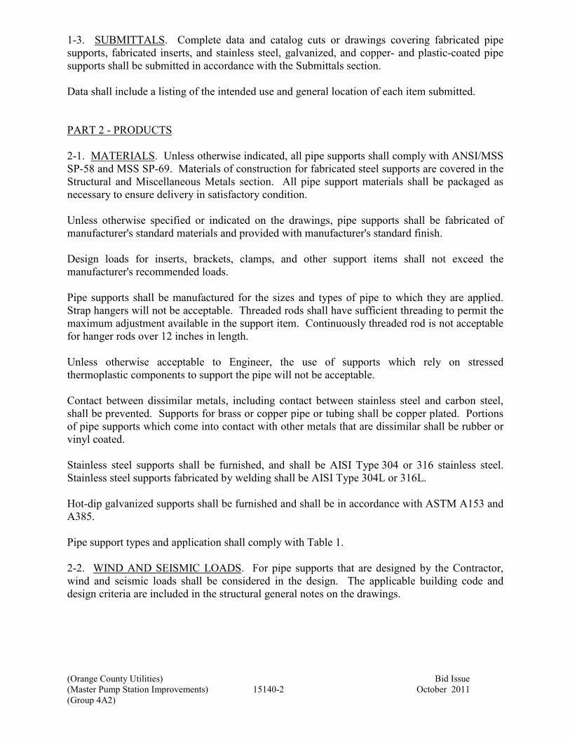
(Orange County Utilities) Bid Issue
(Master Pump Station Improvements) 15140-2 October 2011
(Group 4A2)
1-3. SUBMITTALS. Complete data and catalog cuts or drawings covering fabricated pipe
supports, fabricated inserts, and stainless steel, galvanized, and copper- and plastic-coated pipe
supports shall be submitted in accordance with the Submittals section.
Data shall include a listing of the intended use and general location of each item submitted.
PART 2 - PRODUCTS
2-1. MATERIALS. Unless otherwise indicated, all pipe supports shall comply with ANSI/MSS
SP-58 and MSS SP-69. Materials of construction for fabricated steel supports are covered in the
Structural and Miscellaneous Metals section. All pipe support materials shall be packaged as
necessary to ensure delivery in satisfactory condition.
Unless otherwise specified or indicated on the drawings, pipe supports shall be fabricated of
manufacturer's standard materials and provided with manufacturer's standard finish.
Design loads for inserts, brackets, clamps, and other support items shall not exceed the
manufacturer's recommended loads.
Pipe supports shall be manufactured for the sizes and types of pipe to which they are applied.
Strap hangers will not be acceptable. Threaded rods shall have sufficient threading to permit the
maximum adjustment available in the support item. Continuously threaded rod is not acceptable
for hanger rods over 12 inches in length.
Unless otherwise acceptable to Engineer, the use of supports which rely on stressed
thermoplastic components to support the pipe will not be acceptable.
Contact between dissimilar metals, including contact between stainless steel and carbon steel,
shall be prevented. Supports for brass or copper pipe or tubing shall be copper plated. Portions
of pipe supports which come into contact with other metals that are dissimilar shall be rubber or
vinyl coated.
Stainless steel supports shall be furnished, and shall be AISI Type 304 or 316 stainless steel.
Stainless steel supports fabricated by welding shall be AISI Type 304L or 316L.
Hot-dip galvanized supports shall be furnished and shall be in accordance with ASTM A153 and
A385.
Pipe support types and application shall comply with Table 1.
2-2. WIND AND SEISMIC LOADS. For pipe supports that are designed by the Contractor,
wind and seismic loads shall be considered in the design. The applicable building code and
design criteria are included in the structural general notes on the drawings.

(Orange County Utilities) Bid Issue
(Master Pump Station Improvements) 15140-3 October 2011
(Group 4A2)
PART 3 - EXECUTION
3-1. APPLICATION. Concrete inserts or anchor bolts shall be used to support piping from new
cast-in-place concrete. Expansion anchors shall be used to fasten supports to existing concrete
and masonry.
Anchorage shall be provided to resist thrust due to temperature changes, changes in diameter or
direction, or dead-ending. Anchors shall be located as specified to force expansion and
contraction movement to occur at expansion joints, loops, or elbows, and as needed to prevent
excessive bending stresses and opening of mechanical couplings. Anchorage for temperature
changes shall be centered between elbows and mechanical joints used as expansion joints.
Anchorage for bellows type expansion joints may be located adjacent to the joint.
When expansion joints are required, pipe guides shall be provided adjacent to bellows type
expansion joints. Guides will not be required where mechanical couplings are permitted as
expansion joints. Guides shall be located on both sides of expansion joints, except where
anchors are adjacent to the joint. Unless otherwise indicated on the drawings, one guide shall be
within four pipe diameters from the joint and a second guide within 14 pipe diameters from the
first guide. Pipe supports shall allow adequate movement; pipe guides shall not be used for
support. Pipe guides shall be provided at locations as recommended by the manufacturer.
Pipe supports for insulated cold piping systems shall be sized for the outside diameter of the
insulated pipe, and an insulation protection shield shall be installed between the support and the
insulation. Rigid insulation inserts shall be installed between the pipe and the insulation shields
for piping larger than 2 inches or when needed to prevent crushing of the insulation. Inserts shall
be of the same thickness as the adjacent insulation and shall be vapor sealed.
Insulated hot piping systems shall be supported by clevises, clamps, support saddles, or rollers.
Pipe clamps shall be attached directly to the pipe. Support saddles and rollers shall be sized for
the outside diameter of the insulated pipe, and an insulation protection saddle shall be installed at
the support.
When supports for the FRP piping systems are in contact with less than 180 degrees of the pipe
surface or when the width of the support is less than one-third the nominal pipe diameter
(4 inches minimum), an FRP or steel saddle, shaped to the outside diameter of the pipe, shall be
bonded to at least the bottom 120 degrees of the pipe.
3-2. TYPES OF SUPPORTS. The specific products for pipe supports shall be as indicated in
Table 1 for the specified type and size of support.
TABLE 1 - TYPES OF SUPPORTS
Description and Service
Type
MSS SP 69
(Note 1) Other
Hangers
2-1/2 inch [63 mm] and
smaller pipe
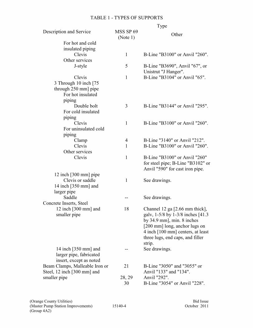
(Orange County Utilities) Bid Issue
(Master Pump Station Improvements) 15140-4 October 2011
(Group 4A2)
TABLE 1 - TYPES OF SUPPORTS
Description and Service
Type
MSS SP 69
(Note 1) Other
For hot and cold
insulated piping
Clevis 1 B-Line "B3100" or Anvil "260".
Other services
J-style 5 B-Line "B3690", Anvil "67", or
Unistrut "J Hanger".
Clevis 1 B-Line "B3104" or Anvil "65".
3 Through 10 inch [75
through 250 mm] pipe
For hot insulated
piping
Double bolt 3 B-Line "B3144" or Anvil "295".
For cold insulated
piping
Clevis 1 B-Line "B3100" or Anvil "260".
For uninsulated cold
piping
Clamp 4 B-Line "3140" or Anvil "212".
Clevis 1 B-Line "B3100" or Anvil "260".
Other services
Clevis 1 B-Line "B3100" or Anvil "260"
for steel pipe; B-Line "B3102" or
Anvil "590" for cast iron pipe.
12 inch [300 mm] pipe
Clevis or saddle 1 See drawings.
14 inch [350 mm] and
larger pipe
Saddle -- See drawings.
Concrete Inserts, Steel
12 inch [300 mm] and
smaller pipe
18 Channel 12 ga [2.66 mm thick],
galv, 1-5/8 by 1-3/8 inches [41.3
by 34.9 mm], min. 8 inches
[200 mm] long, anchor lugs on
4 inch [100 mm] centers, at least
three lugs, end caps, and filler
strip.
14 inch [350 mm] and
larger pipe, fabricated
insert, except as noted
-- See drawings.
Beam Clamps, Malleable Iron or
Steel, 12 inch [300 mm] and
smaller pipe
21 B-Line "3050" and "3055" or
Anvil "133" and "134".
28, 29 Anvil "292".
30 B-Line "3054" or Anvil "228".

(Orange County Utilities) Bid Issue
(Master Pump Station Improvements) 15140-5 October 2011
(Group 4A2)
TABLE 1 - TYPES OF SUPPORTS
Description and Service
Type
MSS SP 69
(Note 1) Other
Side Beam Bracket 34 B-Line "B3062" or Anvil "202".
Wall Supports and Frames,
Steel, 12 inch [300 mm] and
smaller pipe (Note 2)
Brackets 32 B-Line "B3066" or Anvil "195".
33 B-Line "B3067" or Anvil "199".
Prefabricated channels -- 12 ga [2.66 mm thick], galv,
1-5/8 inches [41.3 by 41.3 mm],
with suitable brackets and pipe
clamps.
Offset pipe clamp,
1-1/2 inch [38 mm] and
smaller pipe
-- Galv, 1-1/4 by 3/16 inch [32 by
4.7 mm] steel, with 3/8 inch
[9.5 mm] bolts.
Offset pipe clamp, 2 to
3-1/2 inch [50 to 88 mm]
pipe
-- Galv, 1-1/4 by 1/4 inch [32 by
6 mm] steel, with 3/8 inch
[9.5 mm] bolts.
Floor Supports, Steel or Cast
Iron
6 inch [150 mm] and
smaller pipe
37 (with
base) B-Line "B3090" or Anvil "259".
8 through 24 inch [200 to
600 mm] pipe
38 B-Line "B3093" or Anvil "264".
Pipe Alignment Guides -- B-Line "B3281" through
"B3287" or Anvil "255".
Turnbuckles Steel 13 B-Line "B3202" or Anvil "230".
Hanger Rods, Carbon Steel,
Threaded Both Ends, 3/8 inch
[10 mm] minimum size
-- B-Line "B3205" or Anvil "140".
Weldless Eye Nut, steel 17 B-Line "B3200" or Anvil "290".
Insulation Protection Saddle 39 B-Line "B3160 Series" or Anvil
"160 Series".
Insulation Protection Shield 40 B-Line "B3151" or Anvil "167".
Table 1 Notes:
1. MSS SP-69 supports and hangers are illustrated on Figure 1-15140.
2. Pipe clamps or other devices which rely on the application of a clamping
force to the supported pipe in order to maintain the clamp position or location
in a prefabricated channel or track will not be acceptable for use with
nonmetallic pipe or tubing.
3-3. SUPPORT SPACINGS. Pipe supports and expansion joints shall be spaced in accordance
with Tables 2, 3, 4, and 5. The types of pipes to be supported are as specified herein. Table 2

(Orange County Utilities) Bid Issue
(Master Pump Station Improvements) 15140-6 October 2011
(Group 4A2)
covers spacings for the standard operating conditions specified for each pipe material. Tables 3
and 4 cover PVC and FRP pipe spacings where operating conditions are in excess of the
temperature and specific gravity requirements covered in Table 2. Table 5 covers PVC and FRP
pipe which carries air or liquids with a specific gravity other than 1.0.
TABLE 2 – MAXIMUM PIPE SUPPORT SPACINGS AT STANDARD
TEMPERATURES AND SERVICES
Type of Pipe Pipe Support
Max Spacing
Max Run
Without
Expansion
Joint, Loop, or
Bend
(Note 1)
Expansion
Joint Max
Spacing
(Note 2)
Type of
Expansion
Joints
feet [m] feet [m] feet [m]
Cast iron or Ductile
iron
15 [4.5] 80 [24.4] 80 [24.4] Note 6
Steel, for other services
1-1/4 inch
[31 mm] and
smaller
7 [2.1] 30 [9.1] 100 [30.5] Note 3
1-1/2 to 4 inch
[38 to 100 mm]
10 [3.0] 30 [9.1] 100 [30.5] Note 3
Over 4 inch
[100 mm]
15 [4.5] 80 [24.4] 80 [24.4] Note 6
Stainless steel
1-1/4 inch
[31 mm] and
smaller
7 [2.1] 30 [9.1] 100 [30.5] Note 3
1-1/2 to 4 inch
[38 to 100 mm]
10 [3.0] 30 [9.1] 100 [30.5] Note 3
Over 4 inch
[100 mm]
15 [4.5] 80 [24.4] 80 [24.5] Note 3
PVC, Schedule 80, for other services at a maximum temperature of 100°F [38°C]
and a maximum specific gravity of 1.0.
1/8 and
1/4 inch [3 and
6 mm]
Continuous
Support
20 [6.1] 60 [18.3] Note 3
1/2 inch
[13 mm]
4 [1.2] 20 [6.1] 60 [18.3] Note 3
3/4 inch
[19 mm]
4-1/2 [1.3] 20 [6.1] 60 [18.3] Note 3
1 and
1-1/4 inch [25
and 31 mm]
5 [1.5] 20 [6.1] 60 [18.3] Note 3
1-1/2 and
2 inch [38 and
50 mm]
5-1/2 [1.6] 20 [6.1] 60 [18.3] Note 3

(Orange County Utilities) Bid Issue
(Master Pump Station Improvements) 15140-7 October 2011
(Group 4A2)
TABLE 2 – MAXIMUM PIPE SUPPORT SPACINGS AT STANDARD
TEMPERATURES AND SERVICES
Type of Pipe Pipe Support
Max Spacing
Max Run
Without
Expansion
Joint, Loop, or
Bend
(Note 1)
Expansion
Joint Max
Spacing
(Note 2)
Type of
Expansion
Joints
feet [m] feet [m] feet [m]
2-1/2 inch
[63 mm]
6 [1.8] 20 [6.1] 60 [18.3] Note 3
3 inch
[75 mm]
7 [2.1] 20 [6.1] 60 [18.3] Note 3
4 inch
[100 mm]
7-1/2 [2.3] 20 [6.1] 60 [18.3] Note 3
6 inch
[150 mm]
8-1/2 [2.6] 20 [6.1] 60 [18.3] Note 3
8 inch
[200 mm]
9-1/2 [2.8] 20 [6.1] 60 [18.3] Note 3
10 inch
[250 mm]
10 [3.0] 20 [6.1] 60 [18.3] Note 3
12 inch
[300 mm]
11 [3.3] 20 [6.1] 60 [18.3] Note 3
FRP, for low pressure and odor control pipe at a maximum temperature of 150°F
[66°C] and a maximum specific gravity of 1.0.
1 inch
[25 mm]
4 [1.2] 60 [18.3] 100 [30.5] Note 3
1-1/2 inch
[38 mm]
4-1/2 [1.3] 60 [18.3] 100 [30.5] Note 3
2 inch
[50 mm]
5-1/2 [1.6] 60 [18.3] 100 [30.5] Note 3
3 inch
[76 mm]
6 [1.8] 60 [18.3] 100 [30.5] Note 3
4 inch
[100 mm]
6-1/2 [2] 40 [12.2] 100 [30.5] Note 3
6 inch
[150 mm]
7-1/2 [2.3] 40 [12.2] 100 [30.5] Note 3
8 inch
[200 mm]
8-1/2 [2.6] 40 [12.2] 100 [30.5] Note 3
10 inch
[250 mm]
9-1/2 [2.8] 40 [12.2] 100 [30.5] Note 3
12 inch
[300 mm] and
larger
10 [3.0] 40 [12.2] 100 [30.5] Note 3
Table 2 Notes:

(Orange County Utilities) Bid Issue
(Master Pump Station Improvements) 15140-8 October 2011
(Group 4A2)
1. Unless otherwise acceptable to Engineer, an expansion joint shall be
provided in each straight run of pipe having an overall length between loops
or bends exceeding the maximum run specified herein.
2. Unless otherwise acceptable to Engineer, the spacing between expansion
joints in any straight pipe run shall not exceed the maximum spacing
specified herein.
3. Expansion joint fittings are specified in the respective piping procurement
sections.
4. At least two properly padded supports for each pipe section.
5. At least one support for each pipe section.
6. Expansion joints shall be mechanical couplings.
7. No expansion joints are required.
8. Supports for 5 and 10 foot [1.5 and 3 m] long pipe sections shall be located
within 18 inches [460 mm] of each joint. Supports shall be positioned to
maintain the piping alignment and to prevent the piping from sagging.
3-3.01. Temperature Adjustments for PVC Pipe. Not used.
3-3.02. Temperature Adjustments for FRP Pipe. Not used.
3-3.03. Specific Gravity Adjustments for PVC and FRP Pipe. Not used.
3-4. INSTALLATION.
3-4.01. General. All piping shall be supported in a manner which will prevent undue stress on
any valve, fitting, or piece of equipment. In addition, pipe supports shall be provided at changes
in direction or elevation, adjacent to flexible couplings, and where otherwise shown. Pipe
supports and hangers shall not be installed in equipment access areas.
Where horizontal piping is arranged with two or more parallel lines, trapeze hangers may be used
in lieu of individual hangers. Trapeze assembly shall consist of structure attachments as
previously specified with rod size dependent upon total weight supported. Spacing of assemblies
shall be determined by the minimum pipe size included in the group supported. Trapeze
horizontal assemblies shall be structural angle or channel section of sufficient size to prevent
measurable sag between rods. All lines shall be attached to the horizontal with intermediate pipe
guides and U-bolts or one-hole clamps. Pre-engineered support equipment may be used when
selected and installed in accordance with the manufacturer's recommendations.
No copper pipe shall contact a pipe support or hanger of dissimilar metal. Hangers and supports
for copper pipe shall be copper-plated, plastic coated, or copper pipe shall be galvanically
isolated using Neoprene strips or other material as approved.
No piping shall be supported from the pipe above.
Horizontal piping hanger support rods shall attach to steel beams with center-loading I-clamps,
or welded beam clips. Hanger support rods shall attach to concrete slabs or beams with inserts.

(Orange County Utilities) Bid Issue
(Master Pump Station Improvements) 15140-9 October 2011
(Group 4A2)
Anchorage shall be provided to resist both lateral and longitudinal seismic forces. Seismic
forces shall be calculated assuming the pipes are full.
3-4.02. Inserts. Reference building structural concrete drawings for concrete inserts. When not
provided as part of the building concrete structure, provide inserts for suspending hangers from
reinforced concrete slabs and sides of reinforced concrete beams.
Where concrete slabs form finished ceilings, provide inserts flush with the slab surface.
Where inserts are omitted, drill through concrete slab from below and provide thru-bolt with
recessed square steel plate and nut recessed into and grouted flush with slab. X-ray locate
existing reinforcing rods before drilling.
3-4.03. Pipe Hangers and Supports. Hanger rod sizing for copper pipe and plastic pipe shall be
same as for steel pipe. Install hangers to provide a minimum 1/2 inch [13 mm] space between
finished covering and adjacent work.
A hanger shall be placed with 18 inches of each horizontal elbow, and on both sides of all piping
accessories and valves weighing 20 lbs [9 kg] or more.
Hangers shall have 1-1/2 inches minimum vertical adjustment.
Support horizontal cast iron, ductile iron and no-hub piping systems adjacent to each joint.
Support vertical piping at every floor using riser clamps.
Support riser piping independently of connected horizontal piping.
Hanger and hanger components shall be sized specifically for the pipe size it is to be used on.
3-5. PLACEMENT. Unless closer spacing is indicated on the drawings, the maximum spacing
for pipe supports and expansion joints shall be as indicated in Tables 2, 3, 4, and 5.
Rubber hose and flexible tubing shall be provided with continuous angle or channel support.
Unless otherwise indicated on the drawings or acceptable to Engineer, piping shall be supported
approximately 1-1/2 inches out from the face of walls and at least 3 inches below ceilings.
End of Section

This page was left blank intentionally


HANGERS AND SUPPORTS
FIG 1-15140(B)


(Orange County Utilities) Bid Issue
(Master Pump Station Improvements) 15180-1 October 2011
(Group 4A2)
Section 15180
VALVE AND GATE ACTUATORS
PART 1 - GENERAL
1-1. SCOPE. This section covers furnishing manual and powered valves and gate actuators and
accessories as specified herein.
1-2. GENERAL. Equipment provided under this section shall be fabricated and assembled in
full conformity with drawings, specifications, engineering data, instructions, and
recommendations of the equipment manufacturer, unless exceptions are noted by Engineer.
Actuators shall be furnished with all necessary parts and accessories indicated on the drawings,
specified, or otherwise required for a complete, properly operating installation and shall be the
latest standard products of a manufacturer regularly engaged in the production of actuators.
1-2.01. General Equipment Stipulations. The General Equipment Stipulations shall apply to all
equipment furnished under this section. If requirements in this specification differ from those in
the General Equipment Stipulations, the requirements specified herein shall take precedence.
1-2.02. Governing Standards. Except as modified or supplemented herein, all powered actuators
shall conform to applicable requirements of ANSI/AWWA C540.
Except as modified or supplemented herein, all manual and cylinder actuators for butterfly and
eccentric plug valves shall conform to the applicable requirements of ANSI/AWWA C504.
Except as modified or supplemented herein, all manual actuators for ball valves shall conform to
the applicable requirements of ANSI/AWWA C507.
Except as modified or supplemented herein, all manual actuators for sluice and slide gates shall
conform to the applicable requirements of ANSI/AWWA C560.
1-2.03. Power Supply. Power supply to electric actuators will be 480-volts three phase.
1-2.04. Marking. Each actuator shall be marked with the manufacturer's name, model number,
and the country of origin. An identifying serial number shall be stamped on a corrosion-resistant
plate attached to the actuator.
1-2.05. Temporary Number Plates. Each actuator shall be factory tagged or marked to identify
the actuator and the applicable valve or gate by number or service as indicated in the valve or
gate schedule.
1-3. SUBMITTALS. Complete drawings, details, and specifications covering the actuators and
their appurtenances shall be submitted in accordance with the Submittals section. Submittal
drawings shall clearly indicate the country of origin of each actuator and its components.

(Orange County Utilities) Bid Issue
(Master Pump Station Improvements) 15180-2 October 2011
(Group 4A2)
The drawings shall include separate wiring diagrams for each electrically operated or controlled
actuator and the electrical control equipment. Each actuator drawing shall be identified with the
respective valve number or name.
For electric or cylinder actuators, certified copies of reports covering proof-of-design testing of
the actuators as set forth in Section 5 of ANSI/AWWA C540, together with an affidavit of
compliance as indicated in Section 6.3 of ANSI/AWWA C540, shall be submitted to Engineer
before the actuators are shipped.
1-4. DELIVERY, STORAGE, AND HANDLING. Shipping shall be in accordance with the
Shipping section. Handling and storage shall be in accordance with the Handling and Storage
section.
PART 2 - PRODUCTS
2-1. PERFORMANCE AND DESIGN REQUIREMENTS.
2-1.01. General. Actuators and appurtenances shall be designed for the conditions and
requirements as indicated in the respective valve and gate sections.
Liberal factors of safety shall be used throughout the design, especially in the design of parts
subject to intermittent or alternating stresses. In general, working stresses shall not exceed
one-third of the yield point or one-fifth of the ultimate strength of each material.
2-1.02. Valve Actuators. Each actuator shall be designed to open or close the valve under all
operating conditions. Actuators shall be designed for the maximum pressure differential across
the valve and maximum velocities through the valve where indicated in the respective valve
schedules.
Valve actuators shall be provided and adjusted by the valve manufacturer. Actuator mounting
arrangements and positions shall facilitate operation and maintenance and shall be determined by
the valve manufacturer unless indicated otherwise on the drawings or directed by Engineer.
When valves are to be buried, submerged, or installed in vaults, the actuators and accessories
shall be sealed to prevent the entrance of water. The design water depth shall be as indicated in
the respective valve schedules but not less than 20 feet [6.1 m].
2-1.03. Gate Actuators. Actuators shall be sized to produce the torque or thrust required to
operate the gate when subject to the seating and unseating operating heads as indicated in the
respective gate schedules.
Both the design head and the operating head shall be measured from the surface of the liquid to
the center line of the gate.
2-1.04. Limit Switches. Limit switches shall be provided as indicated on the drawings or in the
valve and gate schedules.

(Orange County Utilities) Bid Issue
(Master Pump Station Improvements) 15180-3 October 2011
(Group 4A2)
For manual or cylinder type actuators, each limit switch shall be heavy duty type, with a cast
NEMA Type 4 enclosure, a spring return roller lever, and four isolated contacts (two normally
open and two normally closed) rated 10 amperes at 120 to 480 volts ac and 5 amperes at
125 volts dc. The switches shall be Allen Bradley "802T" or Square D "9007 Type C".
Limit switches for programmable and standard electric actuators shall be as indicated in their
respective paragraphs.
2-2. MATERIALS. Except as modified or supplemented herein, materials used in the
manufacture of actuators shall conform to the requirements of ANSI/AWWA C504 and C540.
2-3. VALVE MANUAL ACTUATORS.
2-3.01. General. Manual actuators of the types listed in the valve specifications or schedules
shall be provided by the valve manufacturer.
Unless otherwise indicated or specified, each geared manual actuator shall be equipped with an
operating handwheel.
The direction of rotation of the wheel, wrench nut, or lever to open the valve shall be to the left
(counterclockwise). Each valve body or actuator shall have cast thereon the word "Open" and an
arrow indicating the direction to open.
The housing of traveling-nut type actuators shall be fitted with a removable cover which shall
permit inspection and maintenance of the operating mechanism without removing the actuator
from the valve. Travel limiting devices shall be provided inside the actuator for the open and
closed positions. Travel limiting stop nuts or collars installed on the reach rod of traveling-nut
type operating mechanisms shall be field adjustable and shall be locked in position by means of a
removable roll pin, cotter pin, or other positive locking device. The use of stop nuts or
adjustable shaft collars which rely on clamping force or setscrews to prevent rotation of the nut
or collar on the reach rod will not be acceptable.
Each actuator shall be designed so that shaft seal leakage cannot enter the actuator housing.
Valves for throttling service shall be equipped with an infinitely variable locking device or a
totally enclosed gear actuator.
Actuators shall produce the required torque with a maximum pull of 80 lbs [356 N] on the lever,
handwheel, or chain. Actuator components shall withstand, without damage, a pull of 200 lbs
[890 N] on the handwheel or chainwheel or an input of 300 foot-lbs [407 J] on the operating nut.
2-3.02. Handwheels. Handwheel diameters shall be at least 8 inches [200 mm] but not more
than 24 inches [600 mm] for 30 inch [750 mm] and smaller valves and not more than 30 inches
[750 mm] for 36 inch [900 mm] and larger valves.
2-3.03. Chainwheels. Unless otherwise specified in the valve schedules, all valves with center
lines more than 7'-6" [2.3 m] above the floor shall be provided with chainwheels and operating
chains. Each chainwheel operated valve shall be equipped with a chain guide which will permit

(Orange County Utilities) Bid Issue
(Master Pump Station Improvements) 15180-4 October 2011
(Group 4A2)
rapid handling of the operating chain without "gagging" of the wheel and will also permit
reasonable side pull on the chain. Suitable extensions shall be provided, if necessary, to prevent
interference of the chain with adjacent piping or equipment. Operating chains shall be hot-dip
galvanized or zinc plated carbon steel and shall be looped to extend to within 4 feet [1.2 m] of
the floor below the valve.
2-3.04. Levers. Levers shall be capable of being locked in at least five intermediate positions
between fully open and fully closed. In any building or structure containing lever operated
valves, at least two operating levers shall be provided for each size and type of lever operated
valve.
2-3.05. Chain Levers. Suitable actuator extensions shall be provided, if necessary, to prevent
interference of the chain with adjacent piping or equipment. Operating chains shall be hot-dip
galvanized carbon steel and shall be looped to extend to within 4 feet [1.2 m] of the floor below
the valve.
2-3.06. Wrench Nuts. Unless otherwise specified in the valve schedules or on the drawings,
wrench nuts shall be provided on all buried valves and on all valves that are to be operated
through floor boxes. Unless otherwise directed by Owner, all wrench nuts shall comply with
Section 4.4.13 of AWWA C500. At least two operating keys shall be furnished for operation of
the wrench nut operated valves.
2-3.07. Operating Stands. Operating stands shall be provided in the locations indicated on the
drawings or as indicated in the valve and gate schedules. Operating stands shall support the
handwheel approximately 36 inches [900 mm] above the floor. A sleeve made from standard
weight galvanized steel pipe shall be provided for the opening in the floor beneath each
operating stand. When stems are 10 feet [3 m] or longer, a suitable thrust bearing shall be
provided in each operating stand to carry the weight of the extension stem.
2-3.08. Wall Brackets. Wall brackets shall be provided to support manual actuators in the
locations indicated on the drawings or in the respective valve schedules. The horizontal face of
the bracket shall be predrilled to accept the actuator and the stem without modification. The top
of the bracket shall extend sufficiently to bear on and transfer thrust loads to the top of the
supporting structure.
2-4. GATE MANUAL ACTUATORS. Not used.
2-5. PROGRAMMABLE ELECTRIC ACTUATORS. Not used.
2-6. STANDARD ELECTRIC ACTUATORS.
2-6.01. General. Standard electric actuators as listed in the valve and gate schedules
(specification 11291) shall be provided by the valve or gate manufacturer.
Standard electric actuators for 12 inch [300 mm] and smaller butterfly valves and eccentric plug
valves shall be quarter-turn type and shall be Auma "SGBV05" through "SGBV12",
EIM “Series P, Q, or R”, Limitorque "LY", or Rotork "AQ", without exception.

(Orange County Utilities) Bid Issue
(Master Pump Station Improvements) 15180-5 October 2011
(Group 4A2)
All other standard electric actuators shall be multiturn type and shall be Auma "SABV07.1"
through "SABV48.1", EIM “Series 2000”, Limitorque "L120", or Rotork "A Range", without
exception.
Standard electric actuators produced by other manufacturers are not acceptable.
Each standard electric actuator shall be furnished complete with a motor, gearing, handwheel,
limit switches and torque sensors, lubricants, heating elements, wiring, and terminals. Each
actuator shall be constructed as a self-contained unit with a cast iron or aluminum alloy housing,
of a type as indicated in the valve and gate schedules, and shall be integrally assembled on the
applicable valve or gate by the valve or gate manufacturer.
Actuators shall be designed to cycle the valve or gate from the fully open to the fully closed
position or the reverse in approximately 60 seconds or as indicated in the valve and gate
schedules.
Actuator motors may be mounted horizontally adjacent to or vertically above the reduction
gearing. All gearing shall be oil or grease lubricated.
2-6.02. Motors. Motors shall be totally enclosed, high torque design made expressly for valve
actuator service, capable of operating the valve under full differential pressure for two complete
strokes or one complete cycle of travel without overheating. Motors shall be designed in
accordance with NEMA standards and shall operate successfully at any voltage within
10 percent above or below rated voltage. Motor bearings shall be permanently lubricated.
2-6.03. Power Gearing. Power gearing shall consist of hardened steel spur or helical gears and
alloy bronze or hardened steel worm gear, all suitably lubricated, designed for 100 percent
overload, and effectively sealed against entrance of foreign matter. Steel gears shall be hardened
to at least 350 Brinell. Planetary or cycloidal gearing or aluminum, mild steel, or nonmetallic
gears will not be acceptable. Gearing shall be designed to be self-locking so that actuation of a
torque switch by a torque overload condition will not allow the actuator to restart until the torque
overload has been eliminated. If a secondary gear box is required, it shall be designed to
withstand the locked rotor torque of the actuator.
2-6.04. Handwheel Mechanism. The handwheel shall not rotate during motor operation. During
handwheel operation the motor shall not affect the actuator operation. The actuator shall be
responsive to electrical power and control at all times and, when under electrical control, shall
instantly disengage the handwheel. The handwheel shall rotate counterclockwise to open the
valve. An arrow indicating the opening direction and the word "Open" shall be cast on the
handwheel. The force required to operate the handwheel shall not exceed 80 lbs [350 N]. The
handwheel shall have a padlockable declutch lever.
2-6.05. Torque Sensing. Torque and thrust loads in both closing and opening directions shall be
limited by a torque sensing device. Each torque sensing device shall be provided with an
adjustment setting indicator. The adjustment shall permit a variation of approximately
40 percent in torque setting. Switches shall have a rating of not less than 6 amperes at 120 volts
ac and 0.5 ampere at 115 volts dc.
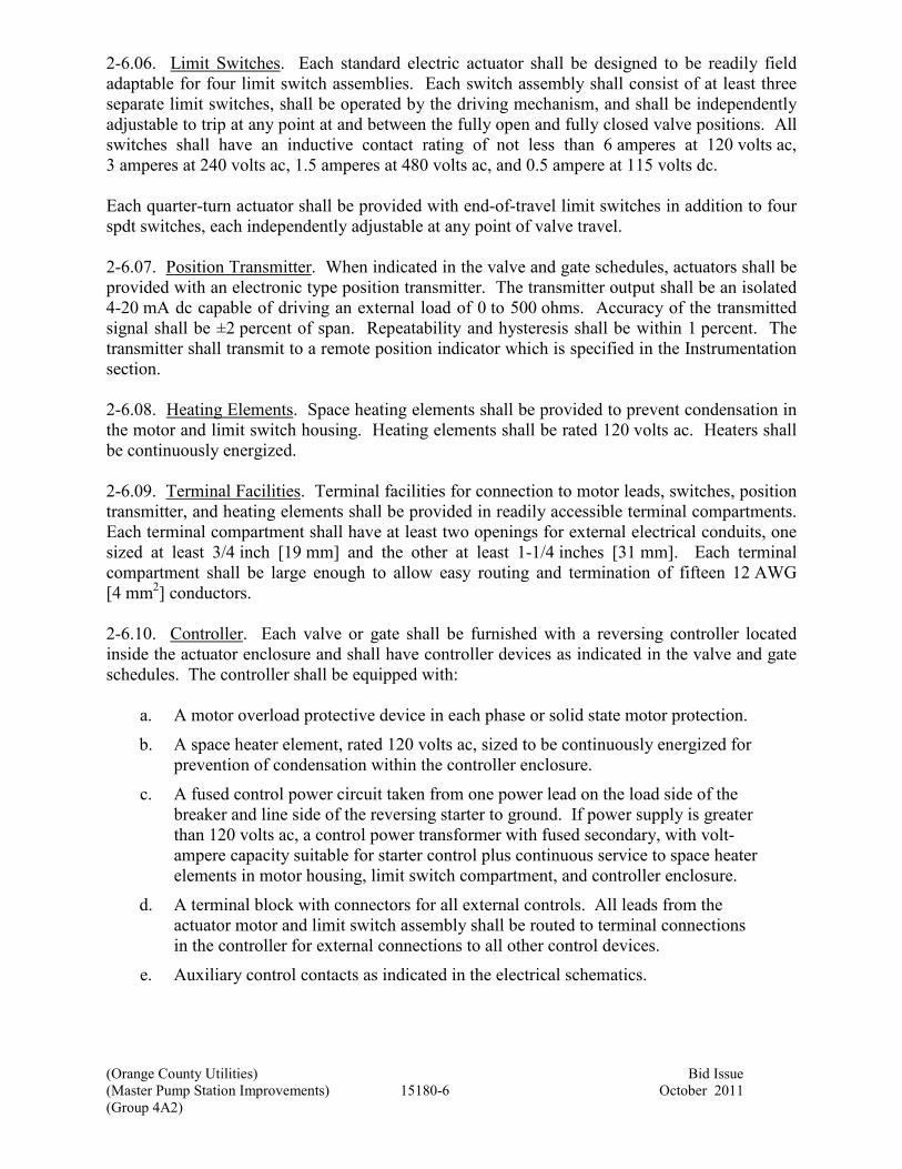
(Orange County Utilities) Bid Issue
(Master Pump Station Improvements) 15180-6 October 2011
(Group 4A2)
2-6.06. Limit Switches. Each standard electric actuator shall be designed to be readily field
adaptable for four limit switch assemblies. Each switch assembly shall consist of at least three
separate limit switches, shall be operated by the driving mechanism, and shall be independently
adjustable to trip at any point at and between the fully open and fully closed valve positions. All
switches shall have an inductive contact rating of not less than 6 amperes at 120 volts ac,
3 amperes at 240 volts ac, 1.5 amperes at 480 volts ac, and 0.5 ampere at 115 volts dc.
Each quarter-turn actuator shall be provided with end-of-travel limit switches in addition to four
spdt switches, each independently adjustable at any point of valve travel.
2-6.07. Position Transmitter. When indicated in the valve and gate schedules, actuators shall be
provided with an electronic type position transmitter. The transmitter output shall be an isolated
4-20 mA dc capable of driving an external load of 0 to 500 ohms. Accuracy of the transmitted
signal shall be ±2 percent of span. Repeatability and hysteresis shall be within 1 percent. The
transmitter shall transmit to a remote position indicator which is specified in the Instrumentation
section.
2-6.08. Heating Elements. Space heating elements shall be provided to prevent condensation in
the motor and limit switch housing. Heating elements shall be rated 120 volts ac. Heaters shall
be continuously energized.
2-6.09. Terminal Facilities. Terminal facilities for connection to motor leads, switches, position
transmitter, and heating elements shall be provided in readily accessible terminal compartments.
Each terminal compartment shall have at least two openings for external electrical conduits, one
sized at least 3/4 inch [19 mm] and the other at least 1-1/4 inches [31 mm]. Each terminal
compartment shall be large enough to allow easy routing and termination of fifteen 12 AWG
[4 mm2] conductors.
2-6.10. Controller. Each valve or gate shall be furnished with a reversing controller located
inside the actuator enclosure and shall have controller devices as indicated in the valve and gate
schedules. The controller shall be equipped with:
a. A motor overload protective device in each phase or solid state motor protection.
b. A space heater element, rated 120 volts ac, sized to be continuously energized for
prevention of condensation within the controller enclosure.
c. A fused control power circuit taken from one power lead on the load side of the
breaker and line side of the reversing starter to ground. If power supply is greater
than 120 volts ac, a control power transformer with fused secondary, with volt-
ampere capacity suitable for starter control plus continuous service to space heater
elements in motor housing, limit switch compartment, and controller enclosure.
d. A terminal block with connectors for all external controls. All leads from the
actuator motor and limit switch assembly shall be routed to terminal connections
in the controller for external connections to all other control devices.
e. Auxiliary control contacts as indicated in the electrical schematics.

(Orange County Utilities) Bid Issue
(Master Pump Station Improvements) 15180-7 October 2011
(Group 4A2)
Reversing controllers shall be both mechanically and electrically interlocked and shall be
provided with the necessary direct-operated auxiliary contacts for required interlocking and
control.
Valve controllers shall be expressly selected for long life and reliable, low maintenance service
under rugged service conditions.
2-6.11. Control Module. Valves or gates indicated for modulating service in the valve and gate
schedules shall be provided with a control module for position modulating type service. The
control module shall be mounted within the valve actuator limit switch housing. The module
shall accept a standard 4-20 mA dc analog input signal with a load impedance of not greater than
400 ohms. The control module shall contain adjustments for span, zero, gain, and deadband.
The actuator shall have a slide-wire type position feedback potentiometer which provides a
position feedback signal to the control module.
2-6.11.01. Control Performance. For any operating torque within the specified range of the
valve actuator, the valve and actuator shall perform within these specified limits:
Linearity Linearity of actual valve position as compared to demand signal
shall be within ±4 percent of span over the entire operating range.
Repeatability For any repeated demand signal to the valve actuator, the actual
valve position shall be repeated.
Deadband Deadband of the valve actuator shall be adjustable from 1 to
10 percent of span.
Hysteresis For any repeated demand signal to the valve actuator, from either
an increasing or a decreasing direction, the actual valve position
shall be repeated within 1 degree of valve shaft rotation.
2-7. HYDRAULIC CYLINDER ACTUATORS. Not used.
2-8. AIR CYLINDER ACTUATORS. Not used.
2-9. AIR-OIL CYLINDER ACTUATORS. Not used.
2-10. PORTABLE ELECTRIC ACTUATORS. Not used.
2-11. PORTABLE HYDRAULIC ACTUATORS. Not used.
2-12. ACTUATOR ACCESSORIES.
2-12.01. Extension Stems. Extension stems and stem guides shall be furnished when indicated
in the respective valve schedules, indicated on the drawings, or otherwise required for proper
valve operation. Extension stems shall be of solid steel and shall be not smaller in diameter than
the stem of the actuator shaft. Extension stems shall be connected to the actuator with a single
Lovejoy "Type D" universal joint with grease-filled protective boot. All stem connections shall
be pinned.

(Orange County Utilities) Bid Issue
(Master Pump Station Improvements) 15180-8 October 2011
(Group 4A2)
At least two stem guides shall be furnished with each extension stem, except for buried valves.
Stem guides shall be of cast iron, bronze bushed, and adjustable in two directions. Stem guide
spacing shall not exceed 100 times the stem diameter or 10 feet [3 m], whichever is smaller. The
top stem guide shall be designed to carry the weight of the extension stem. The extension stem
shall be provided with a collar pinned to the stem and bearing against the stem thrust guide.
Extension stems for chemical resistant butterfly valves located in drainage sumps shall be the
two-piece type with stainless steel stem, PVC housing, wall support, and collar. Unless otherwise
indicated on the drawings, the length of the stem extension shall be as necessary to position the
valve operator 12 inches above the maximum liquid level in the immediate area.
Extension stems for buried valve actuators shall extend to within 6 inches [150 mm] of the
ground surface, shall be centered in the valve box using spacers, and shall be equipped with a
wrench nut.
Extension stems for buried valve actuators shall be provided with position indicators as specified
in the valve schedules.
2-12.02. Position Indicators. Unless otherwise specified, each valve actuator shall be provided
with a position indicator to display the position of the plug or disc relative to the body seat
opening.
For quarter turn plug, ball, or cone type valves installed in interior locations, the indicating
pointer shall be mounted on the outer end of the valve operating shaft extension and shall operate
over an indicating scale on the operating mechanism cover. Where the shaft passes through the
cover, a suitable stuffing box or other seal shall be provided to prevent the entrance of water.
Each actuator for butterfly valves, except where located in manholes, buried, or submerged, shall
have a valve disc position indicator mounted on the end of the valve shaft. A disc position
indicator shall also be provided on each operating stand or the actuator mounted thereon.
2-12.02.01. Position Indicators for Buried Actuators. When specified in the respective valve
schedules, each buried valve actuator shall be equipped with a position indicator. Position
indicators shall be Indico "Model 179 Valve Position Indicators" manufactured by the Mills
Engineering Company, Needham Heights, Massachusetts, or "Diviner" ground level position
indicator manufactured by the Henry Pratt Company, Aurora, Illinois. Each indicator assembly
shall be designed for installation on the extension stem connected to the operating stem of the
buried actuator mechanism and shall be mounted in the top section of the valve box beneath the
valve box cover. Each indicator shall be equipped with a wrench nut. Internal gearing shall be
sealed and protected from the elements.
2-12.03. Floor Boxes. Openings through concrete slabs provided for key operation of valves
shall be provided with a cast iron floor box complete with cover. The floor box shall be of the
depth indicated on the drawings. Where the operating nut is in the slab, the stem shall have a
guide to maintain the nut in the center of the box; where the nut is below the slab, the opening in
the bottom of the box shall accommodate the operating key.

(Orange County Utilities) Bid Issue
(Master Pump Station Improvements) 15180-9 October 2011
(Group 4A2)
Each floor box and cover shall be shop coated with manufacturer’s standard coating.
2-12.04. Torque Tubes. Torque tube shall utilize pipe rather than solid shafting between the
valve input shaft and the output shaft of the valve floorstand operator. An adjustment of 2 inches
[50 mm] shall be provided in the torque tube installation. Torque tube shall be coated with the
same material as the submerged valve.
2-12.05. Valve Boxes. Not used.Each valve buried to a depth of 4 feet [1.2 m] or less shall be
provided with a slide type valve box. Valve boxes shall be cast iron, extension sleeve type,
suitable for the depth of cover indicated on the drawings. Only one extension will be allowed
with each slide type valve box. Valve boxes shall be at least 5 inches [125 mm] in inside
diameter, shall be at least 3/16 inch [4.7 mm] thick, and shall be provided with suitable cast iron
bases and covers.
Each valve buried deeper than 4 feet [1.2 m] shall be provided with a valve box consisting of a
cast iron cover and a 6 inch [150 mm] Cast Iron Pipe section. The cover shall be Clay & Bailey
"No. 2193". The pipe shaft shall extend from the valve to 5 inches [125 mm] inside the valve
box cover.
All parts of valve boxes, bases, and covers shall be shop coated with manufacturer's standard
coating.
Valve boxes which are to be provided with position indicators shall have top sections and covers
designed for proper installation of the position indicator and accessories.
2-13. SHOP PAINTING. All ferrous metal surfaces, except bearing and finished surfaces and
stainless steel components of valve actuators and accessories, shall be shop painted for corrosion
protection. The valve manufacturer's standard coating will be acceptable, provided it is
functionally equivalent to the specified coating and is compatible with the specified field
painting.
The following surfaces shall be painted:
Polished or Machined Surfaces Rust-preventive compound.
Other Surfaces Epoxy enamel.
Actuators and Accessories Universal primer.
PART 3 - EXECUTION
3-1. INSTALLATION. Actuators will be installed on the valves in accordance with the Valve
Installation section and gates in accordance with the Gate Installation section.
3-2. NETWORK SETUP. A manufacturer’s representative for the programmable electric
actuator manufacturer shall inspect all network terminations for conformity with the
manufacturer’s recommended methods of terminating the network to each actuator, and shall
notify the Contractor of any wiring modifications required. The manufacturer’s representative

(Orange County Utilities) Bid Issue
(Master Pump Station Improvements) 15180-10 October 2011
(Group 4A2)
shall also set addresses for each valve and prove communication over the network. The valve
manufacturer shall furnish the required information to the control system supplier that will allow
the specified control and monitoring for each programmable electric actuator.
The Contractor shall coordinate these activities between the actuator manufacturer and the
control system supplier.
End of Section

(Orange County Utilities) Bid Issue
(Master Pump Station Improvements) 15400-1 October 2011
(Group 4A2)
Section 15400
PLUMBING
PART 1 - GENERAL
1-1. SCOPE. This section covers the furnishing and installation of materials, fixtures,
equipment, and appurtenances associated with the plumbing systems as specified herein and as
indicated on the drawings. Additional requirements for plumbing systems shall be as indicated
in the schedules on the drawings. Suitable connections shall be provided for each fixture, piece
of equipment, and appurtenance.
Pipe materials, valves, thermal insulation, and pipe supports which are not an integral part of the
fixture or piece of equipment and are not specified herein are covered in other sections.
1-2. GENERAL. Equipment furnished and installed under this section shall be fabricated,
assembled, erected, and placed in proper operating condition in full conformity with the
drawings, specifications, engineering data, instructions, and recommendations of the equipment
manufacturer unless exceptions are noted by Engineer.
1-2.01. Coordination. Contractor shall verify that each component of the plumbing system is
compatible with all other parts of the system; that all piping, fixtures, and appurtenances are
appropriate; and that all devices necessary for a properly functioning system have been provided.
Where two or more units of the same class of equipment are required, they shall be the product
of a single manufacturer; however, all the component parts of the system need not be the
products of one manufacturer.
Where several manufacturers' names have been listed in this section as possible suppliers, only
the products of the first manufacturer listed have been checked for size, functions, and features.
1-2.02. General Equipment Stipulations. The General Equipment Stipulations shall apply to all
equipment and materials provided under this section. If requirements in this specification differ
from those in the General Equipment Stipulations, the requirements specified herein shall take
precedence.
1-2.03. Governing Standards. Except as modified or supplemented herein, all work covered by
this section shall be performed in accordance with all applicable municipal codes and ordinances,
laws, and regulations. In case of a conflict between this section and any state law or local
ordinance, the latter shall govern.
All work shall conform to the requirements of AGA, ASTM, NFPA, and UL safety
requirements.
1-2.04. Power Supply. Unless otherwise specified, power supply to equipment with motors
shall be as indicated on the drawings.

(Orange County Utilities) Bid Issue
(Master Pump Station Improvements) 15400-2 October 2011
(Group 4A2)
1-2.05. Metal Thickness. Metal thicknesses and gages specified herein are minimum
requirements. Gages refer to US Standard gage.
1-3. MECHANICAL IDENTIFICATION.
1-3.01. Number Plates. All plumbing equipment, piping, and valves denoted on the drawings by
a symbol and an identifying number shall be provided with an identifying number plate. The
identifying text shall be identical to the symbols indicated herein or on the drawings and shall be
located in a conspicuous place. Number plate symbols and numbers shall be capitalized block
letters with a minimum height as indicated below.
Item Identified Letter Height, inches [mm]
Major Equipment 3/4 [19]
Minor Equipment 1/2 [13]
Number plate height shall be twice the letter height. Number plate length shall be as needed,
with suitable margins all around. Lettering shall be placed in one row where practicable;
however, where required due to excessive length, lettering shall be placed on more than one row
and centered.
Number plates shall be in the form of nameplates unless equipment is too small to accommodate
the specified nameplate, then tags shall be used. Nameplates and tags shall be metal or plastic.
Plastic nameplates and tags shall be laminated phenolic not less than 1/8 inch [3 mm] thick and
shall be black with a white core. Metal nameplates and tags shall be at least 12 gage [2.66 mm]
thickness with engraved or imprinted symbols. Tags shall have smooth edges and shall be a
minimum diameter of 1-1/2 inches [38 mm]. Tags shall be installed with corrosion-resistant
chains or straps. Nameplates shall be installed with corrosion-resistant mechanical fasteners.
1-3.02. Equipment Plates. Plumbing equipment shall be identified with engraved or stamped
equipment plates securely affixed to the equipment in an accessible and visible location.
Equipment plates shall be in addition to the number plates specified in the preceding paragraph.
Equipment plates shall indicate the manufacturer's name, address, product name, catalog number,
serial number, capacity, operating and power characteristics, labels of tested compliances, and
any other pertinent design data. Equipment plates listing the distributing agent only will not be
acceptable.
1-3.03. Piping. Piping identification shall be as specified in the protective coatings section.
1-3.04. Valves. Valves that have been assigned an identification number shall be identified with
tags.
1-4. SUBMITTALS.
1-4.01. Drawings and Data. Complete assembly and installation drawings, and wiring and
schematic diagrams, together with detailed specifications and data covering materials, parts,
devices, and accessories forming a part of the equipment furnished, shall be submitted in
accordance with the submittals section. Device tag numbers indicated on the drawings shall be

(Orange County Utilities) Bid Issue
(Master Pump Station Improvements) 15400-3 October 2011
(Group 4A2)
referenced on the wiring and schematic diagrams where applicable. The data and specifications
to be submitted for each unit shall include, but shall not be limited to, the following:
Equipment, Piping Accessories, and Appurtenances
Name of manufacturer.
Type and model.
Construction materials, thicknesses, and finishes.
Capacities.
Pressure and temperature ratings.
Overall dimensions.
Piping connection sizes and locations.
Net weight.
Horsepower [kW].
Power requirements.
Wiring diagrams.
Plumbing Fixtures
Name of manufacturer.
Type and model.
Construction materials, thicknesses, and finishes.
Water consumption data.
Overall dimensions.
Rough-in dimensions.
Piping connection sizes and locations.
Net weight.
1-4.02. Operations and Maintenance Data and Manuals. Not used.
1-5. QUALITY ASSURANCE.
1-5.01. Welding Qualifications. All welding procedures and welding operators shall be
qualified by an independent testing laboratory in accordance with the applicable provisions of
AWS Standard Qualification Procedures. All procedure and operator qualifications shall be in
written form and subject to Engineer’s review. Accurate records of operator and procedure
qualifications shall be maintained by Contractor and made available to Engineer upon request.
1-5.02. Qualification. The plumbing system installer shall be licensed as stipulated by the
authority having jurisdiction.
1-5.03. Manufacturer's Experience. Unless the equipment manufacturer is specifically named in
this section, the manufacturer shall have furnished equipment of the type and size specified
which has been in successful operation for not less than the past 5 years.
1-5.04. Construction. Plumbing fixtures shall be constructed in accordance with the following
standards:
Stainless Steel ANSI/ASME A112.19.3M
Faucets ANSI/NSF 61

(Orange County Utilities) Bid Issue
(Master Pump Station Improvements) 15400-4 October 2011
(Group 4A2)
1-6. DELIVERY, STORAGE, AND HANDLING. Shipping shall be in accordance with the
shipping section. Handling and storage shall be in accordance with the Handling and Storage
section.
1-7. EXTRA MATERIALS. Not used.
PART 2 - PRODUCTS
2-1. SERVICE CONDITIONS. All plumbing fixtures and equipment shall be designed and
selected to meet the specified conditions.
2-2. PERFORMANCE AND DESIGN REQUIREMENTS. All fixtures and equipment shall be
designed to meet the performance and design conditions specified herein and indicated on the
drawings.
2-2.01. Dimensional Restrictions. Layout dimensions will vary between manufacturers and the
layout area indicated on the drawings is based on typical values. Contractor shall review the
contract drawings, the manufacturer’s layout drawings, and installation requirements and shall
make any modifications required for proper installation subject to acceptance by Engineer.
2-3. ACCEPTABLE MANUFACTURERS. Acceptable manufacturers shall be as listed in the
respective product description paragraphs.
2-4. MANUFACTURE AND FABRICATION.
2-4.01. Anchor Bolts and Expansion Anchors. Anchor bolts, expansion anchors, nuts, and
washers shall be as indicated in the anchorage in concrete and masonry section unless otherwise
indicated on the drawings.
2-4.02. Surface Preparation. All iron and steel surfaces, except motors and speed reducers, shall
be shop cleaned by sandblasting or equivalent, in strict conformance with the paint
manufacturer’s recommendations. All mill scale, rust, and contaminants shall be removed before
shop primer is applied.
2-4.03. Shop Painting. All steel and iron surfaces shall be protected by suitable coatings applied
in the shop. Surfaces which will be inaccessible after assembly shall be protected for the life of
the equipment. Coatings shall be suitable for the environment where the equipment is installed.
Exposed surfaces shall be finished, thoroughly cleaned, and filled as necessary to provide a
smooth, uniform base for painting. Electric motors, speed reducers, starters, and other
self-contained or enclosed components shall be shop primed or finished with an oil-resistant
enamel or universal type primer suitable for top coating in the field with a universal primer and
aliphatic polyurethane system.
Surfaces to be coated after installation shall be prepared for painting as recommended by the
paint manufacturer for the intended service, and then shop painted with one or more coats of the
specified primer.

(Orange County Utilities) Bid Issue
(Master Pump Station Improvements) 15400-5 October 2011
(Group 4A2)
Surface finish damaged during installation shall be repaired to the satisfaction of Engineer. Field
painting shall conform to the requirements of the painting section.
2-4.04. Equipment Bases. Not used.
2-4.05. Special Tools and Accessories. Equipment requiring periodic repair and adjustment
shall be furnished complete with all special tools, instruments, and accessories required for
proper maintenance. Equipment requiring special devices for lifting or handling shall be
furnished complete with those devices.
2-4.06. Piping Systems. Unless otherwise specified herein, piping system materials shall be as
specified in other sections.
2-4.07. Valves. Unless otherwise specified herein, valves indicated to be a part of the plumbing
systems shall be as specified in other sections.
2-5. WATER SUPPLY PIPING ACCESSORIES.
2-5.01. Water Hammer Arresters. Not used.
2-5.02. Trap Primers. Not used.
2-5.03. Thermostatic Mixing Valves. Not used.
2-5.04. Vacuum Relief Valves. Not used.
2-5.05. Thermometers. Not used.
2-5.06. Strainers. Not used.
2-5.07. Hose Faucets. Hose faucets shall be constructed with nickel or chrome plated cast brass
body, solid brass stem, threaded bonnet, and “T” style handle. Hose faucets shall be provided
with a ¾ inch male pipe thread inlet and a ¾ inch male hose thread outlet unless otherwise
indicated on the drawings. Hose faucets shall be Prier Brass “Model C-138NP.75” or
Arrowhead Brass Products.
2-5.08. Hose Valves. Not used.
2-5.09. Wall Hydrants. Not used.
2-5.10. Pressure Gauges. Not used.
2-6. DRAINAGE AND VENT PIPING ACCESSORIES.
2-6.01. Cleanouts. Cleanouts shall be provided where indicated on the drawings and required by
the referenced codes, and shall be of the required type.
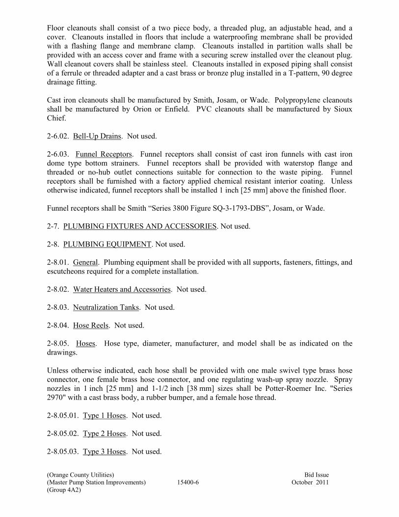
(Orange County Utilities) Bid Issue
(Master Pump Station Improvements) 15400-6 October 2011
(Group 4A2)
Floor cleanouts shall consist of a two piece body, a threaded plug, an adjustable head, and a
cover. Cleanouts installed in floors that include a waterproofing membrane shall be provided
with a flashing flange and membrane clamp. Cleanouts installed in partition walls shall be
provided with an access cover and frame with a securing screw installed over the cleanout plug.
Wall cleanout covers shall be stainless steel. Cleanouts installed in exposed piping shall consist
of a ferrule or threaded adapter and a cast brass or bronze plug installed in a T-pattern, 90 degree
drainage fitting.
Cast iron cleanouts shall be manufactured by Smith, Josam, or Wade. Polypropylene cleanouts
shall be manufactured by Orion or Enfield. PVC cleanouts shall be manufactured by Sioux
Chief.
2-6.02. Bell-Up Drains. Not used.
2-6.03. Funnel Receptors. Funnel receptors shall consist of cast iron funnels with cast iron
dome type bottom strainers. Funnel receptors shall be provided with waterstop flange and
threaded or no-hub outlet connections suitable for connection to the waste piping. Funnel
receptors shall be furnished with a factory applied chemical resistant interior coating. Unless
otherwise indicated, funnel receptors shall be installed 1 inch [25 mm] above the finished floor.
Funnel receptors shall be Smith “Series 3800 Figure SQ-3-1793-DBS”, Josam, or Wade.
2-7. PLUMBING FIXTURES AND ACCESSORIES. Not used.
2-8. PLUMBING EQUIPMENT. Not used.
2-8.01. General. Plumbing equipment shall be provided with all supports, fasteners, fittings, and
escutcheons required for a complete installation.
2-8.02. Water Heaters and Accessories. Not used.
2-8.03. Neutralization Tanks. Not used.
2-8.04. Hose Reels. Not used.
2-8.05. Hoses. Hose type, diameter, manufacturer, and model shall be as indicated on the
drawings.
Unless otherwise indicated, each hose shall be provided with one male swivel type brass hose
connector, one female brass hose connector, and one regulating wash-up spray nozzle. Spray
nozzles in 1 inch [25 mm] and 1-1/2 inch [38 mm] sizes shall be Potter-Roemer Inc. "Series
2970" with a cast brass body, a rubber bumper, and a female hose thread.
2-8.05.01. Type 1 Hoses. Not used.
2-8.05.02. Type 2 Hoses. Not used.
2-8.05.03. Type 3 Hoses. Not used.

(Orange County Utilities) Bid Issue
(Master Pump Station Improvements) 15400-7 October 2011
(Group 4A2)
2-8.05.04. Type 4 Hoses. Type 4 hoses shall be suitable for lay flat water discharge service and
shall be rated for 75 psig [500 kPa gauge] working pressure. The hose shall be 1-1/2 inch
[38 mm] ID with a heavy-duty polyvinyl chloride (PVC) body and synthetic, high tensile textile
cord reinforcement. Type 4 hoses shall be Gates Rubber Company "Masterflex 500".
2-9. COLOR. Plumbing equipment shall have the manufacturer's standard color and finish
unless otherwise indicated in the schedules.
2-10. ELECTRICAL. Electrical controls and disconnects shall be furnished and installed under
the electrical section, except where specified herein. All electrical controls shall have enclosures
suitable for the environment and NEMA rating as indicated on the electrical drawings.
PART 3 - EXECUTION
3-1. INSPECTION. Equipment installed in existing facilities with limited access shall be
suitable for being installed through available openings. Contractor shall field verify existing
opening dimensions and other provisions for installation prior to submittal of bids.
3-2. PREPARATION.
3-2.01. Surface Preparation. All surfaces to be field painted shall be dry and free of dirt, dust,
sand, grit mud, oil, grease, rust, loose mill scale, or other objectionable substances, and shall
meet the recommendations of the paint manufacturer for surface preparation. Cleaning and
painting operations shall be performed in a manner which will prevent dust or other
contaminants from getting on freshly painted surfaces. Oil and grease shall be completely
removed by use of solvents or detergents before mechanical cleaning is started. The gloss of
previously painted surfaces shall be dulled if necessary for proper adhesion of top coats.
3-3. INSTALLATION. Materials furnished under this section shall be installed in proper
operating condition in full conformity with the drawings, specifications, engineering data,
instructions, and recommendations of the equipment manufacturer, unless exceptions are noted
by Engineer.
Unless otherwise indicated, sleeves shall be provided for all pipe penetrations through concrete
and masonry walls. Sleeves and sealing requirements shall be as indicated in the miscellaneous
piping and accessories installation section and as indicated on the drawings.
Not all required reducing fittings and unions are indicated. Additional fittings and unions shall
be provided as needed to connect all equipment and appurtenances.
Insulating fittings shall be provided to prevent the contact of dissimilar metals in piping systems.
When located indoors, fuel gas pressure regulator vents and fuel train vent valves shall be piped
to the exterior of the building in accordance with the applicable codes and standards.
(Orange County Utilities) Bid Issue
(Master Pump Station Improvements) 15400-8 October 2011
(Group 4A2)
Piping shall not be routed over or in front of electrical switchboards or panels unless acceptable
to Engineer.
3-3.01. Water Supply Piping and Accessories. Water hammer arresters shall be provided in the
hot and cold water supply piping at all quick closing valves, at solenoid valves, and at plumbing
fixtures. When not indicated on the drawings, arresters shall be located and sized by Contractor
in accordance with PDI Standard No. WH201. Contractor shall submit arrester location and
sizing plans to Engineer for approval prior to installation. Where possible, water hammer
arresters shall be installed in an accessible location.
Water supply piping to hose faucets and hose valves shall be secured with a pipe support within
6 inches [150 mm] of the fixture.
3-3.02. Drainage and Vent Piping and Accessories. Unless otherwise indicated or required by
code, horizontal sanitary drainage piping 3 inches [75 mm] in diameter or smaller shall be
installed at a uniform slope of 1/4 inch per foot [2 percent]; horizontal sanitary drainage piping
larger than 3 inches [75 mm] in diameter shall be installed at a uniform slope of 1/8 inch per foot
[3 mm/300 mm]; horizontal storm drainage piping shall be installed at a uniform slope of
1/8 inch per foot [3 mm/300 mm].
Drainage fittings shall be installed to convey flow in the piping in the intended direction. To the
extent possible, changes in direction shall be made by sweep type fittings. Quarter-bends and
sanitary tee fittings shall not be installed for vertical to horizontal or horizontal to horizontal
changes of direction.
Plumbing vents through roofs shall be located at least 12 inches [300 mm] from a parapet or
from the intersection of a cant with the roof deck, and shall be installed with watertight flashings.
Plumbing vents shall be located no closer to operable windows or air intakes than is allowed by
the applicable code.
Vents connecting to horizontal sanitary piping shall connect above the centerline of the piping
and shall rise at an angle of not less than 45 degrees from the horizontal to a point at least
6 inches [150 mm] above the flood level rim of the fixture served before offsetting horizontally.
Cleanouts on drainage piping inside structures shall be located where indicated on the drawings.
Additional cleanouts shall be provided where required by the applicable code or authority having
jurisdiction. Cleanouts located in drainage risers shall be located 12 inches [300 mm] above the
finished floor.
Unless otherwise indicated or required by the applicable code, cleanout size shall equal the line
size for 4 inch [100 mm] and smaller drainage piping, and 4 inches [100 mm] in diameter for
drains larger than 4 inch [100 mm]. Proper clearance shall be provided for access to cleanouts.
Floor cleanouts shall be installed flush with the finished floor.
Floor drains, trench drains, floor sinks, funnel receptors, and bell-up drains indicated to be
equipped with traps shall be provided with deep seal "P" traps located as close to the drain as
possible.

(Orange County Utilities) Bid Issue
(Master Pump Station Improvements) 15400-9 October 2011
(Group 4A2)
3-3.03. Plumbing Fixtures and Accessories. Not used.
3-4. FIELD QUALITY CONTROL.
3-4.01. Installation Check. An installation check by an authorized representative of the
manufacturer of equipment specified herein is not required.
3-4.02. Startup and Testing. Field performance tests shall be conducted to demonstrate that each
system is functioning as specified and to the satisfaction of Engineer.
If inspection or tests indicate defects, the defective work or material shall be replaced, and
inspection and tests repeated. All repairs to piping shall be made with new materials. Caulking
of threaded joints or holes will not be acceptable.
3-5. ADJUSTING. All devices shall be adjusted for proper flow and quiet operation. Faucet
and supply assemblies shall be adjusted or repaired to eliminate leaks. All drains shall be
checked for proper operation.
3-6. PROTECTION. Plumbing fixtures, equipment and appurtenances shall be protected from
damage immediately after installation.
3-7. CLEANING. After completion of testing and immediately before the final inspection,
plumbing fixtures, equipment, piping, and appurtenances shall be thoroughly cleaned. Cleaning
materials and methods shall be as recommended by the manufacturer. All faucet aerators shall
be removed, cleaned, and reinserted.
Any stoppage, discoloration, or other damage to parts of the building, its finish, or furnishings
shall be repaired at no additional cost to Owner.
3-8. DISINFECTION. Not used.
3-9. OPERATOR INSTRUCTION AND TRAINING. Not used.
End of Section

This page was left blank intentionally

(Orange County Utilities) Bid Issues
(Master Pump Station Improvements) 16050-1 October 2011
(Group 4A2)
Section 16050
ELECTRICAL
PART 1 - GENERAL
1-1. SCOPE. This section covers the furnishing and installation of equipment and materials
needed for this contract. It also covers conduit, wiring, and terminations for electrical equipment
installed under Section 16100.
This section applies to installation and interconnection of electrical equipment furnished under
other sections, except electrical items designated to be installed under those sections.
1-2. GENERAL. Electrical apparatus on equipment shall be installed complete and placed in
readiness for proper operation.
Electrical materials furnished and installed under this section shall be fabricated, assembled,
erected, and placed in proper operating condition in full conformity with the drawings,
specifications, engineering data, instructions, and recommendations of the equipment
manufacturer, unless exceptions are noted by Engineer.
1-2.01. General Equipment Stipulations. The General Equipment Stipulations shall apply to
equipment provided under this section. If requirements in this specification differ from those in
the General Equipment Stipulations, the requirements specified herein shall take precedence
Coordination. Electrical work shall conform to the construction schedule and the progress of
other trades.
1-2.02. Anchor Bolts and Expansion Anchors. Anchor bolts, nuts, washers, and expansion
anchors shall comply with section 05550, Anchorage in Concrete and Masonry, except smaller
than 3/4 inch [19 mm] will be permitted to match NEMA standard size bolt holes on motors and
electrical equipment.
1-2.03. Drawings. Supplementing this section, the drawings indicate locations of equipment and
enclosures and provide one-line and schematic diagrams regarding the connection and
interaction with other equipment.
1-3. CODES AND PERMITS. Work shall be performed and materials shall be furnished in
accordance with the NEC - National Electrical Code, the NESC - National Electrical Safety
Code, and the following standards where applicable
NEC National Electrical Code
NESC National Electrical Safety Code,
ANSI American National Standards Institute.
ASTM American Society for Testing and Materials.

(Orange County Utilities) Bid Issues
(Master Pump Station Improvements) 16050-2 October 2011
(Group 4A2)
AWG American Wire Gauge.
Fed Spec Federal Specification.
ICEA Insulated Cable Engineers Association.
IEEE Institute of Electrical and Electronics Engineers.
IESNA Illuminating Engineering Society of North America.
NEIS National Electrical Installation Standards
NEMA National Electrical Manufacturers Association.
NFPA National Fire Protection Association.
UL Underwriters' Laboratories.
Equipment covered by this section shall be listed by UL, or by a nationally recognized third
party testing laboratory. Costs associated with obtaining the listing shall be the responsibility of
Contractor. If no third-party testing laboratory provides the required listing, an independent test
shall be performed at Contractor’s expense. Before the test is conducted, Contractor shall submit
a copy of the testing procedure to be used.
1-4. IDENTIFICATION.
1-4.01. Conduit. Conduits in manholes, hand holes, building entrance pull boxes, junction
boxes, and equipment shall be provided with identification tags. Identification tags shall be
19 gage [1 mm thick] stainless steel, with 1/2 inch [13 mm] stamped letters and numbers as
indicated on the drawings. Identification tags shall be attached to conduits with nylon tie wraps
and shall be positioned to be readily visible.
1-4.02. Conductors. Conductors in power, control, and instrumentation circuits shall be
identified and color coded as described herein.
1-4.02.01. Conductor Identification Number. Except for lighting and receptacle circuits, each
individual conductor in power, control, and instrumentation circuits shall be provided with wire
identification markers at the point of termination.
Wire markers shall be heat-shrinkable tube type, with custom typed identification numbers. The
wire numbers shall be as indicated on the equipment drawings. The wire markers shall be
positioned to be readily visible for inspection.
1-4.02.02. Conductor Color Coding. Power conductors shall be color coded as indicated below.
For conductors 6 AWG and smaller, the color coding shall be the insulation finish color. For
sizes larger than 6 AWG, the color coding may be by marking tape. The equipment grounding
conductor shall be green or green with one or more yellow stripes if the conductor is insulated.
The following color coding system shall be used in order of a, b, c, or 1, 2, 3:
120/240V — black, red, and white (neutral)
208Y/120V — black, red, blue, and white (neutral)
240/120V — black, orange (high leg), blue, and white(neutral)
(Orange County Utilities) Bid Issues
(Master Pump Station Improvements) 16050-3 October 2011
(Group 4A2)
480V – brown, orange, yellow
480Y/277V — brown, orange, yellow, and gray (neutral)
Where 120/240 and 208Y/120 volt systems share the same conduit or enclosure, the neutral for
either the 120/240 volt system shall be white with a permanent identifiable violet stripe.
Control and instrumentation circuit conductors shall be color coded as indicated in the Cable
Data Figures at the end of this section.
1-4.03. Motor Starters Motor starters shall be provided with nameplates identifying the related
equipment. Pilot controls and indicating lights shall have engraved or etched legends
Nameplates shall be laminated black-over-white plastic, with 1/8 inch [3 mm] engraved letters,
and shall be securely fastened to the motor starters with stainless steel screws.
1-4.04. Control Stations. ControlControl stations shall be provided with nameplates identifying
the related equipment. Pilot controls and indicating lights shall have engraved or etched legends
("start", "stop", etc.) as indicated on the drawings. Nameplates shall be laminated
black-over-white plastic, with 1/8 inch [3 mm] engraved letters, and shall be securely fastened to
the control stations with stainless steel screws.
1-4.05. Circuit Breakers. Circuit breakers shall be provided with nameplates identifying related
equipment. Nameplates shall be laminated black-over-white plastic, with 1/8 inch [3 mm]
engraved letters, and shall be permanently fastened to the circuit breakers with stainless steel
screws.
1-4.06. Disconnect Switches. Switches shall have front cover-mounted permanent nameplates
that include switch type, manufacturer's name and catalog number, and horsepower [kW] rating.
An additional nameplate, engraved or etched, laminated black-over-white plastic, with 1/8 inch
[3 mm] letters, shall be provided to identify the associated equipment. Both nameplates shall be
securely fastened to the enclosure with stainless steel screws.
1-4.07. Arc Flash Hazard Labels. Lighting panels, power panels, power centers, and meter
socket enclosures shall be provided with permanent labels warning the risk of arc flash and
shock hazard. Labels shall be designed in accordance with ANSI Z535.4-1998 and shall include
the following:
WARNING
Arc Flash and Shock Hazard
Appropriate personal protection equipment (PPE) required. SEE NFPA 70E. Equipment must be
accessed by qualified personnel only.
Turn off power sources prior to working on or inside equipment.
1-5. SUBMITTALS. Submit documents in accordance with the submittals section. The
drawings and data shall include, but not limited to:
Installation Manual

(Orange County Utilities) Bid Issues
(Master Pump Station Improvements) 16050-4 October 2011
(Group 4A2)
Operation and Maintenance Manuals
Starters, all types
Motor nameplate data
Complete set of final conform to construction documents
1-5.01. Submittal Identification. Each sheet of descriptive literature submitted shall be clearly
marked to identify the material or equipment as applicable:
a. Lamp fixture descriptive sheets shall show the fixture schedule letter,
number, or symbol for which the sheet applies.
b. Equipment and materials descriptive literature and drawings shall show the
specification paragraph for which the equipment applies.
c. Sheets or drawings covering more than the item being considered shall have
inapplicable information crossed out.
d. A suitable notation shall identify equipment and materials descriptive
literature not readily cross-referenced with the drawings or specifications.
e. Schematics and connection diagrams for electrical equipment shall be
submitted for review. A manufacturer's standard connection diagram or
schematic showing more than one scheme of connection will not be
acceptable.
f. Transient voltage surge suppressor submittals shall include drawings
(including unit dimensions, weights, component and connection locations,
mounting provisions, and wiring diagrams), equipment manuals that detail
the installation, operation and maintenance instructions for the specified unit(s),
and manufacturer’s descriptive bulletins and product sheets.
Contractor shall submit the name and qualifications of the Engineering and Testing Services firm
proposed to perform the coordination study and the on site testing.
1-6. PROTECTION AND STORAGE. During construction, the insulation on electrical
equipment shall be protected against absorption of moisture, and metallic components shall be
protected against corrosion by strip heaters, lamps, or other suitable means. This protection shall
be provided immediately upon receipt of the equipment and shall be maintained continuously.
PART 2 - PRODUCTS
2-1. POWER SERVICE ENTRANCE. Contractor shall consult the local electric utility, prior to
bidding, regarding their service installation requirements, and shall furnish the service equipment
in compliance with these requirements. Contractor’s bid shall include costs for installation
complying with utility requirements. The Utility Company contact information for the pump
station is indicated below.
PS-3006 – Orlando Utilities Commission – Mr. Chris Fatkin – 407-423-9100 Ext 4336

(Orange County Utilities) Bid Issues
(Master Pump Station Improvements) 16050-5 October 2011
(Group 4A2)
2-2. CABLE. Cables of each type (such as lighting cable or 600 volt power cable) shall be from
the same manufacturer.
Cables shall conform to the Cable Data Figures at the end of this section and as described herein.
2-2.01. Lighting Cable. Lighting cable (Figure 1-16050 XHHW-2) shall be provided only in
lighting and receptacle circuits operating at 277 volts or less.
2-2.02. 600 Volt Power Cable. Cable in power, control, indication, and alarm circuits operating
at 600 volts or less, except where lighting, multi-conductor control, and instrument cables are
required, shall be 600 volt (Figure 1-16050 XHHW-2).
2-2.03. Instrument Cable. Cable for electronic circuits to instrumentation, metering, and other
signaling and control equipment shall be two- or three-conductor instrument cable twisted for
magnetic noise rejection and protected from electrostatic noise by a total coverage shield. Types
of instrument cables shall be as indicated in Figures 2, 3 or 4-16050.
2-2.04. Multi-conductor Control Cable. When indicated on the Drawings, cable in control,
indication and alarm circuits shall be multiconductor. Cable shall be Figure 5-16050 14 AWG
THHN-THWN.
2.3. CONDUIT.
2-4.01. Rigid Steel Conduit. Not Used
2-4.02. Intermediate Metal Conduit (IMC). Not Used
2-4.03. Liquidtight Flexible Metal Conduit. Liquidtight flexible metal conduit shall be hot-dip
galvanized steel, shall be covered with a moisture-proof polyvinyl chloride jacket, and shall be
UL listed.
2-4.04. Utility (PVC) Duct. Not Used
2-4.05. Rigid Nonmetallic (PVC) Conduit. PVC conduit shall be heavy wall, Schedule 80, UL
labelled for aboveground and underground uses, and shall conform to NEMA TC-2 and UL 651.
2-4.06. Electrical Metallic Tubing (EMT). Not Used
2-4.07. Rigid Aluminum Conduit (RAC). Rigid aluminum conduit and fittings shall be
manufactured of 6063-T1 alloy, shall conform to ANSI C80.5, and shall be manufactured in
accordance with UL 6.
2-5. WIRING DEVICES, BOXES, AND FITTINGS. Concealed conduit systems shall have
flush-mounted switches and convenience outlets. Exposed conduit systems shall have
surface-mounted switches and convenience outlets.
2-5.01 Conduit Boxes and Fittings.

(Orange County Utilities) Bid Issues
(Master Pump Station Improvements) 16050-6 October 2011
(Group 4A2)
a. Galvanized or cadmium plated, threaded, malleable iron boxes and fittings
shall be manufactured by Crouse-Hinds, Appleton, or O Z Gedney. In
applications utilizing aluminum conduit systems, aluminum boxes and
fittings manufactured by Crouse-Hinds, Appleton, or O Z Gedney shall be
installed.
b. Sheet steel device boxes shall be manufactured by Appleton, Raco, or Steel
City.
c. Hub arrangements on threaded fittings shall be the most appropriate for the
conduit arrangement to avoid unnecessary bends and fittings.
2-5.02 . Device Plates.
a. Galvanized or cadmium-plated device plates shall be used on surface
mounted outlet boxes where weatherproof plates are not required.
b. Device plates on flush mounted outlet boxes where weatherproof plates are
not required shall be AISI Type 302 stainless steel, Eagle "93nnn series",
Hubbell "S series", or Leviton "840nn-40 series"; nylon or polycarbonate,
Eagle "513nV series", Hubbell "Pn series", or Leviton "807nn-I series".
c. Device plate mounting hardware shall be countersunk and finished to
match the plate.
d. Device plates for switches outdoors or indicated as weatherproof shall have
provisions for padlocking switches "On" and "Off", and shall be Appleton
"FSK-1VS", Crouse-Hinds "DS185" or O Z Gedney "FS-1-WSCA".
e. Device plates for receptacles indicated as weatherproof shall be Appleton
"FSK-WRD", Crouse-Hinds "WLRD1", or O Z Gedney "FS-1-WDCA.
f. Flush-mounted, weatherproof plates shall be provided with adapter plates,
Appleton "FSK-SBA" or Crouse-Hinds "FS031".
g. Device plates for ground fault interrupter receptacles indicated to be
weatherproof shall be Appleton "FSK-WGFI", Eagle "966", or O Z Gedney
"FS-1-GFCA".
h. Receptacle covers outdoors or otherwise indicated to be weatherproof
while in-use shall be die cast aluminum and shall include a padlock eye.
Covers for standard convenience outlets shall be Hubbell “WP8M” or
Thomas and Betts Red Dot “CKMDV”. Covers for ground fault interrupter
receptacles shall be Hubbell “WP26M” or Thomas and Betts Red Dot
“CKMGV”.
i. Engraved device plates, where required, shall be manufactured by Leviton,
or equal.
2-5.03. Wall Switches.
a. Switches on ac lighting panel load circuits through 277 volts shall be 20
amperes, 120/277 volts.

(Orange County Utilities) Bid Issues
(Master Pump Station Improvements) 16050-7 October 2011
(Group 4A2)
b. Switches for pulse control of lighting contactors shall be 20 amperes,
120/277 volts, momentary, double-throw, center "Off",
c. Switches on ac lighting panel load circuits through 277 volts in Class I,
Division 1 and Division 2, Group D hazardous areas indicated on the
drawings shall be 20 ampere, 120/277 volts. Hazardous area switches shall
be factory sealed tumbler switches
2-5.04. Receptacles.
a. Standard convenience outlets shall be duplex, three-wire, grounding,
20 amperes, 125 volts
b. Ground fault circuit interrupter receptacles shall be duplex, 20 amperes,
125 volts
e. Receptacles in Class I, Division 1 and Division 2, Group D hazardous
areas indicated on the drawings shall be three-wire, grounding, 20
amperes, 125 volts. Hazardous area receptacles shall be factory sealed,
with an integral switch that is only activated when an approved
matching plug is fully inserted and rotated into the engaged position.
2-6. JUNCTION BOXES, PULL BOXES, AND WIRING GUTTERS. Indoor boxes and
gutters shall be constructed of sheet steel, shall be galvanized after fabrication, and shall be
rigidly supported by hot-dip galvanized hardware and framing materials, including nuts and
bolts.
Indoor boxes and gutters in corrosive areas and outdoor boxes and gutters shall be NEMA Type
4X, stainless steel and shall be rigidly supported by stainless steel framing materials. Mounting
hardware, which includes nuts, bolts, and anchors, shall be stainless steel. Damaged coatings
shall be repaired according to the manufacturer's instructions.
Bolt-on junction box covers 3 feet [900 mm] square or larger, or heavier than 25 lbs [11 kg],
shall have rigid handles. Covers larger than 3 by 4 feet [900 by 1200 mm] shall be split.
Junction and pull boxes with a removable side opposite the underground conduits shall be
provided over building ends of underground conduit banks. Boxes shall be sized in accordance
with the National Electrical Code, including space for full size continuations of underground
conduits not originally continued. Conduit arrangement shall leave maximum space for future
conduits.
2-7. LIGHTING FIXTURES. Lighting fixtures shall be furnished as described in the fixture
schedule. Lighting fixtures shall be furnished complete with lamps. Pendant fixtures shall have
swivel type box covers and threaded conduit pendants unless otherwise specified.
2-7.01. Electronic Ballasts. Electronic ballasts furnished with fluorescent type lighting fixtures
shall be CBM certified as meeting requirements of ANSI C82.11 with a THD level of not more
than 20 percent.

(Orange County Utilities) Bid Issues
(Master Pump Station Improvements) 16050-8 October 2011
(Group 4A2)
2-8. LIGHTING PANELS. Each lighting panel shall be a dead-front, 120/240 volt or 208Y/120
volt panelboard with bolt-on circuit breakers.
2-8.01. Cabinet. The panel shall have a flush-mounted or surface-mounted enclosure with a
NEMA designation appropriate for the location where it will be installed. The enclosure shall
have a hinged trim cover. Breaker operating handles shall be accessible through a latched,
lockable, door. At the completion of the contract, a neatly printed or typed directory listing the
panel and circuit identities shall be mounted inside the door. Hand written will not be acceptable.
2-8.02. Circuit Breakers. Circuit breakers shall be thermal-magnetic, bolt-in, individually front
replaceable, and shall indicate "On", "Off", and "Tripped". Breakers indicated as multiple-pole
shall be common trip. Breakers shall have interrupting ratings not less than required by analysis.
Handle clips to prevent casual operation of breakers shall be provided for 10 percent (at least
two) of the breakers and applied to the circuits directed. Breakers and provisions for future
breakers shall be provided in the quantities, number of poles, and ampere ratings indicated.
2-8.03. Buses. The panel shall have main and neutral buses insulated from the cabinet, and a
ground bus bolted to the enclosure. Buses shall be copper. The ground bus shall be similar to a
neutral bus and shall have a good ground connection to the cabinet, a removable bond to the
neutral bus, clamp type lugs for the ground cable in each supply conduit, and connections for a
ground cable in each load conduit.
2-9. CONTROL PANEL (CP-1) Control panel CP-1 shall be as specified in the Orange County
Utilities “Standards and Construction Specifications Manual” section 3412 Wastewater Pump
Station Electrical Power & Control System, latest edition, with modifications as indicated in the
contract drawings. Control panel manufacturer shall be one of the approved suppliers as listed in
APPENDIX D of the Orange County Utilities “Standards and Construction Specifications
Manual”.
2-9.01. Cabinet. The panel shall be a surface-mounted or free standing enclosure with a NEMA
3R, Type 316 Stainless Steel, 14-gauge enclosure, with drip shield and door gasket. The
enclosure shall have a door with latch and lock.
2-9.02. Circuit Breakers. Circuit breakers shall be thermal-magnetic, bolt-in, individually front
replaceable, and shall indicate "On", "Off", and "Tripped". Breakers indicated as multiple-pole
shall be common trip type. Breakers shall have interrupting ratings not less than that required by
analysis.
2-9.03. Combination Solid-State Starters. As required, or as indicated on the drawings, the
control panel enclosure shall include a breaker combination, solid-state, reduced voltage solid
state starter (RVSS). Six back-to-back silicon controlled rectifiers shall be used to provide
smooth, stepless motor acceleration. When the motor reaches full speed, a bypass contactor shall
close and carry the continuous duty motor current. This bypass contactor shall bypass the SCRs
of the solid state starter once the motor is up to speed. The effect of the bypass contactor during
run shall be for the elimination of heat buildup resulting from the voltage drop across the SCRs
of the solid state starter. The RVSS shall be rated for motor starting duty and a selector switches
and pilot lights and control shall be provided as indicated on the drawing schematic.
a. Starters shall be 3 phase, 60 Hz, with overloads, a 120 volt ac
(Orange County Utilities) Bid Issues
(Master Pump Station Improvements) 16050-9 October 2011
(Group 4A2)
bypass contactor coil, a dry-type control transformer, and a
molded-case circuit breaker. Control transformers shall be
mounted with the removable starters and shall have capacity for
all simultaneous loads. Control transformers shall have both
primary leads fused, one secondary lead fused, and one
secondary lead grounded.
b. As required, spare interlock contacts, whether on the starter or
on a relay, shall be wired separately to the unit terminal board.
c. Starters shall include smooth starting and stopping, adjustable
starting torque, adjustable ramp time, inverse time overload
current trip, current limit, phase loss protection, and adjustable
electronic overloads.
d. An external manual breaker operating handle with provisions for
up to three padlocks shall be provided on each starter. The
access door shall be interlocked with the circuit breaker so that
the door cannot be opened, except by an interlock override,
while the breaker is closed.
e. CONTRACTOR shall match control transformers, overloads,
and the minimum sizes of starters to equipment furnished, which
may differ from the estimated values indicated on the drawings.
Overload relay devices shall be adjusted to reflect reduced motor
current caused by load-side power factor correction capacitors (if
required).
f. Unless otherwise specified, spare starters shall have breakers and
overloads sized for the largest rated motor and 100 watts extra
transformer capacity.
g. As required, starters shall include an auxiliary contactor for
connection to a line-side power factor correction capacitor. The
contactor shall be interlocked to prevent the capacitor from
being connected before the bypass contactor has energized.
ACCEPTABLE MANUFACTURERS. Combination Solid State starters (RVSS) shall be
manufactured by Siemens-Robicon, Allen-Bradley, Eaton Cutler-Hammer or Square D without
exception. The products of other manufacturers will not be acceptable.
2-10. SURGE PROTECTION DEVICES (SPD’S) .
2 -10.01. Scope. Surge Protection Devices (SPD) shall be provided as specified. Each unit shall
be designed for parallel connection to the wiring system and shall utilize non-linear voltage-
dependent metal oxide varistors (MOV) in parallel.
SPD devices shall be furnished and installed for the electrical equipment indicated, and as
specified herein.

(Orange County Utilities) Bid Issues
(Master Pump Station Improvements) 16050-10 October 2011
(Group 4A2)
Lighting panels shall be rated for the low exposure level capacity.
Power panels, Switchboards, main breakers and main pumps station control panels shall have
SPD devices rated for a high exposure levels.
2-10.02. Standards. The specified unit shall be designed, manufactured, tested and installed in
compliance with the following standards:
ANSI/IEEE C62.41 and C62.45;
ANSI/IEEE C62.1 and C62.11;
National Electrical Manufacturers Association (NEMA LS1 Guidelines);
National Fire Protection Association (NFPA 20, 70 [NEC], 75, and 78);
Underwriters Laboratories UL 1449 Latest Edition and 1283
The unit shall be UL 1449 Second Edition Listed as a Transient Voltage Surge Suppressor and
UL 1283 Listed as an Electromagnetic Interference (EMI) Filter.
2-10.03. Environmental Requirements.
a. Operating Temperature: -40°F to +140°F [-40°C to +60°C].
b. Relative Humidity: Reliable operation with 5 percent to 95 percent non-
condensing.
2-10.04. Electrical Requirements.
a. Unit Operating Voltage. The nominal unit operating voltage and
configuration shall be as indicated on the drawings.
b. Maximum Continuous Operating Voltage (MCOV). The SPD device shall be
designed to withstand a MCOV of not less than 115 percent of nominal RMS
voltage.
c. Operating Frequency. Operating frequency range shall be 47 to 63 Hertz.
d. Protection Modes. protected modes are defined per NEMA LS-1, Paragraph
2.2.7. Following IEEE Standard 1100, section 9.11.2 recommendations, Four-
wire configured systems shall provide, Line-to-Neutral (L-N), Line-to-Ground
(L-G), and Neutral-to-Ground (N-G), and Line-to-Line (L-L) protection.
Three-wire configured systems shall provide, Line-to-Line (L-L) protection
and Line-to-Ground (L-G) protection.
e. Rated Single Pulse Surge Current Capacity. The rated single pulse surge
current capacity, in amps, for each mode of protection of the unit shall be as
required and shall be no less than listed in the following table.
L-N L-G N-G L-L
High Exposure Level 150 kA 150 kA 150 kA 150 kA

(Orange County Utilities) Bid Issues
(Master Pump Station Improvements) 16050-11 October 2011
(Group 4A2)
Low Exposure Level 80 kA 80 kA 60 kA 80 kA
f. UL 1449 Second Edition Suppression Voltage Rating (SVR). The maximum
SVR per mode for the device (inclusive of disconnect) shall be as required and
shall not exceed the following:
Voltage L-N L-G N-G L-L
120/240 500 V 500 V 500 V 800 V
480 V 900 V 1000 V 1500 V 1800 V
g. Noise Attenuation. EMI noise rejection or attenuation values shall be
measured in accordance with test and evaluation procedures outlined in
NEMA LS-1. The unit shall be capable of a minimum -40 dB attenuation at
100kHz when tested per the 50 ohm insertion loss method as defined by MIL-
STD-220A.
h. Minimum Repetitive Surge Current Capacity. The minimum number of
repetitive surges per mode as a result of testing a 20 kV, 10kA ANSI/IEEE
C62.41 Category C3 surge current with less than a 10 percent degradation of
clamping voltage shall be as follows:
For integral and external installation and power panels: 5,000.
For lighting panels: 3,500.
i. Overcurrent Protection. At high exposure levels, the SPD device shall
incorporate internal fusing capable of interrupting, at minimum, up to 200 kA
symmetrical fault current with 600 volts ac applied.
At low exposure levels, the SPD device shall incorporate internal fusing
capable of interrupting, at minimum, up to 65kA symmetrical fault current
with 600 volts ac applied.
The device shall be capable of allowing passage of the rated maximum surge
current for every mode without fuse operation.
j. Unit Status Indicators. The unit shall include long-life, externally visible
phase indicators that monitor the on-line status of the unit. When furnished
integral to the panelboard, the status indicators shall be viewable through a
clear window within the panelboard door, or similar provision made to ensure
visibility with the door closed.
2-10.05. Warranty. The manufacturer shall provide a minimum Ten Year Limited Warranty
from date of shipment against failure when installed in compliance with applicable national/local
electrical codes and the manufacturer's installation, operation and maintenance instructions.
2-10.06. Installation. The SPD devices shall be installed according to the manufacturer’s
recommendations. If possible for the integral units, provide direct bus connections.

(Orange County Utilities) Bid Issues
(Master Pump Station Improvements) 16050-12 October 2011
(Group 4A2)
2-10.07. Options.
a. Disconnect Switch. Each SPD device shall be furnished with an integral
disconnect switch. The unit shall be UL 1449 Second Edition listed as such,
and the UL 1449 Second Edition Suppression Voltage Ratings shall be
provided. The disconnect switch shall be fused and capable of withstanding,
without failure, the published maximum surge current magnitude without
failure or damage to the switch. A circuit breaker may be used in lieu of an
integral disconnect switch.
b. Enclosure. For the SPD units to be mounted externally of the protected
electrical equipment, provide NEMA 4x SS or plastic rated enclosures
suitable for the locations indicated on the drawings.
2-10.08. Acceptable Manufacturers. SPD devices shall be manufactured by Surge Suppression
Incorporated, Josyln or Current Technology. The products of other manufacturers will not be
acceptable.
2-11. SEPARATELY ENCLOSED MOTOR STARTERS. Separately enclosed motor starters,
unless otherwise specified, shall be full voltage, magnetic, non- reversing and NEMA rated. The
starter enclosures shall have NEMA type designations appropriate for the locations where they
will be installed. NEMA Type 4X stainless steel enclosures shall be provided for outdoor
locations.
One thermal overload relay shall be provided in each phase lead. Each starter shall be provided
with an external, manually reset push button for resetting the thermal overload relays.
Each starter shall include auxiliary contacts as required, plus one spare NO and one spare NC
contact.
Contractor shall match the sizes of control power transformers, overload devices, heaters, and
starters to the equipment furnished, as they may differ from the values indicated on the drawings.
Control power transformers shall have both primary leads fused, one secondary lead fused, and
one secondary lead grounded.
Starters shall be provided with control terminal blocks. Terminal blocks shall be pull-apart type
rated 20 amperes. Current carrying parts shall be tin-plated. The removable portion of the
terminal blocks shall be used for factory installed wiring.
Push buttons, selector switches, and pilot lights indicated on the schematics to be provided on or
in the starter enclosure shall be 30.5 mm heavy-duty, oiltight construction. Pilot lights shall be
full voltage type with LED lamps. Push buttons on starters located outdoors shall be provided
with protective caps.
2-11.01. Three Phase Starters. Three phase starters shall be circuit breaker combination type
consisting of 3 phase, 60 Hz contactors with thermal overloads, a 120 volt ac coil, a dry type
control power transformer where required, and a circuit breaker disconnect. Control power
transformers shall be sized to handle simultaneous loads. Starters shall be at least NEMA Size 1,
or as indicated on the drawings.

(Orange County Utilities) Bid Issues
(Master Pump Station Improvements) 16050-13 October 2011
(Group 4A2)
Circuit breakers shall be 600 volt magnetic motor circuit protectors for motors smaller than
100 horsepower [75 kW] and 600 volt thermal-magnetic type for 100 horsepower [75 kW] and
larger motors. Each breaker shall be manually operated with a quick-make, quick-break,
trip-free toggle mechanism.
Three phase starters shall be furnished with external manual breaker operating handles and
provisions for up to three padlocks. The access door shall be interlocked with the motor circuit
protector, so that the door cannot be opened, except by an interlock override, while the breaker is
closed.
The complete 3 phase starter shall have an interrupting rating of at least 42,000 amperes at
480 volts.
2-11.02. Single Phase Starters. Single phase starters shall consist of single phase, 60 Hz
contactors with thermal overloads and an integral or separately enclosed short-circuit protection
device. Starters shall be at least NEMA Size 0, or shall be sized as indicated on the drawings.
Integral short-circuit protection devices for single-phase starters shall be 120/240 volt, magnetic
motor circuit protectors.
Separately enclosed short-circuit protection devices for single phase starters shall be molded case
circuit breakers for motor loads 6 amperes and higher and fused switch disconnects for motor
loads lower than 6 amperes. Circuit breaker disconnects shall be 120/240 volt, molded-case,
thermal-magnetic circuit breakers. Fused switch disconnects shall have quick-make, quick-break
mechanisms and 250 volt, dual-element, time-delay fuses.
The short-circuit protection devices shall have external operating handles capable of being
padlocked in the open position, and shall have an interrupting rating of at least 22,000 amperes at
240 volts.
2-13. CONTROL STATIONS. Control stations shall be provided as indicated on the one-line
diagrams or schematics or as required by the equipment furnished. Pilot devices shall be 30.5
mm heavy-duty, oiltight construction, and shall perform the functions indicated. Pilot lights
shall be full voltage type with LED lamps. Indoor control stations shall have NEMA Type 13
enclosures. Control stations outdoors or indicated to be weatherproof shall have NEMA
Type 4X stainless steel enclosures with protective caps on the control devices. Control stations
in NEC Class I, Division 1 and Division 2, Group D hazardous areas shall have NEMA Type 7
enclosures, or be factory sealed type.
2-14. SEPARATELY ENCLOSED CIRCUIT BREAKERS/Main Disconnect Switch (MDS-1).
MDS-1 shall be service entrance rated and provided with SPD in accordance with this
specification and the drawings. Circuit breakers shall be 3 pole, 480 volt, molded-case circuit
breakers of not less than 42,000 amperes interrupting rating at 480 volts ac, complete with
thermal and instantaneous trip elements. Breaker enclosures shall have NEMA designations
appropriate for the locations where they will be installed. NEMA Type 4X stainless steel
enclosures shall be provided for outdoor locations. Each breaker shall be manually operated
with a quick-make, quick-break, trip-free toggle mechanism. Bimetallic thermal elements shall
withstand sustained overloads and short-circuit currents without injury and without affecting
calibration.

(Orange County Utilities) Bid Issues
(Master Pump Station Improvements) 16050-14 October 2011
(Group 4A2)
Circuit breakers shall have "On", "Off", and "Tripped" indication and pad-lockable exterior
handles.
2-15. DISCONNECT SWITCHES. Unless otherwise specified, each disconnect switch shall be
3 pole, non-fusible, 600 volts, with a continuous current rating as indicated.
Switches located indoors shall have NEMA type enclosure designations as required by the
locations where they will be installed. Switches located outdoors shall have NEMA Type 4X
stainless steel enclosures. Switches in chlorine rooms, or in other areas where contact with
caustic substances may occur, shall have NEMA Type 4X enclosures of molded reinforced
polyester.
Switches shall have high conductivity copper, visible blades; non-teasible, positive, quick-make,
quick-break mechanisms; and switch assembly plus operating handle as an integral part of the
enclosure base. Each switch shall have a handle whose position is easily recognizable and which
can be locked in the "Off" position with three padlocks. The "On" and "Off" positions shall be
clearly marked.
Switches shall be UL listed and horsepower [kilowatt] rated, and shall meet the latest edition of
NEMA KS1. Switches shall have defeatable door interlocks that prevent the door from being
opened while the operating handle is in the "On" position.
2-16. LIGHTING AND AUXILIARY POWER TRANSFORMERS. Separately mounted
transformers shall be provided in the phases, kVA, and voltages indicated. Transformers shall be
self-air-cooled, dry type, encapsulated, wall- or floor-mounted, and enclosed for wiring in
conduit. Transformers installed outdoors shall be weatherproof. Transformers shall have at least
two full capacity voltage taps. Transformers shall meet NEMA TP1 guidelines for energy
efficiency.
2-17. LIGHTING CONTACTORS. Not used.
2-18. PHOTOELECTRIC CONTROLS. Not Used.
2-19. RELAY ENCLOSURES. Relay enclosures shall be furnished as indicated. The enclosure
shall have a NEMA designation appropriate for the location where it will be installed. Pilot
devices shall be heavy duty, oiltight construction. Relays and timers shall have 120 volt, 60 Hz
coils rated for continuous duty in 40 C ambient and 10 ampere, 120 volt ac contacts.
Intrinsically safe relays shall be installed within the enclosures in accordance with NEC
requirements.
2-20. DOOR ENTRY SWITCHES. Switches shall be heavy-duty industrial, adjustable,
magnetic wide gap type. Switch and magnet housings located in NEC Class I, Division 1 and 2,
Group D hazardous areas shall be die-cast aluminum, explosion-proof. Switch and magnet
housings located in other areas shall be anodized aluminum.

(Orange County Utilities) Bid Issues
(Master Pump Station Improvements) 16050-15 October 2011
(Group 4A2)
PART 3 - EXECUTION
3-1. INSTALLATION, TESTING, AND COMMISSIONING. Material, equipment, and
components specified herein shall be installed, tested, and commissioned for operation in
compliance with NECA 1000 – NEIS Specification System. Where required in NECA 1000,
testing and commissioning procedures shall be followed prior to energizing equipment.
3-2. ARC FLASH HAZARD ANALYSIS. Contractor shall commission an Arc Flash Hazard
Analysis for each piece of electrical equipment in accordance with OSHA 29 CFR Part 1910,
NEC, NFPA 70E, and IEEE 1584 and shall submit an Arc Flash Hazard Analysis report as
specified herein.
The Arc Flash Hazard Analysis shall be performed in association with, or as a continuation of,
the short circuit study and protective-device coordination study.
Arc Flash Hazard Analysis calculations shall lead to a selection of a level of Personal Protective
Equipment (PPE) that is a balance between the calculated incident energy exposure and the work
activity being performed, while meeting the following concerns:
Provide adequate protection.
Avoid the need for more protection than is warranted.
Results of the Arc Flash Hazard Analysis shall be used to identify the flash-protection boundary
and the incident energy at assigned working distances throughout any position or level in the
overall electrical generation, transmission, distribution, or utilization system.
The analysis shall include, but shall not be limited to, the following:
A tabulation of the symmetrical RMS bolted fault current available and X/R ratio at
each piece of electrical equipment.
A tabulation of the arc fault current available at each piece of electrical equipment.
A list containing the incident energy and the flash-protection boundary for electrical
equipment.
A list containing each piece of electrical equipment, its corresponding incident energy,
hazard rating, and the required Personal Protective Equipment.
An Engineering and Testing Services firm acceptable to Engineer shall conduct the Arc Flash
Hazard Analysis.
3-2.01. Arc Flash Analysis Software. The Arc Flash Hazard Analysis shall be performed using
the latest version of ETAP or SKM Power*Tools for Windows software, without exception.
After the final version of the study and analysis are completed and accepted, Contractor shall
provide two (2) copies of the SKM working electronic files to Owner.
3-2.02. Arc Flash Hazard Report. Contractor shall be responsible for submitting complete and
accurate arc flash analysis information in the Arc Flash Hazard Report. The report shall be
submitted to Engineer for review before the final report is prepared. Contractor shall ensure that

(Orange County Utilities) Bid Issues
(Master Pump Station Improvements) 16050-16 October 2011
(Group 4A2)
calculated values for flash-protection boundary, working distance, incident energy, and required
Personal Protective Equipment is submitted and provide substantiation that the information will
be prominently displayed on electrical equipment.
The Arc Flash Hazard Analysis report shall be bound in a standard 8-1/2 by 11 inch three-ring
binder and shall be submitted in accordance with the submittals section. Final selection of
required Personal Protective Equipment shall be subject to review and acceptance by Engineer.
3-2.03. Arc Flash Labeling. After approval of the Arc Flash Hazard Report, Contractor shall
furnish and install arc flash warning labels on the applicable electrical equipment. electrical
equipment shall be provided with the appropriate ANSI compliant arc flash labeling. Labels
shall include the flash protection boundary distance, incident energy, and minimum required
Personal Protective Equipment.
3-3. COORDINATION STUDY. Contractor shall commission a short circuit study and
protective-device coordination study of relays, fuses, circuit breakers, and other protective
devices and shall submit a coordination report as specified herein. The study shall include the
entire distribution system, or the portion of the system indicated as required, starting with the
smallest – 480 volt, 3 phase, 60 Hz – circuit protective device on the load end, to the nearest
protective device on the power company's line side.
Contractor shall be responsible for and shall ensure that relays and circuit breakers are set
according to the study results.
The study shall include, but shall not be limited to, the following:
Color-coded printouts of coordination curves prepared with calculation software.
A tabulation of protective relay and circuit breaker trip settings and recommended sizes
and types of medium-voltage fuses.
Motor starting profiles for 50 horsepower [37 kW] and larger motors.
Transformer damage curves and protection, evaluated in accordance with ANSI/IEEE
C57.109.
Coordination curve(s) from the power company, if available.
Calculated short-circuit values at nodes in the distribution system included within the
scope of the coordination study.
An Engineering and Testing Services firm acceptable to Engineer shall conduct the coordination
study.
Contractor shall be responsible for obtaining the following:
The coordination curves for relays, fuses, and circuit breakers.
Transformer damage curves.
Motor data.
Other applicable information for new and existing electrical equipment.

(Orange County Utilities) Bid Issues
(Master Pump Station Improvements) 16050-17 October 2011
(Group 4A2)
Contractor shall coordinate with the power company to obtain the required protective device
curves and shall be responsible for the field work associated with obtaining the necessary data on
existing relays, circuit breakers, fuses, and transformers to be included in the coordination study.
The available 3 phase, symmetrical fault current at the point of service shall be obtained from the
Power Company.
The coordination report shall be bound in a standard 8-1/2 by 11 inch [210 by 275 mm] three-
ring binder and shall be submitted in accordance with the submittals section. Final selection of
protective device settings or sizes shall be subject to review and acceptance by Engineer.
3-4. POWER AND SERVICE ENTRANCE INSTALLATION. Contractor shall consult the
local electric utility regarding their service installation requirements, and shall install the service
equipment in compliance with these requirements. Contractor shall install power service
equipment components except for components installed by the utility as directed in the utility
service installation requirements.
Contractor shall coordinate details and timing of service entrance installations with the utility.
Contractor shall complete and submit service applications to the electric utility as necessary.
The Utility Company contact information for the pump station is indicated below.
PS-3006 – Orlando Utilities Commission – Mr. Chris Fatkin – 407-423-9100 Ext 4336
3-5. TELEPHONE SERVICE ENTRANCE INSTALLATION. Not Used
3-6. CABLE INSTALLATION.
3-6.01. General. Cable shall be installed according to the following procedures, taking care to
protect the cable and to avoid kinking the conductors, cutting or puncturing the jacket,
contamination by oil or grease, or any other damage.
a. Stranded conductor cable shall be terminated by lugs or pressure type
connectors. Wrapping stranded cables around screw type terminals is not
acceptable.
b. Stranded conductor cable shall be spliced by crimp type connectors.
Twist-on wire connectors may be used for splicing solid cable and for
terminations at lighting fixtures.
c. Splices may be made only at readily accessible locations.
d. Cable terminations and splices shall be made as recommended by the
cable manufacturer for the particular cable and service conditions.
Shielded cable stress cone terminations shall be IEEE Class 1 molded
rubber type. Shielded cable splices shall be tape or molded rubber type
as required. Shielded cable splices and stress cone terminations shall be
made by qualified splicers.

(Orange County Utilities) Bid Issues
(Master Pump Station Improvements) 16050-18 October 2011
(Group 4A2)
e. Cable shall not be pulled tight against bushings nor pressed heavily
against enclosures.
f. Cable-pulling lubricant shall be compatible with cable jackets; shall not
contain wax, grease, or silicone.
g. Cables operating at more than 2000 volts shall be fireproofed in cable
vaults, manholes, and handholes. Fireproofing shall be applied with a
half-lapped layer of Arc-Proofing Tape, anchored at each end with a
double wrap of Glass Cloth Tape.
h. Where necessary to prevent heavy loading on cable connections, in
vertical risers, the cable shall be supported by woven grips.
i. Spare cable ends shall be taped, coiled, and identified.
j. Cables shall not be bent to a radius less than the minimum recommended
by the manufacturer. For cables rated higher than 600 volts, the
minimum radius shall be 8 diameters for non-shielded cable and
12 diameters for shielded cable.
k. Cables in one conduit, over 1 foot [305 mm] long, or with any bends,
shall be pulled in or out simultaneously.
l. Circuits to supply electric power and control to equipment and devices
are indicated on the one-line diagrams. Conductors in designated
numbers and sizes shall be installed in conduit of designated size.
Circuits shall not be combined to reduce conduit requirements unless
acceptable to Engineer.
3-6.02. Underground Cable Pulling Procedure. Care shall be taken to prevent excessive physical
stresses that would cause mechanical damage to cables during pulling.
The procedure shall include the following:
a. Point of cable entrance into the duct system.
b. Point of cable exit from the duct system.
c. Type of cable grip to be used.
d. Type of pulling device to be used.
e. Method of continuously monitoring cable tension during pulling.
f. Identification of manholes through which cable will be pulled or where
splices will be made.
g. Size and type of cable sheave assemblies to be used.
3-6.03. Cable Insulation Test. Not Used
3-7. CONDUIT INSTALLATION. Contractor shall be responsible for routing conduits listed
on the circuit schedule and panel schedules. Where conduit routing is shown on plans, it shall be
considered a general guideline. Contractor field verify locations are suitable prior to installation,

(Orange County Utilities) Bid Issues
(Master Pump Station Improvements) 16050-19 October 2011
(Group 4A2)
and make adjustments as required to avoid interferences with existing facilities, and other new
construction activities.
Unless specified otherwise, conduit installation and identification shall be completed according
to the following procedures.
3-7.01. Installation of Interior and Exposed Exterior Conduit. This section covers the
installation of conduit inside structures, above and below grade, and in exposed outdoor
locations. In general, conduit inside structures shall be concealed. Large conduit and conduit
stubs may be exposed unless otherwise specified or indicated on the drawings. No conduit shall
be exposed in water chambers unless so indicated on the drawings.
a. Conduit installed in exposed indoor locations, except corrosive areas
indicated on the drawings, and in floor slabs, walls, and ceilings of
hazardous (classified) locations, shall be rigid aluminium. Exposed
conduit shall be rigidly supported by stainless steel hardware and
framing materials, including nuts and bolts.
b. Conduit installed in floor slabs and walls in non-hazardous locations
shall be rigid Schedule 80 PVC.
c. Conduit installed in exposed outdoor locations shall be Rigid
Aluminum. Mounting hardware, which includes nuts, bolts, and
anchors, shall be stainless steel.
d. Final connections to dry type transformers, to motors without flexible
cords, and to other equipment with rotating or moving parts shall be
liquidtight flexible metal conduit with watertight connectors installed
without sharp bends and in the minimum lengths required for the
application, but not longer than 6 feet [1.8 m] unless otherwise
acceptable to Engineer.
e. Terminations and connections of rigid aluminum conduit shall be taper
threaded. Conduits shall be reamed free of burrs and shall be
terminated with conduit bushings.
f. Exposed conduit shall be installed either parallel or perpendicular to
structural members and surfaces.
g. Two or more conduits in the same general routing shall be parallel, with
symmetrical bends.
h. Conduits shall be at least 6 inches [150 mm] from high temperature
piping, ducts, and flues.
i. Conduit installed in corrosive chemical feed and storage areas as
indicated by Area Type on the drawings shall be rigid Schedule 80
PVC.
j. Rigid Schedule 80 PVC conduit shall have supports and provisions for
expansion as required by NEC.
k. Metallic conduit connections to sheet metal enclosures shall be securely

(Orange County Utilities) Bid Issues
(Master Pump Station Improvements) 16050-20 October 2011
(Group 4A2)
fastened by locknuts inside and outside.
l. Rigid Schedule 80 PVC conduit shall be secured to sheet metal device
boxes using a male terminal adapter with a locknut inside or by using a
box adapter inserted through the knockout and cemented into a
coupling.
m. Conduits in walls or slabs, which have reinforcement in both faces, shall
be installed between the reinforcing steel. In slabs with only a single
layer of reinforcing steel, conduits shall be placed under the
reinforcement. Conduits larger than 1/3 of the slab thickness shall be
concrete encased under the slab.
n. Conduits that cross structural joints where structural movement is
allowed shall be fitted with concrete tight and watertight
expansion/deflection couplings, suitable for use with metallic conduits
and rigid Schedule 80 PVC conduits.
o. Conduit shall be clear of structural openings and indicated future
openings.
p. Conduits through roofs or metal walls shall be flashed and sealed
watertight.
q. Conduit installed through any openings cut into non-fire rated concrete
or masonry structure elements shall be neatly grouted. Conduit
penetrations of fire rated structure elements shall be sealed in a manner
that maintains the fire rating as indicated on the Architectural Drawings.
r. Conduits shall be capped during construction to prevent entrance of dirt,
trash, and water.
s. Exposed conduit stubs for future use shall be terminated with
galvanized pipe caps.
t. Concealed conduit for future use shall be terminated in equipment or
fitted with couplings plugged flush with structural surfaces.
u. Where the drawings indicate future duplication of equipment wired
hereunder, concealed portions of conduits for future equipment shall be
provided.
v. Horizontal conduit shall be installed to allow at least 7 feet [2.1 m] of
headroom, except along structures, piping, and equipment or in other
areas where headroom cannot be maintained.
w. Conduit shall not be routed across the surface of a floor, roof, or
walkway unless approved by Engineer.
x. Conduits that enter enclosures shall be terminated with acceptable
fittings that will not affect the NEMA rating of the enclosure.
y. Nonmetallic conduit, which turns out of concrete slabs or walls, shall be
connected to sweep 90 degree elbows of PVC-coated rigid aluminum
conduit before it emerges.
z. Power conductors to and from adjustable frequency drives shall be

(Orange County Utilities) Bid Issues
(Master Pump Station Improvements) 16050-21 October 2011
(Group 4A2)
installed in rigid aluminum conduit.
3-7.02. Underground Conduit Installation. Excavation, backfilling, and concrete work shall
conform to the respective sections of these specifications.
a. Underground conduits indicated not to be concrete encased shall be
rigid Schedule 80 PVC.
b. Underground conduit bend radius shall be at least 2 feet [600 mm] at
vertical risers and at least 3 feet [900 mm] elsewhere.
c. Underground conduits and conduit banks shall have at least 2 feet
[600 mm] of earth cover, except where indicated otherwise.
d. Underground conduit banks through building walls shall be cast in
place, or concreted into boxouts, with water stops on sides of the
boxout. Water stops are specified in the cast-in-place concrete section.
e. Underground nonmetallic conduits, which turn out of concrete or earth
in outdoor locations, or turn underground, shall be connected to sweep
90 degree elbows of mastic coated rigid aluminum conduit before they
emerge.
f. Conduits not encased in concrete and passing through walls, which have
one side in contact with earth, shall be sealed watertight with special
rubber-gasketed sleeve and joint assemblies or with sleeves and
modular rubber sealing elements.
g. Underground conduits shall be sloped to drain from buildings to
manholes.
h. Each 5 kV or higher voltage cable, each 250 kcmil [120 mm2] or larger
cable, and each conduit group of smaller cables shall be supported from
manhole walls by inserts, or brackets and fiberglass reinforced polyester
cable saddles.
i. Telephone cables shall not be installed in raceways, conduits, boxes,
manholes, or hand-holes containing other types of circuits.
j. Intercommunication and instrument cables shall be separated the
maximum possible distance from power wiring in pull-boxes, manholes,
and hand-holes.
3-7.03. Sealing of Conduits. After cable has been installed and connected, conduit ends shall be
sealed by forcing nonhardening sealing compound into the conduits to a depth at least equal to
the conduit diameter. This method shall be used for sealing conduits at hand-holes, manholes,
and building entrance junction boxes, and for 1 inch [25 mm] and larger conduit connections to
equipment.
Conduits entering chlorine feed and storage rooms shall be sealed in a junction box or conduit
body adjacent to the point of entrance.

(Orange County Utilities) Bid Issues
(Master Pump Station Improvements) 16050-22 October 2011
(Group 4A2)
Conduits entering hazardous (classified) areas and submersible or explosion proof enclosures
shall have sealing fittings with sealing compound.
3-7.04. Reuse of Existing Conduits. Existing conduits shall not be reused.
3-8. WIRING DEVICES, BOXES, AND FITTINGS. Metallic and nonmetallic conduit boxes
and fittings shall be installed in the following locations:
3-8.01. Conduit Boxes and Fittings.
a. Galvanized or cadmium plated, threaded, malleable iron boxes and
fittings shall be installed in concrete walls, ceilings, and floors; in the
outdoor faces of masonry walls; and in locations where weatherproof
device covers are required.
b. Galvanized or cadmium plated sheet steel boxes shall be installed in the
indoor faces of masonry walls, in interior partition walls, and in joist
supported ceilings.
c. Rigid PVC device boxes shall be installed in exposed nonmetallic
conduit systems.
d. PVC coated boxes and fittings shall be installed in PVC coated conduit
systems.
3-8.02. Device Plates. Oversized plates shall be installed where standard-sized plates do not
fully cover the wall opening.
3-8.03. Wall Switches.
a. Wall switches shall be mounted 3'-6" [1.05 m] above floor or grade.
b. After circuits are energized, wall switches shall be tested for proper
operation.
3-8.04. Receptacles.
a. Convenience outlets shall be 18 inches [450 mm] above the floor unless
otherwise required.
b. Convenience outlets outdoors and in garages; in basements, shops,
storerooms, and rooms where equipment may be hosed down; shall be
4 feet [1.2 m] above floor or grade.
c. After circuits are energized, each receptacle shall be tested for correct
polarity and each GFCI receptacle shall be tested for proper operation.
d. Conduit and wire for convenience outlet installation is not shown on the
drawings and shall be sized, furnished, and installed by Contractor.
Conductors shall be minimum 12 AWG and conduit shall be minimum
3/4 inch for convenience outlet installation.

(Orange County Utilities) Bid Issues
(Master Pump Station Improvements) 16050-23 October 2011
(Group 4A2)
3-8.05. Special Outlets.
a. Wall thermostats shall be 4'-6" [1.35 m] above the floor unless
otherwise required. Thermostats on exterior walls shall be suitably
insulated from wall temperature.
b. Telephone outlets shall be 18 inches [450 mm] above the floor unless
otherwise required. Telephone outlets outdoors and in garages; in
basements, shops, storerooms, and rooms where equipment may be
hosed down; shall be 4 feet [1.2 m] above floor or grade.
c. Clock outlets shall be located 7 feet [2.1 m] above the floor.
d. Horns and strobe lights for audio/visual alarms shall be mounted a
minimum of 8 feet above finished floor and shall be positioned to
provide maximum penetration of the surrounding area.
3-9. EQUIPMENT INSTALLATION. Except as otherwise specified the following procedures
shall be used in performing electrical work.
3-9.01. Setting of Equipment. Equipment, boxes, and gutters shall be installed level and plumb.
Boxes, equipment enclosures, metal raceways, and similar items mounted on water- or
earth-bearing walls shall be separated from the wall by at least 1/4 inch [6 mm] thick
corrosion-resistant spacers. Where boxes, enclosures, and raceways are installed at locations
where walls are not suitable or available for mounting, concrete equipment pads, framing
material, and associated hardware shall be provided.
3-9.02. Sealing of Equipment. Outdoor substation, switchgear, motor control center, and similar
equipment shall be permanently sealed at the base, and openings into equipment shall be
screened or sealed with concrete grout to keep out rodents and insects the size of wasps and mud
daubers. Small cracks and openings shall be sealed from inside with 100% silicone sealant.
3-10. GROUNDING.
3-10.01. General. The electrical system and equipment shall be grounded in compliance with
the National Electrical Code and the following requirements:
a. Ground conductors shall be at least 12 AWG [4 mm2] soft drawn copper
cable or bar.
b. Ground cable splices and joints, ground rod connections, and equipment
bonding connections shall meet the requirements of IEEE 837, and shall
be exothermic weld connections or irreversible high-compression
connections. Mechanical connectors will not be acceptable. Cable
connections to bus bars shall be made with high-compression two-hole
lugs.

(Orange County Utilities) Bid Issues
(Master Pump Station Improvements) 16050-24 October 2011
(Group 4A2)
c. Ground cable through exterior building walls shall enter within 3 feet
[900 mm] below finished grade and shall be provided with a water stop.
Unless otherwise indicated, installation of the water stop shall include
filling the space between the strands with solder and soldering a 12 inch
[300 mm] copper disc over the cable.
d. Ground cable near the base of a structure shall be installed in earth and as
far from the structure as the excavation permits, but not closer than 24
inches [600 mm]. The tops of ground rods and ground cable
interconnecting ground rods shall be buried a minimum of 30 inches [750
mm] below grade, or below the frost line, whichever is deeper.
e. Powered equipment, including lighting fixtures and receptacles, shall be
grounded by a copper ground conductor in addition to the conduit
connection.
f. Ground connections to equipment and ground buses shall be made with
copper or high conductivity copper alloy ground lugs or clamps.
Connections to enclosures not provided with ground buses or ground
terminals shall be made with irreversible high-compression type lugs
inserted under permanent assembly bolts or under new bolts drilled and
inserted through enclosures, other than explosion proof enclosures, or by
grounding locknuts or bushings. Ground cable connections to anchor
bolts; against gaskets, paint, or varnish; or on bolts holding removable
access covers will not be acceptable.
g. The grounding system shall be bonded to the station piping by connecting
to the first flange inside the building, on either a suction or discharge
pipe, with a copper bar or strap. The flange shall be drilled and tapped to
provide a bolted connection.
h. Ground conductors shall be routed as directly as possible, avoiding
unnecessary bends. Ground conductor installations for equipment ground
connections to the grounding system shall have turns with minimum bend
radii of 12 inches [300 mm].
i. Ground rods not described elsewhere shall be a minimum of 3/4 inch
[19 mm] in diameter by 30 feet [3 m] long, with a copper jacket bonded
to a steel core.
j. Test wells and covers for non-traffic areas shall be molded high density
polyethylene. Test wells for traffic areas shall be precast concrete
construction rated for traffic duty with concrete or cast iron covers.
3-10.02. Grounding System Resistance. The grounding system design depicted on the contract
drawings is the minimum design required for each building or structure. Each system shall
comply with the maximum resistance of 5 ohms to ground, which may require additional
equipment which exceeds minimum required by NEC. Contractor shall confirm the system
grounding resistance with the results of the testing specified herein. Systems exceeding the
maximum resistance specified shall be supplemented with additional grounding provisions and
retested until the maximum specified resistance is achieved.

(Orange County Utilities) Bid Issues
(Master Pump Station Improvements) 16050-25 October 2011
(Group 4A2)
3-10.03. Grounding System Testing. The grounding system of each new building, electrical
distribution system or structure and each existing building or structure indicated below, shall be
tested to determine the resistance to earth. Testing shall be performed by an independent
electrical or grounding system testing organization. Testing shall be completed after not less
than three full days without precipitation and without any other moistening or chemical treatment
of the soil.
3-10.03.01. New Grounding Systems. Grounding systems of each new building, electrical
distribution system or structure shall be tested for resistance to earth utilizing the three-point fall
of potential test as defined by IEEE 81. Testing shall be completed prior to installation of the
electrical distribution equipment to ensure the grounding system is isolated from the utility
grounding system and the systems of other structures. The current source probe for the test shall
be placed in soil at a distance of 5 to 10 times the distance of the widest measurement across the
grounding system ring or grid to ensure adequate measurements outside of the grounding
system’s sphere of influence. Test probe measurements shall be taken at a distance of one foot
from the grounding system reference connection and at each 10 percent increment from the
grounding system reference connection to the current source probe location. Test results shall be
documented on a graphical plot with resistance in ohms on the vertical axis and distance in feet
on the horizontal axis. The results shall clearly indicate a system resistance plateau which
confirms a valid test procedure.
3.10.03.02. Existing Grounding Systems. Not used.
3-11. LIGHTING FIXTURE INSTALLATION. The drawings indicate the general locations
and arrangements of the lighting fixtures. Fixtures in rows shall be aligned both vertically and
horizontally unless otherwise specified. Fixtures shall be clear of pipes, mechanical equipment,
structural openings, indicated future equipment and structural openings, and other obstructions.
Conduit and wire for lighting fixture installation is not shown on the drawings and shall be sized,
furnished and installed by Contractor. Circuits to emergency lighting units, exit signs, and
fixtures indicated to be night lights shall not be switched. Circuits to fluorescent lighting fixtures
indicated to have emergency battery packs shall include an additional un-switched hot conductor.
Conductors shall be minimum 12 AWG and conduit shall be minimum 3/4 inch for lighting
fixture installation.
3-12. MODIFICATIONS TO EXISTING EQUIPMENT. Modifications to existing equipment
shall be as required to maintain existing pumping operations during construction of new
facilities. Temporary power or relocation of existing power and control wiring, equipment, and
devices shall be provided as required during construction. Coordination and timing of outages
shall be as necessary. Electrical power interruptions will only be allowed where agreed upon in
advance with Owner, and scheduling at times of low demand may be required.
3-12.01. Demolition. Existing cable, conduit and equipment shall be removed as part of this
project. Conduit supports and electrical equipment mounting hardware shall be removed, and
holes or damage remaining shall be grouted or sealed flush. Conduit partially concealed shall be
removed where exposed, and plugged with expanding grout flush with the floor or wall unless it
interferes with new construction, in which it shall be completely removed. Repairs shall be
refinished to match the existing surrounding surfaces. Demolished equipment shall be removed
from the site and legally discarded or salvaged.

(Orange County Utilities) Bid Issues
(Master Pump Station Improvements) 16050-26 October 2011
(Group 4A2)
End of Section

STANDARD SPECIFICATIONS
REFERENCE: ICEA S-95-658 (NEMA WC 70). CONDUCTOR: Concentric-lay, uncoated copper; strand Class B. Wet/dry maximum operating temperature 90°C. INSULATION: Cross-linked thermosetting polyethylene, ICEA S-95-658, Paragraph 3.6. SHIELD: None. JACKET: None. FACTORY TESTS: Cable shall meet the requirements of ICEA S-95-658.
Cable Details
Size Number of Strands
Conductor Insulation Thickness*
Maximum Outside Diameter
AWG or kcmil
mm2
in.
µm
in.
mm
14 2.5 7 0.030 760 0.17 4.32
12 4.0 7 0.030 760 0.19 4.83
10 6.0 7 0.030 760 0.21 5.33
8 10.0 7 0.045 1140 0.27 6.86
6 16.0 7 0.045 1140 0.31 7.87
4 25.0 7 0.045 1140 0.36 9.14
2 35.0 7 0.045 1140 0.42 10.67
1 40.0 19 0.055 1400 0.48 12.19
1/0 50.0 19 0.055 1400 0.52 13.21
2/0 70.0 19 0.055 1400 0.57 14.48
4/0 95.0 19 0.055 1400 0.68 17.27
250 120.0 37 0.065 1650 0.75 19.05
350 185.0 37 0.065 1650 0.85 21.59
500 300.0 37 0.065 1650 0.98 24.89
750 400.0 61 0.080 2030 1.22 31.00
1,000 500.0 61 0.080 2030 1.37 34.80
*The average thickness shall be not less than that indicated above. The minimum thickness shall be not less than 90 percent of the values indicated above. A durable marking shall be provided on the surface of the cable at intervals not exceeding 24 inches (600 mm). Marking shall include manufacturer's name, XLP, XHHW-2, conductor size, and voltage class.
600 Volt, Single Conductor Lighting/Power Cable (600-1-XLP-NONE-XHHW-2)
BLACK & VEATCH Cable Data Figure 1-16050
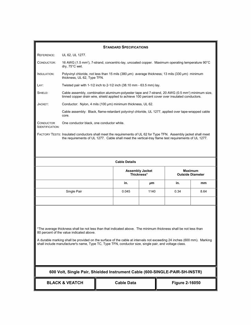
STANDARD SPECIFICATIONS
REFERENCE: UL 62, UL 1277. CONDUCTOR: 16 AWG (1.5 mm2), 7-strand, concentric-lay, uncoated copper. Maximum operating temperature 90°C
dry, 75°C wet. INSULATION: Polyvinyl chloride, not less than 15 mils (380 µm) average thickness; 13 mils (330 µm) minimum
thickness, UL 62, Type TFN. LAY: Twisted pair with 1-1/2 inch to 2-1/2 inch (38.10 mm - 63.5 mm) lay. SHIELD: Cable assembly, combination aluminum-polyester tape and 7-strand, 20 AWG (0.5 mm2) minimum size,
tinned copper drain wire, shield applied to achieve 100 percent cover over insulated conductors. JACKET: Conductor: Nylon, 4 mils (100 µm) minimum thickness, UL 62. Cable assembly: Black, flame-retardant polyvinyl chloride, UL 1277, applied over tape-wrapped cable
core. CONDUCTOR One conductor black, one conductor white. IDENTIFICATION: FACTORY TESTS: Insulated conductors shall meet the requirements of UL 62 for Type TFN. Assembly jacket shall meet
the requirements of UL 1277. Cable shall meet the vertical-tray flame test requirements of UL 1277.
Cable Details
Assembly Jacket Thickness*
Maximum Outside Diameter
in. µm in. mm
Single Pair 0.045 1140 0.34 8.64
*The average thickness shall be not less than that indicated above. The minimum thickness shall be not less than 80 percent of the value indicated above. A durable marking shall be provided on the surface of the cable at intervals not exceeding 24 inches (600 mm). Marking shall include manufacturer's name, Type TC, Type TFN, conductor size, single pair, and voltage class.
600 Volt, Single Pair, Shielded Instrument Cable (600-SINGLE-PAIR-SH-INSTR)
BLACK & VEATCH Cable Data Figure 2-16050

STANDARD SPECIFICATIONS
REFERENCE: UL 62, UL 1277. CONDUCTOR: 16 AWG (1.5 mm2), 7-strand, concentric-lay, uncoated copper. Maximum operating temperature 90°C
dry, 75°C wet. INSULATION: Polyvinyl chloride, not less than 15 mils (380 µm) average thickness; 13 mils (330 µm) minimum
thickness, UL 62, Type TFN. LAY: Twisted triad with 1-1/2 inch to 2-1/2 inch (38.10 mm - 63.5 mm) lay. SHIELD: Cable assembly, combination aluminum-polyester tape and 7-strand, 20 AWG (0.5 mm2) minimum size,
tinned copper drain wire, shield applied to achieve 100 percent cover over insulated conductors. JACKET: Conductor: Nylon, 4 mils (100 µm) minimum thickness, UL 62. Cable assembly: Black, flame-retardant polyvinyl chloride, UL 1277, applied over tape-wrapped cable
core. CONDUCTOR One conductor black, one conductor white, one conductor red. IDENTIFICATION: FACTORY TESTS: Insulated conductors shall meet the requirements of UL 62 for Type TFN. Assembly jacket shall meet
the requirements of UL 1277. Cable shall meet the vertical-tray flame test requirements of UL 1277.
Cable Details
Assembly Jacket Thickness*
Maximum Outside Diameter
in. µm in. mm
Single Triad 0.045 1140 0.35 8.87
*The average thickness shall be not less than that indicated above. The minimum thickness shall be not less than 80 percent of the value indicated above. A durable marking shall be provided on the surface of the cable at intervals not exceeding 24 inches (600 mm). Marking shall include manufacturer's name, Type TC, Type TFN, conductor size, single triad, and voltage class.
600 Volt, Single Triad, Shielded Instrument Cable (600-SINGLE-TRIAD-SH-INSTR)
BLACK & VEATCH Cable Data Figure 3-16050

STANDARD SPECIFICATIONS
REFERENCE: UL 62, UL 1277.
CONDUCTOR: 18 AWG (0.75 mm2), 7-strand, concentric-lay, uncoated copper. Maximum operating temperature 90°C dry,
75°C wet.
INSULATION: Polyvinyl chloride, not less than 15 mils (380 µm) average thickness; 13 mils (330 µm) minimum thickness, UL 62, Type TFN.
LAY: Twisted pairs or triads with 1-1/2 inch to 2-1/2 inch (38.10 - 63.5 mm) lay.
SHIELD: Each pair or triad and cable assembly: Combination aluminum-polyester tape and 7-strand, 20 AWG (0.5 mm2) minimum size, tinned copper drain wire, shield applied to achieve 100 percent cover over insulated conductors. Shield tape on pair and/or triad assemblies shall be applied in such a way as to give total shield isolation from other pairs' or triads' shields.
JACKET: Conductor: Nylon, 4 mils (100 µm) minimum thickness, UL 62.
Cable Assembly: Black, 90°C, flame-retardant polyvinyl chloride, UL 1277, Table 10.17, applied over tape-wrapped cable core.
CONDUCTOR IDENTIFICATION:
Pair: One conductor black, one conductor white.
Triad: One conductor black, one conductor white, one conductor red.
PAIR Identification: Each pair and/or triad numbered.
FACTORY TESTS: Insulated conductors shall meet the requirements of UL 62 for Type TFN. Assembly jacket shall meet the requirements of UL 1277. Cable shall meet the vertical-tray flame test requirements of UL 1277.
Cable Details
Assembly Jacket Thickness* Maximum Outside Diameter
in. µm in. mm
Number of Pairs
4 0.045 1140 0.554 14.07
8 0.060 1520 0.749 19.02
12 0.060 1520 0.896 22.76
24 0.060 1520 1.256 31.90
Number of Triads
4 0.060 1520 0.648 16.46
8 0.060 1520 0.823 20.99
12 0.080 2030 1.030 26.16
24 0.080 2030 1.393 35.38
*The average thickness shall be not less than that indicated above. The minimum thickness shall be not less than 80 percent of the values indicated above.
A durable marking shall be provided on the surface of the cable at intervals not exceeding 24 inches (600 mm). Markingshall include manufacturer's name, Type TC, Type TFN, conductor size, number of pairs or triads, and voltage class.
600 Volt, Multiple Pair and/or Triad, Shielded Instrument Cable
(600-MULTI-PAIRS-TRIADS-SH-INSTR)
BLACK & VEATCH Cable Data Figure 4-16050

STANDARD SPECIFICATIONS
REFERENCE: UL 83, UL 1277, ICEA S-73-532, ICEA S-58-679. CONDUCTOR: 14 AWG (2.5 mm2), 7 or 19 strands, concentric-lay, uncoated copper. Maximum operating temperature
90°C dry, 75°C wet. INSULATION: Polyvinyl chloride, not less than 15 mils (380 µm) average thickness; 13 mils (330 µm) minimum
thickness, UL 83, Type THHN and THWN. SHIELD: None. JACKET: Conductor: Nylon, 4 mils (100 µm) minimum thickness, UL 83. Cable assembly: Black, flame-retardant polyvinyl chloride, UL 1277, applied over tape-wrapped cable
core. CONDUCTOR ICEA S-58-679, Method 1, Table 2 or ICEA S-58-679, Method 3, Table 2. White IDENTIFICATION: or green conductors shall not be provided. FACTORY TESTS: Insulated conductors shall meet the requirements of UL 83 for Type THHN-THWN. Assembly jacket
shall meet the requirements of UL 1277. Cable shall meet the flame test requirements of UL 1277 for Type TC power and control tray cable.
Cable Details
Number of Conductors
Assembly Jacket Thickness*
Maximum Outside Diameter
in. µm in. mm
2 0.045 1140 0.38 9.65
3 0.045 1140 0.39 9.91
4 0.045 1140 0.44 11.18
5 0.045 1140 0.46 11.68
7 0.045 1140 0.49 12.45
9 0.045 1140 0.61 15.49
12 0.060 1520 0.66 16.76
19 0.060 1520 0.77 19.56
24 0.060 1520 0.93 23.62
30 0.080 2030 0.98 24.89
37 0.080 2030 1.05 26.67
*The average thickness shall be not less than that indicated above. The minimum thickness shall be not less than 80 percent of the values indicated above. A durable marking shall be provided on the surface of the cable at intervals not exceeding 24 inches (600 mm). Marking shall include manufacturer's name, Type TC, Type THWN or THHN, conductor size, number of conductors, and voltage class.
600 Volt, Multiconductor 14 AWG (2.5 mm2) Control Cable (600-MULTI-THHN-THWN)
BLACK & VEATCH Cable Data Figure 5-1605026 05 11


(Orange County Utilities) Bid Issue
(Master Pump Station Improvements) 16100-1 October 2011
(Group 4A2)
Section 16100
ELECTRICAL EQUIPMENT INSTALLATION
PART 1 - GENERAL
1-1. SCOPE. This section covers the installation of electrical equipment.
1-2. GENERAL. Equipment specified to be installed under this section shall be erected, and
placed in proper operating condition in full conformity with drawings, specifications,
engineering data, instructions, and recommendations of the equipment manufacturer, unless
exceptions are noted by ENGINEER.
The electrical equipment identified as being provided by others will be furnished complete for
installation by CONTRACTOR. Technical specifications under which the equipment will be
purchased are available.
1-2.01. Coordination. When manufacturer's field services are provided by the equipment
manufacturer, CONTRACTOR shall coordinate the services with the equipment manufacturer.
CONTRACTOR shall give ENGINEER written notice at least 14 days prior to the need for
manufacturer's field services furnished by others.
Submittals for equipment furnished under the original procurement contract will be furnished to
CONTRACTOR upon completion of review by ENGINEER. CONTRACTOR shall review
equipment submittals and coordinate with the requirements of the Work and the Contract
Documents. CONTRACTOR accepts sole responsibility for determining and verifying all
quantities, dimensions, and field construction criteria.
1-3. DELIVERY, STORAGE, AND HANDLING.
1-3.01. Delivery. When sills are required for electrical equipment, they shall be shipped ahead
of the scheduled equipment delivery to permit installation before concrete is placed.
1-3.02. Storage. Upon delivery, all equipment and materials shall immediately be stored and
protected by CONTRACTOR in accordance with Section 01614, and in accordance with
manufacturer's written instructions, until installed in the Work. Equipment shall be protected by
CONTRACTOR against damage and exposure from the elements. At no time shall the
equipment be stored on earth or grass surfaces or come into contact with earth or grass.
CONTRACTOR shall keep the equipment clean and dry at all times. Openings shall be plugged
or capped (or otherwise sealed by packaging) during temporary storage.
1-3.03. Handling. Electrical equipment shall be moved by lifting, jacking, or skidding on rollers
as described in the manufacturer's instructions. Special lifting harness or apparatus shall be used
when required. Lifting and jacking points shall be used when identified on the equipment.
CONTRACTOR shall have required unloading equipment on site to perform unloading work on
the date of equipment delivery.
(Orange County Utilities) Bid Issue
(Master Pump Station Improvements) 16100-2 October 2011
(Group 4A2)
1-4. ARC FLASH HAZARD LABELS. Switchgear, switchboards, motor control centers, motor
control line-ups, and transfer switches shall be provided with permanent labels warning the risk
of arc flash and shock hazard. Labels shall be designed in accordance with ANSI Z535.4-1998
and shall include the following information:
WARNING
Arc Flash and Shock Hazard
Appropriate personal protection equipment (PPE) required. See NFPA 70E.
Equipment must be accessed by qualified personnel only.
Turn off all power sources prior to working on or inside equipment.
Additional information shall be provided on the labels where specified in the Arc Flash Hazard
Analysis section of specification 16050.
PART 2 - PRODUCTS
Not used.
PART 3 - EXECUTION
3-1. INSTALLATION, TESTING, AND COMMISSIONING. All installation work shall be in
accordance with manufacturer's written instructions.
All material, equipment, and components specified to be installed according to this Section shall
be installed, tested, and commissioned for operation in compliance with NECA 1000 – NEIS
Specification System. Where required in NECA 1000, testing and commissioning procedures
shall be followed prior to energizing equipment.
Electrical equipment cubicles and vertical sections shall be installed plumb and level. Drawout
equipment carriages, circuit breakers, and other removable components shall operate free and
easy without binding or distortion.
Unless otherwise indicated or specified, all indoor floor-mounted electrical equipment and
control cabinets shall be installed on concrete equipment pads four inches [102 mm] in height.
3-1.01. Cleaning. All deposits of oil, grease, mud, dirt or debris shall be cleaned from the
electrical equipment following installation and field wiring. A detergent water based solution, or
other liquid cleaners not harmful to material or equipment finishes, shall be used as
recommended by the manufacturer.
End of Section

(Orange County Utilities) Bid Issue
(Master Pump Station Improvements) 16220-1 October 2011
(Group 4A2)
Section 16220
GENERAL PURPOSE INDUCTION MOTORS
PART 1 - GENERAL
1-1. SCOPE. This section covers single and three-phase, small (fractional) and medium
(integral) horsepower, alternating current motors rated 500 horsepower and less (NEMA MG1).
Motors shall be designated and coordinated with the driven equipment and shall be located as
indicated on the drawings.
1-2. GENERAL. Motors furnished under Driven Equipment Specification sections shall be
fabricated and assembled in full conformity with drawings, specifications, engineering data,
instructions, and recommendations of the equipment manufacturer unless exceptions are noted
by the ENGINEER.
1-2.01. General Equipment Stipulations. The General Equipment Stipulations shall apply to all
motors, unless otherwise specified. If requirements in this specification differ from those in the
General Equipment Stipulations, the requirements specified herein shall take precedence.
1-2.02. Governing Standards. Motors furnished under this section shall be designed,
constructed, and tested in accordance with the latest version of NEMA MG 1 and IEEE 112, Test
Method B.
1-2.03. Nameplates. All motor nameplate data shall conform to NEMA MG 1 requirements.
1-3. SUBMITTALS. Complete assembly, foundation, and installation drawings, together with
complete engineering data covering the materials used, parts, devices, and accessories forming a
part of the motor shall be submitted in accordance with the submittals section. The drawings and
data shall include, but shall not be limited to, the following:
Motors
Name of manufacturer.
Type and model.
Type of bearing and method of lubrication.
Rated size of motor, hp [kW], and service factor.
Temperature rise and insulation rating.
Full load rotative speed.
Net weight.
Efficiency at full, 3/4, and 1/2 load.
Full load current.
Locked rotor current.
Space heater wattage, where applicable.
Motor temperature switch data, where applicable.
RTD data, where applicable.

(Orange County Utilities) Bid Issue
(Master Pump Station Improvements) 16220-2 October 2011
(Group 4A2)
1-4. OPERATION AND MAINTENANCE DATA AND MANUALS. Adequate operation and
maintenance information shall be supplied. Operation and maintenance manuals shall be
submitted in accordance with the submittals section.
Operation and maintenance manuals shall include the following:
a. Assembly, installation, alignment, adjustment, and checking
instructions.
b. Lubrication and maintenance instructions.
c. Guide to troubleshooting.
d. Parts lists and predicted life of parts subject to wear.
e. Outline, cross-section, and assembly drawings; engineering data; and
wiring diagrams.
f. Test data and performance curves, where applicable.
PART 2 - PRODUCTS
2-1. SERVICE CONDITIONS. Service conditions for motors shall be as specified in the driven
equipment specification sections. Motors shall be designed for special conditions such as area
classification, altitude, frequent starting, intermittent overload, high inertia, mounting
configuration, or service environment. Where site elevation and ambient temperature is not
specified in the driven equipment specification sections, the motors shall be designed for the
following.
Site elevation Below 3,300 ft [1,000 m]
Ambient temperature 50 °C
Unless specified otherwise, all motors shall be designed for full voltage starting and to operate
from an electrical system that may have a maximum of 5 percent voltage distortion according to
IEEE 519.
Motors utilizing a reduced-voltage, autotransformer starter shall be capable of reduced-voltage
starting at a 65 percent tap setting.
Motors utilizing a reduced voltage solid state starter shall be capable of starting at 50% of the
specified voltage.
When powered from an adjustable frequency drive (AFD), motors shall be inverter duty and
specifically selected for service with an adjustable frequency type speed controller and shall be
derated as required to compensate for harmonic heating effects and reduced self-cooling
capability at low speed operation. Each motor shall not exceed a Class B temperature rise when
operating in the installed condition at load with power received from the adjustable frequency
drive. All motors driven by AFDs shall be supplied with full phase insulation on the end turns

(Orange County Utilities) Bid Issue
(Master Pump Station Improvements) 16220-3 October 2011
(Group 4A2)
and shall meet the requirements of NEMA MG 1, Part 31. In addition to the requirements of
NEMA MG 1, Part 31, motors shall be designed to be continually pulsed at the motor terminals
with a voltage of 1600 volts ac.
2-2. PERFORMANCE AND DESIGN REQUIREMENTS. Design and construction of each
general-purpose motor shall be as specified herein. Motor voltage, frequency, speed, service
factor, and insulation class shall be as follows.
Motor voltage. 460, 3 phase for ½ horsepower and larger,
120, single phase for smaller than ½
horsepower
Frequency. 60 Hz
Speed. Constant speed
Service factor. 1.15
Insulation class and temperature rise
above 40o C design ambient (by
resistance method.
Class F with 80o C rise at 1.0 SF
Enclosure. Totally enclosed fan cooled
Main conduit box sized to include. Main motor leads and space heater leads
where space heaters are specified
2-2.01. Nameplate Horsepower. Motor nameplate horsepower [kW] shall be equal to or greater
than the maximum load imposed by the driven equipment.
2-2.02. Enclosures. All motors shall be self-ventilated. All self-ventilated open type motors,
including those with dripproof, splashproof, and weather protected enclosures, and the fan covers
of totally enclosed fan cooled motors shall meet NEMA MG 1 requirements for a fully guarded
machine.
2-2.02.01. Totally Enclosed Motors. Totally enclosed motors shall be furnished with drain holes
and rotating shaft seals. Frames, bearing brackets, external terminal housings, and fan covers for
fan cooled motors shall be cast iron. External cooling fans for fan cooled motors shall be
fabricated of brass, bronze, aluminum alloy containing not more than 0.2 percent copper,
malleable iron, or plastic. All plastic fans shall be fabricated of a reinforced thermosetting
plastic and shall be UL approved.
2-2.02.02. Outdoor Motors. Outdoor motors shall have NEMA weather protected enclosures.
All exposed metal surfaces shall be protected, where practical, with a corrosion resistant
polyester coating. Exposed uncoated surfaces shall be of a corrosion resistant metal. Enclosure
exterior and interior surfaces, air gap surfaces, and windings shall be protected with a corrosion
resistant alkyd enamel, polyester, or epoxy coating.
2-2.02.03. Motors for Hazardous Locations. Motors for hazardous locations shall be in
accordance with the NEC and of the correct type enclosures for the particular service as specified
in NEMA MG 1. Motors shall meet the requirements of UL 674.
2-2.02.04. Encapsulated Windings. Where required, motors shall be provided with
encapsulated windings meeting the requirements of NEMA MG1-1.27.2.

(Orange County Utilities) Bid Issue
(Master Pump Station Improvements) 16220-4 October 2011
(Group 4A2)
2-2.02.05. Severe Duty Chemical Service Motors. Motors shall be provided with special
corrosion-resistant finish and encapsulated windings meeting the requirements of NEMA
MG1-1.27.2 and IEEE 841.
2-2.03. Main Conduit Boxes. The main conduit box shall be in accordance with NEMA MG 1.
The main conduit boxes shall be diagonally split for easy access to the motor leads, and designed
for rotation in 90-degree increments. A gasket shall be furnished between the halves of the box.
Conduit openings in the main conduit box shall match the size and quantity of conduits indicated
on the one line drawings.
The main conduit box shall be oversized at least one size larger than NEMA standard. The main
conduit box shall be sized for all indicated accessory leads.
Motors furnished in NEMA 320 frame series and larger shall have conduit boxes designed and
constructed to permit motor removal after installation without disconnecting raceways.
2-2.04. Leads. Motor power leads shall be wired into the main conduit box. Unless otherwise
specified, space heater leads shall be wired into the main conduit box. All motor leads and their
terminals shall be permanently marked in accordance with the requirements of NEMA MG 1,
Part 2. Each lead marking shall be visible after taping of the terminals.
All motors rated 100 horsepower [74 kW] and larger, and all vertical motors shall have the
direction of rotation marked by an arrow mounted visibly on the stator frame near the terminal
housing, or on the nameplate, and the leads marked for phase sequence T1, T2, T3, to correspond
to the direction of rotation and supply voltage sequence.
Leads for dual-voltage rated or for multispeed motors shall be easily connected or reconnected in
the main conduit box for the operating voltage or for the specified speeds. Permanent
instructions for making these connections shall be furnished inside the main conduit box or on
the motor frame or nameplate.
2-2.05. Terminals. Cable type leads shall be provided with Burndy Type YA or acceptable
equal compression type connectors.
2-2.06. Grounding Connections. All motors shall be furnished with a ground connection.
2-2.07. Bearings. All bearings shall be self-lubricating, shall have provisions for relubrication,
and shall be designed to operate in any position or at any angle.
Motor bearings shall be antifriction type with L10 life rating of 40,000 hours in accordance with
AFBMA Standards.
All bearing mountings shall be designed to prevent the entrance of lubricant into the motor
enclosure or dirt into the bearings, and shall be fitted with pipes, drain plugs, and fittings
arranged for safe, easy relubrication from the outside of the motor while the motor is in service,
as necessary.

(Orange County Utilities) Bid Issue
(Master Pump Station Improvements) 16220-5 October 2011
(Group 4A2)
2-2.08. Rotors. All induction motors shall have squirrel-cage rotors adequately sized to avoid
overheating during acceleration of the motor and driven equipment. Rotors shall be dynamically
balanced to 0.08 in./sec [2.03 mm/s] or less.
2-2.09. Shafts. Shafts shall be furnished with corrosion resistant treatment or shall be of a
corrosion resistant material.
2-2.10. Torque Characteristics. Motors rated 200 horsepower [149 kW] and less shall have
torques and locked-rotor current in accordance with NEMA MG 1, Part 12.
2-2.11. Motor Space Heaters. Unless otherwise specified, motors 1 horsepower and larger shall
be provided with a space heater element sized to prevent condensation on the core and windings.
The space heaters shall be isolated or so located as to prevent heat damage to adjacent painted
surfaces and shall be suitable for 120 volt, 60 Hz, single phase power supply.
2-2.12. Temperature Sensing Devices. Each motor controlled by an adjustable frequency drive
shall be furnished with at least one automatic reset winding temperature switch per phase.
Temperature switch contacts shall be normally closed and rated 5 amps at 120 volts ac. The
contacts shall be wired in series with the end leads brought out to the motor terminal box.
2-2.13. Assembly. All motors shall be completely assembled with the driven equipment,
lubricated, and ready for operation.
2-2.14. Efficiency. Motors shall be premium efficiency type and shall have a NEMA nominal
efficiency nameplate value equal to or greater than values indicated in the following table.
Efficiency shall be determined in accordance with IEEE 112, Test Method B.
Vertical motors shall have efficiency values equal to or greater than those indicated in the
following table minus 0.50.
Motor Nominal Efficiency Values Nominal Efficiency Values
kW hp
Open Drip Enclosure TEFC Enclosure
3600
rpm
1800
rpm
1200
rpm
900
rpm
3600
rpm
1800
rpm
1200
rpm
900
rpm
0.7 1 84.0 85.5 82.5 75.0 77.0 85.5 82.5 75.5
1.1 1.5 84.0 86.5 86.5 78.0 84.0 86.5 87.5 80.0
1.5 2 85.5 86.5 87.5 86.5 85.5 86.5 88.5 85.5
2.2 3 85.5 89.5 88.5 89.5 87.0 89.5 89.5 86.5
3.7 5 86.5 89.5 89.5 89.5 88.5 89.5 89.5 85.5
5.6 7.5 88.5 91.0 90.2 88.5 90.0 91.7 91.0 86.5
7.5 10 89.5 91.7 91.7 91.0 91.0 91.7 91.0 91.0

(Orange County Utilities) Bid Issue
(Master Pump Station Improvements) 16220-6 October 2011
(Group 4A2)
Motor Nominal Efficiency Values Nominal Efficiency Values
kW hp
Open Drip Enclosure TEFC Enclosure
3600
rpm
1800
rpm
1200
rpm
900
rpm
3600
rpm
1800
rpm
1200
rpm
900
rpm
11.2 15 90.2 93.0 91.7 91.0 91.0 92.4 92.0 91.0
14.9 20 91.7 93.0 92.4 92.0 92.0 93.0 92.0 91.0
18.7 25 92.4 93.6 93.0 92.0 92.0 93.6 93.0 91.0
22.4 30 93.0 94.1 93.6 93.0 92.4 93.6 93.0 93.0
29.8 40 93.0 94.1 94.1 93.0 92.4 94.1 94.1 93.0
37.3 50 93.0 94.5 94.1 93.0 93.0 94.5 94.1 93.0
44.8 60 93.6 95.0 94.5 94.0 93.6 95.0 94.5 93.0
56 75 94.0 95.0 95.0 94.0 93.6 95.4 95.0 94.0
74.6 100 94.5 95.4 95.0 95.0 94.1 95.4 95.0 94.0
93.2 125 95.0 95.4 95.0 95.0 95.0 95.4 95.0 94.0
112 150 95.0 95.8 95.4 95.0 95.0 95.8 95.8 94.0
149 200 95.4 95.8 95.4 95.0 95.4 96.2 95.8 94.1
186 250 95.0 95.8 95.4 95.0 95.8 96.2 95.8 94.5
224 300 95.4 95.8 95.4 95.8 96.2 95.8
261 350 95.4 95.8 95.4 95.8 96.2 95.8
298 400 95.8 95.8 95.8 95.8 96.2 95.8
336 450 95.8 96.2 96.2 95.8 96.2 95.8
373 500 95.8 96.2 96.2 95.8 96.2 95.8
2-3. ACCESSORIES.
2-3.01. Special Tools and Accessories. Motors requiring periodic repair and adjustment shall be
furnished complete with all special tools, instruments, and accessories required for proper
maintenance. Each motor shall be provided with lifting eyebolts or lugs and appropriate fittings
for adding bearing lubricant. Grease lubricated units shall be provided with a means of venting
the casing. Oil lubricated units shall be provided with constant level oilers or with sight glasses
arranged to indicate operating and static oil levels.
2-4. ANCHORS. CONTRACTOR shall furnish suitable anchors for each item of equipment as
required for driven equipment.

(Orange County Utilities) Bid Issue
(Master Pump Station Improvements) 16220-7 October 2011
(Group 4A2)
2-5. BALANCE. All rotating parts shall be accurately machined and shall be in as nearly
perfect rotational balance as practicable. Excessive vibration shall be sufficient cause for
rejection of the equipment. The mass of the unit and its distribution shall be such that resonance
at normal operating speeds is avoided. In any case, the unfiltered vibration displacement
(peak-to-peak), as measured at any point on the machine, shall not exceed the limits as required
.At any operating speed, the ratio of rotative speed to the critical speed of a unit or its
components shall be less than 0.8 or more than 1.3.
PART 3 - EXECUTION
3-1. INSTALLATION. Each motor will be installed in accordance with the Equipment
Installation section.
End of Section

This page was left blank intentionally

(Orange County Utilities) Bid Issue
(Master Pump Station Improvements) 16491-1 October 2011
(Group 4A2)
Section 16491
AUTOMATIC TRANSFER SWITCH
PART 1 - GENERAL
1-1. SCOPE. This section covers outdoor automatic transfer switches, which shall be
furnished, and tested as specified and as indicated on the drawings.
Automatic transfer switch equipment shall meet the design conditions and features.
1-2. GENERAL. Equipment furnished and installed under this section shall be fabricated,
assembled, erected, and placed in proper operating condition in full conformity with the
drawings, specifications, engineering data, instructions, and recommendations of the equipment
manufacturer, unless exceptions are noted by Engineer.
1-2.01. General Equipment Stipulations. The General Equipment Stipulations shall apply to all
equipment furnished under this section. If stipulations in this specification differ from those in
the General Equipment Stipulations, the requirements specified herein shall take precedence.
1-2.02. Dimensional Restrictions. Layout dimensions will vary between manufacturers and the
layout area indicated on the drawings is based on typical values. Contractor shall review the
contract drawings, the manufacturer's layout drawings and installation requirements, and make
any modifications required for proper installation subject to acceptance by Engineer.
1-2.03. Workmanship and Materials. Equipment supplier shall guarantee all equipment against
faulty or inadequate design, improper assembly or erection, defective workmanship or materials,
and leakage, breakage, or other failure. Materials shall be suitable for service conditions.
1-2.04. Governing Standards. The equipment furnished under this section shall be designed,
constructed, and tested in accordance with UL 1008, Standard for Safety Transfer Switch
Equipment; NFPA 110, Standard for Emergency and Standby Power Systems; and the latest
applicable standards of ANSI, NEMA, and IEEE.
1-2.05. Nameplates. Each control device and each control wire terminal block connection inside
the units shall be identified with a permanent nameplate or painted legend to match the
identification on the manufacturer's wiring diagram.
1-2.06. System Characteristics. The equipment will be connected to a power system with
characteristics as specified below:
Voltage, phase 480, 3-phase
Frequency 60 Hz
Number of conductors 4-wire

(Orange County Utilities) Bid Issue
(Master Pump Station Improvements) 16491-2 October 2011
(Group 4A2)
1-3. SUBMITTALS. Complete assembly, foundation, and installation drawings, together with
complete engineering data covering the materials used, parts, devices, and accessories forming a
part of the transfer switch, shall be submitted in accordance with the submittals section. The
drawings and data shall include, but shall not be limited to, the following:
Drawings showing front and side views, plan, and weight.
Rating and specifications.
Circuit breaker time-current characteristic curves, if applicable.
Single-line, control schematic, and wiring connection diagrams.
Operation and maintenance and manuals including a list of spare parts.
1-4. OPERATION AND MAINTENANCE MANUALS. Adequate operation and maintenance
information shall be supplied as required in the Submittals section. Operation and maintenance
manuals shall be submitted in accordance with the Submittals section. The operation and
maintenance manuals shall be in addition to any instructions or parts lists packed with or
attached to the equipment when delivered.
1-5. DELIVERY, STORAGE, AND HANDLING. Shipping shall be in accordance with the
Shipping section. Handling and Storage shall be in accordance with the Handling and Storage
section.
PART 2 - PRODUCTS
2-1. ACCEPTABLE MANUFACTURERS. The automatic transfer switch shall be
manufactured by Russell Electric or Eaton Cutler-Hammer.
2-2. CONSTRUCTION FEATURES.
2-2.01. Enclosure. The enclosure for the transfer switch shall be as follows:
Type of mounting Freestanding or wall Mounted
Enclosure rating Outdoor NEMA Type 3R or 4X stainless steel for pad
or Wall mounting, with drip shield and door gasket.
2-2.02. Rating. Automatic transfer switches shall be service entrance rated for continuous duty
in both normal and emergency positions. The transfer switch shall be rated as indicated on the
drawings.
2-2.03. Space Heaters. A thermostatically controlled space heater, sized to prevent
condensation within the enclosure, shall be provided. A disconnect switch shall be provided for
the heater circuit. The space heater shall be rated for 120 volts ac and will be powered from an
internal power source.
2-2.04. Surge Protection Device. Surge protection devices shall be provided for each ATS as
indicated on the drawings and as specified in 16050.

(Orange County Utilities) Bid Issue
(Master Pump Station Improvements) 16491-3 October 2011
(Group 4A2)
2-3. PERFORMANCE AND DESIGN REQUIREMENTS.
2-3.01. Equipment Description. The automatic transfer switches shall transfer electric loads
from the normal source of electric power to an emergency source of power as indicated on the
drawings. The transfer switches shall automatically transfer the electrical load circuits upon an
interruption or a decrease in the voltage of the normal source of power and shall transfer the
loads back to the normal source when it becomes available. The transfer switches shall be
furnished with integral overcurrent protection as required. The switches shall be electrically
operated but mechanically held in both the normal and emergency positions. The operating
mechanism shall be momentarily energized from the source to which the load is being
transferred. The automatic transfer switches shall be so designed that the load circuits cannot
be connected to more than one source of power at a time.
2-3.01.01. Automatic Transfer Switch. .
1. Switches shall be Floor or Wall Mounted construction, Nema 4X 316 Stainless Steel.
There shall be permanently affixed to the interior of the enclosure door both a data-plate
that includes generator KVA/KW, fuel tank capacity, rated fuel consumption, serial and
model number of generator set, and a 10-inch x 12 inch pocket for log sheet storage.
2. The switching panel shall consist of completely enclosed assemblies and a separate
control or transformer panel. Control power for all transfer operations shall be derived
from the line side of the source to which the load is being transferred.
3. Each transfer switch shall be positively interlocked both mechanically and electrically to
prevent simultaneous closing of both sources under either automatic or manual operation.
Main contacts shall be mechanically locked in position in both normal and emergency
positions.
4. Transfer switches shall be capable of being operated manually under full rated load
conditions. Manual operation shall be accomplished by a permanently attached manual
operator, or by integrally mounted pushbuttons. Removable manual operating handles,
and handles that may move in the event of an electrical operation during the manual
operation, are not acceptable. Manual operators requiring source or load disconnection
prior to manual operation are not acceptable.
5. The transfer switch shall have a multi-tap voltage selection plug for ease of voltage
adjustment in the field.
6. Where shown on the drawings, transfer switches applied as service entrance equipment,
shall be provided with over-current trip units and a service entrance label. A key-operated
selector switch shall be provided to disconnect the power supplies. Indicators shall be
provided to show the availability of each source as well as breakers in a disconnected
position. Provide a neutral disconnect link for four-pole switched neutral switches, and a
removable neutral-to-ground main bonding jumper, on utility incoming source only, for
switches to meet UL service entrance requirements.
7. Where indicated on the drawings, the transfer switches shall be provided with a draw-out
mechanism to allow easy access for preventive maintenance, testing or inspection. The
draw-out mechanism shall provide visual indicators as to the position of the
switch/breaker during the draw-out operation.
2-3.01.02. Bypass-Isolation Switch. Not Used.

(Orange County Utilities) Bid Issue
(Master Pump Station Improvements) 16491-4 October 2011
(Group 4A2)
2-3.01.03. Control System. The microprocessor-based logic controller shall be door
mounted and shall provide the operator with an overview of the transfer switch status,
parameters, and diagnostic data. The controller shall be hardened against potential problems
from transients and surges. Operation of the transfer switch and monitoring of both sources shall
be managed by the controller. The controller shall have a voltage range of 0-790 volts (50/60 Hz)
and an accuracy of +/- 2% of nominal input voltage. The controller shall have a frequency range
of 40-80 Hz and an accuracy of +/- .1 Hz. Control power input range shall be from 65 Vac – 160
Vac RMS 50/60 Hz. The controller shall be listed under UL Standard 1008.
The microprocessor-based controller shall include an LED display, and shall display the
following:
A detailed step-by-step operating instruction plate shall be provided on the front of the switch.
Connected Source and Load voltages on all phases
Connected Source and Load frequency
Condition status – Under-voltage, under-frequency, etc…
Real time clock for Time / Date stamp
Historical data
Programming and set point information
Password entry
Timer countdown for each timer while functioning
Help function for detailed description of displayed messages
The microprocessor-based controller shall include individual LED’s for indicating the following:
Mimic Bus Diagram showing Availability status of NORMAL source
Mimic Bus Diagram showing Availability status of EMERGENCY source
Mimic Bus Diagram showing Connection status of NORMAL source
Mimic Bus Diagram showing Connection status of EMERGENCY source
Mimic Bus Diagram showing Preferred status of NORMAL source
Mimic Bus Diagram showing Preferred status of EMERGENCY source
Mimic Bus Diagram showing Energized status of LOAD
Automatic mode
Test mode
Program mode
Display Navigational indicators for Status, Source 1, Source 2, History, Time/Date and Set
Points
The microprocessor-based controller shall contain the following features:
Password programming protection
Set points shall be stored in Non-Volatile memory, and use of an external battery source to
maintain operation during “dead” periods shall not be required.
Selector Switch for “PROGRAM” or “RUN”
Historical Data Storage to include:
Engine Run Time
NORMAL source Available time
EMERGENCY source Available time
NORMAL source Connected time
EMERGENCY source Connected time

(Orange County Utilities) Bid Issue
(Master Pump Station Improvements) 16491-5 October 2011
(Group 4A2)
LOAD Energized Time
Number of Transfers
Date, Time and Reason for Last Sixteen (16) transfers
The microprocessor-based controller shall contain the following voltage and frequency features:
The voltage of each phase of the NORMAL source and the EMERGENCY source shall be
monitored, with under-voltage dropout adjustable from 50% to 90% of nominal and pickup
adjustable from dropout setting +/-2% to 100% of nominal. The transfer to emergency will be
initiated upon reduction of the normal source to 85 percent of the normal voltage, and retransfer
to normal shall occur when the normal source restores to 90 percent of the normal voltage.
The frequency of the NORMAL source and the EMERGENCY source shall be monitored with
under-frequency dropout adjustable from 90% to 100% of nominal and pickup adjustable from
dropout setting +1 Hz to 110% of nominal.
The microprocessor-based controller shall contain the following time delay features:
A time delay shall be provided on transfer to EMERGENCY source, adjustable from 0 to 1800
seconds. TDNE – Time Delay Normal to Emergency
A time delay shall be provided to override a momentary power outage or voltage fluctuation,
adjustable from 0 to 120 seconds. TDES – Time Delay engine Start
A time delay shall be provided on retransfer from EMERGENCY source to NORMAL source,
adjustable from 0 to 1800 seconds. The time delay shall be automatically bypassed if the
emergency source fails and the normal source is available. TDEN – Time Delay Emergency to
Normal
A time delay shall be provided after retransfer that allows the generator to run unloaded prior to
shutdown, adjustable form 0 to 1800 seconds. TDEC – Time Delay Engine Cool down
A time delay shall be provided for engine failure to start, fixed setting of 6 seconds. TDEF –
Time Delay Engine Fail
An In-Phase Monitor transition, which will permit a transfer or re-transfer between the
NORMAL and EMERGENCY sources that have a phase angle difference of 8 degrees or less.
Feature to include a permissible frequency difference and synchronization time set points of 1-60
minutes. The adjustable frequency difference shall be 0.00 to 3.0 Hz
All delays shall be field adjustable from the microprocessor-based controller without the use of
special tools.
The microprocessor-based controller shall contain the following features:
“HELP”, “INCREASE”, “DECREASE”, “STEP” and “DISPLAY SELECT” pushbuttons
Plant exerciser, selectable – 7-day interval, adjustable 0-600 minutes, load or no-load with
Failsafe
System Test Pushbutton
Maintained 4-Position Test Switch “AUTO”, “TEST”, ENGINE START” and “OFF”
Bypass Time Delay Emergency to Normal (TDEN) Pushbutton
Bypass Time Delay Normal to Emergency (TDNE) Pushbutton
Maintenance Electrical Operator Isolator Switch. Provide a 2-Position Selector Switch,
maintained contact, marked: “OPERATE” and “DISABLE”.
Lockable stainless steel cover for controller
Space heater

(Orange County Utilities) Bid Issue
(Master Pump Station Improvements) 16491-6 October 2011
(Group 4A2)
The microprocessor-based controller shall contain the following input/output contacts:
One (1) Form A contact for closure of the Generator start circuit. The contacts shall be of silver
alloy with gold flashing. The contacts shall be rated for 5-Amp at 250-Vac and 5-Amp at 30-
Vdc.
One (1) Form C contact for NORMAL Source Position. The contacts shall be rated for 10-Amp
at 250-Vac and 10-Amp at 30-Vdc. {15E}
One (1) Form C contact for EMERGENCY Source Position. The contacts shall be rated for 10-
Amp at 250-Vac and 10-Amp at 30-Vdc. {15F}
One (1) Form C contact for NORMAL Source Available. The contacts shall be rated for 10-Amp
at 250-Vac and 10-Amp at 30-Vdc. {14E}
One (1) Form C contact for EMERGENCY Source Available. The contacts shall be rated for 10-
Amp at 250-Vac and 10-Amp at 30-Vdc. {14F}
One (1) Form C contact for ALARM SIGNAL. The contacts shall be rated for 10-Amp at 250-
Vac and 10-Amp at 30-Vdc.
The control system shall consist of all control devices necessary to operate the switch as
described.
All control components shall meet or exceed the voltage withstand capability in accordance with
IEEE 472 and NEMA ICS 1-109.
2-3.03. Shop Painting. All iron and steel surfaces, except machined surfaces and stainless steel,
shall be shop painted with the manufacturer's standard coating. Finish color shall be ANSI 61.
Field painting, other than touchup painting, shall not be required. A sufficient quantity of
additional coating material and thinner shall be furnished to permit field touchup of damaged
coatings.
The underside of equipment to be installed in exposed outdoor locations shall be thoroughly
cleaned and coated with an automotive type undercoating material. The coating shall be thick
enough to withstand normal handling during shipping and installation. The underside is defined
as the surfaces in contact with the floor or pad and other surfaces not readily accessible for field
painting. The coating may be factory or field applied.
2-3.04. Shop Tests. After the equipment has been completely assembled, it shall be shop tested
for general operating condition, circuit continuity, high potential, and for compliance with the
governing standards. Certified test results shall be submitted to Engineer before the equipment is
shipped.
PART 3 - EXECUTION
3-1. INSTALLATION. The transfer switch will be installed in accordance with Section 16100
and manufacturers instructions.
3-2. FIELD QUALITY CONTROL.

(Orange County Utilities) Bid Issue
(Master Pump Station Improvements) 16491-7 October 2011
(Group 4A2)
3-2.01. Installation Check. An installation check by a representative of the manufacturer is not
required.
End of Section

This page was left blank intentionally

(Orange County Utilities) Bid Issue
(Master Pump Station Improvements) 16670-1 October 2011
(Group 4A2)
Section 16670
LIGHTNING PROTECTION SYSTEMS
PART 1 - GENERAL
1.1 SCOPE. This section covers furnishing the design of the lightning protection systems for the
site and the furnishing and installation of the lightning protection equipment.
Lightning protection systems shall be furnished, installed, and tested as specified. Lightning
protection equipment shall meet the requirements specified herein.
Lightning protection systems shall consist of, but not be limited to, air terminals; main, bonding,
and down conductors; ground terminals; and all required connectors and fittings required to
complete the system.
The lightning protection system shall include the bonding of all roof-mounted mechanical
equipment, roof drains, roof mounted ladders, chimneys, antennas, and other roof mounted metal
objects.
1-2. GENERAL. Contractor shall furnish all installation drawings, tools, equipment, materials,
and supplies and shall perform all labor and obtain all inspections to complete the work as
specified, and in compliance with all codes, standards, and regulations.
Contractor shall provide coordination with other contractors and supervision of installation as
needed during construction.
The design of the system shall include determination of the overall lightning hazard for the
geographic location of the project and for the structures, the selection of Class I and/or Class II
materials, the need of corrosion protection for the copper and/or aluminum components used,
and consideration of other pertinent factors. The design shall produce a zone of protection from
lightning to prevent personal injury, structural damage, and equipment downtime.
Equipment furnished and installed under this section shall be fabricated, assembled, erected, and
placed in proper operating condition in full conformity with the drawings, specifications,
engineering data, instructions, and recommendations of UL unless exceptions are noted by
Engineer.
The system shall be installed by an installer who has UL listing and subscribes to the UL Follow-
Up Service.
1-2.01. General Equipment Stipulations. The General Equipment Stipulations shall apply to all
equipment furnished under this section.
Lightning protection systems shall be bonded to grounding electrode systems in accordance with
the National Electrical Code. If requirements in this specification differ from those in the
General Equipment Stipulations, the requirements specified herein shall take precedence.

(Orange County Utilities) Bid Issue
(Master Pump Station Improvements) 16670-2 October 2011
(Group 4A2)
1-2.02. Governing Standards. All system components furnished under this section shall be
designed in accordance with ANSI/UL 96 - Lightning Protection Components. All lightning
protection systems furnished under this section shall be designed, constructed, and tested in
accordance with UL 96A – Installation Requirements for Lightning Protection Systems and
ANSI/NFPA 780 – Standard for the Installation of Lightning Protection Systems.
Lightning protection systems shall be bonded to grounding electrode systems in accordance with
the National Electrical Code.
1-2.03. Workmanship and Materials. Contractor shall guarantee all equipment against faulty or
inadequate design, improper assembly or erection, defective workmanship or materials, and
leakage, breakage, or other failure. Materials shall be suitable for service conditions.
All equipment shall be designed, fabricated, and assembled in accordance with recognized and
acceptable engineering and shop practice. Individual parts shall be manufactured to standard
sizes and thicknesses so that repair parts, furnished at any time, can be installed in the field. Like
parts of duplicate units shall be interchangeable. Equipment shall not have been in service at any
time prior to delivery, unless required by tests.
1-3. SUBMITTALS. Complete certification of design calculations; assembly, and installation
drawings; together with complete engineering data covering the materials used and the parts,
devices, and accessories forming the system, shall be submitted in accordance with the
submittals section.
1-4. QUALITY ASSURANCE. The lightning protection system shall be inspected and tested
after installation by conducting continuity and ground resistance tests as well as a visual
inspection. Inspection results and test data shall be submitted in accordance with the submittals
section. Upon completion of the installation, Contractor shall apply for and deliver the UL
Master Label “C” for each structure/building.
PART 2 - PRODUCTS
2-1. ACCEPTABLE MANUFACTURERS. The system components shall be manufactured by
a company that has been specializing in the design and manufacture of UL listed lightning
protection equipment for at least 5 years.
2-2. MATERIALS. All manufactured and fabricated components shall conform to NFPA 780
Class I or Class II as needed for the structures on which they will be installed.
Aluminum conductors and air terminals shall be mounted on aluminum surfaces only.
All materials furnished for the lightning protection system shall bear the inspection label of UL.

(Orange County Utilities) Bid Issue
(Master Pump Station Improvements) 16670-3 October 2011
(Group 4A2)
PART 3 - EXECUTION
3-1. INSTALLATION. The lightning protection system shall be installed in a neat and
inconspicuous manner so all components will blend in with the appearance of the building. All
conductors shall be concealed or semi-concealed during construction using methods
recommended in NFPA 780 and UL 96A.
Air terminals shall have base supports designed for the surface on which they are used and shall
be securely anchored. All exposed metal eave troughs, roof vents, guy wires, antennas, and air
handling equipment shall be bonded to the lightning protection system in such a way that two
paths to ground are provided.
The lightning protection system shall be bonded to structure/building electrical ground rings
wherever they are available.
End of Section

This page was left blank intentionally