OptiPlex 5090 Small Form Factor Service Manual - Dell
97
OptiPlex 5090 Small Form Factor Service Manual Regulatory Model: D15S Regulatory Type: D15S004 October 2021 Rev. A02
-
Upload
khangminh22 -
Category
Documents
-
view
1 -
download
0
Transcript of OptiPlex 5090 Small Form Factor Service Manual - Dell

OptiPlex 5090 Small Form FactorService Manual
Regulatory Model: D15SRegulatory Type: D15S004October 2021Rev. A02

Notes, cautions, and warnings
NOTE: A NOTE indicates important information that helps you make better use of your product.
CAUTION: A CAUTION indicates either potential damage to hardware or loss of data and tells you how to avoid
the problem.
WARNING: A WARNING indicates a potential for property damage, personal injury, or death.
© 2021 Dell Inc. or its subsidiaries. All rights reserved. Dell, EMC, and other trademarks are trademarks of Dell Inc. or its subsidiaries. Othertrademarks may be trademarks of their respective owners.

Chapter 1: Working inside your computer...................................................................................... 6Safety instructions.............................................................................................................................................................. 6
Before working inside your computer.......................................................................................................................6Safety precautions.........................................................................................................................................................7Electrostatic discharge—ESD protection................................................................................................................7ESD field service kit ..................................................................................................................................................... 8Transporting sensitive components.......................................................................................................................... 9After working inside your computer..........................................................................................................................9
Chapter 2: Removing and installing components.......................................................................... 10Recommended tools..........................................................................................................................................................10Screw List............................................................................................................................................................................ 10Major components of your system................................................................................................................................. 11SD-card reader................................................................................................................................................................... 12
Removing the SD-card reader.................................................................................................................................. 12Installing the SD-card reader.....................................................................................................................................13
Side cover............................................................................................................................................................................ 14Removing the side cover............................................................................................................................................ 14Installing the side cover.............................................................................................................................................. 16
Front bezel........................................................................................................................................................................... 17Removing the front bezel...........................................................................................................................................17Installing the front bezel.............................................................................................................................................18
2.5-inch hard drive............................................................................................................................................................ 19Removing the 2.5-inch hard-drive caddy...............................................................................................................19Removing the 2.5-inch hard drive...........................................................................................................................20Installing the 2.5-inch hard drive..............................................................................................................................21Installing the 2.5-inch hard-drive caddy................................................................................................................ 22
3.5-inch hard drive............................................................................................................................................................23Removing the 3.5-inch hard-drive caddy.............................................................................................................. 23Removing the 3.5-inch hard drive...........................................................................................................................24Installing the 3.5-inch hard drive............................................................................................................................. 25Installing the 3.5-inch hard-drive caddy................................................................................................................ 26
Solid-state drive.................................................................................................................................................................27Removing the M.2 2230 solid-state drive............................................................................................................. 27Installing the M.2 2230 solid-state drive............................................................................................................... 28Removing the M.2 2280 solid-state drive.............................................................................................................29Installing the M.2 2280 solid-state drive............................................................................................................... 30
Memory modules................................................................................................................................................................ 31Removing the memory modules............................................................................................................................... 31Installing the memory modules.................................................................................................................................32
Hard-drive and optical-drive bracket........................................................................................................................... 33Removing the hard-drive and optical-drive bracket........................................................................................... 33Installing the hard-drive and optical-drive bracket............................................................................................. 35
Optical drive....................................................................................................................................................................... 38
Contents
Contents 3

Removing the slim optical-drive...............................................................................................................................38Installing the slim optical-drive.................................................................................................................................39
WLAN card..........................................................................................................................................................................40Removing the WLAN card.........................................................................................................................................40Installing the WLAN card............................................................................................................................................41
Heat-sink and fan assembly............................................................................................................................................42Removing the heat-sink and fan assembly............................................................................................................42Installing the heat-sink and fan assembly..............................................................................................................43
Heat-sink fan...................................................................................................................................................................... 43Removing the heat-sink fan......................................................................................................................................43Installing the heat-sink fan........................................................................................................................................44
Expansion card...................................................................................................................................................................45Removing the graphics card..................................................................................................................................... 45Installing the graphics card....................................................................................................................................... 46
Optional I/O modules (Type C/ HDMI / DPl)............................................................................................................ 47Removing optional I/O modules (Type-C/ HDMI/VGA/DP/Serial)............................................................... 47Installing optional I/O modules (Type C/ HDMI/VGA/DP/Serial)..................................................................48
Coin-cell battery................................................................................................................................................................49Removing the coin-cell battery................................................................................................................................49Installing the coin-cell battery..................................................................................................................................50
Intrusion switch.................................................................................................................................................................. 51Removing the intrusion switch................................................................................................................................. 51Installing the intrusion switch...................................................................................................................................52
Power-supply unit............................................................................................................................................................. 53Removing the power-supply unit.............................................................................................................................53Installing the power-supply unit...............................................................................................................................55
Processor............................................................................................................................................................................ 58Removing the processor............................................................................................................................................58Installing the processor..............................................................................................................................................59
System board...................................................................................................................................................................... 61System board callouts - 5090 Small Form Factor............................................................................................... 61Removing the system board..................................................................................................................................... 62Installing the system board....................................................................................................................................... 64
Chapter 3: Software....................................................................................................................69Drivers and downloads.....................................................................................................................................................69
Chapter 4: System setup............................................................................................................. 70Boot menu...........................................................................................................................................................................70Navigation keys..................................................................................................................................................................70Boot Sequence....................................................................................................................................................................71System setup options........................................................................................................................................................71
Overview........................................................................................................................................................................75Boot Configuration...................................................................................................................................................... 77Integrated Devices...................................................................................................................................................... 78Storage...........................................................................................................................................................................79Display............................................................................................................................................................................ 80Connection....................................................................................................................................................................80Power.............................................................................................................................................................................. 81
4 Contents

Security..........................................................................................................................................................................82Passwords..................................................................................................................................................................... 84Update Recovery.........................................................................................................................................................85System Management..................................................................................................................................................86Keyboard........................................................................................................................................................................87Virtualization................................................................................................................................................................. 87Performance................................................................................................................................................................. 87System Logs................................................................................................................................................................. 88
Updating the BIOS............................................................................................................................................................ 88Updating the BIOS in Windows................................................................................................................................88Updating the BIOS in Linux and Ubuntu................................................................................................................ 89Updating the BIOS using the USB drive in Windows..........................................................................................89Updating the BIOS from the F12 One-Time boot menu.....................................................................................89
System and setup password.......................................................................................................................................... 90Assigning a system setup password....................................................................................................................... 90Deleting or changing an existing system setup password..................................................................................91
Clearing CMOS settings...................................................................................................................................................91Clearing BIOS (System Setup) and System passwords.......................................................................................... 92
Chapter 5: Troubleshooting.........................................................................................................93Dell SupportAssist Pre-boot System Performance Check diagnostics................................................................93
Running the SupportAssist Pre-Boot System Performance Check................................................................93Diagnostic LED behavior..................................................................................................................................................93Real-Time Clock (RTC Reset)........................................................................................................................................95Recovering the operating system................................................................................................................................. 95Backup media and recovery options.............................................................................................................................95WiFi power cycle............................................................................................................................................................... 95Drain residual flea power (perform hard reset)......................................................................................................... 95
Chapter 6: Getting help and contacting Dell................................................................................ 97
Contents 5

Working inside your computer
Safety instructionsUse the following safety guidelines to protect your computer from potential damage and to ensure your personal safety. Unlessotherwise noted, each procedure included in this document assumes that you have read the safety information that shippedwith your computer.
WARNING: Before working inside your computer, read the safety information that is shipped with your
computer. For more safety best practices, see the Regulatory Compliance home page at www.dell.com/
regulatory_compliance.
WARNING: Disconnect your computer from all power sources before opening the computer cover or panels.
After you finish working inside the computer, replace all covers, panels, and screws before connecting your
computer to an electrical outlet.
CAUTION: To avoid damaging the computer, ensure that the work surface is flat, dry, and clean.
CAUTION: To avoid damaging the components and cards, handle them by their edges, and avoid touching the
pins and the contacts.
CAUTION: You should only perform troubleshooting and repairs as authorized or directed by the Dell technical
assistance team. Damage due to servicing that is not authorized by Dell is not covered by your warranty. See the
safety instructions that is shipped with the product or at www.dell.com/regulatory_compliance.
CAUTION: Before touching anything inside your computer, ground yourself by touching an unpainted metal
surface, such as the metal at the back of the computer. While you work, periodically touch an unpainted metal
surface to dissipate static electricity which could harm internal components.
CAUTION: When you disconnect a cable, pull it by its connector or its pull tab, not the cable itself. Some cables
have connectors with locking tabs or thumbscrews that you must disengage before disconnecting the cable.
When disconnecting cables, keep them evenly aligned to avoid bending the connector pins. When connecting
cables, ensure that the ports and the connectors are correctly oriented and aligned.
CAUTION: Press and eject any installed card from the media-card reader.
CAUTION: Exercise caution when handling Lithium-ion batteries in laptops. Swollen batteries should not be used
and should be replaced and disposed properly.
NOTE: The color of your computer and certain components may appear differently than shown in this document.
Before working inside your computer
About this task
NOTE: The images in this document may differ from your computer depending on the configuration you ordered.
Steps
1. Save and close all open files and exit all open applications.
2. Shut down your computer. Click Start > Power > Shut down.
1
6 Working inside your computer

NOTE: If you are using a different operating system, see the documentation of your operating system for shut-down
instructions.
3. Disconnect your computer and all attached devices from their electrical outlets.
4. Disconnect all attached network devices and peripherals, such as keyboard, mouse, and monitor from your computer.
CAUTION: To disconnect a network cable, first unplug the cable from your computer and then unplug the
cable from the network device.
5. Remove any media card and optical disc from your computer, if applicable.
Safety precautions
The safety precautions chapter details the primary steps to be taken before performing any disassembly instructions.
Observe the following safety precautions before you perform any installation or break/fix procedures involving disassembly orreassembly:● Turn off the system and all attached peripherals.● Disconnect the system and all attached peripherals from AC power.● Disconnect all network cables, telephone, and telecommunications lines from the system.● Use an ESD field service kit when working inside any to avoid electrostatic discharge (ESD) damage.● After removing any system component, carefully place the removed component on an anti-static mat.● Wear shoes with non-conductive rubber soles to reduce the chance of getting electrocuted.
Standby power
Dell products with standby power must be unplugged before you open the case. Systems that incorporate standby power areessentially powered while turned off. The internal power enables the system to be remotely turned on (wake on LAN) andsuspended into a sleep mode and has other advanced power management features.
Unplugging, pressing and holding the power button for 20 seconds should discharge residual power in the system board.
Bonding
Bonding is a method for connecting two or more grounding conductors to the same electrical potential. This is done throughthe use of a field service electrostatic discharge (ESD) kit. When connecting a bonding wire, ensure that it is connected to baremetal and never to a painted or non-metal surface. The wrist strap should be secure and in full contact with your skin, andensure that you remove all jewelry such as watches, bracelets, or rings prior to bonding yourself and the equipment.
Electrostatic discharge—ESD protection
ESD is a major concern when you handle electronic components, especially sensitive components such as expansion cards,processors, memory DIMMs, and system boards. Very slight charges can damage circuits in ways that may not be obvious, suchas intermittent problems or a shortened product life span. As the industry pushes for lower power requirements and increaseddensity, ESD protection is an increasing concern.
Due to the increased density of semiconductors used in recent Dell products, the sensitivity to static damage is now higher thanin previous Dell products. For this reason, some previously approved methods of handling parts are no longer applicable.
Two recognized types of ESD damage are catastrophic and intermittent failures.● Catastrophic – Catastrophic failures represent approximately 20 percent of ESD-related failures. The damage causes
an immediate and complete loss of device functionality. An example of catastrophic failure is a memory DIMM that hasreceived a static shock and immediately generates a "No POST/No Video" symptom with a beep code emitted for missing ornonfunctional memory.
● Intermittent – Intermittent failures represent approximately 80 percent of ESD-related failures. The high rate ofintermittent failures means that most of the time when damage occurs, it is not immediately recognizable. The DIMMreceives a static shock, but the tracing is merely weakened and does not immediately produce outward symptoms related tothe damage. The weakened trace may take weeks or months to melt, and in the meantime may cause degradation of memoryintegrity, intermittent memory errors, etc.
Working inside your computer 7

The more difficult type of damage to recognize and troubleshoot is the intermittent (also called latent or "walking wounded")failure.
Perform the following steps to prevent ESD damage:● Use a wired ESD wrist strap that is properly grounded. The use of wireless anti-static straps is no longer allowed; they do not
provide adequate protection. Touching the chassis before handling parts does not ensure adequate ESD protection on partswith increased sensitivity to ESD damage.
● Handle all static-sensitive components in a static-safe area. If possible, use anti-static floor pads and workbench pads.● When unpacking a static-sensitive component from its shipping carton, do not remove the component from the anti-static
packing material until you are ready to install the component. Before unwrapping the anti-static packaging, ensure that youdischarge static electricity from your body.
● Before transporting a static-sensitive component, place it in an anti-static container or packaging.
ESD field service kit
The unmonitored Field Service kit is the most commonly used service kit. Each Field Service kit includes three main components:anti-static mat, wrist strap, and bonding wire.
Components of an ESD field service kit
The components of an ESD field service kit are:● Anti-Static Mat – The anti-static mat is dissipative and parts can be placed on it during service procedures. When using an
anti-static mat, your wrist strap should be snug and the bonding wire should be connected to the mat and to any bare metalon the system being worked on. Once deployed properly, service parts can be removed from the ESD bag and placed directlyon the mat. ESD-sensitive items are safe in your hand, on the ESD mat, in the system, or inside a bag.
● Wrist Strap and Bonding Wire – The wrist strap and bonding wire can be either directly connected between your wristand bare metal on the hardware if the ESD mat is not required, or connected to the anti-static mat to protect hardware thatis temporarily placed on the mat. The physical connection of the wrist strap and bonding wire between your skin, the ESDmat, and the hardware is known as bonding. Use only Field Service kits with a wrist strap, mat, and bonding wire. Neveruse wireless wrist straps. Always be aware that the internal wires of a wrist strap are prone to damage from normal wearand tear, and must be checked regularly with a wrist strap tester in order to avoid accidental ESD hardware damage. It isrecommended to test the wrist strap and bonding wire at least once per week.
● ESD Wrist Strap Tester – The wires inside of an ESD strap are prone to damage over time. When using an unmonitoredkit, it is a best practice to regularly test the strap prior to each service call, and at a minimum, test once per week. Awrist strap tester is the best method for doing this test. If you do not have your own wrist strap tester, check with yourregional office to find out if they have one. To perform the test, plug the wrist-strap's bonding-wire into the tester while it isstrapped to your wrist and push the button to test. A green LED is lit if the test is successful; a red LED is lit and an alarmsounds if the test fails.
● Insulator Elements – It is critical to keep ESD sensitive devices, such as plastic heat sink casings, away from internal partsthat are insulators and often highly charged.
● Working Environment – Before deploying the ESD Field Service kit, assess the situation at the customer location. Forexample, deploying the kit for a server environment is different than for a desktop or portable environment. Servers aretypically installed in a rack within a data center; desktops or portables are typically placed on office desks or cubicles. Alwayslook for a large open flat work area that is free of clutter and large enough to deploy the ESD kit with additional space toaccommodate the type of system that is being repaired. The workspace should also be free of insulators that can cause anESD event. On the work area, insulators such as Styrofoam and other plastics should always be moved at least 12 inches or30 centimeters away from sensitive parts before physically handling any hardware components
● ESD Packaging – All ESD-sensitive devices must be shipped and received in static-safe packaging. Metal, static-shieldedbags are preferred. However, you should always return the damaged part using the same ESD bag and packaging that thenew part arrived in. The ESD bag should be folded over and taped shut and all the same foam packing material should beused in the original box that the new part arrived in. ESD-sensitive devices should be removed from packaging only at anESD-protected work surface, and parts should never be placed on top of the ESD bag because only the inside of the bag isshielded. Always place parts in your hand, on the ESD mat, in the system, or inside an anti-static bag.
● Transporting Sensitive Components – When transporting ESD sensitive components such as replacement parts or partsto be returned to Dell, it is critical to place these parts in anti-static bags for safe transport.
8 Working inside your computer

ESD protection summary
It is recommended that all field service technicians use the traditional wired ESD grounding wrist strap and protective anti-staticmat at all times when servicing Dell products. In addition, it is critical that technicians keep sensitive parts separate from allinsulator parts while performing service and that they use anti-static bags for transporting sensitive components.
Transporting sensitive components
When transporting ESD sensitive components such as replacement parts or parts to be returned to Dell, it is critical to placethese parts in anti-static bags for safe transport.
After working inside your computer
About this task
CAUTION: Leaving stray or loose screws inside your computer may severely damage your computer.
Steps
1. Replace all screws and ensure that no stray screws remain inside your computer.
2. Connect any external devices, peripherals, or cables you removed before working on your computer.
3. Replace any media cards, discs, or any other parts that you removed before working on your computer.
4. Connect your computer and all attached devices to their electrical outlets.
5. Turn on your computer.
Working inside your computer 9

Removing and installing components
NOTE: The images in this document may differ from your computer depending on the configuration you ordered.
Recommended toolsThe procedures in this document may require the following tools:● Phillips #0 screwdriver● Phillips #1 screwdriver● Plastic scribe-Recommended for field technician
Screw ListThe following table shows the screw list and the images for different components.
Table 1. Screw list
Component Screw type Quantity Image
M.2 2230/2280 solid-state drive M2x3 1
SD-card reader M3x5 2
WLAN card M2x3 1
Fan and heatsink assembly Captive screws 4
Power-supply unit 6x32 3
System board 6-32 4
2
10 Removing and installing components
Major components of your system
1. Side cover
Removing and installing components 11

2. Intrusion switch3. SD-card reader4. Processor fan and heat-sink assembly5. Processor6. Memory module7. 2.5-inch hard-drive8. 2.5/3.5-inch hard-drive caddy9. Hard-drive and Optical-drive bracket10. Optical Drive11. Front bezel12. Chassis13. System board14. Chassis fan15. Power Supply Unit16. Powered Graphical processing unit17. M.2 WLAN18. Speaker
NOTE: Dell provides a list of components and their part numbers for the original system configuration purchased. These
parts are available according to warranty coverages purchased by the customer. Contact your Dell sales representative for
purchase options.
SD-card reader
Removing the SD-card reader
Prerequisites
1. Follow the procedure in before working inside your computer.2. Remove the side cover.3. Remove the front bezel.4. Remove the 2.5/3.5-inch hard-drive caddy.5. Remove the hard-drive and optical-drive bracket.
About this task
The following images indicate the location of the SD card and provide a visual representation of the removal procedure.
12 Removing and installing components

Steps
1. Unroute the PSU cable from the routing guides on the SD-card reader bracket.
2. Remove the two screws (M3x5) that secure the SD-card bracket to the system board and computer.
3. Lift the SD-card reader from the connector on the system board.
Installing the SD-card reader
Prerequisites
If you are replacing a component, remove the existing component before performing the installation procedure.
About this task
The following image indicates the location of the SD-card reader and provides a visual representation of the installationprocedure.
Removing and installing components 13

Steps
1. Place the SD-card reader onto the connector on the system board.
2. Install the two screws (M3x5) that secure the SD-card bracket to the system board and computer.
3. Reroute the cables through the routing guides on the SD-card reader bracket.
Next steps
1. Install the 2.5/3.5-inch hard-drive caddy.2. Install the hard-drive and optical-drive bracket.3. Install the front bezel.4. Install the side cover.5. Follow the procedure in after working inside your computer.
Side cover
Removing the side cover
Prerequisites
1. Follow the procedure in before working inside your computer.
NOTE: Ensure that you remove the security cable from the security-cable slot (if applicable).
About this task
The following images how the side covers and provide a visual representation of the removal procedure.
14 Removing and installing components

Steps
1. Slide the release latch to the right until your hear a click and slide the cover towards the back of the computer.
2. Lift the side cover from the computer.
Removing and installing components 15

Installing the side cover
Prerequisites
If you are replacing a component, remove the existing component before performing the installation procedure.
About this task
The following image shows the side cover and provides a visual representation of the installation procedure.
16 Removing and installing components

Steps
1. Place the side cover onto the system aligning the tabs on the chassis.
2. Slide the side cover towards the front of the computer until you hear the release latch click.
Next steps
1. Follow the procedure in after working inside your computer.
Front bezel
Removing the front bezel
Prerequisites
1. Follow the procedure in before working inside your computer.2. Remove the side cover.
About this task
The following images indicate the location of the front bezel and provide a visual representation of the removal procedure.
Steps
1. Gently pry and release the front-bezel tabs sequentially from the top.
2. Rotate the front bezel outward from the chassis.
3. Remove the front bezel from the chassis.
Removing and installing components 17

Installing the front bezel
Prerequisites
If you are replacing a component, remove the existing component before performing the installation procedure.
About this task
The following image indicates the location of the front bezel and provides a visual representation of the installation procedure.
18 Removing and installing components

Steps
1. Align and insert the front-bezel tabs with the slots on the chassis.
2. Rotate the front bezel towards the chassis and snap it into place.
Next steps
1. Install the side cover.2. Follow the procedure in after working inside your computer.
2.5-inch hard drive
Removing the 2.5-inch hard-drive caddy
Prerequisites
1. Follow the procedure in before working inside your computer.2. Remove the side cover.3. Remove the front bezel.
About this task
The following images indicate the location of the 2.5-inch hard-drive caddy and provide a visual representation of the removalprocedure.
Removing and installing components 19

Steps
1. Disconnect the hard-drive data and power cables from the connectors on the hard drive and push the left tab towards thehard-drive to free the caddy from the chassis
2. Release the hard-drive caddy from the tabs on the right side and slide the hard-drive caddy out.
NOTE: The hard-drive's power and data cables can only connected from the bottom side of the caddy. Make a note of
the orientation of the hard drive to avoid errors during installation.
Removing the 2.5-inch hard drive
Prerequisites
1. Follow the procedure in before working inside your computer.2. Remove the side cover.3. Remove the front bezel.4. Remove the 2.5-inch hard-drive caddy.
About this task
The following images indicate the location of the 2.5-inch hard drive and provide a visual representation of the removalprocedure.
20 Removing and installing components

Steps
1. Pull the two tabs from the hard-drive caddy away from the hard-drive.
2. Slide the hard-drive towards the right to free it from the mounting points on the caddy and lift it away from the system.
Installing the 2.5-inch hard drive
Prerequisites
If you are replacing a component, remove the existing component before performing the installation procedure.
About this task
The following image shows the 2.5-inch hard drive and provides a visual representation of the installation procedure.
Removing and installing components 21

Steps
1. Align the hard-drive with the mounting points on the caddy and place the hard-drive onto it.
2. Pull the tabs on the right side of the caddy until the hard-drive clicks into place.
Next steps
1. Install the 2.5-inch hard-drive caddy.2. Install the front bezel.3. Install the side cover.4. Follow the procedure in after working inside your computer.
Installing the 2.5-inch hard-drive caddy
Prerequisites
If you are replacing a component, remove the existing component before performing the installation procedure.
About this task
The following image indicates the location of the 2.5-inch hard-drive caddy and provides a visual representation of theinstallation procedure.
22 Removing and installing components

Steps
1. Place the tabs on the right side of the hard-drive caddy onto the holders on the chassis and push the left side of the caddydown until it clicks into place.
NOTE: Use the arrows seen on the caddy as guides to identify the tabs on the tray.
2. Connect the hard-drive data and power cables to the connectors on the hard drive.
Next steps
1. Install the front bezel.2. Install the side cover.3. Follow the procedure in after working inside your computer.
3.5-inch hard drive
Removing the 3.5-inch hard-drive caddy
Prerequisites
1. Follow the procedure in before working inside your computer.2. Remove the side cover.3. Remove the front bezel.
Removing and installing components 23

About this task
The following images indicate the location of the 3.5-inch hard-drive caddy and provide a visual representation of the removalprocedure.
Steps
1. Disconnect the hard-drive data and power cables from the connectors on the hard drive and push the left tab towards thehard-drive to free the caddy from the chassis
2. Release the hard-drive caddy from the tabs on the right side and slide the hard-drive caddy out.
NOTE: The hard-drive's power and data cables can only connected from the bottom side of the caddy. Make a note of
the orientation of the hard drive to avoid errors during installation.
Removing the 3.5-inch hard drive
Prerequisites
1. Follow the procedure in before working inside your computer.2. Remove the side cover.3. Remove the front bezel.4. Remove the 3.5-inch hard-drive caddy.
About this task
The following images indicate the location of the 3.5-inch hard drive and provide a visual representation of the removalprocedure.
24 Removing and installing components

Steps
1. Pull the two tabs from the hard-drive caddy away from the hard-drive.
2. Slide the hard-drive towards the right to free it from the mounting points on the caddy and lift it away from the system.
Installing the 3.5-inch hard drive
Prerequisites
If you are replacing a component, remove the existing component before performing the installation procedure.
About this task
The following image shows the 3.5-inch hard drive and provides a visual representation of the installation procedure.
Removing and installing components 25

Steps
1. Align the hard-drive with the mounting points on the caddy and place the hard-drive onto it.
2. Pull the tabs on the right side of the caddy until the hard-drive clicks into place.
Next steps
1. Install the 3.5-inch hard-drive caddy.2. Install the front bezel.3. Install the side cover.4. Follow the procedure in after working inside your computer.
Installing the 3.5-inch hard-drive caddy
Prerequisites
If you are replacing a component, remove the existing component before performing the installation procedure.
About this task
The following image indicates the location of the 3.5-inch hard-drive caddy and provides a visual representation of theinstallation procedure.
26 Removing and installing components

Steps
1. Place the tabs on the right side of the hard-drive caddy onto the holders on the chassis and push the left side of the caddydown until it clicks into place.
NOTE: Use the arrows seen on the caddy as guides to identify the tabs on the tray.
2. Connect the hard-drive data and power cables to the connectors on the hard drive.
Next steps
1. Install the front bezel.2. Install the side cover.3. Follow the procedure in after working inside your computer.
Solid-state drive
Removing the M.2 2230 solid-state drive
Prerequisites
1. Follow the procedure in before working inside your computer.2. Remove the side cover.3. Remove the front bezel.4. Remove the 2.5/3.5-inch caddy.
Removing and installing components 27

About this task
The following images indicate the location of the M.2 2230 solid-state drive and provide a visual representation of the removalprocedure.
Steps
1. Remove the single (M2x3) screw that secures the solid-state drive to the system board.
2. Slide and lift the solid-state drive off the system board.
Installing the M.2 2230 solid-state drive
Prerequisites
If you are replacing a component, remove the existing component before performing the installation procedure.
About this task
The following image indicates the location of the M.2 2230 solid-state drive and provides a visual representation of theinstallation procedure.
28 Removing and installing components

Steps
1. Align the solid-state drive with the socket on the system board and slide it in.
2. Replace the single (M2X3) screw that secures the M.2 solid-state drive to the system board.
Next steps
1. Install the 2.5/3.5-inch hard-drive caddy.2. Install the front bezel.3. Install the side cover.4. Follow the procedure in after working inside your computer.
Removing the M.2 2280 solid-state drive
Prerequisites
1. Follow the procedure in before working inside your computer.2. Remove the side cover.3. Remove the front bezel.4. Remove the 2.5/3.5-inch hard-drive caddy.
About this task
The following images indicate the location of the M.2 2280 solid-state drive and provide a visual representation of the removalprocedure.
Removing and installing components 29

Steps
1. Remove the screw (M2x3) that secures the solid-state drive to the system board.
2. Slide and lift the solid-state drive off the system board.
Installing the M.2 2280 solid-state drive
Prerequisites
If you are replacing a component, remove the existing component before performing the installation procedure.
About this task
The following image indicates the location of the M.2 2280 solid-state drive and provides a visual representation of theinstallation procedure.
30 Removing and installing components

Steps
1. Align the solid-state drive with the socket on the system board and slide it in.
2. Replace the single (M2X3) screw that secures the M.2 solid-state drive to the system board.
Next steps
1. Install the 2.5/3.5-inch hard-drive caddy.2. Install the front bezel.3. Install the side cover.4. Follow the procedure in after working inside your computer.
Memory modules
Removing the memory modules
Prerequisites
1. Follow the procedure in before working inside your computer.2. Remove the side cover.3. Remove the 2.5/3.5-inch hard-drive caddy.4. Remove the hard-drive and optical-drive bracket.
NOTE: CAUTION: To prevent damage to the memory module, hold the memory module by the edges. Do not touch the
components on the memory module.
About this task
The following images indicate the location of the memory modules and provide a visual representation of the removal procedure.
Removing and installing components 31

Steps
1. Use your fingertips to carefully spread apart the securing-clips on each end of the memory-module slot.
2. Grasp the memory module near the securing clip, and then gently ease the memory module out of the memory-module slot.
NOTE: Grasp the memory module near the securing clip, and then gently ease the memory module out of the memory-
module slot.
NOTE: If the memory module is difficult to remove, gently ease the memory module back and forth to remove it from
the slot.
Installing the memory modules
Prerequisites
If you are replacing a component, remove the existing component before performing the installation procedure.
About this task
The following image indicates the location of the memory modules and provides a visual representation of the installationprocedure.
32 Removing and installing components

Steps
1. Ensure that the securing clips are in an open position.
2. Align the notch on the memory module with the tab on the memory-module slot.
3. Insert the memory module into the memory-module connector until the memory module snaps into position and the securingclip locks in place.
NOTE: The securing clips return to the locked position. If you do not hear the click, remove the memory module and
reinstall it.
NOTE: Repeat step 1 to step 3 when installing more than one memory module in your computer.
Next steps
1. Install the 2.5/3.5-inch hard-drive caddy.2. Install the side cover.3. Follow the procedure in after working inside your computer.
Hard-drive and optical-drive bracket
Removing the hard-drive and optical-drive bracket
Prerequisites
1. Follow the procedure in before working inside your computer.2. Remove the side cover.3. Remove the front bezel.4. Remove the 2.5/3.5-inch hard-drive caddy.
About this task
The following images indicate the location of the hard-drive and optical-drive bracket and provide a visual representation of theremoval procedure.
Removing and installing components 33

34 Removing and installing components

Steps
1. Remove the hard-drive power and data cables that are routed via the locking mechanism.
2. Remove the cables from the routing points on the bracket.
3. Move the lock handle from the locking mechanism towards the left to unlock the bracket and detach it from the chassis.
4. Hold the lock handle to lift the bracket.
5. Lift the bracket upwards and detach it from the mounting points on the top portion of the chassis.
6. Disconnect the power and SATA cables from the optical drive and lift the bracket away from the computer.
Installing the hard-drive and optical-drive bracket
Prerequisites
If you are replacing a component, remove the existing component before performing the installation procedure.
About this task
The following image indicates the location of the hard-drive and optical-drive bracket and provides a visual representation of theinstallation procedure.
Removing and installing components 35

36 Removing and installing components

Steps
1. Connect the power and SATA cables to the optical drive while holding the bracket upside down.
2. Hold the bracket upright and align the mounting points with the ones on the chassis.
3. Push the bracket until the assembly is secured onto the chassis.
4. Move the lock handle from the locking mechanism towards the right to lock the bracket in place.
5. Route the optical drive's power and data cables through the routing guide on the bracket.
6. Route the hard-drive power and SATA cables through the routing guide on the lock.
Next steps
1. Install the 2.5/3.5-inch hard-drive caddy.2. Install the front bezel.3. Install the side cover.4. Follow the procedure in after working inside your computer.
Removing and installing components 37

Optical drive
Removing the slim optical-drive
Prerequisites
1. Follow the procedure in before working inside your computer.2. Remove the side cover.3. Remove the front bezel.4. Remove the 2.5/3.5-inch hard-drive caddy.5. Remove the hard-drive and optical-drive caddy.
About this task
The following images show the slim optical-drive and provide a visual representation of the removal procedure.
Steps
1. Press the tab on the optical drive to release the optical drive from the hard-drive and optical drive bracket.
2. Slide the optical drive out of the hard-drive and optical drive bracket.
38 Removing and installing components

Installing the slim optical-drive
Prerequisites
If you are replacing a component, remove the existing component before performing the installation procedure.
About this task
The following images show the slim optical-drive and provide a visual representation of the installation procedure.
Steps
1. Insert and slide in the optical drive into the hard-drive and optical drive bracket.
2. Push the optical drive unit until it clicks in place.
Next steps
1. Install the hard-drive and optical-drive caddy.2. Install the 2.5/3.5-inch hard-drive caddy.3. Install the front bezel.4. Install the side cover.5. Follow the procedure in after working inside your computer.
Removing and installing components 39

WLAN card
Removing the WLAN card
Prerequisites
1. Follow the procedure in before working inside your computer.2. Remove the side cover.3. Remove the front bezel.4. Remove the 2.5/3.5-inch hard-drive caddy.5. Remove the hard-drive and optical-drive bracket.
About this task
The following images indicate the location of the wireless card and provide a visual representation of the removal procedure.
Steps
1. Remove the screw (M2x3) that secures the wireless card to the system board.
2. Slide and lift the wireless-card bracket off the wireless card.
3. Disconnect the antenna cables from the wireless card.
40 Removing and installing components

4. Slide and remove the wireless card at an angle from the wireless-card slot.
Installing the WLAN card
Prerequisites
If you are replacing a component, remove the existing component before performing the installation procedure.
About this task
The following image indicates the location of the wireless card and provides a visual representation of the installation procedure.
Steps
1. Connect the antenna cables to the WLAN card.
The following table provides the antenna-cable color scheme for the WLAN card of your computer.
Table 2. Antenna-cable color scheme
Connectors on the wireless card Antenna-cable color
Main (white triangle) White
Auxiliary (black triangle) Black
Removing and installing components 41

2. Slide and place the wireless-card bracket on the wireless card.
3. Align the notch on the wireless card with the tab on the wireless-card slot.
4. Slide the wireless card at an angle into the wireless-card slot.
5. Replace the screw (M2x3) that secures the wireless card to the system board.
Next steps
1. Install the 2.5/3.5-inch hard-drive caddy.2. Install the hard-drive and optical-drive bracket.3. Install the front bezel.4. Install the side cover.5. Follow the procedure in after working inside your computer.
Heat-sink and fan assembly
Removing the heat-sink and fan assembly
Prerequisites
1. Follow the procedure in before working inside your computer.2. Remove the side cover.3. Remove the front bezel.
About this task
The following images indicate the location of the heat-sink and fan assembly and provide a visual representation of the removalprocedure.
Steps
1. Disconnect the fan cable from the connector on the system board.
2. Loosen the four captive screws that secure the heat-sink and fan assembly to the system.
3. Lift the heat-sink and fan assembly from the system.
42 Removing and installing components

Installing the heat-sink and fan assembly
Prerequisites
If you are replacing a component, remove the existing component before performing the installation procedure.
About this task
The following image indicates the location of the heat-sink and fan assembly and provides a visual representation of theinstallation procedure.
Steps
1. Place the heat-sink and fan assembly onto the system board.
2. Tighten the captive screws that secure the heat-sink and fan assembly to the system board.
3. Connect the fan cable to the connector on the system board.
Next steps
1. Install the front bezel.2. Install the side cover.3. Follow the procedure in after working inside your computer.
Heat-sink fan
Removing the heat-sink fan
Prerequisites
1. Follow the procedure in before working inside your computer.2. Remove the side cover.3. Remove the front bezel.
Removing and installing components 43

About this task
The following images indicate the location of the fan and provide a visual representation of the removal procedure.
Steps
1. Disconnect the fan cable from the connector on the system board.
2. Loosen the four captive screws that secure the fan to the heat-sink assembly.
3. Lift the fan assembly from the system.
Installing the heat-sink fan
Prerequisites
If you are replacing a component, remove the existing component before performing the installation procedure.
About this task
The following image indicates the location of the fan and provides a visual representation of the installation procedure.
44 Removing and installing components

Steps
1. Place the fan onto the heat-sink assembly.
2. Tighten the captive screws that secure the fan to the heat-sink assembly.
3. Connect the fan cable to the connector on the system board.
Next steps
1. Install the front bezel.2. Install the side cover.3. Follow the procedure in after working inside your computer.
Expansion card
Removing the graphics card
Prerequisites
1. Follow the procedure in before working inside your computer.2. Remove the side cover.
About this task
The following images indicate the location of the graphics card and provide a visual representation of the removal procedure.
Removing and installing components 45

Steps
1. Lift the pull tab and open the expansion-card door.
2. Push and hold the securing tab on the graphics-card slot and lift the graphics card from the PCIe x16 card slot.
Installing the graphics card
Prerequisites
If you are replacing a component, remove the existing component before performing the installation procedure.
About this task
The following image indicates the location of the graphics card and provides a visual representation of the installation procedure.
46 Removing and installing components

Steps
1. Align the graphics card with the PCIe x16 card slot on the system board.
2. Using the alignment post, connect the card in the connector and press down firmly. Ensure that the card is firmly seated.
3. Close the expansion-card door, and press until it clicks into place.
Next steps
1. Install the side cover.2. Follow the procedure in after working inside your computer.
Optional I/O modules (Type C/ HDMI / DPl)
Removing optional I/O modules (Type-C/ HDMI/VGA/DP/Serial)
Prerequisites
1. Follow the procedure in before working inside your computer.2. Remove the side cover.3. Remove the front bezel.
Removing and installing components 47

4. Remove the fan assembly.
About this task
The following images indicate the location of the optional I/O Modules and provides a visual representation of the removalprocedure.
Steps
1. Remove the two (M2X3) screws that secure the optional I/O module to the computer chassis.
2. Disconnect the I/O-module cable from the connector on the system board.
3. Remove the I/O module from the computer.
Installing optional I/O modules (Type C/ HDMI/VGA/DP/Serial)
Prerequisites
If you are replacing a component, remove the existing component before performing the installation procedure.
About this task
The following images indicate the location of the system board and provide a visual representation of the installation procedure.
48 Removing and installing components

Steps
1. To remove the dummy metal bracket, insert a flat-head screwdriver in the hole of the bracket. Push the bracket to releasethe bracket, and then lift the bracket out from the system.
2. Insert the optional I/O module (Type-C/HDMI/VGA/DP/Serial) into its slot from the inside of your computer.
3. Connect the I/O cable to the connector on the system board.
4. Replace the two (M3X3) screws to secure the optional I/O module to the system.
Next steps
1. Install the fan assembly.2. Install the side cover.3. Follow the procedure in after working inside your computer.
Coin-cell battery
Removing the coin-cell battery
Prerequisites
1. Follow the procedure in before working inside your computer.2. Remove the side cover.3. Remove the graphics card.
NOTE: Removing the coin-cell battery resets the BIOS setup program settings to default. It is recommended that you note
the BIOS setup program settings before removing the coin-cell battery.
About this task
The following images indicate the location of the coin-cell battery and provide a visual representation of the removal procedure.
Removing and installing components 49

Steps
1. Using a plastic scribe, push the coin-cell battery securing-clip on the coin-cell battery socket to release the coin-cell batteryout of the slot on the system board.
2. Lift the coin-cell battery off its slot on the system board.
Installing the coin-cell battery
Prerequisites
If you are replacing a component, remove the existing component before performing the installation procedure.
About this task
The following image indicates the location of the coin-cell battery and provides a visual representation of the installationprocedure.
50 Removing and installing components

Steps
1. Insert the coin-cell battery into its slot on the system board with the positive side (+) label facing up.
2. Press down and snap the coin-cell battery into the slot on the system board.
Next steps
1. Install the graphics card.2. Install the side cover.3. Follow the procedure in after working inside your computer.
Intrusion switch
Removing the intrusion switch
Prerequisites
1. Follow the procedure in before working inside your computer.2. Remove the side cover.
About this task
The following image indicate the location of the intrusion switch and provide a visual representation of the removal procedure.
Removing and installing components 51

Steps
1. Press down on the latch on the intrusion switch cable and disconnect it from the connector on the system board.
2. Slide the intrusion switch and lift it away from the computer .
Installing the intrusion switch
Prerequisites
If you are replacing a component, remove the existing component before performing the installation procedure.
About this task
The following image indicates the location of the intrusion switch and provides a visual representation of the installationprocedure.
52 Removing and installing components

Steps
1. Slide the intrusion switch into the slot on the chassis.
2. Insert the connector from intrusion switch cable into the connector on the system board until it clicks into place.
Next steps
1. Install the side cover.2. Follow the procedure in after working inside your computer.
Power-supply unit
Removing the power-supply unit
Prerequisites
1. Follow the procedure in before working inside your computer.2. Remove the side cover.3. Remove the 2.5-inch hard-drive assembly.4. Remove the hard-drive and optical-drive bracket.
About this task
The following images indicate the location of the power-supply unit and provide a visual representation of the removalprocedure.
Removing and installing components 53

54 Removing and installing components

Steps
1. Remove the optical-drive SATA cables from the retention clip on the support bracket.
2. Remove the two screws (M6X32) and slide the support bracket out from the slot.
3. Disconnect and unroute the power-supply cable from the routing guides on the chassis.
4. Remove the three screws (M6X32) that secure the power-supply unit to the chassis.
5. Press down on the securing clip to release the power supply from the chassis.
6. Slide and lift the power supply from its slot on the chassis.
Installing the power-supply unit
Prerequisites
If you are replacing a component, remove the existing component before performing the installation procedure.
About this task
The following image indicates the location of the power-supply unit and provides a visual representation of the installationprocedure.
Removing and installing components 55

56 Removing and installing components

Removing and installing components 57
Steps
1. Align and place the power-supply unit into the slot on the chassis.
2. Slide the power-supply unit into the slot until it clicks in place.
3. Replace the three screws (M6X32) to secure the power-supply unit to the chassis.
4. Route the power-supply cables through routing guides and connect it to the connectors on the system board.
5. Place the support bracket into the slot and secure it with the two screws (M6X32).
6. Connect the optical-drive SATA cable through the retention clip on the support bracket.
Next steps
1. Install the 2.5-inch hard-drive assembly.2. Install the hard-drive and optical-drive bracket.3. Install the side cover.4. Follow the procedure in after working inside your computer.
Processor
Removing the processor
Prerequisites
1. Follow the procedure in before working inside your computer.2. Remove the 2.5/3.5-inch hard-drive caddy.3. Remove the side cover.4. Remove the fan and heat-sink assembly.
NOTE: The processor may become hot during normal operation. Allow sufficient time for the heat sink to cool before you
touch it.
CAUTION: For maximum cooling of the processor, do not touch the heat transfer areas on the heat sink. The oils
in your skin can reduce the heat transfer capability of the thermal grease.
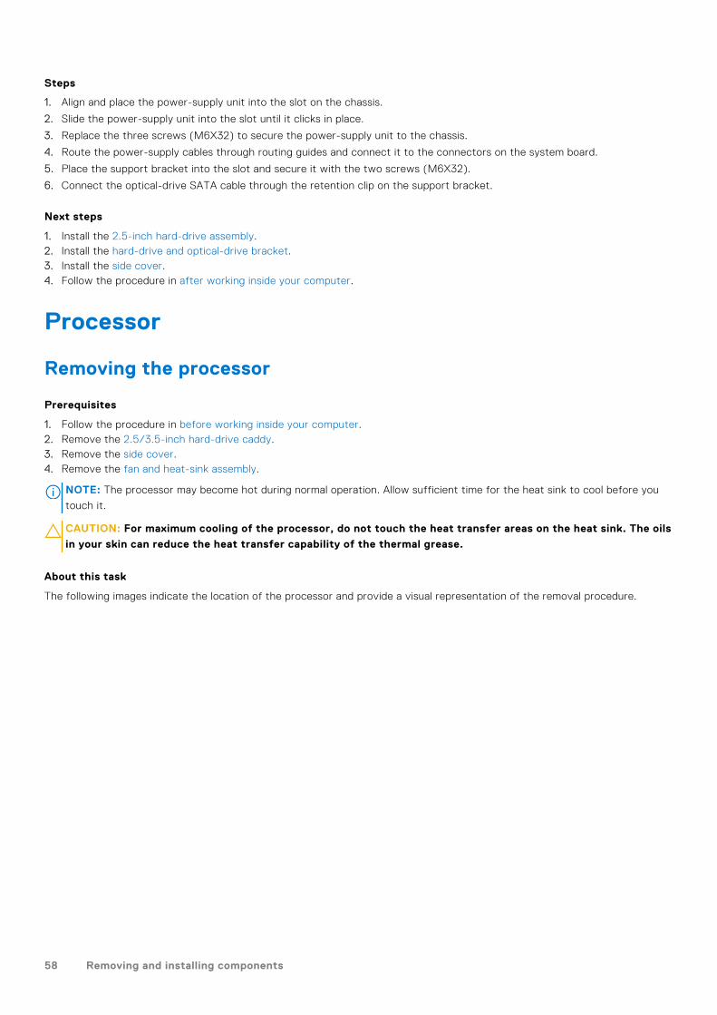
About this task
The following images indicate the location of the processor and provide a visual representation of the removal procedure.
58 Removing and installing components

Steps
1. Press the release lever down and then push it away from the processor to release it from the securing tab.
2. Extend the release lever completely and open the processor cover.
3. Gently lift the processor from the processor socket on the system board.
CAUTION: When removing the processor, do not touch any of the pins inside the socket or allow any objects
to fall on the pins in the socket.
Installing the processor
Prerequisites
If you are replacing a component, remove the existing component before performing the installation procedure.
About this task
The following image indicates the location of the processor and provides a visual representation of the installation procedure.
Removing and installing components 59

Steps
1. Ensure that the release lever on the processor socket is fully extended in the open position.
2. Align the notches on the processor with the tabs on the processor socket and place the processor in the processor socketon the system board.
NOTE: Ensure that the processor-cover notch is positioned underneath the alignment post.
NOTE: The pin-1 corner of the processor has a triangle that aligns with the triangle on the pin-1 corner on the processor
socket. When the processor is properly seated, all four corners are aligned at the same height. If one or more corners of
the processor are higher than the others, the processor is not seated properly.
3. When the processor is fully seated in the socket, pivot the release-lever down and place it under the tab on the processorcover.
Next steps
1. Install the fan and heat-sink assembly.2. Install the 2.5/3.5-inch hard-drive caddy.3. Install the side cover.4. Follow the procedure in after working inside your computer.
60 Removing and installing components

System board
System board callouts - 5090 Small Form Factor
1. Video connector2. Intrusion switch connector3. ATX CPU power connector4. Processor fan connector5. Memory module connector6. M.2 SSD PCIe connector7. Power button connector8. SD-card reader connector9. M.2 WLAN connector10. SATA 0 connector11. SATA 1 connector12. ATX system power connector13. SATA 3 connector14. SATA power connector15. Internal speaker cable connector16. Coin-cell battery17. PCIe x16 (Slot2) and PCIe x4 (Slot1)18. Type-C connector19. PS/2 KB/Mouse Connector20. Processor socket
Removing and installing components 61

Removing the system board
Prerequisites
1. Follow the procedure in before working inside your computer.2. Remove the side cover.3. Remove the front bezel.4. Remove the 2.5/3.5-inch hard-drive caddy.5. Remove the graphics card.6. Remove the solid-state drive.7. Remove the WLAN card.8. Remove the fan assembly.9. Remove the memory modules.10. Remove the processor.
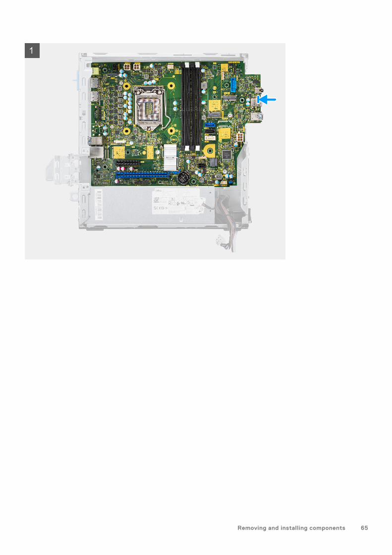
About this task
The following images indicate the location of the system board and provide a visual representation of the removal procedure.
62 Removing and installing components

Removing and installing components 63

Steps
1. Remove the screw (6-32) that secures the front I/O bracket to the chassis.
2. Lift the front I/O panel away from the chassis.
3. Disconnect the following cables from their connectors on the system board:
● Intrusion switch● ATX system board power supply cables● Power button switch● ATX CPU power supply cable● SATA data cables● SATA power cable● Fan cable
4. Remove the four screws (6-32) and the single standoff screw (M2x4) which secure the system board to the chassis.
5. Free the system board from the back I/O panel by sliding it towards the right and lift the system board out of the chassis.
Installing the system board
Prerequisites
If you are replacing a component, remove the existing component before performing the installation procedure.
About this task
The following image indicates the location of the system board and provides a visual representation of the installation procedure.
64 Removing and installing components
Removing and installing components 65

66 Removing and installing components

Steps
1. Align and lower the system board into the system until the stand-off points at the back of the system board align with thoseon the chassis.
2. Replace the four screws (6-32) and the single standoff screw (M2X4) screw to secure the system board to the chassis.
3. Connect the following cables to the respective connectors on the system board:
● Intrusion switch● ATX system board power supply cables● Power button switch● ATX CPU power supply cable● SATA data cables● SATA power cable● System fan cable
4. Align and lower the I/O panel into the slot on the chassis.
5. Replace the screws (6-32) to secure the I/O panel to the chassis.
Next steps
1. Install the processor.2. Install the fan assembly.3. Install the WLAN card.
Removing and installing components 67

4. Install the solid-state drive.5. Install the memory modules.6. Install the graphics card.7. Install the 2.5/3.5-inch hard-drive caddy.8. Install the side cover.9. Follow the procedure in after working inside your computer.
68 Removing and installing components

SoftwareThis chapter details the supported operating systems along with instructions on how to install the drivers.
Drivers and downloadsWhen troubleshooting, downloading or installing drivers it is recommended that you read the Dell Knowledge Based article,Drivers and Downloads FAQ 000123347.
3
Software 69

System setupCAUTION: Unless you are an expert computer user, do not change the settings in the BIOS Setup program.
Certain changes can make your computer work incorrectly.
NOTE: Before you change BIOS Setup program, it is recommended that you write down the BIOS Setup program screen
information for future reference.
Use the BIOS Setup program for the following purposes:● Get information about the hardware installed in your computer, such as the amount of RAM and the size of the hard drive.● Change the system configuration information.● Set or change a user-selectable option, such as the user password, type of hard drive installed, and enabling or disabling
base devices.
Boot menu
Press <F12> when the Dell logo appears to initiate a one-time boot menu with a list of the valid boot devices for the system.Diagnostics and BIOS Setup options are also included in this menu. The devices listed on the boot menu depend on the bootabledevices in the system. This menu is useful when you are attempting to boot to a particular device or to bring up the diagnosticsfor the system. Using the boot menu does not make any changes to the boot order stored in the BIOS.
The options are:● UEFI Boot:
○ Windows Boot Manager● Other Options:
○ BIOS Setup○ BIOS Flash Update○ Diagnostics○ Change Boot Mode Settings
Navigation keysNOTE: For most of the System Setup options, changes that you make are recorded but do not take effect until you restart
the system.
Keys Navigation
Up arrow Moves to the previous field.
Down arrow Moves to the next field.
Enter Selects a value in the selected field (if applicable) or follow the link in the field.
Spacebar Expands or collapses a drop-down list, if applicable.
Tab Moves to the next focus area.
Esc Moves to the previous page until you view the main screen. Pressing Esc in the main screen displays amessage that prompts you to save any unsaved changes and restarts the system.
4
70 System setup

Boot SequenceBoot sequence enables you to bypass the System Setup–defined boot device order and boot directly to a specific device (forexample: optical drive or hard drive). During the Power-on Self-Test (POST), when the Dell logo appears, you can:● Access System Setup by pressing F2 key● Bring up the one-time boot menu by pressing F12 key.
The one-time boot menu displays the devices that you can boot from including the diagnostic option. The boot menu optionsare:
● Removable Drive (if available)● STXXXX Drive
NOTE: XXXX denotes the SATA drive number.
● Optical Drive (if available)● SATA Hard Drive (if available)● Diagnostics
NOTE: Choosing Diagnostics, displays the SupportAssist screen.
The boot sequence screen also displays the option to access the System Setup screen.
System setup options
NOTE: Depending on this computer and its installed devices, the items listed in this section may or may not appear.
Table 3. System setup options—System information menu
General-System Information
System Information
BIOS Version Displays the BIOS version number.
Service Tag Displays the Service Tag of the computer.
Asset Tag Displays the Asset Tag of the computer.
Ownership Tag Displays the ownership tag of the computer.
Manufacture Date Displays the manufacture date of the computer.
Ownership Date Displays the ownership date of the computer.
Express Service Code Displays the express service code of the computer.
Memory Information
Memory Installed Displays the total computer memory installed.
Memory Available Displays the total computer memory available.
Memory Speed Displays the memory speed.
Memory Channel Mode Displays single or dual channel mode.
Memory Technology Displays the technology used for the memory.
DIMM 1 Size Displays the DIMM 1 memory size.
DIMM 2 Size Displays the DIMM 2 memory size.
PCI Information
SLOT2 Displays the PCI information of the computer.
SLOT3 Displays the PCI information of the computer.
SLOT5_M.2 Displays the PCI information of the computer.
Processor Information
System setup 71

Table 3. System setup options—System information menu (continued)
General-System Information
Processor Type Displays the processor type.
Core Count Displays the number of cores on the processor.
Processor ID Displays the processor identification code.
Current Clock Speed Displays the current processor clock speed.
Minimum Clock Speed Displays the minimum processor clock speed.
Maximum Clock Speed Displays the maximum processor clock speed.
Processor L2 Cache Displays the Processor L2 Cache size.
Processor L3 Cache Displays the Processor L2 Cache size.
HT Capable Displays whether the processor is HyperThreading (HT) capable.
64-Bit Technology Displays whether 64-bit technology is used.
Device Information
SATA-0 Displays the SATA device information of the computer.
SATA-1 Displays the SATA device information of the computer.
M.2 PCIe SSD-2 Displays the M.2 PCIe SSD information of the computer.
LOM MAC Address Displays the LOM MAC address of the computer.
Video Controller Displays the video controller type of the computer.
Audio Controller Displays the audio controller information of the computer.
Wi-Fi Device Displays the wireless device information of the computer.
Bluetooth Device Displays the Bluetooth device information of the computer.
Boot Sequence
Boot Sequence Displays the boot sequence.
Boot List Option Displays the available boot options.
UEFI Boot Path Security
Always,Except Internal HDD Enable or disable the system to prompt the user to enter the Admin passwordwhen booting a UEFI boot path from the F12 boot menu. Default: Enabled
Always Enable or disable the system to prompt the user to enter the Admin passwordwhen booting a UEFI boot path from the F12 boot menu. Default: Disabled
Never Enable or disable the system to prompt the user to enter the Admin passwordwhen booting a UEFI boot path from the F12 boot menu. Default: Disabled
Date/Time Displays the current date in MM/DD/YY format and current time in HH:MM:SSAM/PM format.
Table 4. System setup options—System Configuration menu
System Configuration
Integrated NIC Controls the on-board LAN controller.
Enable UEFI Network Stack Enable or disable UEFI Network Stack.
SATA Operation Configure operating mode of the integrated SATA hard drive controller.
Drives Enable or disable various drives on board.
SATA-0 Displays the SATA device information of the computer.
SATA-1 Displays the SATA device information of the computer.
M.2 PCIe SSD-2 Displays the M.2 PCIe SSD information of the computer.
72 System setup

Table 4. System setup options—System Configuration menu (continued)
System Configuration
SMART Reporting Enable or disable SMART Reporting during system startup.
USB Configuration
Enable USB Boot Support Enable or disable booting from USB mass storage devices such as externalhard drive, optical drive, and USB drive.
Enable front USB Port Enable or disable the front USB ports.
Enable rear USB Port Enable or disable the rear USB ports.
Front USB Configuration Enable or disable the front USB ports.
Rear USB Configuration Enable or disable the rear USB ports.
Audio Enable or disable the integrated audio controller.
Miscellaneous Devices Enable or disable various onboard devices.
Table 5. System setup options—Video menu
Video
Multi-Display Enable or disable multiple displays.
Primary Display Set or change the primary display.
Table 6. System setup options—Security menu
Security
Admin Password Set, change, or delete the administrator password.
System Password Set, change, or delete the system password.
Internal HDD-0 Password Set, change, or delete the internal hard-disk drive password.
Password Configuration Control the minimum and maximum number of characters allowed for Adminand System passwords.
Password Change Enable or disable changes to the System and Hard Disk passwords when anadministrator password is set.
UEFI Capsule Firmware Updates Enable or disable BIOS updates through UEFI capsule update packages.
PTT Security
PTT On Enable or disable Platform Trust Technology (PTT) visibility to the operatingsystem.
Clear Default: Disabled
PPI ByPass for Clear Command Enable or disable the TPM Physical Presence Interface (PPI). When enabled,this setting will allow the OS to skip BIOS PPI user prompts when issuingthe Clear command. Changes to this setting take effect immediately.Default:Disabled
Absolute(R) Enable or disable the BIOS module interface of the optional Computrace(R)Service from Absolute Software.
Admin Setup Lockout Enable to prevent users from entering Setup when an Admin Password is set.
Master Password Lockout Disables the master password support. Hard Disk passwords need to becleared before changing the setting.
SMM Security Mitigation Enable or disable SMM Security Mitigation
Table 7. System setup options—Secure Boot menu
Secure Boot
Secure Boot Enable Enable or disable the secure boot feature.
System setup 73

Table 7. System setup options—Secure Boot menu (continued)
Secure Boot
Secure Boot Mode Modifies the behavior of Secure Boot to allow evaluation or enforcement ofUEFI driver signatures.
● Deployed Mode-Default: Enabled● Audit Mode-Default: Disabled
Deployed Mode Enable or disable the deployed mode.
Audit Mode Enable or disable the audit mode.
Expert Key Management
Expert Key Management Enable or disable Expert Key Management.
Custom Mode Key Management Select the custom values for expert key management.
Table 8. System setup options—Intel Software Guard Extensions menu
Intel Software Guard Extensions
Intel SGX Enable Enable or disable Intel Software Guard Extensions.
Enclave Memory Size Set the Intel Software Guard Extensions Enclave Reserve Memory Size.
Performance
Multi Core Support Enable multiple cores.
Default: Enabled.
Intel SpeedStep Enable or disable Intel Speedstep Technology.
Default: Enabled.
NOTE: If enabled, the processor clock speed and core voltage are adjusteddynamically based on the processor load.
C-States Control Enable or disable additional processor sleep states.
Default: Enabled.
Intel TurboBoost Enable or disable Intel TurboBoost mode of the processor.
Default: Enabled.
HyperThread control Enable or disable HyperThreading in the processor.
Default: Enabled.
Power Management
AC Recovery Sets what action the computer takes when power is restored.
Enable Intel Speed Shift Technology Enable or disable Intel Speed Shift Technology.
Auto On Time Enable to set the computer to turn on automatically every day or on apreselected date and time. This option can be configured only if the Auto OnTime is set to Everyday, Weekdays or Selected Days.
Default: Disabled.
USB Wake Support Enable the USB devices to wake the computer from Standby.
Deep Sleep Control Enables you to control the Deep Sleep mode support.
Wake on LAN/WLAN Enables the computer to be powered on by special LAN signals.
Block sleep Enables you to block entering to sleep mode in OS environment.
POST Behavior
Numlock LED Enables the NumLock function when computer boots.
74 System setup

Table 8. System setup options—Intel Software Guard Extensions menu (continued)
Intel Software Guard Extensions
Keyboard Errors Enables the keyboard error detection.
Fastboot Enable to set the speed of the boot process.
Default: Thorough.
Extend BIOS POST Time Configure additional pre-boot delay.
Full Screen Logo Enable or disable to display full screen logo.
Warnings and Errors Sets the boot process to pause when Warnings or Errors are detected.
Table 9. System setup options—Virtualization Support menu
Virtualization Support
Virtualization Specify whether a Virtual Machine Monitor (VMM) can utilize the additionalhardware capabilities provided by Intel Virtualization Technology.
VT for Direct I/O Specify whether a Virtual Machine Monitor (VMM) can utilize the additionalhardware capabilities provided by Intel Virtualization Technology for Direct I/O.
Table 10. System setup options—Wireless menu
Wireless
Wireless Device Enable Enable or disable internal wireless devices.
Table 11. System setup options—Maintenance menu
Maintenance
Service Tag Display the system’s Service Tag.
Asset Tag Create a system Asset Tag.
SERR Messages Enable or disable SERR messages.
BIOS Downgrade Control flashing of the system firmware to previous revisions.
Data Wipe Enable to securely erase data from all internal storage devices.
BIOS Recovery Enable the user to recover from certain corrupted BIOS conditions from arecovery file on the user primary hard drive or an external USB key.
Table 12. System setup options—System Logs menu
System Logs
BIOS Events Display BIOS events.
Table 13. System setup options—SupportAssist System Resolution menu
SupportAssist System Resolution
Auto OS Recovery Threshold Control the automatic boot flow for SupportAssist System Resolution Consoleand for Dell OS Recovery tool.
Overview
This section provides hardware specification for the system and contains no modifiable settings.
Table 14. BIOS Overview Page
Options Description
Series and system model number This field shows the following information:
System setup 75

Table 14. BIOS Overview Page (continued)
Options Description
● BIOS Version - The version of the BIOS installed on thecomputer.
● Service tag - The unique 7 digit hexadecimal identificationnumber for the computer.
● Asset tag● Manufacture Date - The date for when the unit was
manufactured.● Ownership Date - The date for when the unit's ownership
was transferred to the end user.● Express Service Code - An alternative to Service Tag, 11-
digit numerical identification number for the computer.● Ownership Tag● Signed Firmware Update - This helps to verify that only
Dell Signed and released BIOS can be installed on thecomputer.
Processor The Processor field provides information related to the CPUon the computer:● Processor Type - This field mentions the CPU model and
generation information.● Maximum Clock Speed - This field mentions the maximum
clock speed that the CPU is capable of reaching.● Minimum Clock Speed - This field mentions the minimum
clock speed that the CPU is capable of reaching.● Current Clock Speed - This field mentions the clock speed
that the CPU is running at currently.● Core Count - This field gives the count of the physical
cores on the CPU.● Processor ID● Processor L3 Cache - This field shows the amount of
cache storage available on the CPU.● Microcode Version● Intel Hyper-Threading Capable - This field helps identify if
the CPU is capable of Hyper-Threading.● 64-bit Technology - This field helps identify the CPU
architecture.
Memory The Memory field provides information related to the memoryon the computer:● Memory Installed - This field gives the amount of memory
installed on the computer.● Memory Available - This field gives the amount of memory
available for use on the computer.● Memory Speed - This field mentions the speed at which
the memory runs on the computer.● Memory Channel Mode - This field helps us identify if the
computer has Dual-Channel memory utilization capability.● DIMM_SLOT 1 - This field shows the capacity of the
memory installed in the first DIMM slot.● DIMM_SLOT 2 - This field shows the capacity of the
memory installed in the second DIMM slot.
Devices The Devices field provides information related to the memoryon the computer:● Panel Type - This field mentions the type of display panel
used on the computer.
76 System setup

Table 14. BIOS Overview Page (continued)
Options Description
● Video controller - This field mentions the type of videocontroller used on the computer.
● Video Memory - This field gives the capacity of the videomemory available for use on the computer.
● Wi-Fi Device - This field mentions the type of wirelessdevice available for use on the computer.
● Native Resolution - This field mentions the native videoresolution supported on the computer.
● Video BIOS Version - The version of the BIOS installed onthe computer.
● Audio Controller - This field mentions the type of audiocontroller used on the computer.
● Bluetooth Device - This field mentions the type ofBluetooth device available for use on the computer.
● LOM MAC Address - This field provides the unique MACaddress for the computer.
Boot Configuration
This section provides Boot Configuration related details and settings.
Table 15. Boot Configuration:
Options Description
Boot Sequence
Boot Mode: UEFI only This section allows the user to choose the first bootabledevice that the computer should use to boot the system. Itlists all potential bootable devices.● Windows Boot Manager (Enabled by default)● UEFI Boot Drive (Enabled by default)● Add Boot option - Allows the user to manually add a Boot
path.
Secure Digital(SD) Card Boot This section contains a toggle switch that allows the user toenable or disable the option to allow the computer to bootfrom an SD Card.
Secure Boot
Enable Secure Boot This section contains a toggle switch that allows the user toenable or disable Secure Boot. (OFF by default)
Secure Boot Mode This section allows the user to select one of the two SecureBoot options available on the computer:● Deployed Mode - This mode checks the integrity of UEFI
drivers and bootloaders before allowing execution. Thisoption allows for full Secure Boot protections (Enabled bydefault.)
● Audit Mode - This mode performs a signature check butnever does a block execution of all UEFI drivers andbootloaders. This mode is only used when making changesto Secure Boot Keys.
Expert Key Management
System setup 77

Table 15. Boot Configuration: (continued)
Options Description
Enable Custom Mode This section contains a toggle switch that allows the user toenable or disable Custom Mode. This mode allows the PK,KEK, db and dbx security key databases to be manipulated.(OFF by default)
Custom Mode Key Management This section helps the user to select the Key Database toallow modification. The options available are as below:● PK (Selected by default)● KEK● db● dbx
Integrated Devices
This section provides Integrated Devices details and settings.
Table 16. Integrated Devices
Options Description
Date/Time
Date This section allows the user to change the date which takeseffect immediately. The format used is MM/DD/YYYY.
Time This section allows the user to change the time which takeseffect immediately. The format used is HH/MM/SS in 24 hourformat. The user also has an option to switch between 12-hours or 24-hours clock.
Audio
Enable Audio This section contains a toggle switch that allows the user toenable or disable the audio on the computer. It also allows theuser to:● Enable Microphone (Enabled by default.)
Serial Port This section allows the user to set the Serial PortConfiguration:● Disabled● COM1: Port is configured at 3F8h with IRQ4 (Selected by
default)● COM2: Port is configured at F28h with IRQ3● COM3: Port is configured with 2E8h with IRQ4
USB Configuration This section helps the user to make changes to the USBsettings on the computer. The options available are asfollows(All options are enabled by default):● Enable Front USB Ports● Enable Rear USB Ports● Enable USB Boot Support
Front USB Configuration This section allows the user to manually enable the 4 USBports on the front bezel (All USB ports are enabled bydefault.). The options are:● Front Port 1 (Bottom Left)● Front Port 2 (Bottom Right)
78 System setup

Table 16. Integrated Devices (continued)
Options Description
● Front Port 3 (Top Left)● Front Port 4 (Top Right)
Rear USB Configuration This section allows the user to manually enable the 4 USBports on the back (All USB ports are enabled by default.). Theoptions are:● Rear Port 1 (Top Left)● Rear Port 2 (Left Middle)● Rear Port 3 (Bottom Left)● Rear Port 4 (Bottom Right)● Rear Port 4 (Middle Right)● Rear Port 4 (Top Right)
Dust Filter Maintenance This field enabled or disabled BIOS messages for maintainingthe optional dust filter. BIOS will generate a pre-boot reminderto clean or replace the dust filter based on the following timeintervals:● Disabled (selected by default)● 15 days● 30 days● 60 days● 90 days● 120 days● 150 days● 180 days
Storage
This section provides storage details and settings.
Table 17. Storage
Options Description
SATA Operation
SATA Operation This section allows the user to select the operating modeof the integrated SATA hard drive controller. The followingoptions are available:● Disabled - SATA controllers are disabled.● AHCI - SATA is configured in AHCI mode.● RAID On - SATA is setup to support RAID (Intel Rapid
Storage Technology). (Selected by default)
Storage Interface
Port Enablement This section allows the user to enable or disable the onboarddrives on the computer. The following options is available (ONby default).● SATA-0● SATA-1● SATA-3● M.2 PCIe SSD-0● M.2 PCIe SSD-1
SMART Reporting
System setup 79

Table 17. Storage (continued)
Options Description
Enable SMART Reporting This section contains a toggle switch that allows the userto enable or disable the S.M.A.R.T(Self-Monitoring, Analysis,and Reporting Technology) option on the system (OFF bydefault).
Drive Information This section provides information about the connected andactive drives on the computer. The following options areavailable:● M.2 PCIe SSD-0
○ Type○ Device
Enable MediaCard This section allows setting the media cards ON/OFF orenable/disable media card in read-only state. The followingoptions are available:● Secure Digital (SD) Card (Enabled by default)● Secure Digital (SD) Card Read-Only Mode
Display
This section provides display details and settings.
Table 18. Display
Options Description
Multi-Display This section contains a toggle switch which allows the userto enable/disable Multi-Display. (disabled by default). Thisfeature is only supported on Windows 7 and above.
Primary Display
Video Primary Display This section allows the user to select the video controllerfor the primary display when multiple video controllers aredetected. The options are:● Auto (Selected by default)● Onboard Video
Full Screen Logo
Full Screen Logo This section contains a toggle switch which allows the user toenable/disable the option to view a full screen logo (disabledby default).
Connection
This section provides connection details and settings.
Table 19. Connection
Options Description
Network Controller Configuration
Integrated NIC This section allows the user to change the on-board LANcontroller options. The options are as follows:
80 System setup

Table 19. Connection (continued)
Options Description
● Disabled - The internal LAN is off and not visible to theoperating system.
● Enabled - The internal LAN is enabled.● Enabled with PXE (Selected by defauly) - The internal LAN
is enabled with PXE boot capabilities.
Wireless Device Enable This section contains a toggle switch that allows the user toenable or disable WLAN and Bluetooth on the computer. Theoptions are as follows:● WLAN (Enabled by default).● Bluetooth (Enabled by default).
Enable UEFI Network Stack This section contains a toggle switch that allows the user toenable or disable installation of UEFI networking protocols.(ON by default)
Wireless Radio Control This section contains a toggle switch that allows the userto enable or disable a feature where the system will sensea connection to a wired network and disable the WLAN orWWAN connection (OFF by default).
HTTP(s) Boot Feature
HTTP(s) Boot Feature This section contains a toggle switch that allows the user toenable or disable HTTP(s) Boot capabilities (ON by default).
HTTP(s) Boot Modes ● Auto Mode - HTTP(s) Boot automatically extracts BootURL from DHCP(Dynamic Host Configuration Protocol) -Selected by default.
● Manual Mode - HTTP(s) Boot reads Boot URL provided bythe user.
This section also contains an "Upload" and "Delete" option forprovisioning of the certificates required to connect to HTTPsBoot server.
Power
This section provides power details and settings.
Table 20. Power
Options Description
USB Wake Support
Enable USB Wake Support This section contains a toggle switch to allow the user toenable or disable USB Wake Support. It allows the systemto use USB devices like a mouse and keyboard to wake thesystem from standby mode (OFF by default).
NOTE: This feature only works if the power adapter isconnected to the system.
AC Behavior This section allows the user to control the behavior of thesystem when power is restored after an unexpected loss ofpower. The options here are:● Power Off - System stays off after AC power is restored
(Selected by default)
System setup 81
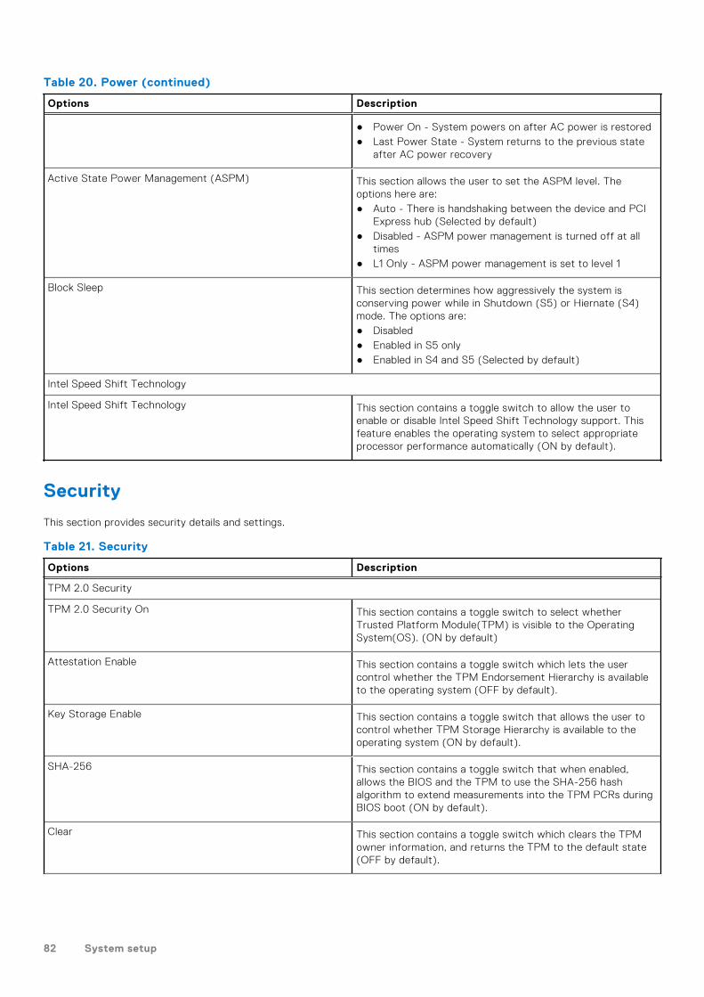
Table 20. Power (continued)
Options Description
● Power On - System powers on after AC power is restored● Last Power State - System returns to the previous state
after AC power recovery
Active State Power Management (ASPM) This section allows the user to set the ASPM level. Theoptions here are:● Auto - There is handshaking between the device and PCI
Express hub (Selected by default)● Disabled - ASPM power management is turned off at all
times● L1 Only - ASPM power management is set to level 1
Block Sleep This section determines how aggressively the system isconserving power while in Shutdown (S5) or Hiernate (S4)mode. The options are:● Disabled● Enabled in S5 only● Enabled in S4 and S5 (Selected by default)
Intel Speed Shift Technology
Intel Speed Shift Technology This section contains a toggle switch to allow the user toenable or disable Intel Speed Shift Technology support. Thisfeature enables the operating system to select appropriateprocessor performance automatically (ON by default).
Security
This section provides security details and settings.
Table 21. Security
Options Description
TPM 2.0 Security
TPM 2.0 Security On This section contains a toggle switch to select whetherTrusted Platform Module(TPM) is visible to the OperatingSystem(OS). (ON by default)
Attestation Enable This section contains a toggle switch which lets the usercontrol whether the TPM Endorsement Hierarchy is availableto the operating system (OFF by default).
Key Storage Enable This section contains a toggle switch that allows the user tocontrol whether TPM Storage Hierarchy is available to theoperating system (ON by default).
SHA-256 This section contains a toggle switch that when enabled,allows the BIOS and the TPM to use the SHA-256 hashalgorithm to extend measurements into the TPM PCRs duringBIOS boot (ON by default).
Clear This section contains a toggle switch which clears the TPMowner information, and returns the TPM to the default state(OFF by default).
82 System setup

Table 21. Security (continued)
Options Description
PPI Bypass for Clear Commands This section contains a toggle switch which controls the TPMPhysical Presence Interface(PPI). When enabled, this settingwill allow the OS to skip BIOS PPI user prompts when issuingthe clear command (OFF by default).
TPM State This section allows the user to enable or disable the TPM. Thisis the default operating state for the TPM when you want touse its complete arrays of capabilities (enabled by default).
Intel Total Memory Encryption
Total Memory Encryption(TME) This section allows the user to enable/disable TME to protectmemory from physical attachs including freeze spray, probingDDR to read the cycles etc. All of the system memoryis encrypted by the TME block attached to the memorycontroller
Chassis Intrusion
Chassis Intrusion This field controls the chassis intrusion feature● Disabled - Will not report intrusions during POST● Enabled - Will report intrusions during POST● On-silent - Detects intrusions but does not display any
detected intrusions during POST (Selected by default)
Clear Intrusion Warning This section contains a toggle switch to enable/disablewarnings on intrusion (OFF by default).
SMM Security Mitigation This section allows the user to enable or disable UEFI SMMsecurity Mitigation protections (ON by default).
Data Wipe on Next Boot
Start Data Wipe This section contains toggle switch which when enabledensures that the BIOS will queue up a data wipe cycle forstorage device(s) connected to the system board on the nextreboot (OFF by default).
Absolute
Absolute This section lets the user enable, disable or permanentlydisable the BIOS module interface of the optional AbsolutePersistence Module service from Absolute Software. Theoptions available are as follows:● Enable Absolute - Enables Absolute Persistence and load
the firmware Persistence Module (Selected by default)● Disable Absolute - Disables Absolute Persistence. The
firmware Persistence Module is not installed.● Permanently Disable Absolute - Permanently disables
Absolute Persistence module interface from further use.
UEFI Boot Path Security
UEFI Boot Path Security This section lets the user control whether the system willprompt the user to enter the admin password(if set) whenbooting to a UEFI booth path device from F12 boot menu. Theoptions available are as below:● Never● Always● Always Except Internal HDD (Selected by default)
System setup 83
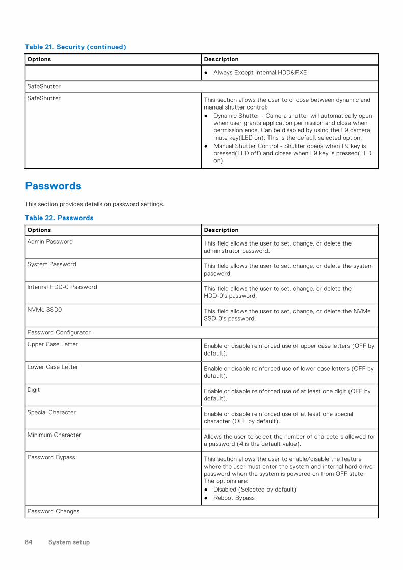
Table 21. Security (continued)
Options Description
● Always Except Internal HDD&PXE
SafeShutter
SafeShutter This section allows the user to choose between dynamic andmanual shutter control:● Dynamic Shutter - Camera shutter will automatically open
when user grants application permission and close whenpermission ends. Can be disabled by using the F9 cameramute key(LED on). This is the default selected option.
● Manual Shutter Control - Shutter opens when F9 key ispressed(LED off) and closes when F9 key is pressed(LEDon)
Passwords
This section provides details on password settings.
Table 22. Passwords
Options Description
Admin Password This field allows the user to set, change, or delete theadministrator password.
System Password This field allows the user to set, change, or delete the systempassword.
Internal HDD-0 Password This field allows the user to set, change, or delete theHDD-0's password.
NVMe SSD0 This field allows the user to set, change, or delete the NVMeSSD-0's password.
Password Configurator
Upper Case Letter Enable or disable reinforced use of upper case letters (OFF bydefault).
Lower Case Letter Enable or disable reinforced use of lower case letters (OFF bydefault).
Digit Enable or disable reinforced use of at least one digit (OFF bydefault).
Special Character Enable or disable reinforced use of at least one specialcharacter (OFF by default).
Minimum Character Allows the user to select the number of characters allowed fora password (4 is the default value).
Password Bypass This section allows the user to enable/disable the featurewhere the user must enter the system and internal hard drivepassword when the system is powered on from OFF state.The options are:● Disabled (Selected by default)● Reboot Bypass
Password Changes
84 System setup

Table 22. Passwords (continued)
Options Description
Enable Non-Admin Password Changes This section contains a toggle switch which when on, user canchange system and hard drive password without the need foradmin password (OFF by default).
Admin Setup Lockout
Enable Admin Setup Lockout This section contains a toggle switch which allows theadministrator to control how users can or cannot access BIOSsetup (OFF by default).
Master Password Lockout
Enable Active Password Lockout This section contains a toggle switch which allows the user todisable active password support (OFF by default).
Update Recovery
This section provides details on Update Recovery settings.
Table 23. Update Recovery
Options Description
UEFI capsule Firmware Updates
Enable UEFI Capsule Firmware Updates This field contains a toggle switch which allows the user toenable or disable BIOS updates through UEFI capsule updatepackages (ON by default).
BIOS Recovery from Hard Drive
BIOS Recovery from Hard Drive This field contains a toggle switch which allows the userto enable or disable recovery from certain corrupted BIOSconditions from a recovery file on the user's primary harddrive or an external USB key (ON by default).
BIOS Downgrade
Allow BIOS Downgrade This field contains a toggle switch which allows the user toenable or disable flashing of the system firmware to previousrevisions.
SupportAssist OS Recovery
SupportAssist OS Recovery This field contains a toggle switch which allows the userto enable or disable the boot flow for SupportAssist OSRecovery tool in the events of certain system errors (ON bydefault).
BIOSConnect
BIOSConnect This field contains a toggle switch which allows the user toenable or disable BIOSConnect setup to attempt cloud ServiceOS recovery if the main operating system fails to boot with aset number of failures (ON by default).
Dell Auto OS Recovery Threshold
Dell Auto OS Recovery Threshold This field allows the user to select the number of failed bootattempts by the system before SupportAssist OS Recovery istriggered. The options here are as below:
System setup 85

Table 23. Update Recovery (continued)
Options Description
● Off● 1● 2 (selected by default)● 3
System Management
This section provides System Management settings.
Table 24. System Management
Options Description
Service Tag
Service Tag This field provides the unique Service Tag of the computer.
Asset Tag
Asset Tag This field provides the asset tag which is a unique and upto 64-character identification that can be set by the ITadministrator.
Wake on LAN
Wake on LAN This field allows the user to select if and how the systemshould boot when connected to LAN. The options here are asfollows:● Disabled - The system will not boot with any special LAN
signals (selected by default).● LAN only - Allows the system to be powered on by a
special LAN signal from a network computer.● WLAN only - Allows the system to power on by special
WLAN signals.● LAN or WLAN - Allows the system to power on by special
LAN or wireless LAN signals.● LAN with PXE Boot - Allows the system to wake-up from
S4 or S5 state and boot to PXE.
Auto On Time
Auto On Time This field allows the user to set defined days/time when thesytem can automatically power on. The options here are asfollows:● Disabled (selected by default)● Everyday● Weekdays● Select Days
SERR Messages This section allows the user to enable or disable(ON/OFF) theSERR message mechanism (ON by default).
NOTE: Some graphics cards require SERR messagemechanism to be disbaled.
First Power On Date This option if enabled lets the user see the ownership date(disabled by default).
86 System setup

Keyboard
This section provides keyboard settings.
Table 25. Keyboard
Options Description
Enable keyboard Error Detection This field contains a toggle switch(ON/OFF) to allow thekeyboard-related errors to be reported when the systemboots.
Numlock LED This field contains a toggle switch(ON/OFF) to allow the userto decide if the Numlock LED should be on when the systemboots.
Virtualization
This section provides details on Virtualization settings.
Table 26. Virtualization
Options Description
Intel Virtualization Technology
Enable Intel Virtualization Technology(VT) This field contains a toggle switch to enable or disableVirtualization to run Virtual machine monitor(VMM) (enabledby default).
VT for Direct I/O
Enable Intel VT for Direct I/O This field allows the user to enable or disable the system frombeing able to perform VT for Direct I/O (enabled by default).
Performance
This section provides Performance settings.
Table 27. Performance
Options Description
Multi-Core Support
Active Cores This field allows the user to configure the number of activecores on the computer. The options are as follows:● All Cores (selected by default)● 1● 2● 3
Intel SpeedStep
Enable Intel SpeedStep Technology This field contains a toggle switch to enable or disableIntel SpeedStep Technology which allows the computer todynamically adjust processor voltage and core frequency,decreasing average power consumption and heat production(enabled by default).
C-States Control
System setup 87

Table 27. Performance (continued)
Options Description
Enable C-States Control This field contains a toggle switch to enable or disable C-States Control that configures the CPU's ability to enterand exit low power states. When off, it disables all C-States(enabled by default).
Intel Turbo Boost Technology
Enable Intel Turbo Boost Technology This field allows the user to enable or disable Intel TurboBoost Technology (enabled by default).● Disabled - Does not allow the Intel Turbo Boost
Technology driver to increase the performance state ofthe processor above the standard performance.
● Enabled - Allows the Intel Turbo Boost Technologyto increase the performance of the CPU or graphicsprocessor.
Intel Hyper-Threading Technology
Enable Intel Hyper-Threading Technology This field allows the user to configure this feature wherethe processor resources are used more effectively, enablingmultiple threads to run on each core (enabled by default).
Dynamic Tuning: Machine Learning
Enable Dynamic Tuning: Machine Learning This field allows the user to configure the OS' capability toenhance dynamic power tuning capabilities based on detectedworkloads (disabled by default)
System Logs
This section contains BIOS, Thermal and Power event logs.
Table 28. System Logs
Options Description
BIOS Event Log
Clear BIOS Event log This field contains a toggle switch to Keep or Clear BIOSEvent logs. It also lists all saved events(Date, Time, Message)- ("Keep" selected by default).
Updating the BIOS
Updating the BIOS in Windows
About this task
CAUTION: If BitLocker is not suspended before updating the BIOS, the next time you reboot the system it
will not recognize the BitLocker key. You will then be prompted to enter the recovery key to progress and the
system will ask for this on each reboot. If the recovery key is not known this can result in data loss or an
unnecessary operating system re-install. For more information on this subject, see Knowledge Article: https://
www.dell.com/support/article/sln153694
88 System setup

Steps
1. Go to www.dell.com/support.
2. Click Product support. In the Search support box, enter the Service Tag of your computer, and then click Search.
NOTE: If you do not have the Service Tag, use the SupportAssist feature to automatically identify your computer. You
can also use the product ID or manually browse for your computer model.
3. Click Drivers & Downloads. Expand Find drivers.
4. Select the operating system installed on your computer.
5. In the Category drop-down list, select BIOS.
6. Select the latest version of BIOS, and click Download to download the BIOS file for your computer.
7. After the download is complete, browse the folder where you saved the BIOS update file.
8. Double-click the BIOS update file icon and follow the on-screen instructions.
For more information, see knowledge base article 000124211 at www.dell.com/support.
Updating the BIOS in Linux and Ubuntu
To update the system BIOS on a computer that is installed with Linux or Ubuntu, see the knowledge base article 000131486 atwww.dell.com/support.
Updating the BIOS using the USB drive in Windows
About this task
CAUTION: If BitLocker is not suspended before updating the BIOS, the next time you reboot the system it
will not recognize the BitLocker key. You will then be prompted to enter the recovery key to progress and the
system will ask for this on each reboot. If the recovery key is not known this can result in data loss or an
unnecessary operating system re-install. For more information on this subject, see Knowledge Article: https://
www.dell.com/support/article/sln153694
Steps
1. Follow the procedure from step 1 to step 6 in Updating the BIOS in Windows to download the latest BIOS setup program file.
2. Create a bootable USB drive. For more information, see the knowledge base article 000145519 at www.dell.com/support.
3. Copy the BIOS setup program file to the bootable USB drive.
4. Connect the bootable USB drive to the computer that needs the BIOS update.
5. Restart the computer and press F12 .
6. Select the USB drive from the One Time Boot Menu.
7. Type the BIOS setup program filename and press Enter.The BIOS Update Utility appears.
8. Follow the on-screen instructions to complete the BIOS update.
Updating the BIOS from the F12 One-Time boot menu
Update your computer BIOS using the BIOS update.exe file that is copied to a FAT32 USB drive and booting from the F12One-Time boot menu.
About this task
CAUTION: If BitLocker is not suspended before updating the BIOS, the next time you reboot the system it
will not recognize the BitLocker key. You will then be prompted to enter the recovery key to progress and the
system will ask for this on each reboot. If the recovery key is not known this can result in data loss or an
unnecessary operating system re-install. For more information on this subject, see Knowledge Article: https://
www.dell.com/support/article/sln153694
System setup 89

BIOS Update
You can run the BIOS update file from Windows using a bootable USB drive or you can also update the BIOS from the F12One-Time boot menu on the computer.
Most of the Dell computers built after 2012 have this capability, and you can confirm by booting your computer to the F12One-Time Boot Menu to see if BIOS FLASH UPDATE is listed as a boot option for your computer. If the option is listed, then theBIOS supports this BIOS update option.
NOTE: Only computers with BIOS Flash Update option in the F12 One-Time boot menu can use this function.
Updating from the One-Time boot menu
To update your BIOS from the F12 One-Time boot menu, you need the following:
● USB drive formatted to the FAT32 file system (key does not have to be bootable)● BIOS executable file that you downloaded from the Dell Support website and copied to the root of the USB drive● AC power adapter that is connected to the computer● Functional computer battery to flash the BIOS
Perform the following steps to perform the BIOS update flash process from the F12 menu:
CAUTION: Do not turn off the computer during the BIOS update process. The computer may not boot if you turn
off your computer.
Steps
1. From a turn off state, insert the USB drive where you copied the flash into a USB port of the computer.
2. Turn on the computer and press F12 to access the One-Time Boot Menu, select BIOS Update using the mouse or arrow keysthen press Enter.The flash BIOS menu is displayed.
3. Click Flash from file.
4. Select external USB device.
5. Select the file and double-click the flash target file, and then click Submit.
6. Click Update BIOS. The computer restarts to flash the BIOS.
7. The computer will restart after the BIOS update is completed.
System and setup passwordTable 29. System and setup password
Password type Description
System password Password that you must enter to log on to your system.
Setup password Password that you must enter to access and make changes tothe BIOS settings of your computer.
You can create a system password and a setup password to secure your computer.
CAUTION: The password features provide a basic level of security for the data on your computer.
CAUTION: Anyone can access the data stored on your computer if it is not locked and left unattended.
NOTE: System and setup password feature is disabled.
Assigning a system setup password
Prerequisites
You can assign a new System or Admin Password only when the status is in Not Set.
90 System setup

About this task
To enter the system setup, press F2 immediately after a power-on or reboot.
Steps
1. In the System BIOS or System Setup screen, select Security and press Enter.The Security screen is displayed.
2. Select System/Admin Password and create a password in the Enter the new password field.
Use the following guidelines to assign the system password:● A password can have up to 32 characters.● The password can contain the numbers 0 through 9.● Only lower case letters are valid, upper case letters are not allowed.● Only the following special characters are allowed: space, (”), (+), (,), (-), (.), (/), (;), ([), (\), (]), (`).
3. Type the system password that you entered earlier in the Confirm new password field and click OK.
4. Press Esc and a message prompts you to save the changes.
5. Press Y to save the changes.The computer reboots.
Deleting or changing an existing system setup password
Prerequisites
Ensure that the Password Status is Unlocked (in the System Setup) before attempting to delete or change the existingSystem and Setup password. You cannot delete or change an existing System or Setup password, if the Password Status isLocked.
About this task
To enter the System Setup, press F2 immediately after a power-on or reboot.
Steps
1. In the System BIOS or System Setup screen, select System Security and press Enter.The System Security screen is displayed.
2. In the System Security screen, verify that Password Status is Unlocked.
3. Select System Password, alter or delete the existing system password and press Enter or Tab.
4. Select Setup Password, alter or delete the existing setup password and press Enter or Tab.
NOTE: If you change the System and/or Setup password, re enter the new password when prompted. If you delete the
System and Setup password, confirm the deletion when prompted.
5. Press Esc and a message prompts you to save the changes.
6. Press Y to save the changes and exit from System Setup.The computer restarts.
Clearing CMOS settings
About this task
CAUTION: Clearing CMOS settings will reset the BIOS settings on your computer.
Steps
1. Remove the side cover.
2. Remove the coin-cell battery.
3. Wait for one minute.
4. Replace the coin-cell battery.
System setup 91

5. Replace the base cover.
Clearing BIOS (System Setup) and System passwords
About this task
To clear the system or BIOS passwords, contact Dell technical support as described at www.dell.com/contactdell.NOTE: For information on how to reset Windows or application passwords, refer to the documentation accompanying
Windows or your application.
92 System setup

Troubleshooting
Dell SupportAssist Pre-boot System PerformanceCheck diagnostics
About this task
SupportAssist diagnostics (also known as system diagnostics) performs a complete check of your hardware. The DellSupportAssist Pre-boot System Performance Check diagnostics is embedded with the BIOS and is launched by the BIOSinternally. The embedded system diagnostics provides a set of options for particular devices or device groups allowing you to:● Run tests automatically or in an interactive mode● Repeat tests● Display or save test results● Run thorough tests to introduce additional test options to provide extra information about the failed device(s)● View status messages that inform you if tests are completed successfully● View error messages that inform you of problems encountered during testing
NOTE: Some tests for specific devices require user interaction. Always ensure that you are present at the computer
terminal when the diagnostic tests are performed.
For more information, see https://www.dell.com/support/kbdoc/000180971.
Running the SupportAssist Pre-Boot System Performance Check
Steps
1. Turn on your computer.
2. As the computer boots, press the F12 key as the Dell logo appears.
3. On the boot menu screen, select the Diagnostics option.
4. Click the arrow at the bottom left corner.Diagnostics front page is displayed.
5. Click the arrow in the lower-right corner to go to the page listing.The items detected are listed.
6. To run a diagnostic test on a specific device, press Esc and click Yes to stop the diagnostic test.
7. Select the device from the left pane and click Run Tests.
8. If there are any issues, error codes are displayed.Note the error code and validation number and contact Dell.
Diagnostic LED behaviorTable 30. Diagnostic LED behavior
Blinking pattern
Problem description Suggested resolutionAmber White
1 2 Unrecoverable SPI FlashFailure
2 1 CPU failure ● Run the Dell SupportAssist/Dell Diagnostics
tool.
5
Troubleshooting 93

Table 30. Diagnostic LED behavior (continued)
Blinking pattern
Problem description Suggested resolutionAmber White
● If problem persists,replace the system board.
2 2 System board failure (includedBIOS corruption or ROM
error)
● Flash latest BIOS version● If problem persists,
replace the system board.
2 3 No memory/RAM detected ● Confirm that the memorymodule is installed
properly.● If problem persists,
replace the memorymodule.
2 4 Memory/RAM failure ● Reset the memory module.● If problem persists,
replace the memorymodule.
2 5 Invalid memory installed ● Reset the memory module.● If problem persists,
replace the memorymodule.
2 6 System board / ChipsetError / Clock failure / Gate
A20 failure / Super I/Ofailure / Keyboard controller
failure
● Flash latest BIOS version● If problem persists,
replace the system board.
3 1 CMOS battery failure ● Reset the CMOS batteryconnection.
● If problem persists,replace the RTS battery.
3 2 PCI or Video card/chip failure Replace the system board.
3 3 BIOS Recovery image notfound
● Flash latest BIOS version● If problem persists,
replace the system board.
3 4 BIOS Recovery image foundbut invalid
● Flash latest BIOS version● If problem persists,
replace the system board.
3 5 Power rail failure ● EC ran into powersequencing failure.
● If problem persists,replace the system board.
3 6 SBIOS Flash corruption ● Flash corruption detectedby SBIOS
● If problem persists,replace the system board.
3 7 Intel ME (ManagementEngine) Error
● Timeout waiting on ME toreply to HECI message
● If problem persists,replace the system board.
4 2 CPU Power Cable ConnectionIssue
94 Troubleshooting

Real-Time Clock (RTC Reset)The Real Time Clock (RTC) reset function allows you or the service technician to recover Dell systems from No POST/NoPower/No Boot situations. The legacy jumper enabled RTC reset has been retired on these models.
Start the RTC reset with the system powered off and connected to AC power. Press and hold the power button for thirty (30)seconds. The system RTC Reset occurs after you release the power button.
Recovering the operating systemWhen your computer is unable to boot to the operating system even after repeated attempts, it automatically starts DellSupportAssist OS Recovery.
Dell SupportAssist OS Recovery is a standalone tool that is preinstalled in all Dell computers installed with Windows operatingsystem. It consists of tools to diagnose and troubleshoot issues that may occur before your computer boots to the operatingsystem. It enables you to diagnose hardware issues, repair your computer, back up your files, or restore your computer to itsfactory state.
You can also download it from the Dell Support website to troubleshoot and fix your computer when it fails to boot into theirprimary operating system due to software or hardware failures.
For more information about the Dell SupportAssist OS Recovery, see Dell SupportAssist OS Recovery User's Guide atwww.dell.com/serviceabilitytools. Click SupportAssist and then, click SupportAssist OS Recovery.
Backup media and recovery optionsIt is recommended to create a recovery drive to troubleshoot and fix problems that may occur with Windows. Dell proposesmultiple options for recovering Windows operating system on your Dell PC. For more information. see Dell Windows BackupMedia and Recovery Options.
WiFi power cycle
About this task
If your computer is unable to access the internet due to WiFi connectivity issues a WiFi power cycle procedure may beperformed. The following procedure provides the instructions on how to conduct a WiFi power cycle:
NOTE: Some ISPs (Internet Service Providers) provide a modem/router combo device.
Steps
1. Turn off your computer.
2. Turn off the modem.
3. Turn off the wireless router.
4. Wait for 30 seconds.
5. Turn on the wireless router.
6. Turn on the modem.
7. Turn on your computer.
Drain residual flea power (perform hard reset)
About this task
Flea power is the residual static electricity that remains in the computer even after it has been powered off and the battery isremoved.
For your safety, and to protect the sensitive electronic components in your computer, you are requested to drain residual fleapower before removing or replacing any components in your computer.
Troubleshooting 95

Draining residual flea power, also known as a performing a "hard reset", is also a common troubleshooting step if your computerdoes not power on or boot into the operating system.
To drain residual flea power (perform a hard reset)
Steps
1. Turn off your computer.
2. Disconnect the power adapter from your computer.
3. Remove the base cover.
4. Remove the battery.
5. Press and hold the power button for 20 seconds to drain the flea power.
6. Install the battery.
7. Install the base cover.
8. Connect the power adapter to your computer.
9. Turn on your computer.
NOTE: For more information about performing a hard reset, see the knowledge base article 000130881 at
www.dell.com/support.
96 Troubleshooting

Getting help and contacting Dell
Self-help resourcesYou can get information and help on Dell products and services using these self-help resources:
Table 31. Self-help resources
Self-help resources Resource location
Information about Dell products and services www.dell.com
My Dell app
Tips
Contact Support In Windows search, type Contact Support, and pressEnter.
Online help for operating system www.dell.com/support/windows
Access top solutions, diagnostics, drivers and downloads, andlearn more about your computer through videos, manuals anddocuments.
Your Dell computer is uniquely identified by a Service Tag orExpress Service Code. To view relevant support resources foryour Dell computer, enter the Service Tag or Express ServiceCode at www.dell.com/support.
For more information on how to find the Service Tag for yourcomputer, see Locate the Service Tag on your computer.
Dell knowledge base articles for a variety of computerconcerns
1. Go to www.dell.com/support.2. On the menu bar at the top of the Support page, select
Support > Knowledge Base.3. In the Search field on the Knowledge Base page, type the
keyword, topic, or model number, and then click or tap thesearch icon to view the related articles.
Contacting DellTo contact Dell for sales, technical support, or customer service issues, see www.dell.com/contactdell.
NOTE: Availability varies by country/region and product, and some services may not be available in your country/region.
NOTE: If you do not have an active Internet connection, you can find contact information about your purchase invoice,
packing slip, bill, or Dell product catalog.
6
Getting help and contacting Dell 97